TaTissue72LowRes1.pdf - The Automotive Technician
48
Holden AH Astra Radio reset Volvo V50 Condenser leak Ford Ranger TDI Power loss VW Combo EGR clogged Mercedes ML500 AC not cool WWW.TAT.NET.AU Servicing Batteries Air conditioning 4x4 focus HVAC Issue 72 Like us on Facebook Repair solutions Join TaT today www.tat.net.au Y o u r D i a g n os t i c P a r t n e r The Automotive Technician The Automotive Technician 2019
-
Upload
khangminh22 -
Category
Documents
-
view
6 -
download
0
Transcript of TaTissue72LowRes1.pdf - The Automotive Technician

Holden AH Astra
Radio reset Volvo V50
Condenser leak Ford Ranger TDI
Power loss VW Combo EGR clogged
Mercedes ML500 AC not cool
WWW.TAT.NET.AU
ServicingBatteriesAir conditioning4x4 focus
HVAC
Issue 72
Like us on FacebookRepair solutions
Join TaT today www.tat.net.au
Your Diagnostic Partner The
Automotive Technician
The Automotive Technician
MART9053-N ICON RANGE TAT 190x165mm AD.indd 1 11/10/2019 2:08 pm
2019

CAPRICORN TRADE ACCOUNTFewer bills to pay, less paperwork!
“What did we do before we joined Capricorn? Spent lots of time sourcing different parts and paying different bills. Now, with our Capricorn Trade Account, we get instant credit to use with so many Preferred Suppliers – including the biggest names in the industry – plus the convenience of having just one statement to pay each month. We even earn reward points with our purchases – which we’ve redeemed for some great holidays with Capricorn Travel!”
SVS Autocare - Capricorn Member
Join Capricorn today.1800 560 554 | [email protected] | capricorn.coop
Members initially join Capricorn on a trial basis. After successful completion of the 12 month trial period and having met the minimum required spend of $12,000 p/a, they may become full Members through the purchase of shares. Members are not elligible to earn/redeem reward points during the 12 month trial period.
TRADE-ADVERTISING-NEW-V2 (use this one).indd 4 26/09/2018 1:02:09 PM

The Automotive Technician 3
PublisherThe Automotive Technician Pty LtdABN 27 121 589 80230 Dale StreetBROOKVALE NSW 2100Ph: 1300 828 000(in Australia)or + 61 2 9907 1332Fax: 1300 828 100All communications to:[email protected] boardGeoff MuttonJeff SmitJanene ChampionTechnical editorJeff SmitSub-editorCameron McGavinGeneral managerGeoff MuttonScan Data directorRod MaherTechnical researchDeyan BarrieRepair solution traffic managerAlex CowieTechnical assistance moderatorScott Thomas
Technical contributorsBrendan SorensenMark RaboneFrank Massey (UK)Clinton Brett (Diesel Help)Allan Gray (Terrain Tamer)Jack StepanianSam NazarianJason Smith
Technical assistance teamBrendan SorensenAndrew KolloscheSideth ChivMaurice DonovanGil SherAnthony TyddWayne BroadyJason SmithMarty HosieJack Stepanian
Associate team membersGary HomanPeter HindsGraham PattersonAllen ChamberlainSimon Forsey
ColumnistsGeoff Mutton (TaT Biz)
Advertising inquiriesJanene [email protected] 226 77003 5862 3090 Graphic designRussell Jones Graphic Design [email protected] 0411 817 012 PrintingMcPherson’s Printing Group76 Nelson St, Maryborough VIC 3465mcphersonsprinting.com.au
The Automotive Technician Pty Ltd publishes, in print and on its website, technical advice, case studies and items contributed by its members and readers for the purpose of educating technicians and preparing them for a rewarding aftermarket future.
All advices are given in good faith, and are based on actual workshop repairs.No guarantee is given, nor any liability accepted in respect to any published advice.
The Automotive Technician Pty Ltd is not responsible for the accuracy of any information contained in material submitted by contributors or other third parties and published either in print or in digital format online and accepts no liability in relation to such materials or their content.
Newsworthy articles or comments are welcomed, and should be submitted to the technical editor.
All material appearing in The Automotive Technician is copyright.
Reproduction in whole or in part is illegal without prior written consent from the Editorial board.
TaT SD (Scan Data), TaT programs and TaT reviews are exclusive resources to financial members of the TaT network.
All are strictly copyright and must not be published, copied or shared in any manner outside the TaT membership.
All advertisers agree to indemnify the publisher for all damages or liabilities arising from their published or unpublished material.
CONTENTS - The Automotive Technician - Issue 72, 2019
• TaT’s a fact • TaTassist • TaT share • TaT train • Tat Biz • TaT SD (Scan Data)
• TaT programs • TaT reviews • TaT check • TaT find
are all trade names ofThe Automotive Technician Pty Ltd
The Automotive Technician is a member of the Circulations Audit Board.
Audit period 1st April to 30th September 2018. Average net distribution 9795
Affiliated associationsVASA –
[email protected] Society Alliance Supplier
42 Clinton BrettFAQ – When do you replace diesel injectors?
30 Maurice DonovanThe Three Amigos
12 Craig BaillsPoor promo’s equal poor industry
16 Jason SmithBad battery earth
8 Frank MasseyA deep dive into batteries
6 Brendan SorensenDigital service records – the cloud on the horizon
34 Allan GrayDiesel droolings!
27 Sam and JackClosed-loop systems – what are they? (Part 1)
THE TAT TEAM
CAPRICORN TRADE ACCOUNTFewer bills to pay, less paperwork!
“What did we do before we joined Capricorn? Spent lots of time sourcing different parts and paying different bills. Now, with our Capricorn Trade Account, we get instant credit to use with so many Preferred Suppliers – including the biggest names in the industry – plus the convenience of having just one statement to pay each month. We even earn reward points with our purchases – which we’ve redeemed for some great holidays with Capricorn Travel!”
SVS Autocare - Capricorn Member
Join Capricorn today.1800 560 554 | [email protected] | capricorn.coop
Members initially join Capricorn on a trial basis. After successful completion of the 12 month trial period and having met the minimum required spend of $12,000 p/a, they may become full Members through the purchase of shares. Members are not elligible to earn/redeem reward points during the 12 month trial period.
TRADE-ADVERTISING-NEW-V2 (use this one).indd 4 26/09/2018 1:02:09 PM

The Automotive Technician 4
It’s hard to believe 2019 is already coming to an end, the last 12 months have gone by so fast.
The TaT team has travelled a lot again this year. We’ve been all over Australia and New Zealand, meeting technicians and sharing information and knowledge at training nights and conferences. It has been an absolute pleasure to mix with such a great group of technicians. There is nothing more satisfying than sharing knowledge and seeing the gratitude from those who attend.2020 is already building to be an exciting and even bigger year than 2019.
We have decided to launch a new training program, the Electrification Education Program (EEP). We are currently building a fully electric vehicle that started as a 1999 Toyota Starlet and will end up fully electric. I am building it as a training vehicle so technicians will be able to construct, test and understand the basic theory behind electric vehicles, as well as test-driving the car.The plan is to have the TaT electric car at the Australian Automotive Aftermarket Association’s (AAAA) Auto Care Convention in Brisbane on June 19 and 20. Lock away those dates now for what I believe will be the best automotive-technician training conference ever held in Australia. Not only will we be presenting our electric vehicle and some training sessions, Frank Massey – TaT technical contributor and world-renowned trainer – will be attending and presenting a number of great training sessions as well. Many other well-known presenters will be attending the conference, making it the one conference in 2020 you do not want to miss.After the AAAA Auto Care Convention we will begin rolling out a training program like no other, our EEP. Our plan is to host hands-on training days at our head office in Sydney, as well as rolling out a condensed travelling road show to bring the electrical training to a venue near you. I hope to catch up with a record number of members and fellow technicians in 2020.From myself and the whole TaT team, best wishes for a great end to 2019, a great Christmas and a very Happy New Year. If you’re able to get some time off, enjoy the break. If you’re working through, I hope the festive season is busy and profitable.
with Jeff Smit
This 2008 Holden Captiva (Z20S1 engine) came in with its owner complaining that it was frequently not starting and/or stalling. Its timing belt had just been replaced.
Scanning the vehicle brought up only one fault code: P0340 – Camshaft sensor fault.After checking and confirming the power (5V) and the earth to the sensor, it was time to check it with a oscilloscope.That showed the sensor was working fine and had a good output, so the next step was checking the engine timing.Using a known good CMP/CKP waveform from the TaT website (pic 1), we discovered the camshaft timing was out
by 20 degrees (pic 2). The camshaft gear in this engine doesn’t have a keyway and when it’s removed the camshaft must be secured at the back by removing the vacuum pump and installing a locking tool. We can only assume this hadn’t been done and the camshaft had shifted. Realigned the camshaft to the camshaft gear and refitted the belt.
The problem was solved.Daniel ArmerToyotechBUSSELTON, WA
2008 Holden Captiva
Timing all mixed upShare your solutions
Want to share a repair
solution? www.tat.
net.au/tat-share1 2 Δ 1/Δ
Time Axis 468.9 ms --.-- --.--57.24° --.-- --.--
4/09/2019 7:41:47 PM
Vehicle HoldenYear 2008
Pico Technology www.picoauto.com PicoScope 6 Automotive Version 6.13.6.3775 PicoScope 4425
5.623
1.623
-0.377
-2.377
-4.377
-6.377
-8.377
-10.38
-12.38
-14.38
VDC
18.49
14.49
10.49
6.491
2.491
-1.509
-5.509
-9.509
-13.51
20.0
VDC
0.0 0.2 0.4 0.6 0.8 1.0 1.2 1.4 1.6 1.8 2.0s
720°0°
Reference measurement57.24'
1 2 Δ 1/ΔTime Axis 249.1 ms --.-- --.--
36.45° --.-- --.--
11/09/2014 7:46:35 PM
Vehicle Chevrolet CaptivaYear 2010
Known good vehicle36.45'
Pico Technology www.picoauto.com PicoScope 6 Automotive Version 6.13.6.3775 PicoScope 4425
37.23
17.23
7.228
-2.772
-12.77
-22.77
-32.77
-42.77
-50.0
VDC
16.24
12.24
8.244
4.244
0.244
-3.756
-7.756
-11.76
20.0
VDC
0.0 50.0 100.0 150.0 200.0 250.0 300.0 350.0 400.0 450.0 500.0ms
720°0°
Reference measurement36.45'
1 2

The Automotive Technician 5
9036
-L T
AT 0
7/19
ICON SERIES Ignition Coils Range
Ignition Coils, Coil On Plug and Coil Packs.
Over 200 Ignition Coils in the ICON SERIES Range.
Two-Year Warranty across the Range.www.premierautotrade.com.au
IGNITION
The Premier ALTerNATiVe
MART9036-L ICON IGC TAT AD 210x297mm.indd 1 11/07/2019 2:29 pm

The Automotive Technician 6
Digital service records – the cloud on the horizon
Brendan Sorensen
The last bolt has been tightened, you jump through the ever-shrinking hoops of resetting the service reminder and then go to stamp the logbook. But wait – where is the logbook?
A cloud looms overhead but they didn’t predict rain today. It’s the other type of cloud – cloud-based storage digital service record (DSRs).Mazda Europe first introduced DSRs back in 2005. Unlike our Australian models, they did away with a paper logbook, allowing dealers and independent repairers alike to register for access to update maintenance records.So why the change? What’s wrong with a stamp? Well, it’s fair to say the manufacturers are a bit like Big Brother. They want to know everything and more – who currently owns the car, where it is, who is working on it and what they are doing. Mazda alone has already logged more 10 million DSR entries – that’s a lot of data.Under the traditional logbook arrangement, Big Brother is left in the dark when Mrs Jones comes to an independent repair centre for servicing. By logging everything electronically, however, the manufacturer can easily implement cost-effective customer-based marketing strategies.The positive spin-off for the vehicle owner is the ability to access their records anywhere, anytime (sort of like a paper book that stays in the glovebox, right?). Apps such as ‘Mercedes Me’ allow the owner to access their maintenance records and include genuinely useful features such as a GPS vehicle locator so you can never lose your three-tonne Mercedes G Wagon in a carpark again.The true goal of these apps is a foot in the door to the hub of an owner’s life – their phone. Any independent repairer worth their salt will be issuing service reminders but now the manufacturer can, too. Even if they haven’t seen the car since the original sale, they have accurate information on when and what that vehicle needs, allowing them to target marketing directly to that customer.Implementation of DSRs has been slower in Australia but will pick up pace because it really is a no-brainer for manufacturers.The lack of a paper logbook is common in Europe, with everyone from Land Rover through to Subaru going digital. EU rules state that independant garages should be able to access DSRs for update free of charge. The reality is the systems are often less than intuitive and require a reasonably sound level of IT knowledge to ensure that – once you’ve found the manufacturer’s DSR burrow hole – you are using the right internet browser and Java version, etc.Toyota North America still supplies a physical logbook but also has a DSR that even allows the owner themselves to update the records with their own DIY repairs.With every cloud, there is a silver lining. DSRs are a great way to elevate your workshop above the competition. By staying ahead of the curve and obtaining access when possible, you can show how tech-savvy your workshop is.When it comes to manufacturers not quite playing fair, many workshops are taking the opportunity to print out their own branded service book, a reasonably low-cost idea to gain customer loyalty.
The Australian Automotive Aftermarket Association (AAAA) states: ’It is likely that access to e-logbooks will be a feature of the new Mandatory Industry Code for Sharing Service and Repair information. Until this new code is signed off by the government and becomes enforceable, it is recommended that workshops record the service and recommend that customers retain a copy in their glovebox. It’s not ideal but it’s a stop-gap measure to support consumers until the new code is enacted.’The OEM-info resource on the TaT website – accessible from the main member homepage (www.tat.net.au) – is a great source of knowledge on manufacturer-specific information, including each brand’s portal web addresses.TaT’s current day-to-day use of DSRs in Australia is as follows:
Volkswagen Audi Group (VAG)Access the specific manufacturer site at the following web addresses (one set of Erwin log-in credentials will allow access to all):
https://erwin.volkswagen.de https://erwin.audi.com https://erwin.skoda-auto.cz
Once logged in, follow these steps to log a service record on a suitable late-model VAG vehicle:
Products and Services. Digital Service Schedule. Enter a valid late-model vehicle identification number (VIN) from that manufacturer.
Open DSS. Create Maintenance Table. Follow the prompts to fill out the form and save a new record.
Print record to show to customer.
The Automotive Technician 7
BMW/MINI https://aos.bmwgroup.com
Last year we posted a video walking through the whole process of logging a BWM DSR:
Go to www.tat.net.au and enter ‘BMW AOS’ into the search bar or search ‘BMW’ on the TaT YouTube page
BMW has since changed its registration options. If you choose independent repairer, you will notice Australia is not listed. Instead choose, ‘User Group -> Other’ (please justify your request). Australia will now be available in the country drop-down box. You can then carry on registration from there.
It should be noted that updating the AOS site will update the DSR but won’t instantly update the service history that is viewable in the in-car centre-screen menu – this in-car data, however, can be updated using a select few scan tools such as Autologic.
Jaguar Land RoverAlthough we have first-hand knowledge of a handful of independents obtaining registration in Australia, attempts last year and more recently have resulted in futile email responses ending with ’In the Australian market, we do not have Block Exemption like in Europe so we do not give anyone access’. Where does this leave the customer? We have lodged several incidences of these email trails with the AAAA and recommend you do the same.The reality is DSRs are going to creep in and become the norm. As independents, we need to be ahead of the curve before it becomes another reason for customers to visit the dealer. It may seem cumbersome and over the top compared to a logbook but there are real benefits for all parties involved providing we stick to our guns and obtain fair access – and charge accordingly for the extra time spent on each service, just as the dealers do.If you have any access difficulties that affect your ability to provide a complete logbook service for your customer, let the AAAA know at [email protected]. This will help it continue gathering data for the Right To Repair campaign.
DEMYSTIFY THE TECH-TALK WITH VEHICLE VISUALS
Hundreds of service and repair animations to help you explain repairs to your customers
• access the animations online• send by email or sms• use in Facebook posts and email marketing• use the animations on your own website• play on your waiting room TV• low monthly subscription• unlimited users per location• subscribe online at au.vehiclevisuals.com
Access through the website, or fully integrated with ...
... to send informative animations with service reminders, quotes, invoices and more!
See our full range of customer experience software at www.serviceprograms.com.au

The Automotive Technician 8
A deep dive into batteries
Frank Massey
The vehicle battery has ceased to be simply a chemical energy-storage device, instead turning into a critical integrated component of a vehicle’s electronics
network. It is also increasingly responsible for the total electromotive force in electric vehicles (EVs).
Despite its growing importance, the battery remains little understood by many techs and often isn’t given the respect it should. I will begin here with some interesting technical facts provided by Yuasa Batteries, our battery partners here in the UK.Many independent battery manufacturers limit the critical internal components to reduce cost, maximise profit and range application. This includes a smaller cell capacity and increasing the electrolyte strength to artificially meet the cold current amps (CCA) rating.Reducing lead content reduces reliability, specification and lifecycle. The electrolyte has a direct effect on performance and lifespan. Increasing electrolyte strength to artificially meet capacity specifications will increase internal corrosion.The end of life is directly affected by the number of start cycles over time. This is the defining feature of two/three/four/five-year battery construction – the battery begins its decline following manufacture! The initial formatting drives impurities off the plates and, as a result, the peak CCA performance should be achieved. The peak performance period (lifespan) depends on a battery’s warranty specification. The final phase is a rapid decline in output and eventual failure. The correct action is to replace the battery before the final decay.
The health checksHands up who checks batteries at the point of delivery? If they are below 12.4V send them back.Six cells at 2.12V produce a voltage differential of 12.72 fully charged.At 0ºC a battery has 66 per cent available capacity. Excessive heat can also have a negative effect on battery performance and accelerate failure and end of life due to plate corrosion, an increase in self discharge and increased electrolyte loading.A 10ºC rise in temperature will increase the self-discharge rate from 0.1V to 0.2V per month.10ºC = 60-month battery life.25ºC = 36-month battery life,Plate sulphation is normal during battery discharge when both plates are coated with lead sulphate or the plate voltage falls below 12.4V. Prompt recharging will displace the lead sulphate, the battery will recover and perform normally. However, if allowed to stand it will crystalise and harden
Specific gravity (SG)This is the ratio of the density of the liquid being tested to the density of water. In the case of battery testing, the hydrometer is measuring the specific gravity of the battery’s electrolyte. The higher the acid concentration in the electrolyte, the higher the specific gravity.The death zone of a battery rendering it unrecoverable is SG @ 1.04, cell voltage @ 1.9V and total battery voltage @ 11.3V.Recovery is marginal from an SG @ 1.2 and a battery voltage @ 12.3V.
Acid stratification accelerates failure and can occur due to cold weather and short drive cycles. The separation of acid has the effect of increasing the open-circuit voltage (OCV) while reducing the CCA performance, yet superficial testing can appear to show a healthy, fully charged battery.Conventional flooded batteries should be maintained within five per cent of their fully charged state if premature cell failure is to be avoided, whereas absorbed glass mat (AGM) batteries operate normally with a 50 per cent cycle rate.24V systems and vehicles using two batteries require both the CCA and OCV be in balance.This is also a critical factor with EVs that use lithium batteries because cell differential will lead to differential cell charge and overheating. Stop/start vehicles will be fitted with either an enhanced flooded battery (EFB) or AGM battery.
Key differences between these two batteries are: Extended life compared to conventional flooded batteries. Improved temperature resilience. Improved charging and cycle times. Additional internal plate components. Leak resistant to 55ºC.
AGM performance improvements include: 4 x extended cycle times. Sealed plates at 1 bar, preventing loss of active material. Very low internal resistance. High energy yield. Electrolyte totally absorbed in the glass mat; 100 per cent leak free.
Testing opportunitiesHopefully by now most repair shops have a conductance tool. This applies a small load (current @ approximately 1-1.5A). The load is proportional to the correct battery specification provided the correct battery has been entered. The internal resistance and state of charge is checked against an algorithm, providing a linear comparison with a load-discharge test.We can also use a scope with a Hall-effect current clamp. This will provide real-time voltage drop and current draw across the whole cranking spectrum. A healthy battery will return at least 100A more than the CCA rating during the initial starter ring-gear engagement. Pico diagnostics also provides a battery-test facility with very similar results to a conductance test.It’s also worth a word about correct battery support while downloading software or conducting diagnostics. Voltage drop over networks is critical and may lead to functional failure.
The lithium battery and EVsI have been very outspoken about the current euphoria with plug-in EVs, so let me make this a technical critique and not just personal or political. The current known lithium reserves are estimated at 350 million tons. Most of it is politically accessible – you guys in Oz have a lot of it.

The Automotive Technician 9
Frank Massey is a leading automotive technical trainer and writer in Lancashire, England. www.autoinform.co.uk
The demands can be simply split into three equal parts – batteries, lubricants and ceramics, and propulsion and weapons technology.A 65W lithium battery requires 10kg of lithium. If current predictions of 500 million EVs by 2040 are correct, global resources will only last 18 years. This does not factor in economic expansion from emerging continents such as China, India and South America. It also does not factor in the much bigger battery demands of 4WDs and small commercial vans.Lithium recovery and extraction from exhausted batteries only offers a 20 per cent return at best. Disposal will be an environmental problem because lithium is essentially a brine with the fourth lightest mass in the periodic table.Charging is without doubt one of the most contentious subjects. Some manufacturers are claiming a very short stopover with high current charging strategies. Other considerations include the poor business model for charging stations – lots of vehicles stationary over long periods of time, together with the power
network required to carry the load, and what about the operating overheads for charging ports?For me the biggest issue is the primary energy source. Coal, oil, gas, biomass, nuclear and renewables are all currently used to produce electricity. Given production processes, transportation, energy loss in the conversion processes, it doesn’t look so clean anymore.The current marketing battles remind me of the past video format, Beta Max or VHS, with hybrids and plug-ins all competing for the myth of clean transportation for the future.In my opinion, future personal-vehicle development lies with the hydrogen cell. Interestingly, China has announced an ambitious program for hydrogen-powered vehicles. Europe, on the other hand, rarely gives lip service to this obvious development. I suspect the problem with new clean-vehicle technology is how governments will apply taxation in place of gasoline and diesel?

The Automotive Technician 10
I teach various subjects but there’s one that inevitably strikes fear into the hearts of all of my students – Basic Electrical.
‘How can you understand what you can’t see?’ they will say. ‘There are wires everywhere!’ is another common refrain.There was a time when I, too, was in the dark and had no idea how to deal with this ‘black magic’, as some of my students call it. Indeed, I am still learning and have many a forehead-slapping moment.One of the best tools you can have in your tool kit is an accurate schematic or wiring diagram. Many hours can be lost by just guessing and not understanding the circuits and the system that is being used.I have also learnt a few lessons from my association with TaT and people who are far brighter than I. That’s just it – we can’t know everything. I always say to my students, ‘You don’t have to know everything, just someone who does or where to find it’.But back to the point of this story. If you learn some of the basics – yes, that includes formulae – you can diagnose some electrical faults with more confidence.Let’s start by taking our hats off to a fella by the name of George Ohm (1789-1854), a physicist and mathematician who realised the relationship between voltage, current and resistance. This is conveniently known as Ohm’s Law. I write it as V=Ax? because those are the symbols shown on my multimeter.So how does this formula help us with diagnostics? And how does it relate to electrical and mechanical resistance?
Electrical resistanceVoltage and current are proportional to one another. Or, in other words, they both go up and down together. Current and resistance are inversely proportional to one another.Confused? I teach my students a trick that helps them to remember and creates something of a strange sight in the workshop. We’ve all seen soccer players do ‘The Aeroplane’ when they score a goal. We can adapt that action to show the relationship between current and resistance (pic 1).How does this help with electrical diagnosis? The more resistance there is in a circuit, the less current will be able to flow. Classic example – your customer brings their vehicle in with a dull tail-light (low current) on the right side but the left is normal. The fault is most likely due to excessive resistance, perhaps a bad earth connection or corrosion at some point. Now let’s think of bending our arms in the opposite direction (pic 2).
At the other end of the scale is something obvious but not often thought of – a blown fuse. Yes, fuses have a current rating and when the resistance has been overcome by excessive current, the fuse blows and is history. Perhaps there has been a short to ground and the resistance of the load is now not included in the circuit. In that case, there is not enough resistance in the circuit for the amount of current flowing through it.So that’s the end of the story? Well, I’m afraid it’s not quite so simple. Here’s a curve ball for you – mechanical resistance doesn’t play by the rules!
Mechanical resistanceHere’s a case in point. I was recently given a Pico oscilloscope waveform from Anthony Tydd, who was diagnosing a Peugeot 407 with a slow-cranking issue. The waveforms he captured were interesting because they proved the mechanical-resistance conundrum.Slow-cranking starter motor (pic 3)The starter motor is required to crank at approximately 250RPM to start our engine. However, in this case, due to worn bushes creating excessive friction or mechanical resistance on the armature shaft, the starter was cranking slow. But rather than this resistance decreasing the current as in the case of electrical resistance, it increases. Also note that the voltage has dropped but the current has increased – strange!Notice the RPM on the lower right of the waveform – 149.45RPM. As you can see, it was cranking too slow and seems to have taken 1.423 seconds to start. Voltage was down at 9.728V but the current was through the roof at 362.9A.Replacement starter motor with normal cranking (pic 4)Once a replacement starter was fitted, the measurements came back to where they should be.We can now see the RPM has increased – 256.6RPM and it has only taken 621.3 milliseconds to start the engine. The voltage drop during cranking is a respectable 10.22V and the current was now down to an acceptable 248.1A.How does this help us with diagnosis? Just by observing the rules above, we can conclude whether the fault is due to electrical resistance (corrosion, poor connection) or mechanical resistance (worn starter bushes or partially seized engine).
This example is really just scratching the surface of electrical diagnosis and all its intricacies. But just understanding a simple formula and its variations can really help you diagnose with confidence.Mark RabonePart-time TAFE NSW Teacher, Part-time Max The MechanicGOULBURN, NSW
CURRENT
RESISTANCE
CURRENT
RESISTANCE
Electrical resistance mechanical resistance
1
2
3
4
VSMark Rabone
The Automotive Technician 11

The Automotive Technician 12
Poor promo’s equal poor industrywith Craig Baills
The value of our trade is determind by the sum of the marketing our customers are exposed to.
That’s right. As long as we have dealerships, franchises, online platforms, corporate entities and individual businesses promoting that they can supply the cheapest logbook service in town, our value as a professional industry will never increase.Every time a consumer sees a billboard for a logbook service for $99, an a/c regas for $85 or cheap-as-chips pink slips, that price – subliminally – becomes the benchmark for their perception of pricing in our industry. Either that, or it raises doubts about the quality of service or whether they got ripped off at their last service, which was more expensive than this cheap price they are now seeing.I’ve had discussions over the past two months with workshop owners who have lost work because they were priced out of the game by some lowball business underselling the same job, underselling the industry and more than likely underselling themselves. Now I’m not talking a 10 per cent difference, I’m talking 50 per cent plus. What the?Value your time, value your business, value your staff, value your ability and, most of all, value your customer. Stop working for a turnover and work for a profit and the benefit and sustainability of the trade. Christmas only comes once a year and the sooner these people promoting cheap pricing realise this and stop being Santa Claus the better. It’s OK to charge out your experience and expertise – stop under-selling it.Add some vitality to your business and stop getting hooked up in the day-to-day functionality of trying to make ends meet. Don’t leave money on the table just to get jobs in the door. If you’re in it for the long haul, pay close attention to how you are marketing your business. Your business will benefit from correct pricing strategies and your back pocket will as well.It’s time we, as an industry, collectively commit to the future, the next 10 years and beyond. We need to pull together, value-add to our customers and stop under-pricing and giving them the perception that we are cheap. We are not the knuckle-dragging, greasy-overall-wearing image of the past.
We are highly skilled, trained and educated professionals who are exposed to more advancement in technology than we have ever been exposed to before. We are, without a doubt, the most highly skilled trade out there.It’s time for those who have an influence on price perception to wake up and start valuing our skill set. If you’re in charge of marketing for franchises, dealerships, corporate workshops, third-party booking sites or even a small independent workshop, those who are trying to build their shops and the value of the industry don’t appreciate you undervaluing it. It’s time to change and change now.There are many of us out there who just get on with our business, quietly achieving, serving our customers and realising the value of what we do. Always be striving to achieve better outcomes for the business and the consumer, to increase the benefits to our staff and our bottom line, to develop our training, present a professional workshop and keep up to date.But loss-leader advertising for a $99 service is a loss leader for the industry, not just for those trying to get work through the door. A point of difference based on cheap pricing is an industry point of destruction. Find a different strategy that will have long-term benefit for your business and the industry.Any strategy we can develop that values our trade and presents this value to the consumer will have long-term benefits for the trade. Better pricing and better hourly rates mean better wages for technicians, increased training and development and will eventually help mitigate the skills shortage in this country.Anyone in business knows it takes a lot of hard work, dedication and heart to be successful and automotive businesses are no exception. We are not a commodity that can be sold to the lowest bidder. Our professionalism, education and skill set is not something that can be purchased online. The vehicles we are working on can no longer be cheaply serviced and the customers we are working with have much higher expectations.We must move forward into the future with this in mind. Promote to your consumers but don’t undersell our industry doing it.Here’s to the future.

The Automotive Technician 13
hph dpf ad
Installing aftermarket accessories onto modern vehicles with controller area network (CAN bus) systems can
require additional precautions to prevent unexpected or undesirable interactions with these systems. Electric trailer-brake controllers fall into this group.Redarc has developed its Encapsulated Protection Device (EPDK-001) to block such interactions with auto emergency braking (AEB), adaptive cruise control (ACC), electronical stability control (ESC), downhill assist and other features.The EPDK-001 is suitable for use with in-vehicle electric trailer-brake controllers, including Redarc’s Tow-Pro Elite. It has been developed to allow normal operation of an electric brake controller, including activation of trailer brake lights during manual override, without interfering with vehicle’s CAN bus systems in the often-harsh on and off-road environments encountered by people who use their vehicles to tow. Redarc says if you’re deciding whether to use its EPDK-001 or a simple diode, you need to consider these points.
Is it suitably rated?The module needs to be suitably rated, not only for current but also for voltage drop. Just any diode may be under-rated and will tend to overheat and go short circuit, meaning it no longer blocks feedback to the vehicle system, resulting in a number of possible problems, including dash fault lights, the cruise control being turned off
(not desirable in a trailer-sway situation) or interference with AEB and other systems.If the over-current is bad enough, it can even cause the diode body to split and go open circuit. This results in the vehicle’s brake pedal no longer activating the trailer brakes or brake lights.
Is it mounted on a heat sink?A diode dissipates power during operation. For this reason, Redarc has attached the EPDK-001 module to a heat sink to protect it from the excessive temperature rise.
Does it have secure lead terminations?Diode leads tend to be relatively fragile compared to the wires they need to be connected to, especially in an under-chassis installation. Any stress or movement of those wires will invariably end up on those fragile diode leads, concentrated at the point where they enter the diode body, making them very prone to breaking off.
In fact, those leads tend to break after being flexed just a few times. This results in the vehicle brake pedal no longer activating the trailer brakes or brake lights.
Does it have optimum weather protection and can it be securely mounted?If a diode is installed with its leads and wire joins exposed to water from road spray, etc, corrosion will quickly set in and eventually fracture the leads, typically right at the diode body. This also results in the vehicle brake pedal no longer activating the trailer brakes or brake lights.The Redarc EPDK-001 module – including the diode circuitry, heat sink and wire terminations – is fully encapsulated in a plastic over-moulded package that also includes channels to allow non-slip secure mounting with cable ties.So do you want to find a suitable diode, solder wires onto its leads, put heat-shrink sleeving over the joints and wrap it in duct tape and hope it is waterproof? Do you then find a way of making sure your cable ties secure it without bending/further stressing the diode leads or would you rather use a high-quality waterproof module with its mating waterproof connector and 500mm colour-coded leads?If your thinking the latter, the Redarc EPDK-001 could be your answer.For more information go towww.redarc.com.au
Why use Redarc’s EPDK-001?

The Automotive Technician 14
I ’m starting to get the impression that governments and vehicle manufacturers are beginning to panic.
Let’s begin by accepting that our personal transportation will not be powered by hydrocarbon fuels much longer. This statement includes hybrid and battery-powered vehicles for the same reason. We are being subject to a whole raft of impractical short-term solutions, the latest of which – and the subject of this article – is bio-ethanol fuels.The reason I express this opinion is the true impact on emissions, from production and refinement to transportation, is not included in statistics covering their environmental effect. Bio-mass fuel for electricity generation is a perfect example of this. The EU has decreed that monitoring of stack emissions need not be published. Also excluded are the felling, drying, production and transportation influences.I will begin with the political initiative, a reduction in greenhouse-gas emissions, reduction in fossil-fuel dependency, alternative fiscal revenue for the farming community and a reduction in EU farming subsidies. Try not to laugh – it’s all true. Africa starves while we grow fuel!Ethanol is a hydrocarbon (C2H5OH, octane 104). The fuel is produced from a fermentation process using fast-growing energy crops such as sugar cane, wheat, maize and sometimes bio-degradable waste, animal feed and timber. The claim is its renewable factor gives it an advantage over fossil fuel. Vehicles can operate with up to 85 per cent bio-content with no operational disadvantages and significant carbon dioxide (CO2) reductions.I can confirm from a European motorcycle tour this year that E10 bio-ethanol fuel is widely available.Before you dash out to join the green party, however, there are some technical considerations the government seems to have overlooked. Bio-ethanol fuel is corrosive. Copper, aluminium, plastics and rubber are among its prey. And just before I forget, there is a critical lubrication service update that is due to an increase in fuel-oil contamination…I think you’re starting to get the picture. Now let’s focus on its combustion problems. It has a unique evaporation envelope, around 78ºC. It requires a significant increase in fuel quantity on cold start, often requiring a pre-heater system, as well as a much-modified ignition profile. On the positive side, once efficient combustion is achieved, the knock resistance allows a more aggressive ignition angle and increased cylinder pressures.I’m going to focus on Audi, which has offered a ‘Flex Fuel’ version of its A4 luxury sedan since 2009.
It can operate up to E85 with no modification. To my knowledge, there are no or very few bi-ethanol vehicles in the UK. You might have noticed warning stickers in the fuel filler cap on most vehicles expressing non-biocompatibility.So back to my point. Why is the UK government considering a pilot trial for E10? Currently all petrol sold in the UK can have E5 content without any notification at the pumps.
Moving onto the technical requirements. The Audi Flex Fuel powerplant is based on the 2.0-litre TFSI turbo four-cylinder petrol engine, with Bosch MED 17.1 control. It has sequential mapped ignition, knock control and digital hot-film air-mass
measurement. Fuelling is via homogenous direct injection, with port injection on cold start. Intake cam adjustment is performed via Audi’s valvelift system (AVS) on the exhaust cam.
Due to low vaporisation when cold (known as ‘autarkic cold start’), the air/fuel mixture cannot form the required composition for ignition. Significant modifications to conrods and bearings are required to withstand the higher cylinder pressure, as well as modifications to the variable-load in-tank pump components and wiring prevent corrosion damage. An additional digital fuel-quality sensor is fitted
to the low-pressure fuel line, enabling critical adjustment to thermodynamic fuel properties and ignition maps.Bosch injection-control strategy includes injection on intake and compression, with multiple strikes on compression when cold and additional injection pressure of 150 bar. A new aluminium manifold with a port injector is fitted to avoid pre-heaters on cold start.
The point I am trying to make here is not based on a simple pessimistic naivety but a serious concern that not enough focus is being applied to a long-term strategic solution. Two key pre-requisites will have to be recognised. The first is a reconstruction of social order around a coherent public transport system. The second is a recognition that private vehicle transport is a privilege and not an automatic right.
Editor’s note: Frank, you have hit the nail on the head. Here in Australia we have a government pushing E10 for all the wrong reasons. The aftermarket industry has taken on the task of educating its customers about the downsides of using E10 in their vehicles, which is not doing them, their vehicles or the environment any good at all. Sales of E10 are dropping and sales of 95 and 98 octane are going up for all the right reasons.
Frank Massey is a leading automotive technical trainer and writer in Lancashire, England. www.autoinform.co.uk
FLEX FUEL Frank Massey

The Automotive Technician 15
142 manufacturers - 34,000 models - 600,000 technical proceduresAutodata is part of the Solera Group. Visit www.autodata-group.com for more information
IT’S CLEAR TO SEE WHY MORE WORKSHOPS TRUST AUTODATAComprehensive and trusted access to technical information for service, maintenance, diagnostics and repair
Try Autodata now at
www.autodata-group.com
TAT 2019.indd 1 26/03/2019 09:12:48
A customer with a 2008 Daihatsu Sirion came in
complaining that their power steering was intermittently not working. The engine in this model was the 2ZR-A0067259 1.8-litre petrol four-cylinder.The electric power-steering warning light was on and a road test confirmed the steering was intermittently very heavy. We also noticed the steering tended to fail once the interior of the vehicle had warmed up.
Tested the power-steering motor and found the motor continuity wasn’t consistent when turning the steering wheel. Removed the steering assembly from the vehicle, then removed and opened the motor. That showed that the brushes had worn and the commutator segments were burnt and very dark in colour.Cleaned the brushes and the commutator, reassembled and refitted, then road-tested the vehicle through all temperature situations. All good.Gary FisherAuto Super Shoppe Nelson CityNELSON, NEW ZEALAND
Loss of power steering
Share your solutions
2008 Daihatsu Sirion
Want to share a repair solution? www.tat.net.au/tat-share
This 2005 Toyota LandCruiser with the 2UZ-FE petrol V8
was intermittently stalling and brought in to be diagnosed.Scanning the engine-management system brought up one fault code: P0339 – Crankshaft sensor intermittent.A close visual inspection around the engine showed that the wiring for the crank-angle sensor and oil-pressure switch had been incorrectly routed near the drivebelt. Both had rubbed through (pic 1).
After repairing the damaged wiring and correctly resecuring the wiring harness, we were able to clear the code. No trace of the fault was experienced during an extensive road test.Matthew FishJindabyne Auto RepairsJINDABYNE, NSW
2005 Toyota LandCruiser
Incorrect wiring path
Share your solutions
Want to share a repair solution? www.tat.net.au/tat-share
1

The Automotive Technician 16
The carMazda 3 BL10, 01/2010, LFDE 2.0-litre four-cylinder petrol, 148,511km on the clock.
The complaintThe radio would sometimes stop working briefly, and when this happened the power steering would stop working, too, both just for a second or two.
Some historyThe car had been booked in for a service and the young lady had only bought the car within the last six months, so it was the first time I had seen or serviced the vehicle. While booking the car in, the customer was asked if there were any problems or issues that needed attention and she said the radio would sometimes turn off and the power steering would stop working at the same time, but only briefly.
Diagnostic sequenceNormal service procedures uncovered a potential problem. Specifically, while smart testing the battery, I noticed that a near-new battery had been fitted and there was some corrosion on the negative battery terminal. When a smart battery test was performed the battery failed (pic 3 and 4). After moving the smart tester’s alligator clips from the battery terminals directly to the negative battery post, however, the smart-tester result came up as a pass (pic 5 and 6).The next step was performing a voltage-drop test using a digital multimeter (DMM), which confirmed my suspicions about the corroded negative battery terminal.
With the DMM connected between the negative battery terminal and the negative battery post – and the system loaded by turning the ignition on, the headlights onto high beam and the heater fan on – the reading was 276.10 millivolts (mV). A second test measured 228.3mV (pic 7 and 8).
Note: when performing a voltage drop test it’s normally a good idea to load the system by cranking the engine to apply maximum load. However, in my case I was working solo, so the best load I could produce was by turning some accessories on. Either way the reading I had was way too high.
The repairThe next step was fitting a battery memory saver (pic 13) to the diagnostic link so the keep-alive memory (KAM) would not be disturbed and any DTCs or adaptive learning for future reference would not be lost.If you are not using a memory-saver device, this is when you should scan the modules to check for DTCs in the systems. You don’t want to lose any
information that may help the diagnostic process later on. Then both battery terminals were removed and thoroughly cleaned using a dedicated battery terminal-and-post cleaner.
The clean battery terminals were refitted to the clean battery posts
Jason Smith
4
5
6
3
Badbattery earth

The Automotive Technician 17
and the voltage drop was retested (pic 9), which resulted in readings of 0mV post to terminal and 0mV battery post to engine block (pic 10).
Some battery-terminal spray was then sprayed onto the terminals for protection (pic 11 and 12).Further on into the service, the control modules were scanned and no DTCs came up in any of the modules and no other faults were found that may have led to the radio or power-steering problems. The car was returned to the owner with a explanation of what was found and the tasks performed and recommended to monitor the problem. The customer was contacted two weeks later and said the problem had not returned.
In closingIt pays to have a systematic approach when servicing a vehicle because it might help find a simple but important problem such as this vehicle had.And good battery post-and-terminal cleaner is a must for every workshop, as is a memory-saving device.I’ve been saying this for many years – the days of customers performing DIY work on their cars have long gone. Even the supposedly simple task of changing a battery now requires a bit more than just loosening and tightening a few bolts. Care is required and certain procedures have to be followed.
7
8
9 13
10 11 12

The Automotive Technician 18
Elite
The traction control light was on in this 2010 Ford Falcon XR6.
Scanning the vehicle brought up the following code:P1571– Brake-light switch failure.Checked the lights and replaced the switch because it is known for causing this problem and we had done it several times before.
Then checked the switch adjustment. It was OK but the fault was still there.
Further inspection showed that the tail lights were fitted with LED globes
and this was causing the
fault to log.Fitted
standard globes,
cleared the fault codes and the
problem was gone.Anthony Tydd
Briggs AutomotiveBENDIGO, VIC
Wrong tail light bulbs
Share your solutions
Want to share a repair solution? www.tat.net.au/tat-share
2010 Ford Falcon XR6
This 2007 Volkswagen Passat with the BVY engine code was
brought in on a tow truck with a no-start condition.The vehicle had just had a new starter motor fitted and would crank but not fire. The battery had been flattened from the continuous cranking trying to get it to go.Charged the battery and did quick check for spark. There was no spark.Connected the vehicle up to the scan tool and that showed multiple faults in all systems, including the engine and ECU relay open circuit.
Noticed some odd, non-original fuses in the engine-bay fuse box, so consulted the wiring diagram and component location for fuse requirements. Discovered some fuses were missing from the fuse box, including fuse 14, the engine-management fuse!After filling the respective gaps, the vehicle started. Someone must have removed the missing fuses, so why not replace them?Gary FisherAuto Super Shoppe Nelson CityNELSON, NZ
Missing fuses cause no-start
Share your solutions
Want to share a repair solution? www.tat.net.au/tat-share
2007 Volkswagen Passat

The Automotive Technician 19
fp ad RDA

The Automotive Technician 20
C apped-price servicing for new vehicles and in some cases even free servicing for the duration of the warranty, along with servicing information that’s not
easily accessible, are conspiring to make things tough for the modern independent workshop. Many are fighting a battle to keep customers for servicing and simple jobs with good profit such as brakes, suspension and even tyres.The truth is the trade has changed a lot in the past two decades, so much we’re seeing an increasing number of experienced mechanics having problems with common repairs and service procedures.A lot blame manufacturers for the lack of information provided but the fact is many simply have a lack of knowledge or lack the correct tools and equipment. And there are trained technicians who are being recognised and elevating their position in the market despite all problems they have to deal with on daily basis.Probably the most difficult and time-consuming task for technicians is educating customers about the importance of using manufacturer-approved fluids and parts. With Asian manufacturers historically being so prominent in the Australian market, most workshops are used to having up to three different types of oil and being able to cover up to 95 per cent of requirements with that.But with European manufacturers now a big part of the scene, we are seeing increasing numbers of workshops and technicians failing to fulfill service requirements and blaming the manufacturers for it. Manufacturers, however, do not have issues with any independent workshop servicing their product so long as the workshop and technician meet minimum criteria for training, tools and parts to successfully complete a service/repair operation.A big problem in the industry, however, is there are simply not enough trained representatives to deal with so many different engine types and models. In most cases, they require a specific type of oil or engine lifespan is drastically shortened.For example, if we compare Mercedes-Benz’s and BMW’s AMG and M products respectively to any other manufacturer we will see that, in most cases, each type of engine uses only one type of oil that has been engineered specifically for the engine design. This often leads to bad advice such as, ‘5W30 is 5W30 and any brand can be used’. This is simply not the case and thinking it can ultimately cause a lot of harm to our industry. Specific engines require specific oil with the correct additives, detergents and sulphur and ash content. It isn’t easy to keep all types in stock and not all brands make oil for all vehicles. While many passenger vehicles that don’t meet high Euro exhaust-emissions standards might be able to use many different brands and types, the very newest require specific oils that typically won’t be available anywhere else except a dealership. The link below is easily accessible from any device and shows a list of all fluids tested and approved by Mercedes-Benz, as well as all of the oil manufacturers that have been tested and will not void the factory warranty if used. https://bevo.mercedes-benz.com/bevolistenmain.php?content_action=search&navigation_path=bevolisten&language_id=1&blatt=236.15&suchbegriff=
In today’s market we have such a wide variety of different engine-injection and charging types and every single difference is important when it comes to choosing the correct oil or filter. A naturally aspirated, direct-injection engine will need one type of oil where exactly the same type of engine with twin turbochargers or a supercharger will operate at a completely different temperature, revolutions and stress levels.Incorrect oil can lead to engine or turbo failure in less than two weeks. These small, often overseen differences are very important. A fuel filter of the same shape does not mean the same flow rate and can lead to an engine running lean. Strange fault codes can be activated after air-filter replacement because the air filter does not meet the strict flow table to provide an accurate mass airflow (MAF) reading. This is the most important value for exhaust-gas recirculation (EGR) operation and EGR is installed in all petrol and diesel engines.Furthermore, many vehicles are designed to use fuel with a minimum 95RON rating and above yet it is common to find 91RON in the tank. Although it may not look like a significant difference, it is often enough to damage valves and/or trigger catalyst-system fault codes.For comparison only, Honda’s MY18 Civic 1.8-litre petrol model meets Euro IV emissions standards while any European vehicle made in 2018 will meet Euro VI.There is nothing wrong with any standard in any brand as long as the technician is aware what standard the vehicle they are working on adheres to, what the differences are and what kind of servicing material should be used so warranty terms are met. Then the customer gets a quality service and, most importantly, headache-free use of the vehicle.
The challenges of servicing modern vehicles with Branko
Gavrilovic
Supplied by Branko Gavrilovic of European Tuning.For more information go to www.europeantuning.com.au

The Automotive Technician 21

The Automotive Technician 22
mild
-hyb
rid
syst
ems
Unlike true-hybrid configurations that use an engine and/or electric motor to propel the vehicle, 48V mild-hybrid systems
integrate a 48V electric motor/generator assembly to supplement the engine, improving acceleration and enhancing fuel economy.
Components such as the a/c compressor, power-steering pump and engine-oil pump are also typically electrified, further reducing the engine load and increasing fuel efficiency.Electrifying vehicles with voltage higher than 12V is not new – the automotive industry contemplated using a 42V system in the 1990s. This was eventually dismissed due to concerns about cost and practical matters such as switches and relays prematurely failing. However, with environmental concerns now driving vehicle design and modern electronics making use of transistors, diodes and microswitches that are more robust, this is now a more viable option.So why stop at 48V? Current regulations state anything over 60V officially becomes ‘high-voltage’. This adds extra cost due to the addition of expensive shielding, connectors and conduits such as the orange ones commonly seen on many hybrid (HEV) and electric (EV) vehicles.48V doesn’t mean the electrical architecture of the entire vehicle moves to 48V. The conventional 12V supply is still used to power many of the standard circuits such as lights, door locks, electric windows and the infotainment system.The common 48V mild-hybrid system consists of only a small number of additional components – the electric motor/generator assembly, an AC/DC inverter, DC/DC converter, 48V battery and E-charger.
Electric motor/generator assemblyThe water-cooled, belt-driven electric motor/generator replaces the regular alternator and functions to restart the engine after a stop/start event, while the conventional 12V starter motor is used for normal starting via the ignition key.At times, the electric motor/generator can support the engine to improve acceleration and reduce load strategically to maximise fuel economy. In addition, the electric motor/generator, in generator mode, recharges both batteries, similar to a conventional alternator but also when the vehicle is coasting or braking.
AC/DC inverterThe AC/DC inverter can either be integrated or non-integrated into the 48V electric motor/generator and exists to perform two functions.The first is to convert the direct current (DC) from the 48V battery to alternating current (AC), which then powers the electric motor/generator in motor mode.The second is to convert the AC generated by the electric motor/generator while in generator mode to DC and recharge the 12V and 48V batteries.
DC/DC converterBecause the vehicle encompasses both 12V and 48V systems, a DC/DC converter is installed to reduce the electrical voltage from 48V to 12V.
48V batteryThe lithium-ion 48V battery is generally located in the rear of the vehicle and, just like the electric motor/generator, it can use the cooling system to dissipate heat.
E-chargerThe conventional turbocharger is superseded by an electrified version better known as an E-charger. Instead of waiting for the exhaust gases to spin the impeller up to speed, an electric motor is used to drive the impeller, instantly providing the necessary boost without the familiar delay of traditional turbocharged engines. Superchargers can also be electrified to provide equivalent results.The 48V mild-hybrid system is continually evolving to fulfill ever more stringent exhaust-emissions regulations, improve fuel economy and increase acceleration. For this reason, vehicle manufacturers are already developing other intelligent enhancements to compliment the system, including:
• Dynamic skip-fire (DSF) technology: This integrates cylinder deactivation with the 48V mild-hybrid system, isolating a cylinder by disconnecting the camshaft followers. This locks the inlet and exhaust valves in the closed position when less power is required, resulting in better fuel economy• Extended stop/start technology: Unlike
conventional stop/start technology that switches the engine off when the vehicle comes to a complete stop, the
extended stop/start system also switches the engine off when approaching a stop or while the vehicle is cruising at a constant speed.• Electrically-heated catalytic converter: In order to reduce the amount of harmful emissions, the catalytic converter must reach operating temperature as quickly as possible. Hybrid systems can struggle
with this due to frequent stop/start events or coasting with engine off. This
can be easily solved, however, by heating the catalytic converter electrically using the 48V
system.• Electrifying engine-driven ancillaries: The water pump and a/c compressor are two examples of components that can be electrified. This reduces parasitic engine drag and, more notably, allows the components to set their own duty cycle based on vehicle and driver demands.48V mild-hybrid technology, then, offers a cost-effective solution that satisfies emission regulations and future increases in energy-hungry electrical components.The use of this technology will continue to grow due to ever-stricter CO2 emissions targets and continuing decline of the internal-combustion engine.In a response to growing demand for hybrid and electric vehicles in Australia, vehicle diagnostic and repair-solution provider Autodata is now rolling out HEV and EV drive-system diagrams.
For more information go to www.autodata-group.com
48V
1. Electric motor/generator assembly
2. AC/DC inverter
3. 48V battery
4. DC/DC converter
5. 48V power-distribution unit
6. 12V battery
7. 12V power-distribution unit
8. E-charger

The Automotive Technician 23
Customer complaintThe battery was going flat.
Problem summaryThe owner advised that the radio was turning on by itself. A new battery had been fitted.
Diagnostic sequenceThe owner was advised that the radio should turn itself off
when the key was removed. Confirmed that the radio was on all the time and would not turn off unless manually switched off via the head unit. We knew that there was a procedure to reset the radio from previous experience. Fortunately the owner’s manual was in the glovebox.
Fault descriptionIt appeared the radio setting had been changed unknowingly. It can be reset using the correct buttons on the centre console (pic 1).The procedure is called ‘Ignition Logic: Activate/Deactivate’.Here’s a pic of the instructions in the owner’s manual (pic 2).
Fault solutionCarried out the procedure as required using the ‘settings’ button and the rocker switch (pic 3).Advised the owner that the information was in their owner’s manual for future reference. Problem solved.
Recommended time Diagnostic time was 45
minutes, taking into account preparation and research.
Repair time was 15 minutes, taking into account location of parts and carrying out the repair to a tested outcome.
To access the entire Repair Solutions database
www.tat.net.au/tats-a-fact
Repair solutionsRepair solutionsHOLAS05517HOLDEN AH ASTRA 2005Four-cylinder
1 2 3
To access the entire Repair Solutions database www.tat.net.au/tats-a-fact
Repair solutionsRepair solutions
Customer complaintThe vehicle had the glow-plug light on and was in limp mode.
Problem summaryThe vehicle was a 1.6-litre turbodiesel (TDI) with 87377km on the clock. It had a code that would not clear.
Diagnostic sequenceScanning the vehicle brought up the following code:P0403-00 (74612) – EGR vacuum regulator solenoid valve malfunction.
Fault descriptionThe vehicle was in limp mode.
Fault solutionRemoved and inspected the exhaust gas recirculation (EGR) assembly (pic 1). There was carbon build-up (pic 2).Fitted a new EGR assembly, cleared the code and then road-tested the vehicle. Problem solved.
Recommended time Diagnostic time was 1.5 hours, taking
into account preparation and research. Repair time was 4.5 hours, taking into
account location of parts and carrying out the repair to a tested outcome.
VWCO10116VOLKSWAGEN COMBO 2010Four-cylinder
1
2

The Automotive Technician 24
Customer complaintThe a/c had suddenly stopped cooling.
Problem summaryThe system had gas but was not pumping.
Diagnostic sequenceThe compressor in this vehicle, fitted with the M113 V8 petrol engine, is an electronically controlled variable-stroke type unit. A scan tool showed that the control valve was not being energised and controlled by the automatic climate-control (ACC) system. The code that came up for the ACC module was: 9004 (B1004) – Refrigerant pressure and temperature sensor (B12/2).Acquired some technical information and interrogated the live data via the scan tool.There was an excessively high temperature reading considering the system was not running. Did some research and found this particular model has a special switch that does not just measure refrigerant pressure but also the temperature of the gas vapour coming out of the compressor. This combined temperature/pressure switch is located on the high-side (vapour) pipe from the compressor to the condenser-block fitting (pic 1), near the washer bottle at the back of the headlight area. Checked the relevant circuits and confirmed that there was a faulty refrigerant temperature/pressure switch (pic 2).The switch is a four-pin type (pic 3) and has its thermal sensor at the tip of the switch (pic 4).
Fault descriptionFaulty temperature/pressure combination switch.The ACC module apparently shuts the compressor down if the temperature reaches more than 200ºC.
Fault solutionThe a/c system had to be degassed prior to the replacement of the switch. In this case, the system had a full charge. The new temperature/pressure switch was fitted, then the a/c system was serviced and recharged.Next came a performance test. Problem solved.
Time charged Diagnostic time was two hours, taking into
account preparation and research. Repair time was two hours, taking into account
location of parts and carrying out the repair to a tested outcome.
To access the entire Repair Solutions database www.tat.net.au/tats-a-fact
Repair solutionsMERML05624MERCEDES-BENZ ML500Eight-cylinder2005
1
2
3
4
1a

The Automotive Technician 25
Repair solutions
Customer complaintThe a/c system wasn’t very efficient.
Problem summaryThe system had been given a regas the previous month. Checked over the a/c system. Suspected a slow leak.
Diagnostic sequenceThe a/c system still had some gas, so recovered and weighed it (370g). The system appeared to have lost about 150g in a few weeks. Went over the vehicle looking for signs of glow dye. Nothing was found.Evacuated the a/c system and recharged it with a full amount of gas. Then left the vehicle to sit before going over it with leak detectors. Nothing was picked up inside the vehicle.Removed the front-bumper assembly and covers to access the condenser
area (pic 1) and found a wet spot on the condenser.This was the only area that showed a hint of dye but the leak must have been on the inside of the condensor because it could not be picked up with an electronic detector.Degassed system, then disassembled the front end to access the condenser. The air-intake box that also houses the powertrain control module (PCM) had to be unbolted and removed (pic 2). Next the engine-fan assembly came out (pic 3). Then removed the complete radiator and condenser assembly (pic 4). The wet patches could now be easily seen.
Fault descriptionPulled apart the two parts and found the leak on the inside lower corner between the condenser and radiator.
The location of the accumulator and other major components, such as the starter and alternator just to name a few (pic 5), were more accessible.
Fault solutionReassembled with a new condenser, then refitted the radiator assembly (pic 6), engine-fan assembly and intake housing (pic 7). Evacuated the a/c system before reassembling the front end. Then added oil and recharged system with R134a.The a/c was rechecked and performance tested. It was now OK.
Recommended time Diagnostic time was 1.5 hours, taking
into account preparation and research. Repair time was four hours, taking into
account location of parts and carrying out the repair to a tested outcome.
VOLV505615VOLVO V502005Five-cylinder
4
2
6
53
7
1

The Automotive Technician 26
To access the entire Repair Solutions database www.tat.net.au/tats-a-fact
Repair solutions
Customer complaintThe vehicle was suffering from a loss of power while driving.
Problem summaryThe owner said the vehicle would intermittently lose power. On a couple of occasions it had shaken at idle and stalled.
Diagnostic sequenceScanned the vehicle and there were codes in the powertrain control module (PCM):P0192-FF – Fuel rail pressure sensor low input.U0101-FF – Lost communication with transmission control module (TCM).Road-tested the vehicle with equipment hooked up and the fault showed up once. Looked at the freeze-frame data and at one point there was zero pressure. Researched possible causes and scenarios, concentrating on the P0192 code. Monitored the rail-pressure sensor circuits.
Then, while testing, the main engine harness was bumped and the vehicle cut out. The fault was able to be replicated every time the harness was moved. On occasions the vehicle would crank and not fire up again until harness was moved.
Fault descriptionThe fault was isolated to a wiring issue in the main harness, specifically in the section going from the guard across to the engine (pic 1).Back-probed and checked the voltage at the pressure sensor.Pin A90 is the 5V input supply.
Pin A40 is signal to ECU 0.2V to 4.8V. Pin A91 is ground – this was the circuit affected.Stripped back the wiring harness and isolated the fault to a broken wire inside the insulation of the earth feed to the pressure sensor.
Fault solutionChecked the rest of the wires and made sure they were all intact by giving them a good pull from both ends. Then repaired the harness and secured it to minimise the damage from vibration. Cleared the codes and checked operation. The fault was rectified.
Recommended time Diagnostic time was three hours, taking
into account preparation and research. Repair time was one hour, taking into
account location of parts and carrying out the repair to a tested outcome.
FORRA10128FORD RANGER TDI2010Four-cylinder
1
Australasia’s No.1 technical automotive magazine mailed to you six times per year plus search over 1900 pages of past editions.
Access to over 2000 diagnostic repair solutions searchable by vehicle, problem and fault code.
Access to over 15,000 good scan tool and scope-data uploads to compare to the bad data you have retrieved from your vehicle.
Technical assistance from the TaT Tech team and fellow members.
Access to 20 in-house designed diagnostic calculators and software programs.
Access to an electronically logged database of over 8000 fault code definitions.
If you like the magazine, you will love the website!
Your diagnostic partner
First name: ...................................................................... Last name: ............................................................................................
Mail address: .................................................................. Suburb: ...................................................... State: ............. Country: ........................................ Post Code: ...............
Company: ............................................................. Phone: (......) .................................. Mobile: ........................................... Email: ........................................................................
Capricorn account: Account name: .............................................................. Account no: .......................................... Signature: ........................................................
Credit card: Visa Mastercard Card No: Expiry: ......... /......... /............. CCV No: ..................
Name on card: ........................................................................................ Signature: ....................................................................
When completed, please email to: [email protected] or fax to +61 2 9907 1356
Diagnostic programs
Technical assistance
Good scan/scope data
Fault code database
TaT Magazine
Repair solutions
Annual membership is only $249 per year and includes:
Sign up online at www.tat.net.au or complete and return the form below.

The Automotive Technician 27
Many of today’s computerised automotive electronic controls operate in what is called a ‘closed-loop’ system.
Diagnosis a malfunctioning system can be extremely challenging. Why? Because these systems are entangled in feedbacks. To diagnose these systems, you need to understand the ever-increasing list of components involved that need to be functional for ‘closed-loop-edness’ to be completed.As an example, let’s take the operation of cruise control.
Traditional cruise control (pic 1) with its simple controls (pic 2) has evolved into what’s known as active cruise control or ACC (pic 3), which uses sophisticated stereoscopic cameras (pic 4) operating on CAN bus (pic 5) and can also apply the brakes (pic 6) to maintain a safe distance between vehicles ahead.Closed-loop systems rely on many input parameters (pic 7) from designated sensors (blue) to perform a given task, say, controlling an actuator (red and purple). If just one component fails, and there are many in the loop, then the whole system will be brought down and rendered inoperative.What if the closed loop fails?If driveability is compromised, then the electronic control modules – thanks to the software programmers – will attempt to
substitute pre-determined values or pre-set defaults to allow the system to operate in an open loop, therefore allowing the system to continue operating in a ‘safe’ mode (but more about that in following colums).Diagnosis – where to start?
In this first article of this series, we will focus on the diagnosis of malfunctioning closed-loop systems, not only attempting to convey a basic understanding of what a closed loop is but what allows a system to be enabled (i.e. to operate in a closed loop). But, first, let’s examine what a closed-loop system entails.
What is a closed loop?
In simple terms, a closed loop is a system used to maintain a specific desired outcome for a given task. Sensors are often used that feedback information to the controller (i.e. the task-controlling ECM) and compensate for any deviations that occur while maintaining a specific desired outcome for a given task. Conventional cruise control
Let’s take the example of conventional cruise control (pic 1 and 2) and assume that it is set to a cruise speed of 40km/h. In order to maintain a specific desired outcome for a given task, the cruise-control actuator (pic 8) will hold a specific butterfly opening, via its cable control, on the throttle body (pic 9), thereby maintaining the specific desired outcome
of 40km/h. If the vehicle encounters an incline, however, it will naturally begin to lose speed because the throttle is being ‘held’ at a specific butterfly opening.Clearly, there is a need for a ‘feedback’ signal (pic 7, yellow) from the wheel-speed sensor (pic 7, green) to inform the controller (pic 10) that the speed has changed. This deviation will also need to be compensated to maintain a specific desired outcome for the given task (i.e. cruising at 40km/h).Essentially, the system is operating in a closed loop if and when ECM acts and begins to pull on the cable to increase the throttle opening (pic 9) until the desired speed is reached.As the road undulates and the vehicle speed deviates from the desired speed, the controller will continuously compensate by altering the position of the butterfly, therefore attempting to maintain the
specific outcome of cruising at 40km/h. This is thanks to the feedback signal (pic 7, yellow).While the operation of this system is entwined in the feedback signal, the actual process hinges on computing flow charts.What is a flow chart?A flow chart is a diagrammatic representation of the work flow (i.e. the process) that highlights the steps involved in completing the task of closed-loop-edness (pic 11). For example, let’s hypothetically assume that we want to maintain a cruising speed of, say, 40km/h. The flow chart provides a systematic understanding of the process in the following manner: Let’s take another look a pic 11. (Continued p.28)
Closed-loop systems – what are they? (Part 1)
with Sam Nazarian and Jack Stepanian
1
4
2
5
3
6
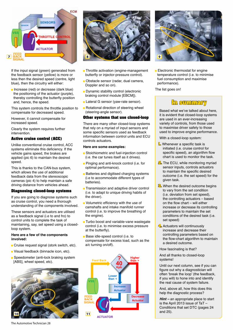
The Automotive Technician 28
If the input signal (green) generated from the feedback sensor (yellow) is more or less then the desired speed (centre, light blue), then the circuitry will either: Increase (red) or decrease (dark blue) the positioning of the actuator (purple), thereby controlling the butterfly position and, hence, the speed.
This system controls the throttle position to compensate for decreased speed. However, it cannot compensate for increased speed. Clearly the system requires further intervention.Active cruise control (ACC)Unlike conventional cruise control, ACC systems eliminate this deficiency. If the vehicle gains speed, the brakes are applied (pic 6) to maintain the desired speed. This is thanks to the CAN-bus system, which allows the use of additional feedback data from the stereoscopic cameras (pic 4) to help maintain a safe driving distance from vehicles ahead.Diagnosing closed-loop systemsIf you are going to diagnose systems such as cruise control, you need a thorough understanding of the components involved. These sensors and actuators are utilised as a feedback signal (i.e to and fro) to control units to complete the task of maintaining, say, set speed using a closed-loop system. Here are a few of the components involved: Cruise request signal (stork switch, etc). Visual feedback (binnacle icon, etc). Speedometer (anti-lock braking system [ABS], wheel speed, etc).
Throttle activation (engine-management butterfly or injector-pressure control). Obstacle sensor (radar, dual camera, Doppler and so on). Dynamic stability control (electronic braking control module [EBCM]). Lateral G sensor (yaw-rate sensor). Rotational direction of steering wheel (steering-angle sensor).
Other systems that use closed-loopThere are many other closed-loop systems that rely on a myriad of input sensors and some specific sensors used as feedback information between control units and ECU controls actuators. Here are some examples: Stoichiometric and fuel-injection control (i.e. the car tunes itself as it drives). Pinging and anti-knock control (i.e. for optimal performance). Batteries and digitised charging systems (i.e to accommodate different types of batteries). Transmission and adaptive driver control (i.e. to adapt to unique driving habits of the driver). Volumetric efficiency with the use of camshafts and intake manifold runner control (i.e. to improve the breathing of the engine). Turbo boost and variable-vane wastegate control (i.e. to minimise excess pressure at the butterfly). Base idle-speed control (i.e. to compensate for excess load, such as the a/c turning on/off).
Electronic thermostat for engine temperature control (i.e. to minimise fuel consumption and maximise performance).
The list goes on!
In summaryBased what we’ve talked about here, it is evident that closed-loop systems are used in an ever-increasing variety of controls, from those used to maximise driver safety to those used to improve engine performance. With a closed-loop system:1. Whenever a specific task is
initiated (i.e. cruise control for specific speed), an algorithm flow chart is used to monitor the task.
2. The ECU, while monitoring myriad sensor inputs, controls actuators to maintain the specific desired outcome (i.e. the set speed) for the given task.
3. When the desired outcome begins to vary from the set condition (i.e. deviation from set speed), the controlling actuators – based on the flow chart – will either increase or decrease its controlling parameters to maintain the set conditions of the desired task (i.e. set speed)
4. Actuators will continuously increase and decrease their controlling parameters based on the flow-chart algorithm to maintain a desired outcome.
How fascinating is that? And all thanks to closed-loop systems!Until our next column, see if you can figure out why a diagnostician will often ‘break the loop’ (the feedback, if you will) to hone into and identify the real cause of system failure. And, above all, how this does this help the diagnostic process?Hint – an appropriate place to start is the April 2013 issue of TaT – Conditions that set DTC (pages 24 and 25).
7 8
10
9
11

The Automotive Technician 29

The Automotive Technician 30
A while back a customer brought his 2004 LandRover Discovery 2 in with the anti-lock braking system (ABS), traction control and hill-descent system lights shining on the dash (pic 1 or 2). On the internet, this is commonly known as the ‘Three Amigos’.
There are many reasons why these dash lights can illuminate. In this case, my Autologic scan tool revealed an issue with the ABS shuttle valves or something related to their circuitry. My wiring diagrams did not show just which of the wires that left the ABS module were the actual shuttle-valve terminals (pic 3). There were wires shown that went to the ECM – some of these had to be from the shuttle valves but I didn’t know precisely which wires were what. With limited information available on the topic, my staff carried out a voltage-drop test at the powers and grounds of the ABS module. They then removed the ABS module and unscrewed the shuttle-valve assembly off the bottom of the unit.The ABS unit houses two shuttle valves (pic 4). The valves are actuated when brake-pedal pressure is applied via the master brake cylinder. The shuttle valves have a micro-switch attached to them and a set of resistors located between them. The shuttle-valve switches will change depending on the position of the shuttle valve in relation to the ABS operation. The signal from the shuttle valve is used by the ABS to send information to the ECM to detect the correct operation of the brakes and ensure the integrity of the ABS.There are a number of DIY shuttle-valve assembly replacement videos on YouTube and they all seem hell-bent on leaving the hydraulic brake lines attached to the ABS unit and simply bending the pipes up so you can access the shuttle valve underneath. This is a big no-no because it puts stress on those pipes and could make them brittle and susceptible to eventual breakage.It’s much safer, and more professional, to simply undo these pipes. That means there is less risk of comeback or, worse, the loss of brakes due to a pipe breaking. The downside of doing it this way is you will need to bleed the brakes after reinstalling the ABS unit. Once my staff had removed the ABS unit and unscrewed the shuttle valve, they noticed the plastic insulation that protects the shuttle-valve wiring had deteriorated, leaving exposed copper wires.
Because this was an intermittent problem, it was suspected that a scenario such as the vehicle hitting a bump was shorting the wires together and causing the fault to show on the dash.A new shuttle-valve assembly was fitted, the ABS unit was reinstalled and the brakes were bled. All the fault codes were cleared and the car was given back to the customer.There was a time when LandRover did not service the shuttle-valve assembly as an individual part. Rather, you had to buy the whole ABS module as a complete package. This cost big dollars and, due to the high demand and the likely embarrassment this caused the brand, it now services just the shuttle valves on their own.It is always a workshop’s biggest nightmare when a car that has supposedly been fixed returns with what seems to be the same problem. This would be the case for this Discovery but, fortunately, the customer was understanding. He’d seen the old shuttle-valve assembly himself and how the copper wiring had been exposed. Sure enough, scanning the car and seeing the same fault code made us suspect a circuitry problem. My customer suggested I talk to a LandRover specialist in Tasmania, who recommended I bypass the wiring that goes through the ABS module that sends the shuttle-valve message straight to the ECM.
Now I am not someone who blindly does something just because I am told to. First, I have to understand what I
am doing and whether doing it is absolutely necessary, otherwise it can be like
throwing parts at a car hoping to fix a problem – you might get lucky but you might also just be wasting your customer’s money.
The other critical concern was we were dealing with ABS. That raised a
serious question – would bypassing the shuttle-valve wiring that goes through the ABS module affect the safety of the ABS and traction control? If the answer to this kind of question is yes my philosophy is I cannot and will not touch it.After removing the ABS module and then the shuttle-valve assembly, we discovered that only one of the two shuttle-valve wires that go through the ABS module and then out through the ABS main terminal plug had continuity (pic 5).My staff used a number of different wiring diagrams and, while he could see three wires that came out of the ABS module and went to the ECM, he had no way of knowing which one was the signal wire from the shuttle valve that signalled the ECM.On top of needing to know which wire was the shuttle-valve signal wire, we also had to be sure the shuttle-valve signal was not directly relevant to the operation of the ABS module.After much research, we came the conclusion that the two shuttle-valve wires – despite passing through the ABS module – had no direct reference or effect on the ABS module. This, however, doesn’t mean the ECM does not use the shuttle-valve signal to affect the ABS via controller area network (CAN) bus.
The Three AmigosMaurice Donovan 1 2
3 4 5

The Automotive Technician 31
Find solutions for every brake job at www.bendix.com.auOr freecall the Bendix Brake Advice Centre on 1800 819 666Bendix is a trademark of Honeywell International Inc.
Your customers demand more from their vehicles everyday with heavy loads and driving on construction sites. Feel confident that Bendix Heavy Duty Disc Brake Pads work as hard as they do.
READY TO WORK HARDER, COOLER AND LONGER.
PerformanceWORSE BETTER
0 2 4 6 8 10
FADE
PAD LIFE
ROTOR LIFE
BRAKE NOISE
OPERATING FRICTION LEVEL
WHEEL CLEANLINESS
Bendix Heavy Duty Competitor
The signals the ECM monitors from the shuttle valve are ‘closed’, ‘open’, ‘one open’ or ‘one closed’. If the ECM senses an open or short in the circuit, a fault code is set and the Three Amigos show up on the dash.With this in mind, we made the decision to bypass the open circuit within the ABS module but we had to know which terminal was the ABS shuttle-valve signal terminal. I could not get this info from data suppliers with access to factory manuals, so – as we all do at times – I used Google.I soon learnt the yellow-and-green traced wire was my shuttle-valve signal wire and was definitely the one that had an open circuit. The other shuttle-valve wire was simply a ground wire.
My staff used a solder seal sleeve heatshrink, which allows you to simply push both wires in at each end of the sleeve and then use a heat gun to heat up the solder inside the plastic sleeve
and melt the solder (pic 6). Shrinking the plastic heatshrink encapsulating the solder also melts the two copper
wires to join and seal them, making a perfectly water-tight join.Once the shuttle-valve assembly was refitted to the bottom of the ABS module, then the bypass wire neatly routed under the ABS unit and joined to the main ABS module’s wiring harness, the ABS unit was reinstalled. After bleeding the brakes and clearing all fault codes, this vehicle was finally fixed. The
customer is happy because he did not have to buy a new ABS module, which would have been necessary if we hadn’t bypassed the open circuit (pic 7 or 8).
6 7 8

The Automotive Technician 32
Battery stabilisers are a tool that should be in every workshop but the truth is they are not.
The scary thing is a high percentage of workshops probably haven’t heard of them or are familiar with what they can and should be used for.A battery stabiliser is used to deliver and maintain a steady voltage of around 14.0V regardless of the current draw from actions such as fans, lights or during the scanning and programming of modules, coding of new diesel injectors, software-update process or long periods of KOEO (key on, engine off) diagnosis.This voltage is delivered with no (or very low) AC ripple. This is not the case for normal battery chargers and that can affect systems when programming.
The use of slave batteries, booster packs or normal battery chargers instead of a battery stabiliser is bad practice and can cause damage to modules if the correct voltage is not maintained. Sudden current fluctuations can also occur during programming, which is why a battery stabiliser should always be used – it’s not worth risking modules by using the wrong tool.
Examples of useIn my business I’m using my battery stabilisers not just when programming modules but on every car that is scanned. I have found them valuable because they prevent the vehicle’s battery from being run low when scanning modules during servicing, diagnosis and repairs.One of the images on this page (pic 12) was sent to me by a TaT technician who’d
connected a battery stabiliser while he was performing a full auto scan on an Audi A3 – check out the 47.1A reading!Another fellow TaT technician has advised me that, when performing a Nissan X-Trail idle relearn without a scan tool, a battery stabiliser must be connected to keep the battery voltage near 14.0V or the relearn
will not work. This is just another reason why the use of a battery stabiliser is essential.Using a battery stabiliser while performing a simple scan of all modules is particularly important with some Nissans and Hondas. I recently scanned a Nissan Tiida and Qashqai and the scan tool searched for 56 modules on both vehicles. That number was 40 modules for a Mitsubishi ZG Outlander (pic 4, 5 and 6). With each scan taking approximately 10 minutes to complete, this process risks running an average battery to a critical state of charge.In some Honda Civics and Accords the battery voltage doesn’t even have to drop too far during a scan before you end up with the VSA (vehicle stabilty assist) warning light stuck on the dash, thereby requiring a VSA relearn to clear it.
Before I had a battery stabiliser I often found myself rushing to perform scans quickly so I wouldn’t run the battery too low. Now I find the whole process a lot less stressful – you can set up the battery stabiliser and scan tool, then go off to perform other service tasks while waiting for the scan to complete. For me, that’s often stuff like replacing the lube sticker, lubricating the door hinges or replacing the wiper blades.
PurchasingIt’s only recently that a decent selection of suppliers have selling battery stabilisers. Just over two years ago at the Australian Automotive Aftermarket Association (AAAA) trade show in Melbourne, I took the time to visit different suppliers to investigate my battery-stabiliser options and few had any idea what I was looking
for – many tried to sell me a battery charger! Back then the Autoland PS-M1 was pretty much all that was available but now there are a few more brands coming onto the market and suppliers are in the know.I’ve tested two battery stablilisers in my workshop, the Endeavour ET9420 and the Autoland PS-M1, and both seem good. Both show the amps being drawn by the vehicle and the voltage output on the display. The Endeavour unit has an adjustable voltage output that could be useful when setting up alcohol interlockers on vehicles. The Autoland unit is set to deliver at a non-adjustable 14.0V, which may suit some people better.Very high current draw can occur during programming, especially on European vehicles, so the amp-output rating of a battery stabiliser is important.
Battery stabilisers–
Jason Smith
An essential tool
1
4
2
11
5
3
6

The Automotive Technician 33
The Endeavour unit is rated at 120A and the Autoland at 110A. These are the maximum ratings and peak outputs, so be sure to check the rating suits your purpose. Also bear in mind these quoted amp ratings are from the manufacturers and could probably only be held for short periods of time.
I know of a TaT technician who specialises in European vehicles and uses a Snap-on battery stabiliser with a specification of 170A stable and peak of 300A. Another fellow TaT technician has told me about one or two models in the Projecta and CTEK battery-charger range that have a supply mode to support the battery during diagnostic or fault-finding work. These are a lower cost option but apparently have a very low amp output, so are only suitable for scanning vehicles, not programming.
This is clearly stated on the specifications of the units.Before choosing a battery stabiliser for your workshop, it’s important to work out which one will suit your business and budget.
! CAUTION !A note of caution. Care must be taken not to accidentally start a vehicle with a battery stabiliser connected as this
could damage the unit.
In closingA battery stabiliser should be right at the top of your workshop-tool wishlist. If you set it up on a trolley you’ll find it can be easily moved around (pic 1, 4, 5, 7, 8, 10 and 11), which will ensure you use it.
8
11
97
10
DPF FAILURE
If everything is working fine, a vehicle’s diesel particulate filter (DPF) should last at least 250,000km before needing to be replaced.
Unfortunately, however, this often is not the case. Any hydrocarbon introduced to the DPF outside of what is normal for the regeneration process can cause failure. The introduced hydrocarbons can be either diesel fuel or oil.If a vehicle comes through the workshop with an indicated DPF problem, don’t simply assume it’s time to change to a new one. If there is an underlining fault that is not fixed, your customer will only return later, usually unhappy, with the same DPF fault.What causes these hydrocarbon introductions? It can be a number of things, either one issue or a combination of several.
Possible faults include leaking fuel injectors, leaking turbocharger oil seals or, in extreme cases involving excessively worn engines, crankcase blow-by. A faulty sensor could also be the problem and should be checked.The DPF is fitted with a pressure-differentiation system that senses the difference in exhaust-gas pressure between the front and rear of the actual filtration section.
These pressure tubes can get blocked by carbon from the exhaust, which stops the regeneration system from working at all, allowing the filter to block. It can also make the regeneration system operate constantly, which can cause a meltdown of the filter unit. Either scenario is not good for a DPF.
Some regeneration systems have an additional diesel injector in the exhaust system that adds extra fuel for PDF regeneration. These injectors can stick closed, preventing a proper regeneration, or get stuck completely or partially open, causing overfuelling and a DPF blockage or meltdown.Most DPF regeneration systems are locked until the engine coolant temperature, crankcase oil temperature and exhaust gas temperature reach normal operating levels. Are they reaching normal? Even a stuck-open radiator thermostat can stop regenerations occuring.Remember, the DPF is the symptom, not the disease. Proper diagnosis of any DPF problem is essential, whatever is wrong with your customer’s car. In the end it will save you and your customer money and keep them satisfied with your service.
For more information contact DPF Sales Australia on 1300 821 877 or go to www.dpfaustralia.com.au

The Automotive Technician 34
Once upon a time in a faraway land, some bloke was playing
around in his backyard and invented an engine that ran on oil. Oil – can you imagine what the neighbours thought of that? I can’t even start my mower up without the sniffer squad paying me a visit.
The other day a client who runs his diesel on used fat from the local fish and chip shop drove into our workshop and left his engine ticking over. I got into trouble because the girls upstairs knocked off for lunch thinking the food truck had arrived. I must admit, it did smell a bit like a burnt hamburger! He admitted to me that he had not thought to check the salt level in the waste fat before running it in his vehicle.The diesel engines first fitted to commercial vehicles were, by today’s standards, very smoky, rough, noisy, slow, heavy and dropped a lot of oil (engine and fuel) on the ground. Understandably, development and public acceptance was very slow. The possibility that a diesel-engined passenger car would ever be accepted by the public was beyond imagination.Early diesel-engine manufacturers seemed unconcerned about improving its obvious shortcomings. One major complaint that affected owners and the general public was the tendency for it to leak fuel. The fuel came from normal leakage at the injectors, which was channelled through a short pipe and allowed to discharge into the atmosphere or down the outside of the engine block onto the ground!Some engines were fitted with a burner system inside the manifold to aid starting and reduce noise. Other attempts to improve public acceptance gradually overcame the long-held aversion to these smoky, noisy engines. A new generation of so-called high-speed diesels became almost an overnight success, sought after as a powerful engine with – wait for it – minimum oil leakage. These newer diesel engines became much more acceptable to the public with their increased power, internally retained fuel leakage and much-reduced noise and vibration.We’ve come a long way since the time when one engine fitted to a popular truck consisted of three cylinders, no cylinder heads, six pistons, twelve connecting rods and one crankshaft. This supercharged, horizontally opposed two-stroke 3.5-litre 120hp engine was fitted to Commer trucks in the 1950s and ‘60s and a low-revving, economical powerplant. It sounds quite complicated but had many features that, if developed with today’s technology and materials, might have been much more successful. Of course, that would apply to many projects of the past.
Now, with emissions regulations becaming stricter every year, almost every part of the faithful engine that ran on oil is being completely redesigned. Enter the common-rail diesel, or CRD. The differences between these and traditional
diesels are well known and initial opposition to these highly developed engines has been answered. If the extra care and differences in operating procedures are followed,
we should enjoy a powerful, economical, quiet, easy-to-start and, most importantly, low-emissions vehicle, as well as expecting reasonably high trouble-free kilometres.Terrain Tamer carries a range of new and second-hand injectors to suit all popular 4WDs. We also stock full-service kits, which include gaskets, seals, injectors and pipes. Pipes can be purchased individually. In some service books, injector pipes are listed to be changed with surprisingly few kilometres to prevent them deteriorating internally.At the risk of repeating myself, here’s a list of precautions to help owners avoid finding themselves in
a situation crying out, ‘Why didn’t someone tell me?’
Consider fitting a ‘petrol-stop’ fuel-filler cap (misfuelling costs millions of dollars per year). Use diesel fuel additive constantly as a sulphur replacement to lubricate the high-pressure fuel pump and help keep the injectors clean. Fit an extra fuel filter (an absolute must). Fit a good-quality catch can to intercept the soot, sludge, carbon and oil mist from the tappet cover before it contaminates the turbocharger, intercooler, exhaust-gas recirculation (EGR) valve and intake manifold. Use the vehicle at least twice a week for 30 minutes minimum (non-stop). Do not idle engine for more than four minutes when cold. Change engine oil at least every 5000km (follow oil spec in owner’s handbook). And, once again, drive as far as you like with any warning light on at $1000 per kilometre.
As Red Adair famously said,
Diesel droolings!
Allan Gray
‘If you think
a professional
mechanic is
costly, just wait
‘til you hire an
amateur!’

The Automotive Technician 35
3 YearWarranty
NATIONWIDE
A/C Compressor KitsThe easy and reliable way to repair contaminated Air Conditioning systems backed with a nationally supported 3 year warranty.
A/C Compressor Kits include all the parts needed to completely restore the vehicle air conditioning system back to new condition.
Kit includes:Compressor, Condenser, Compressor OilThermal Expansion Valve / Orifice Tube,Receiver Drier / Accumulator,Air Conditioning System Treatment,Measuring Cup & System Guard Strap
®
Available from Adrad Stockists including:
or Contact Adrad
1800 882 043
Suits 1,400+
Applications
adradradiators.com.au
TAT_Compressor_Kits_Ad0919
A 2011 Nissan Patrol diesel (ZD30 common-rail) was brought in with its traction control
and anti-lock braking system (ABS) warning lights showing on the dash.During a road test of the vehicle, we could feel it lose power, so scanned the vehicle and it logged a code for the engine ECU (P1089) and another for an ECU fault in the ABS module. The customer had been informed by another repairer that P1089 was a fuel-pump fault code and that it should not affect the ABS or traction control, so they had brought the vehicle to us.After road-testing the vehicle again for
approximately 10-15 minutes, it started to lose power and surge. After that the traction control and ABS lights came on and it became slightly hard to restart. However, it was still driveable and didn’t appear to be going into a limp mode.A rescan of the engine ECU only brought up the same P1089 fuel-pump code. The only code for the ABS and traction
control was an ECU fault with no useful description. The check-engine light (CEL) was not on, only those for the ABS and traction control.We determined that the ABS module had to be receiving the fault error code from the engine ECU and was then disabling the ABS and traction control because it could not control engine power. We carried out a flow test on injectors and they tested OK.Then we tested the fuel rail and found the pressure-control valve was leaking. A new fuel rail was fitted and the vehicle was road-tested extensively. No further issues were experienced.Andrew SlaboszMechanics 2 UROCKLEA, QLD
Fuel leak causes strange fault codesShare your solutions
Want to share a repair solution? www.tat.net.au/tat-share
1
2 4
3
2011 Nissan Patrol
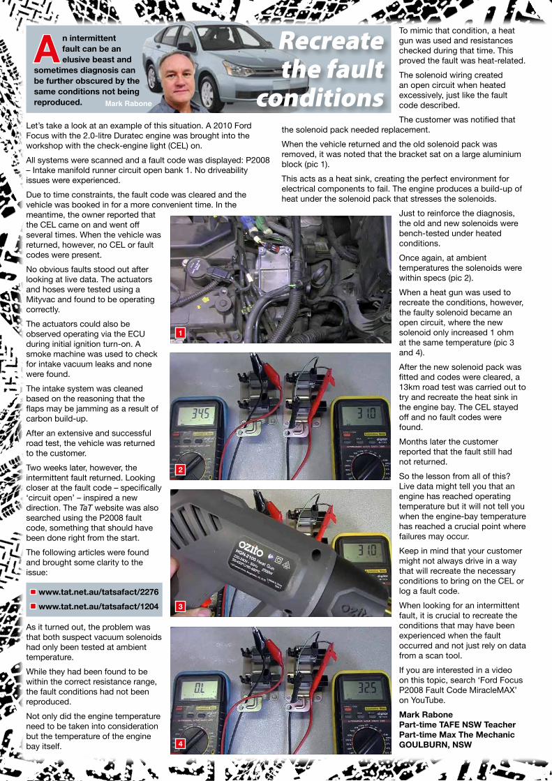
The Automotive Technician 36
An intermittent fault can be an elusive beast and
sometimes diagnosis can be further obscured by the same conditions not being reproduced.
Let’s take a look at an example of this situation. A 2010 Ford Focus with the 2.0-litre Duratec engine was brought into the workshop with the check-engine light (CEL) on. All systems were scanned and a fault code was displayed: P2008 – Intake manifold runner circuit open bank 1. No driveability issues were experienced.Due to time constraints, the fault code was cleared and the vehicle was booked in for a more convenient time. In the meantime, the owner reported that the CEL came on and went off several times. When the vehicle was returned, however, no CEL or fault codes were present.No obvious faults stood out after looking at live data. The actuators and hoses were tested using a Mityvac and found to be operating correctly. The actuators could also be observed operating via the ECU during initial ignition turn-on. A smoke machine was used to check for intake vacuum leaks and none were found.The intake system was cleaned based on the reasoning that the flaps may be jamming as a result of carbon build-up. After an extensive and successful road test, the vehicle was returned to the customer.Two weeks later, however, the intermittent fault returned. Looking closer at the fault code – specifically ‘circuit open’ – inspired a new direction. The TaT website was also searched using the P2008 fault code, something that should have been done right from the start. The following articles were found and brought some clarity to the issue:
www.tat.net.au/tatsafact/2276 www.tat.net.au/tatsafact/1204
As it turned out, the problem was that both suspect vacuum solenoids had only been tested at ambient temperature. While they had been found to be within the correct resistance range, the fault conditions had not been reproduced.Not only did the engine temperature need to be taken into consideration but the temperature of the engine bay itself.
To mimic that condition, a heat gun was used and resistances checked during that time. This proved the fault was heat-related. The solenoid wiring created an open circuit when heated excessively, just like the fault code described.The customer was notified that
the solenoid pack needed replacement.When the vehicle returned and the old solenoid pack was removed, it was noted that the bracket sat on a large aluminium block (pic 1). This acts as a heat sink, creating the perfect environment for electrical components to fail. The engine produces a build-up of heat under the solenoid pack that stresses the solenoids.
Just to reinforce the diagnosis, the old and new solenoids were bench-tested under heated conditions. Once again, at ambient temperatures the solenoids were within specs (pic 2).When a heat gun was used to recreate the conditions, however, the faulty solenoid became an open circuit, where the new solenoid only increased 1 ohm at the same temperature (pic 3 and 4).After the new solenoid pack was fitted and codes were cleared, a 13km road test was carried out to try and recreate the heat sink in the engine bay. The CEL stayed off and no fault codes were found. Months later the customer reported that the fault still had not returned.So the lesson from all of this? Live data might tell you that an engine has reached operating temperature but it will not tell you when the engine-bay temperature has reached a crucial point where failures may occur.Keep in mind that your customer might not always drive in a way that will recreate the necessary conditions to bring on the CEL or log a fault code. When looking for an intermittent fault, it is crucial to recreate the conditions that may have been experienced when the fault occurred and not just rely on data from a scan tool.If you are interested in a video on this topic, search ‘Ford Focus P2008 Fault Code MiracleMAX’ on YouTube.Mark RabonePart-time TAFE NSW TeacherPart-time Max The MechanicGOULBURN, NSW
Recreate the fault
conditionsMark Rabone
1
2
3
4

The Automotive Technician 37
RDA qp 37
The front-end auxiliary drive (FEAD) supplies power to a vehicle’s auxiliary equipment and supports its comfort and safety. For a professional repair, it’s important to observe
the vehicle manufacturer’s testing and replacement intervals.A typical FEAD system includes high-output alternators, a/c, power-steering pump and start/stop systems. Downsized engines, with their greater power requirements, can place further demands on the system.Schaeffler engineers recommend the replacement of the entire FEAD when a fault is detected in any of the system components. Because of the high demands on the system, all components must work perfectly together, with all components subjected to the same levels of wear.Schaeffler says its INA FEAD KIT contains all of the components required for a complete OE-quality system replacement for a reliable and lasting repair, including:
Drive belt (also known as a serpentine, V-belt or multi-ribbed belt) – The drive belt transfers the rotational movement of the crankshaft to the components being driven. Idler pulleys – These guide the course of the multi-ribbed belt to the auxiliary components, ensuring optimum torque transmission. Belt tensioner – Mechanical or hydraulic tensioners ensure the belt remains at the optimum tension, preventing slippage, noise and belt vibration. Alternator pulleys – These are used on the rotor shaft of the alternator to dampen all vibration in the belt drive. The pulley disconnects the rotor from the rotational irregularities of the engine.
Over-running alternator pulley (OAP) and over-running alternator decoupler (OAD) – These control alternator speed and dampen the entire FEAD. Belt-pulley decoupler – This dampens oscillation of the crankshaft, minimising noise and vibrations. Water pump – This circulates coolant mixture to prevent overheating and engine damage.
Each INA FEAD KIT is tailored to a specific vehicle type and includes the drive belt, tensioning pulley, deflection pulley and necessary accessories. Depending on vehicle type, the kit may also include an OAP, torsional vibration damper, belt-pulley decoupler or a water pump. A specific belt-route diagram is also included to help make assembly fast and easy.Visit Schaeffler’s REPXPERT technical portal for more information and the full INA Front End Auxiliary Drive Spare Parts Catalogue 2019/20.
For more information go to www.repxpert.com.au
The simple solution for a complete FEAD repair
This 2012 Mazda CX-5 with the 2.2-litre diesel engine was
occasionally losing power. It would start slowing down but then regain full power and have no further issues.The check-engine light (CEL) was not showing but the customer mentioned his wife thought she had noticed smoke coming from under the bonnet.A scan of the vehicle showed no fault codes. After road test up the highway with the scan tool connected, there were still no codes and all live data seemed to be OK – even when the problem occurred.Then one morning we were moving the vehicle out of the workshop with the bonnet up when a tech noticed a slight puff of black smoke coming up from near the firewall. When we removed the
engine cover and turbocharger heat shield, we discovered the exhaust-pressure sensor had melted and the hose had split.After giving the relevant part numbers to Mazda for the sensor, we were surprised to receive a totally different sensor with a new bracket, hose and wiring harness. The original sensor was plastic and the new one was metal.We fitted the sensor but left the new harness out because the original plug fitted. Then, however, the vehicle would not rev.Once we fitted the supplied harness, everything was corrected. The customer is as happy as Larry and says it’s never driven betterJarrod WhiteInGear MechanicalTOMAGO, NSW
Superseded exhaust-pressure sensor
Share your solutions
Want to share a repair solution? www.tat.net.au/tat-share
2012 Mazda CX-5

The Automotive Technician 38
We know how important it is to your success to provide you with the right parts range at competitive pricing when you need them. Today, Kelpro is more than just rubber and hardparts. We are constantly adding new products and now offer a comprehensive range in:
Suspension & Driveline components Window Regulators & SwitchesOil Seals Sump Plugs Engine Mounts
This maintains Kelpro at the forefront in range development supported by a knowledgeable team.
For more information call 1800 605 673 or visit www.kelpro.com.au
KELPRO. A PART OF YOUR SUCCESS.
A 2010 Ford FG Falcon XR6 came in with its owning reporting an
intermittent warning light on dash followed by rough running and/or stalling . The engine in this vehicle was the 4.0 litre petrol six.Scanning the vehicle brought up the following powertrain control module (PCM) fault codes:P1340 – Camshaft position sensor B circuit.P1381 – Camshaft position timing over advanced.P1386 – Variable-cam timing (VCT) over advanced.Conducted all of the usual diagnostic tests, including a lights check, battery condition, charge rate and voltage drop on ground circuits. Extracted and analysed all available
fault-code information and data, including freeze-frame data.Decided to concentrate on the P1340 because it was a circuit code and had returned after clearing. Connected the scope to both of the camshaft-position sensors’ signal circuits and observed. The intake-side signal was good but the exhaust-side sensor was dropping in and out. Tested the wiring back to the PCM and no faults were found.We informed the customer that a new camshaft-position sensor on the exhaust side was required (part number 1W4Z 6B288 AA).Marty HosieBarclay’s Radiator Service & Wagga Car A/C ServiceWAGGA WAGGA, NSW
2010 Ford FG Falcon XR6
Faulty sensor causes stalling issues
Share your solutions
Want to share a repair solution? www.tat.net.au/tat-share
This smoky 2014 Ford Territory with the 2.7-litre Duratorq
diesel V6 had its check-engine light (CEL) on and was losing power. A road test of the vehicle confirmed it had no power, was blowing smoke and hard to start. A full scan brought up the following powertrain control module (PCM) code: P045C00 – EGR B control circuit low.Cleared the fault code but the same one returned. Tried looking at the data, then to drive the exhaust-gas recirculation (EGR) system through the scan tool, but could not find anything.Removed the left-side EGR valve and found it was stuck
open. Tried cleaning it with no success, so replaced the faulty valve. All fixed.Matthew FishJindabyne Auto RepairsJINDABYNE, NSW
Territory smoke signals
Share your solutions
2014 Ford Territory
Want to share a repair solution? www.tat.net.au/tat-share

The Automotive Technician 39
with Jason Smith
Most technicians know that you should never use an impact gun or the like to
remove or refit the top nut of a shock absorber or strut during shock absorber or strut replacement.Doing this can not only severely damage the shaft and internals of the shocker or strut but actually break the shaft.
Often, though, these retaining nuts are buried deep inside a top tower, preventing the use a normal spanner and shifter. That’s where the temptation to use an impact gun comes in, so what tool do you use?
I have come across a reasonably priced gem from Boston Mechanic, the BM505 Shock Absorber and Strut Tool Kit. It has 43 different fittings, adaptors and tools, allowing the technician to select the correct adaptor to hold the shocker shaft (pic 3, 6, 7, 9 and 10), then use the correct-sized socket to fit over the top of the adaptor (pic 7, 8, 10 and 11), allowing
easy removal or retightening of a shocker or strut nut.The BM505 comes in a blow-moulded case with all adaptors, sockets and tools clearly marked for quick identification. The female-style two-way ratchet (pic 4
and 12) is a simple but smart design that allows the quick removal of shocker and strut top nuts. Note that you will still require your own breaker bar (pic 13) to unlock shocker nuts and your own tension wrench (pic 13) when refitting nuts to ensure correct torque.This tool is well presented, well made and a real time and headache saver.
It should be part of every workshop’s special tool cabinet.
The Boston Mechanic BM505 Shock Absorber and Strut Tool Kit is now available through Burson Auto Parts.
REVIEWEquipment reviews
Boston Mechanic BM505 shocker
and strut tool kit
1 2
3
4
5 6 7
8 9
11 12 13
101a

The Automotive Technician 40
This 2001 Holden VU Commodore Ute had failed its annual
registration inspection because its supplemental restraint system (SRS, or airbag) warning light was staying on. The clock spring had already been replaced but that had not extinguished the airbag light.A full system scan brought up the following fault code: 163 – SDM control module internal fault.We conducted the usual general diagnostic tests first, including all lights, a charging-system test and a voltage-drop on main ground circuits. We were initially unable to communicate with the sensing diagnostic module (SDM) but eventually
managed intermittent communication and extracted the fault code mentioned above. The instrument cluster also contained several SRS-related fault codes also.Removed the centre console to access the SDM. Tested all electrical circuits to it and all were good.Checked with the Holden dealer, who said the original SDM had been superseded and replaced by a new SDM. The part number for the original superseded unit was 92075493, the part number of its replacement is 92107343.Fitted a new SDM, then cleared the codes and road-tested the vehicle. All fixed.Marty HosieBarclay’s Radiator Service & Wagga Car A/C ServiceWAGGA WAGGA, NSW
Fault in SRS module
Share your solutions
2001 Holden VU Commodore Ute
Want to share a repair solution? www.tat.net.au/tat-share
This 2014 Ford Ranger with the 3.2-litre Duratorq
diesel five-cylinder engine was misfiring on cold mornings.Because it only happened when it was cold – never hot – and there were no fault codes, we went straight to the glow plugs.
After testing them we found one was faulty (i.e. open-circuit).We recommended fitting a full set of glow plugs to the owner. They agreed, so we went ahead with the replacement. The miss on cold mornings is no more.Matthew FishJindabyne Auto RepairsJINDABYNE, NSW
Cold start misfire
Share your solutions
2014 Ford Ranger
Want to share a repair solution? www.tat.net.au/tat-share

The Automotive Technician 41
This 2009 Subaru Impreza WRX with the EJ25 2.5-litre DOHC turbocharged engine came in
with its check-engine light (CEL) on.An initial inspection confirmed the vehicle’s CEL was showing. During a road test under normal driving conditions, it seemed slightly underpowered.Scanning the vehicle brought up the following fault code: P0011 – Variable-valve control bank 1 fault.Checked the data and there were no obvious issues at the time of testing.The service history of the vehicle was unknown and the suspect variable-valve timing (VVT) solenoid was easy to access, so removed it and checked for sludging or signs of scoring on the shuttle valve.Everything appeared okay, so reassembled, cleared the memory and road-tested the vehicle again. This time it did not fault, so it was returned to the owner.The next week the vehicle was back with the CEL on again and the owner saying it now had an engine noise under load.
Scanned the vehicle and the original code reappeared. During a more aggressive road test, a noise could be heard from the turbo under boost.Inspected the turbo and found it had excess free-play and a damaged impeller.Further investigation and research showed the turbo oil feed and bank 1 VVT oil feed come off a common banjo-pipe fitting on the top of the right-side cylinder head. The banjo bolt has an internal gauze filter that can block, restricting oil flow to both circuits (pic 1 and 2).A new banjo bolt was fitted and the oil flow to the turbo was flow-tested and found to be good. There were no other signs of excess sludging.A new turbo was then fitted, the oil and filter changed and the fault codes cleared. A month on and there have been no more problems.Jon WolrigeMaroochy Car CareMAROOCHYDORE, QLD
Share your solutions
Want to share a repair solution? www.tat.net.au/tat-share
Hidden oil filter causes turbo issues
2009 Subaru Impreza WRX
1
2

The Automotive Technician 42
with Clinton Brett of Diesel Help Australia
FAQ – When do you replace diesel injectors? CRD and non-CRD
Diesel injectors (pic 1) experience some of the harshest of conditions of any
components in a diesel engine. Their fine tolerances will be expected to cope with changed conditions every time the tank is filled and engine is running. Conventional diesels were a daily job for us in the diesel fuel-injection industry and with common-rail diesel (CRD) now the market leader, the replacement of these will become a weekly event for most workshops.In a CRD engine, each injector will open and close between three to eight times per cylinder stroke.Remember this when you’re considering replacing only one failed injector. You must replace all of them! Along with this common mistake, I regularly hear of technicians replacing the injectors due to the vehicle blowing smoke.After delivering training for six years and assisting hundreds with over-the-phone diagnostics, I understand where this easy misdiagnosis has come from, especially when dealing with the more mature, senior technicians who’ve been in the trade for 20-plus years. Back when petrol, gas and electronic fuel-injection had a huge presence in Australia, most school leavers destined for the automotive trade chose to be a petrol rather than a diesel mechanic. When only traditional mechanical systems were around. I chose diesel and recall some of the petrol guys had to spend a short stint in the diesel pump room.If you were studying petrol mechanics, you would often only pick up on some of the key failures on the mechanical injectors, typically smoke. Some injectors would smoke but smoke could also be the result of other failures. And we shouldn’t forget the colours of the ‘diesel rainbow’, blue, black and white (pic 2). This diagnosis was learnt in the workplace and would take years beyond trade school to learn. I have 20 years of CRD experience and 30-plus with all diesels. I’m still learning new faults and diagnostic tricks every week. There is a significant difference between old diesel and CRD systems, particularly when diagnosing and reading smoke signals.
Replacing CRD injectorsWhile smoke though can be a visible symptom of failed CRD injectors, it is not as common as smoke from early diesel injectors. The following symptoms or failures can occur after work such as replacing the injectors:
These faults tend to be more evident if the engine has overheated and the injectors have not been replaced.
This takes me to my first recommendation for injector replacement. An overheated engine means everything got extremely hot and the injector nozzles are going to cop the full extent of that high temperature. The clearance between both the nozzle body and needle in early diesels was fine and CRD injectors have a clearance of less than a human hair, approximately 0.002mm (pic 3). This means when you hit it with extremely high temperatures, enough to melt pistons and crack cylinder heads, the nozzle is going to become quite distorted.
Often distorted injectors will not impact on operation when cold, especially on the injector tester, but when they’re reinstalled back into the engine and warmed up to operating temperatures they won’t always work according to the plan. This has often resulted in a destroyed engine when the fault hasn’t been picked up soon enough. This happens on both CRD and non-CRD engines. Injectors must always be replaced if the engine got hot to the max on the temperature gauge, even if they had only just been replaced.Some symptoms can
include rattle and black smoke at the same time or a complete misfire. Other symptoms l mentioned such as smoke, rattles and starting issues are too complex to explain here. You’re going to have to attend our training courses or join Diesel Help. That info requires more than reading and pictures.
Wear and tearInjectors are replaced for preventative maintenance. Light passenger vehicles not constantly operating like a heavy vehicle or machinery. Both CRD and non-CRD and direct or indirect injectors should be replaced between 150,000km and 200,000km. Due to longer running periods, heavy trucks and machinery are typically changed at higher hours or kilometres, around 250,000km to 300,000km.A worn injector will contribute to incomplete combustion and may result in some of the above symptoms.
Contamination - Water/petrol/other unwanted fluid or substancesOnce it’s been confirmed that the contamination has made it to the injectors, they must be replaced. In contamination cases, I advise replacing all moving and metal components – pump,
Injectors.
Injector clearance.
Smoke colours.
1
3
2
White/black/blue smoke.
Rattling engine.
Hard starting.
Engine over-revving.
Loss of power or poor performance.
Engine failure.

The Automotive Technician 43
injectors, including rail and pipes. The entire system must be cleaned to ensure no contamination is present. Take a look at the internal moving part of an injector on this page (pic 4) – the grey area is worn.Special notes: Remember to always clean the seats correctly – do not cut seats (pic 5). Replace injector bolts, washers/seals and, with CRD or other high-pressure diesel fuel systems, the injector pipes
to avoid contamination and always use dust caps (pic 6). Check out our website for a wide range of dust caps. Always torque injectors to the specified setting.
Testing CRD injectorsThere are several different designs of injector and the differences between them are too complex to explain here. Attend one of our training courses to understand how to correctly test injectors in the engine using either the back-leakage method or feedback values using a scan tool.Keep a lookout for our training sessions held in your area. If there isn’t one, get a group of associates together and book a group session.
Proudly supplied by Clinton Brett of Diesel Help Australia. To purchase a one-off, over the phone diesel diagnostic assistance for a current job go to www.dieselhelp.com.au/helpmenow and
apply TaT50% to receive a 50 per cent discount.
Contaminated valve.
Injectors seats leaking.
4
5
6 Dust caps, pipes, bolts.
This Ford Ranger was brought in by its owner with the traction-control light on. Before that
would happen there would be a loud clunk, then the engine would have reduced power. These issues would reset after the car was restarted.The owner noted that the issue had initially only occurred about once a month before progressing to nearly every morning. It would occur within the first couple of minutes of driving following a cold start. After a restart, the vehicle would be fine for rest of the day.This Ranger was a 2014 model with the P4AT diesel motor. Scanning the vehicle brought up the following codes (pic 1):Engine
P042F-00 – EGR control stuck closed. No sub-code available – not current DTC.
P0700-00 – Transmission control system (MIL request). No sub-code available – Not current DTC.
Transmission U0401-00 – Invalid data received from ECM/PCM. No sub-code available – Not current DTC.
Anti-lock braking system (ABS) U0401-00 – Invalid
data received from ECM/PCM. No sub-code available - Not current DTC.Onboard diagnostics (OBD) P042F – EGR ‘A’ control
stuck closed. U0401 – Invalid data
received from ECM/PCM ‘A’.
Although the only warning light seen by the customer had been the traction-control light, freeze-frame data of the exhaust gas recirculation (EGR) code showed the same conditions they had described (low seconds since
engine start, cold coolant temperature, throttle position as described).During a road test of the vehicle we were eventually able to catch the EGR’s actual versus desired position not agreeing, though not for long enough to experience any warning lights or symptoms. We concluded that when the EGR code was setting, the vehicle was likely reverting to a fail-safe mode, selecting one gear (explaining the clunk) and reducing power until the ignition was cycled.We removed and inspected the EGR inlet and outlets. All were OK. We then supplied and fitted a new EGR, cleared all of the fault codes and road-tested the vehicle when cold. No further issues were experienced.Brendan SorensenSteve Sorensen MechanicalBROWNS PLAINS, QLD
2014 Ford Ranger
EGR affecting traction controlShare your solutions
Want to share a repair solution? www.tat.net.au/tat-share
Vehicle System ReportVEHICLE INFORMATIONVIN-----------------
MAKEFordYEAR2014MODELRanger PX
ENGINE2.2L-DT Diesel
SYSTEMCodeScanCODE SCAN RESULTSSystems Analyzed: 9Engine: 2
Transmission: 1Antilock Brakes: 1Airbag: 0Body Control Module: 0Front Control/Display Interface Module: 0
Instrument Panel: 0Speech Recognition Module: 0OBDII: 2EngineP042F-00 | EGR Control Stuck Closed. No Sub-Code Available. - Not Current DTC.
P0700-00 | Transmission Control System (Mil Request) . No Sub-Code Available. - Not Current DTC.
TransmissionU0401-00 | Invalid Data Received From ECM/PCM. No Sub-Code Available. - Not Current DTC.
Antilock BrakesU0401-00 | Invalid Data Received From ECM/PCM. No Sub-Code Available. - Not Current DTC.
OBDIIP042F | EGR "A" Control Stuck ClosedU0401 | Invalid Data Received From ECM/PCM "A"
READINESS MONITORSTests CompleteFuel SystemComprehensive ComponentEGR/VVT
Boost Pressure System
Page: 1
2014 Ford Ranger PX 2.2L-DT Diesel
Date: 05/08/2019 08:25AM
1

The Automotive Technician 44
The AutodoctaAudi Q3: Fuel-filler nozzle continuously cuts out when refuelling vehicleQuestion: A customer’s Audi Q3 2.0 TDI is in for a routine service and they have complained that the fuel-filler nozzle continuously cuts out when refuelling the vehicle. We have experienced the fault when refuelling and have visually checked the fuel-filler pipe for blockages but cannot find the source of the fault. Is this something you have heard of before?
Answer: Yes, we have heard of this fault before on Audi Q3 models with the CFFB engine code. The cause is the fuel-tank ventilation system becoming blocked. Check the fuel-tank breather cap for blockages and replace if necessary (fig.1.1). Check the fuel-tank breather hose and the fuel-tank breather valve for blockages (fig.1.2 and fig.1.3). If the fuel-tank breather hose or the fuel-tank breather valve is blocked, fit a new fuel tank. Refuel vehicle to ensure the fault has been resolved.Leading automotive technical-information provider Autodata shares manufacturer-verified fixes to common problems found in vehicles. To learn more about its innovative online tools for workshops go to www.autodata-group.com/au
This 2007 Holden Rodeo
3.0-litre diesel (4JJ1-TC) presented with the reverse-light fuse blowing, resulting in the four-wheel-drive (4x4) transfer system not working.After checking the wiring diagrams and speaking with an auto-electrician friend, we discovered the fuse for the reverse lights also powers the neutral switch and 4x4 transfer ECM.Further investigation suggested this issue can easily crop up if the engine or transmission
have been out of the vehicle at any time – the plugs for the clutch slave and neutral switch on the wiring harness (one brown, one grey) can easily be mixed up with the two switches on the right side of the gearbox (also one brown and one grey), which use exactly the same type of plug socket.Once the correct plugs are reunited, the issues will be resolved.Sam ShaughnessyPhil Maywald Auto RepairsMT GAMBIER, SA
2007 Holden Rodeo
All mixed upShare your solutions
Want to share a repair solution? www.tat.net.au/tat-share
Vehicles are complex machines that can sometimes have issues
that don’t seem to be related. Part of mechanical diagnosis, however, is understanding how the various parts of a vehicle work together and what can happen to parts on one end when those on the other end go bad.
For example, the failure of a vehicle’s fuel pump can lead to associated ignition-coil problems and ongoing engine damage. Generally when a vehicle ends up in a workshop with a misfiring or reduced-power condition, a technician will ensure the fuel flow and pressure are adequate and the ignition system is capable of burning the air/fuel charge in all cylinders as required for optimum engine performance before proceeding with further diagnosis.A poor-quality or failing fuel pump that has insufficient fuel flow and/or pressure typically creates a leaner than normal fuel mixture under certain driving conditions.
This lean-mixture condition requires a higher than normal ignition spark output from the ignition coil that eventually leads to an ignition-coil
failure.
The rate that it starts and continues to fail is generally determined by the quality of the ignition coil and how lean the mixture remains. Naturally a poor-quality ignition coil will fail at an accelerated rate.
Fuel-injected engines are very sensitive to both fuel pressure and volume. Fitting a quality replacement fuel pump is also
always recommended to ensure adequate fuel pressure during all driving conditions. Maintaining the correct air/fuel mixture minimises the emission levels and ensures correct engine performance. Premier Auto Trade’s Icon Series is an extensive offering of more than 240 ignition coils and 370 electric fuel pumps, modules and mechanical fuel pumps covering tens of millions of Australian vehicle applications, with all parts covered by a two-year/40,000km warranty.
FUEL PUMPS AND IGNITION CONCERNS
For more information go towww.premierautotrade.com.au

The Automotive Technician 45
C linton Brett brings more than 20 years of experience to diesel fuel injection.
A fifth-generation mechanic, Clinton diagnoses diesel faults around the world by phone, email or video link and conducts live common-rail diesel (CRD) diagnostics training courses for all automotive repairers and the fleet-servicing industry.Clinton identified that with the increasing number of diesel passenger vehicles with fuel systems using advanced technology, workshops were reporting an increasing number of system faults and issues, often wrongly assuming that the problem was electrical when it was, in fact, a fuel-system problem. Often the correct diagnosis would not come until a number of attempts had been made to fix the issue, ultimately costing the vehicle owner a fortune.Whether you are beside the road, in the paddock or in the workshop, Clinton is a reassuring and knowledgeable voice at the end of the phone helping you work through the problem to find its source. Clinton has helped customers find issues within minutes that have stumped several workshops!
Dates and locations are subject to change. Check the website for additions and changes to this list. For more information go to www.dieselhelp.com.au, email [email protected] or contact Clinton Brett 0432 738 003
Cost: $143 inc GST. More information and booking: Email: [email protected] or call Bee on 0476 173 930
Timaru NZ – Fri 22nd Nov 5.30pm – 9pm and Sat 23rd Nov 8.30am – 4pmNelson NZ – Fri 29th Nov 5.30pm – 9pm and Sat 30th Nov 8.30am – 4pmSunshine Coast QLD – Fri 6th Dec 5.30pm-9pm and Sat 7th Dec 8.30am-4pm
Auckland NZ – Tue 19th Nov 5.30pm-9pmTauranga NZ – Wed 20th Nov 5.30pm-9pmGreymouth NZ – Wed 27th Nov 5.30pm-9pm
Diagnostics and aftermarket training
The ultimate CRD training course – 10 hours of common-rail diesel diagnostics training over two days
Common diesel faults and scan-tool course
Here is his current course program
Training schedule:
Training schedule:
Course description:
Course description:
Explanation of common-rail diesel Identify components and location Types of common-rail diesel systems Component operation and known failures Preventative maintenance for all diesel engine systems, including fuel, intake, turbo, EGR and DPFs
Common diesel faults and fault codes Using sensors already on the car to direct your diagnosis On-vehicle demonstrations of the scan-tool capabilities Identifying important scan-tool data used when diagnosing dieselsTo maximise learning, each course is
limited to 15 participants. The course includes booklet, certificate, meals and refreshments. All participants receive a two-month free trial of Diesel Help membership on completion of the course.
Course 1
Course 2
VALHALLA INDUSTRIES Professional Diagnostic and Automotive Technical Training MASTERTECH-105
TopiCS CovEREd in MASTERTECH 105 diESEl inCludE:
Understanding and diagnosing MAF’s, MAP and boost sensors, Variable vane turbochargers, Intercoolers, EGR’s, Diesel catalysts and DPF’s, Feedback values and Drivability complaints
ModERn, SAfE And EASy TESTing METHodS uSing:
Diesel fault codes, Scan tool data analysis, Bi-directional actuation, Functional pathways, CRD component testing, Alternate diagnostic techniques, Thermal imaging, Smoke testing and more!
TRAining SCHEdulE:
Norwood SA – Mon 25th November 6pm-9.30pmSeacliff SA – Tue 26th November 6pm-9.30pmMawson Lakes SA – Wed 27th November 6pm-9.30pmWooloongabba SA – Thu 28th November 6pm-9.30pmTownsville QLD – Mon 2nd December 6pm-9.30pmInnisfail QLD – Tue 3rd December 6pm-9.30pmAtherton QLD – Wed 4th December 6pm-9.30pmCairns QLD – Thu 5th December 6pm-9.30pm
Common rail diesel - Forced Induction and emissions diagnostics

The Automotive Technician 46
The need for information and vehicle data is growing almost daily. With general electrical
and electronic diagnostics becoming a larger part of a normal workshop’s workload, the availability of accurate vehicle data and information is becoming ever more essential to get the job done.But good information and data isn’t free and information subscriptions are an increasing expense item for workshops. One Capricorn member workshop I interviewed was paying for the following information and assistance subscriptions: Autodata, OurAuto, TaT, Diesel Help Australia, Autonerdz, IATN, Diagnostic Network, Snap-on Information system, Autologic and various OE service and information portals. These add up to thousands of dollars every year.Every supplier that sells these products will happily tell you their subscription is an investment and not an expense. They are correct but only if you have a way of recouping your costs.So how do you recoup these costs? The answer is charging your customers a data fee.Before we discuss how to do this, let’s wind the clock back 15 years. If I’d asked a group of mechanics back then who charged a separate diagnostic fee I would have received very strange looks. ‘You can’t do that!’ or ‘Customers still expect free quotes’ would have been typical responses. Fast forward to today and the overwhelming majority of workshops charge a separate diagnostic fee. Everyone now understands that you can’t solve problems and give away your expertise for free.My point with mentioning the need to charge a separate diagnostic fee is that it may have felt odd once but it’s now the
norm. The same applies with charging a data fee. It might feel uncomfortable now but it will be the norm within the next few years.If you think your current subscription costs are hefty now, hold onto your hat. They are only going dramatically increase and where they end up is unknown.There is no way your hourly labour rate will be able to cover these growing costs, so you need to start charging a data fee to cover them. So how do you do it without upsetting the customer? Like everything, you need to be upfront. If you just slap it on the bill at the end the result will be an upset customer. So be upfront and explain to them that in order to diagnose and fix the problem correctly and as quickly as possible you will need access to vehicle information and data. And this information is going to cost money.Here’s an example: ’In order to diagnose your vehicle, we are going to need to access data and wiring diagrams. These will help us diagnose the problem more quickly and accurately. These will cost $25. Are you happy for me to go ahead and access these?’Customers like to think that they have saved money, so you need to make it
clear that this information and data will save time and the labour charge could be lower. Emphasise that the data will also help make the diagnosis as accurate as possible. When the job is done, present the information or data you have used to the customer with the invoice. This small gesture will validate the purchase and leave them with the perception that they have received full value for money. Showing them a complicated wiring diagram will also help shift their perception that mechanics are just ‘grease monkeys’.Just what fee to charge is something to be determined by each individual workshop but, as a guide, a sliding scale from $10 to $45 is quite common. Workshops need some flexibility because some data is harder to obtain.If this data is presented properly to your customer, they will happily accept the fee because they will know the job is being done more efficiently and accurately. Your workshop will now be in a better position to fund subscriptions, memberships, equipment updates and training.If you’re not already charging a data fee, it’s time to start doing it. Your hourly labour rate simply can’t cover these increasing costs anymore.
Business resources
For more info visitwww.tatbiz.net.au
TaT Biz is the business-training arm of TaT that specialises in business coaching for automotive workshops. Geoff Mutton specialises in one-
on-one business coaching for automotive workshops.
with Geoff Mutton from TatBiz
Charging datafees
■lighter – less unsprung weight
■less shock – less shock load on the differential gears
■quieter – the leaf springs do not touch each other
■comfort – with better articulation
View our demonstration videos online at terraintamer.com/suspension
Terrain Tamer Parabolic Leaf Springs are designed for the ultimate ride quality. Utilising a new design on an
old technology, the parabolic spring allows a comfortable ride whether the vehicle
is fully loaded or empty.
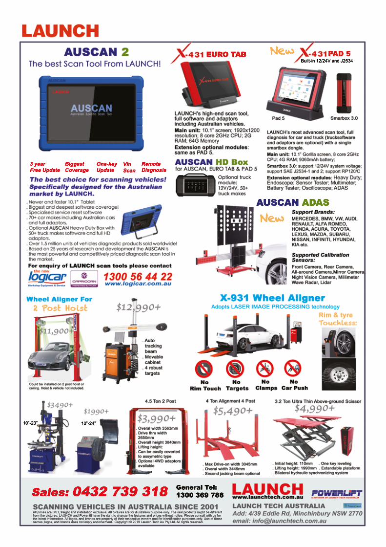
The Automotive Technician 47
EURO TABEURO TAB
All prices are GST, freight and installation exclusive. All pictures are for illustration purpose only. The real products might be different from the pictures. LAUNCH and Powerlift have the right to change the features and prices without notice. Please consult with us for the latest information. All logos, and brands are property of their respective owners and for identification purposes only. Use of these names, logos, and brands does not imply endorsement. Copyright © 2019 Launch Tech Au Pty Ltd. All rights reserved.
New
General Tel:1300 369 788
10”-24” 10”-23”
AUSCAN ADAS
New
PAD 5NewBuilt-in 12/24V and J2534

Our pumps and injectors are as heavy duty as the applications theypower. But when it comes to service, they need a delicate pair of hands.Delphi-approved repairers use specialist equipment, highly-trainedtechnicians and genuine OE parts to deliver a precise and cost-effectiverepair. For heavy duty, choose the Delphi Diesel Authorised network.
©2015 Delphi Automotive PLC. All rights reserved.
delphiautoparts.com