Appendix-A - VTechWorks
44
118 Appendix-A (WoodFrameMesh Users Manual) This manual describes the basic methodology for developing finite element models of structures using the WoodFrameMesh mesh generator program. The user should read this manual to understand the basic assumptions and automating features of the program and how they can be used to generate finite element models. A step by step procedure for developing an input file is discussed followed by an example to generate a finite element model for a simple box shaped wooden house. The manual also contains a tutorial which presents some basic examples along with the 3D graphical view of the finite element models as seen using SAP 2000. A.1 About WoodFrameMesh WoodFrameMesh is a MS-DOS based application which is written in the Visual C++ .NET framework for automating the generation of two-dimensional finite element models for structures. Although the program is specifically written for modeling wooden structures, it may also be used to model any structure using shell, frame and non-linear link elements. The output generated is in SAP 2000 version 7.xx .S2K format, which can be analyzed both by WoodFrameSolver and SAP 2000. The idea of generating output in .S2K format greatly facilitated in verification of the accuracy of output models in the absence of any graphic viewer in the WoodFrameSolver program. A.2 WoodFrameMesh Program Execution The WoodFrameMesh program is executed as a Win32 console application. When the program is executed, it asks the user to enter the input file name without the extension. It assumes the extension as .txt and looks for the file in the same folder from where the program is executed. If the input file is not found, the program tells the user that the input file cannot be found; otherwise it starts reading the input file. If the input file format is incorrect, the program will display an error message and will prompt the user to correct the data. Once the input file is read, the program checks the data for
-
Upload
khangminh22 -
Category
Documents
-
view
2 -
download
0
Transcript of Appendix-A - VTechWorks

118
Appendix-A
(WoodFrameMesh Users Manual)
This manual describes the basic methodology for developing finite element models of
structures using the WoodFrameMesh mesh generator program. The user should read
this manual to understand the basic assumptions and automating features of the program
and how they can be used to generate finite element models. A step by step procedure
for developing an input file is discussed followed by an example to generate a finite
element model for a simple box shaped wooden house. The manual also contains a
tutorial which presents some basic examples along with the 3D graphical view of the
finite element models as seen using SAP 2000.
A.1 About WoodFrameMesh WoodFrameMesh is a MS-DOS based application which is written in the Visual C++
.NET framework for automating the generation of two-dimensional finite element models
for structures. Although the program is specifically written for modeling wooden
structures, it may also be used to model any structure using shell, frame and non-linear
link elements. The output generated is in SAP 2000 version 7.xx .S2K format, which can
be analyzed both by WoodFrameSolver and SAP 2000. The idea of generating output in
.S2K format greatly facilitated in verification of the accuracy of output models in the
absence of any graphic viewer in the WoodFrameSolver program.
A.2 WoodFrameMesh Program Execution The WoodFrameMesh program is executed as a Win32 console application. When
the program is executed, it asks the user to enter the input file name without the
extension. It assumes the extension as .txt and looks for the file in the same folder from
where the program is executed. If the input file is not found, the program tells the user
that the input file cannot be found; otherwise it starts reading the input file. If the input
file format is incorrect, the program will display an error message and will prompt the
user to correct the data. Once the input file is read, the program checks the data for

119
validity and echoes all the input data along with errors if it encounters any. In the case
where the program encounters any errors while reading the input data, it asks the user to
correct the data; else it proceeds for mesh generation and modeling. Figure A.1 shows an
interface for the WoodFrameMesh executable.
Figure A.1: Interface for WoodFrameMesh executable
A.3 Input Model Generation The WoodFrameMesh program requires a varying degree of input to produce a
finite element model. The input model is derived from a CAD1 model and consists of
points, lines and polygons which in turn are outlined as a computational domain inside
the input file. Currently this process is done manually by the user because the CAD
interface is yet to be developed (by the sponsor). The user is essentially required to break
down the components of the structure into geometric objects and boundary condition
objects which can be meshed by the program. These geometric objects may be
comprised of diaphragms, walls, lips, openings and constraint lines. Figure A.2 show
some of these geometric objects in a typical house structure. In addition, the user is also
1 Computer Aided Design

120
required to provide data for the application of restraints, springs, non-linear links, frames
and nodal loading at the desired positions, also called boundary conditions, on the
meshed structure. This is done by identifying the locations where one intends to apply
these boundary conditions.
The input file for the mesh generator is designed to minimize the data needed to
mesh and model the structure and to reduce the computation time for both. Figure A.3
shows the basic layout of input file data required by the WoodFrameMesh program.
Figure A.2: Some structural components in a typical house structure

121
Figure A.3: Basic layout of the input file for WoodFrameMesh
A step by step procedure of generating an input model from the CAD information is
as follows:
Step 1: The user is required to define the units of length and force in which input data is
going to be provided. The WoodFrameMesh program requires the user to write the
keyword SYSTEM before providing the units. This is done as follows:
SYSTEM
LENGTH= IN FORCE=Kips
Note: Consistent units are required as these units are used for labeling purposes only. No
unit conversions are performed by the program.
Step 2: The next step is to define the joint information. Sometimes these joints are also
referred to as nodes. A joint is defined by a unique joint number and its location in space
i.e. x, y, z coordinates. The user needs to identify boundary joints at critical points of

122
each component i.e. diaphragm, wall, openings etc. These critical points are the end
points of the edges of the components and the points obtained by the projection of
connected edges of other components, for example the base of a boundary wall lying
above a diaphragm boundary, a lip element lying below the diaphragm and above the
wall, as shown in Figures A.4, A.5 and A.6. This projection is derived to have mesh
conformity at the boundaries of the components. Figure A.7 shows an example of mesh
conformity at the boundaries. For a particular component, joints should be generated in
such a way that they account for all boundary mesh compatibility at the time of mesh
generation. Here one should note that the boundary mesh conformity is very much
dependent upon the user’s judgment and in no way could be accounted for the automating
feature of the program.
Figure A.4: Diaphragm of a house with boundary walls above and below it

123
Figure A.5: Edges of objects to generate nodes (Section A-A)
Figure A.6: Projection of objects over each other to generate boundary nodes
(Section A-A)

124
Figure A.7: Showing mesh conformity at the boundaries of wall, lip and diaphragm
In addition to the geometric objects, the user also needs to identify boundary joints
for restraints, springs, frames, non-linear links and loads. This is not as difficult as it is
for geometric objects. In most cases it is just two end nodes which are required to be
defined as shown in Figures A.8 and A.9.
After identifying joints on all the objects, all the joints are numbered. The joints must
be numbered with integer tags and can be numbered in any order but their numbers
should not be duplicated. The WoodFrameMesh program requires the user to write the
keyword JOINT before providing the joint data. The user should write the joint number
and co-ordinates inside the input file as shown below.
JOINT 1 X=50 Y=0 Z=0 2 X=48 Y=14 Z=0 3 X=46 Y=19.59592 Z=0 …….
Note: X, Y and Z are global X, Y and Z axes.

125
Figure A.8: Node identification of spring, restraint, shell and load objects in a
vertical wall model
Figure A.9: Showing node identification of restraint, shell and load objects in a
cantilever model

126
Step 3: In this step the user is required to define restraint line objects i.e. the position
where one intends to apply restraints. Applying restraints to a model using the
WoodFrameMesh program requires the user to identify the restraint line objects as shown
in Figures A.7 and A.8. These line objects are meshed by the program to generate
additional joints and then appropriate restraints are applied on them. The
WoodFrameMesh program requires the user to write the keyword RESTRAINTS before
providing the restraint line object information. In addition the user needs to provide the
end nodes of the line objects, a list of restrained degree of freedom and the mesh size,
shown as follows:
RESTRAINTS ADD=25,28 DOF=U1,U2,U3 MS=6.0 ADD=29,32 DOF=U2,R1,R2 MS=6.0 ADD=33,36 DOF=U1,R1,R3 MS=6.0 ADD=37,40 DOF=U1,U2,U3,R1,R2,R3 MS=6.0 …….
Note: ADD denotes the joint numbers between which restraints are to be added. DOF
stands for degree of freedom. U1, U2 and U3 are displacements in the global X, Y and Z
directions. R1, R2 and R3 are the rotations in the global X, Y and Z directions. MS
stands for the mesh size to be used while dividing the restraint line object.
Step 4: If the model requires application of springs, then one need to identify spring line
objects over which springs are needed. Applying springs to a model using
WoodFrameMesh requires the user to identify the spring line objects as shown in Figure
A.8. These line objects are meshed by the program to generate nodes and then
appropriate springs are applied on them. The WoodFrameMesh program requires the
user to write the keyword SPRINGS before providing the spring line object information.
In addition, the user needs to provide the end nodes of the line objects, a list of spring
stiffnesses and the mesh size, shown as follows:

127
SPRINGS ADD=25,28 U1=10000 U2=10000 U3=10000 R1=10000 MS=6.0 ADD=29,32 U1=10000 U2=10000 MS=6.0 ADD=33,36 U1=10000 U2=10000 MS=6.0 ADD=37,40 U1=10000 U2=10000 MS=6.0 …….
Note: ADD denotes the joint numbers in between which springs are to be added. U1, U2
and U3 are the lateral stiffnesses in the global X, Y and Z directions. R1, R2 and R3 are
the rotational stiffnesses in the global X, Y and Z directions. MS stands for the mesh size
to be used while dividing the spring line object.
Step 5: This step requires the user to define material properties for the geometric objects.
This is an essential requirement as all the structures would have some kind of geometric
objects associated with them. The WoodFrameMesh program requires the user to write
the keyword MATERIALS before providing the other material information. This is done
as follows:
MATERIALS NAME=STEEL IDES=S M=0 W=0 T=0 E=29000 U=.3 A=.0000065 EM=1.0 SM=1.0 NAME=OTHER IDES=N M=0 W=0 T=0 E=1600 U=.2 A=0 EM=1.0 SM=1.0
……. Note: NAME represents the name of the material. IDES represents the design type (this
must be used, only for models which are to be analyzed using SAP 2000. The design
type is associated to frame members only. For details one can refer to SAP 2000
manual). M represents the mass per unit volume. W represents the weight per unit
volume. E represents Elasticity modulus, U is the Poison’s ratio, A is the coefficient of
thermal expansion, EM is the elasticity multiplier, and SM is the shear modulus
multiplier. The above format is similar to the way material properties are defined in SAP
2000 .S2K format. The above two materials are default materials in SAP 2000 version
7.xx format and if user intends to use SAP 2000 for analysis of the generated finite
element model, then he/she always must specify these default properties.

128
Step 6: If user intends to use the frame elements in the model then he/she needs to define
the section properties beforehand. The WoodFrameMesh program requires the user to
write the keyword FRAME SECTIONS before providing the other frame information.
This is done as follows:
FRAME SECTIONS NAME=FSEC1 MAT=STEEL SH=R T=18,10 A=180 J=3916.671 I=4860,1500 AS=150,150
……. Note: NAME represents the name of the frame section. MAT represents the material
name corresponding to the section. SH is type of cross-section for example R for
rectangular. T represents the breadth and width of the cross-section. A is the total area
of the cross-section. J is the torsional constant. I represent the moment of inertia of the
cross-section about local Y and local Z axes. AS is the shear area in the local Y and local
Z directions.
Step 7: If one intends to use the shell elements in the model, then one needs to define its
properties beforehand. The WoodFrameMesh program requires the user to write the
keyword SHELL SECTIONS before providing the shell section information. This is
done as follows:
SHELL SECTIONS NAME=SSEC1 MAT=OTHER TYPE=Shell,Thin MATANG=0 TH=0.4375 THB=0.4375 NAME=SSEC2 MAT=OTHER TYPE=Shell,Thin MATANG=0 TH=0.4375 THB=0.4375
…….
Note: NAME represents the name of the shell section. MAT represents the material
name corresponding to the section. TYPE represents the type of shell to be used for
example Shell, Thin or Shell, Thick. Shell objects may be defined as thick (if their
behavior includes transverse shear deformation according to the Mindlin/Reissner theory)
or as thin (if their behavior neglects transverse shear deformation according to the
Kirchhoff theory). MATANG is the material angle of the shell. For orthotropic
materials, you may enter an angle by which the material local 1 axis is rotated counter-

129
clockwise from the object local 1 axis. TH and THB represent the thickness along
membrane and bending directions, respectively.
Step 8: If one intends to use the non-linear link elements in the model then one needs to
define its properties beforehand. The WoodFrameMesh program requires the user to
write the keyword NLPROP before providing the link information. This is done as
follows:
NLPROP NAME=NLPR1 TYPE=Damper DOF=U1 KE=10000 CE=0 DOF=U2 KE=10000 CE=0 DJ=0 DOF=U3 KE=10000 CE=0 DJ=0 DOF=R1 KE=10000 CE=0 DOF=R2 KE=10000 CE=0 DOF=R3 KE=10000 CE=0
…….
Note: NAME represents the name of the link section. TYPE represents the type of link to
be used for example Damper, Gap etc. DOF represents the degree of freedom. U1, U2,
U3, R1, R2 and R3 are the global directions along which stiffnesses of the link elements
may exist. KE is the effective stiffness and CE is the effective damping. DJ in the rows
corresponding to DOF, U2 and U3 represents the distance where stiffness is to be applied
from the J end of the link element. DJ may be defined only for DOF U2 and U3.
Step 9: Using frame elements in a structural model is done by identifying frame line
objects as it is done for springs and restraints. These line objects are meshed by the
program and appropriate frame elements with section properties, and local axes angle and
number of segment information are generated. The WoodFrameMesh program requires
the user to write the keyword FRAME before providing the frame line object
information. In the input file, the user needs to provide the end nodes of the line objects,
section name, number of segments, local axes angle and the mesh size, shown as follows:

130
FRAME 1 J=37,40 SEC=FSEC1 NSEG=2 ANG=0 MS=6.0 2 J=25,28 SEC=FSEC1 NSEG=2 ANG=0 MS=6.0 3 J=29,32 SEC=FSEC1 NSEG=2 ANG=0 MS=6.0 4 J=33,36 SEC=FSEC1 NSEG=2 ANG=0 MS=6.0
…….
Note: J represents the end joint numbers. SEC corresponds to frame section properties to
be used. NSEG is the number of segments over which results are to be obtained when the
model is analyzed by the solver. WoodFrameSolver currently does not have this
capability, but SAP 2000 has the capability to present the results for the number of
segment provided by the user. ANG is the local axis angle of the frame element. This is
an angle by which local axis 2 of the element will be rotated around local axis 1. Local
axis 1 is along the length of the element. By default local axis 2 is always in the 1-Z
plane except if the element is vertical and then it is parallel to the global X axis. MS is
the mesh size to be used while dividing the frame line object.
Step 10: In this step user needs to identify surface objects and corresponding joint
numbers. Surface object is an object which has a closed form geometry i.e. diaphragms,
walls, openings and constraint lines. A constraint line is an exception to the surface
objects as it does not enclose any area, but the WoodFrameMesh program internally
generates a virtual opening to accommodate the constraint line while meshing. Hence it
should also be considered as a surface object while identifying surface objects. These
constraint lines if any exist any, are required to be defined in order to have mesh
compatibility at the intersection of walls and diaphragm. Figure A.10 shows an interior
wall and a diaphragm. Openings are required to be defined in order to exclude the area
while meshing the diaphragms or the walls.
Currently in the WoodFrameMesh program these surface objects are treated as larger
shell elements which are required to be meshed using either triangular or quadrilateral
shell elements. For diaphragms and openings, the user needs to define the joint numbers
in a closed fashion. For example, for the diaphragm and opening as shown in Figure
A.11, the user needs to write the joint numbers as 1,2,3,4,1 and 5,6,7,8,5, respectively.
Similarly, for the walls, user needs to provide the joint numbers in clockwise or

131
anticlockwise fashion but is not required to make a closed numbering as for the
diaphragms and openings. This slight difference is due to the requirement posed by
different algorithms implemented for meshing diaphragms and walls.
Figure A.10: Showing an interior wall and a diaphragm
Figure A.11: Showing numbering for diaphragm and opening
Meshing shell objects is the key feature of the WoodFrameMesh mesh generator.
Any closed domain with any number of boundary segments could be filled in by
triangular elements. Quadrilateral elements using WoodFrameMesh could be generated
only over quadrilateral domains. In wood houses, diaphragms are mostly complex

132
shaped with openings and line constraints, and hence should be meshed using triangles.
Figure A.12 shows some complex diaphragms. In a large percentage of houses, walls
and lips have four sides and hence they should be meshed using quadrilaterals. This
doesn’t at all mean that walls cannot be meshed using triangular elements or diaphragms
using quadrilateral elements. For the former one just needs to define a wall as a
diaphragm object inside the input file with triangular meshing type or a wall with
triangular type of meshing. Meshing diaphragms using quadrilateral elements could be
handled by breaking the diaphragm objects into smaller four sided objects with no
constraints and openings inside it. In such a case one should divide the boundary in such
a way that the boundary mesh conformity is maintained, as one can miss out on the
boundary conformity of the mesh.
Figure A.12: Diaphragm objects mostly having complex shapes
Quadrilateral meshing applied to walls uses the methodology which takes the
advantage of the quadrilateral shape of the objects. The technique implemented for
quadrilateral element generation is applicable only to quadrilateral domains and thus if
the wall is an n sided polygon (n > 4) it must be broken down into combinations of
quadrilaterals as shown in Figure A.13. This structured procedure was adopted over the

133
other available unstructured meshing techniques because it is fast and it is for a wall not
be designed as a quadrilateral. In some situations the wall could have a diaphragm
coming into it as shown in Figure A.14, for such a situation the user should choose a
triangular meshing type over the wall, as only it can accommodate the line constraints.
Figure A.13: Walls (quadrilateral or a combination of 2-quadrilaterals)

134
Figure A.14: Wall with sloped diaphragm coming into it
The WoodFrameMesh program requires the user to write the keyword SHELL before
providing the shell object information. The input format required for the shell objects
inside the input file is as follows:
SHELL 1 J=1,2,3,4,5,6,7,8,9,10,11,12,1 SEC=SSEC1 SA=1 ST=D MT=T MS=6.0 2 J=22,24,23,22 SEC=SSEC2 SA=1 ST=O MT=N MS=6.0 3 J=2,3,15,14 SEC=SSEC2 SA=3 ST=L MT=Q MS=6.0 4 J=3,4,16,15 SEC=SSEC2 SA=4 ST=L MT=Q MS=6.0 5 J=4,5,17,16 SEC=SSEC2 SA=5 ST=L MT=Q MS=6.0 6 J=5,6,18,17 SEC=SSEC2 SA=6 ST=L MT=Q MS=6.0 7 J=6,7,19,18 SEC=SSEC2 SA=7 ST=L MT=Q MS=6.0 8 J=7,8,20,19 SEC=SSEC2 SA=8 ST=W MT=Q MS=6.0
……. Note: SEC represents the section name. SA is the shell associativity. Diaphragms and
walls will always have the same object number for its shell associativity. Openings and
constraint will always be contained by some diaphragm or wall and hence they will have

135
the shell associativity corresponding to the object number of the diaphragm or wall in
which they are contained. ST represents the type of shell it could be a diaphragm,
opening, wall or constraint. MT represents the meshing type to be used for a particular
object. It can have T, Q, or N values corresponding to triangular, quadrilateral or no
meshing. N is used for openings and constraint lines. MS represents the desired mesh
size of the elements to be generated.
Step 11: If the user intends to have finite element link elements at some location in the
model, then this can be achieved by identifying two line objects at that location lying
opposite to each other. These line objects are meshed by the program and the opposite
nodes are connected to generate finite length non-linear link elements. The program
meshes both the line objects to generate the same number of line segments and hence the
same number of opposite nodes. As the program performs checks to merge closer nodes,
and the user cannot have the length of the non-linear link less than 0.1 unit length. The
WoodFrameMesh program requires the user to write the keyword NLLINK before
providing the linear link line object information. In the input file, the user needs to
provide the end nodes of the line objects, section name, number of segments, local axes
angle and the mesh size, shown as follows:
NLLINK 1 J=14,15,26,27 NLP=NLPR1 ANG=0 MS=6.0 2 J=17,18,38,39 NLP=NLPR1 ANG=0 MS=6.0 3 J=20,21,31,30 NLP=NLPR1 ANG=0 MS=6.0 4 J=23,24,35,34 NLP=NLPR1 ANG=0 MS=6.0
……. Note: J is the joint numbering of the two opposite line segments to be meshed to generate
finite length link elements. NLP is the link property name. ANG is the local axis angle
desired for the finite length link element. MS is the mesh size which is to be used to
mesh the link line segments.
Step 12: In the current capability, WoodFrameMesh can only apply nodal loads on the
structural model. Nodal loads are defined as line objects in the input file which is

136
meshed by the program to apply loads at the generated nodes (see Figures A.7 and A.8).
The WoodFrameMesh program requires the user to write the keyword LOAD before
providing the nodal load line object information. The input format for nodal loads inside
the WoodFrameMesh input file is as follows:
LOAD NAME=LOAD1 SW=1 CSYS=0 TYPE=FORCE ADD=1,2 UX=1 UY=1 UZ=1 RX=1 RY=1 MS=6.0 ADD=2,3 UX=1 UY=1 RX=1 MS=6.0 ADD=3,4 UX=1 UY=1 MS=6.0
……. ……. …….
Note: NAME is the name of the load. SW is the self weight factor. TYPE represents the
type of force to be used. Currently as the program can only apply nodal loads, TYPE
should always be equal to FORCE. ADD is used to define the joint numbers for the line
segments which would be meshed to generate nodes over which loading would be
applied. UX, UY, UZ, RX, RY and RZ are used to specify force and moment values in
the global directions. MS stands for the mesh size to be used while dividing the nodal
load line object.
Step 13: WoodFrameMesh program requires the user to write the keyword END
followed by a semicolon at the end of the file.The input format for END is as follows:
END;
A.4 Step by Step Example This section presents a step by step example for writing an input file for a simple box
shaped house shown in Figure A.15. The output model is desired to be analyzed using
WoodFrameSolver. The desired mesh size throughout the model is 6.0 inches.
Diaphragms are to be meshed with triangular elements, whereas lips and walls are to be
meshed using quadrilateral elements. In addition the following boundary conditions and
input parameters are desired to be applied on the generated finite element model:

137
• Length units = inches and force units = Kips.
• All six degrees of freedom restrained at the base of the walls.
• Vertical springs of stiffness 1000 Kips/in2 are desired at the base of the lip
elements.
• Modulus of Elasticity = 1600 Kips/in2, Mass per unit volume = 0, Weight per unit
volume = 0, Poisson’s ratio = 0.3, Elasticity multiplier = 1, Shear modulus
multiplier = 1.0, Material Name = STEEL.
• Frame material = STEEL, SH=R, T=18,10, A = 180, J=3916.671, I=4860,1500,
AS=0,0.
• Shell name = SSEC1, Material = STEEL, TYPE=Shell, Thin, MATANG=0,
TH=0.45 and THB=0.45
• Link name = NLPR1, TYPE=Damper, DOF=U1,U2,U3,R1,R2,R3, KE=100
Kips/in2, CE = 0 and DJ = 0
• Frames elements at the base of all the walls
• Diaphragm, lips and walls defined as SSEC1.
• Link elements connecting walls and lips.
• Unit nodal loading in X-direction along any one of the edges of the diaphragm.
The graphical view of the meshed structure as seen in SAP 2000 is shown in Figure
A.17.

138
Figure A.15: A simple box shaped house
Step 1: Define the units.
SYSTEM
LENGTH= IN FORCE=Kips
Step 2: Define the joints. Figure A.16 shows the joint numbering. In the Figure A.16 the
walls are pulled slightly below from their actual locations in order to present a clear
picture.
90” 120”
240” 150”
90”
12”
X Y Z

139
Figure A.16: Showing joint numbering
JOINT 1 X=0 Y=240 Z=0 2 X=0 Y=180 Z=0 3 X=0 Y=60 Z=0 4 X=0 Y=0 Z=0 5 X=30 Y=0 Z=0 6 X=120 Y=0 Z=0 7 X=150 Y=0 Z=0 8 X=150 Y=60 Z=0 9 X=150 Y=180 Z=0 10 X=150 Y=240 Z=0 11 X=120 Y=240 Z=0 12 X=30 Y=240 Z=0 13 X=0 Y=240 Z=-12 14 X=0 Y=180 Z=-12 15 X=0 Y=60 Z=-12 16 X=0 Y=0 Z=-12 17 X=30 Y=0 Z=-12 18 X=120 Y=0 Z=-12 19 X=150 Y=0 Z=-12

140
20 X=150 Y=60 Z=-12 21 X=150 Y=180 Z=-12 22 X=150 Y=240 Z=-12 23 X=120 Y=240 Z=-12 24 X=30 Y=240 Z=-12 25 X=0 Y=180 Z=-102 26 X=0 Y=180 Z=-12.2 27 X=0 Y=60 Z=-12.2 28 X=0 Y=60 Z=-102 29 X=30 Y=0 Z=-102 30 X=30 Y=0 Z=-12.2 31 X=120 Y=0 Z=-12.2 32 X=120 Y=0 Z=-102 33 X=30 Y=240 Z=-102 34 X=30 Y=240 Z=-12.2 35 X=120 Y=240 Z=-12.2 36 X=120 Y=240 Z=-102 37 X=150 Y=180 Z=-12.2 38 X=150 Y=60 Z=-12.2 39 X=150 Y=60 Z=-120 40 X=150 Y=180 Z=-120
Step 3: Define restraint line objects. The input format for the generation of restraints at
the base of all the walls as follows:
RESTRAINTS ADD=25,28 DOF=U1,U2,U3,R1,R2,R3 MS=6.0 ADD=29,32 DOF=U1,U2,U3,R1,R2,R3 MS=6.0 ADD=33,36 DOF=U1,U2,U3,R1,R2,R3 MS=6.0 ADD=39,40 DOF=U1,U2,U3,R1,R2,R3 MS=6.0
Step 4: Define spring line objects. The input format for the generation of vertical springs
at the base of all the lip elements is as follows:
SPRINGS
ADD=13,14 U3=1000 MS=6.0 ADD=15,16 U3=1000 MS=6.0 ADD=16,17 U3=1000 MS=6.0 ADD=18,19 U3=1000 MS=6.0 ADD=19,20 U3=1000 MS=6.0 ADD=21,22 U3=1000 MS=6.0 ADD=22,23 U3=1000 MS=6.0 ADD=24,13 U3=1000 MS=6.0

141
Step 5: Define material properties. The input format for the defining material properties
is as follows:
MATERIALS NAME=STEEL IDES=S M=0 W=0 T=0 E=1600 U=.3 A=.0000065 EM=1.0 SM=1.0
Step 6: Define frame section properties. The input format for the defining frame section
properties is as follows:
FRAME SECTIONS NAME=FSEC1 MAT=STEEL SH=R T=18,10 A=180 J=3916.671 I=4860,1500 AS=150,150 Step 7: Define shell section properties. The input format for the defining shell section
properties is as follows:
SHELL SECTIONS NAME=SSEC1 MAT=OTHER TYPE=Shell,Thin MATANG=0 TH=0.4375 THB=0.4375 Step 8: Define link properties. The input format for defining the link properties is as
follows:
NLPROP NAME=NLPR1 TYPE=Damper DOF=U1 KE=100 CE=0 DOF=U2 KE=100 CE=0 DJ=0 DOF=U3 KE=100 CE=0 DJ=0 DOF=R1 KE=100 CE=0 DOF=R2 KE=100 CE=0 DOF=R3 KE=100 CE=0

142
Step 9: Define frame elements. The input format for the generation of frame elements at
the base of all the walls is as follows:
FRAME 1 J=25,28 SEC=FSEC1 NSEG=2 ANG=0 MS=6.0 2 J=29,32 SEC=FSEC1 NSEG=2 ANG=0 MS=6.0 3 J=33,36 SEC=FSEC1 NSEG=2 ANG=0 MS=6.0 4 J=39,40 SEC=FSEC1 NSEG=2 ANG=0 MS=6.0
Step 10: Defining shell elements. The input format for the generation of shell elements
is as follows:
SHELL 1 J=1,2,3,4,5,6,7,8,9,10,11,12,1 SEC=SSEC1 SA=1 ST=D MT=T MS=6.0 2 J=13,1,2,14 SEC=SSEC1 SA=2 ST=L MT=Q MS=6.0 3 J=14,2,3,15 SEC=SSEC1 SA=3 ST=L MT=Q MS=6.0 4 J=15,3,4,16 SEC=SSEC1 SA=4 ST=L MT=Q MS=6.0 5 J=16,4,5,17 SEC=SSEC1 SA=5 ST=L MT=Q MS=6.0 6 J=17,5,6,18 SEC=SSEC1 SA=6 ST=L MT=Q MS=6.0 7 J=18,6,7,19 SEC=SSEC1 SA=7 ST=L MT=Q MS=6.0 8 J=19,7,8,20 SEC=SSEC1 SA=8 ST=L MT=Q MS=6.0 9 J=20,8,9,21 SEC=SSEC1 SA=9 ST=L MT=Q MS=6.0 10 J=21,9,10,22 SEC=SSEC1 SA=10 ST=L MT=Q MS=6.0 11 J=22,10,11,23 SEC=SSEC1 SA=11 ST=L MT=Q MS=6.0 12 J=23,11,12,24 SEC=SSEC1 SA=12 ST=L MT=Q MS=6.0 13 J=24,12,1,13 SEC=SSEC1 SA=13 ST=L MT=Q MS=6.0 14 J=25,26,27,28 SEC=SSEC1 SA=14 ST=W MT=Q MS=6.0 15 J=29,30,31,32 SEC=SSEC1 SA=15 ST=W MT=Q MS=6.0 16 J=33,34,35,36 SEC=SSEC1 SA=16 ST=W MT=Q MS=6.0 17 J=37,38,39,40 SEC=SSEC1 SA=17 ST=W MT=Q MS=6.0 Step 11: Defining link elements. The input format for having finite length link elements
between walls and lip elements is as follows:
NLLINK 1 J=14,15,26,27 NLP=NLPR1 ANG=0 MS=6.0 2 J=17,18,30,31 NLP=NLPR1 ANG=0 MS=6.0 3 J=20,21,38,37 NLP=NLPR1 ANG=0 MS=6.0 4 J=23,24,35,34 NLP=NLPR1 ANG=0 MS=6.0
143
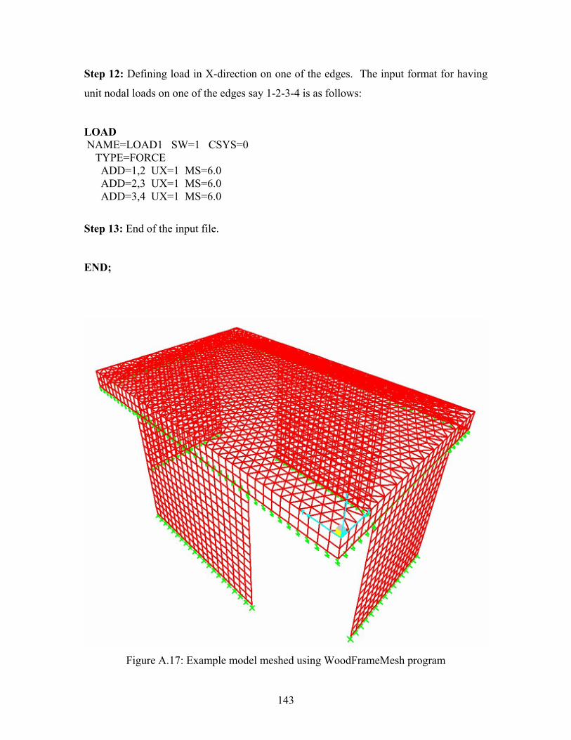
Step 12: Defining load in X-direction on one of the edges. The input format for having
unit nodal loads on one of the edges say 1-2-3-4 is as follows:
LOAD NAME=LOAD1 SW=1 CSYS=0 TYPE=FORCE ADD=1,2 UX=1 MS=6.0 ADD=2,3 UX=1 MS=6.0 ADD=3,4 UX=1 MS=6.0
Step 13: End of the input file.
END;
Figure A.17: Example model meshed using WoodFrameMesh program

144
A.5 Tutorial This section presents a tutorial for the generation of some basic finite element models
using the WoodFrameMesh program. The input files for the following models are
presented in section A.6. The output generated by the WoodFrameMesh program is
viewed in SAP 2000 and their 3D view is also presented.
A.5.1 Semi-Circular Plate
Input file name: Semi-CircularPlate.txt
Purpose: To generate a finite element model of a semi-circular plate using triangular
elements in XY plane.
Description: The plate is restrained along the straight line edge on all the nodes
generated. The plate is loaded along the semi-circular boundary with loads in X and Y
directions.
Figure A.18: Semi-circular plate filled with triangular shell elements
A.5.2 Square Plate
Input file name: Square-PlateT.txt
Purpose: To generate a finite element model of a square plate using triangular elements in
the XY plane.
Description: The plate is restrained on all the nodes generated along one of the edges.
The plate is loaded along the edge opposite to the restrained edge with loads in X and Y
directions.

145
Figure A.19: Square plate filled with triangular shell elements
A.5.3 Sloped Roof House
Input file name: Sloped-Roof.txt
Purpose: To generate a finite element model of a sloped roof house using triangular
elements for diaphragms and quadrilateral for walls.
Description: All the walls are restrained at their base in the direction perpendicular to the
plane of the wall. All the walls have spring elements at their base in the vertical direction
and in the plane of the wall. All the walls are connected to the lip using finite length non-
linear link elements. For details regarding the spring, material and section properties, one
can refer to the Sloped-Roof input file presented in section A.6.

146
Figure A.20: Sloped roof house filled with triangular and quadrilateral shell elements
A.5.4 Flat Roof House with Opening
Input file name: Flat-RoofA.txt
Purpose: To generate a finite element model of a flat roof house with opening using
triangular elements for diaphragms and quadrilateral for walls.
Description: All the walls are restrained at their base in the direction perpendicular to the
plane of the wall. The walls have spring elements at their base in the vertical direction
and in the plane of the wall. The walls are connected to the lip using finite length non-
linear link elements. For details regarding the spring, material and section properties, one
can refer to the Flat-RoofA input file in section A.6

147
Figure A.21: Flat roof house (with opening) filled with triangular and quadrilateral shell
elements
A.5.5 Flat Roof House with Opening and Interior Wall
Input file name: Flat-RoofB.txt
Purpose: To generate a finite element model of a flat roof house with opening and interior
wall using triangular elements for diaphragms and quadrilateral for walls.
Description: All the walls are restrained at their base in the direction perpendicular to the
plane of the wall. The walls have spring elements at their base in the vertical direction
and in the plane of the wall. The walls are connected to the lip using finite length non-
linear link elements. For details regarding the spring, material and section properties, one
can refer to the Flat-RoofB input file in section A.6.

148
Figure A.22: Flat roof house (with opening and interior wall) filled with triangular and
quadrilateral shell elements

149
A.6 INPUT FILES
This section presents the input file for the models discussed in the previous section.
The portion bounded by the solid lines goes inside the input file to be used by the
WoodFrameMesh program.
A.6.1 Input File Name: Semi-CircularPlate.txt SYSTEM LENGTH=IN FORCE=Kip JOINT 1 X=50 Y=0 Z=0 2 X=48 Y=14 Z=0 3 X=46 Y=19.59592 Z=0 4 X=44 Y=23.74868 Z=0 5 X=42 Y=27.12932 Z=0 6 X=40 Y=30 Z=0 7 X=30 Y=40 Z=0 8 X=20 Y=45.82576 Z=0 9 X=10 Y=48.98979 Z=0 10 X=0 Y=50 Z=0 11 X=-10 Y=48.98979 Z=0 12 X=-20 Y=45.82576 Z=0 13 X=-30 Y=40 Z=0 14 X=-40 Y=30 Z=0 15 X=-42 Y=27.12932 Z=0 16 X=-44 Y=23.74868 Z=0 17 X=-46 Y=19.59592 Z=0 18 X=-48 Y=14.0 Z=0 19 X=-50 Y=0 Z=0 RESTRAINTS ADD=1,19 DOF=U1,U2,U3,R1,R2,R3 MS=4.0 SPRINGS MATERIALS NAME=STEEL IDES=S M=0 W=0 T=0 E=29000 U=.3 A=.0000065 EM=1.0 SM=1.0 NAME=OTHER IDES=N M=0 W=0 T=0 E=3000000 U=.2 A=0 EM=1.0 SM=1.0 FRAME SECTIONS NAME=FSEC1 MAT=STEEL SH=R T=18,10 A=180 J=3916.671 I=4860,1500 AS=150,150

150
SHELL SECTIONS NAME=SSEC1 MAT=STEEL TYPE=Shell,Thin MATANG=0 TH=0.45 THB=0.45 NAME=SSEC2 MAT=STEEL TYPE=Shell,Thin MATANG=0 TH=0.40 THB=0.40 NLPROP NAME=NLPR1 TYPE=Damper DOF=U1 KE=100 CE=100 DOF=U2 KE=100 CE=100 DOF=U3 KE=100 CE=100 DOF=R1 KE=100 CE=100 DOF=R2 KE=100 CE=100 DOF=R3 KE=100 CE=100 FRAME SHELL 1 J=1,2,3,4,5,6,7,8,9,10,11,12,13,14,15,16,17,18,19,1 SEC=SSEC1 SA=1 ST=D MT=T MS=4.0 NLLINK LOAD NAME=LOAD1 SW=1 CSYS=0 TYPE=FORCE ADD=1,2 UX=100 UY=100 MS=4.0 ADD=2,3 UX=100 UY=100 MS=4.0 ADD=3,4 UX=100 UY=100 MS=4.0 ADD=4,5 UX=100 UY=100 MS=4.0 ADD=5,6 UX=100 UY=100 MS=4.0 ADD=6,7 UX=100 UY=100 MS=4.0 ADD=7,8 UX=100 UY=100 MS=4.0 ADD=8,9 UX=100 UY=100 MS=4.0 ADD=9,10 UX=100 UY=100 MS=4.0 ADD=10,11 UX=100 UY=100 MS=4.0 ADD=11,12 UX=100 UY=100 MS=4.0 ADD=12,13 UX=100 UY=100 MS=4.0 ADD=13,14 UX=100 UY=100 MS=4.0 ADD=14,15 UX=100 UY=100 MS=4.0 ADD=15,16 UX=100 UY=100 MS=4.0 ADD=16,17 UX=100 UY=100 MS=4.0 ADD=17,18 UX=100 UY=100 MS=4.0 ADD=18,19 UX=100 UY=100 MS=4.0 END;

151
A.6.2 Input File Name: Square-PlateT.txt SYSTEM LENGTH=IN FORCE=Kip JOINT 1 X=0 Y=0 Z=0 2 X=100 Y=0 Z=0 3 X=100 Y=100 Z=0 4 X=0 Y=100 Z=0 RESTRAINTS ADD=1,4 DOF=U1,U2,U3,R1,R2,R3 MS=6.0 SPRING MATERIALS NAME=STEEL IDES=S M=0 W=0 T=0 E=29000 U=.3 A=.0000065 EM=1.0 SM=1.0 NAME=OTHER IDES=N M=0 W=0 T=0 E=3000000 U=.2 A=0 EM=1.0 SM=1.0 FRAME SECTIONS NAME=FSEC1 MAT=STEEL SH=R T=18,10 A=180 J=3916.671 I=4860,1500 AS=150,150 SHELL SECTIONS NAME=SSEC1 MAT=STEEL TYPE=Shell,Thin MATANG=0 TH=0.45 THB=0.45 NAME=SSEC2 MAT=STEEL TYPE=Shell,Thin MATANG=0 TH=0.40 THB=0.40 NLPROP NAME=NLPR1 TYPE=Damper DOF=U1 KE=100 CE=100 DOF=U2 KE=100 CE=100 DOF=U3 KE=100 CE=100 DOF=R1 KE=100 CE=100 DOF=R2 KE=100 CE=100 DOF=R3 KE=100 CE=100 FRAME SHELL 1 J=1,2,3,4,1 SEC=SSEC1 SA=1 ST=D MT=T MS=6.0

152
NLLINK LOAD NAME=LOAD1 SW=1 CSYS=0 TYPE=FORCE ADD=2,3 UX=100 UY=100 RX=100 RY=20 RZ=20 MS=6.0 NAME=LOAD2 SW=1.5 CSYS=0 TYPE=FORCE ADD=2,3 UX=100 UY=100 RX=100 RY=20 RZ=20 MS=6.0 END;

153
A.6.3 Input File Name: Sloped-Roof.txt SYSTEM LENGTH=IN FORCE=Kip JOINT
1 X=0 Y=0 Z=120 2 X=60 Y=0 Z=180 3 X=120 Y=0 Z=120 4 X=120 Y=90 Z=120 5 X=240 Y=90 Z=120 6 X=240 Y=150 Z=180 7 X=240 Y=210 Z=120 8 X=0 Y=210 Z=120 9 X=60 Y=150 Z=180 10 X=0 Y=0 Z=109 11 X=60 Y=0 Z=169 12 X=120 Y=0 Z=109 13 X=120 Y=90 Z=109 14 X=240 Y=90 Z=109 15 X=240 Y=150 Z=169 16 X=240 Y=210 Z=109 17 X=0 Y=210 Z=109 18 X=0 Y=30 Z=0 19 X=0 Y=30 Z=108 20 X=0 Y=90 Z=108 21 X=0 Y=90 Z=0 22 X=0 Y=120 Z=0 23 X=0 Y=120 Z=108 24 X=0 Y=180 Z=108 25 X=0 Y=180 Z=0 26 X=0 Y=180 Z=120 27 X=0 Y=120 Z=120 28 X=0 Y=90 Z=120 29 X=0 Y=30 Z=120 30 X=0 Y=180 Z=109 31 X=0 Y=120 Z=109 32 X=0 Y=90 Z=109 33 X=0 Y=30 Z=109 34 X=120 Y=15 Z=0 35 X=120 Y=15 Z=108 36 X=120 Y=75 Z=108 37 X=120 Y=75 Z=0 38 X=120 Y=15 Z=109 39 X=120 Y=75 Z=109 40 X=120 Y=15 Z=120 41 X=120 Y=75 Z=120 42 X=150 Y=90 Z=120 43 X=210 Y=90 Z=120 44 X=150 Y=90 Z=109 45 X=210 Y=90 Z=109 46 X=150 Y=90 Z=0 47 X=150 Y=90 Z=108 48 X=210 Y=90 Z=108 49 X=210 Y=90 Z=0

154
50 X=180 Y=210 Z=120 51 X=60 Y=210 Z=120 52 X=180 Y=210 Z=109 53 X=60 Y=210 Z=109 54 X=60 Y=210 Z=0 55 X=60 Y=210 Z=108 56 X=180 Y=210 Z=108 57 X=180 Y=210 Z=0
RESTRAINTS ADD=18,21 DOF=U1 MS=6.0 ADD=22,25 DOF=U1 MS=6.0 ADD=34,37 DOF=U1 MS=6.0 ADD=46,49 DOF=U2 MS=6.0 ADD=54,57 DOF=U2 MS=6.0 SPRING ADD=18,21 U3=100 U2=100 MS=6.0 ADD=22,25 U3=100 U2=100 MS=6.0 ADD=34,37 U3=100 U2=100 MS=6.0 ADD=46,49 U3=100 U1=100 MS=6.0 ADD=54,57 U3=100 U1=100 MS=6.0 MATERIALS NAME=STEEL IDES=S M=7.324016E-07 W=.000283 T=0 E=29000 U=.3 A=.0000065 EM=1.0 SM=1.0 NAME=OTHER IDES=N M=0 W=0 T=0 E=3000000 U=.2 A=0 EM=1.0 SM=1.0 FRAME SECTIONS NAME=FSEC1 MAT=STEEL SH=R T=18,10 A=180 J=3916.671 I=4860,1500 AS=150,150 SHELL SECTIONS NAME=SSEC1 MAT=OTHER TYPE=Shell,Thin MATANG=0 TH=0.45 THB=0.45 NLPROP NAME=NLPR1 TYPE=Damper DOF=U1 KE=100 CE=100 DOF=U2 KE=100 CE=100 DOF=U3 KE=100 CE=100 DOF=R1 KE=100 CE=100 DOF=R2 KE=100 CE=100 DOF=R3 KE=100 CE=100

155
FRAME 1 J=18,21 SEC=FSEC1 NSEG=2 ANG=0 MS=6.0 2 J=22,25 SEC=FSEC1 NSEG=2 ANG=0 MS=6.0 3 J=34,37 SEC=FSEC1 NSEG=2 ANG=0 MS=6.0 4 J=46,49 SEC=FSEC1 NSEG=2 ANG=0 MS=6.0 5 J=54,57 SEC=FSEC1 NSEG=2 ANG=0 MS=6.0 SHELL 1 J=1,2,9,8,26,27,28,29,1 SEC=SSEC1 SA=1 ST=D MT=T MS=6.0 2 J=2,3,40,41,4,9,2 SEC=SSEC1 SA=2 ST=D MT=T MS=6.0 3 J=4,42,43,5,6,9,4 SEC=SSEC1 SA=3 ST=D MT=T MS=6.0 4 J=9,6,7,50,51,8,9 SEC=SSEC1 SA=4 ST=D MT=T MS=6.0 5 J=10,1,2,11 SEC=SSEC1 SA=5 ST=L MT=Q MS=6.0 6 J=11,2,3,12 SEC=SSEC1 SA=6 ST=L MT=Q MS=6.0 7 J=12,3,40,38 SEC=SSEC1 SA=7 ST=L MT=Q MS=6.0 8 J=38,40,41,39 SEC=SSEC1 SA=8 ST=L MT=Q MS=6.0 9 J=39,41,4,13 SEC=SSEC1 SA=9 ST=L MT=Q MS=6.0 10 J=13,4,42,44 SEC=SSEC1 SA=10 ST=L MT=Q MS=6.0 11 J=44,42,43,45 SEC=SSEC1 SA=11 ST=L MT=Q MS=6.0 12 J=45,43,5,14 SEC=SSEC1 SA=12 ST=L MT=Q MS=6.0 13 J=14,5,6,15 SEC=SSEC1 SA=13 ST=L MT=Q MS=6.0 14 J=15,6,7,16 SEC=SSEC1 SA=14 ST=L MT=Q MS=6.0 15 J=16,7,50,52 SEC=SSEC1 SA=15 ST=L MT=Q MS=6.0 16 J=52,50,51,53 SEC=SSEC1 SA=16 ST=L MT=Q MS=6.0 17 J=53,51,8,17 SEC=SSEC1 SA=17 ST=L MT=Q MS=6.0 18 J=17,8,26,30 SEC=SSEC1 SA=18 ST=L MT=Q MS=6.0 19 J=30,26,27,31 SEC=SSEC1 SA=19 ST=L MT=Q MS=6.0 20 J=31,27,28,32 SEC=SSEC1 SA=20 ST=L MT=Q MS=6.0 21 J=32,28,29,33 SEC=SSEC1 SA=21 ST=L MT=Q MS=6.0 22 J=33,29,1,10 SEC=SSEC1 SA=22 ST=L MT=Q MS=6.0 23 J=18,19,20,21 SEC=SSEC1 SA=23 ST=W MT=Q MS=6.0 24 J=22,23,24,25 SEC=SSEC1 SA=24 ST=W MT=Q MS=6.0 25 J=34,35,36,37 SEC=SSEC1 SA=25 ST=W MT=Q MS=6.0 26 J=46,47,48,49 SEC=SSEC1 SA=26 ST=W MT=Q MS=6.0 27 J=54,55,56,57 SEC=SSEC1 SA=27 ST=W MT=Q MS=6.0 NLLINK 1 J=19,20,33,32 NLP=NLPR1 ANG=0 MS=6.0 2 J=23,24,31,30 NLP=NLPR1 ANG=0 MS=6.0 3 J=35,36,38,39 NLP=NLPR1 ANG=0 MS=6.0 4 J=44,45,47,48 NLP=NLPR1 ANG=0 MS=6.0 5 J=52,53,56,55 NLP=NLPR1 ANG=0 MS=6.0 LOAD NAME=LOAD1 SW=1 CSYS=0 TYPE=FORCE ADD=1,2 UX=10 UY=10 RX=10 RY=20 RZ=20 MS=6.0 ADD=2,3 UX=10 UY=10 RX=10 RY=20 RZ=20 MS=6.0 NAME=LOAD2 SW=1 CSYS=0 TYPE=FORCE ADD=1,2 UX=10 UY=10 RX=10 RY=20 RZ=20 MS=6.0 ADD=2,3 UX=10 UY=10 RX=10 RY=20 RZ=20 MS=6.0 END;

156
A.6.4 Input File Name: Flat-RoofA.txt SYSTEM LENGTH=IN FORCE=Kip JOINT
1 X=0 Y=0 Z=120 2 X=60 Y=0 Z=120 3 X=120 Y=0 Z=120 4 X=180 Y=0 Z=120 5 X=180 Y=60 Z=120 6 X=180 Y=120 Z=120 7 X=180 Y=180 Z=120 8 X=120 Y=180 Z=120 9 X=120 Y=90 Z=120 10 X=60 Y=90 Z=120 11 X=60 Y=180 Z=120 12 X=0 Y=180 Z=120 13 X=0 Y=120 Z=120 14 X=0 Y=60 Z=120 15 X=60 Y=30 Z=120 16 X=120 Y=30 Z=120 17 X=120 Y=60 Z=120 18 X=60 Y=60 Z=120 19 X=0 Y=0 Z=109 20 X=60 Y=0 Z=109 21 X=120 Y=0 Z=109 22 X=180 Y=0 Z=109 23 X=180 Y=60 Z=109 24 X=180 Y=120 Z=109 25 X=180 Y=180 Z=109 26 X=120 Y=180 Z=109 27 X=120 Y=90 Z=109 28 X=60 Y=90 Z=109 29 X=60 Y=180 Z=109 30 X=0 Y=180 Z=109 31 X=0 Y=120 Z=109 32 X=0 Y=60 Z=109 33 X=60 Y=30 Z=109 34 X=120 Y=30 Z=109 35 X=120 Y=60 Z=109 36 X=60 Y=60 Z=109 37 X=60 Y=0 Z=0 38 X=60 Y=0 Z=108 39 X=120 Y=0 Z=108 40 X=120 Y=0 Z=0 41 X=180 Y=60 Z=0 42 X=180 Y=60 Z=108 43 X=180 Y=120 Z=108 44 X=180 Y=120 Z=0 45 X=0 Y=60 Z=0 46 X=0 Y=60 Z=108 47 X=0 Y=120 Z=108 48 X=0 Y=120 Z=0

157
RESTRAINTS ADD=37,40 DOF=U2 MS=6.0 ADD=41,44 DOF=U1 MS=6.0 ADD=45,48 DOF=U1 MS=6.0 SPRING ADD=37,40 U3=1000 U2=1000 MS=6.0 ADD=41,44 U3=1000 U1=1000 MS=6.0 ADD=45,48 U3=1000 U1=1000 MS=6.0 MATERIALS NAME=STEEL IDES=S M=0 W=0 T=0 E=29000 U=.3 A=.0000065 EM=1.0 SM=1.0 NAME=OTHER IDES=N M=0 W=0 T=0 E=3000000 U=.2 A=0 EM=1.0 SM=1.0 FRAME SECTIONS NAME=FSEC1 MAT=STEEL SH=R T=18,10 A=180 J=3916.671 I=4860,1500 AS=150,150 SHELL SECTIONS NAME=SSEC1 MAT=STEEL TYPE=Shell,Thin MATANG=0 TH=0.45 THB=0.45 NAME=SSEC2 MAT=STEEL TYPE=Shell,Thin MATANG=0 TH=0.40 THB=0.40 NLPROP NAME=NLPR1 TYPE=Damper DOF=U1 KE=100 CE=100 DOF=U2 KE=100 CE=100 DOF=U3 KE=100 CE=100 DOF=R1 KE=100 CE=100 DOF=R2 KE=100 CE=100 DOF=R3 KE=100 CE=100 FRAME 1 J=37,40 SEC=FSEC1 NSEG=2 ANG=0 MS=6.0 2 J=41,44 SEC=FSEC1 NSEG=2 ANG=0 MS=6.0 3 J=45,48 SEC=FSEC1 NSEG=2 ANG=0 MS=6.0 SHELL 1 J=1,2,3,4,5,6,7,8,9,10,11,12,13,14,1 SEC=SSEC1 SA=1 ST=D MT=T MS=6.0 2 J=1,2,20,19 SEC=SSEC2 SA=2 ST=L MT=Q MS=6.0 3 J=2,3,21,20 SEC=SSEC2 SA=3 ST=L MT=Q MS=6.0 4 J=3,4,22,21 SEC=SSEC2 SA=4 ST=L MT=Q MS=6.0 5 J=4,5,23,22 SEC=SSEC2 SA=5 ST=L MT=Q MS=6.0 6 J=5,6,24,23 SEC=SSEC2 SA=6 ST=L MT=Q MS=6.0 7 J=6,7,25,24 SEC=SSEC2 SA=7 ST=L MT=Q MS=6.0 8 J=7,8,26,25 SEC=SSEC2 SA=8 ST=L MT=Q MS=6.0 9 J=8,9,27,26 SEC=SSEC2 SA=9 ST=L MT=Q MS=6.0 10 J=9,10,28,27 SEC=SSEC2 SA=10 ST=L MT=Q MS=6.0

158
11 J=10,11,29,28 SEC=SSEC2 SA=11 ST=L MT=Q MS=6.0 12 J=11,12,30,29 SEC=SSEC2 SA=12 ST=L MT=Q MS=6.0 13 J=12,13,31,30 SEC=SSEC2 SA=13 ST=L MT=Q MS=6.0 14 J=13,14,32,31 SEC=SSEC2 SA=14 ST=L MT=Q MS=6.0 15 J=14,1,19,32 SEC=SSEC2 SA=15 ST=L MT=Q MS=6.0 16 J=15,16,34,33 SEC=SSEC2 SA=16 ST=L MT=Q MS=6.0 17 J=16,17,35,34 SEC=SSEC2 SA=17 ST=L MT=Q MS=6.0 18 J=17,18,36,35 SEC=SSEC2 SA=18 ST=L MT=Q MS=6.0 19 J=18,15,33,36 SEC=SSEC2 SA=19 ST=L MT=Q MS=6.0 20 J=37,38,39,40 SEC=SSEC2 SA=20 ST=W MT=Q MS=6.0 21 J=41,42,43,44 SEC=SSEC2 SA=21 ST=W MT=Q MS=6.0 22 J=45,46,47,48 SEC=SSEC2 SA=22 ST=W MT=Q MS=6.0 23 J=15,16,17,18,15 SEC=SSEC1 SA=1 ST=O MT=N MS=6.0 NLLINK 1 J=38,39,20,21 NLP=NLPR1 ANG=0 MS=6.0 2 J=42,43,23,24 NLP=NLPR1 ANG=0 MS=6.0 3 J=46,47,14,13 NLP=NLPR1 ANG=0 MS=6.0 LOAD NAME=LOAD1 SW=1 CSYS=0 TYPE=FORCE ADD=1,2 UX=100 UY=100 RX=100 RY=20 RZ=20 MS=6.0 ADD=2,3 UX=100 UY=100 RX=100 RY=20 RZ=20 MS=6.0 ADD=3,4 UX=100 UY=100 RX=100 RY=20 RZ=20 MS=6.0 ADD=4,5 UX=100 UY=100 RX=100 RY=20 RZ=20 MS=6.0 NAME=LOAD2 SW=1.5 CSYS=0 TYPE=FORCE ADD=1,2 UX=100 UY=100 RX=100 RY=20 RZ=20 MS=6.0 ADD=2,3 UX=100 UY=100 RX=100 RY=20 RZ=20 MS=6.0 END;

159
A.6.5 Input File Name: Flat-RoofB.txt SYSTEM LENGTH=IN FORCE=Kip JOINT
1 X=0 Y=0 Z=120 2 X=60 Y=0 Z=120 3 X=120 Y=0 Z=120 4 X=180 Y=0 Z=120 5 X=180 Y=60 Z=120 6 X=180 Y=120 Z=120 7 X=180 Y=180 Z=120 8 X=120 Y=180 Z=120 9 X=120 Y=90 Z=120 10 X=60 Y=90 Z=120 11 X=60 Y=180 Z=120 12 X=0 Y=180 Z=120 13 X=0 Y=120 Z=120 14 X=0 Y=60 Z=120 15 X=60 Y=30 Z=120 16 X=120 Y=30 Z=120 17 X=120 Y=60 Z=120 18 X=60 Y=60 Z=120 19 X=0 Y=0 Z=109 20 X=60 Y=0 Z=109 21 X=120 Y=0 Z=109 22 X=180 Y=0 Z=109 23 X=180 Y=60 Z=109 24 X=180 Y=120 Z=109 25 X=180 Y=180 Z=109 26 X=120 Y=180 Z=109 27 X=120 Y=90 Z=109 28 X=60 Y=90 Z=109 29 X=60 Y=180 Z=109 30 X=0 Y=180 Z=109 31 X=0 Y=120 Z=109 32 X=0 Y=60 Z=109 33 X=60 Y=30 Z=109 34 X=120 Y=30 Z=109 35 X=120 Y=60 Z=109 36 X=60 Y=60 Z=109 37 X=60 Y=0 Z=0 38 X=60 Y=0 Z=108 39 X=120 Y=0 Z=108 40 X=120 Y=0 Z=0 41 X=180 Y=60 Z=0 42 X=180 Y=60 Z=108 43 X=180 Y=120 Z=108 44 X=180 Y=120 Z=0 45 X=0 Y=60 Z=0 46 X=0 Y=60 Z=108 47 X=0 Y=120 Z=108 48 X=0 Y=120 Z=0 49 X=30 Y=30 Z=120

160
50 X=30 Y=60 Z=120 51 X=30 Y=90 Z=120 52 X=30 Y=30 Z=109 53 X=30 Y=60 Z=109 54 X=30 Y=90 Z=109 55 X=30 Y=30 Z=0 56 X=30 Y=30 Z=108 57 X=30 Y=60 Z=108 58 X=30 Y=60 Z=0 59 X=30 Y=60 Z=0 60 X=30 Y=60 Z=108 61 X=30 Y=90 Z=108 62 X=30 Y=90 Z=0
RESTRAINTS ADD=37,40 DOF=U2 MS=6.0 ADD=41,44 DOF=U1 MS=6.0 ADD=45,48 DOF=U1 MS=6.0 ADD=55,58 DOF=U1 MS=6.0 ADD=59,62 DOF=U1 MS=6.0 SPRING ADD=37,40 U3=1000 U2=1000 MS=6.0 ADD=41,44 U3=1000 U1=1000 MS=6.0 ADD=45,48 U3=1000 U1=1000 MS=6.0 ADD=55,58 U3=1000 U1=1000 MS=6.0 ADD=59,62 U3=1000 U1=1000 MS=6.0 MATERIALS NAME=STEEL IDES=S M=0 W=0 T=0 E=29000 U=.3 A=.0000065 EM=1.0 SM=1.0 NAME=OTHER IDES=N M=0 W=0 T=0 E=3000000 U=.2 A=0 EM=1.0 SM=1.0 FRAME SECTIONS NAME=FSEC1 MAT=STEEL SH=R T=18,10 A=180 J=3916.671 I=4860,1500 AS=150,150 SHELL SECTIONS NAME=SSEC1 MAT=STEEL TYPE=Shell,Thin MATANG=0 TH=0.45 THB=0.45 NAME=SSEC2 MAT=STEEL TYPE=Shell,Thin MATANG=0 TH=0.40 THB=0.40 NLPROP NAME=NLPR1 TYPE=Damper DOF=U1 KE=100 CE=100 DOF=U2 KE=100 CE=100 DOF=U3 KE=100 CE=100 DOF=R1 KE=100 CE=100 DOF=R2 KE=100 CE=100 DOF=R3 KE=100 CE=100

161
FRAME 1 J=37,40 SEC=FSEC1 NSEG=2 ANG=0 MS=6.0 2 J=41,44 SEC=FSEC1 NSEG=2 ANG=0 MS=6.0 3 J=45,48 SEC=FSEC1 NSEG=2 ANG=0 MS=6.0 SHELL 1 J=1,2,3,4,5,6,7,8,9,10,11,12,13,14,1 SEC=SSEC1 SA=1 ST=D MT=T MS=6.0 2 J=1,2,20,19 SEC=SSEC2 SA=2 ST=L MT=Q MS=6.0 3 J=2,3,21,20 SEC=SSEC2 SA=3 ST=L MT=Q MS=6.0 4 J=3,4,22,21 SEC=SSEC2 SA=4 ST=L MT=Q MS=6.0 5 J=4,5,23,22 SEC=SSEC2 SA=5 ST=L MT=Q MS=6.0 6 J=5,6,24,23 SEC=SSEC2 SA=6 ST=L MT=Q MS=6.0 7 J=6,7,25,24 SEC=SSEC2 SA=7 ST=L MT=Q MS=6.0 8 J=7,8,26,25 SEC=SSEC2 SA=8 ST=L MT=Q MS=6.0 9 J=8,9,27,26 SEC=SSEC2 SA=9 ST=L MT=Q MS=6.0 10 J=9,10,28,27 SEC=SSEC2 SA=10 ST=L MT=Q MS=6.0 11 J=10,11,29,28 SEC=SSEC2 SA=11 ST=L MT=Q MS=6.0 12 J=11,12,30,29 SEC=SSEC2 SA=12 ST=L MT=Q MS=6.0 13 J=12,13,31,30 SEC=SSEC2 SA=13 ST=L MT=Q MS=6.0 14 J=13,14,32,31 SEC=SSEC2 SA=14 ST=L MT=Q MS=6.0 15 J=14,1,19,32 SEC=SSEC2 SA=15 ST=L MT=Q MS=6.0 16 J=15,16,34,33 SEC=SSEC2 SA=16 ST=L MT=Q MS=6.0 17 J=16,17,35,34 SEC=SSEC2 SA=17 ST=L MT=Q MS=6.0 18 J=17,18,36,35 SEC=SSEC2 SA=18 ST=L MT=Q MS=6.0 19 J=18,15,33,36 SEC=SSEC2 SA=19 ST=L MT=Q MS=6.0 20 J=37,38,39,40 SEC=SSEC2 SA=20 ST=W MT=Q MS=6.0 21 J=41,42,43,44 SEC=SSEC2 SA=21 ST=W MT=Q MS=6.0 22 J=45,46,47,48 SEC=SSEC2 SA=22 ST=W MT=Q MS=6.0 23 J=15,16,17,18,15 SEC=SSEC1 SA=1 ST=O MT=N MS=6.0 24 J=49,50,51 SEC=SSEC1 SA=1 ST=C MT=N MS=6.0 25 J=52,49,50,53 SEC=SSEC2 SA=25 ST=L MT=Q MS=6.0 26 J=53,50,51,54 SEC=SSEC2 SA=26 ST=L MT=Q MS=6.0 27 J=55,56,57,58 SEC=SSEC2 SA=27 ST=W MT=Q MS=6.0 28 J=59,60,61,62 SEC=SSEC2 SA=28 ST=W MT=Q MS=6.0 NLLINK 1 J=38,39,20,21 NLP=NLPR1 ANG=0 MS=6.0 2 J=42,43,23,24 NLP=NLPR1 ANG=0 MS=6.0 3 J=46,47,14,13 NLP=NLPR1 ANG=0 MS=6.0 4 J=52,53,56,57 NLP=NLPR1 ANG=0 MS=6.0 5 J=53,54,60,61 NLP=NLPR1 ANG=0 MS=6.0 LOAD NAME=LOAD1 SW=1 CSYS=0 TYPE=FORCE ADD=1,2 UX=100 UY=100 RX=100 RY=20 RZ=20 MS=6.0 ADD=2,3 UX=100 UY=100 RX=100 RY=20 RZ=20 MS=6.0 ADD=3,4 UX=100 UY=100 RX=100 RY=20 RZ=20 MS=6.0 ADD=4,5 UX=100 UY=100 RX=100 RY=20 RZ=20 MS=6.0 NAME=LOAD2 SW=1.5 CSYS=0 TYPE=FORCE ADD=1,2 UX=100 UY=100 RX=100 RY=20 RZ=20 MS=6.0 ADD=2,3 UX=100 UY=100 RX=100 RY=20 RZ=20 MS=6.0 END;