APPENDICES - City and County of Denver
57
APPENDICES
-
Upload
khangminh22 -
Category
Documents
-
view
0 -
download
0
Transcript of APPENDICES - City and County of Denver

APPENDICES

APPENDICES
GLOBEVILLE STORMWATER SYSTEMS STUDY

APPENDIX A: SUMMARY HYDROLOGIC & HYDRAULIC ANALYSES
APPENDICES
GLOBEVILLE STORMWATER SYSTEMS STUDY

Employee Owned
2480 W. 26th Street, Unit B225
Denver, Colorado 80211 Tel: +1 303-964-3333
www.merrick.com
TECHNICAL MEMORANDUM July 3, 2019
SUBJECT: Globeville Community Drainage Study
Summary Hydrologic & Hydraulic Analyses:
GENERAL:
The Globeville – Utah Junction Watershed is unique in that it does not have a formal drainage channel to
convey runoff. Rather, flows throughout the basin are conveyed to the South Platte River via storm drain
pipes and through the various street networks. Much of the existing storm pipes are too small to convey
even minor flows within the basin. Consequently, degrees of flooding within the basin can be a frequent
occurrence.
PREVIOUS DRAINAGE STUDIES:
The main stormwater master plan completed within the basin is the Globeville-Utah Junction Watershed
Outfall Systems Plan (OSP), developed by CH2M-HILL in 2013. The study found that “the current storm
drain systems do not have capacity to convey the 5-year or 10-year storms and do not convey a major,
100-year storm event”. Criteria used to evaluate alternatives referenced the Urban Drainage and Flood
Control District (UDFCD), City and County of Denver Storm Drainage Design & Technical Criteria, and the
Adams County Storm Drainage Design and Stormwater Quality Regulations. From these references, the
following criteria was implemented to evaluate storm drainage alternatives:
1. Minor Storm Drain Design = 5-year storm.
a. The OSP looked to focus their efforts on solving the 5-year storm. However, they did
consider alternatives for the 2-year and the 10-year storms.
2. Major Storm Drain Design = 100-year storm.
3. Minor Street Conveyance Design: Flow will not overtop the street curb, with 5 feet of pavement
that is free of water on either side of the street crown.
4. Major Street Conveyance Design: Depth of water shall not exceed 12 inches at the flow line.
Public and private buildings shall not be impacted by flow in the street.
Since the Globeville – Utah Basin does not contain natural open drainageways, the primary means of
conveying runoff is through storm pipes. Consequently, the OSP’s primary focus was to improve the storm
drainage conduits to meet the criteria above.
The OSP developed alternative plans for the 48TH Avenue corridor that were based on routine
maintenance and rehabilitation of existing facilities, increased storm drain capacity, and increased

2
detention capacity. Five (5) alternative plans were created during the alternative analysis stage of the OSP,
which include:
Alternative 1: 2-year Increased Pipe Capacity: Objective was to reduce street flooding to a depth
of six-inches during the 2-year storm event.
Alternative 2: 5-year Increased Pipe Capacity: Objective was to reduce street flooding to a depth
of six-inches during the 5-year storm event.
Alternative 3: 10-year Increased Pipe Capacity: Objective was to reduce street flooding to a
depth of six-inches during the 10-year storm event.
Alternative 4: Detention Only: Objective was to maximize detention at reasonable locations to
reduce the storm water impact.
Alternative 5: Combined Detention and Increased Storm Drain Capacity: Objective was to
optimize the benefits from the previous alternatives to provide the most flood
mitigation and meet or exceed minor storm criteria.
Alternatives 1-3 were formulated to determine the correct storm drain size to meet the street flow depth
criteria for the minor storm. These alternatives did not specifically address minimizing flows from the
Sunnyside Basin. Proposed increased storm drain capacity was anticipated to help convey additional
flows.
Alternative 4 - Detention Only analysis was also evaluated at various locations throughout the basin to
provide a means of reducing flows to existing pipe infrastructure. Detention alone did reduce flooding in
certain areas, but not to capacity of existing storm drains. Overall the alternative was considered to be
the least effective for surface flooding reduction.
Finally, an alternative was developed that combined alternatives 1 through 4. This alternative focused on
addressing flooding problems throughout the Globeville – Utah Junction Basin including addressing
overflows from the Sunnyside Neighborhood. The OSP concluded that the engineer’s recommended plan
was Alternative 5 – Combined Alternative. However, after further review from stakeholders (UDFCD, City
and County of Denver, Adams County), a selected plan letter was submitted to the OSP authors from the
stakeholders, which made modifications to the engineer’s recommendations. Specifically, the 48th Avenue
outfall, the 13.5 ac-ft detention pond at 52nd Avenue and Zuni Street Park was removed. For the Sunnyside
Outfall, the 4.6 ac-ft pond at 46th Avenue and Pecos Street was removed as well as the 2.2 ac-ft pond at
44th Avenue and Tejon Street Park (Chaffee Park) was removed. Additionally, the City and County of
Denver requested that all flows from the Sunnyside Basin be routed through the Inca Street Pond. The
engineer’s recommended plan flows from the Sunnyside Basin were connected to the existing 72-inch
RCP that flows south out of the Sunnyside Basin to Park Avenue. Flows that were unable to be contained
in the pipe were to be routed to the Inca Street Pond. The City and County of Denver requested the change
to match the concept developed within the Northwest Denver Sub-Area Drainage and Transportation
Study, Final Report.
Prioritization/Phasing of OSP:
For the City and County of Denver, the OSP provided a prioritization and phasing recommendation for the
Globeville Basin. The following is a summary of the priorities.

3
1. Inca Street Detention Pond:
Construction of the Inca Street Detention Pond would prevent overflows from the Sunnyside
Basin reaching the 48th Avenue storm drain system. The Inca Street Detention Pond concept was
first developed in the Northwest Denver Sub-Area Drainage and Transportation Study published
in January of 2012. The report was developed by WHPacific, Felsburg Holt & Ullevig, PKM Design
Group, and Civitas for the City and County of Denver. The report documented that runoff from
the Sunnyside and Highland basins can overwhelm the existing storm sewer infrastructure causing
excess water to flow onto the Gold Line (Northwest Commuter Rail), south of 48th Avenue. Three
alternatives were developed to reduce the flooding along the rail yard, which included the
following:
• Alternative A: Construct a new detention pond referred to as Pond 1. Construction of this
pond would be between West 40th Avenue and West 38th Avenue on Inca Street. Proposed
storage for Pond 1 was estimated to be 13.9 ac-ft. A new outfall from this pond would be
constructed via Jason Street, which would outfall to the South Platte River. The proposed
pipe alignment for this alternative is similar to the Truncated L Project proposed by ICON
in the Memorandum for the Globeville – Utah Junction Storm Drain Master Plan
Evaluation, dated May of 2017.
• Alternative B: Construct two detention ponds. In addition to Pond 1, Pond 2 would be
constructed within the footprint of the Comic Book Building located on Jason Street,
between 45th and 47th Avenue. This proposed pond is the same pond referenced in the
OSP to be built at 45th Avenue and Inca Street property (Inca Street Pond). Proposed
capacity of the pond was 20.6 ac-ft. This alternative would allow existing storm sewer
infrastructure to be utilized as ponds provide peak flow attenuation.
• Alternative C: Storm sewer interceptor system consisting of large diameter storm sewer
pipes that would convey runoff to the South Platte River via Jason Street.
2. Sunnyside Reach SS (Sunnyside)-2:
• SS-2 involves upsizing storm pipes from the intersection of Zuni Street and 46Th Avenue
to the Inca Street Detention Pond (Pond 2).
3. Reach 48-1 (East of Kalamath Street):
• Installation of twin 78” diameter RCP’s in 48th Avenue west of the Rennick Rail Yard to
approximately Pennsylvania Street.
• Installation of 2 - 10’ x 6’ RCB’s from 48th Avenue and Pennsylvania Street to the outfall at
the South Platte River.
Further analysis of the drainage concepts from the OSP and the Northwest Denver Sub-Area Drainage and
Transportation Study was studied by ICON Engineering Inc. in May of 2017 for the City and County of
Denver. Like the OSP final recommendations, analysis did not include potential detention ponds.
• ICON used 2-dimensional hydraulic analysis to evaluate the effectiveness of storm sewer
systems to reduce surface flooding.
• The existing storm drain pipe capacity values were subtracted from inflow hydrographs
at applicable locations. Residual surface flows were then modeled using FLO-2D and areas
of flooding that were equal to, or greater than, 1 foot of depth were mapped as Potential
Inundation Areas (PIA).
4
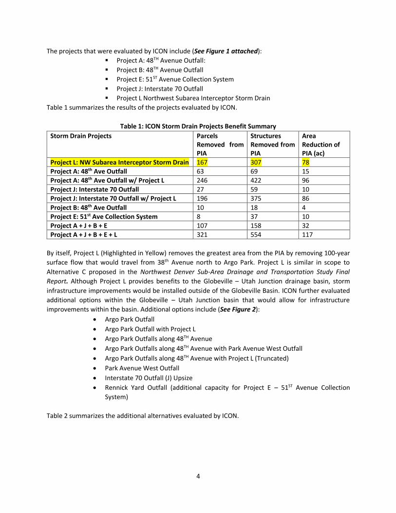
The projects that were evaluated by ICON include (See Figure 1 attached):
▪ Project A: 48TH Avenue Outfall:
▪ Project B: 48TH Avenue Outfall
▪ Project E: 51ST Avenue Collection System
▪ Project J: Interstate 70 Outfall
▪ Project L Northwest Subarea Interceptor Storm Drain
Table 1 summarizes the results of the projects evaluated by ICON.
Table 1: ICON Storm Drain Projects Benefit Summary
Storm Drain Projects Parcels Removed from PIA
Structures Removed from PIA
Area Reduction of PIA (ac)
Project L: NW Subarea Interceptor Storm Drain 167 307 78
Project A: 48th Ave Outfall 63 69 15
Project A: 48th Ave Outfall w/ Project L 246 422 96
Project J: Interstate 70 Outfall 27 59 10
Project J: Interstate 70 Outfall w/ Project L 196 375 86
Project B: 48th Ave Outfall 10 18 4
Project E: 51st Ave Collection System 8 37 10
Project A + J + B + E 107 158 32
Project A + J + B + E + L 321 554 117
By itself, Project L (Highlighted in Yellow) removes the greatest area from the PIA by removing 100-year
surface flow that would travel from 38th Avenue north to Argo Park. Project L is similar in scope to
Alternative C proposed in the Northwest Denver Sub-Area Drainage and Transportation Study Final
Report. Although Project L provides benefits to the Globeville – Utah Junction drainage basin, storm
infrastructure improvements would be installed outside of the Globeville Basin. ICON further evaluated
additional options within the Globeville – Utah Junction basin that would allow for infrastructure
improvements within the basin. Additional options include (See Figure 2):
• Argo Park Outfall
• Argo Park Outfall with Project L
• Argo Park Outfalls along 48TH Avenue
• Argo Park Outfalls along 48TH Avenue with Park Avenue West Outfall
• Argo Park Outfalls along 48TH Avenue with Project L (Truncated)
• Park Avenue West Outfall
• Interstate 70 Outfall (J) Upsize
• Rennick Yard Outfall (additional capacity for Project E – 51ST Avenue Collection
System)
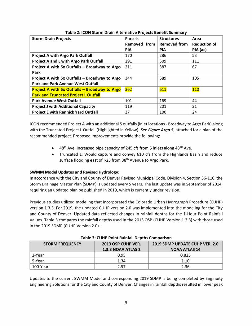
Table 2 summarizes the additional alternatives evaluated by ICON.
5
Table 2: ICON Storm Drain Alternative Projects Benefit Summary
Storm Drain Projects Parcels Removed from PIA
Structures Removed from PIA
Area Reduction of PIA (ac)
Project A with Argo Park Outfall 170 286 53
Project A and L with Argo Park Outfall 291 509 111
Project A with 5x Outfalls – Broadway to Argo Park
211 387 67
Project A with 5x Outfalls – Broadway to Argo Park and Park Avenue West Outfall
344 589 105
Project A with 5x Outfalls – Broadway to Argo Park and Truncated Project L Outfall
362 611 110
Park Avenue West Outfall 101 169 44
Project J with Additional Capacity 119 201 31
Project E with Rennick Yard Outfall 37 100 24
ICON recommended Project A with an additional 5 outfalls (inlet locations - Broadway to Argo Park) along
with the Truncated Project L Outfall (Highlighted in Yellow). See Figure Argo 5, attached for a plan of the
recommended project. Proposed improvements provide the following:
• 48th Ave: Increased pipe capacity of 245 cfs from 5 inlets along 48TH Ave.
• Truncated L: Would capture and convey 610 cfs from the Highlands Basin and reduce
surface flooding east of I-25 from 38th Avenue to Argo Park.
SWMM Model Updates and Revised Hydrology:
In accordance with the City and County of Denver Revised Municipal Code, Division 4, Section 56-110, the
Storm Drainage Master Plan (SDMP) is updated every 5 years. The last update was in September of 2014,
requiring an updated plan be published in 2019, which is currently under revision.
Previous studies utilized modeling that incorporated the Colorado Urban Hydrograph Procedure (CUHP)
version 1.3.3. For 2019, the updated CUHP version 2.0 was implemented into the modeling for the City
and County of Denver. Updated data reflected changes in rainfall depths for the 1-Hour Point Rainfall
Values. Table 3 compares the rainfall depths used in the 2013 OSP (CUHP Version 1.3.3) with those used
in the 2019 SDMP (CUHP Version 2.0).
Table 3: CUHP Point Rainfall Depths Comparison
STORM FREQUENCY 2013 OSP CUHP VER. 1.3.3 NOAA ATLAS 2
2019 SDMP UPDATE CUHP VER. 2.0 NOAA ATLAS 14
2-Year 0.95 0.825
5-Year 1.34 1.10
100-Year 2.57 2.36
Updates to the current SWMM Model and corresponding 2019 SDMP is being completed by Enginuity
Engineering Solutions for the City and County of Denver. Changes in rainfall depths resulted in lower peak

6
discharge rates. Additional corrections incorporated into the SWMM Model from Enginuity include the
following:
• Node and Link identification was changed to match the City and County of Denver’s GIS ID Data.
• Generic street sections and trapezoidal channels used in the OSP for overflow conveyance were
replaced with new sections cut from 2014 topography.
• In the OSP, all pipes were modeled as a circular conduit. Pipe shapes were updated in the 2019
SDMP to reflect actual conduit geometries.
The OSP SWMM Model utilized the Kinematic Wave Routing. This method does not account for backwater
effects, entrance and exit losses, flow reversal within conduits, or pressurized flow. Enginuity updated the
SWMM Model to utilize the Dynamic Wave Routing, which does account for the backwater effects,
entrance and exit losses, flow reversal within conduits, and pressurized flow.
Merrick acquired a copy of the latest SWMM model and updated hydrology from the City and County of
Denver for the Globeville Project.
Globeville SWMM Model Updates:
Two versions of the SWMM Model were provided to Merrick from the City and County of Denver.
1. No Inadvertent Detention
2. With Inadvertent Detention
During development of the OSP, inadvertent detention locations were implemented into the SWMM
Model. Inadvertent detention sites are low areas in the basin where water accumulates during rainfall
events. Although these locations are not protected under the umbrella of detention, their presence in the
basin does influence runoff through the basin and many participants felt the need to account for them in
the model. However, there is concern that since these locations are not classified as detention,
development could eliminate their presence, removing the benefit.
For the update to the SDMP, the City and County of Denver revisited the inadvertent detention topic and
made the following revisions. All inadvertent detention would be removed from the SWMM Model except
for two locations, the Rennick Rail Yard and Argo Park. Per the request from the City and County of Denver,
Merrick added the Rennick Rail Yard and Argo Park inadvertent detention ponds to the “no inadvertent
detention” SWMM Model, which became the baseline model for the Globeville Study. Subsequent
modeling scenarios were compared to the baseline results to evaluate benefits.
The Argo Park inadvertent detention modeled in SWMM shows a storage volume of 43 ac-ft. Review of
existing topography of the park and surrounding area indicates a storage volume of 43 ac-ft would pond
to a maximum depth of about 2.2 feet in the park. The OSP SWMM Model outflow from the Argo Park
inadvertent detention is 156 cfs. See Figure 3 for a representation of approximate ponding limits in the
park and surrounding area. Incremental storage was calculated using the Conic Approximation Method as
described below:

7
𝑉 = (ℎ
3) (𝐴1 + 𝐴2 + (𝐴1𝐴2)0.5
Where:
V = Volume (ft3)
h = distance between the two areas (ft)
A1 = Area 1(ft2)
A2 = Area 2 (ft2)
Table 4 summarizes the stage-storage determined with the available contours in the Argo Park area.
Table 4: Contour Area Argo Park
STAGE
(ft)
ELEVATION
(ft)
CONTOUR AREA (ft2)
INCREMENTAL STORAGE
(ft3)
TOTAL STORAGE
(ft3)
TOTAL STORAGE
(ac-ft)
0.00 5146.00 207,752 0 0 0
1.00 5147.00 676,759 419,825 419,825 9.6
2.00 5148.00 1,728,019 1,162,063 1,581,888 36.3
2.15 5148.15 1,900,000 271,999 1,853,887 42.6
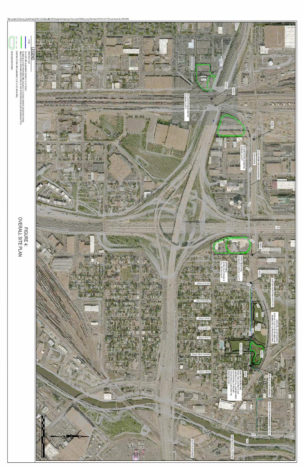
To evaluate the potential benefits of alternatives within the 48th Avenue corridor to reduce flooding within
the Argo Park area, the following node locations were monitored with each modeled scenario (See Figure
4 – Overall Site Plan for locations of nodes). Locations include the Node A (West Side of Gold Line
(Northwest Commuter Rail), Node B (East Side of Gold Line (Northwest Commuter Rail)), Node C (East of
Railroad Tracks near 48th Avenue), Node D (Intersection of 48th Avenue and the Rennick Rail Yard (RRY)),
Node E (Intersection of 48th Avenue and Broadway), Node F (Intersection of 48th Avenue and Lincoln
Street), Node G (Intersection of 48th Avenue and Logan Street), Node H (Argo Pond Outlet Location), and
Node I (Intersection of 48th Avenue and Pearl Street).
Monitored variables include peak discharge at each location, pipe conveyance and overflow (surface
flow). Baseline information for the 100-year storm event (future conditions) at these locations is
summarized in Table 5.
Table 5: SWMM Baseline H&H Conditions
Location Q TOTAL NODE
(CFS) Q PIPE LEAVING NODE
(CFS) Q OVERFLOW LEAVING NODE
(CFS)
NODE A 267.92 ---- ----
NODE B 282.53 ---- ----
NODE C 302.56 ---- ----
NODE D 381.53 123.82 253.04
NODE E 423.39 276.68 146.83
NODE F 480.55 348.88 131.04
NODE G 473.99 118.93 352.04
NODE H 275.81 171.96 103.85
NODE I 209.92 198.83 11.26

8
Globeville Detention Pond Analysis Objectives:
Since the publication of the OSP, the City and County of Denver Parks Department is now more open to
development of strategic detention locations in park areas that provide both community and flood
reduction benefits. A Vision Implementation Team (community stakeholders) Meeting was held on
February 19, 2019 that summarized potential detention locations.
• 51st and Zuni (Chaffee Park): The pond location was highlighted in the OSP with an estimated
storage volume of 13.5 ac-ft. The OSP did not provide contouring of the proposed pond location
• I-70 South Detention Pond (46th and 47th Avenue): Estimated storage volume is 13.0 ac-ft
• I-70 North Detention Pond (48th Avenue and Rennick Rail Yard): 18.0 ac-ft
• Upper Ridge Detention Pond (48th Avenue and Broadway): 14.0 ac-ft
• Argo Park Detention: 5.0 ac-ft
Since the OSP’s primary recommendation centered on increased pipe sizes to mitigate flooding, the
Globeville Community Drainage Study evaluated strategic detention locations as well as pipe conveyance
to reduce flooding impacts. Detention focuses on pond development that is aesthetically pleasing and
provides neighborhood recreational opportunities. Evaluation of alternatives to diminish flooding impacts
to the Globeville Basin provide guidance for further study. Additional analysis and design are necessary to
further investigate and refine alternatives.
For detention analysis, SWMM utilizes a user defined stage -storage and outflow curves to simulate flow
from the pond. Outflow curves for each pond were generated by using the computer program, Hydraflow
Hydrographs Extension for AutoCAD Civil 3D 2018 (Hydraflow). Hydraflow is a hydrologic program that
offers a means of simulating routing through a pond. For each pond, inflow hydrographs from the SWMM
Model were incorporated into Hydraflow and an outflow curve was developed that reflected the
proposed outlet orifice diameter. Outflow curves from Hydraflow were then incorporated into the SWMM
Model for analysis with the stage-storage curves.
The following is a summary of the detention pond analysis and the potential benefits to the Globeville
Basin.
Globeville Detention Analysis – Individual Ponds:
51ST Avenue and Zuni Street (Chaffee Park Detention Pond):
The updated SWMM Model by Enginuity did not include this pond as part of the proposed basin
improvements. A representative pond volume was added by Merrick to the SWMM model at the 51ST
Avenue and Zuni Street Park location. The 100-YR Future condition flow to this location is approximately
183 cfs. Analysis evaluated detaining most of this flow (releasing approximately 48 cfs) and what affects
reduced flow would have in the lower portion of the basin. Results showed that many of the benefits of
this pond are attenuated through the system and are less noticeable in the lower portion of the basin
near the Rennick Rail Yard.
I-70 South Detention Pond:
The location of the I-70 South Detention Pond is immediately north (47th Avenue and Jason Street) of the
originally proposed Inca Street Detention Pond (Pond 2) discussed earlier in this report. The original
location would require purchasing a large building. Available market value information indicates
acquisition of the property would be expensive. Available property to construct a detention pond
9
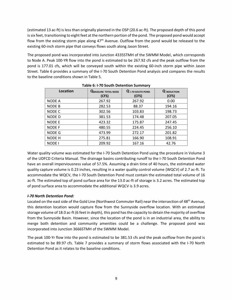
(estimated 13 ac-ft) is less than originally planned in the OSP (20.6 ac-ft). The proposed depth of this pond
is six feet, transitioning to eight feet at the northern portion of the pond. The proposed pond would accept
flow from the existing storm pipe along 47th Avenue. Outflow from the pond would be released to the
existing 60-inch storm pipe that conveys flows south along Jason Street.
The proposed pond was incorporated into Junction 4335STMH of the SWMM Model, which corresponds
to Node A. Peak 100-YR flow into the pond is estimated to be 267.92 cfs and the peak outflow from the
pond is 177.01 cfs, which will be conveyed south within the existing 60-inch storm pipe within Jason
Street. Table 6 provides a summary of the I-70 South Detention Pond analysis and compares the results
to the baseline conditions shown in Table 5.
Table 6: I-70 South Detention Summary
Location QBASELINE TOTAL NODE
(CFS) Q I-70 SOUTH POND
(CFS) Q REDUCTION
(CFS) NODE A 267.92 267.92 0.00
NODE B 282.53 88.37 194.16
NODE C 302.56 103.83 198.73
NODE D 381.53 174.48 207.05
NODE E 423.32 175.87 247.45
NODE F 480.55 224.45 256.10
NODE G 473.99 272.17 201.82
NODE H 275.81 166.90 108.91
NODE I 209.92 167.16 42.76
Water quality volume was estimated for the I-70 South Detention Pond using the procedure in Volume 3
of the UDFCD Criteria Manual. The drainage basins contributing runoff to the I-70 South Detention Pond
have an overall imperviousness value of 57.5%. Assuming a drain time of 40 hours, the estimated water
quality capture volume is 0.23 inches, resulting in a water quality control volume (WQCV) of 2.7 ac-ft. To
accommodate the WQCV, the I-70 South Detention Pond must contain the estimated total volume of 16
ac-ft. The estimated top of pond surface area for the 13.0 ac-ft of storage is 3.2 acres. The estimated top
of pond surface area to accommodate the additional WQCV is 3.9 acres.
I-70 North Detention Pond:
Located on the east side of the Gold Line (Northwest Commuter Rail) near the intersection of 48th Avenue,
this detention location would capture flow from the Sunnyside overflow location. With an estimated
storage volume of 18.0 ac-ft (6 feet in depth), this pond has the capacity to detain the majority of overflow
from the Sunnyside Basin. However, since the location of the pond is in an industrial area, the ability to
merge both detention and community amenities could be a challenge. The proposed pond was
incorporated into Junction 3666STMH of the SWMM Model.
The peak 100-Yr flow into the pond is estimated to be 381.53 cfs and the peak outflow from the pond is
estimated to be 89.97 cfs. Table 7 provides a summary of storm flows associated with the I-70 North
Detention Pond as it relates to the baseline conditions.

10
Table 7: I-70 North Detention Summary
Location QBASELINE TOTAL NODE
(CFS) Q I-70 NORTH POND
(CFS) Q REDUCTION
(CFS) NODE A 267.92 267.92 0.00
NODE B 282.53 282.53 0.00
NODE C 302.56 302.56 0.00
NODE D 381.53 89.97 291.56
NODE E 423.32 106.04 317.28
NODE F 480.55 155.24 325.31
NODE G 473.99 203.08 270.91
NODE H 275.81 153.89 121.92
NODE I 209.92 153.87 56.05
Water quality volume was estimated for the I-70 North Detention Pond. The drainage basins contributing
runoff to the I-70 North Detention Pond have an overall imperviousness value of approximately 45%. The
estimated water quality capture volume is 0.19 inches, resulting in a water quality control volume (WQCV)
of 2.4 ac-ft. To accommodate the WQCV, the I-70 North Detention Pond must contain the estimated total
volume of 21 ac-ft. The estimated top of pond surface area for the 18.0 ac-ft of storage is 3.6 acres. The
estimated top of pond surface area to accommodate the additional WQCV is 4.1 acres.
Upper Ridge Detention Pond:
The proximity of this detention pond provides an opportunity to merge stormwater detention with
possible community recreational amenities, since it is situated within the transition zone from industrial
to residential. The identified location is estimated to provide a capacity for 21 ac-ft of detention volume.
Proposed detention is preferred to be built on half of the area to allow for other amenities to be included
outside of stormwater control, resulting in 14 ac-ft of storage. Analysis shows that for the 14 ac-ft of
detention, the outlet pipe would need to be two 54” pipes; otherwise, the pond is inundated with water
and does not operate correctly. For the pond to function adequately, the storage volume will need to be
closer to the 21 ac-ft.
The peak 100-YR flow into the pond is estimated to be 423.32 cfs and the peak outflow from the pond is
113.72 cfs. Table 8 summarizes the results from modeling the Upper Ridge Detention Pond, assuming a
site that provides 21 ac-ft of potential storage.
Table 8: Upper Ridge Detention Summary
Location QBASELINE TOTAL NODE
(CFS) Q UPPER RIDGE POND
(CFS) Q REDUCTION
(CFS) NODE A 267.92 267.92 0.00
NODE B 282.53 282.53 0.00
NODE C 302.56 302.56 0.00
NODE D 381.53 381.53 0.00
NODE E 423.32 113.72 309.60
NODE F 480.55 129.26 351.29
NODE G 473.99 170.39 303.60
NODE H 275.81 144.50 131.31
NODE I 209.92 144.50 65.42

11
Water quality volume was estimated for the Upper Ridge Detention Pond. The drainage basins
contributing runoff to the I-70 North Detention Pond have an overall imperviousness value of
approximately 65%. The estimated water quality capture volume is 0.26 inches, resulting in a water quality
control volume (WQCV) of 3.8 ac-ft. To accommodate the WQCV, the Upper Ridge Detention Pond must
contain the estimated total volume of roughly 25 ac-ft. The estimated top of pond surface area for the
21.0 ac-ft of storage is 4.2 acres. The estimated top of pond surface area to accommodate the additional
WQCV is 5.0 acres.
Argo Park Detention Pond:
The Argo Park area provides approximately 5.0 ac-ft (4 feet in depth) of volume. The Argo Park pond was
used with the I-70 South, I-70 North, and Upper Ridge Detention Ponds in combination. Flow reduction
from the proposed Argo Park Pond is included in the detention pond results in Tables 6, 7 and 8. Flow to
this location is predominately from street flow along 48th Avenue that is a result of surcharged conduits.
Upon reaching Logan Street, 48th Avenue ends and Argo Park begins. Under the proposed Argo Park
Detention scenario, runoff to Argo Pond will be conveyed through a swale that will provide a transition
from the street or from inlet capture. Detained water will be slowly released back into the main storm
line. Inflow into the pond is anticipated to be approximately 43 to 135 cfs, depending upon which
upstream detention pond is utilized.
Globeville Individual Detention Summary:
Preliminary results show that the I-70 North Detention Pond provides the greatest benefit for reducing
100-year flows. Since the pond size is similar to the OSP Inca Street Pond (Pond 2), the benefits of the I-
70 North Detention Pond are similar to the those estimated for the OSP Inca Street Pond. However, the
original intent of the Inca Street Pond was to detain flow from the Sunnyside Basin and convey flow south
along Jason Street to Sunnyside storm water infrastructure. The I-70 North Detention Pond detains this
flow, but outflow will be to the Globeville Basin, not the Sunnyside Basin.
Ideally, maintaining flows within their basin of origin is desirable. Hence, the I-70 South Detention Pond
provides some mitigation of runoff from the Sunnyside Basin. Unfortunately, the smaller detention
volume will not allow all the Sunnyside storm runoff to be managed within the Sunnyside Basin. Flow from
the 46th Avenue overflow will eventually reach 48th Avenue and will be conveyed through the RR ditch
along the south side of 48th Avenue.
Finally, the Upper Ridge Detention Pond will require a larger storage volume than the initially proposed
14 ac-ft. The larger storage volume of 21 ac-ft works best to reduce 100-YR flows.
Implementation of individual ponds does not reduce surface street flows enough to satisfy the City and
County of Denver’s Drainage Criteria.
Globeville Detention Analysis - Combined Ponds:
Analysis looked at optimizing detention pond benefits by combining pond locations in series to reduce
peak flood water. Combined storage volume for the I-70 South and Upper Ridge Detention ponds is 34 ac-
ft plus 6.5 ac-ft of total estimated WQCV. Table 9 provides a summary of incorporating the benefits of
both the I-70 South and the Upper Ridge Ponds in series.

12
Table 9: I-70 South & Upper Ridge Detention Pond Summary
Location QBASELINE TOTAL NODE
(CFS) Q I-70 SOUTH & UPPER RIDGE
(CFS) Q REDUCTION
(CFS) NODE A 267.92 267.92 0.00
NODE B 282.53 88.33 194.20
NODE C 302.56 103.85 198.71
NODE D 381.53 174.42 207.11
NODE E 423.32 70.07 353.25
NODE F 480.55 72.26 408.29
NODE G 473.99 125.42 348.57
NODE H 275.81 170.52 105.29
NODE I 209.92 170.49 39.43
Additional analysis investigated combining the I-70 South Detention Pond and the I-70 North Detention
Pond. Combined storage volume for these two ponds is 31 ac-ft plus 5.1 ac-ft of total estimated WQCV.
Table 10 summarizes the results of this analysis.
Table 10: I-70 South & I-70 North Pond Summary
Location QBASELINE TOTAL NODE
(CFS) Q I-70 SOUTH & I-70 NORTH
(CFS) Q REDUCTION
(CFS) NODE A 267.92 267.92 0.00
NODE B 282.53 88.33 194.20
NODE C 302.56 103.84 198.72
NODE D 381.53 57.44 324.09
NODE E 423.32 76.66 346.66
NODE F 480.55 131.37 349.18
NODE G 473.99 178.17 295.82
NODE H 275.81 190.79 85.02
NODE I 209.92 190.78 19.14
Finally, the I-70 North Detention Pond was combined with the Upper Ridge Pond. Combined storage
volume for these two ponds is 39 ac-ft plus 6.2 ac-ft of total estimated WQCV. Results from this analysis
is summarized in Table 11.
Table 11: I-70 North & Upper Ridge Pond Summary
Location QBASELINE TOTAL NODE
(CFS) Q I-70 NORTH & UPPER RIDGE
(CFS) Q REDUCTION
(CFS) NODE A 267.92 267.92 0.00
NODE B 282.53 282.53 0.00
NODE C 302.56 302.56 0.00
NODE D 381.53 90.03 291.50
NODE E 423.32 78.21 345.11
NODE F 480.55 78.20 402.35
NODE G 473.99 122.87 351.12
NODE H 275.81 168.30 107.51
NODE I 209.92 168.33 41.59
13
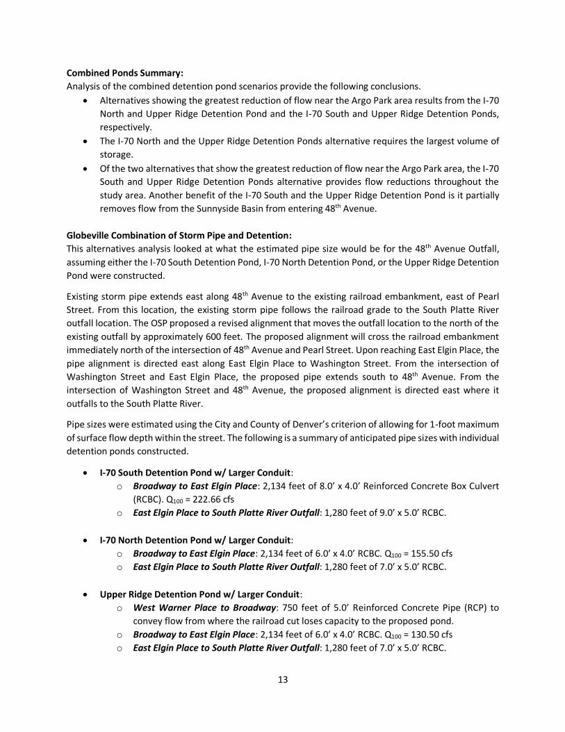
Combined Ponds Summary:
Analysis of the combined detention pond scenarios provide the following conclusions.
• Alternatives showing the greatest reduction of flow near the Argo Park area results from the I-70
North and Upper Ridge Detention Pond and the I-70 South and Upper Ridge Detention Ponds,
respectively.
• The I-70 North and the Upper Ridge Detention Ponds alternative requires the largest volume of
storage.
• Of the two alternatives that show the greatest reduction of flow near the Argo Park area, the I-70
South and Upper Ridge Detention Ponds alternative provides flow reductions throughout the
study area. Another benefit of the I-70 South and the Upper Ridge Detention Pond is it partially
removes flow from the Sunnyside Basin from entering 48th Avenue.
Globeville Combination of Storm Pipe and Detention:
This alternatives analysis looked at what the estimated pipe size would be for the 48th Avenue Outfall,
assuming either the I-70 South Detention Pond, I-70 North Detention Pond, or the Upper Ridge Detention
Pond were constructed.
Existing storm pipe extends east along 48th Avenue to the existing railroad embankment, east of Pearl
Street. From this location, the existing storm pipe follows the railroad grade to the South Platte River
outfall location. The OSP proposed a revised alignment that moves the outfall location to the north of the
existing outfall by approximately 600 feet. The proposed alignment will cross the railroad embankment
immediately north of the intersection of 48th Avenue and Pearl Street. Upon reaching East Elgin Place, the
pipe alignment is directed east along East Elgin Place to Washington Street. From the intersection of
Washington Street and East Elgin Place, the proposed pipe extends south to 48th Avenue. From the
intersection of Washington Street and 48th Avenue, the proposed alignment is directed east where it
outfalls to the South Platte River.
Pipe sizes were estimated using the City and County of Denver’s criterion of allowing for 1-foot maximum
of surface flow depth within the street. The following is a summary of anticipated pipe sizes with individual
detention ponds constructed.
• I-70 South Detention Pond w/ Larger Conduit:
o Broadway to East Elgin Place: 2,134 feet of 8.0’ x 4.0’ Reinforced Concrete Box Culvert
(RCBC). Q100 = 222.66 cfs
o East Elgin Place to South Platte River Outfall: 1,280 feet of 9.0’ x 5.0’ RCBC.
• I-70 North Detention Pond w/ Larger Conduit:
o Broadway to East Elgin Place: 2,134 feet of 6.0’ x 4.0’ RCBC. Q100 = 155.50 cfs
o East Elgin Place to South Platte River Outfall: 1,280 feet of 7.0’ x 5.0’ RCBC.
• Upper Ridge Detention Pond w/ Larger Conduit:
o West Warner Place to Broadway: 750 feet of 5.0’ Reinforced Concrete Pipe (RCP) to
convey flow from where the railroad cut loses capacity to the proposed pond.
o Broadway to East Elgin Place: 2,134 feet of 6.0’ x 4.0’ RCBC. Q100 = 130.50 cfs
o East Elgin Place to South Platte River Outfall: 1,280 feet of 7.0’ x 5.0’ RCBC.

14
In each scenario, the size of the RCBC from East Elgin Place to the South Platte River outfall was increased
by approximately 50%. Greater capacity was introduced to account for unknown tailwater conditions
influenced by flows in the South Platte River. Furthermore, realignment of the conduit may introduce
additional basin inflows to the system. Further analysis and design will provide more information
pertaining to these assumptions.
Sunnyside and Highland Basins:
Previous studies show that surface flows within the Highland Basin spill over into the Globeville-Utah
Junction basin. Spill locations occur in the following locations:
• Intersection of I-70 and Gold Line (Northwest Commuter Rail)
• Area east of Park Avenue West, between I-25 and the South Platte River
To reduce spill flows, Project L (Northwest Subarea Interceptor Storm Drain) was evaluated by ICON
Engineering. The project is classified as a 100-year storm drain system without detention. Large storm
pipes extend from 47th Avenue and extend south along Jason Street where they cross under I-25 and
outfall to the South Platte River. Inlets along the pipe alignment capture surface flows and direct these
flows to the pipe system, requiring large pipes be sized to convey these flows. A significant inlet system
to capture surface flows is a crucial component to the success of the proposed project.
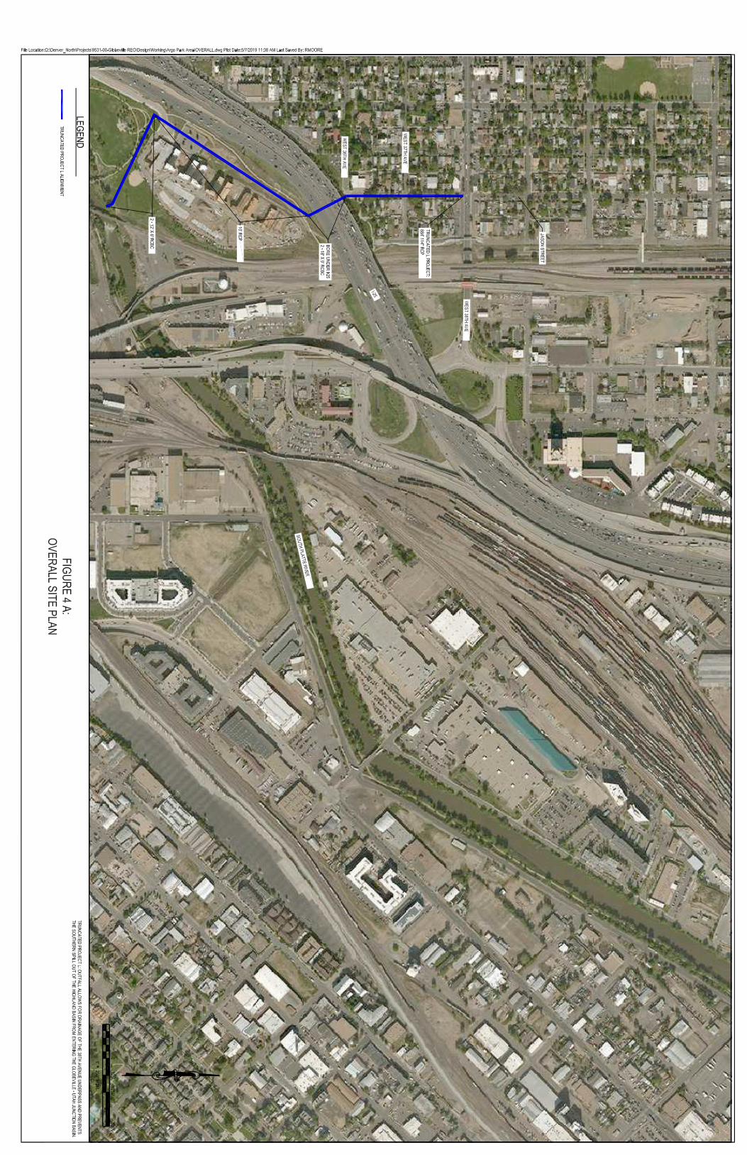
The Truncated L is a shorter version of the Project L. The beginning point of the Truncated L is at the
intersection of 38th Avenue and Jason Street (See Figure 4A). The Truncated L will convey 600 cfs and
prevent the southern spill out of the Highlands Basin from entering the Globeville-Utah Junction Basin.
Since the beginning location for the Truncated L is in the southern segment of the original Project L; the
Truncated L will not capture surface flows in the area south of the intersection of I-70 and the Gold Line
(Northwest Commuter Rail), but the proposed detention ponds along 48th Avenue will account for this
flow.

15
FIGURES


This page was left blank intentionally

APPENDICES
GLOBEVILLE STORMWATER SYSTEMS STUDY

APPENDIX B: SOUTH PLATTE RIVER ANALYSIS
APPENDICES
GLOBEVILLE STORMWATER SYSTEMS STUDY
Employee Owned
2480 W. 26th Street, Unit B225
Denver, Colorado 80211 Tel: +1 303-964-3333 [email protected]
www.merrick.com
TECHNICAL MEMORANDUM May 10, 2019
SUBJECT: Globeville Community Drainage Study:
South Platte River Analysis:
The Denver Urban Waterways Restoration Study was initiated in 2015 by the City and County of Denver
and the Urban Drainage & Flood Control District in cooperation with the United States Army Corps of
Engineers to ascertain habitat improvements to the South Platte River along with two other major
waterways. Within the South Platte River corridor, the study focused on the 7-mile reach of river that
extends from 6th Avenue to 58th Avenue within the City and County of Denver and Adams County. This
study focused on three primary goals that include: 1) ecosystem restoration, 2) flood risk reduction, and
recreational improvements. For goals 1 and 2, the objective was to identify cost effective plans to restore
habitat and ecological function and reduce flood risks.
River modeling of existing conditions, utilizing HEC-RAS (1D model) and TUFLOW (2D model), showed
spilling just upstream of 38th Street and west overbank flooding from 38th Street to 58th Avenue. Overbank
spilling in this area is not identified in the effective Flood Insurance Rate Map. In addition, the river
modeling identified inadequate freeboard along the existing Globeville Levee from 38th Street to Franklin
Street. FEMA levee regulations require 3 feet minimum of freeboard along the channel with 4 feet of
minimum freeboard within 100 feet of bridges and major river structures. Identified differences between
the effective model and the existing conditions model included riverbed aggradation and higher
roughness coefficients due to dense vegetative growth along the river bank. Other modeling differences
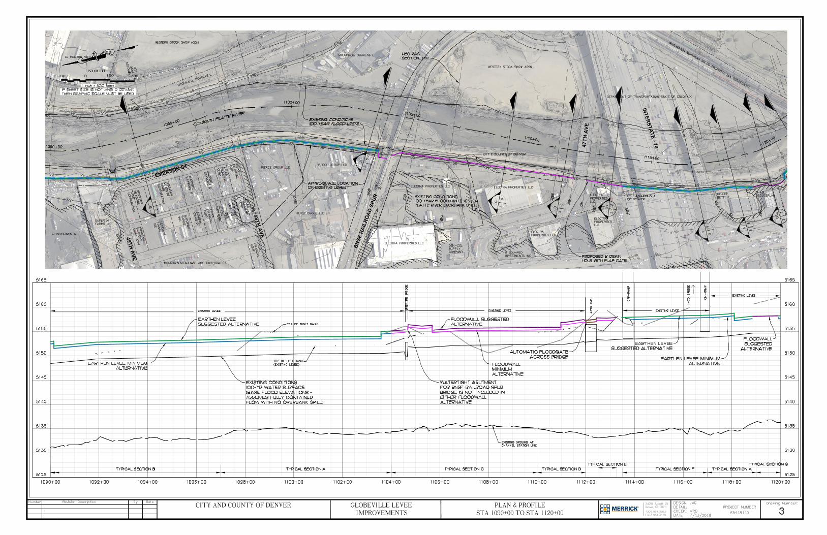
included revised hydrology, the availability of more detailed contour mapping, bridge elevation data, and
corrections to channel length inconsistencies within the effective model. Channel aggradation and higher
roughness coefficients produce higher water surface elevations that are further exacerbated by 100-year
flows hitting existing bridge decks. Bridges of concern include: the railroad spur bridge (downstream of I-
70), the 47th Avenue bridge, the BNSF Railroad bridge, and the pedestrian bridge (at Globeville Landing
Park). These bridges are too low and act as hydraulic controls, causing higher water surface elevations
upstream, resulting in overbank spilling upstream of 38th Street.
The overbank spill at 38th Street and the inadequate freeboard along the Globeville Levee, will result in
portions of the Globeville Basin being placed back in the regulated FEMA Floodplain. Consequently,
residents will be required to purchase flood insurance if the overbank spill is not eliminated and the levee
deficiency is not rectified. The Urban Waterways Restoration Study proposed alternatives that included
widening the river, raising the railroad spur bridge and pedestrian bridge, and relocating a portion of the
levee. These improvements, in combination with raising the 38th Street bridge, would eliminate the spill
upstream of 38th Street but would not correct the levee freeboard deficiencies. Widening the river,
reconstructing bridges and relocating a portion of the levee would be very costly and would take a
significant amount of time to accomplish. Further evaluation by the City showed that reconstructing the
levee to the required height to meet FEMA criteria was the most cost effective and timely solution to the

2
overbank flooding in the Globeville community. See Attachment 1 for the Globeville Levee Recertification
Conceptual Design Memorandum.
The Vision Implementation Team (VIT) consisting of community stakeholders, was not entirely convinced
that reconstructing the levee was the best solution. As a result, the engineering team was tasked with the
following requests for analysis:
1. Widening Channel near Ringsby Court.
2. Dredging the South Platte River.
3. Diverting Flow Upstream of 38th Street.
Ringsby Court Channel Widening: Upstream of the 38th Street Bridge there exists an open space
area on the west bank that could be excavated to provide a wider channel section on this reach
of the river. VIT input suggested that this area could provide more channel capacity that could
reduce headwater elevations and reduce overbank spilling. Widening the river on the east bank
was also suggested but was not analyzed due to the large trunk sanitary sewer pipeline that would
have to be relocated. Hydraulic analysis of the wider channel on the west bank showed that as
flow approached the 38th Street Bridge, the additional area allowed water to spread out, but in
doing so, the velocities reduced, and the water surface elevation increased.
South Platte River Dredging: Dredging the South Platte River was analyzed within the river
corridor extending from the Franklin Street drop structure to upstream of 38th Street (See
Attachment 2 for the Reach 2 and 3 Dredging Modeling Summary). Analysis looked at three
dredging options that include the following:
1. Dredge behind the Franklin Street drop, lowering the channel at the downstream end about 6’ and grading at a 0.12% slope upstream past 38th Street. This option lowers the water surface elevation at the overbank spill location by 4.35 feet, eliminating the spill, and results in flows passing under the BNSF Railroad and 38th Street Bridges.
2. Dredge from the crest of the Franklin Street drop, grading at a 0.12% slope upstream past 38th Street. Resulting water surface elevation at the overbank spill location was reduced by 1.04 feet but does not eliminate the spill.
3. Dredge starting at the upstream side of the I-70 bridge, lowering the channel up to 5’ and grading at a 0.12% slope upstream past 38th Street. The resulting water surface elevation at the overbank spill location is reduced by 1.30 feet but does not eliminate the spill.
Although the dredging Option 1 could eliminate the spill, concerns associated with dredging the river channel by 6 feet make this option impractical and include: the potential for compromising existing bridge structures by exposing piles and other foundational components, the cost of dredging, the on-going maintenance costs that would be required to remove future sediment, and environmental concerns with dredging in the channel.
Diverting Flow Upstream of 38th Street: VIT input suggested if a portion of the South Platte River
flow were diverted through a bypass pipe, resulting water surface elevations within the river
would be reduced enough to pass under the BNSF and 38th Street Bridges, thereby reducing the
backwater depth enough to remove the spill. The bypass pipe would be installed upstream of the
38th Street Bridge and would outflow into the river downstream of the BNSF Bridge. A hydraulic
analysis was performed to investigate the feasibility of diverting enough flow to eliminate the spill
(See Attachment 3). Analysis achieved a reduction of 2 feet; however, attempting to divert

3
additional flow to further reduce water surface elevations resulted in minimal changes in
elevation. Tailwater elevation where the diverted flow re-enters the river influence headwater
elevations and establish a threshold on the amount of elevation change that can be achieved. The
threshold of two feet of elevation decrease that was achieved in the analysis is less than the 4
feet +/- that is required to eliminate the spill.
From an economic standpoint, the estimated cost associated with installing conduits to reduce
elevations by 2 feet would require 13 – 96-inch tunnel pipes, with each pipe able to convey 600
cfs. Assuming 800 feet of tunneling or 10,400 linear feet of required pipe, the cost ($4,100/foot
of pipe installed) is estimated to be $43 Million. Additional costs would be incurred to construct
inlet and outlet structures, walls, and property acquisition to accommodate construction of the
pipes. Anticipated costs would likely exceed $45 Million and would not eliminate the entire spill.
Hydraulic constraints limit the amount of water surface lowering that can be achieved, which does
not eliminate the spill. The cost, limited space for placement of large conduits, potential for
conflicts with existing utilities, and tunneling under the BNSF Railroad tracks, make this option
impractical.
Conclusion:
Ultimately, widening the river and raising the BNSF Bridge and other bridges in the area to heights above
the 100-year elevation would be ideal for eliminating the overbank spill; however, this alone would not
fix all the levee freeboard deficiencies.
Factoring in all the available analysis, the City and County of Denver recommends reconstructing the
Globeville Levee to correct freeboard deficiencies and ultimately remove residents from the regulated
floodplain. Implementation of this plan has begun with the City and County of Denver designating funds
for the levee improvements design.
Attachments:
1. Globeville Levee Recertification Conceptual Design Memorandum
2. Reach 2 and 3 Dredging Modeling Summary
a. Profile of Dredging Behind the Franklin Street Drop
b. Profile of Dredging from Crest of Franklin Street Drop
c. Profile of Dredging from I-70
3. South Platte River Bypass Pipe Memorandum

ATTACHMENT 1

Q:\Denver_North\Projects\8110-00-S. Platte River 6th-58th FS\Design\Working\2018-04-02_Globeville Floodplain\SPR Levee Memo_Revised 2018.docx
MEMORANDUM
July 17, 2018
TO: Dave Jula, PE, CFM
FROM: Mike Galuzzi, PE and Jennifer Goldman, EIT
CC: Peter Baertlein, PE, City and County of Denver
Jennifer Williams, PE, City and County of Denver
David Bennets, PE, CFM, Urban Drainage and Flood Control District
Brooke Seymour, PE, CFM, Urban Drainage and Flood Control District
RE: Globeville Levee Recertification Conceptual Design
This memorandum is an update to our previous November 2, 2016 memorandum, which summarizes
the conceptual design methods and results for modifying the existing Globeville Levee to provide
freeboard required by FEMA, from Franklin Street through 38th Street, and eliminate the overbank spill
at Ringsby Court south of 38th Street. The updated design accounts for the increase in water surface
elevation through the reach, due to adjustments in the hydraulic modeling which resulted from changes
to bank stations and manning’s n values.
EXISTING LEVEE FREEBOARD ANALYSIS
The existing Globeville Levee is located along the left bank of the South Platte River, beginning at the
upstream side of Franklin Street Bridge and terminating at the downstream side of 38th Street Bridge.
The existing levee is primarily an earthen berm with a 10’ wide top. The existing levee includes concrete
floodwalls at McDonalds Real Estate Company/Shadl properties (Sta. 1119+00 – 1120+00) and the KLN
Properties LLC property (Sta. 1123+00 – 1127+00).
The existing conditions 100-year HEC-RAS hydraulic model profile, as prepared for the South Platte River
Study, was reviewed to identify existing freeboard deficiencies and overbank spill locations. The
hydrologic values used in the HEC-RAS model are based on the approved CLOMR for the South Platte
River. From the CLOMR, the 100-year peak discharge within the study area is 20,000 cfs. The hydraulic
modeling results used for the conceptual design of the levee reflect a fully contained flow condition.
The contained condition accounts for an increased water surface elevation when all the water remains
in the river and does not spill out. The downstream boundary condition within the model was set from
the combined South Platte River HEC-RAS model received from Olsson Associates on July 18, 2016. The
existing 1-foot contour interval LiDAR mapping, supplemented with the levee survey elevation table
from the 2009 South Platte River Globeville and North Areas LOMR 09-08-0729P, was used to identify
freeboard deficiencies.
Two sets of design criteria were used to analyze the levee deficiencies. The first set of criteria is for the
“minimum alternative design” that meets minimum FEMA levee accreditation requirements. The second
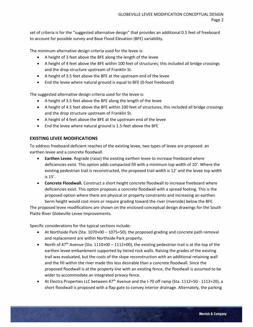
GLOBEVILLE LEVEE MODIFICATION CONCEPTUAL DESIGN Page 2
set of criteria is for the “suggested alternative design” that provides an additional 0.5 feet of freeboard
to account for possible survey and Base Flood Elevation (BFE) variability.
The minimum alternative design criteria used for the levee is:
• A height of 3 feet above the BFE along the length of the levee
• A height of 4 feet above the BFE within 100 feet of structures; this included all bridge crossings
and the drop structure upstream of Franklin St.
• A height of 3.5 feet above the BFE at the upstream end of the levee
• End the levee where natural ground is equal to BFE (0-foot freeboard)
The suggested alternative design criteria used for the levee is:
• A height of 3.5 feet above the BFE along the length of the levee
• A height of 4.5 feet above the BFE within 100 feet of structures; this included all bridge crossings
and the drop structure upstream of Franklin St.
• A height of 4 feet above the BFE at the upstream end of the levee
• End the levee where natural ground is 1.5-feet above the BFE
EXISTING LEVEE MODIFICATIONS
To address freeboard deficient reaches of the existing levee, two types of levee are proposed: an
earthen levee and a concrete floodwall.
• Earthen Levee. Regrade (raise) the existing earthen levee to increase freeboard where
deficiencies exist. This option adds compacted fill with a minimum top width of 10’. Where the
existing pedestrian trail is reconstructed, the proposed trail width is 12’ and the levee top width
is 15’.
• Concrete Floodwall. Construct a short height concrete floodwall to increase freeboard where
deficiencies exist. This option proposes a concrete floodwall with a spread footing. This is the
proposed option where there are physical or property constraints and increasing an earthen
berm height would cost more or require grading toward the river (riverside) below the BFE.
The proposed levee modifications are shown on the enclosed conceptual design drawings for the South
Platte River Globeville Levee Improvements.
Specific considerations for the typical sections include:
• At Northside Park (Sta. 1070+00 – 1075+50), the proposed grading and concrete path removal
and replacement are within Northside Park property.
• North of 47th Avenue (Sta. 1110+00 – 1112+00), the existing pedestrian trail is at the top of the
earthen levee embankment supported by tiered rock walls. Raising the grades of the existing
trail was evaluated, but the costs of the slope reconstruction with an additional retaining wall
and the fill within the river made this less desirable than a concrete floodwall. Since the
proposed floodwall is at the property line with an existing fence, the floodwall is assumed to be
wider to accommodate an integrated privacy fence.
• At Electra Properties LLC between 47th Avenue and the I-70 off ramp (Sta. 1112+50 - 1113+20), a
short floodwall is proposed with a flap gate to convey interior drainage. Alternately, the parking

GLOBEVILLE LEVEE MODIFICATION CONCEPTUAL DESIGN Page 3
lot between the building and 47th Avenue might possibly be regraded to serve as the levee
freeboard.
Bridge Deficiencies
To create a permanent levee closure, the levee must connect to the existing bridge abutments with a
watertight connection. In a flood event, it will be necessary to seal off levee segments where the height
is reduced below design grade by a roadway or railway intersection. For purposes of this study, we have
assumed that roadway bridges can be sealed off using automatic passive floodgates to ensure adequate
freeboard and a watertight connection across bridges. The 47th Ave Bridge and 38th St Bridge would
include these gates. It is not feasible to use an automatic passive floodgate across the BNSF Railroad
Spur Bridge, so an alternate method (e.g. sand bags) would need to be used to ensure a watertight
connection across the bridge during a flood event.
The BNSF Railroad Spur Bridge at Sta. 1104+50 is open deck and has no railings (Figure 1). The existing
timber abutment at this bridge does not allow for a water tight seal with the proposed floodwall.
The National Western Center Master Plan proposes two roadway bridges across the river between
Franklin Street and the BNSF railroad bridge. Increased levee heights to accommodate future bridges
are not included in the conceptual design.

GLOBEVILLE LEVEE MODIFICATION CONCEPTUAL DESIGN Page 4
Figure 1. BNSF Railroad Spur Bridge
CONCEPTUAL LEVEE DESIGN AT RINGSBY COURT
The existing Globeville Levee terminates at the downstream side of the 38th Street Bridge. The profile
comparison of the top of the left bank and the 100-year water surface shows a spill between the
upstream face of the 38th Street Bridge to approximately 1,200 feet upstream. The Ringsby Court
roadway section is adjacent to the South Platte River with little to no setback from the top of the left
bank. Raising the roadway grades along Ringsby Court would greatly impact the adjacent properties and
require numerous retaining walls, and for these reasons, only a floodwall was considered through this
reach.
The previous floodwall design for the existing Globeville Levee was used for the conceptual design. The
wall consists of 30” diameter drilled caissons spaced at 10-feet on-center with a 36–inch wide grade
beam and a concrete wall (see Section G on Drawing 7. The drilled caissons are intended to be
embedded into bedrock. Since a geotechnical investigation is not available, the bedrock depth for this
conceptual design is assumed to be the same as shown on the design drawings for the nearest floodwall,
just downstream of the 38th Street Bridge at KLN Properties LLC, with a bottom of pier elevation of 5105
ft.
Alternative Floodwall Design
The floodwall design from the existing Globeville Levee project appears to be a high cost alternative.
Upon cursory review, the floodwall design for the previous project appears to be constrained by the
close proximity to existing buildings. Being close to existing buildings, the design would have addressed
additional surcharge loads, vibration concerns, limited access width for heavy equipment, and concerns
of open excavation close to the building foundations. The proposed levee extension along Ringsby Court
is further away from buildings and has improved construction access. Investigating structural
CANNOT PROVIDE
WATERTIGHT CONNECTION
TO BRIDGE ABUTMENT DUE
TO EXISTING ABUTMENT
DESIGN

GLOBEVILLE LEVEE MODIFICATION CONCEPTUAL DESIGN Page 5
alternatives to the floodwall is not a part of the scope for this conceptual design; however, Merrick
recommends investigating alternative floodwall designs during preliminary design. Possible alternatives
include a driven sheet pile foundation with a concrete cap or H-piles on a batter with a grade beam and
wall.
Ready Mixed Development
Development is planned at the Ready Mixed Concrete site (Taxi North LLC) located at the southwest
corner of Ringsby Court and Washington Street. Merrick reviewed the existing topography at this site to
see if modifying the grade of the site during redevelopment could eliminate the overbank spill. Since the
development is on the west side of Ringsby Court, filling in the site would not eliminate the spill at the
left bank. The Ringsby Court and Washington Street intersection would continue to be an opening and
serve as a flooding path. To eliminate the opening at the Ringsby Court and Washington Street
intersection, the floodwall along Ringsby Court must tie in to the 38th Street Bridge, as shown in Figure 2.
Even with the proposed accredited levee system, the developer should consider building above the S.
Platte River BFE to remove proposed structures from a moderate-risk flood hazard area.
38th Street Bridge
As shown in the following photograph (Figure 2), the proposed floodwall will need to connect to the 38th
Street Bridge with a permanent watertight connection. In the event of a major flood event, the roadway
will need to be closed to traffic, since the passive automatic floodgates would be upright at the first
detection of water.
Figure 2. 38th Street Bridge Closure
Bank Protection
The existing left bank through this reach of the South Platte River has steep side-slopes with some near
vertical slopes due to erosion. The existing riprap appears to be inconsistent and varied in placement. To
protect the left bank and the proposed floodwall upstream of 38th St, Merrick proposes improving the
bank with 2:1 and 3:1 side slopes and protecting the slope against erosion with buried, soil-filled Type M
riprap.
CONNECT FLOODWALL TO
GUARDRAIL WITH
WATERTIGHT JOINT

GLOBEVILLE LEVEE MODIFICATION CONCEPTUAL DESIGN Page 6
Additional Design Considerations
Additional design considerations for the proposed floodwall include:
• Flap gates are required at all interior drainage storm sewer outfalls that cross the proposed
floodwalls.
• The stormwater runoff along the northbound lane of Ringsby Court currently discharges directly
to the South Platte River via overland flow on the embankment. The proposed floodwall
prevents this existing flow pattern, so a roadside drainage system is required to convey
stormwater flow to the river. It appears that catch basin inlets can be constructed on the
landside of the floodwall and connect to the existing storm sewer outfalls.
• There is an existing manhole at the edge of pavement (near Sta. 1138+00) where the floodwall is
proposed. The manhole is assumed to be a fiber optic vault for the fiber optic line located along
the left bank. If so, the fiber optic line will need to be relocated for the floodwall construction.
• The existing utility pole at the 38th Street Bridge will need to be reset.
HEC-RAS Model Results
HEC-RAS was used to model the proposed floodwall and bank stabilization for the reach along Ringsby
Court. The proposed floodwall with and without bank stabilization was modeled and compared to the
existing conditions model. Manning’s n-values were not adjusted down for proposed conditions, as it
was conservatively assumed that the future slope condition will be similar to the existing dense
vegetation. Note that vegetation may need to be limited along the proposed levee at the river bank. The
proposed concrete floodwall with bank stabilization results in a no rise condition for the 100-year
floodplain.
If there are any questions or concerns with the provided information, please contact Jennifer Goldman
at [email protected] or 303-353-3712.

SH
EE
T 3
S
H
E
E
T
4
S
H
E
E
T
5
S
H
E
E
T
2
S
H
E
E
T
3
COVER SHEETIMPROVEMENTS
GLOBEVILLE LEVEE
CITY AND COUNTY OF DENVER
NORTH200 0 200 400
CONCEPTUAL DESIGN
SOUTH PLATTE RIVER
GLOBEVILLE LEVEE IMPROVEMENTS
DENVER, COLORADO
JULY 2018
M
A
T
C
H
L
IN
E
S
T
A
. 1
1
0
3
+
5
0
MA
TC
HLIN
E
S
TA
.1103+
50
AutoCAD SHX Text
INTERSTATE 70
AutoCAD SHX Text
47TH AVE
AutoCAD SHX Text
WASHINGTON STREET
AutoCAD SHX Text
45TH AVE
AutoCAD SHX Text
RINGSBY COURT
AutoCAD SHX Text
35TH STREET
AutoCAD SHX Text
36TH STREET
AutoCAD SHX Text
CHESTNUT PLACE
AutoCAD SHX Text
38TH STREET
AutoCAD SHX Text
WASHINGTON STREET
AutoCAD SHX Text
SOUTH PLATTE RIVER
AutoCAD SHX Text
BNSF RAILROAD
AutoCAD SHX Text
FRANKLIN STREET
AutoCAD SHX Text
48TH AVE
AutoCAD SHX Text
49TH AVE
AutoCAD SHX Text
53RD AVE
AutoCAD SHX Text
SOUTH PLATTE RIVER
AutoCAD SHX Text
EMERSON STREET
AutoCAD SHX Text
ADAMS COUNTY
AutoCAD SHX Text
CITY AND COUNTY OF DENVER
AutoCAD SHX Text
Number
AutoCAD SHX Text
Revision Description
AutoCAD SHX Text
By
AutoCAD SHX Text
Date
AutoCAD SHX Text
PROJECT NUMBER
AutoCAD SHX Text
Drawing Number:
AutoCAD SHX Text
DESIGN:
AutoCAD SHX Text
DETAIL:
AutoCAD SHX Text
CHECK:
AutoCAD SHX Text
DATE:
AutoCAD SHX Text
Denver, CO 80211
AutoCAD SHX Text
2420 Alcott St
AutoCAD SHX Text
T303.964.3333
AutoCAD SHX Text
F303.964.3355
AutoCAD SHX Text
7/10/2018
AutoCAD SHX Text
MRG
AutoCAD SHX Text
JAG
AutoCAD SHX Text
65418110
AutoCAD SHX Text
1
AutoCAD SHX Text
IF SHEET SIZE IS NOT ANSI D (22"X34") THEN GRAPHIC SCALE MUST BE USED
AutoCAD SHX Text
1 inch = 200 feet
AutoCAD SHX Text
Q:\DENVER_NORTH\PROJECTS\8110-00-S. PLATTE RIVER 6TH-58TH FS\DESIGN\WORKING\2018-04-02_GLOBEVILLE FLOODPLAIN Last Saved: July 10, 2018 Last Saved: July 10, 2018 July 10, 2018
AutoCAD SHX Text
Xref Q:\Standards\CAD\Merrick\Logo\Merrick & Company-Logo-Color.dwg
AutoCAD SHX Text
LEGEND: : EXISTING LEVEE EARTHEN LEVEE MINIMUM ALTERNATIVE EARTHEN LEVEE SUGGESTED ALTERNATIVE FLOODWALL MINIMUM ALTERNATIVE FLOODWALL SUGGESTED ALTERNATIVE
AutoCAD SHX Text
A
AutoCAD SHX Text
1
AutoCAD SHX Text
2
AutoCAD SHX Text
SECTION CUT KEY
AutoCAD SHX Text
SECTION ID
AutoCAD SHX Text
SHEET WHERE SECTION IS CUT
AutoCAD SHX Text
SHEET WHERE SECTION IS SHOWN
AutoCAD SHX Text
SHEET INDEX
AutoCAD SHX Text
SHEET NO. 1 2 3 4 5 6 7
AutoCAD SHX Text
SHEET TITLE COVER PLAN & PROFILE STA 1062+00 - STA 1090+00 PLAN & PROFILE STA 1090+00 - STA 1120+00 PLAN & PROFILE STA 1120+00 - STA 1150+00 PLAN & PROFILE STA 1150+00 - STA 1160+00 TYPICAL SECTIONS TYPICAL SECTIONS

A
2
6
B
2
6
A
26
F
R
A
N
K
L
I
N
S
T
B
2
6
R
A
C
E
S
T
STA 1062±00 TO STA 1090±00PLAN & PROFILE
IMPROVEMENTSGLOBEVILLE LEVEE
CITY AND COUNTY OF DENVER
NORTH100 0 100 200
AutoCAD SHX Text
D
AutoCAD SHX Text
D
AutoCAD SHX Text
D
AutoCAD SHX Text
D
AutoCAD SHX Text
D
AutoCAD SHX Text
D
AutoCAD SHX Text
D
AutoCAD SHX Text
D
AutoCAD SHX Text
D
AutoCAD SHX Text
D
AutoCAD SHX Text
D
AutoCAD SHX Text
D
AutoCAD SHX Text
D
AutoCAD SHX Text
15
AutoCAD SHX Text
33
AutoCAD SHX Text
33
AutoCAD SHX Text
12
AutoCAD SHX Text
12
AutoCAD SHX Text
12
AutoCAD SHX Text
8
AutoCAD SHX Text
15
AutoCAD SHX Text
Abandoned
AutoCAD SHX Text
270
AutoCAD SHX Text
285.2
AutoCAD SHX Text
290.3
AutoCAD SHX Text
295.2
AutoCAD SHX Text
305
AutoCAD SHX Text
320
AutoCAD SHX Text
330
AutoCAD SHX Text
340
AutoCAD SHX Text
341
AutoCAD SHX Text
310
AutoCAD SHX Text
338
AutoCAD SHX Text
324
AutoCAD SHX Text
326
AutoCAD SHX Text
328
AutoCAD SHX Text
300
AutoCAD SHX Text
298
AutoCAD SHX Text
291
AutoCAD SHX Text
290
AutoCAD SHX Text
275
AutoCAD SHX Text
281
AutoCAD SHX Text
HEC-RAS SECTION, TYP.
AutoCAD SHX Text
DENVER TERMINAL RAILROAD CO
AutoCAD SHX Text
UNION PACIFIC RAILROAD CO
AutoCAD SHX Text
ROCKIN LAZY L LAND LLC
AutoCAD SHX Text
MIDDLETON PROPERTIES LLC
AutoCAD SHX Text
CITY AND COUNTY OF DENVER
AutoCAD SHX Text
CITY AND COUNTY OF DENVER
AutoCAD SHX Text
KAI INVESTMENTS LLC
AutoCAD SHX Text
CITY AND COUNTY OF DENVER
AutoCAD SHX Text
DENVER ROCK ISLAND RAILROAD INC
AutoCAD SHX Text
WESTERN STOCK SHOW ASSN
AutoCAD SHX Text
POWER ASSIST COMPANY
AutoCAD SHX Text
STATE OF COLORADO
AutoCAD SHX Text
LE MOUTON NOIR LLC
AutoCAD SHX Text
GI INVESTMENTS
AutoCAD SHX Text
CITY AND COUNTY OF DENVER
AutoCAD SHX Text
GLOBEVILLE RIVERFRONT ARTS CENTER LLC
AutoCAD SHX Text
JJJ PROPERTIES LLC
AutoCAD SHX Text
CITY AND COUNTY OF DENVER
AutoCAD SHX Text
CITY AND COUNTY OF DENVER
AutoCAD SHX Text
UNION PACIFIC RAILROAD CO
AutoCAD SHX Text
NORTHSIDE PARK
AutoCAD SHX Text
CITY AND COUNTY OF DENVER LIMITS
AutoCAD SHX Text
EXISTING CONDITIONS 100-YEAR FLOOD LIMITS
AutoCAD SHX Text
EXISTING CONDITIONS 100-YEAR FLOOD LIMITS (SOUTH PLATTE RIVER OVERBANK SPILL)
AutoCAD SHX Text
approximate location of existing levee
AutoCAD SHX Text
SOUTH PLATTE RIVER
AutoCAD SHX Text
RR BRIDGE
AutoCAD SHX Text
FRANKLIN ST.
AutoCAD SHX Text
STOCK YARD BRIDGE
AutoCAD SHX Text
NORTHSIDE PARK
AutoCAD SHX Text
EXISTING GROUND AT CHANNEL STATION LINE
AutoCAD SHX Text
TOP OF RIGHT BANK
AutoCAD SHX Text
EXISTING CONDITIONS 100-YR WATER SURFACE (BASE FLOOD ELEVATION - Assumes fully contained flow with no overbank spill)
AutoCAD SHX Text
EARTHEN LEVEE MINIMUM ALTERNATIVE
AutoCAD SHX Text
BEGIN LEVEE AT UPSTREAM SIDE OF FRANKLIN ST. BRIDGE
AutoCAD SHX Text
EARTHEN LEVEE SUGGESTED ALTERNATIVE
AutoCAD SHX Text
TOP OF LEFT BANK (EXISTING LEVEE)
AutoCAD SHX Text
Number
AutoCAD SHX Text
Revision Description
AutoCAD SHX Text
By
AutoCAD SHX Text
Date
AutoCAD SHX Text
PROJECT NUMBER
AutoCAD SHX Text
Drawing Number:
AutoCAD SHX Text
DESIGN:
AutoCAD SHX Text
DETAIL:
AutoCAD SHX Text
CHECK:
AutoCAD SHX Text
DATE:
AutoCAD SHX Text
Denver, CO 80211
AutoCAD SHX Text
2420 Alcott St
AutoCAD SHX Text
T303.964.3333
AutoCAD SHX Text
F303.964.3355
AutoCAD SHX Text
7/13/2018
AutoCAD SHX Text
MRG
AutoCAD SHX Text
JAG
AutoCAD SHX Text
65418110
AutoCAD SHX Text
2
AutoCAD SHX Text
IF SHEET SIZE IS NOT ANSI D (22"X34") THEN GRAPHIC SCALE MUST BE USED
AutoCAD SHX Text
1 inch = 100 feet
D
3
6
C
3
6
G
3
7
A
3
6
B
N
S
F
R
A
I
L
R
O
A
D
S
P
U
R
47T
H
A
VE
IN
T
E
R
S
T
A
T
E
-
7
0
B
N
S
F
R
A
I
L
R
O
A
D
B
2
6
A
3
6
E
3
7
F
3
7
E
M
E
R
S
O
N
S
T
4
9
T
H
A
V
E
4
8
T
H
A
V
E
NORTH100 0 100 200
STA 1090±00 TO STA 1120±00PLAN & PROFILE
IMPROVEMENTSGLOBEVILLE LEVEE
CITY AND COUNTY OF DENVER
AutoCAD SHX Text
D
AutoCAD SHX Text
D
AutoCAD SHX Text
D
AutoCAD SHX Text
D
AutoCAD SHX Text
D
AutoCAD SHX Text
D
AutoCAD SHX Text
D
AutoCAD SHX Text
D
AutoCAD SHX Text
D
AutoCAD SHX Text
D
AutoCAD SHX Text
D
AutoCAD SHX Text
D
AutoCAD SHX Text
24
AutoCAD SHX Text
78
AutoCAD SHX Text
30
AutoCAD SHX Text
66
AutoCAD SHX Text
18
AutoCAD SHX Text
18
AutoCAD SHX Text
24
AutoCAD SHX Text
39
AutoCAD SHX Text
36
AutoCAD SHX Text
21
AutoCAD SHX Text
12
AutoCAD SHX Text
84/60
AutoCAD SHX Text
30
AutoCAD SHX Text
24
AutoCAD SHX Text
18
AutoCAD SHX Text
15
AutoCAD SHX Text
114/72
AutoCAD SHX Text
Abandoned
AutoCAD SHX Text
350
AutoCAD SHX Text
360
AutoCAD SHX Text
370
AutoCAD SHX Text
371
AutoCAD SHX Text
380
AutoCAD SHX Text
390
AutoCAD SHX Text
391
AutoCAD SHX Text
395
AutoCAD SHX Text
420
AutoCAD SHX Text
355
AutoCAD SHX Text
368
AutoCAD SHX Text
375
AutoCAD SHX Text
388
AutoCAD SHX Text
392
AutoCAD SHX Text
415
AutoCAD SHX Text
358
AutoCAD SHX Text
356
AutoCAD SHX Text
410
AutoCAD SHX Text
357
AutoCAD SHX Text
LE MOUTON NOIR LLC
AutoCAD SHX Text
LE MOUTON NOIR LLC
AutoCAD SHX Text
WESTERN STOCK SHOW ASSN
AutoCAD SHX Text
MCDONALD, DOUGLAS L
AutoCAD SHX Text
MCDONALD, DOUGLAS L
AutoCAD SHX Text
WESTERN STOCK SHOW ASSN
AutoCAD SHX Text
DEPARTMENT OF TRANSPORTATION STATE OF COLORADO
AutoCAD SHX Text
BURLINGTON NORTHERN RR CO PROPERTY TAX DEPARTMENT
AutoCAD SHX Text
KELLEY, BETTY F
AutoCAD SHX Text
SHADL, ABDUSSALAM
AutoCAD SHX Text
ELECTRA PROPERTIES LLC
AutoCAD SHX Text
ELECTRA PROPERTIES LLC
AutoCAD SHX Text
ELECTRA PROPERTIES LLC
AutoCAD SHX Text
D SQUARED INVESTMENTS INC
AutoCAD SHX Text
ELECTRA PROPERTIES LLC
AutoCAD SHX Text
ELECTRA PROPERTIES LLC
AutoCAD SHX Text
DEN-COL SUPPLY COMPANY
AutoCAD SHX Text
ELECTRA PROPERTIES LLC
AutoCAD SHX Text
PIERCE GROUP LLC
AutoCAD SHX Text
PIERCE GROUP LLC
AutoCAD SHX Text
PIERCE GROUP LLC
AutoCAD SHX Text
ATLAS FINANCIAL CORP
AutoCAD SHX Text
ATLAS FINANCIAL CORP
AutoCAD SHX Text
RUPPERT, RAYMOND R
AutoCAD SHX Text
RUPPERT, RAYMOND R
AutoCAD SHX Text
MOUNTAIN MEADOWS LAMB CORPORATION
AutoCAD SHX Text
MOUNTAIN MEADOWS LAMB CORPORATION
AutoCAD SHX Text
MOUNTAIN MEADOWS LAMB CORP.
AutoCAD SHX Text
SUPERIOR FARMS INC
AutoCAD SHX Text
SUPERIOR FARMS INC
AutoCAD SHX Text
STIMSON, CRAIG D
AutoCAD SHX Text
ATLAS FINANCIAL CORP
AutoCAD SHX Text
SUAZO, MARIA
AutoCAD SHX Text
NORTHWEST LAND CO
AutoCAD SHX Text
ATLAS FINANCIAL CORP
AutoCAD SHX Text
MOUNTAIN MEADOWS LAMB CORPORATION
AutoCAD SHX Text
ATLAS FINANCIAL CORP
AutoCAD SHX Text
SUPERIOR FARMS INC
AutoCAD SHX Text
GI INVESTMENTS
AutoCAD SHX Text
HEC-RAS SECTION, TYP.
AutoCAD SHX Text
EXISTING CONDITIONS 100-YEAR FLOOD LIMITS (SOUTH PLATTE RIVER OVERBANK SPILL)
AutoCAD SHX Text
EXISTING CONDITIONS 100-YEAR FLOOD LIMITS
AutoCAD SHX Text
PROPOSED 6" DRAIN HOLE WITH FLAP GATE
AutoCAD SHX Text
approximate location of existing levee
AutoCAD SHX Text
SOUTH PLATTE RIVER
AutoCAD SHX Text
47TH AVE.
AutoCAD SHX Text
OFF-RAMP
AutoCAD SHX Text
I-70 BRIDGE
AutoCAD SHX Text
ON-RAMP
AutoCAD SHX Text
BNSF RR BRIDGE
AutoCAD SHX Text
EXISTING GROUND AT CHANNEL STATION LINE
AutoCAD SHX Text
TOP OF LEFT BANK (EXISTING LEVEE)
AutoCAD SHX Text
TOP OF RIGHT BANK
AutoCAD SHX Text
EXISTING CONDITIONS 100-YR WATER SURFACE (BASE FLOOD ELEVATIONS - ASSUMES FULLY CONTAINED FLOW WITH NO OVERBANK SPILL)
AutoCAD SHX Text
FLOODWALL MINIMUM ALTERNATIVE
AutoCAD SHX Text
EARTHEN LEVEE MINIMUM ALTERNATIVE
AutoCAD SHX Text
WATERTIGHT ABUTMENT FOR BNSF RAILROAD SPUR BRIDGE IS NOT INCLUDED IN EITHER FLOODWALL ALTERNATIVE
AutoCAD SHX Text
EARTHEN LEVEE MINIMUM ALTERNATIVE
AutoCAD SHX Text
EARTHEN LEVEE suggested ALTERNATIVE
AutoCAD SHX Text
FLOODWALL suggested ALTERNATIVE
AutoCAD SHX Text
EARTHEN LEVEE suggested ALTERNATIVE
AutoCAD SHX Text
AUTOMATIC FLOODGATE ACROSS BRIDGE
AutoCAD SHX Text
floodwall suggested ALTERNATIVE
AutoCAD SHX Text
IF SHEET SIZE IS NOT ANSI D (22"X34") THEN GRAPHIC SCALE MUST BE USED
AutoCAD SHX Text
1 inch = 100 feet
AutoCAD SHX Text
Number
AutoCAD SHX Text
Revision Description
AutoCAD SHX Text
By
AutoCAD SHX Text
Date
AutoCAD SHX Text
PROJECT NUMBER
AutoCAD SHX Text
Drawing Number:
AutoCAD SHX Text
DESIGN:
AutoCAD SHX Text
DETAIL:
AutoCAD SHX Text
CHECK:
AutoCAD SHX Text
DATE:
AutoCAD SHX Text
Denver, CO 80211
AutoCAD SHX Text
2420 Alcott St
AutoCAD SHX Text
T303.964.3333
AutoCAD SHX Text
F303.964.3355
AutoCAD SHX Text
7/13/2018
AutoCAD SHX Text
MRG
AutoCAD SHX Text
JAG
AutoCAD SHX Text
65418110
AutoCAD SHX Text
3

A
4
6
G
3
7
6
B
N
S
F
R
A
I
L
R
O
A
D
3
8
T
H
S
T
RIN
G
SB
Y C
T
AR
KIN
S C
T
G
4
7
H
4
7
A
4
6
W
A
S
H
I
N
G
T
O
N
S
T
3
5
T
H
S
T
C
H
E
S
T
N
U
T
P
L
NORTH100 0 100 200
STA 1120±00 TO STA 1150±00PLAN & PROFILE
IMPROVEMENTSGLOBEVILLE LEVEE
CITY AND COUNTY OF DENVER
AutoCAD SHX Text
D
AutoCAD SHX Text
D
AutoCAD SHX Text
D
AutoCAD SHX Text
D
AutoCAD SHX Text
D
AutoCAD SHX Text
D
AutoCAD SHX Text
D
AutoCAD SHX Text
D
AutoCAD SHX Text
D
AutoCAD SHX Text
D
AutoCAD SHX Text
D
AutoCAD SHX Text
D
AutoCAD SHX Text
D
AutoCAD SHX Text
D
AutoCAD SHX Text
D
AutoCAD SHX Text
D
AutoCAD SHX Text
D
AutoCAD SHX Text
D
AutoCAD SHX Text
D
AutoCAD SHX Text
D
AutoCAD SHX Text
36
AutoCAD SHX Text
15
AutoCAD SHX Text
15
AutoCAD SHX Text
24
AutoCAD SHX Text
78
AutoCAD SHX Text
15
AutoCAD SHX Text
15
AutoCAD SHX Text
15
AutoCAD SHX Text
24
AutoCAD SHX Text
30
AutoCAD SHX Text
10
AutoCAD SHX Text
24
AutoCAD SHX Text
144
AutoCAD SHX Text
12
AutoCAD SHX Text
10
AutoCAD SHX Text
18
AutoCAD SHX Text
24
AutoCAD SHX Text
78
AutoCAD SHX Text
420
AutoCAD SHX Text
430
AutoCAD SHX Text
431
AutoCAD SHX Text
435
AutoCAD SHX Text
436
AutoCAD SHX Text
440
AutoCAD SHX Text
450.5
AutoCAD SHX Text
451
AutoCAD SHX Text
1535
AutoCAD SHX Text
415
AutoCAD SHX Text
425
AutoCAD SHX Text
432
AutoCAD SHX Text
438
AutoCAD SHX Text
445
AutoCAD SHX Text
455
AutoCAD SHX Text
636
AutoCAD SHX Text
1085
AutoCAD SHX Text
460
AutoCAD SHX Text
448
AutoCAD SHX Text
BURLINGTON NORTHERN RR CO PROPERTY TAX DEPARTMENT
AutoCAD SHX Text
KELLEY, BETTY F
AutoCAD SHX Text
SHADL, ABDUSSALAM
AutoCAD SHX Text
MCDONALDS REAL ESTATE CO
AutoCAD SHX Text
CITY & COUNTY OF DENVER
AutoCAD SHX Text
KLN PROPERTIES LLC
AutoCAD SHX Text
CITY & COUNTY OF DENVER
AutoCAD SHX Text
BOTTLING GROUP LLC
AutoCAD SHX Text
MENALTO LLC
AutoCAD SHX Text
HURLEY, BERNARD
AutoCAD SHX Text
MENALTO LLC
AutoCAD SHX Text
MENALTO LLC
AutoCAD SHX Text
WEIL, TRACY
AutoCAD SHX Text
BOSON, ROBERT J
AutoCAD SHX Text
DELGANEY SHOP
AutoCAD SHX Text
3500 CHESTNUT LLC
AutoCAD SHX Text
CITY & COUNTY OF DENVER
AutoCAD SHX Text
CITY & COUNTY OF DENVER
AutoCAD SHX Text
CITY & COUNTY OF DENVER
AutoCAD SHX Text
REGIONAL TRANSPORTATION DISTRICT
AutoCAD SHX Text
RINGSBY COURT LLC
AutoCAD SHX Text
TAXI BUILDING I LLC
AutoCAD SHX Text
TAXI FITNESS LLC
AutoCAD SHX Text
RINGSBY COURT LLC
AutoCAD SHX Text
FREIGHT LLC
AutoCAD SHX Text
FREIGHT ON THE RIVER LLC
AutoCAD SHX Text
FREIGHT RESIDENCES LLC
AutoCAD SHX Text
FREIGHT LLC
AutoCAD SHX Text
TAXI NORTH LLC
AutoCAD SHX Text
SPRAT-PLATTE RANCH CO LLLP
AutoCAD SHX Text
TAXI NORTH LLC
AutoCAD SHX Text
TR-B ASSOC.
AutoCAD SHX Text
TR-B ASSOC.
AutoCAD SHX Text
GLOBEVILLE LANDING PARK
AutoCAD SHX Text
CONNECT FLOODWALL TO BRIDGE WITH WATERTIGHT JOINT
AutoCAD SHX Text
approximate location of existing levee
AutoCAD SHX Text
MENALTO LLC
AutoCAD SHX Text
HEC-RAS SECTION, TYP.
AutoCAD SHX Text
EXISTING CONDITIONS 100-YEAR FLOOD LIMITS (south platte river overbank spill)
AutoCAD SHX Text
PROPOSED FLAP GATE AT 24" OUTFALL
AutoCAD SHX Text
PROPOSED FLAP GATE AT 24" OUTFALL
AutoCAD SHX Text
PROPOSED FLAP GATE AT 24" OUTFALL
AutoCAD SHX Text
PROPOSED FLAP GATE AT 30" OUTFALL
AutoCAD SHX Text
EXISTING CONDITIONS 100-YEAR FLOOD LIMITS
AutoCAD SHX Text
RELOCATE FIBER OPTIC MANHOLE AND LINE
AutoCAD SHX Text
RELOCATE UTILITY POLE
AutoCAD SHX Text
PROPOSED FLOODWALL
AutoCAD SHX Text
BNSF RR BRIDGE
AutoCAD SHX Text
PED. BRIDGE
AutoCAD SHX Text
38TH ST.
AutoCAD SHX Text
TOP OF LEFT BANK
AutoCAD SHX Text
EXISTING GROUND AT CHANNEL STATION LINE
AutoCAD SHX Text
TOP OF LEFT BANK (EXISTING LEVEE)
AutoCAD SHX Text
TOP OF RIGHT BANK
AutoCAD SHX Text
EXISTING CONDITIONS 100-YR WATER SURFACE (BASE FLOOD ELEVATION - ASSUMES FULLY CONTAINED WITH NO OVERBANK SPILL)
AutoCAD SHX Text
FLOODWALL SUGGESTED ALTERNATIVE
AutoCAD SHX Text
END LEVEE AT 0' FREEBOARD (MINIMUM ALTERNATIVE)
AutoCAD SHX Text
FLOODWALL MINIMUM ALTERNATIVE
AutoCAD SHX Text
EARTHEN LEVEE SUGGESTED ALTERNATIVE
AutoCAD SHX Text
EARTHEN LEVEE MINIMUM ALTERNATIVE
AutoCAD SHX Text
CONNECT FLOODWALL TO BRIDGE STRUCTURE WITH WATERTIGHT CONNECTION
AutoCAD SHX Text
EARTHEN LEVEE MINIMUM ALTERNATIVE
AutoCAD SHX Text
EARTHEN LEVEE SUGGESTED ALTERNATIVE
AutoCAD SHX Text
FLOODWALL SUGGESTED ALTERNATIVE
AutoCAD SHX Text
AUTOMATIC FLOODGATE ACROSS BRIDGE
AutoCAD SHX Text
FLOODWALL MINIMUM ALTERNATIVE
AutoCAD SHX Text
IF SHEET SIZE IS NOT ANSI D (22"X34") THEN GRAPHIC SCALE MUST BE USED
AutoCAD SHX Text
1 inch = 100 feet
AutoCAD SHX Text
Number
AutoCAD SHX Text
Revision Description
AutoCAD SHX Text
By
AutoCAD SHX Text
Date
AutoCAD SHX Text
PROJECT NUMBER
AutoCAD SHX Text
Drawing Number:
AutoCAD SHX Text
DESIGN:
AutoCAD SHX Text
DETAIL:
AutoCAD SHX Text
CHECK:
AutoCAD SHX Text
DATE:
AutoCAD SHX Text
Denver, CO 80211
AutoCAD SHX Text
2420 Alcott St
AutoCAD SHX Text
T303.964.3333
AutoCAD SHX Text
F303.964.3355
AutoCAD SHX Text
7/13/2018
AutoCAD SHX Text
MRG
AutoCAD SHX Text
JAG
AutoCAD SHX Text
65418110
AutoCAD SHX Text
4
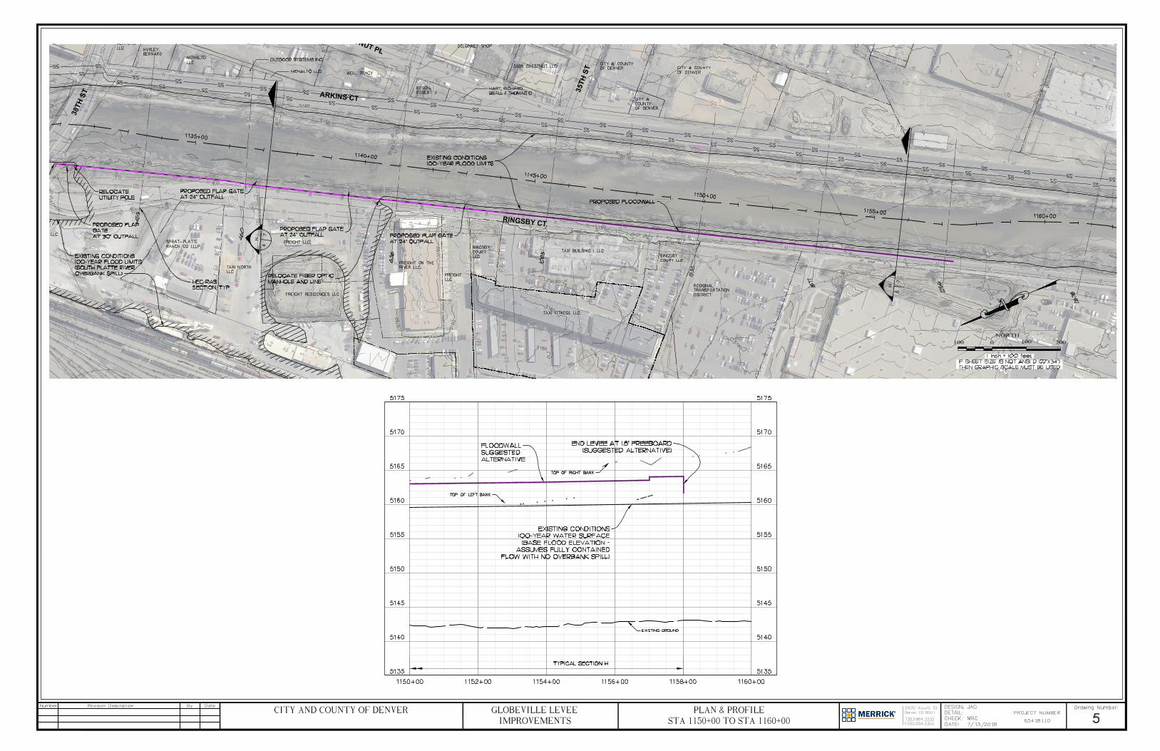
3
8
T
H
S
T
RIN
G
SB
Y C
T
AR
KIN
S C
T
H
5
7
H
4
7
3
5
T
H
S
T
C
H
E
S
T
N
U
T
P
L
NORTH100 0 100 200
STA 1150±00 TO STA 1160±00PLAN & PROFILE
IMPROVEMENTSGLOBEVILLE LEVEE
CITY AND COUNTY OF DENVER
AutoCAD SHX Text
D
AutoCAD SHX Text
D
AutoCAD SHX Text
D
AutoCAD SHX Text
D
AutoCAD SHX Text
D
AutoCAD SHX Text
D
AutoCAD SHX Text
D
AutoCAD SHX Text
D
AutoCAD SHX Text
D
AutoCAD SHX Text
D
AutoCAD SHX Text
D
AutoCAD SHX Text
48
AutoCAD SHX Text
12
AutoCAD SHX Text
12
AutoCAD SHX Text
36
AutoCAD SHX Text
15
AutoCAD SHX Text
15
AutoCAD SHX Text
24
AutoCAD SHX Text
78
AutoCAD SHX Text
15
AutoCAD SHX Text
15
AutoCAD SHX Text
15
AutoCAD SHX Text
24
AutoCAD SHX Text
30
AutoCAD SHX Text
18
AutoCAD SHX Text
18
AutoCAD SHX Text
1535
AutoCAD SHX Text
455
AutoCAD SHX Text
636
AutoCAD SHX Text
1085
AutoCAD SHX Text
1877
AutoCAD SHX Text
2256
AutoCAD SHX Text
460
AutoCAD SHX Text
2678
AutoCAD SHX Text
MENALTO LLC
AutoCAD SHX Text
HURLEY, BERNARD
AutoCAD SHX Text
MENALTO LLC
AutoCAD SHX Text
WEIL, TRACY
AutoCAD SHX Text
BOSON, ROBERT J
AutoCAD SHX Text
DELGANEY SHOP
AutoCAD SHX Text
3500 CHESTNUT LLC
AutoCAD SHX Text
CITY & COUNTY OF DENVER
AutoCAD SHX Text
CITY & COUNTY OF DENVER
AutoCAD SHX Text
CITY & COUNTY OF DENVER
AutoCAD SHX Text
REGIONAL TRANSPORTATION DISTRICT
AutoCAD SHX Text
RINGSBY COURT LLC
AutoCAD SHX Text
TAXI BUILDING I LLC
AutoCAD SHX Text
TAXI FITNESS LLC
AutoCAD SHX Text
RINGSBY COURT LLC
AutoCAD SHX Text
FREIGHT LLC
AutoCAD SHX Text
FREIGHT ON THE RIVER LLC
AutoCAD SHX Text
FREIGHT RESIDENCES LLC
AutoCAD SHX Text
FREIGHT LLC
AutoCAD SHX Text
TAXI NORTH LLC
AutoCAD SHX Text
SPRAT-PLATTE RANCH CO LLLP
AutoCAD SHX Text
TAXI NORTH LLC
AutoCAD SHX Text
CONNECT FLOODWALL TO BRIDGE WITH WATERTIGHT JOINT
AutoCAD SHX Text
MENALTO LLC
AutoCAD SHX Text
HEC-RAS SECTION, TYP.
AutoCAD SHX Text
EXISTING CONDITIONS 100-YEAR FLOOD LIMITS (south platte river overbank spill)
AutoCAD SHX Text
PROPOSED FLAP GATE AT 24" OUTFALL
AutoCAD SHX Text
PROPOSED FLAP GATE AT 24" OUTFALL
AutoCAD SHX Text
PROPOSED FLAP GATE AT 24" OUTFALL
AutoCAD SHX Text
PROPOSED FLAP GATE AT 30" OUTFALL
AutoCAD SHX Text
EXISTING CONDITIONS 100-YEAR FLOOD LIMITS
AutoCAD SHX Text
RELOCATE FIBER OPTIC MANHOLE AND LINE
AutoCAD SHX Text
RELOCATE UTILITY POLE
AutoCAD SHX Text
PROPOSED FLOODWALL
AutoCAD SHX Text
TOP OF LEFT BANK
AutoCAD SHX Text
EXISTING GROUND
AutoCAD SHX Text
EXISTING CONDITIONS 100-YEAR WATER SURFACE (BASE FLOOD ELEVATION - ASSUMES FULLY CONTAINED FLOW WITH NO OVERBANK SPILL)
AutoCAD SHX Text
TOP OF RIGHT BANK
AutoCAD SHX Text
FLOODWALL SUGGESTED ALTERNATIVE
AutoCAD SHX Text
END LEVEE AT 1.5' FREEBOARD (SUGGESTED ALTERNATIVE)
AutoCAD SHX Text
IF SHEET SIZE IS NOT ANSI D (22"X34") THEN GRAPHIC SCALE MUST BE USED
AutoCAD SHX Text
1 inch = 100 feet
AutoCAD SHX Text
Number
AutoCAD SHX Text
Revision Description
AutoCAD SHX Text
By
AutoCAD SHX Text
Date
AutoCAD SHX Text
PROJECT NUMBER
AutoCAD SHX Text
Drawing Number:
AutoCAD SHX Text
DESIGN:
AutoCAD SHX Text
DETAIL:
AutoCAD SHX Text
CHECK:
AutoCAD SHX Text
DATE:
AutoCAD SHX Text
Denver, CO 80211
AutoCAD SHX Text
2420 Alcott St
AutoCAD SHX Text
T303.964.3333
AutoCAD SHX Text
F303.964.3355
AutoCAD SHX Text
7/13/2018
AutoCAD SHX Text
MRG
AutoCAD SHX Text
JAG
AutoCAD SHX Text
65418110
AutoCAD SHX Text
5

TYPICAL SECTION - STA. 1066+00-1081+00, 1085+00-1097+00
B
TYPICAL SECTION - STA. 1064+75-1066+00±, 1081+00-1085+00, 1097+00-1104+00,
1117+00±-1119+00, 1120+00-1121+50, 1127+50-1130+75
A
TYPICAL SECTION - STA. 1104+00-1110+00
C
TYPICAL SECTION - STA. 1110+00-1112+00
D
NORTH20 0 20 40
TYPICAL SECTIONSIMPROVEMENTS
GLOBEVILLE LEVEE
CITY AND COUNTY OF DENVER
AutoCAD SHX Text
EXISTING CONDITIONS 100-YR WATER SURFACE
AutoCAD SHX Text
FENCE
AutoCAD SHX Text
EXISTING CONCRETE PATH
AutoCAD SHX Text
3
AutoCAD SHX Text
1
AutoCAD SHX Text
3
AutoCAD SHX Text
1
AutoCAD SHX Text
COMPACTED FILL
AutoCAD SHX Text
*NOTE: - REMOVE AND REPLACE WALK IN NORTHSIDE PARK STA. 1070+00 TO STA. 1075+00
AutoCAD SHX Text
PROPOSED EARTHEN LEVEE
AutoCAD SHX Text
EXISTING GROUND
AutoCAD SHX Text
EXISTING CONDITIONS 100-YR WATER SURFACE
AutoCAD SHX Text
PROPERTY LINE, FENCE LINE, OR OBSTRUCTION
AutoCAD SHX Text
PROTECT EXISTING PATHS
AutoCAD SHX Text
3
AutoCAD SHX Text
1
AutoCAD SHX Text
3
AutoCAD SHX Text
1
AutoCAD SHX Text
*NOTE: -RECONSTRUCT CONNECTOR PATH AT STA. 1080+00 AND 1082+00 WITH 5% MAX. LONGITUDINAL GRADE
AutoCAD SHX Text
COMPACTED FILL
AutoCAD SHX Text
PROPOSED EARTHEN LEVEE
AutoCAD SHX Text
EXISTING GROUND
AutoCAD SHX Text
EXISTING CONDITIONS 100-YR WATER SURFACE
AutoCAD SHX Text
EXISTING CONCRETE PATH
AutoCAD SHX Text
PROPOSED CONCRETE FLOODWALL
AutoCAD SHX Text
FENCE, PROPERTY LINE
AutoCAD SHX Text
EXISTING GROUND
AutoCAD SHX Text
PROPERTY LINE
AutoCAD SHX Text
EXISTING CONDITIONS 100-YR WATER SURFACE
AutoCAD SHX Text
EXISTING CONCRETE PATH
AutoCAD SHX Text
REMOVE AND REPLACE EXISTING CONCRETE PATH
AutoCAD SHX Text
PROPSOED CONCRETE FLOODWALL
AutoCAD SHX Text
FENCE
AutoCAD SHX Text
EXISTING GROUND
AutoCAD SHX Text
IF SHEET SIZE IS NOT ANSI D (22"X34") THEN GRAPHIC SCALE MUST BE USED
AutoCAD SHX Text
HORIZONTAL SCALE: 1 inch = 20 feet VERTICAL SCALE: 1 inch = 5 feet
AutoCAD SHX Text
Q:\DENVER_NORTH\PROJECTS\8110-00-S. PLATTE RIVER 6TH-58TH FS\DESIGN\WORKING\2018-04-02_GLOBEVILLE FLOODPLAIN Last Saved: May 24, 2018 Last Saved: May 24, 2018 May 24, 2018
AutoCAD SHX Text
Number
AutoCAD SHX Text
Revision Description
AutoCAD SHX Text
By
AutoCAD SHX Text
Date
AutoCAD SHX Text
PROJECT NUMBER
AutoCAD SHX Text
Drawing Number:
AutoCAD SHX Text
DESIGN:
AutoCAD SHX Text
DETAIL:
AutoCAD SHX Text
CHECK:
AutoCAD SHX Text
DATE:
AutoCAD SHX Text
Denver, CO 80211
AutoCAD SHX Text
2420 Alcott St
AutoCAD SHX Text
T303.964.3333
AutoCAD SHX Text
F303.964.3355
AutoCAD SHX Text
11/01/2016
AutoCAD SHX Text
BCS, MRG
AutoCAD SHX Text
MMIKS
AutoCAD SHX Text
CWISLEDER
AutoCAD SHX Text
65418110
AutoCAD SHX Text
6
AutoCAD SHX Text
NOTES: : 1. SUGGESTED ALTERNATIVE IS NOT SHOWN IN TYPICAL SECTIONS FOR CLARITY. ADD AN ADDITIONAL 0.5' OF FREEBOARD ABOVE BASE FLOOD ELEVATION FOR SUGGESTED ALTERNATIVE. 2. SEE SHEETS 2-5 FOR PROFILES OF TOP OF FLOODWALL AND TOP OF EARTHEN LEVEE.

TYPICAL SECTION - STA. 1113+50-1117+00±
F
TYPICAL FLOODWALL SECTION - STA. 1131+50±-1158+00±
H
TYPICAL SECTION - STA. 1112+50-1113+25
E
TYPICAL FLOODWALL SECTION - STA. 1119+00 -1120+00, 1122+50±-1127+50±
G
NORTH20 0 20 40
TYPICAL SECTIONSIMPROVEMENTS
GLOBEVILLE LEVEE
CITY AND COUNTY OF DENVER
AutoCAD SHX Text
3
AutoCAD SHX Text
3
AutoCAD SHX Text
1
AutoCAD SHX Text
1
AutoCAD SHX Text
EXISTING CONDITIONS 100-YR WATER SURFACE
AutoCAD SHX Text
I-70 BRIDGE PIER
AutoCAD SHX Text
FENCE
AutoCAD SHX Text
COMPACTED FILL
AutoCAD SHX Text
EXISTING CONCRETE PATH
AutoCAD SHX Text
PROPOSED EARTHEN LEVEE
AutoCAD SHX Text
EXISTING GROUND
AutoCAD SHX Text
EXISTING CONDITIONS 100-YR WATER SURFACE
AutoCAD SHX Text
PROPOSED CONCRETE FLOODWALL
AutoCAD SHX Text
CURB AND GUTTER
AutoCAD SHX Text
EXISTING VEGETATED EMBANKMENT (RIPRAP IS INCONSISTENT ALONG BANK)
AutoCAD SHX Text
EXISTING EDGE OF ASPHALT
AutoCAD SHX Text
2
AutoCAD SHX Text
1
AutoCAD SHX Text
BURIED, SOIL-FILLED TYPE M RIPRAP
AutoCAD SHX Text
PROPOSED GRADE
AutoCAD SHX Text
RINGSBY COURT
AutoCAD SHX Text
ASSUMED BOTTOM OF DRILLED CAISSON AT ELEV. 5105'
AutoCAD SHX Text
GRADE BEAM
AutoCAD SHX Text
30" DIA. DRILLED CAISSON
AutoCAD SHX Text
EXISTING RIVER BED
AutoCAD SHX Text
EXISTING CONDITIONS 100-YR WATER SURFACE
AutoCAD SHX Text
6" DRAIN HOLE WITH FLAP GATE
AutoCAD SHX Text
PROPOSED CONCRETE FLOODWALL
AutoCAD SHX Text
EXISTING CONCRETE PATH
AutoCAD SHX Text
EXISTING GROUND
AutoCAD SHX Text
EXISTING CONDITIONS 100-YR WATER SURFACE
AutoCAD SHX Text
EXISTING CONCRETE FLOODWALL
AutoCAD SHX Text
EXISTING GRADE BEAM
AutoCAD SHX Text
EXISTING 30" DIA. DRILLED CAISSON
AutoCAD SHX Text
EXTEND HEIGHT OF EXISTING CONCRETE FLOODWALL BY ADDING A 1' VERTICAL CONCRETE EXTENSION.
AutoCAD SHX Text
IF SHEET SIZE IS NOT ANSI D (22"X34") THEN GRAPHIC SCALE MUST BE USED
AutoCAD SHX Text
HORIZONTAL SCALE: 1 inch = 20 feet VERTICAL SCALE: 1 inch = 5 feet
AutoCAD SHX Text
Q:\DENVER_NORTH\PROJECTS\8110-00-S. PLATTE RIVER 6TH-58TH FS\DESIGN\WORKING\2018-04-02_GLOBEVILLE FLOODPLAIN Last Saved: May 24, 2018 Last Saved: May 24, 2018 May 24, 2018
AutoCAD SHX Text
Number
AutoCAD SHX Text
Revision Description
AutoCAD SHX Text
By
AutoCAD SHX Text
Date
AutoCAD SHX Text
PROJECT NUMBER
AutoCAD SHX Text
Drawing Number:
AutoCAD SHX Text
DESIGN:
AutoCAD SHX Text
DETAIL:
AutoCAD SHX Text
CHECK:
AutoCAD SHX Text
DATE:
AutoCAD SHX Text
Denver, CO 80211
AutoCAD SHX Text
2420 Alcott St
AutoCAD SHX Text
T303.964.3333
AutoCAD SHX Text
F303.964.3355
AutoCAD SHX Text
11/01/2016
AutoCAD SHX Text
BCS, MRG
AutoCAD SHX Text
MMIKS
AutoCAD SHX Text
CWISLEDER
AutoCAD SHX Text
65418110
AutoCAD SHX Text
7
AutoCAD SHX Text
NOTES: : 1. SUGGESTED ALTERNATIVE IS NOT SHOWN IN TYPICAL SECTIONS FOR CLARITY. ADD AN ADDITIONAL 0.5' OF FREEBOARD ABOVE BASE FLOOD ELEVATION FOR SUGGESTED ALTERNATIVE. 2. SEE SHEETS 2-4 FOR PROFILES OF TOP OF FLOODWALL AND TOP OF EARTHEN LEVEE.

ATTACHMENT 2
Employee Owned
2480 W. 26th Street, Unit B225
Denver, Colorado 80211 Tel: +1 303-964-3333 [email protected]
www.merrick.com
MEMORANDUM October 12, 2018
TO: Project File
FROM: Jennifer Goldman
SUBJECT: Reach 2and 3 Dredging Modeling Summary
Three runs were completed for dredging in Reaches 2 and 3:
1. Dredge behind the Franklin St drop, lowering the channel at the downstream end about 6’ and grading at a 0.12% slope upstream past 38th St
2. Dredge from the crest of the Franklin St drop, raising the channel in some places, but making the channel trapezoidal and grading at a 0.12% slope upstream past 38th
3. Dredge starting at the upstream side of the I-70 bridge, lowering the channel up to 5’ and grading at a 0.12% slope upstream past 38th St
The results for the three runs are as follows:
1. Lowers the water surface at the spill 4.35’, which is showing the water to get under both the BNSF RR bridge and 38th St completely, and also eliminating the spill
2. Lowers the water surface at the spill 1.04’ 3. Lowers the water surface at the spill 1.3’
The profiles for each run are attached. The pink is the existing ground and water surface, the black and blue are
the alternative ground and water.
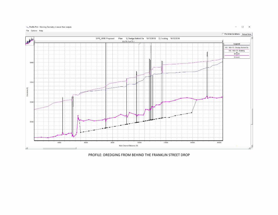
PROFILE: DREDGING FROM BEHIND THE FRANKLIN STREET DROP
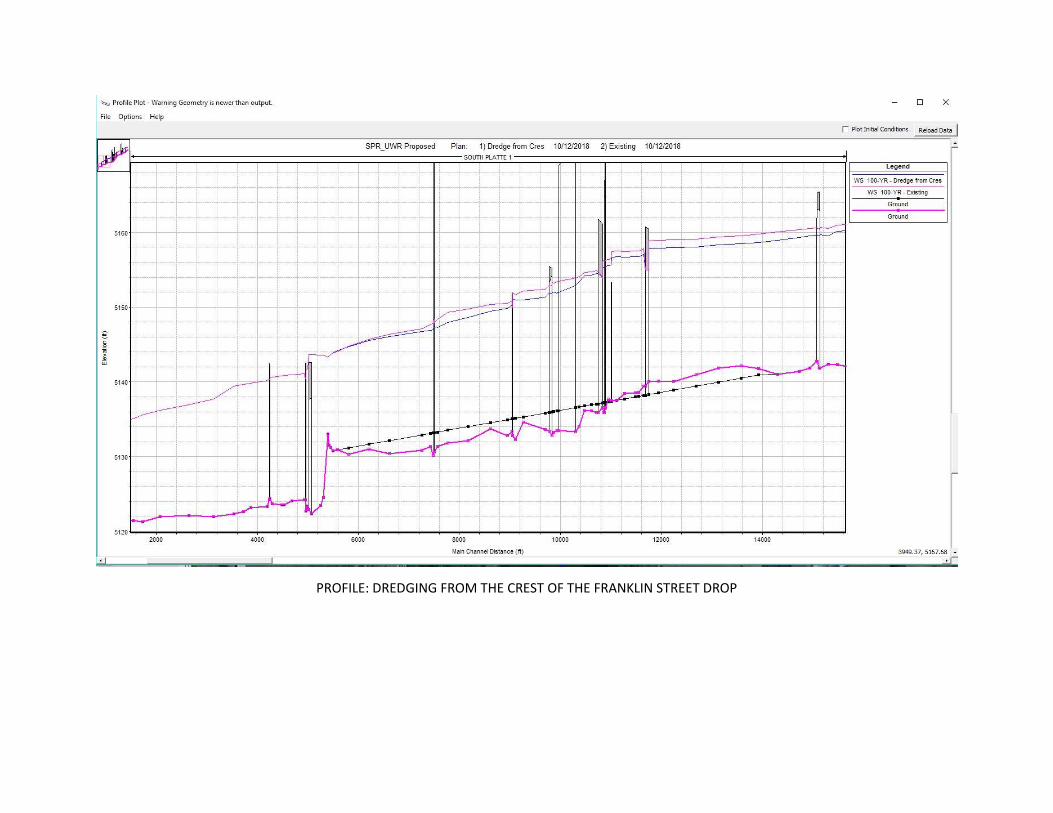
PROFILE: DREDGING FROM THE CREST OF THE FRANKLIN STREET DROP
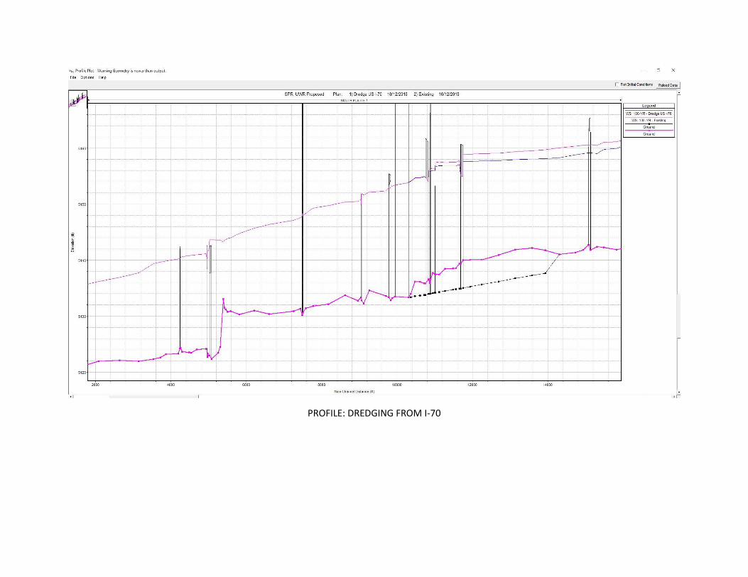
PROFILE: DREDGING FROM I-70
ATTACHMENT 3

Employee Owned
2480 W. 26th Street, Unit B225
Denver, Colorado 80211 Tel: +1 303-964-3333 [email protected]
www.merrick.com
MEMORANDUM October 22, 2018
TO: Project File
FROM: Robert C. Moore, P.E.
SUBJECT: South Platte River Bypass Pipe
Below is a summary of an analysis performed on diverting flow upstream of the 38TH Street Bridge:
Modeling of Diversion:
▪ At HEC-RAS Cross Section 460 (upstream of 38TH Street Bridge), a lateral weir was placed in
the model to divert flow from the river. Diverted flow reconnects to the river at Cross
Section 420, located downstream of the RR Bridge.
▪ Diverted flow is conveyed in a lateral ditch. Since HEC-RAS does not provide a means to
place a culvert through numerous cross sections, the lateral ditch is replacing the pipe
conveyance.
The following Table reflects flow rates diverted through the lateral weir along with resulting headwater
elevations at the 38TH Street Bridge.
Q DIVERTED
(cfs)
US WSE 38TH Bridge
(ft)
Weir Elev.
(ft)
Delta WSE
(ft)
0 5158.63 ---- 0.00
4411 5157.38 5152 -1.25
5095 5157.24 5151 -1.39
5668 5157.08 5150 -1.55
6252 5156.95 5149 -1.68
6758 5156.82 5148 -1.81
7331 5156.73 5147 -1.90
7830 5156.64 5146 -1.99
Preliminary analysis shows that a significant Q will be required to reduce headwater elevations above the 38TH
Street Bridge. To reduce headwater elevations at the 38TH Street Bridge, roughly 40% of the 100-year flow is

required to be diverted. However, headwater elevations in the above Table are still above the low chord
elevation of the 38Th Street Bridge. The low chord elevation of the 38Th Street Bridge is 5153.84 feet.
To convey this type of flow through a pipe would require 13 – 96-inch tunnel pipes, with each pipe able to convey
600 cfs. Assuming 800 feet of tunneling or 10,400 linear feet of required pipe, the cost ($4,100/foot of pipe
installed) is estimated to be $43 Million. Additional costs would be incurred to construct inlet and outlet
structures, walls, and property acquisition to accommodate construction of the pipes. Anticipated costs would
likely exceed $45 Million and would not eliminate the entire spill.
Hydraulic constraints limit the amount of water surface lowering that can be achieved, which does not eliminate
the spill. Assuming we could lower the water surface enough to reduce the spill, the cost, limited space for
placement of large conduits, potential for conflicts with existing utilities, and tunneling under the BNSF Railroad
tracks, make this option impractical.

This page was left blank intentionally

APPENDICES
GLOBEVILLE STORMWATER SYSTEMS STUDY
APPENDIX C: COMMUNITY RESOURCE GUIDE
APPENDICES
GLOBEVILLE STORMWATER SYSTEMS STUDY
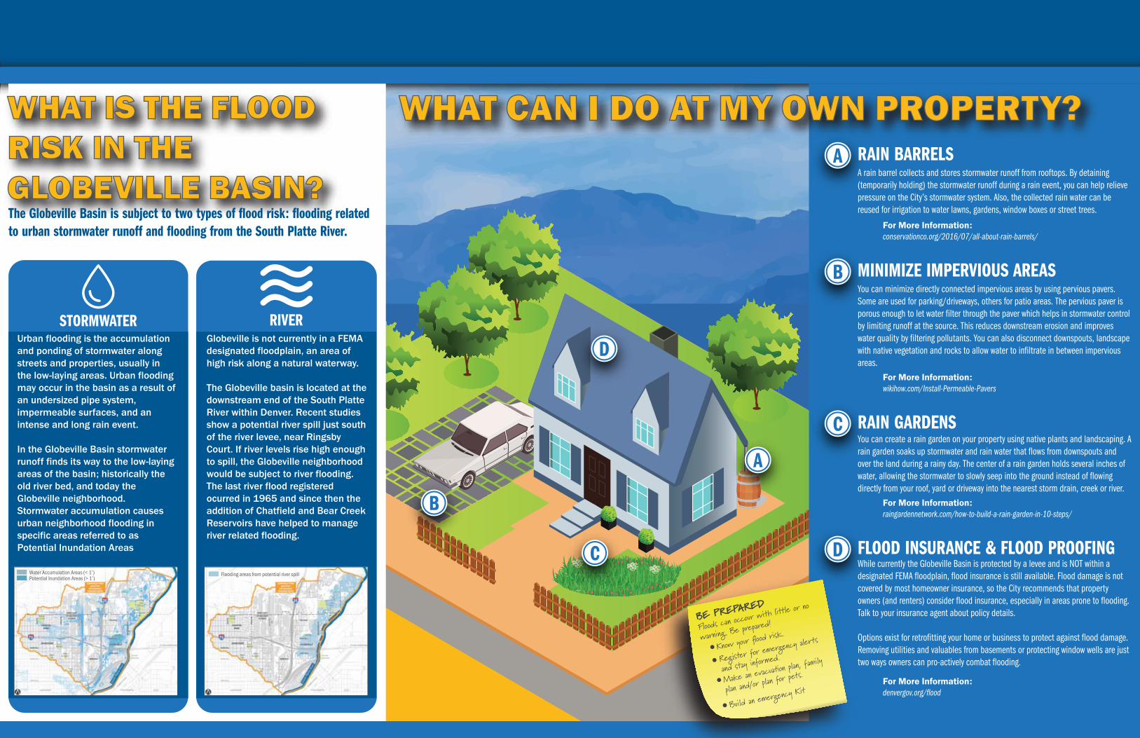
WHAT CAN I DO AT MY OWN PROPERTY?A rain barrel collects and stores stormwater runoff from rooftops. By detaining (temporarily holding) the stormwater runoff during a rain event, you can help relieve pressure on the City’s stormwater system. Also, the collected rain water can be reused for irrigation to water lawns, gardens, window boxes or street trees.
For More Information:conservationco.org/2016/07/all-about-rain-barrels/
RAIN BARRELSA
For More Information:raingardennetwork.com/how-to-build-a-rain-garden-in-10-steps/
You can create a rain garden on your property using native plants and landscaping. A rain garden soaks up stormwater and rain water that flows from downspouts and over the land during a rainy day. The center of a rain garden holds several inches of water, allowing the stormwater to slowly seep into the ground instead of flowing directly from your roof, yard or driveway into the nearest storm drain, creek or river.
RAIN GARDENSC
For More Information:wikihow.com/Install-Permeable-Pavers
You can minimize directly connected impervious areas by using pervious pavers. Some are used for parking/driveways, others for patio areas. The pervious paver is porous enough to let water filter through the paver which helps in stormwater control by limiting runoff at the source. This reduces downstream erosion and improves water quality by filtering pollutants. You can also disconnect downspouts, landscape with native vegetation and rocks to allow water to infiltrate in between impervious areas.
MINIMIZE IMPERVIOUS AREASB
For More Information:denvergov.org/flood
While currently the Globeville Basin is protected by a levee and is NOT within a designated FEMA floodplain, flood insurance is still available. Flood damage is not covered by most homeowner insurance, so the City recommends that property owners (and renters) consider flood insurance, especially in areas prone to flooding. Talk to your insurance agent about policy details.
Options exist for retrofitting your home or business to protect against flood damage. Removing utilities and valuables from basements or protecting window wells are just two ways owners can pro-actively combat flooding.
FLOOD INSURANCE & FLOOD PROOFINGD
A
B
C
D
WHAT IS THE FLOOD RISK IN THE GLOBEVILLE BASIN?
STORMWATER RIVERUrban flooding is the accumulation and ponding of stormwater along streets and properties, usually in the low-laying areas. Urban flooding may occur in the basin as a result of an undersized pipe system, impermeable surfaces, and an intense and long rain event.
In the Globeville Basin stormwater runoff finds its way to the low-laying areas of the basin; historically the old river bed, and today the Globeville neighborhood. Stormwater accumulation causes urban neighborhood flooding in specific areas referred to as Potential Inundation Areas
Water Accumulation Areas (< 1’)
Globeville is not currently in a FEMA designated floodplain, an area of high risk along a natural waterway.
The Globeville basin is located at the downstream end of the South Platte River within Denver. Recent studies show a potential river spill just south of the river levee, near Ringsby Court. If river levels rise high enough to spill, the Globeville neighborhood would be subject to river flooding. The last river flood registered ocurred in 1965 and since then the addition of Chatfield and Bear Creek Reservoirs have helped to manage river related flooding.
The Globeville Basin is subject to two types of flood risk: flooding related to urban stormwater runoff and flooding from the South Platte River.
Potential Inundation Areas (> 1’)Flooding areas from potential river spill
BE PREPARED
Floods can occour w
ith little or no
warning. Be prepared!
Build an emergency K
itMake an ev
acua�on plan, family
plan and/or plan for
pets.
Register for emergency a
lerts
and stay informed.
Know your �ood risk.
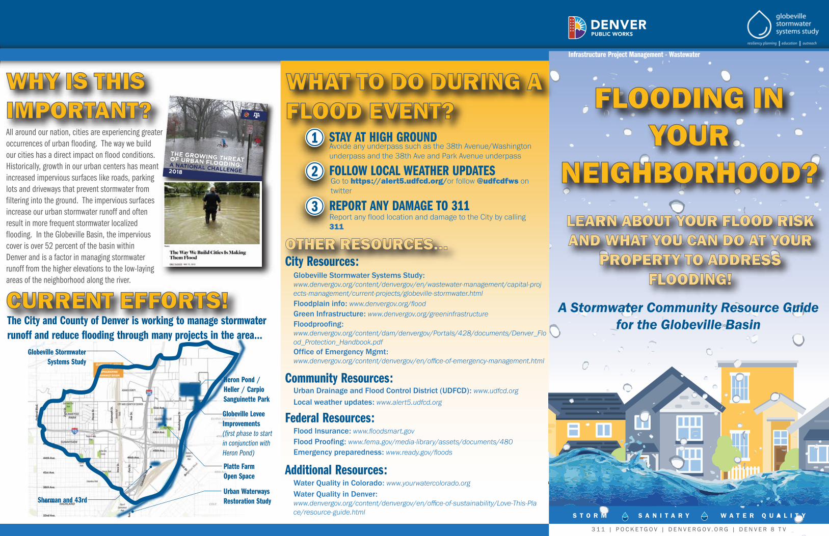
Infrastructure Project Management - Wastewater
Infrastructure Project Management - Wastewater
S T O R M S A N I T A R Y W A T E R Q U A L I T Y
3 1 1 | P O C K E T G O V | D E N V E R G O V . O R G | D E N V E R 8 T V
FLOODING IN YOUR
NEIGHBORHOOD?
WHY IS THIS IMPORTANT?
CURRENT EFFORTS!
WHAT TO DO DURING A FLOOD EVENT?
LEARN ABOUT YOUR FLOOD RISK AND WHAT YOU CAN DO AT YOUR
PROPERTY TO ADDRESS FLOODING!
A Stormwater Community Resource Guide for the Globeville Basin
All around our nation, cities are experiencing greater occurrences of urban flooding. The way we build our cities has a direct impact on flood conditions. Historically, growth in our urban centers has meant increased impervious surfaces like roads, parking lots and driveways that prevent stormwater from filtering into the ground. The impervious surfaces increase our urban stormwater runoff and often result in more frequent stormwater localized flooding. In the Globeville Basin, the impervious cover is over 52 percent of the basin within Denver and is a factor in managing stormwater runoff from the higher elevations to the low-laying areas of the neighborhood along the river.
Globeville Stormwater Systems Study
Sherman and 43rd
Avoide any underpass such as the 38th Avenue/Washington underpass and the 38th Ave and Park Avenue underpass
Globeville Stormwater Systems Study: www.denvergov.org/content/denvergov/en/wastewater-management/capital-projects-management/current-projects/globeville-stormwater.html
Urban Drainage and Flood Control District (UDFCD): www.udfcd.org
Local weather updates: www.alert5.udfcd.org
Floodplain info: www.denvergov.org/flood Green Infrastructure: www.denvergov.org/greeninfrastructureFloodproofing: www.denvergov.org/content/dam/denvergov/Portals/428/documents/Denver_Flood_Protection_Handbook.pdfOffice of Emergency Mgmt: www.denvergov.org/content/denvergov/en/office-of-emergency-management.html
Go to https://alert5.udfcd.org/or follow @udfcdfws on twitter
Report any flood location and damage to the City by calling 311
Platte Farm Open Space
Urban Waterways Restoration Study
Heron Pond / Heller / Carpio Sanguinette Park
STAY AT HIGH GROUND1
City Resources:
Community Resources:
Flood Insurance: www.floodsmart.govFlood Proofing: www.fema.gov/media-library/assets/documents/480Emergency preparedness: www.ready.gov/floods
Federal Resources:
Water Quality in Colorado: www.yourwatercolorado.orgWater Quality in Denver: www.denvergov.org/content/denvergov/en/office-of-sustainability/Love-This-Place/resource-guide.html
Additional Resources:
FOLLOW LOCAL WEATHER UPDATES2
REPORT ANY DAMAGE TO 3113
Globeville Levee Improvements (first phase to start in conjunction with Heron Pond)
OTHER RESOURCES...
The City and County of Denver is working to manage stormwater runoff and reduce flooding through many projects in the area...