
Apollo 15 Mission Report - Welcome to NASA Headquarters
286
i
-
Upload
khangminh22 -
Category
Documents
-
view
3 -
download
0
Transcript of Apollo 15 Mission Report - Welcome to NASA Headquarters
i
ii
iii
TABLE OF CONTENTS
1 MISSION SUMMARY_____________________________________________________ 1 2 INTRODUCTION ________________________________________________________ 5 3 TRAJECTORY___________________________________________________________ 6
3.1 LAUNCH AND TRANSLUNAR TRAJECTORIES ________________________________ 6
3.2 LUNAR ORBIT ______________________________________________________________ 6 3.2.1 Orbital Phase_____________________________________________________________________6 3.2.2 Descent ________________________________________________________________________11 3.2.3 Ascent and Rendezvous ___________________________________________________________12 3.2.4 Lunar Module Deorbit ____________________________________________________________13 3.2.5 Orbit-Shaping Maneuver and Subsatellite Launch _______________________________________13
3.3 TRANSEARTH AND ENTRY TRAJECTORY___________________________________ 13
4 LUNAR SURFACE SCIENCE _____________________________________________ 14 4.1 SUMMARY OF LUNAR SURFACE ACTIVITIES _______________________________ 14
4.2 APOLLO LUNAR SURFACE EXPERIMENTS PACKAGE CENTRAL STATION____ 19
4.3 PASSIVE SEISMIC EXPERIMENT____________________________________________ 21
4.4 LUNAR SURFACE MAGNETOMETER EXPERIMENT__________________________ 23
4.5 SOLAR WIND SPECTROMETER EXPERIMENT_______________________________ 24
4.6 HEAT FLOW EXPERIMENT_________________________________________________ 24
4.7 SUPRATHERMAL ION DETECTOR EXPERIMENT ____________________________ 25
4.8 COLD CATHODE GAGE EXPERIMENT ______________________________________ 26
4.9 LASER RANGING RETRO-REFLECTOR EXPERIMENT________________________ 26
4.10 SOLAR WIND COMPOSITION EXPERIMENT_______________________________ 27
4.11 LUNAR SURFACE DRILL OPERATION ____________________________________ 27
4.12 LUNAR GEOLOGY _______________________________________________________ 27 4.12.1 Landing Site ____________________________________________________________________27 4.12.2 Extravehicular Traverses __________________________________________________________28 4.12.3 Summary of Geology _____________________________________________________________30 4.12.4 Equipment______________________________________________________________________30 4.12.5 Photography ____________________________________________________________________31
4.13 SOIL MECHANICS EXPERIMENT _________________________________________ 31
5 INFLIGHT SCIENCE AND PHOTOGRAPHY _______________________________ 33 5.1 GAMMA-RAY SPECTROMETER EXPERIMENT_______________________________ 36
5.2 X-RAY FLUORESCENCE EXPERIMENT______________________________________ 36
5.3 ALPHA-PARTICLE SPECTROMETER EXPERIMENT __________________________ 37
5.4 MASS SPECTROMETER EXPERIMENT ______________________________________ 37
5.5 PARTICLE SHADOWS /BOUNDARY LAYER EXPERIMENT ____________________ 38
iv
5.6 SUBSATELLITE MAGNETOMETER EXPERIMENT ___________________________ 38
5.7 S-BAND TRANSPONDER EXPERIMENT ______________________________________ 39 5.7.1 Command and Service Module/Lunar Module__________________________________________39 5.7.2 Subsatellite _____________________________________________________________________39
5.8 DOWN-LINK BISTATIC RADAR OBSERVATIONS OF THE MOON ______________ 39
5.9 APOLLO WINDOW METEOROID EXPERIMENT______________________________ 40
5.10 ULTRAVIOLET PHOTOGRAPHY - EARTH AND MOON _____________________ 40
5.11 GEGENSCHEIN FROM LUNAR ORBIT _____________________________________ 41
5.12 SERVICE MODULE ORBITAL PHOTOGRAPHY ____________________________ 42 5.12.1 Panoramic Camera _______________________________________________________________42 5.12.2 Laser Altimeter __________________________________________________________________43
5.13 COMMAND MODULE PHOTOGRAPHY ____________________________________ 43
5.14 VISUAL OBSERVATIONS FROM LUNAR ORBIT ____________________________ 44
6 COMMAND AND SERVICE MODULE PERFORMANCE._____________________ 45 6.1 STRUCTURAL AND MECHANICAL SYSTEMS ________________________________ 45
6.2 ELECTRICAL POWER AND FUEL CELLS ____________________________________ 45
6.3 CRYOGENIC STORAGE ____________________________________________________ 45
6.4 COMMUNICATIONS _______________________________________________________ 46
6.5 INSTRUMENTATION _______________________________________________________ 46
6.6 GUIDANCE, NAVIGATION, AND CONTROL __________________________________ 46
6.7 PROPULSION ______________________________________________________________ 52 6.7.1 Reaction Control Systems__________________________________________________________52 6.7.2 Service Propulsion System _________________________________________________________52
6.8 ENVIRONMENTAL CONTROL AND CREW STATION _________________________ 53 6.8.1 Environmental Control System______________________________________________________53 6.8.2 Crew Station/Equipment___________________________________________________________55
6.9 CONTROLS AND DISPLAYS_________________________________________________ 55
6.10 EXTRAVEHICULAR ACTIVITY EQUIPMENT ______________________________ 56
6.11 CONSUMABLES _________________________________________________________ 56 6.11.1 Service Propulsion Propellant_______________________________________________________56 6.11.2 Reaction Control System Propellant__________________________________________________58 6.11.3 Cryogenics _____________________________________________________________________60 6.11.4 Water _________________________________________________________________________61
7 LUNAR MODULE PERFORMANCE _______________________________________ 62 7.1 STRUCTURAL AND MECHANICAL SYSTEMS ________________________________ 62
7.2 COMMUNICATIONS _______________________________________________________ 64
7.3 RADAR ____________________________________________________________________ 65
7.4 CONTROLS AND DISPLAYS_________________________________________________ 65
7.5 GUIDANCE, NAVIGATION, AND CONTROL __________________________________ 66
7.6 PROPULSION ______________________________________________________________ 73
v
7.6.1 Reaction Control System __________________________________________________________73 7.6.2 Descent Propulsion System ________________________________________________________73 7.6.3 Ascent Propulsion System _________________________________________________________73
7.7 ENVIRONMENTAL CONTROL SYSTEM______________________________________ 73
7.8 CONSUMABLES____________________________________________________________ 74 7.8.1 Descent Propulsion System Propellant. _______________________________________________74 7.8.2 Ascent Propulsion System Propellant_________________________________________________75 7.8.3 Reaction Control System Propellant__________________________________________________76 7.8.4 Oxygen ________________________________________________________________________77 7.8.5 Water _________________________________________________________________________78 7.8.6 Electrical Power _________________________________________________________________79
8 LUNAR SURFACE OPERATIONAL EQUIPMENT ___________________________ 79 8.1 EXTRAVEHICULAR MOBILITY UNIT _______________________________________ 79
8.2 LUNAR ROVING VEHICLE _________________________________________________ 83 8.2.1 Deployment_____________________________________________________________________84 8.2.2 Steering________________________________________________________________________85 8.2.3 Electrical Power _________________________________________________________________85 8.2.4 Navigation______________________________________________________________________85 8.2.5 Thermal________________________________________________________________________86 8.2.6 Crew Station ____________________________________________________________________86 8.2.7 EXTRAVEHICULAR COMMUNICATIONS EQUIPMENT _____________________________86
9 PILOT'S REPORT_______________________________________________________ 88 9.1 TRAINING_________________________________________________________________ 89
9.2 LAUNCH __________________________________________________________________ 89
9.3 EARTH ORBITAL OPERATIONS ____________________________________________ 89
9.4 TRANSLUNAR INJECTION__________________________________________________ 90
9.5 TRANSLUNAR FLIGHT OPERATIONS _______________________________________ 90 9.5.1 Transposition, Docking, and Extraction _______________________________________________90 9.5.2 Translunar Coast_________________________________________________________________91 9.5.3 Scientific Instrument Module Door Jettisoning _________________________________________92
9.6 LUNAR ORBIT OPERATIONS PRIOR TO DESCENT ___________________________ 92 9.6.1 Lunar Orbit Insertion _____________________________________________________________92 9.6.2 Lunar Module Activation, Undocking and Separation ____________________________________93
9.7 POWERED DESCENT AND LANDING ________________________________________ 93
9.8 LUNAR SURFACE OPERATIONS ____________________________________________ 95 9.8.1 Lunar Module Cabin Activity_______________________________________________________95 9.8.2 Lunar Geology __________________________________________________________________97 9.8.3 Lunar Surface Mobility Systems Performance _________________________________________100 9.8.4 Lunar Surface Science Equipment Performance________________________________________105
9.9 LUNAR ORBITAL SOLO OPERATIONS _____________________________________ 106 9.9.1 Maneuvers_____________________________________________________________________106 9.9.2 Science and Photography _________________________________________________________106
9.10 ASCENT, RENDEZVOUS AND DOCKING __________________________________ 108 9.10.1 Ascent ________________________________________________________________________108 9.10.2 Rendezvous____________________________________________________________________109 9.10.3 Docking and Crew Transfer _______________________________________________________110
vi
9.11 POST-DOCKING LUNAR ORBITAL OPERATIONS _________________________ 110 9.11.1 Lunar Module Jettison ___________________________________________________________110 9.11.2 Flight Plan Updating_____________________________________________________________111 9.11.3 Maneuvers_____________________________________________________________________111 9.11.4 Command and Service Module Housekeeping_________________________________________111
9.12 TRANSEARTH FLIGHT OPERATIONS ____________________________________ 112 9.12.1 Transearth Coast Extravehicular Activity_____________________________________________112 9.12.2 Science and Photography _________________________________________________________113 9.12.3 Navigation_____________________________________________________________________113
9.13 ENTRY AND LANDING __________________________________________________ 114
10 BIOMEDICAL EVALUATION ___________________________________________ 139 10.1 BIOMEDICAL INSTRUMENTATION AND PHYSIOLOGICAL DATA _________ 139
10.2 MEDICAL OBSERVATIONS ______________________________________________ 147 10.2.1 Adaptation to Weightlessness______________________________________________________147 10.2.2 Medications____________________________________________________________________148 10.2.3 Sleep _________________________________________________________________________148 10.2.4 Radiation______________________________________________________________________148 10.2.5 Visual Light Flash Phenomenon____________________________________________________149 10.2.6 Water ________________________________________________________________________149 10.2.7 Food _________________________________________________________________________150
10.3 PHYSICAL EXAMINATIONS _____________________________________________ 150
10.4 BONE MINERAL MEASUREMENT________________________________________ 151
10.5 APOLLO TIME AND MOTION STUDY ____________________________________ 152
11 MISSION SUPPORT PERFORMANCE ____________________________________ 153 11.1 FLIGHT CONTROL _____________________________________________________ 153
11.2 NETWORK _____________________________________________________________ 154
11.3 RECOVERY OPERATIONS_______________________________________________ 154 11.3.1 Command Module Location and Retrieval____________________________________________155 11.3.2 Postrecovery Inspection __________________________________________________________158
12 ASSESSMENT OF MISSION OBJECTIVES________________________________ 159 13 LAUNCH PHASE SUMMARY____________________________________________ 162
13.1 WEATHER CONDITIONS ________________________________________________ 162
13.2 ATMOSPHERIC ELECTRICITY __________________________________________ 162
13.3 LAUNCH VEHICLE PERFORMANCE _____________________________________ 163
14 ANOMALY SUMMARY _________________________________________________ 165 14.1 COMMAND AND SERVICE MODULES ____________________________________ 165
14.1.1 Service Module Reaction Control System Propellant Isolation Valves Closed ________________165 14.1.2 Water Panel Chlorine Injection Port Leakage__________________________________________167 14.1.3 Service Propulsion System Thrust Light On Entry Monitor System ________________________168 14.1.4 Integral Lighting Circuit Breaker Opened ____________________________________________171 14.1.5 Battery Relay Bus Measurement Anomaly____________________________________________172 14.1.6 Mass Spectrometer Boom Talkback Indicated Half-Barberpole On Retract __________________173 14.1.7 Potable Water Tank Failure To Refill________________________________________________177 14.1.8 Mission Timer Stopped___________________________________________________________179 14.1.9 Main Parachute Collapse _________________________________________________________180
vii
14.1.10 Data Recorder Tape Deterioration ________________________________________________183 14.1.11 Digital Event Timer Obscured ___________________________________________________185 14.1.12 Crew Restraint Harness Came Apart ______________________________________________187 14.1.13 Loose Object In Cabin Fans_____________________________________________________189 14.1.14 Scanning Telescope Visibility ___________________________________________________190 14.1.15 Gyro Display Coupler Roll Alignment ____________________________________________191 14.1.16 Unable To Open Circuit Breaker Supplying Main A Power To Battery Charger ____________193 14.1.17 Pivot Pin Failure On Main Oxygen Regulator Shutoff Valve ___________________________193 14.1.18 Crew Optical Alignment Sight Fell Off Stowage Mount_______________________________195
14.2 LUNAR MODULE _______________________________________________________ 196 14.2.1 Water/Glycol Pump Differential Pressure Fluctuations __________________________________196 14.2.2 Water Separator Speed Decrease ___________________________________________________198 14.2.3 Broken Water Gun/Bacteria Filter Quick Disconnect____________________________________199 14.2.4 Intermittent Steerable Antenna Operation ____________________________________________201 14.2.5 Descent Engine Control Assembly Circuit Breaker Open ________________________________204 14.2.6 Abort Guidance System Warning ___________________________________________________204 14.2.7 No Crosspointer Indication________________________________________________________206 14.2.8 Broken Range/Range Rate Meter Window____________________________________________208
14.3 SCIENTIFIC INSTRUMENT MODULE EXPERIMENTS______________________ 210 14.3.1 Panoramic Camera Velocity/Altitude Sensor Erratic ____________________________________210 14.3.2 Loss of Laser Altimeter Altitude Data _______________________________________________213 14.3.3 Slow Deployment Of Mapping Camera ______________________________________________215 14.3.4 Gamma Ray Spectrometer Calibration Shifts__________________________________________216
14.4 APOLLO LUNAR SURFACE EXPERIMENTS PACKAGE AND ASSOCIATED LUNAR SURFACE EQUIPMENT_________________________________________________ 217
14.4.1 Problems During The Lunar Surface Drilling Operations ________________________________217 14.4.2 Central Station Rear Curtain Retainer Removal Lanyard Broke ___________________________224 14.4.3 Intermittent Lock of Universal Handling Tool In Suprathermal Ion Detector Fitting ___________225
14.5 GOVERNMENT FURNISHED EQUIPMENT ________________________________ 226 14.5.1 Television Control Unit Clutch Slippage _____________________________________________226 14.5.2 Lunar Communications Relay Unit Downlink Signal Lost _______________________________227 14.5.3 Lunar Surface 16-mm Camera Magazines Jammed _____________________________________230 14.5.4 Lunar Module Pilot's 70-mm Camera Film Advance Stopped _____________________________231 14.5.5 Difficult to Obtain Water From Insuit Drinking Device__________________________________232 14.5.6 Lunar Module Pilot Oxygen Purge System Antenna Was Damaged ________________________232 14.5.7 Retractable Tether Failure ________________________________________________________233
14.6 LUNAR ROVING VEHICLE ______________________________________________ 235 14.6.1 Deployment Saddle Difficult To Release From Vehicle _________________________________235 14.6.2 Volt/Ammeter Inoperative ________________________________________________________236 14.6.3 Front steering System Inoperative __________________________________________________237 14.6.4 Lunar Roving Vehicle Seat Belt Problems ____________________________________________237
15 CONCLUSIONS _______________________________________________________ 238
1
1 MISSION SUMMARY Apollo 15 was the first in a series of missions designed to conduct exploration of the moon over longer periods, greater ranges, and with more instruments for scientific data acquisition than on previous missions. Major modifications and augmentations to the basic Apollo hardware were made, the most significant being installation of a scientific instrument module in one of the service module bays, modification of the lunar module to carry a greater scientific payload and permit a longer stay on the lunar surface, and the provision of a lunar roving vehicle. The landing site chosen for the mission was an area near the foot of the Apennine Mountains and adjacent to Hadley Rille. The mission accomplished all of its objectives and is providing the scientific community with a large amount of new information concerning the moon and its characteristics.
The space vehicle was launched from the Kennedy Space Center, Complex 39A at 9:34:00.6 a.m. e.d.t. (13:34:00.6 G.M.T.), on July 26, 1971. The spacecraft was manned by Colonel David R. Scott, Commander; Major Alfred J. Worden, Command Module Pilot; and Lt. Col. James B. Irwin, Lunar Module Pilot. The spacecraft /S-IVB combination was inserted into a nominal earth parking orbit approximately 1-1 minutes 44 seconds after lift-off. S-IVB restart for translunar injection was initiated during the second revolution at about 2 hours and 50 minutes. The maneuver placed the spacecraft/S-IVB combination on a translunar trajectory that would allow return to an acceptable earth-entry corridor using the reaction control system engines. Approximately 27 minutes after injection into the translunar trajectory, the command and service module was separated from the S-IVB and docked with the lunar module. The lunar module was extracted from the spacecraft/launch vehicle adapter. Shortly thereafter, the S- IVB tanks were vented and the auxiliary propulsion system was fired to target the S-IVB for a lunar impact. The first spacecraft midcourse correction was performed at about 28 hours 40 minutes with a velocity change of 5.3 ft/sec. One other small midcourse correction was performed during translunar flight.
The spacecraft was inserted into a lunar orbit of 170.1 by 57.7 miles at approximately 78 hours 32 minutes. About 1 hour later, the impact of the S-IVB stage was sensed by the Apollo 12 and 14 seismometers. The impact point was about 146 kilometers (79 miles) from the planned point and useful scientific data were obtained. The spacecraft was inserted into a 58.5-by-9.6 mile orbit at about 82 hours 40 minutes and a trim maneuver was performed later to adjust the perilune for powered descent. Undocking and separation occurred at about 100 hours 39 minutes and, approximately 1 hour later, the command and service module was placed in a near-circular orbit in preparation for the acquisition of scientific data.
The lunar module touched down on the lunar surface about 550 meters (1800 feet) from the planned target point at 104:42:29. The landing point was 26 degrees 6 minutes 4 seconds north latitude and 3 degrees 39 minutes 10 seconds east longitude (referenced to the Rima Hadley Lunar Photomap, Orbiter V site 26.1, First Edition, published by the U.S. Army Topographic Command, April 1970). A hover time capability of about 103 seconds remained after touchdown.
2
About 2 hours after landing, the Commander stood on the ascent engine cover with the upper part of his body extending through the upper hatch opening to photograph and describe the area surrounding the landing site. This extravehicular activity period lasted about 33 minutes. Approximately 12 1/2 hours later, the first lunar surface extravehicular activity commenced. Initially, the crew collected and stowed a contingency sample, deployed the lunar roving vehicle, unstowed the Apollo lunar surface experiments package and other equipment, and configured the lunar roving vehicle for lunar surface operations. Some problems were experienced in deploying and checking out the rover, but these were worked out and the crew drove the vehicle to Elbow Crater where they collected and documented samples, giving an enthusiastic and informative commentary on lunar features. Television control during various stops was provided by the Mission Control Center. After obtaining additional samples and photographs near St. George Crater, the crew returned to the lunar module using the lunar rover navigation system. The distance driven was about 10.3 kilometers (5.6 miles). The crew then proceeded to the selected Apollo lunar surface experiments package deployment site, approximately 110 meters (360 feet) west-northwest of the lunar module. They deployed the experiments essentially as planned except that the second heat flow experiment probe was not emplaced because drilling was more difficult than expected and the hole was not completed. The first extravehicular activity lasted about 6 hours and 33 minutes.
The crew spent about 16 hours in the cabin between the first and second extravehicular periods. Upon egress for the second extravehicular activity, the lunar rover was checked out and prepared for the second sortie. The first leg of the 12.5-kilometer (6.8-mile) round trip was south to the Apennine front, but east of the first traverse. Stops were made at Spur Crater and other points along the base of the front, as well as Dune Crater on the return trip. The return route closely followed the outbound route. Documented samples, a core sample, and a comprehensive sample were collected, and photographs were taken. After reaching the lunar module, the crew returned to the experiments package site where the Commander completed drilling the second hole for the heat flow experiment and emplaced the probe. During this period, the Lunar Module Pilot performed soil mechanics tasks. Drilling was again performed by the Commander to obtain a deep core sample, but the operation was terminated because of time constraints. The crew then returned to the lunar module and deployed the United States flag. The second extravehicular activity ended after about 7 hours 12 minutes.
The crew spent almost 14 hours in the cabin following the second extravehicular period. The third extravehicular activity began later than originally planned to allow additional time for crew rest. This and other delays at the experiments package site required deleting the planned trip to the North Complex. The first stop was at the experiments package site to retrieve the deep core sample. Two core sections were disengaged, but the drill and the remaining four sections could not be separated and were left for later retrieval. The third geological traverse was in a westerly direction and included stops at Scarp Crater, Rim Crater, and The Terrace, an area along the rim of Hadley Rille. Extensive samples were obtained as well as a double core tube and photographs of the west wall of Hadley Rille where exposed layering was observed. The return trip was east toward the lunar module with a stop at the experiments package site to retrieve the remaining sections of the deep core sample. One more section was separated and the
3
remaining three sections were returned in one piece. After returning to the lunar module, the lunar rover was unloaded and parked for ground-controlled television coverage of the lunar module ascent. The total distance traveled during the third extravehicular activity was about 5.1 kilometers (2.8 miles), and it lasted about 4 hours 50 minutes. The total distance traveled with the lunar roving vehicle during the three extravehicular periods was 27.9 kilometers (15.1 miles) and the total weight of lunar samples collected was about 170 pounds.
While the lunar module was on the surface, the Command Module Pilot completed 34 lunar orbits operating scientific instrument module experiments and cameras to obtain data concerning the lunar surface and the lunar environment. Some of the scientific tasks accomplished during this time were the photographing of the sunlit lunar surface; gathering data needed for mapping the bulk chemical composition of the lunar surface and determining the geometry of the moon along the ground track; visually surveying regions of the moon to assist in identification of processes which formed geologic features; obtaining lunar atmospheric data; and surveying gamma-ray and X-ray sources. Good-resolution panoramic and mapping camera photographs were obtained during the mission.
After 66 hours 54 minutes and 53 seconds on the lunar surface, the ascent stage lifted off at 171:37:23. A nominal lunar-module-active rendezvous was performed followed by docking at about 173 hours 36 minutes.
The lunar module was jettisoned one revolution later than planned because of some difficulty with verifying the tunnel sealing and suit integrity. Jettisoning occurred at about 179 hours 30 minutes and, about 1 1/2 hours later, the lunar module was deorbited with lunar impact occurring at 26 degrees 21 minutes north latitude and 0 degrees 15 minutes east longitude, about 23 1/2 kilometers (12.7 miles) from the planned impact point and about 93 kilometers (50 miles) west of the Apollo 15 landing site. The impact was recorded by the Apollo 12, 14, and 15 seismic stations.
Before leaving lunar orbit, a subsatellite was deployed in an orbit of approximately 76 by 55 miles, and all systems are operating as expected. The transearth injection maneuver was initiated at about 223 hours 49 minutes.
At about 242 hours, transearth coast extravehicular activity began. Television coverage was provided while the Command Module Pilot retrieved film cassettes and examined the scientific instrument module for abnormalities. This extravehicular activity lasted approximately 38 minutes. The-total extravehicular time during the mission was 19 hours and 47 minutes.
A small midcourse correction of 5.6 ft/sec was performed at the seventh midcourse correction opportunity. The command module was separated from the service module as planned and a nominal entry followed with the spacecraft being observed on the main parachutes. During the descent, one of the three main parachutes failed, but a safe landing was made at 295:11:53. The best estimate of the landing coordinates is 26 degrees 7 minutes 48 seconds north latitude and 158 degrees 8 minutes 24 seconds west longitude, about 1 mile from the planned landing point. The crew was brought onboard the recovery ship by helicopter about 39 minutes after landing. The Apollo 15

4
mission was successfully concluded with the placing of the command module onboard the recovery ship about 1 1/2 hours after landing.
5
2 INTRODUCTION The Apollo 15 mission was the fifteenth in the series using Apollo flight hardware and achieved the fourth manned lunar landing. The objectives of the mission were to investigate the lunar surface in a preselected area of the Hadley-Apennine region; emplace and activate surface experiments; evaluate the capability of the Apollo equipment to provide extended lunar surface stay time, increased extravehicular operations, and surface mobility; and conduct inflight experiments and photographic tasks from lunar orbit.
This report provides the National Aeronautics and Space Administration and other interested agencies with the results of the Apollo 15 mission. Some aspects of the mission such as preliminary scientific results and launch vehicle performance are reported in greater detail in other publications (references 1 and 2). This report contains:
A discussion of the performance of spacecraft systems and onboard equipment, including significant anomalies incurred and their resolution. (The results of anomaly investigations not completed by the time of publication will be reported individually.)
A description of the mission by the flight crew.
A summary of science operations.
A summary of the operational support provided by the flight control, manned space flight network, and recovery teams.
A biomedical evaluation.
A summary of launch conditions and launch vehicle performance.
An assessment of mission objectives satisfactorily accomplished.
In addition, in Appendixes A through D, the configuration of the spacecraft and the equipment aboard the spacecraft are identified, and information is presented concerning spacecraft manufacturing and checkout history, postflight testing, and data availability. A complete analysis of all applicable data is not possible within the time frame of the preparation of this report. Therefore, report supplements will be published as necessary. Appendix E lists the reports and gives their status, either published or in preparation.
Times, unless otherwise specified, are elapsed time from range zero, established as the integral second before lift-off. Range zero for this mission was 13:34:00 G.M.T., July 26, 1971. Customary units are used except in cases where metric units have a common usage, such as measurement of lunar surface distance. In these instances, both metric and customary units are given for convenience. All mileage distances are in nautical miles and all weights are referenced to earth gravity.
6
3 TRAJECTORY The general trajectory profile of this mission was similar to that of Apollo 14 except for a few refinements. The most significant difference was that the angle of descent to the lunar surface was increased from 14 degrees to 25 degrees. Tables 3-I and 3-II give the times of major flight events and definitions of the events; Tables 3-III and 3-IV contain trajectory parameter information; and Table 3-V is a summary of maneuver data.
3.1 LAUNCH AND TRANSLUNAR TRAJECTORIES
The launch trajectory is reported in reference 3. Because of earth parking orbit insertion dispersions, the S-IVB instrument unit received two navigation updates prior to translunar injection. Nominally, the translunar injection maneuver is targeted to a 79-mile pericynthion. The command and service module, a-long with the lunar module, lower this pericynthion to 68 miles as a result of their ejection and separation from the S-IVB. Although the translunar injection maneuver was targeted to a 79-mile pericynthion, one of 139 miles was achieved. Two midcourse correction maneuvers were performed in addition to the normal vehicle separation maneuvers to reach the desired 68-mile pericynthion.
After command and service module/lunar module ejection, the S-IVB performed an evasive maneuver. Then the S-IVB, using its auxiliary propulsion system, performed two maneuvers designed to impact it at the desired lunar location of 3 degrees 39 minutes south latitude and 7 degrees 35 minutes west longitude. Initial tracking after the two maneuvers indicated that impact would be within 37 kilometers (20 miles) of the target. However, because of an error in targeting due to tolerances in the tracking vector and unexpected vehicle thrusting, the impact occurred 146 kilo meters (79 miles) from the target at 1 degree 31 minutes south latitude and 11 degrees 49 minutes west longitude.
3.2 LUNAR ORBIT
3.2.1 Orbital Phase
The spacecraft was inserted into a 170.1-by-57.7-mile orbit around the moon using the service propulsion system. Approximately 4 hours later, the descent orbit insertion maneuver was performed, and the spacecraft was lowered to an orbit having a 58.5-mile apocynthion and a 9.6-mile pericynthion. This orbit gradually decayed, requiring a trim maneuver to adjust the orbit for powered descent initiation.

7
TABLE 3-I - SEQUENCE OF EVENTS

8
TABLE 3-II - DEFINITIONS OF EVENT TIMES

9
Missing Table
TABLE 3-III - TRAJECTORY PARAMETERS
10
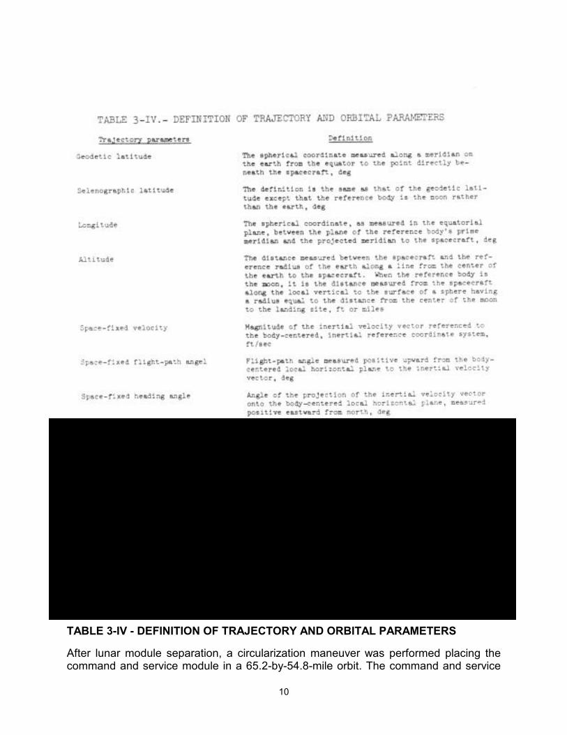
TABLE 3-IV - DEFINITION OF TRAJECTORY AND ORBITAL PARAMETERS
After lunar module separation, a circularization maneuver was performed placing the command and service module in a 65.2-by-54.8-mile orbit. The command and service

11
module remained in this orbit until about 6 hours prior to scheduled lunar module ascent when a 3-degree plane change maneuver was made so that the orbital plane of both vehicles would be coincident at the time of lift-off.
TABLE 3-V - MANEUVER SUMMARY
3.2.2 Descent
A landing site update of 853 meters (2800 feet) downrange was incorporated at about 2 minutes into the powered descent to correct for downrange error. No other updates were necessary. The crew made at least seven site redesignations for a total change of 338 meters (1110 feet) uprange and 409 meters (1341 feet) to the right. The landing point was about 550 meters (1800 feet) northwest of the premission target point. The coordinates of the landing site are 26 degrees 6 minutes 4 seconds north latitude and 3
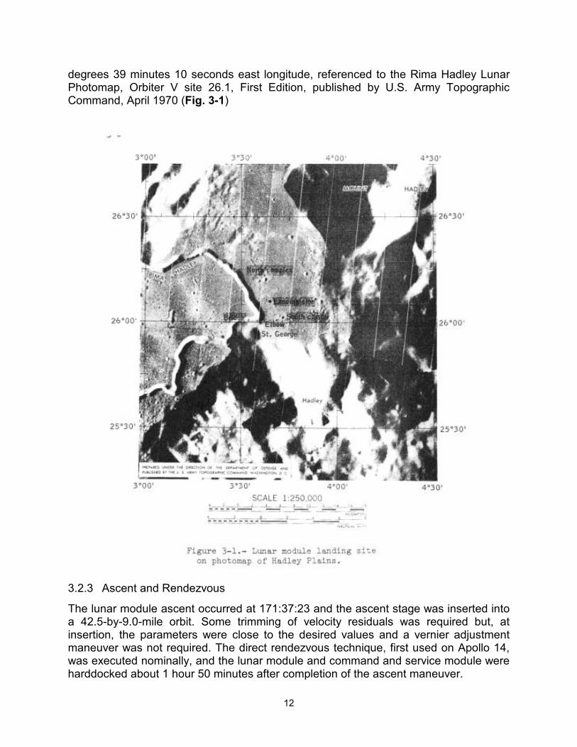
12
degrees 39 minutes 10 seconds east longitude, referenced to the Rima Hadley Lunar Photomap, Orbiter V site 26.1, First Edition, published by U.S. Army Topographic Command, April 1970 (Fig. 3-1)
3.2.3 Ascent and Rendezvous
The lunar module ascent occurred at 171:37:23 and the ascent stage was inserted into a 42.5-by-9.0-mile orbit. Some trimming of velocity residuals was required but, at insertion, the parameters were close to the desired values and a vernier adjustment maneuver was not required. The direct rendezvous technique, first used on Apollo 14, was executed nominally, and the lunar module and command and service module were harddocked about 1 hour 50 minutes after completion of the ascent maneuver.
13
3.2.4 Lunar Module Deorbit
Jettisoning of the lunar module ascent stage from the command and service module was delayed one revolution to permit reverifications of hatch and suit integrity. However, as a result of the delayed Jettisoning, the lunar module attitude for the maneuver was different than planned. With this change, the lunar module impacted the moon about 23.5 kilometers (12.7 miles) from the target. The coordinates of the impact point were 26 degrees 21 minutes north latitude and 0 degrees 15 minutes east longitude which is about 93 kilometers (50 miles) west of the Apollo 15 landing site.
The command and service module was to perform a 1-ft/sec retrograde separation maneuver after lunar module Jettisoning to minimize the possibility of recontact but, because of the Jettisoning delay, a 2-ft/sec posigrade maneuver was performed.
3.2.5 Orbit-Shaping Maneuver and Subsatellite Launch
In preparation for launching the subsatellite just prior to transearth injection, an orbit-shaping maneuver was performed during the 73rd lunar revolution using the service propulsion system to optimize the subsatellite orbit. The satellite was launched about an hour after the shaping maneuver into an orbit having an inclination of minus 28.7 degrees with an apocynthion of 76.3 miles and a pericynthion of 55.1 miles. The orbital lifetime is expected to be in excess of 1 year.
3.3 TRANSEARTH AND ENTRY TRAJECTORY
The transearth injection maneuver was performed at 223 hours 49 minutes. On the transearth flight, no midcourse corrections were made until about 3 hours prior to entry. A 5.6-ft/sec maneuver was performed using the service module reaction control system. The service module was separated from the command module 15 minutes prior to entry. Conditions for the entry of the spacecraft into the earth's atmosphere were nominal. The best estimate of the spacecraft landing point is 26 degrees 7 minutes 48 seconds north latitude and 158 degrees 8 minutes 24 seconds west longitude.
14
4 LUNAR SURFACE SCIENCE The following experiments associated with the Apollo lunar surface experiment package are discussed in this section: suprathermal ion detector, cold cathode gage, passive seismometer, lunar surface magnetometer, solar wind spectrometer, heat flow, and lunar dust detector. Other experiments and activities discussed consist of a laser ranging retro-reflector experiment, a solar wind composition experiment, lunar geology, soil mechanics, and lunar gravity measurement. Additionally, the operation of the lunar drill, used in conjunction with the heat flow experiment and to obtain a deep core sample, is described. A comprehensive discussion of the preliminary scientific results of this mission are contained in reference 2. References to descriptions of the experiment equipment are contained in Appendix A.
4.1 SUMMARY OF LUNAR SURFACE ACTIVITIES
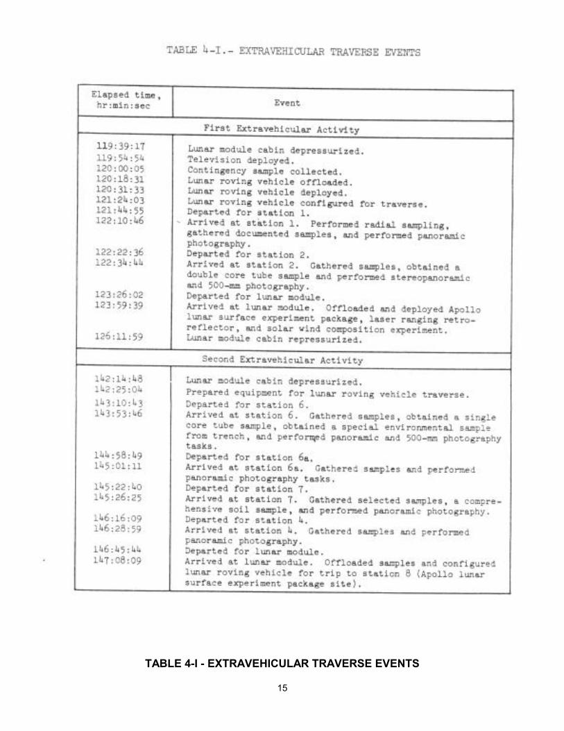
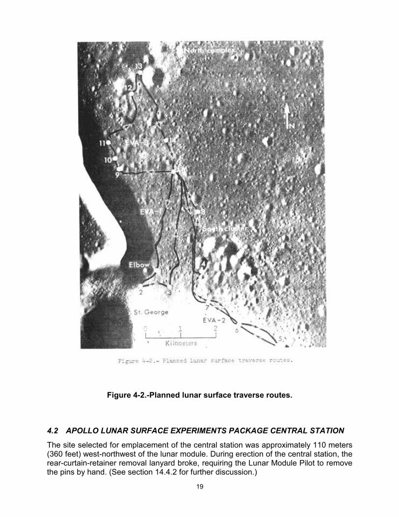
Because of the variety of surface features, the Haaley-Apennine landing site permitted extensive diversified geologic exploration and sampling. During the approximately 67 hours on the surface, the crew conducted a 33- minute standup extravehicular activity as well as three extravehicular activities for experiment operations and lunar roving vehicle traverses. The timelines for the three extravehicular activity periods are contained in Table 4-1. The actual and planned traverse routes are shown in figures 4.1 and 4-2, which are actual photographs of the lunar surface taken with the panoramic camera.
15
TABLE 4-I - EXTRAVEHICULAR TRAVERSE EVENTS
16
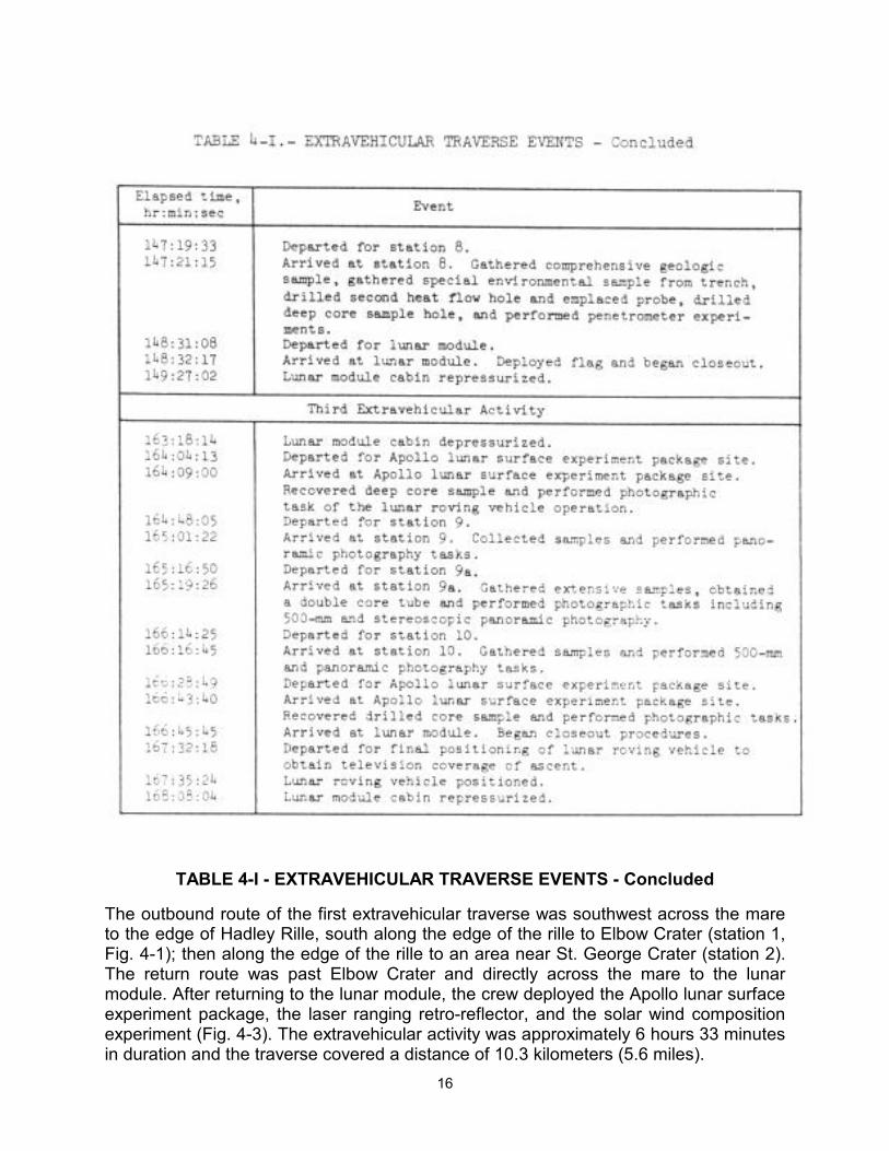
TABLE 4-I - EXTRAVEHICULAR TRAVERSE EVENTS - Concluded
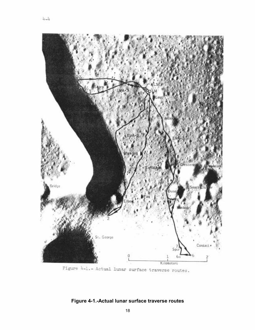
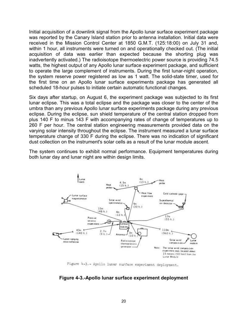
The outbound route of the first extravehicular traverse was southwest across the mare to the edge of Hadley Rille, south along the edge of the rille to Elbow Crater (station 1, Fig. 4-1); then along the edge of the rille to an area near St. George Crater (station 2). The return route was past Elbow Crater and directly across the mare to the lunar module. After returning to the lunar module, the crew deployed the Apollo lunar surface experiment package, the laser ranging retro-reflector, and the solar wind composition experiment (Fig. 4-3). The extravehicular activity was approximately 6 hours 33 minutes in duration and the traverse covered a distance of 10.3 kilometers (5.6 miles).
17
The second extravehicular activity was southeast across the mare to the Apennine front (stations 6 and 6a) northwest to Spur Crater (station 7) and north to the area of Dune Crater (station 4). The return was north across the mare to the Apollo lunar surface experiment package site (station 8) and then to the lunar module. The duration of the second extravehicular activity was approximately 7 hours 12 minutes, and the distance traveled was 12.5 kilometers (6.8 miles).
The third extravehicular activity included a 5.1-kilometer (2.8-mile) traverse. The outbound trip was west to Scarp Crater (stations 9 and 9a) and northwest along the edge of the rille (station 10). The return was east across the mare to the lunar module. The duration of the third extravehicular activity was approximately 4 hours and 50 minutes.
18
Figure 4-1.-Actual lunar surface traverse routes
19
Figure 4-2.-Planned lunar surface traverse routes.
4.2 APOLLO LUNAR SURFACE EXPERIMENTS PACKAGE CENTRAL STATION
The site selected for emplacement of the central station was approximately 110 meters (360 feet) west-northwest of the lunar module. During erection of the central station, the rear-curtain-retainer removal lanyard broke, requiring the Lunar Module Pilot to remove the pins by hand. (See section 14.4.2 for further discussion.)
20
Initial acquisition of a downlink signal from the Apollo lunar surface experiment package was reported by the Canary Island station prior to antenna installation. Initial data were received in the Mission Control Center at 1850 G.M.T. (125:18:00) on July 31 and, within 1 hour, all instruments were turned on and operationally checked out. (The initial acquisition of data was earlier than expected because the shorting plug was inadvertently activated.) The radioisotope thermoelectric power source is providing 74.5 watts, the highest output of any Apollo lunar surface experiment package, and sufficient to operate the large complement of instruments. During the first lunar-night operation, the system reserve power registered as low as 1 watt. The solid-state timer, used for the first time on an Apollo lunar surface experiments package has generated all scheduled 18-hour pulses to initiate certain automatic functional changes.
Six days after startup, on August 6, the experiment package was subjected to its first lunar eclipse. This was a total eclipse and the package was closer to the center of the umbra than any previous Apollo lunar surface experiments package during any previous eclipse. During the eclipse, sun shield temperature of the central station dropped from plus 140 F to minus 143 F with accompanying rates of change of temperatures up to 260 F per hour. The central station engineering measurements provided data on the varying solar intensity throughout the eclipse. The instrument measured a lunar surface temperature change of 330 F during the eclipse. There was no indication of significant dust collection on the instrument's solar cells as a result of the lunar module ascent.
The system continues to exhibit normal performance. Equipment temperatures during both lunar day and lunar night are within design limits.
Figure 4-3.-Apollo lunar surface experiment deployment
21
4.3 PASSIVE SEISMIC EXPERIMENT
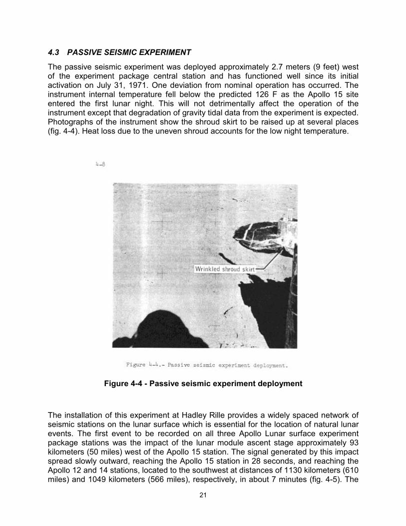
The passive seismic experiment was deployed approximately 2.7 meters (9 feet) west of the experiment package central station and has functioned well since its initial activation on July 31, 1971. One deviation from nominal operation has occurred. The instrument internal temperature fell below the predicted 126 F as the Apollo 15 site entered the first lunar night. This will not detrimentally affect the operation of the instrument except that degradation of gravity tidal data from the experiment is expected. Photographs of the instrument show the shroud skirt to be raised up at several places (fig. 4-4). Heat loss due to the uneven shroud accounts for the low night temperature.
Figure 4-4 - Passive seismic experiment deployment
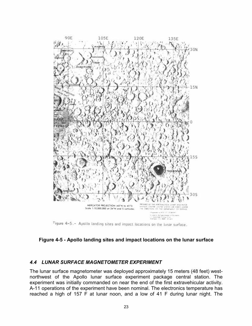
The installation of this experiment at Hadley Rille provides a widely spaced network of seismic stations on the lunar surface which is essential for the location of natural lunar events. The first event to be recorded on all three Apollo Lunar surface experiment package stations was the impact of the lunar module ascent stage approximately 93 kilometers (50 miles) west of the Apollo 15 station. The signal generated by this impact spread slowly outward, reaching the Apollo 15 station in 28 seconds, and reaching the Apollo 12 and 14 stations, located to the southwest at distances of 1130 kilometers (610 miles) and 1049 kilometers (566 miles), respectively, in about 7 minutes (fig. 4-5). The
22
fact that this small source of energy was detected at such great range strongly supports the hypothesis that meteoroid impacts are being detected from the entire lunar surface.
Two moonquakes were detected at all three stations during the moon's travel through its first perigee following activation of the Apollo 15 station. Preliminary analysis places the focus of one of these moonquakes 400 kilometers (216 miles) southwest of the Apollo 15 station. It is believed that the second moonquake was 1000 kilometers (540 miles) southwest of the Apollo 12 and 14 stations and was 800 kilometers (432 miles) deep.
The S-IVB impact extended the depth to which lunar structure can be determined by seismic methods to nearly 100 kilometers (54 miles). From this and previous data from impacts of spent vehicles, it now appears that a change in composition occurs at a depth of 25 kilometers (13.5 miles) beneath the surface. This implies that the lunar crust is equivalent to the crust of the earth, and about the same thickness.
Two meteoroid impacts were recorded at the Apollo 15 station during the first 2 weeks of its operation. One of these impacts was recorded at all three stations and was located by triangulation. Fourteen impact events were recorded by the Apollo 12 and 14 stations during this period. Signals were also recorded that were caused by events and activities associated with lunar surface operations, particularly the movements of the lunar roving vehicle and the ascent from the lunar surface. The lunar roving vehicle was detected at ranges up to 5 kilometers (2-7 miles) with an accuracy within approximately 0.5 kilometer (0.27 mile). As in previous missions, numerous signals were also recorded from venting of gases and thermal "popping" within the lunar module.
23
Figure 4-5 - Apollo landing sites and impact locations on the lunar surface
4.4 LUNAR SURFACE MAGNETOMETER EXPERIMENT
The lunar surface magnetometer was deployed approximately 15 meters (48 feet) west-northwest of the Apollo lunar surface experiment package central station. The experiment was initially commanded on near the end of the first extravehicular activity. A-11 operations of the experiment have been nominal. The electronics temperature has reached a high of 157 F at lunar noon, and a low of 41 F during lunar night. The
24
instrument is routinely commanded into a calibration mode every 18 hours by the central station timer. The one-time site survey was successfully-completed on August 6. The remanent magnetic field at the site is lower than that measured at the Apollo 12 and 14 sites. The eddy current produced by the interaction of the solar wind with the lunar surface has been measured.
4.5 SOLAR WIND SPECTROMETER EXPERIMENT
The solar wind spectrometer was deployed 4 meters (13 feet) north of the Apollo lunar surface experiment package central station and was activated near the end of the first extravehicular activity. The instrument recorded engineering and background data for approximately 2 earth days before the seven dust covers were removed.
The instrument recorded normal magnetospheric plasma data until the instrument passed into the geomagnetic tail of the earth. As expected, the plasma level in the geomagnetic tail was below the measurement threshold of the instrument (and essentially no solar wind plasma was detected) Upon emerging from the geomagnetic tail, the instrument was switched to the extended-range mode with no operational problems. The instrument will be left in this mode for correlation of data with the Apollo 12 solar wind spectrometer which is also operating in the same mode. A comparison of samples of simultaneous data from the two instruments has already demonstrated differences in the electron and proton components of the solar wind plasma that strikes the surface of the moon at the two stations. The solar plasma levels during the lunar night, as expected, were below the measurement threshold of the instrument.
4.6 HEAT FLOW EXPERIMENT
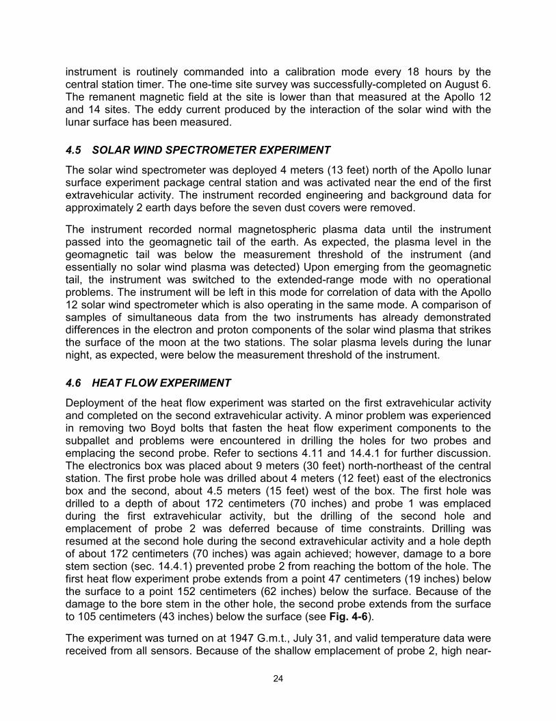
Deployment of the heat flow experiment was started on the first extravehicular activity and completed on the second extravehicular activity. A minor problem was experienced in removing two Boyd bolts that fasten the heat flow experiment components to the subpallet and problems were encountered in drilling the holes for two probes and emplacing the second probe. Refer to sections 4.11 and 14.4.1 for further discussion. The electronics box was placed about 9 meters (30 feet) north-northeast of the central station. The first probe hole was drilled about 4 meters (12 feet) east of the electronics box and the second, about 4.5 meters (15 feet) west of the box. The first hole was drilled to a depth of about 172 centimeters (70 inches) and probe 1 was emplaced during the first extravehicular activity, but the drilling of the second hole and emplacement of probe 2 was deferred because of time constraints. Drilling was resumed at the second hole during the second extravehicular activity and a hole depth of about 172 centimeters (70 inches) was again achieved; however, damage to a bore stem section (sec. 14.4.1) prevented probe 2 from reaching the bottom of the hole. The first heat flow experiment probe extends from a point 47 centimeters (19 inches) below the surface to a point 152 centimeters (62 inches) below the surface. Because of the damage to the bore stem in the other hole, the second probe extends from the surface to 105 centimeters (43 inches) below the surface (see Fig. 4-6).
The experiment was turned on at 1947 G.m.t., July 31, and valid temperature data were received from all sensors. Because of the shallow emplacement of probe 2, high near-
25
surface temperature gradients will keep the differential thermometers on the upper section off-scale during most of a lunar day-night cycle. The lower section of probe 2 and both the upper and lower sections of probe 1 are returning valid data on subsurface temperatures. Sensors on these sections that are shallower than 80 centimeters (32 inches) are seeing the effects of the diurnal cycle of surface temperature, but these variations are well within the range of measurement. Lunar surface temperatures are being obtained from five of the eight thermocouples in the probe cables that are just above or on the lunar surface because of the shallow emplacement.
Data for the reference thermometer sampled with the probe 2 thermocouple measurement went off-scale high at 1027 G.m.t - , August 7; however, the data from this reference thermometer is also sampled with the probe 1 thermocouple measurement, and is valid. Therefore, no data have been lost.
4.7 SUPRATHERMAL ION DETECTOR EXPERIMENT
The suprathermal ion detector experiment was deployed and aligned approximately 17 meters (55 feet) east-northeast of the Apollo lunar surface experiment package central station. Some difficulty was encountered during deployment when the universal handling tool did not properly interface with the experiment receptacle and, as a result, the instrument was dropped. The instrument was initially turned on near the end of the first extravehicular activity and operated normally, returning good scientific data. After about 30 minutes of operation the instrument was commanded to "standby" to allow outgassing. The dust cover was removed by ground command prior to the second extravehicular activity. Subsequently, the instrument was commanded on for five periods of approximately 30 minutes each to observe the effects of: (1) depressurization for the second extravehicular activity, (2) depressurization for the third extravehicular
26
activity, (3) depressurization for equipment jettisoning, (4) ascent, and (5) lunar module ascent stage impact. During some of this time simultaneous observations of intense magnetosheath ion fluxes were made by all three suprathermal ion detector instruments now on the moon. The high voltage was commanded off prior to the hotter part of the first lunar day to allow further outgassing and was commanded back on shortly before lunar sunset.
4.8 COLD CATHODE GAGE EXPERIMENT
The cold cathode gage experiment was deployed about 0.3 meter (1 foot) northeast of the suprathermal ion detector experiment. The instrument was turned on and the seal was commanded open 3 minutes prior to the end of the first extravehicular activity. Upon initial turn-on, the gage indicated full- scale, and during the first half hour, the output became slightly less than full-scale. Subsequently, the high voltage was commanded off to allow outgassing.
The experiment was operated five more times simultaneously with the suprathermal ion detector experiment for periods of approximately 30 minutes each. The purpose of the operations was to observe the effects of the lunar module depressurizations for the second and third extravehicular activities and equipment jettison, the effects of the lunar module ascent from the lunar surface, and lunar module ascent stage impact. In each of the three depressurizations, the output of the experiment was driven to full-scale for approximately 30 seconds. The response to the lunar module depressurizations was very similar to that obtained during the Apollo 14 mission. The lunar module ascent resulted in the longest full-scale output (approximately 85 seconds). The exhaust from the lunar module ascent was detected for approximately 17 minutes.
The high voltage was turned off until just prior to the first lunar sunset to permit additional instrument outgassing. As the instrument and the lunar surface cooled during lunar night, the output of the gage gradually decreased to 10E-12 torr. This value is very near that observed on the Apollo 14 gage during lunar night. Two gas clouds of unknown origin were observed at the Apollo 15 site at 0400 and 1930 G.m.t. on August 15; these may be associated with Apollo 15 hardware left on the lunar surface.
4.9 LASER RANGING RETRO-REFLECTOR EXPERIMENT
The laser ranging retro-reflector was deployed during the first extravehicular activity approximately 43 meters (140 feet) west-southwest of the Apollo lunar surface experiment package central station. Leveling and alignment were accomplished with no difficulty. The McDonald Observatory team initially acquired a return signal from the Apollo 15 instrument August 3, 1971, when atmospheric conditions first permitted ranging. Based on successful acquisition on every attempt, and the receipt of four to five consecutive returns during a number of operations, the return signal strength appears higher than returns from the Apollo 11 and 14 retroreflectors (fig. 4-5). No degradation of the retro-reflector appears to have resulted from lunar module ascent engine firing.
27
4.10 SOLAR WIND COMPOSITION EXPERIMENT
The solar wind composition experiment, a specially prepared aluminum foil designed to entrap noble gas particles, was deployed at the end of the first extravehicular period and retrieved near the end of the third extravehicular period. The experiment was deployed approximately 15 meters (50 feet) southwest of the lunar module for a total foil exposure time of 41 hours and 8 minutes. Upon retrieval, the foil could not readily be rolled up mechanically and had to be rolled manually. This problem has been experienced on previous missions but does not affect the experiment. The returned hardware showed that the edge of the foil had rolled onto the reel- handle, which caused enough friction to stop the mechanical wind-up. Good data on the abundance of the isotopes of helium and neon in the solar wind have already been obtained.
4.11 LUNAR SURFACE DRILL OPERATION
The lunar surface drill, used for the first time on the lunar surface, provided a means for one crewman to emplace the heat flow experiment probes below the lunar surface and collect a subsurface core. For the heat flow experiment, the bore stems used in drilling remained in position in the lunar soil and functioned as an encasement to preclude cave-in of unconsolidated material. The subsurface core was obtained by drilling six core stems into the lunar soil. The stems were then removed and capped for return to earth.
The performance of the drill power-head and the core stem was good. However, full depth penetration with the bore stems was a problem and extraction of the core stems from the hole was difficult (see sec. 14.4.1). The two bore stem holes were drilled to a depth of about 172 centimeters (70 inches) instead of the desired 294 centimeters (120 inches), with one of the bore stem strings probably sustaining damage at a point slightly above the first joint [about 105 centimeters (43 inches) below the surface] (see fig. 4-6).
4.12 LUNAR GEOLOGY
4.12.1 Landing Site
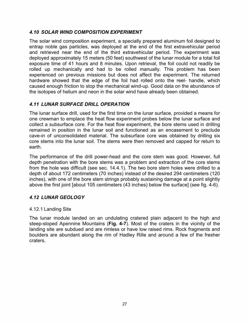
The lunar module landed on an undulating cratered plain adjacent to the high and steep-sloped Apennine Mountains (Fig. 4-7). Most of the craters in the vicinity of the landing site are subdued and are rimless or have low raised rims. Rock fragments and boulders are abundant along the rim of Hadley Rille and around a few of the fresher craters.
28
4.12.2 Extravehicular Traverses
Areas visited during the extravehicular activities that are defined on photogeologic maps were the mare surface of Palus Putredinis; the Apennine Mountain Front; Hadley Rille; and a cluster of secondary craters.
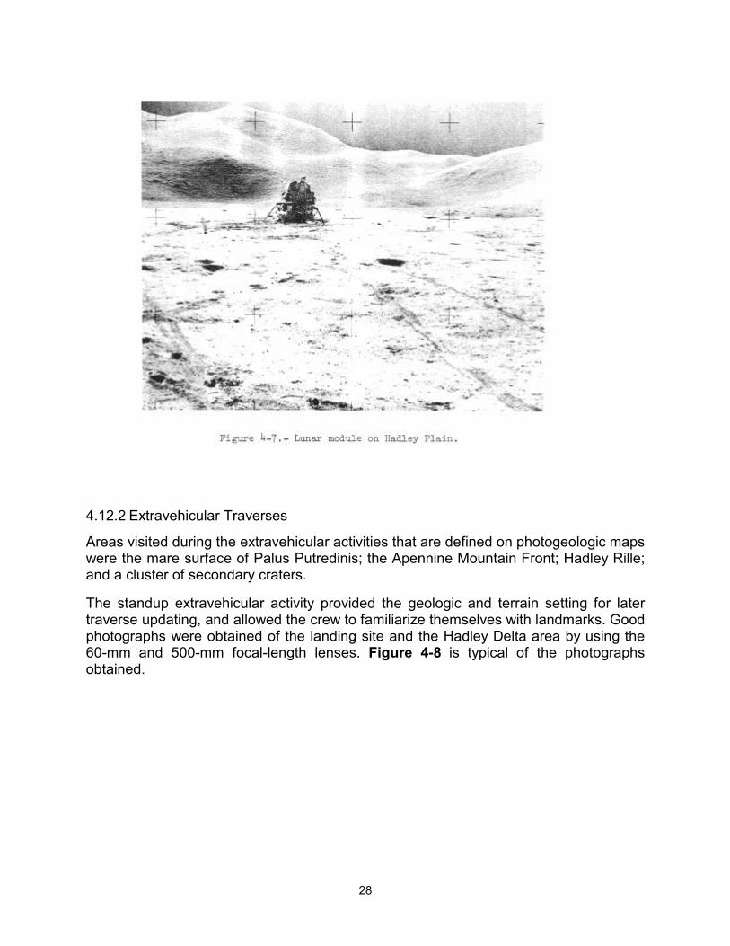
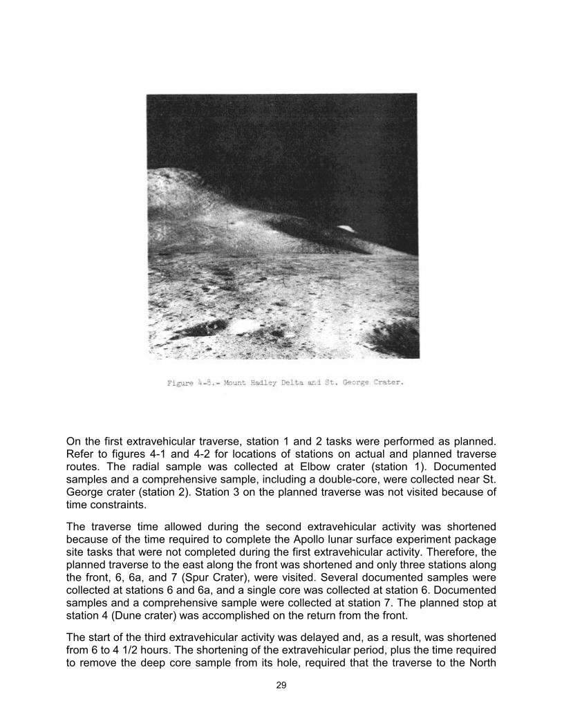
The standup extravehicular activity provided the geologic and terrain setting for later traverse updating, and allowed the crew to familiarize themselves with landmarks. Good photographs were obtained of the landing site and the Hadley Delta area by using the 60-mm and 500-mm focal-length lenses. Figure 4-8 is typical of the photographs obtained.
29
On the first extravehicular traverse, station 1 and 2 tasks were performed as planned. Refer to figures 4-1 and 4-2 for locations of stations on actual and planned traverse routes. The radial sample was collected at Elbow crater (station 1). Documented samples and a comprehensive sample, including a double-core, were collected near St. George crater (station 2). Station 3 on the planned traverse was not visited because of time constraints.
The traverse time allowed during the second extravehicular activity was shortened because of the time required to complete the Apollo lunar surface experiment package site tasks that were not completed during the first extravehicular activity. Therefore, the planned traverse to the east along the front was shortened and only three stations along the front, 6, 6a, and 7 (Spur Crater), were visited. Several documented samples were collected at stations 6 and 6a, and a single core was collected at station 6. Documented samples and a comprehensive sample were collected at station 7. The planned stop at station 4 (Dune crater) was accomplished on the return from the front.
The start of the third extravehicular activity was delayed and, as a result, was shortened from 6 to 4 1/2 hours. The shortening of the extravehicular period, plus the time required to remove the deep core sample from its hole, required that the traverse to the North
30
Complex and mare station 14 be omitted. However, the premission-planned traverse to stations 9 and 10 at Hadley Rille was made. A sample was collected from the upper portion of a bedrock ledge exposed near station 9a. Documented samples were collected at stations 9 and 9a, and a rake sample and a double core were collected at station 9a.
4.12.3 Summary of Geology
Samples were collected that appear to be representative of the Apennine Front, the mare in the vicinity of the landing site, bedrock from the rim of Hadley Rille, and a possible ray associated with Aristillus or Autolycus. Some breccias were collected that appear similar to those collected on Apollo 14; others appear to be indurated regolith. Abundant glass, found as coatings on the rock surfaces and in fractures, is associated with the breccias. Also collected were basaltic rocks ranging from vesicular and scoriaceous to dense with phenocrysts greater than a centimeter long.
Layered bedrock ledges are exposed in the upper parts of Hadley Rille. These are probably a cross-section of mare flows and possibly bedded pyroclastic materials. At least some of the samples from station 9a (Fig. 4-1) are probably representative of the upper part of the mare stratigraphic sequence.
Planar structures in the Apennine Front occur in different orientations from one mountain to the next, which suggests rotation of large blocks along the faults that are shown on the premission maps. The faults and associated rotation were probably caused by the impact event that produced the Imbrium Basin.
4.12.4 Equipment
The equipment used during the geology portion of the extravehicular activities performed well with the following exceptions:
Excessive time was required for the gnomon to damp.
Sample return container 2 did not seal properly because part of a collection bag was caught in the seal area between the knife edge and the indium seal.
The Lunar Module Pilot's camera did not advance film properly near the end of the second extravehicular activity. The camera failed again during the third extravehicular activity after six pictures had been taken. (See section 14-5.4 for further discussion.)
Problems with the drilling were experienced as described in section 14.4.1.
The polarizing filter for the Hasselblad electric data camera could not be installed because of excessive dust in the bayonet fitting.
Both retractable tethers (Yo-yo's) failed (sec. 14.5.7).
The tongs were difficult to operate during the third extravehicular activity; however, a backup pair was supplied for such a contingency and these operated satisfactorily.
31
4.12.5 Photography
A total of 1152 photographs was taken on the lunar surface with the 60- mm and 500-mm focal-length cameras. At least one 360-degree 60-mm panorama was taken at every station except stations 3 and 4. Apollo 15 was the first mission using the 500-mm focal length lens mounted on the 70-mm Hasselblad electric data camera hand-held by a crewman. Good photography was obtained of distant photographic targets such as the Apennine Front and across and inside Hadley Rille.
4.13 SOIL MECHANICS EXPERIMENT
The soil mechanics experiment provided data on the physical characteristics and Mechanical properties of the lunar surface and subsurface soil. Activities during Apollo 15 unique to the soil mechanics experiment were performed during a compressed timeline at station 8 (Fig. 4-1) near the end of the second extravehicular activity with only one crewmember available to do the work instead of two as scheduled. The Lunar Module Pilot excavated the soil mechanics trench, exposing a Vertical face to an estimated depth of a little more than 1 foot without apparent difficulty. The vertical face exposed a fine-grained, cohesive, gray material with small white fragments and larger fragments of glass. Stratification was not observed. Digging of the trench was followed by six of seven planned measurements using the self- recording penetrometer. These tests consisted of four cone penetration resistance tests and two plate load tests. No time was available for the detailed planned photographic documentation of these activities, nor was the television camera on the lunar roving vehicle in a suitable position to provide a high degree of detail.
Data from the penetrometer tests were intended to provide quantitative information on the physical properties of the lunar soil to depths up to 74 centimeters (30 inches). The data, now under study, will probably not provide the quantitative detail on physical properties originally anticipated because of the following reasons: (1) The soil structure at the site had greater penetration resistance than had been anticipated (2) A particularly resistant layer was encountered at a depth of only a few centimeters; (3) The lunar surface plate on the penetrometer failed to stay in the proper position during four of the tests because the friction between the reference plate bushing and the shaft was less than had been anticipated.
The average depth of lunar roving vehicle tracks was on the order of 1 centimeter (1/2 inch), in agreement with predictions based on terrestrial wheel/soil interaction tests performed on simulated lunar soil. Figure 4-9 illustrates vehicle tracks, footprints, and excavated areas.

32
The large number of photographs and the numerous observations made by the crew concerning the interactions between the lunar surface and (1) the crew, (2) the lunar module, (3) the lunar roving vehicle, and (4) the experiment packages and handtools will be of value to the soil mechanics experiment. The core tubes, which were modified for this mission, performed satisfactorily.
4.14 LUNAR GRAVITY MEASUREMENT
Accelerometer data telemetered to earth between lunar module touchdown and inertial measurement unit powerdown were obtained to determine the observed lunar gravity. Nineteen measurements were taken during four operating periods. The time spans and sequence of the periods were: 658 seconds, 240 seconds, 12 seconds, and 269 seconds. Lunar gravity at the landing site will be calculated from the reduced data.

33
5 INFLIGHT SCIENCE AND PHOTOGRAPHY The inflight experiments and photographic tasks conducted during the Apollo 15 mission are discussed in this section. The discussion is concerned primarily with experiment hardware performance and data acquisition operations. In instances where preliminary scientific findings were available at the time of report preparation, they are included, but more complete information on scientific results will be found in reference 2.
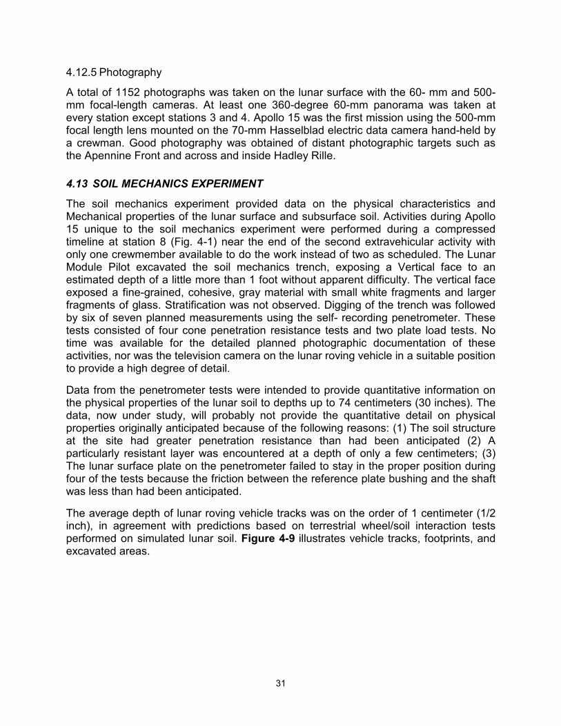
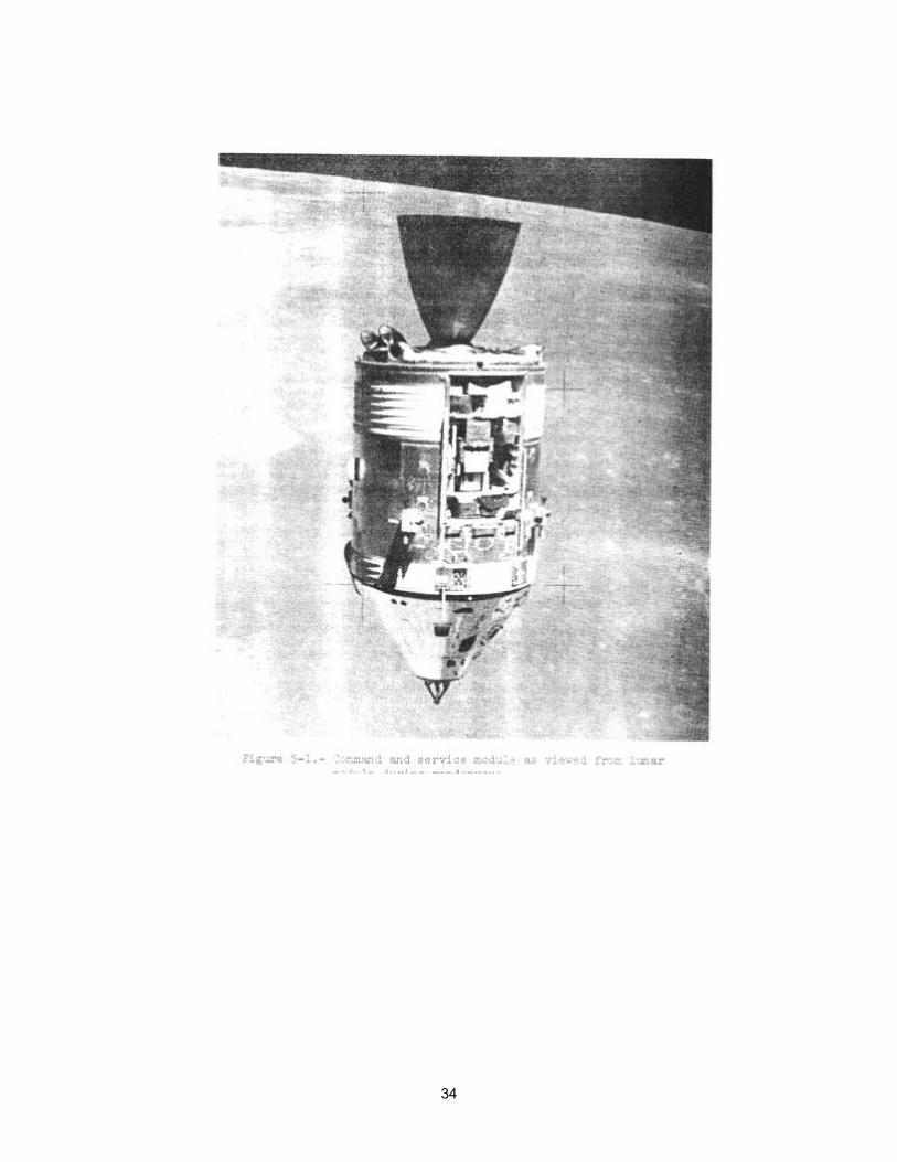
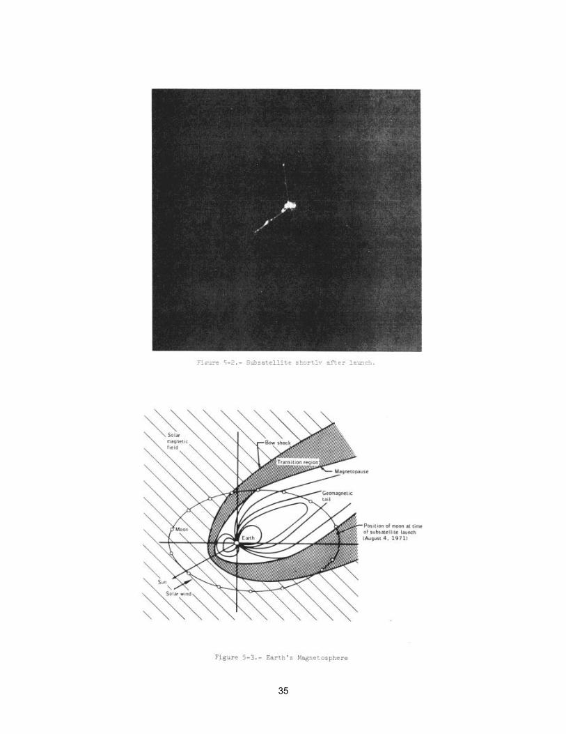
The experiments located in the scientific instrument module bay of the service module (Fig. 5-1) consisted of a gamma ray spectrometer, an X-ray spectrometer, an alpha-particle spectrometer, a mass spectrometer; and a subsatellite which is the vehicle for a particle shadows/boundary layer experiment, an S-band transponder experiment, and a magnetometer experiment. The subsatellite (Fig. 5-2) was launched successfully just prior to transearth injection on August 4 at approximately 2100 G.m.t., and was inserted into a 76.3-by-55.1-mile lunar orbit with an inclination of minus 28.7 degrees. The three subsatellite experiments are expected to acquire data for a period exceeding 1 year. At the time of launch, the moon was in the magnetosheath (transition) region of the earth's magnetosphere (Fig 5.3), one of several data collecting regions of scientific interest. All subsatellite experiments are turned off while the battery is being recharged after each tracking revolution. Both the magnetometer and particle shadows/boundary layer experiments are acquiring data on all revolutions except those when the battery is being charged.
34
35
36
Other inflight experiments consisted of ultraviolet photography of the earth and moon, photography of the Gegenschein from lunar orbit, an S-band transponder experiment using the command and service module and lunar module S-band communication systems, a down-link bistatic radar experiment using both the S-band and VHF communications systems of the command and service module and an Apollo window meteroid experiment.
Photographic tasks that were designated as detailed objectives rather than experiments are also discussed. They are the service module orbital photography employing the panoramic camera, the mapping camera, and the laser altimeter; and command module photography of lunar surface areas and astronomical subjects. A brief description of the equipment used for these experiments and photographic tasks is given in appendix A.
5.1 GAMMA-RAY SPECTROMETER EXPERIMENT
The gamma-ray spectrometer was operated in lunar orbit for over 90 hours. The instrument was operated in the minimum-background mode for prime data collection approximately 65 percent of the time. The remaining of the time it was operated in various non-minimum-background modes to determine the effects of background radiation sources on the prime data. The instrument was also operated for approximately 50 hours during transearth flight obtaining background data necessary for analysis of the lunar data, and to acquire data from galactic sources.
The instrument as well as the deployment boom performed well throughout the mission. However, two anomalous conditions occurred which affected instrument calibration. First, a downward drift in the linear gain of the photomultiplier or pulse analyzer was detected after the first boom extension (prior to undocking in lunar orbit) when several lines in the spectrum of the Apollo lunar surface experiment package fuel capsule were used for calibrations. The drift decreased in magnitude from an initial rate of 1 percent per hour to 0.4 percent per day and, eventually, reached a fairly stable state. The second anomalous condition was noted about 2-3/4 hours after transearth injection, when spectrum zero shifted eight channels, causing loss of the 0.279-million-electron-volt calibration reference. Commencing at 246:56, the problem disappeared for approximately 25 hours, returning at 271:47 and remaining for the rest of transearth flight. These problems are discussed further in section 14.3.4.
The preliminary data indicates variations in radioactivity as the spacecraft passed over different kinds of terrain. The western mare areas are generally the highest in radioactivity, with the eastern maria being somewhat lower. The highlands are the lowest in activity with a slightly lower level in the far-side highlands. The data further indicate a continuum level comparable to that predicted from Ranger 3 and Luna 10 data. Peaks due to potassium, thorium, oxygen, silicon, and iron have been identified. Detailed analysis is expected to show the presence and distribution of uranium, magnesium, aluminum, and titanium.
5.2 X-RAY FLUORESCENCE EXPERIMENT
All X-ray spectrometer objectives were achieved and no hardware problems were noted. About 90 hours of data were obtained from operation of the instrument in lunar
37
orbit, and approximately 26 hours of data were acquired while in transearth flight. During this latter period, the instrument was pointed at six preselected locations to acquire data on possible variations in X-ray intensity. Two observations were coordinated with simultaneous ground-based observations. After 276 hours, the instrument was left on to obtain data for use in the search for new sources of X-ray emission and to improve spectral information on known sources.
Near the end of transearth flight, an engineering test was conducted to determine if the gas-filled proportional counters Would be damaged by direct impingement of solar X-rays. The experiment continued to operate satisfactorily after the test.
The preliminary data shows that the fluorescent X-ray flux was more intense than predicted; that the concentration of aluminum in the highlands is about 50 percent greater than in the maria; and that the ratio of magnesium-to-aluminum in Mare Smithii and Mare Chrisium is about 50 percent greater than in the highlands between, and to the east and west of, the two maria. Analysis of the X-ray astronomy observations made enroute to the earth has shown that the intensity in X-ray output of Scorpius X-1 and Cygnus X-1 fluctuates with periods of several minutes.
5.3 ALPHA-PARTICLE SPECTROMETER EXPERIMENT
All primary objectives of the alpha-particle experiment were achieved. The spectrometer was operated for approximately 80 hours in lunar orbit to acquire prime data, and approximately 50 hours during transearth coast to acquire background data.
Two of the ten detectors were intermittently noisy. The noise was at a very low rate (approximately 0.5 count per second) with occasional bursts at higher rates. Since the noise was generally restricted to one detector at a time, the loss of data is not expected to have a significant effect on the validity of the analysis.
An engineering test was performed near the end of transearth flight (in conjunction with the test on the X-ray spectrometer). The open experiment covers, which permitted direct sunlight impingement on the instrument, resulted in three of the ten detectors (including the two noisy detectors) showing some evidence of photosensitivity.
The planned coverage of the lunar surface was obtained. The alpha particle spectrometer did not detect any local areas of radon enhancement (An objective of the experiment was to locate craters or fissures by detecting alpha particles emitted by radon isotopes - daughter products of uranium and thorium). The general radon evolution rate of the moon is three orders of magnitude less than that of earth. A refinement of the data, in which summation of counts from successive orbital passes over the same area is made, will be required to make more definitive statements about the lunar distribution of radon isotopes.
5.4 MASS SPECTROMETER EXPERIMENT
Thirty-three hours of prime lunar orbit data were collected with the command and service module minus X axis in the direction of travel, and 7 hours of background data with the command and service module pointed in the opposite direction. During

38
transearth coast, approximately 48 hours of data were gathered, including waste water dumps, oxygen purges, and boom- retraction tests.
The mass spectrometer boom retract mechanism in the scientific instrument module stalled during five of twelve cycles. Data, supported by the Command Module Pilot's observations during extravehicular activity, confirmed that the boom had retracted to within 1 inch of full retraction.
Each of the five cycles in which the boom did not fully retract was preceded by a period of cold soaking of the boom. In each instance, the boom would retract fully after warm-up. The boom was fully retracted for command module/service module separation. This anomaly is discussed further in section 14.1.6.
The instrument operated well, providing good data. Even though the boom retraction problem resulted in failure to collect prime data during one scheduled period, and real-time scheduling problems prevented instrument operation for another scheduled period, an adequate amount of data was acquired.
The mass spectrometer measured an unexpectedly large amount of gas at orbital altitude around the moon. This amount was an order of magnitude greater than that seen during transearth coast. Many gases were detected, including water vapor, carbon dioxide, and a variety of hydrocarbons. Data obtained during transearth coast indicate that a gaseous contamination cloud existed up to a distance of 4 feet from the command and service module, but contamination was not detected at the maximum extension of the mass spectrometer (24 feet).
5.5 PARTICLE SHADOWS /BOUNDARY LAYER EXPERIMENT
The charged-particle telescope detectors were turned on immediately after subsatellite launch and are operating normally. Proper operation of the proton detection system was indicated when a large flux of protons in the 35 000- to 100 000-electron-volt range were observed near the magnetopause (fig. 5-3). Twenty-four hours after subsatellite launch, the electrostatic analyzer detectors were turned on, and have operated normally with no evidence of high-voltage corona or arcing.
When the moon is not in the earth's geomagnetic tail, the effect of the moon's shadow on the solar wind electrons is clearly detected. The variation in the shadow shape is rather large. With the moon in the earth's tail, a very tenuous plasma is seen. Within the plasma sheet, intensities increase with some flow of plasma from the earth's direction.
5.6 SUBSATELLITE MAGNETOMETER EXPERIMENT
The magnetometer was turned on when telemetry from the subsatellite was acquired, and the instrument has performed satisfactorily. The experiment has operated continuously except for an 18-hour period after the lunar eclipse of August 6, and periods when the power is turned off to enable the batteries to return to full charge.
The magnetometer is returning better-than-expected information in relation to detecting surface anomalies. The principal investigator is carrying out hand calculations on far-side data that indicate excel-lent repetitive information over the craters Gagarin,
39
Korolev, and Van de Graaff. While in the solar wind, the magnetometer is mapping the signature of the diamagnetic cavity behind the moon. As the subsatellite crosses the terminator, variations in the solar magnetic field by factors of two to three are detected by the magnetometer. These may be caused by interaction of the solar wind with local magnetic regions near the limb. More careful long-term analysis is required to confirm this preliminary finding.
5.7 S-BAND TRANSPONDER EXPERIMENT
5.7.1 Command and Service Module/Lunar Module
Good gravitational profile data along the spacecraft lunar ground tracks were obtained. The anticipated degradation of the data caused by changes in spacecraft position from uncoupled attitude control engine firings was not significant. Indications are that the gross shapes of mascons in Serenitatis, Crisium, and Smythii can be established. This complements the Apollo 14 results on Nectaris. Detailed gravity profiles of the Apennines and Procellarum regions were also obtained.
5.7.2 Subsatellite
The initial data contained a high level of noise caused by a wobble about the spin axis. The wobble was inherent in the subsatellite deployment and was subsequently removed by the onboard wobble damper.
The subsatellite S-band transponder is working well, and is being operated every twelfth lunar revolution. The tracking data shows that the perilune variation is following preflight predictions and is expected to confirm the predicted orbital lifetime (greater than 1 year). The subsatellite transponder has shown at least one new mascon in the region of the crater Humboldt on the eastern lunar near side. Repeated overflights of the lunar near side from varying altitudes as the subsatellite orbit decays will be necessary before an accurate gravitational map can be made and large anomalies defined.
5.8 DOWN-LINK BISTATIC RADAR OBSERVATIONS OF THE MOON
The experiment data consists of records of both frequencies (S-band and VHF) during the front-side passes on lunar revolutions 17 and 28. During these dual-frequency periods, signals were bounced off the moon and received at Goldstone (210-ft dish antenna for S-band) and at Stanford University (150-ft dish antenna for VHF). On revolutions 53 through 57 (the crew sleep period), only the VHF frequency was reflected from the moon to the earth.
The experiment results will require considerable data processing. Determination of the bulk dielectric constant and near-surface roughness along the spacecraft track appears possible with the present data. S-band data from revolution 17 are not usable because of incorrect spacecraft attitude. However, VHF data from revolution 17 appear to be of high quality. The attitude error was discovered and corrected in time for revolution 28, and all the data for that revolution are of excellent quality. The VHF experiment conducted during revolutions 53 through 57 provided high quality data. Apollo 15 data may be correlated with data obtained from the Apollo 14 bistatic radar experiment since
40
the spacecraft groundtracks of Apollo 15 during both S-band/VHF operation and VHF-only operation intersect the Apollo 14 groundtrack during S-band/VHF operation.
5.9 APOLLO WINDOW METEOROID EXPERIMENT
The command module side and hatch windows were scanned at a magnification of 20X prior to flight to determine the general background of chips, scratches and other defects. Postflight, the windows will again be scanned at 20X (and higher magnifications for areas of interest) to map all visible defects. Possible meteoroid craters will be identified to determine the meteoroid cratering flux of particles responsible for the degradation of glass surfaces exposed to the space environment.
5.10 ULTRAVIOLET PHOTOGRAPHY - EARTH AND MOON
Ultraviolet photographs were obtained while in earth and lunar orbit, and during translunar and transearth coast. The following table lists the ultraviolet photography sequences performed on Apollo 15. Each sequence consisted of two exposures without the use of a filter and two exposures each with a 2600-angstrom filter, a 3750-angstrom filter, and a 4000- to 6000- angstrom visual-range filter. In addition, some color-film exposures were obtained, as planned, with the visual-range filter. These are noted in the last column of table 5-1. Preliminary examination shows that the exposures were excellent
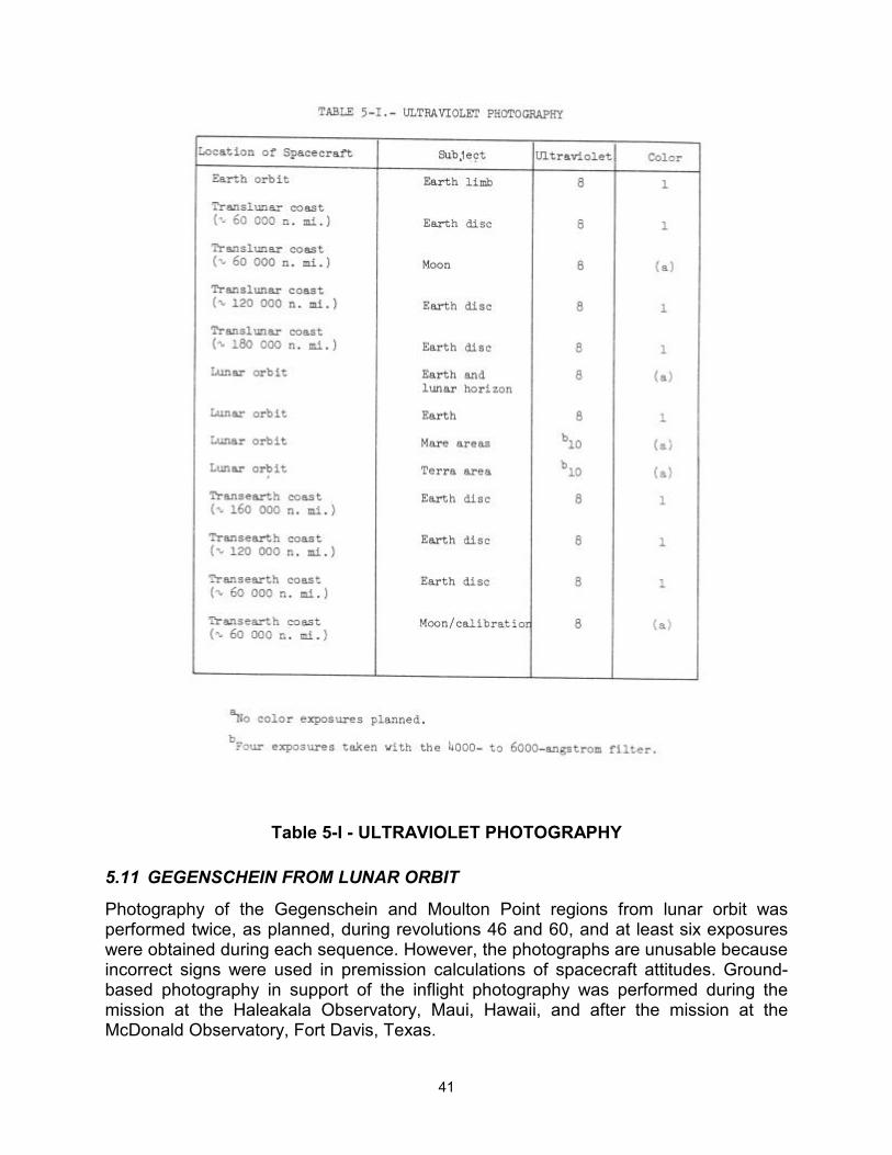
41
Table 5-I - ULTRAVIOLET PHOTOGRAPHY
5.11 GEGENSCHEIN FROM LUNAR ORBIT
Photography of the Gegenschein and Moulton Point regions from lunar orbit was performed twice, as planned, during revolutions 46 and 60, and at least six exposures were obtained during each sequence. However, the photographs are unusable because incorrect signs were used in premission calculations of spacecraft attitudes. Ground-based photography in support of the inflight photography was performed during the mission at the Haleakala Observatory, Maui, Hawaii, and after the mission at the McDonald Observatory, Fort Davis, Texas.
42
The camera system used for the Gegenschein experiment and other astronomy tasks performed well. A comparison of preflight and postflight calibration exposures with the faintest brightness observed in the Apollo 15 exposures (of the Milky Way) demonstrates that this camera system is very satisfactory for the Gegenschein experiment, now scheduled for the Apollo 16 mission.
5.12 SERVICE MODULE ORBITAL PHOTOGRAPHY
5.12.1 Panoramic Camera
The panoramic camera was carried on Apollo 15 to obtain high-resolution panoramic photographs of the lunar surface. The areas photographed included the Hadley Rille landing sites (Figs. 4-1 and 4-2), several areas being considered as the Apollo 17 landing site, the Apollo 15 lunar module ascent stage impact point, near-terminator areas, and other areas of general coverage. Anomalous operation of the velocity/altitude sensor (section 14.3.1) was indicated on the first panoramic camera pass on revolution 4 and subsequent passes; however, good photography was obtained over all critical areas.
The delay in lunar module jettison caused cancellation of photographic passes planned for revolutions 58 and 59. These passes were rescheduled for revolutions 60 and 63, but sidelap with adjacent areas photographed on revolutions 33 and 38 was decreased.
All imagery is of very high quality. Examination of the film shows that less than one percent of the total film exposed was seriously degraded by the velocity/altitude sensor malfunction. 5.12.2 Mapping Camera.
The mapping camera was carried aboard the Apollo 15 service module to obtain high-quality metric photographs of the lunar surface. Mapping camera operation was desired during all panoramic camera passes and on selected dark-side passes to assist in analysis of data from the laser altimeter. The camera functioned normally and, essentially, the entire area overflown in daylight was photographed. However, the laser altimeter failed (see the following section) and all scheduled dark-side mapping activities subsequent to revolution 38 were deleted. A problem with the mapping camera deployment mechanism was also experienced. The camera extension and retraction cycles varied from 2 to 4 minutes as compared to about 1 1/2 minutes required prior to flight. After the last deployment, the camera did not completely retract. This anomaly is discussed further in section 14.3.3.
The mapping camera was turned off during the panoramic camera pass over the landing site on revolution 50 in a test to determine if the velocity/altitude sensor anomaly might be related to the mapping camera operation. This resulted in a minor loss of coverage. Also, the photographic pass planned for revolution 58 was deferred until revolution 60 because of the delay in lunar module jettison. The consequence of this was a decrease in sidelap below the desired 55 percent.
Approximately 6 hours of mapping camera operating time remained at transearth injection. About 1 1/2 hours of this were expended photographing the receding moon, and 3 1/2 hours were used photographing selected star fields with the stellar camera
43
associated with the mapping camera.
Image quality is excellent throughout the entire sequence of 3400 frames. The entire portion of the lunar surface which was overflown by Apollo 15 in daylight has been covered by excellent stereoscopic photography which is as well suited to detailed analysis and geologic interpretation as it is to mapping.
5.12.2 Laser Altimeter
The laser altimeter was flown to accurately measure lunar topographic elevations in support of mapping and panoramic camera photography, and inflight experiments. The altimeter was designed to supply a synchronized altitude measurement for each mapping camera exposure on light-side photography, and independent altitude measurements on the dark side to permit correlation of topographic profiles with gravity anomalies obtained from spacecraft tracking data.
Operation of the altimeter was nominal through revolution 24, but improper operation was noted on the next operation (revolution 27). The performance of the altimeter became progressively worse until, on revolution 38, the altimeter ceased to operate (sec. 14.3.2). Consequently, the altimeter was not operated on subsequent dark-side passes , although operation on lightside mapping camera passes was continued. On revolution 63, an attempt was made to revive the altimeter through a switching operation by the Command Module Pilot, but the effort was not successful.
Approximately 50 percent of the planned altimeter telemetry data were actually obtained before the instrument failed. The data from the early orbits have been correlated with S-band transponder data for the frontside pass, and show the shape of the gravity anomalies as related to mare basins. The complete circumlunar laser altimeter data show that, relative to the mean lunar radius, the average lunar far side is about 2 kilometers (1.1 mile) high and the average near side is about 2 kilometers low.
5.13 COMMAND MODULE PHOTOGRAPHY
While in lunar orbit, photographs were taken from the command module of lunar surface sites of scientific interest, and of specific portions of the lunar surface in earthshine and near the terminator. Also, while in lunar orbit, photographs were taken of low-light-level astronomical subjects including the solar corona, the zodiaca-1 light, lunar libration point L4, and of the moon as it entered and exited the earth's umbra during lunar eclipse. During translunar and transearth coast, photographs were taken of a contamination test and star fields were photographed through the command module sextant.
In accomplishing some of the tasks, the crewman obtained extra frames and some with longer exposures than required. This will enhance the value of the total data desired. The only 16-mm data acquisition camera magazine containing very-high-speed black-and-white film was lost. About 35 percent of the magazine had been exposed during lunar orbital flight and transearth coast for solar corona and sextant star field photography. The most probable cause of the loss of the magazine was that it floated through the hatch during the Command Module Pilot's extravehicular activity. This required a substitution of a slower black-and-white film magazine for the final sextant
44
star field photography and real-time update for contamination photography but, because premission-planned exposure settings were used with the much slower film, the sextant star field photographs are not clear.
Photographs were obtained of 21 of 23 specific lunar surface targets, the solar corona, the moon during lunar eclipse as it entered and exited the earth's umbra, star fields through the command module sextant, lunar libration region L4, and specific areas of the lunar surface in earthshine and in low light levels near the terminator. Near-terminator strip photography scheduled on revolution 58, and 2 of the 23 lunar surface targets scheduled on revolutions 58 and 59 were deleted because of the delay in lunar module jettison due to problems during tunnel venting operations and subsequent extension of the crew's sleep period. Based on preliminary examination of the dim-light photography, it appears that excellent quality imagery was obtained of the solar corona, the zodiacal light and the lunar surface in earthshine.
5.14 VISUAL OBSERVATIONS FROM LUNAR ORBIT
Visual observations from lunar orbit was an objective implemented for the first time on this mission. The Command module Pilot was asked to make and record observations of special lunar surface areas. Emphasis was to be placed on characteristics difficult to record on film, but which could be delineated by the eye, such as subtle color differences between surface units. All of the scheduled targets were observed and the results relayed. These results are documented in reference 2. Significant observations were as follows:
a. Fields of cinder cones were discovered on the southeast rim of Mare Serenitatis (Littrow area) and the southwest rim of the same mare basin (Sulpicius; Gallos area).
b. A landslide or rock glacier was delineated on the northwest rim of the crater Tsiolkovsky on the lunar farside (fig. 4-5).
c. A ray-excluded zone around the crater Proclus on the west rim of Mare Crisium. was interpreted as being caused by the presence of a fault system at the west rim of the crater.
d. Layers on the interior walls of several craters were found and were interpreted as volcanic collapse craters , or "caldera", in the maria.

45
6 COMMAND AND SERVICE MODULE PERFORMANCE.
6.1 STRUCTURAL AND MECHANICAL SYSTEMS
Command module accelerometer data indicated a sustained 5-hertz longitudinal oscillation of 0.35g peak-to-peak amplitude prior to first stage center engine cutoff. Similar oscillations have occurred on previous Apollo flights and are within acceptable structural design limits . Oscillations measured during second and third stage boost were less than 0.05g peak amplitude in any direction and were not structurally significant.
Translunar docking loads were higher than those of previous missions (see sec. 7-1).
Main parachute deployment for earth landing, beginning at approximately 10 500 feet, was normal. However, at approximately 6000 feet, one of the three main parachutes was observed to have collapsed. Details of this anomaly are reported in section 14.1.9.
6.2 ELECTRICAL POWER AND FUEL CELLS
The electrical power system batteries and fuel cells performed satisfactorily throughout the mission.
The entry, auxiliary, and pyrotechnic batteries performed normally. Entry batteries A and B were charged nine times during flight (battery A - 4 times; battery B - 5 times). Load sharing and voltage delivery were satisfactory during each of the service propulsion firings. The batteries were near the fully charged level at entry.
The fuel cells were activated 59 hours prior to launch and the system was configured with fuel cell 2 on main bus A. Fuel cells 1 and 3 were on open-circuit until 3.5 hours before lift-off when fuel cells 1 and 2 were placed on main bus A and fuel cell 3 on main bus B. This configuration was maintained throughout the flight. Load variance between fuel cells was a nominal 4 to 7 amperes during flight, with the fuel cells supplying 653 kilowatt-hours of energy at an average current and bus voltage of 77 amperes and 28.8 volts, respectively.
6.3 CRYOGENIC STORAGE
The cryogenic storage system satisfactorily supplied reactants to the fuel cells and metabolic oxygen to the environmental control system throughout the mission. The quantities of oxygen and hydrogen consumedas compared to preflight predictions are given in section 6.11-3.
The system supplied all demands including the extravehicular activity during transearth coast when the system supplied a flow rate of approximately 12.2 lb/hr and the pressure and heater temperatures remained within the anticipated limits.
46
6.4 COMMUNICATIONS
Performance of the command and service module communications system was nominal throughout the mission, except that the Command Module Pilot's lightweight headset microphone was inoperative when the headset was removed from stowage. Inflight troubleshooting verified that the failure was in the microphone. Past history shows three microphone amplifier failures out of approximately 300 units in use. The headset was transferred to the lunar module and jettisoned; therefore, the failure could not be isolated to a specific component.
6.5 INSTRUMENTATION
The instrumentation performed normally with three exceptions.
The service module reaction control system quad A fuel manifold pressure measurement was intermittently noisy (about 4 percent). However, there were other measurements for determining the manifold pressure.
The central timing equipment timer was reset at 97 hours 53 minutes. A time correction was inserted by up-data link, and the timer continued to operate properly throughout the flight. The noise susceptibility of the reset line to the central timing equipment has been evident on other spacecraft. However, because of the ease of updating, the problem has not been considered significant enough to justify redesign.
The first 20 feet of tape on the data recorder reproducer became degraded after about 100 dumps. This portion of the tape was not used for the remainder of the flight. This anomaly is discussed further in section 14.1.10.
6.6 GUIDANCE, NAVIGATION, AND CONTROL
Performance of the guidance, navigation, and the primary and backup control systems was good throughout the flight. The two anomalies experienced during the mission were minor in nature causing no loss of system capability. They were excessive attenuation of light through the scanning telescope, and improper alignment of the roll axis when the gyro display alignment pushbutton was depressed. Descriptions of the anomalies and the corrective action being taken are included in sections 14.1.15 and 14.1.16.
The primary guidance system satisfactorily monitored the trajectories during launch and the translunar injection maneuver. The most probable velocity errors at insertion were minus 1.5, minus 41.5, and minus 10.8 ft/sec in the X, Y, and Z platform axes , respectively. The errors were determined from data obtained from several sources: the Saturn guidance system, the command module guidance system, the Saturn guidance system data modified by tracking data, and command module platform realignments in earth orbit.
Separation from the S-IVB and the transposition maneuver were nominal. Daring the
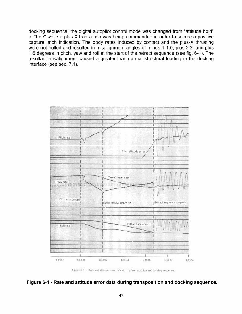
47
docking sequence, the digital autopilot control mode was changed from "attitude hold" to "free" while a plus-X translation was being commanded in order to secure a positive capture latch indication. The body rates induced by contact and the plus-X thrusting were not nulled and resulted in misalignment angles of minus 1-1.0, plus 2.2, and plus 1.6 degrees in pitch, yaw and roll at the start of the retract sequence (see fig. 6-1). The resultant misalignment caused a greater-than-normal structural loading in the docking interface (see sec. 7.1).
Figure 6-1 - Rate and attitude error data during transposition and docking sequence.
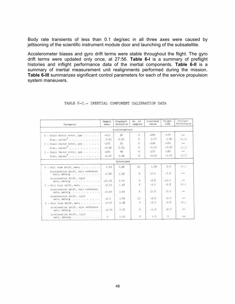
48
Body rate transients of less than 0.1 deg/sec in all three axes were caused by jettisoning of the scientific instrument module door and launching of the subsatellite.
Accelerometer biases and gyro drift terms were stable throughout the flight. The gyro drift terms were updated only once, at 27:56. Table 6-I is a summary of preflight histories and inflight performance data of the inertial components. Table 6-II is a summary of inertial measurement unit realignments performed during the mission. Table 6-III summarizes significant control parameters for each of the service propulsion system maneuvers.
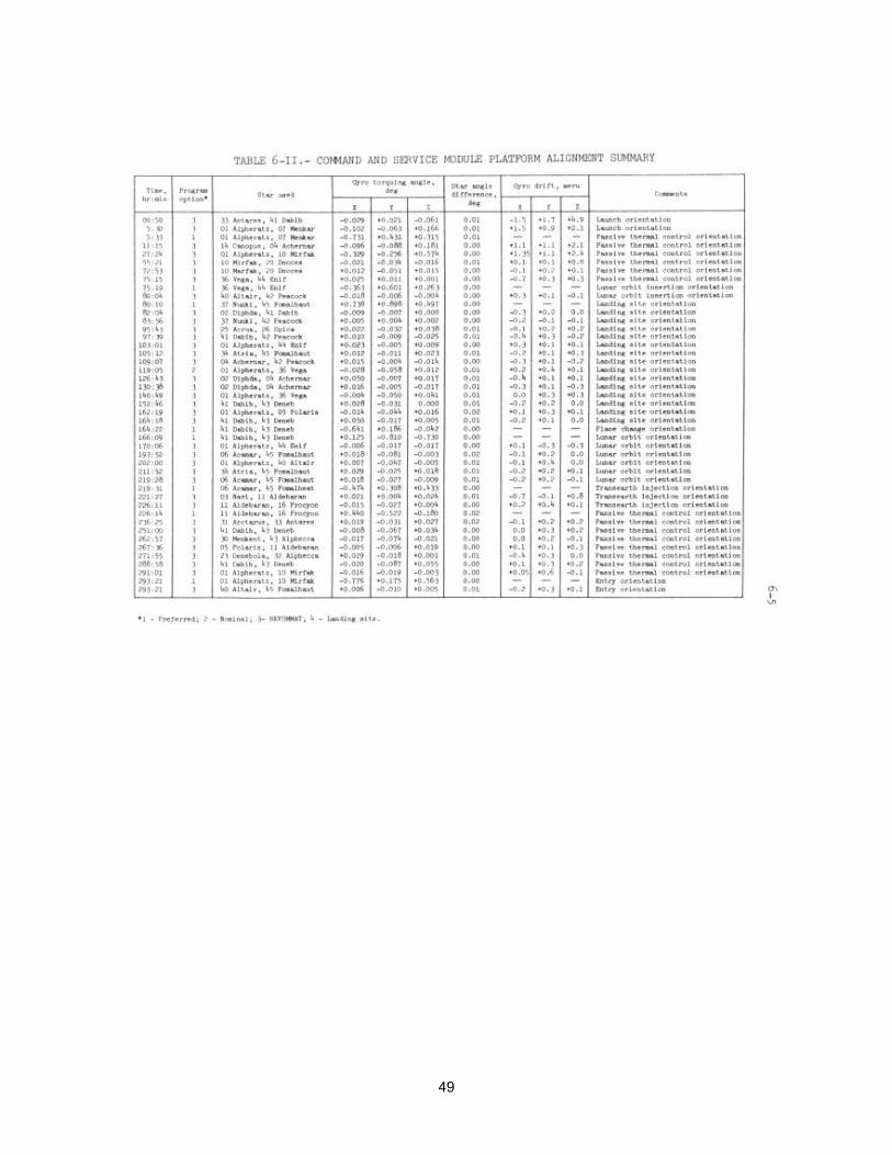
49
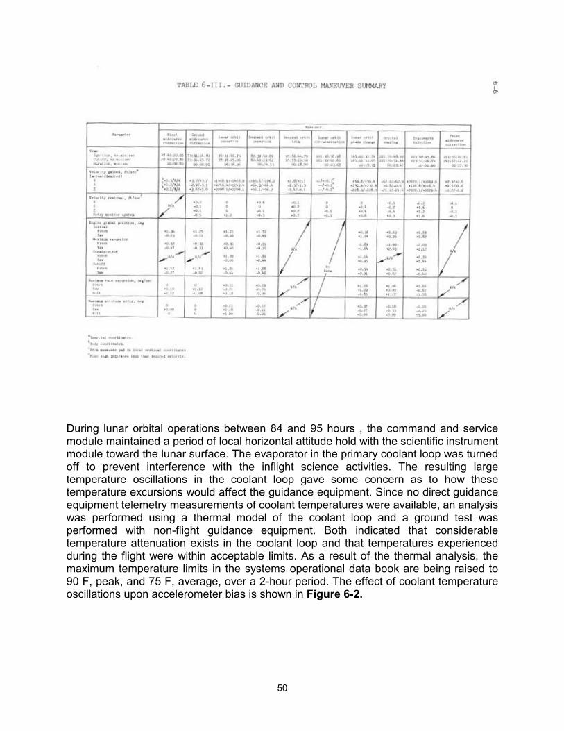
50
During lunar orbital operations between 84 and 95 hours , the command and service module maintained a period of local horizontal attitude hold with the scientific instrument module toward the lunar surface. The evaporator in the primary coolant loop was turned off to prevent interference with the inflight science activities. The resulting large temperature oscillations in the coolant loop gave some concern as to how these temperature excursions would affect the guidance equipment. Since no direct guidance equipment telemetry measurements of coolant temperatures were available, an analysis was performed using a thermal model of the coolant loop and a ground test was performed with non-flight guidance equipment. Both indicated that considerable temperature attenuation exists in the coolant loop and that temperatures experienced during the flight were within acceptable limits. As a result of the thermal analysis, the maximum temperature limits in the systems operational data book are being raised to 90 F, peak, and 75 F, average, over a 2-hour period. The effect of coolant temperature oscillations upon accelerometer bias is shown in Figure 6-2.
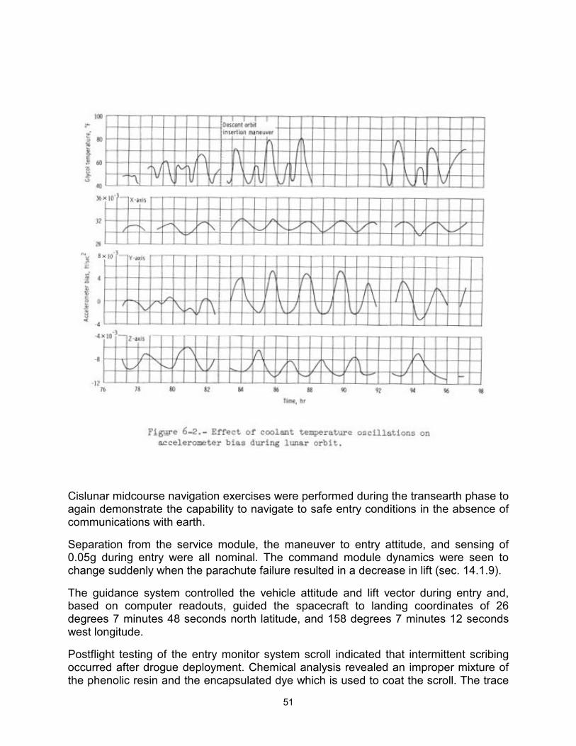
51
Cislunar midcourse navigation exercises were performed during the transearth phase to again demonstrate the capability to navigate to safe entry conditions in the absence of communications with earth.
Separation from the service module, the maneuver to entry attitude, and sensing of 0.05g during entry were all nominal. The command module dynamics were seen to change suddenly when the parachute failure resulted in a decrease in lift (sec. 14.1.9).
The guidance system controlled the vehicle attitude and lift vector during entry and, based on computer readouts, guided the spacecraft to landing coordinates of 26 degrees 7 minutes 48 seconds north latitude, and 158 degrees 7 minutes 12 seconds west longitude.
Postflight testing of the entry monitor system scroll indicated that intermittent scribing occurred after drogue deployment. Chemical analysis revealed an improper mixture of the phenolic resin and the encapsulated dye which is used to coat the scroll. The trace
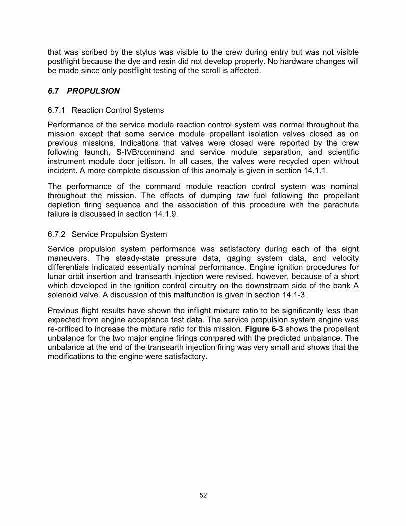
52
that was scribed by the stylus was visible to the crew during entry but was not visible postflight because the dye and resin did not develop properly. No hardware changes will be made since only postflight testing of the scroll is affected.
6.7 PROPULSION
6.7.1 Reaction Control Systems
Performance of the service module reaction control system was normal throughout the mission except that some service module propellant isolation valves closed as on previous missions. Indications that valves were closed were reported by the crew following launch, S-IVB/command and service module separation, and scientific instrument module door jettison. In all cases, the valves were recycled open without incident. A more complete discussion of this anomaly is given in section 14.1.1.
The performance of the command module reaction control system was nominal throughout the mission. The effects of dumping raw fuel following the propellant depletion firing sequence and the association of this procedure with the parachute failure is discussed in section 14.1.9.
6.7.2 Service Propulsion System
Service propulsion system performance was satisfactory during each of the eight maneuvers. The steady-state pressure data, gaging system data, and velocity differentials indicated essentially nominal performance. Engine ignition procedures for lunar orbit insertion and transearth injection were revised, however, because of a short which developed in the ignition control circuitry on the downstream side of the bank A solenoid valve. A discussion of this malfunction is given in section 14.1-3.
Previous flight results have shown the inflight mixture ratio to be significantly less than expected from engine acceptance test data. The service propulsion system engine was re-orificed to increase the mixture ratio for this mission. Figure 6-3 shows the propellant unbalance for the two major engine firings compared with the predicted unbalance. The unbalance at the end of the transearth injection firing was very small and shows that the modifications to the engine were satisfactory.
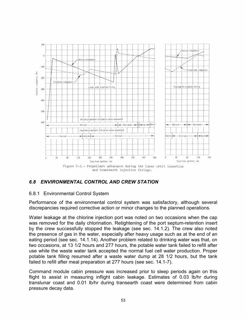
53
6.8 ENVIRONMENTAL CONTROL AND CREW STATION
6.8.1 Environmental Control System
Performance of the environmental control system was satisfactory, although several discrepancies required corrective action or minor changes to the planned operations.
Water leakage at the chlorine injection port was noted on two occasions when the cap was removed for the daily chlorination. Retightening of the port septum-retention insert by the crew successfully stopped the leakage (see sec. 14.1.2). The crew also noted the presence of gas in the water, especially after heavy usage such as at the end of an eating period (see sec. 14.1.14). Another problem related to drinking water was that, on two occasions, at 13 1/2 hours and 277 hours, the potable water tank failed to refill after use while the waste water tank accepted the normal fuel cell water production. Proper potable tank filling resumed after a waste water dump at 28 1/2 hours, but the tank failed to refill after meal preparation at 277 hours (see sec. 14.1-7).
Command module cabin pressure was increased prior to sleep periods again on this flight to assist in measuring inflight cabin leakage. Estimates of 0.03 lb/hr during translunar coast and 0.01 lb/hr during transearth coast were determined from cabin pressure decay data.
54
Noises were heard from the cabin fans that were believed to have been caused by an object striking the fan blades. Cycling of the fans allowed the fans to run normally (see sec. 14.1.13).
Prior to crew transfer for lunar module housekeeping, difficulty was experienced in obtaining proper lunar module/command module differential pressure gage readings. The difficulty resulted in insufficient lunar module pressure decay at cabin pressure equalization. Consequently, extra lunar module venting was required to obtain additional oxygen enrichment and assure minimum oxygen concentration for later suited activities.
Radiator outlet temperatures while in translunar coast and lunar orbit. were 10 to 150 F higher than preflight thermal studies indicated they would be. During the flight, calculations using more accurate heat load inputs resulted in considerably closer predictions, although some degradation of radiator coating may have contributed to the higher-than-predicted temperatures. The radiator outlet temperatures were greater than on previous missions because of the vehicle attitude and higher electrical loads required to support the scientific instrument module experiments.
During preparations for lunar module jettison, after an apparently successful hatch integrity check, the differential pressure decreased between the command module cabin and tunnel, indicating the possibility of a command module hatch leak. Although a subsequent 10-minute check demonstrated satisfactory hatch integrity, an inspection of both the lunar module and command module hatch seals was made. No evidence of contamination or damage was found. The hatches were reinstalled and a successful hatch integrity check was performed. The crew had also experienced difficulty in obtaining an acceptable suit circuit integrity check during the lunar module jettison preparations. After being unable to pressurize the suit loop more than 1 psi above cabin pressure, the crew doffed their helmets and gloves, and the Commander also unzipped his pressure garment assembly, unlocked and removed the liquid cooling garment connector, and installed a water connector plug. After rezipping the suit and donning helmets and gloves, a successful integrity check was completed. Subsequently, because of the hatch integrity problem previously mentioned, the suit integrity was again broken, and the suit check had to be repeated. This check was again unsatisfactory because one suit glove was not properly connected. After making the correct connection, a final suit circuit test was successfully completed. The delay resulted in the lunar module being jettisoned one revolution later than planned.
Droplets of water came from two of the three blue (supply) hoses when they were relocated for the transearth injection firing. Since cabin humidity continued to be normal and no recurrence of the problem was observed, most likely the condensation was an effect of the large primary coolant loop temperature transient on the suit circuit heat exchanger during lunar orbit.
During the period of the entry propellant depletion firing, cabin pressure continued to increase at a rate consistent with the ambient atmospheric entry pressure. Manual closure of the cabin pressure relief valves at that time should have prevented any additional inflow. Since use of onboard gas supplies was not sufficient to account for the change, apparently the manual valve was not completely closed or abnormally high
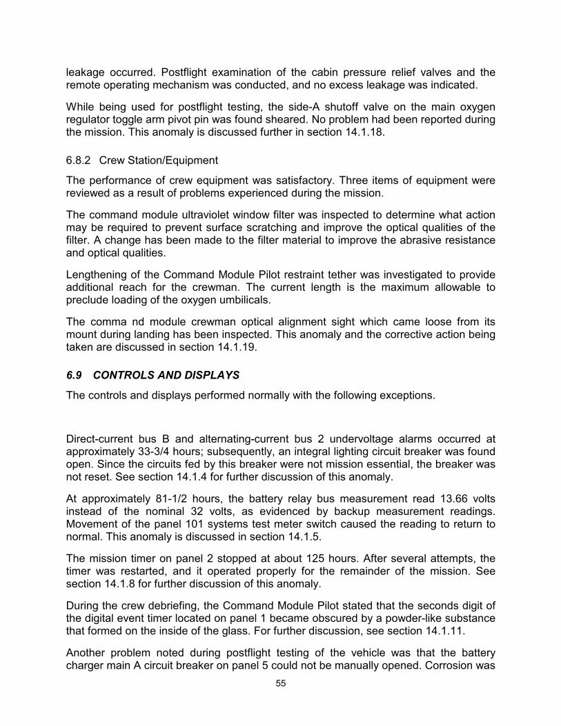
55
leakage occurred. Postflight examination of the cabin pressure relief valves and the remote operating mechanism was conducted, and no excess leakage was indicated.
While being used for postflight testing, the side-A shutoff valve on the main oxygen regulator toggle arm pivot pin was found sheared. No problem had been reported during the mission. This anomaly is discussed further in section 14.1.18.
6.8.2 Crew Station/Equipment
The performance of crew equipment was satisfactory. Three items of equipment were reviewed as a result of problems experienced during the mission.
The command module ultraviolet window filter was inspected to determine what action may be required to prevent surface scratching and improve the optical qualities of the filter. A change has been made to the filter material to improve the abrasive resistance and optical qualities.
Lengthening of the Command Module Pilot restraint tether was investigated to provide additional reach for the crewman. The current length is the maximum allowable to preclude loading of the oxygen umbilicals.
The comma nd module crewman optical alignment sight which came loose from its mount during landing has been inspected. This anomaly and the corrective action being taken are discussed in section 14.1.19.
6.9 CONTROLS AND DISPLAYS
The controls and displays performed normally with the following exceptions.
Direct-current bus B and alternating-current bus 2 undervoltage alarms occurred at approximately 33-3/4 hours; subsequently, an integral lighting circuit breaker was found open. Since the circuits fed by this breaker were not mission essential, the breaker was not reset. See section 14.1.4 for further discussion of this anomaly.
At approximately 81-1/2 hours, the battery relay bus measurement read 13.66 volts instead of the nominal 32 volts, as evidenced by backup measurement readings. Movement of the panel 101 systems test meter switch caused the reading to return to normal. This anomaly is discussed in section 14.1.5.
The mission timer on panel 2 stopped at about 125 hours. After several attempts, the timer was restarted, and it operated properly for the remainder of the mission. See section 14.1.8 for further discussion of this anomaly.
During the crew debriefing, the Command Module Pilot stated that the seconds digit of the digital event timer located on panel 1 became obscured by a powder-like substance that formed on the inside of the glass. For further discussion, see section 14.1.11.
Another problem noted during postflight testing of the vehicle was that the battery charger main A circuit breaker on panel 5 could not be manually opened. Corrosion was
56
found around the indicator sleeve of the breaker actuating knob. This anomaly is discussed in section 14.1-17.
6.10 EXTRAVEHICULAR ACTIVITY EQUIPMENT
The environmental control system and crew equipment performed successfully throughout the transearth extravehicular activity. Operation of the new components, including the umbilical, suit control unit, pressure control valve, oxygen control and communications panels, and the extravehicular activity warning system was entirely nominal. All checks and activities went smoothly, and the extravehicular portion lasted less than 40 minutes. Cabin pressure was restored as planned, using the three 1-pound oxygen bottles from the rapid repressurization system and CMP-flow mode until 3.0 psia was reached, and then discharging the unused oxygen purge system to bring the pressure above 5.0 psia. Subsequent depletion of the residual 2000 psi in the oxygen purge system was accomplished by using it once to increase cabin pressure prior to a sleep period and on the following day, when the remainder was allowed to bleed into the cabin at a controlled rate.
6.11 CONSUMABLES
The command and service module consumable usage during the Apollo 15 mission was well within the red line limits and, in all systems, was close to the preflight predicted values.
6.11.1 Service Propulsion Propellant
Service propulsion propellant and helium loadings and consumption values are listed in the following table. The loadings were calculated from gaging system readings and measured densities prior to lift-off.
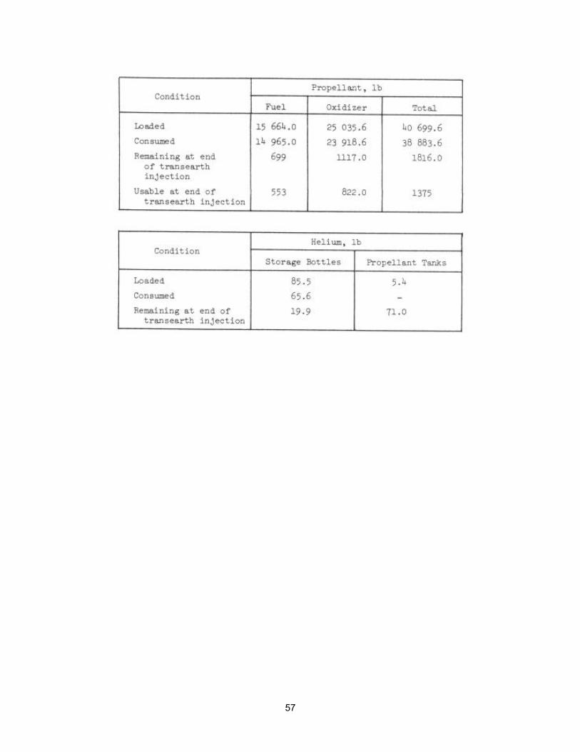
57
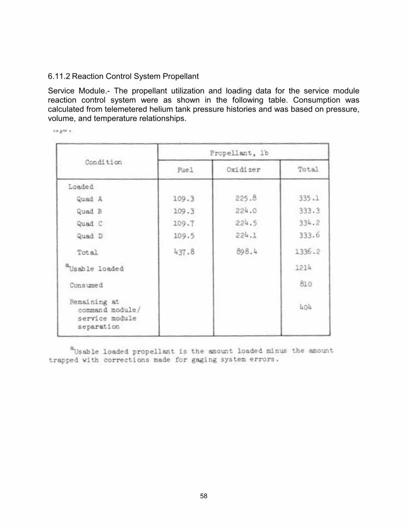
58
6.11.2 Reaction Control System Propellant
Service Module.- The propellant utilization and loading data for the service module reaction control system were as shown in the following table. Consumption was calculated from telemetered helium tank pressure histories and was based on pressure, volume, and temperature relationships.
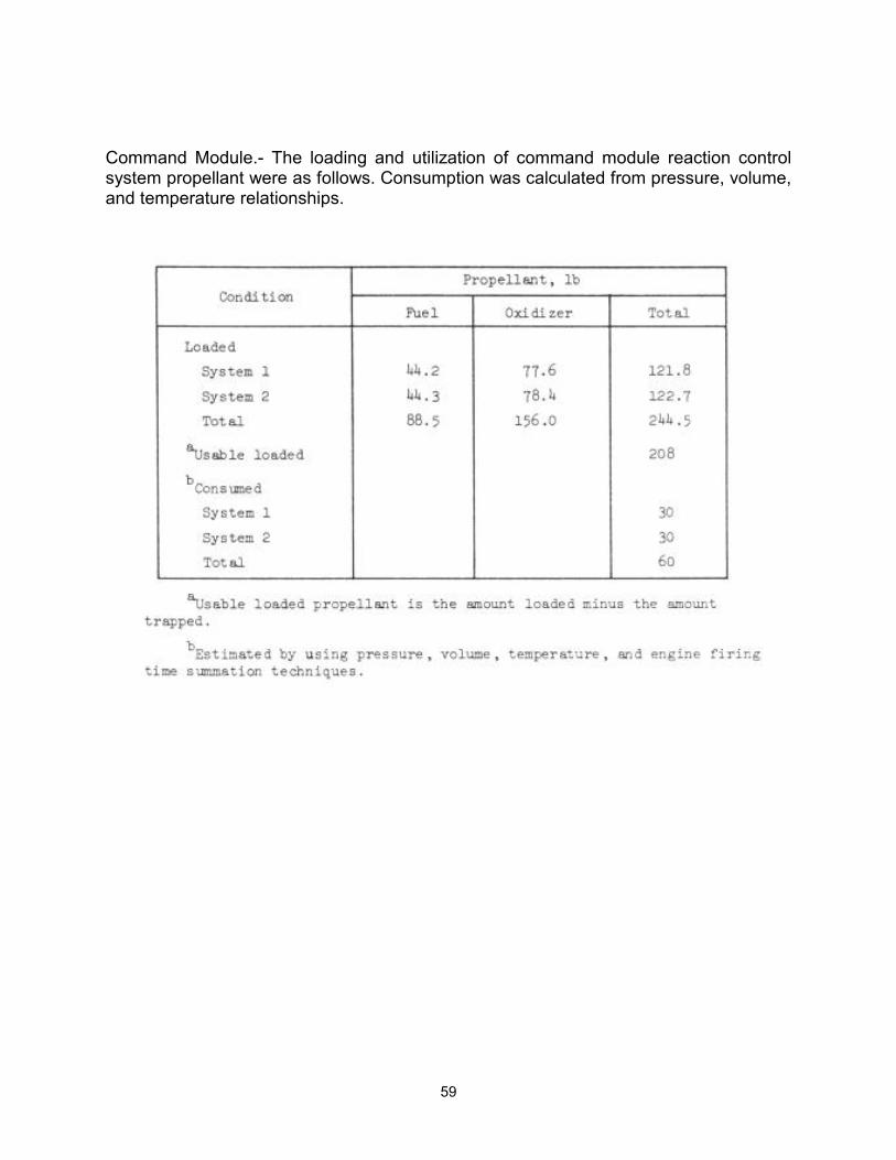
59
Command Module.- The loading and utilization of command module reaction control system propellant were as follows. Consumption was calculated from pressure, volume, and temperature relationships.
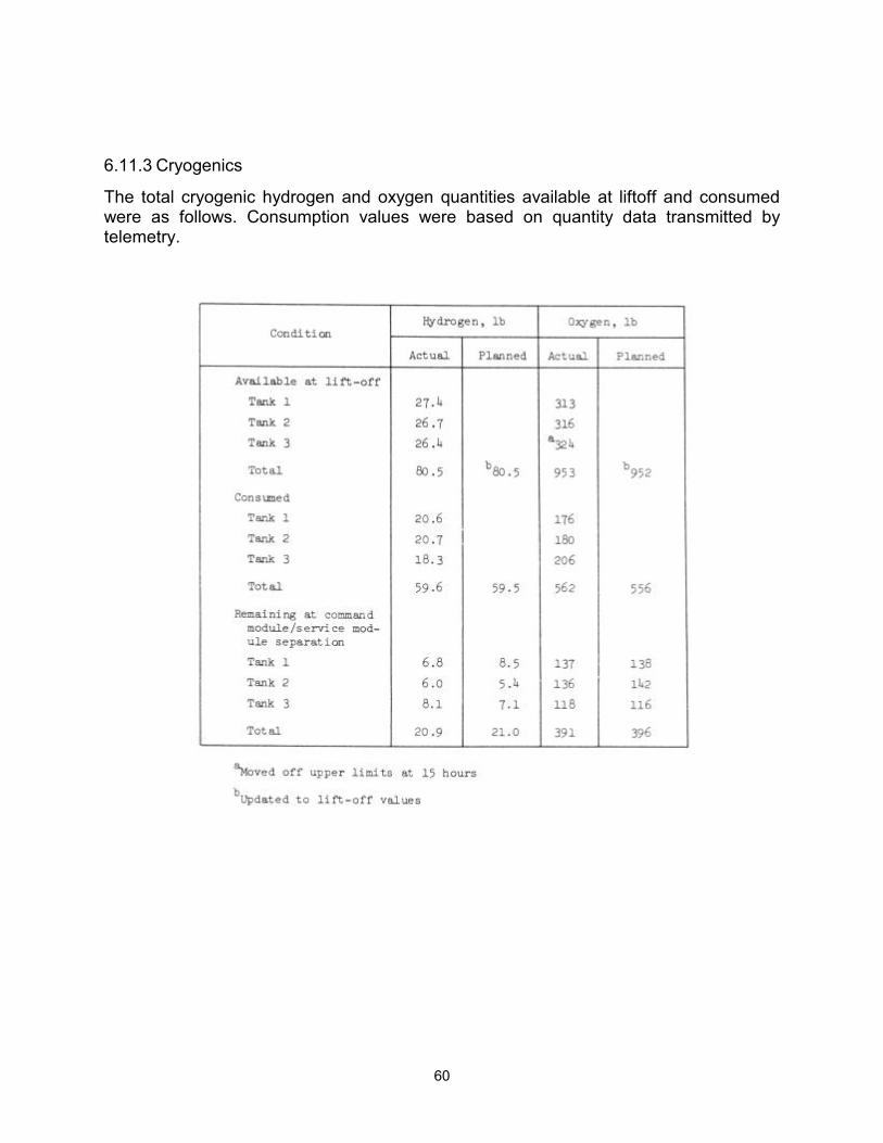
60
6.11.3 Cryogenics
The total cryogenic hydrogen and oxygen quantities available at liftoff and consumed were as follows. Consumption values were based on quantity data transmitted by telemetry.
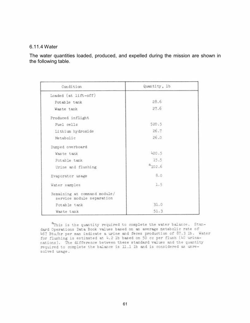
61
6.11.4 Water
The water quantities loaded, produced, and expelled during the mission are shown in the following table.
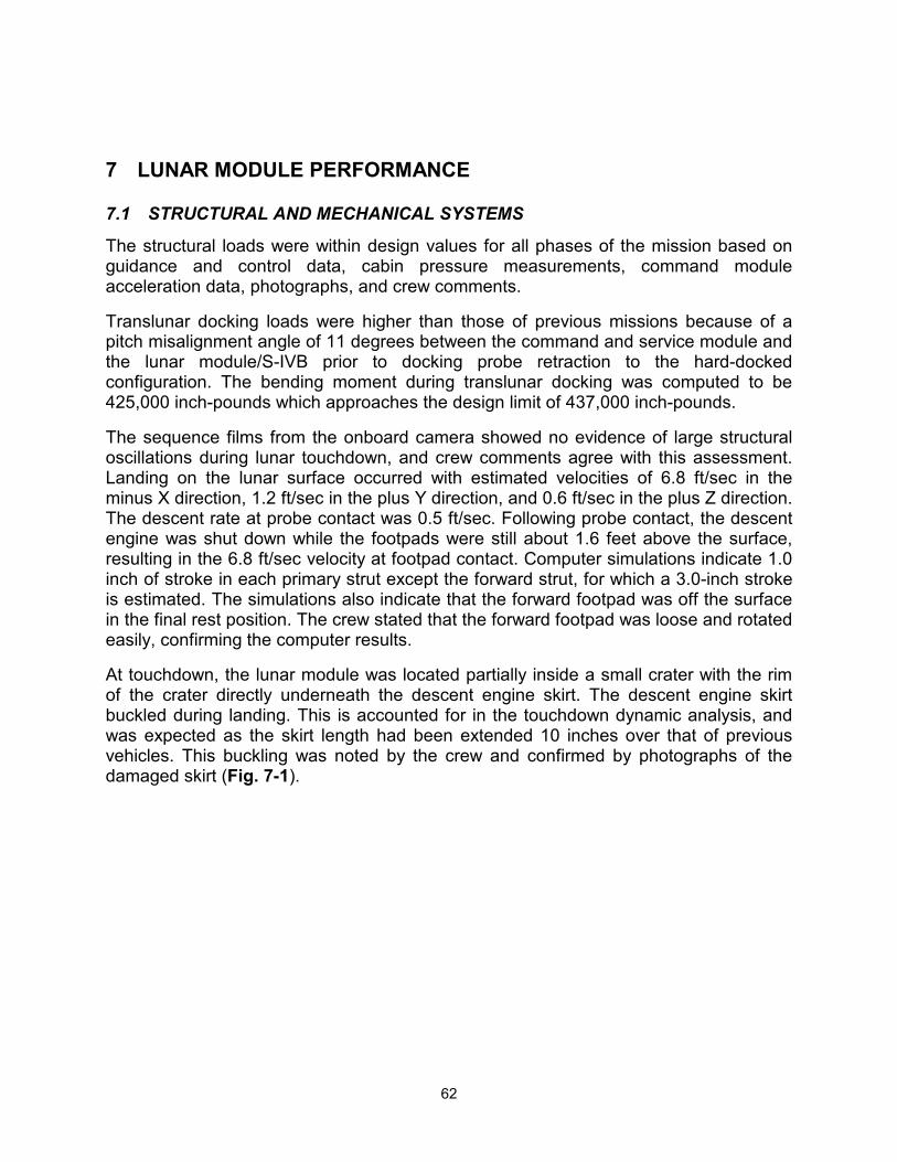
62
7 LUNAR MODULE PERFORMANCE
7.1 STRUCTURAL AND MECHANICAL SYSTEMS
The structural loads were within design values for all phases of the mission based on guidance and control data, cabin pressure measurements, command module acceleration data, photographs, and crew comments.
Translunar docking loads were higher than those of previous missions because of a pitch misalignment angle of 11 degrees between the command and service module and the lunar module/S-IVB prior to docking probe retraction to the hard-docked configuration. The bending moment during translunar docking was computed to be 425,000 inch-pounds which approaches the design limit of 437,000 inch-pounds.
The sequence films from the onboard camera showed no evidence of large structural oscillations during lunar touchdown, and crew comments agree with this assessment. Landing on the lunar surface occurred with estimated velocities of 6.8 ft/sec in the minus X direction, 1.2 ft/sec in the plus Y direction, and 0.6 ft/sec in the plus Z direction. The descent rate at probe contact was 0.5 ft/sec. Following probe contact, the descent engine was shut down while the footpads were still about 1.6 feet above the surface, resulting in the 6.8 ft/sec velocity at footpad contact. Computer simulations indicate 1.0 inch of stroke in each primary strut except the forward strut, for which a 3.0-inch stroke is estimated. The simulations also indicate that the forward footpad was off the surface in the final rest position. The crew stated that the forward footpad was loose and rotated easily, confirming the computer results.
At touchdown, the lunar module was located partially inside a small crater with the rim of the crater directly underneath the descent engine skirt. The descent engine skirt buckled during landing. This is accounted for in the touchdown dynamic analysis, and was expected as the skirt length had been extended 10 inches over that of previous vehicles. This buckling was noted by the crew and confirmed by photographs of the damaged skirt (Fig. 7-1).
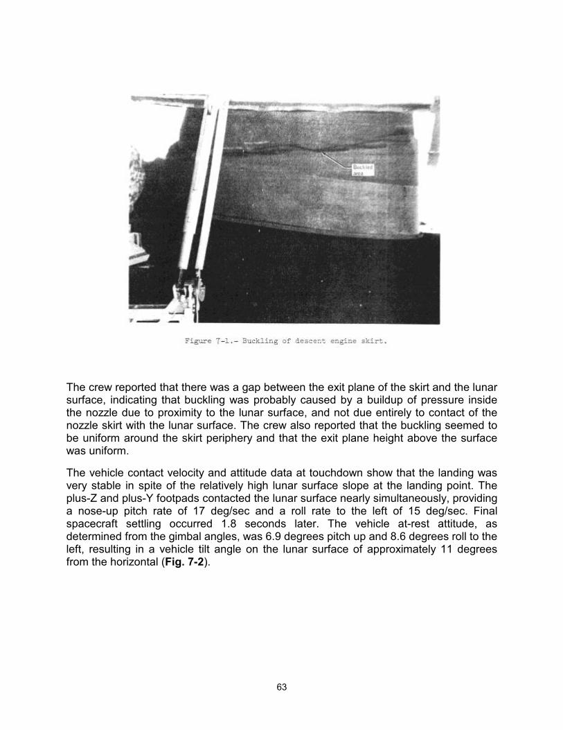
63
The crew reported that there was a gap between the exit plane of the skirt and the lunar surface, indicating that buckling was probably caused by a buildup of pressure inside the nozzle due to proximity to the lunar surface, and not due entirely to contact of the nozzle skirt with the lunar surface. The crew also reported that the buckling seemed to be uniform around the skirt periphery and that the exit plane height above the surface was uniform.
The vehicle contact velocity and attitude data at touchdown show that the landing was very stable in spite of the relatively high lunar surface slope at the landing point. The plus-Z and plus-Y footpads contacted the lunar surface nearly simultaneously, providing a nose-up pitch rate of 17 deg/sec and a roll rate to the left of 15 deg/sec. Final spacecraft settling occurred 1.8 seconds later. The vehicle at-rest attitude, as determined from the gimbal angles, was 6.9 degrees pitch up and 8.6 degrees roll to the left, resulting in a vehicle tilt angle on the lunar surface of approximately 11 degrees from the horizontal (Fig. 7-2).
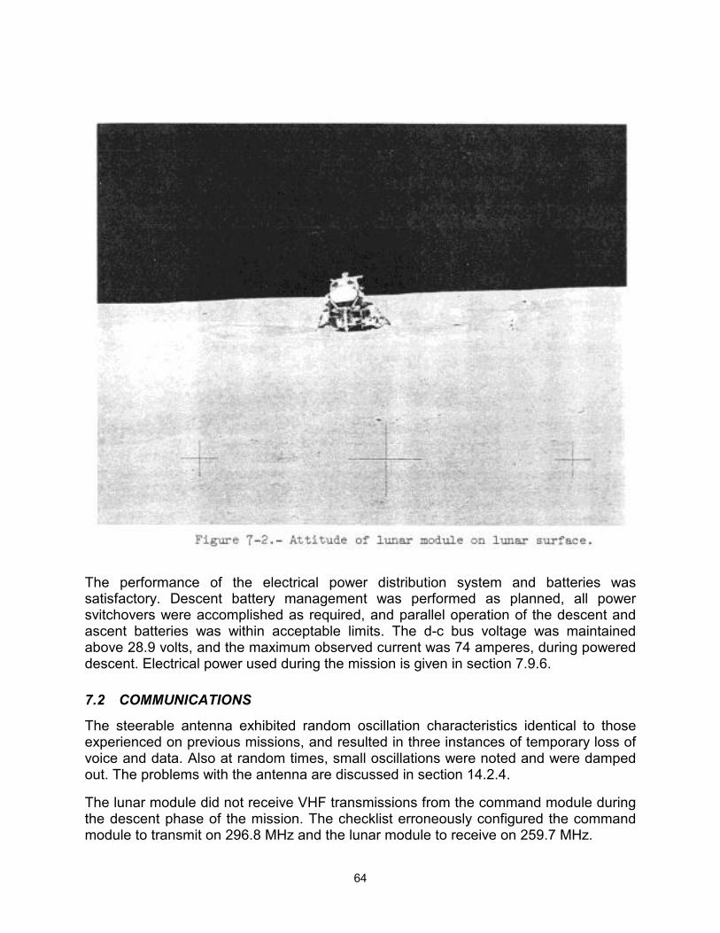
64
The performance of the electrical power distribution system and batteries was satisfactory. Descent battery management was performed as planned, all power svitchovers were accomplished as required, and parallel operation of the descent and ascent batteries was within acceptable limits. The d-c bus voltage was maintained above 28.9 volts, and the maximum observed current was 74 amperes, during powered descent. Electrical power used during the mission is given in section 7.9.6.
7.2 COMMUNICATIONS
The steerable antenna exhibited random oscillation characteristics identical to those experienced on previous missions, and resulted in three instances of temporary loss of voice and data. Also at random times, small oscillations were noted and were damped out. The problems with the antenna are discussed in section 14.2.4.
The lunar module did not receive VHF transmissions from the command module during the descent phase of the mission. The checklist erroneously configured the command module to transmit on 296.8 MHz and the lunar module to receive on 259.7 MHz.
65
With the exceptions noted above, all functions including voice, data, and ranging of both the S-band and the VHF equipment operated satisfactorily during all phases of the mission.
7.3 RADAR
The landing radar acquisition of slant range and velocity was normal. The acquired slant range of 42,000 feet increased to about 50,000 feet in approximately 10 seconds. The indication of range increase may have been caused by blockage from a lunar mountain at initial acquisition. Velocity was acquired at an altitude of approximately 39 000 feet above the local terrain. Landing radar outputs were affected at an altitude of about 30 feet by moving dust and debris.
Rendezvous radar tracking operation during the rendezvous sequence was nominal. A lunar module guidance computer program was used after lunar orbit insertion to point the rendezvous radar antenna at the command and service module, thus enabling acquisition at approximately 109 miles. Two problems were noted during the mission and are as follows:
During the VHF ranging system/rendezvous radar comparison test after undocking and separation, a range difference of 2400 feet existed between the rendezvous radar and VHF ranging systems. This difference represents high-frequency ranging-tone cycle slippage in the rendezvous radar, probably caused by excessive phase shift. Range errors associated with cycle slippage, due to insufficient heater operation, have occurred during system checkout and have produced phase shifts. Downlink data at the time of the problem indicates that the rendezvous radar transponder heater was not in operation when the rendezvous radar checkout was first attempted; therefore, it is assumed that the phase shift was caused by low temperatures.
b. Acquisition with the rendezvous radar during ascent was unsuccessful. The radar antenna was pre-positioned prior to lunar lift-off to an approximate lunar-module guidance-computer designated position for acquisition following insertion. In this position, acquisition would have been accomplished when the command module came into the rendezvous radar antenna field of view. A review of lift-off television data revealed rendezvous radar antenna movement during the first 2 seconds of flight. Analysis has also shown that expansion of the ascent engine plume, after being deflected from the descent stage structure, exerts sufficient pressure on the antenna to overcome gimbal friction and move the antenna. Radar acquisition apparently was not accomplished because the radar antenna moved. Rendezvous radar tracking during ascent is not required.
7.4 CONTROLS AND DISPLAYS
The controls and displays performed normally. The range/range-rate tape meter glass was broken with about 20 percent of the glass missing; however, the meter operated satisfactory during the flight. Section 14.2.8 contains a discussion of this anomaly.
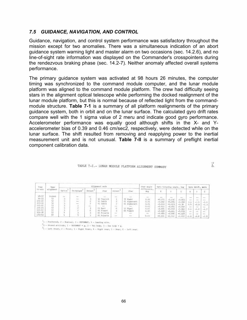
66
7.5 GUIDANCE, NAVIGATION, AND CONTROL
Guidance, navigation, and control system performance was satisfactory throughout the mission except for two anomalies. There was a simultaneous indication of an abort guidance system warning light and master alarm on two occasions (sec. 14.2.6), and no line-of-sight rate information was displayed on the Commander's crosspointers during the rendezvous braking phase (sec. 14.2-7). Neither anomaly affected overall systems performance.
The primary guidance system was activated at 98 hours 26 minutes, the computer timing was synchronized to the command module computer, and the lunar module platform was aligned to the command module platform. The crew had difficulty seeing stars in the alignment optical telescope while performing the docked realignment of the lunar module platform, but this is normal because of reflected light from the command- module structure. Table 7-1 is a summary of all platform realignments of the primary guidance system, both in orbit and on the lunar surface. The calculated gyro drift rates compare well with the 1 sigma value of 2 meru and indicate good gyro performance. Accelerometer performance was equally good although shifts in the X- and Y-accelerometer bias of 0.39 and 0.46 cm/sec2, respectively, were detected while on the lunar surface. The shift resulted from removing and reapplying power to the inertial measurement unit and is not unusual. Table 7-II is a summary of preflight inertial component calibration data.
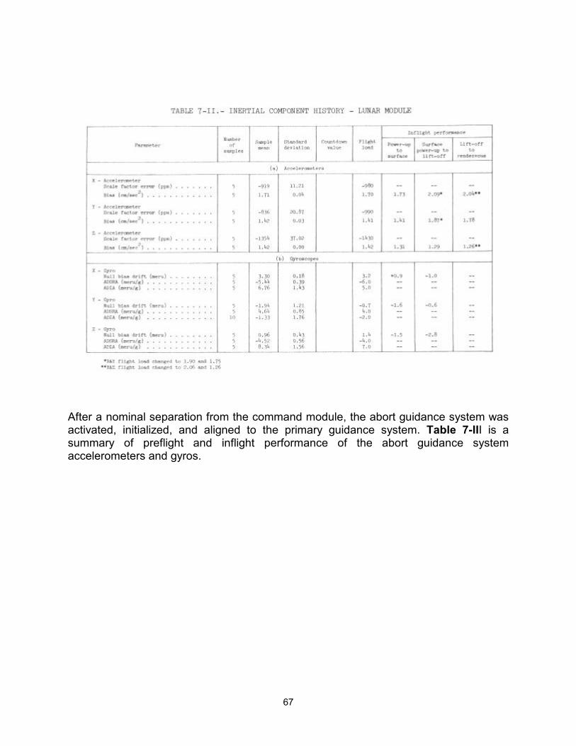
67
After a nominal separation from the command module, the abort guidance system was activated, initialized, and aligned to the primary guidance system. Table 7-III is a summary of preflight and inflight performance of the abort guidance system accelerometers and gyros.
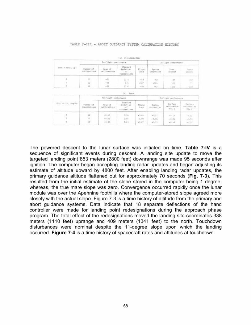
68
The powered descent to the lunar surface was initiated on time. Table 7-IV is a sequence of significant events during descent. A landing site update to move the targeted landing point 853 meters (2800 feet) downrange was made 95 seconds after ignition. The computer began accepting landing radar updates and began adjusting its estimate of altitude upward by 4800 feet. After enabling landing radar updates, the primary guidance altitude flattened out for approximately 70 seconds (Fig. 7-3). This resulted from the initial estimate of the slope stored in the computer being 1 degree; whereas, the true mare slope was zero. Convergence occurred rapidly once the lunar module was over the Apennine foothills where the computer-stored slope agreed more closely with the actual slope. Figure 7-3 is a time history of altitude from the primary and abort guidance systems. Data indicate that 18 separate deflections of the hand controller were made for landing point redesignations during the approach phase program. The total effect of the redesignations moved the landing site coordinates 338 meters (1110 feet) uprange and 409 meters (1341 feet) to the north. Touchdown disturbances were nominal despite the 11-degree slope upon which the landing occurred. Figure 7-4 is a time history of spacecraft rates and attitudes at touchdown.
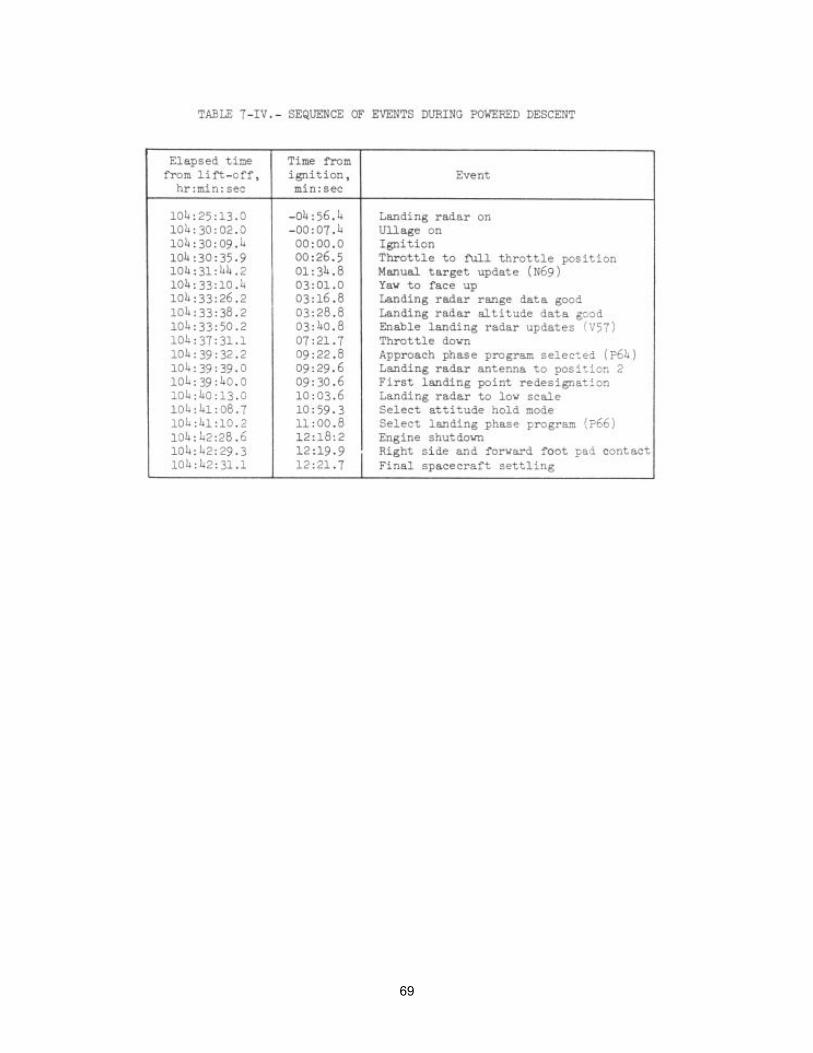
69
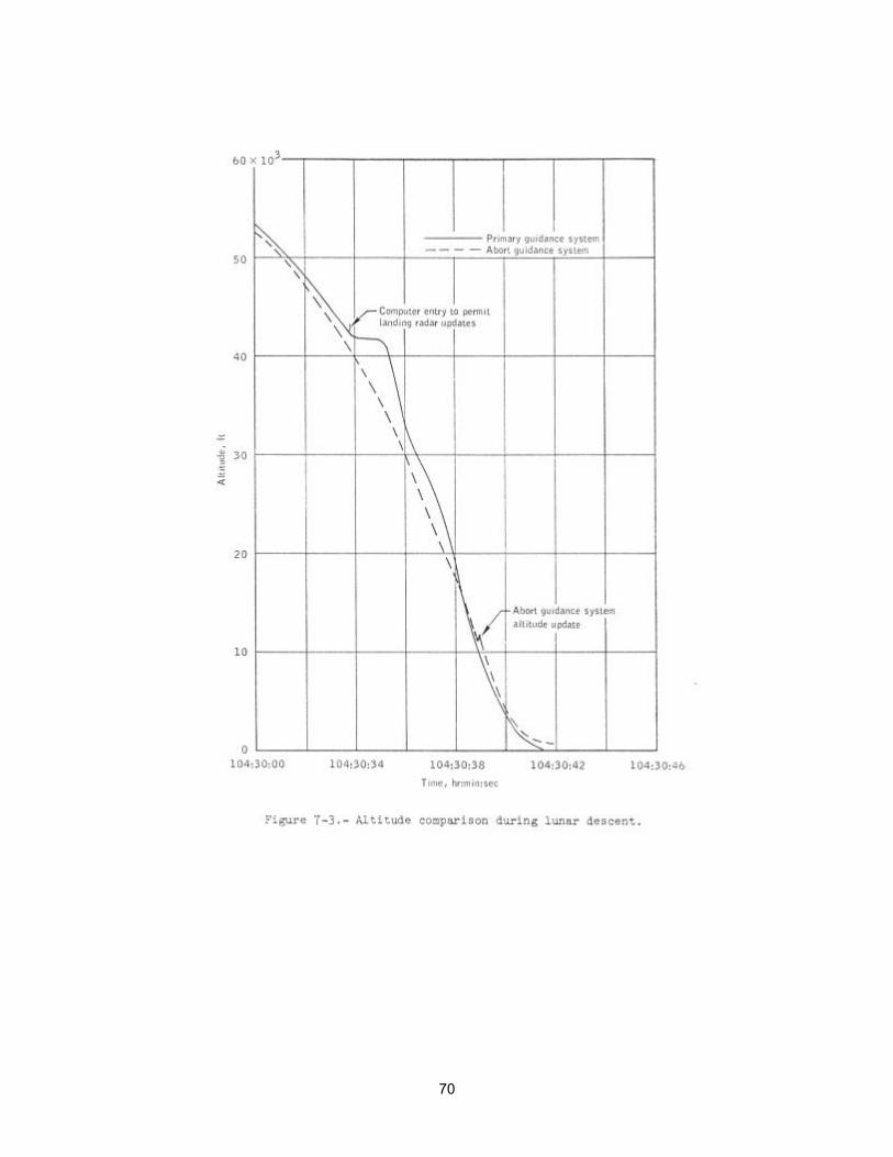
70
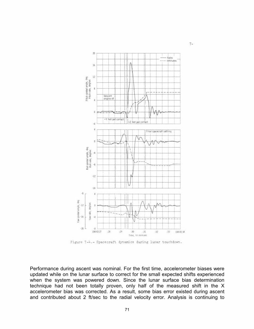
71
Performance during ascent was nominal. For the first time, accelerometer biases were updated while on the lunar surface to correct for the small expected shifts experienced when the system was powered down. Since the lunar surface bias determination technique had not been totally proven, only half of the measured shift in the X accelerometer bias was corrected. As a result, some bias error existed during ascent and contributed about 2 ft/sec to the radial velocity error. Analysis is continuing to
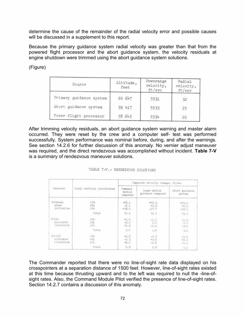
72
determine the cause of the remainder of the radial velocity error and possible causes will be discussed in a supplement to this report.
Because the primary guidance system radial velocity was greater than that from the powered flight processor and the abort guidance system, the velocity residuals at engine shutdown were trimmed using the abort guidance system solutions.
(Figure)
After trimming velocity residuals, an abort guidance system warning and master alarm occurred. They were reset by the crew and a computer self- test was performed successfully. System performance was nominal before, during, and after the warnings. See section 14.2.6 for further discussion of this anomaly. No vernier adjust maneuver was required, and the direct rendezvous was accomplished without incident. Table 7-V is a summary of rendezvous maneuver solutions.
The Commander reported that there were no line-of-sight rate data displayed on his crosspointers at a separation distance of 1500 feet. However, line-of-sight rates existed at this time because thrusting upward and to the left was required to null the -line-of-sight rates. Also, the Command Module Pilot verified the presence of line-of-sight rates. Section 14.2.7 contains a discussion of this anomaly.
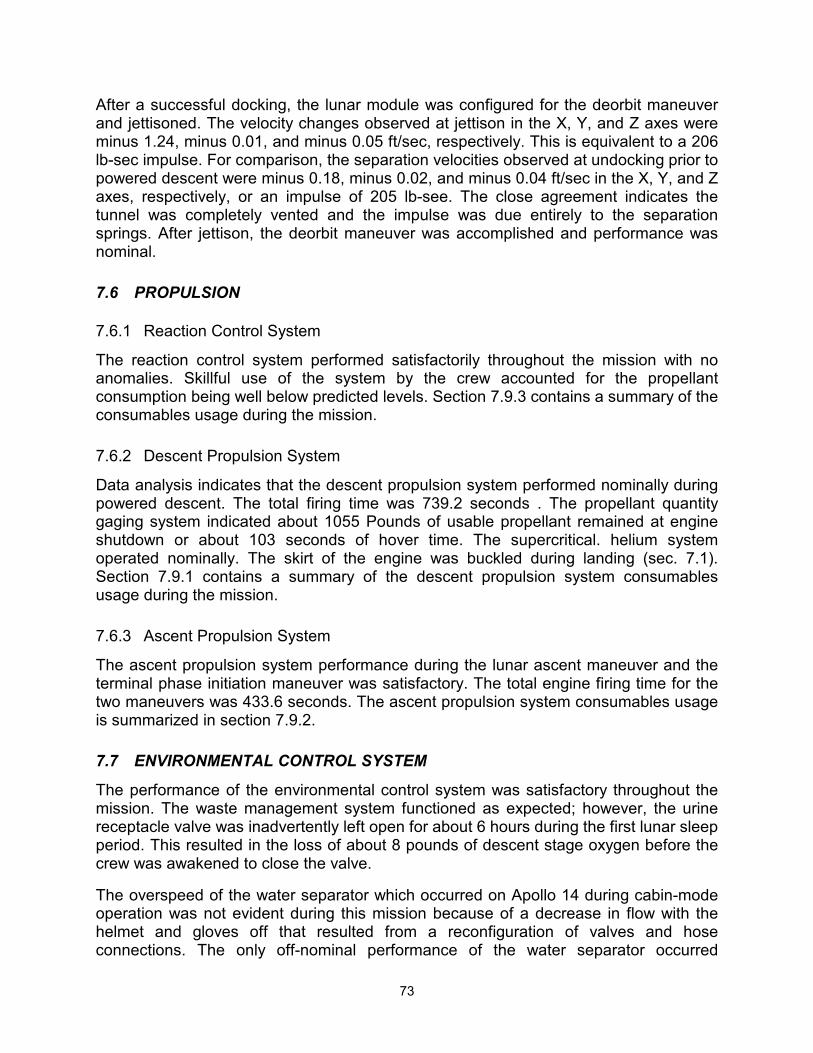
73
After a successful docking, the lunar module was configured for the deorbit maneuver and jettisoned. The velocity changes observed at jettison in the X, Y, and Z axes were minus 1.24, minus 0.01, and minus 0.05 ft/sec, respectively. This is equivalent to a 206 lb-sec impulse. For comparison, the separation velocities observed at undocking prior to powered descent were minus 0.18, minus 0.02, and minus 0.04 ft/sec in the X, Y, and Z axes, respectively, or an impulse of 205 lb-see. The close agreement indicates the tunnel was completely vented and the impulse was due entirely to the separation springs. After jettison, the deorbit maneuver was accomplished and performance was nominal.
7.6 PROPULSION
7.6.1 Reaction Control System
The reaction control system performed satisfactorily throughout the mission with no anomalies. Skillful use of the system by the crew accounted for the propellant consumption being well below predicted levels. Section 7.9.3 contains a summary of the consumables usage during the mission.
7.6.2 Descent Propulsion System
Data analysis indicates that the descent propulsion system performed nominally during powered descent. The total firing time was 739.2 seconds . The propellant quantity gaging system indicated about 1055 Pounds of usable propellant remained at engine shutdown or about 103 seconds of hover time. The supercritical. helium system operated nominally. The skirt of the engine was buckled during landing (sec. 7.1). Section 7.9.1 contains a summary of the descent propulsion system consumables usage during the mission.
7.6.3 Ascent Propulsion System
The ascent propulsion system performance during the lunar ascent maneuver and the terminal phase initiation maneuver was satisfactory. The total engine firing time for the two maneuvers was 433.6 seconds. The ascent propulsion system consumables usage is summarized in section 7.9.2.
7.7 ENVIRONMENTAL CONTROL SYSTEM
The performance of the environmental control system was satisfactory throughout the mission. The waste management system functioned as expected; however, the urine receptacle valve was inadvertently left open for about 6 hours during the first lunar sleep period. This resulted in the loss of about 8 pounds of descent stage oxygen before the crew was awakened to close the valve.
The overspeed of the water separator which occurred on Apollo 14 during cabin-mode operation was not evident during this mission because of a decrease in flow with the helmet and gloves off that resulted from a reconfiguration of valves and hose connections. The only off-nominal performance of the water separator occurred
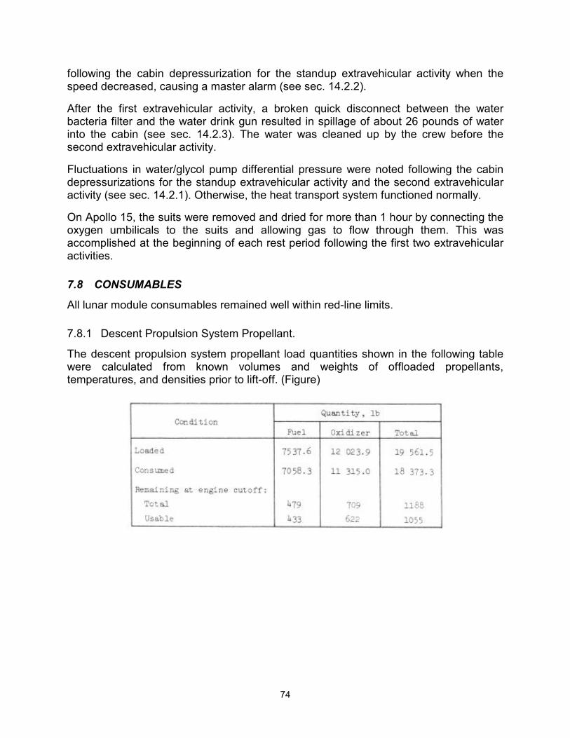
74
following the cabin depressurization for the standup extravehicular activity when the speed decreased, causing a master alarm (see sec. 14.2.2).
After the first extravehicular activity, a broken quick disconnect between the water bacteria filter and the water drink gun resulted in spillage of about 26 pounds of water into the cabin (see sec. 14.2.3). The water was cleaned up by the crew before the second extravehicular activity.
Fluctuations in water/glycol pump differential pressure were noted following the cabin depressurizations for the standup extravehicular activity and the second extravehicular activity (see sec. 14.2.1). Otherwise, the heat transport system functioned normally.
On Apollo 15, the suits were removed and dried for more than 1 hour by connecting the oxygen umbilicals to the suits and allowing gas to flow through them. This was accomplished at the beginning of each rest period following the first two extravehicular activities.
7.8 CONSUMABLES
All lunar module consumables remained well within red-line limits.
7.8.1 Descent Propulsion System Propellant.
The descent propulsion system propellant load quantities shown in the following table were calculated from known volumes and weights of offloaded propellants, temperatures, and densities prior to lift-off. (Figure)
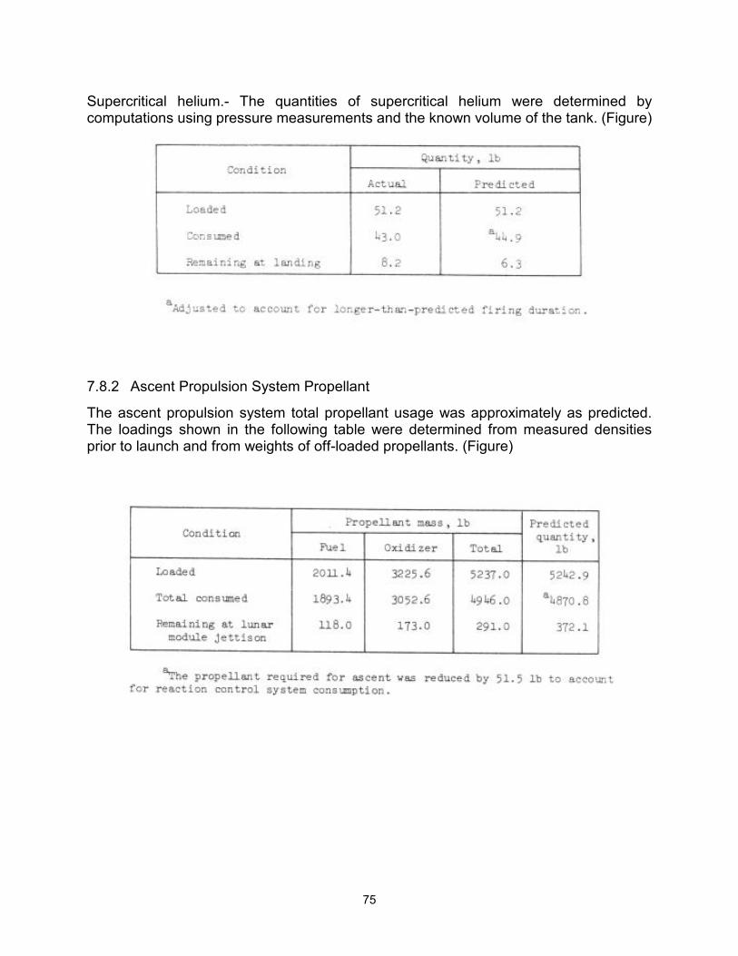
75
Supercritical helium.- The quantities of supercritical helium were determined by computations using pressure measurements and the known volume of the tank. (Figure)
7.8.2 Ascent Propulsion System Propellant
The ascent propulsion system total propellant usage was approximately as predicted. The loadings shown in the following table were determined from measured densities prior to launch and from weights of off-loaded propellants. (Figure)
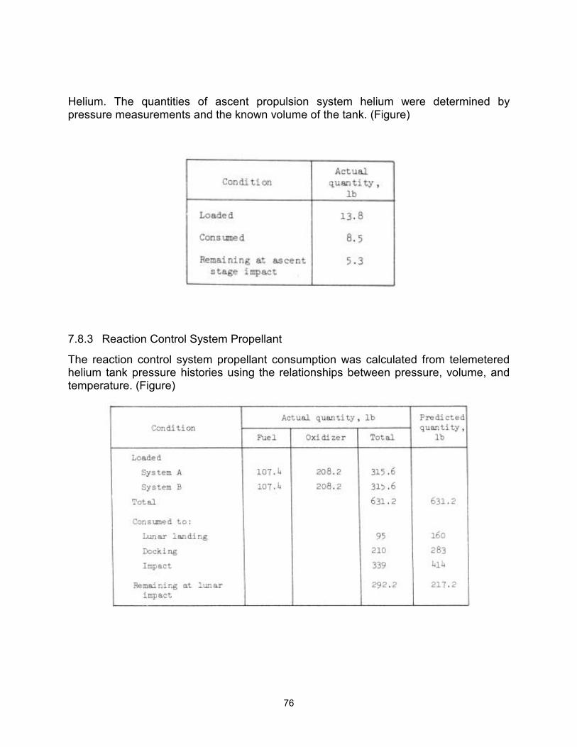
76
Helium. The quantities of ascent propulsion system helium were determined by pressure measurements and the known volume of the tank. (Figure)
7.8.3 Reaction Control System Propellant
The reaction control system propellant consumption was calculated from telemetered helium tank pressure histories using the relationships between pressure, volume, and temperature. (Figure)
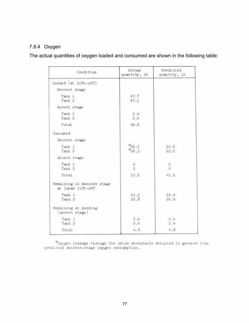
77
7.8.4 Oxygen
The actual quantities of oxygen loaded and consumed are shown in the following table:
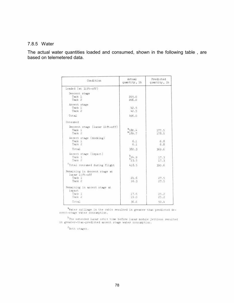
78
7.8.5 Water
The actual water quantities loaded and consumed, shown in the following table , are based on telemetered data.
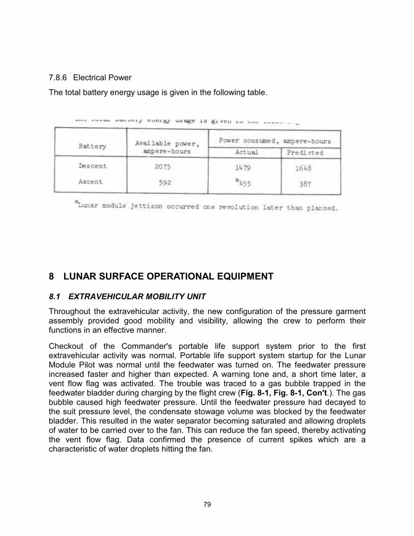
79
7.8.6 Electrical Power
The total battery energy usage is given in the following table.
8 LUNAR SURFACE OPERATIONAL EQUIPMENT
8.1 EXTRAVEHICULAR MOBILITY UNIT
Throughout the extravehicular activity, the new configuration of the pressure garment assembly provided good mobility and visibility, allowing the crew to perform their functions in an effective manner.
Checkout of the Commander's portable life support system prior to the first extravehicular activity was normal. Portable life support system startup for the Lunar Module Pilot was normal until the feedwater was turned on. The feedwater pressure increased faster and higher than expected. A warning tone and, a short time later, a vent flow flag was activated. The trouble was traced to a gas bubble trapped in the feedwater bladder during charging by the flight crew (Fig. 8-1, Fig. 8-1, Con't.). The gas bubble caused high feedwater pressure. Until the feedwater pressure had decayed to the suit pressure level, the condensate stowage volume was blocked by the feedwater bladder. This resulted in the water separator becoming saturated and allowing droplets of water to be carried over to the fan. This can reduce the fan speed, thereby activating the vent flow flag. Data confirmed the presence of current spikes which are a characteristic of water droplets hitting the fan.
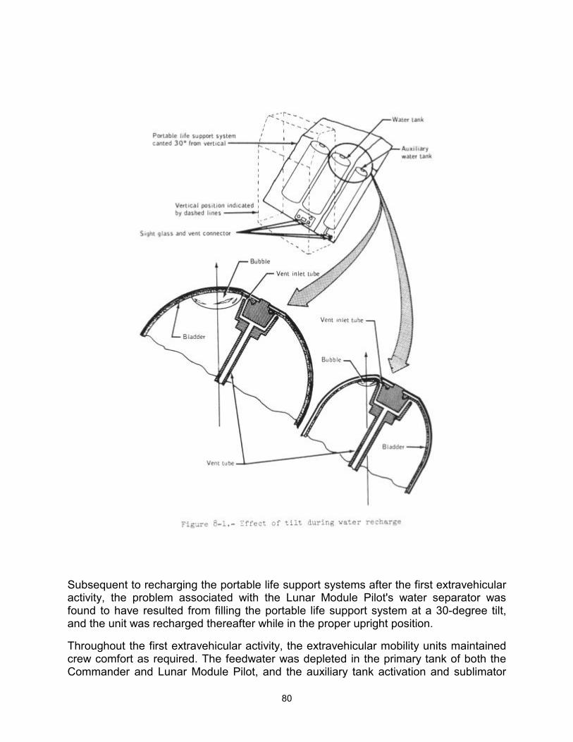
80
Subsequent to recharging the portable life support systems after the first extravehicular activity, the problem associated with the Lunar Module Pilot's water separator was found to have resulted from filling the portable life support system at a 30-degree tilt, and the unit was recharged thereafter while in the proper upright position.
Throughout the first extravehicular activity, the extravehicular mobility units maintained crew comfort as required. The feedwater was depleted in the primary tank of both the Commander and Lunar Module Pilot, and the auxiliary tank activation and sublimator
81
repressurization were normal. During this period, the sublimator gas-outlet temperature on the Commander's extravehicular mobility unit ran slightly higher than expected. A comparative analysis of the extravehicular mobility unit parameters indicates that the condition was most likely caused by the cooling water flow running at a low-normal rate.
The first extravehicular activity was terminated about one-half hour earlier than planned because of a higher-than-expected oxygen usage by the Commander.
The communications check at the beginning of the second extravehicular activity was initially unsuccessful for the Lunar Module Pilot because his antenna was broken (sec. 14.5.6). The crewmen taped the antenna to the oxygen purge system in the stowed configuration and the communications check was successfully completed. In this configuration the limiting range is about 305 meters (1000 feet) between crewmen. The feedwater was depleted in the primary tank of both the Commander and the Lunar Module Pilot during the second extravehicular activity, and the auxiliary tank activation, the sublimator repressurization, and the sublimator gas-outlet temperature were normal.
During portable life support system activation for the third extravehicular period, the sublimator gas-outlet temperature and feedwater pressure of the Lunar Module Pilot's extravehicular mobility unit were both reading lower than expected. At lunar module depressurization, these parameters began an upward trend which led to normal readings by the time the Lunar Module Pilot reached the lunar surface.
Oxygen, feedwater, and power consumption of the extravehicular mobility units during the three extravehicular periods are shown in Table 8-1. For the Commander's first and second extravehicular activities, and the Lunar Module Pilot's first extravehicular activity, the oxygen redline limits were approached, indicating that the crew workload was approaching the portable life support system capability.
The only problems associated with the lunar module crew station equipment during the mission was that the Lunar Module Pilot could not get water from the insuit drinking device during the first and second extravehicular activities (see sec. 14.5-5), and the Commander's insuit drinking device mouthpiece became displaced during the second extravehicular activity. However, neither insuit drinking device problem constrained the extravehicular activities. The insuit drinking device was not used for the third extravehicular activity because of the short extravehicular activity time.
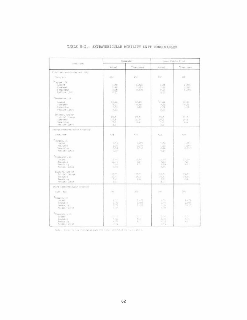
82
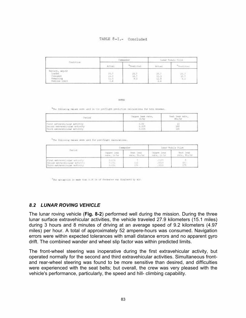
83
8.2 LUNAR ROVING VEHICLE
The lunar roving vehicle (Fig. 8-2) performed well during the mission. During the three lunar surface extravehicular activities, the vehicle traveled 27.9 kilometers (15.1 miles) during 3 hours and 8 minutes of driving at an average speed of 9.2 kilometers (4.97 miles) per hour. A total of approximately 52 ampere-hours was consumed. Navigation errors were within expected tolerances with small distance errors and no apparent gyro drift. The combined wander and wheel slip factor was within predicted limits.
The front-wheel steering was inoperative during the first extravehicular activity, but operated normally for the second and third extravehicular activities. Simultaneous front- and rear-wheel steering was found to be more sensitive than desired, and difficulties were experienced with the seat belts; but overall, the crew was very pleased with the vehicle's performance, particularly, the speed and hill- climbing capability.
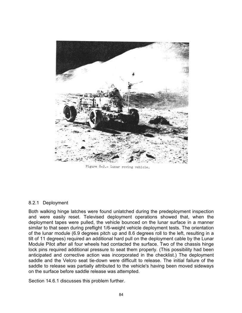
84
8.2.1 Deployment
Both walking hinge latches were found unlatched during the predeployment inspection and were easily reset. Televised deployment operations showed that, when the deployment tapes were pulled, the vehicle bounced on the lunar surface in a manner similar to that seen during preflight 1/6-weight vehicle deployment tests. The orientation of the lunar module (6.9 degrees pitch up and 8.6 degrees roll to the left, resulting in a tilt of 11 degrees) required an additional hard pull on the deployment cable by the Lunar Module Pilot after all four wheels had contacted the surface. Two of the chassis hinge lock pins required additional pressure to seat them properly. (This possibility had been anticipated and corrective action was incorporated in the checklist.) The deployment saddle and the Velcro seat tie-down were difficult to release. The initial failure of the saddle to release was partially attributed to the vehicle's having been moved sideways on the surface before saddle release was attempted.
Section 14.6.1 discusses this problem further.
85
8.2.2 Steering
During preparations for the first traverse, the front wheels did not respond to steering commands. The Commander changed busses and observed the ammeter closely to find out if power was being applied to the front wheels in response to steering commands. No response was seen. He then tried, without success, to manually force the front wheels to turn. The front wheel steering remained inoperative, thus the rear wheels were used for steering during the first traverse (see sec. 14.6-3). Little difficulty was experienced in driving, except that attempts to avoid nearby objects resulted in the rear wheels sliding into small craters and objects that the driver was trying to avoid. In at least one slide, the vehicle rotated through 180 degrees.
During checkout of the vehicle for the second traverse, the crew cycled the forward steering power switch and circuit breaker, and found that the front wheel steering operated normally. In starting the second traverse, the Commander first tried dual steering. Then, after the dual steering was found to be very sensitive, he tried front-wheel-only steering. However, this mode was discontinued because the rear wheels tended to wander. (It had been decided not to lock the rear wheels mechanically because of the prior problem with the front wheels.) Therefore, the dual steering mode was used for the remainder of the second traverse and the entire third traverse.
8.2.3 Electrical Power
The lunar roving vehicle used less power than predicted. The predicted power consumption was based on worst-case surface roughness and soil composition, but the actual surface conditions were less severe. The cause of an initial ampere-hour reading of 105 ampere-hours instead of 121 amperehours is not known. Subsequent readings, correlated with ammeter readings, produce an estimated total power consumption of 52 ampere-hours of the 242 ampere- hours available. The consumed electrical power corresponds to a rate of 1.87 ampere-hours per kilometer. The preflight prediction of the usage rate was 3.67 ampere-hours per kilometer. Except for the ampere-hour indicator readings and the inoperative battery 2 volt/ammeter (sec. 14.6.2), the electrical power system operation was normal during the traverses.
After ascent, the video signal was lost from the lunar surface television camera. Postflight analysis and tests show that this loss (section 8-3) was probably caused by opening of the auxiliary power circuit breaker under combined electrical and thermal loads. This anomaly is discussed further in section 14-5.2.
8.2.4 Navigation
The vehicle navigation system operation was normal. The odometer showed a total distance traveled of 27.9 kilometers (15.1 miles). The navigation system provided sufficient information to locate the lunar module at any time during all traverses. Evaluation indicates that the gyro drift rate was essentially zero and the distance error at the maximum range of 5.0 kilometers (2-7 miles) was approximately 0.3 kilometer (0.16 mile). No traverse realignments were required. Closure errors for the three traverses were 0, 100, and 200 meters, well within predictions.
86
8.2.5 Thermal
The thermal control system, in general, performed satisfactorily. drive motors remained cool and battery temperatures were maintained within established limits.
At the beginning of the second extravehicular activity, the battery 1 cover had closed automatically, as expected. Battery 2 apparently had not cooled down enough and the cover was still open. It was closed manually powering up the vehicle. When the vehicle was activated, battery-1 temperature was 68 degrees F and battery-2 temperature was 78 degrees F. The difference was probably caused by the difference in dust accumulation on the thermal mirrors. These temperatures are consistent with predicted cool-down rates with the covers open and warm-up rates with the covers closed. During the second traverse, the battery-1 and battery-2 temperatures increased to 92 F and 98 F, respectively. The battery covers were opened at the conclusion of the second extravehicular activity period.
At the beginning of the third extravehicular activity, both covers were open. Little battery cool-down had occurred, probably because of further dust accumulation on both battery mirrors, although the battery covers had been closed for the traverses. The covers must not have been closed tight enough against the Velcro edges to keep dust off the mirror surfaces. Only a small amount of dust on the surface will preclude the desired cool-down. At the conclusion of the traverse, battery-1 and battery- 2 temperatures had increased to 108 F and 113 F, respectively, which is an acceptable level.
8.2.6 Crew Station
The crew station was satisfactory except that the seat belts were difficult to fasten (sec. 14.6.4). Prelaunch belt adjustment did not properly account for the reduced gravity in combination with the pressurized suits, and the belts were too short for lunar surface operations. Additionally, the Commander's seat belt hook caught repeatedly on the ground support equipment electrical connector on the console post.
8.2.7 EXTRAVEHICULAR COMMUNICATIONS EQUIPMENT
The lunar communications relay unit operated normally during all lunar surface extravehicular activities. The voice and data quality were good.
Communications from the lunar roving vehicle while it was in motion or temporarily stopped were satisfactory except that the lack of manual realignment of the low-gain antenna to earth resulted in noisy down-link voice at one time when the lunar roving vehicle was parked on a steep slope during the second extravehicular activity.
Fixed-site television operation on the lunar roving vehicle was satisfactory except for difficulty in using the antenna optical sight. With the lunar roving vehicle pointed in the down-sun direction, the sun was directly in the crewmen's eyes when using the optical sight. The design concept was to orient the rotatable sight to a position where sun glare would be avoided. When the lunar roving vehicle was parked north or south, the sun was 90 degrees to the side and no glare resulted. In those instances when glare

87
prevented the use of the optical sight, the lunar communication relay unit automatic gain control meter was used.
Lunar dust on the television camera lens caused a halo effect and sun reflected glints. Improvement in picture quality was restored periodically after the crew brushed the lens.
The ground-commanded television assembly operated successfully during the three extravehicular activity periods and provided coverage of the lunar lift- off. Good quality video signals were received while the camera was operating with the lunar module and the lunar communications relay unit. The elevation clutch began to slip during the second extravehicular period and the condition became worse during the third extravehicular period (section 14.5-1). The crew, on several occasions, manually assisted the elevation mechanism to regain an operative camera pitch angle.
The television camera was activated about 40 hours after the ascent from the lunar surface. After about 13 minutes of satisfactory operation, signals from the lunar communications relay unit were lost and all attempts to reactivate this system have failed. Refer to section 14.5.2 for a discussion of this anomaly.
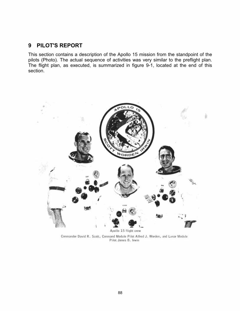
88
9 PILOT'S REPORT This section contains a description of the Apollo 15 mission from the standpoint of the pilots (Photo). The actual sequence of activities was very similar to the preflight plan. The flight plan, as executed, is summarized in figure 9-1, located at the end of this section.
89
9.1 TRAINING
The crew of Apollo 15 was able to concentrate their training time primarily on learning new operational techniques and becoming qualified in scientific aspects of the mission because of the demonstrated reliability and performance of Apollo hardware and because they had the experience of one complete training cycle as backup crew for Apollo 12.
Approximately one-third of the crew's training time was applied to science. In addition, the crew participated in many phases of development and planning of the new operational and scientific techniques to be utilized in the accomplishment of the objectives of the Apollo 15 mission.
Standard training for Apollo 15 included emphasis on the following new items developed for this mission: Scientific instrument module and associated extravehicular activity; lunar roving vehicle and associated equipment; A7L-B pressure garment assembly; concepts and equipment for expanded lunar geology investigation; and major modifications to the computer program for the command module, lunar module, and abort guidance system. Because of the vast amount of new equipment programmed for lunar surface activity, considerable crew time and effort were devoted to development of procedures in order to optimize the time devoted to lunar surface exploration. Excellent support was received, both in training and procedures development, throughout the 20 months of preparation for the flight.
9.2 LAUNCH
Countdown and launch preparations were well coordinated and timely. Significant events were generally completed approximately 20 minutes ahead of schedule. The crew was comfortable and the crew station was in excellent condition.
Ignition and lift-off were positive with the same overall vehicle vibration frequency throughout S-IC flight that has been noted on previous flights. Noise levels were lower than those the Commander had experienced on Apollo 9, and communications were excellent throughout powered flight. S-IC staging was abrupt and was accompanied by a 3- to 4-degree vehicle yaw, which was corrected soon after S-II ignition. All other displayed and physiological cues were as reported on previous flights with the exception of a very low-amplitude 10- to 12-hertz vehicle vibration during both S-II and S-IVB powered flight, and the lack of a perceptible cue to the programmed shift in propellant utilization during S-II operation.
9.3 EARTH ORBITAL OPERATIONS
All systems checks during earth orbit were completed ahead of schedule and in a satisfactory manner. Those checks included an alignment of the inertial measurement unit, an entry monitor system test, and basic checks of the environmental control and reaction control systems. The alignment was within the drift tolerance voiced up from the ground, and the entry monitor system test indicated an accelerometer bias of 0.01 ft/
90
sec. The reaction control system was tested using minimum impulse to insure proper operation. During postinsertion checks, the secondary isolation valve for quad B was found closed, but the valve was reset satisfactorily. At about 1 hour, the quad D primary and secondary isolation valves were also found closed and these were also reset.
The systems preparations for translunar injection were completed approximately 20 minutes ahead of schedule, and updates were received in a timely manner. A new procedure was employed to align the flight director attitude indicator for translunar injection which would allow smooth manual takeover at any time. Also, a new computer program was utilized which allowed computer monitoring and shutdown of the translunar injection burn if takeover had been required.
9.4 TRANSLUNAR INJECTION
All events in the translunar injection sequence were as expected with two exceptions. First, in repressurization of the S-IVB hydrogen tank, the increase in pressure was much slower than that experienced in preflight training; however, the ground confirmed that the repressurization cycle was nominal and final pressure values were within the expected range. Second, an S-IVB propellant utilization shift was manifested as a marked surge in thrust 1 minute after ignition. A low-amplitude vibration of about 10 to 12 hertz was felt throughout the translunar injection maneuver. The S-IVB cutoff was 3 seconds early; however, the crew had been informed by Mission Control to expect this.
9.5 TRANSLUNAR FLIGHT OPERATIONS
9.5.1 Transposition, Docking, and Extraction
The transposition and docking were accomplished in a fashion that was slightly different from the checklist procedure. All of the procedures up to the point of separation were accomplished as prescribed. The separation was completed with the guidance and navigation system autopilot in control of the spacecraft attitude. After separation, however, attitude control was switched to the stabilization and control system. The manual attitude pitch switch was placed in ACCEL CMD and the spacecraft was pitched 180 degrees at a rate of 2 deg/sec. After completion of the 180-degree pitch maneuver, control of spacecraft attitude was returned to the guidance and navigation autopilot and an automatic maneuver was made to the docking attitude. While the automatic maneuver was being performed, forward thrusting was accomplished for approximately 4 seconds to insure positive closing of the command and service module and the S-IVB. The closing rate was approximately 0.1 ft/sec. On contact, there was no indication of probe capture latch engagement. Forward thrusting was applied for approximately 1 to 2 seconds and the capture latch indication was then received. The probe was activated to the retract position and the two spacecraft were hard-docked. At the completion of the docking maneuver, the forward hatch was removed and the latches were checked. One latch was not locked onto the docking ring. That latch was recocked and latched manually. The lunar module umbilicals were then attached, and the hatch was replaced. Extraction of the lunar module from the S-IVB was nominal and, at its completion, an automatic maneuver was made to an attitude which allowed a view of subsequent S-IVB maneuvers.
91
9.5.2 Translunar Coast
Spacecraft systems.- Shortly after the transposition and docking maneuver, the service propulsion system thrust light on the entry monitor system panel was illuminated, indicating a possible electrical short in the service propulsion ignition system. A fault isolation procedure was transmitted to the crew and the short was isolated to bank A of the service propulsion system electrical circuitry. The first midcourse correction was utilized for further troubleshooting. Ignition was initiated by closing the pilot valve main A circuit breaker. Since this started the engine, the nature and location of the short allowed bank A to be manually controlled for subsequent maneuvers. A special procedure was then developed for lunar orbit insertion and transearth injection whereby the service propulsion system maneuvers would be initiated normally with bank B after which the pilot valve main A circuit breaker would be closed manually, turning on bank A. Prior to the termination of the firing, the pilot valve main A circuit breaker would be opened and the firing would be terminated automatically on bank B. All other service propulsion system maneuvers were to be accomplished using bank B only.
Passive thermal control was employed to insure uniform surface heating as on previous flights. Because a new computer program was used to establish the spin rate, new procedures were developed for the initiation of passive thermal control. On the first two attempts, the pitch and yaw rates were not satisfactorily damped before starting the spin-up. However, passive thermal control was satisfactorily established on the third and all subsequent attempts.
An electrical short occurred in the a-c power system somewhere in the lower equipment bay -lighting circuitry, resulting in an opened circuit breaker on the electrical systems panel. No troubleshooting was performed to locate the short and the circuit breaker was left open. The affected lights in the lower equipment bay and on the entry monitor system scroll were out for the remainder of the mission. Rheostats for the operable lights in the lower equipment bay were taped in the positions in which they were found and they remained that way for the remainder of the flight.
During a chlorination cycle, a water leak was discovered on the water panel around the chlorine injector port. The leak appeared as a ball of water around the port. The water was absorbed by towels until information was received from Mission Control indicating that the insert in the open end of the chlorine injector port was possibly loose. Tools were obtained from the tool kit, the port was tightened, and the leak subsided.
The first entry into the lunar module was made on schedule and all planned equipment was transferred. The command and service module oxygen hose was not used. During the inspection, the tunnel misalignment was found to be less than 1 degree (plus or minus 10 degrees is allowed). Also, the range/range-rate tapemeter glass was found broken. The command module vacuum cleaner was used to clean up most of the glass fragments. An additional entry into the lunar module was made at about 57 hours at the request of Mission Control so that additional data on the batteries could be obtained. The vacuum cleaner and lunar module cabin fans were used to gather additional glass. No loose object was found that could account for glass breakage.
92
Simulated cislunar midcourse navigation sightings were accomplished during translunar coast for horizon calibration and on-the-job training. The midcourse navigation exercises were valuable from the standpoint that they allowed the Command Module Pilot to calibrate his eye to a horizon for subsequent use in all transearth coast sightings.
Science and photography.- All science operations during translunar coast were completed as scheduled. These operations included such things as sextant photography of star patterns and ultraviolet photography of the earth and moon. The ultraviolet photography was completed as prescribed, requiring specific spacecraft attitudes and special operations associated with command module window 5. A removable filter had been installed to protect the crew from ultraviolet radiation. This filter required removal to allow the ultraviolet photography. Because of the handling, the filter became increasingly scratched during the flight.
9.5.3 Scientific Instrument Module Door Jettisoning
The scientific instrument module door was jettisoned after the second midcourse correction and prior to lunar orbit insertion. To prepare for this, the crew donned their pressure garments, performed a pressure integrity check, and maneuvered the spacecraft to the proper attitude. Jettisoning of the door was felt as a very light "thud" in the command module. The only abnormal indication was the closing of the service module reaction control system B secondary propellant isolation valve, which was reset with no difficulty. The door was first observed from command module window 5 at a distance of about 50 feet and on a trajectory 90 degrees from the longitudinal axis of the spacecraft. Door jettison was accomplished without difficulty and with much less reaction than had been anticipated.
9.6 LUNAR ORBIT OPERATIONS PRIOR TO DESCENT
9.6.1 Lunar Orbit Insertion
All checks for lunar orbit insertion were completed as scheduled in the flight plan, and all systems were verified as acceptable for lunar orbit operations. The maneuver to the lunar orbit insertion attitude was verified by a sextant star check. Subsequently, the service propulsion system thrusting program was activated and the velocities and angles were verified by the ground. All commands from the ground were received in a timely manner. The firing was accomplished as described in section 9.5.2. The maneuver was initiated with very small transients, the attitude excursions were never greater than approximately 1 degree, and the gimbal position indications showed a very smooth and positive response to the shift in the center of gravity. The maneuver was terminated by the guidance and navigation system with zero residuals. The descent orbit initiation maneuver was accomplished using service propulsion system bank B alone. This maneuver, as in the lunar orbit insertion maneuver, was preceded by systems checks which were all nominal, and the maneuver was nominal. A subsequent descent orbit insertion trim maneuver that had been anticipated and scheduled prior to flight was, in fact, required before undocking because of perturbations in the orbit up to that point. It was a very small maneuver of approximately 3 ft/sec and was
93
accomplished using the reaction control system maneuver program. All pre-maneuver checks were completed nominally and the maneuver was performed satisfactorily.
9.6.2 Lunar Module Activation, Undocking and Separation
On the day scheduled for landing, entry into the lunar module was about 40 minutes early. Final closure of the suit zippers was accomplished in the lunar module. One procedural change was made in order to purge the suit umbilical hoses: Both suit isolation valves were placed in the FLOW position for 15 seconds, then in the DISCONNECT position, after which the suit gas diverter valve was placed in the CABIN position. Checklist functions were generally performed 10 minutes ahead of schedule.
As noted in earlier flights, stars were difficult to see through the alignment optical telescope while docked with the command module. However, the results of a two-star sighting using the cursor-spiral technique indicated platform realignment could be achieved with the optics.
The suit loop integrity check was unsuccessful on the first attempt. The checklist procedure was followed, but there was obviously a leak because the pressure drop was approximately 1 psi in 30 seconds. The valve detents were checked, the regulator was rechecked, and then another integrity check was made. This time, the pressure drop was acceptable at 0.1 psi in 1 minute. The time a1lowed to accomplish the required functions for powered descent is more than sufficient. This became apparent when a number of unanticipated events occurred. Condensate had formed on the lunar module windows and the heaters had to be activated in order to clear them. Undocking was delayed for approximately 40 minutes because the command module/lunar module power transfer umbilical connections were not electrically engaged. A descent engine throttle check had to be redone because the descent engine control assembly circuit breaker was in the open position during the first check. The timeline was regained by the time of the scheduled guidance and navigation system platform realignment and the pace was very leisurely as the time for powered descent initiation approached; the crew even had time to eat lunch. The rendezvous radar self-test was normal but, after separation, the range indicated by the rendezvous radar was approximately twice that indicated by VHF ranging (see sec. 7.4).
9.7 POWERED DESCENT AND LANDING
The angle of the final descent trajectory after high gate was increased from 14 degrees to 25 degrees for Apollo 15. This afforded improved dispersion conditions during the braking phase over the Apennine Mountains, better visibility after pitchover, and more precise control of manual landing site redesignations.
After receiving final uplinks from the Manned Space Flight Network, the powered descent program was called up in the lunar module guidance computer 10 minutes prior to ignition. The landing radar circuit breaker was closed 5 minutes prior to ignition, as planned, and all events were nominal through the first minute of powered flight. Automatic ullage and ignition were clearly evident by physiological cues. A correction was manually entered into the computer to move the targeted landing site about 853 meters (2800 feet) west (downrange) just prior to ignition plus 2 minutes. The indicated
94
quantity of onboard fuel was 2 percent low at this time, but this was considered acceptable by ground control. Three minutes after ignition, the spacecraft was yawed to the planned inplane face-up attitude. Immediately thereafter, at approximately 43 000 feet altitude, landing radar data became acceptable and computer updates were initiated. Landing radar data were solid throughout the remainder of powered flight.
Throttle recovery occurred on time, and manual attitude hold was evaluated with the following expected results: positive response, considerable reaction control system activity, and rapid return to smooth automatic guidance at the Completion of the check. Predicted pitchover time (high gate) was checked in the computer, and conformed to the preflight nominal time of 9 minutes 22 seconds.
At an altitude of approximately 9000 feet, the upper fourth of Hadley Delta Mountain (11,000 feet high) was visible out of the left window. The feeling of slow, forward, floating motion was experienced and, because of the relative position and motion with respect to the mountain, an impression of a downrange overshoot was experienced. At about 8000 feet altitude, ground control informed the crew that the expected landing site was to be approximately 915 meters (3000 feet) south of the targeted site.
Pitchover occurred on time and the only positive recognizable lunar surface feature was Hadley Rille. Topographic relief was much less than had been anticipated from the enhanced 20-meter (65-foot) resolution photography and the associated preflight lunar terrain models. Sharp landmark recognition features within the Plain of Hadley were almost nonexistent; however the South Cluster was soon identified. Based upon the apparent position relative to this feature, plus the 915-meter miss distance to the south given by ground control, several landing point redesignations were made to the right (north).
At an altitude of approximately 5000 feet, a pair of subdued craters, which appeared to be Salyut and its northerly adjacent neighbor, were identified. Uprange landing point redesignations were made so that the landing could be made in the correct area northwest of Salyut Crater. The touchdown point was selected from an altitude of 2000 feet and the lunar module was maneuvered to land on what appeared to be a smooth level surface. The low-gate phase (manual control) of the trajectory was manually selected and confirmed at an altitude of 400 feet. Descent rate reduction was initiated at a height of about 200 feet, and visual reference was maintained by watching several fragments on the lunar surface which were located 30 to 40 meters (100 to 130 feet) west of the selected site. A trace of blowing surface dust was observed at a height of 130 feet with only a slight increase down to 60 feet. Beginning at this altitude, out-of-the window visibility was completely obscured by dust until after touchdown.
Tapemeter altitude and altitude rate data readings, provided orally by the Lunar Module Pilot, appeared to be consistent with the visual observations throughout the terminal phase of the landing. Surface features and texture became well defined at an altitude of approximately 1000 feet and, based on preflight experience with visual simulator displays, descent rates appeared completely nominal and comfortable. Sensations after manual takeover at 400 feet were almost identical with those experienced in lunar landing training vehicle operations. The combination of visual simulations and lunar
95
landing training vehicle flying provided excellent training for the manual portion of the lunar landing. Comfort and confidence existed throughout this phase.
Additional manual maneuvering south and west could easily have been made below 400 feet; however, because of increased surface mobility afforded by the lunar roving vehicle, a landing anywhere within the 3-sigma dispersion ellipse was considered a precise landing, and additional maneuvering within this ellipse, other than for terrain obstacle avoidance, was considered unnecessary.
The engine stop button was activated shortly after the contact lights were illuminated to preclude excessive pressure buildup within the nozzle of the descent engine (which had been extended 10 inches since Apollo 14). Touchdown was firm but only slightly more so than nominal lunar landing training vehicle landings. Roll and pitch rates were evident at touchdown as the rear and left foot pads came to rest in a shallow subdued crater which was not visible during the final phase of the landing. The posttouchdown events were nominal; no spurious reaction control system firings occurred, and permission for the lunar stay was voiced by Houston in a timely manner.
9.8 LUNAR SURFACE OPERATIONS
9.8.1 Lunar Module Cabin Activity
Standup extravehicular activity This operation went very smoothly. No problem was encountered in removing and stowing the drogue. There was no direct sunlight on the lunar module panels as observations were made and pictures taken from the high vantage point. The base of the Apennine Front at Hadley Delta, as well as the North Complex, was visible from this point, and because of the lack of obstacles, acceptable lunar roving vehicle trafficability over all traverse routes was verified.
The secondary water separator was selected during this period because of a caution light during primary separator operation. After the standup extravehicular activity, the primary separator was reselected.
A picture taken during the standup extravehicular activity which reveals the stratigraphy of Silver Spur is shown in Figure 9-2. The sun angle during subsequent extravehicular activities did not allow this observation.
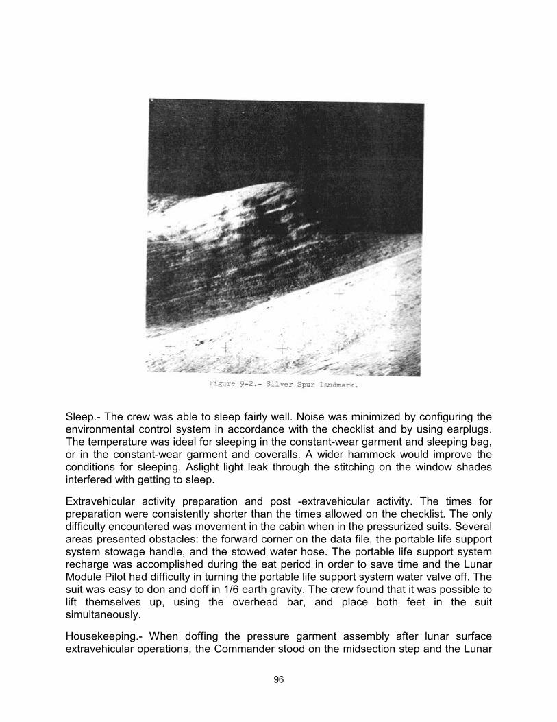
96
Sleep.- The crew was able to sleep fairly well. Noise was minimized by configuring the environmental control system in accordance with the checklist and by using earplugs. The temperature was ideal for sleeping in the constant-wear garment and sleeping bag, or in the constant-wear garment and coveralls. A wider hammock would improve the conditions for sleeping. Aslight light leak through the stitching on the window shades interfered with getting to sleep.
Extravehicular activity preparation and post -extravehicular activity. The times for preparation were consistently shorter than the times allowed on the checklist. The only difficulty encountered was movement in the cabin when in the pressurized suits. Several areas presented obstacles: the forward corner on the data file, the portable life support system stowage handle, and the stowed water hose. The portable life support system recharge was accomplished during the eat period in order to save time and the Lunar Module Pilot had difficulty in turning the portable life support system water valve off. The suit was easy to don and doff in 1/6 earth gravity. The crew found that it was possible to lift themselves up, using the overhead bar, and place both feet in the suit simultaneously.
Housekeeping.- When doffing the pressure garment assembly after lunar surface extravehicular operations, the Commander stood on the midsection step and the Lunar
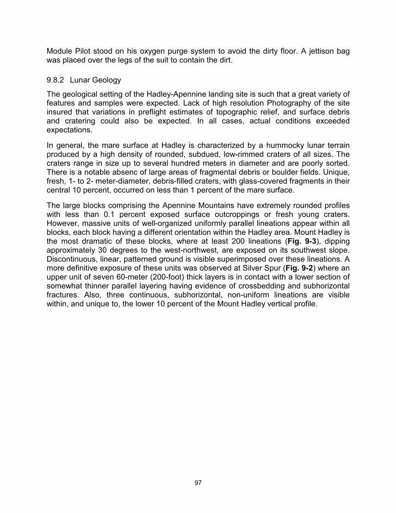
97
Module Pilot stood on his oxygen purge system to avoid the dirty floor. A jettison bag was placed over the legs of the suit to contain the dirt.
9.8.2 Lunar Geology
The geological setting of the Hadley-Apennine landing site is such that a great variety of features and samples were expected. Lack of high resolution Photography of the site insured that variations in preflight estimates of topographic relief, and surface debris and cratering could also be expected. In all cases, actual conditions exceeded expectations.
In general, the mare surface at Hadley is characterized by a hummocky lunar terrain produced by a high density of rounded, subdued, low-rimmed craters of all sizes. The craters range in size up to several hundred meters in diameter and are poorly sorted. There is a notable absenc of large areas of fragmental debris or boulder fields. Unique, fresh, 1- to 2- meter-diameter, debris-filled craters, with glass-covered fragments in their central 10 percent, occurred on less than 1 percent of the mare surface.
The large blocks comprising the Apennine Mountains have extremely rounded profiles with less than 0.1 percent exposed surface outcroppings or fresh young craters. However, massive units of well-organized uniformly parallel lineations appear within all blocks, each block having a different orientation within the Hadley area. Mount Hadley is the most dramatic of these blocks, where at least 200 lineations (Fig. 9-3), dipping approximately 30 degrees to the west-northwest, are exposed on its southwest slope. Discontinuous, linear, patterned ground is visible superimposed over these lineations. A more definitive exposure of these units was observed at Silver Spur (Fig. 9-2) where an upper unit of seven 60-meter (200-foot) thick layers is in contact with a lower section of somewhat thinner parallel layering having evidence of crossbedding and subhorizontal fractures. Also, three continuous, subhorizontal, non-uniform lineations are visible within, and unique to, the lower 10 percent of the Mount Hadley vertical profile.
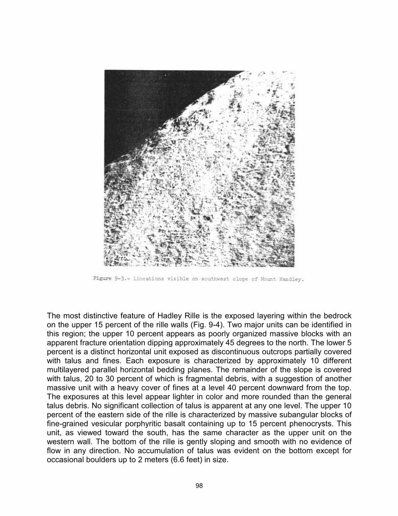
98
The most distinctive feature of Hadley Rille is the exposed layering within the bedrock on the upper 15 percent of the rille walls (Fig. 9-4). Two major units can be identified in this region; the upper 10 percent appears as poorly organized massive blocks with an apparent fracture orientation dipping approximately 45 degrees to the north. The lower 5 percent is a distinct horizontal unit exposed as discontinuous outcrops partially covered with talus and fines. Each exposure is characterized by approximately 10 different multilayered parallel horizontal bedding planes. The remainder of the slope is covered with talus, 20 to 30 percent of which is fragmental debris, with a suggestion of another massive unit with a heavy cover of fines at a level 40 percent downward from the top. The exposures at this level appear lighter in color and more rounded than the general talus debris. No significant collection of talus is apparent at any one level. The upper 10 percent of the eastern side of the rille is characterized by massive subangular blocks of fine-grained vesicular porphyritic basalt containing up to 15 percent phenocrysts. This unit, as viewed toward the south, has the same character as the upper unit on the western wall. The bottom of the rille is gently sloping and smooth with no evidence of flow in any direction. No accumulation of talus was evident on the bottom except for occasional boulders up to 2 meters (6.6 feet) in size.
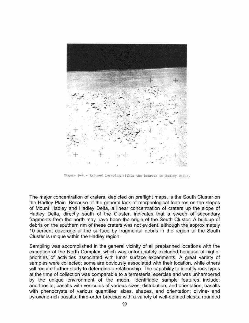
99
The major concentration of craters, depicted on preflight maps, is the South Cluster on the Hadley Plain. Because of the general lack of morphological features on the slopes of Mount Hadley and Hadley Delta, a linear concentration of craters up the slope of Hadley Delta, directly south of the Cluster, indicates that a sweep of secondary fragments from the north may have been the origin of the South Cluster. A buildup of debris on the southern rim of these craters was not evident, although the approximately 10-percent coverage of the surface by fragmental debris in the region of the South Cluster is unique within the Hadley region.
Sampling was accomplished in the general vicinity of all preplanned locations with the exception of the North Complex, which was unfortunately excluded because of higher priorities of activities associated with lunar surface experiments. A great variety of samples were collected; some are obviously associated with their location, while others will require further study to determine a relationship. The capability to identify rock types at the time of collection was comparable to a terresterial exercise and was unhampered by the unique environment of the moon. Identifiable sample features include: anorthosite; basalts with vesicules of various sizes, distribution, and orientation; basalts with phenocrysts of various quantities, sizes, shapes, and orientation; olivine- and pyroxene-rich basalts; third-order breccias with a variety of well-defined clasts; rounded
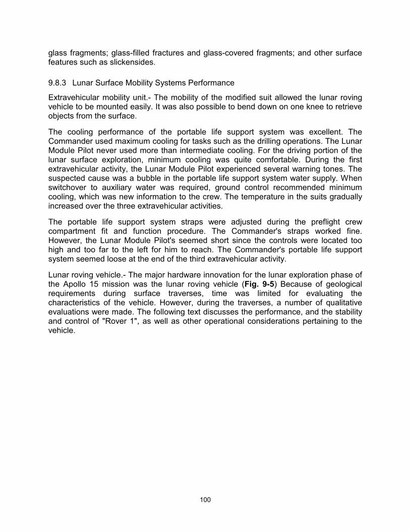
100
glass fragments; glass-filled fractures and glass-covered fragments; and other surface features such as slickensides.
9.8.3 Lunar Surface Mobility Systems Performance
Extravehicular mobility unit.- The mobility of the modified suit allowed the lunar roving vehicle to be mounted easily. It was also possible to bend down on one knee to retrieve objects from the surface.
The cooling performance of the portable life support system was excellent. The Commander used maximum cooling for tasks such as the drilling operations. The Lunar Module Pilot never used more than intermediate cooling. For the driving portion of the lunar surface exploration, minimum cooling was quite comfortable. During the first extravehicular activity, the Lunar Module Pilot experienced several warning tones. The suspected cause was a bubble in the portable life support system water supply. When switchover to auxiliary water was required, ground control recommended minimum cooling, which was new information to the crew. The temperature in the suits gradually increased over the three extravehicular activities.
The portable life support system straps were adjusted during the preflight crew compartment fit and function procedure. The Commander's straps worked fine. However, the Lunar Module Pilot's seemed short since the controls were located too high and too far to the left for him to reach. The Commander's portable life support system seemed loose at the end of the third extravehicular activity.
Lunar roving vehicle.- The major hardware innovation for the lunar exploration phase of the Apollo 15 mission was the lunar roving vehicle (Fig. 9-5) Because of geological requirements during surface traverses, time was limited for evaluating the characteristics of the vehicle. However, during the traverses, a number of qualitative evaluations were made. The following text discusses the performance, and the stability and control of "Rover 1", as well as other operational considerations pertaining to the vehicle.
101
The manual deployment technique worked very well. Simulations had demonstrated the effectiveness of this technique and, with several minor exceptions, it worked exactly as in preflight demonstrations. The first unexpected condition was noticed immediately after removing the thermal blanket when both walking hinges were found open. They were reset and the vehicle was deployed in a nominal manner. The support saddle, however, was difficult to remove after the vehicle was on the surface. No apparent cause was evident. Additionally, both left front hinge pins were out of their normal detent positions; both were reset with the appropriate tool. After removal of the support saddle, the rover was manually positioned such that "forward" would be the initial driving mode.
Front steering was inoperative during the first extravehicular activity. All switches and circuit breakers were cycled a number of times during the early portion of the first extravehicular activity with no effect on the steering. Subsequently, at the beginning of the second extravehicular activity, cycling of the front steering switch apparently enabled the front steering capability which was then utilized throughout the remaining traverses.
Mounting and dismounting the rover was comparable to preflight experience in 1/6-gravity simulations in the KC-135 aircraft. Little difficulty was encountered. The normal mounting technique included grasping the staff near the console and, with a small hop, positioning the body in the seat. Final adjustment was made by sliding, while using the footrest and the back of the seat for leverage. It was determined early in the traverses
102
that some method of restraining the crew members to their seats was absolutely essential. In the case of Rover 1, the seatbelts worked adequately; however, excessive time and effort were required to attach the belts. The pressure suit interface with the rover was adequate in all respects. None of the preflight problems of visibility and suit pressure points were encountered.
The performance of the vehicle was excellent. The lunar terrain conditions in general were very hummocky, having a smooth texture and only small areas of fragmental debris. A wide variety of craters was encountered. Approximately 90 percent had smooth, subdued rims which were, in general, level with the surrounding surface. Slopes up to approximately 15 percent were encountered. The vehicle could be maneuvered through any region very effectively. The surface material varied from a thin powdered dust [which the boots would penetrate to a depth of 5 to 8 centimeters (2 to 3 inches) on the slope of the Apennine Front to a firm rille soil which was penetrated about 1 centimeter (one-quarter to one-half inch) by the boot. In all cases, the rover's performance was changed very little.
The velocity of the rover on the level surface reached a maximum of 13 kilometers (7 miles) per hour. Driving directly upslope on the soft surface material at the Apennine Front, maximum velocities of 10 kilometers (5.4 miles) per hour were maintained. Comparable velocities could be maintained obliquely on the slopes unless crater avoidance became necessary. Under these conditions, the downhill wheel tended to dig in and the speed was reduced for safety.
Acceleration was normally smooth with very little wheel slippage, although some soil could be observed impacting on the rear part of the fenders as the vehicle was accelerated with maximum throttle. During a "Lunar Grand Prix", a roostertail was noted above, behind, and over the front of the rover during the acceleration phase. This was approximately 3 meters (10 feet) high and went some 3 meters forward of the rover. No debris was noted forward or above the vehicle during constant velocity motion. Traction of the wire wheels was excellent uphill, downhill, and during acceleration. A speed of 10 kilometers per hour could be attained in approximately three vehicle lengths with very little wheel slip. Braking was positive except at the high speeds. At any speed under 5 kilometers (2.7 miles) per hour, braking appeared to occur in approximately the same distance as when using the 1-g trainer. From straight-line travel at velocities of approximately 10 kilometers per hour on a level surface, the vehicle could be stopped in a distance of approximately twice that experienced in the 1-g trainer. Braking was less effective if the vehicle was in a turn, especially at higher velocities.
Dust accumulation on the vehicle was considered minimal and only very small particulate matter accumulated over a long period of time. Larger particles appeared to be controlled very well by the fenders. The majority of the dust accumulation occurred on the lower horizontal surfaces such as floorboards, seatpans, and the rear wheel area. Soil accumulation within the wheels was not observed. Those particles which did pass through the wire seemed to come out cleanly. Dust posed no problem to visibility.
Obstacle avoidance was commensurate with speed. Lateral skidding occurred during any hardover or maximum-rate turn above 5 kilometers per hour. Associated with the lateral skidding was a loss of braking effectiveness. The suspension bottomed out
103
approximately three times during the entire surface activity with no apparent ill effect. An angular 30- centimeter (1-foot) high fragment was traversed by the left front wheel with no loss of controllability or steering, although the suspension did bottom out. A relatively straight-line traverse was easily maintained by selection of a point on the horizon for directional control, in spite of the necessity to maneuver around the smaller subdued craters. Fragmental debris was clearly visible and easy to avoid on the surface. The small, hummocky craters were the major problem in negotiating the traverse, and the avoidance of these craters seemed necessary to prevent controllability loss and bottoming of the suspension system.
Vehicle tracks were prominent on the surface and very little variation of depth occurred when the bearing on all four wheels was equal. On steep slopes, where increased loads were carried by the downhill wheels, deeper tracks were encountered - perhaps up to 3 or 4 centimeters (an inch or two) in depth. There was no noticeable effect of driving on previously deposited tracks, although these effects were not specifically investigated. The chevron tread pattern left distinct and sharp imprints. In the soft, loose soil at the Apollo lunar surface experiment package site, one occurrence of wheel spin was corrected by manually moving the rover to a new surface.
The general stability and control of the lunar roving vehicle was excellent. The vehicle was statically stable on any slopes encountered and the only problem associated with steep slopes was the tendency of the vehicle to slide downslope when both crewmen were off the vehicle. The rover is dynamically stable in roll and pitch. There was no tendency for the vehicle to roll even when traveling upslope or downslope, across contour lines or parallel to contour lines. However, qualitative evaluation indicates that roll instability would be approached on the 15-degree slopes if the vehicle were traveling a contour line with one crewmember on the downhill side. Both long- and short-period pitch motions were experienced in response to vehicle motion over the cratered, hummocky terrain, and the motion introduced by individual wheel obstacles. The long-period motion was very similar to that encountered in the 1-g trainer, although more lightly damped. The "floating" of the crewmembers in the 1/6-g field was quite noticeable in comparison to 1- g simulations. Contributions of shortperiod motion of each wheel were unnoticed and it was difficult to tell how many wheels were off the ground at any one time. At one point during the "Lunar Grand Prix", all four wheels were off the ground, although this was undetectable from the driver's seat.
Maneuvering was quite responsive at speeds below approximately 5 kilometers per hour. At speeds on the order of 10 kilometers per hour, response to turning was very poor until speed was reduced. The optimum technique for obstacle avoidance was to slow below 5 kilometers per hour and then apply turning correction. Hardover turns using any steering mode at 10 kilometers per hour would result in a breakout of the rear wheels and lateral skidding of the front wheels. This effect was magnified when only the rear wheels were used for steering. There was no tendency toward overturn instability due to steering or turning alone. There was one instance of breakout and lateral skidding of the rear wheels into a crater approximately 1/2 meter (1-112 feet) deep and 1-1/4 meters (4 feet) wide. This resulted in a rear wheel contacting the far wall of the crater and subsequent lateral bounce. There was no subsequent roll instability or tendency to turn over, even though visual motion cues indicated a roll instability might
104
develop.
The response and the handling qualities using the control stick are considered adequate. The hand controller was effective throughout the speed range, and directional control was considered excellent. Minor difficulty was experienced with feedback through the suited crewmember to the hand controller during driving. However, this feedback could be improved by a more positive method of restraint in the seat. Maximum velocity on a level surface can be maintained by leaving the control stick in any throttle position and steering with small inputs left or right. A firm grip on the handle at all times is unnecessary. Directional control response is excellent although, because of the many dynamic links between the steering mechanism and the hand on the throttle, considerable feedback through the pressure suit to the control stick exists. A light touch on the hand grip reduces the effect of this feedback. An increase in the lateral and breakout forces in the directional hand controller should minimize feedback into the steering.
Two steering modes were investigated. On the first extravehicular activity, where rear-wheel-only steering was available, the vehicle had a tendency to dig in with the front wheels and break out with the rear wheels with large, but less than hardover, directional corrections. On the second extravehicular activity, front-wheel-only steering was attempted, but was abandoned because of the lack of rear wheel centering. Four-wheel steering was utilized for the remainder of the mission. It is felt that for the higher speeds, optimum steering would be obtained utilizing front steering provided the rear wheels are center-locked. For lower speeds and maximum obstacle avoidance, four-wheel steering would be optimal. Any hardover failure of the steering mechanism would be recognized immediately and could be controlled safely by maximum braking.
Forward visibility was excellent throughout the range of conditions encountered with the exception of driving toward the zero-phase direction. Washout, under these conditions, made obstacle avoidance difficult. Up-sun was comparable to cross-sun if the opaque visor on the lunar extravehicular visor assembly was lowered to a point which blocks the direct rays of the sun. In this condition, crater shadows and debris were easily seen. General lunar terrain features were detectable within 10 degrees of the zero phase region. Detection of features under high-sun conditions was somewhat more difficult because of the lack of shadows, but with constant attention, 10 to 11 kilometers (5-1/2 to 6 miles) per hour could be maintained. The problem encountered was recognizing the subtle, subdued craters directly in the vehicle path. In general, 1-meter (3 1/4-foot) craters were not detectable until the front wheels had approached to within 2 to 3 meters (6-1/2 to 10 feet).
The reverse feature of the vehicle was utilized several times, and preflight-developed techniques worked well. Only short distances were covered, and then only with a dismounted crewmember confirming the general condition of the surface to be covered.
The 1-g trainer provides adequate training for lunar roving vehicle operation on the lunar surface. Adaptation to lunar characteristics is rapid. Handling characteristics are quite natural after several minutes of driving. The major difference encountered with respect to preflight training was the necessity to pay constant attention to the lunar terrain in order to have adequate warning for obstacle avoidance if maximum average speeds
105
were to be maintained. Handling characteristics of the actual lunar roving vehicle were similar to those of the 1-g trainer with two exceptions: braking requires approximately twice the distance, and steering is not responsive in the 8- to 10-kilometer (4- to 5 1/2-mile) per hour range with hardover control inputs. Suspension characteristics appeared to be approximately the same between the two vehicles and the 1/6-g suspension simulation is considered to be an accurate representation with the exception of the crewmembers' weight.
The navigation system is accurate and a high degree of confidence was attained in a very short time. Displays are also adequate for the lunar roving vehicle systems.
Lunar communications relay unit.- The lunar communications relay unit and associated equipment operated well throughout the lunar surface activities. The deployment techniques and procedures are good, and the operational constraints and activation overhead are minimum. Alignment of the high-gain antenna was the only difficulty encountered, and this was due to the very dim image of the earth presented through the optical sighting device. The use of signal strength as indicated on the automatic gain control meter was an acceptable back-up alignment technique.
9.8.4 Lunar Surface Science Equipment Performance
Apollo lunar surface experiment package.- The packages were manually removed from the scientific equipment bay. During unstowing of equipment, the universal handling tools were difficult to remove from the stowed position and the scientific equipment bay doors required cycling to the fully closed position. In deploying the central station, the strings which pull the rear pins on the sun shield cover were broken, requiring the Lunar Module Pilot to pull the pins with his fingers. Connection of the suprathermal ion detector experiment to the central station was very difficult. The task required the Lunar Module Pilot to use both hands and all the weight that he could bring to bear on the locking collar. Another difficulty was in the deployment of the suprathermal ion detector experiment. The universal handling tool was not locked, which caused the suprathermal ion detector experiment to fall off the tool when positioning the experiment.
Emplacement of the heat flow experiment and collection of the deep core sample were difficult and required far more time and effort than anticipated. Operation of the hardware components was acceptable with the exception of the vise on the geology pallet. The vise was installed incorrectly and was useless for separating the assembled stems.
The primary cause of the working difficulties encountered with the lunar drill was the lack of knowledge of the regolith encountered at the Hadley site. Because of the hardness of the material 1 meter (3 1/4 feet) below the surface, the bore stems for drilling the holes for the heat flow experiment did not penetrate at the expected rates and did not excavate deep material to the surface. Because of the resulting high torque levels on the chuck-stem interface, the chuck bound to the stems and, in one case, required destruction of the stem to remove the chuck and drill. The deep core sample could not be extracted from the hard soil by normal methods and required both crewmen lifting on the drill handles to remove it. The exterior flutes contributed to this condition since the core stems were pulled into the lunar surface when the drill was
106
activated. See section 14.4.1 for further discussion.
Soil mechanics.- The classic trench was easily dug in the vicinity of the Apollo lunar surface experiment deployment site. Penetrometer measurements were made at the trench and in the lunar roving vehicle tracks. The floor of the trench was a very hard resistant layer. In making the penetrometer measurements, the trench side was collapsed by pushing on the flat plate positioned about 10 centimeters (4 inches) from the trench wall. A problem with the penetrometer was that the ground plane would not stay in the extended position because of excessive spring force (see section 4.13).
Geology tools.- The retractable tethers (yo-yo's) failed during the first extravehicular activity. These devices were used by the Commander to secure tongs and by the Lunar Module Pilot to secure the extension handle during the geology work. They would have been used to hold the universal handling tools during deployment of the Apollo lunar surface experiment package. Unfortunately, both yo-yos failed before the experiment package was deployed. Cord was used for the flight equipment instead of wire, as on the training equipment. The tongs, scoop, hammer, and rake worked well, and the rake also functioned well as a scoop. The newly designed core tube worked well in that the sample was completely retained. Penetration of the surface with the core tube was usually accomplished with a hard push; however, the hammer was required to obtain a double core. The locking and unlocking of the buddy secondary life support system bag attached to the rear of the geology pallet was very difficult because the locking tab was hidden behind the bag. Sample return container 2 was not sealed because a portion of the collection bag was caught in the rear hinge.
Cameras.- The film in the 16-mm data acquisition camera would not pull through the camera. Only one magazine worked on the lunar surface. Also, the Lunar Module Pilot's 70-mm Hasselblad electric data camera malfunctioned at the end of the second extravehicular activity. An inspection in the lunar module cabin revealed excessive lunar material on the film drive. The camera failed again on the third extravehicular activity and was returned to earth. These anomalies are discussed in sections 14.5.3 and 14-5.4.
9.9 LUNAR ORBITAL SOLO OPERATIONS
9.9.1 Maneuvers
Solo maneuvers in lunar orbit included circularization and a plane change. Both of these maneuvers were accomplished using service propulsion system bank B only because of the aforementioned circuit problem with bank A. The maneuvers were nominal and were accomplished with residual velocities of an order that required no further maneuvering.
9.9.2 Science and Photography
Scientific instrument module experiments.- The scientific instrument module was operated during the three days of lunar surface activity according to carefully detailed preflight planning. Because of the complexity of the scientific instrument module, all operations during this period were to be accomplished without deviation from the flight plan. In the event that difficulties were encountered, items were to be dropped from the
107
flight plan. Some flight difficulties were experienced with the scientific instrument module operations. These difficulties were associated with the retraction of the mass spectrometer boom and with the extension and retraction of the mapping camera. The mass spectrometer boom extended normally but did not always indicate full retraction. It was suspected that the boom was retracting into the carriage, but not far enough to cause an indication of full retraction. The monitoring, as well as the timing of the boom extensions and retractions, required an expenditure of time which had not been anticipated preflight. The mapping camera extended and retracted more slowly than had been anticipated and it eventually failed in the extended position. This also required additional monitoring time on the part of the Command Module Pilot. The mass spectrometer boom retraction problem is discussed in more detail in section 14.1.6 and additional discussion on the mapping camera problem is given in section 14.3.3.
The scientific instrument module bay activity was essentially a monitoring operation. Functions were performed at a prescribed time and required very careful attention to the details in the flight plan. One procedure that was used to assist in this monitoring activity was the use of computer time on the display keyboard in the lower equipment bay. The procedure required the initiation of an external delta-velocity program at a prescribed time. The clock in the computer would then count down to, and up from, that time. However, because of the calculations required by the computer during operation of this program, the spacecraft actually deviated out of the attitude control dead bands. Therefore, after the first day in lunar orbit, the computer program was used for very short intervals of time only. Consequently, the monitoring of the scientific instrument module bay became much more difficult because the timing of these events had to be accomplished using ground elapsed time, and not time relative to an event. Also complicating the monitoring was the fact that the lights in the lower equipment bay could no longer illuminate the mission timer because of the previously described short in the a-c electrical system.
All of the solo operations in lunar orbit were accomplished well within the capability of the Command Module Pilot with respect to the amount of work that had to be done in the time available. There were times when visual observation of the surface and hand-held photography were accomplished in conjunction with the operation of the scientific instrument module bay. This posed no problem and was accomplished as prescribed.
Command and service module photography.- The onboard photography was accomplished generally as prescribed in the flight plan except that the operation was more detailed than had been anticipated prior to flight. Acquisition of all photographic targets was based on flight plan time. However, with additional training just prior to flight, the Command Module Pilot attained a sufficient degree of proficiency in target recognition and in the geology of the lunar surface so that detailed flight plan times were not required.
The photography was accomplished using the settings prescribed in the flight plan and additional photographs were taken utilizing the settings based on sun angles that were listed in both the orbit monitor charts and by an orbit monitor wheel which was developed for that purpose. The photography from window 5 posed some problems because of a Lexan filter installed inside of the spacecraft (since no ultraviolet filter existed within the window). The Lexan filter, at this time, was scratched and it did not
108
appear that good photography could be taken through that window, so the filter was removed for the photography and then replaced.
Visual observations.- In conjunction with the photography, visual observations of selected surface features were made. These observations were designed to allow a better understanding of large-scale geologic processes. Three areas of special interest were centered around the crater Tsiolkovsky, the Littrow area, and the Aristarchus Plateau.
Tsiolkovsky is a large impact crater centered at 128 degrees east latitude, and uniquely placed in the region between the large mare basins and the upland areas on the back side. It is a deep crater with a prominent central peak and steep rim walls; the crater walls are cut by several faults. The smooth, dark crater floor resembles the mare surfaces visible on the moon's near side. There is much evidence of volcanic processes on the eastern side of the crater as shown by numerous lava flows originating along fault zones and filling minor craters around Tsiolkovsky. On the western side, there is a large rock avalanche that extends from the rim northwest into the subdued crater Fermi.
The Littrow area was viewed because of distinct color banding extending out into Mare Serenitatis. This banding appears to have been produced by volcanism in the form of flows or volcanic ash deposits. Within the darkest band, there were numerous small positive features believed to be cinder cones. These are the first well-documented cinder cones observed on the moon.
The Aristarchus Plateau appears to be the most active volcanic area on the moon. There are many lava flows and rille-like features in the central plateau area.
One of the mysteries about the rilles has been the rille termini. If these features were formed by lava flows, there would be delta-shaped flow tongues formed at the outlets. Inflight observation resulted in the conclusion that if these delta-shaped flow tongues were present, they were covered by lava flows that inundated the rilles.
9.10 ASCENT, RENDEZVOUS AND DOCKING
9.10.1 Ascent
Ascent ignition was automatic, the programmed pitchover was smooth and positive, and the trajectory appeared nominal throughout the maneuver. Five minutes after lift-off, radar lock-on was attempted with negative results; 5 seconds of high slew in each direction also resulted in no signal strength. Approaching insertion, Houston advised of a radial error in the primary guidance and navigation system and recommended an in-plane trim of the abort guidance system velocity residuals. At automatic primary guidance and navigation system shutdown, the abort guidance system indicated a residual velocity of minus 3.5 ft/sec. This was trimmed to minus 2 ft/sec along the longitudinal axis. No vernier adjustment was required, and the ground advised that the terminal phase initiate maneuver would be off-nominal and that final approach would be from near horizontal; these factors were due to the command and service module orbit.
109
9.10.2 Rendezvous
Lunar module.- The abort guidance system warning light came on shortly after insertion. The light was reset normally and the abort guidance system self-test was satisfactory. After insertion, there was early confirmation of rendezvous radar, primay guidance and navigation system, and abort guidance system guidance data. Automatic updating was enabled in both the primary guidance system and the abort guidance system. At final computation for terminal phase initiation, there were 26 marks in the primary guidance and navigation system, and 13 range marks and 13 range-rate marks in the abort guidance system. Another accelerometer bias update was made on the primary guidance system before terminal phase initiation. The primay guidance and navigation system solution was used.
Nominal procedures were used for primary guidance and navigation system midcourse corrections. For the abort guidance system, several rangerate inputs were manually inserted to insure that there were sufficient marks to obtain good solutions. The technique used was to watch the mark counter until the range changed to a plus value, then the range rate was manually entered. The command and service module tracking light was not visible until 40 minutes after sunset at a range of approximately 18 miles.
When approaching the last braking gate (1500 feet separation distance), the Commander was surprised to see that no line-of-sight rates were indicated by the rendezvous radar crosspointers. (Refer to sec. 14.2.7 for a discussion of this anomaly.) Line of site rates were verified by the Command Module Pilot. Thrusting left and up approximately 4 ft/sec was required to null the line-of-site rates. The resulting out-of-plane angle at station keeping was approximately 20 degrees.
Command and service module.- The command and service module was prepared for the rendezvous by deactivating all of the scientific instrument module bay experiments, retracting all of the booms, and closing the camera and experiment covers. All but four reaction control jets were activated 3 hours before lunar module ascent initiation to allow proper ground tracking and orbit determination. On the rendezvous revolution itself, VHF contact was made just prior to ascent and the Manned Space Flight Network relay was deactivated. All communications with the lunar module were accomplished using the VHF. Just prior to insertion, VHF ranging was activated. Several resets were required before the ranging was locked, and subsequently, lock was broken only once.
After insertion, a lunar module state vector was uplinked from the ground and an automatic maneuver was made to the rendezvous tracking attitude. The rendezvous was completed using a minimum-key-stroke (automatic sequencing) computer program. This program was new for this flight, and was designed to relieve the Command Module Pilot's workload. The computer automatically sequenced through the rendezvous maneuvers and tracking periods. It was initiated at the pre-terminal phase initiation program and was terminated with the final rendezvous computer program, which maneuvered the command and service module to the desired tracking attitude just prior to docking. The program functioned as anticipated and allowed the Command Module Pilot much greater time for optical tracking and systems monitoring.
There was same difficulty at first in actually seeing the lunar module tracking light
110
because the lunar module was not centered in the scanning telescope. After going into darkness, the light was observed at about 15 degrees from the center of the telescope. After two marks were taken, the optics tracked the lunar module in the center of the sextant. A total of 18 optical and 19 VHF marks were taken before the final solution was initiated. The maneuver to the terminal phase initiate attitude was a small maneuver of approximately 20 to 30 degrees in pitch. After the lunar module performed the terminal phase initiation maneuver, the actual velocity changes were inserted into the computer. The command and service module then was maneuvered automatically to the tracking attitude. Ten optics and nine VHF marks were taken prior to the first midcourse correction and 18 optics and 11 VHF marks were taken prior to the second midcourse correction. All solutions were compared with the lunar module solutions and were within the prescribed limits. The lunar module subsequently accomplished the maneuvers based on its own solutions.
9.10.3 Docking and Crew Transfer
Beginning at terminal phase finalization, the spacecraft was maneuvered to the crew-optical-alignment-sight tracking attitude to monitor the lunar module and to verify line-of-sight rates. The lunar module assumed a station keeping position with the command and service module and a maneuver was initiated to allow photographs to be taken of the scientific instrument module bay. After this was accomplished, the spacecraft were maneuvered to the docking attitude. The docking was initiated and completed by the command and service module. Again, the closing rates were approximately 0.1 ft/sec, and the docking was completed by thrusting along the longitudinal axis on contact until capture latch engagement was indicated. After the capture latches were engaged and the attitudes were stabilized, the probe was retracted and a hard dock was accomplished.
Several operations were initiated almost simultaneously after the docking. The scientific instrument module bay experiments were activated and operated throughout the time of transfer of equipment from the lunar module to the command and service module. The experiments operations hindered the transfer to some extent because the Command Module Pilot was required to monitor and observe the scientific instrument panel in the command and service module. However, the transfer was successfully completed and all transfer bags were stowed in the proper locations. The lunar module crew transferred back into the command and service module and preparations were made for undocking.
9.11 POST-DOCKING LUNAR ORBITAL OPERATIONS
9.11.1 Lunar Module Jettison
After all equipment was stowed, the crew donned their helmets and gloves and prepared the tunnel for lunar module Jettison. Some difficulty was experienced with venting the pressure in the tunnel. The differential pressure across the tunnel hatch would not increase as expected. The hatch was removed and the seals on both the lunar module hatch and the command module hatch were checked. Both hatches were replaced and the differential pressure check was completed satisfactorily. A pressure suit integrity check was then accomplished; again, with some difficulty. The crew

111
considered that the liquid cooled garment connector was responsible for the failure of one of the suits to pressurize properly, so a plug was inserted into the Commander's suit. After the plug was installed and the suits were rezipped, the suit circuit pressure integrity check was accomplished normally. Because of the difficulty with the tunnel and with the suit circuit integrity check, the lunar module jettison was delayed approximately one revolution, after which it was accomplished normally. However, because of the difference in orbital position from the planned position at the time of the lunar module jettision, the separation maneuver was recomputed to assure a positive separation distance. This was accomplished about 20 minutes after jettision and all subsequent events were nominal.
9.11.2 Flight Plan Updating
After rendezvous and with all three crewmen aboard the command and service module, the flight plan was updated to utilize the full capability of the scientific instrument module bay. The flight plan changes were considerable, but with one crewman free to copy the updates, the other two crewmen were available to monitor and perform the scientific instrument module activities. This meant that all three crewmen were utilized a good percentage of the time. The operation was performed satisfactorily and the real-time changing of the flight plan was accomplished without difficulty. The philosophy that there would be no changes in the flight plan during the solo operations and that the flight plan would be subject to real-time change when all three crewmen were aboard was satisfactory.
9.11.3 Maneuvers
Prior to the transearth injection maneuver, an orbital shaping maneuver was performed to launch the subsatellite into an orbit guaranteeing a long lifetime. This was a relatively short thrusting maneuver and was accomplished using service propulsion system bank B. The subsatellite was jettisoned as scheduled and it was observed approximately 15 to 20 feet away from the spacecraft. All arms were extended and it was rotating with a coning angle of approximately 10 degrees.
The next maneuver was the transearth injection maneuver which was accomplished without difficulty. The service propulsion system was again activated by the special procedure. Gimbal position indications were very smooth and there was very little attitude excursion. The maneuver was completed nominally.
9.11.4 Command and Service Module Housekeeping
Particular emphasis was placed on housekeeping throughout the flight in order to maintain organization within the command module crew compartment with the additional stowage requirements for the Apollo 15 mission. Normal cabin living activities required more time than anticipated preflight because of additional equipment, onboard stowage conditions, new pressure suits, a strict adherence to nutrition schedules, and limitations on overboard dump periods. The most efficient manner of completing these activities was to perform all cleaning, dumping, canister change, and chlorination operations just prior to a rest period, exclusive of any scientific instrument module
112
activities. Similarly, an exclusive waking and eat period just after the rest period and prior to any other activities (such as scientific instrument module activation and flight plan updates) conforms to normal daily activities on earth and results in far more efficient utilization of time during flight.
9.12 TRANSEARTH FLIGHT OPERATIONS
9.12.1 Transearth Coast Extravehicular Activity
Approximately 16 hours after the transearth injection maneuver, the crew had completed preparations for an extravehicular activity which was specifically planned to retrieve the panoramic and mapping camera cassettes from the scientific instrument module. The preparation for the extravehicular activity was accomplished in a nominal fashion and required approximately 5 112 hours. Preparation of the command module was partially accomplished during the night preceding the extravehicular activity and was completed approximately 2 hours before the flight plan time for the event. This allowed an unhurried, careful preparation of all equipment and resulted in an extravehicular activity that was accomplished on time and without difficulty. The final preparation associated with the extravehicular activity involved the relocation of some rock bags and containers, removal of the center couch, donning of pressure suits, suit integrity checks, and the donning of the special extravehicular activity umbilical and pressure suit equipment by the Command Module Pilot. This was accomplished satisfactorily per the check- list. The spacecraft was maneuvered to the extravehicular activity sun-angle attitude which allowed illumination of the scientific instrument module bay, while insuring that the sun did not shine directly into the command module hatch. In this attitude the sun angle was low with respect to the scientific instrument module, but reflections in and around the module illuminated all of the equipment. After side hatch opening, the television and 16-mm cameras were installed on the hatch to record the extravehicular activity. The 16-mm camera operated for only 3 or 4 frames and produced only one recoverable picture (Fig. 9-6). The camera had apparently been turned on and then inadvertently turned off after a three-second interval while set at a frame rate of one frame per second. The television camera operated properly. The Command Module Pilot proceeded to the scientific instrument module bay in a fashion similar to that used during training. The operation required about 16 minutes and was completed in an efficient manner even though an off-nominal condition existed in that the mapping camera was extended and could not be retracted. The panoramic camera cassette was returned to the hatch and was tethered inside the command module. The mapping camera cassette was returned on the second trip. Because of the difficulty with the mass spectrometer boom, and the mapping camera extension and retraction mechanism, a third trip was made to the scientific instrument module to investigate these pieces of equipment. The spectrometer was observed to have retracted to the point of capture by the guide pins in the carriage but had not retracted fully. No external jamming of the mapping camera carriage was seen. One additional problem, associated with the panoramic camera, was investigated during the third trip. The panoramic camera velocity/altitude sensor malfunctioned during lunar orbit operations. The sensor was examined and nothing was in the line of sight of the velocity/altitude sensor to account for the failure. Following the extravehicular activity, the Command Module Pilot ingressed, the hatch was closed, and the command module was pressurized using the
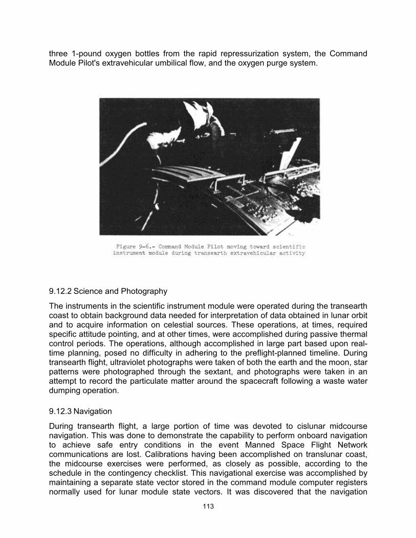
113
three 1-pound oxygen bottles from the rapid repressurization system, the Command Module Pilot's extravehicular umbilical flow, and the oxygen purge system.
9.12.2 Science and Photography
The instruments in the scientific instrument module were operated during the transearth coast to obtain background data needed for interpretation of data obtained in lunar orbit and to acquire information on celestial sources. These operations, at times, required specific attitude pointing, and at other times, were accomplished during passive thermal control periods. The operations, although accomplished in large part based upon real-time planning, posed no difficulty in adhering to the preflight-planned timeline. During transearth flight, ultraviolet photographs were taken of both the earth and the moon, star patterns were photographed through the sextant, and photographs were taken in an attempt to record the particulate matter around the spacecraft following a waste water dumping operation.
9.12.3 Navigation
During transearth flight, a large portion of time was devoted to cislunar midcourse navigation. This was done to demonstrate the capability to perform onboard navigation to achieve safe entry conditions in the event Manned Space Flight Network communications are lost. Calibrations having been accomplished on translunar coast, the midcourse exercises were performed, as closely as possible, according to the schedule in the contingency checklist. This navigational exercise was accomplished by maintaining a separate state vector stored in the command module computer registers normally used for lunar module state vectors. It was discovered that the navigation
114
could, in fact, be performed onboard to at least validate the state vector during a nominal transearth coast. The techniques for accomplishing the cislunar sightings were essentially the same as had been used during translunar coast. The earth at this time appeared as a very thin crescent because of the earth-sun relationship, but the horizon was easily discernible. The sightings were taken with the spacecraft in minimum- impulse control, and all but the last set of sightings were accomplished using uncoupled thrusters for attitude control. Low attitude rates were maintained and the sightings were easier than had been experienced preflight. The onboard state vector was maintained until just prior to entry and it would have been satisfactory in the event that a loss of communications had been experienced.
9.13 ENTRY AND LANDING
The preparation for entry was accomplished normally and the third midcourse correction was performed to insure that the target point was acceptable. In preparation for service module separation, all systems were checked, chill-down of the spacecraft was accomplished as prescribed, and the spacecraft was maneuvered to the service module jettison attitude. The jettison was accomplished as planned. Entry was nominal, with the entry interface occurring at the proper time. The entry monitor system indicated 0.05g at the expected time and the entry monitor system, the guidance and navigation system, and the accelerometers were all in agreement during entry. The lack of entry monitor system background lighting did not affect observation of the scroll. The entry was normal, but during descent on the main parachutes, one of the parachutes partially deflated. The main parachutes deployed normally at 10 000 feet, and checklist items were performed. However, following the reaction control system depletion firing, the partially-deflated parachute was observed. The condition resulted in a higher rate of descent than with three fully-inflated parachutes. Calls were received from the recovery team indicating that the situation was being observed by ground personnel. All checks subsequent to this were made according to the checklist and, because of the higher rate of descent, touchdown was accomplished about 32 seconds earlier than it would have with all parachutes fully inflated. The landing loads were higher than normal; however, it did not appear that the couch struts had stroked. The only internal indication of a hard landing was that the crew optical alignment sight was detached from its stowage bracket and fell to the aft bulkhead.
All events after landing were normal. The parachutes were released and, because of the low wind condition, settled around the command module. The recovery ship and forces were near the spacecraft at landing and recovery operations were normal.
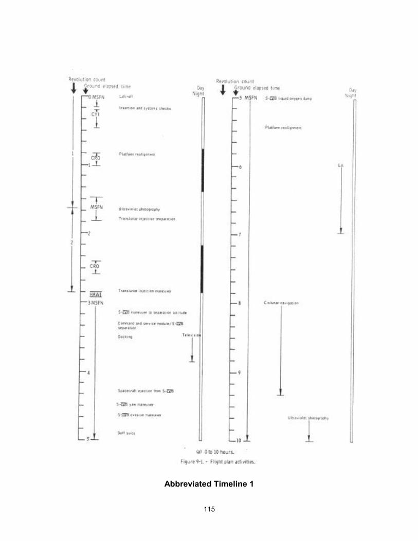
115
Abbreviated Timeline 1
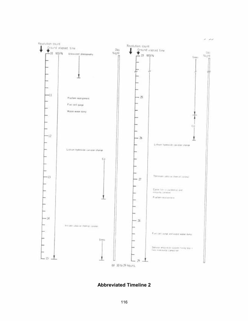
116
Abbreviated Timeline 2
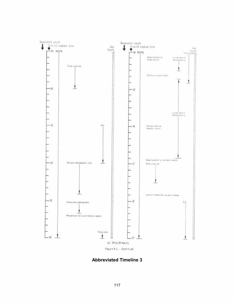
117
Abbreviated Timeline 3
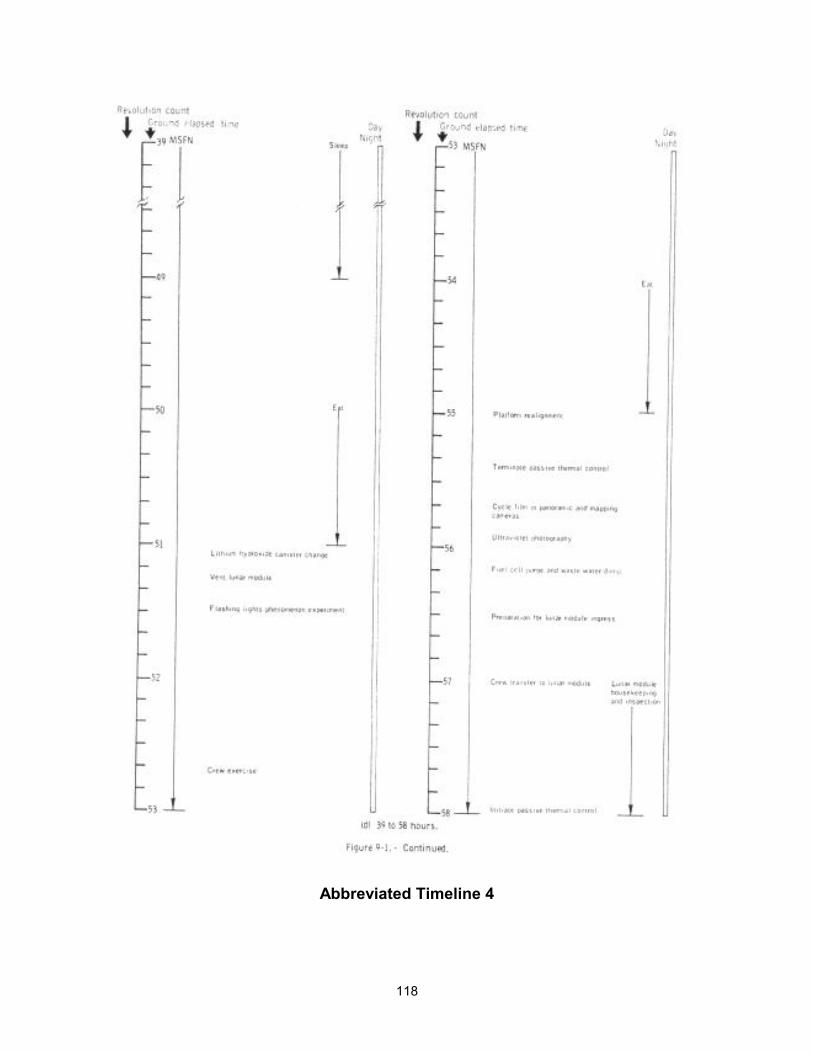
118
Abbreviated Timeline 4
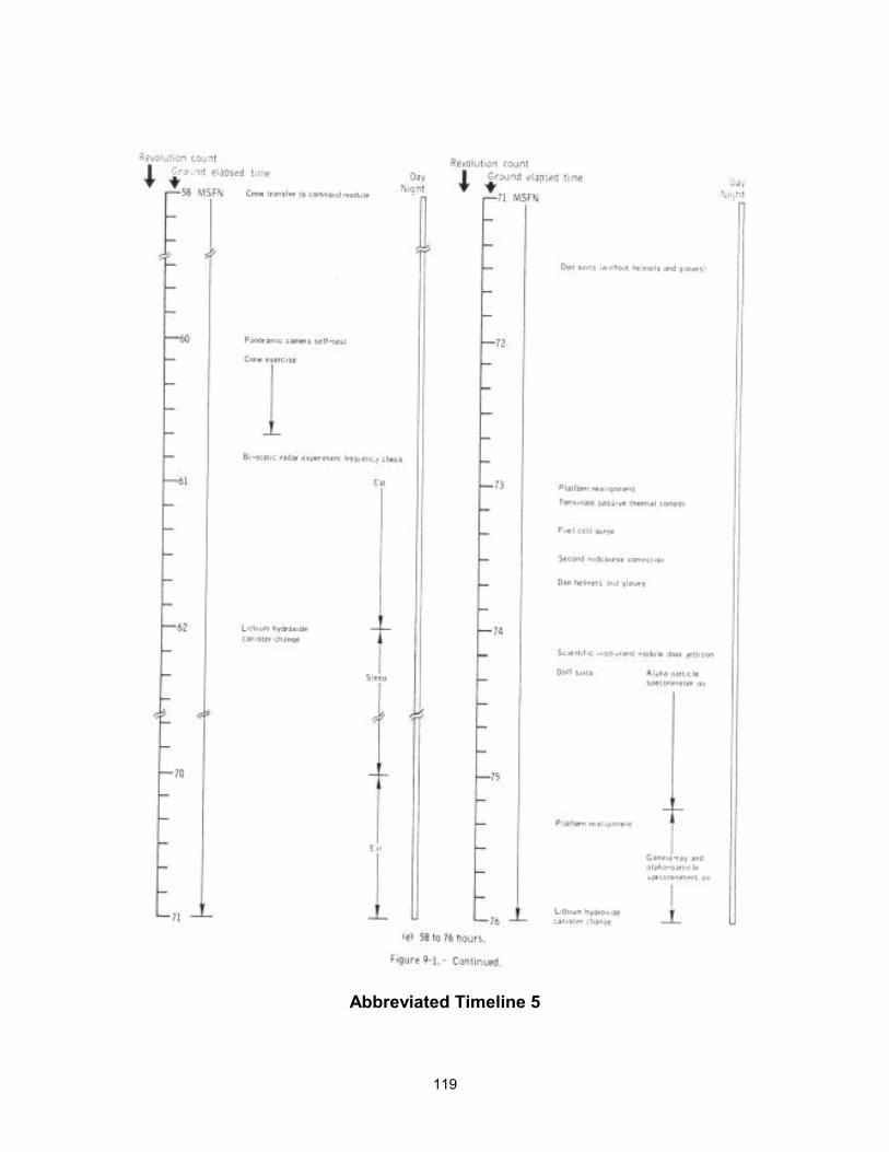
119
Abbreviated Timeline 5
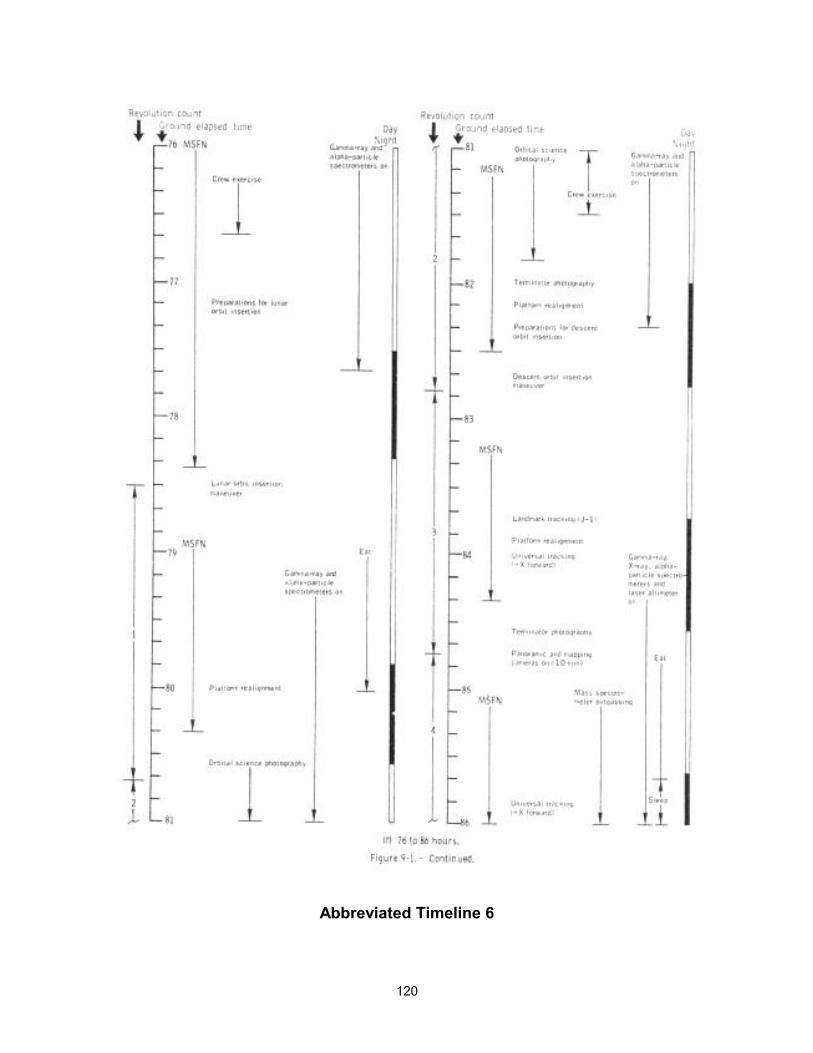
120
Abbreviated Timeline 6

121
Abbreviated Timeline 7
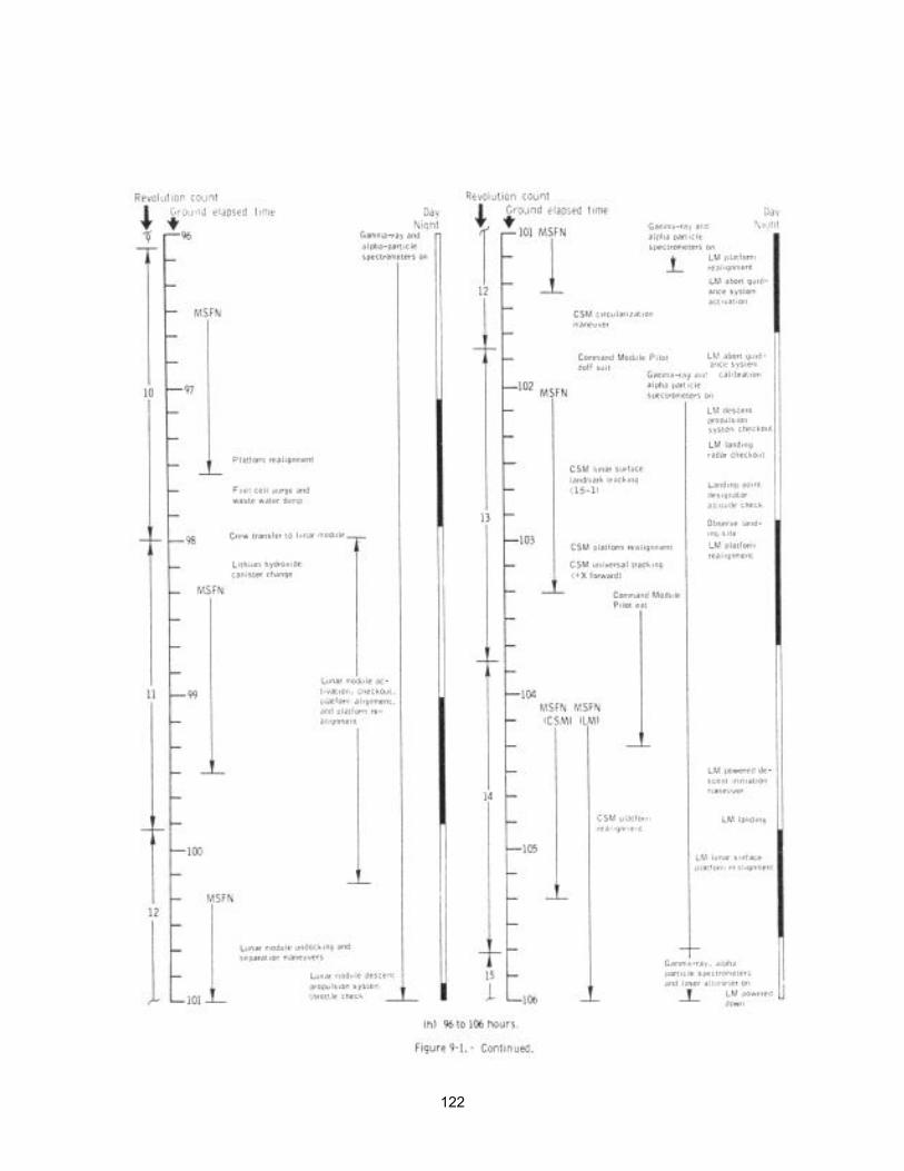
122
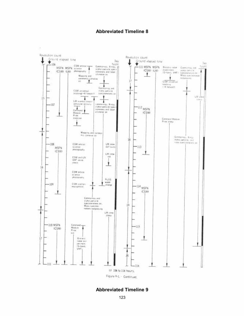
123
Abbreviated Timeline 8
Abbreviated Timeline 9
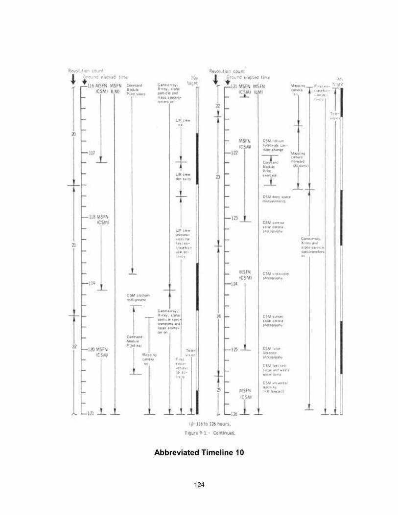
124
Abbreviated Timeline 10
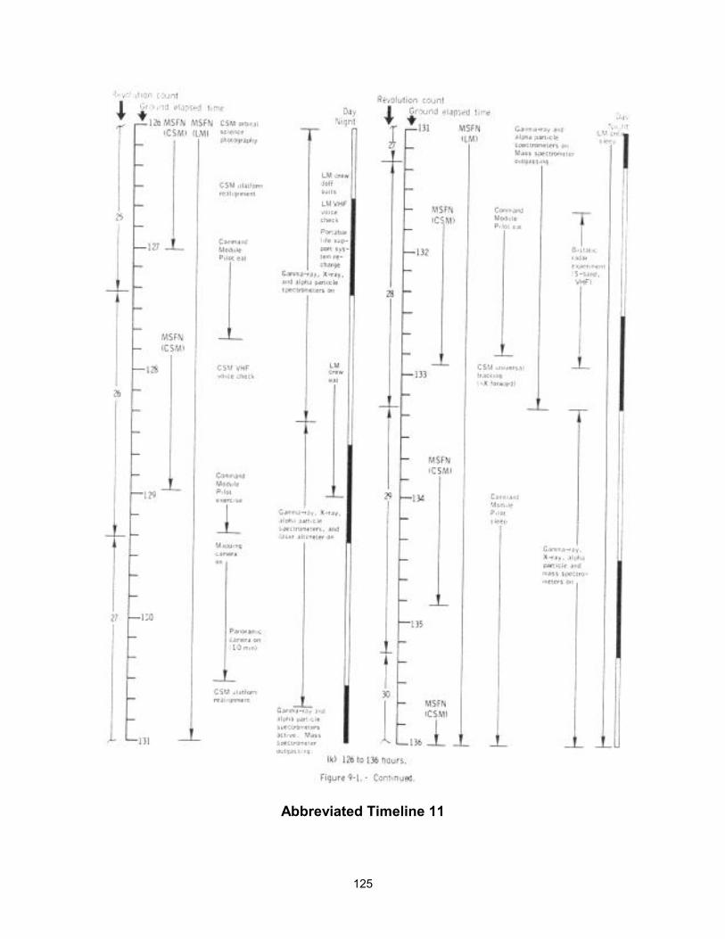
125
Abbreviated Timeline 11
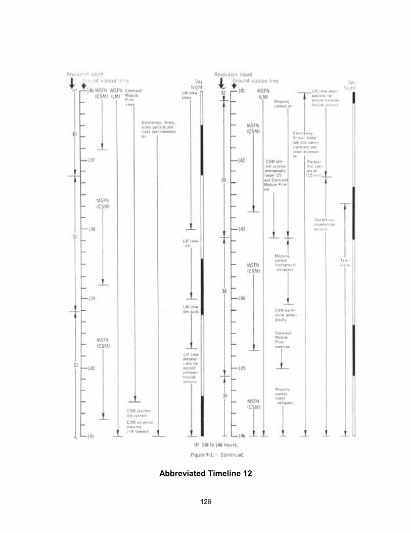
126
Abbreviated Timeline 12
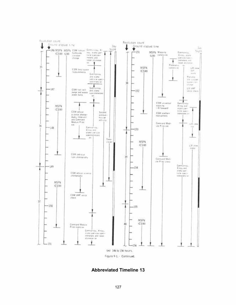
127
Abbreviated Timeline 13
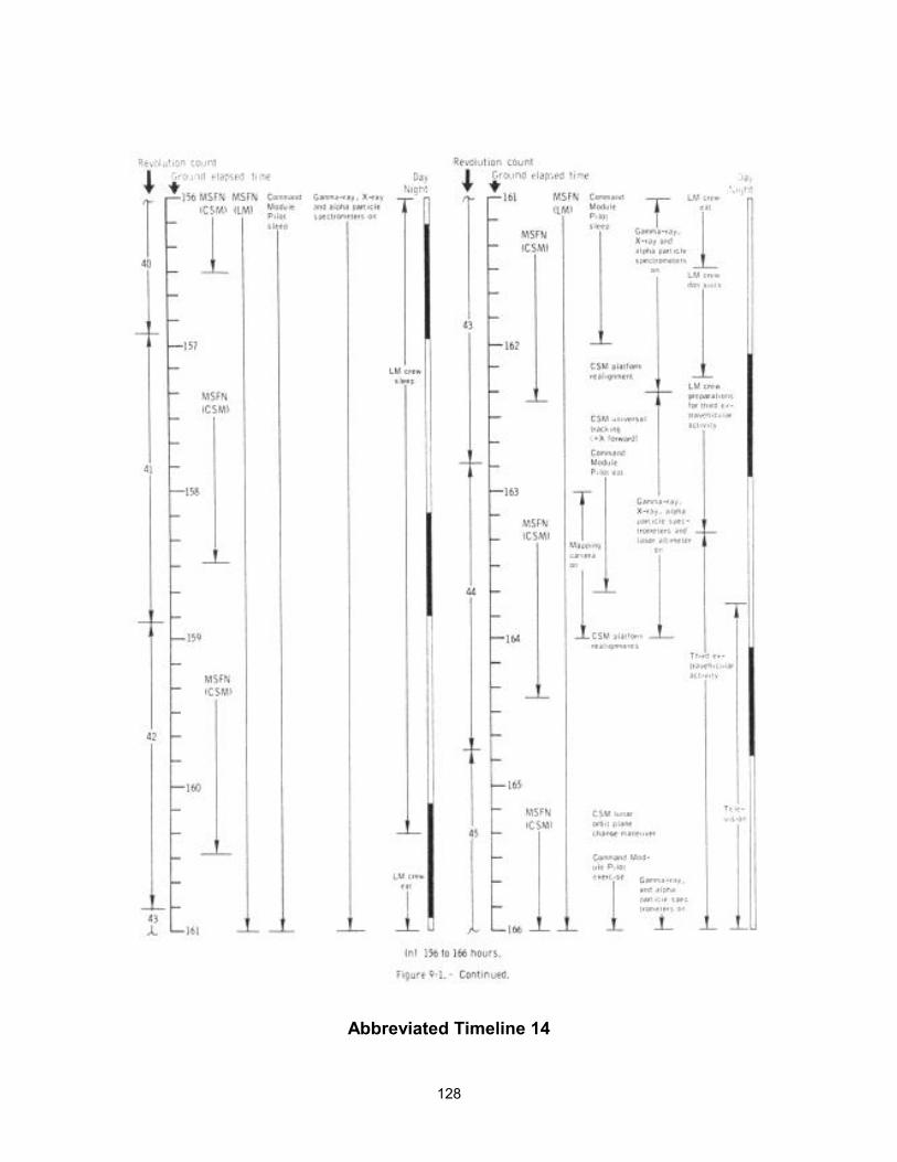
128
Abbreviated Timeline 14
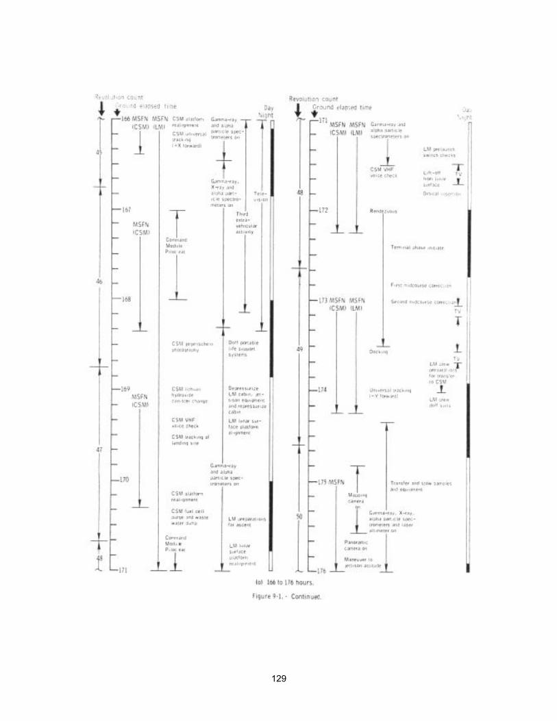
129
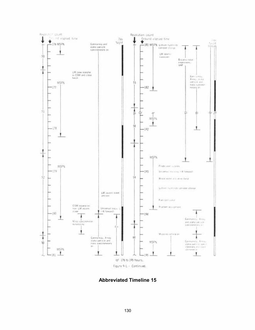
130
Abbreviated Timeline 15
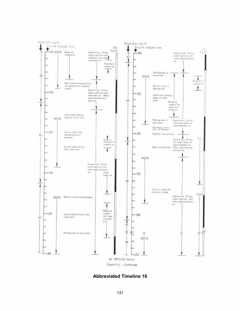
131
Abbreviated Timeline 16

132
Abbreviated Timeline 17
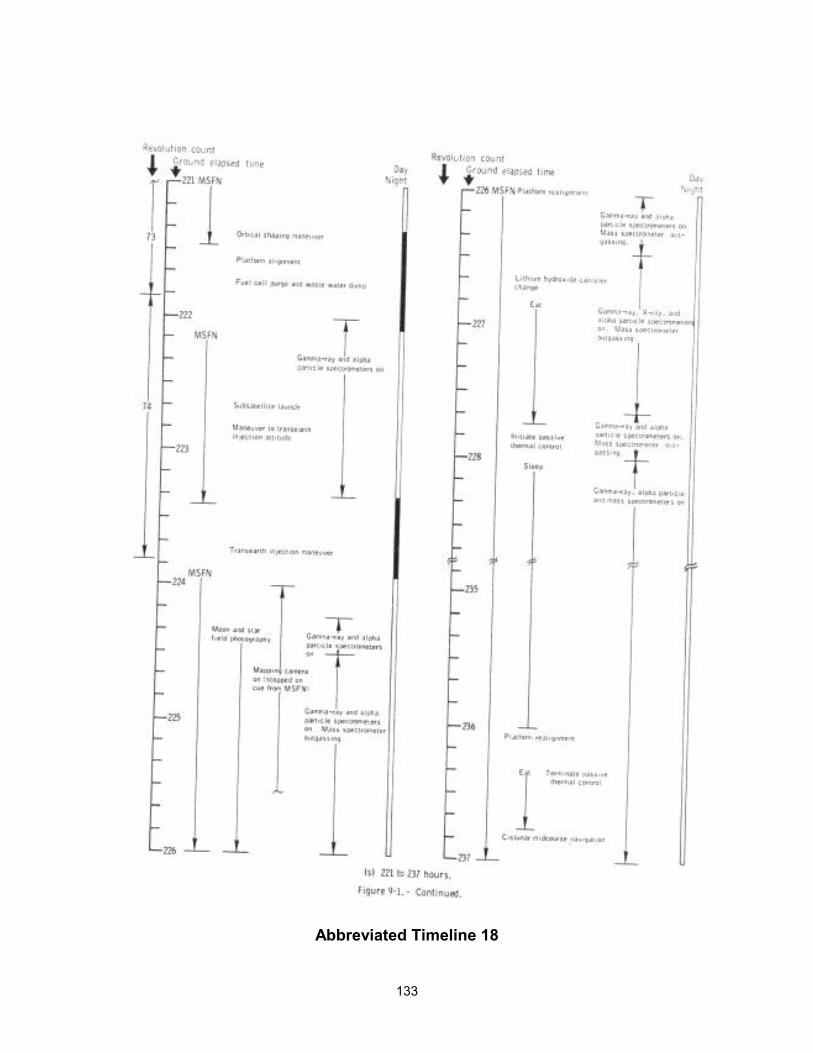
133
Abbreviated Timeline 18
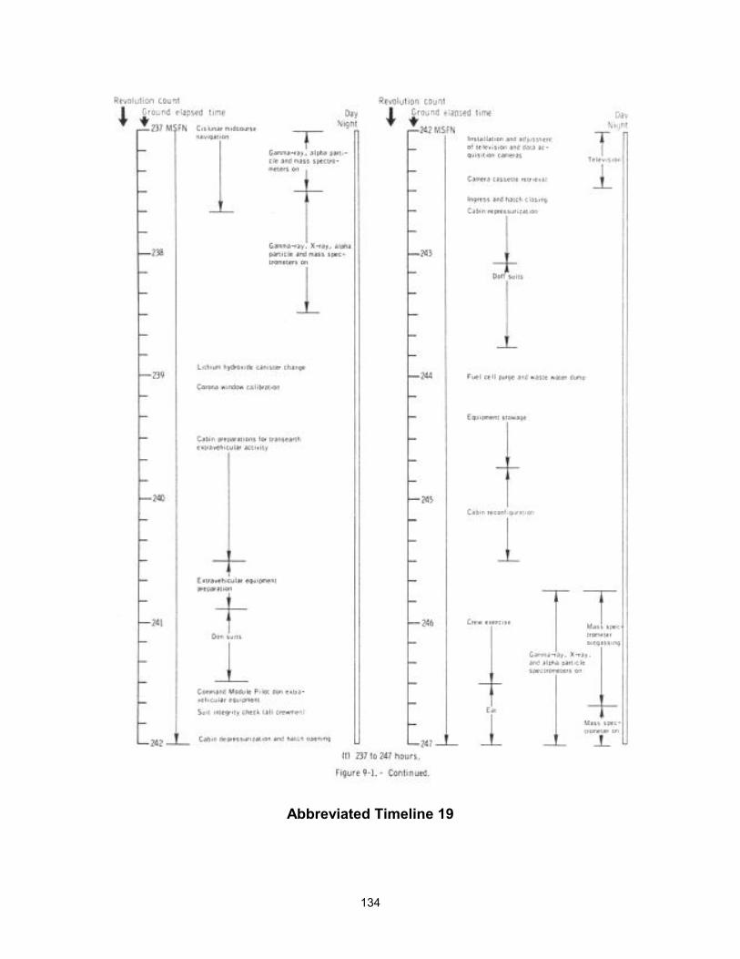
134
Abbreviated Timeline 19

135
Abbreviated Timeline 20
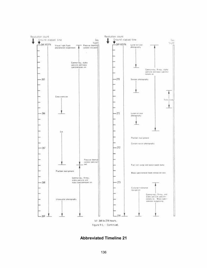
136
Abbreviated Timeline 21
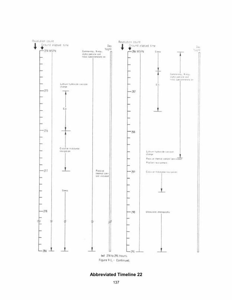
137
Abbreviated Timeline 22
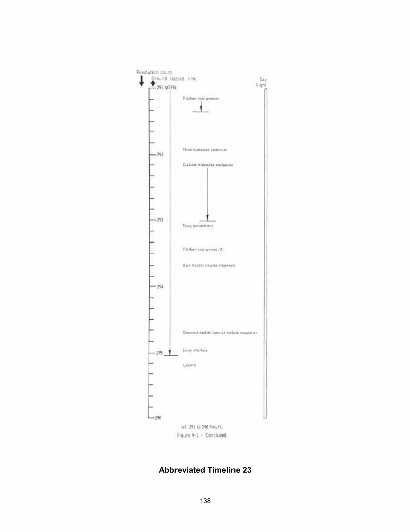
138
Abbreviated Timeline 23
139
10 BIOMEDICAL EVALUATION This section is a summary of the Apollo 15 medical findings based on a preliminary analysis of the biomedical data. A total of 885.5 manhours of space flight experience was accumulated during the 12.3 days of flight. The flight crew health stabilization program for this mission was similar to that for Apollo 14. Nine of the one hundred and sixty primary contact personnel were removed from primary contact duty because of infectious illness. This was the first lunar landing mission in which a postflight quarantine period was not required. The basis for the decision to discontinue the quarantine was the absence of pathologic or toxic properties attributable to the lunar materials returned on three previous lunar missions. The crewmen remained in good health throughout the mission.
10.1 BIOMEDICAL INSTRUMENTATION AND PHYSIOLOGICAL DATA
The Apollo 15 mission was the first on which sponge/pellet electrodes were used in the bioharness. This type of biosensor was developed to reduce skin irritation experienced with the previous continuous-wear electrodes. Only one crewman's bioharness was worn and monitored at a time during the translunar and transearth phases of the mission. The wearing time was alternated between work-days and sleep periods for each crewman. Physiological data were transmitted simultaneously from all three crewmen only during launch, extravehicular activities, and entry.
The quality of data obtained with these new electrodes was good. Less skin irritation was seen at the biosensor sites than has been seen on previous Apollo missions. The only biomedical instrumentation problem experienced during the flight occurred approximately 65 seconds after lift-off when the impedance pneumograms (respiratory function) for all three crewmen showed large baseline shifts which were caused by air trapped within the electrodes sponge. At about 14 hours, the crewmen restored their impedance pneumogram data by venting the electrodes. Preflight altitude chamber tests had shown that venting the electrodes would restore the data.
The Commanders heart rates ranged from 81 to 98 beats per minute during lunar descent and 65 to 88 beats per minute during ascent (Figs. 10-1 and 10-2). The metabolic rates of the two lunar surface crewmen during the three lunar surface extravehicular periods are correlated with their heart rates as shown in Figures 10-3 Part 1, and 10-3 Part 2, 10-4 Part 1 and 10-4 Part 2 and 10-5 Part 1, and 10-5 Part 2. The Commander's average heart rates for the first, second, and third periods were 92, 84, and 85 beats per minute, respectively; and the Lunar Module Pilot's average heart rates for the three periods were 125, 107, and 105 beats per minute, respectively. A summary of the average metabolic rates and total production during all extravehicular activity periods is presented in Table 10-I.
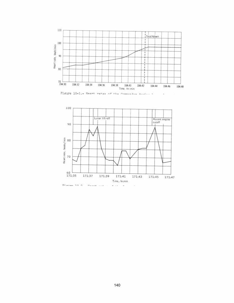
140
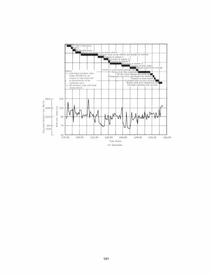
141
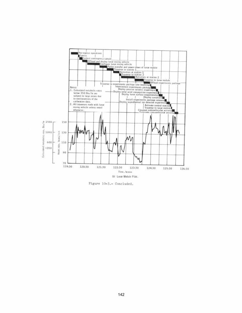
142
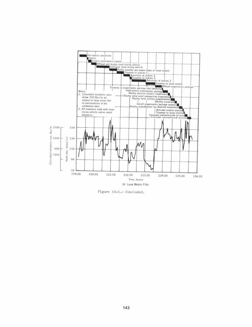
143
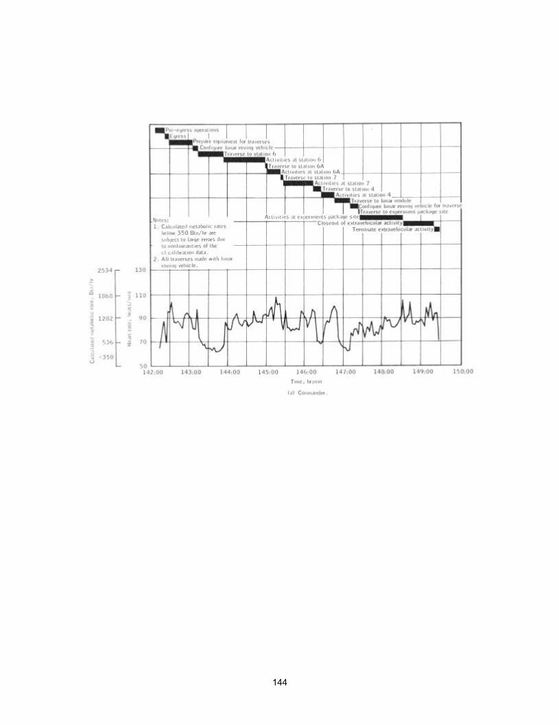
144
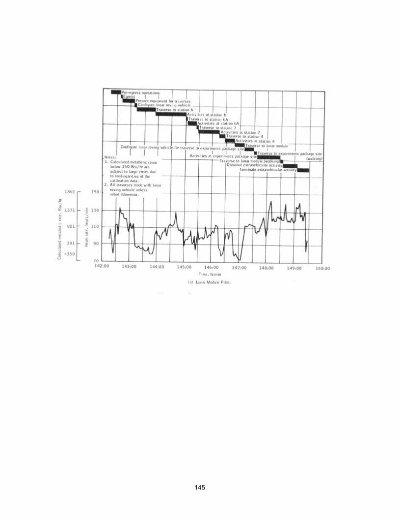
145
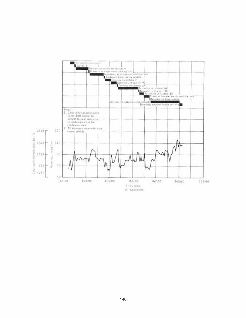
146
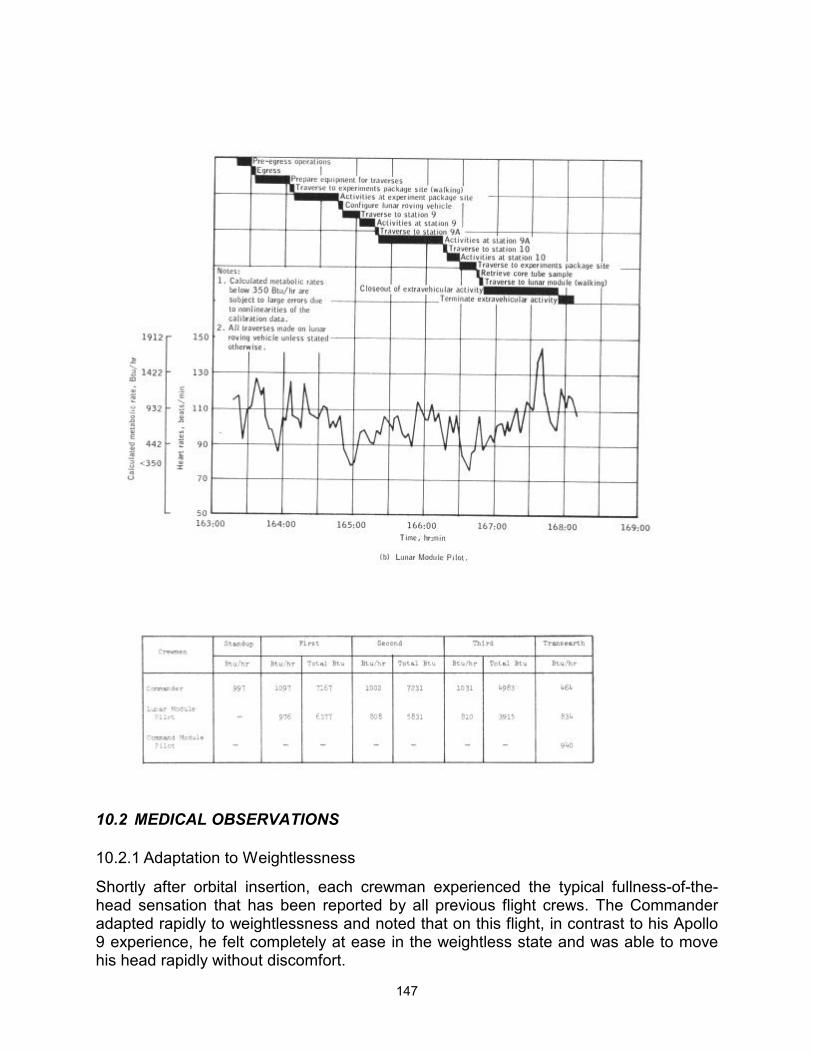
147
10.2 MEDICAL OBSERVATIONS
10.2.1 Adaptation to Weightlessness
Shortly after orbital insertion, each crewman experienced the typical fullness-of-the-head sensation that has been reported by all previous flight crews. The Commander adapted rapidly to weightlessness and noted that on this flight, in contrast to his Apollo 9 experience, he felt completely at ease in the weightless state and was able to move his head rapidly without discomfort.
148
The Command Module Pilot apparently experienced no difficulty in adapting to weightlessness; but the Lunar Module Pilot reported that his sensation of head-fullness lasted 3 days. In addition, the Lunar Module Pilot experienced slight giddiness which precluded rapid head or body movements. This sensation disappeared shortly after landing on the lunar surface and did not recur on returning to the zero-gravity environment.
None of the crewmen experienced nausea, vomiting, or disorientation during any phase of the mission. An observation made by the crew was that their facial features were distorted because of the lack of gravity. The crew also reported the discomfort and soreness of the lower back muscles associated with postural changes during weightlessness.
10.2.2 Medications
Aspirin and nose drops were the only medications used during the mission. The Commander took a total of 14 aspirin to relieve the pain he developed in his right shoulder after the difficult deep core tube drilling operation on the lunar surface. The Command Module Pilot used nose drops just prior to earth entry to prevent possible middle ear blockage.
10.2.3 Sleep
Very little shift of the crew's normal terrestrial sleep cycle occurred during the translunar and transearth coast phases of this mission. As a result, all crewmen received an adequate amount of sleep during these periods.
Displacement of the terrestrial sleep cycle during the three lunar surface sleep periods ranged from 2 hours for the first sleep period to 7 hours for the third sleep period. This shift in the sleep cycle, in addition to the difference between the command module and lunar module sleep facilities, no doubt contributed to the lunar module crewmen receiving less, sleep on the lunar surface than was scheduled in the flight plan. However, the most significant factors causing loss of crew sleep were operational problems. These included hardware malfunctions as well as insufficient time in the flight plan to accomplish assigned tasks. During the first sleep period, the crewmen went to sleep one hour later than planned and had to arise one hour early to fix a cabin oxygen leak. The crewmen again were an hour late in getting to sleep for the second lunar surface sleep period. The final sleep period was changed so that the beginning of the period was 2 1/2 hours later than originally planned. The period, which had been planned to last 7 hours, was terminated after 6 1/2 hours to begin preparations for the final extravehicular activity. Lengthening the work days and reducing the planned sleep periods on the lunar surface coupled with a significant alteration of the lunar module crewmen' circadian rhythm produced a sufficient fatigue level to cause them to operate on their physiological reserves until they returned to the command module.
10.2.4 Radiation
The Commander's personal radiation dosimeter failed to integrate the dosage properly after the first 24 hours of flight. In order to have f'unctional dosimeters on each lunar
149
module crewman while on the lunar surface, the Command Module Pilot transferred his unit to the Commander prior to lunar module intravehicular transfer. The final readings from the personal radiation dosimeters yielded net integrated (uncorrected) values of 360 millirads for the Commander and 510 millirads for the Lunar Module Pilot. The passive dosimeters worn continously by all crewmen during the entire mission yielded an average of 300 millirads at skin depth. This dosage is well below the threshold of detectable medical effects.
10.2.5 Visual Light Flash Phenomenon
Three observation periods of approximately 1 hour were conducted during translunar and transearth coast as well as during lunar orbit. The crew reported seeing the point sources of light noted by previous Apollo crews. The frequency of the light flashes ranged from once every 2 minutes to once every 5 minutes for each crewman. The frequency of light flashes was greater during translunar flight than transearth flight.
10.2.6 Water
The crew reported that the taste of the drinking water in both the command module and the lunar module was good. All scheduled inflight chlorinations of the command module water system were reported accomplished. Preflight testing of the lunar module potable water system iodine levels showed that use of the bacterial filter would be necessary to prevent bacterial contamination during the mission. The crew reported the sporadic occurrence of gas bubbles in the command module drinking water, but this did not interfere with food hydration.
The Commander consumed about 16 ounces of water during the first extravehicular activity; however, his insuit drinking device slipped under his neck ring on the second extravehicular activity and he was unable to obtain any water. The Lunar Module Pilot was never able to obtain drinking water from his device. The insuit drinking devices were not used during the third extravehicular activity (see sec. 14-5.5).
Inflight water samples were taken on the first and last days of the flight to determine the nickel ion concentration. Analysis of these two inflight water samples revealed that the nickel ion concentration on the first day of flight rose from a prelaunch value of 0.35 parts per million to 6.3 parts per million. On the last day of the flight, 2.7 parts per million of nickel ion concentration were found. The latter was not a representative sample because of the reported water system anomaly (section 14.1.14) which occurred about 12 hours before the sample was taken. This anomaly resulted in only a portion, if any, of the chlorine/buffer/inhibitor solution being injected into the potable water tank and, subsequently, the hot water heater. The nickel ion concentration is believed to result from a chemical reaction between the purification inhibitors and the nickel brazing used in the hot water heater. Three postflight hot water port samples taken 8 hours, 13 hours, and 17 days after recovery yielded nickel ion concentrations of 2.34, 2.02, and 0.34 parts per million, respectively. These data indicate that the postflight nickel ion concentration diminishes as a function of time when the water system is deactivated rather than increases as previously presumed. Postflight analysis of the command module water showed no chlorine residual. The level of nickel ions in the potable water
150
is not considered to be injurious to the crewmen.
10.2.7 Food
The food system on this flight was similar to that of previous Apollo missions with the exception that additional food stowage space was provided in both the command and service module and the lunar module to accommodate the extra food required for a 12.3-day lunar mission. Prior to flight, each crewman evaluated about 100 available foods and selected his menu. The food was arranged in meal packages for the first 10 days of flight. Menus and supplemental food for the remainder of the mission were selected in real time from the food pantry.
The inflight menus were designed to provide approximately 2400 kilocalories per man per day with 400 additional kilocalories in beverages and extra food supplied in the pantry. Thus a total of 2800 kilocalories were available for each crewman on a daily basis. On launch day, each crewman was also provided with a specially prepared and packaged frozen sandwich, suits.
Estimates of the crews' food consumption, based on the onboard food log and the returned food, indicate that an average of 2801, 2372, and 2568 kilocalories per day were consumed by the Commander, the Command Module Pilot, and the Lunar Module Pilot, respectively. The crew commented favorably after the flight on the quality of the inflight food and the food systems. The new insuit food bars were used by both lunar module crewmen on the first and second extravehicular activities. They did not carry the food bar on the third extravehicular activity.
10.3 PHYSICAL EXAMINATIONS
Each crewman received a comprehensive physical examination at 28, 13, and 5 days prior to launch, with brief examinations conducted daily during the last 5 days before launch.
A comprehensive physical examination conducted shortly after landing showed that the crew was in good health. Body weight losses incurred by the Commander, Command Module Pilot, and Lunar Module Pilot during the mission were 2-3/4, 3, and 5-1/2 pounds, respectively. All crewmen suffered varying degrees of minor skin irritiation at the biosensor sites. The cause of this irritation was mechanical friction rather than allergic reaction. The skin irritation subsided within 48 hours without medical treatment.
The Commander had hemorrhages under the fingernails of the middle finger, ring finger, and thumb of his right hand and on the ring finger of his left hand. These hemorrhages were attributed to an insufficient pressure suit arm-length size causing the finger tips to be forced too far into the extravehicular gloves during hard-suit operations. The pressure suit fit was adjusted to suit the Commander's preference to increase his sensitivity of touch. The Commander's painful right shoulder was due to a muscular/ligament strain which responded rapidly to heat therapy.
The time required by the crew to return to preflight baseline levels in lower body negative pressure measurements and bicycle ergometry tests was longer than for
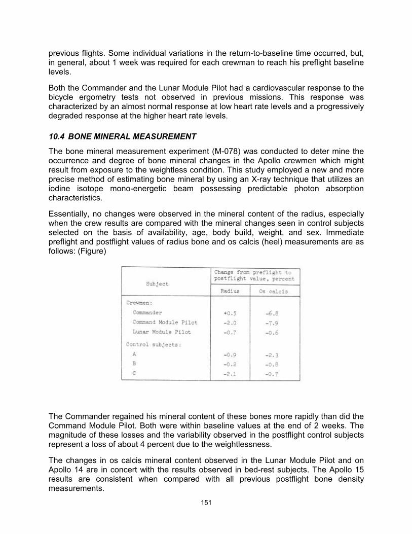
151
previous flights. Some individual variations in the return-to-baseline time occurred, but, in general, about 1 week was required for each crewman to reach his preflight baseline levels.
Both the Commander and the Lunar Module Pilot had a cardiovascular response to the bicycle ergometry tests not observed in previous missions. This response was characterized by an almost normal response at low heart rate levels and a progressively degraded response at the higher heart rate levels.
10.4 BONE MINERAL MEASUREMENT
The bone mineral measurement experiment (M-078) was conducted to deter mine the occurrence and degree of bone mineral changes in the Apollo crewmen which might result from exposure to the weightless condition. This study employed a new and more precise method of estimating bone mineral by using an X-ray technique that utilizes an iodine isotope mono-energetic beam possessing predictable photon absorption characteristics.
Essentially, no changes were observed in the mineral content of the radius, especially when the crew results are compared with the mineral changes seen in control subjects selected on the basis of availability, age, body build, weight, and sex. Immediate preflight and postflight values of radius bone and os calcis (heel) measurements are as follows: (Figure)
The Commander regained his mineral content of these bones more rapidly than did the Command Module Pilot. Both were within baseline values at the end of 2 weeks. The magnitude of these losses and the variability observed in the postflight control subjects represent a loss of about 4 percent due to the weightlessness.
The changes in os calcis mineral content observed in the Lunar Module Pilot and on Apollo 14 are in concert with the results observed in bed-rest subjects. The Apollo 15 results are consistent when compared with all previous postflight bone density measurements.
152
10.5 APOLLO TIME AND MOTION STUDY
Analysis of the time and motion data indicates that the crewmen adapted readily and efficiently to the lunar surface environment. Changes in walking speed were noted during the first and second extravehicular activities as the crewmen gained experience and confidence in moving about the lunar surface. The walking speed for both crewmen under comparable conditions increased from 1.0 ft/sec to 1.5 ft/sec during the first extravehicular activity and from 1.5 ft/sec to 2.0 ft/sec during the second extravehicular activity. No further increase was observed on the third extravehicular activity.
The time to perform tasks on the lunar surface varied. On the average, tasks required 33 percent more time to perform on the lunar surface than on earth. However, some tasks took less time to perform on the lunar surface than in a 1-g environment.
153
11 MISSION SUPPORT PERFORMANCE
11.1 FLIGHT CONTROL
Flight control provided satisfactory operational support for all required areas during the Apollo 15 mission. A number of the problems that were encountered are discussed elsewhere in this report. Only those problems that are unique to flight control, or have operational considerations not previously mentioned, are presented in this section.
A radial velocity error in the launch vehicle guidance system at earth-orbit insertion necessitated a navigation update to minimize the subsequent planned midcourse correction. Without the update, a 32-ft/sec velocity change would have been required at 9 hours. After updating the state vector, the actual midcourse correction was approximately 5 ft/sec (See section 6.5.)
As a result of the service propulsion system thrust light anomaly discussed previously, the crew was requested to deactivate both pilot valve circuit breakers immediately after the light was first observed. This measure was instituted to safeguard against an inadvertent firing until the problem could be thoroughly understood. To isolate the cause of the Malfunction, a test was conducted in conjunction with the first midcourse correction and the problem was resolved, including the development of workaround procedures. The crew was instructed to power down the entry monitor system scroll in order to eliminate the nuisance factor of a constant false light indication until the use of the entry monitor system was required.
During the first period of scientific instrument module activity for film advancement, the ground station (Madrid) had a problem in locking onto the FM subcarrier. This was determined to be a site procedural problem. All sites were briefed on the problem and no subsequent problems were encountered.
After lunar module ingress and the crew's description of the broken glass cover on the range/range rate tapemeter, ground tests were performed to verify that the tapemeter would function properly with the glass broken, exposing the inside of the instrument to the cabin atmosphere. A careful review of procedures was made to evaluate crew monitoring techniques during descent. A technique was developed to use the abort guidance system for displaying raw landing radar altitude data should the tapemeter and the primary guidance and navigation system fail, but the technique was not voiced to the crew.
At acquisition of signal during the 12th lunar revolution, the lunar module crew reported that they had been unable to separate from the command and service module and that the Command Module Pilot was investigating the probe umbilical integrity. An off-scale high docking probe temperature was indicative of a possible umbilical problem. The umbilicals were found to be the source of the problem, and the condition was corrected. Meanwhile, the crew had been advised by Mission Control that undocking and separation were not time critical. The separation was achieved about 36 minutes late.
154
Landmark tracking was deleted during the umbilical integrity problem, but adequate data were later obtained when the command and service module was in a higher orbit.
During the sleep period after the standup extravehicular activity, the descent oxygen was being depleted at a rate about 1 pound/hour greater than expected. The oxygen quantity was not critical, but the descent oxygen tank pressure was critical to allow a full portable life support system recharge for the third extravehicular activity, The crew was awakened approximately 1 hour early to locate the leak. They found that the leak was caused by the urine receptacle device being inadvertently left open. The early completion of this task allowed preparations for the first extravehicular activity to start about 20 minutes early.
11.2 NETWORK
Adequate support was provided by the Mission Control Center and Manned Space Flight Network. Although a number of minor discrepancies and problems arose during the mission, there was no interruption of mission support. The most significant problem, in terms of potential impact, was an error in a command module computer delta-velocity return update. The error was not discovered until after the load had been transmitted to the spacecraft. A different load was then generated and transmitted to correct the data in the command module computer. A correction to the software will be made for the next mission.
11.3 RECOVERY OPERATIONS
The Department of Defense provided recovery support in accordance with the mission planning for Apollo 15. Ship support for the primary landing area in the Pacific Ocean was provided by the helicopter carrier USS Okinawa. Active air support consisted of five SH-3G helicopters from the Okinawa and two HC-130 rescue aircraft staged from Hickam Air Force Base, Hawaii. Two of the helicopters, designated "Swim 1" and "Swim 2", carried underwater demolition team personnel and the required recovery equipment. The third helicopter, designated "Recovery," carried the flight surgeon and was utilized for the retrieval of the flight crew. The fourth heliccpter, designated "Photo," served as a photographic platform for both motion picture photography and live television coverage. The fifth helicopter, designated "Relay," served as a communications relay aircraft. The two HC-130 aircraft, designated "Hawaii Rescue 1" and "Hawaii Rescue 2," were positioned to track the command module after it had exited from S-band blackout, as well as to provide pararescue capability had the command module landed uprange or downrange of the target point. The inset in Figure 11-1 indicates the relative positions of the recovery ship and HC-130 aircraft prior to landing. The recovery forces assigned to the Apollo 15 mission are shown in Table 11-I.
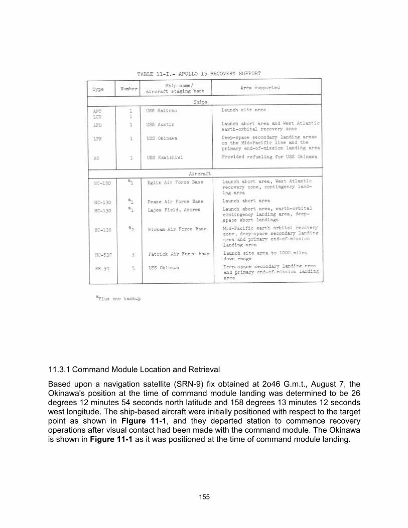
155
11.3.1 Command Module Location and Retrieval
Based upon a navigation satellite (SRN-9) fix obtained at 2o46 G.m.t., August 7, the Okinawa's position at the time of command module landing was determined to be 26 degrees 12 minutes 54 seconds north latitude and 158 degrees 13 minutes 12 seconds west longitude. The ship-based aircraft were initially positioned with respect to the target point as shown in Figure 11-1, and they departed station to commence recovery operations after visual contact had been made with the command module. The Okinawa is shown in Figure 11-1 as it was positioned at the time of command module landing.
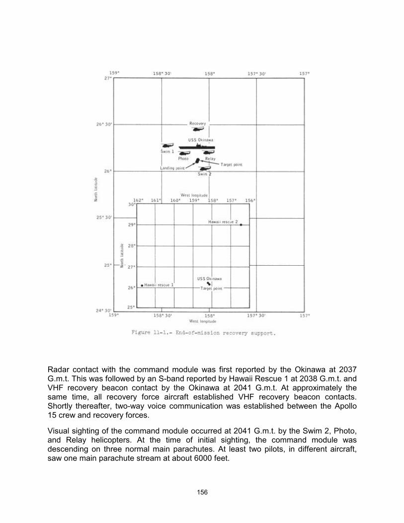
156
Radar contact with the command module was first reported by the Okinawa at 2037 G.m.t. This was followed by an S-band reported by Hawaii Rescue 1 at 2038 G.m.t. and VHF recovery beacon contact by the Okinawa at 2041 G.m.t. At approximately the same time, all recovery force aircraft established VHF recovery beacon contacts. Shortly thereafter, two-way voice communication was established between the Apollo 15 crew and recovery forces.
Visual sighting of the command module occurred at 2041 G.m.t. by the Swim 2, Photo, and Relay helicopters. At the time of initial sighting, the command module was descending on three normal main parachutes. At least two pilots, in different aircraft, saw one main parachute stream at about 6000 feet.
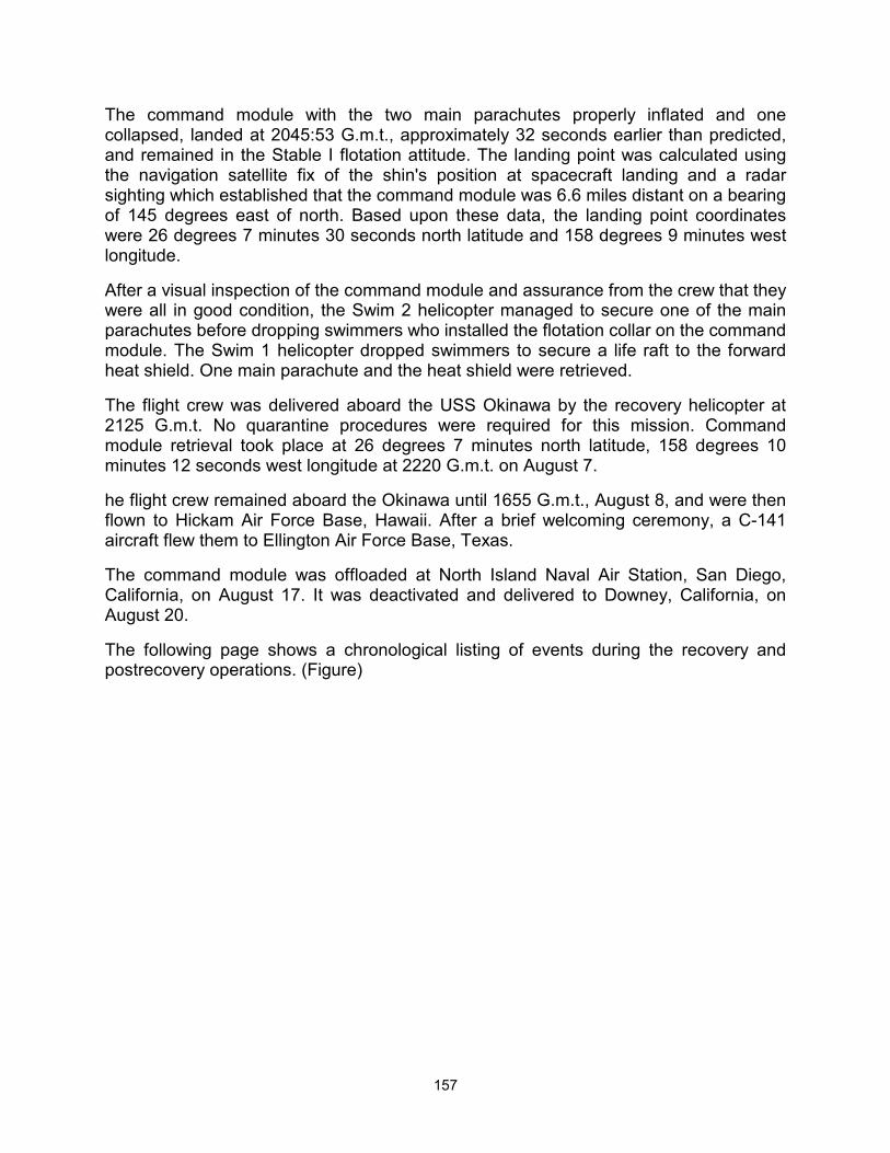
157
The command module with the two main parachutes properly inflated and one collapsed, landed at 2045:53 G.m.t., approximately 32 seconds earlier than predicted, and remained in the Stable I flotation attitude. The landing point was calculated using the navigation satellite fix of the shin's position at spacecraft landing and a radar sighting which established that the command module was 6.6 miles distant on a bearing of 145 degrees east of north. Based upon these data, the landing point coordinates were 26 degrees 7 minutes 30 seconds north latitude and 158 degrees 9 minutes west longitude.
After a visual inspection of the command module and assurance from the crew that they were all in good condition, the Swim 2 helicopter managed to secure one of the main parachutes before dropping swimmers who installed the flotation collar on the command module. The Swim 1 helicopter dropped swimmers to secure a life raft to the forward heat shield. One main parachute and the heat shield were retrieved.
The flight crew was delivered aboard the USS Okinawa by the recovery helicopter at 2125 G.m.t. No quarantine procedures were required for this mission. Command module retrieval took place at 26 degrees 7 minutes north latitude, 158 degrees 10 minutes 12 seconds west longitude at 2220 G.m.t. on August 7.
he flight crew remained aboard the Okinawa until 1655 G.m.t., August 8, and were then flown to Hickam Air Force Base, Hawaii. After a brief welcoming ceremony, a C-141 aircraft flew them to Ellington Air Force Base, Texas.
The command module was offloaded at North Island Naval Air Station, San Diego, California, on August 17. It was deactivated and delivered to Downey, California, on August 20.
The following page shows a chronological listing of events during the recovery and postrecovery operations. (Figure)
158
11.3.2 Postrecovery Inspection
Visual inspection of the command module in the recovery area revealed the following minor discrepancies:
One of the VHF-antenna ground planes was damaged.
The O-ring that seals the forward heat shield cover to the tunnel was loose.
The docking ring was slightly damaged, as generally occurs
A section of the aft heat shield, approximately 12 inches by 14 inches by 1/2-inch deep, was missing. (This generally occurs to some degree from the water impact.)
159
12 ASSESSMENT OF MISSION OBJECTIVES The four primary objectives (ref. 4) assigned to the Apollo 15 mission were:
Perform selenological inspection, survey, and sampling of materials and surface features in a pre-selected area of the Hadley-Appenine region.
Emplace and activate surface experiments.
Evaluate the capability of the Apollo equipment to provide extended lunar surface stay time, increased extravehicular operations, and surface mobility.
Conduct inflight experiments and photographic tasks from lunar orbit.
Twelve detailed objectives (derived from primary objectives) and twenty-four experiments (listed in Table 12-1 and Table 12-1 Concluded and described in reference) were assigned to the mission. Preliminary indications are that adequate data were obtained to successfully complete all objectives.
The Manned Spacecraft Center participated in two of nine approved operational tests. The two operational tests were: lunar gravity measurement (using the lunar module primary guidance system) and a lunar module voice and data relay test (a lunar module and Manned Space Flight Network test of voice and portable life support system data from the Lunar Module Pilot). Both tests were completed.
The other seven tests were performed for the Department of Defense and the Kennedy Space Center. These tests are designated as follows:
Chapel Bell (classified Department of Defense test)
Radar skin tracking
Ionospheric disturbance from missiles
Acoustic measurement of missile exhaust noise
Army acoustic test
Long-focal-length optical system
Sonic boom measurement

160
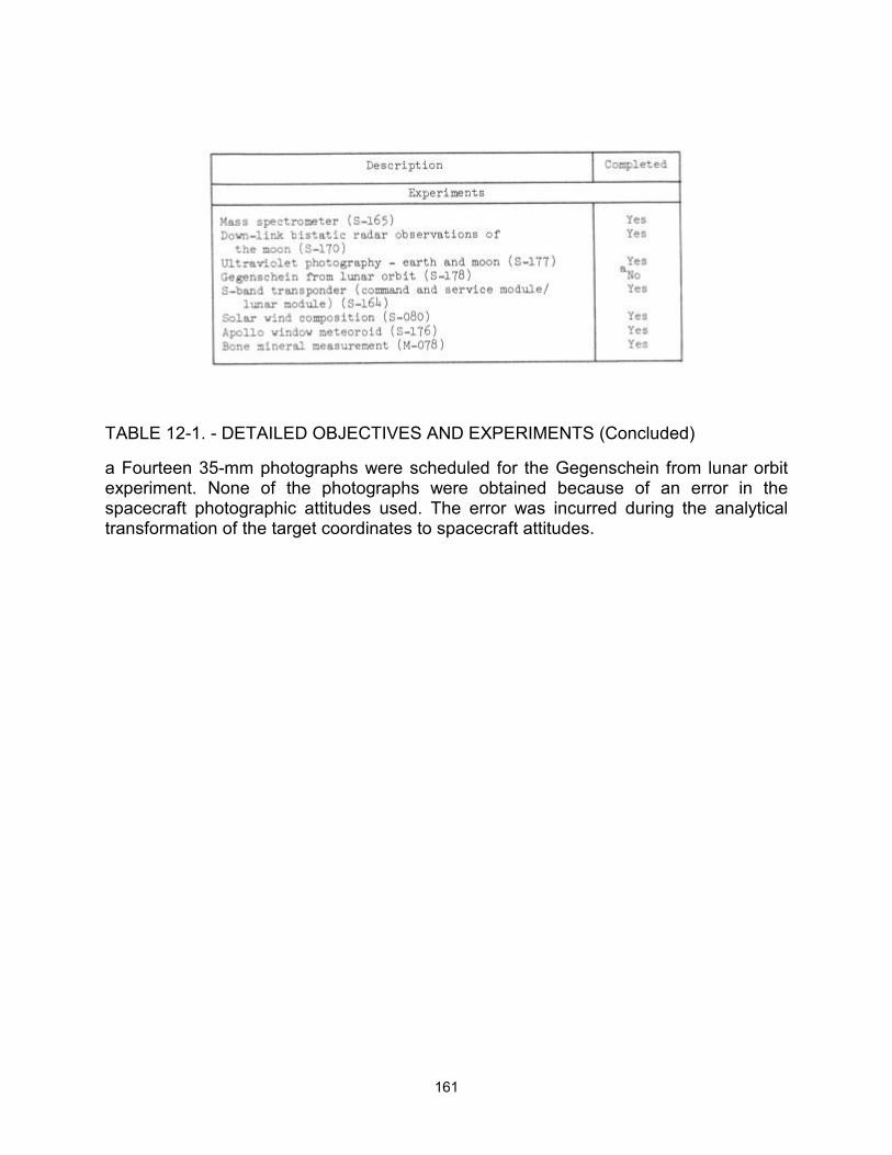
161
TABLE 12-1. - DETAILED OBJECTIVES AND EXPERIMENTS (Concluded)
a Fourteen 35-mm photographs were scheduled for the Gegenschein from lunar orbit experiment. None of the photographs were obtained because of an error in the spacecraft photographic attitudes used. The error was incurred during the analytical transformation of the target coordinates to spacecraft attitudes.
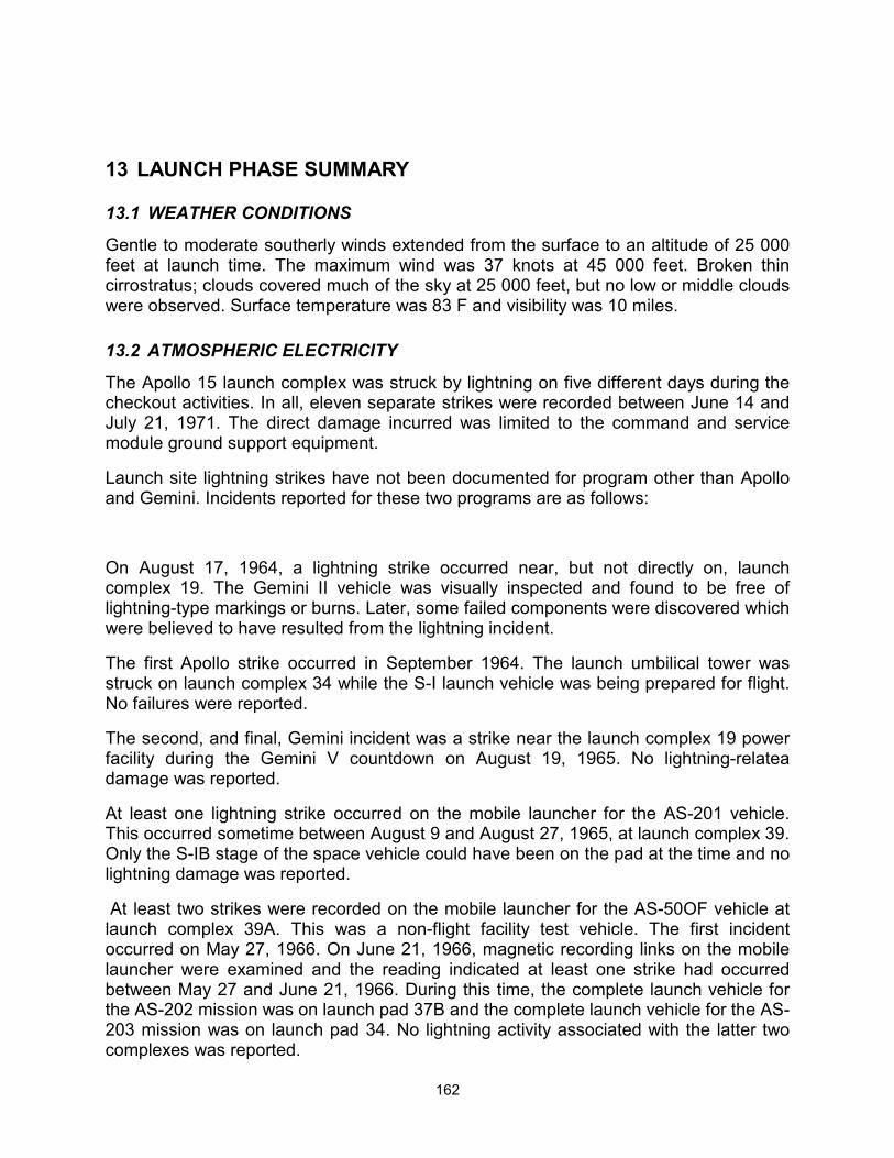
162
13 LAUNCH PHASE SUMMARY
13.1 WEATHER CONDITIONS
Gentle to moderate southerly winds extended from the surface to an altitude of 25 000 feet at launch time. The maximum wind was 37 knots at 45 000 feet. Broken thin cirrostratus; clouds covered much of the sky at 25 000 feet, but no low or middle clouds were observed. Surface temperature was 83 F and visibility was 10 miles.
13.2 ATMOSPHERIC ELECTRICITY
The Apollo 15 launch complex was struck by lightning on five different days during the checkout activities. In all, eleven separate strikes were recorded between June 14 and July 21, 1971. The direct damage incurred was limited to the command and service module ground support equipment.
Launch site lightning strikes have not been documented for program other than Apollo and Gemini. Incidents reported for these two programs are as follows:
On August 17, 1964, a lightning strike occurred near, but not directly on, launch complex 19. The Gemini II vehicle was visually inspected and found to be free of lightning-type markings or burns. Later, some failed components were discovered which were believed to have resulted from the lightning incident.
The first Apollo strike occurred in September 1964. The launch umbilical tower was struck on launch complex 34 while the S-I launch vehicle was being prepared for flight. No failures were reported.
The second, and final, Gemini incident was a strike near the launch complex 19 power facility during the Gemini V countdown on August 19, 1965. No lightning-relatea damage was reported.
At least one lightning strike occurred on the mobile launcher for the AS-201 vehicle. This occurred sometime between August 9 and August 27, 1965, at launch complex 39. Only the S-IB stage of the space vehicle could have been on the pad at the time and no lightning damage was reported.
At least two strikes were recorded on the mobile launcher for the AS-50OF vehicle at launch complex 39A. This was a non-flight facility test vehicle. The first incident occurred on May 27, 1966. On June 21, 1966, magnetic recording links on the mobile launcher were examined and the reading indicated at least one strike had occurred between May 27 and June 21, 1966. During this time, the complete launch vehicle for the AS-202 mission was on launch pad 37B and the complete launch vehicle for the AS-203 mission was on launch pad 34. No lightning activity associated with the latter two complexes was reported.
163
On July 27, 1967, a lightning strike occurred at launch complex 37B. The complete launch vehicle was on the pad at the time of the incident. Ground support equipment damage was found at a later date, which may have been caused by the lightning.
The only other lightning strike reported prior to the Apollo 15 prelaunch activities occurred during the launch phase of the Apollo 12 mission. This occurrence is documented in reference 6.
Existing weather data were examined for the May-through-July periods from 1966 to the launch of Apollo 15. Reported cloud-to-ground lightning strikes for a period of 90 days within the general vicinity of Cape Kennedy showed the daily average to be as follows:
(Figure)
Thunderstorms are more prevalent on the west side of the Indian River and remain west of the launch pad. During the summer of 19T1, however, the west winds prevailed more frequently than the preceding several years, thus causing the thunderstorms to move east. The lightning density in conjunction with the general easterly movement of the storms contributed to the number of strikes being higher than in the past.
13.3 LAUNCH VEHICLE PERFORMANCE
The eighth manned Saturn V Apollo space vehicle, AS-510, was launched on an azimuth 90 degrees east of north. A roll maneuver was initiated at 12.2 seconds after lift-off and the vehicle was placed on a flight azimuth of about 80 degrees. The trajectory parameters from launch through translunar injection were nominal. Earth-parking-orbit insertion conditions were achieved 4.4 seconds earlier than planned.
The performance of the S-IC propulsion system was satisfactory and the specific impulse and mixture ratios were near the predicted values. Four of the eight S-IC retromotors and all of the S-II stage ullage motors were removed for this flight; therefore, the S-IC/S-II separation sequence was revised. This sequence change extended the coast period between S-IC outboard engine cutoff and S-II engine start command by one second. The S-IC/S-II separation sequence and S-II engine thrust buildup performance was satisfactory.
The S-II propulsion system performed normally. The specific impulse and mixture ratios were near predicted values. This was the second S-II stage to incorporate a center-engine liquid-oxygen feedline accumulator as a longitudinal oscillation (POGO) suppression device. The operation of the accumulator system was effective in suppressing these types of oscillations.
164
The S-IVB stage J-2 engine operated satisfactorily throughout the first and second firings and had normal start and cutoff transients. The firing time for the first S-IVB firing was 141.5 seconds, 3.8 seconds less than predicted. Approximately 2.6 seconds of the shorter firing time can be attributed to higher than predicted S-IVB performance. The remainder can be attributed to S-IC and S-II stage performances. The specific impulse and engine mixture ratio were near the predicted values.
Abnormal temperatures were noted in the turbine hot gas system between the first S-IVB firing engine cutoff and second firing engine start command. Most noticeable was the fuel turbine inlet temperature. During liquid hydrogen chilldown, this temperature decreased from +130 to -100 F at the time of the second engine start command. The oxidizer turbine inlet temperature also indicated a small decrease. In addition, the fuel turbine inlet temperature indicated an abnormally fast decrease after engine cutoff for the first firing. A possible cause of the decrease in turbine inlet temperature was a small leak past the gas generator fuel inlet valve.
The S-IVB firing time for translunar injection was 350.8 seconds. Upon completion of the spacecraft separation, transposition, docking, and extraction operations, the S-IVB evasive maneuver was performed and, subsequently, the vehicle was placed on a trajectory to impact the lunar surface in the vicinity of the Apollo 14 landing site. The S-IVB/instrumentation unit impacted the lunar surface at 1 degree 31 minutes south latitude and 11 degrees 49 minutes west longitude with a velocity of 8455 ft/sec. This impact point is approximately 146 kilometers (79 miles) from the target of 3 degrees 39 minutes south latitude and 7 degrees 35 minutes west longitude. Although the impact location was not within the preferred region, scientific data were obtained from the impact.
The impact point projected from the first auxiliary propulsion system maneuver was perturbed by unplanned attitude control thrusting that occurred to counteract forces resulting from a water leak in the sublimator. Following the second auxiliary propulsion system maneuver, the small and gradually decreasing unbalanced force from the sublimator water leak continued to act for a period of 5 hours and further perturbed the point of impact.
The structural loads experienced during the S-IC boost phase were well below design values. Thrust cutoff transients experienced were similar to those of previous flights. During S-IC stage boost, 4- to 5hertz oscillations were detected beginning at approximately 100 seconds. The maximum amplitude measured at the instrumentation unit was ±0.06g. Oscillations in the 4- to 5-hertz range have been observed on previous flights. The structural loads experienced during the S-IVB stage firings were well below design values.
The guidance and navigation system provided satisfactory end conditions for the earth parking orbit and translunar injection. The control system was different from that of Apollo 14 because of redesigned filters and a revised gain schedule. These changes were made to stabilize structural dynamics caused by vehicle mass and structural changes and to improve wind and engine-out characteristics.
The launch vehicle electrical systems and emergency detection system performed

165
satisfactorily throughout all phases of flight. Operation of the batteries, power supplies, inverters, exploding bridge wire firing units, and switch selectors was normal. Vehicle pressure and thermal environments in general were similar to those experienced on earlier flights. The environmental control system performance was satisfactory. All data systems performed satisfactorily through the flight.
More details of the launch vehicle operation and performance are given in reference 1.
14 ANOMALY SUMMARY This section contains a discussion of the significant anomalies that occurred during the Apollo 15 mission. The discussion is divided into six major areas: command and service modules; lunar module; scientific instrument module experiments; Apollo lunar surface experiments package and associated equipment; government-furnished equipment; and the lunar roving vehicle.
14.1 COMMAND AND SERVICE MODULES
14.1.1 Service Module Reaction Control System Propellant Isolation Valves Closed
During postinsertion checks, the quad B secondary isolation valve talkback indicated that the valve was closed, and the switch was cycled to open it. Subsequently, talkbacks indicated that both the primary and secondary valves for quad D were also closed, and these valves were reopened. At S-IVB separation (approximately 3 hours 22 minutes), all the aforementioned valves closed and were reopened. Upon jettisoning of the scientific instrument module door, the quad B secondary valve closed and was reopened.
This type of valve (a magnetic latching valve, shown in Fig. 14-1) has, in previous missions, closed as a result of pyrotechnic shocks. Ground tests have shown that the valve will close at a shock level of approximately 80g sustained for 8 to 10 milliseconds. There were no indications of shock levels of the magnitude required to close the valve during launch.
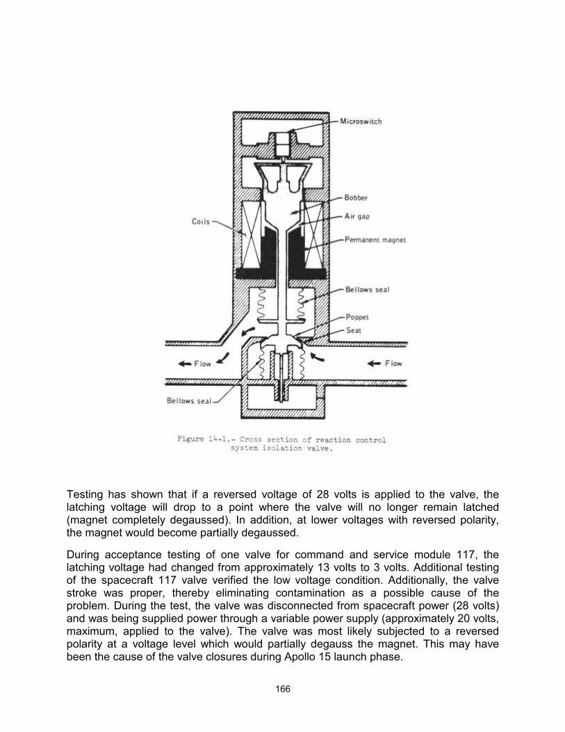
166
Testing has shown that if a reversed voltage of 28 volts is applied to the valve, the latching voltage will drop to a point where the valve will no longer remain latched (magnet completely degaussed). In addition, at lower voltages with reversed polarity, the magnet would become partially degaussed.
During acceptance testing of one valve for command and service module 117, the latching voltage had changed from approximately 13 volts to 3 volts. Additional testing of the spacecraft 117 valve verified the low voltage condition. Additionally, the valve stroke was proper, thereby eliminating contamination as a possible cause of the problem. During the test, the valve was disconnected from spacecraft power (28 volts) and was being supplied power through a variable power supply (approximately 20 volts, maximum, applied to the valve). The valve was most likely subjected to a reversed polarity at a voltage level which would partially degauss the magnet. This may have been the cause of the valve closures during Apollo 15 launch phase.
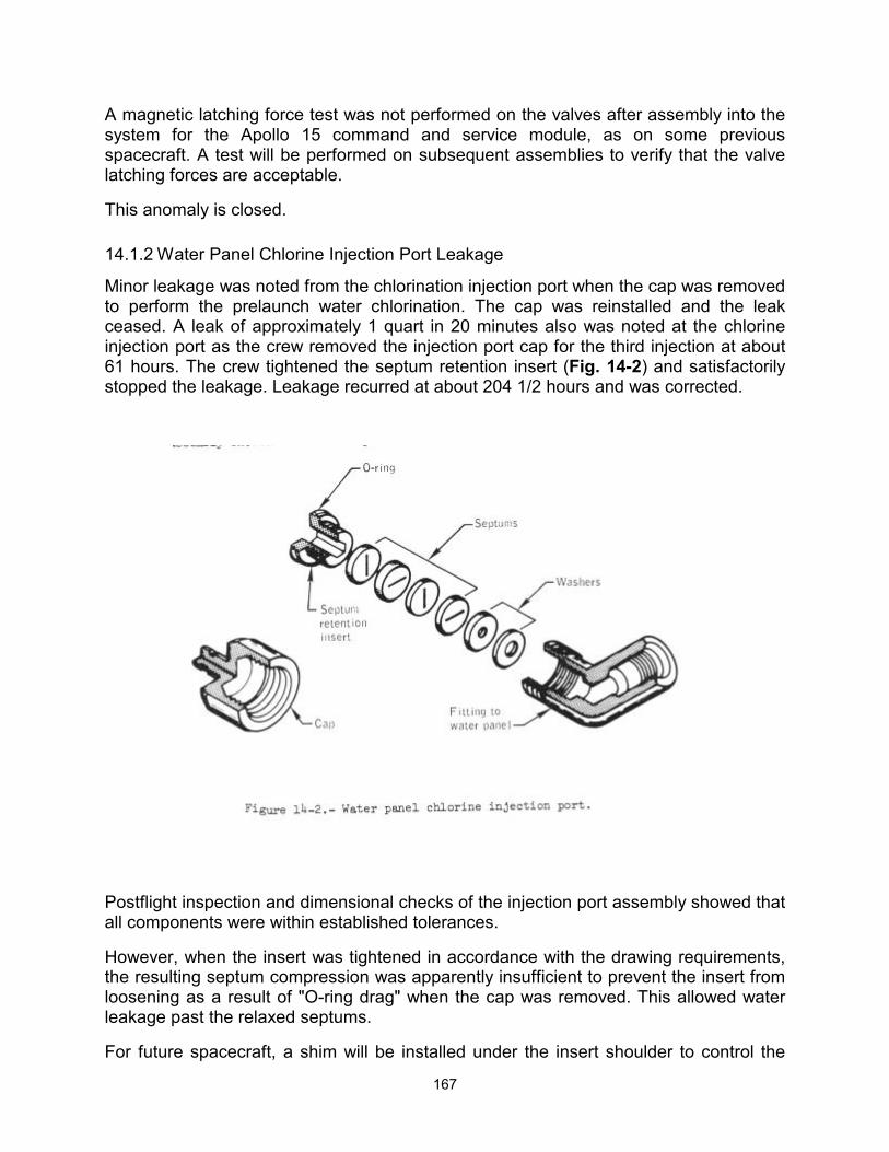
167
A magnetic latching force test was not performed on the valves after assembly into the system for the Apollo 15 command and service module, as on some previous spacecraft. A test will be performed on subsequent assemblies to verify that the valve latching forces are acceptable.
This anomaly is closed.
14.1.2 Water Panel Chlorine Injection Port Leakage
Minor leakage was noted from the chlorination injection port when the cap was removed to perform the prelaunch water chlorination. The cap was reinstalled and the leak ceased. A leak of approximately 1 quart in 20 minutes also was noted at the chlorine injection port as the crew removed the injection port cap for the third injection at about 61 hours. The crew tightened the septum retention insert (Fig. 14-2) and satisfactorily stopped the leakage. Leakage recurred at about 204 1/2 hours and was corrected.
Postflight inspection and dimensional checks of the injection port assembly showed that all components were within established tolerances.
However, when the insert was tightened in accordance with the drawing requirements, the resulting septum compression was apparently insufficient to prevent the insert from loosening as a result of "O-ring drag" when the cap was removed. This allowed water leakage past the relaxed septums.
For future spacecraft, a shim will be installed under the insert shoulder to control the
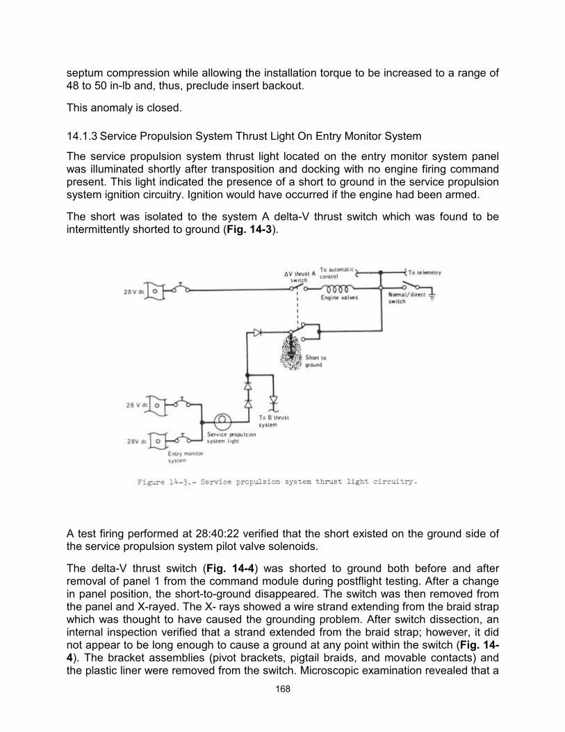
168
septum compression while allowing the installation torque to be increased to a range of 48 to 50 in-lb and, thus, preclude insert backout.
This anomaly is closed.
14.1.3 Service Propulsion System Thrust Light On Entry Monitor System
The service propulsion system thrust light located on the entry monitor system panel was illuminated shortly after transposition and docking with no engine firing command present. This light indicated the presence of a short to ground in the service propulsion system ignition circuitry. Ignition would have occurred if the engine had been armed.
The short was isolated to the system A delta-V thrust switch which was found to be intermittently shorted to ground (Fig. 14-3).
A test firing performed at 28:40:22 verified that the short existed on the ground side of the service propulsion system pilot valve solenoids.
The delta-V thrust switch (Fig. 14-4) was shorted to ground both before and after removal of panel 1 from the command module during postflight testing. After a change in panel position, the short-to-ground disappeared. The switch was then removed from the panel and X-rayed. The X- rays showed a wire strand extending from the braid strap which was thought to have caused the grounding problem. After switch dissection, an internal inspection verified that a strand extended from the braid strap; however, it did not appear to be long enough to cause a ground at any point within the switch (Fig. 14-4). The bracket assemblies (pivot brackets, pigtail braids, and movable contacts) and the plastic liner were removed from the switch. Microscopic examination revealed that a
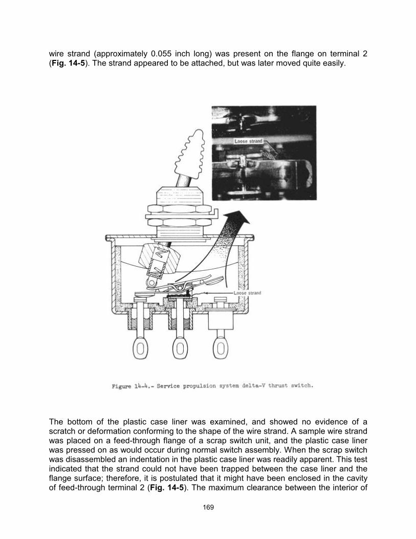
169
wire strand (approximately 0.055 inch long) was present on the flange on terminal 2 (Fig. 14-5). The strand appeared to be attached, but was later moved quite easily.
The bottom of the plastic case liner was examined, and showed no evidence of a scratch or deformation conforming to the shape of the wire strand. A sample wire strand was placed on a feed-through flange of a scrap switch unit, and the plastic case liner was pressed on as would occur during normal switch assembly. When the scrap switch was disassembled an indentation in the plastic case liner was readily apparent. This test indicated that the strand could not have been trapped between the case liner and the flange surface; therefore, it is postulated that it might have been enclosed in the cavity of feed-through terminal 2 (Fig. 14-5). The maximum clearance between the interior of
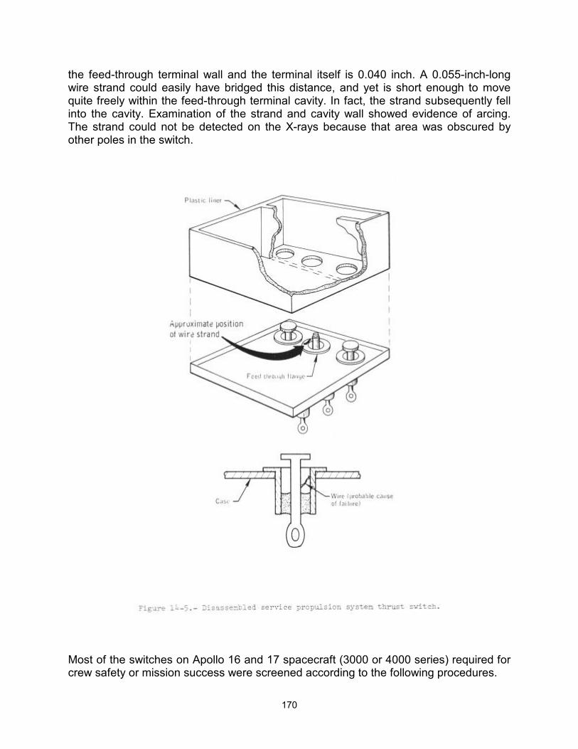
170
the feed-through terminal wall and the terminal itself is 0.040 inch. A 0.055-inch-long wire strand could easily have bridged this distance, and yet is short enough to move quite freely within the feed-through terminal cavity. In fact, the strand subsequently fell into the cavity. Examination of the strand and cavity wall showed evidence of arcing. The strand could not be detected on the X-rays because that area was obscured by other poles in the switch.
Most of the switches on Apollo 16 and 17 spacecraft (3000 or 4000 series) required for crew safety or mission success were screened according to the following procedures.
171
Additional inspection points were employed during manufacturing.
The switches were X-rayed prior to acceptance testing.
The acceptance vibration test was 3-axis random (4000 series) or single-axis sinusoidal (3000 series) test.
The switches were X-rayed after acceptance testing.
The following switches for Apollo 16 were of an earlier series and have been replaced with 4000 series switches:
a. Up telemetry data/back-up voice b. VHF ranging c. Battery charger d. Thrust vector control servo power e. Postlanding ventilation f .Crew optical alignment sight power g. Optics power h. Inertial measurement unit power i. Rendezvous radar transponder power
Switches required for crew safety and mission success for Apollo 17 which had not been screened according to the aforementioned procedures will also be replaced. In addition, two science utility power switches are to be disabled and stowed, and two circuit breakers are to be added to provide series protection for the command and service module/lunar module final separation function.
This anomaly is closed.
14.1.4 Integral Lighting Circuit Breaker Opened
The a-c bus 2 and the d-c bus B under-voltage alarms occurred and, subsequently, the integral lighting circuit breaker opened.
A short circuit sufficient to cause the circuit breaker to open would also cause the alarms. As a result of the problem, some display keyboard lights, the entry monitor system scroll lighting, and various other backlighting were not used for the remainder of the mission.
Postflight testing of the vehicle disclosed that the short circuit was in the mission timer. The timer was removed from the vehicle and returned to the vendor for further analysis. Teardown analysis revealed a shorted input filter capacitor.
The capacitor is rated for 200-volt d-c applications and is being used in an a-c application at voltages up to 115 volts. Since the dielectric in the ceramic capacitor is a piezolectric material (barium titanate), the 400-cycle a-c voltage actually causes the

172
materials in the capacitor to mechanically vibrate at that frequency. Over a period of time, the unit could break down because of mechanical fatigue. This may have been the cause of failure of this capacitor.
There are two mission timers on the command module and one on the lunar module. The unit on the lunar module is separately fused. Fuses will be added to the units in the Apollo 16 and 17 command modules. Appropriate action will be taken to correct the timer design and an inline change will be made on both the command module and lunar module.
This anomaly is closed.
14.1.5 Battery Relay Bus Measurement Anomaly
At approximately 81-1/2 hours, the battery relay bus voltage telemetry measurement read 13.66 volts instead of the nominal 32 volts, as evidenced by battery bus voltage measurements. The crew verified that the same low voltage reading was present on the panel 101 systems test meter. When the crew moved the systems test meter switch, the reading returned to normal.
Postflight testing of the vehicle and all of the involved components revealed no anomalous condition which could have caused the problem but did isolate the problem to the instrumentation circuitry and verify that the functional operation of the bus was not impaired. Analysis indicates that the only way to duplicate the flight problem would be to connect a resistance of 2800 ohms from ground to the battery relay bus measurement circuit (Fig. 14-6). No resistance near this magnitude was measured during postflight testing. The most probable cause of the anomaly was that insulation resistance at the output terminal of the switch was lowered because of humidity.
173
This is the only time that a problem of this type has occurred during the Apollo Program and the probability of recurrence is considered to be very low. If the problem does occur again, other measurements are available for the determination of the battery relay bus voltage.
This anomaly is closed.
14.1.6 Mass Spectrometer Boom Talkback Indicated Half-Barberpole On Retract
The mass spectrometer boom did not fully retract on five of twelve occasions. Data analysis, supported by the crew debriefing, indicates that the boom probably retracted to within about 1 inch of full retraction. Cold soaking of the deployed boom and/or cable harness preceded each anomalous retraction. In each case, the boom retracted fully after warmup.
The deploy/retract talkback indicator is normally gray when off, when the boom is fully retracted, or when it is fully extended. The indicator is barberpole when the boom is extending or retracting, and will show half barberpole if the drive motor stalls. The crew noted this last condition on the incomplete retractions.
An inflight test of the Apollo 15 boom indicated that the problem was a function of temperature. Testing and examination of the Apollo 16 spacecraft showed that the failure was possibly caused by pinching of the cable harness during the last several inches of boom retraction. The cable could have been pinched between the bell housing and rear H-frame bearing (Fig. 14-7), or a cable harness loop was jammed by a boom alignment finger against the bell housing (Fig. 14-8).
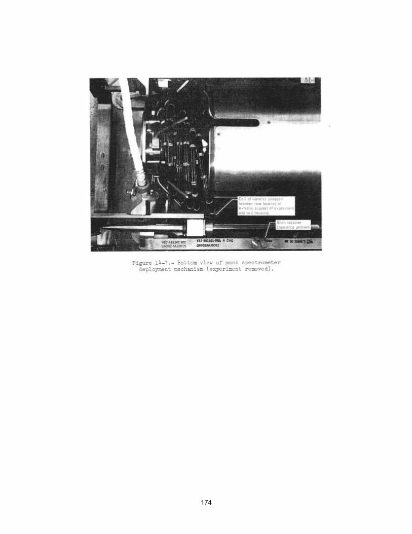
174
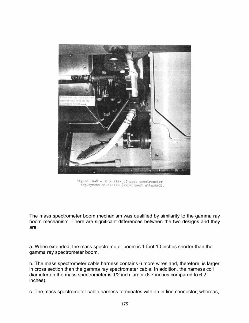
175
The mass spectrometer boom mechanism was qualified by similarity to the gamma ray boom mechanism. There are significant differences between the two designs and they are:
a. When extended, the mass spectrometer boom is 1 foot 10 inches shorter than the gamma ray spectrometer boom. b. The mass spectrometer cable harness contains 6 more wires and, therefore, is larger in cross section than the gamma ray spectrometer cable. In addition, the harness coil diameter on the mass spectrometer is 1/2 inch larger (6.7 inches compared to 6.2 inches). c. The mass spectrometer cable harness terminates with an in-line connector; whereas,
176
the gamma ray spectrometer harness terminates with a 90-degree connector. d. The mass spectrometer rear H-frame bearings retract past the lip of the bell housing; whereas, the retracted bearing position for the gamma ray experiment boom is even with the bell housing lip. Therefore, the lip on the sides of the mass spectrometer bell housing is relieved about 1/2 inch for bearing clearance.
The differences between the two configurations are now considered to be significant enough to have required separate testing for the mass spectrometer boom assembly. Accordingly, a delta qualification test will be instituted and a thermal vacuum environmental acceptance test will be performed on each flight unit.
Additional failure modes revealed during the testing of the Apollo 16 unit are:
a. Insufficient clearance between the spectrometer rear H-frame bearings and the boom housing bearings in relation to the rail support bean shim retainers. This could have been significant on Apollo 15, had a jettison been attempted. b. Misalignment between the right-hand guide rail forward floating section and the rigid rear section.
If the boom does not retract to within approximately 12 inches of full retraction, it will be jettisoned prior to the next service propulsion system firing. Tests have shown that the boom will not buckle during a service propulsion system firing when retracted to within 14.5 inches of full retraction.
Corrective actions for Apollo 16 are as follows:
a. A thermal vacuum test will be added to the acceptance test requirements. b. The brackets supporting the service loop at the experiment end of the cable harness will be redesigned. c. The existing finger guides will be extended. d. The bell mouth housing will be extended. e. Lead-in ramps will be added to the inboard bearing housings. f. Rail support beam shim retainer movement will be corrected by using anti-roll pins in place of shim retainers. g. A proximity switch modification kit will be installed to show when the boom has reached to within about 1 foot of full retraction.
177
This anomaly is closed.
14.1.7 Potable Water Tank Failure To Refill
The potable water tank quantity began to decrease during meal preparation at approximately 277 hours and failed to refill for the remainder of the flight. The waste water tank continued to fill normally and, apparently, accepted fuel cell water for this period. A similar occurrence had been noted earlier, at 13 1/2 hours, when the potable tank quantity decreased as the crew used the water, and remained constant until a waste water dump was performed at 28 1/2 hours. This decrease had been attributed to a closed potable tank inlet valve until the crew verified in their debriefing that the valve had been open during this time. The amount of water drained from the tank verified that the tank instrumentation was reading correctly.
During a postflight fill operation, with the waste tank inlet valve closed, and water introduced at the hydrogen separator, both the potable and waste water tanks filled.
The check valve between the fuel cell and waste tank dump leg (Fig. 14-9) was tested and found to leak excessively. A tear-down analysis of the check valve was performed and a piece of 300-series stainless steel wire (approximately 0.0085 by 0.14 inch) was found between the umbrella and the seating surface (Fig. 14-9). This contaminant could cause the umbrella to leak and yet move around sufficiently to allow adequate seating at other times. The wire most probably came from a welder's cleaning brush and was introduced into the system during buildup. Safety wires and tag wires are of a larger diameter than the one found. The check valve at the potable water tank inlet is of a different configuration and is spring loaded closed. The 1-psi pressure required to open this valve is a large pressure drop compared to the other components at the low flow of 1-1/2 lb/hour, and would, therefore, cause the water to flow to the waste tank.
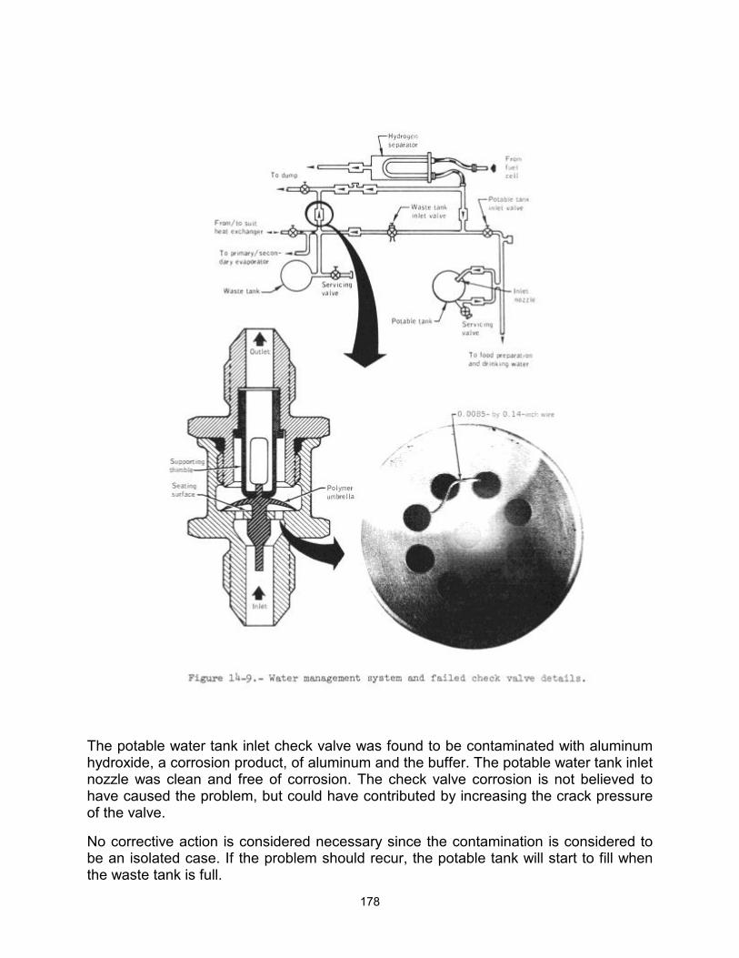
178
The potable water tank inlet check valve was found to be contaminated with aluminum hydroxide, a corrosion product, of aluminum and the buffer. The potable water tank inlet nozzle was clean and free of corrosion. The check valve corrosion is not believed to have caused the problem, but could have contributed by increasing the crack pressure of the valve.
No corrective action is considered necessary since the contamination is considered to be an isolated case. If the problem should recur, the potable tank will start to fill when the waste tank is full.
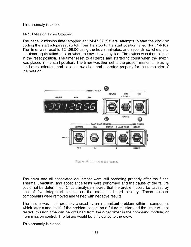
179
This anomaly is closed.
14.1.8 Mission Timer Stopped
The panel 2 mission timer stopped at 124:47:37. Several attempts to start the clock by cycling the start /stop/reset switch from the stop to the start position failed (Fig. 14-10). The timer was reset to 124:59:00 using the hours, minutes, and seconds switches, and the timer again failed to start when the switch was cycled. The switch was then placed in the reset position. The timer reset to all zeros and started to count when the switch was placed in the start position. The timer was then set to the proper mission time using the hours, minutes, and seconds switches and operated properly for the remainder of the mission.
The timer and all associated equipment were still operating properly after the flight. Thermal , vacuum, and acceptance tests were performed and the cause of the failure could not be determined. Circuit analysis showed that the problem could be caused by one of five integrated circuits on the mounting board circuitry. These suspect components were removed and tested with negative results.
The failure was most probably caused by an intermittent problem within a component which later cured itself. If the problem occurs on a future mission and the timer will not restart, mission time can be obtained from the other timer in the command module, or from mission control. The failure would be a nuisance to the crew.
This anomaly is closed.

180
14.1.9 Main Parachute Collapse
One of the three main parachutes was deflated to approximately one fifth of its full diameter at about 6000 feet altitude. The command module descended in this configuration to landing. All three parachutes were disconnected and one good main parachute was recovered. Photographs of the descending spacecraft indicate that two or three of the six riser legs on the failed parachute were missing (Fig. 14-11).
Three areas that were considered as possible causes are:
The forward heat shield, which was in close proximity to the spacecraft flight path.
A broken riser/suspension line connector link which was found on the recovered parachute (Fig. 14-12).
The command module reaction control system propellant firing and fuel dump.
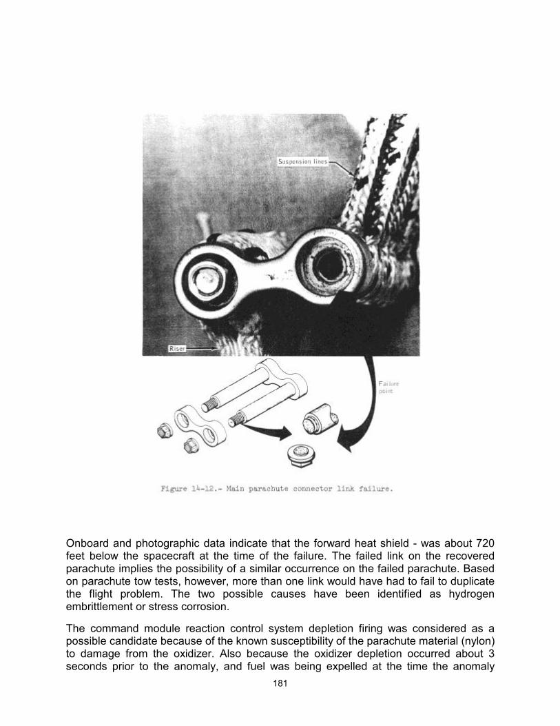
181
Onboard and photographic data indicate that the forward heat shield - was about 720 feet below the spacecraft at the time of the failure. The failed link on the recovered parachute implies the possibility of a similar occurrence on the failed parachute. Based on parachute tow tests, however, more than one link would have had to fail to duplicate the flight problem. The two possible causes have been identified as hydrogen embrittlement or stress corrosion.
The command module reaction control system depletion firing was considered as a possible candidate because of the known susceptibility of the parachute material (nylon) to damage from the oxidizer. Also because the oxidizer depletion occurred about 3 seconds prior to the anomaly, and fuel was being expelled at the time the anomaly
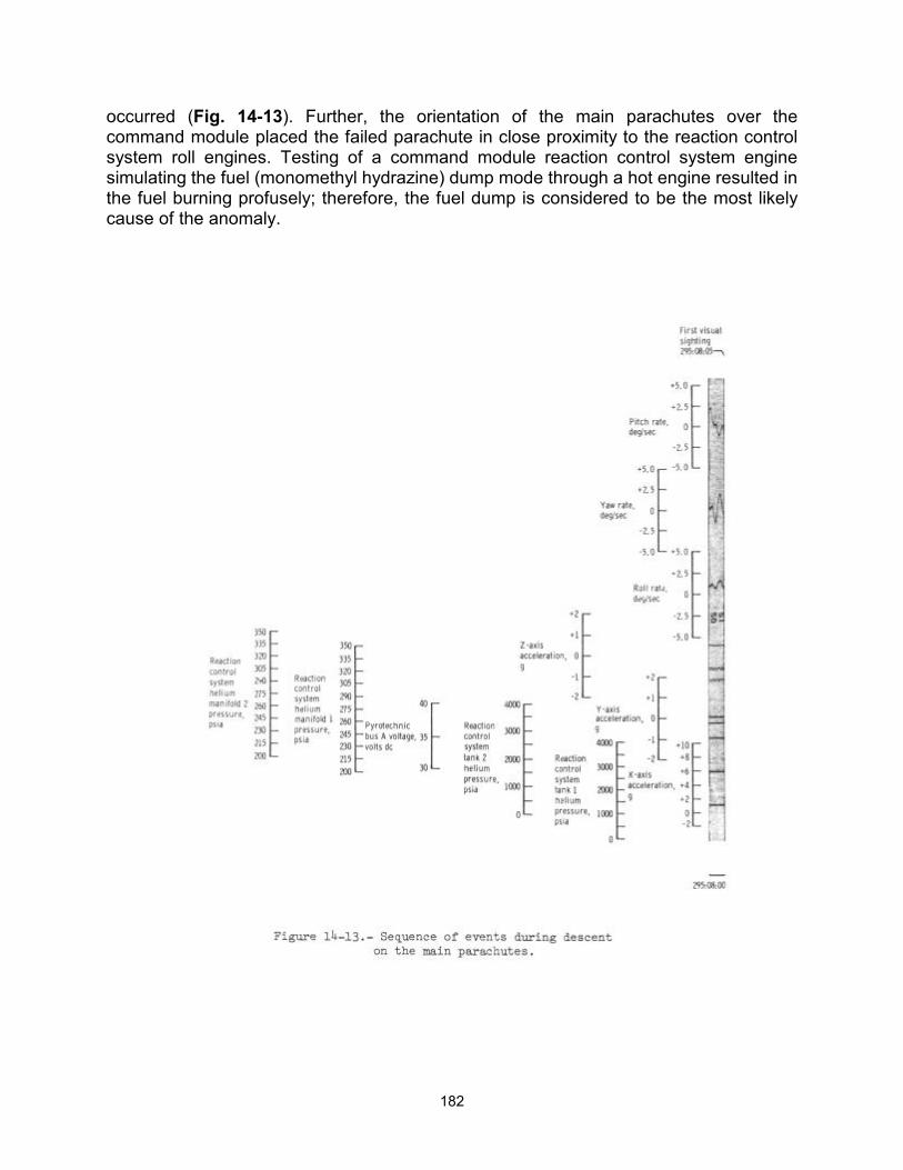
182
occurred (Fig. 14-13). Further, the orientation of the main parachutes over the command module placed the failed parachute in close proximity to the reaction control system roll engines. Testing of a command module reaction control system engine simulating the fuel (monomethyl hydrazine) dump mode through a hot engine resulted in the fuel burning profusely; therefore, the fuel dump is considered to be the most likely cause of the anomaly.
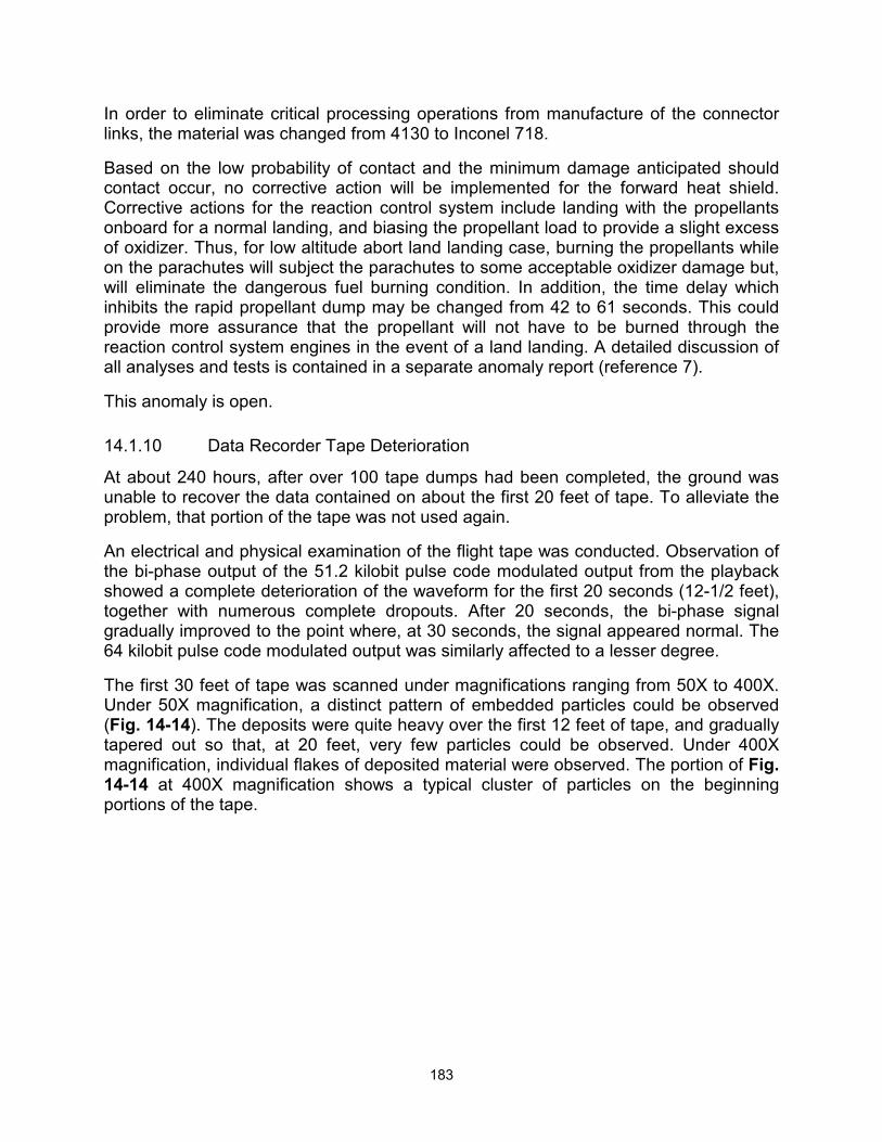
183
In order to eliminate critical processing operations from manufacture of the connector links, the material was changed from 4130 to Inconel 718.
Based on the low probability of contact and the minimum damage anticipated should contact occur, no corrective action will be implemented for the forward heat shield. Corrective actions for the reaction control system include landing with the propellants onboard for a normal landing, and biasing the propellant load to provide a slight excess of oxidizer. Thus, for low altitude abort land landing case, burning the propellants while on the parachutes will subject the parachutes to some acceptable oxidizer damage but, will eliminate the dangerous fuel burning condition. In addition, the time delay which inhibits the rapid propellant dump may be changed from 42 to 61 seconds. This could provide more assurance that the propellant will not have to be burned through the reaction control system engines in the event of a land landing. A detailed discussion of all analyses and tests is contained in a separate anomaly report (reference 7).
This anomaly is open.
14.1.10 Data Recorder Tape Deterioration
At about 240 hours, after over 100 tape dumps had been completed, the ground was unable to recover the data contained on about the first 20 feet of tape. To alleviate the problem, that portion of the tape was not used again.
An electrical and physical examination of the flight tape was conducted. Observation of the bi-phase output of the 51.2 kilobit pulse code modulated output from the playback showed a complete deterioration of the waveform for the first 20 seconds (12-1/2 feet), together with numerous complete dropouts. After 20 seconds, the bi-phase signal gradually improved to the point where, at 30 seconds, the signal appeared normal. The 64 kilobit pulse code modulated output was similarly affected to a lesser degree.
The first 30 feet of tape was scanned under magnifications ranging from 50X to 400X. Under 50X magnification, a distinct pattern of embedded particles could be observed (Fig. 14-14). The deposits were quite heavy over the first 12 feet of tape, and gradually tapered out so that, at 20 feet, very few particles could be observed. Under 400X magnification, individual flakes of deposited material were observed. The portion of Fig. 14-14 at 400X magnification shows a typical cluster of particles on the beginning portions of the tape.
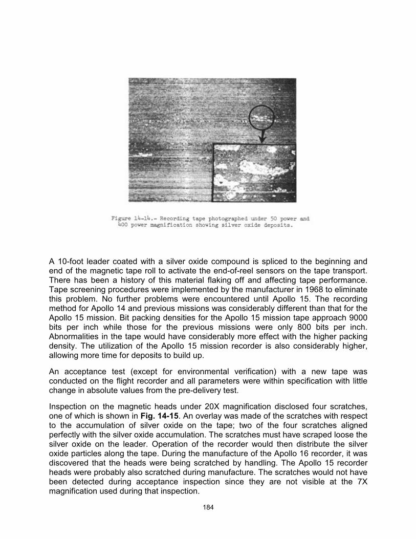
184
A 10-foot leader coated with a silver oxide compound is spliced to the beginning and end of the magnetic tape roll to activate the end-of-reel sensors on the tape transport. There has been a history of this material flaking off and affecting tape performance. Tape screening procedures were implemented by the manufacturer in 1968 to eliminate this problem. No further problems were encountered until Apollo 15. The recording method for Apollo 14 and previous missions was considerably different than that for the Apollo 15 mission. Bit packing densities for the Apollo 15 mission tape approach 9000 bits per inch while those for the previous missions were only 800 bits per inch. Abnormalities in the tape would have considerably more effect with the higher packing density. The utilization of the Apollo 15 mission recorder is also considerably higher, allowing more time for deposits to build up.
An acceptance test (except for environmental verification) with a new tape was conducted on the flight recorder and all parameters were within specification with little change in absolute values from the pre-delivery test.
Inspection on the magnetic heads under 20X magnification disclosed four scratches, one of which is shown in Fig. 14-15. An overlay was made of the scratches with respect to the accumulation of silver oxide on the tape; two of the four scratches aligned perfectly with the silver oxide accumulation. The scratches must have scraped loose the silver oxide on the leader. Operation of the recorder would then distribute the silver oxide particles along the tape. During the manufacture of the Apollo 16 recorder, it was discovered that the heads were being scratched by handling. The Apollo 15 recorder heads were probably also scratched during manufacture. The scratches would not have been detected during acceptance inspection since they are not visible at the 7X magnification used during that inspection.
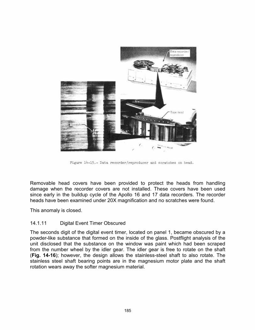
185
Removable head covers have been provided to protect the heads from handling damage when the recorder covers are not installed. These covers have been used since early in the buildup cycle of the Apollo 16 and 17 data recorders. The recorder heads have been examined under 20X magnification and no scratches were found.
This anomaly is closed.
14.1.11 Digital Event Timer Obscured
The seconds digit of the digital event timer, located on panel 1, became obscured by a powder-like substance that formed on the inside of the glass. Postflight analysis of the unit disclosed that the substance on the window was paint which had been scraped from the number wheel by the idler gear. The idler gear is free to rotate on the shaft (Fig. 14-16); however, the design allows the stainless-steel shaft to also rotate. The stainless steel shaft bearing points are in the magnesium motor plate and the shaft rotation wears away the softer magnesium material.
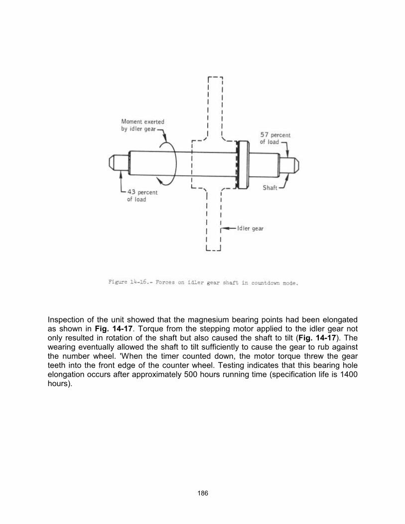
186
Inspection of the unit showed that the magnesium bearing points had been elongated as shown in Fig. 14-17. Torque from the stepping motor applied to the idler gear not only resulted in rotation of the shaft but also caused the shaft to tilt (Fig. 14-17). The wearing eventually allowed the shaft to tilt sufficiently to cause the gear to rub against the number wheel. 'When the timer counted down, the motor torque threw the gear teeth into the front edge of the counter wheel. Testing indicates that this bearing hole elongation occurs after approximately 500 hours running time (specification life is 1400 hours).
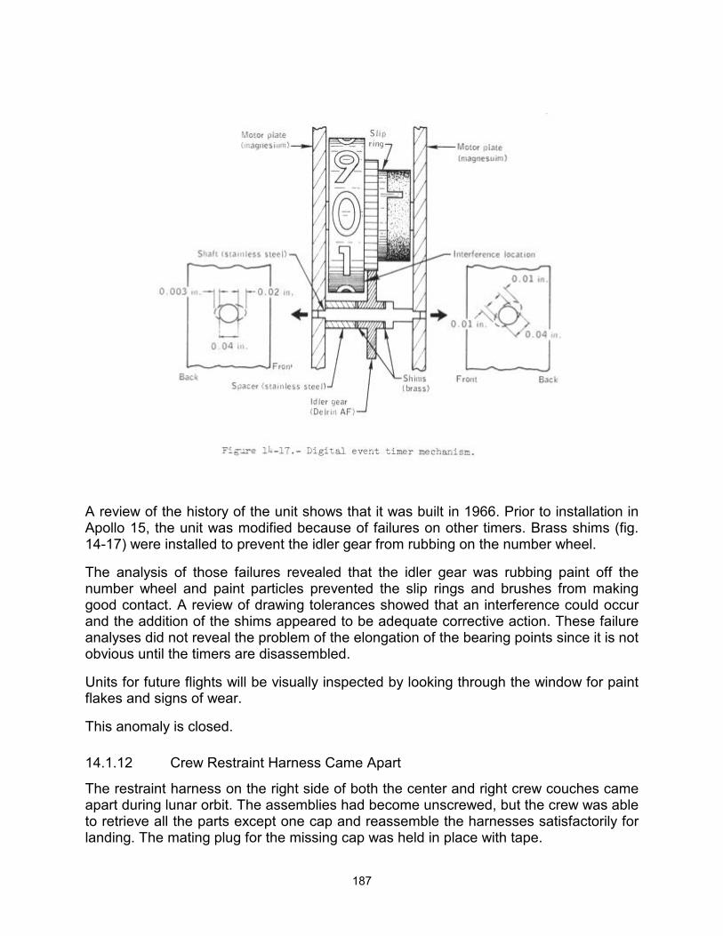
187
A review of the history of the unit shows that it was built in 1966. Prior to installation in Apollo 15, the unit was modified because of failures on other timers. Brass shims (fig. 14-17) were installed to prevent the idler gear from rubbing on the number wheel.
The analysis of those failures revealed that the idler gear was rubbing paint off the number wheel and paint particles prevented the slip rings and brushes from making good contact. A review of drawing tolerances showed that an interference could occur and the addition of the shims appeared to be adequate corrective action. These failure analyses did not reveal the problem of the elongation of the bearing points since it is not obvious until the timers are disassembled.
Units for future flights will be visually inspected by looking through the window for paint flakes and signs of wear.
This anomaly is closed.
14.1.12 Crew Restraint Harness Came Apart
The restraint harness on the right side of both the center and right crew couches came apart during lunar orbit. The assemblies had become unscrewed, but the crew was able to retrieve all the parts except one cap and reassemble the harnesses satisfactorily for landing. The mating plug for the missing cap was held in place with tape.
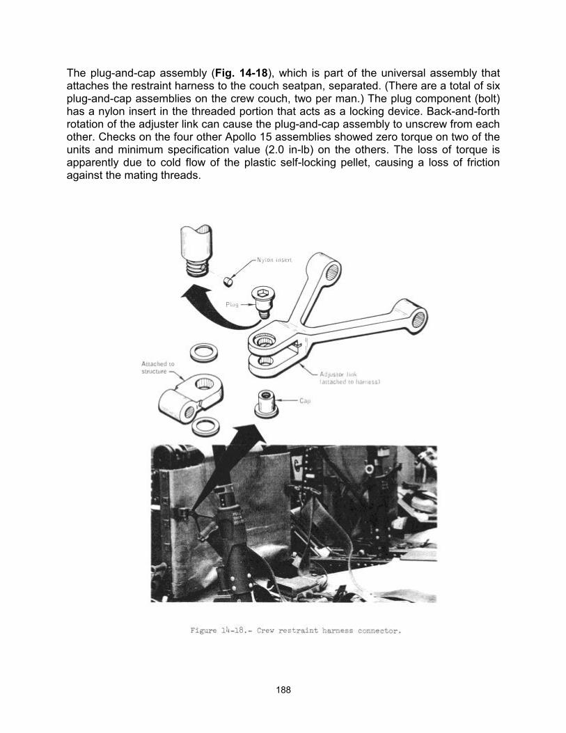
188
The plug-and-cap assembly (Fig. 14-18), which is part of the universal assembly that attaches the restraint harness to the couch seatpan, separated. (There are a total of six plug-and-cap assemblies on the crew couch, two per man.) The plug component (bolt) has a nylon insert in the threaded portion that acts as a locking device. Back-and-forth rotation of the adjuster link can cause the plug-and-cap assembly to unscrew from each other. Checks on the four other Apollo 15 assemblies showed zero torque on two of the units and minimum specification value (2.0 in-lb) on the others. The loss of torque is apparently due to cold flow of the plastic self-locking pellet, causing a loss of friction against the mating threads.

189
A thread locking sealant will be used to prevent the problem on future missions.
This anomaly is closed.
14.1.13 Loose Object In Cabin Fans
During portions of the flight when the cabin fans (Fig. 14-19) were activated, the crew heard sounds like an object striking the blades. Cycling the fans several times allowed the object to be retained in a position that precluded it from interfering with fan operation.
Inspection of the fans revealed considerable gouging on the leading edges of the blades of both fans (Fig. 14-19). No marks were found on the outlet de-swirl vanes of either fan. After extensive examination, including the lunar dust filter, a 1/4-inch washer was found in the ducting.
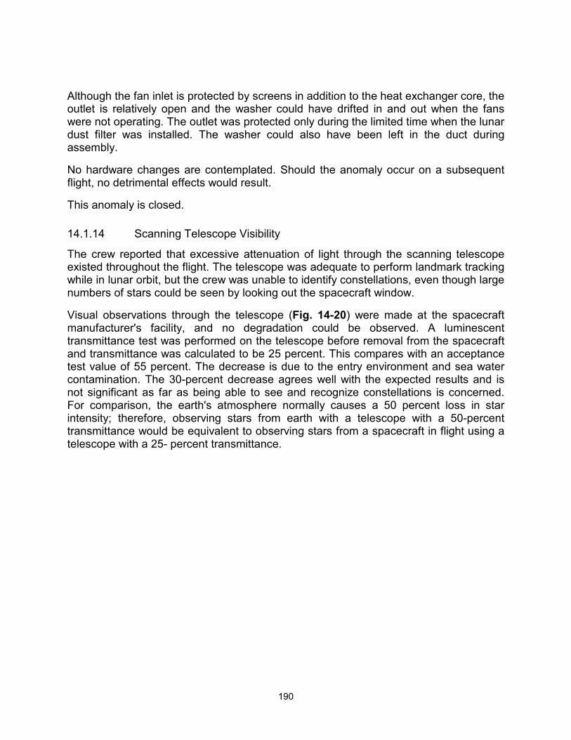
190
Although the fan inlet is protected by screens in addition to the heat exchanger core, the outlet is relatively open and the washer could have drifted in and out when the fans were not operating. The outlet was protected only during the limited time when the lunar dust filter was installed. The washer could also have been left in the duct during assembly.
No hardware changes are contemplated. Should the anomaly occur on a subsequent flight, no detrimental effects would result.
This anomaly is closed.
14.1.14 Scanning Telescope Visibility
The crew reported that excessive attenuation of light through the scanning telescope existed throughout the flight. The telescope was adequate to perform landmark tracking while in lunar orbit, but the crew was unable to identify constellations, even though large numbers of stars could be seen by looking out the spacecraft window.
Visual observations through the telescope (Fig. 14-20) were made at the spacecraft manufacturer's facility, and no degradation could be observed. A luminescent transmittance test was performed on the telescope before removal from the spacecraft and transmittance was calculated to be 25 percent. This compares with an acceptance test value of 55 percent. The decrease is due to the entry environment and sea water contamination. The 30-percent decrease agrees well with the expected results and is not significant as far as being able to see and recognize constellations is concerned. For comparison, the earth's atmosphere normally causes a 50 percent loss in star intensity; therefore, observing stars from earth with a telescope with a 50-percent transmittance would be equivalent to observing stars from a spacecraft in flight using a telescope with a 25- percent transmittance.
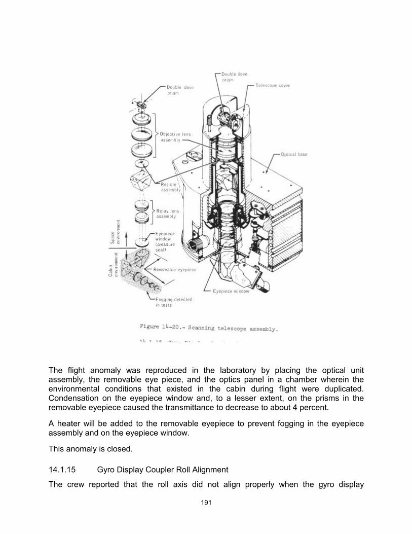
191
The flight anomaly was reproduced in the laboratory by placing the optical unit assembly, the removable eye piece, and the optics panel in a chamber wherein the environmental conditions that existed in the cabin during flight were duplicated. Condensation on the eyepiece window and, to a lesser extent, on the prisms in the removable eyepiece caused the transmittance to decrease to about 4 percent.
A heater will be added to the removable eyepiece to prevent fogging in the eyepiece assembly and on the eyepiece window.
This anomaly is closed.
14.1.15 Gyro Display Coupler Roll Alignment
The crew reported that the roll axis did not align properly when the gyro display
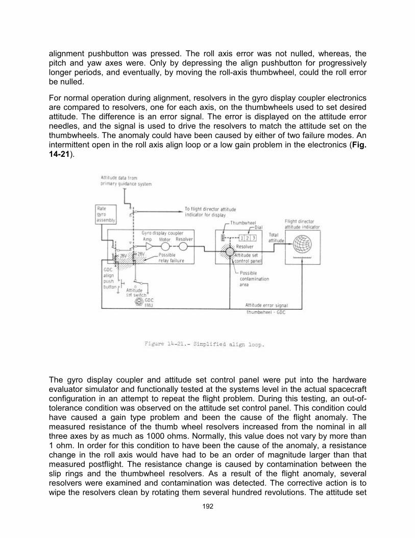
192
alignment pushbutton was pressed. The roll axis error was not nulled, whereas, the pitch and yaw axes were. Only by depressing the align pushbutton for progressively longer periods, and eventually, by moving the roll-axis thumbwheel, could the roll error be nulled.
For normal operation during alignment, resolvers in the gyro display coupler electronics are compared to resolvers, one for each axis, on the thumbwheels used to set desired attitude. The difference is an error signal. The error is displayed on the attitude error needles, and the signal is used to drive the resolvers to match the attitude set on the thumbwheels. The anomaly could have been caused by either of two failure modes. An intermittent open in the roll axis align loop or a low gain problem in the electronics (Fig. 14-21).
The gyro display coupler and attitude set control panel were put into the hardware evaluator simulator and functionally tested at the systems level in the actual spacecraft configuration in an attempt to repeat the flight problem. During this testing, an out-of-tolerance condition was observed on the attitude set control panel. This condition could have caused a gain type problem and been the cause of the flight anomaly. The measured resistance of the thumb wheel resolvers increased from the nominal in all three axes by as much as 1000 ohms. Normally, this value does not vary by more than 1 ohm. In order for this condition to have been the cause of the anomaly, a resistance change in the roll axis would have had to be an order of magnitude larger than that measured postflight. The resistance change is caused by contamination between the slip rings and the thumbwheel resolvers. As a result of the flight anomaly, several resolvers were examined and contamination was detected. The corrective action is to wipe the resolvers clean by rotating them several hundred revolutions. The attitude set
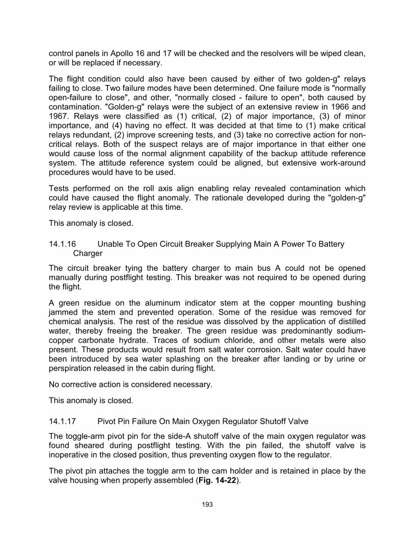
193
control panels in Apollo 16 and 17 will be checked and the resolvers will be wiped clean, or will be replaced if necessary.
The flight condition could also have been caused by either of two golden-g" relays failing to close. Two failure modes have been determined. One failure mode is "normally open-failure to close", and other, "normally closed - failure to open", both caused by contamination. "Golden-g" relays were the subject of an extensive review in 1966 and 1967. Relays were classified as (1) critical, (2) of major importance, (3) of minor importance, and (4) having no effect. It was decided at that time to (1) make critical relays redundant, (2) improve screening tests, and (3) take no corrective action for non-critical relays. Both of the suspect relays are of major importance in that either one would cause loss of the normal alignment capability of the backup attitude reference system. The attitude reference system could be aligned, but extensive work-around procedures would have to be used.
Tests performed on the roll axis align enabling relay revealed contamination which could have caused the flight anomaly. The rationale developed during the "golden-g" relay review is applicable at this time.
This anomaly is closed.
14.1.16 Unable To Open Circuit Breaker Supplying Main A Power To Battery Charger
The circuit breaker tying the battery charger to main bus A could not be opened manually during postflight testing. This breaker was not required to be opened during the flight.
A green residue on the aluminum indicator stem at the copper mounting bushing jammed the stem and prevented operation. Some of the residue was removed for chemical analysis. The rest of the residue was dissolved by the application of distilled water, thereby freeing the breaker. The green residue was predominantly sodium-copper carbonate hydrate. Traces of sodium chloride, and other metals were also present. These products would result from salt water corrosion. Salt water could have been introduced by sea water splashing on the breaker after landing or by urine or perspiration released in the cabin during flight.
No corrective action is considered necessary.
This anomaly is closed.
14.1.17 Pivot Pin Failure On Main Oxygen Regulator Shutoff Valve
The toggle-arm pivot pin for the side-A shutoff valve of the main oxygen regulator was found sheared during postflight testing. With the pin failed, the shutoff valve is inoperative in the closed position, thus preventing oxygen flow to the regulator.
The pivot pin attaches the toggle arm to the cam holder and is retained in place by the valve housing when properly assembled (Fig. 14-22).
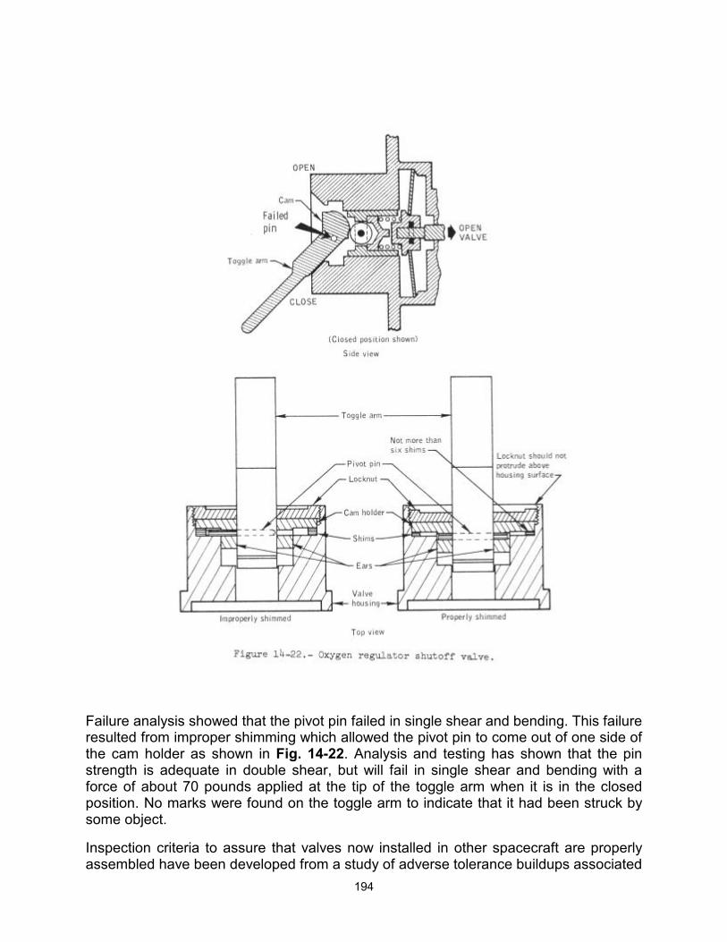
194
Failure analysis showed that the pivot pin failed in single shear and bending. This failure resulted from improper shimming which allowed the pivot pin to come out of one side of the cam holder as shown in Fig. 14-22. Analysis and testing has shown that the pin strength is adequate in double shear, but will fail in single shear and bending with a force of about 70 pounds applied at the tip of the toggle arm when it is in the closed position. No marks were found on the toggle arm to indicate that it had been struck by some object.
Inspection criteria to assure that valves now installed in other spacecraft are properly assembled have been developed from a study of adverse tolerance buildups associated
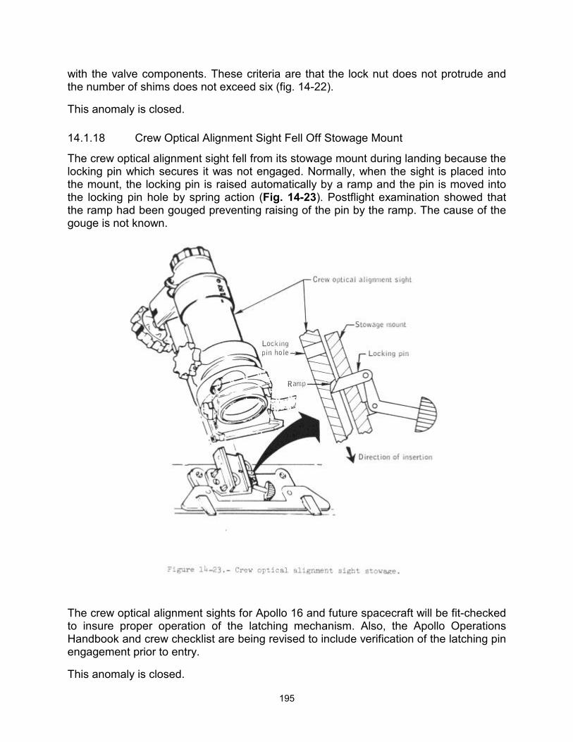
195
with the valve components. These criteria are that the lock nut does not protrude and the number of shims does not exceed six (fig. 14-22).
This anomaly is closed.
14.1.18 Crew Optical Alignment Sight Fell Off Stowage Mount
The crew optical alignment sight fell from its stowage mount during landing because the locking pin which secures it was not engaged. Normally, when the sight is placed into the mount, the locking pin is raised automatically by a ramp and the pin is moved into the locking pin hole by spring action (Fig. 14-23). Postflight examination showed that the ramp had been gouged preventing raising of the pin by the ramp. The cause of the gouge is not known.
The crew optical alignment sights for Apollo 16 and future spacecraft will be fit-checked to insure proper operation of the latching mechanism. Also, the Apollo Operations Handbook and crew checklist are being revised to include verification of the latching pin engagement prior to entry.
This anomaly is closed.
196
14.2 LUNAR MODULE
14.2.1 Water/Glycol Pump Differential Pressure Fluctuations
Variations were noted in the water/glycol pump differential pressure shortly after the cabin depressurizations for the standup extravehicular activity and the second extravehicular activity. The variations were similar on both occasions. The pressure differential decreased from about 20 psid (normal) to about 15 psid, then increased to about 27 psid and returned to normal (Fig. 14-24).
The total times for the cycles were 3 minutes during the standup extravehicular activity and 10 minutes during the second extravehicular activity. The pump discharge pressure remained relatively stable throughout both periods. If pressure fluctuations had taken place in the heat transport system, both the pump discharge pressure and differential pressure should have varied together.
After the second fluctuation occurred, water/glycol pump 2 was selected because of the erratic differential pressure. All parameters were normal during pump 2 operation. The crew reselected pump 1 prior to egress for the second extravehicular activity, and it operated satisfactorily. Later, after docking, the pump was turned off momentarily and the pump discharge pressure readout was verified as correct since it decreased to the
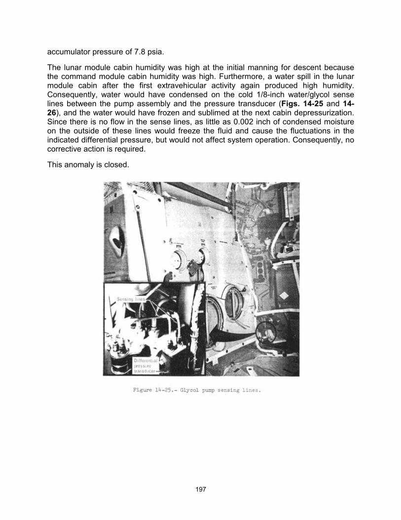
197
accumulator pressure of 7.8 psia.
The lunar module cabin humidity was high at the initial manning for descent because the command module cabin humidity was high. Furthermore, a water spill in the lunar module cabin after the first extravehicular activity again produced high humidity. Consequently, water would have condensed on the cold 1/8-inch water/glycol sense lines between the pump assembly and the pressure transducer (Figs. 14-25 and 14-26), and the water would have frozen and sublimed at the next cabin depressurization. Since there is no flow in the sense lines, as little as 0.002 inch of condensed moisture on the outside of these lines would freeze the fluid and cause the fluctuations in the indicated differential pressure, but would not affect system operation. Consequently, no corrective action is required.
This anomaly is closed.
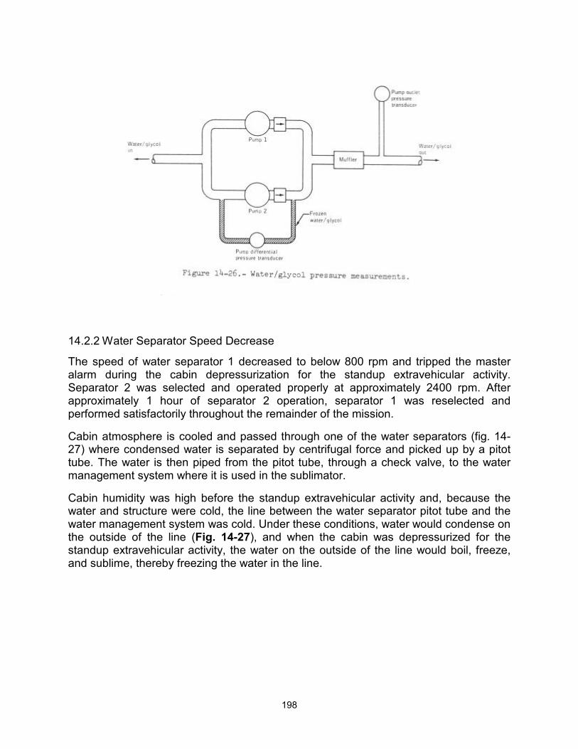
198
14.2.2 Water Separator Speed Decrease
The speed of water separator 1 decreased to below 800 rpm and tripped the master alarm during the cabin depressurization for the standup extravehicular activity. Separator 2 was selected and operated properly at approximately 2400 rpm. After approximately 1 hour of separator 2 operation, separator 1 was reselected and performed satisfactorily throughout the remainder of the mission.
Cabin atmosphere is cooled and passed through one of the water separators (fig. 14-27) where condensed water is separated by centrifugal force and picked up by a pitot tube. The water is then piped from the pitot tube, through a check valve, to the water management system where it is used in the sublimator.
Cabin humidity was high before the standup extravehicular activity and, because the water and structure were cold, the line between the water separator pitot tube and the water management system was cold. Under these conditions, water would condense on the outside of the line (Fig. 14-27), and when the cabin was depressurized for the standup extravehicular activity, the water on the outside of the line would boil, freeze, and sublime, thereby freezing the water in the line.
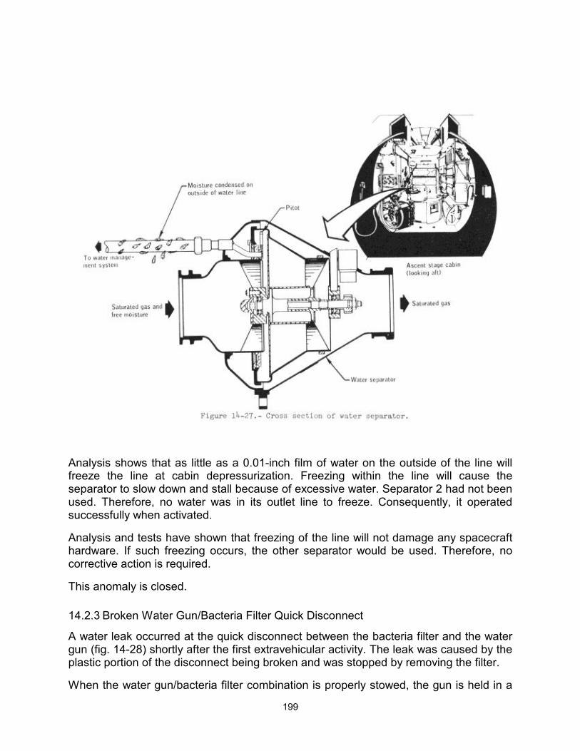
199
Analysis shows that as little as a 0.01-inch film of water on the outside of the line will freeze the line at cabin depressurization. Freezing within the line will cause the separator to slow down and stall because of excessive water. Separator 2 had not been used. Therefore, no water was in its outlet line to freeze. Consequently, it operated successfully when activated.
Analysis and tests have shown that freezing of the line will not damage any spacecraft hardware. If such freezing occurs, the other separator would be used. Therefore, no corrective action is required.
This anomaly is closed.
14.2.3 Broken Water Gun/Bacteria Filter Quick Disconnect
A water leak occurred at the quick disconnect between the bacteria filter and the water gun (fig. 14-28) shortly after the first extravehicular activity. The leak was caused by the plastic portion of the disconnect being broken and was stopped by removing the filter.
When the water gun/bacteria filter combination is properly stowed, the gun is held in a
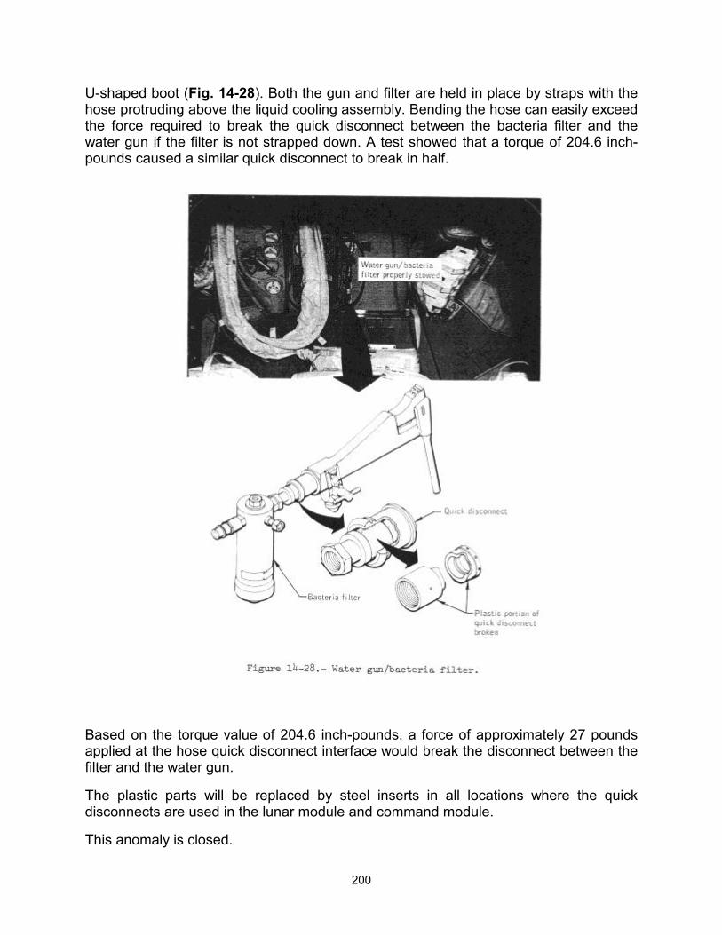
200
U-shaped boot (Fig. 14-28). Both the gun and filter are held in place by straps with the hose protruding above the liquid cooling assembly. Bending the hose can easily exceed the force required to break the quick disconnect between the bacteria filter and the water gun if the filter is not strapped down. A test showed that a torque of 204.6 inch-pounds caused a similar quick disconnect to break in half.
Based on the torque value of 204.6 inch-pounds, a force of approximately 27 pounds applied at the hose quick disconnect interface would break the disconnect between the filter and the water gun.
The plastic parts will be replaced by steel inserts in all locations where the quick disconnects are used in the lunar module and command module.
This anomaly is closed.
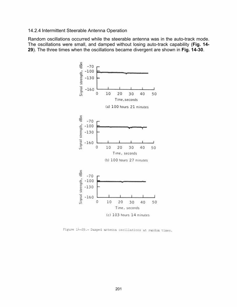
201
14.2.4 Intermittent Steerable Antenna Operation
Random oscillations occurred while the steerable antenna was in the auto-track mode. The oscillations were small, and damped without losing auto-track capability (Fig. 14-29). The three times when the oscillations became divergent are shown in Fig. 14-30.
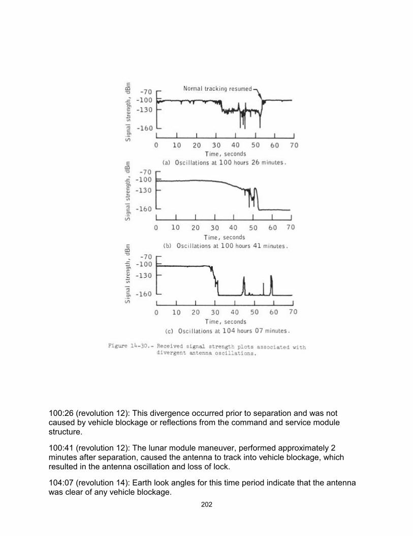
202
100:26 (revolution 12): This divergence occurred prior to separation and was not caused by vehicle blockage or reflections from the command and service module structure.
100:41 (revolution 12): The lunar module maneuver, performed approximately 2 minutes after separation, caused the antenna to track into vehicle blockage, which resulted in the antenna oscillation and loss of lock.
104:07 (revolution 14): Earth look angles for this time period indicate that the antenna was clear of any vehicle blockage.
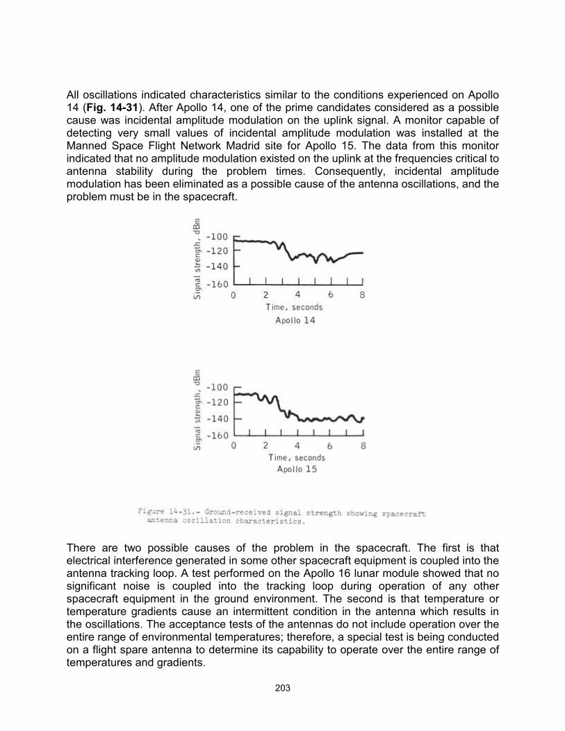
203
All oscillations indicated characteristics similar to the conditions experienced on Apollo 14 (Fig. 14-31). After Apollo 14, one of the prime candidates considered as a possible cause was incidental amplitude modulation on the uplink signal. A monitor capable of detecting very small values of incidental amplitude modulation was installed at the Manned Space Flight Network Madrid site for Apollo 15. The data from this monitor indicated that no amplitude modulation existed on the uplink at the frequencies critical to antenna stability during the problem times. Consequently, incidental amplitude modulation has been eliminated as a possible cause of the antenna oscillations, and the problem must be in the spacecraft.
There are two possible causes of the problem in the spacecraft. The first is that electrical interference generated in some other spacecraft equipment is coupled into the antenna tracking loop. A test performed on the Apollo 16 lunar module showed that no significant noise is coupled into the tracking loop during operation of any other spacecraft equipment in the ground environment. The second is that temperature or temperature gradients cause an intermittent condition in the antenna which results in the oscillations. The acceptance tests of the antennas do not include operation over the entire range of environmental temperatures; therefore, a special test is being conducted on a flight spare antenna to determine its capability to operate over the entire range of temperatures and gradients.
204
This anomaly is open.
14.2.5 Descent Engine Control Assembly Circuit Breaker Open
The descent engine control assembly circuit breaker was found open during the engine throttle check after lunar module separation from the command and service module. The circuit breaker was closed and the check was successfully performed.
If there was a short circuit condition, it is highly unlikely that the fault would have cleared at the instant the breaker opened. Thus, when the breaker was reset, it would have reopened. Data were reviewed for current surges large enough to trip the 20-ampere breaker, but none were found. The crew stated that they may have left the circuit breaker open. This is the most probable cause of the anomaly.
This anomaly is closed.
14.2.6 Abort Guidance System Warning
Abort guidance system warnings and master alarms occurred right after insertion into lunar orbit and at acquisition of signal prior to lunar module deorbit. The first one was reset by the crew; the second persisted until lunar impact. Performance of the abort guidance system appeared normal before, during, and after the time of the alarms.
Exceeding any of the following three conditions in the abort guidance system can cause the system warning light to illuminate. In each case, the warning light would reset automatically when the out-of-tolerance condition disappears.
a. 28 ±2.8 volts dc b. 12 ±1.2 volts dc c. 400 ±15 hertz
A fourth condition which could cause the warning light to illuminate is the receipt of a test-mode fail signal from the computer. This condition requires manually resetting the warning light by placing the oxygen/water quantity monitor switch to the CW/RESET position.
The conditions for generating a test mode fail signal are as follows (none of these conditions was indicated in any of the computer data).
a. Computer restart: A restart would cause internal status indicators to be reset and telemetry quantity "Vdx" to be set to a prestored constant (minus 8000 ft/sec). b. Computer self test: Computer routines perform sum checks of computer memory and logic tests. Failure of these would set a self-test fail status bit.
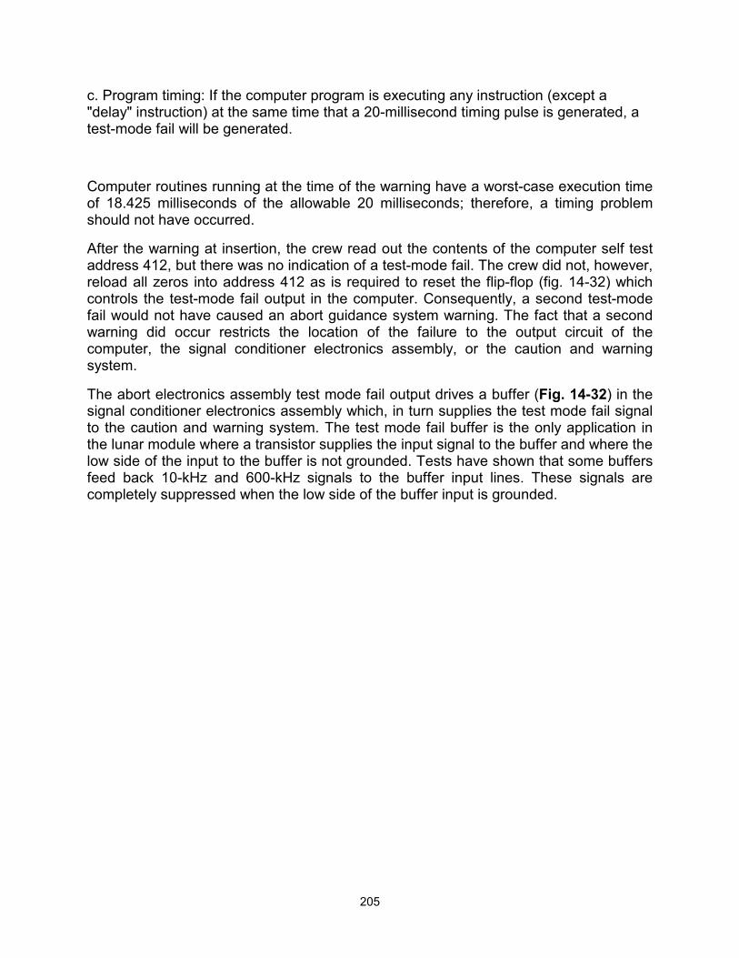
205
c. Program timing: If the computer program is executing any instruction (except a "delay" instruction) at the same time that a 20-millisecond timing pulse is generated, a test-mode fail will be generated.
Computer routines running at the time of the warning have a worst-case execution time of 18.425 milliseconds of the allowable 20 milliseconds; therefore, a timing problem should not have occurred.
After the warning at insertion, the crew read out the contents of the computer self test address 412, but there was no indication of a test-mode fail. The crew did not, however, reload all zeros into address 412 as is required to reset the flip-flop (fig. 14-32) which controls the test-mode fail output in the computer. Consequently, a second test-mode fail would not have caused an abort guidance system warning. The fact that a second warning did occur restricts the location of the failure to the output circuit of the computer, the signal conditioner electronics assembly, or the caution and warning system.
The abort electronics assembly test mode fail output drives a buffer (Fig. 14-32) in the signal conditioner electronics assembly which, in turn supplies the test mode fail signal to the caution and warning system. The test mode fail buffer is the only application in the lunar module where a transistor supplies the input signal to the buffer and where the low side of the input to the buffer is not grounded. Tests have shown that some buffers feed back 10-kHz and 600-kHz signals to the buffer input lines. These signals are completely suppressed when the low side of the buffer input is grounded.
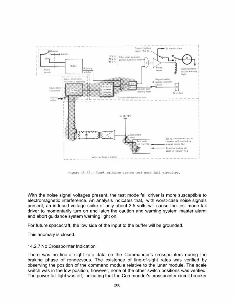
206
With the noise signal voltages present, the test mode fail driver is more susceptible to electromagnetic interference. An analysis indicates that,, with worst-case noise signals present, an induced voltage spike of only about 3.5 volts will cause the test mode fail driver to momentarily turn on and latch the caution and warning system master alarm and abort guidance system warning light on.
For future spacecraft, the low side of the input to the buffer will be grounded.
This anomaly is closed.
14.2.7 No Crosspointer Indication
There was no line-of-sight rate data on the Commander's crosspointers during the braking phase of rendezvous. The existence of line-of-sight rates was verified by observing the position of the command module relative to the lunar module. The scale switch was in the low position; however, none of the other switch positions was verified. The power fail light was off, indicating that the Commander's crosspointer circuit breaker
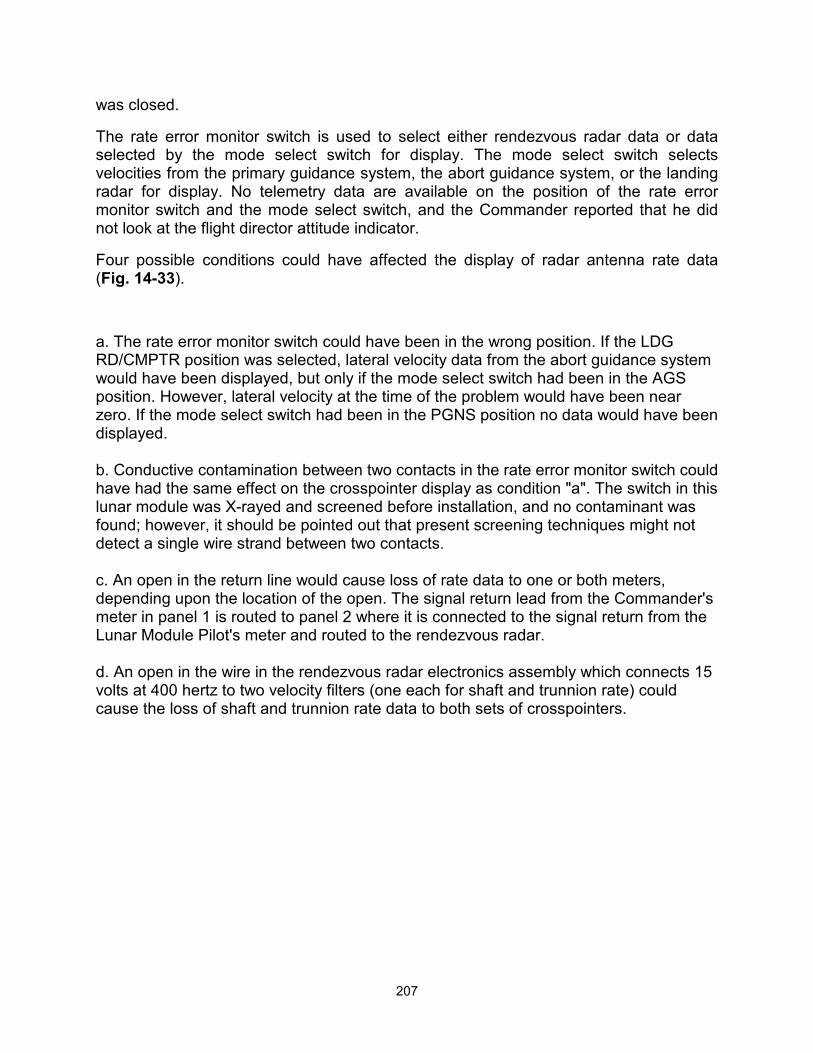
207
was closed.
The rate error monitor switch is used to select either rendezvous radar data or data selected by the mode select switch for display. The mode select switch selects velocities from the primary guidance system, the abort guidance system, or the landing radar for display. No telemetry data are available on the position of the rate error monitor switch and the mode select switch, and the Commander reported that he did not look at the flight director attitude indicator.
Four possible conditions could have affected the display of radar antenna rate data (Fig. 14-33).
a. The rate error monitor switch could have been in the wrong position. If the LDG RD/CMPTR position was selected, lateral velocity data from the abort guidance system would have been displayed, but only if the mode select switch had been in the AGS position. However, lateral velocity at the time of the problem would have been near zero. If the mode select switch had been in the PGNS position no data would have been displayed. b. Conductive contamination between two contacts in the rate error monitor switch could have had the same effect on the crosspointer display as condition "a". The switch in this lunar module was X-rayed and screened before installation, and no contaminant was found; however, it should be pointed out that present screening techniques might not detect a single wire strand between two contacts. c. An open in the return line would cause loss of rate data to one or both meters, depending upon the location of the open. The signal return lead from the Commander's meter in panel 1 is routed to panel 2 where it is connected to the signal return from the Lunar Module Pilot's meter and routed to the rendezvous radar. d. An open in the wire in the rendezvous radar electronics assembly which connects 15 volts at 400 hertz to two velocity filters (one each for shaft and trunnion rate) could cause the loss of shaft and trunnion rate data to both sets of crosspointers.
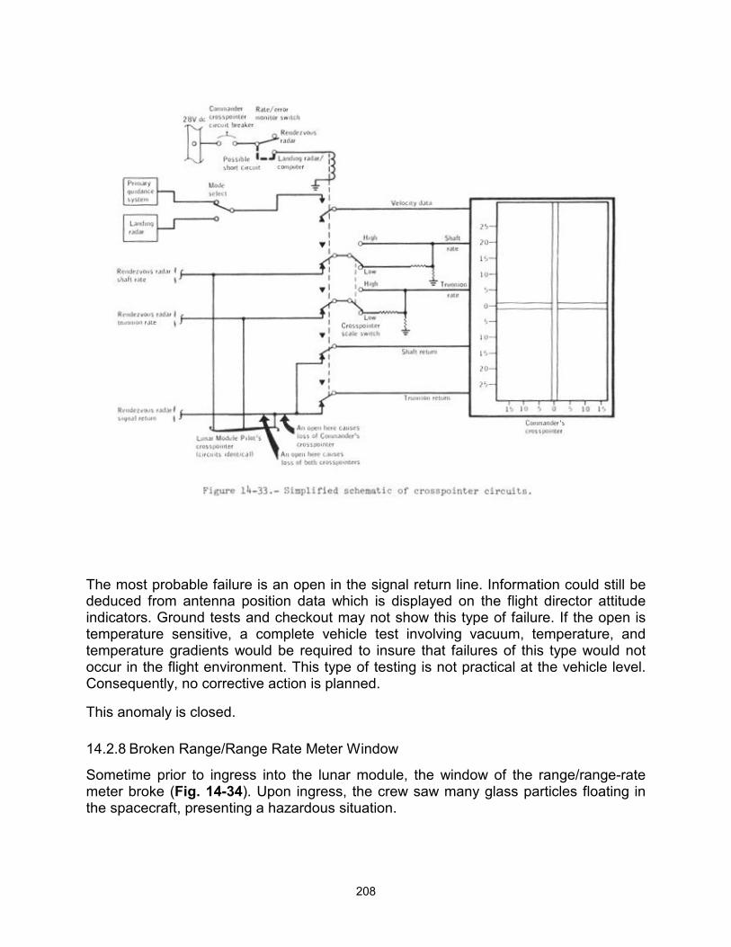
208
The most probable failure is an open in the signal return line. Information could still be deduced from antenna position data which is displayed on the flight director attitude indicators. Ground tests and checkout may not show this type of failure. If the open is temperature sensitive, a complete vehicle test involving vacuum, temperature, and temperature gradients would be required to insure that failures of this type would not occur in the flight environment. This type of testing is not practical at the vehicle level. Consequently, no corrective action is planned.
This anomaly is closed.
14.2.8 Broken Range/Range Rate Meter Window
Sometime prior to ingress into the lunar module, the window of the range/range-rate meter broke (Fig. 14-34). Upon ingress, the crew saw many glass particles floating in the spacecraft, presenting a hazardous situation.
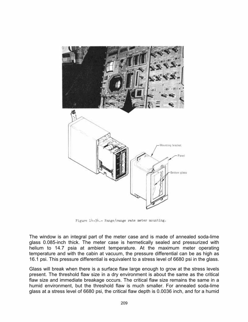
209
The window is an integral part of the meter case and is made of annealed soda-lime glass 0.085-inch thick. The meter case is hermetically sealed and pressurized with helium to 14.7 psia at ambient temperature. At the maximum meter operating temperature and with the cabin at vacuum, the pressure differential can be as high as 16.1 psi. This pressure differential is equivalent to a stress level of 6680 psi in the glass.
Glass will break when there is a surface flaw large enough to grow at the stress levels present. The threshold flaw size in a dry environment is about the same as the critical flaw size and immediate breakage occurs. The critical flaw size remains the same in a humid environment, but the threshold flaw is much smaller. For annealed soda-lime glass at a stress level of 6680 psi, the critical flaw depth is 0.0036 inch, and for a humid
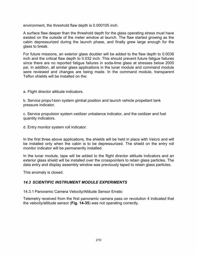
210
environment, the threshold flaw depth is 0.000105 inch.
A surface flaw deeper than the threshold depth for the glass operating stress must have existed on the outside of the meter window at launch. The flaw started growing as the cabin depressurized during the launch phase, and finally grew large enough for the glass to break.
For future missions, an exterior glass doubler will be added to the flaw depth to 0.0036 inch and the critical flaw depth to 0.032 inch. This should prevent future fatigue failures since there are no reported fatigue failures in soda-lime glass at stresses below 2000 psi. In addition, all similar glass applications in the lunar module and command module were reviewed and changes are being made. In the command module, transparent Teflon shields will be installed on the:
a. Flight director attitude indicators. b. Service propu1sion system gimbal position and launch vehicle propellant tank pressure indicator. c. Service propulsion system oxidizer unbalance indicator, and the oxidizer and fuel quantity indicators. d. Entry monitor system roll indicator.
In the first three above applications, the shields will be held in place with Velcro and will be installed only when the cabin is to be depressurized. The shield on the entry roll monitor indicator will be permanently installed.
In the lunar module, tape will be added to the flight director attitude indicators and an exterior glass shield will be installed over the crosspointers to retain glass particles. The data entry and display assembly window was previously taped to retain glass particles.
This anomaly is closed.
14.3 SCIENTIFIC INSTRUMENT MODULE EXPERIMENTS
14.3.1 Panoramic Camera Velocity/Altitude Sensor Erratic
Telemetry received from the first panoramic camera pass on revolution 4 indicated that the velocity/altitude sensor (Fig. 14-35) was not operating correctly.
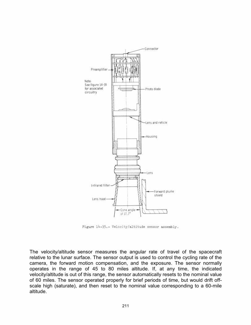
211
The velocity/altitude sensor measures the angular rate of travel of the spacecraft relative to the lunar surface. The sensor output is used to control the cycling rate of the camera, the forward motion compensation, and the exposure. The sensor normally operates in the range of 45 to 80 miles altitude. If, at any time, the indicated velocity/altitude is out of this range, the sensor automatically resets to the nominal value of 60 miles. The sensor operated properly for brief periods of time, but would drift off-scale high (saturate), and then reset to the nominal value corresponding to a 60-mile altitude.
212
Breadboard tests and circuit analyses of the velocity/altitude electronics (Fig. 14-36) did not indicate failure. Tests were conducted in which endless belts of lunar scene photography from Apollo 8 and 15 were passed in front of velocity/altitude sensors. Sensors from the prototype and qualification units, and flight unit number 1 were used. By varying the illumination level, sensor performance somewhat similar to the Apollo 15 anomaly could be obtained.
The results of the tests, coupled with analyses of the basic sensor design, indicate that the problem is related to the optical signal-to-noise ratio. The remaining flight hardware will be modified to improve this ratio. The optical signal will be enhanced by increasing the lens aperture from f/4.0 to f/3-5 and by deleting the infrared filter. The optical noise (reflections) will be reduced by increasing the length of the lens hood and by repositioning the sensor so that the camera's forward plume shield will not be in the field of view of the sensor. In addition, a manual override of the velocity/altitude sensor will be provided on the remaining flight units. By using a three-position switch, two preselected velocity/altitude ratios will be provided, as well as the automatic function.
This anomaly is closed.
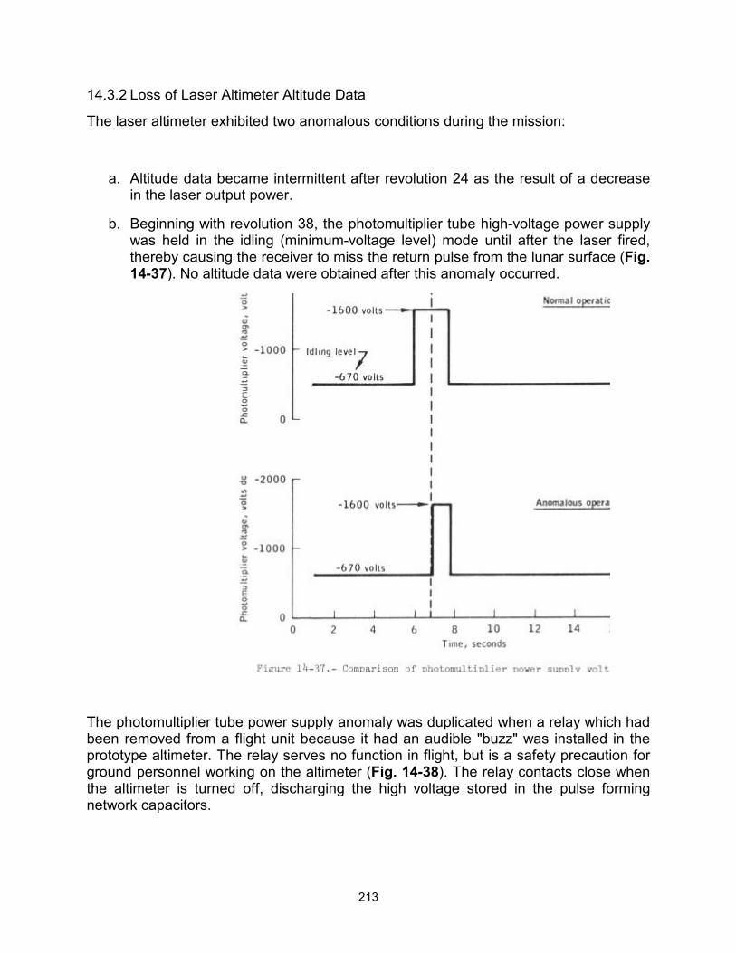
213
14.3.2 Loss of Laser Altimeter Altitude Data
The laser altimeter exhibited two anomalous conditions during the mission:
a. Altitude data became intermittent after revolution 24 as the result of a decrease in the laser output power.
b. Beginning with revolution 38, the photomultiplier tube high-voltage power supply was held in the idling (minimum-voltage level) mode until after the laser fired, thereby causing the receiver to miss the return pulse from the lunar surface (Fig. 14-37). No altitude data were obtained after this anomaly occurred.
The photomultiplier tube power supply anomaly was duplicated when a relay which had been removed from a flight unit because it had an audible "buzz" was installed in the prototype altimeter. The relay serves no function in flight, but is a safety precaution for ground personnel working on the altimeter (Fig. 14-38). The relay contacts close when the altimeter is turned off, discharging the high voltage stored in the pulse forming network capacitors.
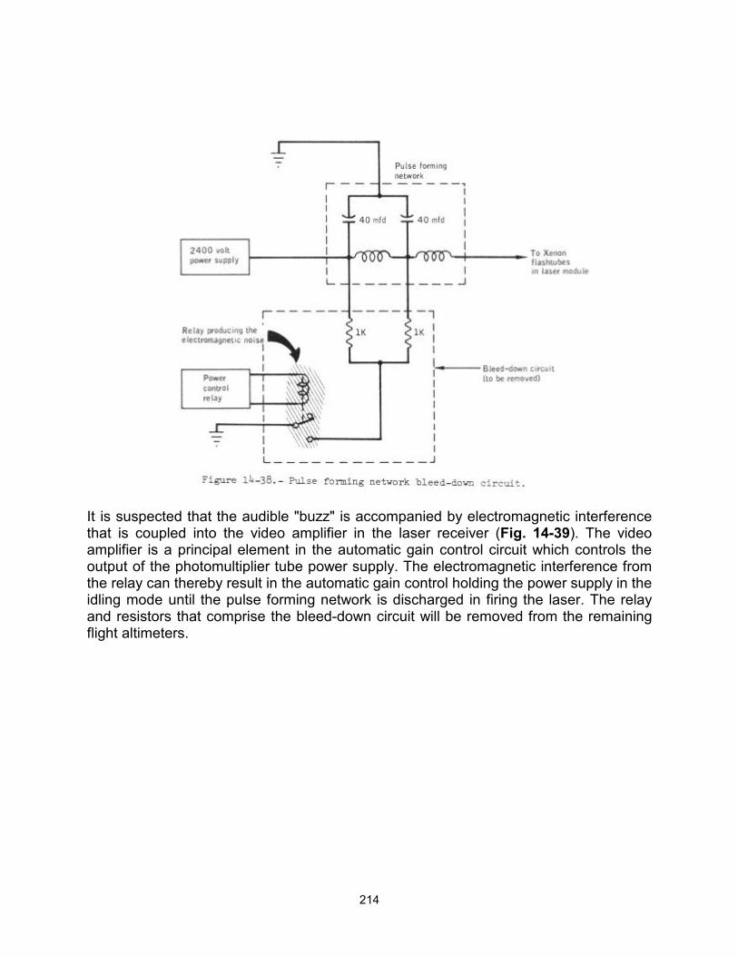
214
It is suspected that the audible "buzz" is accompanied by electromagnetic interference that is coupled into the video amplifier in the laser receiver (Fig. 14-39). The video amplifier is a principal element in the automatic gain control circuit which controls the output of the photomultiplier tube power supply. The electromagnetic interference from the relay can thereby result in the automatic gain control holding the power supply in the idling mode until the pulse forming network is discharged in firing the laser. The relay and resistors that comprise the bleed-down circuit will be removed from the remaining flight altimeters.
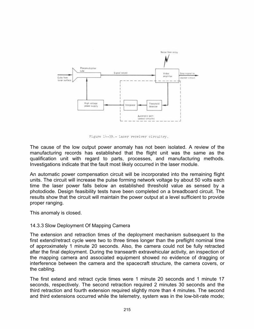
215
The cause of the low output power anomaly has not been isolated. A review of the manufacturing records has established that the flight unit was the same as the qualification unit with regard to parts, processes, and manufacturing methods. Investigations indicate that the fault most likely occurred in the laser module.
An automatic power compensation circuit will be incorporated into the remaining flight units. The circuit will increase the pulse forming network voltage by about 50 volts each time the laser power falls below an established threshold value as sensed by a photodiode. Design feasibility tests have been completed on a breadboard circuit. The results show that the circuit will maintain the power output at a level sufficient to provide proper ranging.
This anomaly is closed.
14.3.3 Slow Deployment Of Mapping Camera
The extension and retraction times of the deployment mechanism subsequent to the first extend/retract cycle were two to three times longer than the preflight nominal time of approximately 1 minute 20 seconds. Also, the camera could not be fully retracted after the final deployment. During the transearth extravehicular activity, an inspection of the mapping camera and associated equipment showed no evidence of dragging or interference between the camera and the spacecraft structure, the camera covers, or the cabling.
The first extend and retract cycle times were 1 minute 20 seconds and 1 minute 17 seconds, respectively. The second retraction required 2 minutes 30 seconds and the third retraction and fourth extension required slightly more than 4 minutes. The second and third extensions occurred while the telemetry, system was in the low-bit-rate mode;
216
therefore, these deployment times are not obtainable. Subsequent extensions and retractions required 2 to 4 minutes.
Load tests show that a restraining force of 250 pounds would increase the deployment time to 1 minute 45 seconds. With one of the two extend/retract mechanism motors operating, the 250-pound restraint would increase the deployment time to 2 minutes 25 seconds.
Voltage tests show that 12 volts to the motors (28 volts dc nominal rating) would result in deployment times of approximately 4 minutes. Had this occurred during the mission, however, the indicator which shows that power is applied to the motors would have displayed a partial barberpole during deployment operations. The barberpole indicator is connected in parallel with the motors and, since the position is voltage-dependent, it can be used to approximate the voltage levels to the motors. During the flight, a full barberpole indication was always observed.
Apparently, the problem first occurred sometime between the first and second retractions. During this period, a 4-second service propulsion system firing was performed for lunar orbit circularization. An evaluation of vibration test data indicates, however, that the circularization firing was probably not a factor in the anomaly. An investigation is being made to determine if there is mechanical interference between the camera and the reaction control system plume protection covers.
This anomaly is open.
14.3.4 Gamma Ray Spectrometer Calibration Shifts
During the mission, the gamma ray spectrometer experienced a downward gain shift of approximately 30 percent, but this was compensated for by commanding the high-voltage step function from the command module. The drift decreased with time at an initial rate of 1 percent per hour and a final rate of 0.4 percent per day. Near the end of the mission, the gamma ray spectrometer was operating in a relatively stable state at 824.8 volts (high voltage step 6). (A step 4 voltage of 777.8 volts was the normal position in preflight operation.) The spectrometer to be flown on Apollo 16 was aged at flux rates representative of those encountered in lunar operation. The unit has stabilized after having experienced a gain change of approximately 8 percent.
After transearth injection, a temporary eight-channel zero reference shift was observed. This shift disappeared when the instrument was repowered after the transearth extravehicular activity, and subsequent instrument operation was normal for about 25 hours during transearth coast. Shortly before entry, the offset shift reappeared and remained until the experiment was turned off. Normalization of the data during processing will compensate for this offset.
Tests conducted with the qualification unit verified that the change in gain was due to aging effects of the photomultiplier tube in the gamma ray detector assembly as a result of high cosmic ray flux rates in lunar operation. The zero shift appears to be associated with the run-down inhibit signal between the clock-gate module and the analog-to-digital converter (Fig. 14-40).
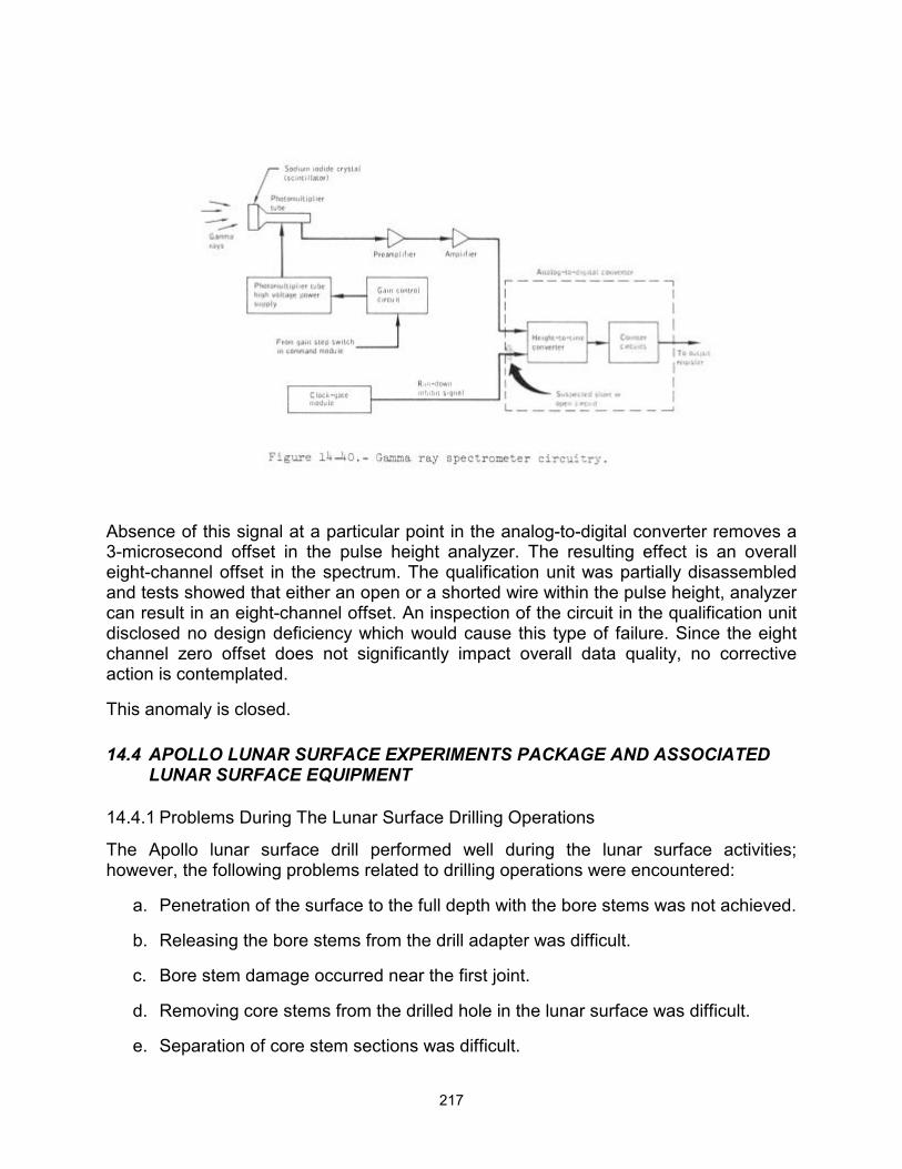
217
Absence of this signal at a particular point in the analog-to-digital converter removes a 3-microsecond offset in the pulse height analyzer. The resulting effect is an overall eight-channel offset in the spectrum. The qualification unit was partially disassembled and tests showed that either an open or a shorted wire within the pulse height, analyzer can result in an eight-channel offset. An inspection of the circuit in the qualification unit disclosed no design deficiency which would cause this type of failure. Since the eight channel zero offset does not significantly impact overall data quality, no corrective action is contemplated.
This anomaly is closed.
14.4 APOLLO LUNAR SURFACE EXPERIMENTS PACKAGE AND ASSOCIATED LUNAR SURFACE EQUIPMENT
14.4.1 Problems During The Lunar Surface Drilling Operations
The Apollo lunar surface drill performed well during the lunar surface activities; however, the following problems related to drilling operations were encountered:
a. Penetration of the surface to the full depth with the bore stems was not achieved.
b. Releasing the bore stems from the drill adapter was difficult.
c. Bore stem damage occurred near the first joint.
d. Removing core stems from the drilled hole in the lunar surface was difficult.
e. Separation of core stem sections was difficult.
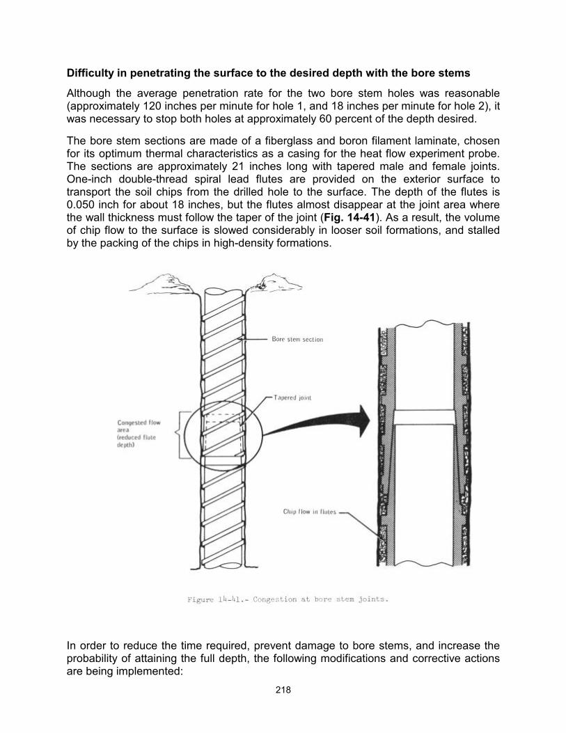
218
Difficulty in penetrating the surface to the desired depth with the bore stems
Although the average penetration rate for the two bore stem holes was reasonable (approximately 120 inches per minute for hole 1, and 18 inches per minute for hole 2), it was necessary to stop both holes at approximately 60 percent of the depth desired.
The bore stem sections are made of a fiberglass and boron filament laminate, chosen for its optimum thermal characteristics as a casing for the heat flow experiment probe. The sections are approximately 21 inches long with tapered male and female joints. One-inch double-thread spiral lead flutes are provided on the exterior surface to transport the soil chips from the drilled hole to the surface. The depth of the flutes is 0.050 inch for about 18 inches, but the flutes almost disappear at the joint area where the wall thickness must follow the taper of the joint (Fig. 14-41). As a result, the volume of chip flow to the surface is slowed considerably in looser soil formations, and stalled by the packing of the chips in high-density formations.
In order to reduce the time required, prevent damage to bore stems, and increase the probability of attaining the full depth, the following modifications and corrective actions are being implemented:
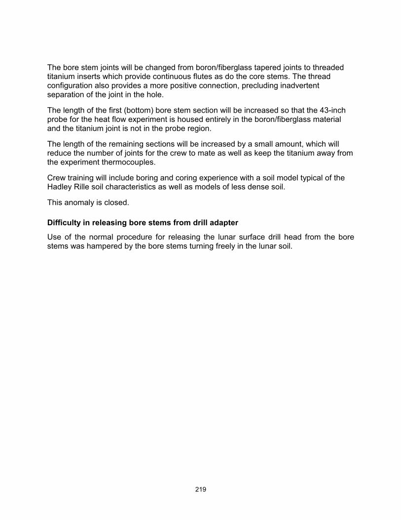
219
The bore stem joints will be changed from boron/fiberglass tapered joints to threaded titanium inserts which provide continuous flutes as do the core stems. The thread configuration also provides a more positive connection, precluding inadvertent separation of the joint in the hole.
The length of the first (bottom) bore stem section will be increased so that the 43-inch probe for the heat flow experiment is housed entirely in the boron/fiberglass material and the titanium joint is not in the probe region.
The length of the remaining sections will be increased by a small amount, which will reduce the number of joints for the crew to mate as well as keep the titanium away from the experiment thermocouples.
Crew training will include boring and coring experience with a soil model typical of the Hadley Rille soil characteristics as well as models of less dense soil.
This anomaly is closed.
Difficulty in releasing bore stems from drill adapter
Use of the normal procedure for releasing the lunar surface drill head from the bore stems was hampered by the bore stems turning freely in the lunar soil.
220
In the bore stem drilling position, the key blocks are restrained inside, and the spindle drives against the shoulder of the adapter outer shell (Fig. 14-42). The operational sequence to release the bore stem from the adapter includes the following steps:
With the bore stem held stationary, the power head is rotated by hand 90 degrees counterclockwise. This moves the spindle and adapter shoulder about 1/4-inch apart and releases the spring-loaded key blocks outward.
With the key blocks in the outward position, pulsing the power head transfers power from the spindle through the key blocks to the collet shoulder, thus moving the collet about 1/4-inch, and releasing the bore stem.
In development ground tests, the soil friction usually kept the bore stem from turning in this operation. When there was insufficient friction from the soil, the bore stem was grasped with the gloved hand. On Apollo 15, the soil did not hold the bore stem, and the core-stem wrench was used to hold the bore stems for this operation.
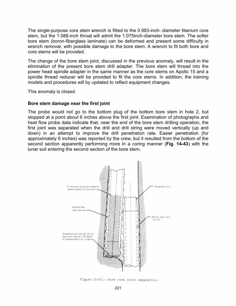
221
The single-purpose core stem wrench is fitted to the 0.983-inch- diameter titanium core stem, but the 1.088-inch throat will admit the 1.075inch-diameter bore stem. The softer bore stem (boron-fiberglass laminate) can be deformed and present some difficulty in wrench removal, with possible damage to the bore stem. A wrench to fit both bore and core stems will be provided.
The change of the bore stem joint, discussed in the previous anomaly, will result in the elimination of the present bore stem drill adapter. The bore stem will thread into the power head spindle adapter in the same manner as the core stems on Apollo 15 and a spindle thread reducer will be provided to fit the core stems. In addition, the training models and procedures will by updated to reflect equipment changes.
This anomaly is closed.
Bore stem damage near the first joint
The probe would not go to the bottom plug of the bottom bore stem in hole 2, but stopped at a point about 6 inches above the first joint. Examination of photographs and heat flow probe data indicate that, near the end of the bore stem drilling operation, the first joint was separated when the drill and drill string were moved vertically (up and down) in an attempt to improve the drill penetration rate. Easier penetration (for approximately 6 inches) was reported by the crew, but it resulted from the bottom of the second section apparently performing more in a coring manner (Fig. 14-43) with the lunar soil entering the second section of the bore stem.
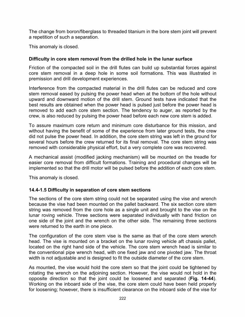
222
The change from boron/fiberglass to threaded titanium in the bore stem joint will prevent a repetition of such a separation.
This anomaly is closed.
Difficulty in core stem removal from the drilled hole in the lunar surface
Friction of the compacted soil in the drill flutes can build up substantial forces against core stem removal in a deep hole in some soil formations. This was illustrated in premission and drill development experiences.
Interference from the compacted material in the drill flutes can be reduced and core stem removal eased by pulsing the power head when at the bottom of the hole without upward and downward motion of the drill stem. Ground tests have indicated that the best results are obtained when the power head is pulsed just before the power head is removed to add each core stem section. The tendency to auger, as reported by the crew, is also reduced by pulsing the power head before each new core stem is added.
To assure maximum core return and minimum core disturbance for this mission, and without having the benefit of some of the experience from later ground tests, the crew did not pulse the power head. In addition, the core stem string was left in the ground for several hours before the crew returned for its final removal. The core stem string was removed with considerable physical effort, but a very complete core was recovered.
A mechanical assist (modified jacking mechanism) will be mounted on the treadle for easier core removal from difficult formations. Training and procedural changes will be implemented so that the drill motor will be pulsed before the addition of each core stem.
This anomaly is closed.
14.4-1.5 Difficulty in separation of core stem sections
The sections of the core stem string could not be separated using the vise and wrench because the vise had been mounted on the pallet backward. The six section core stem string was removed from the core hole as a single unit and brought to the vise on the lunar roving vehicle. Three sections were separated individually with hand friction on one side of the joint and the wrench on the other side. The remaining three sections were returned to the earth in one piece.
The configuration of the core stem vise is the same as that of the core stem wrench head. The vise is mounted on a bracket on the lunar roving vehicle aft chassis pallet, located on the right hand side of the vehicle. The core stem wrench head is similar to the conventional pipe wrench head, with one fixed jaw and one pivoted jaw. The throat width is not adjustable and is designed to fit the outside diameter of the core stem.
As mounted, the vise would hold the core stem so that the joint could be tightened by rotating the wrench on the adjoining section. However, the vise would not hold in the opposite direction so that the joint could be loosened and separated (Fig. 14-44). Working on the inboard side of the vise, the core stem could have been held properly for loosening; however, there is insufficient clearance on the inboard side of the vise for
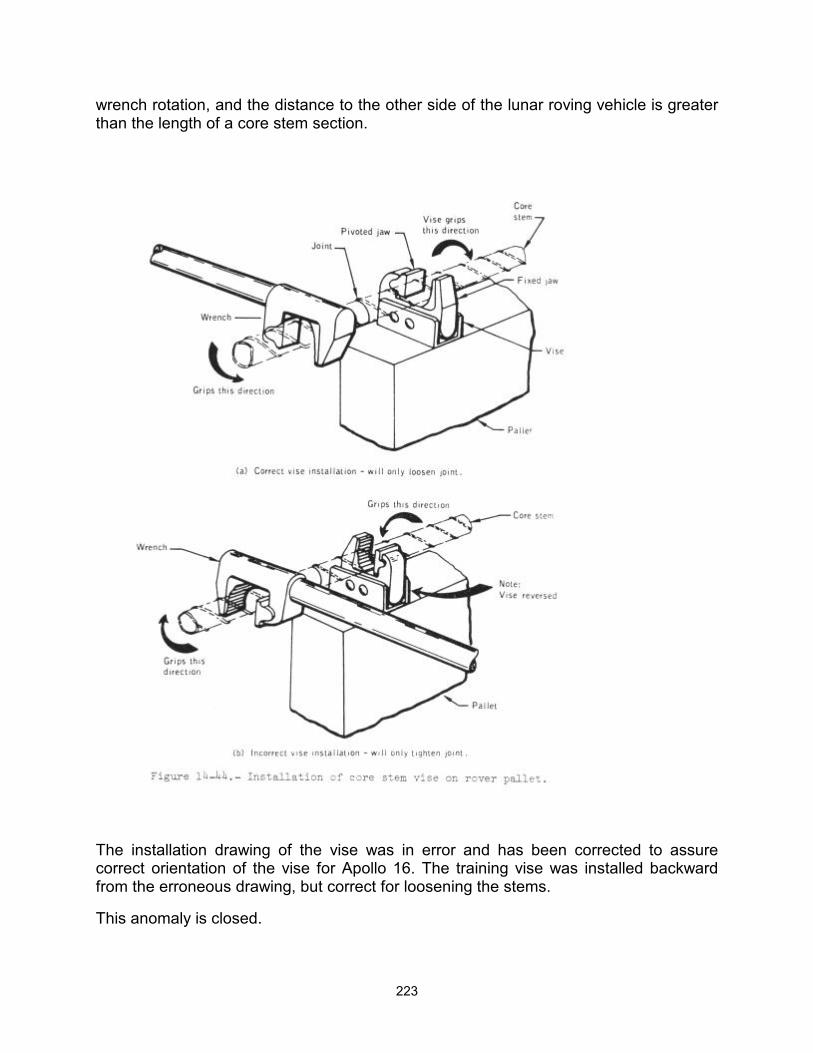
223
wrench rotation, and the distance to the other side of the lunar roving vehicle is greater than the length of a core stem section.
The installation drawing of the vise was in error and has been corrected to assure correct orientation of the vise for Apollo 16. The training vise was installed backward from the erroneous drawing, but correct for loosening the stems.
This anomaly is closed.
224
14.4.2 Central Station Rear Curtain Retainer Removal Lanyard Broke
To remove the retainer for the central station rear curtain, added for Apollo 15, it was necessary to remove two retaining pins (Fig. 14-45). The two pins, a universal handling tool fitting, and the curtain retainer are joined by a three-section lanyard. When the universal handling tool was inserted in the fitting and raised to remove the first pin, that section of the lanyard broke. When an effort was made to remove both pins simultaneously by inserting the handle under the lanyard joining the two pins, that part of the lanyard broke. The pins and retainer were then removed by hand.
The Dacron lanyard is being changed from a 50-pound test rated material to a 180-pound test rated material with acceptance pull tests being increased to 20 pounds for
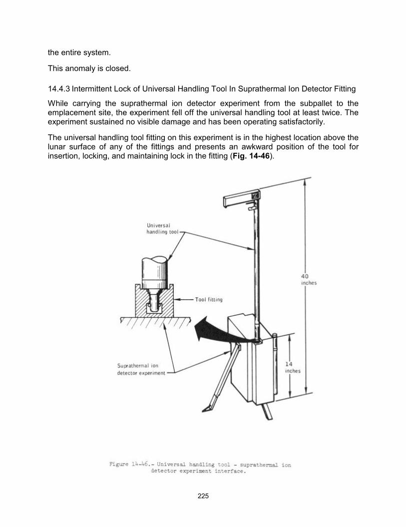
225
the entire system.
This anomaly is closed.
14.4.3 Intermittent Lock of Universal Handling Tool In Suprathermal Ion Detector Fitting
While carrying the suprathermal ion detector experiment from the subpallet to the emplacement site, the experiment fell off the universal handling tool at least twice. The experiment sustained no visible damage and has been operating satisfactorily.
The universal handling tool fitting on this experiment is in the highest location above the lunar surface of any of the fittings and presents an awkward position of the tool for insertion, locking, and maintaining lock in the fitting (Fig. 14-46).
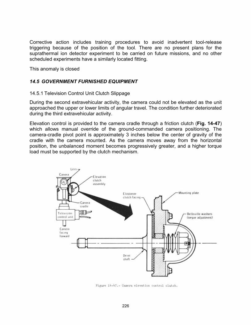
226
Corrective action includes training procedures to avoid inadvertent tool-release triggering because of the position of the tool. There are no present plans for the suprathermal ion detector experiment to be carried on future missions, and no other scheduled experiments have a similarly located fitting.
This anomaly is closed
14.5 GOVERNMENT FURNISHED EQUIPMENT
14.5.1 Television Control Unit Clutch Slippage
During the second extravehicular activity, the camera could not be elevated as the unit approached the upper or lower limits of angular travel. The condition further deteriorated during the third extravehicular activity.
Elevation control is provided to the camera cradle through a friction clutch (Fig. 14-47) which allows manual override of the ground-commanded camera positioning. The camera-cradle pivot point is approximately 3 inches below the center of gravity of the cradle with the camera mounted. As the camera moves away from the horizontal position, the unbalanced moment becomes progressively greater, and a higher torque load must be supported by the clutch mechanism.
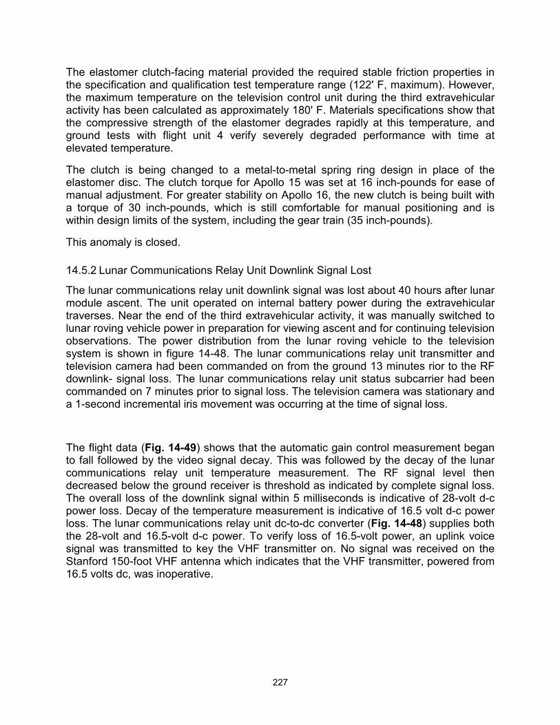
227
The elastomer clutch-facing material provided the required stable friction properties in the specification and qualification test temperature range (122' F, maximum). However, the maximum temperature on the television control unit during the third extravehicular activity has been calculated as approximately 180' F. Materials specifications show that the compressive strength of the elastomer degrades rapidly at this temperature, and ground tests with flight unit 4 verify severely degraded performance with time at elevated temperature.
The clutch is being changed to a metal-to-metal spring ring design in place of the elastomer disc. The clutch torque for Apollo 15 was set at 16 inch-pounds for ease of manual adjustment. For greater stability on Apollo 16, the new clutch is being built with a torque of 30 inch-pounds, which is still comfortable for manual positioning and is within design limits of the system, including the gear train (35 inch-pounds).
This anomaly is closed.
14.5.2 Lunar Communications Relay Unit Downlink Signal Lost
The lunar communications relay unit downlink signal was lost about 40 hours after lunar module ascent. The unit operated on internal battery power during the extravehicular traverses. Near the end of the third extravehicular activity, it was manually switched to lunar roving vehicle power in preparation for viewing ascent and for continuing television observations. The power distribution from the lunar roving vehicle to the television system is shown in figure 14-48. The lunar communications relay unit transmitter and television camera had been commanded on from the ground 13 minutes rior to the RF downlink- signal loss. The lunar communications relay unit status subcarrier had been commanded on 7 minutes prior to signal loss. The television camera was stationary and a 1-second incremental iris movement was occurring at the time of signal loss.
The flight data (Fig. 14-49) shows that the automatic gain control measurement began to fall followed by the video signal decay. This was followed by the decay of the lunar communications relay unit temperature measurement. The RF signal level then decreased below the ground receiver is threshold as indicated by complete signal loss. The overall loss of the downlink signal within 5 milliseconds is indicative of 28-volt d-c power loss. Decay of the temperature measurement is indicative of 16.5 volt d-c power loss. The lunar communications relay unit dc-to-dc converter (Fig. 14-48) supplies both the 28-volt and 16.5-volt d-c power. To verify loss of 16.5-volt power, an uplink voice signal was transmitted to key the VHF transmitter on. No signal was received on the Stanford 150-foot VHF antenna which indicates that the VHF transmitter, powered from 16.5 volts dc, was inoperative.
228
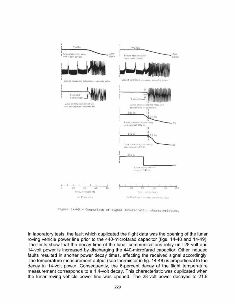
229
In laboratory tests, the fault which duplicated the flight data was the opening of the lunar roving vehicle power line prior to the 440-microfarad capacitor (figs. 14-48 and 14-49). The tests show that the decay time of the lunar communications relay unit 28-volt and 14-volt power is increased by discharging the 440-microfarad capacitor. Other induced faults resulted in shorter power decay times, affecting the received signal accordingly. The temperature measurement output (see thermistor in fig. 14-48) is proportional to the decay in 14-volt powcr. Consequently, the 6-percent decay of the flight temperature measurement corresponds to a 1.4-volt decay. This characteristic was duplicated when the lunar roving vehicle power line was opened. The 28-volt power decayed to 21.8
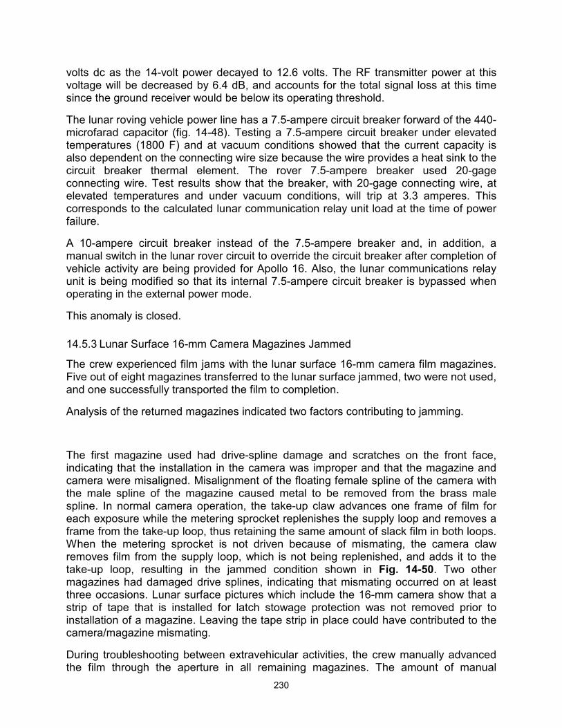
230
volts dc as the 14-volt power decayed to 12.6 volts. The RF transmitter power at this voltage will be decreased by 6.4 dB, and accounts for the total signal loss at this time since the ground receiver would be below its operating threshold.
The lunar roving vehicle power line has a 7.5-ampere circuit breaker forward of the 440-microfarad capacitor (fig. 14-48). Testing a 7.5-ampere circuit breaker under elevated temperatures (1800 F) and at vacuum conditions showed that the current capacity is also dependent on the connecting wire size because the wire provides a heat sink to the circuit breaker thermal element. The rover 7.5-ampere breaker used 20-gage connecting wire. Test results show that the breaker, with 20-gage connecting wire, at elevated temperatures and under vacuum conditions, will trip at 3.3 amperes. This corresponds to the calculated lunar communication relay unit load at the time of power failure.
A 10-ampere circuit breaker instead of the 7.5-ampere breaker and, in addition, a manual switch in the lunar rover circuit to override the circuit breaker after completion of vehicle activity are being provided for Apollo 16. Also, the lunar communications relay unit is being modified so that its internal 7.5-ampere circuit breaker is bypassed when operating in the external power mode.
This anomaly is closed.
14.5.3 Lunar Surface 16-mm Camera Magazines Jammed
The crew experienced film jams with the lunar surface 16-mm camera film magazines. Five out of eight magazines transferred to the lunar surface jammed, two were not used, and one successfully transported the film to completion.
Analysis of the returned magazines indicated two factors contributing to jamming.
The first magazine used had drive-spline damage and scratches on the front face, indicating that the installation in the camera was improper and that the magazine and camera were misaligned. Misalignment of the floating female spline of the camera with the male spline of the magazine caused metal to be removed from the brass male spline. In normal camera operation, the take-up claw advances one frame of film for each exposure while the metering sprocket replenishes the supply loop and removes a frame from the take-up loop, thus retaining the same amount of slack film in both loops. When the metering sprocket is not driven because of mismating, the camera claw removes film from the supply loop, which is not being replenished, and adds it to the take-up loop, resulting in the jammed condition shown in Fig. 14-50. Two other magazines had damaged drive splines, indicating that mismating occurred on at least three occasions. Lunar surface pictures which include the 16-mm camera show that a strip of tape that is installed for latch stowage protection was not removed prior to installation of a magazine. Leaving the tape strip in place could have contributed to the camera/magazine mismating.
During troubleshooting between extravehicular activities, the crew manually advanced the film through the aperture in all remaining magazines. The amount of manual
231
advancement varied from five to twenty-one frames in the jammed magazines. The film supply loop (Fig. 14-50) normally contains three to five excess frames. The normal procedure is to inspect the magazine for proper frame alignment in the aperture area, and manually advance the film not more than one frame, if required to obtain proper alignment. The excessive manual advancement depleted the film supply loops in all magazines.
Hardware analysis, air-to-ground voice tapes, and crew debriefing indicate that the lunar surface camera functioned properly, and the jammed magazines resulted from procedural errors. Corrective actions are to insure adequate crew training through scheduled prelaunch briefings, stress malfunction procedures and corrective actions, and put a removal flag on the tape.
This anomaly is closed.
14.5.4 Lunar Module Pilot's 70-mm Camera Film Advance Stopped
Near the end of the second extravehicular activity, the 70-mm camera ceased to advance film. The crew reported that the camera was again operational after return to the lunar module. The camera was used again on the third extravehicular activity; however, after a short series of exposures had been made, the failure recurred. The camera was used for additional photography during the transearth phase without recurrence of the problem.
Postflight analysis of the hardware included operational testing, disassembly and
232
inspection, and measurement of battery charge. Operational testing with film loads indicated proper film advancement until approximately 200 cycles had been accumulated, at which time the failure mode was duplicated several times in succession. The film did not advance, although the motor was running. Disassembly and examination of the drive mechanism showed that the two set screws in the drive pinion were slipping on the motor shaft. After the last use of the camera during the mission, the crew had difficulty removing the magazine. This was caused by a rivet which had become detached from the camera magazine latch mechanism.
Corrective action is as follows: Flats will be ground on the motor shaft. A locking compound will be applied to the set screws when they are properly torqued against the flats. Also, epoxy will be applied to the tops of the screws to prevent them from backing off.
This anomaly is closed.
14.5.5 Difficult to Obtain Water From Insuit Drinking Device
After satisfactory operation during the first extravehicular activity, the mouthpiece of the insuit drinking device was displaced and the Commander was not able to obtain water during the second extravehicular activity. The Lunar Module Pilot was not able to actuate the drink valve of the insuit drinking device during either the first or second extravehicular activities.
After each extravehicular activity, the insuit drinking device was removed from the suit and all of the water consumed, thus verifying proper operation of the insuit drinking device drink valve. The problem was associated with the positioning of the insuit drinking device within the suit.
Ground tests using suited subjects and other equipment configurations indicated that the existing equipment provides the optimum configuration. The tests also showed that personal experience is essential to obtaining optimum individual positioning. Crew training is to include more crew experience in making the position adjustments required for the individual's needs.
This anomaly is closed.
14.5.6 Lunar Module Pilot Oxygen Purge System Antenna Was Damaged
The crew reported that the Lunar Module Pilot's oxygen purge system antenna was broken off near the bottom during communications checkout prior to the second extravehicular activity. Previously, a notch had been observed in the antenna blade (see Fig. 14-51).
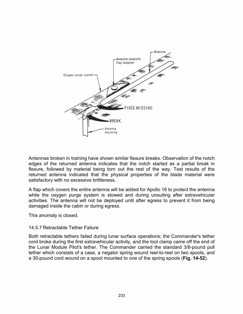
233
Antennas broken in training have shown similar flexure breaks. Observation of the notch edges of the returned antenna indicates that the notch started as a partial break in flexure, followed by material being torn out the rest of the way. Test results of the returned antenna indicated that the physical properties of the blade material were satisfactory with no excessive brittleness.
A flap which covers the entire antenna will be added for Apollo 16 to protect the antenna while the oxygen purge system is stowed and during unsuiting after extravehicular activities. The antenna will not be deployed until after egress to prevent it from being damaged inside the cabin or during egress.
This anomaly is closed.
14.5.7 Retractable Tether Failure
Both retractable tethers failed during lunar surface operations; the Commander's tether cord broke during the first extravehicular activity, and the tool clamp came off the end of the Lunar Module Pilot's tether. The Commander carried the standard 3/8-pound pull tether which consists of a case, a negator spring wound reel-to-reel on two spools, and a 30-pound cord wound on a spool mounted to one of the spring spools (Fig. 14-52).
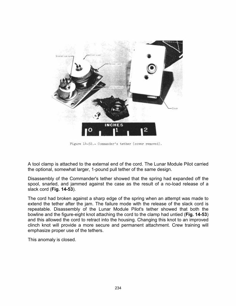
234
A tool clamp is attached to the external end of the cord. The Lunar Module Pilot carried the optional, somewhat larger, 1-pound pull tether of the same design.
Disassembly of the Commander's tether showed that the spring had expanded off the spool, snarled, and jammed against the case as the result of a no-load release of a slack cord (Fig. 14-53).
The cord had broken against a sharp edge of the spring when an attempt was made to extend the tether after the jam. The failure mode with the release of the slack cord is repeatable. Disassembly of the Lunar Module Pilot's tether showed that both the bowline and the figure-eight knot attaching the cord to the clamp had untied (Fig. 14-53) and this allowed the cord to retract into the housing. Changing this knot to an improved clinch knot will provide a more secure and permanent attachment. Crew training will emphasize proper use of the tethers.
This anomaly is closed.

235
14.6 LUNAR ROVING VEHICLE
14.6.1 Deployment Saddle Difficult To Release From Vehicle
The lunar roving vehicle deployment saddle was difficult to release from the vehicle during the final stage of deployment operations.
The causes of this problem are twofold and interrelated.
a. The saddle-to-vehicle connection (Fig. 14-54) has close-tolerance interfaces to provide the rigidity required to prevent release-pin distortion and permanent binding. This design requires the vehicle/saddle interface to be completely free of stress to permit easy separation.
b. The tilt of the lunar module to the rear and sideways, together with an uneven lunar surface, provided some stress preloading of the vehicle/saddle interface. Attempts by the crew to improve the rover position by moving and pulling on it may have aggravated this situation. The crew was aware that the interface had to be free of stress, and when this was accomplished, the saddle separated.
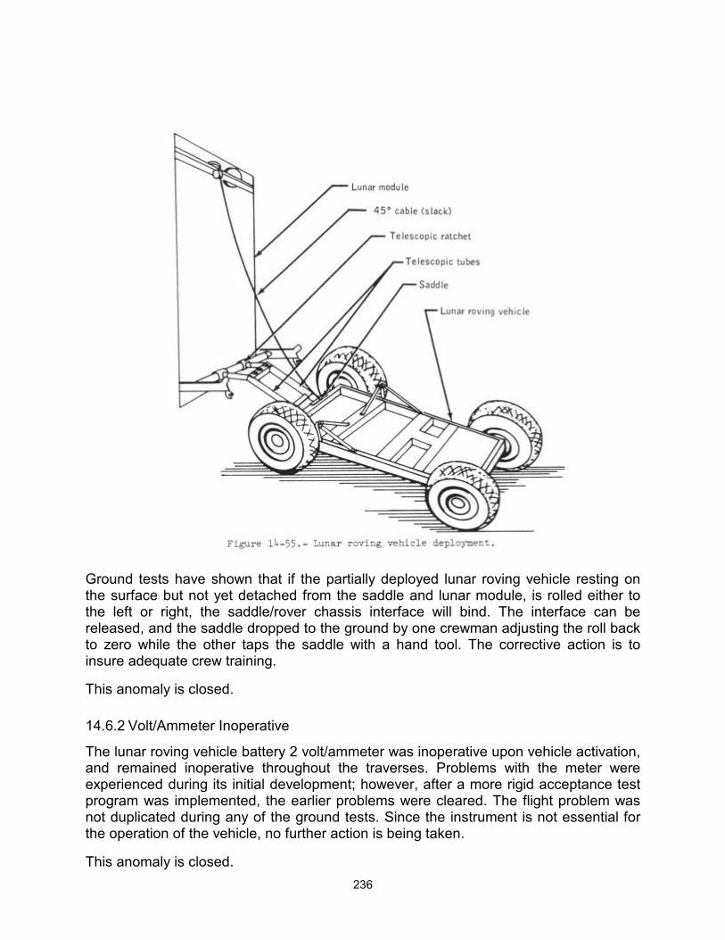
236
Ground tests have shown that if the partially deployed lunar roving vehicle resting on the surface but not yet detached from the saddle and lunar module, is rolled either to the left or right, the saddle/rover chassis interface will bind. The interface can be released, and the saddle dropped to the ground by one crewman adjusting the roll back to zero while the other taps the saddle with a hand tool. The corrective action is to insure adequate crew training.
This anomaly is closed.
14.6.2 Volt/Ammeter Inoperative
The lunar roving vehicle battery 2 volt/ammeter was inoperative upon vehicle activation, and remained inoperative throughout the traverses. Problems with the meter were experienced during its initial development; however, after a more rigid acceptance test program was implemented, the earlier problems were cleared. The flight problem was not duplicated during any of the ground tests. Since the instrument is not essential for the operation of the vehicle, no further action is being taken.
This anomaly is closed.
237
14.6.3 Front steering System Inoperative
During initial lunar roving vehicle activation, the front steering was inoperative. Electrical checks were made which verified that electrical power was being supplied to the front steering system. Unsuccessful attempts were made to manually rotate the wheels about their steering axes and to detect steering motor stall current on the ammeter. The forward steering circuit breaker and switch were cycled without any apparent effect. Consequently, the front steering was switched off for the first traverse. During preparations for the second traverse, the forward steering circuit breaker and switch were cycled and front steering was operative; however, the time that front steering capability was restored is unknown. Front-wheel wandering did not occur during the first traverse, indicating a mechanical problem. The steering continued to function properly for the second and third traverses. During the second traverse, the rear steering was turned off temporarily and wandering of the rear wheels occurred.
The most likely cause of this anomaly is motor and/or gear train binding, as indicated by the inability to drive back through the linkage and gear train by manually pushing against the wheels. Electrical causes are possible, but less likely.
The front steering system of the Apollo 16 lunar roving vehicle is currently being analyzed because of an intermittent failure of a similar nature. Manually pushing against the wheels would not always drive back through the linkage and gear train and the motor stalled at limit current for 0.8 second during a test of this condition.
This anomaly is open.
14.6.4 Lunar Roving Vehicle Seat Belt Problems
The following seat belt problems were experienced throughout all traverses
a. The crew was trained to stow the belts, prior to egress, on the inboard handholds. However, during egress and ingress, the belt hooks would slip through the handholds to the floor area. Finding the belts after ingress was difficult because of their displacement from the proper stowage location.
b. The belts snagged repeatedly on the ground Support equipment connector on the console support structure when displaced from the proper stowage locations.
c. The belts were not of sufficient length to secure the hooks to the outboard handholds easily. This resulted primarily from an unexpected decrease in suit contour conformance to the seated position in 1/6g. Consequently, the crewmen's laps were several inches higher than had been anticipated.
The main causes of these problems, in addition to insufficient belt length, were insufficient belt rigidity and lack of visibility of the securing operation.
New, stiffer seatbelts with an over-center tightening mechanism will be provided for Apollo 16 to eliminate adjustment after each ingress and to provide more tightening capability.
This anomaly is closed.
238
15 CONCLUSIONS The Apollo 15 mission was the fourth lunar landing and resulted in the collection of a wealth of scientific information. The Apollo system, in addition to providing a means of transportation, excelled as an operational scientific facility. The following conclusions are drawn from the information in this report:
The Apollo 15 mission demonstrated that, with the addition of consumables and the installation of scientific instruments, the command and service module is an effective means of gathering scientific data. Real- time data allowed participation by scientists with the crew in planning and making decisions to maximize scientific results.
The mission demonstrated that the modified launch vehicle, spacecraft and life support system configurations can successfully transport larger payloads and safely extend the time spent on the moon.
The modified pressure garment and portable life support system provided better mobility and extended the lunar surface extravehicular time.
The ground-controlled mobile television camera allowed greater real-time participation by earth-bound scientists and operationsl personnel during lunar surface extravehicular activity.
The practicality of the lunar roving vehicle was demonstrated by greatly increasing man's load carrying capability and range of exploration of the lunar surface.
The lunar communications relay unit provided the capability for continuous communications enroute to and at the extended ranges made possible by the lunar roving vehicle.
Landing site visibility was improved by the use of a steeper landing trajectory.
Apollo 15 demonstrated that the crew can operate to a greater degree as scientific observers and investigators and rely more on the ground support team for systems monitoring.
The value of manned space flight was further demonstrated by the unique capability of man to observe and think creatively, as shown in the supplementation and redirection of many tasks by the crew to enhance scientific data return.
The mission emphasized that crew training equipment must be flight equipment or have all the fidelity of flight equipment.
239
APPENDIX A - VEHICLE AND EQUIPMENT DESCRIPTION
This section contains a discussion of changes to the spacecraft, the extravehicular systems, and the scientific equipment since Apollo 14. In addition, equipment used on Apollo 15 for the first time is described.
The Apollo 15 command and service module (CSM-112) was of the block II configuration, but was modified to carry out a greater range of lunar orbital science activities than had been programmed for any previous mission. The lunar module (LM-10) was modified to allow an increase in lunar surface stay time and accommodate a larger scientific payload. The launch escape system and the spacecraft/launch vehicle adapter were unchanged. The Saturn V launch vehicle used for this mission was AS-510. The significant configuration changes for the launch vehicle are given in reference 1.
A.1 COMMAND AND SERVICE MODULES
A.1.1 Structure and Thermal Systems
A scientific instrument module was installed in sector I of the service module (Fig. A-2). The module containing instruments for the acquisition of scientific data during lunar orbit was attached with 1/4- inch bolts to radial beams 1 and 6, to the new cryogenic tank panel, and to the aft bulkhead of the service module. The sides of the scientific instrument module were constructed of aluminum stiffened sheet, and the shelves that supported the instruments were made of bonded aluminum sandwich. A door covered the module until about 4 1/2 hours prior to lunar orbit insertion when it was pyrotechnically cut free and jettisoned in a direction normal to the X-axis of the spacecraft (Fig. A-2). Protective covers and thermal blankets provided thermal control for individual instruments within the module. For additional thermal control, the inside surfaces of the module were coated with a material having an absorptivity- to-emissivity ratio of 0-3/0.85; the surfaces facing the radial beams, and the radial beams themselves, were coated with a material having an absorptivity- to-emissivity ratio of 0.05/0.4. The instruments are discussed; in section A.4.2.
Because of the requirement to retrieve film cassettes from the scientific instrument module during transearth coast, extravehicular activity handrails and handholds were installed along the sides of the module and inside the scientific instrument module. A foot restraint was also attached to the module structure (Fig. A-3).
A.1.2 Cryogenic Storage
A third hydrogen tank was installed in sector I of the service module, as planned for all J-type missions. The isolation valve between oxygen tank 2 and 3 was moved from sector IV to the forward bulkhead to decrease its vulnerability in the event of a catastrophic tank failure. All single-seat check valves in the hydrogen and oxygen lines were replaced with double-seat valves having greater reliability. Thermal switches formerly used in the hydrogen tank heater circuits inside the tanks were removed.
240
A.1.3 Instrumentation
A scientific data system was integrated with the existing telemetry system (Fig. A-4) to provide the capability for processing, storing, and transmitting data from the scientific instrument module. The data processor, located in the scientific instrument module, necessitated changes to the data storage equipment and the introduction of a data modulator and a tape recorder data conditioner. The data storage equipment was modified to have twice the recording time of the previous equipment, and was redesignated the data recorder reproducer. The tape recorder data conditioner was added to minimize flutter-induced jitter of recorded pulse- code-modulated data.
A.1.4 Displays and Controls
Switch S30 was deleted from panel 2 and its function was incorporated into switch S29 so that both cabin fans operated simultaneously. Toggle switch S137 was added to panel 2 for hydrogen tank 3 fan motor control. The pressure and quantity outputs of hydrogen tank 3 were connected to meter displays through switches S138 and S139 on panel 2. Panels 181 and 230 were added to provide controls for the experiment equipment in the scientific instrument module. Experiment cover controls were added to Panel 278. Panel 603 (Fig. A-5) was added to provide umbilical connections for extravehicular activity. Panel 604 (Fig. A-5) was added to provide an audio warning signal to the extravehicular crewman in the event of low suit pressure or low oxygen flow.
A.1-5 Propulsion
The diameter of the fuel inlet orifice in the service propulsion system was decreased to improve the propellant mixture ratio.
A.1.6 Environmental Control System
Several oxygen components were added to accommodate the scheduled extravehicular activity for retrieval of data from the scientific instrument module. The command module components consisted of a larger restrictor and filter for the higher flow rate, check valves to prevent backflow, connectors for the attachment of the umbilical, and a pressure gage.
A.1.7 Crew Provisions and Extravehicular System
The Command Module Pilot's space suit was basically the same as the Apollo 14 lunar surface suits except that the water connector and lunar module attach points had been removed. An umbilical assembly (Fig. A-6) was furnished to serve as a tether and provide oxygen, communications, and electrocardiogram and respiration rate measurements for the extravehicular crewman. An adapter plate mounted on the chest of the suit allowed attachment of an oxygen purge system (transferred from the lunar module). The purge valve was also brought from the lunar module to be used with the oxygen purge system. A pressure control valve was provided to maintain suit pressure at 3.5 to 4.0 psia at a flow rate of 10 to 12 lb/hr during the extravehicular activity. A suit control unit (Fig. A-6) was connected to the suit end of the umbilical to maintain the desired oxygen flow rate and activate the suit pressure alarm if an anomalous condition
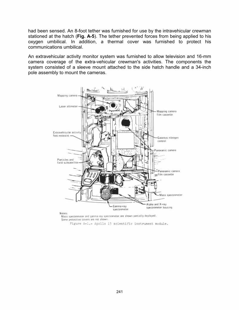
241
had been sensed. An 8-foot tether was furnished for use by the intravehicular crewman stationed at the hatch (Fig. A-5). The tether prevented forces from being applied to his oxygen umbilical. In addition, a thermal cover was furnished to protect his communications umbilical.
An extravehicular activity monitor system was furnished to allow television and 16-mm camera coverage of the extra-vehicular crewman's activities. The components the system consisted of a sleeve mount attached to the side hatch handle and a 34-inch pole assembly to mount the cameras.
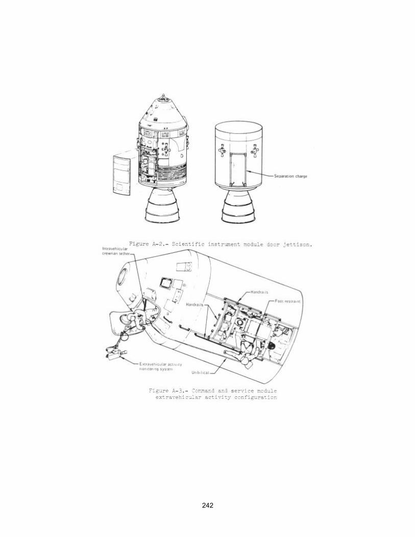
242
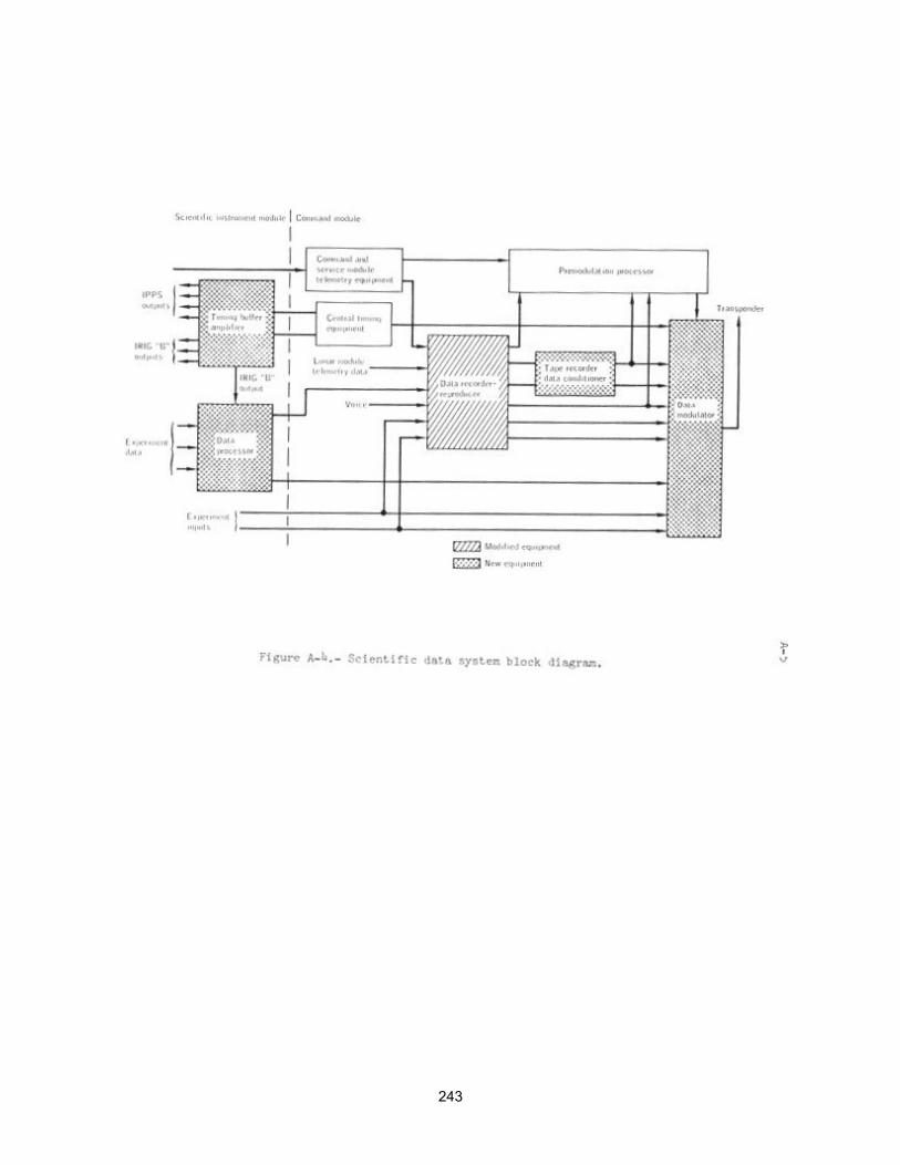
243
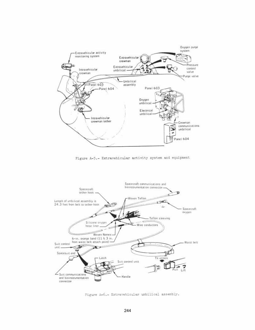
244
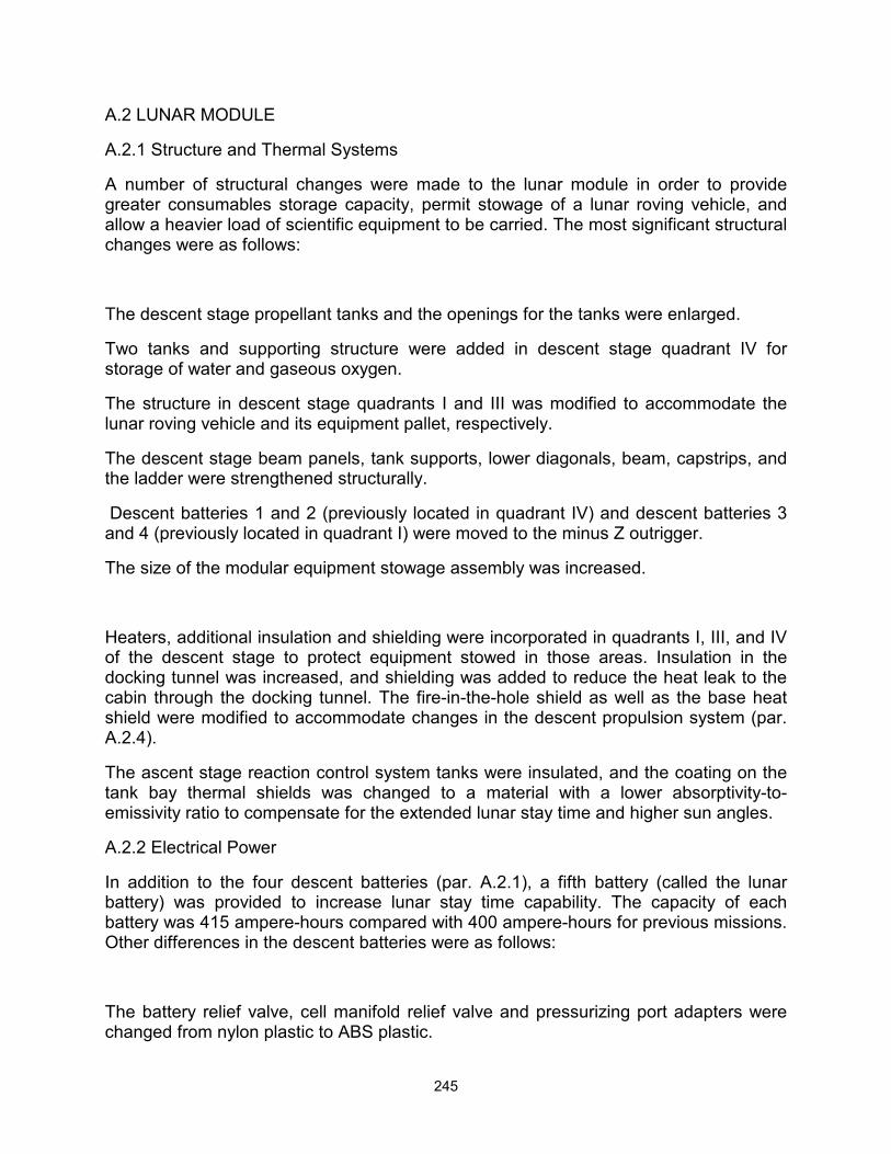
245
A.2 LUNAR MODULE
A.2.1 Structure and Thermal Systems
A number of structural changes were made to the lunar module in order to provide greater consumables storage capacity, permit stowage of a lunar roving vehicle, and allow a heavier load of scientific equipment to be carried. The most significant structural changes were as follows:
The descent stage propellant tanks and the openings for the tanks were enlarged.
Two tanks and supporting structure were added in descent stage quadrant IV for storage of water and gaseous oxygen.
The structure in descent stage quadrants I and III was modified to accommodate the lunar roving vehicle and its equipment pallet, respectively.
The descent stage beam panels, tank supports, lower diagonals, beam, capstrips, and the ladder were strengthened structurally.
Descent batteries 1 and 2 (previously located in quadrant IV) and descent batteries 3 and 4 (previously located in quadrant I) were moved to the minus Z outrigger.
The size of the modular equipment stowage assembly was increased.
Heaters, additional insulation and shielding were incorporated in quadrants I, III, and IV of the descent stage to protect equipment stowed in those areas. Insulation in the docking tunnel was increased, and shielding was added to reduce the heat leak to the cabin through the docking tunnel. The fire-in-the-hole shield as well as the base heat shield were modified to accommodate changes in the descent propulsion system (par. A.2.4).
The ascent stage reaction control system tanks were insulated, and the coating on the tank bay thermal shields was changed to a material with a lower absorptivity-to-emissivity ratio to compensate for the extended lunar stay time and higher sun angles.
A.2.2 Electrical Power
In addition to the four descent batteries (par. A.2.1), a fifth battery (called the lunar battery) was provided to increase lunar stay time capability. The capacity of each battery was 415 ampere-hours compared with 400 ampere-hours for previous missions. Other differences in the descent batteries were as follows:
The battery relief valve, cell manifold relief valve and pressurizing port adapters were changed from nylon plastic to ABS plastic.
246
The method for attaching the cell manifold to the manifold relief valve adapter was changed to prevent leakage.
A battery relay control assembly was added to route battery status information to the proper channels because of the electrical control assembly sections shared by batteries 2, 3, and the lunar battery, and an interlock was added so that the lunar battery could not be switched to both buses at the same time.
A-2.3 Instrumentation and Displays
Water sensors were changed from quantity measuring devices to pressure transducers for greater reliability. Descent fuel and oxidizer temperature sensors were changed from immersion to container-surface measurements because the measurements would provide more useful data. Temperature sensors were added in the modular equipment stowage assembly to provide flight statistical data. Instrumentation was added, and controls and displays were changed on panel 14 because of the addition of the lunar battery.
A-2.4 Propulsion
The descent propellant system was modified to increase the tank capacity 1200 pounds, and the engine performance and operating life were increased. These changes involved: (1) increasing the length of the tanks, (2) changing material in the thrust chamber from an ablative silicon to an ablative quartz, (3) replacing the exit cone with a lightweight cone, and (4) increasing the nozzle extension 10 inches. Routing of pressurization lines was modified to accommodate the larger propellant tanks. Modifications to decrease the amount of unusable propellant consisted of deleting propellant balance lines between like tanks and adding trim orifices to the tank discharge lines (one orifice is fixed and the other is adjustable).
The oxidizer lunar dump valve installation was modified to be identical to the Apollo 14 fuel lunar dump valve configuration. Thus, both valves were installed to reverse flow direction through them and an orifice was added upstream of each valve. This change was made to insure that the valve would remain open with either liquid or gas flow.
In the reaction control system, a weight reduction of approximately 25 pounds resulted from the removal of the isolation valves from all engines.
A.2.5 Environmental Control System
Extended stay time on the lunar surface required an increase in the supply of lithium hydroxide cartridges. The oxygen and water supply was increased for the same reason by adding a storage tank in the descent stage for each system. Check valves were added at the outlets of the original and new tanks, and servicing quick disconnects and pressure transducers were added in association with the new tanks.
A new high pressure (approximately 1400 psia) portable life Support system recharge capability was incorporated in conjunction with the added oxygen tank. The recharge assembly includes regulators, overboard relief valves, an interstage disconnect, a
247
shutoff valve, and a quick disconnect to mate with the portable life support system recharge hose. In addition, the recharge hose was lengthened by 10 inches to permit recharging of the portable life support system before it was doffed.
Instead of providing stowed urine bags and a portable life support system condensate container as on Apollo 14, a 5-gallon tank was installed in quadrant IV of the descent stage for both urine and portable life support system condensate.
A.2.6 Crew Provisions and Cabin Stowage
Neck ring dust covers were provided to keep lunar dust out of the pressure garment assemblies when not being worn. Tool carriers, attachable to the portable life support system, were provided to facilitate carrying of geological tools, sample bags and rock bags. An adapter was stowed to permit the crewmen to connect their liquid cooling garments to the lunar module water supply after removal of their pressure garment assemblies.
The ascent stage lower midsection and the lower left- and right-side consoles were modified to carry additional lunar samples (each area could carry a 40-pound bag). In order to carry the 70-mm, camera with 500-mm lens and 70-mm film magazines, a special multipurpose container was installed in the area behind the engine cover.
A-3 LUNAR SURFACE MOBILITY SYSTEMS
A-3.1 Extravehicular Mobility Unit
The pressure garment assembly was changed to improve mobility and visibility, to permit easier donning and doffing, and to improve it otherwise. The changes were as follows:
Neck and waist joints were added.
The wrist rings were enlarged.
The shoulder area was modified.
The torso zipper was moved.
Gas connectors were repositioned.
A manual override relief valve was added.
The insuit drinking device was redesigned to hold 32 ounces of water instead of 8 ounces.
The portable life support system was modified to extend the lunar surface stay time capability. There were four major changes:
248
An auxiliary water bottle was added.
A larger battery was incorporated.
A higher pressure oxygen bottle was used.
Higher capacity lithium hydroxide cartridges were used.
A.3.2 Lunar Roving Vehicle
The lunar roving vehicle (Fig. A-7), used for the first time on Apollo 15, is a four-wheeled manually-controlled, electrically-powered vehicle that carried the crew and their equipment over the lunar surface. The increased mobility and ease of travel made possible by this vehicle permitted the crew to travel much greater distances than on previous lunar landing missions. The vehicle was designed to carry the two crewmen and a science payload at a maximum velocity of about 16 kilometers per hour (8.6 mi/hr) on a smooth, level surface, and at reduced velocities on slopes up to 25 degrees. It can be operated from either crewman's position, as the control and display console is located on the vehicle centerline. The deployed vehicle is approximately 10 feet long, 7 feet wide and 45 inches high. Its chassis is hinged such that the forward and aft sections fold back over the center portion, and each of the wheel suspension systems rotates so that the folded vehicle will fit in quadrant I of the lunar module. The gross operational weight is approximately 1535 pounds of which 455 pounds is the weight of the vehicle itself. The remainder is the weight of the crew, their equipment, communications equipment, and the science payload.
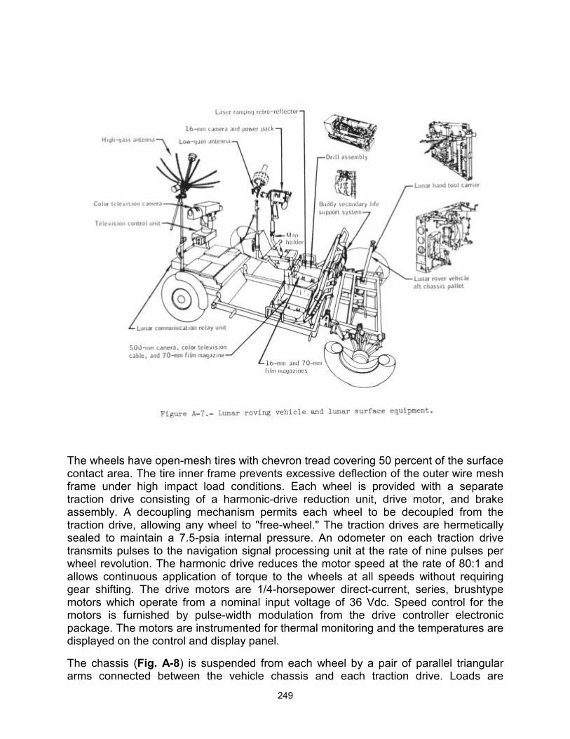
249
The wheels have open-mesh tires with chevron tread covering 50 percent of the surface contact area. The tire inner frame prevents excessive deflection of the outer wire mesh frame under high impact load conditions. Each wheel is provided with a separate traction drive consisting of a harmonic-drive reduction unit, drive motor, and brake assembly. A decoupling mechanism permits each wheel to be decoupled from the traction drive, allowing any wheel to "free-wheel." The traction drives are hermetically sealed to maintain a 7.5-psia internal pressure. An odometer on each traction drive transmits pulses to the navigation signal processing unit at the rate of nine pulses per wheel revolution. The harmonic drive reduces the motor speed at the rate of 80:1 and allows continuous application of torque to the wheels at all speeds without requiring gear shifting. The drive motors are 1/4-horsepower direct-current, series, brushtype motors which operate from a nominal input voltage of 36 Vdc. Speed control for the motors is furnished by pulse-width modulation from the drive controller electronic package. The motors are instrumented for thermal monitoring and the temperatures are displayed on the control and display panel.
The chassis (Fig. A-8) is suspended from each wheel by a pair of parallel triangular arms connected between the vehicle chassis and each traction drive. Loads are
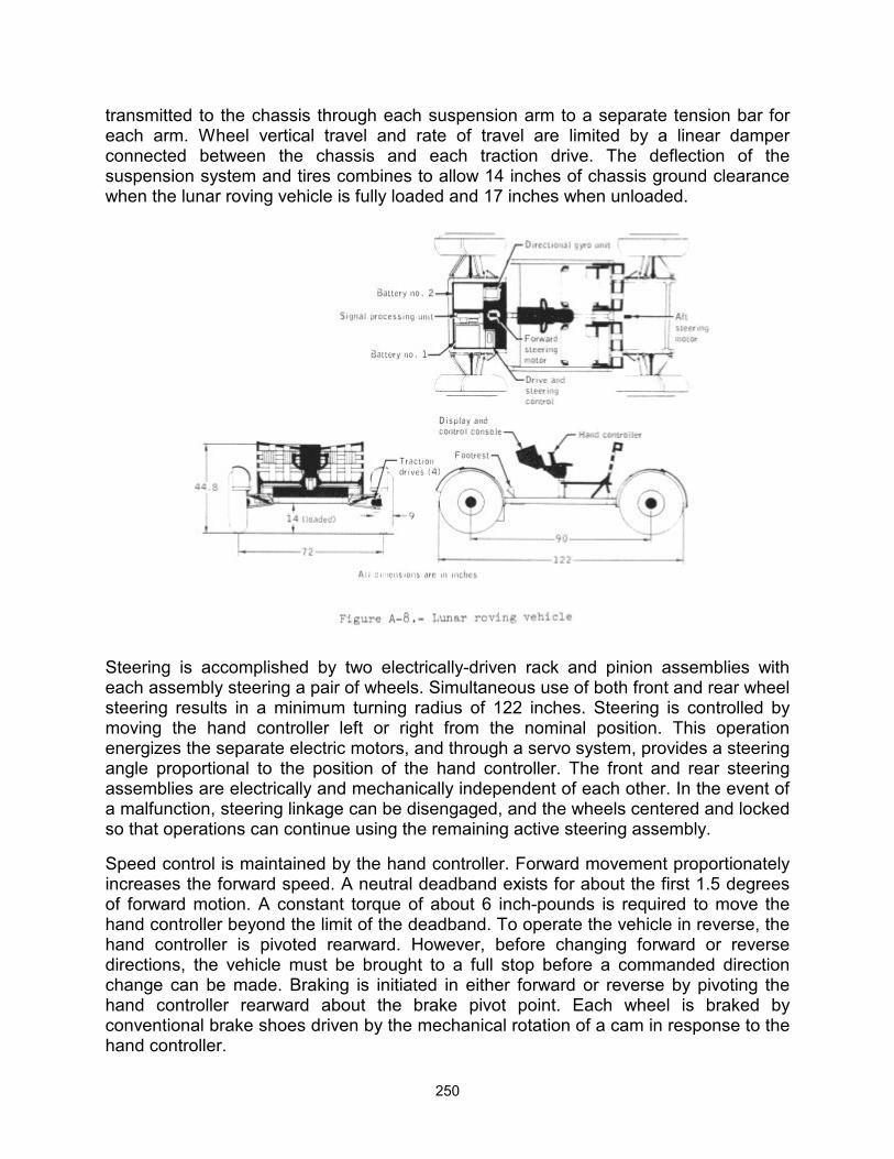
250
transmitted to the chassis through each suspension arm to a separate tension bar for each arm. Wheel vertical travel and rate of travel are limited by a linear damper connected between the chassis and each traction drive. The deflection of the suspension system and tires combines to allow 14 inches of chassis ground clearance when the lunar roving vehicle is fully loaded and 17 inches when unloaded.
Steering is accomplished by two electrically-driven rack and pinion assemblies with each assembly steering a pair of wheels. Simultaneous use of both front and rear wheel steering results in a minimum turning radius of 122 inches. Steering is controlled by moving the hand controller left or right from the nominal position. This operation energizes the separate electric motors, and through a servo system, provides a steering angle proportional to the position of the hand controller. The front and rear steering assemblies are electrically and mechanically independent of each other. In the event of a malfunction, steering linkage can be disengaged, and the wheels centered and locked so that operations can continue using the remaining active steering assembly.
Speed control is maintained by the hand controller. Forward movement proportionately increases the forward speed. A neutral deadband exists for about the first 1.5 degrees of forward motion. A constant torque of about 6 inch-pounds is required to move the hand controller beyond the limit of the deadband. To operate the vehicle in reverse, the hand controller is pivoted rearward. However, before changing forward or reverse directions, the vehicle must be brought to a full stop before a commanded direction change can be made. Braking is initiated in either forward or reverse by pivoting the hand controller rearward about the brake pivot point. Each wheel is braked by conventional brake shoes driven by the mechanical rotation of a cam in response to the hand controller.
251
The vehicle is powered by two silver-zinc batteries, each having a nominal voltage of 36 Vdc and a capacity of 120 ampere hours. During lunar surface operations, both batteries are normally used simultaneously on an approximate equal load basis. These batteries are located on the forward chassis and are enclosed by a thermal blanket and dust covers. The batteries are monitored for temperature, voltage, output current, and remaining ampere hours on the control and display panel. Each battery is protected from excessive internal pressures by a relief valve set to open at 3.1 to 7 psi differential pressure. The circuitry was designed so that if one battery fails, the entire electrical load can be switched to the remaining battery.
The control and display console is separated into two main functional parts - navigation on the upper part and monitoring controls on the lower part. Navigation displays include pitch, roll, speed, heading, total distance traveled, as well as the range and bearing back to the lunar module. Heading is obtained from a sun-aligned directional gyro, speed and distance from wheel rotation counters, and range and bearing are computed from these inputs. Alignment of the directional gyro is accomplished by relaying pitch, roll and sun angle readings to earth where an initial heading angle is calculated. The gyro is then adjusted by slewing with the torquing switch until the heading indicator reads the same as the calculated value. The displays utilize a radioluminescent material (promethium) that provides visibility under lunar shadow conditions.
Thermal control devices are incorporated into the vehicle to maintain temperature sensitive components within the necessary temperature limits. They consist of special surface finishes, multilayer insulation, space radiators, surface mirrors, thermal straps, and fusible mass heat sinks. The basic concept of thermal control for forward chassis components is to store energy during operation, and transfer energy to deep space while the vehicle is parked between sorties. The space radiators are mounted on the top of the signal processing unit, the drive control electronics, and on batteries 1 and 2.
A-3.3 Extravehicular Communications
Because the lunar roving vehicle takes the crew beyond the range of reliable radio communications with the lunar module using the portable life support system communications equipment, radio communications equipment are provided on the lunar roving vehicle that operate independently of the lunar module. This communications equipment is capable of relaying voice and telemetry data from the moon to the earth as well as transmitting color television pictures. The equipment also provides the capability for reception of voice communications from the earth, relay of voice to the crew, and ground-command control of the television camera. The lunar roving vehicle radio equipment, technically called the lunar communications relay unit, employs a VHF radio link between the lunar roving vehicle and earth. The color television camera with its positioning assembly, technically called the ground commanded television assembly, is connected to the lunar communications relay unit by a cable which carries ground commands to the television control unit and returns the television pictures to the lunar communications relay unit for transmission to earth. The crewmen communicate directly with each other using their extravehicular communications systems. Three batteries per crewman are provided for the three traverses. However, a connection is made to the lunar roving vehicle power system when the communications equipment is placed on
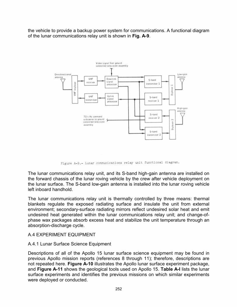
252
the vehicle to provide a backup power system for communications. A functional diagram of the lunar communications relay unit is shown in Fig. A-9.
The lunar communications relay unit, and its S-band high-gain antenna are installed on the forward chassis of the lunar roving vehicle by the crew after vehicle deployment on the lunar surface. The S-band low-gain antenna is installed into the lunar roving vehicle left inboard handhold.
The lunar communications relay unit is thermally controlled by three means: thermal blankets regulate the exposed radiating surface and insulate the unit from external environment; secondary-surface radiating mirrors reflect undesired solar heat and emit undesired heat generated within the lunar communications relay unit; and change-of-phase wax packages absorb excess heat and stabilize the unit temperature through an absorption-discharge cycle.
A.4 EXPERIMENT EQUIPMENT
A.4.1 Lunar Surface Science Equipment
Descriptions of all of the Apollo 15 lunar surface science equipment may be found in previous Apollo mission reports (references 8 through 11); therefore, descriptions are not repeated here. Figure A-10 illustrates the Apollo lunar surface experiment package, and Figure A-11 shows the geological tools used on Apollo 15. Table A-I lists the lunar surface experiments and identifies the previous missions on which similar experiments were deployed or conducted.
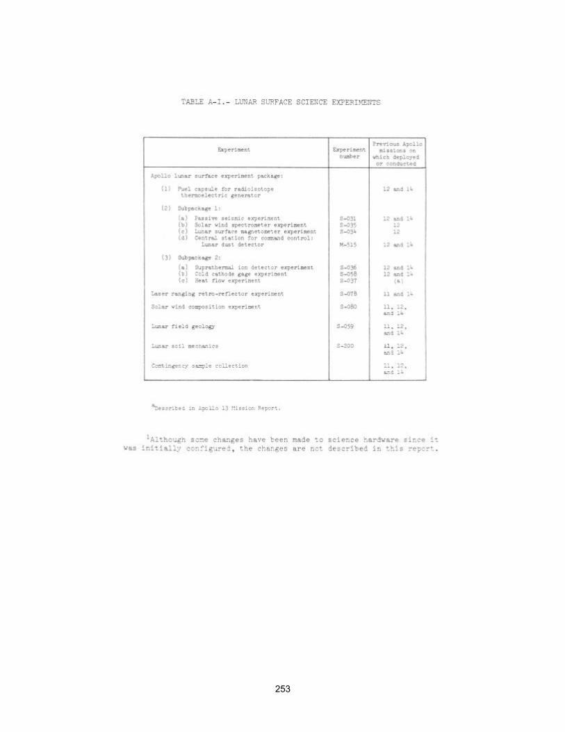
253
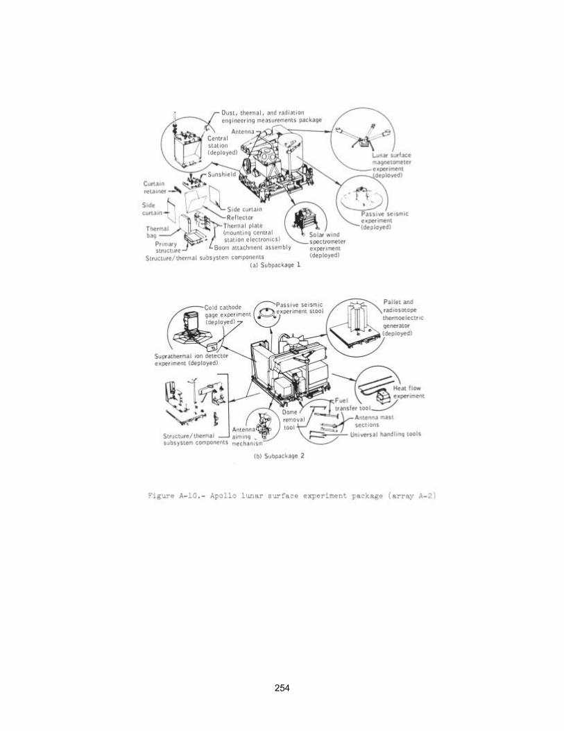
254
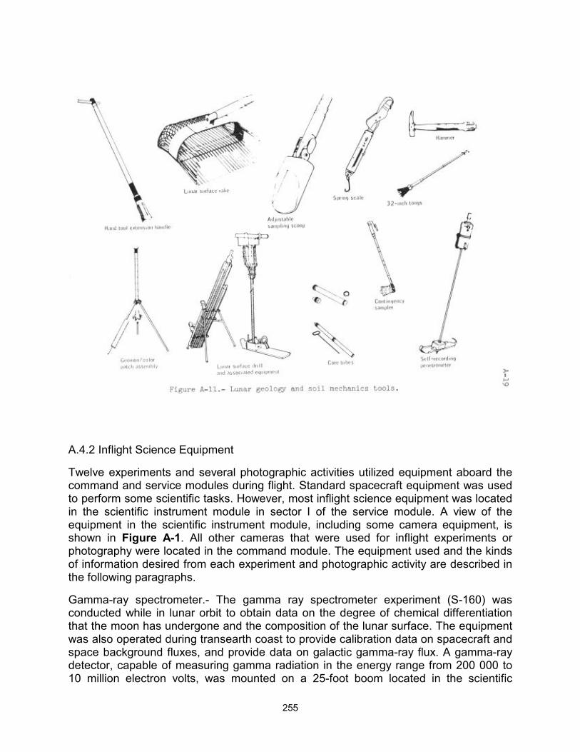
255
A.4.2 Inflight Science Equipment
Twelve experiments and several photographic activities utilized equipment aboard the command and service modules during flight. Standard spacecraft equipment was used to perform some scientific tasks. However, most inflight science equipment was located in the scientific instrument module in sector I of the service module. A view of the equipment in the scientific instrument module, including some camera equipment, is shown in Figure A-1. All other cameras that were used for inflight experiments or photography were located in the command module. The equipment used and the kinds of information desired from each experiment and photographic activity are described in the following paragraphs.
Gamma-ray spectrometer.- The gamma ray spectrometer experiment (S-160) was conducted while in lunar orbit to obtain data on the degree of chemical differentiation that the moon has undergone and the composition of the lunar surface. The equipment was also operated during transearth coast to provide calibration data on spacecraft and space background fluxes, and provide data on galactic gamma-ray flux. A gamma-ray detector, capable of measuring gamma radiation in the energy range from 200 000 to 10 million electron volts, was mounted on a 25-foot boom located in the scientific
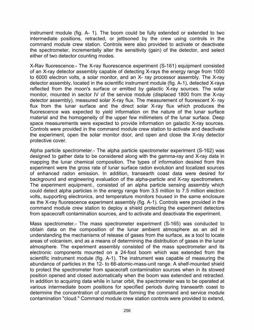
256
instrument module (fig. A- 1). The boom could be fully extended or extended to two intermediate positions, retracted, or jettisoned by the crew using controls in the command module crew station. Controls were also provided to activate or deactivate the spectrometer, incrementally alter the sensitivity (gain) of the detector, and select either of two detector counting modes.
X-Rav fluorescence.- The X-ray fluorescence experiment (S-161) equipment consisted of an X-ray detector assembly capable of detecting X-rays the energy range from 1000 to 6000 electron volts, a solar monitor, and an X- ray processor assembly. The X-ray detector assembly, located in the scientific instrument module (fig. A-1), detected X-rays reflected from the moon's surface or emitted by galactic X-ray sources. The solar monitor, mounted in sector IV of the service module (displaced 1800 from the X-ray detector assembly), measured solar X-ray flux. The measurement of fluorescent X- ray flux from the lunar surface and the direct solar X-ray flux which produces the fluorescence was expected to yield information on the nature of the lunar surface material and the homogeneity of the upper few millimeters of the lunar surface. Deep space measurements were expected to provide information on galactic X-ray sources. Controls were provided in the command module crew station to activate and deactivate the experiment, open the solar monitor door, and open and close the X-ray detector protective cover.
Alpha particle spectrometer.- The alpha particle spectrometer experiment (S-162) was designed to gather data to be considered along with the gamma-ray and X-ray data in mapping the lunar chemical composition. The types of information desired from this experiment were the gross rate of lunar surface radon evolution and localized sources of enhanced radon emission. In addition, transearth coast data were desired for background and engineering evaluation of the alpha-particle and X-ray spectrometers. The experiment equipment., consisted of an alpha particle sensing assembly which could detect alpha particles in the energy range from 3.5 million to 7.5 million electron volts, supporting electronics, and temperature monitors housed in the same enclosure as the X-ray fluorescence experiment assembly (fig. A-1). Controls were provided in the command module crew station to deploy a shield protecting the experiment detectors from spacecraft contamination sources, and to activate and deactivate the experiment.
Mass spectrometer.- The mass spectrometer experiment (S-165) was conducted to obtain data on the composition of the lunar ambient atmosphere as an aid in understanding the mechanisms of release of gases from the surface, as a tool to locate areas of volcanism, and as a means of determining the distribution of gases in the lunar atmosphere. The experiment assembly consisted of the mass spectrometer and its electronic components mounted on a 24-foot boom which was extended from the scientific instrument module (fig. A-1). The instrument was capable of measuring the abundance of particles in the 12- to 66-atomic-mass-unit range. A shelf-mounted shield to protect the spectrometer from spacecraft contamination sources when in its stowed position opened and closed automatically when the boom was extended and retracted. In addition to acquiring data while in lunar orbit, the spectrometer was to be operated at various intermediate boom positions for specified periods during transearth coast to determine the concentration of constituents forming the command and service module contamination "cloud." Command module crew station controls were provided to extend,
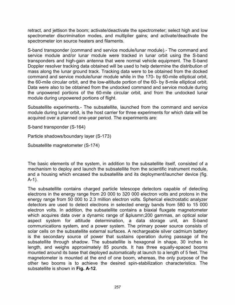
257
retract, and jettison the boom; activate/deactivate the spectrometer; select high and low spectrometer discrimination modes, and multiplier gains; and activate/deactivate the spectrometer ion source heaters and filaments.
S-band transponder (command and service module/lunar module).- The command and service module and/or lunar module were tracked in lunar orbit using the S-band transponders and high-gain antenna that were normal vehicle equipment. The S-band Doppler resolver tracking data obtained will be used to help determine the distribution of mass along the lunar ground track. Tracking data were to be obtained from the docked command and service module/lunar module while in the 170- by 60-mile elliptical orbit, the 60-mile circular orbit, and the low-altitude portion of the 60- by 8-mile elliptical orbit. Data were also to be obtained from the undocked command and service module during the unpowered portions of the 60-mile circular orbit, and from the undocked lunar module during unpowered portions of flight.
Subsatellite experiments.- The subsatellite, launched from the command and service module during lunar orbit, is the host carrier for three experiments for which data will be acquired over a planned one-year period. The experiments are:
S-band transponder (S-164)
Particle shadows/boundary layer (S-173)
Subsatellite magnetometer (S-174)
The basic elements of the system, in addition to the subsatellite itself, consisted of a mechanism to deploy and launch the subsatellite from the scientific instrument module, and a housing which encased the subsatellite and its deployment/launcher device (fig. A-1).
The subsatellite contains charged particle telescope detectors capable of detecting electrons in the energy range from 20 000 to 320 000 electron volts and protons in the energy range from 50 000 to 2.3 million electron volts. Spherical electrostatic analyzer detectors are used to detect electrons in selected energy bands from 580 to 15 000 electron volts. In addition, the subsatellite contains a biaxial fluxgate magnetometer which acquires data over a dynamic range of ±200 gammas, an optical solar aspect system for attitude determination, a data storage unit, an S-band communications system, and a power system. The primary power source consists of solar cells on the subsatellite external surfaces. A rechargeable silver cadmium battery is the secondary source of power that sustains operation during passage of the subsatellite through shadow. The subsatellite is hexagonal in shape, 30 inches in length, and weighs approximately 85 pounds. It has three equally-spaced booms mounted around its base that deployed automatically at launch to a length of 5 feet. The magnetometer is mounted at the end of one boom, whereas, the only purpose of the other two booms is to achieve the desired spin-stabilization characteristics. The subsatellite is shown in Fig. A-12.
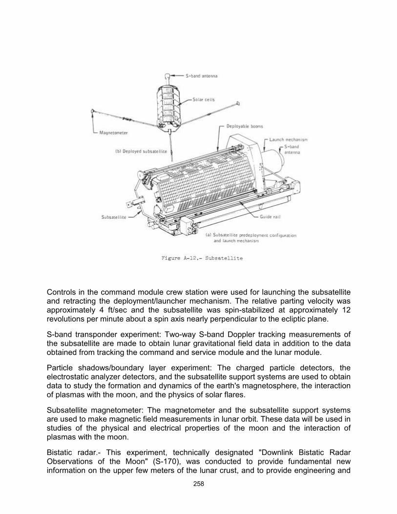
258
Controls in the command module crew station were used for launching the subsatellite and retracting the deployment/launcher mechanism. The relative parting velocity was approximately 4 ft/sec and the subsatellite was spin-stabilized at approximately 12 revolutions per minute about a spin axis nearly perpendicular to the ecliptic plane.
S-band transponder experiment: Two-way S-band Doppler tracking measurements of the subsatellite are made to obtain lunar gravitational field data in addition to the data obtained from tracking the command and service module and the lunar module.
Particle shadows/boundary layer experiment: The charged particle detectors, the electrostatic analyzer detectors, and the subsatellite support systems are used to obtain data to study the formation and dynamics of the earth's magnetosphere, the interaction of plasmas with the moon, and the physics of solar flares.
Subsatellite magnetometer: The magnetometer and the subsatellite support systems are used to make magnetic field measurements in lunar orbit. These data will be used in studies of the physical and electrical properties of the moon and the interaction of plasmas with the moon.
Bistatic radar.- This experiment, technically designated "Downlink Bistatic Radar Observations of the Moon" (S-170), was conducted to provide fundamental new information on the upper few meters of the lunar crust, and to provide engineering and
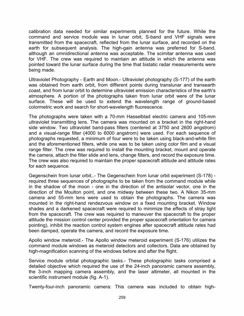
259
calibration data needed for similar experiments planned for the future. While the command and service module was in lunar orbit, S-band and VHF signals were transmitted from the spacecraft, reflected from the lunar surface, and recorded on the earth for subsequent analysis. The high-gain antenna was preferred for S-band, although an omnidirectional antenna was acceptable. The scimitar antenna was used for VHF. The crew was required to maintain an attitude in which the antenna was pointed toward the lunar surface during the time that bistatic radar measurements were being made.
Ultraviolet Photography - Earth and Moon.- Ultraviolet photography (S-177) of the earth was obtained from earth orbit, from different points during translunar and transearth coast, and from lunar orbit to determine ultraviolet emission characteristics of the earth's atmosphere. A portion of the photographs taken from lunar orbit were of the lunar surface. These will be used to extend the wavelength range of ground-based colormetric work and search for short-wavelength fluorescence.
The photographs were taken with a 70-mm Hasselblad electric camera and 105-mm ultraviolet transmitting lens. The camera was mounted on a bracket in the right-hand side window. Two ultraviolet band-pass filters (centered at 3750 and 2600 angstrom) and a visual-range filter (4000 to 6000 angstrom) were used. For each sequence of photographs requested, a minimum of four were to be taken using black-and-white film and the aforementioned filters, while one was to be taken using color film and a visual range filter. The crew was required to install the mounting bracket, mount and operate the camera, attach the filter slide and lens, change filters, and record the exposure time. The crew was also required to maintain the proper spacecraft attitude and attitude rates for each sequence.
Gegenschein from lunar orbit..- The Gegenschein from lunar orbit experiment (S-178) -required three sequences of photographs to be taken from the command module while in the shadow of the moon - one in the direction of the antisolar vector, one in the direction of the Moulton point, and one midway between these two. A Nikon 35-mm camera and 55-mm lens were used to obtain the photographs. The camera was mounted in the right-hand rendezvous window on a fixed mounting bracket. Window shades and a darkened spacecraft were required to minimize the effects of stray light from the spacecraft. The crew was required to maneuver the spacecraft to the proper attitude the mission control center provided the proper spacecraft orientation for camera pointing), inhibit the reaction control system engines after spacecraft attitude rates had been damped, operate the camera, and record the exposure time.
Apollo window meteroid.- The Apollo window meteroid experiment (S-176) utilizes the command module windows as meteroid detectors and collectors. Data are obtained by high-magnification scanning of the windows before and after the flight.
Service module orbital photographic tasks.- These photographic tasks comprised a detailed objective which required the use of the 24-inch panoramic camera assembly, the 3-inch mapping camera assembly, and the laser altimeter, all mounted in the scientific instrument module (fig. A-1).
Twenty-four-inch panoramic camera: This camera was included to obtain high-
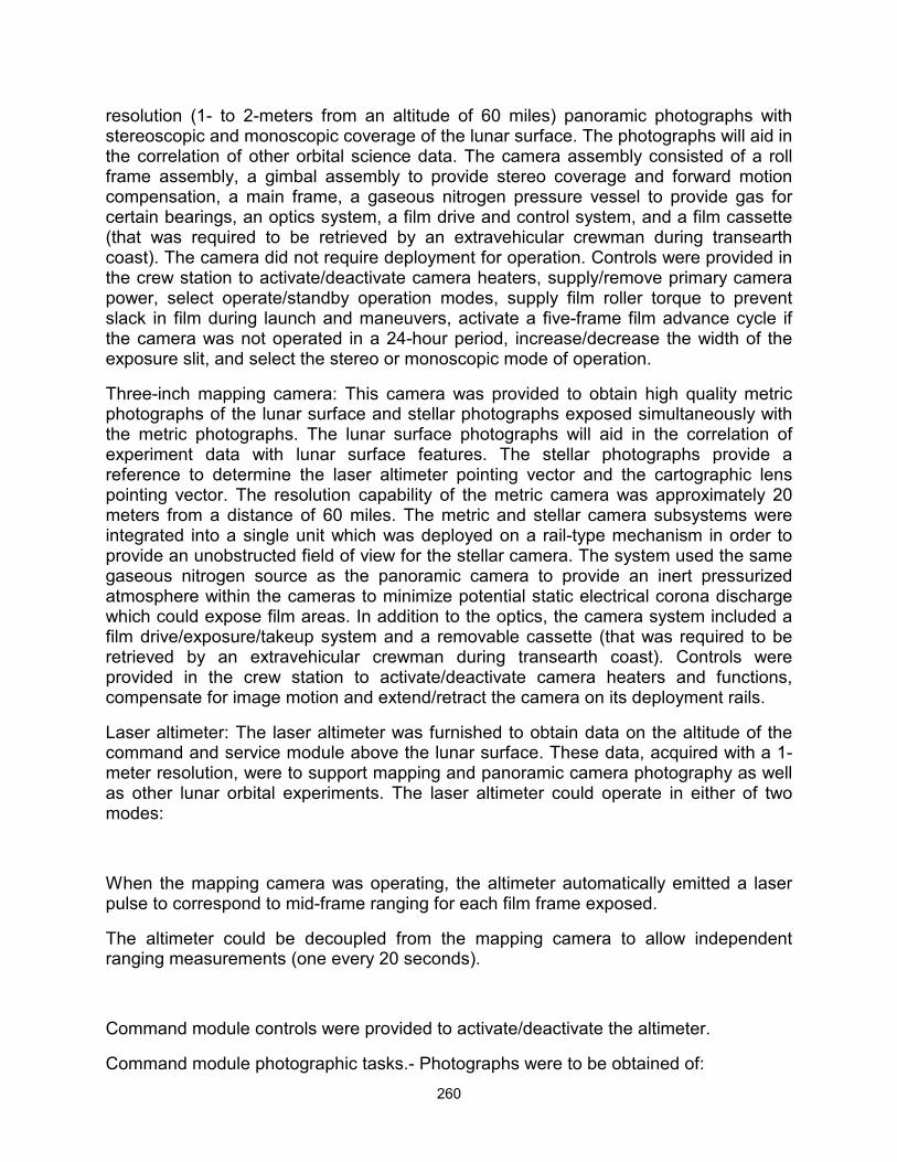
260
resolution (1- to 2-meters from an altitude of 60 miles) panoramic photographs with stereoscopic and monoscopic coverage of the lunar surface. The photographs will aid in the correlation of other orbital science data. The camera assembly consisted of a roll frame assembly, a gimbal assembly to provide stereo coverage and forward motion compensation, a main frame, a gaseous nitrogen pressure vessel to provide gas for certain bearings, an optics system, a film drive and control system, and a film cassette (that was required to be retrieved by an extravehicular crewman during transearth coast). The camera did not require deployment for operation. Controls were provided in the crew station to activate/deactivate camera heaters, supply/remove primary camera power, select operate/standby operation modes, supply film roller torque to prevent slack in film during launch and maneuvers, activate a five-frame film advance cycle if the camera was not operated in a 24-hour period, increase/decrease the width of the exposure slit, and select the stereo or monoscopic mode of operation.
Three-inch mapping camera: This camera was provided to obtain high quality metric photographs of the lunar surface and stellar photographs exposed simultaneously with the metric photographs. The lunar surface photographs will aid in the correlation of experiment data with lunar surface features. The stellar photographs provide a reference to determine the laser altimeter pointing vector and the cartographic lens pointing vector. The resolution capability of the metric camera was approximately 20 meters from a distance of 60 miles. The metric and stellar camera subsystems were integrated into a single unit which was deployed on a rail-type mechanism in order to provide an unobstructed field of view for the stellar camera. The system used the same gaseous nitrogen source as the panoramic camera to provide an inert pressurized atmosphere within the cameras to minimize potential static electrical corona discharge which could expose film areas. In addition to the optics, the camera system included a film drive/exposure/takeup system and a removable cassette (that was required to be retrieved by an extravehicular crewman during transearth coast). Controls were provided in the crew station to activate/deactivate camera heaters and functions, compensate for image motion and extend/retract the camera on its deployment rails.
Laser altimeter: The laser altimeter was furnished to obtain data on the altitude of the command and service module above the lunar surface. These data, acquired with a 1-meter resolution, were to support mapping and panoramic camera photography as well as other lunar orbital experiments. The laser altimeter could operate in either of two modes:
When the mapping camera was operating, the altimeter automatically emitted a laser pulse to correspond to mid-frame ranging for each film frame exposed.
The altimeter could be decoupled from the mapping camera to allow independent ranging measurements (one every 20 seconds).
Command module controls were provided to activate/deactivate the altimeter.
Command module photographic tasks.- Photographs were to be obtained of:
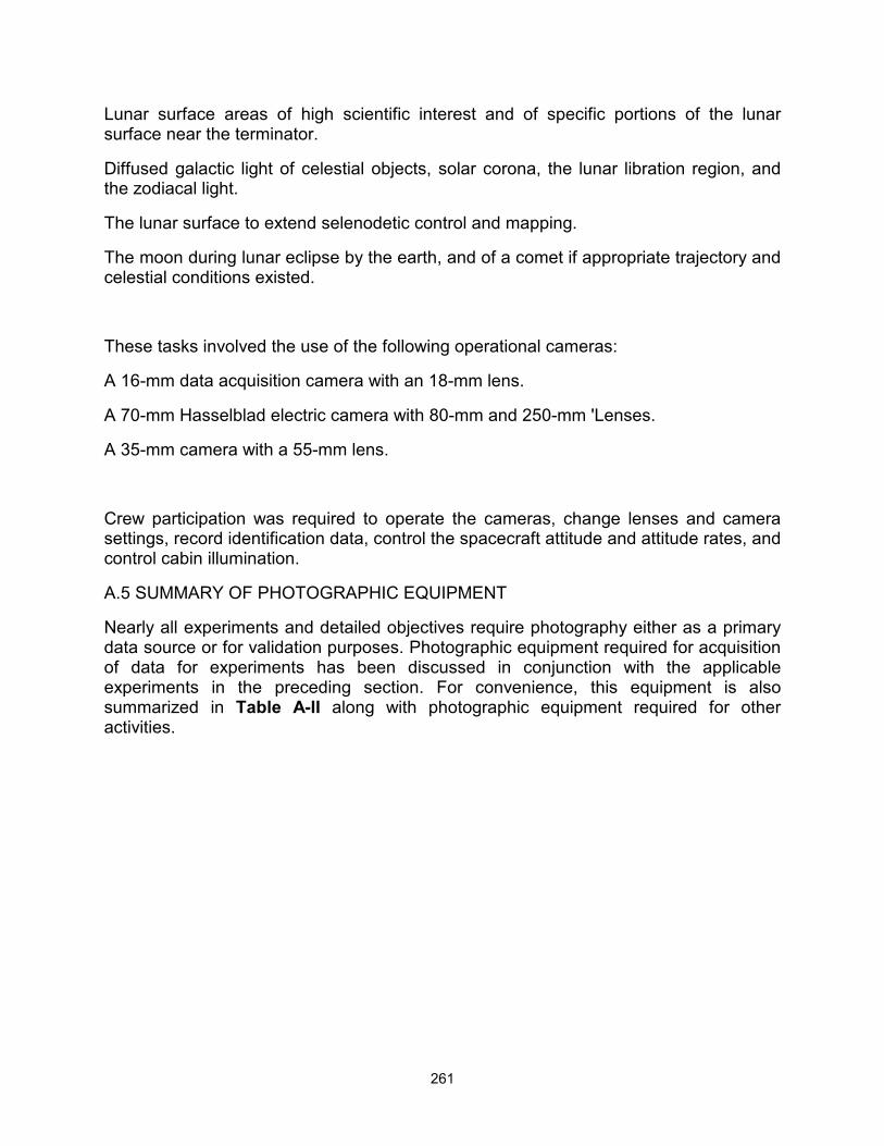
261
Lunar surface areas of high scientific interest and of specific portions of the lunar surface near the terminator.
Diffused galactic light of celestial objects, solar corona, the lunar libration region, and the zodiacal light.
The lunar surface to extend selenodetic control and mapping.
The moon during lunar eclipse by the earth, and of a comet if appropriate trajectory and celestial conditions existed.
These tasks involved the use of the following operational cameras:
A 16-mm data acquisition camera with an 18-mm lens.
A 70-mm Hasselblad electric camera with 80-mm and 250-mm 'Lenses.
A 35-mm camera with a 55-mm lens.
Crew participation was required to operate the cameras, change lenses and camera settings, record identification data, control the spacecraft attitude and attitude rates, and control cabin illumination.
A.5 SUMMARY OF PHOTOGRAPHIC EQUIPMENT
Nearly all experiments and detailed objectives require photography either as a primary data source or for validation purposes. Photographic equipment required for acquisition of data for experiments has been discussed in conjunction with the applicable experiments in the preceding section. For convenience, this equipment is also summarized in Table A-II along with photographic equipment required for other activities.

262
A.6 MASS PROPERTIES
Mass properties for the Apollo 15 mission are summarized in Table A-III. These data represent the conditions as determined from postflight analyses of expendable loadings and usage during the flight. Variations in command and service modules and lunar module mass properties are determined for each significant mission phase from lift-off through landing. Expendables usage are based on reported real-time and postflight data as presented in other sections of this report. The weights and center-of-gravity of the individual modules (command, service, ascent stage, and descent stage) were measured prior to flight and inertia values calculated. All changes incorporated after the actual weighing were monitored, and the mass properties were updated.
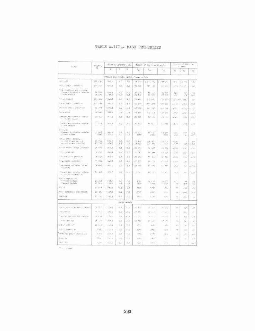
263

264
APPENDIX B - SPACECRAFT HISTORIES
The history of command and service module (CSM 112) operations at the manufacturer's facility, Downey, California, is shown in Fig. B-1, and the operations at Kennedy Space Center, Florida, in Fig. B-2.
The history of the lunar module (LM-10) at the manufacturer's facility, Bethpage, New York, is shown in Fig. B-3, and the operations at Kennedy Space Center, Florida, in Fig. B-4.
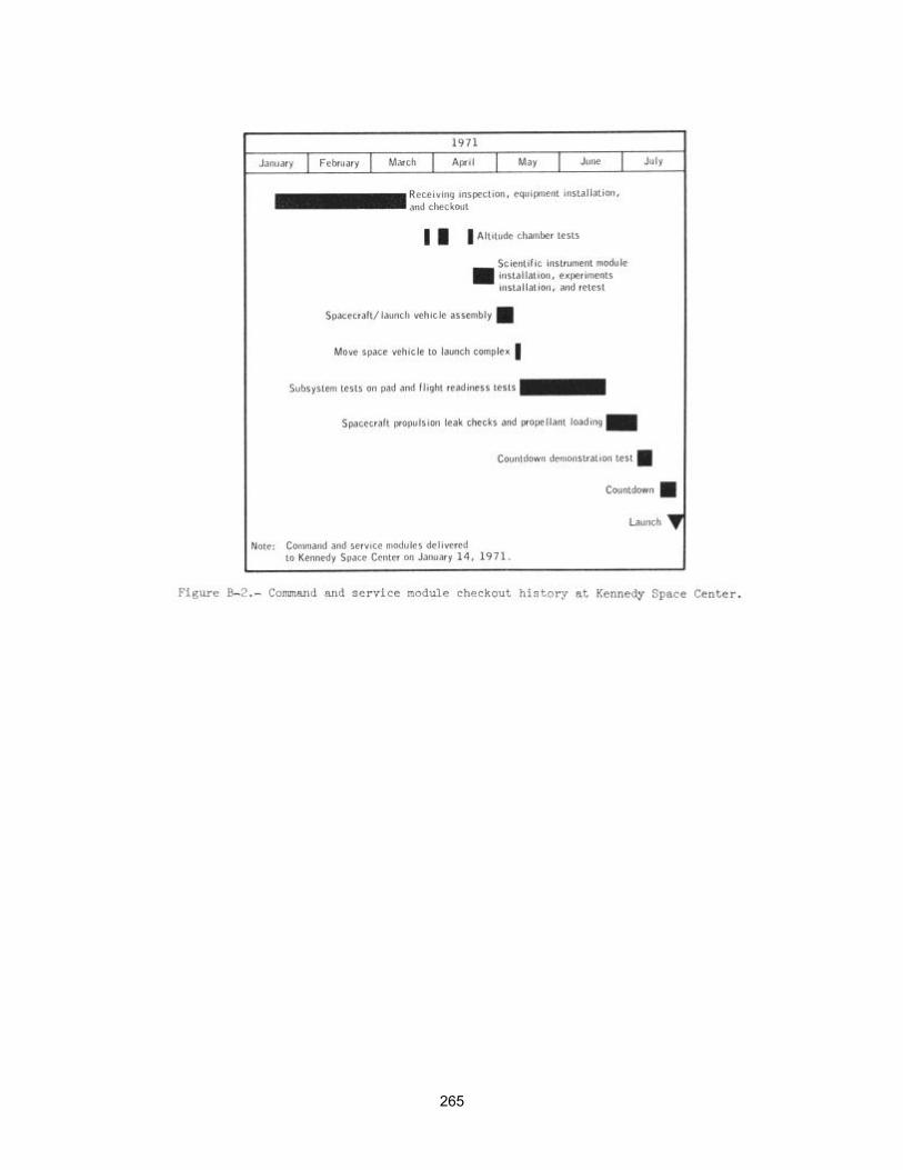
265
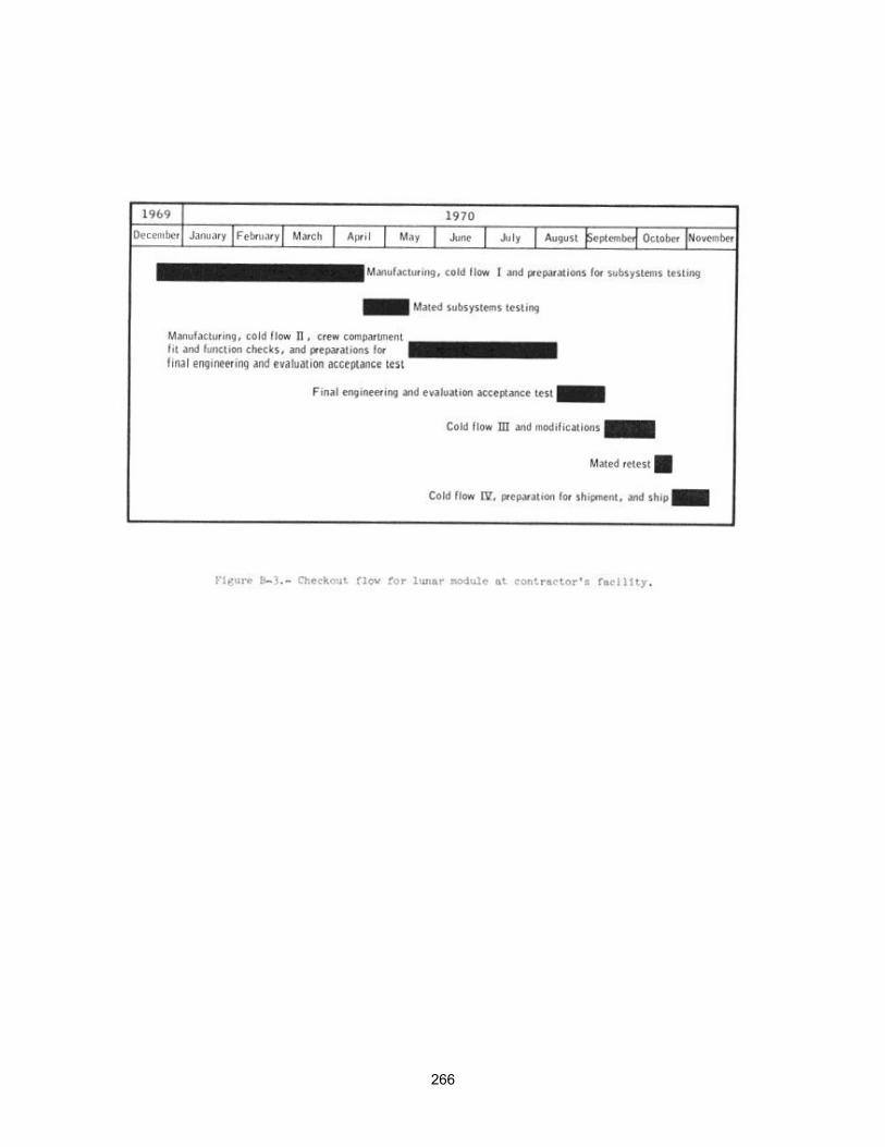
266
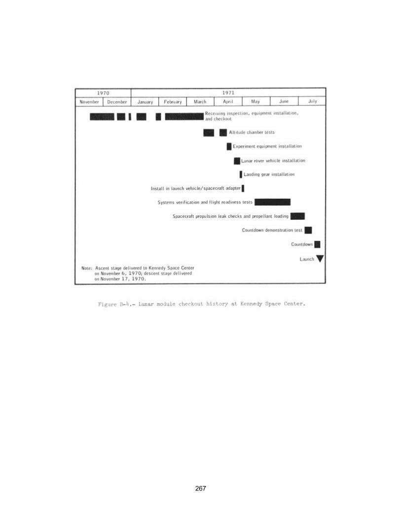
267
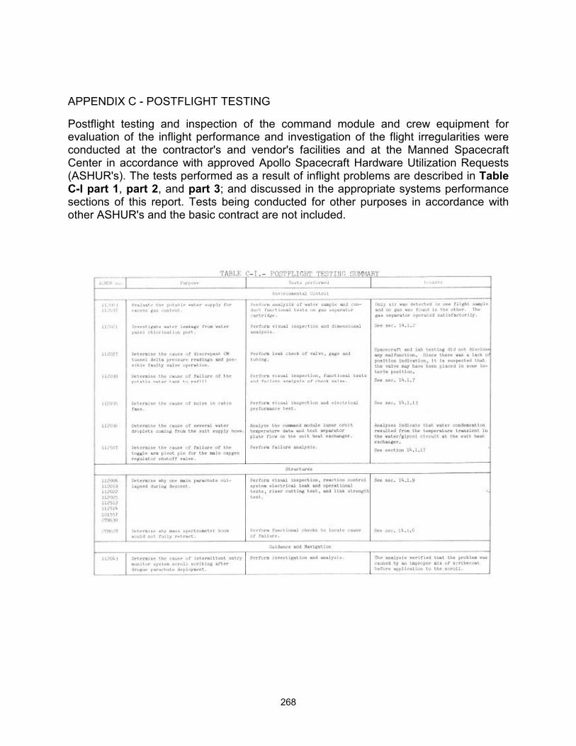
268
APPENDIX C - POSTFLIGHT TESTING
Postflight testing and inspection of the command module and crew equipment for evaluation of the inflight performance and investigation of the flight irregularities were conducted at the contractor's and vendor's facilities and at the Manned Spacecraft Center in accordance with approved Apollo Spacecraft Hardware Utilization Requests (ASHUR's). The tests performed as a result of inflight problems are described in Table C-I part 1, part 2, and part 3; and discussed in the appropriate systems performance sections of this report. Tests being conducted for other purposes in accordance with other ASHUR's and the basic contract are not included.
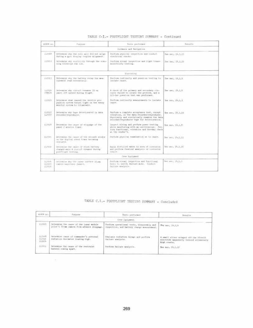
269
270
APPENDIX D - DATA AVAILABILITY
Tables D-I part 1 and D-I part 2; and D-II are summaries of the data made available for systems performance analyses and anomaly investigations. Table D-I lists the data for the command and service module, and Table D-II, the lunar module. The following table contains the times that experimental data were made available to the principal investigator for scientific analyses.
Time, hr:min Time, hr:min
From To From To
73:43 78:30 174:13 220:50
79:00 82:20 222:18 223:00
83:40 95:50 224:10 238:34
105:30 165:00 245:57 271:30
165:20 168:17 273:00 288:20
For additional information regarding data availability, the status listing of all mission data in the Central Metric Data File, building 12, should be consulted.
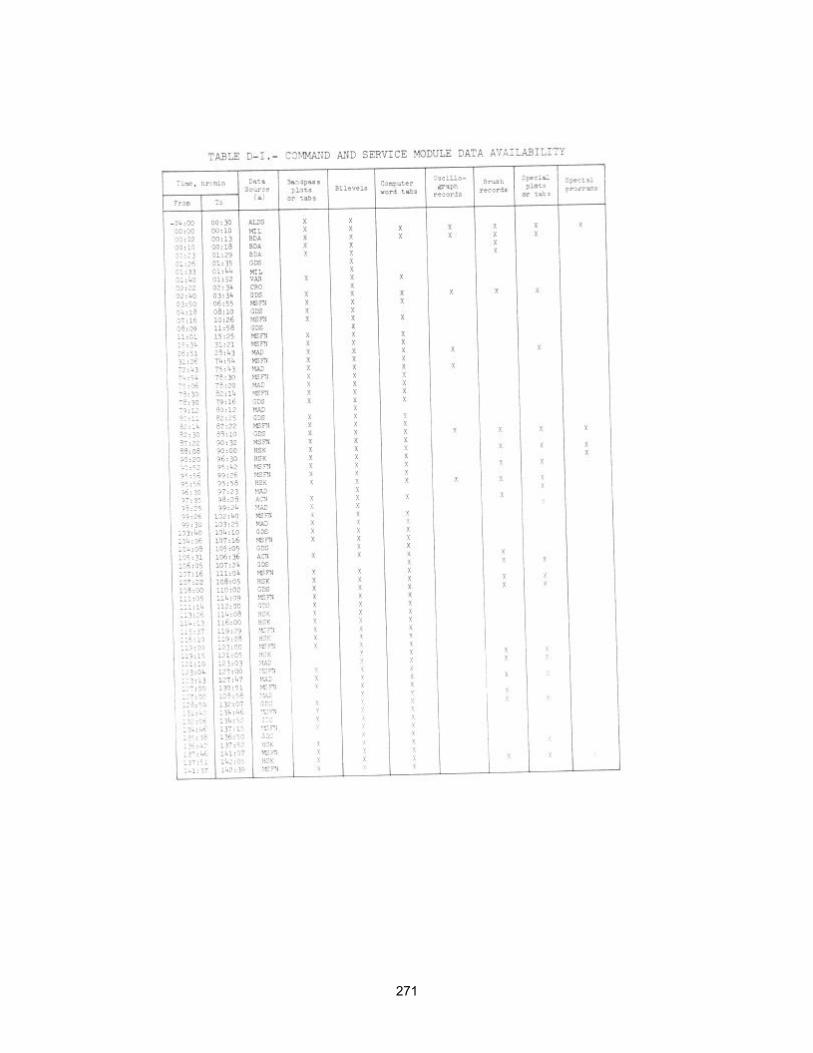
271
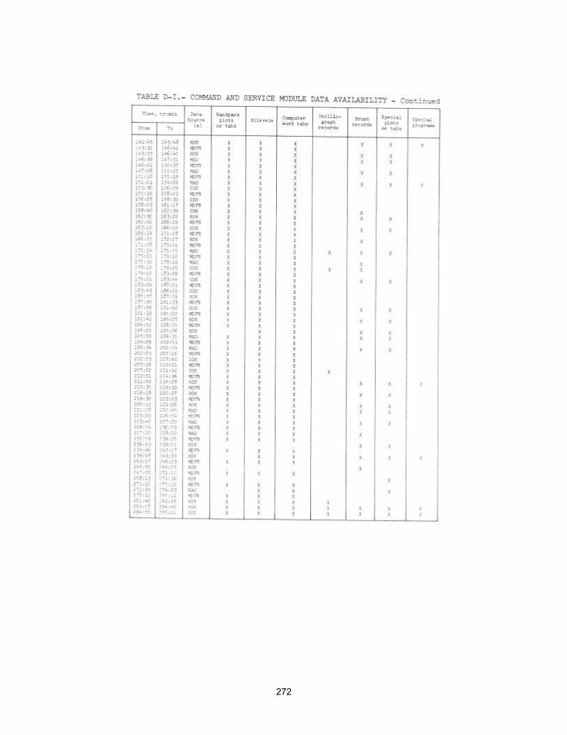
272
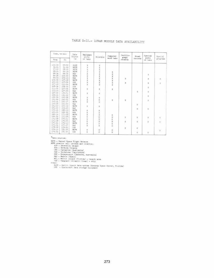
273
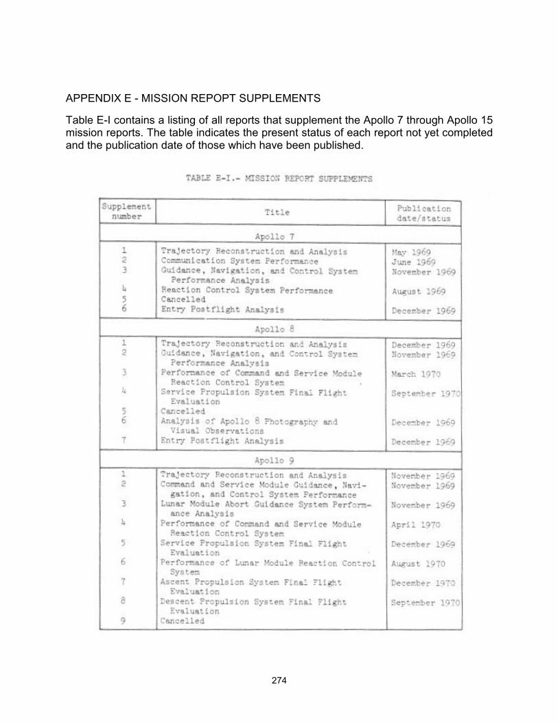
274
APPENDIX E - MISSION REPOPT SUPPLEMENTS
Table E-I contains a listing of all reports that supplement the Apollo 7 through Apollo 15 mission reports. The table indicates the present status of each report not yet completed and the publication date of those which have been published.
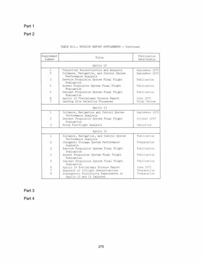
275
Part 1
Part 2
Part 3
Part 4

276
APPENDIX F � GLOSSARY
Anorthosite: A granular, textured igneous rock regarded as having solidified at considerable depth. It is composed almost entirely of a soda-lime feldspar.
Apocynthion: The point in the orbit of a moon satellite which is farthest from the moon.
Apolune: See apocynthion.
Bow shock: The shock wave produced by the interaction of the solar wind with the earth's dipole magnetic field. It is also the outer boundary of the magnetosheath (transition region).
Breccia: A course-grained rock composed of angular fragments of pre-existing rocks in a fine-grained matrix.
Caldera: A broad crater-like basin surrounding a volcanic vent and having a diameter many times that of the vent.
Circadian rhythm: Relating to biological variations with a cycle of about 24 hours.
Cislunar: Pertaining to the space between the earth and moon.
Clast: A fragment of rock or mineral, commonly included in a larger rock.
Comprehensive sample: A 1-kilogram collection of rocks representative of a given area. Desired sample diameters range from approximately 3/8 inch to 1 1/2 inches.
Contingency sample: Approximately 2 kilograms of lunar material collected in the immediate vicinity of the lunar module during the early part of the first extravehicular period. This is done to increase the probabaility of returning a lunar sample to earth if early termination of extravehicular operations is necessary.
Densitometric: Relating to determining the degree of opacity of any translucent medium.
Diamagnetic cavity: An area having a magnetic permeability less than one.
Diurnal: Recurring daily. On earth, diurnal processes repeat themselves every 24 hours; on the moon, every 28 days.
Documented sample: A sample that is photographed before being picked up, the area photographed after sample removal, and a reference photograph taken to identify the location.
Double core tube sample: A sample obtained using two drive core tubes connected end to end.
Earthshine: Illumination of the moon's surface by sunlight reflected from the earth's surface and atmosphere.

277
Ecliptic: The plane defined by the earth's orbit about the sun.
Ergometry test: A test performed to measure muscular fatigue under controlled conditions.
Front: The outer slopes of a mountain range that rises above a plain or plateau.
Geomagnetic tail: An elongation of the earth's magnetic field whereby it is drawn in the anti-solar direction to an undetermined distance. It is also called the nagnetotail.
Gnomon: A rod mounted on a tripod in such a way that it is free to swing in any direction and indicate the local vertical.
Hummocky: Multiple low, rounded hills or knolls.
J-missions: A classification of Apollo lunar exploration missions for which provisions are made for extended lunar surface stay time, surface vehicular mobility and communications, and more extensive science data acquisition.
Kilocalorie: An amount of food having an energy-producing value of one large calorie (equivalent to 1000 gram calories).
Limb: The outer edge of the apparent disc of a celestial body, as the moon or earth, or a portion of the edge.
Lunar libration: A point in space which, from the viewpoint of an observer on earth, is about 60 degrees from the earth-moon axis in the direction of the moon's travel and on its orbital path.
Lunation: The average period of revolution of the moon about the earth with respect to the sun. A period of 29 days 12 hours 44 minutes 2.8 seconds. Also called a synodical month.
Magnetosheath: The region between the solar wind bow shock and the earth's dipole magnetic field. It varies in size and, within the region, the solar wind is reduced and the magnetic field is poorly defined. It is also called the transition region.
Magnetosphere: The region of the earth's atmosphere where ionized gases contribute to the dynamics of the atmosphere and where the forces of the earth's magnetic field are predominant.
Magnetospheric plasma: Plasma evolved in the magnetosphere.
Magnetotail: See geomagnetic tail.
Magnetopause: The boundary between the magnetosheath (transition region) and the earth's dipole magnetic field.
Mare: A large, dark, flat area on the lunar surface (lunar sea).
Mascons: Large mass concentrations beneath the lunar surface. They are believed to be large bodies that have impacted the lunar surface.

278
Meru: Milli earth rate unit. One thousandth of the earth's rotational rate.
Metric photography: Photography having an appropriate network of coordinates or reference points to permit accurate measurements.
Monoscopic photograph: A single photograph of a given area, or subject obtained with a camera having one lens system and shutter.
Morphological: Relating to the shapes and contours of objects or areas.
Moulton Point: A theoretical point on the sun-earth axis thought to be located about 940 000 statute miles from the earth in the anti-solar direction. It is also designated as the Ll libration point of the earth.
Noble gases: Monatomic gases that are relatively inert.
Olivine: An igneous mineral that consists of a silicate of magnesium and iron.
Pericynthion: The point in the orbit of a moon satellite that is nearest to the moon, or the point in the trajectory of a vehicle that is nearest to the moon.
Perilune: See pericynthion.
Phenocrysts: Crystals in igneous rocks that are larger than the crystalline matrix in which they are imbedded.
Planar: Two-dimensional.
Plasma: An electrically conductive gas comurised of neutral particles, ionized particles, and free electrons, but which as a whole, is electrically neutral.
Plasma sheet: As used in this report, the term refers to a region in the center of the geomagnetic tail, approximately 10 earth radii in width, in which there is a marked increase in particle flux.
Porphyritic: The texture of rocks which contain distinct crystals imbedded in a relatively fine-grained groundmass.
Pyroclastic rocks: Rocks formed by fragmentation as a result of volcanic action.
Pyroxene: A mineral occurring in short, thick, prismatic crystals, or in crystals of square cross section; often laminated, and varying in color from white to dark green or black (rarely blue).
Radial sample: A sample consisting of material taken from a crater's ejecta field at a crater's rim, at a distance equal to the crater's radius, and at a distance equal to the crater's diameter.
Radon: A radioactive gaseous element with atomic number 86 and atomic masses of 220 and 222. Formed by the radioactive decay of radium.
Regolith: The surface layer of unsorted fragmented material on the earth or moon that
279
overlies solid material
Rille: A long, narrow valley on the moon's surface.
Scoriaceous: Having the characteristics of rough, vesicular, cindery, usually dark lava.
Selenodetic: Relating to the branch of applied mathematics that determines by observation and measurement the positions of points on the moon's surface and the size and shape of the moon.
Selenological: Relating to the branch of astronomy that deals with the moon.
Slikensides: Smooth, grooved and polished surfaces of rocks produced by friction on fault planes and joint faces.
Solar corona: The outer visible envelope of the sun.
Solar wind: Streams of particles (plasma) emanating from and flowing approximately radially outward from the sun.
Spectrometric: Relating to the measurement of wavelengths of rays of a spectrum.
Stereoscopic photographs: Two photographs obtained of a given area or subject from different angles so that the images, when viewed through a stereoscope, appear as a three-dimensional reproduction of the area or subject photographed.
Talus: An accumulated mass of angular rock debris on a hill side or at the foot of a mountain.
Terminator: The border between the illuminated and dark portions of the moon or planets
Transition region: See magnetosheath.
Umbra: The darkest portion of the shadow of a large body such as the earth or moon wherein light is completely blocked.
Vesicular: Containing small spherical cavities.
Zodiac: An imaginary belt that extends 8 degrees on either side of the ecliptic. It includes the paths of the moon and principal planets.
Zodiacal light: A faint glow seen along the zodiac in the west after sunset and in the east before sunrise.