APB 3622-HCC-11-0110_Rev1_de - Futurasmus KNX Group
219
Home Control Center Version 4.1.0 User manual Revision 2019-12-15
-
Upload
khangminh22 -
Category
Documents
-
view
0 -
download
0
Transcript of APB 3622-HCC-11-0110_Rev1_de - Futurasmus KNX Group

Home Control Center
Version 4.1.0
User manual
Revision 2019-12-15

APB 3622-HCC-11-0110_Rev1_en
ComBridge Home Control Center HCC
Version: 4.1.0
Copyright © 2019 by IPAS GmbH (Date 2019-12-15) 2 / 219
Table of contents
Table of contents ............................................................................................................................................. 2
1 Introduction ............................................................................................................................................... 7
1.1 System requirements ............................................................................................................................. 9
1.2 Using special characters and symbols .................................................................................................. 9
1.3 ComBridge HCC features .................................................................................................................... 10
1.4 Concept overview ................................................................................................................................ 11
2 Security .................................................................................................................................................. 13
2.1 Web page visit via HTTPS ................................................................................................................... 13
2.2 Authentication ...................................................................................................................................... 13
2.3 Password-Management ....................................................................................................................... 14
2.3.1 Initial definition of the passwords in the ETS ................................................................................ 14
2.3.2 Visualization password .................................................................................................................. 15
2.3.3 Configuration password (Editor).................................................................................................... 15
2.3.4 Additional passwords .................................................................................................................... 16
2.3.5 Change passwords ....................................................................................................................... 16
2.3.6 Reset passwords ........................................................................................................................... 16
2.4 Certificates ........................................................................................................................................... 17
2.4.1 Loading a customer-specific certificate ......................................................................................... 17
2.4.2 Create a new certificate ................................................................................................................ 18
2.4.3 Certificate query in the browser .................................................................................................... 18
3 Getting started ........................................................................................................................................ 19
3.1 ETS Download ..................................................................................................................................... 20
3.2 Change Passwords .............................................................................................................................. 21
3.3 Calling graphical editor ........................................................................................................................ 21
3.4 Installation Connection Managers ....................................................................................................... 22
4 ETS configuration ................................................................................................................................... 25
4.1 Parameter ............................................................................................................................................ 25
4.2 Network Settings .................................................................................................................................. 26
4.3 Date/Time ............................................................................................................................................ 28
4.4 General Objects 1-5 ............................................................................................................................. 29
4.5 Parameters Objects 6-250 ................................................................................................................... 30
4.6 Objects 6-255 ....................................................................................................................................... 31
5 Web-Configuration page ........................................................................................................................ 33
5.1 Overview .............................................................................................................................................. 33
5.2 IP Configuration ................................................................................................................................... 34

APB 3622-HCC-11-0110_Rev1_en
ComBridge Home Control Center HCC
Version: 4.1.0
Copyright © 2019 by IPAS GmbH (Date 2019-12-15) 3 / 219
5.3 SMTP ................................................................................................................................................... 34
5.4 Security ................................................................................................................................................ 35
5.5 Password ............................................................................................................................................. 36
5.6 Certificates ........................................................................................................................................... 37
5.7 SONOS Module ................................................................................................................................... 38
5.8 API Connection .................................................................................................................................... 39
5.8.1 Voice control.................................................................................................................................. 39
5.8.2 Registering with the service provider 1HOME .............................................................................. 39
5.8.3 Protecting access via password .................................................................................................... 40
5.8.4 Activating individual functions for voice control ............................................................................. 40
5.9 Restart ................................................................................................................................................. 40
6 Editor ...................................................................................................................................................... 41
6.1 Editor User Interface ............................................................................................................................ 41
6.1.1 The File-Menu ............................................................................................................................... 42
6.1.2 The Edit Menu ............................................................................................................................... 43
6.1.3 The View Menu ............................................................................................................................. 43
6.1.4 The Module Menu ......................................................................................................................... 43
6.1.5 The Configuration Menu ................................................................................................................ 44
6.1.6 The Help Menu .............................................................................................................................. 44
6.2 Objects, virtual objects and group addresses ...................................................................................... 45
6.2.1 Group addresses ........................................................................................................................... 46
6.2.2 Communication objects ................................................................................................................. 47
6.2.3 Virtual objects ................................................................................................................................ 48
6.2.4 Conflicts caused by different data points ...................................................................................... 48
6.2.5 Categories ..................................................................................................................................... 49
6.3 Creating a visualisation page ............................................................................................................... 50
7 Control elements .................................................................................................................................... 52
7.1 Selecting a style ................................................................................................................................... 52
7.2 Control elements in the components list .............................................................................................. 53
7.3 Principal properties .............................................................................................................................. 54
7.3.1 General .......................................................................................................................................... 54
7.3.2 Properties ...................................................................................................................................... 54
7.3.3 Status ............................................................................................................................................ 55
7.3.4 Layout ............................................................................................................................................ 56
7.4 Standard and basic functions of the control elements ......................................................................... 56
7.4.1 Light switch /general ..................................................................................................................... 56
7.4.2 Blinds/shutter switch ..................................................................................................................... 57

APB 3622-HCC-11-0110_Rev1_en
ComBridge Home Control Center HCC
Version: 4.1.0
Copyright © 2019 by IPAS GmbH (Date 2019-12-15) 4 / 219
7.4.3 Status ............................................................................................................................................ 58
7.4.4 Advanced control elements ........................................................................................................... 58
7.4.5 Navigation and labelling ................................................................................................................ 66
8 Modules .................................................................................................................................................. 72
8.1 Schedules ............................................................................................................................................ 72
8.1.1 Astronomical calendar configuration ............................................................................................. 72
8.1.2 Schedule configuration .................................................................................................................. 73
8.1.3 HTML View of schedules .............................................................................................................. 77
8.1.4 HTML View of periods ................................................................................................................... 79
8.1.5 HTML View of schedules (Desktop) .............................................................................................. 80
8.2 Scenes ................................................................................................................................................. 81
8.2.1 KNX scenes ................................................................................................................................... 82
8.2.2 My scenes ..................................................................................................................................... 86
8.2.3 HTML View of scenes ................................................................................................................... 87
8.2.4 HTML View of scenes (Desktop)................................................................................................... 90
8.3 Logic module ........................................................................................................................................ 92
8.3.1 Event evaluation at the entrance of the gates ............................................................................... 93
8.3.2 Enable and Disable logic gates ..................................................................................................... 95
8.3.3 Data point types and invert option ................................................................................................ 96
8.3.4 Logic inputs and outputs ............................................................................................................... 97
8.3.5 Logic gates .................................................................................................................................... 98
8.3.6 Comparator ................................................................................................................................... 99
8.3.7 Advanced functions ..................................................................................................................... 100
8.3.8 Logic ports ................................................................................................................................... 103
8.4 Notification and alarm module ........................................................................................................... 104
8.4.1 Contacts ...................................................................................................................................... 105
8.4.2 Messages .................................................................................................................................... 106
8.4.3 Alarm/Notification ........................................................................................................................ 108
8.4.4 SMTP server configuration .......................................................................................................... 109
8.4.5 Web user interface ...................................................................................................................... 110
8.4.6 Alarm history ............................................................................................................................... 112
8.5 Chart Module ..................................................................................................................................... 114
8.5.1 Data point configuration .............................................................................................................. 114
8.5.2 Element configuration ................................................................................................................. 115
8.5.3 HTML display .............................................................................................................................. 119
8.6 Monitoring module ............................................................................................................................. 120
8.6.1 Configuration ............................................................................................................................... 120

APB 3622-HCC-11-0110_Rev1_en
ComBridge Home Control Center HCC
Version: 4.1.0
Copyright © 2019 by IPAS GmbH (Date 2019-12-15) 5 / 219
8.6.2 HTML display .............................................................................................................................. 121
8.7 TCP/UDP commands ........................................................................................................................ 122
8.7.1 PJLINK: Control of projectors ...................................................................................................... 123
8.8 Overview of the data points ............................................................................................................... 125
8.8.1 Change of designation ................................................................................................................ 125
8.8.2 Change of presentation form ....................................................................................................... 126
8.9 Sonos Control .................................................................................................................................... 128
8.10 Philips HUE ...................................................................................................................................... 130
9 Voice Control ........................................................................................................................................ 134
9.1 Enable the interface ........................................................................................................................... 134
9.2 Protect access via password ............................................................................................................. 134
9.3 Activation of individual functions ........................................................................................................ 135
9.4 Setup on the router (Port Forwarding) ............................................................................................... 135
9.5 Sign into the service provider 1HOME .............................................................................................. 135
10 Smart & Tablet Visu ......................................................................................................................... 136
10.1 Configuring the ComBridge HCC..................................................................................................... 137
10.2 Accessing the SmartEditor .............................................................................................................. 137
10.3 Configuration .................................................................................................................................... 140
10.3.1 Configuration specifically for the tablet visu .............................................................................. 141
10.4 Voice Control ................................................................................................................................... 144
10.5 Info view panel ................................................................................................................................. 145
10.6 Menu structure ................................................................................................................................. 146
10.7 Menu ................................................................................................................................................ 147
10.8 Special pages .................................................................................................................................. 148
10.8.1 Lighting functions ...................................................................................................................... 149
10.8.2 Switching General ..................................................................................................................... 157
10.8.3 Status General .......................................................................................................................... 163
10.8.4 Solar protection ......................................................................................................................... 168
10.8.5 Scene Effect .............................................................................................................................. 172
10.8.6 Advanced Elements .................................................................................................................. 176
10.8.7 HVAC functions ......................................................................................................................... 183
10.8.8 Fan Coil functions ..................................................................................................................... 189
10.8.9 Audio / Video ............................................................................................................................. 191
10.8.10 IP camera functions ................................................................................................................ 193
10.8.11 Chart ........................................................................................................................................ 194
10.9 Calling the Smart Visualization ........................................................................................................ 196
10.9.1 Call Visu (Smart) ....................................................................................................................... 196
APB 3622-HCC-11-0110_Rev1_en
ComBridge Home Control Center HCC
Version: 4.1.0
Copyright © 2019 by IPAS GmbH (Date 2019-12-15) 6 / 219
10.9.2 Call Visu (Tablet) ....................................................................................................................... 196
11 Tips .................................................................................................................................................. 197
11.1 Backup and restore .......................................................................................................................... 197
11.2 Calling a visualization page ............................................................................................................. 198
11.3 General ............................................................................................................................................ 199
11.4 Sending e-mails with attachment ..................................................................................................... 199
11.5 Status object in the ETS .................................................................................................................. 200
11.6 Firmware Update ............................................................................................................................. 201
11.7 Firmware update from version 3.0 ................................................................................................... 201
11.8 Master-Reset (KNX Data) ................................................................................................................ 202
11.9 Storage control................................................................................................................................. 203
12 Appendix .......................................................................................................................................... 204
12.1 Default settings ................................................................................................................................ 204
12.2 Working with group addresses from version 2.0 upwards ............................................................... 204
12.2.1 OPC Export ............................................................................................................................... 204
12.2.2 Linking group addresses with elements .................................................................................... 206
12.2.3 Initialising values ....................................................................................................................... 207
12.2.4 Using group addresses in the scheduling editor ....................................................................... 208
12.2.5 Using group addresses in scenes ............................................................................................. 208
12.3 Data sheet ........................................................................................................................................ 209
12.4 Safety instructions ........................................................................................................................... 210
12.4.1 Remote access to the visualization ........................................................................................... 210
12.4.2 Remote access to the editor ..................................................................................................... 210
12.4.3 Portforwarding ........................................................................................................................... 211
12.5 Disclaimer for Cyber Security .......................................................................................................... 212
12.6 Illustration of different styles ............................................................................................................ 213
12.6.1 Style Black ................................................................................................................................. 213
12.6.2 Style Blue .................................................................................................................................. 214
12.6.3 Style White Transparent ............................................................................................................ 215
12.6.4 Style Black Transparent ............................................................................................................ 216
12.7 Definition of terms ............................................................................................................................ 217
12.8 Licenses ........................................................................................................................................... 219
12.9 References ....................................................................................................................................... 219
12.10 Sources and References ............................................................................................................... 219

APB 3622-HCC-11-0110_Rev1_en
ComBridge Home Control Center HCC
Version: 4.1.0
Copyright © 2019 by IPAS GmbH (Date 2019-12-15) 7 / 219
1 Introduction
The ComBridge HCC is the first graphical, web-based visualization of IPAS GmbH in a compact device with
the ETS application program. Unlike the well-known ComBridge Studio Evolution, the ComBridge HCC is a
system with a database in XML format, which means that the visualization and the editor are an integral
part of a database. The entire ComBridge HCC software, including the database, is pre-installed in high-
performance embedded hardware. This means that the ComBridge HCC only needs to be integrated into
the corresponding network in order to start commissioning.
Only basic network knowledge, a standard browser and the ETS programming software are required to
create a project. It is a DIN rail mounted device. The size is 4 TE. With the ComBridge HCC, fully graphical
individual visualizations can be projected. These are displayed with an Internet browser. Up to 250 KNX
objects and an additional 1000 group addresses can be visualised with the ComBridge HCC. The group
addresses are configured and programmed using ETS 3 (vd5) and higher.
Furthermore, the ETS is used:
• The assignment of the group addresses to the communication objects.
• The configuration of the IP network parameters.
• The parameterization of the access protection of the web pages and the web editor.
• Setting the device as a time master (synchronisation of the time server via IP) or as a time slave
(synchronisation of KNX telegrams).
• Parameterisation of a read request for the 250 KNX object values after a restart/bus reset.
A web editor (editor) is provided on the device for the free design of the web pages. The Web Editor is
opened with the integrated Connection Manager. This is loaded directly from the device when it is used for
the first time. The editor can be used to display graphics and images in various web formats, such as JPG,
PNG, GIF, etc. The editor can also be used to create a new web page. Drag & Drop connects the
programmed group addresses with display and control elements. A library of display and operating
elements of the following categories is available:
• Switching Light • Solar Protection
• Switching General • Advanced Elements
• Switching Miscellaneous • Navigation + Label
• Status General
These display and control elements are offered in various designs (styles):
• Style Black • Style Blue
• Style Black Transparent • Style Blue Transparent

APB 3622-HCC-11-0110_Rev1_en
ComBridge Home Control Center HCC
Version: 4.1.0
Copyright © 2019 by IPAS GmbH (Date 2019-12-15) 8 / 219
Powerful central functions are also available. The parameterized communication objects and group
addresses can be used in the following application modules:
Sheduler: with astronomical calendar, for 300 time schedules, with up to 30 time switching commands per
time schedule.
Logic Control: fully graphical logic module with up to 1000 logic functions.
Scene Control: with up to 5000 scenes or events.
Messenger and Alarm Control: Alarm function with up to 250 different alarms and e-mail function with up
to 20 contacts.
Chart Module: for recording up to 10 data points and displaying graphs and bars.
Monitoring Module: for monitoring and storing up to 1000 events in a ring memory.
TCP/UDP commands: IP-Interface for controlling up to 20 IP devices via up to
20 TCP/UDP commands.
Overview Datapoints: Data point manager for displaying, managing and editing communication objects
and group addresses.
SONOS Control: Direct control of the SONOS Home Sound System.
Philips HUE: Control of the Philips HUE LED lighting system.
The configuration of the mentioned central functions is done with the Web Editor.
The Smart Editor is also located on the device. It creates simple and intuitive visualizations, optimized for
mobile browsers and all common smartphones. The projected Smart or Tablet visualizations have a
continuously structured display and operating philosophy.
Five languages (German, Spanish, French, Italian and English) can be selected to operate the two editors.
Via the configuration page of the ComBridge HCC, a firmware upload can be carried out via the network
and the ComBridge HCC can therefore always be kept up to date.
The management of the passwords for calling up the visualization views is also carried out via the
configuration page of the ComBridge HCC. In addition, the ComBridge HCC provides an interface to KNX
installations via data networks using the Internet protocol (IP).
At the same time, this device offers communication between KNX devices and PCs or other data
processing devices (KNXnet/IP tunneling).

APB 3622-HCC-11-0110_Rev1_en
ComBridge Home Control Center HCC
Version: 4.1.0
Copyright © 2019 by IPAS GmbH (Date 2019-12-15) 9 / 219
1.1 System requirements
An Internet browser is required for displaying the Web Editor, the Smart Editor or for displaying the
visualization pages. All browsers use HTML5 functionality. Google Chrome, Mozilla Firefox, Microsoft Edge
and Safari (based on iOS) are tested in the current versions (version of this document). Internet Explorer is
only partially supported. The configuration requires Adobe AIR to be installed on the PC. For
commissioning, the HCC can be connected directly to a PC or laptop using a crossover patch cable. The
configuration can also be performed by a remote client PC in the network.
Note: Using other web browsers or other versions may cause errors in the operation and display of the
web pages or the function is not guaranteed.
1.2 Using special characters and symbols
Depending on country-specific system settings, different unicodes are used to represent certain characters.
Web applications often use unicodes which may not properly show an Umlaut (ä, ö, ü). We therefore
recommend you avoid using an Umlaut or special character.

APB 3622-HCC-11-0110_Rev1_en
ComBridge Home Control Center HCC
Version: 4.1.0
Copyright © 2019 by IPAS GmbH (Date 2019-12-15) 10 / 219
1.3 ComBridge HCC features
Bridge HCC is delivered as follows:
• ComBridge HCC with pre-installed software
• Operating and installation instructions
The following can be found at the bottom of the REG
casing (from left to right):
• 24 VDC – power supply,
• KNX bus coupler
• RJ45 plug for Ethernet
The factory setting of the ComBridge HCC
IP address assignment: manual IP
IP address: 192.168.1.133
Physical address: 15.15.255
User password:
Editor password: "HCC".
A KNX project created with the ETS programming software should be available for the initial
commissioning. This corresponds to the normal procedure. In general, however, the ComBridge HCC can
also be commissioned without a project. The ComBridge HCC can then be connected to the network.
Access is then via a web browser of your choice. See chapter: 2.1 Web page visit via HTTPS.
Error LED
The Error LED indicates the following errors:
• KNX connection is interrupted.
• ETS application is not loaded.
• e-mail could not be sent.
• Internal error

APB 3622-HCC-11-0110_Rev1_en
ComBridge Home Control Center HCC
Version: 4.1.0
Copyright © 2019 by IPAS GmbH (Date 2019-12-15) 11 / 219
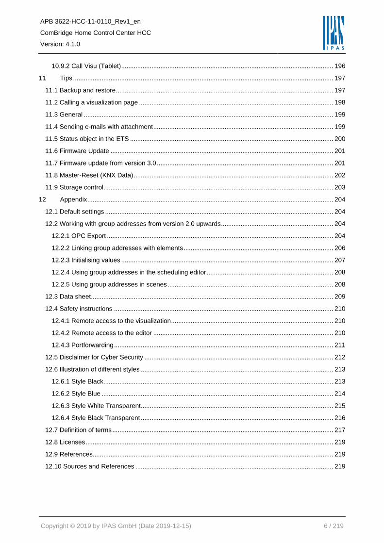
1.4 Concept overview
The editors (Editor / Smart Editor) are opened with the integrated Connection Manager. This is based on
the Adobe AIR application, with which web applications can be downloaded and run directly on the desktop
as an ordinary program. This will combine the benefits of desktop applications with those of web
applications.
For editing and configuration of the central
functions
For creating smart or tablet visualizations
Each visualization page is called up via a web address in a standard browser. The main component of this
web address is the IP address of the ComBridge HCC configured in the ETS: "http://<IP>/…".
The applications are selected via an appropriate extension of the URL.
APB 3622-HCC-11-0110_Rev1_en
ComBridge Home Control Center HCC
Version: 4.1.0
Copyright © 2019 by IPAS GmbH (Date 2019-12-15) 12 / 219
Exemple: Standard IP address: 192.168.1.133.

APB 3622-HCC-11-0110_Rev1_en
ComBridge Home Control Center HCC
Version: 4.1.0
Copyright © 2019 by IPAS GmbH (Date 2019-12-15) 13 / 219
2 Security
The ComBridge HCC version 4.0 or higher supports encrypted HTTPS connections. HTTPS (Hyper Text
Transfer Protocol Secure) is displayed in the URL if a website is secured by an SSL certificate. To ensure
secure access to the device, it is recommended to purchase certificates from a certificate authority. These
certificates can then be loaded into the ComBridge HCC See also chapter: 12.5 Disclaimer for Cyber
Security. These certificates will then be recognized as valid by all current browsers.
The ComBridge HCC can also create new certificates itself. Since these certificates were not issued by a
certification authority, they are not recognized as valid by the browsers and there are browser-dependent
error messages. In addition, cyber attacks can be detected worse or not at all. For these reasons, this
procedure is not recommended. A self-signed certificate is pre-installed. The browser window displays
buttons similar to "Advanced" and "Continue insecure" that allow you to bypass the displayed security
warning and continue with the unsecured loading of the website. See also Chapter: 12.4 Safety
instructions.
Note: To manage the certificates, it is very important that the time in the device is set correctly. It must
therefore be ensured that the time is set correctly either via a time server on the Internet or via KNX, see
chapter: 3.1 ETS Download.
2.1 Web page visit via HTTPS
The web visualization is called by default via port 443 (HTTPS). For internal purposes, the connection can
also be activated via port 80 (HTTP). For this, the setting must be adjusted on the configuration page
("https: // <ip> /config.php", see chapter: Fehler! Verweisquelle konnte nicht gefunden werden. Fehler!
Verweisquelle konnte nicht gefunden werden..
Note: For external connections via the Internet, only a secure connection via HTTPS must be used. All
configuration pages to change the passwords are only accessible via HTTPS.
2.2 Authentication
The ComBridge HCC provides a standard DIGEST authentication. For this purpose, a standard window for
entering a username and a password is displayed in the browser.

APB 3622-HCC-11-0110_Rev1_en
ComBridge Home Control Center HCC
Version: 4.1.0
Copyright © 2019 by IPAS GmbH (Date 2019-12-15) 14 / 219
2.3 Password-Management
The visualization views and the editors necessary for the configuration should avoid unwanted requests
from the WLAN or the Internet, e.g. via DynDNS access with a port forwarding, well sealed off. The
respective password protection of the ComBridge HCC must be used for this purpose! By default, a
password security rule should be met, so that only passwords with at least 8 characters, uppercase and
lowercase letters, at least one digit and special characters are accepted. Choose a random password,
without repetition or personal reference. Change your password regularly.
2.3.1 Initial definition of the passwords in the ETS
The default editor password "HCC" in the ETS should be changed before the ETS download. A password
for the visualization pages is not assigned in the ETS. It is recommended to change the pre-set passwords
in the ETS before downloading. The password length is max. 8 characters (depending on the national
language). Number and special characters are accepted.
The passwords defined in the ETS must be changed again at the first time.

APB 3622-HCC-11-0110_Rev1_en
ComBridge Home Control Center HCC
Version: 4.1.0
Copyright © 2019 by IPAS GmbH (Date 2019-12-15) 15 / 219
2.3.2 Visualization password
If a password for the visualization has been assigned in the ETS, the user is prompted to assign a new
password when the visualization is called. It is automatically directed to the password page ("https: // <ip>
/visu_password.php"). This page is only accessible via the encrypted HTTPS connection.
If no visualization password was assigned during parameterization in the ETS, the corresponding field
(existing password) remains empty when confirming the new password. If a password was entered during
the ETS configuration, this new password is required to confirm the password change. The new password
is required for later access of the visualization pages via web browser and replaces the ETS password.
The default user for the visualization is "visu". This name
can not be changed. By default, a password security rule
should be met, so that only passwords with at least 8
characters, uppercase and lowercase letters, at least one
digit and special characters are accepted. However, the
need to meet this requirement can be disabled by disabling
the checkbox on the page. However, this procedure is not
recommended.
Passwords can also be changed subsequently via the central configuration page ("https: // <ip>
/config.php") of the ComBridge HCC. The current password is required to confirm the change.
Note: If the operation takes place exclusively internally in a secure network, the password for the
visualization can also be switched off completely on request. The input fields can remain empty for this. An
empty password leads to a direct entry into the visualization without password prompting (direct login).
This procedure is not recommended.
2.3.3 Configuration password (Editor)
The editor password is required to call the editor and the central configuration page ("https: // <ip>
/config.php") of the ComBridge HCC. The default user for configuration tasks is "editor". This name can not
be changed. When the editor is first called or the configuration page, the existing password corresponds to
that from the ETS configuration. If this was not changed during the ETS configuration, the default password
is "HCC". Again, a password policy is checked by default, which was explained in the previous chapter. The
configuration also includes the firmware update (Chapter: 11.6 Firmware Update), which is only possible as
user "editor".

APB 3622-HCC-11-0110_Rev1_en
ComBridge Home Control Center HCC
Version: 4.1.0
Copyright © 2019 by IPAS GmbH (Date 2019-12-15) 16 / 219
The username of the configuration pages can not be
changed and is defined as "editor" as in the visualization.
When re-assigning the password, the same safety
recommendations apply as with the assignment of the
visualization password.
The editor password can also be changed later via the
central configuration page ("https: // <ip> /config.php"). The
current password is needed for the change.
2.3.4 Additional passwords
Apart from the visualization and the configuration, passwords for the Smart Editor and for the API Interface
can still be assigned. The same safety recommendations apply as with the other passwords.
2.3.4.1 Smart Editor Password
The Smart Editor always has the default editor password, which was previously defined in the ETS. At the
first call, the user is prompted to assign a new password for the Smart Editor. It is also possible to redefine
this password separately via the central configuration page ("https: // <ip> /config.php") page.
2.3.4.2 API Interface
The API interface with the predefined user "apiuser" does not have a valid password by default. This
password must be changed immediately when using this interface via the central configuration page.
2.3.5 Change passwords
Passwords can be changed at any time. For this, the central configuration page ("https: // <ip> /config.php")
of the ComBridge HCC is called. The changes are made in the "Password" area. For a password change,
the knowledge of the last password is always required.
2.3.6 Reset passwords
If the passwords of the device should or must be reset, it is necessary to perform a master reset on the
device. This process is described in detail in Chapter: 11.8 Master-Reset (KNX Data). After the master
reset, a first ETS download must be carried out. After this download, the passwords are set according to
the ETS inputs for the visualization, the editor and the smart editor. The user is prompted to change the
passwords as in the first call.

APB 3622-HCC-11-0110_Rev1_en
ComBridge Home Control Center HCC
Version: 4.1.0
Copyright © 2019 by IPAS GmbH (Date 2019-12-15) 17 / 219
2.4 Certificates
Digital certificates ensure security on the Internet. An SSL Certificate is a small data file that digitally binds
a cryptographic key to the details of an organization or device. When installed on a web server, it activates
the security lock and https protocol (via port 443) and enables secure connections from a web server to a
browser. They authenticate the identity of IP devices and other encrypted sites. Each time you visit the
ComBridge HCC website, your browser receives a certificate. Only with this certificate can a tap-proof,
encrypted connection be established between your PC and the ComBridge HCC. The procedure is as
follows:
• A browser tries to establish a connection to a website secured with SSL.
• The browser requests the identity of the web server.
• The server sends a copy of its SSL certificate to the browser.
• The browser checks whether the certificate is trustworthy. If this is the case, it sends a message to
the server.
• The server then sends back a digitally signed confirmation to initiate an SSL-encrypted session.
For more information about certificates and how they work, see:
https://en.wikipedia.org/wiki/Public_key_certificate.
2.4.1 Loading a customer-specific certificate
The ComBridge HCC supports the loading of customer-specific certificates. Certificates can be loaded via
the central configuration page "config.php". Via the "Certificates" tab, the certificate and the appropriate
private key are loaded. After loading, this certificate must be activated. See also chapter: 5.6 Certificates.
Note: To ensure secure access to the device, it is recommended to purchase certificates from a certification
authority. Certification authorities are e.g. Verisign https://www.verisign.com/ or Geotrust
https://www.geotrust.com/de/ssl/. These certificates can then be loaded into the ComBridge HCC. These
certificates will then be recognized as valid on all current browsers.
Note: Alternatively, certificates can also be loaded directly via "https://<ip>/upload_cert.php". This page can
be used to load a certificate and the appropriate private key. This requires authentication with the editor
password. The activation then takes place after loading the certificate.

APB 3622-HCC-11-0110_Rev1_en
ComBridge Home Control Center HCC
Version: 4.1.0
Copyright © 2019 by IPAS GmbH (Date 2019-12-15) 18 / 219
2.4.2 Create a new certificate
The ComBridge HCC is also able to create a new certificate. The created certificate is self-signed and can
therefore not be verified on the Internet. A certificate already exists in the delivery state. If desired by the
customer, this certificate can be replaced by a newly created certificate. This is done via the ComBridge
HCC configuration page under the "Certificates" tab. The creation of certificates by the ComBridge HCC is
not recommended for security reasons. See also Chapter: 5.6 Certificates.
Note: As these certificates were not issued by a certification authority, they are not recognized as valid by
the browsers and there are browser-dependent error messages. In addition, cyber attacks can be detected
worse or not at all. For these reasons, this procedure is not recommended. For security reasons, a
certificate must be created in the local network and should not be created via a remote connection. A new
certificate should be created manually under the following aspects.
- Changing the IP address or the network settings
- Changing the DynDns address
- Changing the Host Name
Note: A newly generated certificate has a term of 5 years and must then be renewed.
2.4.3 Certificate query in the browser
The SSL protocol is used for the certificate query. If a certificate is used by a Certificate Authority, no
further action is required.
If a certificate created by the ComBridge HCC itself is used, authenticity cannot be verified. When the
visualization is called by a browser, a message is therefore displayed which must be acknowledged for
further work with the ComBridge HCC. This is displayed differently for each browser. For security reasons,
the use of self-created certificates is not recommended.
Note: When using a customer-specific certificate, the authenticity and validity of the certificate can be
verified by the browser on the Internet. In this case there are no further hints which have to be
acknowledged.

APB 3622-HCC-11-0110_Rev1_en
ComBridge Home Control Center HCC
Version: 4.1.0
Copyright © 2019 by IPAS GmbH (Date 2019-12-15) 19 / 219
3 Getting started
In a first step, the device is supplied with 24 VDC voltage and connected to the KNX. The basic settings are
made with the ETS. This includes:
• Assign KNX physical address
• Set IP parameters, incl. Gateway and DNS server
• Set timer (default is an NTP server on the Internet)
Note: In principle, an ETS configuration and download must first be performed. Password-protected pages
can not be accessed without a previously performed ETS download. Corresponding error messages
appear as follows:

APB 3622-HCC-11-0110_Rev1_en
ComBridge Home Control Center HCC
Version: 4.1.0
Copyright © 2019 by IPAS GmbH (Date 2019-12-15) 20 / 219
3.1 ETS Download
The ComBridge HCC is configured and loaded like every KNX device with the ETS. The detailed
description of the objects and parameters is explained in chapter: 4 ETS configuration below.
Basically, the following settings must be observed:
• Correct setting of network parameters
• Correct setting of the time (slave or master)
It is recommended to use a fixed IP address to ensure that the HCC is always reachable via this IP
address.
In addition, make sure that the subnet mask is set to at least 255.255.255.0.
To ensure an external connection to the Internet, for example, to reach a time server or to allow e-mail
delivery, the DNS server and the gateway must be set to the address of the DSL router.
The setting of the time in the HCC is very important, so that the time programs and also the Chart module
work correctly.
Basically, it is possible to synchronize the time from the KNX, provided there is a real-time clock in the
KNX. In this configuration, the HCC operates as a "slave" and must regularly receive the time via KNX via
the objects and their group addresses.
It is recommended to synchronize the time via an Internet NTP time server. These are the default settings
in the ETS parameters.
Note: In this case, the DNS server and the gateway must be entered correctly in the ETS parameters. It is
important to note that basically after an ETS download, the password must be changed both for the editor
and for the normal visualization, see chapter: 2.3 Password-Management.

APB 3622-HCC-11-0110_Rev1_en
ComBridge Home Control Center HCC
Version: 4.1.0
Copyright © 2019 by IPAS GmbH (Date 2019-12-15) 21 / 219
3.2 Change Passwords
After the ETS download, the user is prompted to change the password. To change a password always
requires the knowledge of the last password. After the ETS download, the existing password corresponds
to that from the ETS configuration. See chapter: 2.3.1 Initial definition of the passwords in the ETS .
The default user for the visualization is "visu". This
name can not be changed. By default, a password
security rule should be met, so that only passwords
with at least 8 characters, uppercase and lowercase
letters, at least one digit and special characters are
accepted. However, the need to meet this
requirement can be disabled by disabling the
checkbox on the page. However, this procedure is
not recommended. All password management
information is described in Chapter: 2.3 Password-
Management.
Note: If the operation takes place exclusively internally in a secure network, the password for the
visualization can also be switched off completely on request. The input fields can remain empty for this. An
empty password leads to a direct entry into the visualization without password prompting (direct login).
This procedure is not recommended.
3.3 Calling graphical editor
As of version 4, the editor is no longer called as a Flash plugin within a browser, but as a stand-alone
program. For this, the Adobe AIR package must be installed on the computer. In order to allow multiple
versions of a HCC to be edited with the corresponding editor, a so-called Connection Manager is installed
which, after checking the firmware, starts the correct editor.
Installation of the Connection Manager is described in the next chapter: 3.4 Installation Connection
Managers.

APB 3622-HCC-11-0110_Rev1_en
ComBridge Home Control Center HCC
Version: 4.1.0
Copyright © 2019 by IPAS GmbH (Date 2019-12-15) 22 / 219
3.4 Installation Connection Managers
When used for the first time, this tool can be loaded directly from the device. For this the page
http://<ip>/editor.php is called, or the tool can be loaded on the configuration page, see configuration
page https://<ip>/config.php.
The installation package for the Connection Manager is copied to the PC, depending on the browser,
usually in the download directory. After starting the installation, the following message appears:
Important note: To use the Connection Manager and the editor, the Adobe AIR package must be
installed. The free download is available at www.adobe.com, or it is automatically installed over the
Internet when the Connection Manager is installed. Adobe AIR is required to use the application. If this is
not already available on the computer, it will be installed directly in this setup. For this, the delivery
conditions are displayed and must be accepted. After installation, if activated in the query, a shortcut icon
appears on the desktop.

APB 3622-HCC-11-0110_Rev1_en
ComBridge Home Control Center HCC
Version: 4.1.0
Copyright © 2019 by IPAS GmbH (Date 2019-12-15) 23 / 219
The Connection Manager launches with a user interface to connect to an HCC:
In einem zweiten Schritt wird das Passwort abgefragt. Im Anschluss wird der aktuelle Editor geladen und
aufgerufen.
For security reasons, the validity of the certificate must be confirmed with "Yes":
The configuration and use of the editor is explained in detail in chapter: 6 Editor.

APB 3622-HCC-11-0110_Rev1_en
ComBridge Home Control Center HCC
Version: 4.1.0
Copyright © 2019 by IPAS GmbH (Date 2019-12-15) 24 / 219
Important note: To use the Connection Manager and the Editor, no proxy must be configured in the
system and / or in Internet Explorer. If a proxy has been configured and it cannot be switched off, an
exception must be entered for the IP address of the device.

APB 3622-HCC-11-0110_Rev1_en
ComBridge Home Control Center HCC
Version: 4.1.0
Copyright © 2019 by IPAS GmbH (Date 2019-12-15) 25 / 219
4 ETS configuration
This chapter describes the ETS configuration in detail.
4.1 Parameter
Parameter Settings
Device name (max. 30 char)
Use this parameter to name the device
Method of IP address assignment Manual entry Via DHCP server
The IP address can either be entered manually or defined automatically via DHCP
Query is started following a bus reset in: 10 seconds 20 seconds 30 seconds 1 minute 2 minutes 3 minutes 4 minutes 5 minutes
Use this parameter to set the time after which you want to query status objects following a bus reset
Time delay between queries 200 milli seconds 500 milli seconds 1 second 2 seconds
Use this parameter to set the time delay between queries
Webserver port 80
This parameter defines the port number of the integrated web server. The default setting is port number 80
Password for visualisation
Use this parameter to set the password for the web visualisation. By default no password is defined. You can enter up to 8 characters (0-9,A-Z). No distinction is made between capital and lower case letters.
Editor password HCC
Use this parameter to set the editor password for the web visualisation. By default no password is defined. You can enter up to 8 characters (0-9,A-Z). No distinction is made between capital and lower case letters.
APB 3622-HCC-11-0110_Rev1_en
ComBridge Home Control Center HCC
Version: 4.1.0
Copyright © 2019 by IPAS GmbH (Date 2019-12-15) 26 / 219
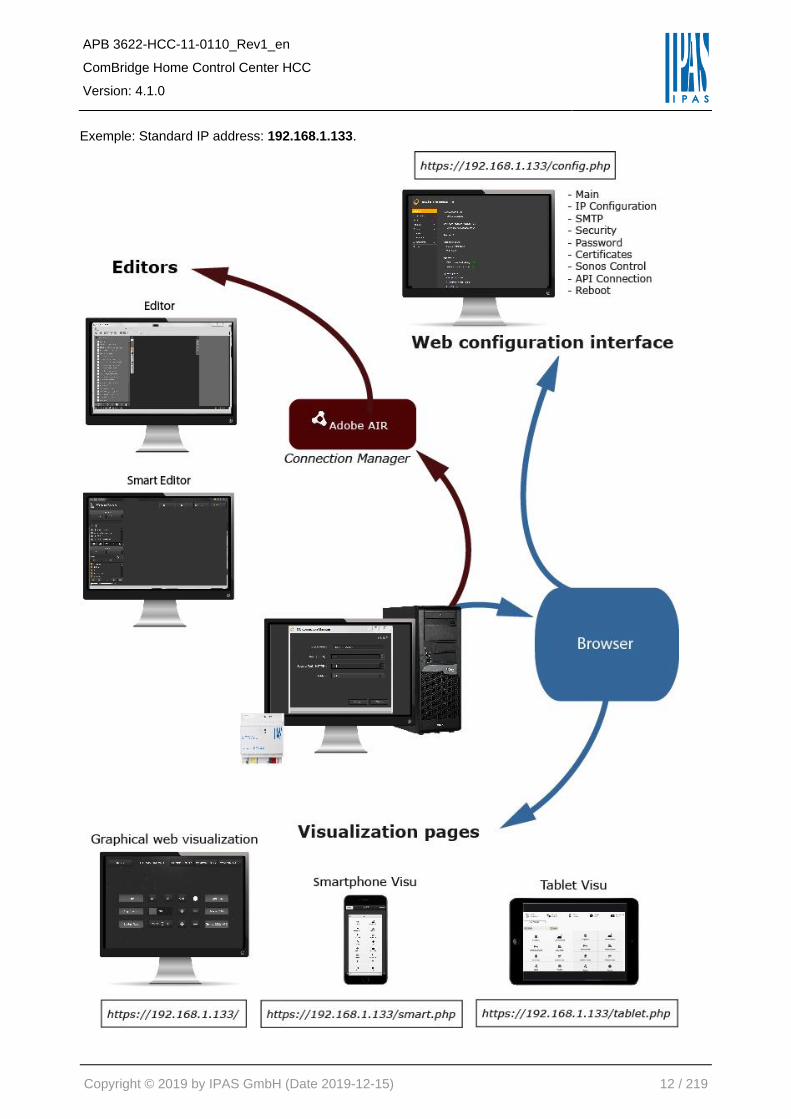
4.2 Network Settings
Parameter Settings
IP-address / 1. Byte 192
IP-address / 2. Byte 168
IP-address / 3. Byte 1
IP-address / 4. Byte 133
This parameter is used for the standard IP address of the ComBridge HCC. If DHCP mode was selected, the address is permanently overwritten by the address assigned by the DHCP server. After changing the ip address a new certificate should be created manually, see Fehler! Verweisquelle konnte nicht gefunden werden. Fehler! Verweisquelle konnte nicht gefunden werden.
Subnet Mask / 1. Byte 255
Subnet Mask / 2. Byte 255
Subnet Mask / 3. Byte 255
Subnet Mask / 4. Byte 0
This parameter is used for the standard IP subnet mask of the ComBridge HCC. If DHCP mode was selected, the mask is permanently overwritten by the address assigned by the DHCP server. If the device is configured without DHCP server (setting fixed IP address), the device must have the correct subnet mask for it to function properly.
IP-address Default Router / 1. Byte 192
IP-address Default Router / 2. Byte 168
IP-address Default Router / 3. Byte 1
IP-address Default Router / 4. Byte 1
The standard router is used to send telegrams which are addressed to a PC outside of the local network. If DHCP mode is selected, the address is permanently overwritten by the DHCP-server. If the DHCP server itself does not transmit an address for a router, it is assumed that no router is to be used. If you want to configure the device without standard router, please use the pre-set (invalid) address (0.0.0.0)
DNS server address / 1. Byte 192
DNS server address / 1. Byte 168

APB 3622-HCC-11-0110_Rev1_en
ComBridge Home Control Center HCC
Version: 4.1.0
Copyright © 2019 by IPAS GmbH (Date 2019-12-15) 27 / 219
DNS server address / 1. Byte 1
DNS server address / 1. Byte 1
This parameter is used for the standard IP subnet mask of the DNS server. If DHCP mode was selected, the mask is permanently overwritten by the address assigned by the DHCP server. If the device is configured without DHCP server (setting fixed IP address), the device must have a DNS server address to enable name resolution, for example to access a time server. Usually the standard gateway is also the DNS server.

APB 3622-HCC-11-0110_Rev1_en
ComBridge Home Control Center HCC
Version: 4.1.0
Copyright © 2019 by IPAS GmbH (Date 2019-12-15) 28 / 219
4.3 Date/Time
Parameter Settings
Time zone (GMT-5:00) Eastern (USA/Canada) (GMT-6:00) Central (USA/Canada) (GMT-7:00) Mountain (USA/Canada) (GMT-8:00) Pacific (USA/Canada) (GMT+1:00) Brussels,Berlin,Rome,Stockholm,Vienna, etc.
The parameter Time zone ensures the adjustment to the local area. Please see above for some of the currently available options.
Summer time – winter time change Active Inactive
This parameter defines whether the time is automatically changed from summer to winter time and vice versa.
Clock synchronisation Master (HCC -> KNX) Slave (KNX -> HCC)
The following synchronisation options are available: Synchronisation via the device (Master Mode). In this mode the time can be synchronised via IP and a time server. Synchronisation via KNX (Slave Mode). In this mode the internal clock is synchronised via telegrams from the KNX.
Selecting the date/time object Date and time object Date/time object combines both types
The time and date information can be sent via 2 different data types: Date and time object (DPT10, DPT11) or a combined object (DPT19).
Time server 1 (SNTP) Time server 2 (SNTP)
To synchronise the real-time clock, the time server (SNTP) can be queried in regular intervals
Sending interval for date/time information 1 minute 2 minutes 5 minutes 10 minutes 30 minutes 1 hour 2 hours 4 hours 8 hours 12 hours 24 hours
Use this parameter to set the sending interval for the transmission of date and time information to the KNX.

APB 3622-HCC-11-0110_Rev1_en
ComBridge Home Control Center HCC
Version: 4.1.0
Copyright © 2019 by IPAS GmbH (Date 2019-12-15) 29 / 219
4.4 General Objects 1-5
The following communication objects can be selected:
Object Object name Function Type Flags
1 Device status Status 4 Byte CTR
Data type: 4 Byte
2 Date (DPT 11.001) Datum 3 Byte CTR
Data type: 11.001
2 Date (DPT 11.001) Datum 3 Byte CUW
Data type: 11.001
3 Time (DPT 10.001) Time 3 Byte CTR
Data type: 10.001
2 Date (DPT 11.001) Date 3 Byte CUW
Data type: 11.001
4 DateTime (DPT 19.001)
DateTime 8 Byte CTR
Data type: 19.001
4 DateTime (DPT 19.001)
DateTime 8 Byte CUW
Data type: 19.001
5 Scene Scene 8 Byte CUW
Data type: 1 Byte

APB 3622-HCC-11-0110_Rev1_en
ComBridge Home Control Center HCC
Version: 4.1.0
Copyright © 2019 by IPAS GmbH (Date 2019-12-15) 30 / 219
4.5 Parameters Objects 6-250
Parameter Settings
Object 6 Text 6
Use this parameter to describe object 6. This configuration is possible for all objects.
Note: The name can also be imported later on in the Editor via an ESF import.
Data type No object 1 bit 1 Byte 0..100% 1 Byte unsigned 1 Byte signed 2 Byte unsigned 2 Byte signed 2 Byte float 4 Byte unsigned 4 Byte signed 4 Byte float 14 Byte text
This parameter sets the data type of the communication object. This configuration is possible for all objects.
Activate query on start-up no yes
This parameter defines for each object whether or not to send a query to the bus when the device is started.
For this definition, the corresponding communication object is displayed in the ETS in order to be
connected to a group address.

APB 3622-HCC-11-0110_Rev1_en
ComBridge Home Control Center HCC
Version: 4.1.0
Copyright © 2019 by IPAS GmbH (Date 2019-12-15) 31 / 219
4.6 Objects 6-255
Possible object times for Object 6 to 255. The function and type are defined in the ETS configuration.
Object Object name Function Type Flags
6 Object 6 Binär 1 Bit AKSÜ
Data type: 1 bit
6 Object 6 0..100% 1 Byte UCWT
Data type: 1 Byte 0..100%
6 Object 6 unsigned 1 Byte UCWT
Data type: 1 Byte unsigned
6 Object 6 signed 1 Byte UCWT
Data type: 1 Byte signed
6 Object 6 unsigned 2 Byte UCWT
Data type: 2 Byte unsigned
6 Object 6 signed 2 Byte UCWT
Data type: 2 Byte signed
6 Object 6 float 2 Byte UCWT
Data type: 2 Byte float
6 Object 6 unsigned 4 Byte UCWT
Data type: 4 Byte unsigned
6 Object 6 signed 4 Byte UCWT
Data type: 4 Byte signed
6 Object 6 float 4 Byte UCWT
Data type: 4 Byte float
6 Object 6 text 4 Byte UCWT
Data type: 4 Byte Text

APB 3622-HCC-11-0110_Rev1_en
ComBridge Home Control Center HCC
Version: 4.1.0
Copyright © 2019 by IPAS GmbH (Date 2019-12-15) 32 / 219
Object Object name Function Type Flags
255 Object 6 Binär 1 Bit AKSÜ
Data type: 1 bit
255 Object 6 0..100% 1 Byte UCWT
Data type: 1 Byte 0..100%
255 Object 6 unsigned 1 Byte UCWT
Data type: 1 Byte unsigned
255 Object 6 signed 1 Byte UCWT
Data type: 1 Byte signed
255 Object 6 unsigned 2 Byte UCWT
Data type: 2 Byte unsigned
255 Object 6 signed 2 Byte UCWT
Data type: 2 Byte signed
255 Object 6 float 2 Byte UCWT
Data type: 2 Byte float
255 Object 6 unsigned 4 Byte UCWT
Data type: 4 Byte unsigned
255 Object 6 signed 4 Byte UCWT
Data type: 4 Byte signed
255 Object 6 float 4 Byte UCWT
Data type: 4 Byte float
255 Object 6 text 4 Byte UCWT
Data type: 4 Byte Text

APB 3622-HCC-11-0110_Rev1_en
ComBridge Home Control Center HCC
Version: 4.1.0
Copyright © 2019 by IPAS GmbH (Date 2019-12-15) 33 / 219
5 Web-Configuration page
The configuration page shows the most important settings and allows you to set various properties.
For this purpose, the menu sub-items are described in detail below.
The configuration page can be accessed via HTTPS://<ip>/config .php.
5.1 Overview
All relevant information is displayed on the "General" tab. Here it is also possible to load a new firmware
into the device. All "links" are marked with the character .
Display of the installed firmware version and the update
function for a new firmware. See Chapter: 11.6 Firmware
Update.
Display of the installed version of the Connection
Manager and the update function for updating the
Connection Manager.
Display of the current date and time on the ComBridge
HCC.
Checking the status of the tunnel and object connection.
The red indication means inactive, the green indicates
active.
Display of the available and used flash memory.
Display of the available RAM memory and its use.
To load the editor, the Connection Manager is required on the PC. This can be loaded here and then
installed on the PC, see also chapter: 6 Editor.

APB 3622-HCC-11-0110_Rev1_en
ComBridge Home Control Center HCC
Version: 4.1.0
Copyright © 2019 by IPAS GmbH (Date 2019-12-15) 34 / 219
5.2 IP Configuration
In this tab the IP settings are displayed and configured.
IP: Displays the network address specified in the ETS.
Mask: Displays the address of the IP subnet mask
specified in the ETS.
Gateway: Displays the gateway address specified in the
ETS.
DNS: Displays the DNS address specified in the ETS.
DynDNS: Entry of the domain name registered with a
DDNS service. See also Chapter: 12.7 Definition of
terms.
Host Name: In Microsoft networks the Host Name can also be used to address the device with this name.
A change is possible and becomes active when the system is restarted. See also Chapter: 4 ETS
configuration.
Note: If the Host Name or DynDNS is changed, a new certificate should then be created manually, see
Chapter: 2.4 Certificates. The certificate is supplemented by entries in the "Certificate Subject Alt Name".
This avoids additional warnings when validating the certificate.
5.3 SMTP
Starting with firmware version 4, the SMTP configuration is no longer carried out in the Web Editor, but is
called via this tab on the configuration page "https://<ip>/config.php".
Host IP: Name of the outgoing e-mail server
(e.g. [email protected]).
Port: Port of the SMTP server (e.g. 587).
Sender: Sender of the e-mail.
SMTP Authentication: If authentication is required, this
option must be activated. A new window opens in which
the user name and password are entered. No SSL or
TTLS can be selected for authentication.
Note: It is strongly discouraged to use an SMTP configuration without authentication and TLS encryption.
To check the specifications and error-free execution of an e-mail, press the "Test" key. A test-e-mail will be
sent to the sender.

APB 3622-HCC-11-0110_Rev1_en
ComBridge Home Control Center HCC
Version: 4.1.0
Copyright © 2019 by IPAS GmbH (Date 2019-12-15) 35 / 219
Example Hotmail
Host IP: The address of the Hotmail SMTP server is: smtp.live.com.
Port: The required Hotmail SMTP port is 587.
From e-mail: Your full Hotmail address (for example, [email protected]).
Authenticate SMTP: Enable this option.
User: Hotmail SMTP username: Your full Hotmail address (e.g. [email protected]).
Password: The stored Hotmail password.
Authentication: TTLS
Note: Gmail requires special security procedures that are not supported in ComBridge HCC. To still use
Gmail as your provider, you must configure your Gmail account accordingly. See also
https://support.google.com/accounts/answer/6010255?hl=en and
https://www.google.com/settings/security/lesssecureapps.
5.4 Security
Under this sub-item the following security properties can be activated or deactivated. See also Chapter:
2 Security.
Status/Activation Password protection in the local
network: With this setting, password protection in local
networks can be cancelled. This allows all devices in
the same subnet to access the visualization without
password query. Requests from another subnet or the
Internet are only accepted with query.
Status/Activation iFrame usage: By default, the visualization is not allowed to be displayed in a window
of another server. However, this setting can also be activated for a corresponding application.
Status/activation of HTTP connection: unencrypted HTTP connection is preset. For security reasons it is
not recommended to allow unencrypted HTTP connections.
Status/Activation of the KNXnet/IP tunnel connection: The KNXnet/IP tunnel can be deactivated with
this setting for security reasons. The tunnel is active by default.
Status/Activation of the KNXnet/IP object connection: The KNXnet/IP object server can be deactivated
with this setting for security reasons. The tunnel is active by default.
Note: The current editor password is required to confirm the changes. See Chapter: 2.3.3 Configuration
password (Editor).

APB 3622-HCC-11-0110_Rev1_en
ComBridge Home Control Center HCC
Version: 4.1.0
Copyright © 2019 by IPAS GmbH (Date 2019-12-15) 36 / 219
5.5 Password
Passwords can be assigned and changed under this sub-item. See also Chapter: 2.3 Password-
Management.
The default user for the visualization is "visu". This
name cannot be changed. By default a password
security rule should be met so that only passwords with
at least 8 characters, upper and lower case, at least
one digit and special characters are accepted.
However, the need to meet this requirement can be
turned off by disabling the checkbox on the page. It is
not recommended to deactivate this function and to use
insecure passwords. See also Chapter: 2.3 Password-
Management.
Note: The same procedure applies to the passwords for the Editor and the Smart Editor.
Note: To change a password you always need to know the last password.

APB 3622-HCC-11-0110_Rev1_en
ComBridge Home Control Center HCC
Version: 4.1.0
Copyright © 2019 by IPAS GmbH (Date 2019-12-15) 37 / 219
5.6 Certificates
In order to offer an SSL-encrypted connection to your server, you need an SSL certificate. In this sub-item
you have the possibility to create a new certificate or to load your own certificate. See also Chapter: 2.4
Certificates.
After creating a new certificate, the new certificate
must be accepted in the browser.
It is also possible to download your own certificate. The certificate must be loaded in the form of a .pem file.
The private key is then loaded in the form of a .pem file. The certificate and the private key are activated via
the "Activate" button.
Note: It is not recommended to use self-signed certificates.
Note: It is recommended to purchase and use certificates from a certification authority such as Verisign
https://www.verisign.com/ or Geotrust https://www.geotrust.com/en/ssl/.

APB 3622-HCC-11-0110_Rev1_en
ComBridge Home Control Center HCC
Version: 4.1.0
Copyright © 2019 by IPAS GmbH (Date 2019-12-15) 38 / 219
5.7 SONOS Module
The company SONOS develops and produces active loudspeaker systems and HiFi components that are
wirelessly networked via WLAN. With the ComBridge HCC it is possible to control the Sonos loudspeakers
directly. Basic settings of the SONOS module are made in the editor. See Chapter: 8.9 Sonos Control.
The Configuration Manager of the ComBridge HCC allows you to call up a previously defined playlist. This
is called with the name stored in the SONOS favorites. In order to be able to change this trigger online
without the editor, it is possible to change the assignment to the triggers via this page and a drop-down box
displaying all configured favorites.

APB 3622-HCC-11-0110_Rev1_en
ComBridge Home Control Center HCC
Version: 4.1.0
Copyright © 2019 by IPAS GmbH (Date 2019-12-15) 39 / 219
5.8 API Connection
API is the abbreviation for Application Programming Interface. An API is a program interface through which
project planners and developers can access the functions of an application. In contrast to a user interface,
in an API it is not a human being who communicates with a system, but applications communicate directly
with each other.
Status/Activation of the API Connection: By
activating the API Connection, functions such as voice
control in the ComBridge HCC can be used. The
interface is deactivated by default. To use voice
control, the API-interface must be activated. See also
Chapter: 9 Voice Control.
The API-interface with the predefined user "apiuser"
does not have a valid password by default. This
setting must be changed immediately when using this
interface via the central configuration page. To
change the password, the current editor password is
required. It is strongly recommended to assign a
secure password for the API-interface. See Chapter:
2.3.5 Change passwords.
5.8.1 Voice control
Voice control systems such as ALEXA and GOOGLE HOME are supported from firmware version 4 via a
third-party app from 1HOME. The following steps are necessary for activation:
5.8.2 Registering with the service provider 1HOME
After a login to 1HOME has taken place, the ComBridge HCC can be connected via a fixed IP address or a
DynDNS entry and a port number. This port number must be linked in your DSL router to the internal IP
address of the ComBridge HCC (Port Forwarding). See also Chapter: 12.4.3 Portforwarding. For
authentication, the previously defined password and the user "apiuser" must be entered. The configuration
is then loaded from the ComBridge HCC into your 1HOME account. To activate the interfaces in ALEXA or
GOOGLE HOME, please follow the description on the 1HOME website. If you have any questions, please
contact the 1HOME-Support: https://www.1home.io.

APB 3622-HCC-11-0110_Rev1_en
ComBridge Home Control Center HCC
Version: 4.1.0
Copyright © 2019 by IPAS GmbH (Date 2019-12-15) 40 / 219
Note: The 1HOME service is not free and the user must create an account with 1HOME. More information
can be found on the 1HOME website: https://www.1home.io.
Note: ALEXA and GOOGLE HOME are registered trademarks. See Chapter: 12.9 References.Zugriff über
Passwort schützen
5.8.3 Protecting access via password
API-interface with the predefined user "apiuser" does not have a valid password by default. This setting
must be changed immediately when using this interface via the central configuration page. To change the
password, the current editor password is required. See also chapter: 2.3.4 Additional passwords.
5.8.4 Activating individual functions for voice control
In the Smart Editor, each function can be released
separately for access via Voice Control. The checkbox
"Allow API-access" must be checked. The identifier
and the higher-level menu item are later used for
voice control as name and room.
5.9 Restart
Here you have the possibility to restart the device.

APB 3622-HCC-11-0110_Rev1_en
ComBridge Home Control Center HCC
Version: 4.1.0
Copyright © 2019 by IPAS GmbH (Date 2019-12-15) 41 / 219
6 Editor
The editor is started via the tool "HCC Connection Manager", see chapter : 3.4 Installation Connection
Managers.
6.1 Editor User Interface
Upon delivery, the pre-set language is English. To change the
language, please open the selection window in the menu Config
→ Select Language. Please select the required language and
close the window. The selected language only becomes active
after the Editor is re-started. Please close the Editor and log-in
again.
The figure below shows the ComBridge HCC Editor interface. Enter http://“assigned IP address“/editor.php
in the web browser to load the page. At the top of the screen is the title bar of the main menu. Just below
the bar, you will see several icons representing the most important editing functions such as save, delete,
copy, cut, etc. In the centre of the screen, you will find the visualisation workspace. The functions menu is
located to the left and the properties menu to the right of the workspace.

APB 3622-HCC-11-0110_Rev1_en
ComBridge Home Control Center HCC
Version: 4.1.0
Copyright © 2019 by IPAS GmbH (Date 2019-12-15) 42 / 219
The tool bar
Save project
Generate Visualisation
Cut
Copy
Paste
Delete
Activate grit
Latch to the grid
Increase grid size
Reduce grid size
Bring to front
Send to back
Main menu functions in detail:
6.1.1 The File-Menu
New: Opens a new project page
Save: Saves any changes made to the project
Release: Generates a visualisation of the project in HTML format and
saves it in the ComBridge HCC
Export: The entire project is exported and saved on the PC/laptop.
Restore: The locally saved project is recovered and restored on the
ComBridge HCC
Import: ESF import or import of a visualisation page. To import group
addresses from the ETS, please use the ESF file (OPC export)
created with the ETS. A selection of character sets is available for
this purpose to import different characters such as Greek or Chinese.
A previously exported visualisation page, for example from a different
project, can also be imported.
Export: The current visualisation page can be exported.
Group address control: Shows how many of the 1000 possible group addresses are already in use.
Integrity check: Checks whether group addresses that are used multiple times, are potentially used with
different data types.
Reboot system: The HCC device will be re-started.
Exit: The Editor closes. We recommend you use this option before you terminate the software.

APB 3622-HCC-11-0110_Rev1_en
ComBridge Home Control Center HCC
Version: 4.1.0
Copyright © 2019 by IPAS GmbH (Date 2019-12-15) 43 / 219
6.1.2 The Edit Menu
Move to front: The selected element will be moved to the front.
Send to back: The selected element will be sent to the back.
Select all: All elements of the current page will be selected at once.
Unselect all: All elements of the current page will be unselected at once.
Cut: The selected element will be cut and stored on the clipboard.
Copy: The selected element will be copied and stored on the clipboard.
Paste: The selected element will be inserted at the position of the cursor.
Delete: Deletes the selected element
6.1.3 The View Menu
Toolbar: The top tool bar becomes visible/invisible.
Properties: Gives direct access to the selected elements
Pages: Shows the visualisation pages
Objects: Shows the communication objects
Virtual DP: Shows the existing variables
Components: Shows the visualisation components
6.1.4 The Module Menu
Time schedules: Access to the Editor module for schedules
Logic module: Access to the Editor module for logic functions
Scene Control: Access to the Editor module for scenes
Notification and alarm module: Access to the Editor module for alarm
settings
Chart module: Access to the configuration of data points for use in charts
Monitoring module: Configuration of data points for labelling.
TCP/UDP commands: Access to the Editor module for the configuration
of IP devices that are to be controlled remotely.

APB 3622-HCC-11-0110_Rev1_en
ComBridge Home Control Center HCC
Version: 4.1.0
Copyright © 2019 by IPAS GmbH (Date 2019-12-15) 44 / 219
6.1.5 The Configuration Menu
Select Language: Pre-sets the user language. The language only
becomes active after the device has been re-started.
Select Style: This option allows the user to select different image
styles which are stored on the device. See chapter: 11 Tips for more
details.
Restore default: The default settings and default parameters are
restored. The ETS parameters and IP configuration, however, remain
intact.
Disable autosave: Activate this option to disable autosaving the project (every minute).
Preferences: general system settings, see also chapter: 5 Web-Configuration page.
Astronomical configuration: Stores GPS data in order to correctly calculate the times for sunrise and
sunset. See chapter: 8.1.1 Astronomical calendar configuration.
6.1.6 The Help Menu
Offers links to the IPAS website or the online Wiki system.
The menu item System Info provides the user with information
about currently available memory space, the software version
and the length of time the device has been running since the last
start-up.

APB 3622-HCC-11-0110_Rev1_en
ComBridge Home Control Center HCC
Version: 4.1.0
Copyright © 2019 by IPAS GmbH (Date 2019-12-15) 45 / 219
6.2 Objects, virtual objects and group addresses
Three types of objects can be used in the Editor:
• communication objects
• virtual objects (variables)
• group addresses
Altogether 250 communication objects, 745 variables and up to 1000 group addresses are available.
Both object types can be called up via the tab of the tab Objects.
In the lower part of the object selection window is the object management area. By clicking on the
corresponding icons you can:
• Add objects
• Delete objects
• Copy objects
• Insert objects
The "Forward / Backward" icons navigate through the pages of existing objects.

APB 3622-HCC-11-0110_Rev1_en
ComBridge Home Control Center HCC
Version: 4.1.0
Copyright © 2019 by IPAS GmbH (Date 2019-12-15) 46 / 219
6.2.1 Group addresses
Group addresses are imported via esf import and listed in a tree view on the left hand side. Open the
configuration window of the group address via a double-click or via the context menu that appears following
a right mouse-click.
Name: You can use the name field to overwrite the name configured in the ETS.
Address: Shows the group address
Size: Data length (data format) of the group address
DPT: Data point type
SubDPT: Modifiable in the Editor to ensure correct display in the visualisation
Range: Here you can enter the value range for inputs (time schedules or scenes).
User Interface: In the HTML configuration pages, this input style is displayed.
Categories: Objects or group addresses can be sorted into categories.

APB 3622-HCC-11-0110_Rev1_en
ComBridge Home Control Center HCC
Version: 4.1.0
Copyright © 2019 by IPAS GmbH (Date 2019-12-15) 47 / 219
6.2.2 Communication objects
Communication objects are imported and represented by the parameters configured in the ETS application
program. Open the configuration window of the "object" via a double-click or via the context menu that
appears following a right mouse-click.
Name: You can use the name field to overwrite the name configured in the ETS.
Read on init: Read request, cannot be edited in the Editor.
DPT: Data point type defined in the ETS, cannot be edited in the Editor.
SubDPT: Modifiable in the Editor to ensure correct display in the visualisation.
Default value: Modifiable in the Editor so that you can work with a pre-defined value if no valid value exists
in the KNX.
Format Decimals: Modifiable in the Editor to define the number of decimal places that are to be displayed
for analogue values.
Group addresses: The group address defined in the ETS for this object, cannot be edited in the Editor.

APB 3622-HCC-11-0110_Rev1_en
ComBridge Home Control Center HCC
Version: 4.1.0
Copyright © 2019 by IPAS GmbH (Date 2019-12-15) 48 / 219
6.2.3 Virtual objects
The virtual objects allow the internal exchange of data and parameters between the visualization, alarm,
chart, monitoring, logic and schedule function module. To create a new virtual object, right-click in the list of
virtual objects. In the now opened window the following properties can be parameterized:
Name: Name of virtuel object
Display Name: Mask for a user-specific description, which is displayed in the online configuration pages.
DPT: DPT of your choice
SubDTP: The datapoint subtype is required to represent values in the visualisation
Default value: Default value of the variable before the current data has been assigned to the object
User Interface: In the HTML configuration pages, this input style is displayed.
Categories: Objects or group addresses can be sorted into categories.
6.2.4 Conflicts caused by different data points
Each time the application program is downloaded via
ETS, the Editor will check the data points assigned
by the ETS. If there is a difference between already
existing and newly assigned DTPs, the change needs
to be acknowledged.
If the change is acknowledged, the DTPs in all linked objects are updated. If the change is rejected, all
linked objects are de-activated. Once the Editor is re-started the same procedure is carried out again.

APB 3622-HCC-11-0110_Rev1_en
ComBridge Home Control Center HCC
Version: 4.1.0
Copyright © 2019 by IPAS GmbH (Date 2019-12-15) 49 / 219
6.2.5 Categories
To group data points in a meaningful way, categories can be created and the group addresses can be
assigned to these categories. In all windows in which the list of data points (group addresses) can be
selected, the categories can be used to help find group addresses faster.
Note: The "DTP Management" module is available for displaying, managing and editing the available data
points and for assigning categories. See chapter: 8.8 Overview of the data points.

APB 3622-HCC-11-0110_Rev1_en
ComBridge Home Control Center HCC
Version: 4.1.0
Copyright © 2019 by IPAS GmbH (Date 2019-12-15) 50 / 219
6.3 Creating a visualisation page
The first step to create a comprehensive visualisation is to generate a visualisation page ("page").
Visualizations with the HCC are always tied to a project. This page consists of a combination of images and
controls. When delivered, all pages of the sample project are displayed.
Note: The visualization always starts with the 1:index page. This will always be the starting point of your
visualization.
Pressing the right mouse button opens the context menu with the option "New page". This opens a new
page for editing in the Editor area. Creating a new visualization page is also possible via the main menu
"File / New / Page".
At the bottom of the list, an icon bar appears with the following functions. These functions are for adding,
deleting, copying and pasting visualization pages.

APB 3622-HCC-11-0110_Rev1_en
ComBridge Home Control Center HCC
Version: 4.1.0
Copyright © 2019 by IPAS GmbH (Date 2019-12-15) 51 / 219
If a visualization project has already been
created, the available pages are displayed
in the left list box. On the right-hand side
of the workspace, a menu now shows the
properties of the new page. After creating
a new will automatically appear on the
right side of the editor, a menu will appear
with the properties of the new page.
General settings:
ID: ID number
Type: Type of element
Name: Name of the page; the default name is “NewPage”. When
giving a name to a page, we recommend using a name that is
relates to the project so as to facilitate identification
Style:
Background: Background colour
Transparent: Visible/invisible
Image: Selection of a background image. Use to select images
and save these on the device. You can also delete images currently
stored in the flash memory. Use to load an image as
background image. Use to delete background images.
Scale image: Tick this box to automatically adjust the image
resolution to the configured size.
X:Y Ratio: Tick this box to retain the width to height ratio when the
image is re-sized.
Size:
Size: defines the size of the page. The width and height are shown
in pixels.

APB 3622-HCC-11-0110_Rev1_en
ComBridge Home Control Center HCC
Version: 4.1.0
Copyright © 2019 by IPAS GmbH (Date 2019-12-15) 52 / 219
7 Control elements
This chapter explains the functions of the provided controls.
7.1 Selecting a style
From Version 1.1.0 different styles can be selected. In the menu item
Configuration / Styles all styles are listed for selection. These are already
predefined and are already stored in the HCC upon delivery. Please see
chapter: 12.6 Illustration of different styles for a description of all styles.
Press the “Delete“ button to remove styles from the device.
Note: Remember that the style definition is linked to the corresponding images. These need to be deleted
separately to free up memory space on the device.

APB 3622-HCC-11-0110_Rev1_en
ComBridge Home Control Center HCC
Version: 4.1.0
Copyright © 2019 by IPAS GmbH (Date 2019-12-15) 53 / 219
7.2 Control elements in the components list
ComBridge HCC offers a range of control elements for the configuration of control functions.
Select a control element and pull it via drag and drop
from the components menu to the work space. You can
edit the properties of the selected element in the
properties menu on the right-hand side. The control
elements are divided into the following groups:
• Switching Light
• Switching General
• Switching Miscellaneous
• Status General
• Shutter
• Advanced Elements
• Navigation + Label
There are two types of properties that can be assigned to the control elements.
• Principal properties
• Individual properties
Principal properties are the same for all control elements. They will be described in the following chapter.
The descriptions are examples that apply to all other control elements. Individual properties differ
depending on the control element. They will be explained for each element.

APB 3622-HCC-11-0110_Rev1_en
ComBridge Home Control Center HCC
Version: 4.1.0
Copyright © 2019 by IPAS GmbH (Date 2019-12-15) 54 / 219
7.3 Principal properties
7.3.1 General
The section "General" is used to set the general properties.
Id: Internal ID number
Type: Type of element
Name: Name of the element
Visible: to be displayed in the visualisation.
Enabled: Tick this box to activate the switching functions. Otherwise
only status information will be displayed.
7.3.2 Properties
In the "Properties" area, general settings of the element used are made.
Show status: The current status of the element is displayed (not for
text or input values).
Show Tooltip: The Help window opens if the mouse hovers over the
element.
Tooltip: Input field for the tooltip that is to be shown
Objecttools
Selects an object or group address
The selected object or group address can be edited
A virtual object can be added
Removes the assigned communication object or group address from the element

APB 3622-HCC-11-0110_Rev1_en
ComBridge Home Control Center HCC
Version: 4.1.0
Copyright © 2019 by IPAS GmbH (Date 2019-12-15) 55 / 219
7.3.3 Status
The "Status (Style)" section selects the characteristics of font, colour, border and background.
Font:
- Font: All installed fonts are available
- Font size: Font sizes in point, selectable between 8 to 127
- Font colour: Selectable from color chart with 216 colors (HTML)
Colour:
- Background color: Selection of the color of the font background
- Transparent: Select if the background is displayed / not displayed
Border:
- Border style: no (no frame), solid (solid), inset (3D line),
outset (3D line)
- Border colour: Selectable from color chart with 216 colors (HTML)
- Border size: Selectable between 0 px (no frame) and 20 px
- Corner radius: Selectable between 0 px (no radius) and 20 px
Image:
You can select a background image for the control element. Use to select an image from an existing list.
Use to load a new image as background. Press to delete the background image.
Note: Pressing and subsequently removes images that have already been uploaded from the flash
memory. It is also possible to delete entire directories.

APB 3622-HCC-11-0110_Rev1_en
ComBridge Home Control Center HCC
Version: 4.1.0
Copyright © 2019 by IPAS GmbH (Date 2019-12-15) 56 / 219
7.3.4 Layout
In the "Layout" section, the size and position of an element can be preset.
Width: Defines the width of the sides
Height: Defines the height of the sides
X: Defines the distance to the left of the element
Y: Defines the distance to the top of the element
Z: Defines the position of the layer (foreground/background)
Locked: The element is blocked and can not be moved around the
Editor.
Coordinate Box: If you click in the middle, the element is adjusted to
the size of the window. You can also define the distance to the
window margin.
7.4 Standard and basic functions of the control elements
7.4.1 Light switch /general
The device offers two independent elements for the transmission of
ON/OFF telegrams. Although value types are transmitted depending
on the data point type assigned, images are always prepared as a
1 bit DPT.
Toggle switches require a status value when they are visualised for
the first time so that when pressed, they will transmit the inverse
value. The toggle element can receive the actual status directly from
the assigned communication object that was used to configure it. If no
such value is received, the element will remain in an undefined status
and only show the background image, not indicating whether it is
(ON/OFF).

APB 3622-HCC-11-0110_Rev1_en
ComBridge Home Control Center HCC
Version: 4.1.0
Copyright © 2019 by IPAS GmbH (Date 2019-12-15) 57 / 219
7.4.2 Blinds/shutter switch
Three different switch elements are available for the control of
blinds/shutters:
- Blind/slats – 1 push-button control
- Blind/slats UP
- Blind/slats DOWN
- Shutter UP
- Shutter DOWN
- Shutter STOP
7.4.2.1 Special features: Blinds
To configure the group blind/slats UP/DOWN, you will require communication objects and additional
settings:
Behaviour: It is possible to select the action of the button (up, down,
toggle).
Status: Enter the position of the communication object so that the
element can obtain the current status.
Short keypress: A slat adjustment/start/stop telegram is sent via this
object if the pushbutton is pressed briefly.
Time long pulse: Time in milliseconds until a long keypress is
recognised
Long keypress: The telegram for the up/down command is sent via this
object after a long keypress.
To configure the group Blinds "UP/DOWN/STOP" you will only need the communication objects. As only
the group address is sent in this case, please remember to select the address for the shutter run. For the
stop command, however, please select the address for slat control.
Details of the properties are described in chapter: 7.3.2 Properties.

APB 3622-HCC-11-0110_Rev1_en
ComBridge Home Control Center HCC
Version: 4.1.0
Copyright © 2019 by IPAS GmbH (Date 2019-12-15) 58 / 219
7.4.3 Status
This shows the current value. You can find the different symbols both
under switch components and under the component group Status
General. The "value status" is displayed in numbers not as an image.
7.4.4 Advanced control elements
This component category lists different control elements for value
setting.

APB 3622-HCC-11-0110_Rev1_en
ComBridge Home Control Center HCC
Version: 4.1.0
Copyright © 2019 by IPAS GmbH (Date 2019-12-15) 59 / 219
7.4.4.1 RGB Element
The RGB element is used to set RGB values via group addresses. In this element, RGB values can be set
via group addresses. Different options for color control are offered on the KNX. The HCC supports the
desired activation by the following selection:
1 x 3 Byte (RGB)
1 x 3 Byte (HSV)
3 x 1 Byte (RGB) + 1 Byte White
3 x 1 Byte (RGB)
1 x 3 Byte (RGB) + 1 Byte White
6 Byte (RGBW)
With this element, RGB (RGBW) values can be set via group addresses. A color light control is possible.
Red channel: Selection of the object or group address for the red
channel (values 0...100%)
Green channel: Selection of the object or group address for the green
channel (values 0...100%)
Blue channel: Selection of the object or the group address for the blue
channel (values 0...100%)
White channel: Selection of the object or group address for the white
channel (values 0...100%)
Note: Only applies if Hue Control is not active.
When selecting the Hue Control (HSV), the values are entered in the following form:
Hue: Selection of the object or group address for the Hue channel
(values 0..100%). Active if Hue Control is set active.
Saturation: Selection of the object or group address for the saturation
channel (values 0..100%). Active if Hue Control is set active.
Brightness: Selection of the object or group address for the Brightness
channel (values 0..100%). Applies only if Hue control is set active.

APB 3622-HCC-11-0110_Rev1_en
ComBridge Home Control Center HCC
Version: 4.1.0
Copyright © 2019 by IPAS GmbH (Date 2019-12-15) 60 / 219
In this element, 7 colors can be predefined as desired. In the visualization
view, these 7 colors are directly available as color scenes.
In the visualization view, the following appears after clicking on the icon RGBW control element:
The color is selected in the outer color circle. In the inner square, the
color saturation and the brightness are adjusted.
In the horizontal direction, the saturation is changed and in the vertical
direction, the brightness is adjusted.
If the additional white channel has been configured for RGBW control, the
slider can be used to vary the white color in the range 0 to 100%. The 7
predefined colors can be called up directly as a color scene.

APB 3622-HCC-11-0110_Rev1_en
ComBridge Home Control Center HCC
Version: 4.1.0
Copyright © 2019 by IPAS GmbH (Date 2019-12-15) 61 / 219
7.4.4.2 HTML chart
This element is used to display curve and bar charts. The different options are listed in chapter: 8.5 Chart
Module.
7.4.4.3 IP camera
This element is used to display a web cam. The image can be shown in both .jpg and .mjpg.
When specifying user name and password, the standard Basic Authentication is used.
Host IP: IP address of the web cam
Port: Port number of the camera
User: Username to enable the camera
Password: Password to enable the camera
Format: You can choose whether the camera should provide the
image in jpg or mjpg.
Path: Path on which the camera images will be provided.
7.4.4.4 Stepper
The value +/value - element is used to increase or decrease a value in increments. For example, it may be
used for thermostats.
Behaviour: Determines the switch behaviour
(increase/decrease/toggle)
Long pulse: Time in milliseconds after which a signal is deemed a
long keypress. During this time, the steps are enumerated and when
the button is released, the enumerated end value is sent.
Step: Increment of next next value.
Send time: The time in milliseconds after which the value is sent to
the bus. With repeated keys during this time, the value is counted
internally, and the final value is sent after this time.
Maximum: Highest value that can be sent to the bus.
Minimum: Lowest value that can be sent to the bus.

APB 3622-HCC-11-0110_Rev1_en
ComBridge Home Control Center HCC
Version: 4.1.0
Copyright © 2019 by IPAS GmbH (Date 2019-12-15) 62 / 219
7.4.4.5 Slider
he slider can be used to regulate values without increments, for example to control a dimmer. It works like
an input value-send element and therefore requires a communication object to display a value.
The element can be scaled for DPT 8 bit unsigned values and DPT 8
Bit (0...100%). If “Live Dragging“ is activated, the current value is
shown.
From version 1.2 upwards two different types of sliders are
available. Tick the “value status“ box to display the current value
or untick the box if you do not wish to display the value. Both
types can be arranged vertically or horizontally. If you choose the
vertical option, you can also define whether you would like to
show the maximum value at the top or bottom.
Note: If you select "vertical top", the minimum value starts from the "top". This can be particularly useful
for blind actuators with a position status or absolute positioning
The image below shows the different display format. For the first slider, the minimum value is at the bottom
and for the second slider, the minimum value is at the top (blind/shutter positon). Additionally, there is the
possibility to choose from 2 styles:
Style 1 Style 2

APB 3622-HCC-11-0110_Rev1_en
ComBridge Home Control Center HCC
Version: 4.1.0
Copyright © 2019 by IPAS GmbH (Date 2019-12-15) 63 / 219
7.4.4.6 Matrix Element
You can use the matrix element to send and display different values with
a pushbutton. The values can be configured individually. First, you should
define the properties and connect an object to the element.
Use the parameter "Unknown status" to define which status is to be
shown if the KNX status is unknown or does not match the definition.
Use the +/- buttons “Sending Elements” properties to create an individual
status. Use the “Sending Elements Status” tab to define every status
required for this value.
Value: This is the value that is to be sent or to be checked for. The value
can be sent either as a number with text (before or after the value) or it
can be configured as an image. For the latter, please select an image
from the Image library.
A typical example for its use is temperature control with different
status types such as:
- Comfort (value 0)
- Stand-By (value 1)
- Night (value 2)
- Frost protection (value 3)

APB 3622-HCC-11-0110_Rev1_en
ComBridge Home Control Center HCC
Version: 4.1.0
Copyright © 2019 by IPAS GmbH (Date 2019-12-15) 64 / 219
7.4.4.7 Analogue display
Analogue values can be easily displayed by using this element.
Show number ticks: Values between the ranges will be displayed as
a number.
Number of ticks: This parameter defines the number of values
between the ranges.
Show status: If enabled the current status value will be displayed.
Min value: Bottom value range
Max value: Top value range
Alert value 1-4: It is possible to define up to 4 threshold values which
will later be displayed in different colours on the scale. They can serve
as warning or alarm values.
Colours and Layout of this element are defined in the style tab. You can also define the transparency for all
colour settings. "1" means no transparency.
Background colour: Background colour of the element.
Indicator colour: This parameter defines the colour of the indicator.
Tick: This parameter defines the colour for the ticks.
Alert colour 1-4: The colours for the alert thresholds defined above
can be configured here.
Text: Defines the font type and colour.

APB 3622-HCC-11-0110_Rev1_en
ComBridge Home Control Center HCC
Version: 4.1.0
Copyright © 2019 by IPAS GmbH (Date 2019-12-15) 65 / 219
The image below shows different types of display:
7.4.4.8 Operating mode element
This element is a pre-configured matrix element to set the operating mode of a heating controller, see
previous chapter: 7.4.4 Advanced control elements.
7.4.4.9 Fan element
This element is a pre-configured matrix element to control fan levels, see matrix element. 5 steps with the
values 0%, 20%, 40%, 60%, 80% and 100% can be defined. The status is not displayed through the value
but via different fan symbols.
7.4.4.10 Advanced element
This element is very complex allowing for the realisation of different applications. The "General" section
allows you to set a password so that a page can only be changed after entering the correct password.
Application: Page changeover
Link Page: A pop-up with all currently configured pages is displayed and a
page of your choice can be displayed.
External link: If you tick this box, you can load an external website (e.g. a
web cam).
External link: Use this field to define the http address of the external page.
Page container: Please select whether you would like to load the page in a
frame (container) or as a new page (_blank).
Application: Value setting and page changeover following a KNX event
Send value: If you select this setting, the value defined under Value is sent
to the KNX when you press the pushbutton.
Jump to page: If you select this setting, you can define an object as trigger
for a page changeover. In addition, you can enter the condition as well as
the reference value for this condition.

APB 3622-HCC-11-0110_Rev1_en
ComBridge Home Control Center HCC
Version: 4.1.0
Copyright © 2019 by IPAS GmbH (Date 2019-12-15) 66 / 219
7.4.4.11 Value setting
This element is used to send a telegram with a selected value to the bus. Depending on the DPT selected,
the display may vary.
Format for 1bit DPT
Format for 1byte, 2 byte, 4 byte DPT
Format for 14 byte DPT
Press SEND to transmite the value displayed in the visualisation to the bus.
Note: The maximum number of characters for the 14 Byte format is 14. Additional characters are
automatically cut out.
7.4.4.12 Alarm Status
This element displays a status via a blinking alarm symbol (the function is comparable to the normal binary
status).
7.4.5 Navigation and labelling
This component category lists different control elements for the navigation and for labelling.

APB 3622-HCC-11-0110_Rev1_en
ComBridge Home Control Center HCC
Version: 4.1.0
Copyright © 2019 by IPAS GmbH (Date 2019-12-15) 67 / 219
7.4.5.1 Special features: Page container
A page container is a frame that is used to display other pages. If you drag the element into the workspace,
a pop-up window appears where you can select the pages for this frame. However, you can also select
these later. The default size of the page container is 600x480 pixels. This size can be changed at any time.
The container is used in conjunction with the control elements for loading a web page (navigation) or
external website. This means the container makes it possible to create a frame within a website in which
other pages can be displayed. In addition to the general properties (more about this in the chapter: 7.3.1
General, the user has various setting options.
The properties select the page to fit in the container. The option
"Scroll" (off / on / auto) shows or hides a scroll bar depending on the
setting.
By selecting "External Link" external web pages can be displayed in
the container
Note: When selecting the page container, the option “_blank” is only available for external links.
The option “blank” opens a new window in Edge, IE, Chrome and a new tab in Firefox.
Styles include background color, transparency (whether the
background should be displayed / not displayed), or border properties
such as color, width, and radius of the container.
The Layout area lets you change the default container size and
position within the page. More in the chapter: 7.3.4 Layout.

APB 3622-HCC-11-0110_Rev1_en
ComBridge Home Control Center HCC
Version: 4.1.0
Copyright © 2019 by IPAS GmbH (Date 2019-12-15) 68 / 219
7.4.5.2 Special features: Page navigation without background image
This element is used to load other pages either in a pop-up window, a
container or on a new page
The "properties" section allows to define the behavior and the links of a visualization page.
Open in: Here it is decided whether the new page should be called in
a popup window or in a container.
Page: A pop-up, shown below, will be displayed with all currently
configured pages, and the desired page can be displayed.
External link: When this feature is enabled, an external web page
(e.g., a webcam) can be called.
External link: Here the http address of the desired external page is
defined.
When selecting pages, not only pre-
configured visualization pages are
listed, but also all preset pages that the
device can provide, such as:
- Scenes - Desktop
- Scene
- Schedules - Desktop
- Schedules
- Period
- All Objects
- Upload
- Alarm
- Alarm History
- Monitoring Module
Page Container: Here you can choose whether this page should
be called in a frame (container) or as a new page (_self).

APB 3622-HCC-11-0110_Rev1_en
ComBridge Home Control Center HCC
Version: 4.1.0
Copyright © 2019 by IPAS GmbH (Date 2019-12-15) 69 / 219
For settings such as "Value Status", "Show Tooltip" and the text input "Tooltip" see chapter: 7.3.2
Properties.
Send value: If this setting is selected, the value defined in "Value" is sent
to the KNX when the button is pressed.
Go to page: If this setting is selected, an object can be defined as trigger
for a page break. In addition, the condition as well as the comparison
value of this condition can be entered.
Selects an object or group address
The selected object or group address can be edited
A virtual object can be added
Removes the assigned communication object or group address
from the element
In the section Status (Style) you can select the characteristics of font, background and frame.
Common Settings: When selected, layout properties are shared
Text before / after status: Defines whether the text appears before or
after the status field
Font: Selection of font, font size, font color and formatting. All fonts
installed on the computer are available
Color: Selection of the background color
Transparent: Select whether the background should be displayed /
not displayed
Border: selection of a frame and its formatting features (shape color,
width and corner radius)
Background: Selection of the background color
Image: With an existing image is selected from a list. With a new
image is loaded. Using, the current image can be removed from the
application
Image: You can select a background image for the control element.
Use to select an image from an existing list. Use to load a
new image as background. Press to delete the background image

APB 3622-HCC-11-0110_Rev1_en
ComBridge Home Control Center HCC
Version: 4.1.0
Copyright © 2019 by IPAS GmbH (Date 2019-12-15) 70 / 219
Settings in the Layout section, see chapter: 7.3.4 Layout.
Note: After each adaptation, the HTML display must be updated via
the "Generate visualization" button.
7.4.5.3 Special features: Page navigation with Background image
The element is identical to the previous one with the difference that a
background is already predefined to allow the appearance of a
navigation key.
7.4.5.4 Special features: Label
Dieses Element dient zur Beschreibung eines anderen Elements. Die Beschreibung wird in das
vorgesehene Text-Feld eingetragen.
General settings and layout are described in chapter:
7.3 Principal properties.
Note: To avoid errors in the text display, please do not use the backlash “\” symbol.

APB 3622-HCC-11-0110_Rev1_en
ComBridge Home Control Center HCC
Version: 4.1.0
Copyright © 2019 by IPAS GmbH (Date 2019-12-15) 71 / 219
7.4.5.5 Special features: Background image
This element inserts a custom background image into a visualization page. The
description is entered in the provided text field.
See chapter: 7.3.1 General.
Background: This is used to select the background colour.
Image: Use to select an existing image from a list and to
upload new images. Deletes the current image from the
element.
Scale: Tick the Scale box to adjust the image to the resolution set
under Properties.
X:Y Ratio: retains the width-to-height ratio when the image is
resized.
Positioning details are described in chapter: 7.3.4 Layout.
Note: Use followed by “Remove image“ to remove already uploaded images from the flash-memory. It
is possible to delete entire directories.

APB 3622-HCC-11-0110_Rev1_en
ComBridge Home Control Center HCC
Version: 4.1.0
Copyright © 2019 by IPAS GmbH (Date 2019-12-15) 72 / 219
8 Modules
The ComBridge HCC offers the user a wide range of functions to easily and effectively automate a KNX
system. The functions are structured in a modular manner. Go to the main menu Modules to select a
function. The different modules are described below:
• Scheduler
• Logic Control
• Scene Control
• Messenger and Alarm Control
• Chart Modul
• Monitoring Module
• TCP/UDP comands
• Overview Datapoints
• Sonos Control
• Philips Hue
8.1 Schedules
From Version 3.0 upwards, an astronomical calendar is available. This means that switch commands can
be defined to coincide with sunrise and sunset. These times are entered as offsets and can be up to 3
hours long.
8.1.1 Astronomical calendar configuration
To ensure that the times for sunrise and sunset are calculated correctly, the longitude and latitude of the
location need to be known. These can be entered in the Editor.

APB 3622-HCC-11-0110_Rev1_en
ComBridge Home Control Center HCC
Version: 4.1.0
Copyright © 2019 by IPAS GmbH (Date 2019-12-15) 73 / 219
This setting is carried out in the editor:
A few pre-defined locations are available including details
of longitude and latitude. Values are entered as decimal
degrees. The internet offers numerous tools to find the
exact data.
8.1.2 Schedule configuration
The ComBridge HCC allows 300 time switching commands per week with up to 30 events. A timer module
is called in the editor for the configuration. The following figure shows the window of the schedule editor:
On the left side, the objects or group addresses are displayed for selection. The
schedules already created are displayed in the middle. On the right side is the
menu for the basic settings. In the lower part the time commands can be defined
and edited. In this menu section new schedules can be added, existing schedules
can be doubled or deleted.
Note: Please select the object first, as the name is automatically replaced with the
object name in this case or with the group address name in the case of a group
address.

APB 3622-HCC-11-0110_Rev1_en
ComBridge Home Control Center HCC
Version: 4.1.0
Copyright © 2019 by IPAS GmbH (Date 2019-12-15) 74 / 219
Selecting a schedule completes the page with the individual definitions in the next step:
Name: Name of the schedule
Active: Activates/de-activates the schedule
Exception: If this option is activated, the period specified in the schedule is applied to all other schedules
linked to the same object, ie other normal schematics of the object are deactivated at this time and only the
exception is executed, see chapter: 8.1.2.1 Example of an exception .
Visible: If you tick this box, the schedule becomes visible to the user enabling the user to make changes.
Period: By default, each scheduling module is set to an annual cycle. You can select other time periods
with the buttons to the right of the field. The beginning and the end of a period are shown in the fields
below. You can use the calendars next to the fields to select a date.
Objects: defines the object or group address for which the schedule is created.
Enabled by: The schedule can be triggered via another object. It will only be executed if the value of the
enabling object is "1".
Categories: Here the object (schedule) can be assigned to a category. This allows for sorting and grouping
in the web configuration interface.
It is possible to randomly vary a timer within a certain
range. This function can be activated and also made
visible for the HTML pages. In addition, this function can
be deactivated via an object for the entire circuit
diagram. In this way, a presence can be simulated since
the command is not executed at the same time each day. The following section shows you how to set up
events for a schedule. Up to 30 events are possible per schedule.

APB 3622-HCC-11-0110_Rev1_en
ComBridge Home Control Center HCC
Version: 4.1.0
Copyright © 2019 by IPAS GmbH (Date 2019-12-15) 75 / 219
Use the command buttons at the bottom to:
• Add a new entry
• Delete an entry
• Edit an entry
• Duplicate an entry
Active: Activates/de-activates the event.
Visible: If you tick the box, the schedule becomes visible to the user.
Astronomical: If you activate the astronomical clock, a time difference before/after sunrise/sunset can be
defined.
Time: Sets the time when the event is triggered.
Value: Value entry. The field varies depending on the DPT.
Weekday: Selects the weekdays on which the event will take place.
Variance: Enter the random variance in the time switch point. The switching value is changed every day
with a value within this variance.
Note: Entries can be directly edited in window.

APB 3622-HCC-11-0110_Rev1_en
ComBridge Home Control Center HCC
Version: 4.1.0
Copyright © 2019 by IPAS GmbH (Date 2019-12-15) 76 / 219
8.1.2.1 Example of an exception
In an annual program, they open the blind every day at 6:00. To do this, you define a normal annual
program:
Now, if you would like to open the blind 1 hour later during the summer holidays, you can define an
exception for this period:

APB 3622-HCC-11-0110_Rev1_en
ComBridge Home Control Center HCC
Version: 4.1.0
Copyright © 2019 by IPAS GmbH (Date 2019-12-15) 77 / 219
8.1.3 HTML View of schedules
Once the configuration in the Editor is complete, the user can make changes on the visualisation page. You
will need to create an appropriate link (See chapter: 7.4.5.2 Special features: Page navigation without
background image), in the visualisation in order to display the current schedule on the visualisation page.
Note: The user can only make changes if you ticked the option "Visible" in the properties section.
Enter the name of the time schedule in the info bar. A disabled schedule is "crossed out". By selecting the
line, a drop-down area appears to activate the schedule or assign it to a predefined period.

APB 3622-HCC-11-0110_Rev1_en
ComBridge Home Control Center HCC
Version: 4.1.0
Copyright © 2019 by IPAS GmbH (Date 2019-12-15) 78 / 219
In addition, the basic function of variance can also be
activated here. To get to the view of the switching
commands for this schedule, the button at the end of the
line can be clicked. The switching point as well as the
selected days (marked black and bold) are displayed.
Active: Here, this switching command can be deactivated
or activated.
Astro: Here you can define, whether it is a normal time or
an offset to sunrise or sunset.
Variance: Here the variance function can be activated.
Weekday: Activation / deactivation of individual weekdays.
After / Before: The time is after or before
Sunsetting / rising.
Time: Dropdown menu for setting the time at which an
event should be executed.
Random Variance + -: Drop-down menu for setting the
variance by which the set time should vary each day.
Value: Allows changing the value sent on the bus. An astro time is defined relative to sunrise or sunset. To
recognize this setting in the overview page, a "(A)" appears in the line.
Delete: This entry can be deleted.
Note: An (A) in the overview line means that this time was defined relative to the sunset or sunrise. An (R)
in the summary row means that this time is varied every day.

APB 3622-HCC-11-0110_Rev1_en
ComBridge Home Control Center HCC
Version: 4.1.0
Copyright © 2019 by IPAS GmbH (Date 2019-12-15) 79 / 219
With the button the settings can
be saved.
The +button allows the addition
of new schedules.
Note: The setting options depend on the preselection of the DTP (data point types) in the editor.
8.1.4 HTML View of periods
Once the period settings in the Editor are complete, the user can modify the settings on the visualisation
page. To access the web interface, you will need to create the appropriated link in the visualisation in order
to display the current schedule on the visualisation page.
Name: Name of the period
Start: Start date of the period
End: End date of the period
Press the button to save your settings.

APB 3622-HCC-11-0110_Rev1_en
ComBridge Home Control Center HCC
Version: 4.1.0
Copyright © 2019 by IPAS GmbH (Date 2019-12-15) 80 / 219
8.1.5 HTML View of schedules (Desktop)
Once the configuration in the Editor is complete, the user can make changes on the visualisation page. You
will need to create an appropriate link in the visualisation in order to display the current schedule on the
visualisation page, see chapter: 7.4.5.2 Special features: Page navigation without background image.
This desktop view shows on the left side a tree with all available categories and the corresponding
schedule programs. On the right side, the settings for this schedule is displayed.
In this view the user can directly change:
• activation or deactivation of the entry
• time of executing
• the weekday can be set
• the value can be set
New schedule commands can be added with the button . The button shows further setting
options.
Here you can set both the astro-function and the variance around the time switch point

APB 3622-HCC-11-0110_Rev1_en
ComBridge Home Control Center HCC
Version: 4.1.0
Copyright © 2019 by IPAS GmbH (Date 2019-12-15) 81 / 219
8.2 Scenes
The Scenes Module in ComBridge HCC allows for the configuration of up to 5000 scenes or events. This
number includes 64 KNX scenes. One scene consists of a list of events with communication objects that
are launched by a trigger object. The scenes control menu can be opened from the main menu of the
Editor by clicking on Modules /Scenes Control.
The configuration window for scenes contains on the left hand side the object list or the treeview of group
addresses followed by pre-defined scenes with the name KNXScenes (scenes that can be invoked via the
central scenes object) as well as user-defined scenes called MyScenes.

APB 3622-HCC-11-0110_Rev1_en
ComBridge Home Control Center HCC
Version: 4.1.0
Copyright © 2019 by IPAS GmbH (Date 2019-12-15) 82 / 219
8.2.1 KNX scenes
For the use of KNX scenes there are fixed parameters defined by the KNX standard specifications.
Add scenes Edit scenes Remove scenes Clone scenes
For activating KNX scenes, some parameters are defined, defined by the KNX standard.
Name: Name of the scene
Category: The scene can be assigned to a category.
Enabled by: Enables/disables a complete scene
Trigger object: Name of the trigger object. Click on to select the trigger object of your choice from a list or
via drag&drop from the selection tree on the left.
Editable: The scene may be edited in an HTML configuration.
Visible: The trigger condition is also displayed in the HTML configuration page and is available there.

APB 3622-HCC-11-0110_Rev1_en
ComBridge Home Control Center HCC
Version: 4.1.0
Copyright © 2019 by IPAS GmbH (Date 2019-12-15) 83 / 219
8.2.1.1 Triggering a scene
The two buttons for triggering a scene offer the following options:
Section Trigger
Play value: Select the logical trigger condition and the number of trigger impulses required to invoke the
scene.
Record value: Select the logical trigger condition and the number of trigger impulses required to record the
scene.
Restore value: Select the logical trigger condition and the number of trigger impulses required to restore
the scene. This function is not supported by KNX scenes.
Stop value: Select the logical trigger condition and the number of trigger impulses required to stop the
scene. This function is not supported by KNX scenes.
Once: If you tick this box the linked action will only be performed once. The scene will only be re-started on
receipt of a new value.
Enable: The trigger condition can be deactivated. By default, all conditions are enabled.
Visible: The trigger condition is also displayed in the HTML configuration page and is available there.
Note: It is also possible to freely assign the group address. That is, any known group address is entered
directly in the field, regardless of the group addresses offered after an esf file import. The group address,
with its effect, should be known from the ETS project. The corresponding data point type should be
considered!

APB 3622-HCC-11-0110_Rev1_en
ComBridge Home Control Center HCC
Version: 4.1.0
Copyright © 2019 by IPAS GmbH (Date 2019-12-15) 84 / 219
Area event
In the table view, the objects or group addresses can be dragged and dropped. The values can be
changed directly in this view.
Delay: Defines the initial delay of this event.
Object: Here an object or a group address is defined via drag & drop or by keyboard input.
Display name: For presentation on an HTML configuration page, another description text can be entered
in this field.
Value: This field defines the value. The input option depends on the type of DP, for example, colours can
also be entered via a colour palette.
Activate: This can be used to deactivate or activate an event.
Edit: This setting determines whether the event can be edited in the HTML configuration.
Used: This setting indicates whether this event can be used in the HTML configuration.
Available: All events with this option are offered as possible events in the HTML configuration.
Es stehen am unteren Rand folgende Befehlstasten zur Verfügung:
Add
event
Edit
event
Remove
event
Clone
event
Note: If an event of a scene is to be executed, but not provided in the HTML configuration, the "Used"
setting must be deactivated.
The events can be edited directly in the overview window. Clicking opens the following settings window:
Search: Opens a search window.
New virtual object: Create a new virtual object.
Edit process point: Editing the process point.
Disconnect: Disconnects the current process item.

APB 3622-HCC-11-0110_Rev1_en
ComBridge Home Control Center HCC
Version: 4.1.0
Copyright © 2019 by IPAS GmbH (Date 2019-12-15) 85 / 219
Note: If the scene editor is open and a scene recording has been started within the project at the same
time, the changed values are adopted in the scene module after the recording has ended. If the editor is
already open, changes in the device will not be displayed until the editor is restarted.
Note: 14-byte DPTs can not be used as the trigger object of a scene. If alphanumeric and numeric
characters are used to start a scene, it will not be executed.

APB 3622-HCC-11-0110_Rev1_en
ComBridge Home Control Center HCC
Version: 4.1.0
Copyright © 2019 by IPAS GmbH (Date 2019-12-15) 86 / 219
8.2.2 My scenes
This selection configures your own scenes with their own trip objects or group addresses within the
ComBridge HCC. The following figure shows an example of a standard scene:
Note: It is also possible to freely assign the group address. Any known group address is entered directly in
the field, regardless of the group addresses offered after an esf file import. The group address, with its
effect, should be known from the ETS project. The corresponding data point type must also be considered.
Triggering scene
The triggering of a scene is described in chapter: 8.2.1.1 Triggering a scene.

APB 3622-HCC-11-0110_Rev1_en
ComBridge Home Control Center HCC
Version: 4.1.0
Copyright © 2019 by IPAS GmbH (Date 2019-12-15) 87 / 219
8.2.3 HTML View of scenes
After completing the configuration settings, the user has the option to make settings and changes on the
visualization page. For access, a linked link must be created in the visualization to display the current
schedule on the visualization page. Depending on the configuration in the editor, actions for the HTML view
are released.
Possible actions in the scene overview are:
• Play (Play)
• Record
• Stop
• Restore
• Event
To change the scenes, press the "Event" button:
On the following page, individual commands can be executed directly or tested. To make changes, the edit
mode can be selected via the upper "Edit" button. Basically, a "Save" button appears to save the changes
permanently in the device.

APB 3622-HCC-11-0110_Rev1_en
ComBridge Home Control Center HCC
Version: 4.1.0
Copyright © 2019 by IPAS GmbH (Date 2019-12-15) 88 / 219
In this mode, a "Plus" button appears in the header to add new events. Only events that were previously
marked with the option "Available" in the editor are displayed here. The lower part now displays all events
that have been marked with the option "used" in the editor. All events with the option "Edit" can also be
changed in the HTML view.
The following changes are available:
• Position or sequence of events
• Activation or deactivation of an event
• Change the name
• Change the value
• Test or execute an event
• Delete the event
Note: The possible options for designing the HTML configuration are described in chapter: 8.2.2 My
scenes.
Clicking on the text or the value opens another popup to change
these values.
In addition to the name and value, a delay may also be defined prior
to the execution of the event. For this purpose, another event "delay"
is displayed:

APB 3622-HCC-11-0110_Rev1_en
ComBridge Home Control Center HCC
Version: 4.1.0
Copyright © 2019 by IPAS GmbH (Date 2019-12-15) 89 / 219
Depending on the data point type and the selected display form, different windows are displayed:
Note The type of representation can be defined in the overview of the data points, see chapter: 8.8
Overview of the data points.

APB 3622-HCC-11-0110_Rev1_en
ComBridge Home Control Center HCC
Version: 4.1.0
Copyright © 2019 by IPAS GmbH (Date 2019-12-15) 90 / 219
8.2.4 HTML View of scenes (Desktop)
Once the configuration in the Editor is complete, the user can make changes on the visualisation page. You
will need to create an appropriate link in the visualisation in order to display the current scene on the
visualisation page, see chapter: 7.4.5.2 Special features: Page navigation without background image.
This desktop view shows on the left side a tree with all available categories and the corresponding scenes.
On the right side, the settings for this scene is displayed.
In the upper part of the view, the following functions can be executed, if enabled in the editor (see chapter:
6 Editor.
Scene is started
Scene is recorded
Scene is stopped
Scene will be set to
previous valus
With the + key, further events from a list can be added to this scene. Any change can be saved with the
Save button.
In addition, the trigger of a scene is displayed, and can also be changed accordingly.
Note: Saving a change is only possible if an editor is not open at the same time.

APB 3622-HCC-11-0110_Rev1_en
ComBridge Home Control Center HCC
Version: 4.1.0
Copyright © 2019 by IPAS GmbH (Date 2019-12-15) 91 / 219
In the following, all events are listed for this scene:
The following parameter can be changed:
• Position or sequence of events
• Activation or deactivation of an event
• Change the name
• Change the value
• Test or execute an event
• Delete the event
An event can also be tested with the button

APB 3622-HCC-11-0110_Rev1_en
ComBridge Home Control Center HCC
Version: 4.1.0
Copyright © 2019 by IPAS GmbH (Date 2019-12-15) 92 / 219
8.3 Logic module
In addition to standard gates such as "AND", "OR", "INVERT", the ComBridge HCC’s powerful logic module
also offers comparators, mathematical operators, converters and logic gates. The fully graphical workspace
makes the configuration quick and easy. Start the logic module by clicking on modules/logic elements in
the main menu. The following image shows the window of the logic editor.
The tool bar offers the following functions:
Saves the logic plan in the Editor
Inserts a copy of the selected element
Cuts the selected element
Copies the selected element
Deletes the selected element
On the left-hand side logic plans can be organised in up to 40
different folders. Each one contains a group of functions which
can consist of up to 25 logic elements. This means that
altogether up to 1000 logic functions can be realised.
You can also copy entire logic pages. Click on the required logic
page with the right mouse button and select Copy Logic Page
from the context menu.

APB 3622-HCC-11-0110_Rev1_en
ComBridge Home Control Center HCC
Version: 4.1.0
Copyright © 2019 by IPAS GmbH (Date 2019-12-15) 93 / 219
The central element of a logic function is the
logic gate with inputs on the left-hand side and
outputs on the right hand side. Inputs and
outputs are configured with the respective
communication elements.
If the connector of a logic element is selected
with a pressed-down left mouse button, a line
to another connector can be created by
dragging the mouse along.
If the contact has been successful, the colour of the line changes from grey to green. The list of
configuration parameters opens after selecting an item on the right side of the editor. Logic pages can also
be completely copied. To do this, right-click the desired logic page and select Copy Logic Page in the
context menu. This mouse click also makes it possible to cut, paste and delete logic diagrams.
Note: The basic settings are identical to all existing logic functions.
8.3.1 Event evaluation at the entrance of the gates
By default, all events on a gate input will result in the calculation of the gate. This is marked with the flag
"Send", see picture:
In some applications, an event at an input should not directly lead
to the execution of the logic. In this case, the "Send" flag can be
deactivated. A changed value will then be used for calculation at
another input event and the result will be made available at the
output.

APB 3622-HCC-11-0110_Rev1_en
ComBridge Home Control Center HCC
Version: 4.1.0
Copyright © 2019 by IPAS GmbH (Date 2019-12-15) 94 / 219
8.3.1.1 Mathematical functions
These logic gates calculate a mathematical function depending on the input values. The inputs are linked to
an operator and calculated. The result is sent to the bus.
PLUS: E1 + E2 + E3 + E4 = A1
MINUS: E1 - E2 - E3 - E4 = A1
MULTIPLIED: E1 * E2 * E3 * E4 = A1
DIVIDED: E1 / E2 / E3 / E4 = A1
MINIMUM
MAXIMUM
AVERAGE
Example of an addition of 4 inputs

APB 3622-HCC-11-0110_Rev1_en
ComBridge Home Control Center HCC
Version: 4.1.0
Copyright © 2019 by IPAS GmbH (Date 2019-12-15) 95 / 219
8.3.2 Enable and Disable logic gates
From version 2.0 upwards, all logic gates can be enabled or disabled either via an object or a group
address (v-entry above). To do so, please connect the input to an object. If you choose input “1“, the gate is
executed. If the value at the input is “0“, the gate is disabled a no signal is processed.
For this input other data types can also be linked.
In this case, the following rule applies:
Value equals 0 → block is disabled
Vale not equal 0 or not connected → block is enabled
Note: When changing the activation input from 0 to 1 (activate), the flag "Send",
see previous chapter, decides whether the logic should be executed directly. By
default, the logic is not executed immediately upon activation.

APB 3622-HCC-11-0110_Rev1_en
ComBridge Home Control Center HCC
Version: 4.1.0
Copyright © 2019 by IPAS GmbH (Date 2019-12-15) 96 / 219
8.3.3 Data point types and invert option
The inputs and outputs of the logic gates can be connected to all types of data points, except date/time.
Each logic gate is working with double precision internally as well as with positive and negative values.
The processing order is as follows:
• Convert the data point type into double precision
• Possible inverting procedure in the input will be executed
• Calculating of logic gate is executed
• Possible inverting procedure in the output will be executed
• Transfer of the internal value to the data point type of the output
• Control the value range and limit if necessary
The inputs as well as the outputs of logic gates can be inverted. In the property window, tick the box for the
respective input or output to activate the inverting option:
The following rules must be considered:
A binary value will be managed as: 0 → 1; 1 → 0
An analogue value will be managed as: 5 → -5; -10 → 10
The linked data point type is now being checked. In case the output of a logic block results in the value -5
and the data point type of the output is “unsigned” the value is limited to 0. In this case the limited value 0 is
sent instead of the calculated value -5.

APB 3622-HCC-11-0110_Rev1_en
ComBridge Home Control Center HCC
Version: 4.1.0
Copyright © 2019 by IPAS GmbH (Date 2019-12-15) 97 / 219
8.3.4 Logic inputs and outputs
Click on the “Logic“ tab to open the logic elements menu. Selection of the "General" settings of the selected
element.
The ID and type are assigned automatically.
Name: A name can be assigned for easier identification. The name
is displayed underneath the element.
The section for defining the "Properties" of the selected element.
Communication objects can be selected for inputs and outputs. If a
communication object is configured for the first time, it is
automatically assigned the name of the logic element.
If the communication object is changed, the name must be adjusted manually. Logic inputs have one input
per element. Select the input to configure the corresponding properties. Logic outputs have one output per
element. Select the output to configure the corresponding properties.
Note: With the outputs it is possible from Version 2.0 to define a
cyclically sending output. This property must be activated, and the
interval must be defined in seconds.

APB 3622-HCC-11-0110_Rev1_en
ComBridge Home Control Center HCC
Version: 4.1.0
Copyright © 2019 by IPAS GmbH (Date 2019-12-15) 98 / 219
8.3.5 Logic gates
It can be chosen from three groups of logic gates: comparators, mathematical functions and binary
functions. All logic gates have 4 inputs and one output. To configure, the corresponding logic gate must be
selected.
Seend always: If you tick this box, the trigger conditions are
analysed every time a telegram is received, and the result is sent to
the bus.
Send when... (True): The value is only sent if the condition is true.
Value: Value that is to be sent
Send when... (False): The value is only sent if the condition is false.
Value: Value that is to be sent
Execute on init: If you tick this box, the trigger conditions are
analysed after every download, reset or re-start of the device and the
result is sent to the bus.
Note: The option "at start ... (execute)" requires that the parameter "Read object values from the bus
during a restart" has been activated. If inputs have no value, this is an undefined state. If this is the case,
there is no evaluation of the triggering condition. Analogue values can also be sent. This can be very
interesting if a threshold or temperature value should be set after a logical check.
8.3.5.1 Validity of the inputs
Inputs can only be processed if they contain a valid value. If inputs do not have a valid value due to a
missing query or for other reasons, the dominant case is executed at the gate.
Example AND gate: 1 input are valid, all others are invalid:
If the valid input is 0, it sets output 0 because 0 is dominant at an AND gate.
If the valid input is 1, the output remains 0 if all other outputs do not have a valid 1 as well.
Example OR gate: 1 input is valid; all others are invalid:
If the valid input is 1, it sets output 1 because 1 is dominant at an AND gate
If the valid input is 0, the output remains 1 as long as all other outputs are not also a valid 0.

APB 3622-HCC-11-0110_Rev1_en
ComBridge Home Control Center HCC
Version: 4.1.0
Copyright © 2019 by IPAS GmbH (Date 2019-12-15) 99 / 219
8.3.6 Comparator
These gates compare the inputs with one another. The following compare functions can be selected in the
property’s menu:
EQUAL E1 = E2 = E3 = E4 = A1
MENOR E1 < E2 < E3 < E4 = A1
MAYOR E1 > E2 > E3 > E4 = A1
DISTINCT E1 <> E2 <> E3 <> E4 = A1
< = E1 <= E2 <= E3 <= E4 = A1
> = E1 >= E2 >= E3 >= E4 = A1
Example of a comparator operation with 4 inputs:

APB 3622-HCC-11-0110_Rev1_en
ComBridge Home Control Center HCC
Version: 4.1.0
Copyright © 2019 by IPAS GmbH (Date 2019-12-15) 100 / 219
8.3.7 Advanced functions
This tab contains time and delay functions.
Delay functions: The input [in] is sent to the output [out] after a
delay. The delay time is defined in seconds
Note: The delay time can be changed from the outside via the [set] input. Use a communication object or
a group address to set a value that overwrites the delay time. This value is saved permanently so that the
change is also visible and active in the Editor after a restart. It is possible to link all data types to the [set]
input. The following rules have to be taken into account:
- Values < 0: these values are being ignored
- Values > 4294944: these values are limited to 4294944
Note: Floating point values are always rounded down. Sample: 24.8 → 24
ON/OFF/staircase function: After a delay time the input [in] presents
itself at the output [out] in different ways. The delay time is defined
in seconds. The following functions can be selected:
• ON delay
• OFF delay
• Staircase

APB 3622-HCC-11-0110_Rev1_en
ComBridge Home Control Center HCC
Version: 4.1.0
Copyright © 2019 by IPAS GmbH (Date 2019-12-15) 101 / 219
The behaviour can also be defined in more detail:
Function: ON delay:
A "1“ event at the input is sent to the output after a delay.
Option re-trigger with 1
• enabled: if another “1“ is received at the input [in], the delay time is restarted.
• disabled: if another “1“ is received at the input [in], the delay time is not restarted and the “1“ event
is sent to the output after the initial delay time has expired.
Option stop with 0
• enabled: if a “0“ is received, the delay time can be stopped immediately and the event is not sent to
the output.
• disabled: if a “0“ is received, a “1“ event is still sent to the output after the delay time.
Function: OFF delay:
A "0" event at the input is sent to the output after a delay.
Option re-trigger with 0
• enabled: if another “0“ is received at the input [in], the delay time is restarted.
• disabled: if another “0“ is received at the input [in], the delay time is not restarted and the “0“ event
is sent to the output after the initial delay time has expired.
Option stop with 1
• enabled: if a “1“ is received, the delay time can be stopped immediately and the event is not sent to
the output.
• disabled: if a “1“ is received, a “1“ event is still sent to the output after the delay time.

APB 3622-HCC-11-0110_Rev1_en
ComBridge Home Control Center HCC
Version: 4.1.0
Copyright © 2019 by IPAS GmbH (Date 2019-12-15) 102 / 219
Function: staircase
A "1" event at the input is immediately sent to the output and after a delay time reset to “0“.
Option re-trigger with 1
• enabled: if another “1“ is received at the input [in], the delay time is restarted and the output
therefore reset later.
• disabled: if another “1“ is received at the input [in], the delay time is not restarted and the “1“ event
is sent to the output after the initial delay time has expired. Only afterwards can the function be
activated again
.
Option stop with 0
• enabled: if a “0“ is received, the delay time can be stopped immediately and the “0“ event is
immediately sent to the output.
• disabled: if a “0“ is received, a “0“ event is only sent to the output after the delay time.
Note: The delay time can be changed from the outside via the [set] input. Use a communication object or
a group address to set a value that overwrites the delay time. This value is saved permanently so that the
change is also visible and active in the Editor after a restart.

APB 3622-HCC-11-0110_Rev1_en
ComBridge Home Control Center HCC
Version: 4.1.0
Copyright © 2019 by IPAS GmbH (Date 2019-12-15) 103 / 219
8.3.8 Logic ports
Use these ports to create logic connections with the standard gates AND, NAND, OR, NOR, XOR, XNOR,
NOT and GATE. Up to four inputs can be connected to a logic port.
AND: E1 ^E2 ^ E3 ^ E4 = A1
OR: E1 v E2 v E3 v E4 = A1
NAND: E1 ^E2 ^ E3 ^ E4 = A1
NOR: E1 v E2 v E3 v E4 = A1
XOR: E1 ^E2 ^ E3 ^ E4 = A1
XNOR: E1 v E2 v E3 v E4 = A1
Example of an AND logic gate with 4 inputs
Note: In all logic modules, the order of the calculation is the same. The results from the calculations of I1
and I2 are used for the calculation of I3. This is then used as the basis for the calculation of the final result
with I4. Please remember this order to avoid errors with calculations using DIV, SUB, MAYOR, MENOR
and AVERAGE.

APB 3622-HCC-11-0110_Rev1_en
ComBridge Home Control Center HCC
Version: 4.1.0
Copyright © 2019 by IPAS GmbH (Date 2019-12-15) 104 / 219
8.4 Notification and alarm module
The ComBridge HCC’s alarm module offers 250 different alarms, the issuing of 250 messages and the
creation of 20 contacts with the possibility of assigning 2 e-mails per contact. An alarm is linked to a
communication object that is launched by a configured value. The module registers all current states of an
alarm system and displays them in detail. Alarms can both be displayed in a window on the visualisation
page or they can be sent by e-mail to a pre-determined address. The alarm module can be opened from
the main menu of the editor by clicking on Modules / Alarm Control. Three settings are required to configure
the alarm module.
Contacts: A list of contacts that are to be notified in case of an alarm
Messages: Definition of the message text and assignment of e-mail addresses
Alarm/notification: List of conditions that will trigger an alarm

APB 3622-HCC-11-0110_Rev1_en
ComBridge Home Control Center HCC
Version: 4.1.0
Copyright © 2019 by IPAS GmbH (Date 2019-12-15) 105 / 219
8.4.1 Contacts
The contact list can contain a maximum of 20 addresses with 2 notification texts each. Click on ADD to
open a window where you can enter the name (compulsory entry) and first name for the contact address.
Please save the entry before you enter the e-mail address.
Now click on CHANGE to open a window where you can enter the e-mail address. These contact details
will be used for the alarm management and alarm notification.

APB 3622-HCC-11-0110_Rev1_en
ComBridge Home Control Center HCC
Version: 4.1.0
Copyright © 2019 by IPAS GmbH (Date 2019-12-15) 106 / 219
8.4.2 Messages
Use this section to configure the alarm notifications required for the project. The parameters are displayed
in lines as shown in the example below:
The created parameters are displayed as lines, as the following example shows:

APB 3622-HCC-11-0110_Rev1_en
ComBridge Home Control Center HCC
Version: 4.1.0
Copyright © 2019 by IPAS GmbH (Date 2019-12-15) 107 / 219
Click on the Add button to open a window where you can enter a new message. Use the edit and
delete buttons to edit or delete an existing alarm.
Name: Name of the alarm
Subject: Subject line of the message
Message: The message text that is sent with the e-mail
Note: The notification window can also contain place holders such as object name, object value, condition
and threshold which can be filled with the real value when the alarm is triggered.
Email: E-mail recipient
Attachment: When activated one of the following attachments can be sent:
- Alarm recording
- Data recording
- Chart recording
The data is sent in form of an xml file that can be loaded directly with a spreadsheet program.
Value Send: Sends a value (on alarm) to the linked communication object
Value: The value that is sent to the bus
Note: Once you have completed all the entries, please press Save. If you press Delete, all entries are
deleted. Cancel closes the window without saving the entries.

APB 3622-HCC-11-0110_Rev1_en
ComBridge Home Control Center HCC
Version: 4.1.0
Copyright © 2019 by IPAS GmbH (Date 2019-12-15) 108 / 219
8.4.3 Alarm/Notification
Use the alarm window to configure the alarm conditions and link the alarm to a previously configured
message:
Name: Name of the alarm or notification
Category: Alarm category. Assigning an alarm to a category makes the administration of the different
alarms easier. Categories can be created or deleted via the +/- buttons.
Alarm: If you select “Always“, an alarm is triggered every time the threshold value has been reached. If you
select “only first time“, the alarm is only sent once.

APB 3622-HCC-11-0110_Rev1_en
ComBridge Home Control Center HCC
Version: 4.1.0
Copyright © 2019 by IPAS GmbH (Date 2019-12-15) 109 / 219
Threshold: Defines the object, the comparator and the threshold value
Alarm status: Here an object can be defined to send the alarm state.
Acknowledgment: This can be used to acknowledge an alarm via an external object or group address.
Status Acknowledgment: Here an object can be defined to send the acknowledgment status. With a
group address, e.g. an external buzzer is triggered to indicate an unacknowledged alarm.
Message: Message text
Hide message: Stops the notification from causing an alarm with entry in the alarm list. This means that e-
mail messages can be sent without creating a potentially disturbing alarm.
Sound: Defines whether there should be an acoustic acknowledgement. By default, the existing sound file
bell.mp3 is played. The number that follows defines how often the sound should be repeated. “0” means
infinite repetition. The sound is played on acknowledgement.
Note: Please remember that the threshold communication object only supports the following DTP:
DPT_1_0XX:
DPT_5_001:
DPT_5_010:
DPT_7_001:
DPT_8_001:
DPT_9_0XX:
DPT_12_001:
DPT_13_001:
DPT_14_0XX:
// 1-bit Boolean 1 o 0
// 8-Bit Unsigned Value
// 8-Bit Unsigned Value
// 2-Octet Unsigned Value
// 2-Octet Signed Value
// 2-Octet Float Value
// 4 -Octet Unsigned Value
// 4-Octet Signed Value
// 4-Octet Float Value
// DPT_Scaling
// DPT_Value_1_Ucount
// DPT_Value_2_Ucount
// DPT_Value_2_Count
// DPT_Value_4_Ucount
// DPT_Value_4_Count
8.4.4 SMTP server configuration
All e-mails defined in the alarm module can only be sent if a valid SMTP service has been previously
configured. To do this, configure the e-mail service on the config page, see chapter: Fehler!
Verweisquelle konnte nicht gefunden werden. Fehler! Verweisquelle konnte nicht gefunden
werden..

APB 3622-HCC-11-0110_Rev1_en
ComBridge Home Control Center HCC
Version: 4.1.0
Copyright © 2019 by IPAS GmbH (Date 2019-12-15) 110 / 219
8.4.5 Web user interface
A web user interface administers the alarms. This greatly simplifies the administration even of complex
alarm settings.
A link in the visualisation or a pop-up window (notification window) on the open visualisation page both
enable access after an alarm has been triggered
Note: If the browser supports notification, the alarm is also displayed when the browser window is
minimised. Whether notification is to be displayed for this website is queried when the alarm first arrives.
However, it can also be configured later. As an example, see the settings for Chrome:
https://support.google.com/chrome/answer/3220216?hl=de
Clicking on the cross at the top right closes the pop-
up window. Clicking in the pop-up window calls up the
alarm page.
The alarm confirmation is displayed symbolically
on the left. The alarm is still active.
If the alarm is no longer active, but has not yet
been confirmed, this is indicated by a white icon.
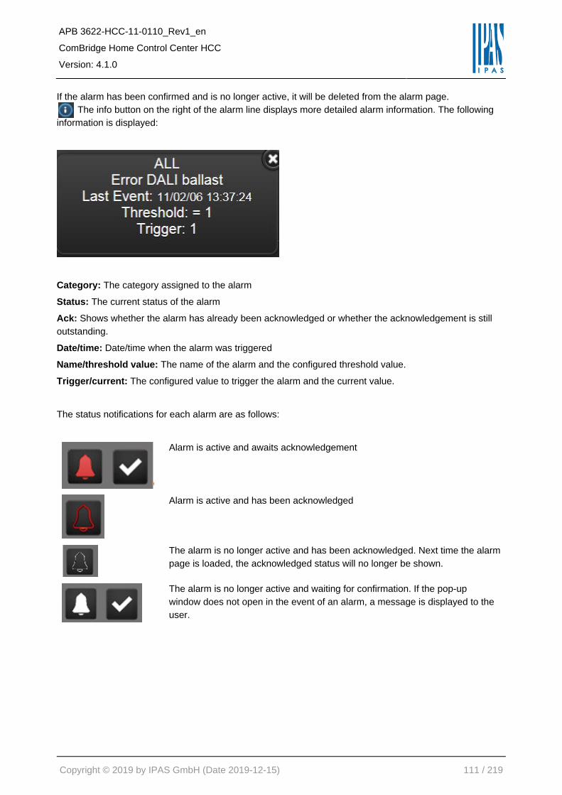
APB 3622-HCC-11-0110_Rev1_en
ComBridge Home Control Center HCC
Version: 4.1.0
Copyright © 2019 by IPAS GmbH (Date 2019-12-15) 111 / 219
If the alarm has been confirmed and is no longer active, it will be deleted from the alarm page.
The info button on the right of the alarm line displays more detailed alarm information. The following
information is displayed:
Category: The category assigned to the alarm
Status: The current status of the alarm
Ack: Shows whether the alarm has already been acknowledged or whether the acknowledgement is still
outstanding.
Date/time: Date/time when the alarm was triggered
Name/threshold value: The name of the alarm and the configured threshold value.
Trigger/current: The configured value to trigger the alarm and the current value.
The status notifications for each alarm are as follows:
Alarm is active and awaits acknowledgement
Alarm is active and has been acknowledged
The alarm is no longer active and has been acknowledged. Next time the alarm
page is loaded, the acknowledged status will no longer be shown.
The alarm is no longer active and waiting for confirmation. If the pop-up
window does not open in the event of an alarm, a message is displayed to the
user.

APB 3622-HCC-11-0110_Rev1_en
ComBridge Home Control Center HCC
Version: 4.1.0
Copyright © 2019 by IPAS GmbH (Date 2019-12-15) 112 / 219
8.4.6 Alarm history
All registered alarms are recorded in a log file which can be shown on the web-interface.
Date / Time: Date / time of the alarm event
Action: The change of alarm states:
NORMAL: The status is back to normal
ALARM: The alarm is triggered
ACK: The alarm was confirmed
Alarm: The name assigned to the alarm
Trigger: The value now of change to another state

APB 3622-HCC-11-0110_Rev1_en
ComBridge Home Control Center HCC
Version: 4.1.0
Copyright © 2019 by IPAS GmbH (Date 2019-12-15) 113 / 219
In addition, there is a filter option. You can filter according to alarm name, date and time. Three icons are
shown for the filter:
Search for a search term.
Page is updated.
The selected data can be exported as xml file. The file can be opened directly with a
spreadsheet program.
Note: The alarm history is not saved persistently and is therefore empty when the device is re-started.
However, if you perform a deliberate re-start, for example through an ETS download or firmware update,
the data is saved.

APB 3622-HCC-11-0110_Rev1_en
ComBridge Home Control Center HCC
Version: 4.1.0
Copyright © 2019 by IPAS GmbH (Date 2019-12-15) 114 / 219
8.5 Chart Module
The chart module is used to graphically display values in the form of bar or curve diagrams.
8.5.1 Data point configuration
Open the configuration window by clicking on the module’s menu.
Polling time: If this setting is activated, the respective data point is polled cyclically. A read request is sent
to the KNX bus. The polling interval in seconds is also defined. These data are recorded and the average,
maximum and minimum are calculated and stored per minute. If no value is received from the KNX bus
within one minute, the values that are not present in the meantime can be interpolated. After one hour,
values are calculated and stored as hourly average, hourly minimum and hour minimum.
Interpolate: When this setting is enabled, non-existing data will be interpolated.
The "Save" button records the configured data points.
Note: Up to 10 data points can be defined for chart recording.
You can also define whether you would like to query data points cyclically (read request on the KNX) and
whether you would like to interpolate values. The data is recorded and every minute the average value, the
maximum value and the minimal value are saved. If no value is received within a minute, the value can be
interpolated (if selected). After one hour, these values are saved as hourly average value as well as
maximum and minimum value for the hour.

APB 3622-HCC-11-0110_Rev1_en
ComBridge Home Control Center HCC
Version: 4.1.0
Copyright © 2019 by IPAS GmbH (Date 2019-12-15) 115 / 219
8.5.2 Element configuration
After this basic configuration, the element can be placed on a web page and the form of representation can
be defined in detail.
In the "General" section, the data point to be used for recording is
defined. More about this in the chapter: 7.3.1 General.
ID: Display of the internal ID number.
Type: Display of the element property.
Name: Name of the control element.
Visible: Display of the element in the visualization.
Active: Activation of the switching functions. When deactivated,
only the status information is displayed.
In the properties, the display of a tooltip and the legend (diagram
caption) can be selected.
The "Style" section contains the assignment of the diagram title as
well as general layout options. More about this in the chapter: 7.3.3
Status.

APB 3622-HCC-11-0110_Rev1_en
ComBridge Home Control Center HCC
Version: 4.1.0
Copyright © 2019 by IPAS GmbH (Date 2019-12-15) 116 / 219
Under display format, you can choose between a curve and a bar chart.
Bar chart
Curve chart
Entries can be deleted or placed in the foreground or in the
background. By clicking on the corresponding entry further
parameters are displayed. The calculation type of the display value
is defined in the "Properties" tab.
The following calculation types are available:
• Average
• maximum
• minimum
• Delta of the average values
• Delta of maximum values
• Pos. Delta of the average values
• Pos. Delta of maximum values
When the bar graph is selected, the fill color and transparency can
be set in the Pillar area. For transparency, the default value is 1
(no transparency).
When the line chart is selected, the line width (px) and the
appearance (curve / segment) can be selected in the "Line" area in
addition to Fill color and Transparency.

APB 3622-HCC-11-0110_Rev1_en
ComBridge Home Control Center HCC
Version: 4.1.0
Copyright © 2019 by IPAS GmbH (Date 2019-12-15) 117 / 219
The "Axis" area can be used to define the shape of the X-axis and Y-axis. Important is the definition of the
preset time range.
The values on the axes can be displayed with or without decimal
places. By specifying the prefix and suffix, e.g. Units are plotted on
the Y axis. Also, the Y-axis can be manually scaled by defining the
maximum or minimum. If no information is given at this point,
scaling will be performed automatically based on the values.
The "Value point" section, shape, transparency and size can be
varied.
In the area, a grid can be made visible and its shape can be
defined. The direction of the grid lines can be considered a normal
grid (x- and y-axis), or only horizontal (y-axis) or only vertical (x-
axis). Grid color, transparency and fill color can also be set.

APB 3622-HCC-11-0110_Rev1_en
ComBridge Home Control Center HCC
Version: 4.1.0
Copyright © 2019 by IPAS GmbH (Date 2019-12-15) 118 / 219
The delta calculation calculates the difference between the current value and the previous value. This can
be very interesting for the representation of a power consumption, for example. The difference in an energy
meter would indicate the consumption per hour, for example.
It is possible to create a daily profile. The following delta values are used for the respective time ranges:
Time range Delta Number of values
1 hour 1 minute 60
3 hours 5 minutes 36
6 hours 10 minutes 36
12 hours 15 minutes 48
1 day 60 minutes 24
1 day (30 min) 30 minutes 48
1 week 24 hour 7
1 week (12 Stunden) 12 hours 14
1 week (6 Stunden) 6 hours 28
1 month 1 day 30
3 months 1 week 12
6 months 1 week 24
1 year 1 months 12

APB 3622-HCC-11-0110_Rev1_en
ComBridge Home Control Center HCC
Version: 4.1.0
Copyright © 2019 by IPAS GmbH (Date 2019-12-15) 119 / 219
8.5.3 HTML display
The chart module presents itself on the website as follows:
The time range can be adjusted on-line. The display style (curve or bar) is defined in the Editor and cannot
be changed on-line. If you use the cursor to hover over a value point or bar, a tooltip with additional
information will appear automatically.
• Name of the data point
• Date and time
• Value
Note: The recorded data is saved in the volatile memory (RAM) and is therefore no longer available after a
restart (power loss). If you perform a deliberate re-start, however, for example via an ETS download or
firmware update, the data is still available.

APB 3622-HCC-11-0110_Rev1_en
ComBridge Home Control Center HCC
Version: 4.1.0
Copyright © 2019 by IPAS GmbH (Date 2019-12-15) 120 / 219
8.6 Monitoring module
The monitoring module is a service tool and is used to analyze data on the KNX bus. This module is like
the group monitor from the ETS tool. It helps the system integrator, or the installer troubleshoot. The
monitoring module is a recording module to log all or only certain bus events.
8.6.1 Configuration
Use the modules menu to load the configuration window.
In this module you can choose the data you would like to record.
1st approach: Lists all group addresses or objects you want to record.
2nd approach: Lists all group addresses or objects you do not want to record.
Note: Up to 1000 events are logged. Then the older entries are deleted so that the last 1000 entries are
always visible. The recorded data are kept in volatile memory (RAM) and are therefore no longer available
after a restart (power failure). However, if a deliberate restart is performed, e.g. By ETS download or a
firmware update, the data is saved and will not be lost.

APB 3622-HCC-11-0110_Rev1_en
ComBridge Home Control Center HCC
Version: 4.1.0
Copyright © 2019 by IPAS GmbH (Date 2019-12-15) 121 / 219
8.6.2 HTML display
The saved data can be displayed via a navigation element.
Please select the entry "monitoring module".
In addition, a filter option is available. You can filter according to name or date and time.

APB 3622-HCC-11-0110_Rev1_en
ComBridge Home Control Center HCC
Version: 4.1.0
Copyright © 2019 by IPAS GmbH (Date 2019-12-15) 122 / 219
8.7 TCP/UDP commands
With this module it is possible to send telegrams via the ComBridge HCC. Up to 20 devices, e.g. Beamer,
router, audio / video equipment, heating systems, etc., each with up to 20 TCP / UDP commands are
controlled. For this purpose, data points such as communication objects, virtual objects or group addresses
are defined. If the value content of these data points meets a specific condition, defined commands are
sent to the IP users.
Several IP subscribers can be defined. Each subscriber is identified by:
Name: Name of the IP device to be controlled.
Host IP: IP address of the IP device to be controlled.
Port: Port number of the IP device.
Communication Type: TCP or UDP identified.
Use the buttons to add, delete, edit or double any IP
subscribers. Up to 20 IP subscribers can be defined.
Note: Up to 20 IP subscribers can be defined.

APB 3622-HCC-11-0110_Rev1_en
ComBridge Home Control Center HCC
Version: 4.1.0
Copyright © 2019 by IPAS GmbH (Date 2019-12-15) 123 / 219
In the bottom part, a list of commands can be defined for each subscriber. The following example shows
the control of a VU + SAT receiver (DreamBox):
The trigger object can be a communications object, a virtual object or a group address. You can also select
a condition according to the data point type. Use the field “type“ to define whether the IP subscriber is to
expect an ASCII command or a binary command. The corresponding IP command is sent for each input
event after the condition has been successfully checked.
Note: Up to 20 commands can be defined. An http command is defined as follows:
Example: http:/<ip>:90/control?command=25
Type: ASCII
Data: GET /control?command=25
Further commands for DreamBox or similar devices can be found here:
http://wiki.dbox2-tuning.net/wiki/index.php/Enigma2:WebInterface
Note: If you click on the right mouse button in the data field, you can add the placeholder [VALUE] which
will be replaced with the real data point value on execution. Any changes become active as soon as they
are saved.
8.7.1 PJLINK: Control of projectors
PJLink is a standard for configuring video projectors over a network interface. It was developed by the Data
Projector Group within the Japan Business Machine and Information System Industries Association
(JBMIA). The aim of the standard is to define a manufacturer and model-independent interface for the
configuration and monitoring of video projectors. This standard is already supported by over 300 models
and many manufacturers. The following syntax should be used in the TCP module to control projectors via
PJLINK:
- IP address: <ip> of projector
- Port: 4352
- Command: PJLINK <password> <command> <parameter>
<password> has to be replaced by the password given by the projector
Example: Projector switch ON
Typ: ASCII
Data: PJLINK <password> POWR 1

APB 3622-HCC-11-0110_Rev1_en
ComBridge Home Control Center HCC
Version: 4.1.0
Copyright © 2019 by IPAS GmbH (Date 2019-12-15) 124 / 219
Example:
Command Parameter Description
POWR 0 = Standby
1 = Switch On
On/Off
INPT 11: RGB 1
12: RGB 2
13: RGB 3
31: DIGITAL 1
32: DIGITAL 2
33: DIGITAL 3
46: AUX1
21: VIDEO 1
22: VIDEO 2
25: VIDEO 5
47: AUX 2
48: AUX 3
49: AUX 4
Input Selection

APB 3622-HCC-11-0110_Rev1_en
ComBridge Home Control Center HCC
Version: 4.1.0
Copyright © 2019 by IPAS GmbH (Date 2019-12-15) 125 / 219
8.8 Overview of the data points
All available data points are summarized in a list. In this list, the representation of these data points can be
predefined. This predefined representation is used as the basis for all configuration pages. These include
the HTML configuration pages for the weekly programs and the scenes. All data points are divided into the
following categories:
In order to filter or find certain data points, various criteria can be set under "Filter".
8.8.1 Change of designation
Each group address has an internal name (usually from the export of the ETS). It is possible here to
replace this name with a "display name".

APB 3622-HCC-11-0110_Rev1_en
ComBridge Home Control Center HCC
Version: 4.1.0
Copyright © 2019 by IPAS GmbH (Date 2019-12-15) 126 / 219
8.8.2 Change of presentation form
Furthermore, it is possible to vary the appearance of the control buttons. For a simple on / off command, 3
different views can be selected:
For a 1-byte value, such as an indication in% (0...100%), the following display forms can be selected:
- Step +/-
- Slider horizontal
- Slider vertical
For analog values, the range of values can be restricted and the number of decimal places can be defined.

APB 3622-HCC-11-0110_Rev1_en
ComBridge Home Control Center HCC
Version: 4.1.0
Copyright © 2019 by IPAS GmbH (Date 2019-12-15) 127 / 219
Assignment of categories
To group data points in a meaningful way, user-defined categories can be created, and the group
addresses, objects or virtual objects assigned to these categories. In all windows, where group addresses,
objects or virtual objects required from the list of data points are selected, the categories can be used for
quicker search. The text field at the top allows a full-text search. Also group addresses of a category can be
found like this.
There are 4 buttons available for creating and editing categories:
Add: button to add a new category.
Delete: button to delete an existing category.
Edit: button to edit (name) an existing category.
Copy: button to copy an existing category.
The data points to be assigned are added to the created categories by the direction keys or by drag & drop.
The "Save" button saves the created categories and their contents.

APB 3622-HCC-11-0110_Rev1_en
ComBridge Home Control Center HCC
Version: 4.1.0
Copyright © 2019 by IPAS GmbH (Date 2019-12-15) 128 / 219
8.9 Sonos Control
From ComBridge HCC Version 4.0 it is possible to control SONOS loudspeakers directly.
The configuration is carried out in the editor in the menu item Module --> SONOS Module.
With the plus button, a new Sonos loudspeaker can be added.
With the help of the magnifying glass loudspeakers in the network can be found. All relevant
information about the found SONOS loudspeakers is displayed in a new window. For a better overview it is
possible to assign an alias name. Then select the desired loudspeaker to define the control elements.

APB 3622-HCC-11-0110_Rev1_en
ComBridge Home Control Center HCC
Version: 4.1.0
Copyright © 2019 by IPAS GmbH (Date 2019-12-15) 129 / 219
The following commands are currently supported:
• Play
• Stop
• Pause
• Next
• Previuos
• Volume
• Volume Inc
- The volume is relatively changed by a defined value.
• Mute
• LED
- The LED on the loudspeaker can be switched on (condition true) or off (condition false)
• Button_Lock
- The button operation on the loudspeaker can be locked (condition true) or released (condition
false)
• Bass
• Treble
• Load
• Playlist
- The desired playlist is selected from the list of Sonos favorites
Similar to the general TCP module, see chapter: 8.7 TCP/UDP commands, these commands can be
assigned to group addresses or virtual objects. To trigger a command, a condition can be defined. A
special feature is the command "Volume". If this command is ideally linked to a group address or object of
the data type 1-byte scaling (0 ... 100%), the value is passed directly to the command. The condition for
this is "ANY". At each event, the value is passed to the Sonos loudspeaker. A value of 30% would set the
speaker to 30% of the volume. However, it is possible to set the volume to a fixed value for another
condition.
Note: In version 4.0, the interface does not yet support the updating of the values, if they are changed by
another app. Therefore, it makes more sense to make the incremental change in volume: Volume_Inc

APB 3622-HCC-11-0110_Rev1_en
ComBridge Home Control Center HCC
Version: 4.1.0
Copyright © 2019 by IPAS GmbH (Date 2019-12-15) 130 / 219
Here you can additionally specify the change in the volume by the current value. This can then be sent via
a 1bit command simply via KNX button. This sample changes the volume by +-5%, depending on the group
address linked.
Of course, the same object or group address can be used:
Note: The command Playlist requires a second parameter indicating the title of the desired playlist.
This title must be under the favorites. If this title is found in Sonos Favorites, this list will be selected.
Thus, it is possible to select different playlists by pressing a button.
It is thus possible to use a normal light switch with on / off to adjust the volume. For this, the volume can
be increased with the condition "On" and the volume can be reduced with the condition "Off". With this
configuration only one group address is necessary. The favorites in SONOS are only recognized by the
name. It is therefore advisable to select simple names for the favorites in the SONOS configuration.
Note: SONOS is a registered trademark. See chapter: 12.9 References.
8.10 Philips HUE
Starting with the ComBridge HCC version 4, it is possible to directly control the Philips HUE LED lighting
system. Hue is the Philips lighting system that allows you to wirelessly control your lighting using an
application. The system allows the control of the lighting of a house via a mobile app. The system can be
operated via a smartphone, a tablet or a voice control function. A Philips HUE system always consists of a
bridge and connected lights. The bridge implements the interface to the IP network to allow control via apps
or the ComBridge HCC. To do this, the bridge must be in the same network. The procedure described here
assumes that the Philips system has already been fully installed. All lights are already registered with the
Philips app at the bridge.
Each client, including the ComBridge HCC, must register with the Bridge and authenticate. This process is
performed by pressing a button on the bridge. This assigns a "token" for authentication so that the HCC
can send commands to the connected HUE lights. The following description describes step by step the
configuration process and the login at the bridge:
Note: Both the HCC and the PC with the editor must be in the same IP network. The configuration is
carried out in the editor in the menu item Modules -> Philips HUE.

APB 3622-HCC-11-0110_Rev1_en
ComBridge Home Control Center HCC
Version: 4.1.0
Copyright © 2019 by IPAS GmbH (Date 2019-12-15) 131 / 219
With the plus button, a new Philips Bridge can be added.
The magnifying glass can be used to find Philips systems (bridges).
The button OK adds the found bridge to the list.

APB 3622-HCC-11-0110_Rev1_en
ComBridge Home Control Center HCC
Version: 4.1.0
Copyright © 2019 by IPAS GmbH (Date 2019-12-15) 132 / 219
Until now no token, or the authentication has not yet been performed. Pressing the Quit button prompts you
to press the button on the Philips Bridge. This must take place within 2 minutes.
Now you should first press the button on the bridge and then confirm in the editor window with OK.
A so-called token is generated which allows the HCC to send switching commands to the bridge. The
polling interval defines the time that the system will update values that were not set with the HCC but with
another HUE app. The following shows all configured lights with the corresponding possible switching
commands:
Depending on the type of luminaire, the possible objects are displayed.

APB 3622-HCC-11-0110_Rev1_en
ComBridge Home Control Center HCC
Version: 4.1.0
Copyright © 2019 by IPAS GmbH (Date 2019-12-15) 133 / 219
Note: Color control requires the data point type: 232.600 (3-byte RGB). The color temperature is coded
with the DPT: 7.600 (2 byte unsigned).
The HUE commands can be linked with group addresses, with communication objects or with virtual
objects.
In the HUE Bridge, or with the help of various apps, groups can be formed. This means that several lights
can be combined and switched simultaneously.
Note: Philips HUE is a registered trademark. See chapter: 12.9 References.

APB 3622-HCC-11-0110_Rev1_en
ComBridge Home Control Center HCC
Version: 4.1.0
Copyright © 2019 by IPAS GmbH (Date 2019-12-15) 134 / 219
9 Voice Control
Voice Control systems, such as ALEXA and GOOGLE HOME are supported as of version 4.0 via a
third-party app from 1HOME. To activate this interface, the following steps are necessary:
9.1 Enable the interface
Call the configuration page: --> https: // <ip> /config.php and call menu "API Connection". API is the
abbreviation for Application Programming Interface. An API is a program interface. Access the functions of
an application via the project developers and developers. Unlike a user interface, an API does not
communicate with a system, but applications communicate directly with one another. Here the API
connection is always activated.
9.2 Protect access via password
The link defines the password of the connection.
The default user can not be changed and is set to "apiuser". After the first update to Version 4.0, the
password is set to "apiuser" by default. In the mask you can and should change this password.

APB 3622-HCC-11-0110_Rev1_en
ComBridge Home Control Center HCC
Version: 4.1.0
Copyright © 2019 by IPAS GmbH (Date 2019-12-15) 135 / 219
9.3 Activation of individual functions
In the Smart Editor, each function can be released
separately for access via voice control. For this, the
checkbox "Allow API access" must be ticked. The identifier
and the parent menu item will later be used as name and
space for voice control.
However, these terms can still be changed later in the
interface of the VOXIOR configuration.
9.4 Setup on the router (Port Forwarding)
Port forwarding allows individual services of a local network to be accessed from the Internet. For the
function to be accessible from the Internet and thus for the service provider, the router must be configured
accordingly. A fixed IP address or a DynDns address is required. For all common routers the DynDNS
service can be activated. In addition to the address accessible on the Internet, an external port number
must be defined. This external port number must be linked to the SSL 443 security port. Also see chapter:
12.4.3 Portforwarding.
Note: The external API interface is only accessible via the encrypted port 443.
9.5 Sign into the service provider 1HOME
The service through 1HOME is not free and the user must create an account with 1HOME. For more
information, visit the Voxior website: --> https://www.1home.io/.
After registering with 1HOME, the ComBridge HCC can be connected via a fixed IP address or a Dyndns
entry and a port number. This port number must be linked in your DSL router to the internal IP address of
the ComBridge HCC (Port Forwarding). For authentication, the previously defined password and the user
"apiuser" must be entered. Also see chapter: 12.4.3 Portforwarding.
Afterwards the configuration from the ComBridge HCC will be loaded into your 1HOME account.
To activate the skills in ALEXA or GOOGLE HOME please follow the description on the website of 1HOME.
If you have any questions, please contact Voxior Support: https://www.1home.io/.
Note: ALEXA or GOOGLE HOME are registered trademarkes. See chapter: 12.9 References.

APB 3622-HCC-11-0110_Rev1_en
ComBridge Home Control Center HCC
Version: 4.1.0
Copyright © 2019 by IPAS GmbH (Date 2019-12-15) 136 / 219
10 Smart & Tablet Visu
The ComBridge HCC makes it possible to optimise visualisations for different end user devices such as
smartphones or tablets. In addition to the WEB editor, there is a Smart Editor on the ComBridhe HCC. This
is very easy and intuitive to use. The smart or tablet visualizations designed in this way have a consistently
structured display and operating philosophy. The Smart Visualization is optimized for mobile browsers, for
all smartphones and a room control unit. Here are two examples:
Tablet Visu view:
Smart Visu view:

APB 3622-HCC-11-0110_Rev1_en
ComBridge Home Control Center HCC
Version: 4.1.0
Copyright © 2019 by IPAS GmbH (Date 2019-12-15) 137 / 219
10.1 Configuring the ComBridge HCC
Before you can start the SmartVisu configuration, you need to set the network configuration. Network
settings are necessary to adjust the standard settings to the network conditions of the project. For this
purpose, you need to first configure these settings in the ETS application program and load them onto the
device. The PC used to create the project must also have the appropriate settings to access the device via
the network.
10.2 Accessing the SmartEditor
The call is made in the Connection Manager, as described in chapter: 3.4 Installation Connection Managers.
The username for the Smart Editor is set to "smarteditor" by default. The default password is "HCC".
However, it must be changed on the first call of the Smart Editor.
To assign a Smart Editor password, the configuration page is first called up at the address
(https:// <ip>/config.php). The language of the device configuration can be preset in the editor under
Language Settings.

APB 3622-HCC-11-0110_Rev1_en
ComBridge Home Control Center HCC
Version: 4.1.0
Copyright © 2019 by IPAS GmbH (Date 2019-12-15) 138 / 219
The Smart Editor password allows access to the Smart Editor to generate a Smart Visualization. This
prevents any user from making changes to the visualization.
Access Installer: via Connection Manager, see chapter: 3.4 Installation Connection Managers
Access user: https:// <ip>/smart.php
Only one installer can be logged in to the Smart Editor. If another installer logs in simultaneously (e.g.,
remotely), a warning message will appear. This also applies to the normal editor. In principle, only one editor
can be opened.
The figure shows the working area of the ComBridge HCC. In the header, on the right, of the Smart Editor
are the function buttons for "Import", "Export", "Configuration" and "Activate".
Note: Please be careful when restoring a normal visu backup because it also contains the smartvisu
configuration. If a smartvisu configuration is created after a normal visu backup file and this backup is
restored later, the smartvisu configuration will be lost because it was previously empty. If a global backup is
required, we recommend you use the normal editor backup option.

APB 3622-HCC-11-0110_Rev1_en
ComBridge Home Control Center HCC
Version: 4.1.0
Copyright © 2019 by IPAS GmbH (Date 2019-12-15) 139 / 219
Restore a previous configuration file in the editor.
Save the actual configuration into a file on a local PC.
Allows selecting the style and theme of the visualisation.
Releases the actual configuration into HTML.
The configuration workspace is located in the upper right corner of the screen. On the left-hand side there
are two different tabs:
Topology: Shows a tree structure with the functions/folders created for the visualisation
Info View: Shows status values from the installation in order to display them in a slide left panel in the
visualization
On the bottom of the workspace, the following icons are available:
• Create new folder/icon
• New function
• Delete function
• Move function created up/down
The second window shows objects and group addresses that can be linked via drag&drop.
Note: Any number of folders, subfolders or functions can be created. If not all folders (page navigations /
containers) or not all functions can be displayed on the visualization pages of the smartphone or tablet,
sliders are displayed on the right and bottom of the visualization view. Thus, one can navigate to all existing
visualization pages and functions.

APB 3622-HCC-11-0110_Rev1_en
ComBridge Home Control Center HCC
Version: 4.1.0
Copyright © 2019 by IPAS GmbH (Date 2019-12-15) 140 / 219
10.3 Configuration
Das Konfigurationsfenster ermöglicht die Auswahl verschiedener Layouts der Visualisierung.
Name: This text appears like a tittle in
the upper right-hand corner of the
visualisation
Style: Allows selecting an icon for
group style. The following are available:
Black, Black/Transparent, Blue, Multi
colour and White/Transparent.
Layout: Allows changing the type of
representation of the icons between
aligned layout type and central layout
type.
Theme: Allows changing the
background colour between 5 different
options: Black, Blue/Grey, White,
Yellow and Red.
Logo: Here you can define a logo that
should be displayed later in the upper
left corner of the Smart Visu.
With the selection of topics, a specific background color of the display and user interface can be selected.
The four colors black, blue / gray, yellow and white are available. Presentation of the possible topics:

APB 3622-HCC-11-0110_Rev1_en
ComBridge Home Control Center HCC
Version: 4.1.0
Copyright © 2019 by IPAS GmbH (Date 2019-12-15) 141 / 219
10.3.1 Configuration specifically for the tablet visu
Further configuration settings relate to the display on a tablet. Please load the Smart Visu via the following
link: http://<ip>/tablet.php. Up to 4 containers with information can be displayed in the tablet visu.
The transparency of these containers can be set between 0 and 100%. In addition, it can be defined at which
position the first menu level (1st container) should be displayed. Basically, there is the option of selecting a
visualization page previously created in the editor as the default background or a static image as the
background.

APB 3622-HCC-11-0110_Rev1_en
ComBridge Home Control Center HCC
Version: 4.1.0
Copyright © 2019 by IPAS GmbH (Date 2019-12-15) 142 / 219
It is possible to choose a previously created visualisation page or a static image as standard background.
Width and height should correspond to the resolution of the tablet used.
The following is an overview of the four possible containers: The top container shows all the status
information that was defined in the info view, see chapter: 10.5 Info view panel.
The left container usually shows the main menu. A further menu level can be displayed in the bottom
container. These buttons are automatically displayed with the selected background image. The container
on the right shows the different functions. This level corresponds to the function view in the Smart Visu for
smart phones.
Left container: first
menu level
Top container:
Info View

APB 3622-HCC-11-0110_Rev1_en
ComBridge Home Control Center HCC
Version: 4.1.0
Copyright © 2019 by IPAS GmbH (Date 2019-12-15) 143 / 219
The menu items of the first menu level are displayed on the left-hand side. If a second menu level is being
configured, the second level is shown in the bottom container.
To do so, please select the parameter “next level below” on the previous level. This means that the next
level is displayed in the bottom container. Every page can be displayed via a dynamic visualisation page or
a static background image.
It can be chosen between the layout "distributed" and centered. This setting refers to the arrangement of
the display and operating functions or their icons. The "distributed" setting displays the function icon and
the function label on the left. With the respective button on the right of the function line, a submenu for the
function is displayed, e.g. the dimming function is displayed as a slider or the RGB control as a special
element. Basically, for simple functions, e.g. On / Off, can be switched directly over the entire operating
line, the submenu is not necessary.
Likewise, a logo can be set. This logo is displayed in the Smart Visualization at the top left of the menu bar.
By default, a HCC logo is preset. Other pictures can be uploaded and set.

APB 3622-HCC-11-0110_Rev1_en
ComBridge Home Control Center HCC
Version: 4.1.0
Copyright © 2019 by IPAS GmbH (Date 2019-12-15) 144 / 219
10.4 Voice Control
Voice Control systems, such as ALEXA and GOOGLE HOME are supported from Version 4.0 via a third-
party app of the company VOXIOR.
In the Smart Editor, each function can be enabled separately for access via voice control. To do this, check
the "Allow API access" checkbox. The identifier and the parent menu item will later be used as the name
and space for voice control. However, these terms can still be changed later in the interface of the VOXIOR
configuration.
The configuration for connecting to Voxior is described
in chapter: 9 Voice Control.

APB 3622-HCC-11-0110_Rev1_en
ComBridge Home Control Center HCC
Version: 4.1.0
Copyright © 2019 by IPAS GmbH (Date 2019-12-15) 145 / 219
10.5 Info view panel
This panel enables you to add different status values from the installation in order to show them in a slide
left panel in the visualization.
Example: If the alarm icon is clicked, a window with the current settings will appear.
The following status types are available:
The following status types are available:
Status value: Accept any kind of DPT
Status ON/OFF: Ready for 1 bit DPT
Status Alarm: Ready for 1 bit DPT
Status Date: Ready for Date DPT
Status Time: Ready for Time DPT

APB 3622-HCC-11-0110_Rev1_en
ComBridge Home Control Center HCC
Version: 4.1.0
Copyright © 2019 by IPAS GmbH (Date 2019-12-15) 146 / 219
10.6 Menu structure
With a double-click on the folder or a click on the plus-
symbol in front of the folder you get to the subfolder etc.
There you can now define further subpages and thus
an operator topology. The function button "Add
function" creates a function on the operating page.
Before the display and operating functions are set up, the page structure or navigation of the Smart Visu
project must be defined in the Topology tab or the display content of the various containers must be
defined in a Tablet Visu project. To do this, the Add button is used to create a menu or a special page with
its name.
This name is displayed under the navigation button for this page. Access to the respective page can also
be protected with a password. This is set up under "Password". Behind "Picture" you can select a suitable
icon for the navigation button. This can, for example, represent a trade such as lighting, sun protection or
HVAC or present a local structure such as office 1, office 2, meeting room etc. In the special pages, the
web views of the various modules already configured in the web editor, such as schedules, periods, alarms,
alarm history, monitoring, can be assigned.
Special configuration parameters for tablet visualization are offered. If you activate the Next level selection
below, a second menu level is displayed in another container. Each menu page or special page can be
represented by a dynamic visualization page from the Web Editor or by a static background image.
Function categorized in groups are available for visualization.
The following categories are offered:

APB 3622-HCC-11-0110_Rev1_en
ComBridge Home Control Center HCC
Version: 4.1.0
Copyright © 2019 by IPAS GmbH (Date 2019-12-15) 147 / 219
10.7 Menu
Menu items can be added at the menu level. The corresponding configuration page appears on the
right-hand side of the window:
Here the image, the identifier and a password can be displayed, if desired.

APB 3622-HCC-11-0110_Rev1_en
ComBridge Home Control Center HCC
Version: 4.1.0
Copyright © 2019 by IPAS GmbH (Date 2019-12-15) 148 / 219
10.8 Special pages
Special pages can be added at the menu level. In the special pages, the Web views can be assigned from
the various modules already configured in the Web Editor, such as schedules, periods, alarms, alarm
history, monitoring. Special configuration parameters for the tablet visualization are offered. If you activate
the option "next level down", a second menu level will be displayed in another container.
Each menu page or special page can be represented by a dynamic visualization page from the Web Editor
or by a static background image. With a double-click on the folder or a click on the plus-symbol in front of
the folder you get to the subfolder etc. There you can now define further sub-pages and thus an operating
topology. A function is created with the function button "Add function". This is displayed on the operating
page.
Here the image, the identifier and a password can be displayed, if desired. The selection of the special
page is made possible by clicking on the magnifying glass:
The ready-made pages are displayed accordingly in the respective browser

APB 3622-HCC-11-0110_Rev1_en
ComBridge Home Control Center HCC
Version: 4.1.0
Copyright © 2019 by IPAS GmbH (Date 2019-12-15) 149 / 219
10.8.1 Lighting functions
To create the functions, the respective relevant folder, the page, is selected and a function is added. The
selection of the function "Lighting" offers 7 types to choose from.
10.8.1.1 Light switch
This element sends ON/OFF values. Its status is updated directly via the assigned communication object
“processpoint”. If no status value is received, the object will remain in a state called “Invalid”.
Icon: Icon function
Label: Function name.
Order: Position assigned in the visualisation.
Function: LIGHTING
Subtype: Light switch.
Confirm Action: If this option is activated, the action will be confirmed via a popup window.
Processpoint: Communication object or virtual variable linked.
Images: Images to show for each action/status.
Allowed DPT: 1bit
The default icons can be changed by clicking on them with the mouse. The next figure shows a list of all
available icons. The result is displayed in the navigator as follows:

APB 3622-HCC-11-0110_Rev1_en
ComBridge Home Control Center HCC
Version: 4.1.0
Copyright © 2019 by IPAS GmbH (Date 2019-12-15) 150 / 219
10.8.1.2 Light Ceiling
This element sends ON/OFF values. Its status is updated directly via the assigned communication object
“processpoint”. If no status value is received, the object will remain in a state called “Invalid”.
Icon: Icon function.
Order: Position assigned in the visualisation.
Label: Function name.
Function: LIGHTING
Subtype: Light ceiling.
Confirm Action: If this option is activated, the action will be confirmed via a popup window.
Processpoint: Communication object or virtual variable linked.
Images: Images to show for each action/status.
Allowed DPT: 1bit
The default icons can be changed by clicking on them with the mouse. The next figure shows a list of all
available icons. The result is displayed in the navigator as follows:

APB 3622-HCC-11-0110_Rev1_en
ComBridge Home Control Center HCC
Version: 4.1.0
Copyright © 2019 by IPAS GmbH (Date 2019-12-15) 151 / 219
10.8.1.3 Light Desk
This element sends ON/OFF values. Its status is updated directly via the assigned communication object
“processpoint”. If no status value is received, the object will remain in a state called “Invalid”.
Icon: Icon function.
Order: Position assigned in the visualisation.
Label: Function name.
Function: LIGHTING
Subtype: Light desk.
Confirm Action: If this option is activated, the action will be confirmed via a popup window.
Processpoint: Communication object or virtual variable linked.
Images: Images to show for each action/status.
Allowed DPT: 1bit
The default icons can be changed by clicking on them with the mouse. The next figure shows a list of all
available icons. The result is displayed in the navigator as follows:

APB 3622-HCC-11-0110_Rev1_en
ComBridge Home Control Center HCC
Version: 4.1.0
Copyright © 2019 by IPAS GmbH (Date 2019-12-15) 152 / 219
10.8.1.4 Light (text)
This element sends ON/OFF values to control a light and also shows text descriptions for actions and status.
Its status is updated directly via the assigned communication object “processpoint”. If no status value is
received, the object will remain in a state called “Invalid”.
Icon: Icon function.
Order: Position assigned in the visualisation.
Label: Function name.
Function: LIGHTING
Subtype: Light switch text.
Confirm Action: If this option is activated, the action will be confirmed via a popup window.
Processpoint: Communication object or virtual variable linked.
Text OFF: Text to show for OFF value/status.
Text ON: Text to show for ON value/status.
Images: Images to show for each action/status.
Allowed DPT: 1bit
The default icons can be changed by clicking on them with the mouse. The next figure shows a list of all
available icons. The result is displayed in the navigator as follows:

APB 3622-HCC-11-0110_Rev1_en
ComBridge Home Control Center HCC
Version: 4.1.0
Copyright © 2019 by IPAS GmbH (Date 2019-12-15) 153 / 219
10.8.1.5 Dimmer
This element sends On/Off and absolute values to control a dimmer light. It also shows text descriptions for
actions and status. Its status is updated directly via the assigned communication objects “processpoint”. If no
status value is received, the objects will remain in a state called “Invalid”
Icon: Icon function.
Order: Position assigned in the visualisation.
Label: Function name.
Function: LIGHTING
Subtype: Dimmer.
Confirm Action: If this option is activated, the action will be confirmed via a popup window.
Processpoint: Communication object or virtual variable linked.
Text OFF: Text to show for OFF value/status (Value = 0%)
Text ON: Text to show for ON value/status (Value=100%)
Images: Images to show for each action/status.
Allowed DPT: 1byte
The default icons can be changed by clicking on them with the mouse. The next figure shows a list of all
available icons. The result is displayed in the navigator as follows:

APB 3622-HCC-11-0110_Rev1_en
ComBridge Home Control Center HCC
Version: 4.1.0
Copyright © 2019 by IPAS GmbH (Date 2019-12-15) 154 / 219
10.8.1.6 RGB Light
This element sends 3 x 1 byte absolute values to control an RGB light. Its status is updated directly via the
assigned communication objects “processpoint”. If no status value is received, the objects will remain in a
state called “Invalid”
Icon: Icon function
Order: Position assigned in the visualisation
Label: Name assigned to the function
Type: Switching
Subtype: RGB light
Confirm Action: If this option is activated, the action will be confirmed via a popup window.
Red channel: 1byte object or virtual variable linked for red colour control.
Green channel: 1byte object or virtual variable linked for green colour control.
Blue channel: 1byte object or virtual variable linked for blue colour control.
Predefined colours: Colours to send sequentially.
Allowed DPT: 1byte
The default icons can be changed by clicking on them with the mouse. The next figure shows a list of all
available icons. The result is displayed in the navigator as follows:

APB 3622-HCC-11-0110_Rev1_en
ComBridge Home Control Center HCC
Version: 4.1.0
Copyright © 2019 by IPAS GmbH (Date 2019-12-15) 155 / 219
10.8.1.7 RGBW Light
This element sends 4 x 1 byte absolute values to control an RGB light with White colour control.
Its status is updated directly via the assigned communication objects “processpoint”. If no status value is
received, the objects will remain in a state called “Invalid.
Icon: Icon function.
Order: Position assigned in the visualisation.
Label: Name assigned to the function.
Type: Switching
Subtype: RGBW light.
Confirm Action: If this option is activated, the action will be confirmed via a popup window.
Red channel: 1byte object or virtual variable linked for red colour control.
Green channel: 1byte object or virtual variable linked for green colour control.
Blue channel: 1byte object or virtual variable linked for blue colour control.
White channel: 1byte object or virtual variable linked for blue colour control.
Predefined colours: Colours to send sequentially.
Allowed DPT: 1byte
The default icons can be changed by clicking on them with the mouse. The next figure shows a list of all
available icons. The result is displayed in the navigator as follows:

APB 3622-HCC-11-0110_Rev1_en
ComBridge Home Control Center HCC
Version: 4.1.0
Copyright © 2019 by IPAS GmbH (Date 2019-12-15) 156 / 219
10.8.1.8 Dimmer (color temperature)
With this element it is possible to adjust a light in both the brightness and in the color temperature. Both
values are adjusted via a slider. For the color temperature, the minimum and maximum possible value range
can be entered.

APB 3622-HCC-11-0110_Rev1_en
ComBridge Home Control Center HCC
Version: 4.1.0
Copyright © 2019 by IPAS GmbH (Date 2019-12-15) 157 / 219
10.8.2 Switching General
To create the functions, the relevant folder, the page, selected and added a function. The selection of
Function "Switch General" offers 6 types to choose from.
10.8.2.1 General ON/OFF
This element sends ON/OFF values. Its status is updated directly via the assigned communication object
“processpoint”. If no status value is received, the object will remain in a state called “Invalid”.
Icon: Icon function.
Order: Position assigned in the visualisation.
Label: Function name.
Function: Switching General
Subtype: General ON/OFF.
Confirm Action: If this option is activated, the action will be confirmed via a popup window.
Processpoint: Communication object or virtual variable linked.
Images: Images to show for each action/status.
Allowed DPT: 1bit
The default icons can be changed by clicking on them with the mouse. The next figure shows a list of all
available icons. The result is displayed in the navigator as follows:

APB 3622-HCC-11-0110_Rev1_en
ComBridge Home Control Center HCC
Version: 4.1.0
Copyright © 2019 by IPAS GmbH (Date 2019-12-15) 158 / 219
10.8.2.2 Socket ON/OFF
This element sends ON/OFF values. Its status is updated directly via the assigned communication object
“processpoint”. If no status value is received, the object will remain in a state called “Invalid”.
Icon: Icon function.
Order: Position assigned in the visualisation.
Label: Function name.
Function: Switching General
Subtype Socket ON/OFF.
Confirm Action: If this option is activated, the action will be confirmed via a popup window.
Processpoint: Communication object or virtual variable linked.
Images: Images to show for each action/status.
Allowed DPT: 1bit
The default icons can be changed by clicking on them with the mouse. The next figure shows a list of all
available icons. The result is displayed in the navigator as follows:

APB 3622-HCC-11-0110_Rev1_en
ComBridge Home Control Center HCC
Version: 4.1.0
Copyright © 2019 by IPAS GmbH (Date 2019-12-15) 159 / 219
10.8.2.3 General ON/OFF Text
This element sends ON/OFF values and shows text descriptions for actions and status. Its status is updated
directly via the assigned communication object “processpoint”. If no status value is received, the object will
remain in a state called “Invalid”.
Icon: Icon function.
Order: Position assigned in the visualisation.
Label: Function name.
Function: Switching General
Subtype: General ON/OFF Text.
Confirm Action: If this option is activated, the action will be confirmed via a popup window.
Processpoint: Communication object or virtual variable linked.
Text OFF: Text to show for OFF value/status.
Text ON: Text to show for ON value/status.
Images: Images to show for each action/status.
Allowed DPT: 1bit
The default icons can be changed by clicking on them with the mouse. The next figure shows a list of all
available icons. The result is displayed in the navigator as follows:

APB 3622-HCC-11-0110_Rev1_en
ComBridge Home Control Center HCC
Version: 4.1.0
Copyright © 2019 by IPAS GmbH (Date 2019-12-15) 160 / 219
10.8.2.4 Presence ON/OFF
This element sends ON/OFF values and shows texts descriptions for actions and status. Its status is updated
directly via the assigned communication object “processpoint”. If no status value is received, the object will
remain in a state called “Invalid”.
Icon: Icon function.
Order: Position assigned in the visualisation.
Label: Function name.
Function: Switching General.
Subtype: Presence ON/OFF.
Confirm Action: If this option is activated, the action will be confirmed via a popup window.
Processpoint: Communication object or virtual variable linked.
Text OFF: Text to show for OFF value/status.
Text ON: Text to show for ON value/status.
Images: Images to show for each action/status.
Allowed DPT: 1bit
The default icons can be changed by clicking on them with the mouse. The next figure shows a list of all
available icons. The result is displayed in the navigator as follows:

APB 3622-HCC-11-0110_Rev1_en
ComBridge Home Control Center HCC
Version: 4.1.0
Copyright © 2019 by IPAS GmbH (Date 2019-12-15) 161 / 219
10.8.2.5 General (ON)
This element sends ON values and shows text descriptions for ON actions and status. Its status is updated
directly via the assigned communication object “processpoint”. If no status value is received, the object will
remain in a state called “Invalid”.
Icon: Icon function.
Order: Position assigned in the visualisation.
Label: Function name.
Function: Switching General.
Subtype: General ON.
Confirm Action: If this option is activated, the action will be confirmed via a popup window.
Processpoint: Communication object or virtual variable linked.
Text ON: Text to show for ON value/status.
Images: Images to show for each action/status.
Allowed DPT: 1bit
The default icons can be changed by clicking on them with the mouse. The next figure shows a list of all
available icons. The result is displayed in the navigator as follows:

APB 3622-HCC-11-0110_Rev1_en
ComBridge Home Control Center HCC
Version: 4.1.0
Copyright © 2019 by IPAS GmbH (Date 2019-12-15) 162 / 219
10.8.2.6 General (OFF)
This element sends OFF values and shows text descriptions for OFF actions and status. Its status is updated
directly via the assigned communication object “processpoint”. If no status value is received, the object will
remain in a state called “Invalid”.
Icon: Icon function.
Order: Position assigned in the visualisation.
Label: Function name.
Function: Switching General.
Subtype: General OFF.
Confirm Action: If this option is activated, the action will be confirmed via a popup window.
Processpoint: Communication object or virtual variable linked.
Text OFF: Text to show for OFF value/status.
Images: Images to show for each action/status.
Allowed DPT: 1bit
The default icons can be changed by clicking on them with the mouse. The next figure shows a list of all
available icons. The result is displayed in the navigator as follows:

APB 3622-HCC-11-0110_Rev1_en
ComBridge Home Control Center HCC
Version: 4.1.0
Copyright © 2019 by IPAS GmbH (Date 2019-12-15) 163 / 219
10.8.3 Status General
To create the functions, the relevant folder, the Page, selected and added a feature. The selection of
Function "Status General" offers 5 types to choose
from.
10.8.3.1 Status Value
This element shows different status values of the assigned communication object.
Icon: Icon function.
Order: Position assigned in the visualisation.
Label: Name assigned to the function.
Function: Status general
Subtype: Status value
Processpoint: Communication object or virtual variable linked.
Unit: Unit for the received status value.
Allowed DPT: Any DPT
The default icons can be changed by clicking on them with the mouse. The next figure shows a list of all
available icons. The result is displayed in the navigator as follows:

APB 3622-HCC-11-0110_Rev1_en
ComBridge Home Control Center HCC
Version: 4.1.0
Copyright © 2019 by IPAS GmbH (Date 2019-12-15) 164 / 219
10.8.3.2 Status (ON/OFF)
This element shows the ON/OFF status values of the assigned communication object.
Icon: Icon function.
Order: Position assigned in the visualisation.
Label: Name assigned to the function.
Function: Status general
Subtype: Status ON/OFF
Processpoint: Communication object or virtual variable linked.
Allowed DPT: 1bit
The default icons can be changed by clicking on them with the mouse. The next figure shows a list of all
available icons. The result is displayed in the navigator as follows:

APB 3622-HCC-11-0110_Rev1_en
ComBridge Home Control Center HCC
Version: 4.1.0
Copyright © 2019 by IPAS GmbH (Date 2019-12-15) 165 / 219
10.8.3.3 Status Alarm
This element shows ON/OFF alarm status values of the assigned communication object.
Icon: Icon function.
Order: Position assigned in the visualisation.
Label: Name assigned to the function.
Function: Status General
Subtype: Status Alarm.
Processpoint: Communication object or virtual variable linked.
Allowed DPT: 1bit
The default icons can be changed by clicking on them with the mouse. The next figure shows a list of all
available icons. The result is displayed in the navigator as follows:

APB 3622-HCC-11-0110_Rev1_en
ComBridge Home Control Center HCC
Version: 4.1.0
Copyright © 2019 by IPAS GmbH (Date 2019-12-15) 166 / 219
10.8.3.4 Status Date
This element shows date status values of the assigned communication object.
Icon: Icon function.
Order: Position assigned in the visualisation.
Label: Name assigned to the function.
Function: Status General
Subtype: Status Date
Processpoint: Communication object or virtual variable linked.
The default icons can be changed by clicking on them with the mouse. The next figure shows a list of all
available icons. The result is displayed in the navigator as follows:

APB 3622-HCC-11-0110_Rev1_en
ComBridge Home Control Center HCC
Version: 4.1.0
Copyright © 2019 by IPAS GmbH (Date 2019-12-15) 167 / 219
10.8.3.5 Status Time
This element shows time status values of the assigned communication object.
Icon: Icon function.
Order: Position assigned in the visualisation.
Label: Name assigned to the function.
Function: Status General
Subtype: Status Date
Processpoint: Communication object or virtual variable linked.
The default icons can be changed by clicking on them with the mouse. The next figure shows a list of all
available icons. The result is displayed in the navigator as follows:

APB 3622-HCC-11-0110_Rev1_en
ComBridge Home Control Center HCC
Version: 4.1.0
Copyright © 2019 by IPAS GmbH (Date 2019-12-15) 168 / 219
10.8.4 Solar protection
To create the functions, the relevant folder, the page, selected and added a feature. The selection. The sun
protection function offers 4 types to choose from.
10.8.4.1 Simple shutter
This element sends stop and movement values for shutter control via the assigned communications objects.
Icon: Icon function.
Order: Position assigned in the visualisation.
Label: Name assigned to the function.
Type: Solar protection
Stop blind: Stop communication object or virtual variable linked (1bit allowed)
Shutter movement: Movement communication object or virtual variable linked (1bit allowed).
Images: Images linked to every action
The default icons can be changed by clicking on them with the mouse. The next figure shows a list of all
available icons. The result is displayed in the navigator as follows:

APB 3622-HCC-11-0110_Rev1_en
ComBridge Home Control Center HCC
Version: 4.1.0
Copyright © 2019 by IPAS GmbH (Date 2019-12-15) 169 / 219
10.8.4.2 Blind shutter (with slats)
This element sends stop and movement values for blind control, and step values for slats control via the
assigned communications objects.
Icon: Icon function.
Order: Position assigned in the visualisation.
Label: Name assigned to the function.
Type: Solar protection.
Stop blind: Stop/Slat communication object or virtual variable linked (1bit allowed).
Shutter movement: Movement communication object or virtual variable linked (1bit allowed).
Images: Images linked to every action
Allowed DPT: 1bit
The default icons can be changed by clicking on them with the mouse. The next figure shows a list of all
available icons. The result is displayed in the navigator as follows:

APB 3622-HCC-11-0110_Rev1_en
ComBridge Home Control Center HCC
Version: 4.1.0
Copyright © 2019 by IPAS GmbH (Date 2019-12-15) 170 / 219
10.8.4.3 Slide shutter (with position control)
This element sends stop, movement and position values for shutter control. Its status is updated directly via
the assigned communication objects.
Icon: Icon function.
Order: Position assigned in the visualisation.
Label: Name assigned to the function.
Type: Solar protection.
Stop blind: Stop communication object or virtual variable linked (1bit allowed).
Shutter movement: Movement communication object or virtual variable linked (1bit allowed).
Position: Position communication object or virtual variable linked (1byte allowed).
Images: Images linked to every action
The default icons can be changed by clicking on them with the mouse. The next figure shows a list of all
available icons. The result is displayed in the navigator as follows:

APB 3622-HCC-11-0110_Rev1_en
ComBridge Home Control Center HCC
Version: 4.1.0
Copyright © 2019 by IPAS GmbH (Date 2019-12-15) 171 / 219
10.8.4.4 Shutter (with position control and slats)
This element sends stop, movement and position for blind control and slat position values for slats control. Its
status is updated directly via the assigned communication objects
Icon: Icon function.
Order: Position assigned in the visualisation.
Label: Name assigned to the function.
Type: Solar protection.
Stop blind: Stop communication object or virtual variable linked (1bit allowed).
Shutter movement: Movement communication object or virtual variable linked (1bit allowed).
Position: Position object or virtual variable linked (1byte allowed).
Position of Slats: Slat object or virtual variable linked (1byte allowed)
Images: Images linked to every action
The default icons can be changed by clicking on them with the mouse. The next figure shows a list of all
available icons. The result is displayed in the navigator as follows:

APB 3622-HCC-11-0110_Rev1_en
ComBridge Home Control Center HCC
Version: 4.1.0
Copyright © 2019 by IPAS GmbH (Date 2019-12-15) 172 / 219
10.8.5 Scene Effect
To create the functions, the relevant folder, the page, selected and added a function. The selection of the
function "Scenes / Effects" offers 4 types to choose from.
10.8.5.1 Scene
This element controls a specific scene via a scene number. Functions such as transmitting play values or
record values are controlled via the assigned communication object, according to KNX specifications.
Icon: Icon function.
Order: Position assigned in the visualisation.
Label: Name assigned to the function.
Type: Scene effect
Confirm action: Directly sends the specified value without opening the popup window.
Scene number: Number to control a specific scene (valid values 1..64)
Processpoint: Scene communication object or virtual variable linked (1byte allowed).
Images: Images linked to every action
The default icons can be changed by clicking on them with the mouse. The next figure shows a list of all
available icons. The result is displayed in the navigator as follows:

APB 3622-HCC-11-0110_Rev1_en
ComBridge Home Control Center HCC
Version: 4.1.0
Copyright © 2019 by IPAS GmbH (Date 2019-12-15) 173 / 219
10.8.5.2 Variable Scene
This element controls different numbers of scenes with a 1 byte communication object, by adding the number
and text description for each scene. Functions such as transmitting play values or record values are
controlled via the assigned communication object, according to KNX specifications.
Icon: Icon function.
Order: Position assigned in the visualisation.
Label: Name assigned to the function.
Type: Scene effect
Processpoint: Scene object or virtual variable linked (1byte allowed).
Values: Field to add numbers and text description for each scene to be controlled. Images: Images linked
to every action
The default icons can be changed by clicking on them with the mouse. The next figure shows a list of all
available icons. The result is displayed in the navigator as follows:

APB 3622-HCC-11-0110_Rev1_en
ComBridge Home Control Center HCC
Version: 4.1.0
Copyright © 2019 by IPAS GmbH (Date 2019-12-15) 174 / 219
10.8.5.3 Effect
This element controls a specific effect via an effect number. Functions such as transmitting play values or
record values are controlled via the assigned communication object, according to KNX specifications.
Icon: Icon function.
Order: Position assigned in the visualisation
Label: Name assigned to the function.
Type: Scene/Effect
Confirm action: Sends the specific number without opening the popup window.
Effect number: Fixed number to control a specific effect (valid values 1..16).
Processpoint: Effect object or virtual variable linked (1byte allowed).
Images: Images linked to every action
The default icons can be changed by clicking on them with the mouse. The next figure shows a list of all
available icons. The result is displayed in the navigator as follows:

APB 3622-HCC-11-0110_Rev1_en
ComBridge Home Control Center HCC
Version: 4.1.0
Copyright © 2019 by IPAS GmbH (Date 2019-12-15) 175 / 219
10.8.5.4 Variable Effect
This element controls different numbers of effects, by adding the number and text description for each one.
Functions such as transmitting play values or record values are controlled via the assigned communication
object, according to KNX specifications.
Icon: Icon function.
Order: Position assigned in the visualisation
Label: Name assigned to the function.
Type: Scene/Effect
Processpoint: Effect object or virtual variable linked (1byte allowed).
Values: Field to add a variable number of scenes with a text description for each one in order to control the
defined effects.
Images: Images linked to every action
The default icons can be changed by clicking on them with the mouse. The next figure shows a list of all
available icons. The result is displayed in the navigator as follows:

APB 3622-HCC-11-0110_Rev1_en
ComBridge Home Control Center HCC
Version: 4.1.0
Copyright © 2019 by IPAS GmbH (Date 2019-12-15) 176 / 219
10.8.6 Advanced Elements
To create the functions, select the relevant folder, the page, and add a function. Selecting the Advanced
Controls feature offers 6 types to choose from.
10.8.6.1 Set Analogue Fixed Value
This element sends a fixed preset analog value to any DPT. The step size for setting the analog value can
be set. This analog value depends on the value assigned in its value range Data point type of the linked
object or group address.
Icon: Icon function.
Order: Position assigned in the visualisation
Label: Name assigned to the function.
Type: Advanced elements
Confirm action: Sends the specific number without opening the popup window
Processpoint: Communication object or virtual variable linked (any DPT).
Values: Fixed value to be sent.
Images: Images linked to every action
The result is displayed in the navigator as follows:

APB 3622-HCC-11-0110_Rev1_en
ComBridge Home Control Center HCC
Version: 4.1.0
Copyright © 2019 by IPAS GmbH (Date 2019-12-15) 177 / 219
10.8.6.2 Numeric
This element sends numeric values within a predefined range considering the minimum and maximum
values. In its value range, this value depends on the assigned data point type of the linked object or group
address.
Icon: Icon function.
Order: Position assigned in the visualisation
Label: Name assigned to the function.
Type: Advanced elements
Processpoint: Communication object or virtual variable linked (5, 6, 7, 8, 9, 12, 13, 14 DPT’s).
Minimum: Minimum value of the range to be sent.
Maximum: Maximum value of the range to be sent.
Step: Established step value to increment/decrement the value to be sent.
Allowed DPT: 5, 6, 7, 8, 9, 12, 13, 14
The result is displayed in the navigator as follows:

APB 3622-HCC-11-0110_Rev1_en
ComBridge Home Control Center HCC
Version: 4.1.0
Copyright © 2019 by IPAS GmbH (Date 2019-12-15) 178 / 219
10.8.6.3 Change value
This element switches between two predefined values. In its value range, this value depends on the
assigned data point type of the linked object or group address.
Icon: Icon function.
Order: Position assigned in the visualisation
Label: Name assigned to the function.
Type: Advance Elements
Confirm action: Toggle between both numbers without opening the popup window
Processpoint: Communication object or virtual variable linked (any DPT).
Value 1: First value to be sent.
Value 2: Second value to be sent.
Allowed DPT: all
The result is displayed in the navigator as follows:

APB 3622-HCC-11-0110_Rev1_en
ComBridge Home Control Center HCC
Version: 4.1.0
Copyright © 2019 by IPAS GmbH (Date 2019-12-15) 179 / 219
10.8.6.4 Date
This element displays the value (date) of the linked communication object. The date is updated by the
correspondingly configured object or group address.
Icon: Icon function.
Order: Position assigned in the visualisation
Label: Name assigned to the function.
Type: Advanced elements
Processpoint: Communication object or virtual variable linked.
Allowed DPT: 11
The result is displayed in the navigator as follows:

APB 3622-HCC-11-0110_Rev1_en
ComBridge Home Control Center HCC
Version: 4.1.0
Copyright © 2019 by IPAS GmbH (Date 2019-12-15) 180 / 219
10.8.6.5 Time
This element shows the time value received from the assigned communication object.
Icon: Icon function.
Order: Position assigned in the visualisation
Label: Name assigned to the function.
Type: Advanced elements
Processpoint: Communication object or virtual variable linked.
Allowed DPT: 11
The result is displayed in the navigator as follows:

APB 3622-HCC-11-0110_Rev1_en
ComBridge Home Control Center HCC
Version: 4.1.0
Copyright © 2019 by IPAS GmbH (Date 2019-12-15) 181 / 219
10.8.6.6 Matrix
This element sends different values using one object from a predefined list of values adding icons, text
descriptions and values for each action. Functions such as transmitting values and receiving values are
controlled via the assigned communication object.
In case the received value does not match with any value on the list, the Unknown status will be shown
according to the option selected below (Unknown, higher range, lower range, don’t show, closest value).
Icon: Icon function.
Order: Position assigned in the visualisation
Label: Name assigned to the function.
Type: Advanced elements
Subtype: Matrix.
Processpoint: Communication object or virtual variable linked.
Unknown status: The following options are available:
- Unknown: If the value received does not match with any value, the selected icon and text will be shown.
- Higher range: The higher value from the list is displayed
- Lower range: The lower value from the list is displayed
- Don’t show: If the value received is not on the list of values, nothing will be shown
- Closest: The closest value will be shown
-
Allowed DPT: any DPT

APB 3622-HCC-11-0110_Rev1_en
ComBridge Home Control Center HCC
Version: 4.1.0
Copyright © 2019 by IPAS GmbH (Date 2019-12-15) 182 / 219
The result is displayed in the navigator as follows:

APB 3622-HCC-11-0110_Rev1_en
ComBridge Home Control Center HCC
Version: 4.1.0
Copyright © 2019 by IPAS GmbH (Date 2019-12-15) 183 / 219
10.8.7 HVAC functions
To create the functions, select the relevant folder, the page, and add a function. The selection of the
function "HVAC" offers 7 types to choose from.
10.8.7.1 Setting Room Operating Modes
This element is used to control the room temperature. The room operating mode or automatic mode is set.
The associated value is transmitted via the linked 1-byte object or the group address. If no status value is
received, the object remains in the "invalid" state. An icon as a question mark signals this. This element
displays the current room temperature. The received measured value is updated via the linked 2-byte
floating-point object or the group address.
Icon: Icon function.
Order: Position assigned in the visualisation
Label: Name assigned to the function.
Function: HVAC
Type: Setting Room Operating Modes.
Confirm action: Toggle sequentially between the 5 modes available without opening the popup window.
(Automatic/Comfort/Pre-Comfort/Energy Save/Protection mode)
Processpoints: The following are available:

APB 3622-HCC-11-0110_Rev1_en
ComBridge Home Control Center HCC
Version: 4.1.0
Copyright © 2019 by IPAS GmbH (Date 2019-12-15) 184 / 219
Operating Mode: Allows changing the mode
- Automatic mode (value 0).
- Comfort mode (value 1)
- Pre-Comfort mode (value 2)
- Energy Save (value 3
- Protection mode (value 4)
- Disconnected
Current temperature: Displays the value of the current temperature using a 2 bytes float comm. object
The result is displayed in the navigator as follows:
Without indication of the actual temperature
With indication of the actual temperature

APB 3622-HCC-11-0110_Rev1_en
ComBridge Home Control Center HCC
Version: 4.1.0
Copyright © 2019 by IPAS GmbH (Date 2019-12-15) 185 / 219
10.8.7.2 Setting Room Operating Modes/ Setpoint Value
This element can control thermostats using advanced parameters, such as 1 byte for control mode, current
temperature, and set point temperature (controlled by 2 bytes DPT offset values). The values used for each
action are predefined through KNX specifications. Functions such as transmitting values and receiving
values are controlled via the assigned communication objects.
Icon: Icon function.
Label: Name assigned to the function.
Function: HVAC
Type: Setting Room Operating Modes /Set point value
Confirm action: Toggle sequentially between the 5 modes available without opening the popup window.
(Automatic/Comfort/Pre-Comfort/Energy Save/Protection mode)
Objects:
- Current temperature (2 bytes float comm.)
- Setpoint (2 bytes float comm.)
- Setpoint offset (2 bytes float comm.)
- Step (2 bytes float comm.)
- Minimum/maximum value
Allowed DPT: 1 byte standard HKL / KNX object and 2 byte floating point
The result is displayed in the navigator as follows:

APB 3622-HCC-11-0110_Rev1_en
ComBridge Home Control Center HCC
Version: 4.1.0
Copyright © 2019 by IPAS GmbH (Date 2019-12-15) 186 / 219
10.8.7.3 Setting room operating modes / Setting Value (2 bytes float) + Info
controller
This element controls thermostats using advanced parameters such as 1 byte for control mode,
heating/cooling status, current temperature, valve position and set point temperature (controlled by 2 bytes
float offset values). The values used for each action are predefined through KNX specifications.
Icon: Icon function.
Label: Name assigned to the function.
Order: Position assigned in the visualisation
Function: HVAC
Type: Setting Room Operating Modes /Setting Value (2 byte float) + Info Controller.
Confirm action: Toggle sequentially between the 5 modes available without opening the popup window.
(Automatic/Comfort/Pre-Comfort/Energy Save/Protection mode)
Objects:
- operating modes (1 byte)
- setpoint (2 byte floating point)
- setpoint shift (2 byte floating point)
- step (2 byte floating point)
- minimum value / maximum value
- Current temperature (2 byte floating point)
- Operating mode heating / cooling (1 bit: only if the corresponding object is linked)
- Controller output (1 byte: only if the corresponding object is linked)
-
Allowed DPT: 1-byte standard HKL / KNX object and 2-byte floating point

APB 3622-HCC-11-0110_Rev1_en
ComBridge Home Control Center HCC
Version: 4.1.0
Copyright © 2019 by IPAS GmbH (Date 2019-12-15) 187 / 219
The result is displayed in the navigator as follows:
Without linked objects
With linked objects

APB 3622-HCC-11-0110_Rev1_en
ComBridge Home Control Center HCC
Version: 4.1.0
Copyright © 2019 by IPAS GmbH (Date 2019-12-15) 188 / 219
10.8.7.4 Setting Room Operation Modes / Setpoint Value (1 bit) + Info Controller
This element controls thermostats using advanced parameters such as 1 byte for control mode,
heating/cooling status, current temperature, valve position, set point status and set point temperature
(controlled by 1 bit DPT offset values). The values used for each action are predefined through KNX
specifications.
This function differs only in that a 1- bit object can be used for setpoint adjustment:
- Setpoint shift (1 bit) 1 = Increase 0 = Lower
10.8.7.5 Setting Room Operation Modes / Setpoint Value (1 byte) +Info Controller
This element controls thermostats using advanced parameters such as 1 byte for control mode,
heating/cooling status, current temperature, valve position, set point status and set point temperature. The
values used for each action are predefined through KNX specifications.
This function differs only in that a 1 - byte object can be used for setpoint adjustment:
- Setpoint shift (1-byte signed) + value

APB 3622-HCC-11-0110_Rev1_en
ComBridge Home Control Center HCC
Version: 4.1.0
Copyright © 2019 by IPAS GmbH (Date 2019-12-15) 189 / 219
10.8.8 Fan Coil functions
To create the functions, select the relevant folder, the page, and add a function. The selection of the
function "fan control" offers 2 types to choose from.
10.8.8.1 Fan Control via 1 byte object
This element controls three speeds of fan drives (1 byte DPT) and the mode change of automatic / manual (1
bit DPT). If no status value is received, the object remains in the "invalid" state. An icon as a question mark
signals this.
Icon: Icon function.
Order: Position assigned in the visualisation
Label: Name assigned to the function.
Type: HVAC
Object: Communication object (1 byte DPT) for sending different values
Values: Value 0 = Off, Value 1 = Level 1, Value 2 = Level 2, Value 3 = Level 3
Automatic/Manual: Communication object (1 bit DPT) for changing the operation mode
The result is displayed in the navigator as follows:

APB 3622-HCC-11-0110_Rev1_en
ComBridge Home Control Center HCC
Version: 4.1.0
Copyright © 2019 by IPAS GmbH (Date 2019-12-15) 190 / 219
10.8.8.2 Fan Coil - 1bit control
This element controls the 3 speeds of fan coil actuators by using a 1 bit DPT and the mode
(automatic/manual) by using a 1 bit DPT.
Icon: Icon function.
Order: Position assigned in the visualisation
Label: Name assigned to the function.
Type: HVAC
Automatic/Manual: Communication object (1 bit DPT) for changing the mode of the fan coil speed control
actuator.
- Level 1: Communication object (1 bit DPT) to select the speed of fan level 1
- Level 2: Communication object (1 bit DPT) to select the speed of fan level 2
- Level 3: Communication object (1 bit DPT) to select the speed of fan level 3
-
When switching from one level to another, the other values are first set to "0" before the desired level (1 bit
object) is set to "1".
The result is displayed in the navigator as follows:

APB 3622-HCC-11-0110_Rev1_en
ComBridge Home Control Center HCC
Version: 4.1.0
Copyright © 2019 by IPAS GmbH (Date 2019-12-15) 191 / 219
10.8.9 Audio / Video
To create the functions, select the relevant folder, the page, and add a function. The selection of the
function "Audio / Video" offers 2 types to choose from.
10.8.9.1 Simple remote control
This element sends different values using one object for each one. A list with predefined values for basic
media actions is available. Icons, texts, descriptions and values can be adjusted for each action. Actions
such as Power, Play, Stop, Volume up and Volume down are ready to use.
Icon: Icon function.
Order: Position assigned in the visualisation
Label: Name assigned to the function.
Type: Audio/Video
Subtype: Simple remote control.
Objects: For each one of the following actions a different communication object (any DPT) can be linked.
Functions: The following options are available:
- Power.
- Play
- Stop
- Volume up
- Volume down
The result is displayed in the navigator as follows:

APB 3622-HCC-11-0110_Rev1_en
ComBridge Home Control Center HCC
Version: 4.1.0
Copyright © 2019 by IPAS GmbH (Date 2019-12-15) 192 / 219
10.8.9.2 Advanced remote
This element is the same as before but includes an extended media values list. It sends different values
using one object for each one. Icons, texts, descriptions and values can be adjusted for each action.
Icon: Icon function.
Order: Position assigned in the visualisation
Label: Name assigned to the function.
Type: Audio / Video
Subtype: Advanced remote control.
Objects: For each one of the following actions a different communication object (any DPT) can be linked.
Functions:
- Power - Ch +
- Play - Ch –
- Stop - Back
- Pause - Foward
- Volume up - AV
- Volume down - Mute
The result is displayed in the navigator as follows:

APB 3622-HCC-11-0110_Rev1_en
ComBridge Home Control Center HCC
Version: 4.1.0
Copyright © 2019 by IPAS GmbH (Date 2019-12-15) 193 / 219
10.8.10 IP camera functions
To create the functions, select the relevant folder, the page, and add a function. The selection of the
function "IP Camera" offers 2 types to choose from.
10.8.10.1 JPG IP / MJPG Camera
This element shows an image for JPG IP and MJPG camera types.
Icon: Icon function.
Label: Name assigned to the function.
Type: JPG IP Camera
Path: The path given by the camera, starting with "/"
Host IP: IP address configured in the camera
Port: Port configured in the camera
User/password: Access configured in the camera
The result is displayed in the navigator as follows:
Note: Authentication with User / Password uses Basic Authentication. In case of doubt, it must be clarified
whether the connected camera supports this authentication. The function IP Camera works with a proxy
on the HCC, so that the Smart Visu only needs a connection to the HCC in the browser.

APB 3622-HCC-11-0110_Rev1_en
ComBridge Home Control Center HCC
Version: 4.1.0
Copyright © 2019 by IPAS GmbH (Date 2019-12-15) 194 / 219
10.8.11 Chart
To create the function, select the relevant folder, the page, and add a function.
10.8.11.1 Chart configuration
This element shows the chart display of a data point.
Icon: Icon function.
Label: Name of the configured function
Order: Position assigned in the visualisation
Function: Chart
Type: Chart
Object: Choice of one of the available objects. The list of objects is created in the configuration of the
normal editor, see chapter: 8.5.1 Data point configuration. Up to 10 data points can be selected.
Default range: Allows you to select the time range to be displayed. Values between 1 hour and 1 year can
be selected.
Value: The average, maximum and minimum value can be displayed.

APB 3622-HCC-11-0110_Rev1_en
ComBridge Home Control Center HCC
Version: 4.1.0
Copyright © 2019 by IPAS GmbH (Date 2019-12-15) 195 / 219
The result is shown in the visualisation as follows:

APB 3622-HCC-11-0110_Rev1_en
ComBridge Home Control Center HCC
Version: 4.1.0
Copyright © 2019 by IPAS GmbH (Date 2019-12-15) 196 / 219
10.9 Calling the Smart Visualization
10.9.1 Call Visu (Smart)
After completion of the configuration of the Smart Visualization, it should be saved with the button "Exit" (Save):
With the button "Activate" the HTML pages are generated:
After entering the IP address preset in the ETS and the extension "smart.php" in the web browser, the smart visualization is called: https:// <ip>/smart.php.
10.9.2 Call Visu (Tablet)
After completion of the configuration of the tablet visualization, this should be saved with the button "Exit" (Save):
With the button "Activate" the HTML pages are generated:
After entering the IP address preset in the ETS and the extension "tablet.php" in the web browser, the smart visualization is called: https:// <ip>/tablet.php.

APB 3622-HCC-11-0110_Rev1_en
ComBridge Home Control Center HCC
Version: 4.1.0
Copyright © 2019 by IPAS GmbH (Date 2019-12-15) 197 / 219
11 Tips
11.1 Backup and restore
The current project can be saved under menu item File "Backup".
The backup is saved in a file with the extension .hcc. If you restore a project, please remember that all
current data is lost. The current project is overwritten.
The following notice appears in the Editor after the restore:
Press OK to go to the normal visualisation level. Once a project has been successfully restored, the
restored project is not automatically displayed.

APB 3622-HCC-11-0110_Rev1_en
ComBridge Home Control Center HCC
Version: 4.1.0
Copyright © 2019 by IPAS GmbH (Date 2019-12-15) 198 / 219
The following screen appears in the visualisation
To activate the restored project, all pages in the editor must be generated again. To do this, select
Generate visualization in the File menu and select all HTML pages that are to be generated.
11.2 Calling a visualization page
It is possible to jump directly to one of the configured pages. This means that HMI devices in different
rooms can always call up the corresponding page and do not have to be navigated to this page first.

APB 3622-HCC-11-0110_Rev1_en
ComBridge Home Control Center HCC
Version: 4.1.0
Copyright © 2019 by IPAS GmbH (Date 2019-12-15) 199 / 219
11.3 General
• To select several control elements at the same time, please hold down the shift button and click on
the required elements with the mouse. You can now copy the selection and paste it into other
pages.
• Please use the same grid size on all pages to enable the insertion of copied elements at the right
position.
• Lasso function: From version 1.2 upwards you can also select several elements with the mouse at
the same time (Lasso function).
• Copy pages: Use the context menu (right click) in the left tree to copy a page once or several
times.
• If you enter the group addresses directly, you can use the ETS style (number, space, number,
space, number) and the address is changed into 1/2/3.
11.4 Sending e-mails with attachment
The sending of e-mails is configured with the notification and alarm module, see chapter: 8.4.2 Messages.
Different attachments can be defined within the message:
• Alarm recording
• Data recording
• Chart recording
The data is sent in the form of xml files, which can be called directly by a spreadsheet program. In order for
this notification not to lead to an alarm, the alarm function can be switched off, see chapter: 8.4 Notification
and alarm module.
Hide message: Stops the notification from causing an alarm with entry in the alarm list. This means that e-
mail messages can be sent without creating a potentially disturbing alarm.

APB 3622-HCC-11-0110_Rev1_en
ComBridge Home Control Center HCC
Version: 4.1.0
Copyright © 2019 by IPAS GmbH (Date 2019-12-15) 200 / 219
11.5 Status object in the ETS
For an automatic diagnosis that is running in the background, the current service status of ComBridge HCC
is sent to the bus. Communication object 1 of the ETS application is set aside for this purpose. Please use
a DPT 4 Byte "unsigned" for the configuration. This communication object is solely meant to be used as a
diagnosis object and must not be used for other tasks. If an error occurs, an assigned value (error code) is
automatically sent to the bus enabling a quick error analysis by means of an error code table. Once the
error has been addressed, the value 0 (device o.k.) is sent to the bus
0 - no error
<> 0 - error
Error analysis according to masks:
Web error
Policy error
FTP error
DNS error
SMTP un-defined username
SMTP un-defined password
SMTP invalid password
SMTP interrupted connection
SMTP Server/Port error
SMTP invalid host name
SMTP error
0x00100000
0x00200000
0x00400000
0x00800000
0x01000000
0x02000000
0x04000000
0x10000000
0x20000000
0x40000000
0x80000000
// server is not started
// server is not started
// server is not started
// dns is wrong
// user is needed
// password is needed
// SMTP: user or pass error
// server is down
// SMTP: bad server or bad port
// Bad get hostbyname
// SMTP: unknown error
Status object (Obj nº1) is set back to 0 if the bus is not connected.

APB 3622-HCC-11-0110_Rev1_en
ComBridge Home Control Center HCC
Version: 4.1.0
Copyright © 2019 by IPAS GmbH (Date 2019-12-15) 201 / 219
11.6 Firmware Update
The device includes the ability to upload updated firmware. The page is accessed in the browser under -->
http: // "assigned IP address" /upload.php or via the general configuration page under --> http:// "assigned
IP address" /config.php.
To import a firmware update, the editor password is required. The appropriately configured password is
requested for the user "editor". It opens a new page from which the update can be executed. The file with
the update should first be saved on the desktop of the used PC / laptop. The command line is used to enter
the location of the file directly or using the "Select File" button. searched. The update is carried out with the
"Press" key.
Note: Please do not turn off the PC/laptop during the upgrade. If possible, please terminate all parallel
processes beforehand.
11.7 Firmware update from version 3.0
With the firmware update from the version 3.x to the version 4.x some special features are to be
considered. The firmware update is delivered in 2 parts:
• HCC_update4100_part1.hpc
• HCC_update4100_part2.hpc
There must be at least 13 Mbytes of memory available. If this requirement is not met, the editor
configuration data must first be saved (Editor: File menu --> Save) and then reset to the default setting
(Editor: Configuration menu --> restore default setting).
As usual, the firmware update page http://<ip>/upload.php is called in version 3.x. After importing the first
part, the following communication is processed encrypted. After restarting the device, the connection is
redirected to HTTPS. To do this, the certificate must first be accepted.

APB 3622-HCC-11-0110_Rev1_en
ComBridge Home Control Center HCC
Version: 4.1.0
Copyright © 2019 by IPAS GmbH (Date 2019-12-15) 202 / 219
Then the 2nd part of the update can be loaded via the page https://<ip>/config.php. For security reasons, a
new password must first be assigned, see chapter: 3.2 Change Passwords.
On the "General" tab, the second part of the update can be selected and loaded.
11.8 Master-Reset (KNX Data)
In order to put the ETS configuration data in the delivery state and thus also the possibility to re-assign the
passwords with the ETS, a master reset can be carried out.
The following steps are necessary for this:
• Supply device with 24V voltage
• Disconnect the KNX bus from the device
• Press and hold the programming button for 5 seconds until the Error LED starts to flash
• If the programming button (Error LED flashes) is still pressed, connect the bus to the device
• Release the programming button
• The device will be without ETS data and with the phy. Address 15.15.255 restarted
With the following ETS download, the passwords of the ETS configuration are activated.
After this initial ETS download, the user will be asked on the website to change these ETS passwords, see
chapter: 3.2 Change Passwords.
Note: A master reset does not change the IP settings.

APB 3622-HCC-11-0110_Rev1_en
ComBridge Home Control Center HCC
Version: 4.1.0
Copyright © 2019 by IPAS GmbH (Date 2019-12-15) 203 / 219
11.9 Storage control
For the firmware update to be able to be loaded neatly, the device must have twice the memory at the time
of the upload.
Example: The firmware update has a size of 7 Mbyte.
Accordingly, there must be a free flash memory of 14 Mbytes in
the device, check see chapter: 5.1 Overview or 6 Editor (menu
item: Help --> System Info).
If the storage space is insufficient, the device must be set to the
delivery state (menu item: Configuration --> Restore default).
Note: A backup should always be created before.

APB 3622-HCC-11-0110_Rev1_en
ComBridge Home Control Center HCC
Version: 4.1.0
Copyright © 2019 by IPAS GmbH (Date 2019-12-15) 204 / 219
12 Appendix
12.1 Default settings
The default setting of ComBridge HCC is:
• IP address assignment: manual IP
• IP address: 192.168.1.133
• Physical address: 15.15.255
• User password:
• Editor password:
• Smart Editor password: identical to the editor password
For the first commissioning, please use a KNX project which was created with the ETS programming tool.
You can then connect the ComBridge HCC to the network. You can choose any web browser for the
connection.
12.2 Working with group addresses from version 2.0 upwards
In the firmware versions 2.0 upwards you can make direct use of up to 1000 group addresses. These can
be directly linked to the elements or pulled out of a list via drag&drop.
12.2.1 OPC Export
To use the group addresses they can be exported. For this, the format "ETS project file (knxproj)" or "OPC
export (esf)" can be selected when exporting from the ETS 5. Importing the group addresses into the Home
Control Center requires the ESF format.
12.2.1.1 Export from the ETS 5
Select the required project on the overview page, then trigger the export with the right mouse button →
Export. A dialog box opens for selecting the desired format and assigning the file name. Alternatively, the
export can also be triggered via the export symbol of the button bar.

APB 3622-HCC-11-0110_Rev1_en
ComBridge Home Control Center HCC
Version: 4.1.0
Copyright © 2019 by IPAS GmbH (Date 2019-12-15) 205 / 219
Usethe menu item --> "Import ESF read in" to
import an esf file that has previously been
generated as an OPC export with the ETS. If you
have used special characters such as Greek or
Chinese, the respective set of characters can be
pre-selected. You can also define whether you
want to overwrite any already existing description
texts or defined sub-datapoint types.
The display in the Editor is the same as in the ETS. Whilst the data length of the esf export in the ETS is
known, the exact data type is not known. The Editor therefore has the following pre-settings:
1 bit --> 1 bit
1 byte --> 1 byte unsigned
2 byte --> 2 byte float, SubDPT: DPT_Value_Temp
4 byte --> 4 byte float
12.2.1.2 Export aus der ETS 4
To use the group addresses, a so-called OPC export can be carried out in older ETS versions. For this, the
menu item Extras → Export OPC is selected in the button bar. All group addresses already linked in the
ETS project are saved in ESF format. The import into the IPCC is done as described above.

APB 3622-HCC-11-0110_Rev1_en
ComBridge Home Control Center HCC
Version: 4.1.0
Copyright © 2019 by IPAS GmbH (Date 2019-12-15) 206 / 219
12.2.2 Linking group addresses with elements
Use drag&drop to pull one or several group addresses from the tree into an entry field to link them. You can
also enter a group address with the keyboard. If no sub-datapoint type has been defined for this address,
the editing window for the group address opens up automatically.
You can also open the window by clicking on the button. Up to 5 group addresses can be linked to
an element. By default, the datapoint type and sub-datapoint type are defined for each link. The first
column „Read on start“ defines which group addresses are to be read when the device is started. The
address and name columns display the corresponding function. The last column “Sending“ defines which
group address is to be used as the sending address. All other group addresses listen in as is usual for
touch sensors in a KNX installation. You can also select the number of decimal places you want to be
displayed.
Note: The description of the group addresses can also be changed subsequently. Use the option flag
during the import to select whether you want to overwrite the text with the text from the ETS. The
"Sending" flag is automatically set for the first group address. The second group address (usually a status
address) gets the "Read" flag automatically in order to send a read request. This group address is
indicated by"*".

APB 3622-HCC-11-0110_Rev1_en
ComBridge Home Control Center HCC
Version: 4.1.0
Copyright © 2019 by IPAS GmbH (Date 2019-12-15) 207 / 219
12.2.3 Initialising values
With the right ETS settings, objects which are configured via ETS can be read by the KNX at start-up of the
device. To define this behaviour for the additional group addresses, please use the settings page in the
Editor:
The following selection is supported:
- Read Request on startup
- Read Request on page load (default)
In order to avoid 1000 group addresses (maximal configuration) from being queried during start-up, it is
possible to send the read request only when the page on which the group address was linked, is loaded for
the first time. In general, a read request is sent only if the option above has been selected and if no valid
value is already available. As soon as a valid value is present, no read request will be sent to the KNX.
However, it is also possible to read all existing group addresses during start-up (see first option). In this
case the time delay settings between the read requests are defined in the ETS as usual.

APB 3622-HCC-11-0110_Rev1_en
ComBridge Home Control Center HCC
Version: 4.1.0
Copyright © 2019 by IPAS GmbH (Date 2019-12-15) 208 / 219
12.2.4 Using group addresses in the scheduling editor
The scheduling editor has been optimised so that a schedule can be configured easily and quickly without
additional pop-up windows.
12.2.5 Using group addresses in scenes
The scene editor has been optimised so that scenes can be configured easily and quickly without additional
pop-up windows. All values can be edited directly in the table or via drag & drop.

APB 3622-HCC-11-0110_Rev1_en
ComBridge Home Control Center HCC
Version: 4.1.0
Copyright © 2019 by IPAS GmbH (Date 2019-12-15) 209 / 219
12.3 Data sheet
Power supply
• 24 V DC
Control elements
• Programming button to toggle between normal and
addressing mode
Display elements
• LED red indicates normal/addressing mode
• ERR-LED red signals a fault status
• LNK-LED yellow signals communication via Ethernet
connection
Connectors
• Bus line: KNX bus connector (black/red)
• Power supply: bus connector (yellow/white)
• Ethernet 100 Mbit: RJ45 plug
Mechanical data
• Casing: Plastic ABS-V0
• Dimensions REG casing 4TE:
Widht: 72 mm
Hight: 55 mm
Lengt: 86 mm
• Weight: 150 g
• Mounting: 35mm DIN rail
Electrical safety
• Pollution class: 2
• Protection type (in accordance with EN 60529): IP20
• Protection class: (in accordance with IEC 1140) I
• Overvoltage category: III
• Bus: Separated extra-low voltage SELV DC 24 V
EMC- requirements
• Complies with EN 50090-2-2 and EN 61000-6-2:2005,
• EN 61000-6-3:2007
Environmental conditions
• Weather resistance: EN 50090-2-2
• Environmental conditions during operation: -5°C to +45°C
• Storage temperature: -25°C to +70°C
• Rel. humidity (non condensing): 5 % to 93 %
Approbation
• EIB/KNX registered
CE-Signage
• According to EMC-Guidelines (Residential and commercial
buildings), Low Voltage guidelines

APB 3622-HCC-11-0110_Rev1_en
ComBridge Home Control Center HCC
Version: 4.1.0
Copyright © 2019 by IPAS GmbH (Date 2019-12-15) 210 / 219
12.4 Safety instructions
The visualization pages and the necessary editors (configuration) should be effectively protected against
unauthorized requests from the intranet or the internet. For this purpose, the respective password
protection of the Connection Manager or Editor must be strictly applied. Your password should be at least
eight characters long. It can consist of any combination of letters, numbers and symbols (ASCII
characters). Choose a random password, without repetition or personal reference. Change your password
regularly.
12.4.1 Remote access to the visualization
The visualization should only be accessed via the encrypted port 443.
- WEB server for calling the graphical HTML visualization, the smart visualization and the tablet
visualization: Port 443 (HTTPS) or if released Port 80 (HTTP)
12.4.2 Remote access to the editor
A remote access to the editor may only be set up via an encrypted connection. Because the relevant ports
that are used by the programs or services must be open. This so-called port forwarding allows
protected access to the editor from the Internet. For the different services and functions the
following ports are used:
- Access to the editor for a full graphic configuration or for access to the Smart Editor:
Ports 443, 80, 10005, 10006
It must be ensured that the ports 10005 and 10006 are also accessible to the outside with this number.
These are to be configured accordingly in the port rules 1:1.
To set up a Virtual Private Network (VPN)
for remote access to the ComBridge HCC.
With this one can access the HCC safely
and protected from the Internet. The VPN
client (eg PC, tablet, smartphone) sends a
request (black arrows) to the VPN router via
the VPN tunnel encrypted in the Internet.
This checks the authorization of the client
and forwards the request only after
successful login to the Internet or the
intranet (blue arrows). The answer is the
reverse way.
The administration of access rights (ports) to
the ComBridge HCC within a network must
be coordinated with the network
administrator.

APB 3622-HCC-11-0110_Rev1_en
ComBridge Home Control Center HCC
Version: 4.1.0
Copyright © 2019 by IPAS GmbH (Date 2019-12-15) 211 / 219
12.4.3 Portforwarding
The own network and the participants there should be well isolated from unwanted requests from the
Internet. This task is performed in the network by the router, which provides a packet filter for this purpose in
order to block unwanted network traffic from outside.
With NAT (Network Address Translation), the router also ensures that the participants in the local network
are not directly accessible, but go online collectively over the IP of the router. On the Internet, thanks to
NAT, the IP address assigned to the router by the provider always appears as the sender of all data packets
from the local network. Direct communication from the Internet to a LAN PC is therefore not possible, which
is a good thing for security reasons. The sender from the Internet does not even know that the data packets
do not originate from the router itself, but from a PC behind it. And data packets that the router cannot
assign to a client computer in the internal network are discarded by the built-in packet filter for security
reasons.
In order for a PC and individual services in the local network to be accessible from the outside, you must
release the required ports. The router must be configured accordingly. This is achieved by port release on
the router, which then ensures that the requests to the open port are also forwarded internally to the correct
device. More information can be found at: https://en.wikipedia.org/wiki/Port_forwarding.
Note: A fixed IP address or a DynDns address is required to use voice control. The DynDNS service can be
activated for all common routers. In addition to the address accessible on the Internet, an external port
number must be defined. This external port number must be linked to the security port SSL 443.
Note: The external API-interface is only accessible via the encrypted port 443.

APB 3622-HCC-11-0110_Rev1_en
ComBridge Home Control Center HCC
Version: 4.1.0
Copyright © 2019 by IPAS GmbH (Date 2019-12-15) 212 / 219
12.5 Disclaimer for Cyber Security
To protect systems, systems, machines and networks against online threats, it is necessary to implement a
holistic, state-of-the-art security concept and to always keep it up to date.
You are responsible for preventing unauthorized access to your equipment, systems, machines and
networks. These should only be connected to a network or the Internet if and as far as the connection is
required and if adequate security precautions (eg firewalls or network segmentation) are available. In
addition, the safety recommendations of IPAS GmbH must be observed. For more information, please
contact your contact person at IPAS GmbH or visit our website.
IPAS GmbH strongly recommends that you use updates as soon as they become available, and always use
the latest versions. Using versions that are no longer supported or using the latest updates may increase
your risk of online threats. IPAS GmbH strongly recommends following safety recommendations on the
latest security threats, patches and related measures.

APB 3622-HCC-11-0110_Rev1_en
ComBridge Home Control Center HCC
Version: 4.1.0
Copyright © 2019 by IPAS GmbH (Date 2019-12-15) 213 / 219
12.6 Illustration of different styles
12.6.1 Style Black

APB 3622-HCC-11-0110_Rev1_en
ComBridge Home Control Center HCC
Version: 4.1.0
Copyright © 2019 by IPAS GmbH (Date 2019-12-15) 214 / 219
12.6.2 Style Blue

APB 3622-HCC-11-0110_Rev1_en
ComBridge Home Control Center HCC
Version: 4.1.0
Copyright © 2019 by IPAS GmbH (Date 2019-12-15) 215 / 219
12.6.3 Style White Transparent

APB 3622-HCC-11-0110_Rev1_en
ComBridge Home Control Center HCC
Version: 4.1.0
Copyright © 2019 by IPAS GmbH (Date 2019-12-15) 216 / 219
12.6.4 Style Black Transparent

APB 3622-HCC-11-0110_Rev1_en
ComBridge Home Control Center HCC
Version: 4.1.0
Copyright © 2019 by IPAS GmbH (Date 2019-12-15) 217 / 219
12.7 Definition of terms
DBMS Database Management System
DHCP Dynamic Host Configuration Protocol
DLL Dynamic Link Library
DNS Domain Name System
DSL Digital Subscriber Line: High-speed data transfer via a standard telephone cable.
DynDNS Dynamic DNS
EIB European Installation Bus
EIBA EIB Association
ETS KNX Tool software: This is the standard KNX configuration tool.
Internet A global network that consists of numerous individual networks which are
connected by the use of TCP/IP protocols. The Internet comprises the individual
networks of universities, schools, companies, research institutes, government
departments, individuals and other organisations. The regulatory authority for this
global network is the Internet Activities Board (IAB).
Internet Address IP address
IP Internet Protocol. This is the network-layer protocol on which the Internet is based.
IP offers a simple, wireless packet exchange. Other protocols such as UDP and
TCP use IP to perform their connection-oriented and secure delivery services
IP Address A 4-byte (32 bit) number which uniquely identifies a computer, other Internet device
or an IP Internet network. The IP address describes a specific network or a specific
network gateway. An example for an IP address is 192.168.1.1. Normally an IP
address is assigned from an existing pool of IP addresses either by a LAN network
administrator or an IP Service Provider.
JVM Java Virtual Machine. This is the runtime environment for programmes written in
Java. Modern browsers use JVM to execute Java Applets that are contained in
web sites.
KNX KNX association (Konnex association).
KNXnet/IP Protocol to transmit telegrams between KNX sub-networks or between a KNX sub-
network and a PC via an IP network (LAN or WAN).
KNXnet/IP device EIBnet/IP protocol to configure KNXnet/IP devices via an IP network (LAN or
management WAN).
KNXnet/IP Routing EIBnet/IP protocol to transmit telegrams between KNX/KNX sub-networks (“Line
coupler function”) via an IP network (LAN or WAN).
KNXnet/IP Tunneling KNXnet/IP protocol for point-to-point transmission of telegrams between an
EIB/KNX sub-network and, for example, a computer via an IP network (LAN or
WAN). Tunnelling can be used for visualisation and configuration.
LAN Local Area Network. This network is restricted to a local area – a single building, a
collection of buildings or a single room.

APB 3622-HCC-11-0110_Rev1_en
ComBridge Home Control Center HCC
Version: 4.1.0
Copyright © 2019 by IPAS GmbH (Date 2019-12-15) 218 / 219
ODBC Open Database Connectivity. A driver manager and a group of ODBC drivers
which enable applications to access a database when using SQL as default
language.
OPC OLE for Process Control. A uniform interface between process control and SCADA
systems.
RDBMS Relational Data Base Management System
SCADA System Control and Data Acquisition
SMTP Simple Message Transport Protocol. This is the electronic mail protocol.
SQL Structured Query Language.
TCP Transmission Control Protocol. Transport-layer protocol which uses the Internet
Protocol (IP) for the secure and guaranteed delivery of packets.
UDP User Datagram Protocol. UDP uses a wireless, non-guaranteed packet delivery
method. It is much faster than TCP. UDP can be used as a reliable method of
transport when a higher layer protocol exists, which guarantees that data is
transmitted to the recipient.
WAN Wide Area Network. This network connects IP devices and computers in different
cities and countries.

APB 3622-HCC-11-0110_Rev1_en
ComBridge Home Control Center HCC
Version: 4.1.0
Copyright © 2019 by IPAS GmbH (Date 2019-12-15) 219 / 219
12.8 Licenses
In the ComBridge HCC software open source parts were used, which in detail under Help --> OSS
Licenses are visible:
The file ReadmeOSS can be found locally in the directory
"C:\Users\<username>\AppData\Roaming\HCCConnectionManager\Local Store
\versions\<Version>\editor".
12.9 References
© 2004-2019 SONOS, Inc. All rights reserved. Sonos® and Sonos product names are registered
trademarks of SONOS, Inc. All other products and services may be trademarks of their respective owners.
SONOS, Inc.
© Philips and Hue are registered trademarks of Koninklijke Philips Electronics NV.
Amazon, Echo, Alexa and all related logos are trademarks of Amazon.com, Inc. or its affiliates.
© 2017 Google LLC All rights reserved. Google Home is a trademark of Google LLC
Apple and Siri are trademarks of Apple Inc., registered in the US and other countries.
© 2019 Apple Inc. All rights reserved.
12.10 Sources and References
- Wikipedia