Antiplane response of a dike with flexible soil-structure interface to incident SH waves
11
Antiplane response of a dike with flexible soil-structure interface to incident SH waves Abdul Hayir a,b , Maria I. Todorovska b, * , Mihailo D. Trifunac b a Technical University of Istanbul, Civil Engineering Department, 80626 Maslak, Istanbul , Turkey b University of Southern California, Civil Engineering Department, Los Angeles, CA 90089-2531, USA Accepted 6 May 2001 Abstract Studies of the effects of differential ground motions on structural response generally do not consider the effects of the soil-structure interaction. On the other end, studies of soil-structure interaction commonly assume that the foundation of the structure (surface or embedded) is rigid. The former ignore the scattering of waves from the foundation and radiation of energy from the structure back to the soil, while the latter ignore quasi-static forces in the foundations and lower part of the structure deforming due to the wave passage. This paper studies a simple model of a dike but considers both the soil-structure interaction and the flexibility of the foundation. The structure is represented by a wedge resting on a half-space and excited by incident plane SH-waves. The structural ‘foundation’ is a flexible surface that can deform during the passage of seismic waves. The wave function expansion method is used to solve for the motions in the half-pace and in the structure. The displacements and stresses in the structure are compared with those for a fixed-base model shaken by the free-field motion. The results show large displacements near the base of the structure due to the differential motion of the base caused by the wave passage. q 2001 Elsevier Science Ltd. All rights reserved. Keywords: Soil-structure interaction; Wave passage effects; Differential motion; Dynamic interaction; Flexible surface foundation 1. Introduction Soil-structure interaction is a complex phenomenon, involving scattering and diffraction of the incident waves from the structure foundation (wave passage effects or kine- matic interaction), and propagation of wave energy into the structure and radiation back into the soil (dynamic interac- tion). In this process, the soil, the foundation and the struc- ture all deform. To reduce the complexity of the problem, various simplifying assumptions are made, starting from ignoring completely the soil-structure interaction and the wave nature of the excitation (rigid base assumption; the excitation is simplified to horizontal driving motion). Another simplifying assumption is to ignore the wave nature of the excitation, but account for the flexibility of the soil and the radiation of energy back into the soil by adding springs and dash-pots between the structure and the rigid base. The spring and dash-pot constants may be pre-calcu- lated using wave propagation methods, but assuming that the foundation is rigid and using linear theory. The rigid foundation assumption reduces to a minimum the additional degrees-of-freedom in the formulation of the system equilibrium equations, at most to three translations and three rotations of the rigid foundation. The simplest model is a two-dimensional (2D) anti-plane model, that is a structure on elastic half-space and excited by plane SH waves [3,6,15], in which there is only one additional degree- of-freedom that is translation of the foundation relative to the soil. The next more complicated model is the same 2D model but excited by in-plane motion, that is plane P and SV-waves or Rayleigh waves, which requires three addi- tional degrees-of-freedom, that are horizontal and vertical translation and rocking of the foundation relative to the soil [12]. In all of these models, perfect bond is assumed between the foundation and the soil, and the soil and struc- ture are usually assumed to be linear. These assumptions are violated to various degrees depending on the design of the foundation and the material properties of the soil. Numerical simulations of seismic response of soil-structure systems with flexible foundations are rare [1,5] and difficult to evaluate in absence of strong motion records. As far as we know, there exists no strong motion program to document distortions and warping of foundations of structures during the passage of strong seismic waves. An example of experi- mental evidence of flexibility of a building foundation is Soil Dynamics and Earthquake Engineering 21 (2001) 603–613 0267-7261/01/$ - see front matter q 2001 Elsevier Science Ltd. All rights reserved. PII: S0267-7261(01)00035-5 www.elsevier.com/locate/soildyn * Corresponding author. Tel.: 11-213-740-0616; fax: 11-213-744-1426. E-mail address: [email protected] (M.I. Todorovska).
Transcript of Antiplane response of a dike with flexible soil-structure interface to incident SH waves
Antiplane response of a dike with ¯exible soil-structure interface toincident SH waves
Abdul Hayira,b, Maria I. Todorovskab,*, Mihailo D. Trifunacb
aTechnical University of Istanbul, Civil Engineering Department, 80626 Maslak, Istanbul , TurkeybUniversity of Southern California, Civil Engineering Department, Los Angeles, CA 90089-2531, USA
Accepted 6 May 2001
Abstract
Studies of the effects of differential ground motions on structural response generally do not consider the effects of the soil-structure
interaction. On the other end, studies of soil-structure interaction commonly assume that the foundation of the structure (surface or
embedded) is rigid. The former ignore the scattering of waves from the foundation and radiation of energy from the structure back to the
soil, while the latter ignore quasi-static forces in the foundations and lower part of the structure deforming due to the wave passage. This
paper studies a simple model of a dike but considers both the soil-structure interaction and the ¯exibility of the foundation. The structure is
represented by a wedge resting on a half-space and excited by incident plane SH-waves. The structural `foundation' is a ¯exible surface that
can deform during the passage of seismic waves. The wave function expansion method is used to solve for the motions in the half-pace and in
the structure. The displacements and stresses in the structure are compared with those for a ®xed-base model shaken by the free-®eld motion.
The results show large displacements near the base of the structure due to the differential motion of the base caused by the wave passage.
q 2001 Elsevier Science Ltd. All rights reserved.
Keywords: Soil-structure interaction; Wave passage effects; Differential motion; Dynamic interaction; Flexible surface foundation
1. Introduction
Soil-structure interaction is a complex phenomenon,
involving scattering and diffraction of the incident waves
from the structure foundation (wave passage effects or kine-
matic interaction), and propagation of wave energy into the
structure and radiation back into the soil (dynamic interac-
tion). In this process, the soil, the foundation and the struc-
ture all deform. To reduce the complexity of the problem,
various simplifying assumptions are made, starting from
ignoring completely the soil-structure interaction and the
wave nature of the excitation (rigid base assumption; the
excitation is simpli®ed to horizontal driving motion).
Another simplifying assumption is to ignore the wave nature
of the excitation, but account for the ¯exibility of the soil
and the radiation of energy back into the soil by adding
springs and dash-pots between the structure and the rigid
base. The spring and dash-pot constants may be pre-calcu-
lated using wave propagation methods, but assuming that
the foundation is rigid and using linear theory.
The rigid foundation assumption reduces to a minimum
the additional degrees-of-freedom in the formulation of the
system equilibrium equations, at most to three translations
and three rotations of the rigid foundation. The simplest
model is a two-dimensional (2D) anti-plane model, that is
a structure on elastic half-space and excited by plane SH
waves [3,6,15], in which there is only one additional degree-
of-freedom that is translation of the foundation relative to
the soil. The next more complicated model is the same 2D
model but excited by in-plane motion, that is plane P and
SV-waves or Rayleigh waves, which requires three addi-
tional degrees-of-freedom, that are horizontal and vertical
translation and rocking of the foundation relative to the soil
[12]. In all of these models, perfect bond is assumed
between the foundation and the soil, and the soil and struc-
ture are usually assumed to be linear. These assumptions are
violated to various degrees depending on the design of the
foundation and the material properties of the soil.
Numerical simulations of seismic response of soil-structure
systems with ¯exible foundations are rare [1,5] and dif®cult to
evaluate in absence of strong motion records. As far as we
know, there exists no strong motion program to document
distortions and warping of foundations of structures during
the passage of strong seismic waves. An example of experi-
mental evidence of ¯exibility of a building foundation is
Soil Dynamics and Earthquake Engineering 21 (2001) 603±613
0267-7261/01/$ - see front matter q 2001 Elsevier Science Ltd. All rights reserved.
PII: S0267-7261(01)00035-5
www.elsevier.com/locate/soildyn
* Corresponding author. Tel.: 11-213-740-0616; fax: 11-213-744-1426.
E-mail address: [email protected] (M.I. Todorovska).
provided by detailed microtremor measurements of a seven-
storey building in Van Nuys conducted by Trifunac et al. [17].
They show contours of relative amplitude and phase of the
motion on the ground level in the building and in the area
surrounding the building. The wave propagation is seen from
the direction of the primary sources of the ambient noiseÐa
busy freeway to the west and a busy street to the north of the
building. The shape of these contours may change depending
on the time of the day, but the evidence of wave propagation
will be there. There are no such data from strong shaking, but
it is reasonable to expect that the same would occur during
strong motion.
In general terms, the soil-structure interaction will
lengthen the apparent period of the system, will increase
the relative contribution of rocking excitation of ground
motion to the total response, and will usually reduce the
maximum base shear [13]. The bene®ts of including soil-
structure interaction in the design of structural systems
result from the scattering of incident wave energy from
the foundation, and from additional radiation of structural
vibration energy into the soil. When the soil surrounding the
foundation experiences small to modest levels of non-linear
response, the soil-structure interaction will lead to further
signi®cant loss of the available input energy. The degree to
which the soil-structure interaction modi®es the foundation
and structural response depends mainly on the ¯exibility of
the soil relative to the foundation and to the structure. In
predictions by analytical and numerical models, it also
depends signi®cantly on the modeling assumptions. The
rigid foundation assumption, for example, exaggerates the
effects of scattering and radiation of incident waves, and
may overestimate the damping effects in the soil. It may
also overestimate the rocking and torsional response of
the foundation. Large foundation rocking, coupled with
the gravity forces and with the vertical accelerations, may
be of concern for the stability of the structure, and may be a
possible system failure mode, due to dynamic instability.
This paper presents a model and solution for the response
of a wedge shaped structure on a half-space to incident SH
waves, where the interface between the structure and the
half-space is a ¯exible surface and both kinematic and
dynamic soil-structure interaction effects are considered. In
a way, this is a generalization of the work of Todorovska and
Trifunac [9±11], Todorovska and Lee [8], and Kojic and
Trifunac [2±4] who considered a 2D and 3D structure with
¯exible surface structure-soil interface and the wave passage
effects for incident SH-waves, but neglected the soil-structure
interaction. They showed that nonharmonic `modes' of vibra-
tion also contribute to the response, and their participation is
signi®cant when the horizontal velocity of the wave at the
base corresponds to incidence beyond critical angle. The
deformation of the structure is such that the top moves
very little, but the ®rst story sustains signi®cant deformations
to follow the motion at the soil. In this case, the base ¯ex-
ibility is bene®cial for the upper stories but may lead to
critical conditions for the ®rst story columns [16]. This
paper presents the mathematical model and a method of solu-
tion by the wave function expansion method, discuses
convergence of the Fourier±Bessel series, examines agree-
ment with other published results that are similar or special
cases of this model (the circular valley problem and ridge
problem), and presents results for the displacements on the
free surface and inside the structure, all for different para-
meters of the soil-structure system and for different angles of
incidence of SH-waves. The results for structural response
are compared with those for a rigid base model.
2. Model
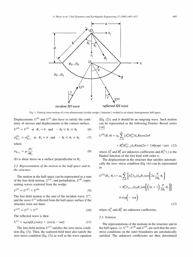
The 2D model consists of a circular wedge welded to an
elastic homogeneous half-space. Both media are linear,
elastic, homogeneous and isotropic, with shear wave velo-
cities and shear moduli bD, mD, b s and m s. Fig. 1 shows a
vertical cross-section of the model. The wedge has radius b,
angle 2u 0 and a vertical axis of symmetry through points O
and O1 which are the origins of the two Cartesian coordinate
systems, x-y-z and x1-y1-z1, used to describe the motion of
the system. Axes y and y1 project into points on the plane
shown in Fig. 1 and point towards the reader. Associated
with these two Cartesian coordinate systems are cylindrical
coordinate systems R-u -y and R1-u 1-y1 as shown in Fig. 1.
The distance between the origins of these two coordinate
systems is d� bcosu 0. The half-width of the base of the dike
is a� bsinu 0, which we will use as characteristic length of
the model. The excitation is a plane SH-wave with
frequency v , angle of incidence g , amplitude u0, displace-
ment in the y-direction, and described by
U i� � � u0exp�ks�xsing 2 zcosg�2 ivt �1�where t is time and ks � v=bs is the wave number in the
half-space.
2.1. Equations of motion and boundary and continuity
conditions
The structure and half-space will respond by anti-plane
motions, U(D) and U(s), such that they both satisfy the wave
equation
22U
2x21
22U
2z2� 1
b2
22U
2 t2�2�
subject to the following zero-stress boundary conditions
s �S�uy � 0 at R . a and u � ^p
2�3�
s�D�u1y � 0 at R1 , b and u1 � ^u0 �4�where
suy � m
R
2U
2u�5�
is the shear stress on a surface perpendicular to u .
A. Hayir et al. / Soil Dynamics and Earthquake Engineering 21 (2001) 603±613604
Displacements U(D) and U(S) also have to satisfy the conti-
nuity of stresses and displacements at the contact surface,
U�D� � U�S� at R1 � b and 2 u0 # u1 # u0 �6�
s�D�R1y1� s�S�R1y1
at R1 � b and 2 u0 # u1 # u0 �7�where
sR1y1� m
2U
2R1
�8�
(8) is shear stress on a surface perpendicular to R1.
2.2. Representation of the motion in the half-space and in
the structure
The motion in the half-space can be represented as a sum
of the free-®eld motion, U( ff ), and perturbation, U(R), repre-
senting waves scattered from the wedge
U�S� � U� ff � 1 U�R� �9�The free-®eld motion is the sum of the incident wave, U(i),
and the wave U(r) re¯ected from the half-space surface if the
structure were not there
U� ff � � U�i� 1 U�r� �10�The re¯ected wave is then
U�r� � u0exp�ks�xsing 1 zcosg�2 ivt� �11�The free-®eld motion U( ff ) satis®es the zero-stress condi-
tion (Eq. (3)). Then, the scattered ®eld must also satisfy the
zero-stress condition (Eq. (3)) as well as the wave equation
(Eq. (2)), and it should be an outgoing wave. Such motion
can be represented as the following Fourier±Bessel series
[14]
U�R��R; u� � u0
X1n�0
�ARn H�1�2n �ksR�cos2nu
1 BRn H�1�2n11�ksR�sin�2n 1 1�u�exp�2ivt� �12�
where ARn and BR
n are unknown coef®cients and H�1�n �:� is the
Hankel function of the ®rst kind with order n.
The displacement in the structure that satis®es automati-
cally the zero±stress condition (Eq. (4)) can be represented
as
U�D��R1; u1� � u0
X1n�0
�AD
n J2n�kDR1�cos
�2n
p
2u0
u1
�
1 BDn J2n11�kDR1�sin
��2n 1 1
�p
2u0
u1
��
£ exp
�2 ivt
��13�
where ADn and BD
n are unknown coef®cients.
2.3. Solution
The representations of the motions in the structure and in
the half-space, i.e. U( ff ), U(R) and U(D), are such that the zero-
stress conditions on the outer boundaries are automatically
satis®ed. The unknown coef®cients are then determined
A. Hayir et al. / Soil Dynamics and Earthquake Engineering 21 (2001) 603±613 605
Fig. 1. Vertical cross-section of a two-dimensional circular wedge (`structure') welded to an elastic homogeneous half-space.
from the continuity conditions (Eqs. (6) and (7)). Matching
the continuity conditions requires same representation for
U( ff ), U(R) and U(D). Such a representation is expansion in
Fourier±Bessel series of R1 and u 1 with period 2p . The
expansions of U(i) and U(r) are
U�i� � u0eiksdcosgX1m�0
em�2i�mJm�ksR1�cosm�u1 1 g�exp�2ivt�
�14�
U�r� � u0e2iksdcosgX1m�0
em�i�mJm�ksR1�cosm�u1 2 g�exp�2ivt�
�15�
where
em �1; m � 0
2; m . 0
(�16�
The scattered waves, U�R�, are transformed using the
exterior region form of the Graf's Addition Theorem by
which
H�1�n �ksR�cosnu
sinnu
( )� �21�n
X1m�0
H�1�n �ksR1� em
2{�Jn1m�ksd�
1 �21�nJm2n�ksd��cosmu1
2 �Jn1m�ksd�2 �21�nJm2n�ksd��sinmu1}
�17�
Substitution of Eq. (17) into Eq. (12) gives
U�R��R1; u1� � u0
X1m�0
X1n�0
H�1�m �ksR1��ARn Pm;n�ksd�cosmu1
1 BRn Qm;n�ksd�sinmu1�exp�2ivt�
�18�
where
Pm;n�s� � em
2�Jm12n�s�1 �21�2nJm22n�s��
Qm;n�s� � em
2�Jm12n11�s�2 �21�2n11Jm22n11�s�� �19�
The expression for U�D� is transformed by expanding
cos 2np
2u0
u1
� �and sin �2n 1 1� p
2u0
u1
� �
in Eq. (13) in Fourier series of period 2p . This leads to
U�D��R1; u1� � u0
X1m�0
X1n�0
�CnJ2n�kDR1�Mm;ncosmu1
1 DnJ2n11�kDR1�Nm;nsinmu1�exp�2ivt��20�
where
Mm;n � 1
p
Zp
2pcos 2n
p
2u0
u1
� �cosmu1du1 �21�
Nm;n � 1
p
Zp
2psin �2n 1 1� p
2u0
u1
� �sinmu1du1 �22�
The above Fourier expansion assumes extension of U�D�
beyond the domain of the structure, i.e. on �2p;p�, to mini-
mize the Gibb's effects at u1 � ^u0. After evaluation of the
integrals
Mm;n �
1;
1 1 sin 4npp
2u0
� �= 4np
p
2u0
� �;
�21�msin 2npp
2u0
� �= 2
m2p
4n
p
2u0
� �21
1npp
2u0
" #;
n � m � 0
m � 2np
2u0
m ± 2np
2u0
8>>>>>><>>>>>>:�23�
Nm;n �
0;
1 2 sin 2�2n 1 1�p p
2u0
� �= 2�2n 1 1�p p
2u0
� �;
�21�msin �2n 1 1�p p
2u0
� �= 2
mp
21�2n 1 1�2p
2m
p
2u0
" #;
n � m � 0
m � �2n 1 1� p
2u0
m ± �2n 1 1� p
2u0
8>>>>>><>>>>>>:�24�
The stresses are
s s� �rz �R1; u1� �
s0
kDR1
ms
mD
X1m�0
X1n�0
ARn Tm�3; ksR1�Pm;2n�ksd�cosmu1
1BRn Tm�3; ksR1�Qm;2n11�ksd�sinmu1
1Tm�1; ksR1�em�2i�mexp�iksdcosg�cosm�u1 1 g�1Tm�1; ksR1�em�i�mexp�2iksdcosg�cosm�u1 2 g�
�25�
s �D�rz �R1; u1� � s0
kDR1
X1m�0
X1n�0
ADn T2n�1; kDR1�Mm;ncosmu1
1 BDn T2n11�1; kDR1�Nm;nsinmu1
�26�where
Tm�j; s� � mCm�s�2 sCm11�s�;
Cm�s� �
Jm�s�;Ym�s�;
j � 1
j � 2
H�1�m �s�;H�2�m �s�;
j � 3
j � 4
8>>>>><>>>>>:�27�
A. Hayir et al. / Soil Dynamics and Earthquake Engineering 21 (2001) 603±613606
and
s0 � mDkDu0 �28�is the reference stress to be used for normalization if not
speci®ed otherwise.
The corresponding substitutions in the continuity condi-
tion Eqs. (6) and (7) then gives the following two in®nite
systems of equations written in matrix form
: ...
:
¼ �Wsymm;n �2£2
¼
: ...
:
26666643777775
m£n
..
.
ARn
ADn
( )2£1
..
.
8>>>>>><>>>>>>:
9>>>>>>=>>>>>>;n£1
�...
{Vsymm }2£1
..
.
8>>>><>>>>:
9>>>>=>>>>;n£1
�29�where
�W symm;n �2£2 �
J2n�kDb�Mmn 2H 1� �m �ksb�
T2n�1; kDb�Mmn 2ms
mD
Tm�3; ksb�
264375
2£2
�30�
{Gm}2£1 �emJm�ksb�cosg��2i�mexp�iksdcosg�1 imexp�2iksdcosg��
ms
mD
emTm�1; ksb�cosg��2i�mexp�iksdcosg�1 imexp�2iksdcosg��
8><>:9>=>;
2£1
�31�and
: ...
:
¼ �Wasymm;n �2£2
¼
: ...
:
26666643777775
m£n
..
.
BRn
BDn
( )2£1
..
.
8>>>>>><>>>>>>:
9>>>>>>=>>>>>>;n£1
�...
{Vasymm }2£1
..
.
8>>>><>>>>:
9>>>>=>>>>;n£1
�32�where
�Wasymm;n �2£2 �
J2n11�kDb�N�m11�;n 2H�1�m11�ksb�T2n11�1; kDb�N�m11�;n 2
ms
mD
Tm11�3; ksb�
264375
2£2
�33�
{Vasymm }2£1
�em11Jm11�ksb�cosg��2i�m11exp�iksdcosg�1 im11exp�2iksdcosg��
ms
mD
em11Tm11�1; ksb�cosg �2i�m11exp�iksdcosg�1 im11exp�2iksdcosg�h i
8><>:9>=>;
�34�The systems of Eqs. (29) and (32) can be solved numeri-
cally for the unknown coef®cients of expansion, after trun-
cation to ®nite systems.
2.4. Solution for a wedge on a rigid base
For the rigid base case, the solution of the problem is
simple. Because the motion at the base of the wedge is
synchronous, the sum in Eq. (13) collapses into one
termÐthe even term for n� 0. If the excitation is a driving
harmonic motion equal to the free-®eld motion at point O,
i.e. 2u0exp�2ivt�, then the displacement in the wedge is
U�D� � 2u0
J0�kDR1�J0�kDb� exp�2ivt� �35�
3. Results and analysis
We present the results in terms of dimensionless para-
meters. We de®ne dimensionless parameter
h � 2a
bT� va
pb�36�
equal to the ratio of the width of the `foundation' and the
wavelength, l , of shear waves in the soil (l � bT ). It can
be interpreted as dimensionless length of the base of the
structure or as dimensionless frequency.
The results we present were calculated by a code written
in Mathematica 4.0 interpreter language. All computations
were done in double precision. In all cases, the amplitude of
the incident wave is u0 � 1.
3.1. Accuracy
While in theory the accuracy of the results should
increase with increasing number of terms, in practice the
Fourier±Bessel series start diverging for number of terms
grater than a critical value, which depends on the wave-
length of the incident waves. The reason for this is that
Bessel functions of very high order are progressively smal-
ler numbers, becoming numerically indistinguishable for
suf®ciently large order, and the system of equations
becomes ill conditioned. The convergence is faster for
longer incident waves (small h ), and for larger angle of
the wedge. It is the fastest for the special case when 2u0 �1808 which is the circular valley problem for which the
matrices of the systems of equations to be solved are
block-diagonal [14]. We show results typically for
2u0 � 1508. The convergence also depends on where the
motion is evaluated.
The convergence is illustrated in Fig. 2, showing normal-
ized displacement amplitude uU�D�u=u0 for N � 5; 6 and 7,
where N is the highest order term in the truncated series, for
g � 458 and for a `soft' structure with mD=mS � 1=6 and
rD=rS � 2=3. uU�D�u=u0 is plotted vs. h for 0 , h , 1 and
2u0 � 1508. Different parts correspond to different points
along the surface of the wedge, at x=a � 0, ^0.5, ^0.75
and ^1. These results show that, as h increases, the conver-
gence is the best in the center (x=a � 0) and worst at the
corners (x=a � 1) of the base. In this paper we analyze
results for h # 1 and for 1508 # 2u0 # 1808.Table 1 shows upper bounds for the normalized displace-
ment and stress residuals along the surface of the wedge for
A. Hayir et al. / Soil Dynamics and Earthquake Engineering 21 (2001) 603±613 607

vertical and horizontal incidence and for h � 0:25, 0.5, 0.75
and 1. It is seen that the residuals are small.
3.2. Results for special casesÐcircular valley and two
ridges
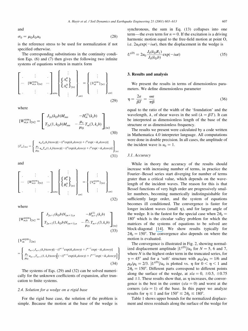
When the angle of the wedge is 2u0 � 1808, the wedge
structure becomes a circular valley [14]. Fig. 3 shows
displacement amplitude (normalized by the amplitude of
the incident wave) along the free surface for
23 , x=a , 3, for h � 0:5 and for angles of the wedge
2u0 � 1508, 1658 and 1808. Top and bottom parts corre-
spond to incident angles g � 08 and 908. The ratio of mate-
rial constants is mD=mS � 1=6 and rD=rS � 2=3. It is seen that
inside the structure, the displacements are larger for a shar-
per wedge. The results for 2u0 � 1808 coincide with those
of Trifunac [14].
When the material properties of the wedge and half-space
are the same, the model represents a topographic irregular-
ity±a triangular hill. Fig. 4 shows the amplitudes along the
free surface for 23 , x=a , 3, h � 0:5, angles of the
wedge 2u0 � 106:38, 126.98 and 151.98, corresponding to
d/a ratios 0.75, 0.5 and 0.25, respectively, and incident
angles g � 08, 458 and 908. Our results agree qualitatively
with those of SaÂnchez-Sesma et al. [7] for a ridge with
boundary de®ned by the function
y � d�1 2 �x=a�2�e23�x=a�2 �37�
where d is the height of the symmetrical ridge and 2a is the
width at the base. For d/a� 0.75 and g � 90 our method
does not converge for N , 7 and for this reason our results
for d/a� 0.75 (top right corner) are not shown in Fig. 4.
A. Hayir et al. / Soil Dynamics and Earthquake Engineering 21 (2001) 603±613608
Table 1
Upper bounds for normalized (Normalization factor for displacements is
the amplitude of the incident waves, u0, and for the stresses is
s0 � mDkDu0) displacement and stress residuals along the contact surface,
for unit amplitude incident wave and for a `soft' structure (mD=ms � 1=6 and
rD=rs � 2=3)
h N g � 08 g � 908
eU es eU es
0.25 4 1.2 £ 10211 8.7 £ 10211 1.7 £ 10210 8.4 £ 10210
0.50 5 3.2 £ 1028 2.6 £ 1027 8.8 £ 1028 8.6 £ 1027
0.75 6 8.2 £ 1026 8.1 £ 1025 1.3 £ 1025 1.4 £ 1024
1.00 7 1.1 £ 1024 1.3 £ 1023 7.6 £ 1024 1.2 £ 1022
Fig. 2. Normalized displacement amplitudes |U|/u0 vs. h , for incidence angle g � 458, evaluated at seven points along the free-surface (x/a�21, 20.75,
20.5, 0, 0.5, 0.75 and 1). The index of the highest order term in the series is N� 5, 6, and 7.
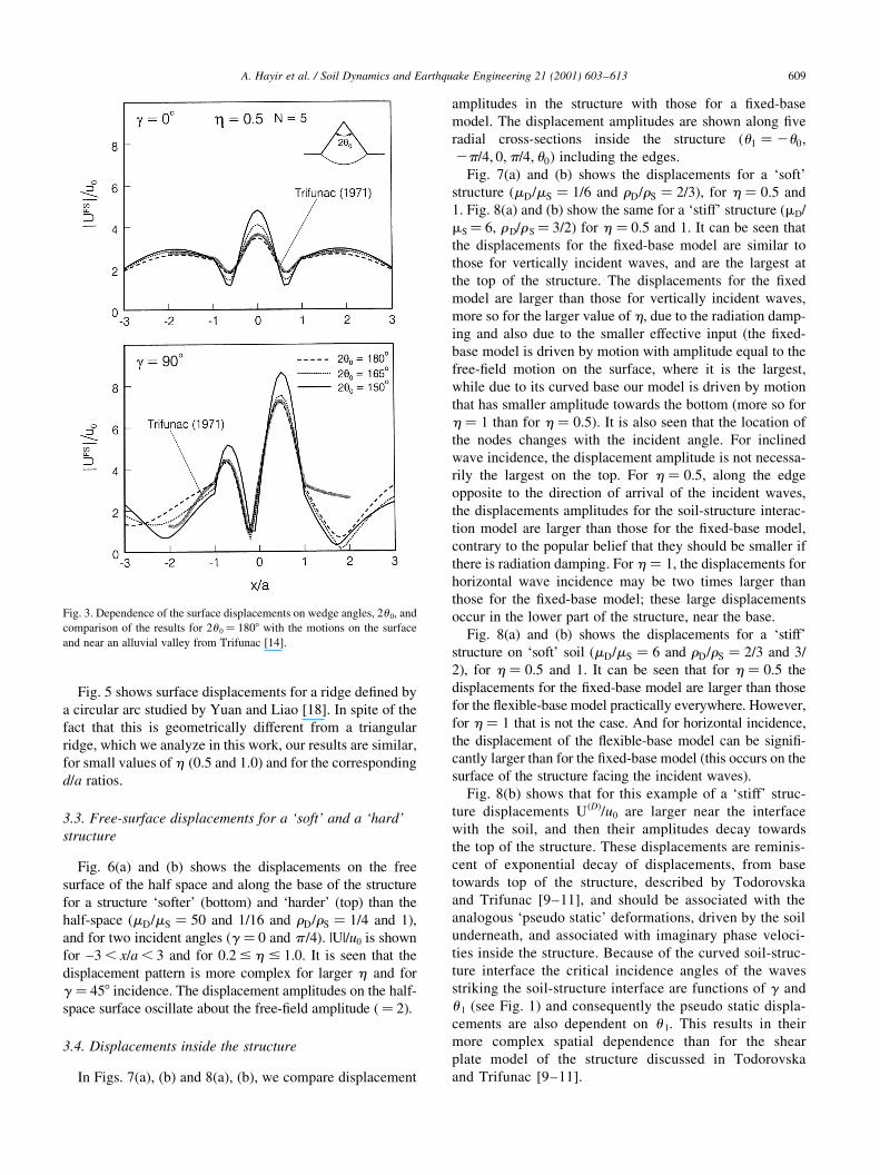
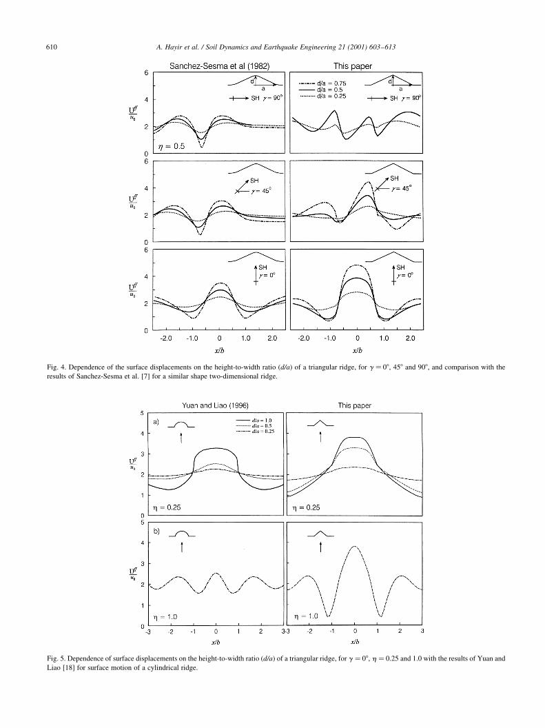
Fig. 5 shows surface displacements for a ridge de®ned by
a circular arc studied by Yuan and Liao [18]. In spite of the
fact that this is geometrically different from a triangular
ridge, which we analyze in this work, our results are similar,
for small values of h (0.5 and 1.0) and for the corresponding
d/a ratios.
3.3. Free-surface displacements for a `soft' and a `hard'
structure
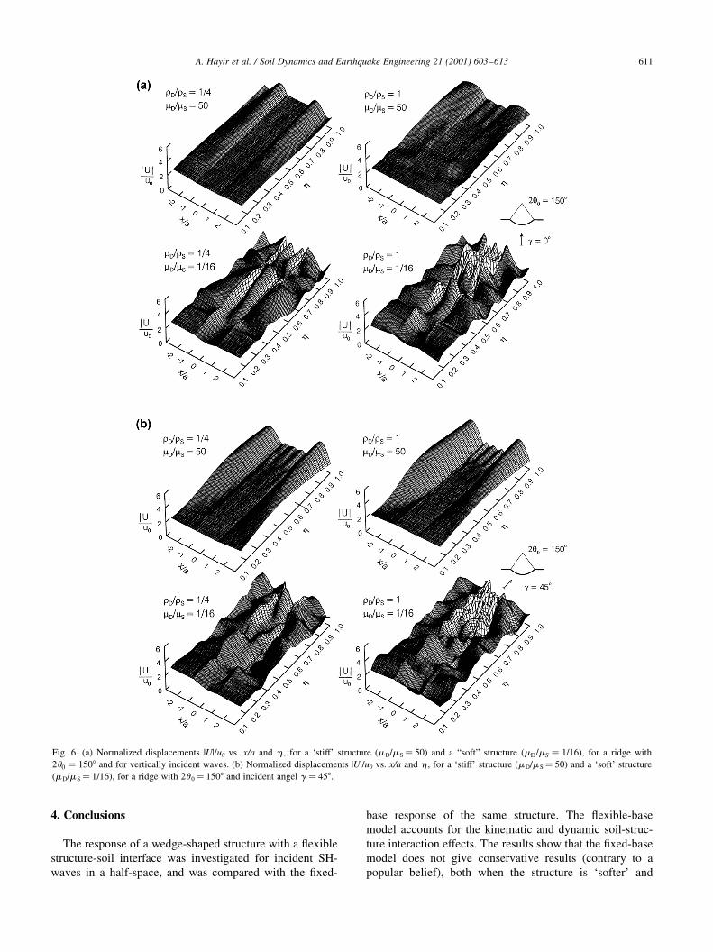
Fig. 6(a) and (b) shows the displacements on the free
surface of the half space and along the base of the structure
for a structure `softer' (bottom) and `harder' (top) than the
half-space (mD=mS � 50 and 1/16 and rD=rS � 1=4 and 1),
and for two incident angles (g � 0 and p /4). |U|/u0 is shown
for ±3 , x/a , 3 and for 0.2 # h # 1.0. It is seen that the
displacement pattern is more complex for larger h and for
g � 458 incidence. The displacement amplitudes on the half-
space surface oscillate about the free-®eld amplitude (� 2).
3.4. Displacements inside the structure
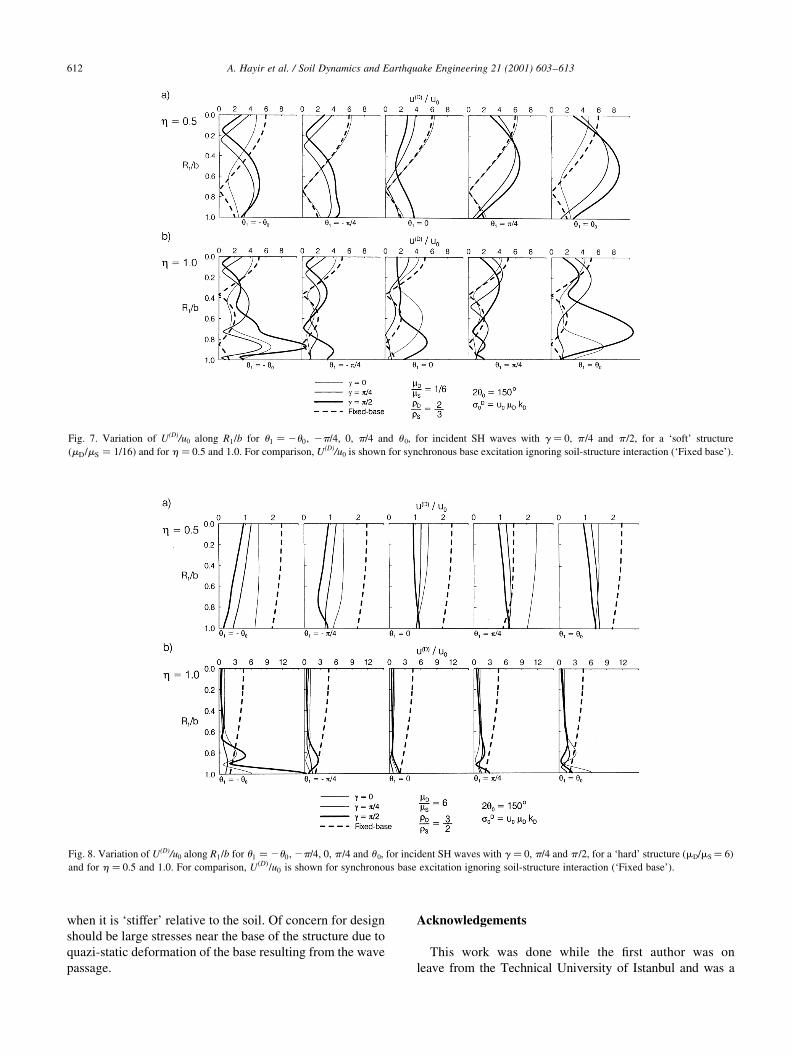
In Figs. 7(a), (b) and 8(a), (b), we compare displacement
amplitudes in the structure with those for a ®xed-base
model. The displacement amplitudes are shown along ®ve
radial cross-sections inside the structure (u1 � 2u0;
2p=4; 0;p=4; u0) including the edges.
Fig. 7(a) and (b) shows the displacements for a `soft'
structure (mD=mS � 1=6 and rD=rS � 2=3), for h � 0:5 and
1. Fig. 8(a) and (b) show the same for a `stiff' structure (mD/
mS� 6, rD/rS� 3/2) for h � 0.5 and 1. It can be seen that
the displacements for the ®xed-base model are similar to
those for vertically incident waves, and are the largest at
the top of the structure. The displacements for the ®xed
model are larger than those for vertically incident waves,
more so for the larger value of h, due to the radiation damp-
ing and also due to the smaller effective input (the ®xed-
base model is driven by motion with amplitude equal to the
free-®eld motion on the surface, where it is the largest,
while due to its curved base our model is driven by motion
that has smaller amplitude towards the bottom (more so for
h � 1 than for h � 0:5). It is also seen that the location of
the nodes changes with the incident angle. For inclined
wave incidence, the displacement amplitude is not necessa-
rily the largest on the top. For h � 0:5, along the edge
opposite to the direction of arrival of the incident waves,
the displacements amplitudes for the soil-structure interac-
tion model are larger than those for the ®xed-base model,
contrary to the popular belief that they should be smaller if
there is radiation damping. For h � 1, the displacements for
horizontal wave incidence may be two times larger than
those for the ®xed-base model; these large displacements
occur in the lower part of the structure, near the base.
Fig. 8(a) and (b) shows the displacements for a `stiff'
structure on `soft' soil (mD=mS � 6 and rD=rS � 2=3 and 3/
2), for h � 0:5 and 1. It can be seen that for h � 0:5 the
displacements for the ®xed-base model are larger than those
for the ¯exible-base model practically everywhere. However,
for h � 1 that is not the case. And for horizontal incidence,
the displacement of the ¯exible-base model can be signi®-
cantly larger than for the ®xed-base model (this occurs on the
surface of the structure facing the incident waves).
Fig. 8(b) shows that for this example of a `stiff' struc-
ture displacements U(D)/u0 are larger near the interface
with the soil, and then their amplitudes decay towards
the top of the structure. These displacements are reminis-
cent of exponential decay of displacements, from base
towards top of the structure, described by Todorovska
and Trifunac [9±11], and should be associated with the
analogous `pseudo static' deformations, driven by the soil
underneath, and associated with imaginary phase veloci-
ties inside the structure. Because of the curved soil-struc-
ture interface the critical incidence angles of the waves
striking the soil-structure interface are functions of g and
u 1 (see Fig. 1) and consequently the pseudo static displa-
cements are also dependent on u 1. This results in their
more complex spatial dependence than for the shear
plate model of the structure discussed in Todorovska
and Trifunac [9±11].
A. Hayir et al. / Soil Dynamics and Earthquake Engineering 21 (2001) 603±613 609
Fig. 3. Dependence of the surface displacements on wedge angles, 2u 0, and
comparison of the results for 2u 0� 1808 with the motions on the surface
and near an alluvial valley from Trifunac [14].
A. Hayir et al. / Soil Dynamics and Earthquake Engineering 21 (2001) 603±613610
Fig. 5. Dependence of surface displacements on the height-to-width ratio (d/a) of a triangular ridge, for g � 08, h � 0.25 and 1.0 with the results of Yuan and
Liao [18] for surface motion of a cylindrical ridge.
Fig. 4. Dependence of the surface displacements on the height-to-width ratio (d/a) of a triangular ridge, for g � 08, 458 and 908, and comparison with the
results of Sanchez-Sesma et al. [7] for a similar shape two-dimensional ridge.
4. Conclusions
The response of a wedge-shaped structure with a ¯exible
structure-soil interface was investigated for incident SH-
waves in a half-space, and was compared with the ®xed-
base response of the same structure. The ¯exible-base
model accounts for the kinematic and dynamic soil-struc-
ture interaction effects. The results show that the ®xed-base
model does not give conservative results (contrary to a
popular belief), both when the structure is `softer' and
A. Hayir et al. / Soil Dynamics and Earthquake Engineering 21 (2001) 603±613 611
Fig. 6. (a) Normalized displacements |U|/u0 vs. x/a and h , for a `stiff' structure (mD/mS� 50) and a ªsoftº structure (mD=mS � 1=16), for a ridge with
2u0 � 1508 and for vertically incident waves. (b) Normalized displacements |U|/u0 vs. x/a and h , for a `stiff' structure (mD/mS� 50) and a `soft' structure
(mD/mS� 1/16), for a ridge with 2u 0� 1508 and incident angel g � 458.
when it is `stiffer' relative to the soil. Of concern for design
should be large stresses near the base of the structure due to
quazi-static deformation of the base resulting from the wave
passage.
Acknowledgements
This work was done while the ®rst author was on
leave from the Technical University of Istanbul and was a
A. Hayir et al. / Soil Dynamics and Earthquake Engineering 21 (2001) 603±613612
Fig. 8. Variation of U(D)/u0 along R1=b for u1 � 2u0, 2p=4, 0, p /4 and u 0, for incident SH waves with g � 0, p/4 and p /2, for a `hard' structure (mD/mS� 6)
and for h � 0.5 and 1.0. For comparison, U�D�=u0 is shown for synchronous base excitation ignoring soil-structure interaction (`Fixed base').
Fig. 7. Variation of U(D)/u0 along R1=b for u1 � 2u0, 2p=4, 0, p=4 and u 0, for incident SH waves with g � 0, p /4 and p /2, for a `soft' structure
(mD=mS � 1=16� and for h � 0.5 and 1.0. For comparison, U(D)/u0 is shown for synchronous base excitation ignoring soil-structure interaction (`Fixed base').

Postdoctoral Fellow at the University of Southern California.
The ®nancial support for his stay from TUBITAK-NATO is
gratefully acknowledged. The authors also thank T.Y. Hao
for her help in preparation of the illustrations presented in this
paper.
References
[1] Iguchi M, Luco JE. Vibration of ¯exible plate on visoelastic medium.
J Enrng Mech, ASCE 1982;108(6):1103±20.
[2] Kojic S, Trifunac MD. `Earthquake Response of Arch Dams to Nonu-
niform Canyon Motion'. Dept. of Civil Eng., Rep. No. CE 88-03.
University of Southern California, Los Angeles, California, 1988.
[3] Kojic S, Trifunac MD. Earthquake stresses in arch dams: IÐtheory
and antiplane excitation. J Eng Mech, ASCE 1991;117(3):532±52.
[4] Kojic S, Trifunac MD. Earthquake stresses in arch dams: IIÐexcitation
by SV, P and Rayleigh waves. J Eng Mech, ASCE 1991;117(3):553±74.
[5] Liou G-S, Huang PH. Effects of ¯exibility on impedance functions
for circular foundations. J Eng Mech, ASCE 1994;120(7):1429±46.
[6] Luco JE. Dynamic interaction of a shear wall with the soil. J Eng
Mech, ASCE 1969;95:333±46.
[7] SaÂnchez-Sesma FJ, Herrera I, AvileÂs J. A boundary method for elastic
wave diffraction: application to scattering of SH-waves by surface
irregularities. Bull Seism Soc Am 1982;72(2):473±90.
[8] Todorovska MI, Lee VW. Seismic waves in buildings with shear
walls or central core. J Eng Mech, ASCE 1989;115(12):2669±86.
[9] Todorovska MI, Trifunac MD. Antiplane earthquake waves in long
structures. J Engrg Mech, ASCE 1989;115(12):2687±708.
[10] Todorovska MI, Trifunac MD. A note on the propagation of earth-
quake waves in buildings with soft ®rst ¯oor. J Engrg Mech, ASCE
1990;116(4):892±900.
[11] Todorovska MI, Trifunac MD. A note on excitation of long structures
by ground waves. J Engrg Mech, ASCE 1990;116(4):952±64.
[12] Todorovska MI, Trifunac MD. Analytical model for in-plane build-
ing-foundation-soil interaction: incident P-, SV- and Rayleigh waves.
Rep. No. CE 90-01. Dept. of Civil Engrg, University of Southern
California, Los Angeles, California, 1990.
[13] Todorovska MI, Trifunac MD. The system damping, the system
frequency and the system response peak amplitudes during in-plane
building-soil interaction. Earthquake Engrg Struct Dynam
1992;21(2):127±44.
[14] Trifunac MD. Surface motion of a semi-cylindrical alluvial
valley for incident plane SH waves. Bull Seism Soc Am
1971;61(2):1755±70.
[15] Trifunac MD. Interaction of a shear wall with the soil for incident
plane SH waves. Bull Seism Soc Am 1972;62:63±83.
[16] Trifunac MD, Todorovska MI. Response spectra for differential motion
of columns. Earthquake Engrg Struct Dynam 1997;26(2):251±68.
[17] Trifunac MD, Ivanovic SS, Todorovska MI, Novikova EI, Gladkov
AP. Experimental evidence for ¯exibility of a building foundation
supported by concrete friction piles. Soil Dynam Earthquake Engrg
1999;18(3):169±87.
[18] Yuan X, Liao ZP. Surface motion of a cylindrical hill of circular-arc
cross-section for incident plane SH waves. Soil Dynam Earthquake
Engrg 1996;15:189±99.
A. Hayir et al. / Soil Dynamics and Earthquake Engineering 21 (2001) 603±613 613