Antagonism of behavioral effects of bromocriptine by prolactin in female cats
Advanced Robotics 22 (2008) 39–55www.brill.nl/ar
Full paper
Antagonism for a Highly Anthropomorphic Hand–ArmSystem
Markus Grebenstein and Patrick van der Smagt ∗
Institute of Robotics and Mechatronics, German Aerospace Center/DLR Oberpfaffenhofen, PO Box1116, 82230 Wessling, Germany
Received 22 May 2007; revised 22 May 2007; accepted 6 September 2007
AbstractA novel approach to antagonism in robotic systems is introduced and investigated as the basis for an un-equalled, highly anthropomorphic hand–arm system currently being developed. This hand–arm system,consisting of a 19-d.o.f. hand and a 7-d.o.f. flexible arm, will be based on antagonistic principles in or-der to study and mimic the human musculoskeletal system, as well as to advance safety in robotics. Koninklijke Brill NV, Leiden and The Robotics Society of Japan, 2008
KeywordsHand, antagonism, anthropomorphic, muscle, arm
1. Introduction
Biological musculoskeletal systems are antagonistic. Each joint is activated by agroup of muscles, pulling the bones via tendons. Apparently for reasons of lin-earization of the dynamics [1], this architecture is rather complex, e.g., for planarmotion of the elbow and shoulder only, the human arm uses a total of 19 muscles(Fig. 1), forming a complex of agonist, antagonist, monoarticulate and biarticulatemuscles.
From a biological point of view, there are many reasons to use antagonistic driveprinciples for generating motion. Of course, a strong one is the fact that muscles,responsible for vertebrate motion, can only pull and not push. However, apart fromthat restriction, the antagonistic approach leads to two important advantages: thesystem is energy-optimal for various tasks [2] and the joints are intrinsically flexi-ble.
* To whom correspondence should be addressed. E-mail: [email protected]
Koninklijke Brill NV, Leiden and The Robotics Society of Japan, 2008 DOI:10.1163/156855308X291836

40 M. Grebenstein, P. van der Smagt / Advanced Robotics 22 (2008) 39–55
Figure 1. Simplified, planar model of the human arm [5] using 19 muscles or muscle groups in total.In this model, only the muscles that are responsible for motion of the elbow or shoulder in the planeare accounted for.
Flexibility is a key characteristic for physically interacting with an environment.When humans and robots physically cooperate, the first issue that has to be resolvedis ensuring safety for the human as well as for the robot. In Ref. [3], a promis-ing collision detection and reaction approach, applicable to flexible-joint robots,is presented, but antagonistic actuation offers fundamentally new concepts. Apartfrom precluding prohibitively high stiffness during physical contact, antagonism al-lows predefining the real physical behavior of the manipulator by adjusting the jointstiffness as a function of, for example, joint velocity or output inertia of the robot.A possible heuristic of adjusting the joint stiffness during a rest-to-rest motion isdescribed in Ref. [4].
In order to obtain dynamic properties very similar to musculoskeletal systems,we therefore consider antagonistic drive principles of key importance for futurerobotics. Using this principle, we are constructing a revolutionary hand–arm sys-tem which mimics the kinematic and dynamic properties of the human hand–armcomplex as closely as possible. Using biological drive and joint concepts, this newhand–arm system will consist of a hand with 19 active d.o.f. attached to a robot armwith 7 active d.o.f., all with weight, size and strength properties equal or close tothat of humans.
2. Approaches to Antagonism in Robotics
Antagonistic drive principles have two major important characteristics: an antag-onistic system is energy-optimal for various tasks [2] and antagonistically drivenjoints are intrinsically flexible. This latter property leads to completely new possi-bilities with respect to safe human–robot interaction, but also with respect to thecontrol of such drive principles.
M. Grebenstein, P. van der Smagt / Advanced Robotics 22 (2008) 39–55 41
The development of antagonistic robot joints is a multi-disciplinary challengerather than a mechanical problem. Therefore, a large antagonistic system requires acomplete system design, including control strategies for the most important controlmodes. Due to the elastic elements, every motor action in an antagonistic systemwill induce vibration.
Flexibility at the joint level requires the inclusion of a nonlinear spring betweenthe actuator and the joint. Two different principles can be distinguished in theliterature: those based on linear springs and those based on nonlinear (typicallyrubber-based) elements.
2.1. Rubber
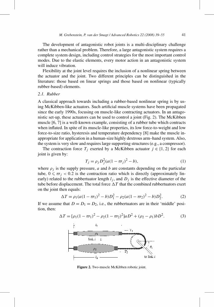
A classical approach towards including a rubber-based nonlinear spring is by us-ing McKibben-like actuators. Such artificial muscle systems have been propagatedsince the early 1990s, focusing on muscle-like contracting actuators. In an antago-nistic set-up, these actuators can be used to control a joint (Fig. 2). The McKibbenmuscle [6, 7] is a well-known example, consisting of a rubber tube which contractswhen inflated. In spite of its muscle-like properties, its low force-to-weight and lowforce-to-size ratio, hysteresis and temperature dependency [8] make the muscle in-appropriate for application in a human-size highly dextrous arm–hand system. Also,the system is very slow and requires large supporting structures (e.g., a compressor).
The contraction force Tj exerted by a McKibben actuator j ∈ {1,2} for eachjoint is given by:
Tj = ρjD2j (a(1 − �j)
2 − b), (1)
where ρj is the supply pressure, a and b are constants depending on the particulartube, 0 � �j < 0.2 is the contraction ratio which is directly (approximately lin-early) related to the rubbertuator length lj , and Dj is the effective diameter of thetube before displacement. The total force �T that the combined rubbertuators exerton the joint then equals:
�T = ρ1(a(1 − �1)2 − b)D2
1 − ρ2(a(1 − �2)2 − b)D2
2 . (2)
If we assume that D = D1 = D2, i.e., the rubbertuators are in their ‘middle’ posi-tion, then:
�T = [ρ1(1 − �1)2 − ρ2(1 − �2)
2]aD2 + (ρ2 − ρ1)bD2. (3)
Figure 2. Two-muscle McKibben robotic joint.
42 M. Grebenstein, P. van der Smagt / Advanced Robotics 22 (2008) 39–55
Defining �ρ = ρ1 − ρ2 (the ‘difference pressure’) and ρ0 = ρ1 + ρ2 (the ‘basepressure’ or stiffness), and grouping we find:
�T = µ1ρ0θ + µ2�ρθ2 + µ3�ρ. (4)
The hysteretic behavior, caused by the rubber material, of aMcKibben-driven joint can be modeled by substituting different values for D. Ifwe assume that muscle 1 has a diameter D1 = D + �D before displacement andthat muscle 2 has a diameter D2 = D − �D before displacement, then (1) can bewritten as:
�T = P1(a(1 − �1)2 − b)(D + �D)2
+ P2(a(1 − �2)2 − b)(D − �D)2.
By splitting this equation in three parts for D, �D and D�D we can apply (4) bysubstituting first D and then �D in (3), such that:
�T = (µ1 + µ′1)ρ0θ + (µ2 + µ′
2)�ρθ2 + (µ3 + µ′3)�ρ
+ µ′′1�ρθ + µ′′
2ρ0θ2 + µ′′
3ρ0, (5)
where the parameters µ′i and µ′′
i are:
µ′i = µi
�D2
D2, µ′′
i = µi
�D
D.
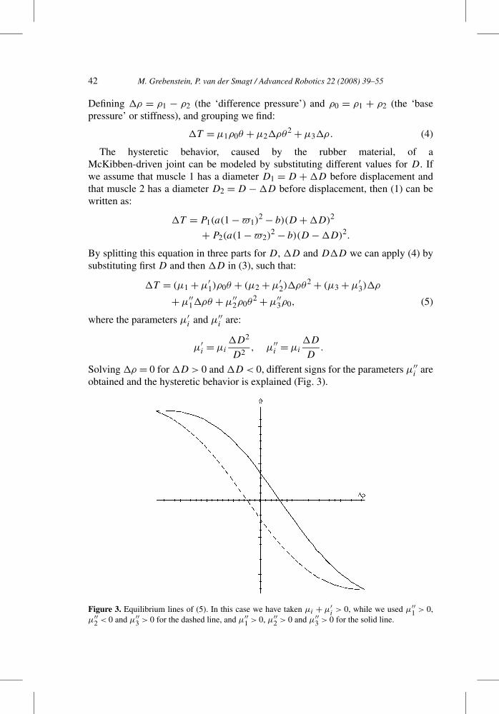
Solving �ρ = 0 for �D > 0 and �D < 0, different signs for the parameters µ′′i are
obtained and the hysteretic behavior is explained (Fig. 3).
Figure 3. Equilibrium lines of (5). In this case we have taken µi + µ′i> 0, while we used µ′′
1 > 0,µ′′
2 < 0 and µ′′3 > 0 for the dashed line, and µ′′
1 > 0, µ′′2 > 0 and µ′′
3 > 0 for the solid line.
M. Grebenstein, P. van der Smagt / Advanced Robotics 22 (2008) 39–55 43
We have investigated a different approach to obtain nonlinear spring characteris-tics. In this set-up, two DC motors control a joint through nonlinear elastic elements.These elastic elements consisted of a cylindrical pot containing up to six rubberballs with a diameter between 6 and 9 mm. A downside tendon leads through thispot and presses a plate located above the balls against the bottom of the pot. Ow-ing to their highly non-linear properties rubber balls are used. These characteristicsderive from the behavior of the elastomer as well as their spherical geometry.
The characteristics of the rubber balls can be approximated by an exponentialfunction. A problem with this approach, however, appeared to be the hysteresis ofthe rubber balls. Although this hysteresis can be reduced by sufficient lubrication,it cannot be prevented. Furthermore, the flexibility obtained through this approachis rather limited, while the pots are comparatively large. We, therefore, abandonedthis line of research.
2.2. Linear Springs
Due to their compact size and high force-to-weight ratio, DC motors are a morelikely candidate for actuation in anthropomorphic systems. Most approaches consistof two motors working against (to increase stiffness) or with (to change position)each other and are connected over gear boxes via elastic elements. In most cases,these elastic elements consist of springs [9–11]. Since springs are linear, however,these alone do not suffice — increasing the force of a linear spring does not increaseits stiffness. Therefore, such solutions have to include a mechanism changing thelinear properties of the spring into a non-linear behavior.
There have been different approaches towards obtaining non-linear springs inthe literature. Morita and Sugano [12] used a spring leaf with varying length in or-der to induce nonlinearities on the spring. The construction, however, was difficultand error-prone, and led to a complex nonlinear transfer function. Migliore et al.[11] used a special spring device inducing a force–length relationship which canbe determined by the curvature of a bar extending two springs. The constructionis relatively large and may suffer from non-linear friction and wear-and-tear. Toni-etti et al. [13] introduced a variable stiffness actuator, a rather complex and largestructure actuating three springs with tendons over rollers. English and Russell [14]construct an antagonistic elbow joint using similar approaches as presented in thispaper. However, in our approach the elbow actuators cannot be placed in the lowerarm, since that space is needed for the hand actuators. Also, they assume that armstiffness is independent of joint position, but that would lead to linear springs andremove the requirement of robustness against collisions, since the stiffness near thejoint limit would not increase, as it does in our case.
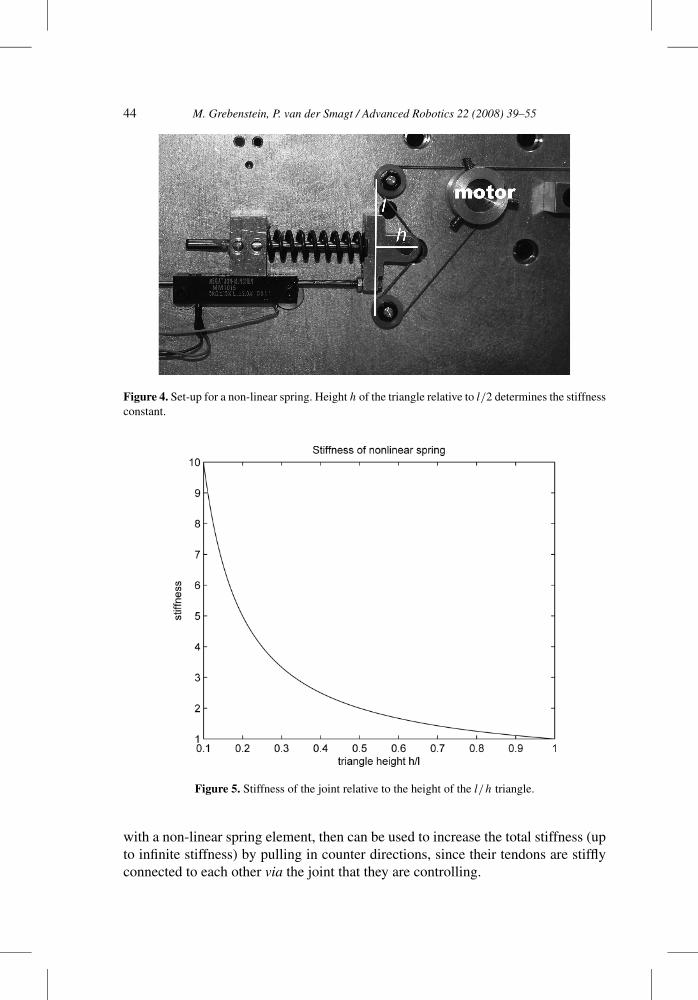
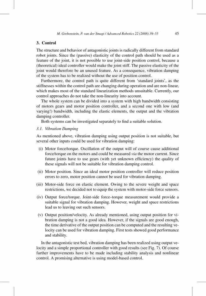
Our concept follows the approach in Ref. [13], but in a significantly simplifiedform. In our set-up, each motor is equipped with a non-linear spring element (seeFig. 4). Each element consists of a linear spring which pushes the tendon, formingit into a triangle. The height h of this triangle relative to half base l determinesthe stiffness of the construction (Fig. 5). Two motors, each of which is equipped
44 M. Grebenstein, P. van der Smagt / Advanced Robotics 22 (2008) 39–55
Figure 4. Set-up for a non-linear spring. Height h of the triangle relative to l/2 determines the stiffnessconstant.
Figure 5. Stiffness of the joint relative to the height of the l/h triangle.
with a non-linear spring element, then can be used to increase the total stiffness (upto infinite stiffness) by pulling in counter directions, since their tendons are stifflyconnected to each other via the joint that they are controlling.
M. Grebenstein, P. van der Smagt / Advanced Robotics 22 (2008) 39–55 45
3. Control
The structure and behavior of antagonistic joints is radically different from standardrobot joints. Since the (passive) elasticity of the control path should be used as afeature of the joint, it is not possible to use joint-side position control, because a(theoretical) ideal controller would make the joint stiff. The passive elasticity of thejoint would therefore be an unused feature. As a consequence, vibration dampingof the system has to be realized without the use of position control.
Furthermore, the control path is quite different from ‘standard joints’, as thestiffnesses within the control path are changing during operation and are non-linear,which makes most of the standard linearization methods unsuitable. Currently, ourcontrol approaches do not take the non-linearity into account.
The whole system can be divided into a system with high bandwidth consistingof motors gears and motor position controller, and a second one with low (andvarying!) bandwidth, including the elastic elements, the output and the vibrationdamping controller.
Both systems can be investigated separately to find a suitable solution.
3.1. Vibration Damping
As mentioned above, vibration damping using output position is not suitable, butseveral other inputs could be used for vibration damping:
(i) Motor force/torque. Oscillation of the output will of course cause additionalforce/torque on the motors and could be measured via the motor current. Sincefuture joints have to use gears (with yet unknown efficiency) the quality ofthese signals will not be suitable for vibration damping control.
(ii) Motor position. Since an ideal motor position controller will reduce positionerrors to zero, motor position cannot be used for vibration damping.
(iii) Motor-side force on elastic element. Owing to the severe weight and spacerestrictions, we decided not to equip the system with motor-side force sensors.
(iv) Output force/torque. Joint-side force–torque measurement would provide asuitable signal for vibration damping. However, weight and space restrictionslead us to leaving out such sensors.
(v) Output position/velocity. As already mentioned, using output position for vi-bration damping is not a good idea. However, if the signals are good enough,the time derivative of the output position can be computed and the resulting ve-locity can be used for vibration damping. First tests showed good performanceand stability.
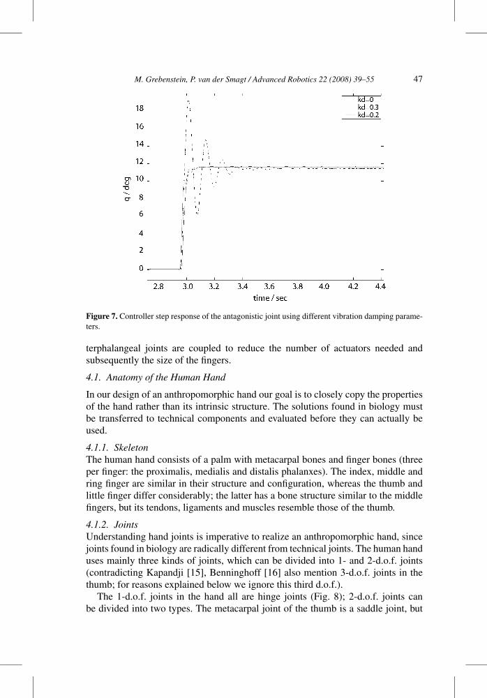
In the antagonistic test bed, vibration damping has been realized using output ve-locity and a simple proportional controller with good results (see Fig. 7). Of coursefurther improvements have to be made including stability analysis and nonlinearcontrol. A promising alternative is using model-based control.
46 M. Grebenstein, P. van der Smagt / Advanced Robotics 22 (2008) 39–55
3.2. Force Control
Since the spatial limits in the anthropomorphic arm are quite strict, the numberof sensors needed has to be kept low. We, therefore, opted for using system stateknowledge for additional data acquisition.
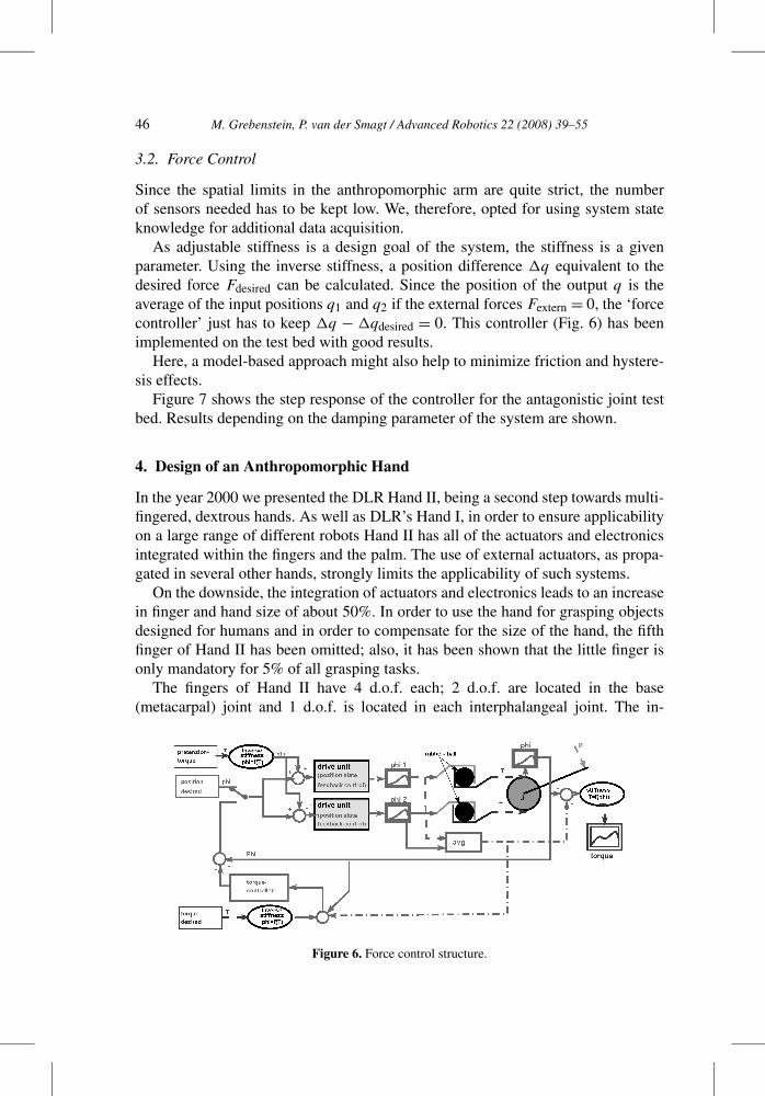
As adjustable stiffness is a design goal of the system, the stiffness is a givenparameter. Using the inverse stiffness, a position difference �q equivalent to thedesired force Fdesired can be calculated. Since the position of the output q is theaverage of the input positions q1 and q2 if the external forces Fextern = 0, the ‘forcecontroller’ just has to keep �q − �qdesired = 0. This controller (Fig. 6) has beenimplemented on the test bed with good results.
Here, a model-based approach might also help to minimize friction and hystere-sis effects.
Figure 7 shows the step response of the controller for the antagonistic joint testbed. Results depending on the damping parameter of the system are shown.
4. Design of an Anthropomorphic Hand
In the year 2000 we presented the DLR Hand II, being a second step towards multi-fingered, dextrous hands. As well as DLR’s Hand I, in order to ensure applicabilityon a large range of different robots Hand II has all of the actuators and electronicsintegrated within the fingers and the palm. The use of external actuators, as propa-gated in several other hands, strongly limits the applicability of such systems.
On the downside, the integration of actuators and electronics leads to an increasein finger and hand size of about 50%. In order to use the hand for grasping objectsdesigned for humans and in order to compensate for the size of the hand, the fifthfinger of Hand II has been omitted; also, it has been shown that the little finger isonly mandatory for 5% of all grasping tasks.
The fingers of Hand II have 4 d.o.f. each; 2 d.o.f. are located in the base(metacarpal) joint and 1 d.o.f. is located in each interphalangeal joint. The in-
Figure 6. Force control structure.
M. Grebenstein, P. van der Smagt / Advanced Robotics 22 (2008) 39–55 47
Figure 7. Controller step response of the antagonistic joint using different vibration damping parame-ters.
terphalangeal joints are coupled to reduce the number of actuators needed andsubsequently the size of the fingers.
4.1. Anatomy of the Human Hand
In our design of an anthropomorphic hand our goal is to closely copy the propertiesof the hand rather than its intrinsic structure. The solutions found in biology mustbe transferred to technical components and evaluated before they can actually beused.
4.1.1. SkeletonThe human hand consists of a palm with metacarpal bones and finger bones (threeper finger: the proximalis, medialis and distalis phalanxes). The index, middle andring finger are similar in their structure and configuration, whereas the thumb andlittle finger differ considerably; the latter has a bone structure similar to the middlefingers, but its tendons, ligaments and muscles resemble those of the thumb.
4.1.2. JointsUnderstanding hand joints is imperative to realize an anthropomorphic hand, sincejoints found in biology are radically different from technical joints. The human handuses mainly three kinds of joints, which can be divided into 1- and 2-d.o.f. joints(contradicting Kapandji [15], Benninghoff [16] also mention 3-d.o.f. joints in thethumb; for reasons explained below we ignore this third d.o.f.).
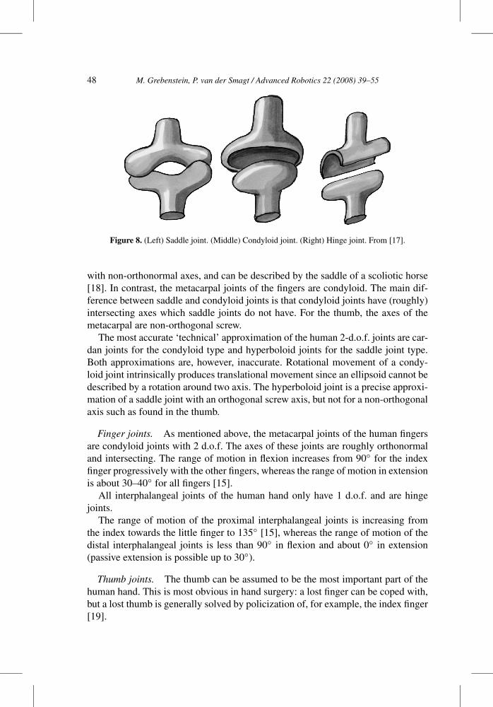
The 1-d.o.f. joints in the hand all are hinge joints (Fig. 8); 2-d.o.f. joints canbe divided into two types. The metacarpal joint of the thumb is a saddle joint, but
48 M. Grebenstein, P. van der Smagt / Advanced Robotics 22 (2008) 39–55
Figure 8. (Left) Saddle joint. (Middle) Condyloid joint. (Right) Hinge joint. From [17].
with non-orthonormal axes, and can be described by the saddle of a scoliotic horse[18]. In contrast, the metacarpal joints of the fingers are condyloid. The main dif-ference between saddle and condyloid joints is that condyloid joints have (roughly)intersecting axes which saddle joints do not have. For the thumb, the axes of themetacarpal are non-orthogonal screw.
The most accurate ‘technical’ approximation of the human 2-d.o.f. joints are car-dan joints for the condyloid type and hyperboloid joints for the saddle joint type.Both approximations are, however, inaccurate. Rotational movement of a condy-loid joint intrinsically produces translational movement since an ellipsoid cannot bedescribed by a rotation around two axis. The hyperboloid joint is a precise approxi-mation of a saddle joint with an orthogonal screw axis, but not for a non-orthogonalaxis such as found in the thumb.
Finger joints. As mentioned above, the metacarpal joints of the human fingersare condyloid joints with 2 d.o.f. The axes of these joints are roughly orthonormaland intersecting. The range of motion in flexion increases from 90◦ for the indexfinger progressively with the other fingers, whereas the range of motion in extensionis about 30–40◦ for all fingers [15].
All interphalangeal joints of the human hand only have 1 d.o.f. and are hingejoints.
The range of motion of the proximal interphalangeal joints is increasing fromthe index towards the little finger to 135◦ [15], whereas the range of motion of thedistal interphalangeal joints is less than 90◦ in flexion and about 0◦ in extension(passive extension is possible up to 30◦).
Thumb joints. The thumb can be assumed to be the most important part of thehuman hand. This is most obvious in hand surgery: a lost finger can be coped with,but a lost thumb is generally solved by policization of, for example, the index finger[19].
M. Grebenstein, P. van der Smagt / Advanced Robotics 22 (2008) 39–55 49
The metacarpal joint (anatomically correct: trapezo-metacarpal joint). Sincethe coupling of the bones in the human hand is not stiff, compliant motion in al-most every direction is possible. Subsequently, there are several opinions of howmany d.o.f. the metacarpal and thus the first interphalangeal joint of the thumb has.Kapandji [15] hypothesizes 2 d.o.f. in the metacarpal and 2 d.o.f. in the first inter-phalangeal joint, while Ref. [16] suggests 3 d.o.f. in the metacarpal and 1 d.o.f. inthe first interphalangeal joint.
Following Kapandji [15], we consider the metacarpal of the thumb to be a2-d.o.f. saddle joint. In contrast to ‘standard’ saddle joints, the contact surfacesare not formed by a common generatrix rotating about two orthogonal axes (e.g.,hyperboloids). Rather, Kuczynski [18] showed that the surface of the saddle on theproximal side of the joint is bent around a third axis. This deformation of the sad-dle surface introduces a coupled additional rotation around the longitudinal axis ofthe thumb which is necessary to enable opposition of the thumb, required for mostmanipulation tasks (during this rotation the inner surface of the thumb changes itsorientation by 90–120◦ towards the inner side of the palm).
The interphalangeal joints (anatomically correct: metacarpo-phalangeal joint anddistal interphalangeal joint) of the thumb are similar to those of the fingers. Ka-pandji proposes that the fifth d.o.f. of the thumb is located in the proximal inter-phalangeal joint as a limited-range d.o.f. along the longitudinal axis of the medialphalanx. One hint to prove this is that the proximal interphalangeal joint of thethumb is not a hinge joint, but a condyloid joint. Based on the experiences frompolicization, this d.o.f. can be assumed less important; after all, near-perfect handfunctionality can be regained by replanting the index finger as a thumb. The rangeof motion of the proximal interphalangeal joint is 60–70◦ in flexion and 0◦ in ex-tension, whereas the the distal interphalangeal joints motion range is about 75–80◦in flexion and 5–10◦ in extension.
4.2. Getting it Together: the Joints of the DLR Anthropomorphic Finger
As already mentioned, the most difficult point in the design of an anthropomorphichand is to understand the human hand and copy its properties rather than copyingthe biological structure hand itself. There are several key differences between bio-logical and technical systems which have to be taken into account in order to endup with a optimal technical system. An example is the lack of renewable materialsin technical systems. Also, there is a need to keep the system as simple as possiblefrom a control point of view, since we are still not able to build capable enoughbiologically inspired control methods for complete integrated systems. Therefore,several simplifications have to be realized.
4.2.1. ActuationOne of the major problems of most current robotic hands (e.g., the UB Hand[20], Robonaut Hand [21], Karlsruhe Hand [22], DLR Hand) is robustness againstimpact. The maximum force that can be exerted by these hands is sufficient for per-forming manipulation tasks and their agility is good enough to catch balls, but they
50 M. Grebenstein, P. van der Smagt / Advanced Robotics 22 (2008) 39–55
are limited in use due to their sensitivity regarding impacts. For instance, the weightof the ball that is caught by Hand II has to be limited to prevent major damage to thehand; the maximum speed of service robots opening doors has to be strongly limitedto prevent major damage in the case of contact with stiff objects in the environment.The reason for this sensitivity is the lack of mechanical elasticity of the fingers, re-sulting in an inability to store energy short-term. Flexibility obtained through activecontrol, such as is obtained with Hand II that is impedance-controlled using a con-trol frequency of 1 kHz, can be used to react to slow impacts and contact with stiffobjects, but in the case of fast impact (‘ball throwing’), a large amount of energy istransferred within the first microseconds, to which no active controller can react.
To make systems more robust against impacts from balls, doors, walls, etc., themechanical structure of the system has to be intrinsically elastic and should be ableto store a reasonable amount of energy. It is important, however, that the complianceof the system can be varied, since it has to act compliant for contacts but stiff forprecision manipulation. Therefore, future robotic systems have to be of the variablestiffness type.
However, there is another argument. Tendon-driven hands, especially where ten-dons are led over several joints and are very stiff (e.g., steel cables), in due timealways suffer from tendon slack and tendon superextension, since eccentricity injoints and other mechanical tolerances leads to varying tendon lengths. In systemswhich are driven by only one actuator, this problem can only be addressed usingadditional (not variable) elasticities within the tendons, thus decreasing system per-formance.
A solution which solves both problems mentioned above is the use of antago-nistic drives. By having two actuators controlling a single joint via spring elementswith nonlinear stiffness, impact can be stored in these springs, while varying tendonlengths, causing small changes in the stiffness of the joint, can be easily addressedby calibration. After all, the drives enable control of the passive stiffness of thejoint.
Therefore, the fingers of DLR’s anthropomorphic hand will be actuated by an-tagonistic actuators.
4.2.2. JointsThe condyloid joints of the human fingers imply an additional movement of thefinger in the longitudinal direction, since the ellipsoidal contact surfaces cannotbe generated using a 2-d.o.f. motion and a common geriatrix. First, this leads tocomplications calculating the inverse kinematics of the finger. Furthermore, ex-tended wear is to be expected at the contact surfaces. Contact surfaces of tech-nical joints and human joints are completely different since the contact areas inthe human hand are flexible. Flexible joint surfaces in technical systems wouldfail due to excessive wear. Wear in biological systems is compensated for byrenewable materials. For these reasons, hyperboloid joints are more applicable.Simulations showed that the use of non-intersecting axes of hyperboloid jointsreduces the functionality of the hand only marginally if the main axis of the
M. Grebenstein, P. van der Smagt / Advanced Robotics 22 (2008) 39–55 51
finger (flexion/extension) is distal to the secondary axis of the finger (adduc-tion/abduction).
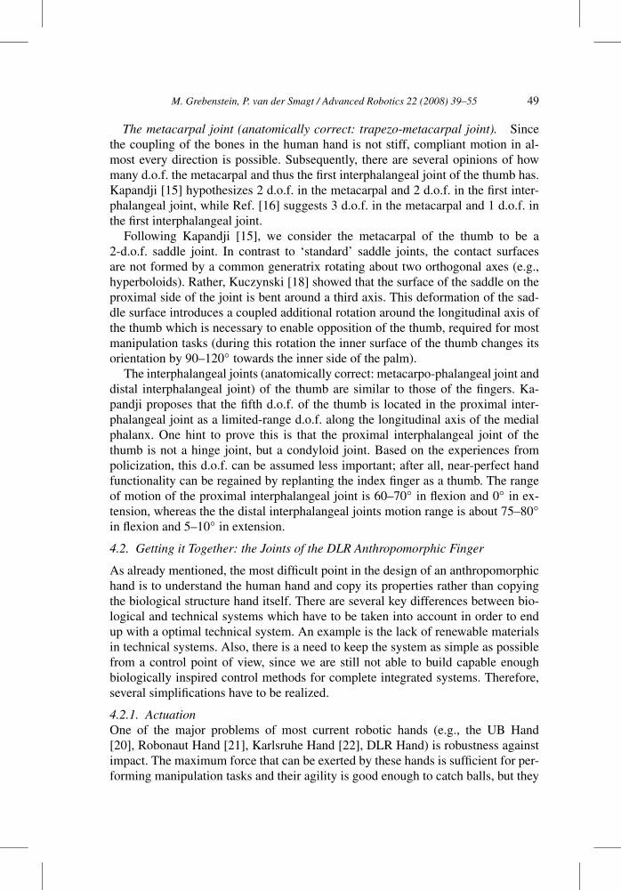
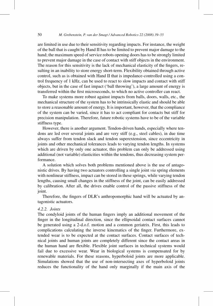
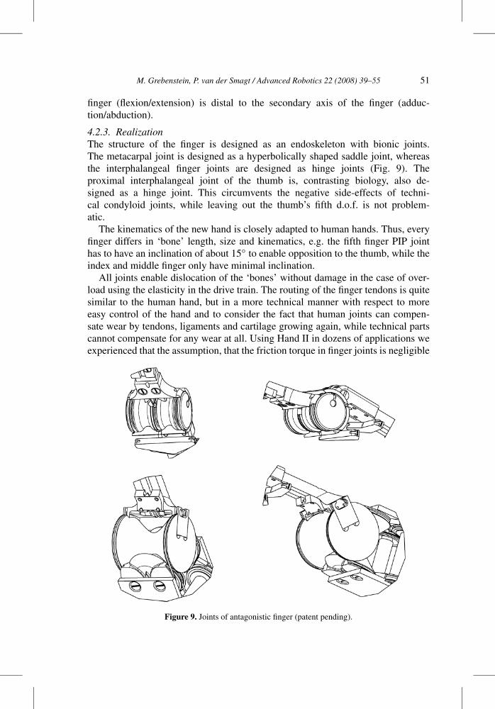
4.2.3. RealizationThe structure of the finger is designed as an endoskeleton with bionic joints.The metacarpal joint is designed as a hyperbolically shaped saddle joint, whereasthe interphalangeal finger joints are designed as hinge joints (Fig. 9). Theproximal interphalangeal joint of the thumb is, contrasting biology, also de-signed as a hinge joint. This circumvents the negative side-effects of techni-cal condyloid joints, while leaving out the thumb’s fifth d.o.f. is not problem-atic.
The kinematics of the new hand is closely adapted to human hands. Thus, everyfinger differs in ‘bone’ length, size and kinematics, e.g. the fifth finger PIP jointhas to have an inclination of about 15◦ to enable opposition to the thumb, while theindex and middle finger only have minimal inclination.
All joints enable dislocation of the ‘bones’ without damage in the case of over-load using the elasticity in the drive train. The routing of the finger tendons is quitesimilar to the human hand, but in a more technical manner with respect to moreeasy control of the hand and to consider the fact that human joints can compen-sate wear by tendons, ligaments and cartilage growing again, while technical partscannot compensate for any wear at all. Using Hand II in dozens of applications weexperienced that the assumption, that the friction torque in finger joints is negligible
Figure 9. Joints of antagonistic finger (patent pending).
52 M. Grebenstein, P. van der Smagt / Advanced Robotics 22 (2008) 39–55
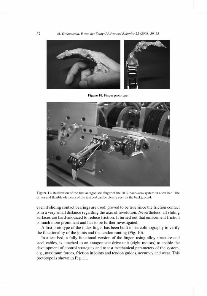
Figure 10. Finger prototype.
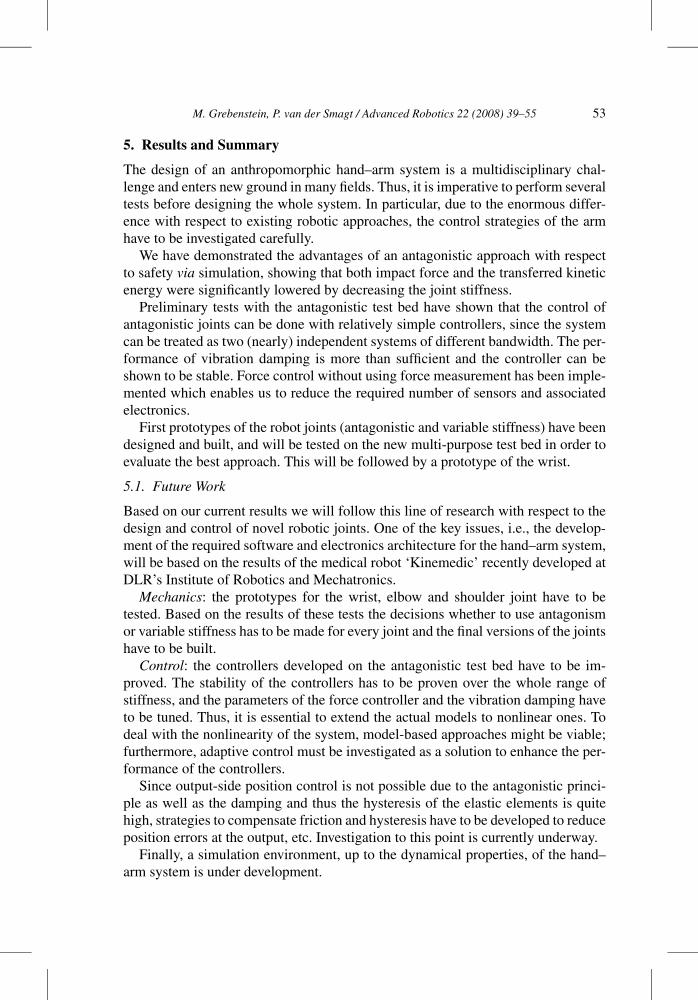
Figure 11. Realization of the first antagonistic finger of the DLR hand–arm system in a test bed. Thedrives and flexible elements of the test bed can be clearly seen in the background.
even if sliding contact bearings are used, proved to be true since the friction contactis in a very small distance regarding the axis of revolution. Nevertheless, all slidingsurfaces are hard-anodized to reduce friction. It turned out that enlacement frictionis much more prominent and has to be further investigated.
A first prototype of the index finger has been built in stereolithography to verifythe functionality of the joints and the tendon routing (Fig. 10).
In a test bed, a fully functional version of the finger, using alloy structure andsteel cables, is attached to an antagonistic drive unit (eight motors) to enable thedevelopment of control strategies and to test mechanical parameters of the system,e.g., maximum forces, friction in joints and tendon guides, accuracy and wear. Thisprototype is shown in Fig. 11.
M. Grebenstein, P. van der Smagt / Advanced Robotics 22 (2008) 39–55 53
5. Results and Summary
The design of an anthropomorphic hand–arm system is a multidisciplinary chal-lenge and enters new ground in many fields. Thus, it is imperative to perform severaltests before designing the whole system. In particular, due to the enormous differ-ence with respect to existing robotic approaches, the control strategies of the armhave to be investigated carefully.
We have demonstrated the advantages of an antagonistic approach with respectto safety via simulation, showing that both impact force and the transferred kineticenergy were significantly lowered by decreasing the joint stiffness.
Preliminary tests with the antagonistic test bed have shown that the control ofantagonistic joints can be done with relatively simple controllers, since the systemcan be treated as two (nearly) independent systems of different bandwidth. The per-formance of vibration damping is more than sufficient and the controller can beshown to be stable. Force control without using force measurement has been imple-mented which enables us to reduce the required number of sensors and associatedelectronics.
First prototypes of the robot joints (antagonistic and variable stiffness) have beendesigned and built, and will be tested on the new multi-purpose test bed in order toevaluate the best approach. This will be followed by a prototype of the wrist.
5.1. Future Work
Based on our current results we will follow this line of research with respect to thedesign and control of novel robotic joints. One of the key issues, i.e., the develop-ment of the required software and electronics architecture for the hand–arm system,will be based on the results of the medical robot ‘Kinemedic’ recently developed atDLR’s Institute of Robotics and Mechatronics.
Mechanics: the prototypes for the wrist, elbow and shoulder joint have to betested. Based on the results of these tests the decisions whether to use antagonismor variable stiffness has to be made for every joint and the final versions of the jointshave to be built.
Control: the controllers developed on the antagonistic test bed have to be im-proved. The stability of the controllers has to be proven over the whole range ofstiffness, and the parameters of the force controller and the vibration damping haveto be tuned. Thus, it is essential to extend the actual models to nonlinear ones. Todeal with the nonlinearity of the system, model-based approaches might be viable;furthermore, adaptive control must be investigated as a solution to enhance the per-formance of the controllers.
Since output-side position control is not possible due to the antagonistic princi-ple as well as the damping and thus the hysteresis of the elastic elements is quitehigh, strategies to compensate friction and hysteresis have to be developed to reduceposition errors at the output, etc. Investigation to this point is currently underway.
Finally, a simulation environment, up to the dynamical properties, of the hand–arm system is under development.
54 M. Grebenstein, P. van der Smagt / Advanced Robotics 22 (2008) 39–55
Acknowledgements
This work was partly funded by the FP6 programme SENSOPAC (FP6-IST-028056) and NEUROBOTICS (FP6-IST-001917).
References
1. R. Osu and H. Gomi, Multijoint muscle regulation mechanisms examined by measured humanarm stiffness and EMG signals, J. Neurophysiol. 81, 1458–1468 (1999).
2. M. Damsgaard, J. Rasmussen and S. T. Christensen, Numerical simulation and justification ofantagonists in isometric squatting, in: Proc. 12th Conf. of the European Society of Biomechanics,pp. 101–102 (2000).
3. A. De Luca, A. Albu-Schäffer, S. Haddadin and G. Hirzinger, Collision detection and safe reac-tion with the DLR-III lightweight manipulator arm, in: Proc. IEEE Int. Conf. on Robotics andAutomation, pp. 1623–1630, Beijing (2006).
4. A. Bicchi and G. Tonietti, Fast and soft arm tactics: dealing with the safety-performance trade-offin robot arms design and control, IEEE Robotics Automat. Mag. 11, 22–33 (2004).
5. E.-J. Nijhof and E. Kouwenhoven, Simulation of multijoint arm movements, in: Biomechanicsand Neural Control of Posture and Movement (J. M. Winters and P. E. Crago, Eds), pp. 363–372.Springer, Berlin (2002).
6. G. K. Klute, J. M. Czerniecki and B. Hannaford, McKibben artificial muscles: Pneumatic actu-ators with biomechanical intelligence, in: Proc. IEEE/ASME Int. Conf. on Advanced IntelligentMechatronics, pp. 221–226, Atlanta, GA (1999).
7. G. Tonetti and A. Bicchi, Adaptive simultaneous position and stiffness control for a soft robot arm,in: Proc. IEEE Int. Conf. on Intelligent Robots and Systems, pp. 1992–1997, Lausanne (2002).
8. P. van der Smagt, F. Groen and K. Schulten, Analysis and control of a rubbertuator robot arm,Biol. Cybernet. 75, 433–440 (1996).
9. K. Koganezawa and S. Ban, Stiffness control of antagonistically driven redundant D.O.F. manip-ulator, in: Proc. IEEE Int. Conf. on Intelligent Robots and Systems, pp. 2280–2285, Lausanne(2002).
10. K. Koganezawa, Mechanical stiffness control for antagonistically driven joints, in: Proc. IEEE Int.Conf. on Intelligent Robots and Systems, pp. 1544–1551, Edmonton, Alberta (2005).
11. S. A. Migliore, E. A. Brown and S. P. Deweerth, Biologically inspired joint stiffness control, in:Proc. IEEE Int. Conf. on Robotics and Automation, pp. 4519–4524, Barcelona (2005).
12. T. Morita and S. Sugano, Design and development of a new robot joint using a mechanicalimpedance adjuster, in: Proc. IEEE Int. Conf. on Robotics and Automation, pp. 2469–2475,Barcelona (1995).
13. G. Tonietti, R. Schiavi and A. Bicchi, Design and control of a variable stiffness actuator for safeand fast physical human/robot interaction, in: Proc. IEEE Int. Conf. on Robotics and Automation,pp. 528–533, Barcelona (2005).
14. C. E. English and D. Russell, Implementation of variable joint stiffness through antagonistic ac-tuation using rolamite springs, Mech. Machine Theory 34, 27–40 (1999).
15. A. Kapandji, The Physiology of the Joints. Churchill Livingstone, Edinburgh (1998).16. A. Benninghoff and D. Drenckhahn, Anatomie. Makroskopische Anatomie, Histologie, Embryolo-
gie, Zellbiologie, Bd 1. Urban & Fischer at Elsevier, Munich (2002).17. Wikipedia, Hinge joint. http://en.wikipedia.org/wiki/Hinge_joint (2006).18. K. Kuczynski, The thumb and the saddle, Hand 7, 120–122 (1975).
M. Grebenstein, P. van der Smagt / Advanced Robotics 22 (2008) 39–55 55
19. A. E. Flatt, Our thumbs, Proc. Baylor Univ. Med. Center 15, 380–387 (2002).20. L. Biagiotti, F. Lotti, C. Melchiorri, G. Palli, P. Tiezzi and G. Vassura, Development of UB hand 3:
early results, in: Proc. IEEE Int. Conf. on Robotics and Automation, pp. 4488–4493, Barcelona(2005).
21. C. S. Lovchik and M. A. Diftler, The robonaut hand: a dexterous robot hand for space, in: Proc.IEEE Int. Conf. on Robotics and Automation, pp. 907–912, Detroit, MI (1999).
22. A. Kargov, T. Asfour, C. Pylatiuk, R. Oberle, H. Klosek, S. Schulz, K. Regenstein, G. Bretthauerand R. Dillmann, Development of an anthropomorphic hand for a mobile assistive robot, in: Proc.9th Int. Conf. on Rehabilitation Robotics, pp. 182–186, Chicago, IL (2005).
About the Authors
Markus Grebenstein finished his degree in Mechanical Engineering at the Tech-nical University in Munich in 1996. Engaged at DLR’s Institute for Robotics andMechatronics in 1996, he worked on the development of electromechanic carbrakes until 1998 when he moved to research and development of antropomor-phic robotic hands. Starting in 2000, he is Head of mechanical development andleading the development of DLRs anthropomorphic hand–arm system.
Patrick van der Smagt received his PhD on Neural Systems for Robotics fromthe University of Amsterdam in 1995. He then moved to Germany, joining theInstitute of Robotics and Mechatronics at the DLR. First focusing on learning sys-tems and cerebellar models, he built-up and is head of the Bionics Group whichfocuses on biologically inspired technical systems, from sensing to motion. Heis and was Editor and Book Editor for Neural Networks, conference chair andboard member, EU project leader, has published numerous papers and holds sev-eral patents.
Copyright © 2022 FDOKUMEN