ANEXO 2E - Repositorio Digital - EPN
370
I ANEXO 2E BASES PARA EL CONCURSO DE OFERTAS DE UN SISTEMA DE TRANSMISIÓN MCPC 1:3 COTIZACIONES PARA UN SISTEMA MCPC 1:3 . i CALIFICACIÓN DE LAS OFERTAS
-
Upload
khangminh22 -
Category
Documents
-
view
0 -
download
0
Transcript of ANEXO 2E - Repositorio Digital - EPN

I
ANEXO 2EBASES PARA EL CONCURSO DE OFERTAS DE UN SISTEMA
DE TRANSMISIÓN MCPC 1:3
COTIZACIONES PARA UN SISTEMA MCPC 1:3 .
i CALIFICACIÓN DE LAS OFERTAS

• Guayaquil, 29 de Octubre de 1997
t
i
i
Sr. Dr.Carlos MuñozPresidente de la Asociación de Canales de Televisión del EcuadorCiudad
De mis consideraciones:
Adjunto a la presente las bases técnicas para las ofertas de las empresas proveedorasde equipos de las estaciones terrenas satelitales de Guayaquil y Quito.
Las bases presentadas reúnen las necesidades técnicas de las estaciones de televisión,para la transmisión de su programación regular, así como también los requerimientosde asignación de espacio satelital de Panamsat.
Se ha considerado el mejor nivel de redundancia del sistema a fin de evitar .probablesfallas de los equipos, que dejen una estación de televisión fuera del aire, lo que brindaun alto porcentaje de fiabilidad en la operación.
No se incluyen los enlaces desde las estaciones de televisión a las estaciones terrenas,hasta definir su ubicación. Tampoco se ha considerado la obra civil y los sistemas deprotección de energía eléctrica (grupo electrógeno, UPS, reguladores de voltaje,supresores de transiente).
Atentamente
Ing. William Cobos UrdíalesPresidente Comisión Técnica Satélite!

Comisión Técnica Satelital ACTVEProyecto de enlace satelital
Bases para presentar ofertas
Aspectos Generales
• Dos estaciones terrenas con 18 MHz de ancho de banda cada una• Ubicación: Guayaquil y Quito• Sistema de transmisión MCPC• Banda de frecuencia del satélite: C• Panamsat: Satélite Pasl / haz latino / Transponder 13• Redundancia 1:1 en todas las etapas exceptuando el encoder que debe ser 1:3
(ninel de redundancia estadísticamente aconsejable)
Requerimientos de Recepción
• G/T= 25 dB/°K mínimo• BER: garantizado < 10"9
Requerimientos de Transmisión
• 'EIRP no deberá exceder el consumo de potencia máximo permitido por el PAS-1en un ancho de banda de 18 MHz por estación terrena
• La antena debe cumplir la Norma US FCC 25.209, apertura de 2°, atenuación delóbulos laterales y aprobada por Intelsat
• La antena deberá ser tipo Dual Reflector• Alimentador de dos puertos (Polarización Lineal)• LKB tipo PLL de 25°K o mejor (redundancia 1:1)• Dehydratador• Filtros de rechazo de banda
Amplificador de Alta Potencia
• El HPA debe contemplar adicionalmente un crecimiento futuro de 4 dB y su costodebe ser incluido en la propuesta
• HPA broadband 500 MHz (redundancia 1:1)

Up-converter
+ Banda C Estándar+ Frecuencia de entrada IF 70 MHz +/~ 2QMHz
Modulador
4 Frecuencia de salida IF 70 MHz +/- 20MHz+ FEC programable+ Norma MPEG-2/DVB
Multiplexor
+ Acceso condicional individual (encryption)+ Scrambling DVB cotizar por separado si es opcionalf Capacidad de 6 canales de entrada mínimo* Velocidad de Transmisión (final data rate); mínimo 48 Mbps4 Velocidad de entrada 1.5 a 15 Mbps por canal
Encoder
+ Cumplir norma MPEG-2¿DVB4 Entradas de video: Digital DI (norma CCIR 601)
Analógico Compuesto NTSC4 Entradas de audio; 2 canales estéreos analógicos balanceados
Expansibles a 4 canales estéreos analógicosf Sistema de compensación para retardo de audio (LIP-SYNC)4 Entrada de Datos: 3 8,4 Kbps o mejor
Master Clock Generator
t Capacidad de sincronización de todo el sistema MCPC4- En lo posible contar con capacidad de monitoreo de sus parámetros por el sistema
de Administrador Central.
Administrador Central
* Sistema Controlador de Redundancia4 Niveles de alarma: Flexibilidad de selección de parámetros que generen alarmas4- Alarmas audibles y visuales

4 Control de acceso local y remoto4 Envío de alarmas a multiusuarios4 Interface gráfica amigable para el ususario4 Control automático del sistema incluido redundancias (switches, routíng
switchers, encoders, multiplexores, moduladores, Up-Converter, HPA, LNB)* Capacidad de mostrar status de cada equipo incluido los redundantes4 Diagnósitco de fallas.4 Configuración en el sistema de un Computador de Back-up con verificación
constante entre ellos.
Acceso Remoto Multiusuario
4 Mínimo seis usuarios remotos4 Acceso al status del encoder (restingido a cada usuario)4 Modificación de parámetros (restingido a cada usuario)4 Administración de acceso condicional- encryption-(restingido a cada usuario)4 Seguridad de acceso remoto por medio de passwords. •4 Acceso remoto para test de fábrica.
Routing switchers
4 Entradas y salidas de video: digital DI (norma CCIR 601)Analógica compuesto NTSC
4 Dimensiones de las matrices digital y analógica: 6 x 6 mínimo4 Fuente de poder redundante4 Paneles de control local4 Control desde el administrador central del sistema4 Audio: 2 canales estéreos entrada/salida balanceados
Capacidad de expansión futura a 4 CH estéreos entrada/salidabalanceados
4 Audio follow video
Patch panels de video
4- Digital serial y analógico compuesto4- Loop through4 Patchs cord (20 unidades)
Patch panels de audio
4 Analógico entradas/salidas balanceados

Patch card (40 unidades)
Receptor satelital IRD (4 unidades)
* Compatibilidad absoluta con las características del encoder4- MPEG-2 ÍDVB (video decompression)4 Descrambling DVB4 Entrada: Banda Lt Video de salida: Compuesto NTSC y Digital DI
Conector BNCt Recepción de cuatro canales de audio estéreo balanceados4- Opciones controladas desde la estación terrena:4 Acceso condicional4 Encryption4 Bit rates de canales con variación dinámica
Sistema de Monitoreo
4 Monitoreo en Banda (monitor de spectrum)4- Monitoreo individual de los receptores IRD4- Monitoreo de señales de entrada en audio y video: analógico y digital (WFM,
monitor color 14" alta resolución)
Consideraciones:
1. Cada Oferente deberá presentar el Cálculo de desempeño del sistema (LINKBUDGEI) aprobado por Panamsat.
2. Cada Oferente deberá presentar la tabla Eb/No VS BER del IRD para diferentesvalores de FEC.
3. Cada oferente deberá presentar la tabla de ANCHO DE BANDA OCUPADA VSDATARATE para diferenes valores de FEC.
4. Se deberá presentar una descripción detallada de costos y características técnicasde los equipos que conformarían la estación terrena.
5. El sistema debe tener una garantía mínima de 2 años y especificar como seejecutaría la misma.
6. Capacitación de personal para la operación de cada equipo.

7. Los oferentes que se seleccionen para la ronda final deberán demostrar elfuncionamiento del sistema completo.
8. En la propuesta deberá incluirse una lista de clientes con sistemas similares enoperación.
Por la Comisión Técnica Satelital:
Ing. Willjam CobosIng. Gustavo HerreraIng. Alejandro AguilarIng. Felipe PaucarIng. César MaclasIng. Andrés Peñañel
SiTvTeleamazonasTelesistemaEcuavisaGamavisiónTC Televisión

Guayaquil, 28 de Enero de 1998
Sr. Dr.Carlos Muñoz I.Presidente de ACTVECiudad.De mis consideraciones:
Adjunto a la presente encontrará Ud. El análisis técnico de las ofertas presentadas para elproyecto de enlace satelital para la ACTVE. De la evaluación del cumplimiento de basesse han seleccionado los sistemas propuestos por las compañías California Microwave-STS y Scientific Atlanta, y se han agregado consideraciones generales importantes de cadauna que pueden servir para un análisis posterior.
Como se estableció en las bases es necesario que los oferentes seleccionados demuestrenel funcionamiento del sistema a fin de verificar sus especificaciones, parámetros ycaracterísticas, para la decisión técnica final.
Considero que no debe tomar una decisión basada en las propuestas económicaspresentadas, en virtud de que se ha encontrado dettalles que se indican en las conclusionesy que se sugiere sean revisados.
Atentamente,
Ing. William Cobos UrdíalesPresidente de la Comisión Técnica Satelital ACTVE
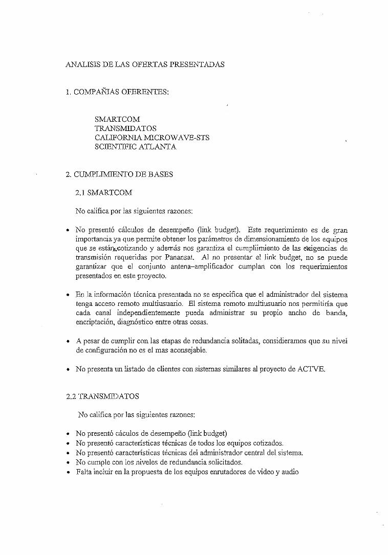
ANÁLISIS DE LAS OFERTAS PRESENTADAS
1. COMPAÑÍAS OFERENTES:
SMARTCOMTRANSMIDATOSCALIFORNIA MICROWAVE-STSSCIENTTFTC ATLANTA
2. CUMPLIMIENTO DE BASES
2.1 SMARTCOM
No califica por las siguientes razones:
• No presentó cálculos de desempeño (link budget). Este requerimiento es de granimportancia ya que permite obtener los parámetros de dimensionamiento de los equiposque se estáj>,cotizando y además nos garantiza el cumplümiento de las exigencias detransmisión requeridas por Panansat. Al no presentar el link budget, no se puedegarantizar que el conjunto antena-amplificador cumplan con los requerimientospresentados en este proyecto.
• En la información técnica presentada no se especifica que el administrador del sistematenga acceso remoto multiusuario. El sistema remoto multiusuario nos permitiría quecada canal independientemente pueda administrar su propio ancho de banda,encriptación, diagnóstico entre otras cosas.
• A pesar de cumplir con las etapas de redundancia solitadas, considieramos que su nivelde configuración no es el mas aconsejable.
• No presenta un listado de clientes con sistemas similares al proyecto de ACTVE.
2.2 TRANSMIDATOS
No califica por las siguientes razones:
• No presentó cáculos de desempeño (link budget)• No presentó características técnicas de todos los equipos cotizados.• No presentó características técnicas del administrador central del sistema.• No cumple con los niveles de redundancia solicitados.• Falta incluir en la propuesta de los equipos enrutadores de video y audio

2.3 CAL1PORMAMECROWAVE-STS
Califica con las bases del proyecto. Sin embargo consideramos imprescindible quesuministre información técnica complementaria que permita comparar en detalle lasbondades de sus equipos.
2.4 SCffiNTTFIC ATLANTA
Califica con.las bases del proyecto.
3. ASPECTOS A CONSIDERAR DE LAS EMPRESAS CALIFICADAS
3.1 CALIFORNIA MICROWAVE-STS
• Tiene presencia en Ecuador a través de las ventas realizadas a empresas como:EMETELIMPSAT
• De acuerdo al listado de clientes su mayor experiencia ha sido en la integración desistemas para telefonía; y datos, y en menor escala para televisión. •&•
• De la. información recibida, concluimos que esta empresa integra sus sistemas con unagran número de equipos y partes de otras marcas.
3.2 SCffiNTlFIC ATLANTA
• De acuerdo al listado de clientes tiene una amplia experiencia en:Redes de video comprimidoSistemáis MCPC (Múltiples canales por portadora)Estaciones terrrenas para sistemas de cable y televisiónSistemas de satélites móviles.
• Son Fabricantes de la mayor parte de los equipos del sistema.• PANAMSAT calificó a esta marca como su estándar de transmisión-recepción para
eventos especiales como los emitidos por OTE.

4. CONCLUSIONES
Hemos seleccionado a dos empresas oferentes basados en la documentación y datostécnicos presentados por ellos, sin embargo dicha selección deberá complementarse conlas pruebas reales de los equipos para verificar las especificaciones, parámetros ycaracterísticas técnicas del sistema, a fin de definir la mejor opción.
Nuestro análisis ha sido completamente técnico. Al revisar las propuestas económicashemos notado una falta de homogeneidad en la presentación de las mismas, ya que hayequipos que en una oferta son considerados opcionales, mientras que en la otra es parte dela propuesta original. Consideramos adecuado solicitar una propuesta concreta para suanálisis.
Por la Comisión Técnica Satelital
Ing. William CobosIng. Gustavo HerreraIng. Alejandro A.guilarIng. Felipe PaucarIng. César MacíasIng. Andrés Peñafiel
SiTvTeleamazonasTelesistemaEcuavisaGamavisiónTC Televisión

Formulario de evaluación del sistema MCPCSistema MPEG-2/DVB (ENCODER)
CARACTERÍSTICARedundancia 1 :3 del Ene.
Norma MPEG-2/DVBEntrada Vid Dig.CCIR 601Entrada Vid An Comp NTSCAud 2 CHs Estéreos Analg. Bal.Aud. Expansibles a 4 CHsCompensación retardo AudioEntrada Datos 38.4 Kbps
SMARTCOMS
SSSS
SSs
SCIENTIFICATL.SSSSSSSS
TRANSMIDATOS
NSSSssss
CALIFORNIA MWSSS
SS
SSS
SISTEMA MPEG-2/DVBJDECODER)
CARACTERÍSTICAMPEG-2/DVB CompatibleDescrambling DVBEntrada Banda LSalida Vid Compuesto NTSCSalida Vid Digital ccir 601Salida Aud. 4CHs Est. Bal.Tabla £b/No vs BER (FEC)
SMARTCOMSS
Sssss
SCIENTIF1C ATL.SSSSSSS
TRANSMIDATOSSSSSNSS
CALIFORNIA MWSSSSSSS
OPCIONES CONTROLADAS DESDE LA ESTACIÓN TERRENA
CARACTERÍSTICAAcceso Condicional
EncryptionBit Rale de CHs Dinámico
SMARTCOMS
sS
SCIENTIF1CATL.SSS
TRANSMIDATOSS
SS
CALIFORNIA MWSS
S
SISTEMA MPEG-2/DVB (MODULADOR)CARACTERÍSTICARedundancia 1 :1 del Mod.lfFout70MHz+/-20MHzVelocidad de Tx >48MbpsFEC programableNorma MPEG-2/DVB
Modulación QPSKTabla BW vs Symbol Rate (FEC)
SMARTCOMSSsssss
SCIENTIFIC ATL.S
SSS
Sss
TRANSMIDATOS
S -Ssssss
CALIFORNIA MWS
SSssss
SISTEMA MPEG-2/DVB (MUX)CARACTERÍSTICARedundancia 1 :1 del Mux.Acceso Cond. Individual
Scramblíng DVBCHs de entrada 6 MínimoVelocidad de TX>48Mbps1 .5 a 1 5 Mbps por canal
SMARTCOMSS
SSS
S
SCIENTIFIC ATL.S
SSS
SS
TRANSMIDATOSS
?S
SSS
CALIFORNIA MWSSS
SSS
MASTER CLOK GENERATOR
CARACTERÍSTICASincronización Sist. MCPCMon'rt. Para metros por A.C.
SMARTCOMN
N
SCIENTIF1C ATL.S
S
TRANSMIDATOSNN
CALIFORNIA MWS
S
ROUNTING SW1TCHERSCARACTERÍSTICARedundancia 1.3 del Ene.Norma MPEG-2/DVBEntrada Vid Dig.CCIR 601Entrada Vid An Comp NTSCAud 2 CHs Estéreos A BalAud. Expansibles a 4 CHsCompensación retardo AudioEntrada Datos 38.4 Kbps
SMARTCOMSSSSSsss
SCIENTIFIC ATL.SSSSSSSS
TRANSMIDATOSNNNN jNNNN
CALIFORNIA MWSSSSSSSS

SISTEMA DE RF
UP-CONVERTER
CARACTERÍSTICARedundancia 1:1 Up-Converter.Banda C EstándarIFin70MHz+/-20MHz
SMARTCOMSSS
SCIENTIFIC ATL.SSS
TRANSMIDATOSSSS
CALIFORNIA MWSSS
AMPLIFICADORCARACTERÍSTICARedundancia 1:1 del HPACrecimiento futuro de 4dBHPABroadbandSOOMHz
SMARTCOMS?S
SCIENTIFIC ATL.SSS
TRANSMIDATOSN?N
CALIFORNIA MWSSS
ANTENA DE TX
CARACTERÍSTICANorma US FCC 25.209Aprobada por IntelsatDual Reflector (Casegrain)AHmientador 2 Puertos (P.L.)DehydratorTransmit Rej'ecí FilterLNBTipoPLL=25°KRedundancia 1:1 LNB
SMARTCOMSS
SS
SSSS
SCIENTIFIC ATL.S
SSS
SSSS
TRANSMIDATOSSSS
SSSSS
CALIFORNIA MWSS
SSS
SSS
LINKBUDGET TOTALCARACTERÍSTICACálculo de desempeñoAncho de Banda ISMHzSistema de Tx MCPCEIRP no excede Max. PAS-1
SMARTCOMN
NN
N
SCIENTIFIC ATL.SSS
S
TgftNSMIDATOSNN
NN
CALIFORNIA MWSSS
S
ADMINISTRADOR DEL SISTEMACARACTERÍSTICANiveles de alarmaSel. De Parámetros de AlarmaAlarmas Audibles y VisualesControl de Acceso Local y Rem.Envío alarmas a mutíiusuariosIníerface Gráfica AmigableControl automático del SistemaControl de RedundanciaControl Routing Switchers
SMARTCOMS
S
SSNSSSS
SCIENTIFIC ATL.SSSSSSSSS
TRANSMIDATOSSSSSSSS
SN
CALIFORNIA MWSSSSSSSSS
ACCESO REMOTO MULTIUSUARIOCARACTERÍSTICAMínimo 6 Usuarios RemotosAcceso all Enc.restringuido c/uModíf. P a ram. restringido c/uAcceso Condic.restinguido c/uAcceso Remoto por PasswordsAcc. Remo, para Test de Fábrica
SMARTCOM
???
?7?
SCIENTIFIC ATL.S
SS
SSS
TRANSMIDATOS?
???
??
CALIFORNIA MWSSSSSS
ADICIONALESCARACTERÍSTICAGarantía de 2 añosCapacitación del Personal
SMARTCOMSS
SCIENTIFIC ATL.SS
TRANSMIDATOSSS
CALIFORNIA MWSS
S: SÍ cumple con las basesN: No cumple con las bases

October 14, 1997
Via Facsímile 011-593-2-566-436
Mr. Carlos Muñoz InsuaPresidente Asociación de Canales de Televisión del EcuadorGuayaquil, Ecuador
DearMr. Muñoz;
Pursuant to our phone conversation this morning, I am pleased to present to you.PanAmSat's final pricing proposal for non-preamptible space segment at C-band onthe PAS-1 and PAS-1R satellites at 45 degrees west.
PAS-1/PAS-1RLatín Beam
MONTLY Recurring Charges(All prices in US Dollars) .
,?;". f- ••
Bandwith End of life Years 3 thryu 10(Service on PAS-1) (Service on PAS-1R)
36 MHz $83,333 $166,667
The above prices do not include local PTT, government or ministry mark-ups3 taxes,levier, tariffs or licensing fees outside the U.S. The service does not include any in-country ground segment. the customer is responsible for obtaining all requiredregulatory approval and authorizations from the government of Ecuador to provideservices through PanAmSat.
The prices, temas and conditions contained here in this document are confidential andare not to be publicized, published or otherwise divulged to sources outside ofAECTV without the express writen consent of PanAmSat. This Information is forAECTV employees with a need to know only. The proposed availability, prices.,terms and conditions of this budgetary price proposal are valid for 30 days from thedate of issue and may be revoked or changed at PanAmSat5 s solé disertation withoutnotice.

PanAnSat Services, including satellite space segment capacity or other PanAmSatServices, are available on a first-come/first-serve basis: Reservations for capacity willnot be accepted. Customers may acquire PanArnSat Services only upon execution ofa Service Agreement between the parties and he payment of the requisite Deposit andone-time Charges.
Shoul you have any questions., please feel free to contact me. Thanks agaln for yourinterest in PanAmSat.
Yours truly,
Richard KohlwegRegional Manager

SECTION2.0SYSTEM DE5CRIPTION
2.1 OVERVIEW
CM-STS PROPOSES TWO EARTH STATIONS FROVEDING DIGITALVIDEO AND STEREO AUDIO TO SERVICE HEAD-ENDS:
C-BAND EARTH STATIONS WILL BE MSTALLED AT GUAYAQUIL AND QUITOTHREE DIGITAL VIDEO WITH TWO STEREO CHANNELS PER VTDEO CHANNEL
(EXPÁNDANLE TO 4 STEREO CHANNELS PER VIDEO CHANNEL) PER SITE,LOCAL AND REMOTE CONTROL OF VIDEO AND AUDIO ENCODERS
CONDITIONAL ACCESS AND DVB STANDARD 3CRAMBLMGHIGH-LEVEL OF REDUNDANCY PRO VIDES RELIASELJTY
CM-STS INDUSTRY AND LOCAL EXPERIENCE
The Association of Televisión Channels of Ecuador (ACTVE) wjll provide digital sareílitedistríbuHon channels co service head-ends located in remote regions oí íhe country. The ACTVEnetwork; shown in Figure 1, will be comprísed of two eanh stations each initially providing threevideo with 2 síereo audio chaimeis per video channeL. These video and audio channels origínateírom one to three studios and are fed to an eanh stadon vía a terrestríal analog microwavenetwork.. The eanh staiion digitizes, compresses. and mulííplexes these channels into a singleMúltiple Channel per Carrier (MCPC) data stream for transmissíon ío the service head-ends.These head-ends íhen conven the channels ío analog format for disíribution Ehrough a local áreaanalog video and audio nérwork.
CM-STS proposes a complete eanh station and digital video and audio turn-key solution. Thisallows ACTVE to coordínate with a single, experienced entity throughout the installation process.írom planning íhrough commissioning. The speciñc íechnical solutíon wiíl be presented in thefollowing sections through an overall system level description and detailed documentation ofmajor system componems. Actual produci specincations are provided the product Data Sheets inthe Appendix,
The proposed systems will allow centralized control at íhe eanh stations or remote control íromíhe programming studios of íhe MCPC Digital subsystem. In additiorij the program-by-programcondítional access funciion can be managed from íhe eanh staíions or remotely from the studios.

CA
LIF
OR
NIA
MIC
RP
WA
VE
5A
TE
LL
ITE
TR
AN
5M
ISS
1D
NS
YS
TE
MS
CM
I-ST
S D
esig
n
Com
plet
e E
nd-E
nd T
urn-
Key
Sol
utio
n
Ana
log
vide
o an
audi
o di
slri
buti
on i:
subs
crib
ers
Stal
e-of
-the
-arl
dig
ital
vid
eopr
imar
y br
oadc
asl
from
hub
lo
TV
RO
hea
d-en
ds
13 G
Hz
Mic
row
ave
link
sm
s tu
di o
s Lo
mai
n hu
b
Lea
der
¡n S
niel
liie
Com
mun
ii:;
iiit
)n.s

2.2 SYSTEM DESCMPTION
The block díagram of íhe Quito and Guayaquil Earth Stations is shown in Figure 2.2-1 and thedeíailed equipment descñptions ar.e^ provided in the following sections. The equipmentcomplement íncludes the following:
• Advanced 6.3 meter Compact Cassegrain antenna, with manual positioning• 400 W TWTAs in a 1:1 redundant configuration• 27° LNBs in a 1:1 redundant configuration• High-performance 1:1 redundant up converter with equalizers subsystem• 3-H 1RD Subsystem• 1:3 redundant MPEG2-DVB encoder subsystem with Network Management System
(NMS)• 1:1 redundant secondary multiplexer• 1:1 MPEG2-DVB digital video modulator• An STS Graphical Monitor and Control System (GMACS) for management of each
earth station is recommended as an option
2.2.1. Vértex C-Band 6.3 Meter Core Site Antenna The proposed antenna for the is a 6.3-meter antennañnanufactured by Vértex Communications Corporation. The antenna subsystemwill consist of:
• 6.3-meter compact cassegrain antenna• Two-port linear polarized feed• Kingpost pedestal design• Drive package ínclucling drive motors, limií switches, and transducer brackets• Rain blower• Ladder and platform• Environmental enclosure with lighting and exhaust blowers• Líghtning protection• Aircrañ warning lights.
The 6.3-rneter diameter Compact Cassegrain-type antenna will be instailed with a 2 port C-Band3
linear polarized feed system. The feed assembly provides operation for satellites using the 3.7 -4.2 GHz receive band and 5.925 - 6.425 GEÍz transmit band. The reflector/pedestal systemempioys the latest state-of-the-art methods in design and manufacturing techniques. This designoffers several advantages over the conventional mount; its main features are as follows:
• Reduced installation time due to the compact Cassegrain design, precisión formed panelsand matched tooling which reduces installation and testing time
• Hígh stiñhess/weight ratio reflector structure, insuring minimum handling in high windproblems.
• Low maintenance bearings on the elevation and azimuth axes.• Simplified foundation design, reducing the complexity of design and minimizing the
volume of concrete required.
USE OR.DISCLOSURE OF DATA CONTAINED ONTH1S PAGE IS SUBÍECTTO THE

CMI-STS will provide twp (2) lightning arrestors on the antenna structure to protect the antennasubsystem. They will be mounted at the highest locations on the main reflector tip and at the apexof the subreñector suppórt as shown. The structure ítseif will be used as the prímary low-impedance path to ground. Jumpers will be provided across the elevation and azimuth axes toensure low impedance continuity and to protect axis bearing.
Table 4 íists the electrícal specífications for this antenna, Tabíe 5 Íists íhe mechanicalspeciñcations for the antenna, and the Data Sheet is incíuded in Section 5.
2.2.2 High Power Amplifier.The proposed high power amplifiers (HPA) are 400 Watt Traveling Wave Tube Arnpliñers(TWTAs) designed for operation over the frequency range of 5.85 to 6.425 GHz. These HPAsare designed and.manufactured by CPI (formally Varían) and represent the latest state-of-árteíectronics in compact TWTA design. This new compact design is ideal for appíications wherepower and space are a prime consideration as the units are ío be housed in existing buildings.
The unit employs a high efñciency, duai-depressea collector helix TWT backed by many years offíela proven experíence in airborne and military appíications. The subsystem meets the applicablesafety and elecíromagnetic compatibility standards. The data sheet is provided in the Appendix.
As can be seen in Figure 6_ íhe HPAs are conñgured in a 1:1 redundant configuratíon ¿or highreliability. The speciñcations for this redundant médium power amplíñer system are íisted inTableó.'
2.2.3 Low Noise Block Converter fLNBI Subsvstem.The LNB subsystem is comprísed of iransmit reject ñlters. input redundancy switching, the LNBs.the output redundancy switching. The subsystem is coníigured for a 1:1 redundant operation.The LNBs are uncooled with a máximum noise temperatura of 27°K at 23° C ambient, mínimumgain of 60 dB, and frequency range of 3.7 - 4.2 GHz. The uncooled conñguration provides highreliability requiring no maintenance.
The LNBs are housed in weather-proof housing with a pressurabie waveguide ñtting. The unitcontains all the necessary DC bias and performance moniíoring circuitry. The fauit signa! Unes aremonitored by the 1:1 LNB Monitor and Control Unit located within the equipment room. TheLNB Monitor and Control Unit operates in conjuncrion with the LNB switching system located inthe antenna hub enclosure and provides automatic/manual switching between the LNBs ío ensurethat the operational LNB is on-line at all times. The controller monitors LNB current. providesinput (waveguide) and output (coaxial) switch position commands, and provides aíarm and switchposition status. A data sheet is provided in the Appendix
I
i!
USE OR DJSCLOSURE OF DATA CONTAíNED ONTHÍS PAGE IS SUBJECTTO THE

Tabie 4. RF Specifications for C-Band 6.3-Meter Earth Station AntennafBCingpost Mount) with Tx/Rx Feed
Electrical Speciñcatíons.
Frequency in GECz
Typical Gain at Midband
Beamwidth-3 dB-15 dB
Receive
3.700-4.200
45.50 dBi
0.26°0.55°
Transmit
5.925-6.425
50/40 dBi
0.22°0.46°
Tabie 5. 6.3-Meíer Mechanical Specifications
Azimuth Travel
Elevation Travel
Polarization Travel
Polarization Travel Rate
Weight - Reflector
Weight- Pedestal J-'
Shipping Weight (Typical)
Shipping Volume
• Finishes:
Foundation Size
Concrete Volume
Reinforcing Steel
Soil Bearing Pressure
Operational Winds
Survival Winds
120° continuous
0° ta 90° continuous
± 95°
1.5°/second
1,350 pounds (612 kg)
1,700 pounds (771 kg)
4980 pounds (2259 kg)
704 cubic feed (20 m3)
White
16.5 f t x 16.5 ftx 1.5 ft(5.0mx5.0mx0.46m)
15.5 cubic yards(ll.Sm3)
1,460 pounds (662 kg)
2,000 PSF (10,000 kg/m2)
45 mi./hr (72 km/hr) gusts to60 mi./hr (97 km/hr)
125 mi./hr (200 km/hr) @58°F (15°C)
USE OP.DISCLOSURE OF DATA CONTAiNED ONTHIS PACE IS SUBJECTTO THE
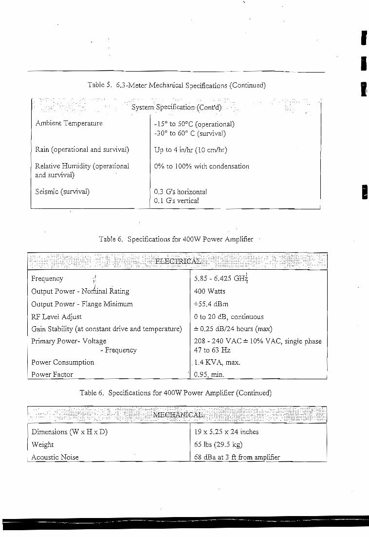
Table 5. 6.3-Meter Mechanical Specifications (Continued)
Ambient Temperature
Rain (operational and survival)
Relaíive Humidity (operanonaland survival)
Seismic (survival)
System^Spec^cation^ConíM). • • : .
-15° to 50°C (operational)-30° to 60° C (survival)
Up to 4 in/hr (10 cm/hr)
0% to 100% with condensation
0.3 G's horizontal0.1 G's vertical
III
e
Table 6. Specifications for.400W Power Amplifier
ELECIÍHCAL
Frequency -J
Ouíput Power - Nominal Rating
Output Power - Flange Mínimum
RP Level Adjust
Gain Stability (at constant drive and temperature)
Primary Power- Voltage- Frequency
Power Consumption
Power Factor
5.85 - 6.425 GHz
400 Watts
+55.4 dBm
O to 20 dB, contínuous
¿ 0.25 dB/24 hours (max)
208 - 240 VAC i 10% YAC, single phase47 to 63 Hz
.1.4KVA,max.
0.95, min.
Table 6. Specifications for 400W Power Amplifier (Continued)
MECHANICAL
Dimensions (W x H x D)
Weight
Acoustic Noise
19x5.25x24inches
65 Ibs (29.5 kg)
68 dBa at 3 ft from amplifier

2.2.4 MPEG2-DVB Encoder Subsvstem
PROGENY™ MX is a real-time MPEG-2 encoder which complies with the DVB
recomrnendanon. The encoder compresses the video and audio source program material.
muítiplexes them together, along with the data channel. It feeds the resultant data bit stream to the
system multiplexer. The encoder is composed of four basic building bíocks as shown in ihe
diagram. These bíocks are as foliows:
» Video / Audio Interface B lóele
* Video Encoder
» Audio Encoder
* Data Channel Interface
* Program Multipiexer
The encoders are impíemented in a 1:3 redundant conñguration which can be expanded to a 1:6
redundant configuration ín the íuture. The neiwork management system controls the input router
consisting of analog video, digital video and analog audio (up to 4 stereo channels per video)
decks conñgured as an audio follows video switch. The router also provides múltiple outputs ;n a
one to many conñguration for monitoring purposes.
Video / Audio Interface
The video/ audio interface block converts the analog video and audio inputs ío common íntemal
digital formats for use by the corresponding compressors. The interface suppons any one of
several source inputs which are common to the market. such as: Composite. S-VHS, Y-U-V,
digital parallel DI and SDI (Serial Digital Interface) for video and analog or digital AES/EBU
standard for audio. In case of analog audio input, sampling occurs at a 48 KHz rate, 16 bits per
sample prior to compression.
Audio Encoder
The audio compression block receives the digitally encoded audio data from the audio interface.
and compresses the data. The resultant output data stream is fed to íhe program multiplexer.
Compression of the audio signa! is performed by a DSP chip which runs the MPEG standard
audio (Musicam) compression algorithm layers I and H
Video Encoder
The video Encoder block receives the digitally sampled video data from the video interface in
parallel DI format, and compresses the data. The resultant output bit stream is fed to íhe prograrn
multiplexer. The compression of the parallel DI format data ís performed by dedicated MPEG
RISC processors which run íhe MPEG compression algorithm micro-code. The MPEG encoding
USE OR DISCLOSURS Cr DATA C2NTAINED ON 7HÍS PACE !S SüBJECTTOTHE

cbip-set is supplied by C-CUBE Microsystems Inc. Compression process is in accordance wirh
MPEG - 2 Main Leve! MaiaProfile (MLMP).
_____ _____ Encoder Block Diagram
CompositeS-VHS
AES/EBU
Aux Data
urst i/u -*• —
SP *~allelDl >*~
\udio *»-U *-
"-
VideoInputs
Video/AudioInterface
(-'••
AudioInpurs
1
ParaílelDÍ
EncodedVideoData
Digital Ai
*-
idiofc.
*-5
VideoEncoder
Tirningand
Sync
AudioEncoder
ProgramMuí
i CPU .^ >
ISA bus
.*Ti- •^•'
Clock ^Data ., ^
3Serial MPEG II Tnmsporr Data
RS232RemoteControl/Status
RS422
Frogram Multiplezer
The program multiplexer receives the compressed video and audio bit síream as well as íhe
auxiliary daía and merges them togeíher to form íhe Transpon bií stream compüant to íhe MPEG
II síandard. In addiíion, the multiplexer can fonn MPEG u program or MPEG I sysíem bií
streams. The outpuí of íhe program mulíiplexer consisís of a serial daía bit stream and dará cíock
with data rates from 1.5 to 15 Mbps. The multiplexing task is performed by a DSP chip and
software. . >t
USE OR DISCLOSURE OF DATA CO.VTAJNED ON TOÍS PACE IS SUSJECTTOTHE

Compression Standard
MPEG II compression is used in the-encoder implementation. MPEG U is an internationaí coding
standard developed for compression of high quality TV CCIR-601 images (720 by 480 une
resolution for NTSC, 720 by 576 for PAL). The MPEG mechanism is based on I, P and B frames
processing. It has a ñeld/frame coding mechanism which takes advantage of the interlaced nature
of video images and uses sophisticated motion estimation and compensation predicíors. MPEG II
deals with both progressive and interlaced video sequences.
Compression is implemented using Adaptive Field Frame (APF) processing, Le., informaíion is
processed and updated every picture fíeld. The AFF processing provides a superb picture quality
that is mostly recommended for high motion pictures.
The output bit stream is Transpon: Stream in accordance with the MPEG - 2 and the DVB
recommendations.-
USE OR. DISCLOSURE OF DATA CONTAJNED ONTH1S PAGE IS SUBJECTTO THE

^S-EEOIJCATIONS
InputsDI
Serial
According to CCIRRec. 656-1 (Bit-serial interface):
Bit Rate * 270 Mbps
Logic Levéis Unbaianced, 75 Ohm source
impedance, ECL
Connector BNC
Paralleí
According to SMPTE 125M
Frequency 27 MHz.
Logic levéis Balanced ECL.
Connector Sub-miniature 25 pinD type.
Qptional: Composite Video
Video Format:
Impedance:
Connector:
Return loss:
Frequency:
Level:
Quantization Levéis
Sampling Frequency:
Optional: S-VHS
Connector Type
Y Signa! Level
Y Signal Frequency
C Signal Level
C Signal Frequency
Impedance
Return Loss
Quantization Levéis
Sampling Frequency
525/60, 625/50 Selectable
75 Ohms) Unbaíanced
BNC
26 dB or greater
25Hzto5.75MHz
IVp-p
8 bits
13.5MHz
Mini-Din 4 pin
l .OVp-p
25Hzto5.75MHz
0.285 V p-p
25Hzto2.75MHz
75 Ohms, Unbaianced
26 dB
10 bits (Y), 8 bits (C), accordine to
CCIR-601,
13.5 MHz
i
USE OR. DISCLOSURH OF DATA CONTAINED ONTHIS PACE IS SUBJECTTO'mE

Optional: Y-U-V TCOMPONENT)
Connector
Impedance
Y Signal Level
Y Signal Frequency
R-Y Signal Level
R-B Signal Level
R-Y, R-B Frequencies
Quantization Levéis
Sampling Frequency
BNCx3
75 Ohms, unbalanced
l . O V p - p
25 Hz to 5.75 MHz
0.7 V p-p
0.7Vp-p
25 Hz to 2.75 MHz
10 bits
13.5 MHz
Audio AES/EBU
According to AES/EBU specifications for professional/broadcast use:
Data Type Serial
Logic Level RS-422, TIL Balanced
Connector XLR, 3 pin
Qptional: Analog Audio
Impedance:
Connector:
Return LOÍÍS
Frequency:
Level:
Balance:
Number:
Quantization Levéis
Sampling Frequency
OutputsSerial Data Interface:
600 Ohms, Balanced
XLR, 3 pin.
26 dB or greater
20 Hz to 20 KHz
-M.OdBm
30 dB Mínimum
2 independent audio channels
16 bits
48 KHz
RS-422, TTL BalancedData Interface
Serial Data Clock Qutput Interface:
Clock Interface
Internal Clock Rate
Interna! dock, selected by the host.
Externa! dock; for flexible channei data rate up to 15 Mbps.
Note: 3,1, 3.2 - those interfaces wül be provided on the same 25 pin D type connector.
RS-422, TIL Balanced
2.048, 3.072, 4.096, 6.144, 8.192, 12 Mbps
USE OR. DISCLOSUILE OF DATA CONTADJED ONTHIS PACE IS SUBJECTTO THE

I
Channel data raíes are provided in two modes as follows:
Video
(a) Internal clock- 2.048, 3.072, 4.096, 6.144, 8.192 and 12 Mbps
(b) Extemal clock- 1.5 to 15 Mbps
The selection between the tvvo modes is done by software.
Audio
The audio data rate at the stereo mode is 192 Kbps.
Compression
Vídeo:
MPEG n - Adaptive Field Frame (AFF)
MPEG E - Frame Based (FB)
MPEG I - Optionai
Audio: MPEG 1 layers 2, CD quality
Format: Transpon stream, DVB compliant. Program stream - option.
Extemal DataInterface:Data rate:Connector:
ResolutionCOR 601:
HalfDl: -
SIF:
RS-232
Upto38.4Kbps
D-type 9-pin
480x704 NTSC
576x704 PAL
480x352 NTSC
576x3 52 PAL
240x352 NTSC
288x352 PAL
USE OS.DISCLOSURE OF DATA CONTA^ED OHTH1S PAGE IS SUBÍECTTO THE

SystemOpen system architecture, ISA bus
Flexible data rate 1.5 to 15 Mbps•-%.
Conditional access provisión
External Control-Status Interface
Video source selection:
Transmit/Receive: RS-232 Serial Interface
Connector: D-type 9-pin
DataRaíe: 1.2to 19.2 Kbps
The following functions are remotely controllable with an external host:
Controls
Composite Video
S-VHS Video
Y-U-V Video
Serial Digital Interface
Analog audio
AES/EBU
2, 3, 4, 6, 8 or 12/15 Mbps selectable
525/60, 625/50 selectablei.
Dl,Half-Dl,SIF.
Audio source selection:
Out put bit Raíe:
Vídeo Format: 3
Video Resolution:
Clock Internal or External
Status Qutputs: (Via RS-232 Serial Interface)
All of the following status functions will be provided to an external host via the serial data
interface upon a status request.
Video Encoder Failure.
Audío Encoder Failure.
Encoder Video/Audio Configuraron.
Encoder Model Number, and Software Versión Number.
Excessive Temperature or fan failure.
Front Panel Controls and Indicators
Panel indicators and switches are provided to change the input interface, video
resolution, output bit rate and video format and for status feedback.
USE OR. DISCLOSURE OF DATA CONTMNED ON THIS PACE JS SURJECTTO THE

ILast Used ConfigurationThe íast used configuration will be saved so that the Encoder can be initialized
properly in the event of a power failure without external intervention.
PackagingDimensions:
Widttj
Height
Depth
Weisht;
19.0"
7.0" (4U)
17.0"
15 Ka.
EnvironmentalTemperature;
Operating:
Storaae:
0*40° C.
-20*70° C.
Power220VAC±10%, 50Hz
or 110VAC±10°/0j 47*63 Hz
2.2.5 JVIPEG2-DVB M?CPC MÜLT3TLEXER1 •
STS will provide the secondary multiplexer which will take the three MPEG2-DVB transpondata streams and combine them into one ISO/IEC 13818-1 múltiple program MPEG-2 TransponStream.. The multiplexers are provided in a 1:1 redundant conñguration.
The MPEG-2 Transport Stream multiplexer combines the Transpon Stream packets of up toeight single program Transport Streams into a single múltiple program Transport Stream. Themultiplexing of baseband signáis and associated data conforms to the ISO/TEC 13818-1 standard.The output of the multiplexer is MPEG-2 DVB compiiant.Data is received from any MPEG-2 sources, thus enabling cascaded multiplexers to processhigher number of programs.-Service Information (SI) encoding conforms to ETS 300 468.The MPEG-2 Transport Stream multiplexer can be operated in a stand-aione fashion or it can becontrolled by a system controller (option) vía a Telecommunication Management Network by anetwork management system.
/I ^
i
USE OR DISCLOSURE OF DATA CONTAINED ONTHIS PAGE IS SU3JECTTOTHE

Multiplexer Function
• The system receives up to eight MPEG-2 streams and combines them into one transpon:stream while; '~-(a) removing nuil or unwanted packets,(b) re-mapping PIDs if necessary and,(c) extracting transport-related information for subsequent processing.
• Any Program-Speciñc Information (PSI) and Specific Information (SI) received is extracted,processed and integrated with íhe iocally generated data of this type .
• Each input consists of a single program Transpon Stream. The eight inputs carry individualprograms with independent time bases.
• Each Program may contain video, audio and associated data.• Program Clock Reference (PCR) re-stamping process is being done by using the System Time
Clock (STC). Re-stamping feature is performed by software.» Re-multiplexing; this fea.ture supports:
(a) rate conversión (i. e. QPSK to QAM)• (b) extracting specific transpon: stream out of múltiple transport stream,
(c) extracting programs from incoming one TS and incorporating re - muitiplexing with otherencoding sources,(d) extracting various programs out of múltiple TS inpuís and re-multiplexing them into singleTS.
• Optionally, an output of one multiplexer may serve as an input to a second one. In that casewhere two multiplexers are concatenated, a total of 15 programs may be combined to oneTransport Stream. However, inputs/output data rate should be in accordance with muitiplexerinputs/output limitation respectively.
Architecture description:
SPTS -7-
SPTS -7-
sedal input
¡ntartac* #1
1' .
/ *•logic
unrt
serial input
interface #2
1/
/ *logic
unrt
serial input
interfaco #n
1
/ *logic
unrt
F1FO
Buífer i ISA bus
T
ISA
intarfaca
,
Ethernet
inteífaceto Service PC
DSP32 FIFO
Buítor
3
/ *-señal ourout
interfaceMPTS{n)
Figure 1: Overall architecture of the MPEG-2 Transport Stream multiplexer
USE OH. DÍSCLOSUKE OF DATA CONTAINED ONTTÜS PAGE ÍS SUBJECTTOTHE

The Transport Multiplexer is based on ISA bus architecture and consists of:1. 4S6sx Host - CPU Board , Including RS-2 interface (ISA).The CPU board is
responsible for muítiplexer management.2. Multiplexer Board - The Multiplexer board includes the DSP and the I/O interface;
it is responsible for receiving the program ínput stream, extracting the payload dataand processing of the MPEG-2 transport packets.
3. VGA Display Board - This board is for local CPU control.4. Ethernet Board (option) - This board enables multiplexers remote control and
network communication.5. The unit enclosure is capable of housing one or two multiplexers.
i
Program Specifíc Information / Service Information (PSI/SIj
The multíplexer generates or updates the foilowing tables and inserts them into the outgoíng Multiprogram Transport Stream
• Program Association Table (PAT)• Conditional Access Table (CAT)• Program Map Table ' (PMT)• Network Information Table (NIT)• Bouquet Association Table (BAT)• Service Description Table (SDT)• Event Information Table (EIT)• Time and Date Table (TDT)• Running Status Table (RST)
Hardware confíguration
The basic system configuration operates as a local stand-alone system. In this case, the PSI/SI isgenerated from the local datábase in combination with the PSI/SI informatíon received in theincoming Transport Streams (see figure 2).
LAN Management Confíguration foptional)
Multiplexers for the various chaméis can be interconnected by a LAN, so that a centralizedPSI7SI management system is responsible for the consistency of the PSIYSI tables for alloutgoing Transport Streams of all multiplexers. The PSI/SI management sysíem can run on aService PC, which is also connected to the LAN in order to communicate with all the multiplexers(see figure 3).
USE OR DISCLOSURE OF DATA CONTAINED ON THiS PAGE IS SUBJECTTOTHE

CentralizadDatabase-L
I Figure 2: Information, ñow and PSJ7SI table processing - stand alone configuration
i
USE OR. DISCLOSUKÍ OF DATA CONTAINED ON THIS PAGE IS 5UBJECTTO THE
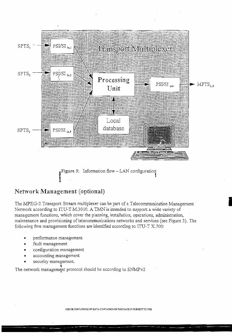
SPTSj
SPTS,
SPTS,
MPTSltt
.Figure 3; Information flow - LAN configuratiorí
Netvvork Management (optional)
The NIPEG-2 Transpon Stream multiplexer can be pan of a Teiecommunication ManagementNetwork according to ITU-T M.3010. A TMN is iníended to suppon a wide variety ofmanagement fimctions, which cover the planning, installation, operations, administration,maintenance and provisioning of telecommunications networks and services (see Figure 3). Thefollowing uve management functions are identified according to ITU-T X.700:
• performance management• fault management• configuration management• accounting management• security managemení.
?The network management protocol should be according to SNMPv2
USÉ OR. DISCLOSURE OF DATA CONTAíNED ONTHIS PACE IS SUBJECTTOTHE

Conditional Access
The encryption system is embedded within the muitiplexing system in íhe forrn of board that piuginto the multiplexer motherboard.For the sake of símpiiciry, the encryption is done at the outpui of the multiplexer .The input interface board convens the ^/ÍPEG-TRANSPORT signáis from diírerem: inpui sources
. (serial or parallel, at different signa! levéis) to an ínternal format stream. Thís siream is forwardedto the muitípiexer encryption board(s). The multiplexed output is forwarded EO the scramblerboard in an internal format stream ( serial differeniial ciock and data ) , which under coníroí of íheCAS (Conditional Access System ) decides on the íly which program requires scrambíing, andunder which key (control word). The scrambled data is then passed io the muítipíexer interfaceboard in an internal format stream ( paraileí 8 bits data bus , ciock and sync ).
Each scrambler board suppons up to 15 independent program's. The scrambíing of the program'sis implemented by a high-speed, ñoating point DSP and 2 iarge-sized FPGA's (ñeíd programmabíegate array).
The FPGA's are soft-programmed and thus are able to perform the block and stream scrambíingalgorithms. The soft&rogramrning of the FPGA's means that during the system inMáiization theyare loaded with " program's " that describes gate leve! interconnections. This aílows máximumñexibility (in terms of fuñiré upgrades) of the aigorithms, requires no hardware modiñcations.
The scrambler board DSP parses the incoming stream, and decides which program needs to beencrypted, and under which key (even/odd). It then 'pumps1 the data and íhe different key valúesinto the FPGA's, and upon completion - moves the data to the output circuits.
The CAS case, which is in charge of the entire C.A. system, has two links with the MUX;
1. The channel through which the CAS delivers the keys (control words) to cheencryption boxes (see Figure 4). Those keys, according to which the programs areencrypted, are being changed once in a second (or even more frequently).
2. The channel through which the CAS senas íhe information regarding the encryptionkeys. This information is broadcast to íhe entire community of subscribers, each ofwhich is able to extract from it either his own prívate key for the next period of time(EMM), or the key according ío which the next program is about ío be encrypted(ECM). Both of these messages are plugged into the MPEG-2 stream by the MUX.The EMEví's are being plugged into a MPEG Conditional-Access-tabie, which isdedicated to this kind of messages, while the ECM's are being inserted into theProgram-Map-Tables (whicK contain further information).
USE OR. DISCLOSURE OF DATA CONTAÍNED ON THIS PAGE IS SUBJECTTO THE
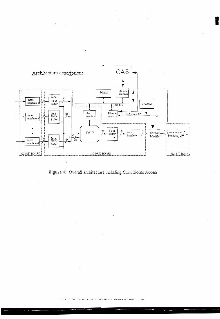
Architecture descriotion:
DSP 32/ fc
/ *
X BOA
F1FO
• Buffer
RD
a/
/serialinterface
1
'/ ,
yBOARD
a/
/ —sena! ouipu-interface J
MC-INT E
I
Figure 4: Overall architecture inciuding Conditional Access

Electrical Interfaces
Input
Input interface:
Máximum effective data rate at RS-422:Máximum efFective data rate at other inputs
Input Rate: RS-422TaxiT-Link I/F
Input Format:
External ClockClock rate:
RS-422, RJ45Options:'Taxi (Asynchronous Serial Interface), RJ45T-LÍnk (Asynchronous Serial Interface),BNCSSI (Synchronous Serial Interface), BNC
15 MbpsTotal input rate.up to 40 Mbps (typical38.159 Mbps) option: up to 53 Mbps
2 * 15 Mbps40 Mbps270 Mbps
MPEG-2 Transport Stream
Serial Clock up to 40 MHzRS-422, RJ45
Control and Data input port: RS-232
Number of I/O ports:Data rate:Input signal level:
OutputOutput interface:
Output Taxi rate:Output T-Link rate:
Máximum efFective data rate:
Output Format
1 or 2 (option), DB91.2-19.2 KbpsRS-232
DVB (LVDS Parailei Iníerface), DB25Asynchronous serial interface:Taxi (ASI), RJ45T-Link (ASI), BNC
67.5 Mbps270 Mbps
40 Mbps (typical 38.159 Mbps)Option: up to 53 Mbps
MPEG-2 Transport Stream
USE OR. DÍSCLOSURE OF DATA CONTAINED OH THIS PACE IS SUB/ECTTO THE

IPower Supply
Power:
•*••.
MechanicalThe unit size ís 19" rack mounted 4U high.
•Environmental*Storage temperatura:
Operating temperature:
Storage humidity (non condensing):
Scrambler Interfaces
Input
.. : v Input interface:
Output
Output interface:
CAS-Interfaces
Ethernet Interface:
110-115Vacor220^230Vac47 to 63Hz
0-40°C
95%
Differential'-Data & Clock ai RS-422 Level's
Parallel 8 bit's data ciock and syncIníerface i
!I
IEEE 802.3 Ethernet: RJ45 interfaces,BNC interfaces
2.2.6 SDM-2020 Video Modulator
The proposed modern, the SDM-2020 manufactured by EF Data is implemented in a 1:1redundant configuration. The performance parameters are shown in Table TBD-1. The unit isDVB/ASI compliant and provides a standard RS-422 serial/parallel interface with optionai RS-485 and RS-232 interfaces. Modulation includes QPSK, 8-PSK, and 16 QAM and can combineViterbi inner coding and Reed-Solomon outer coding. The SDM-2020 may be programmed bythe user to any rate between 1 to 100 Mbps in 1 bps steps localiy on the front panel display,remotely via a terminal or PC, and includes M&C features. The unit maintains the current
USE OR DISCLOSURE OF DATA CO.VTTAíNED OHTHIS PAGE ¡S SU3JECTTO THEI
I

confíguratíon in non-volatüe memory and returns to the original configuration when power isrestored. The current configuration and status is displayed continuously on íhe front panei.
The SDM-2020 suppons DVB appiications for sateilite transmission and converts an MPEG-2data stream to an ETS 300 421 deññed sateílite channei and-in addition to íhe modulaíion andcodíng options provides:
1. Physical interfacing and synchronization with MPEG-2 transpon muííipíexer and de-multiplexer
2. Scrambíing3. Baseband shaping and moduiation
The modulators will be configured as i: 1 redundant connguration. The Modern ProtectionSwirch will s\vitch both íhe DVB/ASI input and íhe 70 MKz output to the backup modulator.The Modem Protection Switch will maintain the current configuration and status of íhemodulators.
The Modem Protection Switch is aJso controllable from a front panel dispíay or remotely, throughthe M&C system. The system. status can be dispíayed on the front pane! of the switch.
2.2.7 C-Band V901 Up Converter
CM-STS proposes a 1:1 up convener system utilizing STS V901 synthesized, 125 KHz step,converters. The STS V901 Series thin-Iine frequency convener represents íhe newest in convenertechnology and is íhe result of extensive experience in the design, manufacture and installation ofeanh station networks. The V901 frequency convener pro vides exceptíonaí spectral purity andfrequency stabiliry for INTELSAT services, as weil as other regional sateílite systems.
The V901 frequency convener uses dual conversión and is designed with a fuíly agile, synthesizedlocal oscillator providíng tuning of the convener frequency in 125 XHz steps. Local oscillatorsare referenced to and interna! 5 MHz standard, or can be íocked to an external reference ifdesired. In absence of an external reference, the convener automaíically switches to an interna!ovenized hígh-stability, low phase noise crystal oscillator. The frequency convener provides an IFbandwidth of 70 ± 20 MHz or 140 ± 40 MHz. For íhe proposed eanh station, operation will be at70 ± 20 MHz.
A microprocessor-controlled user-friendly front panei permits local frequency seíecíion, access to100 non-voiatiíe memory locaíions, and features an alphanumeric dispíay. The front panei allowsremote/local monitor and control selection and provides sepárate alarms for RP and EF localoscillators, CPU and a summary alarm . The front panel also provides siope, gain and frequencyadjustments. To facilítate testing and maintenance, an KF local oscillaíor monitor pon is availableon the front panel. The back panel provides the various EF, KF and control connections, as well asa wide range prirnary AC input (100, 120, 220 or 230/240 VAC).
USE OR DISCLOSURE OF DATA CONTAINED ONTHIS PACE IS SUBJECTTOTHE

Digital Dará Rare
Symbol Rate
Modulation DVB ComplíantOprional Modulation
Forward Error Correciion
Data Scrambling
Dará interieaving
Compaiibiliry
Outpur Frequency
Output Power
Inrernal Clock Stability
Ourpur Impedance
Ouíput Rerurri Loss
input Inrerface
Transmit Frequency Stability
Clock Source
Output Spurious/Harrnonics
Remote Interface
Status/Control
Status LED's
-Stauís Relavs
> Tabíe TBD-l. Modulator Speciflcations1 to 100 Mbps, ín 1 bps steps, programmabíe
1 to 37.5 iVís/s máximum
QPSK at 1/2, 2/3, 5/6, 3/4 and 7/3 rares8PSKat2/3 and 5/6 raíe16QAM ar 3/4 and 7/8 rate
VirerbL K=7, Reed Solomon per ETS 300 421
Per ETS 3 00 421
Per ETS 300421
QPSK Per ETS 300 421
50-180 MHz in 2.5 KHz steps
-20 to -í-5 dBm in 0.1 db steps, accuracy of ±0.5dB
75n(50Ooptionai)
>18dB
DVB/ASI
¿lOppm ,. .
Internad or Externa! usenseJectable
<-55 dBc in any'4kHz band
RS 422 standard (RS485 / RS 232 optional)
Data Rate, Code Rate, Modulation Type, Frequency,Acquisition Range, Tx Power, Tx IF ON/OFFCode Rate
Power on, Sync, Transmitter On, Test Mode. TransmitFault Síored Fault, Transmit AlarmFauít Common equipment Fault, Alarm
lil
A unique feature of the V901 frequency converter ís íts built-in 1:1 protection iogic circuitryeliminating the need for any externa! Iogic control. When a fault is detected from the on-lineconverter, the backup convener initiates the necessary switching to repiace the failed unit. Thebackup converter controls the external transfer switch vía relay output.
The V901 frequency converter simplifies mainíainability through a modular design. The modularapproach simplifies fault localization and allows easy replacement of modules. The V901 Seriesfrequency converters were also designed with a great deal of commonality between up and downconverter subassemblies which further reduces the number of required spares.
The V901 frequency converters, by providing superior frequency síability and spectral puritycombined wiíh low intermodulation distortion and group delay equalization, ensure rhe integrity
i
USE OR D1SCLOSUR£ OF DATA CDNTAINED OHTHIS PACE ÍS SUB/ECTTD THE

of the digital carriers being transmitted and received. The technical specifications of the V901converter are Usted in Table 2.2.6-1
Table 2.2.6-1. Up Converter C-Band V901 Series
Eléctrica! Specifications
Input Characteristics
Frequency Range
Impedance
Connector
Return Loss
Standard
70 ±20MHz
75 ohms
BNC3 Femaie
23 dB
Output Specifications
Frequency
Tuning Step Size
Impedance
Connector
Return Loss
Power Output, 1 dB Compression
3rd Order Intercept
Spurious, Carrier Independent
Spurious, Carrier dependent
Muting
5.850-6.425 GHz
125 KHz
50 ohms
SMA, female
23 dB
+13 dBm
+23 dBm
-85 dBm
-65 dBm
Greaíer than 80 dB
Transfer Characteristics
Frequency Sense
ImageRejection
AM to PM Conversión
Gain
Gain Adjustment
Continuous (front panel)
Gain Stability:
No Spectrum Inversión
90 dB
0.1°/dB max. to -15 dB output
+10 dB
15 dB
. ±0.25 dB/day±0.5 dB/day
USE OR DISCLOSURE OF DATA COKTAJNED ONTKIS PACE IS SUBJECTTO THE
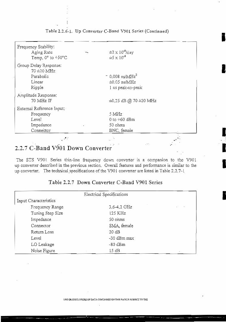
Table 2.2.6-1. Up Converíer C-Band V901 Series (Continued)
Frequency Stability:Aging RateTemp. 0° to +50°C
Group Delay Response;70¿20MHzParabolicLinearRipple
Amplitude Response:TOMHzIF
External Reference Input:FrequencyLevelImpedanceConnector
O.OOS ns/MHz"¿0.05 ns/MHz1 ns peak-ío-peak
-0.25 dB@70¿20MHz
5MHzO to +60 dBm50 ohmsBNC, female
i
i
2.2.7 C-Band V901 Down Converter
The STS V901 Series thín-line frequency down converter is a companion to the V901up converter described in the previous secíion. Overail features and performance is similar to theup converter. The technical.specifícations of the V901 converter are usted in Table 2.2.7-1
Table 2.2.7 Down Converter C-Band V901 Series
iii
Input CharacteristlcsFrequency RangeTuning Step SízeImpedanceConnectorReturn LossLevelLO LeakageNoise Figure
Eléctrica! Specifications
3.6-4.2 GHz125 KHz50 ohmsSMA, female20 dB-30 dBm max-80 dBm15 dB
i
USE OR. DÜSCLOSURE OF DATA CONTAÍHED ON THIS PAGE IS SUBJECTTOTHE

Table 2.2.7 Down Converter C-Band V901 Seríes (Confd)
Output CharacterísticsFrequency ""~ImpedanceConnectorReturn LossPower output, 1 dB compression3rd Order InterceptSpurious, Carrier Independen!Spurious, Carrier DependentMutingTransfer Characterístics
Frequency SenseImageRejectionAM to PM ConversiónGainGain Adjustment
Coníinuous (front panel)Local/Remote Control
Gain Stability:Frequency Stability:
Aging RateTemperatura 0° to +50°C
Group Delay Response:@70±20 MHz
ParaboíícLinearRipple
Amplitude Response;@70 ±20 MHz
External Reference Input:FrequencyLevelConnector
70 ¿20 MHz75 ohmsBNC, female23 dB+15 dBm-f25dBm-70 dBm-70dBcGreaterthan SO dB
No Spectnim Inversión70 dB0.1°/dB max. to O dBm output-rSO dB max.
15 dB
¿0.25 dB/day, ¿0.5 dB/month
±2xlQ-9/day¿5xlO'9
0.008 ns/MHz2±0.05 ns/MHz1 ns peak-to-peak
±0.25 dB
5MHzO to +6 dBmBNC, female
USE OR DISCLOSURE OF DATA CONTAINED ONTHIS PACE ÍS SUBJECTTOTHE

2.2.8 GMACS
STS offers the industr/s mosi capable computerized monitor and control system. Based on over tenyears of development, STS1 M&C system is simple to use and maintain while being exiremeiy capable.A color graphics interface makes the system much easier for íhe operators to íeam. AIl interfaces areintuitive with a ciear menú struciure. The single most important factor is that STS' M&C system canbe easily updated by ACTVE personnel to reñect on-going growth and modifications of the staíion.Since STS1 M&C is datábase driven, the displays and control can be modified by the user withoutneedíng to write ne\ software.
t
2.3 System Analysis
STS as an experienced sateilke systems house has íhe abÜíty to assure compliance and meetcapability requirements as speciñed by the customer and all regulating authorities of íhe satelliteíndustry. STS has conducíed a system analysis in order to assure the all cusíomer and satelliteprovider guidelines are met. STS is compliant with all íhe RF specification provided by ACTVEincluding a margin of 4 dB for future gr.owth (see Link Budget Eb/No vs. BER chart for theIRD). STS is aísc compliant with the redundancy and capability requirements as speciñed byACTVE. This incimies compliance to the dual stereo audio channel per video requirement as welland the analog/digital router Lnput requirement. STS has also included the E)aía Rate vs. SatelliteBandwidth Chart as specified by the customer.
2.3.1 IRD Performance
Progeny™ MX Profess'ional Integrated Receiver-Decoder
1. Qverview
This document describes the Progeny™ MX Professionai Integrated Receiver Decoder(IRD), which is MPEG-2, DVB complaint. The IRD is designed ío provide high qualityvideo as well as audio and daía for satellite program distribution. The Progeny™ MX IRDis based on internationai standards such as MPEG-2 and DVB, thus providing open system,open architecture and interoperable solution. The IRD comprises a QPSK Digital SatelliteReceiver and MPEG-2 decoder, integrated into either, 1U rack mounted, or Table Topcompact enclosure. The receiver is suitable eíther for MCPC or SCPC applications whilethe decoder segment provides MPEG-2 demultiplexing, audio and video decoding as well asdata services. The unit can be configured and controlled through a firont panel where all set-up parameters are LCD dísplayed. A detailed description of íhe receiver and the decodersegments is provided herein.
USEOP-DISCLOSUREOFDATACONTAINEDONTHÍSPAGEISSUBJECrTOTHE

Gu»y»auÍI ta Racwis-eSrt*
MQQÜLATiON PARAMtmaia
FECCoo«RaM 0.76797 *R«wuinxi SER 1.0E-10
Coding G*m O.OD dBImoíom^Ttatxxi Lo** 0.40 dB!JnkO*tgn Mafyin 0.00 dBRwiuirad Sy*t*m Eb/No S.90 dBModulaboo Typ* QPSXSymeoJRaU 12.57 Mt/sC*nr f Barxjwvnn 15.0SO WHzCh»nrwd B-oowxitn 17. BQ5 MHzReauírwd C/N • 8.B7 dB
?U,T=I ' PARAW^T^RS • PAS iOryol Lortgrtuo* [+ W of - E) 45 •Upfmk Fr»co«ocy 6.214 GHz
Upiink PoUruatiofi (V.H of q VCo-nlink Fr»Qii*ocy 3.883 GHl
Downlink PoUnzation HTmnioooóef Banowi<jtn í-4 MHzE!RP M.fiO dBWG/T -2.'0 aBrtíSFD -£5.eO dBW/m1
SlatxxiK»«CMog (±a*í) O.GS í'
THANSWrT CARTH STAT1ON P*RAMET=RSSha Loartxxi: Guayaquil
Loogruxi» (*• W«*tor- East) 73.0 'Latmxía (*• Nonn or • Soum) -2.3 *HeiQht AMSL 500.CO rtRain Rat« of ZDO«; COR Mod*i 1 47 mm/hf
Avrt*nr«:Siza 3.CSO mErftów>cy 73.X %A/i»nr\ G*rn ' 50.SI1 dB .-.. .Poirrang &+*mon: Upíink 49.:ia 'Pointing Azimum 86.71 'PoUnz. Rcxaboo fte.Cn '
Auto-Tr*ck fT N) \Trartsmrt Lin* LOM:
Swnr±, Cooptw O.t» dBHyood 0.00 dB
Fiftef J 0,05 dBW»v«guK*« '! 1.-10 aBToolTrantmrt Lina Lo*s#» / USO aB
Traniínram;Numtwí oí Carrier* Upfinked 1HPAB»ckon 2.SO dBMargin .4.1X1 dB
HPA Req'd. ow Carri«f 336.19 Watts
RBCEIVE CARTW STATION PARAWFF=RSSrta Loobon: Ríí Tv -S't»
LoogiuxJ* (* W«íof • EMÍ) 78.CD *LatmxJ* {+ Noftn or - Soucí) -1.10 'H^gtitAMSL 100.00 flRain R»la of 2oo«: COR Moó«1 147 fiwivhr
Ant»nna:Size 3.30 m
A^tanrw Gain 42.07 dBPwnbng El«v*tioo: Downlink SQ.ífl •Po-nung Aximutn 55.37 'Polam, Rotaboo M.CU •Auto-Tr»ck (Y or N) N
R*c*fwr:LNATftfnpwatum 25.00 KAm»nn« T«mp., 10* EW 23.53 KSf>t»m Mo** T*rop*fatut« S3.C-4 KESG^"«t 10- Elevalxxi Angl«: 24.07 dB/K
O«r Sky G/T «t Op riüng El* bon Angk:
Sy»t»m No<*« 1Vnp*f«tur* 50.5C KES GJT (Oc*nting) 25.03 d&fK
JONT AVAH *ñtl ITY QO ocj %
Dosvnhnk Pam AvaibDiltty 99.990 %
TRANSPONnFP -^ pARAMFTFñSBEUotmk AajusOTx»nt F*cdf o.OO d8BSCo*nlinic Aafusl. Factor Q.QO dB
SFD Pao O.OO dBE!RP ' 36.60 dBWG/T .2,40 dB^<SFD -SS.flO tíBVJIm1
Tf3níDOod«í Outout Baoccfl ,, 3.50 dBTr«n*pooa*f Inoirt B*ckoft 3.80 dBAvailao^ E1RP 33.10 oBWAv^itaDU a»fxjw>otn 54.00 MRzCam«f E1RP 25.23 üBW 'Cam*f CXrtput B*clccfl ñ.37 dBCamef Input Baocnrt a.fi? dB
IJPHNK ANAIYSISC¡«af SkyESEIRP 68.17 dBW
Anunna Gain 50.91 dBPowef Into A/Wona 53.28 Watt»
Majt EIRP Denwty 33.15 dBW-4kHiFr*« Soac« Lo« 199.70 dBAnt«nrw Po<mjrtg Lo»» - 0.21 dBAtmo»ph«ftc Lo*» 0.06 dBI»aijo0«c AJ»Í 37.32 dB-m*ÍUfrw Input Bacfcofl a.fi? dBIrooent Flux [>o*Jty -»4.4S dBW/rn^Trar«oofxi«-S.F.D. -85.SO dBW/m1
FiuxReUtiv« to Saturaoon -fl.Sa dBTr»rwxxxj*f G/T -2.40 dBvKBoíumann't Conttant -228,flO dBW/K^-ttC-7J up (cUar rty) 22.01 dB
Uplink F»d«UoJ.nlc Patn AvaiUbility 99.995 %
Rain AnenuaDoo 4.76 dBRMuir»d EIRP (rain lad«) 72.B3 dBWEítm Statxxi E!RP 68.17 dBWFliaRaUüv* to Satuntxxi -13.64 dBCTÍ UB (rain faó«} 17.65 d8
DOWNLINK ANALYSISCUar Slcy.Tran*pooó*f EiRP 30.80 dBWCam*( Output B»cxofT 5.37 dBC*m«r EIRP 28.23 dBWFr»« So»c» Lo»» 195.53 dBAtiT>a*pb*nc Lo»» 0.05 dBAm*nrui Ptxnong Lo»« 0.11 dBES G/T 25.03 dB/KBorczmann'» Cofistant -228.80 d8W/K/HzC-TJ down (d«ar *ky) 14.08 d9 '
Wrtfi Uplink FnnFluí R«bov« to Saturaoon -13.64 dBOutpul Backofl 13.13 dBQNd<jwn(upf*J«) 9.31 d8
Downlink Patn Availability 9O.900 %Rain Anenuatxxi 0.88 d9GJTD«gradabon 2.52 d8Toal Lo»s Du« a Rain 3.69 08C.TÍ dovíTi (rain f»d«) 10.38 d8
•
SP*C£ SEGWENT SUMMARY% EIRP 32.00 %% Baoavrtom 32.00 %
sYcfp=M CUIMMARY
OTJ uodnk 22.61 dB •CW ocwnlink 14 06 dB
C.1 IDOÍ op 2S.50 dSC.1M 16.C6 dBCl »dj «t dovn 24 IB dBOí looJ owvn 25.5S 'dBOí i*TT«m*l 2S.OO dBC/(N+I} toal «yttem 11.48 dBON í*qu¡r«¿ S.B7 dBUnic KUroin 4.4¿ tíBUA. F»o« M«rgin 4.37 tíBCVL F«o* U*rgm ~*5.7S dB
UPLINK FADe...{to«) 4 ? 6 d BUplink Px?*«f Coatroí... 0.00 fl 8
C/N upluik 17.65 d8CVN cíownlinlc 8.31 d8Oí «dj t«t up ' 24.07 dBC-looJup 22.15 dBCTM 15.41 dBC.1 »dj tal oown 19.43 dB
Gltorrwínal 24.24 dBC/(N*0 total iy»»m 7.06 dBC/N rwuif*d fl.97 dBUnK Margin 0.11 dB
COWNUNKFADe...(to«) 3.88 dBC/N Uplink 22.81 dBC/N downlink 10.33 dBC1*djutup 28.53 dBC1 ísxií Up .• . . 2S.SO d8 .OTW Iñ.CS dBC/l»d¡«tdovn '•- 24.1S (J8C-lHX>íc»«n 25.50 dBC/l teíT»«jÍ4l 28.12 dBC/(N*I) total «y*»m 8.06 dBC/N r»quii»d 6.97 dBünk Wargin 2.06 dB
EQUIPWENT SUMMARYTRANSMfT.AnWnoa Su» 6.30 mA«»nna G*in 50.31 dBFr»qu»f>cy 6.214 GHzEIRPf«rC«nm 63.17 dBW
Max BRP D»n*rty 33.15 dSW.4kHz
HPA Poww «1 Antofina 53.28 W«mTr«n»m(»t*on LJn« Lo»» 1.50 dBHf A Pt>»wr Oxmxrt 75.28 WataHPA Backofl X50 dBM»fgm 4.00 dBUdink Po^ f Consol 0.00 dB
HPA R»q'd, f*f CartWf 33fl.l9 Watti
RECEIVE.....
AJTt»ofia Gain 4Z07 dBLNA Input U>*Í -05.70 dBMLNA No«*« T»mo^»tur» 25.00 KAra*nn» T»mi»f«tur» 11.15 K
MUn«ichNoí»* -101.00 KSyKmn NoU* T«mp 50.5a KGfT it Oo*ratJr>g Angla: 25.03 dB/K
U-l \40UTH-I WJ4A2CKA3 I1/1V»7
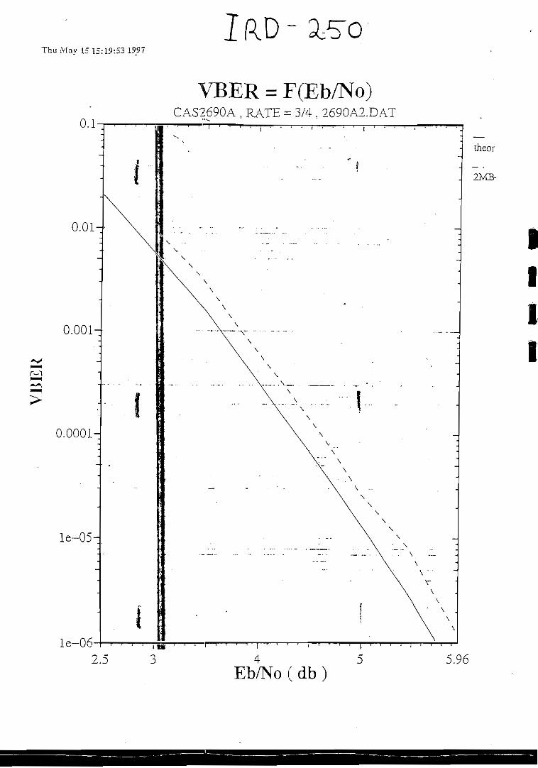
IRD -Thu May 15 15:19:53 1S97
0.01-
0.001-
0.0001-
le-05-
le-062.5
VBER = F(Eb/No)CAS2690A , RATE = 3/4 , 2690A2.DAT
theor
2MB-
*iii
Eb/No ( d b )5.96

P97-S570 Three Channel MPEG2-DVB MCPC Bandwidth Requirement 5:36 PM
I
I
8 Mbps/Ch
-
6 Mbps/Ch
4 Mbps/Ch
3 Mbps/Ch
2 Mbps/Ch
ComposiíeData Rate(Mbps)
25.52025.52025.52025.52025.52025.52025.52025.52025.520
19.31419.31419.31419.31419.31419.31419.31419.31419.314
13.10913.10913.10913.10913.10913.10913.10913.10913.109
10.00610.00610.00610.00610.00610.00610.00610.00610.006
6.9046.9046.9046.9046.9046.9046.9046.9046.904
Reed-SolomonO Yerbead(Mbps)
2.1722.1722.1722.1722.1722.1722.1722.1722.172
1.6441.6441.6441.6441.6441.6441.6441.6441.6-44
1.3161.1161.1161.1161.1161.1161.1161.1161.116
0.8520.852O.S520.8520.8520.852O.S52O.S520.85?.
0.5880.5880.58S0.5SS0.5880.5880.5880.5880.588
FEC CodeRate
•-••,
1/22/33/45/67/82/35/63/47/8
1/22/33/45/67/82/35/63/47/8
1/22/33/45/6 .7/82/35/63/47/8
1/22/33/45/67/8
- 2/35/63/47/8
1/22/33/45/67/82/35/63/47/8
TransmissionRate
(Mbps)
55.38441.53836.92233.23031.64841.53833.23036.922
. 31.648
41.91631.43727.94425.15023.95231.43725.15027.94423.952
28.44921.33718.96617.07016.25721.33717.07018.96616.257
21.71616.28714.47713.02912.40916.28713.02914.47712.409
14.98211.2379.98S8.9898.56111.237S.9899.9888.561
ModülationType
QPSKQPSKQPSKQPSKQPSK8PSKSPSK
16QAM16QAM
QPSKQPSKQPSKQPSKQPSKSPSKSPSK
16QAM16QAM -
QPSKQPSKQPSKQPSKQPSKSPSKSPSK .
16QAM16QAM
QPSKQPSKQPSK 'QPSKQPSKSPSKSPSK
16QAM16QAM
QPSKQPSKQPSKQPSKQPSKSPSKSPSK
16QAM16QAM
SymbolRate
(Mbps)
27.69220.76918.46116.61515.S2413.84611.0779.2317.912
20.95S15.71913.97212.57511.97610.4798.3836.9865.9S8
14.22510.6689.4838.5358.1287.1125.6904.7424.064
10.8588.1437.2396.5156.2045.4294.3433.6193.102
7.4915.6184.9944.4954.2813.7462.9962.4972.140
OccupiedBandwidth
(MHz)
33.23024.92322.15319.93818.98916.61513.29211.0779.494
25.15018.86216.76715.09014.37112.57510.060 -8.3837.186
17.07012.80211.38030.2429.7548.5356.8285.6904.877
13.0299.7728.6867.8187.4456.5155.2124.3433.723
8.989. 6.742
5.9935.3945.1374.4953.5962.9962.568
RequiredTransponderBandwidth
(MHz)
33.76829.07625.846
" 23.26122.15319.38415.50712.92311.077
29.34122.00619.56117.60516.76714.67111.7379.7808.383
. 19.91514.93613.27611.94911.3809.9577.9666.6385.690
15.20111.40110.1349.1218.6867.6016.0805.0674.343
10.4887.8666.9926.2935.9935.2444.1953.4962.996
S576BWTeleAmaz.xls Pagel CM-STS, USA

I
OPSK Receiver
General DescriüííonThe receiver segmení is a complete digital receiver includíng tuner, QPSK demodulator andForward Error Correcíion deccsder. The board receives L-band RF input signaí coming froman LNB. The synthesized tuner down-converts this signa! ínto two (1 and Q) analog outpuís.The two outputs of the tuner are digitized by a dual ADC. The quantized outputs of theanalog to digital converter are then fed to the coherent demodulator, fully compliant with íhev'DVB-S specificaíions. Auíomaíic gain control, half Nyquist filtering, symbol raíe recoveryand carrier recovery are all carried ouí using digiíal processing techniques. The outpuí of thedemoduiation part of the chip is fed to the FEC unit for error correction. This part includesVlterbi decodíng, frame synchronizaíion, de-iníerleaving and Reed-Solomon decoding.Coding rate, spectral inversión and phase ambiguities are automatically solved by the FECdecoder.All these fünctions are fully compliant with the DVB-S specifications (ETS 300 421).
Receiver features• L-Band input:.950-2050 MEÍz.• Input level: -65 to -25 dBm.• L- Band Loop-íhrough outpuí for cascadmgIRD's.
• <' 'Symbol rate: 3-30 M Symbols/sec. • _ "~ • • - ^• Digital AGC. - . " ' I• Carrier acquisiíion range: ± SR/2.• Specíral inversión >supported.• Viíerbi decoding rates: 1/2, 2/3, 3/4, 4/5, 5/6, 7/8, 8/9 & Constraint iength - 7.• De-interleaving.• Reed-Solomon decoding (204, 188, 8).• MPEG-2 íransport síream output.• Fully compliant withDVB specifications (ETS 300 421).
i
i
iUSE OH. DÍSCLOSURE OF DATA CONTAÍNED ON THIS PAGE IS SUBJECTTO THE

I
i
MPEG-2 DECODER
General Descripción
The decoder receives MPEG-2 Múltiple sen/ices transpon layer input and it decodes onevideo sen/ice, one stereo audio program and additional data streams. It demultiplexes the bitstream to exirací the appropriate service, decodes the video audio and prívate data, andconvenís them to the desired analog and digital formáis. All operations are flexible andcontrolled by an internal CPU.
The following drawing pjesents the board block diagram.
The decoder contains the following major blocks:
Transpon: DeMuxThe Transpon: DeMux extracts one program stream out of the MPEG-2 system transpon:streams. The stream is synchronous parallel according to DVB (options: serial RS422 andparallel TIL). The parallel inputs (LYDS and TTL) can be loop through to a LVDSbuffered output. The Transpon: DeMux demultipiexes the data and sends the appropriateinformation to each block: the video síream to the Video Decoder, the audio stream to theAudio Decoder and the prívate data to the outpuí. The appropriate channel is selected bythe CPU.
i USE OR DfSCLOSURE OF DATA CONTAINED ONTHIS PAGE IS SUB/ECTTOTHE

Video DecoderThe Video Decoder receives a digirai decompressed stream from the Transpon DeMux. Ttdecodes the video according to MPEQ-2 Video standard and convens the input resolutionsto 720 pixeis per une. The resultan: output (8 bit CbYCrY) is forwarded to the PAL orNTSC Encoder. A Paralleí Digitai Interface (PDD and Serial Digital Interíace (SDI) areavailable as^options.Audio Decoder -jThe Audio Decoder receives a digital stream írom the Transpon DeMux. It decompressesthe ISO MPEG-1 ¡ayer I and II audio. The resultant output is forwarded to a Digital íoAnalog dual channeí audio converter. The digital outputs are transferred to the board'soutputs.PAL/NTSC EncoderThe PAL/NTSC Encoder receives íts input írom íhe Video Decoder. It convens the digitaldata to the analog NTSC or PAL forrnat. The output of the block is high quaiity compositeand S-Video (Y/C). The encoder has the provisión for Closed Caption and Extended DataServices Encoding (Une 21).Digital to Analog Audio ConvenerThe Digital to Analog Convener convens the digital stream to two analog signáis using a
'•'16 bit delta - sigma DAC with severa! over sampíe ciock ;¿Jtes by reading the MPEG audiostream Information and programming ihe PLL for the proper operation.CPUThe CPU conírols the operations of the board. The CPU is connected to 2 remote termináisvia two RS232 serial ports, Or vía one RS232 pon and one RS485 pon. Those pons allowthe operator to configure the board, to select the oroüer service, to monitor and Í02 the
"" i « * £ "board status, to upgrade software, and to control the prívate data output. -Conditional AccessThe decoder has a provisión for optional proprietary Conditional Access. This CA issuitable for small nerwork operation with not more than several thousands of subscribers.The CA provides descrembling as we!l as subscriber addressability i.e. per each subscriberand/or per groups of subscribers.Svnc. LockThe board has a provisión for synchronization locking. In this mode, the synchronízation ofthe board follows the synchronization of a composite color-black signal (black-burst).
USE OR. DISCLOSUR£ Or DATA CONTAJNED ON TH!S PACE IS SUB/ECTTO THE
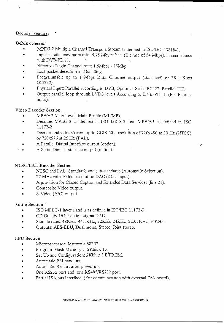
Decoder Features.
DeMux SectionMPEG-2 Múltiple Channel Transport Stream as deñned in ISO/TEC 13818-1.
• Input parailei máximum rate: 6.75 Mbytes/sec, (Bit rate of 54 Mbps). in accordancewithDVB-PIlll.
• Effecíive Single Channel rate: 1.5Mbps - 15Mbp.• Lost packet deíection and handling.• Programmable up io 1 Mbps Data Channel output (Balanced) or 38.4 Kbps
(RS232).• Physical Input: Parallel according to DVB; Options: Serial RS422, Parailei TTL.
Output parailei loop through LVDS levéis According to DVB-PI111. (For Parallelinput).
Video Decoder SectionMPEG-2 Main Level, Main Profíle (ML/MP).Decodes MPEG-2 as defined in ISO 13818-2, and MPEG-1 as defined in ISO11172-2
• Decodes video bit: stream: up to COR 601 resolution of 720x480 at 30 Hz (NTSC)or 720x576 at 25 Hz (PAL).
• A Parallel Digital Interface output (option).• • A Serial Digital Interface output (option).
NTSC/PAL Encoder Section• NTSC and PAL Standards and sub-standards (Automatic Selection).• 27 MHz with 10 bits resolution DAC (8 bits input).• A provisión for Closed Caption and Extended Data Services (Une 21).• Composite Video output.
S-Video (Y/C) output
Audio SectionISO MPEG-1 layer I and II as defined in ISO/IEC 11172-3.
• CD Quality 16 bit delta - sigma DAC.Samóle rates: 48KEz, 44.1KHz, 32KHz, 24KHz, 22.05KHz, 16KHz.
• Outputs: AES-EBU, Dual mono, Stereo, Joint stereo.
CPU Section• Microprocessor: Motorola 68302.• Program: Flash Memory 512Kbit x 16.
Set Up and Configuration: 2Kbit x 8 E2PROM.• Automatic PSI handling.• Automatic Restart aíler power up.
One RS232 port and one RS485/RS232 port.» Partial ISA bus iníeiface. (For communication with external D/A board).
USE OR. DlSCLOSURE OF DATA CONTAWED ON THIS PACE IS SUBJECTTO THE
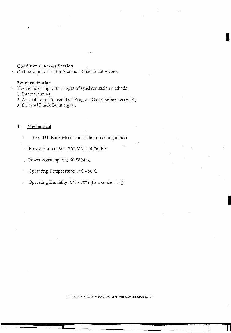
Conditional Access SectionOn board provisión for Scopus's Conditional Access.
Syn chr o nizatio nThe decoder supports 3 types of synchronlzation methods:1. Interna! timing.2. According to Transmitters Program Clock Reference (PCR).3. External Black Burst signa!.
4. Mechanical
Size: 1U, Rack Mount or Table Top configuraíion
• Power Source: 90 - 260 VAC, 50/60 Hz
. Power consumption: 60 W Max.
• Operating Temperature: 0°C - 50°C
• Operating Humidity: 0% - 80% (Non condensing)
USE OR DISCLOSUR£ OF DATA COKTAIHED ON THIS PACE 1S SURIECT TO THE
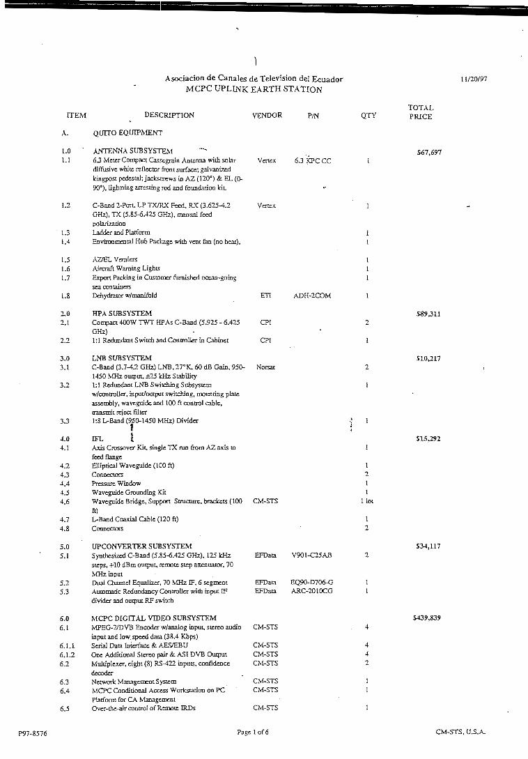
Asociación de Canales de Televisión del EcuadorMCPC UPLINK EARTH STATION
11/20/97
ÍTEM DESCRUTION
A. QUITO EQUIPMENT
LO - ANTENNA SUBSYSTEM1.1 63 Meter CompactCassegraiii Antenna with solar
diffusivc whitc reflector front surface; gaivanizedIdngpost pedestal; jackscrews in AZ (120°) & EL (0-90°), lighcníng arrestmg rod and foundadon kit.
1.2 C-Bacd 2-PorU LP TX/RX Fced, RX (3.625-4.2GHz), TX (5.S5-6.425 GHz), manual feedpo lanzado o
1.3 Ladder and PlarformL.4 Environmental Hub Pacliagc witfa vcnt fan (no bear).
1.5 AZ/EL Veraicrs1.6 Aircraft Waraing Lights.,7 Expon PacLing ín Cusiomcr furnished ocean-going
sea containers1.8 Dcbydrator w/manífold
2.0 HPA SUBSYSTEM2.1 Compact 4QOW TWT HFAs C-Band (5.925 - 6.425
GHz)2.2 1:1 Rcdundant Switch and Controller in Cablnet
3.0 LNB SUBSYSTEM3.1 C-Band (3.7-4.2 GHz) LNB, 27°K, 60 dfl Gain, 950-
1450 MHz ouiput. ¿Z5 kHz Scabüity3.2 1:1 ReduiKÍant LNB Svitching Subsystcm
w/contraller, input/output switching, mountíng píateasscmbly, wavcguidc and 100 ft control cable,transnrit reico. filtcr
3.3 1:8 L-Band (950-1450 MHz) Divider
4.0 DFL j,4.1 Axis Crossover Kít. single TX nm from AZ axis to
fcedflange4.2 Ellipdcai Waveguide (100 ft)4.3 Coonectors4.4 PTCSSUIT: WÍDOOW4.5 Wavcguidc Grounding Kit4.6 Waveguide Bridgc, Suppon Stmourc, bradccts (100
ft)4.7 L-Band Coaxial Cable (120 ft)4.8 Coonectors
5.0 UPCONYERTER SUBSYSTEM5.1 Synthesized C-Band (5.85-6.425 GHz), 125 kHz
stcps, +10 dBm output, remóte stcp anenuator, 70MHz input
5.2 Dual Channc! Equalizer, 70 MHz IF. 6 segrnent5.3 Auiomaric Rcdundancy Controller witfa input IF
divider and output RF switch
6.0 MCPC DICrTAL VTDEG SUBSYSTEM6. i MPEG-2/DVB Encoder w/aoalog ínput. sierro audio
ínput and low. spced data (38.4 Kbps)6.1. i Serial Data Iníerface & A^S^BU6.1.2 One Adcütioaal Stereo pair & ASI DVB Output6.2 Multiplexer, cíght (8) RS^t22 ínputs, confídence
decodcr6.3 Networt Management System6.4 MCPC Condítional Access Workstation on PC
Platfonn for CA Management6.5 Ovcr-the-air control of Remóte IRDs
VENDOR
Vértex
Venex
P/N
6.3 KPC CC
ETI
CPI
CPÍ
Norsat
ADH-2COM
CM-STS
EFData
EFDataEFData
CM-STS
CM-STSCM-STSCM-STS
CM-STSCM-STS
CM-STS
V901-C25AB
EQ90-D706-GARC-2010CG
QTY
1211
llot
1
2
TOTALPRJCE
567,697
589,311
510,217
$15,292
534,117
5439,839
P97-8576 Page 1 of6 CM-STS, U.S.A.

Asociación de Canales de Televisión del EcuadorMCPC UPLINK EARTH STATION
11/20/97
ÍTEM DESCRDPTION
8 x 3 Router, SDI digitaJ video with dual AES/EBUdigital audio and analog video with dual sicrco S x 8Video, and redundant power suppíiesFram: with dual AC power suppíies8 x 8 SDI Video Module8 x 8 AES/EBU Audio Module8 x 8 Analog Video Module8 x S Dual Cnannel Analog Audio ModuleProgrammable Pushbuoon PanelRemóte Programmable Pushbuuon PanelDigital to Analog Convener for Monitor
Digital/Analog Vídeo/Audio Patch PanelMaster Clock GeneratorQPSKModulator1:1 Red, Modulator SwitcbWired Equipment Cabinet13" Production Video Monitor for ínput Sigua!Monitoring
IRD SUBSYSTEMERD witn L-band ínpuL anaiog outputAddidooal audio (one stereo duat-cfaanneJ)8" Producñon MonitorPAL/NTSC Wavefonn MonitorStereo Audio Monitor/AmplifierSpcetmm MonitorWircd Equipmem Cabinct
MISCELLANEOUS MATERIALSMise. On-sitc Materials
VENDOR P/N
6.6
6.6.16.6.26.6.36.6.46.6.56.6.66.6.76.9
6.106.116.126.136.146.15
7.07.17.1.17.27.37.47.57.6
P97-8576
B.
1.01.1
1.2
1.31.4
1.51.61.7
2.02.1
2.2
3.03.1
3.2
3.3
EFDataEFData
CM-STSSoay
SDM-2020SMS-30Í
PVM-14M2U
CM-STSCM-STS
SoayTeJaroníx , >Di-ircL
TelarQüix.CM-STS
PVM-8041Q173570061705A
CM-STS
QUITO EQUJPMENT SUBTOTAL
GUAYAQUIL EQUIPMENT
ANTENNA SUBSYSTEM63 Meter Compact Casscgrain Antcnna witfa solardifíusive wfaite reflector iront surface; galvanízcdkingpost pedestal: jacksocws in AZ (120°) & EL (0-90°), lightning arresring rod and fouodatíoa idL
C-Band 2-Port. LP TX/RX Peed, RX (3.625-4^GHz), TX (5.85-6.425 GHz), manual fccdpolarizatkmLaddcr and PlatfonnEnvironroental Hub Package widí vent fan (no beat).
A2/ELVemieTsAircraft Waming LíghtsExpon Packing in Custotrer fumisbed ocean-goingsea containersDehydrator w/manifold
HPA SUBSYSTEMCompact 400^ TWT HPAs C-Band {5.925 - 6.425GHz) jf1:1 Redundant Switcb and Controller in Cabtoet
Vértex
Vencx
63 KPCCC
ETI
CPI
CPI
ADH-2COM
LNB SUBSYSTEMC-Band (3.7-4.2 GHz) LNB, 27°K, 60 dB Gain. 950- Norsat1450 MHz output, £25 IcHz Stability1:1 Redundant LNB Swítcníng Subsysxcmw/cootroller, inpui/outpui switching, nnuntíng píateasscmbly, wavcguide and 100 ft control cable,transmit reject filter1:8 L-Band (950-1450 MHz) Dividcr
Pagc2of6
QTYTOTALPRICE
S33,935
S 13,858
$704,264
567,697
I
$39,311
S10.Z17
CM-STS. U.S.A.

Asociación de Canales de Televisión del EcuadorMCPC UPLINK EARTH STATION
ÍTEM DESCRTPTION VENDO R P/N QTY
11/20/97
TOTALPR1CE
4.04.1
4.24.34.44.54.6
4.74.8
5.05.1
5.25.3
6.06.1
6.1.16.1.26.2
6.36.4
6.56.6
6.6.16.6.26.6.36.6.46.6.56.6.66.6.76.7
6.86.96.106.116.126.13
7.07.17.1.17.27.37,47.57.6
P97-8576
CFLAxis Crassover Kit, single TX nm &om AZ axis to • - ifecd flangeElliptical Waveguide C100 ft) 1Connectors 2Pressurc Window 1Waveguide Grounding Kit 1Waveguide Bridgc, Suppon Structure, brackets (100 CM-STS I lotft)L-Band Coaxial Cable (120 ft) 1Coonectors 2
UPCONYERTER SUBSYSTEMSyntbesizcd C-Band (5.85-6.425 GHz), 125 kHz EFData V901-C25AB 2steps, +10 dBm output, re-mote stnp aoenuaior, 70MHz input.Dual Channcl Equalizer, 70 MHz IF. 6 segment EFData EQ90-D706-G 1Automatic Reduodancy Controller wini inpui IF EFData AR.C-2Q 10CG Idivider and output RF switcfa
MCPC DIGITAL VIDEO SUBSYSTEMMPEG-2/DVB Encodcr M'/analog input, sterco audio CM-STSinput and low specd data (38.4 Kbps)Serial Data intafacc & AES^BU CM-STSOne Addiáooai Sterco pair &. ASI DVB Output CM-STSMufdplcxcr. cight (8) RS-422 inputs, confídcacc CM-STSdecoderNecworic Management System CM-STS 1MCPC CoDditional ACCCÍS Wortstanon OQ PC CM-STS 1Platfonn for CA ManagcnicatOvcr-the-aír control of Remote IRDs CM-STS 18 x 8 Router, SDI digiial 'ndeo witfa dual AES/EBUdigital audio and analog video witfi dual sterco 8 x 8Video, and redundant power suppliesFratnc with dual AC powca- supplies 2S x 8 SDI Vídeo Module 18 x 8 AES/EBU Audio Module 28x8 Analog Video Module 18x8 Dual Channel Analog Audío Module 2Programmablc Pushbuooii Panel 1Remóte Programmable Pushbutttm Panel 1Digital to Analog Convcner I
Digital/Analog Video/Audio Patch Panel IMaster Ctock Gencraior 1QPSKModulator EFData SDM-2020 21:1 Red, Modulator Switch EFDaia SMS-301 1Wired Equiptncnt Cabbel: CM-STS 313" Producdon Video Monitor for InputSignal Sooy PVM-14M2U 1Monítoring
IRD SUBSYSTEMIRD widí L-band ínput, analog output CM-STS 4Additional audio (one stcreo dual-cfaannd) CM-STS 48" Productíoo Monitor Sony PVM-8041Q 4PAL/NTSC Waveform Monitor Tektronix 1735 1Stereo Audío Monitor/Amplifíer Di-tech 7006 1Spectrura Monitor Tektronix 1705A 1Wtred Equipment Cabinet CM-STS 1
MISCELLANEOUS M.VTERLVLSMise. On-sitc Materials CNÍ-STS - 1
GUAYAQUIL EQUIPMENT SUBTOTAL
Pace 3 of 6
515^92
S34,U7
$439^39
533,935
513,858
5704,264
CM-STS, U.S.A.

Asociación de Canales de Televisión del EcuadoriMCPC UPLINK EAKTH STATION
11/20/97
1.0 ENGINEERINC, PMO, D&D1.1 Design Rcview1.2 System Engineeriug fRacks, Intercnts)1.3 Design & Drafüng1.4 Progiam Management/Pian
2.0 ES-PLANT INTEGRATTON AND TEST2.1 In-PIant Integrad on2.2 In-Plant Test
3.0 IN-PLANT TRAINING3.1 Laboral SI,000 per day pius expenses x 1.20
4.0 DOCUMENTATION4.1 Standard Drawing Package
5.0 ON-SITE INSTALLATÍON & TEST5.1 Instailatkm & Test5.2 Installatíon Supervisión5.3 Test Equípmcnt Rental
SERVICES SUBTOTAL
EQUTPMENT AND SERVICES TOTAL
YENDOR
CM-STSCM-STSCM-STSCM-STS
CM-STSCM-STS
CM-STS
CM-STS
P/N QTYTOTALPRICE
513 ,182
520,000
S5,419
S140.593
EQUÍPMENT AND SERVICES GRANO TOTAL
CM-STS
CM-STS
111
5302,194
51,710,722
(515,000)
51,695,722
D. SPARES (Coocurrent with System)
LO.1.1
2.02.1
3.03.1
3.1.13.1.23.2
3.3
E.
1.01.1
1.2
2.02.1
LNB SUBSYSTEM-C-Band (3.7-4.2 GHz) LNB, 27°K. 60 dB Gain. 950-1450 MHz ouiput, d¿25 kHz Stabiüty
HPA SUBSYSTEMCompact 400W TWT HPAs C-Baod (5.925 - 6.425GHz)
MCPC DIGITAL VIDEO SUBSYSTEMMPEG-2/DVB Encoder w/analog mpuí, stcreo audíoinput and low spccd data (38.4 Kbps)Serial Data Intcrfacc & AES/EBUOne Additional Stereo paír & ASI DVB OutputMultíplcxer, eigbt (8) R5-422 mputs, confídencedecoderQPSK Modulator
OPTIONS
ANTENNA SUBSYSTEMServo Interface Kíc dríve motors for AZ, EL andpolarizaflon, Hmit switcbes, brackctryforniouiiringlimít switches and cransducers, conduhs and cables.For Model 7133B Controller wíih size 1 1 singlesrxcd transducere
, Antcnaa Jog Control Uoit with thrcc axis control
MCPC DIGITAL VIDEO SUBSYSTEMAdditíonal Two (2) Sterco Audio pairs (4 total pairs)
Norsat 1
CPI 1
CM-STS 1
CM-STS 1 'CM-STS 1CM-STS 1
EFData SDM-2020 1
Verrex 2
Venex 2
CM-STS i
SS43
537,632
551,071
S29J16
59,700
517,650
512^62
51432
P97-8576
2.2 Additíonal 8 x 8 Rouier Modules for two alditíonalStereo audío pairs
Leitch
Pagc4of6
SS,489
CM-STS, U.S.A.

Asociación de Canales de Televisión del EcuadorMCPC UPLINK EARTH STATION
11/20/97
Leitch FR-X-Í-2RU-2ACLeitch ASR-Sx8Leitch ASM-8xSA2
CM-STS
Líster
Exidc
Zenith
ÍTEM DESCRJPTION VENDOR P/N QTY
2.2.1 Framc with dual AC powcr supplies2.2.2 8 x 8 AES/EBU Audio Module2.2.3 S x 8 Dual Channel Analog Audio Module2.3 Additional Digital/Aoalog Patch PancJ for two
addirional stcreo audio pairs2.4 Remote Coaditional Access Terminal
, 3.0 POWER SUBSYSTEM3.1 Generator. 20 kVA, 16 kW, 240/120V, single phase,
60 Hz with control panel, battery, batrery chargeT,silencer, 10 gallón fue! tank, tuain circuit breaker
3.2 10 kVA UPS, 7 kW. 240/120V, single pbasc, 60 Hzw/anto and maintenance bypass, 15 min barterybacicup
3.3 Automatíc Transfer Switch, 100A, 2-polc, 24O/120V,single pbase, 60 Hz, NEMA 1 cncloscd
3.4 Main Panel, 100 A, 24Cfl20V, single phasc, 60 Hz, 2NEMA 1 enclosed
3.5 Tcchnical Panel, 60 A, 240/120V, single pbasc, 60 . 2Hz, NEMA 1 encloscd
3.6 Utility Panel, 100 A, 240/120V, single pbase, 60 Hz, 2NEMA 1 cncloscd
3-7 Surge Supprcssor . 23.8 Powcr System Engracaing CM-STS 13.9 SparePartKit 1
4.0 IRD SUBSYSTEM4.1 IRD with L-band input. analog outpul CM-STS 14.1.1 Additíonal audio (one stereo dual-channcl) CM-STS 1
5.0 MONITOR AND CONTROL SYSTEM("Central Adminístrator")
5.1 SutnrnaryAlarmPanel CM-STS D61486-15.2 GMACS í5.2.1 GMACS Worfcstatíon 16000-002515.2.2 17" Monitor* 16000-001365.2.3 ZSOFT Photofinish 16000-001275.2.4 GMACS Site Liccnse A649005.2.5 PC-SCP 16000-002475.2.6 DigÍboard/RS422/485 16000-000055.2.7 DtO Boara CM-STS D635185.2.8 Software Engineering CM-STS5.2.9 GMACS Manual CM-STSNote: ítem 4.0 is for onc site, Double quantírics and pricc
for both sites.
P97-8576
6.0 MICRO WA VE SUBSYSTEM6.1 13 GHz Single Channcl Modulated Transmit CM-MRC FLR127T 6
Terminal,+30 dBm RF output. basebandvideo/composite ¡nput, 525/625 Une video
6.2 First Audio Modulator with LPF CM-MRC ASM-LPF ó6.3 Audio Modulator CM-MRC ASM-N 186.4 13 GHzSíngJe Cbanncl, Modulated Reccive CM-MRC FLR127R 6
Terminal, bascband vidco/coropositc input, 525/625linc video
6.5 First Audio Demoduiator with LPF CM-MRC ASD-LPF 66.6 Audío Demoduiator CM-MRC ASD-N 186.7 l.SM Single Polarized Antenna. 12.2 lo 13.25 GHz Andrcw P6-122F 126.8 Elüptical Waveguide, 35m Andrew EWP127A 126.9 Waveguide Conncctors Andrcw 1127DCT 246.10 Dehydrator w/manifold ETI ADH-2COM 66.11 Prcssurc Window 126.12 Waveguide Grounding Kits 126.13 Tower. I5m 86.14 Wircd Equipment Cabinet CM-STS &6.15 Engmeering, PMO and D&D CM-STS 1
Page5of6
TOTALPRICE
52,079
517,322
5102,798
51,748
545,485
$623,934
CM-STS, U.S.A.

Asociación de Canales de Televisión del EcuadorMCPC UPLINK EARTH STATION
11/20/97
ÍTEM DESCRIPTION YENOOR
6.16 In-Pbnt Integraáon and Test CM-STS6.17 Packing and Shipping CM-STS6.13 On-Site ínstallanon and Test CM-STS6.19 ProgramManagemenc/PIan _ CM-STS
Note; Sborr-haul microwavc linJc basca on aaunobsiructed iinc of site.
NOTES:- AU priccs are in U.S. doilars and are exclusive of
taxcs, impon dudes and Gustóos cbarges.- Equipment has-a rwo ycar wananty, with the
exccprion of thc TWT Tubc which has a one ycarwarranty.
- Tbc foüowing Ítems are CFE:1. Provisión ÍOT tecimical andtiálity power at ibe main
building and antenna fóundatíotí2. Licenscs and permiis3. SateiEic coordinarioo during anteana vcrificarion.4. Site access required 7 days per weei:, 24 bours per
day.5. Site survey and documcntaiioii.
P/N QTY
11I1
TOTALPRICE
I
I
II
II
P97-S576 Pagc 6 of 6 CM-STS, U.S.A.

IVÉRTEX 6.3-METER
MODEL 6.3 KPK & KPC CC (Kingpost Pedestal)K U - B A N D & C - B A N D
IE A R T H S T A T I O N A N T E N N A S
The Vértex 6.3-Meter Ku-band and C-band antenna deliversexceptional performance for receive only and transmií-receiveworldwide applications.
The Model 6.3 KPK/KPC antenna ofíers a deep dish reflectorwhich incorporales precision-formed panels, radiáis and hubassembly wiíh matched tooíing for ease oí assembly without fieldalignment. The antenna features an innovaííve compactCassegrain subreflector and unique feed design which results inhigh gain, low noise temperatura, high antenna efficiency andexceilent rejection of noise and microwave iníerierence. A largecenter hub provides spacious accommodaiion for equipmentmounting. The reflector is supporíed by a síee! azimuíh/elevation
Ipost pedestal providing síiffness and pointing accuracy. The_destals are designed forfuil orbital are coverage.
The antenna meéis FCC Regulaíion 25.209, IESS (Intelsat),Euíelsat, AsiaSat or ITU-RS-580 sidelobe specificaíion beyond thefirst sidelobe.
Opíions:
• Two port, three porí, four port, and six port Rx/Tx linear or circularpolarizad feeds
• Reflector and feed deicing sysíems vvith manual or automaíiccontrols
• Manual or motorized azimuth, elevation and polarizaron drivesystems wiíh controls and readouts
• Turnkey ¡nstallations or installaíion assisíance
VÉRTEX ANTENNA DIVISIÓN

* 5.2 METER KPK/KPCR.F. SPECIFICAT10NS
-«•gcuencv tn GHz'
-^tenna Gain: -25/5 350 GHz-:;:CO/5. '35 GHz
í - 22Q.'6 425 GHz* C =50/l 3 730 GHz" =50/14 125 GHz*2"Or4500GHz
¿ritsnr.3 Noise Temperaturef " Eievation
"C" Elevación:2' Sevatmn-C" Elevación
~.c:cai G/T at 20"' Slsvauon. 2 Si 3 GHz. Clear l-onzcn35:K LNA50 ;K LNA
~ --"caí G/T a( 20" Eievation *" 850 GHz. Clear Hcrcon'3 'K LNA
J'3'K LNA
=2ttern Beamwioth in Cegrees at 2 912/6 137 GHz- 3 cH Eeamwiath
• '5 cB Seamwiatn
-2K2fn Beamwiath m Decress at 11 cSQ/1^ 125 GHz• 2 cB Seamwiaíh•*5 23 Eeatr.v/ic:n
3SS;
• sí Sidelooe across (íie bañe='am Angie A from 1 to ¿S Degrses-cr ¿nales from ¿6 to "50 Dearees
C.-C5S Polanzation isotation
.viinm '• d3 Beamwicth
/3WR fñeturn Lcssl
¿VI2I ^3110
=cri-!o-Pori isolation
=cr-tc-Pon Isolatian
•TO-PQH iSQlanon iRxts P-x ~xjo~x Same 3anci
'-eec tnsemon or Chmic LOSS
C'j'.cul Wavecuice Flanee interface
"•;;2i Power Hanaíina CaDaoilirr
C-5ANDJ-PCRT C!RC. PQL FEED
RECEiVE
3 525-" 200
-15 50 cEi-:6 JO cSi .-•i7 'OcSi
51 'K¿2"K27' K2¿'K
27 S cB/K
082" ~2
TRANS.MIT
5 550-5 ¿25
50 ^0 cBi50 50 cBi51 23cBi
049' 02
-55 =2 c-B -15 =2 cBMeéis Intetsat (IE5S1 or ITU-RS-
550 sicsioce sceaíícations
20.7 dB30.7 aB
30.7 cB30. 7 CE
* 25 ' !19QcBl
0.50 aB
0 0 aS (Inoull
-oSQaB
200tiB
0.20 tíB
CPR-229G
350aB
-55.0 aB
0.0 dB flnoutl
23QdB
0.20 aB
CPR-15SG
lO.OOlWVC1//
KU-3AND2-PORT LINEAR POL FEED
RECE1VE
1055-12 "50
55 20 c=i55 70 =5i;6 30 rB-
53' K~T'<
52" K57" K
34 5 cB/K33 5 cS/X
0.2505=
TRANSMIT
•3 "50-1 f 00
55 SO cEirriQcEí~ 30 =Si
022j -3
-15 =2-5 -15 =2 :EMeers inielsat (1ESS1. sutetsat. cr
!TL'-^S-5SQ siaelone soecitícations
25.0 cS350 c9
1 30- 177dB)
00 c£ .Inoutl
-55.0 cB
0.60c5
WR-75 Fíat
350tíE35 O'cB
i 25 1 •••: 90 sSl
-30 0 cB
0 0 tíB flnoutl
0¿5aB
WR-75 Fíat
2.00 kW OV
KU-SAND•i-PORT LINEAR POL FEED
RECE! VE
I095-t2"
55 1QcB<55 50 =S(
£6' K73' K "65" K59" K
342 cB/K•1 ~ ~¡—r¿
0.25
Meéis ^tsisat 'i'T"J.«S-;=0 s'ce'
35.0C525.0 ?B
TRANSMIT
-3"0-1¿5CC
57 IC cBis~ :: iBi
222 '- "7-- -n
35 CcB35 0 cB i
' 20' : i7~zei
0.0 cB ¡ínoutl
-SSOcB
300cB
0.65 cB
WR-75 ='at
i
j-=G 0 dE I
C 2 cE ftncut)
::OCÍB |
j fQdB
WR-75 Fíat
2 GO '<W CW
II
I
975-2018
MOTES Othef ocerationa! frequenctes availaole.10% of sidelooes may exceea the siaelooe scecificaticnsPcv^rnandlingcanaDility is oased en and limned ty trie cnysicalcnaracienstics m trie feeci components. Microwave po-werat these levéis may ccntncute to Ihe raaiationnazaro cr exceso cenain oíf-axis e.i.r o. soecifjcalions.
l[ valúes are al the rear 'eea ouicut tianae
— VÉRTEX ANTENNA DIVISIÓN .

i

hp 5 dB/
REF -30.0 dBm
ATTEN 0 dB
MKR A-2.92 MHz
23.90 dB
.•/*S**V*Vw
CENTER 65.0 MHz
RES BW 300 kHz
VBW 1 kHz
SPAN 11.3 MHz
SWP 113 msec

hp 5 dB/
REF -30.0 dBm
ATTEN 0 dB
MARKER A
6 . 0 .
MHz
0
dEi
CENTER 65.0 MHz
RES BW 300 kHz
MKR A 6.00 MHz
0.70 dB
VBW 1 kHz
SPAN 11.3 MHz
SWP 113 msec

4OOW Compact Médium Power Amplifierfor 'Satellite Communications
The VZC-S964A4
watt TWTPower
Amplifíer-
ligh efficiency in a
Compact package.
Compact'f."<tS- ^
P>roxides 400 watts of power in a 3 rack unltpttcHcage, dieital ready, for wideband, sínele- and
&S? omulci-carrier satellite servíce in the 5.850-6.650GHz frequency band. Ideal for transportable andfixed arth statíon applicatíons where space andprime power are at a premium.
EfficientEmploys a high efficiency dual-depressed colleccorhelix traveling wave tube backed by many years offield-proven experience in aírborne and militar/applicatíons.
Simple to OpérateUser-fríendly rnicroprocessor-controlled logíc wíthintegrated computer interface. Digital mecering, pindiode attenuation and optional incegrated linearizerfor improved intermodulation performance.
Global ApplicationsMeces International Safety Standard EN-60215,Electromagnetic Compacibilit)' S9/336/EEC andHarmonic Standard EN-60555-2 to satisfy
üworldwíde requirements.
Easy to MaintainModular design and built-in fault diagnosticcapabílity wicK convenienc and clearly visibleindicacors behind front panel door for easymaintainability in the field.
Worldwide SupportBacked by over nvo decades of satelliteCommunications experience, and CPI's worldwide24-hour customer support nec\vork thac includes9 regional factory Service Centers.
I
satcom é/divisíonCPI satcom división headquarters811 Hansen WayP.O. Box 51625, Palo Alto, CA 94303
te/r (650) 846-3700fax: (650) 424-1744
e-mail: market¡[email protected]!.comwww.cpii.com/satcom/

G-Barid ^^^^^^^^^^^^^^HO^^^^^^^^^^^^H
SPECrFICATIONS, VZO6964A4Eléctrica!
OPTIONS:
• Reinóte Control Panel
• Integral Linearizer
• Redundant ctnd Poiuer
Combined Subsystems
• Extended Freqitency
(5.85 to 7.075 GHz;
ModelNumber
\fZC-6964AA)
• Esternal Recehe Band
RejectBilter (Increetses loss
by 70 dB up to 4.8 GHz)
TWT Model Number
Frequency
Ouípuí PowerTWTRange
Bandwidth
Gain
RF Level Adjust
Gain Stabiliíy
Gain Slope
Gain Variation
inputVSWR
OutputVSWR
Load VSWR
Residual AM
Phase Noise
AM/PM Conversión
Harmonio Output
Noise and Spurious(at rated gain)
Noise Figure
Intermoduiation
VTC-6265M1
5.850 to 6.650 GHz
4QQW min.
350W min.
800 MHz
75 dB min. at rated power output;78 dB min. at smali signa!
0 to 25 dB
±0.25 dB/24hr max.(atconstantdweandiemp.)
0.02 dB/MHz max.
1 .0 dB pk-pk across any 80 MHz band;2.5 dB pk-pk across the 800 MHz band
1.3:1 max.
1.3:1 max.
2.0:1 max. operational; any valué for operationwíthout damage
-50dBcbe!ow10kHz-2D(1.3+IogFkH:)dBc,10kHzio500kHz-85 dBc above 500 kHz
Single Carrier, 7 dB below raíed power,exceeds IESS-308/309 by 6 dB.
3°/dB max. for a single carrier ai8 dB below rated power
-60 dBc at raíed power, second and íhirdharmonlcs
<-130 dBW/4 kHz from 3.6 to 4.2 GHz<-65 dBW/4 kHz from 4.2 to 1 2.0 GHz<-1 1 0 dBW/4 kHz from 1 2.0 to 40.0 GHz
10dBmax.
-24 dBc max. with two equal carriers
Eléctrica! (continued)
Group Delay(in any 40 MHz bartd)
Primary Power
Power Consumption
0.01 ns/MHz linear max.0.001 ns/MHz2 parabollc max.0.5 ns pk-pk ripple max.
110-240VAC±10%,single phase 47-63HZ
1.3kVA,íyp.i.bkVA.max.
Power Factor 0.95 min.
Environ mental (Operating)
AmbientTemperature
Relaíive Humidity
Altitude
Shock and Vibration
Acousíic Noise
Mechan i cal
Coollng CÍWT)
RFInpuíConnection
RF Output Connectíon
RF Ouíput Monitor
DÍmensions(WxHxD)
Weight
-10°to + 50°C operating-40° ío + 70°C non-operating
95% non-condensing
1 0,000 fí. witli standard adiabaticderaüng of 2°C/1000 ft, operaiing;40,000 fí, non-operaíing
Designed for normal transportationenvlronmení perSection 514.4MIL-STD-810E. Designed íow¡thstand20Gat1l ms (1/2 sinpulse) in non-operatingconfiguration.65dBA@3ft. from ampüfier
Forced air with integral blower.Rearalriníake&exhaust.-
Type N female
CPR137Gwaveguideflange,UNF2B 10-32
Type N female
19x5.25x24Ín.(483xl33x610mm)
70 Ib. (31. 8 kg) max.
at total ouipuí power 7 dB (4 dB wiíh optionalintegral linearizer) below raíed single-carrieroutput
For more detailed Information, please referto the corresponding CPI Technlcal Descriptíon.
Note: Specificattons may change wíthout notice as a result ofadditíonal data orproduct reftnement. Please
contact CPI beforg using this ínformatíon for system desígn.
MKT19, ISSUE 8 8/97 2500
Comnntnícaiioits & Power Industries
división
formerfy varían® mep

CH1: A/R
1.0 dB/
REF
4- 80.00 dB
1
>-- STRT
H-5 . 8500GHZ
STOP
+ 6.4250GHZ

SY
ST
EM
G
RO
UP
D
EL
AY
D
IST
OR
TIO
N
Am
pH
íic
r M
ocJ
c! '
Se
rio
!'
A.
LL
nc
ur
Co
uip
on
eiiL
O
» O
í¿¿
n
sc
c/M
llx
U,
l'ü
rab
olic
C
om
po
ncn
U
O*Ó
OO
¿£ n
scc/M
II//
C.
lUpple
C
om
po
ne
nt
Q-
^^
n
sc
c p
-p
Tcs
tcd
Q -Z O U vu un O Z Z Z o h- 0¿ o t- l/l Q 3
4o

RES
IDU
RL
Reí
—-
L)
nq "O H- 3 '-'_ O D-
3C O O o cr:
REF
-48.
0 DB
C
10 D
B/D
IV
L. .
STflRT .0 HZ
RDK
ID HZ
MRRK
ER
2 50
3.0
Hí
_ .
, .
_..
.
c
.. „
- — ;„
.
¡Mod
o!
no.
¡VZC
G96
5F4
i
•H-1
-I--
H-I-H
—H
--I-4-
feri
al
na
J248
B
iCus
íom
or
¡Sa
les
Ord
ar
iTes
ted
By
JROL
RND
EZEL
L
DflT
E
SEP-
1B-1
991
VBW
30 H
ZSTOP 5 000.0 HZ
ST 1
00 SEC

CS3IS3G3
LT>rxj
0£LU^riQ¿CC
oz
unLiJ
CJJ03
I
oa: 3HP LlGK
•

vanan®microwave equípment producís
3200 PatríckHenr^DríveSanta dará, CA 95054Phone; (408) 496-6273
Fax: (408) 496-6235
Technical Description
OBand Compact Médium Power AmplifierModel VZC-6964A4
INTRODUCTIONThis document provides a detailed technicaldescription of the Variari C-band CompactMédium Power Amplifier (MPA), a 400 Wattmédium power traveling wave tube ampiifierdesigned specifically for uplink service incommercial satellite termináis, 'fly-aways'and satellite news gathering (SNG) vehicles.Its compact, light weight irnplementarion of awide band traveling wave tube (TWT) per-mits continuous, efficient operation across theentire 5.85 to 6.425 GHz frequency range(5,850 to 6.650 GHz opcional). The CompactMPA also incorporares the use of a micropro-cessor control system, thereby simplifying in-^terfacing with remote control and monitor fa-cilities speeding the integration process. Ad-ditionally it features power factor correction(.95 min.) allowing the unit to meet the totalharmonic distortion requirement of IEC-555.It is also designed to meet IEC-215 safety re-quirements.
The VZC-6964A4 Compact MPA is a memberof a comprehensive line of communication
amplifiers including TWT Low Power Ampli-fiers (LPAs), Médium Power Amplifiers(MPAs), High Power Amplifiers (HPAs) andHigh Power Klystron Amplifiers (KPAs) de-signed specifically for service in commercialsatellite earth stations operating in standardfrequency bands.
Varían Associates Inc. has been a recognizedworld leader in the field of microwave tubetechnology for over 50 years and has beenactive in the design and manufacture of abroad range of microwave power amplifiersand related producís for more than 20 years.Varian Microwave Equipment Products(MEP) was organized in the mid~1970's tobring together, under a single business center,the strengths of the existing Varian groupsinvolved with commercial satcom and instru-mentation power amplifiers.
Today, Varian MEP has provided thousandsof fully integrated satellite uplink power am-plifiers in the S, C, X and Ku- band frequencyranges to worldwide users and has becomethe leading supplier of this class of products.
EQUIPMENT DESCRIPTION
General
The VZC-6964A4 Compact MPA (Figure 1) ispackaged in a 5.25 inch tall slide-mounteddrawer suitable for standard 19-inch rackmounting. This enclosed assembly housesboth the RF and power supply sections of theampiifier. The RF section includes the TWT,solid state intermediate power ampiifier(IPA), input/output isolation circuits, inputattenuator, RF detectors and output harmonicfilter. The power supply section includes the
power factor correction, power processor, andhigh voltage regulation circuitry. It also con-taros all monitor, control and protection cir-cuits necessary to permit safe, efficient andreliable operation of the Compact MPA .
The VZC-6964A4 Compact MPA is protectedfrom operational damage caused by abnormalAC, DC, RF faults or insufficient cooling. Theampiifier will automatically recycle itself aftera prime power interruption or transient faultcondition.
400 W C-Band Compact MPA 12/19/94 TD-25

Personnel safety is of utmost importance andis safeguarded by proper grounding and by
cess interlocks and shields/ which preventrysical entry into the hígh voltage sections.
The front panel of the unit serves as the pri-mary user interface housing all monitor andcontrol functions including a type N RP con-nector to sample and measure output RFpower. Opening the small access door on thefront panel allows easy access to configurationDIP switches that can be set during installa-tion, up/down buttons that permit the settinghigh and low alarrn trip points (such as LowRF), and a set of detall fault LEDs to helptrouble-shoot during operation.
Principal functions are also brought to the fiveuser interface connectors located on the rearpanel for remote monitor and control. Con-trol/ fault and monitoring functions are avail-able via: the RS-422/4S5 computer interface(CIF) designed to interface directly with acomputer, a second RS-422/4S5 port to beused when the optional Varían remote control
nel is purchased/ a'more basic analog com-.md/status port designed for users who will
not be operating remotely via a computer/ asepárate switching port for use with switch-
Ing/power combining subsystems/ and a userinterlock port for use when interfacing otherequipment or controls with the CompactMPA."
As an option/ digital attenuation is availablewhich allows for RP drive attenuation adjust-ment via the serial remote interface portsthereby enhancing remote monitor and con-trol capabilities.
To expedite field rnaintenance procedures/ theVZC-6964A4 Compact MPA urilizes a modu-lar design approach consisting of Line Re-placeable Units (LRU s)/ which permit servicepersonnel to maintain the Compact MPA inthe field without need of retuming the entireunit to the depot or factory. Comprehensívebuilt-in-test (BIT) sequences and diagnosticprocedures allow field personnel to localízethe fault to the individual LRU/ make the nec-essary replacement and return the amplifier toservice with a mínimum of operational down-time.
Cf
The overall amplifier enclosure measures ap-proximately 19" (w)'x 5.25" (h) x 24" (d)/ plusair duct adaptéis/ and weighs approximately70 Ibs. The TWT Amplifier can be installed in
FIGURE 1 - The Compact MPA l2 TD-25 12/19/94 4OO W C-Band Compact MPA

a 1:1,1:2 or 1:3 auto switching/ or power com-bined configuration as rieeded by end usermission.
RF Subsystem
A conservative field-proven approach is uti-lized in the Compact MPA KF subsystem. TheRP block dlagram (Figure 2) identifies all ma-jor circuit elements for this technical descrip-tion.
A low level KF input signal is applied to theCompact MPA vía a type N connector (isola-tor) located at the rear of the enclosure. Theisolator limits the input VSWR to a level of 1.3or less back to the source. The RP input is thenrouted to the attenuator (manual or digital).The attenuator/ controlled vía the front panel/has a control range of a nominal 25 dB withquick response and excellent linearity. If thePIN diode attenuation option is purchased/built-in memory circuits are provided to re-turn the attenuator to a previously set level inthe event prime power outages-'óf up to onehour are experienced. The output of the at-tenuator is connected to the input port of thesolid state intermediare power amplifier(IPA). The IPA is designed to be transparentto final amplifier RF parameters and is tem-perature compensated to minimize drift. As aresult, the overall TWT Compact MPA gain isspecified to be stable within ±0.25 dB/24hours with ±10% line voltage variations. Theoutput of the IPA is then fed to the input of
' the TWT. The IPA and TWT provide a com-bined subsystem gain of at least 75 dB at ratedpower.
The primary TWT employed in this poweramplifier is the Varian VTC-6265M1 TWT fea-turing compact conduction cooling, dual de-pressed collectors for efficient operation andPeriodic Permanent Magnet (PPM) focusedhelix design. It is designed especially for com-pact/ light weight applications involving sat-ellite uplink service.
The output waveguide assembly interfaces tothe TWT and protects the tube from abnormalor transient conditions which could perma-nently damage the TWT. This assembly con-sists of an isolator/ harrnonic filter, and three-port directional coupler. The high power iso-lator provides a low VSWR to the externalwaveguide run and antenna feed. The isola-tor assists in protecting the TWT from exces-sive reflected power due to damaged/brokenwaveguides or antenna components. The iso-lator is rated such that it will safelyrciissipateall reflected power eqúal to the full rated out-put of the Compact MPA for the duration oftime until the protection circuits shut off thehigh voltage power supplies. In addition/ theisolator is designed such that it can safely dis-sipate a VSWR mismatch of 2.0:1 (12% of for-ward RF power) indefinitely.
The harmonic filter contairied in the outputwaveguide assembly provides a mínimum of
WMil.LVl.BMlf
FIGURE 2 - Compact MPA RF Diagram
400 W C-Band Compact MPA 12/19/94 TD-25
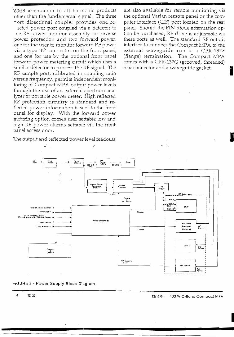
"60dB attenuation to all harmonic productsother than the fundamental signal. The three~ort directionál coupler provides one re-
meted power port coupled via a detector to.ne RF power monitor assembly for reversepower protection and two forward power,one for the user to monitor forward RF powervia a type 'N' connector on the front panel,and one for use by the optional front panelforward power metering circuit which uses asimilar detector to process the RF signal. TheRF sample port, calibrated in coupling ratio.versus frequency, permits independent moni-toring of Compact MPA output power levéisthrough the use of an external spectrum ana-lyzer or portable power meter. High reflectedRF protection circuitry is standard and re-flected power Information is sent to the frontpanel for display. With the forward powermetering option comes user settable low andhigh RF power alarms settable via the frontpanel access door.
The output and reflected power level readouts
are also available for remote monitoring viathe optional Varían remote panel or the com-puter interface (CIF) port located on the rearpanel. Should the PIN diode attenuation op-tion be purchased, RF drive is adjustable viathese ports as well. The standard RF outputinterface to connect the Compact MPA to theexternal waveguide run is a CPR-137F(flange) termination. The Compact MPAcomes with a CPR-137G (grooved, threaded)rear connector and a waveguide gasket. i
i
nGURE 3 - Power Supply Block Díagram
TD-25 12/19/94 4OO W C-Band Compact MPA
I

Power Supply Subsystem
Overview
The power supply portion of the CompactMPA provides ail of the internal voltages nec-'essary to opérate the TWT/ RP driver (IPA)/forced air cooling system and auxiliary cir-cuits for control/ monitoring and protection ofthe Compact MPA. Only the AC input poweris required for operation. The travelling wavetube derives its operation from four DC powersupplies: a filament heater low voltage sup-ply/ a helix high voltage supply/ and two col-lector high voltage supplies, The power sup-ply design utilized in the VZC-6964A4 is ofthe switch mode power conditioner (SMPC)¡
type which has an excellent reputation for re-liability and stability. An added advantage ofthe SMPC approach over outdated linearpower supplies is its intrinsic high efficiencyand safe operation. By limiting the amount ofthe instantaneous stored energy in the powersupply/ the risk of permanent damage to theCompact MPA due to abnormal or transientconditions is avoided. The momentary levelof stored energy (measured in joules) is wellbelow the máximum limit of energy that thetube can safely dissipate during normal op-eration. A simplified block diagram of thepower supply is shown in Figure 3. The prin-cipal circuit modules are discussed in the fol- 'lowing paragraphs.
Power Factor Correction Module
Input primary power (single phase, 220-240VAC/ 50/60 Hz) flows via a EMI filter and themain circuit breaker to both the cooling sys-tem power supply and the Power Factor Cor-rection Module. This module provides aregulated 375 VDC to the Power Processorand allows the Compact MPA to meet therequirements of IEC-555 regarding total har-monic distortion. In the event of a failure ofthis module/ a DC bus fault flag is sent to themicro-controller for proper fault handling anddisplay via the detall fault LEDs locatedthrough the front panel access door.
• Power Processor Module
The power processor circuits provide the nec-essary Une and load regulation of the input375 volt DC bus/ which is converted via aswitch regula tor and bridge circuit to a nomi-nal 200 volt/ 21 KHz to drive the high voltagemodule. A sample of the helix high voltageoutput is returned to the switch regulator forerror feedback correction and sends a pulse-width modulated signal through an opticalisolator to the switching transistors. This ap-proach allows careful regulation of the TWThelix and collector voltages and protects bothsupplies from over voltage/under voltage orshort circuit conditions. Low voltage outputsare also produced by this assembly (+/- 15VDC and 16 VAC) which are used to opératevarious internal circuit functions as well asprovide power for the RF monitor circuit/ mi-cro-controller assembly/ front panel display,and IPA. Internal sensors provide the neces-sary over-current protection functions forthese supplies.
High Voltage Module
The high voltage module provides the follow-ing key power supply functions: regulatedTWT heater supply/ regulated TWT high volt-age helix and collector supplies/ helix supplycurrent/voltage monitoring and fault protec-tion. The high voltage module contains thetransformers/ rectifiers/ filters and voltage/current sense resistors for crirical TWT volt-ages. The incoming 200 volt, 21 KHz signal isapplied to the primary of a multi-section highvoltage transformer which provides all of thehigh voltage levéis necessary to opérate thetraveling wave tube. Since the helix and col-lectors share the same transformer and regula-tor/ the high voltage circuit design establishesthe collector voltages at50% (collector #1) and32% (collector #2) depression below the helixvoltage. This relationship permits optimumefficiency and substantial energy savingswhile extending the useful life of the TWT. Asepárate step-down transformer with rectifierand filter network is employed to provide theheater voltage.
400 W C-Band Compact MPA 12/19/94 TD-25

Control and Display-Modules
The Control and Display Modules are de-igned to assure correct operation of the
^ower amplifier and easy maintainabilitywith minimal operator training and activity.Microprocessor circuits along with status andfault LEDs provide automatic sequencing ofCompact MPA operation and continuousmonitoring of critical parameters. If a faultshould occur, the Compact MPA either re-cycles back to its state prior to the fault orlatches into the FAULT state. In either case,the appropnate front panel lamp will illumi-nate. Also, a detaü fault display is iocatedinside the front panel access door which canbe used in assisting a maintenance technicianin isolating the fault to a repiaceable compo-nent or subassembly. The front panel accessdoor also provides a convenient means of al-lowing the user to set features such as systemconñguration and low KF alarm.
Figure 4 and the Product Specifications belowpresent a complete list of controls, displays,
nd LED indicators on the front pahels. Ailanel indicators are reliable, bright LEDs.
When control power is turned on, the micro-processor self-tests all internal functions andstarts HTD (Heater Time Delay). Once theHTD is completed, the STANDBY indicatorilluminates to tell the operator that the highvoltage may be applied. Depressing theTRANSMIT/STANDBY key initiates the BOS(Beam On Sequence). At the successful con-clusión of BOS, the unit is in the TRANSMITstate (high voltage is on). Alternatively, the
operator may depre'sS"the TRANSMIT/STANDBY key during HTD causing the TXSELECT lamp to illuminate. In this case, theBOS is initiated automatically at the comple-tion of HTD. In the interest of promoting longlife of the TWT, the heater voltage is reducedby 10 percent whenever the Compact MPA isin any beam off state (either STANDBY orFAULT states) for more than one minute.
In the event of AC prime power interruptions,the power supply will automatically recyclewhen the AC power is reapplied. If the loss ofpower is less than a few seconds, the amplifierwill return immediately to its previous state.If the outage is of longer duration, a propor-tíonal HTD is performed before retuming tothe previous state. The longest HTD is threeminutes.
If a fault occurs during TRANSMIT, theFAULT LED will light and the unit will switchfrom TRANSMIT to FAULT. Two scenariosare possible.
The firstscenario occurs when a fault lasrslessthan four seconds (a transient fault) or whenfewer than three transient faults occur withintwenty seconds. In this case, the unit willrecycle back to TRANSMIT. Each transientfault will genérate a recycle. Each recyclefrom FAULT to TRANSMIT will be delayedby one second. After the unit successfullyrecycles to TRANSMIT, the RECYCLEDFAULT LED will flash until the user pressesRESET. Each fault causes a detall fault LED toilluminate behind the front panel access door.
o
: varia-: e
anón1 = ~™~™*™HéTERSEUCT r~í H M rT E= «Mcno«i-i
LJ I—I LJ LJ ^= BB1.a,Mí«,-,
O O O O O O O Oncicim"
(^J R£SET
/^ VOCXL.( ) ft£f-]OTEX—' VIP
O
O .1 RFSAMPLE •
FIGURE 4 - Compact MPA Front Panel
TD-25 12/19/94 -100 W C-Band Compact MPA

This LED will remain lit until the RESET but-ton is pressed or power is cycled.
The second scenario occurs when a fault lastslonger than four seconds or when at leastthree faults occur within twenty seconds. Inthis case the unit will be latched into FAULTand the FAULT LED will flash. To reset theunit for normal operation/ clear the source ofthe fault. Then/ press RESET. If the fault wassuccessfully cleared/ the FAULT LED will ex-tinguish and the unit will be in STANDBY.
. Press TRANSMIT/STANDBY to resumetransmitting.
In either case, the pertinent fault remains dis-played on the detail fault display inside thefront panel access door until hitting the RE-SET button. This allows the able user or tech-nician the ability to identify individual faultsto a specific module or subassembly.
Power Monitor Module
The RE power monitor assembly receives sig-náis from the forward and reflected power RFdetectors for use in fault/alarrn sensing andforward power metering (optional). The re-flected RF fault sensor/recycle circuit protectsthe TWT against excessive reflected powerdue to abnormal waveguide or antenna condi-tions. Additionally/ the forward power metercircuit measures both coritinuious-wave (CW)and peak RP signáis when the optional meter-ing option is purchased. Also included in themetering option is a forward low RF alarmcircuit which compares the output power witha user-settable low RF set point and rriggersan alarm/ should output power fall below thislevel.
Mechanical Design
General
The VZC-6964A4 is packaged in a standardrack mounted drawer measuring 19" wide by5.25" high and 24" deep (plus connectors, fanand air duct adapters). The unit is cooled via aforced air cooling system consisting of two
axial fans/ an air filter and an exhaust duct.Allowances are made for 0.10" H20 drop dueto customer ducting losses.
LRU Philosophy
The Compact MPA utilizes a modular designapproach incorporating LRU's for ease ofmaintainability in the field. The maintenanceconcept employed in the VZC-6964A4 is tolocalize a malfunction or circuit failure downto the level of an LRU/ extract the LRU andreplace with an equivalent part provided inthe spares kit. This procedure can be com-pleted in the field without resorting to thecostly practice of retuming the entire CompactMPA to the depot for servicing. The philoso-phy is to configure the Compact MPA LRU'sas building blocks with a specific function thatcan be monitored by sensors and fault indica-tors on a re al-time basis.
400 W C-Band Compact MPA 12/19/94 TD-25

-íctrical_equer\cy ;
Output Power :
•TWT•flange
Bandwidth
Gain•at rated power• small signal
RF Level Adjust Range
Output Power Settability
Gain Stability• at constant drive & tempera ture
5.S50 - 6.425 GHz (5.850 - 6.650 GHz optionai)
55.5 dBm min. (400 watts)54.4 dBm min. (350 watts min.)
575 MHz (SOO MHz optionai)
75 dB min.78 dB min.
Q t o 2 5 d Bi
±0.2 dB
±0.25 dB/24 hr max.(after 30 min. warm-up)•over tempera ture, const. dr. (any frequency) ±1.0 dB over oper. temp. range (typical)
+0.75 dB over +10°C (typical)
m Slope
Gain Variation• across any 80 MHz band• across the 800 MHz band
InputVSWR • ;
Output VSVVR
Load VSWR• full spec compliance• operation without damage• continuous operation
Residual AM•belowlOKHz•10to500KHz•aboveSOOKHz
±0.02 dB/MHz máximum (atsmaíl signal)
1.0 dB pk-pkmax.2.5 dB pk-pk max.1.3:1 máximum
1.3:1 máximum
1.5:1 max.any valué2.0:1 máximum
-50 dBc-20 (1.3+logF KHz) dBc-85 dBc
TD-25 12/19/94 400 W C-Band Compact MPA
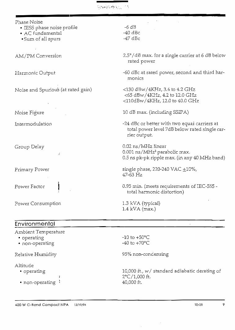
Phase Noise• IESS phase noise profíle• AC fundamental•Sum of all spurs
AM/PM Conversión
Harmonio Output
Noise and Spurious (at rated gain)
Noise Figure
Intermodulation
Group Delay
Primary Power
*Power Factor j
i
Power Consumption
-6dB-40 dBc-47 dBc
2.5°/dB max. for a single carrier at 6 dB belowrated power
-60 dBc at rated power, second and third har-monics
<130 dBw/4KHz, 3.4 to 4.2 GHz<65 dBw/4KHz, 4.2 to 12.0 GHz<110dBw/4KHz/ 12.0 to 40.0 GHz
10 dB max. (including SSIPA)
-24 dBc or better with two equal carriers attotal power level 7dB below rated single car-rier output.
0.02 ns/MHz linear0.001 ns/MHz2 parabolic max.0.5 ns pk-pk rípple max. (in any 40 MHz band)
single phase, 220-240 VAC ±10%,47-63 Hz
0.95 min. (rneets requirements of IEC-555 -total harmonic distortion)
1.3 kVA (typical)1.4 kVA (max.)
EnvironmentalAmbient Temperature
• operating• non-operating
Relative Humidity
Altitude• operating
• non-operating I
-10 to +50°C-40 to +70°C
95% non-condensing
10,000 ftv w/ standard adiabatíc derating of2°C/1,000 ft.40,000 ft.
400 W C-Band Compací MPA 12/19/94 TD-25

Shock and Vibra tion Designed for normal transportation environ-ment per Section 514.4 MIL-STD-S10E. De-signed to withstand 20G at 11 ms (1/2 sinepulse) in non-operating condition.
Mechanical
Cooling
RF Input Connection
RF Output Connection
RF Output Monitor
Dimensions, (W x H x D)
Weight
and Acousticlíeat Dissipation
Acoustic Noise
Forced air w/integral blowers. Rear intakeand exhaust. Máximum external pressureloss allowable: 0.10 inches water column.
Type 'N' Female
CPR-137 waveguide flange, grooved,threaded UNC 2B 10-32
Type 'N' Female
19 x 5.25 x 24 in. (483 x 133 x 610 mm)
65 Lbs. max.
1,100 Watts max.
65 dBA (as measured at 3 ft.)
i
Monitors and Controls
Control Functions
Monitoring
ntrol/ Status Display
Main Power On/OffTX (Transmit) SelectTransmit/Standby (Beam on/off)RF Drive Adjust (manual standard)Local/Remote/Computer (CEF) SelectIndicator TestFault Reset
RF Output Sample Port (-40 dBm nominal,Type 'N')RF Reflected Power (W)Helix Current (mA)Helix Voltage (kV)
Power OnHeater Time Delay (HTD)
10 10-25 12/19/94 400 W C-Band Compact MPA

Fault/Alarm Display
i
Metering Option
TX (Transmit) SelectStandbyTransmit (Beam on)Local/Remote/CIFMeter.Select Switch
Recycled FaultFaultLow RF (with Forward Power Metering)High Reflected RFInterlocks Open (power supply temp. or am-
plifier cover)Helix Over-current
Helix VoltagePower Supply AreDC Buss FaultTWT Over-temperature
RF Output Power (dBm and Watts)Attenuator Setting (applicable with PIN diode
attenuation option)
Remote Control Interface
Control Functions Transmit/Standby (Beam on/off)Fault ResetRF. Drive Adjust (with optional PIN diodeattenuation)
Monitoñng
Control/ Status
Fault/Alarm Displays
RF Reflected PowerHelix CurrentHelix Voltage
Power On/OffTX Select (Transmit Select)Heater Time Delay (HTD)StandbyTransmit (Beam on)Local/Remote/Computer I/F
Recycled FaultFault
400 W C-Band Compact MPA 12/19/94 TD-25

Metering Option
Options and FeaturesOptions & Compatibility
Features
RF Output Power (dBm and Watts)Attenuator Setting (applicable with PIN diodeattenuation option)
Forward Power Metering (CW and Peak; re-quired for remote forward power monitor-ing for use of High/Low RF Alarm Fea-ture and/or when configured in a redun-dant operation).PIN Diode Attenuation (required for remoteattenuation)Remóte Control PanelRedundant and Power Combined subystems
Designed to meetENC-60215/IEC-555 Safety/Harmonio standards as well as 89/336 EEC/EMC standards.Filaments voítage reduction of 102 in standby.RS-232, RS-422/485 (4-wire) computer Ínter-face standard. v
Auto Fault Recycle . "" 'Internal test points for eas'e of maintenance.MTBF of 20,000 hours less TWTMTTR < 1 hourAlso available in 350W Ku- Band and 400WX-Band
III
I
I
12 TD-25 12/19/94 400 W C-Band Compací MPA
I

SUPPORT SERVICES
Documentation
Varían Microwave Equipment Products pro-vides a standard commercial documentationpackage for all producís. The standard pack-age for a satellite communication. TWT poweramplifier includes a comprehensive operationand maintenance manual, outline and ínter-face drawings, acceptance test procedure/re-port (ATP), and Spare Parts Lists.
The technical manual provides instruction forunpacking and installation, initial set-up, cali-bración, normal operatiori, maintenance andrepair of the equipment. The manual includesschematíc diagrams, block diagrams, and wir-ing Information sufficient for use by mainte-nance personnel. Outline and interface draw-ings provide dimensions and the location andsize of mounting holes, duct work, andwaveguide, so that site preparation can beaccomplished prior to receipt of the equip-ment. t. ^
The ATP outlines the test performed, circuitand test equipment used, and limits estab-lished. Space is providecl for recording andcertifying the test results, consolidating all re-lated information in one document. The spareparts documentation package consists of acommercial recommended spare parts to sup-port the equipment for a one-to-two year peri-od of operation.
Training
Varían MEP offers training courses coveringthe installation, operation and maintenance ofits equipment. The training course on highpower amplifiers consists of lectures usingtraining material, such as technical manualsand drawings, plus actual operation and ad-justments demonstrated on the equipment.
Small training groups (up to five or six stu-dents) assure the customer that each studenthas an opportunity to particípate fully in dem-onstration activities. Courses may be con-ducted at the Varían factory or on-site. Courseduration varíes from several days to one ortwo weeks, depending on the scope of workagreed upon and the skill level of the students.
Field Service
The product support activity of Varían in-cludes a staff of experienced, professional ser-vice technicians to assist users in maintainingfull performance from their Varían power am-plifiers. A telephone "hot line" permits accessto one of these technicians on a 24-hour perday basis. Operational problems often can bediagnosed, corrective action prescribed, andnormal operation restored through such tele-phone consultation. When called for, how-ever, the service technicians are prepared togive on-site assistance.
Product Suppjrt carnes a large inventory ofspare parts chat can be made ready for ship-ment within' 24 hours. Coupled with a dedi-cated dial-in telephone line, this service is ef-fective in aiding users to restore equipment toOperational status with minimum downtime.Technical assistance and factory approved re-placement parts are also available at strategi-cally located Regional Sen/ice Centers in theU.S., Europe, and the Pacific Rim.
400 W C-Band Compact MPA 12/19/94 TD-25 13

V901-CC-Band SynthesizedFrequency Converter
CALIFORNIAMICRDWAVE
EFDATA
V901-C Syníhesized Frequency Converters are a direct resultof California Microwave's exíensive experience in satelliteearth síation technology. Each C-Band frequency converter isdesigned to meet the rigorous demands of today's rapidlyexpanding digital Communications ¡ndustry. The V901-Cconverters offer excepíional spectral purity and frequencystabiliíy, and meet the stringent requirements for INTELSATÍDR, IBS, and TOMA services. FM-FDM, SCPC, and HDTVtransmissions are supported also.
Superior frequency stabiliíy and spectrai puntyLocal/remóte monitor and controlFroní-panel gain, slope and frequency trirn adjustmentsNon-volatile memory (100 channel síorage)Internal/external referenee capabilityLocal/remote muting capabilitiesGroup delay equalizedUniversal AC inpuíTriple serial ports: RS232/RS422/RS485User-friendly front panel controls wlth alphanumeric display125 kHz frequency stepsSingle rack unit (1 RU)
V901-C converters meet and exceed ARABSAT, EUTELSAT,and INTELSAT Earth Station Standards (]ESS) -308 and -309emuiation specifications for:• Intermedíate Data Rate (IDR)• INTELSAT Business Services (IBS)• Satellite Multl-Service System (SMS)
System downtime is minimizad with V901-C frequencyconverters because they ar;é designed for máximum reliabilityand easy mainíenance. Modular construction and commonalityof up and down converter assemblies allow simple and cost-effective support.
The V901-C can be tuned in incremenís of 125 kHz step sizesdue to iís fully agile, synthesized local oscillator.
Local oscillators are referenced to an internal or external5 MHz standard. In íhe absence of an external referenee, theconverter automatically switches to the internal, high-stabilitycrystal oscillator.
A microprocessor-conírolled, user-friendly front panel permiíslocal frequency selection, access to 100 non-volatile memorylocaíions, and serial porí configuration. The front panel alsodisplays power supply voltages and interna! temperaíure.
In addiíion to manually-adjusíable, coníinuous attenuation, anopíiona!, digitally-controlled 30 dB aííenuator, adjustable in0.5 dB steps, is available. This permits both local and remótegain adjustmení. Settings for each channel can be stored innon-volatile memory for signal level normalizaíion.
Top-quality performance is assured when utilizing thecomprehensive une of California Microwave groundCommunications equipment in fully iníegrated subsystems. Asan, example, a typical IDR subsystem míghí include frequencyqonverters, satellite group delay equalízers, 1:N protection,and compuíerized monitor and control display.
V901-C converters are 1.75 inches high and fit into standardEIA racks and cabineís. An exhaüst fan provides internalcooling and allows íhe units ío be síacked wiíhout degradingperformance.
For ¡ncreased monitor and control, converíer subsysíems maybe used in conjunction with any une of monitor and conírolequipment. This feature allows station operaíors ío view andcommand entire earth síation funcíions from a remote [ocation.
IF frequency of 70or140 MHzO ío 30 dB síep attenuator in 0.5 dB incremenísHigh RF outpuí power level
Copyright ©1997 EFData Corporation -1- 06/03/97

V901-C SERIES CONVERTER SPECIFICATIONS
Up Converter SpecificationsInput CharacterísticsFrequency RangesImpedanceReturn LossConnector Type
Output CharacteristicsFrequency RangesTuning Step SizeImpedanceReíurn LossPower ouíput @ 1 dB
Cornpression Point3"1 Order InterceptSpurious, Carrier IndependentSpurious, Carrier Dependen!
Phase Noise (dBc/Hz) 100 Hz offsetPhase Noise (dBc/Hz) 1 kHz offsetPhase Noise (dBc/Hz) 10 kHz offsetPhase Noise (dBc/Hz) 100 kHz offsetPhase Noise (dBc/Hz) 1 MHz offsetConnector TypeMuting
Transfer CharacteristicsFrequency SenseImage RejectionAM ío PM ConversiónGainGain Adjusiment
ManualProgrammable
Gain Stability
Frequency StabilityAging RateOver Operating Temperature
Amplitude Respc¡)se
Group Déla/ ResponseParabolic
Linear
Ripple
External Reference InputFrequencyLevelimpedanceConnector Type
70 ±20 MHzpr 140 ±40 MHz7Sn23 dBBNC, Female
5.845 ío 6.425 GHz125 kHz50 O20 dB
-5 dBm (+10 dBm opíional)+5 dBm (+20 dBm optional)-75 dBm @ -5 dBm output-55 dBc @ Fe < 1 kHz-80 dBc @ Fc> 1 kHz-67-77-87-97-105N, Female>80 dBc
Positive-85 dB min0.1°/dBmaxto-10 dBm output+10 dB max or +30 dB {optional)
10 dB (continuous)30 dB in 0.5 dB steps (optional)±0.3 dB @ 25°±10°C±1.5dB,0°to50°C
±2x10'9/day±5X10*±20 MHz, ±0.25 dB±40 MHz, ±0.4 dB
0.008 ns/MHz2, ±20 MHz0.003 ns/MHz2, ±40 MHz±0.05 ns/MHz, ±20 MHz±0.03 ns/MHz, ±40 MHz1 ns pk-ío-pk, ±20 MHz1 ns pk-ío-pk, ±40 MHz
5 MHzO io +6 dBm50OBNC, Female
General Up and Down Converter SpecificationsPrimary Power
Down Converter SpecificationsInput CharacteristicsFrequency RangesTuning Step SizeLevelImpedanceReíurn LossNoise FigureLO LeakageConnector
Output CharacteristicsFrequency RangesImpedanceReturn LossPower Output @ 1 dB
Cornpression Point3Id Order InterceptSpurious, Carrier Independen!Spurious, Carrier Dependen!
Phase Noise (dBc/Hz) 100 Hz offsetPhase Noise (dBc/Hz) 1 kHz offsetPhase Noise (dBc/Hz) 10 kHz offsetPhase Noise (dBc/Hz) 100 kHzoffsetPhase Noise (dBc/Hz) 1 MHz offsetConnector TypeMuíing
Transfer CharacteristicsFrequency SenseImage RejectionAM to PM ConversiónGainGain AdjustmentManualProgrammableGain Stability
:T-Frequency Síabilily '
Aging RateOver Operating Temperature
Ampliíude Response
Group Delay ResponseParabolic
Linear
Ripple
External Reference InputFrequencyLevelImpedanceConnector Type
3.6-4.2 GHz125kHz-30 dBm rnaxson20 dB15 dB-80 dBm maxN, Female
70 ±20 MHz or 140 ±40 MHz75 íl23 dB
-f 15 dBm4-25 dBm-70 dBm © +40 dB gain-55 dBc @ Fe < 1 kHz-60 dBc @ Fc>1 kHz-67-77-87-97
-105BNC, Female>80 dBc.
Positive70 dB min0.1 "/dB max to O dBm output+50 dB max
10 dB (continuous)30 dB in 0.5 dB steps (opíional)±0.4 dB @ 25°±10°C±1.5dB, 0°to500C
±2x10'9/day±5x10'9±20 MHz, ±0.25 dB±40 MHz, ±0.4 dB
0.008 ns/MHz2, ±20 MHz0.003 ns/MHz2, ±40 MHz±0.05 ns/MHz, ±20 MHz±0.03 ns/MHz, ±40 MHz1 ns pk-to-pk, ±20 MHz1 ns pk-to-pk, ±40 MHz
5 MHzOto+6 dBmsonBNC, Female
I
I
I
RequirementsVolíage
FrequencyConsumpííonSignal Monitors
Single phase, 90 to 264 VACuniversal AC ínput47 to 63 Hz50 W, nominalRFLO
EnvironmentTemperature
OperatingNon-operating
HumidityOperatingNon-operating
Máximum altitude
Shock & Vibration
0°to500C(+32Dto+122DF)-30° to +75°C (-22° to +167°F)
O to 95%Oto 100%3,048 m(10,000 ft)15,240 m (50,000 ft)As encountered in normalcommercial shípping, handling,and operation
MechanicalSpecificationsUnit Dimensions(excludinghandles)Net Weight
4.45 cm x 53.34 cm x 55.88 cm(1.75"HxirWx21"D)
7.3 kg. (16lbs.) nominal
IIIIIIIt
EFData Corporation2105 West 5th PlaceTempe, Arizona 85281 USA(602) 968-0447C A V > {p,r\O\R "J ftQQ
"Ynitr Frrnr Frpp C.hnirp" EFData producís are manufacturad under a '/• ' /L "Your Lrror t-ree o/jo/ce ^^ ^ cert¡fíed ¡QQ goQ1 http://www.efdaia.com
EFData reserves the right to make changes ID Specifications of producís described In this data sheet at any time wíthout notice and without obligatlon to notify any person of such changes.
EFData Corporation Product Data Sheet -2- (Part Number DS/V901C) 06/03/97
I
I

APPLICATION REVISIONS
NEXTASSEMBLY USED ON LTR DESCRIPTION DATE APPROVED
4055 REL PER EDR #5200-16415 6/94 RB
A REY ECO 8774A; REL/EDR 5200-16868 10/94 BK/
REV ECO 9701 A; REL/EDR 51710-19363 9/96
PUBS
II
FINAL ACCEPTANCE TEST PROCEDURE
V-9Q1 SERIES SYNTHESIZEP UPCONVERTER
PERFORMED BY
UNLESS OTHERWISE SPECIFIEDALL DIMENSIONS ARE IN INCHES
TOLERANCESDECIMALS ANGLES
2PL±03 3PL±010 ±1/2"
MATERIAL7FINISH
DRAWNCHECKED
BY
GR ENGR
BY
J. Rabal
¿*1¿ <f/A
R.
DATE
6/94
6/94
CALIFORNIAMICHDWAVE
SATELLITETRAN5MI55IONSY5TEM5
HAUPPAUGE, NEW YORK 11788
FINAL ACCEPTANCE TEST PROCEDUREV-901 SERIES SYNTHESIZED
UP CONVERTER
SIZE
A
CODEIOENTNO.
9U450SC AL E N/A
DRAWING NO.
A64908REV SHEET 1 OF 37

SECTION
TABLE OF CONTENTA
TITLE
I
1.0
2.0
3.0
INTRODUCTION/RECOMMENDED TEST EQUEPMENT
MODULE REQUIREMENTS
C-BAND UP CONVERTER SPECrFTCATTONS
4.0
4.1
4.2
4.3
4.4
4.5
A.6
4.7
4.8
GAIN, GAIN RANGE, AND TUNABILITY
1 dB COMPRESSION
AMPLFTUDE AND GROUP DELAY RESPONSE
RETURN LOSS
UP CONVERTER SPURIOUS AND MUTING
INTERMODULATION , •
PHASE NOISE
FUNCTIONAL TESTS
4.8.1
4.8.2
4.8.3
4.8.4
4.8.5
4.8.6
4.S.7
MONITOR FUNCTIONS''REFERENCE OSCILLATOR ADJUSTMENT'EXTERNAL REFERENCE INDICATIONALARM CONDITIONSLOCAL/REMÓTE OPERATIONSTORE/RECALL OPERATIONDIAGNOSTIC TEST PROGRAM
4.9
Appendix A
SERIALIZATION OF MODULESM&C DIP SWITCH & JUMPER SETTINGS
CALIFORNIA M1CROWAVE, INC. - STSSIZE CODEIDENTNO.
9U450DRAWING NO.
SCALE N/A REV B
A64908SHEET2of 37
II

SECTION
5.0
5.1
5.2
5.3
5.4
5.5
5.6
5.7
5.8
5.8.1
5.8.2
5.8.3
5.8.4
5.8.5
5.8.6
5.8.7
5.9
TABLE OF CONTENTS (CONTINUED)
TITLE
TEST DATA SHEETS
GAM, GAIN RANGE AND TUNABILITY
1 dB COMPRESSION
AMPLITUDE AND GROUP DELAY RESPONSE
RETURNLOSS
UP CONVERTER SPURIOUS AND MUTING
INTERMODULATION
PHASE NOISE
FUNCTTONAL TESTS
MONITOR FUNCTIONS
REFERENCE OSCILLATOR ADJUSTMENT
EXTERÑAL REFERENCE INDICATION
ALARM CONDITIONS
LOCAL/REMOTE OPERATION
STORE/RECALL OPERATION
DIAGNOSTIC TEST PROGRAM
SERIALIZATION
"l
i
CALIFORNIA MICROWAVE, INC. - STSSIZE
ACODEIDENTNO.
9U450DRAWING NO.
A64908SCALE N/A REV B SHEET3of37
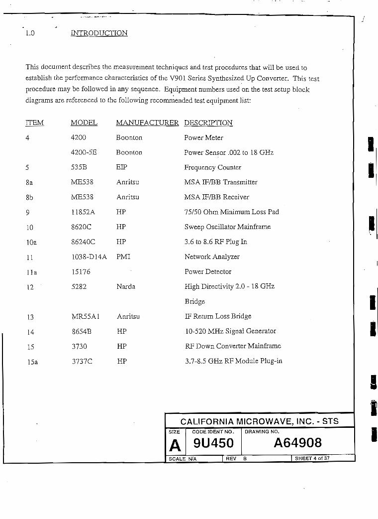
1.0 INTRODUCTION
This document describes the measurement techniques and test procedures that will be used to
establish the performance characteristlcs of the V901 Series Synthesized Up Converter. This test
procedure may be followed in any sequence. Equipment numbers used on the test setup block
diagrams are referenced to the following recommended test equipment list:
MANUFACTURER DESCRIPTION
Power Meter
Power Sensor .002 to 18 GHz
Frequency Counter
MSAIF/BB Transmitter
MSAIF/BBReceiver
75/50 Ohm Mínimum Loss Pad
Sweep Oscillator Mainframe
3.6to8.6RFPlugIn
Network Analyzer
Power Detector
High Directivity 2.0-18 GHz
Bridge
IF Return Loss Bridge
10-520 MHz Signal Generator
RF Down Converter Mainframe
3.7-8.5 GHz RF Module Plug-in
ÍTEM
4
5
8a
8b
9
10
10a
11
l i a
12
13
14
15
15a
MODEL
4200
4200-5E
535B
ME538
ME538
11852A
8620C
86240C
1038-D14A
15176
5282
MR55A1
8654B
3730
3737C
MANUF
Boonton
Boonton
EIP
Anritsu
Anritsu
HP
HP
HP
PMI
Narda
Anritsu
HP
HP
HP
CALIFORNIA MICROWAVE, INC. - STSS1ZE
ACODEIDENTNO.
9U450DRAWING NO.
A64908SCALE N/A j REV B SHEET4of37

LO
ÍTEM
2.0
RECOMMEN5ED TEST EOUIPMENT (Continued)
18
19
23
24
25
36
8566B
3293-1
3048A
~
8495B
HP
Narda
HP
STS
HP
Narda
Spectrum Analyzer
1-12.4 GHz Directional Coupler
HP Phase Noise Measurement
System
70/140 Crystal Test Sct
70 dB Step Attenuator
Assorted 50 Ohm N-Type
Fixed Attenuators
NOTE
1. STS reserves the right to substitute equivalent test equipment or to
alter a given procedure based-on the availability of test equipment
at the time of test.
2. For operation of test equipment, refer to O&M manual of each test
equipment being used.
MODULE REQUIREMENTS
All lower level module alignments musí be completed before this ATP is staxted.
Refer to Appendix A for M&C jumper and dip swiích settings
CALIFORNIA MICROWAVE, INC, - STSS1ZE
ACODEIDENTNO.
9U450DRAWING NO.
A64908SCALE N/A | REV B SHEET 5 of 37

3.0 C-BAND UP CONVERTER SPECIFrCATIONS
Amplitude Slope Adjustment Range:
RFLO MON Frequency Adjustment Range:
Monitor Functions:
Power Supply 1
Power Supply 2
Power Supply 3
Phase Noise:
OBand Up and Down Converter:
2.0 dB p-p
8.0 IcHz mínimum
21.0 V±Q.4V
15.0 V ±0.3 V
5.25 V +0.2V
! 1 PhaseFreo. Noise
í
1 ~^°
-60
-70
f -so
•90
100
%v !
C-BAND PHASE NOISE
•K
,
i
-12U10
•
---. . , I!¡t¡TT-J
i
1!li
i ji
— ~i
hi •
X
,X
•j
1
•
•
<.1i
t
1
! í! 1
brea
100 ICOO 1-ltf* l-IO5 l-\#Frequcncy (Hz)
(Hz) fdBc/Hz) '
kpts =
' 10 -50
100 -70
300 -74
1000 -76
2000 -78
3000 -79
5000 -83
10000 -88
30000 -96
50000 -101
100000 -105
[ 1000000 -105 J
CALIFORNIA MICROWAVE, INC. - STSS
Á
S
IZE
ACODEIDENTNO.
9U450CALE N/A REV
DRAWING NO.
A64908B | SHEETGOÍ37
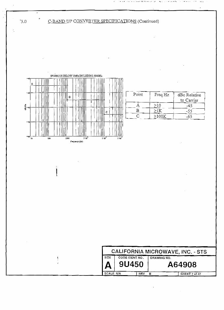
'3.0 C-BAND UP CONVERTER SPECIFICATIONS (Conünued)
SFURIOUS BEUO W1 MHi IHCLUDING 30/60Hz
Point
ABC
FreqHz
>10>1K>100K
dBcRelaíiveto Carrier
-45-55-65
10 100 1000 J-IO
íCALIFORNIA MICROWAVE, INC. - STS
S1ZE
ACODEIDENTNO.
9U450DRAWING NO.
A64908SCALE N/A REV B SHEET7of37

3.0 C-BAND UP CONVERTER SPECIFICATIONS (Continued)
The followmg specifications apply to the Up Converter RF Assemblies:
Input Frequency:
OutputFrequency Range;
Nominal Gain
Gain Range:
Optional Step Atten.
Nominal Input
Nominal Output
1 dB Compression
3rd Order Intercept
Group Delay: Parabolic:
70 MHz ±20 MHz
140 MHz ±40 MHzLinear:
70 MHz ±20 MHz
140 MHz ±40 MHz
Ripple
Amplitude Response: 70 MHz
140 MHz
Return Loss: Input
Output
Spurious: Carrier Related (>1 MHz)
Carrier Independent (>1 MHz)
Muting
V901-C20XX
V901-C40XX
70 ±20 MHz
140 ±40 MHz
5.845 - 6.425 GHz
10.0 dB
+5.0/-5.0 dB
cont.
O to 30 dB
Atten. in
0.25 dB steps
-25.0 dBm
-15.0 dBm
-5.0 dBm minimum
+5.0 dBm minimum
0.008 ns/MHz2 «
0.003 ns MHz2 '
±0.05 ns/MHz
±0.03 ns/MHz
1.0 ns p-p
±0.15dB±10MHz
±0.25 dB ±20 MHz
±0.25 dB ±20 MHz
±0.40 dB ±40 MHz
23.0 dB minimum
23.0 dB minimum
-65 dBc minimum
-85 dBm máximum
-80 dBc minimum
CALIFORNIA MICROWAVE, INC. - STSSI2E
ACODEIDENTNO.
9U450DRAWING NO.
A64908SCALE N/A REV B SHEET8o(37

3.0 C-BAND UP CONVERTER SPECMCATIONS (Continued)
The foHowing specificaíions apply to the Up Converter RF Assemblies:
Input Frequency:
Output Frequency Range:
Nominal Gain
Gain Range:
Optional Step Atten.
Nominal Input
Nominal Output
1 dB Compression
3rd Order Intercept
Group Delay: Parabolic:
70 MHz ±20
140 MHz ±40 MHzLinear:
70 MHz ±20 MHz
140 MHz ±40 MHz
Ripple
Amplitude Response: 70 MHz
140 MHz
N/A
N/A
Return Loss:
Spurious;
Muting
Input
Output
Carrier Related (>1 MHz)
Carrier Independent (>1 MHz)
70 ±20 MHz
140 ±40 MHz
5.845-6.425 GHz
+25.0 dB
+5.0/-5.0 dB
cont.
O to 30 dB
Atten.in
0.25 dB steps
-25.0 dBm
0.0 dBm
+10.0 dBm minimum
+20.0 dBm minimum
0.008 ns/MHz2
0.003 ns MHz2
±0.05 ns/MHz
±0.03 ns/MHz
LO ns p-p
±0.15 dB ±10 MHz
±0.25 dB ±20 MHz
±0.25 dB ±20 MHz
±0.40 dB ±40 MHz
23.0 dB minimum
23.0 dB minimum
-65 dBc minimum
-70 dBm máximum
-80 dBc minimum
CALIFORNIA MICROWAVE, INC. - STSS1ZE
ACODEIDENTNO.
9U450DRAWING NO.
A64908SCALE N/A REV B SHEET9OÍ37
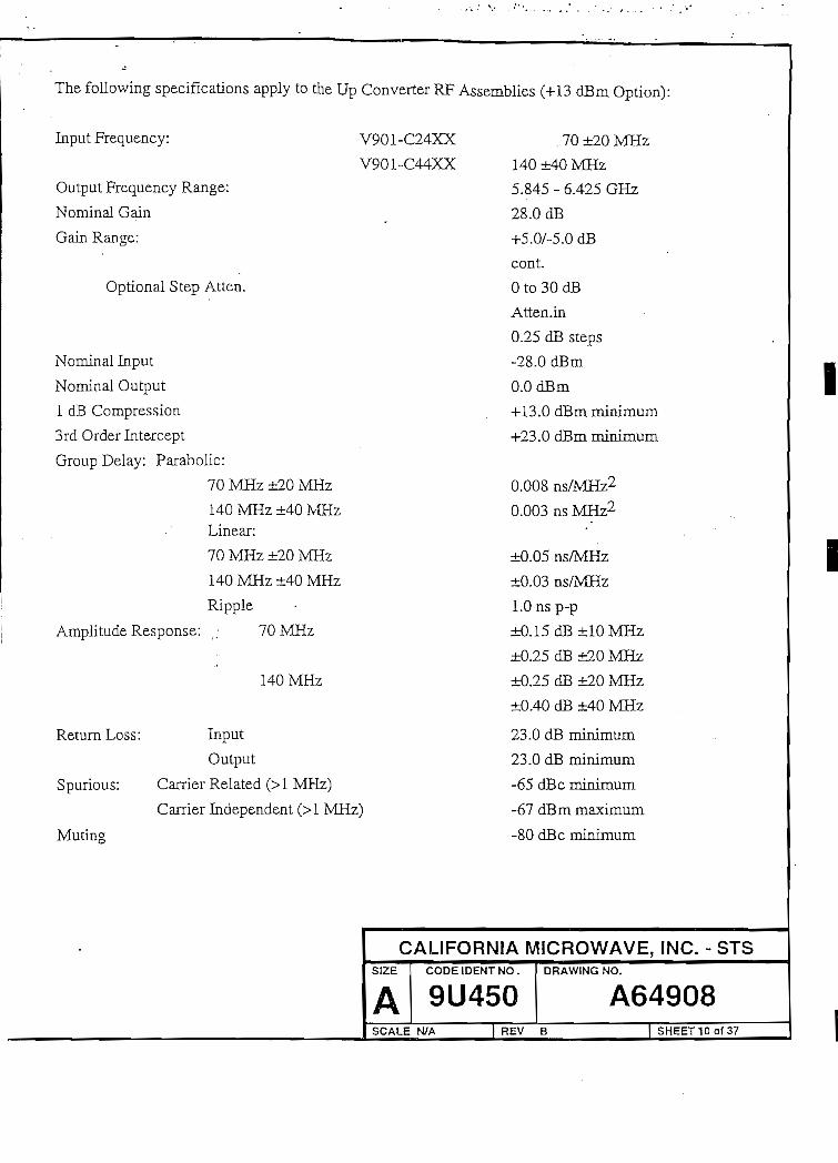
The following specifícations apply to the Up Converter RF Assemblies (+13 dBm Option):
Input Frequency:
Output Frequency Range:
Nominal Gain
Gain Range:
Optional Step Atten.
Nominal Input
Nominal Output
1 dB Compression
3rd Order Intercept
Group Delay: Parabolic:
70 MHz ±20 MHz
140 MHz ±40 MHzLinear:
70 MHz ±20 MHz
140 MHz ±40 MHz
Ripple
Amplitude Response: (; 70 MHz
140 MHz
V901-C24XX
V901-C44XX
Return Loss:
Spurious:
Mutina
Input
Output
Carrier Related (>1 MHz)
Carrier Independent (>1 MHz)
. 70 ±20 MHz
140 ±40 MHz
5.845 - 6.425 GHz
28.0 dB
+5.0A5.0 dB
cont.
O to 30 dB
Atten.in
0.25 dB steps
-28.0 dBm
0.0 dBm
+13.0 dBm minimum
+23.0 dBm minimum
0.008 ns/MHz2
0.003 ns MHz2
±0.05 ns/MHz
±0.03 ns/MHz
LO ns p-p
±0.15 dB ±10 MHz
±0.25 dB ±20 MHz
±0.25 dB ±20 MHz
±0.40 dB ±40 MHz
23.0 dB minimum
23.0 dB minimum
-65 dBc minimum
-67 dBm máximum
-80 dBc minimum
CALIFORNIA MICROWAVE, INC. - STSSIZE CODEIDENTNO.
9U450DRAWING NO.
SCALE N/A REV B
A64908| SHEETIQofS?"

4.0 TEST PROCEDURE
NOTE:
ALL ÜNIT ÜNDER TEST füüT) PERFORMANCE SPECIFICATIONS WILL BE
REFERENCED TO SECTION 3.0 OF THIS 'TEST PROCEDURE.
4.1 GA3N. GAIN RANGE, AND TUNABILITY
NOTE
. ON CONVERTERS EQUIPPED WITH THE STEP ATTENUATOR
OPTION (C55244-1), ENSURE THAT THE ATTENUATION IS SET TO
MÍNIMUM (00.00) AS INDICATED ON THE FRONT PANEL DISPLAY.
* All "Band-Edge" frequencies referred to in this section are defíned as
follows:
70 MHz IF Output:
Lower Band-Edge = Lowest UUT RF Frequency +20 MHz
ÜJpper Band-Edge = Highest UUT RF Frequency -20 MHz
140 MHz IF Output:
Lower Band-Edge - Lowest UUT RF Frequency +40 MHz
Upper Band-Edge = Highest UUT RF Frequency -40 MHz
a. Refer to the test setup in Figure 4-1.
t
CALIFORNIA MICROWAVE, INC. - STSSIZE
ACODEIDENTNO.
9U450DRAWING NO.
A64908SCALE N/A REV B SHEET11 of 37

MSATRANSMITER
IFIN
UNITUNDERTEST
POWER METER
II
flFOUT
A64908-1.DES
II
Figure 4-1. Gain, Gain Range and Tunability
Set the MSA transrnítter sweep width to 0.0 MHz and the output frequency to the
specified UUT IF ínput frequency.
Set the MSA transmitter output levej to obtain the UUT specified nominal input
level.
Set the UUT RF output frequency to the center of the band. Apply JF signal to input
J4 of the RF module. Set the converter gain potentiometer as required to obtain the
specifíed UUT gain. Connect the IF amplifíerto the RF module. Tune the IF
amplifíer and set gain to O dB. Verify on the Test Data Sheets (TDS) that the
converter meets the UUT specification.
i
Check the lower and upper UUT RF output band-edge frequencies. Verify on TDS
that the gain meets the UUT specification. Reset the UUT RF output frequency to
the center of the band.
CALIFORNIA MICROWAVE, INC. - STSSIZE CODEIDENTNO.
9U450DRAWING NO.
A64908SCALE N/A REV B SH£ET12of 37
I

4.2
f. Set the con verter F/P gain potentíometer to obtain máximum UUT gain. Record the
máximum gain on the TDS. Set the potentiometer so that the gain ís 10 dB below
the UUT specifíed nominal gain, and verify its successful adjustment on the TDS.
Reset the potentiometer to the UUT specified nominal gain.
NOTE
Paragraph 4.1 steps g. through i. apply only to converters
supplied with the Step Attenuator Option (C55244-1).
g. Depress the FREQ button locaíed on the front panel of the converter test bed. The
attenuator status is displayed to the right of the frequency status.
h. Depress the arrow keys to obtain an attenuator status reading of 00.25. Verify on the
TDS that the UUT output level has decreased by 0.25 dB.
i. Repeat step 3.1.h for an attenuator status of 00.50, 01.00, 02.00, 04.00, 08.00, and
16.00.
1 dB COiMPRESSION
a. Refer to the test setup in Figure 4.1.
b. Set the MSA. transmitter sweep width to 0.0 MHz and the output frequency to the
specified UUT IF Input frequency. Set the UUT RF output frequency to the center of
the band.
c. Set the MSA transmitter output level to derive the UUT specifíed nominal input
level.
!1
i
CALIFORNIA MÍCROWAVE, INC. - STSSIZE
ACODEIDENTNO.
9U450DRAWING NO.
A64908SCALE N/A REV B SHEET13of37

d. Set the converter gain potentiometer as required to obtain the specifíed UUT gain.
e. Decrease the attenuation on the MSA transmitter by 1 dB. Calcúlate the gain and
compare this valué to that in paragraph 4.2 step d. The 1 dB compression point
occurs when the differencne between the two gain valúes differ by 1.0 dB. If the 1
dB compression point has not been attained, continué to decrease the attenuation
until this criterion is met. At the Í dB compression point record the power meter
reading on the TDS.
4.3 AMPLITUDE AND GROUP DELAY RESPONSE
NOTE:
ALL "BAND-EDGE" FREOÜENCIES REFERRED TQ IN THIS SECTIQN ARE
DEFINED AS FOLLÓ WS:
70 MHz IF OUTPUT:
LowerBand-Edge = Lowest UUT RF Frequency + 20 MHz
UpperBand-Edge = Highest UUT RF Frequency - 20 MHz
140 MHz EF OUTPUT:
Lower Band-Edge = Lowest UUT RF Frequency + 40 MHz
Upper Eland-Edge = Highest UUT RF Frequency - 40 MHz
a. Refer to the test setup shown in Figure 4-2.
CALIFORNIA M1CROWAVE, INC. - STSSIZE
ACODEIDENTNO.
9U450DRAWING NO.
A64908SCALE N/A REV B |SHEET14of37

8aMSA
TRANSMITTER
IFIN
UNITUNDERTEST
OUT15a
PLUGIN
15DOWN
CONVERTER
A64908-2.DES
Figure 4-2. Amplitude and Group Delay Test Setup
b. Set the MSA transmitter to the IF mode, and the MSA transmitter and receiver
frequency to the UUT nominal IF input frequency. Record the UUT IF input
frequency on the TDS.
c. Set the UUT RF output frequency to center band. Record the center band frequency
on the TDS.
d. Set the MSA transmitter output level to derive the UUT specifíed nominal IF input
level.
e. Set the converter gain potentiometer to the UUT specifíed nominal output power
level.
f. Set the sweep width of the MSA transmitter and receiver to meet the UUT IF input
bandwídth specífícation.
g. Set the down converter frequency control to the specifíed UUT RF output center
band frequency.
CALIFORNIA MICROWAVE, INC. - STSSIZE
ACODEIDENTNO.
9U450DRAWING NO.
A64908SCALE N/A REV B SHEET15of37

h. Set the MSA receiver controls as follows:
1. Yl for 0.5 dB per división (Amplitude Response)
2. Y2 for LO nsec per división (Group Delay)
i. Verify that the amplitude and group delay response meet the UUT speciflcation.
Place a grid transfer sheet on the MSAA receiver CRT. Trace the amplitude and
group delay response and attach it to the TDS.
j. Repeat paragraph 4.3 steps b. through i. for the
speciñed lower band edge and upper UUT RF inpuí
band-edge frequencies.
4.4 RETURN LQSS
a. Refer to the test setup in Figure 4-3.
MSATRANSMITTER
MSARECE1VER
10,10a
SWEEÍ3OSCILLATOR
11
NETWORKANALYZER
IF 13 IFOUT IN
IFSRIDGE
RF 13 REFIN OUT
RFBRIDGE
[FIN RFOUT
UNITUNDERTEST
CONVERTERTESTBED
Figure 4-3. Retura Loss Test Setup
A64908-3.DES
CALIFORNIA MICROWAVE, INC. - STSSIZE CODE IDENT NO. DRAWING NO.
A 9U450 A64908SCALE N/A REV B SHEET 16 of 37
I
I

The MSA transmitter/receiver will be used for the IF return loss measuremení, while the signa!
generator/network analyzer will be used for the RF return loss measurement.
IFINPUT:
b. Set the frequency and sweep wídth of the MSA transmitter to meet the UUT IF input
frequency and bandwidth specifícation.
c. Obtain a reference for the return loss measurement.
d. Connect the bridge output to the UUT IF output. Record the worst case retum loss on
the TDS.
RF INPUT:
e. Adjust the start and stop frequencies of the sweep generator to correspond with the
UUT RF output frequency range. Record these frequencies on the TDS. Repeat
paragraph 4.4 steps c. and d. for the RF output retum loss measurement.
4.5 UP CONVERTER SPURIOUS AND MUTJNG
Refer to Figure 4-4.
14SIGNAL
GENERATOR
RFOUT
950/75
IFIN
UNITUNDERTEST
RFOUT
18
SPECTRUMANALYZER
A64908-4.DES
Figure 4-4. Up Converter, Spurious, and Muting Test Setup
CALIFORNIA MICROWAVE, INC. - STSSI2E
ACODEIDENTNO.
9U450DRAWING NO.
A64908SCALE N/A REV B SHEET17of37

Set the start and stop frequencies of the spectrum analyzer to the UUT specified RF
output bandwidth. Set the UUT RF output frequency to the lower band-edge
frequency.
Record the UUT RF output frequency on the TDS. Obtain a
reference of the UUT RF output level on the spectrum analyzer. Verify on the TDS
that any carrier and non carrier related spurious meets the UUT specification.
Repeat paragraph 4.5 steps b. and c. for the center and upper band-edge UUT RF
output frequencies.
Set the UUT RF output frequency to the center of the band. Obtain a UUT RF output
reference level on the spectrum analyzer. Using the F/P, MUTE the converter. Note
the UUT RF output level and compare it with the reference. Verify on the TDS that
the difference between the two signal levéis meets the UUT speciñcation.
Using the F/P, disable the MUTE and observe that the UUT RF output level returas
to.the reference set on the spectrum analyzer. ,.
4.6 INTERMODULATIQN
Refer to the test setup in Figure 4-5.
CALIFORNIA MICROWAVE, INC. - STSSIZE CODEIDENTNO,
9U450DRAWING NO.
A64908SCALE N/A 1 REV B SHEET18 of 37

MIN LOSSPAD
A6490B-5.DES
Figure 4-5. Intermodulation Test Setup
b. Set the UUT RF output frequency to the center of the band. Record this frequency
on the TDS.
c. Set the fírst signal generator output frequency to obtain 2.5 MHz below the UUT RF
output center frequency, as indicated on the spectrum analyzer. Set the second signal
generator output frequency to obtain 2.5 MHz above the UUT RF output center
frequency.
d. Set both signal generator output levéis for -3.0 dBm at the UUT RF output as
indicated on the spectrum analyzer.
Ie. Noteíthe presence of two third order producís 5.0 MHz from the camers. Measure
3the 3rd order product level which is the difference between the highest carrier output
and the highest third order product.
f. Calcúlate the 3rd order intercept point as deñned below:
3rd Qrder Int. Point Product Level -f Carrier Level2
Carrier level is defíned as the output of either carrier tone.
i jI{
CALIFORNIA MICROWAVE, INC. - STSSIZE
ACODEIDENTNO.
9U450DRAWING NO.
A64908SCALE N/A REV B SHEET19of37
4.7
Record the resulting 3rd order intercept point on the TDS.
NOTE
Determine that the resultant intermodulatíon level is not being degraded by the
intermodulation level of the spectrum analyzer. The input attenuator setting on the
spectrum analyzer should be set > 20 dB.
PHASE NOISE
Phase noise will be measured utilizing a phase noise test set and associated equipment. The noise
measurement is automatic and controlled by the HP3048A software.
The 3048A software measures phase noise in offsets from 10 Hz to
10 MHz, The phase noise is measured with the UUT tuned to the center of the RF operating
frequency range. The down converter phase noise is measured at the RFLO output. Attenuate this
output as necessary to the -5 to +5 dBm input range of the canier noise test set. The up converter
phase noise is measured at the RF output. A low phase noise, high stability IF input signal is
applied to the up converter from a 70/140 MHz crystal oscillator.
The IF input signal level is to be consistent with the gain and RF output level of the UUT. Refer to
the test setup in Figure 4-6.
CALIFORNIA MICROWAVE, INC. - STSSIZE
ACODEIDENTNO.
9U450DRAWING NO.
A64908SCALE N/A | REV B | SHEET20OÍ37

UNIT UNDER TESTRF
OUT
(27)
HP3048A
R-PORTINPLTT
HP11729C,
M WAVE IFINPUT OUTPUT
A64908-1.DES
Figure 4-6. Phase Noise Test Setup
NOTE
1. Verify that all test equipment has been on for a minimum of 12
hours to allow for stabilization. (only remove ac power for short
periods, <5 minutes).
2. Select the required test from the TEST FILE menú depending on
the nominal uplink RF band and IF bandwidth of the UUT.
3. Load the speciflc TEST FELE
4. When the measurement is complete attach a hard copy of the
following:
Single sideband phase noise plot from
lOHzto 1 MHz
• Spurious table listing from 10 Hz to
1 MHz
Verify data in plot and spurious table are within specifications.
CALIFORNIA MICROWAVE, INC. - STSSIZE
ACODEIDENTNO.
9U450DRAWING NO.
A64908SCALE N/A REV B SHEET21 oí 37

4.8.1 MONITOR FUNCTTONS
a. Press the RESET button on the logic PCB. Verify on the TDS that all LED indicator
lamps are momentarily illuminated as well as all pixels on the front panel display.
b. Depress the F/P "MON" button. Scroll through the display and verify on the TDS
that the +21, +15, and +5 volt display measurements meet the UUT Voltage monitor
speciñcations.
c. Verify on the TDS that the temperature display is functioning. With the UUT top
cover off, the temperature reading should be within room ambient +8C.
d. Observe the RFLO frequency display where:
RFLO = RF - 1200 MHz for the 140 MHz IF up converter
RFLO = RF - 1130 MHz for the 70 MHz IF up converter
Verify the proper display on the TDS.
4.8.2 REFERENCE OSCILLATOR ADJUSTMENT
a. Connect the frequency counter to the front panel RFLO MON port.
b. Set the'front panel REF ADJ to the mínimum and máximum RFLO monitor
frequency and verify on the TDS that the frequency range corresponds to the UUT
speciñcation.
c. Set the front panel REF ADJ to the RFLO frequency displayed in the UUT monitor
mode.
CALIFORNIA MICROWAVE, INC. - STSSIZE
ACODEIDENTNO.
9U450DRAWING NO,
A64908SCALE N/A REV B SHEET22of37

4.8.3 EXTERNAL REFERENCEINDICATTON
a. Apply an external 5 MHz reference at a level of O dBm. to connector J2 on the rear
panel of the UUT. Verify on the TDS that the front panel display monitor indicares
'Reference: External1.
b. Remove the external 5 MHz reference and verify on the TDS that the front panel
display returns to the 'Reference: Interna! status and that no front panel alarms are
present.-;}
4.8.4 ÁLARM ¿ONDITIONS
a. Disconnect the RFIN cable from the RFLO. Verify on the TDS that the LO, MUTE
and SUM alarms are illuminated.
b. Depress the MAINT button and verify that the MUTE alarm is extinguished.
c. Depress the OPER button and observe that the MUTE alarm is illuminated.
d. Reconnect the RF IN cable to the RFLO and verify ori the TDS that all alarms are
extinguished.
e. Disconnect the REF IN cable from the IFLO. Verify on the TDS that the LO,
MUTE, and SUM alarms are illuminated.
\. Reconnect the cable and verify on the TDS that all alarms are extinguished.
CALIFORNIA MICROWAVE, INC. - STSSIZE
ACODEIDENTNO. DRAWING NO.
A64908SCALE N/A [ REV B ) 5HEET23of37

g." Depress and hoid the RESET switch on the logic card for severa! seconds. Verify on
the TDS that the CPU alarm is illuminated.
h, Verify on the TDS that all alarms are extinguished when you reléase the RESET
button.
i. Disconnect the PWR cable from the IF amplifier/equalizer assembly. Verify on
TDS that the RF, SUM and MUTE alarms are illuminated.
4.8.5 LOCAL/REMOTE OPERATIQN
a. Ensure that the UUT LOCAL indicator is illuminated.
b. Depress the FREQ button and verify on the TDS that one of the frequency digits on
the display is flashing.
c. Depress the CLR button and verify on the TDS that the flashing ceases.ij"
d. Depress the RMT/LCL button and verify on the TDS that the REMOTE indicator is
illuminated.
e. . Depress the FREQ butíon and verify on the TDS that none of the digits on the
display frequency blink. Return the UUT to the LOCAL condition.
4.8.6 Store/Recall Functio.n
Using the corresponding UUT front panel buttons, verify on the TDS that you can STORE and
RECALL a frequency.
CALIFORNIA MICROWAVE, INC. - STSSIZE
ACODEIDENTNO.
9U450•u' \J*~f+J \J
DRAWING NO.
A64908SCALE N/A j REV B SHEET24of37
I

I
II
I
4.8.7 DIAGNOSTIC TEST PROGRAM
A diagnostic program has been developed to perforrn interface testing on the V-901 Series Up and
Down Converters. The software for this program is menú driven and provides all of the instructioñí
required to complete the tests. Set up the test equipment as shown in Figure 4-7. Run the
diagnostic program and attach the printout results to the TDS.
HPIBBUS
SERIALDATA
Figure 4-7. Diagnostic Test Setup
4.9 SERIALIZATION OF MODULES
Record all serial numbers of the modules and PC cards Usted on the TDS, as well as any part
numbers and revisión levéis that may nave been omítted.
CALIFORNIA MICROWAVE, INC. - STSSIZE
ACODEIDENTNO.
9U450DRAWING NO.
A64908SCALE N/A | REV B | SHEET25OÍ37

5.0 TEST DATA SHEETS
5.1 GAIN. GAIN RANGE AND TUNABILITY
5.2
d. Nominal Gain (Center Freq.)
e. fl (Lower Band-Edge)
f2(UpperBand-Edge)
f. Máximum Gain (Center Freq.)
Minimum Gain (Center Freq.)
STEP ATTENUATOR OPTION
UUT Output Level
UUT Output Level
UUT Output Level
UUT Output Level
UUT Output Level
UUT Output Level
UUT Output Level
Meets Spec. at
Meets Spec. at
Meets Spec. at
Meets Spec. at
Meets Spec. at
Meets Spec. at
Meets Spec. at
00.25 dB
00.50 dB
01.00 dB
02.00 dB
04.00 dB
08.00 dB
16.00 dB
GAW
_Check
_Check
Check
Check
'¿X Check
X Check
^ Check
^ Check
Check
^ Check
^ Check
1 dB COMPRESSION (At Center Frequency)
LIMTTS
Per Spec.
±2dBofCF
±2dBofCF
> Spec.
Per Spec.
e. 1 dB Compression Point dBm
Limit
> Spec.
CALIFORNIA MICROWAVE, INC. - STSSIZE CODÉ1DENTNO.
9U450DRAWING NO.
A64908SCALE N/A REV B SHEET260Í37
I

5.3 AMPLITUDE AND GROUP DELAY RESPONSE
b. Input Frequency: _
c. Output Frequency: ^
.MHz
.MHz
Vertical CalibrationCAmplitude Response):
Vertical Calíbration (Group Deíay):
0.5 dB/div.
1.0 nsec/div.
ii. Amplitude and Group Delay Response:
I
I
I
NX
ODr-C\
10in
ücri
fN4=
•oCD
D.X
Ü-M
CALIFORNIA MICROWAVE, INC. - STSSIZE
ACODEIDENTNO.
9U450DRAWING NO.
A64908SCALE N/A REV B SHEET27of 37

5.3 AMPLITUDE AND GROUP DELAY RESPONSE
b. Inpuí Frequency:
c. Output Frequency:
7°O? 135
.MHz
MHz
Vertical Caiibration (Amplitude Response): 0.5 dB/div.
Vertical Caiibration (Group Delay): 1.0 nsec/div.
i. Amplitude and Group Delay Response:
MX
CDr-»
3C 31U.
TUl
oC\
I ca*-N. uoí
ü en
a_j u.ai M
UJQ
caT3
in
a.31
CALIFORNIA MICROWAVE, INC. - STSSIZE CODEIDENTNO.
9U450DRAW1NG NO.
A64908SCALE N/A REV B SHEET28QÍ 37

AMPLITUDE AND GROUP DELAY RESPONSE
b. Input Frequency:
c. Output Frequency:
, MHz
MHz
Vertical Calibration (Amplícude Response): 0.5 dB/div.
Vertical Calibration (Group Delay): 1.0 nsec/div.
i. Amplítude and Group Delay Response:
u,tn
MXX ^li,10O
OC\
6i m\O
ce3E
Q
UJQ
nx.CU
CALIFORNIA MICROWAVE, INC. - STSSI2E
ACODEIDENTNO.
9U450DRAWING NO.
A64908SCALE N/A REV B SHEET29of37

5.4 RETURN mssH
L
IF OUTPUT: ?
StartFrequency; ;
StopFrequency; ;
d. Worst Case Returniíoss:
RFINPUT:
e. Start Frequency-: ]
Stop Frequency:
ÍWorst Case Return Loss:
•• i:
70 MHz'
50 iMHz
90 MHz
140 MHz
100 MHz
180 MHz
dB
Limit
> Spec.
MHz
á¿MHz
dB
Limit
> Spec.
' f
i- Ít
• - I¡1
CALIFORNIA MICROWAVE, INC. - STSSIZE
ACODEIDENTNO.
9U450DRAWING NO.
A64908SCALE N/A REV B SHEET300Í37

UP CQNVERTER SPURIOUS AND MUTING
Lower Band-Edge:
c. RF Output Frequency
Carrier Related Spurs Within Spec.
Non-Carrier Related Spurs Within Spec.
Center Frequencv: .i
c. RF Output Frequency
Carrier Related Spurs Within Spec.
Non-Carrier Related Spurs Within Spec.
Upper Band-Edge:
c. RF Output Frequency
Carrier Related Spurs Within Spec.
Non-Carrier Related Spurs Within Spec.
Muting:e. RF Output Muting Within Spec.
INTERMODULATION5.6
b. RF Output Frequency
g. 3rd Order Intercept Point
58^5 MHzS Checky Check
MHz
Check
Check
MHz
Check
Check
Check
MHz
Limit
dBm >Spec.
CALIFORNIA MICROWAVE, INC. - STSSIZE
ACODEIDENTNO.
9U450DRAWING NO.
A64908SCALE N/A REV B J SHEET31 of 37

CALIFORNIA MICROWAVE, INC. - STS


5.Í FUNCTIONAL TESTS
5.8.1 MONITOR FUNCTIONS
a. ALL LED's and display pixels illuminated
b. +21 V display measurement within
+15 V display measurement within spec.
+5 V display measurement within spec.
c. Temp. display functional
d. Reference frequency display correct
5.8.2 REFERENCE OSCILLATOR ADJUSTMENT
b. REF ADI range within UUT specifxations
5.8.3 EXTERNAL REFERENCE INDICATION
a. Front panel displays 'Reference: Externa!1
b. Front panel displays 'Reference: Interna!1
check
check
check
check
check
check
check
check
check
-CALIFORNIA MICROWAVE, INC. - STS
SIZE
ACODEIDENTNO.
9U450DRAWING NO.
A64908SCALE N/A REV B SHEET33of37

5.8.4 ALARM CONDITIONS
a. LO, MUTE, and SUM alarms illuminated
b. MUTE alarm is extinguished
c. MUTE alarm is illuminated
d. All alarms are extinguished
e. LO, MUTE, and SUM alarms illuminated
f. All alarms are extinguished
CPU alarm illuminated
All alarms are extinguished
i. IF amp/eq. alarm
5.8.5 LOCAL/REMOTE OPERATION
b. Frequency digit flashes
c. Frequency digits stop flashing
d. REMOTE índícator is illuminated
e. Frequency digits do not flash
check
.check
.check
.check
.check
.check
.check
check
v check
_l check
check
JL check
^ check
CALIFORNIA MICROWAVE, INC. - STSSIZE
ACODEIDENTNO.
9U450DRAWING NO.
A64908SCALE N/A REV B SHEET34oí37

"•-&'• •.:-.'*• '_: S¿1afe$te¿á -S1:,
5-8.6 _^____-y
a. STORE and
5.8.7 DIAGNOSTIC-TE^r;
I
Attach diagnostic test printout to this data sheet:
«i.
check
íi
CALIFORNIA MjCRDWAVE, INC. - STS \E
ACODEIDENTNO. í
9U450^DRAWING NO. •> • í
í A64|G8 1SCALE N/A REV *~B . " SHEET 35 of 37

i f r~ i f, ir M r* i
T.! T ! !~í*~ i n ( XI
ii a T si i ~. c? T ri
c i n ri 11 T ' v n i i
•i.irii n r xi A C Í T J S M ' •••ni ;
cr\i íoi.ri.m.-i
T = _!2 A US
A o 11 ¡a n n s i i
^ i .— -\ Mv-.r i oí i\i-¡ ¡ f..iT i / i
i i ¡ji—t i »..M ! ÍT-T,.'

5.9 SERIALIZATTON
DESCRIPTION
Converter RF Module
PART NUMBER REV. LEVEL SERIAL*
70 MHzIFAmP./Eq. Module C63992-3
140 MHz IF Amp./Eq. Module C63993-2
Step Atten. Assy.
RF Ampliñer (Optional)
Power Supply
Reference Oscillator
RFLO
IFLO
A58218-1
C59980-1 roe
A
Monitor and Control PCB D62789-I
Firmware
Model No.' Serial No.
Performed By Date
751
I
'•-CALIFORNIA MICROWAVE, INC. - STS
SIZE
ACODEIDENTNO.
9U450DRAWING NO.
A64908SCALE N/A REV B SHEET36of37

APPENDIXA
= DOWN CONVERTER
, = 70 MHz IF
= Amp 3 Installed
1 =UP CONVERTER
1 =140 MHz IF
1 = Amp 3 not instailed
SW5 SW4125 kHz STEP SIZE
1 MHz STEPSIZE2.5 MHZ STEP SIZE
O = NO DIGITAL ATTEN., 1 = DIGITAL ATTEN INSTALLED
SW2 ! SW1C-BANDX-8ANDKU-1KU-2
SW2
5W3 TOBEDETERMINED
JP1JP2JP3JP4JP5JP6
1-2 WATCH DOG DISABLED1-2 PORTA, 422TERMINATED1-2 PORT A, 422 ENABLED (DEFAULT)1-2 F/P GAIN POT ENABLED (DEFAULT)1-2 EXT. OPTO BIAS1-2 PORT B. 422 TERMINATED
2-3 WATCH DOG ENABLED (DEFAULT)2-3 PORT A 422 NOT TERMINATED (DEFAULT)2-3 PORT A 232 ENABLED2-3 NOTUSED2-3 INT. OPTO BIAS (DEFAULT)2-3 PORT B, NOTTERMINATED (DEFAULT)
CALIFORNIA MICROWAVE, INC. - STSSIZE
ACODEIDENTNO.
9U450DRAWING NO.
A64908SCALE N/A REV B SHEET37of37

I
IIII
II

I
II
CÓDIGO™ MULTIPLEXERMPEG-2 DVB MULTIPLEXER/MODEL RTM-360
IIII
copus1 CÓDIGO™ Multiplexer
ís a real-time muítiplexer for
multiplexing múltiple encoded
MPEG-2 transport bit streams ¡nto a
single MPEG-2 transpon: bit stream.
The CÓDIGO™ Multiplexer is
complíant with DVB recommendations.
The Multiplexer, which supports ( •
Scopus' prograrn encoder—the
CÓDIGO™ Encoder—provides a '
comprehensive solution for encoding
and multiplexing múltiple MPEG-2 ;
programs. . " . ;.,
Features 'V^'
IIB Multiplexing up to 15 MPEG-2transport streams
Built-in DVBscramblerJ1I
IIB
llfl
III
III
III
Standard conditional accessInterface to support a wide range ofservices such as video on demand,pay per view, etc.
Proven solution for operation íncable Head-End and satellite uplinks
The CÓDIGO™ Multiplexer canaccept múltiple MPEG-2 bit streamspre-stored on a video server, tocréate a single high-speed transportstream feeding into variouscommunication channels
Can serve as a Remultiplexer forflexible re-allocation of videoprograms
Built-in confídence decoder

COpICO™ MULTIPLEXERMPEG-2 DVB MULTIPLEXER/MODEL RTM-360
Capabilitíes
Qh~
^Om
Oo:HüUJ
LU
o
oOCDUO
c/5-
oCO
N^>
ü
"cro
Ó.'¿LZ3— 1
0)
CMOCOi
COCOCM
XCOLL.
CD
'S-
\f.
CM
COLT>
O)CM
u-I
CDr-
oQJ
"oícro13OQJ
©O
"o0)LU
"roE
LU
O
CD
OLUi
ZJcrro03
iQJ
O
QJCCcui¿.
roTJO
I Receiving up to eightMPEG-2 streams andcornbining them into asingle transpon streamoutput
I Remultiplexing of¡ncomíng MPEG-2transpon: streams
I Packet handling andprocessing, Packet[dentifier's (PID)remapping
I Processing any ProgramSpecific Information (PSI)and Service Information(SI)
I Built in scrambling andCondkional AccessInterface
I Linking an additionalmultiplexer within thesame package to provídea total of 15 programscombined into onetranspon: stream
Input
I Number of inputs:Basic-8Concatenated-I5
- I Interface: RS-422Optional: TAXI, DVB/ASI(HOTLink™)
I Data rateat RS-422: 2-15 Mbpsat DVB/ASI: up to38 Mbps
I Format: MPEG-2Transpon: Stream
Qutput
I Interface: DVB parallel orDVB/ASI (HOTLink™),TAXI
I Máximum effective datarate: 40 Mbps, option upto 55 Mbps
I Forrnat: MPEG-2transpon: stream
PSI/SI Management
I Stand alone basicconfiguración—PSI/SI isgenerated either from a[ocal datábase and/orfrom incorning transpon:streams
I Centralizad PSI/SImanagement systemgenerates PSI/SI tablesthrough Ethernet card
Access Control Option
I On board scrambling foreach video prograrn
I Interfaced withconditional access system
I Handling EntitlementControl Messages (ECM)and EntitlementManagement Messages(EMM)
Mechanical
I Compact design, I9"rackmounted, 4U
Iu-
>I5
I
I
I
I
I
I
Si S' Digital Video I Compression I
A T A D I R A N S U B S I D I A R V
TADIB.AN
Scopus DVC Ltd.Digital Video Compression26 Hashoftim Se. P.O.B. 267HolonS8l02,lsraeITel: 972-3-SS74630 Fax: 972-3-557-4637Email: [email protected] Wide Web Site:http://wvAV.interage.co.il/scopus/index.htmUSA: Tadiran Electronics Industries575 Lexington Av., 21 st floorNew York, NY 10022Tel: (212)751-5081 Fax: (212) 75 I - 5 I 8 I / 2CÓDIGO™ is a registered trademark of Tadiran mIsrael, Germany. France and the U.K., and is beingregistered m ihe U.S.A. and Japan.
©1996 Scopus DVC Lid. PN 9609v004.00
I
I

TM
MPEG-2 DVB REAL-TIME ENCODER7MODEL E-l 10 OEM model
«¿25 .
s' Digital Video I Compression I
A T A D 1 R A K S U B S I D I A R Y
TADIRAN 5É?
l
I
copus1 CÓDIGO™ Encoder,embodying 10 years experience
in designing and producing real-
cime video encoding systems, deliversreliable and high performance real-time
MPEG 2 DVB encoding. -•*^•'••:-;
Better picture quality at a gíven channel
bit rate is a result of Scopus' uníque ~^'fl
approach to MPEG-2 compression *'-'''implementation, Featuring advanced
video pre-processing, efficient error
protection and sophisticated bufferingcontrol. Based on a PC ISA bus, the
Encoder offers both standard and ^ ..
modular architecture for various add-onfeatures. ' - '',-,._- - ---.'• \---.--
Output is fully compliant.vyith the .
MPEG-2 DVB standard, enabling plug- -
and-play performance. The CÓDIGO™Encoder can be interfaced with cable,
satellite, microwave and copper-wire :
, modemsj as well as with digital video;storage devices. -¡r*—^^. ~ - • - • - -v:
A
The CÓDIGO™ Encoder isavailable ¡n 4 versíons
"III Studio Grade Encoder incorporating^/Adaptive Fíeld frame process
T1IB Broadcast Grade Encoder utilizing-• ; * . . jrame-based encoding
"-"ijll. Entertainment Grade Encoder
> III Instructional Grade Encoder^ c: ; providing low cost VHS quality
Options include
; III Two additíonal stereo channels
III A high-speed data interface
III Teletext and Cióse Caption
Available in a compact standard 19" rack
unit,'the CÓDIGO™ Encoder can becontrolled from the front panel or acomputer terminal. Customized OEM
versions are also available.
I

ELE
CT
RO
LA
B C
ÍA.
LT
DA
.A
ve.
Luis
Orr
antia
C.,
Mz.
601
, S
I. 59
, O
fc.
101
Tel
f. 2
91-4
56
291-
449
Fax
286
-602
Em
ail:
Ele
ctro
@ec
ua.n
et.e
eC
dla.
Ken
nedy
Nor
te -
Gua
yaqu
il -
Ecu
ador
:
1
" ' •
' !
••--
*
P -
k 5
' I °
a r
t EU
"H
« n
> -i
C
.1»
~í
«
O.
Or
sK
3n
°-fD
«*•
"<
^ ^
O
coi
n n
U<"
LoP
•(-
)>..
1:
i 3 e
n\*B
m i
'-,
j***i*
?~~~
*~^
M M
co
nre
l_i
2.
opj
n 7*
~
0
SQ
P °
V.
<~í
J> P
^
70-•
Ln
«
£5
Bir n re
O c rr •D C rtM
M
c
x f°
"S t
rt
— r-
j
O ^
eo
1/1
mM
T
) -
_,
0)
-^_
S.
f0
__
cr
o. 5
^
T3
-cT
O
w
Í-a»
O
y"
Q_
PJ n W
O CJ rt-
P>
n
n r-
>
3"
rr J
r-
¿T5>
tu ^
g
3
3
rt
—3
3
O
O
fD
fp_ .j 00
M
M
—(U
^o
o.
~o~"
S
r 5
JA
rt rt
3
0-^
3
O
w_
O
"» fD re 0
o>
tr o
o 3
~»
co o
registe
red
in th
e
©1
99
6 S
copus D
n £
£>• u
T
52 ¿
*° -
Ssi
vD
-
O O oC
ÓD
IGO
™ is a
Israel, Germ
any.
reg
istere
d tt
France a
nd t
3-
OÍm
a
.r—
1^
P 3
Tí
E;". ^
T
03 ü
Q.
™ '
-. H
0-
9:
2.
3tra
-1 3"
-1 ÍL 13 ,M ~J en en o co -n X 'P M -j
en "P en — CO
z fD -< O -i 7^ z -< o o NJ
SJ
en -~J
Cn r~ fD X,
D'
era n O 3 > M w rt r±
iO O ~i
f~
^ d >t
=*l
— <
S
"5-n
n
m S
"^
rt
(D
0
rt
=. °
.n'
=¿t/l
vi
—
n3
OQ
. T
3C
C
1/1 ti
2.
5'
ÍE c^
« ro X ir
O ~f Q- g CU
fD ro cr eo rt"
P.
m H. PT
ÍO D fD í-t íR\n n (D rl ^—
,
-1 1
fD_
O
" §
--J 3
10
en
¿J ®
en o
Cn
NJ
M 1
_4v
oíO
- ~l
CJ
5?o
SL
-n w X vO ~-J NJ
CJ
¿n tn •"•J
4x
Ó~-
UJ -J
0^
3T
-M
.J-
nW
P
LO
'
11
3
oco
nf
o-D
3
"Os
:_
ÍDD
J
M
NJ
OO
s D
CO n O "D C M O < o FT o.
g 0 H S > 2 ,-W
:^ > ?
> <
z
íx o
c
n oro
3tn
-D
n
K
> °
>*. •
< \
r4
CO ~D "d O
"• ~
" H
Z
~o
3 -o
w 3
rn3
w
C
T)
°-^
'
O
NJ
DJ
3
31
w
t-1
§ »
re
pjw
3
n o 3 •o
ressio
n
NJ
CO co X cu o -D > I"
NJ
Jx
O X co O Z co O
Cn
Jx
--J
C
Ocr
- o
X
Xco
co
CT1
O
^O
0
>ü z
r^ "I
r^ c
o n
Ln
--J
cr-
X • M O ~D> r~
4x
00 o X •-J NJ
O Z CO o
Re
so
lu
c?.
5" 3CP
co
S -g
W
ran ^
w 3
<l
Xco
co
~D
^ ~J
'
>co rj
- O •
(P cr ?r p-
O
_
^
C;=;•
s5- fD ~i
i -*
iO
—
•0 §
D.
9=
w'^
<"D
-*
iT
"
~i
^ 0
^ 3 rt •o PJ 3 re
__
n o 3 rt-
-í O_
•
«
^^
03
0-5
o
m
o
o-6
3
-7
- c
g<T
3
•§
^ "0
<
S
W
w re
2
n
3
-i
D-
rt
- 5*
-^
S
-§
§ c
8.
Q-
< 3:^
-U
S.
(TO P
o 3- ^
-
•<
~Z,
\T>
<
O
Si
fD
C-i
rt
-s W n 7T
3 fí> n _í CJ 3 ñ* E
_
•n
rn
3-
5-3~
X
O
rt
^
rt
M fD
3 re
rt
™
3
^
3ÍP_
w
BL£X "
w
So
1
ÍLfj
-i
re-i
=ü
Q
rt
S
S(ti
C.
C1-
cr
Q-
re
" rt re
n o n ~ 5' &Q
•B
—
33 Í
7i
Oen
re
;>
-Qv
-^
™
n
Co
c—
ri"
cr
i c
D5
M
J2
^<
t~n
CL
w• —
r cu
rt
H
rt
recr
«"
3
"P
í w
1/1
pj
^rt
"nD
n S rt"
fD n rt C ~í re
t/i
*< w rt fD 3
2 O s o
9 O"
no —
o n o
> m
¡" i o
m D
n mo '
D m O D m i~ m

NETWORK MANAGEMENT SYSTEM/MODEL NMS-400
S' Dlglul VldeolCompression I
A T A D I R A H S U B S I O I A R Y
copus1 CÓDIGO™ Network
Management System provides
the user with a very easy-to-use,
flexible and comprehensive solution for
monitoring and controlling all the
digital compression equipment in the
digital Head-End (or an uplinksíte).
The Network Management System ;
uses MS-Windows™ as a front-end
GUI that enables the user to configure,
monitor and update all Scopus' devices
in the Head-End.
Confíguration can be done manually or
by recalling a pre-saved confíguration
file. The MPEG-2 Program Specific
Information (PSI) and the DVB Service
Information (SI) can be generated, -
rnodified and inserted inside the output
MPEG-2 transpon: stream. A
confidente receiver can be controlled
and monitored "by the NMS for
monitoring video quality and transpon:
^stream integrity.
The Network Management System can
execute diagnostic programs on every
specific device ¡n the Head-End for easy
troubíeshooting.
;Features
1ÍÍ "Runs under MS-Windows™
\\í Graphical User Interface (GUI)
líí Controls all the devices in theHead-End
ÍII Redundancy control 1:1 to N:M
itl Monitors system and alerts user onmalfunction
HE Manual confíguration mode
US Reloads pre-saved confíguration file
iíl Ethernet communication withcornponents (IEEE 802 lOBaseT)
l

EL
EC
TR
OL
AB
CÍA
. LT
DA
.A
ve.
Luis
Orr
antia
C.,
Mz.
601
, S
I. 59
, O
fc.
101
Tel
f. 29
1-45
6 29
1-44
9 F
ax 2
86-6
02E
mai
l: E
lect
ro@
ecua
.net
.ec
Cdl
a. K
enne
dy N
orte
- G
uaya
quil
- E
cuad
or
regisie
re
©1996
S
o
±
=
~"
¡3-
O
1T
n 5
rr >
Q-
'
z ¿
<£ -
S*2
w
I ?
o Ui
~ (
3 •
2- n
erm
any.
TI
3 c
re 1 n1
ro C Tí'
;i H
3
£LD
••
í Í3
Í 5
s- -J
j Ln L/
i'
O CO
x -n w
. • • 'ío
• N
>
Z ro -< o -i 7T z -< O O NJ
NJ
Ln -J Oí
f— ft) X.
5'
cm rt o D > NJ
w rt =1 O 0 1
C LO > w ex -i BJ D rn ro n rt ~! O D n" 1/1 5" ex
zr
c-t
(-1 "H í 3'
rt £ w o« (D h p i/> n O -o
O -1 ex ? ex ro ro a* LO n fi>
m B£.
7T m ^ fO n rt
=í»i>netv¡s
o' p b 0) n
-1 £L vD -•-I
NJ
OJ
Ln Ln --J 4*.
CT
^O
JO -n w X •O •
Jto itj
jC O o n Ln co o ro M"
w ro_
M CT
-
X a> rr O ?r 3* co r* pD O" f CD NJ a^ •~-j
a «r rt*
W_
< ex fD O n o 3 TU ~! n> Ul
M o' D
t/i
n O T3 c D < n t-t a.
X ir

ITM
IRD/MODEL IRD-250
MÚLTIPLE CHANNEL IRD/MODEL MRD-260
IRD-250
MRD-260
'Digital VideolCompression I
T A D I R A N S U B S I D I A R Y
TA.ÜIRAN S&?
i
copus extensive experience in
developingand producing ;>-..-•
compressed video products has
resultad in che design and
implementation ofthe CÓDIGO™ <
IRD and the COD1CO™ Múltiple
Channel IRD.
Both units are designed to provide high
quality video, as well as audio, and data
for satellite program distributlon.
The COD1CO™ IRD and Múltiple
Channel IRD are based on international
standards such as'DVB and MPEG-2.
CÓDIGO™. IRD.products1 open
system and architecture ensures an
interoperable solutíon.
Both units can be configured and
-controlled through a front panel where
all set-up parameters are LCD
displayed.
CÓDIGO™ IRD
The CODICO™ !RD is a single
' Commercial Integrated Receiver
Decoder.
The IRD comprises a QPSK Digital
Satellite Receiver and an MPEG-2
Decoder, is DVB compliantand is
available in a 19" IU rack-mounted unit
or a compact table-top unit. The QPSK
Receiver ¡s suitable either for MCPC or
SCPC applications, while the Decoder
segment provides MPEG-2
demultipíexing, audio and video
decoding, and data services.
CODICO™ Múltiple Channel IRD
The CÓDIGO™ Múltiple Channel IRD
is composed of a single Receiver and
up to 8 múltiple Decoders, providing a
perfect solutíon for cable head-ends
múltiple channel decoding.
The Múltiple Channel IRD is available in
a 19" 4U rack-rnounted unit.
I

ELE
CT
RO
LAB
CÍA
. LT
DA
.A
ve.
Luis
Orr
antia
C.,
Mz.
601
, S
I. 59
, O
fc.
101
Telf.
291
-456
29
1-44
9 Fa
x 28
6-60
2E
mai
l: E
lect
ro@
ecua
.net
.ec
Cdl
a. K
enne
dy N
orte
- G
uaya
quil
- E
cuad
or
i«
••
••
O 0
>
— o
- tT
íb
S g
r s
, o=
1(8
?§
.?=7
w
w
"-0
—
m
"5
o,
O
>
O Z
m
-X
5T
rn
p¡
2CP
l >
J_C
Ifi° — w
J> c o_ o••
M
M
M
5-0
-o
o o
z^
ni^
co
"^
:!
§.H
lf|¡
gl£
l¡W
ZJ
fo
i C
I
1 w
W
c
L*
J ^
S "c
o c
Z -
;:
:L ¡
T §•
22
g¡ ^
StK
i'^
Q
-l
>D
^C
o'f2
— • '
ÍM
* -rn
O
-^
C
L
* "
' ®
-
&J
£i,S
^^
^.^
r^
f0
^^
"•
• :!_
fD
IJ
L/) l
)
— >i
Z3
r¿
5'~
'"o
5 =
ñ O
=J i-
^-
S í
S-
S
^
o-
<p
— ¡
-*
- O
~7
Q
^, —
fD
' ST
-
o "
n
0—
2fD
~¡
a¡ 5'
< CL fD O^
^
fD
-ÍX
CL
D-^
^
3"° ^
n
— n
n
^
°n
-O
.Q
Q
fD
Z3
,w
"
O
fD
__
13
C
•
C ^
t/i
° ^
"° 3
2.
5"
rí < ° ~
O
" ^
r&
oí
co -5
- -i
—
o_
^ fD
^-
rt
i — fD
Q_
fD
[u
L_
fr
Z
-s
013
(D
W
Q
-i
íj* , (D
^O
O
^
O n> n o CL D'
tra w fD Crq 3 fD 3 rt
n
_•**
Q.
™ |
oo 3
" O D fX fD n O tx 5'
Ofl
—
a.
D_
í
O O
2 5
n^
§.0
?o
m
m
O -
> o
Z
10Z
£
;o D 2 o D m
o o H O
reg
istere
d in
the
©!9
96
Sco
pu
sD
'
<•
C
ÍT >
*°
n.
2 .
S
"SvO
P
o in
Israel. G
erm
any.
•u -i 3 O.
rr (D C T;C
ÓD
IGO
™ is
are
giste
r
n» 3 Q.
1
fD.
"ío o co -n X 'ÑJ >. i
Z ro o -i Z o o NJ
NJ
Ul
Ln r- fD X,
Z3'
OQ n O < N
1
rtti
O o
C en DJ CL
rn fD n ~ Ó D_ ñ* w D"
r-t
~P.
í" 5'
n fD 1 (KJ fD n O E^ n O
o fX a fD fD cr
t/i
rí*
fD
rn 3 fD ro n D fD rt Di' o' p ^3 fD rt
H £L vO --4
Ln
Un
OJ
O (U X •-O
N>
X o o Ln
00 o N> cu
26 H
ashofcim
rt o ro NJ
O Ofl' rt' BL < CL
fD O O o 3 — S o" 3
n O C O O r-t
G.
o i
M
>•
33 : í>
c
*4
O
M. ;
incA
*" "
L-sJ
^
i o Q.
O ¡a o § 13 S o &
> — -^ S. 3
3
3
••
5 ^
Jv
O ~!
_5x
cr
07^
^ rt fD 1 5'
~o c r-t
C/l
*líi
rt ro 3
•
•»°-
O °
- O
ro
JX
rD
V1/
7
^3
M
-J
n
c. n
i
30
3^
3^
3^
SI
™ S
I C
Lro
W
fD
-r,
-í <
- ^
co
o "a S*
r-t SÍ •*<
O o 3 O.
rt O*
D 5L P n n ÍO Ul
w
K ••
g 3
UJ
n
n
E!o
D
n
£.
o,
3 fD ~t n fD
O o D rt ¿«•
MI
f° I
^
£
"0
D.
gl
g-
^-
rt TD
r!
<.
w
w
(""i
-<
r¡X
a
5}
S"
rtf
fD
-3- p
ío c
V
1 c
tj "
D
NJ "°
•g s
y s
-i
-art
O rt
a pj rt PJ
na
m*
w
Q jo
jx
en
-i
« o
—
3fD
T
3
tn
~OO
C
^ ^
i: o
í^1?
H3
r-
OJ
W
"
£L ^
Srt
^
™ P
í
"T;
Pi
~T~
77"
-ív
g § f-
*0
0
N
J 7
T
^" -N
_N
D Ñ>

TM
MPEG-2 DVB DECODER/MODEL CG-24 \C card modei
Video I Comp;ession
T A D I R A N S U B S I D I A R A
II
II
he CODICO™ Decoder ¡s a
high performance video
decoder—a proven solución
for handling encoded and scrambled
video, audio and data bit streams ¡n
real-time.
Scopus' extensive experíence in
developing and producing cornpressed
video products has gone into the
design and implementation of the
CODICO™ Decoder.
The Process
illl MPEG-2 DVB transpon: screaminput ís received by decoder
lili One program is extractad frommany
lili Bit stream is demultiplexed—decoding the video, audio andprívate data, and converting themto the desired format
An on-board condicional access
¡nterface, ¡ncluding descrambling and
keys decrypcíon, is optíonally available.
All operations can be modified and
controlled by an internal CPU.
Video ¡s processed at full CCIR 601
resolución for broadcasc qualicy
performance. Lower video resolución
(SIF, Half DI) enables the unit to
address a varíety of svscem applications
as required. The uníc can support
decoding of compressed TV images
transmitted over sacellite channels, via
hybríd coax/fiber-optic links, or over
telephone unes.
The CODICO™ Decoder supports
Scopus1 CODICO™ Encoder, as well
as its CODICO™ Mulciplexer.
The unic is available as a stand-alone PC
board or as a stand-alone table-top
decoder to support various customer
needs such as sacellice links, cable
networks, ATM/ADSL channei, MMDS
networks or other forms of
transmission.

ELE
CT
RO
LAB
CÍA
. LT
DA
.A
ve.
Lui
s O
rran
lia
C.,
Mz.
601
, SI
. 59
, O
fc.
101
Tel
f. 2
91-4
56
291-
449
Fax
286
-602
Em
ail:
Ele
ctro
@ec
ua.n
et.e
cC
dla.
Ken
nedy
Nor
te -
Gua
yaqu
il -
Ecu
ador
M
" cr
oí
< •
s "S
0
w -
< -1
;*> 3
£
8V^
P
73 -r
o-t. c
en
c
^^
N
i"0
,-,
OJ
•
D
>o
z
ro
TT4x
-j
-7T
_N
• -o Cu
-
1n
J
i — i
ü_
—o)
Oc
—
5L O
, t/ -
ís: 5
M
M
L/l
_S
. O
O
_i,
_S
O "°
O S
!. "o
w m
i
5 m
- P
WT
J 9
^ -
£ 3
>°
NJ
W
C
O
EZ
"2
.
i, »
M
P
B.
ro
s=1
M
t—
D
Q.
<BÍD
ÍD
<ex
ai
£L_.
DD
D D
_ 5'
< CL
ÍD Q
^
••"
Ln
Q.
"33
CT-
r~J
"D•*-
s
y =<j <
sí2
P ^ ^
co
B.
^rs
KS
^E
1/1
S ro ^
— O
rt
~i
[T)
' —
-<C
g
S;
o
— 0
3-
" PJ
W
R, n
" n
•S
S "°
W
-T
—
f\ '
PT
f"
nn
rt
!±
7O
£J
ru 3
S.
0 «
-^ n O
3 T) C rt
3 n
S 0
9 o
fO
n- '
o n
£ 0
o
Sm n o
gn
m
t )
2 O 2 o §m m
¿J
r n
M
M
m c
-4X
"0
T
rt „
P
""!
PT
DK
0
w
ñ
Cn
-0
o -^
?3 2 "
O
cr
HT
-^ ~
O
nW
"*
i/i
«.
"D
n>JQ
í"
-=-
!D(D
3 5'
•o c n
1/1
•-< w i~t
ID 3M
—
°- O
°-
OÍD J^
ÍD
Y
CO
T3
M
-Jn rt
, n
'
~¡
O
"
XfU
X
CJ
O
3
3
3
SJcr
—
cr
o.
D
D
ÍD -r,
-1 <
-i
^°
ca
O ~o n. ÍD* n P -i
•-<
n o D o_ rf o" ~ P y n n fU t/i i/i
>. .
^ ?
V1
ofO
D
UJ
rt
"M
-u (U
D
DC
í íD
rD
—
i- o ÍD
O o D rt-
O
O i M -CX
. — ,

CALIFORNIAMICRQWAVE
SATEiLLITETRAN5MI5SIONSYSTEMS
California Microwave seis new, higher síandardsin digital televisión satelliíe transmission wiíh theDVB Interoperable PROGENY™ XP DigitalTelevisión Exciíer.
The rapid move íoward digital transmission oítelevisión signáis by satellite will have significantbenefits for Satellite News Gathering (SNG) andother televisión distribution operatíons. Digitaltransmission provides lower transponder costs,less HPA power requiremenís, improved signa!qualiíy, simpler operation, and more reliable ser-vice, compared with today's analog systems.
Recognizing the ímportance of this trend,California Microwave Satellite TransmissionSystems - a leader in advanced digital satellitetechnology - has created the second generationPROGENY XP Digital Televisión Exciter to meetthe requiremenís of televisión broadcastersaround the world.
FEATURES:•i MPEG-2 video compression standard• Fully Compliant DVB-S Modulator• 1/2, 2/3, 3/4, 5/6 and 7/8 FEC code raíes.li Continuously variable íransmission rate
from 1.5 to 15 Mbps« NTSC (525/60) and PAL (625/50) video síandards•l D1 serial digital video ¡nterfacen Composiíe, Y/C and component analog
vídeo interface•l Analog audio, AES/EBU and SDI embedded
digital audio•l Optional support íor up to 3 stereo audio pairs• Teleíext and high-speed auxiliary user
data optional•l Compatible wilh a wide range of receivers
for every application•l Rugged construction foríhe SNG envíronment• Operator-friendly wiíh intuiíive íront panel*i Universal power supply (85-265 Vac)
Wiíh its innovative design, PROGENY XP com-bines the latest MPEG-2 video and audio com-pression with advanced modulation and frequencyconversión, all in a single rugged unit.This ¡níe-grated digital TV exciter ¡s easily installedin DSNG vehicles, fly-away termináis, or fíxed¡nstallations.
PROGENY XP ishighly reliable, simple toopérate, and lightweight.It occupies much lessrack space than the threesepárate uniís - digitalencoder, modulaíor, andconverter- typicallyrequired for digital televi-sión satellite operations,This second generationdesign ¡ncludes higherbit rates, and a widerselection of FEC rates forincreased performanceand full DVB compliance.
The small size and light weight of PROGENY XP, and its ability to deliver high performance with asmall antenna, are what make it possible to build ultra-compact, full-function digital satelliíe newsgathering systems like our NewsTrek™ DSNG Vehicle.

Video Inputs
Digital VídeoVideo input:
Data rate:Logic levéis:Connector type:
Composíte VideoVideo input:Impedance:Connector íype;Frequency:Level:Quanfization levéis:
Y/CVideo input Y/C vídeo:Impedance:Connector type:Y Signal frequency:Y Signal level:C Signal frequency:C Signal level:
ComponentVideo inpui:
impedance:Connector type:Y signal level:Y Signal frequency:R-Y, R-B, level:R-Y, R-B, frequency:
Video encoding
Vídeo data rafes
Resolution (NTSC/PAL)
Outputs
Serial digital input; 525/60, 625/50standards,selectable270 MBPS serial dataBalanced ECLBNC
525/60, 625/50 standards, selectable75 Ohms, unbalancedBNC25 Hz to 5.75 MHz1.0 V peak-ío-peak8 bits, no false codes wiíh input •overdrive
525/60, 625/50 standards, selectable75 Ohms, unbalancedMini-DIN 4-p¡n25 Hz to 5.75 MHz1.0 Vp-p25 Hz ío 2.75 MHz0.285 V p-p
Component video: 525/60, 625/50standards, selectable75 Ohms, unbalancedBNCx31.0 Vp-p25 Hz to 2.75 MHz0.7 V p-p25 Hz to 2.75 MHz
MPEG-2 with I, P, and B frames
1.5 io 15 Mbps continuously variableIn 100 Hz síeps
704 x 480/576 full resolution352 x 480/576 half resolution352 x 240/288 quaríer resolution
Audio Inputs
Type:Channels:
Impedance:Connector íype:Frequency:Input Level:Quantization Level:
Analog or AES/EBU Serial Digital1 stereo audio pair (or 2 mono)2 and 4 síereo channel options available600 Ohms or 10K Ohms, balancedXLR (mini XLR for optional channels)20 Hz - 20 kHz+4 dBm (nominal), +18 dBm (peak)16biís(4SkHzsampling) J
Auxiliary InputsAsynchronous Auxíliary Communications ChannelsData rate: Up to 38.4 Kbps, RS-232Connecíor: 9-pin D-type
Synchronous High-speed Auxiliary Communications ChannelData rate: Up to 2.048 Mbps, RS-449Connector: 25-pin D-type
ModulatorModulation:Outer error correction code:Inner error correcíion rate:
IF output:IF output power:Output connector:
Frequency ConverterOutput frequency:
Gain:1 dB compression:Impedance:Muting:Spurious:
Output connector:Phase noise:
Monitor and ControlLocal:
Remóte:
OPSK, roll-off per ETS 300 421Reed Solomon RS (204,188,1=8)Convolutional Code (rate = 1/2, 2/3,3/4, 5/6, 7/8)70 MHz-20 dBm to +0 dBm75 Ohm, BNC
Ku-band 13.75-14.5 GHzC-band 5.845 - 6.425 GHz(6.650 GHz opííonal)+5dB+9 dBm50 OhmsGreater ¡han 80 dB-70 dBm carrier independen!-80 dBc carrier dependen!SMA, female6 dB (typical), better than IESS 308
Operator friendly control panel withbright display of set-up functions,operatingstatus and fault alarmsRS 232/485 terminal interface for localor remote PC-based monitor andconírol
i
Power RequirementsVolt a ge:
Frequency:
Consumptíon:
Environment
Temperature:
Humldíty:
Máximum altitude;
Shockand vibratíon:
MechanicalDimensions:
Net weight:Insta Hat ion:
Universal power supply with inputrange 85 to 265 Vac47 to 63 Hz, auío-sensing365 Watts nominal (encoder,modulaíor, and frequency converteractive)
Operating Non-operating0° ío +45°C -30° ío +75°C(+32° ío +113°F) (-22° ío +167°F)
O ío 95% O Eo 95%(non-condensing) (non-condensing)
3,048 meters 15,240 meíers(10,000 feet) (50,000 feeí)Designed for DSNG environment
III
5 RU height22.22 cm x 48.26 cm x 50.8 cm(8.75" Hx 19" Wx20"D)
25 kg (55 Ib.)
Standard 48.26 cm (19") rack mouní
I
CALIFORNIAMICRDWAVE
SATELLITETRAN5MI55IDNSYSTEMS
California Microwave Satelliíe Transmission Systems125 Kennedy OriveHauppauge, New York 11788 USATEL: +1 516272-5600FAX:+1 516272-5500http://www.cmi-sis.comemail: [email protected]
ISO 9001 Quallty SystemISO 9001 registratlon is your assurance Ihat we meet
the hlghest quality standards. This also ensuies Ihat our producíscan be evaluated by a common set o( global!/ accepled criteria.
Because we are continua!!/ ímproving our producís,speciíicatíons are subject to change without notlce.
PROGENY"1 XP is a trademark ofCalifornia Microwave Sateilíle Transmission Systems
© 1996 California Microwave Satellite Transmission Systems
PXP8/96HS1

Excelencia tecnológicaCon (a selección apropiada detecnología de acceso, por ejemplo,TDMATDMA, FATDMA, SCPC, MCPCo FDMA, así como la elección deconectividad apropiada en malla,(DAMA), estrella o de punto a punto,STS crea su propia red usando equiposRF y de banda de base inigualables yefectivos en costes. Se evaluarán afondo las consideraciones derendimiento, tales como tasa de erroren bitios (BÉR), disponibilidad,contabilidad, calidad de la señal ycapacidad y se determinarán laconectividad óptima y lasconfiguraciones de termínales másconvenientes para satisfacer susrequisitos. Ninguna otra compañía tienemás experiencia que STS enel campo de ia modulación,consideraciones de codificación,señalización, cronometraje,sincronización y administración deredes.
Nuestra extensa experiencia enconjunto con la amplia gama deproductos inalámbricos de otrasdivisiones de California Microwave, nospermite crear e implementar solucionesintegrales de sistemas.
Desde enlaces satelitales de puntoa punto, hasta complejas redes detelecomunicaciones de nodos múltiples,que incluyen una diversidad detecnologías inalámbricas, STS facilitauna comunicación más eficaz entre [aspersonas y las organizaciones.
Un mundo de recursos en lastelecomunicacionesinalámbricasSTS ofrece redes locales, regionalese internacionales que forman sistemasde comunicaciones globales con lacapacidad necesaria para facilitar elacceso inmediato a comunicacionesde voz, datos y vídeo.
Entre los ejemplos de nuestraexperiencia en integración de sistemasse incluyen:• Retrotransporte de microondas
desde centros internacionales demantenimiento de transmisión(ITMC) hasta estaciones terrestresde portón de paso
• Interconexión de milla final• Integración celular y de sistema de
ordenador personal con redesVSAT/telefonía rurai/SATCOM
• Redes integradas SATCOM yterrestres para interconexión deredes telefónicas privadas y públicas
• Videqdisiribución digital• Circuitos [ocales inalámbricos
MONITOREO Y CONTROLNuestras capacidades de red incluyenavanzados sistemas de moniíoreo ycontrol de diseño específico a base deordenador fáciles de usar y mantener.
El Sistema Gráfico de Monitoreo yControl (GMACS™) de STS permiteuna máxima flexibilidad y confiabilidaden la operación y administración de lasestaciones y redes satelitales/terrestres y redes inalámbricasterrestres desde cualquier sitio centralo lugar remoto.
Presentaciones gráficas acolores a base de menúDentro del entorno de Windows™ lapantalla GMACSTM representa en formagráfica los principales subsistemas dela red, y los instrumentos integradosde configuración de pantallaspermiten presentaciones especialmentediseñadas de la conectividad delsistema, mapas, situación, configuraciónde los equipos, alarmas e informaciónde diagnóstico.
Operación local y remotaEl software GMACS puede usarse paracontrol operativo local y/o remoto. Élsistema adquiere datos mediante unaconexión directa y/o por marcado a lasinstalaciones de la red, coninterrogación automática de cadaestación para presentar su situacióny cualquier alarma.
La flexibilidad de nuestro softwareamplía las opciones de hardware.El software GMACS es compatiblecon una amplia gama de equipos ysistemas de otros fabricantes, y laadición de equipos nuevos no exigemodificación de los códigos.
PRODUCTOS STSLas estaciones y redes satelitales yterrestres provistas por STS exigen unaamplia gama de equipos decomunicaciones terrestres. Parasatisfacer esta necesidad, ofrecemosuna sobresaliente línea de productosque complementan la capacidad denuestros sistemas.
Los productos STS se distinguenpor su sencillez y confíabilidad deoperación, e incluyen los siguientesequipos de nuestra propia fabricación:• Sistemas digitales de
telecomunicaciones satelitales• Transformadores de enlace
ascendente y descendente• Moduladores y desmoduladores• Compensadores• Unidades de conmutación
redundantes• Subsistemas desmoduladores IF
de múltiples canales• Terminales Inmarsat
Nuestro Sistema de TelevisiónSaíelital Digital PROGENY™ es unainnovación que incorpora ventajasimposibles de lograr con los sistemasanalógicos. Integra tres tecnologíasanteriormente independientes paraentregar enlaces de televisión digitalescomprimidos con codificación MPEG-2,modulación QSPK y conversión defrecuencia para operación ya sea enbanda Ku o C. Sus beneficios incluyenacceso a una gama más amplia decanales de transpondedor, costes detranspondedor más bajos, requisitosde ancho de banda de transpondedorangosto, necesidades de alimentaciónI-IPA más bajas y mejor calidad deseñal, incluso con las antenas máspequeñas; todo esto con unaoperación más sencilla y confiable,y capacidad interoperativa DVB conlos productos de compresión de latelevisión digital fabricados por otrasempresas.
CALIFORNIAMICROWAVE
5ATELLITETRAN51VU55IDNSYSTEMS
California MicrowaveSatellite Transmíssion Systems125 Kennedy OriveHauppauge, Nueva York 11788 EE.UU.TEL: +1 516-272-5672FAX: +1 516-272-5500
10 Collyer Quay No 18-08Ocean BuildingSingapur 0104TEL: (65) 538-8583FAX: (65) 538-5636
Windows1" es una marca registrada ds Microsoft Corporation.PROGENY™ y GMACS™son marcas registradas de
California Microwave Satellile Transmission Systems.Derechos literarios 1996 California Microwave
Satellite Transmission Syslems.Debido a que modernizamos constantemente nuestros productos,
las especificaciones están sujetas a cambio sin previo aviso.Códigos: SYSBROSPAM/5M/RS1/5-96 o
SYSBROPORT/5M/RSI/5-96Impreso en EE.UU.

II
I
I
I

ASOCIACIÓN DE CANALES DE TELEVISIÓNDEL ECUADOR
9 de Octubre // 1200, Piso 5Th
Guayaquil , Ecuador
A'iTN: Dr. Carlos MuñozTn : (50.1)430-2508: ; ... ('593)456-6436
Quotation FormDníc: N u v c i n h e i - 2 0 , 1997Quotc: 98-356-118Pngc: I o f5
FKOM: Abel Tamayo/ Norlhcrn La t ín America SalesSatellite Televisión Nctwork División
1 184 Birchwood RuadWcston, Florida 33327TcL:(954)349-1690Fax.: (954) 389-9580
Auíhorized Stenaturc:
:/"/, • i.\ suhject (o all térras and condilianx stated beíoH1 and on t/iu altached. Thafo//o\i'ing JIWC/Y shmikl he /r/Vr/ •"i'//-'.v form: "This order incorporales Quoittlion No. 98-356-1 ¡8, dttted November ¡8. ¡997, ofíhe Sntelliiü 7"»•/." ' P/V/"w'0/7 ofScientific-Állanla. " Quotalion is validfor 90 days.
ítem No. Quantity Description Unít Price
QUOTATION FOR ASOCIACIÓN DE TELEVISIÓN DEL ECUADOR(2)1:3 POWERVU™ COIVJ PRESSION SYSTEM
WITH PCC-2000 -. ¡' .& '' ' '
(2)6 METER HUB UPLINK FOR QUITO & GUAYAQUIL
e TSpccinl T f r m s and Conditions of OITcr: Standard
Oclivcry:
Tcrms:
Basis n f O f f c r :
PowerVu Systems 6 wecks Subject to Export LicenscsUpl inks 90-120 days
E j e c u í i--;
Customer (o providc Sciciilific-Allanla, on customer's account, an irrevocableLefter ofCreciil bolh in a Ibrní and confimied by a bank acccpíable toScicnliHc-Atlanla wilh 1 5" 'ó downpaymcnt due wi th purchasc ordcr,75% due upon s l i ipn icn l aiul 1 0% due upon acceptance. Leíter ol 'Creditto be delivered (o Scienlific-Allanta upon reccipt ofordcr.
Ex-Works Factory

' "
Quotation ForraDate: N o v c m b e r 2 0 , 1997Quofc : 98-356-118Pagc: 2 of 5
•i.- ;\ (o al! íerms andconditiom sfafvd balow and on thu (iffached Thefal/mi'tng \mrdt xhrmld he. fy/icc/un //;.•'/•'xjiwnt: "This ordcr incorporales Ouoíalion No. 98-356-II8. dutcd Nuvcmber 20. 1997, oftheSatellitt1 Tclrvivi"!!Pirisu'ii afScicnlifíc-Átianla. " Quotation ia valurfor 9JI c/ays.
I
l icm No. Quanti ty Dcscription U n i t Price
d w t ; V'ii SyFv 1:1 Rc í lnndan tPowerVu™ System wifh PCC-3000 for C u a y a q n i l and Q u i t o each .sysíem (o inc lude:
b.c.d.
C. IK05
22222
1 lot1 lot
1 lot
1 lot
2 Systems
\MBLING UPGRADE
41-100
Encoding Subsystcm con.sisling of:- Six Slot Channelbank Chassis- Single Channel Video Encodcr (three card sel)- MPRG Analog Auclío Encoder Card- MuRiplex Control Card
Mul t i p l ex Subsystem consislingof:- Six Slot Channelbank Chassüs- MuHíplex Control Card-SWIFRece iveCard-Conditional Access Card-Utility Dala Card
Variable Raie Modulator
PowerVr™ Command Centre (PCC) 2000 EncoderManagement Computer wilh Conditional Access SoftwareLocal ControlComputcrRemote Control ComputerModems for Remotc'AccessModcm for diagnostic-Access
Mastcr Sync Generator
Analog Baseband Protection Switch70 M H z t o L-Band Upconverter
Vídeo and Audio Patch PanclsEquipment Rack.s ; '.
Video and Audio Dís l r ibul ion Ampli f iers
System Integration and Test in Atlanta/Toronto
TOTAL 1:3 RRD. .SY.STKM w/PCC-3000 5618,015
'
I
i
PowcrVu Commerical IROPowcrVu Headcnd IRO
51,675 eachSI,200 each
S 6.7(10s no.onn

&'S m -m - •ciei 1 icAtlanta Quotation Form
Date: Novcmbcr 20 , 1997Quotc: 98-356-118Pngc: 3 o f 5
TVí/.v,//,'"'." £v suhjccl lo all terms and conditions siaied helow andnn (he eiliached. Thefollowing words shnitldhe typcd "n •'• •O/v/.>WíM-'.v fiírní: "This order incorporales Qitolalian No. 98-356-11 ti, datad November 20. ¡997. ofíheSateUite Tc¡cr;\i -n,\Vniv)í7, fjivisinn ofScienlific-Allanla. " Qitolaüon is vcilhífor 90 c/ai'.v.
I" Quantíty Descríplion Unit Price
i. • _ ' d incH'r C-band antcnnaisubsysíem to i n c l u d e for Quito and G u a y a q u i l :
11
civi- subsystcm ío include:
2
6meter reflector and inountSurface foundation kít2-port Transmit/Rcceive C-Band l inear co-polarized fccd, w/T.x rcjcctMghtníng Proleclíon K i tPolarization drive moduleManua l actuators
Transmit Waveguide Kit, single portHub Cover
6 Meter Commissioning Kit ( for transmit antenna)
25K C-Band LNB PLL!:l redundant wnveguidc swítch packagc.7630 protection switch control ler
ni ter
! i K'. 'dimdanf UPA subsystem to includc:
400 Watt C-band Compací MPARF coupler for Iransmil waveguide1:1 Switch and Load (w/ganged input)
1 : 1 u 'dui i í iant RF converter subsysíem ío inc lude : ; •
2 Model 7790A C-band RF upconverter consisting of:
M ' -n t i o r anc! control subsystcm to inc lude :
I1
materials to inc lude :
ILot
7674-2 Earth Stalion Control lerSAbus Interface Kit (50 I:l)7603 Contact Clorure InterfaceCustom screen devclopmcnt
Equipment Racks ( i n c l n d i n g Card L-Band patcli panels)Regeneraíive dehydralorIFL(oncTx and twn Kx nms oí" 15m)1FL Cablclray and support malcriáis for I5m)Mise, integration n ia ter ia l s
7. rn»Í!HH'rin» and Management Services:
G R A N O TOTAL l r() lf UF SYSTEM S 259,900 each

Quotation FormDíiíc: Novcnihcr20 , 1997Quotc: 98-356-118Pn^c: 4 o f5
í/fM.v ¡s xukjcct (o olí terina and condiiiom sfaíed balow and on (ha aíiached. Thefollowing \vordxshnuld he iypcd /"? //'• /.•/;],-/• 'x fonn: "This order incorporales Qiiolalion No. 98-356-118. daíed Novciriher 20. 1997. oflheSale/Ufe Tc!i>\-¡<.'¡< .-iwi [ih'ix'mn ofScienlific-Allanía. " Quotation is vaüdjor 9f)_ ckiys.
I
1Quantity Description Unil Príce
RFTEST EQUIPMENT:
222
RFSPARES:
iii
C to L-Band Test TranslatorSpectrum Analyscr. C-BandH P 4 3 7 B Power Meter wíth M P 1 1 7 0 A CableHP 8481A Power sensorTest Cables and adaptors
TOTAL RF EQUIPEMT
25KC-band P L L L N B400W C-Band HPA Spares Kit7709A Upconverter Spare
;'!/
V.
TOTAL RFSPARF.S
roWER VU INSTALLATION AND TRAINING:
14 days14 days2
14 days
Installer/TraínerHotel & MeáisAirfareMiscellaneous
E j e c u t i v a
VI .
TOTAL POWER INSTALLATION & TRAINING
STATION AND RF SUPERVISIÓN AND T R A I N I N G :
S23.47H
22 days22 days2
SPARES:
Two antenna supervisor^ for I I days each (poríal-to-porlal)Hotel and MeáisAirfare and transporlalionRental of Test Equipnienl Por PanAmSat Ins la l la t ionShipment of tools f n r a n t c n n n ins ta l lTOTAL RF SUPERVISIÓN AND TRA1NING
Single Channel Bnccidcr (Threc carde set)MPEG-2 Audio Encndcr CarelMul t ip lex Control CnrdSVVIFMul t ip lex I n p u t CardConditíonal Access C'ardUti l i ly Cada Card- 'Variable Modulntor fFDM orTDM)
TOTAL POWER .SPARE PARTS
I
'lo -
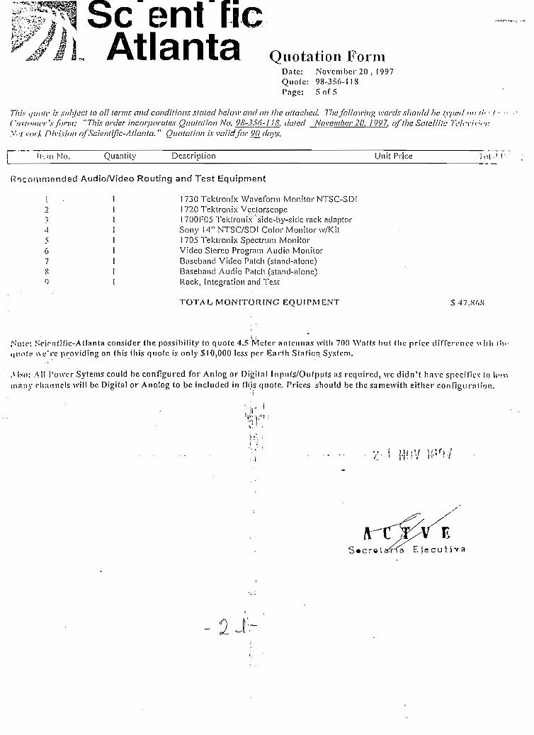
Se ~ entAtlanta Quotation Form
Date: Novcmbcr20 , 1997Quote: 98-356-118Pnge: 5o f5
This (/HÜ/C ¿v sithjtict to ail íerms and conditions staíed below and on (he ailached. Tfiafoüowing words should he lyped ñuC'jv!"»icr'.\- fornt: "This order incorporales Qiiotalion No. 98-356-118. daíed Noventher 20, ¡997. off/ie SatellHc 7VA'r.'>Y-' / ' i ' íM-A f>/Y/".í/Vj/í nfScientific-Allanta. " Quotation /.v validfnr 90_ dayx.
I l - . M ) NO. Quantity Description Unit Price
Rocoí'iimended AudioA/ideo Routing and Test Equipment
1 1 1730 Tektronix WnveCorm Monitor NTSC-SDI2 I 1720 Tektronix Vectofscope?v 1 I700F05 Tektronix side-by-side rack adaptor*1 I Sony 14"NTSC/SDI Color Monitor w/Kít5 1 1705 Tektronix Spectrum Monitor6 1 Video Stereo Program Audio Monitor7 1 Baseband Vídeo Patch (sfnnd-alone)S 1 Baseband Audio Patch (stnnd-alone)() I Rack, Integration and Test
TOTAL MONITORING E Q U I P M E N T
Noto; Snonf i f í c -At l an ta consider the possibility to quoíe 4.5 Meter a n t c n n a s \viil i 700 Wntts b u t (he pricc c l í f re rcncc -.liíii li j uo ÍL 1 \sc"rc providíng on this this quoíe is only $10,000 less per Ear fh Station Sy.sfem.
iU.-ífi; A I I l 'u\vcr Syíems could be configured for Anlog or Digi ta l Inpuís /Outputs as requircd, we d idn ' t ha ve spccifici to Iti nany t ' f i a tmc l s will be Digi ta l or Anolog to be included in tlíis quoíc. Pnces should be thesamewi th either con f ígu ro l l ón .
. v. ; H I ; V ¡¿ir,y
ES • c r e 1 aíVa E j e c u t i v a

TERMS AND CONniTIONS OF SALE,> : ; ; ; . ;••-• i
p. tVl -/-'I'
SUí :-.Mi K'-ATLANTA. INC.
-\p.¡ ^^^"wi \?\~~Tr*^^*'
ASOD V. ION n i -TELEVISIÓN DEL ECUADOR ** -^" Ejecuté*
1. Gr.fií£RAL
1.1 The InTns "we", "us", and "our" are used to referto Scientífic-Atlanla, Inc.; the terms "you" and "your" refer to Purchaser, The temí "li?m" \ti'-o'J !o reíer to our products or servjces or both provided un3er this Contract.
i J P-jrrhascr's order is binding only when accepted ¡n writing at the offices of Scientific-Atlanta, Inc. in Atlanta, Georgia. We reject ar.y [ornr, :i"rrnnMinns in Purchaser's order which are different from or additional to theso terms and conditions or any changes to the order after
2, unless approved in writing and signad by our authorized representativa.
'.Víí m?y make partía! shípments to fill your order. We will not be Hable for our failure to perform hereunder due to any act of God, fiíc. bb~i;. ,-tiílc. unusually severe weather, delay caused by a governrnent, delay of a subcontractororsupplier in furnishing materials and serien? <:my oíhcr cause beyond our reasonable control.
Purchasers located in the United States assume all responsibility for obtaining any required export or ¡mport aulhorizations for any of cu» U'1"d from the United States. Purchaser agrees not to export any ítems in violation of applicable expoit or ¡mport regulations. Fcr UPM"-.by us to Purchasers located outside the United States, we shall obtain any required export authorizstion from the United Stntos
llovernment and Purchaser shall provide any required assistance in obtaining Information or documente required for such authoriznli-?n
'• *> . if '!'*> Itams are to be used in fulfilling a conlract with the United Stales Government we agree to comply with the mandatory governnimtC'.í'tnd provisions that are appÜcable to us under federal law and regulations, províded Purchaser has given us written notíce of theíippSicnble provisions and we have accepted them in writing.
í 6 Thf laws of the State of Georgia, except for ¡ts rules or principies of conflíct of laws, shall govern all matters relaüng to this sale. The UMÍ'« jNaíions Convention on Contracts for the International Sale of Goods shall not apply to this Contract.
1.7 rXCEPT FOR CLAIMS FOR PERSONAL INJURY CAUSED BY ÍTEMS FURNISHED HEREUNDER, WE SHALL NOT BE LIABLE TOPUFÍCHASER OR ANY OTHER PERSON OR ENTITY FOR INDIRECT, SPECIAL, INCIDENTAL, CONSEQUENTIAL. ^UNITIVE. ORGXFWPLARY DAMAGES ARISING OUT OF OR IN CONNECTION WITH THIS TRANSACTION OR ANY ACTS OR OMISSIONSV, SOCIATED THEREWITH OR RELATING TO THE SALE OR USE OF ANY ÍTEMS OR SERVICES FURNISHED, WHETHER Si JC1 'CLA'M ÍS BASED ON BREACH OFWARRANTY, CONTRACT TORTOR OTHER LEGAL THEORY AND REGARDLESS OFTHE CAU^.Cf SUCH LOSS OR DAMAGES OR WHETHER ANY OTHER REMEDY PROVÍDED HEREIN FAILS. IN NO EVENT SHALL OUR TOTAL( IAP1LITY UNDER THIS CONTRACT EXCEED AN AMOUNT EQUAL TO THE TOTAL AMOUNT PAID FOR ÍTEMS PURCHASED
1.8 • A:»Y Eidion arising out of this transaction must be commenced wilhifi one year after the cause of action has accrued.
1.9 íf any provisión of this Contract is held-illegal or unenforceable by any court or other authority of competent jurisdictíon. such provisión shal! bdeemed severable from íhe remaining provisions of this Contract and shall not affect or impair the valídíty or enforceability of the renwnmgprcvipions of this Contract.
, i1.11 Tíie hondings are for convenience only and are not to be used in the construction or interpretatíon of these terms and conditions.
2. rniOE AND PAYMENT . . . . . . . . . . . . . . . . . .
2.1 I-'fiCi's for ítems lo be delivered in the United States are F.O.B. our desígnaíed factory.
2.2 Prires tor Kems to be delivered outsíde the United States are Ex Works (EXW, INCOTERMS 1 990) our facility in the United Síales or ñhio^-Iat our eíection.
2 3 Píkoi do not include freight; insurance; sales, use, excise or similar taxes; or duties. Where appropríate, such taxes will be addod lo íhe•n "••• e and paíd by Purchaser, unless Purchaser provides us evidence of payment or certifícate of exemption.
2.4 'í'-.I<3;-we have establíshed a credit limit for Purchaser, we may require payment or a down payment and an irrevocable letterof crr.dií alPufc'«a3Gr's expense, ¡n advance of shipment. If credit is granted. any amounts not paid when due shall bear interest at the rale of 1 ' ;"'• pormonlh or at the highest rate permitted by law (whichever is less), from íhe dnte of shipment until paid. We retain a lien on the líems unti! pn;lf.T
2.5 Pürc'isscr's order will be deemed a representation that Purchaser is solvent and able to pay for the ítems ordered. If Purchaser fail? lt; nin^epaymonli; v^hen due, or if bankruptcy or insolvency proceedings nio instituted by or against Purchaser. or if Purchaser makes an assicinmen!íor li:o boncfil of credilors, Purchaser will be deemed in default and we will have the right to termínate our obííga(íons by written notíce toPurchasfir. bul such lermination v;ill not affect Purchaser's obligation to pay for llems delívered and work in progress.
3. TITLEAÑD DELIVERY
3.1 For ítems shipped to a Purchaser located within the United Staíes, title and risk of loss pass to Purchaser when ítems are tendered to íhec=rr¡er at place of shipment. We can arrange for in-transit insurance on Purchaser's writlen instructíons and at Purchaser's expense.
- 2 - 2 . -

-.•; .'¡oms shipped to a Purchaser located ouíside the United States, risk of loss passes to Purchaser when ítems are tendered to \hr • -> • • !; . _ •'• ".f shípment. and títle passes to Purchaser when ítems are mnde available to Purchaser on board the carrier at the port of drr-í-i.tt *W: nan arrange for ¡n-transit insurance on Purchaser's wrítten ¡nslructions and at Purchaser's expense.
3 .I- líiodelivery schedule quoted to Purchaser runs from the date of our acceptance in writing of Purchaser's order, which forinternntHiMl ••*;!*.jH occur after the satisfaction of each of the following:
a receipt of signad and acknowledged purchase order; • >• - . • ' : ;h receipt of down payment; andc receipt of divisible, irrevocable, confirmad letter of credit in a form acceptabie to us.
i'-ii Iti-ins td he cvporlcd from the Uniled Statc.s, the delivcry .schedule is also subjeel lo [lie rcccipl of all nccessary expon" dneumcnts muí niiilt<iii • • • ; • •
3 rt Accrptance shall be accomplished by using applicable test procedures or programs we establish. Non-conforming ítems musí b*> ^.-r-;-,w'thin ten (10) calendar days after receipt or they will be deemed accepted. If inslallation by us is not ¡ncluded ¡n the purchase oH?f..?or.nptence tests shall be performed at our plañí. If Purchsser's order specifies source inspection, we wíll give Purchaser ai leasí f?."= (^fHv^nce notice of the date of such acceptance tests. If installation by us is included in the purchase price, acceptance shall occur PÍ f ^instaüalion site when we demónstrate that the appücable diagnostic or veriflcation programs work properly or the ítem is otherwiss•J-vnonstrnted to be ¡n normal operating condiüon. If installation is scheduled ordelayed by the Purchaser more than thirty (30) days ;if*--:.'"•':'jt¡r*t; Purchaser shall be deemed to have accepted the ítems on the thirty-first (31) day after the date of delivery.
j3.5 Any software or documentalion delivered in connection with thí.s order is delivered under a nonexclusive, non-íransferable licensQ te i-^''
in connection with the ítems delivered hereunder. Purchaser may not modify, reproduce, decompile, reverse engineer or transfer «;::••"* A.••> •rír.v;u¡nentation without our prior written consent. Purchaser may be required to enter into a sepárate license agreement which will suf >*•••tf*is section.
•4 ! W:> warrant good title to any hardware furnished under this Contract. For software, we warrant that we have the right to grant any sofu. :!<••'Lctnse granted. We warrant that services will be performed in a good and workmanlike manner. We also warrant that during the W.Tf-. i-Poriod (as defined below), each ítem we deliver (otherthan separately licensed software and services) will:
ta l Be frcc frum material delects in wurkmanship and malcriáis; andÍM) Under ordinary use. conforní in all malcría! rcspccls to ils publísbed spccíficalions currcnt at Ihc lime the llein was shippcd.
•; 2 liems may include refurbíshed goods, subassemblíes or components, which we warrant as provided ¡n thís section 4.
£, j Th» Warranty Period begins on the date the ítem is delivered and extends for 12 months for hardware and 90 days for software, pnif-; -• • 'sprvices. We will repair or Aplace, at our option. any product returned to us by Purchaser at its expense díínng the Warranty Peiíori -• '• •'"'tatte (o satisfy this Waeranty, unless the failure was the result of shipping; improper installation, mainteiísnce or use: abnormal cond;t;•?•••: "•'' in'Tjtion; attempted rpodification or repair by the Purchaser; or an act of God. We will reperform any &érvíces which do not conformé '•'.•:-'/'/arraníy provided we have received notice of non-conformance within the Warranty Period. THIS WARRANTY IS IN LIEU OF Al 1. O''í;:"V/ARRANTIES, EXPRESS, IMPLIED OR STATUTORY INCLUDING ANY WARRANTY OF MERCHANTABILITY, FITNESS FOR APARTICULAR PURPOS'E OR NONINFRINGEMENT. PURCHASER'S SOLÉ REMEDY FOR ANY BREACH OF WARRANTY is THEí'FPAIR OR REPLACEMENT, ATOUR OPTION, OFTHE FAILED ÍTEM. WE SPECIFICALLY DISCLAIM ANY AND ALL WARRANTI' ^r>'í'RESS OR IMPL1ED. TO CUSTOMERS OF PURCHASER.
5. INFRINGEMENT OF INTELÍECTUAL PROPERTY
5.1 V/e will pay all costs, damages and attorneys' fees (other than altorneys1 fees and Aiitiv4¿damlgeá'Vtribubble to acts of Purchaser) fin='lyon a finaing that the design orpgnstqwarded ín any suit by a third party against Purchaser to the extent based upon a finaing that the design or construction of the ítem, ss
furnished, infringes the proprietary rights of such third party provkled that PurctS«ea:pfIB(Víp[lyi)»Dtiffeáfí^híw?iírn9 of any allegation of surhinfn.-igementand we are given the right at our expense to settie such charge and, through attorneys of ourown cholee, to defend or co-Mc?;fíñfense of any suit based upon such charge. Provided. however, that our entire obligation to indemnify Purchaser shall not exceed íh« tcí^
i. paid lo us by Purchaser forthe allegedly ¡nfringing ítem purchassd under this Contract,
5.2 In Ihe event that the use of an ítem becomes, or in our opinión mny become the subject of any claim, suit or proceeding, or if theUSP or sale an ítem is enjoined, we may, at our option and expense, do one or more of the following:
ohlain for Purchaser the right lo use the ítem:modify the ítem so that U becomes noninfringingor rcpiace Ihc llem wilh a noninfringing ítem, wliile rcmainingin compliancc \\i!li the pii'>!¡.V.!sprcificalions in nll malcrial respccls;
'• > ecii.sc lo deliver Ihc llem lo Purchaser; or(>n requirc Pnrcbaser lo relurn to us o filie allegedly inrnngin<i llem and upon relurii, p:iv to Purchaser an amouní cqual lo the piice paid 1\* i-.i-r
lor ihc ítem, less dupreciation (based on a íive-ycar lile, wilh slraifilil-linc dcpreciation) np to Ihc time that Purchaser ccascs to use ihc ItJiu ns aresult of such claim.
5.3 NoUvithstanding any oíher provisión of this Section, we shall have no liabiüty for any infringement arising from or occurring as a result cf '
f.-i] use of tiie ítem in combination wilh olher Ítems, unless \ve sold nr mailc tlicm all as a conihination. or('') incorporation ofa spccülc design or mndillcation al tlie ret¡nesl u I* Purchaser, orÍ ÍT) failure by Purchaser lo implemenl ehanges, replacumcnls nr ne\ ix'lea-si's reconiniendetl by S-A and made availahle al no cosí lo Pnu'li;i ..••
whcre the mfringcniejil would be avoided by such ehanycs. ropliiceinculs or nc\ ideases.
5.4 TÍ-II seclion 5 sets forth our entíre liabiliLy to Purchaser with respect to the ¡nfringemenl of intellectual property by the ítem, and ws rn^e nowar^anty of noninfringement, express or implied.

PAT
H L
OSS
, E
LE
VA
TIO
N
AN
GL
E,
&"K
" F
AC
TO
R
Con
dití
ons
Sate
llite
Sate
llite
Lon
gitu
de (
Deg
Eas
t)
;TX
Site
Mam
eTX
Fre
quen
cy
;
TX
Sit
e L
ongi
tude
{D
eg E
ast)
TX S
ite
Lat
itud
e (D
eg N
orth
) <
TX
Eie
vaüo
n A
ngle
'
Upi
ink
Los
s
RX
Site
Ñam
eR
X F
requ
ency
RX
Sit
o L
ongi
tude
[D
eg E
ast)
RX
Sito
Lat
itud
e (D
eg N
orth
)El
evai
ion
Ang
leD
üwnl
ink
loss
Bea
m T
ype
Upi
ink
Bet
a Fa
ctor
Dow
nlin
k B
eta
Fact
orY
Fact
orG
loba
l C
oeff
.: cu
orc
dG
loba
l U
/L B
.E.
adj.:
gu
' '
Glo
bal
D/L
B.E
.adj
.:gd
K. F
acto
r
XP
DR
SF
D
(bca
m p
eak
HO
dB
aun
.)X
PDR
G/T
(bc
am p
cakT
XPD
R E
IRP
(bea
mp
e^c)
:^ro
,•*
"*.-v
^^
a"
\s
~~
-»«T
'
,í' "
""
\m Q
uito
Upi
ink
4.5m
rec.
- I
S.O
MH
zD
VB
-3/4
Rat
e FE
CC
lear
Sky
PAS
I3
15.0
° Eas
tQ
.uito
. Ecu
ador
6.15
0GH
z28
l.5°
Eas
t-0
.2°N
orth
51.0
°!9
9.6d
B
Chi
nchi
pe.
Ecu
ador
3.95
0GH
z28
I.O
°Eas
t"4
;5cN
'orth
50.2
°19
5.Sd
B(T
rans
pond
er#1
3)La
tín,
72
MH
zTW
T-1
.5dB
-2.0
dB 0.0
•"
-O
.OdB
-S7.
2dB
W/m
:
-Q.8
dB/K
3S.9
dBW S
e A
6.0m
Gua
yaqu
il U
piin
k4
.5m
rec.
- ÍS
.OM
Hz
- D
VB
-3/4
Rat
e FE
CC
lear
Sky
PAS
131
5.0°
Eas
tG
uaya
quil
, Ecu
ador
6.15
0GH
Z2S
O.O
°Eas
t-2
.2°N
orth
49.3
°¡9
9.6d
B
Chi
nchi
pe, E
cuad
or3.
950G
Hz
2SI.
O°E
asi
-4.5
°Nor
th50
.2°
195.
SdB
(Tra
nspo
nder
#13)
Latí
n, 7
2 M
HzT
WT
-1.5
dB-2
.0dB 0.0 _
.-
O.O
dB
-87,
2dB
\V/n
r'
' -O
.SdB
/K38
.9dB
W
-«
ient
mc
llan
ta
4.5m
Qui
to U
piin
k4.
5mre
c. -
IS.
OM
Hz
DV
B-3
/4 R
ate
FEC
Cle
ar S
kyPA
S 1
. 31
5.0°
Eas
tQ
uito
. E
cuad
or6.
Í50G
HZ
281.
5°E
ast
-0.2
°Nor
th51
.0°
199.
6dB
Chi
nchi
pe.
Ecu
ador
3.95
0GH
z2S
1.0°
Eas
t-4
.5°N
orth
50.2
°19
5.Sd
B(T
rans
pond
er#1
3)La
tin, 7
2 M
HzT
WT
-1.5
dB-2
.0dB 0.0 - - -
O.O
dB
-S7.
2dB
W/m
3
. -O
.SdB
/K38
.9dB
W
4.5m
Gua
yaqu
il U
piin
k4
.5m
rec.
- IS
.OM
Hz
DV
B-3
/4 R
ate
FEC
Cle
ar S
kyPA
S 1
3 15
.0°
East
Gua
yaqu
il.
Ecu
ador
6.15
0GH
Z2S
O.O
°Eas
t-2
.2°N
orth
49.3
°I9
9.6d
B
Chi
nchí
pe,
Ecu
ador
1 3
.950
GH
ZIS
l.O
^ast
-4.¿
-Xor
th50
.2a
!95.
SdB
{Tra
nspo
nder
#13}
Latí
n, 7
2 M
HzT
WT
-1.5
dB-2
.0dB 0.0
• - - -
O.O
dB
-S7.
2dB
W/n
r-Ü
.SdB
/K3S
.9dB
W
-. -

EA
RT
HST
AT
10N
C/T
Para
mot
er
Ant
enna
Si'/
eA
nten
na E
leva
tion
Ang
leA
mbi
eni T
empe
ratu
re a
t L
NA
'Ant
enna
Eff
icie
ncy
Ant
enna
Gaí
nA
dd'l
Feed
or
Pola
rize
r lo
ssA
nten
na n
oíse
tem
pera
tura
wit
hout
add'
t fe
ed/p
oiar
izer
los
s ft
with
add
'I fe
ed p
olar
izer
los
s <>
Ant
enna
Gaí
n at
the
Feed
Por
t ^
Ope
ratin
g Fr
eque
ncy
<•>_
VS
WR
ofF
eedO
utpu
t v
VSW
R o
í* L
NA
Inpu
t £
Ant
enna
-LN
A r
efle
ctio
n C
oeff
.Fe
ed t
o L
NA
Los
s ^
LNA
LXB
G-ain
~¿
Los
s ¡r
om L
NA
lo
BD
C (
O if
LN
B)
,B
DC
Gui
níO
ifL
NB
)B
DC
Noi
se F
igur
e (O
if
LN
B)
L-B
and
IFL
Cab
le L
oss
Rec
eive
r Noi
se F
igur
eA
nten
na N
oise
Tem
pera
ture
at
LNA
Feed
Los
sffo
rtem
p. c
ompe
nsat
ion)
Add
itio
nal T
amb
Ant
enna
Noi
seFe
ed t
o LN
A L
oss
Tem
pera
ture
Feed
10
LNA
VSW
R T
empe
ratu
reLN
A N
oise
Tem
pera
tura
('«
] 25°
C)
LNA
Noi
se T
empe
ratu
re (
/Vy a
mbi
ent)
LNA
Noi
se F
igur
e (@
am
bien
t)LN
A t
o B
DC
Effe
cts
(O if
LN
B)
BD
C to
Rec
eive
r Eff
ects
Tota
l Sys
tem
Tem
pera
ture
Ant
enna
Gai
n at
LN
A I
nput
Toia
l Sy
stem
Tem
pera
tura
Car
rier
Lev
e! a
t L
NA
/LN
B o
utpu
tG
irri
er L
evol
at
Rec
eive
r In
put
DV
B-3
/4 R
ate
FEC
D
VB
-3/4
4.5m
50.2
°30
.0°C
64.9
%43
.5dB
¡O
.ldB
15.0
K;
I8.4
K43
.5dB
i3.
950G
Hz
1.30
2.00
0.35
8 .:
\B 'j
. 60
.0dB
O.O
dBO.
OdB
O.Od
BI5
.0dB
I5.0
dB16
.0K
0.2d
B0.
2KO.
OKI2
.9K
25.0
K27
.SK
0.4d
BO.
OK0.
3K57
.0K
42.9
dBi
17.6
dB-3
6.8d
Bm
oLS
dBm Sc
ient
ific
Atl
anta
Rat
e FE
C4.
5m50
.2°
30.0
°C64
.9%
43.5
dBi
O.l
dB
15.0
K18
.4K
43.5
dBi
3.95
0GH
z1.
302.
000.
358
O.OO
dB60
.0dB
O.O
dBO.
OdB
O.Od
Bló
.OdB
15.0
dB16
.0K
0.2d
B0.
2KO.
OK12
.9K
25.0
K27
.SK
0.4d
BO.
OK0.
3K57
.0K
42.9
dBi
I7.6
dB-3
6.8d
Bm
-5I.
8dB
m
DV
B-3/
^I R
atcF
EC
4.5m
50.2
°30
.0°C
64.9
%43
.5dB
iO
.idB
I5.0
KÍ8
.4K
43.5
dBi
3.95
0GH
z1.
302.
000.
358
O.OO
dB60
.0dB
O.Od
BO.
OdB
O.Od
B15
.0dB
I5.0
dBI6
.0K
0.2d
B0.
2ÍC
O.O
K
12.9
K25
.0K
27.S
K0.
4dB
O.OK:
0.3 E
C57
.0K
42.9
dBi
!7.6
dB-3
6.8d
Bm
óI.S
dRm
DV
B-3
/4 R
ate
FEC
4.5m
50.2
°30
.0°C
64.9
%43
.5dB
iO
.ldB
15.0
ICI8
.4K
43,5
dBi
3.95
0GH
Z1.
302.
00V
0.35
8O.
OOdB
60.0
dBO
.OdB
O.Od
BO.
OdB
15.0
dBiD
.OdB
IÓ.OK
:0.
2dB
0.2K
O'.O
K12
.9K
25.0
K27
.SK
.0.
4dB
O.OK
.0.
3IC
57.0
K42
.9dB
i17
.6JB
-36.
8dB
m-5
I.Sd
Bm

II
HO
Í .6 -
iE j e c u t i v a
II

AN
TE
NN
A P
OIN
TIN
G E
RR
OR
4-X
Sate
llite
N/S
Sta
tion
Kee
ptng
Sate
llit
e EA
V S
tati
on K
eepi
ng\V
orst
Sat
elli
te M
otio
n
TX
Ant
enna
Dia
met
erA
utot
rack
ing
of T
X A
nten
naT
X A
nten
na 3
dB
Bca
imvi
dth
Init
ial M
ispo
inti
ngM
tepo
ímin
g du
e to
Win
dT
ota!
RSS
Poi
ntin
g Er
ror
TX P
oim
ing L
oss
RX
Ant
enna
Dia
met
erA
utot
rack
ing
of R
X A
nten
naR
X A
nten
na 3
dB
Bea
mw
idth
Inií
ial M
ispo
inti
ngM
ispo
inti
ng d
ue t
o W
ind
Tot
al R
SS P
oint
ing
Erro
rR
X P
oint
ing
Los
s
DV
B-3
/4 R
ate
FEC
: 0.
05°
0.05
°0.
07°
6.0m no
Ü.5
7°0.
09°
0.02
°1
0.12
°0.
5dB
4.5m no
.
1.18
°(
' 0.
20°
0.05
°0.
22°
0.4d
B
DV
B-3
/4 R
ate
FEC
0.05
°0.
05°
0.07
°
6.0m no
0.57
°0.
09°
0.02
°0.
12°
0.5d
B
4.5m no
1.18
°0.
20°
0.05
°0.
22°
0.4d
B
DV
B-3
/4 R
ate
FEC
0.05
°0.
05°
0.07
°
4.5m no
0.76
°0.
13°
0.02
°
O.ó
dB
4.5m no
1.13
°0.
20°
0.05
°0.
22°
0.4d
B
DV
B-3
/4 R
ate
FEC
0.05
°0.
05°
0.07
°
4.5m no
0.76
°0.
13°
0.02
°0.
15=
0.5d
B
4.5m no
1.18
°0.
20°
0.05
=0.
22°
Ü.4
dB
có
/ '
s ^
/
ieni
ífic

i (O 00 \S
Con
dití
ops
Sate
llue
Bea
m T
ype
Typ
e of
Ser
vice
Rec
eive
Ant
enna
Siz
eT
rans
mit
Ant
enna
Siz
eU
sabl
e In
form
atio
n R
ate
Ree
d-So
iom
on i
nner
Cod
eC
odin
g R
ate
(1/2
=0.5
, 3/4
=0.7
5)T
rans
mis
síon
Rat
eP
SK
Tvp
e(l=
BP
SK
.2=
QP
SK
)C
arri
eroc
cupi
ed B
W (
sym
bol
ra^a
jC
arri
er S
paci
ng
®A
lioc
ated
Ban
dwid
th
-i 3fc
/M
odui
ator
Fíl
ierA
lpha
(35
%)
—
/C
arri
er -
40 d
B B
andw
klth
^
t*
${.>
i
\. Ü
PL
INK
£ ^5
\n
EIR
P p
er C
xr
£
\g
loss
es
£•
v5
\h L
oss
%
\n A
tten
uati
on
\c A
nten
na Á
rea
SFD
al
Bea
m E
dge
G/T
ai
Bea
m
Edge
Upl
ínk
Foot
prín
t Adv
anía
geIn
put
¡Sac
koff
per
Car
rier
UpI
inkT
herm
al C
/NU
plin
klM
EIR
PDen
sity
Upü
nk I
nter
mod
ulat
ion
C/N
Tot
al ü
plin
k C
/(N
-H)
DV
B-3
/4 R
ate
FEC
Cle
arS
kyPA
S í
Lat
ín. 7
2 M
HzT
WT
QPS
K4.
5m6.
0ni
'.1
8,03
1 K
bps
188/
204
3/4
26,0
87 K
bps 2
13,0
44 K
Hz
1.38
1 8.0
00
KH
z35
%iS
.OO
OK
Hz
\
O.o
dB19
9.6d
B0.
3dB
37.2
dB/m
2
-87.
2dB
W/m
:
-O.S
dB/K
-I.5
dB12
.0dB
20.2
dB4.
0dB
W/4
KH
z26
.3dB
.-
I9.2
dB
DV
B-3
/4 R
ale
FEC
Cle
arSk
yP
AS
1La
tín, 7
2 M
HzT
WT
QPS
K4.
5m6.
0m18
.031
Kbp
s18
8/20
43/
426
.087
Kbp
s 2
13.0
44 K
Hz
1.38
IS.O
OO
KH
z35
%18
.000
KH
z
-. .-*
"i
" rf
65.5
dBW
0.5d
B!9
9.6d
B0.
3dB
37.2
dB/m
2
-87.
2dB
W/m
2
-O.S
dB/K
-I.5
dB12
.0dB
20.2
dB'
-l.O
dBW
MK
Hz
26.3
dBI9
.3dB
DV
B-3
/4 R
ate
FEC
. C
lear
Sky
PAS
1La
tín, 7
2 M
HzT
WT
QPS
K4.
5m4.
5m18
,031
Kbp
s18
8/20
43/
426
.087
Kbp
s 213
,044
KH
z1.
3818
,000
KH
z35
%18
,000
KH
z
65.4
dBW
0.5d
B19
9.6d
B0.
3dB
37.2
dB/m
2
-87.
2dB
W/m
3
-O.S
dB/K
:-1
.5dB
12.0
dB20
.2dB
4.0d
BW
/4K
Hz
26.3
dB[9
.2dB
DV
B-3
/4 R
ate
FEC
Cle
arSk
yPA
S 1
Lat
ín, 7
2 M
HzT
WT
QPS
K4.
5m4.
5m18
.031
Kbp
si 8
8/20
43/
426
.087
Kbp
s 213
,044
KH
z1.
3818
,000
KH
z35
%iS
.OO
OK
Hz
65.4
dBW
0.5d
B19
9.6d
B0.
3dB
37.2
dB/m
--8
7.2d
B\W
nr-O
.SdB
/K-l
.5dB
12.0
dB20
.2dB
4.0d
BW
AiK
Hz
26.3
dB19
.2dB
II.
TR
AN
SP
ON
DE
R I
NT
ER
MO
DU
LA
TIO
N N
OiS
EIM
P D
ensi
ty a
t B
eam
Edi
ieC
IM-2
3.6d
BW
MK
Hz
17.U
IB Sel
-23/
)dB
\V/4
KH
/.17
.UÍB
snti
fic
-23.
6dB
W/4
Kii
z17
.UÍH
-23.
ÍHlB
\\V4K
I!z
I7.U
1B
At-
anrc

111.
DO
WN
LIN
K
—O
Bea
m E
dge
Satu
rate
d X
PDR
EIR
P ¡
Dow
nlin
k Fo
otpr
int A
dvam
age
Inpu
t to
Out
put
Bac
koff
i
XPD
R O
utpu
t Bac
koff
per
Cxr
-
D/L
EIR
Ppe
rCar
rier
atE
/SPa
th L
oss
:
Atm
osph
ere/
Rai
n Att
enua
tion
Poin
ting
los
scs
Eart
h St
atio
n G
/TR
ain
G/T
Deg
rada
tion
Dow
nlin
k Th
erm
al C
/N
Con
dfti
ons
IV. C
O-C
I1A
NN
EL
IKT
ER
FER
EN
CE
V.
TO
TA
L G
'(N
+I)N
OIS
EPh
ase
Noi
se D
egra
datio
nTo
tal
C/fN
-H)
G'(í
s'o-i-
Io)
Tota
lE
b/N
o To
ta!
Unc
orre
cted
BER
-pre
dict
ed Í
RD
BE
R*
Dcc
odin
gO
ulpu
t Byt
e Er
ror
Ral
eE
b/N
o R
equi
red a
tThr
esho
idC
lear
-Sky
Mar
gin
Not
e: T
his
anii
lysi
s do
es n
ot í
nclu
de (
he -
effe
cts
ofT
erre
stri
al I
nter
fere
nce.
38.9
dBW
-2.0
dBl.
SdB
!0.2
dB26
.7dB
W
.19
5.8d
.B0.
2dB
,
0.4d
B
'•25
.3dB
/ÍC
O.O
dB13
.1dB
DV
B-3
/4 R
ate
FEC
Cle
ar S
ky
.20
.0dB
0.5d
B9.
9dB
Sl.l
dB-I
-lz
S.Sd
B4.
44 E
-04
Vite
rbi'
- R-S
. <1
E-1
2\B 3.
0ÜB
38.9
dB\
-2.0
dBl.S
dBI0
.2dB
26.7
dBW
195.
8dB
0.2d
B0.
4dB
' '
25.3
dB/K
O.Od
B!3
.1dB
DV
B-3
/4 R
ate
FEC
Cíe
ar S
ky20
.0dB
0.5d
B9.
9dB
Sl.l
dB-H
zS
JdB
4.41
E-0
4V
iterb
i - R
-S<
IE-I
25.
5dB
3.0d
B
3S.9
dBW
' -2
.0dB
l.SdB
I0.2
dB26
.7dB
W19
5.Sd
B0.
2dB
0.4d
B25
.3dB
/KO.
OdB
13.l
dB
DV
B-3
/4 R
ate
FEC
Cle
ar S
ky20
.0dB
0.5d
B9.
9dB
'81.
1dB
-Hz
S.5d
B4.
42E
-04
Vit
erbi
- R
-S<
iE-I
25.
5dB
3.0d
B
3S.9
dBW
-2.0
dBl.
SdB
10.2
dB26
.7dB
\19
5.8d
B0.
2dB
0.4d
B25
.3dB
/KO
.OdB
v 13
.1dB
DV
B-3
/4 R
ato
FEC
Cle
ar S
ky20
.0dB
0.5d
B9.
9dB
81.1
dB-H
zS.
5dB
4.45
E-0
4V
iterb
i - R
-S<
1E-Í
25.
5dB
3.0d
B
**«i f
í
-TI Í~
"" ) 't
* á
OC
í'-i
í j-
íííí

TR
AN
SP
ON
DE
R U
TIL
IZA
TIO
N3/
4 R
ale
FEC
' 3/
4 Ra
le F
EC3/
4 R
ale
FEC
3/4
Rat
e FE
C
O 1
1. PE
R C
AR
RIE
RTr
ansm
it A
nten
na S
ize
Info
rmat
ion
Rat
e (I
) i
Mín
imum
D/L
EIR
P at
Ear
th S
tati
onTX
Poi
min
g L
oss
& A
tm/R
ain
Alte
n.
:M
áxim
um D
/L E
!RP
at E
arth
Sta
tion
Dow
nlin
k Fo
otpr
im A
dvan
tagc
Max
D/L
EIR
P pe
r C
arri
er a
t B.
E.M
ax D
/L E
IRP
per
Car
rier
at
B.E.
XPD
R S
atur
ated
EIR
PLe
ased
XPD
R O
utpu
t B
acko
ffLe
ased
EiR
P A
vail
able
at
B.E.
% o
f Lé
ase
Pow
er p
er C
arri
er
Leas
ed B
andw
idih
Ava
ilab
le%
Ehn
d\\i
dth
Ifse
d pe
rCxr
' £/
)\
iM
£&•
II. T
OT
AL
XPD
R LÉ
ASE
£_
/
Qua
ntit
yof C
arri
ers
a\J
Pow
er p
er L
ink
Typ
e -A
T<
Pow
er o
í' O
ther
Car
rier
s °*
h^\T
\e E
IRP
Req
uire
d tn t\\e
EIR
P R
equi
red
^
<*'¡
^
Tota
] X
PDR
Out
pui B
acko
iT
£ \l
%of
Léa
se P
ower
Z W
\h p
er C
arri
er T
ype
Ban
dwid
th o
F O
thcr
Car
ricr
sG
uard
band
sTo
tal
Ban
dwid
th R
equi
red
Tot
al %
oí"
Loas
e B
andw
idlh
Üse
d
"•6.
0m'"
lS03
IKbp
s26
.7dB
W" O
.OdB
26.7
dBW
-2.0
dB2S
.7dB
VV
737.
2wat
ts38
.9dB
W4.
2dB
34.7
dB\
25.0
%
72.0
00 K
Hz
25.0
%
I73
7.2w
atts
O.O
wat
ts73
7.2w
atts
2S.7
dBW
10.2
25.0
%
•
ISO
OO
KH
zO
KH
zO
KH
zIS
OO
OK
Hz
25.0
%
Scie
nti
ó.Om
!803
1Kbp
s26
.7dB
WO.
OdB
26.7
dB\
-2.0
dB2S
.7dB
\73
7.9\
vatts
38.9
dB\
4.2d
B34
.7dB
\25
.0%
72.0
00 K
Hz
25.0
%
I73
7.9\
vatts
O.O
wat
ts73
7.9w
atts
2S.7
dBW
10.2
25.0
%
ISOO
OKHz
OK
Hz
OK
Hz
ISOO
OKHz
25.0
%
fie
4.5m
ÍS03
1Kbp
s26
.7dB
\O.
OdB
2ó.7
dBW
-2.0
dB28
.7dB
\73
8.2\
vans
38.9
dBW
4.2d
B34
.7dB
W25
.0%
72.0
00 K
Hz
25.0
^0 173
S.2
wat
tsO
.Ow
atts
73 S.
2 wat
ts2S
.7dB
Wi 0
.225
.0%
ISOO
OKHz
OKI-í
zO
KH
zIS
OOOK
Hz25
.0%
4.5m
1803
1Kbp
s26
.7dB
\O.
OdB
26.7
dB\
-2.0
dB2S
.7dB
W73
7. 1 w
atts
38.9
dB\
4.2d
Bv
34.7
dB\
25.0
°ó
72.0
0U K
Hz
25.0
° 'ó !73
7. 1 \
\att
s0.
0\\a
ns73
7. I
wan
s2S
.7dB
\10
.225
.0%
ISO
OO
KH
zO
KH
zO
KH
zIS
OO
OK
Hz
25.0
° o
-•-.
,— -
•,U
t,
• ,'
*';
' 5

HP
A C
AL
CU
LA
TIO
NS
DV
B-3
/4 R
ate
FEC
D
VB
-3/4
Ral
e FE
CD
VB
-3/4
Rai
e FE
CD
VB
-3/4
Rat
e FE
C
1. O
UT
PU
TB
AC
KO
FF
U
Car
rier
Typ
eE
/S E
IRP/
carr
ier
Tra
nsm
ii A
ntcn
na S
ize
Ean
h S
tatin
n IX
Am
cnna
Gai
nIF
L an
d S
v\itc
hing
Los
s(R
aek
Mo
un
t}L'
pünk
Mar
gin
HPA
Po\
\or
requ
ired
per
Car
rier
Qua
mii
y of
Aci
he
Car
ricr
sH
PA P
ower
Roq
'd p
er C
xr T
\eH
PA P
ower
Req
'd p
er C
.\ T
> pe
HPA
Pow
er o
fOtl
ier
Car
rier
sH
PA C
ompo
site
Pow
er R
equi
red
HP
AS
izeO
tTer
ed
. (
HPA
Pow
er A
vail
able
HPA
Typ
eB
acko
ff íb
r Q
uasi
-Lín
earii
vO
uipu
i Bac
koíT
Ava
ilabl
e H
PA
hea
droo
m
1803
1Kbp
s65
.5dB
W6.
0m49
.7dB
I.5Ü
B0.
5dB
!7.S
dB\ 1
IT.S
dBW
59.6
waü
sO
.Ow
atts
I7.8
dBW
200.
0wau
s25
.4 d
BW
TW
T3.
üdB
7.7Ü
B4.
7dB
1803
1Kbp
s65
.5dB
W6.
0m49
.7dB
I.5d
B0.
5dB
17.8
dBW 1
!7.8
dBW
60.0
wat
tsO
.Ow
atts
I7.S
dBW
200.
0wat
ts25
,-ídB
WT
WT
j.OdB
7.6d
B4.
6dB
IS03
lKbp
s65
.4dB
W4.
5m46
.7dB
1.5d
B0.
5dB
20.7
dB\ i i
20.7
dBW
118.
0wat
tsO
.Ow
atts
20.7
dB\
700.
0\vn
tts27
.9dB
WT
WT
j.O
dB7.
2dB
4.2d
B
IS03
iKbp
st
65.4
dBW
4.5m
46.7
dBl.
5dB
0.5d
B20
.7dB
W i i20
.7dB
\I I
S.ów
atts
O.O
wat
ts20
.7dB
W70
0.0l
vatt
s27
.9Í1
BW
TW
T3
0d
B7
2d
B4.
lid 13
Scie
ntíf
ic

Sheetl
PüworV'u System - Information Rate Versus Allocated RF Bandwidth '
Aii.-cated BW(MHz)*
4.5
9.0
•
ia.o!
; 36.0-.
¿?.5
i
Symbol Rate (Msps)
-3-.26Í;
6.52
13.04
26.09!
30.80'
i
1/2
3.00-6.01
12.02
24.04
28.39
2/3
4.00
8.01
16.02
32.04
37.85
3/4
4.50
9.01
18.02
36.04
42.58
5/6
5.01
10.02
20.04
40.08
47.31
7/8
5.26
.10.52
21.04
42.08
49.67
i .ÍINFORMATION RATE (Mbps) '
; AMocrtíed Bandwidth = 1.38 * Symbol Rate (spectrum of carríer drops to -40 dBc poínts,•v*- íic*fined by DVB specification)
III
IIII
' í -or»l«el« Ei .oul l i»
Page 1
i
i

I
PowerVu Commercial IRD: Uncorrected BBR* rnle displayed on front pnnel of IRD.
vcrsus Eb/No, for each FEC rate of operation. /FEC Rate
Front Panel BERdisplay2.00E-021 .OOE-02
5.00E-032.00E-03
I.OOE-035.00E-042.00E-04l.OOE-045.00E-05
2.00E-05
l.OOE-055.00E-06
2.00E-06l.OOE-06
DVBSpecifiedThreshold
1/2
6.5 dB7.6 dB8.5 dB9.5 dB
10.3dB10,9 dBl l . 7 d B12.2 dB12.8 dB!3.3dB
13,7 dB14.0 dB14.3 dB14.6 dB
4.5 dB
2/3
5.2 dH6.4 dB7.4 dB8.4 dB9.1 dB9.8 dB
lO.OdB1 1 . 1 d BH . ó d B
12.1 dBI2 .5dR12.8UB!3.2dB13.5 díi
5.0 dB
3/4
5.9 dR6.9 dB7.9 dB8.6 dB9.3 dB
10. 1 dB• I0 .6dBI I . 1 d Bl i . ó d B
. I Z O d B12.3 dB12.7 dB12.9 dB
'5.5clB
5/6
6.2 dB1A dB8.1 dB8.7 dB9.5 dB
10.1 dBl O . ó d Bí l . I dB1 [ .5dBl l . 7 d B
12.1 dB12.4dB
6.0 dB
7/8
7.1 dB7.9 dB8.5 dB9.3 dB9.9 dB
10.4dB10.9 dB1 l . 2 d BI 1 . 5 d B1 1.9dB12.2 dB
6.4 dB
Nnic: .Standard dcvialíon was 0.2ÜI3.
All mcíiSLiremenls taken overa rangc of symhol rales. . • • •
All IRDs mcasurcd excccded Ihreshold performance, huí IÍFK íüsptay was nnslahlc ncjr Ihrcshold
* Correcicd BIZR is "qtiasi-error-lrec" opcralion (<10cxp-l2). as dcllncd hy DVB, Ihr operation al ar
ahovc (he Rh/No thrcshold for any spccidc PHC rale.
>3-
Scientific-Atlanta Proprietary Information

- 1:3 Analog or D-1 Video with4 Mono Analog or AES-EBU Audio
P/N559177g&£&¿fé¿ vwy- ' --¿-"-¿jg" •••""• ••'•
Rxxx^^^^^xx^V J »~«n= I /\- t /
j» 1 RU Blank Panele
a
a
a
.1 4
2 RUBÍank Panel4
2 RU Blank Panel
|» 1 RUBÍank Panel
|» 1 RUBÍank Panel
^ í RUBÍank Paneli 1 RUBÍank Panel
p 1 RU Blank Panels
«
'
re
2 RUBÍank Panel
I *>
PCC 2000/3000MONITOR
o
>
*^
V
B PCC 2000 / 3000 Keyboai-d
• Rackmount Concentrator
• 1 RUBÍank Pane!
• PCC 2000/
»
ífW
52 RU Blank Pane
>
ok
ffl
1¡» 1 RUBÍank Panela
2 RU Blank Panel>
2 RU Blank.Pane!a
»*> RU Blank Pane
»
9 APC f
D (e RM1000UPS
1- "j:
Aí^
:
£
í
t
r
K
•
>
»
»
*
í
Q
D
B
3
B
e
3
>
•:
*
V
H
6
K
K
K
•:
J
3
/ \^ r * fc</^/<^^^^
\i /
s
1 RUBÍank Panel
—Encoder I ~
••**-"•
" - i .Q ' E= =3 t= — d
' 1 RU Blank Panel<\ ~ " •r~~-~ •«
Modulator t-r~¡ — ¡ — i — r9 . O ' n a o - 0
> '"*""" Baseband
> Swtch (1A)ggSS^mm Audio Patch Panei ;
• 1 RUBÍank Panel
°n°->o Video Patch Panel
•fr "D^ibution Arr.pjí
2 RU Blank Pane">
*$. = ™ Vídeo =
Muitiplexer —
> 1 RU Blank Panel
Secondary "Muitiplexer —.
» 1 RUBÍank Panel
_
Encoder 1 —
* 1 RUBÍank Panel
==3^H===^=5É
•*
.£r£;
1 acialIQQBJ
•
' ^^R
OH a 1JDHal 1ISS2J . f
•
•
•
= c^=3 *
•
•
= I '„
«
"
•
ft— V,
•
/ \ "S^l /
* 1 RU Blank Panel •
í '* —
< Encoder 2 —
i ___ . . „j »•=• ¿=a» 1 RUBÍank Panel
% '
J Encoder 3 —
1 a__
"> RU Blank Panel9 •
I RU Blank Panel •
» 1 RUBÍank Panel •
* 1 RU Blank Panei ' «
2 RU Blank Pa^c! "a e
. 2 RU Blank Panelo • m
2 RU Blank Panel» «
2 RU Blank Panela •
2 RU Blank Panel9 e
• 1 RUBÍank Panel •
1 RUBÍank Panel •
2 RUBÍank Panel0 «
2 RU Blank Panela t
<» 1 RUBÍank Panel •
• 1 RU Blank Panel •
2 RU Blank Panela •
2 RU Blank Panela «
a 1 RUBÍank Panel «
» 1 RU Blank Panel «
2 RU Blank Panela m
1 RUBÍank Panel «
/ \1 FRONTVIEW
A2FRONTVIEW A3 FRONTVIEWPrepared By George B. McLeod on 07/16/97

Appendix A.l
MPEG-2/DVB COMPLIANCE
Scientífic, Atlanta

ISO/IEC 13818-3 Information Technology - Generic Coding of Moving Pictures and
Associated Audio: Audio
ETS 300 421 Digital broadcasting systems for televisión, sound and data ser/ice:;;
Framing structure, channel coding and modulation for 11/12 GRz satellite servíces
(Dec.'94)
ETS 300 468 Digital broadcasting systems for televisión, sound and data serviccs:
Speciñcation for Service Information (SI) in Digital Video Broadcasting (DVBj
systems (June'95)
DVB A0001 rev.l Digital broadcasting systems for televisión; Implementation
guidelines for Che use of MPEG-2 syutems; Video and audio in satellite and cable
broadcasting applicaüons (June'95)
- . ^ .ENCODING AND TRANSMISSION SYSTEM COMPLIANCE
COMPLIANCE WITK ISO/ÍEC 13818-1 (SYSTEMS)
".-nvcrVu™ is fully compliant with the Transport'Stream definition within ISO/IEC 13818-1,
í;-..;luding the important aspects of timing/buffer management, program location informadon (PSI),
a--?J the location of conditional access information. All bitstreams generated comply with the
•;_ -,::•;•:. PCRs are inserted every 40 ms as DVB recommends. Synchronization of video and audio
••-.-es ihe descríbed PCR/PTS method for guaranteed lip-synch. The GOP structure is
•.;-• •,.;pirnmable. The clock frequenc'y tólerance is ±54 Hz, an order of magnitude more accuratc
« i ¿n iVíPEG's and DVB's minimums.
I .2 COMPLIANCE WITH ISO/IEC 13318-2 (VIDEO)
V'- - video encoder generates a legal Main Proñle/Main Level (MP/ML) bitstream embedded witíún
.he transpon stre^am. As required, defined lower proflles and levéis are automatically supported,
•• :;-.e foilowing DVB resolutions are supported: 352x576; 480x576; 544x576; and a!so
'••;-'./":iQx576. Intrinsically, therefore; I (Intra), P (Predictive), and B (Bi-directional) frames are
Scientiíic, Atlanta PowerVii S

• : i v supponed. The transmission of pan vectors is supported for 16:9 codíng. The encoder
•-.•/u1 rales bitrates (excluding Systems overhead) in the range 2 Mb/s - 15 Mb/s, the upper l imi t
1 .;!rg determined by the MP/ML deflnition. The same encodercan accept PAL orNTSC inputs fbr
• í í - rnstomers convenience,
> . 4 COMPLIANCE WITH ISO/IEC 13818-3 (AUDIO)
"V* Cuello encoder generates bitstreams which comply with the syntax and scmantics for the f ru i r
;, . . 'es currently availabie in accordance with DVB requirements: single channel (mono); chía!
.: :r.cj (two independent audios coded in one stream); stereo (L &: R coded in one stream); amj
. - , : • • • ; sr.ereo (L & R coded using stereo redundancy). All the full sampling rates of 32 IcH?.
' r . ; !:Hz, and 48 kHz are implemented. For mono the following coded bitrates are availabie: ?J,
•"• rtát 64, SO, 96, 112, 128, 160, and 192 kb/s. For all other methods these rates apply: 64, 96.
. :::. 128, 160, 192, 224, 256, 320, and 384 kb/s. Layer 2 bitrates of 256 and 384 kb/s are
:•• v"::n:ncnded to achieve transparent quality for stereo signáis; a compromise rate of 192 kb/s
.•.Y'.TS a slight reduction in quality while reducing the required bitrate. No emphasis is applied in
.-xordance with DVB. : '
- : COMPLIANCE WITH ETS 300 468 (DVB SI)
•".: PowerVu™ encoder can créate the tables dcfined in the above document, generating legal'
'Yp. i - ix and following the semantics. The NIT (network information table), BAT (bouquet
.- -í.-ciation table), and SDT (sen/ice description table) can be generated and the EIT (event
• '.ííination table) is availabie to carry present/following information as DVB requires, given
; . . !\.ble inputs from the broadcaster or datábase man agen The TDT (time and date table) and RST
- • n i n g status table) can also be transmitted. The RST can be used to trigger other devices, such
:,- VCR recording. The reader will recall that the defmition of an Electronic Viewing Guide is
•j . ) - i : .c i í ly outside the scope of ETS 300 468. Scientifíc-Atlanta can offer "transparent lega!
'.-1 ;t-:-nsions?I to this standard to resolve identified deficicncies - such as the signaling of prívate data.
T ••: CLístomer should approach Scientifíc-Atlanta to discuss EVG issues separately.
mcans penmtted by the standard. A legal extensión woiilti be discarded by decoders which did notisc i t , but the decoder would continué to function without impairmcnt.
¿)7
(Scientific c-^-L Atlanta A . I - :

COMPLIANCE WITH ETS 300 421 (DVB RF)
is performed on the stream for encrgy dispersión purposes and the first MPEG
sync byte in eight is complementad to support RF coding synchronization, as specífieil
y: DVB, and then (204,188,8) Reed Solomon error protection is added. The signal is then
rrjnvolutionally interleaved to a depth 1=12. The full range of convolutional codes specifíed by
DVB is offered: 1/2, 2/3, 3/4, 5/6, and 7/8; thcse are user-set. PowerVu™ uses Gray-coded
quarernary phase shift keying (QPSK) modulation. The roll-off factor speciñed by DVB of 35% is
¡v.álable. Scientifíc-Atlanta equipment also supports 27%. Scicntific-Atlanta's product meets the
>i;wJ npectrum mask given in ETS 300 421 whea using 35% roll-off.
; . f l DECODING AND RECEPTION SYSTEM COMPLIANCE
:, ; COMMERCIAL DECODER COMPLIANCE
.- .. i " • COMPLIANCE WTTH ISO/EEC 13818-1 (SYSTEMS). i : , •
;i>»; ciemux chip accepts and demultiplexes any legal MPEG-2 transpon stream subject to bitrate
-••"^sri^Jnls, and uses the received PCRs to genérate an internal system clock, which is the timebase
raínst which presentation and decoding complefion times are triggered-according to the PTS
'preseniation timestarnp) (and when appropriate DTS - decoding timestamp) fíeld.s received. The
'.¿cc'dtir ís capable ofoperating over the full tolerance of the system cJock frequency as DVB
.piares, and with the 100 ms PCR repetition rate as MPEG/DVB requires. The valúes of
traj?sport_scrambling_control defíned by DVB are correctJy recognized.
The commercial decoder can be operated in a mode where channel selection uses the PSI (program
;,r: JÍuc inforrnation) data received, but PE) (packei Identification) valúes can also be selected froin
Ú-.,, front panel.
4. L2 COMPLIANCE WTTHISO/IEC 138)8-2 (VIDEO)
'• :¿ video decoder engine accepts any defíned Main Proñle/Main Level video elementary stream
•i;'.i iiy definition any video síreíirn of a defíned profije or level below this. Pan and sean features
SfrScíentificL Atlanta PowerVu SP

•upportcd. The decoding of still frame (single I-pictures) is supported. The video decoder
:>.;os íhc transport_error_indicator when set to error to freeze-frame the video to amelioraie the
•:>cts oír the errored data. The decoder produces the resolutions 352x288, 352x576, 480x576,
••••• "176, and 704x576 corresponding to the PAL input as coded. The decoder determines
v. ív-íther ñelds should be upsampled independeníly or when combined as a frame, in accordance
•--.. i ih i he encoding method.
i J COMPLIANCE WTTH ISO/ffiC 13818-3 (AUDÍO)
V;,c audio decoder engine accepts any legal layer 1 or layer 2 audio elementar/ strearn codc'l
1 x ' - ' f 'üng to the standard using the mono, dual channel, stereo, or joint stereo and can decode ihe
- . - : - : stereo information from an MPEG-2 compatible multi-channeí audio bitstream. Tho
ri- í í ' .? ! ing frequencies of 32, 44.1, and 48 IcHz will alí be supported. The commercial decoder
r<n"'.senrs two audio stereo paJr at output, with an option of two additional stereo pairs.
«i. í .4 COMPLIANCE WTTH ETS 300 468 (DVB SI)
• '-v;e the DVB SI is dafa. irítended for the end viewer, it is typically not relevant in applications
?*--;r.g commercial decóders. The NIT however is by default used for multiplex acquisition.
.:, ! .5 COMPLIANCE WITH ETS 300 421 (DVB RF)5
7',\': intcroperability of the commercial decoder was clearly demonstrated publicly at the
T-:;.;com'95 exhibición where a Sciencifíc-Atlanta decoder received and presented a signal from
.: - - . ' T ¡ J i t e feeds generated by NTL and Philips encoders. ExplicitJy, the unit first performs
-') . ;volutional decoding (auto-detection of rato) and convolutional de^interleaving. The RS parity
L.l i ' i are used ío correct any errors received on the incoming signal up to the limit of the code,
i..-.?v;;y dispersal is removed, and compliant 188 byte transport stream packets are passed on to the
.. - -nu i t i p l ex chip with the sync bytes restored. II uncorrectable errors are detected then this is
- . .nvcycd to the demux chip by setting the transport_error_indicator flag as recommended by DVB.
.,/4-5
Scíentífic. Atlanta

. 2 CONSUMER DECODER COMPLÍANCE
-:.•:.;. COMPLÍANCE WITHISO/EEC L3818-1 (SYSTEMS)
T'ie uemux chip accepts and demultiplexes any legal MPEG-2 transport stream subject to bitrnte
júr-itaf-ions, and uses the received PCRs to genérate an internal system clock, which is the dmebase
.r^aínst which presentation and decoding completion times are tríggered according to the PTS (and
w!v:n appropriate DTS) ñelds received. The decoder is capable of operatíng over the full tolerancc
uí ;'.(c system cíock frequency and the 100 ms PCR rcpetition rate as MPEG/DVB requires. Tho
•vi-k'^s of transport_scrambling_control deñned by DVB are currecüy recognized.
", , , '_ decoder opérales in a mode where channel sclcction is achieved through the PSI data received,
/.i.Ich is interpreted according to the standards. Any syntax received which is privately coded can
L't :dcntifíed and skipped as DVB recorrunends.
.".2 COMPLÍANCE WTTH ISO/teC 13818-2 (VIDEO)
"""•.e vjdeo decoder engine accepts any defined Main Proflle/Main Level video elementary stream
r'-'f{ by definition ar.y video stream of a defined profile or level below this/. It will present the
image as it was intended at encoding. Pan and sean features are supported. The decoding of stijl
fram¿ (single I-pictures) will be supported. The video decoder uses the transport_error_jndicator
v/l^n set to error to actívate slice-Ievel concealment, or freeze-framing to amelíorate the effects of
• S? '.rrored data. The decoder accepts the resolutions 352x288, 352x576, 480x576, 544x576, and
7'>!x576 when the input was PAL set as coded in one of these formats. Video windowing is
::upportsd according to DVB.. The decoder determines whether fields should be upsampled'
^dcpcndently or when combined as a trame, in accordance with the encoding method.
4.2.3 COMPLÍANCE WTTHISO/IEC 13818-3 (AUDIO) '
"he audio decoder engine accepts any defined layer 1 or layer 2 audio elementary stream coded
^conriing to the standard using the mono, dual channel, stereo, or joint stereo and can decode the
-;-r.s:c Etéreo information from an MPEG-2 compasible multí-channel audio bitstream. The basíc
,.irr.piing frequencies of 32, 44.1, and 48 kHz are supported, It can present one audio stereo pair
S5TJ ScieníifícL Atlanta PowerVuSP

Appendix A.2
MPEG SYSTEM PARAMETERS
Scíentific- Atlanta

: . 4 COMPLIANCE WTTH ETS 300 468 (DVB SI)
í : : % consumer decoder is designed to utilize the DVB SI information, wi th the EIT being used MI
r^iícnt/following" mode. The NIT is the method used to tune to the channel. Scienüñc-Atlnn;-
i-o provides "legal" extensions e.g., to support the listing of utility data whhin a progrnm.
Míinmers interested in EVGs should approach Scicntific-Atlanta to discuss their requirements ^
-.v H-hich alternative best fits their application.
*: consumer decoder performs exactly the same tasks as the commercial decoder. The uni t fi:x:
- r;>rms convolutional decoding (auto-detection) and convoluuonal de-interleaving. The RS
- :riiy bits are used to correct any errors received on the incoming signal up to the limit of the codc.
•rgy dispersaJ is removed, and 188 byte transpon: packets are passed on to the demuluplex cHr
• - " í h the sync bytes restored. If uncorrectable errors are detected then this is conveyed to thr
:- r^'jx chip by setting the transport_error^indicator flag as recommended by DVB.
'í CONCLUSIONS
.";¡j document explains in detall how Scientífic-Atlaiita producís conform to the MPEG and DVB
-íundards in a general sense. Electrícal specifications for example are not speciñed by the
: -..'.dards. The full features offered by these producís are descríbed individually in the appropriate
ona .sheets. A broadcaster or operator typically has rcquirements which extend well beyond thr
< .n /p l iance points determined through MPEG and DVB, e.g., the transrrussion of an EVG, text
rv-..srmes or other data, and interested partics should discuss with. Scientific-Atlanta how thei rt¡1 i i vidual needs can be met.
SPieníific
. Atlanta

MPEG SYSTEM FARAMETERS
MPEG OVERVIEW
>.: i er.ü fie-Atlanta has adopted the Moving-Picture Expert Group (MPEG) standard for d íg i t r i
•••^npression. MPEG was formed in 1988 to establish a standard for the compressed
; - "^ntation of moving pictures. To date, the activities of the MPEG video group have resulte i
:;, :-.VQ standards: ISO/IEC 11172 (MPEG-1), which is optimized for non-interlaced sourc~
' ' .-nal, and ISO/IEC 13818 (MPEG-2), which adds support for interlaced source material.
" -"'"G-l was originally intended for use with digital storage medía operating at rates up to about
i ."• rnegabits per second (Mb/s); however, the syntax of MPEG-1 allows it to be used at rates up io
••"• •• $5 Mb/s. Because of its optimization for progressive scanned source material, MPEG-1 is
rir '">!!y suited for movie-on-demand services.
Á-^HG-2 has been developed for higher date-.rate interlaced video applicaüons, primarily in the 2 to ' :-
:.: Mb/s range. The intended applications incl&de cable and satellite televisión distribución as \vcll
;:.i -ronsumer electronic devices. The syntax is very similar to MPEG-1, the biggest dlffercncc
u- :-• 'he added techniques fordealing withÁnterlaced video. -Ij f !
. ; • . . ", MPEG-1 and MPEG-2 support a varíety of spatial and temporal resolutions. Consequently,i-
bcth standards can be'iused in 525 line, 30 frame per second and 625 line, 25 frame per second
;;-v-licauons. Furthermore, both standards support 24 frame per second movie modes and can be
. - - / - i to support 4:3, 16:9, and other aspect ratios. An cssential characteristic of both standards Ss
v-i 'r Ocxibility. This flexibility allows future improvements in performance to be obtained by
:;;-*;rívIing just the encoder. No changes to the installed dccoderbase'are required.
'i i" ; MPEG-2 standard is composed of three main parts: video, audio, and systems. Each of the
r/.:1::. ¡hrce secdons will describe these components of íhe standard individually.
ScisniríícCOM-ó-ín Atienta

VIDEO
OVERVIEW
Sí; vera I techniques are used to achieve high compression. The ñrst is to select an appropriare
;;p«cial resolución for the signal. The aigopithm then uses block-based motion compensation to
ícJacc the temporal redundancy. Motion compensation is used both for causal prediction of the
Cv¡rrent picture from aprevious picture and for non-causal, interpolative prediction from past and
f :;ure pictures. Motion vectors are defined for ecch 16-pixel by 16-tine región of the irnage. Th^
J;J7crence signal (i.e., the prediction error) is further c'ompressed using the discrete cosine
:rvtn?.form (DCT) to remove spatial correlation before it is quantized in an irreversible process that
fij.-'.cards the less important Information. Finally, me rnotion vectors are combined with the residual
DCT information and transmitted using variable Icngth codes.
2.2 TEMPORAL PROCESSING
'.'¿cause of the conflicting requirements of random, access and highly efficient compression, tliree
•••un picture types are defined. Intra-frame codea pictures (I-frames) are coded without reference
:: other pictures. They provide access points to íhe coded sequence where decoding can begin, bul
.••••: coded v/ith only modérate compression. Predictive-frame coded pictures (P-frames) are coded
rr">-v. efñcientiy using motion cornpensated prediction from a past intra or predictive coded picttire
í;nci are generally used as a reference for further prediction.
Bidirectionally-predictive-frame coded pictures (B-frames) provide the highest degree of
:.jí;ipression but require both past and future reference pictures for motion compensation. This
rranslates into more required memory in decqdcrs, and henee a small increase in cosí, while
ii'Cieasing the subjective quality of the video beiug viewed by approximately 20%. B-frames are
ni, ver used as references for prediction.
The orgarúzation of the three picture types in a sequence is very flexible. The choice is left to the
ei¡-:oder and will depend on the requirements of the application. Figure 1 illustrates the relationship
o ¡Vür.g the three different picture types.
ScientlficAtlanta COM 6-III

NSG-Í425A
Figure 1, The Relationship Among I-Frames, B-Frames, and P-Frames
—A-Ctf>V ES « c r e l a u p f a E j e c u t i v a
Cf.fM.6-t 11Scientific
Atlanta

• » . í MOTION REPRESENTATION - MACROBLOCKS}
T •'.?. cholee of 16 x 16 macroblocks for the motion compensation unit is a result of the tradc-olt
*>.- ' ; v/cen the coding gain provided by using motion Information and the overhead needed to store ir.
i:;v;h macroblock can be one of a number of different types. For example, intra-coded, forward-
"rr:dioíive-coded, backward-predicüve-coded, and bidirectionally-predictive-coded macroblocks
Dcpcnding on the type of macroblock, motion vector infonnation and other'side information i"
í,rirod with the compressed prediction error sigaal in each macroblock. The motion vectors an?
(.ricodcd differentially with respect to the last transruitted motion vector, using variable lerigrh
'•'".les, The máximum length of the vectors that may be represented can be progranuned, on •:
pk'iure-by-picture basis, so that the mosl demanding applications can be met without
.oirpromising the performance of the system in more normal situatíons. It is the responsibiíiry oí
:''-\'¿ encoder to calcúlate the appropriate motion vectors.
" 4 SPATIAL REDÜNDANCY REDÜCTION
"! ;th original pictures and prediction error signáis have high spatial redundancy. MPEG uses n
*>lock-based DCT method with visually weighted quantization and run-length coding. Aftermouoa
compcnsated prediction or interpolaron, the residual picture is split into 8 x 8 blocks. Tríese are
íc;»nsformed into the DCT domain where they are weighted before being quantized. Aí'ter
¡..anüzation many of the coefñcients are zero'in valué and so two-dimensional run-length and
' .viable length coding is used to encode the remaining coefñcients efñciently.
;.o • - FUTURE. ENHAN.CEMENTS . . _. •
,V.- MPEG-2 tool kit for the other profiles inchde extra syntax for techniques for scaleable coding.
fcoucncy scalabih'ty, and spatial scalability.
*:'r:c;uency scalability is a technique üke data partitioning, but each channel contains low order DCT
:;<;efficients that are reñnements of the lower layer quantization error. Spatial scalability is a
,:••- hod of encoding such that upper layer DCT coefñcients are refínements of the lower layer
ouintization error, i
SaentííicAtlanta

V.'hi lc Scicntific-Aüanta fully expects the MAIN profile to be the first and most widely app!k".
p n i f i l c of MPEG-2, any hígher profile decoder should be capable of decoding a MAIN prof i i -
' ' ' tMream. Therefore, the process of upgrading to support these extended features should pose ! > •;>robíem to the operator.
- Q IO -\c
r-oM-6.ui Atlanta
ISO/IEC 11172-3 (MPEG-1)
The audio channels in Scientific-Atlanta's digital compression system employ the MFEG-1
l:*JO/ÍEC 11172-3 layer 2 data compression process. The MPEG-1 layer 2 audio source codirg
! .chnique achieves reduced bit rate audio data transmission while providing an audio channel wi th
cxcellent measured and subjective listening performance. The subband fúter based algorithm of íhe
MPEG process is optimized on Lhe basis of human psychoacoustic models to miniínizc the
¡ransmitted bit rate of the encoded audio. The full bandwidth decoded signal has greater thati 90
d3 dynamic range and well preserved transient response charactcristics. The digital signal
Processing of the encoder/decoder combination has been optiraized to acnleve a robust, efücient.
cosr effective decoder knplementation while maintaining perccived CD quaüty audio performa.ti.ee.
The use of the ISO/MPEG standard encoding for the audio ensures proven performance v/ith
f;oruinued enhanccments at the lowest implementarion costs. The ISO/IEC 11172-3 layer 2 audio
I .-AS been thoroughly tested by ITU-R and the. CRC and shown to be capable of satisfying (he
requíremen.ís for contríbution, distribuúon, and emission applications.
Man y details of the audio encoding for the standard were not fixed in the standard. The syntax of
the coded data and source coding structure tbat créate compaübility with the decoder are f u l l y
specifíed, but the psychoacoustic models and bit allocation algorí.thm are unspeciñed. This has
alíowed coding performance enhancements and added features beyond those tested by ITU-R LO
continué to be offered. The competition for high volume worldwide markets of producís utilÍ7Íu[-r
the standard will assure that further enhancements and hardware cost reductions occur.
3.: CHANNEL FLEXIBILITY
A. single MPEG-T layer 2 audio service can pro vid.-: either two channels (e.g., stereo) of audio or a
ráugle channel (e.g., mono) or audio.
ScítíntificAítanía COM-d-iU

MULTICHANNEL COMPATIBILITY
r.-.rnpatibilhy with ISO/IEC 11172-3 (MPEG-1) is an important feature of ISO/IEC 1381S 3
. *.<r;7G-2) multichannel audio coding. An MPEG-2 mulüchannel audio decoder is required to N-
;.i:!a lo decode the two channels of an MPEG-1 encoder of the same layer, and an MPEG- I
íVrndcr must be able to extract the basic tv/b channeis from the coded bit stream of an MPEG- 2
n-.i:!íichannel audio coderof the same layer.
. Scientificc-nM-6-iii Atlanta

SYSTEMS
OVERVIEW
The systems part of the MPEG-2 document describes a syntax and set of semandc rules for the
¡nuitiplexing of the coded video, audio, and data associated with one or more programs. Each
program is composed of one or several elementary streams. MPEG-2 systems has allowed for tv/o
rliffercnt types of stream descriptions: Program Stream and Transport Stream. Both streams am
p;;cket-based.
'{>-, Program Stream (PS) utilizes variable-lcngth packets and is íntended for "error-fr.ee"
cnvironments in which software parsing is desired. The packets are generally relatively large ( 1 FC
::.) 2K bytes).
The Transport Stream (TS) is specifícally designed for transmission in "enror-prone" condítionT
anr] íncíudes features for enhanced error resiliency and packet loss detection. Transport packers p.rc
-;.f fixed Icngth and are relatively short (length -- 188 bytes).
Transformador! between the two stream types is possible- and is supported by a common structu't:
u;^d by both streams; the Packetized Elementary Stream or PES. The PES provides a standaí :1
hr.ider and method for packaging the elementary stream data (video, audio, etc.) and P"r
•is.'-ociating presentación and decoding time stamps with such data.
Tlic Scíentific-Atlanta transpon: system is the MPEG-2 Systems Transport Stream. Indeed.
Sdcndfíc-Atlanta has been intimately involved in the developmenc of t'his part of the MPEG-2
TRANSPORT MULTIPLEX PACKET STRUCTUREi-. ;
/
T¡¡- syntax and semanucs of the MPEG-2 Transpon Stream is defmed ín the ISO/TEC 13818-1.
A simple diagrarn of the basic transpon packet Ls shown in Figure 2. The length of the packeí ¡s
;i-;ed at 188 tíytes for all applications. Having one fixed length greatly promotes interoperability
;nd ease of backhaul/routing. This is because drop/add circuitry for packet insertion/deletion msy
be standardized and no transcoding of formats is necessary between mulüplexes. The single, fixed
ScientrficAíl^nía

¡v. 'kíM icngth also direcüy supports "pass-through" modes on combined satellite/CATV/telephony
: : .'-.v^;ks sínce encrypted packets may bere-routed without being decrypted.
í".1. h trnnsport packet starts with a four byte header. The flrst byte is a synchronization by¡c,
\' h allows a demultiplexer to synchronize on the bit stream. These four header bytes occur in
•rv-ry packet. The header may be followed-by adaptation field (AF), the presence of which is
'.-;"!i:tl:; by two header bits. Speciflc conditions define whether the AF is present or not. Tbn
.l t ;/ ' ' ' íM.ion field may not extend beyond the end of the transport packet.
:. ÍTeadcr 1
i , i • n Adaptation Fíeld Pavload
Figure 2. MPEG-2 Transport Packet Format
HEADER FIEÜDS
• licader fields are described below in Figure 3.S e c r e t a r i a
n
\\t
ErrorIndicator .
•i
I bit
PayloadUnitStartIndicator
1 bit
TransportPríoríty
i bit
PTD
13 bits
TransponScramblingControl
2 bits
AdaptationFieldControl
2 bits
Cont inui tvCounter
4 bits
FigureS. Prcfix Format
~^' '" Sync Bvte is a ñxed valué that is used to lócate the beginning of each ñxed-length packet.
i i i v M i g a sync byte supports packet boundary location by Transport Stream parsing alone. In the
0VP- salellite specification, the sync byte is used to re.soíve phase ambiguity also.
i ^- Transport Error Indicator can be used to trigger conccalment.
T.i*. Pavload Unit Start Indícator identifíes whcthcr a PES packet or PSI section starts in tíic
ScieníiíicAtlanta

Tho Transport PrioritV bit allows transport entities to assign higher priority to selected packets.
This may be used as a directive to data links for error protection or other special treatment.
Tic PID (Packet Identifierl allows the identification of the source of the data in the packet, The
?!D identiñes the strearn that is canied in the associated transport packet.
"!"!->e Transport Scrambling Control ñeld is deñned as follows:
00 This packet has no encryption
01 User-defined (This packet is encrypted with the even key.)
10 User-defined (This packet is encrypted with the odd key.)
1 1 User-defined (This packet is encrypted with the fixed key.)
The definition and management of the encryption keys are not specified by MPEG, but aj;e
cxpücitly supported through recognized prívate data streams anri in prívate áreas of the adaptarían
Pie Adaptaüón FJeid Control bits signal the .Vucture of the payload section:
00 Reserved
01 No adaptation field, payload only
10 Adaptation field only, no payload
1 1 Adaptadon field folio wed by payload
Tne Continuitv Counter is a module- 16 counter that is incremented with each packet sent. It is
r-*cd by the decoder to detect packet loss, or repcateil packets.
4.2.2 ADAPTATION FIELD
Ths adaptation ñeld, when present, may carry both MPEG-related and prívate information of
rulevance to a given transport stream or the elcrncntary stream carried within a given transport
packet. Provisions for clock recovery (such as the Program Clock Reference, PCR) and
r-.:ícryption key managemeut are typical of this Information.
Sdenírfíc ___ „Atí-anta COM-& \n

::-" riogram Clock Reference (PCR) is a counter valué that represents a "snapshot" of thc Sysicm
'!";".;: Clock for the associated program at the time the PCR bytes were put into the Transpon
S'-ronm. The dccoder uses this valué to synchronize the decoder system clock whh the encnclor
•: ::;-:rm clock. The lower 9 bits of the PCR are a module-300 counter that is incremented at thc
?~ MíTz clock rate. At each module-300 "rollover" the count in the upper 33 bits is incremente^.
TV uppcr 33 bits then represent counts that occur at a 90 kHz rate. This is done so that other ü:n~
•-:-!:-nps (Presentation and Decode, discussed later) can be compared using the 90 kHz valué.
Pupuse every program in an MPEG-2 Transport Stream may havc its own PCR, programs mny
• • "* mitl t iplexcd asynchronously and independently. This has positive implications for both Iho
' • vi.haul and re-routing of MPEG data. In particular, Transport Stream assembly at any particnlnr
nciv.'ork node does not depend on gen-locking of video signáis either from locally or remotHy
•'.-•• viuated sources.
TÍ-" PCR fíeld may be modiñed by multiplexers and is used to accumulate delays that are incurrcd
'!>r'>'jsh various stages of multiplexing. Wherever there exists a possibility of a variable delay of a
.;••- .-rkci, the PCR valué should be adjusted to reflect that delay. Figure 4 illustrates how the PCR
i :'',] is used at the decoder for clock recovery,
"i::: adaptación fíeld is also the location where explicit support for random access and stream
> > ! ; - in is included.
'-•'i-.'co and audio data is cut into PES packets, which tcnd to be relaüvely long (Ik to 2k bytcsl.
P. .;h PES packet has a variable length header foJlowed by video, audio, or data payioad. The PES
d:;f." header starts with a 24 bit: fíxed prefíx. Support for several niche appllcations is found al this
í"vol. Most importantly, this is the location of Presentation Time Stamps (PTSs) and Decoding
Tirnc Stamps (DTSs). These PTS and DTS are used to inforrn the decoder when to decode and
,;:-:;'iay a picture and when to play an audio segmcnt. The valué of the PTSs and DTSs refer to the
sr'tr.c ciock established by the PCRs. . . •
ScieníiíicAtlanta

Video, Audio PTS
jYiPEG-2Transport
Stream
ToDfsplay
DTC = Local decoder time clock
VCO= Voltage control oscillator
U = Timestamp linearizer
Figure "4." MPEG Deccdcr Timing Recovery
ScfentificAtlanta COM-6-ni
'. í PROGRAM SPECIHC INFORMATION (PSl)
' • ' ? ! .-c a multiplex may contain múltiple programs, with severa! video and audio streams in total, a
• • ' * ! hod is required to identify which elementary streams belong together. The Progrnrn
. V rociation Table (PAT) is in a ñxed location in every MPEG transpon stream. It lists t i »?
:• • •pf t rnms present, andpoints to the PrograrrrMap Table (PMT) for each individual program. TI1-:
I ,\ f describes which set of PCRs belong to that program, and defines the video, audio, ancl any
/ * ¡":ioníü data streams which compase the program. This data is sent in "sections," which are
•" :-;rrl 05 payload in transport packets. A Concii t ional Access Tabíe (CAT) is dcfined to carry
•'•;" basic conditional access informatíon.
! . - V 5 PACKET DATA
TV* payload secdon of the transport packet carnes either elementary stream data in PES packof.
' '; •-.•o, audio, text) or control information (program specific information, conditional access, etc.)
Or.iy one type of data is allowed in packets labeled with a common PID valué. In order to a d n p t
'h? packet transmission to any data-Iink rate, it is in practice necessary to define a "stuff1 packet tn
í> ^ í-^nt wben a data-linkinXerface is demanding packets and there are no valid packetfí-to sénd. Tne
; -ved "stuff packet ID has been assigned the valué of OxlFFF.
- 1 .5 .L Data Packetization. Figure 5 shows how raw compressed data is packetized. The
vi, !-.'.o or audío data is first cíut into access units. An audio frame is an audio access uait. A video
..•••;:;ss unit consists of a picture. Each access unit may have a time stamp (DTS and/or PTS'l
;! -í-ojiated with it, the valué of which is coded in the PES packet header. Typically, one aceces
••'r.'". will be coded in one PES packet butthis is not a rcquirement.
>'.1.: packets are then inserted into transport packets. The PES header always starts in the ñrst
; i./:-::id byte of the transport packet. There may be nn adaptation field after the four byte header
•.vl.-i.:h could contain a PCR. Note that one PES packet may be spread sequentiaJly over severa]
':•-. ^port packets which share the same PID (in this cose denoted XY). The ability to interleave. in
•/ t!,i from other sources (e.g., a packet with PID valué QP) is one of the strengths of MPEG-2
•vr.:-sport Stream multiplexing. - ' •
A C
ScientiíkAtlanta

One TP = 188 bytes-** *-
4*
\t
Packet Header
xr AF
PES
HDR
PES i
DATA
•
rCff* HDR
41
PES DATA
4 4
Synchrcnoi
Structuro
. Stuffing (AF)
X^ PES DATA XV^ PES DATA •
T.I End
iTimingInfo
of respacket
¡ Elementar^ citrsam
Access Unitstarts here
Access iJnitstarts hera
Figure 5. MPEG Tracsport Stream Schemaüc
¡4Sc&ntíflcAtlanta COM-6 SU
Ti'^ram speciñc information is sent in section.s which fit directly into transpon packets, w i r h o u t
]'] \ hcaders.
.{.2.5.2 Closed Captioning. Other program-related data such as closed-caption data may ly
scnt ín Lhe user data portion of the MPEG video.
• t . 3 UTILITY AND OTHER DIGITAL DATA SERVICES
ASYNCHRONOUS DATA
A ;ynchronous serial data can be transmitted using the MPEG-2 Transport Stream. This typc oí"
; ; : ' r ; i does not rely on "lockdng" the decoder clock with a clock at the encoder. In order to guaraníes
' r > ' ' E ¡he decoder buffer wilí not overflow, the máximum service race at the encoder must be less
íh sn or equai to the data rate used at the decoder. Flow control should be provided at the encoilcr
10 ensure that the source is throttled when approaching the limits of the ínput buffer. The rn\
.psvnchronous data is placed into Transport Stream packets for transmission. Each transmis.sion
;- '':kct should always start with a one-byte byte-count that indicates the number of valid bytc^"-
This allows for partía! packets to be flushed by the encoder after a programmable time-out. The
•'.¡ccodcr wilí output the data serially at a standard serial baud rate. Note that the baud rate at i'ie
¡•••coder and encoder do not have to match. Virtual channel information should include data tha t
'.•: ücatcs the minimum decoder baud rate needed to ensure buffer integrity, but the actual choice of
' • • . M / l rate could be set independenüy at the decodcr.
SYNCHRONOUS DATA ;
synchronous serial data can also be cnrried by the MPEG-2 Transport Stream. This,
ív-v/cver, requires that PCR valúes be transmitted that are locked to the synchronous rate that is
b'Jng served at the encoder. Also, at the decoder, the clock that is providing the output rate rnust
he locked to the 27 MHz system clock which is in turn tied to the incoraing PCR valúes. This
M.-.'.hod wouíd be used to transmit high-speed synchronous data and telephony standards such as
r.-l l . Like asynchronous data, this data wouid not have to undergo any pre-formatting beforc
'-• : :ig placed into Transport Stream packets. - ; ; .
-P6- A C TScieníific ^-^r
roM-6-1» Atlanta

43.3 TEXT AND SUBTTTLE SERVICES
Yr.xi: services are sent:using the general format of a command byte followed by the data tha t
•rorrosponds to that command. In most cases the length of the message will be variable. T\v> 9
iypes of tcxt data transmission are possible with tlús system. Eight-bit character codes are sent tbr
c-'r/iformance to World System Text (WST) and for other character sets that can be satisfied vvi'h •
255 codes. I
WST infonnation can be sent through the system and then transíated into the analog VBI región at
thí; decoder. This occurs automatically ín the Commercial IRD.
.4 CONTROL DATA AND FORMATS
ENTTTLEMENT MANAGEMENT MESSAGES
r/.;.íitlement Management Messages (EMMs) will be sent usíng a predetermined packet ID that \vill
uc se: at i be encoder and decoder. It will be the responsibility of tUsjlecoder hardware to filtev
ct.víi EMM l^ased on the address field and then store filtered EMMs in a/local área for decryption
.vad interprciation by the local microprocessor and secure element.
• í _ ' •
A'kU'cssed commands are only sent to one decoder and are encrypted using the secret identiív
nuuiber (SSN) of the decoder.
4 4.2 VIRTUAL CHANNEL MAPS
Y:r:.ual channel map infonnation is sent using a predetermined packetüD that is set at the encodcr -
and decoder. Virtual channel maps provide a lógica! mapping between user-selected program •
ü;;innel and speciñc packet streams.
ScrentífícAtlanta

'¿ÍC-i
POWEIWU™ SYSTEM ARCBITECTÜRE
iiii
A C J/;VÉ _S«ere t a f i a E j e c u t i v a "
o
COM-l-HIScientíflc
Allanta

I
III
I
III

POWERVU™ SYSTEM ARCHITECTURE
1.0 SYSTEM DESCRIPTION
Scientifíc-AÜanta has developed a digital video system for its MPEG-2 digitaJ video
compression system with all of the feacures you would expect from a manufacturar which
pioneered the use of satellites for televisión transmission. This system reflects the many years of
experience Sciendfic-Atlanta has in supplying products and systems to meet the business needs
of its custoraers in the televisión broadcasting, prívate networks, and cable televisión industries.
It draws heavily on the experience gained in delivering over a million addressable and non-
addressable set-top conveners, more dian one hundred thousand B-MAC anaJog decryption
systems, and over one hundred thousand ISO-11172 (MPEG-L) digital compression decoders.
The features and functions of Scientifíc-Atlanta's digital video compression upliak system are
descYibed in this document. ,The functional completeness of Scientiflc-Atlanta's producéis
evidence of Scientifíc-Atlanta's Tptal System Solution approach to the development of this
product.
1.1 DESIGNED TO INTERNATIONAL STANDAROS
Scientiñc-Atlanta has designed this system in accordance with the Intemational Standards
Organizadon's ISO/IEC113818 Standard "Coding of - Moving Píctures and Associated Audio"
(aiso referred to as the MPEG-2 standard). This standard specifíes the elements of a compressed
digital video and audio bitstream, including the packet based transpon structure which
encapsulates the vídeo and aadio bitstreams. Scientific-Adama's selección of ÍSO/IEC~138L8 as
the basis for its digital compression system assures:
a. Ready availability of mass produced (and henee low cost) components due to the use
of the standard in other products, including products for the consumer elecrrorücs
market V i M u ' /¿. ' h i./ v
b. Compaübiliry with products being developed for sateliite and cable televisión
delivery, as weil as digital storage and retrieval systems.
coM-i-raSctenttficAtlanta
1.2 FLEXIBLE, EXPANDABLE, AND UPGRADABLE
.Saentifíc-Atlanta's digital vídeo cornpression .system is desígned to be flexible, expandable, an.d
upgradable, The basic elements of the cornpression system (encoders, multiplexers, and che i ikc)
ÍITC cnpable of operación over both satellite. and terrestríal transrrüssion paths. U is possible tf i
incrcase the number of channels one at a time cost effcctively, and upgrade the system as
improvemencs and innovations become avaiJpble. This is achieved through the highly modulnr
design approach adopted by Sciend fie-Adán ta, based on the channelbank architecaire.
A major advantage of the system design is the modular I/O cards which help smooth the
transiüon from anaJog-to-digital technology. A system can be purchased with analog I/O cards 10
aMow the user to feel the cost savings of digital transmission. When the studio upgrades to serial
digital video, new digital interface cards can be purchased at a minímal upgrade cost. The
system design is so flexible, you can even mix and match.
1.3
ílvcrv slement of Scientiílc-Atlanta's digital video cornpression Upílnk system is engineered for
fulíy redundan: operación. In critica! applications such as a Direct-to-Home (DTH) satellite
5eryic_e where many subscribers will be affected by an equipmenf-failure, it is not accepcable ro
rcly on manual responses to equipment failure. Spare equipment needs to be on-line and
into operation by an automatic control system.
Rcdundancy ís a!so a critica! requirement ín nenvork contribuuon feeds, to ensure the. reJíabie
dclivery of program materia! to the studio, or rcbroadcast centre.
1.4 UNCOMPROMISED CONDITEONAL ACCESS AND ENCRYPTION
Scienufic-Adanta's Condiüonal Access and Hncryption (CA&E) system was ürst developed in
1984, for use with the B-MAC analog satellitc televisión transmission system. CA&E is a vita!
•.Mcment, especiaUy in a satellite system, to proteo: program access rights and revenue by
prevendng unauthorized recepción. Scienúfic-Atlanta's system has been refmed and enhanccd
ovcr the lase decade to maintain network intcgricy and securicy.
ScíontíficAtíar^a COM-I-ITI

! ,5 POWERFÜL SUBSCRIBER USER INTERFACE
.A!ro dcveloped as an elernent of the B-MAC system is the text-based user interface b u i l t in to
Sriemifíc-Atlanta's digital video compression system. Each Integrated Receiver/Decoder íTRDi
is rquipped with a text decoder, to conven text data imbedded in the transpon; stream into a
vi.íco character and graphics On-Screen Dísplay (OSD).
Tí'-c On-Screen Display (OSD) assists the subscriber in ínstalüng the ÍRD and in understanding
v hích'programs he is authorízed to receive. Wíth pov/erñil self diagnostic features built into ¡he
i?.O, the OSD also assists the Customer Service Representativo (CSR) to diagnose the cause of
rccsption problems reponed by the subscriber, in many cases without the need to dispatch a
rxiinician to the receiving location. The built-in OSD permits the Scientiflc-Atlanta digital
• Meo compression system. to offer additional teletext funcuons to the broadcaster. Examples
i. .-.'lude text based información ser/ices and múltiple language capüonlng,
VjrruaJ channels allow the cperator to define discrete services consisting of individual íV-icieo.
rv.KÍio, data, or text txansmissionstfrorn within a given uplink service that appear to a consumemos
¡i'Mitionai or incrementa! channels. Vinual channels can suppon a myriad of programming
'-•pponunities (and reverme" síreams) for broadcasters, including múltiple language audio, múltiple
liinguage subtitles, audio orüy, and text or data based services.
A sophisticated "point and. shoot" Electronic Prpgram Guide (EPG) is also available to funberí ; •
e:ihance the ease of access to programs. 'The EPG allows the subscriber to look anead at
j'TOgrams available on all channels, and select the desired program using a simple GraphJcaJ User
íp.tcrface (GUI) and the remote control. This system has been developed by Scienúñc-Atlanca'í
Üroadband Communicaüons Group for use in the latest generación gf addressable CATV home
cnromunicaüons termináis, and overcomes the problem facing the subscriber as the number of
-iiannels increases ~ how to find out what is on and choose what to watch.
Scfentjficc>M-i-m Atlanta

1.6 CO1VÍPLETE SATELLÍTE AND CABLE SOLUTION
Scientific-Atlama's.development work in digital video compression has encompassed systems for
both satellite and terrestrial video. The complete product family includes single and múlt iple
channel satellite delivery systems, digital srorage. and retrieval systems, and cable TV de I i ver.'
:-ystems. Scientifíc-Atlanta's product family is the most complete end-to-end system in íhe
índustry, and assures Scientific-Atlanta's customers of the ability to migrate and expand ínto ne\
markets as the need arises, without the need to decommission existing equipment.
1.7 SUITABLE FOR MANY APPLTCATIONS
Scientific-Atlanta's modular approach to digital video compression uplink systems has resulted M¡
a system vvhich readily adapts for use in any of the major markets using digítaJ video
compression today, including:
' a. Direct-To-Home (DTH) broadcosting
b. ' Cable Redistribution
c. Broadcast Retransmission
d. Backhaul/Contríbution
e. Specíalty/Business TV.
1.8 SUPPORTS FDM AND TDM SATELLITE TRANSMISIÓN
Scieruifíc-Atianta's digital video compression uplink system can be conñgured as either one or
more video programs in one multiplex, occupying up to a whole transponder. or each video
prograra can be encoded,.sep_arately. and uplinked as a single muldp.lex, with seyeral of sucli
carrier in one transponder. This means chai a system can start with a single video service.
occupving and buyíng only part of a traasponder, and then grow in video ser/ices, occupyins
more bandwidth as necessary. The initíal hardv/arc can be easily extended to do chis.
ScientríicAbanta

¿.O SYSTEM ARCHTTECTURE
?., 1 BASIC REDUNDANT SYSTEMn » c r e t a r i a E j e c u H •-"*
A typical redundam TDM system is comprised of one Digital Video Encoder (DVE) for each
vrrvice (a servtce Ís generally a single vídeo with its associated audio). Up to cwo additioppl
o i H Í t a l video encoders per multiplex are provided for redundancy. If an on-line digital video
".:icodcr fails, the standby unit may be switched on-line to repface the failed unit. A baseband
rirotcction switch ís used to ensure that the appropriate source input ¡s available at the standby
encoder,
Tnc baseband protecuon switch is typicalíy a 10x1 Audio-Follow-Video (AFV) switch. The
source signáis to the prímary encoders are passively íooped through the protection switch and are
íhcrcfore not dependent upon the operation of the 10x1 AFV switch,
F:.;ich digital video encoder outputs two idéntica! ptócetized MPEG data streams. One of these
-.lita streams is routed to each of the 1:1 redundaría multipíexers. That is..each encoder is
connected to both the primary and standby multipíexers so that valid encoder output signáis are "'
aJways present at the input to the multipíexers.
Tile muítiplexers also have duplícate outputs which are each connected to each of the 1:1
modulators. This ensures that at least one valid multiplex output sisnal Ís alwavs avaílabíe at theI • r r ._ ,
¡nodulator input. The modulator will automatically "fall-back" to the secondary input if the
prímary input fails.
Modulator output switching is provided by a 1:1 RF protección switch. Lf a failure of the on-l inc
modulator occurs, the standby modulator ¡s switched on-line under concrol of che PowerVu
Command Centre (PCC). A built-in 1:1 switching funcuon exists within the modulators so it is
íilso possible and reasonable to opérate without the externa! switch.
Thc raodulator applies the Forward Error Correction (FEC) coding to the data stream and QPSK
modulares an IF carríer compliant with the DVB satellite transmission standard. The modulator
Is connected to the PCC for redundancy and configuración control. A standard SAbus remóte
control pon is available on the modulator to allow connection to a Scientific-Atlanta earth staüon
controller svstem. '
SciGntfficAtlanta

Figure 1 ülustrates a 4-channel up l ínk system, wích one standby encaden The PCC
interconnections are not shown, for claríty. In che diagram, encoder redundancy ¡s ¡:4: chai. ir.
•one standby encoder supports four active encoders. The redundancy of the multiplexer cuij
modulator is 1:1, recognizing che additional importance of reliability in equipment cü"'Y¡ri¿!
múltiple channels of programming. -Redundancy is concroíled by che PCC, which also próvidos
the means to secup the multiplexer, modulator, and each encoder. The PCC is aJso respon.sibiü
for managing the CA&E, and has a hosC intcrfacc for a Subscriber Management System (SMS) or
billing computen An additional unit not .shown is Che Master Sync Generator (MSYNC)
ensures ail devices opérate on the same ciock.
VIDEO 1ANOAUDIOPROGHAMsouñce *
• • Figure-1, -Typical Upünk System (1:4 Redundant)
This architecaire is easily expanded Co increase the number of channels by adding addhiom'J
actíve and standby encoders, as required. The basic multiplexer can support up to twelvc
encoders, nonnally designated as ten active encoders and Cwo standby encoders. More than 12
encoders coold in the futiore be multiplexed into one signal by adding higher level muJtíple.xínc;
(dcscribed further in Section 4.2). The architecture wLU suppon as many encoders combined Into
one carrier as will fit into the bandwidth of the. cran?ponder.
ScientfficAtlanta
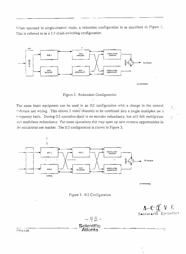
'-Vh.cn operated in single-channel mode, a redundant configuración is 05 described in Figure 2.
This is referred to as a 1:1 chain switching configuración.
Figure 2. Redundam Configuration
same basic equipment can be used in an 0:2 configuración wich a chanse in the control
>fiv/are and wiring. This allows 2 video''channels to be combined into a single- multiplex on a
:nporary basis. During 0:2 operación.chere is no encoder redundancy, but scill full mukiplexer
-i moduíator redundancy. For some operauons this may open up new revenue opportunities in
c occasional use market. The 0:2 configuration is shown in Figure 3.
3. 0:2 Configuración
SclentfflcAtlanta

í3.0 CHANNELBANK CHASSIS ARCmXECTURE
Tne flexibility and modularity of the Scientific-Atlanta digital vídeo compression uplink sysicir, •
is largely due to the design of the channelbank chassis, which forms the basis of the encoder ai id
muítípíexer units described in this document. Trióse aspects of the channelbank chassis wl¡íc!:
are common to all the units which empíoy it are described in this section, rather than repeated fnr
each unit,
3.1 FUNCTIONAL DESCRIFTION
IIThe channelbank chassis is a standard rack mounting card cage occupying 5 rack units (222.i '
mm) of venicaJ space, and accommodating six horizontaJly mounted cards. The chassis feruut^s
a high speed motherboard mounted approxímaeely 100 mm forward of the rear panel. T;»?
motherboard is equipped with printed circuít board edge connectors on the front and the rear.
ailowing the main functional PCBs to be plugged in from the front of the chassis and smnlh:
intcrface PCBs to be plugged in from the rear, as shown in Figure 4. In this way, opíu'iiMl
physicJtLand eléctrica] interface (rear panel) modules can be providccljbr the vanous rurK.'áon>!
[front panel) cards that make up the system. ,;-
The channelbank chassis is equipped with rcdundant ac power supply modules and de power
supply distribution is designed so that failure of one power supply does not prevent the rernaining
power supply from maíntaining operatioa of the system. A visual alarm indicates that a pov/cr
supply has failed, and identifies the faiJed power supply. The power supply can be removed ar.'i
reinstailed without removíng power from the operating equipment.
SctóntrficAtlanta

jS/ POWE*^ / SUP-TJES
H1NG6-OOWNFBOMT PWJEL
Figure 4. Channelbank Chassis
la r ia E]ec u Vlv «
ScientificAtlanta
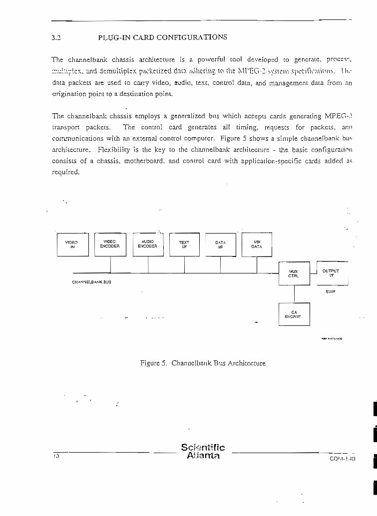
3.2 PLU-G-IN CARD CONFIGURATIONS
The channelbank chassis architecture ¡s a powerful tool deveioped to genérate, proccsr.
ir.ul'.irlíx. and demultíplcx packeúied data .uíUerine. 10 ihe MrOG-Z system speeifU' ;vúiMis. Hu-
data packets are used to carry video, audiü, texc, control data, and management data from an
origiíiation point to a destiuation point.
The channelbaak chassis ernploys a generaiized bus which accepts cards generacing MPEG-.1
transpon: packets. The control card generates all dming, requests for packets, ar¡*i
coramunicaüons wkh an externa! control compurer. Figure 5 shows a simple channelbank bu<*
architeccure. Rexibilicy is the key to thc channelbank architecture - che basic conflguratinn
consists of a chassis, motherboard. and control card with application-speciflc cards added n<
required.
AUDIOENCODEH
VBIDATA
CHA/ÍNELBANK BUS
Figure 5. Channelbank Bus Archjtecrure
ScterrtrficAfjanta coM-i-in

"! !.~ .-ihannelbank cbassis will accommodate up to síx cards from the following lisc of availablc
; :"e-in cards.
Video Encoder (3cardset)
Audio EncoderVertical BlanJcing ínter/al Processor
Control (mandatory)
* S\VIF* Receive
SWTFTransmit
• Utility DataTeletext Input
Condicional Access and Encryptíon
-í H I V products have been d.eveloped which consist of a channelbank chassis equipped wich a
c group of functíonal cards,
A lypicaJ single channel digical video encoder comprises: video encoder card set (3 cards), four-
• «•h.'inncl audio encoder card, and control card. This confíjjuration is illustrated ¡n Figure 6. Thís
vil has a spare siot for an additional functional card, if desired. Popular configurations use this
*¡-i for either VBí processing or addiuonaJ audío capabiiities.
\
-'¡T7 is the síngíe wirc ¡merface, the fibcr system used to connecc the signal path of the differenl devices'.Yn the S-A modular architecrure. See paragraph 3.4 for funher Information.
- ¿] ¿fScíentjfic
Atlanta

vioeo INPUT
VIDEO EH-7OOEH
AUDtOEXXJDER
-*- roí
Figure 6, FDM DigitaJ Audio/Video Encoder Unjt
The MPEG-2 multiplexer compases: one or more SWIF receive cards, CA&E card, opuonai
utiiicy data card, and control card.i
The prímary restríctions in card placement are that each chassis must contain one contro! card.
Only one condicional access and encrypüon card is required per múltiple*, since a chassis can
genérate at most one dme división multiplcxed output stream.
3.3 CONTROL CAED
Each funcdonal card Ln che channelbank chassis produces a stream of MPEG-2 transpon paclteis.
These packets are assembled for output to ihe modulator or TIU (Telco Interface Unit for E3 or
DS3 Üoks), or a higher level muldplexer by che control card. This card assures that the packeis
from each encoder card and input card are read out at the appropriate rate and sequen'rcd
accordíng to the multiplex setup instruciion? from the PCC.
12
ScterrtíficAtlanta COSÍ \!

y íic control card's main responsíbilíty is to transfer data, status, and commands between i t s c l f
Mr»J the other cards in che channelbank chassís, as well as interface to ocher channelbank chassis.
U communicates wich each encoder card or input card via the channelbank bus. It can determino
(he configuración and status of each card inserted into the backpJane and program the parameícrs
of each card. Commands are sent between MPEG-2 packet data transfers, and status is returneii
i ¿ i a similar manner.
Dnta is transferred in packec format from the encoder cards eicher to a memory to awni t
proccssing by che encrypcion card or to a buffer to awaic transfer to che next stage of processini;.
\Vhcn encrypcion has taken place, the packets are Cransferred back to the buffer of the contro!
card EO await transfer to Che next stage of processing. In eicher case, che time stamp in the packct
hender is modified when the packet is transferred, to correct for the processing delayí
-ncountered.
Cqmmunication wich che PCC takes place over two Ethernet links. From the PCC the control
en reí receives inforrnatiorú^at determines system configuración parameters such as uit ratc
.Ulocations,, Packet Identificatixm (PE)), program numbers, encryption parameters, and theMike.
"t rransfers status Information on the channelbank chassis and cards co the PCC to assist in
svstcm morütoring and redundancy control. ' • ••'
X4 SWJF OÜTPUTINTERFACE - . - . " • 'i •" '
, \a designed ünk protocol operating on a Single Wtre Interface (SWIF) is used
for the standard oucput daca interface from the control card. This interface is used co connect onc
channelbank chassis co another;,sucruas an encoder to a mulüplexer, or..a multiplexer co a hiaher
icvcl muítiplexer or modulator. The SV/TF interface is a short-haul visible light óptica] fiber.
in tended for the interconnection of digital video compression system equipment at one site.
The asynchronous SWIF protocol is used to carry the MPEG-2 Transpon Stream packets. Due to
:!ie use of fiber transmission and the short interconnecüon distances, no error correction is
provided in this protocol. The óptica! transmission rninimizes pocenüai Electro-Ma^netic
Cornpadbüity (EMC) problems which could otherwise arise from the high speed data
;;-ansrnission. The máximum transmission rate of the SWIF interface is 52 iVíb/s.
ScientrficCOM-1 -ni Atlanta S e c r e t a r i a

3.5 SPECIFICATIONS
3.5.1 MPEG-2 TRANSPORT STREAM OUTPUT INTERPACE SPECIFICATIONS
' '",- 'i* Jí3jr3mctEir' : •*' ' "».""-•• .
Imerface
Eormat
Connector
11 - "- '-' 1.1-1" -'-:'•'" '"•" Specií5catibnr"';r:tV-;
MPEG-2 transpon stream wíth muJüplexedvideo, audio, and data packets
SV/IF Link ¡
Dual (redundamj HP Versaule Link fíber-optiqconnector
3.5.2 REMOTE CONTROL ENTERE AGE SPECIFICATIONS
[.: •; ' • -^ v-.-" • Pacameteír'.' .:;.':•<"'••• •.'.
Jntcrface
Format
Data LinkLayer
íConnector
'(•'• "• '•-• SpecífTcatfom i
Etheraec lOBaseT
CBMC coramand stnicture
TCP/IP protocol with boot P addressresolución
Dual ("redundant) RJ-45 lOBaseT connector
3.5.3 CONTROLS AND INDICATORS (CHASSIS)
: ::'- .'•"' •'* : • . ' . • ' • GontTOlS- : ' -•'-.:' ''. ' • Indfcators/Dísplay- ' i
Pr»m»r C\n fl ^^)^
1
1
1
I
ScientíficAtlanta

ELECTRICAL SPECEFICATIONS
' .- . Harameterr- - - • ,^:-
-•íuiee R.ange
."•:nencv
• -Tcction
• -*vcr Consumptíon
* •"- ' Specífícatíorn "'-' "'
90V ac to 265V ac |
50/60 Hz. ±10% j
Fuse and Line Filcer
200 W, Max
MECHANTCAL SPECrFICATTONS
• "-i" -¿Biu^eteír^ • £'?''?
.'.-orating Temperature
> r.iEC Temperature
i'.cnicljtv
\ií;;uclet
7 '-r>t; ruedan
".-•'ine
•'••-- '*•''•• SpecIfTcatiorr; ' '
0°C to 50°C (32°F to [22°F) - chassis andmuJtiplexer cards
0°C to 40°C (32°F to 104°F} - encoder cards
-20°C to 60°C M°F to 140°F)
0 to 95% noncondensins
0 to 2500 m (0 to 8202 ft)
Modular approach. EIA RS-310C, 19",rack-mount 5U Í222.5 mm) hiah
Integral circulation fans
A"C'Secretaria E j e c u t i v a
SclentrficAllanta

4.0 MPEG-2 DIGITAL VIDEO ENCODER
4.1 FUNCTIONAL DESCRTPTTON iTíie MPEG-2 digital video encoder pftrforms the function of compressing the video and au«i i ,
signáis in accordance wíth the MPEG-2 standard. If anaiog input interfaces are used for vií-f
and/or audio, the digital video encoder provides the anaJog to digital conversión also. The cn;íp"'
of the digitai video encoder is MPEG-2 stream packets, for connection to a mulciple."?r
modulator, or terrestriai communicauons nctv/ork. Tne encorícr uses a/i idéntica! chassis ro ti;?
multiplexer. Each chassis is equipped with redundant power supplies.
The digitai video encoder wÜI accept PAL, NTSC, or optionaJIy DI video inputs. As depicteil ¡p.
Figure 7, the basic digital video encoder will aJso encode r-vo stereo pairs of audio. or wirh "!:°
addition of a second audio encoder card. fotir stereo pairs. The audio prqgnims encoded by ;he
digital video encoder do not need to be relafed to the video program.
i
VIDEOINPUT
AUOIOa-ÍCODEH
CAP1D
AUDIOINPUT
IfíTEHF^CECARD
AUDIOINF'JTS
PRIM
SEC
SV/IFMPEG-2THANSPORTSTREAM
OUTPUTS
ETHERNETIffTEHFACS
Figure 7. Dicital Video Encoder
ScientíficAtíanta COM-'

'"ontrol over the encoding process such as bitrate. resolution, program stream ideniifíGatron; eic..
• • : prrformed by the PowerVu Command Centre (PCC), via the Ethernet control interface.
•i.2 VIDEO ENCODER CARD SET
i 1.1 VIDEO INPUT CARD
;"hc video input card is the first of three maín cards whjch comprise the video compressor. It is
«•.omprised of two pieces: the main input card which plugs into the froru of the channelbank
dí-TSSis, and the interface card which plugs into the rear panel and provides the input connections
f - > r the video input card.
The anaJog input interface card provides any of the following input options simply by placing
;>'mpcrs/switches appropriately on the card: composite PAL or NTSC (according to the video
íormai serting of the encoder), analog component Y/C. component GBR. or component YPrPK
Analog component input ct?nnectors for YPbPr are shared with GBR using a switchabl'í.-inpuí
rn.'itríx on the video input card. «Matrix operation is seleceed according to the video input formar
scm'ng of the encoder. - ' "
.'r¡ optional digital video input interface card accepts the SMPTE-259M ( D I ) serial digital inpui
firmar.
Ti': video input card accepts the analog or dígita! video from the video input interface card. and
•.Tocesses it prior to MPEG-2 compression. This processing includes any decoding and
"latrixing of the anaJog inputs, as well as analog to ITU-R-601 digital conversión. The video
i-put card aJso synchronizes the íncoming video to the system timebase, which ailows múltiple
n.,ynchronous video signáis to be mulüplexed together in a TDM uplinic system.
ScienírficAtlanta

The vídeo inpuc card also provides the necessary flltering and down sampling to the appropritue
-resplution prior to cornpression. Because not alí applications liave the same video q u a l i í y
requirement, Scientiflc-Aüanta has designed the encodíng system to handle severa! d i f f r ren í
resoíucions. The lower the resolution needed, the fewer the bies required to achieve a given
quaiity and, as a consequence, the lowcr the transmission bandwidth required. Table 1 ¡Ilustrares
the availablc resolutions and typical applications in which Scientjfíc-Aüanta v/ould recornrnend
their use. The typicai.bit rate range is not a limitación irnposed by the encoder - the encoder can
be configured to opérate ai bitrates between 2 ívíb/s and 15 Mb/s, independent of the resolunon
settíng.
Table 1. Availabíe Resolutions and Typical Applications
¡- ' ApplicatíoctTVpe'1 - - -Film-Based
íünrériainmerK
Cable Headcnd
16:9. Wíde-Aspcc:
Srudio. CCTR-601
í'-'íS*; .'Eliminan cerSpa tía ti -.-'". ''' . Resolútíbiir
352H x 480/576V
480Hx480/576V
544H x 480/576V ':>.
704H x 480/576V ;
704Hx480/576VA
-- CEírominaacerSpatíaJjTRTesoIutíoTu
I76Hx24Q/2SSV
240H x 240/238V
272Hx240/2S8V
352Hx240/288V
" XypicaUBítRaterRan^e:
2.0 to 4.5 Mb/s
3.5 to 6.0 Mb/s
4.0 to 7.5 Mb/s
5.0 to 10 Mb/s
352H x 240/288 V • j 6.5 to 10 Mb/s
Wide-aspect rano video is processed in the same manner as standard video by the vídeo inr'H
card. The abilicy to interpret a 16:9 aspect rario program and display a poníon of it on a 4:3
aspect racio display is a decoder function. When encodJng 16:9 aspect ratio picrures, pan and
sean codes generated in the broadcast studio. are sent as user data fíelds or as pícture dispiay
extensión ñelds v/ithin the MPEG-2 video coded bit stream. The decoder recovers the pan and
sean codes which indícate the_cprrect horizontal window. ¡n the picture to display, and interprets-
these to dispiay the picture as intended.
As a special function for NSTC systems rcqmrcd to comply with FCC regulaüons, the FCC
caption data on Une 21 of an NTSC input signal is stripped off the uaput video by the vídeo irpu'
card. The resultant data is processed by the control card for transmission as user data. This is
automatícaily reinserted into the video signal output by the commercíal IRJD.
13 C O M - l - H l

VIDEO ENCODER i AND 2 CARDS
The two cards which make up the MPEG-2 video encoder receíve ITU-R-óOl data from il .c
video input card and perform the MPEG-2 video compression process.
This video compression process is perfonned by a iarge number of Appiication SpecihL
Intcgrated Circuits (ASICs). Microcode is loaded into these ICs under control of Lhe PCC to
define the parameters used to perform the MPEG-2 video compression. The MPEG-2
compression process achieves a high quality digital video bitstream at very low bitrates through ,\n of temporal processing, spaüal redundancy reduction, and bítrate reducüon.
F.nch pícture is broken up into small rectangular sections (caJled macroblocks) for processing ::*.
i he encoder. Temporal processing is performed by encoding the video signal as a succession of
• ntra-coded, Predictive and Bidírectionally predictive picturcs (I- , P- and B-frames). An I-frame
is a complete piccure, which can be reconstructed in the decoder without reference to any odu:
picture (there is no temporal/^socessing involved in encoding an I-frame).. Regular encotíing of
í-frames is essential, even thouigh hígher compression couíd be achieved with fewer [-frames.
bccause ic is the I-frame thatallows the decoding process to start.
Moción prediction is performed to produce the P-frames. Substandai reductions are achieved in
the number of bícs required to encode a P-frame compared to an I-frame, because the oniy
Information transmitted during a P-frame are the predictive moción veccors, and the difference
berween che frame to be encoded and the frame prcdicted by applyíng the moción vectors co ti1.e
previous I- or P-frame. Similarly,'B-frames are transmitted as a pair of moción vectors and :hc
Jiffcrence berween the frame to_be_encoded and che frame predicted by applyingyfhose-moción
vectors co the nearesc I- or P-frames in each dirección. - '$i¿„--
- t '/. 'Ncxt, a Discrece Cosine Transform (DCT) ís applicd co conven the spaüal informaüon Lnco a
series of DCT coeffíciencs. These coeffícients tend to diminish ui signifícance when thcv
rcprcsent higher spatíal frequencies (horizontal and vertical detall). The DCT coeffícients ir°
qu.'indzed using a visually weighted process. Tliis quancizaüon is the process wherein any
t'i:;tortion occurs, since the Information discarded by quantízatíon can never be reconscru'cced.
F;;ially. zig-zag scanning is used to select Che DCT coeffícients co be transmitted in approximatei
order of sieniñcance, from the lowesc spaüal frequency to the highest. Variable lensth codJns is'
_ _ Sctentificco.M-i-m Atlanta

then applíed to assign shorter code words to more frequently occurring bit patterns to
eliminare any redundancy in the bitstream,
In addition to compressing the video data, the video encoder cards also prefíx the blocks of
compressed data with a Packetized Eltfmentary Stream (PES) header. The PES header comajns
data identifyíng important attributes of the video blLstream, an example of which is rhe
Presentation Time Starnp (PTS). The primary purpose of the PTS is to provide for audío/vidro
synchronization. The decoder corrects for differences in delay through the vídeo and audio
encoding processes by buffering the audio data to synchronize the video and audio stream PT5
valúes.
4.3 AUDIO ENCODER CAJRD SET
Tlie audio encoder card set is comprísed of rwo sepárate pieces, which together make up '.!•?
encoding function: the audio encoder card plugs into the front panel of the encoder, and the audio
input: interface card which plugs into the rear panel and provides the input connecúons to íhe
encoder card.
An analog input interface card is provided as standard with every encoder. _It provides four XI.?*
connectors on the rear panel of the digital video encoder chassis. The inputs are baianced, high
impedance (brídging) intended for operation with studio program level audio signáis frorn lo'-v
impedance sources. The baianced input reduces common mode hum and noise pick up, and the
high impedance prevents source loading, in accordance with normal saidio practices. A 600 ohrr
terrnlnation can be jumper seíected on the audio ínput interface card. This card is also jumper
selectable to accept AES/EBU digital inputs v¡;i t\vo of the four XLR input connectors.
*• i
The AES/EBU formar accommodates two oudio channels within the data framíng for the
interface. The digital audio input interfacc card accepts múltiple inpuc sample rates. jumper
selectable for 32, 44.1, and 48 kilosamples per second. A digital re-sampüng filter is used to
change rates prior to compression. The audio data is presented to the audio encoder card ícr
encoding, in a manner ideática! to the processing used for the analog audio Ínput interface.
The audio' encoder card receives four mono input channels (two stereo pairs) in eíther an anaJos
or digital format from the I/O card. The audio data is presented to an asynchronous sampling rate
convener where the input data is rate converted to the system sample clock frequency. Each
audio channel is thea compressed using the ISO/TEC 1 i 172 (MPEG-1) layer 2 data compression
Scierrtíflc20 Aílanta

í
process. While the audío channels themseíves are encoded in pairs, the proccssing i t sc l f is
O'Misidered to be independent. The card is backwards compatible with the MPEG-2 mul t í channc l
'\viension of ISO/IEC 11172-3 for future multichannel appücations. Note that for mono and
•ucrco transmission, MPEG-2 coding is the same as MPEG-1 coding,
The audio encoder block diagram, Figure 8, dcptcts the audio encoding process. Analog audio
irputs are level adjusted and limited if necessary before being sampled by a two channel 18 bit
•• vcrsampüng A/D convener. Two full bandvvidth 20 kHz audio signáis are converted to a serial
••-•!t strcam that is presented to the Digital Signal Processor (DSP), wíiich performs the MPEG- 1
r'íüo data compression process. The encoded audio from the audío encoder card is then outpiu
orno the channelbank bus as MPEG-2 transpon: packets, to be combined with the data strearn
i : ~ > m the video encoder, under the control of the control card.
ANALOGINPUT
CHANNEL1
CHANNEL 2
DIGITAL
INPUT
MPEG
MPEG CIccíC
i
Figure 8. Audio Encoder Block Diagram
coM-i-m
V E' S e c r e t a r i a E j r c u 1 i v r»
SctentfíícAtlanta

4.5.4 VÍDEO RESOLUTION
Ii
'• •• . " •• WcTeotStajid'ardí *>*-:'"
PAL
NTSC
SDF
. . . • — ¡|:- *•'''.' •" ArvailáblerResolütFon^ [
704 x 576 ;544x576480 x 576352 x 576
704 x 480544 x 480480 x 480352 x 480
352 x 288 !352 x 240 !
ii
4.5.5 MPEG-2 VIDEO ENCODDMG SPECIFICATIONS
¿"*:''4 /•'-" '£•'&:''• ' Faraineíer •1;'-";«'-.v '"
Video Bitrate
Profiles and Levéis
Temporal Processing
Coding of Interlaced Video
SpatiaJ Redundancy Reduction
Chrominance Format
Encoding Transit Delay
í . ; •'"' i»'C'>i • - . • i , "• -s;*' rr- • r— i — ' í- -• ' '• '• ypecincaüon; ¡
Constaiif- Bitrate Encoding. selectable in ||100 kb/s-increments from 3 to 15 Mb/s '•
t - . • . ,iMain-'ProfiJe @ Main Level '
I- , P--and B-frames supponed ,1
Adapdve Field/Frame Processing supponed 'P-frame; ±100V, ±60H " iB-frame:±68V, ±36H ';
Discrete Cosine Transform fDCT)
4:2:0 ;
375 ms, typicai ac 8 Mb/s ;(Lncreases wtth reductíon in bi trate) " '
26Scíentífic
Atlanta
I/
II

ANALOG AUDIO INPUT SPECIHCATIONS
: • ' Parameteír ••<'" '.:-• 'i-'^C
itprcdancc
A'jr'io Lcvel
Connector
'••i'ürmcd Clipping
M- ix imum Inüut
í .fivcí Adiiiscme-nt
.Vifiio Delay Adjusnment
'r.vwí Frequencv Range
i • ' • '*• ' . ' • • • • ' • SpecífTcatibro^' -<r"::--
>10 k_, brídgine
OdBm APL,-f!8dBmPPL
XLR-3-31 (female pin male shell)
+ 18.2 dBm
-f26dBm
±8dB
±17 ms, reladve co video
20 Hz to 20 kHz
DIGITAL AUDIO INPUT SPECIRCATTONS
Faramefetr' ."' • '*":-'">.,—»•>
.%;jLir:;}Ic Rates (note: the MPEG audioí!
:?ncoderonJy uiilizes 16 bits/sample)
¿> :-Ui! Inierface
í~^M:it:rLor •.»
Lev1"-! Adiustment (
•\'sí!íiio Dclav Adjusunent
>' : " ' " ' • • " - " S*pedETcaí.rüni :Sr' ' *'" '^' ' • ' • .
1. 32.0 kilosamples/sec 16 bics/sample linear2. 44.1 kilosamples/sec 16 bits/sample linear3. 48.0 kilosamples/sec 16 bits/sample linear4. 48.0 kilosamples/sec 20 bits/sample linear
AES/EB U formar. RS-422
XLR-3-31 ítype 1)
Non e
±17 ms. rcíaüve to video
E j e c u t í v a
;oM-;-tn
-JIÓÍ2,-ScientlíicAtlanta

5.0
5.1
MPÉG-2 AUDIO-ONLY FNCODER
FUNCTTONAL DESCRUTION
The MPEG-2 audio-onJy encoder performs the funcüon of compressíng audío signáis in
accordance \vich the MPEG-2 standard. Its applicacion arises in systems where a large number of
audio programs are to be muldplexed into an MPEG-2 transpon stream, and there is insufficietu
capacity available in the digital video encoder units. Analog or digital inputs can be speciíled !>••
the audio-onJy encoder, If analog input interfaces are used, the audio-only encoder performs ibe
analog to digital conversión. The output of the audio-only encoder is an MPEG-2 transpon
stream for connection to a multiplexer or moclulator.
As depicted in Figure 9, the basic audio-only encoder will encode a total of eight channels (four
stereo pairs) of audio. Assignment of the audio programs onto Virtual Channel numbers t l i ac the
subscriber can tune to is performed from the PCC.
III
lil
AUDIOINPUTS
;
L-/4- —1L d
5l ,
^~L 8
AUDIOINPUT
INTERFACECARD
INPUTIN 1 hH^ALic
CARD
¥
-•
AUDIO
FNCODER
CARD
*
AUDIOENCODER
CARD
A
r
OPTIONALCARO
< — r
i«— >
inDmí¿
-c_JUJ
¡j
1, J OPTIONAL
'" CAROII
r i
'J OPTIONAL!i CARD 1
1 !
•-
l
CONTROLCARO e*
I/OCARD
ETHEINTEr
P.RIM -i
SEC /
RNET3rACE
SWIF MPEG-2TRANSPORT STREAM
OUTPUTS
Figure 9. Audio-Cnly Encoder
ScfentíflcAbanta C O M - i - l l í
ll

SPECIFICATIONS
Tlie audio-only encoder specifícatíons are idéntica! to the audío speciflcations for the digital
video encoder, as set out in Sections 4.5.6 and 4.5.7.
5 3 AUDIO ENCODER CARD SET
» h e Audio Encoder Card Set is idéntica! to that descríbed for the dígita! video encoder, as set our
in Sccüon 4.3.
SctentificAtlanta

6.0 MPjEG-2 iVTULTIPLEXER. i
6.1 FUNCT1ONAL DESCRIFI1ON
The MPEG-2 multiplexer combines the individual transpon streams from the various video and
audio encoders into a single higher level MPEG-2 transpon stream for connecuon to a modulador
orTTU. It is also capable of performing the CA&E functions, when equipped with a CA&E card.
The multiplexer can ai'so accept utílity data screams and conven these into MPEG-2 user úzi:\, when equipped with the uülíty data card.
The basic uplink system multiplexer is illuf/.rated in Figure 10. Up to 12 transpon stream inpius
can be connected to the un.it, four each to the tliree SWIF receive cards. The multiplexer
provides the automauc redundancy switching on failure of an encoder, by passins packets from :>
standby transpon stream input, in lieu of the transpon stream input from the failed encoder. The
available inputs to the multiplexer are therefore shared bec\veen the active input devices and l^i
standby input devices. For example. two SWIF receive cards (8 transpon stream inputs
altogeuher) would support a 2:6 multiplex.
ScientíficAilarrta

SWIFMPEG-2
rnAHSPORTSTREAM
INPUTS
SWIFRECEIVE
CARD
SWIFHECEIVE
SWIFRECEIVE
CARD
, h"*
rt
DÍ
Z
<
ü
I
4 > CA&ECARD
lii
^ J npnnMAi1 CARO11I
V*
PRIM-i- SWIF MPEG-2SEC/ ^TRANSPOflTSTREAM
OUTPUTS
NSG K62A/MOO
Figure 10. MPEG-2 Packet Multiplexer
The Scien tifio Atlanta muítiplexer operates as ri; p'rcassigned multiplexer. That is. it does not
¡vníorm staüstical mulüplexing. -In preassigned operation each video; audío, data, and text
f'T-vice may be assigned throughput by the PCC, thereby determirring che bitrate per service
!• íi-cd on the application.
'-' l SWIF RECE.IVE CARD .
E.¡i:h SWIF receive card provides four SWIF inputs for \CPEG-2 transpon: strearns from encodcrc:ví>sÍs. The transpon stream packets from ail the SWIF receive cards are combined under
c .TI'rol of the control card.
-JoScientffic
Atlanta

6.3 CONDITIONAL ACCESS AND ENCRYPTION CARD
The conditíonal acc'ess and encryption (CA&E) card supplies encryption to the individua]
transpon streams being transferred from che control card. This encryption is applied at ihe
deinentary siream level (that is to the-* individual video, audio, data and/or text stream.O '
Encrypting individual elementary streams gives 'the operator the ability to target individual
programs to customers instead of providing the entire multiplex. Also, individual elementary
sacaras may be.flexibly packaged in different combinations to forra program packages tailored te
consumer preferences. The encryption is required for addressabiliry of individual decoders, e.g..
to throw decoder backpanel contacts, even íf access to the video is not an issue.
The CA&E card sequences the encryption. process. It maintains tables of control words and
inulti-session keys (MSKs) which are changed at programrned intervals. The actual control of
encryption is originated from the PCC. The CA&E card can genérate the control words and keys
v/cally or receive them over the Ethernet from the PCC. Entitlement Management Messag^s
CEMMs) can be encrypteiT at either the PCC or on the CA&E card. EMMs apply to individual
decoders. Entidement Control Messages (ECMsJ are encrypted by the CA&E card. ECIvís referkí
lo a particular elementary stream.
7"bc conditional access card is required in the system even if the condicional access is not
implemented.
6.4 UTTLITY DATA CARD
í->;eiHiñoAdama's digital video compression uplink system suppons the ability to deliver low-
speed asynchronous or high-speed synchronous data channels ¡n addition to ehe video and audío
piograms. Becaase of the flexible bandwidth ailocations available Ln the system, it is possible to
tnde off data channel requírements for bandwidtíi against other service requírements.
Each urility data card will accept up to four low speed daca irjputs, either asynchronous (refer to
Section 6.6.2) or synchronous (refer to Section 6.6.3). The transmission rates can be set
independen ti y of each other for inputs on the cnrd. The input dará is converted into MPEG-2
User Data Packets, and combined into the transpon: stream under control of the control card. The
uu'Jicy data card is bstalled b the muldplexer chassis.
Scfentffíc

MASTER SYNC GENERATOR
' l . - c iVlasrcr Sync Generator (MSYNC) is used to synchronize the diffcrenc elements of thc
.>y=tcm by locking the íntemaJ 27 MHz docks together. All encoders and multiplexers are ail
¡!)CJ:cd to this. There are six direct outputs, which carry a 3.375 MHz cairier with time reference
rnaíkcrs that repeat ac 50 Hz. These can be fed into analog video distribución amplifíers when
more sources are required. Additíonally the MSYNC can be used as a source of black, and burst.
i f -,\;crnaJ equipment requires this.
MPEG-2 TRANSPORT STREAM INPUT ÍNTERFACE SPECEFICATIONS
' : ' ' '*'•" Parámeteír " ': v^ *':&-
rsíace
n;at <---[^
nnector
l'./Vj --•.'•»''»* " SpecifTcatíbro . "
MPEG-2 transpon format with mulüplexedvideo, audio. and data
SWIF Link
Single HP Versatile Línk fiber-opüc connector
ASYNCHRONOUS UTELEÍT DATA INPUT INTERFACE SPECEFICATIONS
• - ' ' ," ' Parainetfer r r'
Í";-í-rrface Formac
C^*"-nector
r^^rsmission Rates
'• : ' - • SpecifTcatíbra •
RS-232/RS-485, asynchronous
D-subminiacure 9-pin
0.3.0.6. 1.2.4.8, 9.6,19.2. or 38.4 kb/s !
SYNCHRONOUS UTILnT DATA INPUT DNTEREACE SPECIHCATIONS
.••••>^A?^PStt¿meteF "'vSííp^tS-
í::->-if3cc Formac
">;r;..<aor
."; •n-ímission Rates
? ^S'^XÍ-X' í-ÍJÍ*Specífí"caüoDk1¿.'-*; \
RS 422, svnchronous
D-subminiacure 25-pin
Nx64 kb/s to 2048 kb/s (El )
ScientfficAtlanta

6.6.4i
MPEG-2 TRANSPORT 5TREAM SWTF OUTPUTIÑTERFACE SPECJFICATIONS
II
; "•:":". • . '• ' Barameterr v-v - • ' •* •*•
Interface ^
Format
Transmission Rates. '
Connector
Í* *'*'" ' •'• •}'" ' Specíñcatiorr> ' • |
MPEG-2 transpon format \vith muítipJexedvideo, audio, and data
SWIFLink
i Mb/s to 52 Mb/s !
Single HP Versatile Link flbcr-optic'connecrorí'liiiiIII
ScientíficAtlanta COM-MI'
I

7.0 QPSK MODULATOR
7.1. FUNCTIONAL DESCRJPTION
TV Scientifíc-Aüanta QPSK modulator converrs the serial MPEG-2 transpon stream produced
hy che muhiplexer into an intermedíate frequency (IF) carrier for satellite transrru'ssion. Tlic
o' t tput of the modulaior is a 70 MHz or 140 MHz IF, for upconversion to the appropriace C-band
or Ku-band transponder frequency. The modulator operates over the symbol rate range 1.5 EO
'J-O.S Msym/sec, variable in 100 symbol per second increments.
Thc modulator also adds the inner (convolutional) and outer (Reed-Soíomon) Forward Error
Correcüon (FEC) necessary to overeóme the noisy satellite transmission process. The FEC
process ís performed in accordance with the DVB specification and ETSI standard (ETS 300
~in.K 1994). The moduiator confortas with this standard in ail other respects also, includins
spcctrum mask and EF loop performance.
Figura 11 illustrates the functionai blocks in the modulator. Tríe modulator consists of thres
c.artís: interface, encoder, and modulator. The tríree cards are supported by the chassis. power
v 'pply, and front panel control assembly.
2UNDANTSVVIF
INTERFACECARO ENCODER MODULATOR 1F
OUTPUT
CONTROLPANEL &DISPLAY
Figure 11. QPSKModularor Block Diagram
Tíic modulator is a flexible unit whích provides for the input of a wide variety of data núes, FEC
raes, and RF bandv^idths. Input data can be accepted from either SWTF. or E3/DS3 input
in":rfiices vía a Terrestrial Interface Unit (TTU).
SctentíílcAllanta
-406
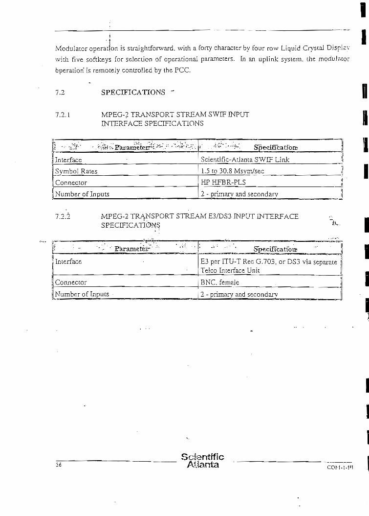
Modulacor operación is straightforward. with a forty characcer by four row Liquid CrystaJ Displsy
with rlve softkeys for selección of operational paramecers. In an uplink system. Che modu.lator
óperaüorí is remocely controlled by the PCC.
7.2 SPECIFICATIONS -
7.2.1 MPEG-? TRANSPORT STREAM SWEF INPUTINTERFACE SPECIFICATIONS
( t ••• •.'•"•• . '/.^.'.. Pbr^íTTTPÍ'pr^' i*T^" " ' •"'•IT* ''•-''.f í .. - • r — > I - - JC tü'tlJJJ IZÍXZLr - • • • • • . - •
^ -
ÍjYnterface
>vmbol Races
"onnector
Number of Inputs
. -.... .• . i, .-;v- .'••-;'-. SpecifícatibrE ]
Scientiñc-Atlanta SWEF Link ¡
1.5 co 30.8 Msyin/sec i
HPHFBR-PLS ¡¡
2 - prímarv and secondarv t
7.2.2 MPEG-2 TR/YNSPORT STREAM E3/DS3 INPUT INTERFACESPECmCATIÓNS Jx,
!: - "' - ' Farametérr ' " ! '
Interface
Cormector
JNumber of Inpucs •
SpecifícatfoiE
E3 per UU-T Rec G.703, or DS3 via sépame ;Teico Incerface Unit
BNC, femaJe
2 - primary and secondary
ScterrtrflcC O M - Í - I U

7.2.3 FORWARD ERROR CORRECTTON AND MODULATION SCHEME
¡{ — . .¿- • • ' ''Faraineteir. *;"--?-• ;-••'*
JMuI t ip lex Adaptación and Energy Dispersa!
i Cúter Coding
jímcrleaving Depthj _ ..1 ínner Códing
| Baseband Shapine¡¡jf Modulación ForraatS5 Symbol Ratesi f ~ 1/2 x Transmission Rate)
r>; :':V' :";;"-v -" SpecifTcatíbrD
Per ETS 300 421:1 994 (DVB)
Reed-SoJomon (204,188, T=8)
12
Convoluüonal, R=l/2, 2/3, 3/4, 5/6 or7/8
Square-root Raised Cosine, a~0.35
QPSKL gray coded
1.5 co 30.8 Msym/sec in 100 syrnboiysec steps
7.2.4 IF OUTPUT INTERFACE SPECIHCATIONS
Ü'1 » -« -,-t-/*:«í;^j:.v^ ,...'; •r^-js^fyí'. : . ' •- ' ';'-:l^'!Tv; .-••',•'••- '••v'^.i j j - .. ".•-.•;r'.^.- •.-rEaranreteír 7-" J - .1- ;-- •'•"
1 Ourpuc Frequency Range
¡!a.Svnchesizer Step^'Size •-:
,; Ti-cauency Stability;l
'•' Output Impedance'¡!! Connector
lj Outout Return Loss
i Outout Leve! Ranee
¡i Levcl Steo Size
'j ^DLirious Ourputs3Ü Svnthesizer Phase Noise
í "Víi^IflfV— *•"* t".'¿!'.'; v < . CT *r-— '*<- " • ' * " *..-r--í--. _y:.*u .¡t/^.r- ^; Speafícatioirt •• :-v • -v
70:-MHz (52 MHz to 88 MHz), or j140 ÍVO-íz f 104 Kfflz to 176 MHz)
250"(ckz
1 x 10⁻⁶
75 ohms unbalanced i
BNC. female
20 dB
-25dBmto-5dBm0.5 dB or less ;
Less than -50 dBc/4 kHz ' i
Becrer than EESS-3(J8 by 6 dB
co.M-i-inScientíficAbanta
E j ccu I i •-'

7.2.5 CONTROL AND MONITORING FEATURES
í = - • ''-''./-v • Eunctíbns ' ' " * . .
AJphanumeric Displav
Function Kevs
Numeric Keypad
JF Monitor
L-Band Monitoring Outpuc
Mute Indicator
AJarm Indicator
'.'-"" • Speciffcatián.1
4 rovv by 40 character LCD |
5 "soft" kevs
Twelve key, for direct entry of numericparameters, e.s., output frequencv
-20dB.BNC. female
F type, for direct connection to ERJD
Red LED I
Red LED (synthesizer. Cransmic level)
7.2.6 ELECTRICAL SPECIFICATIONS
i *%&* . ^^S^parameteir.:" : '^*:'&
Voitage Ran.ee
Frequencv •
Procecdon
Power Consumpüon
~*'-^- : Specífícatfoos " j•i
90V ac co 265V ac \.t !¡
47 Hz 10 63 Hz ,«• !¡u
jt'use and line filter • .'- ¡i
<50W j
7.2.7 MECHANÍCAL SPECIFICATIONS
? ''•'?.* ' Parameteir' ' '"*"* """ ''" '
Operatins Temperature
Storage Temperacure . . . . - • -
Humidicy
Alticude
Phvsical Constructíon
CoolingtU r
• ' • " ' " Specífícatíott
0°C to 40°C Í32°F co l04°Fi ¡
-20°C to 60°C {-4°F to 140°F) - • i
0 to 90%, noncondensíne i
0 to 2500 mecers (8200 ft)
2 RU hieh. 19" rack: moant chassis i
Integral cooling fan
38Scientífic
Atlanta COM-:

S.O TELCO INTERJFACE UNIT (TIU)
íí.l DESCREPITON
'ílsc Telco Interface Unit (TIU) is a MPEG-2 format conversión unit which provides dúplex
intcrface between tejephone company high-spced coax lines and Scíentiflc-Atlanta's Single Wirc
ímcrface (SWIF) fiber optic lines, It can be factory conñgured for E3 (European) or DS3 (U.S.1»
formáis. The TIU is a fully self-contaíned unit and requires only input and output data paths anu
AC Power Source.
The TTU removes input framing, adds or removes stuff packets as necessary, adds or removes
Rccd-Solomon encoding data, and adds output framing. The TIU can be configured for ful!
dúplex communication passing data in both directions simultaneously or ic can be configured fe-?
símplex in either direcuon. The TIU consists of five major funcdonal modules. These an1
THLCO I/O, SWIF ENPUT, SWTF OUTPUT, CONTROL, and MICRO-CONTROLLER. Al!
five -modules are located on a single PC board.
,8.7. TELCO I/O
The TELCO I/O module provides both the physica! incerface to the teiephone nerwork and th.e
fmning funcüon necessary for passing high-speed dJgital data Communications. It aJso provide?
high speed clock generación, The physical interface consists of a high speed (E3 or DS3) input. a
loopback output, and a high-speed output. Transformer couplíng is used to próvida
wíth the network.
S.3 SWIF INPUT - •
Thc SWTF INPUT module provides three functions. Thcse are physical interface, data and clock
rccovery, and SWIF to MPEG-2 format conversión, The physical interface consists of rvvo
i-J^nncal circuits. These have fíber-optíc receivcrs and ECL high-speed buffer amplifiers.
Primary or secondary input is selected by the onboard controller based on SWTF lock detection.
T'ic ciata and clock recovery function is performed by phase locking an oscillator to the incoming
rinr.i scrcam. The formac conversión funcdon is performed by a propríecary DEMUX ASIC. This
dcvice receives the serial bit strearn, makes it parajlel, stríps stuff packets. buffers the data, and
ouiputs it on request from the Control Module.
. ScfentifiC s^rc.Mrla Ei>culif£coM-i-ru Atlanta

8.4 SWIF OUTPUT
The SWEF OUTPUT module a!so provides three funciions. These are MPEG-2 to SWJF fornv
conversión, clock generation, and physicai interface. Format conversión is performed by anni.lici
SA DEMUX ASÍC. This device receives parailel data, buffers it. adds stuff packets as neccssnry.
and convens the data to serial S"WTF format. The clock generator provides the 27 MHz aiv.l
54 MHz clocks required for SWIF transmission. SWTF data is output by two identical circuir
These consist of CMOS buffers driving a transistor which in turn drives a fiber-optic
8.5 CONTROL
The CONTROL module directs the flow and tiraing of data from input module to output mecí"!;
in each direction. ít aiso performs Ree.d-Solomon encoding and decoding of the data stream.
8.6 MICRO-CONTROLLER
The micro-controll-sr-is used during staruip to program the various componénts of the TU.".
Based on the setting orkhe dip switches. the MJCRO-CONTROLLER will configure the dupl í rv
TTU as receive onáy, transmit only, or a full dúplex unh. (Transmit and receive are referenced :o
the Telco tmerfacev)' After stanup, the iVÜCRO-CONTROLLER is used to monitor the operación.
of the TTU and detecr error conditions, These error conditions and the TIU status are displav«d
on the front panel using LEDs. Forra C ccmtact closure ourputs are available at the rear panel for
remote status índication, as weü as RS-23?. and SAbus interfaces.
8.7
High-speed conversión between SWEF and standard Telco interfaces (G.7Ü3)
Simplex or full dúplex operación
Redundant SWIF inputs
Redundan: SWTF outputs
Passive loopthrough of Telco input.
ScierrtificAllanta C¿M ; ¡ú
i
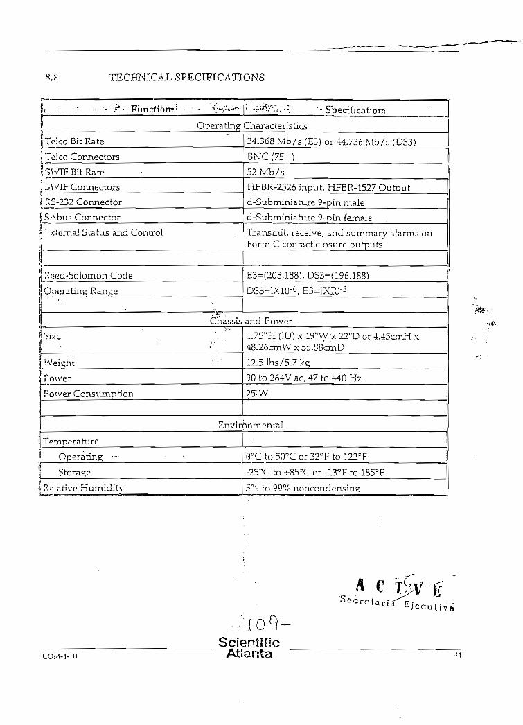
H.S TECHNICAJL SPECIFTCATIONS
* « • • • • . • • • • • " • : = -FunctibiBi- • • %--" 1 '•$&r*~¿."..' •• SpecírTcatíom
| Operatlng Characteristics
¡Tf-IcoBitRate
." Telco Connectors
Í^WIFBítRate
!j JV/IF Connectors
i RS-232 Connector
1 SAbus Connector
» Fxternal Status and Control
!
ríoed-Solomon Code
Operating Range
'•
34.368 Mb/s (E3) or 44.736 ívíb/s (DS5)
BNC (75 J
52Mb/5
HFBR-2526 input, HFBR-1527 Output
d-Subminiature 9-pin male
d-Submíniature 9-pin female
Transmit, receive, and sumrnary aJarms onForm C contact ciosure outputs
E3=(208,188)/ DS3=(196,1S8)
DS3=IX10-6, E3=IXIO-3
Chassis and Power
Sizc"
Weieht
Power
Power Consumption
1.75"H (IU) x !9"W'x 22"D or 4.-Jt5cmH \D
12.51bs/5.7ke
90 to 264V ac, 47 to 440 Hz
25: w
Environmentai
Temoera ture
Operating •-
Stora^e
Reía uve Humiditv
i
0°C to 50°C or 32°F to 122=F
-25'C to ^-855C or -13°F to 1853F
5% fo 99% noncondensine;
co.M-i-m
- ' ; fO°í-• \ I
ScíentfficAtlanta

¿O AUTJ®MATIC REDUNDANCY<
9.1 REDUNDANCY PHILOSOrHY
Evcr}' element in the Scientifíc-Atianta digital video compression uplink system is designed for
fully automauc redundancy.
Digital video encoders are protected in a 1:N fashícm, wich one standby encoder available (r
replace one of N operaüng encoders. If therc are more tnan six channels of encoding Scientific-
AUanta recomrnends 2:N redundant operation, Tliis level of redundancy is standard in the
broadcast and telecomrnunications industries. Prioricy levéis can be assigned. such thac in the
event of múltiple failures the highest priority charmeJs will have access to the scandby encoderísi.
A fully redundanc 2:6 uplink system is illustrated in Figure 12.
Mullí pJexers and modulators are protected wirh 1:1 ivdundancy, where there is one standby uní:
for every operadng unit. Thís level of redundancy is normal for these "cornmon equjpmeiií"
Ítems because of the' múltiple video channels these produces suppon. -*-.-
Automatic redundancy operauon is controlled by the PowerVu Cornmand Centre (PCC), which
monicors the diagnostics aJarms in every operntional unit. If a failure occurs in an encoder muí
ihs uplinJc system has an availabíe standby, the system automacically switches to the standby unic.
A failure of either the main mukiplexer and/or main satelíice modulacor results in an automatic
sv/itch to the standby multiplexer anoVor standby sarellite modulator (as necessary). Tlüs
switchíng occurs' virtually instantaneously; however, a freeze frame of up to 2 seconds can resníi:
at the decoder, due to the Joss of synchronisarion of the MPEG-2 decodíng process. A freeze
frame of severa! seconds can occur if the standby encoder required automatic re-confisuration to
match the encoding parameters of the failed encoder.
Video and audio crosspoint switching equipmeut is provided to select the correct inputsígnal fcr
ühe standby encoder, and this is also controlled by the PCC.
SciantificAtlanta

WUX(PR1MARY)
MUX,ISECONDARY1
Figure 12. Redundant Uplink Confíguration (2:6 shown)
S e - c r o l a r v a
REDüNDANCY ARCHITECTÜRE
Rcdundancv is desisned into the Scientiñc-Atlama di si cal video compression svstem at all levéis:"} > r
the channelbank chassis itself. the digital video encoder, the packet multiplexer, and the
rnodulator.
9 2.1 CHANNELBANK CHASSIS POVVER SüPPLY REDÜNDANCY
T'ic digital video encoder, digital audio encoder, and packet multiplexer are all built up from the
chíumeibank chassis. Each channelbank chassis has fully redundant, hoc pluggable ac power
suppiies. including dual ac Lnput connectors v/íth independent fuse protección. Continuous
or^ration of a channelbank chassis is assured in the event of failure of one power supply because
cach power suppíy is dimensioned to be capable of providing power for the entire chassis. An
ainrm diagnosüc is presented to the operator v¡a the PCC in the event of a failed power supply.
and a LED iñdicator is provided on the front panel of the channelbank chassis to identify the
ía»icy power supply.
coM-i-mScientrfícAtlanta

9 2.2 DIGnAJL VIDEO ENCODER REDUNDANCY
0.2.2.1 M:N Backup. M:N redundancy switchíng to protect the encoders is províded by
•'ic packei multiplexer. An exarnple for 2:6 redundancy switching is illustrated in Figure 12.
The transpon: stream output rrom each staixiby encoder is fed to a designated standby input on
th". multiplexer. In the event that the PCC ídentifies that an operating encoder has failed, it
pcrforms the following-sequence automatically:
a. ídentifies an availabie standby encodrr, rcferring to the príoríty tabíe if necessary to
pre-empt the standby from backing up a lower priority encoder.
b. Switches the correct video and audio signáis to the input of the standby encoder,
c. Configures the standby encoder to match the encoding parameters of the failed
encoder, if necessary, and
d. ínstrucrs the packet multiplexer to rojr?: packets from the standby encoder into the
output stream, in place of packets from th i' failed encoder.
9.2.2.2 Baseband Switching. Each standhy encoder is equipped with a video and audio
crosspoint switch on its input. Duplícate video and audio signáis of trióse being fed to each
operating encoder are red to the switch and routed to the input of the standby encoder as required.
lrpon request, Scientiñc-Atlanta will quote the distribution amplifiers required to genérate the
duplícate video and audio sources. Switching is performed by the crosspoint switch under
control of the PCC.
Tae baseband switching may be conñgured to support analog video and audio. or digital video
o:id audJo (e.g., SMPTE-259M). If a combination of analog and dígita! sources are required. the
encoder redundancy may be separated into analog and digital layers. For exaraple, a 2:6 system
•-.vilh a mixture analog and digital inputs could be conñgured as 1:2 analog and 1:4 digitai
rcdur.dancv.
ScientifícAllanta COM-MH

PACKET MULTIPLEXER REDUNDANCY
í'Xinndancy switching for the packet multiplexer is provided by the QPSK modulator. The
transpon stream output from both the maln and standby mukipiexer is fed to the two transpon
sircnm inputs on the QPSK modulator. In the event that the PCC identifies that the main
multiplexer has failed, it instructs the modulator to switch from the priman' to the secondnry
transpon stream input. .
rrimnjy and secondary transpon streams are availablc to the modulator from two ieienl ical ly
w.íígured packet multiplexer units. Each unit is provided with idéntica] digital input streams.
^-•••í cnnñgured by the PCC to multiplex and apply CA&E to these ínputs in the same manner.
Fnch multiplexer therefore ourputs funcüonaJly idéntica! MPEG-2 transpon streams, aJthough
í|'°sc may not be necessaríly synchronous or completely idéntica] due to the flexibility permitted
in ihc MPEG-2 systems syntax.
ín 'fie case of input strf^ps from encoders, the idenucaJ signa] for the standby multi&cxer comes
from. íhe second SWTF oufiput from the multiplex control card (refer to Section 4.3). íífthe case
S -.-fi .-•' '*', y to the muítiplexer, such as user data and text, 'the system operator muse
provide two feeds of the.s'ame data from the source equipment for ful] redundancy. ' •
-\:.4 QPSK MODULATOR REDUNDANCY
I1.! redundancy switching of the modulators can be achieved through the automadc control of ihe
mo'iulator's output muting capabilicy. ín this case, the outputs of che two moduíators are
C'T*>íned in a simple, low-cost, passive combincr without the need for the .RF switch.
Tí;': srandby modulator is provided with idéntica] transpon stream inputs to those feeding the
main moduíator. These transpon streams come from che second SWTF outputs from che
múltiple* control card in the main and standby muJtiplcxer urdes. This architecture ailows the
moJuíator and multiplexer redundancy to be fully independent; that is, a failure of any moduJator
amJ any multíplexer can be accommodated by the redundancy scheme automaücally, Tlús
rrovidcs a hígher leve] of redundancy than would be the case if the multiplexer and modulator
tve re crcatcd as asinsíe functionaJ cbain.
Scientrííc ^rroAtianía 45

10-ü SYSTEM DESIGN CONSIDERATIONS
10.1 RF SYSTEM DESIGN
Trie Sciemific-Atlanta digital video corapression upliak system provides a QPSK data camer ar
JF as íes output. The bandwidth of this carrier will be determJned by the available transponer
capacicy, the desired transmission rate and the desired convolutionai FEC race. The desired FEC
rate will normally be determined from a link performance analysis and is a tradeoff betwr^j
inforrnation carrying capacícy and dovvniink amennasize.
The QPSK carríer rcquires upconversion tn the correcr transrnission frequency and high po'vrr
ampliñcation in order to transmit to the satellhe. To ensure that the performance of the overall
uplink and downünk is not significantly degraded by the additional upünk earth srati.-r.
equipment. the suitable design guideÜnes shoüld be followed for üie RF upi ink system, snch -K
rhose specifíed by INTELSAT document JESS-308.
10.1.1 AVAILABLE BÍTRATE VERSUS BANDWIDTH, FEC RATE,AiND THRESHOLD
For a given (user-selected) cransmitted symbol rate. me carrier bandwidth mav be caJculated irop:
Lhe symboí rate (S) by the following approxirnate relaúonships:
-3dB Bandwidth = 1* (S)
. - lOdB Bandwidth = i.2* (S)
-16 dB Bandwidth = • 1.28* (S)
-20 dB Bandwidth = 1.31* (S)
-26 dB Bandwidth - 1.34* (S) . .
-30 dB Bandwidth - 1.36* (S)
-40 dB Bandwidth = 1.38* (S)
The usable information rate (Ru) and traasmission rate (T) may be determined from tlie
foIJowing deñnitions based on che convolutional Forward Error Correction (FEC) code selecred.
Ru = S*FEC*( 188/204)
T = 5*2
ScíentífícAíjanta

The following tabíe illustrates by example the results of the above caJculations for a carricr
u'vjnsmitting 27.50 Msym/sec. The overaíl performance of the moduJator and ERD combination is
spocifíed to be compliaiu with DVB recommendations. These performance parameters for
thrc.shold performance as a function of FEC are summarízed in the fol lowing table. The Et/No
valúes are based on Ru.
Symbol Rate 27,50 Msym/sec
Carrier -3 dB Bandwidth:
Carrier -10 dB Bandwidth:
Carríer -16 dB Bandwidth:
Carrier -20 dB Bandwidth;
Carríer -26 dB Bandwidth:
Carríer -30 dB Bandwidth:
Carrier -40 dB Bandwidth:
27.50 MHz
33.00 MHz
35.20 MHz
36.03 MHz
36.85 MHz
37.40 MHz
37.95 MHz
r:iC
TTircshold Es/No Í IFLOOD)
Information Rate fRM)
Transmission Rate (Ti
C?>!o ai Thrcshold
C / N ( í n 3 d B BW)r.t Thrcshold
1/2
4,5 dB
23.34 Mb/s
55.00 Mb/s
78.5¿dB/Hz
4.15dB
2/3
5dB
33.79 Mb/s
55.00 Mb/s
80.29 dB/Hz
5.S9dB
i_ 3/d
5.5 dB
38.0! Mb/s
55.00 Mb/s
S1.30dB/Hi
6.91 dB
5/6
6dB
42.2^ Mb/s
55.00 Mb/s •
32.36 dB/Hz
7.26 dB
7/8
' " 6.4 dB
44.35 Mb/s
55.00 Mb/s
S2.S7 dB/Hz
8.43 dB
ería E|»cu t iv~J
ScienlificAtlanta

10.2 DATA TRANSMISSION DESIGN
The available bítrate in the ÍVÍPEG-2 transport raultiplex can be flexibíy allocated among
various program and other data streams, depending on che operauonal requirements of the syst
operator. This ailocatíon process wouJd normally be performed when the digital
compression system is ñrst installed; however, it can be modified as the need aríses througlujiu
the ufe of the system to add, delete, or modify the allocation for any panicular service. There are
many tradeoffs involved in chis aJlocadon process, acd some optimization may be desirable aftcr
experience in the performance of the system hns been gained. Some of the parameters which can
be traded off against available bitrate are:
a. number of vídeo ser/ices
b. video encodíng quality
c. text page updare rate
d. TRD refresh rate
e. number of audio services' -T
f. audio encoding quaJiry. *.-?
,/Jlocation of the available bitrate among che video services need not be equol. Depending on üic
amount of moción and detall in the source material, and- the source itself (film or video), ai:
unequal share of the available bitrate may be appropriate. High detall, fast acdon material such
as Uve sports requires a higher bitrate than rclatívely static fílm-based material. Tlie bitrate for
each video stream can be allocated from che PCC, in 100 kb/s increments, up to che capacity of
the multiplex, (allowing for system data also).
The number of. audio streams associated with cnch video stream can alsó be set on a per service
basis. It is possible to allocate audio streams wbu'ch are aot tied to any particular video program
scream, even though the audio encoding msy be performed in the same chassis as a video
program. For example, if there was a need to provide a digital s ate Hite radio service. the
SoientLfíc-Atlanta digital video compression upüok system will pennít this. The radio service
woold appear to the subscriber as a "virtual channel", which has a cbaimel number, but no
a.ssociated uve video program. If desired, a texc page can be assigned as video to accompany n.
radio virtual channel.
SclorrtlíloAtlanta

I
IPOWERVU™ COMMAND CENTRE 2000
ScientifícAtlanta

II
1IIIIII
II

POWERVU™ COMMANI) CENTRE 2000
i.;} OVERVIEW
PowcrVu™* Command Centre 2ÜOO (PCC-2000) Control systems províde a complete d i p i i n i
vi.Ico comprcssion solution for a wide range of application áreas. PowerVu Command Centre
software offers network managemenl. security. and decodcr managcment capabüities for
rMTM;rnmmers, broadcaslers and otber network operators who need to control m ú l t i p l e encocleí:-'.
¡mihiplexers and large decoder populalions.
Thr PCC-2000 system supports up to four N:M cncoder systems.. Users needing to rendí n
-.-.(•!UKvidc decoder populalion vía múlt iple satel l i tc bops may do so wiíbout re-cncoding (he
'*r i" inal scrviccs through thc PCC-2000s mull i - f rcqucncy plan support.
Tlic PCC-2000 supports 2:n (n < 10) redundan! PowcrVu system. The PCC-2000 monitors thc
Mníus of the primary encoder^.and switches thc input services to the appropriate backup encodor
and output of the síandby uni t on-line in the cvent o f a failure o f a primary un i t . Encoder priorUy
i ; snpported. The PCC-2000 then ílags the system failure and displays'the current equ ipmoiH
cenfiguration. This feature adds robustncss ío the up l ink system and simplif ies t roubleshooünu
of thc PowerVu equipmcnt.
The PCC-2000 operates on a UNIX based File Scrver with one or more Clients running a
\\"I:KÍo\vs 95 OS providing centralized control, of the cornpression up l ink system, network
sccunty. and the decoder population. This client/scrver configuration gives the network
administrator acccss to the compression system from anywhere wi th in thc LAN/\\AN. \Vi th
P.MVOIC dial-up-access, the PCC-2000 may be rcmotcly accessed and configured from a remóte
di ' i l-up site.
T,,C
PowrrVu is a trademark of Scientific-Atlanta, Inc.
SciehtificAtlanta

2.0 PCC-2000 FEATURES
Rascd on Server/Client architecture, thc PCC-2000 software allows users lo control the u p ü n k
d'vices, services, and decoders/subscribers vía an easy-to-use graphical user interfacc. 1 he
r.ystem rriay D^lSña^"^^loc~a1íy^nsTerndtely nccording to system requircmenís.
The PCC-2000 Server runs on UNIX, while thc Client, which proveds the graphical user
intcrface, runs on Windows 95. Software management and design features include:
2.1 SCRAMBLING AND ENCHVPT1ON
The security of tlie PCC System is divided into two major parbs: scrambling & encrypriun.
Scrambling is applied to the video, audio and data ekmients of scrvices that are broadcast. Th^
cfíect of scrambling is to Tóele up' the information by "mixing" the broadcast digits v v i i J i a
complicaled matheniatical function. An encrlption key 'Control Word' (CVV) is required to recocer
an intelligible streaní of digits. Scrambling con come in various forms, cxamples are DVn
Hncrvption Standard (DES) scrambling or the DVB Common Scrambling algoritlim. EncryplioM
pertains to ciphering of tíaé encription (or control word) key delivery porlion of Condi'fíónal AfXí."?
Within the PowerVxi Sys,tem Lhís uses a Scicntífic Atlanta (S-A) proprietary algoriüim./
To cnsure Üie security of the PowerVu System/ Encryption Key delivery is divided into three le^'e|s:
(a) a random number generator which produces a new Control Word (typically every 1 -'4
sec)
(b) a Multi-Session Key (MSK), changed vía the system operator (typically on a monl l i ly
basis)
(c) Secret Serial Number (S.SN) which is a unique number associated with each.dccoder. .
Thc Power Command Centre keeps a se cu re datábase of the SSNs for all the decoders in
the network. These three levéis are nsec) in (he following manner (refer to the "Conditional
Access" diagram):
• The objcctive is .to deliver Control Woixls to authorized decoders at the same speed
that the CW is being changed. This is accomplished by sending the C\ and
associated sccurity-relatcd infonnaí ion (sucli as program cosí and tier) as a packci
ScsentificAllanta n^( ; ,M
Istream ( callecl Entiílemenl Control Mcssages or ECMs) in the broadcasl múltiples.
Ali decoders equipped with PowerVu CA circuits can access (hese ECM packcts. t l i cy
are protected from unauthorized access by bcing encryptcd with the.MSK.
Only decoders which have the currcnt MSK can decipher the ECM contenls and
discover Ihe CW. The MSK can be changed. so another type ofmessage 'En t i t l emcn!
Management Message' (EMM) is sent to decoders with this informaíion.
Each EMM packct is targeted at a single decoder, and is encrypted using thc
decoder's unique SSN to prevcnt inlercepíion by any decoder except the i n tended
target. In addition to the MSK. other CA related information such as t i e r
(subscription) authorisátions are sent with the MSK. The broadcast signa! therefoie
contains scrambled video, audio and data plus ECM packets delivering Control
Words plus EMM paekets carrying MSK informaí ion addresscd to specific decodors.
Thus: EMM: specific ío one decoderECM: specific to on^rogram .
'\ IRD CA circuit is conflgured to capture any EMM wilh that decoder's address. This is Lhcn
-proccsscd within a secure microprocessor to discover Ihc-ívíSK (using the unique SSN which i"
prot ' ramd into the micro at the factory). This is secret information for authorized decoders only.
so ihc MSK is stored insidc the micro where it is inacccssible. When an ECM packet is received
it is also processed within the secure micro, ancl providing all conditions are met (e.g., the
dc^o.Icr has the right tier perniissions). the decoder will reléase the CVV to the descrambler and
(iic scrvice is viewable.
II
\v ES e c r e t a r i a E j
Scíenliflcrn\i.4.m Atlanta
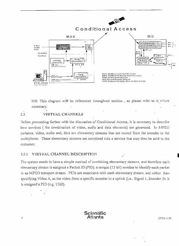
VirfiMtAud ioD.Mn
Scttmbllng
f . t f W n c f
£~I3
P C C - X O O O
C o n d i t i o n a l A c c e s s
M UX
A ve i, ¿w
• herypübn'.
* I A D P J
ECM: EnlHIcment Conifol Mm.CcjEM M: En Híleme ni M » n » o e m e n i M T i 5 » o e33H: Se cíe I SerlM HitmbefISE: Inl-.inül Secuiily El = mrnlO S E : OulDcinrd 5f curily EI-M r ni ISm x r i
NB: This diagram vvü'l: be referenced throughout section , so picase re Per to i t \vh-jrc
necessar)'.
2.2 VIRTUAL CÍ-IÁNNELS
Dcforc procceding further with the discussion of Conditional Access, it is ncccssary to describe
how services ( the combination of video, audio and data elements) are generated. In MPI ICi
parlance, video, audio and, data are elementary streams Ihat are routed from the encoder to the
nuilliplexer. These elementary streams are combined into a service that may then be sold to the
customer.
2.2.1 VIRTUAL CHANNEL DESCRIPTION
The system needs to have a simple method ofcombining elementary streams, and therefore cach
elementar/stream is assigned a Packet ID (PJD). a u n i q u e ( 1 3 bit) numberto identlTyeach packei
in an MPEG transport stream. PIDs are associatcd with each elementary stream. and rather than
spccifying Video A. as the video from a specifíc encoder in a uplink (i.e., Signal 1, Encoder 5). it
is assigned a PID (e.g. 1560).
ScíéntíficAtlanta COM-l-I!)
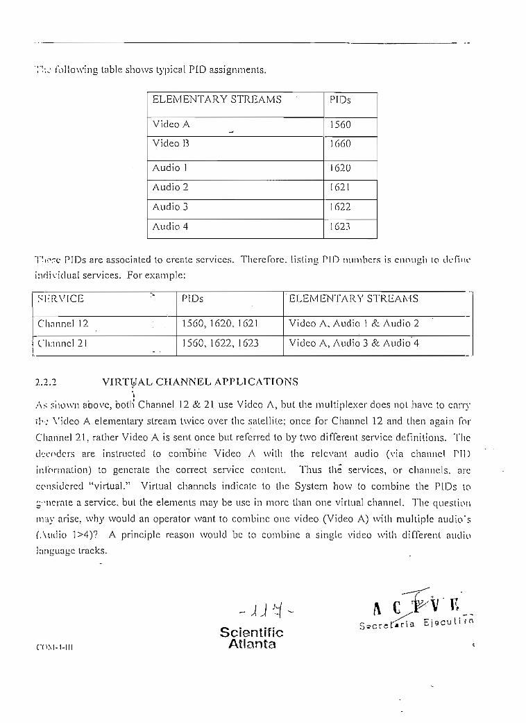
ollowing table shows typícal P1D assignmenls.
ELEMENTARY STREAMS
Video A
Video B
Audio )
Audio 2
Audio 3
Audio 4
PIDs
1560
1660
i 620
1621
1622
1623
TV:xre PIDs are assocíated to créate scrvices. Thercforc. l is t ing PÍO numbcrs is enough to def ino
ind iv idua l services. For example:
S I - R V I C E
Channel 12 ; .
Chnnncl 21 . .- -
PIDs
1560, 1620, 1621
1560, 1622, 1623
'ELEMENTARY STREAMS
Video A, Audio 1 & Audio 2
Video A, Audio 3 & Audio 4
2.2.2 VIRTUAL CHANNEL APPLICATIONS
As shown above, botlí Channel 12 & 21 use Video A, but the multiplexer does not have to carry
T Í ' : Video A elementary stream twice over llic satellite; once for Channel 12 and then again for
Channel 21. rather Video A is sent once but referred to by two different service definilions. The
tk-cpclcrs are instructed to combine Video A with the relcvanl audio (via channcl PI1)
in!onrmtion) to genérate the correct service contení. Thus the services, or channels. are
considcrcd "virtual." Virtual channels indícate to tlie System how to combine the PIDs to
::"McríUe a service, but the elemenls may be use in more Iban one virtual channel. The question
muy arise. why would an operator want to combine one video (Video A) with múlt iple audio's
fAi i í l i o 1>4)? A principie reason would be to combine a single video with differenl audio
humuaue tracks.
rnM-l-III
ScientlfícAtlanta
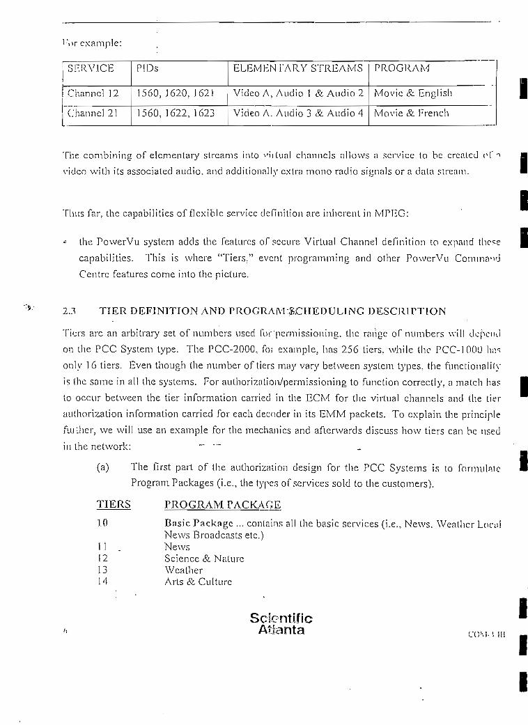
i 'or example:
SERVICE
Channel 12
Channel 21
PIDs
15Ó03 1620. 1621
1560, 1622, 1623
ELEMEN l'ARY STREAMS
Video A, Audio 1 & Audio 2
Video A. Audio 3 & Audio 4
PROGRAM
Movic & English
Movie & French
The combining of elcmentary streams into ^ i i l ua l channcls allows a scrvice to be crcaled oí i
video with its associated audio. and addi t ional ly extra mono radio simials or a data stream.
TIius far. the capabilities of flexible servicc deílnitiou are inhcrent in MPEG:
* the PowerVu system adcls the feattires ofsecure Virtual Channel de f in i t ion to expand thcs
capabilities. This is where "Tiers." event programming and other PowerVu
Centre features come into the picture.
23 TIER DEFJNITION ANO PROGRAM:£.CHEOULING DESCRIPTION
Ti'jrs are an arbitrary set of numbers uscd for 'permissioning. the rañge of numbers \vill clopciui
oa tiie PCC System type. The PCC-2000, foi example, has 256 tiers. while the PCC-100Ü \w
only 16 tiers. Even though the number of tiers may vary betvveen systeni types, the funct ional i íy
is Ihe same in al! the systems. For authorization/permissioning to fundíon correctly, a match has
to occur between the tier information carried in the ECM for the virtual channels and the lier
auí.horization information carried for each decoder in its EMM packets. To explain the principie
fiuíl ier, we will use an example for the mechanics and afterwards discuss how tiers can be nsed
in the network: ~ "~
(a) The first part of the authorizalion design for the PCC Systems is to formúlale
Program Packages (i.e., the types of services sold to the customers).
TIERS PROGRAM PACKAGE
10 Basic Package ... contains al l the basic services (i.e., News. Weathcr Loci:lNews Broadcasts etc.)
11 . News12 Science & Naturc13 Weather14 Arts & Culture
ScícntificAbanta CCAM MI
III

\*1617
Basic SporlsChildrerfsBasic Movies
20212223
Local BroadcastsLocal Broadcast/4Local Broadcast BLocal Broadcasl C
30 Premium Movies ... contains all channels in Premium Movies Package31 Movies: Classics32 Movies: New Releases33 Movies: Cartoons
40 Hobby Channcls ...contains all clmunels in the TIobies Package41 Hobbies: Gardcning42 Hobbies: Golf43 Hobbies: Arts & Crafts44 Hobbies: físhing
100 Premium Sports ...contains all channels in the Premium Sports Package101 Sports: Hockey102 Sports: Footbalí \.] 03 Spfbhs: Auto Racing104 Sports: Baseball
(b) All virtual channels have to be associated with Program Packages/tiers (e.g. VC 2
is a basic sports channel, and thcrefore is assigned tier 10 as being part oí the
Basic Package and tier 15 for the Basic Sports Package). After this task is
completed, all the Program/lier iníbrmation is combined with the Vir tual
Channels informalion. to genérate an HCM packet.
VCs PIDs TIERS
veve
2-ij
1360,
1560,
1322,
1522,
1323
1060
10,
30
15
PROGRAM
Basic Sports
Premium Movies Secreta r ía E íe-j• . o 'í v ^
In turn. customers purchase various services/Packages from the syslem operator.
There añer. the Program tiers associatcd with the Packages wil l be assigned to (he
ScientlficAtlanta

/ . í . l BLACKOUT/SPOTLIGUT CODE APPLICATIONS
lhe combination of tier and íocation codes increases the aulhorization capability of the PCC
.-.»..-.icnisT butlñov/^Te-í-Iie-b 1 aekoi¡t/spQt]igl>t-joer.\\- codes used within the System? The m;iin
¡víison behind the codes, as the ñame suggests. is to blackout áreas within a región not allowed t- . -»
\ ic\ a program due to copyright rules or adverlising/conlent regulation. In the example bel'v^-
tbe r.ports program is sold in all six regions. Due to syndication reasons. the gamc/program is not
ni'mved to be broadcast in a certain radias arouncl the city. The re fo re a l l the IRDs in the sluulod
arc.a will be assigned blackout codcs matching iliose associalcd wiíh the Blackout codes (Fil o-i
t i t o virtual channel/program event and Ih ere foro wil l be "blacked-out" dur ing the period oí" t l io
TIER 'LOCATIQN
Inicie IRD 50
Outside IRÉ) 50 Í1020B
Citv
Location codes can also be used to divide the J K D population in terms of demographic graups for
f.:ívertising and DMA codes (designated marketing áreas) to aid in program distribución.
í.omc additional ítems to note:
(a) t Any virtual channel or any event within a virtual channel. can carry a máximum of
10 íocation codes for authorizalions at any point in time.
Atlanta

(h) Each IRD can hold up to a max. o f 4 locations codcs in i ts" profi le at any point in
time. _ t .
(c) The 4 bit location code can genérate up to 65,535 blackout/spotlight regions.
Thorcíbrc the combinations of the various aüthorizotion method wi th in íhe Syslem increases the
ücxihil i ty of íhe condítional access system to meet íhe requirements of many customers.
2 5 FJNGERPRINT TRÍGGER
Thn use of fingerpriní trigger during an event forces decoders luned to the vir tual channel tn
iii '-;play momeníarily theír User address (the known portion of the SSNs in the decoder) in a
serios of vcry small coded dots. The ílngerprint can be sel to trigger at a certain point in time
di i r i ny the event, and the fingerprint set to be shovvn for a spccified pcriod of time.
•-By capturing this display (on tape) one'San interpret the results ío determine íhe decoder's User
t*-1,.
Address. In this way the source o|" i Ilegal tape distribution-.can be traced ío identify lhe.
<'¡!vcribcr violating the programing sub'scription rights.
2.6 FORCÉ TUNING
Forcc Tuning is the ability to forcé a decoder or group of decoders to a specific channel volhin
the System's virtual channel map. This feature is part of the decoder profile. íherefore the
information is sent out in EMM messages to the specific decoders, to tune to a specific channel
now or after a certain" amount of time/delay. The decoder reinains set to tliat channel un t i l c i ther
the forcé tuning is disabled or the decoder operaíor/user selects another channel.
(Picase note the front panel of the IRD can be locked-out, see decoder lock-out fea ture) .
Thcrc is no authorization involved wiLh this function. and therefore if a decoder is sent to a
channel for \vhich it is not authorized, a blank scrcen a[^pears wilh the message "Not authorized."
Forcé t u n i n g may be uscd for múl t ip le reasons, a maín (ask to move a group of decoders to íhe
corren virtual channel before the Program begins. to en.sure the customer is tuned to the corred
-l'JSL-Scienttf ic • r^ T , ¿, p
CDM-I-III Atlanta V -~ '•'S e c r e L-s: r í o £ i 5 c u t i v a

dumnel to rcceivc the program. Anothcr rca.son may be to pcrfbnn an OS Downlaad (picase so--
secíion belovv, for furthcr details).
Z.l HOMING CHANNEL
Tíiís fcature enables the system operatorio choose the channel the decoder tunes to upan scrvicc
rcnioration after a power intcrruption ío the decoder. Definit ion oí íhe homing channel is parí oí
íhe decoder profile. There are two opíions avni lable:
(a) have the decoder tune to the la.st channel viewcd on the IRD befo re the servicc
disruptíon (defaulí setting on th..- decoders) o
(b) have the decoder(s) return to a specific channel upen service restoration.
The ability to select the channel a decoder starts up on service restoration can be very use fu l . ¡f
íhcre is a channel carrying an Program schedul';. (i.e.. EPG guide or transmittcd text) for the PCC
System. When íhe S3;stem has such a channel, the operator may wish to have a l l decoders tune lo
ihis channel when ever íhey are turned-on to see "tf-7;a/ is on ?icx(.** ín add i t ion . if the program
provider ^ants the ÍRD user to receive a spcciflc program on a .cbfpnne l , the homing chnmH
feaíure can be set at this specific channel. Tn Üiis manner the decoder. is guaranteed to start on tlic
corrcct channel upon service restoration. ^ •
2.8 DECODER LOCK-OUT
Tn prevent tampering with the IRD settings íhe front panel of the decoders may be "Locked-Ouf"
via the PCC systems. The IRD has the ability ío be set at various levéis of Lock-out and the leve!
the ÍRD is set at is determined by the PCC (picase see list below). Decoder Lock-Out opérales Ín
íhe same manner as Homing Channel, so Ihal cach decoder has a default setting, as determinedby the system operator.
Levcl Dcscription
0 All settings on the decoder are unlocked (JRD lockout disabled)
1 All settings unlocked except Factory reset and Password options
2 All settings unlocked except Receiver Setup and User Setup' options
3 ^ All settings locked (access via Password)
4 All settings locked (acccss via remote terminal or PCC up l ink signa! onM
ScsentificAtlanta CPV., ,„

( i n an IRD, if the user has the password ií can be movc betwccn levéis 0>3. bul if an IRD is s"!
í»t 1-vcl 4, only the PCC can move the IRD to another Lock level.
2/i IRD CONTROL OUTPUTS
A l l of the PowerVu IRDs have TTL open-collector output ports (as known as "coffec-poi"
ront''ols) located on the back panel of the decoder. These output ports can be cont ro l lcd íhroii '!1!
íhe íuithorization S3'stem to act as general purpose remote control ports and to control accessmy
c-.¡"ipment. such as tape machines, video swilchers or coffee makers. The controls are activad i
:•! *hc start o f a n evcnt, thercforc, if a tape machine is attachcd to the porl ií could be sct to s lnr t
recording the incoming program.
Tlic state of the switch is as follows: The active síate is "low" (sinking curren O and the non-
: vi i ve state in "High" impedance. unless a pull-up resistor is connecíed ío the remóte contr - ' l
íui lput pin. When the decoder is not receiving an input signal, or is deaulhorized, thc remóle
c-O'ilrol dcfaulís to "high."
High: The output is high state (+5V) .-,
Low. The output is low state (OV)
Pulse High: Pulse output ío a high síate (f-5V) for x milliseconds
Pu/se Low: Pulse output ío a low síaíe (OV) for y mil l iseconds A fr>'T V íji i ^ / A, j B ^ __-.XA *. * -r-«
-/_ = 267 milliseconds (525-Iine or 60IIz systems) 'Sícrétáf iá E j e c u *:X = 320 milliseconds (625-Iine or SOIlz systems)
I\'o Control: Ouípuí remains in íhe síaíe thaí ií was in after the last coníroí operaíion. If n l l
control outpuís are seí ío No Control^ íhe PCC system do'es not transniit a command to
control the oulputs, which reduces thc authorizat ion lock-up time and the memory
ovcrhead.
2.10 DOWNLOADING OS SOFTAVAUE
I:ach of the PCC S);síems have the abiliíy ío download new operating software (OS) to thc
decoder popiüation. Even íhough this funcíion is not síricíly a parí of condit ional access. as íh^1
05í do\vnload code can be applied to íhe complete decoder popuiat ion. íhe cond i t iona l
IVn'urc.s can be used to provide new code ío a specific group of decoders.
ScientificAtlanta

T!ie melhod used to download is ío créate a spccific virtual channel ío download OS files to i! •:
.-Jccoders. load the new OS software into the PCC and bave the information iransmitted lo ihc
i!-:coders.• To have only a small group of IRDs receive the code. the IRDs in question are/?;>£*?
íiifiedio a virtual channel created specially to do the OS download. Only those IRDs tunecí ío íbc
spccific virtual channel wil l receive the new OS codo.
Jicms to note;
(a) Downloading OS to the Í R D causes momenlary (up to 15 minutes ) servio*disruptions on íhe ÍRD, and llierefore, customers should plan to download at ihetime that least affect the viewing audience.
(b) The number of download OS files required per ÍRD depends on the ÍRD type (i.e..Cornmercial vs. Business). Not all new features can he downloaded into i'i--IRDs.
(c) It is recommcnded that an OS Download not be ini t ia lcd without the assistance oí'an Scientiílc Atlanta Representative to ensure the procedure is done correc'iy.othcrwise major consequences could arise.
2.1 i CONDJTIONAL ACCESS SUMMARY
AU.-:lhc feaíures associaled with condit ional nccess makes IheJPCC Systems vcry flexible to incx't
the dcsign needs of many lypes of satelíite cÜstribution syslems, from single channel/backhauls.
innlti-channel, common carrier/service providers to Direct to Home (DTH). Providing m ú l t i p l o
methods of raising revenue for the System operator.
Picase see the cart belovv to verify \vhich CA features are included in the specific PCC Systems.
ScierrtificAtienta

j \ ia i i .c t Types
Condi t ional Access
5'Ysicm Functions
Y í r t M a l channels
L:\'cnt/program scheduling
Dccoder Functions
Ticrs
I.ncaíion/blackout codes
Fimirrprint trigger: hidden
Snicll i tc code download
I")ccodcr lock-outi orce lime £ homing channel
I K D Support: control outpuls. •_ .
IfiiéÉÉtiJSinglechannel/backhaul
Yes
-
] 6/sys
No-
1 ó shared
No
Yes
Yes
Yes
No
Yes
1 4 * »^ ¡Tí fljÉmÁmj&xüJIJiMulti-channel/largenetworkYes
-
500/sys
Yes
-256 shared
Yes
Yes
Yes •
Yes •
Yes '
Yes
|L/¿tgMifi^^^
Common cnrrier/Service provider
Yes
-
500/svs
Yes
-104 shared +152/programmer
Yes
Yes
Yes
Yes
Yes
Yes .
¿9e^&ieSK.fílK^tKJif^7íK^^-^Direct to í lome
Yes
-
500/svs
Yes
-
256+i
Yes
Yes
Yes
Yes
Yes ' .
Yes
3.ÍJ UPLINKCONTROL
The PcuverVu Command Centre maintains, conlrols and moniíors the PowerVu system devices
se» :luil the following aclions may be laken:• Múltiple Signáling ' M i• Redundan! Syslems• Automatic Switching
• Modulator Configuralion • p T1"*^/'""'F
3.1 MÚLTIPLE SIGNALING • S¿5f5 ta r i . E j e c u t i v a
Hach PCC-2000 system can support up to four transponder systems, each o f w h i c h has its own
i:roup of upHnk devices •—encoders. multiplexer(s) and modulalors •—and sends its oulput to ils
own transponder.
3.2 REOUNDANCV SYSTEMS
To prcvcnt Iransmission disruptions in the case of cquipmenl fai lurc, the PCC-2000 sysícm
usuai ly contains bolh primary and standby encoders and multiplexers. Prímary encoders and
ScientificAtlanta

multiplexers actively Iransmil data under normal operaling conditions. Under typical opcraí ínp
conditions when a device fails, or maintenance is to be performed. the standby unit takes over !l»c
fatlcd device's functions until the primary unit is back on-line.
3.2.1 REDUNDANT SYSTEM SETUP
During sysíem installation, the primary and secondar}' encoders and rnultiplexers are groupcd by
aíphanumeric codes to identify linked 'units for the purpose of changeover/redundancy. lu
nddition, each encoder and multip]exer is designated as either primar}' or secondar}'. • Tbis
Information is stored in the datábase when the syslem is being instal led. The numher in íhe
Jower left córner ofeach encodcr and tnultipicxer represents thc redundancy group to vvhich íhe
group belongs.
Bach uplink configuration may be set to autoniatically switch over to the standby units when a
primar}' unit is not performing normally. Or, the system may be manually switched to perfbrm
maintenance on a primary unit.
3.2.2 AUTOMATIC SWiTCíHNG
When a changeover from a primary uni t to a sccondary one is required. PCC-2000 automaticaily
changes to the best possible choice among encoders and/or mulliplexers. The changeover i?
dijplayed on each device.
3.3 MODULATOR CONFíGURATION
Thc ability to control the modulators through íhe PCC system enables one to command Uv»
complete uplink from a central control poinl. The modulator accepts a SWIF optical input and
oulputs an IF frequency at 70 MHz or 140 Mllz. Thc IF frequencies from each modulator are
eombined .and passed on to the RF dislribution system (i.e., combiners, dividers. upconvert.ors..
cíe,).
Only one of the modulators produces a signa! with carrier. the other is muted. A failure in one of
[he modulators causes the other to go on-line ímrnediaíeiy.
ScientificAtlanta

.i.-í CLIENT/SERVER CONNECTIONSi tu- l'CC is set up into a Client/Server conflguraíion wllich allows remote c l i en l s to access t l u -
svsU'in. Three types ofconnections are possiblc:
Direct connecüon vía coaxial or t>vis(ed pnir Etherne t cable:
A direct connection means íhat the PCC-2000 Client is directly attached to the PCC-2000 Server via one of these types of cables:1. Coaxial^ (10-Base-2) cable with a 50 Ohm T-connector al each end of the
connection.2. Twisted pair (10-Base-T) cable.
LAN (ncfrvvork) connection:The PCC 2000 has assigned to i t 1P addresses for both the clients and servers.Connecting a pre-existing LAN requircs only íhe physical connection to the nehvork.The PCC ñíe scrver may thcn be accesscd as any othcr network dcvice. Uiroimhcalling its IP address.
Dial-in modem connection
To facilítate configuraron of the- 'PowerVu compression syslcm froin other. locatíons a dial-up modem connection may be made to the scrver. Using Point-to-Point Protocol (PPP), the PCC may be configured by an authorized c l ien t .
««ConHéclíngtón
'Status! Díáhng . Cancd'
The PCC-2000 Server runs a text-only UNIX versión of the system. The serven is used to
imin tn in the systein time, download the decoder datábase from diskette. back up and restore data,
vicu the transaction log. and shul down and boot up the system. The PCC-2000 Cl ien t is thcn
uscd lo configure and control the PCC-2000 system.
3.-U SERVER PASSWORDS
Tho sccurily of the UNIX and PCC-2000 Server clcpcnds upon the passwords l l ia t the uscr enlcrs
lo {.'.'• i i í access to the PCC-2000 datábase and system files. Passwords are dcsigued to be changcd
on a regular basis as is deemed necessary by the syslcm administrator
v ¡;E i c * r » i I
C O M - I - Ü
_ j.2 r-ScíentiHcAtlanta

DATA-BACKUP
''í'hc scrvcr's backup ap'fi restore functions allovv one to store copies of crit ical dala files onto /iu
i"-: leí nal médium. Tape backups may be scheduled to run atuomaücally. flach backup consista
• J'!\vo slages: backing xip ihc data, and ver i fy ing the backcd up dala. I f a cliange occurs d u r í n u
ilio first aítempt, Ihe verification vvill fail.
•í.O CONCLUSIÓN
Scienlif ic Atlanta has combincd mnny ycars ofcxper icncc in securc video network dcsign n ' v l
VíPFiG-2 digital compression to dcliver Ihe sla(e-of-the-ar( PovvcrVu Cotnmand Centre 2Ü f V V
'! ¡•'e PCC family of producís also includes the OCC-10QO for SCPC applícations wilh fcwer iban
Í C O Ü decoders. The PCC-3000 which providcs m ú l t i p l e neíwork opcraíors lo share a
:.iu!íiplexers and the PCC-4000 whích is designad Por large DTII applications.
ScrpntificAtilinta

L'
Appendix A.5
COMMERCIAL IRD DESCRTPTION
•
A G-f V E•Sec re t a r i a E j e c u t i v a
Scientific. Atlanta

1.2
Optional Features
1. Video (serial DI) outputs/Digital audio (AES/EBU)
2. SWIF input for MPEG-2 transport stream input
3. High-speed synchronous data port (múltiples of 64 kb/s up to 2048 kb/s, E1A-RS-
422).
PERFORMANCE AND FEATURES nRF Parameters
Lnput FrequencyTuning Step SizeSatellite Frequency BandInput ImpedanceInput ConnectorInput Power RangeImage RejectionInput Return LossNoise FigureAFC-Tuning RangeDemoduladon MethodIF Loop PerformanceIFBandwidth
Viterbi FECReed-Solomon FEC
950 to 2050 MHz250 kHzC-&Ku-Band75 ohmsF-Type fe mal e
-30 to -65 dBm per carrier>30dB10 dB Min (950 to 2050 MHz) \/15 dB at-65 dBtn input±2 MHz
QPSK
DVB compliant per ETS 300 42ÍVariable to support receivedsymbol rates of 1.5 to30.8 Msymysec
1/2,2/3,3/4,5/6,7/8DVB compliant per ETS 300 421
Dccompressed Audio and Video
Video Resolution all ResolutionsCapable of I, P & B Frame Decoding
Video Decompression TypeAudio Decompression Type
Televisión Standard
ScientificAtlanta
704 x 576/480544 x 576/480480 x 576/480352 x 576/480352x288/240
MPEG-1 or MPEG-2 MP @ ML
MPEG-2 (Stereo/Musicam®)Layer 2
PAL/NTSC auto-switching(SECAM available)
n
-
Bl

Video Outputs (AnaJog)
Connector Type
Sepárate Text Monitor Output
BNC (75 ohms)
BNC
Audio Output ("Analog")
Peak Output Level
Frequency ResponseTotal Harmonic Distribuüon
Dynamic Range
Crosstalk at 1 kFfe
Output Level Adjustment
Oucput Impedance
Number of Outputs
+ 18 dBm ínto 600 ohm baJanccii
20 Hz to 20 kHz ±2 dB
<0.3 % at 1 kHz
80 dB60 dB, ful! scale (20 Hz to 20 kV
±6 dB Min range (with overajlarnplítude limlted by the peakourput level + 18 dJBm)
600 ohms2 stereo pairs standard
AC Power.Requirements
Voltageim:.
Line Frequency
LNB Po\ver
Voltage
Current
Overcurrent Protection
90 to 264V ac
47 to 63 Hz
+13V verdea]
+ I8V horizontal
or 19V fixed
500 mA Max
Foldback current limjting
. /.
\T V
Environmental Condítions
Continuous Operation
Temperature
Humidity (noncondensing)
23° Celsius nominal(O to 50° Celsius)
O to 95%
COM-3-IUScientificAtlanta

Rear Panel I/O Descríptions
Control/Connector
ACIN
RFIN
LNB Power
VIDEO OUT
DI SERIAL DIGITALVIDEO (Optionai)
SEP. TEXI
AGCOUT
BALANCEDAUDIO
UNBALAÑCEDAUDIO
Mono, Stereo
DIGITAL AUDIO(Optionai)
VOLL,R
Fiber Omput
Fiber Iñput (Optionai)
Expansión Port
DEC-320
F
Slide Switch
BNC
BNC
BNC
RCA PHONO
Screw Terminal
RCA
Slide Switch
XLR
Trimpot
SV/IF
SW1F
DB25S
High-Speed DataOutput (Optional)
DB9(EIA-RS-422)
ScientrficAtlanta
Function/Descriptiori
Voitage input 90 to 264V ac
Connection from LNB to IRD
Turns LNB power (ON or OFF)
Provides video output forconnection to video monitor
Provides digital serial DI output
Al I text output is routed to tíiisvideo output
Provides an output voltage forantenna peaking
Baseband video output withadjustable audio levéis for use w i t hextemal audio amplifíer and cablejiead-end moduíator
This output is provided tointerface with the TV sets
Provide selection for mono orstereo
Provides digital audio output(AES/EBU) format
Adjusts the audio level- for theassociated audio output
Thisrjutput provides the completeMPEG-2 transport stream signal
This input accepts an MPEG-2transport stream input signal
Múltiple function connector foreight auxiliary remote control andcomputer diagnostics with remótetuning control. Provides low-sp?eddataup to 38.4 kb/s.
Provides synchronous dataup to2048 kb/s (El)
COM-3-ÍII

1.3 INPUT AND OUTPUT CONNECTIONS
Figure 1 shows the rear panel connections to [he base Model D9223 Commercial ÍRD. Fie"?'-
shows the same view when equipped with most of the availabJe options.
o - (o) © ©
Figure 1. Model D9223 Commercial ÍRD Rear Panel Connections
© : <ci-,:
© (0) ~<§n§)
Figure 2. Model D9223 Commercial TRD Rear Panel Connections with Options
COM-3-ITI
ScientiíicAtlanta

"'':? cnmmercial IRD features an extensive diagnostics capability. This has been provided as ;i
icvult of Scientiflc-Atlanta's extensive experience with secure satellite televisión transmission
•,y:-tcras, starting with B-MAC in 1984.
The diagnostics raake use of the internal charactcr generator/graphics capabilities of the IRD
••"i-screen display and fall into two maín classes: 1) user information and 2) troubleshooting aids.
L"'-?rs are advised by on-screen messages when thcy have been denied access to a prograrn for íiny
iv.ason. The reason can be expliciüy stated in tho message, and the message can be edited by the
nctwork operator via the PCC. This allows the operator to customize the user interface to the
•:.>7ulhional access system.
I" ;(TS may be deauthorized for a number of reasons, including:
MSK authorizaü'on not received (cornpJetely deauthorized)
Program tier not set (not subscribed i'?' 'hat particular ser/ice)
Regional blacked out (blackout requíred in certain regions for program rights.
Tn ?id in resolving trouble calis from users, diagnostics information can be called up on the screen
oFUie IRD text output, which provides an indication of:
Frequency to which the IRD is tuned
Signa! level
Bit error rate
Authorization state.
i.i -;onjunction with the user information on-screen display, the troubleshooting diagnostics will
s,,v-: ibz network operator considerable man power in managing the network. The sepárate texl
nj'.put allows the operator to observe the IRD sel up and diagnostics without interrupting the main
•-i-'co output.
ScientíficAtlanta COMO-¡u
Appendix B
COMPONENT DATA SHEETS
" E i e o ü U Y 8
Scientific, Atlanta

III
I

Singlc-channel/Bnckhaul
Multi-channel/Large network
Cominon cnrrier/Sei vico, providor
Direct-lo-Homc
?'s Powc. Vu Commnnd; • • • ; ;V»EVÍ/Í.'$ complete iiintm$cweiit
' •- v í / í - i / /br ///c PoiverVít pwduct
"í'i: í\uvtirVu Command Centre• , T.C-) i« the heart of the PowerVuv-n-.i!,u i ¡"niniiy. PCC systems areC'ipip .-H of fourmain components:\ i\\-nrk Méinngument, whichr :Vi:>I'j tlio video, audio, and data-. i < icos of the uplink; Securit}', whichpr ".'¡'les conditionai access and
ív./-.; i.ion to cnsure the security oftl'.r srsit-ni; Subscriber Management,•• iii-.li ;:ontixils the downlink receiver• InU'i-líisc: and Remóte Access which. ;: ^--'-(.íípncction to the system from,-' vuhoi iMn the world.
ThoP-WírVii Comma'nd Centréisa\c m four models to meet theií'jinniHls oíspccificsatellite videoo- ií)-.ins>ion markcts: Models 1000,
FEATURES
• MPEG-2/DVB compatible
• Grapllical usor interface providing easy access for viewing and/or settingsystem parameters
• Automatic-redundancy switchover upon failure of encoders, multipk'xers,or modulatoEfí
• Muí tipie freqüency plans
• Fingerprint trigger lo deauthorize unauthorized dislribulion ofprogramming
• Password-prütected access to datábase and system functions
• Multi-user support for simultaneólos access by more than one user
• Logging of transactions for tliird party analysis
• On-line datábase editing and storage of subscriber data
• Full control oísubscriber authorization vía tier bits
• System control vía an external or remote computer
• Access to the PCC control system using various methods of connection
• Network management and subscriber control integra ted with condilionalaccess and enciyption in a single system
• Several models meeting the various demands of the satellite industry
• Flexible system dcsigns based on modular construction

.
is Conimand Centre
|f ;ni íSTRY STANDARDS
•Vv-PiTiONAL ACCESS:i'f¿VM CONTROL
. ..;í.p-íí¡ncv•lo'/*''.''1 rontrol1 \ :.\r:/cf control
• tior control.'.-:• ; - . :-MFUNCTIONS
,'.:'-i-ii d.nnnels..»/'•:• "¡'fo'jrnm schedulíngLv T.O'ÍÍK ioq
Transn^lion Ioq•V'-'-'.vríl privileqe system:-;r. :v;~r. compuíer ¡nterfaceí.í;.: L-^kup?.'..-»*. 'i-ootior datábase w/database management','• :••_ •.: , ¡-nriuency índicesL!..il!.;jio íi-'^juency plans' :-y:vnon carrier serviosM'/.í'vA'i'.ix Software
nrr.OFZR FUNCTIONS7,.--'.
l/--.. ;;•:;•!. ' :v;Kout codesHí(! ion íiíujerprinttriggerSnt-~:li(e rode downloadFcvr? í ..i::-- & homing channelHerrete control outputsTeieS^xt personal messages editor£¡. v!:ni>¡o Rroqram Guide (EPG)!/ ••:' « ^¡'vPerViewflPPV)VBI n: -i • i. vertió n
COMPUTERComrvKi coinouterCompnl'^: ronfígurationGUI r'':'"1^nsí.íu'í'-usor remóte access
| » WK^^^É
MPEG-2/DVB
^ Yes
1:1, c'hainYesYesYes
16NoYesNoYesNoYes
1,000YesNoNoNo
16NoYesYesNoYesNoNoNoYes
Armada 1120Laptop
YespcANYWHERE"
UÍSj5;Í!líLJ
MPEG-2/DVB
Yes
4x2:10YesYesYes
500YesYesYesYesYesYes
50,000NoYesNoYes'"
256•YesYesYesYesYesNoNoNoYes
ProSiqnia 300Rack mount
Yes5 users
fcJsLsSi^il^
MPEG-2/DVB
Yes
4x2:10YesYesYes
500YesYesYesYesYesYes
50,000NoYesYesYes
152/proqrammerYesYesYesYesYesNoNoNoYes
ProSiqnia 300Rack mount
Yes10 users
j&z&^^-WBj¿£l£fí; i'!'! - ; í .¿
MPEG-2/DVB
Yes
MúltipleYesYesYes
500YesYesYesYesYesYes
10,000.00'JNoNoNoYes
256YesYesYes
• YesYesYesYesYesYes
Proliant 4500RRack mounl
Yes10 users a
Srienlific-Allanta for more iníormation on productn^ntioned in this liíerature.
Tlie SdonlifioAllanta logo, PoweiVu and MetroMux aie tradeinaiks o/ Pr;-:nt;i
Atlnntn. Inc. Other trariemarks mentloned are tradeniarks oí thcír leíppríi""cfinipniíiüR. Spcclflcnlions and piotlnct nvnilnliilllv nic subjpci lnolicfi.
ScientííicAlia nía
ScienlHic-Allanla, Inc. Salellite Televisión NetworksUníled States: 4356 Communications Orive. Norcross, GA-30093; TQ].: 1-770-903-6057; Fax: 1-770-903-6464Canadá: 120 Middlefield Road, Scarborough, Ontario Ganada MIS 4M6; Tel.: 1-416-299-68S8; Fax: 1-416-299-7145
Unüed Kingdom: Home Park Estale, Kings Langley, Herts.,Uniled Kingdom WD48LZ; Tel.: 44-1923-2GG133; Fax: 44-1923-269018llaly: Via Fosso Centroni, 4 Aligólo Via Anagnina, 00040 Roma, lialy; FcL: 39-67-98^0030; Fax: 39-67-98'l-003'1Chile: Avda.11 de Septiembre 2155, Torre C-Oí. 807, Santiago, Chile; Tei: 56-2-232-2681; Fax: 56-2-232-2002Argentina: Scientilic-Allanta, Inc., 25 de Mayo 293, Piso 7A. 1002 Buenos Aires, Argentina: Tel.: 54-1 342-0321; Fax: 54-1 345-8047Singapore:ScientÍIÍc-Atlanta(S)Pte. Ltd., 1 Claymore Drivé, ¿'08-11 OrchardTowers.SIngapore 229594; Tel.: 65-733-4314; Fax: 65-73?-^-^Beijíng: Lucky Tower. Block B, Suite 1413-14, No. 3 Dong San Huan Bei Lu, Beipng, China 100027: Tel.: 8610-461-5761; Fax: 8610-461-"=? iAustralia: Utiit 2,2 Aquatic Orive, French's Forres!. MSW 2086, Australia; Tel.: 612-9-452-3388; Fax: 612-9-451-4432
42D370B © Copyright 1997 Scientífic-Atlanta, Inc. All rights reserved. Prinled in USA. 0397M
2

•
I
•
•
P0300
The Model 7753 C-Band and the Model7754 Ku-Band Beacon Receiver/Doianconverter provide precise antennapositioning data to maximize receivedsígnal strength.
DESCRIPTIONThe Model 7753 C-Band and Model7754 Ku-Band Beacon Receiver/Downconverter provide preciseanalog voltage corresponding tobeacon receiver power levéis as aninput to a Model 8860 AntennaPosition Controller or compatible/ toposition motorized antennas foroptimum signal receptíon. Bothunits provide front panel indicadonsof beacon signal operating range anddownconverter phase locked loopstatus. Output voltage control andoffset control can be accomplishedfrom the front panel.
The Model 7753 includes a dualchannel, C-band downconverter thattranslates a 5 MHz wide band in the3.625 GHz to 4.2 GHz range to70 MHz. The bands are factory
preset to customer specifícation. Upto' four different beacon. frequencieswithin each band can be selected atthe front panel or by remoteoperation. The power in a 200 kHzbandwidth is detected and processedto provide an output voltage that isproportional to the received signalstrength.
The Model 7754 includes a dualchannel Ku-band downconverterthat translates a 5 MHz wide portionof the selected band (10.95 to11.7 GHz, 11.7 to 12.2 GHz, or 12.25to 12.75 GHz) to 70 MHz. Up to fourdifferent beacon frequencies may bepreset in the 5 MHz channel. Thebeacon receiver then measures theRF power in a 110 kHz widebandwidth around the selectedbeacon frequency. This power levelis converted into a de output voltageproportional to the received signalstrength.
i FEATURES ; . ' . ' .JE V f . ,
* • Compáct 3-1/2 inch unit houses receiver and downconvertezi -; . -v" - * - . ' • . • ; ' - j* > '; ' -:**. •• , •'. 'i > • Front panel control and monitoring i
í v TJ & l"r; ¿i i i s u i •' ' <: W- va- *<¿ *: : • Remotely controllable * -%
: : í í:^" •* • ' - " ; ." ' I1* i• Fróñt panel synthesizer lock and beacon signal range indicators
• Compatible with both the Model 8840A and 8860 series of Steptrac-k J |-.Antenna Position Controllers . • • ; . . ..'£* '&!;•
• Fixed pr ''ariable output voltage for compatibility with any controller(
• Compatible with the Mod'el 7670 Earth Stationtóntroller fániíly"^ 1* '• ~ • '^
Scientific-Atlanta 404-903-6001AtterAugustl, 1995 please cali
I '• ' : , 770-903-6001" ';

MODEL 7754 KU-BAND BEACONRECEIVER/DOWNCONVERTER
DOWNCONVERTER TECHNICALSPECIFICATIONS
ElectricalInputfrequency: Two 5 MHz bands
Factory selected from 1 of the followíng ranges:l0.956Hztol1.706Hzrange11,7 GHzto 12.2 GHz range12,25 GHztol2.75 GHzrange
Ouíputfrequency: 70.0 ±2.5 MHzInpuí ¡mpedance: 50 ohms with > 14 dB return lossOutput ¡mpedance: 50 ohms with 20 dB reíurn lossInput leve! range: -60 dBm to -100 dBm per beaconMáximum input power; -30 dBm/5 MHz bandFrequency stability
Temperature: ±30 kHz 0°C to 50°CTime: ±40 kHz peryear, fixed temperature
Conversión gain: 40 dB ±3 dBGain flatness: ±0.3 dB in a 5 MHz bandGain síability: ±1 dB aging and temperaturaOuí-of-band rejection:
>60dB wíthin image band>80 dB O GHzto 9.0 GHz, 14.0 GHzto 14.5 GHz
LO leakage at input: -50 dBm max.Noise figure: <16dBOuíput 3rd order intercept: +10 dBmFault reporting: Loss of phase lock reportedPower requirements: 115/230Vac±10%, 50/60 Hz±10%Power consumption: 60Wmax.
Physical and EnvironmentalConnections:
Input is type SMA female (RF inpuí)Output is type BNC témale (70 MHz output)
Operaíing temperature: 0°C ío 50°C (32°Fto 122°F)Operating humidiíy: <95% non-condensingDimensions: 19 in. Wx20in. Dx3.5in. H
(48.26 cm W x 50.8 cm D x 8.9 cm H)
BEACON RECEIVER TECHNICALSPECIFICATIONS
Eléctrica!Inpuí frequency range: 67.5 MHz to 72.5 MHzInput impedance: 50 ohmsInpuí return loss: >14dBOperating input power level:
Max,-20dBm/carrierMin, -60 dBm/carrier
Input aggregaíe power level: -10 dBm in a 5 MHz bandwidthNominal sensiíiviíy and linearity:
A Output: 0.25V/dB±10%J fixedB Output: 0.25, 0.50,1.0VAJB ±10%, selectable wiíh ofíseí
Predetection bandwidth: 110 kHzTypical minimum operational C/No : 55.5 dBc/HzSensiíivity ai C/No of 55.5 dBc/Hz: 0.18V/dB minimumFrequency selection: SOkHzstepsMinimum beacon spacing: 250 kHzOutput A voltage range: OV de to +1OV deOuíput A absolute voltage error: ±0.25V max.Ouíput source resistance: 1000 ohmsSignal level stability: ±1 dB overa±10°C window
PhysicalInput connector (70 MHz inpuí): Type BNC femaleOuípuí A, B, Remote R1, R2, R3, Alarm NO, NO, O Terminal sírip,
No. 16 AWG máximum wire size

Satellite Televisión Networks
Master Syne Genérator ScientificAtlanta
P0361
The PowerVn Master Sync Genératorgenerales the MSYNC signal used tofrec¡uenc\j synchronize other equípmentin the Sdentific-Átlanta MPfG-2/DVEencoding system.
DESCRIPTIONThe PowerVu Master Sync Genératoris a stable dock reference fo Scientific-Atlanta's PowerVu digital videoencoding system. It provides anMSYNC signal used to frequency-lock a chain of MPEG-2 encoders andmultiplexers. The Program ClockReference (PCR) is encoded onto thesignal/ ensuring that all of thes}'stem's encoders remain in sync.
IFEATURES i-'• Stable (±2 ppm) internál clock reference gerdockéd to any.orié^ot tile", ¿-^i•-{).•"'?£•'' : • " -v "Vi'-- -i,- • • --í .Y J ' ,- 'sf-.i--"'-^ r-^ "V . .'' ' - -: " •- ' • ' : - ;
" T ' a stable video refeence simal (NTStPÁL-I,•'. ". ;-AiJ •- '' . ' •'.', -,, ,• ' • '*?•• --. " '
,;_' '^.a síable LOO, 5.007 pr ÍO.OO ¡MHz CW-reference (i.ev GPS reference)í-1 -: • • • • ' - " ' ' ' ' :?> : ,í' -:, ..V ;' "
. -' another Po^verVu Master S}mc Genérator (for redundancy)
'•"Six MSYNC outputs" / " • - 1 - " ''•" '
• Two color black video outputs (NTSQ PAL:I, PAL-B, PAL-M or PAL-N)
t»/itóSYMC sienal can be dístribúted likelbasébáhd video (no clamps) on'-^-•-'-i.i''"' ' • ' " '• ' '. "í *'• •••''•' r- ""-Iv" •' , • • ' -* "íJÍ*í i
-^ Regular 75 olim coax using standard analbg^ideo distribution amplifiers
Scientific-Atlanta 770-903-6057http://www.sciatl.Gom
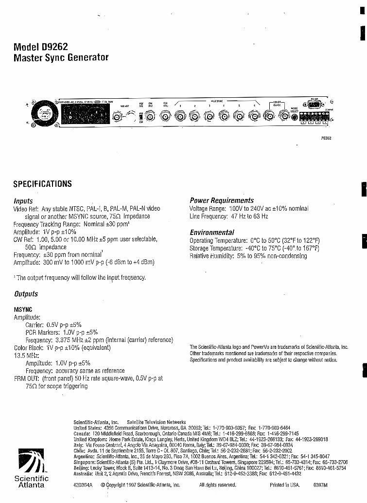
Motlel D9262Master Sync Generator
II
P0362
SPECIFICATIONS
InputsVideo Reí: Any stable IMTSC, PAL-I, B, PAL-M, PAL-N video
signal or another MSYNC source, 75O impedanceFrequencyTracking Range: Nominal ±30 ppm1
Amplítude: 1Vp-p±10%CW Ref: 1.00,5.00 or 10.00 MHz ±5 ppm user selectable,
50Q ¡mpedanceFrequency: ±30 ppm from nominal'Amplítude: 300 mV to 1000 mV p-p (-6 dBm to +4 dBm)
1 The ouíput frequency will follow íhe input frequency.
Outputs
MSYNCAmplitude:
Carrier: 0.5V p-p ±5%PGRMarkers: 1.0Vp-p±5%Frequency: 3.375 MHz ±2 ppm (interna! (carrier) reference)
Color Black: 1Vp-p±10% (equivalent)13.5 MHz:
Ampiítude: 1.0Vp-p±5%Frequency: accuracy same as reference
FRM OUT: (front panel) 50 Hz rate square-wave, 0.5V p-p at75nforscopetriggering
Power RequirementsVoltage Range: 10OV to 240V ac ±10% nominalLine Frequency: 47 Hzío 63 Hz
EnvironmentalOperaíing Temperaíure: 0°C ío 50°C (32°Fto 122°F)Síorage Temperatura: -4ü°C to 75DC (-40°.to 167°F)Relative Humidity: 5% ío 95% non-condensing
i
i
The Scieníific-Aíiania logo and PowerVu are trademarks oí Scíeníific-Atlania, Inc.Other írademarks meníioned are írademarks of their respective companies.Specifications and producí availabiliíy are subject to change without noíice.
I
SeientificAtlanta
Scientific-Atianta, Inc. Sateilite Televisión NetworksUnited States: 4356 Communications Orive, Worcrass, GA 30093; Tel.: 1-770-903-6057; Fax: 1-770-903-6464Canadá: 120 Middlefield Road, Scarborough, Ontario Ganada MIS 4M6;Tel: 1-416-299-6888; Fax: 1-416-299-7145Uniíed Kingdom: Home Park Estaíe, Kings Langley, Herís, United Kingdom WD4 8L2; Tel.: 44-1923-266133; Fax: 44-1923-269018Italy: Via Fosso Centran!, 4 Angolo ViaAnagnina, 00040 Roma, Italy; Tel.: 39-67-984-0030; Fax: 39-67-984-0034Chile: Avda.11 de Septiembre 2155, Torre C-Of. 807, Santiago, Chile; Tel.: 56-2-232-2681 ¡Fax: 56-2-232-2002Argentina: Scíentific-Atlanta, Inc., 25 de Mayo 293, Piso 7A, 1002 Buenos Aires, Argentina; Tel.: 54-1 342-0321; Fax: 54-1 345-8047Singapare:Scíentific-Atlanta(S) Píe. Ltd., 1-Claymore Orive,#08-11 OrchardTowers,Singapore229594;Tet: 65-733-4314;Fax: 65-733-2706Beijíng: LuckyTower, Block 8, Suüe 1413-14, No. 3 Dong San Huan Bei Lu, Beijing, China 100027; Tel.: 8610-461-5761; Fax: 8610-461-5754Australia: Unit 2,2 Aquatic Orive, French's Forrest, NSW 2086, Australia; Tel.: 612-9-452-3388; Fax: 612-9-451-4432
42D364A © Copyright 1997 Scientific-Aílanta, Inc. All rights reserved. Priníed in USA. 0397M

Satellite Televisión Networks
Model D9261:ScientificAtlanta
P0412
The Single Wire Interface (SWF)Disiiibution Amplifier is used to providemúltiple SWIF outputs from one or tiuoSVftFinputs.
DESCRIPTIONThe SWIF Distribuüon Ampiifíerconsists of two 1:14 banks of SWIFdrivers. The unit can be configuredfor a single input channel with 28identical outputs (1:28) or for dualinput channels with 14 outputs each(1:14x2).
Alarm information is made availableon the contact closure for each bank,located at the rear of the device. Thealarms indicate either a loss of SWIFinput signal or power failure for eachbank.
SWIF input selecdon is made via rearpanel contact closure. In redundantswitching mode, the user can selectwhich of the two inputs drives the 28identical outputs.
Scientific-Atlanta 770-903-6057http://Miv.sciatl.Gom
'tó£i:FEATURES £ ¿ ¿• l:28or^:Í4putput.cpnfiguratioíé':|. ^
,. "VJ."'ÍC-'- - ' ' " , • - ,-• ' ;- . "& -ÍT.. i', , ,-..,..- ^
• Mode selectíonvia rear panel tdggle sjfíp. .¡> Si "v"/;'1 ?.
• ST-stylé:fibre connectors - - C ' v - - f '
• Contact closures for redundancy control - v':';¿.
• Metroíyíux™ compatible accessóry . ' - . : •• s
• Universalpówersupply . - • " • "^^\^.
• lUMgI:Cl9-iachrackmountablé ^ ^'^^^$^':^f^''í'-®^"3HBl

Mociel 09261SWIF Distribution Amplifier
I
IP0413
SWIFInputsFibre Input: Wave length 660 nm or 820 nm fibre-opíic systemConnector: ST Bayonet síyle
SWIF OutputsFibre Ouíput: Wave lengíh 820 nm fibre-opíic systemConnector; ST Bayonet style
Alarm ContactaType: Form C contacts, NC, C, NOConnecíor: Spring terminal blockAlarms: Powerfail, SWÍFreceivefail
PhysicaiDimensions: 1.75 in. H x 19.0 in. W x 22 in. D
(4.5 cm x 48.4 cm x 55.8 cm)
Power RequirementsVoitage Range: 10OV to 240V ac ± 10% nominalUne Frequency: 47 Hzto 63 HzPower Consumption; 50W
EnvironmentaiOperating Temperature: 0°C to 40°C (32°F to 104°F)StorageTemperature: -25°Cto85°C (-13°Fto185°F)Relativa Humidity; 5% to 95% non-condensing
The Scieníífic-Atlanta logo, PowerVu and MeíroMux are trademarks oí Scientiíic-Atlanta, Inc. Oiher trademarks mentioned are trademarks of their respectivecompanies. Specifícaiions and product availability are subject to change withoutnoíice.
IIIIIII
ScientificAtlanta
Sdentific-Atlanta, Inc. Satellite Televisión NetworksUnited States: 4356 Communications Orive, Norcross, GA 30093; Tel.: 1-770-903-6057; Fax: 1-770-903-6464'Canadá: 12'0 Middlefield Road, Scarborough, Ontario Canadá MIS 4M6; Tel.: 1-416-299-6888; Fax; 1-416-299-7145United Kingdom: Home Park Estáte, Kings Langley, Herís, United Kingdom WD4 8LZ; Tel.: 44-1923-266133; Fax: 44-1923-269018Italy: Via Fosso Centroni, 4 Angolo Via Anagnina, 00040 Roma, Italy; Tel.: 39-67-984-0030; Fax: 39-67-984-0034Chile: Avda.11 de Septiembre 2155,Torre C-Of. 807, Santiago, Chile;Tel.: 56-2-232-2681 ¡Fax: 56-2-232-2002Argentina: Scieníific-Atlanta, Inc., 25 de Mayo 293, Piso 7A, 1002 Buenos Aires, Argentina; Tel.: 54-1 342-0321; Fax: 54-1 345-8047Singapore: Scientific-Atlanta (S) Pte. Ltd., 1 Claymore Orive, #08-11 Orchard Towers, Singapore 229594; Tel.: 65-733-4314; Fax: 65-733-2706Beijing: LuckyTower, Block B, Suite 1413-14, Mo. 3 Dong San Huan Bei Lu, Beijing, China 100027;Tel.: 8610-461-5761; Fax: 8610-461-5754Australia: Unit 2,2 Aquatic Orive, French's Forresí, NSW 2086, Australia; Tel.: 612-9-452-3388; Fax: 612-9-451-4432
42D422Z © Copyright 1997 Scientific-Atlanta, Inc. All righís reserved. Printed in USA. 0397M

Satellite Televisión Networks
fr^^^Headenc Satellite Recyer Scientific
Atlanta i
P0397
The PowerVu Headend Satellite Receiver,one ofa series of Scientific-AtlantaMPEG-2/DVB digital compressionproducís, is designedfor the headend andSMATV market. It provides a cost-effective, variable-rate solution totransition existing analog seroices todigital and. expand services in the fritare.
DESCRIPTIONSdentific-Atlanfca's PowerVu HeadendSatellite Receiver is optimized toreceive broadcasts using state-of-the-art MPEG-2/DVB digital compressiontechnology. The receiver offersfeatures such as the capability toreceive video/ audio, data/ VBI/ andconditíonal access.
FEATURES :; . , :";. / . • --v^|v":- . - -• MPEG-2/DVB digital video and audio signáis ín*525- or 625-line systems
• Variable symbol rates from 3.0 to 30.8 MsymboJsfk;; . • • ' :
• Single or múltiple channel per carrier operatiórJMtMn the same unit f *
• Smartcardréceptáde'forfiéldup^adablesecu^ity¿^':> / v , /_;,-•; .'-1 -;V. .--' • ; - . L *~> '•'''%&£&*$'*• '" '" *-•
• Selectable Viterbi Forward Error Correctíon ratesfpí H2-, 2/3/3/4,5/6 or7/8 (installer selectable or downloadable over safellité) .
. - : - . . - ,, . '^'^f^F-: ••"- i ^• Low-speed data output at rates up to 38.4 kb/s':^M%cpansion port"'}
• LeftandrightbalancedandmibalancedaudíopucpuÉ ' A
• Multilingual subtitling • ' . • -- .;; -, y
• ReinsertíoríofNABST/AMÓLIandn (Nielsen)/ and WST€|fá *|"?í|
• Cue tone equivalent signalling information and control %y-
• LNB power on/off switch "^&$-\^-
Scientific-Atlanta 770-903-6057http://www.sciatl.com

MPEG-2 Video DecompressionThe PowerVu Headend Satellite Receiver is equipped withan MPEG-2 A'ideo decompression processor that allowsthe receiver to decompress MPEG-2 video ínformationstreains. Once decompressed, the receiver automaticallydetects the iine rate of the original video and returns to itsoriginal 525-line NTSC or 625-line PAL format. Ihe videois then output on an RCA connector to facilítate connec-tion to televisión sets. The output can be selected in either16x9 or 4x3 aspect ratio format.
Video StandardThe D9225 receiver is capable of receiving 525-line or 625-line video formáis and displaying them as either NTSQPAL-M, PAL-B/ or PAL-N respectively.
MPEG-2 Audio ChannelsThe PowerVu receiver is equipped with an MPEG(Musicam) audio decompressor. Audio is output on 600ohm balanced screw termináis suitable for audio redis-tribución. Unbalanced audio outputs are also provided forconnection to standard TVs. Output levéis for eachbalanced channel are adjustable on the rear panel.
Enhanced SecurityThe receiver is equipped with a smart card slot in the frontpanel of the unit. Smart cards may be used to change thesecurity and identity of the receiver if piracy of the signalis suspected.
Cue Tone Equivalent SignallíngThe receiver provides four control outputs to driveexterna! devices for real-time switching. This feature canbe used to aid in the insertion of local advertisements atthe headend.
Search and FindThe search and fínd feature provides ease of installation.The find function is used to forcé the receiver to search fora digital channel when the downlink frequency is notknown. This is especially useful when .installing thereceiver. Search is used to reacquire a digital channelbroadcast by the network.
SubtitüngThe receiver is capable of supporting multilingualsubtitling within the PowerVu system. Implementation ofsubtitling is independent of the cháracter set and thus canbe displayed in any language.
Software DownloadOver-the-air software downloading is an available featurewhich allows upgrading of the receiver's operating systemsoftware and provides additional feature enhancements.
Easy installation and Channel TuningAll the Ínformation needed for proper installation and setup of the PowerVu receiver can be found in one of threeplaces: the easy-to-follow guide supplied with each unit;the front panel display; or the sepárate on-screen menútext display. When the unit is turned on and tuned to thecorrect downlink frequency in either the C- or Ku-bandrange, the frequency plan, virtual channel map/ andcondicional access Ínformation are transmitted to thereceiver where they are stored in nonvolatile memory.Virtual channels are then used to select the authorízedservices. Hexibility for defining these channels/ as well asother services/ is provided by the PowerVu CommandCentre.
Simple User InterfaceAn easy-to-use user Interface with on-screen help textallows simple receiver setup. Status screens facilítatemonítoríng of receiver operación providing real-timeupdating of received services.
ReceivgrFreq Mode
Frequency
' L.O. Freq #1
¡LO. Freq #2
Crossover
i Poíarization
i FEC Rale
1 Symbol Rate
SetupL-Band/#1
950.00
9.750
N/A _J
N/A
• « J7/8
28.3465
Return to the
Mon 01/01/97
, NetworK ID 1
01:15AM
' ; AFC Leve! +15
Signal Strength 24
Signal
Signal
Fínd
Quality 0
State No
Off
ILock
I2. Search Setup
|1. Exlt :
Receíver Sta tus menú
Band: Low Kum.
ScknllflcAtlanta
Receiver Setup Screen
Additional OutputsThe PowerVu receiver offers asynchronous low-speeddata port with data rates up to 38.4 kb/s.
Four opeivcollector outputs are also provided for remotecontrol of transmitters, VCRs, or other external devices.These four outputs are controlled from the uplink.
A remote control port allows access to the receiver's frontpanel functions vía an RS-232 terminal. Tliis allows usersto monitor and control key receiver parameters.

SPECIFICATIONS
System - MPEG-2/DVB CompatibleModulation: QPSKInner FEC: Variable (1/2,2/3,3/4,5/6, or7/8)OuterFEC: ReedSoIomontT = 8MPEG-2Transport
TunerInput Level: -30 dBm ío -60 dBm per carrier -Frequency Range: 950MHzto2150MHzSyrnbol Rate Range: 3.0 to 30.8 Msymbols/s
Video OutputVideo DecompressionType: MPEG-2Level: 1.0Vp-p±lO%Frequency Response: UptoSMHzMáximum Video Resolution: 704 x 576Chroma-luma Delay: ± 75 nsUne Time Distortion: 3% max.Luminance Nonlinearity; 5%Differeníial Gain: 5% max.Differential Phase: 5° max.SignaRo-Noise Ratio: > 56 dBVBI Line Reinsertion: Lines 10-22 in NTSC fields 1 and 2 or PAL
unes 7-22
Audio OutputsOne stereo output wiih unbalanced drivers
Output Level: 2V RMS at 10 K max.Two balanced, adjustable audio outputs, factory setfor unity
gain(OdBmoutíorOdBmin) •Output Level: Adjustable from -6 dB to +6 dB providing a
máximum ouípuí up ío +18 dBm into 600H
Expansión PortLow-speed Data: RS-232 asynchronous data at
rates of 300,1200, 2400, 4800, 9600,19,200,and 38,400 b/s
Four open-collector outputs íor control of externa! devicesSerial Remote Control and Moniíoring Outputs: RS-232 data at
raíes of 600,1200, 2400, 4800, and 9600 b/s
EnvironmentalOperating Temperature: 0°C to 50°C (32°F to 122°F)Storage Temperature: ~40°C to 60°C (-40°Fto 140°F)Relative Humidity: 5% ío 95% non~condensing
PhysicalDimensions:
3.5 in. Hx 19.0 in.Wx 13.3 in. D(8.9 cm H x 48.3 cm W x 33,8 cm D)
Chassis is two units high, capable of mounting in an EIA standard19in. widerack
Weight: 11.5 Ibs (5.22 kg) approx.
Power RequirementsVoltage Range: 10OV ío 240V ac ±10% nominalLine Frequency: 47 Hz to 63 HzPower Consumption: 63WLNB Drive Voltage (on/off selectable): 13/19V de at 500 mA max.
Optional: 15Vdcat500 mAmax.
803-248 North American Model
100-240V AC54-tOHl
O JA MAX
BALANCEO AUDIOrAUDIOl
ScíentlflcAtlanta
I RFIN
LNB POWER
IZSON DFF
LNB PWR•t13M9V500mA
EXPANSIÓN PORT
Equipped with 3P North American polarized AC cable (P/N 773-500)

Model D9225Headend Saíellite Receiver
Ordering Information
HOWTOORDER
STEP
1
2
DIRECTION
Select the product part number (e.gv 803-248)
Select the AC cable kit for the applícable counhy (e.£;., 773-500 forU.S.)
II
MODELS
PARTNUM3ERS
15VDC LNB Power
Factory Video Standard Default
North American
803-248
NTSC
Japanese
803-249
XNTSC
Euro- Asía
803-253
PAL IAC Cable Kits
Country-specific AC cable kits are available attime of order.Exampíes of some available kiís are shown below. Please notethatthese exampies may apply to other countries or regióosworldwide. i
..PART NUMBER j COUNTRY773-001773-002773-003773-004773-500
ItalyUK
AustraliaEurope
North America/ Japan I
The Scieníific-Ailanta logo and PowerVu are trademarks of Scientiíic-Ailanta, Inc.Other trademarks mentioned are trademarks of theír respective compames.Specificaíions and product availabiliíy are subject to change without notice.
ScientificAtlanta
Scientific-Atlanía, Inc. SatelIIte Televisión NetworksUnited States: 4356 Communications Orive, Norcross, GA 30093; Tel.: 1-770-903-6057; Fax: 1-770-903-6464Canadá: 120 Middlefield Road, Scarborough, Ontario Canadá MIS 4M6;Tel: 1-416-299-6888; Fax: 1-416-299-7145United Kingdom: Home Park Estáte, KingsLangley, Herís, United Kingdom WD4 8U; Tel.: 44-1923-266133; Fax: 44-1923-269018Italy: Via Fosso Ceníroni, 4 Angolo Via Anagnina, 00040 Roma, Italy; Tel.: 39-67-984-0030; Fax: 39-67-984-0034Chile: Avda.1l de Septiembre 2155, Torre C-Of. 807, Santiago, Chile; Tel.: 56-2-232-2681; Fax: 56-2-232-2002Argentina: Scientiíic-Atlanta, Inc., 25 de Mayo 293, Piso 7A, 1002 Buenos Aires, Argentina; Tel.: 54-1 342-0321; Fax: 54-1345-8047Singapore: Scientific-Atlanta (S) Re. Ltd., 1 Claymore Orive, #08-11 Orchard Towers, Singapore 229594; Tel.: 65-733-4314; Fax: 65-733-2706Beijing: Lucky Tower, Block B, Suite 1413-14, No. 3 Dong San Huan Bei Lu, Beijing, China 100027; Tel.: 8610-461-5761; Fax: 8610-461-5754Australia: Unit 2,2 Aquatic Orive, French's Forrest, NSW 2086, Australia; Tel.: 612-9-452-3388; Fax: 612-9-451-4432
II
42D395A © Copyright 1997 Scientific-Atlanta, Inc. All rights reserved. Printed in USA. 0397M

Satellite Televisión Networks
ScientificAtlanta •:
PD358
T/te PotüerVw Eiisiiiess Satellite Receiver,one ofa series of Sdentific-AtlantaMPEG-2/DVB digital compressionproducís, is designedfor the hisíness TVmarket. It provides a cost-effective,variable-rate solutíon to transitíonexisting analog services to digital andexpand services m thefiiture.
DESCRIPT10NScientific-Atlanta's PowerVu BusinessSatellite Receiver is optimized toreceive broadcasts using state-of-the-art MPEG-2/DVB digital compressiontechnology. The receiver offersfeatures such as the capabilit)' toreceive digitally encrypted video,audio/ data and VBI, and supportsconditional access.
FE ATURES;? J;• .MPEG-2/DVB digital video and audio signáis 'for 525- or 625-lme£/A-
" ' " . 'Systems •;;£.-. . v •':; ' ^-r •;!'•.< - .-• "' • "$?%$
•^ Variable.symbolratesfrom3.0to3Q.8Msymbols/s •', .- ;:' r, |
• _ Wideband broadcast data output at rates üp to 13.5 Mb/s for high^^;w ' bandwidth data services ' v :•'( • ' , ; '; 'yf'^'
• Low-speed data output at rates up to 38.4 kb/s via an expansionpbjt'
• Separate;S-video output providing crisp/clear display of aúthoriz¿'cdigital channels •'••"•= ^-'-'
• RemsertionofNABST/A^íOLIandn.(Ni|s.en)/an(lWSTdata .;•-;, >
• Modiúated TV output for directMterface'-ío.-TV.sets;/j';
• LNBpoweron/offswitch ' ' "
• I, P, and B-frame decoding provided as a standard feature
• Multílingual subtitling
Scientific-Atlanta 770-903-6057http://www.sciatl.com

MPEG-2 Video DecompressionThe PowerVu Business Satellite Receiver is equipped withan MPEG-2 video decompression processor that allowsthe receiver to decompress MPEG-2 video inforniationstreams. Once decompressed, the receiver automaticallydetects the Une rate of the original video and returns ít tothe original 525-líne NTSC or 625-line PAL forma t. Videoís then output on an RCA connector to facilítate connectionto televisión sets. The output can be selected in either 16x9or 4x3 aspect ratio format.
Video StandardThe D9234 receiver is capable of receiving 525-line or 625-line video formáis and displaying them as either NTSC,PALM, PAL-B, or PAL-N respectively.
Wideband Broadcast DataThe receiver aiso provides a (optional) RS-422 widebandbroadcast data port with data output up to 13.5 Mb/s,allowing transmission of high bandwidth data services.This feature is used in applications where large files ofHata are to be transmitted during unscheduled programperiods instead of video/ audio, or other data services.Any other services cannot be received simultaneouslywith wideband data.
Search and FíndThe search and find feature provides ease of installation inad hoc network applications. The find function is used toforcé the receiver to search for a,digital channel when thedownlink frequency is not known. This is especially usefulwhen installing the receiver. Search is used to reacquire adigital channel broadcast by the network.
Software DownloadOver-the-air software downloading is an available featurewhich allows upgrading of the receiver's operating systemsoftware and provides additional feahire enhancements.
Easy Installation and Channel TuningAll the information needed for proper installation and setup of the PowerVu receiver can be found in one of threeplaces: the easy-to-follow guide supplied with each unit;the front panel display; or the sepárate on-screen menútext display. When the unit is turned on and tuned to thecorrect downlink frequency in either the C- or Ku-bandrange/ the frequency plan, virtual channel map, andconclitional access information are transmitted to thereceiver where they are stored in nonvolatile memory.Virtual channels are then used to select the authorizedservices. Hexibility for defining these channels/ as well asotlier services/ is provided by the PowerVu CommandCentre.
Enhanced SecürityThe receiver is equipped with a smart card slot in the frontpanel of the unit. Smart cards may be used to change thesecurity and identiíy of the receiver if piracy of the signalis suspected.
Cue Tone Equivalent SignallingThe receiver provides control outputs to drive externa!devices for real-time switching. This feature can be used toaid in the inserción of local advertísement at the headend.
Additional OutputsThe PowerVu receiver also offers asynchronous low-speed data port with data rates up to 38.4 kb/s.
Additionally/ four open-collector outputs are provided forremote control of transmitters/ VCRs/ or other externa!devices. These four outputs are controlled from the uplink.
A remote control port allows access to the receiver's frontpanel functions vía an RS-232 terminal. This allows usersto monitor and control key receiver parameters.
Simple User InterfaceAn easy-to-use user interface with on-screen help textallows simple receiver setup. Status screens facilitatemonitoring of receiver operation providing real-timeupdating of received services.
Jteceiyer Statusí Network ID 1 |
\s 000-000-0000-0¡
'- Smart Card Nol Inst. ;
í Signal Strength 24 \l Qualíty O !
. Sígnai State No Lock j
! ADP (ene} O/O
; ADP [non-ene) O/O
Mon 01/01/97 01:15AM
Reset ADP i
A. Configuraron
3. Receiver Setup
2. User Setup
Return to the Main Menú
Rectiver Status Screen
SubtitlingThe receiver is capable of supporting multilingualsubtitling within the PowerVu system. Implementation ofsubtitling is independerá of the character set and thus canbe displayed in any language.

SPECIFICATIONS
System - MPEG-2/DVB CompatibleModulation: QPSKInner FEC: Variable (1/2,2/3,3/4,5/6, or 7/8)OuterFEC: Reed Solomon,T = 8MPEG-2Transport
TunerInput Level: -30 dBm to -60 dBm per carrierFrequency Range: 950 MHzto 2150 MHzSymbo! Rate Range: 3.0 to 30.8 Msymbols/s
Video Output
Video Decompression Type: MPEG-2Leve!: 1.0Vp-p±10%Frequency Responso: Upto5MHzMáximum Video Resoluíion: 704 x 576Chroma-luma Delay: ± 75 nsune Time Distortion: 3% max.Luminañce Nonlineariíy: 5%Differential Gain: 5% max.Differential Phase: 5° max.Signal-to-Noise Raíio: > 56 dBVBl Line Reinsertion: Lines 10-22 in NTSC fields 1 and 2 or PAL
Unes .7-22Máximum video bit rates above 8 Mb/s may be limited by
simultaneous reception of other services within tne samevirtual channel.
S-Video OutputsSupports either PAL or NTSC video síandards depending on
MPEG signal being decompressed.
Audio OutputsProvides a stereo ouíput wiíh unbaianced drivers
Output Level: 2V RMS at 10 K max.
Ordering Information
Expansión PortLow-speed Data: RS-232 asynchronous
data at rates of 300,1200, 2400, 4800, 9600,19,200, and 38,400 b/s
Four open-collector outputs for control of exíernal devicesSerial Remote Control and Monitoring Outputs: RS-232 data
at rates of 600,1200, 2400,4800, and 9600 b/s
Wideband Broadcast Data OutputRS-422 levéis at rates of 421.875 K, 843.75 K, 1687.5 K, 3375 K,
6750 K, 13.5 Mb/s. Receiverfunctions as the DCE providingaclockíotheDTE.
Modulated TV OutputSupports either VHF NTSC Ch 3/4, VHF NTSC Ch 1/2, UHF
PAL B/G -i-1 Ch 30-39. PAL I selected vía sude switch.
EnvironmentalOperating Temperaíure: 0°C to 40°C (32°F to 104°F)Storage Temperatura: -40°C ío 60°C (-40°Fto 140°F)Relative Humidity: 5% to 95% non-condensing
PhysicalDimensions:
2.5 in. Hx 14.0 in.Wx 10.5 in. D(6.4 cm H x 35.6 cm W x 25.4 cm D)
Weight: 11.5 Ibs (5.22 kg) approx.
Power RequirementsVolíage Range: 100V to 240V ac ±10% nominalLine Frequency: 47 Hzto 63 HzPower Consumption: 35WLNB Drive Voltage (on/off selecíable): 13/19V de at 250 rnA max.
Optional: 15V at 250 mA max.
MODELStjgí" |í". ;"$:PART NÜÍVÍBERS .MGDUbg^RS .v"7?VHF NTSC Ch3/4VHF NTSC Ch1/2UHF PAL B/G +1
Ch 30-39Át>GABHE^^ >S" :"'2P North American
polarizad2P Japanese
non-polarized3P UK polarized2P EuroplugOPTIONS • • • - • - •Wideband broadcast dataTV SCART15VDCLNB Power
1 • •** VÍ ' Tf*3fr 'SS' '•36' ^9''^-'t Noriimme/1can/|803-223'V^ 803-282^
X
X
X
X
X
•v¿'^ .Japanese •$£&803-2241- '803-283
X
X
X
X
X
X
X
.1:803-225'- 803?284Í
X
X
X
X
X
XX
^03-22^1 "S^SsS'
X
X
X
X
X
XX

Model D9234Business Satellite Receiver
I803-223 North American Model
WIDEBAND DATA
TVOUTor.v.vy/o ^¿i
D
EXPANSIÓN PORT
w ACIN
A l—enrrwi—I * 100-240VACLfe¿ad A 50-so Hz
+13/+19V250mA
ANTIN LAUDIOJ VIDEO S-VIDEOScientificAtlanta
Salellrte Televisión Nfltwmk División
i
Equipped with: VHF NTSC Ch 3/4 modulator2P North American polarized AC cable
803-226 Euro-Asia Model
D D Q Q O D D D lD O D D D D O D |
TV/VCR
LNB POWER
C3ON OFF
TSG ANTIN
EXPANSIÓN PORT
LNB PWR+13/+l9V250mA
_LAUDIOJ VIDEO S-VIDEO
ScientificAtlanta
n Netwxk DMston
iiii
Equipped with: UHF PAL B/G+I Ch 30-39 modulator; PAL I supported in TV modulator output by I/G slide switch• TVSCART
2P Europlug AC cable
Some models may be applicable to other countries, asdetermined atíime of orden
The Scientific-Atlania logo and PowerVu are trademarks of Scientífic-Ailanía, Inc.Other trademarks mentioned are trademarks of their respective companies.Specificaíions and product availability are subject to change without noíice.
ScientificAtlanta
Scienlific-Aílanta, Inc. Satellite Televisión NetworksUnited States: 4356 Communications Orive, Norcross, GA 30093; Tel.: 1-770-903-6057; Fax: 1-770-903-6464Canadá: 120 Middlefield Road, Scarborough, Ontario Canadá MIS 4M6;Tel.: 1-416-299-6888; Fax: 1-416-299-7145United Kingdom: Home Park Estáte, Kings Langley, Herts, United Kingdom WD4 8LZ; Tel.: 44-1923-266133; Fax: 44-1923-269018Italy: Via Fosso Centroni, 4 Angolo Via Anagnina, 00040 Roma, Italy; Tel.: 39-67-984-0030; Fax: 39-67-984-0034Chile: Avda.11 de Septiembre 2155, Torre C-Of. 807, Santiago, Chile; Tel.: 56-2-232-2681; Fax: 56-2-232-2002Argentina: Scientific-Atlanta, Inc., 25 de Mayo 293, Piso 7A, 1002 Buenos Aires, Argentina; Tel.: 54-1 342-0321; Fax: 54-1 345-8047Singapore:Scientific-Atlanta(S)Pte.Ltd., 1 GlaymoreOrive,#08-11 OrchardTowers.singapore229594;Tel.: 65-733-4314;Fax: 65-733-2706Beíjing: LuckyTower, Block B, Suite 1413-14, No. 3 Dong San Huan Bei Lu, Beijing, China 100027; Tel.: 8610-461-5761; Fax: 8610-461-5754Australia: Uníí 2,2 Aquaíic Orive, French's Forrest, NSW 2086, Australia; Tel.: 612-9-452-3388; Fax: 612-9-451-4432
42D365B ©Copyright 1997 Scientific-Atlanta, Inc. I rights reserved. Printed in USA. 0397M
I
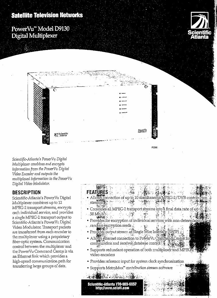
Satellite Televisión Networks
PowerVu™Modet D9Í3QDigital Multiplexer
iScientificAtlanta
P0366
Bdentific-Atlanta's PowerVu DigitalMultiplexer combines and encryptsinformation from the PowerVu DigitalVideo Encoder and outpnts themultiplexed information to the PowerVuDigital Video Modulator.
DESCR1PTIONScientific-Atlanta's PowerVu DigitalMultíplexer combines up to 12MPEG-2 transport streams/ encryptseach individual service, and providesa single MPEG-2 transport output toScientific-Atlanta's PowerVu DigitalVideo Modulator. Transport packetsare transferred from each encoder tothe multiplexer usíng a proprietaryfiber-optic system. Communicationcontrol between the multiplexer andthe PowerVu Command Centr.e is víaan Ethernet link which provides ahigh-speed corrununication path fortransferring large groups of data.
• Combines all MPEG-2 traítópórt s.treáms'.intQ'a.final data rate of-up tó¿||fa
• Provides'for encryption of individual services' wíth non-deterrninMa^S*-4;-, .v. .,-., ;r _ _ ,(. ,;M _ ... í. aKliM»..
v • - - . • • > - - . . . - -*•-, •• Pro vides output s tream ás'Sinffle Wire Iníerface '(SWIF) 'A.;'
Í* - X',-L ••*; ' • - - -:yv- ° -• •••:.f[; . ~ • '•'<-v'i«^.t-%^- < ríí'*" ,"A IT** '. ^-- - - ¡ - ' - • ",•'"•', 'n '$•'* 'TT ^í- ' ^* •'•-T<,Í:I' .'-rí;-í* .X ¡
• Allows etnernet connechon to PowerVu GommandCentre fo;J^ ií •"• j - • '^''j L u ^ " - ¿ .•^• tó'11^^ -^" - -
Supports redundant operation of both multiplexer^and MPE1
video encoders
Provides reference input for systern dock synduonization
Supports MetroMux™ contribution stream software
¿--Scientific-Atlanta 770-903-6057http://www.sciatl.com t -,"J ; v'-"5Í"'^-)-*í'.1''-V-ií^gíy
•.-. •- ',- . - • ._• y.-..T'j't;.-. . Ví*t^j'

I
P0364
MODEL D9711 MSYNC CONTROL CARD SETThe Control Card set is the heart of the PowerVu DigitalMultiplexer. Its primary responsibility is the multiplexingof services ínto a single MPEG-2 transport stream.Diagnostic and status information from all cards isreported via the control card back to the PowerVuCommand Centre. The MSYNC signal is used tosynchronize all service clocks and may be referenced tothe master studio clock. MSYNC is available from thei-PowerVu Model D9262 Master Sync Generator.
The I/O card provides an Ethernet connection allowingcommunication with the PowerVu Command Centre.Form C contact closure alarms are provided to indicateMinor, Major, and Power faults. A loop-through connectorfor the Scientific-Atlanta MSYNC signal is also provided.
MODEL D9730 SWIF RECEIVE CARD SETAll services generated within a single PowerVu DigitalVideo Encoder are transferred as MPEG-2 transportpackets via the SWIF (Single Wire Interface) opticalinterface. Each SWIF receive card accepts up to four SWTFoptical inputs and a máximum of three cards can beinserted into the chassis to increase the number ofavailable inputs. SWIF employs a low-cost, reliable fiber-optic system for iiiterconnection and provides signal noiseand ground loop immunity.
CONDITIONAL ACCESS AND SYSTEM CONTROL
ModelD9740 Conditional Access CardSetThe MSYNC Control card interfaces with the ConditionalAccess card, providing control of condicional accessservices.
The interface card for the Conditional Access card setprovides an Ethernet port for high-speed communicationwith the PowerVu Command Centre.
Conditional access information generated by the PowerVuCommand Centre is passed to the multiplexer vía anEthernet conneetion. Each video, audio, or data service isassigned a unique Packet IdentifLer (PID), and isindependently encrypted by the system. This level ofcontrol allows custom access levéis for each' decoder.
Additionally Form C contact closure alarms are providedfor ívíinor, Major, and Power alerte. A pass-through portfor the synchronization signal is also provided.
Model D9745 System Control Interface CardThis card functions identical to the D9740 ConditionalAccess card except that it is not equipped with DESservice scrambling capability.
iii

MODEL D9737 DVB SCRAMBLER CARDThe D9737 DVB Scrambler is an auxiliar/ card thatprovides the capabüity of scrambling services using theDVB Common Scrambling algorithm. This card mateswith the D9740 Conditíonal Access card or the D9745System Control I/F card to provide a complete condicionalaccess and scrambling solution.
MODEL D9733 DATA MULTIPLEXER CARDAuxiliary data services in tríe PowerVu system are handledby the PowerVu D9733 Data Multiplexer card. The DataMultiplexer card accepts up to four asynchronous dataservices and two high-speed services. Each high-speed portcan be independently configured for either commercial orbusiness data services.
Asynchronous, or low-speed data/ is accepted at RS-232levéis and rates from 300 to 38,400 baud. The user canselect máximum latency times and handshaking control.
Two íypes of high-speed data are supported by the D9733Data Multiplexer: commercial high-speed data andwideband broadcast data services. Many third partyproducís can be added to enable file transmission, databroadcast, and Internet services.
Commercial synchronous data services are accepted atRS422 levéis and discrete njtes from 9.6 kb/s to 2.048 Mb/s(El). The interface is a simple clock and data port, with norequirements for software protocol. The system can beconfigured to accept or supply the data clock at the uplinksite, but must supply the data clock at receive sites. Thisservice is only supported by appropríately equippedPowerVu Model D9233 Commercial Satellite Receivers.
Wideband broadcast data servicesfor BTV applications are accepted atRS-422 levéis and at discrete rates rangingfrom about 400 kb/s to 13.5 Mb/s. The interfaceis exactly the same as that of the commercial high-speed service, but the PowerVu system must supply thedata clock at both the uplink and receive sites. This serviceis only supported by PowerVu Business Satellite Receiversequipped with wideband broadcast data support
METROMUX SOFTWAREMetroMux™ software is an option available on thePowerVu Command Centre 2000,3000, and 4000 systems.The software enables the PowerVu Digital Multiplexer toremultiplex transport streams generated at diverselocations. Contact Scientinc-Atlanta for more informationon this software product.
STANDARD CONFIGURATIONThe PowerVu Digital Multiplexer contains the followingcards as a standard configuraa'on:
• MSYNC Control Card - Model D9711
• Conditíonal Access Card - Model D9740
• SWTF Receive Card - Model D9730
• Three empty slots
CardSet Options:• Additíonal SWIF Receive Cards - Model D9730
• Data Multiplexer Card - Model D9733
• DVB Scrambler Card - Model D9737
• System Control I/F Card - Model D9745
P0368

ModelD9130Digital Multiplexer
SPECIFICATIONS
Inputs
SWIF INProvides connecíivity for contribuíion síreamsWavelength: 660 nm, visible red fiber-optic sysíemConnecíor: HP versatile link
EthernetCommunication línkíothe PowerVu Command Centre for
transmission of system configuration and statusinformaron
Type: lOMb/sanalogConnecíor: RJ-45 (10Base-T)
MSYNCSynchronizes múltiple chassís to a single studio reference dockConnecíor: BNC (75O)
Auxilíary SerialFor future use
Outputs
SWIF OutCombined services transport stream for connecíion to a QPSK
modulaíororTelco InterfaceWavelengíh: 660 nm, visible red fiber-opíic sysíemConnecíor: HP versatile link
Alarms ContactsType: Form C contacísConnecíor: Spring terminal blockAlarms: Minoralarm, majoralarm, and powerfaultConíacts: 3 seis (NC, Common, NO) plus 2 grounds
OPTIONS
D9733 Data Multiplexer Card
Asynchronous Data InputsChannels: 4independeníType: RS-232E, DCE 9-pin D-sub femaleRates: 300,1200, 2400, 4800, 9600,19,200, 38,400 b/sFormaí: Datatransmitíed as 8 bits, no parity, 1 stop bit
Synchronous Data InputsChannels: 2independentType: RS-422, differential 5V inputs (clock & data),
9-pin D-sub maleCommercial Rates: 9.6 K, 19.2 K, 38.4 K, 57.6 K, 64 K, 76.8 K,
96 K, 115.2 K, 128 K, 192 K, 256 K, 384 K, 512 K,1.024 Mb/s, 1.536 Mb/s, 2.048 Mb/s
Business (Wideband Broadcast) Rates: 421.875 K, 843.75 K,1.6875 M, 3.375 M, 6.75 M, 13.5 Mb/s
EnvifonmentalOperaíing Temperature: 0°C ío 40°C (32°Fto 104°F)Storage Temperatura: -20°Cto 60°C (-4°Fto 140°F)Relative Humidiíy: 0% to 95% non-condensing
PhysicalDimensions:
8.75 in. Hx 19.0 in.Wx 20 in.D(13.3 cm H x 48.3 cm W x 50.0 cm D)5U high, 19 in. rack mountable
Power RequirementsVolíage Range: 10OV to 240V ac ±10% nominal .une Frequency: 47 Hz to 63 HzPower Consumption: 200Wmax.
The S cíe níific-Atlanta logo, MetroMux and PowerVu are trademarks of Scientiíic-Atlanta, Inc. Other trademarks mentioned are trademarks of their respectivecompames. Specifications and product availability are subject ío change withoutnoíice.
ScientificAtlanta
Scientific-Atlanta, Inc. Satellite Televisión NetworksUnited States: 4356 Communications Orive, Norcross, GA 30093; Tel.: 1-770-903-6057; Fax: 1-770-903-6464Canadá: 120 Middiefield Road, Scarborough, Ontario Ganada MIS 4M6;Tel.: 1-416-299-6888; Fax: 1-416-299-7145United Kingdom: Home Park Estáte, Rings Langley, Herts, United Kingdom WD4 8L2; Tel.: 44-1923-266133; Fax: 44-1923-269018Italy: Via Fosso Centroni, 4 Angolo Via Anagnina, 00040 Roma, Italy; Tel.: 39-67-984-0030; Fax: 39-67-984-0034Chile: Avda.11 de Septiembre 2155, Torre C-Of. 807, Santiago, Chile; Tel.: 56-2-232-2681; Fax: 56-2-232-2002Argentina: Scientific-Atlanta, Inc., 25 de Mayo 293, Piso 7A, 1002 Buenos Aires, Argentina;Tel.: 54-1 342-0321; Fax: 54-1 345-8047Singapore: Scientific-Atlanta (S) Pte. Ltd., 1 Claymore Orive,#08-11 OrchardTowers, Singapore 229594;Tel.: 65-733-4314; Fax: 65-733-2706Beijing: Lucky Tower, Block B, Suiíe 1413-14, No. 3 Dong San Huan Bei Lu, Beij'ing, China 100027; Tel.: 8610-461-5761; Fax: 8610-461-5754Australia: Unit2,2 Aquatic Orive, French's Forrest, NSW 2086, Australia; Tel.: 612-9-452-3388; Fax: 612-9-451-4432
•I42D329C © Copyright 1997 Scientifíc-Atlanta, Inc. All rights reserved. Printed in USA. 0697M

Satellite Televisión Networks
PowerVu™ Model D9380Digital Video Modulator
11ScientificAtlanta
The PowerVu Digital VideoModitlator ís a variable rate, high-perfonnance, MPEG 2/DVB compatibleQPSK modidator designedfor eithersingle channel or midtiple clmnnelsatellite transmission.
DESCRIPTIONScientific-Atlanta's PowerVu DigitalVideo Modulator is a flexible, high-performance, variable-rate satellitemodulator using digital signal .processing techniques for versatility.Used in conjunction with Scientific-Atlanta's PowerVu digital videocompression system for singlechannel or múltiple channelapplications, the modulator compileswith all applicable ITU-R and IESSrecommendations and is CE tested.
The PowerVu Digital VideoModulator accepts redundant singlewire interface (SWIF) optical inputsand outputs a QPSK modulatedsignal. The variable IF frequency canbe centered about either 70 MHz or140 MHz. Programmable FEC ratesand fully variable symbol rates allowfor optimization of transponderusage. Modulator operatingparameters and redundancy are allcontrolled by the PowerVuCommand Centre (PCC) via Ethernetcontrol ports.
FEATURES• MPEG-2/DVB compatible
• Frequency agüe output for 70 MHz or 140 MHz operation
• Menu-driven front panel control for stand-alone operation
• Selectable symbol rates frorn 1 Msymbols/s to 31 Msymbols/s
• • Usable Information rates from 0.93 Mb/s to 50 Mb/s
• Programmable Fonvard Error Correction (FEC) rates of 1/2,2/3,3/4,5/6, or 7/8'
• Transmission rates from 2 Mb/s to 62 Mb/s
• CW mode for uplink system alignment
• Input interfaces via optical Single Wire Interface (SWIF)
• On-line spare redundancy control via the PowerVu Command Centre
• Digital signal processing for baseband filtering
• Two rack units (2U) high
• Serial (SAbus) and Ethernet monitor and control ports
Scientific-Atlanta 770-903-6057http://www.isciatl.com

Model D9380Digital Video Modulator
SPECIFICATIONS
Operating CharacterísticsModulation: QPSKFraming and Coding: Compliantwith DVB specificaíionsViterbi FEC Rates: 1/2, 2/3, 3/4, 5/6,7/8ReedSoIomon: T = 8Convolutional Interleave: Depth of 12Symbol Rate: 1 to 31 Msymbols/s (100 symbols/s stepsize)Transmission Rate: 2 Mb/s to 62 Mb/s (200 b/s stepsize)Usable Information Rate: Ru = 0.93 Mb/s to 50 Mb/sAlpha = 35% per DVB specificationOuíput Frequency: 70 MHz (52 to 88 MHz) and 140 MHz
(104 to 17.6 MHz)Stepsize: 250 kHzSíability: <±2 ppmOutput Connector: BIMC (témale)Impedance: 75Q.Output Reíurn Loss: -20 dB max.Output Level: -5 to -25 dBm (0.1 dB steosize)Stepsize: 0,1 dBSynthesizer Phase Noise: Exceeds IESS-308 requirernentsOuíput Spurious (except CW mode):
In-Band: >50 dBc/4 kHzOut-of~Band: >80 dBc/4 kHz (fuíl transponder carrier)
>60 dBc/4 kHz (1/4 transponder carrier)Monitor Connector: BNC (témale, 7-5Q.) •Alarms: Summary alarm vía contact closureInpuí Data Iníerface: SWIF (optical), two ¡nput, switchableMonitor and Control: SAbus (EIA RS-422/485),
Ethernet (10Base-T)
EnvironmentalOperating Temperatura: 0°C to 50°C (+32°F to122°F)Storage Temperature: -25°C to 85°C (-13°Fto 185°F)Relative Humidity: 5% to 95% non-condensing
PhysicalDimensions: 3.5 in. H x 19 in. W x 22 in. D
(8.9 cm H x 48.3 cm W x 55.9 cm D)Weight: 20!bs(9kg)
Power RequírementsVoltage Range: 10OV to 240V ac ±10% nominalLíne Frequency: 47 Hz ío 63 Hz auto selectablePower Consumption: 60Wtypical
Carrier Bandwidth CalculatíonCarrier bandwidíh calculation based on a known carrier relativepower level and symbol rate ¡s as follows: •
1. From Table 1, determine the rolloff factor for a gívenrelative level.
2. Calcúlate carrier BW usingCarrier BW = symbol rate x rolloff factor
Example: Given symbol rate of 6.5217 Msymbols/s calcúlate thecarrier bandwidth at -40 dB relative power level.
1. From Table 1, rolloff factor for -40 dB relative powerlevel is 1.38.
2. Calculating carrier BW,Carrier BW = 6.5217 x 1.38 = 9 MHzCarrier BWat-40 dBis 9 MHz
i
Table 1.
Reí Lvl (dB)-3-10-16-20-26-30-40
Carrier Bandwidth RangesRolloff Factor Carrier BW (MHz)
1.0 1.0-31.01.2 1.2-37.21.28 1.28-39.681.31 1.31-40.611.34 1.34-41.541.36 ' 1.36-42.161.38 1.38-42.78
The Scientific-Aílanta logo and PowerVu are trademarks of S cié ntific-Atlanta, Inc.Other trademarks mentioned are trademarks of their respective companíes.Specifications and product availabiiity are subject to change wiíhout notice.
Scientif/cAtlanta
Scientific-Atlanta, Inc. Satellite Televisión NetworksUnited States;- 4356 Communications Orive, Norcross, GA 30093; Tel.: 1-770-903-6057; Fax: 1-770-903-6464Canadá: 120 Middlefield Road, Scarborough, Ontario Canadá MIS 4M6; Tel.: 1-416-299-6888; Fax: 1-416-299-7145United Kingdom: Home Park Estáte, Rings Ungley, Herís, United Kingdom WD4 8LZ; Tel.: 44-1923-266133; Fax: 44-1923-269018Italy: Via Fosso Centroni, 4 Angelo Via Anagnina, 00040 Roma, Italy; Tel.: 39-67-984-0030; Fax: 39-67-984-0034Chile: Avda.11 de Septiembre 2155, Torre C-Of. 807, Santiago, Chile; Tel.: 56-2-232-2681; Fax: 56-2-232-2002Argentina: Scientiíic-Aílanta, Inc., 25 de Mayo 293, Piso 7A, 1002 Buenos Aires, Argentina; Te!.: 54-1 342-0321; Fax: 54-1 345-8047Singapore: Scieníiíic-Atlanía (S) Pte. Ltd., 1 Claymore Orive, #08-11 Orchard Towers, Singapore 229594; Tel.: 65-733-4314; Fax: 65-733-2706Beijing: LuckyTower, BlockB, Suite 1413-14, No. 3 Dong San Huan Bei Lu, Beijing, China 100027;Tel.: 8610-461-5761; Fax: 8610-461-5754Australia: Unií 2,2 Aquatic Orive, French's Forresi, NSW 2086, Australia; Tel.: 612-9-452-3388; Fax: 612-9-451-4432
42D319C © Copyright 1997 Scientiíic-Aílanta, Inc. Al I righís reserved. Printed ¡n USA. 0397M

'^•^tartV'"- ' '
0MMON
«Si
DESCRIPTION
The DVB Cornmon Scramblingmethod is finding acceptance inmany markets. Scientific-Atlanta.is pleased to offer thistechnology in the PowerVu dig-ital compression product line.Common Scrambling wasformerly referred to asSuperscrambling, and can beconsiderad an alternativa to theDES method, Scrambling andencryption are the two elementsof conditional access necessaryfor rendering the signal securefor transmission and receptiononly by authorized parties.
DVB Common Scrambling is amethod of making the videoand audio elements of a trans-mission unintelligible.Common Scrambling does notimply common encryption (keymanagement), or that one com-pany's conditional access prod-ucts are directiy compatiblewith those of another,
Common Scrambling ¡n the
PowerVu Uplink
Support of CommonScrambling in the PowerVuuplink system incorporates asepárate card in the ModelD9130 Digital Multiplexer (i.ev
Model D9737 DVB Scrambler)which operates in conjunctionwith the Model D9745 SystemControl Interface card. All ser-vices requiring scrambling arepassed from the SystemControl Interface card to theDVB Scrambler card, thus mak-ing a multiplex either DESscrambled or DVB common-scrambled. Control of servicesand conditional access fuñe-tions remains unchanged com-pared to the existing DES-based PowerVu CommandCentre control computers. Allother elements of an uplinksystem also remain unchanged.
Common Scrambling in the
PowerVu Receiver
PowerVu decoders supportingCommon Scrambling can auto-sense whether a signal is DES-scrambled or commoivscram-bled. This simpliñes inventorymanagement and the userinterface. The Model D9223Commercial Satellite Receiveris currently available withCommon Scrambling as anoption. This feature will beoptionally available in mid-1997 on both the Model D9234Business Satellite Receiver andthe Model D9225 HeadendSafcellite Receiver. All receivers
will have DEScapability even ifordered with the CommonScrambling option.
The PowerVu Ad'vaníage
Common Scrambling PowerVusystems may also be orderedwith DES capability in theuplink. Havíng both scramblingmethods provides an immedi-ate recovery path in casescrambling is brbken. IfCommon Scrambling is broken,it is possible to change to theDES mode of operation, andimmediately recover the securi-ty of the signal. This can bedone without interruption ofservice, without site visite,without the cost and effort ofmailing out new smartcards,and without any kind of userintervention.
For more information, contactLouise WasüewskiSatellite Televisión Network DivisiónScientifie-Atlanta, Inc.4356 Communications DriveNorcross,GA 30093(770)903-6481 (phone)(770)903-6464 (fax)
©1997 Scienlific-Atlanta, inc. All rigltls reserved.Priuicd in U.5.A. The Scientific-Atlanta logo,
PoiuerVu, and MctroMitx aretrademarks of Scienlific-Atlanla, Inc.
42A421Z
Specificaiians and availabilily subjectlo change without nolicc.

Model 80107-Meter Satellite EarthStatíoil Antenna
ScientificAtlanta
P0373
Sdentific-Atíanta's Model 80107-Meter Earth Station Antenna offersbroadcast cjiíality performance combinedwith umtswl dependability and long-tenn economy in an earth station tliatfiáhj meéis FCC and CCIR recjuirementsfor radíation sidelobes,
DESCRIPTIONThe Sáentific-Atlanta Model 80107-Meter Earth Station Antenna is anideal cholee as a hub station for theexpanding business terminal market.It features an elevation-over-azimuthTORQUETUBE™ mount, availablewith either manual or motorizedactuators.
The TORQUETUBE mount covers180 degrees of azimuth in over-lapping 110 degree sectors or anoptional, continuous 180 degreemount is available.
Stretch-formed reflector panelsprovide a cost-effective product withthe gain and surface tolerancerequired for Ku-band operation. Thespecified gain is realized using thehigh-efficiency shaped surfacedesign techniques developed for
other Scientific-Atlantaantenna products. These designparameters were also chosen to yieldlow sidelobe characteristics that meetor exceed FCC or CCIR standards,including requirements for 2 degreesspacing.
OPTIONS• Motorización with AdapTrack
Controller
• De-idng
• Lightning protection
• Linear Ku-band feeds
• Linear and circular C-band feeds
• 180° continuous azimuth mountavailable
• Transmit waveguide kit
FEATURES• Compliant with FCQ INTELSAT, EUTELSAT, and CCIR recommendations
• All aluminum reflector
• High-efficiency shaped Cassegrain optics
• Mirdmum shipping and installaüon costs
• Locked-in surface accuracy minimizes panel alignment on-site
• Foundation design minimizes site preparation and installationrequiréiíiénts
• Uses Model 8860/8861/8862 Antenna Controller with AdapTrack opüon
• Supportecíby a fulllineof standard options
Scientific-Atlanta?.-'• 770-903-6001

M o ti e! 80107-MeterSatelliteEarthStation Antenna
SPECIFICATIONS
ElectrícalC-Band Ku-Band
Operaíing Frequency (GHz):TransmítReceive
Gain (Midband, Reí Peed Horn):TransmitReceiveFeed Insertion Loss (dB)
DP-2-PortRX/RX Linear:Receive
RT-2-PortRX/rx Linear:TransmitReceive
4PL-4-PortRX/TX Linear:TransmitReceive
4PC-4-PortRX/TX Circular:TransmitReceive
VSWR (Transmit/Receive):Beamwidth(-3dB):
TransmitReceive
First Sidelobe Level:Radiaíion Patíern: (C-Band and Ku-Band): Meets current FCC,
INTELSAT, EUTELSAT, and CCIR specificationsAntenna NoiseTemperature (Typical, Ref. Feed Horn):
Eievation C-Band Ku-Band10° 27K 36K20° 20 K 27 K30° 17 K 25 K40° 14 K 24 K
Power Handling Capability 5 kW (CW) 2 kW (CW)Cross Polarizaron Isolaíion (on axis, min.) (Linear):
Transmit 35 dB 35 dBReceive 30 dB 30 dB
Feed Port isolation (4-port Linear):TX/RX 85 dB 85 dBRX/RXandTX/TX 35 dB 35 dB
Voltage Axial Raíio:(Circular Polarizaron) 1.06:1
5.850 to 6.425
3.625 ío 4.2
51.2 dBi347.8 dBi1
.05'
.103
.10'
.153
.151
.173
.171
1.3:1
0.48°
0.71°14.0 dB
14.0 to 14.510.95 ío 12.75
58/Í dBi457.1 dBi2
.222
.21J
.222
.314
.332
1.3:1
0.22°0.25°14.0dB
MechanícalAntenna Diameter: 7 Meters (23 ft)Antenna Type: Cassegrain.Reflector Construction: 18 panels, precisión síreích-formed
aluminumMountType: Elevaíion-over-azímuíhAntenna Travel:
Eievation: 0° to 90° continuousAzimuth: 180° available in 3 overlapping 110° sectors
Polarization Adjustment:Manual: 360° continuousMoíorized: ±90°
AníennaTravel Rate (Moíorized): Various - Consult Factory
C-Band Ku-BandFeed Interface:
Transmií: CPR-137G WR-75Receive: CPR-229G WR-75
WeightMeí: 4,500 Ibs (2,041 kg)Shipping: 6,500 Ibs (2,948 kg)
Shipping Volume: 820 ft3 (23.2 m3}
EnvironmentalWind Loading:
Operational: 80 mi/h (129 km/h) gusíing to 95 mi/h(153km/h)
Survival: 125 mi/h (201 km/h), no ¡ce 87 mi/h (140 km/h),wiíh 1 in. (2.5 cm) radial ice
Temperature Range:Operational/Survival: -40°F to +150°F (~40°C to +65°C)
Aímospheric Condiíions: Salt, poliutants and corrosiveconíaminants asfound in coastal and industrial áreas.
Noíe: ' Referencedaí3.95GHz2 Referencedatl 1.95 GHz3 Referencedat 6.175 GHz4 Referenced ai 14.25 GHz
The Scíentifíc-Atlanta logo and TORQUETUBE are trademarks oí Scientific-Atlanía,Inc. Oíher trademarks meníioned are trademarks of íheir respective companies.Specifications and product availabiliíy are subject ío change wiíhout notice.
III
I
ScientificAtlanta
Scientifíc-Atíanla, Inc. Sateliite Networks DivisiónUnited States: 4356 CommunicatJons Orive, Norcross, GA 30093; TeL: 1-770-903-5000; Fax: 1-770-903-6245Canadá: 120 Middlefíeld Road, Scarborough, Ontario Canadá MIS 4M6;TeI.: 1-416-299-6888; Fax: 1-416-299-7145United Kingdom: Home Park Estáte, Rings Langley, Herís, United Kingdom WD4 8LZ; Tel.: 44-192-326-6133; Fax: 44-192-326-9018Australia: Unií 2,2 Aquatic Orive, French's Forrest, NSW 2086, Australia; Tei.: 612-452-3388; Fax: 612-451-4432Itaíy: Via Fosso Centroni, 4 Angolo ViaAnagnina, 00040 Roma, Itely; TeL: 39-67-984-0030; Fax: 39-67-984-0034Chile: Avda.11 de Septiembre 2155, Torre C-Of. 807, Santiago, Chile; TeL: 56-2-232-2681; Fax: 56-2-222-2002Singapore: ScientifÍc-Aílanta(S) Píe. Lid., 1 Claymore Orive, #08-11 Orchard Towers, Singapore 229594; Tel.: 65-733-4314; Fax: 65-733-2706Beijing: LuckyTower, Building B, Suite 1110-1112, No. 3 Dong San Huan Bei Lu, Beijing. China 100027; TeL: 8610-461-5761; Fax: 8610-461-5754
42D191B © Copyright 1995 Sdentific-Atlanta, Inc. All rights reserved. Printed in USA. 0596M
I
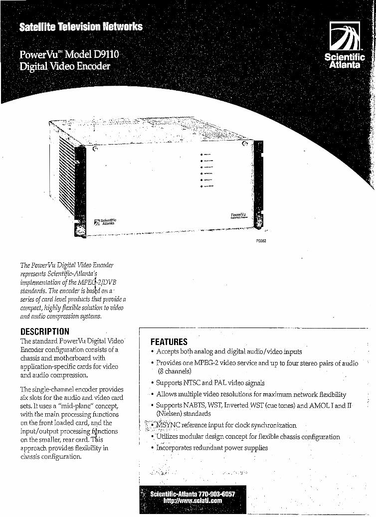
Satellite Televisión Networks
PowerVu™ ScientificAtlanta
—71 Sclentiflc7jl\a
Tlie PoioerVu Digital Video Encoderrepresents Scientific-Atlanta'simphnentation of the MPEG-2¡DVBstandards. The encade)- is based on a -series ofcard level producís tlmi provide acampad, highly flexible solution to videoand audio compression systems.
DESCRIPTIONThe standard PowerVu Digital VideoEncoder configuration consists of achassis and motherboard withapplication-specific cards for videoand audio compression.
The single-channel encoder providessix slots for the audio and video cardsets. It uses a "mid-plane" concept/with the main processing functionson the front loaded card, and theinput/output processing fánctionson the smaller, rear card. Tlkisapproach provides flexibility inchassis configuratíon.
P0363
FEATURES• Accepts both analog and digital audio/video inputs
• Provides one MPEG-2 video service and up to four stereo pairs of audio(8 channels) • .
• Supports NTSC and PAL video signáis
• Allows múltiple video resolutions for máximum network flexibility
• Supports NABTS, WST7 Inverted WST (cue tones) and AMOL I and H(Nielsen) standards
• MSYNC reference input for clock synchronization •
• Uülrzes modular design concept for flexible chassis configuration
• Incorporates redundant power supplies ''.
Scientific-Atlanta 770-903-6057http://wv.ny.sciatl.com

MODEL D9786 VIDEO INPUT CÁRDThe video input card accepts either analog composite orcomponent video and converts it to an ITU-R-601 formatthat is ready for compression. It will also accept an ITU-656 serial signal directly and pass it to the videocompressor.
The video input card synchronizes incoming vídeo to thesystem timebase, allowing the incoming video signáis tobe asynchronous to each other. It performs 10-bitprocessing and provides the necessary fíltering anddownsampling to the appropriate resolution prior tocompression. This enables one encoder to compress a widerange of programming from film-based to studio quality.As network applications and programming coníentchange, customers can change the video data rate tomaximize the quality o£ transmitted video.
MODEL D9787 MPEG-2 VIDEO ENCODER CARDThe video encoder card compresses the digitized videosignal received from the input processor. Video iscompressed usingMPEG technology and state-of-the-artadaptive field/frame encoding algorithms. Compressedvideo is then packetized into a transport stream and sentto the control card.
ModelD9783 Cue Tríggerl/0 CardThis optional I/O card mates with the D9787 MPEG-2Video Encoder Card providing connection between thePowerVu encoder and contact closure equipment such asVTTC decoders or commercial insertion equipment. Thecontact closure information is transmitted with thecompressed video and output at the receiver expansiónport. Two input interface formats are supported. A barrierstrip accepts physical contact closure information fromrelays and switches while an RS-232 serial port acceptsdata from customer equipment and computers. Up to foursepárate closures outputs are supported for the entire
. PowerVu receiver product family. The PowerVu ModelD9223 Commercial Satellite Receiver can support anadditional four closure outputs.
MODEL D9782 AUDIO ENCODER CARD SETThe audio encoder card accepís four mono input channels,which can be configured as two stereo pairs in eitheranalog, AES/EBU digital format or an AES/EBU digitalaudio signal embedded in a serial-Dl stream. Inputs areprocessed using MPEG (Musicam) audio compressionprior to packetization, and transferral of the data to theMSYNC Control card. A wide range of audio bit rates issupported.
MODEL D9785 VBI DATA PROCESSOR CARDThe VBI data processor card accepts a composite videosignal and an optional video sync reference.
The VBI card processes video-data unes in the verticalblanking interval. Normally these Unes are not visible tothe viewer, and are used to transmit information such asclosed captioning, teletext, and Nielsen rating information.The VBI card processes valid data lines in either NTSC orPAL video signáis. Data is extracted and passed through tothe receiver/ where it is reinserted into the correct locationin the video frame. Currently supported data standardsinclude: NABTS, WST, Inverted WST (cue tones), andAMOLI and II (Nielsen). Non-data video waveforms suchas NTC7, VTTS and VIRS are not supported.
RS-232 ports aüow connectíon of subtitle transmissionequipment providing up to three data streams with onelanguage per stream. Each subtitle stream is transmitted asa service with video for reception at the receiver. Theappropriate subtitle stream is decompressed and displayedover video as determined by the virtual channel selectionat the receiver.
MODEL D9711 MSYNC CONTROL CARD SETThe main function of the MSYNC control card set is tomultiplex the services into a single MPEG-2 transportstream. Diagnostic and status information from all cards isreported via the control card back to the PowerVuCommand Centre. The MSYNC signal is used tosynchronize all service docks with the master studio clock.MSYNC is available from the PowerVu Model D9262Master Sync Generator and may be referenced to a masterstudio clock or standard clock reference,
An Ethernet connection is provided to allow the card tocommunicate with the PowerVu Command Centre. FormC contact closure alarms are provided to indícate Minor,Major, and Power faults. Aloop-through connector for theScientific-Atlanta MSYNC signal is provided.

ModelD9711ModelD9786ModelD9787ModelD9782
STANDARD CONFIGURATIONThe PowerVu Digital Video Encoder contains thefollowing cards as a standard configuration:
• MSYNC Control Card• Advanced Video Input Card• MPEG-2 Video Encoder Card• Audio Encoder Card ;• Two expansión slots g
Expansión Card Set Options:
• Additional Audio Encoder - Model D9782• VBIDataProcessor - Model D9785
• Cue Trigger I/O - Model D9783
SPECIFICATIONS
Video InputsA cholee oí video inputs provides migration path from existinganalog to digital equipment
Composite Video InputImpedance: 75Q unbalancedVideo Level: 1Vp~p±0.3Vp-pSync: OV to -0.286V p-p, composite videoReturn Loss: >25 dBBandwídth:
Upto4.2MHz(NTSC) jUpto5.5MHz(PAL) J
Connecíor: BNC loop-through (orterminated)
Component Video InputImpedance: 75O unbalancedVideo Level: BettaorMII.selectableReturn Loss: >25 dBBandwidth:
Up to 4.2 MHz (NTSC)Up to 5.5 MHz (PAL)
Connector: BNC loop-through (orterminaíed)
Serial Digital (01) Video Inputimpedance: 75Q. unbalancedlnterface:SMPTE259M(270Mb/s) -Format: ITU-R-601 •<*- CGt&-Connector: BNC ¡oop-through (active)
Audio Inputs
Analog Audio InputProvides migraíion path írom existing anaíog to
digital equipmentRange: 2GHzto20kHz±0.25 dBImpedance: >10Kohm,all levéis reíerence to 600Q sourceAudio Level:
O dBm (APL)+18 dBm (PPL)
Sample Rates: 32K, 44.1 K, 48K samples/secondIndicated Clip: +18.2 dBmMáximum Input: +26 dBmLevel Adjusí: ± 8 dBA/V Delay Adj.: ± 17 ms relaíive to videoConnecior: XLR-3-31 (female pin, male shell)
Digital Audio InputSerial ¡nterface: AES/EBU formatSample Rates: 32 K, 44.1 K, 48 K samples/second, 16-bit linear
or 48 K samples/second, 20-bit linearConnector: XLR-3-31 (female pin, mafe shell)
Optional Digital (D1) Audio InputImpedance: 75ü unbalancedInterface: SMPTE259M (270Mb/s)AES/EBU (as above)Format: 1TU-R-6G1Connecíor: BNCIoop-íhrough (active)
EthernetCommunication linkto PowerVu Command Centre íor
transmisslon of system configuration and statusinformation.
Type: 10 Mb/s analogConnector: RJ-45 (10Base-T)

ModelD9110Digital Video Encoder I
P0365
Video: MPEG-2 adaptive field/frame encoding(Main Level/Main Profile)
Video Bit Rates: 3to15Mb/sAudio: MPEG-1 layer 2 encodingAudio Bit Bates: 64to384kb/sTransport: Mulíiplexed MPEG-2 transport packets, with individual
audio and vídeo packetized elementary streams (PES)Format; SWIF (Single Wire Interface)Waveiength: 660 nm, visible red fiber-optic systemConnector: HPVersatilelink
Alarms ContactsType: Form C contactsConnecíor: Spring terminal blockAlarms: Minor Alarm, Major Alarm, and Power FaultContacts: 3 sets (NC, Comrnon, NO) plus 2 grounds
OPTIONS
D9785 VBI Data Processor Card
Composite Video Input OnlyImpedancé: 75O unbalanced, resistiveVideo Level: 1V p~p, synctipto 100% white barRate: Up to 6.9375 Mb/s instantaneousActive Lines:
NTSC: Iinesl0to22,fields1 &2PAL: Iines7to22,fields1 &2
External Sync: Levéis in accordance with CCIR-624 for NTSCand PAL modes
Connector: BNC loop-throughStandards: NABTS, WST, Inverted WST, AMOLI and II (Nielsen)
'ZnvironmentalOperating Temperature: 0°C ío 40°C (32°Fío 104°F)StorageTemperaíure: -20°C ío 60°C (-4°Fto 140°F)Reiative Humidity: 0% to 95% non-condensing
PhysicalDimensions:
8.75 in. Hx 19.0 in.Wx 2.0 in. D(13.3 cm H x 48.3 cm W x 500 cm D)5U higrí, 19 in. rack mountable
Power RequirementsVoltage Range: 10OV to 240V ac ±10% nominalUne Frequency: 47 Hzto 63 HzPower Consumption: 200W max.Redundant power supplies
The Scíentific-Atlanta logo and PowerVu are trademarks oí Scientific-Atlanta, Inc.Other trademarks mentioned are trademarks of iheir respective companies.Speciíications and product availability are subject ío change wiíhout notice.
III
I
ScientificAtlanta
Scientific-Atlanta, Inc. Satellite Televisión NetworksUnited States: 4356 Communications Orive, Norcrass, GA 30093; Tel.: 1-770-903-6057; Fax: 1-770-903-6464Canadá: 120 Middlefíeíd Road, Scarborough, Ontario Ganada MIS 4M6;TeI.: 1-416-299-6888; Fax: 1-416-299-7145Uniíed Kingdom: Home Park Estáte, Kings Ungley, Herts, United Kingdom WD4 8LZ; Tel.: 44-1923-266133; Fax: 44-1923-269018Italy: Via Fosso Centroni, 4 Angolo Via Anagnina, 00040 Roma, Italy; Tel.: 39-67-984-0030; Fax: 39-67-984-0034Chile: Avda.11 de Septiembre 2155, Torre C-Of. 807, Santiago, Chile; Tel.: 56-2-232-2681; Fax: 56-2-232-2002Argentina: Scieníific-Atlanta, Inc., 25 de Mayo 293, Piso 7A, 1002 Buenos Aires, Argentina; Tel.: 54-1 342-0321; Fax: 54-1 345-8047Singapore: Scientiíic-Atlanta (S) Pte. Ltd., 1 Claymore Orive, #08-11 Orchard Towers, Singapore 229594; Tel.: 65-733-4314; Fax: 65-733-2706Beijing: LuckyTower, Block B, Suiíe 1413-14, No. 3 Dong San Huan Bei Lu, Beijing, China 100027; Tel.: 8610-461-5761; Fax: 8610-461-5754Australia: Unií 2,2 Aquatic Orive, French's Forresí, NSW 2086, Australia; Tel.: 612-9-452-3388; Fax: 612-9-451-4432
42D328C © Copyright 1997 Scientific-Atlanta, Inc. All rights reserved. Priníed in USA. 0697M

Satellite Televisión Networks
PówérVu ScientificAtlanta
SATELUTE TELEVISIÓN NETWORKS •*
PcmerVu™Digital Video Compression Systems
wítíi Dígito/ Televisión for ifií 2/íí Ctrtuiy
: to giidc yon inio tbi igltJ ftture."When you nicd lomea
needt, aod fe »c ffl stxforrthyíir ofrjjjpíj-rvj WPEG-biIcd {l o-/tie Pitarcí Eípcrtí GroLp)
'Itíipo'iTTSJ tomtna-kinof CKÍ amlogbraliec, cotpled witíi our cuüng edg= ¿Í0o¿ tetíaolofy,
Ciupo McdcOTi-TtlcRed, Cltál,tlic£jopcm Etoodcail Union, Gccciil Molón, KoreaTelecom,Tuniír Bn-j-icajaoj, &>d aaoy a&ai.
Sáentific-Atlanta's PoiverVu system combined with readilyavaüable, off-the-slielf PC producís creates a variety ofcost-effective sohitions for moving data from a satellite itplink toreinóte receive sites,
DESCRIPTIONReliable video distributíon is the main reason a growingnumber of programmers and broadcasters are installingPowerVu MPEG-2/DVB digital video compressionsystems. Many are extending the systenYs contributionmade to overall business operations through theimplementation of data applications/ including Internetaccess, data streaming, and file transfers.
These value-added applications/ developed using customerinput and existing PC perípheral equipment, enable usersto capitalize on these capabilities via existing PCs/ modems/and networks. Since additional off-the-shelf equipment isreadily available, implementíng these new capabilities can becompletad quickly and often without major expenditures.
Internet AccessThe Internet access application capitalizes on the PowerVusystem's ability to deliver a 2 Mb/s "pipe" via satellite fortransmitting huge amounts of data from an Internet site toa remote client site (see diagram on next page).
Since transmitting data from the client site to the Internet isas easy as mouse clicks or a few keystrokes/ this link can beadequately served usrng 28.8 or 33.6 kb/s modems overtelephone lines. But rather than directly accessing theInternet/ the client modem connections arrive at a localserver equipped with a TI Master PC card from LinearSystems Inc. Connectivity between this server and theInternet is completed via a terrestrial link/ such as a TI orISDN line. The server passes the client P.Cs requests forinformation to the Internet and as the response flows backit is stored (cached) on the server's hard drive. Then/ usingthe TI master/ the response information is also routed to thePowerVu system for distribution back to the remote clientvia a 2 Mb/s satellite link instead of over the lower speedmodem link. Even with the time required for satellite delay,this low-speed-in/ wide-path-out solution providessignificant response-tirne performance improvementscompared to traditíonal modem bi-directional Communi-cations/ and severa! clients can share the 2 Mb/s link.
Scientific-Atlanta 770-903-6057http://wwrw.sciatl.com

Bidirecíional28.8 Kb/s ünk
Internet Access Sijstem Application
Data StreamifigData streaming applications are virtually identical to thesateilite broadcast of video programming provided by thePowerVu system (see diagram below).
In Canadá/ software from Televitesse Systems Inc. is usedin the PowerVu system to transmit digitízed live or storedversions of audío and video material via sateilite tocustomers equipped with accesTV™ videoasset management software. The PowerVusignal can broadcast accesTV digital videostreams to remote sites using IP unicast (toa particular site) or IP multicasting (to anumber of remote sites). At the remote site,the video streams can be distributed locallyover an existing corporate LAN to anynumber of computers on the network.accesTV has been integrated with leadingmedia servers such as the Oracle VideoServer to provide manageable, largevolume video-on-demand solutions. Acentralized archive can be placed at the"headend" allowing users to "pulí" contenton-demand via the PowerVu system, oralternatively place it at the "edges" to
provide a "push" solution. Using the PowerVu signalwith Televitesse software/ indexed, searchable, andscaleable video can be delivered to corporations whichneed to provide live or pre-recorded news, training-on-demand/ CEO'messages, and late-breaking information totheir employees and customers.
IIIII
3sr~
Server transmits pre-stored contení(Í.6.JW1 files) as TCP/IP(UDP)packeís over 2 Mb/s sateilite link
Server
'. 2 Mb/s1RS-422 )¡nk
Gllents receive multicast broadcast packets viaT1-Master cards, and can p!ay multimedia informationin real time.
i
Data Streaming Application

File TransferMoving large amounts of data at scheduled times tospecific PCs can be supported by the PowerVu system andthe Fazzt™ Digital DeHvery System from KenCast, Inc.(see diagram below).
Since managing transmission of ver}7" large files does notrequire the overhead that accompanies TCP/IP or Internetdata, the Fazzt system assigns a very small header to thedata to simplify operatíons and increase efficiency. A cardin the transmitting PC (server), opera ting under thedirection of Fazzt Windows 3.1/NT/95 software, routesthe files to the PowerVu system for satellite uplink and•delivery to the remote sites. Additional software and PCcards at the receive sites complete the system. Files may bequeued up and transmitted as they become avaüable orscheduled for delivery at specific times. The Fazzt systemnot only allows you to specify which files are sent, but alsocontrols where they are stored i.ev the directory locationon the.receiving hard drive.-This application is very usefulfor updating remote multimedia kiosks. Luce the otherPowerVu data applications, this flexible system formoving files uses readily avaüable PC producís which canbe installed in existing computers at customer locations.
The PowerVu AdvantageFor more than 20 years and in morethan 130 countries worldwide, Scientific-Atlanta has provided innovative technologyto the cable/ broadcast, business, and hometelevisión markets. The Satellite Televisión NetworkDivision's PowerVu product line includes the latestgeneration of MPEG-2/DVB encoding and decodingproducís/ and the PowerVu Command Centre providesnetwork management/ signal security/ and subscriberaccess control systems. Additionally/ the división offers afull range of earth station antennas/ controllers/ RFconverters/ exciters and receivers to provide customers
' with end-to-end televisión distribution systems.
ConteníProvider
RemoteSíation 1
RemoteSíaiion 2
File Transfer Application

PowerVu® Data Applications 1\--''<:-'?:^[ ^ ';.-;";. ;,fEATl^ :;:'/;.:..:;;;:S- ^CÓMMÉRCI^ BUSfí^S£^
Data Types Accepted
Interface Levéis
Data Rates Supported
Connector
Uplink Clo'cking Modes
Simultaneous Services
PowerVu Command Centre Support
Supports Third Party Equipment
High-speed data
RS-422
9.6 K, 19.2 K, 38.4 K, 57.6 K, 64 K, 76.8 K,115.2 K, 128 K, 192 K, 256 K, 384 K, 512 K,1.024 M, 1.536 M, 2.048 Mb/s
9-pin D female
Internal (supply)
External (accepted)
Yes
Yes
Yes
Wideband data
RS-422
421.875 K, 843.75 K^l.687 M, 3.375 M,
6.75 M, 13.5 Mb/s
9-pin D female
Internal (supply only)
Data with audio and video (up to3.375 Mb/s)
Yes -
Yes
I
Contact the vendors mentioned in this literature for more
information on their products. '•'
Linear Systems Inc. web address: www.linsys.ca
Kencast, Inc. e-mail: [email protected]
Televitesse Systems Inc. e-mail: [email protected]
The Scientific-Atlanta logo and PowerVu are registered trademarks ofScientific-Atlanta Inc., accesTV Ís a trademark of Televitesse Systems,
Inc., and Fazzt is a trademark of Kencast, Inc. Other trademarksmentioned are trademarks of their respective companies. Specifications
and product availability are subject to change without notice.
ScientificAtlanta
Scientific-Atlanta, Inc. " Satelüíe Televisión NetworksUnited States: 4356 Communications Orive, Norcross, GA 30093; Tel.: +770-903-6057; Fax: +770-903-6464Canadá: 120 Middlefield Road, Scarborough, Ontario Ganada MIS 4M6; Tel.: +416-299-6888; Fax: +416-299-7145United Kingdom: Home Park Estáte, Rings Langley, Herts, United Kingdom WD4 812; Tel.: +44-1923-266133; Fax: +44-1923-269018Italy: Via Fosso Ceníroni, 4 Angelo Via Anagnina, 00040 Roma, líaly; Tel.: +39-67-984-0030; Fax: +39-67-984-0034Chile: Avda.11 de Septiembre 2155, Torre C-Of. 807, Santiago, Chile; Tel.: +56-2-232-2681; Fax: +56-2-232-2002Argentina: Scienírfic-Aílanta, Inc., 25 de Mayo 293, Piso 7A, 1002 Buenos Aires, Argentina; Tel.: +54-1 342-0321; Fax: +54-1 345-8047Singapore: Scientific-Atlanta (S) Píe. Ltd., 1 Claymore Orive, #08-11 Orchard Towers, Singapore 229594; Tel.: +65-733-4314; Fax: +65-733-2706Beiiing: LuckyTower, Block B, Suite 1413-14, No. 3 Dong San Huan Bei Lu, Beíjing, China 100027; Tel.: +8610-6461-5761; Fax: + 8610-6461-5754Australia: Unit 2,2 Aquatic.prive, French's Forrest, NSW 2086, Australia; Tel.: +61-2-9-4523388; Fax: +61-2-9-4514432
42D433Z © Copyright 1997 Scientiíic-Atlanía, Inc. All righís reserved. Printed in USA. 0897M

P0333
The PowerVu Commercial SatellüeReceiver is one ofa series of Scientific-Atlanta MPEG-2/DVB digitalcompression producís designedforbroadcast and cable headend aptplications.
DESCRIPTIONScientific-Atlanta's PowerVuCommercial Satellite Receiver isoptimized to receive broadcasts usingstate-of-the-art MPEG-2 digitalcompression technology. The receiveroffers features such as the capabilityto receive digitally encrypted videoand audio/ utílity data, VBI, teletext,and conditional access.
Single or Múltiple Channel PerCarrier OperatíonThe PowerVu Commercial SatelliteReceiver is configured to receiveeither single channel or múltiplechannel information services. Thisprovides a migration path fromanalog to digital services without theneed for expensive equipmentchangeouts.
FEATURES ^ ;>.• MPEG-2/DVB digital video and audio signáis in 525- or 625-line systems
--Sínáe- or multiple-channel per carrier operation^
_^¿ariable symbol rates from 3.0 Msymbols/s to 30.8 Msymbols/s
' sSectable ViterbLForward Error Correction rates of 1/2, 2/3,3/4,5/6 or7/8 (installer selectable or down-loadable over satellite)
Two pairs of balanced audio outputs with detachable connectors for easyinstallation
Non-encrypted utílity data output at rates up to 38.4 kb/s
Sepárate text and video output, allowing the operator to access• diagnostics menus without disrupting the decompressed video signaloutput
Supports VBI reinsertíon of NABTS, AMOL I and E (Nielsen), and WSTdata .
Supports reinsertíon of VBI lines 10 to 22 in NTSC fields 1 and 2 or PALlines 7 to 22, fields 1 and 2
Eight programmable output switches and Form C contact closures forcontrol of external devices such as VCRs and transmitters
Compatible with 4x3 and 16x9 wide aspect raido transmissions
Downloadable software capability via the PowerVu Command Centreproviding site upgradeability
Smart card receptade for field upgradable security*''' • •
Remote serial interface for monitoring diagnostícs and tuning control
Scientific-Atlanta 770-903-6057http://www.sciatl.com

MPEG-2 Video DecompressionThe PowerVu Commercial Satellite Receiver is equippedwith an MPEG-2 video decompression.processor thatallows the receiver to decompress either MPEG-1 orMPEG-2 video Information streams. Once decompressed,the receiver automatically detects the Une rate of theoriginal video and returns it to its original 525-line NTSCor 625-line PALformat. The video is then outputforredistribution on a BNC connector to facilítate connectionto other broadcast receive equipment. The output can beselected in either 16x9 or 4x3 aspect ratio format.
Video StandardThe D9223 receiver is capable of receiving 525-line or 625-line video formats and displaying them as either NTSC,PAL-M, PAL-B, or PAL-N respectively.
MPEG-2 Audio ChannelsThe PowerVu receiver is equipped with an MPEG(Musicam) audio decompressor. Audio is output on600 ohm balanced screw termináis suitable for audioredistribution. Unbalanced audio outputs are alsoprovided for coni'iection to standard TVs. Output levéisfor each balancee1, channel are adjustable on the rear panel.An additional four mono charmels or two stereo pairs areavailable as an option.
Search and FindThe search and find feature provides ease of installation.The find function is used to forcé the receiver to search fora digital channel when the downlink frequency is notknown. This is especially useful when installing thereceiver. Search is used to reacquire a digital channelbroadcast by the network.
Monitor Video OutputA monitor output is provided as a standard feature formonitoring the receiver's diagnostics and performancewithout interrupting the video services. This output alsoprovides video.
Enhanced SecurítyThe receiver is equipped with a smart card slot in the frontpanel of the unit. Smart cards may be used to change thesecurity and identity of the receiver if piracy of the signalis suspected.
Cue Tone Equivalent SignallingThe receiver pro vides control outputs to drive externaldevices for real-time switching. This feature can be used toaid in the insertion of local advertisements at the headend.
Easy Installation and Channel TuningAll Information needed for proper installation and set up ofthe PowerVu receiver can be found in one of three places:
the easy-to-follow guide supplied with each unit; the frontpanel display; or the sepárate on-screen menú text display.When the unit is turned on and tuned to the correctdownlink frequency in either the C- or Ku-band range, thefrequency plan, virtual channel map, and conditionalaccess information are transmitted to the receiver wherethey are stored in nonvolatile memory. Virtual charmels arethen used to select the authorized services. Flexibility fordefining these channels, as well as other services/ isprovided by the PowerVu Command Centre.
SuhtitlingThe receiver is capable of supporting miútilingualsubtitling within the PowerVu system. Implementation ofsubtitling is independent of the character type and thuscan be displayed in any language.
MPEG-2 Input and OutputIf the receiver is equipped with the optional MPEG-2input, it can be used to monitor a PowerVu uplink signalbefore transmission. Alternatively, the input can be used interrestrial applications to receive and display a SWIFsignal from a PowerVu Telco Interface Unit (TtU).
The MPEG-2 transport output is useful for applicationswhere signáis are to be remultiplexed and transmittedover múltiple satellite hops. PowerVu MetroMux™software is applicable for tros system transmissionapplication, retaining the same video and audio quality asthe original source signal: Please contact Sdentific-Atlantafor more information on this PowerVu software product.
Additional OutputsThe PowerVu receiver offers a non-encrypted asynchronousutility data port with selectable data rates up to 38.4 kb/s.
Eight open-collector outputs are also provided for remotecontrol of transmitters, VCRs, or other external devices.These eight outputs can be set on the front panel orcontrolled from the uplink.
Two relay contacts are provided on the receiver. The firstindicares authorization while the second is controlled byany one of the eight remote control pins. These relaycontacts can be enabled or disabled on the front panel orvía an RS-232 terminal.
An AGC output is provided to aid in signal peaking(antenna tuning). A remote control port allows access tothe receiver's front panel functions vía an RS-232 terminal.This allows monitoring of key receiver parameters fordiagnostics control.

SPECIFICATIONS
System - MPEG-2/DVB CompatibleModulation: QPSKInner FEC: Variable (1/2, 2/3,3/4,5/6, or7/8)OuíerFEC: Reed Solomon,T=8MPEG-2Transport
TunerInput Level: -30 dBm to -65 dBm per carrierFrequency Range: 950 MHzto 2050 MHzTuning Stepsize: 250 kHzSymbol Rate Range: 3.0 Msymbols/s to 30.8 Msymbols/sSíepsize: 100symbols/sCarrier Capture Range: ±1.5MHzCarrier Acquisition Time: < 2 secondsSatellites: C-band and Ku-bandImpedance: 75H
Video Output [RS-250C satellíte]Video Decompression Type: MPEG-2Level:
100IRE±5%(NTSC)1.0Vp-p±5%(PAL)
Frequency Response:-2 dB'at 5.0 MHz, 704 x 480/576 sample densiíy-2 dB at 3.0 MHz, 544 x 480/576 sample densiíy
Máximum Video Resoluíion: 704x576Chroma-luma Delay: ±26nsReíd Time Distoríion:
<3IRE(NTSC)<2%(PAL) -
LineTime Disíoríion: <1%ShortTimeDistortion: <2%Luminance Nonlineariíy: < 5%Differential Gain:
<4IRE(NTSC)<4%(PAL)
Differential Phase: 2°Signa¡-ío-[\loiseRatio:>56dB
Audio OutputsNumber of Channels: Two stereo pair or four mono channelsOutput Level: Balanced, adjustable audio outputs are factory set
for uniíy gain (O dBm out for O dBm in). Range is adjustablefrom-10dBto+2dB, providing a máximum outpuíof upto+18dBminto600a
Frequency Response: ± 2.0 dB, 20 Hz ío 20 kHzTotal Harmonio Distortion: < 0.3% at 1 kHzDynamic Range: 80 dB (CCIR/Arm weighting)Crosstalk: 60 dB
Expansión PortUtility Data: RS-232 asynchronous data at rates
up to 38.4 kb/sSetíings: 300,1200, 2400,4800, 9600,19,200, and
38,400 b/s
MPEG-2 OutputScientific-Atlanta SWIF link. MPEG-2 transport format with
muitiplexed video, audio, and data
OPTIONSAddiíional Two Stereo Pairs or Four Mono Channels: 600Q
balancedDigital Video Output (D1) and Digital Audio Output
Serial Interface:Video: SMPTE 259MAudio: AES/EBU format
MPEG-2 Input: Scieníific-Aílanía SWIF link. MPEG-2íransport format with multiplexed video, audio, and data
High-Speed Data: RS-422 synchronous data at raíes from9.6 kb/s to 2048 kb/s
Settings: 9.6 K, 19.2 K, 38.4 K, 57.6 K, 64 K, 76.8 K, 96 K,115.2 K, 128 K, 192 K, 256 K, 384 K, 512 K, 1.024 M,1.536 M, and 2.048 Mb/s
EnvíronmentalOperating Temperature: 0°C to 50°C (32°F to 122°F)Storage Temperature: -40°C to 60°C (-40°Fto 140°F)Relative Humidity: 5% to 95% non-condensing
PhysicalDimensions:
3.5 in. Hx 19.0 in.Wx 13.3 in. D(8.9 cm H x 48.3 cm W x 33.8 cm D)Chassis is two units high, capable of rack mouníing in an
EIA standard 19 ¡n. wide rackWeight: 11.5 Ibs (5.22 kg) approx.
Power RequirementsVoltage Range: 100Vto240Vac±lO% nominalUne Frequency: 47 Hz to 63 HzPower Consumption: 63Wmax.LNB Orive Voltage:
Three position slide switchPosition 1 - +19V do @ 500 mA max.Position 2 - offPosition 3 - +13V/+19V @ 500 mA max.,
HA/ controlled output for dual modeapplications

Model D9223Commercial Satellite Receiver
Ordering Information
HOWTOORDER ' ' • - '
STEP,
1
2
DIRECTION
Select the product part number (e.gv 803-201)
Select the AC cable kit for the applicable coutry (e.gv 773-500 forU.S.)
P4^NUMBERV-•A-mni^r- - ••••- .v1-;1
OSEONSw .A4-pair audioHigh-speed data
(9.6Kto2.04SMb/sDigital Output
SWIFIN
803-200" - TW,
:;S03-!p
X
.=.803-202-,
X
V: 8Q3-203;
X
<®SÍP4
X
r--- •.#- «M»nayi, ' -OAQ *5ynE?2
^fl3£ÜÍÍ
X
X
XX
X
llÓ3:£07..
X
X
SÓ3-208 .
XX
III
AC Cable KitsCountry-specific AC cable kits are available at time of order.
Ir
803-206 'f
tf Baíft'irMK m bft^^v^^^b^sgai^j^ s[TJffir '*""'*KjD"«l " r '*"•ft'i^'w rL.f(ElAY OUT-" BALANCEDAUDI04 *— BAl lCED AUfflO 3 ' •—BALW4CED AUDIO 2 1 BALANCEO AUDIO 1
SclentíficAtlanta
EXR*NSK3N PORT HH3H SPEB3 DATA
IWOFFIínsV
OT rM
1 f
IBase model equipped with 4-pair audio + high-speed data -f SWIFIN options
ScientificAtlanta
The Scieníífic-Atlanta logo, MetroMux and PowerVu are trademarks of Scientific-Atlanta, Inc. Oíher irademarks mentioned are trademarks of íheir respectivecompames. Specificatbns and product availabiliíy are subj'ecíto change withoutnotice.
Scientific-Atlanta, Inc. Satellite Televisión NetworksUnited States:-'4356 Communications Orive, Norcross.GA 30093; Tel.: 1-770-903-6057; Fax: 1-770-903-6464Canadá: 120 Middlefield Road, Scarborough, Ontario Canadá MIS 4M6;Tet: 1-416-299-6888; Fax: 1-416-299-7145United Kingdom: Home Park Estáte, Kings Langley, Herís, United Kingdom WD48U; Tel.: 44-1923-266133; Fax: 44-1923-269018Italy: Via Fosso Centroni, 4 Angolo Via Anagnina, 00040 Roma, Italy; Tel.: 39-67-984-0030; Fax: 39-67-984-0034Chile: Avda.11 de Septiembre 2155, Torre C-Of. 807, Santiago, Chile; Tel.: 56-2-232-2681; Fax: 56-2-232-2002Argentina: ScienüíioAtlanía, Inc., 25 de Mayo 293, Piso 7A, 1002 Buenos Aires, Argentina; Tel.: 54-1 342-0321; Fax: 54-1 345-8047Síngapore: Scientific-Atlanta (S) Pte. Lid., 1 Claymore Orive, #08-11 Orchard Towers, Singapore 229594; Tel.: 65-733-4314; Fax: 65-733-2706Beifing: Lucky Tower, Block B, Suüe 1413-14, No. 3 Dong San Huan Bei Lu, Beíjing, China 100027; Tel.: 8610-461-5761; Fax: 8610-461-5754Australia: Unit 2,2 Aquaiic Orive, French's Forrest, NSW 2086, Australia; Tel.: 612-9-452-3388; Fax: 612-9-451-4432
I
I42D327B © Copyright 1997 Scientific-Atlanta, Inc. All rights reserved. Printed in USA. 0397M

DESCRIPTIONVideo Subtitling is a PowerVu sys-tem feature, and is defined togetherwith all other virtual channel sub-scriber services at the uplink víaPowerVu Command Centre (PCC)system software. The video subti-tling feature provides the ability todisplay the audio portion of foreign-language programming as captionsat the^bottom of the TV monitorscreen in a language understood bythe viewer. Video subtitle support isprovided for the PowerVuCommercial, Headend, andBusiness Satellite Receivers. Videosubtitles can be set for displáy in anumber of dífferent languages, orcan be disabled.
As many as six language subtitlescan be configurad on each encoder.Any receiver can be configured toselect any one of the six languagesubtitles, Each subtitle can consist ofone or múltiple lines of text that willbe displayed at the bottom of theTV screen attached to the receiver.Video subtitle text can be displayedas either white or yellow charactersagainst a varíety of backgrounds.Video subtitling services are associ-ated with a sepárate PID (PacketIDentification).
í1
Video Subtitlingat the PowerVu UplinkPowerVu uplink VBI service sup-port for video subtitling is providedby Screen Subtitling Systems Imitextvideo subtitling equipment andScientific-Atlanta's Model D9785VBI Processor I/O card vía theModel D9110 Digital Video Encoder.Each VBI Processor I/O card cansupport up to three Imitext videosubtitling encoder outputs for amáximum of six subtitle languages(Le., two languages per RS-232port). Multi-language video subti-tles support is available on both thePCC-2000 and PCC-3000 uplink sys-tems.
Imitext-encoded video subtitlingdata suppüed to the VBI dataProcessor I/O card serial port istransmítted as part of the com-pressed MPEG-2 stream. It is config-urable vía the PCC system softwarefor selection and displáy at thedownlink (Le., receiver).
Avaüability of multi-language subti-tling depends on the currentPCC/Screen Subtitling SystemsImitext configuración, the currentreceiver video subtitles languagesetting, and the currently installedreceiver operating software ver-sions.
'-:$i,-í; ?*"
Tfte PowerVuAdvantage "''-*.,:The PowerVu video subtitling ^system solution provides auto-mated, time-coded playback of sin-gle or múltiple language subtitles.This, in addition to standard full-subtitle editing capability, maxi-mizes the power and flexibilityneeded for meeting the mostdemanding video subtitles require-ments. Integrating PowerVu videosubtitling as part of your encoderconfiguration can substantiallyenhance your digital subtitlingcapability.
A typical PowerVu video subtitlingsystem configuration is shown onthe reverse side.
For more información, contactJacob JeevanayagarrvSatellite Televisión NetworksScientifíc-Atlanta Canadá Inc.120 Middlefield RoadScarborough, ON M1D 4M6(416) 299-6888 (phone)(416)299-7145 (fax)
©7937 Sticntific-Atltwtn, Inc. AI! rigltls rescrveti.Priniai in U.S.A. The Scienti/ic-AUnnín logo and
PowerVu are rcgistered trfidcmarks ofScicntific-Atlanta, Inc.
42A436Z
Sfccificaliotis anti avaUabUity subjccíío changa witliout naíicc.

Sat
ellit
eU
plin
k
1:6
Po
we
rVu
Uplin
k
Sys
tem
To V
B! D
ata
Pro
cess
or C
ard
RS
-232
Ser
ial I
/O P
ort
on
aV
lde
oE
nco
de
r
To
Rcc
eive
r
RFl
nput
Sat
ollit
eD
ownü
nk
Mod
e! D
9223
Co
mm
erc
ial R
ece
ive
r
Scl
ontif
lcA
tlant
a
H@
CV
AV
.V-V
.V.V
y ®
©
D
PCC
-200
0or
PCC
-300
0
Vid
eo O
utw
lth S
ubtit
les
SR
U-2
Com
pute
r
— p="=
-
<¡ O H H- 1 H ir1-
O
Typ
ical
Pow
erV
u V
ideo
Sub
titlin
g S
ysíe
m C
onfíg
urat
ion

DESCRIPTIONPowerVu Cue Triggering is a pow-erful and flexible solution forautomating the insertion and syn-chronization o£ commercial mes-sages into video programming.Cueing is fypically used for theremote operation of VTR and/orother commercial insertion e'quip-ment located at a remote site suchas a cable headend. A PowerVureceiver generates the cueing andtriggering control for this equip-ment Cue triggering support is pro-vided for the PowerVu Commercial,Headend and Business SatelliteReceivers. Uplink interfacing forremote cueing control is available .via the Cue Trigger I/O card's serialport or 8-bit parallel port. Theseinterfaces can be connected to a PCworkstation or terminal, or to otherautomatic contact-closure equip-ment such as a VITC decoder.
Cue Triggeringat the PowerVu UplinkPowerVu uplink support for cuetriggering is provided by theopcional Model D9783 Cue TriggerI/O card. This I/O card operateswith the Model D9787 MPEG-2Video Encoder Card to provide adirect interface between the ModelD9110 Digital Video Encoder andextemal contact-closure equipmentfor commercial insertion.
The RS-232 serial port operates viaspecialized remote control com-mands to provide data I/O controland monitoring for externally-con-nected equipment. Contact-closureinformation is transmitted synchro-nously as part of the compressedMPEG-2 video signal, appearing atthe expansión port of the destina-tion receiver.
The byte-wide paralM'port pro-vides eight input pairs for direct(relay) connection to contact-closureequipment via two removablespring terminal blocks. Each inputpak corresponds to one bit of the 8-bit control word, and is isolatedfrom all other inputs, and fromchassis power and ground. In addi-tion, the assertion level of each portpin is selectable via PowerVuCommand Centre (PCC) systemsoftware.
Cue Triggering on the ReceiverThe PowerVu family of receiverproducts supports up to four sepá-rate contact-closure outputs. TheModel D9223 Commercial SatelliteReceiver also supports four addi-tional contact-closure outputs.Compatible operation of the receiv-er expansión port is supported bysepárate receiver remote controlcommands.
The PowerVuAdvantageThe PowerVu Model D9783 CueTrigger I/O card solution ensuresframe-level synchronization of theinserted commercial messages.Integrating cue triggering as part ofyour encoder configuration can sub-stantially reduce overall systemcomplexity and maintenancerequirements.
Future availability is planned forintegrating cue tones operabilitywith cue triggering as a softwareand hardware enhancement.
For more information,. contactJacob JeevanayagamSatellite Televisión NetworksScientifie-Atlanta Canadá Inc.120 Middlefield RoadScarborough, ON M1D 4M6(416) 299-6888 (phone)(416)299-7145 (fax)
©1997 Scieniific-Atlnntn, Inc. All righís rescroed.Printcil in U.S.A. The Scieníific-Atlnnta logo and
PoiverVuare regíslercci trademarks ofScientífic-Atlnnin, Inc.
42Á435Z
Sfiecifictitions and avrtilabüilii fubjcctlo clinngc witliaut noti'cc.

PowERVu® CUE TRIGGERING
The figure below shows typical program or event cueing applications using both serial port (ref. A) and parallel port(ref. B) interface facilities provided by the Model D9783 Cue Triggering I/O card.
To CueTriggerSerial Port
1/0
PowerVuUplínkSystem
To CueTriggerParallel Port
Input
n
PC/Workstation or terminal(or other automatic contact-closure device)
SatelliteUplínk
To Rece ¡verRF Input
Model D9223 Receiver
— 0.
VTR
138•ooooooc
l-©©"' ©
Receiver Video OutputTo Event Controller
Vídeo Input
Receiver Expansión Port I/OTo Event Controller Serial I/O
VTR Video OutputTo Event ControllerVideo Input
Event Controller Port l/OTo VTR Serial l/O
Switched Video Output{Receiver orVTR)
Event ControllerSwttching Device

ANEXO 2FESTÁNDARES DE INTELSAT IESS 503 Y ffiSS 601
I

I
•I

INTELS AT EARTH STATION STANDARDS ÍIESS)
DocumentIESS-503 (Rev. 1)
PERFORMANCE CHARACTERISTICS FOR QPEN-NETWORK DIGITAL TELEVISIÓNI TRANSMISSION
APPROVALDATE: 17 Febmary. 1998

1
IESS-503 (Rev. 1)
DIGITAL TELEVISIÓN TRANSMTSSIQNS IN GLOBAL BEAM CAPACITY(INTELSAT VI, VII/VEA, andVIE)
1. INTRODUCTION
This document* describes the performance characteristics of open-network digital~h +
televisión (TV) carriers conforming to the MPEG-2 and DVBT standards whíchutilize Global beam capacity on INTELSAT VI, VU/VIIA and VITE satellites, Thespecifícatíon addresses TV carriers employing either Single Channel Per Carrier(SCPC) or Múltiple Channel Per Carrier (MCPC) with Conditional Accessdeactivated§ transmission formats. Transmission requiremente are provided for thetwo situations of a) a transponder utilized solely for digital TV transmission and b) a •transponder utilized for both analog and digital TV services simuluineously.
Provided with this IESS module is a PC based computer program called the "Digital •TV Link Calculator" which is intended as a design aid for estimating earth stationand space segment resource requirements . Actual requirements for a specifictransmission link will be provided by INTELSAT as part of the SSOG line-up •message.
1.1 Advantages Of Digital Techniques For TV Transmission
Open-network} occasional-use TV transm.issi.ons have been traditionally analog innature and accommodated in C-Band Global beam Channel 12 using either half-transponder (17.5/20 MHz) or full transponder (30 MHz) TV/FM RF carriers. Thelimited e.i.r.p. of the C-Band Global beam transponders requires, however, the use oflarge gateway earth stations with antenna diameters of 11 meters (or larger) to ensureadequate reception qualíty.
As a result of technological advances made in recent years in digital imageprocessing and compression techníques, digital TV signáis with image qualities that
This IESS module has been completely revised with Revisión 1 ío reflecL the advances in digital TVstandardization Lhat occurred since the original reléase of this module.Recommendation ITU-T H.222.0 (07/95): "Information Technology - Generic Coding Of Moving PicturesAnd Associated Audio Information: System". (1SO/IEC 13818-1).ETS 300 421 (1994): "Digital Broadcasting Systems for Televisión, Sound and Data Services; FramingSíTücture, Channel Coding and Modulation for 11/12 GHz Satellíte Services"MCPC service with Conditional Access activated will be incorporated into tESS-503 when a coinmon,interoperable Conditional Access scherae can be universalíy ngreed upon among equipment vendors.

IESS-503 (Rev. 1)Page2
are visually superior to the traditional analog TV can now be realizad. Thisimproved quality can be achieved at Information data rates and power levéis that arelow enough thac múltiple (> 2) digital TV channels can now be supported in a 41MHz C-Band Global beam transponder, as compared to only two 20 MHz TV/FMcarriers at present. In addition to the improved utilización of the space segment,digital techniques enable the use of smaller, transportable lower cosí earth stationswhich facilitares the use of such earth termináis for Satellite News Gathering (SNG)application.
There has been a consequential growing demand for more capacity to accommodatedigital TV carriers which necessitates the need for INTELSAT to develop an open-network digital TV standard which can be used on a global basis and which wouldultimately replace TV/FM. In the interina, however, digital TV and TV/FMtransmissions will need to co-exist in the same transponder. Given the inevitabletrend towards the total digitalization of the INTELSAT network and the operationalconstraints which mixed analog TV/digital TV operation imposes, itis appropriatethat INTELSAT begin the process of phasing out all TV/FM transmissions in
g Channel 12 which is dedicatedfor occasional use televisión. Accordingly ,(j beginning on 1 lanuary 2003 all TV transmissions using Channel 12 shall employQ digital TV encoding techniques as described in tbis IESS module. Analog televisión
transmission will continué to be supported in other Global beam capacity. .
2.0 THE INTELSAT DIGITAL TV SERVICE
2.1 Required Digital TV Transponder Utilizad Bandwidth
2.1.1 Available Bandwidth Increments
The INTELSAT Board of Governors has approved a tariff for supporting digital TVcarriers in Global Beam capacity. Under this tariff structure space segment resourcesmay be obtained in the discrete bandwidth increments indicated in the INTELSATTariff Manual. The required bandwidth increment is a function of the informationrate, codingrate, receive earth station G/T, as well as the particulars of thetransmission pach (see paragraphs 2.1.2 and 2.1.3).
2.L2 Máximum Information Rate Supportable In A Bandwidth Increment
The bandwidth occupied by a digital TV carrier is dependent on the symbol rate andrnodem filtering characteristics. To minirníze adjacent carrier interference it isnecessary to control the spectral energy falling within the assigned bandwidth of anadjacent-carrier. Accordingly, an "allocated bandwidth" is defined for a carrier suchthat the total energy falling outside this bandwidth will not cause excessive adjacentcarrier interference. For modern QPSK modems employing digital filtering

i
IESS-503 (Rev. 1)Page3
techniques, the following relationships are assumed to exist between informationrate, FEC rate, symbol time , and allocated bandwidth.
T= (2 x FEC Rate) / RuB = 1 0/TJ-JOGC i.U / i.
Balc = 1.35/T
where: RU = Usable Information Rate*FEC Rate = Forward Error Correction Code Rate
•= 1.085106 x Convolutional Inner Code rate[RS(204,188,T=8) concatenated outer code assumed]
T = Symbol TimeBOCC = Occupied Bandwidth or IF Noise BandwidthBaic = Allocated B andwidtb fl
The máximum information rate that can be supported in any of rhe availablebandwidth increments as a function of the inner Convolutional FEC rate selected isproviJed in Table 1. The valúes of Table 1 are an absolute máximum informationrate that can be accommodated within a bandwidth increment and do not consider theparticulars of the RF transmission patb (Seeparagraph 2.1.3). B
2.1.3 Required B andwidth Tncrement
IIn addition to the carrier symbol rate, the required b.andwidth increment is a function •of the particulars of the RF transmission path, i.e., the receive earth station G/T3
geographic location of the correspondent earth stations and the uplink and thedownlink patb propagation statistics.
B Transmission links requiring transponder resources in excess of that indicated in 9Q Table 1 shall be assigned the mínimum bandwidth increment having »l| transponder resources adequate to achieve the quality of service objectives of| paragraph2.3.
The Digital TV Link Calculator provided with this module enables Users to estímatethe bandwidth. increment required as a function of all the key transmission linkcharacteristics.
2.2 Modem/Codec Bit Error Rate Performance
H The modem shall be compliant with DVB-S specifications. A Convolutional| encoding/Viterbi decoding inner code of rate 1/2, 2/3, 3/4, 5/6 or 7/8 shall be used in •
The Usable Information Rate (Ru) includes: video encoding rate. audio channel rate, Packetization OH,Conditional Access OH, Quantization OH and Asynchronous Timíng OH.
I

I
I
II
ffiSS-503 (Rey. 1)Page4
§ conjunction with a concatenated Reed-Solomon (204, 188) outer code (interleavingB depth=12). The modulación techniqueshall be QPSK. Table 2 indicates the
máximum IF Eb/No performance assumed in DVB-S required ío achieve a BER of2 x 10"4 at the inpnt to the Reed Solomon decoder.
2.3 Quality Qf Service
Table 2 indicates the clear sky Eb/No that wil] be provided. Included in the linkdesign is a system margin of 2 dB above that required to achieve a BER of 2 X 10"4 atthe input to the Reed-Solomon decoder. Typical link performance will pro vi de aBER performance of 10"10 or better at the output of Reed-Solomon decoder for all but0.2 % of the year (99.8% availability). Clear sky BER performance will be 10'13 orbetter. Measurements in INTELSAT's Technical Laboratories have indicated thatimprovement of the BER beyond approximately 10"8 for digital TV signáis haslimitad subjective benefit.
2.4 Mixed Analog and Digital TV Transponder Operation
Non-intelligible crossralk can occur between camers utilizing the same transponderdue to the AM-PM transfer mechanisms of the earth station and spacecraft highpower amplifiers. Tests performed by INTELSAT have indicated that limitations onthe power level of a digital carrier operating in a power amplifíer with a TV-FMcarrier must be observed to limit the level of crosstalk observed in the baseband ofthe TV-FM carrier to acceptable levéis. The required protection ratio is a function ofthe information rate of the digital TV carrier. Users intending to utilize an earthstation HPA to support both TV-FM and digital carriers need to consider the levéis ofcrosstalk that may result. To protect TV-FM camers from non-intelligible crosstalkresulting from digital TV camers utilizing the same transponder, one of the threefollowing limitation will be applied to the permitted transponder output backoff ofthe digital TV carrier:
a) Transponder Utilized By Analog TV And Múltiple Digital TV Carriers
Máximum Single Carrier O.B.O. (dB) =-12.5 + 10 Log [Bandwidth Increment (MHz) / (Transponder Bandwidth (MHz) -20)]
This relationship has been derived assuming that the half transponder available fordigital TV use is fully utilized. Each digital TV carrier is apportioned a fracción ofthe total permissible transponder output power as deterrnined by the portion of thehalf transponder utilized by that particular carrier*.
* The User is referred to Table 1 fbr the defined set of bandwidlh incrementa.

IESS-503 (Rev. 1)Page5
b) Transponder Utilized By An Analog TV And Single Digital TV Carrier WithA Symbol Rate of 4.4 MSymbols/s or Less
Máximum Carrier O.B.O. = -12.5 dB
c) Transponder Utilized By An Analog TV And Single Digital TV Carrier WithSymbol Rate Of Greater Than 4.4 MSymbols/s
Máximum Carrier O.B.O. = -10.5 dB
In developing their transmission design, Users should normally assume thatCondition (a) applies as other digital TV carrier transmissions may be scheduledconcurrently in the same transponder. Users needing the increased capabilitiesprovided by Conditions (b) or (c) should confirm with INTELSAT as to theoperational plans (i.e. the scheduled number of carriers ) at the time of transmission.
3. BASEBAND CHARACTERISTICS
3.1 Baseband Structure
The basis for the digital TV standard is the MPEG-2 and DVB specifíc ations, whichare both widely recognized, internacional in scope, and are being used by digital TVequipment manufacturers.
3.1.1 Video Coding-
g The video source coding shall conform with the MPEG-2 Main Profile at Main LevelB (MP@ML) in accordance with Rec. ITU-T H.262.0 (ISO/IEC 13818-2).
3.1.2 Audio Coding
| The audio source coding shall conform with the MPEG-2 layer 1 or-2 in accordance| with ISO/IEC 13818-3.
3.1.3 Program Specifíc Information And Service Information
The Program Specifíc Information (PSI) provides the information necessary to enableautomatic confíguration of the receiver to demultiplex and decode the variousstreams of programs within the multiplex. The PSI data comprises four types oftables: the Program Association Table (PAT), the Program Map Table (PMT), theConditional Access Table (CAT), and the Network Information Table (NIT).
The DVB Service Information (SI) is the means by which information on theprograms and services available is conveyetí to thereceived and subsequently to the

III
I
IESS-503 (Rev. 1)Page 6
end user. The SI enables the end user to choose from current program offerings andenables tbe decoder to configure itself to decode the chosen program. The SI addscomplernentary data to aid automatic timing of IRDs* and to provide additionalInformation intended for the display to the user.
| The PSI;and SI shall conform with all of the relevant requirements specified by| MPEG-2 and DVB, respectively. Support of the following tables is mandatory:
| PAT Program Association Table )| PMT Program Map Table ) MPEG-2| CAT Conditional Access Table )| NIT Network Information Table )
| SDT Service Description Table )| TDT Time and Date Table ) DVB-SIf
| EIT Event Information Table )
Whilesomeof these tables (e.g., SDT, TDT, EIT) may not be necessary for a DigitalSNG or a SCPC system, these tables are necessary for the identification of services*and events§ and DVB-SI compliance. Wherever possible, default valúes should beused to facilítate interoperation.
4. Supplernentary Performance Requirements For Earth Stations Used For DigitalTelevisión
| Earth stations receiving/transmitting digital TV carriers shall meet the RF| performance requirements for Standard G earth stations contained in IESS-601. la| addition, earth stations utilized for digital TV transmissions shall meet the RF| requirements contained in this IESS module.
4.1 Equivalent Isotropic Radiated Power (e.i.r.p.)
The necessary e.i.r.p. per carrier during clear-sky conditions is a function of satellitesensitivity, transmit and receive earth station geographic location, receive earth| station G/T, Information rate and the FEC employed. The nominal uplink e.i.r.p.| may, therefore, vary from time-to-time and will be establíshed in coordinación with
Integrated Receiver/Decoder.ETS 300 468; "Digital broadcastlng systems for televisión, sound and data services; Specifícation for ServiceInformation (ST) in Digital Video Broadcasting (DVB) systems.ETS 300 468 defines a "service" as a sequence of programs under the control of a broadcaster which can bebroadcast as part of a scnedule.ETS 300 468 defines an "event1' as a grouping of elemenlary broadcast data streams with a defined start and endLime belonging to a common service, e.g., first haif of afootball match. News Flash, etc.
I

IESS-503 (Rev. 1)Page7
the Technical Operations Control Center (TOCC). For the purpo.se of earth stationplanning, the máximum clear-sky uplink e.i.r.p. levéis which must be available, ifrequested, are specified in Tables B.9 through B.ll.
Users should note that INTELSAT may, from time-to-time, either change thelocation of a satellite orrequire an earth station to transfer operations to opérate witha transponder with a different gain setting. For these and other reasons}
INTELSAT may ask for changes in the nominal uplink e.i.r.p. and a means shall beavailable for such changes to be effected expeditiously with a capability to maintainthe new level constant to within the e.i.r.p. stability requirements of Section 4.1.3.Provisión for adjustment of e.i.r.p. over a range of 15 dB below the mandatorymáximum valué shall .be provided. Means shall also be provided whereby the levelof each transmitted carrier can be monitored. This requirement is considered to besatisfíed if a directional coupler of known coupling factor across the RF band isplaced between the HPA output and the antenna feed input, such as to allow carrierpower measurements to be performed.
4.1.2 '•' e.i.r.p. Correction Factors
The e.i.t.p. valúes usted in Tables B.9 through B.ll apply to earth stations with a 10Ü
elevation angle and located at beam edge. For elevation angles other than 10°, andearth station locations other than at satellite antenna beam edge, the e.i.r.p. correctionfactors K] and K^ given in IESS-402 (e.i.r.p. Correction Factors) can be used toreduce the máximum required e.i.r.p.
4.1.3 e.i.r.p. Stability
The e.i.r.p. in the direction of the satellite shall, except under adverse weatherconditions, be maintained to within +1.0 dB,- 1.5 dB from the level assigned byINTELSAT. This tolerance includes all earth station factors contributing to e.i.r.p.variación, e.g. HPA output power level ínstability, antenna beam pointing and/ortracking error, added on aroot-sum-square basis.
To meet this requirement, Users with earth stations not equipped with auto-track mayneed to perform antenna alignment when the satellite is near the center of its station-keeping box. Satellite posición can be calculated using the method described inIESS-412.
4.1.4 Emission Constraints
4.1.4.1 Off-Axis Emission Density
The off-axis emission density radiated by an earth station shall not exceed the limicsdeflned by Rec. ITU-R S. 524-5. This places certain limitations on the types of earth

IESS-503 (Rev. 1)PageS
station-ío-earth station connections that can be supported and may be a majorconsideración in Satellíte News Gathering applications.
4.1.4.2 Spurious Emissions (Except Intermodulation Products) When The Carrier Is NotActivated
| The ed.r.p. resulting from spurious tones, bands of noise or other undesirable| producís, but excluding multicarrier intermodulation producís and spectral spreading| due to earth síaíion non-linearities, that would be present even though the digital TV| carriers are not activated shall not exceed 4 dBW/4 kHz anywhere within the| frequency range 5,850 -6}650 MHz.
4.1.4.3 Spurious Emissions (Except Intermodulation Products) When The Carrier IsActivaíed
| Spurious products falling in any 4 kHz band, which lie within the frequency range| 5,850 -6,650 MHz, shall be at least 50 dB below the level of an unmodulated carrierg (-SOdBc). ••
As a design goal it is recornmended that the spurious emissions in the 5,850 - 6,650MHz band shall be 60 dB below the level of an unmodulated carrier (-60 dBc)
4.1.4.4 Spurious Emissions (Intermodulation Products) *
The manaatory e.i.r.p. limits for intermodulation products resulting from muldcarrieroperation of the earth station wideband RF equipment are addressed in a sepáratemodule (LESS-401). A sepárate module has been prepared because theiníermodulation products can be formed by the combination of carriers from thevarious techniques used in the INTELSAT system.
4.1.4.5 RF Out-of-Band Emission (Carrier Spectral Sidelobes)
• | To limit interference into adjacent carriers, the e.Lr.p. density outside of the satellite| bandwidth unit allocated for each carrier resulting from specíral re-growíh due to| earíh station non-linearities measured in a 4 IcHz band shall be ai least 26 dB below| the main carrier spectral density.
| The above limit applies only to the spectral sidelobes that may experience re-growth| due to earth station non-linearities. The e.i.r.p. density in the frequency range from| 0.35 R to 0.5 R Hz away from the nominal center frequency shall be at least 16 dB| below the.'peale e.Lr.p. densiíy, measured in a 4 kHz band, where R is the
i

IESS-503 (Rev. 1)Page9
| transmission rate in bits per second*.
In order to meet the requirements in this section and to ensure satisfactory systemperformance, it is recommended that the HPA output backoff not be allowed toexceed~3 dB at all times.
4.1.5 Frequency Tolerance
The carrier frequency tolerance discussed below have been formulated to eliminatethe necessity for INTELS AT to provide a sepárate reference pilot that could be usedfor AFC purposes. Under these conditions, with the satellite translation frequencytolerance discussed below, it is expected that the time interval between earth stati.ontransmit and receive chain frequency adjustments will be on the order of severalmonths.
4.1.5.1 Carrier RP Frequency Tolerance
§ The máximum RF frequency tolerance (máximum uncert:Jnty of initial frequencyg adjustment plus long-term drift) on all earth station transrnitted carriers shall be| ±3.5kHz.
4.1.5.2 Satellite Transponder Translation Frequency Tolerance
The translation frequency tolerance (for all bands) due to the satellite should beassumed to be no worse than ± 25 kHz for the TNTELSAT VI, VII, VEA and VIHsatellites over their lifetime. The translation frequency tolerance over any one monthis typicaUy about ± 2.5 kHz for INTELS AT satellites.
4.1.5.3 Spectrum Inversión
| The transrnitted RF carrier spectrum shall not be in verted with respect to modúlator| output spectrum.
4.1.6 Frequency Planning
Digital TV carriers in non-occasional use capacity carriers may share the transponderwith other carrier types (such as IDR). Earth stations should be designed so thatcarriers can be recei ved in the presence of adjacent carriers.
* The transmission rate (R) is defined as the bit rate ente ring a QPSK modúlator at the earth station (Le., after anyforward error correction (FEC) coding) and is equal twice ihe symhol rate.
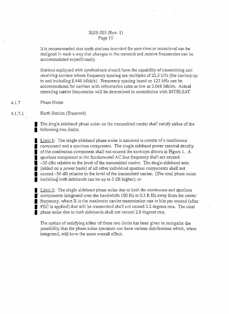
i
IESS-503 (Rev. 1)Page 10
It is recommended that earth stations intended for part-time or occasional use bedesigned in such a way that changes in the transmit and receive frequencies can beaccommodated expeditiously.
Stations equipped with synthesizers shou]d have the capability of transmitting andreceiving carriers whose frequency spacing are múltiples of 22.5 kHz (for carriers upto and induding 8.448 Mbit/s). Frequency spacing based on 125 kHz can beaccommodated for carriers with Information rates as low as 2.048 Mbit/s. Actualoperating carrier frequencies will be determined in consultation with INTELSAT.
4.1.7 Phase Noise
4.1.7.1 Earth Station (Transmit)
The single sideband phase noise on the transmitted carrier shall satisfy either of thefollowingtwolimits:
Limit 1: The single sideband phase noise is assumed to consist of a continuouscomponent and a spurious component. The single sideband power spectral densítyof the continuous component shall not exceed the envelope shown in Figure 1. Aspurious component at the fundamental AC line frequency shall not exceed •-30 dBc relative to the level of the transmitted carrier. The single sideband sum(added on a power basis) of all other individual spurious components shall notexceed -36 dB relative to the leve] of the transmitted carrier. (The total phase noiseincludingboth sidebands can be up to 3 dB higher); or
Limit 2: The single sideband phase noise due to both the continuous and spurioascomponents integrated over the bandwidth 100 Hz to 0.3 R Hz away from the centerfrequency, where R is the máximum carrier transmission rate in bits per second (afterFEC is applied) that will be transmitted shall not exceed 2.2 degrees rms. The totalphase noise due to both sidebands shall not exceed 2.8 degrees rms.
The option of satisfying either of these two limits has been given to recognize thepossibility that the phase noise spectrum. can have various distributions which, whenintegrated, will have the same overall effect.
i

IESS-503 (Rev. 1)Pagell
4.1.7.2 Earth Station (Receive)
The phase noíse performance of the earth station shall be consi.stent with the properoperation of the carrier recovery system of the demodulator given the allowablephase noíse contribution of the corresponding earth station and that expected fromthe satellite. Users are referred to the IESS-400 series of modales for informatlon onthe expected phase noise contribution from the satellite. As a mínimum, it isrecommended that phase noise requírements of the earth station transmit equipmentspecifíed in Section 4.1.7.1 should also be met for the earth station receive -equipment.
iiii

IESS-503 (Rev. 1)Page 12
i
TABLE1
MÁXIMUM USABLE INFORMATION RATE ÍRn) SUPPORTABLEWITHIN THE ALLOCATED CARRTER BANDWIDTH
(C-Band Global Beam Transponders)
FECAJlocated
CarrierBandwidth
(MHz)2.254.56.09.018.024.036.041.0
Máximum Usable Information Rate (Ru ) (Mbit/s)
1/2 2/3 3/4 5/6 7/8
1.53603.07194.09596.143912.287716.383624.575427.9887
2.04804.09595.46128.191816.383621.844832.767237.3182
2.30394.60796.14399.215818,431624.5754 -36.863141.9830
2.55995.11996.826510.239820.4795 <••'27.306040.959046.6478
2.68795.37597.167810.751721.503528.671343.007048.9801 '
iNotes: . ¡
1. The allocated carrie'r bandwidths are those increments (tariff tiers) which have been approvedby the INTELSAT Board of Governors (BG-104-20) for digital TV transmission in occasional-use capacity. Users should refer to the INTELSAT Tariff Manual for any future changes to thetariff tiers.
2. A 41 MHz bandwidth segment can only be offered in the occasional-use channel 12transponders.
3. The actual required bandwidth may depend on the particulars of the RP transmission path. Tbevalúes indicated here are an absolute máximum information rates that can be accommodated.Users should refer to the Digital TV Link Calculator Program distributed with this module.

IESS-503 (Rev. 1)Pagel 3
TABLE2
DIGITAL TV CODEC/MODEM PARAMETERS
Inner FECCode Rate
1/22/33/45/67/8
Threshold Eb/N0 @ BER=2 x W^(Viterbi Decoder Output)
(dB)IE RF
4.55.05.56.06.4
4.95.45.96.46.8
SystemMargin
(dB)
22222
Clear-SkyEb/N0 (RF)
(dB)
6.9'7.47.98.48.8
Notes:
1. The IF thr^hold Eb/N0 valúes include a modem implementation margir* .of O.S dB and abandwidth increase due to the outer code of 0.36 dB.
2. An IF~to-RF degradation of 0.4 dB is assumed.
3. At the threshold Eb/No, the corresponding BER = 10"10 at the RS decoder output; at the clear-slcy Eb/No, the BER will be better than 10'13.

IESS-503 (Rev. 1)Page 14
-30
-40
-50
•60
-70
LU -80
-90
COORDIMATESOFPOINTS
10 100 1K 10K 100K 1M
FREQUENCY FROM CENTER (Hz)
FIGURE 1TRANSMIT EARTH STATION CONTINUOUS
SINGLE SIDEBAND PHASE NOISE REQUIREMENT
P:\CADIIESS\503-01.DWG

II
APPENDDC A toIESS-503 (Rev. 1)
Page A-l
ITU AND ETST REFERENCES
European Telecommunications Standards Institute fETST) B
ETS 300 421: "Digital Broadcastíng Systems for Televisión, Sound and Data Services; FramingStructure-, Channel Coding and Modulntionfor 11/12 GHz Satellite Services". (This Standard hasbeen extended to apply to the C-band transmissions addressed in this IESS).
ETS 300 468: "Digital Broadcastíng system for Televisión; Sound and Data Services; for ServiceInformation (SI)".
ISO/ÍES 13818-3: "Information Technology - Generic Coding of Moving Pictures and Associated BAudio Information: Audio". B
ITU-T Recommendations: B
Rec. ITU- -T H.222.0 (07/95).' "Information Technology - Generic Coding Of Moving PictQres AndAssociated Audio Information: System". (ISO/IEC 13818-1). •
Rec. rrU-TH.262,0 (07/95): "Information Technology - Generic Coding Of Moving Pictures AndAssociated Audio Information: Video". (ISO/IEC 13818-2). •
ITU-R Recommendations:
Rec. ITU-R S. 524-5: "Máximum Permissible Levéis Of Off-Axis e.i.r.p. Density From EarthStations In the Fixed-Satellite Service In The 6 And 14 GHz Frequency Band".
iii
i

APPENDIX B toIESS-503 (Rev. 1)
• PageB-1
TRANSMISSION PARAMETER5. EARTH STATIQN CQNNECTIQN MATRTX. MÁXIMUM
e.i.r.p. FOR INTELS AT VI. VH/VIIA. VHI

APPENDIX B toIESS-503 (Rev. 1)
Pase B-2
TableB.lILLUSTRATIVE TRANSMISSION PARAMETERS FOR DIGITAL TV
[Inner Rate 1/2 FEC, RS (204, 188) Outer Coding, QPSK]
UsabJelnfo.Rate, Ru
(Mbit/s)1.5442.0484.0966.3128.44810.00012.00015.000
SymbolRate
(Msym./s)1.6752.2224.4456.8499.16710.85113.021] 6.277
OccupiedBandwidth
(MHz)1.6752.2224.4456.8499.16710.85113.02116.277
AllocatedBandwidth
(MHz)2.27253.0375
^ 6.00759.247512.397514.692517,625022.0000
ClearSky(BER<10-13)
C/T(dBW/K)-159.8-158.6-155.6-153,7-152.4-151.7-150.9-149.9
C/N0
(dB-Hz)68.870.0
L_ 73.074.976.276.977.778.7
C/N(dB)6.66.66.66.66.66.66.66.6
TableB.2 . ;
ILLUSTRATIVE TRANSMISSION PARAMETERS FOR DIGITAL TV[Inner Rate 2/3 FEC, RS (204, 188) Outer Coding, QPSK]
Usable Info,Rate, Ru
(Mbit/s)1.5442.0484.0966.3128.44810.00012.00015.000
SymbolRate
(Msym./s)1.2571.6673.3335.1376.8758.1389.76612.207
OccupiedBandwidth
(MHz)1.2571.6673.3335.1376.8758.1389.76612.207
AllocatedBandwidth
(MHz)1.73252.27254.52256.95259.292511.002513.250016.5000
ClearSky(BER<10-13)
C/T(dBW/K)-159.3-158.1-155.1-153.2-151.9-151.2-150.4-149.4
c/N0(dB-Hz)
69.370.573.575.476.777.478.279.2
C/N(dB)8.38.38.38.38.38.38.3S.3
NOTE: See the General Notes following Table B.5
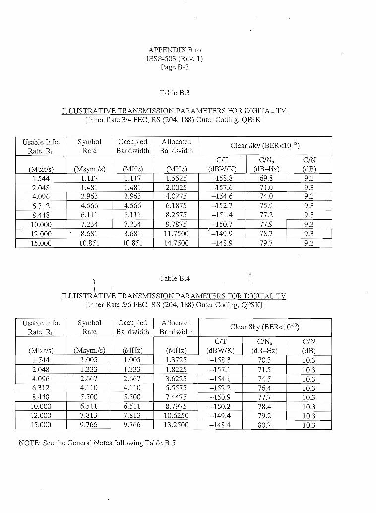
APPENDIX B toIESS-503 (Rev. 1)
Pase B-3
TableB.3
ILLUSTRATIVE TRANSMISSION PARAMETERS FOR DIGITAL TV[Inner Rate 3/4 FEC, RS (204, 188) Outer Coding, QPSK]
Usable Info.Rate, Ru
(Mbit/s)1.5442.0484.0966.3128.44810.00012.00015.000
SymbolRate
(Msym./s)1.1171.4812.9634.5666.1117.234
• 8.68110.851
OccupiedBandwidth
(MHz)1.1171.4812.9634.5666.1117.2348.6S110.851
AllocatedBandwidth
(MHz)1.55252.00254.02756.18758.25759.787511.750014.7500
ClearSky(BER<10-13).
C/T(dBW/K)-158.8-157.6-154.6-152.7-151.4-150.7
" -149.9-148.9
C/NO(dB-Hz)
69.871.074.075.977.277.978.779.7
C/N(dB)9.39.39.39.39.3939.39.3
TableB.4 :i*i
ILLUSTRATIVE TRANSMISSION PARAMETERS FOR DIGITAL TV[Inner Rate 5/6 FEC, RS (204, 188) Outer Coding, QPSK]
Usable Info.Rate, Ru
(Mbit/s)1.5442.0484.0966.3128.44810.00012.00015.000
SymbolRate
(Msym./s)1.0051.3332.6674.1105.5006.5117.8139.766
OccupiedBandwidth
(MHz)1.0051.3332.6674.1105.5006.5117.8139.766
AllocatedBandwidth
(MHz)1.37251.82253.62255.55757.44758.797510.625013.2500
ClearSky(BER<10-13)
C/T(dBW/K)-158.3-157.1-154.1-152.2-150.9-150.2-149.4-148.4
c/N0(dB-Hz)
70.371.574.576.477.778.479.280.2
C/N(dB)10.310.310.310.310.310.310.310.3
NOTE: See the General Notes followingTable B.5

APPENDIX B toIESS-503 (Rev. 1)
PageB-4 iTableB.5
ILLUSTRATIVE TRANSMISSION PAR AMETERS FOR DIGITAL TV[Inner Rate 7/8 FEC, RS (204, 188) Outer Coding, QPSK]
Usable Info.Rate, Ru
(Mbit/s)1.5442.0484.0966.3128.44810.00012.00015.000
SymbolRate
(Msym./s)0.9571.2702.5403.9145.2386.2017.4419.301
OccupiedBandwidth
(MHz)0.9571.2702.5403.9145.2386.2017.4419.301
AllocatedBandwidth
(MHz)1.32751.73253.44255.28757.08758.392510.125012.6250
ClearSky(BER<10~i3)_
C/T(dBW/K)-157.9-156.7-153.7-151.8-150.5-149.8-149.0-148.0
C/N0
(dB-Hz)70.771.974.9 '76.878.1
.78.879.680.6
C/N(dB)10.910.910.910.910.910.910.910.9
NOTE: See the General Notes followingTable B.5
ii
i
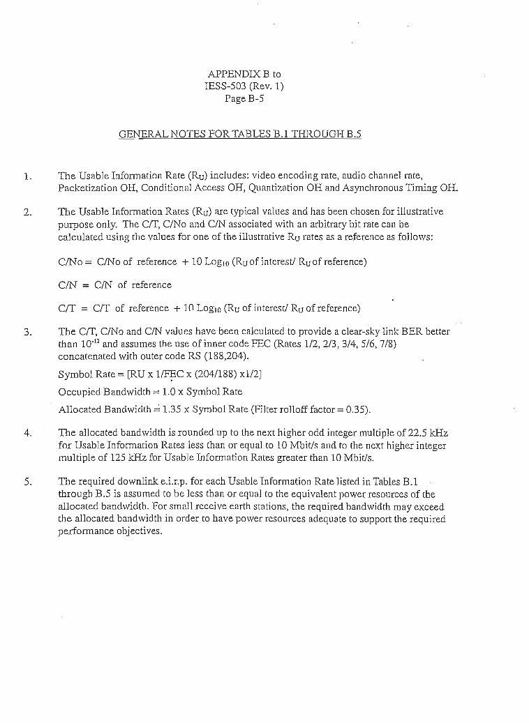
APPENDIXBtoIESS-503 (Rev. 1)
PageB-5
GENERAL NOTES PORTABLES B.l THROUGHB.5
1. The Usable Information Rate (Ru) includes: video encoding rate, audio channel rate,Packetization OH, Conditlona] Access OH, Quantization OH and Asynchronous Timing OH.
2. The Usable Information Rates (Ru) are typical valúes and has been chosen for illustrativepurpose only. The C/T, C/No and C/N associated with an arbitrary bit rate can becalculated usin the valúes for one of the illustrative RU rates as a reference as follows:
C/No- C/No of reference + 10 Log10 (Ruof interest/ Ruof reference)
C/N = C/N of reference
C/T = C/T of reference + 10 Logio (Ru ofinterest/ RU of reference)
3. The C/T, C/No and C/N valúes nave been calculated to provide a clear-sky link BER betterthan 10"13 and assumes the use of inner code FEC (Rates 1/2, 2/3, 3/4, 5/6, 7/8)concatenated with outer code RS (188,204).
Symbol Rate = [RU x 1/FEC x (204/188) xl/2]
Occupied Bandwidth = LO x Symbol Rate
Allocated Bandwidth = 1.35 x Symbol Rate (Filter rolloff factor = 0.35).
4. The allocated bandwidth is rounded up to the next higher odd integer múltiple of 22.5 kHzfor Usable Information Rates less than or equal to 10 Mbit/s and to the next higher integermúltiple of 125 kHz for Usable Information Rates greater than 10 Mbit/s.
5. The required downliak e.i.r.p. for each Usable Information Rate Usted in Tables B.lthrough B.5 is assumed to be less than or equal to the equivalent power resources of theallocated bandwidth. For small receive earth stations, íhe required bandwidth may exceedthe allocated bandwidth in order to have power resources adequate to support the requiredperformance objectives.

APPENDIX B toIESS-503 (Rev. 1)
PageB-6
Tabie B.6(a)
INTELSAT VI' DIGITAL TV SERVICE EARTfí STATION CONNECTIVTTY MATRTX(OFF-AXIS EMISSION MARGINS, dB)
' (Global Beam Channel 9 Used For Digital TV Only)
FECRate
1/2
2/3
3/4
5/6
7/8
ReceíveEarth station
A
F-3F-2F-lH-3H-2
F-3F-2F-lH-3H-2A
F-3F-2F-lH-3H-2A
F-3F-2F-IH-3
A
F-3F-2F-lH-3H-2
Transmit Earth StationA
23.221.119.0
20.618.516.4
17.2 14.612.8S.55.3
10.25.92.7
21.4 1S.S19.417.215.411.06.73.5
20.418.416.314.410.05.72.519.517.515.413.59.1
14.6
S.44.10.9
13.7
7.4
3.1
16.914.9
10.96.5
19.0 16.416.9 14.314.812.9
4.21.0
12.210.35.91.6
-1.6
F-318.015.9
12.07.63.30.1
F-216.514.412.310.56.1
F-l12.610.58.46.6
-2.1-5.3
16.2 14.7
14.2 12.712.010.2
1.5-1.715.213.211.19.2
0.5
10.5S.7
4.3
0.0
13.7
11.79.67.7
3.3
-LO-2.7 I -4.214.312.310.2
3.9-0.4
12.S
2.4-1.9
12.311.79.67.7
3.2
10.2S.l6.2
I -2.5-4.2 -5.7 -9.6
NOTE: See the General Notes followmg Table B.8(b).
II
I
I
I

APPENDTXBtoIESS-503 (Rev. 1)
Page B-7
Table B.6(b)
INTELSAT VI DIGITAL TV SERVICE EARTH STATTON CONNECTIVITY MATRTX(OFF-AXIS EMISSTON MARGTNS, dB)
(Global Beam Channels 10, 11, 12 Used Por Digital TV Only)
FECRate
1/2
2/3
3/4
5/6
7/S
ReceiveKarth station
AB
F-3F-2F-lH-3r-r-2AB
F-3F-2F-lH-3I-I-2AB .¡
F-3 ÜF-2F-lH-3H-2AB
F-3F-2F-lH-3H-2AB
F-3F-2F-lH-3H-2
TransmitEartb StatíonA
24.623.021.319.815.S11.48.3
22.821.219.6
B22.020.418.717.213.2
F-3 1 F-219.4 ! 17.917.816.114.6
16.314.613.1
10.6 ! 9.18.S 1 6.2 ! 4.75.720.218.617.0
18.1 1 15.514.09.66.5
21.820218:617.113.08.65.5
20.919.417.716.212.17.74.6
20.31S.S17.215.611.57.14.0
11.47.03.919.217.616.014.510.46.0•\18.316.S15.113.69.55.1ro17.716.2J4.613.08.94,51.4
3.1 i 1.617.6 j 16.116.014.412.98.84.41.3
16.615.013.411.97.83.40.3
14.512.911.47.32.9-0.215.113.511.910.46.31.9
-1.215.7 ! 14.214.212.5li.O6.9
12.711.09.55.4
2.5 1 1.0-0.6 1 -"U15.113.612.010.46.31.9
13.612.110.58.94.80.4
-1.2 ! -2.7
F-l14.012.410.79.25.20.8-2.312.210.69.07.53.4-LO-4.111.29.68.06.52.4-ro-5.L10.38.87.1
5.61.5
-2.9-6.09.78.26.65.00.9-3.5-6.6
H-34.22.60.9-0.6-4.6
H-2-2.4-4.0-5.7-7.2-11.2
-9.0 PPP8PÜ-1-5.1 ÍÉÜ&ÜÉ2.40.8-0.8-2.3-6.4-10.8-13.9
* 1.41-0.2
-1.8-3.3-7.4
-4.2-5.S-7.4-8.9-13.0
KÜÜ^i-5.2-6.8-8.4-9.9
í -14.0-ii.s P$ffia§8-14.9 feÉ&ggi0.5-LO-2.7-4.2-S.3
-12.7sasesa
-0.1-1.6-3.2-4.8
-6.1-7.6-9.3-10.8-14.9
HU&HífflW$$$$SM
-6.7-8.2-9.8-11.4
-S.9 §|S|||-13.3 tensas$@&ffiÉSti&$®S$$
NOTE: See the General Notes following Table B.8(b).
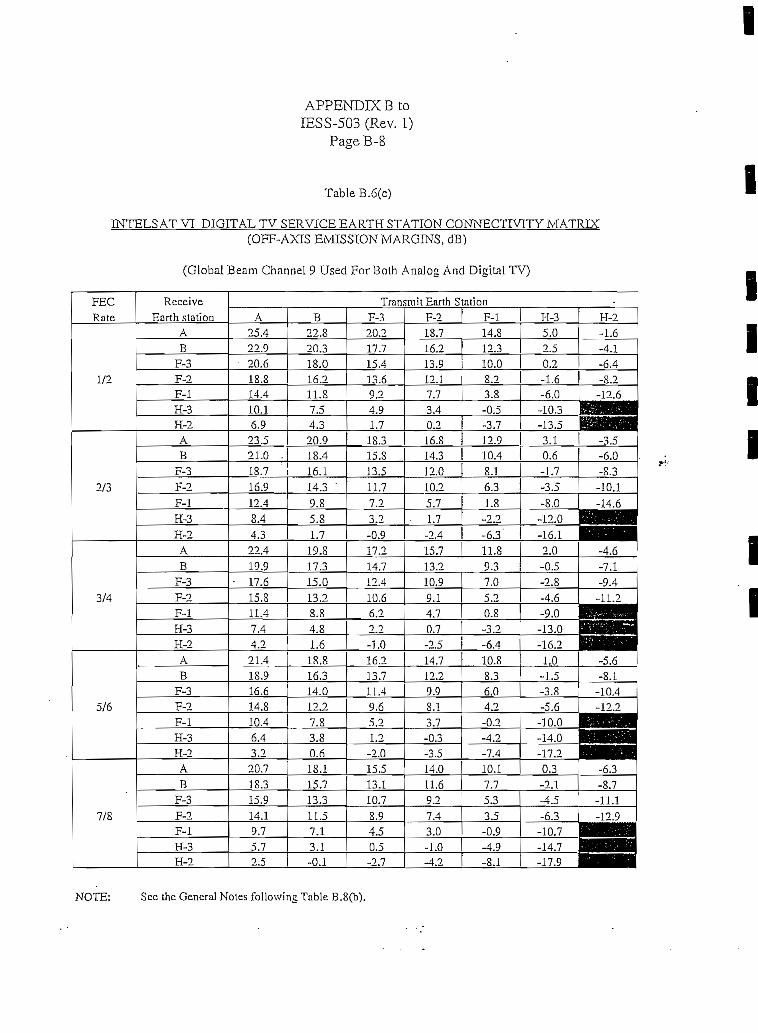
IAPPENDK B toIESS-503 (Rev. 1)
PageB-S
Table B.6(c)
INTELSAT VI DIGITAL TV SERVICE EARTfí STATION CONNECTIVITY MATRIX(OFF-AXTS EMISSION MARGINS, dB)
(Global Beam Channel 9 Used For Both Analog And Digital TV)
FECRate
1/2
2/3
3/4
5/6
7/8
ReceíveEarth statíoa
AB
F-3F-2F-lH-3H-2AB
F-3F-2F-lH-3H-2AB
F-3F-2F-lH-3H-2AB
F-3F-2F-lH-3H-2AB
F-3F-2F-lH-3H-2
Transmit Earth StationA
25.422.9
• 20.618.814.410.16.923.521.0 .18.716.912.48.4
B22.820.318.016.2ll.S7.54.320.918.416.114.3 '9.85.8
4.3 1 1.722.419.9
• 17.615.811.47.44.221.418.916.614.810.46.43.220.718.315.914.19.75.72.5
19.S17.315.013.28 84.81.618.816.314.012.27.83.80.618.115.713.311.57.13.1-0.1
F-320.217.715.413,69.24.91.7
18.315.S13.511.77.23.2-0.917.214.712.410.66.20 •}
-1.016.213.711.49.65.2
1.2-2.015.513.110.78.94.50.5-2.7
F-218.716.213.912.17.73.40.216.8
F-l14.812.310.08.23.8-0.5-3.7
H-35.02.50.2-1.6-6.0-10.3-13.5
12.9 Í 3.114.3 1 10.4 1 0.612.010.25.71.7-2.415.713.210.99.14.7
8.16.31.8
~9 0
-1.7-3.5-8.0
-12.0-6.3" 1 -16.111.89.37.05.20.8
0.7 i -3.2-2.5 1 -6.414.712.29.98.13.7-0.3-3.514.011.69.27.43.0-1.0
10.88.3
2.0-0.5-2.8-4.6-9.0-13.0-16.21.0-1.5
6.0 1 -3.84.2-0.2-4.2-7.410.17.75.33.5-0.9-4.9
-4.2 í -8.1
-5.6-] 0.0-14.0-17.20.3-2.1-4.5-6.3-10.7-14.7-17.9
H-2-1.6-4.1-6.4-8.2-12.6
iH|f9|»fiHHHHJjl|M
-3.5-6.0-S.3-10.1"¿4.6
BHHHJaam-4.6-7.1-9.4-11.2
BHMBHIHmiMMi.aiWnHHBBBIiffiagno|
-5.6 i-8,1-10.4-12.2
EB8HBBBBSaHEHHBHH^•^M^H
-6.3-8.7-11.1
_... -12,9
MIHlflwaaaaauHBHM
I
IIII
II
NOTE: See the General Notes followíng Table B.8(b).

IAPPENDIX B to
IESS-503 (Rev. 1)Page B-9
l
TabieB.6(d)
INTELSAT VI DIGITAL TV SERVICE EARTH STATION CONNECTIVITY MATRIX(OEF-AXIS EMISSIONMARGINS, dB)
(Global BeamChannels 10, 11, 12 Used ForBoth Analog And Digital TV)
FECRate
1/2
2/3
3/4
5/6
7/8
Rece 3 veEarth station
AB
F-3F-2F-lH-3H-2AB
F-3F-2F-l
-jH-2AB \3
F-2F-iH-3H-2AB
F-3F-2F-lH-3H-2AB
F-3F-2F-lH-3H-2
Transmit Earth Station •A
27.225.223.221.517.313.0S.9
25.323.321.319.615.3
7.924.222.220.218.514.310.37.2
23.221.219.217.513.29.05.S
22.520.518.516.812.68.75.5
B24.622.620.618.914.710.46.3
22.720.718.717.012.7
5.321.619.617.615.911.77.74.6
20.618.616.614.910.66.43.219.917.915.914.210.06.1
F-322.020.0
F-220.518.5
18.0 ! 16.516.312.17.83.7
20.1
14.810.66.3o o
18.618.1 Í 16.616.114.410.1
2.719.017.015.013.39.15.12.018.0 ,16.014.012.38.03.80.617.315.313.311.67.43.5
2.9 1 0.3
14.612.98.6
A_
1.217.515.513.511.87.63.60.516.514.512.510.86.52.3-0.915.813.811.810.15.92.0-1.2
F-l16.614.612.610.96.72.4-1.714.712.710.79.04.70.5-2.713.611.69.67.93.7-0.3-3.412.610.68.66.92.6-1.6-4.811.99.97.96.22.0-1.9-5.1
H-36.84.82.81.1-3.1-7.4-11.54.92.90.9-0.8-5.1
-12.5¿ 3.8
1.8-0.2-1.9-6.1-10.1-13.22.80.8-1.2-2.9-7.2-11.4-14.62.10.1-1.9-3.6-7.8-11.7-14.9
H-20.2-1.8-3.8-5.5-9.7-14.0
^fflBBBi
-1.7-3.7-5.7-7.4
-11.7
HSMH^HH—-2.8-4.8-6.8-8.5-12.7
HH9H-3.8-5.8-7.8-9.5-13.8 _J
BUEN_
-6.5-S.5-10.2-14,4.. 1mma
t SBH
NOTE: See the General Notes followlng Tatle B.8(b).

APPENDIXBtoIESS-503 (Rev. 1)
PageB-10
TableB.7(a)
INTELSAT VII/VIIA DIGITAL TV SERVICE EARTfí STÁTION CONNECTIVITY MATRIX(OFF-AXIS EMISSION MARGTNS, dB)
(Global Beam IS-VTI Channels 9B, 10, 11 And IS-VIIA Channel 9B)(Used For Digital TV Only)
FECRate
ReceíveEarth station
Transmit Earth StationA F-3 F-2 F-l
1/2
2/3
A
F-3F-2F-lH-3H-2
F-3F-2F-lH-3
24.622.420.218.414.1
6.6
2Ü.618,5
22.0
17.6
11.57.24.020.218.0
15.916.6 14.012.3 9.7
5.4
19.4 17.917.2 15.715.0 13.513.2 11.78.9 7.4
4.6 3.11.4 -0.1
14.0
17.6 16.115.4 13.913.311.4 9.97.1 5.62.8 1.3
3/4
5/6
A
F-3F-2
H-3H-2A
F-3F-2F-lH-3H-
19.2 16.6 15.119.6 17.0 14.4 12.917.5 14.9 12.315.6 13.0 10.4
4.67.0 4.4 1.8 0.3
3.8 1.2 -2.920.918.716.6
6.1
18.3 15.7 14.216.1 13.5 12.014.0 11.4 9.912.2 9.67.8
3.5 0.9 -0.6
7/8
A
F-3F-2F-lH-3H-2
20.3 17.7 15.1 13.618.1 15.5 12.9 11.416.0 13.4 9.314.2 11.6 9,0 7.5
7.2 4.6 3.15.5 2.9 0.3 -1.22.3 -0.3 -2.9 -4.4
NOTE: fi The. nftnp.rnl Nntfts fn l lnwinP Tahlp. R

11I
APPENDIXBtoIESS-503 (Rey. 1)
PageB-11
TableB.7(b)
TNTELS AT VII/VIIA DIGITAL TV SERVICE EARTH STATION CONNECTIVITY MATRTX(OFF-AXIS EMISSION MARGINS, dB)
(Global Beam IS-VTI Cbannel 12 And IS-VI1A Channels 10, 11, 12)(Used For Digital TV Only)
I
I
I
IiI
NOTF/. * tho. Gc-.np.r.il Ñores fnllmvint» Tnhle. R.Rfht.
FECRate
1/2
2/3
3/4
5/6
7/8
Receive"Harthstation
AB
F-3F-2F-lH-3H-2A'B
F-3F-2F-lH-3H-2
A-íB^
F-3F-2F-lH-3H-2
AB
F-3F-2F-lH-3H-2AB
F-3F-2F-lH-3 ,H-2
TransmitHarth StationA 1 B
26.024.422.621.017.112.89.6
24.222.620.S19.215.311.07.8
23.221.619.818.3
14.310.06.S
22.320.718.917.413.49.15.921.720.118.316.812.88.45.3
23.421.820.01S.414.510.27.0
21.620.018.216.612.78.45.2
20.619.017.215.711.77.44.219.718.116.314.810.86.53.319.117.515.714.210.25.82.7
F-320.819.217.415.S
F-219.317.715,914.3
11.9 1 J0.47.64.419.017.4
6.1->.917,515.9
15.6 1 14,114.010.15.82.61S.O16.414.613.1
9.14.8J.617.115.513.712.28.23.90.716.514.913.111.67.63.20.1
12,58.64.31.116.514.913.111.6
7.63.3
F-l 1 H-315.413.812.010.46.52.2-1.013.612.010.28.64.70.4-2.8-'12.61
11.09.27.7
3.7-0.6
0.1 i -3.815.614.012.210.76.7
11.710.18.36.82.8
'M 1 -1.5-0.815.013.411.610.16.11.7
-1.4
-4.711.19.57.76.20 0
_T 9
-5.3
5.64.02.20.6-3.3-7.6-10.8 .3.8 •2.20.4-1.2-5.1-9.4-12.62.81.2-0.6-2.1-6.1
H-2-1.0-2.6-4.4-6.0-9.9-14.2
lÉ&SK&i-2.8-4.4-6.2-7.8-11.7
IKsfBajgBtiiKB
-3.8-5.4-7.2-8.7-12.7
-10.4 jüüüüi-i 3.61.90.3-1.5-3.0-7.0-11.3-1.4.5
J.3-0.3-2.1-3.6-7.6-12.0msrnm
•HBHBBE1
-4.7-6.3-8.1-9.6
^-13.6^^^^^mEVN^H
"•" ími-5.3-6.9-S.7-10.2-14.2
HHIPHHI8ÍMHIS""™ [Hgnn

If=?I
APPENDIX B toIESS-503 (Rev. 1)
GENERAL NOTES FOR TABLES B.6 THRQUGH B.8(EARTH STATION CONNECTION MATRIX)
1. The indicated off-axis emissioa margins assumed (a) the transmitting andreceiving earthstation are located at beam edge and (b) the transmitting earth station sidelobeperformance is the mínimum specifíed in IESS-601. 5
2. Anegative rnargin indicates the transmit/receive earth station connection does notcomply with the off-axis emission requirements of Rec. ITU-R S.524-5. 5
I3. Transmission paths having a negative margin may still be permitted if: (a) the
transmitting and or íhe receiving earth station have suffícient pattern advantage relativeto beam edge or (b) the transmitting earth station sidelobe performance exceeds themínimum specifíed in IESS-601 or IESS-207 by the indicated margin. Users are referredto IESS-402 for e.i.r.p. adjustment factors appropnate to transmission paths with uplink ' _•or downlink pattern advantage. • |
4. Shaded enfries and eutries not shov/n are transmission paths having a negative margalexceeding -15 dB which is not possible to be achieved practically (See Note 3 above).
5. The máximum e.i.r.p. valúes have been computedusing a saturación flux density of-77.6 dBW/m2for INTELSAT VI and -79.0 dBW/m2for INTELSAT VH/VIIA and VIH forfull transponder loading conditions. Other saturation flux densities may be useddepending on the actual traffic loading.
6. Earth Station Standard: A B F-3 F-2 F-l H-3 H-2
G/T (dB/K): 35.0 31.7 29.0 27.0 22.7 18.3 15.1
' \
Ic™
I
I

I
IIi
APPENDIXBtoIESS-503 (Rev. 1)
PageB-17
TableB.9(a)
INTELSAT VI MÁXIMUM REOUIRED EARTH STATION e. i. r. p. CdBW)
(Global Beam Channel 9 Used For Digital TV Only)
Máximum Required Uplink e.í.r.p. ídBW)
INOTE: See the General Notes foliowingTableB.ll(b).

APPENDIX B toIESS-503 (Rev. 1)
PageB~lS
Table B.9(b)
INTELSAT VI MÁXIMUM REOUIRED EARTH 5TATION e. i. r. p. (dB W)
(Global Beam Channels 10, 11,12 UsedFor Digital TV Only)
1NOTE: See the General Notes following Table B.ll(b).
II

APPENDDCBtoIESS-503 (Rev. 1)
PageB-19
TableB.9(c)
INTELSAT VI MÁXIMUM REOUIRED EARTH STATION e. i. r. p. fdB\\
(Global Beam Channel 9 Used For Both Analog And Digital TV)'
Máximum Requjred Uplink e.i.r.p. fdBW)
NOTE: See the General Notes followíng Table B.l 1 (b).

1
APPENDIX B toIESS-503 (Rev. 1)
Page B-20
TableB.9(d)
INTELSAT VI MÁXIMUM REOUIRED EARTH STATION e. i. r. p. ídBW)
(Global Beam Channels 10, U, 12 Used ForBoth Analog And Digital TV) IMáximum Required Uplink e.i.r.p. ídBW")
III
NOTE: See the General Notes following Table B.l l(b).

II APPENDIX B to
IESS-503 (Rev. 1)Page B-21
Table B.10(a)
INTELSAT VH/VIIA MÁXIMUM REOUIRED EARTH STATION e. i. r. p. fdB\SO
(Global Beam IS-VII Channels 9B, 10, 11 And IS-VIIA Channel 9B), (Used For Digital TV Only)
I
Máximum Required Upiínk e.i.r.p. fdBWI
NOTE: See the General Notes following Table B.H (b).

APPENDIX B toIESS-503 (Rev. 1)
Page B-22
Table B.10(b)
INTELSAT VII/VIIA MÁXIMUM REOUIRED EARTH STATION e. i. r. p. (áBW)
(Global Beam IS-VH Channel 12 And IS-VHA Channels 10, 11, 12)(Used For Digital TV Only)
FECRate
1/2
2/3
3/4
5/6
7/8
RufMbit/s)
1.5442.0484.0966.3128.448
10.00012.00015.0001.5442.04S4.0966.3128.44810.00012.00015.0001.5442.0484.0966.3128.44810.00012.00015.0001.5442.0484.0966.3128.448
10.00012.00015.0001.5442.0484.0966.3128.448
10.00012.00015.000
Máximum Required Uplink e.Lr.p.._(dBW)Receiye Earth Station
60.962.265.267.0
69.0
61.462.765.7
_.67.5
69.570.371.361.963.2
.66.2.68.069.3
.70.0
62.4_63.766.7
70.571.372.362.S64.167.1
70.2_70.971.772.7
62.5
69.9.70.671.472.4
__63,P
69.1_70.471.1
_71.9_72.963.5
_69.670.9
_71.672.473.464.065.3
70.1
72.172.973.964.4
_.65_,768.770.5
72.573.3
_7_4.3
F-364.365.668.670.4
71.772.473.274.2
66.169.170.972.272.973.774.765.366.669.671.472.773.4
74.275.2
67.170.171.973.273,974.775.766.267.570.572.373.674.375.176.1
65.967.270.272.073.374.0
66.467.770.772.5
74.575.376.3
68.171.172.974.274.975.776.767.368.671.673.4
74.775.476.277.267.769.072.0
75.1
76.677.6
F-l
71.174.175.977.2
...77.978.7
.79.770.371.674.6
_.76.477.778.479.280.2
..72.1...75.176.978.278.979.7
71.372.675.6.7.7.4
78.7
79.480.281.271.773.076.077.8
.79.1
.S0.681.6
H-374.175.478.4
74.6.75.978.980.7
75.176.479.4
75.676.979.981.7
76.177.4
H-277.378.681.6
77.;
79.1
78.3
79.6
III
II
79.2
NOTE: See the General Notes following Table B.ll(b).

IAPPENDIX B toIESS-503 (Rev. 1)
PageB-23
TableB.lO(c)
INTELSAT Vn/VIIA MÁXIMUM REOUIRED EARTH STATION e. i. r. p. fdBW)
(Global Beam IS-VH Channels 96,10,11 And IS-VHA Channel 9B)(Used For Both Analog And Digital TV)
I
Máximum Required Uplink e.i.r.p. fdBW)
INOTE: See the General Notes following Table B. 11 (b).

APPENDIX B toIESS-503 (Rev. 1)
Page B-24
TableB.lO(d)
INTELSAT VII/VIIA MÁXIMUM REOUIRED EARTH STATION e. í. r. p.
(Global Beam IS-VII Channel 12 And IS-VIIA Channels 10,11,12)(Used For Both Analog And Digital TV)
I
Máximum Required Uplink e.j-r.p. (dBW) I
I
NOTE: See the Genera] Notes following Table B.ll(b).
I

i
FECRate
1/2
2/3
3/4
5/6
7/8
APPENDIXBtoEESS-503 (Rev. 1)
Page B-25
TableB.ll(a)
INTELSAT VIII MÁXIMUM REOUIRED EARTH STATION e. i. r. p. ídBW)
(Global Beam Channels 9,10, 11, 12 Used For Digital TV Only)
RIÍfMbit/sl
1.5442.0484.0966.3128.44810.00012.00015.0001.5442.0484.0966.3128.44810.00012.00015.0001.5442.04S4.0966.3128.44810.00012.00015.0001.5442.0484.0966.3128.44810.00012.00015.0001.544
4.0966.3128.44810.00012.00015.000
Máximum Repuired Uplink e.i.r.p. fdBVvOReceive Earth Station
A6Q.962.265.267.0
69.0
61.462.765.767.5
69.570.371.361.963.266.268.069.370.0
62.463.766.7
70.571.372.3
64.167.1
70.270.971.772.7
62.5
69.970.671.472.463.064.367.369.170.471.171.972.963.5
69.670.971.672.473.464.065.3
70.171.472.172.973.964.465.7
70.5
72.573.374.3
F-364.365.6
70.471.772.473.274.2
66.169.170.972.272.973.774.765.366.669.671.472.773.474.275.265.767.070.0
73.1
74.675.666.167.470.472.273.574.275.076.0
F-2
67.170.171.973.273.974.775.766.267.570.572.373.674.375.176.166.768.071.0
74.1
75.676.667.2
71.573.374.675.376.177.167.6
71.973.775.075.776.577.5
F-l69,771.074.0
77.1
78.679.670.271.574.576.377.678.379.1
70.772.075.0
78.1
79.6
71.272.575.577.378.679.3
81.171.672.975.977.779.079.7
81.5
H-374.175.478.48Q.281.5
74.6
75.1
81.2
75.676.979.9
76.077.380.3
H-277.278.581.5
77.779.0
78.279.5
78.7
79.1
NOTE: See the General Notes following TableB.ll(b).

II
APPENDIXBtoD3SS-503 (Rev. 1)
Page B-26
Table B.ll(b)
INTELSAT VHI MÁXIMUM REOUIRED EARTH STATION e. i. r. p. ídBWI
(Global Beam Channels 9,10,11,12 Used For Both Anaíog And Digital TV)
Máximum Required Uplink e.í.r.p. fdBW)
IiIIIIII
NOTE: See the General Notes foUowing Table B.ll(b).

I
APPENDIXBtoIESS-503 (Rev. 1)
PageB-27
GENERAL NOTES FOR TABLES B .9 THROUGH B. 11(Earth Station e.i.r.p.)
1. The máximum e.i.r.p. shown is for a 10° elevation angle and for earth stations located atbeam edge. por elevation angíes other than 10°, and earth stations locations other than atbeam edge, the e.i.r.p. valúes shown in Tables B.4 through B.6 may be adjusted by thecorrection factors K¡ and K2 given in IESS-402.
2. The máximum e.i.r.p. valúes have been computed using a saturation flux density of-77.6 dBW/m2 for INTELSAT VI and -79.0 dBW/m2 for INTELSAT VE/VEA and VIH forMI transponder loading conditions. Other saturation flux densities may be used dependingon the actual traffic loading.
3. The Usable Information Rate (Ru) includes: video encoding rate, audio channel rate,Packetizatíon OH, Conditional Access OH, Quantization OH and Asynchronous Timing OH.
4. The máximum required uplink e.i.r.p. for any information rate can be calculated using thevalué of one of the illustrative RU rates as a reference as foliows:
máximum e.i.r.p, = max. e.i.r.p. of reference + 10 loglo (Ruof interest/Ru of reference)
5. Shaded enfríes ancl*entries not shown in the All Digital transponders (Tables: B.9(a)**B.9(b),dB.10(a), B.10(b), B.ll(a)) are notpossible given the e.i.r.p. capability of the satellites.
6. Shaded entries and entries not shown in Mixed analog TV and digital TV transponders(Tables: B.9(c), B.9(d), B.10(c), B.10(d), B.ll(b), are notpossible as a consequence of a) thee.í.r.p. capability of the satellites, b) the required digital TV carrier protection ratio or c) thecarrier allocated bandwidth exceeds the transponder bandwidth segment allocated for digitalTV operatiori (16 MHz : Channels 9,10,11 and 21 MHz: Channel 12).
7. The following rules were applied to the Mixed analog TV and digital TV transponders(Tables: B.4(c), B.4(d), B.5(c), B.5(d), B.6(b)):
(a) For mixed operation of a single digital TV carrier wíth a TV/KM carrier, the digital TVcarrier requires an OBO (output backoff) of 10.5 dB for symbol rates greater than 4.4(Msym./s) and 12.5 dB for symbol rates less than or equal to 4.4 (Msym./s).
(b) For múltiple digital TV operation with a TV/FM carrier} the total OBO of all digital -carriers must not exceed 10.5 dB if all digital TV carriers have symbol rates greater than4.4 Msym./s) and 12.5 dB if any carrier has a symbol rates less than or equal to4.4 Msym./s).
8. Earth Station Standard: A B F-3 F-2 F-l H-3 H-2
G/T (dB/K): 35.0 31.7 29.0 27.0 22.7 18.3 15.1
I
APPBNDIX C toIESS-503 (Rev. 1)
Page C-l
APPENDIX C
REVISIÓN HISTORY
Revisión No. Approval Date MaiorPurpose m
IOriginal 18 Aug. 1993 • New module. ~
1 17 Feb. 1998 • Complete revisión of module for •digital TV service based on MPEG-2 and •DVB Standards.
IIl
IIIll

INTELSAT EARTH STATION STAND ARDS OESS)
DocumentIESS-601 (Rev. 9 )
STANDARD G
PERFORMANCE CHARACTERISTICS FOR EARTH STATIQNSACCESSING THE INTELSAT SPACE SEGMENT FOR INTERNATIONAL AND
DOMESTIC SERVICES NOT COVERED BY OTHER EARTH 5TATIQN STAND ARDS
(6/4, 14/11 and 14/12 GHz)
APPROVAL DATE: 30 November 1998

n
IESS-601 (Rev. 9)PageS
additional verification testing ñor is the submission of a new application forrareqnired.
1.5 Earth stations accessing INTELSAT transponders which do not conform to theStandard G performance characteristics specified in this document (or which cannotautomatically assume the Standard G classification as discussed in paragraph-1.4)will be treated on a case-by-case basis as non-standard earth stations.
2.0
The detailed design of the Standard G earth station has been left to the User,including considerations regarding channel performance. For this reason the"General Guidelines for INTELSAT Earth Stations" discussed in IESS module 101do not apply to Standard G earth stations. However, the following generalguidelines/requirements are provided.
2.1 ., Users of Standard G earth stations should be conscious of the need for flexibility inthe design and operation of the earth station to accommodate changes in theconfiguration of the INTELSAT space segment.
2.2 | It is required that the earth station design be such that changes in the transmitted and| received RF carrier frequencies can be made in order that frequency plans can be| properly coofdinated for purposes of limiting mutual interference and for flexibility| in intersystem coordinación. Due to the probability that very large networks will
exist for some applications, INTELSAT will make its best efforts to minimizechanges of frequency,
2.3 The reliability of earth station equipment should be such that the space segmentcannot be jeopardized by emissions that are in error due to carrier level, frequency, orpolarization state.
n
r
ni

i
1ESS-601 (Rev. 9)Page 4
3.0
3.1 Antenna System
3.1.1 Antenna Sidelobe Pattern (6/4 GHz, 14/11 GHz and 14/12 GHz)
New antennas, for the purpose of this paragraph, are considered to be those whichhave an RFP (or similar document specifying contractual performancecharacteristics) issued after 1995.
(a) Transmit Sidelobe Design Objective
The design objective should be such that the gain of 90 percent of thecopolarized and crosspolarized sidelobe peaks does not exceed an envelopedescribed by:
G = 2 9 - 2 5 log 9 dBi, 1°* < 9 < 20°G = -3.5 dBi, 20° < 9 < 26.3°G = 32-25 log 9 dBi, 26.3° < 9 < 48°G = -10 dBi, 9 > 48°
where: G is the gain of the sidelobe envelope reJative to an isotropicantenna in the direction of the geostatíonary orbit, in dBi.
9 is the angle in degrees between the main beam axis and thedirection considered.
This requirement should be met within any frequency defined in paragraph3.2.2 for any direction which is within 3° of the geostationary are (Rec.ITU-R S.580-5).
(b) Transmit Sidelobe Mandatory Requirements (Existing Antennas)
|
At angles greater than 1°* away from the main beam axis, it is required thatthe gain of 90 percent of the copolarized and crosspolarized sidelobe peaksnot exceed an envelope described by:
For D/A. below 100, this angle becomes 100 7JD degrees.

•I
•
IESS-601 (Rev.9)PageS B
G = 32-25 log 0 dBi, _ 1°* < 0 < 48°G = -10 dBi 0 > 48°
Where G and 0 are defined in paragraph 3.1.1 (a).
This requirement should be met within any frequency defined in paragraph3.2.2 in any direction within 3° of the geostationary are (Rec. ITU-RS.580-5).
(c) Transmit Sidelobe Mandatory Requirements (New Antennas)
It is required that the gain of 90 percent of the copolarized and crosspolarizedsidelobe peales not exceed an envelope described by the following:
D/X < 50
1
tm
•
I
GG
= 3 2 - 2 5 log 0 dBi, V]°*= - 10 dBi,
< 0.
0
<>
DA > 50 (Rec. ITU-R S.580-5 and Rec. ITU-R S.465-5)
GKP$'GG
= 29= .-3.5= 32= -10
- 25 log 0 dBi,dBi,
- 25 log 0 dBi,dBi,
1°*20°26.3°
<
<<
e0
00
<<<>
48° •
48° ' -H
20°26.3°48°48°
where G and 0 are defined in Paragraph 3.1.1(a).
This requirement should be met within any frequency defmed in paragraph3.2.2 in any direction within 3° of the geostationary are.
(d) Receive Sidelobes
In order to protect receive signáis from interference arising elsewhere,restrictions musí also be placed on the receive sidelobe characteristics. 9Therefore, whüe not mandatory, it is recommended that the transmit sidelobecharacteristics apply to the receive band as well.
iFor D/X below 100, this angle becomes 100 X/D degrees.
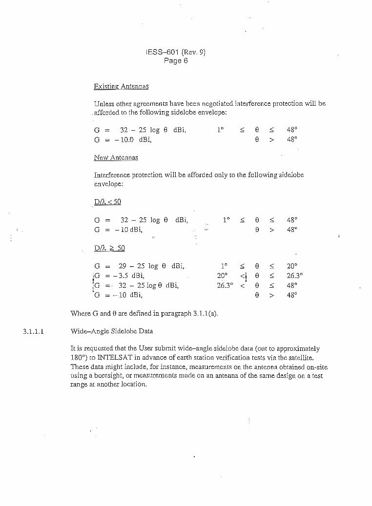
IESS-601 (Rev.9)Page 6
Existing Antennas
Unless other agreements have been negotiated interference protección will be.afforded to the following sidelobe envelope:
G = 32-25 log 0 dBi,G = -10.0 dBi,
New Antennas
1°48°
ínterference protection will be afforded only to the following sidelobeenvelope:
D/X<50
G = 32-25 log 0 dBi,G = -10 dBi,
DA, > 50
. G = 29 - 25 log 9 dBi,>G = -3.5 dBi,f G = • 32 -25 log 9 dBi,'G = -10 dBi,
48°
1° < e < 20°20° <| 9 < 26.3°26.3° <' 8 < 48°
9 > 48°
Where G and 0 are defined in paragraph 3.1.1(a).
3.1.1.1 Wide-Angle Sidelobe Data
It is requested that the User submit wide-angle sidelobe data (out to approximately180°) to INTELSAT in advance of earth station verification tests vía the satellite.These data might include, for instance, measurements on the antenna obtained on-siteusing a boresight, or measurements rnade on an antenna of the same design on a testrange at another location.

IESS-601 (Rev. 9)Page7
3.1.2 Polarization Sense, Orientación and Switchability
3.1.2.1 C-Band Antennas
(a) Transmit and Receive Polarización Senses I
INTELSAT YA, VT, VTT, VIIA and VíTí satelliCes uti l iza dual circular polarización at6/4 GHz in trie hemispheric, zone, and global transponders. Áddicionally,INTELSAT VA, VIT, and VIIA are equipped with two 4 GHz spot beams, eachoperating at a different polarization (RHCP or LHCP)*. •
INTELSAT VILLA provides dual polarization coverage by overlapping twoHemispheric coverages (Heml A or He mi B), each operating with a different linearpolarization.
|j The polarization requiremenís to opérate in che 6/4 GHz band.are shown in TablesU Í(r)and l(b). Earth station> sliall be capable of operating in any designated|j transponder in any polari/.ation sense. However, simultaneous-operation in both .-:j| senses of polarization will nct normalíy be required for eitherthe uplink orfor theU downlink. . .
(b) • Faraday Rotational Effects (Linearly Polarized Antennas Orjerating withINTELSAT VÜIA)
Faraday rotation affects linearly polarized waves passing through theionosphere. The effect of Faraday rotation is a decrease in the crosspolarization discrimination. Because the magnitude of Faraday rotationvaríes as 1/f 2, the effect is not as signiñcant a consideración at Ku-Band. AtC-Band, however, the 1/f" dependence makes Faraday rotación an importantconsideración, particularly on the downlink.
The magnitude of the Faraday rotation depends on frequency, latitude,elevation angle, dirección of propagación, theposition of Che sun relaCive toChe earth station and solar fiare activity. Faraday roCauon has a discinctdiurnal variation pattern which can lead to a diurnal variación incrosspolarization isolation. The diurnal. variations become larger in 5'ears ofhigh sunspot activity and during Che equinox periods of any year.
AuComaCed techniques to compénsate for or Co minimize Che effect of Faradayrotation do exist and are similar to those used to compénsate for rain
Senses of polarization are defined in ITU Radio Regulations Arricie 1 Nos. 148 and 149. i

iiiiii
ÍESS-601 (Rev. 9)PageS
depolarization. Faraday rotation effects can, also, be minimized by applyinga fixed feed rotation equal to one half the expected diurnal variation. It is notpossible, however, to select a fixed, pre-set rotational compensation that is
. adequate for all sunspot activity periods. Rather, the rotational compensation1 must be set on a yearly or seasonal basis.
Users using linear polarization in C-Band are urged to consider feed designswhich would permit, if necessary, feed rotational compensation. Users oflarge earth stations should also consider feed designs which canaccommodate an automated compensation network. As the direction ofFaraday rotation is opposite on the uplink and downlink, feed designs whichpermit independent adjustment of the uplink and downlink are highlydesirable.
(c) Polarization Orientation Of Linearly Polarized Antennas Operating WiíhINTELSAT VTTTA
Q It is required that the earth station feed be able to match the spacecraft| polarization angle within 1 degree under clear-weather conditions. This
requirement does not apply to earth stations employing Faraday rotationcompensation.
J As explained in paragraph (b) above, Faraday rotation is diurnal in naturewith the peak-to-peak diurnal variation increasing during the equinoxperiods of any year and in years of high sunspot activity. Because Faradayrotation effects are at a mínimum just prior to sunrise, it is recommended thatthe antenna feed be aligned during the time period immediately precedinglocal sunri.se. If possible, feeds should be aligned during the time periodwithin one month of a solstice. Alignment of feeds during the period withinone month of a equinox should be avoided whenever possible. It isrecommended that the orientation of feeds aligned during periods other thanthe solstice be realigned during the next solstice period.
3.1.2.2 Ku-B and Antennas
(a) Transmit and Receive Polarization Senses
| The polarization requirements to opérate in the 14/11 and 14/12 GHz bands| j are shown in Table 2. Earth stations are required to opérate with the| * appropriate polarization for each spot beam.
i
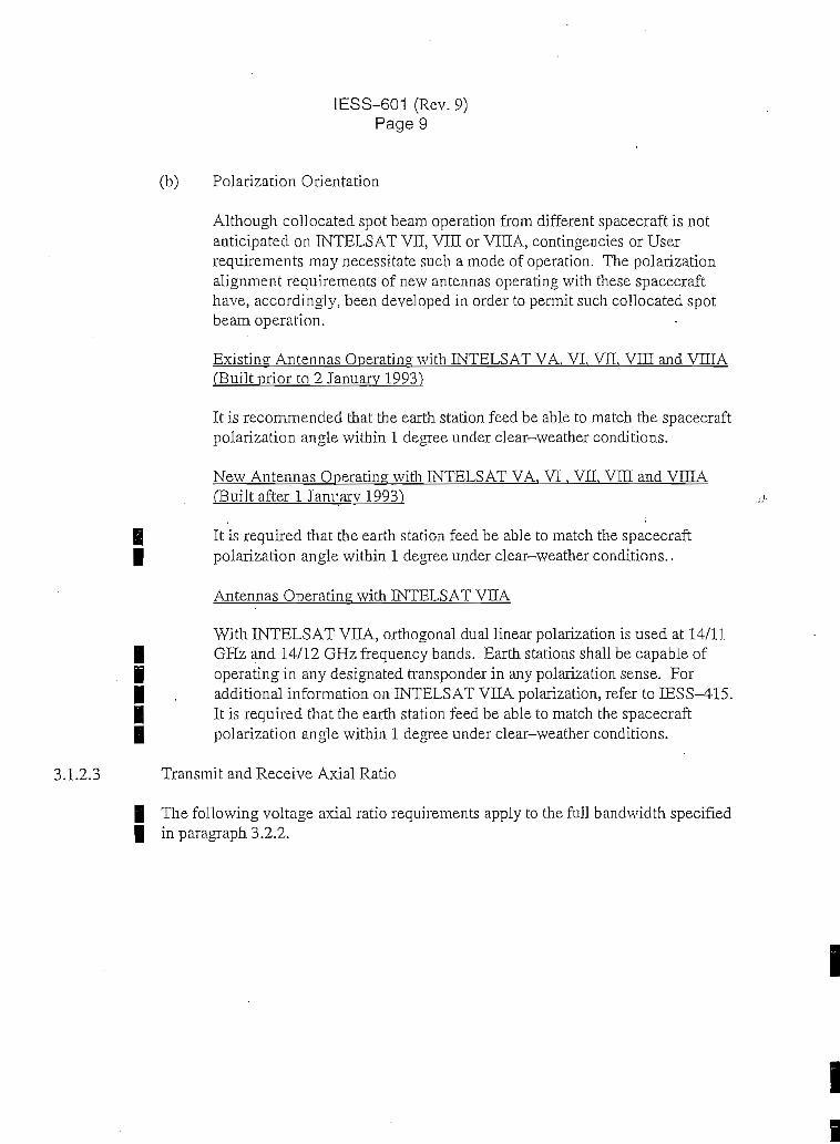
IESS-601 (Rev.9)Page 9 -
(b) Polarization Orientatíon ^
IAlthough collocated spot bearn operation from different spacecraft is notanticipated on TNTELSAT VII, VIII or VILA, contingencies or Userrequirements may necessitate such a mode of operation. The polarizationalignment requirements of new antennas operating with these spacecrafthave, accordingly, been developed in order to permit such collocated spotbeam operation.
Existmg Antennas Operating with INTEL5A.T VA. VI. VII, VIII and VniAíBuilt prior to 2 Januarv 1993")
It is recommended that the earth station feed be able to match the spacecraftpolarization angle within 1 degree under clear-weather conditions.
New Antennas Operating with INTELSAT VA, VI, VIL VIH and VIDA(Built after 1 Janrarv 1993)
g It is required that the earth station feed be able to match the spacecraft| polarization angle within 1 degree under clear-weather conditions..
Antennas Operating with INTELSAT VSA
With INTELSAT VICA, orthogonal dual linear polarization is used at 14/11| GHz and 14/12 GHz frequency bands. Earth stations shall be capable of| operating in any designated transponder in any polarization sense. For| , additional information on INTELSAT VHA polarization, refer to IESS-415.| It is required that the earth station feed be able to match the spacecraft| polarization angle within 1 degree under clear-weather conditions.
3.1.2.3 Transmit and Receive Axial Ratio
| The following voltage axial ratio requirements apply to the full bandwidth speciñed| in paragraph 3.2.2.
i
ii

1ESS-601 (Rev. 9)Page 10
(a) Circu]arly Polarized Antennas Operating in the 5.925 - 6.425 GHz and 3.700- 4.200 GHz Bands (500 MHz)*
Antennas With Diameter Larger Than 2.5 m
The voltage axial ratio of transmission in the direction of the satellite shallnot exceed 1.09 (27.3 dB polarization discrimination) within a cone definedby the antenna tracking and/or pointing errors. The design goal, however, is 1.06(30.7 dB polarization discrimination). It is recommended that this axial ratio notbe exceeded for reception.
Antennas \vith Diameter 2.5 m or Smaller
The voitage axial ratio of transmission in the direction of the satellite shall notexceed 1.3 (17.7 dB polarization discrimination) within a cone defined by theantenna tracking and/or pointing errors. It is recommended that this axial rationot be exceeded for reception. /;.-*
Special Conditions
The following exceptional relaxations apply to specific categories of antennasand will be evaluated on their merits by INTELSAT on a case-by-case basis.
For certain specific applications, it may be possible to reduce the frequencybandwidth specifíed in paragraph 3.2.2 over which the mandatory axial ratiorequirements are to be met in order to achieve some reduction in fhe feed costs.
For 6/4 GHz antennas, there may be special circumstances which wouldpermitstations operating with particular modulation tecbniques to have an antennavoltage axial ratio greater than 1.09, even when a dual polarized spacecraft isbeing accessed. This may occur when frequency plans in oppositely polarizedtransponders can be interleaved, or when it can be demonstrated that no harmfalco-channel interference will be produced, such as may occur when specírumspreading techniques are used. In particular, if it is shovvn in the transmissionplan that the on-axis crosspolanzed aggregate e.i.r.p. density of all antennas atany uplink frequency does not exceed 20 dBW/4 kHz, then antennas withreduced axial ratio performance will be considered on a case-by-case basissubject to the following constraint ideníified in paragraphs (i) below:
These requiremenís also apply to earth stations operating in the 5.850 - 6.425 GHz and 3.625 -4.200 GHz (575 MHz) bands on INTELSAT VI and INTELSAT VIH.

IESS-601 (Rev.9)Page11
I
(i) Antennas with Diameters ín the Range Extending Frorn 4.5 to 7.0 Meterswhich Utilize Meanderline Polarizers
Meanderline polarizers can be utilízed to convert the polarization sense of an •antenna from linear to circular polarization.. Antennas with diameters in the |range extending from 4.5 to 7.0 rneters, using meanderline polarizers, arerequired to have a transmit voltage axial ratio of 1.2 or less. It is expectedthat meanderline polarizers will normally be utilized on an interim basis untilsuch time as the antenna feed can be replaced with a circularly polarizedfeed.
Linearlv Polarized Antennas* With Diameter Larger Than 4.5 Meters
The voltage axial ratio of transmission in the direction of the satellite shallexceed 31,6 (30.0 dB polarization discrimination) within a cone definedbythe antenna tracldng and/or pointing errors. It is recommended that this axialratio be exceeded for reception.
Linearlv Polarized Antennas* With Diameter 4.5 Meters'or Smaller
The voltage axial ratio of transmission in the direction of the satellite shallexceed 22.4 (27.0 dB polarization discrimination) within a cone deñnedby •,the antenna tracldng and/or pointing errors. The design goal, however, is •'31.6 (30.0 dB polarization discrimination). It is recommended that this axialratio be exceeded for reception. •
(c) Existing Antennas Operating in the 14/11 or 12 GHz Bands with INTELSATVA, vi, vn, VEA, vm} VEÍA
As a design objective, the voltage axial ratio of transmission in the direction ofthe satellite should exceed 31.6 (30.0 dB polarization discrimination) everywherewithin a cone centered on the main beam axis. The cone angle is defined by theaníenna tracldng and/or pointing errors. It is recommended that this axial ratio beexceeded for reception.
To assist the rrequency planning process, earth stations operating withINTELSAT VIIA or with satellites having overlapping spot beam coveragesmay be required to submit measured data of the voltage axial ratio oftransmission across the cone defined by the tracMng and/or pointing errors.
The INTELSAT V I I I A spacecraft (Flight 805) utilizas linear polarization in the 6 and 4 GHz bands.

I
•
ji
IESS-601 (Rev. 9)Page 12
(d) New Antennas Operating in the 14/11 or 12 GHz Bands with INTELSAT VA,VI, VH, VITA, VIÍI, VIIIA (Built after 1 January 1993).
Antennas with Diameter Larger Than 2.5 Meters
The voltage axial ratio of transmission in the direction of the satellite shallexceed 31.6 (30.0 dB polarization discrimination) everywhere within a conecentered on the main beam axis. The cone angle is defined by the antennatracking and/or pointing errors. It is recommended thaí íhis axial ratio beexceeded for reception.
Antennas With Diameter 2.5 Meters or Smaller
The voltage axial ratio of transmission in the direction of the satellites shallexceed 20.0 (26.0 dB polarization isolation) everywhere within a cone defínedby the antenna tracking and/or pointing errors. It is recommended thaí thisaxial ratio be exceeded for receptionj*.
Transmit earíh stations which do not comply with this 26 dB polarizationdiscrimination requirement may opérate, provided the polarizationdiscrimination is 20 dB or greater everywhere within a cone defined by theantenna tracking and/or pointing errors and the power density of thetransmitted carrier does not exceed the following:
Máximum e.i.r.p. Density = 52.0 - (26.0 - XPD) dBW/40 kHz
Where: XPD is defined as the worse case polarization discrimination(> 20 dB) across the cone defíned by the antenna tracking and/orpointing error.
Notes:
(1) The above computed e.i.r.p. density may not exceed that permittedby the off-axis emission limitations of Rec. ITU-R S.524-5.
(2) Type-approved antennas are required to meet a 26 dB polarizationisolation across the cone defined by the antenna tracking and/orpointing error.
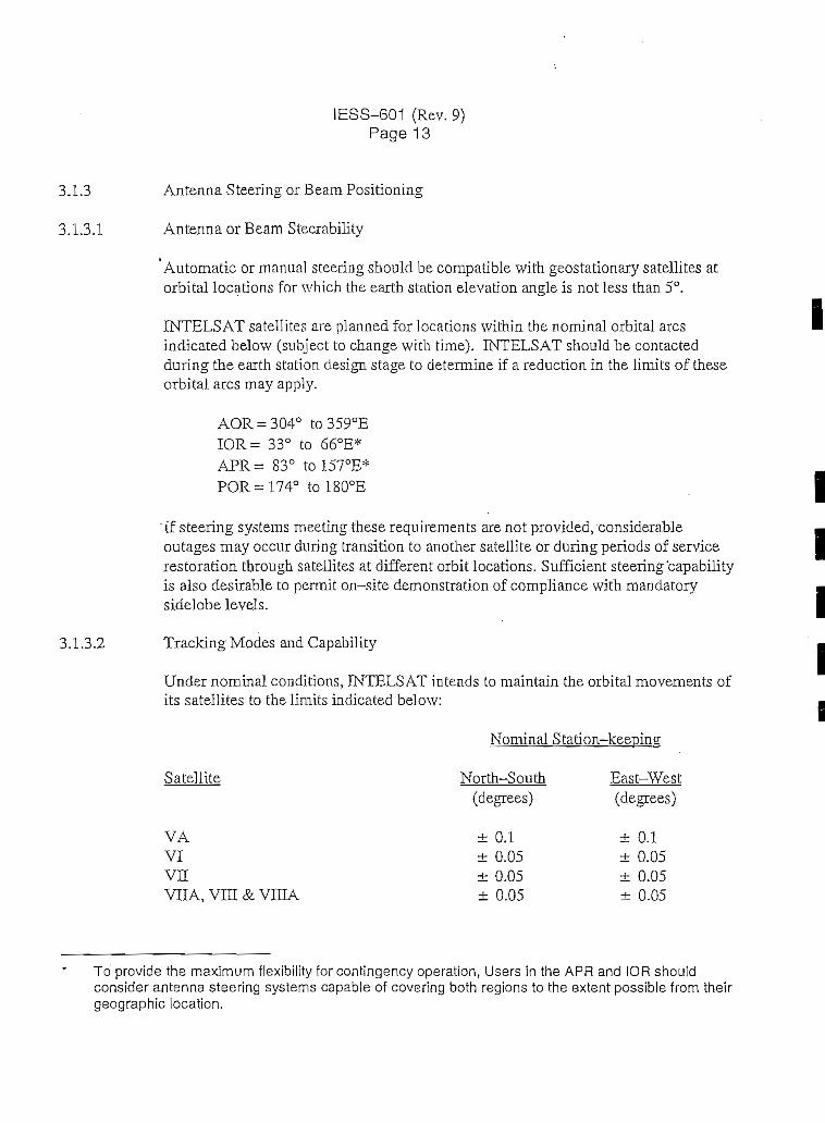
IESS-601 (Rev, 9)Pagel 3
3.1.3 Antenna Steering or Beam Positioning
3.1.3.1 Antenna or Beam Steerability
Automatic or manual steering should be compatible with geostationary satellites atorbital locations for which the earth station elevation angle is not less than 5°.
INTELSAT satellites are planned for locations within the nominal orbital aresindicated below (subject to change with time). INTELSAT should be contactedduring the earth station design stage to determine if a reduction in the limits of theseorbital ares may apply.
° to359°EIOR= 33° to 6ó°E*APR= 83° to 157°E*POR =174° to 180°E
"íf steering systems meeting these requirements are not pro vided, considerableoutages may occur during transition to another satellite or during periods of servicerestoration tbrough satellites ai different orbit locaíions. Sufficient steering 'capabilityis also desirable to permit on-síte demonstration of compliance with mandatorysidelobe levéis.
3.1.3.2 Tracking Modes and Capability
Under nominal conditions, INTELSAT intends to maintain the orbital movements ofits satellites to the limits indicated below:
Nominal Station-keeping
Satellite North-South East-West
VAVIvnVIIA, vm & VIHA
(degrees)
± 0.1± 0.05± 0.05± 0.05
(degrees)
± 0.1± 0.05± 0.05± 0.05
To' provide the máximum flexibilíty for contingency operation, Users in the APR and IOR shouldconsider antenna steering systems capable of covering both regions to the extent possible from theirgeographic location.

i
IESS-601 (Rev.9)Page 14
Based on the above nominal station-keeping limits and the earth station antennabeamwidth, the User should determine whether autotrack is required, taking intoaccount the e.i.r.p. stability required in paragraph 3.1.3.4, the axial ratiorequirement of paragraph 3.1.2.3 and performance objectives. As a minimum,manual tracking capabílity with the fácil i ty to peak up the receive signal isrecommended, since the intended station-keeping limits may be exceeded undercertain special circumstances.
(a) 4 GHzBeacons
4 GHz beacon transmit frequencies for the INTELSAT satellites are shownbelow:
Satellites Beacon Frequencies(MHz)
VA & VI 3,947.5, 3,948.0, 3,952.0 and 3,952.5
VII, VHA, VIE & VELA Same 4 frequencies above used fortelemetry, plus an unmodulatedtracking-on]y beacon at 3,950.0
'Only two of the four beacons on each INTELSAT VA, VI, VE, VEA, VEI,and VIEA satellite can be operated simultaneously, one at the low frequency(3,947.5 or 3,948.0 MHz) and the other at the high frequency (3,952.0 or3,952.5 MHz).
Standard G stations equipped with autotrack should note that for autotrackingof INTELSAT VA and VI series of satellites by means of the beacon signáistransmitted by these satellites, it is necessary to be able to receive andadequately differentiate between the following beacon frequencies: 3,947.5,3,948.0, 3,952.0 and 3,952.5 MHz. It should be noted that a pair of beaconfrequencies will normally be used at any given time, the choice of which willbe determined by INTELSAT. Alternative means for tracking of thesesatellites may be utilized.
Standard G stations accessing INTELSAT VII, VEA, VEt and VEÍAsatellites should, preferably, utilize the unmodulated 3,950 MHz beacon fortracking purposes. However, under contingency circumstances, the earthstations may be required to crack using any of the four telemetry beaconfrequencies, in which case, the provisions of the above paragraph shall apply.
ii

IESS-601 (Rev. 9)Page 15
(b) 11 GHzBeacons (Unmodulated)
The 11 GHz beacon transmit frequencies for the INTELSAT VA, VI, VII,VITA and VITI series are as follows:
11.198 GHz11.452 GHz
Depending on the tracking requirements of Users operatingin the 14/11 GHzbands with antennas smaller than 3.8 meters on INTELSAT VII, VEA andVIH, INTELSAT may opérate the 11.198 GHz and 11.452 GHz beaconssimultaneously. On INTELSAT VA and VI, only one beacon will beoperated at a time. In case of a beacon failure on INTELSAT VA or VI,INTELSAT may, at its discretion, opérate the other beacon transmitter orprovide an artificial beacon at the original frequency. In case of a beaconfailure, some period of time may elapse before such an artificial beacon canbe implemented. 'Lísers on INTELSAT VA and VIrequiring a beacon for .Cracking purposes should confirm with INTELSAT the operational frequencyof the beacon on the satellite of interest and any contingency beacon plans.Users are urged to consider tracking system designs capable of operation witheither beacon frequency.
(c) ¡12 GHz Beacons (Unmodulated)i .;í12 GHz beacon transmit frequencies for the INTELSAT VE, VIIA, VIH andVHIA series are as follows:
- 11.701 GHz associated with the 11.7 to 11.95 GHzband, and
- 12.501 GHz associated with the 12,5 to 12.75 GHzband
Additional information regarding beacons is provided in the IESS 400series spacecraft description modules.
3.1.3.3 Antenna SteeringData
Beginning in 1992, INTELSAT discontinued routinely providing the pointing anglesappropnate to a given satellite for each station. Instead, INTELSAT now providesthe parameters necessary for an earth station to compute its own pointing angles.INTELSAT will, on an exceptional basis, continué to provide pointing data whendifficulties wouldbe experienced by current statíons with the revised approachpending resolution of the difficulty. The User is referred to IESS-412 for details ofthe computational method.

[ESS-601 (Rev.9)Page 16
3.1.3.4 e.i.r.p. Stability
Tropospheric scintillation can occur in C-Band or Ku-Band under both adverseweather and clear-weather conditions. Scintillation affects both linearly andcircularly polarized signáis. The effects of scintillation may be significant on linkshaving elevation angles less than 20°. On links having elevation angles near 5°,scintillation effects can be severe. As a consequence of scintillation, antennasemploying active tracking on low elevation paths may experience antennamispointing or may transmit excessive e.i.r.p. levéis when uplink power control isemployed. The use of program track is, therefore, highly recommended on linksoperating with elevation angles less than 20° for thosepenods when troposphericscintillation is severe and is recommended as the primary tracking method forantennas with elevation angles below 10°.
(a) Clear Weather
Carrier levéis will be agreed upon in the coordinated transmission plandescribed in Section LO.
For tracking earth stations, the e.i.r.p. in the direction of the satellite shall,except under adverse weather conditions, be maint^ained to within +1.0 dB,?- 1.5 dB from the level assigned by INTELSAT. For non-tracking earthístatiohs, the e.i.r.p. in the direction of the satellite shall, except underadverse weather conditions, be maintained to within ±0.75 dB from thelevel assigned by INTELSAT. These tolerances include all earth stationfactors contributing to e.i.r.p. variation, antenna beampointing-and/ortracking error and fluctuations in the output RF power developed by the earthstation transmit equipment, added on a root-sum-square basis.
In allocating a portion of the permitted e.i.r.p. instability to antenna beampointing and/or tracking, Users are cautioned that the crosspolarizationisolation requirements of paragraph 3.1.2.3 must be met across the conedefíned by the antenna tracking beamwidth.
The - 1.5 dB requirement may be modified to a larger valué for applicationshaving sufficient margin. A request for a specific relaxation must besubmitted at the time an earth station application is made and must beaccompanied by a detailed transmission plan as described in Section LO.Any relaxation will be evaluated on its merits by INTELSAT on a case-by-case basis taking into account the immunity of the link to co-channelinterference.

IESS-601 (Rev. 9)Page 17
(b) Adverse Weather Conditions (Ku-Band)
If open-loop uplink power control is used, it is recommended that when theup-path excess attenuation is greater than 1.5 dB, control of transmitterpower be applied to restore the power flux density at the satellite to -1.5 dB,± 1.5 dB of nominal, to theextent that it is possible with the total power
| control range available. The flux density level obtained for clear-sky e.Lr.p.| shall not be exceeded by more than 1.5 dB prior to or following cessation of| precipitaron, except for a brief interval following recovery from propagation| conditions.
3.2 General Radio Frequency Requirements
3.2.1 Satellite Bandwidth and Transponder Frequency Allocations
Transponder frequency details are provided ia íhe IESS 400 seríes spacecraftdescription modules. Services can be assígneü to any avaijable transponder and toany satellite series as may be necessary for contingency operation or resourcemanagement.
3.2.2 Mirdmum Earth Station Bandwidth Requirements •fj
(a) ¿6/4 GHz Bands (All Earth Stations)3 14/12 GHz Bands (All Earth Stations)and 14/11 GHz Bands Having Antennas Larger Than 3.8 Meters
| The instantaneous bandwidth of the earth station antenna feed elements andj LNA shall include one of the full 6/4 GHz, 14/11 or 14/12 GHz frequency| bands indicated in Tables 3(a) and 3(b). The RF electronics of the earthI station (this includes the frequency translators, local oscillators and HPA)| shall be capable of operating (with tuning if necessary) across the full extent| of the indicated transmit and receive bands.
As referred to in paragraph 3.1.2.3, for certain specific applications, it maybe possible to allow a reduction in íhe frequency bandwidth described inTables 3(a) and 3(b) in order to achieve some reduction in the earth terminalcosts whi]e meeting the axial ratio requirements. Any relaxation will beevaluated on its merits by INTELSAT on a case-by-case basis.
The term "open-loop" refers to upl ink power control systems which derive the excess uplink pathattenuation experienced by a given carrier by measurement of the downlink power of another carrier(such as the spacecraft beacon).

IESS-601 (Rev.9)Pagel 8
(b) Earth Stations Utilizing the 14/11 GHz Bands Having Antennas withDiameters 3.8 Meters or Smaller
In order to achieve some reduction in the cost of earth termináis, the RFelectronics (this includes the frequency translators, local oscillators, HPA,and transceivers*, if applicable) need only be capable of operation, withtuning if necessary, across one of the following transmit and receive bandsegments:
Receive
10.95 to 11.2 GHz
11.45 to 11.7 GHz
and
or
and
Transmit
14.0 to 14.25 GHz
14.25 to 14.5 GHz
3.2.3
The earth terminal anterma feed elements shall have an instantáneousbandwidth covering 10.95- 11.7 GHz and 14.0 - 14.5 GHz.
Users are strongly urged to consider terminal designs capable of operationacross the 10.95 to 11.7 GHz and 14.0 to 14.5 GHz bands. WhüeINTELSAT will make every effort to maintain frequency assignments withinthe capabilities of an earth terminal, reassignments may occur as aconsequence of satellite transitíons or trafñc requirements. Frequencyreassignments may also occur as a result of unforeseen circumstances such asmay arise during contingency operation. In such contingency cixcumstances,advanced notification of frequency assignments may not be possible. Usersof the 11 GHz band operating with reduced bandwidth termináis and utilizingthe spacecraft beacon for traclcing purposes should consider in their designsthat, in the event of a failure of the spacecraft beacon, some períod of timemay elapse before the beacon can be restored (see para. 3.1.3.2(b)). Thiswill, generally, be a serious consideration only for earth stations operatingwith inclined orbit satellites.
Ability to Vary Frequency of Camers
The capability to vary the frequency of each transmitted carrier shall be provided, inorder to permit carriers to be radiated anywhere within the earth station operating
The term transceiver is used to denote ¡ntegrated units generaliy containing an LNA, SSPA or TWTA,frequency translators and local oscillators.
I

I
¡i
IESS-601 (Rev. 9)Page 21
a) Spurious Products Associated With Transmissions To Standard E-l, F-l, G, Hor K Earth Stations:
Spurious products falling in any 4 kHz band, which lies within the frequencyrange described in the above table, shall be at least 50 dB below the level of anunmodulated carrier (Le., — 50 dBc)
b) Spurious Products Associated With Transmissions To Standard A, B, C, E-3,E-2, F-3 or F-2 Earth Stations
Spurious products falling in any 4 kHz band, which lies within the frequencyrange described in the above table, shall be:
1) at least 40 dB below the level of an unmodulated carrier (Le., - 40 dBc) forcarriers having information rates up to and including 2.048 Mbit/s.
2) at least 50 dB below the level of an unmoclulated carrier (i.e., - 50 dBc) forcarriers with information rates greater than 2.048 Mbit/s.
3.3.3 Spurious Emission - Intermodulation Products
(a) ft6GHzBand
The e.i.r.p. density resulting from the buildup of intermodulation productstransmltted from the earth station shall not exceed the Jevels shown inTable 4. This requirement applies outside the User's bandwidth. The level ofearth station intermodulation which is acceptable within the User'sbandwidth is determinedby the User.
(b) 14GHzBand
The e.i.r.p. density resulting from the buildup of intermodulation productstransmitted from the earth station shall not exceed the limits shown in Table25under clear-sky conditions. When uplink power control is used, the limit givenin Table 5 may be exceeded duringrain events when the control is active, but,under no circumstance shall it be exceeded by more than 9 dB. This specificationapplies outside the User's bandwidth. The level of earth station intermodulationwhich is acceptable within the User's bandwidth is determined by the User.
!f 'It may be permissible in some cases for the limits given in para. 3.3.3 (a) and (b) tobe exceeded by some intermodulation products if it can be shown that, for the

IESS-601 (Rev.9)Page 22
particular frequency plan, this will not cause the overall noise performance objectivesof the interfered with carriers to be exceeded.
3.3.4 Carrier Spectral Sidelobes
| The spectral sidelobe of each transmitted digital carrier shall be more than 26 dB| down from the spectral mainlobe peale when it falls outside the User's bandwidth.
The acceptable level of spectral sidelobes falling within the User's bandwidth isdetermined by the User.
3.4 Ability to Vary e.Lr.p. of Carriers
It is recommended that means be provided whereby the level. of each transmittedcarrier can be adjusted over a range of 15 dB to meet changes that may occur in theagreed transmission plan.
3.5 Total Receive Power Flux Density at the Earth's Surface
The máximum expected total receive power flux densities for C-Band and Ku-Bandearth stations are shown in Tables 6(a) and 6(b) respectively.
3.6 Amplitude, Group Delay, and Electrical Path Length Equalizafion
In designing the RF subsystem, consideration shouldbe given to amplitude, groupdelay and electric path length equalization requirements necessary to achieve Userperformance objectives.
3.7 Communications Between INTELS AT and Standard G Earth Station
| A Communications link shall be established between INTELS AT and a single point| of contact with the User responsible for control of each network for the purpose| of relaying emergency and routine operational información and data. The User shall| arrange in cooperation with, and to the satisfaction of, INTELSAT for| communication of the appropnate información to all Standard G earth stations in that| particular network. Users should contact INTELSAT regarding selective signalling
speciñcations for voice and teletype in order to gain direct access to the INTELSATOperations Center located in Washington D.C., via the existing ESC Network usedfor regular International services. Access to this center is also availabk through thePublic Network,

IES
S-6
01 (
Rev
.9)
Pag
e 25
TA
BL
El(
a)ST
AN
DA
RD
G E
AR
TH
ST
AT
ION
PO
LA
RIZ
AT
ION
RE
QU
IRE
ME
NT
S T
O O
PÉR
AT
E W
ITH
IN
TE
LSA
TV
A. V
I V
n A
ND
VII
A S
AT
EL
LIT
ES
(6/
4 G
fe)
Cov
erag
e^^_
L G
loba
l A
2.
Glo
bal B
3.
Wes
t H
emis
pher
e(H
emi
I)*
f4.
E
ast H
emis
pher
e(H
emi 2
)* f
5.
NW
Zon
e (Z
l)**
(ZA
)t6.
N
EZ
one
(Z3)
**(Z
B>t
7.
SW
Zon
e (Z
2)**
czot
8.
SE
Zon
e(Z
4)**
fZD
)t9.
C
-Spo
tA
10.
C-S
potB
INT
EL
SAT
VA
Ear
th S
talio
nT
rans
mit
LK
CP
RH
CP
LH
CP
LH
CP
RH
CP
RH
CP
N/A
N/A
N/A
N/A
EarU
i Sta
tion
Rec
eive
RH
CP
LH
CP
RH
CP
RH
CP
LH
CP
LH
CP
N/A
N/A
RH
CP
LH
CP
¿^«^I
NT
EL
SA
TV
I -
Ear
th S
tatio
nT
rans
tnit
LHC
P
RH
CP
LH
CP
LH
CP
RH
CP
RH
CP
RH
CP
RH
CP
N/A
N/A
Ear
th S
tati
onR
ecei
veR
HC
P
LH
CP
BH
CP
RH
CP
LH
CP
LH
CP
LH
C^.
LH
CP
N/A
N/A
INTE
LSA
T V
II/V
UA
.;
Eart
fi St
atio
nT
rans
mit
LH
CP
RH
CP
LH
CP
LH
CP
RH
CP
RH
CP
RH
CP
RH
CP
LH
CP
RH
CP
Ean
h Sl
alio
nR
ecei
veR
HC
P
LH
CP
RH
CP
RH
CP
LH
CP
LH
CP
LH
CP
LHC
P
RH
CP
LH
CP
Hem
i i,
Hem
i 2,
ZA
, ZB
S Z
C, Z
D n
omen
clat
ura
appl
ies
íolK
TE
LS
AT
Vil
and
VII
A o
nLy,
Zl,
Z2,
23,
24
nom
encl
atur
e ap
plie
s L
o IN
TE
LSA
T V
I on
ly.
Thi
s in
díca
les
the
norm
al m
ode
of o
pera
tion
for
INT
EL
SAT
VII
and
VH
A;
líie
iuve
rted
mod
e im
pLie
s dif
fere
nt b
eam
s in
the
Eas
t an
d W
est,
asU
lusi
rate
dinI
ES
S-4
09.
Not
es:
LH
CP
= L
eft-
Han
d C
ircu
larl
y Po
lari
zed.
RH
CP
= R
ight
-Han
d C
ircu
larl
y Po
lari
zed.
N/A
= N
ol a
pplic
able
to
this
spa
cecr
afl
j•_ j
• i
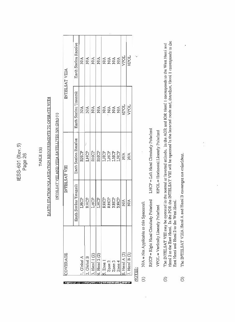
IESS
-601
(R
ev.9
)Pa
ge 2
6
TA
BL
E l
(b)
EA
RT
H S
TATI
QN
PQ
LAR
IZA
TIO
N R
EOU
TREM
ENTS
TO
OPÉ
RA
TE
WIT
H
INTE
LSA
T V
m A
ND
VIT
IA S
AT
EL
LIT
ES
(6/4
GH
zl m
CO
VE
RA
GE
1. G
loba
l A
2. G
loba
l B
3. H
emi
i (2
)4.
Hem
i 2
(2)
5. Z
one
1Z
one
2Z
one
3Z
one
46.
Hem
i A (
3)7.
Hem
i B
(3)
INT
EL
SAT
VIH
Ear
th S
taLi
on T
rans
mit
LH
CP
RH
CP
LH
CP
LH
CP
RH
CP
RH
CP
RH
CP
RH
CP
N/A
N/A
Ear
th S
tati
oa R
ecei
ve
RH
CP
LH
CP
"
RH
CP
RH
CP
LH
CP
LH
CP
LH
CP
LH
CP
N/A
N/A
INT
EL
SA
T V
IHA
Ear
th S
tati
on T
rans
mit
N/A
.N
/AN
/AN
/AN
/A'N
/AN
/AN
/Atí
PO
LV
POL
Ear
th S
tati
on R
ecei
ve
N/A
N/A
N/A
N/A
N/A
N/A
N/A
N/A
VPO
L
HP
OL
NO
TE
S:
(1)
N/A
= N
ot A
pplic
able
to
this
Spa
cecr
afl
RH
CP
= R
ight
Han
d C
ircu
lari
y Po
Jari
zed
VP
OL
= V
erti
call
y L
inea
rly
Pol
ariz
ed
LH
CP
= L
eft
Han
d O
rcul
atly
Pol
ariz
ed
HP
OL
= H
oriz
onta
l Lin
earl
y Po
Jari
zed
(2)
(3)
The
IN
TE
LSA
T V
UI m
ay b
e op
erat
ed ia
the
nor
mal
or i
nver
ted
atti
tude
. In
the
AO
R a
nd I
OR
Hem
i I
corr
espo
nds
to t
he W
est H
emi a
ndH
emi 2
to
the
Eas
t Hem
i, In
the
PO
R t
he I
NT
EL
SA
T V
III
will
be
oper
ated
in.
Lhe
inv
erte
d m
ode
and,
ther
efor
e, H
emi
1 co
rres
pond
s to
Lhe
Eas
l Hem
i an
d H
emi
2 to
the
Wes
t H
emi.
The
IN
TE
LSA
T V
IIIA
Hem
i A
and
Hem
i B
cov
erag
es a
re c
oinc
iden
t.

IESS-601 (Rev. 9)Page 27
TABLE2
EARTH STATIQN PQLARIZATION REQUTREMBNTS TO OPÉRATEWITHINTELSAT VA, VI, VIL VITA, VIH. VTUA SATELLITES
(14/11 GHz AND 14/12 GHz)
Satellite
VA and VI
vrr
VITA
vm(4)
VHIA
805
Coverage
' East SpotWest SpotSpot 1 & Spot 3 (2)
Spot 2S1,S2X,&S3(2)S1X.S2SpotlSpot 2
Spotl
Linear Polarization (1)Earth Station
TransmitHorizontal
VerticalHorizontal
VerticalHorizontal
VerticalHorizontal
Vertical
1 Horizontal
Earth StationReceiveVertical
HorizontalVertical
HorizontalVertical
Horizontal.Vertical
Horizontal
Vertical
(1) Users are referred to the IESS-400 series modules for the definition of horizontal and verticallinear polarización and.the dependence of the polarization orientación on the geographic locationof the earth station.
(2) On INTELSAT VII (F-4, F-5, and F-9) and INTELSAT VIÍA (F-6, F-7, and F-8), Spot 3receive and transmit antenna polarization senses can be swítched in orbit by ground command.
(3) Earth stations located in the South American beam are only required to receive in the verticalpolarization.
(4) The polarization sense of either ÍNTELSAT VIII Spot beam can be changed independently byground command. Users are urged to confírm with INTELSAT the polaiization sense of theSpot beam that will be utilized.
i

IESS-601 (Rev.9)Page 28
TABLE 3(a)MliSTIMUM BANDWIDTH REOUIREMENTS FQR STANDARD G
C-B AND EARTH STATTONS m
Satellite
VA, VI,vn, VHA & vm
VETA
Tx/Rx Antennas:
BandlBand2
Rx-Onlv Antennas:
BandlBand2 •
ITURegión
A1J
All
Earth StationTransmit Freq.
(GHz)
5.925 - 6.425 (2)
5.925-6.425 (2)5.850-6.650 (3)
N/AN/A
Earth StationReceive Freo.
(GHz)
3.700-4.200(2)
3.700-4.200 (2)3.400-4.200 (3)
3.700-4.200 (2)3.4004-4.200 (3)
Transmitand ReceiveBandwidth
(MHz)
500
500800
500800
NOTES:
(1) Users are referred to the IESS-400 series modules for details of the channelization of thevarióos INTELSAT spacecraft.
(2) At 6/4 GHz, Users should consider in íheir design the possibility of extending their usablebandwidth down to 3.625 GHz for receive and down to 5.850 GHz for transmit, in order toinclude transponder (I1 - 21) of INTELSAT VI, VIH and VIDA.
(3) Some Administrations do not permic operation with the entiie 5.850 - 6.650 GHz and 3.4004.200 GHz Bands. Users in such Administrations may equip for those portlons of the bandsthat are permitted.

IESS-601 (Rev.9)Page 29
I
TABLE3(b)IVONIMUM BANDWIDTH REOUIREMENTS FOR. STANDARD G
Ku-B AND EARTH STATIONSm
Satellite
VA, VI
vn, VIIA, vnr (4)
vniA
; ITU
'- Retrion
All
AU
2(2)(3)1 & 3 (2)
o
1 &3
Earth StationTransmitFreq.
(GHz)
14.00-14.50
14,00-14.50
14.00-14.2514.00-14.25
1 ¿.00 -14.2514.00-14.25
Earth StationReceive Freq.
(GHz)
10.95 -11. 20 &11.45 -11.70
10.95- 11.20 &11.45-11.70
11.70-11.9512.50-12.75
11.70-11.9512.50-12.75
NOTES
L
III
(1) Users are referred to the IESS^J-00 series modules for details of trie channelization of thevarious INTELSAT spacecraft.
(2) On INTELSAT VII, the receive band segments of 11.70 - 11.95 GHz and 12.50 -12.75 GHz are interchangeable between the East and West spot beams, so that thisspacecraft series can be operated in any Ocean región.
(3) Earth station Users should consider in their design the possibility of extending theirusable bandwidth to 14.35 GHz in the transmít band and to 11.45 GHz in the receiveband.
(4) For Ku-Band earth stations, consideraron should be given to designing the RF system.with a receive bandwidth of 10.95-12.75 GHz and a transm.it bandwidth of 14.0-14.5GHz. This will simplify conversión from the 11 GHz band to the 12 GHz band andprovide máximum fíexibility for operation with any spacecraft series.

i IESS-601 (Rev.9)Page 30
i
TABLE4
e.i.r.p. DENSITY LTMTTS FOR TNTERMODULATTON PRODUCTS(6 GHz)
UplinJc TransponderImpacted By
IntermodulationProduct
1. Hemi and Zone (2)
2. Global & C-Spot (2)
Limit at 10 degreeElevation Angleand Beam Edge(dBW/4 kHz)
(1)
21
24
CorrectionFactor(dB)
-K,
-K,
Where: Kj and K2 are the correction factors defined in IESS-402 for elevation angles otherthan 10° and earth station locations other than atbeam edge.
NOTES:
(1) Obtaining these levéis involves the suitable choice of operating conditions for allcommon araplifiers.
(2) INTELS AT YUCA has hemispheric coverage only.

IESS-601 (Rev.9)Page 31
TABLE 5
e.i.r.p. DENSITY LTMIT5 FQRINTERMODULATIQN PRODUCTS(14 GHz)
Uplinlc TransponderImpacted By
IntermodulationProduct
Spot
Limit at 10 degreeElevation Angleand Beam Edge
(dBW/4kHz)(l)
VA and VI
10
VE, VITA, VIH,and VIIIA
16
CorrectionFactor(dB)
-K!
I
Where: KI ís the correctíon factor defíned in IESS-402 for elevation angles other than10° and ¿arth station locations other than at beam edge.
NOTES:
(1) Obtaining these levéis involves the suitable choice of operating conditions for allcommon amplifiers.
I
I

IESS-601 (Rev. 9)Page 32
TABLE 6(a)MÁXIMUM POWER FLUX DENSITY (PFD) AT THE EARTH's SURFACE
(C-BandDownlinlcs, dBW/m2)
Satellite Tvpical PFD Per Transnonder Máximum Total PFD*
VA
VI
vnVLCA
vmVIIIA
NOTES:
(Global)
-139.6
-137.1
- 134.6
-134.1
-133.1
N/A
(Hemi/Zone)
-134.1
-132.1
-131.1
-131.1
-130.1
-128.6
(C-Spot)
-129.1
N/A
-125.1
-124.5
N/A
N/A
(A-Pol)**
- 122.4
- 123.5
-117.9
-117.4
-118.8
- -113.4
(B~Pol)*
- 122.4
- 124.0
-117.9
-117.7
-118.8
-113.4
Máximum total PFD is the PFD resulting from all transponders in a given beam.I í
Circularly Polárized Spacecraft
A-pol = A polarization (RHCP), which includes global, hemispheric, and 4 GHz spotbeams.
B-pol = B polarization (LHCP), which includes global, zone, and 4 GHz spot beams.
Linearlv Polarized Spacecraft (TNTELSAT VIH A)
A-pol = Hemi A, which is vertically polarized on the downliák.
B-pol = Hemi B, which is horizontally polarized on the downlink.
r

IESS-601 (Rev.9)Page 33
TABLE 6(b)
MÁXIMUM POWER FLUX DENSITY AT THE EARTH's SURFACE
(Ku-Band Downlinks, dBW/m2). . .• • i
Satellite
VA
VI
VE
VEA
vni
VHIA
DownlinkSpot Beams
11 GHz
HGHz
11 GHz12 GHz
11 GHz12 GHz
11 GHz12 GHz
12 GHz
Typical PFD PerTransponder
-118.7
-118.3
-115.4-115.4
-112.6-T3.6
-113.5-113,5
-117.1
Máximum Total PFD*
-112.3
-110.4
- 107.4-109.1
-106.2-108.8
'-106.2-108.7
-108.9
IMáximum total PFD is the PFD resulting from all transponders in a given beam.
I
i
I

I
1'I
Appendix A toIESS-601 (Rev. 9)
Page A-1
APPENDIX A
* REOUIREMENTS FQR EARTH STATIQNS ACCESSING INTELSAT SPACE 5EGMENTWITHOUT SUBMTTTING ANTENNA PERFORMANCE DATA
1>;,ij (STANDARD Gx)
s_
iii' -
s
if ,.:

,IfI
Appendix B toIESS-601 (Rev. 9) ' n
Pag e B-1 §
ií
APPENDIX B n
• IREGJIREMENTS FOREiARTH STATIONS EiVtPLOYÍNG ENfíANCED PERFORMANCE
' QFFSET-FED ANTENNAS - " ^
STANDARD GE ' ''
íaííiíi
íEf

Appendix B toIESS-601 (Rev. 9)
Page B-2
STANDARD GE
B.l INTRODUCTION
Standard GE is a sub-classiñcation of Standard G earth stations which is used forapplications requüing increased up]ink e.i.r.p. capability or increased protection fromadjacent satellite interference. This Appendix provides supplementary RF| requirements for Standard GE earth stations. Standard GE earth stations are| required to comply with Standard G requirements as contained in trie main body| ofthisIESS module.
B.2 GENERAL ANTENNA PERFORMANCE CHARACTERISTICS REQUIRED FORSTANDARD GE EARTH STATIONS ACCESSING THE INTELSAT SPACESEGMENT
B.2.1 Antenna Sidelobe Pattern (6/4 GHz)
(a) Transm.it Sidelobe Design Objective
The design objective should be such that the gain of 90 percent of thecopolarized and crosspolarized sidelobe peaks does not exceed an envelopedescribed by:
First Sidelobe Gain: G = 15 log (D/A) - 6 dBi, 2.4 < D < 2.8 meter.
D > 2.4 meter
Región Beyond The First Sidelobe:
G = 22-25 log 9 dBi, 1°* < 9 < 10.5°G = -3.5 dBi, 10.5° < 9 < 26.3°G = 32-25 log 6 dBi; 26.3° < 9 < 48°G = -10 dBi, 9 > 48°
where: G is the gain of the sidelobe envelope relative to an isotropicantenna in the direction of the geostationary orbit, in dBi.
9 is the angle in degrees between the main beam axis and thedirection considered.
For DA. below 100, this angle becomes 100 7JD degrees.

Appendix C toIESS-601 (Rev. 9)
Pag e C-1
APPENDIX C
ITU REFERENCES
Radiocommuaication Sector Recommendations:
Rec. ITU-R S.465-5 Adopted 25 April 1993
Rec. ITU-R S.524-5 Adopted 7 March 1994
Rec'rriKR S.580-5 Adopted 25 April 1994
ITU Radio Regulations:
Radio Regulation Article 1 Numbers 148 and 149

Appendix D toIESS-601 (Rev. 9)
Pag e D-1
APPENDIX D
REVISIÓN HTSTORY (continuad)
Revisión No.
Original
1
Approval Date
10 Dec 1987
21 Jun 1989
13 Jun 1990
09 Dec 1991
Maíor Parpóse
• • New module.
• Relax voltage axial ratio to 1.3 for smallC-Bandantennas.
• Add CCIR/CCITTreferences
• Incorpórate INTELSAT VII and K, delete.INTELSATIVA.
• Add revisión history.
• Unífy terminology by replacing terms such asapplicants, earth station operating entities,owners, etc., wittí Users.
• Update CCIRreferences.
• Clarify the requirement for the allowableenergy density of intermodulation producís at6GHz(Table3).
• Make thepolarization requirements ofTable 1 raandatory (para. 3.1.2.1).
• Add a mandatory Ku-B and polarizationrequirement to para. 3.1.2.1. Added Table 2.
• Add mandatory requirement for 1 degree Ku-Band antenna polarization adjustmentaccuracy (para. 3.1.2.2).

Appendix D toIESS-601 (Rev. 9)
Page D-2
APPENDIX D
REVISIÓN HISTORY (continuecH
Revisión No.
3 (Cont'd)
Maior Parpóse
• Add raandatory requirement for Ku-Bandantenna transmit axial ratio (para. 3.1.2.3).
• Clarify how antenna steering data will beprovided (para. 3.1.3.3).
• Add requirernent for upl i nk po wer control(para. 3.1.3.4).
• Claríry tbe transponder translatíon frequencytolerance for INTELSAT VA(IBS) and K(para. 3.2.3).
• Update the 14 GHz band off-beam emissionlimits to be consistent with CCIRRecommendation 524-3 (para. 3.3.1).
09 Feb 1994 Incorpórate INTELSAT VITA.
Extend Standard G definition to include earthstations supporting both domestic andinternational léase services. (Standard Zdesignación will no longer be used for newearth stations accessing the leased spacesegment) (para. 1.1)
Clarify that all Standard A, B, C, D-2, Eearth stations may opérate as a Standard G.Standard F and D-l termináis meeting a 1.09axial ratio over the 5.925 - 6.425 GHz bandmay also opérate as a Standard G. (para. 1.4)
i

Appendíx D toIESS-601 (Rev. 9)
Page D-3
APPENDÍX D
REVISIÓN HISTORY fcontinued)
Revisión No.
4 (Cont'd)
i
III 25 Aug. 1994
Maior Parpóse
Update transmit and receive antenna sideloberequirement to be consistent with Rec. ITU-RS.5S0.4(para.3.1.1)
Update recommended antenna steerabilitylimits. AddAPR región (para. 3.1.3.1).
Update source of antenna steering data (para.3.1.3.3).
Relax clear-weather e.i.r.p. stabilityrequirement to permit larger decrease ofe.Lr.p. under special conditions. Clarify thatULPC systems should restore e.i.r.p. to-1.5 dB of nominal valué under adverseweather conditions (para. 3.1.3.4).
Clarify that mínimum operational bandwidthrequirement of termináis operating in the14/11 GHz bands with antennas smaller than3.8 meters applies only to the antenna feedelements.
Relax RF frequency tolerance for low ratedigital carriers (para. 3.2.4).
Update ITU nomenclature and references toreflect Radio Communications Sectorrecommendations (Appendix A).
Incorpórate INTELSAT VIH and VIDA,includingbandwidth requirements foroperation in the extended C-Bands ofINTELSAT VITTA.
5 Nov 1997
• A%^ear-weatherspuriouSemisSionrequémente with thoseinother ÍES modules (para. 3.3.2).
' Add elr.p. stability requirements for non-trackmg earth stations (para. 3.1.3.4(a)).
• Move Standard Gx requirements toAppendix A.
• Incorpórate Standard GE requirements(Appendix B).

Appendix D toIESS-601 (Rev. 9)
Page D-4
APPENDIX D
REVISIÓN HTSTORY ícontinued)
Revisión No. Approval Date MajorPurpose
5 (Cont'd)
15 Aug. 1995
Add paragraph concerning Faraday rotationand detailing recornmended time periods foraligninglinearlypolarized C-Band antennafeeds (para. 3.1.2.1).
Add special condition for antennas with• diameters in the range of 4.5 to 7 meterswhich utilize meanderlíne polarizers (para.
'3.1.2.3).
Add section 3.5 and associated Tables 6(a)and 6(b) giving máximum and typical earthstation receive PFD levéis.
Add requirement that Ku-Band earth stationsbuilt prior to 1993 may be required tosupply measured data of transmit polarizaciónisolation (para. 3.1.2.3 (c)).