André Miguel Tavares Martins Mobilidade em Redes Veiculares ...
137
Universidade de Aveiro Departamento de Electr´ onica,Telecomunica¸c˜ oes e Inform´ atica, 2015 Andr´ e Miguel Tavares Martins Mobilidade em Redes Veiculares com M´ ultiplos Pontos de Acesso ` a Infraestrutura Mobility in Vehicular Networks with Multiple Access Points to the Infrastructure
-
Upload
khangminh22 -
Category
Documents
-
view
0 -
download
0
Transcript of André Miguel Tavares Martins Mobilidade em Redes Veiculares ...

Universidade de AveiroDepartamento deElectronica, Telecomunicacoes e Informatica,
2015
Andre Miguel TavaresMartins
Mobilidade em Redes Veiculares com MultiplosPontos de Acesso a Infraestrutura
Mobility in Vehicular Networks with MultipleAccess Points to the Infrastructure


Universidade de AveiroDepartamento deElectronica, Telecomunicacoes e Informatica,
2015
Andre Miguel TavaresMartins
Mobilidade em Redes Veiculares com MultiplosPontos de Acesso a Infraestrutura
Mobility in Vehicular Networks with MultipleAccess Points to the Infrastructure
”The best way to predict the future is to create it.”
-Peter Drucker


Universidade de AveiroDepartamento deElectronica, Telecomunicacoes e Informatica,
2015
Andre Miguel TavaresMartins
Mobilidade em Redes Veiculares com MultiplosPontos de Acesso a Infraestrutura
Mobility in Vehicular Networks with MultipleAccess Points to the Infrastructure
Dissertacao apresentada a Universidade de Aveiro para cumprimento dosrequisitos necessarios a obtencao do grau de Mestre em EngenhariaEletronica e Telecomunicacoes, realizada sob a orientacao cientıfica da Pro-fessora Doutora Susana Sargento, Professora Associada com Agregacao doDepartamento de Eletronica, Telecomunicacoes e Informatica da Universi-dade de Aveiro e co-orientacao do Doutor Tiago Condeixa, Engenheiro deSistemas na Veniam.


o juri / the jury
presidente / president Professor Doutor Jose Carlos da Silva NevesProfessor Catedratico do Departamento de Eletronica, Telecomunicacoes e
Informatica da Universidade de Aveiro
vogais / examiners committee Professor Doutor Pedro Nuno Miranda de SousaProfessor Auxiliar da Escola de Engenharia da Universidade do Minho (Ar-
guente)
Professora Doutora Susana Isabel Barreto de Miranda SargentoProfessora Associada com Agregacao do Departamento de Eletronica, Tele-
comunicacoes e Informatica da Universidade de Aveiro (Orientadora)


agradecimentos /aknowledgments
Para comecar gostaria de agradecer aos meus pais, Manuel e MariaMartins, por todas as oportunidades e apoio que sempre me deram.Sem eles nao conseguiria alcancar os meus objetivos na vida. Gostariade agradecer a minha irma, Vera Martins, por todo o apoio e carinhodado ao longo da minha vida, e tambem ao meu cunhado Bruno Nunese ao meu sobrinho Goncalo Nunes pela motivacao e apoio dado nestafase ardua.
Gostaria muito de agradecer tambem a minha namorada, Maria Couto,por toda a paciencia, carinho e apoio dado durante o meu percursoacademico.
Agradeco aos meus amigos e colegas de faculdade Pedro Martins, JoaoPalas, Nuno Valente, Diogo Carvalheira, Jose Andrade, Carolina Mar-tins, Dilsa Bastos, Martinho Mendes, Duarte Fernandes, Andre Ribeiro,Ariana Rodrigues e Luıs Almeida pelos bons momentos passados aolongo deste percurso academico.
Um especial agradecimento ao Nelson Capela pela sua ajuda e grandedisponibilidade. Foi um grande privilegio trabalhar com o Nelson eestou muito grato por toda a ajuda dada.
Gostaria de agradecer a Professora Susana Sargento pela sua orientacaoe apoio dado ao longo da dissertacao, e tambem por me ter cativadopara a area de redes de telecomunicacoes. Foi igualmente um privilegiotrabalhar com a professora Susana.
Por ultimo mas de igual importancia, gostaria de dedicar este paragrafoaos meus amigos e colegas de dissertacao Marco Oliveira, GoncaloPessoa, Goncalo Gomes, Tiago Almeida, Bojan Magusic e FranciscoCastro. Foi excelente fazer parte desta grande equipa e e excelentecontinuar a fazer parte deste grande grupo de amigos.


Palavras-chave Multihoming, Vehicular Ad-Hoc Networks, Mobility, IEEE 802.11p, Wi-fi, Cellular Networks, N-PMIPv6
Resumo Nos dias de hoje assistimos a uma grande evolucao no mundo da tec-nologia e das redes sem fios. Os dispositivos eletronicos possuem cadavez mais capacidades e recursos, o que torna os utilizadores tambemcada vez mais exigentes. A necessidade de estar permanentementeligado a uma rede global leva a que cada vez existam mais pontos deacesso a internet para as pessoas estarem em constante interacao como mundo.As redes veiculares surgiram para suportar aplicacoes de segurancarodoviaria e para melhorar o fluxo rodoviario nas estradas, mas agorasao tambem vistas como uma forma de proporcionar entretenimentoaos utilizadores presentes nos veıculos.
Apesar de todos os avancos na area de redes veiculares ainda existemmuitos desafios para serem resolvidos. A presenca de infraestruturadedicada para as redes veiculares ainda nao e muito vasta, o que levaa ser necessario a utilizacao de hotspots Wi-Fi e de rede celular comoredes de acesso.Para fazer toda a gestao da mobilidade e tambem para manter a ligacaodo utilizador ativa e necessario utilizar um protocolo de mobilidade.Tendo em conta tambem o grande numero de pontos de acesso pre-sentes ao alcance de um veıculo numa cidade por exemplo, seria utilpoder usufruir de todos os recursos disponıveis de modo a melhorartoda a rede veicular, quer para os utilizadores quer para os operadores.O conceito de multihoming permite usufruir de todos os recursos viaveisao alcance de um veıculo, atraves de ligacoes simultaneas.
Esta dissertacao tem como objetivos a integracao de um protocolo demobilidade, o protocolo Network-Proxy Mobile IPv6, com uma abor-dagem de multihoming por pacote, de modo a aumentar o desempenhoda rede veıcular atraves da utilizacao de mais recursos em simultaneo,o suporte de comunicacoes em multi-hop, a capacidade de forneceracesso a internet para os utilizadores das redes veiculares, e a inte-gracao do protocolo desenvolvido num ambiente veicular, com as tec-nologias de rede WAVE, Wi-Fi e celular.
Os testes realizados focaram-se nas caracterısticas de multihoming im-plementadas e na utilizacao da rede veicular atraves uma rede IPv4 paraos utilizadores comuns. Os resultados obtidos mostram que a adicaode multihoming ao protocolo de mobilidade melhora o desempenhoda rede e oferece uma melhor gestao dos recursos disponıveis. Alemdisso, os resultados mostram tambem a correta operacao do protocolodesenvolvido num ambiente veicular.


Keywords Multihoming, Vehicular Ad-Hoc Networks, Mobility, IEEE 802.11p, Wi-fi, Cellular Networks, N-PMIPv6
Abstract Nowadays there is a huge evolution in the technological world and inthe wireless networks. The electronic devices have more capabilitiesand resources over the years, which makes the users more and moredemanding. The necessity of being connected to the global world leadsto the arising of wireless access points in the cities to provide internetaccess to the people in order to keep the constant interaction with theworld.Vehicular networks arise to support safety related applications and toimprove the traffic flow in the roads; however, nowadays they are alsoused to provide entertainment to the users present in the vehicles. Thebest way to increase the utilization of the vehicular networks is to giveto the users what they want: a constant connection to the internet.
Despite of all the advances in the vehicular networks, there were sev-eral issues to be solved. The presence of dedicated infrastructure tovehicular networks is not wide yet, which leads to the need of using theavailable Wi-Fi hotspots and the cellular networks as access networks.
In order to make all the management of the mobility process and tokeep the user’s connection and session active, a mobility protocol isneeded. Taking into account the huge number of access points presentat the range of a vehicle for example in a city, it will be beneficial to takeadvantage of all available resources in order to improve all the vehicularnetwork, either to the users and to the operators. The concept ofmultihoming allows to take advantage of all available resources withmultiple simultaneous connections.
This dissertation has as objectives the integration of a mobility proto-col, the Network-Proxy Mobile IPv6 protocol, with a host-multihomingper packet solution in order to increase the performance of the networkby using more resources simultaneously, the support of multi-hop com-munications, either in IPv6 or IPv4, the capability of providing internetaccess to the users of the network, and the integration of the devel-oped protocol in the vehicular environment, with the WAVE, Wi-Fi andcellular technologies.
The performed tests focused on the multihoming features implementedon this dissertation, and on the IPv4 network access for the normalusers. The obtained results show that the multihoming addition tothe mobility protocol improves the network performance and providesa better resource management. Also, the results show the correctoperation of the developed protocol in a vehicular environment.


Contents
Contents i
List of Figures v
List of Tables vii
Acronyms ix
1 Introduction 11.1 Motivation . . . . . . . . . . . . . . . . . . . . . . . . . . . . . . . . . . . . 11.2 Objectives and Contributions . . . . . . . . . . . . . . . . . . . . . . . . . 31.3 Document Organization . . . . . . . . . . . . . . . . . . . . . . . . . . . . 3
2 State of the art 52.1 Introduction . . . . . . . . . . . . . . . . . . . . . . . . . . . . . . . . . . . 52.2 Vehicular Ad-Hoc NETworks (VANETs) . . . . . . . . . . . . . . . . . . . 5
2.2.1 Characteristics of Vehicular Ad-Hoc NETworks (VANETs) . . . . . 62.2.2 Network Architectures . . . . . . . . . . . . . . . . . . . . . . . . . 72.2.3 Specific Equipment . . . . . . . . . . . . . . . . . . . . . . . . . . . 82.2.4 Addressing Essentials . . . . . . . . . . . . . . . . . . . . . . . . . . 82.2.5 Vehicular Ad-Hoc NETworks (VANETs) Applications and Services 10
2.3 Network Access Technologies . . . . . . . . . . . . . . . . . . . . . . . . . . 112.3.1 Dedicated Short-Range Communications (DSRC) Allocated Spectrum 112.3.2 IEEE 802.11 p (WAVE) . . . . . . . . . . . . . . . . . . . . . . . . 112.3.3 Multi-Technology Approach . . . . . . . . . . . . . . . . . . . . . . 14
2.4 Mobility Protocols . . . . . . . . . . . . . . . . . . . . . . . . . . . . . . . 152.4.1 Mobile Internet Protocol version 6 (MIPv6) . . . . . . . . . . . . . 16
2.4.1.1 Basic Concepts and Terminology . . . . . . . . . . . . . . 162.4.1.2 Protocol Operation Method . . . . . . . . . . . . . . . . . 18
2.4.2 Proxy Mobile Internet Protocol version 6 (PMIPv6) . . . . . . . . . 192.4.2.1 Basic Concepts and Terminology . . . . . . . . . . . . . . 192.4.2.2 Protocol Operation Method . . . . . . . . . . . . . . . . . 20
2.4.3 NEtwork MObility (NEMO) . . . . . . . . . . . . . . . . . . . . . . 21
i

2.4.3.1 Basic Concepts and Terminology . . . . . . . . . . . . . . 222.4.3.2 Protocol Operation Method . . . . . . . . . . . . . . . . . 23
2.4.4 Network-Proxy Mobile Internet Protocol version 6 (N-PMIPv6) . . 242.4.4.1 Protocol Operation Method . . . . . . . . . . . . . . . . . 24
2.5 Multihoming . . . . . . . . . . . . . . . . . . . . . . . . . . . . . . . . . . . 262.5.1 Stream Control Transmission (SCTP) . . . . . . . . . . . . . . . . . 272.5.2 Shim6 . . . . . . . . . . . . . . . . . . . . . . . . . . . . . . . . . . 282.5.3 Multihoming extension for Host Identity Protocol (HIP) . . . . . . 292.5.4 Proxy-based Multihoming Extension for PMIPv6 . . . . . . . . . . 29
2.6 Chapter Considerations . . . . . . . . . . . . . . . . . . . . . . . . . . . . . 30
3 Mobility and Multihoming Base Work 313.1 Mobility Protocol . . . . . . . . . . . . . . . . . . . . . . . . . . . . . . . . 313.2 Previous PMIPv6 Implementation . . . . . . . . . . . . . . . . . . . . . . . 333.3 N-PMIPv6 Implementation Used as Starting Point . . . . . . . . . . . . . 33
3.3.1 Main Modifications . . . . . . . . . . . . . . . . . . . . . . . . . . . 333.3.2 N-PMIPv6 Operation . . . . . . . . . . . . . . . . . . . . . . . . . . 34
3.3.2.1 LMA Operation . . . . . . . . . . . . . . . . . . . . . . . 343.3.2.2 MAG and mMAG Operation . . . . . . . . . . . . . . . . 36
3.3.3 N-PMIPv6 Network Abstraction . . . . . . . . . . . . . . . . . . . . 383.4 Multihoming Approach . . . . . . . . . . . . . . . . . . . . . . . . . . . . . 393.5 Proposed Multihoming Architecture . . . . . . . . . . . . . . . . . . . . . . 403.6 Integration of multihoming with the Mobility Protocol PMIPv6 . . . . . . 42
3.6.1 PMIPv6 Main Modifications . . . . . . . . . . . . . . . . . . . . . . 423.6.2 Multihoming Framework . . . . . . . . . . . . . . . . . . . . . . . . 42
3.6.2.1 LMA New Entities and Operation . . . . . . . . . . . . . 433.6.2.2 MAG New Entities and Operation . . . . . . . . . . . . . 453.6.2.3 User Information Server (UIS) . . . . . . . . . . . . . . . . 45
3.7 Chapter Considerations . . . . . . . . . . . . . . . . . . . . . . . . . . . . . 45
4 Multihoming and N-PMIPv6 Integration 474.1 Introduction . . . . . . . . . . . . . . . . . . . . . . . . . . . . . . . . . . . 474.2 Mobility Connection Manager . . . . . . . . . . . . . . . . . . . . . . . . . 48
4.2.1 Connection Manager Operation . . . . . . . . . . . . . . . . . . . . 494.3 Integration of Multihoming with the Mobility Protocol N-PMIPv6 . . . . . 50
4.3.1 Multi-hop Support . . . . . . . . . . . . . . . . . . . . . . . . . . . 524.3.2 IPv4 over IPv6 Internet Support . . . . . . . . . . . . . . . . . . . 54
4.3.2.1 Router Advertisement Messages Handler . . . . . . . . . . 564.3.3 Uplink Multihoming Base Support . . . . . . . . . . . . . . . . . . 584.3.4 Cellular Support . . . . . . . . . . . . . . . . . . . . . . . . . . . . 59
4.4 Network Mobility Protocol with Multihoming Support Overview . . . . . . 604.5 Multihoming Connection Manager Extensions . . . . . . . . . . . . . . . . 634.6 Integration of the Developed Features in Both Dissertations . . . . . . . . 65
ii

4.7 Chapter Considerations . . . . . . . . . . . . . . . . . . . . . . . . . . . . . 65
5 Implementation 675.1 Introduction . . . . . . . . . . . . . . . . . . . . . . . . . . . . . . . . . . . 675.2 Cross Compiling . . . . . . . . . . . . . . . . . . . . . . . . . . . . . . . . . 675.3 Mobility Connection Manager . . . . . . . . . . . . . . . . . . . . . . . . . 68
5.3.1 Packet Analyser and Interface Configuration Module . . . . . . . . 685.3.2 IEEE 802.11p/IEEE 802.11g Network Scan and Connection Module 69
5.4 Integration of the Multihoming Entities in N-PMIPv6 . . . . . . . . . . . . 705.4.1 Communication between different multihoming entities . . . . . . . 705.4.2 Radius Authentication Alternative Method . . . . . . . . . . . . . . 705.4.3 IEEE 802.11p Incompatibilities with PCAP Tool . . . . . . . . . . 715.4.4 Multihoming FM Entity Flow Analysis . . . . . . . . . . . . . . . . 715.4.5 IP Replication Process . . . . . . . . . . . . . . . . . . . . . . . . . 72
5.5 Multi-hop Support and Encapsulated Flow Analysis . . . . . . . . . . . . . 725.6 IPv4 over IPv6 Internet Support . . . . . . . . . . . . . . . . . . . . . . . . 735.7 Uplink Multihoming Tunnels and Cellular Extensions on Multihoming Con-
nection Manager . . . . . . . . . . . . . . . . . . . . . . . . . . . . . . . . 755.8 Chapter Considerations . . . . . . . . . . . . . . . . . . . . . . . . . . . . . 77
6 Evaluation of Developed Protocol 796.1 Introduction . . . . . . . . . . . . . . . . . . . . . . . . . . . . . . . . . . . 796.2 Testbeds . . . . . . . . . . . . . . . . . . . . . . . . . . . . . . . . . . . . . 80
6.2.1 Equipment . . . . . . . . . . . . . . . . . . . . . . . . . . . . . . . . 806.2.2 Testbed implementation . . . . . . . . . . . . . . . . . . . . . . . . 81
6.2.2.1 Laboratory Testbeds . . . . . . . . . . . . . . . . . . . . . 826.2.2.2 Real World Testbed . . . . . . . . . . . . . . . . . . . . . 85
6.3 Methodologies and Metrics . . . . . . . . . . . . . . . . . . . . . . . . . . . 876.4 Experimental Results of Lab Testbeds . . . . . . . . . . . . . . . . . . . . 88
6.4.1 Tests and Results on Lab Testbed 1 . . . . . . . . . . . . . . . . . . 896.4.2 Tests and Results on Lab Testbed 2 . . . . . . . . . . . . . . . . . . 936.4.3 Tests and Results on Lab Testbed 3 . . . . . . . . . . . . . . . . . . 966.4.4 Tests and Results on Real World Testbed 4 . . . . . . . . . . . . . 100
6.5 Chapter Considerations . . . . . . . . . . . . . . . . . . . . . . . . . . . . . 102
7 Conclusions and Future Work 1037.1 Conclusions . . . . . . . . . . . . . . . . . . . . . . . . . . . . . . . . . . . 1037.2 Future Work . . . . . . . . . . . . . . . . . . . . . . . . . . . . . . . . . . . 104
Bibliography 107
iii

iv

List of Figures
1.1 Vehicular Environment with Multihoming and Multi-hop . . . . . . . . . . 2
2.1 Three categories of VANET network architecture [1] . . . . . . . . . . . . . 72.2 On-Board Unit (On-Board Unit (OBU)): NetRider . . . . . . . . . . . . . 92.3 Warning Message Application on Vehicular Ad-Hoc NETworks (VANETs) 102.4 Dedicated Short-Range Communications (DSRC) channel allocation [2] . . 122.5 IEEE 802.11 p (WAVE) protocol stack [3] . . . . . . . . . . . . . . . . . . 132.6 MIPv6 Architecture . . . . . . . . . . . . . . . . . . . . . . . . . . . . . . . 182.7 PMIPv6 Architecture . . . . . . . . . . . . . . . . . . . . . . . . . . . . . . 212.8 PMIPv6 Registration Signalling Flow . . . . . . . . . . . . . . . . . . . . . 222.9 NEMO Basic Mechanism [4] . . . . . . . . . . . . . . . . . . . . . . . . . . 232.10 N-PMIPv6 Architecture . . . . . . . . . . . . . . . . . . . . . . . . . . . . 252.11 Shim6 Operation [5] . . . . . . . . . . . . . . . . . . . . . . . . . . . . . . 28
3.1 N-PMIPv6 mobility protocol features developed on [6] . . . . . . . . . . . . 323.2 LMA operation flow diagram based on [6] . . . . . . . . . . . . . . . . . . 353.3 Mobile Access Gateway (MAG) and mobile MAG (mMAG) operation flow
diagram based on [6] . . . . . . . . . . . . . . . . . . . . . . . . . . . . . . 373.4 N-PMIPv6 Network Abstraction based on [6] . . . . . . . . . . . . . . . . . 393.5 Multihoming Architecture[7] . . . . . . . . . . . . . . . . . . . . . . . . . . 413.6 Multihoming Framework[7] . . . . . . . . . . . . . . . . . . . . . . . . . . . 423.7 Local Mobility Anchor (LMA) flow diagram . . . . . . . . . . . . . . . . . 44
4.1 Mobility Connection Manager Operation Flow Diagram . . . . . . . . . . . 494.2 Possible Multihoming Scenario in this Stage . . . . . . . . . . . . . . . . . 524.3 Multi-hop communications with two vehicles . . . . . . . . . . . . . . . . . 524.4 Multi-hop and Multihoming Network . . . . . . . . . . . . . . . . . . . . . 534.5 IPv4 Internet Access to Users on Vehicles . . . . . . . . . . . . . . . . . . . 554.6 RA handler flow process . . . . . . . . . . . . . . . . . . . . . . . . . . . . 574.7 RS handler flow process . . . . . . . . . . . . . . . . . . . . . . . . . . . . 584.8 Cellular Network Utilization Scenario . . . . . . . . . . . . . . . . . . . . . 594.9 Mobility Protocol with Multihoming Support Scenario . . . . . . . . . . . 614.10 Single-hop Signalling Flow and Operation Process . . . . . . . . . . . . . . 62
v

4.11 Multi-hop Signalling Flow and Operation Process . . . . . . . . . . . . . . 634.12 Cellular Extension to Multihoming Connection Manager Flow . . . . . . . 64
5.1 IPv6 Encapsulation Process . . . . . . . . . . . . . . . . . . . . . . . . . . 725.2 Cellular connection between an mMAG and an MAG . . . . . . . . . . . . 76
6.1 WAVE Shared Medium . . . . . . . . . . . . . . . . . . . . . . . . . . . . . 816.2 Lab Testbed 1 . . . . . . . . . . . . . . . . . . . . . . . . . . . . . . . . . . 826.3 Lab Testbed 2 . . . . . . . . . . . . . . . . . . . . . . . . . . . . . . . . . . 836.4 Lab Testbed 3 . . . . . . . . . . . . . . . . . . . . . . . . . . . . . . . . . . 846.5 Equipment Used on Real World Testbed . . . . . . . . . . . . . . . . . . . 856.6 Map of Real World Testbed . . . . . . . . . . . . . . . . . . . . . . . . . . 866.7 Real World Testbed 4 . . . . . . . . . . . . . . . . . . . . . . . . . . . . . . 876.8 Throughput on Lab Testbed 1 with Equal Division Rule . . . . . . . . . . 906.9 Throughput on Lab Testbed 1 with Optimized Division Rule . . . . . . . . 906.10 Delay on Lab Testbed 1 with Equal Division Rule . . . . . . . . . . . . . . 916.11 Delay on Lab Testbed 1 with Optimized Division Rule . . . . . . . . . . . 916.12 Packet Loss on Lab Testbed 1 with Equal Division Rule . . . . . . . . . . . 926.13 Packet Loss on Lab Testbed 1 with Optimized Division Rule . . . . . . . . 936.14 Throughput on Lab Testbed 2 with Optimized Division Rule . . . . . . . . 946.15 Packet Loss on Lab Testbed 2 with Optimized Division Rule . . . . . . . . 956.16 Delay on Lab Testbed 2 with Optimized Division Rule . . . . . . . . . . . 966.17 6 Mbits/s IPv4 Flows in single-hop on Lab Testbed 3 with Optimized Divi-
sion Rule . . . . . . . . . . . . . . . . . . . . . . . . . . . . . . . . . . . . . 976.18 12 Mbits/s IPv4 Flows in single-hop on Lab Testbed 3 with Optimized
Division Rule . . . . . . . . . . . . . . . . . . . . . . . . . . . . . . . . . . 986.19 IPv4 Flows in single-hop on Lab Testbed 3 with Optimized Division Rule . 986.20 6 Mbits/s IPv4 Flows in multi-hop on Lab Testbed 3 with Optimized Divi-
sion Rule . . . . . . . . . . . . . . . . . . . . . . . . . . . . . . . . . . . . . 996.21 12 Mbits/s IPv4 Flows in multi-hop on Lab Testbed 3 with Optimized Di-
vision Rule . . . . . . . . . . . . . . . . . . . . . . . . . . . . . . . . . . . 996.22 IPv4 Flows in multi-hop on Lab Testbed 3 with Optimized Division Rule . 1006.23 IPv6 Flow on Real World Testbed 4 in Single-hop and Multi-hop . . . . . . 101
vi

List of Tables
6.1 Testbed Equipment Characteristics part 1 . . . . . . . . . . . . . . . . . . 806.2 Testbed Equipment Characteristics part 2 . . . . . . . . . . . . . . . . . . 81
vii

viii

Acronyms
AP Access Point
AR Access Router
BA Binding Acknowledgement
BCE Binding Cache Entry
BSS Basic Service Set
BU Binding Update
CSMA/CA Carrier Sense Multiple Access with Collision Avoidance
CCA Cooperative Collision Avoidance
CPU Central Processing Unit
CoA Care-of Address
CN Correspondent Node
DSRC Dedicated Short-Range Communications
D-ITG Distributed Internet Traffic Generator
DHCPD Dynamic Host Configuration Protocol Daemon
DNS Domain Name System
EWM Emergency Warning Message
FCC Federal Communications Commission
FCE Flow Cache Entry
FM Flow Manager
FN Foreign Network
ix
GPS Global Position System
HA Home Agent
Hostapd Host access point daemon
HN Home Network
HNP Home Network Prefix
HIP Host Identity Protocol
ICMP Internet Control Message Protocol
IM Information Manager
IEEE Institute of Electrical and Electronics Engineers
IETF Internet Engineering Task Force
IPv4 Internet Protocol version 4
IPv6 Internet Protocol version 6
ISP Internet Service Provider
ITS Intelligent Transportation Systems
LFN Local Fixed Node
LMA Local Mobility Anchor
MA Mobility Agent
MAC Media Access Control
MAG Mobile Access Gateway
mMAG mobile MAG
MANET Mobile Ad-Hoc NETwork
MIPv6 Mobile Internet Protocol version 6
MN Mobile Node
MNN Mobile Network Node
MN-HNP Mobile Node’s Home Network Prefix
MN-ID Mobile Node IDentifier
x

MNN Mobile Network Node
MNP Mobile Network Prefix
MR Mobile Router
NA Neighbor Advertisement
NAT Network Address Translation
NIS Network Information Server
NEMO NEtwork MObility
N-PMIPv6 Network-Proxy Mobile Internet Protocol version 6
NS Neighbor Solicitation
OAI Open Air Interface
OBU On-Board Unit
pps packets per second
PBA Proxy Binding Acknowledgement
PBU Proxy Binding Update
PMIPv6 Proxy Mobile Internet Protocol version 6
PoA Point-of-Attachment
PoAs Points-of-Attachment
PPP Point-to-Point Protocol
Proxy-CoA Proxy Care-of Address
QoS Quality of Service
RA Router Advertisement
REAP REAchability Protocol
RS Router Solicitation
RSSI Radio Signal Strength Indicator
RSU Road Side Unit
SBC Single-Board Computer
xi

SCTP Stream Control Transmission
TCP Transmission Control Protocol
TM Terminal Manager
UDP User Datagram Protocol
UIS User Information Server
ULID Upper-Layer IDentifier
UCE User Cache Entry
V2I Vehicle-to-Infrastructure
V2V Vehicle-to-Vehicle
VANET Vehicular Ad-Hoc NETwork
VMN Visiting Mobile Node
WAVE IEEE 802.11 p
WBSS WAVE Basic Service Set
Wi-Fi IEEE 802.11 a/g/n
WLAN Wireless Local Area Network
WSMP WAVE Short Message Protocol
xii
Chapter 1
Introduction
1.1 Motivation
Being connected is a necessity nowadays. People want to be connected in any place,at any time, in order to chat, download files or simply surf on the internet. With cellularnetworks of last generation this is possible in almost every place, but the high costs ofutilization and the velocity of the connection are still a problem. Another option is to usethe Wi-Fi hotspots deployed on the big cities to connect to the internet, but it has somerestrictions like the lack of handover capabilities and the short coverage area of the accesspoints.
Nowadays the vehicles may be used to give support to some safety vehicular applicationsand to provide internet to the users through a vehicular network. They can connect toother vehicles or to infrastructure and keep a constant internet connection to the usersinside the vehicles. The equipment placed inside the vehicles may have multiple networkinterfaces of diverse technologies, such as WAVE, IEEE 802.11 a/g/n (Wi-Fi) and cellular.There is already implemented a vehicular network in the city of Porto, Portugal, capableof providing vehicular applications such as sensors related applications and internet accessto the people of the city.
With the widespread availability resources in our days, it is raised the question: ”Whynot take advantage of all available network resources instead of only use one Point-of-Attachment (PoA) at a time?”. Multihoming appears to answer this question. The useof multihoming provides a better use of the available resources allowing the devices to beconnected to more than one access network simultaneously, which brings benefits to theuser and to the operator.
To enable the dynamics of communication while moving, the vehicular networks need amobility protocol in order to make the management of the user’s mobility and to provide theconstant connectivity. Our purpose is to integrate multihoming in the mobility protocol,making possible to take advantage of all the available network resources in range of avehicle, no matter what technology they use as long as it is supported by the equipmentplaced in the vehicle.
1

A mobility protocol capable of supporting full network mobility has been implementedand tested in a previous work [6], and it was chosen to be the base mobility protocol in thisdissertation due to the successful tests on a real vehicular environment. A multihomingarchitecture integrated with the PMIPv6 mobility protocol developed in our group [7]was chosen to be integrated with the base mobility protocol in order to obtain a mobilityprotocol with multihoming support.
There is already a full network mobility protocol implemented and working in the realvehicular network, but that protocol does not have multihoming capabilities. The mainmotivation of this dissertation is the implementation of a full network mobility proto-col with multihoming support in order to take advantage of all available resources in avehicular environment, through different technologies, to improve the vehicular networksperformance. Figure 1.1 shows the envisioned scenario.
Figure 1.1: Vehicular Environment with Multihoming and Multi-hop
The main challenges present in this dissertation are related with the integration andextension of the existing multihoming solution to different wireless networks, and its in-tegration with the existing mobility protocol to vehicular networks, the addition of themulti-hop communications integrated in the multihoming, and the extension to cellularand to Internet Protocol version 4 (IPv4) communications to and through the Internet.
2

1.2 Objectives and Contributions
Due to the high offer of access networks in a city, it is really profitable to take advantageof all networks simultaneously. Besides, with more resources it is possible to provide betterservice for the users of a network, and create more applications and services to run on thevehicular networks. With this goal and the previous refereed challenges in mind, the presentdissertation has the following objectives:
• Study the proposed mobility protocol and the multihoming architecture:in order to understand the necessary modifications needed to integrate both.
• Connection manager implementation: In order to test the mobility protocolpreviously developed and to provide a base to the connection manager designed tothe multihoming scenarios.
• Network mobility protocol integrated with multihoming architecture: Adaptthe base mobility protocol to be integrated with the base multihoming architecture.
• Integrate the implemented protocol with real world networks and devices:The protocol implemented has to be adapted to support mobility of IPv4 and IPv6terminals, to provide internet access for the users inside the vehicles, to providemulti-hop communications and to utilize cellular communications when necessary.
• Adaptation of the protocol to work in a vehicular scenario and with theIEEE 802.11p technology: Both the vehicular networks and the IEEE 802.11ptechnology have specific characteristics and the protocol need to be able to run overa vehicular networks with the WAVE technology.
• Evaluation of the developed protocol Evaluate the functionality and perfor-mance of the implemented protocol on laboratory and real world scenarios in orderto validate the protocol operation.
A first version of this work has already given way to a paper submitted in the 10thConference on Telecommunications, Conftele 2015. Two papers are being prepared at thisstage: one that considers the proposed and implemented features on the mobility protocolwith multihoming support, and another that considers the overall solution and results inthe road.
1.3 Document Organization
This document is organized as follows:
• Chapter 1: Presents the dissertation’s motivation, contextualization and objectives.
3

• Chapter 2: Present the state of the art of the vehicular networks, mobility protocolsand multihoming implementations.
• Chapter 3: Describes the base mobility protocol and multihoming architectureselected to be base work on this dissertation.
• Chapter 4: Provides an overview of the concept behind the work developed andimplemented in this dissertation.
• Chapter 5: Presents the technical implementation details in order to fulfil thedissertation’s objectives.
• Chapter 6: Depicts the testbeds used to evaluate the implemented protocol, theobtained results and a discussion on the feasibility of multihoming and mobility invehicular networks.
• Chapter 7: Summarizes the work performed in this dissertation, the main conclu-sions and also suggests possible future improvements to continue the work.
4
Chapter 2
State of the art
2.1 Introduction
In order to give a better comprehension of this document to the reader, the followingchapter presents the fundamental concepts which support the developed work and ananalysis of some related work in this area of study. The chapter is structured as follows.
Section 2.2 introduces the concepts and main features of VANETs. Furthermore, itpresents network architectures, the equipment used and strategies of addressing and mo-bility management.
Section 2.3 presents some of the network access technologies which are used on VANETs.It details the DSRC and WAVE technologies, and explains the idea of multi-technologyusage in order to take advantage of all available resources.
Section 2.4 provides an overview of the mobility protocols that are related to the area,as well as the necessary definitions relevant to the mobility theme. It starts with the baseprotocol, MIPv6, then analyses the PMIPv6 and NEMO protocols, and finishes with themobility protocol that is used as base for this work, N-PMIPv6.
Section 2.5 introduces the multihoming definitions and concepts as well as an overviewof the related work in this subject. The section focuses on the host multihoming type,and provides an overview of the multihoming concepts and architectures. It starts with atransport layer host multihoming protocol, the Stream Control Transmission (SCTP), itthen analyses the Shim6 protocol and the multihoming extension for Host Identity Protocol(HIP), and it finishes with the proxy-based multihoming extension for PMIPv6.
Lastly, section 2.6 resumes and presents the main ideas described in the chapter.
2.2 Vehicular Ad-Hoc NETworks (VANETs)
Evolution is a natural characteristic of the humanity. The evolution in the areas ofwireless networks and automotive industry, along with the great necessity of people to beconnected nowadays, complemented with safety applications, provide the start of vehicularnetworks. This type of wireless networks is composed by moving vehicles equipped with
5
wireless interfaces of similar or different technologies [2], and have as major objectives toprovide connectivity to mobile users everywhere and enable Vehicle-to-Vehicle (V2V) andVehicle-to-Infrastructure (V2I) communications that support the Intelligent Transporta-tion Systems (ITS). The ITS includes several traffic, security and prevention applicationsrelated to vehicles and roads [1].
With the aim to give a base knowledge to the reader about vehicular networks, thenext sections explain some of the special characteristics, components and uses of this classof wireless networks.
2.2.1 Characteristics of Vehicular Ad-Hoc NETworks (VANETs)
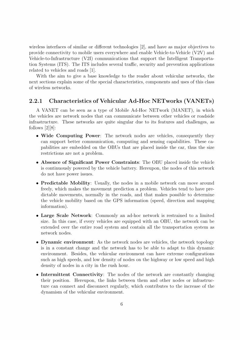
A VANET can be seen as a type of Mobile Ad-Hoc NETwork (MANET), in whichthe vehicles are network nodes that can communicate between other vehicles or roadsideinfrastructure. These networks are quite singular due to its features and challenges, asfollows [2][8]:
• Wide Computing Power: The network nodes are vehicles, consequently theycan support better communication, computing and sensing capabilities. These ca-pabilities are embedded on the OBUs that are placed inside the car, thus the sizerestrictions are not a problem.
• Absence of Significant Power Constraints: The OBU placed inside the vehicleis continuously powered by the vehicle battery. Hereupon, the nodes of this networkdo not have power issues.
• Predictable Mobility: Usually, the nodes in a mobile network can move aroundfreely, which makes the movement prediction a problem. Vehicles tend to have pre-dictable movements, normally in the roads, and that makes possible to determinethe vehicle mobility based on the GPS information (speed, direction and mappinginformation).
• Large Scale Network: Commonly an ad-hoc network is restrained to a limitedsize. In this case, if every vehicles are equipped with an OBU, the network can beextended over the entire road system and contain all the transportation system asnetwork nodes.
• Dynamic environment: As the network nodes are vehicles, the network topologyis in a constant change and the network has to be able to adapt to this dynamicenvironment. Besides, the vehicular environment can have extreme configurationssuch as high speeds, and low density of nodes on the highway or low speed and highdensity of nodes in a city in the rush hour.
• Intermittent Connectivity: The nodes of the network are constantly changingtheir position. Hereupon, the links between them and other nodes or infrastruc-ture can connect and disconnect regularly, which contributes to the increase of thedynamism of the vehicular environment.
6

• Partitioned Network: Due to the high dynamism of the vehicular networks, therewill be large spaces between vehicles, which leads to isolated groups of nodes. Thenetwork is, therefore, subject to frequent fragmentation.
2.2.2 Network Architectures
Considering the vehicular environment and the major purposes of the VANETs, thenetwork architecture should grant communications between nearby vehicles, and commu-nications between the vehicles and fixed roadside infrastructure. According to Wang et all[1] and Lee et all [9], the architecture of VANETs can be summarized in three categoriesas shown in figure 2.1:
Figure 2.1: Three categories of VANET network architecture [1]
• Pure Cellular/WLAN Architecture: Vehicles use fixed infrastructure placednear the roads, such as cellular or Wireless Local Area Network (WLAN) accesspoints (V2I communications), to routing purposes, collect information from sensorsor traffic and to connect to the internet. In order to ensure that the nodes will alwaysbe connected, it is necessary a full road coverage with Road Side Units (RSUs), whichbrings a huge cost to the network. Other major issue with this architecture comprisesthe costs and limitations associated to the use of cellular networks.
• Pure Ad-Hoc Architecture: Since the coverage of cellular and wireless accesspoints is not the ideal for the Pure Cellular/WLAN Architecture due to costs orgeographic limitations, the vehicles can communicate only with other vehicles (V2Vcommunications), resulting in the Pure Ad-Hoc Architecture. The vehicles in thisarchitecture act like the nodes of a usual Ad-Hoc network and can route the databetween them using multi-hop communications. In this architecture there are onlycommunications among vehicles since it is an infrastructure-less architecture.
• Hybrid Architecture: To take advantage of the previous two architectures, thisarchitecture combines the use of cellular and wireless infrastructure (V2I) and theuse of Ad-Hoc communications between vehicles (V2V). The fixed infrastructure willbe placed strategically in the cities and roads in order to allow the vehicles to access
7
the internet and disseminate data. A vehicle out of range of the RSUs can haveinternet access and disseminate data through multi-hop, by connecting to a vehiclein the range of an RSU. If there are not RSUs in range, or other vehicles connectedto them, the node can use cellular networks to acquire connection.
2.2.3 Specific Equipment
In the previous sections, reference was made to the OBUs and RSUs. These componentsare the specific equipment present in a vehicular network along with the infrastructure ofcellular networks and wireless access points. OBUs are the equipments placed inside thevehicles, and RSUs are the road side equipments placed strategically with the aim ofproviding internet to the vehicles and increase the range of the network.
At component level, the RSUs and OBUs are identical with the exception that theRSUs have a physical connection to fixed network by cable or fiber. As stated by MariaKihl [1], the OBUs and RSUs should have:
• Antennas: To receive and send information through different technologies, accordingto the access network in use.
• GPS: Which will get information about the vehicle movement and position, and tosynchronize with the other nodes.
• Sensors: That collects diverse information about the vehicular and urban environ-ment and information about the traffic, driving style, and others.
• Input/Ouput Interface: To interact with the users.
• Central Processing Unit (CPU): Which executes the applications and commu-nication protocols and makes all the required data processing.
Our group have developed an OBU and RSU, called NetRider [10], presented in figure2.2. These boards are part of laboratory testbeds that are used to develop and test somenew concepts and technologies, such as the work developed in this dissertation. Thehardware of the OBUs and RSUs is similar, but the antennas of the RSUs have highergains.
2.2.4 Addressing Essentials
As vehicular networks are classified as Ad-Hoc networks, it means that the nodes,including the RSUs, organize themselves in a network. When a node joins the network, ithas to be assigned an IP address because, usually, the connectivity on an Ad-Hoc networkdepends on mechanisms that use the IP address as node identifier. According to Mohsinand Prakash [11], a protocol to assign IP addresses should fulfill the following criteria:
8

Figure 2.2: On-Board Unit (OBU): NetRider
• Two or more nodes cannot have the same IP address in the network at the sametime.
• An IP address is assigned to a node only during its stay in the network. When thenode leaves the network, its IP address should become available to be assigned toanother node.
• The only acceptable case to deny an IP address to a node is when the whole networkruns out of available IP addresses, or due to security reasons.
• The protocol should handle network partitioning and merging. When two differentpartitions merge, there is a possibility that two or more nodes have the same IPaddress and it should be detected and fixed.
• Only authorized nodes can be configured and access the network.
These criteria will be taken into consideration in the developed solution. As statedabove, vehicular networks are classified as Ad-Hoc networks. Thus, the same addressingmethods of the Ad-Hoc networks can be used in the VANETs [2]. These methods aredivided into two main categories:
• Fixed Addressing: The node is assigned with a fixed address by some mechanismas soon as it joins the network and keep the address while is connected.
• Geographical Addressing: Each node is characterized by its geographical position.The node address changes according to its movement and it can contain many typesof information such as vehicle information, road identification, among others.
9
The used method on the implemented solution is the Fixed Addressing, due to theassociation of the interfaces of the nodes with the prefix of the IP address.
2.2.5 Vehicular Ad-Hoc NETworks (VANETs) Applications andServices
The specific characteristics of the VANETs, mentioned in subsection 2.2.1, allow thedevelopment of new services and applications to the network. Although the main purposeof this type of networks is to increase road safety, it can be used to commercial purposes.According to Yousefi et al [8], these applications and services can be grouped in two mainclasses:
• Comfort Applications: Improves the passengers comfort and traffic efficiency.
• Safety Applications: Increase the safety of passengers by exchanging safety rel-evant information via V2V communications. These applications can also be calledsafety-critical applications due to its relevance on the safety of the users.
The main objective of comfort applications is to make the user travel more pleasant.Nowadays, everyone wants to be connected to the internet. Thus, the vehicular networkwill be used mainly to provide internet access to the users inside the vehicle in this classof applications. Besides this main use, these applications can be utilized to improve thetraffic flow, thereby reducing congestion problems and travel time, and to assist the driverduring a travel.
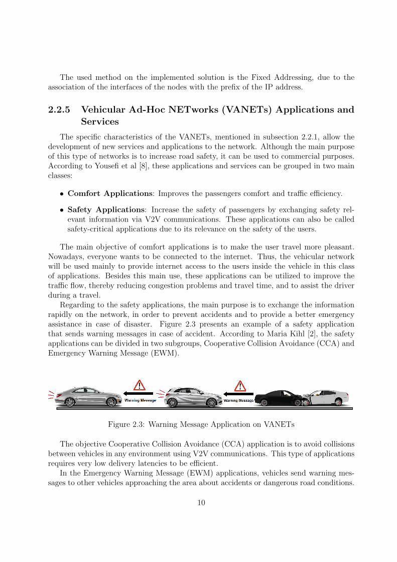
Regarding to the safety applications, the main purpose is to exchange the informationrapidly on the network, in order to prevent accidents and to provide a better emergencyassistance in case of disaster. Figure 2.3 presents an example of a safety applicationthat sends warning messages in case of accident. According to Maria Kihl [2], the safetyapplications can be divided in two subgroups, Cooperative Collision Avoidance (CCA) andEmergency Warning Message (EWM).
Figure 2.3: Warning Message Application on VANETs
The objective Cooperative Collision Avoidance (CCA) application is to avoid collisionsbetween vehicles in any environment using V2V communications. This type of applicationsrequires very low delivery latencies to be efficient.
In the Emergency Warning Message (EWM) applications, vehicles send warning mes-sages to other vehicles approaching the area about accidents or dangerous road conditions.
10

In this type of applications, it is important that the message remains available for thevehicles in the affected zone for a while.
2.3 Network Access Technologies
Due to the developments on the wireless networks technologies, there are several com-munication standards that are suitable to be used as access technologies for vehicularnetworks. The advantages and disadvantages of each standard depends on the type of ap-plication running in the vehicular network and on the considered environment. To improvethe quality of the vehicular network, more than one access technology can be used in orderto make a better use of all the available resources in a city. In the next subsections, it willbe presented some standards and network technologies that can be used in VANETs.
2.3.1 Dedicated Short-Range Communications (DSRC) AllocatedSpectrum
The DSRC Allocated Spectrum is part of the Intelligent Transportation System (ITS).In 1999, U.S Federal Communications Commission (FCC) allocated 75 MHz of the spec-trum on the frequency of 5.9 GHz to be exclusively used for V2V and V2I communications.
The main objective was to enable public safety applications that save lives and improvethe traffic flow but it can be used for private services. The DSRC band is free of chargefor the users like the ones of the 2.4 and 5 GHz but have some usage rules, and the DSRCspectrum is divided in seven channels of 10 MHz each [12]. Channel 178 is the controlchannel and is restricted to emergency and safety communications. The two channels atthe edges of the spectrum are reserved for future advanced accident avoidance applicationsand high-power public safety communication usages [2]. The remaining four channels areservice channels and can be used by any type of application. The DSRC channel allocationcan be seen in figure 2.4.
2.3.2 IEEE 802.11 p (WAVE)
Due to the features of the vehicular environments, a set of new requirements havebeen imposed on today’s wireless communications. The IEEE 802.11 p (WAVE) standardsarose to deal with the high mobility and dynamism in the vehicular environment and withthe lossy wireless links present in the VANETs. These standards created by Institute ofElectrical and Electronics Engineers (IEEE) are a new amendment to the IEEE 802.11standard, specifying extensions to IEEE 802.11a to adapt this standard to communicatein the DSRC spectrum (5.9 GHz) and are composed by IEEE 802.11p and IEEE 1609.Xfamily. The IEEE 802.11p has as target the lower layers (Physical (PHY) and MAC layers),while the IEEE 1609.X deals with the MAC layer and the higher layers. Figure 2.5 showsthe WAVE stack. At the protocol layer level, the WAVE standard supports the InternetProtocol version 6 (IPv6) and WAVE Short Message Protocol (WSMP). The objective of
11

Figure 2.4: DSRC channel allocation [2]
the coexistence of both protocols is to separate the high priority messages from the normalnetwork traffic. Messages from WSMP can be transmitted on the control and servicechannels, while the IP datagrams can only be transmitted on service channels.
To better understand the WAVE standard, the MAC layer amendments will be de-scribed first. The normal IEEE 802.11 MAC operations have a long duration to be suit-able to the IEEE 802.11p. In the IEEE 802.11 standard a radio has to listen for beaconsfrom an PoA and then joins the Basic Service Set (BSS), that is a group of IEEE 802.11stations anchored by an PoA and configured to communicate with each other [13], doingits authentication and association through a set of steps. The IEEE 802.11p introduces theterm ”WAVE mode” [13], that allows the immediate communication between two vehicleswithout the necessity of authentication and association, as long as they are operating in thesame channel. The wave standard also introduces a new BSS type, the WAVE Basic Ser-vice Set (WBSS) [13]. A WAVE station uses an on demand beacon to advertise a WBSS.This advertisement contains all the information about the service offered in the WBSS andthe information needed to configure itself to join the WBSS. Thus, the station can join aWBSS by only receiving a WAVE advertisement. Furthermore, a station leaves a WBSSwhen its MAC stops sending and receiving frames from that WBSS. The transmissionmethod on the MAC layer is based on the Carrier Sense Multiple Access with CollisionAvoidance (CSMA/CA).
Regarding to the physical layer, according to Jiang and Delgrossi [13], three mainchanges have been made:
• Utilization of 10 MHz channels instead of the 20 MHz normally used by IEEE 802.11a,because the guard interval at 20 MHz is not long enough to prevent inter-symbolinterference.
12

Figure 2.5: IEEE 802.11 p (WAVE) protocol stack [3]
• Improvement of receivers performance, with focus on rejection of adjacent channels.
• Improvement of transmission mask, making them more stringent than the ones usedin the others IEEE standards.
According to the WAVE standard [14], the IEEE 1609.X family, responsible for thehigher layers of the WAVE standard, consists on the following five standards:
• IEEE P1609.0 - Architecture: Describes the WAVE architecture and services formulti-channel.
• IEEE 1609.1 - Resource Manager: Specifies the services and interfaces of theWAVE Resource Manager Application.
• IEEE 1609.2 - Security Services for Applications and Management Mes-sages: Defines secure message formats and processing and the circumstances of useof their use.
• IEEE 1609.3 - Networking Services: Defines network and transport layer servicesto support secure WAVE data exchange.
• IEEE 1609.4 - Multi-Channel Operations: Provides enhancements to IEEE802.11 MAC to support WAVE operations.
Regarding to the multi-channel operation and according to Du et al [3], the IEEE 1609.4has four modes of operation:
• Continuous Access: The WAVE station always works on the control channel tosend and receive emergency and safety messages all the time.
13

• Alternating Access: The WAVE station alternates between the control channeland the service channel with a fixed duty-cycle.
• Immediate Access: The WAVE station changes to the service channel immediatelyafter the transmission of the safety message on the control channel is over.
• Extended Access: The WAVE station can use the service channel for a long timewhen there is a high transmission demand for non-safety messages
This standard needs all devices to be synchronized and its synchronization is based onGlobal Position System (GPS). The multi-channel operation is important to provide allthe services on the vehicular networks without prejudice any of them.
The main feature that makes this technology desired to be used in the vehicular net-works is its larger range (up to 1Km in Line of Sight) and the absence of session estab-lishment, which makes the connection to the networks faster (in the order of 10-20 msec)than on other standards.
2.3.3 Multi-Technology Approach
In a world full of different wireless network technologies it is important to take ad-vantage of the available resources. The OBU should be able to connect to the vehicularinfrastructure (RSU) via WAVE technology, and also to the Wi-Fi hotspots present in acity and to the cellular network.
These three wireless network technologies have advantages and disadvantages at thevehicular point of view, and the choice of the network access technology should be madetaking into account the several characteristics of each network and the services and usersrequirements.
Nowadays it is extremely easy to find a Wi-Fi hotspot in a city. The main problems,besides the costs related to the network utilization, are that the Wi-Fi technology has asmall range and the available Access Points (APs) are mostly concentrated in the mainareas of the cities.
Regarding to the cellular networks, their coverage is almost global currently. Withthe recent developments on 4G and 4.5G, the bandwidth restrictions are not a problem,which makes this network technology suitable to use. The huge problems of it are the highlatency and the relatively high costs for the users.
The WAVE technology was designed specially for vehicular networks, which makes thistechnology the most desired to be used on these networks. Besides, this technology wastested in our group on real-world scenarios with success [15].
Considering the three wireless network technologies and the respective features, theideal scenario of multi-technology utilization is to use the WAVE access points wheneverpossible and in the absence of them, use the Wi-Fi access points due to its lower latencyand costs when the vehicles are stopped or moving slowly. In case of absence of WAVEand Wi-Fi access points, it can use cellular networks to maintain the connection.
14
Relatively to this dissertation, all the three network technologies will be considered andused, and, if it is profitable to the user, all the three can be used at the same time. Cellularnetworks remain as a last resort to keep the connection.
2.4 Mobility Protocols
Nowadays the world is in a constant movement, so the mobility demands are not re-stricted to single terminals only. There is also the necessity of support the movement of aentire network that changes its attachment point, maintaining the session of every user’sdevices active.
To support the mobility either of a single terminal or of an entire network, a mobilityprotocol is needed in order to turn this movement seamless for the user. In the traditionalrouting scheme, when a device disconnects from the internet and connects through a dif-ferent network, it needs to be configured with a new IP address, network mask and defaultrouter in order to receive packets.
The vehicular environment is extremely dynamic due to the constant movement ofthe nodes and to their high velocities. Maintain seamless communications between thevehicles and infrastructure is a difficult task. Besides, in a vehicular network, there isa necessity to support a full network movement due to the fact that the vehicles act likemobile routers and the users inside them are connected to the vehicle’s sub-network. Whenthe vehicle changes its point of attachment, the users inside the vehicles will change itspoint of attachment too, and the mobility protocol should be able to support this entirenetwork mobility.
The mobility protocol is responsible for the location management, that consists inthe track and update of the current location of the mobile nodes, and for the handoffmanagement, that aims to maintain the active connections of the mobile node when itchanges its point of attachment. According to Kun Zhu et al. [16] a mobility protocolsuitable for vehicular networks should meet the following requirements:
• Seamless Mobility: Regardless of the vehicle’s location and wireless technology,the user’s session and the service continuity should be guaranteed.
• Fast and Efficient Handover: In the vehicular environment there are differentnetwork technologies. Therefore, the handover can be performed between accesspoints of the same technology, horizontal handover, or between different technologies,vertical handover. Furthermore, the handover needs to be fast due to the specificrequirements of the delay-sensitive applications and services.
• IPv6 Support: An IP address for each node is needed in order to maintain theconnection, and IPv6 can provide a unique address for each node due to its largeaddress space. Besides, it provides better security and Quality of Service (QoS) tothe vehicular applications.
15
• Multi-hop Communications: In order to extend the range of the vehicular net-work, the multi-hop communication requirements should be supported by the mobil-ity protocol.
• Scalability and Efficiency: Vehicular networks can be composed by a large numberof vehicles and thousands of devices connected to the network. A mobility protocolhighly scalable and efficient is needed to support this extremely dynamic environ-ment.
Moreover, the mobility protocols can be divided in three main groups:
• Centralized Protocols: A single mobility anchor keeps mapping information be-tween the hosts and its locations. Besides, there is a central node on the networkresponsible for the routing of all packets.
• Distributed Protocols: The mobility functions are spread through multiple net-works.
• Hybrid Protocols: Combination of the previous two approaches.
In this document it will be given focus to the centralized mobility protocols. Thefollowing sections will present an overview of the existing mobility protocols in order tounderstand which one is suitable to be applied in this dissertation.
2.4.1 MIPv6
The MIPv6 [17] protocol is a subset of the IPv6 that provides support to mobile con-nections. This protocol was designed to authenticate mobile devices using IPv6 addressesand is an update of the Internet Engineering Task Force (IETF) Mobile IP Standard [18].Without the support for mobility in IPv6, the packets destined to a mobile node wouldnot be able to reach the node while it is in a foreign network.
MIPv6 allows nodes to remain reachable while moving through IPv6 internet. It in-troduces the mobility header in the IPv6 protocol in order to exchange the necessaryinformation required to the efficient support of mobility management. Each device is al-ways identified by its home address independently of its current point of attachment to theinternet and, when connected to a foreign network, the device sends its location informa-tion to a home agent responsible to intercept packets destined for the device, and forwardthose packets to the respective tunnels of the current location of the device.
2.4.1.1 Basic Concepts and Terminology
The next terminology and concepts are essential to understand the MIPv6 protocoloperation and concept [17].
Terminology:
16

• Home Address: Permanent IPv6 address assigned to the mobile node when it isconnected to its home network.
• Mobile Node (MN): A node that can move from one attachment point to theinternet to another, while still being reachable through its home address.
• Correspondent Node (CN): Any mobile or stationary node that communicateswith the MN.
• Care-of Address (CoA): The address assigned to the mobile node at its currentpoint of attachment to the internet.
• Home Agent (HA): An entity responsible for intercepting the packets destined tothe MN’s home address, encapsulate and tunnel them to the MN actual registeredCoA.
• Home Network (HN): The network associated with the network link of the HA.
• Foreign Network (FN): The network in which the MN is connected when awayfrom its HN.
• Binding Cache: A cache that contains the number of bindings of the mobile nodesmaintained by the CNs and HAs. Each entry contains the MN home address, CoAand the lifetime of the entry.
• Binding Update List: A list that contains an entry for every binding that the MNhas or is trying to establish with a specific node maintained by each MN.
Protocol messages:
• Router Solicitation (RS): This message is used by a host to trigger the localrouters information transmission of Router Advertisement (RA) messages.
• Router Advertisement (RA): This message can be sent periodically or in responseto a RS message. It contains the necessary information for the node to perform itsconfiguration in order to communicate in the network [19].
• Binding Update (BU): This message is used to inform the HA of the MN currentaddress that depends of its location (CoA) [17].
• Binding Acknowledgement (BA): This message is used by the HA, after per-forming the association between the home address and the CoA of the MN, to validatethe binding process [17].
17

2.4.1.2 Protocol Operation Method
The operation of MIPv6 protocol is based on four operation stages that will be detailedbelow:
• Discovery: The FN agents announces their availability by sending periodically RAmessages in broadcast. The MN performs a scan to capture these messages or sendsa RS message to trigger the process.
• Registration: A mobile node sends a BU message to its HA with the informationobtained from the new point of attachment, causing a binding between the homeaddress and the new CoA to be registered. The HA stores this information on thebinding cache and sends a BA message to the MN in order to validate the registration.
• Binding: It is the association between the home address of the MN and its actualCoA address, and has the duration of the lifetime of that association.
• Tunneling: Creation of the tunnel between the HA address and the respective MN’sCoA in order for the HA to be able to forward all packets destined to the MN throughthis tunnel. This operation is performed after the validation of the registration.
Figure 2.6: MIPv6 Architecture
Figure 2.6 presents the MIPv6 mobility protocol architecture. This protocol also pro-vides a mechanism of route optimization that allows the CN to communicate directly withthe MN without resorting to the HA, thereby reducing the overhead and the end-to-enddelay.
This protocol provides the mobility support to a single device, but it cannot supportthe mobility of an entire network. In a VANET it is necessary to move an entire network
18

of devices connected inside a vehicle along with the vehicle movement through the diverseaccess points. Moreover, this protocol requires interaction by all mobile nodes, whichconsists in a problem to the vehicular network because the objective is to allow everydevice to connect to the network broadcasted by the vehicle without specific software orhardware running in it to connect to the network.
2.4.2 PMIPv6
Another approach to solve the IP mobility challenge is the PMIPv6 [20], a network-based localized mobility management protocol. This approach, unlike the previous one,does not require the mobile node to be involved in the process of exchanging signallingmessages between itself and the HA. It is used a proxy mobility agent in the network toperform the necessary message’s exchange with the HA, and to do the mobility managementon behalf of the MN that is connected to this proxy mobility agent.
2.4.2.1 Basic Concepts and Terminology
The next terminology and concepts are essentials to understand the PMIPv6 protocoloperation and concept [20].
Terminology:
• Local Mobility Anchor (LMA): The LMA is one of the new entities introducedby the PMIPv6 protocol. It is the entity that manages the mobile node’s bindingstate and has the functional capabilities of a HA defined in the MIPv6 protocol [17].It is responsible for maintaining the MN location and forward packets from and tothe MNs.
• Mobile Access Gateway (MAG): Entity responsible to perform the mobilityrelated signalling on behalf of the MN that is attached to it, and for tracking theMN’s movement either to or from it, and report to the respective LMA.
• Proxy Care-of Address (Proxy-CoA): Global address of the egress interface ofthe MAG and the endpoint of the tunnel between the LMA and the MAG. Fromthe point of the view of the LMA, this is the CoA of the MN and the LMA registersthis address in the Binding Cache Entry (BCE) for the specific MN.
• Mobile Node’s Home Network Prefix (MN-HNP): Prefix assigned to the linkbetween the MN and the MAG by the LMA.
• Mobile Node IDentifier (MN-ID): Unique identifier of the MN in the ProxyIPv6 domain, such as the MAC address of one interface.
• Binding Cache: A cache placed in the LMA with BCEs.
19

• Binding Cache Entry (BCE): Entry of the Binding Cache placed in the LMAwith information of the MN. Each entry contains the MN-ID, MAG Proxy-CoA andMN-HNP.
• Binding Update List: Cache placed in the MAG with information about theconnected MNs.
Protocol messages:
• Proxy Binding Update (PBU): This message is sent by the MAG to the MN’sLMA in order to indicate a new MN attached, and to establish a binding betweenthe MN-HNP assigned to one of the MN’s interfaces and its current Proxy-CoA.Moreover, this message has a specific field to indicate if the MN’s attachment is anew one or a handoff from another MAG, a field with the MN-ID and a field withthe MAG Proxy-CoA [20].
• Proxy Binding Acknowledgement (PBA): This message is sent by the LMA toa MAG in response to a received PBU message received from that MAG. It containsinformation about the MN-ID, the MAG address and the prefix assigned by the LMAto the MN [20].
2.4.2.2 Protocol Operation Method
The PMIPv6 protocol aims to provide network-based IP mobility management supportto a MN, without the necessity of its participation in the mobility related signalling. Figure2.7 presents the PMIPv6 architecture.
A MN inside the PMIPv6 domain performs the necessary authentication process. Afterthis process the MAG guarantees that the MN is always on its home network and obtains itshome network prefix, that is unique for every MN in the PMIPv6 domain. The registrationprocess in the PMIPv6 domain can be summarized as follows and figure 2.8 presents thesignalling call flow:
• A MN enters in a new PMIPv6 domain and attaches to the MAG. Then, the MAGdetects the attachment and performs the authentication procedure using an MN-ID.After successful authentication, the MAG obtains the MN information and sends aPBU to the MN’s LMA with the new node information.
• After the LMA receives the PBU message and verifies the authenticity of the PBUsender, assigns a MN-HNP and creates a BCE entry for the specific MN. To finalizethis process, it sends a PBA message to the serving MAG with information aboutthe MN’s home network prefix and sets up a tunnel.
• Upon receiving the PBA message, the MAG sets up a tunnel to the LMA. Then, itsends a RA message to the MN on the access link to advertise the MN-HNP.
20

Figure 2.7: PMIPv6 Architecture
• With the RA message, the MN can configure the IP address to use for packet delivery.
With this process, the LMA can route all the traffic destined to the MN through theestablished tunnels and routes. The MN can change its point of attachment to anotherMAG.
When the MN moves its attachment point to another MAG, the previous one sendsa De-Registration PBU to the LMA to inform the end of the connection. After receivingthis message, the LMA sends a PBA message to the MAG and waits a defined time beforeit deletes the MN BCE. The new MAG will repeat the registration procedure when itdetects the new MN attachment. This process is called handover.
Although this protocol eliminates the need of interaction of the MNs in the signallingprocess, it does not support mobility to a entire network because it only allows the nodesto connected to fixed PoAs.
2.4.3 NEMO
Network Mobility [21] support is an extension of MIPv6 that aims to manage themobility of an entire network. This network mobility can be defined as an entire network,connected to a router with mobility, which dynamically changes its point of attachment
21

Figure 2.8: PMIPv6 Registration Signalling Flow
to the internet, moving as a unit along with the router changing the reachability of thenetwork in the internet topology.
2.4.3.1 Basic Concepts and Terminology
To present the NEMO protocol, it is necessary to introduce some new concepts andterminology [22] first in addition to the previous presented in the MIPv6 section.
Terminology:
• Mobile Router (MR): A router capable of changing its point of attachment to theinternet without discontinuing the connections of the attached devices. This routeracts as a gateway between the attached mobile network and the internet, and hasone or more ingress and egress interfaces. The packets destined to the internet areforwarded through the MR’s egress interface, while the packets destined to the mobilenetwork are forwarded through the MR’s ingress interface.
• Egress Interface: The network interface of the MR attached to the home link orto the foreign link, depending on the MR’s location.
• Ingress Interface: The network interface of the MR attached to the mobile network.
• Mobile Network Prefix (MNP): Prefix of an IP address that identifies the entiremobile network. Every nodes of the mobile network have an IP address with thisprefix.
22

• Mobile Network Node (MNN): Any node connected to the mobile network,that can be either a fixed node (Local Fixed Node (LFN)) or a mobile node (VisitingMobile Node (VMN)).
• Access Router (AR): Router responsible to provide internet access to the MR.
• Mobility Agent (MA): IP device that performs mobility functions.
2.4.3.2 Protocol Operation Method
In the NEMO operation, the MR is responsible to perform the necessary mobilityfunctions instead of the MN. Figure 2.9 presents the basic mechanism of NEMO protocol.
The MN is attached to the MR’s network and can move along with the MR. TheHA will bind an entire network prefix to the MR’s CoA, which means that, every packetdestined for that network will be forwarded to the MR.
Figure 2.9: NEMO Basic Mechanism [4]
Figure 2.9 - a) represents the case in which a LFN is connected on the MR’s network.The operation in this case is performed according with the follow steps:
• The AR assigns the CoA to the MR.
• The MR exchanges the BU and BA messages with its HA in order to register theMNP.
• The HA binds the MNP with the CoA of the MR, thereby creating its BCE.
• The MR sends the RA message with the MNP to the LFN.
23

A data packet destined to the LFN first reaches the HA, and then the HA, forwardsthe packet using the tunnel to the MR. Once in the MR, the packet is forwarded to theLFN on the MR’s network.
Figure 2.9 - b) represents the case in which a VMN is connected on the MR’s network.The main difference to the first case is the fact that the VMN registers the MNP with itsHA in addition to the registration of the MR with its MR.
A data packet destined to the VMN first reaches the VMN’s HA and is forwarded tothe MR’s HA. Then, the packet is forwarded to the MR, and the MR forwards it to theVMN connected to the MR’s network.
With the NEMO, MIPv6 is able to support the mobility of an entire network, but it isnot suitable to be used on the extremely dynamic vehicular environment.
2.4.4 N-PMIPv6
N-PMIPv6 is a combination between the PMIPv6 and NEMO protocols in order tosupport network mobility. According to Soto et al. [23], the joint use of PMIPv6 andNEMO provides two main benefits:
• Transparent Network Mobility Support: The mobility management of the net-work composed by diverse devices moving together is performed by the MRs.
• Transparent Localized Mobility Support Without Node Involvement: TheMRs, with the devices attached, can move to other PMIPv6 domains without chang-ing the IP address.
The main novelty introduced by N-PMIPv6, comparing with PMIPv6, is the introduc-tion of the mMAG entity in addition to the LMA and fixed MAG entities. The mMAGentity [24] is a MR with a similar function to the MAG, previously defined in the PMIPv6section. A mobile node connected to this entity is called MNN. Figure 2.10 presents theN-PMIPv6 architecture.
2.4.4.1 Protocol Operation Method
The registration and handover procedures on N-PMIPv6 are performed according tothe following steps [24][4][23]:
• The mMAG sends a RS message to connect to the fixed MAG-1. When the fixedMAG receives the message, it sends a PBU message with the mMAG-ID to the LMA.
• The LMA receives the PBU message from the MAG, assigns the Home NetworkPrefix (HNP) to the mMAG and creates its BCE. When this process is done, theLMA sends a PBA message to the MAG.
• Upon receiving the PBA message, the fixed MAG sends a RA message to the mMAGcontaining the assigned HNP.
24

Figure 2.10: N-PMIPv6 Architecture
• The mMAG receives the RA message, configures its IP address and then sends aPBU message to the LMA with the MNN-ID.
• The LMA receives the PBU message from the mMAG, assigns the HNP to the MNNand creates its BCE. The M flag, a new field added to the BCE in N-PMIPv6, is setto indicate that the MNN is connected to a mobile network.
• Next, the LMA sends a PBA to the mMAG to confirm the registration. After thereception of the PBA, the mMAG sends a RA message to the MNN with the assignedHNP.
• If the mMAG moves to the fixed MAG-2, it is executed the same procedure describedin the previous steps. The main change on the mMAG’s BCE is the AR field, thatis updated from MAG-1 to MAG-2. The remaining fields of the mMAG’s BCE andMNN’s BCE remain unaltered.
The N-PMIPv6 protocol is able to support either host and network mobility, and doesnot require any modification or extension on the MN. It was the chosen protocol to bethe mobility base protocol on this dissertation due to its characteristics that satisfy theVANETs needs. Also, a modified version of the protocol able to run on vehicular networkshas been previously implemented and submitted to real applications tests on our group ina previous MSc Dissertation [6]. This modified version will be described in chapter 3.
25

2.5 Multihoming
Nowadays, there are multiple access networks in the range of a mobile device in a city.Furthermore, the actual mobile devices are equipped with multiple network interfaces. Theuse of only one network interface to connect to the access network, or the use of only oneaccess network simultaneously does not take full advantage of all available resources in themobile device’s range.
With multihoming, the mobile devices can connect simultaneously to more than oneaccess network, in order to take advantage of all available resources. Multihoming can beclassified in two main types depending of the network end-node:
• Host Multihoming: The end-node in this type is a fixed or mobile device that canhave simultaneously more than one PoA [25].
• Site Multihoming: The end-node in this type is a site (such as an enterprisenetwork) that can get multiple IP connectivity simultaneously from several differentInternet Service Providers (ISPs) [26] [27].
In this dissertation, it will be given more emphasis to the host based multihomingapproach. A device equipped with multiple network interfaces and able to use them toconnect to different access networks is also called multi-homed device [28] [29]. The Host-Multihoming allows end-devices to be simultaneously connected to more than one accessnetwork, and therefore, it also allows to achieve some advantages relating to the normaldevices [30] [7]:
• Capability to perform Load Sharing.
• Increase of reliability.
• Increase of the QoS to the user.
• Best use and management of all available resources.
One of the most important parameter on the multihoming process is the percentageof traffic that is sent through each interface. This parameter should be optimal in orderto take full advantage of all available resources and, consequently, improve the networkperformance.
It is also possible to group the existing multihoming solutions to aggregate the networkbandwidths according with the protocol layer where they are applied [7]:
• MAC Layer: Mainly used when the communication is performed between two en-tities directly connected.
• Network Layer: These solutions make the multihoming process transparent to theupper layers. Thus, it is possible to use the transport protocols that already exist.
26

• Transport Layer: Modification of the current existent transport protocols or de-velopment of new ones with multihoming support.
• Application Layer: Introduction of a middleware between the transport and theapplication layer to support multihoming.
The following sections present an overview of some existing host-multihoming ap-proaches to provide a better understanding of the multihoming concept.
2.5.1 Stream Control Transmission (SCTP)
The SCTP is a transport layer protocol developed by IETF [31][32] with integratedmultihoming capabilities. It is a session-oriented protocol, which means that a relationshipis created between the endpoints of an SCTP association before the beginning of dataexchange and maintained until the end of the process. According to Stewart [32], SCTPoffers the following services to the users:
• Reliable transmission with detection of discarded, reordered, duplicated or corrupteddata, and retransmission when necessary.
• Allows data to be partitioned into multiple streams (multi-streaming), with the prop-erty of independent sequence delivery. Thus, message loss in one stream will not affectthe other streams.
• Supports data exchange between exactly two endpoints, but these endpoints can beidentified by multiple IP addresses.
• Multihoming support at either one or both ends of an association to prevent network-level connection loss.
In order to support multihoming, the SCTP endpoints exchange lists of multiple IPaddresses in combination with an SCTP port, during the initiation of the associationprocess. The endpoint can be reached through the IP addresses present in the list, andthe SCTP packets of the endpoint will be originated from the same IP addresses.
Although SCTP protocol has multihoming support, it is only used to support redun-dancy. If the IP address to which it is sending data becomes unreachable, the SCTPprotocol will try to send to a secondary IP address with the retransmission process likein Transmission Control Protocol (TCP). Due to this characteristic this solution is notsuitable to be applied on this dissertation.
The use of SCTP protocol is affected by several issues such as the handover manage-ment, concurrent multipath transfer and cross-layer activities [33]. Also, it is difficult tomake applications adopt SCTP as their transport layer protocol, instead of the traditionalUser Datagram Protocol (UDP) and TCP protocols [34].
27

2.5.2 Shim6
The Shim6 protocol is a network layer protocol standardized by IETF [35]. In [5] theauthors describe the shim6 architecture for IPv6 multihoming, a solution that relies ona sub-layer placed inside the network layer, called Shim6 sub-layer, along with two newprotocols, Shim6 [35] and REAchability Protocol (REAP) [36].
The proposed Shim6 architecture provides IPv6 multihoming without compromisingthe scalability of the routing system, by using provider addresses that can be aggregated[5]. This architecture is composed by three main components, and figure 2.11 presents anoverview of the Shim6 operation:
• Shim6 Sub-layer: Responsible for mapping and translating the addresses used forpacket exchange on the wire (the locator) to the constant address presented to upperlayers, and from it to the locators used as source addresses. This constant addresspresented to the upper layers is also known as Upper-Layer IDentifier (ULID). Thisnew sub-layer is also responsible for the forwarding process, and is located betweenthe IP routing sub-layer and the IP endpoint sub-layer.
• Shim6 Protocol: Responsible for exchanging mapping information between twocommunicating hosts. The mapping information contains the locators associatedwith a pair of ULIDs.
• REAP Protocol: Responsible for monitoring and detecting failures in the existingcommunicating paths and to find new valid locators combinations if necessary.
Figure 2.11: Shim6 Operation [5]
28

This solution is not suitable to be used on this dissertation due to the fact that it needsmodifications either in the multihoming server and in the multihoming client. Also, withthis solution it is not possible to decide which traffic will be sent through each availableinterface.
2.5.3 Multihoming extension for HIP
The HIP protocol [37] allows authorized hosts to securely establish and maintain sharedIP-layer state, in order to separate the identifier and locator roles of IP addresses. Thisseparation aims to provide continuity of communications across IP address changes.
The HIP proposes an alternative to the use of the IP addresses as locators (routinglabels) and identifiers (endpoint or host identifiers), which consist in the use of publiccryptographic keys as host identifiers, to which higher layer protocols are bound.
In this protocol it is defined locator as a PoA to the network that can also includeadditional information, which affects the way that the packets are handled below thelogical HIP sublayer of the stack.
In host-multihoming configuration [38], a host has multiple locators simultaneously.Using the locator parameter defined previously, a host can inform its peer of the multiplelocators at which it can be reached.
For example, when the mobile host changes its location, and consequently its IP address,it generates a HIP control packet with the locator parameters and sends it to the currentlyactive peer hosts. The peer hosts are now aware of the multiple IP addresses in which themobile host can be reached [39].
This protocol is not suitable to be used in this dissertation, because it would be difficultto develop a HIP approach to decide through which interface the desired traffic will be sent.
2.5.4 Proxy-based Multihoming Extension for PMIPv6
In order to provide multihoming support to the PMIPv6 mobility protocol, a proxy-server has been placed in the network. It has information about the multiple networkinterfaces of each end-user device, used to connect to the network [7][28]. This approachhas been defined and implemented in our group.
The main advantages of this approach are:
• Minimize the control traffic sent through the network, comparing with the previousapproaches.
• The adoption of this approach is simple because it only requires the proxy-server.
• Allow end-users devices to use scheduling techniques and efficient approaches toestimate the characteristics of each connected interface to the network.
The proxy-server is deployed in a specific place in the network, and it is aware of allinterfaces of each device used to connect to the network. In order to make the process of
29
traffic division efficient, it is necessary to accurately estimate the capacity of each connectedinterface of a end-user. After these measurements, the proxy-server determines the bestpercentages of traffic to be sent through each interface and performs the sending of thetraffic through the desired interface.
The biggest concern in this approach is the fact that multiple end-devices could bedisputed for the same proxy-server. The ideal place for the proxy-server in the network isimportant to prevent the proxy-server bottleneck effect.
The multihoming approach chosen to be used in this dissertation uses this solutionas starting point due to the capability of perform the specific traffic division throughthe connected interfaces and to the absence of modifications on the multihoming client.However, it has many several functionalities and features that will be explained in the nextchapter.
2.6 Chapter Considerations
This chapter provided an introduction to the work already existing up to date on thesubject of this dissertation, more precisely on the themes of vehicular networks, mobilityand multihoming.
Regarding to the vehicular networks subject, it presented the main features of this typeof networks, the possible network architectures, the used equipment and some applicationsof this class of networks. To complete this overview of the VANETs, it was also presentedthe specific network access technology developed for vehicular communications, the WAVEtechnology, and a multi-technology approach to these networks.
In the mobility context, it presented several mobility protocols that contributed tocreate the base mobility protocol chosen to be integrated with multihoming on this disser-tation. It gives to the reader a deep knowledge about the mobility protocols concept andterminology that is useful to understand the concept and implementation described in thisdocument.
Finally, with respect to the multihoming subject, this chapter presented some multi-homing solutions, with focus on host multihoming.
After this introduction to vehicular networks, mobility protocols and multihoming im-plementations, the next chapter gives a deeper view of the chosen mobility protocol andmultihoming architecture to be the base work of this dissertation.
30

Chapter 3
Mobility and Multihoming BaseWork
In a vehicular environment there are several PoAs of different technologies. Addition-ally, the vehicular environment is extremely dynamic, and keeping the connection of theusers inside the vehicles while they are moving is a difficult task. The nodes of the vehic-ular network must be able to connect to the different available PoAs, whether they are anRSU, Wi-Fi PoA or cellular tower, and maintain the sessions of the users active, so thatthey do not have any loss of connection during the journey.
The maintenance of the user’s sessions is left to the mobility protocol responsibilitywhile multihoming, more precisely the Host-Multihoming, can provide simultaneous con-nection to different networks of different technologies to the end-devices, taking advantageof the available network resources in the range of the devices. This chapter describes thenetwork mobility protocol N-PMIPv6 and the multihoming architecture used as base forthis dissertation.
Section 3.1 and the following presents the base mobility protocol chosen to be used onthis dissertation, as well as its features, operation process and entities.
Section 3.4 and the following presents the base multihoming approach adopted on thisdissertation, as well as its entities, architecture and integration with the PMIPv6 mobilityprotocol.
Finally, section 3.7 provides an overview of the main ideas described in the chapter.
3.1 Mobility Protocol
When a vehicle moves from one PoA to another, it is necessary to move all the subnetspresent in the vehicle. This requires a network mobility mechanism that supports bothvehicles and passengers mobility when connected to the vehicular network.
In a previous dissertation, Diogo Lopes [6] implemented a network mobility support forVANETs, based on the N-PMIPv6 mobility protocol, that performs the following tasks:
31

• Selects and connects to the best available network, using a connection manager toautomate the process.
• Provides internet access for the users through an IPv4 network.
• Supports different technologies: IEEE 802.11 a/g/n (Wi-Fi), IEEE 802.11 p (WAVE)and cellular networks.
• Supports full network mobility.
In figure 3.1 it is possible to see the implemented features. The car is connected tothe bus through multi-hop and the bus is connected to an WAVE, Wi-Fi or cellular PoA.Both vehicles are providing an IPv4 network to the users inside them in order to access tothe internet. In a certain time, the connection manager of the bus finds a more suitablenetwork and it is performed the handover between the PoAs. The protocol supports thefull network of the vehicles mobility along with the vehicles mobility.
Figure 3.1: N-PMIPv6 mobility protocol features developed on [6]
The N-PMIPv6 implemented by Diogo Lopes was developed taking as basis the PMIPv6implementation modified in our group in a previous dissertation [40]. The N-PMIPv6modified was chosen to be the base mobility protocol of this dissertation due to its featuresoptimized for VANETs, and also because it has been previously tested, optimized andapplied in a real testbed with success.
In order to give a better knowledge for the reader about the base mobility protocol ofthis dissertation, this section aims to explain the main modifications and features done in
32

the previous works [6]. Section 3.2 presents a summary of the main changes and extensionsmade in the PMIPv6 implementation in order to support optimized network handover.Section 3.3 introduces the N-PMIPv6 protocol taking into account the diverse modificationsmade in order to support a full network mobility and to be adapted to vehicular networks,and the operation method of each main entity.
3.2 Previous PMIPv6 Implementation
The PMIPv6 implementation used as base was the Open Air Interface (OAI) PMIPv6[41], version 0.4.1, an open source implementation. This version was modified in a previouswork [40] to support the handover more efficiently. The main changes made were thefollowing:
• Modifications in the method that the LMA processes the MN handover betweenMAGs.
• Modifications in the method of the register of a MN in a MAG in order to reducethe handover delay.
This extended PMIPv6 was the base work of [6]. The next sections will explain theN-PMIPv6 modified protocol operation method and components, as well as the main fea-tures of the base mobility protocol of the present dissertation.
3.3 N-PMIPv6 Implementation Used as Starting Point
In this section it will be explained the operation method of the modified N-PMIPv6[6] as well as the features of the entities and of the overall approach. First, it will besummarized the main changes made in the previous work. Then, it will be described theoperation method of the entities that comprise the mobility protocol.
3.3.1 Main Modifications
Several extensions have been made in order for PMIPv6 to support full network mobil-ity. In the PMIPv6 protocol the MAGs are static entities with pre-defined IP addresses.Moreover, they must have a direct connection to the LMA, not allowing chains of MAGs.If the MAG does not have mobility, the sub-networks associated to it will not have mobilitytoo. The main changes made in the previous work [6] were the following:
• Modification of the PMIPv6 MAG in order to become a mMAG and be able toconfigure itself according to the PoA via which it is connected.
• LMA to recognize the mMAGs and create the tunnels to these as if they were normalMAGs.
33

• MAG entity to be able to know when it will behave as a static or mMAG.
• mMAGs have a RS filtering system in order to ignore its own RS messages.
• Support for IPv4 network on the mMAGs in order to give internet access to the users.
These modifications turned the base mobility protocol N-PMIPv6 ready to run on avehicular network with network mobility support. Next, it will be presented the protocolentities and their operation.
3.3.2 N-PMIPv6 Operation
The N-PMIPv6 protocol architecture is composed by three main entities: the LMA,the MAG and the mMAG. In this section it will be explained the operation of each one inorder to understand better the mobility protocol operation in a vehicular environment.
3.3.2.1 LMA Operation
The LMA entity is responsible for the management of the mobility and for keeping aregistration of the current location of each mMAG connected to the network. In PMIPv6the users connects directly to the MAGs and the LMA makes a registration of each user.In contrast, in the N-PMIPv6 protocol, the users can connect to the mMAGs and themMAGs connects to the MAGs or directly to the MAGs. Thus, the LMA will only registerthe mMAGs, independently of the users attached in the mMAGs.
The MN on PMIPv6 will be the mMAGs on N-PMIPv6, replacing the usual users thatwill be connected to a sub-network of the mMAG. On the point of view of the LMA, theusers connected on the network will be the mMAGs. Figure 3.2 presents the flow diagramof the LMA.
The LMA operation is based on a finite state machine. The MAG entity is responsibleto detect the motion of the mMAGs and send a PBU message to inform and register thenode on the LMA. The LMA only has to receive and process the received PBU messagessent by the MAGs.
When the program captures a PBU message, it has two paths to choose:
• If the mMAG that triggered the registration does not have a BCE, the LMA performsthe registration of the new mMAG.
• If the mMAG that triggered the registration already has a BCE, the LMA onlyupdates the mMAG’s BCE.
If the chosen option is the registration of a new mMAG, the LMA creates and fills thenew mMAG’s BCE according to the information available on the PBU message. Then, ifthe tunnel necessary to communicate with the MAG does not exist, the LMA creates it andconfigures the necessary routes to the mMAG. To finalize the registration of the mMAG,
34
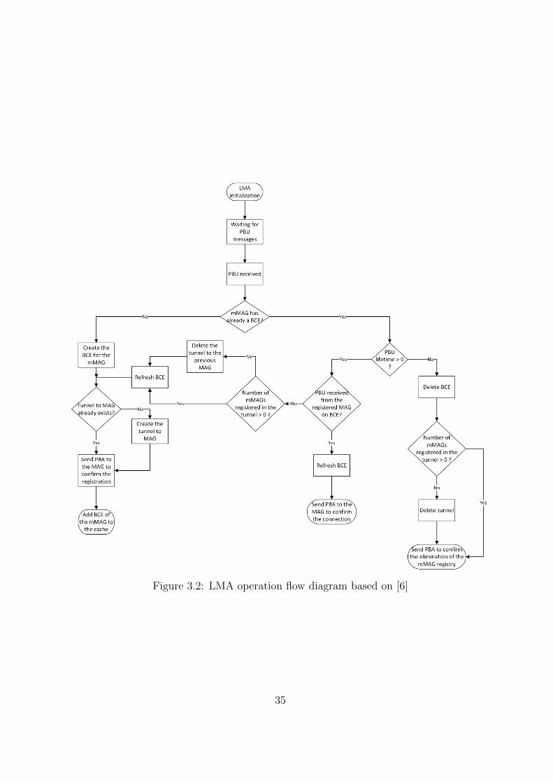
Figure 3.2: LMA operation flow diagram based on [6]
35

a PBA message is sent to the MAG in order to confirm the registration and provide thedesignated network prefix, and the mMAG’s BCE is added to the cache.
If the LMA receives a PBU message related to a mMAG that already has a BCE, itchecks if the PBU lifetime is larger than zero. If the lifetime of the PBU is larger thanzero, the LMA checks if the received PBU is from the MAG identified in the BCE, andin case of confirmation, it only updates the BCE and sends a PBA to the MAG. In caseof the received PBU be from another MAG, it is performed the handover process betweentwo MAGs. In this situation, the LMA eliminates the previous BCE of the mMAG andthe old tunnel and routes from the previous MAG if the number of mMAGs is less or equalto zero, and then registers the mMAG as if it were a new mMAG.
If the lifetime of the PBU is less or equal to zero, the LMA deletes the mMAG’s BCE,and the tunnel to the MAG if it does not have more mMAGs registered on this MAG. Tofinalize, the LMA sends a PBA to the MAG to confirm the elimination of the mMAG’sentry.
A chaining of MAGs causes problems in the establishment of tunnels to the LMA due toa verification performed. For example, in a multi-hop communication, if the LMA detectsthat it already has a tunnel to the first MAG, when the mMAG connected to it, the MAGdoes the request for a new tunnel and it will be discarded. In N-PMIPv6 this verificationwas eliminated in order to provide multi-hop communications.
3.3.2.2 MAG and mMAG Operation
The MAG entity is responsible to detect the movement of the regular users and mMAGs,and to communicate its current location to the LMA. The mMAG is a normal MAGendowed with mobility. The operation method of the static or mobile entity is similar,so the MAG entity need to be able to decide if it has to behave as a static or a mobileMAG. The operation’s process and the decision of operation’s mode of the MAG entityare presented in the figure 3.3.
The MAG and mMAG operation is also based on a finite state machine. The operationprocess of the MAG and mMAG entities can be divided in two main parts:
• First the MAG entity has to decide if it will behave as a static or a mobile MAG.
• After this decision the operation process of both entities is similar, with the exceptionthat both entities capture RS and PBA messages, but only mMAG entity capturesRA messages.
Regarding to the first part of the operation process, to decide if it will behave as astatic or a mobile entity, the MAG checks its configuration file when it initiates. If it hasa pre-defined egress interface address, the MAG will run as a fixed MAG. Otherwise, ifthere is no pre-defined address, the MAG will run as a mMAG.
After this decision, both entities will perform the MAG operation process. When aMAG detects a node, it initiates the operation process and gets its MN-ID. In our case,the MN-ID is the MAC address of its interfaces. Then, if the actual MAG or mMAG
36
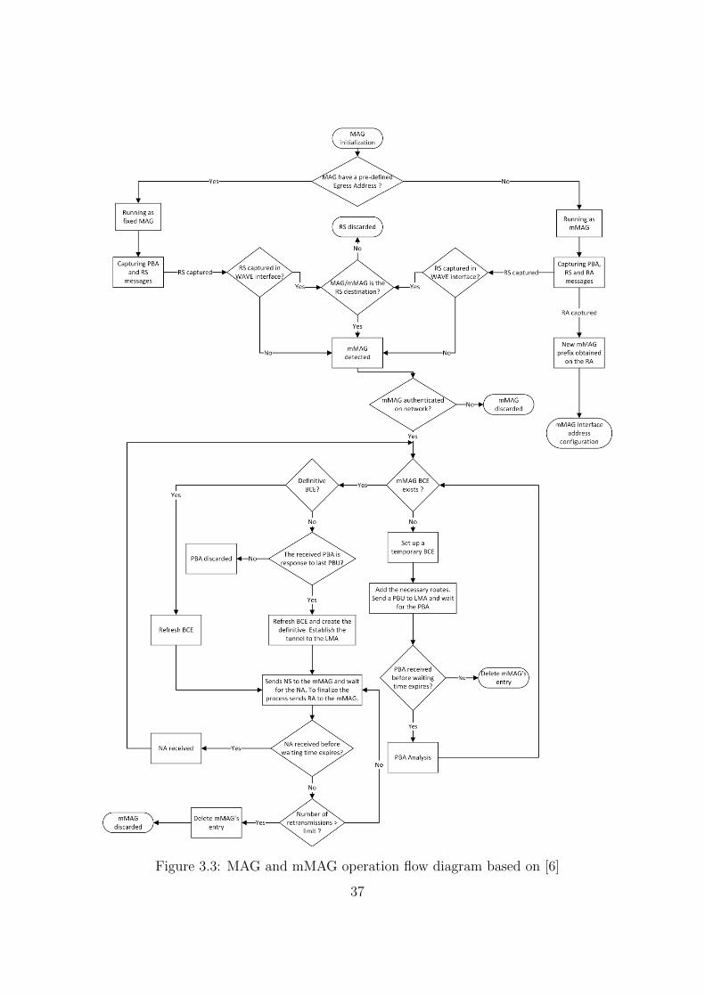
Figure 3.3: MAG and mMAG operation flow diagram based on [6]
37

entity is the destination of the mMAG’s request, it has to be authenticated to be ableto communicate on the network. This validation if performed through a Radius server[42]. The mMAG makes a request to the Radius sever and, through its MN-ID the Radiusserver checks if the node is authorized or not. In case os a negative answer, the mMAG isdiscarded. In case of a positive answer, the following paths can be taken:
• If the mMAG’s BCE does not exists, it will be performed the registration process ofa new mMAG.
• If the mMAG’s BCE exists but it is temporary, the registration process of the mMAGis finished, creating the necessary routes and tunnels.
• If the mMAG’s BCE exists and it is definitive, the BCE is refreshed.
In the first case, after the mMAG’s authentication, the MAG sets up a temporary BCEwith the node information, sends a PBU to the LMA with this information and waits forits response. If within a pre-defined time the MAG does not receive the PBA message inresponse to the sent PBU, it clears the temporary BCE and the mMAG registration isaborted.
If the PBA is received within the pre-defined time, the MAG goes back to the finitestate machine. This time, as the mMAG’s BCE is temporary, the operation process willenter in the second case. First it checks if the received PBA is a response to the last PBUsent, and if it is, it refreshes the mMAG’s BCE and makes it definitive. Then, it establishesthe tunnel to the LMA and creates a periodical task to send Neighbor Solicitation (NS)messages to the mMAG, to verify if it is still reachable or not, and waits for the NeighborAdvertisement (NA) from the node. To finalize, it sends a RA message to the mMAGindicating the HNP assigned. The NS and NA messages have been removed by Diogo afterthe dissertation conclusion.
When the MAG receives the periodical NA messages in response of the sent NS mes-sages, it enters in the third case. As the mMAG’s BCE is definitive, the MAG only updateit and continues the NS task.
These three cases are performed either in the MAG and in the mMAG entity. Beyondthis, the mMAG entity also captures and analyses the RA messages. When the mMAGperforms the registration process on a MAG, it will receive a RA message in the end ofthe process. When it receives the message, it will configure its interface with the assignedprefix to be able to communicate in the network. If the MAG stops receiving NA messagesfrom a node, it assumes that the node is no longer reachable, it deletes the MN registrationand sends a PBU to the LMA to inform about the elimination of the specific node. Insteadof the NA messages, it will be used periodic RA messages to keep the connection of themMAGs.
3.3.3 N-PMIPv6 Network Abstraction
The MAG and mMAG processes are similar and, from the point of view of the LMA,both are identical. If it is ensured that the mMAGs always obtain valid routes in any PoA
38

(other MAGs), they will act as a normal MAG and the mobility of the attached users isensured.
Figure 3.4: N-PMIPv6 Network Abstraction based on [6]
It is possible to see this network as a cluster PMIPv6 network [6] with several hops.Figure 3.4 presents the network abstraction of the N-PMIPv6 mobility protocol, and theway that the several nodes on the network are being seen to the LMA centralized point ofview. With this abstraction, the N-PMIPv6 can support multi-hop connections throughseveral mMAGs, providing internet access to the users.
The mMAG is seen as a normal user to the MAG, connected and registered as usually.This node will have the necessary routes and tunnels, either in the LMA and in the MAG,to be reachable. The mMAG is then a normal operational MAG, and everything betweenthe LMA and the mMAG is only network routing.
The mMAG2 is seen as a normal user to the mMAG, and it will connect and register asusually on the network. It will perform the same process as the mMAG in the MAG and,after the process, it will become also a normal operational MAG. The mMAG2 can provideconnection to a normal user like if it was a normal MAG due to this network abstraction.The network mobility between different MAGs and mMAGs is also ensured.
3.4 Multihoming Approach
On a vehicular environment, the vehicles can access multiple networks of diverse tech-nologies simultaneously, to send and receive different types of information such as internetaccess, safety or sensor gathering information. Usually, a user is connected to a networkonly using a network interface and, when it wants to move to another network, it discon-nects from the previous one and connects to the new network. With multihoming, a user
39

can be connected to more than a network at the same time, using the same or differentnetwork interfaces.
This concept brings some advantages in the communication process such as:
• Capability to perform load-balancing.
• Increase of available resources to a node on the network.
• Better QoS to the users.
• Better resource management, which brings economical advantages.
• Differentiation between different types of traffic.
A multihoming architecture for heterogeneous environments have been developed andimplemented in our group by Nelson Capela [7], and it will be used as the multihomingapproach in this dissertation. The selection of this approach is due to the fact that thissolution has been developed and tested on PMIPv6, a protocol quite similar to N-PMIPv6,the base mobility protocol on this dissertation.
This multihoming architecture is based on an algorithm able to determine the besttraffic allocation considering the available interfaces, previously proposed by Nelson Capela[29].
Nelson proposes a set of entities in [7] that provides the necessary information to thealgorithm of traffic allocation, and applies the rules of multihoming that result from thealgorithm. The next sections pretend to give an overview about these entities imple-mentation, function, and how they are integrated on the mobility protocol, in order tounderstand the base multihoming approach of this dissertation. Section 3.5 presents theproposed multihoming architecture and its main entities. Section 3.6 presents the integra-tion of the multihoming architecture with the PMIPv6 mobility protocol and the operationprocess of the resulting protocol.
3.5 Proposed Multihoming Architecture
Multihoming provides a greater control on the type of the service provided and moreefficient use of the available network resources on the operators side. In this section itwill be presented the main entities of the multihoming architecture proposed in [7] and itsfeatures. Figure 3.5 presents the architecture that supports the multihoming capabilities.
The multihoming architecture can be divided in three main parts, which are, the CoreNetwork, the Mobile Access Networks and the End-Users Mobile/Fixed Terminals. Onthe other hand, each of these parts contains other architecture entities responsible for themultihoming operation.
Regarding to the Core Network it contains:
• Terminal Manager (TM): Performs the management of the users interfaces.
40

Figure 3.5: Multihoming Architecture[7]
• Flow Manager (FM): Identifies and relates the traffic flows of each terminal,determine the amount of traffic sent through each interface of the terminal and applythe obtained rule.
• Information Manager (IM): Obtains the necessary information to the multihom-ing process.
• The PMIPv6 mobility protocol running as LMA.
The Mobile Access Networks is composed by:
• Points-of-Attachment (PoAs): Are the points where the terminals can be con-nected.
• Network Information Server (NIS): Is in charge of store and provide the infor-mation about the access networks.
• The PMIPv6 mobility protocol running as MAG.
At last, the End-Users Mobile/Fixed Terminals contain the User Information Server(UIS), that is responsible to save and provide information about the terminal and itsconnections features.
After this overview of the multihoming architecture, the integration of these entities onthe mobility protocol will be summarized.
41

3.6 Integration of multihoming with the Mobility Pro-
tocol PMIPv6
This section presents the integration of this architecture on the mobility protocol, thePMIPv6.
3.6.1 PMIPv6 Main Modifications
The PMIPv6 protocol is not ready to support multihoming by itself, because it doesnot have the capability to associate the connection of multiple terminal’s interfaces simul-taneously. The new capabilities developed by Nelson [7] were the following:
• Addition of the capability to associate several interfaces to a specific terminal.
• Implementation of an intelligent and dynamic process to split the traffic through theinterfaces of a terminal.
• Implementation of a mechanism to get information about the terminal, the trafficcharacteristics and the network where the terminal is connected.
These new capabilities are provided by the multihoming architecture entities proposedin section 3.5.
3.6.2 Multihoming Framework
The entities of the multihoming architecture have the ability to interact and commu-nicate among them. In order to know how they interact with each other and the networkimplementation, figure 3.6 presents the multihoming framework. Next, each entity func-tionalities and integration will be explained.
Figure 3.6: Multihoming Framework[7]
42
3.6.2.1 LMA New Entities and Operation
The LMA is the central point of the mobility and multihoming operations. With themultihoming extension, the LMA will now have three new entities responsible for themultihoming process. Besides these entities, the LMA will have new rules and routes inorder to perform the multihoming packets routing. Figure 3.7 presents the LMA operationflow with multihoming support.
The LMA operation remains the same, compared with the presented operation in sec-tion 3.3.2.1, but now it has the multihoming support provided by the three new entities.In order to understand the global LMA with multihoming operation process, each of thenew entities will be analysed.
Terminal Manager (TM)
The TM performs the association between different connections and a specific user,using a connection identifier list, and manages the process related with this association,namely, the modifications, insertions or removals of networks and interfaces. A connectionidentifier list is a list where the connection identifier is not the MAC address (like in thePMIPv6) but is a unique identifier not related to the interface. This method is not beingused and is reserved for a future use. The association performed on the developed protocolis made through the user prefix. The interfaces of a user are associated to its prefix.
As can be seen in figure 3.7, when a user connects one interface to a MAG, the PMIPv6performs all the necessary operations and exchanges the necessary messages to register theuser on the LMA. If the interface is from a new user, the LMA adds a new entry in theBCE with the user information, and the TM also adds a new entry in the User CacheEntry (UCE) with information about the user and its interfaces. If the interface is froman existent user, the TM only updates the terminal information. When the BCE of anuser interface is deleted on the LMA, the TM also deletes the user’s UCE if it is the lastinterface of that user. Otherwise, the user’s UCE is only updated.
Flow Manager (FM)
The FM is the entity that defines, calculates and applies the multihoming rule. Infigure 3.7, the FM is responsible for all updates on the Flow Cache Entry (FCE) and onthe multihoming rule. The main functionalities of this entity are:
• Traffic Detection: The FM analyses the received packets filtered by the IP addresson the LMA. It creates or updates the FCE of the users according to the flowsthat belong to each user, and this cache contains general information about the userflows and custom information of each flow. Also, this entity is capable to apply flowpreferences, which is a good advantage for the operators.
• Optimization of the Multihoming Rule: The FM uses a multihoming algorithmpreviously developed in [7] [29], that minimizes the time spent by the packets on the
43
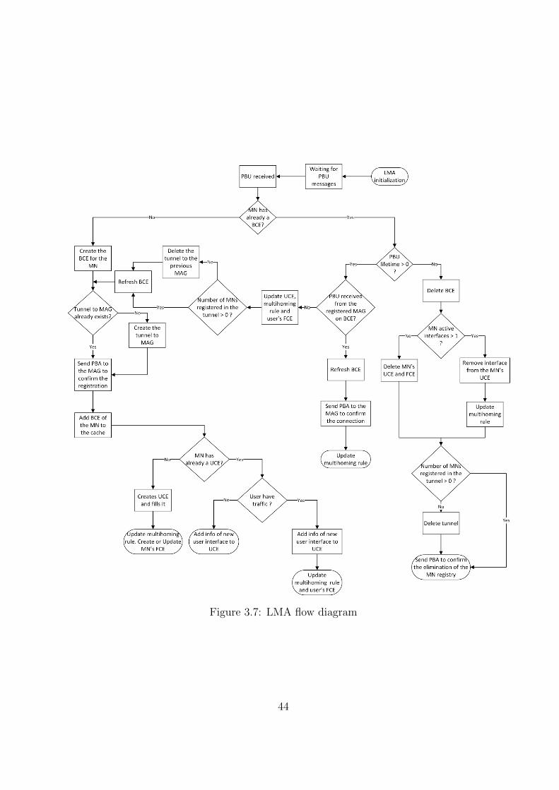
Figure 3.7: LMA flow diagram
44

network to calculate the best rule to be applied on how to divide the traffic throughthe available interfaces of each user.
• Dynamism and traffic validation: The FM analysis of the network is dynamicto deal with the constant modifications of the network characteristics.
Information Manager (IM)
The IM is responsible to obtain the updated and real information about the networkenvironment necessary to determine the multihoming rule. The FM uses the IM to obtainthe information which in turn uses the NIS.
3.6.2.2 MAG New Entities and Operation
The MAG with multihoming support acts like a normal MAG of PMIPv6 protocol,which operation process is described in section 3.3.2.2. However, it has a new entity, theNIS. Moreover, the MAG with multihoming support configures new rules and routes toperform the multihoming traffic routing.
Network Information Server (NIS)
This entity is responsible to provide the necessary information to the IM, and to verifythe state of the access networks. To perform these tasks, it communicates with the IMpresent on the LMA and with the UIS in the user terminal.
3.6.2.3 User Information Server (UIS)
This entity is integrated in the multihoming user, and can communicate with the NISin the MAG. It is used only to enable the selected measurement approach depending onthe access network chosen. Also, this entity collects and saves information in a databaseabout the user interfaces, and the available networks in range.
3.7 Chapter Considerations
Mobility is a need in a vehicular network. The users of the network must be able toperform handover between PoAs, either of the same technology or of different technologies.
To turn the PMIPv6 base protocol in the N-PMIPv6 protocol, several changes weremade. The most significant one was the implementation of the mMAG entity, whichconsists in several modifications on the PMIPv6 MAG in order to make it mobile to supportthe network mobility, and also to make chains of mMAGs aiming to extend the range ofthe network using multi-hop communications.
Another main feature added to the mobility protocol was the support of IPv4 networkto the users attached to the mMAGs, using IPv4-in-IPv6 tunnels in order to grant theinternet access. With the overview of the N-PMIPv6 mobility protocol that supports full
45

network mobility and is able to run on a vehicular network finalized, it is time to analysethe multihoming architecture that was chosen to be integrated with the mobility protocol.
With the use of multihoming, it is possible to take advantage of all available resourcesin the range of a node. Nowadays, every device is already equipped with more thanone wireless network interface, and usually these devices only utilize one interface to beconnected to a network. The multihoming architecture presented in this chapter allowsend-devices to be connected to a network with more than one interface simultaneously,in order to bring advantages to the user side, such as better QoS and resources, andadvantages to the operator side, such as load-balancing and a decrease of economic costs,resulting on a better resource management.
Naturally, multihoming is related with mobility and the multihoming architecture pre-sented in this chapter and developed by Nelson Capela [7] was developed based on amobility protocol, the PMIPv6. Due to the fact that this protocol is not ready to supportmultihoming, several changes have been made and some entities have been added in orderto support the multihoming architecture.
Five main entities responsible for all the multihoming operation have been added tothe mobility protocol main components:
• On the LMA side, it was inserted the TM entity to associate the different connectionsto a certain user, the FM entity to define and apply the multihoming rules, and theIM entity to obtain the necessary information requested by the FM.
• On the MAG side, it was inserted the NIS entity, which is responsible to provide thenecessary information to the IM using also the UIS.
• On the user side, it was inserted the UIS entity with the function to enable theutilization of the measurement approach.
After this overview of the multihoming architecture and of the full network mobilityprotocol used both as base for this dissertation, the next chapter will describe the conceptand solutions implemented in order to integrate the multihoming architecture with theN-PMIPv6 mobility protocol previously modified to work on vehicular networks. Also, itwill present the solutions to integrate the resulting platform with the vehicular environ-ment.
46

Chapter 4
Multihoming and N-PMIPv6Integration
4.1 Introduction
Mobility is inherent to vehicular networks since the nodes of the network are vehiclesthat move freely, and the users are people that can connect and disconnect of the networkin any place at any time. In this dynamic environment, there are several access networksof different technologies spread around, and if a node of the network could be connectedto more than one point of attachment at the same time, it brings some advantages for theusers and for the operators.
The utilization of multihoming can provide the connection to more than one accessnetwork simultaneously, making possible to take advantage of all available resources onthe vehicular environment.
These two components, mobility and multihoming, are essential to take the best per-formance of a vehicular network, and to take advantage of all available resources. Thecurrent network mobility protocol used in our group does not have multihoming support.Therefore it is not possible to use all available resources in a city or in another vehicularenvironment. On the other side, the PMIPv6 developed in our group is integrated withmultihoming, but it only works with a mobile user connected directly to a PoA. Therefore,to develop a network mobility protocol integrated with multihoming support in a vehicularenvironment, the following extensions have to be performed:
• Support full network mobility of the vehicles and of the users inside the vehicles.
• Use the multihoming support in order to take advantage of all available networkresources in the range of a node.
• Run in a vehicular network with Wi-Fi, WAVE and cellular as simultaneous accessnetwork technologies.
47

• Support communications in multi-hop, either on the mobility side and on the internetuser side.
• Provide internet via IPv4 network to the users inside the vehicles either in single-hopor multi-hop connection.
• Connect to more than one PoA simultaneously, with the same interface or withdifferent interfaces of an OBU.
This chapter presents the concept of the integration of the multihoming architectureproposed by Nelson Capela [7] with the full network mobility protocol developed by DiogoLopes [6] in order to implement the network mobility protocol integrated with multihomingsupport, and also the concept of the integration of the developed protocol in a vehicularnetwork with the different available access network technologies. One important note onthe mobility protocol with multihoming is the fact that the multihoming support onlyprovides multihoming in downlink traffic to the users attached to the mMAGs.
4.2 Mobility Connection Manager
The first step of this dissertation was the implementation of a connection manager inorder to choose the best networks available and to configure the mMAG interface addressautomatically.
The connection manager developed and implemented in this point aims to:
• Perform a scan to find all the available Wi-Fi and WAVE networks suitable to themobility protocol.
• Choose the best WAVE or Wi-Fi network in range and connect to the chosen networkby sending a RS message.
• Filter the received packets to capture only RA messages with the board running theconnection manager as destination.
• Analyse the received RA messages in order to obtain the necessary information toconfigure the board network interface.
• Configure the interface which will be connected to the vehicular network and thenecessary default route.
In order to avoid problems with broadcast messages in the WAVE technology, theconnection manager developed sends the RS messages to the link local of the desired PoA.So, the MAG or mMAG will only receive RS messages that are sent to them, and willignore the others.
This version of the connection manager was designed to test the mobility protocol andprovide basic support to multihoming. The necessary changes to have full support to
48

multihoming were developed and implemented in another dissertation running in parallelin our group. Furthermore, in order to fulfil the objective of this dissertation, two newmodules have been added to the multihoming connection manager, which will be explainedin another section.
4.2.1 Connection Manager Operation
When a node changes its point of attachment on the network, it is necessary to senda RS message to the new MAG or mMAG in order to trigger the N-PMIPv6 protocol torealize the handover process. In response, the node receives a RA message with informationto configure the interface. The connection manager performs all the necessary requirementson this process. The flow diagram of the mobility connection manager implemented in thisdissertation can be seen in figure 4.1.
Figure 4.1: Mobility Connection Manager Operation Flow Diagram
The mobility connection manager performs simultaneously a Wi-Fi network scan, a
49

WAVE network scan and the received packets analysis. It runs to manage the availablenetworks and to perform all the necessary configurations on the network mobile node.
Regarding to the Wi-Fi network scan task, the connection manager performs a period-ical scan, with pre-defined periodicity, to find the suitable Wi-Fi networks to be used asaccess networks in the N-PMIPv6 mobility protocol. If it finds a suitable Wi-Fi network,it first checks if there is any suitable WAVE network available before connecting to theWi-Fi network. If there is any WAVE network, the connection manager will ignore theWi-Fi networks. Otherwise, the connection manager will send an RS message either toconnect to the Wi-Fi network if it is a new network or to maintain the connection if it is anetwork that the node is already attached. The WAVE networks have priority to the con-nection manager due to the fact of the WAVE technology has been developed specificallyto VANETs and has better performance on dynamic environments.
On the WAVE network scan task, the connection manager also performs a periodicalscan, with pre-defined periodicity, to find the suitable WAVE networks to be used as accessnetworks in the N-PMIPv6 mobility protocol. If the connection manager finds any suitableWAVE network, it sends a RS message either to connect to the WAVE network if it is a newnetwork or to maintain the connection if it is a network that the node is already attached.
Finally, regarding to the received packet processing task, the connection manager firstperforms a filtering by the type of received packets. If the received packet is a RA message,next the connection manager performs a filtering by the destination Media Access Control(MAC) address of the packet. If the RA message is destined to one of the board’s interfaces,the connection verifies if it is from a new network. In case of positive verification, theconnection manager creates the IPv6 address of the board with the prefix informationreceived on the RA message and with the MAC of the interface in which the messagewas received. When this address is ready, the connection manager configures the desiredinterface, and sets up the necessary uplink routes to be connected on the network.
The pre-defined frequency on the WAVE network scan is bigger than on the Wi-Finetwork scan due to the fact that, when it is performed the scan in the Wi-Fi interface,the data transmission to the users attached to the interface is interrupted.
With this operation process in mind, the implementation details of this approach willbe explained in the next chapter.
4.3 Integration of Multihoming with the Mobility Pro-
tocol N-PMIPv6
After the implementation of the mobility connection manager and the test of the previ-ous developed N-PMIPv6 mobility protocol in [6], it was performed the integration of thechosen multihoming approach entities [7] on the N-PMIPv6 mobility protocol modified in[6].
On the LMA side, it has been integrated the TM, the FM and the IM entities. The LMAflow diagram and the operation process remains the same as presented in section 3.6.2.1.
50

The only modification is the absence of the verification on the tunnel establishment. Ifthere is another previous tunnel for a mMAG in a chain of MAGs/mMAGs the request tocreate the new tunnel is discarded. On other words, if the LMA has a tunnel to a MAGalready created, when a mMAG connects to the MAG and requests a tunnel the requestis discarded.
Regarding to the MAG and mMAG entities, they have been integrated with the NISentity. The flow diagram and operation method remain the same as presented in section3.3.2.2. The only modifications to this operation process are the configuration of the newmultihoming rules, routes and tunnels by the MAG/mMAG entity, the absence of NS andNA messages, replaced by periodical RS messages to keep the connection alive, and thenew entity, NIS, that can communicate with the LMA to provide the necessary informationto the multihoming process and monitor the access networks.
After this integration, the mobility protocol with multihoming support is able to providemultihoming in single-hop communications to a user connected with different networkinterfaces to different PoAs. For example, it is possible to provide communications throughmultiple access networks to a mMAG connected to a Wi-Fi PoA with a network interface,and connected to a WAVE PoA (an RSU) with another network interface. But, sincein the WAVE technology there is no session establishment, it is important to connect totwo or more different WAVE RSUs with the same network interface of the mMAG. Thisfeature was implemented in our mobility protocol with multihoming support in anotherdissertation running in parallel with this one. To make it possible, the registration of anuser’s interface on the BCE is associated with the serving MAG, creating two differentBCEs for the same user’s interface, differing only in the MAG associated to the user.
One of the main changes on the mobility protocol was the withdrawal of the handoverconcept. In the case of the mobility protocol with multihoming support, the handoverconcept does not exist because, the mMAG instead of disconnecting from a PoA to connectto a new one, connects to both simultaneously. It only disconnects from one PoA when itgoes out of the range of the PoA.
In the developed protocol, the normal users are attached to the mMAGs in an IPv4Wi-Fi network, so, if the mMAG has multihoming, the attached user will have it to. Thefull network mobility protocol with multihoming support in this stage is able to:
• Provide multihoming capabilities to a mMAG connected to different PoA with dif-ferent network interfaces.
• Provide multihoming capabilities to a mMAG connected to different PoA with thesame network interface.
• Provide multihoming using all the mMAG interfaces simultaneously.
Figure 4.2 presents an illustrative scenario supported by the developed protocol in thisstage. The vehicle (mMAG) is connected to a Wi-Fi hotspot (MAG), through the Wi-Finetwork interface, and to two WAVE RSUs (MAGs), through the same WAVE networkinterface, simultaneously.
51

Figure 4.2: Possible Multihoming Scenario in this Stage
In order to manage the access networks used by the mMAG and to configure its inter-faces and routes according to the received RA packets, it is used a multihoming connectionmanager. The multihoming connection manager, an extension of the mobility connectionmanager, implemented in another dissertation running in parallel in our group, is ableto connect the mMAG to more than one network in simultaneous, in order to use themultihoming support.
With this initial version of the mobility protocol with multihoming support working,the next step was the implementation of the multi-hop support.
4.3.1 Multi-hop Support
When a vehicle is not in the range of any RSU or Wi-Fi hotspot, it can connect to thenetwork through the cellular network or, through another vehicle connected to one MAG.Figure 4.3 shows a vehicle (mMAG-1) connected directly to a WAVE RSU and to a Wi-Fihotspot (MAGs), and another vehicle (mMAG-2) connected to the first one in multi-hopcommunication.
Figure 4.3: Multi-hop communications with two vehicles
52

The multi-hop is supported directly in the mobility protocol, due to the network ab-straction explained in section 3.3.3. In the case of our mobility protocol with multihomingsupport, the mMAG-2 connected in multi-hop will benefit from the multihoming processof the mMAG-1. The traffic destined to mMAG-2 will be divided through the two MAGsconnected to the mMAG-1, in a process similar to the traffic division in the first hop usingthe IP tables. After the division, the mMAG-1 forwards all the traffic destined to themMAG-2 through the WAVE interface connected to the mMAG-2. It is important to referthat in communications between OBUs (or mMAGs) it is only used WAVE technology.The enforcement of the traffic path is performed using the IPtables rules in order to markthe packets. After the packets marked, the traffic is routed in a normal way, following thedefined rule.
If a user has more than one network interface registered in the UCE, the multihomingprocess can replicate the IP address of one interface in the others in order to divide adata flow through the several interfaces. This replication is executed in the mMAG by theUIS, when the LMA requests it. With this process the multi-hop communications on themobility side are supported in the mobility protocol with multihoming support withoutmajor modifications in its concept.
Figure 4.4: Multi-hop and Multihoming Network
53

In figure 4.4, when the mMAG-1 connects to the two MAGs, the LMA and the MAGscreate the necessary tunnels to communicate with each other. After the registration of themMAG-1 on LMA, and the set up of the necessary routes and tunnels, the mMAG-1 isready to act as a normal MAG to the other nodes on the network. When the mMAG-2connects to the mMAG-1, the LMA and the mMAG-1 create the necessary tunnels tocommunicate in multi-hop. The packets destined to the mMAG-2 are sent through thetunnel created between the LMA and mMAG-1. When the mMAG-1 receives the packets,it forwards them to the mMAG-2. The traffic sent through the tunnel, between the LMAand the mMAG-1, is divided through the two previous tunnels created between the LMAand the MAGs.
The LMA analyses the traffic to the mMAG-2 before and after the encapsulation ofthe packets in the multi-hop tunnel. Therefore, the packets destined to the mMAG-2 willbe analysed and marked to the multi-hop tunnel and, when they are already encapsulatedand about to be sent in the tunnel, the LMA captures the packets again, encapsulatesthem through one of the single-hop tunnels, according to the pre-defined multihoming rule(decision performed per packet), and sends the packets through the single-hop tunnels. TheFM entity has been modified in this dissertation to support the analysis of encapsulatedpackets, in order to provide single and multi-hop communications and to support themodification of the input interface to the output IPv6 tunnels.
4.3.2 IPv4 over IPv6 Internet Support
One of the objectives of this dissertation is to provide internet via IPv4 network to theusers inside the vehicles in single-hop or multi-hop connection, while the vehicular networkis multihomed. Since our mobility protocol with multihoming support only provides IPv6mobility, and the majority of user’s devices still only supports IPv4 networking, it wasnecessary to implement a method to provide internet access to the user’s IPv4 terminals.
When a mMAG connects to several PoAs simultaneously, the mobility protocol withmultihoming support ensures the maintenance of all node’s connections. The adoptedmethod to provide IPv4 internet to the users is composed by:
• IPv4-in-IPv6 tunnelling system between the LMA and the mMAGs, either in single-hop or multi-hop. The IPv4-in-IPv6 tunnels are used to forward the packets fromthe internet to the mMAGs and from the IPv4 networks on mMAGs to the internet.
• Network Address Translation (NAT) server placed on the LMA entity to convert therequests of the mMAGs network’s users into LMA requests to the internet. All thenetwork is seen, from the point of view of the internet, as a unique user [43]. Whenthe LMA receives the packets from the internet, it resets the original address, andsends the packets to the destined users through the established tunnels.
The mobility of the IPv4 users is assured, as long as they remain in the same mMAGnetwork. In the case of mobility of the IPv4 users between different mMAGs, the sessioncontinuity is not ensured by the developed protocol.
54

In order to implement the IPv4 network support, it has been modified the handler func-tion of the RA messages due to the use of more than one network interface simultaneously,it has been implemented a NAT server running in the LMA machine and modified theanalysis of the packets by the FM entity. Figure 4.5 presents the IPv4 network supportprocess.
Figure 4.5: IPv4 Internet Access to Users Inside the Vehicles
When the mMAG-1 connects to the network, it is created an bidirectional IPv4-in-IPv6 tunnel from the LMA to the mMAG-1. To exchange packets between the internetand the mMAG-1 IPv4 network, both entities use the created tunnel. For the multi-hopmMAG-2 the process is similar. The LMA performs the necessary routing process to sendthe captured packets to the mMAGs through the created IPv4-in-IPv6 tunnels. After theencapsulation of the IPv4 in an IPv6 packet, the routing process of the mobility protocolwith multihoming support is responsible to forward the packets to the desired mMAGs andMAGs, through the previous IPv6-in-IPv6 tunnels created by the mobility protocol. Thisis the main issue that has been overcome in this dissertation related to the IPv4-in-IPv6support.
The FM entity has been modified to support the analysis of the packets encapsulated.Now, the entity has to be able to analyse the IPv4 packet encapsulated in an IPv6 packetin the case of single-hop communications between the users attached to mMAG-1 and theinternet, and to analyse the IPv4 packet doubly encapsulated in IPv6 packets in the caseof multi-hop communications between the users attached to mMAG-2 and the internet.
In case of multi-hop communications, the packets are double analysed. The FM entitycaptures and analyses the IPv4 packets encapsulated in IPv6 packets, and forward themto the respective tunnel using the routing rules and tables. After the encapsulation of thesingle-hop tunnel, the IPv4 packets doubly encapsulated with two IPv6 headers are onceagain captured and analysed to be sent to the desired tunnel interfaces.
In the next section it will be explained the modifications performed in the RA messageshandler in order to provide internet access to the users attached to the mMAGs.
55

4.3.2.1 Router Advertisement Messages Handler
With multihoming, a mMAG can have multiple simultaneous egress interfaces. Asstated before, an egress interface is the network interface of the mMAG attached to theMAGs or mMAGs in the multi-hop case. The mobility protocol only supports one egressinterface at each time. Therefore, in order to utilize multiple egress interfaces simultane-ously, a structure has been created to save the information of all egress interfaces. Thisstructure contains the following fields:
• Flag to determine if the interface is in use as egress interface.
• The egress interface name.
• The egress interface address obtained on the RA message.
• Pre-defined time-out variable to set the flag off when the utilization of the interfaceas egress interface expires.
As the mMAGs are equipped with two different interfaces able to perform multihoming,an array of these structures with two positions have been created. The WAVE interfaceand the Wi-Fi interface use one specific position of the array, and the cache of that egressinterface will be stored in the defined position. The operation process in the case ofreceiving an RA message is present in figure 4.6.
When the mMAG receives an RA message, it extracts the information of the message,such as the prefix and the addresses. Next, it will obtain the IPv6 uplink interface of thenode, configured by the connection manager.
If the RA has been received in the WAVE interface, the handler fills the egress cacheof WAVE technology in the specific array position. Next it switches the egress interfaceof the mobility protocol to the WAVE interface and address and configures the IPv4-in-IPv6 tunnel between the WAVE interface and the LMA. The LMA also configures anIPv4-in-IPv6 tunnel between it and the mMAG’s WAVE interface.
If the RA has been received in the Wi-Fi interface, the handler fills the egress cache ofWi-Fi technology in the specific array position too. Next it switches the egress interfaceof the mobility protocol to the Wi-Fi interface and address and configures the IPv4-in-IPv6 tunnel between the Wi-Fi interface and the LMA. The LMA also configures anIPv4-in-IPv6 tunnel between it and the mMAG’s Wi-Fi interface.
To finalize, the handler checks if the uplink IPv4 route is through the same interfaceas in the IPv6 uplink route, a dynamic route configured by the connection manager. Incase of positive answer it does not change the IPv4 uplink route. Otherwise, it changesthe IPv4 uplink route to the same interface as in the IPv6 uplink route.
The egress entries have a pre-defined time-out to switch the usage flag to off. In casethat the mMAG does not receive RA messages through a certain interface for more timethan the pre-defined time-out, the interface is considered disabled on the mobility point ofview.
56
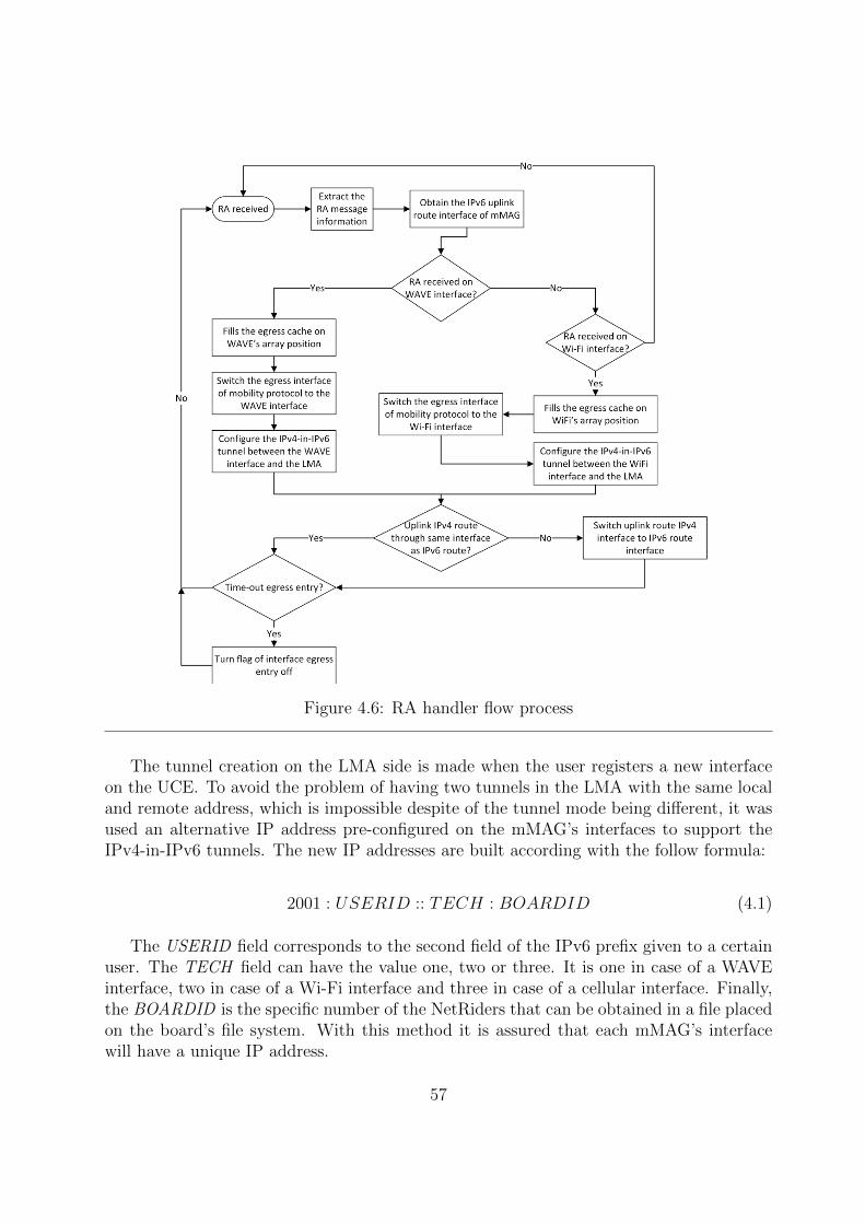
Figure 4.6: RA handler flow process
The tunnel creation on the LMA side is made when the user registers a new interfaceon the UCE. To avoid the problem of having two tunnels in the LMA with the same localand remote address, which is impossible despite of the tunnel mode being different, it wasused an alternative IP address pre-configured on the mMAG’s interfaces to support theIPv4-in-IPv6 tunnels. The new IP addresses are built according with the follow formula:
2001 : USERID :: TECH : BOARDID (4.1)
The USERID field corresponds to the second field of the IPv6 prefix given to a certainuser. The TECH field can have the value one, two or three. It is one in case of a WAVEinterface, two in case of a Wi-Fi interface and three in case of a cellular interface. Finally,the BOARDID is the specific number of the NetRiders that can be obtained in a file placedon the board’s file system. With this method it is assured that each mMAG’s interfacewill have a unique IP address.
57

4.3.3 Uplink Multihoming Base Support
In order to provide a base support to uplink multihoming at the tunnel level, it wasnecessary to create the tunnels between the mMAG and the LMA on the mMAGs sideaccording to the interfaces in use on the downlink multihoming. When the mMAG receivesRA messages through the WAVE and the Wi-Fi interfaces simultaneously, it creates twoIPv4-in-IPv6 tunnels to the LMA. In the actual mobility protocol with multihomingsupport, only one of those tunnels is used to send the IPv4 packets to the LMA, but bothtunnels may be used in a future implementation of uplink multihoming.
Figure 4.7: RS handler flow process
Besides the IPv4-in-IPv6 tunnels, it was also necessary to create the IPv6 tunnels toa mMAG in single-hop using downlink multihoming through the two different interfaces,when that mMAG has another mMAG attached in multi-hop. The creation of the uplinkIPv6 tunnels is made in the reception of the RS messages, because the tunnels will only beused if the mMAG has another mMAG attached. Moreover, upon receiving an RS message,the handler can check the egress interface cache to know which interfaces are being usedon the mobility. The RS handler was modified to fulfil this task and its flow diagram is
58

presented in figure 4.7.Upon receiving an RS message, process it and create the necessary tunnels and routes,
the handler checks if the other interface, other than the destination interface of the RS,is in use on the mobility side. If the other interface is in use, the handler also creates theIPv6 tunnel between that interface and the LMA if the tunnel does not exists. Otherwise,if the other interface is not in use and the IPv6 tunnel between the mMAG and the LMAexists, the handler deletes the tunnel.
With the multiple IPv6 and IPv4-in-IPv6 tunnels between the mMAGs and the LMAdynamically created and deleted on the mMAG entities, the mobility protocol with mul-tihoming support implemented in this dissertation is now able to provide a base structureto support uplink multihoming.
4.3.4 Cellular Support
In order to provide internet and communication capabilities to the users everywhere,at any moment, the cellular network is used as a backup network. The cellular networkis configured to be used only when there is no other suitable network (WAVE or Wi-Finetwork) in the range of the vehicle, due to its high costs of utilization.
Figure 4.8 presents a possible scenario when the utilization of the cellular network isnecessary to keep the sessions of the users. In this scenario the vehicle is connected to theWAVE RSU and then moves along to the Wi-Fi hotspot, using cellular network betweenthe WAVE and Wi-Fi PoAs.
Figure 4.8: Cellular Network Utilization Scenario
When the connection manager only finds one network in the range of the mMAG, andthe Radio Signal Strength Indicator (RSSI) of that network falls below a certain threshold,the connection manager starts sending RS messages to the cellular MAG until it finds anew suitable network above the defined RSSI threshold, whichever the network technology.
59

When the LMA receives a PBU sent by the cellular MAG, related to a mMAG withthe cellular flag usage active, it performs a forced update on the multihoming rule to sendall the traffic destined to the mMAG through the cellular interface. In order to implementthis support, the FM entity was modified to recognize when it has to force the usage of thecellular interface through a flag sent in the PBU messages, and a new extension was addedto the multihoming connection manager in order to send RS messages to the cellular MAGand to configure the mMAG cellular interface and routes when it is necessary.
4.4 Network Mobility Protocol with Multihoming Sup-
port Overview
This section aims to present a simplified overview of the developed network mobilityprotocol with multihoming support in this dissertation. It takes an example scenario asstarting point in order to demonstrate the message exchanged and operations processed inthe mobility protocol entities. Figure 4.9 presents the scenario used as example.
Considering only the connection between the mMAG-1 and the two MAGs in orderto use multihoming, it is possible to observe in figure 4.10 the signalling flow and theoperation process.
The mMAG-1’s connection manager performs a periodic scan in the network andchooses the best networks to connect. After this scan, it sends an RS message to thedesired MAGs in order to create the connection.
When the MAGs receive the RS message, they will create or update, if it is a periodicRS to keep the connection, the BCE of the RS source mMAG-1 interface. Next, the MAGswill send a PBU message to the LMA to complete or update the mMAG-1 registry. Whenthe LMA receives the PBU messages, first it will update or create the BCE of the mMAG-1interface and next it will create or update the UCE of mMAG-1. To complete the process,the LMA updates the multihoming rule, updates or creates the FCE of mMAG-1, createsthe necessary IPv6-in-IPv6 and IPv4-in-IPv6 tunnels and routes, and sends a PBA messageto the MAGs. The BCE of each interface will have a different serving MAG in the case ofthe scenario presented in figure 4.9, either the mMAG uses the same interface or differentinterfaces to connect to the MAGs.
Upon receiving the PBA messages, the MAGs configure the necessary routes and tun-nels to provide communications between the mMAG-1 and the LMA, and send an RAmessage to the mMAG-1. According to the received RA messages, the mMAG-1 will con-figure the interfaces addresses, the uplink route and will create the necessary IPv4-in-IPv6tunnels to provide IPv4 internet access to the users attached to its network. Moreover, themMAG-1 will configure the necessary additional IP addresses to support the IPv4-in-IPv6tunnels.
All the received messages in the entities of the developed protocol are processed andanalysed sequentially. So, a received message in the middle of another message analysiswill not affect the operation process.
60

Figure 4.9: Mobility Protocol with Multihoming Support Scenario
Considering now only the connection between the mMAG-2 and the mMAG-1 in orderto use multi-hop communications, it is possible to observe in figure 4.11 the signalling flowand the operation process.
Due to the network abstraction explained in section 3.3.3, after the registration of themMAG-1 on the network, it will act as a normal MAG to the nodes that will connect to it.When the mMAG-2 connects to the mMAG-1, the operation process will be identical tothe connection between the mMAG-1 and the MAGs, described previously. As previouslystated, the multi-hop communications only use the WAVE technology. So, if a mMAG inmulti-hop connects to two different mMAGs in single-hop, the only difference between itsBCE in the LMA is the serving MAG entry.
The presented scenario provides a simplistic overview of the developed protocol op-eration. It presents the utilization of multihoming to the mMAG-1 in single-hop, the
61

Figure 4.10: Single-hop Signalling Flow and Operation Process
62

Figure 4.11: Multi-hop Signalling Flow and Operation Process
utilization of multi-hop to the mMAG-2 and the supply of IPv4 internet access to theusers attached to mMAGs, either in single-hop or in multi-hop.
4.5 Multihoming Connection Manager Extensions
After the integration of multihoming with the mobility protocol, it was needed to addtwo new modules to the multihoming connection manager in order to support the newfeatures added.
The first module added to the multihoming connection manager consists in a taskresponsible to add the new IP addresses necessary to support the IPv4-in-IPv6 tunnelsdescribed in 4.3.2. This task checks if the new IP addresses exists or not, and in case of anegative answer adds the new IP addresses to the board interfaces according to the formulapresented in 4.1.
The second module added, is responsible for the cellular operation on the multihomingconnection manager. The operation flow of this new module is presented in figure 4.12.
This new module performs a periodic verification of the RSSI of the found or connected
63

Figure 4.12: Cellular Extension to Multihoming Connection Manager Flow
networks in order to decide if it is necessary to use the cellular support. If the mMAGdoes not have any WAVE or Wi-Fi connection, the cellular module activates the cellulartask, if the task is disable, and continues performing the periodic verification of the foundnetworks RSSI. When it finds a suitable network, it disables the cellular task. If the mMAGis connected to one network, the cellular module checks the RSSI of that connection, and,if it goes under a pre-defined threshold, the cellular module activates the cellular task andconsiders that the mMAG does not have any network connected.
Regarding to the cellular task, it is waiting for a signal to start its operation. Ifit receives the signal, it starts sending RS messages through the cellular interface andconfigure the cellular interface with the routes and IP addresses according with the receivedRA messages. If this task receives a signal to stop, it ceases its operation immediately,returning to the normal operation of the multihoming connection manager and the taskreturns to the waiting cycle.
This two new modules will not affect the normal operation of the multihoming connec-tion manager. The cellular module is only used when there is no network in range with anRSSI larger than the pre-defined threshold.
64

4.6 Integration of the Developed Features in Both
Dissertations
As stated before, there is another dissertation running in parallel in our group thataims to develop more features to the network mobility protocol with multihoming support.To finalize this chapter, it is presented in this section the main features and objectives ofthe final version of the developed protocol, considering both dissertations. To summarize,the main objectives are the follows:
• Support of full network mobility either for the vehicles and for the users inside them.
• Utilization of multihoming to take advantage of all available network resources in thevehicular environment.
• Utilization in a vehicular network with Wi-Fi, WAVE and cellular as access networktechnologies.
• Integration with a Multihoming Connection Manager that manages the connectionsand configurations of the OBUs.
• Dynamic adaptation of the multihoming rule that distributes the multihoming traffic,in order to better fit the characteristics of VANETs and its traffic.
• Classification of the traffic according to its priority and posterior distribution of theflows through the available connections of a user, taking into account its character-istics.
• Support of multi-hop communications.
• Provision of internet via IPv4 network to the users inside the vehicles either in single-hop or multi-hop connection.
• Simultaneous connection to more than one PoA with the same or different interfacesof an OBU.
• Utilization of cellular network in order to maintain the connectivity when there areno other networks available.
4.7 Chapter Considerations
In this chapter, it is presented the concept behind the implementation performed onthis dissertation. The main additions implemented on this dissertation were the following:
• Development of a full network mobility protocol with multihoming support.
65
• Integration of the developed protocol in a vehicular environment with WAVE, Wi-Fiand cellular as access network technologies.
• Support of multi-hop communications between the network nodes.
• IPv4 internet access supply to the users within the vehicles.
• Implementation of a cellular support on the multihoming connection manager andon the LMA entity, capable of utilizing the cellular network when there is no othernetwork in the range of the vehicle.
In order to fulfil these objectives, first of all a mobility connection manager has beenmade in order to test the base mobility protocol and to provide a base work to implementthe multihoming connection manager. After the implementation of this connection man-ager, it has been performed the integration of the base mobility protocol N-PMIPv6 withthe multihoming architecture chosen.
Regarding to the IPv4 over IPv6 internet support, it was necessary to adapt all theprotocol with new tunnels, routes and addresses. The mechanism to provide IPv4 internetto the users can be divided in two main parts:
• IPv4-in-IPv6 tunnelling and route system between the LMA and the mMAGs.
• NAT server running in parallel with the LMA entity to translate the private addressesto public addresses in order to access the internet.
Thinking on a future approach of uplink multihoming, the protocol has been modifiedto provide support to an uplink multihoming implementation. In short, the IPv6-in-IPv6tunnels between the LMA and a specific mMAG have been replicated in the mMAG side,making this way a bidirectional communication process.
Finally, to support the cellular utilization, the multihoming connection manager hasbeen modified to utilize the cellular technology when there is no other technology in rangeor when the mMAG have only one connection and its RSSI goes under a certain threshold,and real-time traffic is in place.
The next chapter describes the implementation performed to develop and extend theintegrated mobility and multihoming solution.
66

Chapter 5
Implementation
5.1 Introduction
After the presentation of the developed protocol and mechanisms in this dissertation,this chapter aims to give a close view of the implementation done in order to fulfil thedissertation’s objectives. It presents the challenges and necessary modifications in order toimplement the full network mobility protocol with multihoming support able to run on avehicular network.
The integration of the multihoming architecture in the N-PMIPv6 mobility protocol ledto several modifications in several entities, and to the overcome of several obstacles due tothe equipment, network technologies, and platforms used on the practical implementationof the concept explained in chapter 4.
5.2 Cross Compiling
The equipment used in the implementation in the RSUs and OBUs have limited re-sources. The use of cross compiling was necessary to create the executable of the codeto run on the boards. A cross compiler is a compiler capable of creating executable codein a platform, with the objective of running the program in another platform with lesscomputing resources.
The boards use an operative system based on the openWrt [44], which is a Linuxdistribution for embedded systems. Therefore, to create the executable of the mobilityprotocol, it was necessary to install the openWrt build system, a set of makefiles and patchesthat allows the creation of cross-compilation toolchain, a root file system for embeddedsystems, and the necessary libraries to compile the desired packages. This installation wascarried out according to the tutorial available online at [45]. This was the starting pointof this dissertation and it was necessary either to create the executable to test the basemobility protocol, and to create the executable of the developed network mobility protocolwith multihoming support.
67

5.3 Mobility Connection Manager
The functions and operation method of the mobility connection manager have beenpresented in the previous chapter in section 4.2. Now, it is time to give a depth view ofthe mobility connection manager implementation. This entity can be divided in two mainmodules:
• IEEE 802.11p/IEEE 802.11g network scan and connection module.
• Packet analyser and Interface Configuration module.
Each of these modules will be detailed in the next sections.The RS messages sent by the connection manager are destined to the link local of the
desired AP, instead of the specific multicast address ff02::2 [46]. This is necessary due tothe fact that the WAVE interface captures all the RS messages, even the messages destinedto the other boards.
5.3.1 Packet Analyser and Interface Configuration Module
This module is composed by the functions related with the packet analysis, interfaceconfiguration and board information acquisition. The functions implemented were thefollowing:
• Main - Principal function of the connection manager. It is responsible to initiate thenecessary threads for the connection manager’s operation and to obtain the necessaryinformation about the node to provide to the other functions.
• getBoardID - This function is responsible to obtain the unique identifier of eachboard used. This function only runs one time when the mobility connection manageris initialized.
• getOwnMACs - This function is designed to obtain the MAC addresses of theboard’s interfaces (specifically of the WAVE and Wi-Fi interfaces). It also only runsone time when the mobility connection manager is initialized.
• getPacket - Function that captures all packets that pass through the board in-terfaces. It uses sockets to implement the sniffing process and only captures IPv6packets. It runs along all the operation of the connection manager.
• processPacket - Every time that the function getPacket receives a packet, it callsthis function in order to process the received packet. It also performs a filteringof the packets based on the destination MAC address. This function only calls theremaining functions to process the packet if it is a RA message, and if it passes thefiltering.
68

• printICMPpacket - Analyses the Internet Control Message Protocol (ICMP) headerof the received RA messages to obtain the assigned prefix.
• printIPheader - Analyses the IP header of the received RA messages and storesthe source and destination IP address.
• printETHheader - Analyses the MAC header in order to obtain the source anddestination MAC address.
• getNamebyIP - Obtains the name of the interface where the packet as been receivedthrough the destination IP address.
• configInterface - Configures the interface obtained in the function getNamebyIPwith the IP address made in the function makeIPwMAC.
• makeIPwMAC - With the prefix obtained from the RA message received and theinterface MAC address obtained in the function getOwnMACs, it creates the IPaddress to be applied on the board’s interface.
5.3.2 IEEE 802.11p/IEEE 802.11g Network Scan and Connec-tion Module
This module comprises the functions related with the detection, decision and connectionto the wireless networks available in the range of the board. The functions implementedwere the following:
• getGnet - Performs the periodic scan on the Wi-Fi interface and chooses the bestnetwork found, based on the RSSI.
• getPnet - Performs the periodic scan on the WAVE interface and chooses the bestnetwork found, based on the RSSI.
• connectTo - According with the result of the functions getGnet and getPnet, itdecides which function it is necessary to call in order to connect to the chosen network.
• sendRSP - Sends the RS message to the link local of the desired WAVE PoA inorder to connect to the network. It also sends the periodic RS messages to a networkwhich the board is already connected.
• sendConnectG - Sends a connection request to the Wi-Fi PoA in order to establisha session. Next, it sends a RS message to the link local of the chosen PoA in order toconnect to the network. It also sends the periodic RS messages to a network whichthe board is already connected.
• makeLinkLocal - Creates the link local of the PoA which was chosen to connect,based on the MAC address announced.
69

5.4 Integration of the Multihoming Entities in N-PMIPv6
After the integration of the mobility protocol N-PMIPv6 code, designed to vehicu-lar networks, and of the multihoming architecture code, some problems appeared. Theproblems encountered were the following:
• The communication between the different entities of the multihoming architecturewas corrupted due to different byte order on the transmitted messages.
• It was decided to change the authentication method to the alternative method alsoprovided by the radius tool to authenticate the nodes in the network in order toreduce the amount of messages exchanged.
• The WAVE interface was not supported as ingress interface in the mobility protocoldue to several incompatibility issues with the PCAP tool [47].
• The FM entity expects IPv6 flows in its input interface (interface of LMA connectedto the CN or to the internet), and with the internet access to the users, the inputflows will be IPv4 flows.
• The process of IP replication was modified due to the use of periodic RS messages.
5.4.1 Communication between different multihoming entities
The multihoming implementation assumes that all entities where the multihoming ar-chitecture will be deployed uses the same operative system, which is not the case in thevehicular scenario. The computer, where the LMA is running, has a little endian archi-tecture, while the boards used as network nodes have a big endian architecture. In orderto overcome this obstacle, it was necessary to convert the messages exchanged to the byteorder of the respective operative system. This problem only affects variables of the integerand double type.
To do the necessary conversion, it were used several functions to convert values betweenhost and network byte order [48]. These functions work properly with integer variables,but with double variables it was necessary to create new functions to realize the conversion.
These new functions, convertDouble NetworkToHost and convertDouble HostToNet-work, first convert the double value to an integer, with the desired precision, next it convertsthe integer with the pre-defined functions, and finally sends the value to the destinationentity. When the destination entity receives the value transmitted, it converts again todouble value.
5.4.2 Radius Authentication Alternative Method
In order to reduce the reduce the message exchange on the network, it was decided tochange the authentication method to an alternative method, that relies on the use of amatch file placed in the MAGs.
70

The match file has information about the interfaces of the allowed mobile nodes asso-ciated to the pre-defined prefix of each mobile node. For example, for a mobile node withthe prefix 2001:400::/64, that will connect to the network with the interface identified withthe MAC address D4:CA:6D:55:AB:E4, the entry on the match file will have the followaspect:
� 20010400000000000000000000000000 00000000000000000000D4CA6D55ABE4
To use this alternative method, it was necessary to disable the Radius on the file pmip -hnp cache.c, using the macros undef USE RADIUS and undef CACHE RADIUS.
Besides this match file, there is another file used by the multihoming entities to associatethe interfaces with a certain user, the user ID.txt. This file follows a similar structure of thematch file, but instead of the user prefix associated to the MAC address of the interfaces,it uses an unique identifier for each user.
5.4.3 IEEE 802.11p Incompatibilities with PCAP Tool
The WAVE technology has some incompatibility issues with the PCAP tool. Sincethe PCAP tool is used as a sniffer in the ingress interface, it is impossible to use theWAVE interface as ingress interface. Since the mobility protocol needs to know whatis the ingress interface, in order to set up the tunnels and the necessary routes, it wasnecessary to introduce a flag to signal the use of the WAVE interface as ingress interface.On the configuration file of the mobility protocol, the Wi-Fi interface remains as ingressinterface, but, if the flag is active, this interface will be changed to the WAVE interfaceafter the mobility protocol initialization.
The flag was called FLAG CHANGE INTERFACE and was defined in the files rtnl.h,Flow M process.h and INFO M.h. If the flag is set at zero, it means that it is to use theingress interface specified in the configuration file. If the flag is set at one, it means thatit is to use the WAVE interface as ingress interface.
5.4.4 Multihoming FM Entity Flow Analysis
The FM entity analyses the data flows from its input interface (interface of the LMAconnected to the CN or to the internet). According to the multihoming architecture, thisentity expects an IPv6 flow on its input interface. With the internet access to the usersprovided on the mMAGs, the input flows will IPv4 flows.
In order to avoid this problem, it was changed the input interface of the FM entityto the output tunnel interfaces on LMA, designed for ip6tnl+ to include all output IPv6tunnels, performing in this way a post-routing capture.
In this way, the packets capture will be encapsulated in IPv6 packets, turning theoriginal IPv4 flow into an IPv6 flow without affecting the operation of the mobility protocolwith multihoming support. This modification was performed in the file Flow M process.cin the function flow m start.
71

5.4.5 IP Replication Process
The FM and the UIS entities performs an IP replication process when necessary in orderto use all the mobile node interfaces to receive the flows destined to one of its interfaces.When the mobile node has more than one interface, and the FM entity detects a flowdestined to one specific interface, it sends a request to the mMAG UIS entity to replicatethe destination IP address of the flow on the remaining interfaces of the mMAG.
In the original multihoming approach, the FM entity checks for IPs to reply wheneverit receives a RS message. As the mobility protocol with multihoming support uses theRS messages to periodically keep the mobile nodes connections, the verification of the IPreplication process on each RS received has to be removed.
The UIS was also modified in the method of obtaining the MAC addresses of the mobilenodes to perform the filtering, due to incompatibilities with the boards used.
5.5 Multi-hop Support and Encapsulated Flow Anal-
ysis
After the explanation of the concept of multi-hop support in section 4.3.1, the currentsection presents the necessary modifications to integrate it in the mobility protocol withmultihoming support.
As stated previously, the mobility protocol supports multi-hop communications withoutmajor modifications in its concept, due to the network abstraction presented in section3.3.3. The necessary modification to integrate the multi-hop communications was in theanalysis of encapsulated flows on the FM entity.
Figure 5.1: IPv6 Encapsulation Process
The FM entity is designed to analyse IPv6 flows with only one IPv6 header. Due to
72

the use of tunnels, and to the change of the input interface to the IPv6 tunnels, whena data packet is sent to a node in single or multi-hop, it will be encapsulated or doubleencapsulated, respectively, in other IPv6 packets before the FM captures it to analyse [49].
As can be seen in figure 5.1, the header of the input packets is a single IPv6 header.When the packet is destined to the mMAG-2, the packet is first encapsulated in the tunnelbetween the LMA and the mMAG-1, and next again encapsulated in the tunnel betweenthe LMA and the MAG. In single-hop communications, the packet is only encapsulatedin the tunnel between the LMA and the MAG. The packets are captured either with twoIPv6 headers or with three IPv6 headers.
The function flow m identify flow in file Flow M process.c was modified to, wheneverit receives a packet, check the IPv6 header field next header to know if the packet isencapsulated or not. This verification is performed until the next header field is differentof IPv6 type. Next, it adds an offset to the packet pointer in order to perform the cast ofthe right packet fields to the desired structure.
In order to also support IPv4 flows due to the internet service provided to the usersinside the vehicles, it verifies the next IP headers fields until the next packet header is ofIPv4 type or different than IPv6 type. The offset added to the packet pointer depends onthe packet type of each header of the encapsulated packets.
5.6 IPv4 over IPv6 Internet Support
The adopted method to provide IPv4 internet to the users is composed by two mainparts. The first one is the NAT server running on the LMA machine. In order to implementthe NAT server, it was used the iptables program to configure the tables provided by theLinux Kernel firewall and the chains and rules stored in them. First it was necessary touncomment the line ”net.ipv4.ip forward = 1” in the file ”/etc/sysctl.conf”. After thistwo small modifications, it was necessary to configure the iptables in order to implementthe NAT server between the interface wlan0, connected to the internet, and the interfacesip4tnl+, connected to the IPv4 networks of the mMAGs. The used commands where thefollowing:
� sudo iptables -t nat -A POSTROUTING -o wlan0 -j MASQUERADE
� sudo iptables -A FORWARD -i wlan0 -o ip4tnl+ -m state –state RELATED,ESTABLISHED-j ACCEPT
� sudo iptables -A FORWARD -i ip4tnl+ -o wlan0 -j ACCEPT
With these modifications performed, the LMA has now a NAT server running in paral-lel. The second part of the IPv4 over IPv6 internet support mechanism is the IPv4-in-IPv6tunnelling system between the LMA and the mMAGs. In order to implement this system,it was used IPv4-in-IPv6 tunnels, created between the address of the Ethernet interfaceof the LMA, eth0, and the WAVE or Wi-Fi interfaces of each mMAG, wlan1 and wlan0,
73

respectively. On the LMA side, when the mMAG registers one interface on the LMA, it iscreated the IPv4-in-IPv6 tunnel with the following commands:
� ip -6 tunnel add ip4tnl”USERID””TECH” mode ip4ip6 local ”ETH0LMAIPv6” re-mote ”mMAGINTERFACEIPv6”
� ip link set dev ip4tnl”USERID””TECH” up
As in formula 4.1, the USERID field is the second field of the IPv6 prefix given to themMAG. The TECH field can be assigned with the character ’p’ or ’g’, according with thetechnology of the connected interface. It is assigned with the ’p’ character to the WAVEinterface and with the ’g’ character to the Wi-Fi interface. The ETH0LMAIPv6 is thepre-defined LMA IPv6 address in the configuration files of the mobility protocol. Finally,the mMAGINTERFACEIPv6 is the IP address created to the interfaces of the mMAGsaccording with formula 4.1.
On the mMAGs side, when the mMAG receives an RA message, it is created the IPv4-in-IPv6 tunnel between the RA destination interface and the LMA with the followingcommands:
� ip -6 tunnel add ip4tnl”USERID””TECH” mode ip4ip6 local ”mMAGINTERFACEIPv6”remote ”ETH0LMAIPv6”
� ip link set dev ip4tnl”USERID””TECH” up
The only modification relatively to the process of tunnel creation in the LMA is thechange between the local and remote addresses. This process was integrated in the functionpmip mag recv ra on file pmip handler.c. After the tunnels creation on both sides, itwas necessary to set up the necessary routes to perform the communications. Each IPv4network on the mMAGs is defined according to the following way:
10.”USERID/100”.”USERID%100”.0/24 (5.1)
For example, to a mMAG with the USERID of ”200”, according to the formula 5.1,the network announced on the Wi-Fi interface to the users is the following:
� 10.2.0.0/24
There is a restriction in the allocation of the USERID to the mMAGs due to this processof creating the announced network. As the announced network is an IPv4 network, andthe USERID is a field of an IPv6 address, it was defined that only numbers can be usedto define the USERID field in the IPv6 address.
On the LMA side, when it is created a tunnel IPv4-in-IPv6 to one of the mMAG’sinterface, it is configured an IPv4 route to forward packets destined to the mMAG network,defined according to the previous approach, to the created IPv4-in-IPv6 tunnel.
74

On the mMAG side, when it is created the IPv4-in-IPv6 tunnels to the LMA, it issettled the default IPv4 route to the IPv4-in-IPv6 tunnel associated with the interfacesettled as default to IPv6 uplink routes.
The normal users attached to the IPv4 network of the mMAGs are configured with thedefault route to the IP address of the mMAG interface used to provide the IPv4 network.The configuration of the default route, and the allocation of the IP address to the normalusers is performed by the Dynamic Host Configuration Protocol Daemon (DHCPD) [50]program running in the mMAGs. So, according to the example given previously, theWi-Fi interface of the mMAG will be assigned with the IP address 10.2.0.1. The DHCPDprogram will configure the user’s devices with IP addresses belonging to the network, andthe default route to the address 10.2.0.1, the address of the mMAG Wi-Fi interface. TheDHCPD program also configures the Domain Name System (DNS) server of the user’sdevices.
In order to announce an IPv4 and to configure the users that want to connect to thenetwork it is necessary to run the Host access point daemon (Hostapd) [51] and the DHCPDprograms. The configuration files of each one have to be made according to the desirednetwork to be announced. If it is necessary to use the Wi-Fi interface in the mobility andmultihoming processes and at the same time announce a IPv4 network to the users, it isnecessary to create a virtual Wi-Fi interface. To create this virtual interface, the followingsteps can be used:
� iw phy phy0 interface add ”newIfaceName” type managed
� ip link set ”newIfaceName” address ”uniqueMACaddress” up
The newIfaceName is the name of the virtual interface created and the uniqueMACad-dress is a created MAC address to the new interface. The used MAC addresses on thisdissertation are in the range of 00:00:00:00:00:xx in order to be unique relatively to theinterface MAC addresses of the boards used.
5.7 Uplink Multihoming Tunnels and Cellular Exten-
sions on Multihoming Connection Manager
In order to provide a base uplink multihoming support, the function pmip mag recv -rs on file pmip handler.c was modified to create the uplink IPv6-in-IPv6 tunnels on themMAGs, according with the interfaces used to provide multi-hop communications. Thisfunction creates the equivalent uplink IPv6 tunnels to the ones created on the LMA sideto downlink multihoming, in order to be possible to perform multihoming on the uplinktraffic instead of using only one uplink route.
Regarding to the cellular extensions to the multihoming connection manager, it hasbeen added the following functions:
75

• CellularOperation - Performs the sending of the periodic RS messages and theconfiguration of the cellular interface according to the received RA messages whenthe cellular thread is active.
• checkCelluarUsage - Verifies the variables that enable the cellular usage and acti-vates or disables the cellular thread according to the performed analysis.
With these two new functions, the multihoming connection manager is able to use thecellular technology as access network in the desired cases specified in section 4.3.4.
Other modifications have been made in order to provide the uplink multihoming basesupport and the cellular support. In order to understand the cellular utilization on thedeployed testbeds, figure 5.2 present the connection between a mMAG and a cellular MAG.
Figure 5.2: Cellular connection between an mMAG and an MAG
The mMAG and the MAG are connected to the cellular network with an assigned IPaddress. It is necessary an IPv6-in-IPv4 tunnel between the MAG and the mMAG in orderto maintain the mobility protocol IPv6 communications. The IPv6-in-IPv4 tunnel can becreated using the following command:
� ip link set sit0 up
� ip -6 tunnel add ”tunnelName” mode sit local ”LocalIPv4Address” remote ”Re-moteIPv4Address”
� ip link set ”tunnelName” up
76

The remote and local addresses to create the tunnel are the IP addresses assigned bythe cellular network. In order to automatize the process, the MAG can be connected to anetwork with a fixed public IP address, in order to be always the same address.
As the protocol uses the MAC address of the interfaces to perform the registrationon the caches, it is necessary to create an unique MAC address to the Point-to-PointProtocol (PPP) interfaces of the mMAGs. The created MAC is generated from the IPv6address of the mMAG and it is from our responsibility to assure the uniqueness of thecreated MAC addresses.
The remaining protocol process is maintained. The tunnel between the LMA and thecellular MAG is a normal IPv6-in-IPv6 tunnel and the routing process is still the same.
5.8 Chapter Considerations
In order to fulfil this dissertation’s objectives and to implement a full network mobilitywith multihoming support, it was necessary to modify the base N-PMIPv6 code and alsothe base multihoming architecture code, both presented on chapter 3. The most relevantmodifications performed on the LMA were in the interfaces registration, flow analysis andtunnel and routes creation. On the mMAGs, the main modifications was in the messageshandler and on tunnel and routes creation. Several minor modifications and additions havealso been made in order to integrate the mobility protocol with the multihoming architec-ture and in order to make the integrated protocol able to run in a vehicular environment,with the specific access networks used.
With the integration of both codes, several problems appeared due to the use of differentnetworks technologies, network equipment and architectures. To surpass these obstaclessome modifications have been performed on both codes to make them able to run together.
In order to use the mobility protocol it was necessary to make a mobility connectionmanager. This connection manager was used as a basis to develop the multihoming con-nection manager, necessary to utilize the implemented network mobility with multihomingsupport in this dissertation.
Regarding to the IPv4 internet supply to the users inside the vehicles, it was necessaryto implement a NAT server, running in parallel with the LMA entity, and to implementan IPv4-in-IPv6 tunnelling system to establish communications between the internet andthe mMAGs IPv4 networks.
Finally, to provide the cellular support to the multihoming connection manager, it wasnecessary to implement two new functions. One of the functions is the main functionresponsible for all the cellular operation and the configuration. The other is a functiondesigned to verify constantly the variables that trigger the operation of the cellular thread,and to enable or disable the thread according to those variables.
With a full network mobility protocol with multihoming support able to run on a vehic-ular scenario ready, several tests were performed to evaluate and validate the implementedprotocol. In the next chapter there will be presented the performed tests and configured
77

testbeds, and the obtained results either in a laboratory environment and in a road envi-ronment.
78

Chapter 6
Evaluation of Developed Protocol
6.1 Introduction
With the implementation of the network mobility protocol integrated with multihomingfinished, it is important to performs the required tests to validate the developed solution,and to analyse its performance. The main objective of the performed tests is to evaluatethe functionalities of the developed protocol in the vehicular environment with differentresources available in each scenario. It is expected to verify the following points:
• The mMAG should be able to connect to one Wi-Fi network and to multiple WAVEnetworks at the same time, when available.
• The mMAG should be able to provide internet access through an IPv4 network tothe users attached to it.
• The protocol should support multi-hop communications through WAVE technologyand the mMAG in multi-hop should also be able to provide internet access throughan IPv4 network to the users attached to it.
• The mobility protocol with multihoming support should be able to adapt to theresources available at each moment. A mMAG can be connected either to only onePoA or to multiple PoAs simultaneously.
• The traffic division through the mMAG connected interfaces should be variable ac-cording to the available resources, with a static rule definition.
With this objective in mind, three different testbeds have been developed in the labo-ratory and one in a real world scenario, in order to verify and test all functionalities of theimplemented protocol.
79
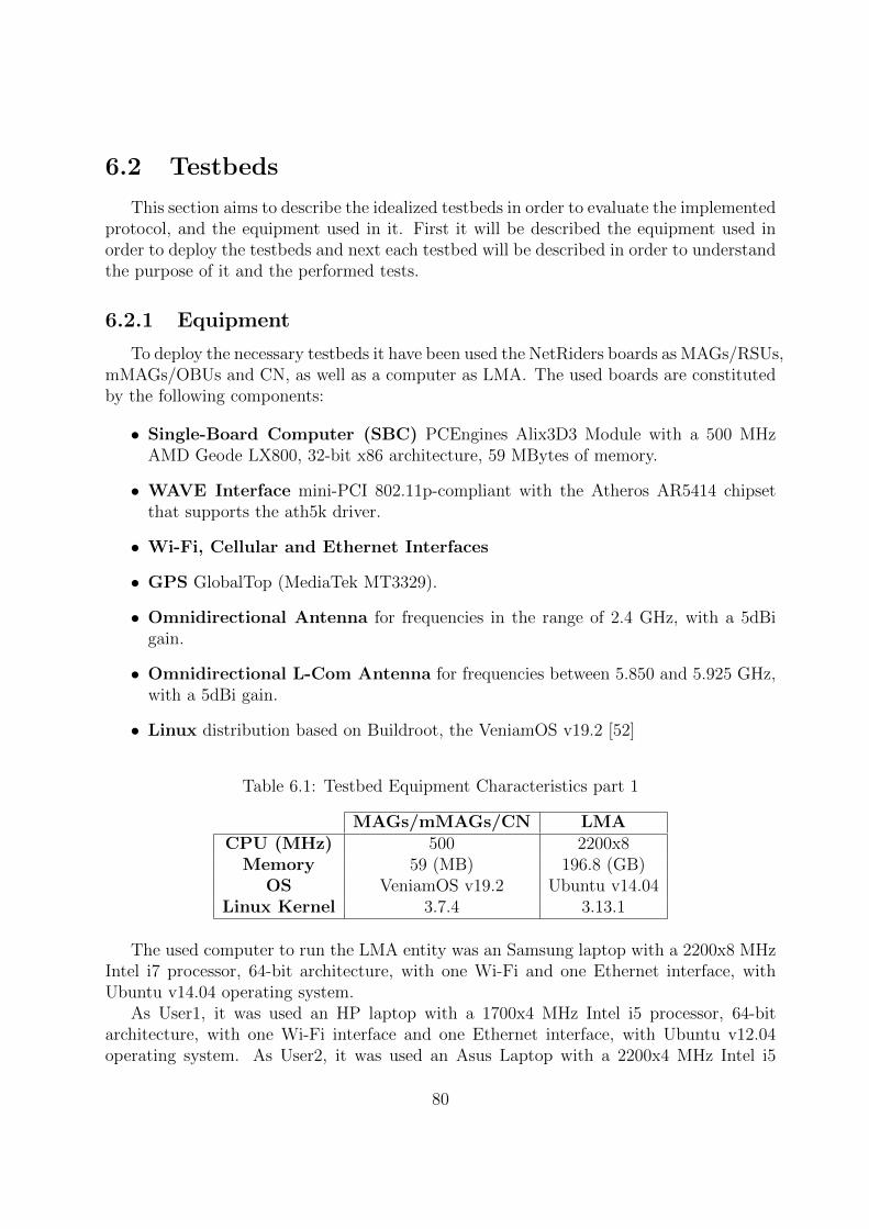
6.2 Testbeds
This section aims to describe the idealized testbeds in order to evaluate the implementedprotocol, and the equipment used in it. First it will be described the equipment used inorder to deploy the testbeds and next each testbed will be described in order to understandthe purpose of it and the performed tests.
6.2.1 Equipment
To deploy the necessary testbeds it have been used the NetRiders boards as MAGs/RSUs,mMAGs/OBUs and CN, as well as a computer as LMA. The used boards are constitutedby the following components:
• Single-Board Computer (SBC) PCEngines Alix3D3 Module with a 500 MHzAMD Geode LX800, 32-bit x86 architecture, 59 MBytes of memory.
• WAVE Interface mini-PCI 802.11p-compliant with the Atheros AR5414 chipsetthat supports the ath5k driver.
• Wi-Fi, Cellular and Ethernet Interfaces
• GPS GlobalTop (MediaTek MT3329).
• Omnidirectional Antenna for frequencies in the range of 2.4 GHz, with a 5dBigain.
• Omnidirectional L-Com Antenna for frequencies between 5.850 and 5.925 GHz,with a 5dBi gain.
• Linux distribution based on Buildroot, the VeniamOS v19.2 [52]
Table 6.1: Testbed Equipment Characteristics part 1
MAGs/mMAGs/CN LMACPU (MHz) 500 2200x8
Memory 59 (MB) 196.8 (GB)OS VeniamOS v19.2 Ubuntu v14.04
Linux Kernel 3.7.4 3.13.1
The used computer to run the LMA entity was an Samsung laptop with a 2200x8 MHzIntel i7 processor, 64-bit architecture, with one Wi-Fi and one Ethernet interface, withUbuntu v14.04 operating system.
As User1, it was used an HP laptop with a 1700x4 MHz Intel i5 processor, 64-bitarchitecture, with one Wi-Fi interface and one Ethernet interface, with Ubuntu v12.04operating system. As User2, it was used an Asus Laptop with a 2200x4 MHz Intel i5
80
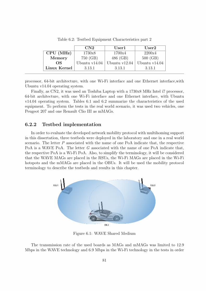
Table 6.2: Testbed Equipment Characteristics part 2
CN2 User1 User2CPU (MHz) 1730x8 1700x4 2200x4
Memory 750 (GB) 486 (GB) 500 (GB)OS Ubuntu v14.04 Ubuntu v12.04 Ubuntu v14.04
Linux Kernel 3.13.1 3.13.1 3.13.1
processor, 64-bit architecture, with one Wi-Fi interface and one Ethernet interface,withUbuntu v14.04 operating system.
Finally, as CN2, it was used an Toshiba Laptop with a 1730x8 MHz Intel i7 processor,64-bit architecture, with one Wi-Fi interface and one Ethernet interface, with Ubuntuv14.04 operating system. Tables 6.1 and 6.2 summarize the characteristics of the usedequipment. To perform the tests in the real world scenario, it was used two vehicles, onePeugeot 207 and one Renault Clio III as mMAGs.
6.2.2 Testbed implementation
In order to evaluate the developed network mobility protocol with multihoming supportin this dissertation, three testbeds were deployed in the laboratory and one in a real worldscenario. The letter P associated with the name of one PoA indicate that, the respectivePoA is a WAVE PoA. The letter G associated with the name of one PoA indicate that,the respective PoA is a Wi-Fi PoA. Also, to simplify the terminology, it will be consideredthat the WAVE MAGs are placed in the RSUs, the Wi-Fi MAGs are placed in the Wi-Fihotspots and the mMAGs are placed in the OBUs. It will be used the mobility protocolterminology to describe the testbeds and results in this chapter.
Figure 6.1: WAVE Shared Medium
The transmission rate of the used boards as MAGs and mMAGs was limited to 12.9Mbps in the WAVE technology and 6.9 Mbps in the Wi-Fi technology in the tests in order
81

to define the throughput limits. Also, it is important to refer that the WAVE medium isshared between the boards within range of each others as can be seen in figure 6.1.
The capacity of the WAVE medium, 12.9 Mbps, will be shared with the RSU1, RSU2and with the OBU. In this dissertation all the boards use the same channel to communicate,and the medium access is always divided by all the nodes with the WAVE technologybecause all the boards used on the testbeds were always in the line of sight of each others.The WAVE technology does not have session establishment, any node can transmit orreceive on the medium without association and the transmission is performed accordingwith the CSMA/CA method.
6.2.2.1 Laboratory Testbeds
The first testbed, presented in figure 6.2, aims to evaluate the network mobility protocolwith multihoming support in single-hop communications, by varying the available resourcesto the mMAG1. The number of MAGs available to the mMAG1 change in order to testthe different testbed configurations.
Figure 6.2: Lab Testbed 1
In this first testbed, the CN is connected directly to the LMA via Ethernet and, in itsturn, the LMA is connected to the MAGs through the IPv6 wired network. The mMAGis connected to the three MAGs through WAVE or Wi-Fi technology, depending on the
82

MAG type, simultaneously to two or three MAGs or to one at a time. The LMA, MAGsand mMAG must be running the mobility protocol with multihoming support program,with the configuration correspondent to the desired entity. Also, the mMAG should berunning the UIS program and the multihoming connection manager.
Figure 6.3: Lab Testbed 2
The second testbed, presented in figure 6.3, aims to evaluate the network mobilityprotocol with multihoming support in multi-hop communications by varying the availableresources to the mMAG1 and to the mMAG2. In the testbed 2, scenario 6.3.A), themultihoming is performed only in the first hop, either with two WAVE MAGs or with oneWAVE and one Wi-Fi MAG connected to the mMAG1 simultaneously. In the scenario6.3.B), it is performed in the two hops, by moving the MAG2 to only be reachable by themMAG2 and maintaining the multihoming scheme in the first hop.
83
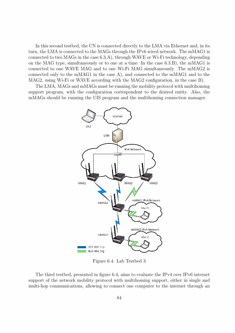
In this second testbed, the CN is connected directly to the LMA via Ethernet and, in itsturn, the LMA is connected to the MAGs through the IPv6 wired network. The mMAG1 isconnected to two MAGs in the case 6.3.A), through WAVE or Wi-Fi technology, dependingon the MAG type, simultaneously or to one at a time. In the case 6.3.B), the mMAG1 isconnected to one WAVE MAG and to one Wi-Fi MAG simultaneously. The mMAG2 isconnected only to the mMAG1 in the case A), and connected to the mMAG1 and to theMAG2, using Wi-Fi or WAVE according with the MAG2 configuration, in the case B).
The LMA, MAGs and mMAGs must be running the mobility protocol with multihomingsupport program, with the configuration correspondent to the desired entity. Also, themMAGs should be running the UIS program and the multihoming connection manager.
Figure 6.4: Lab Testbed 3
The third testbed, presented in figure 6.4, aims to evaluate the IPv4 over IPv6 internetsupport of the network mobility protocol with multihoming support, either in single andmulti-hop communications, allowing to connect one computer to the internet through an
84

IPv4 network. The available MAGs to the mMAG1 change in order to test the differenttestbed configurations.
In this testbed, the CN is connected directly to the LMA via Ethernet and, in itsturn, the LMA is connected to the MAGs through the IPv6 wired network. The mMAG1can be connected to one WAVE MAG and to one Wi-Fi MAG or to two WAVE MAGssimultaneously. Regarding to the mMAG2, it is always connected, in multi-hop, to themMAG1. Both mMAGs are announcing an IPv4 Wi-Fi network that can be used, by theusers, to access the internet.
The LMA, MAGs and mMAGs must be running the mobility protocol with multihom-ing support program, with the configuration correspondent to the desired entity. Also,the mMAGs should be announcing an Wi-Fi network to the users, and running the UISprogram, the DHCPD program and the multihoming connection manager.
6.2.2.2 Real World Testbed
The fourth testbed was implemented in a real world scenario in order to validate theimplemented solutions in a vehicular environment and the mobility and multihoming fea-tures of the developed protocol. The equipment used was the same used on the laboratorytestbeds, with two additional vehicles to simulate the mMAGs movement in a city. Figure6.5 present the real testbed equipment implemented in the roadside and on the vehicles.
Figure 6.5: Equipment Used on Real World Testbed
In 6.5.A) it is possible to see the computer used to run the LMA entity and the boardused as CN in this testbed. Figure 6.5.B) present the MAG placed in the roadside. The
85

other MAG was placed in the same way but in the opposite direction. Figures 6.5.C) and6.5.D) show the equipment placed inside the vehicles that act as mMAGs. It is possible tosee the boards used as mMAGs and the computers used to communicate with them.
In order to introduce the real scenario, figure 6.6 present a map with the equipmentlocation on the roadside.
Figure 6.6: Map of Real World Testbed
The MAGs were separated by 85 meters and placed on the roadside. The LMA and theCN were placed between the MAGs on the roadside too. The mMAGs were placed insidethe vehicles, with an antenna placed on the rooftop in order to minimize the interferences.
The LMA is connected to the MAGs through Wi-Fi and the CN is directly connectedthrough Ethernet to the LMA. The MAGs communicate with the mMAGs through WAVEtechnology. Figure 6.7 present the testbed deployed in the real environment.
This testbed aims to evaluate the multihoming and mobility in a real scenario. Insingle-hop, the mMAG was moved between the MAGs. It started connected to the MAG1,in the middle of the test it was connected to both MAGs simultaneously and in the endof the test the mMAG was connected only to the MAG2. The mMAG2, when used, wasconnected to the mMAG1 along the performed test.
In this testbed, the CN is connected directly to the LMA via Ethernet and, in its turn,the LMA is connected to the MAGs through Wi-Fi. The mMAG1 can be connected toone WAVE MAG or to two WAVE MAGs simultaneously, according to its position on theroad. Regarding to the mMAG2, it is always connected, in multi-hop, to the mMAG1, andmove along the road as the mMAG1.
86

The LMA, MAGs and mMAGs must be running the mobility protocol with multihomingsupport program, with the configuration correspondent to the desired entity. Also, themMAGs should be running the UIS program and the multihoming connection manager.
Figure 6.7: Real World Testbed 4
6.3 Methodologies and Metrics
In this section it is described the metrics obtained in the evaluation process and themethods to obtain it. The chosen metrics to obtain were the following:
87

• Throughput, delay and packet loss with a variable number of PoA in single-hop, withan equal multihoming rule and with an weighted multihoming rule to each PoA inthe laboratory.
• Throughput, delay and packet loss with a variable number of PoA in multi-hop withan weighted multihoming rule to each PoA in the laboratory.
• Throughput between an computer in the internet and another computers connectedto the mMAGs IPv4 networks in the laboratory.
• Throughput during the movement of a mMAG between two MAGs in single-hop ina real world scenario with and without another mMAG connected to it in multi-hop.
With this set of metrics it is possible to get a good characterization of the multihomingbenefits and of the QoS of the network. Also, it is possible to demonstrate the implementedfunctionalities and improvements on this dissertation. Based on these metrics, it is alsopossible to take conclusions on the behaviour of each technology for the multihomingprocess and determine the most profitable resources combinations and utilization.
In order to obtain the necessary metrics, it was necessary to generate traffic betweenthe CN and the mMAGs to the first two testbeds and to the real world testbed, andbetween the CN2 and the user1 and user2 on the third testbed. To perform the trafficgeneration, it was used the Distributed Internet Traffic Generator (D-ITG) tool [53] in thefirst two testbeds and in the real world testbed, and the iperf tool [54] in the third testbed.Both tools allow generating traffic using TCP or UDP as transport protocol but only UDPtraffic was generated due to the fact of not having retransmissions, which grant metricswith greater reliability.
In order to analyse and obtain the graphics of the measured values, it was made anMATLAB [55] script. These results were obtained from tests with the duration of fiveminutes in the laboratory testbeds, and the presented confidence intervals are of 95%.
In the real world scenario, the vehicles were moving at the speed of 25 Km/h in orderto ensure the correct operation of the disconnect message feature implemented in the otherdissertation running in parallel in our group. As the message is sent to the MAG that isgoing to loose the connection, the speed of the vehicle had to be the best to ensure thedelivery of the message and correct operation. This can be modified in order to reachhigher speeds on the vehicles. The tests in single-hop and in multi-hop were performedthree times for each scenario.
6.4 Experimental Results of Lab Testbeds
After the description of the metrics and methods adopted in this dissertation, thissection present the obtained results in the laboratory testbeds.
The performed tests with the D-ITG tool and with the iperf tool were configured [56][57] with the packet size of 1250 bytes and the packets per second (pps) value of 300 pps to
88

the rate of 3 Mbits/s, 600 pps to the rate of 6 Mbits/s, 1200 pps to the rate of 12 Mbits/sand 1800 pps to the rate of 18 Mbits/s.
The multihoming rules adopted on the first testbed were the equal division of trafficthrough the available interfaces and an weighted rule that consider only the PoAs capacity.The used formula to calculate the weighted traffic percentage to each PoA was the follow:
Rule percentage =PoA capacity∑PoAs capacities
∗ 100 (6.1)
The WAVE PoAs have in consideration the shared medium between them. For example,if the available PoAs are a Wi-Fi PoA with the capacity of 6 Mbits/s and two WAVE PoAs,each one with the capacity of 12 Mbits/s, the equal division rule will be 50% of traffic tothe Wi-Fi PoA and 25% of traffic to each WAVE PoA. In the case of the weighted rule,it will be sent 33% of traffic through the Wi-Fi PoA, and 33% and 34% of traffic througheach of the WAVE PoAs.
In the formula 6.1, when there is more than one WAVE PoA, it is considered that thePoA capacity of each one is the defined PoA capacity divided by the number of WAVE PoAsavailable to the node. Also, the sum of the PoAs capacities have this fact in consideration.
In the remaining testbeds it is adopted only the weighted multihoming rule, calculatedaccording to the defined formula 6.1.
6.4.1 Tests and Results on Lab Testbed 1
In this testbed, all the test were performed between the CN and the mMAG1 and theresults presented obtained on the mMAG1, in single-hop. To simplify, the PoAs numberscorrespond to the MAGs numbers on figure 6.2. The resources combinations available tothe mMAG1 tested on the first testbed were the follow:
• mMAG1 connected to the PoA1 through WAVE technology.
• mMAG1 connected to the PoA2 through WAVE technology.
• mMAG1 connected to the PoA3 through Wi-Fi technology.
• mMAG1 connected to the PoA1 through WAVE technology and to the PoA3 throughWi-Fi technology simultaneously, with a multihoming rule of 50%/50% of traffic toeach PoA, and with a multihoming rule of 65% of traffic sent through the PoA1 and35% of traffic sent through the PoA3.
• mMAG1 connected to the PoA1 and PoA2 through WAVE technology and to thePoA3 through Wi-Fi technology simultaneously, with a multihoming rule of 25%/25%of traffic to PoA1 and PoA2, and 50% of traffic to the PoA3. Also, it is tested witha multihoming rule of 34% of traffic sent through the PoA1, 33% through PoA2 and33% of traffic sent through the PoA3.
89

The tests were performed with only one flow with the rate of 3 Mbits/s, 6 Mbits/s, 12Mbits/s or 18 Mbits/s for each combination previously stated. The obtained metrics werethe throughput, delay and packet loss. Figure 6.8 present the throughput obtained on thefirst testbed, using the defined combinations with the multihoming equal division rule, andfigure 6.9 present the same combinations but now with the weighted multihoming rule.
Figure 6.8: Throughput on Lab Testbed 1 with Equal Division Rule
Figure 6.9: Throughput on Lab Testbed 1 with Optimized Division Rule
As can be seen in the figures 6.8 and 6.9, the throughput increase with the use of morethan one PoA of different technologies for rates bigger than the capacity of the individualentities. With two WAVE PoAs and one Wi-Fi PoA, the throughput remains the same dueto the shared medium feature of the WAVE technology. The utilization of more than one
90
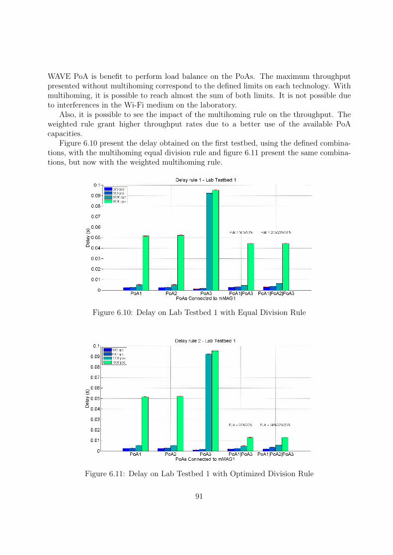
WAVE PoA is benefit to perform load balance on the PoAs. The maximum throughputpresented without multihoming correspond to the defined limits on each technology. Withmultihoming, it is possible to reach almost the sum of both limits. It is not possible dueto interferences in the Wi-Fi medium on the laboratory.
Also, it is possible to see the impact of the multihoming rule on the throughput. Theweighted rule grant higher throughput rates due to a better use of the available PoAcapacities.
Figure 6.10 present the delay obtained on the first testbed, using the defined combina-tions, with the multihoming equal division rule and figure 6.11 present the same combina-tions, but now with the weighted multihoming rule.
Figure 6.10: Delay on Lab Testbed 1 with Equal Division Rule
Figure 6.11: Delay on Lab Testbed 1 with Optimized Division Rule
91

The delay increases with the packet losses on each PoA. The higher delay is observed inthe Wi-Fi PoA to the higher rates, which is the lowest capacity PoA. With multihoming,the delay is lower due to the increase of the global capacity available, which in turn causeless packet losses. Once again, it is possible to see the impact caused by the use of theweighted rule, resulting in a better resource utilization.
Also, it is possible to see that the utilization of two WAVE PoAs with one Wi-Fi PoAdoes not affect the delay value obtained on the utilization of only one WAVE PoA and oneWi-Fi PoA because the utilization of two WAVE PoAs does not increase the throughput.
Figure 6.12 present the packet loss obtained on the first testbed, using the definedcombinations, with the multihoming equal division rule and figure 6.13 present the samecombinations, but now with the weighted multihoming rule.
Figure 6.12: Packet Loss on Lab Testbed 1 with Equal Division Rule
The packet loss observed is related with the defined limits to the maximum throughputof the used technologies. It is possible to see that the utilization of multihoming reducethe packet loss, which is expected due to the increase of available bandwidth. Also it ispossible, again, to verify the importance of the multihoming rule, since the packet lossobserved with the weighted rule is significantly lower than the observed with the equaldivision rule.
In figure 6.13, the losses observed in the situation of the PoA1 and PoA3, and PoA1,PoA2 and PoA3 simultaneously connected are due to wireless interferences on the labora-tory.
With the obtained results, it is possible to verify that the multihoming utilization insingle-hop can provide better QoS to the users, increase the available bandwidth, improvethe delay of the packets on the network, minimize the packet losses and optimize theresources utilization using an weighted multihoming rule.
92

Figure 6.13: Packet Loss on Lab Testbed 1 with Optimized Division Rule
6.4.2 Tests and Results on Lab Testbed 2
In this testbed, all the test were performed between the CN and the mMAG2 and theresults presented obtained on the mMAG2, in multi-hop. To simplify, the PoAs numberscorrespond to the MAGs numbers on figure 6.3. All the connection between the mMAGsare performed through WAVE technology. The resources combinations available to themMAG1 and mMAG2, tested on the second testbed, were the follow:
• mMAG2 connected to the mMAG1 and mMAG1 connected to the PoA1, boththrough WAVE technology.
• mMAG2 connected to the mMAG1 and mMAG1 connected to the PoA2, boththrough WAVE technology.
• mMAG2 connected to the mMAG1 through WAVE technology, and mMAG1 con-nected to the PoA2 through Wi-Fi technology.
• mMAG2 connected to the mMAG1 through WAVE technology, and mMAG1 con-nected to the PoA3 through Wi-Fi technology.
• mMAG2 connected to the mMAG1 through WAVE technology, and mMAG1 con-nected to the PoA1 through WAVE and to the PoA3 through Wi-Fi technologysimultaneously, with a multihoming rule of 65% of traffic sent through the PoA1 and35% of traffic sent through the PoA3.
• mMAG2 connected to the mMAG1 through WAVE technology, and mMAG1 con-nected to the PoA1 and to PoA2 through WAVE technology simultaneously, witha multihoming rule of 50% of traffic sent through the PoA1 and 50% of traffic sentthrough the PoA2.
93
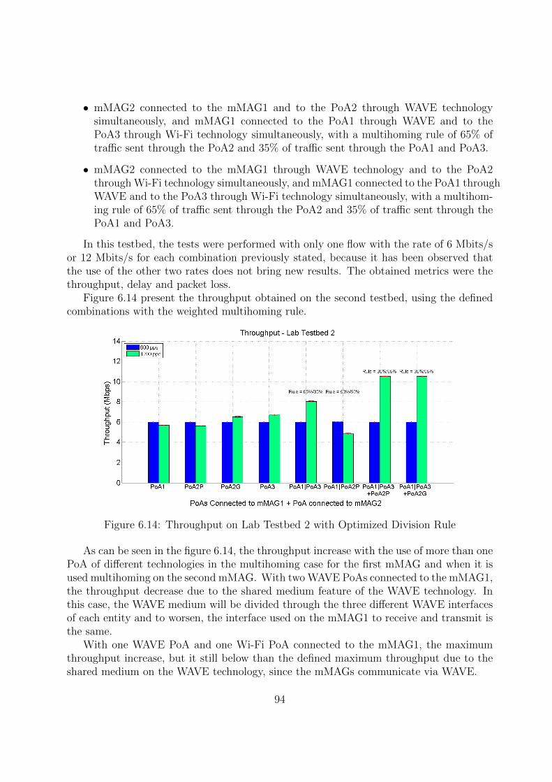
• mMAG2 connected to the mMAG1 and to the PoA2 through WAVE technologysimultaneously, and mMAG1 connected to the PoA1 through WAVE and to thePoA3 through Wi-Fi technology simultaneously, with a multihoming rule of 65% oftraffic sent through the PoA2 and 35% of traffic sent through the PoA1 and PoA3.
• mMAG2 connected to the mMAG1 through WAVE technology and to the PoA2through Wi-Fi technology simultaneously, and mMAG1 connected to the PoA1 throughWAVE and to the PoA3 through Wi-Fi technology simultaneously, with a multihom-ing rule of 65% of traffic sent through the PoA2 and 35% of traffic sent through thePoA1 and PoA3.
In this testbed, the tests were performed with only one flow with the rate of 6 Mbits/sor 12 Mbits/s for each combination previously stated, because it has been observed thatthe use of the other two rates does not bring new results. The obtained metrics were thethroughput, delay and packet loss.
Figure 6.14 present the throughput obtained on the second testbed, using the definedcombinations with the weighted multihoming rule.
Figure 6.14: Throughput on Lab Testbed 2 with Optimized Division Rule
As can be seen in the figure 6.14, the throughput increase with the use of more than onePoA of different technologies in the multihoming case for the first mMAG and when it isused multihoming on the second mMAG. With two WAVE PoAs connected to the mMAG1,the throughput decrease due to the shared medium feature of the WAVE technology. Inthis case, the WAVE medium will be divided through the three different WAVE interfacesof each entity and to worsen, the interface used on the mMAG1 to receive and transmit isthe same.
With one WAVE PoA and one Wi-Fi PoA connected to the mMAG1, the maximumthroughput increase, but it still below than the defined maximum throughput due to theshared medium on the WAVE technology, since the mMAGs communicate via WAVE.
94

The maximum throughput presented without multihoming correspond to the definedlimits on the Wi-Fi technology. On the WAVE technology, as the medium is shared andthe used interface to receive and transmit on the mMAG1 is the same, the maximumthroughput is lower than the defined limit. Also the limit on the WAVE multi-hop casedecrease with the increase of the used PoAs due to a bigger congestion on the sharedmedium.
Using multihoming in the multi-hop mMAG2, it is verified that the throughput increaseto the maximum value reached on this testbed, but it still bellow than the defined maximumthroughput due to the congestion on the WAVE shared medium and to the use of the sameinterface on mMAG1 to receive and transmit packets.
Figure 6.15 present the packet loss obtained on the second testbed, using the definedcombinations with the weighted multihoming rule.
Figure 6.15: Packet Loss on Lab Testbed 2 with Optimized Division Rule
The packet loss results are directly related with the throughput achieved on the testsperformed on this testbed. The same justifications to the throughput results can be appliedto a better comprehension of the packet loss results.
Figure 6.16 present the delay obtained on the second testbed, using the defined combi-nations with the weighted multihoming rule.
As can be seen in the figure 6.16, the delay decrease with the use of more than onePoA in the multihoming case for the second mMAG. With two WAVE PoAs connectedto the mMAG1, the delay increase due to the congestion on the shared medium feature ofthe WAVE technology. In this case, the WAVE medium will be divided through the threedifferent WAVE interfaces of each entity and to worsen, the interface used on the mMAG1to receive and transmit is the same as stated in the throughput analysis.
With one WAVE PoA and one Wi-Fi PoA connected to the mMAG1, the delay is lowerthan on the use of only one WAVE PoA, but it still higher than on the use of only oneWi-Fi PoA. The utilization of the WAVE technology in this case causes an increase of the
95

Figure 6.16: Delay on Lab Testbed 2 with Optimized Division Rule
delay due to the use of the same interface to receive and to transmit the packets on themMAG1.
With the use of multihoming to the mMAG2 it is possible to improve the delay. Whenit is used an dedicated WAVE PoA connected to the mMAG2 simultaneously with themulti-hop connection it is possible to reach the lowest delay levels because the mMAG2only uses the WAVE interface to receive packets. In the case of using an dedicated Wi-FiPoA connected to the mMAG2, the delay is bigger than on the previous case due to theuse of different interfaces to receive the packets.
6.4.3 Tests and Results on Lab Testbed 3
In this testbed, all the test were performed between the CN2 and the User1 or User2and the results presented obtained on the User1 or User2. To simplify, the PoAs numberscorrespond to the MAGs numbers on figure 6.4. All the connection between the mMAGsare performed through WAVE technology.
This testbed aims to test the QoS to the users connected to the mMAGs IPv4 networks.The resources combinations available to the mMAG1 and mMAG2, tested on the thirdtestbed, were the follow:
• mMAG1 connected to the PoA1 and to the PoA2, both through WAVE technology,and User1 connected to the mMAG1 Wi-Fi network. The Wi-Fi network scan wasdisabled in this configuration.
• mMAG1 connected to the PoA1 and to the PoA2, both through WAVE technology,and User1 connected to the mMAG1 Wi-Fi network. The Wi-Fi network scan wasenabled in this configuration.
96

• mMAG1 connected to the PoA1 through WAVE technology and to the PoA3 throughWi-Fi technology and User1 connected to the mMAG1 Wi-Fi network.
• mMAG1 connected to the PoA1 and to the PoA2, both through WAVE technology,mMAG2 connected to mMAG1 through WAVE technology and User2 connected tothe mMAG2 Wi-Fi network. The Wi-Fi network scan was disabled in this configu-ration.
• mMAG1 connected to the PoA1 and to the PoA2, both through WAVE technology,mMAG2 connected to mMAG1 through WAVE technology and User2 connected tothe mMAG2 Wi-Fi network. The Wi-Fi network scan was enabled in this configura-tion.
• mMAG1 connected to the PoA1 through WAVE technology and to the PoA3 throughWi-Fi technology, mMAG2 connected to the mMAG1 through WAVE technology andUser2 connected to the mMAG2 Wi-Fi network.
When a mMAG connects to one Wi-Fi PoA and announces an IPv4 network to theregular users, it is necessary to use one Wi-Fi virtual interface. This utilization reducethe network performance due to a multiplex in the Wi-Fi interface utilization. The resultsobtained on the cases of utilization of a Wi-Fi PoA have this factor in consideration.
Figure 6.17: 6 Mbits/s IPv4 Flows in single-hop on Lab Testbed 3 with Optimized DivisionRule
Figure 6.17 present the reached throughput along the time in the described configu-rations for the User1, using an 6 Mbits/s flow. This flow is sent from the CN2 throughthe internet to the User1. This is possible using the the nat tables in order to forwardthe received traffic to a specific port, and from that port to a specific private ip address.Figure 6.18 present the reached throughput along the time in the described configurations
97
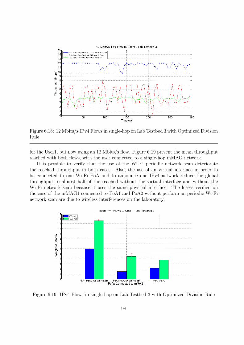
Figure 6.18: 12 Mbits/s IPv4 Flows in single-hop on Lab Testbed 3 with Optimized DivisionRule
for the User1, but now using an 12 Mbits/s flow. Figure 6.19 present the mean throughputreached with both flows, with the user connected to a single-hop mMAG network.
It is possible to verify that the use of the Wi-Fi periodic network scan deterioratethe reached throughput in both cases. Also, the use of an virtual interface in order tobe connected to one Wi-Fi PoA and to announce one IPv4 network reduce the globalthroughput to almost half of the reached without the virtual interface and without theWi-Fi network scan because it uses the same physical interface. The losses verified onthe case of the mMAG1 connected to PoA1 and PoA2 without perform an periodic Wi-Finetwork scan are due to wireless interferences on the laboratory.
Figure 6.19: IPv4 Flows in single-hop on Lab Testbed 3 with Optimized Division Rule
98
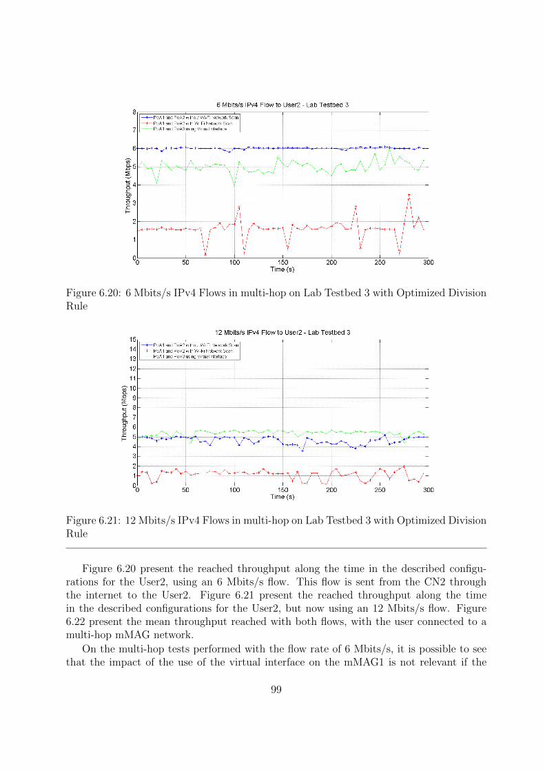
Figure 6.20: 6 Mbits/s IPv4 Flows in multi-hop on Lab Testbed 3 with Optimized DivisionRule
Figure 6.21: 12 Mbits/s IPv4 Flows in multi-hop on Lab Testbed 3 with Optimized DivisionRule
Figure 6.20 present the reached throughput along the time in the described configu-rations for the User2, using an 6 Mbits/s flow. This flow is sent from the CN2 throughthe internet to the User2. Figure 6.21 present the reached throughput along the timein the described configurations for the User2, but now using an 12 Mbits/s flow. Figure6.22 present the mean throughput reached with both flows, with the user connected to amulti-hop mMAG network.
On the multi-hop tests performed with the flow rate of 6 Mbits/s, it is possible to seethat the impact of the use of the virtual interface on the mMAG1 is not relevant if the
99
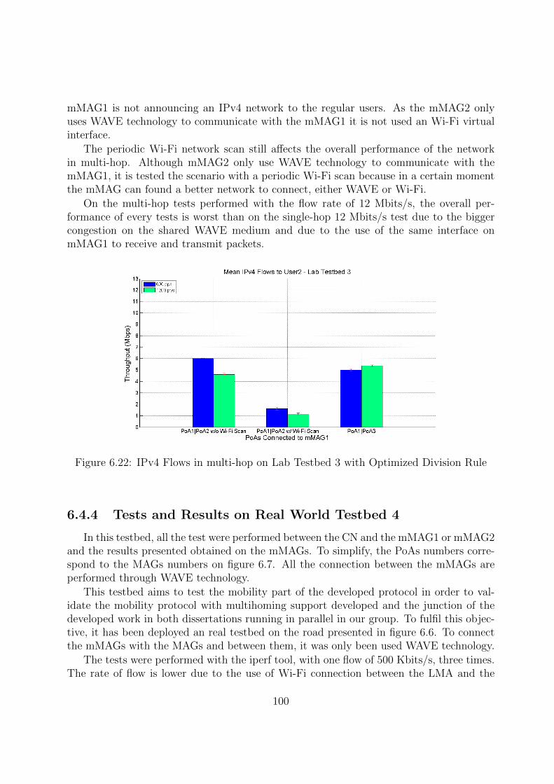
mMAG1 is not announcing an IPv4 network to the regular users. As the mMAG2 onlyuses WAVE technology to communicate with the mMAG1 it is not used an Wi-Fi virtualinterface.
The periodic Wi-Fi network scan still affects the overall performance of the networkin multi-hop. Although mMAG2 only use WAVE technology to communicate with themMAG1, it is tested the scenario with a periodic Wi-Fi scan because in a certain momentthe mMAG can found a better network to connect, either WAVE or Wi-Fi.
On the multi-hop tests performed with the flow rate of 12 Mbits/s, the overall per-formance of every tests is worst than on the single-hop 12 Mbits/s test due to the biggercongestion on the shared WAVE medium and due to the use of the same interface onmMAG1 to receive and transmit packets.
Figure 6.22: IPv4 Flows in multi-hop on Lab Testbed 3 with Optimized Division Rule
6.4.4 Tests and Results on Real World Testbed 4
In this testbed, all the test were performed between the CN and the mMAG1 or mMAG2and the results presented obtained on the mMAGs. To simplify, the PoAs numbers corre-spond to the MAGs numbers on figure 6.7. All the connection between the mMAGs areperformed through WAVE technology.
This testbed aims to test the mobility part of the developed protocol in order to val-idate the mobility protocol with multihoming support developed and the junction of thedeveloped work in both dissertations running in parallel in our group. To fulfil this objec-tive, it has been deployed an real testbed on the road presented in figure 6.6. To connectthe mMAGs with the MAGs and between them, it was only been used WAVE technology.
The tests were performed with the iperf tool, with one flow of 500 Kbits/s, three times.The rate of flow is lower due to the use of Wi-Fi connection between the LMA and the
100

MAGs deployed on the roadside, instead of the Ethernet connection used on the laboratorytestbeds.
The first scenario tested was a single-hop scenario in which the vehicle labelled asmMAG1 on figure 6.7 moves from the PoA1 to the PoA2. In the beginning, the mMAG1 isonly connected to the PoA1 and, as it gets moving it connects to the PoA2 simultaneously.At a certain point, the mMAG1 will lose connection to the PoA1 and it will only remainconnected to the PoA2. The mMAG1 is receiving an flow from the CN during the definedtrip.
The second scenario tested was similar to the first one, but now the mMAG1 has themMAG2 connected to it, testing in this way the multi-hop scenario. The mMAG2 isreceiving an flow from the CN during the defined trip. Figure 6.23 present the obtainedresults from both tests. The moments of connection or disconnection from a PoA aremarked in the figure.
Figure 6.23: IPv6 Flow on Real World Testbed 4 in Single-hop and Multi-hop
It is possible to observe in the figure that the throughput measure, either in single-hop or multi-hop, is approximately constant during the trip and near to the sent fromthe CN. The variations observed on the flows are due to Wi-Fi interferences from othernetworks present in the test environment and to the great distance between the LMA andthe MAGs. These factors degrade the Wi-Fi connection between the LMA and the MAGs,and since all the traffic is sent through that connection, the final measures are affected. Inthe moments of the variation of the number of simultaneous connected PoAs it is observedthat the throughput is concordant with the remaining performed test, without additionallosses due to the event.
101

The multi-hop measures are similar to the single-hop measures. As the capacity of theWAVE medium is considerably bigger than the rate of the sent flow, the problem of theshared medium will not affect the obtained results.
With this result it is possible to confirm the correct operation of the joint disserta-tion’s developed features and the correct operation of the developed protocol in a dynamicenvironment with mobility.
6.5 Chapter Considerations
In this chapter it has been shown and discussed the obtained results, either in thelaboratory environment and in the road environment. Each environment have its owntestbeds and configurations deployed to perform the idealized tests in order to verify thefeasibility of the developed network mobility protocol with multihoming support.
First, it has been described the equipment used on the tests as well as the testbedimplementations for each test scenarios and objectives. In the laboratory environment, ithas been deployed three different testbeds in order to test the multihoming process eitherin single-hop communications and in multi-hop communications, and to test the IPv4 overIPv6 network support. In the real world environment, it has been deployed one testbedcapable of test the multihoming process with mobility on the nodes either to single-hopcommunications and to multi-hop communications.
The results obtained in the laboratory validate the utilization of multihoming to im-prove the QoS of the network, to perform a better management of the available resources,and to improve the performance of the network. It is possible to observe that the useof different network technologies also improve the performance of the network. With theutilization of multihoming it is possible to increase the maximum throughput reached onthe network (when using different PoA technologies), to decrease the delay on the network,to perform load-sharing between the PoAs and to reduce the losses on the network. It isalso possible to see that the multihoming is beneficial either to be applied in single-hop orin multi-hop, and the normal users connected to the mMAG also benefits of it. Anotherimportant factor that can be seen on the obtained results is the importance of the chosenmultihoming rule. The more optimized the rule, the better the obtained results due to abetter management of the available resources.
Regarding to the results obtained on the real world testbed, it is possible to confirm thatthe mobility in the mMAGs does not affect the performance of the multihoming support,and the changes on the network topology are transparent to the developed protocol.
102

Chapter 7
Conclusions and Future Work
7.1 Conclusions
In this dissertation it was developed a full network mobility protocol integrated withmultihoming support. The developed protocol must be able to run on a vehicular environ-ment in order to take advantage of all available resources, support full network mobility ofthe vehicles and of the users inside the vehicles, must support multi-hop communicationseither in the mobility side and on the internet user side and must provide internet accessto the regular users inside the vehicles through an IPv4 network. Along with this, it wasalso necessary to develop a mobility connection manager to automate the mobility protocolprocess and to be the base to the multihoming connection manager, developed in the otherdissertation running in parallel in our group.
In order to fulfil these objectives, it was necessary to implement or modify the following:Implementation of the mobility connection manager, a module that can find and connectto the best network available to a node and also perform the necessary configurations onthe node; Modification of the base N-PMIPv6 protocol in order to integrate with the basemultihoming support, which was also modified to be compatible with the mobility protocol;Modifications on the multihoming base approach in order to support the utilizations of theWAVE technology; Modification of the multihoming entities in order to support multi-hopcommunications; Implementation of an IPv4 over IPv6 Internet support by changing themessage handlers of the mobility protocol and using IPv4-in-IPv6 tunnels; Implementationof the base uplink multihoming support to a future use; Finally, implementation of a cellularnetwork utilization support on the multihoming connection manager and on the networkmobility protocol with multihoming support.
The developed protocol has been tested in lab scenarios and real world scenarios inorder to validate the implemented solution and the correct operation of each feature im-plemented. The obtained results allow to evaluate, according with the chosen metrics, theperformance and impact of the network mobility protocol with multihoming support onvehicular networks. Observing the results presented on chapter 6, it is possible to take thefollowing conclusions:
103
• The developed protocol is able to increase the performance of the network, by usinga large number of resources simultaneously.
• It is possible to perform load-sharing, resulting in a better resource managementprovided by the developed protocol.
• The protocol supports the utilization of multihoming through PoAs of similar tech-nologies or different technologies. It operates with the WAVE technology correctly.
• The multi-hop communications are fully supported and its good performance is en-sured with the correct resource management provided by the protocol.
• The developed solution can use the mMAGs to provide internet access to normalusers, through an IPv4 network.
• The use of virtual interfaces in order to be connected on the mobility side and toprovide internet access to the users proved itself insufficient, since it resulted on largelosses.
• The performance of a Wi-Fi network scan while the mMAG is connected to one ormore WAVE PoAs and has regular users attached to it causes a large decrease of thenetwork performance due to the multiplexing of the Wi-Fi interface.
• The developed protocol supports mobility and it is able to run on dynamic vehicularenvironments, supporting single-hop and multi-hop connections.
• It is possible to see the impact of the multihoming rule on the global performance ofthe protocol. An optimized multihoming rule results on an optimized performancedue to a correct resource management.
It is possible to conclude that the implemented protocol fulfils the dissertation ob-jectives and makes possible to have a better resource management and a large resourcesimultaneous utilization on the vehicular networks, resulting in the improvement of thenetwork performance and of the QoS to the users.
7.2 Future Work
Throughout the dissertation, it was possible to detect that there are still gaps that needto be improved or developed. Noteworthy:
• The utilization of tunnels increase the overhead in the network: The devel-oped protocol uses tunnels in order to communicate with the different nodes, whichincreases the overhead in the network. An alternative routing system with betterperformance shall be considered.
104
• Finalize the uplink multihoming support: In this dissertation, it is only imple-mented the base tunnelling system to the uplink multihoming support. It is necessaryto implement the traffic division decision entity on the nodes of the network and therouting system to perform the traffic allocation.
• The method to analyse the packets in the LMA entity on multi-hop com-munications is not very efficient: On multi-hop communications, the packets aredouble analysed. It is possible to implement a system capable of determining if thetraffic is destined to a node in single-hop or multi-hop, and if it is destined to a nodein multi-hop, the traffic division can be calculated taking into account the single-hopavailable resources to the node, making the process more efficient.
• Limitations of the Wi-Fi technology: In order to use the Wi-Fi technologyon the multihoming and at the same time provide internet access to the users, itis important to develop methods to improve the performance of this simultaneousutilization.
• Realization of more real world tests: In order to validate all the developedfeatures and the performance of the final network mobility protocol with multihom-ing support developed, it is necessary to perform more tests in the real vehicularenvironment.
105

106

Bibliography
[1] Y. Wang and F. Li, “Vehicular ad hoc networks,” in Guide to Wireless Ad Hoc Net-works. Springer London, 2009, pp. 503–525.
[2] H. Moustafa and Y. Zhang, Vehicular Networks: Techniques, Standards and Applica-tions, 1st ed. Boston, MA, USA: Auerbach Publications, 2009.
[3] Y. Du, L. Zhang, Y. Feng, Z. Ren, and Z. Wang, “Performance analysis and enhance-ment of ieee 802.11 p/1609 protocol family in vehicular environments,” in IntelligentTransportation Systems (ITSC), 2010 13th International IEEE Conference on. IEEE,2010, pp. 1085–1090.
[4] F. Teraoka and T. Arita, “Pnemo: A network-based localized mobility managementprotocol for mobile networks,” in Ubiquitous and Future Networks (ICUFN), 2011Third International Conference on, June 2011, pp. 168–173.
[5] A. Garcıa-Martınez, M. Bagnulo, and I. Van Beijnum, “The shim6 architecture foripv6 multihoming,” Communications Magazine, IEEE, vol. 48, no. 9, pp. 152–157,2010.
[6] D. Lopes, “Acesso a Internet com Handover de Veıculos atraves de Gateways Moveis,”Master’s thesis, Universidade de Aveiro, 2013.
[7] N. Capela and S. Sargento, “An intelligent and optimized multihoming approach inreal and heterogeneous environments,” Wireless Networks, pp. 1–21, January 2015.
[8] S. Yousefi, M. S. Mousavi, and M. Fathy, “Vehicular ad hoc networks (vanets): chal-lenges and perspectives,” in ITS Telecommunications Proceedings, 2006 6th Interna-tional Conference on. IEEE, 2006, pp. 761–766.
[9] K. C.Lee, U. Lee, and M. Gerla, “Survey of routing protocols in vehicular ad hocnetworks,” in Advances in Vehicular Ad-Hoc Networks: Developments and Challenges.Information Science Reference, 2010, pp. 149–170.
[10] C. Ameixieira, A. Cardote, F. Neves, R. Meireles, S. Sargento, L. Coelho, J. Afonso,B. Areias, E. Mota, R. Costa, R. Matos, and J. Barros, “Harbornet: A real-worldtestbed for vehicular networks,” Communications Magazine, IEEE, vol. 52, no. 9, pp.108–114, 2014.
107
[11] M. Mohsin and R. Prakash, “Ip address assignment in a mobile ad hoc network,” inMILCOM 2002. Proceedings, vol. 2. IEEE, 2002, pp. 856–861.
[12] J. Kenney, “Dedicated short-range communications (dsrc) standards in the unitedstates,” Proceedings of the IEEE, vol. 99, no. 7, pp. 1162–1182, July 2011.
[13] D. Jiang and L. Delgrossi, “Ieee 802.11 p: Towards an international standard forwireless access in vehicular environments,” in Vehicular Technology Conference, 2008.VTC Spring 2008. IEEE. IEEE, 2008, pp. 2036–2040.
[14] IEEE. (2015) 802.11p-2010 - ieee standard for information technology. [Online].Available: https://standards.ieee.org/findstds/standard/802.11p-2010.html
[15] F. Neves, A. Cardote, R. Moreira, and S. Sargento, “Real-world evaluation of ieee802.11 p for vehicular networks,” in Proceedings of the Eighth ACM internationalworkshop on Vehicular inter-networking. ACM, 2011, pp. 89–90.
[16] K. Zhu, D. Niyato, P. Wang, E. Hossain, and D. In Kim, “Mobility and handoffmanagement in vehicular networks: a survey,” Wireless communications and mobilecomputing, vol. 11, no. 4, pp. 459–476, 2011.
[17] C. Perkins, D. Johnson, and J. Arkko, “Mobility Support in IPv6,” RFC 6275(Proposed Standard), Internet Engineering Task Force, Jul. 2011. [Online]. Available:http://www.ietf.org/rfc/rfc6275.txt
[18] C. Perkins, “IP Mobility Support,” RFC 2002 (Proposed Standard), InternetEngineering Task Force, Oct. 1996, obsoleted by RFC 3220, updated by RFC 2290.[Online]. Available: http://www.ietf.org/rfc/rfc2002.txt
[19] T. Narten, E. Nordmark, W. Simpson, and H. Soliman, “Neighbor Discovery forIP version 6 (IPv6),” RFC 4861 (Draft Standard), Internet Engineering Task Force,Sep. 2007, updated by RFCs 5942, 6980, 7048, 7527, 7559. [Online]. Available:http://www.ietf.org/rfc/rfc4861.txt
[20] S. Gundavelli, K. Leung, V. Devarapalli, K. Chowdhury, and B. Patil, “Proxy MobileIPv6,” RFC 5213 (Proposed Standard), Internet Engineering Task Force, Aug. 2008,updated by RFC 6543. [Online]. Available: http://www.ietf.org/rfc/rfc5213.txt
[21] V. Devarapalli, R. Wakikawa, A. Petrescu, and P. Thubert, “Network Mobility(NEMO) Basic Support Protocol,” RFC 3963 (Proposed Standard), InternetEngineering Task Force, Jan. 2005. [Online]. Available: http://www.ietf.org/rfc/rfc3963.txt
[22] T. Ernst and H.-Y. Lach, “Network Mobility Support Terminology,” RFC 4885(Informational), Internet Engineering Task Force, Jul. 2007. [Online]. Available:http://www.ietf.org/rfc/rfc4885.txt
108

[23] I. Soto, C. J. Bernardos, M. Calderon, A. Banchs, and A. Azcorra, “Nemo-enabled lo-calized mobility support for internet access in automotive scenarios,” CommunicationsMagazine, IEEE, vol. 47, no. 5, pp. 152–159, 2009.
[24] S. Jeon, R. Aguiar, and B. Sarikaya, “Network mobility support using mobile mag inproxy mobile ipv6 domain,” Network, 2012.
[25] J. Arkko, T. Henderson, and C. Vogt, “Host multihoming with the host identityprotocol,” 2015.
[26] J. Bi, P. Hu, and L. Xie, “Site multihoming: Practices, mechanisms and perspective,”in Future Generation Communication and Networking (FGCN 2007), vol. 1. IEEE,2007, pp. 535–540.
[27] J. Abley, B. Black, and V. Gill, “Goals for IPv6 Site-Multihoming Architectures,”RFC 3582 (Informational), Internet Engineering Task Force, Aug. 2003. [Online].Available: http://www.ietf.org/rfc/rfc3582.txt
[28] A. L. Ramaboli, O. E. Falowo, and A. H. Chan, “Bandwidth aggregation in hetero-geneous wireless networks: A survey of current approaches and issues,” Journal ofNetwork and Computer Applications, vol. 35, no. 6, pp. 1674–1690, 2012.
[29] N. Capela and S. Sargento, “Multihoming and network coding: A new approach tooptimize the network performance,” Computer Networks, vol. 75, pp. 18–36, 2014.
[30] J. Abley, K. Lindqvist, E. Davies, B. Black, and V. Gill, “IPv4 MultihomingPractices and Limitations,” RFC 4116 (Informational), Internet Engineering TaskForce, Jul. 2005. [Online]. Available: http://www.ietf.org/rfc/rfc4116.txt
[31] L. Ong and J. Yoakum, “An Introduction to the Stream Control TransmissionProtocol (SCTP),” RFC 3286 (Informational), Internet Engineering Task Force, May2002. [Online]. Available: http://www.ietf.org/rfc/rfc3286.txt
[32] R. Stewart, “Stream Control Transmission Protocol,” RFC 4960 (ProposedStandard), Internet Engineering Task Force, Sep. 2007, updated by RFCs 6096, 6335,7053. [Online]. Available: http://www.ietf.org/rfc/rfc4960.txt
[33] T. D. Wallace and A. Shami, “A review of multihoming issues using the stream controltransmission protocol,” Communications Surveys & Tutorials, IEEE, vol. 14, no. 2,pp. 565–578, 2012.
[34] P.-H. Wu, K.-L. Chiu, and R. Hwang, “Solutions to multihoming in ipv6 based onmipv6 and nemo,” in Pervasive Systems, Algorithms, and Networks (ISPAN), 200910th International Symposium on. IEEE, 2009, pp. 290–295.
109

[35] E. Nordmark and M. Bagnulo, “Shim6: Level 3 Multihoming Shim Protocol forIPv6,” RFC 5533 (Proposed Standard), Internet Engineering Task Force, Jun. 2009.[Online]. Available: http://www.ietf.org/rfc/rfc5533.txt
[36] J. Arkko and I. van Beijnum, “Failure Detection and Locator Pair ExplorationProtocol for IPv6 Multihoming,” RFC 5534 (Proposed Standard), InternetEngineering Task Force, Jun. 2009. [Online]. Available: http://www.ietf.org/rfc/rfc5534.txt
[37] R. Moskowitz, P. Nikander, P. Jokela, and T. Henderson, “Host IdentityProtocol,” RFC 5201 (Experimental), Internet Engineering Task Force, Apr.2008, obsoleted by RFC 7401, updated by RFC 6253. [Online]. Available:http://www.ietf.org/rfc/rfc5201.txt
[38] P. Nikander, T. Henderson, C. Vogt, and J. Arkko, “End-Host Mobility andMultihoming with the Host Identity Protocol,” RFC 5206 (Experimental), InternetEngineering Task Force, Apr. 2008. [Online]. Available: http://www.ietf.org/rfc/rfc5206.txt
[39] P. Nikander, A. Gurtov, and T. R. Henderson, “Host identity protocol (hip): Con-nectivity, mobility, multi-homing, security, and privacy over ipv4 and ipv6 networks,”Communications Surveys & Tutorials, IEEE, vol. 12, no. 2, pp. 186–204, 2010.
[40] J. Dias, A. Cardote, F. Neves, S. Sargento, and A. Oliveira, “Seamless horizontal andvertical mobility in vanet,” in Vehicular Networking Conference (VNC), 2012 IEEE.IEEE, 2012, pp. 226–233.
[41] EURECOM. (2012) Openairinterface proxy mobile ipv6. [Online]. Available:http://www.openairinterface.org/components/page1103.en.htm
[42] FreeRADIUS. (2015) The freeradius project. [Online]. Available: http://www.freeradius.org
[43] D. Wing, “Network address translation: extending the internet address space,” IEEEInternet computing, no. 4, pp. 66–70, 2010.
[44] OpenWrt. (2015) Openwrt wireless freedom. [Online]. Available: https://openwrt.org/
[45] ——. (2015) Openwrt build system – installation. [Online]. Available: http://wiki.openwrt.org/doc/howto/buildroot.exigence
[46] R. Hinden and S. Deering, “IP Version 6 Addressing Architecture,” RFC 4291 (DraftStandard), Internet Engineering Task Force, Feb. 2006, updated by RFCs 5952, 6052,7136, 7346, 7371. [Online]. Available: http://www.ietf.org/rfc/rfc4291.txt
[47] PCAP. (2015) Reference manual pages (3pcap). [Online]. Available: http://www.tcpdump.org/manpages/pcap.3pcap.html
110
[48] L. M. Page. (2015) htonl, htons, ntohl, ntohs - convert values between host andnetwork byte order. [Online]. Available: http://linux.die.net/man/3/htons
[49] A. Conta and S. Deering, “Generic Packet Tunneling in IPv6 Specification,” RFC2473 (Proposed Standard), Internet Engineering Task Force, Dec. 1998. [Online].Available: http://www.ietf.org/rfc/rfc2473.txt
[50] Linux. (2015) dhcpd(8) - linux man page. [Online]. Available: http://linux.die.net/man/8/dhcpd
[51] (2015) hostapd: Ieee 802.11 ap, ieee 802.1x/wpa/wpa2/eap/radius authenticator.[Online]. Available: https://w1.fi/hostapd/
[52] “Buildroot: Making embedded linux easy,” 2012. [Online]. Available: http://buildroot.uclibc.org/
[53] (2015) D-itg, distributed internet traffic generator. [Online]. Available: http://traffic.comics.unina.it/software/ITG/
[54] (2015) iperf - the network bandwidth measurement tool. [Online]. Available:https://iperf.fr/
[55] MathWorks. (2015) Matlab r2011a. [Online]. Available: http://www.mathworks.com/products/new products/release2011a.html
[56] (2015) D-itg 2.8.1 manual. [Online]. Available: http://traffic.comics.unina.it/software/ITG/manual/
[57] (2015) iperf 2 user documentation. [Online]. Available: https://iperf.fr/iperf-doc.php#doc
111