Analytical analysis of the thermal effect on vibrations of a damped Timoshenko beam
25
Analytical analysis of the thermal effect on vibrations of a damped Timoshenko beam Lili Gu, Zhaoye Qin, Fulei Chu n Department of Mechanical Engineering, Tsinghua University, Beijing 100084, China article info Article history: Received 24 September 2014 Accepted 26 November 2014 Keywords: Thermal effect Vibration Timoshenko beam Damping abstract We analyze theoretically the thermal effect on the dynamics of a damped-cantilever Timoshenko beam structure, which is featured with cross-sectional temperature gradi- ents. The thermal effect is incorporated in the dynamic model via the temperature- dependent elastic modulus and the temperature-gradient-induced thermal force. The inhomogeneous boundaries introduced by the thermal moment are handled by decom- posing the total displacement into static and dynamic displacements. In the end, numerical results based on the analytical solutions are given for a better understanding of the thermal effect on the dynamic behaviors. The solutions reveal the circumstances in which thermal eigenvalues should be considered together with the cross-sectional temperature gradients in predicting thermal vibrations. Moreover, the results also high- light the role of axial temperature gradients on the dynamic response induced by equivalent shearing forces. & 2014 Elsevier Ltd. All rights reserved. 1. Introduction The beam structures working in thermal environment have aroused more interests in recent years due to the problem of thermal vibrations. The common recognition of the mechanism for the thermal vibrations is the existence of temperature differences through the cross-section area [1,2]. To characterize the thermal vibrations, many researches were conducted during the past several decades. The pioneer research of thermally induced beam vibrations was to solve the problems of thermal flutters in spacecraft applications, where rapid external heating was significant in the applications of flexible beam structures [3,4]. With the development of turbo-machinery, blade failures in turbomachinery [5,6] were highly regarded as one of the most critical problems. The elevated temperature put more risks to the reliability of blade operations [7,8]. Therefore, the thermally induced beam vibrations were extended into the application of turbomachinery [9]. The thermal effect on the natural frequencies of beam-structure vibrations was the first concern regarding the thermal vibrations. In the related study, the temperature-dependent material properties were considered in the calculation of the beam frequencies to achieve a higher accuracy. The elastic modulus dependent on the temperature linearly [8–10] or of higher orders [11,12] was incorporated in the motion equations. At the presence of non-uniform temperature, the consideration of temperature-dependent modulus will introduce spatial variations of the material properties. Therefore, not only the temperature variations with time but also the temperature gradients should be considered in the investigations of the thermal effect on natural beam frequencies. An example in such area can be found in the work by Tomar and Jain on the Contents lists available at ScienceDirect journal homepage: www.elsevier.com/locate/ymssp Mechanical Systems and Signal Processing http://dx.doi.org/10.1016/j.ymssp.2014.11.014 0888-3270/& 2014 Elsevier Ltd. All rights reserved. n Corresponding author. Tel.: þ86 10 62792842. E-mail address: [email protected] (F. Chu). Mechanical Systems and Signal Processing ] (]]]]) ]]]–]]] Please cite this article as: L. Gu, et al., Analytical analysis of the thermal effect on vibrations of a damped Timoshenko beam, Mech. Syst. Signal Process. (2015), http://dx.doi.org/10.1016/j.ymssp.2014.11.014i
Transcript of Analytical analysis of the thermal effect on vibrations of a damped Timoshenko beam

Contents lists available at ScienceDirect
Mechanical Systems and Signal Processing
Mechanical Systems and Signal Processing ] (]]]]) ]]]–]]]
http://d0888-32
n CorrE-m
PleasTimo
journal homepage: www.elsevier.com/locate/ymssp
Analytical analysis of the thermal effect on vibrationsof a damped Timoshenko beam
Lili Gu, Zhaoye Qin, Fulei Chu n
Department of Mechanical Engineering, Tsinghua University, Beijing 100084, China
a r t i c l e i n f o
Article history:Received 24 September 2014Accepted 26 November 2014
Keywords:Thermal effectVibrationTimoshenko beamDamping
x.doi.org/10.1016/j.ymssp.2014.11.01470/& 2014 Elsevier Ltd. All rights reserved.
esponding author. Tel.: þ86 10 62792842.ail address: [email protected] (F. C
e cite this article as: L. Gu, etshenko beam, Mech. Syst. Signal Pr
a b s t r a c t
We analyze theoretically the thermal effect on the dynamics of a damped-cantileverTimoshenko beam structure, which is featured with cross-sectional temperature gradi-ents. The thermal effect is incorporated in the dynamic model via the temperature-dependent elastic modulus and the temperature-gradient-induced thermal force. Theinhomogeneous boundaries introduced by the thermal moment are handled by decom-posing the total displacement into static and dynamic displacements. In the end,numerical results based on the analytical solutions are given for a better understandingof the thermal effect on the dynamic behaviors. The solutions reveal the circumstances inwhich thermal eigenvalues should be considered together with the cross-sectionaltemperature gradients in predicting thermal vibrations. Moreover, the results also high-light the role of axial temperature gradients on the dynamic response induced byequivalent shearing forces.
& 2014 Elsevier Ltd. All rights reserved.
1. Introduction
The beam structures working in thermal environment have aroused more interests in recent years due to the problem ofthermal vibrations. The common recognition of the mechanism for the thermal vibrations is the existence of temperaturedifferences through the cross-section area [1,2]. To characterize the thermal vibrations, many researches were conductedduring the past several decades. The pioneer research of thermally induced beam vibrations was to solve the problems ofthermal flutters in spacecraft applications, where rapid external heating was significant in the applications of flexible beamstructures [3,4]. With the development of turbo-machinery, blade failures in turbomachinery [5,6] were highly regarded asone of the most critical problems. The elevated temperature put more risks to the reliability of blade operations [7,8].Therefore, the thermally induced beam vibrations were extended into the application of turbomachinery [9].
The thermal effect on the natural frequencies of beam-structure vibrations was the first concern regarding the thermalvibrations. In the related study, the temperature-dependent material properties were considered in the calculation of thebeam frequencies to achieve a higher accuracy. The elastic modulus dependent on the temperature linearly [8–10] or ofhigher orders [11,12] was incorporated in the motion equations. At the presence of non-uniform temperature, theconsideration of temperature-dependent modulus will introduce spatial variations of the material properties. Therefore, notonly the temperature variations with time but also the temperature gradients should be considered in the investigations ofthe thermal effect on natural beam frequencies. An example in such area can be found in the work by Tomar and Jain on the
hu).
al., Analytical analysis of the thermal effect on vibrations of a dampedocess. (2015), http://dx.doi.org/10.1016/j.ymssp.2014.11.014i

L. Gu et al. / Mechanical Systems and Signal Processing ] (]]]]) ]]]–]]]2
coupled bending and torsional vibrations of a turbine-blade-based beam model [10], where the prescribed temperaturegradient is given. Avsec and Oblak [13] found that the natural frequencies were very sensitive to temperature field and smallchanges of temperature could cause significant variations of beam frequencies. With the increasing applications ofcomposite technology, the dynamic characteristics of composite beams under thermal effect became an interesting issueand some related studies were performed [14]. Ergun and Alkan [15] found that the natural frequencies of the compositebeam were largely influenced by the temperature for all types of boundary conditions and geometries.
The frequency issue is not only a result of the thermal effect but also a reason of the thermal resonances at the presenceof rapid heating [16]. Boley found that the necessary condition of thermal flutters was that the period of natural vibrationand the characteristic thermal time should be in the same order [17]. The related phenomena were investigated by manyresearchers in the application of spacecraft and nuclear structures [16,18–20]. In 1997, however, Kidawa-Kukla presented anupdated theory that the thermal resonance could occur when the beam vibration frequency was multiples of the one for theharmonic moving heat source [16]. Lyons [21] commented that the two possible means to accomplish thermally inducedvibrations with experimental methods, one was the instantaneous supply of large amounts of electrical energy and thesecond one was the instantaneous input of radiation or radiation-type particles.
Another important aspect related to thermal vibrations is the thermal excitations arising from the non-uniform thermalstresses over the cross-section area, which will further increase the amplitudes of vibrations [12,2,13]. Regarding thissubject, various work has been done to demonstrate how temperature field influences the vibrations of beams. In most ofthe related studies, the prescribed temperature field and thermal boundaries were given to flexible beams with sheardeformations neglected [20,22,23,3]. Analytical method [22–25], finite element method [2,4] and other numericalapproaches [26] have been utilized throughout these years in the related studies. The work regarding the thermalvibrations of turbomachinery blades so far has been more related with the development of functionally graded materialswhich can withstand high temperature gradients [27]. Nevertheless, Na et al. [9] carried out research within the solid beammodel for turbomachinery blades exposed in a steady temperature field with time-varying external blast and of tem-perature-dependent material properties. Regarding the vibration problem, a vibration control methodology was imple-mented based on the piezoelectric strain actuators.
Despite the fact that various researches have been carried out on the thermal vibrations of beam structures, the thermo-flow-immersed thermal boundaries have not been tackled in the related problems. For beam structures confronted withvarying thermal flow, the pursuit of accurate prediction of dynamic behaviors will require the incorporation of the thermalfactors into the dynamical analysis. Moreover, the knowledge of the sensitive thermal conditions under which thermallyinduced vibrations may become severe will be helpful in preventing possible damage in the structures. Therefore, the paperbrings off an analytical study of the thermal vibrations of a clamped–free beam which is influenced by uneven cross-sectional temperature. A Timoshenko beam model is adopted to account for the shearing effect in the dynamic model,where the damping effect is considered. Both the temperature-dependent material properties and the thermal equivalentforces are modeled for a comprehensive analysis of thermal effect on the thermal vibrations. Besides, the range of excitationsources are narrowed down to the thermal equivalent forces only to highlight the thermal influence. Therefore, the term ofthermal vibrations is utilized in this paper to indicate the vibrations induced by the thermal effect. The analytical solutionsof thermal vibrations are derived to incorporate the information of both thermal environment and mechanical properties.Thereafter, numerical results based on the analytical solutions are given for a better illustration of how the thermal factorsinfluencing the dynamic behaviors of a Timoshenko beam, where various thermal cases are configured and compared.
2. Setup of analytical models
A cantilever beamwith uniform cross-section is configured with the thermal boundaries as shown in Fig. 1. The dynamicmodel and thermal model are to be set up separately in this section, which will then be coupled via the temperature-dependent modulus and the equivalent thermal forces.
Fig. 1. Thermal model for the cantilever beam. (a) Structural boundaries and (b) Thermal boundaries.
Please cite this article as: L. Gu, et al., Analytical analysis of the thermal effect on vibrations of a dampedTimoshenko beam, Mech. Syst. Signal Process. (2015), http://dx.doi.org/10.1016/j.ymssp.2014.11.014i

L. Gu et al. / Mechanical Systems and Signal Processing ] (]]]]) ]]]–]]] 3
2.1. Dynamic model
To highlight the mechanism of thermal vibrations, no rotation is considered for the beam motion in this paper. TheTimoshenko theory is adopted to take the shear deformation into account. Therefore, the axial strain considering thethermal expansion is σx expressed as
σx ¼ �y∂ψ∂x
�αΔT ð1Þ
where ψ is the bending slope, α is the thermal expansion coefficient and ΔT is the temperature rise. The shearing strain τxyis given by
τxy ¼∂v∂x
�ψ ð2Þ
where v representing the lateral displacement. With the strain expressions in Eqs. (1) and (2), the strain energy consideringthe thermal effect here goes
U ¼ 12ET
ZZZV
�y∂ψ∂x
�αΔT� �2
dVþ12k0GZZZ
V
∂v∂x
�ψ� �2
dV ð3Þ
with k0 representing the shear coefficient, which varies with the cross-sectional shapes. According to Ref. [28], k0 is aroundthe value of 0.8492 for rectangular cross-section. The modulus ET is dependent on temperature T under the circumstances ofelevated temperature [11]. The relationship between the temperature and elastic modulus ET for the temperature range of(295–873 [K]) is obtained through the curve-fitting of the data reported by Chen et al. [11], which follows
ET ¼ E0ð�3:365� 10�9T3þ5:98� 10�6T2�4:17� 10�3Tþ1:79Þ ð4Þwhere E0 ¼ 200� 109 Gpa is the elastic modulus at room temperature. The kinetic energy for a beam structure [29] is givenas follows:
K ¼ 12ρAZ L
0
∂v∂t
� �2
dxþ12ρIZ L
0
∂ψ∂t
� �2
dx ð5Þ
The damping force fc is assumed of two parts, which are proportional to the speeds of lateral vibration and the bending-slope separately, as expressed in the following equation:
f c ¼ dv∂v∂t
þdψ∂ψ∂t
ð6Þ
where dv and dψ are the damping coefficients per unit length corresponding to the lateral and bending-slope speedrespectively. The external work resulting from the damping force here goes
W ¼ dv∂v∂tvþdψ
∂ψ∂tψ ð7Þ
With the energy equations given in Eqs. (3), (5) and (7), the motion equations can be obtained by employing Hamilton'sprinciple as follows:
ρA∂2v∂t2
þdv∂v∂t
�k0GA∂2v∂x2
�∂ψ∂x
� �¼ 0 ð8aÞ
ρI∂2ψ∂t2
þdψ∂ψ∂t
�EI∂2ψ∂x2
�k0GA∂v∂x
�ψ� �
¼ f T ð8bÞ
where f T is the equivalent thermal shearing force expressed as
f T ¼∂MT
∂xð9Þ
and with MT ðx; tÞ denoting the equivalent thermal moment which is determined by the cross-sectional temperaturedistribution
MT ¼ ETαZx
ZAyTðx; y; z; tÞ dA dx ð10Þ
The boundaries associated with the cantilever Timoshenko beam are given below:
x¼ 0; vð0; tÞ ¼ 0 ð11aÞ
ψ ð0; tÞ ¼ 0 ð11bÞ
x¼ L; EIψ 0ðL; tÞ ¼ �MT jx ¼ L ð11cÞ
v0ðL; tÞ�ψ ðL; tÞ ¼ 0 ð11dÞ
Please cite this article as: L. Gu, et al., Analytical analysis of the thermal effect on vibrations of a dampedTimoshenko beam, Mech. Syst. Signal Process. (2015), http://dx.doi.org/10.1016/j.ymssp.2014.11.014i

L. Gu et al. / Mechanical Systems and Signal Processing ] (]]]]) ]]]–]]]4
It is well worth noticing that the consideration of thermal effect yields the inhomogeneous boundary at the free end, whichis different from the one in the cases neglecting thermal impact. By introducing the dimensionless parameters as follows:
A ¼ A
L2; dv ¼ dvL
4w1
ET I; dψ ¼ dψL
2w1
ET I; f T ¼ f T L
2
ET I; G ¼ GL4
ET I; I ¼ I
L4;MT ¼MTL
ET I; ρ ¼ ρL6w2
1ET I
;
t ¼ tw1; v ¼ vL; x ¼ x
Lð12Þ
where w1 is the first natural resonance frequency the nondimensionlized forms of governing equations in Eqs. (8a) and (8b)can then be obtained as shown in the following equations:
ρA∂2v∂t2
þdv∂v∂t
�k0GA∂2v∂x2
�∂ψ∂x
� �¼ 0
ρI∂2ψ∂t2
þdψ∂ψ∂t
�∂2ψ∂x2
�kGA∂v∂x
�ψ� �
¼ f T ð13Þ
x¼ 0; vð0; tÞ ¼ 0 ψ ð0; tÞ ¼ 0x¼ 1; ψ 0ð1; tÞ ¼ �MT ;x ¼ 1ðtÞ v0ð1; tÞ�ψ ð1; tÞ ¼ 0 ð14Þ
It should be noted that the bar on top of the nondimensional parameters is omitted in Eqs. (13) and (14) to make theequations more readable.
2.2. Heat transfer model
A generic thermal environment for the beam structure will be modeled, where different temperature distributions mightbe resulted by the adjustment of certain thermal parameters. The heat convection boundaries are applied on the top andbottom surfaces to generate varying cross-sectional temperature gradients. The temperature difference along the spanwisedirection (z-direction in Fig. 1) is regarded as very small so that the heat conduction in this dimension can be neglected,which will yield the Fourier equation as follows:
k∂2T∂x2
þ∂2T∂y2
� �¼ ρCp
∂T∂t
ð15Þ
where k represents the thermal conductivity and Cp the volume heat capacity. The thermal boundaries are written as
t40; x¼ 0; T ¼ Te
t40; x¼ L;∂T∂x
¼ 0
t40; y¼ 0; �k∂T∂x
þH1 T�Teð Þ ¼ 0
t40; y¼ h; k∂T∂x
þH2 T�Teð Þ ¼ 0
t ¼ 0; Tðx; yÞ ¼ T0ðx; yÞ ð16Þwhere Te is the environmental temperature, L the beam length, h the height, H1 and H2 according to the convectioncoefficients on the top and bottom surfaces, respectively and T0ðx; yÞ the initial temperature field. The temperature for theclamped end is considered to be constant while the free end is applied with adiabatic boundary.
The inhomogeneous thermal boundaries presented at Eq. (16) can be homogenized by the following transformation ofvariable T to Te:
~T ¼ T�Te
which will give the Fourier equation with homogenized boundaries shown as below:
k∂2 ~T∂x2
þ∂2 ~T∂y2
!¼ ρCp
∂ ~T∂t
ð17Þ
t40; x¼ 0; ~T ¼ 0
t40; x¼ L; ~T0 ¼ 0
t40; y¼ 0; � ~T0 þH1
0 ~T ¼ 0
t40; y¼ h; ~T0 þH2
0 ~T ¼ 0
t ¼ 0; ~T ðx; yÞ ¼ ~T 0ðx; yÞ ð18Þwhere
H0i ¼Hi=k ð19Þ
Please cite this article as: L. Gu, et al., Analytical analysis of the thermal effect on vibrations of a dampedTimoshenko beam, Mech. Syst. Signal Process. (2015), http://dx.doi.org/10.1016/j.ymssp.2014.11.014i

L. Gu et al. / Mechanical Systems and Signal Processing ] (]]]]) ]]]–]]] 5
and
~T 0ðx; yÞ ¼ T0ðx; yÞ�Te ð20Þ
The partial differential equation in Eq. (17) can be solved by the method of variable separation [30]. The final solution canbe divided into three parts
T1ðxÞ ¼X1m ¼ 1
sin ðβmxÞ
T2ðyÞ ¼X1n ¼ 1
γn cos ðγnyÞþH1 sin ðγnyÞ
CðtÞ ¼ cmneεðγ2n þβ2
mÞt ð21Þ
where ε is the thermal diffusivity which is written as
ε¼ k=ðρCpÞ ð22Þ
and βm and γn are the eigenvalues for one-dimensional conduction problems in x-direction and y-direction, respectively.Similarly, the initial temperature ~T 0ðx; yÞ can be separated in different variables as well. Due to the small thickness of thebeam, the y component T0y is simplified as constant and therefore ~T 0ðx; yÞ is expressed as
~T 0ðx; yÞ ¼ T0T0x ð23Þ
where the x component T0x is of unit amplitude. Therefore, the coefficient cmn, which is decided by the initial condition andthe eigenfunctions of the thermal problem, is finally given by
cmn ¼T0
NðβmÞNðγnÞZ L
0T0xT1 xð Þ dx
Z h=2
�h=2T2 yð Þ dy ð24Þ
The operator N represents the norm of the according eigenvalues and T0x refers to the initial temperature distribution inx directions. The eigenvalues of βm and γn are the solutions of the following two equations [30]:
cosβmL¼ 0
tan γnh¼ γnðH1þH2Þγ2n�H1H2
ð25Þ
The final analytical solution for temperature field is obtained by combining the three sub-equations listed in Eq. (21):
Tðx; y; tÞ ¼ T1ðxÞT2ðyÞCðtÞþTe ð26Þ
Since the thermal diffusivity ε is small, C(t) varies very slowly with time. With the detailed expression for temperature field,the thermal moment and shearing force shown in Eqs. (10) and (9) will be updated to the following form:
MT ¼ ETX1m ¼ 1
X1n ¼ 1
cmnbn sin ðβmxÞe�εðγ2n þβ2mÞt
h ið27aÞ
f T ¼ ETX1m ¼ 1
X1n ¼ 1
cmnbnβm cos ðβmxÞe�εðγ2n þβ2mÞt
h ið27bÞ
where
bn ¼12A
γ2nþ2H1=hγ2n
sin γnh� �þ2γn=h−γnH1
γ2ncos γnh
� �−2γn=hþγnH1
γ2n
� �ð28Þ
According to Eq. (12), the dimensionless thermal-forces are therefore given by
MT ¼αLIp
X1m ¼ 1
X1n ¼ 1
cmnbn sin βmx� �
e�εðγ2n þβ2mÞt
h ið29aÞ
f T ¼αL2
Ip
X1m ¼ 1
X1n ¼ 1
cmnbnβm cos βmx� �
e�εðγ2n þβ2mÞt
h ið29bÞ
It should be noted that the temperature-dependent modulus ET is omitted in the above equations, which implies that theelastic modulus varying with temperature will have no impact on the equivalent thermal forces.
Please cite this article as: L. Gu, et al., Analytical analysis of the thermal effect on vibrations of a dampedTimoshenko beam, Mech. Syst. Signal Process. (2015), http://dx.doi.org/10.1016/j.ymssp.2014.11.014i

L. Gu et al. / Mechanical Systems and Signal Processing ] (]]]]) ]]]–]]]6
3. Analytical solution of the coupling problem
3.1. Solution of vibration modes
First of all, the decoupling process is needed for Eqs. (8a) and (8b). By assuming the solution in time domain as theform in
v¼ VðxÞeωt
ψ ¼Ψ ðxÞeωt
(ð30Þ
By substituting Eq. (30) into the homogeneous form of Eq. (13), we can obtain the following equation:
�k0GA 00 �1
" #V″ðxÞΨ ″ðxÞ
( )þ 0 k0GA
�k0GA 0
" #V 0ðxÞΨ 0ðxÞ
( )þ
ω2ρAþωdv 00 ω2ρIþkGAþωdψ
" #VðxÞΨ ðxÞ
( )¼ 0
0
� �ð31Þ
The ordinary differential equation described in Eq. (31) reflects the spatial vibration. The uncoupling form of Eq. (31) isobtained as
A1V
ψ
( )⁗
þA2V
ψ
( )″
þA3V
ψ
( )¼ 0
0
� �ð32Þ
where
A1 ¼ �k0G=Iρ2
A2 ¼k0Gω2
ρþk0Gdψω
ρ2Iþ ω2
ρþdvωρ2A
� �=I
A3 ¼ � ω4þ dvρA
þdψρI
� �ω3þ k0GA
ρIþdvdψρ2IA
� �ω2þdvk
0Gρ2I
ω�
8>>>>>>>><>>>>>>>>:
ð33Þ
The vibration equations in Eq. (32) share the same coefficients in both lateral and rotational directions, which impliesthat the two vibrations are of the same vibration characteristic value, defined by λ. Therefore, the following spatial vibrationsolutions can be assumed
V ¼ eλx
Ψ ¼ eλx
(ð34Þ
The characteristic equations for the two vibrations can finally be obtained by substituting Eq. (34) into Eq. (32), which aregiven as
A1λ4þA2λ
2þA3 ¼ 0 ð35Þ
Four eigenvalues of λ will be obtained from Eq. (35) as follows:
λ1;3 ¼ 7a¼ 7
ffiffiffiffiffiffiffiffiffiffiffiffiffiffiffiffiffiffiffiffiffiffiffiffiffiffiffiffiffiffiffiffiffiffiffiffiffiffiffiffiffiffiffi�A2þ
ffiffiffiffiffiffiffiffiffiffiffiffiffiffiffiffiffiffiffiffiffiffiffiA22�4A1A3
q2A1
vuut ð36aÞ
λ2;4 ¼ 7b¼ 7
ffiffiffiffiffiffiffiffiffiffiffiffiffiffiffiffiffiffiffiffiffiffiffiffiffiffiffiffiffiffiffiffiffiffiffiffiffiffiffiffiffiffiffi�A2�
ffiffiffiffiffiffiffiffiffiffiffiffiffiffiffiffiffiffiffiffiffiffiffiA22�4A1A3
q2A1
vuut ð36bÞ
With the characteristic eigenvalues given in Eq. (36), the vibration modes can be expressed as
V ¼ C1eaxþC2e�axþC3ebxþC4e�bx
Ψ ¼D1eaxþD2e�axþD3ebxþD4e�bx ð37Þ
The eight unknown coefficients in Eq. (37) can be calculated with the four boundary conditions and four underlyingrelationships between D and C given below:
Di ¼i¼ 1OR2;
a2�2B7a
Ci
i¼ 3OR4;b2�2B7b
Ci
8>>><>>>:
ð38Þ
Please cite this article as: L. Gu, et al., Analytical analysis of the thermal effect on vibrations of a dampedTimoshenko beam, Mech. Syst. Signal Process. (2015), http://dx.doi.org/10.1016/j.ymssp.2014.11.014i

L. Gu et al. / Mechanical Systems and Signal Processing ] (]]]]) ]]]–]]] 7
where B is a function of the eigenvalues, expressed as follows:
B¼ ða2þb2Þγ2
2ð1þγ2 Þ ð39Þ
and with γ ¼ 1=ffiffiffiffiffiffiffiffiffik0GI
p, a character determined by the material and the section-area.
By applying the boundary conditions and the relationships presented in Eq. (38), a set of linear equations in terms ofCi ði¼ 1;2;3;4Þ of spatial vibrations is attained. To ensure there are non-trivial solutions of Ci, the determinant of thecoefficient matrix decided by the obtained linear equations should be equal to zero, which will lead to the frequencyequation. By means of simplification, the frequency equation is finally given as Eq. (40). The damping effects make analyticalapproaches very intricate; therefore, the frequencies are computed numerically. Since the elastic modulus varies withtemperature distributions, the frequency equation will change with temperature as well. The numerical results for thethermal influence on the frequencies and vibration modes of the Timoshenko beam will be presented in the result section:
2γ2 a2þb2� �
ðγþ1Þ3a2b2ab ðγ2a2−b2Þ2þð−γ2b2þa2Þ2� �
cosh aþbð Þþcosh a−bð Þð Þ�
þ �γ2b2þa2� �
γ2a2 � b2� �
b2þa2� �
cosh aþbð Þ−cosh a−bð Þð Þþ4ab� ��
¼ 0 ð40Þ
3.2. Solution of thermal vibrations
Though the frequencies and vibration modes can be obtained with numerical method as discussed above, the analyticalsolutions of the Timoshenko beam subjected to the thermal forces derived in Section 2.2 are not ready to be tackled directlydue to two unsolved problems. The first one is the nonhomogeneous boundaries, as shown in Eq. (14) and the second one isto transform the governing equations from partial differential equations to ordinary ones. The first problem can be solved bythe decomposition of the total vibration Wt , in which one component represents the quasi-static deformation induced bythe inhomogeneous boundary as shown below:
Wt ¼WQSþWd ð41Þwhere W¼ ½vðx; tÞ ψ ðx; tÞ�T , and the subscripts of t, QS and d represent the total, quasi-static and dynamic deformations,respectively. By substituting Eq. (41) into Eq. (13), the original problem is therefore divided into two subproblemscorresponding to the two components. One subproblem is contributed by the quasi-static thermal deformation as shownbelow:
�k0GA ∂2∂x2 k0GA ∂
∂x
�k0GA ∂∂x kGA� ∂2
∂x2
24
35WQS ¼
00
� �ð42Þ
with the inhomogeneous boundaries of
x¼ 0; vð0; tÞ ¼ 0ψ ð0; tÞ ¼ 0
x¼ 1; ψ 0ð1; tÞ ¼ �MT ;x ¼ 1
v0ð1; tÞ�ψ ð1; tÞ ¼ 0 ð43ÞThe second subproblem is contributed by the dynamic vibration as described in the following equation:
ρA 00 ρI
" #∂2
∂t2Wdþ
dv 00 dψ
" #∂∂tWdþ
�k0GA ∂2∂x2 k0GA ∂
∂x
�k0GA ∂∂x kGA� ∂2
∂x2
24
35Wd ¼ FQSþFT ð44Þ
with the homogeneous boundaries as
x¼ 0; vð0; tÞ ¼ 0ψ ð0; tÞ ¼ 0
x¼ 1; ψ 0ð1; tÞ ¼ 0v0ð1; tÞ�ψ ð1; tÞ ¼ 0 ð45Þ
and the parameter FT of the following form:
FT ¼0
f T ðx; tÞ
( )ð46Þ
It should be noted that thermal shearing force fT is zero under axially uniform temperature, which will further lead to zerovalue of FT . By substituting WQS into Eq. (13), the other force component FQS which is induced by quasi-static thermal
Please cite this article as: L. Gu, et al., Analytical analysis of the thermal effect on vibrations of a dampedTimoshenko beam, Mech. Syst. Signal Process. (2015), http://dx.doi.org/10.1016/j.ymssp.2014.11.014i

L. Gu et al. / Mechanical Systems and Signal Processing ] (]]]]) ]]]–]]]8
deformation can be obtained as
FQS ¼ρA 00 ρI
" #∂2
∂t2WQSþ
dv 00 dψ
" #∂∂tWQS ð47Þ
After the homogenization of the boundaries, the analytical solutions will be presented. The solutions for the subproblemdescribed by Eqs. (42) and (43) are obtained as
WQS ¼MT jx ¼ 1�1
2 x2
�x
( )ð48Þ
The second subproblem described in Eq. (44) can be solved by employing the method of eigenfunction expansion tosimplify the partial differential equation to an ordinary differential one [28]. Therefore, the according vibrations and thethermal forces will be rewritten as follows:
Wd ¼X1κ ¼ 1
ϕκðxÞpκðtÞ ð49aÞ
FQS ¼X1κ ¼ 1
ρA 00 ρI
" #ϕκðxÞgκðtÞ ð49bÞ
FT ¼X1κ ¼ 1
ρA 00 ρI
" #ϕκðxÞf κðtÞ ð49cÞ
where ϕκðxÞ ¼ ½VκðxÞ ΦκðxÞ�T is the eigenfunction vector, with VκðxÞ and ΦκðxÞ denoting the eigenfunction of lateraldisplacement and bending-slope, respectively. The parameter pκðtÞ represents the modal vibration in the time domain andwill be solved when the modal forces of f κðtÞ and gκðtÞ are given. To derive f κðtÞ and gκðtÞ, the orthogonality of theeigenfunctions will be utilized and therefore given as follows:
ϕTκ ðxÞ
ρA 00 ρI
" #ϕmðxÞ dx¼
1; κ ¼m
0; κam
(ð50Þ
Substituting Eq. (48) into Eq. (47), and then combining Eq. (49b), we will obtain the following equation:
ρA 00 ρI
" #�1
2 x2
�x
( )∂2
∂t2MT tð Þjx ¼ 1
dv 00 dψ
" #�1
2 x2
�x
( )∂∂tMT tð Þjx ¼ 1 ¼
X1κ ¼ 1
ρA 00 ρI
" #ϕκ xð Þgκ tð Þ ð51Þ
Multiplying both sides of Eq. (51) with ϕm and integrating along the beam length, the modal force gκðtÞ due to the quasi-static thermal deformation will be obtained as
gκ tð Þ ¼Z 1
0ϕκ xð Þ
ρA 00 ρI
" #�1
2 x2
�x
( ) !d2MT jx ¼ 1
dt2þ
Z 1
0ϕκ xð Þ
dv 00 dψ
" #�1
2 x2
�x
( ) !dMT jx ¼ 1
dtð52Þ
As a matter of fact, the thermal constant is very small, which will make the 2nd derivative of MT much smaller than the 1stderivative. Therefore, Eq. (52) can be further simplified in the following form:
gκ tð Þ ¼Z 1
0ϕκ xð Þ
dv 00 dψ
" #�1
2 x2
�x
( ) !dMT jx ¼ 1ðtÞ
dtð53Þ
The modal force f κðtÞ induced by the equivalent thermal moment can be expressed as
f κ tð Þ ¼Z 1
0ϕTκ
0∂MT ðx;tÞ
∂x
( )dx ð54Þ
By substituting Eqs. (49a), (49c) and (49b) into the dimensionless equation of Eq. (44) and multiplying both sides with ϕTκ ðxÞ
then integrating along the beam length, we will obtain the following equation:Z 1
0ϕTκ ðxÞ
XκðmκðxÞ €pκ ðtÞþcκðxÞ _pκ ðtÞþkκðxÞpκtÞ ¼
Z 1
0ϕTκ ðxÞmκðxÞðgκðtÞþ f κðtÞÞ ð55Þ
where
mκ xð Þ ¼ρA 00 ρI
" #ϕκ xð Þ; cκ xð Þ ¼
dv 00 dψ
" #ϕκ xð Þ
kκ xð Þ ¼k0GA d2
dx2 �k0GA ddx
k0GA ddx
d2
dx2�k0GA
24
35ϕκ xð Þ ð56Þ
Please cite this article as: L. Gu, et al., Analytical analysis of the thermal effect on vibrations of a dampedTimoshenko beam, Mech. Syst. Signal Process. (2015), http://dx.doi.org/10.1016/j.ymssp.2014.11.014i

L. Gu et al. / Mechanical Systems and Signal Processing ] (]]]]) ]]]–]]] 9
Under the situation of a free vibration, the mass matrix mκðxÞ and stiffness matrix kκðxÞ hold the relationship in Eq. (57),where wκ is the undamped natural frequency
kκðxÞ ¼ω2κmκðxÞ ð57Þ
By employing the Rayleigh damping coefficients, the damping matrix cκðxÞ is expressed as follows:
cκðxÞ ¼ ðs1þω2κs2ÞmκðxÞ ¼ 2ξκωκmκðxÞ ð58Þ
where s1 and s2 represent the structural damping and viscous damping, respectively, and ξκ is the damping ratio inaccordance with the κth frequency, which is calculated with the following formula:
ξκ ¼12
s1ωκ
þs2ωκ
� �
According to Eqs. (50), (57) and (58), an ordinary partial equation can be eventually obtained as
€pðtÞþ2ξκωκ _pðtÞþω2npðtÞ ¼ gκðtÞþ f κðtÞ ð59Þ
where f κðtÞ and gκðtÞ have been in Eqs. (54) and (53). The analytical solution of Eq. (59) under the combined impact of f κðtÞand gκðtÞ can be written in two components according to the linearity of the system. By employing Duhamel's integral, thethermal vibrations in time domain can be obtained as
pκðtÞ ¼ p1;κðtÞþp2;κðtÞ ð60aÞ
p1;κ tð Þ ¼ 1ωκ
Z t
0e�ξκωκ ðt�τÞgκ tð Þ sinωκ
0 t�τð Þ dτ ð60bÞ
p2;κ tð Þ ¼ 1ωκ
Z t
0e�ξκωκ ðt�τÞf κ tð Þ sinωκ
0 t�τð Þ dτ ð60cÞ
whereωκ0 indicates the damped natural frequency, with a symbol of the prime 0 showing the difference from the undamped
natural frequency ωκ . p1;κðtÞ and p2;κðtÞ represent the responses induced by quasi-static thermal deformation and theequivalent thermal force, respectively.
Now that the analytical solutions in time domain are given for the second subproblem, the corresponding response inboth spatial and time domains can be obtained via the substitution of Eq. (60a) into Eq. (49a) which will give the followingformula:
Wd ¼Wd;1þWd;2 ¼X1κ ¼ 1
ϕκðxÞðp1;κðtÞþp2;κðtÞÞ ð61Þ
where the subscripts 1 and 2 indicate the dynamic responses due to quasi-static deformation and equivalent thermal force,respectively. Substituting Eqs. (48), (61), (60b) and (60c) into the one indicating vibration decomposition in Eq. (41), thetotal displacement is expressed as
Wt ¼�1
2 x2
�x
( )MT ;x ¼ 1 tð Þþ
X1κ ¼ 1
Φκ xð Þp1;κ tð ÞþX1κ ¼ 1
Φκ xð Þp2;κ tð Þ ð62Þ
4. Numerical results
Based on the analytical solutions in the previous section, the numerical results will be presented in this section. Thedirect result of considering the temperature-dependent elastic modulus is the change of structure stiffness which willfurther alter the natural frequencies, vibration modes and the vibration amplitudes. However, the modulus is regarded asindependent of the temperature during the analysis of vibrations amplitude to highlight the influence of thermalboundaries. The parameters related with the geometries and dynamic properties used throughout this section are listedin Table 1, where the elastic modulus is absent because it has been introduced in Eq. (4).
4.1. Frequencies and vibration modes
This subsection will investigate how the temperature influences the frequencies and the vibration modes of theTimoshenko beam via the media of elastic modulus ET. By solving the damped frequency equation of Eq. (40) and usingEqs. (36) and (33), the vibration frequencies wn as well as the eigenvalues, an and bn, for the spatial domain can be obtained.
The first six frequencies and the according eigenvalues with elastic modulus under room temperature are calculated asshown in Table 2. It should be noted that all the results are dimensionless. According to Eq. (4), Young's modulus ETdecreases with the temperature rise. Therefore, the natural frequencies will exhibit a drop at elevated temperature asconveyed from Fig. 2, where the frequencies obtained under room temperature are used as the reference. It is found that the
Please cite this article as: L. Gu, et al., Analytical analysis of the thermal effect on vibrations of a dampedTimoshenko beam, Mech. Syst. Signal Process. (2015), http://dx.doi.org/10.1016/j.ymssp.2014.11.014i

Table 2Frequencies and eigenvalues at room temperature.
Mode 1 2 3 4 5 6
wna 1 6.17 16.84 31.734 50.05 70.75
an 1.87 4.68 7.82 10.93 14.03 17.13bn 1.87 4.62 7.54 10.21 12.60 14.68
a Note: wn ¼wn=w1, where w1 is the first natural frequency and of the value around 306.9 Hz.
Table 1Geometric parameters.a
Name Value Unit
Length L 1 mWidth P 0.1 mHeight h 0.06 mShear modulus G 77.5 GpaShear coefficient k0 0.8492 –
Poisson's ratio 0.29 –
Density 7830 kg m�3
Structural damping s1 3 1/sViscous damping s2 1e�5 1/sThermal expansion α 1:18e�5 1 K�1
Thermal conductivity k 62 W K�1 m�1
Volume heat capacity Cp 460 J kg�1 K�1
a Note: Geometric parameters are given in theoriginal form, i.e., before nondimensionalization.
L. Gu et al. / Mechanical Systems and Signal Processing ] (]]]]) ]]]–]]]10
1st natural frequency has the highest drop than the other modes, which implies that the 1st frequency has the mostsensitivity to temperature variations. Moreover, a general tendency is that the lower modes exhibit higher drop offrequencies. Therefore, it is reasonable to suggest that the frequency shift due to temperature-dependent modulus should bepaid special attention to when low frequency modes are dominant during operation.
Because eigenvalues in the spatial domain are connected with the frequencies as illustrated in Eq. (40), the shift offrequencies will lead to the change of the eigenfunctions under elevated temperature. Since the frequencies of lower modesare found to be more sensitive to temperature rise, the 1st and 2nd vibration modes varying with temperature will be takenfor example. Fig. 3 shows that the curves of both lateral and bending-slope modes become steeper under highertemperature. A similar phenomenon is observed in Fig. 4 as well, where the vibration peak is elevated to a higher pointwhile the vibration valley goes lower at higher temperature level. The phenomenon results in a bigger relative differencebetween the highest point and the lowest one, which is a reflection of the increasing flexibility at higher temperature.However, the most sensitive points to temperature variations occur at different locations in the two sub-figures. The locationnear the middle point exhibits relatively higher variation at elevated temperature for the 2nd lateral mode as shown inFig. 4a, while the one at the free end presents the most drop in vibration amplitude for the 2nd bending-slope mode asrevealed by Fig. 4b.
4.2. Thermal force
The equivalent thermal forces vary with different thermal conditions, which further yields different thermal vibrations.Based on the analysis of thermal model in Section 2.2, various thermal conditions will be generated by the configurations ofconvection coefficients and initial temperature distributions as shown in Table 3. The other thermal parameters such as thethermal conductivity k, thermal capacity Cp and the density ρ are not configured because they are fixed for a given structurematerial. It is well worth stressing that the temperature-dependent elastic modulus has no influence on the dimensionlessthermal forces as revealed by Eqs. (29a) and (29b).
4.2.1. Thermal moment at the free endThe thermal moment influences the thermal response through the quasi-static thermal deformations as conveyed by
Eqs. (45) and (47). The quasi-static thermal deformations are induced by the thermal moment at the free end as shown inEq. (48). Therefore, the comparison of the thermal moment at the axial location of x¼1, denoted asMT ðtÞjx ¼ 1, is made basedon the calculation of Eq. (10). Since the value of T0x at the free end is equal to 1 for all cases listed in Table 3, MT ðtÞjx ¼ 1 in thecases with T0x ¼ 1 are equal to the corresponding ones in the cases with T0x ¼ x. Therefore, only the MT ðtÞjx ¼ 1 of Case 1 toCase 8 are calculated and plotted in the time domain as shown in Fig. 5.
Please cite this article as: L. Gu, et al., Analytical analysis of the thermal effect on vibrations of a dampedTimoshenko beam, Mech. Syst. Signal Process. (2015), http://dx.doi.org/10.1016/j.ymssp.2014.11.014i

1 2 3 4 5 6−24.6%
−24.2%
−23.6%
−22.8%
−22.0%
−21.2%
Mode Number [−]
Rel
ativ
e Fr
eque
ncy
Diff
eren
ce [−
] T=393[K] T=493[K] T=593[K]
T=693[K] T=793[K]
Fig. 2. Frequencies variation under elevated temperature.
0 0.2 0.4 0.6 0.8 1−0.8
−0.7
−0.6
−0.5
−0.4
−0.3
−0.2
−0.1
0
Dimensionless Axial Location [−]
Dim
ensi
onle
ss V
ibra
tion
Am
plitu
de [−
] T=295[K]T=393[K]T=493[K]T=593[K]T=693[K]T=793[K]
0 0.2 0.4 0.6 0.8 1−1.4
−1.2
−1
−0.8
−0.6
−0.4
−0.2
0
Dimensionless Axial Location [−]
Dim
ensi
onle
ss V
ibra
tion
Am
plitu
de [−
] T=295[K]T=393[K]T=493[K]T=593[K]T=693[K]T=793[K]
Fig. 3. The 1st mode shape under varying temperatures: (a) lateral mode-shape and (b) bending-slope mode-shape.
L. Gu et al. / Mechanical Systems and Signal Processing ] (]]]]) ]]]–]]] 11
In Fig. 5, the curves with solid line are for cases of initial temperature amplitude of T0 ¼ 200 K and those with dot-dashlines are for cases T0 ¼ 500 K. It is observed that Cases 1, 2, 5 and 6 all share the same time-varying trend, i.e. with theamplitude increasing firstly and then approaching to zero gradually. Different from the cases just mentioned, the remainingfour cases have the absolute amplitudes decreasing with time and drop to zero rapidly. Therefore, an automatic groupingphenomenon is formed, with Group 1 constituted by Cases 1, 2, 5 and 6 while Group 2 constituted by Cases 3, 4, 7 and 8.
Please cite this article as: L. Gu, et al., Analytical analysis of the thermal effect on vibrations of a dampedTimoshenko beam, Mech. Syst. Signal Process. (2015), http://dx.doi.org/10.1016/j.ymssp.2014.11.014i

0 0.2 0.4 0.6 0.8 1−0.8
−0.6
−0.4
−0.2
0
0.2
0.4
0.6
Dimensionless Axial Location [−]
Dim
ensi
onle
ss V
ibra
tion
Am
plitu
de [−
]
T=295[K]T=393[K]T=493[K]T=593[K]T=693[K]T=793[K]
0 0.2 0.4 0.6 0.8 1−5
−4
−3
−2
−1
0
1
2
Dimensionless Axial Location [−]
Dim
ensi
onle
ss V
ibra
tion
Am
plitu
de [−
] T=295[K]T=393[K]T=493[K]T=593[K]T=693[K]T=793[K]
0.2 0.3 0.4 0.50
0.5
1
1.5
Fig. 4. The 2nd mode shape under varying temperatures: (a) lateral mode-shape and (b) bending slope mode-shape.
Table 3Thermal configurations for cases with constant T0.
Case name H01 H0
2 T0a
T0x ¼ 1 T0x ¼ x (m�1) (m�1) (K)
Case 1 Case 9 0 40 200Case 2 Case 10 0 60Case 3 Case 11 20 �10Case 4 Case 12 10 �20Case 5 Case 13 0 40 500Case 6 Case 14 0 60Case 7 Case 15 20 �10Case 8 Case 16 10 �20
a Note: T0 here is the real initial temperaturesubtracted by the environment based on thehomogenized thermal boundaries in Eq. (18).
L. Gu et al. / Mechanical Systems and Signal Processing ] (]]]]) ]]]–]]]12
By a further investigation, it is found that the major difference between the cases in the two groups is the heatconvection coefficients. The heat convection in Group 1 (comprised Cases 1, 2, 5 and 6) features with only one surfaceparticipating in the generation of the temperature gradients. With a positive H2 applied on the top surface while theadiabatic boundary applied on the bottom surface, the temperature gradients are generated in Group 1. It is shown inTable 3 that Group 2 (constituted by Cases 3, 4, 7 and 8) have both the top and bottom surfaces contributing the temperaturegradients, with the bottom face dissipating heat to the environment while the top face absorbing heat. This way of heat
Please cite this article as: L. Gu, et al., Analytical analysis of the thermal effect on vibrations of a dampedTimoshenko beam, Mech. Syst. Signal Process. (2015), http://dx.doi.org/10.1016/j.ymssp.2014.11.014i

L. Gu et al. / Mechanical Systems and Signal Processing ] (]]]]) ]]]–]]] 13
convection is valid when significant temperature gradients are presented along the thickness. Hence, cases in Group 1present much smaller temperature gradients than in Group2 in the beginning. The heat convection settings in Group 1remove heat away from the top surface continuously and this action increases the temperature gradients over time.However, the temperature gradients enhance the heat conduction within the structure and will eventually make the heatconduction overtake heat convection to be the dominant heat-transfer activity when the temperature gradients are bigenough. In the situation with dominant thermal activity of heat conduction, the temperature gradients will gradually drop.
0 50 100 150 200−0.1
−0.08
−0.06
−0.04
−0.02
0
Time [s]
Dim
ensi
onle
ss T
herm
al M
omen
t [−]
Case 1 Case 2 Case 3 Case 4Case 5 Case 6 Case 7 Case 8
Fig. 5. Time-varying thermal moment at the free end for Cases 1 to 8 (the same for Cases 9 to 16).
0 0.2 0.4 0.6 0.8 1−10
−5
0
x 10−3
Dim
ensi
onle
ss S
hear
ing
Forc
e [−
]
0 0.2 0.4 0.6 0.8 1−2
−1
0
Dimensionless Axial Location [−]
Case 1 Case 2 Case 3 Case 4Case 5 Case 6 Case 7 Case 8
0 0.2 0.4 0.6 0.8 1−0.14−0.12
−0.1−0.08−0.06−0.04−0.02
Dimensionless Axial Location [−]
Dim
ensi
onle
ss S
hear
ing
Forc
e [−
]
Case 9 Case 10 Case 11 Case 12Case 13 Case 14 Case 15 Case 16
0 0.2 0.4 0.6 0.8 1
−1
−0.5
0x 10−3
Fig. 6. Thermal shearing force along x-axis: (a) under axially constant T0x and (b) under axially linear T0x.
Please cite this article as: L. Gu, et al., Analytical analysis of the thermal effect on vibrations of a dampedTimoshenko beam, Mech. Syst. Signal Process. (2015), http://dx.doi.org/10.1016/j.ymssp.2014.11.014i

L. Gu et al. / Mechanical Systems and Signal Processing ] (]]]]) ]]]–]]]14
In addition, the continuous heat loss to the environment decreases the available thermal energy of the beam and furtherreduces the heat convection. Therefore, the convex curves are formed in Group 1 under the combining effects of the reducedthermal energy and the confrontation between heat convection and heat conduction. As a result, the thermal momentsresulted from the temperature gradients in Group 1 exhibit a trend that increases with time in the beginning and thendecreases after reaching the highest point before 50 s. The continuous drop presenting in Group 2 is because the initialtemperature gradients along the thickness are too big that the heat conduction dominates in the very beginning. And theheat conduction helps to reduce the temperature gradients which further yields the decrease of the thermal moment asrevealed in Group 2.
Another phenomenon in Fig. 5 is that cases with higher T0 but the same convection settings tend to have higher thermalmoments, e.g., Case 5 shows higher thermal moment than Case 1. The reason accounting for this phenomenon has beenimplied in Eq. (24) for cmn, a coefficient of thermal moment. The higher T0 leads to bigger cmn and eventually larger thermalmoment. Moreover, it might be noted that the time interval for the thermal moment given here is quite long. During theanalysis of thermal vibrations, the variation of thermal moment within only very short duration is concerned because muchlower period presents in the beam vibration than in thermal variation.
4.2.2. Thermal shearing forceThe thermal shearing force plays an important part in the dynamic response as well as shown in Eq. (60c). Different from
the thermal moment, the trends of shearing force varying with the axial location will change when T0x is applied withdifferent conditions. As a result, both Cases 1–8 and Cases 9–16 are studied to show how the thermal shearing forcesdistribute along the beam length. The shearing forces are calculated based on the first derivative of the equivalent thermalmoments and are presented in Fig. 6, where Fig. 6a is for cases with T0x ¼ 1 and Fig. 6b is for cases with T0x ¼ x. In both sub-figures, the negative value presenting in the shearing forces is due to that the according direction is opposite to the positivedeformation. Corresponding with MT ðtÞjx ¼ 1 at t¼0 s in Fig. 5, grouping phenomena are found again in Fig. 6, where Cases 1,
x [m]
y [m
]
0 0.2 0.4 0.6 0.8 1−0.03
−0.02
−0.01
0
0.01
0.02
0.03
0
50
100
150
200
250
300
350
400
450
x [m]
y [m
]
0 0.2 0.4 0.6 0.8 1−0.03
−0.02
−0.01
0
0.01
0.02
0.03
0
50
100
150
200
250
300
350
400
450
500
Fig. 7. Longitudinally sectional temperature distribution: (a) axially constant T0x, Case 5 and (b) axially linear T0X, Case 13.
Please cite this article as: L. Gu, et al., Analytical analysis of the thermal effect on vibrations of a dampedTimoshenko beam, Mech. Syst. Signal Process. (2015), http://dx.doi.org/10.1016/j.ymssp.2014.11.014i

L. Gu et al. / Mechanical Systems and Signal Processing ] (]]]]) ]]]–]]] 15
2, 5, and 6 exhibit much smaller shearing forces than Cases 3, 4, 7 and 8 in Fig. 6a and Cases 9, 10, 11, and 12 show muchsmaller values than Cases 11, 12, 15 and 16 in Fig. 6b.
In addition to the features similar to those of thermal moment, a new phenomenon is observed by the comparisonbetween the two sub-figures. The absolute amplitudes of shearing forces close to the clamp end in Fig. 6a are generallyhigher than the according values in Fig. 6b. This phenomenon is induced by the combined impact of the configurations of T0xand the thermal boundary settings. According to Eq. (18), the isothermal boundary at the clamped end requires that thetemperature at x¼0 is equal to the environmental temperature. Nevertheless, the initial temperature distribution ofx-component for cases in Fig. 6a is set to constant. As a result of the difference between T0 and the environmenttemperature, a very drastic temperature rise occurs near the clamped end. Due to the linear setting of T0x in Fig. 6b, thetemperature rises linearly from the clamped end to the free one, which ensures the initial temperature at x¼0 equal to theenvironmental one.
For a better illustration of the temperature varying axially, the temperature distributions over the longitudinal sectionare given in Fig. 7. It is demonstrated that the axial temperature variation near the left part is much faster in Fig. 7a whereconstant T0x is applied. The faster variation of axial temperature yields bigger shearing force at the clamped end. It should benoted that the shearing force studied in Fig. 6 is calculated at the moment of t¼0. The shearing force varying with timefollows the same trend as that in the thermal moment since the axial derivative of the thermal moment has no influence onthe time component, which is implied by Eqs. (27a) and (27b).
4.3. Thermal vibrations
The thermal vibrations will be presented according to the contribution by quasi-static thermal deformation and thedynamic response. The results will be compared for the cases configured in Table 3. To highlight the thermal effect on theresponse induced by different thermal boundaries, the elastic modulus is simplified as independent of temperature.
0 0.2 0.4 0.6 0.8 10
0.01
0.02
0.03
0.04
0.05
Dimensionless Axial Location [−]
Dim
ensi
onle
ss Q
uasi
−Sta
tic D
efor
mat
ion
[−]
Case 1Case 2Case 3Case 4
Case 5Case 6Case 7Case 8
0 0.5 10
5x 10⁻⁴
0 0.2 0.4 0.6 0.8 10
0.02
0.04
0.06
0.08
0.1
0.12
Dimensionless Axial Location [−]
Ben
ding
−Slo
pe Q
uasi
−Sta
tic D
efor
mat
ion[
−]
Case 1Case 2Case 3Case 4
Case 5Case 6Case 7Case 8
0 0.5 10
0.5
1x 10⁻³
Fig. 8. Comparison of quasi-static deformation Cases 1–8 configured in Table 3: (a) lateral deformation and (b) bending slope.
Please cite this article as: L. Gu, et al., Analytical analysis of the thermal effect on vibrations of a dampedTimoshenko beam, Mech. Syst. Signal Process. (2015), http://dx.doi.org/10.1016/j.ymssp.2014.11.014i
L. Gu et al. / Mechanical Systems and Signal Processing ] (]]]]) ]]]–]]]16
4.3.1. Thermal quasi-static deformationThe quasi-static deformations are yielded by the inhomogeneous boundary in the dynamic model and the analytical
solutions are given as a function of the thermal moment at the free end as shown in Eq. (48). The thermal moments at thefree end, denoted as MT ðtÞjx ¼ 1, are the same for T0x ¼ 1 and T0x ¼ x when other thermal configurations are the same.Therefore, only Case 1 to Case 8 are taken for the study of quasi-static thermal deformations as shown in Fig. 8. Since thequasi-static deformations have the same time function as that of MT ðtÞjx ¼ 1 according to Eq. (48), only the spatial variationalong the beam length is studied here. The time when the results in Fig. 8 are calculated is at t¼0.
The quasi-static deformation is a direct result of thermal moments at the free end and therefore higher MT ðtÞjx ¼ 1 willlead to higher quasi-static deformations. Corresponding to the grouping phenomenon in Fig. 5, the quasi-staticdeformations in both sub-figures of Fig. 8 present much smaller values in Group 1 (comprised Cases 1, 2, 5 and 6) thanin Group 2 (of 3, 4, 7 and 8). Another similar phenomenon between Figs. 8 and 5 is that the cases with higher initialtemperature amplitude of T0 ¼ 500 K show a tendency of higher quasi-static deformation than those with T0 ¼ 200 K whenother thermal configurations are the same. The reason is that higher T0 induces higher MT ðtÞjx ¼ 1 and hence higher quasi-static deformations since T0 takes part as an amplification factor as implied by Eqs. (24) and (27a).
A nonlinear trend of the axial variations of the deformations is presented in lateral deformations shown in Fig. 8a, whichis different from the linear trend exhibited in bending slopes in Fig. 8b. The reason is because the functions denoting thelateral deformation and bending slope are of different as implied by the first term of Eq. (62).
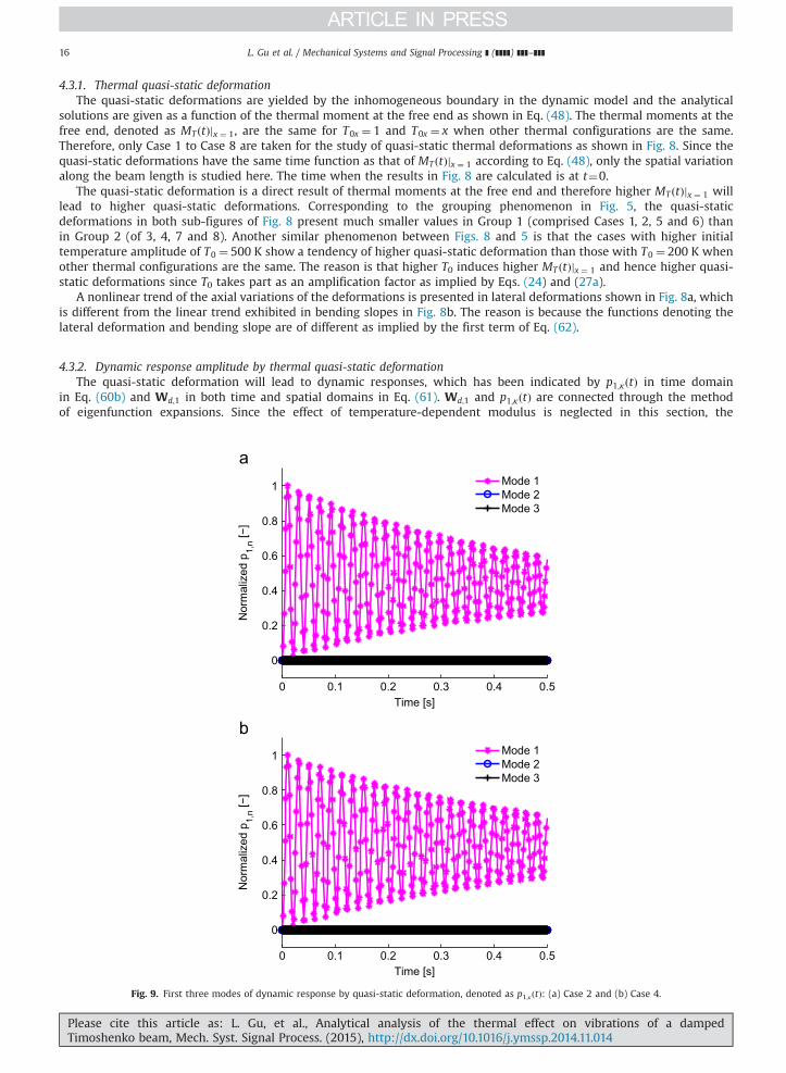
4.3.2. Dynamic response amplitude by thermal quasi-static deformationThe quasi-static deformation will lead to dynamic responses, which has been indicated by p1;κðtÞ in time domain
in Eq. (60b) and Wd;1 in both time and spatial domains in Eq. (61). Wd;1 and p1;κðtÞ are connected through the methodof eigenfunction expansions. Since the effect of temperature-dependent modulus is neglected in this section, the
0 0.1 0.2 0.3 0.4 0.5
0
0.2
0.4
0.6
0.8
1
Time [s]
Nor
mal
ized
p1,
n [−]
Mode 1Mode 2Mode 3
0 0.1 0.2 0.3 0.4 0.5
0
0.2
0.4
0.6
0.8
1
Time [s]
Nor
mal
ized
p1,
n [−]
Mode 1Mode 2Mode 3
Fig. 9. First three modes of dynamic response by quasi-static deformation, denoted as p1;κðtÞ: (a) Case 2 and (b) Case 4.
Please cite this article as: L. Gu, et al., Analytical analysis of the thermal effect on vibrations of a dampedTimoshenko beam, Mech. Syst. Signal Process. (2015), http://dx.doi.org/10.1016/j.ymssp.2014.11.014i

L. Gu et al. / Mechanical Systems and Signal Processing ] (]]]]) ]]]–]]] 17
eigenfunctions are the same for all cases. Therefore, the thermal effect on the vibration contributed by the quasi-staticdeformations can be reflected via the comparisons of p1;κðtÞ.
First of all, the dominance of mode number is studied. Taking Case 2 and Case 4 (configured in Table 3) for example, themodal response due to the quasi-static deformation is calculated based on Eqs. (60b) and (53). The results for both cases are
0 0.05 0.1 0.15 0.20
1
2
3
4
5
6x 10⁻⁵
Time [s]
Vib
ratio
n C
ompo
nent
of p
1,1 [−
]
Case 1 Case 2 Case 3 Case 4
0 0.05 0.1 0.15 0.20
0.2
0.4
0.6
0.8
1
1.2
1.4x 10⁻⁴
Time [s]
Vib
ratio
n C
ompo
nent
of p
1,1 [−
]
Case 5 Case 6 Case 7 Case 8
Fig. 10. p1;1 (first modal response) during initial 0.2 s: (a) Cases 1 to 4 and (b) Cases 5 to 8.
1 1.5 2 2.5 3 3.5 4
50
100
150
200
Mode Number [−]
Eig
enva
lueγ n [−
]
Case 1Case 2Case 3Case 4
Fig. 11. Thermal eigenvalues γn for Cases 1 to 4.
Please cite this article as: L. Gu, et al., Analytical analysis of the thermal effect on vibrations of a dampedTimoshenko beam, Mech. Syst. Signal Process. (2015), http://dx.doi.org/10.1016/j.ymssp.2014.11.014i

L. Gu et al. / Mechanical Systems and Signal Processing ] (]]]]) ]]]–]]]18
further normalized by dividing them with the maximum amplitude, as shown below:
Norm pð Þ ¼ pmaxð½p1; p2;…; pn�Þ
ð63Þ
The normalized results are plotted in Fig. 9 where Fig. 9a is for Case 2 and Fig. 9b for Case 4. Both results have shown thatthe first mode dominates the dynamic response induced by quasi-static thermal deformation. The 2nd and 3rd modes arevery small that the normalized amplitudes are almost zero in both cases. Therefore, the 1st mode, denoted by p1;κðtÞ, will befocused in the following comparisons.
Since the quasi-static deformations resulted from the thermal moment, p1;κðtÞ is therefore a result of the thermalmoment at the free end. Hence, either axially linear or constant T0x will lead to the same result with other thermalconfigurations fixed. Therefore, the comparisons of Case 1 to Case 8 are the same as those conducted for Case 9 to Case 16.Based on this, only half of the cases, i.e., Case 1 to Case 8 are studied here. The results for the initial 0.2 s are calculatedaccording to Eq. (60b) and shown in Fig. 10, where Fig. 10a is for cases with T0 ¼ 200 K and Fig. 10b for cases with T0 ¼ 500 K.
It is found in Fig. 10a that p1;κðtÞ increase in the case order of 4, 3, 1 and 2, which is opposite to the trend of temperaturegradients found at the initial moment as implied in Fig. 8. This phenomenon occurs because the thermal eigenvalues play asignificant role when the analysis is extended in the time domain. According to Ref. [31], the thermal moment varying overtime which has been introduced in Eq. (29a) can be rewritten as follows:
MT ¼ CMΔTe�εðγ2n þβ2mÞt ð64Þ
where ΔT is an index denoting the temperature gradients and CM is the coefficient of thermal moment. The thermaleigenvalue in x-dimension, denoted as βm, is the same for all cases since the thermal boundaries at the beam ends are fixed.However, the thermal configurations of H0
1 and H02 will influence the thermal eigenvalue in y-dimension, denoted by γn.
From Fig. 11, it is shown that γn increases in the order of Cases 1, 2, 4 and 3, which will induce the time-dependent term ofe�εðγ2n þβ2
mÞt increase in the order of Cases 3, 4, 2, and 1. However, p1;κðtÞ is dependent on the 1st time-derivative of MT ðtÞjx ¼ 1
0 20 40 60 80−0.5
0
0.5
1
1.5
2
Time [s]
Nor
mal
ized
p1,
1 [−]
Case 1Case 2Case 3Case 4
0 20 40 60 80−0.5
0
0.5
1
1.5
2
Time [s]
Nor
mal
ized
p1,
1 [−]
Case 5Case 6Case 7Case 8
Fig. 12. Normalized p1;1 (1st modal response by quasi-static deformation) in long run: (a) Cases 1 to 4, T0 ¼ 200 and (b) Cases 5 to 8, T0 ¼ 500.
Please cite this article as: L. Gu, et al., Analytical analysis of the thermal effect on vibrations of a dampedTimoshenko beam, Mech. Syst. Signal Process. (2015), http://dx.doi.org/10.1016/j.ymssp.2014.11.014i
L. Gu et al. / Mechanical Systems and Signal Processing ] (]]]]) ]]]–]]] 19
which is of the following form according to Eqs. (60b) and (53):
p1;κ tð ÞpdMT jx ¼ 1ðtÞdt
¼ �CMε γ2nþβ2m
� �ΔTe�εðγ2n þβ2
mÞt ð65Þ
where an additional term of ðεðγ2nþβ2mÞÞ is introduced due to the time derivative. This additional term will vary with γn as
well and influence the coefficient of p1;κðtÞ. As a result, the additional term will alter the variation trend of the time-dependent term of e�εðγ2n þβ2
mÞt with γn. Therefore, the confrontation of thermal eigenvalue and the temperature gradientsresult in the relative positions of the curves in Fig. 10a. A similar phenomenon is found in Fig. 10b, which can be accountedfor by the similar reason. It should be noted that the plot of thermal eigenvalues γn for Cases 5, 6, 7 and 8 is exactly the sameas Fig. 11 because the heat convection configurations in cases 1–4 are the same as in cases 5–8 as shown in Table 3.
In the situations of no additional heat input, the temperature gradients will decrease gradually, though with theexception of cases with H0
1 ¼ 0 and H02a0 m�1 (e.g., Case 1 and Case 2) which increase in the beginning and then become to
decrease after reaching the highest point. The general dropping trend of the temperature gradients makes the coefficient ofCM in Eq. (65) small enough and the eigenvalues become dominant upon certain transition time. Moreover, the time-dependent term of e�εðγ2n þβ2
mÞt will become extremely small after a long duration which will highlight the additional term inEq. (65). Following this evolution patten, the cases with larger γn tend to show larger vibration amplitude. Due to thecomplicated confrontations between the temperature gradients and thermal eigenvalues, the amplitude of p1;κðtÞ appears inthe ascending order of Cases 2, 1, 3 and 4 after the transition time around 20 s. Another important point regarding Fig. 12 isthe confirmation of the role that T0 plays in the thermal influence. The normalized p1;κðtÞ is utilized in both Fig. 12a and b.Although cases studied in Fig. 12a are of smaller T0 than in Fig. 12b, the same plots are presented in the two figures. Hence, itis demonstrated that T0 only influences the amplitude rather than the varying trend of p1;κðtÞ.
0 0.02 0.04 0.06 0.08 0.10
0.2
0.4
0.6
0.8
1
Time [s]
Nor
mal
ized
p2,
n [−]
Mode 1Mode 2Mode 3
0 0.02 0.04 0.06 0.08 0.10
0.2
0.4
0.6
0.8
1
1.2
Time [s]
Nor
mal
ized
p2,
n [−]
Mode 1 Mode 2 Mode 3
Fig. 13. First three modes of dynamic response by thermal force under T0x ¼ 1, denoted as p2;κðtÞ: (a) Case 2 and (b) Case 4.
Please cite this article as: L. Gu, et al., Analytical analysis of the thermal effect on vibrations of a dampedTimoshenko beam, Mech. Syst. Signal Process. (2015), http://dx.doi.org/10.1016/j.ymssp.2014.11.014i

L. Gu et al. / Mechanical Systems and Signal Processing ] (]]]]) ]]]–]]]20
4.3.3. Dynamic response amplitude by thermal forceThe vibration component contributed by the equivalent thermal shearing force is shown as the third term on the right-
hand side of Eq. (62). As discussed in the last section, the mode shapes are the same for all cases due to the negligence oftemperature effect on the elastic modulus. Therefore, only the corresponding modal response, denoted as p2;κðtÞ, is studiedin this section.
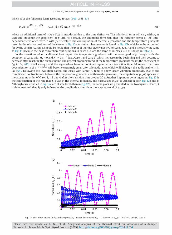
The sensitiveness of the modal response due to the equivalent thermal force is investigated primarily. Different fromp1;κðtÞ, p2;κðtÞ should be investigated for cases of both T0x ¼ 1 and T0x ¼ x because thermal forces are different under the twosituations. Cases 2 and 4 are taken for example in the study of mode sensitiveness of p2;κðtÞ for cases with constant T0x, asshown in Fig. 13 where the normalization procedure in Eq. (63) is employed. It is found that the 1st mode still dominates theresponse. However, the 2nd mode plays an important part as well since its amplitude is too big to be neglected. Modeshigher than the third one are negligible due to almost zero amplitude shown in the figure. Furthermore, the amplitudevariations over time present a slight difference between Fig. 13a and b. This difference can be ascribed to that thetemperature gradients develop differently in Case 2 and Case 4, which can be implied by Fig. 5.
The modal sensitiveness has a different trend for cases with linear T0x, as exhibited in Fig. 14, where Case 10 and Case 12are taken for example. The 1st modal response by thermal force is found much more significant than other modes in bothsub-figures. The 2nd and the higher modes almost approach zero, which implies that they can be discarded in the furtherinvestigation. It is found that the 2nd mode is much less significant in Fig. 14 than in Fig. 13, which is due to that the casesstudied in Fig. 14 have much lower axial-variations of temperature field at the clamped end. This finding provides an insightin related applications that the thermal vibrations can be roughly evaluated by only focusing on the 1st mode when thetemperature variation along the length is very slow.
The 1st and 2nd modes have been found to be dominant modal responses for cases of T0x ¼ 1 and the 1st mode to bedominant for cases of T0x ¼ x. Consequently, it will be studied how the three dominant modal responses are influenced bydifferent thermal configurations. It has been demonstrated that the parameter T0 configured in Table 3 acts as an
0 0.02 0.04 0.06 0.08 0.1−0.2
0
0.2
0.4
0.6
0.8
1
1.2
Time [s]
Nor
mal
ized
p2,
n [−]
Mode 1Mode 2Mode 3
0 0.02 0.04 0.06 0.08 0.1−0.2
0
0.2
0.4
0.6
0.8
1
1.2
Time [s]
Nor
mal
ized
p2,
n [−]
Mode 1 Mode 2 Mode 3
Fig. 14. First three modes of dynamic response by thermal force under T0x ¼ x, denoted as p2;κðtÞ: (a) Case 10 and (b) Case 12.
Please cite this article as: L. Gu, et al., Analytical analysis of the thermal effect on vibrations of a dampedTimoshenko beam, Mech. Syst. Signal Process. (2015), http://dx.doi.org/10.1016/j.ymssp.2014.11.014i

L. Gu et al. / Mechanical Systems and Signal Processing ] (]]]]) ]]]–]]] 21
amplification factor and has no impact on the varying trend of the modal responses. Hence, cases with single value of T0, e.g.,T0 ¼ 200 K, will be utilized for the comparisons. According to the different configurations of T0x, cases of T0x ¼ 1 and T0x ¼ xare compared in separate sub-figures in Fig. 15. It is observed in Fig. 15a and b that the absolute amplitudes of both the 1st
0 0.02 0.04 0.06 0.08 0.1
−1
−0.5
0
0.5
1
x 10
Time [s]
Vib
ratio
n C
ompo
nent
of p
2,1 [−
]
Case 1Case 2Case 3Case 4
0 0.02 0.04 0.06 0.08 0.10
0.5
1x 10
0 0.01 0.02 0.03 0.04 0.05
−6
−4
−2
0
2
4
6
8x 10
Time [s]
Case 1Case 2Case 3Case 4
0 0.01 0.02 0.03 0.040
1
2
x 10
0 0.02 0.04 0.06 0.08 0.1−0.04
−0.03
−0.02
−0.01
0
0.01
0.02
0.03
0.04
Time [s]
Vib
ratio
n C
ompo
nent
of p
2,1 [−
]
Case 9Case 10Case 11Case 12
0 0.02 0.04 0.06 0.08 0.10
2
4
6
x 10
Vib
ratio
n C
ompo
nent
of p
2,2 [−
]
Fig. 15. The modal responses by equivalent thermal force for cases of T0¼200 K: (a) 1st mode for Cases 1 to 4 under T0x ¼ 1, (b) 2nd mode for Cases 1 to 4under T0x ¼ 1 and (c) 1st mode for Cases 9 to 12 under T0x ¼ x.
Please cite this article as: L. Gu, et al., Analytical analysis of the thermal effect on vibrations of a dampedTimoshenko beam, Mech. Syst. Signal Process. (2015), http://dx.doi.org/10.1016/j.ymssp.2014.11.014i

L. Gu et al. / Mechanical Systems and Signal Processing ] (]]]]) ]]]–]]]22
and 2nd modes for cases of T0x ¼ 1 increase in the order of Cases 1, 2, 3 and 4. This observation is corresponding to thethermal shearing forces of the respective cases as shown in Fig. 6a, i.e., higher shearing force yielding larger vibrations. Asimilar trend is found in Fig. 15c that cases of T0x ¼ x increase in the case order of 9, 10, 11 and 12 which is corresponding tothe ascending case order of the thermal shearing forces shown in Fig. 6b. The correspondence found between Figs. 15 and 6reveals that the thermal configurations leading to higher excitation forces will result in higher modal responses.
The relationships of the vibration amplitudes shown in Fig. 15 are limited at the initial stage. They may change over timedue to the fact that the thermal shearing force is time-varying. Therefore, the modal response varying in a rather longduration is further presented in Fig. 16, where a very rough step (compared to the modal response period) is chosen. Theabsolute values of p2;1ðtÞ show a trend of increase in the beginning and then become to decrease after certain point for caseswith H0
1 ¼ 0 and H02a0 m�1, which are Cases 1 and 2 in Fig. 16a and Cases 9 and 10 in Fig. 16b. This phenomenon is caused
by the temperature gradients which show a similar variation trend with time as revealed by the corresponding plots shownin Fig. 5. A general decrease trend of the absolute value of p2;1ðtÞ is shown for Cases 3 and 4 in Fig. 16a and of Cases 11 and12 in Fig. 16b. The continuous drop of the four cases is caused by the general decrease of temperature gradients as impliedby Fig. 5.
In conclusion, the dynamic responses due to shearing force are dominated by the 1st mode and sometimes the 2nd modeis non-ignorable when the temperature distribution has drastic variations along the length. The time-varying responsesexhibit bigger values in the beginning in the cases with both top and bottom surfaces contributing to the temperaturegradients. The vibration trend will change in long run when no additional heat is input, which is corresponding to the time-varying trend of the temperature gradients.
4.3.4. Vibration periodsThe elastic modulus is treated as independent of the temperature, as a result the change of the vibration periods will be
purely contributed by the thermal excitations. It has been observed that the vibration periods in the dynamic responses
0 50 100 150 200−1
−0.8
−0.6
−0.4
−0.2
0
Time [s]
Nor
mal
ized
p2,
1 [−] Case 1
Case 2Case 3Case 4
0 50 100 150 200−1
−0.8
−0.6
−0.4
−0.2
0
Time [s]
Nor
mal
ized
p2,
1 [−]
Case 9Case 10Case 11Case 12
150 160 170−0.32
−0.3−0.28
Fig. 16. Normalized p2;1ðtÞ (1st modal response by thermal force) in long run: (a) Cases 1–4 and (b) Cases 9–12.
Please cite this article as: L. Gu, et al., Analytical analysis of the thermal effect on vibrations of a dampedTimoshenko beam, Mech. Syst. Signal Process. (2015), http://dx.doi.org/10.1016/j.ymssp.2014.11.014i

0 0.05 0.1 0.15
−4
−2
0
2
4
6
x 10−4
Time [s]
Late
ral D
imen
sion
less
Vib
ratio
n [−
] Case 1Case 2Case 3Case 4
0 0.05 0.1 0.15−3
−2
−1
0x 10
0 0.05 0.1 0.15
−5
0
5
10
15
20
25x 10−4
Time [s]
Dim
ensi
onle
ss V
ibra
tion
[−]
Case 1Case 2Case 3Case 4
0 0.05 0.1 0.15−4
−2
0
x 10
Fig. 17. The vibrations at x¼1 for Cases 1 to 4, where T0x ¼ 1 and T0 ¼ 200 K: (a) lateral vibrations and (b) bending-slope.
L. Gu et al. / Mechanical Systems and Signal Processing ] (]]]]) ]]]–]]] 23
shown in Figs. 13 and 14 are almost the same for the same mode of all cases. Thanks to the extremely slow thermalvariations, the time-dependent component in the thermal forces is too faint to generate forced vibrations. To demonstratethis point, the vibrations of the free end are calculated based on Eqs. (61), (60b), and (60c).
Taking cases of lower initial temperature gradients, which are Cases 1–4 and 9–12 in Table 3, for instance, both the lateraland bending-slope vibrations at the free end are plotted. The results are shown in Figs. 17 and 18. The vibration periods forall cases in both figures are around 0.02 s, which is very close to the reciprocal of the 1st natural frequency introduced inTable 2. Via the comparisons between Figs. 17 and 18, it is found that the vibration in the beginning for Cases 1–4 is irregular,in which periodic vibrations are obscure. Whereas, the vibrations for Cases 9–12 present with clear periodic oscillations. Thedifference in the two figures occurs due to that the axial temperature distributions have a drastic change close to theclamped end in Cases 1–4 as has been explained before. The rapid axial temperature variation at the clamped end in Cases1–4 yields bigger shearing force and further much bigger dynamic responses in the clamped end than other parts along thelength. Nevertheless, this unstable factor is suppressed by the damping effect and the vibrations are soon led to regularlyperiodic behavior shortly after four to five periods. The periods for all cases are the same as the one of the 1st modeof vibration.
5. Conclusions
The work presents a theoretical investigation of the thermal effect on a Timoshenko-beam considering the dampingeffect. The analytical solutions were derived for both the temperature field and the vibrations, which are coupled via thetemperature-dependent modulus and the equivalent thermal forces. The numerical data based on the analytical solutions
Please cite this article as: L. Gu, et al., Analytical analysis of the thermal effect on vibrations of a dampedTimoshenko beam, Mech. Syst. Signal Process. (2015), http://dx.doi.org/10.1016/j.ymssp.2014.11.014i

0 0.05 0.1 0.15
−0.02
−0.01
0
0.01
0.02
Time [s]
Late
ral D
imen
sion
less
Vib
ratio
n [−
] Case 9Case 10Case 11Case 12
0 0.05 0.1 0.15
−2
0x 10
0 0.05 0.1 0.15
−0.03
−0.02
−0.01
0
0.01
0.02
0.03
Time [s]
Dim
ensi
onle
ss V
ibra
tion
[−]
Case 9Case 10Case 11Case 12
0 0.05 0.1 0.15
−4
−2
0x 10
Fig. 18. The vibrations at x¼1 for Cases 9 to 12, where T0x ¼ x and T0 ¼ 200 K: (a) lateral vibrations and (b) bending-slope.
L. Gu et al. / Mechanical Systems and Signal Processing ] (]]]]) ]]]–]]]24
are given for the illustration of the thermal effect on dynamic behaviors. Based on the results, some conclusions can be thusdrawn as follows:
(1)
PlTi
For a cantilever Timoshenko beam, it is generally found that the lower modes are more sensitive to temperaturevariations and the 1st frequency exhibits the biggest drop when the temperature rises. As a result of the frequencyreduction with the elevated temperature, the relatively maximum vibration difference along the length is enlarged.
(2)
The thermal moment at the free end MT ðtÞjx ¼ 1 is the root causes of the quasi-static deformations which further arousespart of the dynamic responses. The other excitation source of the thermal vibration is originated from the equivalentshearing force. Both the two thermal excitations exhibit higher values at higher temperature gradients. In addition tothat, the equivalent shearing force is influenced by the axial temperature distributions as well.(3)
The time-dependent dynamic responses induced by the thermal moment are determined by the combination impact ofthe cross-sectional temperature gradients and the thermal eigenvalues. However, the responses generated by thethermal shearing forces can be determined by the temperature gradients alone.(4)
The 1st modal response by thermal forces is found to present much higher amplitudes than other modes. Therefore, thehigher modes are regarded as negligible with an exception that the second modal response is noneligible when casesexhibit very rapid variations along the beam length.(5)
The periods remain the same for all thermal cases when temperature-independent modulus is adopted, which is causedby the very slow variations of thermal process with time.Acknowledgments
The research presented in this paper has been supported by Natural Science Foundation of China (Grant no. 11272170).
ease cite this article as: L. Gu, et al., Analytical analysis of the thermal effect on vibrations of a dampedmoshenko beam, Mech. Syst. Signal Process. (2015), http://dx.doi.org/10.1016/j.ymssp.2014.11.014i

L. Gu et al. / Mechanical Systems and Signal Processing ] (]]]]) ]]]–]]] 25
References
[1] J.R. Blandino, E.A. Thornton, Thermally induced vibration of an internally heated beam, J. Vib. Acoust. 123 (2001) 67–75.[2] N. Marakala, A. Kuttan KK, R. Kadoli, Thermally induced vibration a simply supported beam using finite element method, Int. J. Eng. Sci. Technol. 2
(2010) 7874–7879.[3] E.A. Thornton, Thermal structures for aerospace applications, American Institute of Aeronautics and Astronautics, Inc, Reston, Virginia, 1996.[4] W. Li, Z. Xiang, L. Chen, M. Xue, Thermal flutter analysis of large-scale space structures based on finite element method, Int. J. Numer. Methods Eng. 69
(2007) 887–907.[5] J.S. Rao, Turbomachine Blade Vibration, 4th edition, New Age International (P) Ltd., New Delhi, 1991.[6] A. Rahmani, Modal analysis of a first stage blade in Alstom gas turbine and comparison with experimental results, World Sci. J. 03 (2013) 39–45.[7] W. Pei, D. Zhang, J. Zhang, Vibration property analysis of turbocharger turbine blade under different loads, in: The 4th International Symposium on
Fluid Machinery and Fluid Engineering, Beijing, 2008, no. 4ISFMFE-Ch23.[8] J.S. Tomar, R. Jain, Thermal effect on frequencies of coupled vibrations of pretwisted rotating beams, AIAA J. 23 (8) (1985) 1293–1296.[9] S. Na, L. Librescu, H. Jung, Dynamics and active bending vibration control of turbomachinery rotating blades featuring temperature-dependent
material problems, J. Thermal Stress 27 (2004) 625–644.[10] J.S. Tomar, R. Jain, Thermal effect on frequencies of coupled vibrations of a rotating beam of linearly varying semi-circular cross-section, J. Sound Vib.
95 (1) (1984) 1–7.[11] J. Chen, B. Young, B. Uy, Behavior of high strength structural steel at elevated temperatures, J. Struct. Eng. 132 (12) (2006) 1948–1954.[12] W. Zhang, H. Chen, D. Zhu, X. Kong, The thermal effects on high-frequency vibration of beams using energy flow analysis, J. Sound Vib. 333 (9) (2014)
2588–2600.[13] J. Avsec, M. Oblak, Thermal vibrational analysis for simply supported beam and clamped beam, J. Sound Vib. 308 (3–5) (2007) 514–525.[14] A.E. Alshorbagy, Temperature effects on the vibration characteristics of a functionally graded thick beam, Ain Shams Eng. J. 4 (3) (2013) 455–464.[15] E. Ergun, V. Alkan, Assessment of thermal effects on the free vibration characteristics of composite beams, Mater. Test. 56 (1) (2014) 59–64.[16] J. Kidawa-Kukla, Vibration of a beam induced by harmonic motion of a heat source, J. Sound Vib. 205 (2) (1997) 213–222.[17] B.A. Boley, Theory of Thermal Stresses, Wiley, New York, 1960.[18] B.A. Boley, Thermally induced vibrations of beams, Trans. ASME 23 (2) (1956) 179–181.[19] D.W. Gulick, E.A. Thorton, Thermally-induced vibrations of a spinning spacecraft boom, Acta Astron. 36 (3) (1995) 163–176.[20] J. Kidawa-Kukla, Thermally induced vibration of a cantilever beamwith periodically varying intensity of a heat source, J. Appl. Math. Comput. Mech. 12
(4) (2013) 59–65.[21] W.C. Lyons, Comments on heat induced vibrations of elastic beams, plates and shells, AIAA J. 4 (8) (1966) 1502–1503.[22] G.D. Manolis, D.E. Beskos, Thermally induced vibrations of beam structures, Comput. Methods Appl. Mech. Eng. 21 (1980) 337–355.[23] J. Kidawa-Kukla, Application of the Green functions to the problem of the thermally induced vibration of a beam, J. Appl. Math. Comput. Mech. 262 (4)
(2003) 865–876.[24] E.A. Thornton, Y. Kim, Thermally-induced bending vibrations of a flexible rolled-up solar-array, J. Spacecr. Astron. 30 (1997) 438–448.[25] B.A. Boley, Approximate analyses of thermally induced vibrations of beams and plates, J. Aeronaut. Sci. (1972) 212–216.[26] S. Na, L. Librescu, H. Jung, I. Jeong, Thermally induced vibration control of composite thin-walled rotating blade, in: The 24th International Congress of
the Aeronautical Sciences, Yokohama, Yokohama, 2004. pp. 1–9.[27] S.Y. Oh, L. Librescu, O. Song, Vibration of turbomachinery rotating blades made-up of functionally graded materials and operating in a high
temperature field, Acta Mech. 166 (2003) 69–87.[28] S.M. Han, H. Benaroya, T. Wei, Dynamics of transversely vibrating beams using four engineering theories, J. Sound Vib. 225 (5) (1999) 935–988.[29] M. Petyt, Introduction of Finite Element Vibration Analysis, 2nd edition, Cambridge University Press, United Kingdom, 2010.[30] M.N. Ozisik (Ed.), Heat Conduction, John Wiley & Sons, Inc, New York, 1993.[31] L. Gu, F. Chu, An analytical study of rotor dynamics coupled with thermal effect for a continuous rotor shaft, J. Sound Vib. 333 (2014) 4030–4050.
Please cite this article as: L. Gu, et al., Analytical analysis of the thermal effect on vibrations of a dampedTimoshenko beam, Mech. Syst. Signal Process. (2015), http://dx.doi.org/10.1016/j.ymssp.2014.11.014i