Texture of Rotary-Friction-Welded from Dissimilar Medium ...
Upload
khangminh22Category
view
2download
0
ANALYSIS OF THE EFFECT OF DISSIMILAR WELDING ON A HIGH PRESSURE FLARESTACK
Mahdi E. Mahmoud, M. Harun, Zaifol Samsu, Norasiah Kasim, Zaiton Selamat & K.H. AlahuddinMalaysian Nuclear Agency, Bangi, 43000, Kajang, Malaysia
Tel: 03-89250510 ext. 1566 mahdiezwan @ nuclearmalavsia. gov.mv
Abstract
A flare stack is an elevated vertical stack found in a natural gas processing plant, used primarily fo r combusting waste gases released by pressure relief valves. The materials used fo r our high pressure flare tip are carbon steel (CS) type A516 Gr. 55 fo r its lower portion, and stainless steel (SS) 310 fo r its upper portion. Both were combined into a single unit by arc welding (dissimilar welding), with SS310 as a base metal. After 5 years o f operations, few mechanical deformations were observed on the flare stack, along with corrosion deposit on the CS portion o f the flare. Detailed analysis shows the presence o f toe and shrinkage cracks, along with spheroidization ofpearlite in the CS. These are caused by factors such as mismatched welding and coefficient o f thermal expansion (CTE) between the metals. These factors helped exacerbate crack initiation and propagation. Based on the evidence collected, it is recommended that the CS A516 be replaced with SS310.
Keywords: High pressure flare stack, Heat Affected Zone, toe cracks, shrinkage cracks
Introduction
A flare stack is an elevated vertical stack found in a natural gas processing plant. It is usually made of stainless steel, carbon steel or a mixture of both and its primary function is combusting waste gases released by pressure relief valves. Therefore, it is usually located a bit further from the main part of the plant to avoid these activities from interfering with operations. The gases are combusted as they exit the flare stacks, and this exposes the flare tip to high temperatures. These conditions are cyclic in nature due to the continuous changes in wind speed, directions and gas flow rates in the surrounding of the flare stack.
The size and brightness of the resulting flame depends upon how much flammable material is being released. There are two types of burning on the flare tip, namely internal and external burning. Internal burning occurs under low gas velocity in existing windy conditions. Under these conditions, the stream of waste gases will inadvertently combine with the air near the outlet of the flare tip, and when this mixture is ignited, internal burning occurs. Similarly, external burning occurs when a flame impinges on the external surface of a flare tip. This phenomenon, however, occurs at modest waste gas flow rates under windy conditions. When internal burning or external burning occurs, the flare tip is exposed to high temperatures in a predominantly reducing atmosphere [1,2].
Welding is a process used to join materials (metals or thermoplastics) by using coalescence. There are many type of welding processes such as arc welding, cold welding, submerged arc welding and electroslag welding, and these welding techniques employs many tools and materials. Welding allows us compartmentalize fabrication and combine smaller pieces to form a larger structure, without the hassle of fabricating a large structure at once, which will require a large space and a large amount of energy. A flare stack, being long and large in size, is welded together using the arc welding technique. Arc welding creates an electric arc between an electrode and a base metal to melt the materials at the welding point. In the case of flare stack, the welded units can be of similar or different metals, depending on the applications and environments. Since welding is a process that involves high temperature and the joining of two

metals of similar or dissimilar nature, some welding failures are bound to occur, whether immediately after the welding process or after some operation time. Common failure(s) in welding includes cold and hot cracking, root cracking and toe cracking [3].
Figure 1: HP flare stack
The objective of this analysis is to identify the types of failure that exist in a welded (dissimilar) high pressure flare stack in a reducing atmosphere, determine the cause of failure and to propose solution(s) to overcome these problems.
Experimental methods
The portion of the high pressure (HP) flare stack that was showing signs of damage after 5 years of operations was excised, and thorough visual examinations were performed. Damages and failure regions were identified and marked, with detailed photographs taken. This slab was then sectioned into many pieces, cut into long strips with a width of 2 cm each. From these strips, a 2x2 cm cube is sectioned at the upper and lower portions, for spark emission spectroscopy to determine chemical composition. Extra pieces with similar dimensions were sectioned, and mounted using standard methods for macroscopic examinations using light optical microscopy (LOM). Sections that showed cracks and visible damages were isolated and analyzed using a FEI Quanta Scanning electron microscope (SEM) equipped with an Energy dispersive X-Ray (EDAX) Analysis for microscopic analysis.

Results
• Visual Examinations
Visual examinations involve a cursory inspection at the damaged region on the shell. Telltale signs of corrosion was absent from the top portion, while red splotches (N region) are prominent on the bottom portion of the sample. The sample also seems slightly bulged at certain points, although this was deliberate on the part of the manufacturer to counter possible bulging due to exposure to high temperature. The welded region seem to be unaffected by the corrosion deposits or mechanical deformations.
• Chemical Composition test
A chemical composition test was conducted on small cubic samples (2x2), sectioned from the plate, using spark emission spectroscopy, to determine existing elements in the samples. The spark emission spectroscopy was conducted by Nusantara Tech Sdn. Bhd. in Shah Alam, Selangor. Tables 1 and 2 list the results of the chemical compositions for the bottom and the top portion of the shell respectively.
Element Sample (wt. %) A516, Gr.55 (wt. %)
Fe 98.29C 0.134 0.18-0.26Si 0.21 0.15-0.30
Mn 0.95 0.60-0.90P 0.008 0.035 maxS 0.009 0.04 max
Cr 0.05
Table 1: Results from spark emission spectroscopy test on the bottom portion of the shell

Element Sample (wt. %) Stainless Steel__________________________________________Grade 310 (wt. %)Fe 52.63C 0.04 0.25 maxSi 0.45 1.00 maxMn 1.51 2.00 maxP 0.0177 0.045 maxS 0.0018 0.030 maxCr 24.63 24.00-26.00Mo 0.151 -
Ni 20.10 19.00-22.00
Table 2: Results from the spark emission spectroscopy on the top portion of the shell
From the results, it is surmised that the bottom portion of the shell is CS A516, Gr.55, while the top portion is SS 310 [4].
• Scanning Electron Microscopy and microanalysis
Carbide spheroidization at N (CS region, refer to Fig. 2) can be seen clearly in the SEM micrographs as shown throughout Fig. 3-5, also shows decarburization and grain boundary cracking at the inner surface, with carbide particles precipitating along the grain boundary. In the middle of the cross sectional tube, the lamellar carbide of pearlites have been spheroidized as seen in Fig. 4. The carbide have completely spheroidized at the outer surface of the tube (Fig. 5).
..
l : . j f L . 'hun/jtion
S : * y j f
' . . A
W D I Mag I VacMode Spot HV 2/3/2010 9.4 mm j 10OOx| High vacuum 3.0 30.0 kV 5:11:45 PM
'-----20.0um----- -inner surface
Figure 3: Cross-section along thickness on surface, X1K
Figure 4: Cross section along thickness at the middle, X2K

Element Sample (wt. %) Stainless Steel___________________________________ Grade 310 (wt. %)
Fe 52.63C 0.04 0.25 maxSi 0.45 1.00 maxMn 1.51 2.00 maxP 0.0177 0.045 maxS 0.0018 0.030 maxCr 24.63 24.00-26.00Mo 0.151 -Ni 20.10 19.00-22.00
Table 2: Results from the spark emission spectroscopy on the top portion of the shell
From the results, it is surmised that the bottom portion of the shell is CS A516, Gr.55, while the top portion is SS 310 [4].
• Scanning Electron Microscopy and microanalysis
Carbide spheroidization at N (CS region, refer to Fig. 2) can be seen clearly in the SEM micrographs as shown throughout Fig. 3-5, also shows decarburization and grain boundary cracking at the inner surface, with carbide particles precipitating along the grain boundary. In the middle of the cross sectional tube, the lamellar carbide of pearlites have been spheroidized as seen in Fig. 4. The carbide have completely spheroidized at the outer surface of the tube (Fig. 5).
" .. - 7Gum HouiuLux Clacking * ^ B 1
I_____ J j
' * ^ 8̂ * * iff* s* <■ - —
Grain Boundary j Carbides
___________________■
W D M a g j V a c M o d e S p o t H V 2 /3 /2 0 1 0
9 .4 m m 1 0 0 0 x H ig h v a c u u m 3 .0 3 0 .0 k V 5 :1 1 :4 5 P M
■—20.0iim— in n e r s u r fa c e
Figure 3: Cross-section along thickness on surface, XIK
Figure 4: Cross section along thickness at the middle, X2K

Figure 5: Cross Section along thickness at outer ______________ surface, X2K______________
• Macroscopic and microscopic analysis
Transverse cross-section macrograph of the weld region is shown Fig. 6.The weld joining excellent on the SS portion. However, cracks were detected on the inner and outer surface at the interface between the WM and the heat-affected zone of the CS. These cracks are in the vicinity of the unmatched border(s) of the WM and the CS, while no such cracks are visible in the SS-WM border(s).
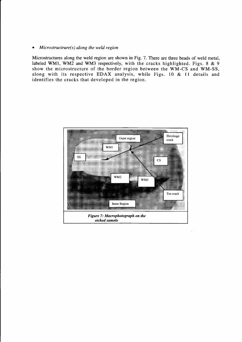
• Microstructrure(s) along the weld region
Microstructures along the weld region are shown in Fig. 7. There are three beads of weld metal, labeled WM1, WM2 and WM3 respectively, w ith the cracks h ig h lig h ted . F igs. 8 & 9 show the m ic ro s tru c tu re o f the b o rder reg ion betw een the W M -CS and W M -SS, along w ith its re sp ec tiv e EDAX an alysis , w hile F igs. 10 & 11 d e ta ils and id en tifie s the cracks tha t developed in the reg ion .

Figure 8: Microstructure at the interface between SS-WM1 X80, matching borders, with EDX analysis of both sides_________________________
Figure 9: Microstructure at the interface between WM1-CS X80, separate borders, with EDX analysis of CS_____________________________
Figure 10: Crack at interface between WM (un-etched) and CS, X50, crack length is about 1 mm, identified as toe cracking____________________________________
Figure 11: Tip of hole between two beads of weld metal, at left side, X80, identified as shrinkage cracks

Discussion and Analysis
Fig. 2 & 6 shows that the high pressure flare stack is starting to undergo failure propagation, and this is supported by the presence of corrosion deposits (red splotches) on the surface of the CS. This is also supported by the fact that small cracks were detected during macroscopic analysis (Fig. 6) on the CS region bordering the WM. The cracks formed perpendicular to the vessel axis, and this might be due to thermal stresses, induced by continuous vibration under high temperature operations [5].
The spheroidal carbides were detected along the grain boundaries of the CS (Fig. 3-5) due to the continuous heating effect, where it might have been heated at 20 to 30°C above the austenite temperature (Ac). For low alloying, with 0.10-0.55%C, the Ac is 751°C. Spheroidized structures allow severe plastic and forming deformations [5, 6]. Based on damage classes, the material has been in Class C, with its spheroidization completed, but its carbide is still grouped in with their original pearlite grains (Fig. 4-5). This proves that the flare stack was exposed to continuous cyclic heating for a long period time just a little above the tolerance temperature for the structure that facilitated in the occurring phenomena observed.
Macroscopic analysis shows cracks at borders of WM-CS and in the middle of WM (Figs. 7-11). The crack in Fig. 7 is identified as a toe crack [7], and the length for both cracks were about 1 mm (Fig. 10). The cracks were initiated at the surface notch and it propagated inward, perpendicular to the vessel axis. This is due to the thermal stresses that resulted from the unmatched welding and a difference in the linear coefficient of thermal expansion for both metals. The SS310 has a linear CTE of 15.9 - 18.9 um/m°C for a temperature range of 500°C and above while the CS A516 Gr. 55 (AISI 1013) has a linear CTE of 11-16.6 um/m°C for similar temperature ranges. The linear CTE causes both parts to expand at different rates, thus creating stress concentration(s) at the border region between the welding. Additionally, the unmatched welding border further allows the CS region to expand further, and potentially separates itself of from the weldment. This contributes to the crack formation at these respective borders as observed in Figs. 6 & 7.
A large hole was detected in the weld bead at the interface between WM1 and WM2 (Fig. 7) and its formation may be due to escaped gases during solidification of the weld during welding. The gases came from the weld torch used during welding (most probably H2), and during solidification, the gases are trapped inside the WM, creating an internal hole, which is only visible when that particular region is sectioned and exposed. The hole is shown in Fig. 11, and this type of crack is called a shrinkage crack [8].
Conclusions & Recommendation(s)
The bottom portion of the shell was identified as CS A516 Gr. 55 and the top portion was SS310, while the WM was identified as SS310. Microscopic analysis of the shell showed that the WM bonded well with the SS but not with the CS, and this inadvertently leads to cracks forming at the region between the WM and the HAZ of the CS. There were also cracks detected in the weld metal (toe and shrinkage cracks) that was due to welding defects and operating conditions on the flare stack. Toe cracks formed due to thermal stresses that developed due to a large mismatch in the linear CTE, while the shrinkage crack formed by the escaped gases during welding solidification. To avoid these failure(s) in the future, it is recommended that the CS portion of the HP flare stack be replace with SS310 using the same electrode materials.
Acknowledgement
We would like to thank Dr Abd. Nassir Ibrahim, Director of Industrial Technology Division, and Dr Azali Muhamad, Head of Materials Technology Group of the Malaysian Nuclear Agency. We would also like to thank the Customer Services Department of Malaysian Nuclear Agency for their financial support.
References
1. John F. Straitz, III. Flare Stack Gas Burner. United States Patent 3822985. July 9, 1974.
2. David Shore "Making the Flare Safe" J. Loss Prev. Process Ind. Vol. 9. No. 6. pp. 363-381, 1996
3. V. J. Colangelo, F. A. (1974). Analysis of Metallurgical Failures. Troy, New York: Wiley.
th4. American Society of Metals "Atlas of Microstructures of industrial alloys" Metals Handbook, 8 Edition, pp. 18- 27
5. Prakash, K. Krishnaprasad and Raghu V. "Fatigue Crack Growth Behavior in Dissimilar Metal Weldment ofStainless Steel and Carbon Steel." World Academy of Science, Engineering and Technology, 2009: 873-879.
6. Her-Hsiung Huang, Wen-Ta Tsai, Ju-Tung Lee "Cracking characteristics of A516 steel weldment in H2Scontaining environments" Materials Science and Engineering , Volume 188, Issues 1-2, 30 November 1994, 219227
7. M.L. Holland "Unusual cases of weld associated cracking experienced in high temperature catalyst reduction behavior." Engineering Failure Analysis, Vol. 5, No. 2, 1998: 171-180
8. V SHANKAR, TPS GILL, S L MANNAN and S SUNDARESAN -Solidification cracking in austenitic stainless steel welds S~adhan~a Vol. 28, Parts 3 & 4, June/August 2003, pp. 359-382.
Copyright © 2022 FDOKUMEN