ImageAdmixture: Putting Together Dissimilar Objects from Groups
9
ImageAdmixture: Putting Together Dissimilar Objects from Groups Fang-Lue Zhang, Ming-Ming Cheng, Member, IEEE, Jiaya Jia, Senior Member, IEEE, and Shi-Min Hu, Member, IEEE Abstract—We present a semiautomatic image editing framework dedicated to individual structured object replacement from groups. The major technical difficulty is element separation with irregular spatial distribution, hampering previous texture, and image synthesis methods from easily producing visually compelling results. Our method uses the object-level operations and finds grouped elements based on appearance similarity and curvilinear features. This framework enables a number of image editing applications, including natural image mixing, structure preserving appearance transfer, and texture mixing. Index Terms—Natural image, structure analysis, texture, image processing Ç 1 INTRODUCTION I MAGE analysis and editing provide an important approach to producing new content in computer graphics. We propose here a dedicated system for users to replace structured objects selected from groups while preserving element integrity and providing visual compatibility. It proffers an unconventional way to create new image content with structured objects, even when they are irregularly arranged. The objects are allowed to be dissim- ilar in appearance and structure, as shown in Fig. 1. Image and texture synthesis from multiple exemplars have been explored in previous work. Pixel-level texture approaches make use of similar statistical properties to generate new results [4], [9], [45]. Patch-based texture synthesis [14] is another set of powerful tools to selectively combine patches from different sources [23]. Recently, Risser et al. [35] employed multiscale neighborhood information to extend texture synthesis to structured image hybrids. They are useful for creating new image or texture results based on examples. These methods are general; but in the context of object replacement within groups, they may not be able to produce visually plausible effects without extensive user interaction. Grouped elements can be rapidly and integrally perceived by the human visual system (HVS) [21], which indicates only considering pixel- or patch-level operations may not be enough to understand the individual structured element properties. Our system is composed of object-level editing algorithms and does not assume any particular texture form or near-regular patterns. Our major objective is to deal with natural images containing piled or stacked objects, which are common in real scenes, from the individual perspective. The naturalness of element replacement depends on the compatibility of input and the result structures. It is measured in our system by the element-separability scores, combining curvilinear features and multiscale appearance similarity. Objects are extracted based on these metrics, with initial center detection followed by a Dilate-Trim algorithm to form complete shapes. Our method also finds suitable candidates for element replacement to ensure the result quality. Our main contribution lies in an object-level manipulation method without regularity assumption and on a new scheme to measure object structure compatibility. 2 RELATED WORK Image composition is a well-studied problem in computer graphics. Early work of Porter and Duff [33] used an alpha matte to composite transparent objects. Recent advance in alpha matting [41], [42] made it possible to generate natural and visually plausible image composite with global or local operation. For our problem, directly apply alpha matting to replace one object by another can generate visual artifacts when illumination conditions vary. Poisson blending [32] and its variations reduce color mismatching by computa- tion in the gradient domain. Farbman et al. [16] achieved similar composition results efficiently. Research efforts have also been made to select candidates for composition from image database [25] or internet images [10], which was applied to create a fantastic artform called Arcimboldo-like collage in [11]. Such methods minimize composition artifacts while keeping the original object shape complete. In our problem, it is essential to seek proper image content to replace items in groups via compatible structures. We also do not simply copy the whole region to the target image for blending. There are procedures to refine boundaries to improve the visual quality of the results when in common situations that the found source and target objects are diverse in structure. IEEE TRANSACTIONS ON VISUALIZATION AND COMPUTER GRAPHICS, VOL. 18, NO. 11, NOVEMBER 2012 1849 . F.-L. Zhang, M.-M. Cheng, and S.-M. Hu are with the TNList, Tsinghua University, Beijing 100084, China. E-mail: [email protected], [email protected], [email protected]. . J. Jia is with the Department of Computer Science and Engineering, The Chinese University of Hong Kong, Room 1018, Ho Sin Hang Engg. Bldg., Shatin, N.T., Hong Kong. E-mail: [email protected]. Manuscript received 27 Aug. 2011; revised 17 Jan. 2012; accepted 17 Jan. 2012; published online 17 Feb. 2012. Recommended for acceptance by M. Agrawala. For information on obtaining reprints of this article, please send e-mail to: [email protected], and reference IEEECS Log Number TVCG-2011-08-0201. Digital Object Identifier no. 10.1109/TVCG.2012.68. 1077-2626/12/$31.00 ß 2012 IEEE Published by the IEEE Computer Society
Transcript of ImageAdmixture: Putting Together Dissimilar Objects from Groups

ImageAdmixture: Putting Together DissimilarObjects from Groups
Fang-Lue Zhang, Ming-Ming Cheng, Member, IEEE, Jiaya Jia, Senior Member, IEEE, and
Shi-Min Hu, Member, IEEE
Abstract—We present a semiautomatic image editing framework dedicated to individual structured object replacement from groups.
The major technical difficulty is element separation with irregular spatial distribution, hampering previous texture, and image synthesis
methods from easily producing visually compelling results. Our method uses the object-level operations and finds grouped elements
based on appearance similarity and curvilinear features. This framework enables a number of image editing applications, including
natural image mixing, structure preserving appearance transfer, and texture mixing.
Index Terms—Natural image, structure analysis, texture, image processing
Ç
1 INTRODUCTION
IMAGE analysis and editing provide an important approachto producing new content in computer graphics. We
propose here a dedicated system for users to replacestructured objects selected from groups while preservingelement integrity and providing visual compatibility. Itproffers an unconventional way to create new imagecontent with structured objects, even when they areirregularly arranged. The objects are allowed to be dissim-ilar in appearance and structure, as shown in Fig. 1.
Image and texture synthesis from multiple exemplarshave been explored in previous work. Pixel-level textureapproaches make use of similar statistical properties togenerate new results [4], [9], [45]. Patch-based texturesynthesis [14] is another set of powerful tools to selectivelycombine patches from different sources [23]. Recently,Risser et al. [35] employed multiscale neighborhoodinformation to extend texture synthesis to structured imagehybrids. They are useful for creating new image or textureresults based on examples.
These methods are general; but in the context of objectreplacement within groups, they may not be able toproduce visually plausible effects without extensive userinteraction. Grouped elements can be rapidly and integrallyperceived by the human visual system (HVS) [21], whichindicates only considering pixel- or patch-level operationsmay not be enough to understand the individual structuredelement properties. Our system is composed of object-levelediting algorithms and does not assume any particulartexture form or near-regular patterns. Our major objective is
to deal with natural images containing piled or stackedobjects, which are common in real scenes, from theindividual perspective.
The naturalness of element replacement depends on thecompatibility of input and the result structures. It ismeasured in our system by the element-separability scores,combining curvilinear features and multiscale appearancesimilarity. Objects are extracted based on these metrics,with initial center detection followed by a Dilate-Trimalgorithm to form complete shapes. Our method also findssuitable candidates for element replacement to ensure theresult quality. Our main contribution lies in an object-levelmanipulation method without regularity assumption andon a new scheme to measure object structure compatibility.
2 RELATED WORK
Image composition is a well-studied problem in computergraphics. Early work of Porter and Duff [33] used an alphamatte to composite transparent objects. Recent advance inalpha matting [41], [42] made it possible to generate naturaland visually plausible image composite with global or localoperation. For our problem, directly apply alpha matting toreplace one object by another can generate visual artifactswhen illumination conditions vary. Poisson blending [32]and its variations reduce color mismatching by computa-tion in the gradient domain. Farbman et al. [16] achievedsimilar composition results efficiently. Research efforts havealso been made to select candidates for composition fromimage database [25] or internet images [10], which wasapplied to create a fantastic artform called Arcimboldo-likecollage in [11]. Such methods minimize compositionartifacts while keeping the original object shape complete.In our problem, it is essential to seek proper image contentto replace items in groups via compatible structures. Wealso do not simply copy the whole region to the targetimage for blending. There are procedures to refineboundaries to improve the visual quality of the resultswhen in common situations that the found source andtarget objects are diverse in structure.
IEEE TRANSACTIONS ON VISUALIZATION AND COMPUTER GRAPHICS, VOL. 18, NO. 11, NOVEMBER 2012 1849
. F.-L. Zhang, M.-M. Cheng, and S.-M. Hu are with the TNList, TsinghuaUniversity, Beijing 100084, China.E-mail: [email protected], [email protected], [email protected].
. J. Jia is with the Department of Computer Science and Engineering, TheChinese University of Hong Kong, Room 1018, Ho Sin Hang Engg. Bldg.,Shatin, N.T., Hong Kong. E-mail: [email protected].
Manuscript received 27 Aug. 2011; revised 17 Jan. 2012; accepted 17 Jan.2012; published online 17 Feb. 2012.Recommended for acceptance by M. Agrawala.For information on obtaining reprints of this article, please send e-mail to:[email protected], and reference IEEECS Log Number TVCG-2011-08-0201.Digital Object Identifier no. 10.1109/TVCG.2012.68.
1077-2626/12/$31.00 � 2012 IEEE Published by the IEEE Computer Society
Our work is also related to example-based texturesynthesis. Efros and Leung [15] proposed a nonparametricpixel-wise method to synthesize new texture from a userprovided example, trying to preserve as much localstructures as possible. The efficiency and capability wereimproved by tree-structured vector quantization [44], globaloptimization [22], and multiscale synthesis [17], [26]. Patch-based approaches [14], [23] form another important line fortexture synthesis with the main idea being to find anoptimal seam between adjacent patches. Mask images [31],[47] and feature maps [37], [46] can be used to guide texturesynthesis. These methods provide a powerful tool forcreating visually similar content from a few examples [43],but none of them can be applied directly to natural imagesfor separating grouped elements, and then replacing objectsin a visually plausible way. The main challenge is that theunderlying structured element regions may be changed inthis process, as demonstrated in Fig. 1.
Synthesis and analysis may also be done at the texel level[34]. Dischler et al. [13] manually segmented texture intoparticles. Automatic methods [1], [40] extracted texels basedon subtree matching in low-level segmentation. They canextract texels that are significantly occluded. It is, however,time-consuming and can fail when segmentation is unreli-able for grouped elements. Ijiri et al. [20] showed how tomanipulate elements which are distributed near-regularly.
Combining features or visually meaningful content fromdifferent samples, i.e., image/texture mixing, allows usersto produce results with large variation. In prior work suchas image hybrids [35], Risser et al. synthesized imagehybrids from exemplars. Other methods [4], [9], [45]generated new texture from multiple examples. The mixedarea produced by these methods tends to have similar
statistics or visual characteristics to the source. In RepFinder[12], although element replacement can be conceptuallyachieved, strict shape similarity has to be enforced andthere is no consideration of object consistency. In contrast,our work places elements from different groups, where thevisual characteristics are allowed to be greatly different.Recently, Ma et al. [30] mixed objects by modeling thecombination of individual elements and their distributions.However, this method cannot solve our problem andrequires users to manually produce the source elements.
3 GROUPED ELEMENTS ANALYSIS
Replacing content within groups of objects is challenging,since our human vision system (HVS) is sensitive to sceneintegrity, shape compatibility, illumination consistency, etc.Our method first finds separable objects in the target imagebased on element-separability analysis, which captures theglobal distribution of grouped elements. An element-separ-ability map is then generated, indicating where to findindividual elements. We use a Dilate-Trim method toextract element boundaries.
3.1 Multiscale Appearance Similarity
The first stage of our method is to detect inherentappearance similarity in the given target group, whichhelps analyze element distribution. The necessity of doingthis has been observed in other texel analysis work [8], [18],[28], [48].
Our system requires the user to choose a point p0 tospecify a key appearance feature of the objects to beextracted, as shown in Fig. 2a. We use multiscale descrip-tors [35] to measure how this point (together with itsneighbors at different scales) matches other parts of thegiven image, which eventually lets us know the possibledistribution of elements in the group. We build a Gaussianpyramid. The finest level is the original image. Each coarserlevel is smoothed and down-sampled by a factor of 2. Thedescriptor vector of pixel p at each level has 75D afterstacking all pixels in a 5� 5 square neighborhood windowin a vector considering three colors. The vector at each levelis projected to only 6D by principal component analysis(PCA). If the total number of levels is L, concatenating all6D vectors in the pyramid yields a 6L-D final descriptor.Our experiments show that L ¼ 4 is generally a goodchoice. Using a larger L can capture a wider range of visualfeatures with higher computational costs.
We measure the euclidean distances between thedescriptor vector for p0 and those for other pixels, whichyield an appearance similarity map Sa with the same size as
1850 IEEE TRANSACTIONS ON VISUALIZATION AND COMPUTER GRAPHICS, VOL. 18, NO. 11, NOVEMBER 2012
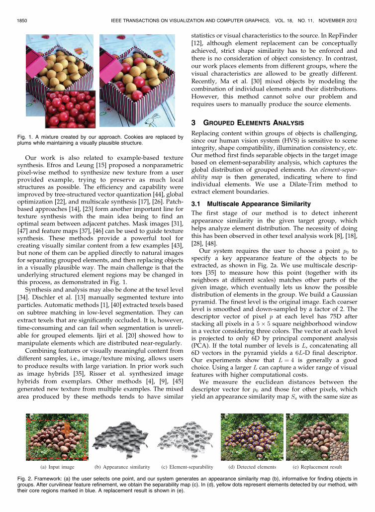
Fig. 1. A mixture created by our approach. Cookies are replaced byplums while maintaining a visually plausible structure.
Fig. 2. Framework: (a) the user selects one point, and our system generates an appearance similarity map (b), informative for finding objects ingroups. After curvilinear feature refinement, we obtain the separability map (c). In (d), yellow dots represent elements detected by our method, withtheir core regions marked in blue. A replacement result is shown in (e).
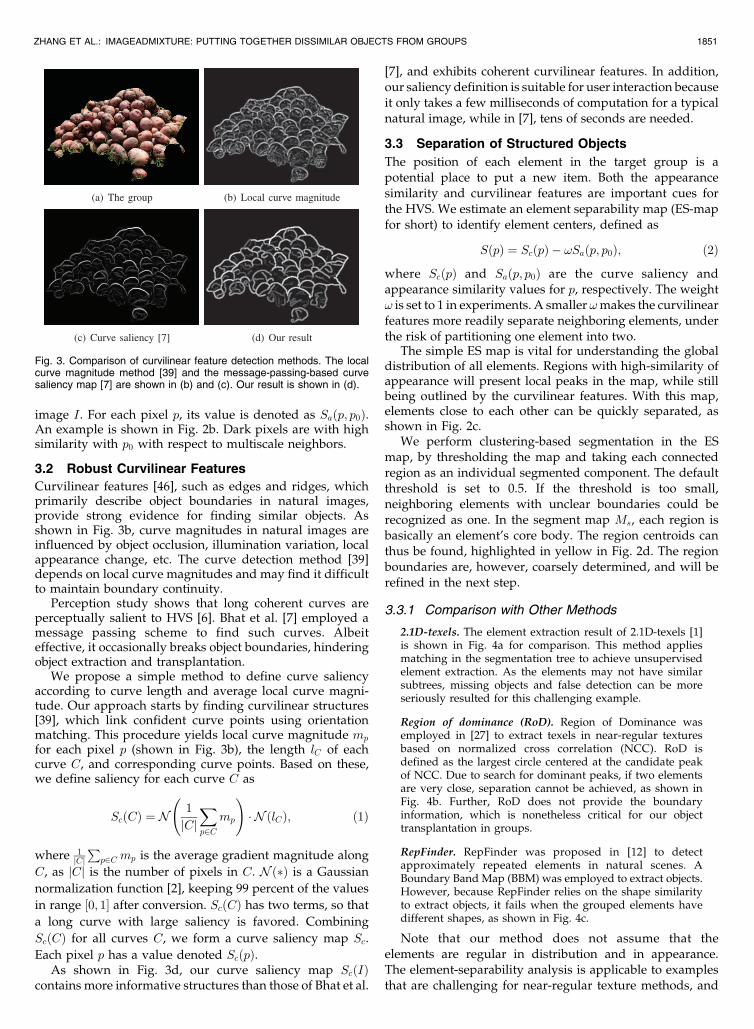
image I. For each pixel p, its value is denoted as Saðp; p0Þ.An example is shown in Fig. 2b. Dark pixels are with highsimilarity with p0 with respect to multiscale neighbors.
3.2 Robust Curvilinear Features
Curvilinear features [46], such as edges and ridges, whichprimarily describe object boundaries in natural images,provide strong evidence for finding similar objects. Asshown in Fig. 3b, curve magnitudes in natural images areinfluenced by object occlusion, illumination variation, localappearance change, etc. The curve detection method [39]depends on local curve magnitudes and may find it difficultto maintain boundary continuity.
Perception study shows that long coherent curves areperceptually salient to HVS [6]. Bhat et al. [7] employed amessage passing scheme to find such curves. Albeiteffective, it occasionally breaks object boundaries, hinderingobject extraction and transplantation.
We propose a simple method to define curve saliencyaccording to curve length and average local curve magni-tude. Our approach starts by finding curvilinear structures[39], which link confident curve points using orientationmatching. This procedure yields local curve magnitude mp
for each pixel p (shown in Fig. 3b), the length lC of eachcurve C, and corresponding curve points. Based on these,we define saliency for each curve C as
ScðCÞ ¼ N1
jCjXp2C
mp
!� N ðlCÞ; ð1Þ
where 1jCjP
p2C mp is the average gradient magnitude along
C, as jCj is the number of pixels in C. Nð�Þ is a Gaussian
normalization function [2], keeping 99 percent of the values
in range ½0; 1� after conversion. ScðCÞ has two terms, so that
a long curve with large saliency is favored. Combining
ScðCÞ for all curves C, we form a curve saliency map Sc.
Each pixel p has a value denoted ScðpÞ.As shown in Fig. 3d, our curve saliency map ScðIÞ
contains more informative structures than those of Bhat et al.
[7], and exhibits coherent curvilinear features. In addition,our saliency definition is suitable for user interaction becauseit only takes a few milliseconds of computation for a typicalnatural image, while in [7], tens of seconds are needed.
3.3 Separation of Structured Objects
The position of each element in the target group is apotential place to put a new item. Both the appearancesimilarity and curvilinear features are important cues forthe HVS. We estimate an element separability map (ES-mapfor short) to identify element centers, defined as
SðpÞ ¼ ScðpÞ � !Saðp; p0Þ; ð2Þ
where ScðpÞ and Saðp; p0Þ are the curve saliency andappearance similarity values for p, respectively. The weight! is set to 1 in experiments. A smaller !makes the curvilinearfeatures more readily separate neighboring elements, underthe risk of partitioning one element into two.
The simple ES map is vital for understanding the globaldistribution of all elements. Regions with high-similarity ofappearance will present local peaks in the map, while stillbeing outlined by the curvilinear features. With this map,elements close to each other can be quickly separated, asshown in Fig. 2c.
We perform clustering-based segmentation in the ESmap, by thresholding the map and taking each connectedregion as an individual segmented component. The defaultthreshold is set to 0.5. If the threshold is too small,neighboring elements with unclear boundaries could berecognized as one. In the segment map Ms, each region isbasically an element’s core body. The region centroids canthus be found, highlighted in yellow in Fig. 2d. The regionboundaries are, however, coarsely determined, and will berefined in the next step.
3.3.1 Comparison with Other Methods
2.1D-texels. The element extraction result of 2.1D-texels [1]is shown in Fig. 4a for comparison. This method appliesmatching in the segmentation tree to achieve unsupervisedelement extraction. As the elements may not have similarsubtrees, missing objects and false detection can be moreseriously resulted for this challenging example.
Region of dominance (RoD). Region of Dominance wasemployed in [27] to extract texels in near-regular texturesbased on normalized cross correlation (NCC). RoD isdefined as the largest circle centered at the candidate peakof NCC. Due to search for dominant peaks, if two elementsare very close, separation cannot be achieved, as shown inFig. 4b. Further, RoD does not provide the boundaryinformation, which is nonetheless critical for our objecttransplantation in groups.
RepFinder. RepFinder was proposed in [12] to detectapproximately repeated elements in natural scenes. ABoundary Band Map (BBM) was employed to extract objects.However, because RepFinder relies on the shape similarityto extract objects, it fails when the grouped elements havedifferent shapes, as shown in Fig. 4c.
Note that our method does not assume that theelements are regular in distribution and in appearance.The element-separability analysis is applicable to examplesthat are challenging for near-regular texture methods, and
ZHANG ET AL.: IMAGEADMIXTURE: PUTTING TOGETHER DISSIMILAR OBJECTS FROM GROUPS 1851
Fig. 3. Comparison of curvilinear feature detection methods. The localcurve magnitude method [39] and the message-passing-based curvesaliency map [7] are shown in (b) and (c). Our result is shown in (d).

provides a reliable object separation scheme in general.
More results are shown in later sections.
3.3.2 Element Extraction by Dilate-Trim
Given the computed element centers, i.e., yellow dots inFig. 4, we now refine each element’s boundary L byrequiring it to have large gradient magnitude and smallirregularity. The active contour model provides one way tosolve this problem. The summed external energy term ofevery contour point is
EL ¼ZL
ScðpÞDðpÞSaðp; p0Þ þ �
ds ¼Xp2L
ScðpÞDðpÞSaðp; p0Þ þ �
; ð3Þ
where � is a small value to avoid division by zero and DðpÞis the distance from pixel p to the corresponding centerpoint. However, as Fig. 5 shows, because the active contourmethod trades off between the contour smoothness andexternal energy distribution, it cannot cover all the details.
We thus use a Dilate-Trim method, sketched inAlgorithm 1, to solve the problem progressively. Specifi-cally, it iteratively dilates regions and then trims them
until the added pixels are less than an adaptive thresholdtðpÞ ¼ SðpÞ=DðpÞ. tðpÞ makes dilation be stopped for pixelswith high separation confidence or distant enough fromthe center. The border gradually expands from the elementcenter, and can evolve differently for various objects,suitable for forming irregular shapes. As Fig. 5 shows, incomparison with the active contours, our method canadaptively and more accurately update object boundaries,fitting our pursuit.
Algorithm 1. Extract an elementary region R by
Dilate-Trim
Initialize R as one region in Ms in Section 3.3;
Initialize R0 ¼ ;;while R�R0 > �, where � is a stopping value do
R0 R; R Dilate(R);
for every pixel p 2 R do
remove p from R, when ScðpÞ < tðpÞ;end for
R largest connected region of R;
end while
Another popular choice for multilabel segmentation inelement groups is by global optimization, such as graphcuts and watershed, taking the element centers as seeds.This scheme cannot handle pixels that do not belong to anyof the elements. One example is shown in Fig. 6a. Ourmethod, on the contrary, considers individual elementsstarting from their centers, and thus can produce bettershapes as shown in Fig. 6b. Pixels are allowed to be not inany of the elements.
3.3.3 Choosing Suitable Elements
We perform Dilate-Trim for each element in the targetimage, exemplified in Fig. 2a, containing a group of objects.
1852 IEEE TRANSACTIONS ON VISUALIZATION AND COMPUTER GRAPHICS, VOL. 18, NO. 11, NOVEMBER 2012
Fig. 5. Comparison of the active contour method and our Dilate-Trim.(a) Separable elements with their core regions. (b) Mask from activecontour. The external energy is calculated by (3). (c) Our automaticallyproduced result.
Fig. 4. Comparison of 2.1D texels [1], Region of Dominance after NCC [18], RepFinder [12] and our method. Yellow dots are the detected elementcenters.
Based on the results, our system allows the user to choosethe element region to replace. Our method then finds acandidate region from the secondary image with similarcurvilinear feature and compatible with the target gradientchange.
The similarity between the two images is measured bycross-correlation. We expand the target object boundary bya few pixels, creating a boundary band map [12]. Then wecalculate cross correlation values between the targetelement and all regions in the secondary image on thebands. The two regions that yield the largest value areregarded as most compatible. If there are multiple objects tobe processed, we repeat this selection process.
4 ELEMENT REPLACEMENT
To replace an element RA in image A by RB obtained fromthe secondary image B, object shape needs to be maintainedwith natural visual appearance change. This goal cannotalways be achieved successfully when using gradient-domain image blending. We instead propose a patchsearching strategy to retain visually compatible borders.The luminance is then transferred to produce final results.
Poisson blending and tone mapping are useful tools inimage composition. The need to keep object appearance inour problem, however, is beyond their capability. First,these methods can drastically change the object color whenthe source and target images are quite different. Second,they cannot create natural boundaries for each replacedobject, as shown in Fig. 1.
4.1 Boundary Replacement
With the candidate region RB found in the secondary imageB, as described in Section 3.3, we initially replace RA by RB,
as shown in Fig. 7b. RB, by definition, contains the mostsimilar curvilinear feature as RA near boundary. Note thatdirectly copyingRB still causes visual artifacts. One intuitiveway to improve it is by employing the nearest neighborsearch, like PatchMatch [5], to refine the boundary of RB.However, as shown in Fig. 7d, this method does not performwell enough when A and B do not have similar structures.
We alternatively look for large intensity variation nearboundaries of RB and RA. The updated region, denoted asRA0 , is produced as
RA0
p ¼RB
arg minqDðp;qÞ p 2 �ðRAÞT��rB
p �rAp
�� > T
RBp otherwise;
(ð4Þ
where �ðRA0 Þ is the 5-pixel width boundary band of RA0 , asshown in Fig. 8. q can be any pixel in RB, and krB
p �rAq k
measures difference in gradient. T is a threshold, set to 0.25by default; our algorithm is insensitive to this value. Dðp; qÞis the distance between p and q, defined as
Dðp; qÞ ¼��NB
q �NAp
��þ ���rBq �rA
p
��; ð5Þ
where NBq and NA
p are masked local windows centered at qand p, respectively. We use � ¼ 1 in all our experiments toequally weight the two factors. Pixels p and q have to beclose in both appearance and gradient to yield a smallDðp; qÞ along the region’s boundary �ðRA0 Þ.
To design NBq and NA
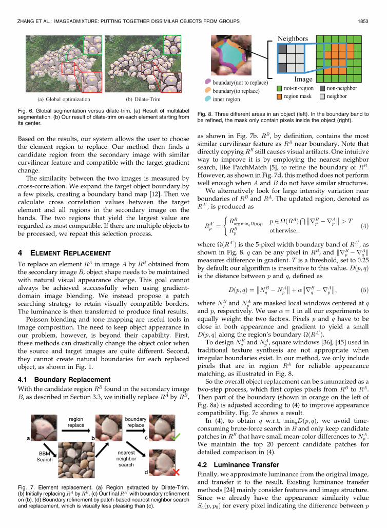
p , square windows [36], [45] used intraditional texture synthesis are not appropriate whenirregular boundaries exist. In our method, we only includepixels that are in region RA for reliable appearancematching, as illustrated in Fig. 8.
So the overall object replacement can be summarized as atwo-step process, which first copies pixels from RB to RA.Then part of the boundary (shown in orange on the left ofFig. 8a) is adjusted according to (4) to improve appearancecompatibility. Fig. 7c shows a result.
In (4), to obtain q w.r.t. minqDðp; qÞ, we avoid time-consuming brute-force search in B and only keep candidatepatches in RB that have small mean-color differences to NA
p .We maintain the top 20 percent candidate patches fordetailed comparison in (4).
4.2 Luminance Transfer
Finally, we approximate luminance from the original image,and transfer it to the result. Existing luminance transfermethods [24] mainly consider features and image structure.Since we already have the appearance similarity valueSaðp; p0Þ for every pixel indicating the difference between p
ZHANG ET AL.: IMAGEADMIXTURE: PUTTING TOGETHER DISSIMILAR OBJECTS FROM GROUPS 1853
Fig. 6. Global segmentation versus dilate-trim. (a) Result of multilabelsegmentation. (b) Our result of dilate-trim on each element starting fromits center.
Fig. 7. Element replacement. (a) Region extracted by Dilate-Trim.(b) Initially replacingRA byRB. (c) Our finalRA0 with boundary refinementon (b). (d) Boundary refinement by patch-based nearest neighbor searchand replacement, which is visually less pleasing than (c).
Fig. 8. Three different areas in an object (left). In the boundary band tobe refined, the mask only contain pixels inside the object (right).

and the user selected pixel p0, we define a luminance scorefunction LðpÞ for every pixel p:
LðpÞ ¼ Saðp; p0Þ ��
�INAp� �INA
p0
�; ð6Þ
where NAp denotes the masked neighborhood of p in image
A, and �INAp
is the average intensity of pixels in NAp . LðpÞ can
be either positive or negative, and is useful to change thepixel brightness depending on its sign. The final luminancetransfer is performed for each pixel p using
P 0ðpÞ ¼ P ðpÞ þ �LðpÞ; ð7Þ
where P ðpÞ and P 0ðpÞ denote the pixel values before andafter luminance transfer, respectively, and � controls thelevel of modification. Large � yields strong highlight orshadow. We use � ¼ 0:75 in all our experiments. Resultsbefore and after luminance transfer are shown in Fig. 10.
5 APPLICATIONS AND RESULTS
In our algorithm implementation, the regions to operateon in the input images are segmented by grab-cut [38] ifnecessary. Then the target objects are separated asdescribed in Section 3. The specified objects are replacedone by one using the method given in Section 4. On a PCwith a CPU at 2.5 GHz and 4 GB RAM, the computationtime is around 0.2 seconds for element analysis on a640� 480 image, and is about 20 milliseconds to replaceeach element.
5.1 Natural Image Examples
In real scenes, it is ubiquitous to see grouped elements withsimilar appearance. Our method is able to produce high-quality element replacement results, as shown in Fig. 9.Unlike image composition techniques, our approachfocuses on mixing visual features into the target area, whilekeeping the original structures, rather than overwritingthem. Our image mixture approach is a complement tocurrent image editing techniques.
5.2 Structure Preserving Appearance Transfer
Our method can also be applied to structure preservingappearance transfer in textured images. We only separateelements in the target image group using the boundaryband map [12] to search for most compatible structures inthe secondary texture image for replacement. Thereupon,the secondary image is not limited to grouped elements.One example is shown in Fig. 11, where we use a lichen
1854 IEEE TRANSACTIONS ON VISUALIZATION AND COMPUTER GRAPHICS, VOL. 18, NO. 11, NOVEMBER 2012
Fig. 9. Mixing elements. (a) Target image. (b) ES-map. (c) Detected elements. (d) Secondary image. (e) Mixing result.
Fig. 10. Results before and after luminance transfer.
Fig. 11. Structure preserving texture transfer: (left) target image andnovel source texture; (right) texture transfer result.
Fig. 12. Texture mixing result. The user inputs two different images,based on which we produce a mixing result. A larger texture can besynthesized from the result.
Fig. 13. Failure cases: (left) grouped objects with complicated 3Dstructure and layers; (right) object groups with incompatible structure.

texture to replace bricks, accomplishing the appearancetransfer effect. The major difference between our approachand texture transfer [14], [19], [29] is that we can preservethe appearance and local structure of the original objectsthat remain in the admixture result. In Fig. 11, lichenappears to be growing on bricks.
5.3 Texture Mixing
To blend texture, prior methods require input samples tohave similar appearance or weak structural features [4], [9],[45]. Our approach is an alternative to this end. We first mixthe two exemplars to create a new texture sample using thesteps described in the paper. Each texton in the two texturesis regarded as an atomic element. Then, we perform thetexture synthesis approach of Lefebvre and Hoppe [26] togenerate a bigger image. One example is shown in Fig. 12,our method spatially blends two different kinds of texels inan element-wise manner, rather than providing a statisti-cally uniform result similar to both inputs. More results ofthe above applications are shown in Fig. 14.
5.4 Limitations
There are a few difficulties that might influence the finalresult quality. First, since we do not estimate any depth orlayer information, our system cannot separate group objectswell when this set of information is needed. We show anexample in the left of Fig. 13, in which leaves overlay,destroying the latent integrity. The lack of depth informa-tion may also make object replacement not visually verypleasing when the 3D structure significantly varies in thetwo input images.
Secondly, we require objects in the secondary image tohave curvilinear compatible content to replace the originalelementary region. As shown in the right of Fig. 13, whenwe replace the rectangular blocks by hexagonal stones, evenconsidering the most compatible regions cannot preservethe visual integrity. The incomplete rocks inserted into thewall do not retain their correct geometric features. Finally,challenging objects like transparent or translucent glasses,
cannot be properly handled in our system. Involving
matting and image recognition will be our future work.
6 CONCLUSION
In this paper, we have proposed a dedicated system to
substitute structured elements within groups by others even
though they are dissimilar in appearance. Different levels of
mixture are allowed in our system, preserving local
structures. Our method requires a very small amount of user
interaction. The analysis and other operations to separate
objects are automatic. The drawback is that we do not
consider layers and depth, which may be problem in some
cases. But overall our method is powerful enough to handle
many examples that are challenging for other approaches.
ACKNOWLEDGMENTS
We thank all the reviewers for their helpful comments. This
work was supported by the National Basic Research Project
of China (Project Number 2011CB302205), the Natural
Science Foundation of China (Project Numbers
61120106007 and 61103079).
REFERENCES
[1] N. Ahuja and S. Todorovic, “Extracting Texels in 2.1D NaturalTextures,” Proc. IEEE 11th Int’l Conf. Computer Vision (ICCV),pp. 1-8, 2007.
[2] S. Aksoy and R. Haralick, “Feature Normalization and Likelihood-Based Similarity Measures for Image Retrieval,” Pattern Recogni-tion Letters, vol. 22, no. 5, pp. 563-582, 2001.
[3] W.-C. Lin and Z.-C. Yan, “Attention-Based High Dynamic RangeImaging,” The Visual Computer, vol. 27, no. 6, pp. 717-727, 2011.
[4] Z. Bar-Joseph, R. El-Yaniv, D. Lischinski, and M. Werman,“Texture Mixing and Texture Movie Synthesis Using StatisticalLearning,” IEEE Trans Visualization and Computer Graphics (TVCG),vol. 7, no. 2, pp. 120-135, Apr.-June 2001.
[5] C. Barnes, E. Shechtman, A. Finkelstein, and D.B. Goldman,“PatchMatch: A Randomized Correspondence Algorithm forStructural Image Editing,” ACM Trans Graphics, vol. 28, pp. 24:1-24:11, 2009.
ZHANG ET AL.: IMAGEADMIXTURE: PUTTING TOGETHER DISSIMILAR OBJECTS FROM GROUPS 1855
Fig. 14. Further results. Each group has three images showing (from left to right) the source image, the secondary image, and our result,respectively.

[6] W. Beaudot and K. Mullen, “How Long Range Is ContourIntegration in Human Color Vision?” Visual Neuroscience, vol. 20,no. 1, pp. 51-64, 2003.
[7] P. Bhat, C. Zitnick, M. Cohen, and B. Curless, “GradientShop: AGradient-Domain Optimization Framework for Image and VideoFiltering,” ACM Trans Graphics, vol. 29, no. 2, pp. 1-14, 2010.
[8] S. Brooks and N. Dodgson, “Self-Similarity Based TextureEditing,” ACM Trans Graphics, vol. 21, pp. 653-656, 2002.
[9] G. Brown, G. Sapiro, and G. Seroussi, “Texture Mixing ViaUniversal Simulation,” Proc. Int’l Workshop Texture Analysis andSynthesis, 2005.
[10] T. Chen, M. Cheng, P. Tan, A. Shamir, and S. Hu, “Sketch2-Photo: Internet Image Montage,” ACM Trans Graphics, vol. 28,no. 5, pp. 124: 1-10, 2009.
[11] H. Huang, L. Zhang, and H.-C. Zhang, “Arcimboldo-LikeCollage Using Internet Images,” ACM Trans Graphics, vol. 30,no. 6, pp. 155:1-155:8, 2011.
[12] M.-M. Cheng, F.-L. Zhang, N.J. Mitra, X. Huang, and S.-M. Hu,“Repfinder: Finding Approximately Repeated Scene Elements forImage Editing,” ACM Trans Graphics, vol. 29, no. 4, pp. 83:1-8,2010.
[13] J.-M. Dischler, K. Maritaud, B. Lvy, and D. Ghazanfarpour,“Texture Particles,” Computer Graphics Forum, vol. 21, pp. 401-410,2002.
[14] A.A. Efros and W.T. Freeman, “Image Quilting for TextureSynthesis And Transfer,” Proc. ACM SIGGRAPH, pp. 341-346,2001.
[15] A.A. Efros and T.K. Leung, “Texture Synthesis by Non-ParametricSampling,” Proc. IEEE Seventh Int’l Conf. Computer Vision (ICCV),pp. 1033-1038, 1999.
[16] Z. Farbman, G. Hoffer, Y. Lipman, D. Cohen-Or, and D.Lischinski, “Coordinates for Instant Image Cloning,” ACM TransGraphics, vol. 28, pp. 67:1-9, 2009.
[17] C. Han, E. Risser, R. Ramamoorthi, and E. Grinspun, “MultiscaleTexture Synthesis,” ACM Trans Graphics, vol. 27, no. 3, pp. 1-8,2008.
[18] J. Hays, M. Leordeanu, A. Efros, and Y. Liu, “Discovering TextureRegularity as a Higher-Order Correspondence Problem,” Proc.Ninth European Conf. Computer Vision (ECCV), pp. 522-535, 2006.
[19] A. Hertzmann, C.E. Jacobs, N. Oliver, B. Curless, and D.H. Salesin,“Image Analogies,” Proc. ACM SIGGRAPH, pp. 327-340, 2001.
[20] T. Ijiri, R. Mch, T. Igarashi, and G. Miller, “An Example-BasedProcedural System for Element Arrangement,” Computer GraphicsForum, vol. 27, pp. 429-436, 2008.
[21] B. Julesz, “Textons, The Elements of Texture Perception, and TheirInteractions.” Nature, vol. 290, no. 5802, pp. 91-97, 1981.
[22] V. Kwatra, I. Essa, A. Bobick, and N. Kwatra, “TextureOptimization for Example-Based Synthesis,” ACM Trans Graphics,vol. 24, pp. 795-802, 2005.
[23] V. Kwatra, A. Schodl, I. Essa, G. Turk, and A. Bobick, “GraphcutTextures: Image and Video Synthesis Using Graph Cuts,” ACMTrans Graphics, vol. 22, pp. 277-286, 2003.
[24] J.-F. Lalonde, A. Efros, and S. Narasimhan, “Estimating NaturalIllumination from a Single Outdoor Image,” Proc. IEEE 12th Int’lConf. Computer Vision (ICCV), pp. 183-190, 2009.
[25] J.-F. Lalonde, D. Hoiem, A.A. Efros, C. Rother, J. Winn, and A.Criminisi, “Photo Clip Art,” ACM Trans Graphics, vol. 26, 2007.
[26] S. Lefebvre and H. Hoppe, “Parallel Controllable TextureSynthesis,” ACM Trans Graphics, vol. 24, pp. 777-786, 2005.
[27] Y. Liu, R. Collins, and Y. Tsin, “A Computational Model forPeriodic Pattern Perception Based on Frieze and WallpaperGroups,” IEEE Trans Pattern Analysis and Machine Intelligence,vol. 26, no. 3, pp. 354-371, Mar. 2004.
[28] Y. Liu, J. Wang, S. Xue, X. Tong, S. Kang, and B. Guo, “TextureSplicing,” Computer Graphics Forum, vol. 28, no. 7, pp. 1907-1915,2009.
[29] Y. Liu, W.-C. Lin, and J. Hays, “Near-Regular Texture Analysisand Manipulation,” ACM Trans Graphics, vol. 23, pp. 368-376,2004.
[30] C. Ma, L.-Y. Wei, and X. Tong, “Discrete Element Textures,” ACMTrans Graphics, vol. 30, pp. 62:1-62:10, Aug. 2011.
[31] W. Matusik, M. Zwicker, and F. Durand, “Texture Design Using aSimplicial Complex of Morphable Textures,” ACM Trans Graphics,vol. 24, no. 3, pp. 787-794, 2005.
[32] P. Perez, M. Gangnet, and A. Blake, “Poisson Image Editing,”ACM Trans Graphics, vol. 22, pp. 313-318, 2003.
[33] T. Porter and T. Duff, “Compositing Digital Images,” ACMSIGGRAPH, vol. 18, no. 3, pp. 253-259, 1984.
[34] G. Martens, C. Poppe, P. Lambert, and R.V.d. Walle, “Noise- andCompression-Robust Biological Features for Texture Classifica-tion,” The Visual Computer, vol. 26, no. 6, pp. 915-922, 2010.
[35] E. Risser, C. Han, R. Dahyot, and E. Grinspun, “SynthesizingStructured Image Hybrids,” ACM Trans Graphics, vol. 29, pp. 85:1-6, 2010.
[36] L. Ritter, W. Li, M. Agrawala, B. Curless, and d. Salesin,“Painting with Texture,” Proc. 17th Eurographics Symp. Rendering(EGSR), pp. 371-377, 2006.
[37] A. Rosenberger, D. Cohen-Or, and D. Lischinski, “Layered ShapeSynthesis: Automatic Generation of Control Maps for Non-Stationary Textures,” ACM Trans Graphics, vol. 28, no. 5, p. 107,2009.
[38] C. Rother, V. Kolmogorov, and A. Blake, ““GrabCut”: InteractiveForeground Extraction Using Iterated Graph Cuts,” vol. 23, no. 3,pp. 309-314, 2004.
[39] C. Steger, “An Unbiased Detector of Curvilinear Structures,”IEEE Trans Pattern Analysis and Machine Intelligence, vol. 20, no. 2,pp. 113-125, Feb. 1998.
[40] S. Todorovic and N. Ahuja, “Texel-Based Texture Segmentation,”Proc. IEEE 12th Int’l Conf. Computer Vision (ICCV), pp. 841-848,2009.
[41] M. Ding and R.-F. Tong, “Content-Aware Copying and Pasting inImages,” The Visual Computer, vol. 26, no. 6, pp. 721-729, 2010.
[42] J. Wang and M.F. Cohen, “Image and Video Matting: A Survey,”Foundation and Trends in Computer Graphics Vision, vol. 3, pp. 97-175, 2007.
[43] L.Y. Wei, S. Lefebvre, V. Kwatra, and G. Turk, “State of the Art inExample-Based Texture Synthesis,” Eurographics, State of the ArtReport, 2009.
[44] L.-Y. Wei and M. Levoy, “Fast Texture Synthesis Using Tree-Structured Vector Quantization,” Proc. SIGGRAPH, pp. 479-488,2000.
[45] L. Wei, “Texture Synthesis from Multiple Sources,” Proc. ACMSIGGRAPH Sketches and Applications, p. 1, 2003.
[46] Q. Wu and Y. Yu, “Feature Matching and Deformation for TextureSynthesis,” ACM Trans Graphics, vol. 23, no. 3, pp. 364-367, 2004.
[47] J. Zhang, K. Zhou, L. Velho, B. Guo, and H. Shum, “Synthesis ofProgressively-Variant Textures on Arbitrary Surfaces,” ACMTrans Graphics, vol. 22, no. 3, pp. 295-302, 2003.
[48] D. Aiger, D. Cohen-Or, and N.J. Mitra, “Repetition MaximizationBased Texture Rectification,” Computer Graphics Forum, vol. 31,no. 2, 2012.
Fang-Lue Zhang received the BS degree fromthe Zhejiang University in 2009. Currently, he isworking toward the PhD degree in TsinghuaUniversity. His research interests include com-puter graphics, image processing and enhance-ment, image and video analysis and computervision.
Ming-Ming Cheng received the BS degree fromthe Xidian University in 2007. Currently, he isworking toward the PhD degree in TsinghuaUniversity. His research interests include com-puter graphics, computer vision, image proces-sing, and sketch-based image retrieval. He hasreceived a Google PhD fellowship award, anIBM PhD fellowship award, and a “New PHDResearcher Award” from the Chinese Ministry ofEducation. He is a member of the IEEE.
1856 IEEE TRANSACTIONS ON VISUALIZATION AND COMPUTER GRAPHICS, VOL. 18, NO. 11, NOVEMBER 2012

Jiaya Jia received the PhD degree in computerscience from the Hong Kong University ofScience and Technology in 2004 and is currentlyworking as an associate professor in theDepartment of Computer Science and Engineer-ing at the Chinese University of Hong Kong(CUHK). He was a visiting scholar at MicrosoftResearch Asia from March 2004 to August 2005and conducted collaborative research at AdobeSystems in 2007. He leads the research group in
CUHK, focusing specifically on computational photography, 3D recon-struction, practical optimization, and motion estimation. He serves as anassociate editor for TPAMI and as an area chair for ICCV 2011. He wason the program committees of several major conferences, includingICCV, ECCV, and CVPR, and cochaired the Workshop on InteractiveComputer Vision, in conjunction with ICCV 2007. He received the YoungResearcher Award 2008 and Research Excellence Award 2009 fromCUHK. He is a senior member of the IEEE.
Shi-Min Hu received the PhD degree fromZhejiang University in 1996. Currently, he isworking as a professor in the Department ofComputer Science and Technology, TsinghuaUniversity, Beijing. He is an associate editor-in-chief of The Visual Computer, associateeditor of Computer and Graphics and on theeditorial board of Computer Aided Design. Hisresearch interests include digital geometryprocessing, video processing, rendering, com-
puter animation, and computer-aided geometric design. He is amember of the IEEE.
. For more information on this or any other computing topic,please visit our Digital Library at www.computer.org/publications/dlib.
ZHANG ET AL.: IMAGEADMIXTURE: PUTTING TOGETHER DISSIMILAR OBJECTS FROM GROUPS 1857