
analysis of the behaviour of a 480 kn maximum hook load ...
12
U.P.B. Sci. Bull., Series D, Vol. 83, Iss. 4, 2021 ISSN 1454-2358 ANALYSIS OF THE BEHAVIOUR OF A 480 KN MAXIMUM HOOK LOAD WORKOVER RIG MAST IN THE CASE OF WIND STRESS Aurelian IAMANDEI 1 , Șerban Nicolae VASILESCU 2 , Ioan POPA 3 , Lavinia Silvia STANCIU 4 , Răzvan George RÎPEANU 5 In the case of well drilling interventions and repair operations, the specific installations must sometimes work for a longer period, of several weeks, during which severe weather conditions may appear. These include those in which high-speed winds occur, which influences the state of stress and displacements of masts, which are spatial constructions. In this paper, the authors aim to study how a mast prototype of 480 kN, which is part of a transportable workover rig, behaves in the case of simultaneous stress caused by the maximum hook load and a wind with 12.7 m/s speed (approx. 50 km/h). Keywords: workover rig, mast, stress, displacements, wind. 1. Introduction The masts of transportable workover rigs are multiple statically indeterminate spatial constructions, consisting of pipe-type bars or profiles [1]. They are transported with all parts of the installation to the location of the borehole by means of a specially designed truck, being placed, during transport, in a horizontal position on the truck chassis. The installation called IC 5, of which the mast prototype that is the subject of the analysis in this article is part, is one for intervention and downhole repair operations of 48 tf (480 kN) and consists of equipment made in accordance with API specifications. With this complex mobile installation (Fig. 1) the following operations can be performed [2]: insertion and 1 Eng. SC IA Project, PhD Student at Department of Mechanical Engineering from Petroleum-Gas University, Ploiești, Romania, e-mail: iamandei@ia-proiect.ro 2 Prof. PhD. Eng., Department of Mechanical Engineering from Petroleum-Gas University, Ploiești, Romania, Romania, e-mail: vserban@upg-ploiesti.ro 3 Assoc. Prof. Phd Eng., Department of Mechanical Engineering from Petroleum-Gas University, Ploiești, Romania, Romania, e-mail: [email protected] 4 Lecturer PhD Eng., Department of Mechanical Engineering from Petroleum-Gas University, Ploiești, Romania, Romania, e-mail: [email protected] 5 Prof. PhD. Eng., Department of Mechanical Engineering from Petroleum-Gas University, Ploiești, Romania, Romania, e-mail: rrapeanu@upg-ploiesti.ro
-
Upload
khangminh22 -
Category
Documents
-
view
0 -
download
0
Transcript of analysis of the behaviour of a 480 kn maximum hook load ...

U.P.B. Sci. Bull., Series D, Vol. 83, Iss. 4, 2021 ISSN 1454-2358
ANALYSIS OF THE BEHAVIOUR OF A 480 KN MAXIMUM HOOK LOAD WORKOVER RIG MAST IN THE CASE OF
WIND STRESS
Aurelian IAMANDEI1, Șerban Nicolae VASILESCU2, Ioan POPA3, Lavinia Silvia STANCIU4, Răzvan George RÎPEANU5
In the case of well drilling interventions and repair operations, the specific installations must sometimes work for a longer period, of several weeks, during which severe weather conditions may appear. These include those in which high-speed winds occur, which influences the state of stress and displacements of masts, which are spatial constructions. In this paper, the authors aim to study how a mast prototype of 480 kN, which is part of a transportable workover rig, behaves in the case of simultaneous stress caused by the maximum hook load and a wind with 12.7 m/s speed (approx. 50 km/h).
Keywords: workover rig, mast, stress, displacements, wind.
1. Introduction
The masts of transportable workover rigs are multiple statically indeterminate spatial constructions, consisting of pipe-type bars or profiles [1]. They are transported with all parts of the installation to the location of the borehole by means of a specially designed truck, being placed, during transport, in a horizontal position on the truck chassis. The installation called IC 5, of which the mast prototype that is the subject of the analysis in this article is part, is one for intervention and downhole repair operations of 48 tf (480 kN) and consists of equipment made in accordance with API specifications. With this complex mobile installation (Fig. 1) the following operations can be performed [2]: insertion and
1 Eng. SC IA Project, PhD Student at Department of Mechanical Engineering from Petroleum-Gas University, Ploiești, Romania, e-mail: [email protected] 2 Prof. PhD. Eng., Department of Mechanical Engineering from Petroleum-Gas University, Ploiești, Romania, Romania, e-mail: [email protected] 3 Assoc. Prof. Phd Eng., Department of Mechanical Engineering from Petroleum-Gas University, Ploiești, Romania, Romania, e-mail: [email protected] 4 Lecturer PhD Eng., Department of Mechanical Engineering from Petroleum-Gas University, Ploiești, Romania, Romania, e-mail: [email protected] 5 Prof. PhD. Eng., Department of Mechanical Engineering from Petroleum-Gas University, Ploiești, Romania, Romania, e-mail: [email protected]

184 A. Iamandei, Ș. N. Vasilescu, I. Popa, Lavinia Silvia Stanciu, R. G. Rîpeanu
removal of sucker pump rods or extraction pipes, bottom tools or submersible pumps; fitting or eliminating the christmas tree; repairing or making remediation works for some well defects such as: milling of cement plugs, washing of sand plugs, instrumentation, etc.
Fig. 1. Composition of the service rig [2]
The specialized literature on the subject of drilling masts or those of service rigs masts is quite little present in papers that present in detail how to perform a computer simulation for such constructions, using the provisions of the API 4F standard. Each mast of each new service rig mast represents a new and unique structure with unique geometry for the maximum hook load to which it will be subjected during the work and it depends on several factors, such as: expected weather conditions, winds, possible earthquakes, the structure of the truck chassis for transportation to the location and work, etc. In general, the handbooks for oilfield equipment like [3] give useful, but very general guidances, without structures analyzed in detail. The development of onshore drilling at increasing depths has necessitated the analysis of masts for drilling rigs in accordance with current standards, so the concerns of specialists in recent years were focused on issues related to structural composition, materials, behaviour in specific working conditions: the analysis of stress and deformations of drilling rig masts due to extreme conditions in order to improve the construction of the parts of the mast and avoid failure [4-8], or the behaviour of masts with specific constructions in case of static or dynamic stress [9-11] were the main research directions of research, arising from practical needs. The domain of masts of workover service rigs is far too little present at this moment.

Analysis of the behavior of a 480 kN (…) workover rig mast in the case of wind stress 185
When working in the wellbore, the installation and its mast must deal with various cases of simultaneous loads, such as: maximum hook load and wind; working hook load and wind; wind expected to act like a hurricane, working in the event of an earthquake, etc. All these possible loading cases are provided by the API 4F standard [12], which contains eight possible cases of loadings that can occur separately during many weeks (or months) of working of the service rig, one of them being the subject of the present paper. The manufacturers want to know the level of stress to be expected for each case, separately. Also, this standard provides, in Chapter 11.8, that after completing the computer simulation, the accuracy of the results shall be verified once again by a qualified individual, other than the designer of the computer model. So, in the present, all Romanian manufacturers of such masts require a finite element analysis for their new built structures.
Because the mast is the largest and highest structure on the workover service rig, it is the greatest contributor to wind loading. This also means that its shape and construction are a huge factor in determining the level of stress for the whole assembly [13-17]. One of the most important cases of stress is when the mast must work with the maximum hook load at the same time with the action of the wind of about 50 km/h speed acting either in the front-rear direction of the mast or in the transverse direction on it. The mast is one with a "U"-shaped section, consisting of two parts: the fixed section, 1,822 mm high, consisting mainly of pipe-type bars, Ø95x8, and the folding section, height 13,408 mm. The crown block and the two resistance anchors are also included in the mast. The total height from the ground in the working position reaches 17,580 mm. When working, the mast is slightly inclined (at an angle of approx. 6°24' with respect to a vertical axis) towards the front. The resistance structure of the folding section consists of four pillars with a circular pipe profile, Ø95x8, joined together on the three sides by horizontal and diagonal bars, also made of circular or square pipe type profiles. At the top of the folding section is rigidly fixed the crown block, which is a rigid structure on which the sheaves over which the wire rope of the operating cable is passed must rest. The sheaves axes have a solid circular section, Ø108, and the sheaves, in number of 4+1, have a Ø560 diameter. The wire rope that passes over them has a diameter of 22 mm.
In the operating position, the mast is anchored to the ground by four safety anchors (two at the front, two at the rear), and at the truck chassis by means of two resistance anchors, Ø18 diameter, which are attached to the mast at the lower level of the crown block. The inclination of the resistance anchors with respect to the vertical axis is 31.4° (31°24').
186 A. Iamandei, Ș. N. Vasilescu, I. Popa, Lavinia Silvia Stanciu, R. G. Rîpeanu
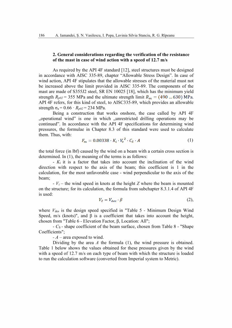
2. General considerations regarding the verification of the resistance of the mast in case of wind action with a speed of 12.7 m/s
As required by the API 4F standard [12], steel structures must be designed in accordance with AISC 335-89, chapter “Allowable Stress Design”. In case of wind action, API 4F stipulates that the allowable stresses of the material must not be increased above the limit provided in AISC 335-89. The components of the mast are made of S355J2 steel, SR EN 10025 [18], which has the minimum yield strength Rp02 = 355 MPa and the ultimate strength limit . API 4F refers, for this kind of steel, to AISC335-89, which provides an allowable strength σa = 0.66 · Rp02 = 234 MPa.
Being a construction that works onshore, the case called by API 4F „operational wind” is one in which „unrestricted drilling operations may be continued”. In accordance with the API 4F specifications for determining wind pressures, the formulae in Chapter 8.3 of this standard were used to calculate them. Thus, with:
(1)
the total force (in lbf) caused by the wind on a beam with a certain cross section is determined. In (1), the meaning of the terms is as follows:
- Ki it is a factor that takes into account the inclination of the wind direction with respect to the axis of the beam; this coefficient is 1 in the calculation, for the most unfavorable case - wind perpendicular to the axis of the beam;
- Vz – the wind speed in knots at the height Z where the beam is mounted on the structure; for its calculation, the formula from subchapter 8.3.1.4 of API 4F is used:
(2), where Vdes is the design speed specified in "Table 5 - Minimum Design Wind Speed, m/s (knots)", and β is a coefficient that takes into account the height, chosen from "Table 6 - Elevation Factor, β, Location: All";
- CS - shape coefficient of the beam surface, chosen from Table 8 - "Shape Coefficients";
- A – area exposed to wind. Dividing by the area A the formula (1), the wind pressure is obtained.
Table 1 below shows the values obtained for these pressures given by the wind with a speed of 12.7 m/s on each type of beam with which the structure is loaded to run the calculation software (converted from Imperial system to Metric).

Analysis of the behavior of a 480 kN (…) workover rig mast in the case of wind stress 187
Table 1 Pressures occurring from the wind with 12.7 m/s speed
Cross-sectional area Shape coefficient, CS Pressure (N/mm2) Ø95x8 0.8 0.00007916
□ 60x60x4 1.5 0.0001484 □ 50x50x4 1.5 0.0001484 60x100x6 1.5 0.0001484 80x40x5 1.5 0.0001484 I-profile 1.8 0.0001781
It is known from strength of materials that normal stresses can be determined using [19]:
(3)
where: y, z are the coordinates in the local axis system of a current point on the section; A, cross-sectional area; zy II , , moments of inertia of the cross-section with respect to axes y and z.
Using the equation (3), the maximum or minimum stresses for elements with cross-sections inscribed within a rectangle shall be determined by the expression:
(4)
where zy WW , are the section moduli. For the elements with annular cross-section, the bending moment is
determined with [19]:
(5)
and the maximum and minimum stresses are determined by [19]:
i
i
x WM
AN±=σ minmax/,
(6)
where zyi WWW == is the section modulus.
3. Loads acting on the mast and their distribution
Since the analyzed case is the one provided in API 4F - “Table 2. Design Loadings for Service rig Masts”, case 1.a (“Design Loading Conditions: Operating”) - the loads taken into account are: the dead weight of the mast assembly: the weight of the hoisting system, Qm = 30 kN; the maximum hook

188 A. Iamandei, Ș. N. Vasilescu, I. Popa, Lavinia Silvia Stanciu, R. G. Rîpeanu
load, Qmax = 480 kN; wind action in the positive direction of the general axis X (rear-front of the mast) or in the direction of the Z axis (transversely on the mast) with speed v = 12.7 m/s. The dead weight of the mast is determined automatically by the finite element software, entering as input data the density of the steel, ρ = 7,850 kg/m3, the dimensions of the cross-sections of the beams and the coordinates of the nodes, with the help of which the length of each element is determined.
The maximum hook load and the weight of the hoisting system together make up a load of approximately Qt = 510 kN and is applied at the crown block level. Due to the friction, the force in the wire rope is no longer constant along its length [1, 20]. The forces in the wire rope are thus determined (Fig. 2):
- the force in the dead line [1]:
(7),
where K=1.04 is a coefficient provided by API RP 9B standard [20], that considers the friction in the sheaves from the crown block and traveling block, as well as between the wire rope and the sheaves, and n = 3 is the number of traveling block sheaves;
- the forces in all other wire rope branches:
(8)
Fig. 2. Forces in wire rope branches Fig. 3. Points for introducing the forces
Applying (7) and (8), the obtained values are: Tm = T0 = T1 = 76.888 kN, T2 =79.964 kN, T3 = 83.162 kN, T4 =86.488 kN, T5 = 89.948 kN, T6 =93.546 kN and the force in te fast line, Ta = T7 = 97.288 kN. These forces were introduced as input data in the software at the points form the crown block shown in Fig. 3 and listed below. Taking into account that α ≈ 9.8 ° and γ ≈ 13.9 ° are the angles that

Analysis of the behavior of a 480 kN (…) workover rig mast in the case of wind stress 189
the dead line and the fast line of wire rope make with respect to the vertical axis, it results:
- in the point 127, - in the direction of the general axis X, in the opposite direction to it, a
force F127,X = ‒76,888·sin α = ‒13,087 N; - in the direction of the general axis Y, in the opposite direction to it, a
force F127,Y = ‒76,888·cos α ‒ 76,888= ‒152,654 N; - in the point 128,
- in the direction of the general axis X, in the opposite direction to it, a force F128,X = ‒97,288·sin γ = ‒23,371 N;
- in the direction of the general axis Y, in the opposite direction to it, a force F128,Y = ‒97,288·cos γ ‒ 93,456 = ‒187,985 N;
- in the points 136 and 137, in the direction of the general axis Y, in the opposite direction to it, the forces F136,Y = ‒ (T2+T3) = ‒ 163,126 N, F137,Y = ‒ (T4+T5) = ‒ 176,436 N.
4. Results obtained after simulating the loading case
The models of the fixed and folding sections, of the crown block and of the anchors were generated using the Ansys software [21] which final assembly is shown in Fig. 4.
Fig. 4. Conceptual model of the mast generated with Ansys software
This conceptual model included the following: 170 points (also included
here are the points that serve to orient some cross-sections or to orient the fast line and the dead line of the wire rope), 299 lines, 744 nodes, six types of ground

190 A. Iamandei, Ș. N. Vasilescu, I. Popa, Lavinia Silvia Stanciu, R. G. Rîpeanu
connections (spatial roller supports) – two for connecting the anchors and four for connecting the fixed section to the folding one, and 299 finite elements (each line was considered a finite element) - 295 elements BEAM 189 type, two elements LINK 10 type for the strength anchors and two elements LINK 8 type for the two counterbraces from the fixed section.
The action of the wind with speed v = 12.7 m/s has as effect a load distributed on all the elements on the rear panel of the mast (the one exposed to the wind). These distributed loads, multiplied by the lengths of the bars on which they act, led to the appearance of forces that were introduced on the calculation model in the nodes at the ends of the elements, using the Ansys software, based on finite element analysis, intensively used in mechanical engineering design [22, 23]. The result was a calculation model with wind forces, in the direction of the general axis X, for the case of wind action in the front-rear direction, concentrated at all points belonging to this panel. Another result was obtained with the wind forces acting in the direction of the general axis Z, for the case of the action of the wind in the transverse direction on the mast, forces which were concentrated at all points of the mast on the two side panels exposed to the wind.
The displacements of all the nodes of the calculation model of the structure were determined in case the wind acts in the front-rear direction, resulting in the deformed shape of the mast (Fig. 5). The deformed shape produced by the loads corresponding to the case of the wind acting transversely is largely like that one shown in Fig. 5 and has not been presented separately.
1
X
Y
Z
DISPLACEMENT
STEP=1SUB =1TIME=1DMX =44.85
Fig. 5. Deformed shape of the mast subjected to the action of wind and maximum hook load
The maximum displacements are recorded at the level of the crown block, at the top of the mast. The maximum total displacement is 44.85 mm for the case

Analysis of the behavior of a 480 kN (…) workover rig mast in the case of wind stress 191
of the wind acting in the front-rear direction. Table 2 shows the displacements obtained in the two cases (I - wind acting in the front-rear direction, II - wind acting transversely on the mast), along the three axes. In case II there is a slight increase of displacements values in the direction of the general axis Z, which can be explained by the fact that the action of the wind is, in this case, in the direction of this axis.
Regarding the level of maximum stresses, their map, corresponding to the loads in case I, is presented in Fig. 6. The maximum values arise in the fixed section in the zone of detail A, highlighted in Fig. 7, and have the value |σmax|=192.5 MPa.
Table 2
Displacements at crown block level, mm Node
Case UX UY UZ
I II I II I II 59 40.25 40.26 -13.07 -13.05 4.9 6.06
120 40.24 40.25 -9.95 -9.93 2.64 4.00 181 37.2 31.76 -9.83 -9.81 2.62 3.98 242 37.22 36.78 -12.68 -12.64 4.88 6.58
Fig. 6. Stress map in case I
Fig. 7. Stress map in case I for the fixed section
In case II, the loads are the same. The difference is that the action of the wind was introduced, proceeding in the manner described above, as forces concentrated in the direction of the general axis Z, at the nodes of the mast on the side panels which are exposed to the wind. The stress map of the assembly is shown in Fig. 8, and in Fig. 9 is presented the detail noted B of the area on the fixed section where the highest stress value occurs. It is found that the stresses

192 A. Iamandei, Ș. N. Vasilescu, I. Popa, Lavinia Silvia Stanciu, R. G. Rîpeanu
existing in the mast elements in the loads corresponding to case II are comparable to those corresponding to case I, with slightly increased values: |σmax|=197.5 MPa.
According to the API 4F standard, the verification calculation is performed assuming that the mast prototype works only with the resistance anchors linked to ground, without the safety anchors. It should be noted that, in both cases, the resistance anchors remain stretched out, the maximum forces in them being recorded in the case of the wind action on the front-rear direction and having the values: 37,750 N and 37,230 N, without the danger of breaking.
Fig. 8. Stress map in case II
Fig. 9. Stress map in case II for the fixed section
6. Conclusions
1. The simulation of the simultaneous load produced by the maximum hook load and a wind with a speed of 12.7 m/s (approx. 50 km/h) for the mast of 480 kN, which is the subject of this work, was performed in accordance with the provisions of the API 4F standard, 2013 Edition, “Specification for Drilling and Well Servicing Structures” - “Table 2. Design Loadings for Service rig Masts”, case 1.a, “Design Loading Conditions: Operating”.
2. The computer simulation was performed by the authors for this mast prototype respecting all the constructive details of the components, the supporting conditions of the assembly, and through a faithful, realistic distribution of the loads produced by the maximum hook load at the crown block level, permanent loads and pressures caused by wind speed.
3. The values of the minimum wind speeds, stipulated in the same standard, in Chapter 8, Table 5 (“Table 5-Minimum Design Wind Speed”) have been considered during the computer simulation.
Analysis of the behavior of a 480 kN (…) workover rig mast in the case of wind stress 193
4. In addition to the wind action with a speed of 12.7 m/s in the front-rear direction (case I) and then, transversely on the mast (case II), the permanent loads and the maximum hook load, Qmax = 480 kN, were considered during the computer simulation.
5. The calculation of the mast was performed considering only the resistance anchors, in the absence of safety anchors connected to the ground.
6. Performing such a simulation requires a large volume of calculation, so, for this purpose, the authors used the specialized finite element analysis software, Ansys 10.0.
7. The maximum hook load and the weight of the hoisting system together make up a total load of approximately Qt = 510 kN which was applied at the crown block level, at the points shown in Fig. 3, taking into account the angles made by the dead line and the fast line of the wire rope with respect to the vertical axis.
8. The highest values of the displacements were recorded at the crown block level, in the case of wind acting in the front-rear direction (case I), the maximum total displacement being 44.85 mm.
9. The influence of the change of wind direction with a speed of 12.7 m/s on the state of stress and strain is quite low in both cases, in relation to the influence of the value of the maximum hook load superimposed over the permanent loads.
10. The maximum mechanical stresses occur at the junction between the two parts of the mast, the fixed section and the folding one, with close values in both cases: 192.5 MPa in case I and 197.5 MPa in case II, these values being below the value of the allowable stress of the S355J2 steel, which is 234 MPa.
R E F E R E N C E S
[1]. A. Bublic, V. Cristea, I. Hirsch, N. Peligrad, Gh. Silion, Utilaj petrolier pentru foraj și extracție (Oilfield equipment for drilling and extraction), Editura Tehnică, București, 1968 (in Romanian).
[2] *** Confind Câmpina Company, http://www.confind.ro/instalatii_interventie_sonde.html, accessed March 2021.
[3]. W. C. Lyons, G. J. Plisga, Standard Handbook of Petroleum & Natural Gas Engineering, Second Edition, Elsevier Inc., United Kingdom, 2005.
[4]. H. Guo, H.L. Zang, „Finite element method analysis of the mast of rotary drilling rig”, Advanced Materials Research, Vols. 374-377, pp. 326-329, 2011, Trans Tech Publications, Germany.
[5]. D. Gosh, H. Roy, S. Ray, A. K. Shukla, „Investigation on Failure of a Drilling Rig Mast Structure”, Journal of Failure Analysis and Prevention, Vol. 15, pp. 474-479, 2015, Springer.

194 A. Iamandei, Ș. N. Vasilescu, I. Popa, Lavinia Silvia Stanciu, R. G. Rîpeanu
[6]. F. Guan, C. Zhou, S. Wei, W. Wu, X. Yi, „Load-Carrying Capacity Analysis on Derrick of Offshore Module Drilling Rig”, The Open Petroleum Engeneering Journal, Vol. 7, pp. 29-40, 2014.
[7]. X. Xianzhong, J. Shengzong, J, Yuanqiang, F. Ding, G. Deli, „Strength Analysis and Calculation of JJ225/42-KC Type Oil Rig Derrick”, Applied Mechanics and Materials, Vols. 190-191, pp. 551-554, 2012, Trans Tech Publications, Switzerland.
[8]. Y. X. Li, W. Q. Xia, W. Q. Shen, H. Luo, „Structural Optimum Design and Analysis of the Mast of Rotary Drilling Rig Based on Finite Element Method”, Research Journal of Applied Sciences, Engineering and Technology, Vol. 4, pp.3222-3230, 2012.
[9]. Al. Pupăzescu, I. Popa, L. S. Stanciu, „The Evaluation of the Stress and Strain Condition for the Mast MU 320 Made out of U and I Profile Beams”, Buletinul Universităţii Petrol-Gaze din Ploieşti, Technical Series, Vol. LX, Nr. 3A/2008, pp. 223-228.
[10]. I. Popa, L. S. Stanciu, „Overload Test Behaviour Simulation Using FEA for a 320 kN Service Rig Mast”, Buletinul Universităţii Petrol-Gaze din Ploieşti, Vol. LXVIII, No. 4/2016, Seria Tehnică, pp. 73-78.
[11]. L. S. Stanciu, I. Popa, „Study of the behaviour of a transportable mast of 500 kN maximum hook load during the free vibrations”, Buletinul Universităţii Petrol-Gaze din Ploieşti, Technical Series, Vol. LXVII, No.3/2015, pp. 45-52.
[12]. *** American Petroleum Institute API, API 4F Standard, „Specification for Drilling and Well Servicing Structures”, 2013 Edition.
[13]. I. Popa, L. S. Stanciu, „Research Regarding Drilling Masts Reliability under the Combined Action of the Wind and the Hook Load”, Tribology in Industry, vol. 37, No. 1 (2015), pp. 29-33.
[14]. L. S. Stanciu, I. Popa, „The Influence of the Wind Direction on the States of Stresses and Displacements for a Service Rig Mast Working under the Static Maximum Hook Load: the 50 km/h Wind Speed Case”, Buletinul Universităţii Petrol-Gaze din Ploieşti, Technical Series, Vol. LXVIII No. 4/2016, pp. 58-66.
[15]. L. S. Stanciu, „Detailed Analysis of the Combined Effects of the Wind Acting on Transverse Direction and of the Rated Hook Load of a Service Rig Mast”, Buletinul Universităţii Petrol-Gaze din Ploieşti, Technical Series, Vol. LXIX No. 1/2017, pp. 82-88.
[16]. L. S. Stanciu, I. Popa, „Redesign of a 500 kN Maximum Hook Load Workover Rig Mast for Operating Conditions and Wind Velocity of 70 km/h”, Applied Mechanics and Materials, Vols. 809-810, pp. 926-931.
[17]. L. S. Stanciu, I. Popa, „Stress and Displacements Analysis for Drilling Mast Elements Made of Rectangular Pipe under the Action of the Wind as a Hurricane”, Key Engineering Materials, Vol. 601, pp. 116-119, Trans Tech Publications, Switzerland.
[18]. *** SR EN 10025-1,2:2004, Produse laminate la cald din oțeluri pentru construcții (Hot rolled products of structural steels, in Romanian).
[19]. Al. Anghel, Rezistența materialelor. Partea II (Strength of materials. Part II), Editura Universității Petrol-Gaze din Ploiești, 2005 (in Romanian).
[20]. *** American Petroleum Institute API, API Recommended Practice 9B, „Application, Care, and Use of Wire Rope for Oil Field Service”, 2015 Edition.
[21]. *** Ansys Release 10.0 Software, Ansys Guide, 2006. [22]. L. Făinuș, N. L. Zaharia, D. I. Tudose, A. Hadăr, „Experimental and numerical analyses of
the stress statein the bolster of the Y25 Cs bogie around the side bearers”, U. P. B., Sci. Bul., Series D, Vol. 78, Iss. 3, 2016, pp. 107-118.
[23]. T. K. Sheng, B. Esakki, S. Ganesan, S. Salunkhe, „Finite element analysis, prototyping and field testing of amphibious UAV”, U. P. B., Sci. Bul., Series D, Vol. 81, Iss. 2, 2019, pp. 125-140.