analysis of communication protocols for neighborhood area
125
ANALYSIS OF COMMUNICATION PROTOCOLS FOR NEIGHBORHOOD AREA NETWORK FOR SMART GRID Adithya Shreyas B.S., The Oxford College of Engineering, Bangalore, India, 2006 PROJECT Submitted in partial satisfaction of the requirements for the degree of MASTER OF SCIENCE in COMPUTER ENGINEERING at CALIFORNIA STATE UNIVERSITY, SACRAMENTO FALL 2010
-
Upload
khangminh22 -
Category
Documents
-
view
3 -
download
0
Transcript of analysis of communication protocols for neighborhood area
ANALYSIS OF COMMUNICATION PROTOCOLS FOR NEIGHBORHOOD AREA NETWORK FOR SMART GRID
Adithya Shreyas B.S., The Oxford College of Engineering, Bangalore, India, 2006
PROJECT
Submitted in partial satisfaction of the requirements for the degree of
MASTER OF SCIENCE
in
COMPUTER ENGINEERING
at
CALIFORNIA STATE UNIVERSITY, SACRAMENTO
FALL 2010
ii
ANALYSIS OF COMMUNICATION PROTOCOLS FOR NEIGHBORHOOD AREA
NETWORK FOR SMART GRID
A Project
by
Adithya Shreyas Approved by: __________________________________, Committee Chair Isaac Ghansah, Ph.D. __________________________________, Second Reader Chung-E Wang, Ph.D. ____________________________ Date

iii
Student:
Adithya Shreyas
I certify that this student has met the requirements for format contained in the University
format manual, and that this project is suitable for shelving in the Library and credit is to
be awarded for the Project.
__________________________, Graduate Coordinator ________________ Suresh Vadhva, Ph.D. Date
Department of Computer Engineering

iv
Abstract
of
ANALYSIS OF COMMUNICATION PROTOCOLS FOR NEIGHBORHOOD AREA NETWORK FOR SMART GRID
by
Adithya Shreyas
Smart Grid’s success heavily lies in the communication infrastructure underneath it. In
Smart Grid, Neighborhood Area Network has a role to play in the HOME-to-HOME or
HOME-to-GRID communication.
There are quite a few technologies in contention to be used to implement neighborhood
area network. In this project the analysis for communication protocols for Neighborhood
Area Network for Smart Grid is done by considering few wireless protocols or standards
like IEEE 802.11, IEEE 802.16, IEEE 802.15.4, 3G and few wired standards like Power
Line Communication and Optical Fiber Communication. The requirements of the
protocols/standards considered for Neighborhood Area Network for Smart Grid are
identified as reliable, secure, power efficient, low latency, low cost, diverse path, scalable
technology, ability to support bursty, asynchronous upstream traffic. The research also
includes analysis of few routing and transport protocols which are used in wired and
wireless networks.
In Transport Protocols, UDP is a well suited protocol over all kinds of media which
enable time critical communication capabilities. For non time critical applications TCP or
SCTP could be considered. For Neighborhood Area Networks, the protocols/standards

v
that are recommended in this project are IEEE 802.11 [Wi-Fi] and Cellular technology
[GSM].
_______________________, Committee Chair Isaac Ghansah, Ph.D. _______________________ Date

vi
DEDICATION
To my parents, teachers and friends

vii
ACKNOWLEDGEMENT
I am thankful to all the people who have helped and guided me through this journey of
completing my Masters Project.
My sincere thanks to Dr. Isaac Ghansah, for giving me the opportunity to work on my
masters project under him and for guiding me throughout the project. My heartfelt thanks
to Dr.Chung-E Wang for agreeing to be my second reader and providing me with his
invaluable inputs on revising my report. My sincere thanks to Dr. Suresh Vadhva for his
invaluable support throughout my graduate program.
My special thanks to my friends Deepak Gujjar, Pooja Ramesh and Abhijith for helping
me with their ideas and by reviewing my project report. I would also like to thank my
roommates and all my friends who have been there for me throughout this graduate
program at California State University Sacramento.
Last but not the least I would like to thank my parents Ramani M.S and Ramesh V, my
sister Shruthi Ramesh, my uncles Shankar and Satish, my friends Vasuki, Subramani,
Pradeep and Karthik for their unconditional love and moral support. They have always
motivated me and are the sole reasons for me to have come this far in life.
viii
TABLE OF CONTENTS
Acknowledgement ……………...……………………………………………………….vii
List of Tables ……...…………...………………………………………………………...xi
List of Figures …………………………………………………………………………...xii
List of Abbreviations ………....……………………………………………….………..xiv
Chapter
1. INTRODUCTION ………………………………………………...…………………...1
1.1. Traditional Grid ……………………………………...…………………...1
1.2. Need for Smart Grid …………………………………..………………….3
1.3. Smart Grid ……………………………………………..…………………5
1.4. Neighborhood Area Networks …………………………...……………….9
1.5. Related Work …………………………………………...……………….11
1.6. Scope of the Project ………………………………………...…………...13
2. REQUIREMENTS FOR NEIGHBORHOOD AREA NETWORK ……..…………..15
3. OVERVIEW OF CANDIDATE NETWORK PROTOCOLS AND STANDARDS ...21
3.1. IEEE 802.11 …………………………………………………………......22
3.2. IEEE 802.16 …………………………………………………………......34
3.3. IEEE 802.15.4 ………………………………………………………...…41
3.4. ANSI C12.22 ..…………………………………………………………..44
3.5. Cellular Communication …..…………………………………….............46
3.6. Powerline Communication ………………………………………...........51
3.7. Optical Fiber Communication …...………………………………...........53
3.8. Wireless Mesh Networks ……………………...…………………..…….54
4. ROUTING PROTOCOLS …………………………………...……………………….59
ix
4.1. Table-Driven Routing Protocol ………………………………………….61
4.1.1. Destination-Sequenced Distance-Vector Routing [DSDVR] ……….......62
4.1.2. Clusterhead Gateway Switch Routing [CGSR] ..………………………..63
4.1.3. Wireless Routing Protocol ...…………………………………………….64
4.2. Source Intitiated On-Demand …………………………...………………65
4.2.1. Ad HOC On-Demand Vector Routing [AODV] ………………………..66
4.2.2. Dynamic Source Routing [DSR] ………………………………………..68
4.2.3. Temporally Ordered Routing Algorithm [TORA] ………………………70
4.2.4. Associativity-Based Routing [ABR] …………………………………….73
5. TRANSPORT PROTOCOL …………………………………………………….75
5.1. Transmission Control Protocol ………………………………………….76
5.2. User Datagram Protocol …………………………………………………78
5.3. Split TCP …………………………………………………………….......79
5.4. Stream Control Transmission Protocol ………………………………….79
5.5. Wireless Datagram Protocol …………………………………………….81
6. SECURITY ISSUES, VULNERABILITIES AND BEST PRACTICES ……………82
6.1. IEEE 802.11 ……………………………………………………………..82
6.1.1. Vulnerabilities and Security Issues ……………………………………...82
6.1.2. Best Practices for 802.11 ………………………………………………..85
6.2. IEEE 802.16 ……………………………………………………………..86
6.2.1. Vulnerabilities and Security Issues ……………………………………...86
6.2.2. Best Practices for 802.16 ………………………………………………..87
6.3. IEEE 802.15.4 …………………………………………………………....88
6.3.1. Vulnerabilities and Security Issues ……………………………………...88

x
6.3.2. Best Practices for 802.15.4 ……………………………………………...91
6.4. GSM Security …………………………………………………………....92
7. POTENTIAL RESEARCH TOPICS ………………………………………………....93
7.1. Choosing a standard for implementing Neighborhood Area Network ….93
7.2. Unpredictable latencies in Wireless Mesh Network …………………….94
7.3. PLC for Home Automation ……………………………………………...95
7.4. IP based Networks ……………………………………………………....95
7.5. Security for Routing protocols in Wireless Mesh Networks ……………96
7.6. Limitation on Wireless Intrusion Detection ……………………………..97
7.7. 802.11 MAC Management Attacks ……………………………………..99
7.8. Physical Security ……………………………………………………......99
7.9. Denial of Service Attacks ……………………………………………….99
7.10. Key Management in IEEE 802.15.4 …………………………………...100
8. CONCLUSION ……………………………………………………………………..102
Bibliography ………………………………………….………………………………..104

xi
LIST OF TABLES
Table 1: Network Types, Coverage and Bandwidth ......................................................... 19
Table 2: IEEE 802.11 Standards and its Variations .......................................................... 23
Table 3: Summary of GSM Specifications ....................................................................... 47
Table 4: Summary of Technologies for NAN (continued) ............................................... 57
Table 5: Summary of Technologies for NAN ................................................................... 58
xii
LIST OF FIGURES
Figure 1: Traditional Grid ................................................................................................... 2
Figure 2: Smart Grid ........................................................................................................... 7
Figure 3: Evolution of Utility Communication Requirements ......................................... 15
Figure 4: Customer Domain: NAN, gateway and HAN ................................................... 16
Figure 5: Smart Grid Building Blocks .............................................................................. 17
Figure 6: Hierarchical Organization of Communication Networks .................................. 20
Figure 7: IEEE 802 family and its relation to the OSI model ........................................... 23
Figure 8: IEEE 802.11 Physical Layer Components ........................................................ 24
Figure 9: IEEE 802.11 Design Components ..................................................................... 25
Figure 10: Positive Acknowledgement ............................................................................. 26
Figure 11: RTS/CTS clearing ........................................................................................... 27
Figure 12: RTS/CTS clearing ........................................................................................... 27
Figure 13: Generic Data Frame ......................................................................................... 29
Figure 14: Frame Control field ......................................................................................... 29
Figure 15: 802.11 Generic Wireless Cards ....................................................................... 32
Figure 16: IP based WiMAX Network Architecture ........................................................ 36
Figure 17: IEEE 802.16 Protocol Layer ........................................................................... 38
Figure 18: Generic MAC PDU Format ............................................................................. 39
Figure 19: GSM User Authentication Process .................................................................. 49
Figure 20: Signal and Data Confidentiality in GSM ........................................................ 50
xiii
Figure 21: Ciphering in GSM ........................................................................................... 50
Figure 22: Wireless Mesh Network .................................................................................. 55
Figure 23: Infra-Structured and Infra-Structuredless Networks ....................................... 60
Figure 24: Ad-Hoc Routing Protocols .............................................................................. 61
Figure 25: Cluster Head Gateway Switch Routing ........................................................... 64
Figure 26: Propogation or RREQ packet .......................................................................... 67
Figure 27: Dynamic Source Routing ................................................................................ 69
Figure 28: Temporally Ordered Routing Algorithm ......................................................... 72

xiv
LIST OF ABBREVIATIONS
AES Advanced Encryption Standard
AMI Advanced Metering Infrastructure
AMR Advanced Meter Reading
ANSI American National Standards Institute
AP Access Point
ASN Access Service Network
ATM Asynchronous Transfer Mode
BPL Broadband over Power Line
BPSK Binary Phase Shift Keying
BS Base Station
BWA Broadband Wireless Access
CDMA Code Division Multiple Access
CMAC Cipher based Medium Access Control
CPE Customer Premises Equipment
CRC Cyclic Redundancy Check
CSN Connectivity Service Network
CTS Clear-to-Send
CUDP Cyclic User Datagram Protocol
DC Direct Current
DL Downlink
xv
DoS Denial of Service
DSSS Direct Sequence Spread Spectrum
EAP Extensible Authentication Protocol
ERP Extended Rate Physical layer
FCS Frame Check Sequence
FDD Frequency Division Duplexing
FFD Full Function Device
FHSS Frequency Hopping Spread Spectrum
GSM Global Satellite for Mobile communication
HAN Home Area Network
HMAC Hashed Medium Access Control
HSDPA High Speed Downlink Packet Access
IEEE Institute of Electrical and Electronics Engineers
IETF International Engineering Task Force
IP Internet Protocol
ITU International Telecommunication Union
kWh kilo Watt hour
LAN Local Area Network
LLC Link Layer Control
LoS Line of Sight
MAC Medium Access Control
MAN Metropolitan Area Network

xvi
MIC Message Integrity Code
MIMO Multiple-input Multiple-output
MLME Media Access Sublayer Management Entity
MPDU MAC Protocol Data Unit
MS Mobile Station
MSDU MAC Service Data Unit
NAN Neighborhood Area Network
NIST National Institute for Standards and Technology
NLoS Non Line of Sight
NWG Network Working Group
OFC Optical Fiber Communication
OFDM Orthogonal Frequency Division Multiplexing
OFDMA Orthogonal Frequency Division Multiple Access
PAN Personal Area Network
PCLP Physical Layer Convergence Procedure
PCMCIA Personal Computer Memory Card International Association
PHY Physical Layer
PKM Privacy and Key Management
PLC Power Line Communication
PMD Physical Medium Dependent
QAM Quadrature Amplitude Modulation
QoS Quality of Service
xvii
QPSK Quarternary Phase Shift Keying
RAN Radio Access Network
RFD Reduced Function Device
RTS Request-to-Send
SAP Service Access Point
SCTP Stream Control Transmission Protocol
SIM Subscriber Identity Module
TCP Transmission Control Protocol
TDD Time Division Duplexing
TDM Time Division Multiplexing
TKIP Temporal Key Integrity Protocol
TMSI Temporary Mobile Subscriber Identity
UDP User Datagram Protocol
UL Uplink
UMTS Universal Mobile Telecommunication Systems
UWB Ultra Wide Band
VLR Visitor Location Register
WAN Wide Area Network
WDP Wireless Datagram Protocol
WEP Wired Equivalent Privacy
Wi-Fi Wireless Fidelity
WiMAX Wireless Interoperability for Microwave Access
xviii
WMN Wireless Mesh Network
WNAN Wireless Neighborhood Area Network
WPA Wi-Fi Protected Access

1
Chapter 1
INTRODUCTION
1.1.TRADITIONAL GRID
The traditional power grid designed in the 1950’s had a primary and only objective of
providing electricity. The traditional grid could be divided into two subsystems namely,
transmission system and distribution system.
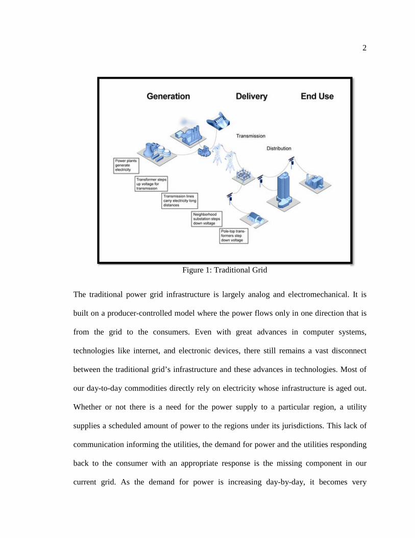
The Figure 1 [1] shows the traditional power grid with the transmission system that
includes the power generation plants, step up transformers, high voltage power lines and
substations. The distribution system consists of substations; step down transformers,
pole-top transformers, and medium voltage power lines. The power plants generate
electricity and step up the voltage for long distance transmissions using step-up
transformers. Further, electricity is transmitted across the high power transmission lines
over long distances to substations where the voltage is stepped down before transmitting
over the medium voltage power lines to the customer premises. The pole-top
transformers further step down the voltage to suit the residential and commercial
specifications.
2
The traditional power grid infrastructure is largely analog and electromechanical. It is
built on a producer-controlled model where the power flows only in one direction that is
from the grid to the consumers. Even with great advances in computer systems,
technologies like internet, and electronic devices, there still remains a vast disconnect
between the traditional grid’s infrastructure and these advances in technologies. Most of
our day-to-day commodities directly rely on electricity whose infrastructure is aged out.
Whether or not there is a need for the power supply to a particular region, a utility
supplies a scheduled amount of power to the regions under its jurisdictions. This lack of
communication informing the utilities, the demand for power and the utilities responding
back to the consumer with an appropriate response is the missing component in our
current grid. As the demand for power is increasing day-by-day, it becomes very
Figure 1: Traditional Grid

3
important that there be an effective communication from the consumer to the utilities
demanding only the required amount of power and the utilities in turn responding back
appropriately to the consumer based on the need.
1.2.NEED FOR SMART GRID [33]
SUSTAINABILITY
Since 1982, the demand for electricity has exceeded the transmission growth by 25%
every year. Increase in demand, calls for increase in power generations which would
directly affect the carbon dioxide emissions from the power generation plants. According
to a study by U.S. Energy Information Administration [EIA] department [33], 40% of the
carbon dioxide emissions are from electricity generation and 20% from transportation. A
5% improvement in electric efficiency is equivalent to carbon emissions from 53 million
cars. Global warming of earth’s surface and lower atmosphere is a result of strengthening
the greenhouse effect where the percentage contribution from carbon dioxide gas to
greenhouse effect is anywhere from 9 – 26% [33]. The human-produced gasses as a result
of electricity generation and transportation are the main cause for global warming. Hence,
a smarter grid is needed, to support sustainability.
RELIABILITY
In the current electricity grid architecture, the utilities are informed of the blackouts or
outages, if and only if, a customer rings them up notifying an outage. This aging
infrastructure which lacks the outage management system is directly affecting the
reliability of the grid. To explain the effects of these blackouts, consider the northeast

4
blackout of 2003 in the US, which resulted in a $6 billion economic loss. According to a
study by U.S. Energy Information Administration [EIA] department [33], the US outages
costs around $150 billion per year which is a $500 per person and these outages are
getting worse. Also, from the first to the second half of the 1990’s, there were an added
41% of outages affecting more than 50,000 people and 15% increase in the average
customers getting affected [33]. An intelligent grid with effective communications
infrastructure detects an outage immediately and notifies a utility office about the outage;
also they could be avoided when power is redirected to the place where the outage is
predicted. To achieve an improved reliability, a smarter grid is the need of the hour.
RENEWABLE ENERGY
The main motivating factors for using renewable energy sources are to reduce the carbon
emissions, reduce the dependency on oil and lower the cost of electricity over the longer
run. Power from renewable energy sources like solar, wind, geothermal and tidal are low
power and intermittent when compared to the one from traditional power generation.
These intermittent sources need a distributed generation to harness the power and sell it
to the utility offices close by. To handle both the distributed and intermittent power
sources, we need a smarter grid.
SECURITY
The current centralized grid is vulnerable to terrorist attacks because in case of attacks
there would be a complete outage and reconstruction of such huge centralized electricity

5
infrastructure in a short time would be impractical. In case of attacks, a significant area is
affected with lack of power supply. Having the power generation distributed would help
us reduce the devastating effect of terror attacks or any natural disasters.
Lastly, the average age of a skilled professional at the utilities is around 48 years. This
would result in a 20% retirement of skilled labors in a span of 7 years. One way we could
recover the loss of these skilled labors in a significant way is by introducing a smarter
grid which could handle their loss. Also, smart grid deployment would directly create
about 280,000 jobs in the US [33].
1.3.SMART GRID
Smart Grid could be thought of as the Internet for energy. Smart Grid is an electricity
infrastructure consisting of devices installed at homes and businesses throughout the
electricity distribution grid for the purpose of energy monitoring which utilizes the
computer, networking and communications technologies all the way from the generation,
transmission and distribution of electricity to consumer appliances and equipments. This
set up provides consumers the ability to monitor and control energy consumption
comprehensively in real time across the smart communication network. The consumers
that generate energy from sources such as: solar, wind or other systems, can also carry
out business with the utilities by outsourcing the surplus energy that they generate.

6
The actors of a Power Grid can be categorized into three main entities. They are
i. Power Generators: Consisting of the centralized power plants, the small
generators and solar panels.
ii. Power Distributors: These are the utilities who are responsible for deliviering
power to the customers.
iii. Power Consumers: The end customers who utilize the services provided but the
distributors and consume energy.
The components of Smart Grid include: a centralized power plant, generators of
renewable energy, demand management systems, processors, sensors and smart
appliances. An example of such a Smart Grid is shown in Figure 2[2].

7
Figure 2: Smart Grid
In the Figure 2[2], the sensors detect the variations and fluctuations in the electricity and
send information signals to the demand management systems. At the demand
management system, decision signals are generated, so as to increase or decrease the
electricity generation and these signals are sent out to the processors. The processors,
without any need for human intervention, would execute these instructions and take
appropriate actions instantaneously.
To understand this process better, let us consider an example of a peak time scenario,
where in, at a certain time in a day, the demand for electricity would be at its peak and
the utilities might have to fire up the peak generators to meet the peak time demand. The
sensors would sense these variations in the demand and would send out signals to
demand management systems. Also, demand management systems could be connected to

8
a database with all the data relating to the peak times and other information, which are
collected over a period of time. Based on the signals sent over by the sensors, the demand
management system would send appropriate control signals to the processors and the
processors in-turn would take appropriate actions like increasing the power generation,
triggering the system to send out the peak time prices to the consumers. Also, based on
customized power profiles registered by the consumers with the utilities, these processors
could initiate shutting down of appliances or manage the appliances according to the
power profiles. An analogy to the customized power profiles could be the different
profiles available on a mobile phone where it would have different ring tone, message
alert, vibrate, backlight settings for each profile based on whether the user is at work,
home, meeting, or driving. Similarly, the power profiles could be a preset recommended
profile set by the utilities, or a customized profile from the consumer wherein, the
consumer specifies his requirements based on his/her need and the price information from
the utilities. For example, he would want to turn off the air-conditioner every fifteen
minutes for a ten minutes interval during the peak times of the day, maintaining the
temperature at 75 degree Fahrenheit. Another example could be of turning on the
television at 8:30pm every weekday and turning off the lights if no person is present in
the room for a duration more than 20 minutes.
Smart grid is intelligent as it is capable of sensing the system overload and rerouting
power to prevent outages and give resolution to conditions or situations faster than a user
could respond. It is efficient as it meets the user’s increasing demand without adding
infrastructure. It is accommodating as the user can do business with the utilities by

9
pumping energy back to the utilities with renewable sources like wind, solar and other
sources. The consumer has the ease to choose the energy consumption profile and
customize it according to his/her preferences. For this reason along with the real-time
communication between the customer and the utilities makes it motivating. It is capable
of delivering power, free of sags, spikes, disturbances and interrupts which is the main
requirement for the data centers and this could be termed as quality-focused. Since, the
Smart Grid’s deployment would be made distributed and not centralized; it becomes
secure and provides resistance to natural and terror attacks. All these features make
Smart Grid intelligent, efficient, accommodating, motivating, opportunistic, quality-
focused, and resilient and lastly “green” as the carbon emissions are lowered with
increased efficiency.
1.4.NEIGHBORHOOD AREA NETWORKS
The efficiency of Smart Grid greatly relies on communication. Communication can be
broadly classified into two types:
DATA COMMUNICATION
The utility offices collect the electricity usage information from consumers on a timely
basis to build a future demand statistics. Example for this would be a smart device which
is part of an air conditioner sending the usage or power consumption information every
minute to the smart meter in kilo watt hour [kWh] units and the smart meters in turn send
the information back to the utility office.

10
CONTROL COMMUNICATION
These are real time communication signals to control the devices at the consumer or
business premises. Example for this could be turning off the air conditioners for a certain
period of time, on request from the consumer during the peak hours when the price per
unit usage is high.
To explain this in a better way, consider an example of IEEE 802.15.4 standard where the
communication could between three main entities, reduced functional devices, fully
functional devices and the utility offices. Reduced functional devices are those devices
that carriers limited functionality to lower cost and complexity. Fully functional devices
support all IEEE 802.15.4 functions and features specified by the standard. Further, the
data communication could be between the reduced functional devices [RFD] (smart
devices installed in homes like heater, refrigerators, air conditioners etc.) and the fully
functional devices [FFD] (say smart meters), and, between the FFD’s to the utility office.
Similarly, the control communication would be from the utility office to the FFD’s and
from FFD’s to the RFD’s.
The communication between the RFD’s and the FFD’s installed at home and business
premises is part of Home Area Network [HAN] and the communication between the
FFD’s and the utility offices is part of Neighborhood Area Network. A set of FFD’s (say
smart meters from a group of houses) would communicate with a device on a pole and
this device would in turn communicate with the utility offices over the neighborhood area
network. And each such device on the pole is interconnected thereby forming a mesh like
network constituting a neighborhood area network.

11
Neighborhood Area Networks [NAN] are a type of packet switched mobile data
networks. NANs are flexible packet switched networks whose geographical coverage
area could be anywhere from the coverage of a LAN, to MAN, to WAN. In Smart Grid,
NAN has a role to play in the HOME-to-HOME or HOME-to-GRID communication.
The order of the day in networking is to provide complete ubiquity, i.e., every device
location is connected to millions of locations and across ten thousands of square miles.
The solution for complete ubiquity is wireless neighborhood area network [WNAN]. The
ubiquitous network requirements for Smart Grid are identified as follows: reliable,
secure, power efficient, low latency, low cost, diverse path, scalable technology, ability to
support bursty, asynchronous upstream traffic to name a few.
In this report, we would mainly focus on the communication sector of Smart Grid, where
analysis of communication, routing and transport protocols for neighborhood area
network for Smart Grid in particular are carried out.
1.5. RELATED WORK In this section we will discuss the work done on communication infrastructure by other
organizations.
Electric Power Research Institute [EPRI] submitted a report on Smart Grid
Interoperability Standards Roadmap to National Institutes of Standards and Technology
[NIST], which lists the near-term actions that NIST proposes to take with regards to the
Interoperability framework. Few of the highest priority tasks related to communication
and cyber security are listed below [5]:

12
Conducting an analysis to select Internet Protocol Suite profiles for smart
grid applications
- NIST should commission a group to perform a
comprehensive mapping of smart grid application requirements to the
capabilities of protocols and technologies in the Internet Protocol Suite to
identify Internet protocol Suite subsets as important for various
applications in the various smart grid domains.
Investigating Communications Interference in Unlicensed Radio
Spectrums -
NIST should commission a group of experts to study the issue
of communications interference in unlicensed radio spectrums for smart
grid applications.
In the interim report, NIST suggests few standards/protocols to use in communication
infrastructure to exchange meter data and control signals. Few protocols that are
identified by NIST for network interoperability are TCP/IP, UDP, ANSI C12.22, IEC-
61850, Ethernet, ZigBee, LAN, WAN, WLAN, Metropolitan Area Network (MAN),
IEEE 802.11x MAC, & IPv4, IPv6 Addressing, Distributed Network Protocol (DNP3)
[5].
Number organizations such as Trilliant Inc. have come up with complete Smart Grid
communication solutions coupled with head-end software to provide utilities with a
solution to meet their Smart Grid networking demands. Few of the solutions that Trilliant

13
Inc. has implemented to the meet the demand-side management and smart metering
solutions are SecureMesh WAN, SecureMesh NAN, SecureMesh HAN and UnitySuite
HES [Head-End Software]. The SecureMesh solutions enable smart grid distribution,
metering and home automation solutions and UnitySuite HES provides the scalable
network operations and management packages [4].
As of today, there is no widely deployed technology in North America to be used for the
implementation of neighborhood area network. The aim of this project is to find suitable
standards/protocols that could be used for Neighborhood Area Network [NAN] for Smart
Grid. Following chapters discuss the requirements for NAN and analyzes
standards/protocols for NAN in Smart Grid.
1.6. SCOPE OF THE PROJECT The aim of this project is to provide a deep insight on the communication protocols used
by the neighborhood area network for Smart Grid. Also, to analyze the protocols,
compare and recommend the best suitable protocol that could be implemented in
neighborhood area networks. And to study the security issues with the identified
protocols, and make few recommendations to solve any open issues and identify the
research areas based on this study. Chapter 1 introduces us to the traditional grid, need
for Smart Grid, structure of Smart Grid and lays the foundation for neighborhood area
network. Chapter 2 emphasizes on neighborhood area network, its requirements for
Smart Grid and its significance in Smart Grid. Chapter 3 acquaints us with the protocols
and standards that are in contention for the implementation in neighborhood area

14
networks. Chapter 4 discusses the different kinds of routing protocols that find their way
into neighborhood area network. Following this would be the discussion on transport
protocols used in neighborhood area network as part of Chapter 5. The next chapter will
discuss the security issues and vulnerabilities associated with the protocols and standards
discussed in Chapter 3. Also Chapter 6 lists the best practices and recommendations for
the protocols or standards discussed in Chapter 3. Even with all the best practices and
recommendations listed in Chapter 6, there would still be few open issues that need to be
addressed; Chapter 7 would identify such research areas in neighborhood area network as
part of the customer domain for Smart Grid.

15
Chapter 2
REQUIREMENTS FOR NEIGHBORHOOD AREA NETWORK
There has been a steady progress in the communication requirements for utility
applications, starting from the one-way communication for reading meter data or
Automated Meter Reading [AMR] to advanced two-way communication of Advanced
Metering Infrastructure [AMI], supporting the outage notification, demand response and
other applications [See Figure 3] [3].
Figure 3: Evolution of Utility Communication Requirements

16
Smart Grid requirements that have extensions to these capabilities including distribution
automation and control, power quality monitoring and substation automation, need a
communication infrastructure that allows utilities to interact with devices on the electric
grid as well as with the customers and distributed power generation and storage facilities
[3]. The customer domain consists of a Neighborhood Area network connecting the
utility to the smart meter installed in the homes of the consumer, the gateway and finally
then home area network which connects all the appliances at home [See Figure 4 [34]].
Figure 4: Customer Domain: NAN, gateway and HAN
The utilities should have the ability to support multiple communication networks like
Home Area Network [HAN], Neighborhood Area Network [NAN] and Wide Area
17
Network [WAN] for various applications like consumer energy efficiency, advanced
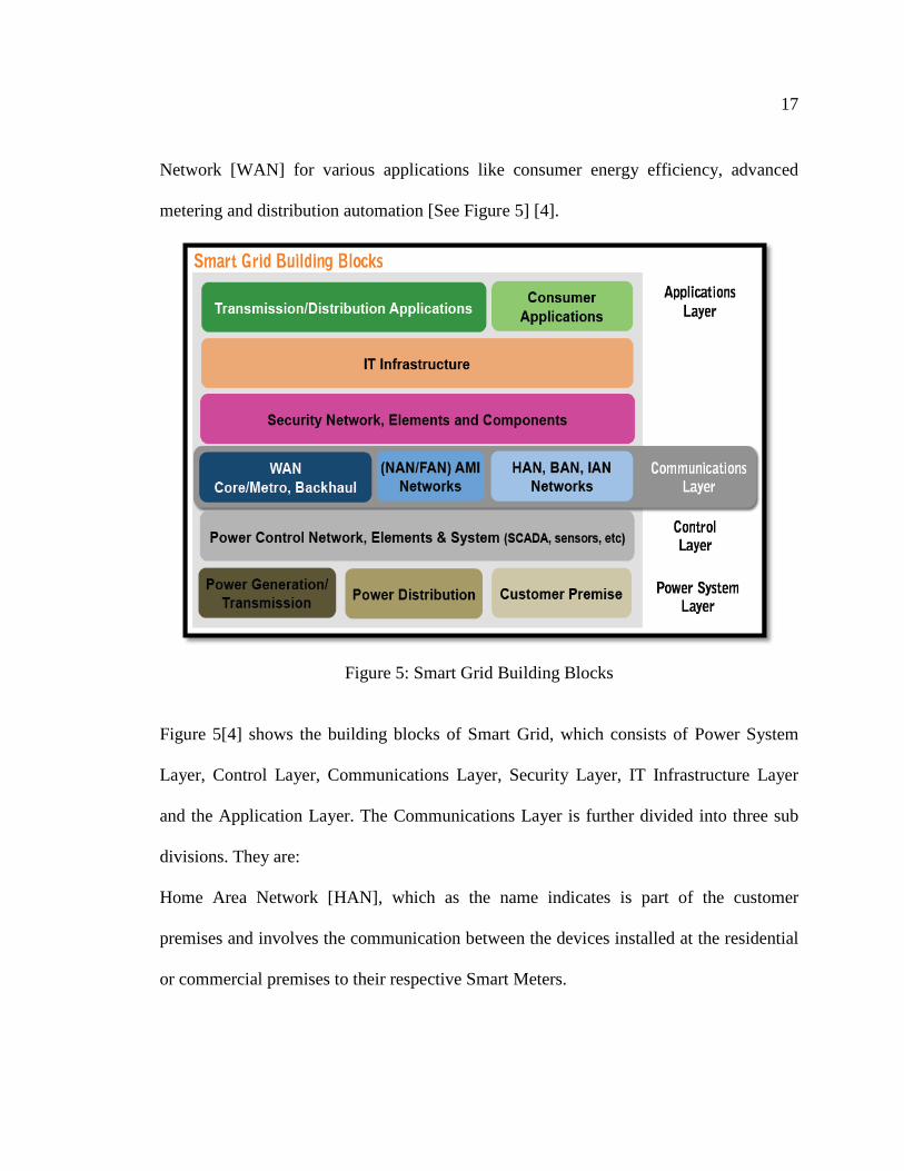
metering and distribution automation [See Figure 5] [4].
Figure 5: Smart Grid Building Blocks
Figure 5[4] shows the building blocks of Smart Grid, which consists of Power System
Layer, Control Layer, Communications Layer, Security Layer, IT Infrastructure Layer
and the Application Layer. The Communications Layer is further divided into three sub
divisions. They are:
Home Area Network [HAN], which as the name indicates is part of the customer
premises and involves the communication between the devices installed at the residential
or commercial premises to their respective Smart Meters.

18
Neighborhood Area Network [NAN] is the communication network that aids the
communications between the utilities and the Smart Meters installed at the customer
premises.
Wide Area Network [WAN] is the communication network responsible for the backhaul
communications.
The Smart Grid communication requirements at high level, is described below [2]:
SECURE
Privacy, Integrity and Confidentiality are the three main focus areas in communication
across the network. Hence, an end-to-end security must be employed to protect user
information and protect the network from unauthorized access.
RELIABLE
The network has to provide maximum availability by incorporating fault tolerance
mechanisms and self-healing failover at each tier of the network. It must provide an
“always-on” communication as part of the electric grid.
FLEXIBLE
The coverage has to be consistent over smaller rural regions to larger urban areas. The
communication network has to have the flexibility to cover the same disparate territories
as the grid itself.

19
SCALABLE
The network needs to be scalable to meet the current and future requirements. It should
be capable of supporting the changing requirements over time to accommodate the
current simple meter reading to the future multi-application that span from demand-side
management to distribution automation. Also, it should be upgradeable and interoperable
to ensure future-proof solution.
COST-EFFECTIVE
The capital and operational expenses of a communication network needs to be within the
potential savings.
The typical characteristics of different communication network layers could be
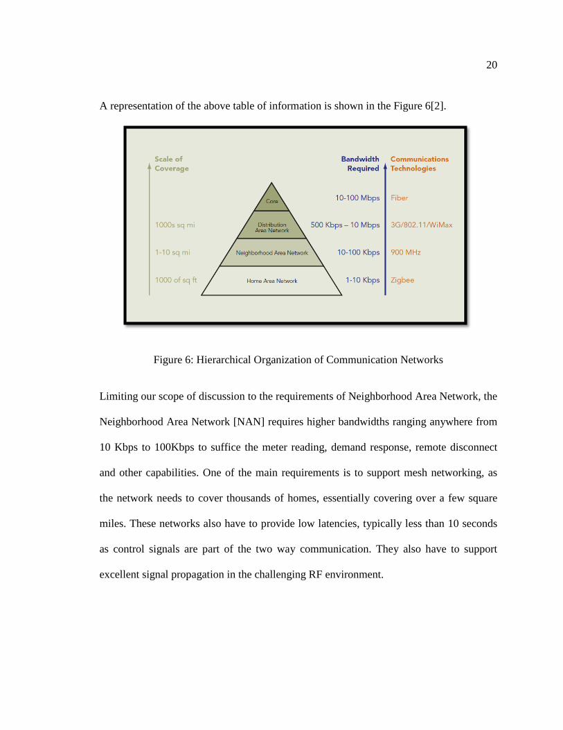
summarized as shown below in Table 1.
Scale of Coverage Bandwidth Required
Example for Communication
Technologies Home Area Network
1000 of Sq. Feet 1-10 Kbps ZigBee
Neighborhood Area Network
1 – 10 Sq. Miles 10-100 Kbps 900 MHz
Distribution/Wide Area Network
1000s Sq. Miles 500 Kbps – 10 Mbps
3G/802.11/WiMAX
Core 10 – 100 Mbps Fiber
Table 1: Network Types, Coverage and Bandwidth
20
A representation of the above table of information is shown in the Figure 6[2].
Figure 6: Hierarchical Organization of Communication Networks
Limiting our scope of discussion to the requirements of Neighborhood Area Network, the
Neighborhood Area Network [NAN] requires higher bandwidths ranging anywhere from
10 Kbps to 100Kbps to suffice the meter reading, demand response, remote disconnect
and other capabilities. One of the main requirements is to support mesh networking, as
the network needs to cover thousands of homes, essentially covering over a few square
miles. These networks also have to provide low latencies, typically less than 10 seconds
as control signals are part of the two way communication. They also have to support
excellent signal propagation in the challenging RF environment.

21
Chapter 3
OVERVIEW OF CANDIDATE NETWORK PROTOCOLS AND STANDARDS
Protocols can be categorized based on the type of connectivity namely wired and
wireless. Each has its own advantages and disadvantages. Reliability, quality of service,
security, cost effectiveness and speed are the advantages to wired networks. While the
disadvantages are difficulty in installation, addition of computers or systems may slow
down the network, looks disorganized and maintenance of cable are difficult. Wireless
networks are neat and clean with no untidy cables hanging around, also the set up is very
easy and does not need a great deal of networking experience. But the downside to
wireless networks is that they are not as reliable and secure as wired networks. They also
have potential radio interference due to obstacles, weather and other wireless devices.
Wireless networks have many other advantages over wired networks which are mainly
mobility, more flexible, easier to use and affordable to deploy and maintain. Every
network transmits data over a medium and for wireless networks the medium is the
electromagnetic radiation. Wireless devices are constrained to operate in a certain
frequency band. Each band has an associated bandwidth, which is simply the amount of
frequency space in the band. So, let us first consider the players in the wireless category
for communication protocols for Smart Grid.
For Smart Grid, a careful choice has to be made in selecting a protocol or a standard for
the data and control information exchanges. This information exchange involves highly
confidential consumer information so customer privacy has to be protected. As far as the
22
control information is concerned, security is at the highest priority, if misused, would
lead to financial loss and sometimes could prove to be fatal.
Keeping the above discussed points in mind, we could consider the following protocols
that could find a place in the communication arena of Smart Grid. They are IEEE 802.11,
802.15.4 and 802.16, ANSI C12.22, 3G, Mesh Networks, optical fiber communication,
and power line communication.
3.1. IEEE 802.11
IEEE 802.11 is the set of standards defining the wireless local area network
communications operating in the 2.4GHz, 3.6GHz or 5GHz frequency bands. These are
defined and amended by the IEEE LAN/MAN standards committee. IEEE 802.11
includes the Wi-Fi [Wireless Fidelity] and its faster cousin IEEE 802.11g. The current
version is IEEE 802.11-2007 and other common and most implemented versions are
IEEE 802.11a, b, g and n. IEEE 802.11 uses the radio wave physical layer. The bands of
operation of these protocols are set by ITU [International Telecommunication Union] for
radio communication. The ISM [Industry, Scientific and Medical] bands are usually
license-free provided that the devices are low-power. IEEE 802.11b/g operates at
2.4GHz, while IEEE 802.11a operates at 5GHz.
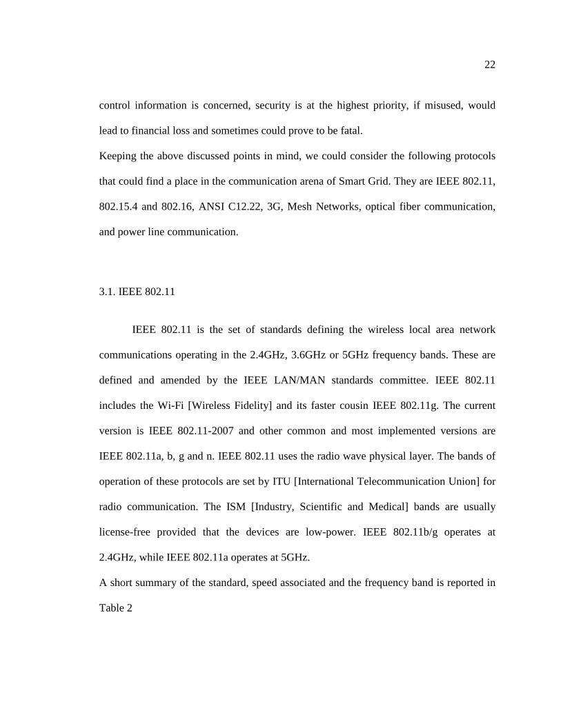
A short summary of the standard, speed associated and the frequency band is reported in
Table 2
23
IEEE Standard Speed Frequency Band 802.11 1Mbps , 2Mbps 2.4 GHz
802.11a Up to 54Mbps 5 GHz
802.11b 5.5 Mbps, 11 Mbps 2.4 GHz
802.11g Up to 54 Mbps 2.4GHz
802.11n Up to 300 Mbps 2.4/5 GHz
Table 2: IEEE 802.11 Standards and its Variations
IEEE 802.11 adds a number of management features to differentiate it from the wired
networks. They have a 48 bit MAC [Media Access Control] address and they look like
the Ethernet network interface cards. These addresses are from the same address pool as
of the Ethernet, to maintain the uniqueness and compatibility when wireless networks are
deployed in networks which contain the wired network too.
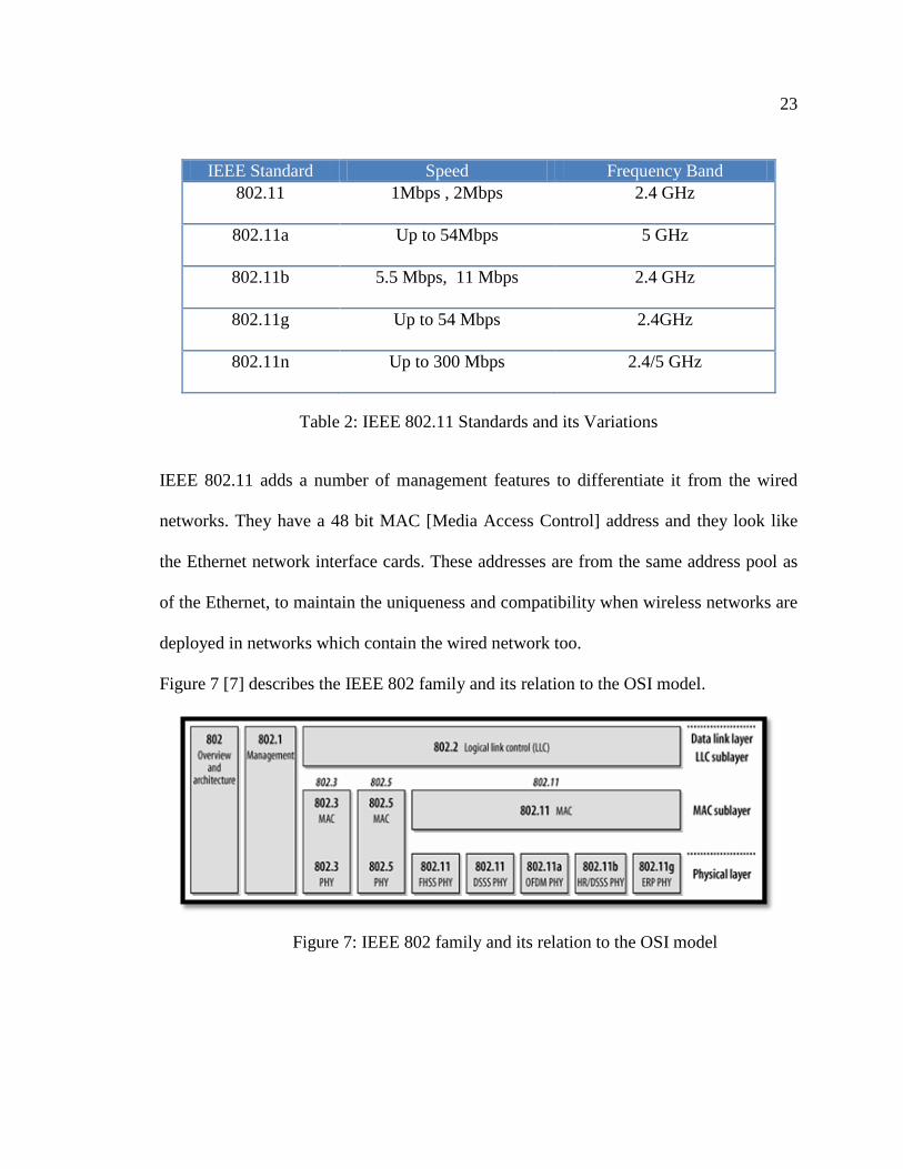
Figure 7 [7] describes the IEEE 802 family and its relation to the OSI model.
Figure 7: IEEE 802 family and its relation to the OSI model

24
IEEE 802 focuses mainly on the lowest two layers of the OSI model because it involves
the physical and data link components. The MAC layer is responsible for setting the rules
for sending data and specify how to access the, whereas, the physical layer is responsible
for the transmission and reception of the data. 802.2 specify the link layer and logic link
control [LLC] which could be used by any LAN technology.
IEEE 802.11 is just another link layer that uses the 802.2/LLC encapsulation.
IEEE 802.11 has MAC layer and two physical layer a FHSS [frequency hopping spread
spectrum] and DHSS [direct hopping spread-spectrum]. Later revisions of the 802.11
standards also include OFDM [orthogonal frequency division multiplexing] for higher
speed which is also backward compatible with IEEE 802.11b.
IEEE 802.11 physical layer has two physical medium components [See Figure 8] [7].
They are
i) Physical Layer Convergence Procedure [PCLP]: which maps the MAC frames
ii) Physical Medium Dependent [PMD]: which transmits the MAC frames
Figure 8: IEEE 802.11 Physical Layer Components
IEEE 802.11 Design consists of four major components [See Figure 9] [7]. They are
Station, Access Point, Wireless Medium and Distribution system.

25
Figure 9: IEEE 802.11 Design Components
i) STATION: is a computing device with wireless network interface cards.
Networks are built to transfer data between stations.
ii) ACCESS POINT [AP]: Performs the bridging function, which converts the
frames of 802.11 into another type (wireless-to-wired) of frame for delivery.
iii) WIRELESS MEDIUM: is used to transfer the frames between stations. The
architecture supports different physical layers to be developed to support 802.11 MAC.
iv) DISTRIBUTION SYSTEM: Number of access points together form a larger
network. The distribution system is a logical component which is responsible for
forwarding the frames to the destination.
CHALLENGES FOR THE MAC
There is higher confidence of message reception at the destination with wired network
when compared to wireless network, because wireless medium is susceptible to
interception of radiations from other devices like microwave ovens, cordless phones etc.
26
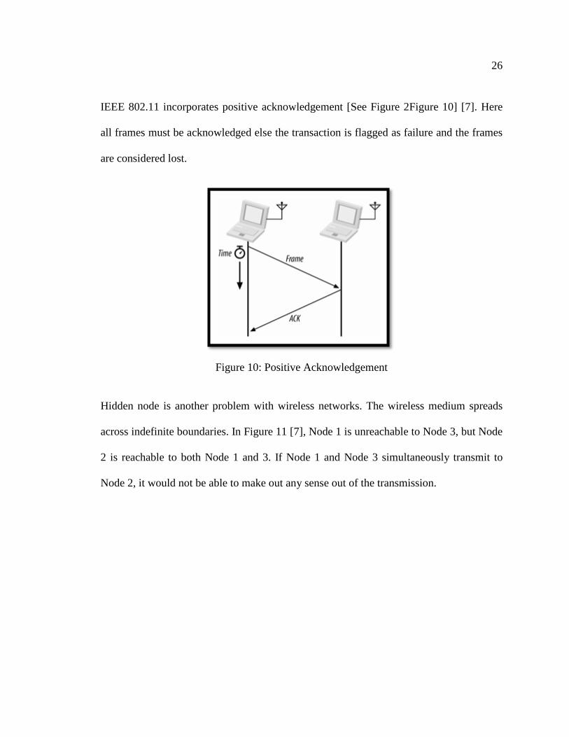
IEEE 802.11 incorporates positive acknowledgement [See Figure 2Figure 10] [7]. Here
all frames must be acknowledged else the transaction is flagged as failure and the frames
are considered lost.
Figure 10: Positive Acknowledgement Hidden node is another problem with wireless networks. The wireless medium spreads
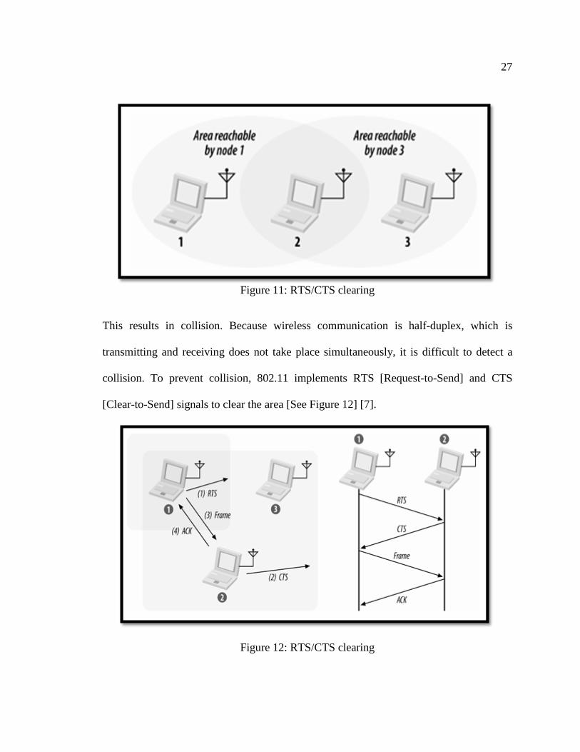
across indefinite boundaries. In Figure 11 [7], Node 1 is unreachable to Node 3, but Node
2 is reachable to both Node 1 and 3. If Node 1 and Node 3 simultaneously transmit to
Node 2, it would not be able to make out any sense out of the transmission.
27
Figure 11: RTS/CTS clearing
This results in collision. Because wireless communication is half-duplex, which is
transmitting and receiving does not take place simultaneously, it is difficult to detect a
collision. To prevent collision, 802.11 implements RTS [Request-to-Send] and CTS
[Clear-to-Send] signals to clear the area [See Figure 12] [7].
Figure 12: RTS/CTS clearing
28
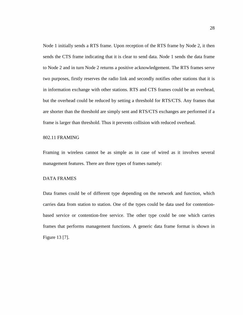
Node 1 initially sends a RTS frame. Upon reception of the RTS frame by Node 2, it then
sends the CTS frame indicating that it is clear to send data. Node 1 sends the data frame
to Node 2 and in turn Node 2 returns a positive acknowledgement. The RTS frames serve
two purposes, firstly reserves the radio link and secondly notifies other stations that it is
in information exchange with other stations. RTS and CTS frames could be an overhead,
but the overhead could be reduced by setting a threshold for RTS/CTS. Any frames that
are shorter than the threshold are simply sent and RTS/CTS exchanges are performed if a
frame is larger than threshold. Thus it prevents collision with reduced overhead.
802.11 FRAMING
Framing in wireless cannot be as simple as in case of wired as it involves several
management features. There are three types of frames namely:
DATA FRAMES
Data frames could be of different type depending on the network and function, which
carries data from station to station. One of the types could be data used for contention-
based service or contention-free service. The other type could be one which carries
frames that performs management functions. A generic data frame format is shown in
Figure 13 [7].

29
Figure 13: Generic Data Frame
As shown in Figure 13 [7], the data frame contains frame control, sequence control and
FCS [Frame Check Sequence] fields. The FCS field is referred to as the cyclic
redundancy check because of the underlying mathematical operations. The Sequence
Control field is a 16 bit field which is used for defragmentation and disregarding
duplicate frames. The Sequence Control field has two parts, A four bit field is the
Fragment number and the rest 12 bits is the sequence number [See Figure 13] [7]. The
Frame control field has many other components as show in Figure 14.
Figure 14: Frame Control field
Protocol Version field indicates the version of 802.11 MAC contained in the frame. The
Type and Sub Type fields indicate the type and subtype of the frames.
ToDS and FromDS indicate whether the frame is destined for a distribution system.
Power Management field indicates whether the sender will be in a power saving mode or

30
not after the exchange of the current frame. The protected frame field indicates whether
protection is enabled by the link layer or not. Order bit indicates whether strict ordering
delivery is implemented or not.
CONTROL FRAMES: This performs area-clearing operations, channel acquisition,
positive acknowledgement and carrier sensing maintenance functions. These use the
same fields as the frame control field [See Figure 14] [7].
MANAGEMENT FRAMES: These perform functions which take care of joining and
leaving the networks and to move association from access points to access points. This is
done by splitting the procedure into three parts. First, the mobile stations must locate a
compatible wireless network to use for access. Next, it must be authenticated with the
network to get itself identified and connect to the network. Finally a mobile station will
be associated with a network to gain access.
802.11 PHYSICAL LAYER
The physical layers are based on the radio technology and different spread spectrum
techniques used.
• 802.11a uses orthogonal frequency division multiplexing [OFDM] PHY
• 802.11b uses direct sequence spread spectrum [DSSS] PHY
• 802.11g uses extended rate PHY[ERP]

31
Spread spectrum is a technique in which a signal in a particular bandwidth is spread in
the frequency domain [8]. This result in a much greater bandwidth than the signal would
have if its frequency were not varied.
FREQUENCY HOPPING SPREAD SPECTRUM is a technique where signals are
transmitted by switching the carrier among many frequency channels in a pseudo-random
sequence which is known both to receiver and transmitter [9].
DIRECT SEQUENCE SPREAD SPECTRUM technique does not hop from one
frequency to another, instead it is passed through a spread function and it is distributed
over the entire band at once [10].
ORTHOGONAL FREQUENCY DIVISION MULTIPLEXING is a technique where
large numbers of closely spaced orthogonal sub-carriers are used to carry data. The data
is divided into number of parallel data streams for each such sub-carrier. Then,
conventional modulation techniques are used to modulate the sub-carriers [11].
32
802.11 HARDWARE
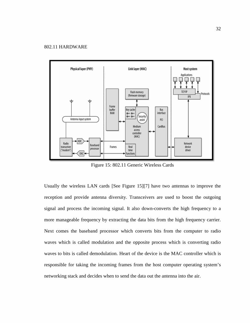
Figure 15: 802.11 Generic Wireless Cards
Usually the wireless LAN cards [See Figure 15][7] have two antennas to improve the
reception and provide antenna diversity. Transceivers are used to boost the outgoing
signal and process the incoming signal. It also down-converts the high frequency to a
more manageable frequency by extracting the data bits from the high frequency carrier.
Next comes the baseband processor which converts bits from the computer to radio
waves which is called modulation and the opposite process which is converting radio
waves to bits is called demodulation. Heart of the device is the MAC controller which is
responsible for taking the incoming frames from the host computer operating system’s
networking stack and decides when to send the data out the antenna into the air.

33
802.11 SECURITY ARCHITECTURE
One of the major features of wireless networks is the ease of connection. This is because
802.11 networks announce their existence with the aid of beacon frames. To protect
against unauthorized access to the network we have to apply access control. It could be
done at various steps as follows:
STATION AUTHENTICATION: Before joining a 802.11 network station authentication
is performed using shared key authentication or sometimes using MAC address filtering
to filter out unauthorized client by MAC address.
LINK LAYER SECURITY: Link-layer authentication is transparent to network
protocols, and will work for any network protocol chosen. Networks are increasingly
homogenous and are based on IP. Link-layer authentication can be used to secure both IP
and IPX. Link Layer Security has a very small foot print and can be easily integrated with
the network interface cards, access point devices and mobile devices. WPA is an industry
standard for providing strong link layer security to WLANs, and supports two
authenticated key management protocols using the Extensible Authentication Protocol
[EAP]. WPA also requires data frame encryption using TKIP [Temporal Key Integrity
Protocol] and message integrity using a Message Integrity Check [MIC].
NETWORK OR TRANSPORT LAYER SECURITY: Network layer security provides
end-to-end security across a routed network and can provide authentication, data
integrity, and encryption services. These services are provided for IP traffic only. IPSec is
a standard network layer security protocol which provides a standard and extensible
method to provide security to network layer (IP) and upper layer protocols such as TCP

34
and UDP. It can also be used between routers or IPSec gateways. Firewalls can be used to
isolate untrusted networks and authenticate users. Also VPN termination devices can
supply encryption over untrusted networks.
3.2. IEEE 802.16 [12][13] WiMAX [Worldwide Interoperability for Microwave Access] is a trade name for IEEE
802.16 standard. WiMAX provides wireless transmission of data in variety of modes
from a point to multi-point links. It is also called as the Last Mile Connectivity of
Broadband Wireless Access [BWA] with a range of around 30 miles and a data transfer
rate of up to 280Mbps with the ability to support data, voice and video. Its operating
range is anywhere from 2GHz to 66GHz. It does not require LOS [Line Of Sight]. A
version of IEEE 802.16 which is IEEE 802.16e adds mobility features operating in the
range of 2-11 GHz license bands. Hence it allows fixed and mobile non Line of Sight
[NLOS] applications primarily to enhance OFDMA [Orthogonal Frequency Division
Multiple Access]. To summarize the salient feature of WiMAX are:
• It enhances orthogonal Frequency Division Multiple Access [OFDMA] by
allowing fixed and mobile Non Line of Sight [NLOS] applications.
• QUALITY OF SERVICE [QoS]
• HIGH DATA RATES: Multiple Input and Multiple Output [MIMO] along with
flexible sub-channelization schemes, coding and adaptive modulation helps mobile
WiMAX technology to support downlink [DL] data rates up to 128 Mbps per sector and
peak uplink [UL] data rates up to 56Mbps per sector in 20MHz bandwidth.
35
• SCALABILITY: The mobile WiMAX has the capability of operating in scalable
bandwidths from 1.25 to 20MHz by utilizing Scalable [SOFDMA].
• SECURITY: The most advanced security features includes Extensible
Authentication Protocol [EAP], advanced Encryption Standard [AES], Cipher Based
Message Authentication Code [CMAC] and Hashed Message Authentication Code
[HMAC].
WiMAX system has two major components: They are:
• BASE STATION: consists of high speed electronics and tower like a cell-phone
tower. Base station provides coverage over an area called cell, which has a maximum
radius of upto 30 miles.
• RECEIVER: could be an antenna, stand-alone box or a PCMCIA [Personal
Computer Memory Card International Association] card in a computer. This is also
referred to as Customer Premise Equipment [CPE].
IEEE 802.16e just provides an air interface, but the end-to-end WiMAX network is
defined by WiMAX forums Network Working Group [NWG], which is responsible for
developing requirements, architecture and protocols for WiMAX using IEEE 802.16e-
2005 as the air interface.
IP BASED WIMAX NETWORK ARCHITECTURE
The overall network [See Figure 16] [13] could be divided into the following logical parts
for an IP based WiMAX Network Architecture:

36
• MOBILE STATIONS [MS]: used by end users to access the network.
• BASE STATIONS [BS]: is responsible for providing air interface to the mobile
stations. Also responsible for features like key management, session management and
dynamic host configuration protocol [DHCP] proxy.
Figure 16: IP based WiMAX Network Architecture
• ACCESS SERVICE NETWORK [ASN]: comprises more than one base stations
and more than one access service network gateway to form the radio access network
[RAN]. Functions of Access Service Network gateway includes intra-ASN location
management and paging, radio resource management and admission control, caching of
subscriber profiles and encryption keys, establishment and management of mobility
tunnel with base stations, Quality of Service [QoS] and policy enforcement, and routing
to the selected connectivity service network [CSN].
• CONNECTIVITY SERVICE NETWORK [CSN]: provides connectivity to
internet, public networks and corporate networks. Also, manages per user policy
management and security and IP address management.

37
WiMAX network is based on the following principles [10]:
• SPECTRUM: which allows WiMAX network to be deployed in both licensed and
unlicensed spectra
• TOPOLOGY: Supports Radio Access Network [RAN] topologies
• INTERNETWORKING: Enables internetworking with WiFi, 3GPP [3rd
Generation Partnership Project which is responsible for the specification, maintenance
and development of global system for mobile communication [GSM]].
• IP CONNECTIVITY: Supports IPv4 and IPv6 network interconnects in clients
and application servers.
• MOBILITY MANAGEMENT: Supports both fixed and mobile access and
broadband multimedia services delivery.
Figure 17 [12] below shows the IEEE 802.16 Protocol Architecture that has 4 layers:
Convergence, MAC, Transmission and physical, which can be mapped to two OSI lowest
layers: physical and data link.
WiMAX PHYSICAL LAYER
WiMAX uses Orthogonal Frequency Division Multiplexing [OFDM] which uses number
of sub-carriers to carry data to overcome multiple signals hitting the receiver. There are
several standards associated to IEEE 802.16, one of them is IEEE 802.16-2004 which
uses 256 carriers and IEEE 802.16e uses scalable OFDMA. 802.16 uses many
modulation techniques like Binary Phase Shift Keying [BPSK], Quaternary Phase Shift
Keying [QPSK] and Quadrature Amplitude Modulation [QAM]. It also supports two

38
types of duplexing. They are Time Division Duplexing [TDD] and Frequency Division
Duplexing [FDD].
Figure 17: IEEE 802.16 Protocol Layer
IEEE 802.16 MAC LAYER
The primary task of the MAC layer is to provide interface between the higher transport
layer and the physical layer. The MAC layer takes packets from the upper layer called
MAC service data units (MSDUs) and organizes them into MAC protocol data units
(MPDUs) for transmission over the air and does the reverse for the received transmission.
The convergence service sublayer can interface with a variety of higher protocols such as
ATM TDM Voice, Ethernet, IP and any other future protocols.
Figure 18 [12] shows the generic form of the MAC PDU. The MAC PDU is the data unit
exchanged between the MAC layers of the BS and its SSs. A MAC PDU consists of a
fixed-length MAC header, a variable-length payload, and an optional cyclic redundancy

39
check (CRC). Two header formats, distinguished by the HT field, are defined: the generic
header and the bandwidth request header. Except for bandwidth request MAC PDUs,
which contain no payload, MAC PDUs contain either MAC management messages or
convergence sublayer data. The encryption Control field indicates whether the data
payload in the header is encrypted or not. The Type field indicates the subheaders and
special payload types present in the message payload. Cyclic Redundancy Check [CRC]
Indicator [CI] field indicates if and how the CRC error check is used for the data.
Encryption Key Sequence [EKS] is an index value that is used to identify the location of
a data packet within a sequence of packets to enable the decryption of the packet. A
connection identifier [CID] is a unique number that is used to identify the logical path of
a communication system. Header Check Sequence [HCS] is a calculated code that is used
to check whether the header is received correctly or not.
Figure 18: Generic MAC PDU Format

40
The MAC incorporates several features such as the following:
• Privacy key management (PKM) for MAC layer security. PKM version 2
incorporates support for extensible authentication protocol (EAP).
• Broadcast and multicast support.
• High-speed handover and mobility management primitives.
• Three power management levels, normal operation, sleep and idle.
• Header suppression, packing and fragmentation for efficient use of spectrum.
WiMAX SECURITY
Security is handled by the Privacy Sublayer of the WiMAX MAC. The primary features
of WiMAX security are as follows:
PRIVACY: Most advanced encryption standards like Advanced Encryption Standard
[AES] and 3DES [Triple Data Encryption Standard] are supported. In addition to the
above, 128 bit and 256 bit keys are used for deriving the cipher during the authentication
phase and also these are periodically refreshed.
AUTHENTICATION: To prevent unauthorized access, a flexible means for
authenticating the subscriber stations and users is provided. This authentication is based
on the Internet Engineering Task Force [IETF] Extensible Authentication Protocol [EAP]

41
which provides different types of credentials such as username and password, digital
certificates like X.509 (which has the username and MAC address) and smart cards.
KEY MANAGEMENT: The keys are transferred securely from the base stations to the
mobile stations using the Privacy and Key Management Protocol version 2 [PKMv2]
which involves periodical reauthorizing and refreshing of the keys.
INTEGRITY: The integrity of the control messages is protected using different message
digest schemes like AES-based CMAC [Cipher Based Message Authentication Code] or
MD5-based HMAC [Hashed Message Authentication Code].
3.3. IEEE 802.15.4 IEEE 802.15.4 based wireless networking standard has emerged as a key to robust,
reliable and secure Home Area Network [HAN] deployments. One of the major players
in HAN for Smart Grid is ZigBee which is based on IEEE 802.15.4 standard. IEEE
802.15.4 defines the physical and medium access control layers for low data rate, short
range wireless communication. The operation is defined in both sub 1GHz and 2.4 GHz
frequency bands, supporting Direct Sequence Spread Spectrum [DSSS] signaling with a
raw data throughput of 250Kbps and can transmit point to point, ranging anywhere from
tens to hundred of meters depending on the output power and receive sensitivity of the
transceiver. Applications of IEEE 802.15.4 include light control systems, environmental
and agricultural monitoring, consumer electronics, energy management and comfort

42
functions, automatic meter reading systems, industrial applications, and alarm and
security systems.
IEEE 802.15.4 DEVICES
An IEEE 802.15.4 network has only one personal area network [PAN] coordinator. There
are two types of devices described in the specification that communicate together to form
different network topologies: full function device [FFD] and reduced function device
[RFD]. An FFD is a device capable of operating as a coordinator and implementing the
complete protocol set. An RFD is a device operating with a minimal implementation of
the IEEE 802.15.4 protocol. An RFD can connect to only an FFD whereas an FFD can
connect to both FFDs and RFDs. A PAN coordinator is the main controller of the
network which can initiate or terminate a connection.
IEEE 802.15.4 PHYSICAL LAYER
The IEEE 802.15.4 has two PHY options based on direct sequence spread spectrum
[DSSS]. The PHY adopts the same basic frame structure for low-duty-cycle low-power
operation at both sub 1GHz bands (868/915 MHz) and at high band (2.4 GHz). The low
band implements binary phase shift key [BPSK] modulation and operates in the 868MHz
band with a raw data rate of 20 kbps and in the 915MHz ISM band with a raw data rate of
40 kbps. The high band adopts offset quadrature phase shift key [O-QPSK] modulation,
operates in 2.4GHz with a raw data rate of 250 kbps.

43
IEEE 802.15.4 MAC LAYER
The MAC sublayer provides two services namely MAC data service and the MAC
management service interfacing to the MAC sublayer management entity [MLME]
service access point [SAP] [MLMESAP]. The MAC data service is responsible for the
transmission and reception of MAC protocol data units [MPDU] across the PHY data
service. The features of MAC sublayer are beacon management, channel access, GTS
management, frame validation, acknowledged frame delivery, association and
disassociation.
IEEE 802.15.4 SECURITY [19]
IEEE 802.15.4 supports both secure and non secure mode. Secure mode devices use AES
to implement the following services:
• ACCESS CONTROL: This enables the device to accept frames from authentic
sources only.
• DATA INTEGRITY: The beacon, data, and command frames are encrypted using
AES encryption algorithm. The AES algorithm is not only used to for encryption but also
to validate data sent. This is achieved using Message Integrity Code [MIC] also called as
Message Authentication Code [MAC]. The MAC can be of different sizes: 32, 64 and
128 bits. This MAC is created encrypting parts of the MAC frame using the Key of the
network, so if we receive a message from a non trusted node, the MAC generated for the
sent message does not correspond to the one what would be generated using the message
with the current secret Key, so the message is discarded.

44
• FRAME INTEGRITY: Ensures that the frames are received from the device that
has the key and the data is protected from modification without the key. Frame integrity
is provided to the beacon, data and command payload using a message integrity code
[MIC].
• SEQUENTIAL FRESHNESS: This is to prevent the replay attacks using a replay
counter which will reject a frame which has a value equal or less than the previous
obtained counter value.
3.4. ANSI C12.22 [23] Earlier the data from the memory of electronic devices would be transported using a
proprietary protocol which was unique to a manufacturer. With the introduction of ANSI
C12.22, an effort to standardize the data formats and transport protocols and desire for
interoperability and support for multiple manufacturers are provided. ANSI C12.22
defines the message services of Advanced Metering Infrastructure [AMI] for Smart Grid.
The concept of ANSI C12.18, ANSI C12.19 and C12.21 are extended to come up with
ANSI C12.22.
ANSI C12.18 standard is a point-to-point protocol developed to transport the meter data
over an optical connection. ANSI C12.19 defines the table data format and ANSI C12.21
standard is developed to transfer the data over telephone modems.
An example for ANSI C12.22 could be described as follows, a C12.22-compliant
message could be sent on a RF mesh network to reach an access point, and then use

45
GSM/CDMA 3G or WiMAX network backhaul and metro fiber networks WAN to move
data from end devices to utility control center/head ends.
The main advantage of the ANSI C12.22 open standards is that it enables interoperability
among smart meters, intelligent field devices and others devices so that smart meter data
can be collected, analyzed and C12.22 devices are controlled over any
NAN/AMI/Backhaul/WAN communication networks as long as the message conforms to
the ANSI protocol.
ANSI C12.22 can be transported over IP for Smart Grid Last Mile and other network
segments. If IP and ANSI C12.22 are combined, C12.22-compliant system avoids
utilities from the risk of single AMI/NAN network and smart meter technologies lock-in.
It provides adaptation to the rapid changes in communications technologies that the
utilities choose to communicate with their end devices. If the meter or the network
changes, the overall end-to-end communication system is not affected, as long as the new
solution provides interoperability at the C12.22/IP layer.
The reason ANSI C12.22 is discussed is for the flexibility that it provides for the
interoperability to the Last Mile network for Smart Grid. ANSI C12.22 defines the
communication between IP nodes and its communication devices and it’s interface that
connects the ANSI C12.22 Network (TCP or UDP).
In Smart Grid, ANSI C12. 22 find its application more appropriately in Smart Grid
gateway devices which defines the interface to communicate the meter data to the utility
over the Smart Grid Last Mile network.

46
3.5. CELLULAR COMMUNICATION
One way to meet the requirements for neighborhood area network is through cellular
communication. Cellular communication is ubiquitous, easy to install and incurs low
maintenance cost. The coverage is excellent because it corresponds to the population
concentration and hence ubiquitous. Cellular communication is already established and
has 95% coverage extended to consumers and hence no additional efforts for installations
are required. Cellular technology is also price-competitive solution because it leverages
the existing carriers and quantity of devices. Advances in IP cellular technology and
competitive pricing among carriers create an ideal environment for the smart grid.
Cellular communication could broadly be categorized into two types namely
GSM [Global System for Mobile Communication] and CDMA [Code Division Multiple
Access]. Each of these platforms has several technology implementations based on their
increasing throughput.
The variants of GSM [22] are
i. GPRS [General Packet Radio Service]
ii. EDGE [Enhanced Data Rates for GSM Evolution]
iii. HSDPA/UMTS [High Speed Downlink Packet Access / Universal Mobile
Telecommunication System]
The variants of CDMA are
i. cdmaOne
ii. CDMA2000/1xRTT
iii. EV-DO Rev A

47
A careful selection has to be made while choosing a hardware design with a cellular
technology which would result in long product development cycle time and short
deployment time. A mistake while choosing a cellular technology will lead to delay in
system development and expensive cellular network certifications.
GSM system was designed as a second generation (2G) cellular phone technology. The
aim was to provide a system that would enable greater capacity than the previous first
generation analog systems which was achieved by using a digital TDMA [time division
multiple access] approach. TDMA technique accommodates more users within the
available bandwidth. In addition to TDMA, ciphering of the digitally encoded speech was
adopted to retain privacy. GSM digitizes and compresses data, then sends it down a
channel with two other streams of user data, each in its own time slot. It operates at 900
MHz or 1,800 MHz frequency band.
In Smart Grid, if GSM is considered then, SIM cards could be inserted in the smart
meters which would easily transmit the meter data over the already built-in wireless
network.
To summarize, the Table 3 [24] shows the GSM specifications
Multiple access technology FDMA / TDMA Duplex technique FDD Band 450, 480, 850, 900, 1800, 1900 Channel spacing 200 kHz Modulation GMSK Speech coding Various - original was RPE-LTP/13 Speech channels per RF channel 8 Channel data rate 270.833 kbps Frame duration 4.615 ms
Table 3: Summary of GSM Specifications

48
GSM SECURITY [25]
GSM is one of the most secure cellular telecommunications available because of the
standardized security methods it offers. The confidentiality of the communication is
offered by the radio link with the application if encryption algorithms and frequency
hopping. The anonymity of the user is ensured by using temporary identification
numbers. For the first time when the device is switched on, the real identity, which is
International Mobile Subscriber Identity [IMSI] is used and then a temporary identifier,
that is the temporary IMSI [TIMSI] is issued. This temporary identifier is valid till the
end of a session [37]. The following section describes few basic security methods used in
GSM which are:
MOBILE STATION AUTHENTICATION: GSM network authenticates the identity of a
user using a challenge response mechanism. Here the GSM network sends a 128 bit
Random Number [RAND] to the Mobile Station [MS]. The MS then computes a signed
response [SRES] based on the encryption of the random number with an authentication
algorithm called A3 using an individual user authentication key (Ki). The MS sends this
SRES to the GSM network, which repeats the calculation to verify the identity of the
subscriber. The user authentication key is never sent over the radio channel providing
enhanced security. The user authentication key is present in the Subscriber Identity
Module [SIM]. The A3 or similar algorithms like A8 are implemented in the SIM which
contains both programming and information. The Figure 19 [25] shows the pictorial
representation of the user authentication process.

49
Figure 19: GSM User Authentication Process
SIGNAL AND DATA CONFIDENTIALITY: The SIM contains the A8 algorithm which
is used to generate the 64 bit ciphering key (Kc). Ciphering key (Kc) is computed by the
same random number RAND that is used in the authentication process. This ciphering
key (Kc) is used to encrypt and decrypt the data between the mobile station [MS] and the
base station [BS]. Based on security consideration and network design, the interval at
which the ciphering key may be changed is decided.
The Figure 20 [25] explains the algorithm flow used for signal and data confidentiality.

50
Figure 20: Signal and Data Confidentiality in GSM
Figure 21 [25] explains the encryption of the data using A5 algorithm and ciphering key (Kc).
Figure 21: Ciphering in GSM
SUBSCRIBER IDENTITY CONFIDENTIALITY: A very commonly used identity
which is exchanged between the mobile station and the network called Temporary
Mobile Subscriber Identity [TMSI] is used to ensure subscriber identity confidentiality.

51
TMSI is a pseudo random number generated and issued by the Visitor Location Register
[VLR] and TMSI is valid only in the area it was issued.
3.6. POWER LINE COMMUNICATION [26]
Power line communication [PLC] uses the existing power lines from utility office to
home and within a home/building to transmit data from one device to another. With
better power line solutions, one can communicate using the existing wiring infrastructure
without rewiring or modifications which makes it a cost effective means of networking
devices. One of the requirements of PLC is that it requires high frequency. The current
lines are designed at 50Hz to 400Hz and are noisy and unreliable. The legal restrictions
on frequency band limit the data rates. There are quite a few challenges associated with
communicating over the power lines. Power loss on these lines is directly proportional to
square of current and distance. Different protocols like X10 protocol, CE bus protocol
and Lon works protocol were used but due to poor bandwidth utilization, low data rate
(60bps t0 10Kbps) and frequency band restrictions made them unqualified for
implementation. Home Plug 1.0 was introduced to mitigate the unpredictable noise and
provides Ethernet class network on the existing power lines with a data rate in the range
of 1 to 14 Mbps. Currently research is carried out to achieve higher data rates upto 100
Mbps which are necessary for applications like HDTV. The quality of the transmitted
signal depends on number of devices (air conditioner, television, hair dryer) that are
switched on at a particular time. The quality of signal may also depend on the wiring
architecture and the distance between the receiver and the transmitter. The key

52
characteristics that are considered to evaluate the performance of power line
communications are:
1) Total number of components to complete a communication device and the cost
associated with it. This includes the cost of implementing an appropriate power supply.
2) The frequency spectrum it uses for communication and its compliance with
regulations.
3) Communication performance in the presence of noisy devices like televisions,
computers and hair dryers which sometimes makes it impossible for the receivers to
decode the transmitted signal, due to high signal distortion.
The applications of power line communication could be as follows:
1) HOME AUTOMATION: PLC could be used to connect home devices that have
an Ethernet port using Powerline adapters. The Powerline adapters plug into the wall
outlet and then are connected using CAT5 cables to the home routers. All the devices
would have a receiver system and each receiver in the system has an address that can be
individually commanded by the signals transmitted over the household wiring and
decoded at the receiver.
2) INTERNET ACCESS (Broadband over PowerLine [BPL]): BPL is internet over
power lines and has many advantages over DSL or cable internet. The most obvious is
the already existing ubiquitous wiring architecture. The wiring architecture reduces the
cost of running Ethernet cables in buildings, overcomes the disadvantage of wireless
networks which are security, limited maximum throughput and inability to power devices
efficiently.

53
3) AUTOMOTIVE: Power-line technology enables in-vehicle communication
network of data, voice, music and video signals by digital means over direct current [DC]
battery power-line.
Major disadvantages of PLC are signal errors due to interference and attenuation.
Interference from nearby device causes signal degradation and Active devices like
transformers, DC-DC converters and passive devices like relays and transistors causes
signal attenuation. This might corrupt the data and/or control signals from/to the utility
offices to the customers.
3.7. OPTICAL FIBER COMMUNICATION [27]
Optical Fiber Communication [OFC] is a technique of sending data or information from
one place to another by sending light pulses through an optical fiber. The light acts as the
carrier wave which is used in modulation to carry the information signal. The
transmission of information involves basic steps which are creating an optical signal to
carry the information using a transmitter, relaying the signal over the optical fiber,
ensuring the signal does not weaken before it reaches the destination and receiving the
data and converting it to electrical signal at the destination.
Optical fiber communication offers lower attenuation and interference and hence is an
advantage over electrical transmission for long distances. OFC finds it application in
telecommunication, television and internet signal transmissions. However the
disadvantage with OFC is that it is very complex and expensive to install the required
infrastructure. OFC is chosen when the system requirements are high bandwidth and long

54
distance communication. OFC can replace thousands of electrical links with a single
higher bandwidth fiber. OFC is extremely low loss and effectively no crosstalk which are
the major advantages over electrical transmission lines.
Synchronous Optical Networking (SONET) and Synchronous Digital Hierarchy (SDH)
are multiplexing WAN protocols, which enable transport of multi digital bit streams
across the same optical fiber by using Light Emitting Diodes (LEDs) or lasers. SONET
and SDH are closely related protocols that are based on circuit mode communication.
SONET/SDH enables various ISPs to share the same optical fiber simultaneously without
interrupting each other’s traffic load. They are physical layer protocols, which offer
continuous connections without involving packet mode communication, and are
distinguished as time division multiplexing (TDM) protocols. Optical Carriers are
typically known by their OC-x number where x is a multiple of the OC-1 rate of 51.84
Mbps and OC-768 rate of 40Gbits/s.
3.8. WIRELESS MESH NETWORKS [29]
Wireless Mesh Networks [WMN] [See Figure 22] [28] are multi-hop wireless networks
formed by the mesh routers and mesh clients [See Figure]. Wireless mesh networking has
emerged as a promising concept to meet the challenges in net-generation wireless
networks such as providing flexibility, adaptive and reconfigurable architecture while
offering cost-effective solutions to service providers.

55
Figure 22: Wireless Mesh Network
The core nodes are the mesh routers which form a wireless mesh backbone among the
nodes. The mesh routers provide a rich radio mesh connectivity which significantly
reduces the up-front deployment cost and subsequent maintenance cost. They have
limited mobility and forward the packets received from the clients to the gateway router
which is connected to the backhaul network/internet. In addition to the conventional
router functions, mesh routers enable mesh networking and have multiple interfaces of
the same or different communications technologies based in the requirement. They
achieve more coverage with the same transmission power by using multi-hop
communication through other mesh routers.
56
The physical layer in a WMN uses some of the techniques like orthogonal frequency
division multiplexing [OFDM], ultra wide band [UWB], Multiple-input Multiple-output
[MIMO] and Smart Antenna technologies to improve the capacity of the WMNs. The
medium Access Control protocols for wireless networks are limited to single-hop
communication while the routing protocols use multi-hop communication. Hence, the
MAC protocols are categorized as single channel and multi channel MAC.
The single channel MAC protocols make use of use a few variations of Contention based
protocols like a general contention based protocol, contention based protocol with
reservation mechanism and/or a contention based protocol with a scheduling mechanism.
Multi-channel MAC protocol is a link layer protocol where each node is provided with
only one interface, but to utilize the advantage of multi-channel communication, the
interface switches among different channels automatically [18].
Wireless mesh networks are considered for a wide range of applications such as backhaul
connectivity for cellular radio access networking, building automation, intelligent
transport system networks, defense systems and surveillance systems.
The existing wireless networking technologies such as IEEE 802.11, IEEE 802.15 and
IEEE 802.16 are used to implement WMNs.

57
The Table 4 & Table 5 summarizes the technologies discussed above which are
considered for implementation of neighborhood area network for Smart Grid.
Technology Features Advantages Disadvantages IEEE 802.11 (Wi-Fi)
Data Transfer Rate: 22 Mbps – 128 Mbps Range: up to ½ mile Operating Frequency: 2.4 GHz to 5 GHz Applications
Low device cost
: Meters (AMI), Distribution Automation [DA]
Suitable to Mesh topology
Low latency
Not yet proven for Smart Grid deployment
IEEE 802.16 (Wi-Max)
Data Transfer Rate: 30Mbps Range: up to 50 km Operating Frequency: 2 GHz to 3 GHz Applications
Low latency
: Meters([AMI), DA, Mobile workforce management
High bandwidth High equipment or
device cost Not yet proven for
Smart Grid deployment
IEEE 802.15.4
Data Transfer Rate: 250 Kbps Range: 100+ meters Operating Frequency: 1 GHz to 2.4 GHz Applications
Suitable for Mesh topology
: Meters (AMI), HAN
Low power consumption
Lesser data rates Short range
coverage
Table 4: Summary of Technologies for NAN (continued)

58
Technology Features Advantages Disadvantages Cellular Range: up to 50 km
Operating Frequency: 900 MHz to 2.4 GHz Applications
Uses existing networks
: Meters (AMI), DA, Mobile workforce management
Low capital investment
Short time-to-market
Low module cost
No direct utility control over the network
Moderate performance
RF Mesh Data Transfer Rate: up to 1 Mbps Range: Variable Operating Frequency: variable Applications
Customizable based on specific need
: Meters (AMI), DA
Self healing and organizing
Low cost
Proprietary Expensive devices Unpredictable
Latencies
Leased Lines (e.g. SONET)
Data Transfer Rate: 1.5 Mbps – 155 Mbps Range: Variable Operating Frequency: Wired (Fiber or copper cables) Applications
High Performance
: Substations, DA
Robust
High recurring cost
No direct utility control
Not available at all sites
Broadband over power lines
Data Transfer Rate: 256 Kbps – 10 Mbps Range: Variable Operating Frequency: 1.8 to 80 MHz (electric carrier) Applications
Low recurring cost
: Substations, DA
Robust
High initial investment
Expensive devices Not widely
implemented Not reliable
Narrowband over power lines
Data Transfer Rate: 1 Kbps – 100+ Kbps Range: Variable Operating Frequency: 9 KHz to 95 KHz Applications
Widely deployed in Europe
: Meters (AMI), DA
Proven and Robust
Low performance High latency
Table 5: Summary of Technologies for NAN

59
Chapter 4
ROUTING PROTOCOLS
Wireless network have become accustomed to enable mobility and also gained popularity
in the computing industry. Currently there are two variations in mobile wireless
networks. They are:
• INFRA-STRUCTURED NETWORK: This network consists of fixed and wired
gateways. The bridges of these networks are called Base stations. A mobile unit is
connected within the network which is connected to and communicates with the nearest
base station [See Figure 23].
• INFRA-STRUCTURELESS MOBILE NETWORK: This network is commonly
known as AD-HOC network and contains no fixed routers. All nodes are in motion and
connect in an arbitrary manner. Nodes present in these networks function as routers
which in turn discovers and maintains paths to other nodes in a network [See Figure 23
[36]].

60
Figure 23: Infra-Structured and Infra-Structuredless Networks
There are numerous protocols developed for AD-HOC mobile networks since the
beginning of Defense Advanced Research Projects Agency [DARPA] packet radio
networks. These protocols had several limitations including power consumption, higher
error rates, and low bandwidth.
AD-HOC routing protocols are mainly categorized into [See Figure 24] [32]:
• Table- Driven
• Demand- Driven (Source initiated)

61
Figure 24: Ad-Hoc Routing Protocols
4.1. TABLE-DRIVEN ROUTING PROTOCOL [32] This protocol maintains up to date and consistent routing information from each and
every node in a network. To perform this, each node has to maintain one or more tables
to save the routing information. They also propagate updates throughout the network in
order to maintain consistent network view.
Some of the existing Table-Driven AD-HOC routing protocols are:
• Destination-Sequenced Distance- Vector Routing [DSDVR]
• Clusterhead Gateway Switch Routing [CGSR]
• Wireless Routing Protocol [WRP]

62
4.1.1. DESTINATION-SEQUENCED DISTANCE-VECTOR ROUTING [DSDVR] [32] This is a distance-vector protocol which is used in MANET [Mobile AD-HOC Network]
with some extensions added to it. A routing table is maintained by each node with one
route entry for each destination by recording the shortest route and a destination sequence
number is used to avoid routing loops. The sequence number is incremented by the node
whenever a change like a new node getting added or if a node gets dropped in its
neighborhood. These numbers are also used to select alternative routes to reach the same
destination. Nodes collect the most recent information by choosing the route with the
greatest number.
Routing updates can generate two types of packets:
• Full Dump packets: This packet carries all available routing information along
with multiple Network Protocol Data Units [NPDUs]. In times of occasional movement,
these packets are transmitted infrequently.
• Smaller Incremental packets: These packets are used depending on the
information which has changed since the last full dump. Each of these broadcasts must fit
into a standard- size NPDU which helps in reducing the traffic generated.
Mobile nodes also maintain an additional table where the data is stored which is then sent
as incremental routing information packets. Each new route broadcast contains the
destination address, number of hops to reach the destination and unique sequence number
to each broadcast. In the event that two updates have the same sequence number then the
route with the smaller metric is used to shorten the path.

63
4.1.2. CLUSTERHEAD GATEWAY SWITCH ROUTING [CGSR] [32] This protocol follows different type of addressing and network organization scheme
adopted when compared to DSDVR protocol. It is a multiple hop mobile wireless
network with several heuristics schemes. Channel access, routing, bandwidth allocation
can be achieved by having a cluster-head controlling a group of AD-HOC networks. A
node is elected as a cluster head using Cluster head selection algorithm and a distributed
algorithm is used within the cluster.
The main disadvantage in following cluster head scheme is that it causes an adverse
affect on routing protocol performance due to frequent cluster head changes. This is
because nodes are busy in cluster head selection instead of packets relaying. To overcome
cluster head selection affect, a Least Cluster Change [LCC] clustering algorithm is used.
This algorithm allows cluster head changes only when two come in contact or when one
node moves out of contact from all other cluster heads.

64
Figure 25: Cluster Head Gateway Switch Routing
DSDVR is used as the underlying routing scheme by CGSR and hence CGSR has the
same overhead as DSDVR. However, CGSR modifies the use of DSDVR by using a
hierarchical cluster-head-to-gateway protocol approach to route traffic from source to
destination. Gateway nodes are those which are within the communication range of two
or more cluster heads. The packet initially is sent by the node to the cluster head which is
then sent to another cluster head through gateway until the cluster head of the destination
node is reached. The packet is then finally transmitted to the destination. An example of
this routing scheme is described in Figure 25 [32]
4.1.3. WIRELESS ROUTING PROTOCOL [32] The wireless protocol is a table based protocol with the perception of maintaining routing
information of all nodes in a network. Each node in the network will maintain the
following four tables:
• Distance Table

65
• Routing Table
• Link-Cost Table
• Message Retransmission List [MRL] Table
In case of an event where a link is lost between two nodes, the nodes send update
messages to their neighbors and update the distance table and checks for new possible
paths and updates the routing table. The link cost table maintains the cost of the link to its
nearest neighbors, and the number of timeouts since successfully receiving a message
from the neighbor. Every entry in the MRL Table contains the sequence number of the
update message, a retransmission counter, an acknowledgement-required flag vector with
entry per neighbor and the list of updates sent in the update message. The MRL Table
decides which updated message has to be retransmitted and which neighbor should
acknowledge the retransmission.
4.2. SOURCE INITIATED ON-DEMAND [32] Source-initiated On-demand routing provides a different approach when compared to the
table-driven routing. Source-initiated on-demand routing creates routes only when
required by the source node. A route discovery process takes place within the network
whenever a node requires route to a destination. This process is completed once the route
is traced or all possible route permutation is found. A route maintenance procedure
maintains the established route until the destination becomes inaccessible along every
path from the source or till the route is no longer required.
Some of the existing Source Initiated On-Demand routing protocols are:
• Ad Hoc On – Demand Distance Vector Routing [AODV]

66
• Dynamic Source Routing
• Temporally Ordered Routing Algorithm
• Signal Stability Routing
• Associativity Based Routing
4.2.1. AD HOC ON –DEMAND VECTOR ROUTING [AODV] [32] Ad Hoc On-Demand Vector routing protocol builds on the Destination-Sequenced
Distance- Vector [DSDV] algorithm. AODV creates routes on demand basis by
minimizing the number of required broadcasts unlike the DSDV algorithm which
maintains a list of routes. This algorithm is an improvement to DSDV algorithm. AODV
is also called as a pure on-demand routing acquisition system because only the nodes
which are on the selected path maintain the routing information are involved in routing
table exchange.
When a source node wants to communicate with some destination node but does not have
a valid route to that destination, the source node then initiates a path discovery process to
discover the other node. To achieve this, source node broadcasts Route Request [RREQ]
packet to its neighbors. This request is in turn sent to its neighbors and so on until either
the destination route or an intermediate node route to the destination is traced.
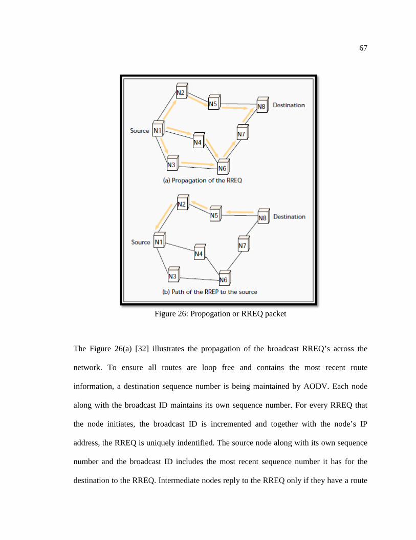
67
Figure 26: Propogation or RREQ packet
The Figure 26(a) [32] illustrates the propagation of the broadcast RREQ’s across the
network. To ensure all routes are loop free and contains the most recent route
information, a destination sequence number is being maintained by AODV. Each node
along with the broadcast ID maintains its own sequence number. For every RREQ that
the node initiates, the broadcast ID is incremented and together with the node’s IP
address, the RREQ is uniquely indentified. The source node along with its own sequence
number and the broadcast ID includes the most recent sequence number it has for the
destination to the RREQ. Intermediate nodes reply to the RREQ only if they have a route

68
to the destination and also the destination sequence number should be greater than or
equal to the current destination sequence number contained in the RREQ.
The intermediate nodes records the address of the neighbors from which the first copy of
the broadcast packet is received in their route tables. This helps in establishing a reverse
path. If nodes later receive additional copies of same RREQ, then such packets are
discarded. Once the RREQ reaches the destination or an intermediate node with a new
route to the destination, the destination or intermediate node replies by sending a Route
Reply (RREP) packet back from which it first received the RREQ packet [See Figure
26(b)] [32].
4.2.2. DYNAMIC SOURCE ROUTING [DSR] [32] Dynamic source routing protocol is an on-demand routing protocol and is based on the
concept of source routing. A mobile node maintains route cache which contains source
routes that is known by mobile nodes. The route cache is continually updated as new
routes to the source are learnt by the mobile nodes.

69
Figure 27: Dynamic Source Routing
DSR protocol maintains two major phases: Route discovery and Route maintenance.
Whenever a mobile node has to send a packet to some destination, it initially checks the
route cache to find out whether the route to the destination is already known. If the route
to the destination is already present in the route cache, it uses the same route to transmit
the packet. On the other hand, if the route to destination is not present in the route cache,
then the node initiates route discovery by broadcasting a route request packet. This route
request packet contains destination address, source node’s address and a unique
identification number. Each and every node checks if it has the destination route to the
address sent in the route request packet. If the node does not find the destination route in
its route cache, it adds its own address to the route record packet and forwards the packet
to the nodes among its outgoing links.
A route reply is generated only when the route request packet reaches the destination or
an intermediate node containing the route to the destination in its route cache. Figure

70
27(a) [32] illustrates the route record formation as the route request propagates through
the network.
If the route reply is generated by the destination, then the destination places the
route record contained in the route request into the route reply. If the route request is
responded by an intermediate node, then it will append its cache route to the route record
to generate the route reply. The responding node must have a route to the initiator in
order to send the route reply. If the responding node has the route to the initiator in its
route cache, then it should use that route. Otherwise, if symmetric link is supported, then
the node must send the route reply by using the reverse route in the route record. If the
symmetric link is also not supported, then the responding node can initiates its own route
discovery and piggyback the route reply on the new route request [32].
Figure 27(b) [32] illustrates the transmission of the route reply with its associated route
record back to the source node.
4.2.3. TEMPORALLY ORDERED ROUTING ALGORITHM [TORA] Temporally ordered routing algorithm is based on the concept of link reversal and is
proposed to operate in a highly dynamic mobile networking environment. It is a highly
adaptive loop-free distributed routing algorithm. This protocol is source initiated and
provides many desired routes for any source or destination pair. The main concept in
TORA is that it provides localization of control messages to a very small set of nodes
near the occurrences of a topological change [32]. To achieve this, each node has to
maintain routing information about adjacent nodes.

71
TORA performs the following basic functions:
• Route creation
• Route maintenance
• Route erasure
Nodes during route creation and maintenance phase establish a Directed Acyclic Graph
[DAG] which is rooted at the destination by using Height metrics as shown in Figure
28(a) [32].

72
Figure 28: Temporally Ordered Routing Algorithm
In case of node mobility a DAG route is broken and route maintenance is required to
reestablish a DAG rooted at the same destination.
Figure 28(b) [32] explains that upon failure of last downstream link, a node creates a new
reference level and all the neighboring nodes propagate through the new reference level
by providing a coordinating structured reaction to failure. The change in adapting the new
reference level is reflected by link reversal which has the same effect as reversing the
direction one or more links when a node has no downstream links [32].

73
Timing is a major factor in TORA because the “height” metric is dependent on the
logical time of link failure. TORA also assumes that nodes have synchronized clocks.
TORA’s height metric is quintuple which comprises of five elements, they are:
• Logical time of a link failure.
• A reflection indicator bit.
• The unique ID of the node that defines the new reference level
• A propagation ordering parameter
• The unique ID of the node
4.2.4. ASSOCIATIVITY- BASED ROUTING [ABR] [32] Associativity-Based Routing is also called as Degree of association stability. This
protocol has a different approach in mobile routing, because it is free from loops,
deadlocks, packet duplicates and defines new routing metrics for ad hoc mobile networks.
A route is selected based on the degree of association stability of mobile nodes. Each
node to signify its existence periodically generates a beacon. This beacon when received
by the neighboring nodes causes their associativity tables to be updated. The associativity
tick of the current node with respect to the beacon node is incremented for every beacon
received.
Association stability is defined by connection stability of one node with respect to
another node over time and space. High degree of association stability indicates low state
of node mobility and vice versa. Associativity ticks are set when the node or the
neighboring nodes move out of proximity.
74
The fundamental objective of ABR is to derive longer- lived routes for ad hoc mobile
networks.
ABR follows three main phases, they are:
• Route Discovery
• Route Reconstruction [RRC]
• Route Deletion
Route Discovery phase is achieved by a broadcast query and await-reply [BQ-REPLY]
cycle. Any node that is looking for a route, broadcasts the BQ message to all the mobile
nodes in order to find the route to the destination. Nodes which are not the destination,
append their addresses and their associativity ticks with their neighbors along with QoS
information to the query packet. The upstream node neighbor’s associativity tick entries
are erased by the successor node by retaining only the concerned entry itself and its
upstream node. In this way, every resultant packet will contain the associativity ticks of
the nodes and route to the destination while arriving at the destination. The destination
chooses the best route by examining the associativity ticks along each path. But, when the
overall degree of association stability is the same along multiple paths, then the route
with the minimum number of hops is selected. The destination replies to the source by
sending a REPLY packet back along the same path. Nodes propagating the REPLY, mark
their route as valid and the rest routes remain inactive. Hence the possibility of duplicate
packets arriving to the destination is avoided.

75
Chapter 5
TRANSPORT PROTOCOL
Smart Grid’s success heavily lies in the communication infrastructure underneath it.
Smart Grid communications are broadly divided into two types namely data
communication and control communication [as discussed in Chapter 1]. These
communications could be achieved through several layers with reference to the OSI
reference model. The OSI model has seven layers namely, application, presentation,
session, transport, network, data link and physical layers. In this chapter, our focus is on
the transport protocols which are part of the transport layer. Transport layer provides two
types of service to an application. They are connection oriented and connection-less
service. Connection oriented service provides reliable, full duplex connection ensuring
end-to-end error detection and correction. While a connectionless service provides higher
speeds as they do not provide flow control and error correction. The requirements for the
transport protocols for Smart Grid are identified as:
• Secure
• Reliable
• High Availability
• Real Time
• Scalable
Few of the important transport protocols that find its place in Smart Grid are listed below.
• Transmission Control Protocol [TCP]
76
• Stream Control Transmission Protocol [SCTP]
• User Datagram Protocol [UDP]
• Wireless Datagram Protocol [WDP]
• Split TCP
• Cyclic UDP [CUDP]
• Wireless Profiled TCP [WP-TCP]
5.1. TRANSMISSION CONTROL PROTOCOL [15]
TCP is a connection oriented protocol where an application process must first
“handshake” with the other processes before sending data. Both the application processes
must exchange some of the preliminary segments to establish the parameters for ensuring
the data transfer. TCP provides full duplex service, that is, two senders can send
information to each other at the same time. But it cannot multicast, that is, a single sender
cannot send it to many receivers at once. The process of establishing connection is also
referred to as a “three-way handshake”, as the client first sends a special TCP segment to
the server and the server then responds with a second TCP segment and once the
connection is established, the third segment is exchanged which is the data payload. The
first two segments do not carry any data payload.
TCP is a connection oriented network and the advantage of it being connection oriented
is that it provides reliable service by incorporating congestion control, sequence number
detection and acknowledgment mechanisms. An orderly delivery of messages is
guaranteed using TCP as it implements sequence number and messages are requested to
be retransmitted if the messages arrive out of sequential order. Also, the messages are

77
retransmitted if the sender does not receive an acknowledgement before the timeout
period.
Usually in wired networks, messages get dropped or fail to reach the destination due to
network congestion. TCP implements congestion control mechanisms to overcome this
network congestion problem. At the same time, for wireless networks, congestion control
mechanism of TCP is an overhead because when a packet or a message is lost due to
disturbances in the communication medium (which is the main cause for packet loss in
wireless networks), TCP assumes that the packet loss is due to the network congestion
and implements congestion control mechanism which lowers the data rate and also delay
delivery of the data to the destination. This would lead to another problem that points to
real time application of TCP. Also, TCP is prone to SYN Flood attacks, where in a
malicious computer sends many requests to the server with spoofed IP addresses and fills
up the connection table that result in dropping of some valid requests. This could be
controlled to an extent by dropping packets from unknown IP addresses.
To summarize the advantages of TCP are it is reliable and efficient in wired networks and
disadvantages however are that TCP does not guarantee a timely delivery of data, it
cannot be used in time critical applications.
In Smart Grid, the control information such as pricing, control signals to medical
equipments and so on are time critical and usage of TCP in time critical applications
become a bottle neck. Hence TCP confines its usage in Smart Grid to transmitting only
non time critical data.
78
5.2. USER DATAGRAM PROTOCOL UDP is the core component of the Internet Protocol Suite. Computer systems use UDP to
send messages across hosts and these messages are referred to as Datagrams. Unlike
TCP, UDP does not add overheads like communication channel establishment, error
correction, flow control or congestion control. UDP rather drops the packet instead of
waiting for a delayed packet. Hence it is a good candidate for time critical applications.
UDP supports multicast and broadcast, that is, a message can be sent simultaneously by a
sender to many receivers. Also, UDP is advantageous whenever there are link failures or
when routes keep changing, since a UDP packet has all the information required by itself
to reach the destination.
As mentioned earlier, UDP does not account for the overhead as compared to TCP,
implementing flow control, congestion control and acknowledgement mechanisms which
make it unreliable. Also, UDP packets are lost due to the fact that routers choose to drop
UDP packets first to TCP packets in case of insufficient memory. UDP is faster and
hence faces problems in a fast sender and slow receiver scenario since flow control is not
implemented.
UDP is susceptible to intrusions because a socket receives data from any host whether it
is participating in the communication or not, hence it makes UDP unsuitable for time
sensitive applications.
In Smart Grid, UDP could be used to broadcast or multicast the pricing changes
information to the subscribers which are not time critical. UDP could also be used to send

79
control signals which are not time critical, like turning on the air conditioning system few
minutes before entering a premise.
5.3. SPLIT TCP Proxies split a TCP connection into multiple local segments. These proxies buffer packets
and deliver them to the next proxy or to the destination. Here, each segment by itself is a
complete TCP connection. TCP segregates the effect of packet errors and delay in
wireless links from the wired connections, so that, TCP congestion control, timeout and
retransmission mechanisms in the wired link do not suffer from the fluctuating quality of
the radio channel. The advantage with Split TCP is that it hides the problems associated
with the wireless links from the wired links and vice versa and provides better TCP
performance when deployed in wireless networks. Split TCP lacks the security aspect in
the end-to-end communication between sender and the receiver. In Smart Grid Split TCP
could be used in a situation where wireless and wired networks bridge together, since
TCP in wired and Wireless Profiled TCP [WP-TCP] in wireless are performance
efficient.
5.4. STREAM CONTROL TRANSMISSION PROTOCOL [31] A mix of TCP and UDP features give rise to another transport protocol called Stream
Control Transmission Protocol [SCTP]. Unlike TCP’s 3-way handshake, SCTP
implements a 4-way handshake to establish a connection between end points. The use of
TCP has two major problems which are:
80
HEAD-OF-LINE BLOCKING - This is a problem where the delivery of the new
message is delayed when a packet of an earlier message sequence arrives late or lost
during transmission. The new message is held within the receiver’s transport layer
buffers until the lost packet of the earlier message is retransmitted.
MULTIHOMING – This is a problem when a host implementing TCP is forced to wait
(in the order of minutes) to communicate critical information to its destination end-point
even when alternative routes exist. Since TCP implements handshaking before the
message transfer phase it sticks to the single point of attachment at the other end.
SCTP implements Multi-Streaming to overcome the head-of-line blocking problem of
TCP. In Multi-Streaming each data associated with SCTP is assigned a particular stream
for data transmission. In every stream the packets or messages are delivered in order but
this order is independent of the order in the other stream. Thus SCTP provides a partial
order delivery by parallel ordered streams. SCTP is message oriented, meaning a message
of 100 bytes is sent as a single message and the receiver receives it as a single read. It is
similar to UDP but with added reliability. Unordered Service is another positive aspect of
SCTP, where unordered reliable delivery would be useful when ordering is taken care at
the application level and hence reduces the TCP overhead for ordering. TCP is prone to
SYN Flood attacks, where a malicious host would send many connection requests with
spoofed IP addresses, there-by using up all the resources of the server by putting entries
in the connection table. SCTP uses SYN cookies wherein during the connection
establishment phase the server presents a cookie to the client that is requesting a
81
connection and the client has to return this cookie during handshake. The server then
verifies the cookie sent by client and if it is the expected cookie then the server allocates
buffer for the new association.
The disadvantage of SCTP is very high set-up time for communication as it involves 4-
way handshake. SCTP is more complex as it involves integrity check mechanism based
on cryptographic hash functions, and validating state cookies, hence the processing
power of the systems should be bit higher compared to normal TCP or UDP processing
systems. High availability is provided by SCTP as it avoids multi-homing and
implements multi-streaming. Also it could be used on high bandwidth as it supports high
receiver window size. In Smart Grid, SCTP could be used for time critical applications as
it has high availability, and could also be used on communication medium which has low
bandwidth and high latency.
5.5. WIRELESS DATAGRAM PROTOCOL [30] One of the protocols of Wireless Application Protocol [WAP] architecture is Wireless
Datagram Protocol [WDP], which covers the transport layer protocols in an internet
model. WDP is similar to UDP, except for the fact that WDP does not depend on the IP
addresses [28]. WDP provides the upper layers an invisible interface which is
independent of the underlying network technology used. WDP also supports port level
addressing, segmentation and reassembly. UDP could be used as WDP for the link layers
that support IP. This concludes that, in Smart Grid if IP is not supported then WDP could
be used instead of UDP, else UDP is a strong player for wireless communication.

82
Chapter 6
SECURITY ISSUES, VULNERABILITIES AND BEST PRACTICES
In this chapter, the focus is on the security issues and vulnerabilities of the protocols or
standards discussed in chapter 3. Wireless networks are prone to attacks for obvious
reasons that the communication medium is easily accessible.
6.1. IEEE 802.11
6.1.1. VULNERABILITIES AND SECURITY ISSUES 1. CONVENIENT ACCESS: 802.11 networks announce their existence with the aid
of beacon frames which are also inviting threats. “War Drivers” use software to log these
appearances of beacon frames and find the locations using GPS. This cannot be avoided
in any means other than protecting the network with strong access control and using VPN
for sensitive traffic.
2. ROGUE ACCESS POINTS: One of the common security risks is with the rogue
access points which are easy to setup and does not even require authorization. End users
are mostly affected as they are not security experts and minimal changes would be done
by the end users on the default settings. Walking through the campus with network
analyzers like NetStumbler is the only way to check for rogue access points around your
premises.
83
3. MAC SPOOFING: The management frames are not authenticated in 802.11.
Every frame has a source address. The attackers take advantage of the spoofed frame to
redirect the traffic and corrupt the ARP tables. To avoid such attacks strong user
authentication has to be provided to allow potential users to access and unauthorized
users can be kept away from the network.
4. DENIAL OF SERVICE ATTACKS:
i. PHYSICAL ATTACKS: Unlike wired networks, physical attacks to wireless
networks are easy as it does not require the attacker to be in the close proximity of the
victim. Simple devices that operate in 2.4 GHz frequency band like cordless phones that
support 802.11b can be used to take the network offline. This is done by reducing the
signal to noise ratio of the channel to an unusable range, by inducing noise into the
network. 802.11b is susceptible to interference from other protocols or technologies like
bluetooth, microwave oven, cordless phones which operate at the same frequency band
using different modulation techniques.
ii. DATA-LINK ATTACKS: Even with WEP turned on, the attacker can perform
DoS attacks by accessing the user information on the link layer. Without WEP, an
attacker has full access to the user information to manipulate the associations between the
stations and access points to terminate access to the network. If an access point is
incorrectly utilizing the diversity antennas, an attacker can potentially deny access of the
customer associated to that particular access point.

84
Also, by spoofing, if the association of APs what is AP? in a particular SSID is found out,
then the client access to that AP can be denied using malicious AP by providing strong
signals using a directional antenna or any other amplification means.
iii. NETWORK ATTACKS: If a network allows any client to associate then DoS
attacks at the network level is a possibility. An attacker can flood ICMP packets to the
gateway, thereby creating a difficult time for clients associated to the same AP to send
and receive packet. An example could be a huge file transfer or a bandwidth hungry
application on a WLAN with slower speeds can hamper the access for all the stations.
5. MAN-IN-THE-MIDDLE ATTACKS: There are two versions of MIM attack.
They are
i. EAVESDROPPING: Since the medium is wireless, the data is easily accessible as
the data is not confined to a physical area and hence the data could be examined at real
time or stored for later examination. To prevent this several rounds of data protection
(encryption) has to be applied before transmitted to avoid the access from attackers.
ii. MANIPULATING: Even with WEP turned on, the attacker can log huge amounts
of data from the WEP protected traffic, store it, examine it and break the protection.
Manipulating is the next step to eavesdropping. ARP poisoning can be used to divert the
traffic through a malicious computer which could stop forwarding the packets and incur a
DoS attack.

85
6.1.2. BEST PRACTICES FOR 802.11 The following section describes the recommendations for the security of 802.11
networks:
1) Media access control (MAC) address filtering [13] would allow us to
configure our wireless access points (APs) with the set of MAC addresses for authorized
wireless clients.
PROS: Helps receive information from authentic sources and prevents unauthorized
access.
CONS: Does not prevent a hacker from MAC spoofing, increases administrative
overheads.
2) Wi-Fi Protected Access (WPA) [13] has an improved encryption algorithm
called Temporal Key Integrity Protocol (TKIP) which uses a unique key for every client
and also uses longer keys that are rotated at configurable intervals. WPA also includes an
encrypted message integrity check field in the packet to prevent denial-of-service and
spoofing attacks.
PROS: With the use of WPA2, VPN connections are not required to secure the wireless
frames.
3) IEEE 802.11w-2009 [14]: The management information is sent in unprotected
frames, which cause network disruption by malicious systems that forge disassociation
requests that appear to be sent by valid equipment. IEEE 802.11w-2009 is an approved

86
amendment to IEEE 802.11 to increase security of the management frames. The objective
of this protocol is to increase the security by providing data confidentiality of
management frames, mechanisms that enable data integrity, data origin authenticity, and
replay protection.
6.2. IEEE 802.16
6.2.1. VULNERABILITIES AND SECURITY ISSUES 1) AUTHENTICATION: The user authentication in Wi-Max uses X.509 certificate
that will uniquely identify each subscriber and makes it difficult for the attacker to spoof
the identity of the legitimate user. The drawback with WiMAX is that it does not have
Base Station (BS) authentication which makes it prone to Man-in-the-middle attacks
exposing subscribers to confidentiality and availability attacks. WiMAX uses privacy and
key management (PKM) protocol mechanism for authentication. 802.16e is an
amendment of 802.16 which uses Extensible Authentication Protocol (EAP) mechanism
for authentication which is optional and rarely used by Service Providers. Since BS does
not authenticate itself, the SS cannot be protected from rogue BS.
2) ENCRYPTION: 802.16e supports for Advanced Encryption Standard (AES)
cipher providing strong confidentiality on user data. Again the drawback is with
encryption not applied on the management frames thereby sufficing the attacker to gather
information about the subscribers in the area and also about the network characteristics.
3) AVAILABILITY: Even though WiMAX uses a licensed RF spectrum, attackers
can use easily available gadgets to jam the network. This is an example for physical layer

87
denial of service attacks whereas attackers can send legacy management frames to
disconnect legitimate station, this is nothing but deauthenticate flood attacks.
4) WATER TORTURE ATTACK: This is a form of physical layer attack where in
the attacker sends a series of frames to any node to drain the battery life of the victim
node.
6.2.2. BEST PRACTICES FOR 802.16 The following section describes the recommendations for the security of 802.16
networks:
1. MESSAGE AUTHENTICATION CODE [MAC] TECHNIQUES [15]: For
vulnerability of management message, message authentication code techniques can be
applied during initial ranging. For example, one-key message authentication code
[OMAC] may be preferable since it provides replay protection
2. PROTECTION AGAINST MASQUERADING PARTIES: A mutual
authentication scheme is necessary, and Extensible Authentication Protocol (EAP), a
generic authentication protocol used in wireless networks, is most commonly proposed.
3. AES-CCM5: AES in CCM mode constructs a unique nonce during the process of
CBC-MAC. AES-CCM also has an advantage that the encryption scheme is also capable
to protect authenticated but unencrypted data.

88
6.3. IEEE 802.15.4
6.3.1. VULNERABILITIES AND SECURITY ISSUES Many applications require confidentiality and data integrity, 802.15.4 addresses these
with the link layer security package.
1) CONFIDENTIALITY: Same key in multiple ACL entries could completely break
the confidentiality property. In this case if the user is using the same key to send two
different messages to different destinations using different ACL entries, then the frame
and key counter will be 0x0 and hence there is a possibility of reusing the nonce as each
recipient will have their own ACL entry with its own nonce state.
2) LOSS OF ACL STATE: There are chances of ACL table getting cleared when
there is a power failure or when the device operates in a low powered state.
i) POWER FAILURE: In case of power failures the ACL entries are cleared,
however, the ACL table is repopulated by the software with appropriate keys. But, the
issue is with the nonce states. All the nonce states are reset to a known value say 0 (zero)
and there by reuse of nonce is forced to occur which comprises security. In such cases,
the application still seems to work but fails to secure the communication from
eavesdropping.
ii) LOW POWERED OPERATION: Again the issue is with how to retain the nonce
states when the device enters the low powered state. To increase the power consumption
efficiency, only few parts of the device is on for a small fraction of the time and hence

89
the possibility of the device emerging with a cleared ACL is high and hence incurred is
the reuse of the nonce state.
POSSIBLE FIX: Suitable fix to this problem could be saving and storing the nonce states
in flash memories which incurs additional cost, power consumption and also is slow and
energy inefficient.
3) KEY MANAGEMENT PROBLEMS: This problem arises due to the inability in
the ACL tables to support different keying models.
i) GROUP KEYING: There is no support for using the same key for multiple ACL
entries. For example if a group of nodes (n0, n1, ..n4) wants to use a key k1 and group of
nodes (n5, n6, .. n9) wants to use the key k2. As discussed earlier since each ACL entry
can be associated to a single destination address, this type of model cannot be supported.
If attempts are made to create separate ACL entries for each node then the reuse of nonce
state problem arises.
POSSIBLE FIX: Fix for this could be creating a single ACL entry for key k1. Before
sending, changing the destination address associated with that ACL entry for a message
would suffice.
ii) NETWORK SHARED KEYING: The network cannot be protected from replay
attacks when using a network wide shared key. to use the network shared keying model
the application has to use the default ACL entry but a default ACL entry could be used
only if there is no matching ACL entry. Now if a sender s1 sends 50 messages with

90
replay counter 0 – 49 along with the shared key with the default ACL entry and now
when a sender s2 attempts to send a message with replay counter 0 (zero), the device
would reject the message as the replay counter is not greater than 49. Hence network
shared keying model cannot be implemented.
4) CONFIDENTIALITY AND INTEGRITY PROTECTION: Researches have
proven that unauthenticated encryption modes can introduce risks of protocol level
vulnerabilities compromising not only integrity but also confidentiality. An example for
this could be AES-CTR which uses counter mode without a MAC.
5) DENIAL OF SERVICES: As discussed previously, the replay attacks could make
the device to reject packets. For example consider a device that last received a packet
with replay counter 99, now receives an illegitimate packet with a replay counter
0xffffffffh, with any payload with the key k. Since the replay counter is greater than 99
the device receives the packet and decrypts it, resulting in random garbage. Further the
device rejects any legitimate packet with a valid replay counter resulting in denial of
service attack.
6) NO ACKNOWLEDGEMENT PACKETS INTEGRITY: There is an option for
the sender to request an acknowledgement for the packets sent from the recipients. But
there is no confidentiality or integrity provided for the acknowledgement packets thereby
attracting the attacker to forge the acknowledgement packets. For example, an attacker
could make the recipient drop a packet sent by the sender, by making the CRC to be
invalid by sending a short burst of interference. And now the attacker could forge a valid-

91
looking acknowledgement so the sender is assured of the receipt of the packet by the
recipient.
6.3.2. BEST PRACTICES FOR 802.15.4 The following section describes the recommendations for the security of 802.15.4
networks:
1) MAC ADDRESS FILTERING [15]: This security mechanism is defined
with the IEEE 802.15.4 standard and is defined in the Access Control List (ACL) mode.
This feature should be enabled to accept the received MAC frames from authorized nodes
listed in the ACL for the host device.
2) FLASH MEMORIES [15]: The loss of ACL entries during power failure
or low powered operation could be fixed by saving and storing the nonce states in flash
memories. But the use of such flash memories incur an additional cost, power
consumption and also is slow and energy inefficient.
3) AES ENCRYPTION STANDARDS [15]: Data privacy protection
mechanisms based on AES encryption standard should be used to protect the transmitted
data.
4) SOURCE NODE AUTHENTICATION [15]: A concept similar to shared
secret key or unique session key that is derived between two entities in order to secure
data transmitted between them should be used to implement source node authentication.

92
6.4. GSM Security
GSM was first implemented in 1991. GSM providers use a version of COMP128 for both
the A3 authentication algorithm and the A8 key generation algorithm. In 1998, Smartcard
Developer association [SDA] together with U.C. Berkeley researches cracked the
COMP128 algorithm stored in SIM and succeeded to get individual user authentication
key (Ki) within several hours. It was then discovered that ciphering Key (Kc) uses only
54 bits. The A8 algorithm takes a 64-bit key, but ten key bits were set to zero.
COMP128-2 and COMP128-3 algorithms have been developed to address the security
issues of COMP128-1. COMP128-2 and COMP128-3 are secret algorithms which have
not been subject to cryptanalysis. COMP128-3 fixes the issue where 10 bits of the
ciphering Key (Kc) were set to zero [35].

93
Chapter 7
POTENTIAL RESEARCH TOPICS
7.1. CHOOSING A STANDARD FOR IMPLEMENTING NEIGHBORHOOD AREA NETWORK There are quite a few technologies in contention to be used to implement neighborhood
area network (See Table 4 & Table 5). A preferred standard would be the one which is
compatible or common across domains like HAN, NAN and WAN. This would decrease
the equipment cost to a great extent as the radio to be used in the devices would need to
support one single technology, which would also ease the implementation. If not a single
technology, lesser the variations used across the domains, the better it is. To explain this
in more detail let us consider an example.
One of the technologies considered for HAN is ZigBee, which is based on IEEE
802.15.4. ZigBee derives the implementation of PHY layer and the MAC layer from the
IEEE 802.15.4 standard. If IEEE 802.15.4 is considered for the implementation of NAN,
the same radio could be used in the devices installed at homes and utilities. The same
packet format could be maintained and so on. This would ease the implementation and
lessen the equipment costs.
Also, it would be more advantageous if an existing technology is chosen, or modifying an
existing technology to satisfy the Smart Grid NAN deployment requirements. Few
technologies like Narrowband over power lines, which are proven and robust in Europe,
could be considered. The advantage of using such a technology would be no new

94
deployments as it uses the existing power lines for data transmission, also data could be
modulated using the AC 60Hz frequency as a carrier.
As of today, there is no widely deployed technology in North America to be used for the
implementation of neighborhood area network. Hence research is required in this area to
choose a protocol based the above discussion.
7.2. UNPREDICTABLE LATENCIES IN MESH NETWORKS An important advantage of mesh networks is that it is self-healing and self-organizing.
Self-organizing is similar to the concept of a Plug and Play device. Add a new node and
the network discovers the node and automatically incorporates it as part of the system.
There is no human intervention required for configuring the new node to be a part of the
network. Also, there is no human intervention required to re-route the messages in case of
node or link failures in a mesh network. Routers choose an alternative path to send the
messages to the destination in case of such failure and this is referred to as self-healing.
The capacity of a network is dependent on number of factors like network architecture,
node density, and number of channels used, node mobility, traffic pattern, and
transmission range. If the number of hops taken to reach a destination increases or the
diameter of the network increases, the capacity (throughput) of the mesh network
decreases due to interference. If n nodes tries to transmit simultaneously on the number
of available channels, and not all the channels are orthogonal (non-overlapping), then the
data gets corrupted at the receiving end. This causes the re-transmission of packets and
creates unpredictable situations from a RF perspective leading to network suffering from

95
unpredictable latencies. A significant amount of research is required to overcome this
problem as RF Mesh networks even if proprietary, are strong contenders for NAN
implementation.
7.3. PLC FOR HOME AUTOMATION There have been a few failed approaches from vendors to develop interoperable profiles
for HAN connectivity. An example for that is ZigBee alliance and HomePlug Powerline
Alliance working together to implement ZigBee energy profile over power lines.
However, due to changes and/or additions to the requirements, the implementation
became very expensive, power hungry and/or considerably slow. Research in this area to
increase the bandwidth to around 1 Mbps and reduce cost and power consumption to
match the HAN requirements, could force PLC to be used instead of RF for HAN. If this
is achieved then PLC could be implemented in both NAN and HAN.
7.4. IP BASED NETWORKS IP based networks are one of the key elements in Smart Grid information networks. The
advantage with IP based networks is the availability of a large variety of tools and
applications that could be applied to Smart Grid, which could be used in both private and
public networks. It also serves as an interface to application and the underlying
communication medium. IP based networks are very reliable with its dynamic routing
abilities and bandwidth sharing properties. It also could satisfy the quality of service
requirements of Smart Grid like minimum access delay and minimum bandwidth
constraints with protocols like Multi Protocol Label Switching [MPLS].
96
Research is required in this area to identify whether IP based network is suitable for a
given set of Smart Grid requirements and whether cyber security could be achieved for
the same.
7.5. SECURITY FOR ROUTING PROTOCOLS IN WIRELESS MESH NETWORKS The two types of path determination (routing) techniques in wireless mesh networks
[WMN] are proactive and reactive routing protocols. Proactive protocols are one which
finds the path irrespective of the demand. Reactive are those which find the path based on
demand. There are threats associated with these routing protocols which might require
knowledge about the routing protocols to inject erroneous packets to the network. The
threats are summarized below:
BLACK-HOLE: Here the attacker creates forged packets to imitate a valid node in the
mesh network. The packets are attracted by advertizing low cost routes and further
attacking by dropping the packets.
GREY-HOLE: Here forged packets are used by the attacker to drop packets, route and
inspect network traffic.
WORM-HOLE: Disruption of routing is carried out by replaying the routing control
messages from one network location to another.
ROUTE ERROR INJECTION: An attacker by injecting erroneous packets to the mesh
network can break the mesh links.

97
These threats greatly depend on the routing technology used. A proprietary routing
protocol is less susceptible to these kinds of threats when compared to routing protocol
like Ad-hoc On-Demand distance vector (AODV). These risks could be reduced by
implementing message integrity checking for the routing messages and device
authentication. Also, the routers in a mesh network are not power constrained but the
clients which are mobile are power constrained. Hence there is a need of efficient routing
mechanism for WMNs.
Research in this area to secure the routing protocols is the need of the hour, as wireless
mesh networks are integral part of Smart Grid communication networks.
7.6. LIMITATION ON WIRELESS INTRUSION DETECTION Detecting threats against wireless networks have become possible since the introduction
of Intrusion Detection Systems [IDS]. The IDS alerts any kind of suspicious activities on
the system. IDS differentiate these activities as either false positives or false negatives.
False positives are false alarms and false negatives are attacks that were not detected. An
IDS consists of three main functions namely event monitoring, analysis engine and
response. Event monitoring is collection of data and performing some kind of pattern
matching to detect an abnormal activity. The analysis engine has the intelligence to detect
the malicious intent from the collected data. The response alerts the system administrator
with the result of the investigation performed at the analysis engine stage.
The analysis engine ha two types of attack detection methods namely misuse detection
and anomaly detection. Misuse detection is also called as Signature-based detection as it
98
incorporates the pattern matching schema to detect attacks. The traffic is matched against
signatures in the knowledge base and if pattern matches, implies there is an attack. In
anomaly detection which is exactly opposite to misuse detection, the traffic is checked for
normal behavior which is called as normal profile. If there is a deviation to the normal
behavior, the administrator is alerted.
Intrusion detection systems offer defense to an extent for the 802.11 MAC spoofing and
denial- of-service [DoS] attacks using the above mentioned attack detection mechanism.
Intrusion detection sensors are effective when deployed indoors but are not feasible when
deployed outdoors with the increasing number of nodes participating in the mesh network
as it becomes tedious to collect data for analysis from multiple nodes to feed it to the
analysis engine.
Neither of the two, misuse detection nor anomaly detection is perfect as in case of misuse
detection if there is a new attack, there is no signature developed yet to match it with.
Hence there is an increase rate of false negatives (failed to detect the attacks). Later a
signature needs to be developed for future use and it’s a time consuming process. In
anomaly detection, there is no need for new signatures to be developed as there is no
pattern matching done for attacks. Instead pattern matching is done for the normal
behavior (normal profile). But, in this case it is difficult to finalize on the normal
behavior and nail the normal profile. Even a slight deviation to the normal profile, even
though not with a malicious intent is detected as attack and the administrator is alerted. A
lot of investigation has to be done and hence time consuming.

99
Hence here exists a limitation on the intrusion detection system which needs to be
addressed.
7.7. 802.11 MAC MANAGEMENT ATTACKS MAC spoofing is one of the major concerns as the management frames are not encrypted.
The protection of management frames is not addressed within 802.11 standards. An
attacker could take advantage of the spoofed frames to redirect the traffic and corrupt the
ARP tables. Work on protecting the MAC management frames is required.
7.8. PHYSICAL SECURITY Wireless networks when considered for NAN, the access points are required to be placed
in environments which are not trustworthy (e.g. head-end devices on poles or buildings,
smart meters outside homes). Hence these devices are not in the physical and
administrator control of the network operator. At the same time, a wired network at some
point in time requires wired media backhaul, which exposes sensitive network
connections.
7.9. DENIAL OF SERVICE ATTACKS Denial-of-Service has always been the foremost concern in wireless networks. To address
this issue, we have to first come up with an effective solution to prevent MAC spoofing
(discussed above).

100
7.10. KEY MANAGEMENT IN IEEE 802.15.4 Asymmetric cryptographic algorithms like RSA and Diffie-Hellman use very long
variables of sufficient length to ensure security. Sensor networks have very little memory
and it is not sufficient to even hold these variables, let alone performing any operations
on these variables. Also sensor networks are characterized to be supplied with limited
energy. Hence the life span of a node is limited which in-turn limits the life span of a
usable key. This hardware and energy constraint needs to be addressed and a better
efficient key management protocols and solutions need to be designed keeping the above
constraints in mind.
To minimize the memory constraint and ease the management overhead, network-wide
shared keying method was introduced. Here all the nodes in a network use a single key to
communicate with one another. Thereby minimizes the memory requirement. But the
management becomes trivial, as, if a single node in a network is compromised, an
adversary could use the compromised node to undermine the security guarantees of the
entire network.
To avoid the problem with network-wide shared keying method, pair-wise keying was
introduced. Here a pair of nodes in a network uses a unique key to establish secure
communication. But this comes with the management and memory overhead. As the
number of nodes increases in a network, each node’s memory requirement and key
management abilities needs to be questioned and upgraded.

101
A low cost solution to the above discussed keying methods was provided with trade-off
between network-wide shared keying and pair-wise keying, with partial resistance to
node compromise. Here a common key was used to establish secure communication
between a set of nodes belonging to a group. The groups are made based on the location,
network topology and other similar functions.
To summarize, firstly, if the same key is used in multiple ACL entries then it is likely to
reuse a nonce value (unique key used for encryption) which could break the
confidentiality. For example if a user sends a message m1 with a nonce value x1 to
recipient r1 and sends a message m2 with the same nonce value x1 to recipient r2, then
the adversary can retrieve the message as show below.
(m1 Ek(x1) ) (m2 Ek(x1)) = m1 m2
Secondly, network-wide shared key is incompatible with replay protection. For example,
if user A sends 100 messages to recipient r1, then the replay counter would have been
incremented from 0 to 99 at the receiver end. Now if user B sends a message to recipient
r1 with a replay counter 0, then recipient r1 rejects the message from user B as its replay
counter is now set to 99 and the replay counter value from user B is less than its replay
counter value. There has to be some form of co-ordination between the nodes in the
replay counter space. This would not be feasible when the node density increases.
Work on finding a solution that would solve the problem of the ACL tables’ inability to
support different keying models is required in IEEE 802.15.4.

102
Chapter 8
CONCLUSION
The project focuses on the Neighborhood Area Network protocols/standards for Smart
Grid, where Neighborhood Area Networks [NAN] are a type of packet switched mobile
data networks, whose geographical coverage area could be anywhere from the coverage
of a LAN, to MAN, to WAN. In Smart Grid, NAN has a role to play in the HOME-to-
HOME or HOME-to-GRID communication. Few of the requirements for NAN for Smart
Grid are identified as follows: reliable, secure, power efficient, low latency, low cost,
diverse path, scalable technology, ability to support bursty, asynchronous upstream traffic
to name a few.
In this project, a few protocols/standards like IEEE 802.11, IEEE 802.16, IEEE 802.15.4,
3G (GSM), optical fiber communication, Powerline communication were selected as
candidates for NAN and were analyzed. Also, a few Ad-hoc routing protocols like
Destination-Sequnced Distance Vector [DSDV] protocol, Wireless Routing Protocol
[WRP], Dynamic Source Routing [DSR] were discussed. The connection oriented
transport protocols like TCP, SCTP and Split-TCP, and connectionless protocols like
UDP, Cyclic UDP and WDP were also analyzed for their advantages and disadvantages
along with their support for security.
In all of the Transport Protocols discussed, UDP is a well suited protocol over all kinds of
media which enable time critical communication capabilities. For non time critical

103
applications TCP or SCTP could be considered. Amongst the Routing Protocols
discussed in Chapter 4, the table-driven DSDV protocol has the best performance and it
outperforms both DSR and AODV but the delay experienced by DSDV packets are
greater than the delay experienced by the on-demand routing protocols. For
Neighborhood Area Networks, the protocols/standards that are recommended in this
project are IEEE 802.11 [Wi-Fi] and Cellular technology [GSM] as these are better than
the other protocols/standards in terms of security, range of coverage, availability and ease
of implementation.
The research done in this project can be extended to overcome some of the issues like
unpredictable latencies in RF mesh networks. It can be further extended to come up with
a protocol for Powerline communications that could provide higher data rates and which
will have the ability to withstand distortions and interferences from other devices. Also,
come up with ways to overcome the security issues with Ad Hoc On-demand Vector
Routing [AODV]. Another area that would require an extended study would be to
overcome the Key Management issue with IEEE 802.15.4 standard.

104
BIBLIOGRAPHY
[1] Smart Grid News, “Smart Grid 101: The Traditional Grid”, [Online]. Available: http://www.smartgridnews.com/artman/publish/Business_Smart_Grid_101_Resources/The-Traditional-Grid-1599.html
[2] Consumer Energy Report, Smart Grid Image, [Online]. Available: http://www.consumerenergyreport.com/wp-content/uploads/2010/04/smartgrid.jpg
[3] Tropos GridCom, “A Wireless Distribution Area Network for Smart Grids”, White Paper, [Online]. Available: http://www.smartgridnews.com/artman/uploads/1/distribution_automation_tropos_maybe.pdf
[4] Trilliant Inc., “The Multi-Tier Smart Grid Architecture”, [Online]. Available: http://www.trilliantinc.com/solutions/multi-tier-architecture/
[5] Available: http://www.nist.gov/smartgrid/upload/InterimSmartGridRoadmapNISTRestructure.pdf
[6] Wikipedia, “IEEE 802.11”, [Online]. Available: http://en.wikipedia.org/wiki/IEEE_802.11
[7] “802.11 Wireless Networks, The Definitive Guide”, Mathew Gast, ISBN 0-596-10052-3, O'Reilly Publications
[8] Wikipedia, “Spread Spectrum”, [Online]. Available: http://en.wikipedia.org/wiki/Spread_spectrum

105
[9] Wikipedia, “Frequency Hopping Spread Spectrum”, [Online]. Available: http://en.wikipedia.org/wiki/Frequency-hopping_spread_spectrum
[10] Arcelect, “Frequency Hopping Spread Spectrum”, [Online]. Available: http://www.arcelect.com/dsss_fhss-spead_spectrum.htm
[11] Wikipedia, “Orthogonal Frequency Division Multiplexing”, [Online].Available: http://en.wikipedia.org/wiki/Orthogonal_frequency-division_multiplexing
[12] Available: http://scissec.scis.ecu.edu.au/proceedings/2006/aism/Hasan%20-%20Security%20Issues%20of%20IEEE%20802.16%20(WiMAX).pdf
[13] Available: http://www.tutorialspoint.com/WiMAX/WiMAX_technology.htm
[14] Available: http://wirelessman.org/docs/02/C80216-02_05.pdf
[15] “Computer Networking: a top down approach featuring the Internet”, James F. Kurose, Keith W. Ross, 3rd Edition
[16] Available: http://technet.microsoft.com/en-us/library/bb457091.aspx
[17] Available: http://en.wikipedia.org/wiki/IEEE_802.11w-2009
[18] Available: Yan Zhang, Jun Zheng, Honglin Hu, Security in Wireless Mesh Networks, CRC Press, 2009
[19] Naveen Shastry, David Wagner, Security Considerations for IEEE 802.15.4 Networks. UC Berkley. Year of Publication – 2004.

106
[20] Ghansah, Isaac, 2009. Smart Grid Cyber Security Potential Threats, Vulnerabilities and Risks California Energy Commission, PIER Energy-Related Environmental Research Program. CEC-500-2008-027
[21] Available: http://www.nist.gov/public_affairs/releases/smartgrid_interoperability.pdf
[22] Available: http://industrial-embedded.com/connecting-smart-the-smart-grid
[23] Available: http://osgug.ucaiug.org/utilisec/amisec/Meetings/20081119%20-%20Telecon/ansic1222-CLEAN-20081116.doc
[24] Available: http://www.radio-electronics.com/info/cellulartelecomms/gsm_technical/gsm_introduction.php
[25] Available: http://www.netlab.tkk.fi/opetus/s38153/k2003/Lectures/g42GSM_security.pdf
[26] Available: http://en.wikipedia.org/wiki/Power_line_communication
[27] Available: http://en.wikipedia.org/wiki/Fiber-optic_communication
[28] Available: http://www.nicta.com.au/research/project_list/completed_projects/smart_applications_for_emergencies/networks/mesh
[29] A. Geriks, J. Purcell, A Survey of Wireless Mesh Networking Security Technology and Threats, SANS Institute, September 2006.

107
[30] Wikipedia, “Wireless Datagram Protocol”, [Online]. Available: http://wiki.wireshark.org/Wireless_Datagram_Protocol
[31] RFC2960, “Stream Control Transmission Protocol”, [Online]. Available: http://www.ietf.org/rfc/rfc2960.txt
[32] Available: http://www.eecs.harvard.edu/~mdw/course/cs263/papers/royer-ieeepc99.pdf
[33] Office of Electricity Delivery and Energy Reliability, “The Smart Grid, An Introduction”, US Department of Energy. Available: http://www.oe.energy.gov/DocumentsandMedia/DOE_SG_Book_Single_Pages.pdf
[34] Available: http://www.sensorsmag.com/files/sensor/nodes/2008/1526/Figure2.jpg [online]
[35] Available: http://www.gsm-security.net/faq/gsm-a3-a8-comp128-broken-security.shtml [Online]
[36] Available: http://osa.inria.fr/wiki/uploads/Developments/infrastructure.jpg [Image]
[37] Comparative Analysis of GSM and CDMA technologies. [Online] Available: http://citeseerx.ist.psu.edu/viewdoc/download?doi=10.1.1.11.3538&rep=rep1&type=pdf