
Analysis and design of a differential sampled-line six-port ...
13
This is a repository copy of Analysis and design of a differential sampled-line six-port reflectometer. White Rose Research Online URL for this paper: http://eprints.whiterose.ac.uk/82385/ Version: Accepted Version Article: Julrat, S, Chongcheawchamnan, M, Khaoraphapong, T et al. (1 more author) (2012) Analysis and design of a differential sampled-line six-port reflectometer. IEEE Transactions on Microwave Theory and Techniques, 61 (1). 244 - 255. ISSN 0018-9480 https://doi.org/10.1109/TMTT.2012.2227788 [email protected] https://eprints.whiterose.ac.uk/ Reuse Unless indicated otherwise, fulltext items are protected by copyright with all rights reserved. The copyright exception in section 29 of the Copyright, Designs and Patents Act 1988 allows the making of a single copy solely for the purpose of non-commercial research or private study within the limits of fair dealing. The publisher or other rights-holder may allow further reproduction and re-use of this version - refer to the White Rose Research Online record for this item. Where records identify the publisher as the copyright holder, users can verify any specific terms of use on the publisher’s website. Takedown If you consider content in White Rose Research Online to be in breach of UK law, please notify us by emailing [email protected] including the URL of the record and the reason for the withdrawal request.
-
Upload
khangminh22 -
Category
Documents
-
view
0 -
download
0
Transcript of Analysis and design of a differential sampled-line six-port ...
This is a repository copy of Analysis and design of a differential sampled-line six-port reflectometer.
White Rose Research Online URL for this paper:http://eprints.whiterose.ac.uk/82385/
Version: Accepted Version
Article:
Julrat, S, Chongcheawchamnan, M, Khaoraphapong, T et al. (1 more author) (2012) Analysis and design of a differential sampled-line six-port reflectometer. IEEE Transactionson Microwave Theory and Techniques, 61 (1). 244 - 255. ISSN 0018-9480
https://doi.org/10.1109/TMTT.2012.2227788
[email protected]://eprints.whiterose.ac.uk/
Reuse
Unless indicated otherwise, fulltext items are protected by copyright with all rights reserved. The copyright exception in section 29 of the Copyright, Designs and Patents Act 1988 allows the making of a single copy solely for the purpose of non-commercial research or private study within the limits of fair dealing. The publisher or other rights-holder may allow further reproduction and re-use of this version - refer to the White Rose Research Online record for this item. Where records identify the publisher as the copyright holder, users can verify any specific terms of use on the publisher’s website.
Takedown
If you consider content in White Rose Research Online to be in breach of UK law, please notify us by emailing [email protected] including the URL of the record and the reason for the withdrawal request.
AbreprinfoanpeevimdeMwivestrm
im
of
de
un
Si
de
sy
ap
m
br
sy
en
el
no
a
re
m
vi
ci
an
De
So
ma
Un
bstract�The eflectometer (resented in this
n Coplanar Strior interfacing wnd four balunserformance ofvaluated with mpedance meaesigned and fa
Measurement reith the measurector networkructure gives
mode interferen
Index Termmpedance measu
The six-port
f microwave
etermines the
nder test (DU
ince phase d
etectors can b
ystem can
pplications tha
measurement [4
reast cancer d
ystems [11]-[1
Previously, m
nded designs
lectromagnetic
oise, etc. This
differential sy
ejection can be
measurement te
iewpoint, a di
ircuit in terms
nd offers high
Manuscript rece
S. Julrat, M. C
epartment of Co
ongkla University
ail: mitchai@coe
I. D. Robertso
niversity of Leed
An
analysis and(SPR) based s paper. The pip (CPS) transwith the RF sos connected tof the propos
a common-masurement. A bricated at 1 Gesults for varired results obtak analyzer. I
a significant nce signals.
ms�Reflectom
urement, transm
I. INT
reflectometer
measuremen
e complex re
UT) from four
does not nee
be used and
be realized.
at can use SP
4]-[5], moistu
detection [9],
13], to name b
most SPRs h
s which ar
c interferenc
s will be mani
ystem. It is w
e considerably
echnique [14]
ifferential circ
s of a capabili
her dynamic
eived xxxxxxx
Chongcheawcham
omputer Enginee
y, Songkhla, 90
.psu.ac.th).
on is with the I
s, Leeds LS2 9JT
alysis
Sakol Julrat,
d design of a on a sampl
practical differsmission line foource and dev the RF logared differentia
mode rejection prototype dGHz in order tous load impeained from a ct is shown tadvantage in
metry, microw
mission line me
TRODUCTION
r (SPR) is we
nts and sens
eflection coef
r signal ampli
d to be mea
a low cost m
There are
PR, such as d
ure content de
imaging sen
but a few.
ave been imp
re fundamen
ce, ground b
ifested as com
ell known tha
y improved by
]. From a cir
cuit outperfor
ity to reduce c
range [15].
mnan and T. Kh
ering, Faculty of
0112, Thailand. (
Institute of Mic
T, UK
and D
Line
Mitchai Chon
differential sled-line strucrential SPR is rorm, using twovice under testithmic detectoal SPR strucn ratio analydifferential SPto verify the a
edances are comcommercial authat the diffn rejecting co
wave measur
asurements
ll known in th
ing. The tec
fficient of a
itude measure
asured direct
measurement
e several lo
dielectric perm
etermination
nsors [10] and
plemented as
ntally sensiti
bouncing, su
mmon-mode n
at the common
y using a diffe
rcuit impleme
rms the single
common-mod
Thus, to effe
aorapapong are
f Engineering, P
(corresponding a
crowaves and P
Design
Six-P
ngcheawcham
Ian D.
six-port ture is realized o baluns t (DUT) ors. The cture is sis and
PR was analysis. mpared tomatic
ferential ommon-
rements,
he field
chnique
device
ements.
tly, RF
[1]-[3]
ow-cost
mittivity
[6]-[8],
d radar
single-
ive to
ubstrate
noise in
n-mode
ferential
entation
e-ended
de noise
ectively
with the
Prince of
author e-
hotonics,
red
an
the
stru
alg
stu
est
SP
rej
to
rea
suf
dif
par
coe
com
stru
and
giv
and
Ex
con
Se
is
com
mo
con
res
sig
fro
DC
n of a
Port R
mnan Senior M
. Robertson Fe
duce these unw
SPR system,
e design. The
ucture and d
gorithm based
In this paper
udy the conc
tablish a meth
PR performan
ection ratio (C
demonstrate
adily be app
fficient accura
fferential SPR
rameters and
efficient and
mmon-mode
ucture is pres
d simulation
ven in Section
d fabricated
xperimental re
ncept in Secti
ction VI.
II
The proposed
illustrated in
mposed of a
ode; ports 1 a
nnected to ba
spectively. Fo
gnal power me
om these four
C outputs are u
Fig. 1 P
Differ
eflecto
Member, IEEE
ellow, IEEE
wanted signal
, a differentia
e key to achi
develop a refl
d on the differe
r, mixed-mode
cept of the
hod to determi
nce is conside
CMRR). The
the feasibili
plied to a d
acy for many
R structure is
d the metho
calibration
rejection ra
sented and dis
results of th
n IV. The diffe
to operate
esults of this p
ion V. Finally
I. DIFFERENT
d SPR system
n Fig. 1. Th
a six-port ne
and 2 of the
aluns that con
our more balu
easurement po
baluns are co
used to determ
Proposed different
rentia
omete
E, Thanate Kha
ls and enhanc
al technique sh
ieve this is to
lection coeffi
ential-mode n
e S-parameter
differential S
ine the reflect
ered in terms
structure prop
ty of the co
differential S
y applications
s analyzed w
ods for dete
are presente
atio for the
cussed in Sec
he differential
erential SPR s
at 1 GHz
prototype are
y, the paper w
TIAL SPR CON
m based on a d
he differential
etwork operat
differential si
nnect to the R
uns are empl
ort, numbers
onnected to R
mine the reflec
tial six-port netw
l Sam
er
aoraphapong,
ce dynamic ra
hould be app
o use a diffe
icient determi
etwork.
r analysis is u
SPR structur
tion coefficien
s of common
posed in [16] i
oncept since
PR structure
s. In Section
with mixed-mo
ermining refl
d. An analy
e differential
ction III. The
SPR structu
structure is de
on FR4 sub
used to valida
will be conclu
NCEPT
differential str
l SPR struct
ting in diffe
ix-port netwo
RF source and
oyed, one for
3 to 6. The o
RF detectors a
ction coefficie
work structure
mpled-
and
1
ange in
lied to
erential
ination
used to
re and
nt. The
n-mode
is used
it can
e with
II, the
ode S-
flection
ysis of
SPR
design
ure are
signed
bstrate.
ate the
uded in
ructure
ture is
erential
ork are
DUT,
r each
outputs
and the
ent.

m
di
sc
th
re
po
an
co
po
di
ar
po
di
eq
w鯨怠di
re
en
an
tra
an
(1
Si欠態eq
w
po
Fig. 2
A. Mixed-m
To analyze t
mixed-mode S
ifferential and
chematic diag
he differential
eflected and i
ort 券 [17]. 欠鳥nd reflected w
ommon-mode
ort 券 [14].
ifferential wav
re differential
ort 券, respectiv
To obtain t
ifferential SP
quations can b
where 倦 = 3,4,怠態, 鯨態怠, and
ifferential SPR
epresenting th
nded port 1 an
nd 鯨頂賃態 are
ansmission co
nd 2 to the com
Rewriting (1
1d), we obtain
決 決
ince the refle態【決態, (2a) an
quation form a
where 】決鳥賃】態 a
ower waves
2 Conceptual sche
mode S-param
the proposed
S-parameters
d common-mo
ram defining
SPR. From
incident wav鳥津 and 決鳥津 a
waves at differ
incident and
The convers
ve variable ca
and common
vely.
the power w
PR structure
be defined as f決怠 噺 鯨決態 噺 鯨決鳥賃 噺決頂賃 噺5 and 6 deno鯨態態 are sin
R. 鯨鳥賃怠 and 鯨鳥he transmissio
nd 2 to the dif
mixed-mode
oefficients fro
mmon-mode p
b) in terms o
n, 決鳥賃 噺 岾鯨鳥賃態 伐決頂賃 噺 岾鯨頂賃態 伐ection coeffici
nd (2b) can b
as follows, 】決鳥賃】態 噺 】決頂賃】態 噺and 】決頂賃】態 ar
at port k, re
ematic of the diff
meter analysis
differential SP
are adopted
ode signals. F
the various w
Fig. 2, 欠津 a
ves, respective
are the differe
rential port 券.
reflected wav
sion between
an be found i
n mode power
wave equatio
in Fig. 2,
follows, 鯨怠怠欠怠 髪 鯨怠態欠態鯨態怠欠怠 髪 鯨態態欠態鯨鳥賃怠欠怠 髪 鯨鳥賃鯨頂賃怠欠怠 髪 鯨頂賃態otes the detect
ngle-ended S鳥賃態 are mixed
on coefficien
fferential port
e S-parameter
om the single-
port 倦, respect
f 欠怠 and apply
伐 聴匂入迭聴鉄鉄聴鉄迭 峇 欠態 髪伐 聴迩入迭聴鉄鉄聴鉄迭 峇 欠態 髪ient of the D
be rewritten
】畦鳥賃康 髪 稽鳥賃噺 】畦頂賃康 髪 稽頂賃re differential
spectively. 畦鳥
ferential SPR
s
PR shown in
d to describ
Fig. 2 illustra
wave paramet
and 決津 repres
ely, at single
ential-mode in
欠頂津 and 決頂津ves at common
n single-ende
in [18]. 鶏鳥津 a
r wave at diffe
n of the pr
the wave v
態 態 賃態欠態 態欠態
tor port numb
S-parameters
d-mode S-para
nts from the 倦, respectivel
rs representin
-ended signal
tively.
ying this to (
髪 岾聴匂入迭聴鉄迭 峇 決態
髪 岾聴迩入迭聴鉄迭 峇 決態
DUT (康) is e
in the power
賃】態】決態】態 賃】態】決態】態
and common鳥賃 and 稽鳥賃 a
Fig. 1,
be the
ates the
ters for
sent the
e-ended
ncident
are the
n-mode
ed and
and 鶏頂津
ferential
roposed
variable
(1a),
(1b),
(1c),
(1d),
ber. 鯨怠怠,
of the
ameters
single-
ly. 鯨頂賃怠
ng the
l port 1
1c) and
(2a),
(2b).
qual to
r wave
(3a),
(3b),
n-mode
are the
cha
Th
res
To
Fo
and
pra
com
com
eff
SP
the
sys
SP
To
(3a
per
equ
wh鶏鳥賃thr
can
exa
Co
fro
fol
wh鶏鳥the
res
ma
cal
dif
III
dif
tra
no
beh
dif
Th
qu
aracteristic pa
he differential
sidual commo
o determine 康or a perfect b
d thus only
actice, since
mmon-mode
mmon-mode s
fects to the per
B. Calibrat
In order to m
PR structure, a
e characterist
stematic error
PR hardware c
o calibrate the
a) is applied.
rform mathem
uation system
頒鶏鳥戴鶏鳥替鶏鳥泰鶏鳥滞番here 察 is the 賃 噺 】決穴倦】に is
rough the balu
n be determ
ample five sta
onsequently, th
om (4) by pe
llowing equati
here 捲沈珍 denot態袋珍 denotes t
e balun; for 倹spectively. Th
anner to the t
libration algo
fferential SPR
I. ANALYSIS
In the differ
fferential-mod
ansmission lin
ise and unba
havior relatin
fferential tran
his will degr
antify the pe
arameters of t
l signal is ob
on-mode signa
, either (3a) o
balun, the com
(3a) will be
imbalance in
noise cannot
signal adds to
rformance.
tion method
measure 康 by
a calibration p
tic parameters
rs caused by th
can also be rem
differential S
By substituti
matical manip
m presented in
番 噺 】決態】態 頒系怠怠系態怠系戴怠系替怠characteristic
the differenti
un at port k, w
mined with se
andard loads
he real and im
erforming ma
ions:-
Re岶康岼 噺 デデIm岶康岼 噺 デデ
tes the eleme
the differentia倹 = 1-4, this
he solution fo
technique pro
orithms [20]-[
R.
OF COMMON-
rential SPR
de operation
nes and balu
alanced effec
ng to the po
smission lines
rade the diff
erformance of
the differentia
btained throug
al appears fro
or (3b) is theo
mmon-mode s
applied to th
n the balun i
be complete
o the power re
y using the pr
procedure is n
s of the diff
he non-ideal c
moved in the
PR, the powe
ing k=3, 4, 5
pulation, we o
matrix form a系怠態 系怠戴 系系態態 系態戴 系系戴態系替態 系戴戴 系系替戴 系 matrix for th
ial-mode pow
where k=3, 4,
everal calibra
can be used f
maginary parts
atrix inversio
デ 捲ぬ倹ね倹噺な ぉ 牒匂 鉄甜乳デ 捲な倹ね倹噺な ぉ 牒匂 鉄甜乳
デ 捲ね倹ね倹噺な ぉ 牒匂 鉄甜乳デ 捲な倹ね倹噺な ぉ 牒匂 鉄甜乳
ent at row i a
al-mode powe
leads to 鶏鳥戴 ,or 康 in (5) is
oposed by Ho
22] can also
-MODE REJECT
structure sho
is obtained
uns. In pract
cts can occur
ower source,
s and baluns
ferential SPR
f the propose
al six-port ne
gh a balun w
om the same
oretically suff
signal is elim
he computati
is unavoidabl
ely eliminated
eading which i
roposed diffe
needed to dete
fferential SPR
characteristics
calibration pr
er equation sho
5 and 6 in (3
obtain a calib
as follows:- 系怠替系態替系戴替系替替番 頒 な】康】態Re岶康岼Im岶康岼番
he differential
wer that is ob
5, 6. In this c
ation scheme
for calibration
s of ī can be
n, resulting
and column j
er obtained th
鶏鳥替 , 鶏鳥泰 an
found in a s
oer [19] and s
be applied f
TION RATIO (C
own in Fig.
d with diffe
ice, common
r due to non
grounding sy
used in the d
R performanc
ed differential
2
etwork.
while a
balun.
ficient.
minated
on. In
le, the
d. This
in turn
erential
ermine
R. The
s of the
rocess.
own in
a) and
bration
(4)
l SPR.
btained
case, 察
es; for
n [19].
solved
in the
(5a),
(5b),
of 察-1.
hrough
d 鶏鳥滞 , similar
several
for the
CMRR)
1, the
erential
n-mode
n-ideal
ystem,
design.
ce. To
l SPR,
3
common-mode rejection ratio (CMRR) analysis is applied.
Normally, CMRR is defined by the differential-mode
transmission versus the common-mode signal transmission
from the input port (port A) to output port (port B) as follows
[14];-
系警迎迎 噺 にど log怠待 嵳聴匂匂遁豚聴迩迩遁豚 嵳 (6),
where CMRR is in decibels (dB). 鯨鳥鳥喋凋 and 鯨頂頂喋凋 denote the
differential transmission coefficients and common mode
transmission coefficients from input port A to output port B,
respectively. Similarly, the CMRRs of the 2-port differential
transmission line that is used in the proposed differential SPR
can be defined as follows,
系警迎迎態怠 噺 にど log怠待 嵳聴匂匂鉄迭聴迩迩鉄迭 嵳 (7a), 系警迎迎怠態 噺 にど log怠待 嵳聴匂匂迭鉄聴迩迩迭鉄 嵳 (7b),
where 系警迎迎態怠 and 系警迎迎怠態 refer to the CMRR from
differential port 1 to 2 and port 2 to 1, respectively. 鯨鳥鳥態怠 and 鯨鳥鳥怠態 are differential-mode transmission parameters from port
1 to 2 and from port 2 to 1, respectively. 鯨頂頂態怠 and 鯨頂頂怠態 are
common-mode transmission parameters from port 1 to 2 and
from port 2 to 1, respectively.
For the 3-port balun circuit that is used in the proposed
differential SPR, the CMRR is defined in a different way
since the common-mode port is unavailable at the single-
ended port of the balun. This can be defined as follows [14];-
系警迎迎鳥鎚 噺 にど log怠待 嵳聴匂濡聴迩濡 嵳 (8a), 系警迎迎鎚鳥 噺 にど log怠待 嵳聴濡匂聴濡迩嵳 (8b),
where 系警迎迎鳥鎚 and 系警迎迎鎚鳥 refer to the single-ended to
differential ports and from differential to single-ended ports,
respectively. 鯨鳥鎚 and 鯨頂鎚 denote the transmission coefficients
from single-ended port to differential and to common modes,
respectively. 鯨鎚鳥 and 鯨鎚頂 are the transmission coefficients
from differential and common-mode to single-ended modes,
respectively.
By applying the CMRR definitions of differential line and
balun circuit to the proposed differential SPR shown in Fig. 1,
we define its CMRR as the ratio between the differential and
common-mode signal transmissions at power reading port k (k
being 3, 4, 5 or 6) referred to the single-ended RF input port 1
as follows,
系警迎迎賃怠 噺 にど log怠待 嵳聴匂入迭銚迭聴迩入迭銚迭嵳 (9)
Eliminating 欠怠, by using (3b) and rewriting in term of 康, we
obtain,
系警迎迎賃怠 噺 にど log怠待 嵳岫聴匂入鉄聴鉄迭貸聴匂入迭聴鉄鉄岻辻袋聴匂入迭岫聴迩入鉄聴鉄迭貸聴迩入迭聴鉄鉄岻辻袋聴迩入迭 嵳 (10)
From (10), it is shown that the CMRR of the proposed
differential SPR is a function of the load, with reflection
coefficient 康, at port 2. This means that to evaluate the CMRR
of the differential SPR, various DUT measurements are
required - in particular, five standard loads 康 of 0, -1, 1,+j and
-j. However, 鯨頂賃怠 and 鯨頂賃態 in (10) will not be obtained by
direct measurement since the common-mode signal is
unavailable at single-ended port of the 3-port balun. In this
paper, 鯨鳥賃沈, and 鯨頂賃沈 where i is either 1 or 2, can be obtained
by the steps given below:-
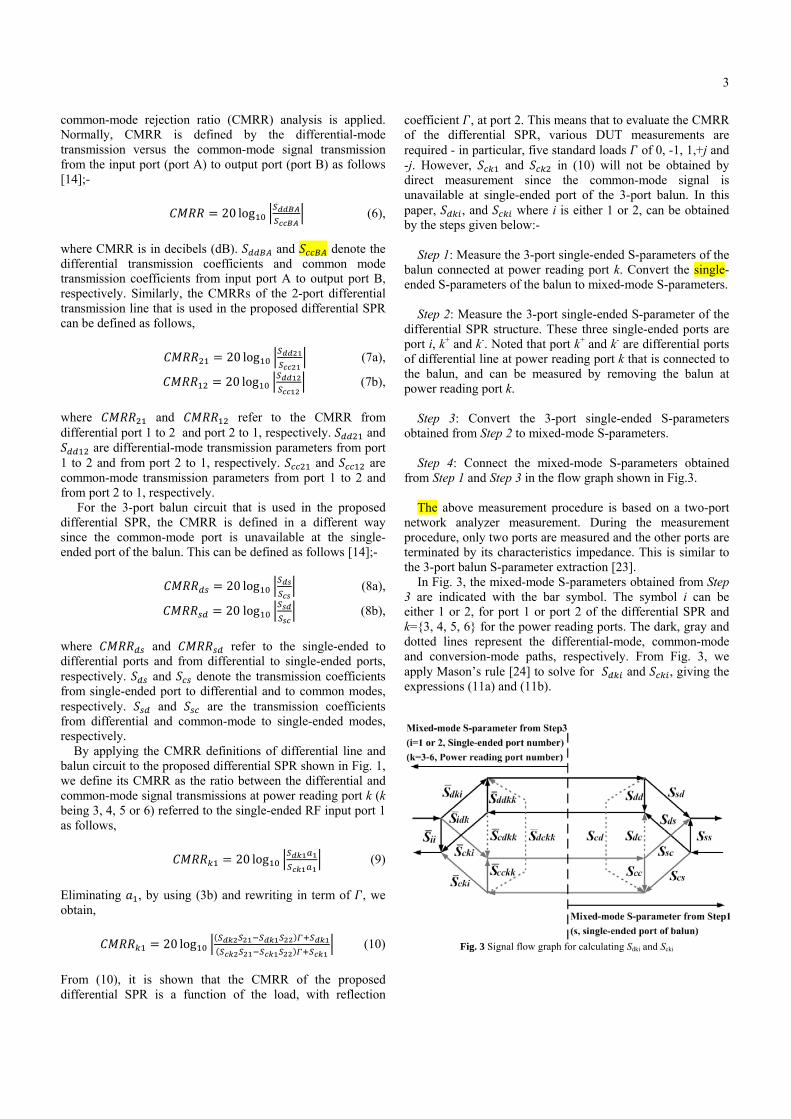
Step 1: Measure the 3-port single-ended S-parameters of the
balun connected at power reading port k. Convert the single-
ended S-parameters of the balun to mixed-mode S-parameters.
Step 2: Measure the 3-port single-ended S-parameter of the
differential SPR structure. These three single-ended ports are
port i, k+ and k-. Noted that port k+ and k- are differential ports
of differential line at power reading port k that is connected to
the balun, and can be measured by removing the balun at
power reading port k.
Step 3: Convert the 3-port single-ended S-parameters
obtained from Step 2 to mixed-mode S-parameters.
Step 4: Connect the mixed-mode S-parameters obtained
from Step 1 and Step 3 in the flow graph shown in Fig.3.
The above measurement procedure is based on a two-port
network analyzer measurement. During the measurement
procedure, only two ports are measured and the other ports are
terminated by its characteristics impedance. This is similar to
the 3-port balun S-parameter extraction [23].
In Fig. 3, the mixed-mode S-parameters obtained from Step
3 are indicated with the bar symbol. The symbol i can be
either 1 or 2, for port 1 or port 2 of the differential SPR and
k={3, 4, 5, 6} for the power reading ports. The dark, gray and
dotted lines represent the differential-mode, common-mode
and conversion-mode paths, respectively. From Fig. 3, we
apply Mason�s rule [24] to solve for 鯨鳥賃沈 and 鯨頂賃沈, giving the
expressions (11a) and (11b).
Fig. 3 Signal flow graph for calculating Sdki and Scki
TA
(s
lin
lin
ill
de
di
in
CP
re
us
en
po
de
po
an
IV
is
ca
to
gi
in
of
ch
w
tra
m
qu
at
w
di
ex
lin
m
sin
m
tra
5(
di
cr
鯨鳥賃沈 噺鯨頂賃沈 噺
ABLE I. DIMEN
substrate height=
Chara
impeda
5
1
2
IV.
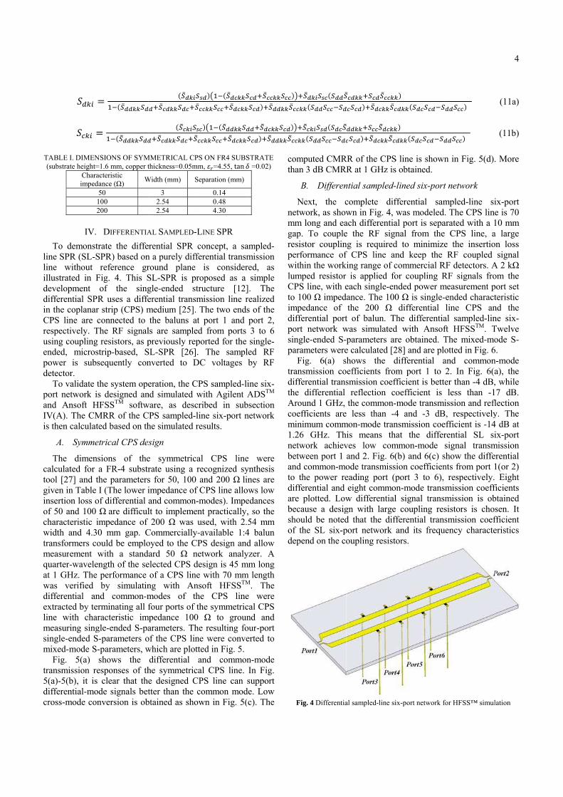
To demonstr
ne SPR (SL-S
ne without
lustrated in F
evelopment
ifferential SPR
n the coplanar
PS line are c
espectively. T
sing coupling
nded, microst
ower is subs
etector.
To validate t
ort network is
nd Ansoft H
V(A). The CM
then calculate
A. Symme
The dimens
alculated for a
ool [27] and th
iven in Table I
nsertion loss o
f 50 and 100
haracteristic im
width and 4.30
ansformers co
measurement w
uarter-wavelen
t 1 GHz. The
was verified
ifferential an
xtracted by ter
ne with char
measuring sing
ngle-ended S-
mixed-mode S-
Fig. 5(a) s
ansmission re
(a)-5(b), it is
ifferential-mod
ross-mode con
噺 怠貸岫聴違匂匂入入聴匂噺 怠貸岫聴違匂匂入入聴匂匂NSIONS OF SYM
=1.6 mm, copper t
acteristic
ance (ȍ) W
50
100
200
DIFFERENTIA
rate the diffe
SPR) based on
reference gr
Fig. 4. This S
of the sing
R uses a diffe
strip (CPS) m
connected to
The RF signal
resistors, as p
trip-based, S
sequently con
the system ope
s designed an
HFSSTM softw
MRR of the C
ed based on th
trical CPS des
sions of the
a FR-4 substr
he parameters
I (The lower i
of differential a
ȍ are difficul
mpedance of
0 mm gap. C
ould be emplo
with a stand
ngth of the se
performance
by simulatin
nd common-m
rminating all f
racteristic im
gle-ended S-pa
-parameters o
-parameters, w
shows the
esponses of th
clear that the
de signals bet
nversion is ob
岫聴違匂入日聴匂袋聴違迩匂入入聴匂迩袋聴違岫聴違迩入日聴濡匂袋聴違迩匂入入聴匂迩袋聴違迩
MMETRICAL CP
thickness=0.05mm
Width (mm) S
3
2.54
2.54
AL SAMPLED-L
erential SPR c
n a purely diff
round plane
SL-SPR is pr
gle-ended st
erential transm
medium [25].
the baluns at
ls are sample
previously rep
SL-SPR [26].
nverted to D
eration, the C
nd simulated w
ware, as desc
CPS sampled-l
he simulated r
sign
e symmetrica
rate using a r
s for 50, 100
impedance of
and common-
lt to implemen
200 ȍ was u
Commercially-
oyed to the CP
ard 50 ȍ ne
elected CPS d
of a CPS line
ng with An
modes of th
four ports of t
mpedance 100
arameters. Th
of the CPS lin
which are plott
differential
he symmetric
e designed C
tter than the c
btained as sho
聴濡匂岻盤怠貸岫聴違匂迩入入聴聴違迩迩入入聴迩迩袋聴違匂迩入入濡迩岻盤怠貸岫聴違匂匂入入聴匂迩迩入入聴迩迩袋聴違匂迩入入聴PS ON FR4 SUBS
m, 綱追=4.55, tan 絞Separation (mm)
0.14
0.48
4.30
LINE SPR
concept, a sa
ferential transm
is consider
roposed as a
tructure [12]
mission line r
The two ends
t port 1 and
d from ports
ported for the
. The sampl
DC voltages
PS sampled-li
with Agilent A
cribed in sub
line six-port n
results.
al CPS line
recognized sy
and 200 ȍ li
CPS line allo
-modes). Impe
nt practically,
used, with 2.
-available 1:4
PS design and
etwork analy
design is 45 m
e with 70 mm
nsoft HFSSTM
he CPS line
the symmetric
0 ȍ to groun
he resulting fo
ne were conve
ted in Fig. 5.
and common
al CPS line.
CPS line can s
common mod
own in Fig. 5(
聴迩匂袋聴違迩迩入入聴迩迩岻匪入聴迩匂岻袋聴違匂匂入入聴違迩迩匂匂袋聴違匂迩入入聴迩匂岻匪聴迩匂岻袋聴違匂匂入入聴違迩迩STRATE 絞 =0.02)
ampled-
mission
red, as
simple
]. The
realized
s of the
port 2,
3 to 6
single-
led RF
by RF
ine six-
ADSTM
bsection
network
e were
ynthesis
nes are
ows low
edances
, so the
54 mm
4 balun
d allow
yzer. A
mm long
m length M. The
e were
cal CPS
nd and
our-port
erted to
n-mode
In Fig.
support
de. Low
c). The
com
tha
N
net
mm
gap
res
per
wit
lum
CP
to
im
dif
por
sin
par
tra
dif
the
Ar
coe
mi
1.2
net
bet
and
to
dif
are
bec
sho
of
dep
F
匪袋聴違匂入日聴濡迩岫聴匂匂聴違迩入入岫聴匂匂聴迩迩貸聴匂袋聴違迩入日聴濡匂岫聴匂迩聴違迩入入岫聴匂匂聴迩迩貸聴匂迩mputed CMR
an 3 dB CMRR
B. Differen
Next, the c
twork, as show
m long and ea
p. To couple
sistor couplin
rformance of
thin the work
mped resistor
PS line, with e
100 ȍ imped
mpedance of
fferential port
rt network w
ngle-ended S-
rameters were
Fig. 6(a) s
ansmission co
fferential trans
e differential
round 1 GHz,
efficients are
inimum comm
26 GHz. Th
twork achiev
tween port 1
d common-mo
the power re
fferential and
e plotted. Low
cause a desig
ould be noted
the SL six-p
pend on the co
Fig. 4 Differentia
聴違迩匂入入袋聴迩匂聴違迩迩入入匂迩聴迩匂岻袋聴違匂迩入入聴違迩匂匂入入袋聴迩迩聴違匂迩入入迩聴迩匂岻袋聴違匂迩入入聴違迩匂
RR of the CPS
R at 1 GHz is
ntial sampled-
complete dif
wn in Fig. 4, w
ach differentia
e the RF sign
ng is required
f CPS line an
ing range of c
is applied fo
each single-en
ance. The 100
the 200 ȍt of balun. Th
was simulated
parameters ar
e calculated [2
hows the d
efficients from
smission coef
reflection co
the common-
less than -4
mon-mode tran
is means tha
ves low com
and 2. Fig. 6(
ode transmiss
eading port (p
eight commo
w differential
gn with large
d that the diff
port network
oupling resisto
al sampled-line si
入岻迩匂入入岫聴匂迩聴迩匂貸聴匂入岻匂入入岫聴匂迩聴迩匂貸聴匂S line is shown
s obtained.
lined six-port
fferential sam
was modeled.
al port is sepa
nal from the
d to minimize
nd keep the
commercial R
or coupling R
nded power m
0 ȍ is single-
differential
he differentia
d with Ansof
re obtained. T
28] and are plo
differential a
m port 1 to 2
fficient is bette
oefficient is
mode transmi
4 and -3 dB
nsmission coe
at the differ
mmon-mode s
(b) and 6(c) s
ion coefficien
port 3 to 6),
n-mode transm
l signal transm
coupling res
fferential trans
and its freque
ors.
ix-port network fo
匂匂聴迩迩岻
匂匂聴迩迩岻
n in Fig. 5(d).
t network
mpled-line si
. The CPS line
arated with a 1
CPS line, a
e the insertio
RF coupled
RF detectors. A
RF signals fro
measurement p
ended charact
line CPS an
al sampled-lin
ft HFSSTM. T
The mixed-mo
otted in Fig. 6
and common
2. In Fig. 6(a
er than -4 dB,
less than -1
ission and refl
, respectively
fficient is -14
rential SL si
signal transm
how the diffe
nts from port 1
respectively.
mission coeff
mission is ob
sistors is cho
smission coef
ency characte
for HFSS� simul
4
(11a)
(11b)
. More
ix-port
e is 70
10 mm
a large
on loss
signal
A 2 kȍ
om the
port set
teristic
nd the
ne six-
Twelve
ode S-
6.
n-mode
a), the
, while
7 dB.
flection
y. The
4 dB at
ix-port
mission
erential
1(or 2)
Eight
ficients
btained
sen. It
fficient
eristics
lation
Tr
Cr
H
co
sim
ba
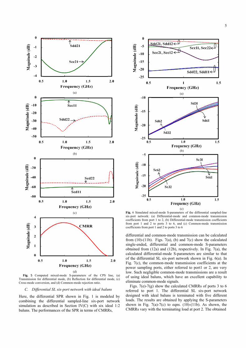
Fig. 5 Compu
ransmission for d
ross-mode conver
C. Differen
Here, the diffe
ombining the
mulation as d
aluns. The per
uted mixed-mod
differential mode
rsion, and (d) Com
ntial SL six-po
erential SPR
e differential
described in
rformances of
(a)
(b)
(c)
(d)
de S-parameters
, (b) Reflection
mmon-mode reje
ort network w
shown in Fi
sampled-lin
Section IV(C
f the SPR in te
of the CPS
for differential m
ection ratio.
with ideal balu
g. 1 is mode
e six-port n
C) with six id
erms of CMRR
line, (a)
mode, (c)
uns
eled by
network
deal 1:2
Rs,
Figsix-
coe
from
coe
dif
fro
sin
obt
cal
of
Fig
pow
low
of
eli
ref
des
loa
sho
CM
g. 6 Simulated m
-port network:
efficients from po
m port 1 and 2
efficients from po
fferential and
om (10)-(11b)
ngle-ended, d
tained from (
lculated differ
the differenti
g. 7(c), the co
wer sampling
w. Such neglig
using ideal b
minate comm
Figs. 7(e)-7(g
ferred to por
signed with i
ads. The resul
own in Fig. 7
MRRs vary wi
mixed-mode S-par
(a) Differential-
ort 1 to 2, (b) Di
2 to ports 3 to
ort 1 and 2 to port
common-mod
). Figs. 7(a),
differential an
(12a) and (12b
rential-mode
ial SL six-por
ommon-mode
g ports, either
gible common
baluns, which
mon-mode sign
g) show the ca
rt 1. The di
ideal baluns i
lts are obtaine
7(a)-7(c) to e
ith the termina
(a)
(b)
(c) rameters of the
mode and comm
ifferential-mode t
6, and (c) Com
ts 3 to 6
de transmissio
(b) and 7(c) s
nd common-m
b), respective
S-parameters
rt network sho
e transmission
r referred to p
n-mode transm
h have an exc
nals.
alculated CM
ifferential SL
is terminated
ed by applyin
eqns. (10)-(11
ating load at p
differential samp
mon-mode trans
transmission coe
mmon-mode trans
on can be calc
show the calc
mode S-param
ely. In Fig. 7(
are similar t
own in Fig. 6
n coefficients
port1 or 2, ar
missions are a
cellent capabi
MRRs of ports
L six-port ne
with five di
ng the S-param
1b). As show
port 2. The ob
5
pled-line
smission
fficients
smission
culated
culated
meters
a), the
to that
6(a). In
at the
re very
a result
ility to
3 to 6
etwork
fferent
meters
wn, the
tained
6
(a) (b)
(c) (d)
(e) (f)
(g)
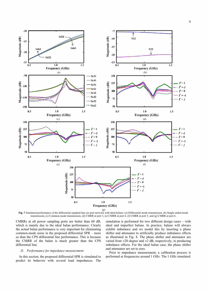
Fig. 7 Simulated performance of the differential sampled-line six-port network with ideal baluns: (a) Differential mode transmission, (b) Single-ended mode
transmission, (c) Common-mode transmission, (d) CMRR at port 3, (e) CMRR at port 4, (f) CMRR at port 5, and (g) CMRR at port 6.
CMRRs at all power sampling ports are better than 60 dB,
which is mainly due to the ideal balun performance. Clearly
the actual balun performance is very important for eliminating
common-mode noise in the proposed differential SPR � more
so than the CPS differential line performance. This is because
the CMRR of the balun is much greater than the CPS
differential line.
D. Performance for impedance measurement
In this section, the proposed differential SPR is simulated to
predict its behavior with several load impedances. The
simulation is performed for two different design cases � with
ideal and imperfect baluns. In practice, baluns will always
exhibit imbalance and we model this by inserting a phase
shifter and attenuator to artificially produce imbalance effects
as illustrated in Fig. 8. The phase shifter and attenuator are
varied from ±20 degree and ±2 dB, respectively, to producing
imbalance effects. For the ideal balun case, the phase shifter
and attenuator are set to zero.
Prior to impedance measurement, a calibration process is
performed at frequencies around 1 GHz. The 1 GHz simulated
re
im
re
ca
qu
di
W
fr
th
ca
on
lin
to
50
LD
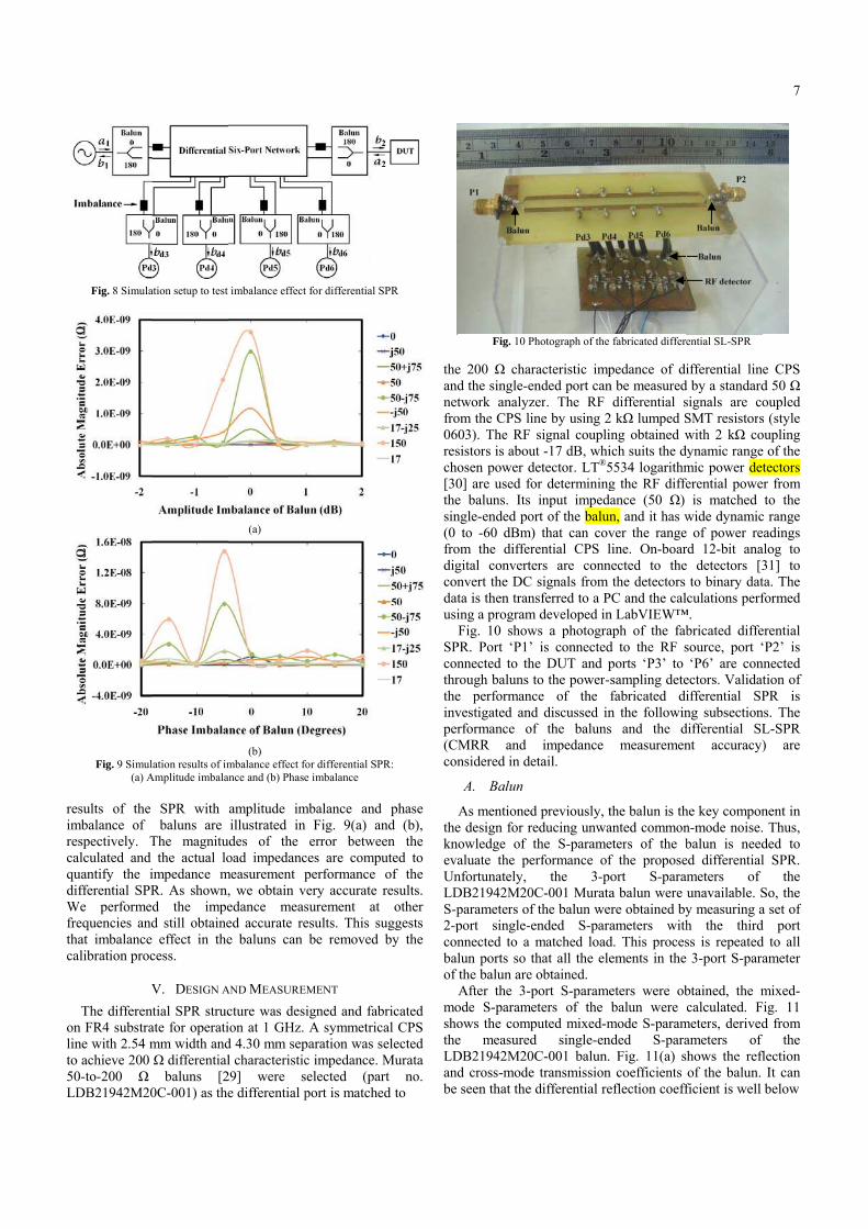
Fig. 8 Simula
Fig. 9 Simul
(a) A
esults of the
mbalance of
espectively. T
alculated and
uantify the i
ifferential SPR
We performed
equencies and
hat imbalance
alibration proc
V
The different
n FR4 substra
ne with 2.54 m
o achieve 200
0-to-200 ȍ
DB21942M20
ation setup to test
ation results of im
Amplitude imbalan
SPR with
baluns are
The magnitud
the actual lo
impedance m
R. As shown,
d the impe
d still obtaine
effect in the
cess.
V. DESIGN A
tial SPR struc
ate for operati
mm width and
ȍ differential
baluns [2
0C-001) as the
imbalance effect
(a)
(b)
mbalance effect fo
nce and (b) Phase
amplitude im
illustrated in
des of the
oad impedanc
measurement p
, we obtain v
edance meas
ed accurate re
e baluns can
AND MEASURE
cture was des
on at 1 GHz.
d 4.30 mm sep
l characteristic
29] were s
e differential p
t for differential S
for differential SP
e imbalance
mbalance and
n Fig. 9(a) an
error betwe
ces are compu
performance
very accurate
surement at
esults. This su
be removed
EMENT
igned and fab
A symmetric
paration was s
c impedance.
selected (par
port is matche
SPR
PR:
d phase
nd (b),
en the
uted to
of the
results.
other
uggests
by the
bricated
cal CPS
selected
Murata
rt no.
ed to
the
and
net
fro
06
res
cho
[30
the
sin
(0
fro
dig
con
dat
usi
SP
con
thr
the
inv
per
(C
con
the
kn
eva
Un
LD
S-p
2-p
con
bal
of
mo
sho
the
LD
and
be
Fig. 10 P
e 200 ȍ char
d the single-en
twork analyz
om the CPS lin
03). The RF
sistors is abou
osen power d
0] are used fo
e baluns. Its
ngle-ended po
to -60 dBm)
om the differ
gital converte
nvert the DC
ta is then tran
ing a program
Fig. 10 show
PR. Port �P1�
nnected to th
rough baluns t
e performanc
vestigated and
rformance of
MRR and
nsidered in de
A. Balun
As mentioned
e design for re
owledge of t
aluate the pe
nfortunately,
DB21942M20
parameters of
port single-e
nnected to a
lun ports so t
the balun are
After the 3-p
ode S-parame
ows the comp
e measured
DB21942M20
d cross-mode
seen that the
hotograph of the
racteristic imp
nded port can
zer. The RF
ne by using 2
signal coupli
ut -17 dB, whi
detector. LT®5
or determining
input impeda
rt of the balun
) that can cov
rential CPS l
ers are conn
signals from
nsferred to a P
m developed in
ws a photogra
is connected
he DUT and p
to the power-s
ce of the f
d discussed in
f the baluns
impedance
etail.
d previously, t
educing unwa
the S-parame
erformance of
the 3-po
C-001 Murata
f the balun we
ended S-para
matched load
that all the ele
obtained.
port S-parame
eters of the
puted mixed-m
d single-en
C-001 balun.
transmission
differential re
fabricated differe
pedance of di
n be measured
differential s
2 kȍ lumped S
ng obtained w
ich suits the dy
5534 logarithm
g the RF diffe
ance (50 ȍ)
n, and it has w
ver the range
line. On-boar
nected to the
the detectors
PC and the cal
n LabVIEW�
aph of the fab
d to the RF s
ports �P3� to
sampling dete
fabricated di
n the followin
s and the d
measuremen
the balun is th
anted common
eters of the b
f the propose
ort S-param
a balun were
re obtained by
ameters with
d. This proces
ements in the
eters were ob
balun were
mode S-param
nded S-para
Fig. 11(a) s
n coefficients
eflection coeff
ential SL-SPR
ifferential line
d by a standard
signals are co
SMT resistors
with 2 kȍ co
ynamic range
mic power det
erential powe
is matched
wide dynamic
of power re
rd 12-bit ana
detectors [3
to binary dat
culations perf
�.
bricated diffe
source, port �
�P6� are con
ectors. Validat
ifferential SP
ng subsection
differential SL
nt accuracy)
he key compon
n-mode noise.
balun is need
ed differential
meters of
unavailable. S
y measuring a
h the third
ss is repeated
3-port S-para
btained, the m
calculated. F
meters, derived
ameters of
hows the refl
of the balun.
ficient is well
7
e CPS
d 50 ȍ
oupled
s (style
oupling
e of the
tectors
r from
to the
c range
adings
alog to
31] to
ta. The
formed
erential
�P2� is
nnected
tion of
PR is
ns. The
L-SPR
) are
nent in
Thus,
ded to
l SPR.
the
So, the
a set of
d port
d to all
ameter
mixed-
ig. 11
d from
the
flection
It can
below
F
-2
di
co
G
co
tra
co
Th
fo
fr
be
us
SP
di
sim
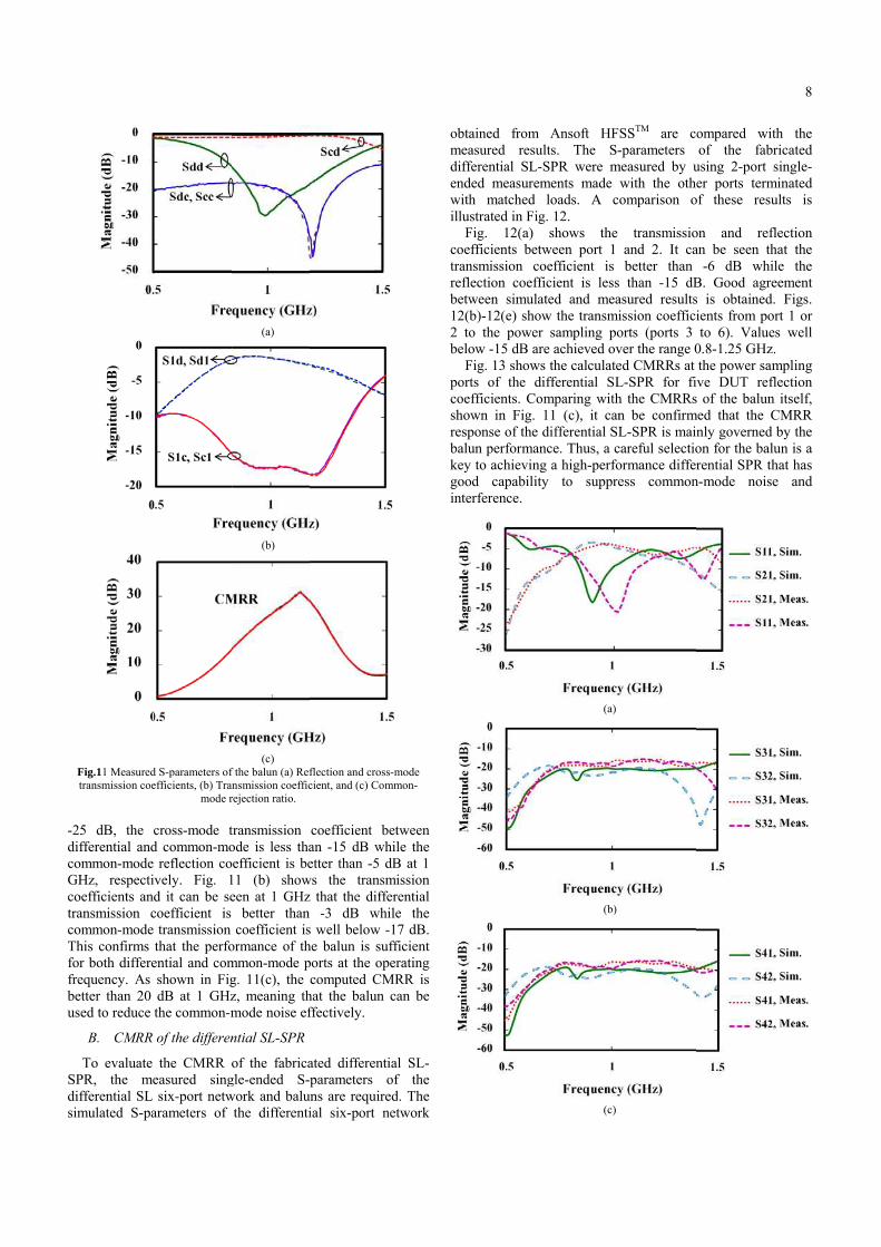
Fig.11 Measured
transmission coe
25 dB, the c
ifferential and
ommon-mode
GHz, respectiv
oefficients and
ansmission c
ommon-mode
his confirms t
or both differe
equency. As
etter than 20
sed to reduce t
B. CMRR
To evaluate
PR, the me
ifferential SL
mulated S-pa
d S-parameters of
efficients, (b) Tran
mode r
cross-mode t
d common-mo
reflection co
vely. Fig. 1
d it can be se
coefficient is
transmission
that the perfo
ential and com
shown in Fig
dB at 1 GHz
the common-m
of the differen
the CMRR o
easured sing
six-port netw
arameters of
(a)
(b)
(c)
f the balun (a) Ref
nsmission coeffic
rejection ratio.
transmission
ode is less tha
efficient is be
11 (b) show
een at 1 GHz
better than
coefficient is
ormance of th
mmon-mode p
g. 11(c), the
z, meaning th
mode noise ef
ntial SL-SPR
of the fabrica
gle-ended S-
work and balu
the differenti
flection and cross
cient, and (c) Com
coefficient b
an -15 dB wh
etter than -5 d
ws the transm
z that the diffe
-3 dB wh
s well below -
he balun is su
ports at the op
computed CM
hat the balun
ffectively.
ated differenti
parameters o
uns are require
ial six-port n
s-mode
mmon-
between
hile the
dB at 1
mission
ferential
ile the
-17 dB.
ufficient
perating
MRR is
can be
ial SL-
of the
ed. The
network
obt
me
dif
end
wit
illu
coe
tra
ref
bet
12
2 t
bel
por
coe
sho
res
bal
key
go
int
tained from
easured resu
fferential SL-
ded measurem
th matched
ustrated in Fig
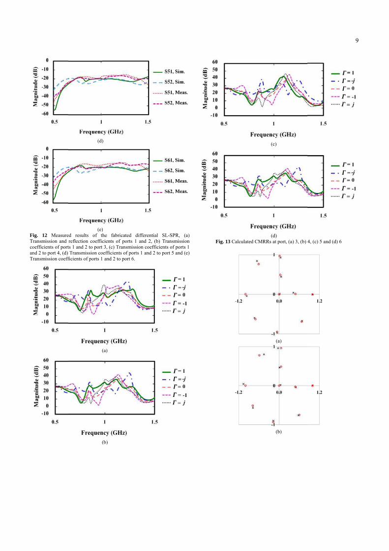
Fig. 12(a)
efficients betw
ansmission co
flection coeff
tween simula
(b)-12(e) show
to the power
low -15 dB ar
Fig. 13 shows
rts of the di
efficients. Co
own in Fig.
sponse of the
lun performan
y to achieving
od capability
terference.
Ansoft HF
ults. The S-
SPR were m
ments made
loads. A co
g. 12.
shows the
ween port 1
oefficient is
ficient is less
ated and mea
w the transmi
r sampling po
re achieved ov
s the calculate
ifferential SL
omparing with
11 (c), it can
differential SL
nce. Thus, a c
g a high-perfo
y to suppre
(a)
(b)
(c)
SSTM are co
-parameters
measured by u
with the othe
omparison o
transmissio
and 2. It ca
better than
than -15 dB
asured results
ission coeffici
orts (ports 3
ver the range 0
ed CMRRs at
L-SPR for fiv
h the CMRRs
n be confirm
L-SPR is main
careful selectio
ormance differ
ess common
ompared wit
of the fabr
using 2-port s
er ports term
of these resu
on and refl
an be seen th
-6 dB whil
B. Good agre
s is obtained.
ients from po
to 6). Value
0.8-1.25 GHz.
the power sam
ve DUT refl
of the balun
med that the C
nly governed
on for the balu
rential SPR th
n-mode noise
8
th the
ricated
single-
minated
ults is
flection
hat the
le the
eement
. Figs.
rt 1 or
s well
.
mpling
flection
itself,
CMRR
by the
un is a
hat has
e and
FiTr
co
an
Tr
ig. 12 Measure
ransmission and
oefficients of port
nd 2 to port 4, (d)
ransmission coeff
(d)
(e)
ed results of th
reflection coeffic
ts 1 and 2 to port
Transmission co
ficients of ports 1
(
(
)
)
he fabricated d
cients of ports 1
3, (c) Transmiss
oefficients of port
and 2 to port 6.
(a)
(b)
differential SL-S
and 2, (b) Tran
ion coefficients o
ts 1 and 2 to port
SPR, (a)
nsmission
of ports 1
5 and (e)
Fig. 13 Calc
(c
(d
culated CMRRs a
c)
d)
at port, (a) 3, (b) 4
(a)
(b)
4, (c) 5 and (d) 6
9
10
(c)
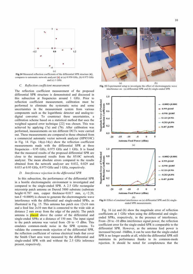
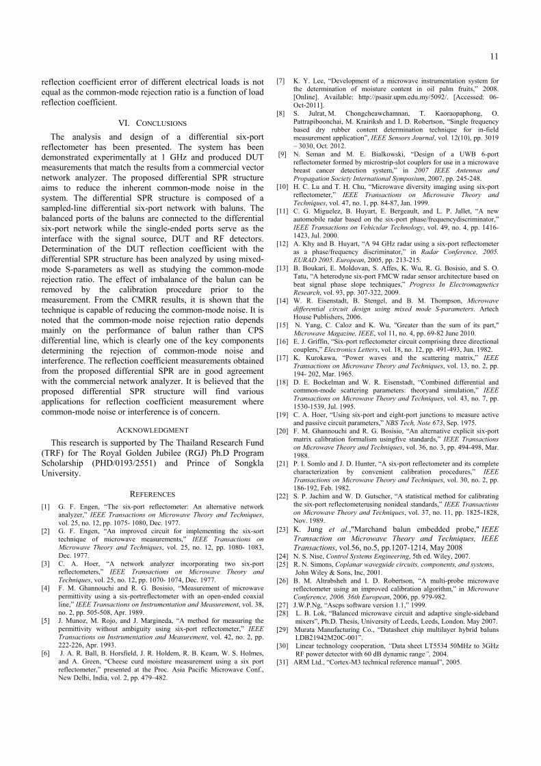
Fig.14 Measured reflection coefficients of the differential SPR structure (x), compares to automatic network analyzer (o) at (a) 0.950 GHz, (b) 0.975 GHz
and (c) 1 GHz
C. Reflection coefficient measurement
The reflection coefficient measurement of the proposed
differential SPR structure is demonstrated and discussed in
this subsection at frequencies around 1 GHz. Prior to
reflection coefficient measurement, calibration must be
performed to eliminate the systematic noise and some
uncertainties in the measurement system from various
components such as the logarithmic detector and analog-to-
digital converter. To counteract these uncertainties, a
calibration scheme based on a statistical method that uses the
weighted squared error technique [22] was chosen. This was
achieved by applying (7a) and (7b). After calibration was
performed, measurements on ten different DUTs were carried
out. These measurements are compared to those obtained from
a commercial automatic vector network analyzer (HP8510C)
in Fig. 14. Figs. 14(a)-14(c) show the reflection coefficient
measurements made with the differential SPR at three
frequencies - 0.95 GHz, 0.975 GHz and 1 GHz. It is found
that the measured results of the proposed differential SPR are
close to the measured results from the 8510C network
analyzer. The mean absolute errors compared to the results
obtained from the network analyzer are 0.032, 0.029 and
0.033 at 0.95 GHz, 0.975 GHz and 1 GHz, respectively.
D. Interference rejection in the differential SPR
In this subsection, the performance of the differential SPR
in a hostile electromagnetic environment is investigated and
compared to the single-ended SPR. A 2.5 GHz rectangular
microstrip patch antenna on Duroid 5880 substrate (substrate
height=0.787 mm, copper thickness=0.017 mm, 綱追=2.20, tan 絞 =0.0009) is chosen to generate the electromagnetic wave
interference with the differential and single-ended SPRs, as
illustrated in Fig. 15. This antenna has patch size 12x16 mm
and a feed line 2x10 mm that is connected to the wide side at
distance 2 mm away from the edge of the patch). The patch
antenna is placed above the center of the differential and
single-ended SPRs at a distance of 150 mm. The input signal
to the patch antenna was varied from -20 to +5 dBm. This
emulates common-mode noise in the SPR systems. To
validate the common-mode rejection of the differential SPR,
the reflection coefficient of various electrical loads that cover
the Smith Chart area were measured by the differential and
single-ended SPR with and without the 2.5 GHz inference
present, respectively.
(a) (b)
Fig. 15 Experimental setup to investigate the effect of electromagnetic wave
interference on: (a) differential SPR and (b) single-ended SPR
(a)
(b)
Fig.16 Effect of emulated interference on (a) differential SPR and (b) single-
ended SPR measurements.
Fig. 16 (a) and (b) show the magnitude error of reflection
coefficients at 1 GHz when using the differential and single-
ended SPRs, respectively, in the presence of interference.
From -20 to -10 dBm interference signal power, the reflection
coefficient error for the single-ended SPR is comparable to the
differential SPR. However, as the antenna feed power is
increased beyond -10dBm, it can be seen that the single-ended
SPR is no longer useable at all, whilst the differential SPR still
maintains its performance thanks to its common-mode
rejection. It should be noted for completeness that the
11
reflection coefficient error of different electrical loads is not
equal as the common-mode rejection ratio is a function of load
reflection coefficient.
VI. CONCLUSIONS
The analysis and design of a differential six-port
reflectometer has been presented. The system has been
demonstrated experimentally at 1 GHz and produced DUT
measurements that match the results from a commercial vector
network analyzer. The proposed differential SPR structure
aims to reduce the inherent common-mode noise in the
system. The differential SPR structure is composed of a
sampled-line differential six-port network with baluns. The
balanced ports of the baluns are connected to the differential
six-port network while the single-ended ports serve as the
interface with the signal source, DUT and RF detectors.
Determination of the DUT reflection coefficient with the
differential SPR structure has been analyzed by using mixed-
mode S-parameters as well as studying the common-mode
rejection ratio. The effect of imbalance of the balun can be
removed by the calibration procedure prior to the
measurement. From the CMRR results, it is shown that the
technique is capable of reducing the common-mode noise. It is
noted that the common-mode noise rejection ratio depends
mainly on the performance of balun rather than CPS
differential line, which is clearly one of the key components
determining the rejection of common-mode noise and
interference. The reflection coefficient measurements obtained
from the proposed differential SPR are in good agreement
with the commercial network analyzer. It is believed that the
proposed differential SPR structure will find various
applications for reflection coefficient measurement where
common-mode noise or interference is of concern.
ACKNOWLEDGMENT
This research is supported by The Thailand Research Fund
(TRF) for The Royal Golden Jubilee (RGJ) Ph.D Program
Scholarship (PHD/0193/2551) and Prince of Songkla
University.
REFERENCES
[1] G. F. Engen, �The six-port reflectometer: An alternative network
analyzer,� IEEE Transactions on Microwave Theory and Techniques,
vol. 25, no. 12, pp. 1075- 1080, Dec. 1977.
[2] G. F. Engen, �An improved circuit for implementing the six-sort
technique of microwave measurements,� IEEE Transactions on
Microwave Theory and Techniques, vol. 25, no. 12, pp. 1080- 1083,
Dec. 1977.
[3] C. A. Hoer, �A network analyzer incorporating two six-port
reflectometers,� IEEE Transactions on Microwave Theory and
Techniques, vol. 25, no. 12, pp. 1070- 1074, Dec. 1977.
[4] F. M. Ghannouchi and R. G. Bosisio, �Measurement of microwave
permittivity using a six-portreflectometer with an open-ended coaxial
line,� IEEE Transactions on Instrumentation and Measurement, vol. 38,
no. 2, pp. 505-508, Apr. 1989.
[5] J. Munoz, M. Rojo, and J. Margineda, �A method for measuring the
permittivity without ambiguity using six-port reflectometer,� IEEE
Transactions on Instrumentation and Measurement, vol. 42, no. 2, pp.
222-226, Apr. 1993.
[6] J. A. R. Ball, B. Horsfield, J. R. Holdem, R. B. Keam, W. S. Holmes,
and A. Green, �Cheese curd moisture measurement using a six port
reflectometer,� presented at the Proc. Asia Pacific Microwave Conf.,
New Delhi, India, vol. 2, pp. 479�482.
[7] K. Y. Lee, �Development of a microwave instrumentation system for
the determination of moisture content in oil palm fruits,� 2008.
[Online]. Available: http://psasir.upm.edu.my/5092/. [Accessed: 06-
Oct-2011].
[8] S. Julrat, M. Chongcheawchamnan, T. Kaoraopaphong, O.
Pattrapiboonchai, M. Krairiksh and I. D. Robertson, �Single frequency
based dry rubber content determination technique for in-field
measurement application�, IEEE Sensors Journal, vol. 12(10), pp. 3019
� 3030, Oct. 2012. [9] N. Seman and M. E. Bialkowski, �Design of a UWB 6-port
reflectometer formed by microstrip-slot couplers for use in a microwave
breast cancer detection system,� in 2007 IEEE Antennas and
Propagation Society International Symposium, 2007, pp. 245-248.
[10] H. C. Lu and T. H. Chu, �Microwave diversity imaging using six-port
reflectometer,� IEEE Transactions on Microwave Theory and
Techniques, vol. 47, no. 1, pp. 84-87, Jan. 1999.
[11] C. G. Miguelez, B. Huyart, E. Bergeault, and L. P. Jallet, �A new
automobile radar based on the six-port phase/frequencydiscriminator,�
IEEE Transactions on Vehicular Technology, vol. 49, no. 4, pp. 1416-
1423, Jul. 2000.
[12] A. Khy and B. Huyart, �A 94 GHz radar using a six-port reflectometer
as a phase/frequency discriminator,� in Radar Conference, 2005.
EURAD 2005. European, 2005, pp. 213-215.
[13] B. Boukari, E. Moldovan, S. Affes, K. Wu, R. G. Bosisio, and S. O.
Tatu, �A heterodyne six-port FMCW radar sensor architecture based on
beat signal phase slope techniques,� Progress In Electromagnetics
Research, vol. 93, pp. 307-322, 2009.
[14] W. R. Eisenstadt, B. Stengel, and B. M. Thompson, Microwave
differential circuit design using mixed mode S-parameters. Artech
House Publishers, 2006.
[15] N. Yang, C. Caloz and K. Wu, "Greater than the sum of its part,"
Microwave Magazine, IEEE, vol 11, no. 4, pp. 69-82 June 2010.
[16] E. J. Griffin, �Six-port reflectometer circuit comprising three directional
couplers,� Electronics Letters, vol. 18, no. 12, pp. 491-493, Jun. 1982.
[17] K. Kurokawa, �Power waves and the scattering matrix,� IEEE
Transactions on Microwave Theory and Techniques, vol. 13, no. 2, pp.
194- 202, Mar. 1965.
[18] D. E. Bockelman and W. R. Eisenstadt, �Combined differential and
common-mode scattering parameters: theoryand simulation,� IEEE
Transactions on Microwave Theory and Techniques, vol. 43, no. 7, pp.
1530-1539, Jul. 1995.
[19] C. A. Hoer, �Using six-port and eight-port junctions to measure active
and passive circuit parameters,� NBS Tech, Note 673, Sep. 1975.
[20] F. M. Ghannouchi and R. G. Bosisio, �An alternative explicit six-port
matrix calibration formalism usingfive standards,� IEEE Transactions
on Microwave Theory and Techniques, vol. 36, no. 3, pp. 494-498, Mar.
1988.
[21] P. I. Somlo and J. D. Hunter, �A six-port reflectometer and its complete
characterization by convenient calibration procedures,� IEEE
Transactions on Microwave Theory and Techniques, vol. 30, no. 2, pp.
186-192, Feb. 1982.
[22] S. P. Jachim and W. D. Gutscher, �A statistical method for calibrating
the six-port reflectometerusing nonideal standards,� IEEE Transactions
on Microwave Theory and Techniques, vol. 37, no. 11, pp. 1825-1828,
Nov. 1989.
[23] K. Jung et al.,"Marchand balun embedded probe," IEEE
Transaction on Microwave Theory and Techniques, IEEE
Transactions, vol.56, no.5, pp.1207-1214, May 2008 [24] N. S. Nise, Control Systems Engineering, 5th ed. Wiley, 2007.
[25] R. N. Simons, Coplanar waveguide circuits, components, and systems,
John Wiley & Sons, Inc, 2001.
[26] B. M. Altrabsheh and I. D. Robertson, �A multi-probe microwave
reflectometer using an improved calibration algorithm,� in Microwave
Conference, 2006. 36th European, 2006, pp. 979-982.
[27] J.W.P.Ng, �Ascps software version 1.1,� 1999.
[28] L. B. Lok, �Balanced microwave circuit and adaptive single-sideband
mixers�, Ph.D. Thesis, University of Leeds, Leeds, London. May 2007.
[29] Murata Manufacturing Co., �Datasheet chip multilayer hybrid baluns
LDB21942M20C-001�.
[30] Linear technology cooperation, �Data sheet LT5534 50MHz to 3GHz
RF power detector with 60 dB dynamic range�, 2004.
[31] ARM Ltd., �Cortex-M3 technical reference manual�, 2005.

20
So
inc
ap
So
Ch
in
gra
cu
wa
joi
In
Ki
008, he joined th
ongkhla, Thailand
clude microwave
pplications. Dr. C
ociety.
hair for the 2011
microwave and
ants as PI and
urrently leads an
ave LTCC comp
ining Leeds he
stitute at the Un
ing's College Lon
Sakol JMechatro
degree in
Prince of
disk driv
Bachelor
in Comp
Universit
applicatio
measurem
Mitchai Bangkok,
in teleco
Institute o
1992, the
signal pro
U.K., in
engineerin
Guildford
He join
Technolo
he Faculty of En
d, as an Associat
e circuit design a
Chongcheawcham
Ian RobeCentenary
Wave Cir
Electronic
published
and millim
editing th
Design an
the IEEE i
and millim
He was G
European Micro
millimetre-wave
led 5 major E
IeMRC-funded p
onents with Lou
was a founder
niversity of Surre
ndon.
Julrat obtained
onics Engineerin
n Electrical Eng
f Songkla Unive
ves industry for
rs degree. He is
puter Engineerin
ty. His research
on, dielectric m
ment systems.
Chongcheawch, Thailand. He re
ommunication
of Technology L
e M.Sc. degree
ocessing from Im
1995, and the P
ng from the
d, U.K., in 2001.
ned the Maha
gy, Bangkok, in
ngineering, Princ
te Professor. His
and microwave te
mnan is a member
ertson holds th
y Chair in Mic
rcuits and is H
c & Electrical
over 400 papers
metre-wave engi
he well-known
nd Technology. H
in 2012 for contr
metre-wave system
General Technica
owave Week � the
e engineering. H
EPSRC-funded co
project in 3D m
ghborough and I
member of the
ey and led the M
d Bachelors de
ng in 2005 and
gineering in 20
rsity. He worked
two years follow
currently a Ph.D
ng, Prince of
h interests are
measurement, sen
hamnan was
eceived the B.En
from King M
Ladkrabang, Ban
in communica
mperial College,
Ph.D. degree in
University of
anakorn Univer
n 1992, as a Lec
ce of Songkla Un
current research
echniques for ag
r of the IEEE M
he University o
crowave and Mi
Head of the Sc
Engineering.
in the area of m
ineering as wel
book RFIC and
He was elected F
ributions to MMI
m-in-package tec
al Programme Co
e premier Europe
He has held over
ollaborative proj
microwave and mi
Imperial College.
e Advanced Tec
MMIC Research
egree in
d Master
009 from
d in hard
wing the
D. student
Songkla
six-port
nsors and
born in
ng.degree
Mongkut�s
ngkok, in
tion and
London,
electrical
Surrey,
rsity of
cturer. In
niversity,
interests
ricultural
icrowave
of Leeds
illimetre-
chool of
He has
microwave
ll as co-
d MMIC
Fellow of
IC design
chnology.
ommittee
ean event
r £3M in
jects. He
illimetre-
. Prior to
chnology
Team at
12