
An overview of hydrogen storage methods
30
Hydrogen Materials Science and Chemistry of Carbon Nanomaterials edited by T. NejatVeziroglu International Association for Hydrogen Energy, University of Miami, FL, U.S.A. SvetlanaYu. Zaginaichenko Institute of Hydrogen and Solar Energy, Kiev, Ukraine DmitryV. Schur Institute for Problems of Materials Science of MAS, Kiev, Ukraine B. Baranowski Institute of Physical Chemistry of PAS, Warsaw, Poland Anatoliy P. Shpak Institute for Metal Physics of MAS, Kiev, Ukraine and Valeriy V. Skorokhod Institute for Problems of Materials Science of MAS, Kiev, Ukraine Kluwer Academic Publishers Dordrecht / Boston / London Published in cooperation with NATO Scientific Affairs Division
Transcript of An overview of hydrogen storage methods

Hydrogen Materials Science
and Chemistry
of Carbon Nanomaterials
edited by
T. NejatVezirogluInternational Association for Hydrogen Energy, University of Miami, FL, U.S.A.
SvetlanaYu. ZaginaichenkoInstitute of Hydrogen and Solar Energy, Kiev, Ukraine
DmitryV. SchurInstitute for Problems of Materials Science of MAS, Kiev, Ukraine
B. BaranowskiInstitute of Physical Chemistry of PAS, Warsaw, Poland
Anatoliy P. ShpakInstitute for Metal Physics of MAS, Kiev, Ukraine
and
Valeriy V. SkorokhodInstitute for Problems of Materials Science of MAS, Kiev, Ukraine
Kluwer Academic Publishers
Dordrecht / Boston / London
Published in cooperation with NATO Scientific Affairs Division

Proceedings of the NATO Advanced Research Workshop onHydrogen Materials Science and Chemistry of Carbon NanomaterialsSudak, Crimea, Ukraine14-20 September 2003
A C.I.P. Catalogue record for this book is available from the Library of Congress.
ISBN 1-4020-2668-4 (PB)ISBN 1-4020-2667-6 (HB)ISBN 1-4020-2669-2 (e-book)
Published by Kluwer Academic Publishers,P.O. Box 17, 3300 AA Dordrecht, The Netherlands.
Sold and distributed in North, Central and South Americaby Kluwer Academic Publishers,101 Philip Drive, Norwell, MA 02061, U.S.A.
In all other countries, sold and distributedby Kluwer Academic Publishers,P.O. Box 322, 3300 AH Dordrecht, The Netherlands.
Printed on acid-free paper
All Rights Reserved©2004 Kluwer Academic PublishersNo part of this work may be reproduced, stored in a retrieval system, or transmittedin any form or by any means, electronic, mechanical, photocopying, microfilming,recording or otherwise, without written permission from the Publisher, with the exceptionof any material supplied specifically for the purpose of being enteredand executed on a computer system, for exclusive use by the purchaser of the work.
Printed in the Netherlands.

AN OVERVIEW OF HYDROGEN STORAGE METHODS
V.A.YARTYS1 and M.V.LOTOTSKY1'21 Institute for Energy Technology, FOB 40, N-2027, Kjeller, Norway2Institute for Problems of Material Science of National Academy of Sciencesof Ukraine, Lab. #67, 3 Krzhyzhanovsky Str, OB 142, Kiev, Ukraine
e-mail [email protected]
Abstract
Hydrogen is an attractive, pollution-free energy carrier, which is characterised inaddition by a flexible and efficient energy conversion. Technology of hydrogen productionis well developed and has advantage of practically unlimited basis of the raw materials.However, low density of hydrogen gas, low temperature of its liquefaction, as well as highexplosive risk in combination with its negative influence on the properties of designmaterials bring to the forefront the problems of the development of effective and safehydrogen storage systems. Namely these problems suppress at present the development ofhydrogen power engineering and technology.
This paper reviews the existent and prospective hydrogen storage methods,observes the dynamics of their development in the last three decades. The special attentionis paid to metal hydrides, both as to their direct usage in the hydrogen storage systems andconcerning the maintenance of the alternative methods, to improve their efficiency.
On the basis of the analysis of available data, it is concluded that the bestcompetitive position in the future will have combined systems realising several methods ofhydrogen storage and processing. The methods could include small- and medium-scalemetal hydride hydrogen storage units, as well as thermal sorption compressors providinggas-cylinder and cryogenic hydrogen storage systems. Buffer units for hydrogen storage,purification and controlled supply to a consumer could be in demand as well.
1. Introduction
The deficit of natural resources of hydrocarbon fuels, in combination with globalenvironment problems, stipulated a great interest to use hydrogen as a universal syntheticenergy carrier for stationary and mobile applications. Such an approach is caused byunlimited basis of the raw materials for hydrogen production, the high energy output ofhydrogen, technological flexibility and environment safety of the energy conversionprocesses using hydrogen.
The concept of hydrogen energy system, proposing the transfer of powerengineering, industry and transport to hydrogen, was born in mid 1970s, against abackground of the worldwide oil crisis [1-4]. The changing in the state of world energysupply market in the second half of the 1980s resulted in some decrease of growth rates inhydrogen R&D activities. First of all, it was caused by economic factors, mainly by highprice of commercial hydrogen as compared to conventional energy carriers. As aconclusion, the main attention was paid at that time to the improvement of technical andeconomic indices of hydrogen production, as well as to the increase of efficiency of itsconsumption [5]. At the same time, the problems of hydrogen storage and processing
75
TM Veziroglu et al (eds.),Hydrogen Materials Science and Chemistry of Carbon Nanomaterials, 75-104.© 2004 Kluwer Academic Publishers. Printed in the Netherlands.

76
remained in the shadow. However, since the moment when the factor of environmenthazard began to be introduced into economic calculations, the ecological cleanness ofhydrogen made its usage in a number of production processes potentially profitable [6],Simultaneously, hydrogen storage problems and transportation became of special topicality,
The present status of hydrogen energy and technology in the world is characterisedby the stable growth rates which are mainly conditioned by environment factor. Thecorresponding activities are mainly financed from state and international public budgets,The Hydrogen Program of the USA Department of Energy (DOE) [7,8], the Program ofInternational Energy Agency (1EA) [9,10] and a number of others are the typical examples.Apart from state and non-government public organisations, a number of commercialcompanies, mainly from the motor-car industry [11,12], invests the hydrogen energy R&Dactivities. The main priorities in these investments are hydrogen fuel cells, as well asimprovement of existent and creation of new hydrogen storage methods.
Utilization of hydrogen as a fuel or energy carrier (Table 1) is based on the highlyexothermic reaction of hydrogen with oxygen. When hydrogen is produced by waterelectrolysis, and the efficiency of an electrolyser is of 60-75%, the real power consumptionfor the production of 1 m3 (STP) of hydrogen gas is 4 to 5 kW-h. When 1 m3 (STP) of.hydrogen gas is burned in a power installation with the efficiency of 15-20%, the yield is0.45 to 0.6 kW-h. Similarly, the yield of a fuel cell with the efficiency of 40-60% is 1.2 to1.8 kW'h/m3 H2. Therefore, the total efficiency of a hydrogen energy cycle is 10 to 15%when a heat engine is used as a final consumer, and 24 to 45% if hydrogen is utilisedelectrochemically. The advantages of hydrogen as a fuel include its high heating value,completeness of combustion practically in the whole range of "fuel / oxidant" ratios, highflame temperature, high heat efficiency (for hydrogen fuelled internal combustion enginesit is 50% higher than for petrol fuelled ones), and the absence of air pollutants emissions.
The specific (per weight unit) energy value of hydrogen is much more than the onefor all natural or synthetic fuels, at the lowest environment pollution (Fig. 1). At the sametime, hydrogen is the lightest known substance, so it is problematic to store it in smallcontainers. The main disadvantage of hydrogen is too low volumetric energy density,because at usual conditions it exists in the gaseous form having very low boiling point (-252.8°Qand critical temperature (-239.96 °C) [19]. 1 kilogram of hydrogen gas at room temperatureand atmospheric pressure has volume of 11 m , so as to provide 100 km run for the electriccar with fuel cells it is necessary to have on board about 33 m3 of gaseous hydrogen [20],Thus the development of the effective methods of compact storage of hydrogen is a keyproblem of its utilization.
Nowadays the annual hydrogen production is about 50 billions m3 (STP) or 45millions tons. Despite of wide hydrogen usage in the industry (main consumers areammonia and methanol production, as well as petrochemical industry), the fraction ofmarketable hydrogen is only 5% of its total production [21,22]. Such low value is causedby hydrogen storage and transportation problems, so as the large consumers prefer to havetheir own hydrogen production facilities, rather than to buy hydrogen from specialisedproducers [5,13].
The problem of hydrogen storage is closely connected to the necessity ofdevelopment of reliable and effective methods of hydrogen compression. Hydrogencompressors having wide spectrum of technical characteristics are also in great demand forchemical industry, metallurgy, cryogenic engineering, air-space industry and other fields.
As it was mentioned earlier, hydrogen production by water electrolysis is ratherpower-consuming process. The less power-consuming methods of hydrogen production bycoal or hydrocarbons conversion [5,13] are accompanied by CO2 emissions. Moreover,

77
TABLE 1. Characteristics of hydrogen as a fuel or energy carrier [13-18]
Theoretical energy equivalent for the reaction'2 H2 + O2 -> 2 H2O
MJ / kg H2
kW h / kg H2
k W h / m 3 H 2( l )
Electrochemical decomposition potential of pure water to H2 + O2, Vu)
Heating value, M] I kg H2
Hydrogen content in the stoichiometric combustiblemixture, vol.%
Temperature of self-ignition of the combustiblemixture, °C
Flame temperature, °C
Concentration limits of hydrogen burning in themixture, vol %:
Concentration limits of detonation in the mixture,vol. %
Maximum flame propagation speed, m/s
Lower
Higher
Hydrogen - airHydrogen - oxygen
Hydrogen - airHydrogen - oxygen
H2 - air, stoichiometricmixture
H2 (73 0 vol.%) - O2Hydrogen - air
Hydrogen - oxygenHydrogen - air
Hydrogen - oxygenHydrogen - air
Hydrogen - oxygenExtinguishing distance for hydrogen - air stoichiometric mixture, mmw
Minimum energy for the ignition of stoichiometric mixture H2 + O2, mJ
12063353001 24
1145-11991354-141 829536667
510-580580-590
2235
25254.1-72.53 5-94 0
13-5915 5-9326-349-13506-08
_JLQ2_
Notes: ( ) - at normal conditions: P=l .01308 bar, T=0 °C(2) -P=l.010085 bar, T=25 °C
hydrogen produced by these methods is much less pure (main impurities are CO2 and CO)than one produced by electrolysis. At the same time, there exist the significant additionalresources to produce hydrogen by its extraction from waste and technological gases ofchemical, petrochemical and by-product-coking industries, and metallurgy. These resourcescan be big enough: according to the data of the Institute of Mechanical EngineeringProblems of National Academy of Science of Ukraine for 2000 [23], in the Ukraine, onlyon the chlorine and fertilisers plants, the annual losses of hydrogen were of 11.8 thousandstons. On the Ukrainian by-product-coking plants 350 thousands tons of commercialhydrogen which could be produced from coke-oven gas were lost. The other chemicalenterprises had significant resources as well. The possibility to use the similar resources inhydrogen energy and technology directly depends on the solution of the problem ofselective hydrogen extraction from gas flows and related problem of hydrogen purification.
The above-mentioned problems of hydrogen storage, compression and extraction /purification are far from being the complete list of the problems of hydrogen energy-technological cycle. At the same time, namely these problems determine the possibility ofits successful implementation on the stage which connects hydrogen production and end-user consumption. The most difficult here is to solve the hydrogen storage problem. Belowwe present the more detailed review of the actual state of the art, including bothcommercial hydrogen storage methods and the prospective ones, being on the stage oftechnological developments.

78
Figure 1. Specific heating value (a) and emissions of combustion products (b) for naturaland synthetic fuels [5,13—17]
2. Methods of hydrogen storage
The requirements to hydrogen storage systems first of all are determined by thecharacter of corresponding applications. So, the low total weight is important for mobileapplication, but it is not so critical for stationary systems, e.g. filling stations. Similarly, thelow volume is essential for small transport, but it is less important for stationaryapplications. A fuel cell car with the peak hydrogen consumption of 1-3 g/s to providenecessary acceleration, has to have about 5 kg H2 on board (is equivalent to 600 MJ) tohave the same running distance as a petrol-consuming car [11]. DOE [7,8] established thegoals for on-board hydrogen storage systems which require the weight H storage capacitynot less than 6.6%, and the volumetric one not less than 63 g/1. According to DOE

79
requirements, the mobile hydrogen storage systems must also be effective as to their cost /performances relation: the reversible hydrogen storage capacity must be more than 75% ofthe total one, and the storage cost must be less than 50% of the cost of stored hydrogen. Theself-discharge time, or dormancy, should be less than one month [11]. The motor-car Hstorage system has to operate at the temperature not more than 100 °C having the gooddynamics of hydrogen input / output, especially in the course of its recharging. Themechanical strength (resistance to a damage when accidental strike occurs) is obligatory. Itis also desirable that the system could operate at moderate pressures, would have low heatlosses, and would be serviceable if charged with hydrogen contaminated with impurities ofoxygen, water vapours, traces of methane, carbon dioxide and carbon monoxide.
According to DOE classification [7], hydrogen storage methods can be divided intotwo groups:
The first group includes physical methods which use physical processes(compression or liquefaction) to compact hydrogen gas. Hydrogen being stored by physicalmethods contains H2 molecules which do not interact with a storage medium. Now thefollowing physical methods of hydrogen storage are available:
> Compressed hydrogen gas:• Gas cylinders;• Stationary storage systems including underground reservoirs;• Hydrogen storage in pipelines;• Glass microspheres.
> Liquid hydrogen: stationary and mobile cryogenic reservoirs.Chemical (or physical-chemical) methods provide hydrogen storage using physical-
chemical processes of its interaction with some materials. The methods are characterised byan essential interaction of molecular or atomic hydrogen with the storage environment. Thechemical methods of hydrogen storage include:
> Adsorption:• Zeolites and metal-organic adsorbents;• Active carbon;• Carbon nanomaterials.
> Bulk absorption in solids (metal hydrides).> Chemical interaction:
• Liquid (organic) hydrides;• Fullerenes;• Ammonia and methanol;• Water-reacting metals (sponge iron, Al and Si-based alloys).
At present these methods are on the stage of R&D or pilot industrialimplementation.
This Section considers the hydrogen storage methods which are alternative as tometal-hydride one.
2.1. STORAGE OF THE COMPRESSED HYDROGEN GAS (CGH2)
2.1.1. High-pressure cylindersHydrogen storage in high-pressure cylinders is the most convenient and industrially-approved method. Usually, steel gas cylinders of the low (up to 121) or medium (20 to 50 1)capacity are in use for the storage and transportation of the moderate quantities ofcompressed hydrogen at the environment temperature from -50 to +60 °C. The industrialcylinders of larger capacity, up to several cubic meters, are produced as well. Gas pressurein the commercial cylinders is 150 atmospheres for the countries of the former USSR and

82
available for use, and the losses caused by it are about 25% of the total annual capital costs. Asecondary loss (1 to 3% of the contents of storage system) comes from hydrogen leaks [30,31].
Apart from the possibility of creation of very large-scale underground hydrogenstorage systems, there exist industrial compressed hydrogen storage facilities which areusually large spherical containers rated for the pressure 12-16 bar having volume 15000cubic meters and more. Moreover, the distribution pipelines network (pressure 35—75 bar)can be also used as a storage system to take up peaks in supply. This storage technology iswidely used in the natural gas industry and can be easy converted to hydrogen [30].
2.2. LIQUID HYDROGEN (LH2)
Nowadays the technology of hydrogen liquefaction and liquid hydrogen storage is welldeveloped. Cryogenic vessels having screen-vacuum heat isolation allow one to reachmaximum weight capacity as compared to the other hydrogen storage methods. It is a reasonfor a preference of liquid hydrogen storage in transport (especially aerospace) applications.Significant recent developments have resulted in a creation of highly efficient cryogenictanks, fuelling infrastructure, as well as in the improvement of safety for the all complex ofsystems providing liquid hydrogen storage.
Fig. 4 shows the comparative data on energy content in liquid and compressedhydrogen under different pressures. For a LH2 tank system, the typical nominal operationalpressures are in the range from 1 to 3.5 bar. Grading for CGH2 considers 240 bar as acommon pressure today and 350 bar common in the near future. Pressures up to 700 barreflect an envisaged technical goal. As can be seen, the specific energy content of LH2 is 1.6-4 times higher, even as compared with the existing prototypes of 700 bar composite pressurecylinders. In practice, this advantage is even more pronounced, due to easier up-scaling of thecryogenic LH2 storage units. So, a 40 tons trailer can carry 6.4 times more hydrogen than thesame trailer loaded with compressed hydrogen gas in the cylinders [27,32]. The morepronounced scale effect of cryogenic LH2 storage units is in the space applications wherehydrogen storage capacity of ~86 wt.% is achieved. So, the LH2 tank with the propellant forthe main engines of Space Shuttle contains 84800 kg of liquid hydrogen under the pressure of2.2-2.3 bar; the total volume of the tank is 1516 m3 and its dry weight is only 13150 kg [33].
Figure 4. Energy content in the liquid (LH2) and the compressed gaseous (CGH2)hydrogen at different pressures [32]
Apart from large- and medium-scale hydrogen storage units, some test prototypesdemonstrating automotive applications of liquid hydrogen storage have been successfullycreated. These prototypes include both LH2-fueled cars and cryogenic filling stations. An

83
example is the NECAR 4 car with LH2 at Munich airport having the following characteristics[34]:
Mercedes A modelRange 450 kmSpeed 145 km/hFuelEvaporation rateH volume density:
LH2100 1 = 5 kg, 9 bar; Linde AG1% /day50g/l
Table 3 shows comparative information about performances of LH2 and CGH2hydrogen storage methods as applied to 6.4 kg of stored hydrogen (target value for thehydrogen-fueled car). As it can be seen, the main problem of liquid hydrogen storage is in toohigh power consumption, up to one-third of hydrogen heating value. Fig. 5 shows ourestimations of power inputs for an ideal cooling machine to cool hydrogen from the roomtemperature. We roughly assumed the constant specific heat capacity of hydrogen taken fromthe reference [13]. A comparison of these data with our estimations of power consumption forhydrogen compression (Fig. 3) shows that the value of mechanical work to cool hydrogenfrom 300 K down to boiling point (20 K) more than 5 times exceeds the work to compresshydrogen gas from 1 to 700 bar at room temperature. Taking into account that the efficiencyof the modern hydrogen compressors [28,29] can be up to 50%, we can conclude that even atvery high efficiency of hydrogen liquefaction process (about 80%, starting from the data ofTable 3), power inputs for hydrogen liquefaction would exceed ones for hydrogencompression more than twice. It makes the method too expensive and competitive only inthe some special cases, like aviation and space industry.
TABLE 3. Comparison of LH2 and GH2 on a basis of 6.4 kg of stored hydrogen [27,32]Performance
System volume, litresSystem weight, kgEnergyconsumption
MJ% of H2 heating valueEstimated "ideal"value, MJ
LH2 vacuum-insulated cryostat,
P=l bar11086
25428
-200
CGH2 Commercialcomposite cylinder
P=200 bar49525013615
-45
Apart from extremely high power consumption, cryogenic LH2 storage ischaracterised by evaporation losses that may occur during fuelling LH2 tanks and duringperiods of inactivity (dormancy), due to heat penetration from environment. Hydrogenlosses from cryogenic storage unit depend on a container design and volume, material ofheat isolation, and now can be as low as 10% per a year for large-scale storage units(thousands of m3). However, the lower-scale units are characterised by larger losses, so asthe storage time of LH2 in an on-board cryogenic tank on a car is limited approximately by1 week [11]. Efficient usage of liquid hydrogen fuel by a car with 17 km / litre vehicle canbe achieved only if the daily driving distance exceeds 100 km [35].
2.3. CRYOGENIC PRESSURE CONTAINERS
One of the recent developments, which seems to be a prospective hydrogen storagemethod combining advantages of both compressed and liquid H2 storage, is in thedevelopment of cryogenic pressure containers [35,36]. The main idea here is in usage ofcommercially available pressure vessels for liquid hydrogen storage. The realisation is incombination of such a vessel (aluminium-lined glass- or carbon-fibre-wrapped) placed

84
inside cryogenic heat insulation shell. The storage unit can be loaded either with liquidhydrogen or with compressed one.
Figure 5. Estimated power inputs ("ideal" mechanical work) for hydrogen cooling.
Periodic cooling of the pressure vessel does not worsen its strength performances,moreover its burst pressure even increases, may be due in part to work hardening that tookplace during the cold cycling.
In our opinion, further prospectives in the development of this method is incombination of high hydrogen pressure with cooling down to liquid nitrogen temperatures.Indeed, as it can be seen from the Fig. 5, a sharp increase of power inputs for hydrogencooling is observed at the temperatures below 50 K, so as the less-deep chilling (e.g. to theboiling point of liquid nitrogen which is produced by the industry in large quantities formoderate prices) requires much lower power inputs. From the other hand, a combinedcooling and compression allow to reach rather high hydrogen volumetric densities, evenmore than for liquid hydrogen at P=l bar. Our corresponding estimations based onhydrogen P - V - T reference data [13,19] are shown in the Fig. 6.
Figure 6. Volumetric densities of compressed and liquid H2, g/l.

85
2.4. TECHNOLOGY DEVELOPMENTS IN HYDROGEN STORAGE
Here we briefly discuss some other hydrogen storage methods being now at the R&D stage.The commercial potential of some of these methods is not clear yet, the others seem not tobe market-competitive and are mostly of academic interest. Nevertheless, theirconsideration would be useful to have a more complete presentation of the state of the art inhydrogen storage.
2.4.1. Encapsulated hydrogen storage (glass micro-spheres)
Hydrogen storage in glass micro-spheres appeared as a side result of R&D activitiesin laser-induced nuclear fusion. The developed technology allows to produce hollow glassspheres, 5-500 microns in diameter and ~1 micron in wall thickness, by using a process ofspraying glass gels [7,13]. The glass is permeable for hydrogen at moderate temperatures.Because of that, glass micro-spheres can be filled with hydrogen. Hydrogen loading requires toapply temperatures of 200-400 °C and pressures 350-630 bar; loading is completed inapproximately 1 hour. The weight hydrogen fraction in the micro-spheres can reach 10 wt.%which corresponds to hydrogen volume capacity of 20 g/dm3. The energy consumption in thismethod (for hydrogen compression and heating of the micro-spheres during hydrogen chargeand discharge) is higher than for the compressed H2. The main disadvantage of this method is invery high losses of hydrogen (up to 50 % during 100-110 days), because of mechanicaldestruction of the micro-spheres (for example, during transportation) and, also, due to thehydrogen permeability through the walls, even at room temperature. As a result of the detailedcost and performance analysis, the R&D activities in this direction in the framework of DOEHydrogen Program have recently been suspended [7].
2.4.2. Adsorption methods of hydrogen storage
Zeolites and metal-organic adsorbents As it has been shown in some experimental studies (see,for example, [37]), hydrogen adsorption by some zeolites can be applied to achievereversible hydrogen storage in the temperature range 20-200 °C and pressures 25-100 bar.However, the maximum storage capacity (less than 10 cmVg) is still too low to exhibit acompetition with other storage systems. Nevertheless, it is possible to improve hydrogen storageperformances of zeolites by realisation of the low-temperature adsorption, as well as by applyingmodern techniques of their synthesis and modification. The latter approach also can have someperspectives concerning the creation of new synthetic hydrogen adsorbents with similar micro-porous structure. Metal organic frameworks (MOF) are example of such compounds. Onerepresentative of MOF is the compound Zn4O[O2C-C8H4-CO2]3, whose structure is thehigh-porosity cubic frame having specific surface area of 2500-3000 m2/g. This compoundadsorbs up to 4.5 wt.% H at 70 K and 20 bar, or up to 1 wt.% H at the room temperatureand the same pressure [38]. The question about possibility to increase hydrogen sorptioncapacity of this class of compounds, as well as about their synthesis in large quantities andfor acceptable prices remains unclear yet.
Hydrogen cryo-adsorption on activated carbon. This method uses the process of a lowtemperature adsorption of hydrogen on a low-density (380 g/dm3) activated carbon.Usually, temperature range is about 65-78 K. Charging of the storage unit with hydrogen iscarried out at pressures about 40 bar; hydrogen discharge takes place at the sametemperature when pressure is reduced to ~2 bar. At such conditions up to 60-65 % ofhydrogen adsorbed by the carbon is reversibly stored. Hydrogen sorption capacity of theadsorbent is about 7-8 wt.% (reversible capacity is equal to 4-5 wt.%). The density ofstored energy is about 1.7 kW-h/kg or 0.645 kW-h/m3 [13]. The energy consumption

86
necessary for cooling the adsorbent bed and for the hydrogen compression is relativelyhigh, however, it is much smaller compared to the figures for the storage of liquidhydrogen. Moreover, cryo-adsorption method uses a "cheap" cold, because the operatingtemperature is close to the boiling point of nitrogen (77 K), which is a common commercialrefrigerant. The most prospective way to apply this type of storage is its combination withcompressed H2 storage in the cryogenic pressure containers.
In the recent studies of hydrogen adsorption on activated carbon it is mentioned thatthe H storage density at 77 K and 55 bar is as high as 35 g/1 (10-13 wt.%) [11]. It wasattributed to a condensation of liquid hydrogen in the micropores of activated carbon. Thistemperature, 77 K, exceeds the critical temperature for the molecular hydrogen in morethan two times. However, the experimental results do not agree with recent modelling ofhydrogen adsorption on active carbon providing the maximum adsorption capacity of 2.0-3.3 wt.% at 77 K [39]. Further detailed studies are necessary to reveal the potential ofcarbon materials in hydrogen storage
Hydrogen storage in carbon nanomaterials. Carbon inhabits a multitude of different nano-scale morphologies, including recently discovered fullerenes and nanotubes, as well asgraphite nanofibres. All these materials are of significant interest concerning theirapplications for hydrogen storage [11,39,40]. Except of fullerenes whose interaction withhydrogen is a chemical process similar to the formation / decomposition of "organichydrides", the other types of carbon nanomaterials interact with hydrogen gas either via vander Waals attractive forces (physisorption) or via a dissociative chemisorption of H2molecules [41].
The available literature data concerning hydrogen sorption capacity of carbonnanomaterials are rather conflicting [40,41]. At ambient temperatures and pressures the H2sorption capacity of similarly prepared SWNT spans the range from ~8 wt.% [42], down to< 1 wt.% H [43]. There are also available the data concerning extremely high (up to 60wt.% H) hydrogen sorption capacity of some kinds of carbon nanofibres [44]. However,these reports have not been reproduced elsewhere. Several groups have reported acorrelation between the amount of adsorbed H2 in carbon nanomaterials and the specificsurface area [45,46] and / or the micropore volumes [47] of the sorbents. The sorptioncapacities observed do not exceed the values reported for other carbon materials with highsurface area (e.g. activated carbon [48]). The main conclusion from these studies is that theH2 uptake is due to a physisorption process, and that a considerable room-temperature-H2-storage does not take place in carbon nanotubes and nanofibres.
Apart from differences in the structure of the materials used by different authors, sampleweight, degree of purity, and P-T conditions, an additional source of the disagreements in thereported storage capacities of carbon nanomaterials could lie in inappropriate techniques of thevolumetric measurements. The major sources of errors are incorrect volume calibrations, first of allintroduced by the contributions from a not properly determined density of the sample. For high-pressure experiments, a proper thermal management of the measurement system (avoidingtemperature fluctuations and taking into consideration the exothermal effects from the introductionof pressurised gas into the reactor, and the temperature increase as a result of the adsorptionprocesses) should be achieved as well [49].
No doubts that the research of hydrogen sorption properties of different carbonnanomaterials having well-defined structures is very interesting from the fundamental point ofview, and a growing research activities in this field will result in better understanding of gas - solidinteraction mechanism. However, the initial optimism concerning creation of very efficienthydrogen storage material on the basis of nanoscale carbon would seem to be premature yet.

87
2.4.3. Organic hydrides andfidlerenes
An example of organic chemical system allowing to store reversibly hydrogen is a system"benzene - cyclohexane" [13]:
CftHe + 3 H2 o QHn + 206.2 kJ/moleThe hydrogenation / dehydrogenation processes take place at 200-400 °C and
10-100 bar H2 in presence of catalyst (Pt, Pd, Mo2O3). Hydrogen storage in organic hydrides isvery efficient concerning weight and volume storage capacities (5—7 wt.% or 70-100 g/1 H volumedensity). However, the energy consumption for the heating of the storage system providing thenecessary reaction temperature is too large. It is higher than the one for cryogenic hydrogen storage[7,13]. So, this method can be used only in some specific cases (e.g. in chemical industry) when awaste heat source having sufficient temperature potential is available.
A similar option of hydrogen storage is a reversible catalytic hydrogenation of the doubleC=C bonds in fullerenes. In such a process, the C^ fullerene can be hydrogenated up to thecomposition CgoHw that corresponds to 6.3 wt.% H. The hydrides of intermetallic compounds areproved to be the efficient catalysers of the reversible hydrogenation / dehydrogenation processes.However, the dehydrogenation temperature (more than 400 °C) is still too high for the practicalpurposes [40,50].
2.4.4. Sponge iron and other water-reacting metals
The process of hydrogen generation by a high-temperature reaction of water vapours with spongeiron is known for a long time. The following reaction, taking place at T=550-600 °C, is a basis ofthis hydrogen storage method:
3 Fe + 4 H2O -* Fe3O4 + 4 H2It is possible to make this process reversible, because the starting iron can be recovered by
reducing Fe3O4, for example using carbon monoxide. By arranging the thermodynamic cycle ofwater decomposition using sponge iron, including an appropriate selection of the catalyst, thetemperature of hydrogen generation and further recovery of iron can be reduced to some extent[13]. However, an economic and environmental analysis of this technology has resulted in aconclusion that it is not efficient enough on a competitive scale [7].
Another technology development in a similar direction is in the usage of the reaction ofaluminium or silicon alloys (so-called, power-accumulating substances) with alkaline solutions forhydrogen generation. By appropriate selection of the alloying components, as well as designfeatures and operating conditions of hydrogen-generating reactor, it is possible to reach rather fastreaction kinetics in the soft conditions and to easily control hydrogen generation. Thecorresponding R&D was intensively conducted in 1980th, in particular at the Institute ofMechanical Engineering Problems, Ukraine [51]. This technology efficiently generates hydrogenand is not appropriate for the reversible H2 storage. But in some special cases, including theavailability of peak electric power, it may be prospective in energy storage.
2.4.5. Ammonia andmethanol
The advantage of hydrogen storage and transportation in the form of ammonia or methanol is inhigh hydrogen volume density (109 g/1 for liquid NH3 at T=15 °C, P=7.2 bar; and 99 g/1 forCH3OH at room temperature). This is higher, in both cases, than for LH2. Hydrogen is obtained bythe following catalytical reactions [13]:
CH3OH + H2O -» CO2 + 3 H2 - 49 kJThe dissociation of ammonia is carried out at temperatures 800-900 °C using iron as a
catalyser. The process of hydrogen generation from methanol requires the temperature 300-400 °Cin presence of the zinc — chromium catalyser. Both for ammonia and for methanol, the storagemedium is used only once. This irreversibility, as well as too high power inputs for hydrogen

generation, restricts a wider implementation of the above-mentioned hydrogen storage methods.Besides, the corrosion activity of ammonia is also a serious factor restricting its usage in hydrogenstorage [39]. At the same time, if to reduce the temperature of methanol decomposition reaction, itsusage as hydrogen storage medium can be competitive in a number of applications, includingmotor transport [11].
3. Metal hydrides as hydrogen storage medium and their potential in related applications
3.1. GENERAL CONSIDERATION
Metal hydride method of hydrogen storage is based on the process of the reversible hydrogenabsorption in hydride forming metals or intermetallic compounds with the formation of metalhydrides (MH). Hydrogen in the MH is placed in interstitials of crystal structure of the matrix ofthe metal (intermetallide) as individual, not associated in molecules, H atoms.
Two options of hydrogen absorption by MH are available: by gas — solid reaction (1) orelectrochemical charging from an aqueous electrolytic solution (2):
(1)(2)
where M denotes hydride forming metal or intermetallic compound; indexes s, g and 1 correspondto the solid, gas and liquid phases respectively. Both reactions are reversible, so as by the smallchanges of the temperature or pressure we can change direct process (charging with hydrogen) tothe opposite (hydrogen discharge) and vice versa.
Hydrogen directly interacts according to mechanisms (1) or (2) with many individualmetals forming binary hydrides, MHX. The formation of the binary hydrides is accompanied by theessential changes in the mutual location of the M atoms taking place in the course of expansion ofthe crystal lattice. The latter either remains invariant, or (in the major cases) rearranges itself(Table 4). This process requires considerable energy contribution and, as a rule, it is conditioned bya high metal - hydrogen chemical affinity, i.e. a strong chemical bond M - H must be formed. Ittakes place for the stable binary hydrides, such as hydrides of alkali and alkali-earth metals, rare-earth elements, actinides, elements of titanium subgroup, etc. For these metals, reaction (1) isreversible only at increased temperatures and, as a rule, it has too slow kinetics. It is unacceptablefor the most applications. Another extreme case is the formation of unstable binary hydrides oftransition metals (e.g., Ni) having weak M — H bond. For these metals, hydride formation takesplace by hydrogen sorption from a gas phase (direct process of the reaction 1) only under high,about several kilobars, hydrogen pressures. The corresponding electrochemical reaction (2) can berealised in this case only at high overpotentials.
Apart from binary ones, the class of hydrides of intermetallic compounds (IMC) having acommon formula AmBnHx exists. The EVICs are the compounds of two or more metals, at least oneof which (A) has a strong affinity to hydrogen, e.g. forms a stable binary hydride. The componentB does not interact with hydrogen at usual conditions. Hydride forming intermetallides areaccepted to classify starting from the ratio of their hydride forming (A) and non hydride forming(B) components. From a great number of families of hydride forming intermetallides several onesare of practical importance, namely: AB5 (CaCus structure type), AB2 (Laves phases), AB (CsCl-relative structure types), and A2B (AlB2-relative structure types), hi the ABs compounds rare-earthelements and / or calcium are the A-component; in the AB2 and AB A is the element of titaniumsubgroup; and in A2B A is mainly magnesium. Transition metals (Fe, Co, Ni, V, Mn, Cr, etc.)constitute mainly the B component in all families. The formation of intermetallic hydrides isaccompanied by the expansion of the crystal lattice, typical values of increasing the volume of theunit cell are varied from 10-15 to 20-25%. The symmetry of the metal matrix remains, as a rule,invariant in the course of hydride formation (Table 4). However, when the contents of theA-component increases, hydrogenation of the intermetallide results in more significant changes ofthe arrangement of metallic atoms that results either in the essential changing the symmetry (TiFe,

89
Mg2Ni), or even in the degradation with the formation of the mixture of stable A-based binaryhydride and B-enriched IMC (Mg2Cu). Intermetallic hydrides are characterised by the excellentkinetics of reversible hydrogen sorption — desorption according to (1) or (2) mechanisms whichtake place in the soft conditions, close to "room" ones.
From the classes of MH under consideration, hydrides of IMC have the biggest practicalimportance, including hydrogen storage applications.
One more class of MH are coordination compounds where hydrogen presents as a ligand.These compounds (complex hydrides), as a rule, can be synthesized only by methods ofpreparative chemistry and can not be a medium for reversible hydrogen storage. However, in thesystems on the basis of sodium alanate, NaAlHt, the reversible hydrogen sorption - desorption ispossible in the presence of catalyser. So, such systems will be also briefly discussed in this section,together with binary and intermetalric hydrides.
The majority of MH are characterised by a high hydrogen content: the ratio of number ofatoms of the bounded hydrogen to the number of atoms of the parent metal varies from 0.7-1.1 forintermetallic hydrides up to 3.75 for ThjH^, and even to 4.5 for recently discovered complexhydride BaReH9 [39].
Typical relations between volumetric and weight hydrogen capacities for different MH areshown in the Fig. 7 [39,52-67]. Also, the points corresponding to hydrogen storage capacities ofliquid hydrogen (LH2) [32] and compressed hydrogen gas in the modern composite gas cylinders(CGH2) [27] are plotted here. It is seen from the figure that metal hydride hydrogen storage methodcan compete with conventional ones as to compactness, but is it inferior in hydrogen weightcapacity. The latter is somewhere better for the hydrides of the light elements (group n in Fig. 7),but their usage as a hydrogen storage medium in most cases is problematic. So, the decompositionof some of such hydrides BeH2, LiBFLO is the irreversible process, and formation / decompositionof the others on mechanism (1) takes place at too high temperatures and requires significant energyconsumption.
Figure 7. Relation between weight and volume hydrogen capacities for binary andintermetallic hydrides on the basis of transition metals (I), and binary and complexhydrides of the light elements (II)

90
TABLE 4. Kinds and some typical representatives of metal hydrides [39,52-67]
kindfamily
Binary
(ntermetalhcAB5
IntermetalhcAB2
[ntermetalhc
AB
'Intermetalhc"A2B
Parent metal (compound)
Formula
Li
Mg
Ca
Ti
V
La
Pd
Th
CaNis
LaNis
LaNi4Al
TiCr, 9
TiMn, 5
ZrMn3 2
ZrV2
ZrCr2
TiFe
ZrNi
Mg2Ni
Mg2Cu
Structure(type)
b c c
h e p
c cp
h e p
b c ch e p
ABAC
c p p
Hexagonal(CaCu5)
Hexagonal(MgZn2)
Cubic(MgCu2)
b c c(CsCl)
Orthorombic(CrB)
Hexagonal(M&Ni)
Orthorombic
Latticeperiods,
Aa=350
a=320c=520
a=556
a=295c=468
a=3 027a=377
c=12 16
a=388
a=508
a=4 950c=3 936_ C f\1 c
c=3 987a=5 066c=4 070a=4 927c=7 961a=4927r- 7 0^1
a=4 988c=8 200a=7 416a=7 207
a=2 975
a=3 258b=9 941c=4 094
a=5 19c=13 22
a=5 284b=907c=18 25
Higher hydride
Formula
LiH
MgH2
CaH2
TiH2
VH2
LaH3
PdH07
Th4H,5
CaNi5H4 5
LaNi5H6
LaNi4AlH43
TlC/fi 9112 9
TiMn[ 5H2 5
ZrMn3 2H4
ZrV2H48ZrCr2H3 5
TiFeH, 9
ZrNiH3
Mg2NiH4
Structure(type)
f c c(NaCl)
Tetragonal(rutile)Ortho-rombic(PbCl2)
f c c(CaF2)
Cubic(CeH3)f e e
(NaCl)Cubic
(Th4H15)
Hexagonal(CaCu5)
Hexagonal(MgZn2)
Cubic(MgCu2)
Monochmc
Ortho-rombic(CrB)
Monochmc
Latticeperiods, A
a=4 083
a=45168c=3 0205a=5 936b=6 838c=3 600
a=4 454
a=4271
a=5 602
a=4085
a=9 110
a=5 305c=4 009
c=4 269a=5319c=4 235a=5 171c=8518a=5271c=8 579a=5 424c=8 682a=7 956a=7 697a=4 704b=2 830c=4 7043=97 0°a=353
b=1048c=430
a=6 497b=6414c=6 6013=93 2°
MgH2 + 'A MgCu2

91
Generally, reaction (1) has three stages. On the first one hydrogen forms a solidsolution in the matrix of the metal M (a-phase); in so doing its equilibrium concentration,C = H/M, is determined by the pressure, P, of hydrogen gas and the temperature, T. Therelation can be approximately described by the Henry - Sieverts law:
c = K(T}P^ . (3)After reaching a higher limit which corresponds to the hydrogen concentration in the
saturated solid solution, C = a, the further hydrogen sorption (second stage) is accompaniedby hydride (p-phase) formation with hydrogen concentration C = b (b> a), so as thematerial balance of the reaction (1) can be written as:
l/(b-a) MHa (s) + 1/2 H2 (g) <-» l/(b-a) MHb (s). (4)According to the Gibbs phase rule, the process (4) is reversible at the constant
hydrogen pressure, PD, which corresponds to the appearance of the plateau on the pressure- composition isotherm, e.g. the dependence of the equilibrium hydrogen pressure (P) onhydrogen concentration (C) at constant temperature (7) - Fig. 8a. After complete transitionof the solid solution to the hydride, further hydrogen sorption (third stage) is hydrogendissolution in the hydride (i-phase. In so doing, hydrogen equilibrium concentrationincreases with the pressure, asymptotically approaching to its upper limit, CmcK which isdetermined by hydrogen capacity of the metal, or the number of the available for hydrogeninsertion interstitials per the number of the metal atoms.
Figure 8. A schematic representation of the idealised PCT diagram of hydrogen — metalsystem: a -pressure - composition isotherms at the temperatures Ti<T2<T3<Tc;
b - temperature dependence of plateau pressure
Starting from the equilibrium condition in the plateau region that is the equality ofhydrogen chemical potentials in the gas phase and two solid ones (solution MHa andhydride MHh), the known Van't Hoff relation determining the temperature dependence ofplateau pressure can be derived:
AS0 Aff°lnPD= + , (5)
D R RT
* The Henry — Sieverts law is valid for ideal solid solutions that is equivalent to C —> 0 for metal—hydrogen systems

92
where AH and AS are correspondingly standard enthalpy and entropy of the hydrideformation reduced to 1 mole of hydrogen gas. The dependence of plateau pressure on thetemperature in In PD - l/T coordinates is a straight line whose slope is proportional toAH° and ordinate of crossing with pressure axis (at 1/7M)) - to the AS value (Fig. 8b).
The concentration limits (a, b) of the existence of the two-phase (cx+P) plateauregion (miscibility gap) are temperature-dependent. They become closer when thetemperature increases, and coincide when it becomes equal to a critical value, Tc, - thiscorresponds to plateau degeneration into inflection point. Above the critical temperaturehydrogen in metal exists only as an a-solution (Fig. 8a).
The above-mentioned dependence between equilibrium pressure / concentrationvalues and the temperature (PCT diagram) is the most practically important characteristicfor hydride forming metals and intermetallides. As a rule, the reference literature presentsit's simplified parameters that are hydrogen capacity of the hydride and the enthalpy andthe entropy of its formation determining temperature dependence of plateau pressure. Theenthalpy, A// , is considered to be approximately equal to the heat effect, Q, of thereaction (1).
Fig. 9 shows the temperature dependencies of plateau pressure for a number of MHmaterials having practical importance. Depending on the nature of the hydride formingmetal or intermetallide, the reversible hydrogen sorption on the mechanism (1) can berealised in the extremely wide pressure / temperature ranges. More visually it can be seen inFig. 10 where we presented the available reference data on thermodynamics of hydrogensorption - desorption by about 100 hydride forming materials [52,56-69] as the values oftemperature corresponding to the equilibrium hydrogen pressure above MH equal to 1 bar.
From the point of view of hydrogen storage applications, it is conventional toseparate metal hydrides into two groups, viz. "low-" and "high-" temperature ones (Fig.10). This separation is quite artificial, but it is reasonable to adopt it, since usually thefeatures and performances of hydrogen storage systems are dependent on metal hydridetype according to above-mentioned classification [70].
3.2. LOW-TEMPERATURE METAL HYDRIDES.
This type contains hydrides of several classes of intermetallic compounds, e.g. AB5 (A -rare earth metal; B - Ni as a basis, Co, Al, Mn, etc. as alloying additives), AB2 (A - Ti, Zr;B - Mn, Fe, Cr, etc.), AB (e.g. TiFe) and so on. The most important feature of thesematerials is in relatively high rate of hydrogen sorption - desorption processes at pressuresand temperatures close to the "ambient" conditions (1 bar, 20 °C). The advantage ofhydrogen storage in low-temperature metal hydrides, apart from their high hydrogenvolume density, is a high purity of supplied hydrogen, due to the selectivity of hydrogenabsorption by the hydride-forming alloys. Efficient control of hydrogen pressure at theoutput of MH storage unit, by controlling thermal action onto the MH layer is an additionaladvantage of the low-temperature MH, allowing for an extension in the performance of thehydrogen storage unit by the function of hydrogen compression. A combination ofconventional hydrogen storage methods with the metal hydride H storage (e.g., using of theMH in the H2 compressing and liquefying systems) is considered to be very promising.

93
Figure 9. Equilibrium pressure ~ temperature dependencies for some MH [56-69]. Theshaded area (P=l-10 bar, T=0—100 °C) corresponds to the most common specifications
frtv h\>flrn(raw vtrti"n(ra eije/^fwe
Figure 10. Temperatures of hydrogen desorption from the different MH at P=l bar. Theshaded area (T=0-100 °C) corresponds to the most common specifications for hydrogen
storage systems
The main drawback of the low-temperature MH hydrogen storage is in a rather lowweight content of H (typical value is up to 1.5 wt.% for AB5 and up to 2 wt.% for AB2 andAB alloys). Moreover, the real values of the weight and volume hydrogen storagecapacities are even smaller in the MH hydrogen storage units (see below). Similarly, thepower consumption to provide hydrogen release from the MH container is higher than thevalue of the corresponding heat of the decomposition of MH. Because of a low heatconductivity of the MH layer and heat losses, the thermal efficiency of the MH devicesrarely exceeds 30-35% [71].
Nevertheless, the majority of MH applications including hydrogen storage units arebased on the use of low-temperature MH, first of all, due to their technological flexibility.

94
3.3. HIGH-TEMPERATURE METAL HYDRIDES
This type mainly comprises magnesium-based alloys and intermetallics, which, ascompared to the low-temperature hydrides, have larger weight capacity (up to 7.6 wt.% forthe magnesium hydride) and a smaller price. However, hydrogen absorption - desorptionkinetics in these materials is usually slow. Both absorption and desorption processes takeplace at increased temperatures (250—350 °C). High power consumption for the high-temperature MH hydrogen storage is caused by a necessity to maintain elevatedtemperatures, as well as to stimulate hydride decomposition which heat of formationexceeds the values for the low-temperature MH in more than two times. Nevertheless, thishydrogen storage method can be acceptable for the specific applications where the wasteheat with corresponding temperature potential is available.
3.4. COMPLEX HYDRIDES (ALANATES)
Recently, some of the complex hydrides (alanates) became a subject of intensive researchconcerning their possible applications as hydrogen storage materials. Indeed, thesecompounds have rather large weight hydrogen fraction (7.4 wt.% H for NaAlEL,). For manyyears these compounds are known as nonreversible "chemical" hydrides and have not beenconsidered as reversible MH hydrogen storage materials. However, in 1997 it wasdiscovered [62] that in the presence of TiCl3 as a catalyst the following two stage reversiblereaction is possible:
NaAlH4 o 1/3 Na3AlH6 + 2/3A1 + H2 <-» NaH + Al + 3/2 H2The net reaction gives a theoretical reversible hydrogen storage capacity of 5.6
wt.%, with the potential of hydrogen release about 100 °C. Now the alanate systems are thesubject of intensive R&D studies. In particular, these R&D are the part of the DOEHydrogen Program for the creation of efficient hydrogen storage systems [7,62-65].
Nevertheless, in our opinion, this direction has no large commercial potential, inparticular, because of too slow kinetics of the reversible hydrogen absorption - desorption,as well as due to the degradation of the reversible hydrogen sorption properties duringprolonged cycling. These problems, perhaps, could be solved, but not the other importantprincipal drawback of the alanates. This problem is in extremely high chemical activity ofthe alanates with respect to the traces of oxygen and water vapours — which can even leadto the explosion. So, safety aspects make an important difference between the metalhydrides and the alanates in favour of applications of the metal hydrides.
3.5. ADVANTAGES OF METAL HYDRIDES
Since the end of 1960s the processes of reversible interaction of hydrogen with hydrideforming metals and alloys are in the focus of the R&D activities aimed to the creation ofthe extremely compact and technologically flexible hydrogen storage units. First of all, it isconditioned by the record high hydrogen volumetric density in the MH. The latter usually isabout 0.09-0.1 g/cm3 [57] that is higher than the density of liquid hydrogen (0.07 g/cm3)and can be compared with hydrogen density in such hydrogen-saturated compounds aswater (0.11 g/cm ). The maximum hydrogen density in the metal hydrides corresponds to0.15 g/cm3 for TiH2 and 0.18 g/cm3 for VH2 [58], so the hydrogen packing density in theMH can 2 to 2.7 times exceed the density of liquid hydrogen. Recently discovered intermetallichydrides with anomally short H - H distances [72] have the local hydrogen density of 0.56g/cm3 that is 8 (!) times more than the LH2 density.
A very important advantage of hydrogen storage in metal hydrides is in the improvedsafety. Indeed, at room temperature hydrogen gas pressure above metal hydride does seldomexceed several bars. This feature, together with multi-functionality of MH hydrogen storage

95
systems (possibility of hydrogen purification due to high selectivity of hydrogen sorption /desorption processes with MH materials, easy pressure control at the output of MH storage unit,the increased chemical activity of supplied hydrogen, etc.) makes these systems the mostpreferable, for example, in laboratory applications. Small- (tens litres H2) and medium-scale(several cubic meters) MH hydrogen storage systems are commercially available now, and theirniche in the market increases, maybe not fast but permanently.
4. Metal hydride hydrogen storage units
Already three decades passed since the first demonstrations of the applications of MH. A wideimplementation of this technology can be observed in the MH rechargeable batteries and, also,in MH hydrogen storage units. Dozens of companies all over the world, in USA, Japan, Westand East Europe, China and other regions, are engaged into these activities. A brief summaryconcerning the companies and institutions engaged in the applications of MH is presented inTable 5.
Mainly, commercial MH storage units are intended for laboratory applications providingsafe and compact storage of high-purity hydrogen (capacity from 30-40 litres to few m3, supplypressure 1-10 bar). The available offers of these units often propose a few typical layouts, inagreement with the specification from consumer. Technological flexibility of the MH unitsallows to adjust their characteristics to the specific consumer's conditions.
Apart from the small- and medium- scale metal hydride hydrogen storage units, severalexamples of relatively large-scale ones are also known. Usually, these units are the intermediate(buffer) storage reservoirs being component parts of hydrogen refuelling stations. The units (75to 90 m3 H2 STP) are characterised by compactness, safety and easy operation. The largest MHhydrogen storage unit (~15000 m3 H2 stored in 100 tons of metal hydride) was produced by GfEGesellschaft fur Elektrometallurgie mbH [78], which now is a part of the HERA HydrogenStorage Systems, GmbH company [79]. It was built for the German submarine U-212.
It is also feasible to use metal hydride hydrogen storage units in some special mobileapplications, where weight storage capacity is not so critical, but safety and compactness arenecessary (Fig. 11). One example is a zero emission technological transport, like tractor orforklift. The latter approach is of special interest, because here MH hydrogen storage unit can bemounted as a counter balance. Such a solution, in particular, was successfully implemented inthe mid 80-th at the Institute of Mechanical Engineering Problems, Ukraine [70]. The similarone was also mentioned in the comprehensive review on vehicular hydrogen storage systemsprepared by Volvo [11].It should be noted that in the majority of reviews [39,57,58, etc] the values of weight andvolume hydrogen sorption capacities of the metal hydride hydrogen storage method arepresented as the maximum capacities of the bulk MH material. Namely such values were alsopresented by us in Fig. 7. hi the real MH hydrogen storage units these parameters are lower. Itcan be illustrated by Fig. 12 where the weight and volume efficiencies of hydrogen storage for24 laboratory and vehicular MH units on the basis of "low-temperature" AB5, AB2 and ABmaterials are presented as the function of H storage capacity of the unit.
TABLE 5. Companies and institutions engaged in metal hydride applicationsOrganisation (countrylErgenics, Inc. (USA)
[73]
Main activitiesHydride forming alloysFuel cellsHy-Stor® segmented MH batteryThermal sorption compressorsHeat pumpsHeat storage
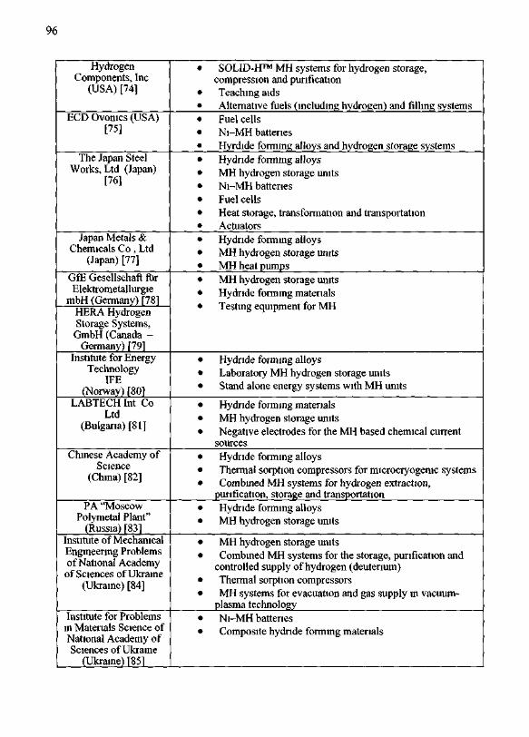
96
HydrogenComponents, Inc
(USA) [74]
BCD Ovonics (USA)[75]
The Japan SteelWorks, Ltd (Japan)
[76]
Japan Metals &Chemicals Co , Ltd
(Japan) [77]
GfE Gesellschaft furElektrometallurgie
mbH (Germany) [78]HERA HydrogenStorage Systems,GmbH (Canada -
Germany) {79]_Institute for Energy
TechnologyIFE
(Norway) [80]LABTECH Int Co
Ltd(Bulgaria) [81]
Chinese Academy ofScience
(China) [82]
PA "MoscowPolymetal Plant"_(Russia) [83]
Institute of MechanicalEngineering Problemsof National Academy
of Sciences of Ukraine(Ukraine) [84]
Institute for Problemsin Materials Science ofNational Academy ofSciences of Ukraine
(Ukraine) [85]
• SOLID-H™ MH systems for hydrogen storage,compression and purificationTeaching aidsAlternative fuels (including hydrogen) and filling systemsFuel cellsNi-MH batteriesHyrdide forming alloys and hydrogen storage systemsHydride forming alloysMH hydrogen storage unitsNi-MH batteriesFuel cellsHeat storage, transformation and transportationActuatorsHydride forming alloysMH hydrogen storage unitsMH heat pumpsMH hydrogen storage unitsHydride forming materials
• Hydride forming alloys• Laboratory MH hydrogen storage units• Stand alone energy systems with MH units
• Hydride forming materials• MH hydrogen storage units• Negative electrodes for the MH based chemical current
sources• Hydride forming alloys• Thermal sorption compressors for microcryogenic systems• Combined MH systems for hydrogen extraction,
purification, storage and transportation• Hydride forming alloys• MH hydrogen storage units
• MH hydrogen storage units• Combined MH systems for the storage, purification and
controlled supply of hydrogen (deuterium)• Thermal sorption compressors• MH systems for evacuation and gas supply in vacuum-
plasma technology• Ni-MH batteries• Composite hydride forming materials

97
Figure 11. Transport applications of MH hydrogen storage units:a — metal hydride storage tank in minivan [86]b- a utility vehicle with PEMFC and MH hydrogen storage [59]c — hydrogen-powered PEM FC forklift (Siemens AG; photo from Fuel
Cells 2000 1999 [11])d - hydrogen-powered ICE forklift with 2 7 Nm3 H2 MH storage unit
(IPMach [70])
The characteristics of the units produced by Ergenics [73], HERA [79], IPMach[70], IFE (our data), as well as some ones reviewed by Volvo in [11] were used as startingdata. The volumetric efficiency was defined as the ratio of the real volumetric H capacity(quantity of stored hydrogen divided by volume of the unit) to the maximum volumetrichydrogen density of the MH used in the unit. Similarly, the weight efficiency wasdetermined as the ratio of the weight H capacity (hydrogen quantity divided by the unitweight) to the maximum weight H capacity of the corresponding MH.
It is seen from Fig. 12a that the volumetric efficiency of hydrogen storage in the realMH units does not practically correlate with the scale of the unit, but as a rule, it does notexceed 40-50% of the total volumetric H density in the MH material. As to the weightefficiency, it is observed a tendency of its increase with the unit scale. Moreover, for thelow-scale units (up to -500 litres H2) this effect is more pronounced. Anyway, 70-75% isthe upper limit for the weight efficiency of the MH hydrogen storage systems.
There exist several reasons reducing the hydrogen storage capacity of the MH unitsbelow the capacity of the MH material. First, the useful storage capacity of the unit isdetermined not by the total, but by the reversible hydrogen capacity of the material, i.e. bythe quantity of hydrogen which can be reversibly absorbed / desorbed in the course of theunit operation. This parameter depends both on the properties of the used MH (mainly onPCT characteristics of the corresponding system with hydrogen gas), and, also, on workingpressure and temperature range. The system TiCr2-x - H2 (Fig. 13) is the vivid illustration;here the reversible hydrogen capacity at 7M)-120 °C and P=10-100 bar is less than 20% ofthe total H capacity of the material.
In most cases the reversible capacity of "low-temperature" MH is about 60-80% ofthe total hydrogen capacity for AB, ABa and ABs [56], and 50-60% for pseudo-binaryhydrides on the basis of b.c.c. vanadium alloys [61]. For the "high-temperature" hydrides,

98
Figure 12. Volumetric (a) and weight (b) storage efficiencies of MH hydrogen storage units
based on pure magnesium and its intermetallides (e.g., MgiNi), the reversible capacityderived from PCT characteristics is more than 90% of the total value [56]. However, high-alloyed magnesium alloys containing significant amounts of relatively heavy components(rare earths, Ni, etc.) added for improvement of hydrogen sorption - desorption kineticshave the real capacity about 5.5 wt.% H that is 72% of the total capacity of MgH2 (7.6wt.%) [89]. For the catalysed systems on the basis of NaAlH4 the reversible hydrogencapacity, corresponding to the reaction (6) is of 5.6 wt.%, or 75% of the total hydrogenquantity in the alanate (7.4 wt.%); if only the first low-temperature stage of this reaction istaken into account, its reversible capacity is already 3.7 wt.%, i.e. 50% of total value [65].
Another factor reducing the weight hydrogen capacity of the MH storage units ismaterial consumption of the container. This factor is also important in the large-scale unitswhere, apart from container itself, the presence of special heat transfer elements forimprovement heat transfer in the MH layer is necessary. The usage of lighter designmaterials allows to reduce in some extend the losses in the weight capacity of the system.However, this effect is mainly essential for the low-scale units. So, in the Fig. 12a thepoints denoted by opened squares correspond to the aluminium-made containers, and thestars correspond to containers made of stainless steel.
The main reason of reducing in volumetric hydrogen capacity in the real MH storageunits is the upper limit of safe packing density of the MH loaded into container. It isobligatory to avoid the damage of the swelling effect of the MH material in the course ofhydrogen absorption. This limit depends on the value of volume increase of the metalmatrix under hydrogenation. For AB5, according to the experimental data [90], the safepacking density is about 45% of the bulk density of the H storage alloy.
Taking into account the above-mentioned, it can be concluded that MH hydrogenstorage units having a conventional layout (rigid container with the internal heat exchangeror without it where the MH powder is loaded) will have the volumetric hydrogen storagecapacity not higher than 50% and the weight one no more than 75% of the total capacity of

99
Figure 13. Total (Cmax) and reversible (Crev) hydrogen sorption capacity for the TiCr2-x~H2 system [87,88]
the MH. According our estimations, it corresponds to the storage of gaseous hydrogenunder the pressure 400 to 800 bar. But the real pressure of hydrogen gas inside MHhydrogen storage unit usually does not exceed several bars what is important from thereasons of safety and the absence of expenses for hydrogen compression. Moreover, theimprovement of the design of MH containers (usage of light materials, non-traditionallayout, etc.) can improve weight- and volumetric indices of MH hydrogen storage units. So,according to Volvo estimations [11], hydrogen storage capacity of the mobile MH Hstorage units can be only 10-20% lower than the hydrogen capacity of the MH.
5. Evaluation of suitability of different methods for different applications based onphysical and chemical characteristics and particular properties
This Section summarizes the information about performance characteristics of differenthydrogen storage methods considered above
The comparison of the performances of the main hydrogen storage methods ispresented in Fig. 14 and Fig. 15. More detailed characteristics of the methods are given inthe Table 6. We used typical characteristics based on the available reference data. We notethat some of the reference data vary from source to source, especially in case of themethods being on the R&D stage. Nevertheless, these data reflect the existing trends andcan be used for the comparative purposes.
From the data of Table 6 it can be concluded that all methods have advantages anddisadvantages and there is no a specific hydrogen storage method which is superior to theremaining alternative ones. Cost, volume, weight and performance should be consideredtogether in making a choice for optimal storage method suiting the specific requirements.
In the industrial-scale methods of hydrogen storage significant progress is achievedin the improvement of the weight and volume efficiencies of H storage in compressed H2(350-700 bar composite cylinders) and LH2 forms with weight H capacities reaching 20wt.% for the vehicle applications and exceeding 50 % for the large scale storage units.Metal hydrides provide the best solution in achieving safe H storage and reaching thehighest level of H volume densities required for the applications in stationary and standalone systems where the weight density is not critical.

100
It should also be noted that the synergy of physical and chemical methods of Hstorage allows a prospective scenario allowing to suit different applications Combinedsystems (e g , cryogenic pressure cylinders or pressure cylinders + MH compressors) arethe most prospective
TABLE 6 Comparison of hydrogen storage methods
Group
Physical
Chemical
Subgroup
Compressedgas storage
Method
SteelcylindersCommercialcompositecylindersAdvancedcompositecylindersGlass micro-spheres
Cryogenic (LH2)
Cryo-adsorption
Metalhydrides
"Low-Temperature"(20-100°C)
"High-Temperature"(25(MK)0°C)
Complexhydrides(alanates)
Organic hydrides
Gasolme(4)
Storageconditions
P,bar
200
250
690
350-630
1
2-^0
001-20
1 90
1-200
10-100
1
T, °C
20
20
20
200-400
OS 9
-208195
20-100
250-350
125-165
300-400
20
Storage performances
Weight%H
100W
25
1006
1008
10010100
15-2060-8238-5215-1808-1335-7625-5640-5630-4050-7035-474128
HVolumedensity,g/dm1
178
223
297
20
71
1 S ^0
90 10060-70
90-10060-70
30
70-100
29
Energyconsumption,
%(*
9
10
125
25
279
8 1
104
206
134
28
® As compared with hydrogen heating value 39 413 kW h/kg^3) Numerator — "ideal" value, denominator - real value (due to limited efficiency of thestorage system)*4^ In energy equivalents

101
Figure 14. Weight- and volume capacities of hydrogen storage methods
Figure 15. Energy consumption of hydrogen storage methods

102
A detailed comparative analysis of hydrogen storage alternatives resulted in thefollowing recommendations for the applications of the different storage methods [11]:> Underground reservoirs and moderate-pressure chambers are recommended for
seasonal stationary energy storage;> High-pressure composite cylinders are the best solution in the transport applications
with large carrying capacity (buses, trucks, ferries);> Cryogenic high-pressure vessels and methanol reformers are recommended in the
smaller-scale transport applications (cars, tractors);> Cryogenic low-pressure vessels are the best solution for the use in aviation and space
applications;> Metal hydrides are recommended for the use in the low-scale hydrogen storage units.
In our opinion, these recommendations are rather realistic, except for metal hydrideswhose applications seem to be broader. It is caused by the fact that metal hydrides form abasis for multi-functional applications allowing to combine several options, for example,hydrogen storage, purification and controlled supply to a consumer, provided by a singledevice [70]. As an example, the metal hydride system intended for hydrogen recovery fromammonia purge gas (50% H2), its purification (purity 99.999%), storage and transportation(200 Nm3 H2 in four MH containers) and supply to a glass factory in China can be given[91].
The most promising applications of the metal hydrides directly connected toalternative hydrogen storage methods involve MH-based hydrogen thermal sorptioncompressors as auxiliary facilities for filling gas cylinders, as well as for re-liquefactionsystems in LH2 hydrogen storage [92]. The main R&D activities in the implementation ofthis approach are in the detailed adjustment of the properties of MH, system designaccording to the consumer's specification.
References
1. F. Barbir, Review of Hydrogen Conversion Technologies, Clean Energy Research Inst., Univ. of Miami,Coral Gables, FL 33124, U.S.A.
2. J.O'M. Bockris, and T.N. Veziroglu, Environmental Conservation 12 (1985) 1053. T.N. Veziroglu and F. Barbir, Int. J. Hydrogen Energy 17 (1992) 3914. T.N. Veziroglu, in: Y.Yurum (Ed), Hydrogen Energy System. Production and Utilization of Hydrogen and
Future Aspects (NATO AS1, Series E, Vol.295), Kluwer Academic Publishers, Dordrecht — Boston —London, 1994, p. 1
5. E.E.Spilrain, S.P.Malyshenko and G.G.Kuleshov, An Introduction to Hydrogen Energy,"EnergoAtomlzdat", Moscow, 1984 (in Russian)
6. J.O'M. Bockris and J.C.Wass, in: T.N. Veziroglu and A.N. Protsenko (Eds.), Hydrogen Energy ProgressVII. Proc. 7th World Hydrogen Energy Conf., Moscow, U.S.S.R, 25-29 Sept. 1988, Vol.1, Pergamon Press,New York e.a., 1988, p. 101
7. A Multiyear Plan for the Hydrogen R&D Program, Rationale, Structure, and Technology Roadmaps,Office of Power Delivery, Office of Power Technologies, Energy Efficiency and Renewable Energy, U.S.Department of Energy, August 1999
8. Report to Congress on the Status and Progress of the DOE Hydrogen Program, February 4, 19999. International Energy Agency. Experience Curves for Energy Technology Policy, OECD/IEA, 200010. List of Task 12 Publications and Presentations. IEA Task 12: Metal Hydrides and Carbon for Hydrogen
Storage, 200111. J.Pettersson and O.Hjortsberg (Volvo Teknisk Utveckling AB), Hydrogen storage alternatives — a
technological and economic assessment, KFB-Meddelande 1999:27, published December 1999, KFBsDNR 1998-0047
12. R.Wurster, Overview of Existing Experience in Hydrogen and Fuel Cells in Germany and Europe,Recherches et perspectives industrielles sur la pile a combustible etl'hydrogene Paris, 13 decembre 2001
13. D.Yu.Hamburg and N.F.Dubovkin (Eds.), Hydrogen: Properties, Production, Storage, Transportation,Applications. Reference Book, "Khimia", Moscow, 1989 (in Russian)
14. Properties of Fuels, Alternative Fuels Data Center (AFDC); US Department of Energy, Office ofTransportation Technologies, http://www.afdc.doe.gov/pdfs/fueltable.pdf

103
15. Hydrogen Energy Equivalents, H—ION SOLAR, Inc, http://www.hionsolar.com/n-heql.html16. Hydrogen Fuel. http://www.dynein.com/Hydrogen/hydrogen.htm17. G.Nicoletti, Int. J. Hydrogen Energy, 20 (1995) 75918. W.Zittel and R.Wurster, Hydrogen in the Energy Sector, Ludwig-Bolkow-Systemtechnik GmbH, - Issue :
8.7.1996, http://www.hvweb.de/Knowledge/w-i-energiew-eng.html19. M.P.Malkov (Ed.), Reference Book on Physical-Technical Basics of Cryogenics, "EnergoAtomlzdat",
Moscow, 1985 (in Russian)20. L.Schlapbach, Materials Research Bulletin, 27 (2002) 67521. L.Browning, Projected Automotive Fuel Cell Use in California, P600-01-022, Consultant Report -
Prepared for California Energy Commission, October 200122. R.Ramachandran and R.K.Menon, Int. J. Hydrogen Energy, 23 (1998) 59323. V.V.Solovey (Ed.), Development of the concept of increasing the efficiency of alternative energy carriers
and non-conventional power sources in the production complex of the Ukraine, Report by A.N.PodgornyInstitute of Mechanical Engineering Problems of National Academy of Sciences of Ukraine, Kharkov,2000.
24. Composite Cylinders Latest Developments, by Dynetek Advanced Lightweight Fuel Storage Systems TM;Asia- Pacific Natural Gas Vehicles Summit, Brisbane, Australia; April 10, 2001; Rene Rutz, VP Marketing& Business Development
25. Quantum Technologies. Inc.. http://www.qtww.com26. Hydrogen composite tank program, Proc. 2002 U.S. DOE Hydrogen Program Review NREL/CP-610-
3240527. R.S.Irani, Materials Research Bulletin, 27 (2002) 68028. PDC Machines, Inc. (www.pdcmachines.com). compressors data.29. RIXIndustries (www.rixindustries.com). RIX 3KX series compressors30. D.Hart, Hydrogen Power: The Commercial Future of the "Ultimate Fuel", Financial Times Energy
Publishing, a Division of Pearson Professional Limited, 199731. R.D.Venter and G.Pucher, Int. J. Hydrogen Energy 22 (1997) 79132. J.Wolf, Materials Research Bulletin 27 (2002) 68433. Space Shuttle Projects Office, http://shuttle.msfc.nasa.gov34. KNOW HOW, 2/2000, LINDE TECHNISCHE GASE GMBH.35. S.M.Aceves, J.Martinez-Friaz and O.Garsia-Villazana. Low temperature and high pressure evaluation of
insulated pressure vessels for cryogenic hydrogen storage, Proc. 2000 Hydrogen Program Review,NREL/CP - 570 - 28890
36. S.M.Aceves, J.Martinez-Frias, O.Garsia-Villazana and F.Espinosa-Loza, Performance and certificationtesting of insulated pressure vessels for vehicular hydrogen storage, Proc. 2001 DOE Hydrogen ProgramReview, NREL/CP - 570 - 30535
37. J.Weitkamp, M.Fritz and S.Ernst, Int. J. Hydrogen Energy 20 (1995) 96738. N.L.Rosi, e.a. Science 300 (2003) 112739. L.Schlapbach and A.Zuttel, Nature 414 (2001) 35340. V.I.Trefilov, D.V.Schur e.a., Fullerenes, "ADEF Ukraine", Kiev, 2001 (in Russian)41. A.Zuttel and S.-I.Orimo, Materials Research Bulletin 27 (2002) 70542. A.C. Dillon, e.a., Hydrogen storage in carbon single-wall nanotubes, Proc. 2002 DOE hydrogen program
review, 2002, National renewable energy laboratory, Golden, CO 80401-3393.43. M. Hirscher, e.a., Applied Physics A-Materials Science & Processing, 72 (2001) 12944. A.Chambers, C.Park, R.T.K.Baker and N.M.Rodriges, J. Phys. Chem. B102 (1998) 425345. A. Ziittel, e.a., J. Alloys and Compounds 330 (2002) 67646. R. Strobel, e.a., J. Power Sources, 84 (1999) 22147. M.G. Nijkamp, e.a., Applied Physics A-Materials Science & Processing 72 (2001) 61948. R. Chahine and T.K. Bose, Int. J. Hydrogen Energy 19 (1994) 16149. B.P.Tarasov, J.P.Maehlen, e.a., J. Alloys and Compounds 356-357C (2003) 51050. D.V.Schur, B.P. Tarasov, e.a., in: T.N.Veziroglu et al (Eds.), Hydrogen Materials Science and Chemistry of
Metal Hydrides (NATO Science Series II, Vol.82), Kluwer Academic Publishers, 2002, p. 151. B.A.Troshenkin, Circulation and film evaporators and hydrogen reactors, "Naukova Dumka", Kiev, 1985
(in Russian)52. M.Mueller, J.P.Blackledge and G.G.Libovitz (Eds.), Metal Hydrides, Academic Press, New York &
London, 196853. VA.Yartys, V.V.Burnasheva and K.N.Semenenko, Uspekhi Khimii 52 (1983) 529 (in Russian)54. W.B.Pearson. The crystal Chemistry and Physics of Metals and Alloys, Russian Translation (in 2 volumes),
"Mir", Moscow, 197755. P.Villars and L.D.Calvert. Pearson's Handbook of Crystallographic Data for Intermetallic Phases, Second
Edition. Volume 4.- ASM International, The Materials Information Society, Materials Park, OH 44073.56. G.Sandrock, J. Alloys and Compounds 293-295 (1999) 87757. P.Dantzer, in: H.Wipf (Ed.), Hydrogen in Metals. III. Properties and Applications (Topics in Applied
Physics, Vol. 73), Springer-Verlag, Berlin -Heidelberg, 1997, p.279

104
58 G Sandrock, S Suda and L Schlapbach, in L Schlapbach (Ed ), Hydrogen in Intermetalhc Compounds IISurface and Dynamic Properties Applications, Spnnger-Verlag, 1992, p 197
59 R C Bowman, Jr and B Fultz Materials Research Bulletin 27 (2002) 68860 J -M Joubert, M Latroche and A Percheron-Guegan, Ibid 69461 E Akiba and M Okada, Ibid 69962 B Bogdanovic and G Sandrock, Ibid 71263 K J Gross, G J Thomas, G Sandrock, Hydride Development for Hydrogen Storage, Proc 2000 Hydrogen
Program Review, NREL/CP-570-2889064 J Tolle, Ti- oder Ti und Fe-dotierte Natnumalanate als nue reversible Wasserstoffspeichermateriahen,
Dissertation aus dem Max-Planck-Institut fiir Kohlenfbrschung, Mulheim am Rhur, 1998, Bd 4, S 1-14465 B Bogdanovic, e a , J Alloys and Compounds 302 (2000) 3666 P Dantzer, F Meuner, Materials Science Forum 31 (1988) 167 B A Kolachev, R E Shahn, A A Il'in Alloys for Hydrogen Storage Refei ence Book, "Metallurgy",
Moscow, 1995 (in Russian)68 EL Huston, G D Sandrok, J Less-Common Metals 74 (1985) 43569 G G Libowitz, K T Feldman Jr , C Stem, J Alloys and Compounds 253-254 (1997) 67370 V V Solovey, Yu F Shmal'ko and M V Lototsky, Problemy Mashmostroemya (J of Mechanical
Engineering) 1 (1998) 115 (in Russian)71 Yu F Shmal'ko, A I Ivanovsky, e a, in T N Veziroglu, e a (Eds), Hydrogen Energy Progress XI Proc
11-th World Hydrogen Energy Conf Stuttgart Germany 23-28 June 1996, Int Association for HydrogenEnergy, 1996, vol 2, p i 33 5
72 V A Yartys, e a, J Alloys and Compounds 330-332 (2002) 13273 Ergemcs Inc 373 Margaret King Ave Rmgwood, NJ 07456, USA, http //www hydrides com/74 Hydrogen Components Inc 12420 North Dumont Way, Littleton, CO 80125, USA,
http //www hydrogencomponents com/75 ECU Ovomcs 2956 Waterview Drive Rochester Hills, Michigan 48309, USA, http //www ovonic com/76 The Japan Steel Works Ltd Hydrogen Energy Center Hibiya Mitsui Bldg , 1-2, Yurakucho 1-Chome,
Chioda-ku Tokyo 100 0006, Japan, http //www isw co ip/77 Japan Metals & Chemicals Co Ltd Department of Metal Hydride Alloy Business 8-4 Koami-Cho,
Nihonbashi, Chuo-ku, Tokyo 103-8531, Japan, http //www imc co ip78 GfE Gesellschaftfur Elektrometallurgie mbH Hoefener Strasse 45 D-90431 Nuremberg, Germany,
http //www gte-onhne de79 HERA Hydrogen Storage Systems GmbH 577 Le Breton Longueuil, Quebec, Canada J4G 1R9, Hoefener
Strasse 45, 90431, Nuremberg, Germany, http //www herahvdrogen com/80 Institute for Energy Technology, P O Box 40, Kjeller, N 2027, Norway, http //www ife no81 LABTECHInt Co Ltd Alloys Research and Manufacturing Mladost-1, bl 25/A, Sofia-1784, BULGARIA,
http //labtech solo bg/82 Chinese Academy of Sciences Zhong guan kun, Beijing 100080, People's Republic of China83 PA Moscov, Polymetal Plant , 49 Kashirskoe Road, Moscow 116409, Russia84 AN Podgorny Institute of Mechanical Engineering Problems of National Academy of Sciences of Ukraine,
2/10 Pozharsky Str , Kharkov 61046, Ukraine, http //ipmach kharkov ua85 Institute for Problems in Materials Science of National Academy of Sciences of Ukraine, 3
Krzhyzhanovsky Str , Kiev 03180, Ukraine, http //hydro ipms kiev ua86 T Schucan, Case Studies of Integrated Hydrogen Energy Systems, International Energy Agency Hydrogen
Implementing Agreement Task 11 Integt ated Systems Final report ofSubtask A Chapter 2,IEA/H2/T11/FR1-2000
87 J R Johnson, J Less-Common Met, 73 (1980) 34588 O Been, e a, J Alloys and Compounds, 267 (1998) 11389 B P Tarasov, e a, in D V Schur, S Yu Zagmaichenko and T N Veziroglu (Eds ), Hydrogen Materials
Science and Chemistry of Carbon Nanomatenals (ICHMS'2003) VIII International Conference Sudak -Crimea-Ukraine September 14-20 2003,Kiev 2003,p 298-301
90 K Nasako, Y Ito, N Hiro, M Osumi, J Alloys and Compounds 264 (1998) 27191 M Au, e a, Int J Hydrogen Energy 21 (1996) 3392 V A Yartys and M V Lototsky Metal Hydride High Pressure Hydrogen Compression Present Status —
Review, Institute for Energy Technology, Department of Energy Systems, 2002