An iterative robot-image Jacobian approximation of image-based visual servoing for joint limit...
13
Int. J. Mechatronics and Automation, Vol. X, No. Y, 200X 1 Copyright © 200X Inderscience Enterprises Ltd. An iterative robot-image Jacobian approximation of image-based visual servoing for joint limit avoidance Indrazno Siradjuddin*, T. Martin McGinnity, Sonya Coleman and Laxmidhar Behera Intelligent Systems Research Centre, University of Ulster, Magee Campus, Northland Road BT487JL, Northern Ireland, UK Fax: +44-28-7137-5616/5570 E-mail: [email protected] E-mail: [email protected] E-mail: [email protected] E-mail: [email protected] *Corresponding author Abstract: In this paper, we propose a new method addressing the robot-image Jacobian approximation of image-based visual servoing (IBVS) for a redundant manipulator. The robot-image Jacobian is approximated iteratively and is a model free. A linearised model of the robot-image Jacobian is applied, based on the first order Taylor series approximation. A weighted least norm solution is induced in a pseudo inverse computation of the approximated robot-image Jacobian. The resulting control law then can be used for visual servoing tasks with joint limit avoidance capability using both a static target or moving target. The self-motion of the robot joints resolves the redundancy during visual servoing tasks when one or more joints are approaching their joint limits. A design and stability analysis of the proposed method is discussed in this paper. Simulated and real-time experiments using a 7 DOF PowerCube robot manipulator are conducted. The IBVS is configured using a monovision eye-in-hand system configuration. The system behaviour and performances of the proposed method are presented and analysed. Keywords: a redundant robotics manipulator; image-based visual servoing; IBVS; robot-image Jacobian approximation; mechatronics automation; redundancy resolution; joint limit avoidance. Reference to this paper should be made as follows: Siradjuddin, I., McGinnity, T.M., Coleman, S. and Behera, L. (xxxx) ‘An iterative robot-image Jacobian approximation of image-based visual servoing for joint limit avoidance’, Int. J. Mechatronics and Automation, Vol. X, No. Y, pp.000–000. Biographical notes: Indrazno Siradjuddin received his BE in Electrical and Electronics Engineering from Brawijaya University, Indonesia in 2000, and Master in Electrical and Electronics Engineering from Institut Teknologi Sepuluh Nopember, Indonesia in 2004. He is currently pursuing his PhD in the Department of Computing and Engineering at University of Ulster, Magee. His primarily research interests include vision-based robot manipulator control, intelligent control, neural networks and fuzzy systems. T. Martin McGinnity received his first class (Hons.) degree in Physics in 1975, and PhD degree from the University of Durham, Durham, UK in 1979. He is a Professor of Intelligent Systems Engineering within the Faculty of Computing and Engineering, University of Ulster, Derry, Northern Ireland. He is currently the Director of the Intelligent Systems Research Centre, which encompasses the research activities of approximately 100 researchers. He is the author or co-author of more than 275 research papers. His current research interests are focused on computational intelligence, to explore and model biological signal processing, particularly in relation to cognitive robotics and computational neuroscience. He has been awarded both a Senior Distinguished Research Fellowship and a Distinguished Learning Support Fellowship in recognition of his contribution to teaching and research. He is a Senior Member of the IEEE, Fellow of the IET and a Chartered Engineer. Sonya Coleman received her BSc (Hons.) in Mathematics, Statistics and Computing from the University of Ulster, UK in 1999, and PhD in Mathematics from the University of Ulster, UK in 2003. She is currently a Senior Lecturer in the School of Computing and Intelligent System at the University of Ulster, Magee. She has 50+ publications primarily in the field of mathematical image processing and much of the recent research undertaken by her has been supported by
Transcript of An iterative robot-image Jacobian approximation of image-based visual servoing for joint limit...
Int. J. Mechatronics and Automation, Vol. X, No. Y, 200X 1
Copyright © 200X Inderscience Enterprises Ltd.
An iterative robot-image Jacobian approximation of image-based visual servoing for joint limit avoidance
Indrazno Siradjuddin*, T. Martin McGinnity, Sonya Coleman and Laxmidhar Behera Intelligent Systems Research Centre, University of Ulster, Magee Campus, Northland Road BT487JL, Northern Ireland, UK Fax: +44-28-7137-5616/5570 E-mail: [email protected] E-mail: [email protected] E-mail: [email protected] E-mail: [email protected] *Corresponding author
Abstract: In this paper, we propose a new method addressing the robot-image Jacobian approximation of image-based visual servoing (IBVS) for a redundant manipulator. The robot-image Jacobian is approximated iteratively and is a model free. A linearised model of the robot-image Jacobian is applied, based on the first order Taylor series approximation. A weighted least norm solution is induced in a pseudo inverse computation of the approximated robot-image Jacobian. The resulting control law then can be used for visual servoing tasks with joint limit avoidance capability using both a static target or moving target. The self-motion of the robot joints resolves the redundancy during visual servoing tasks when one or more joints are approaching their joint limits. A design and stability analysis of the proposed method is discussed in this paper. Simulated and real-time experiments using a 7 DOF PowerCube robot manipulator are conducted. The IBVS is configured using a monovision eye-in-hand system configuration. The system behaviour and performances of the proposed method are presented and analysed.
Keywords: a redundant robotics manipulator; image-based visual servoing; IBVS; robot-image Jacobian approximation; mechatronics automation; redundancy resolution; joint limit avoidance.
Reference to this paper should be made as follows: Siradjuddin, I., McGinnity, T.M., Coleman, S. and Behera, L. (xxxx) ‘An iterative robot-image Jacobian approximation of image-based visual servoing for joint limit avoidance’, Int. J. Mechatronics and Automation, Vol. X, No. Y, pp.000–000.
Biographical notes: Indrazno Siradjuddin received his BE in Electrical and Electronics Engineering from Brawijaya University, Indonesia in 2000, and Master in Electrical and Electronics Engineering from Institut Teknologi Sepuluh Nopember, Indonesia in 2004. He is currently pursuing his PhD in the Department of Computing and Engineering at University of Ulster, Magee. His primarily research interests include vision-based robot manipulator control, intelligent control, neural networks and fuzzy systems.
T. Martin McGinnity received his first class (Hons.) degree in Physics in 1975, and PhD degree from the University of Durham, Durham, UK in 1979. He is a Professor of Intelligent Systems Engineering within the Faculty of Computing and Engineering, University of Ulster, Derry, Northern Ireland. He is currently the Director of the Intelligent Systems Research Centre, which encompasses the research activities of approximately 100 researchers. He is the author or co-author of more than 275 research papers. His current research interests are focused on computational intelligence, to explore and model biological signal processing, particularly in relation to cognitive robotics and computational neuroscience. He has been awarded both a Senior Distinguished Research Fellowship and a Distinguished Learning Support Fellowship in recognition of his contribution to teaching and research. He is a Senior Member of the IEEE, Fellow of the IET and a Chartered Engineer.
Sonya Coleman received her BSc (Hons.) in Mathematics, Statistics and Computing from the University of Ulster, UK in 1999, and PhD in Mathematics from the University of Ulster, UK in 2003. She is currently a Senior Lecturer in the School of Computing and Intelligent System at the University of Ulster, Magee. She has 50+ publications primarily in the field of mathematical image processing and much of the recent research undertaken by her has been supported by
2 I. Siradjuddin et al.
funding from EPSRC award EP/C006283/11, the Leverhulme Trust and the Nuffield Foundation. Additionally she is co-investigator on the EU FP7 funded project RUBICON. She is the author or co-author of over 70 research papers in image processing, robotics and computational neuroscience. In 2009, she was awarded the Distinguished Research Fellowship by the University of Ulster in recognition of her contribution research.
Laxmidhar Behera is currently a Professor at the Department of Electrical Engineering, IIT Kanpur. He joined the Intelligent Systems Research Center (ISRC), University of Ulster, UK, as a reader on sabbatical from IIT Kanpur during 2007 to 2009. He obtained his BSc and MSc in Engineering from NIT Rourkela in 1988 and 1990, respectively. A PhD from IIT Delhi, he has worked as an Assistant Professor in BITS Pilani during 1995 to 1999 and pursued his Postdoctoral studies in the German National Research Center for Information Technology, GMD, Sank Augustin, Germany during 2000 to 2001. He has also worked as visiting researcher/professor in FHG, Germany, and ETH, Zurich, Switzerland. He has more than 150 papers to his credit published in refereed journals and conference proceedings. His research interests include intelligent control, robotics, neural networks, and cognitive modelling.
1 Introduction A robot manipulator is an arm-like mechanism which consists of a series of linked joints with a number of degrees of freedom (DOF). Robot manipulator applications were originally designed to avoid the need for human interaction with hazardous materials and environments. Recently, robot manipulators have been used in more widespread applications, for example, to help disabled people with impaired shoulder functions (Rahman et al., 2012). Usually the full task of the robot manipulator is to move the end-effector in 3D space which has 6-DOF variables to represent its position and orientation. A manipulator is termed kinematically redundant when it possesses more DOF than it is needed to execute a given task.
A redundant robot manipulator is very useful for avoiding joint limits, singularities configuration and obstacles, during servoing to desired positions or trajectories of the robot end-effector. One method to exploit such redundancy is through global optimisation such as motion planning of the robot end-effector trajectory to reach a desired target position and orientation (Yahya et al., 2009). However, a complete set of points information along the planned trajectory is required. Therefore, this method is not suitable for tasks requiring instantaneous trajectory modification during motion. In contrast, instantanous joint trajectories for points along the robot end-effector can be determined using a local optimisation method (Tan and Dubey, 1995; Marchand et al., 1996). Since the performance criterion is optimised locally, it may not result in the optimal joint trajectory for a global operation, but it is more suitable for an online implementation.
In this paper, we focus on avoiding joint limits using a computationally simple Jacobian approximation, which is necessary for uninterrupted operation of the redundant robot manipulator for an image-based visual servoing (IBVS) system. In Marchand and Chaumette (2001), a method using iterative computation to avoid joint limits has been proposed for visual servoing applications. This method generates a robot motion to ensure the achievement of the main task and to avoid any motion on the axis that is in a critical situation. Recently, an improvement of the algorithm to determine
suitable magnitudes for the avoidance process by adding an additional task using a gradient projection method has been proposed in Marey and Chaumette (2010). However, the tasks separation of joint limit avoidance using redundancy could result in undesired joint velocities due to inefficient robot end-effector screw computation of an inaccurate model (Patchaikani and Behera (2010).
Low cost vision sensors are important sensor in robotics and industrial applications since they can provide salient information of the robot environment, extracted from images. Visual feedback is even more crucial in, for example, a surgery robotics application. In Guo et al. (2012), a force and a visual feedback are used to develop a robotic catheter system for vascular interventional surgery. An example of an industrial application is the use of a stereo camera used to analyse the air flow based on the 3D particle velocity measurement (Klimentjew et al., 2011).
A method that uses a visual feedback extracted from the vision sensor image to control the motion of a robot is called vision-based robot control, it is also known as visual servoing. Basic approaches of visual servoing have been discussed in Chaumette and Hutchinson (2006, 2007). We refer to the method of visual servoing which is determined by the robot kinematic and visual features velocity model as model-based visual servoing (MBVS) system (Siradjuddin et al., 2009). The Jacobians in MBVS are either derived analytically from a-priori models or partially estimated. Recently, the approximation of a coupled robot-image Jacobian using fuzzy learning methods has been proposed in (Goncalves et al., 2008; Siradjuddin et al., 2010). Another learning algorithm based on self-organising maps has been proposed in Swagat et al. (2009) for visual servoing for a redundant manipulator in which the joint limit avoidance task was also considered. In this case the redundancy has been resolved by minimising the weighted least-norm proposed in Patchaikani and Behera (2010). These approaches require offine learning to initialise the parameters.
In Shademan et al. (2010) and Piepmeier et al. (1999), the coupled Jacobians are estimated using a non-linear optimisation algorithm and Broyden’s method is used. More

An iterative robot-image Jacobian approximation of image-based visual servoing for joint limit avoidance 3
recently, in Swagat et al. (2009), the population of the kth state of input-output data pairs has been considered for updating an estimated robot-image Jacobian based on this Broyden’s method. However, using non-linear optimisation algorithms for visual servoing with joint limit avoidance has not yet been explored.
The main issues encountered in visual servoing are related to control, robot kinematics and vision. In this paper, we address these issues by creating a model free system in which the robot Jacobian and the image Jacobian are not computed. Instead we present an iterative method to approximate a coupled robot-image Jacobian which then involves a weighted least-norm in the inverting process of the robot-image Jacobian to constrain the movement of joints which are in a critical situation. The paper presents experimental details using a 7-DOF PowerCube robot manipulator from Schunk with eye-in-hand configuration. The kinematics configuration is presented in Section 2. Section 3 describes MBVS. The design and analysis of the proposed method is discussed in detail in Section 4. Section 5 presents the stability analysis of the proposed scheme. Simulations and real-time experimental results are discussed in Section 6 followed by the conclusion in Section 7.
2 Kinematic model of a 7-DOF PowerCube manipulator
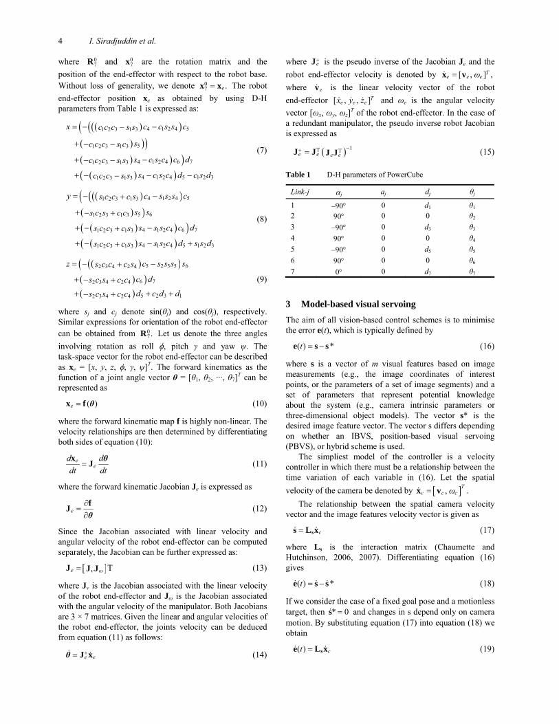
The seven DOF PowerCube manipulator considered in this paper is constructed as open chains where every revolute joint connects the successive links (Figure 1). The role of the model of the mechanical structure is to place the end-effector at a given location (position and orientation) with a desired velocity and acceleration. Given the joint angles of each link, the forward kinematics of the manipulator exactly determines the position and orientation of the robot end-effector in the Cartesian space taking the base link as the reference. The kinematics model is concerned with the relationship between the individual joints of the manipulator and the position and the orientation of the end-effector. The Denavit-Hartenberg (D-H) parameters for this manipulator are derived using the convention given in Spong et al. (2005). In this convention, the four quantities of the jth robot link and robot joint are represented in a homogenous transformation matrix Tj. The four parameters aj, αj, dj and θj are generally given the names link length, link twist, link offset and joint angle, respectively. Each homogenous transformation Tj is represented as a product of four basic transformations
, , , ,Rot Trans Trans Rotj i i ii z θ z d x a z=T α (1)
where
( ) ( )( ) ( )
,
cos sin 0 0sin cos 0 0
Rot0 0 1 00 0 0 1
j
j j
j jz θ
θ θθ θ
⎡ ⎤⎢ ⎥⎢ ⎥=⎢ ⎥⎢ ⎥⎣ ⎦
(2)
,
1 0 0 00 1 0 0
Trans0 0 10 0 0 1
iz djd
⎡ ⎤⎢ ⎥⎢ ⎥=⎢ ⎥⎢ ⎥⎣ ⎦
(3)
,
1 0 00 1 0 0
Trans0 0 1 00 0 0 1
i
j
x a
a⎡ ⎤⎢ ⎥⎢ ⎥=⎢ ⎥⎢ ⎥⎣ ⎦
(4)
( ) ( )( ) ( ),
1 0 0 00 cos sin 00 sin cos 00 0 0 1
i
j jz
j jRot
⎡ ⎤⎢ ⎥−⎢ ⎥=⎢ ⎥⎢ ⎥⎣ ⎦
αα αα α
(5)
Figure 1 Frame assignment for computing D-H parameters
The kinematics parameters of the 7-DOF PowerCube manipulator are given in Table 1. The robot link dimension are as follows: d1 = 0.3180 m, d3 = 0.3375 m , d5 = 0.3085 m, and d7 = 0.2656 m. Multiplying the homogenous transformation Tj; j = 1, 2, …, 7 together yields the forward kinematics of the 7 DOF PowerCube manipulator. The forward kinematic transformation is expressed as
0 07 70
7 0 1⎡ ⎤
= ⎢ ⎥⎣ ⎦
R xT (6)
4 I. Siradjuddin et al.
where 07R and 0
7x are the rotation matrix and the position of the end-effector with respect to the robot base. Without loss of generality, we denote 0
7 .e=x x The robot end-effector position xe as obtained by using D-H parameters from Table 1 is expressed as:
( )( )((( ) ))( ) ) )( )( )
54 1 2 41 2 3 1 3
51 2 3 1 3
764 1 2 41 2 3 1 3
5 1 2 34 1 2 41 2 3 1 3
x cc c s sc c c s s
sc c c s c
dcs c s cc c c s s
d c s ds c s cc c c s s
= − −−
+ − −
+ −− −
+ −− −−
(7)
( )( )((( ) )( )( ) )( )( )
54 1 2 41 2 3 1 3
651 2 3 1 3
764 1 2 41 2 3 1 3
5 1 2 34 1 2 41 2 3 1 3
y cc s s ss c c c s
sss c s c c
dcs s s cs c c c s
d s s ds s s cs c c c s
= − −+
+ − +
+ − −+
+ +− −+
(8)
( )( )(( ) )( )
65 2 3 52 3 4 2 4
762 3 4 2 4
5 2 3 12 3 4 2 4
z sc s s ss c c c s
dcs c s c cd c d ds c s c c
= − −+
+ − +
+ + +− +
(9)
where sj and cj denote sin(θj) and cos(θj), respectively. Similar expressions for orientation of the robot end-effector can be obtained from 0
7.R Let us denote the three angles involving rotation as roll φ, pitch γ and yaw ψ. The task-space vector for the robot end-effector can be described as xe = [x, y, z, φ, γ, ψ]T. The forward kinematics as the function of a joint angle vector θ = [θ1, θ2, ···, θ7]T can be represented as
( )e =x f θ (10)
where the forward kinematic map f is highly non-linear. The velocity relationships are then determined by differentiating both sides of equation (10):
ee
d ddt dt
=x J θ (11)
where the forward kinematic Jacobian Je is expressed as
e∂
=∂
fJθ
(12)
Since the Jacobian associated with linear velocity and angular velocity of the robot end-effector can be computed separately, the Jacobian can be further expressed as:
[ ]e v ω= ΤJ J J (13)
where Jv is the Jacobian associated with the linear velocity of the robot end-effector and Jω is the Jacobian associated with the angular velocity of the manipulator. Both Jacobians are 3 × 7 matrices. Given the linear and angular velocities of the robot end-effector, the joints velocity can be deduced from equation (11) as follows:
e e+= J xθ (14)
where e+J is the pseudo inverse of the Jacobian Je and the
robot end-effector velocity is denoted by [ , ] ,Te e eω=x v
where ev is the linear velocity vector of the robot end-effector [ , , ]T
e e ex y z and ωe is the angular velocity vector [ωx, ωy, ωz]T of the robot end-effector. In the case of a redundant manipulator, the pseudo inverse robot Jacobian is expressed as
( ) 1T Te e e e−+ =J J J J (15)
Table 1 D-H parameters of PowerCube
Link-j αj aj dj θj
1 –90° 0 d1 θ1
2 90° 0 0 θ2 3 –90° 0 d3 θ3 4 90° 0 0 θ4 5 –90° 0 d5 θ5 6 90° 0 0 θ6 7 0° 0 d7 θ7
3 Model-based visual servoing
The aim of all vision-based control schemes is to minimise the error e(t), which is typically defined by
( ) *t = −e s s (16)
where s is a vector of m visual features based on image measurements (e.g., the image coordinates of interest points, or the parameters of a set of image segments) and a set of parameters that represent potential knowledge about the system (e.g., camera intrinsic parameters or three-dimensional object models). The vector s* is the desired image feature vector. The vector s differs depending on whether an IBVS, position-based visual servoing (PBVS), or hybrid scheme is used.
The simpliest model of the controller is a velocity controller in which there must be a relationship between the time variation of each variable in (16). Let the spatial velocity of the camera be denoted by [ ] ., T
c c cω=x v The relationship between the spatial camera velocity
vector and the image features velocity vector is given as
c= ss L x (17)
where Ls is the interaction matrix (Chaumette and Hutchinson, 2006, 2007). Differentiating equation (16) gives
( ) *t = −e s s (18)
If we consider the case of a fixed goal pose and a motionless target, then * 0=s and changes in s depend only on camera motion. By substituting equation (17) into equation (18) we obtain
( ) ct = se L x (19)
An iterative robot-image Jacobian approximation of image-based visual servoing for joint limit avoidance 5
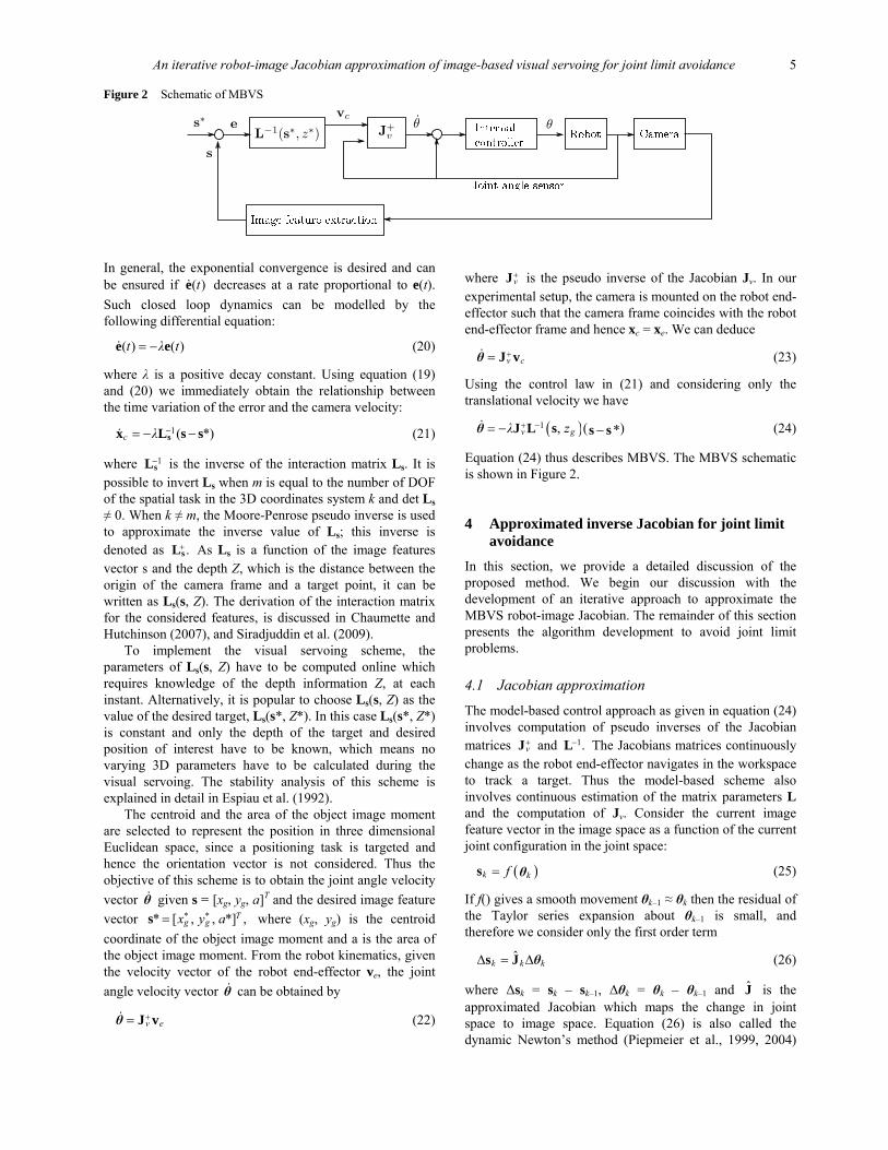
Figure 2 Schematic of MBVS
In general, the exponential convergence is desired and can be ensured if ( )te decreases at a rate proportional to e(t). Such closed loop dynamics can be modelled by the following differential equation:
( ) ( )t λ t= −e e (20)
where λ is a positive decay constant. Using equation (19) and (20) we immediately obtain the relationship between the time variation of the error and the camera velocity:
1( *)c λ −= − −sx L s s (21)
where 1−sL is the inverse of the interaction matrix Ls. It is
possible to invert Ls when m is equal to the number of DOF of the spatial task in the 3D coordinates system k and det Ls ≠ 0. When k ≠ m, the Moore-Penrose pseudo inverse is used to approximate the inverse value of Ls; this inverse is denoted as .+sL As Ls is a function of the image features vector s and the depth Z, which is the distance between the origin of the camera frame and a target point, it can be written as Ls(s, Z). The derivation of the interaction matrix for the considered features, is discussed in Chaumette and Hutchinson (2007), and Siradjuddin et al. (2009).
To implement the visual servoing scheme, the parameters of Ls(s, Z) have to be computed online which requires knowledge of the depth information Z, at each instant. Alternatively, it is popular to choose Ls(s, Z) as the value of the desired target, Ls(s*, Z*). In this case Ls(s*, Z*) is constant and only the depth of the target and desired position of interest have to be known, which means no varying 3D parameters have to be calculated during the visual servoing. The stability analysis of this scheme is explained in detail in Espiau et al. (1992).
The centroid and the area of the object image moment are selected to represent the position in three dimensional Euclidean space, since a positioning task is targeted and hence the orientation vector is not considered. Thus the objective of this scheme is to obtain the joint angle velocity vector θ given s = [xg, yg, a]T and the desired image feature vector * ** [ , , *] ,T
g gx y a=s where (xg, yg) is the centroid coordinate of the object image moment and a is the area of the object image moment. From the robot kinematics, given the velocity vector of the robot end-effector ve, the joint angle velocity vector θ can be obtained by
v e+= J vθ (22)
where v+J is the pseudo inverse of the Jacobian Jv. In our
experimental setup, the camera is mounted on the robot end-effector such that the camera frame coincides with the robot end-effector frame and hence xc = xe. We can deduce
v c+= J vθ (23)
Using the control law in (21) and considering only the translational velocity we have
( )( )1 , *gv zλ + −= − −sJ L s sθ (24)
Equation (24) thus describes MBVS. The MBVS schematic is shown in Figure 2.
4 Approximated inverse Jacobian for joint limit avoidance
In this section, we provide a detailed discussion of the proposed method. We begin our discussion with the development of an iterative approach to approximate the MBVS robot-image Jacobian. The remainder of this section presents the algorithm development to avoid joint limit problems.
4.1 Jacobian approximation
The model-based control approach as given in equation (24) involves computation of pseudo inverses of the Jacobian matrices v
+J and 1.−L The Jacobians matrices continuously change as the robot end-effector navigates in the workspace to track a target. Thus the model-based scheme also involves continuous estimation of the matrix parameters L and the computation of Jv. Consider the current image feature vector in the image space as a function of the current joint configuration in the joint space:
( )k kf=s θ (25)
If f() gives a smooth movement θk–1 ≈ θk then the residual of the Taylor series expansion about θk–1 is small, and therefore we consider only the first order term
ˆk k kΔ = Δs J θ (26)
where Δsk = sk – sk–1, Δθk = θk – θk–1 and J is the approximated Jacobian which maps the change in joint space to image space. Equation (26) is also called the dynamic Newton’s method (Piepmeier et al., 1999, 2004)
6 I. Siradjuddin et al.
and can be represented in continuous form with time sampling Δt as
ˆ
ˆ
k kk
k
t tΔ Δ
=Δ Δ=
s J
s J
θ
θ (27)
Using equations (17) and (23), the relationship between the joint velocity and the image feature velocity can be written as
v= ss L L θ (28)
By comparing equation (28) and (27), one can deduce that J approximates a coupled robot-image Jacobian LsJv. In order to incorporate the joint limit avoidance task, the pseudo inverse of the approximated Jacobian can be computed as
[ ] 11 1ˆ ˆ ˆ ˆT T−+ − −=J W J JW J (29)
where W ∈ Rn×n is a symmetric and positive definite weighting matrix and n is the DOF of the robot manipulator. The computation of W will be discussed in the next section. Let us consider using ˆ +J in closed-loop visual servoing as denoted in equation (24) instead of computing 1ˆ ( , ).v gz+ −J L s For a single movement, one pair of Δs and Δθ is available. The current approximated Jacobian ˆ kJ has to be updated so that the next 1ˆ k+J satisfies a given constraint ˆ .Δ = Δs J θ The approximated Jacobian J can be updated by minimising the cost function such that
( )21 ˆ2
= Δ − ΔE s J θ (30)
Gradient descent is used to minimise the given cost function and the update law is given as
( )
1
1
ˆ ˆˆ
ˆ ˆ ˆ
k kk
Tk k k
η
η
+
+
∂= −
= − ΔΔ − Δ
EJ JJ
J J s J θθ
(31)
where η is the updating rate constant.
4.2 Joint limit avoidance
In order to avoid joint limits using redundancy, a performance criterion as a function of joint angles and their limits is formulated in the following form:
( )( )( )
2,max ,min
,max ,min1
1( )4
ni i
i i i ii
θ θH
θ θ θ θ=
−=
− −∑θ (32)
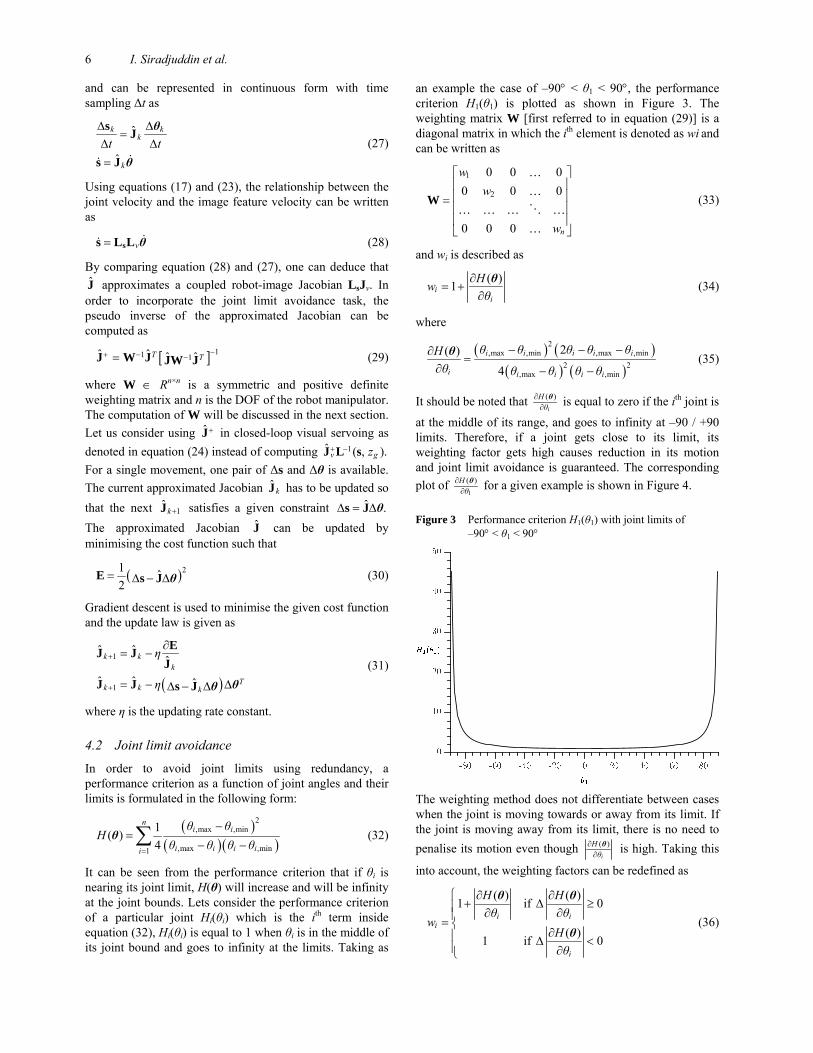
It can be seen from the performance criterion that if θi is nearing its joint limit, H(θ) will increase and will be infinity at the joint bounds. Lets consider the performance criterion of a particular joint Hi(θi) which is the ith term inside equation (32), Hi(θi) is equal to 1 when θi is in the middle of its joint bound and goes to infinity at the limits. Taking as
an example the case of –90° < θ1 < 90°, the performance criterion H1(θ1) is plotted as shown in Figure 3. The weighting matrix W [first referred to in equation (29)] is a diagonal matrix in which the ith element is denoted as wi and can be written as
1
2
0 0 00 0 0
0 0 0 n
ww
w
⎡ ⎤⎢ ⎥⎢ ⎥=⎢ ⎥⎢ ⎥⎣ ⎦
W
……
… … … ……
(33)
and wi is described as
( )1ii
Hwθ
∂= +
∂θ (34)
where
( ) ( )( ) ( )
2,max ,min ,max ,min
2 2,max ,min
2( )4
i i i i i
i i i i i
θ θ θ θ θHθ θ θ θ θ
− − −∂=
∂ − −
θ (35)
It should be noted that ( )i
Hθ
∂∂θ is equal to zero if the ith joint is
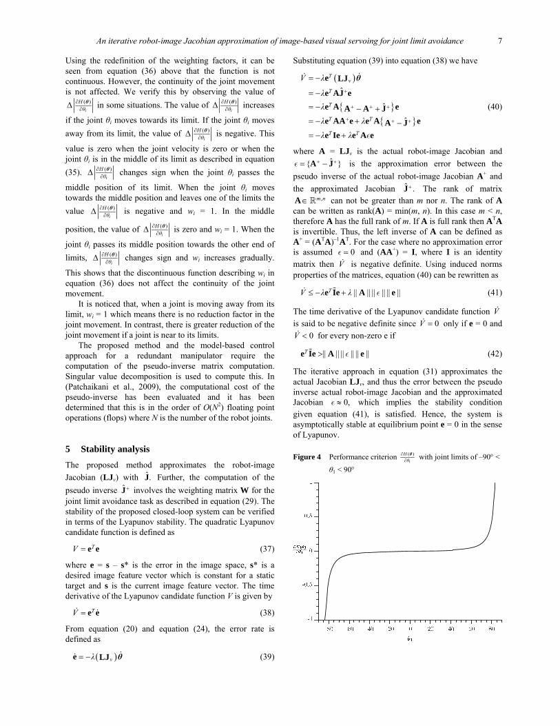
at the middle of its range, and goes to infinity at –90 / +90 limits. Therefore, if a joint gets close to its limit, its weighting factor gets high causes reduction in its motion and joint limit avoidance is guaranteed. The corresponding plot of
1
( )Hθ
∂∂θ for a given example is shown in Figure 4.
Figure 3 Performance criterion H1(θ1) with joint limits of –90° < θ1 < 90°
The weighting method does not differentiate between cases when the joint is moving towards or away from its limit. If the joint is moving away from its limit, there is no need to penalise its motion even though ( )
i
Hθ
∂∂θ is high. Taking this
into account, the weighting factors can be redefined as
( ) ( )1 if 0
( )1 if 0
i ii
i
H Hθ θ
wHθ
⎧ ∂ ∂+ Δ ≥⎪ ∂ ∂⎪= ⎨
∂⎪ Δ <⎪ ∂⎩
θ θ
θ (36)
An iterative robot-image Jacobian approximation of image-based visual servoing for joint limit avoidance 7
Using the redefinition of the weighting factors, it can be seen from equation (36) above that the function is not continuous. However, the continuity of the joint movement is not affected. We verify this by observing the value of
( )i
Hθ
∂∂Δ θ in some situations. The value of ( )
i
Hθ
∂∂Δ θ increases
if the joint θi moves towards its limit. If the joint θi moves away from its limit, the value of ( )
i
Hθ
∂∂Δ θ is negative. This
value is zero when the joint velocity is zero or when the joint θi is in the middle of its limit as described in equation (35). ( )
i
Hθ
∂∂Δ θ changes sign when the joint θi passes the
middle position of its limit. When the joint θi moves towards the middle position and leaves one of the limits the value ( )
i
Hθ
∂∂Δ θ is negative and wi = 1. In the middle
position, the value of ( )i
Hθ
∂∂Δ θ is zero and wi = 1. When the
joint θi passes its middle position towards the other end of limits, ( )
i
Hθ
∂∂Δ θ changes sign and wi increases gradually.
This shows that the discontinuous function describing wi in equation (36) does not affect the continuity of the joint movement.
It is noticed that, when a joint is moving away from its limit, wi = 1 which means there is no reduction factor in the joint movement. In contrast, there is greater reduction of the joint movement if a joint is near to its limits.
The proposed method and the model-based control approach for a redundant manipulator require the computation of the pseudo-inverse matrix computation. Singular value decomposition is used to compute this. In (Patchaikani et al., 2009), the computational cost of the pseudo-inverse has been evaluated and it has been determined that this is in the order of O(N2) floating point operations (flops) where N is the number of the robot joints.
5 Stability analysis
The proposed method approximates the robot-image Jacobian (LJv) with ˆ.J Further, the computation of the pseudo inverse ˆ +J involves the weighting matrix W for the joint limit avoidance task as described in equation (29). The stability of the proposed closed-loop system can be verified in terms of the Lyapunov stability. The quadratic Lyapunov candidate function is defined as
TV = e e (37)
where e = s – s* is the error in the image space, s* is a desired image feature vector which is constant for a static target and s is the current image feature vector. The time derivative of the Lyapunov candidate function V is given by
TV = e e (38)
From equation (20) and equation (24), the error rate is defined as
( )vλ= −e LJ θ (39)
Substituting equation (39) into equation (38) we have
( )
{ }{ }
ˆ
ˆ
ˆ
Tv
T
T
T T
T T
V λ
λλ
λ λ
λ λ
+
+ + +
+ + +
= −
= −
= − − += − + −= − +
e LJ
e AJ ee A eA A Je AA e e A eA Je Ie e A eε
θ
(40)
where A = LJv is the actual robot-image Jacobian and ˆ{ }+ += −A Jε is the approximation error between the
pseudo inverse of the actual robot-image Jacobian A+ and the approximated Jacobian ˆ .+J The rank of matrix
,m n∈A can not be greater than m nor n. The rank of A can be written as rank(A) = min(m, n). In this case m < n, therefore A has the full rank of m. If A is full rank then ATA is invertible. Thus, the left inverse of A can be defined as A+ = (ATA)–1AT. For the case where no approximation error is assumed 0=ε and (AA+) = I, where I is an identity matrix then V is negative definite. Using induced norms properties of the matrices, equation (40) can be rewritten as
|| || || || || ||TV λ λ≤ − +e Ie A eε (41)
The time derivative of the Lyapunov candidate function V is said to be negative definite since 0V = only if e = 0 and
0V < for every non-zero e if
|| || || || || ||T >e Ie A eε (42)
The iterative approach in equation (31) approximates the actual Jacobian LJv, and thus the error between the pseudo inverse actual robot-image Jacobian and the approximated Jacobian 0,≈ε which implies the stability condition given equation (41), is satisfied. Hence, the system is asymptotically stable at equilibrium point e = 0 in the sense of Lyapunov.
Figure 4 Performance criterion 1
( )Hθ
∂∂θ with joint limits of –90° <
θ1 < 90°
8 I. Siradjuddin et al.
6 Experimental results
In this section, we discuss the experimental results of both simulation and real-time experimentations. We begin by analysing the performance of the proposed method in simulation. We follow this with a discussion of the performance analysis for real-time experimentations. The joint angle trajectory, the joint angle velocity, the trajectory of the target centroid and the error in the image space are considered to be main indicators for analysing the proposed method performance.
6.1 Simulation
In simulation, visual servoing for a static target is conducted. In the first scenario, W = I is considered to simulate the proposed method without joint limit avoidance. In the second, a joint limit is applied (θ2,max = 45°) W ≠ I and the self-motion of the robot joints can be verified. Self-motion of the joints produces a different joint angle trajectory such that the specified robot task can be achieved.
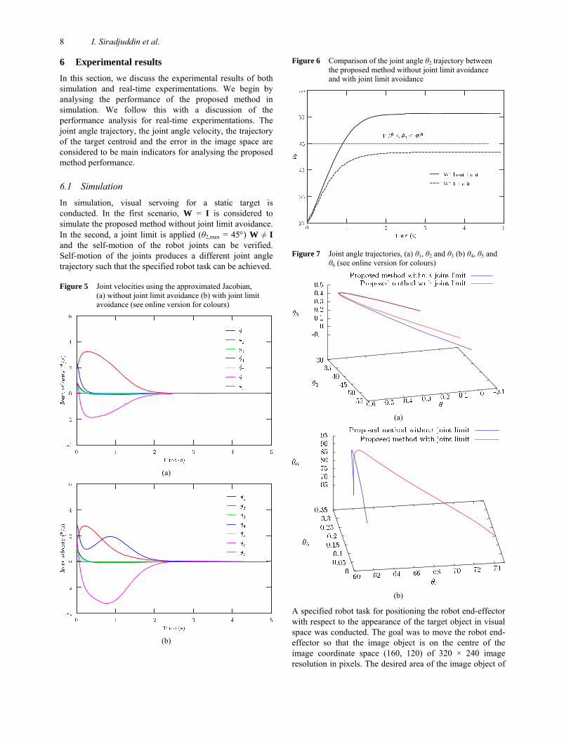
Figure 5 Joint velocities using the approximated Jacobian, (a) without joint limit avoidance (b) with joint limit avoidance (see online version for colours)
(a)
(b)
Figure 6 Comparison of the joint angle θ2 trajectory between the proposed method without joint limit avoidance and with joint limit avoidance
Figure 7 Joint angle trajectories, (a) θ1, θ2 and θ3 (b) θ4, θ5 and θ6 (see online version for colours)
(a)
(b)
A specified robot task for positioning the robot end-effector with respect to the appearance of the target object in visual space was conducted. The goal was to move the robot end-effector so that the image object is on the centre of the image coordinate space (160, 120) of 320 × 240 image resolution in pixels. The desired area of the image object of
An iterative robot-image Jacobian approximation of image-based visual servoing for joint limit avoidance 9
12,000 pixels was used to place the robot end-effector at a distance of 20 cm from the target object in the task space. Figure 5 shows the joint velocities performance of the proposed method. The time sampling of this simulation was 0.04 seconds and the joint velocities converge to zero at approximately 2.5 seconds. The joint velocities of the proposed control law using an approximated Jacobian without joint limits is shown in Figure 5(a). In comparison, if we apply a new joint limit θ2,max = 450, the self-motion of the robot joints can be observed as shown in Figure 5(b). To illustrate this further we focus on plots of 2 4, θ θ and 6.θ It can be seen in Figure 5(b) that 2θ is weighted when it moves near to a given upper limit, in contrast, 2θ has a higher peak when the joint limit is not applied as shown in Figure 5(a). As a consequence, the algorithm produces self-motion for 4θ and 6θ in order to compensate for the movement of 2θ and to achieve the specified task. The observed joint trajectories of θ2 are compared in Figure 6. The algorithm for the joint limit avoidance moves the robot joints within the range of their limits (only). As a result of the self-motion, there are many ways that the robot can move to achieve the task. In this sense, the redundancy of the robot configuration is considered as an advantage. Figure 7 shows the differences of the joint angle trajectories between the proposed method with joint limit avoidance and without joint limit avoidance. As discussed in Section 4.2, the continuity of the joint movements can also be verified from Figure 7.
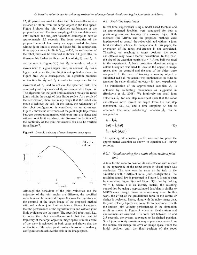
Figure 8 Centroid trajectory of target image on image space
Although the behaviour of the joint velocities and the trajectory of the joint angles are different, the specified robot task can be achieved. Figure 8 shows the trajectory of the centroid of the target image of the proposed method with and without joint limit avoidance. Figure 8 suggests that the performance of the algorithm with and without joint limit avoidance are the same. The specified robot task, i.e., to move the robot end-effector such that the centroid trajectory of the target object in image space is in the centre of the view is achieved in both cases and shows that the self-motion of the robot joint resolves the robot redundancy configurations to achieve the task in the image space.
6.2 Real-time experiment
In real-time, experiments using a model-based Jacobian and an approximated Jacobian were conducted for both a positioning task and tracking of a moving object. Both methods (the MBVS and the proposed method) were implemented to control the robot with and without a joint limit avoidance scheme for comparison. In this paper, the orientation of the robot end-effector is not considered. Therefore, on reaching a target position, the robot end-effector may have different orientations. In this case, the size of the Jacobian matrix is 3 × 7. A red ball was used in the experiment. A back projection algorithm using a colour histogram was used to localise the object in image space, then the centroid and the area of the object were computed. In the case of tracking a moving object, a simulated red ball movement was implemented in order to generate the same elliptical trajectory for each experiment. The initialisation of the approximated Jacobian 0J is obtained by calibrating movements as suggested in (Bonkovic et al., 2008). We intuitively set small joint velocities 0θ for one step movement such that the robot end-effector move toward the target. From this one step movement, Δs0, Δθ0 and a time sampling Δt can be observed. The initial robot-image Jacobian 0J can be computed as
( )
0 0 0
T T0 0 00 0
1T T0 0 00 0
ˆ
ˆ
ˆ −
=
=
=
s J
s J
J s
θ
θ θ θ
θ θ θ
(43)
The updating rate constant η = 0.1 was used to update the approximated Jacobian as shown in equation (31) during servoing.
6.2.1 Visual servoing for a static object without joint limit
A task for the robot to position its end-effector with respect to the appearance of the target object in visual space was conducted. This task was the same as the task in the simulation with a different initial joint configuration. The resulting control law is presented in Figure 9. It can be seen by comparing Figure 9(a) and Figure 9(b) that by making W = I, where I is an identity matrix, the resulting control law by using a approximated Jacobian is similar to MBVS even though minor variations may arise. In this work, the effect of the gravitational force in the controller design is neglected, hence, along with the noisy image data, the joint velocity figures are noisy. It can be compared with the smooth joint velocity performances in the simulation result as shown in Figure 5 where an ideal system and environment are assumed. It is noted that between 1.5 and 2.5 seconds, the system converges to its desired position. Small joint velocity variations may appear since noise from the camera can change the error on image space. From the initial position until the final position of the robot
10 I. Siradjuddin et al.
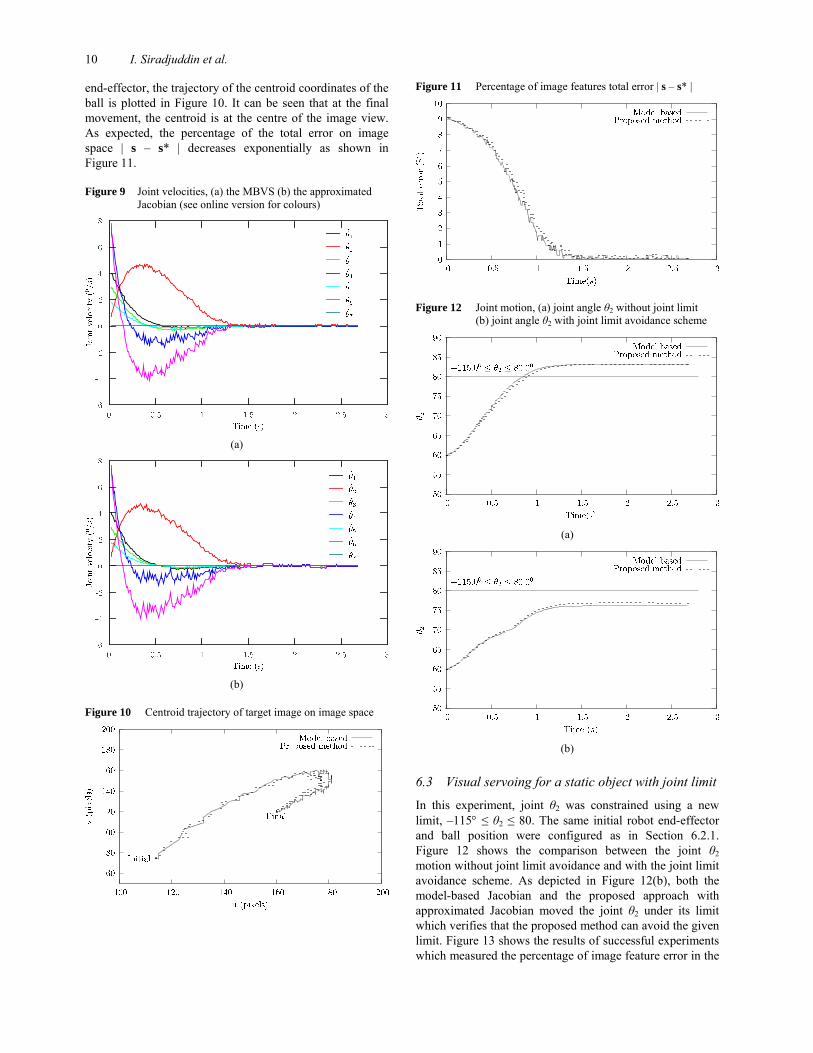
end-effector, the trajectory of the centroid coordinates of the ball is plotted in Figure 10. It can be seen that at the final movement, the centroid is at the centre of the image view. As expected, the percentage of the total error on image space | s – s* | decreases exponentially as shown in Figure 11.
Figure 9 Joint velocities, (a) the MBVS (b) the approximated Jacobian (see online version for colours)
(a)
(b)
Figure 10 Centroid trajectory of target image on image space
Figure 11 Percentage of image features total error | s – s* |
Figure 12 Joint motion, (a) joint angle θ2 without joint limit (b) joint angle θ2 with joint limit avoidance scheme
(a)
(b)
6.3 Visual servoing for a static object with joint limit
In this experiment, joint θ2 was constrained using a new limit, –115° ≤ θ2 ≤ 80. The same initial robot end-effector and ball position were configured as in Section 6.2.1. Figure 12 shows the comparison between the joint θ2 motion without joint limit avoidance and with the joint limit avoidance scheme. As depicted in Figure 12(b), both the model-based Jacobian and the proposed approach with approximated Jacobian moved the joint θ2 under its limit which verifies that the proposed method can avoid the given limit. Figure 13 shows the results of successful experiments which measured the percentage of image feature error in the
An iterative robot-image Jacobian approximation of image-based visual servoing for joint limit avoidance 11
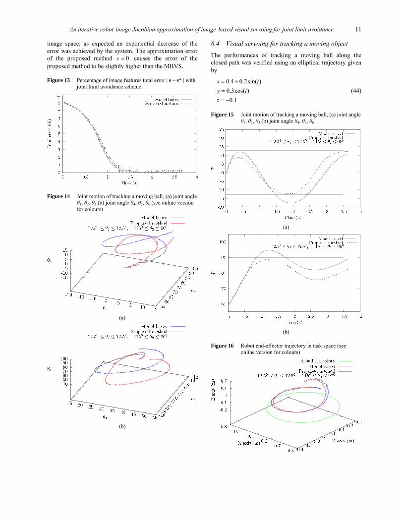
image space; as expected an exponential decrease of the error was achieved by the system. The approximation error of the proposed method 0=ε causes the error of the proposed method to be slightly higher than the MBVS.
Figure 13 Percentage of image features total error | s – s* | with joint limit avoidance scheme
Figure 14 Joint motion of tracking a moving ball, (a) joint angle θ1, θ2, θ3 (b) joint angle θ4, θ5, θ6 (see online version for colours)
(a)
(b)
6.4 Visual servoing for tracking a moving object
The performances of tracking a moving ball along the closed path was verified using an elliptical trajectory given by
0.4 0.2sin( )0.3cos( )0.1
x ty tz
= +== −
(44)
Figure 15 Joint motion of tracking a moving ball, (a) joint angle θ1, θ2, θ3 (b) joint angle θ4, θ5, θ6
(a)
(b)
Figure 16 Robot end-effector trajectory in task space (see online version for colours)
12 I. Siradjuddin et al.
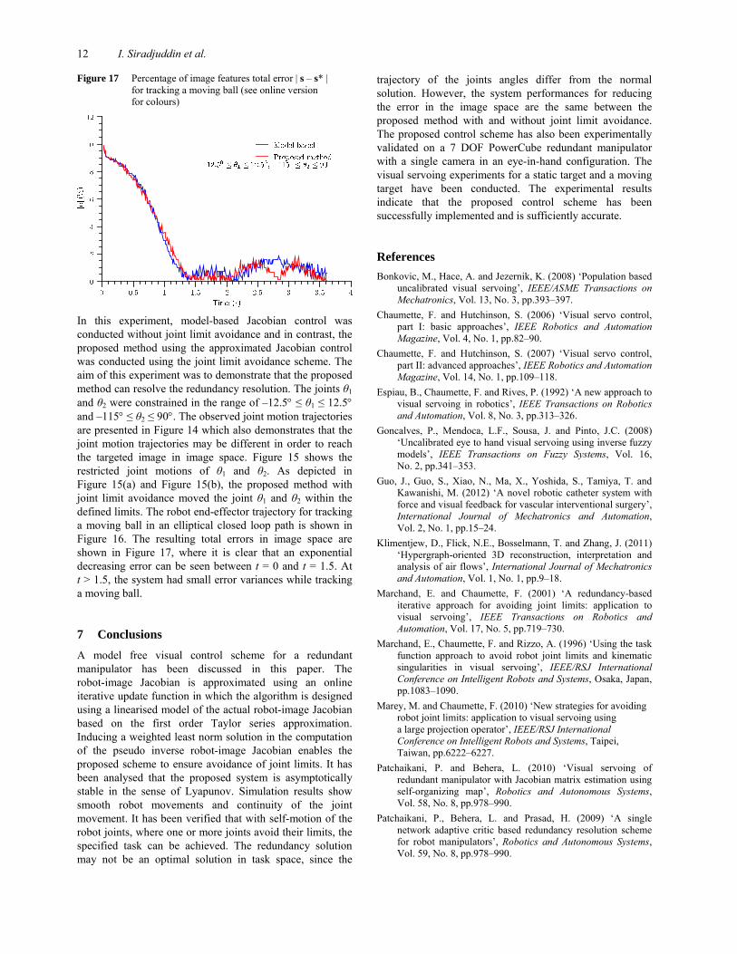
Figure 17 Percentage of image features total error | s – s* | for tracking a moving ball (see online version for colours)
In this experiment, model-based Jacobian control was conducted without joint limit avoidance and in contrast, the proposed method using the approximated Jacobian control was conducted using the joint limit avoidance scheme. The aim of this experiment was to demonstrate that the proposed method can resolve the redundancy resolution. The joints θ1 and θ2 were constrained in the range of –12.5° ≤ θ1 ≤ 12.5° and –115° ≤ θ2 ≤ 90°. The observed joint motion trajectories are presented in Figure 14 which also demonstrates that the joint motion trajectories may be different in order to reach the targeted image in image space. Figure 15 shows the restricted joint motions of θ1 and θ2. As depicted in Figure 15(a) and Figure 15(b), the proposed method with joint limit avoidance moved the joint θ1 and θ2 within the defined limits. The robot end-effector trajectory for tracking a moving ball in an elliptical closed loop path is shown in Figure 16. The resulting total errors in image space are shown in Figure 17, where it is clear that an exponential decreasing error can be seen between t = 0 and t = 1.5. At t > 1.5, the system had small error variances while tracking a moving ball.
7 Conclusions
A model free visual control scheme for a redundant manipulator has been discussed in this paper. The robot-image Jacobian is approximated using an online iterative update function in which the algorithm is designed using a linearised model of the actual robot-image Jacobian based on the first order Taylor series approximation. Inducing a weighted least norm solution in the computation of the pseudo inverse robot-image Jacobian enables the proposed scheme to ensure avoidance of joint limits. It has been analysed that the proposed system is asymptotically stable in the sense of Lyapunov. Simulation results show smooth robot movements and continuity of the joint movement. It has been verified that with self-motion of the robot joints, where one or more joints avoid their limits, the specified task can be achieved. The redundancy solution may not be an optimal solution in task space, since the
trajectory of the joints angles differ from the normal solution. However, the system performances for reducing the error in the image space are the same between the proposed method with and without joint limit avoidance. The proposed control scheme has also been experimentally validated on a 7 DOF PowerCube redundant manipulator with a single camera in an eye-in-hand configuration. The visual servoing experiments for a static target and a moving target have been conducted. The experimental results indicate that the proposed control scheme has been successfully implemented and is sufficiently accurate.
References Bonkovic, M., Hace, A. and Jezernik, K. (2008) ‘Population based
uncalibrated visual servoing’, IEEE/ASME Transactions on Mechatronics, Vol. 13, No. 3, pp.393–397.
Chaumette, F. and Hutchinson, S. (2006) ‘Visual servo control, part I: basic approaches’, IEEE Robotics and Automation Magazine, Vol. 4, No. 1, pp.82–90.
Chaumette, F. and Hutchinson, S. (2007) ‘Visual servo control, part II: advanced approaches’, IEEE Robotics and Automation Magazine, Vol. 14, No. 1, pp.109–118.
Espiau, B., Chaumette, F. and Rives, P. (1992) ‘A new approach to visual servoing in robotics’, IEEE Transactions on Robotics and Automation, Vol. 8, No. 3, pp.313–326.
Goncalves, P., Mendoca, L.F., Sousa, J. and Pinto, J.C. (2008) ‘Uncalibrated eye to hand visual servoing using inverse fuzzy models’, IEEE Transactions on Fuzzy Systems, Vol. 16, No. 2, pp.341–353.
Guo, J., Guo, S., Xiao, N., Ma, X., Yoshida, S., Tamiya, T. and Kawanishi, M. (2012) ‘A novel robotic catheter system with force and visual feedback for vascular interventional surgery’, International Journal of Mechatronics and Automation, Vol. 2, No. 1, pp.15–24.
Klimentjew, D., Flick, N.E., Bosselmann, T. and Zhang, J. (2011) ‘Hypergraph-oriented 3D reconstruction, interpretation and analysis of air flows’, International Journal of Mechatronics and Automation, Vol. 1, No. 1, pp.9–18.
Marchand, E. and Chaumette, F. (2001) ‘A redundancy-based iterative approach for avoiding joint limits: application to visual servoing’, IEEE Transactions on Robotics and Automation, Vol. 17, No. 5, pp.719–730.
Marchand, E., Chaumette, F. and Rizzo, A. (1996) ‘Using the task function approach to avoid robot joint limits and kinematic singularities in visual servoing’, IEEE/RSJ International Conference on Intelligent Robots and Systems, Osaka, Japan, pp.1083–1090.
Marey, M. and Chaumette, F. (2010) ‘New strategies for avoiding robot joint limits: application to visual servoing using a large projection operator’, IEEE/RSJ International Conference on Intelligent Robots and Systems, Taipei, Taiwan, pp.6222–6227.
Patchaikani, P. and Behera, L. (2010) ‘Visual servoing of redundant manipulator with Jacobian matrix estimation using self-organizing map’, Robotics and Autonomous Systems, Vol. 58, No. 8, pp.978–990.
Patchaikani, P., Behera, L. and Prasad, H. (2009) ‘A single network adaptive critic based redundancy resolution scheme for robot manipulators’, Robotics and Autonomous Systems, Vol. 59, No. 8, pp.978–990.
An iterative robot-image Jacobian approximation of image-based visual servoing for joint limit avoidance 13
Piepmeier, J.A., McMurray, G.V. and Lipkin, H. (1999) ‘A dynamic Jacobian estimation method for uncalibrated visual servoing’, IEEE/ASME International Conference on Advanced Intelligent Mechatronics, Georgia, USA, pp.944–949.
Piepmeier, J.A., McMurray, G.V. and Lipkin, H. (2004) ‘Uncalibrated dynamic visual servoing’, IEEE Transactions on Robotics and Automation, Vol. 20, No. 1, pp.143–147.
Rahman, M.H., Saad, M., Kenn, J.P., Archambault, P.S. and Ouimet, T.K. (2012) ‘Development of a 4DoFs exoskeleton robot for passive arm movement assistance’, International Journal of Mechatronics and Automation, Vol. 2, No. 1, pp.34–35.
Shademan, A., Farahmand A-M. and Jagersand, M. (2010) ‘Robust Jacobian estimation for uncalibrated visual servoing’, IEEE International Conference Robotics Automation, Anchorage, Alaska, USA, pp.5564–5569.
Siradjuddin, I., McGinnity, T.M., Behera, L. and Coleman, S. (2009) ‘Visual servoing of a redundant manipulator using shape moments’, IET Irish Signals and Systems Conference, Dublin, Ireland, pp.1–6.
Siradjuddin, I., McGinnity, T.M., Behera, L. and Coleman, S. (2010) ‘Image based visual servoing of a 7 DOF robot manipulator using a distributed fuzzy proportional controller’, IEEE International Conference on Fuzzy Systems, Barcelona, Spain, pp.1098–7584.
Spong, M.W. and Hutchinson, S. and Vidyasagar, M. (2005) Robot Modeling and Control, 1st ed., John Wiley & Sons Inc., New York.
Swagat, K., Shukla, A. and Behera, L. (2009) ‘Visual motor control of a 7 DOF redundant manipulator using redundancy preserving learning network’, Robotica, Vol. 28, No. 6, pp.795–810.
Tan, F.C. and Dubey, R.V. (1995) ‘A weighted least-norm based solution scheme for avoiding joint limits for redundant joint manipulators’, IEEE Transactions on Robotics and Automation, Vol. 11, No. 2, pp.286–292.
Yahya, S., Moghavvemi, M., Yang, S.S. and Mohamed, H.A.F. (2009) ‘Motion planning of hyper redundant manipulators based on a new geometrical method’, IEEE International Conference on Industrial Technology, Gippsland, Australia, pp.1–5.