an iso 9001 & 14001 company tender document
178
Uploaded on 25.02.2021 AN ISO 9001 & 14001 COMPANY TENDER DOCUMENT e-TENDER No: SRO/CON/ETS/060 Tender for “Design, Manufacture, Inspection, Supply, Installation, Trail Run, training, Testing , commissioning and handing over ofJAW Crusher, Sieve Shaker and Turbo Mixer. as per drawings and specification for REPM Plant for Setting up of Rare Earth Permanent Magnet (REPM) Plant at Visakhapatnam,A.P. ” for IREL (India) Limited VOLUME – II Technical Specifications, Scope of Work, Client Documents, QAP and Drawings ENGINEERING PROJECTS (INDIA) LIMITED (A GOVT. OF INDIA ENTERPRISE) Southern Regional Office, Chennai INDEX
-
Upload
khangminh22 -
Category
Documents
-
view
1 -
download
0
Transcript of an iso 9001 & 14001 company tender document

Uploaded on 25.02.2021
AN ISO 9001 & 14001 COMPANY
TENDER DOCUMENT
e-TENDER No: SRO/CON/ETS/060 Tender for “Design, Manufacture, Inspection, Supply, Installation, Trail Run, training, Testing , commissioning and handing over ofJAW Crusher, Sieve Shaker and Turbo Mixer. as per drawings and specification for REPM Plant for Setting up of Rare Earth Permanent Magnet (REPM) Plant at Visakhapatnam,A.P. ” for IREL (India) Limited
VOLUME – II
Technical Specifications, Scope of Work, Client Documents, QAP and Drawings
ENGINEERING PROJECTS (INDIA) LIMITED (A GOVT. OF INDIA ENTERPRISE) Southern Regional Office, Chennai
INDEX

S.No Description Page No No of Pages
1 Technical Specifications, Scope of Work, Client Documents, QAP and Drawings
3-178 176
DESIGN AND OPERATIONAL PHILOSOPY
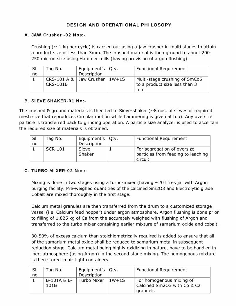
A. JAW Crusher -02 Nos:- Crushing (~ 1 kg per cycle) is carried out using a jaw crusher in multi stages to attain a product size of less than 3mm. The crushed material is then ground to about 200-250 micron size using Hammer mills (having provision of argon flushing).
Sl no
Tag No. Equipment’s Description
Qty. Functional Requirement
1 CRS-101 A & CRS-101B
Jaw Crusher 1W+1S Multi-stage crushing of SmCo5 to a product size less than 3 mm
B. SIEVE SHAKER-01 No:-
The crushed & ground materials is then fed to Sieve-shaker (~8 nos. of sieves of required mesh size that reproduces Circular motion while hammering is given at top). Any oversize particle is transferred back to grinding operation. A particle size analyzer is used to ascertain the required size of materials is obtained.
Sl no
Tag No. Equipment’s Description
Qty. Functional Requirement
1 SCR-101 Sieve Shaker
1 For segregation of oversize particles from feeding to leaching circuit
C. TURBO MIXER-02 Nos:-
Mixing is done in two stages using a turbo-mixer (having ~20 litres jar with Argon purging facility. Pre-weighed quantities of the calcined Sm2O3 and Electrolytic grade Cobalt are mixed thoroughly in the first stage. Calcium metal granules are then transferred from the drum to a customized storage vessel (i.e. Calcium feed hopper) under argon atmosphere. Argon flushing is done prior to filling of 1.825 kg of Ca from the accurately weighed with flushing of Argon and transferred to the turbo mixer containing earlier mixture of samarium oxide and cobalt. 30-50% of excess calcium than stoichiometrically required is added to ensure that all of the samarium metal oxide shall be reduced to samarium metal in subsequent reduction stage. Calcium metal being highly oxidizing in nature, have to be handled in inert atmosphere (using Argon) in the second stage mixing. The homogenous mixture is then stored in air tight containers.
Sl no
Tag No. Equipment’s Description
Qty. Functional Requirement
1 B-101A & B- 101B
Turbo Mixer 1W+1S For homogenous mixing of Calcined Sm2O3 with Co & Ca granuels

PROCESS ENGINEERING
A. JAW Crusher -02 Nos:-
The cooled reaction mixture from the furnace needs to be crushed and then ground before subjecting to leaching. Crushing is carried out using a jaw crusher in two stages to attain a product size of 3 mm. The crushed material is then ground to about 200-500 μm size using Hammer mills.
First stage crushing Feed – Up to 150 mm, Product – 20-50 mm
Second stage crushing Feed – 20-50 mm, Product – 10-20 mm Third stage crushing Feed – 10-20 mm, Product – 3 mm Crushing cycle time 30 min (max) Material to be crushed per cycle 1 Kg Total material to be crushed per day 12.11 Kg No. of passes 3 No. of crushing cycles /day 24.22 No. of crushers required per day considering two shifts operation
0.70 i.e. 1 No.
For 3 tpy production, no. of Crushers considered.
2 no (1 Operating + 1 Standby)
B. TURBO MIXER-02 Nos:-
Mixing is done in two stages using Turbo Mixers. Pre-weighed quantities of the calcined Sm2O3 (4.4 Kg) and Electrolytic grade Cobalt (6.2 Kg) are mixed thoroughly in the first stage. In the second stage, Calcium metal granules (1.852 Kg) is transferred to the Turbo Mixer after Argon flushing. First stage mixing: Samarium Oxide and Cobalt Second stage mixing: Calcium to the above mixture of Samarium Oxide and Cobalt Mixing time at each stage : 6 mins. Each Total cycle time including weighing: 2 hours Two (2) numbers of Turbo-mixers of 20 litre capacity each (1 Operating + 1 Standby) is considered. Jar shall have the provision of Argon flushing during operation.

Guarantee Test Parameters
Sl no
Equipments Description
Guarantee Parameters Major functionality test Preferred Model
Jaw Crushers
1. Feed Size : Up to 150 mm 2. Product Size : Less than 3 mm 3. MOC (Enclosure / fixed & movable jaws) - Hardened steel / Hardened steel or Tungsten carbide lined
1-In jaw crusher, 2 mm to 3 mm size should be obtained maximum after 2 pass. 2. RPM of the hammer mill and suction rate to be Software controlled 3.Hammer mill should have provision of purging inert gas.
(Insmart Systems) - IJC-3
Ro-Tap Sieve Shaker
Product Size : Less than 200 micron
Design to avoid any material loss during operation
(Insmart systems) - INS/RTS
Turbo-mixer
1. Homogenous mixture of Sm2O3, Co & Ca
Rotating speed and timer on the display panel should be software controlled. Capable of mixing 15 kg of material.
(Insmart systems) – INS TM 20
LIST OF MAJOR EQUIPIMENTS
Sl no
Tag. No. Equipments Description
Qty./Nos. Approx Capacity/ Rating/ Size/ Rearks
01 CRS-101 A & CRS-101B
Jaw Crusher 1W+1S 1 Kg per batch (1220mm X 599mm X 1020mm)
02 SCR-101 Sieve Shaker 1 200-250 gm 03 B-101A & B-
101B Turbo Mixer 1W+1S 20 liters with Gas Purging facility

IREL (India) Limited
MUMBAI
TECHNICAL SPECIFICATION FOR COMPRESSED AIR SYSTEM
FOR
RARE EARTH PERMANENT MAGNET PLANT
AT VISHAKHAPATNAM
MECON LIMITED BANGALORE
Doc. No MEC/Q7KN/01/31/S1/REPM/A003/R00 March’2020
Prepared by Checked by Approved by
Pooja Singh Sandeep Ranjan A Venkata Rao

IREL (India) Limited RARE EARTH PERMANENT MAGNET PLANT AT VISHKHAPATNAM
TS FOR COMPRESSED AIR SYSTEM
2 of 8
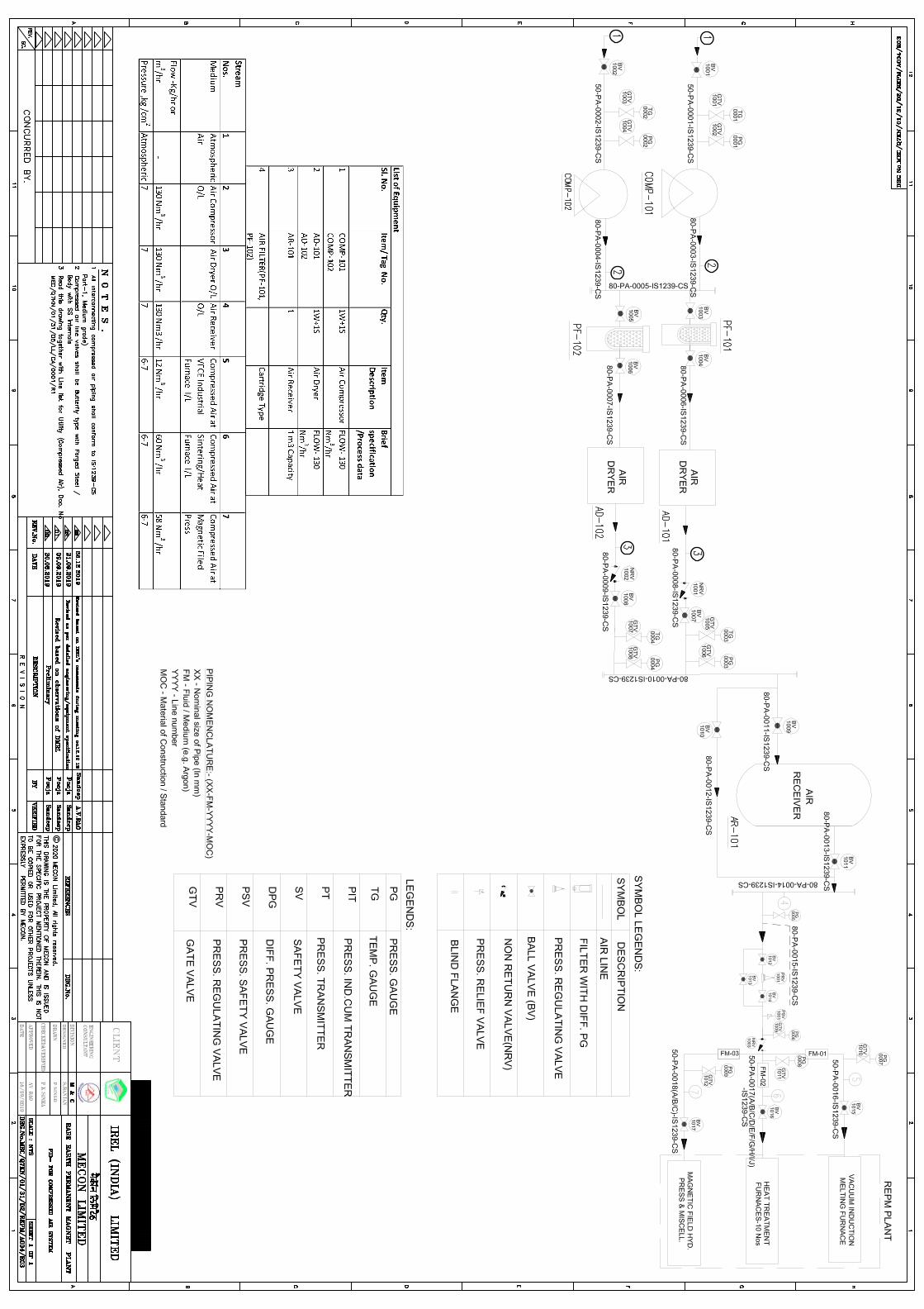
1.0 SCOPE This technical specification covers the requirement for design, manufacture, supply of compressed air system comprising of Air compressors, air dryers and air receivers for meeting the compressed air for process and instrumentation requirements of RE and REPM Plant.
2.0 CODES & STANDARDS
The design, construction, manufacture, supply, testing and other general requirements of the compressor package equipment shall be strictly in accordance with the data sheets, applicable IS codes / API codes and shall comply fully with relevant National/ International standards, Indian Electricity Act, Indian Electricity Rules, regulations of Insurance Association of India and Factories Act while carrying out work as per this specification. Any modification suggested by the statutory bodies either during drawing approval or during inspection, if any, shall be carried out by the Bidder without any additional cost and delivery implications. The following codes and standards (versions/ revisions valid on the date of order) are referenced to & made part of specification: IS 13124 : Reciprocating compressors : Technical supply conditions
ISO 1217 : Displacement compressors : Acceptance
ASME B 31.3 -2016: Process piping
NFPA 12-2015 : Standard on Carbon dioxide Extinguishing system
ASME Sec IX: Qualification Standard for Welding and Brazing Procedures,
Welders, Brazers, and Welding and Brazing Operators
ANSI, ASTM, NEC, NEMA, Indian Electricity Rules, Indian Explosives Act. IS 11461 : Code of Practice for Compressor safety
IS 5456 : Testing of positive displacement Air compressors and Exhausters-
code of practice. ISO 7183 : Compressed Air Dryer Specifications and testing IS 11989 : Specification for Compressed Air Dryers IS 2825 : Fabrication of Air Receiver IS 7938: Specification for Air Receiver for Compressed Air Installation In case of any conflict among the various documents of this requisition the following preferential order shall govern:

IREL (India) Limited RARE EARTH PERMANENT MAGNET PLANT AT VISHKHAPATNAM
TS FOR COMPRESSED AIR SYSTEM
3 of 8
1. Data sheets/drawings 2. This Technical Specification 3. International standards/codes as applicable 4. Indian Standards / codes applicable
Compliance with this specification shall not relieve the Bidder of the responsibility of furnishing equipment and accessories of proper design, material and workmanship to meet the specified operating conditions.
3.0 DESIGN BASIS
The sizing capacity of Air compressor is based on intermittent compressed air requirement for process. The atmospheric air inlet through suction filter is compressed to 8.0 Kg/Cm2(g) pressure.
The moisture present in compressed air pass through dryer to achieve dry compressed air state.
Part of this dry compressed air is stored in air receiver
Compressor maximum vibrations at cylinders and at frame shall be as per relevant standard/specification. The Bidder shall provide for all structural support within the package so that these levels can be achieved
Crosshead, pistons etc of compressor shall be manufacturer standard material and designs
Units of measurement shall be:
FLOW - Nm3/hr & m3/min. PRESSURE - kg/cm2 (g) TEMPERATURE - 0C
The piping of compressed air system shall be as per IS 1239 CS and the instrument air tubing material shall be minimum SS304 from main distribution header to instruments.
All rigid piping, tubing & other components of compressor package shall be designed for full range of pressure & temp and loading.
Components such as pressure gauges, temperature , pressure switches, filter automatic ball valves, safety valves etc., which require in-situ adjustment, maintenance and reading, shall be easily accessible.
Indian standards listed below. Where Indian standards do not exist, the relevant IEC or British The squirrel cage induction motors and their components shall comply with the latest applicable standards.
Vendor shall furnish shell thickness design calculation as per relevant code/specification for approval.
4.0 INSPECTION AND TESTING
a. Inspection and Test Requirements have been spelled out in respective Equipment Data Sheets and this Technical Specification.
IREL (India) Limited RARE EARTH PERMANENT MAGNET PLANT AT VISHKHAPATNAM
TS FOR COMPRESSED AIR SYSTEM
4 of 8
b. Bidder shall confirm therein and include the inspection charges in the lump sum cost.
c. Owner/consultant shall witness tests as per data sheet and this specification. The Bidder shall notify the timing of such inspection and testing at least 15 days in advance to PURCHASER/ CONSULTANT.
d. Bidder shall submit detailed Test Procedure for Approval of compliance to all inspection and testing requirements stipulated .
5.0 PAINTING AND PROTECTION
a. Rust, rust scale and foreign matter shall be removed fully to ensure that a clean and dry surface is obtained.
b. The vendor to ensure that exterior steel surface of equipment and piping painted shall have a fade free life without oxidation of paint surface for at least 5 years .
c. Packing shall be sufficiently robust to withstand rough handling during ocean shipment & in-land journey. Sling points shall be clearly indicated on crates.
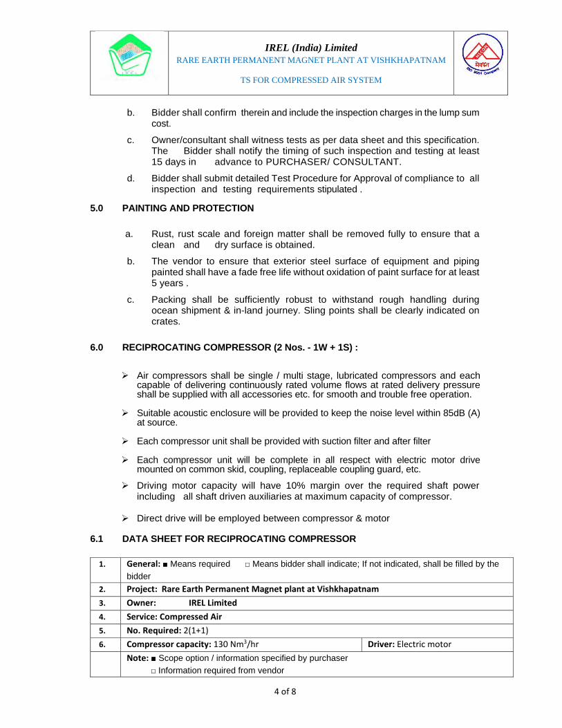
6.0 RECIPROCATING COMPRESSOR (2 Nos. - 1W + 1S) :
Air compressors shall be single / multi stage, lubricated compressors and each
capable of delivering continuously rated volume flows at rated delivery pressure shall be supplied with all accessories etc. for smooth and trouble free operation.
Suitable acoustic enclosure will be provided to keep the noise level within 85dB (A)
at source. Each compressor unit shall be provided with suction filter and after filter
Each compressor unit will be complete in all respect with electric motor drive
mounted on common skid, coupling, replaceable coupling guard, etc.
Driving motor capacity will have 10% margin over the required shaft power including all shaft driven auxiliaries at maximum capacity of compressor.
Direct drive will be employed between compressor & motor
6.1 DATA SHEET FOR RECIPROCATING COMPRESSOR
1. General: ■ Means required □ Means bidder shall indicate; If not indicated, shall be filled by the
bidder
2. Project: Rare Earth Permanent Magnet plant at Vishkhapatnam
3. Owner: IREL Limited
4. Service: Compressed Air
5. No. Required: 2(1+1)
6. Compressor capacity: 130 Nm3/hr Driver: Electric motor
Note: ■ Scope option / information specified by purchaser
□ Information required from vendor

IREL (India) Limited RARE EARTH PERMANENT MAGNET PLANT AT VISHKHAPATNAM
TS FOR COMPRESSED AIR SYSTEM
5 of 8
7. □ Manufacturer: □Model No.: 8. □Place of manufacture: 9. □No. of stages: □Cylinder arrangement: 10. □Cylinder Lubrication: Lubricated /Minimum lubricated/Non Lubricated
■ Site installation data
11. Ambient temp.(oC): 12. Relative Humidity (%): 13. Altitude (m): 14. Earth quake zone: Wind velocity (m/s): 15. Installation: Indoor 16. ■Mounted on a common skid along with driver, enclosed inside an acoustic enclosure ■Electrical area Hazard
17. Class 1, Group D, Division1 as per NEC or Zone 1,Group IIA/IIB as per IS/IEC Applicable Codes and standards
18. Compressor: Reciprocating Piping: ANSI/ASME B31.3
19. Pressure Vessels: ASME Sec VIII, Div-1
20. Noise : 85 dBA @ 1m from enclosure
21. □ Elect. Motors: 22. Functional Parameters
23. Flow : 130 Nm3/hr
24. Working Pressure : 8 Kg/Cm2(g)
25. Temperature inlet
26. Temperature outlet
27. Testing Standard:
□Construction/Design features:28. Nomenclature Unit Stage#1
29. Cylinders
30. No. of cylinders No.
31. Single acting(SA)/double acting(SA)
32. Cylinder Bore/stroke mm/mm
33. Rotational speed RPM
34. Linear average piston speed
m/sec
35. Piston displacement m3/hr
36. Cylinder liner (yes/No)
37. Type of cylinder liner: Dry/wet
38. Clearance pockets: Yes/No
39. Max. Allowable working pressure,Cylinder
Kg/cm2(g)
40. Max./Min. Allow. Working Temp., Cylinder
oC
41. M.A.W.P.Cylinder@ Amb.temp.
Kg/cm2(g)
IREL (India) Limited RARE EARTH PERMANENT MAGNET PLANT AT VISHKHAPATNAM
TS FOR COMPRESSED AIR SYSTEM
6 of 8
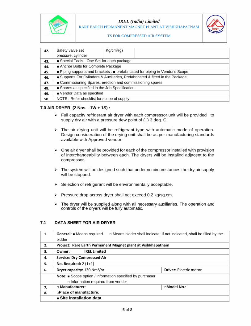
7.0 AIR DRYER (2 Nos. - 1W + 1S) :
Full capacity refrigerant air dryer with each compressor unit will be provided to supply dry air with a pressure dew point of (+) 3 deg. C.
The air drying unit will be refrigerant type with automatic mode of operation. Design consideration of the drying unit shall be as per manufacturing standards available with Approved vendor.
One air dryer shall be provided for each of the compressor installed with provision
of interchangeability between each. The dryers will be installed adjacent to the compressor.
The system will be designed such that under no circumstances the dry air supply will be stopped.
Selection of refrigerant will be environmentally acceptable. Pressure drop across dryer shall not exceed 0.2 kg/sq.cm.
The dryer will be supplied along with all necessary auxiliaries. The operation and
controls of the dryers will be fully automatic.
7.1 DATA SHEET FOR AIR DRYER
42. Safety valve set pressure, cylinder
Kg/cm2(g)
43. ■ Special Tools - One Set for each package
44. ■ Anchor Bolts for Complete Package
45. ■ Piping supports and brackets : ■ prefabricated for piping in Vendor's Scope
46. ■ Supports For Cylinders & Auxiliaries, Prefabricated & fitted in the Package
47. ■ Commissioning Spares, erection and commissioning spares
48. ■ Spares as specified in the Job Specification
49. ■ Vendor Data as specified
50. NOTE : Refer checklist for scope of supply
1. General: ■ Means required □ Means bidder shall indicate; If not indicated, shall be filled by the
bidder
2. Project: Rare Earth Permanent Magnet plant at Vishkhapatnam
3. Owner: IREL Limited
4. Service: Dry Compressed Air
5. No. Required: 2 (1+1)
6. Dryer capacity: 130 Nm3/hr Driver: Electric motor
Note: ■ Scope option / information specified by purchaser
□ Information required from vendor
7. □ Manufacturer: □Model No.: 8. □Place of manufacture: ■ Site installation data
IREL (India) Limited RARE EARTH PERMANENT MAGNET PLANT AT VISHKHAPATNAM
TS FOR COMPRESSED AIR SYSTEM
7 of 8
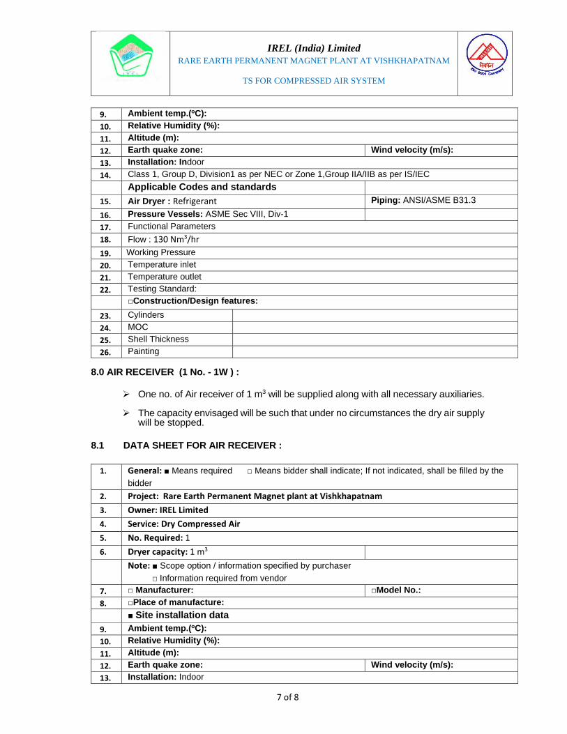
8.0 AIR RECEIVER (1 No. - 1W ) :
One no. of Air receiver of 1 m3 will be supplied along with all necessary auxiliaries.
The capacity envisaged will be such that under no circumstances the dry air supply will be stopped.
8.1 DATA SHEET FOR AIR RECEIVER :
9. Ambient temp.(oC):
10. Relative Humidity (%): 11. Altitude (m): 12. Earth quake zone: Wind velocity (m/s): 13. Installation: Indoor 14. Class 1, Group D, Division1 as per NEC or Zone 1,Group IIA/IIB as per IS/IEC Applicable Codes and standards
15. Air Dryer : Refrigerant Piping: ANSI/ASME B31.3
16. Pressure Vessels: ASME Sec VIII, Div-1
17. Functional Parameters
18. Flow : 130 Nm3/hr
19. Working Pressure
20. Temperature inlet
21. Temperature outlet
22. Testing Standard:
□Construction/Design features:23. Cylinders
24. MOC
25. Shell Thickness
26. Painting
1. General: ■ Means required □ Means bidder shall indicate; If not indicated, shall be filled by the
bidder
2. Project: Rare Earth Permanent Magnet plant at Vishkhapatnam
3. Owner: IREL Limited
4. Service: Dry Compressed Air
5. No. Required: 1
6. Dryer capacity: 1 m3
Note: ■ Scope option / information specified by purchaser
□ Information required from vendor
7. □ Manufacturer: □Model No.: 8. □Place of manufacture: ■ Site installation data
9. Ambient temp.(oC): 10. Relative Humidity (%): 11. Altitude (m): 12. Earth quake zone: Wind velocity (m/s): 13. Installation: Indoor

IREL (India) Limited RARE EARTH PERMANENT MAGNET PLANT AT VISHKHAPATNAM
TS FOR COMPRESSED AIR SYSTEM
8 of 8
14. Class 1, Group D, Division1 as per NEC or Zone 1,Group IIA/IIB as per IS/IEC Applicable Codes and standards
15. Air Receiver : Piping: ANSI/ASME B31.3
16. Pressure Vessels: ASME Sec VIII, Div-1
17. Functional Parameters
18. Flow :
19. Working Pressure
20. Temperature inlet
21. Temperature outlet
□Construction/Design features:22. Cylinders
23. MOC
24. Painting
IREL (India) Limited
MUMBAI
TECHNICAL SPECIFICATION FOR ARGON GAS SYSTEM
FOR
RARE EARTH PERMANENT MAGNET PLANT
AT VISHAKHAPATNAM
MECON LIMITED BANGALORE
Doc. No MEC/Q7KN/01/31/S1/REPM/A004/R00 March’2020
Prepared by Checked by Approved by
Pooja Singh Sandeep Ranjan A Venkata Rao

IREL (India) Limited
RARE EARTH PERMANENT MAGNET PLANT AT VISHKHAPATNAM
TS FOR ARGON GAS SYSTEM
2 of 5
1. SCOPE
This Technical specification covers the minimum requirement for filling, handling, storage & supply of argon gas for its distribution to different consumers (e.g. furnaces, mixers, blender, glove box, laboratory equipment etc) as per flow & pressure requirement of technological process/lab.
2. DESIGN CODE & GRADE
Argon gas is colorless, odorless and non-flammable. It is also non-toxic. The design, construction, manufacture, supply, testing and other general requirements of Argon system shall be as per IS-5760-1998 and other relevant specification/code.
GRADES There shall be three grades of argon, namely: Grade 1 : Ultra high purity argon for use in electronics and allied industries and in direct redding vacuum spectrograph, Grade 2 : High purity argon for use in lamp and allied industries, and Grade 3 : Commercial grade argon for use in welding industry and for other metallurgical operations.
Brand Maximum Impurity Level (PPM By Volume)
Purity % O2 Moisture CO2 CO N2
N-Oxide
H2H-
CompS-
Comp Hg Cl2
IOLAR-1 2 2 1 1 2 1 1 Nil Nil Nil 99.999
3. PROCESS REQUIREMENT & DESIGN BASIS
The processes of making RE metal and RE permanent magnet require use of inert gases. High purity Argon of IOLAR-1 grade shall be made available in MCP (manifold cylinder pallet). The capacity of each cylinder shall be 11 Sm3.
The same shall be transferred to the end user point at 6-7 to 12 kg/cm2. The utility bay has been designed to house 3 Nos of MCPs (1 working +2 stand by) with 15 no of cylinders each connected to network. Requirement of Argon for the process plants shall be 14230 sm3 / year respectively.
High purity Argon of IOLAR-1 grade will also be required for quality control purpose. It is proposed that 5 numbers of 7 sm3 cylinders shall be procured for such use. Argon requirement for QC purpose is estimated to be 700 sm3 / year.
IREL (India) Limited
RARE EARTH PERMANENT MAGNET PLANT AT VISHKHAPATNAM
TS FOR ARGON GAS SYSTEM
3 of 5
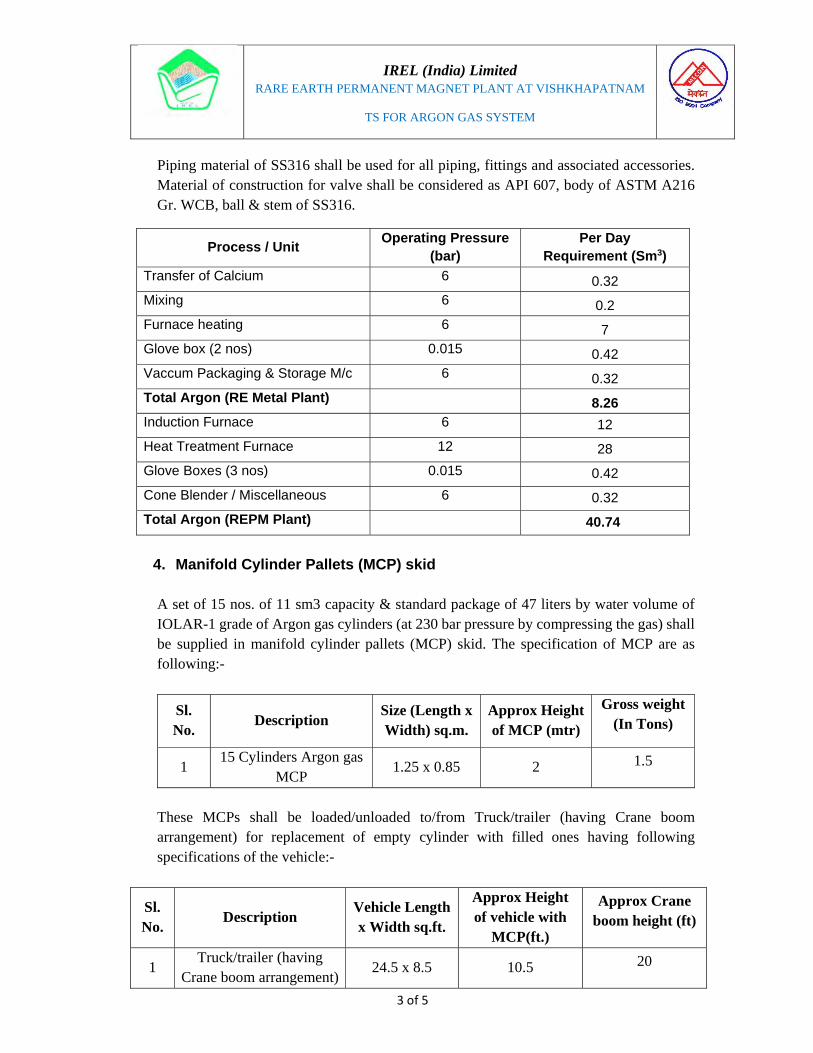
Piping material of SS316 shall be used for all piping, fittings and associated accessories. Material of construction for valve shall be considered as API 607, body of ASTM A216 Gr. WCB, ball & stem of SS316.
Process / Unit Operating Pressure (bar)
Per Day Requirement (Sm3)
Transfer of Calcium 6 0.32 Mixing 6 0.2 Furnace heating 6 7 Glove box (2 nos) 0.015 0.42 Vaccum Packaging & Storage M/c 6 0.32 Total Argon (RE Metal Plant) 8.26 Induction Furnace 6 12
Heat Treatment Furnace 12 28
Glove Boxes (3 nos) 0.015 0.42
Cone Blender / Miscellaneous 6 0.32
Total Argon (REPM Plant) 40.74
4. Manifold Cylinder Pallets (MCP) skid
A set of 15 nos. of 11 sm3 capacity & standard package of 47 liters by water volume of IOLAR-1 grade of Argon gas cylinders (at 230 bar pressure by compressing the gas) shall be supplied in manifold cylinder pallets (MCP) skid. The specification of MCP are as following:-
Sl. No.
Description Size (Length x Width) sq.m.
Approx Height of MCP (mtr)
Gross weight (In Tons)
1 15 Cylinders Argon gas
MCP 1.25 x 0.85 2 1.5
These MCPs shall be loaded/unloaded to/from Truck/trailer (having Crane boom arrangement) for replacement of empty cylinder with filled ones having following specifications of the vehicle:-
Sl. No.
Description Vehicle Length x Width sq.ft.
Approx Height of vehicle with
MCP(ft.)
Approx Crane boom height (ft)
1 Truck/trailer (having
Crane boom arrangement)24.5 x 8.5 10.5 20
IREL (India) Limited
RARE EARTH PERMANENT MAGNET PLANT AT VISHKHAPATNAM
TS FOR ARGON GAS SYSTEM
4 of 5
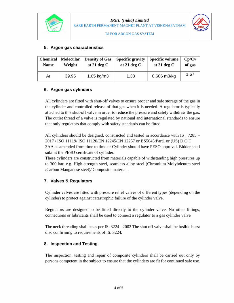
5. Argon gas characteristics
Chemical Name
Molecular Weight
Density of Gas at 21 deg C
Specific gravity at 21 deg C
Specific volume at 21 deg C
Cp/Cv of gas
Ar 39.95 1.65 kg/m3 1.38 0.606 m3/kg 1.67
6. Argon gas cylinders
All cylinders are fitted with shut-off valves to ensure proper and safe storage of the gas in the cylinder and controlled release of that gas when it is needed. A regulator is typically attached to this shut-off valve in order to reduce the pressure and safely withdraw the gas. The outlet thread of a valve is regulated by national and international standards to ensure that only regulators that comply with safety standards can be fitted. All cylinders should be designed, constructed and tested in accordance with IS : 7285 – 2017 / ISO 11119/ ISO 11120/EN 12245/EN 12257 or BS5045:Part1 or (US) D.O.T 3AA as amended from time to time or Cylinder should have PESO approval. Bidder shall submit the PESO certificate of cylinder. These cylinders are constructed from materials capable of withstanding high pressures up to 300 bar, e.g. High-strength steel, seamless alloy steel (Chromium Molybdenum steel /Carbon Manganese steel)/ Composite material . 7. Valves & Regulators Cylinder valves are fitted with pressure relief valves of different types (depending on the cylinder) to protect against catastrophic failure of the cylinder valve. Regulators are designed to be fitted directly to the cylinder valve. No other fittings, connections or lubricants shall be used to connect a regulator to a gas cylinder valve The neck threading shall be as per IS: 3224 - 2002 The shut off valve shall be fusible burst disc confirming to requirements of IS: 3224.
8. Inspection and Testing The inspection, testing and repair of composite cylinders shall be carried out only by persons competent in the subject to ensure that the cylinders are fit for continued safe use.

IREL (India) Limited
RARE EARTH PERMANENT MAGNET PLANT AT VISHKHAPATNAM
TS FOR ARGON GAS SYSTEM
5 of 5
Before any work is carried out the relevant cylinder data and the gas contents shall be identified. The cylinder shall be depressurised and emptied in a safe controlled manner before proceeding. Each cylinder is subject to but not limited to the external & internal visual inspection, permeability testing (optional) and a pressure test using a suitable fluid, normally water. The pressure may be a proof pressure test, or a volumetric expansion test.
9. Test Certificates
The following certificates should be supplied along with cylinders:- 1. Filling permission from chief controller of explosives 2. Manufacturer’s test certificate from BIS 3. Hydro/Pressure testing certificate of cylinders 4. Purity certificate for UHP Gases
10. Loading, unloading and transport of cylinders Cylinders filled, with compressed argon gas, shall be transported duly complying with the provisions laid down in Schedule VI and also observing the relevant provisions of other statutes as applicable.
11. Storage of cylinders (a) Cylinders shall be stored in a cool, dry, well ventilated place under cover, away from boilers, open flames, steam pipes or any potential sources of heat and such place of storage shall be easily accessible. (b) Empty cylinders shall be segregated from the filled ones and care shall be taken that all the valves are tightly shut.
12. Purity of gas (a) Compressed gases shall be free from impurities, which are likely to corrode the metal of the cylinder or form an explosive substance with it or cause the gases to decompose or explode. (b) The gases shall be as dry as possible and the moisture shall be less than 0.02 g/m3 of gas at normal temperature and pressure.

Page 1 of 5
IREL (India) Limited
MUMBAI
TECHNICAL SPECIFICATION FOR DM PLANT FACILITIES
FOR
RARE EARTH PERMANENT MAGNET PLANT
AT VISHAKHAPATNAM
MECON LIMITED BANGALORE
Doc. No MEC/Q7KN/01/31/S1/REPM/A007/R01 March’2020
Prepared by Checked by Approved by
Sandeep Ranjan Sandeep Ranjan A V Rao
IREL (India) Limited
RARE EARTH PERMANENT MAGNET PLANT AT VISHKHAPATNAM
TS FOR DM PLANT FACILITIES
2 of 5
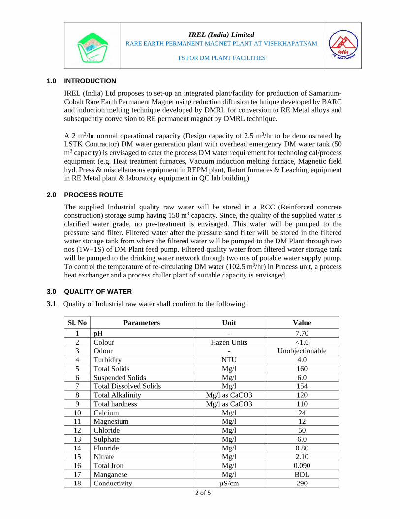
1.0 INTRODUCTION
IREL (India) Ltd proposes to set-up an integrated plant/facility for production of Samarium-Cobalt Rare Earth Permanent Magnet using reduction diffusion technique developed by BARC and induction melting technique developed by DMRL for conversion to RE Metal alloys and subsequently conversion to RE permanent magnet by DMRL technique. A 2 m3/hr normal operational capacity (Design capacity of 2.5 m3/hr to be demonstrated by LSTK Contractor) DM water generation plant with overhead emergency DM water tank (50 m3 capacity) is envisaged to cater the process DM water requirement for technological/process equipment (e.g. Heat treatment furnaces, Vacuum induction melting furnace, Magnetic field hyd. Press & miscellaneous equipment in REPM plant, Retort furnaces & Leaching equipment in RE Metal plant & laboratory equipment in QC lab building)
2.0 PROCESS ROUTE
The supplied Industrial quality raw water will be stored in a RCC (Reinforced concrete construction) storage sump having 150 m3 capacity. Since, the quality of the supplied water is clarified water grade, no pre-treatment is envisaged. This water will be pumped to the pressure sand filter. Filtered water after the pressure sand filter will be stored in the filtered water storage tank from where the filtered water will be pumped to the DM Plant through two nos (1W+1S) of DM Plant feed pump. Filtered quality water from filtered water storage tank will be pumped to the drinking water network through two nos of potable water supply pump. To control the temperature of re-circulating DM water (102.5 m3/hr) in Process unit, a process heat exchanger and a process chiller plant of suitable capacity is envisaged.
3.0 QUALITY OF WATER
3.1 Quality of Industrial raw water shall confirm to the following:
Sl. No Parameters Unit Value
1 pH - 7.70 2 Colour Hazen Units <1.0 3 Odour - Unobjectionable 4 Turbidity NTU 4.0 5 Total Solids Mg/l 160 6 Suspended Solids Mg/l 6.0 7 Total Dissolved Solids Mg/l 154 8 Total Alkalinity Mg/l as CaCO3 120 9 Total hardness Mg/l as CaCO3 110 10 Calcium Mg/l 24 11 Magnesium Mg/l 12 12 Chloride Mg/l 50 13 Sulphate Mg/l 6.0 14 Fluoride Mg/l 0.80 15 Nitrate Mg/l 2.10 16 Total Iron Mg/l 0.090 17 Manganese Mg/l BDL 18 Conductivity µS/cm 290

IREL (India) Limited
RARE EARTH PERMANENT MAGNET PLANT AT VISHKHAPATNAM
TS FOR DM PLANT FACILITIES
3 of 5
Sl. No Parameters Unit Value
19 Nitrile Nitrogen Mg/l BDL 20 Ammonical Nitrogen Mg/l BDL 21 Total plate count per ml Absent
22 MPN (Coliform organisms) per 100 ml
Mg/l Absent
23 Inorganic residue Mg/l 154 24 Organic residue Mg/l <1.0 25 Residual Chlorine BDL 26 Oil & Grease Mg/l BDL 27 E.Coli (CFU/ml) Absent 28 BOD Mg/l <1.0 29 COD Mg/l <1.0 30 Arsenic Mg/l BDL
3.2 Quality of DM water shall confirm to the following:
Sl. No Parameters Unit Value
1 TDS Mg/l ≤ 0.1
2 Conductivity Micro mho/ cm ≤ 0.1
4.0 PROCESS DESCRIPTION
DM Plant shall be a fully automatic plant and it consists of a strong acid cation column for decationising the water, and a strong base anion unit for removal of anionic impurities by exchanging anions present in the feed water. The water is then passed through a polisher unit, which polishes the water further for obtaining water of desired quality. The SAC de-cat ionizes the water (i.e. removes Ca, Mg, Na) by replacing the cations with H+ ions available in the resin. Its regeneration occurs in the counter current mode i.e. the service flow is in down-flow direction and regeneration is in up-flow direction. This ensures that consistently low sodium residual treated water is obtained throughout the cycle. The de-cationised water is passed through SBA unit for removal of anionic impurities by exchanging anions (i.e. Cl, SO4, SiO2 and alkalinity with OH ions available in the resin. Conductivity sensor is located at the outlet of the anion unit. This continuously monitors the quality of treated water and only if the conductivity is within the desired limits the water is allowed to proceed to the DM water storage tank. If for any reason, treated water quality is not within the desired range, the outlet valve of anion unit leading to the DM tank is closed automatically and the recirculation valve opens i.e. water is recirculated back through cation and anion unit for a predetermined time. After this if conductivity does not come within the desired limits there is an audible alarm sounded and a display also comes in the display panel reading treated water quality bad.
IREL (India) Limited
RARE EARTH PERMANENT MAGNET PLANT AT VISHKHAPATNAM
TS FOR DM PLANT FACILITIES
4 of 5
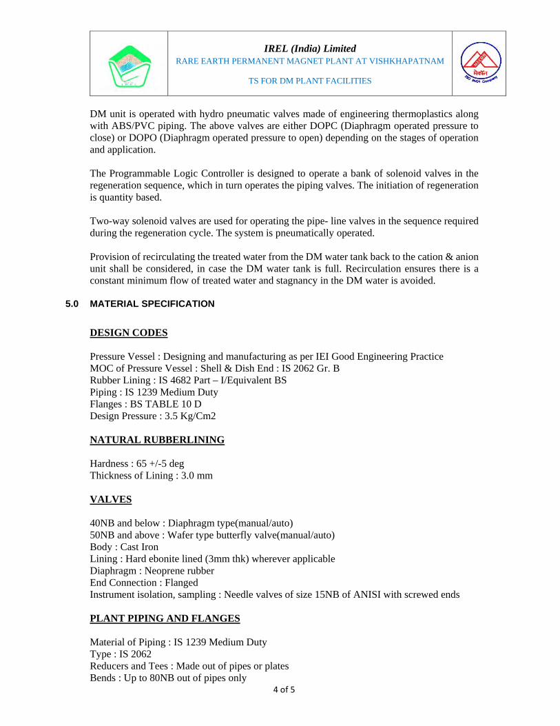
DM unit is operated with hydro pneumatic valves made of engineering thermoplastics along with ABS/PVC piping. The above valves are either DOPC (Diaphragm operated pressure to close) or DOPO (Diaphragm operated pressure to open) depending on the stages of operation and application. The Programmable Logic Controller is designed to operate a bank of solenoid valves in the regeneration sequence, which in turn operates the piping valves. The initiation of regeneration is quantity based. Two-way solenoid valves are used for operating the pipe- line valves in the sequence required during the regeneration cycle. The system is pneumatically operated. Provision of recirculating the treated water from the DM water tank back to the cation & anion unit shall be considered, in case the DM water tank is full. Recirculation ensures there is a constant minimum flow of treated water and stagnancy in the DM water is avoided.
5.0 MATERIAL SPECIFICATION
DESIGN CODES Pressure Vessel : Designing and manufacturing as per IEI Good Engineering Practice MOC of Pressure Vessel : Shell & Dish End : IS 2062 Gr. B Rubber Lining : IS 4682 Part – I/Equivalent BS Piping : IS 1239 Medium Duty Flanges : BS TABLE 10 D Design Pressure : 3.5 Kg/Cm2 NATURAL RUBBERLINING Hardness : 65 +/-5 deg Thickness of Lining : 3.0 mm VALVES 40NB and below : Diaphragm type(manual/auto) 50NB and above : Wafer type butterfly valve(manual/auto) Body : Cast Iron Lining : Hard ebonite lined (3mm thk) wherever applicable Diaphragm : Neoprene rubber End Connection : Flanged Instrument isolation, sampling : Needle valves of size 15NB of ANISI with screwed ends PLANT PIPING AND FLANGES Material of Piping : IS 1239 Medium Duty Type : IS 2062 Reducers and Tees : Made out of pipes or plates Bends : Up to 80NB out of pipes only

IREL (India) Limited
RARE EARTH PERMANENT MAGNET PLANT AT VISHKHAPATNAM
TS FOR DM PLANT FACILITIES
5 of 5
Gaskets : Ring type of natural soft rubber Structure and support : MS Commercial grade MOTORS Type : Totally Enclosed fan Cooled(TEFC) squirrel Cage Protection : IP 55 Insulation : Class F Mounting : Foot Mounted Power supply : 415 +/- 10 % V, 3 Phase, 50 +/- 5 % HZ Duty : Continuous
6.0 LIST OF EQUIPMENT
Refer P&ID for water system (Drg. No. MEC/Q7KN/01/31/D1/PID/WS/0021) for detailed scheme/circuit and list with brief specification of equipment/facilities envisaged for REPM Plant to cater the functioning of DM plant
7.0 CONSUMABLES
Chemicals per regeneration (as consumables) requirement for DM Plant is as following:- 1. HCl as 32% : 11 litres 2. Commercial Grade NaOH as 32% : 10.4 litres 3. Resin : As required

IREL (India) Limited
MUMBAI
TECHNICAL SPECIFICATION FOR AIR-CONDITIONING & VENTILATION SYSTEMS
FOR
RARE EARTH PERMANENT MAGNET PLANT
AT VISHAKHAPATNAM
MECON LIMITED BANGALORE
Doc. No MEC/Q7KN/01/40/S1/REPM/G001/R01 March’2020
Prepared by Checked by Approved by
Surya Kiran Surya Kiran T G Prasad

IREL (India) Limited
RARE EARTH PERMANENT MAGNET PLANT AT VISHKHAPATNAM
TS FOR AIR CONDITIONING & VENTILATION SYSTEM
2 of 57
1.0 SCOPE OF WORK
1.1 Design, Engineer, Manufacture, Assembly along with electrics & instrumentation,
Inspection & testing at manufacturer’s works, supply, delivery at site, unloading &
storage at site, transportation to the place of installation, erection & commissioning,
performance test and handing over of complete Air conditioning and Ventilation System
comprising of the following:
1.1.1 Chilled Water System: The Chilled water plant (CWP) comprising of Twin Screw &
Flooded type chillers and its associated equipment such as Cooling towers, Chilled
water & Condenser water pumps, inter-connecting piping network, Expansion tank,
electrical (power & control) panel, interconnecting wiring / cabling, automation, etc. as
per the specification.
1.1.2 Water cooled Precision type Package Air conditioners (PAC) / Wall mounted split
type air conditioners: inter-connecting condenser water piping (from Plant Room to
PAC room) / Refrigerant piping with valves & actuators, power & control electrics,
supply / return air ducting with diffusers / grilles, thermal & acoustic insulation of
ducting, Fire dampers, volume control dampers etc. as per specification.
1.1.3 Supply & Exhaust Ventilation System: Ceiling mounted Turbo Ventilator / Wall
mounted Tube Axial (TA) fan / Propeller type Fans with bird screen & Cowl / gravity
etc. as per the specification.
1.2 The tenderer shall stand guarantee for the overall performance of the system &
equipment covered under this specification.
1.3 The tenderer, before submitting the offer, shall satisfy himself about the site conditions
as to avoid any difficulty during design / erection / regular operation of the equipment at
site.
1.4 The execution of the work covered under this specification should confirm to the latest
Indian Standards where the same are available, or to the reputed standards acceptable to
the Owner / Consultant. In case, such specifications are not available, the work shall be
according to good engineering practice & norms acceptable to Owner / Consultant.

IREL (India) Limited
RARE EARTH PERMANENT MAGNET PLANT AT VISHKHAPATNAM
TS FOR AIR CONDITIONING & VENTILATION SYSTEM
3 of 57
1.5 Performance Tests & Inspection
a. All the equipment shall be shop tested according to latest Indian / International
Standards as per the approved QAP and the Test certificates shall be furnished as
evidence for such testing.
b. Manufacturer's test certificates shall also be furnished for all the bought out items used
for fabrication and manufacture of the equipment / system.
c. In the event of an order, the equipment will be subjected to a detailed inspection /
operational performance by owner including dimensional check up at Manufacturer's
works as per the tenderer’s approved drawings.
1.6 Accessibility and safety
The equipment supplied shall allow adequate access to facilitate inspection, maintenance
& repair. All moving parts of the equipment shall be well guarded & protected for the
operator’s & maintenance personnel’s safety.
1.7 Welding
All welding shall be of structural steel standard and only certified welders shall be
employed.
1.8 Noise Level
Noise level generated by equipment supplied shall not exceed permissible limit of 85
dB(A) at 1m distance in plant room and shall be less than 60 dB(A) inside the air
conditioned premises.
1.9 Lubrication
a. While initial fill of oil, grease, lubricants & other consumables shall be included with
the equipment; the tenderer shall quote separately for supply of consumables for two
years normal operation along with their specification and rate of lubrication
recommended.
b. The specification & source of supply of all consumables with their equivalents shall
be clearly mentioned in the tender along with chemical compositions & physical
properties & the trade name wherever applicable.
1.10 All necessary foundation bolts, anchor boxes & anchor channels required for the
installation of all the equipment shall be part of the quotation & shall be supplied well in
advance so that civil engineering works can be taken up in time.

IREL (India) Limited
RARE EARTH PERMANENT MAGNET PLANT AT VISHKHAPATNAM
TS FOR AIR CONDITIONING & VENTILATION SYSTEM
4 of 57
1.11 Painting
The parts to be painted shall be cleaned thoroughly of loose mill scale, rust, grease, oil &
any other foreign matter before painting. After cleaning, all the equipment shall be given
one coat of anti-corrosive primer at the supplier’s works. The second coat of primer shall
be given at the erection site followed by two coats of anti-corrosive finish paint as per
the color code indicated below:-
Tentative Color Code
Table No. 1.0
Sl. No. Equipment Color shade Remarks
1. Chilling Packages, pumps etc. Light grey Color code no. 631-IS: 5
2. Condenser cooling water lines Sea green IS: 2379
3. Chilled water lines Dark blue IS: 2379
4. Refrigerant lines - IS: 2379
5. Centrifugal Fan Light grey Color code no. 631-IS: 5
6. Grilles & diffusers Finish paint to
match interiors
Note: Final Color code for all the items shall be as per the Owners’ requirement
1.12 System of units
Metric system of units shall be followed in design, manufacture & supply of all
equipments. Nameplates of equipment as well as operating / maintenance instructions
shall be in English language.
1.13 Maintenance and guarantee
The tenderer shall guarantee the satisfactory performance of the equipment / systems
supplied and erected by them all through the year.
2.0 Works by Owner
a. Providing space / room for installation of the systems, civil foundations for equipment
as per suppliers’ drawings.
b. Electrical power shall be made available (at one point) in the incoming feeder of 415
V for MCCs located in CWP / Package AC Room / Ceiling suspended ducted units.
Further power distribution from electrical panel / starter panel / socket to mechanical

IREL (India) Limited
RARE EARTH PERMANENT MAGNET PLANT AT VISHKHAPATNAM
TS FOR AIR CONDITIONING & VENTILATION SYSTEM
5 of 57
equipment like Chillers / Pumps / CTs / Fire dampers / heaters / Humidifiers / Exhaust
fans / split ACs etc. and Termination is in the scope of successful tenderer.
Except for the above, rest of the works, directly or indirectly associated with completion
of Air conditioning & Ventilation facilities / systems are within the scope of Contractor
i.e. Successful Tenderer.
3.0 DESIGN CRITERIA
a. Design ambient conditions for AC & Ventilation Systems:-
Table No. 2 Sl. No.
Description Summer Monsoon Winter
1. Average Dry bulb temp. 38 ºC 31 ºC 16 ºC
2. Relative Humidity 70 % 85 % 70 %
3. Max. Temperature 45.3 ºC - -
4. Min. Temperature - - 10.5 ºC
b. The parameters (Temp. & Flow) to be considered for the design of chillers is as
indicated below: -
Table No. 3
Sl. No OPERATING CONDITIONS Average Value
1. Chilled water leaving temp 7.0 deg.C
2. Chilled water entering temp 17.0 deg. C
3. Chilled water flow rate 110 m3/hr
4. Condenser water entering temp 32.0 deg. C
5. Condenser water leaving temp 37.0 deg. C
Note: The cooling tower water is also being utilized for Precision Air conditioner
condenser cooling
c. Inside design conditions for Air conditioning systems with Package Air-
conditioners
Temperature : 25 1 º C
Relative humidity : 55 5 %
Dust content : 10 Microns (max)

IREL (India) Limited
RARE EARTH PERMANENT MAGNET PLANT AT VISHKHAPATNAM
TS FOR AIR CONDITIONING & VENTILATION SYSTEM
6 of 57
d. Inside design conditions for Air conditioning systems with Split units:-
Temperature : 25 1 º C
Relative humidity : < 70 %
e. Inside design conditions for Supply & Exhaust Ventilation systems:-
The maximum allowable temperature raise within the (supply / exhaust) ventilated
premises shall be ≤ 5º C over and above the prevailing ambient temperature.
f. Partial list of codes & standards
Nothing in this specification shall be construed to relieve tenderer of his final
responsibility for the completed job. The design, manufacture and performance of AC
& Ventilation systems / equipment shall comply with all currently applicable / latest
International / National standards and safety codes including those specified in Table
No. 4 indicated below:
Table No. 4
IS Standard Particulars
IS 655 & IS 277 : Metal air ducts
IS 7613 : Method of testing panel type air filters
IS 2062 : Weld able structural steel
IS 7896 : Data for outside design conditions for summer months
IS 12436 :Preformed rigid polyurethane foams for thermal insulation
IS 3069 :Glossary of terms, symbols and units relating to thermal insulation materials
IS 3144 : Fire resistance Testing of acoustic insulation
ISO1940 & VDI 2060
: Dynamic balancing
ISO 2372 & VDI 2056
: Vibration
AMCA-201 : Design of centrifugal fans and classification
AMCA-210 : Laboratory Methods of testing fans for rating purposes
AMCA-300 : Reverberant room method for sound testing of Fans

IREL (India) Limited
RARE EARTH PERMANENT MAGNET PLANT AT VISHKHAPATNAM
TS FOR AIR CONDITIONING & VENTILATION SYSTEM
7 of 57
IS 4691 : Motors
IS 4894 : Specification for Centrifugal fans
IS 3588 : Specification for Tube Axial fans
IS:1391 - 1992 : Specification for Split Air-conditioners
IS: 8148 - 2003 : Specification for Package Air-conditioners
IS: 1239 (Part-I) : Piping
g. Duty Cycle of the Plant
AC & Ventilation systems shall be designed to operate in a corrosive, dusty
industrial environment and shall be suitable for continuous operation.
4.0 Premises requiring Air-conditioning & Ventilation facilities, Type of system,
Equipment proposed with tentative capacity & piping work details:
4.1 Air conditioning facilities Table No. 5
Sl. No.
Room name Type of air conditioner
Nos. & standby units
Eqpt. Cap. (Each)
A REPM Plant Area
1 Sintering & heat treatment
area -1 (F201A to 201E)
Water cooled Precision AC
2 (1W+1S) 30.0 TR
2 Sintering & heat treatment
area -2 (F202A to 202E)
Water cooled Precision AC
2 (1W+1S) 30.0 TR
3 Packaging & storage area High wall Split
type AC 2 (2W+0S) 2.0 TR
4 Control Room --- do --- 3 (2W+1S) 2.0 TR
5 Die filling & Pressing Bay --- do --- 3 (3W+0S) 2.0 TR
6 Crushing & Grinding Area Ceiling suspended
Split type AC 2 (1W+1S) 8.75 TR
B RE Metal Plant Area
7 Control room High wall Split
type AC 2 (2W+0S) 2.0 TR
8 Packaging & storage area High wall Split
type AC 2 (2W+0S) 2.0 TR

IREL (India) Limited
RARE EARTH PERMANENT MAGNET PLANT AT VISHKHAPATNAM
TS FOR AIR CONDITIONING & VENTILATION SYSTEM
8 of 57
Table No. 5 Contd…
Sl.
No. Room name
Type of air
conditioner
Nos. &
standby units
Equip. Cap.
(Each)
C Quality Control Laboratory Building
9 Quality control Laboratory
Air cooled Ducted Split type AC
2 (1W+1S) 8.5 TR
10 Lab In charge High wall Split
type AC 1 (1W+0S) 2.0 TR
D MRSS Building (Control Room)
11 Control room High wall Split
type AC 3 (3W+0S) 2.0 TR
E Administrative building
Ground Floor
1 First Aid Room Ceiling Suspended
Cassette type 1 (1W+0S) 2.5 TR
2 Electrical Room --- do --- 1 (1W+0S) 2.5 TR
3 Server room --- do --- 1 (1W+0S) 2.5 TR
4 Reception --- do --- 1 (1W+0S) 2.5 TR
First Floor
1 GM Room Ceiling Suspended
Cassette type 2 (2W+0S) 2.0 TR
2 Secretary --- do --- 1 (1W+0S) 2.0 TR
3 Waiting Lobby --- do --- 1 (1W+0S) 1.5 TR
4 Conference Hall --- do --- 2 (2W+0S) 2.5 TR
5 Record Room --- do --- 1 (1W+0S) 1.5 TR
6 Executive Room -1 --- do --- 1 (1W+0S) 2.0 TR
7 Executive Room -2 --- do --- 1 (1W+0S) 2.0 TR
8 Executive Room -3 --- do --- 1 (1W+0S) 2.0 TR
9 Executive Room -4 --- do --- 1 (1W+0S) 2.0 TR
10 Corridor --- do --- 1 (1W+0S) 1.5 TR

IREL (India) Limited
RARE EARTH PERMANENT MAGNET PLANT AT VISHKHAPATNAM
TS FOR AIR CONDITIONING & VENTILATION SYSTEM
9 of 57
Table No. 5 Contd…
Sl.
No. Room name
Type of air
conditioner
Nos. &
standby units
Equip. Cap.
(Each)
Second Floor
1 Officer Cabin-1 Ceiling Suspended
Cassette type 1 (1W+0S) 2.0 TR
2 Officer Cabin-2 --- do --- 1 (1W+0S) 2.0 TR
3 Officer Cabin-3 --- do --- 1 (1W+0S) 2.0 TR
4 Officer Cabin-4 --- do --- 1 (1W+0S) 2.0 TR
5 Officers Room --- do --- 2 (2W+0S) 2.0 TR
6 Office Area --- do --- 6 (6W+0S) 2.5 TR
7 Corridor --- do --- 1 (1W+0S) 1.5 TR
4.2 Ventilation Facilities
Table No. 6
Sl.
No. Premises details Equipment proposed Tentative Capacity
1. RE Metal Plant area
Fresh air supply
Through louvers.
Exhaust through Turbo
Ventilators
Supply - Fresh air Louvers
-----------------------------------
Exhaust
Wind turbine Ventilators
15 nos. x 4,500 m3/hr
2. REPM Plant area
Fresh air supply
Through louvers.
Exhaust through Turbo
Ventilators
Supply - Fresh air Louvers
----------------------------------
Exhaust
Wind turbine Ventilators
60 nos. x 5,500 m3/hr
3. Workshop Area
Fresh air supply
Through louvers
Exhaust through Tube
Axial (TA) Fan with
bird screen & cowl
Supply - Fresh air Louvers
---------------------------------
Exhaust
Capacity – 6,500 m3/h
St. pr. 10 mm WC
Qty – 3.0 Nos.

IREL (India) Limited
RARE EARTH PERMANENT MAGNET PLANT AT VISHKHAPATNAM
TS FOR AIR CONDITIONING & VENTILATION SYSTEM
10 of 57
Table No. 6 (Contd.)
Sl.
No. Premises details Equipment proposed Tentative Capacity
4. Stores Area
Exhaust through TA
Fan with bird screen &
cowl
Capacity – 5,500 m3/h
St. pr. 10 mm WC
Qty – 4.0 Nos.
5. Chiller Plant Room
Fresh air supply
Through louvers
Exhaust through Tube
Axial (TA) Fan with
bird screen & cowl
Supply - Fresh air Louvers
-------------------------
Exhaust
Capacity – 6,500 m3/h
St. pr. 10 mm WC
Qty – 4.0 Nos.
6. Pump Room
Tube Axial Fan with
louvers & Bird Screen.
Exhaust through
Gravity louvers
Supply
Capacity – 9,000 m3/h
St. pr. 30 mm WC
Qty – 1.0 No.
7. MRSS Fresh air supply
Through louvers
Exhaust through Tube
Axial (TA) Fan with
bird screen & cowl
Supply - Fresh air Louvers
-------------------------
Exhaust
Capacity – 14,000 m3/h
St. pr. 10 mm WC
Qty – 3.0 Nos.
8. Utility area
Tube Axial Fan with
louvers & Bird Screen.
Exhaust through
louvers
Supply
Capacity – 9,500 m3/h
St. pr. 20 mm WC
Qty – 2.0 Nos.
9. Admin Building -
Ground, First &
Second Floor – Toilets
Exhaust through
Propeller type Fan with
Cowl & Bird Screen
Capacity – 500 m3/h
Qty – 11.0 Nos.
IREL (India) Limited
RARE EARTH PERMANENT MAGNET PLANT AT VISHKHAPATNAM
TS FOR AIR CONDITIONING & VENTILATION SYSTEM
11 of 57
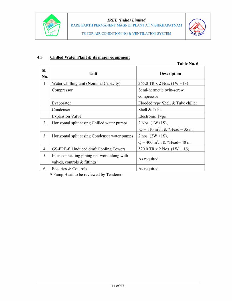
4.3 Chilled Water Plant & its major equipment
Table No. 6
Sl.
No. Unit Description
1. Water Chilling unit (Nominal Capacity) 365.0 TR x 2 Nos. (1W +1S)
Compressor Semi-hermetic twin-screw
compressor
Evaporator Flooded type Shell & Tube chiller
Condenser Shell & Tube
Expansion Valve Electronic Type
2. Horizontal split casing Chilled water pumps 2 Nos. (1W+1S),
Q = 110 m3/h & *Head = 35 m
3. Horizontal split casing Condenser water pumps 2 nos. (2W +1S),
Q = 400 m3/h & *Head= 40 m
4. GS-FRP-fill induced draft Cooling Towers 520.0 TR x 2 Nos. (1W + 1S)
5. Inter-connecting piping net-work along with
valves, controls & fittings As required
6. Electrics & Controls As required* Pump Head to be reviewed by Tenderer

IREL (India) Limited
RARE EARTH PERMANENT MAGNET PLANT AT VISHKHAPATNAM
TS FOR AIR CONDITIONING & VENTILATION SYSTEM
12 of 57
5.0 GENERAL TECHNICAL SPECIFICATION OF THE EQUIPMENT
5.1 WATER CHILLING PACKAGE
The chilling package shall include the following major components: -
a. Semi-hermetic Twin-Screw Compressors of Nominal Capacity 365.0 TR at site
condition
b. Shell & tube Flooded type evaporator
c. Shell & tube water-cooled Condenser
d. Associated refrigerant piping, valves, fittings, accessories and controls
e. Condenser water pumps & Chilled water pumps
f. GS-FRP-fill ID Cooling towers
g. Expansion tank
h. Inter-connecting piping network
i. Electrics & controls
5.1.1 Screw Compressor
a. The compressor should be of twin screw semi - hermetic screw compressor type
suitable for HFC -134a and should offer economical part load operation.
b. The motor should be cooled by independent refrigerant supply to ensure it always
runs at the ideal temperature. Mixture of oil and liquid refrigerant shall be injected in
the compressor in order to get high COP at high condensing pressure.
c. The unit should be provided with an integral oil separator and it shall be of high
efficiency, augmented gas impingement type to maximize oil extraction. The
compressor shall have an in-built oil separator for oil separation before the refrigerant
enters the condenser.
d. The unit should be with electronic expansion device for optimized refrigerant
metering to the evaporator - ensuring maximum utilization of heat exchange surface.
e. The unit shall use the latest microprocessor based control technology – which
constantly monitors all machine parameters and precisely manages the operation of
Compressors & expansion devices for optimum energy efficiency. The control
system shall offer chiller protection during fault conditions arising from high
condensing temperature.

IREL (India) Limited
RARE EARTH PERMANENT MAGNET PLANT AT VISHKHAPATNAM
TS FOR AIR CONDITIONING & VENTILATION SYSTEM
13 of 57
f. The unit shall have automatic capacity control through regulation of slide valve in the
compressor based on requirements of the cooling capacity thus ensuring proper
control on leaving chilled water temperature.
g. The refrigerant shall be environment friendly with zero ozone depletion potential and
minimum global warming potential. Refrigerant containing chlorine CFC and HCFC
shall not be acceptable.
5.1.2 Shell & Tube Chiller
a. The units shall be supplied with shell-and-tube Flooded type evaporator. Replaceable
tubes shall be fabricated from integral finned copper and mechanically bonded to steel
tube sheet. Waterside working pressure should be designed for 10.5 bar. Pressure
relief valve shall be mounted on the suction side of the refrigerant circuit. Evaporator
shall be insulated as specified elsewhere.
b. The chiller shall be designed, manufactured & tested as per the ASHRAE / ARI
standards.
c. The tubes shall be of copper of min. dia. ¾” having minimum wall thickness of 0.63
mm.
d. The chiller shall be designed / selected with an adequate overloading factor to account
for scale formation on the waterside.
e. The chiller assembly shall be tested hydraulically for strength & pneumatically for
leakage pressures as per code of unfired pressure vessels.
f. Chillers shall be adequately insulated (~50 mm thick) by means of self-extinguishing
type rigid polyurethane or equivalent insulation material as per standard procedures.
g. Chiller shall be equipped with the following controls / accessories / safety devices:
- Cooling & anti-freeze thermostats
- Water inlet / outlet connections with flanges & shut-off valves
- Vent connections with valves
- Pressure & temperature gauges at all the water inlets / outlets
- Relief valve, purge valve, drain valve, and shut off valve
- Refrigerant charging connection with valve
- Pressure & temperature gauges at the refrigerant inlet / outlet
- Flow meters & switches on the water lines
h. A liquid level sight glass or view port shall be provided on the side of the chiller to
determine proper refrigerant charge. Fouling factor of 0.0001 ft2.hr.º F/ BTU may be
considered for selection / sizing of Chiller. Pressure drop of water across the cooler
shall be limited to 0.5 kg/cm2.

IREL (India) Limited
RARE EARTH PERMANENT MAGNET PLANT AT VISHKHAPATNAM
TS FOR AIR CONDITIONING & VENTILATION SYSTEM
14 of 57
5.1.3 Condenser
a. The condenser shall be of water-cooled horizontal shell & tube type construction with
water flowing inside the tubes and the refrigerant gas condensing outside the tubes. A
discharge gas baffle shall be incorporated to prevent direct impingement on the tubes.
This baffle shall be designed so as to distribute refrigerant gas properly for most
efficient heat transfer.
b. The condenser shall be equipped with integral finned type, solid drawn, seamless
copper tubes. Minimum tube thickness shall be 0.63 mm with internal turbulator.
(Minimum number of fins shall be 25 per inch).
c. The condenser shall be of water cooled horizontal shell & tube with refrigerant &
water connections, integrally finned copper tubes with adequate surface area to
provide sub-cooling at 2ºC (min.) being imparted to refrigerant liquid within the
condenser shell only. Temperature raise across condenser shall not be more than 5ºC.
Pressure drop of water across condenser shall be limited to 0.9 kg/cm2. Fouling factor
of 0.00025 ft2.hr.ºF/BTU may be considered for selection / sizing of Condenser.
d. Multi-pass construction is desirable for the condenser. It shall be designed for proper
number of passes to give optimum water velocity, efficient heat transfer & allowable
pressure drop. Adequate baffling arrangement shall be used in the condenser to
improve heat transfer. Condenser tubes shall be adequately supported to prevent
sagging & vibration. A purge connection shall be located in the condenser for
efficient elimination of non- condensable.
e. The condenser shall be equipped with the following accessories / safety devices:
- Purge valve
- Charging valve
- Relief valve / fusible plug
- Liquid level indicator
- Hot gas inlet / liquid outlet connections on the shell with flanges
- Water inlet / outlet connections with flanges
- Hand shut-off valve for water inlet & outlet
- Flow switches for the condenser water
- Pressure & temperature gauges for water inlet & outlet / refrigerant gas inlet & liquid
outlet
- Vent valves, drain valves
- Charging valves

IREL (India) Limited
RARE EARTH PERMANENT MAGNET PLANT AT VISHKHAPATNAM
TS FOR AIR CONDITIONING & VENTILATION SYSTEM
15 of 57
f. Condenser assembly should be tested hydrostatically for strength and pneumatically
for leakages at pressures as per latest codes of unfired pressure vessels.
5.1.4 Micro-Processor based Control Panel
a. Each unit shall be provided with a Micro-processor based control Panel, factory
mounted, wired and tested. The control panel shall include alphanumeric display
showing all system parameters in English language with numeric data in English
(FPS) units.
b. All safety and cycling shutdowns shall be annunciated through the alphanumeric
display and consist of day, time, cause of shutdown, and type of restart required.
Safety shutdowns shall include: - high compressor discharge temperature, low
evaporator pressure, motor controller fault and sensor malfunctions, Loss of chilled
water flow, loss of condenser water flow.
Cycling shutdowns shall include: - low water temperature, low oil temperature,
chiller/condenser water flow interruption, power fault, internal time clock and entire
cycle.
c. Control panel shall be able to interface with the Centralized Monitoring System to
monitor operating parameters of chiller and status messages indicating chiller is
ready to start, chiller is operating, chiller is shutdown on a safety requiring reset.
d. Security access shall be provided to prevent unauthorized change of set points to
allow local or remote control of the chiller and to allow manual operation of the oil
pump.
e. The microprocessor shall ensure even compressor loading and optimal energy
efficiency through microprocessor controls.
f. The display shall have operating parameters like:-
- Entering and leaving chilled water temperature.
- Entering and leaving condenser water temperature.
- Refrigerant Suction Pressure.
- Refrigerant Discharge Pressure.
- System Voltage.
- Actual current drawn by compressors.
- Loading / unloading status.
- Compressor running hours.
- Other display / functions which are essential for operation and safety of Chiller.

IREL (India) Limited
RARE EARTH PERMANENT MAGNET PLANT AT VISHKHAPATNAM
TS FOR AIR CONDITIONING & VENTILATION SYSTEM
16 of 57
5.1.5 Inter-connecting refrigerant piping, fittings & valves
a. Refrigerant piping is required to interconnect the compressor, condenser & the chiller
into a closed network.
b. Suction line shall be thermally insulated with polyurethane of 50 mm thick. The
piping design shall be carried out in conformity with the (ANSI – B 31.5 1962) codes
applicable & sound engineering practice. Heavy-duty seamless steel pipe shall be
used for pipe network. While seamless solid drawn copper tubes shall be used for
refrigerant liquid line.
c. The piping network shall be adequately supported to ensure rigidity, strength &
isolated by means of suitable isolators.
d. The tenderer shall furnish complete piping & instrumentation diagrams showing the
arrangement of piping inclusive of all materials, instruments & controls proposed to
be included in the bid. The entire piping network shall be pressure-tested, leak tested,
dried, evacuated & charged with the refrigerant after erection.
e. All bolts & nuts shall be of black hexagonal carbon steel type as per IS: 1363 (1992)
& with the material & other requirements as per IS: 1367- 1992.
f. Velocity in the discharge & Suction pipe of the refrigerant shall be such that no undue
vibration & noise are generated.
g. The piping network shall incorporate loops in the circuit to efficiently separate oil and
liquid refrigerant from hot gas and suction vapor respectively.
h. All horizontal lines shall be pitched to 12 mm for every 3.0 m in the direction of
refrigerant flow. All necessary loops and bends shall be provided to ensure proper
return of oil to the compressor.
i. Each refrigerant circuit shall be suitable for operation on HFC-134a and shall include
the following items:
- Electronic expansion valve
- Removable liquid line drier / strainer
- Liquid line sight glass with moisture indicator.
- Hand shut off valves
- Liquid to suction heat exchanger
5.2 Water pumps (Chilled water / Condenser water)
a. Pump sets are required for the service of chilled water re-circulation & condenser
water re-circulation.
IREL (India) Limited
RARE EARTH PERMANENT MAGNET PLANT AT VISHKHAPATNAM
TS FOR AIR CONDITIONING & VENTILATION SYSTEM
17 of 57
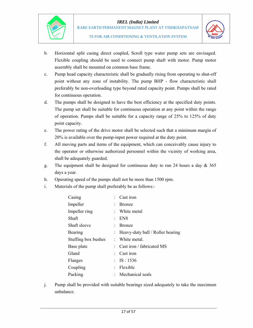
b. Horizontal split casing direct coupled, Scroll type water pump sets are envisaged.
Flexible coupling should be used to connect pump shaft with motor. Pump motor
assembly shall be mounted on common base frame.
c. Pump head capacity characteristic shall be gradually rising from operating to shut-off
point without any zone of instability. The pump BHP - flow characteristic shall
preferably be non-overloading type beyond rated capacity point. Pumps shall be rated
for continuous operation.
d. The pumps shall be designed to have the best efficiency at the specified duty points.
The pump set shall be suitable for continuous operation at any point within the range
of operation. Pumps shall be suitable for a capacity range of 25% to 125% of duty
point capacity.
e. The power rating of the drive motor shall be selected such that a minimum margin of
20% is available over the pump-input power required at the duty point.
f. All moving parts and items of the equipment, which can conceivably cause injury to
the operator or otherwise authorized personnel within the vicinity of working area,
shall be adequately guarded.
g. The equipment shall be designed for continuous duty to run 24 hours a day & 365
days a year.
h. Operating speed of the pumps shall not be more than 1500 rpm.
i. Materials of the pump shall preferably be as follows:-
j. Pump shall be provided with suitable bearings sized adequately to take the maximum
unbalance.
Casing : Cast iron
Impeller : Bronze
Impeller ring : White metal
Shaft : EN8
Shaft sleeve : Bronze
Bearing : Heavy-duty ball / Roller bearing
Stuffing box bushes : White metal.
Base plate : Cast iron / fabricated MS
Gland : Cast iron
Flanges : IS : 1536
Coupling : Flexible
Packing : Mechanical seals

IREL (India) Limited
RARE EARTH PERMANENT MAGNET PLANT AT VISHKHAPATNAM
TS FOR AIR CONDITIONING & VENTILATION SYSTEM
18 of 57
k. Pump & drive motor shall be directly coupled through a flexible coupling. Suitable
coupling guard shall be provided for each pump.
l. Each pump shall be complete with pressure gauge at the suction & discharge
complete with Flow control valves, isolating valve & non-return valves. All integral
piping required for sealing, cooling etc. should be supplied with the pump.
m. Chilled water pump set shall handle water-having temperature of about 5oC &
condenser water pump set shall handle water-having temperature of about 37oC.
n. The impeller & shaft assembly should be statically & dynamically balanced.
o. Dial type pressure & temperature gauges should be provided for suction & discharge
sides.
p. Each pump set shall be tested for mechanical running for at least 4 hours at site.
q. Chilled water pump (casing) should be thermally insulated with polyurethane /
phenotherm insulation of min. 50 mm thickness as per the following procedure:-
i. Clean the surface with wire brush and apply one coat of bituminous primer.
ii. Fix min. 50 mm thick rigid PUF of density 36 ± 2 kg/m3 slab using cold
bituminous adhesive.
iii. Provide aluminum foil laminated Kraft paper as Vapour barrier over the
insulation with proper overlaps and joints by means of self-adhesive Aluminium
foil tape.
iv. Provide sand cement plaster 1:4, 20 mm thick, over GI wire netting of size 20
mm x 22 swg as reinforcement.
v. Apply two coats of synthetic enamel paint of desired shade.
5.3 Cooling Tower
a. Induced draft, Cross flow type, Factory assembled, GS FRP-fill cooling tower shall be
provided for the cooling of condenser water with 4 deg. C approach temperature.
b. Cooling tower shall be designed, manufactured, performance tested as per CTI codes
& CTI certified. The Cooling towers shall comply with Energy efficiency
requirements as per ASHRAE std. 90.1.
c. The capacity of the cooling tower basin shall be adequate to take care of the entire
cooling water required for the air conditioning plant. Only make up water will be
made available from the steel plant network within a distance of ~10.0 M.
d. Minimum water storage in the basin shall be for 2.5 minutes of water circulation.
IREL (India) Limited
RARE EARTH PERMANENT MAGNET PLANT AT VISHKHAPATNAM
TS FOR AIR CONDITIONING & VENTILATION SYSTEM
19 of 57
e. The cooling towers shall be mounted on masonry pillars / Stools welded to roof
members on the terrace of ECR building.
f. The structural framework of the tower including all members & connections shall be
designed for operating loads & prevailing wind pressure. The structural frame shall
be designed to transit all wind, seismic & mechanical loads to unit anchorage. The
steel members shall be of hot dipped galvanized steel & be of sufficient size to safely
withstand all imposed loads. All steel basin panels shall be constructed of heavy
gauge, highly corrosion resistant hot dip galvanized steel. Casing panels will not
provide any structural support. Framework, bolts, nuts & washers shall be non-
corrosive type.
g. The cold-water basin shall have accessories & connections for make up, quick fill,
drain & overflow. Ball & float valve is to be provided for makeup water line. The
makeup water supply pipe shall be positioned at least 2 meters above the maximum
level in the basin. Pressure reducing valve (6.0 bar to 0.5 bar) may be provided to
reduce the pressure of make-up water.
h. The water distribution system shall be either open basin with gravity feed nozzles or
pipe system with nozzles requiring not more than 0.42 kg / cm2 water pressure at
rated capacity. The nozzles shall be spaced to give even distribution of water. The
nozzles shall be self-draining, non-clogging and designed for flexible operation &
ready accessibility. Suitable measuring orifices shall be provided. All main piping
connections shall be brought out & shall end in flanges to facilitate connections.
i. Eliminators shall be provided in removable sections & installed in the cell of the
tower. The number of deflections in the eliminators shall be so arranged as to limit the
drift loss to 0.2 % of the water circulated.
j. All the fasteners shall be of stainless steel. Rubber / Neoprene gaskets must be used
on all bolted joints as a seal against water leakage.
k. Motors of induced draft fan shall be of weatherproof construction. The fan motor
shall be totally enclosed air over (TEAO), reversible, squirrel cage, ball bearing type
designed specifically for cooling tower duty. The motors shall be furnished with
special moisture protection on windings, ball bearings & shafts and labeled
appropriately for cooling tower service.
l. Fans shall be of heavy duty, axial flow, Aluminium alloy blades. Fans & shafts shall
be supported by heavy duty, self-aligning, grease packed ball bearings with moisture
proof seals and integral slinger collars.
m. The cooling tower shall be complete with ladder, access platform for maintenance &
service requirements.

IREL (India) Limited
RARE EARTH PERMANENT MAGNET PLANT AT VISHKHAPATNAM
TS FOR AIR CONDITIONING & VENTILATION SYSTEM
20 of 57
5.4 Chilled Water / Condenser water Piping
a. MS Medium Class piping is to be used as per IS: l239 Part - I for interconnecting
chilled water - piping network. Pipes above 150 mm diameter shall conform to IS:
3589 & shall have minimum 6 mm thickness.
b. Velocity in pipes shall be maximum 2.0 m/sec.
c. Gunmetal gate & globe valves are to be used up to pipe sizes 50 mm & butterfly
valves are to be used above these pipe sizes. Gunmetal valves shall be as per IS: 778
Class - I with screwed ends.
d. Electrically actuated three-way globe valves are to be used in between the chilled
water supply line to PHE and return water line. The valve shall be linked with a
modulating thermostat for actuation signal.
e. Matching flanges shall be as per IS: 6392. All bolts & nuts shall be black hexagonal
carbon steel type conforming to IS: 1363 for material & other requirement as per IS:
1367.
f. Pipe supports shall be of steel, adjustable for height and coated with rust preventive
primer & finish coated with Aluminum paint.
g. Chilled water piping laid indoor shall be as follows: -
Table No. 7
Pipe size Material Joints / Fittings Sealing material
Up to 65
mm
M.S tube Medium
IS-1239 Part –1
1990
a) Welded fittings.
b) Unions
c) Slip on flanges
d) Welded joints
a) Non-hardening
b) Lubricant
c) 3 mm - 3 ply Rubber
insertion
d) ----------
75 to 200
mm ---- do ----
a) Welded
b) Slip on flanges
c) Screwed GI flanges
for GI pipes
a) ----------
b) 3 mm - 3 ply rubber
insertion
c) ----------
h. All piping shall be tested to hydrostatic test pressure of at least one & half times the
maximum of operating pressure but not less than 7 kg/ cm2 for a period of not less
than 24 hours. System may be tested in sections & such section shall be securely
capped. No insulation shall be applied to piping until the completion of pressure
testing to the satisfaction of the owner / Consultant.

IREL (India) Limited
RARE EARTH PERMANENT MAGNET PLANT AT VISHKHAPATNAM
TS FOR AIR CONDITIONING & VENTILATION SYSTEM
21 of 57
i. Pipe supports shall be of steel, adjustable for height and coated with rust preventive
primer and finish coated with aluminium paint. Where pipe and clamp are of
dissimilar material a gasket shall be provided in between.
j. Spacing of pipe supports shall not exceed 2.5 m for NB 32 to 150 mm and 3.0 m for
NB 150 mm and above.
5.5 Thermal Insulation of Chilled water pipes
As the chilled water lines passes through exposed areas - the entire length of Chilled
water line is required to be insulated & finished with sand cement plaster. However,
thermal insulation for both indoor & outdoor is given herewith. The thermal
insulation shall be carried out by the Tenderer as per the following description:
A. Thermal insulation of Indoor Chilled water pipes
a. Clean the pipe surface with wire brush and apply a coat of bituminous primer.
b. Apply a thick coat of bituminous cold adhesive over the surface.
c. Insulate with Poly urethane foam of thickness of 75 / 50 / 25 mm with secured in
position by means of aluminum band of size 20 mm x 24 swg at 300 mm center to
center. GI sheet cladding shall be fixed over insulation. The insulation material
density shall not be less than 32 kg/cu.m
B. Thermal insulation of Outdoor Chilled water pipes
a. Clean the pipe surface with wire brush and apply a coat of bituminous primer.
b. Apply a thick coat of bituminous cold adhesive over the surface.
c. Fix pre-formed pipe sections PUF (Polyurethane / phenolic foam 32 kg/m3)
minimum 50 mm thickness secured in position by means of Aluminium band of size
20 mm x 24 swg at 300 mm center to center.
d. Wrapping the pipe with Aluminium foil laminated Kraft paper as vapour barrier over
the insulation with proper overlaps and joints sealed by means of self-adhesive
aluminium foil tape.
e. Provide cement sand plaster 1:4, 20 mm thick as finishing material with GI wire
netting of size 20 mm x 22 swg as reinforcement
f. Fix plain Aluminium sheet 0.5 mm thick with self tapping screws to the floating rings
made of MS flat 25 x 3 mm at 400 mm center to center. The sheet joint shall be sealed
with suitable sealant.
IREL (India) Limited
RARE EARTH PERMANENT MAGNET PLANT AT VISHKHAPATNAM
TS FOR AIR CONDITIONING & VENTILATION SYSTEM
22 of 57
C. Thermal insulation of below ground Chilled water pipes
a. Clean the pipe surface with wire brush and apply a coat of Bituminous primer.
b. Apply a thick coat of bituminous cold adhesive over the surface
c. Factory Fixed pre-formed pipe sections (Polyurethene foam 48 kg/m3) minimum 50
mm thickness secured in position by means of aluminium band of size 20 mm x
24swg at 300 mm center to center.
d. Cover the insulated pipe with Jute Hessian clothes tar felt sheet.
e. Warp the Tarfelt sheet with 300G polythene sheet and secure with straps of 50mm at
every 1m intervals.
f. Cover the polythene sheet with chicken wire mesh.
g. Finally finish it with 12mm Sand cement plaster.
D. Thermal insulation for GI class B piping for drain:
a. Clean the pipe with wire brush and apply a coat of bituminous primer.
b. Apply thick coat of adhesive.
c. Insert the preformed pipe sections of Aluminum foil faced Nitrile rubber 9mm thick
on the surface.
d. Cover the joint with 50mm Aluminium Adhesive tapes at all places circumferential
and longitudinal.
E. Thermal insulation for PVC Drain piping
a. Clean the pipe and apply a coat of Adhesive.
b. Insert the preformed pipe sections of Aluminum foil faced Nitrile rubber 6mm thick
on the surface.
c. Cover the joint with 50mm Aluminium Adhesive tapes at all places circumferential
and longitudinal.
5.6 Valves & Accessories
5.6.1 Balancing Valve
The balancing valve shall be fitted in to the pipeline system for balancing, control and
shut off. These shall have in-built flow measuring port to measure flow and pressure
for proper balancing and control of water. The body shall be made up of Gun metal/
cast iron body that is corrosion resistant.

IREL (India) Limited
RARE EARTH PERMANENT MAGNET PLANT AT VISHKHAPATNAM
TS FOR AIR CONDITIONING & VENTILATION SYSTEM
23 of 57
5.6.2 Butterfly Valve
The Butterfly valve shall comprise of a standard one-piece body casted out of graded
Cast iron, the disc shall be made out of casted stainless steel, seat made out of Nitrile
rubber for proper isolation/ seal. The coating on the body and disc shall be either
epoxy or PTFE material. Butterfly valve shall perform the function of isolating
valves. All Butterfly valves shall be provided with locking devices.
5.6.3 Globe Valve
The Globe valve shall have a forged casted brass or bronze body, the packing and the
seat shall be made out of Teflon material for valve seat tightness. The valve shall have
a large flow chamber to enable minimum pressure drop and maximum flow. The seals
for the body and bonnet shall be of fully retained gasket.
5.6.4 Y – Strainer
Y- strainer shall have a rigid cast iron body of grade CI 260, a bonnet of the same
material, a basket made out of GI perforated sheet of 24 swg with 3 mm perforations,
the body and bonnet shall have CAF gasket. The strainer shall have a double flanged
body and cover, which are bolted by means of hi tensile bolts.
5.6.5 Ball valve, Butterfly valves, Balancing valve, globe valve, conforming to the
following specifications shall be provided:
----------------------------------------------------------------------------------------------------------
SIZE CONSTRUCTION ENDS
----------------------------------------------------------------------------------------------------------
15 To 40 mm Gun Metal Screwed
50 mm and above Body cast iron spindle and valve Flanged
seat of Bronze or Gun metal or
Nitrile rubber (in case of butterfly Valve)
------------------------------------------------------------------------------------------------------------
5.6.6 All valves shall be heavy duty conforming to BIS 780, BIS 5152, and BIS 5155.
Valves shall have non rising spindles unless otherwise specified and shall be suitable
for not less than 15 Kg per sq.cm gauge working pressure. Valves above 250 mm dia
shall be gear driven.
IREL (India) Limited
RARE EARTH PERMANENT MAGNET PLANT AT VISHKHAPATNAM
TS FOR AIR CONDITIONING & VENTILATION SYSTEM
24 of 57
5.6.7 Flanges shall be of slip on raised face type. The supply of flanges shall also include
supply of bolts and nuts and suitable asbestos/fiber rubber insertion gaskets
(minimum 3 mm thick).
5.6.8 Non-return (check) valves shall be provided conforming to BIS 778 and IS 5312 (Part
I) and in accordance with the following specifications.
------------------------------------------------------------------------------------------------------------
SIZE CONSTRUCTION ENDS
------------------------------------------------------------------------------------------------------------
50 mm and 150 Cast iron/Gun Metal plate Flanged
200 mm to 450 mm Body cast iron, plate Flanged
carbon steel with 13% chrome overlay
-----------------------------------------------------------------------------------------------------------
5.6.9 The spring and hinge/stop pin shall be SS 304 and bearing fine material. Valves shall
be suitable for not less than 15 kg per Sq.cm. gauge working pressure. Non-return
valves shall be disc type. Swing check valves shall normally be used in all water
services. Lift type valves may be used in horizontal runs. Valves shall be suitable for
not less than 15 kg per Sq.cm gauge working pressure.
5.6.10 Strainers shall be of “Y” type strainers, with cast bodies designed for the test pressure
specified for the gate valves. Strainers shall have bronze screen with 3 mm
perforations. Screen shall be removable and replaceable without disturbing of the
main pipes. All strainers shall be provided with equal size isolating gate valves with
non-rising spindle so that the strainer may be cleaned without draining the system.
Strainers shall be provided on the inlet side (at suction) of each pump.
5.6.11 All chilled water piping and fittings shall be pressure tested & then insulated as
described under the section “Insulation”.
5.6.12 After all chilled water piping has been installed, the pressure testing run for at least
three days of 72 hours at pressure not less than 8 kg/cm2. The piping, fittings &
supports shall than be painted with one coat of red oxide paint & two finish coats of
30 Microns each of approved color of synthetic enamel paint conforming to IS 2379
(In case the chilled water piping, the paint shall be done after insulation of the pipes).
The direction of flow of fluid in the pipes shall be visibly marked with identifying
arrows.

IREL (India) Limited
RARE EARTH PERMANENT MAGNET PLANT AT VISHKHAPATNAM
TS FOR AIR CONDITIONING & VENTILATION SYSTEM
25 of 57
5.6.13 Auto Air vent / drain valve of suitable size shall be provided in the chilled water
piping at highest point and at lowest points in the risers respectively.
5.6.14 At the building expansion joints suitable copper bellows should be introduced in the
piping system to overcome expansion and tension on piping system.
5.6.15 Drain Piping
a) All pipes to be used for chilled water (makeup) drain, and condensate drain from PAC
shall be GI Class “B” as per BIS Standards.
b) All joints in the pipe system shall be by screwed fittings using non-hardening
lubricant as sealing material and/or by screwed flanges using 3mm 3-ply rubber
gaskets. Pipe threads and flanges shall be as per BS 534 and BS 4504.
c) All pipe supports shall be of mild steel, thoroughly cleaned and given one primary
coat of red oxide paint before being installed.
d) Fittings shall be of Galvanised steel ‘Medium Class’, malleable casting of pressure
rating suitable for the piping system. Flanges shall be of approved make. Supply of
flanges shall include bolts, washers, and gaskets as required. Sufficient number of
flanges and unions shall be provided for future cleaning and servicing of piping. Tee-
off connections shall be through equal or reducing tees. All equipment and valve
connections or connections to any other mating pipe shall be through unions/screwed
flanges up to 50 mm dia and through screwed flanges for larger diameters, or as
required for the mating connections.
e) Valves shall be similar to those specified for chilled water piping, except that the
smaller valves up to 15mm dia may have screwed female ends.
f) After the piping has been installed, tested and run for at least three days of 72 hours,
all piping and pipe supports shall be painted with one coat of red oxide paint & two
finish coats of 3 mills each of approved color of synthetic enamel paint conforming to
IS 2379.
g) The direction of flow of fluid in the pipes shall be visibly marked with identifying
arrow.

IREL (India) Limited
RARE EARTH PERMANENT MAGNET PLANT AT VISHKHAPATNAM
TS FOR AIR CONDITIONING & VENTILATION SYSTEM
26 of 57
5.7 Water-Cooled Precision Air-conditioning (PRAC) Unit
a. The Water-cooled Precision Air-conditioning (PRAC) unit shall generally comprise
of the following units:
- Hermitic/Semi hermitic digital scroll / automatic variable capacity scroll
Compressor
- Water-cooled condenser
- Cooling coil and refrigerant circuit
- Filters
- Blower (EC Fan)
- Micro Processor based Control Panel
- Drain connections
- Humidifier
- Heater
b. The PRAC unit shall be mounted on attractive, corrosion resistant, thermally and
acoustically insulated cabinets. The refrigerant circuit shall be completely piped at
factory and transported with operating charges of refrigerant and oil. The circuit shall
include thermostatic expansion valve, distributor, liquid strainer, dehydrator and
liquid line shut off valve. It will be protected by Hi-low pressure switch. The
evaporator coil shall be of copper. The AC system shall be provided with Thermostat,
humidistat and strip heaters for control of temperature and humidity to maintain
inside design conditions. The refrigerant for AC unit shall be R410a / R407c or Non-
CFC from environmental point of view and preferably as per ODS (Ozone depleting
substances) guidelines.
c. The air filter shall be dry panel type and should have large surface area and good dust
holding capacity. The cleaning efficiency of the filter shall be more than 90% down to
10 microns. The filter shall be easily replaceable / washable.
d. The PRAC unit shall be suitable for working under industrial environment and
suitable for continuous duty on 24 hours.
e. The blower and the evaporative coil sections of the PRAC unit shall be thermally
insulated to minimise thermal leakages. The unit shall be supplied with rubber pads
for installation on PCC pedestal.

IREL (India) Limited
RARE EARTH PERMANENT MAGNET PLANT AT VISHKHAPATNAM
TS FOR AIR CONDITIONING & VENTILATION SYSTEM
27 of 57
5.7.1 Equipment Description
The description of individual component / parts shall be as described in the following
paragraphs:
1. Evaporator
The evaporator coil shall be of direct expansion type with copper tubes of minimum
10 mm OD and mechanically bonded aluminium fins. It shall be sufficiently deep and
well proportioned to match the airflow and ensure perfect cooling. Tubes shall be
arranged in staggered design for best air contact giving low by-pass. The cooling shall
be maximum of 3 rows and 11fins per inch and the face velocity shall not be more
than 2.5m/s. Drip tray shall be provided to collect the condensate and provided with
drain pipe.
2. Compressor
The refrigerant compressor shall be Hermitic/Semi hermitic digital scroll/automatic
variable capacity scroll Compressor type operating on R-410a / R-407c refrigerant or
any non CFC refrigerant. The Compressor shall have an Energy Efficiency Ratio
(EER) of not less than 12 under designed operating conditions and COP not less than
3.5 at rated capacity. It shall be capable of operating continuously in an industrial
atmosphere. The compressor shall have internal motor protection and be mounted on
vibration isolator. The contactor shall indicate the safety measures provided for the
compressor and motor.
3. Condenser
The condenser shall be water-cooled shell and tube type with effective surface area
for heat transfer taking into consideration the scale factor of 0.0006 for water side and
optimum number of passes to achieve desired duty conditions. Provision shall be
made in the steel cabinet for tube side cleaning during maintenance. The condenser
shall also serve as refrigerant receiver of refrigerant circuit with fusible relief valve.
The condenser shall be suitable for 24 hours operation.
4. Evaporator EC Fan
Vertical top discharge Evaporator EC Fans shall be provided to handle the
conditioned air. The EC fans shall be statically and dynamically balanced and its
operation shall be smooth and quiet. EC Fan shall be with direct drive motor with
variable speed control. The bearings shall be self-lubricating type. A selector switch

IREL (India) Limited
RARE EARTH PERMANENT MAGNET PLANT AT VISHKHAPATNAM
TS FOR AIR CONDITIONING & VENTILATION SYSTEM
28 of 57
with “RESET” position shall be provided for running the fans alone without cooling
as and when required.
5. Air-Filter
The air filter in the indoor unit shall be of dry type. It shall have large surface area and
good dust holding capacity. The cleaning efficiency of the filter shall be more than
90% down to 10 microns. The filter shall be of easily replaceable and washable type.
6. Controls & Instruments
a. For control of temperature and humidity of the conditioned premises, thermostat,
humidistat & strip heaters shall be provided.
b. The necessary controls and instruments shall include thermostatic expansion
valve, sight glass, strainer, cooling thermostat, heating thermostat, humidistat,
dehumidifier, strip heater, shut off purge valve and drain valve, dial type pressure
gauge, temperature gauge etc.
c. The pressure gauge shall be with isolating cocks / valves. Flow / differential
pressure switch shall be installed in condenser water lines to stop the compressor
while water supply stops.
d. The Strip heater shall be interlocked with the Blower (EC fan) of the AC unit to
prevent independent control / switching of heaters.
7. Refrigerant Circuit
The refrigeration system shall be of direct expansion type with one or more hermetic
scroll compressors complete with crank heaters. The system shall have a manual
reset high pressure control, auto reset low pressure switch, externally equalized
thermal expansion valve, refrigerant sight glass, filter drier and charging/ access ports
in each circuit.
Each refrigeration circuit shall include isolation valves in the discharge and liquid
lines to aid servicing and installation. The refrigerant circuit between outdoor unit and
indoor unit shall be carried out as per site conditions. The circuit shall include
thermostatic expansion valve, filter drier and liquid line shut off valve. It will be
protected by Hi-Lo pressure start.
8. Refrigerant & Drain line Insulation
Insulation of refrigerant line shall be carried out with pipe section flexible, closed cell
elastomeric, nitrile rubber insulation covered with aluminium foil. The refrigerant

IREL (India) Limited
RARE EARTH PERMANENT MAGNET PLANT AT VISHKHAPATNAM
TS FOR AIR CONDITIONING & VENTILATION SYSTEM
29 of 57
piping shall be insulated and provided with weather protection. The drain pipe shall
also be insulated to avoid condensation.
5.8 Multi-Split (VRF / VRV) AC Units
5.8.1 Overview
a. The Split A/c units shall conform to IS: 1391 – 1992, Part – II. These shall have
standard features such as Air cooled Condensers, Refrigerant Compressors,
interconnecting refrigerant Piping, Condensate drain connections, thermostat etc., to
make the system complete & give trouble free and satisfactory operation. The units
shall be suitable for working under industrial environment and suitable for continuous
duty.
b. The Outdoor Units shall be of modular construction with VRF / VRV (4-way Cassette
type / Floor mounted type) multiple Indoor units.
c. Each of the modular outdoor units can be equipped with inverter compressors for
higher reliability, improved life, better backup and duty cycling purpose. The system
shall be capable of changing the rotating speed of inverter compressor by inverter
controller to follow variations in cooling and heating load.
d. Outdoor Units shall be suitable for mix match connection of all type of indoor units.
e. The refrigerant piping between indoor units and outdoor unit shall be possible to
extend up to 100.0 m with maximum 20.0 m level difference without any oil traps.
f. Both indoor units and outdoor units shall be factory assembled, tested and filled with
first charge of refrigerant before delivering at site. The major components of the Multi
–Split Air conditioning system shall comprise the following:-
Compressors
Air-cooled Condenser
Condenser fan
Evaporator
Evaporator fan
Filter

IREL (India) Limited
RARE EARTH PERMANENT MAGNET PLANT AT VISHKHAPATNAM
TS FOR AIR CONDITIONING & VENTILATION SYSTEM
30 of 57
Controls
Refrigerant Circuit
Electrics
Touch panel controller with minimum 64 units.
5.8.2 Equipment Description
5.8.2.1 Outdoor Units (ODUs)
a. The outdoor unit shall be factory assembled, with weather proof casing constructed
from heavy gauge mild steel panels and coated with baked enamel finish. The unit
should be completely factory wired tested with all necessary controls.
b. It should also be provided with duty cycling for multiple compressor switching
starting sequence for better stability and prolonged equipment life.
c. The outdoor unit shall be modular in design and should be allowed for side by side
installation.
d. The unit shall be provided with its own microprocessor control panel.
e. The outdoor units shall be coated with anti-corrosion paint & shall be mounted on
galbarium steel base plate.
f. The machine must have a sub-cool feature to use coil surface more effectively
through proper circuit / bridge so that it prevents the flushing of refrigerant from long
piping due to this effect thereby achieving energy savings.
g. The outdoor unit should be fitted with low noise, aero spiral design fan with
aerofitting grille for spiral discharge airflow to reduce pressure loss and should be
fitted with an inverter type DC fan motor for better efficiency.
h. The condensing unit shall be designed to operate safely when connected to multiple
indoor units.
i. The Unit should allow for backup operation to facilitate uninterrupted cooling. Auto
backup required during compressor failure, sensor failure, ODU fan / motor failure.
5.8.2.2 Compressor
a. The compressor shall be highly efficient Rotary / Scroll type and capable of inverter
control. The inverter compressor shall change the speed in accordance to the variation
in cooling or heating load requirement.
b. The Compressor shall be capable of operating continuously.
c. All parts of compressor shall be sufficiently lubricated. Oil heater shall be provided in
the compressor casing.

IREL (India) Limited
RARE EARTH PERMANENT MAGNET PLANT AT VISHKHAPATNAM
TS FOR AIR CONDITIONING & VENTILATION SYSTEM
31 of 57
5.8.2.3 Heat Exchanger
a. The heat exchanger shall be constructed with copper tubes mechanically bonded to
aluminum fins to form a cross fin coil. Tubes shall be arranged in staggered design for
best air contact giving low by-pass.
b. The aluminum fins shall be covered by anti-corrosion resin film.
c. The unit should be with e-pass heat exchanger to optimize the path of heat exchanger
and for better efficiency of condenser.
d. The unit shall be provided with necessary number of direct driven low noise level
propeller type fans arranged for vertical discharge. Each fan shall have a safety guard.
5.8.2.4 Refrigerant Circuit
a. The refrigerant circuit shall include liquid & gas shut-off valves and a solenoid valves
at condenser end. The equipment must have in built refrigerant stabilization control
for proper refrigerant distribution. All necessary safety devices shall be provided to
ensure the safely operation of the system.
b. Refrigerant should be R410A Only.
5.8.2.5 Safety Devices
All necessary safety devices shall be provided to ensure safe operation of the system.
Following safety devices shall be part of outdoor unit:-
High pressure switch,
Fuse,
Fan drive overload protector,
Fusible plug,
Over load relay,
Overload protection for inverter compressor.
5.8.2.6 Oil recovery system
Unit shall be equipped with an oil recovery system to ensure stable operation with
long refrigeration piping lengths. The system must be provided with oil balancing
circuit to avoid poor lubrication.
5.8.2.7 Indoor Units (IDUs)

IREL (India) Limited
RARE EARTH PERMANENT MAGNET PLANT AT VISHKHAPATNAM
TS FOR AIR CONDITIONING & VENTILATION SYSTEM
32 of 57
The type, capacity and location of indoor units generally shall be as indicated in the
drawings & Bill of Quantities.
1) Overview
a. Each indoor unit shall have Electronic expansion valve which senses the temperature
based on variation of the room load and conveys the same for the outdoor modules to
respond accordingly.
b. The Indoor units shall be ceiling mounted cassette type.
c. The address of the indoor unit shall be set automatically for individual and group
control. For centralized control, it shall be set by a remote controller (with an LCD
display panel.
d. The fan shall be dual suction, aerodynamically designed turbo, multi blade type,
statically & dynamically balanced to ensure low noise and vibration free operation of
the system. The fan shall be direct driven type, mounted directly on motor shaft
having supported from housing.
e. The cooling coil shall be made out of seamless copper tubes and have continuous
aluminum fins. The fins shall be spaced by collars forming an integral part. The tubes
shall be staggered in the direction of airflow. The tubes shall be hydraulically /
mechanically expanded for minimum thermal contact resistance with fins. Each coil
shall be factory tested at 21 kg/m2 air pressure under water.
f. Unit shall have cleanable type filter fixed to an integrally moulded Plastic /
Aluminium frame. The filter shall be easily serviceable.
g. Each indoor unit shall have computerized PID control for maintaining design room
temperature. Each unit shall be provided with microprocessor thermostat for cooling
or cooling and heating.
h. Each unit shall be with wireless LCD type remote controller. The remote controller
shall memorize the latest malfunction code for easy maintenance. The controller shall
have self-diagnostic features for easy and quick maintenance and service. The
controller shall be able to change fan speed and angle of swing flap individually as
per requirement.
2) Cassette type unit (Multi flow type)
a. The unit shall be ceiling mounted type. The unit shall include pre-filter, fan section
and DX-coil section.

IREL (India) Limited
RARE EARTH PERMANENT MAGNET PLANT AT VISHKHAPATNAM
TS FOR AIR CONDITIONING & VENTILATION SYSTEM
33 of 57
b. The housing of the unit shall be powder coated galvanized steel. The body shall be
light in weight and shall be able to suspend from four corners. The fan shall be
aerodynamically designed diffuser turbo fan type.
c. Unit shall have an external aesthically designed panel for supply and return air. Unit
shall have four way supply air grilles on sides and return air grille in center.
d. Each unit shall have high lift drain pump, fresh air intake provision, Low gas
detection system and shall be of very low operating sound.
e. All the indoor units regardless of their difference in capacity should have same
decorative panel size for harmonious aesthetic point of view.
5.8.2.8 Centralized type Remote Controller
A multifunctional compact centralized controller shall be provided with the system. It
shall be able to control all the indoor units with the following functions: -
a. Starting / stopping of Air-conditioners as a zone or group or individual unit.
b. Temperature setting for each indoor unit or zone.
c. Switching between temperature control modes, switching of fan speed and direction
of airflow, enabling / disabling of individual remote controller operation.
d. Monitoring of operation status such as operation mode & temperature setting of
individual indoor units, maintenance information and trouble-shooting information.
e. Display of air conditioners operation history.
f. Daily management automation through yearly schedule function with provision for
various schedules.
g. The controller shall have wide screen user friendly display and can be wired by a non
polar 2 wire transmission cable to a distance of 100m away from indoor unit.
5.8.2.9 Refrigerant
a. Refrigerant should be R-410A only.
b. The entire condensing unit & evaporative unit should be factory assembled and tested.
The units should come with an initial charge of Refrigerant from the factory. Any
additional required refrigerant shall be added at site free of cost & loss of refrigerant
due to defect in equipment or workmanship during execution or under warranty
period shall be done free of cost.

IREL (India) Limited
RARE EARTH PERMANENT MAGNET PLANT AT VISHKHAPATNAM
TS FOR AIR CONDITIONING & VENTILATION SYSTEM
34 of 57
5.8.2.10 Refrigerant Piping
a. All refrigerant piping for the system shall be constructed from soft seamless hard
drawn copper pipes, with copper fittings and silver soldered joints. The refrigerant
piping arrangements shall be in accordance with good practices within the air
conditioning industry, and are to include charging connections, suction line insulation
and all other items normally forming part of proper refrigerant circuits.
b. All joints in copper piping shall be sweat joints using low temperature brazing and or
silver solder. Before joining any copper pipe or fitting, its interiors shall be
thoroughly cleaned by passing a clean cloth via wire or cable through its entire length.
The piping shall be continuously kept clean while constructing the joints.
c. Pressure testing shall be carried out after the installation of refrigerant piping.
d. All refrigerant pipes shall be properly supported and supports shall be fixed to the
building structure by means of inserts or anchor fasteners of adequate size and
number to support the load imposed thereon.
5.8.2.11 Drain Piping
The Condensate from the Indoor units shall be drained through properly installed
drain piping designed to prevent any accumulation of condensate in the drain pan.
Drain piping shall be made of rigid PVC pipe of min. 6 Kg/cm2 pressure rating with
water tight threaded connections leading from the Indoor unit to a suitable drain point.
Complete drain piping shall be made leak proof and water tight by means of precise
installation and the use of leak proof sealant / adhesives.
5.8.2.12 Insulation
Insulation of suction and liquid line shall be carried out with pipe section flexible,
closed cell elastomeric, Nitrile rubber insulation with density greater than 40.0 kg/m3
covered with Aluminium foil. The complete refrigerant piping shall be insulated and
provided with weather protection. The drain pipe shall also be insulated to avoid
condensation.
5.8.2.13 Control & Instrumentation
The AC shall be provided with controls / contactors / thermostats suitable for
sequential starting / stopping i.e. the compressor shall start in the last and shall shut
off first.

IREL (India) Limited
RARE EARTH PERMANENT MAGNET PLANT AT VISHKHAPATNAM
TS FOR AIR CONDITIONING & VENTILATION SYSTEM
35 of 57
5.8.2.14 Electrics
a. Supply of incoming starter panel suitable for 72HP system provided with Electronic
scanner (suitable for 3 phase, 4 wire monitoring and display, phase failure, unbalance,
phase sequence, under voltage, overvoltage, auto/manual reset, adjustable unbalance
trip settings, adjustable under/over voltage setting, adjustable trip delay, RS 485
communication port, true RMS values, digital voltmeter similar to Schneider EM
6100 or its equivalent, digital Ammeter similar to L&T intelligent panel meter,
Quasar model or its equivalent) indication lamps for R,Y,B Phase , Busbar having
125A, 4P MCCB at incoming and required no. of suitably rated 4P MCB at outgoing
with suitable copper wiring, 125A stater using L&T/Siemens Contractors or
equivalent.
b. Further connections i.e. from Electrical starter panel to control panel of VRF ODUs
including inter units looping if required and all the control /communication cabling
from ODUs to IDUs and touch panel controller are included in the scope of the
tenderer.
c. All necessary interlocking and alarm circuits shall be arranged so as to eliminate any
possible damage to the AC due to malfunctioning of instruments or any probable
operational mistakes.
5.9 Air cooled Split type Air conditioners
5.9.1 General
The split type A/C units shall conform to IS 1391 – 1992, Part – II. The units shall
have BEE Energy Efficiency rating of not less than 3 star rating. These shall have
standard components such as air cooled condensers, refrigerant compressors,
interconnecting refrigerant piping, condensate drain connections, thermostat etc., to
make the system complete & give trouble free and satisfactory operation. The units
shall also be provided with hand held remote control, air swing, filter, de-odorizing
filter, anti-fungi or Bacteria fill, Ionization, Auto restart, Timer etc.
Each split type air conditioner shall have one outdoor unit and one indoor unit. The
indoor unit shall be of Wall Mounted type. The outdoor units shall be installed on the
wall / floor. The drain from the indoor units is to be inter-connected & properly led to
IREL (India) Limited
RARE EARTH PERMANENT MAGNET PLANT AT VISHKHAPATNAM
TS FOR AIR CONDITIONING & VENTILATION SYSTEM
36 of 57
the nearest drain point. The detailed specifications of individual component / parts
shall be as described in the following paragraphs.
5.9.2 Indoor Unit (IDU) – High wall Type
a. Indoor units shall be wall mounted type. Each unit shall have electronic control valve
to control refrigerant flow rate corresponding to load variations of the room.
b. The address of the indoor unit shall be set automatically for individual and group
control.
c. The fan shall be dual suction, aerodynamically designed turbo, multi blade type,
statically & dynamically balanced to ensure low noise and vibration free operation of
the system. The fan shall be direct driven type, mounted directly on motor shaft
having supported from housing.
d. The cooling coil shall be made out of seamless copper tubes and have continuous
aluminum fins. The fins shall be spaced by collars forming an integral part. The tubes
shall be staggered in the direction of airflow. The tubes shall be hydraulically /
mechanically expanded for minimum thermal contact resistance with fins. Each coil
shall be factory tested at 21kg/sqm air pressure under water.
e. Unit shall have cleanable type filter fixed to an integrally moulded plastic/aluminum
frame. The filter shall be easily serviceable.
f. Each indoor unit shall have computerized PID control for maintaining design room
temperature. Each unit shall be provided with microprocessor thermostat for cooling
or cooling and heating.
g. Each unit shall be with wireless LCD type remote controller. The remote controller
shall memorize the latest malfunction code for easy maintenance. The controller shall
have self-diagnostic features for easy and quick maintenance and service. The
controller shall be able to change fan speed and angle of swing flap individually as
per requirement.
Evaporator
h. The evaporator coil shall be of direct expansion type with copper tubes and
mechanically bonded aluminum fins. It shall be sufficiently deep and well
proportioned to match the airflow and ensure perfect cooling. Tubes shall be arranged
in staggered design for best air contact giving low by-pass.
i. Evaporator Fan
Single Centrifugal evaporator fan shall be provided to handle the conditioned air. The
fan shall be dynamically balanced and its operation shall be smooth and quiet. Fan
shall be complete with direct drive motor. The bearings shall be self-lubricating type.
IREL (India) Limited
RARE EARTH PERMANENT MAGNET PLANT AT VISHKHAPATNAM
TS FOR AIR CONDITIONING & VENTILATION SYSTEM
37 of 57
A selector switch with “RESET” position shall be provided for running the fan alone
without cooling as and when required.
j. Filter
The air filter in the indoor unit shall be of dry type. It shall have large surface area and
good dust holding capacity. The filter shall be of easily replaceable and washable
type.
5.9.3 Outdoor units (ODU)
a. Condenser
The condenser shall be air- cooled copper coil with Aluminum fins type with ample
condensing surface. Tubes shall be arranged in a staggering manner for better
efficiency.
b. Condenser Fan
Propeller fan shall be provided to cool the condenser coil. The fan shall be
dynamically balanced and its operation shall be smooth and quiet. It shall be complete
with direct drive motor. The bearings shall be self-lubricating type.
c. Compressor
The refrigerant compressor shall be hermetically sealed rotary type eco-friendly
refrigerants such as R407c or R410a.
5.9.4 Controls
Electronic Thermostat shall be provided for control of temperature as per the designed
inside conditions.
5.9.5 Refrigerant Circuit
The refrigerant circuit between outdoor unit and indoor unit shall be carried out as per
site conditions. The circuit shall include thermostatic expansion valve, filter drier and
liquid line shut off valve. It will be protected by Hi-Lo pressure start.
5.9.6 Cabinets
Indoor unit shall have elegant cabinet with all controls discretely concealed to make
appearance impressive. Outdoor unit cabinet shall be powder coated so that it is able
to withstand corrosive atmosphere.

IREL (India) Limited
RARE EARTH PERMANENT MAGNET PLANT AT VISHKHAPATNAM
TS FOR AIR CONDITIONING & VENTILATION SYSTEM
38 of 57
5.9.7 Insulation
Insulation of suction and liquid line shall be carried out with pipe section flexible,
closed cell electrometric, nitride rubber insulation covered with Aluminium foil. The
complete refrigerant piping shall be insulated and provided with weather protection.
The drain pipe shall also be insulated to avoid condensation.
5.9.8 Electrics
Electrical control box containing contactors for compressor and fan motor with
control relay and high - low pressure cutouts shall be provided. The electric wiring
between the mains and control box and between indoor /outdoor units and control box
shall be carried out as per standard practice.
5.10 SPECIFICATIONS FOR SHEET METAL DUCTWORK
Scope
The scope of this section comprises supply fabrication, installation and testing of all
sheet metal / aluminum ducts. It may be noted, the specification for Site fabricated
ducting & Factory fabricated ducting are though separate, they shall be considered
complimentary to each other w.r.t. quality / good engineering practices.
I. Ducting (site fabricated)
a. Ducts shall be of Galvanised Iron 20/22/24 gauge and min.18 gauge for plenum box
as per IS: 655 and Galvanised Iron coating thickness shall be grade of 275 gm/Sqm as
per IS: 277 – 1997 irrespective of the duct thickness.
b. All ducting work shall be strictly reinforced to prevent sagging buckling & vibration,
as per IS: 655 or better.
c. All joints shall be flanged.
d. Dampers shall be provided to control the air quantities.
e. Backflow dampers shall also be provided wherever necessary on the discharge side to
prevent back-flow.
f. All the ducting shall be properly supported to the building structures.
g. Thickness of the GI sheets for supply air diffusers and dampers shall be minimum
20/22 G
h. Straight ducts shall be fabricated in segments of maximum 2.5 m length. The ducts
shall have flanged ends & shall have drilled holes for connecting up by bolts.

IREL (India) Limited
RARE EARTH PERMANENT MAGNET PLANT AT VISHKHAPATNAM
TS FOR AIR CONDITIONING & VENTILATION SYSTEM
39 of 57
i. Bolt holes shall be drilled at a linear distance of 100 to 150 mm centre to centre.
j. Rubber gaskets of minimum 3 mm thickness shall be used to join the duct segments.
k. All joints shall be airtight.
l. Bends & elbows shall have a bend turning radius not less than 1 to 1.5 times depth of
rectangular duct.
m. Angle bends of 30, 45 & 60 degree shall be used as far as possible.
n. Ducts shall be suitably supported from wall / ceiling by brackets / hanger rods, using
grip bolts or from structural beams / members. Maximum unsupported length of duct
shall not be more than 3.0 meters.
o. The velocities in the duct shall be limited to maximum 8 & 4 m/sec for supply &
return air respectively.
p. Measuring hatch shall be provided after the fan for measurement of air quantity
delivered by the fan.
q. All ducts shall be tested for leaks, breathing, chattering and vibration noises and
where any of these conditions occur, the same shall be corrected immediately. Supply
air ducting shall be routed through space between false ceiling and under side of roof
slab.
r. The design of the ducting for supplying, conditioned air to different premises shall be
a balanced one. Balancing shall be achieved by providing suitable volume control
dampers.
II. Ducting (Factory fabricated)
a. Governing Standards
Unless otherwise specified here, the construction, erection, testing and performance of
the ducting system shall conform to the SMACNA-1995 standards (“HVAC Duct
Construction Standards – Metal and Flexible – Second Edition – 1995”-SMACNA)
b. Ducting – Raw material
All ducting shall be fabricated of LFQ (Lock Forming Quality) grade prime G.I. raw
material furnished with accompanying Mill Test Certificates.
Galvanising shall be of 275 grains/sq.m. (total coating on both sides).
In addition, if deemed necessary, samples of raw material, selected at random by
owner’s site representative shall be subject to approval and tested for thickness and
zinc coating at contractor’s expense.

IREL (India) Limited
RARE EARTH PERMANENT MAGNET PLANT AT VISHKHAPATNAM
TS FOR AIR CONDITIONING & VENTILATION SYSTEM
40 of 57
The G.I. raw material should be used in coil-form (instead of sheets) so as to limit the
longitudinal joints at the edges only irrespective of cross-section dimensions.
c. Duct Connectors and Accessories
All transverse duct connectors (flanges/cleats) and accessories/related hardware are
such as support systems, shall be zinc-coated (galvanized).
d. Fabrication Standards
All ductwork including straight sections, tapers, elbows, branches, show pieces,
collars, terminal boxes and other transformation pieces must be factory-fabricated or
equivalent Technology. Equivalency will require fabrication by utilizing the
following machines and processes to provide the requisite quality of ducts and speed
of supply:
i. Coil lines to ensure location of longitudinal seams at corners/folded edges only to
obtain the required duct rigidity and low leakage characteristics. No longitudinal
seams permitted along any face side of the duct.
ii. All ducts, transformation pieces and fittings to be made on CNC profile cutters
for required accuracy of dimensions, location and dimensions of notches at the
folding lines.
iii. All edges to be machine treated using lockformers, flangers and roller for turning
up edges.
iv. Sealant dispensing equipment for applying built-in sealant in Pittsburgh lock
where sealing of longitudinal joints are specified / required.
e. Selection of GI gauge and Transverse Connectors
Duct Construction shall be in compliance with 1” (250 Pa) w.g. static norms as per
SMACNA
All transverse connectors shall be the branded 4-bolt slip-on flange system (supplied
by OEM) or equivalent imported makes of similar 4-bolt systems with built-in
sealant.
The specific class of transverse connector and duct gauge for a given duct dimensions
shall be as per SMACNA - Sheet Metal and Air conditioning Contractors’ National
IREL (India) Limited
RARE EARTH PERMANENT MAGNET PLANT AT VISHKHAPATNAM
TS FOR AIR CONDITIONING & VENTILATION SYSTEM
41 of 57
Association Inc-“HVAC Duct Construction Standards- Metal and Flexible”-1995,
U.S.A.
Non-toxic, AC-applications grade P.E. or PVC Gasketing is required between all
mating branded flanged joints. Gasket sizes should conform to flange manufacturer’s
specification.
f. Duct Construction
The fabricated duct dimensions should be as per approved drawings and all
connecting sections are dimensionally matched to avoid any gaps.
Dimensional Tolerances: All fabricated dimensions will be within ± 1.0mm of
specified dimension. To obtain required perpendicularity, permissible diagonal
tolerances shall be ± 1.0 mm per metre.
Each and every duct pieces should be identified by color-coded sticker, which shows
specific part numbers, job name, drawing number, duct sizes and gauge.
Ducts shall be straight and smooth on the inside. Longitudinal seams shall be airtight
and at corners only, which shall be either Pittsburgh or Snap Button Punch as per
SMACNA practice, to ensure air tightness
Changes in dimensions and shape of ducts shall be gradual (between 1:4 and 1:7).
Turning vanes or air splitters shall be installed in all bends and duct collars designed
to permit the air to make the turn without appreciable turbulence.
Plenums shall be shop/factory fabricated panel type and assembled at site.
The deflection of transverse joints should be within specified limit for rectangular
duct deflection as given in SMACNA.
The deflection of transverse joints should be within specified limit for rectangular
duct deflection as given in SMACNA.
Reinforcement of ducts shall be achieved by either cross breaking or straight beading
depending on length of ducts as per SMACNA.
g. Support system

IREL (India) Limited
RARE EARTH PERMANENT MAGNET PLANT AT VISHKHAPATNAM
TS FOR AIR CONDITIONING & VENTILATION SYSTEM
42 of 57
A completely galvanized system consisting of fully threaded rods, slotted angles or
double-L bottom brackets (made out of 3.0 mm M.S. sheet) nuts, washers and anchor
bolts generally conforming to SMACNA standards should be used.
Support for Horizontal duct-Rectangular
S.No. Max. Duct Size (mm) Hanger Rod Diameter Interval (mm)
1 Upto - 700 6 mm 2400
2 701 - 1200 8 mm 2400
3 1201 - 2000 10 mm 2400
4 Above 2000 12 mm 2400
As an alternative, slotted galvanized brackets attached to the top two bolts of may also
be used as appropriate for the site condition.
To provide the required thermal brake effect, Neoprene or equivalent material of
suitable thickness shall be used between duct supports and duct profiles in all supply
air ducts not enclosed by return air plenums.
h. Installation -Tools and tackles for site work
The duct installation shall conform to SMACNA norms. For duct assembly and
installation the use of suitable tools and tackles should be used to give the required
duct quality and speed of installation including (but not restricted to)
Electric Pittsburgh Seamer – used for closing Pittsburgh joints
Electric Slitting shear – to make cut-outs
Drilling machine with drill bits – for drilling holes in sheet metal work
Hammer drill machine with drill bits – for drilling holes in building structures for
anchors
Hoisting system – for lifting the duct assembly upto mounting heights
i. Installation Practice
All ducts shall be installed as per tender drawings and in strict accordance with
approved shop drawings to be prepared by the Contractor.

IREL (India) Limited
RARE EARTH PERMANENT MAGNET PLANT AT VISHKHAPATNAM
TS FOR AIR CONDITIONING & VENTILATION SYSTEM
43 of 57
The Contractor shall provide and neatly erect all sheet metal work as may be required
to carry out the intent of these specifications and drawings. The work shall meet with
the approval of Owner’s site representative in all its parts and details.
Ducting over false ceilings shall be supported from the slab above, or from beams. In
no case shall any duct be supported from false ceilings hangers or be permitted to rest
on false ceiling. All metal work in dead or furred down spaces shall be erected in time
to occasion no delay to other contractor’s work in the building.
Where ducts pass through brick or masonry openings, it shall be provided with 25 mm
thick appropriate insulation around the duct and totally covered with fire barrier
mortar for complete sealing.
All ducts shall be totally free from vibration under all conditions of operation.
Whenever ductwork is connected to fans, air handling units or blower coil units that
may cause vibration in the ducts, ducts shall be provided with a flexible connection,
located at the unit discharge.
j. Documentation & Measurement for ducting
All ducts fabricated and installed should be accompanied and supported by following
documentation:-
1. For each drawing, all supply of ductwork must be accompanied by computer-
generated detailed bill of materials indicating all relevant duct sizes, dimensions
and quantities. In addition, summary sheets are also to be provided showing duct
area by gauge and duct size range as applicable.
2. Measurement sheet covering each fabricated duct piece showing dimensions and
external surface area along with summary of external surface area of duct gauge-
wise.
3. All duct pieces to have a part number, which should correspond to the serial
number, assigned to it in the measurement sheet. The above system will ensure
speedy and proper site measurement, verification and approvals.
k. Testing
After duct installation, a part of duct section (approximately 5 % of total ductwork)
may be selected at random and tested for leakage. The procedure for leak testing

IREL (India) Limited
RARE EARTH PERMANENT MAGNET PLANT AT VISHKHAPATNAM
TS FOR AIR CONDITIONING & VENTILATION SYSTEM
44 of 57
should be followed as per SMACNA - “HVAC Air Duct Leakage Test Manual” (First
Edition)
5.9 Supply Grilles / Diffusers
a. Supply air grilles shall be used for distribution of air into the premises and shall be
mounted on duct collars.
b. Air distribution grilles / diffusers shall be of aluminium with powder coated. Face
velocity of supply air grilles shall not exceed 3 - 4 m/sec.
c. Supply air grilles shall be fitted with built-in louvers as per manufacturer’s standard
design. The grille shall be operated with an easily accessible lever to direct and
control the air (to fully closed position also). The volume and direction control
dampers shall be designed for smooth operation.
d. All duct mounted grilles shall be complete with rubber gaskets and flanged holding
frames of suitable design for the intended installation. They shall be mounted on
collar extending from the duct. No part of grilles shall project into the main duct. Wall
/ vertical mounted supply grilles shall have one set of adjustable louvers. The front of
louvers shall be of horizontal type to adjust vertical deflection.
e. Air distribution diffusers / grilles shall offer a pleasing appearance and be of Powder
coated to match the internals. The grills / diffusers shall also be provided with
adjustable dampers
5.10 Duct Volume Control dampers
a. Volume control damper shall be provided to regulate the airflow in duct.
b. The volume control damper for rectangular duct shall be multi-leaf, opposed acting,
aerofoil blade type with external operating link and operating mechanism.
c. Size of the volume control damper shall be as per duct sizes.
d. Volume control damper shall have flanges at both ends to connect – up with the ducts.
e. The material of Volume control damper shall be GI
5.11 Fresh Air Intake / Arrangement
a. Fresh Air intake / arrangement shall comprise of Pre-filters with damper, cowl, bird
screen & mounting frame.
b. Size of filter panel shall be preferably of standard size – 610 x 610 x 50 / 150 mm
thick for Pre filter.
IREL (India) Limited
RARE EARTH PERMANENT MAGNET PLANT AT VISHKHAPATNAM
TS FOR AIR CONDITIONING & VENTILATION SYSTEM
45 of 57
c. Pre-filter shall be of 3 ply HDPE panel type with efficiency of 90% down to 10
micron.
d. Velocity of air across the filter shall be in the range of 2.0 – 2.5 m / sec.
e. Filter panel shall be cleanable and washable type for reuse.
f. Filter material shall be enclosed in a sheet metal framework. Filter frame shall be
fabricated from 16 G M.S sheet in welded construction. All leakage areas shall be
sealed with suitable sealing compound.
g. Proper sealing shall be ensured to prevent leakage of air between mounting frame and
filter panels.
5.12 Motor operated Fire damper
a. These dampers shall be provided on the supply air duct to isolate the served premises in
case of fire.
b. Operation of these dampers as well as the Fan Motors is to be interlinked with the Plant's
smoke detection system - to switch off in case of Fire.
c. These dampers shall be of heavy-duty construction with special temperature resistant
steel profiles and shall be with very low leakage (< 2% of rated flow).
d. The gear train / linkage mechanism shall be of fire retardant material and provide
smooth operation.
e. The damper leaves shall be mounted on turned brass bushes.
f. The fire dampers shall be of 2 Hours fire rating at 250 deg. C and shall be approved by
reputed bodies such as UL / CBRI / NFPA etc.
g. The actuators of the fire dampers shall be for failsafe spring return type and shall be of 2
hour rating (120 deg. C) and shall be of Belimo / Siemens make only. The actuators shall
be suitable for operation on 230 V AC or 24 V AC, 50 Hz. power supply.
5.13 Thermal insulation of duct
Thermal insulation of supply & return air ducts shall be provided with Nitrile rubber
(Class-O) of thickness not less than 13 mm & 25 mm for return and supply air ducting
respectively. The insulation material density shall not be less than 32 kg/m3 and the
same shall be pre-laminated with Al. foil on one side and seal the joints by means of
aluminium foil self adhesive tape.
5.14 Acoustic insulation of A/C ducts
The acoustic insulation for plenums & 5.0 m from initial portion for ducts shall be
carried out with Open cell nitrile rubber of thickness not less than 25 mm and density
IREL (India) Limited
RARE EARTH PERMANENT MAGNET PLANT AT VISHKHAPATNAM
TS FOR AIR CONDITIONING & VENTILATION SYSTEM
46 of 57
not less than 35 kg / m3 and should be fixed inside the ducts.
5.15 Expansion Tank
Steel tank of suitable capacity, fabricated from 8 mm thick MS plates in welded
construction as per IS: 2062, 1992 is to be provided at the highest point in chilled
water circuit for chilled water expansion cum makeup tank. The bottom of the tank
shall be at least 0.6 m above the highest point of the system. This tank shall be
complete with all accessories like ball & float valve for makeup connections, quick
fill, drain, overflow, vent piping etc. The Expansion tank is to be insulated with 50
mm thk. TF quality EPS finished with cement sand plaster 1:4, 20 mm thick as
finishing material with GI wire netting of size 20 mm x 22 swg as reinforcement.
Fix plain aluminium sheet 0.5 mm thick with self tapping screws to the floating rings
made of MS flat 25 x 3 mm at 400 mm center to center. The sheet joint shall be sealed
with suitable sealant.
5.16 Pre Filters
a. Pre-filters shall be provided at the Inlet of PAC.
b. Size of filters shall be of standard size 610 x 610 x 150 / 50 mm thick for Pre-filters.
c. Velocity of air across the filter shall be in the range of 2 m/sec. Filter panel shall be
cleanable and washable type for reuse.
d. U – tube manometer shall be provided for measuring pressure drop across the filter.
e. Cleaning efficiency of the pre filter element shall be 90% down to 10-micron size of
dust particles.
f. Filter material shall be enclosed in a sheet metal framework. Filter frame shall be
fabricated from 16G M.S sheet in welded construction. All leakage areas shall be
sealed with suitable sealing compound.
g. Proper sealing shall be ensured to prevent leakage of air between mounting frame and
filter panels.
h. The Plenum chamber, housing Fine–filters shall have (air tight construction) access
doors, ladder & platforms for cleaning / replacement of Filters.
5.17 Tube Axial (TA) Flow Fan
a. Tube axial shall be used for the exhaust of hot air. Fan impeller shall be of aerofoil
section. The impeller shall be directly mounted on the motor shaft and the assembly

IREL (India) Limited
RARE EARTH PERMANENT MAGNET PLANT AT VISHKHAPATNAM
TS FOR AIR CONDITIONING & VENTILATION SYSTEM
47 of 57
shall be mounted inside rigid tubular casing. Terminal box shall also be provided
outside tubular casing for ease of electrical connections. The connecting flanges shall
be provided at both ends of tube.
b. TA Fan impeller blade shall be of aerofoil design made of cast Aluminium alloy and
mounted directly on the motor shaft. All fans shall be of rugged steel construction &
suitable for wall mounting & continuous operation. Fans shall be fitted with drilled
flanges for fastening with insert plates of the wall opening.
c. Tube Axial fan shall conform to IS: 3588.
d. The fans are to work at an ambient temperature of + 50 º C during summer & + 10 º C
during winter.
e. Air entry shall be from motor side. Louvre shutter may be provided at the outlet side
of fan to prevent back draft. Consequent loss in capacity shall be taken into account
while selecting the fan.
f. The fan assembly shall be dynamically balanced in accordance with AMCA Standard.
g. Fans shall have suitable volume control damper, cowl & bird screen with provision
for mounting on the wall opening.
h. Fans are to be provided with two coats of anti-corrosive finish paint / epoxy powder
coating over two coats of red oxide primer.
5.18 Propeller Fans
a. The propeller fans shall be suitable for wall mounting.
b. The fans are to work at an ambient temperature of + 50ºC during summer & + 10ºC
during winter & shall conform to IS: 2312.
c. Fans shall be fitted with drilled flanges for fastening with insert plates of the wall
opening. Suitable mounting frames of welded construction for fans shall be part of
supply wherever required.
d. The specifications for fan have been indicated for standard air.
e. All fans shall be of rugged steel construction with proper painting & suitable for wall
mounting & continuous operation.
f. The impeller shall be directly mounted on the motor shaft & motor shall be in the air
stream.
g. Fans are to be provided with two coats of anti-corrosive finishing paint over two coats
of red oxide primer.
5.19 Wind Turbine Ventilator
The Wind Turbine Ventilators shall be specially designed and manufactured as
per industrial specification and standards and rigorously tested to ensure durability
IREL (India) Limited
RARE EARTH PERMANENT MAGNET PLANT AT VISHKHAPATNAM
TS FOR AIR CONDITIONING & VENTILATION SYSTEM
48 of 57
and performance in extreme temperatures and high wind conditions. The
Ventilators shall be able to discharge / exhaust a minimum volume of 4,500 / 5500
m3/hour per ventilator at a wind velocity of 10.0 MPH. The vanes shall be of
double curved for maximum weather durability, maximum wind driven efficiency
and rain spill deflection. MOC of vanes shall be bright hi grade (A1100 / 19000
gr.). The vane assembly shall rotate effortlessly on SS 304 Ball & pin with self
lubricating guiding bush mechanism.
The Turbine ventilator shall be designed to withstand the load of maximum wind
velocity at the site of installation.
The turbine ventilator vanes shall be provided with Electro zinc plated center
shaft, SS mounting (bottom / neck) rings, top cover, metal / FRP base duct
(transition piece), sleeves, support and accessories – nut & bolts, rivets, weather
proofing etc.
6.0

IREL (India) Limited
RARE EARTH PERMANENT MAGNET PLANT AT VISHKHAPATNAM
TS FOR AIR CONDITIONING & VENTILATION SYSTEM
49 of 57
INSPECTION & TESTING
6.1 Inspection
6.1.1 The major equipments with accessories shall be subjected to the inspection. The
tenderer shall be responsible to provide all facilities for inspection and tests at his
works / sub contractor’s works and at site. The tenderer, after prior approval of the
PURCHASER, shall prepare procedure and schedule for QA programme / inspection.
Sufficient notice shall be given by the tenderer to the PURCHASER to enable him to
depute his REPRESENTATIVE.
6.1.2 Results of inspection and tests shall be properly documented in approved manner and
made available when called for.
6.2 Materials
6.2.1 All materials, castings, forgings and standard components like nuts, bolts, bearings,
belts, etc., shall be of tested quality and test certificates for the same shall be made
available.
6.2.2 For (critical) castings and mild steel plates of 6 mm and above in addition to visual –
dimensional and material chemical composition, tensile strength of material shall also
be included.
6.2.3 Inspection requirements for bought out items
The makes and types of all bought out items shall be subjected to approval by
PURCHASER. Test certificates shall be furnished for items such as pipe and
pipefitting, solenoid valves, oil heater, refrigerant valves etc. The inspection / testing
of items such as drive motor, Precision Package ACs, pumps, fans, CTs etc shall be as
per relevant specifications / ARI standards.
6.3 Inspection / Performance Tests at Manufacturer’s Works
6.3.1 The Chiller Units (also Package ACs & CTs as per CTI code) shall be tested as per
ARI standards at MANUFACTURER’s works in the presence of PURCHASER’s
representative for a period of not less than 4 hours at design conditions to
demonstrate the satisfactory performance of the machine. These shall generally
include the following: -
a. Determination of cooling capacity at full load.
b. Demonstration of Evaporator and Condenser performance considering design flow,
fouling factor, pressure drop, etc.

IREL (India) Limited
RARE EARTH PERMANENT MAGNET PLANT AT VISHKHAPATNAM
TS FOR AIR CONDITIONING & VENTILATION SYSTEM
50 of 57
c. Demonstration of operation of various safety controls.
d. Measurements of power consumption (kW input to motor) at each load.
e. Demonstration of operation of lubes System and pressure regulation and lube Oil
heater.
f. Demonstration of operation of purge unit and excess purge control.
g Demonstration of pressure testing of refrigerant circuit.
h. All the necessary instruments (duly calibrated), heat loads etc, required for carrying
out the performance test as indicated above shall be provided by the SUPPLIER.
Results of the performance test shall be submitted to the PURCHASER for approval.
6.3.2 The MANUFACTURER shall provide all the necessary performance / rating curves /
data for the Units at various operating conditions in advance for verification of actual
performance.
6.3.3 All the instruments shall be calibrated and certificates shall be furnished.6
6.3.4 The Chillers shall be dispatched to site in an assembled condition.
6.4 Shipment
The tenderer shall be responsible for ensuring that all equipment are carefully boxed,
crated or otherwise protected for preventing any possible damage during
transportation. Flanges shall be drilled as per ARI / Indian standards and all exposed
surfaces shall be thoroughly greased before dispatch. All the nozzles, which have to
be welded, shall be made ready for welding and shall be protected by fitting suitable
thin metal caps and by tack welding them to nozzles. These tack welds should not
damage the nozzle ends prepared for welding in any way. All openings in instruments
shall be plugged with suitable plastic caps, to prevent entry of dirt and moisture. The
equipment shall be delivered only after obtaining shipping release from the authorized
REPRESENTATIVE of the PURCHASER.
6.5 Field Tests
6.5.1 Detailed procedures for all tests to be conducted at site shall be submitted by the
tenderer sufficiently in advance to the PURCHASER for his approval.
6.5.2 If the Chiller units are assembled at site - pressure and vacuum testing, dehydration
by evacuation, and leak testing shall be performed at site prior to gas and oil
charging. The evaporator and condenser tubes may be cleaned at site before
performance testing. Appropriate correction for fouling factors shall be applied as per
ARI-550. All instruments / equipment necessary to perform the above tests shall be
arranged by tenderer.
IREL (India) Limited
RARE EARTH PERMANENT MAGNET PLANT AT VISHKHAPATNAM
TS FOR AIR CONDITIONING & VENTILATION SYSTEM
51 of 57
6.5.3 Any defects detected during the tests shall be rectified by the tenderer until the test
results become satisfactory.
7.0 PERFORMANCE GUARANTEE, TOLERANCE AND PENALTIES
7.1 The performance tests shall be conducted at site as per ARI standards to demonstrate
their guarantee performance and rectification of defects if any, shall be satisfactorily
done. If the equipment fails to meet the guarantee in any respect, for any reason
whatsoever, and if it is necessary for the tenderer to make alterations for the purpose
of meeting the guarantees, the alterations shall be made and the tenderer at no expense
to the PURCHASER shall perform additional tests required to show the effects of
such alterations. The tenderer shall arrange the necessary test instruments without any
additional cost to the PURCHASER. These test instruments shall have test certificates
from reputed test house, valid for the duration of the performance test.
7.2 Procedure for performance guarantee tests
After satisfactory completion of final acceptance test, the guarantee tests shall be
conducted in the manner described below:-
The Contractor shall, after giving 7 days notice to the purchaser, conduct
performance guarantee tests in the presence of the purchaser / representative.
The guarantee tests shall be carried out when the upstream / downstream systems /
units are fully operational.
The guarantee tests conducted for the systems, as a whole shall last for 24 hours. The
tests shall demonstrate and establish the performance guarantee parameters. If the
performance value of the system falls below the guarantee figures, the contractor shall
rectify the plant and equipment to restore the guarantee figures.
7.3 Guarantee Parameters
The performance of entire Air Conditioning system including Chiller units along with
low side facilities shall be guaranteed for the parameters indicated in this
specification.
a. The performance of the Chiller units / CTs / Package ACs shall also be tested at site
for – Vibration and sound levels, Centrifugal fan performance & static pressure
developed, performance of individual units such as actuator, controller, Fire dampers,
etc.

IREL (India) Limited
RARE EARTH PERMANENT MAGNET PLANT AT VISHKHAPATNAM
TS FOR AIR CONDITIONING & VENTILATION SYSTEM
52 of 57
b. In general, the tenderer shall guarantee the following performance specified for the
Water Chilling Plant along with their associated Low side facilities: -
i) Refrigeration capacity of each machine under operating condition. No negative
tolerance on capacity will be allowed.
ii) Operation of the units under maximum cooling capacity without surging / shut down.
iii) Power consumption of the Chiller units / Pumps / CTs / Package ACs (kW input to
the compressor motor / drives - while working under full load). If the stipulated
requirements are not fulfilled, the tenderer shall make good the deficiency in every
case by altering and / or replacing the part or whole equipment free of charge to
PURCHASER immediately. All replaced part / equipment shall be removed from the
site at the tenderer’s expenses.
iv) No tolerance on higher side will be allowed on power consumption for both High side
/ Low side units. If the power consumed by the units exceeds the figure indicated in
the offer - tenderer would pay to the PURCHASER penalty (which will be mutually
discussed & finalized) for each extra kW drawn from the mains for such units while
working under 100% of the load.
7.4 Warranty
The Tenderer shall warrant for satisfactory performance of the equipment and
material for a period of 18 months from the date of the last dispatch or 12 months
from the date of commissioning of equipment whichever is earlier. The Tenderer
shall replace / repair within seven days of receiving the notice at his own cost any
defective parts in the equipment of his own manufacture or those of his sub-
Tenderers.
8.0 DRAWINGS / DOCUMENTS TO BE SUBMITTED BY THE SUCCESSFUL
TENDERER
8.1 Drawings for approval
1. Water Chilling Plant
a. General arrangement drawings for the Screw chiller units showing dimensions,
technical parameters, material of construction for important components,
weights, etc
b. Equipment layout in Plant room & interconnecting Piping.

IREL (India) Limited
RARE EARTH PERMANENT MAGNET PLANT AT VISHKHAPATNAM
TS FOR AIR CONDITIONING & VENTILATION SYSTEM
53 of 57
c. Equipment selection data, capacity charts, characteristic curves etc. used in the
design / selection.
d. Single line diagram giving cables sizes, rating of feeders & MCC layout &
controls
e. Civil foundation drawings for all equipment with loads
f. P & ID / SLD for chilled water / Condenser water piping representing all valves
& instrumentation and Automation .
g. Chilled water / Condenser water piping layout with detailed pressure drop
calculations along with pump & Chiller selection details.
h. Write-up on operating philosophy.
2. Air Conditioning Systems under Low side facility
a. Equipment Layout drawings in Package AC Rooms (PAC)
b. SLD for Electrics, DB / Starter Panel / PB station layout & controls
c. Civil foundation drawings with loads
f. Supply & Return Air Duct layouts for Air Conditioned premises
g. Write-up on operating philosophy
h. Bill of Quantities
3. General
Typical General arrangement drawings for all Equipment (under supply) such as
Water chilling units, Pumps, Cooling Towers, PACs, Water line Valves, strainers,
Fire dampers, Volume Control, Dampers, Back draft dampers, Gravity louvers
showing the following:-
- Constructional features
- Overall dimensions and technical parameters as per technical specification
- Power feeding arrangement.
- Location of drives and their arrangement.
- Motor ratings
- Operating speeds
- Maintenance and repair provisions
- Operating weights
- Any other information for making the GA drawing complete in all respects.
8.2 Drawings, Data & Calculations for reference and records
- Civil load data

IREL (India) Limited
RARE EARTH PERMANENT MAGNET PLANT AT VISHKHAPATNAM
TS FOR AIR CONDITIONING & VENTILATION SYSTEM
54 of 57
- List of spares, consumables, and special tools & tackles.
- Operation and maintenance manuals
- Copies of all approved drawings & reference drawings / documents (for
distribution)
- Micro film / CD of all drawings
8.3 Contract drawings and documents to furnish along with the supply:
i) Erection drawings, erection specification & erection instructions
ii) Instructions for safe storage including those for electrical, instrumentation and
communication items
iii) Performance data
iv) Test charts and inspection certificates in bound volume
v) Operation & maintenance manuals
vi) Safety manuals
vii) List of spares for 2 year's normal operation / maintenance
viii) Ordering specifications for operating consumables / supplies.
ix) All, As-built drawings, in-bound volumes incorporating approved changes if any
made during erection and commissioning, shall be supplied progressively within two
months of commissioning of the equipment.
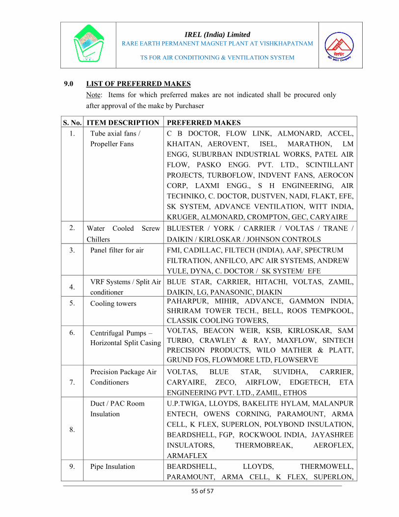
IREL (India) Limited
RARE EARTH PERMANENT MAGNET PLANT AT VISHKHAPATNAM
TS FOR AIR CONDITIONING & VENTILATION SYSTEM
55 of 57
9.0 LIST OF PREFERRED MAKES
Note: Items for which preferred makes are not indicated shall be procured only
after approval of the make by Purchaser
S. No. ITEM DESCRIPTION PREFERRED MAKES
1. Tube axial fans /
Propeller Fans
C B DOCTOR, FLOW LINK, ALMONARD, ACCEL,
KHAITAN, AEROVENT, ISEL, MARATHON, LM
ENGG, SUBURBAN INDUSTRIAL WORKS, PATEL AIR
FLOW, PASKO ENGG. PVT. LTD., SCINTILLANT
PROJECTS, TURBOFLOW, INDVENT FANS, AEROCON
CORP, LAXMI ENGG., S H ENGINEERING, AIR
TECHNIKO, C. DOCTOR, DUSTVEN, NADI, FLAKT, EFE,
SK SYSTEM, ADVANCE VENTILATION, WITT INDIA,
KRUGER, ALMONARD, CROMPTON, GEC, CARYAIRE
2. Water Cooled Screw
Chillers
BLUESTER / YORK / CARRIER / VOLTAS / TRANE /
DAIKIN / KIRLOSKAR / JOHNSON CONTROLS
3. Panel filter for air FMI, CADILLAC, FILTECH (INDIA), AAF, SPECTRUM
FILTRATION, ANFILCO, APC AIR SYSTEMS, ANDREW
YULE, DYNA, C. DOCTOR / SK SYSTEM/ EFE
4. VRF Systems / Split Air
conditioner
BLUE STAR, CARRIER, HITACHI, VOLTAS, ZAMIL,
DAIKIN, LG, PANASONIC, DIAKIN
5. Cooling towers PAHARPUR, MIHIR, ADVANCE, GAMMON INDIA, SHRIRAM TOWER TECH., BELL, ROOS TEMPKOOL, CLASSIK COOLING TOWERS,
6. Centrifugal Pumps – Horizontal Split Casing
VOLTAS, BEACON WEIR, KSB, KIRLOSKAR, SAM TURBO, CRAWLEY & RAY, MAXFLOW, SINTECH PRECISION PRODUCTS, WILO MATHER & PLATT, GRUND FOS, FLOWMORE LTD, FLOWSERVE
7.
Precision Package Air
Conditioners
VOLTAS, BLUE STAR, SUVIDHA, CARRIER,
CARYAIRE, ZECO, AIRFLOW, EDGETECH, ETA
ENGINEERING PVT. LTD., ZAMIL, ETHOS
8.
Duct / PAC Room
Insulation
U.P.TWIGA, LLOYDS, BAKELITE HYLAM, MALANPUR
ENTECH, OWENS CORNING, PARAMOUNT, ARMA
CELL, K FLEX, SUPERLON, POLYBOND INSULATION,
BEARDSHELL, FGP, ROCKWOOL INDIA, JAYASHREE
INSULATORS, THERMOBREAK, AEROFLEX,
ARMAFLEX
9. Pipe Insulation BEARDSHELL, LLOYDS, THERMOWELL,
PARAMOUNT, ARMA CELL, K FLEX, SUPERLON,

IREL (India) Limited
RARE EARTH PERMANENT MAGNET PLANT AT VISHKHAPATNAM
TS FOR AIR CONDITIONING & VENTILATION SYSTEM
56 of 57
S. No. ITEM DESCRIPTION PREFERRED MAKES
POLYBOND INSULATION, FGP, UP TWIGA,
ROCKWOOL INDIA, JAYASHREE INSULATORS,
THERMOBREAK
10. Coupling BIBBY (WELLMAN), FENNER, GBM
11. Bearing SKF/FAG/TATA
12. GI Sheets JINDAL, SAIL, TATA, BHUSHAN,
13. Vibration isolators DUNLOP, EMERALD, GERB, GETZNER
14.
Grills / Diffusers / Fire
Dampers
RAVISTAR, DYNACRAFT, COSMOS, AIRFLOW,
CARYAIRE, AIRMASTER, SYSTEM AIR, RUSKIN
TITUS, SOUTHERN COUGEN/ AQUAFLEX, VEDHA
ENTECH
15. 3/2 way Control Valve HONEYWELL, JOHNSON CONTROLS, SIEMENS
16. Fabricated Duct ROLASTAR, CAMDUCT, DUCTMASTER, WESTERN AIR
DUCTS, ZECO, VEDHA ENTECH
17. Balancing Valve ADVANCE, CASTLE, FLOWCON
18. Actuators SIEMENS, BELIMO, HONEYWELL, JOHNSON
CONTROLS
19. Pipes
TATA, GST, JINDAL , THE INDIAN SEAMLESS AND
METAL TUBES , MAHARASHTRA SEAMLESS LTD,
SAIL, ROURKELA, KALYANI SEAMLESS, ZENEITH
20. Pipe Fittings N.L. HAZRA, SHYAM ENGG, LIFE STYLE MARKETING,
M.S. FITTINGS, CHARGESON
21.
Valves – Gate, Globe &
Check Valve: Cast
Carbon Steel
FISHER XOMER SANMAR / NECO SCHUBERT &
SALZER / LEADER VALVES / KSB PUMP / FOURESS /
BDK / AUDCO / VALTECH INDUSTRIES / HAWA
ENGINEERING /AV VALVES / OSWAL INDUSTRIES /
FLUID CONTROL EQUIPMENT
22. Valves – Gate, Globe &
Check Valve: Cast Iron
GM DALUI & SONS / LEADER VALVES / LEVCON
VALVES / NECCO SCHUBERIL & SALZER LTD /
UPADHYAYA VALVES / H. SARKAR & CO./ AV
VALVES / IVC / SHIVA DURGA / VALTECH
INDUSTRIES / FLUID LINE VALVES / HAWA
ENGINEERING / FLUID CONTROL EQUIPMENT /
INDIAN VALVES / STEAM & MINING / KIRLOSKAR /
FOURESS / LEADER / DEWRANGE
23. Valves – Gate, Globe &
Check Valve: Forged
AUDCO / BDK / FOURESS / LEADER / NECO SCHUBERT
FISHER-XOMOX / AV VALVES / VALTECH

IREL (India) Limited
RARE EARTH PERMANENT MAGNET PLANT AT VISHKHAPATNAM
TS FOR AIR CONDITIONING & VENTILATION SYSTEM
57 of 57
S. No. ITEM DESCRIPTION PREFERRED MAKES
Steel INDUSTRIES / HAWA ENGINEERING / OSWAL
INDUSTRIES /FLUID CONTROL EQUIPMENT / KSB
24. Valves – Ball Valve:
Cast Carbon Steel
AUDCO / BDK / FOURESS / VIRGO / FISHER-XOMOX
SANMAR /OSWAL INDUSTRIES / REYNOLDS /
VALTECH INDUSTRIES / LEADER / KSB / ALFA LAVAL
/ HAWA
25. Valves – Ball Valve:
Cast Iron
AUDCO / BDK / FOURESS / REYNOLDS / VALTECH
INDUSTRIES / KSB / FLEX
26. Valves – Ball Valve:
Forged Steel
AUDCO / BDK / FOURESS / VIRGO / OSWAL
INDUSTRIES / REYNOLDS / VALTECH INDUSTRIES /
LEADER / KSB / ALFA LAVAL / HAWA
27.
Valves – Butterfly
Valve: Cast Carbon
Steel
AUDCO / BDK / FOURESS ENGG (INDIA) /
INTERVALVE / HI-TECH BUTTERFLY VALVES / FLUID
CONTROL EQUIPMENT / KEYSTONE
28. Valves – Butterfly
Valve: Cast Iron
AUDCO / BDK / FOURESS / INTER VALVE (INDIA) /
KSB PUMPS / SHIVA DURGA / UPADHAYA VALVES /
HI-TECH BUTTERFLY VALVES / FLUID CONTROL
EQUIPMENT / KEYSTONE / TYCO VALVES / AVC
ENGG / JASH / INDIAN VALVE
29. Valves – Butterfly
Valve: Forged Steel
AUDCO / BDK /FOURESS ENGG (INDIA) / INTERVALVE
/HI-TECH BUTTERFLY VALVES /KEYSTONE
30. Valve Actuators
AUMA / LIMITORQUE / ROTORK CONTROLS / EL-O-
MATIC
31. Valves – Control Valves
JNM / FISCHER XOMOX / FISHER ROSEMOUNT /
METSO / R.K. CONTROL / TOSHNIWAL / ILP
32. Valves – Flow Control
Valve
FISHER XOMOX / SAMSON(GMBH) / R.K.CONTROLS /
FISHER ROSEMOUNT
33. Valves – Needle Valves FISCHER XOMOX / TUFLIN / AUDCO / BDK
34. Valves – Non-return
Valve
AUDCO / BDK / FOURESS / KSB / XOMOX
35.
Turbine Ventilator
ENCON ENVIROTECH ENGINEERING / GOLDEN
ENGINEERING CO. PVT. LTD / REAL GREEN
ENGINEERS PVT. LTD.

IREL (India) Limited
MUMBAI
LIST OF RECOMMENDED SUPPLIERS FOR MAJOR TECHNOLOGICAL EQUIPMENT
FOR
RARE EARTH PERMANENT MAGNET PLANT
AT VISHAKHAPATNAM
MECON LIMITED BANGALORE
Doc. No MEC/Q7KN/01/31/S1/REPM/A013/R01 May’2020
Prepared by Checked by Approved by
Sandeep Ranjan Sandeep Ranjan A Venkata Rao

Sl. No. Item Description Recommended Suppliers
a) Weighing Machines
1. Contech Instruments Ltd, Navi Mumbai 2. CITIZEN SCALE (INDIA) PRIVATE LIMITED, Mumbai 3. Mettler-Toledo India Private Limited, Vadodara 4. Dhona Instruments (P) Ltd, Kolkata
b) Enclosure Box
c) Glove Boxes
d) Fume Hoods1. Clean Air Systems, Chennai 2. Modern Lab, Chennai
e) Sieve Shaker
f) Jaw Crushers
g) Disc Pulveriser
h) Planetary Ball Mill
i) Hydraulic Cutting Tools1. Evita Technologies, Hyderabad 2. TRANSCOM India, Kolkata
j) V Cone Blender Technic Pharma Equipments, Vasai/Palghar
k) Vacuum Drier1. Mansha Vacuum Equipments Pvt., Ltd, Bengaluru 2. Vacuum Techniques Pvt. Ltd., Bengaluru
l) Vacuum Induction Melting Furnaces
1. Inductotherm (India) Pvt. Ltd. (Authorised supplier of CONSARC equipment in India), Ahmedabad 2. EMPIRE MACHINE TOOLS -Mumbai (Authorised Agents of Retech Systems LLC, a Wholly Owned Subsidiary of Seco/Warwick SA)
m) Magnetic Field Press (Axial / Transverse) Electropneumatic & Hydraulics(I) Ltd, Pune
n) Heat Treatment Furnaces ALD Dynatech Furnaces Pvt Ltd, Navi Mumbai
o) Surface Grinding Machine:1. Evita Technologies, Hyderabad 2. Dhanukar machine tools, Palghar, 3. Atlas Machine Tools Corp. Ludhiana
p) Belt Grinding Machine:1. Evita Technologies, Hyderabad 2. Vijay Machine Tools Pvt. Ltd. Mumbai
q) Packaging M/c1. Intercon, Mumbai 2. Pravee Packaging, Rajkot
r) EDM1. Ratnaparkhi Electronics Ind Pvt Limited, Nashik 2. JK Machines, New Delhi
a) Calciner Furnace with Trays
1. Nanotec Lab, Chennai 2. Pathak Electrical Works, Mumbai 3. Therelek Engineers Private Limited, Bengaluru, 4. BIONICS SCIENTIFIC TECHNOLOGIES (P) LTD, Delhi 5. Tempo Instrument Pvt. ltd, Mumbai 6. KG Projects & Equipment Marketing Company Pvt. Ltd, New Delhi 7. BYSAKH & CO.India, Kolkata
b) Turbo-mixer
c) Jaw Crushers
d) Hammer Mill
e) Ro-Tap Sieve Shaker
f) Weighing Machines (50 / 10 / 3 / 0.5 Kgs)
1. Contech Instruments Ltd, Navi Mumbai 2. CITIZEN SCALE (INDIA) PRIVATE LIMITED, Mumbai 3. Mettler-Toledo India Private Limited, Vadodara 4. Dhona Instruments (P) Ltd, Kolkata
g) Retort Furnace 1. Nanotec Lab, Chennai 2. Therelek Engineers,Bengaluru 3. Ants Ceramics, Mumbai
h) Leaching Equipment1. Chem Tech Pro, Vadodara 2. M/s Plastochem Fabrication (India) Pvt. Ltd.
i) Glove Boxes 1. Vacuum Techniques Pvt. Ltd, Bengaluru 2. Hind High Vacuum, Bengaluru
j) Vacuum Drier1. Mansha Vacuum Equipments Pvt., Ltd, Bengaluru, 2. Hind High Vacuum Co. Ltd, Bengaluru
Toshniwal Brothers (SR) Private Limited, Bengaluru (Authorised Supplier for FRITSCH equipment in India), Bengaluru, Hyderabad
IREL-REPM - LIST OF PREFERRED MAKES FOR MAJOR TECHNOLOGICAL EQUIPMENT
RE Metal Plant Equipment
REPM Plant Equipment
1. Insmart Systems, Hyderabad 2. Toshniwal Brothers (SR) Private Limited, Bengaluru (Authorised Supplier for FRITSCH equipment in India), Bengaluru, Hyderabad
1. Vacuum Techniques Pvt. Ltd, Bengaluru 2. Hind High Vacuum, Bengaluru
PAGE 1 OF 5

Sl. No. Item Description Recommended Suppliers
IREL-REPM - LIST OF PREFERRED MAKES FOR MAJOR TECHNOLOGICAL EQUIPMENT
k) Vacuum Packaging/Storage M/Cs1. Intercon, Mumbai 2. Pravee Packaging, Rajkot
a) X- Ray Diffraction (XRD) Machine1. I.R. Technology Services PVT. Ltd (Authorised supplier of RIGAKU Corporation (JAPAN) equipment in India), Navi Mumbai 2. Bruker India Scientific Private Ltd, Mumbai
b) Oxygen Analyzer Chromatography and instruments Company, Vadodara
c) pH Meter
1. Labindia Instruments Pvt. Ltd. Navi Mumbai 2. Thermo-Fisher Scientific, Bengaluru 3.SYSTRONICS, Ahmedabad 4. Hanna Equipments India Pvt.Ltd, Navi Mumbai 5. Contech Instruments Ltd., Ahmedabad
d) Sub-sieve Autosizer Labindia Instruments Pvt. Ltd. Navi Mumbai
e) BH Loop Tracer
f) Pulse Magnetiser
g) ICP-OES Analyzer (CCD Type)1. Analytik Jena 2. Labindia Instruments Pvt. Ltd. Navi Mumbai
h)1. Portable Gauss Meter for Surface Flux Density Measurement with transverse and axial hall probe
i)2. Gauss Meter for Surface Flux density measurement with transverse and axial hall probe
a) Battery Operated Truck1. Jost's Engg Co. Ltd, Mumbai 2. Godrej & Boyce Mfg Co. Ltd, Mumbai
b) Hand operated Hydraulic trolley Industrial Equipment centre, Secunderabad
a)Air Compressor, Dryers, Receiver with associated pipings, fittings, accessories
1. Elgi Equipments Ltd, Bengaluru 2. Atlas Copco India Pvt Ltd, Pune 3. Kirloskar Pneumatic Co Ltd, Pune
b) Argon MCP with accessories Linde India Ltd, Bengaluru/Vizag
c) DM Plant & Sewage treatment Plant Equipment1. Ion-Exchange India Ltd 2. Envicare Systems, Pune
d) Heat Exchanger system1. Tranter India Pvt Ltd, Secunderabad 2. Alfa-Laval India Pvt Ltd, Pune
1 MCC ( Non – Draw out) SIEMENS/L&T/GE-PC/Schnieder Electric
2 MCCB/MPCB Schneider /L&T/Siemens/ABB
3 Contactors, relays Telemecanique/L & T / Siemens / Alstom
4 Indicating lamps (LED type ) Siemens/Raas Controls/L&T
5 Current Transformers AE / KAPPA / Gilbert & Maxwell / Pragati / Silkans / Instrans
6 Electromechanical Relay Easun Reyrolle/Alstom/ABB
7 Meters : Ammeter, Voltmeter AE / IMP / MECO / RISHAB
8 Control Supply Transformer Southern Electric / KAPPA / Automatic Electric / Kalpa / Pragathi Electrics
9 Miniature Circuit BreakersSIEMENS / MDS / GEPC / Havell / Indo Kopp / S & S Power Swtichgear / Standard
10 Push buttons Vaishno / Siemens / L & T / BCH / GEPC
11 Selector Switches Siemens / Alstom/ Kaycee / Salzer / Easun / GEPC/ L & T / RAAS
12 LT Power Cables & Control Cables.Delton/ Finolex / IND Cable / KEI / NICCO / Polycab / RPG / Torrent / Universal/Fort Gloster.
13 LT Motors Alstom/ ABB/ CGL
Air Conditioning & Ventilation System
DG Set - Mechanical & Electrical components
Structural Solutions Pvt Ltd (Authorised supplier of Laboratorio Elettrofisico Engg, Italy equipment in India), Hyderabad
Structural Solutions Pvt Ltd (Authorised supplier of Laboratorio Elettrofisico Engg, Italy equipment in India), Hyderabad
Transport equipment/facilities
Miscellaneous Equipment
Quality control Laboratory equipment
PAGE 2 OF 5

Sl. No. Item Description Recommended Suppliers
IREL-REPM - LIST OF PREFERRED MAKES FOR MAJOR TECHNOLOGICAL EQUIPMENT
1 Diesel Engine Caterpillar, Kohler, MTU, Cummins, KOEL.
2 Seamless Pipes Maharastra seamless, Jindal saw ltd, Metal & tube company
3 SS, CS, & GI pipesIndia seamless, Maharastra seamless, jindal, Tata iron & steel company ltd., Steel authority of India, Ratnamani, SAW pipes, Lloyds metal & engineers ltd., Zinith, Surya Roshni ltd., Suraj, Rajendra, Prakash,
4 SS, CS, & GI pipe fittingsGujarat infra pipe, EBY industries, Swastik Lloyds, Pipefit Enggrs. Shivananda, TEEKAY tubes
5 Fuel oil pumps Delta Corp n. (Tushaco), Roto pumps, Borne mann, Swelore.
6 FlangesParamount forge Chadhury hammer works, Punjab steelworks, JK forgings, Echjay industries, Kalpesh.
7 Centrifugal pumpsMather & Platt, Kirloskar Brother Limited, KSB Pumps, Kishore, Flow more, Beacon Weir Ltd., Sulzer pumps (I) limited.
8 Gear boxElecon, premium transmission, New Allenberry, Flender, as per manufacturer standard.
9 FastenersSyndicate engineering Harwin engrs., PTD fastners, Steel allied industries, Aggrawal, Banegar brothers, TVS sundaram, Unbrako, Fit tight,
10 Rubber Gasket Vitona elastomers, jay gaskets, perfect gasket, IGP
11 Spiral Wound Metallic Gaskets IGP, Madras industrial products, jay gaskets, Flexitallic.
12 Ball Valves & Non Return ValvesBDK, Audco India Ltd., Kirloskar brothers, Alfa laval (India) ltd., KSB pumps, Tyco, Leader Valves, Micro Finish Valves, Steel Strong Valves
13 Butterfly valvesAudco India Ltd., BDK, crane process, Fisher Xomox, Tyco, Sunders, Alfa laval (India) ltd., Leader valves, Microfinish valves, Steel strong valves
14 Insulation Lloyds insulations (I) limited, Rock Wool, Minwool
15 Alternator Kirloskar / Crompton Greaves / Stamford / Leroy Somers.
16 Generator Protection relays Areva / ABB / Siemens.
17 AMF Control panel C&S / Powergear.
18 ACB Siemens / Areva / ABB / L&T.
19 MCCB ABB / Siemens / Schneider / L&T.
20 Electro-mechanical & Aux. relays Areva / ABB / Easun Reyrolle.
21 LT Contactor and Thermal Over load relays Siemens / Telemecanique / L&T / ABB.
22 Selector switch/Control switch Areva / Kaycee / Salzer / Switron.
23 CTs AE / Kappa / Pragati.
24 Indicating Meters AE / Inudstrial Meters / MECO / Rishab.
25 Integrating Meters AE / IMP / Universal Instruments.
26 Indicating Lamps / Push Button Siemens / L&T.
27 Power Analyser Conzerve.
28 Tinned copper lugs Dowells / Electropower.
29 Battery Exide / Amco.
30 Battery Charger AE / Caldyne / HBI Nife.
Electrical System
PAGE 3 OF 5
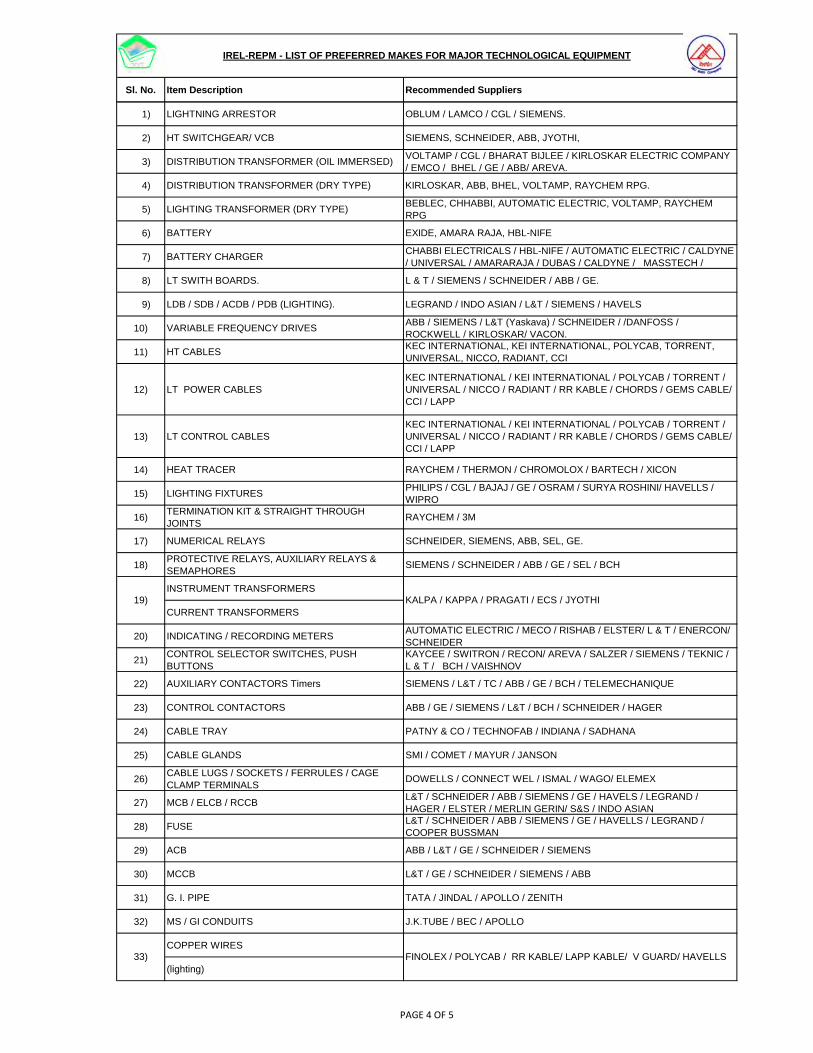
Sl. No. Item Description Recommended Suppliers
IREL-REPM - LIST OF PREFERRED MAKES FOR MAJOR TECHNOLOGICAL EQUIPMENT
1) LIGHTNING ARRESTOR OBLUM / LAMCO / CGL / SIEMENS.
2) HT SWITCHGEAR/ VCB SIEMENS, SCHNEIDER, ABB, JYOTHI,
3) DISTRIBUTION TRANSFORMER (OIL IMMERSED)VOLTAMP / CGL / BHARAT BIJLEE / KIRLOSKAR ELECTRIC COMPANY / EMCO / BHEL / GE / ABB/ AREVA.
4) DISTRIBUTION TRANSFORMER (DRY TYPE) KIRLOSKAR, ABB, BHEL, VOLTAMP, RAYCHEM RPG.
5) LIGHTING TRANSFORMER (DRY TYPE)BEBLEC, CHHABBI, AUTOMATIC ELECTRIC, VOLTAMP, RAYCHEM RPG
6) BATTERY EXIDE, AMARA RAJA, HBL-NIFE
7) BATTERY CHARGERCHABBI ELECTRICALS / HBL-NIFE / AUTOMATIC ELECTRIC / CALDYNE / UNIVERSAL / AMARARAJA / DUBAS / CALDYNE / MASSTECH /
8) LT SWITH BOARDS. L & T / SIEMENS / SCHNEIDER / ABB / GE.
9) LDB / SDB / ACDB / PDB (LIGHTING). LEGRAND / INDO ASIAN / L&T / SIEMENS / HAVELS
10) VARIABLE FREQUENCY DRIVESABB / SIEMENS / L&T (Yaskava) / SCHNEIDER / /DANFOSS / ROCKWELL / KIRLOSKAR/ VACON.
11) HT CABLESKEC INTERNATIONAL, KEI INTERNATIONAL, POLYCAB, TORRENT, UNIVERSAL, NICCO, RADIANT, CCI
12) LT POWER CABLESKEC INTERNATIONAL / KEI INTERNATIONAL / POLYCAB / TORRENT / UNIVERSAL / NICCO / RADIANT / RR KABLE / CHORDS / GEMS CABLE/ CCI / LAPP
13) LT CONTROL CABLESKEC INTERNATIONAL / KEI INTERNATIONAL / POLYCAB / TORRENT / UNIVERSAL / NICCO / RADIANT / RR KABLE / CHORDS / GEMS CABLE/ CCI / LAPP
14) HEAT TRACER RAYCHEM / THERMON / CHROMOLOX / BARTECH / XICON
15) LIGHTING FIXTURESPHILIPS / CGL / BAJAJ / GE / OSRAM / SURYA ROSHINI/ HAVELLS / WIPRO
16) TERMINATION KIT & STRAIGHT THROUGH JOINTS
RAYCHEM / 3M
17) NUMERICAL RELAYS SCHNEIDER, SIEMENS, ABB, SEL, GE.
18) PROTECTIVE RELAYS, AUXILIARY RELAYS & SEMAPHORES
SIEMENS / SCHNEIDER / ABB / GE / SEL / BCH
INSTRUMENT TRANSFORMERS
CURRENT TRANSFORMERS
20) INDICATING / RECORDING METERSAUTOMATIC ELECTRIC / MECO / RISHAB / ELSTER/ L & T / ENERCON/ SCHNEIDER
21) CONTROL SELECTOR SWITCHES, PUSH BUTTONS
KAYCEE / SWITRON / RECON/ AREVA / SALZER / SIEMENS / TEKNIC / L & T / BCH / VAISHNOV
22) AUXILIARY CONTACTORS Timers SIEMENS / L&T / TC / ABB / GE / BCH / TELEMECHANIQUE
23) CONTROL CONTACTORS ABB / GE / SIEMENS / L&T / BCH / SCHNEIDER / HAGER
24) CABLE TRAY PATNY & CO / TECHNOFAB / INDIANA / SADHANA
25) CABLE GLANDS SMI / COMET / MAYUR / JANSON
26) CABLE LUGS / SOCKETS / FERRULES / CAGE CLAMP TERMINALS
DOWELLS / CONNECT WEL / ISMAL / WAGO/ ELEMEX
27) MCB / ELCB / RCCBL&T / SCHNEIDER / ABB / SIEMENS / GE / HAVELS / LEGRAND / HAGER / ELSTER / MERLIN GERIN/ S&S / INDO ASIAN
28) FUSEL&T / SCHNEIDER / ABB / SIEMENS / GE / HAVELLS / LEGRAND / COOPER BUSSMAN
29) ACB ABB / L&T / GE / SCHNEIDER / SIEMENS
30) MCCB L&T / GE / SCHNEIDER / SIEMENS / ABB
31) G. I. PIPE TATA / JINDAL / APOLLO / ZENITH
32) MS / GI CONDUITS J.K.TUBE / BEC / APOLLO
COPPER WIRES
(lighting)
19) KALPA / KAPPA / PRAGATI / ECS / JYOTHI
33) FINOLEX / POLYCAB / RR KABLE/ LAPP KABLE/ V GUARD/ HAVELLS
PAGE 4 OF 5

Sl. No. Item Description Recommended Suppliers
IREL-REPM - LIST OF PREFERRED MAKES FOR MAJOR TECHNOLOGICAL EQUIPMENT
34) PVC CONDUITS AND PVC CASING ‘N’ CAPPING AVON PLAST / MODI / UNIVERSAL / PRECISION
35) DECORATIVE SWITCHES & SOCKETS ANCHOR / CRABTREE/ HAVELLS/ MK ELECTRIC
POWER PLUG & SOCKET
(INDUSTRIAL TYPE)
37) INDICATING LAMPSL&T / SCHNEIDER / SIEMENS / KEYCEE / PRECIFINE / TECHNIC/ BCH / VAISHNO / ESSEN
38) SOLID STATE ANNUNCIATOR L&T / PROCON / INSTALLARM / MINILEC
39) STREET LIGHTING POLES Rajan / KL Industries / Shubham
36) CROMPTON GREAVES / BEST& CROMPTON / EE / GEC / BCH
Note: 1. In case, the equipment is found not available from any of the preferred makes/recommended suppliers listed above, the bidder can procure from the other vendor on prior approval from owner/consultant after submission of credentials of technical capability of the propsed Vendor. 2. Any item/equipment which is not covered in above preferred makes, the bidder can procure from any reputed vendor on prior approval from owner/consultant after submission of credentials of technical capability of the propsed Vendor.
PAGE 5 OF 5

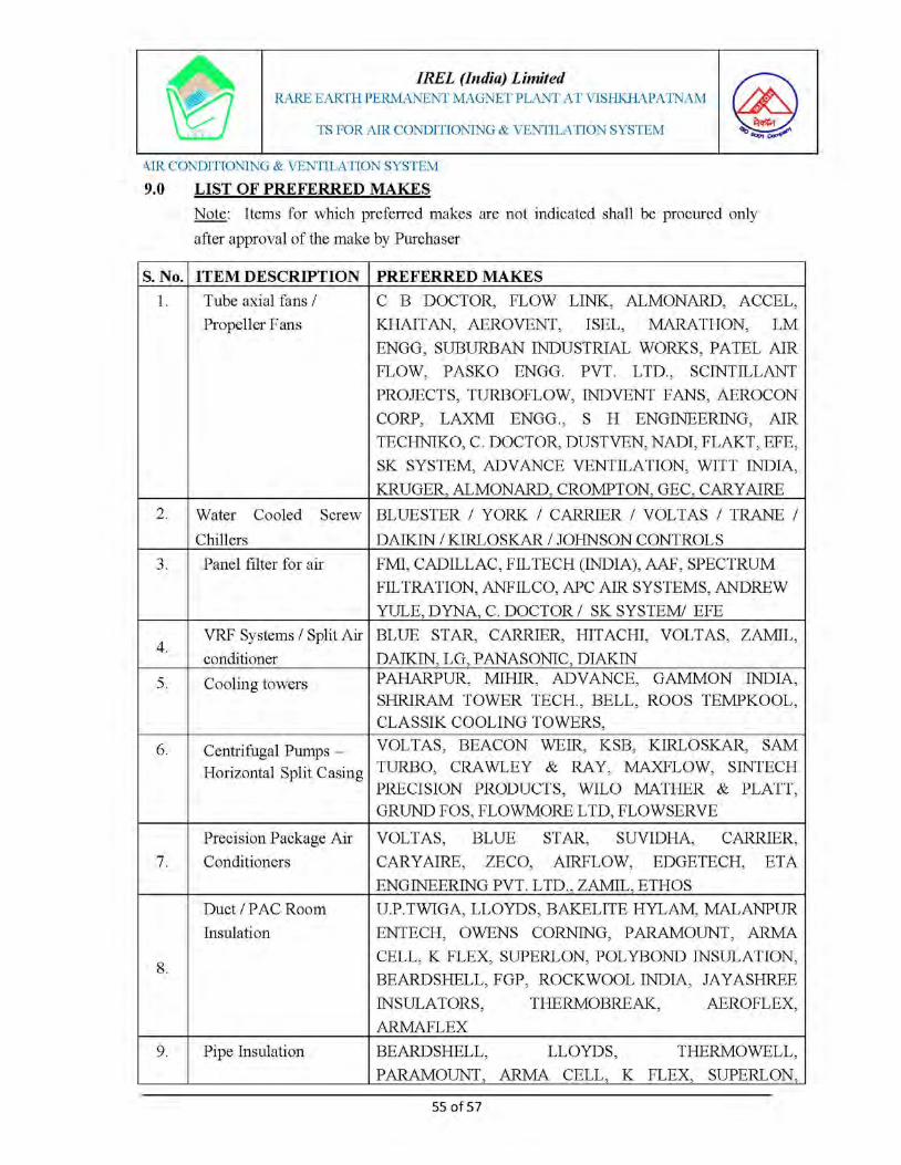


IREL (India) Limited
RARE EARTH PERMANENT MAGNET PLANT AT VISHKHAPATNAM
TECHNICAL SPECIFICATION FOR ELECTRICAL SYSTEM
T.S No. MEC/Q7KN/01/E1/S4/REPM/D401/R01
© 2020, MECON Limited. All rights reserved. Section-VIII Sheet No. 1 of 5
SECTION – VIII : PREFERRED LIST OF MAKES FOR EQUIPMENT

IREL (India) Limited
RARE EARTH PERMANENT MAGNET PLANT AT VISHKHAPATNAM
TECHNICAL SPECIFICATION FOR ELECTRICAL SYSTEM
T.S No. MEC/Q7KN/01/E1/S4/REPM/D401/R01
© 2020, MECON Limited. All rights reserved. Section-VIII Sheet No. 2 of 5
1.00 APPROVED VENDOR LIST FOR EQUIPMENT
a) Makes of the equipment offered shall be limited to the following only. In case of additional makes proposed by tenderer, same shall be subject to approval of Owner/ Consultant
b) Standardization (same make) shall be followed for a particular type of equipment in the plant by the tenderer.
c) The tenderer shall ensure that equipment and components are from Indigenous sources to the maximum possible. Imported equipment/components shall be resorted to only in case of Non availability of equipment/ component from Indigenous sources and with prior approval of owner/Consultant.
Sl. No.
ITEM DESCRIPTION PREFFERED MAKES
1) LIGHTNING ARRESTOR : OBLUM / LAMCO / CGL / SIEMENS.
2) HT SWITCHGEAR/ VCB : SIEMENS, SCHNEIDER, ABB, JYOTHI,
3) DISTRIBUTION TRANSFORMER (OIL IMMERSED)
:VOLTAMP / CGL / BHARAT BIJLEE / KIRLOSKAR ELECTRIC COMPANY / EMCO / BHEL / GE / ABB/ AREVA.
4) DISTRIBUTION TRANSFORMER (DRY TYPE)
:KIRLOSKAR, ABB, BHEL, VOLTAMP, RAYCHEM RPG.
5) LIGHTING TRANSFORMER (DRY TYPE)
:BEBLEC, CHHABBI, AUTOMATIC ELECTRIC, VOLTAMP, RAYCHEM RPG
6) BATTERY : EXIDE, AMARA RAJA, HBL-NIFE

IREL (India) Limited
RARE EARTH PERMANENT MAGNET PLANT AT VISHKHAPATNAM
TECHNICAL SPECIFICATION FOR ELECTRICAL SYSTEM
T.S No. MEC/Q7KN/01/E1/S4/REPM/D401/R01
© 2020, MECON Limited. All rights reserved. Section-VIII Sheet No. 3 of 5
7) BATTERY CHARGER :
CHABBI ELECTRICALS / HBL-NIFE / AUTOMATIC ELECTRIC / CALDYNE / UNIVERSAL / AMARARAJA / DUBAS / CALDYNE / MASSTECH / KELTRON / CHLORIDE POWER SYSTEMS / AUTOMATIC ELECTRIC
8) LT SWITH BOARDS. : L & T / SIEMENS / SCHNEIDER / ABB / GE.
9) LDB / SDB / ACDB / PDB (LIGHTING).
:LEGRAND / INDO ASIAN / L&T / SIEMENS / HAVELS
10) VARIABLE FREQUENCY DRIVES
:ABB / SIEMENS / L&T (Yaskava) / SCHNEIDER / /DANFOSS / ROCKWELL / KIRLOSKAR/ VACON.
11) HT CABLES :KEC INTERNATIONAL, KEI INTERNATIONAL, POLYCAB, TORRENT, UNIVERSAL, NICCO, RADIANT, CCI
12) LT POWER CABLES :
KEC INTERNATIONAL / KEI INTERNATIONAL / POLYCAB / TORRENT / UNIVERSAL / NICCO / RADIANT / RR KABLE / CHORDS / GEMS CABLE/ CCI / LAPP
13) LT CONTROL CABLES :
KEC INTERNATIONAL / KEI INTERNATIONAL / POLYCAB / TORRENT / UNIVERSAL / NICCO / RADIANT / RR KABLE / CHORDS / GEMS CABLE/ CCI / LAPP
14) HEAT TRACER :RAYCHEM / THERMON / CHROMOLOX / BARTECH / XICON
15) LIGHTING FIXTURES :
PHILIPS / CGL / BAJAJ / GE / OSRAM / SURYA ROSHINI/ HAVELLS / WIPRO
16) TERMINATION KIT & STRAIGHT THROUGH JOINTS
: RAYCHEM / 3M
17) NUMERICAL RELAYS : SCHNEIDER, SIEMENS, ABB, SEL, GE.
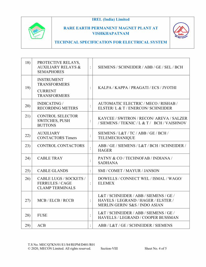
IREL (India) Limited
RARE EARTH PERMANENT MAGNET PLANT AT VISHKHAPATNAM
TECHNICAL SPECIFICATION FOR ELECTRICAL SYSTEM
T.S No. MEC/Q7KN/01/E1/S4/REPM/D401/R01
© 2020, MECON Limited. All rights reserved. Section-VIII Sheet No. 4 of 5
18) PROTECTIVE RELAYS, AUXILIARY RELAYS & SEMAPHORES
: SIEMENS / SCHNEIDER / ABB / GE / SEL / BCH
19)
INSTRUMENT TRANSFORMERS
CURRENT TRANSFORMERS
: KALPA / KAPPA / PRAGATI / ECS / JYOTHI
20) INDICATING / RECORDING METERS
:AUTOMATIC ELECTRIC / MECO / RISHAB / ELSTER/ L & T / ENERCON/ SCHNEIDER
21) CONTROL SELECTOR SWITCHES, PUSH BUTTONS
:KAYCEE / SWITRON / RECON/ AREVA / SALZER / SIEMENS / TEKNIC / L & T / BCH / VAISHNOV
22) AUXILIARY CONTACTORS Timers
:SIEMENS / L&T / TC / ABB / GE / BCH / TELEMECHANIQUE
23) CONTROL CONTACTORS :
ABB / GE / SIEMENS / L&T / BCH / SCHNEIDER / HAGER
24) CABLE TRAY :
PATNY & CO / TECHNOFAB / INDIANA / SADHANA
25) CABLE GLANDS : SMI / COMET / MAYUR / JANSON
26) CABLE LUGS / SOCKETS / FERRULES / CAGE CLAMP TERMINALS
:DOWELLS / CONNECT WEL / ISMAL / WAGO/ ELEMEX
27) MCB / ELCB / RCCB :L&T / SCHNEIDER / ABB / SIEMENS / GE / HAVELS / LEGRAND / HAGER / ELSTER / MERLIN GERIN/ S&S / INDO ASIAN
28) FUSE :L&T / SCHNEIDER / ABB / SIEMENS / GE / HAVELLS / LEGRAND / COOPER BUSSMAN
29) ACB : ABB / L&T / GE / SCHNEIDER / SIEMENS
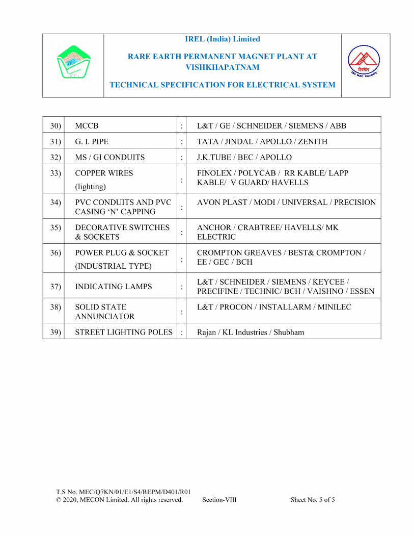
IREL (India) Limited
RARE EARTH PERMANENT MAGNET PLANT AT VISHKHAPATNAM
TECHNICAL SPECIFICATION FOR ELECTRICAL SYSTEM
T.S No. MEC/Q7KN/01/E1/S4/REPM/D401/R01
© 2020, MECON Limited. All rights reserved. Section-VIII Sheet No. 5 of 5
30) MCCB : L&T / GE / SCHNEIDER / SIEMENS / ABB
31) G. I. PIPE : TATA / JINDAL / APOLLO / ZENITH
32) MS / GI CONDUITS : J.K.TUBE / BEC / APOLLO
33) COPPER WIRES
(lighting) :
FINOLEX / POLYCAB / RR KABLE/ LAPP KABLE/ V GUARD/ HAVELLS
34) PVC CONDUITS AND PVC CASING ‘N’ CAPPING
:AVON PLAST / MODI / UNIVERSAL / PRECISION
35) DECORATIVE SWITCHES & SOCKETS
:ANCHOR / CRABTREE/ HAVELLS/ MK ELECTRIC
36) POWER PLUG & SOCKET
(INDUSTRIAL TYPE) :
CROMPTON GREAVES / BEST& CROMPTON / EE / GEC / BCH
37) INDICATING LAMPS :L&T / SCHNEIDER / SIEMENS / KEYCEE / PRECIFINE / TECHNIC/ BCH / VAISHNO / ESSEN
38) SOLID STATE ANNUNCIATOR
:L&T / PROCON / INSTALLARM / MINILEC
39) STREET LIGHTING POLES : Rajan / KL Industries / Shubham
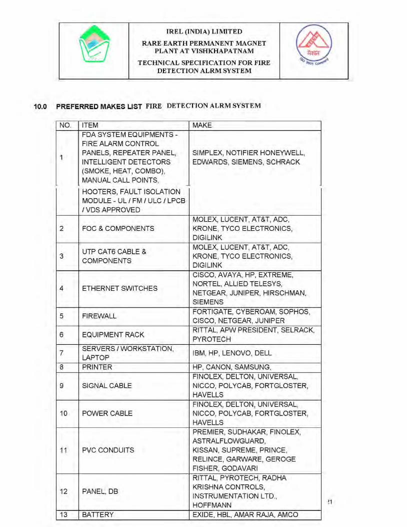


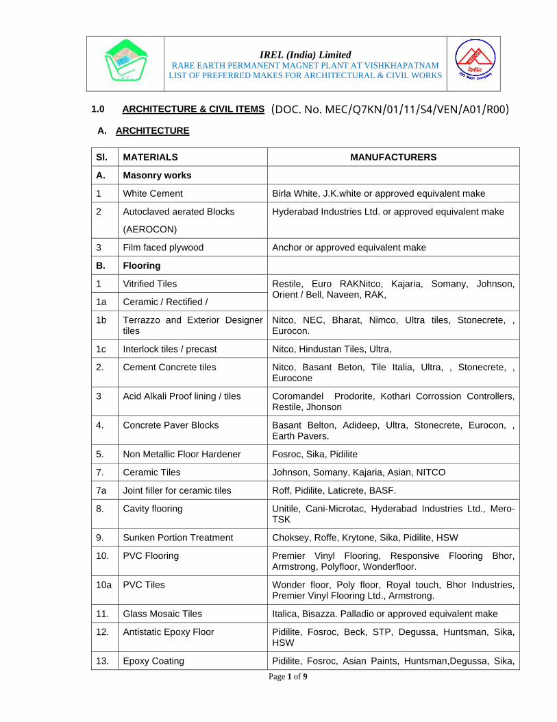
IREL (India) Limited
RARE EARTH PERMANENT MAGNET PLANT AT VISHKHAPATNAM LIST OF PREFERRED MAKES FOR ARCHITECTURAL & CIVIL WORKS
Page 1 of 9
1.0 ARCHITECTURE & CIVIL ITEMS
A. ARCHITECTURE
Sl. MATERIALS MANUFACTURERS
A. Masonry works
1 White Cement Birla White, J.K.white or approved equivalent make
2 Autoclaved aerated Blocks
(AEROCON)
Hyderabad Industries Ltd. or approved equivalent make
3 Film faced plywood Anchor or approved equivalent make
B. Flooring
1 Vitrified Tiles Restile, Euro RAKNitco, Kajaria, Somany, Johnson, Orient / Bell, Naveen, RAK,
1a Ceramic / Rectified /
1b Terrazzo and Exterior Designer tiles
Nitco, NEC, Bharat, Nimco, Ultra tiles, Stonecrete, , Eurocon.
1c Interlock tiles / precast Nitco, Hindustan Tiles, Ultra,
2. Cement Concrete tiles Nitco, Basant Beton, Tile Italia, Ultra, , Stonecrete, , Eurocone
3 Acid Alkali Proof lining / tiles Coromandel Prodorite, Kothari Corrossion Controllers, Restile, Jhonson
4. Concrete Paver Blocks Basant Belton, Adideep, Ultra, Stonecrete, Eurocon, , Earth Pavers.
5. Non Metallic Floor Hardener Fosroc, Sika, Pidilite
7. Ceramic Tiles Johnson, Somany, Kajaria, Asian, NITCO
7a Joint filler for ceramic tiles Roff, Pidilite, Laticrete, BASF.
8. Cavity flooring Unitile, Cani-Microtac, Hyderabad Industries Ltd., Mero-TSK
9. Sunken Portion Treatment Choksey, Roffe, Krytone, Sika, Pidilite, HSW
10. PVC Flooring Premier Vinyl Flooring, Responsive Flooring Bhor, Armstrong, Polyfloor, Wonderfloor.
10a PVC Tiles Wonder floor, Poly floor, Royal touch, Bhor Industries, Premier Vinyl Flooring Ltd., Armstrong.
11. Glass Mosaic Tiles Italica, Bisazza. Palladio or approved equivalent make
12. Antistatic Epoxy Floor Pidilite, Fosroc, Beck, STP, Degussa, Huntsman, Sika, HSW
13. Epoxy Coating Pidilite, Fosroc, Asian Paints, Huntsman,Degussa, Sika,
(DOC. No. MEC/Q7KN/01/11/S4/VEN/A01/R00)

IREL (India) Limited
RARE EARTH PERMANENT MAGNET PLANT AT VISHKHAPATNAM LIST OF PREFERRED MAKES FOR ARCHITECTURAL & CIVIL WORKS
Page 2 of 9
Sl. MATERIALS MANUFACTURERS HSW
C. Wood Works
1. Laminates/ Veneers Formica, Decolam, Century, Merino, National, Green Ply, Durian,LM Lahar, Royal touch, Archidply, Bison Panels
2. Pre-Laminated Particle Board/ Particle Board / Wooden Doors
Novopan, Greenlam, Kitlam, Bhutan Board, Indian Plywood Mfg, Co. Ltd., Indian Wood and Wood Products, Mangalore, Mysore Plywood Limited, Mis Western India Plywood, Orchid Ply
Swastic Wood, Duro, Archiply, Greenply.
3. Flush Door Shutters Kitply, Navapan, Green Ply, Kutty Flush Doors, Anchor, Anand, Kalptaru, Kothari Door, Masonite, Century, Greenply, ALPRO, Indian Plywood, Kutty Flush Doors, Mysore Plywood Ltd., Northern Doors, Wood India, Sakthi Flush Doors.
4. Block boards /Ply Board Greenply, Kitply, Indian Plywood Mfg., Nuboard, Mysore Plywood Ltd., Archidply, Alpro, Eco Board, National, Amul, Century, Kutty Flush doors, Joinery Manufacturer, Northern Doors, Wood India, Calcutta, Pioneer Timber Products,Chandigarh, Sakti Flush doors.
5. Pre-laminated MDF Board Mangalam Timber (Dura Tuff), Century or approved equivalent make
6. 35mm thick exterior grade panel door (both side laminated door)
Mangalam Timber (Dura Tuff) or approved equivalent make
7. 35mm thick exterior grade flush door
Mangalam Timber (Dura Tuff) or approved equivalent make
8. Dry wall partition Saint Gobain, USG or approved equivalent make
8a Adhesive for wood wo Dunlop, Fevicol, Vamicol, MRF
D. Steel Works
1. M.S. Pipe Jindal Hisar, Kalinga, TATA
2. Steel Doors, Windows, MS rolling Shutters, Pressed Steel Door Frames
Sen, Harvic; AGEW, Deccan Structural System, Multiwyn, NCL Seccolor Ltd., Madhu Industries, Swastic Rolling Shutters & Engineering Works, Basic Arch Products, Perfect Industrial Products, Shakti-Met-dor
3. Metal Fire Check Doors Godrej or approved equivalent make
3a Steel Doors & Windows Including fire rated doors
Madhu Industries, Sen, Harvic, AGEW, Hopes Metal, Multiwyn, NCL Seccolor Ltd, Godrej, Shakti-Met-dor
4. Stainless Steel Bolts, Screws, Washers, Nuts
Kundan, Puja, Atul or approved equivalent make

IREL (India) Limited
RARE EARTH PERMANENT MAGNET PLANT AT VISHKHAPATNAM LIST OF PREFERRED MAKES FOR ARCHITECTURAL & CIVIL WORKS
Page 3 of 9
Sl. MATERIALS MANUFACTURERS
5. Stainless Steel Pipes / Flats JINDAL / LLOYDS/ ZENITH/ REMI/ PRAKASH, SAIL/ SANDVIK/ CHOKSI Jindal, Salem Steel, or approved equivalent make,
5a STAINLESS STEEL MATERIALS FOR RAILING
SAIL/ Jindal, Tata
6. Dash Fasteners / Anchor bolts Hilti, Fictner, Canon, Fischer, Bosch, WORTH
7 Screws Gkw/ Nattlefold/ Oxidised.
E. Aluminum Works
1. Aluminium Sections Indal, Bhoruka, Hindalco, Jindal
Century Extrusions Ltd., GALCO, Pennar, Ajit India, Alumilite
2. Fabricator for aluminum Doors, Windows, Curtain Walls, Structural Glazing
Ajit India, Alumilite, ECIE, Alufit, Alfab, Aveey Associates, Hubli, Allied Aluminum, Singhvi Aluminum.
3. Aluminum Cleat arrangement for Glazings
Deco Indalco, Jindal or approved equivalent make
4. Aluminum Composite Panel Alstrong, Alpolic, Alucobond, or approved equivalent make
5. Door Seal – Woolpile Weather Strip
Anand – Reddiplex or approved equivalent make
6. E.P.D.M. Gaskets Anand Reddiplex, Enviro Seals or approved equivalent make
7. Aluminum fittings Doorex, Glassic, DEEP, Aasra
8 Aluminium Grills Deco/ Alumnigrille
F. Fittings & Fixtures
1. Doors & Windows Fixtures / Fittings
Everite, Hardwyn, Earl Bihari, Garnish, Crown, Jyothi, Godrej & Boyce, Secur Industries, Haffele, Ozone
Mouji, Lotus, Ashish, Asra, Jayanth Metal Manufacturer Co. Shalimar Hardware, Everite, IMEX, OXFORD, ARKAY
2. Stainless Steel Door handles, butt hinges (with and without ball bearings), Floor stoppers, Cabinet handles, knobs
KICH, ARCH, NEKI or approved equivalent make
2a Pressed Steel Door Frames Sen Harvic, Techome, Madhu Industries, Nishan Solid Door frame (Solidor), Anjali Enterprises, Sunbeam Shakti-Met-dor

IREL (India) Limited
RARE EARTH PERMANENT MAGNET PLANT AT VISHKHAPATNAM LIST OF PREFERRED MAKES FOR ARCHITECTURAL & CIVIL WORKS
Page 4 of 9
Sl. MATERIALS MANUFACTURERS
3. Stainless Steel Tower bolts, Sliding Bolts
GARG, ARCH, KICH or approved equivalent make
4. Door Closer / Floor spring Everite, Hardwyn, Garnish, Dorma, Hafele, ARCH, KICH
5. Door Locks ACME, Godrej, Harrison, PAG, Hafele
5a Hydraulic Door Closures / Floor Spring & Door Lock
Kelvin, Hyper, Godrej, Eddy, Everite, Hardwyn, Door King, Everest, Dorma, Dewan Industries, Ozone, Servax, Dorset Arkay.
5b SS Hinges Godrej Suzu.
6. Stainless Steel Friction Stay Securistyle, Hafele, Dorma, Hetich, ARCH, KICH or approved equivalent make
7. Aluminum Die-cast handles & two point locking kit.
Giesse, Securistyle, Alu-alpha or approved equivalent make
8. Stainless Steel -handles KICH, Hafele or approved equivalent make
9. Stainless Steel Handrails, Balustrade
KICH, Ozone, ARCH or approved equivalent make
G. PVC/FRP Doors
1.
PVC Doors/FRP Doors ACCUCEL, Thermodeck, Rajashree ,
Omega Fibres or approved equivalent make, Sintex, Rajashri Plastic, Thermodeck, Ambience, Akrosha, Plasopan, Nandini
2 UPVC Doors / windows Fenesta, Weatherseal, Duroplast approved equivalent
H. Painting Works
1. Synthetic Enamel Paints Berger, Asian Paints, Kansai, Nerolac, Jenson & Nicholson, Shalimar,
2. Oil Bound Distemper Asian paints, Berger, Kansai Nerolac, Jenson & Nicholson, Shalimar.
3. Cement Paint Snowcem Plus, Berger, Nerolac, Jenson & Nicholson, Shalimar, ICI Dulex
4. Internal acrylic emulsion paint Asian, Berger, Shalimar, Kansai-Nerolac, Jenson & Nicholson, Super Snowcem, ICI, I-Can Nano, MRF, British Paints.
4a Exterior Paints / Water Proof Cement Paints
Asian, Berger, Shalimar, Nerolac, Surfa Coats, Nitco, Hindustan Colours & Chemicals, Superme, Jenson & Nicholson, Super Snowcem, ICI, I-Can Nano, MRF, M/s Terraco (Terraccin & Terracoat) Ltd.

IREL (India) Limited
RARE EARTH PERMANENT MAGNET PLANT AT VISHKHAPATNAM LIST OF PREFERRED MAKES FOR ARCHITECTURAL & CIVIL WORKS
Page 5 of 9
Sl. MATERIALS MANUFACTURERS
4b Thermo Plastic Paints Shalimar, AutoMark, Asian, Berger, STP, Kataline
5. Exterior Emulsion Paint Dulux (AkzoNobel), Asian, Berger, Johnson & Nicholson, Shalimar, Snowcem Plus
6. Epoxy Paint Kansai-Nerolac, Shalimar, Asian Paints, Roto Polymer and Chemicals, Avcon Technics Pvt. Ltd., Huntsman, ICI, Berger, Jenson & Nicholson, BASF.
7. Cement based Wall Putty Birla, JK, Asian, I-Can Nano, Altek, Acqaproof, Italia
8. Other Paints / Primers Dulux (AkzoNobel), Asian, Berger, Nerolac
I. Glass Works / Polycarbonate Sheet Works
1. Glass/ Float Glass / Toughened Glass
Modi (GG), AIS (Tata), Saint Gobain (SG), Hindustan Pilkington, Asahi, Saint Gobain, Binani Industries, Modi Guard, Triveni, Hindustan, Asahi (AIS)
2. Reflective Glass Glaverbel, Glavermas, Saint Gobain
3. Polycarbonate Sheets GE Plastics, Everest, Sunlite or approved equivalent make
4 Structural glazing frame work Glass facades or approved equivalent
J. False Ceiling / False flooring Works
1. False ceiling – Gypsum Board System
India Gypsum, Laffarge, Boral, Saint Gobain, USG,
Gyproc
2. False ceiling – Aluminum Hunter Douglas (Luxalon), Armstong or approved equivalent make
3. Calcium Silicate Board Aerolite or Approved equivalent make.
3a Pre Laminated Cement Bonded Particle Board False Ceiling
Armstrong, Aerolite
3b False Floors Unitile, NMR Prefabs, Sintex, Mero-TSK
4 Wall Paneling, Mineral Fibrel Acoustic Tiles
Armstrong World Industries/ Indian Gypsum Ltd
5 Non-Asbestos Poly Sheet Everest/ Ramco/ Hyderabad Industries/ Swastik/ Visaka.
6 A/C Sheets Asbestos Cement Ltd (Everest)/ Charminar
K. Sanitary & Plumbing Works
1. Vitreous China Sanitary ware Hindware, Parryware, Kohler, Gabriet,Cera,
1a
Sanitary ware & Flushing Cistern Hindware/ Kohler/ Parryware/J r/ Rak/ Neycer/ Cera/ Johnson-Peddar/ Hindustan/ Roca/ Euro/ Toto/ American Standard.
2. White Glazed Fire Clay Sink Sanfire, Cera, Neycer, Hindware

IREL (India) Limited
RARE EARTH PERMANENT MAGNET PLANT AT VISHKHAPATNAM LIST OF PREFERRED MAKES FOR ARCHITECTURAL & CIVIL WORKS
Page 6 of 9
Sl. MATERIALS MANUFACTURERS
3. Stainless Steel Kitchen Sink Gilma/ Dayana/ Amc/ Parryware/ Prayag/ Frank/ Jayna/ Neelkamal/ Nirali/ Diamond
Orient, Suhag, Commander
4. Plastic Seat Cover of E. W.C. Commander, Bestolite, Diplomat, Jaquar, Sona, Gabriet
5. C.P. Brass Fittings (Plumbing) (General Purpose)
Gem /Parko/ Kingston/ Jal/ Ark/ Parryware/ Prayag/ Lauret/ Mbm/ Hindware/ Esso/ Seiko/ Leader
5a C.P. Brass Fittings (Premium Class)
Jaquar/ Marc/ Ess Essar/ Parryware-Roca/ Kohler/ Toto, Ebax, Nirali
6. Centrifugally / Sand Cast iron pipes & fittings & fixtures (IS 3989/1729)
R.I.F., J. NECO, B.C., B.I.C., ISP, SKF
SRIF, RIFKO, KFAI, Kapilesh, NEC
7. G.I. Pipes Tata, Jindal ,GST, Swastik, Zenith, Ambica, Bharat, Surya Prakash Indus tubes.
8. G.I. Fittings Unik, K.S., Zoloto, PEC, MJM, Bimal or approved equivalent make
9. Gunmetal Valves Zoloto, Leader, Sant, Kilburn, Neta
10. CP Brass stop & Bib Cock Jaquar, EssEss, MARC, Kohler
11. Ball valve with floats Zoloto, Leader, Sant, Jayco
15. PVC Water Tank Sintex, Polycon, Infra or approved equivalent make
16. Mirror Atul Glass Works, Modi Guard, Saint Gobain, Triveni, Aashi, Hindustan Pilkinton, Golden fish
17. Hand Drier Kopal, Automat, Euronics or approved equivalent make
18. PVC flushing cistern Commander, Parryware, Duralite, Hindware
19. PVC Rain Water Pipes Supreme, Prince, Finolex, Oriplast, Kisan
20. C.I. Pipes Class LA and fittings Keso-spun, supra, Electrosteel or approved equivalent make
20a C.I. Pipe & Fittings, Conforming to IS – 1729 /3989
Kesoram, Electro Steel, NECO, TATA, SAIL, RIFKO, Electrotherm.
20b S.C.I. Pipes & Fittings Conforming to IS 1729/3989
SRIF, RIFKO, KFAI, Kapilesh, NECO
21. UPVC / HDPE Pipes & fittings Finolex, Prince, Supreme, Kitec, Oriplast, Polyfab
21a Soil, Waste & Rainwater pipes & fittings, PVC / UPVC / CPVC Pipes
Premier, Sudhakar, Finolex, Astral – Flowguard, Kissan, Supreme, Prince, Reliance, Garware, Geroge Fisher, Godavari
22. C.P. Flush Valves Jaquar, Roca, MARC

IREL (India) Limited
RARE EARTH PERMANENT MAGNET PLANT AT VISHKHAPATNAM LIST OF PREFERRED MAKES FOR ARCHITECTURAL & CIVIL WORKS
Page 7 of 9
Sl. MATERIALS MANUFACTURERS
23. C.P. Angle Valves (Ball valve type)
ITAP : Italy, Bugatti, Italy
24. Gratings, Strainers, Cleanouts etc.
Near Brand (Sage Metals) or approved equivalent make
25. GI Plaster mesh M/s Arpitha Exports or approved equivalent make
26. CP liquid soap container (tilting type)
OMCO or approved equivalent make
27. PTMT Fittings Prayag/ Watertec/ Shakti.
28. Stone Ware (Salt Glazed) Pipes & Gully Trapes.
Mahakaushal/ Swastic/ Perfect/ Burn/ R.K/ Hindmaruti
L. Under deck / Over deck Insulation
1 Phenotherm Bakelite Hylem, Lloyds or approved equivalent make
2 Puff Bakelite Hylem, Lloyds or approved equivalent make
M. Boom barrier Gandhi Automation Pvt ltd. or approved equivalent
N. Turnstile Ski data or approved equivalent
O. Flush Doors Shutters Kalptaru, Kothari Door, Masonite, Century Greenply, ALPRO, Indian Plywood, Kutty Flush Doors, Mysore Plywood Ltd. Northern Doors, Wood India, Sakthi Flush Doors.
P. C.P. Brass Hardware Fittings (Wood Works)
Ebco, ACME, Gem, Zoloto, Navjyothi, Dorma,Jyoti, Garg, Crown, Jayant Metal Manufacturing, Shalimar Hardwares, Everite, Godrej, Oxford, ARKAY.
Q. Blinds Hunter Douglas, Maryel, Aerolux, Vista
B.CIVIL
Sl Description Manufacturer
1 Cement OPC-Grade 43 & 53 ACC, Ultratech, Birla make, Nagarjuna, Zuari, JK Cement, India Cement makes, Lafarge, CCI, Andhra Cement, Priya, Bharthi, Coromandal, Ramco, Gujarat Ambuja, JAYPEE, Mahashakti, Rajashree, Grasim
2 Cement PPC & Slag Cement Ultratech, Ambuja, Jay Pee, Mahashakti, JK Cement, India Cement makes, Lafarge, CCI, Andhra Cement, Coromandal, Ramco, Rajashree, Zuari, Grasim, Ameraja, Parashakthi, ACC, VLTECH
3 Reinforcement Steel SAIL, TATA Steel, RINL, JSPL, JSW
4 Anti Termite Chemical for Mysodel Pvt Ltd, Bayer, Bombay Chemicals, Hindustan Insecticides chemicals, Pest Control(I) Ltd, NOCIL

IREL (India) Limited
RARE EARTH PERMANENT MAGNET PLANT AT VISHKHAPATNAM LIST OF PREFERRED MAKES FOR ARCHITECTURAL & CIVIL WORKS
Page 8 of 9
Sl Description Manufacturer
Treatment (DURASBAN TC), LUPIN (CLASSIC 20), MONTARI INDUSTRIES (PYRAMID), CYNAMID(DURAMET), IPC
5 Water Stops (PVC / Rubber) Omai Plastics, RC Enterprises, Pidilite, 16Basecon, Pask, Asian, Capnhans India, Fixopan Engrs.
6 Expansion Joint and Tarfelt Water proofing
Shalitex, Shalimar Tar Products, LIoyd Insulation, Pidilite, Tiki Tar Industries
7 Admixtures, Injection Grouting & Epoxy Mortar
FOSROC, SIKA, ROFF, ACC, Mc-Bauchemi, Pidilite, SWC-Chryso, BASF, MYK, Choksey
8 Chemical products for RCC Rehabilitation works
Krishna Conchem, Fosroc, SIKA, Pidilite, BASF, STP, FYFE & Company
9 Wire mesh Sterling Enterprises, Trimurty welded mesh, Jeetmal Jalmal, Chand Jain.
10 Non-Shrink grout Compound SWC-Chryso, SIKA, FOSROC, STP Ltd, ACC
11 Sealants SIKA, Ge Silicon, Bostik
12 Polysulphide sealent Pidilite, Choksey, Fix bond
13 Polyurethane sealent Choksey, SIKA, Mahavir Chemical Industries
14 Steel Doors & Windows including fire rated doors
Madhu Industries, Sen Harvic, AGEW, Hopes Metal, Multiwyn, NCL Seccolor Ltd.
15 M.S. Rolling Shutters with or with out Galvanising
Standard, Shudwar, Vinayaka, Swastik Rolling Shutters, Hercules Rolling Shutters, M/s Bengal Rolling Shutters
16 Water proofing compounds false (Admixtures)
Pidi proof, Vamiplus, MYK, Mc-Bauchime, SIKA, Dr. Fixit-Pidilite, BASF, STP, Accoproof, Fosroc
17 M.S. Pipes Maharastra Seamless, Electro steel casting, SAIL, JINDAL SAW, TATA, ITC. KALI, ANI, SEAMLESS, GST
18 G.I. Pipes TATA pipes, JINDAL, G.S.T, Swastik, Zenith, Ambica, Bharat, Surya Prakash, Indus tubes, TATA Steel, Rahat Infra.
19 Soil, Waste & Rainwater pipes & fittings PVC, UPVC / CPVC pipes
Premier, Sudhakar, Finolex, Astral-Flowguard, Kissan, Supreme, Prince, Reliance, Garware, Geroge Fisher, Godavari
20 R.C.C. Hume Pipes Indian Hume Pipes, Pranali, Premier Prestressed Concrete, Pragati Concrete, Udyog, Patel Hume Pipes, Lalchand anand & Sons, KK Spun Raipur, Bhilai Cement manufacturing Company Bhilai, Grewal Cement Pipes Raipur, Laxmishri industries Raipur, Bhabani Cement pipe industries Kolkata, RCC Hume pipe & products Jagdalpur
21 Ductile Iron pipes TATA-Kubota, Jindal Saw, Electro steel casting, Lanco Industries
22 C.I. Manhole Cover & Frame SRIF, RIF NECO, IISCO, B.C., NEER
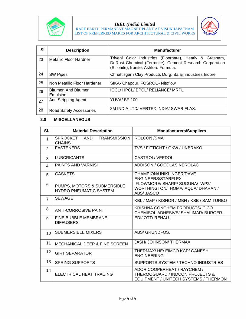
IREL (India) Limited
RARE EARTH PERMANENT MAGNET PLANT AT VISHKHAPATNAM LIST OF PREFERRED MAKES FOR ARCHITECTURAL & CIVIL WORKS
Page 9 of 9
Sl Description Manufacturer
23 Metallic Floor Hardner Triveni Color Industries (Floornate), Heatly & Grasham, DeRust Chemical (Ferronite), Cement Research Corporation (Stilonite), Ironite, Ashford Formula.
24 SW Pipes Chhattisgarh Clay Products Durg, Balaji industries Indore
25 Non Metallic Floor Hardener SIKA- Chapdur, FOSROC- Nitoflow
26 Bitumen And Bitumen Emulsion
IOCL/ HPCL/ BPCL/ RELIANCE/ MRPL
27 Anti-Stripping Agent YUVA/ BE 100
28 Road Safety Accessories 3M INDIA LTD/ VERTEX INDIA/ SWAR FLAX.
2.0 MISCELLANEOUS
Sl. Material Description Manufacturers/Suppliers
1 SPROCKET AND TRANSMISSION CHAINS
ROLCON /SMA
2 FASTENERS
TVS / FITTIGHT / GKW / UNBRAKO
3 LUBCRICANTS CASTROL/ VEEDOL
4 PAINTS AND VARNISH ADDISON / GOODLAS NEROLAC
5 GASKETS
CHAMPION/UNIKLINGER/DAVE ENGINEERS/STARFLEX
6 PUMPS, MOTORS & SUBMERSIBLE HYDRO PNEUMATIC SYSTEM
FLOWMORE/ SHARP/ SUGUNA/ WP2/ WORTHINGTON/ HOMA/ AQUA/ DHARANI/ ABS/ JASCO
7 SEWAGE
KBL / M&P / KISHOR / MBH / KSB / SAM TURBO
8 ANTI-CORROSIVE PAINT KRISHNA CONCHEM PRODUCTS/ CICO CHEMISOL ADHESIVE/ SHALIMAR/ BURGER.
9 FINE BUBBLE MEMBRANE DIFFUSERS
EDI/ OTT/ REHAU.
10 SUBMERSIBLE MIXERS
ABS/ GRUNDFOS.
11 MECHANICAL DEEP & FINE SCREEN JASH/ JOHNSON/ THERMAX.
12 GIRT SEPARATOR THERMAX/ HE/ EIMCO KCP/ GANESH ENGINEERING.
13 SPRING SUPPORTS SUPPORTS SYSTEM / TECHNO INDUSTRIES
14 ELECTRICAL HEAT TRACING
ADOR COOPERHEAT / RAYCHEM / THERMOGUARD / INDCON PROJECTS & EQUIPMENT / UNITECH SYSTEMS / THERMON

SCOPE OF WORK
Name of the project: RARE EARTH PERMANENT MAGNET(REPM) PLANT, VISAKHAPATNAM
Name of EQUIPMENTS:
A. JAW Crusher -02 Nos B. SIEVE SHAKER-01 No C. TURBO MIXER-02 Nos
1. Bidder shall study the Technical Information (technical specification, drawings, BOQ etc.) furnished in the NIT, (provided in separate volumes) and submit detailed implementation plan to EPI.
2. SCOPE OF WORK shall include all the items/equipment FOR DESIGN, Procurement, supply including transportation, packing, insurance FOR OVERSEAS TRANSPORTP, storage at site, fabrication, erection, Inspection, Testing, Calibration, Painting to complete the plant & equipment as per the Technical Specifications, drawings, Bill Of Quantities (BOQ) etc. furnished to the Bidder in this NIT for JAW Crusher, Sieve Shaker and Turbo Mixer.
3. The design engineering shall be in line with relevant IS, engineering code and as per statutory guidelines and norms is in the scope of Bidder.
4. Bidder to note that any item/work which is not specifically mentioned in Technical Specifications, drawings and BOQ but required to complete the plant & equipment for successful commissioning and smooth operation of the plant is also included in the scope of Bidder
5. Any modifications/changes required as per actual site conditions for successful commissioning and smooth operation of the plant is also included in the scope of Bidder without any additional cost to client.
6. The Bidder shall be responsible for obtaining approval from all applicable statutory & government authorities & Submission of drawing / documents required for statutory approvals as per tender document
7. The scope shall also include warranty conditions and other obligations as mentioned in this NIT.
8. The Bidder shall provide guarantee for the systems for safe operation and to meet the laid down norms in tender document
9. Any consumables, materials, instruments, spares, tools & tackles etc. required during equipment acceptance test at manufacturer’s premise and testing & commissioning runs at REPM plant is in the scope of the Bidder

10. Wherever required/instructed by EPI, Bidder shall mobilize the supplier or its authorized representative during the installation/ commissioning of the major equipment at REPM Plant site, without any extra claim
11. The Bidder shall be responsible for deployment of all the necessary resources (e.g. adequate manpower including key professionals, machinery & materials etc.) from commencement of execution of site activities till the commissioning and handing over of plant
12. Preparation & submission of As-built drawings /documents
13. Handing over the new constructed facility to the owner in fully operating condition
14. All equipment/ systems shall be complete in all respects and equipment or accessories not covered in the Technical Specification but essential for proper design and smooth operation and maintenance shall be deemed to be included in the scope of the Bidder
15. PRICES shall include price of Residual design Engineering, supply price of all materials required for completion of the Works in all respects and also shall include all associated activities for completing the work in accordance with the provisions of the Bidding Document
16. PRICES shall include supply, to owner, of all the materials required for incorporation in the permanent Works as determined by Bidder, within the scope of work, to be necessary to establish, commission and operate the Plant/Unit, as specified in the Price Schedule/Schedule of Prices
17. PRICES shall include the price of spare parts for pre-commissioning, commissioning, mandatory/critical spares and the price for such spares shall be included
18. PRICES shall include Procurement services of the materials and shall include other services & costs including but not limited to clearance of the goods through custom and port clearance including filling and/or filling of all custom manifests, bill of entry, and custom declarations and other documents as may be required for the clearance of the goods from custom or port authorities, stevedoring, clearing, forwarding, and handling services as required for clearing, forwarding, and handling imported and indigenous materials and consignments including payment of all Contractor’s cost of any demurrage, wharfage, port charges, siding charges, retention charges, detention charges or other charges whatsoever and howsoever designated or levied by any railway, airport, ship and/ or other authorities for or in connection with the loading or unloading of any materials or vessels or other means of transport beyond the free period or unloading, clearance, retention or detention of loading, as the case may be, provided by the relevant authorities in this connection.
18. PRICES shall include price for special tools and tackles, first fill of lubricants, if any.
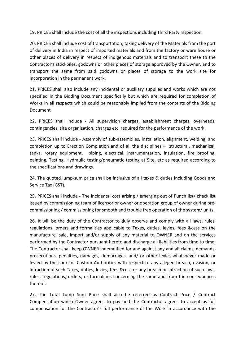
19. PRICES shall include the cost of all the inspections including Third Party Inspection.
20. PRICES shall include cost of transportation; taking delivery of the Materials from the port of delivery in India in respect of imported materials and from the factory or ware house or other places of delivery in respect of indigenous materials and to transport these to the Contractor’s stockpiles, godowns or other places of storage approved by the Owner, and to transport the same from said godowns or places of storage to the work site for incorporation in the permanent work.
21. PRICES shall also include any incidental or auxiliary supplies and works which are not specified in the Bidding Document specifically but which are required for completion of Works in all respects which could be reasonably implied from the contents of the Bidding Document
22. PRICES shall include - All supervision charges, establishment charges, overheads, contingencies, site organization, charges etc. required for the performance of the work
23. PRICES shall include - Assembly of sub-assemblies, installation, alignment, welding, and completion up to Erection Completion and of all the disciplines – structural, mechanical, tanks, rotary equipment, piping, electrical, instrumentation, insulation, fire proofing, painting, Testing, Hydraulic testing/pneumatic testing at Site, etc as required according to the specifications and drawings.
24. The quoted lump-sum price shall be inclusive of all taxes & duties including Goods and Service Tax (GST).
25. PRICES shall include - The incidental cost arising / emerging out of Punch list/ check list issued by commissioning team of licensor or owner or operation group of owner during pre-commissioning / commissioning for smooth and trouble free operation of the system/ units.
26. It will be the duty of the Contractor to duly observe and comply with all laws, rules, regulations, orders and formalities applicable to Taxes, duties, levies, fees &cess on the manufacture, sale, import and/or supply of any material to OWNER and on the services performed by the Contractor pursuant hereto and discharge all liabilities from time to time. The Contractor shall keep OWNER indemnified for and against any and all claims, demands, prosecutions, penalties, damages, demurrages, and/ or other levies whatsoever made or levied by the court or Custom Authorities with respect to any alleged breach, evasion, or infraction of such Taxes, duties, levies, fees &cess or any breach or infraction of such laws, rules, regulations, orders, or formalities concerning the same and from the consequences thereof.
27. The Total Lump Sum Price shall also be referred as Contract Price / Contract Compensation which Owner agrees to pay and the Contractor agrees to accept as full compensation for the Contractor’s full performance of the Work in accordance with the

provisions of the Contract Documents. These Prices shall be FIRM and not subjected to any price escalation. These Prices shall be FIXED AND NOT SUBJECTED TO ANY CHANGE as per provisions of the Contract.
28. The schedule of lump sum prices should be read with all other sections of the Bidding document
29. The Bidder shall be deemed to have studied the drawings, specifications and details of works to be done within the time schedule and to have acquainted himself of the conditions prevailing at REPM site in BARC (Vizag) /. It is the responsibility of the Bidder to assess the type and magnitude of work involved based on information furnished by the owner/Consultant and considering the general site conditions /codes /standards and Good Engineering Practices
29. In case any item, though specifically not covered in Schedule of Lump-sum Prices but the is covered under scope of work / specifications / drawings etc. included with bid, the same shall be provided by the Contractor to the EPIL with no extra claim on this account.
30. The total Lump-sum Price as quoted shall be deemed to include all costs to comply the detailed scope of work as Per Bid Documents/Technical Specifications etc. included with bid.
31. The total payment to be made to the Contractor shall be limited to the extent of work executed subject to maximum of total Lump-sum Price quoted
32. This being the domestic tender hence all bidders shall submit their Prices in Indian Currency only. Payment for this Contract shall also be made in Indian Rupees only.
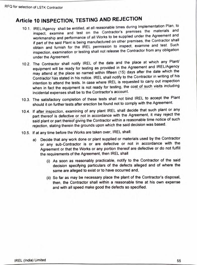
RFQ for selection of LSTK Contractor
Article 10 INSPECTION, TESTING AND REJECTION
10.1. IREL/Agency shall be entitled, at all reasonable times during Implementation Plan, to
inspect, examine and test on the Contractor's premises the materials and
workmanship and performance of all Works to be supplied under the Agreement and
if part of the said Plant is being manufactured on other premises, the Contractor shall
obtain and furnish for the IREL permission to inspect, examine and test. Such
inspection, examination or testing shall not release the Contractor from any obligation
under the Agreement.
10.2. The Contractor shall notify IREL of the date and the place at which any Plant/
equipment will be ready for testing as provided in the Agreement and IREL/Agency
may attend at the place so named within fifteen (15) days after the date which the
Contractor has stated in his notice. IREL shall notify to the Contractor in writing of his
intention to attend the tests. In case where IREL is requested to carry out inspection when in fact the equipment is not ready for testing, the cost of such visits including
incidental expenses shall be to the Contractor's account.
10.3. The satisfactory completion of these tests shall not bind IREL to accept the Plant
should it on further tests after erection be found not to comply with the Agreement.
10.4. If after inspection, examining of any plant IREL shall decide that such plant or any
part thereof is defective or not in accordance with the Agreement, it may reject the
said plant or part thereof giving the Contractor within a reasonable time notice of such
rejection, stating therein the grounds upon which the said decision was based.
10.5. If at any time before the Works are taken over, IREL shall:
Decide that any work done or plant supplied or materials used by the Contractor a)
or any sub-Contractor is or are defective or not in accordance with the
Agreement or that the Works or any portion thereof are defective or do not fulfill
the requirements of the Agreement, then IREL shal
(0) As soon as reasonably practicable, notify to the Contractor of the said decision specifying particulars of the defects alleged and of where the same are alleged to exist or to have occurred and
(i) So far as may be necessary place the plant of the Contractor's disposal then, the Contractor shall within a reasonable time at his own expense and with all speed make good the defects so specified.
IREL (India) Limited 55

RFQ for selection of LSTK Contractor
Article 11 Training of IREL's personnel 11.1 The Contractor shall arrange for training of IREL's personnel in India and/or
abroad (as applicable) for operation, maintenance and other services of the facilities under the Contractor's scope of supply. The contractor shall furnish the details of the training to be provided to IREL's personnel for the approval of IREL IREL, upon discussion with the Contractor, shall provide the field of training and man-days to the Contractor for compliance. The Contractor shall furnish the details of the training to be provided to IREL's personnel abroad for the approval of IREL as per following
11.1.1. The Contractor shall submit Schedule for Training of personnel of IREL
within a reasonable period but not later than six (6) months from the Effective Date of Contract. The schedule shall be mutually agreed upon between IREL and the Contractor.
11.1.2. Al the expenses related to travelling and living etc. (except domestic) shall
be borme by the Contractor for the Trainees.
11.1.3. IREL shall arrange necessary travel documents for its personnel. The Contractor shall, however, assist in arranging visa and medical insurance for such trainees, wherever necessary.
IREL (India) Limited 56

RFQ for selection of LSTK Contractor
Article 12 Mechanical Completion 12.1. Mechanical Completion shall be considered to be achieved when the plant is ready
for Trial Run and Commissioning (it covers supply 8& installation of all equipment facilities and thereafter completion of all activities, completion of all check list/ punch list items as provided by IREL and/or the Agency and/or Statutory bodies like. Fire & Safety Department, Electrical Inspector, Dept. of legal metrology (weights & measures).Factory Inspector, Pollution Control Authorities, etc. including insulation of pipe lines, hydrotest, calibration, painting etc. After completion of this activity
IREL/Agency will issue necessary Mechanical Completion Certificate.
IREL (India) Limited 57

RFO for selection of LSTK Contractor
Article 13 Trial Run
13.1 After Mechanical Completion of the Plant by the Contractor, Trial Run for indvidual equipment/ units shall be conducted by the Contractor to prove that the Plant has been suppied and erected as per Agreement and after erection, Plant is ft for start
up and Commissioning
13.1.1. Trial Run shall be so designed to conduct the systematic check of the components and of the functional operation thereof. Trial Run shall comprise idle.
no-load and part-load trial runs, as applicable. All personnel and necessary spares and raw materials consumables (except Sm03). if any. shall be
arranged by the Contractor.
13.1.2. IREL shall provide power, water and Sm2Os required for the purpose of Tmal Run
13.1.3. Trial Run shall be conducted by the Contractor under its sole responsibility and employing its own personnel. IREL's personnel shail, however, have the right to
witness the Trial Run.
13.2. As soon as all works in respect of Trial Run is completed and IREL is satisfied that the defects and / or deficiencies, indicated by IREL to the Contractor have been rectified the Contractor shall notify to IREL that Plant is fit for Commissioning and Throughput
Test as the case may.
IREL (India) Limited 58
RFQ for selection of LSTK Contractor
Article 14 Commissioning
14.1. After completion of Trial Run, the Contractor shall commission the Plant in accordanc
with provisions and terms of this Agreement
14.2. The Contractor shall provide all personnel and supply the commissioning spares and
raw materials / consumables (except SmO,) etc. required for Comnissioning
14.3. IREL shall provide power, water and Sm,O, required for Commissioning
14.4. Commissioning comprises of
14.4.1. conducting integrated trial run separately for each unit/equipment of the Plant
14.4.2. Throughput Test to be conducted by the Contractor to achieve required plant
capacity and any other parameters as per the Technical Information provided in
Annexure-IV.
14.5. IREL shall issue the Commissioning Certificate subject to the following
14.5.1. Commissioning has been successfully completed and the throughput of the
Plant, auxiliary systems and other parameters are as per the Technical
Information provided in Annexure-IV.
14.5.2. The Contractor has met all the objections/ observations, if any, contained in this
Agreement.
IREL (India) Limited 59

RFQ for selection of LSTK Contractor
Article 15 Operational Assistance for Process Setup
15.1. After successful Commissioning of the Plant by the Contractor, the Contractor shall start providing Operational Assistance for setting up the processes for ensuring smooth operation of the Plant, for a period of three (3) months from the Works
Completion Date 152 IREL shall provide power, water, consumables and raw material required for setting up
the processes for ensuring smooth operation of the Plant.
pply the necessary spares, tools, 15.3. The Contractor shall provide all personnel and tackles etc. required during the period of Operational Assistance for Process Setup and also ill do necessary rectifications/ modifications as per the finding during the seting up of Plant and operations, if any.
IREL (India) Limited
60
RFQ for selection of LSTK Contractor
Article 16 Final Acceptance 16.1. Final Acceptance shall occur in respect of the Works when:
16.1.1. Commissioning and Throughput Test completed by the Contractor
16.1.2. Three (3) months of Operational Assistance for Process Setup has been provided by the Contractor for setting up the processes for ensuring smooth
operation of the Plant
16.1.3. the Contractor has submitted all final "As Built" drawings and format along with
documents including operating manuals, OEM drawings, SOPs for the respective Works in accordance with the provisions of this Agreement as given in Annexure
V.
16.1.4. the Contractor has fulfilled all the obligations under the Agreement.
16.2. At any time after the events set out in Clause 16.1 hereof, have occurred, or in case of any delay not attributable to the Contractor for setting up the processes for
ensuring smooth operation of the Plant beyond the period of Operational Assistancefor Process Setup, Contractor may notify to IREL requesting for the issue of Final
Acceptance Certificate (FAC) for Works.
16.3. IREL, with due recommendation from the Agency, shall within fifteen (15) days after
receipt of the Contractor's notice, issue a FAC
16.4. Payment for Issuance of Final Acceptance Certificate' as per Sub-clause 22.14 and Retention Money, after adjustment of applicable Liquidated Damages, may be released by IREL against submission of Performance Bank Guarantee (by the Contractor) equal to 10% of the Agreement Value valid for 12 months from the date of
issue of FAC.
61 IREL (India) Limited

RFQ or selection of LSTK Contractor
Article 17 Ownership of Materials and Products
171 Notwithstanding anything in this Agreement IREL shal have absokute rights of the
input Materials & output Products at all tines and shall have owner ship and fitle over
the Plant and the Works in progress However the risk and liability of the Plant
including all its components like equipment material structure associated facilifies
and resources shal lie with the Contractor tll until completion of the period of
Operational Assistance for Process Setup as per the satisfaction of IREL Ater
completion of the period of Operational Assistance for Process Setup. the risk and
liability of the Plants including machinery. equipment. structures. toois& tackles
spares. manuals, drawings and any other components shall be transferred by the
Contractor to IREL in accordance with the terms and conditions of this Agreement
17.2 Notwithstanding anything in this Clause. the Contractor shall at all times be
responsible for monitoring the safety and security of its manpower, equipment. tools&
tackles etc being used for completion of Works
IREL (India) Limited 62

RFQ for selection of LSTK Contractor
Article 18 Declaration of the Contractor
T8.7. The Contractor acknowledges that prior to the execution of this Agreement, the
Contractor has after a complete and careful examination made an independent
evaluation of the Site conditions and all the information provided by IREL and has
determined to the Contractor's satisfaction the nature and extent of such difficuties
risks and hazards as are likely to arise or may be faced by the Contractor in the
course of performance of its obligations hereunder. The Contractor shall not be
entitled for any compensation, or extension in time, whatsoever on account of ts
failure to make such examination and evaluation
18.2. The Contractor does not, and shall not, at any time, claim ownership of the land
and/or space provided for the purpose of installation of the Plants. The Contractor is
undertaking the Works for and on behalf of IREL.
63 IREL (India) Limited

RFQ for selection of LSTK Contractor
Article 19 Obligations of the Contractor
19.1. Under this Agreement, the Contractor shall fulfil scope of work (the "Scopeof Work") defined in Technical Information attached as part of Annexure-V
192. Construction of temporary infrastructure
19.2.1. Contractor shall build, at his expense, any necessary temporary infrastruture
required for executing the Scope of Work as defined in Clause 19.1. The Contractor
will be solely responsible for watching and guarding of any temporary infrastructure
built, materials, plants, equipment etc.
19.22. The Contractor shall cover all his equipment and materials at site with requiste
insurance against theft, fire, tempest, flood, earthquake, etc.
19.23.Construction Power and Water shall be under the scope of the Contracto till Mechanical Completion. However, depending on availability with IREL, construction
water may, at the sole discretion of IREL, be provided on a chargeable basis to the
contractor on request.
19.3. Accommodation
19.3.1. IREL shall not be in a position to offer any lodging/ boarding facilities for Contractor's personnel Imen and it shall be the responsibility of the Contractor to
make his own arrangements in this respect. No permanent accommodation facilities shall be constructed by the Contractor at the Site.
19.3.2. The land may be provided by IREL for setting up a temporary labour camp near the project site, upon written request of the Contractor. The Contractor will be required to seek approval from IREL or any designated Technology Providers of IREL, upon the proposal showing actual land requirement, before setting up the
labour camp.
19.3.3. No personnel/ men of Contractor shall be allowed to stay during night time at Site, until unless so is desired for completion of Works or for security purpose. Only temporary structural shelters shall be constructed by Contractor at Site for stay during shift time break. All such temporary constructions as well as stay of Contractor's personnel/ men at Site during night shall be with due approval of
IREL/Agency.19.4. Co-ordination with other Agencies
194.1. The Contractor shall execute his work so as not to obstruct or retard the work being executed simultaneously by other agencies. This aspect shall also be considered while quoting for the Works.
19.4.2. The Contractor shall also follow all instructions from the Technology Providers during the execution of the Works.
19.5. Cleaning the site
19.5.1. The Contractor shall clean all required debris etc. at the site prior to the commencement of work at no extra cost.
IREL (India) Limited 64

RFQ for selection of LSTK Contractor
19.5 2. The Contractor shall comply to various conditions laid out by MoEF and APPCB
BARC Safety Committee and other statutory bodies as the case may be
195.3. On completion of Works the site shall be cleared of all men, materials, plant and
equipment belonging to the Contractor. The Contractor shall renove with IREL's
approval all his temporary arrangements for storage and distribution of construction
water, all electrical installations together with wiring or construction power, site
offices and all other temporary works and shall reinstate and make good any work
disturbed by the temporary work to the satisfaction of IREL. The site and
surroundings shall be handed over in a clean and neat condition as required by
IREL 19.6. The Contractor shall ensure that installation and Commissioning of the Plant on the
land/ space provided by IREL, within a stipulated period of eighteen (18) months from
the Efective Date of the Agreement, subject to the terms mentioned in Clause 19.12.
Indicative Schedule for Implementation for the same has been provided in Annexure
X.
19.7. The Plant is to be located suitably on the land/ space provided by IREL. The
Contractor shall finalize the Plants layout keeping in view the optimum utilization of
topography of the area;
19.8. All the activities related to the Works of this Agreement shall be under periodical
inspection of the representatives of IREL/ Agency/ other statutory bodies;
19.9. The Contractor shall arrange for training of IREL's personnel in India or abroad for
operation, maintenance and other services of the facilities under the Contractor's
scope of supply.
19.10.The employees of the Contractor, including any assignees, entrusted with the job of installation and Commissioning upto the stabilisation of the Plant shall be required to
follow, but not limited to, the Industrial Safety & Health Rules issued by Ministry of
Labour & Employment, Gol; 19.11.While undertaking Works for the Plants, the Contractor shall take all necessary
precautions against any untoward incident, inside the Site beside the area, earmarked
for installation of the Plants, and shall indemnify IREL for any accident, loss or
damage to the property of IREL or any third party due to negligence of the Contractor
and lor its representatives
19.12. The Contractor shall adhere to the Implementation Plan as submitted by the Contractor and approved by IREL after verification, mutual discussion and changes (if any), for successful Commission ing of the Plant, and the Contractor shall ensure no delay in Commissioning the Plants due to any reason whatsoever, other than Force Majeure and subject to IREL fulflling its obligations under this Agreement
19.13.The Contractor shall provide Operational Assistance for Process Setup for a period of three (3) months from the Works Completion Date
19.14. During the period of Operational Assistance for Process Setup, IREL shall provide all raw materials and utilities required for setting up the processes for ensuring smooth operation of the Plant. The Contractor shall provide necessary personnel and spares required during the Operational Assistance for Process Setup period. The cost
IREL (India) Limited 65

RFQ for selection of LSTK Contractor
towards the above is to be subsumed in the overall price quoted by Contractor andis included in LSTK Price
19 15. For any delay in Commissioning of the Plant, the Contractor shall compensate IREL for the loss suffered by IREL (Liquidated Damages) as mentioned in Clause 23 1 of this Agreement,
19 16 The Contractor shal not be the owner of the aforesaid civil structures, building. Plant
and machinery, associated facilities and land during the Agreement period, 19.17.The Contractor shall ensure all the statutory provisions of State Government, Central
Govemment, BARC Safety Committee (BSC) and local authorities including obtaining consent for operation from APPCB, BSC etc. Also, to comply with relevant Safety provisions/ norms at Site, labour laws and industrial laws, Atomic Energy Factory Rules for installation of the Plants/ engagement of labours are followed, and in no
case, the employees / workers engaged by the Contractor directly or indirectly, shall
be the employee of IREL. Any violation of any of the provisions by the Contractor and or its representatives, the same shall be indemnified by them to IREL, against any claim/ demand made by any authority:
19.18. The Contractor shall take all necessary steps for obtaining certficate under the provisions of the Agreement, Labour (Regulation & Abolition) Act, 1970 and the rules made there-under for engaging any contractor and contract labours and comply with all provisions of the said act and the rules;
19.19.Procure raw materials (except Sm203) and consumables for operation of the Plant till Commissioning, or 3 months of consumption, whichever is later.
19.20.The Contractor shall ensure all the environmental norms and regulation under the relevant authorities are followed.
19.21.The Contractor shall be responsible for getting all required approvals and clearances for construction, erection and commissioning of the REPM Plant. IREL shall provide all administrative and facilitating support as required. All statutory costs for getting the clearances shall be reimbursed by IREL at actuals upon submission of documentary
proofs.
19.22.The Contractor shall take all necessary steps for obtaining required approvals and clearances. However, in case of delay(s). not attributable to the Contractor in
receiving the approvallclearances beyond forty-five (45) days from the date of application, IREL may, upon sutable justification, provide necessary extension in Works Completion Date. Any such extension in Works Completion Date shall be provided only in case of no cost obligation to IREL and its decision on said matter shall stand final, as the case may be.
19.23.The Contractor shall provide OEM warranty to IREL for all plant and machinery including QC instruments valid for a period of 1 year from the date of issue of Final
Acceptance Certificate.
19.24. Further, in case of these QC instruments- X- Ray Diffractometer, ICP-OES Analyzer, Oxygen Analyser, BH Loop tracer, Pulse Magnetizer, the Contractor has to provide 3 years extended warranty. A Bank Guarantee from any Indian Nationalised Bank for an amount equal to 5% of the amount billed to IREL against the aforesaid Qc
IREL (India) Limited 66

RFQ for selection of LSTK Contractor
instruments shall be provided by the Contractor in support of 3 years extended warranty beyond the defect liability product period This 5% BG to be to be subrnitted prior to expiry of Perfomance Bank Guarantee
19.25 After successful Commissioning and handing over of the plant to IREL. the Contractor shall provide life cycle support in maintenance and spares supply for critical equipment for the smooth operation of the plant in future on a chargeable basis,
whenever and if so, desired by IREL.
19.26 Contractor shall supply critical/mandatory spares required for trouble free operation of the Plant during the Defect Liability Period as defined in Article 26.
19.27. The Contractor shall ensure that the equipment and all materials supplied under the
Contract are not obsolete, new, unused, of the most recent or current models and incorporate all recentimprovements in design and materials unless provided otherwise in the Agreement. The Contractor shall further warrant that the goods supplied under this Agreement shall have no defect arising from design, materials or
workmanship. 19.28. The Contractor warrants that they will provide competent, qualified and sufficiently
experienced personnel to perform the work correctly and efficiently and shall ensure
that such personnel observe all applicable and statutory safety requirement including instructions from IREL and BARC. Upon IREL's written request, Contractor, entirely at their own expense, shall remove immediately, from assignment to the work, any personnel of the Contractor determined by IREL to be unsuitable and shall promptly replace such personnel with personnel of sufficient quality, competence and
experience. The Contractor shall adhere to the following conditions with respect to
deployment of site managers/ supervisors and site executives:
19.28.1.All site manager/supervisor provided by the Contractor should have at least a
Bachelor's degree in Engineering (B.Tech./ B.E) with at least 8 years of relevant industrial experience.
19.28.2.Minimum 4 site executives to be deployed by the Contractor with at least 3 years of relevant industrial experience. A Bachelor's degree in Engineering
(B.Tech/ B.E) shall be preferred for the same.
At least one of the site executives should have a hands-on experience in Project Management Software (MS Project etc..
IREL (India) Limited 67

RFQ for selection of LSTK Contractor
Article 20 Obligations of IREL
the Agreement, IREL shall provide the Contractor and 20.1. Unless otherwise specified
its Personnel with work permits and such other documents as may be necessary to
enable the Contractor, or its Personnel to perform the services.
20.2. Acess to land and property
IREL warants that the Contractor shall have, free of charge, unimpeded
access to the Site of the Project in respect of which access is required for the
performance of Works;
20.2.1.
20.3. Payment
In consideration of the Works performed by the Contractor under this
Agreement, IREL shall make to the Contractor such undisputed payments and
in such manner as is provided in Article 21 and Article 22 of this Agreement.
20.3.1.
IREL (India) Limited 68
IREL (India) Limited (IREL) 99
Article 20 Indemnity
20.1. The Contractor (“Indemnifying Party”) shall indemnify IREL (“Indemnified Party”) against any claim or damage, demand and any other expenses incurred by IREL for defending such claims / demand made by any authority due to the commission, omission and negligence on the part of the Contractor in complying with any of the statutory provisions, being the owner of the Plants;
20.2. Without prejudice to the generality of Clause 20.1, the Indemnifying Party shall indemnify, and keep the Indemnified Party indemnified against any claim, damages, compensation proceeding, suit and any award rendered in any such suit or proceeding where such claim, proceeding, suit arises out of or in relation to:
20.2.1. Violation or breach of any Applicable Law as may be applicable to the Agreement which may arise out of or in consequence of the construction or maintenance or performance of the Works under the Agreement;
20.2.2. Breach of any conditions imposed by all and any Government Approvals in relation to the Works or any part thereof;
20.2.3. Infringement of any domestic or foreign patent rights, copyrights or other Intellectual Property, proprietary or confidentiality rights with respect to any materials, information, design or process used by the Contractor or by the Sub-contractors in performing the Contractor’s obligations or in any way incorporated in or related to the Project;
20.2.4. Any accident or injury caused to any Third Party, any employee of the Indemnified Party, where such accident or injury is directly or indirectly attributable to any act, omission or negligence on the part of the Indemnifying Party, its agents, representatives or employees.
20.2.5. Any damage or loss of any property, real or personal, to the extent that such damage or loss arises out of or in the course of or by reason of the execution and completion of the Works and the remedying of any defects by the Contractor.
20.2.6. Any breach of the representations and warranties provided herein.
20.2.7. Any sum payable by IREL to Contractor for any breach of the Agreement, or otherwise which is directly or indirectly attributable to the acts and /or omission of the Contractor, its agents, representatives or employees under this Agreement.
20.2.8. The Contractor shall indemnify IREL and keep IREL indemnified to the extent of the value of free issue materials, if applicable, to be issued till such time the entire Agreementis executed and proper account for the free issue materials is rendered. The Contractor shall not utilize IREL’s free issue materials for any job other than the one contracted out in this Agreement and also not indulge in any act, commission or negligence which shall cause/result in any loss/damage to IREL and in which case, the Contractor shall be liable to IREL to pay compensation to the full extent of damage/loss and undertakes to pay the same.

Draft Agreement for undertaking procurement, supply, commissioning, erection and commissioning for REPM Plant
IREL (India) Limited (IREL) 100
Article 21 Insurance 21.1. The Contractor, at its sole cost and expense, shall continue to obtain and maintain all
the construction insurance policies and operational insurance policies required to be taken in respect of the Plant or as may be necessary in accordance with the Prudent Operating Practices. The Contractor shall ensure that IREL is named as an additional insured on all insurance policies with respect to third party liability insurance. Any failure by the Contractor to obtain the insurance coverage or certificates of insurance as required, shall neither relieve the Contractor of the insurance requirements set forth herein nor relieve or limit in any way the Contractor’s obligations and liabilities under any other provision of this Agreement;
21.2. The under mentioned minimum coverage or such additional coverage as may reasonably be required, shall be maintained or caused to be maintained by the Contractor throughout the Agreement period:
Workers Compensation and Employers General Liability Insurance
Builders All Risk Insurance Marine Cargo insurance (if required)
All Risk Property/Comprehensive Machinery Insurance (Upon Completion ofConstruction)
Third party Liability Insurance
21.3. To the extent that the above insurance policies are available through Indian insurance companies, preference shall be given to using these companies.
21.4. Notwithstanding any liability that may arise under this Agreement, any loss for which compensation is due to the Contractor under this Clause, shall not be charged to IREL.
21.5. The Contractor shall cause its insurers or agents to provide IREL with certificates of insurance for required replacement policies or renewals evidencing the endorsements of policies, at least thirty (30) days prior to either termination or expiration of any policy hereunder.
Draft Agreement for undertaking procurement, supply, commissioning, erection and commissioning for REPM Plant
IREL (India) Limited (IREL) 101
Article 22 Force Majeure 22.1. “Force Majeure” is an event beyond the control of Contractor and not involving the
Contractor’s fault or negligence and which is not foreseeable. Such events may include, but are not restricted to acts of IREL/ Contractor either in its sovereign or contractual capacity, wars or revolution, hostility, acts of public enemy, civil commotion, floods, explosions, epidemics, quarantine restrictions, strikes, lockouts and freight embargoes or any other event which IREL may deem fit to consider so. The decision about Force Majeure shall rest with IREL that shall be final and binding. Force Majeure clause has to be compulsorily embedded in the order;
22.2. If there is delay in performance or other failures by the Contractor to perform obligations under this Agreementdue to event of a Force Majeure, the Contractor shall not be held responsible for such delays/failures;
22.3. If a Force Majeure situation arises, the Contractor shall promptly notify IREL in writing of such conditions and the cause thereof within fifteen (15) days of occurrence of such event. Unless otherwise directed by IREL in writing, the Contractor shall continue to perform its obligations under the Agreement as far as reasonable/practical and shall seek all reasonable alternative means for performance not prevented by the Force Majeure event;
22.4. If the performance in whole or in part or any obligation under this Agreement is prevented or delayed by any reason of Force Majeure for a period of exceeding sixty (60) days, IREL may at its option terminate the Agreement,without any financialrepercussion on either side;
22.5. Any delay or non-performance by either Party hereto caused by the occurrence of any event of Force Majeure shall not:
22.5.1. constitute a default or breach of the Agreement;
22.5.2. give rise to any claim for damages or additional cost or expense occasioned thereby;
If and to the extent that such delay or non-performance is caused by the occurrence of an event of Force Majeure.

Draft Agreement for undertaking procurement, supply, commissioning, erection and commissioning for REPM Plant
IREL (India) Limited (IREL) 102
Article 23 Breach of Terms, Suspension and Termination 23.1. Breach of Terms
23.1.1. Should either Party here-to commit breach of any of the terms of this Agreement and in any such case the other Party, shall be entitled, without incurring any liability what-so-ever, to fore-bear from doing such acts or fulfilling such obligations as are to be done or fulfilled by it here under until the Party committing breach on terms herein makes good the said breach;
23.2. Suspension
23.2.1. IREL may suspend the Works in whole or in part at any time by giving the Contractor a notice in writing, if the Contractor shall be in breach of this Agreement or shall fail to perform any of its obligations under this Agreement, including the carrying out of the Works; provided that such notice of suspension (i) shall specify the nature of the breach or failure, and (ii) shall provide an opportunity to the Contractor to remedy such breach or failure within a period not exceeding 30 (thirty) days after receipt by the Contractor of such notice of suspension.
23.2.2. On receiving the notice of suspension from IREL, the Contractor shall stop all such work, which IREL has directed to be suspended with immediate effect. IREL may at any time cancel the suspension notice for all or any part of suspended work by giving written notice to the Contractor specifying the part of work to be resumed and the effective date of suspension withdrawal. The Contractor shall resume the suspended work as expeditiously as possible after receipt of such withdrawal of suspension notice. In the event of suspension of work, IREL shall not be liable to the Contractor for any damage and loss.
23.3. Temporary Suspension:
23.3.1. IREL may at any time temporarily hold the progress of work being performed under the Agreement or any part thereof by notice in writing to the Contractor. All the work so held shall be resumed by the Contractor and extended suitably for the period amounting to temporary suspension based on a schedule as directed by IREL and mutually agreed upon between the Contractor and IREL.
23.3.2. IREL will not pay the Contractor for any work, which is performed during such an interval of suspension, andIREL shall not be liable to the Contractor for any damages or loss caused by such suspension of work.
23.4. Event of Default
Event of Default means the Contractor Event of Default or IREL Event of Default or both as the context may admit or require.
23.4.1. ContractorEvent of Default
Any of the following events shall constitute an event of default by the Contractor("Contractor Event of Default") unless such event has occurred as a result of IREL Event of Default or a Force Majeure event;

Draft Agreement for undertaking procurement, supply, commissioning, erection and commissioning for REPM Plant
IREL (India) Limited (IREL) 103
a. the Contractor fails to remedy any breach hereof or any failure in the performance of its obligations hereunder, as specified in a notice of suspension pursuant to Sub-clause 23.2.1hereinabove, within 30 (thirty) days of receipt of such notice of suspension or within such further period as IREL may have subsequently granted in writing
b. The Contractor fails to commence the Works within thirty (30) days from the Effective Date;
c. The Contractor fails to ensure that Works Completion Date of the Plant is achieved within eighteen (11) months of the Effective Date;
d. Any representation made or warranties given by the Contractor under this Agreement is found to be false or misleading;
e. The transfer, pursuant to law of either (a) the rights and/or obligations of the Contractor under the Agreement, or (b) all or material part of the Contractor; except where such transfer in the reasonable opinion of IREL does not affect the ability of the Contractor to perform, and the Contractor has the financial and technical capability to perform, its material obligations under the Agreement;
f. The Contractor suspends or abandons the Works without prior consent of IREL, provided that the Contractor shall be deemed not to have suspended/ abandoned operation if such suspension/ abandonment was (i) as a result of Force Majeure Event and is only for the period such Force Majeure is continuing, or (ii) is on account of a breach of its obligations under this Agreement by IREL;
g. the Contractor becomes insolvent or bankrupt or enters into any agreement with its creditors for relief of debt or take advantage of any law for the benefit of debtors or goes into liquidation or receivership whether compulsory or voluntary;
h. the Contractor fails to comply with any final decision reached as a result of arbitration proceedings pursuant to Clause 23.2 hereof;
i. the Contractor submits to IREL a statement which has a material effect on the rights, obligations or interests of IREL and which the Contractor knows to be false;
j. any document, information, data or statement submitted by the Contractor in its Bid, based on which the Contractor was considered eligible or successful, is found to be false, incorrect or misleading; or
k. The Contractor repudiates this Agreement or otherwise evidences an intention not to be bound by this Agreement.
23.4.2. IREL Event of Default
The following events shall constitute events of default by IREL ("IREL Event of Default”), unless any such IREL Event of Default has occurred as a result of Contractor Event of Default or due to a Force Majeure Event:
Draft Agreement for undertaking procurement, supply, commissioning, erection and commissioning for REPM Plant
IREL (India) Limited (IREL) 104
a. IREL is in breach of this Agreement and has failed to cure such breach within sixty (60) days of receipt of notice in that behalf from the Contractor;
b. IREL repudiates this Agreement or otherwise evidences an intention not to be bound by this Agreement;
c. Any representation made or warranties given by IREL under this Agreement is found to be false or misleading.
23.5. Recourse to Event of Default
23.5.1. In case of an event of default, the following recourse is available to IREL and the Contractor or both as the situation may warrant:
a. In case of occurrence of Event of Default mentioned in Sub-clause 23.4.1.b and Sub-clause 23.4.1.c, the Contractor shall have an option to ask for extension from IREL specifying the conditions that have restricted the Contractorto complete the tasks in stipulated time. However, IREL’s decision on said matter shall stand final as the case may be;
b. In case of occurrence of Event of Default mentioned in Sub-clause 23.4.1.a, Sub-clause 23.4.1.d, Sub-clause 23.4.1.e, Sub-clause 23.4.1.f, Sub-clause 23.4.1.g, Sub-clause 23.4.1.h, Sub-clause 23.4.1.i, Sub-clause 23.4.1.j and Sub-clause 23.4.1.k IREL shall have the option to seek Termination of Agreement. The Termination shall be governed by Clause 23.6 of this Agreement
c. In case of occurrence of Event of Default mentioned in Sub-clause 23.4.2, the Contractor shall have an option to seek Termination of this Agreement. In seeking the Termination of the Agreement, Contractor would have to clearly demonstrate that the Event of Default has occurred despite all possible steps taken by Contractorto avoid Termination. The Parties shall mutually decide the modalities of Termination.
23.6. Termination due to ContractorEvent of Default
23.6.1. Without prejudice to any other right or remedy which IREL may have in respect thereof under this Agreement, upon the occurrence of anContractor Event of Default, IREL shall be entitled to terminate this Agreement by issuing a Termination Notice (the “Termination Notice”) to the Contractor, provided that before issuing the Termination Notice, IREL shall by a notice in writing inform the Contractor of its intention to issue the Termination Notice (the "Preliminary Notice"). In case the underlying breach/default is not resolved within a period of sixty (60) days from the date of the Preliminary Notice, IREL shall be entitled, to terminate this Agreement by issuing the Termination Notice. Provided further, that IREL shall be entitled to forfeit the Security Deposit;
23.6.2. Upon termination of this Agreement by notice of either Party to the other pursuant to Sub-clauses 23.5.1.b or 23.5.1.c hereof, the Contractor shall, immediately upon dispatch or receipt of such notice, take all necessary steps to bring the Works to a close in a prompt and orderly manner and shall make every reasonable effort to keep expenditures for this purpose to a minimum.

Draft Agreement for undertaking procurement, supply, commissioning, erection and commissioning for REPM Plant
IREL (India) Limited (IREL) 105
23.7. Payment upon Termination
23.7.1. Upon termination of this Agreement pursuant to Sub-clauses 23.5.1.c hereof, IREL shall make the following payments to the Contractor (after offsetting against these payments any amount that may be due from the Contractor to IREL):
a. remuneration pursuant toArticle 15hereof for Works satisfactorily performed prior to the date of termination;
23.8. Disputes about Events of Termination`
23.8.1. If either Party disputes whether an event specified in Sub-clause 23.4.1 or in Sub-clause 23.4.2 hereof has occurred, such Party may, within 30 (thirty) days after receipt of notice of termination from the other Party, refer the matter to arbitration pursuant to Sub-clause 24.2 hereof, and this Agreement shall not be terminated on account of such event except in accordance with the terms of any resulting arbitral award.

Draft Agreement for undertaking procurement, supply, commissioning, erection and commissioning for REPM Plant
IREL (India) Limited (IREL) 106
Article 24 Resolution of Disputes 24.1. Conciliation
24.1.1. All disputes or difference whatsoever arising between the Parties out of or relating to the Agreement shall be settled through discussions between the Chairman & Managing Director of IREL and the Authorised signatory of the Contractor (the “Conciliation”). In case an amicable settlement is not arrived at, the matter shall be settled through Arbitration by appointment of sole arbitrator as approved by CMD, IREL.
24.1.2. Conciliation shall be resorted to prior to invoking Arbitration. The Arbitration clause is to be invoked by the Parties to the Agreement only on failure of Conciliation proceedings to amicably settle the disputes;
24.2. Arbitration
24.2.1. All disputes and differences of any kind what so ever arising out of or in connection with the Agreement or carrying out of the works (whether during the course of works or after their completion and whether before or after determination, abandonment or breach of Agreement) shall be referred to and settled by the person authorized and notified in writing by IREL who shall state his decision in writing. Such a decision may be in the form of a final certificate or otherwise, within a period of 30 days from the date of receipt of such reference to them.
24.2.2. If the Contractor is dissatisfied with the decision of such authorized person, then he may within 30 days of receipt of such decision send a written appeal to IREL, represented by the Chairman and Managing Director at the registered office, Mumbai for Arbitration, in accordance with the provisions of the Arbitration and Conciliation Act and the Rules framed there under from time to time, and for the time being in force. Such written appeals should however specify only those matters in dispute, which have been referred to such authorized person but not satisfied with the decision and the reasons leading to his dissatisfaction.
24.2.3. If the period of 30 days has expired at any stage, stipulated in the preceding paras without any response from the Contractor before such expiry, the Contractor is deemed to have communicated his satisfaction to the decision of IREL at the relevant stage and all his rights of further appeal or as the case may be, adjudication are deemed to have been waived once and for all.
24.2.4. The seat of arbitration will be at Mumbai_ and only the appropriate Court coming under High Court of Mumbai_will have jurisdiction to entertain all matters of litigation to the exclusion of all other courts.
24.2.5. The Contractor shall not in any way delay or default or cause to delay or default the carrying out of the works by reason of the fact that any matter has been agreed to be referred to and / or referred to Arbitration.

Draft Agreement for undertaking procurement, supply, commissioning, erection and commissioning for REPM Plant
IREL (India) Limited (IREL) 107
Article 25 Copyright and Intellectual Property rights 25.1. As between the Parties, the Contractor shall retain the copyright and other Intellectual
Property rights in the Contractor’s Documents and other design documents made by (or on behalf of) the Contractor. The Contractor shall be deemed (by signing this Agreement) to give to IREL a non-terminable transferable non-exclusive royalty-free license to copy, use and communicate the Contractor’s Documents, including making and using modifications of them. This license shall:
25.1.1. apply throughout the actual or intended working life (whichever is longer) of the relevant parts of the Works,
25.1.2. entitle any person in proper possession of the relevant part of the Works to copy, use and communicate the Contractor’ Documents for the purposes of completing, operating, maintaining, altering, adjusting, repairing and demolishing the Works, and
25.1.3. in the case of Contractor’s Documents which are in the form of computer programs and other software, permit their use on any computer on the Site and other places as envisaged by this Agreement, including replacements of any computers supplied by the Contractor:
25.2. The Contractor’s Documents and other design documents made by (or on behalf of) the Contractor shall not, without the Contractor’s consent, be used, copied or communicated to a third party by (or on behalf of) IREL for purposes other than those permitted under this Article 25.
25.3. As between the Parties, IREL shall retain the copyright and other Intellectual Property rights in this Agreement and other documents made by (or on behalf of) IREL. The Contractor may, at its cost, copy, use, and obtain communication of these documents for the purposes of this Agreement. They shall not, without IREL’s consent, be copied, used or communicated to a third party by the IREL, except as necessary for the purposes of the Agreement.

Draft Agreement for undertaking procurement, supply, commissioning, erection and commissioning for REPM Plant
IREL (India) Limited (IREL) 108
Article 26 Governing Law 26.1. The execution interpretation, Construction and performance of this Agreement shall
be governed by and constructed according to the Laws of India.

Draft Agreement for undertaking procurement, supply, commissioning, erection and commissioning for REPM Plant
IREL (India) Limited (IREL) 109
Article 27 Notices 27.1. All Notices or other communications which are required or permitted hereunder shall
be in writing and shall be sufficient if delivered personally or sent by registered or certified mail, facsimile or certified courier to the address shown below.
In case to IREL:
………………………………………….
………………………………………….
Telephone No.:
Fax No.:
E-mail address:
In case to the Contractor:
…………………………………………
…………………………………………
Telephone No.:
Fax No.:
E-mail address:
Draft Agreement for undertaking procurement, supply, commissioning, erection and commissioning for REPM Plant
IREL (India) Limited (IREL) 110
Article 28 General Provisions 28.1. The provisions made under this Agreement shall be applicable except where the
context requires otherwise;
28.2. Disclosure of Information and Right of Inspection: The Parties shall furnish to each other all information reasonably requested in regard to the performances of their respective duties and obligations under this Agreement in such manner and form as the Parties may mutually determine from time to time;
28.3. Amendments and Supplements: All additions, supplements, amendments or variations to this Agreement shall be in writing and shall be signed by the duly authorized representatives of the Parties;
28.4. Entire Agreement: This Agreement including all Annexures hereto, represents the entire understanding between the Parties with respect to the subject matter hereof and supersedes any and all previous oral or written agreements or understanding between the Parties in respect of the Plant;
28.5. Assignments: The rights and obligations hereunder of each of the Parties hereto shall not be assigned to a Third Party without having obtained in writing the prior approval of the other Party;
28.6. Waivers:
28.6.1. No wavier by either Party of any default by the other in the performance of this Agreement (i) shall be effective unless recorded in a document duly executed by an authorised representative of such Party; (ii) shall operate or be construed as a waiver of any other or further default whether of a similar or different character;
28.6.2. The failure by either Party on any occasion to insist upon the performances of any of the terms, condition or provisions of this Agreement shall not constitute a waiver. The grant of additional time or order indulgence by one Party to the other, or acceptance of any variation in performance, shall not constitute a waiver.
28.7. Confidentiality:
28.7.1. TheContractor, its and the Personnel of either of them shall not, either during the term or after the expiration or termination of this Agreement disclose any proprietary information, including information relating to reports, data, Drawings, design software or other material, whether written or oral, in electronic or magnetic format, and the contents thereof; and any reports, digests or summaries created or derived from any of the foregoing that is provided by IREL to the Contractor, its and the Personnel; any information provided by or relating to IREL, its technology, technical processes, business affairs or finances or any information relating to IREL’s employees, officers or other professionals or suppliers, customers, or contractors of IREL; and any other information which the Contractor is under an obligation to keep confidential in relation to the Project, the Works or this Agreement ("Confidential Information"), without the prior written consent of IREL.
Draft Agreement for undertaking procurement, supply, commissioning, erection and commissioning for REPM Plant
IREL (India) Limited (IREL) 111
Notwithstanding the aforesaid, the Contractor, and its personnel of either of them may disclose Confidential Information to the extent that such Confidential Information:
a. is required to be disclosed by Applicable Laws or judicial or administrative or arbitral process or by any governmental instrumentalities, provided that for any such disclosure, the Contractor, its and the Personnel of either of them shall give IREL, prompt written notice, and use reasonable efforts to ensure that such disclosure is accorded confidential treatment; and
b. is provided to the professional advisers, agents, auditors or representatives of the Contractor or its personnel or either of them, as is reasonable under the circumstances; provided, however, that the Contractor or personnel or either of them, as the case may be, shall require their professional advisers, agents, auditors or its representatives, to undertake in writing to keep such Confidential Information, confidential and shall use its best efforts to ensure compliance with such undertaking.
28.8. No Third Party Beneficiaries: This Agreement is intended solely for the benefit of the Parties. Nothing in this Agreement shall be construed to create any duty to, standard of care with respect to, any liability to, or any right of suit or action in, any Third Party.
28.9. Severability: The declaration, as void or unenforceable, of any provisions of this Agreement by any judicial authority or arbitration panel shall not ipso facto render the remaining provisions of the Agreement void or unenforceable.
28.10. Relationship of the Parties: This Agreement shall not constitute either Party as a partner, agent or legal representative of the other Party. Neither Party shall have any right or authority to assume, create or incur any liability or obligation of any kind, expressed or implied, against, in the name of or on behalf of the other Party except in accordance with this Agreement or as may otherwise be agreed in writing by the Parties.
28.11. Governing Language: The language that governs the interpretation of this Agreement is the English language. All Notices required to be given by either Party to the other and all other communications and documentation which are in any way relevant to this Agreement or which are relevant to the execution and implementation of this Agreement, including any dispute resolution proceedings, shall be in English language.
28.12. Counterparts: This Agreement may be executed in two counterparts, each of which when executed and delivered shall constitute an original, but both counterparts shall together constitute but one and the same instrument.
28.13. General Liability Provision: The rights and obligations of the Parties are finally and conclusively defined in this Agreement. Claims for indirect, remote or consequential damages such as loss of production, loss of profit, loss of use are excluded.
Draft Agreement for undertaking procurement, supply, commissioning, erection and commissioning for REPM Plant
IREL (India) Limited (IREL) 112
Article 29 Annexures The following Annexures shall also form integral part of this Agreement.
(i) Annexure I: Bank guarantee format for Security Deposit
(ii) Annexure II: Bank Guarantee format for Performance Bank Guarantee
(iii) Annexure III: RFP document, all addendums, corrigendum and clarificationsissued by IREL, Technical Information and any other official communications
(iv) Annexure IV: Techno-Commercial offer and other documents/ details/ datasubmitted by Contractor at RFP stage
(v) Annexure V: Letter of Intent (LOI) issued by IREL to the Contractor
(vi) Annexure VI: L3 Level Implementation Schedule
(vii) Annexure VII: Detailed Billing Schedule
(viii) Annexure VIII:Instructions to Contractor for Statutory Compliances for Job /Work / Labour Contract
(ix) Annexure IX: Safety Codes and Roles Safety Code.
IN WITNESS HEREOF, the Parties hereto have executed this Agreement in two originals by putting the signature of their respective duly authorised representatives effective as of the day, month and year first written above.
For and on behalf of Contractor For and on behalf of IREL
Signature……………………………… Signature…………………………
Name Name
Designation Designation
Seal Seal
Witness
Signature…………………….. Signature…………………………
Name Name
Designation Designation
Seal Seal
Draft Agreement for undertaking procurement, supply, commissioning, erection and commissioning for REPM Plant
IREL (India) Limited (IREL) 113
Article 30 Details of other terms of Agreement to be provided along with Technical Information 30.1. Training of IREL’s personnel
30.2. Trial Run
30.3. Commissioning
30.4. Performance Test (Equipment/ system performance is to be indicated by the party. The details shall be provided along with Technical Information)
30.5. Final Acceptance
30.6. Payments to the Contractor
30.7. Billing and Payment

IREL (India) Limited
MUMBAI
CONSTRUCTION SAFETY MANUAL
FOR
RARE EARTH PERMANENT MAGNET PLANT
AT VISHAKHAPATNAM
MECON LIMITED BANGALORE
Doc. No MEC/Q7KN/01/31/CSM/01/R1 NOVEMBER ’2019
Prepared by Checked by Approved by
Sandeep Ranjan A Venkata Rao A Venkata Rao
IREL (India) Limited
RARE EARTH PERMANENT MAGNET PLANT AT VISHKHAPATNAM
CONSTRUCTION SAFETY MANUAL
2 of 15
PREFACE
The primary objective of this manual is to ensure effective control of accidents in job sites during construction. It outlines techniques and procedures to be followed for various operations. There is no operation in Project construction works which cannot be performed with absolute safely and efficiently. It is a fact that the degree of safety achieved in Project constructions has a direct bearing on the amount of cost spent to avoid accidents by those who control the conditions and construction activities of the project. It has been observed that accidents do not just happen but occur as a result of unsafe acts or unsafe conditions which are controllable in most of the cases. It is the well-defined policy of the Government to reduce or minimize the conditions which cause or are likely to cause accidents resulting injury to persons and damage to property. This manual provides guide lines regarding safe working procedure, safety regulations, Health measures, safety inspection procedure, Permit to Work procedures, and other requirements to be considered to eliminate construction hazards and thereby prevent injury to workmen.
All Authorities / Officers / Engineers / Contractors / Supervisors, Union representatives and workmen of construction organizations should endeavour their best to adhere to the safe practices to achieve the degree of safety and target to ‘Zero accident’. Apart from the guidelines in this manual, all applicable provisions of Central, State and Local safety laws and regulations as well as relevant Indian Standard Codes should be followed wherever applicable.
IREL (India) Limited
RARE EARTH PERMANENT MAGNET PLANT AT VISHKHAPATNAM
CONSTRUCTION SAFETY MANUAL
3 of 15
Introduction
On behalf of Department of Atomic Energy (DAE), M/s Indian Rare Earths Limited (IREL) intends to set up a plant for production of Samarium-Cobalt rare earth permanent magnets (REPM). For the production facilities of the Samarium-Cobalt Rare Earth Permanent Magnets, a special purpose vehicle (SPV) under Department of Atomic Energy (DAE) will be formed and IREL will act as a management agent of the SPV to run the same. The proposed REPM production facilities shall be of strategic importance to the nation and is a “Make in India” initiative by Department of Atomic Energy (DAE), Indian Rare Earths Limited (IREL), Bhabha Atomic Research Centre (BARC) and Defense Metallurgical Research Laboratory (DMRL). Definition Construction: Construction is the process of making, building, fabrication and/or erection of structures for some facility to be housed in the same. Safety: Safety is the state of being safe or free from any kind of hazard. Contract: A contract is a legally binding mutual agreement between the parties identified in the agreement to fulfil all the terms and conditions outlined in the agreement. Safety Principles Ensuring safety at construction sites is mandatory requirement as it is directly related to welfare of staffs and contractors’ workers.
All accidents and occurrences of near−misses can be avoided by proper planning and thorough implementation of safe practices at work place.
All types of injuries, fatalities, loss of property and time can be minimized through preventive measures.
To increase the safety consciousness of the workforce and the supervisory staffs through continuous training and motivation towards safe practices.
Regular monitoring, inspections and safety audits will form an integral part of the safety programmes at the worksite.
Safety Objectives:
• To provide a safe working environment to all workers and supervisory staffs.
• To ensure safety at each and every level of the project as an integral part of the activities.
• To enhance the safety standards as a continuous effort.
• To complete project in an incident−free manner, without any damage to health, property and environment.
Safety Policy: All the stakeholders are expected to ensure the highest standard of occupational health, safety and environment in all construction activities undertaken in order to achieve zero−accident

IREL (India) Limited
RARE EARTH PERMANENT MAGNET PLANT AT VISHKHAPATNAM
CONSTRUCTION SAFETY MANUAL
4 of 15
working period in all projects and thereby contributing towards enhancement of the safety performance of the centre.
Site Level Safety Committee: (SLSC) Contractor shall form a Site Level Safety Committee (SLSC) comprising employees from all sections and one representative from the department. In addition, the corporate office of the contractor shall have a safety and environmental control section to liaise with the Competent Authority and carry out periodic safety audit at site.
The main job of the Site Level Safety Committee is to ensure health and safety of all employees, workers and the neighborhood and for this the committee shall −
• See that all the provisions of relevant Acts & Rules and conditions referred in contract agreement are conformed to
• See that a well-documented safety programme exists.
• See that a work permit system exists for all construction activities, especially for−
- Any work at hazardous locations such as at height or at depth;
- All hot jobs, fabrication works and electrical repairs & maintenance works;
- All concreting works; and
- Under high noise and high dust environment.
• See that all employees are informed of the hazards involved in their work and are provided with adequate protective equipment.
• See that the work environment and the neighborhood is free from debris, muck, insects and any unhygienic conditions at any time and proper access and illumination is ensured at the workplace.
• See that a detailed schedule for periodic calibration and preventive maintenance of all the machinery and equipment is being implemented.
• See that periodic medical examination of all employees and workers are carried out to the extent required as per the work environment.
• Assess the potential hazards and dangerous occurrences at the work place and examine the effectiveness of the safety and control measures.
• See that various processes of construction and disposal of debris and effluents are safe to ensure conformance to the Environmental Protection Act, 1986.
• Discuss accidents and dangerous occurrences at the work place and examine root causes of accidents and suggest to the management necessary improvements.
• Organize safety circles in the site for developing safety culture.
• Investigate complaints received from anybody about the risks or dangers.

IREL (India) Limited
RARE EARTH PERMANENT MAGNET PLANT AT VISHKHAPATNAM
CONSTRUCTION SAFETY MANUAL
5 of 15
• Promote safety and health by organizing accident prevention programs, campaigns and meets on continual basis by organizing safety weeks, safety competitions, safety talks and film shows on safety, displaying posters and other promotional activities to stimulate interest among staff and workers about safety.
Duties of Safety Officer: The duties of Safety Officer shall be to advise and assist the management in the fulfilment of its obligations, statutory or otherwise, concerning Atomic Energy Factory Rules, 1996 and BOCW Act & Central Rules, prevention of personal injuries and maintaining a safe working environment. These duties shall include the following, namely:-
• To advise the concerned departments in planning and organizing measures necessary for creating a safe working environment for all workmen engaged at site and to prevent any kind of personal injuries and damage to property;
• To advise on safety aspects in all job studies, and to carry out detailed job safety studies of selected jobs and to formulate Job Hazard Analysis Report and Safety Manual during initial mobilization stage of the project;
• To check and evaluate the effectiveness of the action taken or proposed to be taken to prevent personal injuries and damage to property;
• To ensure that all Personal Protective Equipment (PPE) provided to workers as required under any of the provisions of the Act or the Rules conform to the relevant Indian Standards and to advise all Site Engineers / Section−In−Charges / Supervisors to ensure proper use of such PPEs by workers at site;
• To provide advice on matters related to carrying out site safety inspections, daily walk−through surveys, etc.;
• To carry out site safety inspections in order to observe the physical conditions of work and the work practices and procedures followed by workers and to render advice on measures to be adopted for removing the unsafe physical conditions and preventing unsafe actions by workers;
• To render advice on matters related to reporting and investigation of industrial accidents and diseases;
• To report and investigate all accidents and near−misses and to recommend the preventive measures so as to ensure non−occurrence of such cases;
• To investigate the cases of industrial diseases contracted and reportable dangerous occurrences.
• To advise on the maintenance of such records as are necessary relating to accidents, dangerous occurrences and industrial diseases;
• To promote setting up of Site Level Safety Committee (SLSC) and to act as adviser and catalyst to such committees;

IREL (India) Limited
RARE EARTH PERMANENT MAGNET PLANT AT VISHKHAPATNAM
CONSTRUCTION SAFETY MANUAL
6 of 15
• To organize in association with the concerned departments, campaigns, competitions, contests and other activities which will create awareness and will develop and maintain the interest of the workers in establishing and maintaining safe conditions of work and procedures;
• To design and conduct either independently or in collaboration with the training department, suitable training and educational programme for the prevention of personal injuries.
General Safety Provisions: Work Planning: The contractor shall identify the requirements of good practices at site for fulfilment of legal requirement related to environment, occupational health and safety. The contractor shall enlist all the activities under the contract in advance and their effect on safety, health and environment. The contactor shall establish, implement and maintain procedure to identify and have accesses to applicable legal requirements related to environment, occupational health and safety. The contractor shall maintain register of applicable legal requirements which shall be kept updated from time to time. Job Hazard Analysis Report: Contractor shall analyze job−specific hazards in order to identify the probable causes to these hazards, well in advance, and recommend the remedial measures in Job Hazard Analysis Report which shall be submitted to the Department within one month from the issue of work order in the approved format and as per guidelines of the Engineer−In−Charge for approval of the Competent Authority as per regulatory requirement. Contractor shall implement the recommended remedial measures at site in order to create and maintain an accident− free working condition at site. Work Permit: The contractor’s Site Engineer shall seek work permit for all new activities to be taken up at site and submit the form duly signed by him in quadruplicate to Safety Officer before commencement of the daily work. The Safety Officer will inspect the site and give the clearance to the concerned site engineer. One copy of the work permit shall be made available with the contractor’s site engineer, site supervisor, safety officer and departmental staff each. No work shall commence at site without approved work permit. In case of renewal of work permit, such noting shall be made on the work permit. Fire Safety: FIRE-ORDERS
1. Precautions against fire Smoking Is strictly prohibited In the factory area, contravention of this rule is a punishable offence. Care will be taken to keep all the buildings clean. Used cotton waste, oily Rags and other waste materials which may attract fire will be thrown into special receptacles provided there. These do not include salvage materials which have to be sent to the salvage stores regularly. No fire will be permitted in the vicinity of, nor in the Interior of any building except in authorized fire places.

IREL (India) Limited
RARE EARTH PERMANENT MAGNET PLANT AT VISHKHAPATNAM
CONSTRUCTION SAFETY MANUAL
7 of 15
Care will be taken to prevent the leakage of Inflammable liquids like Petrofin or other mineral oils, which attract fire. Paints and thinners are to be kept tightly closed with lids after the day's work. All tanks are forbidden to tamper with electric lights, fittings or wirings. Any defect noticed will be reported to the Section Superintendent, Electrical Section for attention.
2. Flre fighting equipment Fire extinguishers are provided at various locations in the factory. Fire hydrants of 63mm size are fitted on water mains on road sides with quick adapting coupling. Controlled percolation hoses 63mm size of 15m and 7.5m length, each fitted with branch pipes are kept in boxes near the above hydrants.
3. Water supply The pressure in the water mains to which hydrants are fitted is 215 ft· head capacity of booster pump 600 gins/minute. Maximum available water storage is 1 lakh gallons.
4. Fire picket a. i) To render assistance in extinguishing or limiting the fire.
ii) To save life, and iii) To save property Note: Rescue work and medical aid to be given priority.
b. Equipment & Practice On no account will firefighting equipment be used or taken away for any other work. A register showing the dates on which all the fire fighting equipment were examined and tested will be maintained by the Works Department. Any defects or deficiencies will be brought to the notice of Works Manager at once for rectification. Firefighting practices will be held under arrangement to be made by the Works Department and a register showing the dates on which such practices were held will be maintained.
c. Instructions for the use of firefighting appliances The Offlce-in-Charge will, on viewing the fire, determine how it is to be dealt with, taking Into consideration the location and nature of the fire.
d. For fire originated from Petrol. Oil. Paints & Varnishes I) Do not use water jets ii) Use foam type extinguishers and sand tins. (Discharge of foam is harmless to the Operator). iii) Use fog nozzles. For Electric Fires i) Switch off the mains flrst ii} Fight this fire by C02, CTC etc. iii) Transformer fire is to be fought only after earthing the static electricity which may be present. For fire originated from wood, paper, cloth, Rubber, etc. - Use water tins, sand and sodas acid fire extinguishers Note: 1) The soda acid fire extinguisher is a water extinguisher; the chemicals inside the extinguisher are used only to displace the water. For this reason it should not be used on petrol or oil fires. 2) Extinguishers are to be used by trained persons. 3) Use breathing apparatus while using extinguishers. 5. Fire Fighting Instructions The steps for fighting fire are given below. Employees are given practical training in fighting fire.

IREL (India) Limited
RARE EARTH PERMANENT MAGNET PLANT AT VISHKHAPATNAM
CONSTRUCTION SAFETY MANUAL
8 of 15
Step by step procedure to be followed on noticing a fire/ fighting fire, (i) Any one noticing fire In any area of the works shall immediately Inform the fire station and
Security Office through the Internal telephone No. or by personally going to the fire station or security office, whichever is quicker.
(ii) Inform the Site-Incharge (iii) In case of small fire, select/ use the suitable fire extinguishers and extinguish the fire. (iv) In case of big fire, where the use of the extinguisher is Insufficient and Where the water
could be used, hydrant points are to be used, and for this at least two persons are required.
Use of Fire Hydrants Fire fighting fire involving oils and other hydrocarbons, ABC type fire extinguishers, which arer installed at various sensitive locations, clearly marked, as FIRE should be sprayed at the base of the fire & not water. If the fire is small then sand buckets can also be used. (i) ln case of big fire, where the fire fighting fncllities are inadequate, help from the fire station
should be sought over phone or by Wireless set. (ii) Utmost care should be taken so that no life is trapped in fire.
Important points to be considered while carrying out fire fighting/ rescue Operations • Direction of smoke: Fight fire from the opposite direction of the wind flow. • Consequent chemicals release; Take extra care like using gloves, safety shoes, masks, goggles and other· required PPEs to minimise effect on body. • Rescuing trapped persons: Enter smoke filled room with gasmasks and lifeline tied around waist for rescuing trapped persons. • Dealing fire with water: While ftghting fire with water o Safeguard area In order to prevent contamination of water sources. o Don’t use water on electrical, oil, petrol, lubricants and metal fires. o Don't flood the affected area with water unless it is required.
• The contractor shall take all necessary precautions to prevent outbreak of fires at the construction site. Adequate provisions shall be made to extinguish fires should they still break out.
• Quantities of combustible materials like timber, bamboos, coal, paints, etc. shall be the minimum required in order to avoid unnecessary accumulation of combustibles at site.
• Containers of paints, thinners and allied materials shall be stored in a separate room which
shall be well ventilated and free from excessive heat, sparks, flame or direct rays of the sun. The containers of paint shall be kept covered or properly fitted with lid and shall not be kept open except while using.
• Fire extinguishers suitable for the different classes of fire such as Class A, B, C & D as per IS: 2190−1992 (Reaffirmed in 2010) shall be made available at the appropriate places in the construction site. The date of last maintenance of fire extinguisher shall be displayed properly on the same by using maintenance tag. The fire extinguishers shall be sent for maintenance/refilling at least once in 6 months or whenever exhausted. The safety officer shall inspect the condition of the plunger, safety pin, switch grip, hose tube, etc. at least once in a month and report shall be submitted to the departmental representative.
IREL (India) Limited
RARE EARTH PERMANENT MAGNET PLANT AT VISHKHAPATNAM
CONSTRUCTION SAFETY MANUAL
9 of 15
• Adequate number of contractor’s workmen and supervisors shall be given training in firefighting and extinguishing methods.
• The safety officer of the contractor shall plan for site evacuation in fire emergency in order to facilitate to easy and safe exits for entire site work force and supervisory staff. He shall identify and train the designated staff or supervisor for specific role in site evacuation plan.
• The telephone number of the nearest fire station shall be displayed at suitable locations (near telephone, main entrance of the site, first aid centre, stores, etc.) in bold distinct font
Housekeeping:
• The Contractor shall promote and upkeep the practice of good housekeeping throughout the contact period in order to create a safe and hygienic working environment at site. The contractor shall maintain a separate housekeeping team of workers and supervisors who shall maintain the hygienic conditions at site. He shall at all times, keep his work spot, site office, labour toilets and surroundings and roads clean and tidy from rubbish, scrap, surplus materials and unwanted materials, tools and equipment. The contractor shall follow the recommendation of IS: 4082−1996 (Reaffirmed in 2003) for stacking and storage of construction materials and components at site.
• Welding and other electrical cables shall be so routed as to allow safe traffic by all concerned. Electrical cables shall not trail on the ground and they shall be raised above ground with the help of posts, etc.
• The plan of temporary structures shall be such that they do not hamper easy movement of worker and vehicles. No materials on any of the sites of work shall be so stacked or placed as to cause inconvenience to any person or the public. The Engineer−in charge may require the contractor to remove any materials which are considered to be of danger or cause inconvenience to the public. If necessary, the Engineer−in−charge may cause them to be removed at the contractor's cost.
• After the completion of the work, the contractor shall have removed from the work premises all scaffoldings, surplus materials, scrap, rubbish and all temporary structures, huts and sanitary arrangements used/installed for his workmen at site. The contractor shall stack all undesirable materials and debris to the designated area at his own cost, as directed by Engineer−in−charge.
• The Engineer−in−charge has the right to stop work if the Contractor fails to improve upon the housekeeping after having been notified.
• The contractor shall instruct workmen to keep all accesses clear from any obstruction and unwanted material for free and safe movement of the workers and staffs including departmental staffs. He shall provide tool box and safe means for carrying tools (for working at height) to all his workers so that tools and tackles are kept in proper place. The working area shall be free from wastes like nails, binding wires, nuts & bolts, used plastics, etc. so that they do not cause injury to others
Safe access to workplace:

IREL (India) Limited
RARE EARTH PERMANENT MAGNET PLANT AT VISHKHAPATNAM
CONSTRUCTION SAFETY MANUAL
10 of 15
• Adequate and safe means of access and exit shall be provided for all work places, at all elevations. Ladders shall be always used for approaching high elevations.
• Suitable scaffolds shall be provided for workmen for all works that cannot safely be done from the ground, or from solid construction except such short duration work as can be done safely from ladders.
• Safety procedures for Scaffolding and working platform shall be as above.
• All access to the work place shall be well guarded viz. stairs, ramps, etc. and shall be well
illuminated as per the requirement of clause 15.8 (Illumination Guidelines) of SP: 70−2001. The access shall not have any water logging; they shall be levelled and dry so that people do not slip. Sign boards, written in language understood by majority of the workers, and exit signs shall be displayed at suitable location for easy identification. The steps of the stair shall be periodically cleaned for any accumulation of debris, dust, etc.
Common Hazards:
• Barricading and Sign Boards: All work areas around excavated pits, trenches, openings, scaffolding, vehicle movement areas, etc. shall be well cordoned / barricaded with the help of railing, safety tapes (photo luminescent), etc. Photo luminescent sign boards and warnings shall be displayed at required locations and they shall be clearly visible from a distance even at low or no illumination.
• Noise: Suitable ear protection (ear muff) shall be provided to the workers, who are exposed to high noise levels (85dBA and above), e.g. concrete pump operator, vibrator operator, batching plant operator, air compressor operator, grinding machine operator, breaking rocks with pavement breaker, cutting of marble/granite, etc. The exposure duration in case of these workers shall be restricted to the stipulation of Table−1 of Schedule−XI, Rule−88 of AEFR, 1996. Other workers and staff who are in the close vicinity of high noise level such as unskilled worker engaged in concreting works, etc. shall be provided with ear plugs.
• Area Illumination: Adequate lighting facilities such as flood lights, halogen lamps, hand lights and area lighting shall be provided by the contractor at the site of work, storage area of materials and equipment and temporary access roads within his working area. The area illumination shall be such that it promotes work and safety for all workers at site and creates a pleasing environment at work site. The contractor shall obtain written approval of the Engineer−in−charge to the lighting scheme and place of tapping prior to its installation. The intensity of illumination shall depend on the nature of work and the same shall be planned by the contractor in advance based on the recommendations of Hand Book on Functional Requirements of Industrial Buildings (Lighting & Ventilation: SP32−1986). However, a minimum illumination as per the task performed shall be maintained at site; which can be augmented based on nature of work from time to time.
• Dust and fumes: Confined areas like basement, bunkers, etc. shall be under forced ventilation (using blowers) for at least 3−7 air changes per hour depending on presence of dust and fumes generated from grinding, gas cutting, welding, etc. Adequate measure like dust extractor/arresters shall be available for use to prevent spread of dust to nearby areas during open area operations. Workers shall be rested for sufficient time after every one hour of continuous working in dust. The same worker shall not be engaged for grinding for many days continuously and they shall be engaged/kept on job rotation. All necessary PPEs like dust respirators, safety goggles, hand gloves, ear plugs, protective clothes, etc. shall be

IREL (India) Limited
RARE EARTH PERMANENT MAGNET PLANT AT VISHKHAPATNAM
CONSTRUCTION SAFETY MANUAL
11 of 15
provided. Any illness due to continuous work in dust or fume shall be immediately reported to the First Aid Centre. Personal Protective Equipment: All necessary personal protective equipment (PPE) shall be provided by the contractor at his own cost, for his workers, supervisors, staffs and visitor/visiting staffs. All PPEs shall conform to relevant IS code / ASTM / BS or any other international code of practice as given under. The contractor shall make available all type of personal protective equipment for use of workers, supervisors and visitors at site as considered necessary by the Engineer−in−charge and they shall be maintained in a condition suitable for immediate use. Also the contractor shall take adequate steps to ensure proper use of equipment by those concerned. Safety Helmet: IS: 2925−1984 (Reaffirmed 2000) Safety Goggles: IS: 5983−1980 (Reaffirmed 2002) or EN 166:2001 Full body harness safety belt: IS: 3521−1999 Ear Muff / Ear Plug: IS: 6996−1973 (Reaffirmed 1998) or EN 352−1:2002 and EN 352−2:2002 or Face shield: IS: 8521 (Part II) – 1977 (Reaffirmed 2002) IS: 8521 (Part I) –1994 (Reaffirmed 2002) or EN 175F Fall arrestor: EN 353−2:2002 Respirators: IS: 15321 – 2003, IS: 15322 – 2003 Safety shoes: IS: 15298 – 2002 Hand gloves: IS: 4770 – 1991 (Reaffirmed 2001)
• All persons employed or supervising at and / or visiting the construction site shall use safety helmets. The colour coding of helmets may be adopted by the contractor as per site requirement. The contractor shall provide safety shoes for all his workers, supervisors, staffs and visitor/visiting staffs.
• Workers employed on mixing asphaltic materials, concrete, cement and mortars shall use PPEs such as protective goggles, protective foot wears, respirators and hand gloves, etc
• Persons engaged in welding and gas cutting works shall use appropriate welding face shields, leather hand gloves and protective clothes. The persons who assist the welders shall use appropriate goggles.
• Workers breaking rock, grinding and chipping shall use protective goggles, dust respirators, ear muffs/ear plugs, etc. In addition, leather hand gloves shall be used where there is no possibility of entanglement with rotating parts. During work, other workers should maintain the safe distance.
• Persons working at height above ground level or floor and exposed to risk of falling down shall use full harness safety belts, kinetic shock absorbers, fall arrestor, life lines, and grab ropes. The working platform and access shall be protected by cages, guard railings, etc. The area beneath shall be protected by safety net of adequate strength (as per IS: 11057 – 1984) fastened to substantial supports.
• Wherever two−wheelers are allowed, motorcycle and scooter drivers and their pillion riders shall wear crash helmets inside the Project/Plant sites. Safety helmets shall not be replaced with crash helmets and vice−versa.
IREL (India) Limited
RARE EARTH PERMANENT MAGNET PLANT AT VISHKHAPATNAM
CONSTRUCTION SAFETY MANUAL
12 of 15
• When workers are employed in sewers, septic tanks and inside man−holes which are in use, the contractor shall ensure that the manholes are opened and are adequately ventilated. After it has been well−ventilated, the atmosphere inside the space shall be checked for the presence of any explosive mixture, toxic gas or oxygen deficiency. The workers shall be allowed to get into the man−holes under safe working environment only. The man−holes opened shall be cordoned off with suitable railing and provided with warning signals or caution boards to prevent accidents. There shall be proper illumination in the night. All safety measures for working in confined space as given in the Factory Act shall be ensured. In case of forced ventilation, battery backup for ventilation and measures to rescue workers shall be ensured. General Health Management at site: The contractor shall arrange adequate facilities for medical aid and treatment for his staff and workers engaged on the work site and visiting staffs including the first−aid facilities at the project site. General:
• General medical examination: The contractor shall follow the guidelines of Rule 81 (iv), Schedule VII of BOCW Central Rules, 1998 for periodicity of medical examination of building workers.
• High noise level: The contractor shall arrange for audiometry examination for workers exposed to high noise level as per Chapter IX, Rule 88, Schedule XI, Sub−Rule 3 (f) (ii) of AEFR, 1996.
• High dust exposure: The contractor shall arrange for medical examination for workers exposed to high dust level as per Chapter IX, Rule 88, Schedule IV, Sub−Rule 9 of AEFR, 1996.
• Eye sight examination for crane operators, etc.: The contractor shall arrange for medical examination for crane operators and other vehicle operators like operators of material transportation/handling equipment, mechanical excavators, etc. as per Chapter IV, Rule 55 of AEFR, 1996. First Aid Facility: The contractor shall ensure medical and first aid facility at site as per Rule 223 to 232, Chapter XXIV, BOCW Central Rules, 1998 in order to facilitate immediate relief to the injured person before shifting him to the nearest departmental dispensary or public hospital. All the provisions of the above mentioned rules of BOCW Central Rules, 1998 viz. medical examination of building workers, duties of medical attendant, occupational health centre, ambulance room (first aid centre), ambulance van or safety vehicle, etc. shall be arranged by the contractor at site. First-Aid Box, Medicines and Medical Equipment:
• First−aid box containing bandage, sterilized dressing, ruler bandage, triangular bandage, crape bandage, dry gauge, band aid, antiseptic such as savlon/dettol, cotton wool, plaster, scissors, antiseptic creams shall be arranged by the contractor, at a readily accessible place in work site. The quantities of the listed items shall conform to Schedule III of BOCW Central Rules, 1998 (Refer Annexure-8). These shall be maintained in good order under the charge

IREL (India) Limited
RARE EARTH PERMANENT MAGNET PLANT AT VISHKHAPATNAM
CONSTRUCTION SAFETY MANUAL
13 of 15
of Full−time Medical Attendant or the Safety Officer or a responsible person in absence of them.
• The articles for ambulance room or first−aid post with effective communication system shall be arranged by the contractor as per Schedule IV of BOCW Central Rules, 1998. The size of the room shall be adequate for proper treatment of the injured persons and keeping the enlisted articles in an organized manner. The room shall be well ventilated and well illuminated, preferably by natural Records:
The contractor shall maintain all safety and first aid / medical related records and registers in the safety office / first aid post at site and such records and reports shall be made available during audits and whenever required. These records and reports shall be updated by safety officer and / or medical attendant at site in consultation with their superiors and departmental staff from time to time. A typical list of records under good practices for compliance with legal requirements related to environment, occupational health and safety is given below:
• Safety Organization Chart • Training Records like initial safety induction training, pep−talk, etc. • Record of site safety inspection, walk through survey and observation register • Accident investigation report • Record of Accidents, Near−misses / dangerous occurrences • Record of test and examination of equipment and structures (like scaffold check list, etc.) as
per statutes/codes/standards • Safe Operating procedure for various site activities • Record of work permits • Record of monitoring flammable and explosive substances at work place • Records of maintaining and testing of fire fighting equipment • Medical records of workers and staffs (separate register shall be maintained for injury at work
and for general ailments and medical check− up for height passes) • Site emergency plans • Record of waste disposal • Housekeeping inspection record • Minutes of Site Level Safety Committee meetings and monthly safety reports • Record of modification carried out in construction equipment • Calibration and testing record • Record of previous audits • Records of applicable legal requirements • Tree plantation record, if any • Environment and hygiene management plan • General complaint register
Inspection and Safety Audit: The contractor shall arrange internal safety inspections by safety organization, designated for the project, at least once in a month in order to monitor the status of implementation and adherence to the safety procedures. The project shall be subject to external audit by a team / committee headed by Chief Safety Officer, Engineering Services Group at least once in a year. However, the contractor shall be prepared for surprise inspections and audits by the department or any third party authorized by the department.
IREL (India) Limited
RARE EARTH PERMANENT MAGNET PLANT AT VISHKHAPATNAM
CONSTRUCTION SAFETY MANUAL
14 of 15
Training and Awareness Building Programme: The contractor shall train and build up a general awareness in safety among the workers and staffs as a continuous effort throughout the project duration. He shall develop and nurture a good safety culture among the staff and workers for an incident free completion of the project. The contractor shall arrange for celebration of National Safety Day / Week on 4th March every year and shall plan for conducting various safety events, competitions, etc. during this period. He shall identify good safety performers among different trades of workers and staff and shall reward them for their performance so as to motivate the others. Safety Event Calendar: The Safety Officer shall chalk out a safety event calendar for various safety events, training programmes, mock drills, demonstration, inspections and audit etc. and shall intimate the concerned people in advance. The contractor shall submit a copy of safety event calendar to the department at the onset of the project / in the month of January every year. This calendar shall be displayed at the site safety office / first−aid post and the contractor shall ensure that these events are conducted as per schedule. Safety Induction Training: The contractor shall ensure that each and every new worker attends initial safety induction training before reporting at respective place of work. The workers shall report to the safety officer first for receiving safety induction training and after successful completion of such training they shall report to respective site engineer. The safety officer shall intimate the workers about the probable hazards related to the work and shall explain and demonstrate the importance and use of PPEs to them. The medium of instructions shall be chosen depending on the language understood by the majority of the workers. He shall also explain to the workers the security restrictions to be followed inside plant premises. The duration of such induction training depends on the type of worker and shall be decided by the Safety Officer in consultation with the department. Pep talk, Tool-box training: Subsequent to the initial safety induction training, the Safety Officer shall also conduct safety pep talks and tool box training for various teams of workers in regular interval at site. He may identify the groups in advance and finalize the topic of pep talk and schedule the pep talk accordingly so that it does not affect the working hours of the group. He shall arrange pep talks / tool box training on work related topics like use of various PPEs and tools, housekeeping, hot job, electrical works, etc. He shall solicit active participation of workers in such tool box training by asking them to share their experience with their fellow workers. Record of such pep talks and tool box training along with a list of people trained shall be kept at safety office and such records shall be submitted along with monthly safety report. Signboards, Posters, Displays: The contractor shall display adequate numbers of signboards (written/painted in photo−luminescent paint) at various workplaces, movement area of mechanical equipment, diesel store, scaffoldings, first aid post, etc. in order to warn the workers and staff of probable hazards at work site. Such signboards shall be written in the language understood by majority of the workers. The contractor shall also arrange for display of posters as an awareness

IREL (India) Limited
RARE EARTH PERMANENT MAGNET PLANT AT VISHKHAPATNAM
CONSTRUCTION SAFETY MANUAL
15 of 15
building programme. He shall have to maintain these signboards and posters in good condition throughout the contract period and shall have to replace them periodically. Some of the important topics for signboards are given as under for guidance; however, work specific sign boards can be designed and displayed at site.
• Use of proper Personal Protective Equipment (PPE) viz. Safety helmet, safety shoes, safety belt, safety goggles, face shield, ear plug / ear muff, gloves, dust respirators, etc.
• No Smoking specially near diesel room, stores or near combustible materials • Moving parts of equipment viz. fly wheels of piling rigs, motors of pumps, etc. • Hot job and fabrication works viz. welding, gas cutting, grinding, etc. Unsafe Scaffolding
(wherever the scaffold is in unsafe condition) • Open Excavation / Openings in floors (especially near excavated pit, trenches, lift well, stair
well, etc.) • Electrical installations and high voltage equipment viz. welding transformers, meter panels,
fuse distribution boards, etc. • Dismantling / demolition work in progress • High noise level area especially near concrete pumps, demolition areas, etc. • Fragile roofs (where sheeting and roofing work is going on) • Vehicle movement areas, access roads, etc. • Fire extinguisher (class wise) • Emergency exit
Emergency Response Plan: The Emergency Preparedness and Response Manual is intended to serve as a reference guide in the event of an emergency such as riot/disorder/threatening individuals, bomb threat, hazardous materials, explosion, fallen aircraft, fire, natural disaster, national disasters, or other emergencies requiring the evacuation of personnel from site location. All personnel should be aware of and prepared to perform a prompt, safe and successful evacuation and respond to emergency responses as appropriate.
EMERGENCY RESPONSE TEAMS Emergency response teams are the first line of defense in emergencies. The responsibility will be assigned to those personnel as teams who are physically capable of performing duties that may be assigned to them. 1. Use of Center fire extinguishers (All staff), 2. First Aid, 3. Shutdown procedures (Senior management staff), and 4. Evacuation procedures (All staff).

FORM No. 11.20(DQM) F-9 REV. 0 CONTRACTOR
QUALITY ASSURANCE PLAN FOR
STRUCTURAL & MECHANICAL EQUIPMENT
CLIENT
IREL (India) Limited ORDER No. & DATE
SUB-CONTRACTOR PROJECT
RARE EARTH PERMANENT MAGNET PLANT PROJECT, VISHAKHAPATNAM ORDER No. & DATE
INSTRUCTIONS FOR FILLING UP: CODES FOR EXTENT OF INSPECTION, TESTS, TEST CERTIFICATES & DOCUMENTS: 1. QAP shall be submitted for each of the equipment separately with break-up of assembly /
sub-assembly & part / component or for group of equipment having the same specification.
2. Use numerical codes as indicated for extent of inspection & tests and submission of test
certificates & documents. Additional codes & description for extent of inspection & tests may be added as applicable for the plant & equipment.
3. Separate identification number with quantity for equipment shall be indicated wherever
equipment having same specifications belonging to different facilities are grouped together.
4. Weight in tonnes (T) must be indicated under column 5 for each item. Estimated weights
may be indicated wherever actual weights are not available.
Code Description
1. Visual (Welding etc. ) 2. Dimensional 3. Fitment & Alignment 4. Physical Test (sample) 5. Chemical Test (sample) 6. Ultrasonic Test 7. Magnetic Particle Test (MPI) 8. Radiography Test 9. Dye Penetration Tes 10. Metallographic Exam 11. Welder”s Qualification &
weld procedure Test 12. Approval of Test and Repair
procedure 13. Heat Treatment 14. PressureTest
Code Description
15. Leakage Test 16. Balancingt 17. Vibration Test 18. Amplitude Test 19. Sponge Test 20. Dust / Water Ingress Test 21. Friction Factor Test 22. Adhesion Test 23. Performance Test / Characteristic curve 24. No Load / Free Test 25. Load / overload Test 26. Measurement of speeds 27. Accoustical Test 28. Geometrical Accuracy 29. Repeatabiliity & Positioning Accuracy
Code Description 30. Proving Test 31. Surface preparation / Painting 32. Manufacturer’s Test Certificates For bought out items 33. IBR / Other Statutory agencies Compliance certificate 34. Internal Inspection Report by Contractor 35. Hardness Test 36. Spark Test for Lining 37. Calibration 38. Safety Device Test 39. Ease of Maintenance 40. Bearing temperature rise test 41. Out of roundness of roller IS : 8598-1987
D1. D2.
D3. D4.
D5. D6. D7. D8.
D9.
DOCUMENTS
Approved GA drawings Information and other reference drg. / stamped drgs. released for mfg. Relevant catalogues Bill of matl. / Item No. / Identification Relevant catalogues Match mark details Line / Layout diagram Approved Erection procedures Un priced sub P. O. with specification and amendments, if any. Calibration Certificates of all measuring Instruments and gauges
ABBREVIATIONS USED : CONTR : CONTRACTOR MFR : MANUFACTURER
E Q U I P M E N T D E T A I L S I N S P E C T I O N AND T E S T S Test Certificates &
documents to be submitted to MECON
Acceptance Criteria Standards/IS/ BS/
ASME/ Norms and Documents
REMARKS/ SAMPLING PLAN Sl.
No.
Description (with equipment heading,place
of use & brief specifications)
Identification No.
Quantity Manufacturer’s Name & address
Expected Schedule of Final Inspn.
Raw Material and inprocess stage inspection
Final Inspection / Test by
No. T MFR CONTR. MECON MFR CONTR. MECON
1 2 3 4 5 6 7 8 9 10 11 12 13 14 15 16
For MECON (Stamp & Signature) For CONTRACTOR / SUB-CONTRACTOR (Stamp & Signature)
(QAP No. TO BE ALLOTED BY MECON)
QAP No. MEC/Q7KN/01/31/QAP/REPM/ REV. 0
SHEET 1 OF 2
ANNEXURE - A

CONTINUATION SHEET FORM No. 11.20(DQM) F-9 REV. 0
E Q U I P M E N T D E T A I L S INSPECTION AND TESTS Test Certificates & Documents to be
submitted to Mecon
Acceptance Criteria Standards/IS/ BS/
ASME/ Norms and Documents
REMARKS/ SAMPLING
PLAN Sl. No.
Description (with equipment heading,place of use & brief specifications)
Identification No.
Quantity Manufacturer’s Name & address
Expected Schedule of Final Inspn.
Raw Material and inprocess stage inspection
Final Inspection / Test by
No. T MFR CONTR. MECON MFR CONTR. MECON
1 2 3 4 5 6 7 8 9 10 11 12 13 14 15 16
For MECON (Stamp & Signature)
For CONTRACTOR / SUB-CONTRACTOR (Stamp & Signature)
(QAP No. TO BE ALLOTED BY MECON)
QAP No. MEC/Q7KN/01/31/QAP/REPM/ REV. 0
SHEET 2 OF 2

FORM No. 11.20(DQM) F-10 REV. 0 CONTRACTOR
QUALITY ASSURANCE PLAN FOR
ELECTRICAL EQUIPMENT
CLIENT
IREL (India) Limited ORDER No. & DATE
SUB-CONTRACTOR
PROJECT RARE EARTH PERMANENT MAGNET PLANT
PROJECT, VISHAKHAPATNAM ORDER No. & DATE
INSTRUCTIONS FOR FILLING UP: CODES FOR EXTENT OF INSPECTION, TESTS, TEST CERTIFICATES & DOCUMENTS : 1. QAP shall be submitted for each of the equipment separately with break-up of
assembly / sub-assembly & part / component or for group of equipment having the same specification.
2. Use numerical codes as indicated for extent of inspection & tests and submission of
test certificates & documents. Additional codes & description for extent of inspection & tests may be added as applicable for the plant & equipment.
3. Separate identification number with quantity for equipment shall be indicated
wherever equipment having same specifications belonging to different facilities are grouped together.
4. Weight in tonnes (T) must be indicated under column 5 for each item. Estimated
weights may be indicated wherever actual weights are not available.
Code
1. 2. 3. 4. 5. 6. 7. 8. 9. 10.
11.
Description
Visual Dimensional Fitment & Alignment Physical Test (sample) Chemical Test (sample) Ultrasonic Test Magnetic Particle Test (MPI) Radiography Test Dye Penetration Test Measurement of IR value : a) Before HV Test b) After HV Test High Voltage test / Dielectric test
Code
12.
13.
14. 15. 16. 17. 18. 19. 20.
21. 22.
Description
Routine test as per relevant IS / other standard Type tests as per relevant IS / other standard Impulse Test Partial Discharge Test Heat run test / tempr. Rise Test Enclosure protection Test Calibration Noise & Vibration Test certificates for bought out components Tank pressure Test Paint shade verification
Code
23. 24. 25. 26. 27. 28
Description
Short time rating Operational & functional check Over speed Test Flame proof Test Clearance & creepage distance
D1. D2.
D3.
D4. D5. D6.
DOCUMENTS
Approved GA drawings Approved single line / schematic diagram Catalogues / Approved data sheet Approved bill of materials Unpriced P.O. copy Calibration Certificates of all measuring instruments and gauges
ABBREVIATIONS USED : CONTR : CONTRACOR MFR : MANUFACTURER
E Q U I P M E N T D E T A I L S I N S P E C T I O N AND T E S T S Test Certificates &
documents to be submitted to Mecon
Acceptance Criteria Standards/IS/ BS/
ASME/ Norms and Documents
REMARKS/ SAMPLING PLAN Sl.
No.
Description (with equipment heading,place
of use & brief specifications)
Identification No.
Quantity Manufacturer’s Name & address
Expected Schedule of Final Inspn.
Raw Material and inprocess stage inspection
Final Inspection / Test by
No./M T MFR CONTR. MECON MFR CONTR. MECON
1 2 3 4 5 6 7 8 9 10 11 12 13 14 15 16
For MECON (Stamp & Signature) For CONTRACTOR / SUB-CONTRACTOR (Stamp & Signature)
(QAP No. TO BE ALLOTED BY MECON)
QAP No. MEC/Q7KN/01/31/QAP/REPM/ REV. 0
SHEET 1 OF 2
ANNEXURE - B

CONTINUATION SHEET FORM No. 11.20(DQM) F-10 REV. 0
E Q U I P M E N T D E T A I L S INSPECTION AND TESTS Test Certificates &
documents to be submitted to Mecon
Acceptance Criteria Standards/IS/ BS/
ASME/ Norms and Documents
REMARKS/ SAMPLING PLAN Sl.
No.
Description (with equipment heading, place of use & brief specifications)
Identification No.
Quantity Manufacturer’s Name & address
Expected Schedule of Final Inspn.
Raw Material and inprocess stage inspection
Final Inspection / Test by
No./M T MFR CONTR. MECON MFR CONTR. MECON
1 2 3 4 5 6 7 8 9 10 11 12 13 14 15 16
For MECON (Stamp & Signature)
For CONTRACTOR / SUB-CONTRACTOR (Stamp & Signature)
(QAP No. TO BE ALLOTED BY MECON)
QAP No. MEC/Q7KN/01/31/QAP/REPM/ REV. 0
SHEET 2 OF 2

MECON LIMITED BANGALORE
TITLE INSPECTION CALL PROFORMA
DOCUMENT No 11.20(DQM) F – 05/2
PAGE : 1 OF 1
REVISION - 1
INSPECTION CALL No :
DATE :
PROJECT RARE EARTH PERMANENT MAGNET PLANT PROJECT
PURCHASER IREL (India) Limited
CONTRACTOR CONTRACTOR ‘S ORDER No & DATE
SUB – CONTRACTOR Phone No./ Fax No
PLACE OF INSPECTION Phone No./ Fax No.
PROPOSED DATE OF INSPECTION
NAME & DESIGNATION OF CONTACT PERSON WITH PHONE No
MANUFACTURER’S OFF DAY
LIST OF ITEMS OFFERED FOR INSPECTION :
ITEM IDENTIFI-
CATION No ITEM
DESCRIPTION QAP & DRG No .
With Revision
QAP &DRG APPR
STATUS (A/AAN/INF)
QUANTITY ( No / T/M )
Total ordered
Total accepted
Offered now
Legend : A = Approved AAN = Approved As Noted : INF = Information category LIST OF DOCUMENTS & TEST CERTIFICATES ENCLOSED IN 4 SETS
DESCRIPTION REF No & DATE DESCRIPTION REF No & DATE
---------------------------------------------------------------- ( FOR CONTRACTOR / SUB – CONTRACTOR)
ISO9001 CO M PAN Y

Category Approval Information Reference Record Construction
CONTRACTOR
PROJECT
TITLE
PACKAGE DESCRIPTION
DESIGN
PRPRD. BLK
CHECKED SNM EPI DOCUMENT NO.
2 Commented on 08.01.21 APPROVED AG
1 Commented on 02.01.21 PROJECT DOCUMENT NO.
SL DESCRIPTION DATE
DATA SHEET FOR JAW
CRUSHER
(RE METAL PLANT)
CLIENT IREL (INDIA) LTD
CONSULTANT MECON LIMITED
ENGINEERING PROJECTS INDIA LIMITED
(A Government of India Enterprise)
UNDERTAKING RESIDUAL ENGINEERING, PROCUREMENT, SUPPLY, CONSTRUCTION,
ERECTION & COMMISSIONING ON LSTK BASIS FOR RARE EARTH PERMANENT MAGNET,
REPM PLANT
RARE EARTH PERMANENT MAGNET PLANT, VISAKHAPATNAM
TITLE DATA SHEET FOR JAW CRUSHER
RE METAL PLANT
REVEPI‐IREL‐836‐01‐BE‐02‐10202
DATE 01.01.212

Package/ Scope
Project:
Client:
Title:
Project Doc. No.
EPI Doc. No.
Sl. No. Description
1 : Insmart Systems, Hyderabad / Toshniwal Brothers (SR)
Private Limited, Bengaluru (Authorised Supplier for FRITSCH
equipment in India), Bengaluru, Hyderabad
2 : Mixture of Cao and SmCo5
3 : 1 kg per batch
4 : 2 Nos.
5 : Upto 150 mm
6 20 mm‐50mm (Adjustable range)
7 : 20 mm‐50mm (Adjustable)
8 : 10 mm‐20mm (Adjustable range)
9 10 mm‐20 mm (Adjustable range)
10 : Less than 3 mm
11 : (i) Tungsten carbide lined Jaw blade set and
(ii)Hardened steel for fixed & movable jaws
12 : Jaw Crusher IJC‐3 with one (Hardened Steel) Jaw Blade set
mounted in the machine – 2 No.
Hardened Steel Jaw Blade set for IJC‐3 – 1 + 1 sets (One
spare set with each machine).
Tungsten Carbide Lined Jaw Blade set – 2 +2 sets (Two spare
set with each machine).
13 : Hardened and tempered steel
14 : To crush material having medium to substantially high
hardness and brittleness, like Geological material, Bauxite,
Lime stone, Iron Ores, Ferro Alloys, SmCo alloys etc.
15 One set (besides one already mounted in the Jaw crusher)
for each machine, i.e. 2+2 sets"
16 : 3.7kw (5HP) Motor, 1440 Rpm, 440V, 3Phase neutral +
earthing through 16 amps 4 Pole MCB
17 : Machine weight: 500 kgs, Floor Mounted, (No Foundation
required)
18 1120(L)x663(W)x1120(H)
19 : OEM or its Authorized representative shall carry out
installation and commissioning
Power supply
Installation and Commissioning
Machine Weight / Mounting Type
Data Sheet For JAW CRUSHER RE METAL PLANT
EPI‐IREL‐836‐01‐BE‐02‐10202
Item
Product size after 3rd pass
Purpose
Spare jaw blade set
Machine Dimension (Approx)
Feed Size for 3rd pass
Scope of main Supply & Spare
RARE EARTH PERMANENT MAGNET PLANT, VISAKHAPATNAM
Material of construction of side support
wall
UNDERTAKING RESIDUAL ENGINEERING, PROCUREMENT, SUPPLY, CONSTRUCTION, ERECTION &
COMMISSIONING ON LSTK BASIS FOR RARE EARTH PERMANENT MAGNET, REPM PLANT
3.1.4 TECHNICAL DATA SHEET :JAW CRUSHER (In RE METAL PLANT)
Feed size for the 2nd pass
Product size after 2nd pass
Nos. required
Feed Size for 1st pass
Product size after 1st pass
Material to be Crushed
Quantity to be handled
Material of construction of Jaw
Recommended Supplier
EPI‐IREL‐836‐01‐BE‐02‐10202
IREL (INDIA) LTD
Shobhen
Highlight
Shobhen
Highlight
Shobhen
Highlight
Shobhen
Highlight
Shobhen
Highlight
Shobhen
Highlight
Shobhen
Highlight
Shobhen
Highlight

20 : Training shall be provided by the authorized Supplier /OEM
for trouble free operation and maintenance of the
equipment
21 : OEM/ authorized Supplier to provide complete set of
operation, service & maintenance manual ,technical
manuals with full diagrams and drawings in duplicate
Documentation
Training
Shobhen
Highlight

Category Approval Information Reference Record Construction
CONTRACTOR
PROJECT
TITLE
PACKAGE DESCRIPTION
DESIGN
PRPRD. BLK
CHECKED SNM EPI DOCUMENT NO.
2 Commented on 08.01.21 APPROVED AG
1 Commented on 02.01.21 PROJECT DOCUMENT NO.
SL DESCRIPTION DATE
TITLE DATA SHEET FOR SIEVE SHAKER RE METAL PLANT
REVEPI‐IREL‐836‐01‐BE‐02‐10205
DATE 01.01.212
DATA SHEET FOR SIEVE SHAKER
(RE METAL PLANT)
CLIENT IREL (INDIA) LTD
CONSULTANT MECON LIMITED
ENGINEERING PROJECTS INDIA LIMITED
(A Government of India Enterprise)
UNDERTAKING RESIDUAL ENGINEERING, PROCUREMENT, SUPPLY, CONSTRUCTION,
ERECTION & COMMISSIONING ON LSTK BASIS FOR RARE EARTH PERMANENT MAGNET,
REPM PLANT
RARE EARTH PERMANENT MAGNET PLANT, VISAKHAPATNAM

Package/ Scope
Project:
Client:
Title:
Project Doc. No.
EPI Doc. No.
Sl. No.
1
:
2 :
3 :
4 :
5 Quality to be handled per cycle :
6 :
7
:
8
:
9:
10:
11
:
12 :
13 :
14 Machine Dimension (Approx)
:
15:
Scope of main Supply & Spare 1. Ro‐Tap Sieve Shaker without Sieves – 1 No
2. Standard Test Sieves with Brass Frame & SS Cloths
(200 mm Dia x 50 mm height) ‐ 8 Nos (10mm, 5mm,
1mm, 500 Micron, 212 micron, 150 micron, 100
micron, 75 micron and Lid & Pan)
0.5 HP, 230V, 50HZ, SINGLE PHASE AC /THREE PHASE Power supply / Rating
Machine Weight / Mounting Type 92 kg Floor Mounted, (No Foundation required)
Length‐ 920mm
Width‐ 600mm
Height‐ 500mm
Installation and CommissioningOEM or its Authorized representative shall carry out
installation and commissioning
Additional ProvisionTimer is supplied with the machine for control of
Screening Duration
Dia. & Height of each test sieves8” Dia 2” height excluding lid & pan Standard test
sieves with Brass frame & SS cloths"
Purpose / Features
For Efficient granulometric Analysis of sample through
dry screening. There is no loss of material while sieving.
It takes shorter sieving time and gives sharper
separation result
Nos required 1 set
Material to be used/ Mounting Type SmCo alloys
8 nos. (with 1 No. Top cover & Bottom Pan)
Sieve of following sizes required
:150,210,250,300,355,420,500 & 600 micron
Size of material to be screened out
No Of Sieves
200‐250 gms
10 mm (max)
UNDERTAKING RESIDUAL ENGINEERING, PROCUREMENT, SUPPLY, CONSTRUCTION, ERECTION &
COMMISSIONING ON LSTK BASIS FOR RARE EARTH PERMANENT MAGNET, REPM PLANT
DATA SHEET FOR SIEVE SHAKER RE METAL PLANT
Item Description
IREL (INDIA) LTD
EPI‐IREL‐836‐01‐BE‐02‐10205
EPI‐IREL‐836‐01‐BE‐02‐10205
3.1.9 TECHNICAL DATA SHEET :SIEVE SHAKER (In RE METAL PLANT)
RARE EARTH PERMANENT MAGNET PLANT, VISAKHAPATNAM
TYPE Ro ‐ Tap Type
Recommended Supplier Insmart Systems, Hyderabad / Toshniwal Brothers (SR)
Private Limited, Bengaluru (Authorised Supplier for
FRITSCH equipment in India), Bengaluru, Hyderabad
Shobhen
Highlight
Shobhen
Highlight
Shobhen
Highlight
Shobhen
Highlight
Shobhen
Highlight

16
:
17
:
Training
Training shall be provided by the authorized Supplier
/OEM for trouble free operation and maintenance of
equipment.
OEM/ authorized Supplier to provide complete set of
operation, service & maintenance manual ,technical
manuals with full diagrams and drawings in duplicateDocumentation
Shobhen
Highlight

Category Approval Information Reference Record Construction
CONTRACTOR
PROJECT
TITLE
PACKAGE DESCRIPTION
DESIGN
PRPRD. BLK
CHECKED SNM EPI DOCUMENT NO.
2 Commented on 08.02.21 APPROVED AG
1 Commented on 02.01.21 PROJECT DOCUMENT NO.
SL DESCRIPTION DATE
TITLE DATA SHEET FOR TURBO MIXER (RE METAL
PLANT)
REVEPI‐IREL‐836‐01‐BE‐02‐10204
DATE 01.01.212
DATA SHEET FOR TURBO MIXER
(RE METAL PLANT)
CLIENT IREL (INDIA) LTD
CONSULTANT MECON LIMITED
ENGINEERING PROJECTS INDIA LIMITED
(A Government of India Enterprise)
UNDERTAKING RESIDUAL ENGINEERING, PROCUREMENT, SUPPLY, CONSTRUCTION,
ERECTION & COMMISSIONING ON LSTK BASIS FOR RARE EARTH PERMANENT MAGNET,
REPM PLANT
RARE EARTH PERMANENT MAGNET PLANT, VISAKHAPATNAM
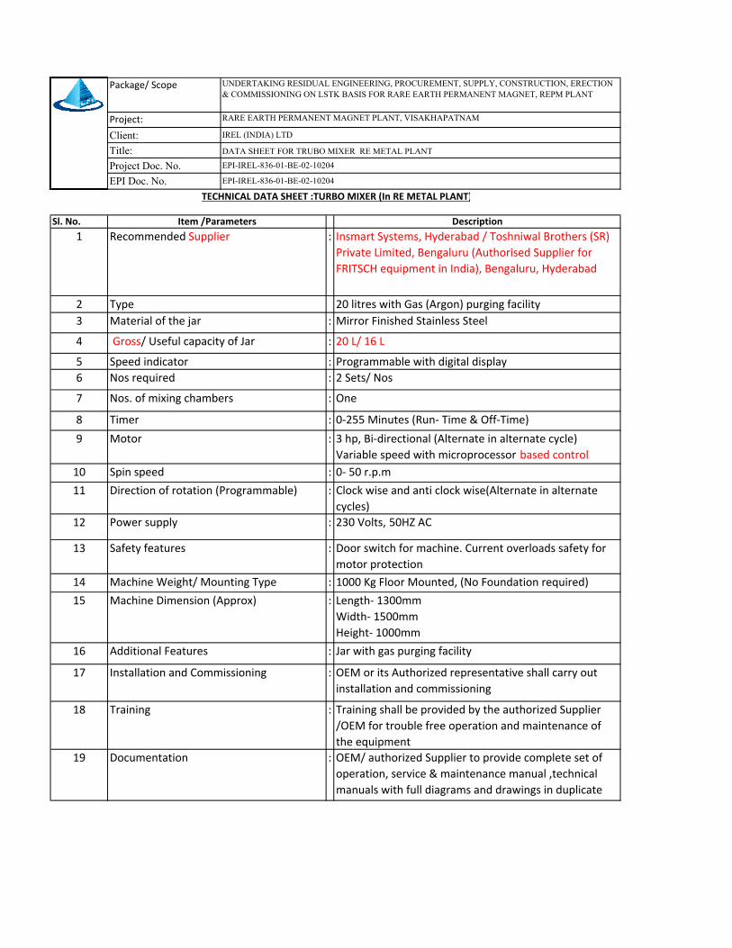
Package/ Scope
Project:
Client:
Title:
Project Doc. No.
EPI Doc. No.
Sl. No.
1 :
2
3 :
4 :
5 :
6 :
7 :
8 :
9 :
10 :
11 :
12 :
13 :
14 :
15 :
16 :
17 :
18 :
19 :
Speed indicator
Nos. of mixing chambers One
1000 Kg Floor Mounted, (No Foundation required)
Machine Dimension (Approx) Length‐ 1300mm
Width‐ 1500mm
Height‐ 1000mm
Direction of rotation (Programmable)
20 litres with Gas (Argon) purging facility
Installation and Commissioning OEM or its Authorized representative shall carry out
installation and commissioning
Training
Type
Material of the jar Mirror Finished Stainless Steel
Gross/ Useful capacity of Jar 20 L/ 16 L
Timer
Motor
Programmable with digital display
2 Sets/ Nos
0‐255 Minutes (Run‐ Time & Off‐Time)
3 hp, Bi‐directional (Alternate in alternate cycle)
Variable speed with microprocessor based control
Nos required
Documentation OEM/ authorized Supplier to provide complete set of
operation, service & maintenance manual ,technical
manuals with full diagrams and drawings in duplicate
Training shall be provided by the authorized Supplier
/OEM for trouble free operation and maintenance of
the equipment
Spin speed 0‐ 50 r.p.m
Power supply 230 Volts, 50HZ AC
Jar with gas purging facility
Door switch for machine. Current overloads safety for
motor protection
Additional Features
Safety features
Machine Weight/ Mounting Type
Clock wise and anti clock wise(Alternate in alternate
cycles)
UNDERTAKING RESIDUAL ENGINEERING, PROCUREMENT, SUPPLY, CONSTRUCTION, ERECTION & COMMISSIONING ON LSTK BASIS FOR RARE EARTH PERMANENT MAGNET, REPM PLANT
Description
Insmart Systems, Hyderabad / Toshniwal Brothers (SR)
Private Limited, Bengaluru (Authorised Supplier for
FRITSCH equipment in India), Bengaluru, Hyderabad
Item /Parameters
Recommended Supplier
DATA SHEET FOR TRUBO MIXER RE METAL PLANT
IREL (INDIA) LTD
EPI-IREL-836-01-BE-02-10204
EPI-IREL-836-01-BE-02-10204
TECHNICAL DATA SHEET :TURBO MIXER (In RE METAL PLANT)
RARE EARTH PERMANENT MAGNET PLANT, VISAKHAPATNAM