An Internship Report On “Embedded Systems”
42
VISVESVARAYA TECHNOLOGICAL UNIVERSITY Belgaum, Karnataka-590014 An Internship Report On “Embedded Systems” Submitted in partial fulfillment for the award of degree of Bachelor of Engineering In Electronics and Communication Engineering 2019-2020 Submitted by P S DEEPAK-1NH16EC071 Under the Guidance of Mr. Rajesh (Asst. Prof, NHCE) NEW HORIZON COLLEGE OF ENGINEERING [Autonomous college permanently Affiliated to VTU, Belgaum, Approved by AICTE & UGC, Accredited by NAAC with ‘A’ grade] Outer Ring Road, Marathalli, Bengaluru-560103
-
Upload
khangminh22 -
Category
Documents
-
view
2 -
download
0
Transcript of An Internship Report On “Embedded Systems”

VISVESVARAYA TECHNOLOGICAL UNIVERSITY
Belgaum, Karnataka-590014
An Internship Report On
“Embedded Systems”
Submitted in partial fulfillment for the award of degree of
Bachelor of Engineering
In
Electronics and Communication Engineering
2019-2020
Submitted by
P S DEEPAK-1NH16EC071
Under the Guidance of
Mr. Rajesh
(Asst. Prof, NHCE)
NEW HORIZON COLLEGE OF ENGINEERING
[Autonomous college permanently Affiliated to VTU, Belgaum, Approved by AICTE & UGC,
Accredited by NAAC with ‘A’ grade]
Outer Ring Road, Marathalli, Bengaluru-560103

DECLARATION
I, P S DEEPAK , student of Batchelor of Engineering in Electronics & communication
Engineering at New Horizon College of Engineering, Bangalore, hereby declare that this
internship work entitled “EMBEDDED SYSTEMS” is an original and bonafide work carried out
by me at Uniq Technologies, Bangalore in particular internship during the academic year 2019-
2020.
I also declare that, to the best of my knowledge the work reported here is not from any other
thesis or dissertation on the basis of which the degree or award was conferred on an earlier
occasion by any student.
Signature of the Guide
Mr. Rajesh

TO WHOMSOEVER IT MAY CONCERN
This is to certify that P S DEEPAK(Reg.no:1NH16EC071) undergoing his ECE from NEW
HORIZON COLLEGE OF ENGINEERING, has completed his 45 days internship with project at this
UNIQ TECHNOLOGIES. All the necessary details were provided from our side for the establishment of
the project.
It is observed that he is sincere and prompt in discharging the duties assigned to his from time to time.
On behalf of our organization we wish him all the best in all his future endeavors.
Thanks & Regards
(HR Head)
(Bangalore Branch)
‐‐‐‐‐‐‐‐‐‐‐‐‐‐‐‐‐‐‐‐‐‐‐‐‐‐‐‐‐‐‐‐‐‐‐‐‐‐‐‐‐‐‐‐‐‐‐‐‐‐‐‐‐‐‐‐‐‐‐‐‐‐‐‐‐‐‐‐‐‐‐‐‐‐‐‐‐‐‐‐‐‐‐‐‐‐‐‐‐‐‐‐‐‐‐‐‐‐‐‐‐‐‐‐‐‐‐‐‐‐‐‐‐‐‐‐‐‐‐‐‐‐‐‐‐‐‐‐‐‐‐‐‐‐ #1 Shifa Arcade, Bharathi Nagar 1st Street, North Usman Road, T‐Nagar, Chennai – 600 017 044 ‐ 42124943 | 95000 88927 | 96001 14466 | [email protected] www.uniqtechnologies.co.in
ACKNOWLEDGEMENT
I express my sincere gratitude to our respected internship guide Mr. Arul Antony for his
valuable guidance and suggestions while carrying out the internship on Embedded systems. I
extend my gratitude to engineering staff and management in Uniq Technologies, Bangalore,
and Karnataka for their support.
I’m proud to be the part of NHCE, the institution which stood with us in the success completion
of the internship. I take this opportunity to thank Department Of Electronics and
Communication Engineering, NHCE for supporting me I also thank my parents, group
members, friends and almighty for constant support.

CHAPTER 1: INTRODUCTION……………………………………………………………………………………..1
CHAPTER 2: DESCRIPTION OF THE ORGANIZATION………………………………………………..…4
2.1: BENEFITS……………………………………………………………………………………………….…………..4
2.2: DEVELOPMENT PROCESS……………………………………………………………………….…………..5
2.3: ENGAGEMENT MODELS……………………………………………………………………………………..5
2.4: DEVELOPMENT…………………………………………………………………………………………………..5
2.5: DESKTOP APPLICATION………………………………………………………………………………………6
2.6: WEB APPLICATION DEVELOPMENT…………………………………………………………………….6
2.7: SMART CLIENT APPLICATION………………………………………………………………………………6
2.8: CONTACT INFORMATION……………………………………………………………………………………7
CHAPTER 3: DEPARTMENT OF STUDENT INTERNED…………………………………………………..8
3.1: ABOUT EMBEDDED SYSTEM……………………………………………………………………………….8
CHAPTER 4: GENERAL ROLES AND RESPONSIBILITIES……………………………………………….10
CHAPTER 5: PROFESSIONAL AND TECHNICAL TAKE-AWAY……………………………………….11
5.1: EMBEDDED SYSTEM ARCHITECTURE…………………………………………………………………11
5.2: DESIGNING AN EMBEDDED SYSTEM………………………………………………………………….11
5.3: IMPLEMENTATION…………………………………………………………………………………………….13
5.4: TESTING…………………………………………………………………………………………………………….14
5.5: ARDUINO…………………………………………………………………………………………………………..17
5.6: ARDUINO IDE…………………………………………………………………………………………………….19
5.7: ADRUINO DUE……………………………………………………………………………………………………20
5.8: ARDUINO SHEILDS……………………………………………………………………………………………..21
5.9: SENSORS……………………………………………………………………………………………………………23
5.10: GSM…………………………………………………………………………………………………………………27
5.11: SOFTWARE………………………………………………………………………………………………………30
5.12: CODES……………………………………………………………………………………………………………..31
CHAPTER 6: CONCLUSION………………………………………………………………………………………..34

NHCE, Dept. of ECE 1
CHAPTER-1 INTRODUCTION
The most basic definition for Embedded Systems can be written as a hardware system along
with a software part embedded to it to perform various tasks. An Embedded Systems can be
defined as an independent entity or a system that is a part of a much larger system. It can be
considered as a microcontroller or a microprocessor designed to perform various application
based tasks.
Embedded Systems comprise of three main components -
• Hardware components
• Software components
• RTOS to supervise the functions.
mechanical or electrical system, frequently with real-time computing constraints. .most frequently
after adding hardware and software it is a medicine complete device. Daily we are using embedded
system to control many devices. An embedded system is a type of computer system with inscribed
function within a huge mechanical or electrical system, frequently with real-time computing
constraints.
Embedded systems are generally classified into two types. They are
• General purpose embedded systems
• Real time embedded systems
Examples for general purpose embedded systems:
• Laptops
• Mobile phones
Examples for real time embedded systems:

NHCE, Dept. of ECE 2
• Air conditioner An embedded system is a computer system with a dedicated function
within a larger
• Traffic light controllers
The major difference between these two embedded systems is that the general-purpose
system uses microprocessor while the other one uses
Microcontroller Now let us have a look on the differences between a microprocessor and a
microcontroller.
Microprocessor is an IC which has only the CPU inside them i.e. only the processing powers
such as Intel’s Pentium 1,2,3,4, core 2 duo, i3, i5 etc. These microprocessors don’t have RAM,
ROM, and other peripheral on the chip. A system designer has to add them externally to make
them functional. Application of microprocessor includes Desktop PC’s, Laptops, notepads etc.
But this is not the case with Microcontrollers. Microcontroller has a CPU, in addition with a
fixed amount of RAM, ROM and other peripherals all embedded on a single chip. At times it is
also termed as a mini computer or a computer on a single chip. Today different manufacturers
produce microcontrollers with a wide range of features available in different versions. Some
manufacturers are ATMEL, Microchip, TI, Freescale, Philips, Motorola etc.
Microcontrollers are designed to perform specific tasks. Specific means applications where the
relationship of input and output is elucidated. Depending on the input, some processing needs to be
done and output is delivered. For example, keyboards, mouse, washing machine, digicam, pendrive,
remote, microwave, cars, bikes, telephone, mobiles, watches, etc. Since the applications are very
specific, they need small resources like RAM, ROM, I/O ports etc .
Microprocessors used to find an applications where assignments are unspecific like developing
software, games, websites, photo editing, creating documents etc. In such situations the relationship
between input and output is not described. They need more amount of resources like RAM, ROM, I/O
ports etc.

NHCE, Dept. of ECE 3
The clock speed of the Microprocessor is quite high as compared to the microcontroller.
Whereas the microcontrollers operate from a few MHz to 30 to 50 MHz, today’s
microprocessor operate above 1GHz as they perform complex tasks.
• Examples of microprocessor: 8085, 8086, Intel core7.
• Examples of microcontroller:8051, PIC, Arduino.

NHCE, Dept. of ECE 4
CHAPTER-2 DESCRIPTION OF THE ORGANIZATION
India info tech an Indian based IT Software development Company that spotlights on
worthwhile, timely delivered and extremely qualitative IT enabled services. With a prosperous
and speckled familiarity in software development elucidation that gives your business a new
dimension over your contestants. Our unique software model will bring utmost targeted result
to your business. This Software Development Company with its Head Office in Chennai have
a team of professionals having in-depth expertise in latest technologies provides expert
software solutions for business of all sizes like - E-commerce, finance, travel & tourism,
youthful entrepreneurs, corporate, IT consultancy organizations etc.… We deliver the top
level mobile applications for Android, Black Berry, Windows, Symbian, Smart Phones, iPhone,
and iPad with the touch of iOS. Get website application done on varied platforms like Java,
PHP, .NET that is productively delivered to various partners and customers globally. At
present, with our knowledge and expertise, we have created a worldwide trail of clients and
partners. Our ultimate customized professional SEO services offered to lots of entrepreneurs
facilitates them to increase utmost ROI for their business and increase traffic.
2.1 BENIFITS
• Assured Return on Investment
• Faster development cycle
• Increased development productivity
• Low development costs
• Reduced time to market
• Quality software products

NHCE, Dept. of ECE 5
2.2 DEVELOPMENT PROCESS
• Project Kick-off
• Software Requirements Analysis and Management
• Software Project Planning
• Software Project Tracking and management
• Software Quality Assurance
2.3 ENGAGEMENT MODELS
• Fixed-Price
• Time and Material
• Dedicated Development Team
• Offshore Development Centre
• On site Consulting
2.4 DEVELOPMENT
India Info tech is a software development company which offer Custom Software
Development services, including product idea analysis, offshore software development to
outsourcing support, and enhancement. India Info tech employs a large pool of software
engineers coming from different backgrounds. With India Info tech software development
services, you reduce outsourcing software development costs and enhance revenue
growth due to our:
• High responsiveness
• Skilled and organized personel
• Strong experience in projects of different complexity

NHCE, Dept. of ECE 6
• Time tested software development process
• On-time and within budget delivery
2.5 DESKTOP APPLICATION
Desktop Applications are robust, rich-client applications that are compiled and run using the
processing power of an individual user's desktop computer. India Info tech has expertise in a
wide variety programming languages, tools, and platforms for client server application. Our
structured methodologies and proven IT processes helps to reduce complexity, risks and costs
associated with client/server development. We will help you develop
customized software applications and assist you thorough out the entire software
development Life Cycle, including systems analysis and design, software development, project
management, implementation and training.
2.6 WEB APPLICATION DEVELOPMENT
Application development has undergone a transition over years, with the migration of
applications from traditional client/server designs to the Internet. We utilize cutting-edge
technologies such as Microsoft ASP.NET, Java/J2EE, ROR, Ajax and XML to meet our customers
varied requirements.
2.7 SMART CLIENT APPLICATION
Uniq tech has developed many Smart Client applications which enable Single Click
Deployment, Enterprise Security, Extensibility and Online and Offline application access etc.

NHCE, Dept. of ECE 7
2.8 Contact Information: Company Name : Uniq Technologies.
Venue : 3rd Floor, 1st Cross, Somasundarapalya, Madiwala, 1st Stage,
S.G.Palya, Bengaluru, Karnataka-560068.
General Phone No : 9600114466.
Company Email : [email protected]
Website : www.uniqtechnologies.co.in

NHCE, Dept. of ECE 8
CHAPTER 3
DEPARTMENT OF STUDENT INTERNED
3.1 ABOUT EMBEDDED SYSTEM
The combination of hardware and software either fixed in capability or programmable is know
Embedded system , that is designed for a specific function. Embedded systems is device used
to control, monitor the operation of equipment’s , machinery or plant. “Embedded” refers to
the internal part.
These are classified into different steps :
Based on the Performance and Functional Requirement:
1. REAL TIME EMBEDDED SYSTEMS: type of systems are defined as these systems in which
the truthfulness of the system depends not only on the logical result computation, but
also the results are produced on time.
➢ Hard real-time systems (e.g., Avionic control). ➢ Firm real-time systems (e.g., Banking). ➢ Soft real-time systems (e.g., Video on demand).
2. DETACHED EMBEDDED SYSTEMS:
➢ This systems do not require a host like a computer, depends on itself.
➢ It takes the inputs from the either analog or digital and processes, calculates and modified the data and gives the end data through the link device which either controls, drives and displays the linked devices.
➢ examples: mp3 music players, digital cameras, video game , microwave ovens and temperature checkup systems.
3. NETWORKED EMBEDDED SYSTEMS:
➢ These systems are branch to a network to access the resources.
➢ connected network can be LAN, WAN, or the internet. The connection maybe wireless or wired. This system is highest growing area in embedded system applications.
4. MOBILE EMBEDDED SYSTEMS:
.
➢ The basic limitations of these devices is the other resources and limitations. ➢ Mobile embedded systems are used in portable embedded devices like cell phone, mobiles,
digital cameras, mp3 players and personal digital assistants, etc

NHCE, Dept. of ECE 9
Based on the Performance of the Microcontroller:
1. SMALL SCALE EMBEDDED SYSTEMS:
➢ These types of systems are designed with a 8 or 16-bit single microcontroller, that may be generated by a battery.
➢ For the developing embedded software for this embedded systems, the important programming tools are editor, assembler, cross assembler and IDE.
2. MEDIUM SCALE EMBEDDED SYSTEMS:
➢ Medium scale embedded systems are designed with a 16 or 32-bit MC, RISCs or DSPs.
➢ Both hardware and software complexities are available.
➢ For the developing embedded software for this system, the main tools are C, C++, JAVA, Visual,RTOS, debugger, source code engineering tool, simulator and IDE.
3. WORDLY EMBEDDED SYSTEMS:
➢ These systems are designed with 32-bit.
➢ type of embedded systems have large hardware and software complexities.
➢ Which may required scalable or configurable processor and programming logical arrays.

NHCE, Dept. of ECE 10
CHAPTER - 4
GENERAL ROLES AND RESPONSIBILITIES
I was interned at the Embedded Department where i was provided exposure to various
microcontroller boards that were available for development of various IOT application areas
like consumer, home automation, security, surveillance, health care, etc. The main agenda of
the department to bond the gap between the company and the students by providing them
with practical experience by considering the various constraints that comes into effect during
the physical implementation of a project.
The department where I was interned helped me bridge the gap between the industry
and academia by providing the complete experience to on board using the various
microcontroller boards like PIC microcontroller, Arduino nano microcontroller etc.
The department has an Industry Excellence Experience Center to learn, innovate, and
prototype embedded designs on various Industry standard hardware and microcontroller
platforms. At the same time build a Rewarding Career to students in embedded Engineering
Domain. The Lab setup and training helped me to become a competent and productive Analog
and Digital design Engineers. The training enabled me to acquire knowledge, skills and
practical experience across the entire front end and backend Full Custom Flow (Circuit to tape-
out). The training covers key fundamental concepts of Physical Design methodology which will
enhance the employability of the students. The Sessions, Lab exercises and Industry Standard
Projects enabled me to get through instills confidence and the analytical abilities required to
work on complex industry’s challenges in various Deep Sub-Micron Technology Process.
Exposure to the use of Physical Design tools familiarity with timing closure and related topics
are covered.
CHAPTER 5

NHCE, Dept. of ECE 11
PROFESSIONAL AND TECHNICAL TAKE-AWAY
5.1 Embedded System Architecture
Embedded system architecture is an generalized form of the system. But this architecture
does not show a detailed implementation information like software source code or hardware
circuit design. As a part of composition of interacting elements the hardware and software
elements are present in embedded system.here elements are used to represent the hardware
and software ,leaving only behavioral and inter relationship information. the one possible
representation of the architecture is a structure. A structure is like snapshot of the system's
hardware and software during design time or at runtime having a particular environment and
a set of elements. Earlier embedded system architecture is used to resolve challenges in a
project. Architecture is the first tool used to analyse the system without defining or knowing
the internal level of implementation.architecture can also be used as a high level blueprint in
defining the infrastructure of a design.
5.2 Designing an Embedded System
The four cornerstones of embedded system modelling are big-bang, code-and-fix, waterfall
and spiral model. Most of the many models used in system design are based on single model.
bang model, no planning is executed before developing the system. The code-and-fix model
requirements are described but no processes are prepared before the start of the
development.

NHCE, Dept. of ECE 12
The waterfall model uses strict process for developing system in steps, each part of the system is
developed step by step. Spiral model is a similar model to waterfall model. Between step feedback and
systematic progress model is shown in Graph 3. In the Graph 3 waterfall and spiral models have been
combined into one system design model. (Arduino 2005).
GRAPH 3. Design and Development Lifecycle Model (adapted from Arduino 2005).
5.3 Implementation
One of the final phases of embedded system design for implementing the design. Basically the design
and implementation of control system or more frequently separated which produces development of
embedded system to be more time consuming and costly.
the implementation phase. There are several tools built to ease the implementation of the system. The
implementation and development process of the embedded system’s hardware and software layer can
be possible with development tools. One of the tools used on the hardware side is Computer-Aided
Design (CAD). CAD is used for simulate circuits at electrical level. In addition to study a circuit’s behavior
before the final circuit and software is implemented simulation is used to test the hardware. Screen

NHCE, Dept. of ECE 13
capture of the software is shown in Graph 4. Integrated Development Environment (IDE) is used for aid
the implementation of the software side present in embedded systems. More information about
Integrated Development Environment is found in chapter 3 under Arduino IDE. (Arduino UNO.)
GRAPH 4. CAD software for circuit simulation
5.4 Testing
The purpose of testing is to check the quality of a system. The tester is trying to test if the system is
operating according to its design. In other words, the tester is trying to testing to find the error also
known as a bug is found from the system. Testing can be also

NHCE, Dept. of ECE 14
used to track if bugs have been fixed. Arduino describes in the quotation what bugs are and how they
behave in a system.
During testing, bugs usually stem from either the system not adhering to the architectural
specifications— i.e., behaving in a way it shouldn’t according to documentation, not be- having in a
way it should according to the documentation, behaving in a way not mentioned in documentation—
or the inability to test the system. (Arduino 2005, 563).
The types of bugs encountered in testing depend on the type of testing performed to the
system. There are four generally used models to test the system: static black box testing, static
white box testing, dynamic black box testing, or dynamic white box testing. Table 1 shows
techniques used for testing. Black box testing means that a tester has no access to schematics
or source code. Black box testing is based on general product information given to the tester.
White box testing also known as clear box or glass box testing is where the tester has access
to the source code and the schematics of the system. Static testing is used when the system
is not running, whereas dynamic testing is applied when the system is running.

NHCE, Dept. of ECE 15
Black Box Testing White Box Testing
Static
Testing
Testing products features
by:
1. Expecting for high-level
fundamental problems,
omissions (i.e., pretending to be
customer, research existing
guidelines,review and test
similar software, etc.).
2. Low-level specification testing
by insuring completeness,
accuracy, preciseness,
Process of methodically revising
hardware and code to bugs without
executing it.
NHCE, Dept. of ECE 16
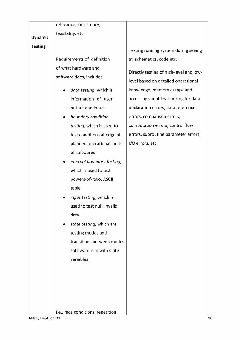
Dynamic
Testing
relevance,consistency,
feasibility, etc.
Requirements of definition
of what hardware and
software does, includes:
• data testing, which is
information of user
output and input.
• boundary condition
testing, which is used to
test conditions at edge of
planned operational limits
of softwares
• internal boundary testing,
which is used to test
powers-of- two, ASCII
table
• input testing, which is
used to test null, invalid
data
• state testing, which are
testing modes and
transitions between modes
soft-ware is in with state
variables
i.e., race conditions, repetition
Testing running system during seeing
at schematics, code,etc.
Directly testing of high-level and low-
level based on detailed operational
knowledge, memory dumps and
accessing variables. Looking for data
declaration errors, data reference
errors, comparison errors,
computation errors, control flow
errors, subroutine parameter errors,
I/O errors, etc.

NHCE, Dept. of ECE 17
testing, stress (starving software =
low memory, slow CPU, slow
network), load (feed
NHCE, Dept. of ECE 18
5.5 ARDUINO
For developing computers embedded system audino is is used as open source tool that it can
sense and control be more of the physical world that the desktop computers. I receiving input
from variety of sensors it can sense the environment. Discerning sau affected by order no by
its controlling lights, motors and other actuators. It can also support standalone applications
l. It can easily integrated with computer / other process.
Brief History of Arduino
In 2005, a project was initiated to make a device for controlling student-built design projects
that was less expensive than the other prototyping system available at the time.
Founders Massimo Banzi and David Cuartielles named the projects after Arduino of Ivrea and
began producing boards in a small factory located in Ivrea.
Features of Arduino UNO:
Microcontroller : ATmega328
Operating Voltage : 5V and 3.3V
Input Voltage : 6-20V
Digital I/O Pins : 14
Analog Input Pins : 6
DC Current per I/O Pin : 40 mA
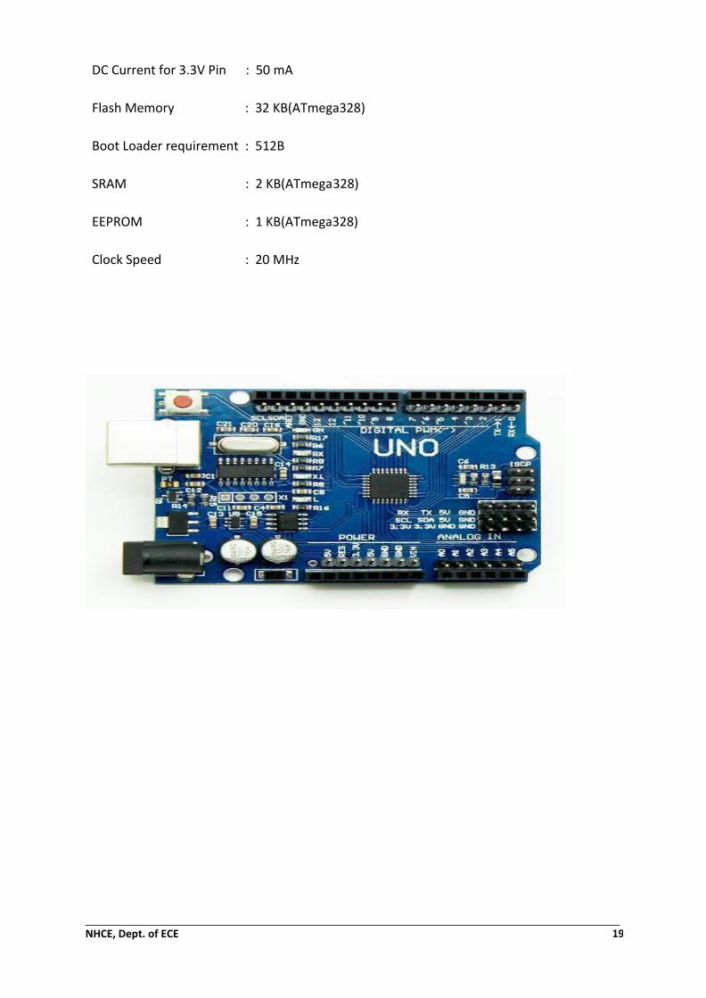
NHCE, Dept. of ECE 19
DC Current for 3.3V Pin : 50 mA
Flash Memory : 32 KB(ATmega328)
Boot Loader requirement : 512B
SRAM : 2 KB(ATmega328)
EEPROM : 1 KB(ATmega328)
Clock Speed : 20 MHz

NHCE, Dept. of ECE 20
5.6 Arduino IDE
Arduino IDE (Integrated Development Environment) is programming prototype which can let
the user to draft various kind of programs and load them into the Arduino microcontroller.
We can also be programmed by using other IDEs too, like Eclipse. Arduino IDE is more versatile.
This Arduino IDE needs no special drivers or additional components. This is available for
Windows, Linux and Mac. Cross compiler-compiles for a different target platform than the one
being programmed.
IDE- SOFTWARE TOOL FOR PROGRAMMING:
➢ File operations and other general options on top. ➢ Buttons for most commonly used options (Verify, Upload, etc.). ➢ Main window-Text editor for writing code. ➢ Message area-for messages to the programmer.

NHCE, Dept. of ECE 21
OPTIONS BUTTONS:
Buttons on the top have the most common, useful operations
➢ Verify – Compiles the code and checks for errors.
➢ Uploads – Uploads the compiled code to the board. Works only if the board is connected.
➢ New – Creates a new sketch, a new program.
➢ Open – Opens an existing sketch.
➢ Save – Saves the current sketch in the directory of your choice.
➢ Serial Monitor – Opens window to communicate with the board.
➢ Require Java Runtime Environment.
➢ Write codes in general C language.
➢ Setup() - Initiates the variables and sets up device instances.
➢ Loop() – Runs the code that contains operations and manipulations, iterates infinitely.
5.7 Arduino Due
The Arduino Due is one of the microcontroller board realated on the Atmel SAM3X8E ARM
Cortex-M3 CPU. The first Arduino dependsd on a 32-bit ARM core microcontroller is Arduino
due. It consists of 54 digital i/o pins in that 12 Can be used for PWM outputs, 12 analog
inputs, 4UARTs, a 84 MHz clock, an USB OTG capable connection, 2 DAC, 2 TWI, a power jack,
an SPI header, a JTAG header, a reset button and an erase button.
FEATURES OF ARDUINODUE:
Microcontroller : AT91SAM3X8E
Operating Voltage : 3.3V
Flash Memory : 96 KB (64 KB and 32 KB)
Clock Speed : 84 MHz
Length : 101.52 mm
Width : 53.3 mm
Weight : 36g

NHCE, Dept. of ECE 22
5.8 Arduino Shields
Audino Shields are type of boards that is used to be plugged on top of the Arduino PCB used
to protect and provide additional capabilities.
There are different types of shields. They are
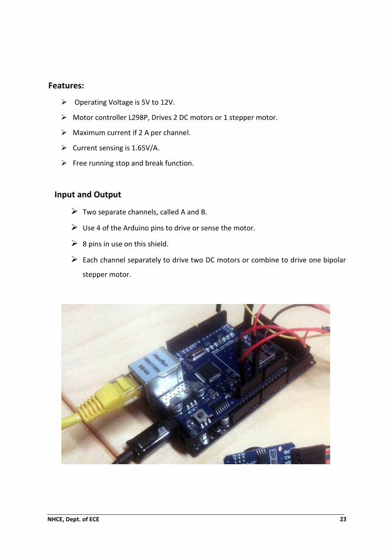
Motor Shield:
A motor shield is a circuit board that contains a motor driver chip to drive motors. It is used
to control the working speed and direction of the motor.
Ethernet Shield:
It allows the user to easily connect Arduino to the internet with an internet connection.
Wi-Fi Shield:
It connects the Arduino to the internet wirelessly.
MP3 Player Shield:
It is used to play any mp3 file from a micro SD card which is mounted on the board.
NHCE, Dept. of ECE 23
Features:
➢ Operating Voltage is 5V to 12V.
➢ Motor controller L298P, Drives 2 DC motors or 1 stepper motor.
➢ Maximum current if 2 A per channel.
➢ Current sensing is 1.65V/A.
➢ Free running stop and break function.
Input and Output
➢ Two separate channels, called A and B.
➢ Use 4 of the Arduino pins to drive or sense the motor.
➢ 8 pins in use on this shield.
➢ Each channel separately to drive two DC motors or combine to drive one bipolar
stepper motor.

NHCE, Dept. of ECE 24
5.9 Sensors
The requirement of a sensor is to react for input physical property and convert it into an
electrical signal that is suitable with electronic circuits (Fraden 2010, 2). Sensors are electronic
devices that measure a physical quality such as light or temperature and convert it to a
voltage. Example of digital temperature and moisture sensor is presented in Graph 9. There
are two types of sensors: digital and analog.
The output of digital sensor where is between 0 and 1 which can translate to sensors voltage
range. Analog sensor can output any value between its voltage ranges. According to the
reading from the sensor changes its output. Digital sensor output is ON (1) often 5v, or OFF
(0), 0v. Analog sensor is used to measure precise numerical information like temperature or
speed. Analog sensors can output almost an infinite range of values. Output pin of sensor
connected to input pinafore denim show the digital form is obtained by the conversion of
data.
Some sensors have analog to digital converter embedded to the sensor so the data is outputted
as digital data. After data is processed to digital form, it can be processed on the
microcontroller. (Karvinen & Karvinen, 2014.)
NHCE, Dept. of ECE 25
ULTRASONIC
The working principle of ultrasonic sensor is same as the working principles of radar system.
It can convert the electrical energy in to the acoustic and vice versa. The ultrasonic wave is
nothing but, a acoustic wave signal which can travel at a frequency above 18kHz. The most
famous sensor HC SR04 generates ultrasonic waves of 40kHz frequency. For communication
with an ultrasonic sensor a microcontroller is used, where microcontroller sends a trigger
signal to ultrasonic sensor. The duty cycle of the trigger signal is 10uS for the HC-SR04 ultra
sonic sensor. When trigged the ultrasonic sensor generates eight acoustic wave bursts and
initiates a timer counter. As soon as the reflected signal is received the timer stops. The output
of the ultrasonic sensor is a high pulse with the same duration as the time difference between
transmitted ultrasonic bursts and the received echo signal.
Features
Here’s a list of some of the HC-SR04 ultrasonic sensor features and specs:
Power Supply: +5V DC
Quiescent Current: <2mA
Working Current: 15mA
Effectual Angle: <15°
Ranging Distance: 2cm – 400 cm/1″ – 1
Resolution: 0.3 cm
Measuring Angle: 30 degree
Trigger Input Pulse width: 10uS
Dimension: 45mm x 20mm x 15mm
How Does it Work?
The ultrasonic sensor uses sonar to determine the distance to an object. Here’s what
happens:

NHCE, Dept. of ECE 26
The transmitter (trig pin) sends a signal: a high-frequency sound.
When the signal finds an object, it is reflected and the transmitter (echo pin) receives it.
SOIL MOISTURE
.The volumetric content in soil is measured by the soil moisture sensors. Removing, drying and
weighting of a sample how the requirements for direct gravimetric measurement of free soil
moisture.By using some other property of soil,soil moisture sensors measure the volumetric
water content indirectly. Depending upon the environmental factors such as soil type,
temperature obstacle the relationship between measure property and soil moisture must be
calibrated and may vary.
Reflected microwave radiation is affected by the soil moisture and is used for remote
sensing in hydrology and agriculture. Portable probe instruments can be used by farmers or
gardeners.
Soil moisture sensors typically refer to sensors that estimate volumetric water content.
Another class of sensors measure another property of moisture in soils called water potential;
these sensors are usually referred to as soil water potential sensors and include
tensiometers and gypsum blocks. Soil moisture causes effect to the defect microwave
radiation and this refraction microwave radiation used for remote sensing in hydrology and
agricultural. Farmers and governors are used the portable probe instruments. The sensors that
estimate volumetric water content is referred by the soil moisture sensors. special class of

NHCE, Dept. of ECE 27
sensors measure some specific property of moisture in soil which is known as water potential.
Dispenser are also known as and referred to soil water potential sensors which include
tensiometres and gypsum block.
Heartbeat Sensor
The designing of heartbeat sensor is happened in such a way that when finger is placed on it
the digital value of the heartbeat is displayed. The heartbeat is happened when the blood is
circulated from one part to other part in the human body.
Two Ways to Measure a Heartbeat
Manual Way: Heart beat can be checked manually by checking one’s pulses at two locations-
wrist (theradial pulse) and the neck (carotid pulse). The procedure is to place the two fingers
(index and middle finger) on the wrist (or neck below the windpipe) and count the number of
pulses for 30 seconds and then multiplying that number by 2 to get the heart beat rate. How-

NHCE, Dept. of ECE 28
ever pressure should be applied minimum and also fingers should be moved up and down till
the pulse is felt.
Principle of Heartbeat Sensor
The principle of heartbeat sensor is based on the principle of photo plethysmography. With
each heartbeat it can measure the the blood volume alternation at the fingertip. This sensor
unit consists of photodiode and IR LED which is placed side by side. The photodiode is used to
sense the portion of light which is reflected back and IR diode is used to transmit an infrared
light into to the fingertip. Blood volume inside the fingertip will represent the intensity of light.
Each and every heartbeat slightly where is the amount of reflected infrared light which can
be detected by photodiode.
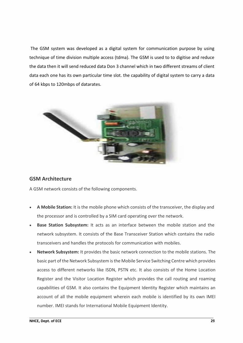
5.1 0 GSM
Full form of GSM is Global System for Mobile communication. GSM modem is a device that is
used for the communication. The GSM idea was firstly developed at Bell Laboratories in 1970.
Now, in the world the most widely used communication system is GSM. The frequency bands
that are used in open and digital cellular technologies are 850MHz, 900MHz, 1800MHz and
1900MHz for the transmitting of mobile voice and data services.
NHCE, Dept. of ECE 29
The GSM system was developed as a digital system for communication purpose by using
technique of time division multiple access (tdma). The GSM is used to to digitise and reduce
the data then it will send reduced data Don 3 channel which in two different streams of client
data each one has its own particular time slot. the capability of digital system to carry a data
of 64 kbps to 120mbps of datarates.
GSM Architecture
A GSM network consists of the following components.
• A Mobile Station: It is the mobile phone which consists of the transceiver, the display and
the processor and is controlled by a SIM card operating over the network.
• Base Station Subsystem: It acts as an interface between the mobile station and the
network subsystem. It consists of the Base Transceiver Station which contains the radio
transceivers and handles the protocols for communication with mobiles.
• Network Subsystem: It provides the basic network connection to the mobile stations. The
basic part of the Network Subsystem is the Mobile Service Switching Centre which provides
access to different networks like ISDN, PSTN etc. It also consists of the Home Location
Register and the Visitor Location Register which provides the call routing and roaming
capabilities of GSM. It also contains the Equipment Identity Register which maintains an
account of all the mobile equipment wherein each mobile is identified by its own IMEI
number. IMEI stands for International Mobile Equipment Identity.

NHCE, Dept. of ECE 30
Features of GSM Module:
• Spectral/Frequency efficiency.
• Supports International roaming.
• Ability to support multiple hand held devices.
• Clear Voice Clarity.
• Low powered handheld devices.
• Uses encryption to make phone calls more secure.
• Ease of accessing the Network.
The most secure telecommunication standard of GSM system concurrently accessible by using
security strategies standardises. The radio channel can shoot the confidential of the call on
the secrecy of a GSM subscriber. This is huge step in achieving end to end security.
GSM Modem
A GSM modem is a device which is very similar to mobile phone, whereas the mobile phone
is operated by human beings but the GSM modem is operated by a microcontrollers. GSM
modem is also used to make a personal computer or any other processor communicate over
a network. A GSM modem requires a SIM card to be inserted in order to operates over a
network range subscribed by the network operator. It can be connected to a computer
through serial, USB or Bluetooth connection.
A GSM modem can also be a standard GSM mobile phone with the appropriate cable and
software driver to connect to a serial port or USB port on your computer. A personal computer
is connected with USB to comb connector and compound DB9 connector is connected to GSM
modem. So, that the setup has been formed to check the GSM modem by using commands
that are compatible to the Operating System. The GSM modem has wide range of applications
in transaction terminals, supply chain management, security applications, weather stations
and GPRS mode remote data logging.
Working of GSM Module:
From the below circuit, a GSM modem duly interfaced to the MC through the level shifter IC
Max232. The SIM card mounted GSM modem upon receiving digit command by SMS from any

NHCE, Dept. of ECE 31
cell phone send that data to the MC through serial communication. While the program is
executed, the GSM modem receives command ‘STOP’ to develop an output at the MC, the
contact point of which are used to disable the ignition switch. The command so sent by the
user is based on an intimation received by him through the GSM modem ‘ALERT’ a
programmed message only if the input is driven low. The complete operation is displayed over
16×2 LCD display.
Intelligent GSM Device for Automation and Security
In these days, the GSM mobile terminal has become one of the items that are constantly with
us. Just like our wallet/purse, keys or watch, the GSM mobile terminal provides us a
communication channel that enables us to communicate with the world. The requirement for
apers onto be reachable or to call anyone at any time is very appealing. In this project,

NHCE, Dept. of ECE 30
As the title of project is depending on translation of SMS from sender to receiver by using GSM
Network technology of transmission. Ubiquitous actress of appliance and bridge control at
home where used by the SMS sending and receiving. Two subsystems are proposed by the
system. To control the home appliance remotely using appliance control subsystem and for
automatic security monitoring you are using security alert system.
According to the user needs and requirements the system is capable enough to send
instructions and conditions via SMS from a particular cell number. On the detection of
intrusion the secretariat can be achieved this is our second aspect though alerting the user
against security risk the system allows automatic generation of SMS
5.11 Software
The Arduino Duemilanove can be programmed with the Arduino software. The Arduino
Integrated Development (IDE) is derived from the IDE for the processing programming
language and is written in Java. It has code editor features such as the syntax highlighting
braces matching automatic indentation indentation and is also capable of compiling and
uploading programs to a board with a single click.A program or code written for Arduino is
called a “sketch”. Arduino programs are written in C and C++.
Loop():
➢ Called after creating setup function.
➢ Function loops consecutively.
➢ Allows the program to change and respond.
➢ Actively controls the Arduino.
Compiler compiles the sketch after writing the code and checks the code for errors. Upload
the program to the configured Arduino board. Check the board whether it will works well or
not. If any problem, then revise the code or circuit you build.
5.12 CODE

NHCE, Dept. of ECE 31
Temperature and Humidity:
#include <dht.h>
#define dht_apin A0 // Analog Pin sensor is connected to
dht DHT;
void setup(){
Serial.begin(9600);
delay(500);//Delay to let system boot
Serial.println("DHT11 Humidity & temperature Sensor\n\n");
delay(1000);//Wait before accessing Sensor
}//end "setup()"
void loop(){
//Start of Program
DHT.read11(dht_apin);
Serial.print("Current humidity = ");
Serial.print(DHT.humidity);
Serial.print("% ");
Serial.print("temperature = ");
Serial.print(DHT.temperature);
Serial.println("C "); delay(5000);
end loop()
TO BLINK AN LED USING EX-OR OPERATION:
void setup() {
pinMode(2,INPUT);

NHCE, Dept. of ECE 32
pinMode(3,INPUT);
pinMode(4,OUTPUT);
}
void loop() {
int a,b;
a=digitalRead(2);
b=digitalRead(3);
if(a==b)
{
digitalWrite(4,0);
}
else
{
digitalWrite(4,1);
}
}
TO BLINK THE WORD DISPLAYED IN THE LCD:
#include<LiquidCrystal.h>
LiquidCrystallcd(12,11,10,9,8,7);
void setup() {
lcd.begin(16,2);
lcd.setCursor(0,0);
lcd.print("NHCE");
}
void loop() {
lcd.display();
delay(1000);

NHCE, Dept. of ECE 33
lcd.noDisplay();
delay(1000);
}
Alcohol Detection:
#include <LiquidCrystal.h>
#include <MQ135.h>
#include "MQ135.h"
void setup() {
Serial.begin(9600);
}
void loop() {
MQ135 gasSensor = MQ135(A0);
float air_quality = gasSensor.getPPM();
Serial.println (air_quality);
delay(3000);
}
CHAPTER 6
CONCLUSION
A systematic approach in designing a system for measurement and also for the control of three
important requirement parts based on the microcontroller.
Ammeters for plant growth, temperature, humidity and soil moisture, has been followed. The

NHCE, Dept. of ECE 34
system which is proposed has successfully overcome the problems of the existing systems by
reducing the consumption of power, complexity and the cost by providing a precise form of
maintaining the environment.
Arduino microcontrollers are constantly evolving development platform. Vastly advancing
technology can easily bypass technology used in Arduino Due and make the technology
outdated. Growing open-source community is constantly developing. More advanced software
is programmed to work similarly with monitoring environment variables.
Environment variable monitoring DIY projects are common in open-source communities.
Multiple greenhouse or household plant monitoring projects can be found online. The key
factor that sets this greenhouse-monitoring project apart from other DIY monitoring system
is the system in which the data is accessed easily by the user through the web interfaces.
Usually web interfacing monitoring systems require multiple hardware to handle hosting
services. To narrow down the cost of hosting and monitoring system was combined to one
device.
further research, the system can be designed in such a way that to operate in a wireless
environment.. To provide access to user interface we are considering the Wi-Fi technology.
And also we have alternate options for wireless connectivity 3G or 4G cellular connectivity.
The monitoring of data access irrespective of distance to location of the greenhouse which
will have left and conduction and monitoring the data more efficiently.

NHCE, Dept. of ECE 35