A “short list” of embedded systems
107
-
Upload
khangminh22 -
Category
Documents
-
view
2 -
download
0
Transcript of A “short list” of embedded systems

Άδεια Χρήσης
Το παρόν εκπαιδευτικό υλικό υπόκειται σε άδειες χρήσης Creative Commons.
Για εκπαιδευτικό υλικό, όπως εικόνες, που υπόκειται σε άδεια χρήσης άλλου τύπου, αυτή
πρέπει να αναφέρεται ρητώς.

3
Some Achievements
FIR
FIR
GMSK
Digital
Modulator
AD9761
2M
UX
IQ 10bits10
10
synReset
inData
gsmDect
readIn
CLOCK
WRITE
SELECT
DECT
Detector
AD9281
DE
MU
X
IQ 8bits8
8
Start_Detection
Symbol
preamble_detectedCLOCK
SELECT
ASPIS
Processor
FPGA 1
AGC &
DC offset block
MAX549A
aux_fso_out
aux_do
aux_fsin
aux_fso_din
aux_clk
SCLK
CS
DIN
OUT I
8
8
66
Data_Clock
slot_detected
Clock
generator
block
13.824MHz
27.648MHz
Clock
4x1152kHz
phi
8x1152kHz
FPGA 2
I/F
I/F
OUT Q
Select
I/F
66
b_clk 13.824MHz
Clock
4x1152kHzStart_Detection
88
t_en
do
H_mode
r_en
bsclk
rec_data
dpllsynchom
slotsynchom
b_clk
EMI_clk
Aux Clock
LPGD
Input
Streams
Output
Streams
Receiver
LPGD ASPIS EASY
AMDREL AMDRELAMDREL

4
Awards
5
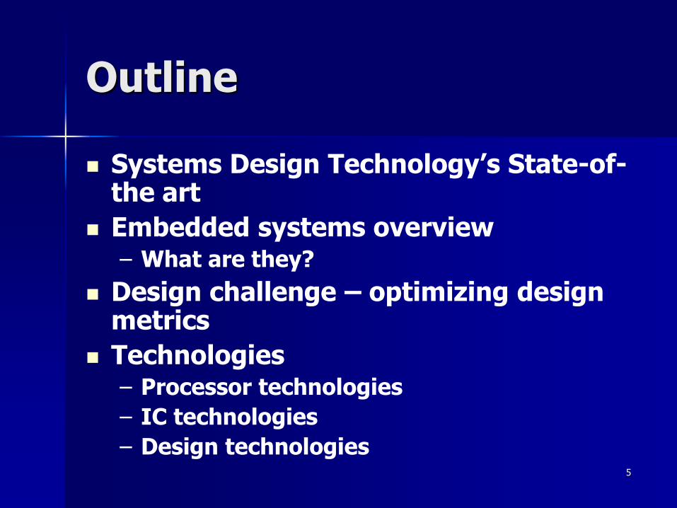
Outline
Systems Design Technology’s State-of-the art
Embedded systems overview– What are they?
Design challenge – optimizing design metrics
Technologies– Processor technologies
– IC technologies
– Design technologies

6
ENIAC –The first electronic computer (1946)
7
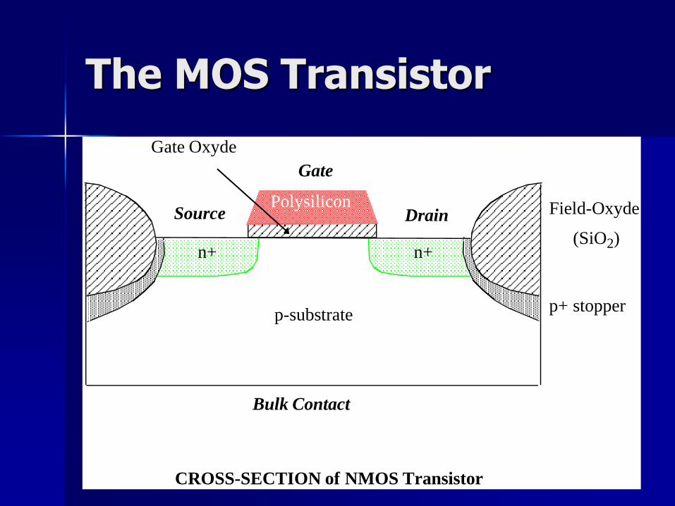
The MOS Transistor
n+n+
p-substrate
Field-Oxyde
(SiO2)
p+ stopper
Polysilicon
Gate Oxyde
DrainSource
Gate
Bulk Contact
CROSS-SECTION of NMOS Transistor

8
Cross-Section of CMOS Technology
12
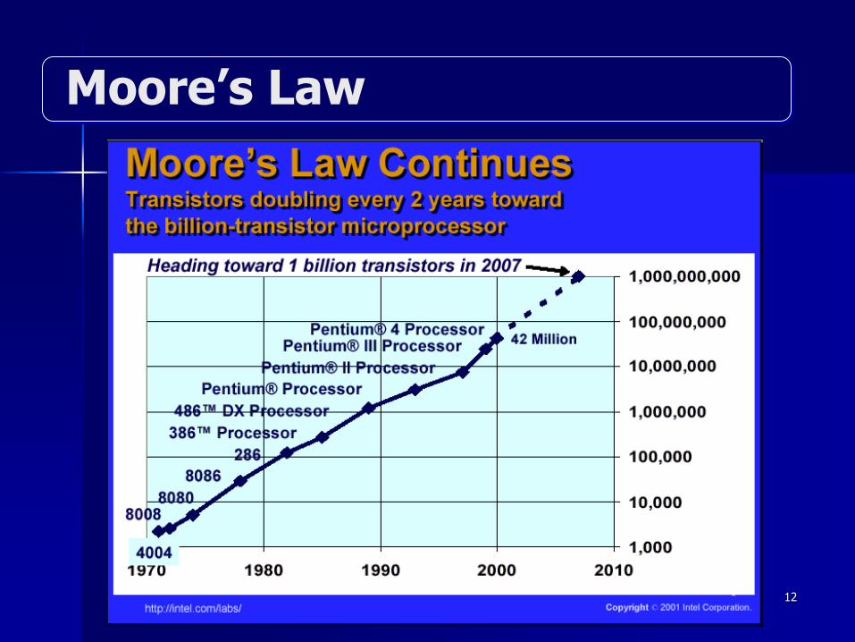
Moore’s Law

13
Intel 4004 Micro-Processor

14

15
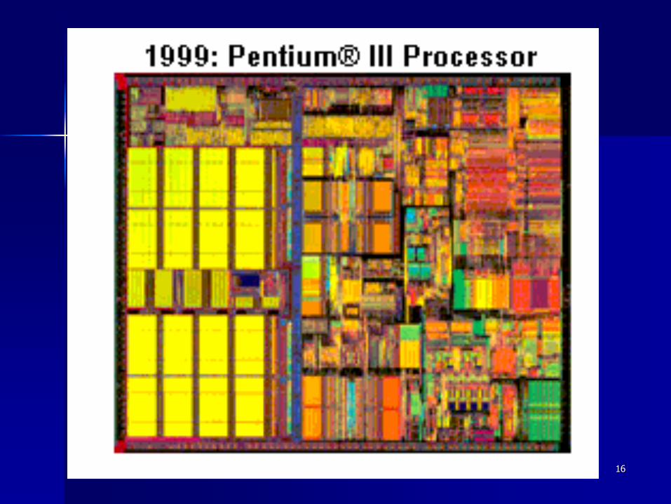
16
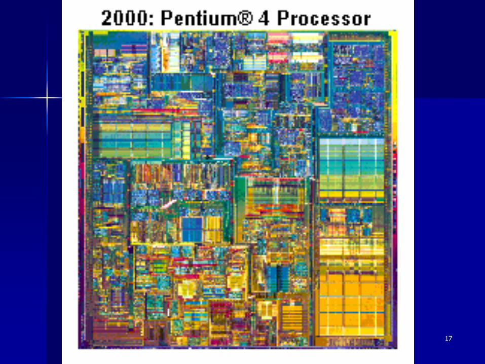
17
18
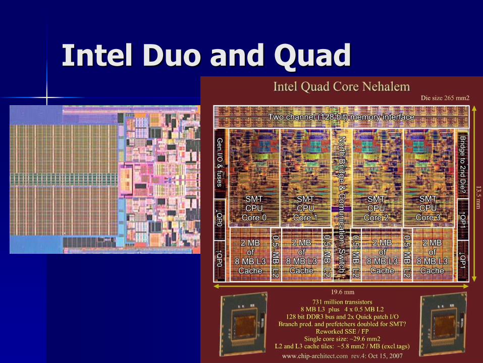
Intel Duo and Quad

19

20

21
ARM … the leader
22
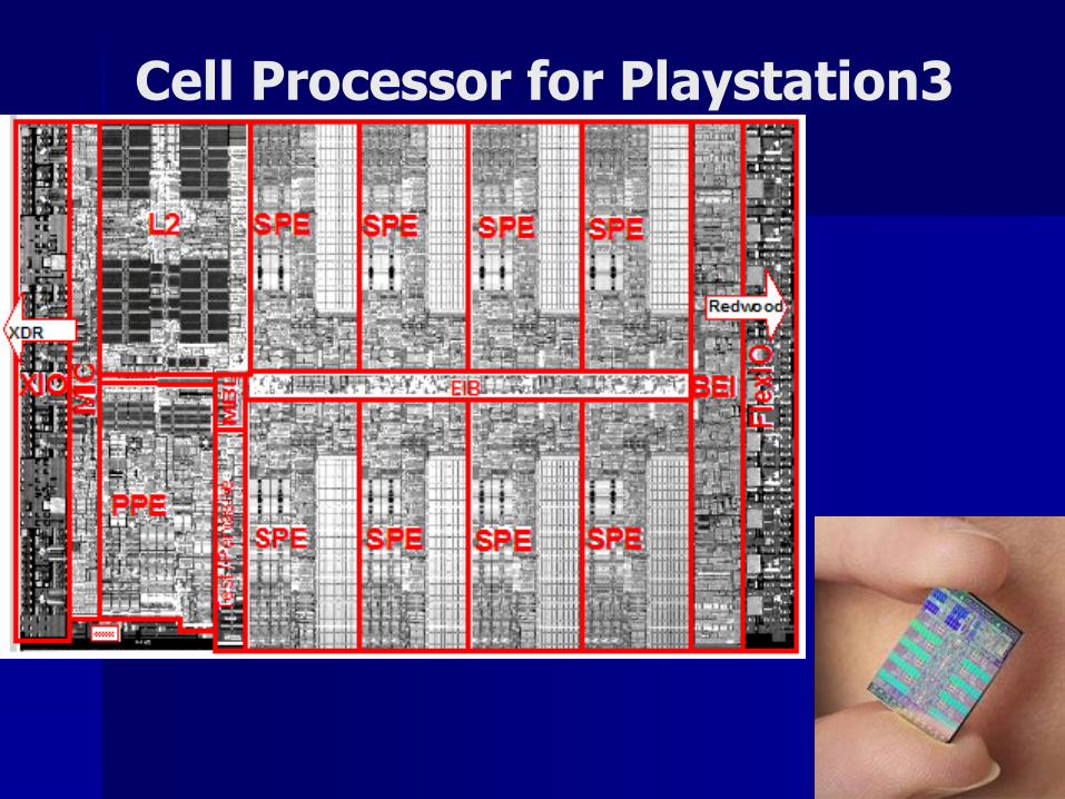
Cell Processor for Playstation3

23
IBM POwer5

24
IBM PowerPC history

25
3-D chips
3 mm x 3 mm FDSOI .18um
technology from MIT Lincoln Lab.
3 physical planes with 3 metal layers each plane
device count ~119K
Courtesy: V. Pavlidis, Rochester Univ., NY, USA
26
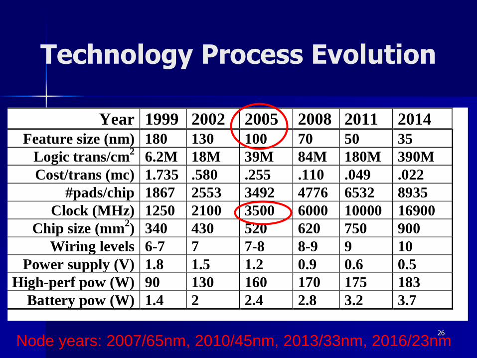
Technology Process Evolution
Year 1999 2002 2005 2008 2011 2014
Feature size (nm) 180 130 100 70 50 35
Logic trans/cm2
6.2M 18M 39M 84M 180M 390M
Cost/trans (mc) 1.735 .580 .255 .110 .049 .022
#pads/chip 1867 2553 3492 4776 6532 8935
Clock (MHz) 1250 2100 3500 6000 10000 16900
Chip size (mm2) 340 430 520 620 750 900
Wiring levels 6-7 7 7-8 8-9 9 10
Power supply (V) 1.8 1.5 1.2 0.9 0.6 0.5
High-perf pow (W) 90 130 160 170 175 183
Battery pow (W) 1.4 2 2.4 2.8 3.2 3.7
Node years: 2007/65nm, 2010/45nm, 2013/33nm, 2016/23nm
27
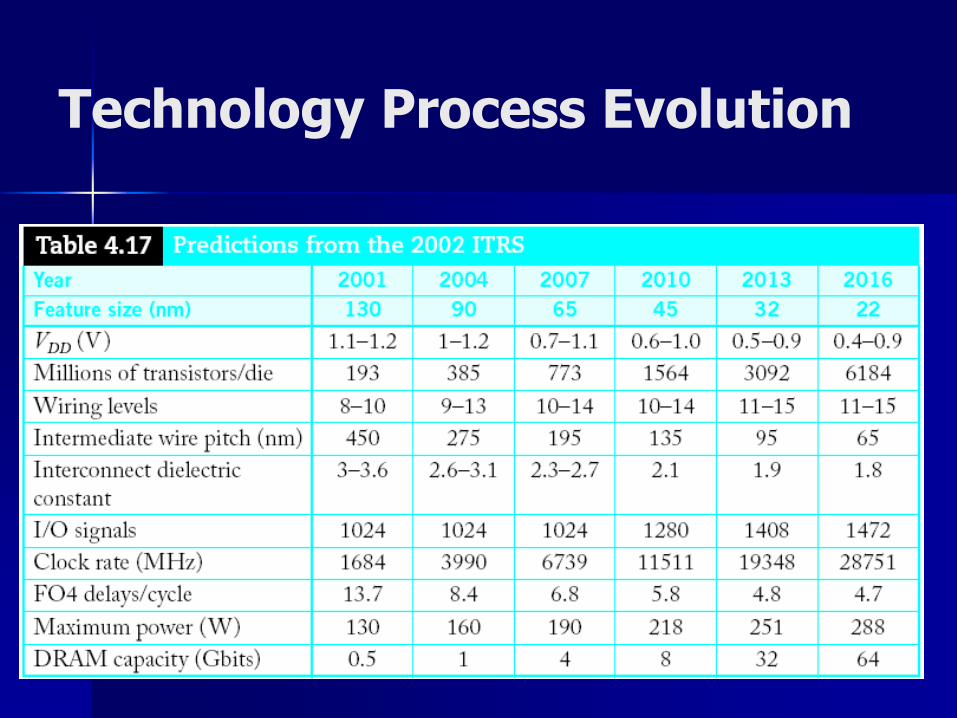
Technology Process Evolution

28
Intel’s Technology Roadmap
Mark Bohr: Intel 04

29
Raising the Level of Abstraction for Design
Performance
driven HWR
3G ENGINE
BlueTooth Controller
IR &
RS232
Compression& Encryption
Engine
CPU
CoreDSP
Core
RTOS
BlueTooth Driver
Comp/Enc Driver
IR/RS232 DriverFPGA
Functional
Differentiation
Software
Transistor
Gate
RTL
IP Blocks & Buses
Courtesy from: Walden C. Rhines – Mentor Graphics Corporation, DAC 2004

30
Bibliography
Books– W. Wolf, “Computers as Components”– P. Marwedel “Embedded Systems Design”– S. Furber, “ARM System-on-Chip Architecture”– P. Panda, “Memory Issues in Embedded
Systems-on-Chip”– F. Vahid and T. Givargis, “Embedded System
Design: A Unified Hardware/Software Introduction”
– F. Catthoor, “Data Access abd Storage Management for Embedded Programmable Processors”
Soudris’ slides http://e-class.duth.gr
31
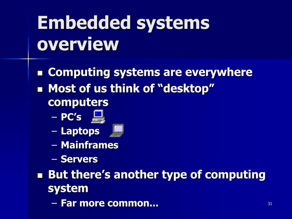
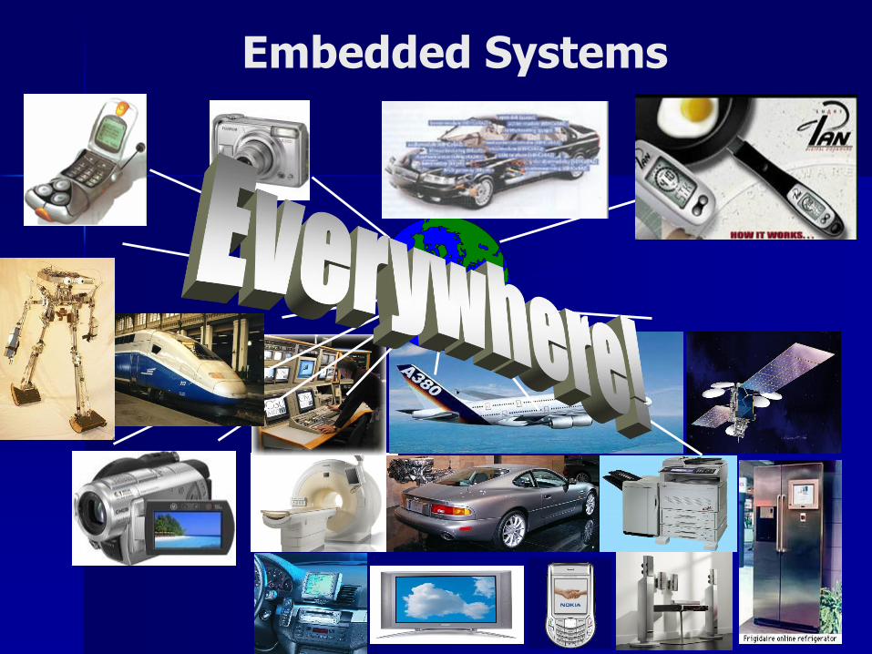
Embedded systems overview
Computing systems are everywhere
Most of us think of “desktop” computers
– PC’s
– Laptops
– Mainframes
– Servers
But there’s another type of computing system
– Far more common...

32
Embedded systems overview
Embedded computing systems
– Computing systems embedded within electronic devices
– Hard to define. Nearly any computing system other than a desktop computer
– Billions of units produced yearly, versus millions of desktop units
– Perhaps 50 per household and per automobile
Computers are in here...
and here...
and even here...
Lots more of these,
though they cost a lot
less each.
33
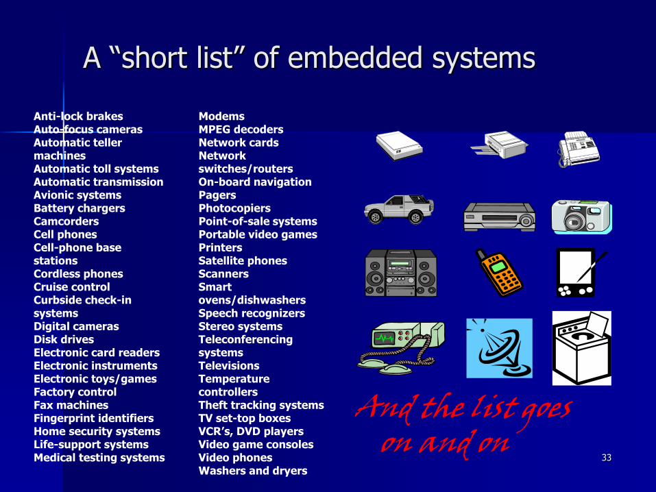
A “short list” of embedded systems
And the list goes on and on
Anti-lock brakesAuto-focus camerasAutomatic teller machinesAutomatic toll systemsAutomatic transmissionAvionic systemsBattery chargersCamcordersCell phonesCell-phone base stationsCordless phonesCruise controlCurbside check-in systemsDigital camerasDisk drivesElectronic card readersElectronic instrumentsElectronic toys/gamesFactory controlFax machinesFingerprint identifiersHome security systemsLife-support systemsMedical testing systems
ModemsMPEG decodersNetwork cardsNetwork switches/routersOn-board navigationPagersPhotocopiersPoint-of-sale systemsPortable video gamesPrintersSatellite phonesScannersSmart ovens/dishwashersSpeech recognizersStereo systemsTeleconferencing systemsTelevisionsTemperature controllersTheft tracking systemsTV set-top boxesVCR’s, DVD playersVideo game consolesVideo phonesWashers and dryers
34
Embedded Systems

35
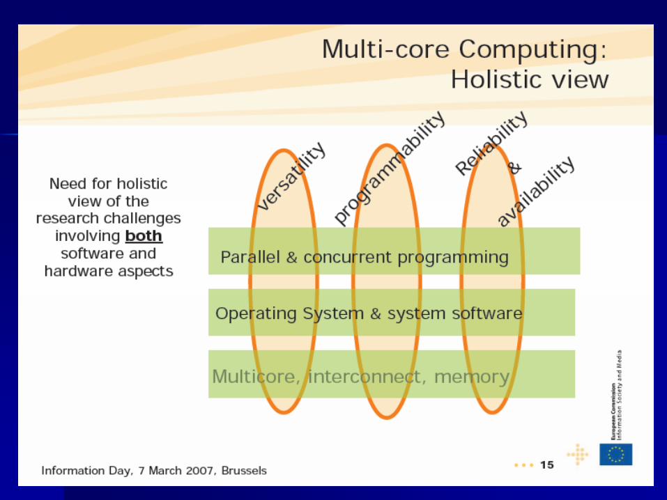
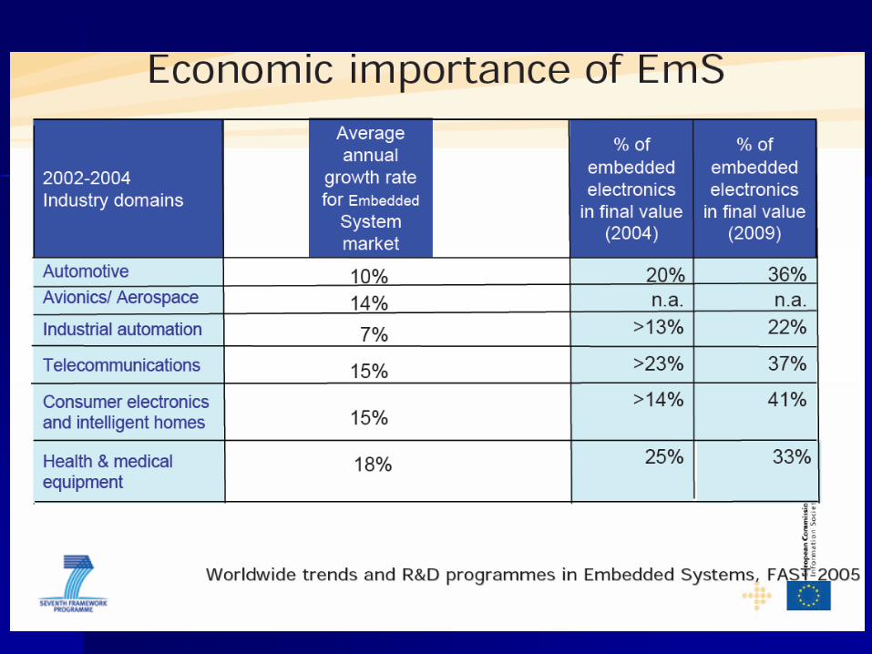
What about Europe?

37
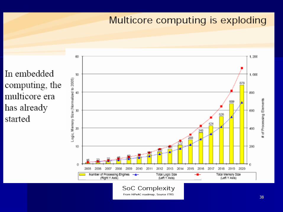
38
39

40
41
42
HiPEAC RoadmapEmbedded systems definitions
1. An embedded system is a special-purpose computer system, which is completely encapsulated by the device it controls. An embedded system has specific requirements and performs pre-defined tasks, unlike a general purpose personal computer.
2. Embedded systems are highly specialisable, often reactive, sub systems that provide, unnoticed by the user, information processing and control tasks to their embedding system.
3. Embedded systems are a combination of computer hardware and software, and perhaps additional mechanical or other parts, designed to perform a dedicated function. In some cases, embedded systems are part of a larger system or product.
4. Embedded systems are inexpensive mass-produced elements of a larger system providing a dedicated, possible time-constrained, service to that system.

43
HiPEAC Roadmap
It is clear that there is not a single definition for the embedded systems. Still, the most important characteristic that makes them different from the general-purpose systems is the ability to perform a specialized task. The embedded systems are characterized by the following properties:
They are information processing sub system of their embedding systems.
They provide specific and highly spesialisable information processing services
They are reactive, i.e. they interact with their physical environment (either using some sensors or actuators or using some kind of connectivity (wired or wireless))
They provide a usually complex functionality to their embedding system

44
Some common characteristics of embedded systems
Single-functioned
– Executes a single program, repeatedly
Tightly-constrained
– Low cost, low power, small, fast, etc.
Reactive and real-time
– Continually reacts to changes in the system’s environment
– Must compute certain results in real-time without delay
45
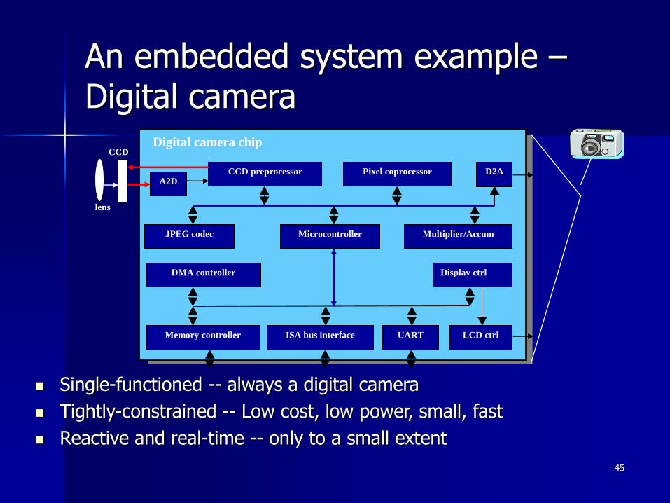
An embedded system example –Digital camera
Single-functioned -- always a digital camera
Tightly-constrained -- Low cost, low power, small, fast
Reactive and real-time -- only to a small extent
Microcontroller
CCD preprocessor Pixel coprocessorA2D
D2A
JPEG codec
DMA controller
Memory controller ISA bus interface UART LCD ctrl
Display ctrl
Multiplier/Accum
Digital camera chip
lens
CCD
46
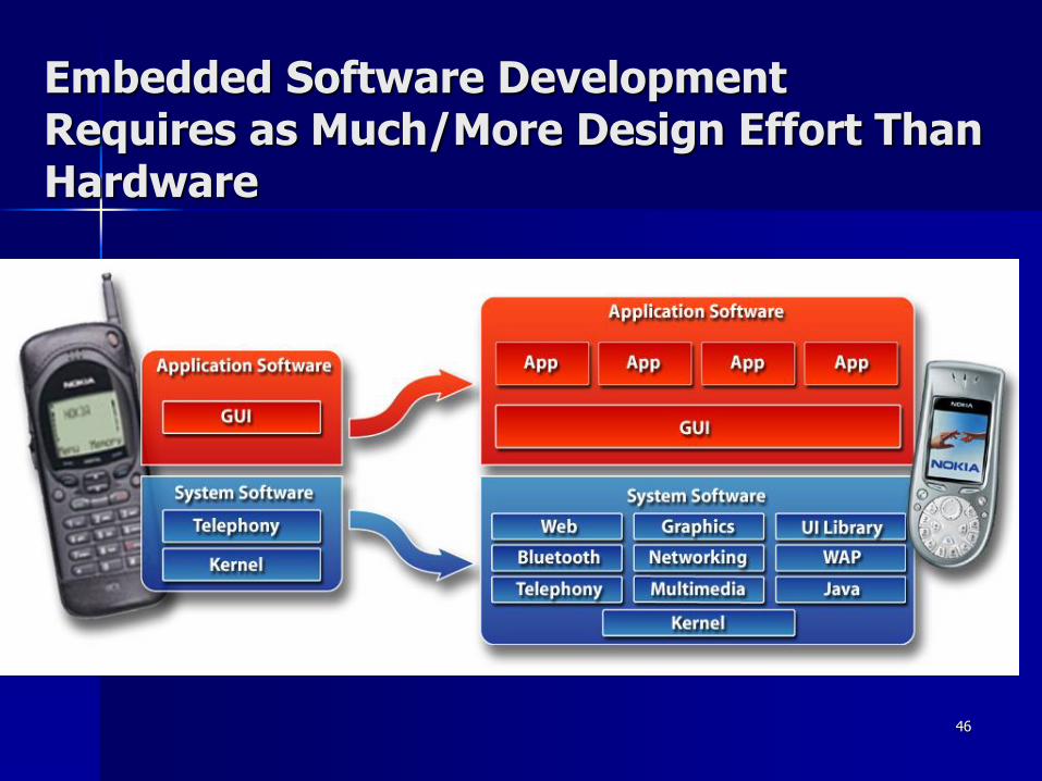
Embedded Software Development Requires as Much/More Design Effort Than Hardware

47
Design at a crossroad
System-on-a-Chip
RAM
500 k Gates FPGA
+ 1 Gbit DRAM
Preprocessing
Multi-
Spectral
Imager
mCsystem+2 GbitDRAMRecog-
nition
Anal
og
64 SIMD Processor
Array + SRAM
Image Conditioning
100 GOPS
Embedded applications where cost, performance, and energy are the real issues!
DSP and control intensive
Mixed-mode
Combines programmable and application-specific modules
Software plays crucial role

48
Design challenge – optimizing design metrics
Obvious design goal:
– Construct an implementation with desired functionality
Key design challenge:
– Simultaneously optimize numerous design metrics
Design metric
– A measurable feature of a system’s implementation
– Optimizing design metrics is a key challenge

49
Design challenge –optimizing design metrics
Common metrics
– Unit cost: the monetary cost of manufacturing each
copy of the system, excluding NRE cost
– NRE cost (Non-Recurring Engineering cost): The one-time monetary cost of designing the
system
– Size: the physical space required by the system
– Performance: the execution time or throughput of
the system
– Power: the amount of power consumed by the system
– Flexibility: the ability to change the functionality of
the system without incurring heavy NRE cost

50
Design challenge – optimizing design metrics
Common metrics (continued)
– Time-to-prototype: the time needed to
build a working version of the system
– Time-to-market: the time required to
develop a system to the point that it can be released and sold to customers
– Maintainability: the ability to modify the
system after its initial release
– Correctness, safety, many more
51
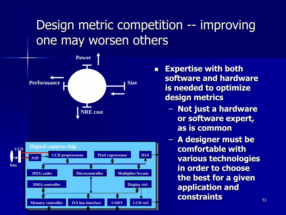
Design metric competition -- improving one may worsen others
Expertise with both software and hardware is needed to optimize design metrics
– Not just a hardware or software expert, as is common
– A designer must be comfortable with various technologies in order to choose the best for a given application and constraints
SizePerformance
Power
NRE cost
Microcontroller
CCD preprocessor Pixel coprocessorA2D
D2A
JPEG codec
DMA controller
Memory controller ISA bus interface UART LCD ctrl
Display ctrl
Multiplier/Accum
Digital camera chip
lens
CCD
52
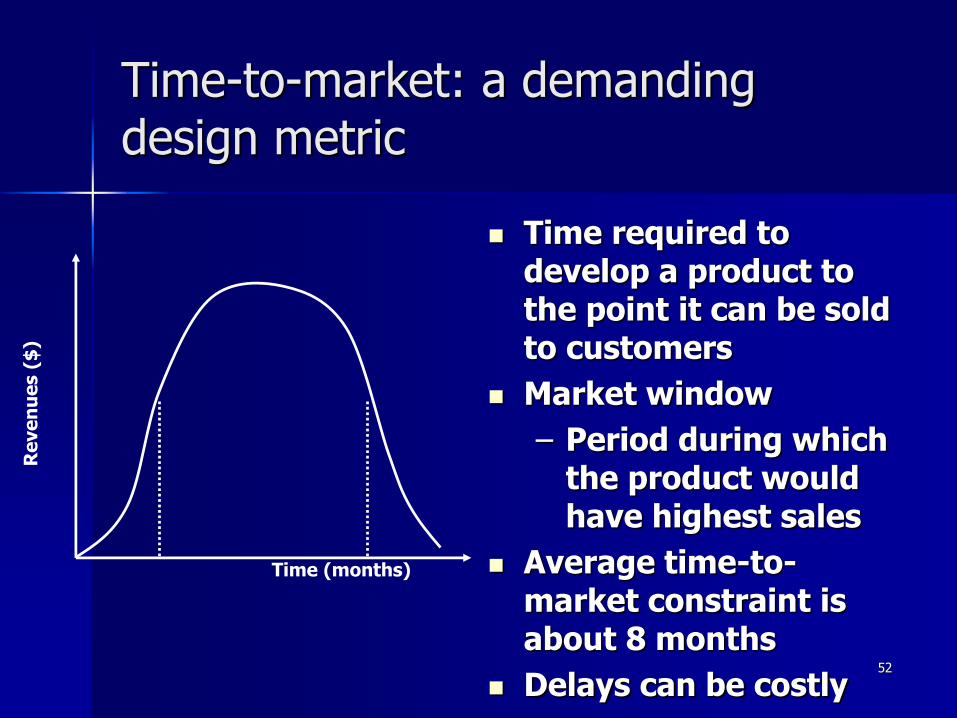
Time-to-market: a demanding design metric
Time required to develop a product to the point it can be sold to customers
Market window
– Period during which the product would have highest sales
Average time-to-market constraint is about 8 months
Delays can be costly
Re
ve
nu
es (
$)
Time (months)
53
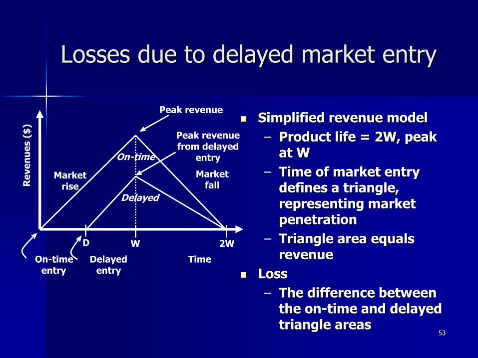
Losses due to delayed market entry
Simplified revenue model
– Product life = 2W, peak at W
– Time of market entry defines a triangle, representing market penetration
– Triangle area equals revenue
Loss
– The difference between the on-time and delayed triangle areas
On-time Delayedentry entry
Peak revenue
Peak revenue from delayed
entry
Marketrise
Market fall
W 2W
Time
D
On-time
Delayed
Re
ve
nu
es (
$)

54
Losses due to delayed market entry (cont.)
Area = 1/2 * base * height
– On-time = 1/2 * 2W * W
– Delayed = 1/2 * (W-D+W)*(W-D)
Percentage revenue loss = (D(3W-D)/2W2)*100%
Try some examples
– Lifetime 2W=52 wks, delay D=4 wks
– (4*(3*26 –4)/2*26^2) = 22%
– Lifetime 2W=52 wks, delay D=10 wks
– (10*(3*26 –10)/2*26^2) = 50%
– Delays are costly!
On-time Delayedentry entry
Peak revenue
Peak revenue from delayed
entry
Marketrise
Market fall
W 2W
Time
D
On-time
Delayed
Re
ve
nu
es (
$)

55
Design Economics (1)
The selling price of an IC Stotal=Ctotal/(1-m),
Ctotal is manufacturing cost for a single IC, m desired profit margin
Costs for produce an IC
– Non-recurring engineering costs (NREs)
– Recurring engineering costs
– Fixed costs

56
Design Economics (2)
Non-recurring engineering costs (NREs)– Engineering design cost
– Prototype manufacturing cost
Recurring costs– Process
– Package
– Test
57
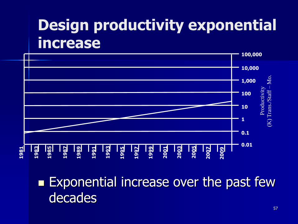
Design productivity exponential increase
Exponential increase over the past few decades
100,000
10,000
1,000
100
10
1
0.1
0.01
19
83
19
87
19
89
19
91
19
93
19
85
19
95
19
97
19
99
20
01
20
03
20
05
20
07
20
09
Pro
du
ctiv
ity
(K)
Tra
ns.
/Sta
ff –
Mo
.
58
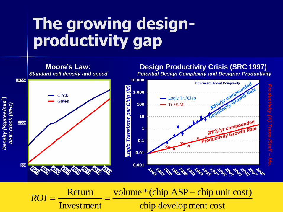
The growing design-productivity gap
Design Productivity Crisis (SRC 1997) Potential Design Complexity and Designer Productivity
10,000
1,000
100
De
ns
ity
(K
ga
tes
/mm
2)
AS
IC c
lock (
MH
z) Gates
Clock
Moore’s Law: Standard cell density and speed
Lo
gic
Tra
nsis
tor
per
Ch
ip (
M)
Pro
du
ctiv
ity (K
) Tra
ns./S
taff –
Mo
.
100,000,000
0.01
0.1
1
10
100
1,000
10,000
Equivalent Added Complexity
1,000
100
10
1
0.1
0.01
0.001
10,000
xxx
x
xx
x x
costt developmen chip
)costunit chipASP (chip*volume
Investment
Return ROI
Logic Tr./Chip
Tr./S.M.

59
Design productivity gap
1981 leading edge chip required 100 designer months– 10,000 transistors / 100
transistors/month 2002 leading edge chip requires 30,000
designer months– 150,000,000 / 5000 transistors/month
Designer cost increase from $1M to $300M
While designer productivity has grown at an impressive rate over the past decades, the rate of improvement has not kept pace with chip capacity
60
The mythical man-month
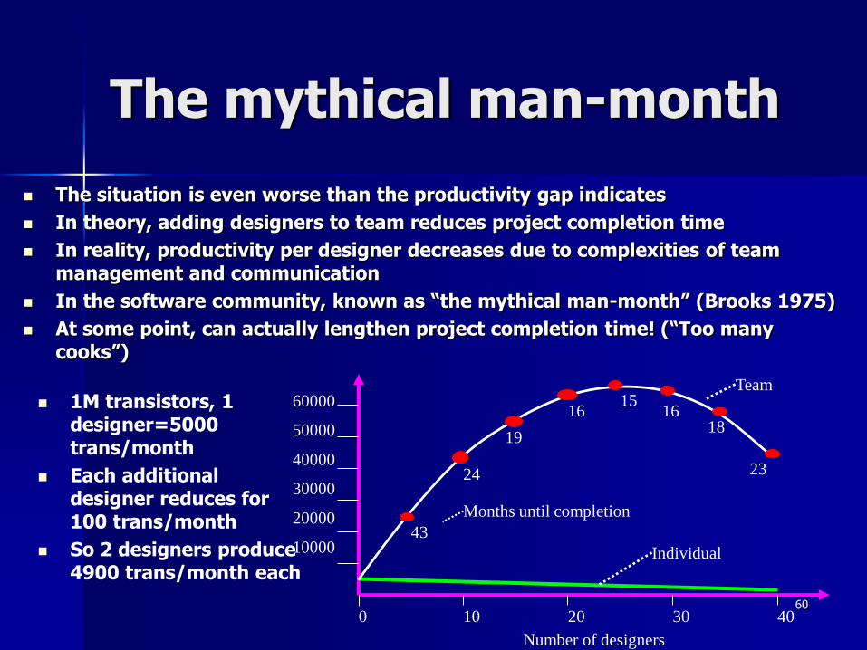
The situation is even worse than the productivity gap indicates
In theory, adding designers to team reduces project completion time
In reality, productivity per designer decreases due to complexities of team management and communication
In the software community, known as “the mythical man-month” (Brooks 1975)
At some point, can actually lengthen project completion time! (“Too many cooks”)
1M transistors, 1 designer=5000 trans/month
Each additional designer reduces for 100 trans/month
So 2 designers produce 4900 trans/month each
10000
20000
30000
40000
50000
60000
10 20 30 400
43
24
19
1615
1618
23
Team
Individual
Months until completion
Number of designers

61
NRE and unit cost metrics
Costs:– Unit cost: the monetary cost of manufacturing each copy
of the system, excluding NRE cost
– NRE cost (Non-Recurring Engineering cost): The one-time monetary cost of designing the system
– total cost = NRE cost + unit cost * # of units
– per-product cost = total cost / # of units
= (NRE cost / # of units) + unit cost
• Example
– NRE=$2000, unit=$100
– For 10 units
– total cost = $2000 + 10*$100 = $3000
– per-product cost = $2000/10 + $100 = $300
Amortizing NRE cost over the units results in an
additional $200 per unit

62
NRE and unit cost metrics
$0
$40,000
$80,000
$120,000
$160,000
$200,000
0 800 1600 2400
A
B
C
$0
$40
$80
$120
$160
$200
0 800 1600 2400
Number of units (volume)
A
B
C
Number of units (volume)
tota
l c
ost
(x1
00
0)
pe
r p
rod
uc
t c
ost
Compare technologies by costs -- best depends on quantity
– Technology A: NRE=$2,000, unit=$100
– Technology B: NRE=$30,000, unit=$30
– Technology C: NRE=$100,000, unit=$2
• But, must also consider time-to-market
63
The performance design metric
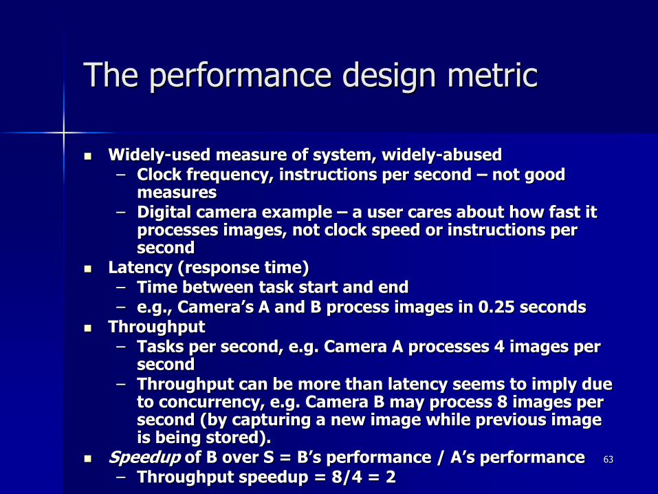
Widely-used measure of system, widely-abused– Clock frequency, instructions per second – not good
measures– Digital camera example – a user cares about how fast it
processes images, not clock speed or instructions per second
Latency (response time)– Time between task start and end– e.g., Camera’s A and B process images in 0.25 seconds
Throughput– Tasks per second, e.g. Camera A processes 4 images per
second– Throughput can be more than latency seems to imply due
to concurrency, e.g. Camera B may process 8 images per second (by capturing a new image while previous image is being stored).
Speedup of B over S = B’s performance / A’s performance– Throughput speedup = 8/4 = 2

64
Design Methodology
• Design process traverses iteratively between three abstractions:
behavior, structure, and geometry
• More and more automation for each of these steps

65
Three key embedded system technologies
Technology
– A manner of accomplishing a task, especially using technical processes, methods, or knowledge
Three key technologies for embedded systems
– Processor technology
– IC technology
– Design technology
66
Processor technology
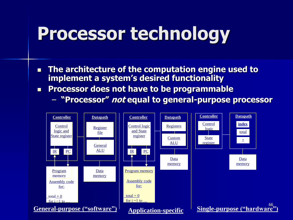
The architecture of the computation engine used to implement a system’s desired functionality
Processor does not have to be programmable
– “Processor” not equal to general-purpose processor
Application-specific
Registers
Custom
ALU
DatapathController
Program memory
Assembly code
for:
total = 0
for i =1 to …
Control logic
and State
register
Data
memory
IR PC
Single-purpose (“hardware”)
DatapathController
Control
logic
State
register
Data
memory
index
total
+
IR PC
Register
file
General
ALU
DatapathController
Program
memory
Assembly code
for:
total = 0
for i =1 to …
Control
logic and
State register
Data
memory
General-purpose (“software”)

67
Processor technology
Processors vary in their customization for the problem at hand
total = 0
for i = 1 to N loop
total += M[i]
end loop
General-purpose
processor
Single-purpose
processor
Application-specific
processor
Desired
functionality
68
General-purpose processors
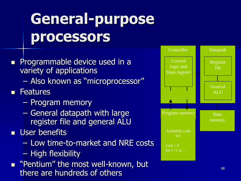
Programmable device used in a variety of applications
– Also known as “microprocessor”
Features
– Program memory
– General datapath with large register file and general ALU
User benefits
– Low time-to-market and NRE costs
– High flexibility
“Pentium” the most well-known, but there are hundreds of others
Datapath
IR PC
Register
file
General
ALU
Controller
Program memory
Assembly code
for:
total = 0
for i =1 to …
Control
logic and
State register
Data
memory

69
Single-purpose processors
Digital circuit designed to execute exactly one program
– a.k.a. coprocessor, accelerator or peripheral
Features
– Contains only the components needed to execute a single program
– No program memory
Benefits
– Fast
– Low power
– Small size
DatapathController
Control logic
State register
Data
memory
index
total
+
70
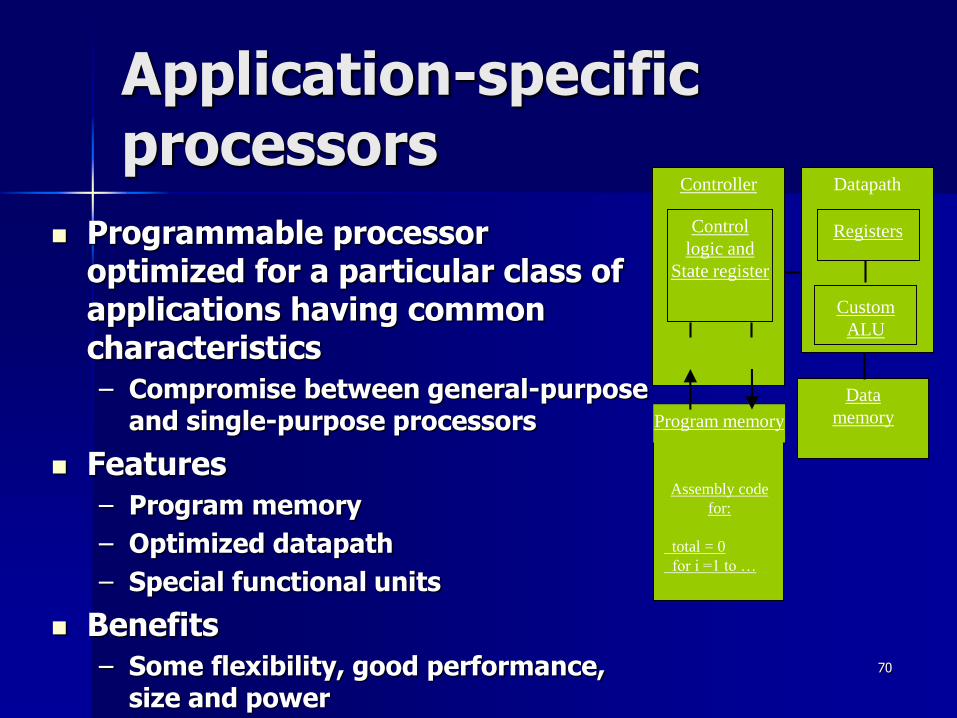
Application-specific processors
Programmable processor optimized for a particular class of applications having common characteristics
– Compromise between general-purpose and single-purpose processors
Features
– Program memory
– Optimized datapath
– Special functional units
Benefits
– Some flexibility, good performance, size and power
Datapath
IR PC
Registers
Custom
ALU
Controller
Program memory
Assembly code
for:
total = 0
for i =1 to …
Control
logic and
State register
Data
memory
71
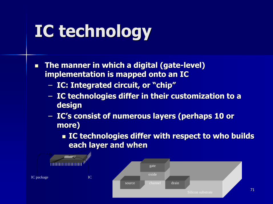
IC technology
The manner in which a digital (gate-level) implementation is mapped onto an IC
– IC: Integrated circuit, or “chip”
– IC technologies differ in their customization to a design
– IC’s consist of numerous layers (perhaps 10 or more)
IC technologies differ with respect to who builds each layer and when
source drainchannel
oxide
gate
Silicon substrate
IC package IC

72
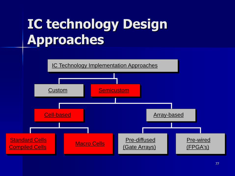
IC technology Design Approaches
Custom
Standard Cells
Compiled CellsMacro Cells
Cell-based
Pre-diffused
(Gate Arrays)
Pre-wired
(FPGA's)
Array-based
Semicustom
IC Technology Implementation Approaches

73
Full-custom design
All layers are optimized for an embedded system’s particular digital implementation
– Placing transistors
– Sizing transistors
– Routing wires
Benefits
– Excellent performance, small size, low power
Drawbacks
– High NRE cost (e.g., $300k), long time-to-market
74
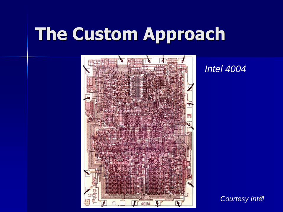
The Custom Approach
Intel 4004
Courtesy Intel

75
Transition to Automation and Regular Structures
Intel 4004 (‘71)
Intel 8080 Intel 8085
Intel 8286 Intel 8486Courtesy Intel

76
77
IC technology Design Approaches
Custom
Standard Cells
Compiled CellsMacro Cells
Cell-based
Pre-diffused
(Gate Arrays)
Pre-wired
(FPGA's)
Array-based
Semicustom
IC Technology Implementation Approaches

78
Semi-custom
Lower layers are fully or partially built
– Designers are left with routing of wires and maybe placing some blocks
Benefits
– Good performance, good size, less NRE cost than a full-custom implementation (perhaps $10k to $100k)
Drawbacks
– Still require weeks to months to develop

79
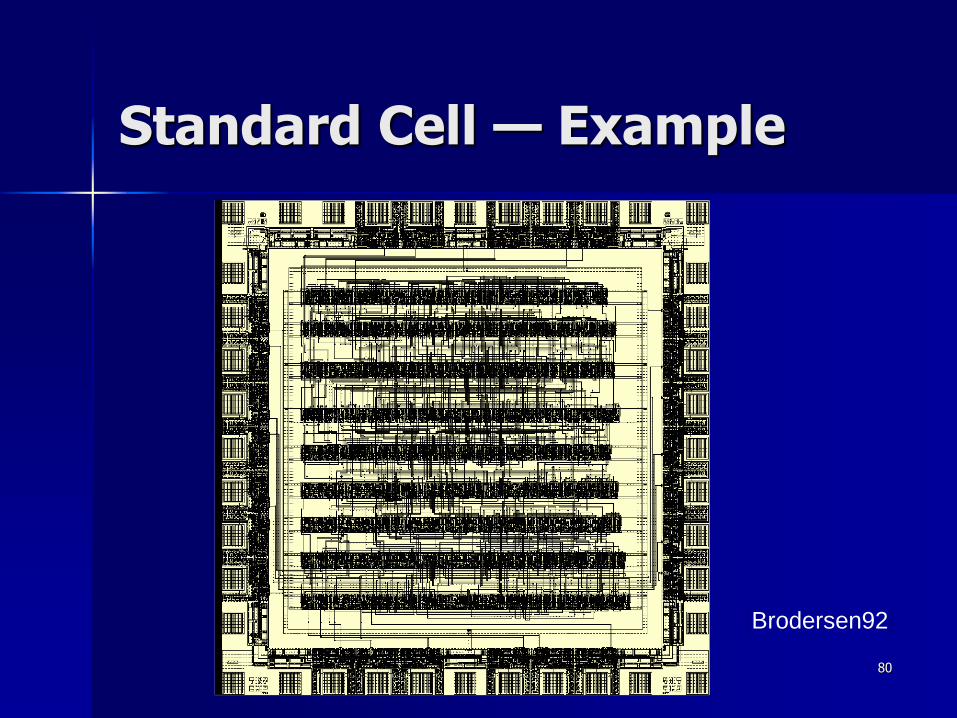
Cell-based Design (or standard cells)
Routing channel
requirements are
reduced by presence
of more interconnect
layers
80
Standard Cell — Example
[Brodersen92]

81
Standard Cell - Example
3-input NAND cell
(from ST Microelectronics):
C = Load capacitance
T = input rise/fall time

82
IC technology Design Approaches
Custom
Standard Cells
Compiled CellsMacro Cells
Cell-based
Pre-diffused
(Gate Arrays)
Pre-wired
(FPGA's)
Array-based
Semicustom
IC Technology Implementation Approaches

83
Programmable Logic Devices
All layers (diffusion, polysilicon, [multi-] metal) may exist– Designers can purchase an IC
– Connections on the IC are either created or destroyed to implement desired functionality
– Field-Programmable Gate Array (FPGA) and recently Gate Arrays are very popular
Benefits– Low NRE costs, almost instant IC availability
Drawbacks– Bigger, expensive (perhaps $30 per unit), power
hungry, slower

84
Gate Array — Sea-of-gates
rows of
cells
routing channel
uncommitted
VDD
GND
polysilicon
metal
possiblecontact
In1 In2 In3 In4
Out
Uncommited
Cell
Committed
Cell
(4-input NOR)
85
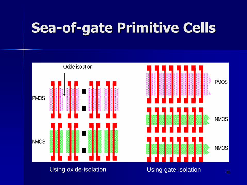
Sea-of-gate Primitive Cells
NMOS
PMOS
Oxide-isolation
PMOS
NMOS
NMOS
Using oxide-isolation Using gate-isolation
86
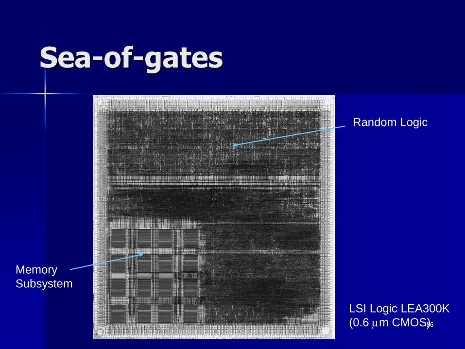
Sea-of-gates
Random Logic
Memory
Subsystem
LSI Logic LEA300K
(0.6 mm CMOS)

87
Prewired Arrays
Classification of prewired arrays (or field-programmable devices):
Based on Programming Technique
– Fuse-based (program-once)
– Non-volatile EPROM based
– RAM based
Programmable Logic Style
– Array-Based
– Look-up Table
Programmable Interconnect Style
– Channel-routing
– Mesh networks
88
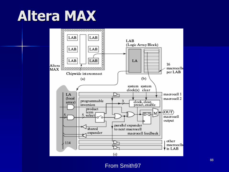
Altera MAX
From Smith97
89
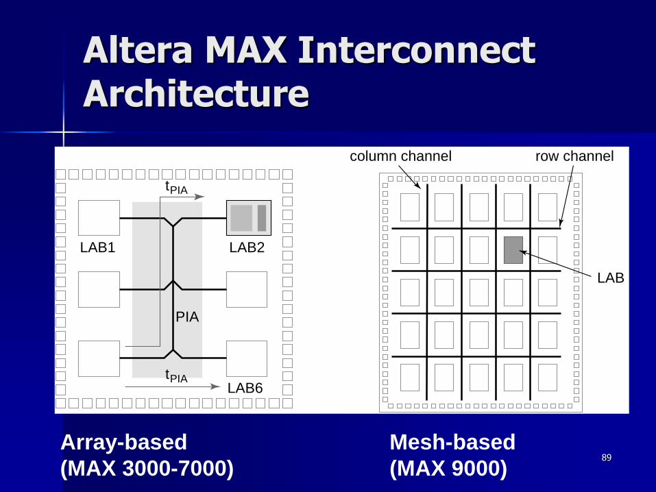
Altera MAX Interconnect Architecture
LAB2
PIA
LAB1
LAB6
tPIA
tPIA
row channelcolumn channel
LAB
Array-based
(MAX 3000-7000)
Mesh-based
(MAX 9000)
90
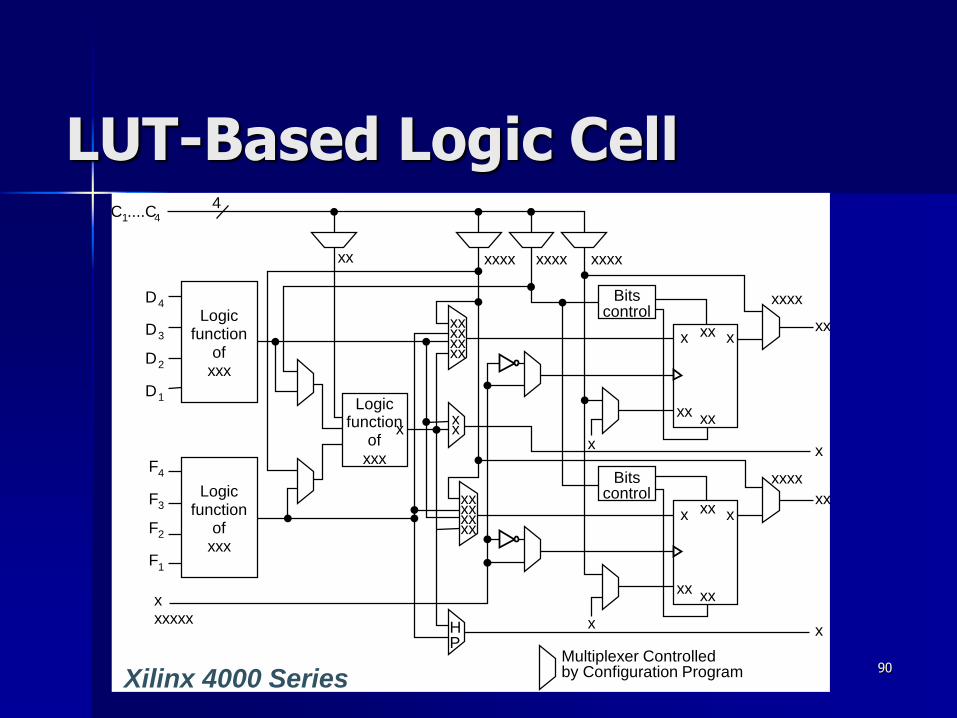
LUT-Based Logic Cell
D4
C1....C4
xxxxxx
D3
D2
D1
F4
F3
F2
F1
Logicfunction
ofxxx
Logicfunction
ofxxx
Logicfunction
ofxxx
xx
xx
4
xxxxxx
xxxxxxxx
xxx
xxxx xxxx xxxx
HP
Bitscontrol
Bitscontrol
Multiplexer Controlledby Configuration Program
x
xx
x
xx
xxx xx
xxxx
x
xx
xxxx
xx
x
xx
xxx
xx
Xilinx 4000 Series

91
Array-Based Programmable Wiring
Vertical tracks
Input/output pinProgrammed interconnection
Interconnect
Point
Horizontal
tracks
Cell
M
92
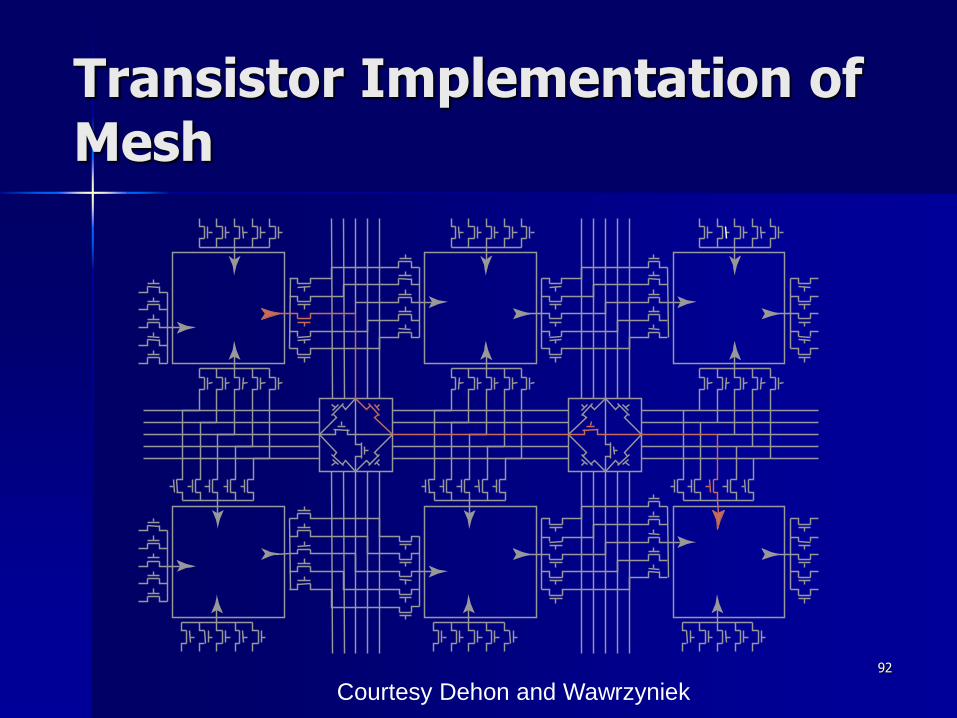
Transistor Implementation of Mesh
Courtesy Dehon and Wawrzyniek
93
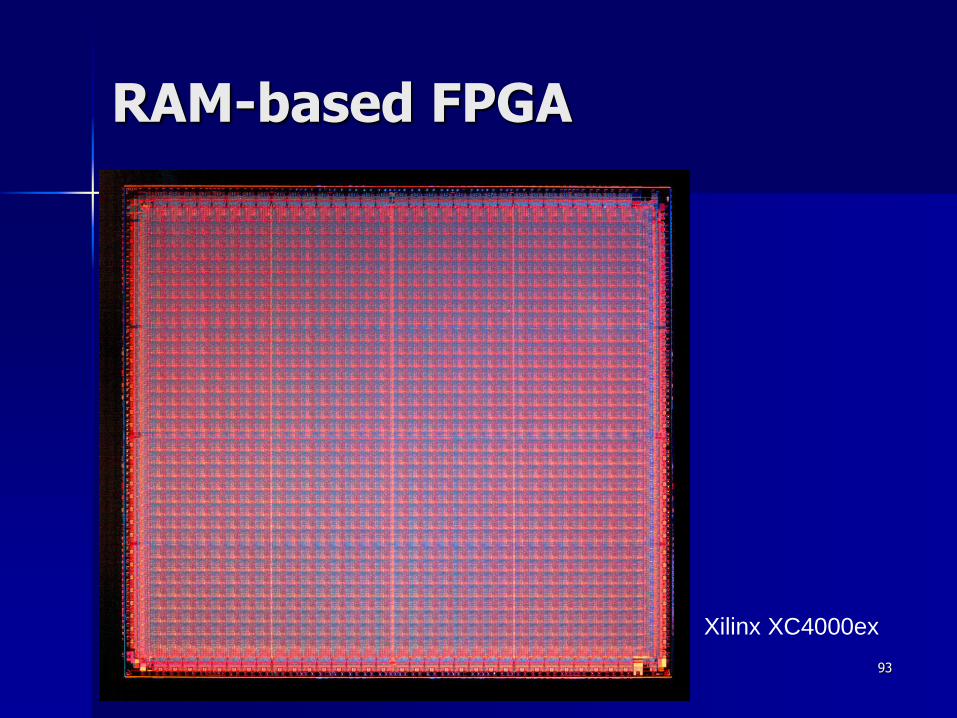
RAM-based FPGA
Xilinx XC4000ex
94
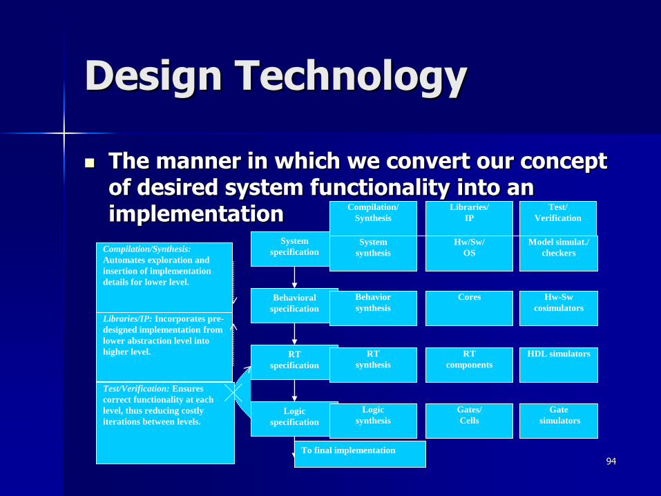
Design Technology
The manner in which we convert our concept of desired system functionality into an implementation
Libraries/IP: Incorporates pre-
designed implementation from
lower abstraction level into
higher level.
System
specification
Behavioral
specification
RT
specification
Logic
specification
To final implementation
Compilation/Synthesis:
Automates exploration and
insertion of implementation
details for lower level.
Test/Verification: Ensures
correct functionality at each
level, thus reducing costly
iterations between levels.
Compilation/
Synthesis
Libraries/
IP
Test/
Verification
System
synthesis
Behavior
synthesis
RT
synthesis
Logic
synthesis
Hw/Sw/
OS
Cores
RT
components
Gates/
Cells
Model simulat./
checkers
Hw-Sw
cosimulators
HDL simulators
Gate
simulators

95
The co-design ladder In the past:
– Hardware and software design technologies were very different
– Recent maturation of synthesis enables a unified view of hardware and software
Hardware/software “codesign” Implementation
Assembly instructions
Machine instructions
Register transfers
Compilers
(1960's,1970's)
Assemblers, linkers
(1950's, 1960's)
Behavioral synthesis
(1990's)
RT synthesis
(1980's, 1990's)
Logic synthesis
(1970's, 1980's)
Microprocessor plus
program bits: “software”
VLSI, ASIC, or PLD
implementation: “hardware”
Logic gates
Logic equations / FSM's
Sequential program code (e.g., C, VHDL)
The choice of hardware versus software for a particular function is simply a tradeoff among various
design metrics, like performance, power, size, NRE cost, and especially flexibility; there is no
fundamental difference between what hardware or software can implement.
96
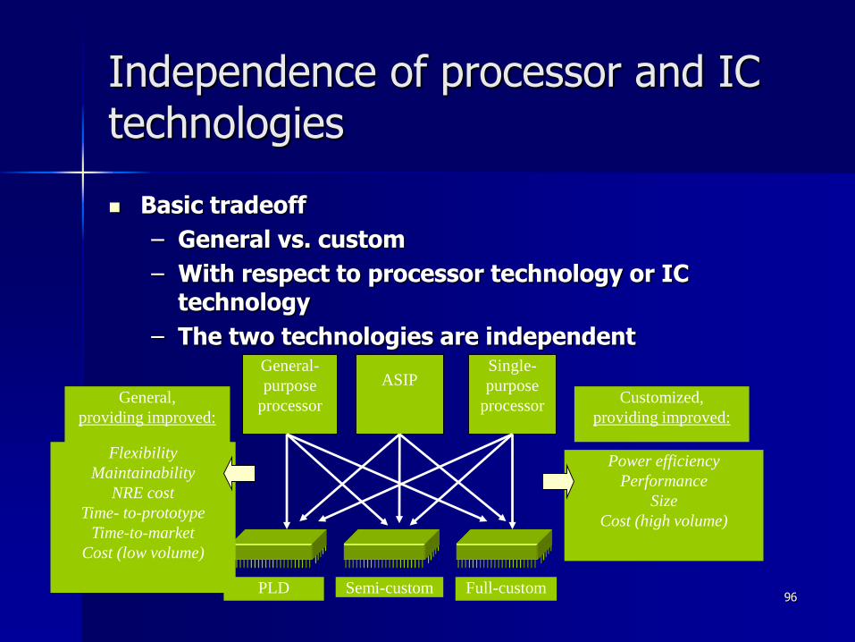
Independence of processor and IC technologies
Basic tradeoff
– General vs. custom
– With respect to processor technology or IC technology
– The two technologies are independentGeneral-
purpose
processor
ASIPSingle-
purpose
processor
Semi-customPLD Full-custom
General,
providing improved:
Customized,
providing improved:
Power efficiency
Performance
Size
Cost (high volume)
Flexibility
Maintainability
NRE cost
Time- to-prototype
Time-to-market
Cost (low volume)

97
Design Decision Trade-offs
98
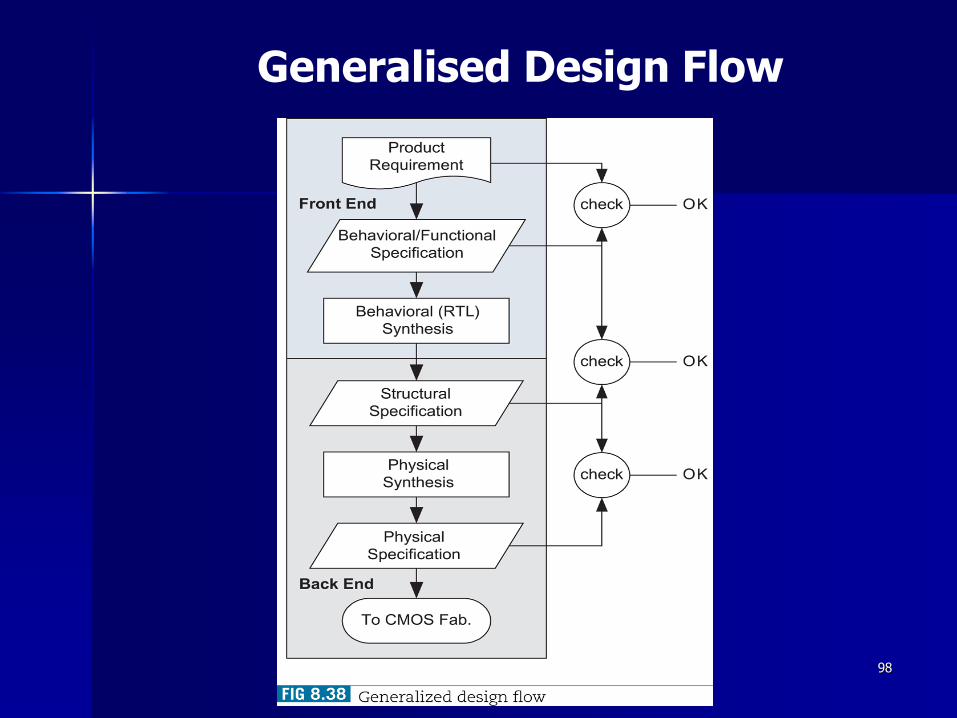
Generalised Design Flow
99
Architecture ReUse
Silicon System Platform
– Flexible architecture for hardware and software
– Specific (programmable) components
– Network architecture
– Software modules
– Rules and guidelines for design of HW and SW
Has been successful in PC’s
– Dominance of a few players who specify and control architecture
Application-domain specific (difference in constraints)
– Speed (compute power)
– Dissipation
– Costs
– Real / non-real time data

100
Platform-Based Design
A platform is a restriction on the space of possible implementation choices, providing a well-defined abstraction of the underlying technology for the application developer
New platforms will be defined at the architecture-micro-architecture boundary
They will be component-based, and will provide a range of choices from structured-custom to fully programmable implementations
Key to such approaches is the representation of communication in the platform model
“Only the consumer gets freedom of choice;
designers need freedom from choice”
(Orfali, et al, 1996, p.522)
Source:R.Newton
101
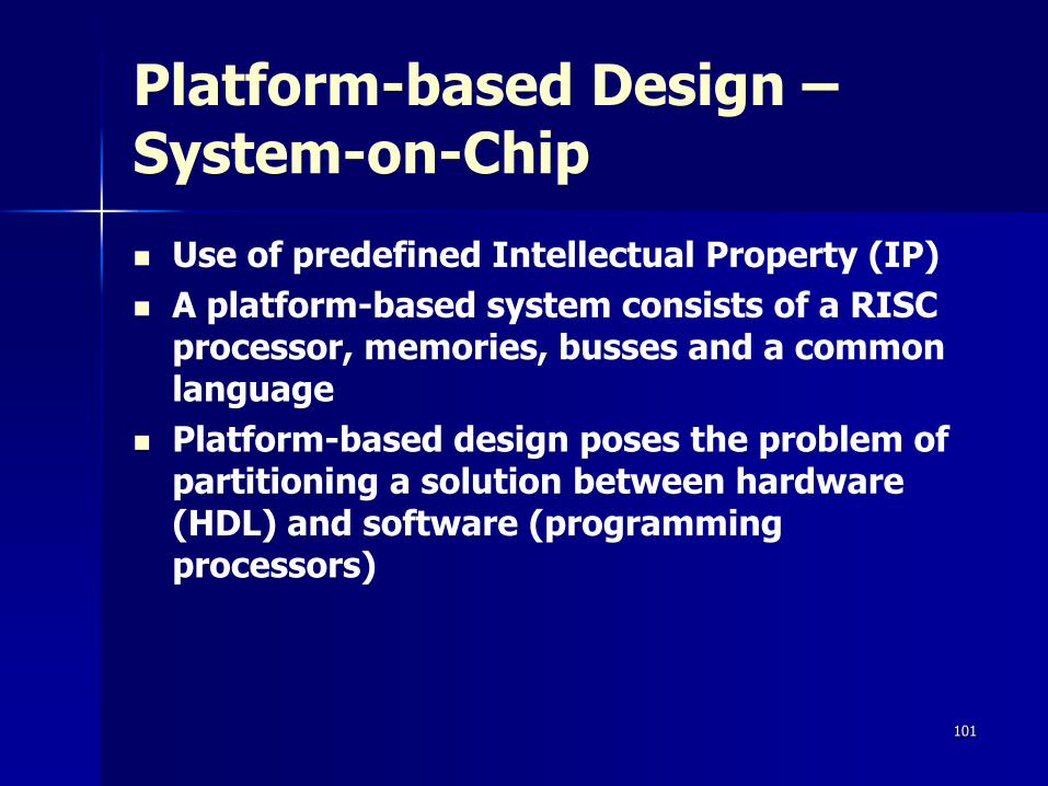
Platform-based Design –System-on-Chip
Use of predefined Intellectual Property (IP)
A platform-based system consists of a RISC processor, memories, busses and a common language
Platform-based design poses the problem of partitioning a solution between hardware (HDL) and software (programming processors)

102
Platforms Enable Simplified SoC Design
Customer demands– Fast turn-around time
– Easy access to pre-qualified building blocks
– Web enabled
Design technology– Core platforms
– ‘Big’ IP
– Emerging SoC bus standards
– Embedded software
– HW/SW co-verificationFar Peripherals
Near Peripherals
Core

103
And Automation of IP Selection & Integration
104
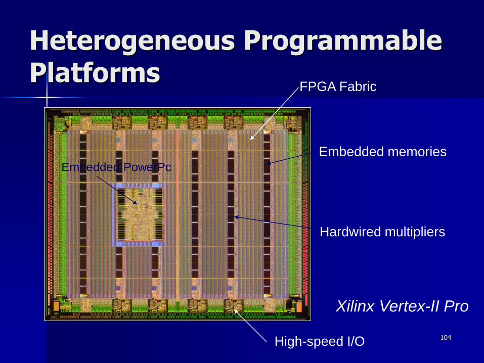
Heterogeneous Programmable Platforms
Xilinx Vertex-II Pro
High-speed I/O
Embedded PowerPc
Embedded memories
Hardwired multipliers
FPGA Fabric
105
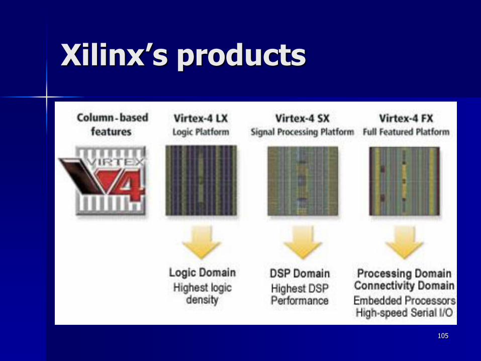
Xilinx’s products

106
Xilinx’s products
107
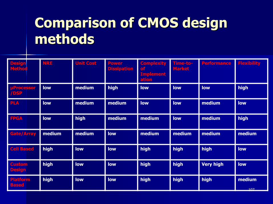
Comparison of CMOS design methods
Design Method
NRE Unit Cost Power Dissipation
Complexity of Implementation
Time-to-Market
Performance Flexibility
μProcessor/DSP
low medium high low low low high
PLA low medium medium low low medium low
FPGA low high medium medium low medium high
Gate/Array medium medium low medium medium medium medium
Cell Based high low low high high high low
Custom Design
high low low high high Very high low
Platform Based
high low low high high high medium
108
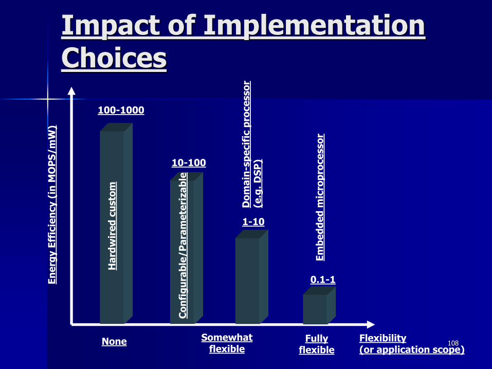
Impact of Implementation Choices
En
erg
y E
ffic
ien
cy (
in M
OP
S/m
W)
Flexibility(or application scope)
0.1-1
1-10
10-100
100-1000
None Fullyflexible
Somewhatflexible
Ha
rdw
ire
d c
usto
m
Co
nfi
gu
rab
le/P
ara
me
teri
za
ble
Do
ma
in-s
pe
cif
ic p
roce
sso
r(e
.g.
DS
P)
Em
be
dd
ed
mic
rop
roce
sso
r
109
Summary
Embedded systems are everywhere
Key challenge: optimization of design metrics
– Design metrics compete with one another
A unified view of hardware and software is necessary to improve productivity
Three key technologies
– Processor: general-purpose, application-specific, single-purpose
– IC: Full-custom, semi-custom, PLD
– Design: Compilation/synthesis, libraries/IP, test/verification

Χρηματοδότηση
Το παρόν εκπαιδευτικό υλικό έχει αναπτυχθεί στα πλαίσια του εκπαιδευτικού έργου του διδάσκοντα.
Το έργο «Ανοικτά Ακαδημαϊκά Μαθήματα» του ΕΜΠ έχει χρηματοδοτήσει μόνο την αναδιαμόρφωση του υλικού.
Το έργο υλοποιείται στο πλαίσιο του Επιχειρησιακού Προγράμματος «Εκπαίδευση και Δια Βίου Μάθηση» και συγχρηματοδοτείται από την Ευρωπαϊκή Ένωση (Ευρωπαϊκό
Κοινωνικό Ταμείο) και από εθνικούς πόρους.