An estimation of the electrical characteristics of planetary shallow subsurfaces with TAPIR antennas
11
An estimation of the electrical characteristics of planetary shallow subsurfaces with TAPIR antennas A. Le Gall, 1 A. Reineix, 2 V. Ciarletti, 1 J. J. Berthelier, 1 R. Ney, 1 F. Dolon, 1 and C. Corbel 1 Received 9 September 2005; revised 21 February 2006; accepted 27 February 2006; published 30 June 2006. [1] In the frame of the NETLANDER program, we have developed the Terrestrial And Planetary Investigation by Radar (TAPIR) imaging ground-penetrating radar to explore the Martian subsurface at kilometric depths and search for potential water reservoirs. This instrument which is to operate from a fixed lander is based on a new concept which allows one to image the various underground reflectors by determining the direction of propagation of the reflected waves. The electrical parameters of the shallow subsurface (permittivity and conductivity) need to be known to correctly determine the propagation vector. In addition, these electrical parameters can bring valuable information on the nature of the materials close to the surface. The electric antennas of the radar are 35 m long resistively loaded monopoles that are laid on the ground. Their impedance, measured during a dedicated mode of operation of the radar, depends on the electrical parameters of soil and is used to infer the permittivity and conductivity of the upper layer of the subsurface. This paper presents an experimental and theoretical study of the antenna impedance and shows that the frequency profile of the antenna complex impedance can be used to retrieve the geoelectrical characteristics of the soil. Comparisons between a numerical modeling and in situ measurements have been successfully carried over various soils, showing a very good agreement. Citation: Le Gall, A., A. Reineix, V. Ciarletti, J. J. Berthelier, R. Ney, F. Dolon, and C. Corbel (2006), An estimation of the electrical characteristics of planetary shallow subsurfaces with TAPIR antennas, J. Geophys. Res., 111, E06S06, doi:10.1029/2005JE002595. 1. Introduction [2] The extensive observations by the Viking spacecraft probes and more recently the high resolutions images from the Mars Global Surveyor camera [Malin and Edgett, 2000] have provided ample evidence of the former presence of liquid water on Mars. Indeed the valley networks bear striking analogies with valleys formed by runoff of surface water on Earth and gullies on crater walls or cliff sides appear similar to erosion features associated with water streams on terrestrial slopes [Baker, 2001]. These observa- tions raise a number of fundamental questions on the geological and climatic history of Mars and the fate of the liquid surface water. If erosion of the atmosphere by interaction with the solar wind may account for the disap- pearance of a part of this water, it is thought that a significant amount of the former surface water may still be trapped in the subsurface under the form of ground ice or even liquid water at lager depths. Present models [Fanale et al., 1986; Squyres et al., 1992; Clifford, 1993] estimate that liquid water may exist at depths of 1 to 3 km at the equator and 7 to 10 km in polar regions. Recent observa- tions [Malin and Edgett, 2000] and models [Helbert and Benkoff, 2005] have raised the question of the existence of liquid water even much closer to the surface. Water on Mars is therefore one of the major questions that will be addressed by missions that will be flown to the planet in the future. Searching for water reservoirs was one of the objectives of the NETLANDER mission that was initiated in 1999 by CNES and unfortunately stopped in 2004. It foresaw the deployment of 4 small geophysical stations on the surface of the planet each including the TAPIR ground- penetrating radar which was proposed to explore the deep underground down to possibly 2 km. This instrument is based on a novel concept which allows one to get an image of the underground reflectors and is briefly described below. [3] As shown by Ciarletti et al. [2003a], retrieving the propagation direction of the reflectors requires knowledge of the electrical characteristics of the subsurface which control the refraction of the electromagnetic waves exiting from the soil. Several methods have already been proposed in the field of electromagnetic investigation of subsurfaces to measure these parameters with particular emphasis on the measurement of the soil water content with a GPR [Van Overmeeren et al., 1997; Reppert et al., 2000; Huisman et al., 2003b; Lambot et al., 2004; Fratticcioli et al., 2004]. Huisman et al. [2003a] have given a general review of these works. The most commonly used methods are based on the Common MidPoint (CMP) or the Wide-angle Reflection and Refraction (WARR) techniques. The wave propagation JOURNAL OF GEOPHYSICAL RESEARCH, VOL. 111, E06S06, doi:10.1029/2005JE002595, 2006 Click Here for Full Articl e 1 Centre d’Etudes des Environnements Terrestre et Plane ´taires (CETP/ IPSL), Saint-Maur, France. 2 XLIM,/OSA/Projet CEM, Faculte ´ des Sciences, Universite ´ de Limoges, Limoges, France. Copyright 2006 by the American Geophysical Union. 0148-0227/06/2005JE002595$09.00 E06S06 1 of 11
Transcript of An estimation of the electrical characteristics of planetary shallow subsurfaces with TAPIR antennas
An estimation of the electrical characteristics of planetary shallow
subsurfaces with TAPIR antennas
A. Le Gall,1 A. Reineix,2 V. Ciarletti,1 J. J. Berthelier,1 R. Ney,1 F. Dolon,1 and C. Corbel1
Received 9 September 2005; revised 21 February 2006; accepted 27 February 2006; published 30 June 2006.
[1] In the frame of the NETLANDER program, we have developed the Terrestrial AndPlanetary Investigation by Radar (TAPIR) imaging ground-penetrating radar to explore theMartian subsurface at kilometric depths and search for potential water reservoirs. Thisinstrument which is to operate from a fixed lander is based on a new concept which allowsone to image the various underground reflectors by determining the direction ofpropagation of the reflected waves. The electrical parameters of the shallow subsurface(permittivity and conductivity) need to be known to correctly determine the propagationvector. In addition, these electrical parameters can bring valuable information on thenature of the materials close to the surface. The electric antennas of the radar are 35 m longresistively loaded monopoles that are laid on the ground. Their impedance, measuredduring a dedicated mode of operation of the radar, depends on the electrical parameters ofsoil and is used to infer the permittivity and conductivity of the upper layer of thesubsurface. This paper presents an experimental and theoretical study of the antennaimpedance and shows that the frequency profile of the antenna complex impedance can beused to retrieve the geoelectrical characteristics of the soil. Comparisons between anumerical modeling and in situ measurements have been successfully carried over varioussoils, showing a very good agreement.
Citation: Le Gall, A., A. Reineix, V. Ciarletti, J. J. Berthelier, R. Ney, F. Dolon, and C. Corbel (2006), An estimation of the electrical
characteristics of planetary shallow subsurfaces with TAPIR antennas, J. Geophys. Res., 111, E06S06, doi:10.1029/2005JE002595.
1. Introduction
[2] The extensive observations by the Viking spacecraftprobes and more recently the high resolutions images fromthe Mars Global Surveyor camera [Malin and Edgett, 2000]have provided ample evidence of the former presence ofliquid water on Mars. Indeed the valley networks bearstriking analogies with valleys formed by runoff of surfacewater on Earth and gullies on crater walls or cliff sidesappear similar to erosion features associated with waterstreams on terrestrial slopes [Baker, 2001]. These observa-tions raise a number of fundamental questions on thegeological and climatic history of Mars and the fate of theliquid surface water. If erosion of the atmosphere byinteraction with the solar wind may account for the disap-pearance of a part of this water, it is thought that asignificant amount of the former surface water may stillbe trapped in the subsurface under the form of ground ice oreven liquid water at lager depths. Present models [Fanale etal., 1986; Squyres et al., 1992; Clifford, 1993] estimate thatliquid water may exist at depths of � 1 to 3 km at the
equator and �7 to 10 km in polar regions. Recent observa-tions [Malin and Edgett, 2000] and models [Helbert andBenkoff, 2005] have raised the question of the existence ofliquid water even much closer to the surface. Water on Marsis therefore one of the major questions that will beaddressed by missions that will be flown to the planet inthe future. Searching for water reservoirs was one of theobjectives of the NETLANDER mission that was initiatedin 1999 by CNES and unfortunately stopped in 2004. Itforesaw the deployment of 4 small geophysical stations onthe surface of the planet each including the TAPIR ground-penetrating radar which was proposed to explore the deepunderground down to possibly 2 km. This instrument isbased on a novel concept which allows one to get an imageof the underground reflectors and is briefly described below.[3] As shown by Ciarletti et al. [2003a], retrieving the
propagation direction of the reflectors requires knowledgeof the electrical characteristics of the subsurface whichcontrol the refraction of the electromagnetic waves exitingfrom the soil. Several methods have already been proposedin the field of electromagnetic investigation of subsurfacesto measure these parameters with particular emphasis on themeasurement of the soil water content with a GPR [VanOvermeeren et al., 1997; Reppert et al., 2000; Huisman etal., 2003b; Lambot et al., 2004; Fratticcioli et al., 2004].Huisman et al. [2003a] have given a general review of theseworks. The most commonly used methods are based on theCommon MidPoint (CMP) or the Wide-angle Reflectionand Refraction (WARR) techniques. The wave propagation
JOURNAL OF GEOPHYSICAL RESEARCH, VOL. 111, E06S06, doi:10.1029/2005JE002595, 2006ClickHere
for
FullArticle
1Centre d’Etudes des Environnements Terrestre et Planetaires (CETP/IPSL), Saint-Maur, France.
2XLIM,/OSA/Projet CEM, Faculte des Sciences, Universite deLimoges, Limoges, France.
Copyright 2006 by the American Geophysical Union.0148-0227/06/2005JE002595$09.00
E06S06 1 of 11

velocity in the subsurface, hence the underground complexdielectric permittivity, can be extracted from multioffsetGPR soundings (at a fixed central position for CMP, at afixed transmitter position for WARR). Another widespreadapproach consists in determining the velocity of groundwaves detected by GPR receivers. Electrical characteristicsof the soil can also be deduced from the reflection coeffi-cient of the air-soil interface although surface roughnessmay make this method quite inaccurate. None of thesemethods is appropriate to the case of a fixed radar, operatingfrom the surface, in a monostatic mode. We have thusdeveloped a new method which relies on the fact that thecurrent distribution of an antenna laid on the ground, hencethe antenna impedance, depends on the electromagneticcharacteristics of the soil. Measuring the TAPIR antennaimpedance thus give access to the electrical parameters ofthe underground.[4] Following a brief description of the TAPIR instru-
ment, we present an analytical and a numerical model of theantenna operation allowing the computation of the antennaimpedance. Results of the detailed numerical simulationsare compared to actual measurements made over sand, anarable soil and pure ice and used to derive the undergroundelectric permittivity and conductivity. The inferred valuesare in good agreement with the direct laboratory measure-ments of permittivity and conductivity of soil samples or thewell known properties of ice.
2. Description of TAPIR Ground-PenetratingRadar
[5] The radar and its operations have been described indetail in previous papers [Berthelier et al., 2000, 2003; Neyet al., 2003] and its principle and main characteristics willbe briefly recalled here.
2.1. Instrument Concept
[6] TAPIR is a pulsed polarimetric ground-penetratingradar which operates at low frequencies, from 2 to �6 MHz,in order to reach kilometric depths in the Martian subsur-face. This range of frequencies offers a good compromisebetween the desired sounding range and a still realistic sizeof electrical antennas (35 meters). Ordinary ground-pene-trating radars achieve a 3D imaging of the subsurface byperforming measurements from a number of locations onthe surface. Since TAPIR was to operate on a fixed landerand thus from a single location, a novel concept wasproposed allowing determination of not only the distancebut also the direction of the reflectors, thus providing a 3Dimaging of the underground structures. The direction of thereflectors is deduced from the propagation vector of thereflected waves which can be retrieved from the analysis of2 horizontal electric components and 3 magnetic compo-nents of the waves [Ciarletti et al., 2003a]. Long rangesoundings require an extremely high sensitivity that can beachieved by a sophisticated onboard processing of the signalsuch as biphasing at transmission and coherent integrationsat reception (up to 231 in the present design). The radar alsoperforms polarimetric observations that bring valuable in-formation on the detailed characteristics of single reflectorssuch as boulders or on reflecting interfaces.
[7] Several modes of operation were anticipated on NET-LANDER. In addition to the nominal radar mode and thebackground mode to measure the HF radio electric ambientnoise, the permittivity operating mode is devoted to thedetermination of the antenna impedance as a function offrequency by measuring the current and voltage at the baseof the antenna during continuous (�10 ms) transmission atseveral frequencies. In this paper, we will focus on this lastmode.
2.2. Electrical Antennas
[8] Several types of antennas are used in GPR: resistivelyloaded dipole, bow-tie antenna, TEM horn, spiral antennaand impulse radiating antenna [Ligthart et al., 2002]. As theantenna dimension is commensurate to the wavelength, onlywire antennas were adequate for TAPIR.[9] The instrument is equipped with two horizontal elec-
tric dipoles, orthogonal to each other that are used for bothtransmission and reception. As often used in high frequencyimpulse radars [Kanda, 1978], these antennas are broadband resistively damped half-wave dipoles. The broad bandis required to transmit short pulses with minimum distortionand the resistive antenna profile damps out natural reso-nances, allowing us to maintain the radar blind zone to lessthan �80 meters in our case. The loading profile adoptedfor TAPIR dipoles is derived from the work of Wu and King[1965] and Shen and King [1965] and expressed as
z0 xð Þ ¼ x02p
y0
L� xð1Þ
z0 is the theoretical impedance as a function of the position
x along the antenna, L, the length of the antenna, x0 =ffiffiffiffim0e0
q=
120 pW, the free space impedance and y0, a complexconstant depending on the antenna geometry (length L andradius a in the case of a wire antenna), the operatingfrequency and the free space wave number k0. Here, eachmonopole is 35 meters long (half wave dipoles atthe frequency of 2 MHz for a relative permittivity of 4)and y0 = 17.63 � 2.43j.[10] This profile is optimized for free space and the
traveling wave has an amplitude which decays linearlyalong the antenna. In theory, the current goes to zero atthe ends of the antenna. At the expense of a nonnegligibleloss in efficiency, the resulting 3 dB bandwidth extendsfrom 100 kHz to 8 MHz.
3. Analytical Model of the Antenna Operation
[11] The antenna characteristics play a key role in theperformances of ground-penetrating radars to detect buriedobjects or layers. GPR antennas are disposed close ordirectly on the surface and their characteristics vary withrespect to ground electromagnetic nature. Although thiscoupling appears as a difficulty to ensure steady perform-ances irrespective of experimental conditions, it may, on theother hand, be used to determine the electromagneticproperties of the soil.[12] In this section, we will establish the analytical
expression of the current distribution and of the antennainput impedance. We assume that dipoles are exited by
E06S06 LE GALL ET AL.: CHARACTERISTICS OF PLANETARY SHALLOW SUBSURFACES
2 of 11
E06S06

harmonic signals and that they lay on a semi-infinitehomogeneous medium.
3.1. Constitutive Parameters of the PropagationMedium
[13] The interaction of harmonic electromagnetic waveswith a linear isotropic homogenous medium can be com-pletely characterized if three scalar constitutive parametersof the medium are known [King and Smith, 1981]: theeffective electric conductivity se, the effective electricpermittivity ee and the permeability m. The electric permit-tivity (often referred to as the dielectric constant) isexpressed as ee = er. e0 where eer is the relative permit-tivity. The present study was conducted assuming that theunderground magnetic permeability is equal to m0 sincemeasurements were performed on nonmagnetic grounds.In the case of Mars, both Viking Landers and the Path-finder Lander/Sojourner Rover brought evidence of thepresence of magnetic minerals on the Martian surface[Hargraves et al., 1977], the red color of the planet alsosuggesting that it contains iron oxides (hematite, maghe-mite) [Heggy et al., 2001; Leuschen et al., 2003]. How-ever, in absence of reliable information on the Martiansubsurface permeability [Ori and Ogliani, 1996] westarted by assuming nonmagnetic materials with: m = m0.The influence of the magnetic properties of the soil on theantenna radiation and its impedance will be the subject ofa future work.[14] Thus, assuming a ejwt time dependence, any
linear isotropic homogenous medium m can be defined bya wave number: km = bm + jam = w(meem)
1/2 (1 + jpem)1/2
where pem =semweem
is the effective loss tangent.
[15] The complex permittivity is given by eC = e0eCr=
ee � jsew .[16] Most of natural dry materials have very low conduc-
tivities (less than 10�4 S/m) and a relative dielectricconstant lying in the range of 2 (sandstone. . .) to 10 (calcite,marble . . .). In contrast, liquid water displays very highvalues for both these parameters. Since we were interestedin probing the Martian soil, our investigation, both theoret-ical and experimental, were limited to the case of lowmoisture with se < 10�3 S/m.
3.2. Coupling of TAPIR Antenna With the Subsurface
[17] As mentioned above, most of the work that havebeen undertaken on the coupling of antennas with the soil[King and Smith, 1981; Lestari et al., 2000; De Jongh et al.,1998] aimed at optimizing the antenna radiation pattern orfinding solution to reduce this coupling and make easier thedata interpretation. Besides, virtually no attention was paidto the case of loaded dipoles which have a specific behavior.[18] We have first developed an analytical model of
antenna operation which, in spite of its simplicity, providesa good insight on the physics of the coupling and especiallyon the role of the various parameters.3.2.1. Wave Velocity Along the Antenna[19] The harmonic wave propagation along a thin wire
with L � a lying on a plane interface between twononmagnetic homogeneous media of wave numbers k1and k2 has been studied by Wait [1972]. It is determinedby the effective conductivity and permittivity that are equal
to the average values of these parameters in the upper andlower media:
keq ¼k21 þ k22
2
� �1=2
ð2Þ
Thus, at the interface between underground and air,
ereq ¼er1 þ er2
2¼ erground þ 1
2ð3Þ
seeq ¼s1 þ s2
2¼ sground
2ð4Þ
In particular, the wave velocity in the antenna is given bythe real part of the wave number:
v ¼ k0
beq� c where beq ¼ Re keq
� �ð5Þ
A parametric study of v (as a function of erground andseground) and its comparison with measurement can thus beused to get insight into the electrical parameters of thesubsurface materials.3.2.2. Spatial Distribution of the Current[20] The current amplitude behavior along the antenna is
determined both by the surrounding medium properties andby the antenna resistive profile.[21] As already mentioned, the resistive profile of the
antenna z0(x) is optimized for free space. Thus the harmonicsolution for the current along the dipole in free space mustsatisfy the differential equation (except at the driving point)[Wu and King, 1965]
@2
@x2þ k20 �
j2k0
L� x
� �I xð Þ ¼ 0 ð6Þ
Its solution is a wave of current traveling in the directionof increasing jxj from the generator up to both ends; thereis no reflected wave. The analytical expression of thecurrent is
I0 xð Þ ¼ � 2pVe0
x0y0 1� jk0L
h i 1� xj jL
� �e�jk0 xj j ð7Þ
where V0e is the driving voltage.
[22] However, in our case, the antennas are laid on theground and thus not in free space and the actual currentprofile differs from the simple linear solution of Wuand King. To establish an analytical expression of thiscurrent distribution, one must notice that the optimizeddistributed resistive loading for the real case should be:
zm(x) =xm2p
ym
L� xwhere xm =
wm0km
and ym is computed for
the medium wave number km. If TAPIR antennas had such aprofile, equation (6), with km instead of k0, would be valid.But, as they have been optimized for free space, one mustintroduce a coefficient in this differential equation, the ratio
E06S06 LE GALL ET AL.: CHARACTERISTICS OF PLANETARY SHALLOW SUBSURFACES
3 of 11
E06S06

(possibly complex) between the actual and the optimizedprofile [Wright and Prewitt, 1975]: dm = z0(x)/zm(x).
dm ¼ dm wð Þ ¼ x0y0
xmym
ð8Þ
The wave equation (except at the driving point) becomes
@2
@x2þ k2m � j2kmdm
L� x
� �I xð Þ ¼ 0 ð9Þ
Wu and King solution (equation (7)) conforms to the case:dm = 1.[23] The cases where dm is lower than 1 and where dm is a
positive integer have been treated by Wu and Shen [1967].[24] The general case has been investigated, for a differ-
ent purpose, by Wright and Prewitt [1975], who gave thefollowing analytical solution:
Im xð Þ ¼ Im 0ð Þ 1� x
L
e�kmx
M 1� dm; 2;�2jkm L� xð Þð ÞM 1� dm; 2;�2jkmLð Þ ð10Þ
where M stands for the Kummer’s functions.At the driving point,
Im 0ð Þ ¼ 2pxmym
1� j
kmL� 2
M 0 1� dm; 2;�2jkmLð ÞM 1� dm; 2;�2jkmLð Þ
� ��1
ð11Þ
where
M 0 c1; c2; zð Þ � @M c1; c2; zð Þ@z
:
[25] Expression (11) allows us to assess the influence ofthe electrical parameters of the antenna environment on thespatial current distribution. In our case, these parameters areobtained as averaged values of the air and in the soil.
[26] Figure 1 displays the decay of the current intensityalong the antenna for a frequency of 4 MHz with therelative dielectric constant of the close subsurface er as aparameter. The conductivity is assumed to be equal to zero.The nonlinearity of the current variation increases with theeffective permittivity.[27] Figure 2 displays the case of a conductivity of 2 10�4
S/m. Curves in Figure 2 show that a higher conductivityincreases the nonlinearity of the current profile along theantenna.[28] Figures 1 and 2 thus provide evidence that the
EM properties of the subsurface have a definite influenceon the characteristics of the antenna. Thus measurementsof the phase and amplitude of the current along theantenna can yield detailed information on the surround-ing medium.[29] While such measurements can be performed in
terrestrial applications, it is obvious that they are out ofscope for planetary missions. The determination of theantenna self impedance is far more practical since onlytwo measurements (current and voltage) are needed. Wehave thus investigated the dependence of the antennaimpedance on the underground geoelectrical parameters.
3.3. Influence of Subsurface Characteristics onAntenna Impedance
[30] The antenna impedance can be defined as the
impedance at the driving point: Za = Zm (0) =Ve0
Im 0ð Þ.[31] Hence, for a medium m,
Za ¼xmym
2p1� j
kmL� 2
M 0 1� dm; 2;�2jkmLð ÞM 1� dm; 2;�2jkmLð Þ
� �ð12Þ
This expression is identical to that of Wu and King [1965]for dm = 1.[32] The frequency profile of the antenna impedance and
its dependence on the permittivity er of the underground isshown in Figure 3 for a conductivity equal to zero. The real
Figure 1. Current distribution along the antenna as a function of the relative permittivity of thesubsurface er. The conductivity of the subsurface, se, is assumed to be zero.
E06S06 LE GALL ET AL.: CHARACTERISTICS OF PLANETARY SHALLOW SUBSURFACES
4 of 11
E06S06

part of the antenna impedance decreases with increasingpermittivity whereas the imaginary one increases. Above 3MHz, the impedance shows weak frequency variations andthe antenna impedance is essentially determined by soilpermittivity. The real part of the impedance is quite sensi-tive to this value while the imaginary part is less affected bypermittivity variations. For er from 1 to 9, the real partincreases by nearly 350W while an increase of 200W isobserved on the imaginary part.[33] Figure 4 displays a similar diagram for several
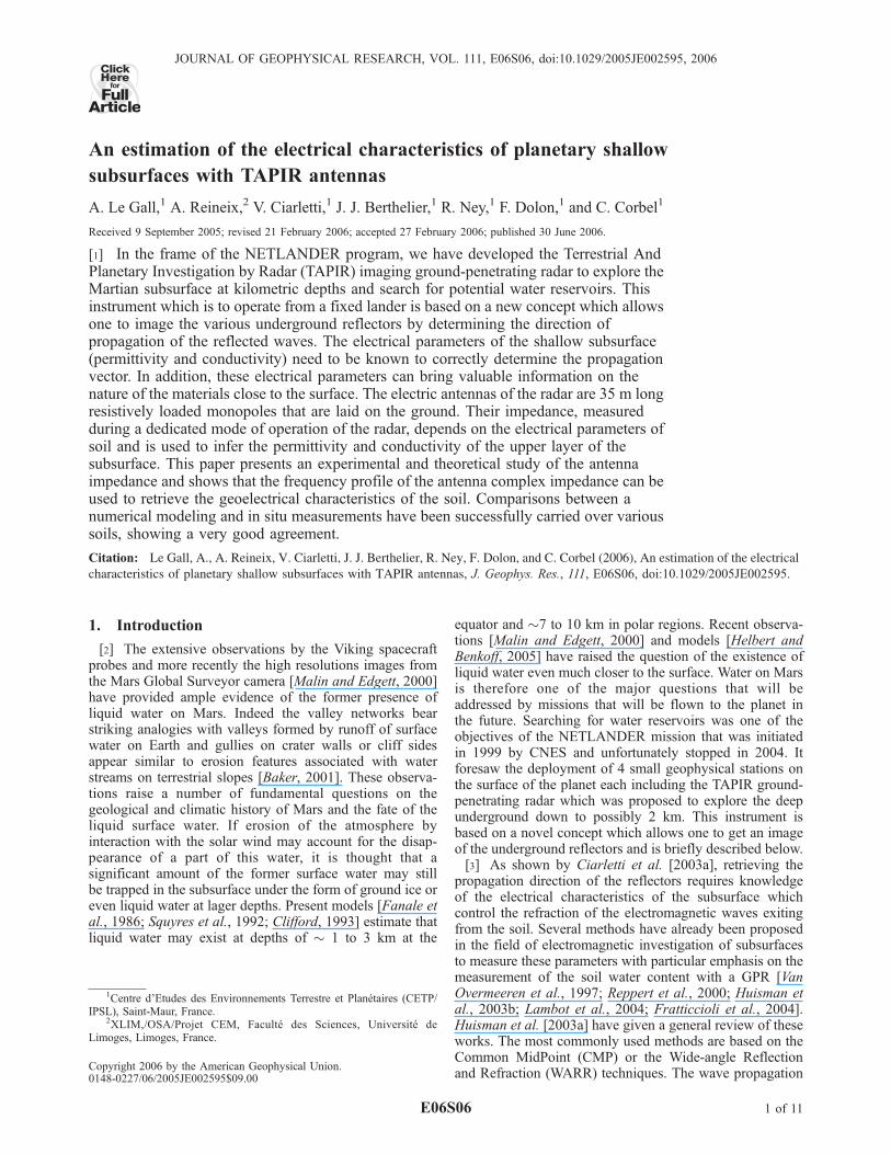
conductivities and a constant relative permittivity equalto 4. The sensitivity of the impedance with respect to theconductivity remains small except in the low frequencyregion, below 1 MHz.[34] In conclusion, the analytical approach gives evidence
of the influence of the electrical properties of the soil on theantenna behavior. The variations of the impedance measure-ments in response to changes in the permittivity andconductivity, in the lower frequency range, are large enoughto allow retrieval of both parameters (with less accuracyfrom the conductivity) from a frequency profile of theantenna impedance. This motivated the development of amore realistic and accurate numerical model of the antennaoperation.
4. Numerical Model of the Antenna Operation
[35] A numerical 3D FDTD code, TRIDIMO, has beendeveloped by XLIM (formerly named IRCOM, Institut deRecherche en Communication Optique et Micro-Ondes) tosimulate the operations of the GPR in an actual environmentand, in particular, to determine the coupling between theantenna and the shallow subsurface with better accuracythan analytical models. This code has been described byMartinat [2001], Bauchet [2004], and Besse [2004] and willbe the subject of a forthcoming paper (V. Ciarletti andA. Reineix, Ciarletti, V. and Reineix, A., Numerical simu-lation of a HF ground penetrating radar with the FDTD
method, manuscript in preparation, 2006). It takes intoaccount the resistive profile of the antennas, the mutualcross coupling and the coupling with the lander structure.It also takes into account frequency dependence of thegeoelectrical parameters.
4.1. FDTD Method
[36] The FDTD (Finite Difference Time Domain) methodallows us to solve the set of Maxwell equations in a rigorousmanner. The numerical algorithm is based on the wellknown Yee [1996] algorithm and relies on the discretizationand resolution of Maxwell curl equations using a timestepping procedure [Martinat, 2001]. The advantages ofthis method lay in its relative simplicity of implementation,its accuracy and its versatility at the expense of a significantcomputation time. Stability conditions requires that the sizeof the discrete volume elements must be of the order of l/10
Figure 3. Frequency variations of the antenna impedance(computed with the analytical model) as a function of therelative permittivity of the shallow subsurface er. Theconductivity of the subsurface, se, is assumed to be zero.
Figure 2. Current distribution along the antenna as a function of the relative permittivity of the shallowsubsurface er. The conductivity of the subsurface, se, is assumed to be 2 10�4 S/m.
E06S06 LE GALL ET AL.: CHARACTERISTICS OF PLANETARY SHALLOW SUBSURFACES
5 of 11
E06S06
where l is the wavelength in the medium corresponding tothe highest frequency of operation (10 MHz). The chosencell dimension is 1 meter in the three perpendicular direc-tions which is small enough compared to the wavelengthand prevents numerical dispersion. Besides, a relationshipbetween the time and the spatial steps allows us to respectthe CFL (Courant-Friedrichs-Levy) stability criterion. Inaddition, wave reflections on the walls of the computationbox are suppressed by PML, ‘‘Perfectly Matched Layers’’[Berenger, 1994; Berenger et al., 2000] technique. Animproved version of this method called CPML [Rodenand Gedney, 1997] has been implemented to take intoaccount more complex underground conditions such aslossy media.
4.2. Antenna Modeling
[37] Electrical antennas are thin metallic Mylar ribbons35 meters long and 10 mm wide. To cope with computa-tional cost issues, they have been modeled as thin cylindri-cal wires as proposed by Holland and Simpson [1981]. Thecorresponding algorithm relies on the following idea: sincethe radius of the antenna is negligible compared to thewavelength, electrostatic and magnetostatic laws are validaround the wire. Current and charge along the antenna canbe derived and used as electrical sources in the Maxwell’sequations. As a consequence, no transverse discretization ofthe wire is required and the spatial increment remainsappropriate to the volume size.[38] The model allows us to insert local electrical ele-
ments (resistance, inductance, capacity. . .) on each segmentof the antenna.
4.3. Soil Modeling
[39] The geoelectrical features of the soil are introducedin each cell of the 3D mesh representing the computationbox through the desired values of the electric permittivityand conductivity. The code would also allow us to take intoaccount the magnetic properties of the subsurface but, as
already indicated, we have, up to now, only considered thecase of nonmagnetic materials.[40] Due to the wide frequency bandwidth of the radar,
the frequency variations of the electric parameters of thesubsurface cannot be neglected. In the time domain, con-volutions have to be performed asking for costly resourcesin memory and computational time. To cope with this issue,the permittivity frequency dependence is described by theclassical Debye’s model [Luebbers et al., 1990].
eC wð Þ ¼ e1 þXNi¼1
Gi
es � e1ð Þ1þ jwti
ð13Þ
ti is the characteristic relaxation time of the dipole momentof the medium, es is the static relative dielectric constant(maximum value) and e1 a permittivity for an infinitefrequency (minimum value). Permittivity is expressed as asum of first order filters which lead to damping exponentialterms in the time domain and thus to faster computation ofthe convolutions.[41] As an example of the validity of the Debye model,
we have performed laboratory measurements of the real andimaginary parts of the permittivity of a sample of sand fromthe Pyla Dune and fitted a Debye model with one pole for aconductive material. The corresponding expression is
eC wð Þ ¼ e1 þ es � e1ð Þ1þ jwti
� jsswe0
ð14Þ
Values of es = 5 (DC or static permittivity), e1 = 4 (infinitefrequency permittivity), ti = 0.8 10�7 s (relaxation time)and ss = 5 10�5 S/m (DC or static conductivity) were foundto give a very good agreement between measurements andmodel values, thus validating the Debye approximation.
4.4. Extent of the Soil Layer Controlling the AntennaCharacteristics
[42] An important issue is to determine to which depth dLthe soil is electrically coupled to the antenna and affect itscharacteristics. One way to obtain this information is toanalyze the variations of the antenna current as a function ofthe depth of the uniform soil beneath. This can be achievedby putting a perfectly reflecting plane at some depth in thecomputation box and computing the current flowing alongthe antenna. If the reflecting plane is very deep, the currentdue to the reflected electromagnetic field is negligible.When the distance from the plane to the surface is reduced,the current along the antenna is modified. dL can beobtained as the depth of the reflecting plane where thechange in the antenna current is negligible (�1%).[43] The FDTD code was used to conduct this investiga-
tion in the case of an antenna laid on a dry sand (er = 4) andoperating at the central frequency of 4 MHz. Numericalsimulations made with a 5 cm spatial step revealed that for adepth of the reflector plane of �1 m, the current is 20 dBbelow the transmitting current level. In near field domain,the transmitted waves are strongly attenuated in the vicinityof the dipole and the soil can be considered as electricallycoupled to the antenna characteristics only down to a depthof �1 m. A similar result was obtained over the whole rangeof frequencies of the radar.
Figure 4. Frequency variations of the antenna impedance(computed by the analytical model) as a function of theconductivity of the shallow subsurface se. The relativepermittivity of the subsurface, er, is assumed to be 4.
E06S06 LE GALL ET AL.: CHARACTERISTICS OF PLANETARY SHALLOW SUBSURFACES
6 of 11
E06S06
[44] In conclusion the measurements of the antenna char-acteristics such as its impedance provide information on theEM properties of a thin layer of �1 m beneath the surface.
5. Measurements and Comparison With Models:Determination of the Electrical Properties of theShallow Subsurface
[45] In this section, we compare model simulations andmeasurements of the antenna characteristics performedduring several field tests.
5.1. Soil Characteristics
[46] The antenna operation can be studied by measuringvarious parameters: the wave propagation velocity and thecurrent profile along the antenna or, more simply, theantenna impedance.[47] Wave propagation and current profile were measured
over a rather dry arable soil, in the park of Saint-MaurObservatory, and over the Pyla sand dune, in the South ofFrance. Antenna impedance measurements were performedon the Pyla dune and on the Antarctic ice shelf during theRANETA (RAdar of NEtlander in Terre Adelie) campaign[Berthelier et al., 2005].5.1.1. Saint-Maur Observatory[48] The Saint-Maur Observatory garden can be consid-
ered as an arable soil containing organic materials. Mea-surements on this site were performed in spring, in a ratherdry period with no rain during the preceding week. The soilcan thus be considered as rather dry.[49] A sample was collected a few months later, in
meteorological conditions similar to those encounteredduring the antenna tests. Measurements of the electromag-netic properties of the sample were performed with theimpedance analyzer HP4192A in the PIOM laboratory(Laboratoire de Physique des Interactions Ondes-Matiere).The analyzer instrument operates in the frequency rangefrom 5 Hz to 13 MHz and provides the real and imaginaryparts of the permittivity as a function of frequency. At theoperating frequency of 4 MHz, the derived relative dielec-tric constant is �5 and the effective conductivity is �10�3
S/m. Yet, one must keep in mind that these values can varylocally due to the natural inhomogeneity in the moisture andorganic material contents. However, the measurements canbe thought as representative of the average values of er andse with possible random deviations of 30%.5.1.2. Pyla Dune[50] With a height of 100 m, the Pyla Dune is the highest
dune of Europe. It constitutes a suitable ground to testground-penetrating radars since it is a quite homogenousand moderately lossy medium.[51] Measurements of the electromagnetic properties of
the sand of the Pyla Dune have been performed in the PIOMlaboratory for a number of samples collected at varioustimes, locations on the dune and depths below the surface.The relative permittivities of these samples range from 2.9to 4.4 and the effective conductivity from 10�5 to 10�4 S/m[Ciarletti et al., 2003b] at TAPIR operating frequencies(from 1 to 4 MHz).5.1.3. Antarctic Ice Shelf[52] The RANETA campaign took place in January/Feb-
ruary 2004, over the Antarctic ice shelf, in Terre Adelie. The
electromagnetic properties of ice as a function of tempera-ture and frequency are well known. They have been recentlyreviewed by Fujita et al. [2000]. Up to 600 MHz, theelectromagnetic parameters are practically independent offrequency. The average temperature of the ice between thesurface and the bedrock at the location of the measurementsis estimated to ��20 C. Typical values of the electricconductivity and of the relative dielectric constant arerespectively 5 10�5 S/m and 3.2 at this temperature.Besides, between ��10 C and ��30 C, the relative per-mittivity is virtually unchanged and the conductivityremains low, between 10�6 and 3 10�5 S/m.
5.2. Signal Propagation Along the Antenna
[53] The measurements were performed with a currenttransformer (Bergoz CT-C1.0) on 35 meters resistivelyloaded dipoles for long pulses (>4 ms, in order to installthe required stationary mode) and at a central frequency of4 MHz.[54] The nominal accuracy of the CT is 0.5% in the wide
bandwidth [200 Hz, 500 MHz], uncertainties on currentmeasurement are thus very low.5.2.1. Wave Propagation Velocity Along the Antenna[55] During field tests at Saint-Maur Observatory, two
independent data sets were acquired, one with the antennaslying on the surface, the second one with the antenna 1 meterabove the surface. Measurements on the Pyla dune were onlyperformed with the antenna directly laid on the surface.[56] In the first case, with the antenna laid on the
surface, the measured wave velocity is �1.78 108 m s�1,whereas, one meter above the surface, the wave velocity is�2.56 108 m s�1
. This result is in good agreement withtheory (see section 3.2.1); it shows that even 1m above thesurface, the soil has still a measurable influence on theantenna since the measured velocity is well below its valueof 3 108 m s�1 in free space. In Figure 5 we have plotted thecomputed ratio between the propagation constant in theantenna beq and the propagation constant in the air b0 as afunction of the electromagnetic properties of the near bysoil (er, se) (see section 3.2.1). The thick line is the measured
ratio:beqb0
=c
v 1.68.
[57] When the electric conductivity is less than �3 10�4
S/m, it has practically no influence on the wave velocitywhich is uniquely determined by the relative dielectricconstant er. On the contrary, larger values of se have asignificant effect on the wave velocity. As can be seen onthe curves in Figure 5, the pair (er, se) obtained on our solesample can be matched with different solutions. Dependingon which measurement, er or se, is supposed to be moreaccurate, one can obtain 2 extreme solutions: er = 4.7 ± 0.2,se = 10�5 S/m or er = 3.8 ± 0.15, se � 10�3 S/m. Accordingto King and Smith [1981] the dielectric and conductingproperties of a soil greatly depend on the moisture content.Typically, when dry, a soil may have relative permittivityranging from 2 to 6 and conductivity between 10�5 and10�4 S/m. Thus, since the soil is certainly rather dry, we canreduce the possible solutions for se to: 10
�4 Sm�1 � se �10�5 Sm�1.[58] It must be also emphasized that, in garden environ-
ments such as in the park of Saint-Maur Observatory, thecharacteristics of the soil, moisture and organic contents,
E06S06 LE GALL ET AL.: CHARACTERISTICS OF PLANETARY SHALLOW SUBSURFACES
7 of 11
E06S06

may display large variations over distances of a few metersand depths of a few tens of centimeters. Very clearly, the35 m length of the antenna and the �1 m extent in depth ofthe soil layer coupled with the antenna would have requiredsome �10 samples to be taken in order to get representativeaverage values of the electrical properties.[59] To conclude, the analytical approach combined with
measurements of the wave propagation speed acquisitionbrings a range of possible values for er and se. In our case,the best fit solution is: er � 4.7 ± 0.2 and se � 10�4 S/m.5.2.2. Current Profile[60] Figure 6 displays the normalized amplitude decay of
the measured current for three different cases, on the sanddune, on the garden soil and 1 meter above and theoreticalcurves from the analytical model are shown in thick lines.[61] For the dry soil cases, a technical error in the
measurements procedure makes the current measurementsbeyond 25 m inaccurate and thus they must be discarded.The curves are consistent with the analytical results thatpredict that an increase of the effective permittivity entails amore nonlinear variation of the current intensity along theantenna. For an antenna 1 meter above the soil, the currentprofile is quasi-linear, as expected since the conditionsare closer to those in free space. By adjusting the parameters(er, se) in the analytical model, we have determined best fitvalues:[62] 1. For the Pyla Dune: er = 4.2 and se = 3 10�5 S/m.[63] 2. For the air: er = 1 and se = 2 10�5 S/m.[64] 3. For the quite dry earth: er = 4.8 and se = 10�4 S/m.[65] For the garden soil, there is a good agreement with the
values of relative permittivity and conductivity deducedfrom the wave velocity and laboratory measurements. Forthe sand of the Pyla dune, these values are also consistentwith those given by [Barbin, 1996; Bauchet, 2004] and withextracted values from the literature in the case of dry sand.They also provide satisfying fits when used in numericalmodel.
5.3. Antenna Impedance
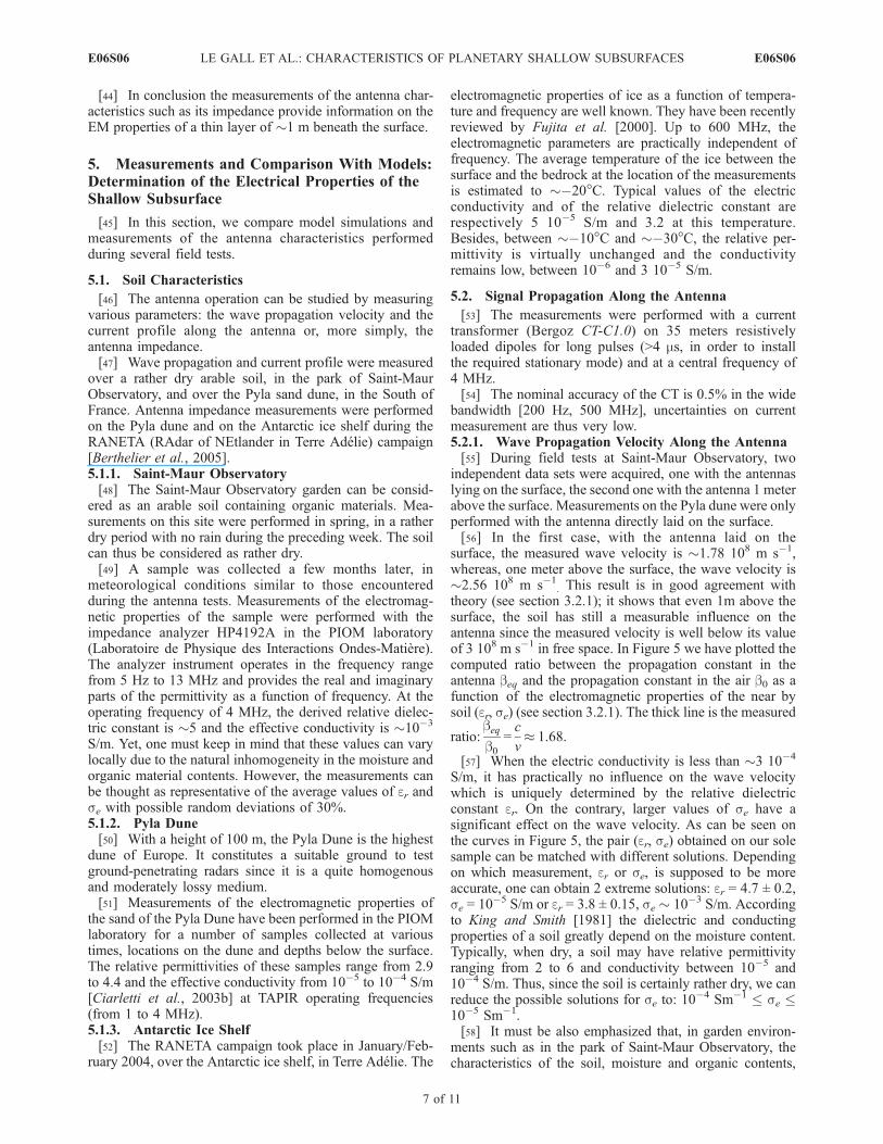
[66] As stated above, impedance measurement are inpractice the only way to determine the relative permittivityand conductivity of the upper layer of planetary soil. Theimpedance frequency profile also provides insight in thefrequency dependence of the complex permittivity. Resultsshown just above have proved the ability of the analyticalmodel to describe antenna characteristics at a single fre-quency but, in the case of a range of frequencies, thenumerical model is far more suitable to data interpretation.[67] Figure 7 shows the antenna impedance measured on
the Pyla Dune in the frequency range 0.3 to 6 MHz and thecorresponding analytical and numerical simulationsobtained with a single pole Debye model of a conductivesand as indicated in section 4:
eC wð Þ ¼ 4þ 5� 4ð Þ1þ 8� 10�8 � jw
� j5� 10�5
we0
[68] The localized increase of the impedance near 4 MHzis due to the presence of a parasitic broadcast transmitter.The analytical model relies on a simplified approach con-sidering an isolated antenna with a continuously varyingresistive profile. The FDTD code takes into account theactual antenna with discrete resistances between conductivesegments and more importantly its coupling with the landerstructure, the other antennas and the electronics. The result-ing fit is very satisfying and provides evidence of thevalidity and accuracy of the numerical model.[69] Similar numerical simulations have been achieved
with a set of different values of the geoelectrical parameters.Figure 8 shows for example a 2D color diagram of thenumerically computed real and imaginary parts of theantenna impedance at 1 MHz as functions of the relativepermittivity and the conductivity of the subsurface. Com-
Figure 5. Wave propagation velocity along the antenna asa function of the relative permittivity er and of theconductivity se of the shallow subsurface. Comparisonbetween analytical simulations and measurements per-formed at Saint-Maur Observatory (thick line).
Figure 6. Comparison between measurements and ananalytical model of the current distribution along theantenna. Measurements were performed in three locations:on the Pyla Dune, on a dry garden soil, and one meterabove. Simulations curves correspond to the best fit toexperimental data.
E06S06 LE GALL ET AL.: CHARACTERISTICS OF PLANETARY SHALLOW SUBSURFACES
8 of 11
E06S06
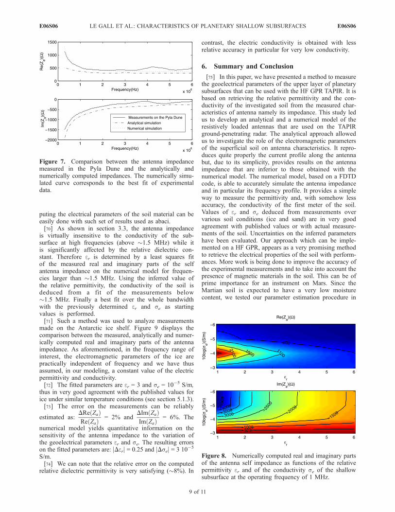
puting the electrical parameters of the soil material can beeasily done with such set of results used as abaci.[70] As shown in section 3.3, the antenna impedance
is virtually insensitive to the conductivity of the sub-surface at high frequencies (above �1.5 MHz) while itis significantly affected by the relative dielectric con-stant. Therefore er is determined by a least squares fitof the measured real and imaginary parts of the selfantenna impedance on the numerical model for frequen-cies larger than �1.5 MHz. Using the inferred value ofthe relative permittivity, the conductivity of the soil isdeduced from a fit of the measurements below�1.5 MHz. Finally a best fit over the whole bandwidthwith the previously determined er and se as startingvalues is performed.[71] Such a method was used to analyze measurements
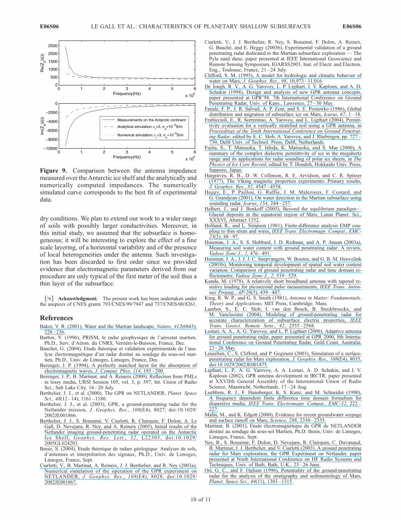
made on the Antarctic ice shelf. Figure 9 displays thecomparison between the measured, analytically and numer-ically computed real and imaginary parts of the antennaimpedance. As aforementioned, in the frequency range ofinterest, the electromagnetic parameters of the ice arepractically independent of frequency and we have thusassumed, in our modeling, a constant value of the electricpermittivity and conductivity.[72] The fitted parameters are er = 3 and se = 10�5 S/m,
thus in very good agreement with the published values forice under similar temperature conditions (see section 5.1.3).[73] The error on the measurements can be reliably
estimated as:DRe Zað ÞRe Zað Þ = 2% and
DIm Zað ÞIm Zað Þ = 6%. The
numerical model yields quantitative information on thesensitivity of the antenna impedance to the variation ofthe geoelectrical parameters er and se. The resulting errorson the fitted parameters are: jDerj = 0.25 and jDsej = 3 10�5
S/m.[74] We can note that the relative error on the computed
relative dielectric permittivity is very satisfying (�8%). In
contrast, the electric conductivity is obtained with lessrelative accuracy in particular for very low conductivity.
6. Summary and Conclusion
[75] In this paper, we have presented a method to measurethe geoelectrical parameters of the upper layer of planetarysubsurfaces that can be used with the HF GPR TAPIR. It isbased on retrieving the relative permittivity and the con-ductivity of the investigated soil from the measured char-acteristics of antenna namely its impedance. This study ledus to develop an analytical and a numerical model of theresistively loaded antennas that are used on the TAPIRground-penetrating radar. The analytical approach allowedus to investigate the role of the electromagnetic parametersof the superficial soil on antenna characteristics. It repro-duces quite properly the current profile along the antennabut, due to its simplicity, provides results on the antennaimpedance that are inferior to those obtained with thenumerical model. The numerical model, based on a FDTDcode, is able to accurately simulate the antenna impedanceand in particular its frequency profile. It provides a simpleway to measure the permittivity and, with somehow lessaccuracy, the conductivity of the first meter of the soil.Values of er and se deduced from measurements overvarious soil conditions (ice and sand) are in very goodagreement with published values or with actual measure-ments of the soil. Uncertainties on the inferred parametershave been evaluated. Our approach which can be imple-mented on a HF GPR, appears as a very promising methodto retrieve the electrical properties of the soil with perform-ances. More work is being done to improve the accuracy ofthe experimental measurements and to take into account thepresence of magnetic materials in the soil. This can be ofprime importance for an instrument on Mars. Since theMartian soil is expected to have a very low moisturecontent, we tested our parameter estimation procedure in
Figure 7. Comparison between the antenna impedancemeasured in the Pyla Dune and the analytically andnumerically computed impedances. The numerically simu-lated curve corresponds to the best fit of experimentaldata.
Figure 8. Numerically computed real and imaginary partsof the antenna self impedance as functions of the relativepermittivity er and of the conductivity se of the shallowsubsurface at the operating frequency of 1 MHz.
E06S06 LE GALL ET AL.: CHARACTERISTICS OF PLANETARY SHALLOW SUBSURFACES
9 of 11
E06S06
dry conditions. We plan to extend our work to a wider rangeof soils with possibly larger conductivities. Moreover, inthis initial study, we assumed that the subsurface is homo-geneous; it will be interesting to explore the effect of a finescale layering, of a horizontal variability and of the presenceof local heterogeneities under the antenna. Such investiga-tion has been discarded to first order since we providedevidence that electromagnetic parameters derived from ourprocedure are only typical of the first meter of the soil thus athin layer of the subsurface.
[76] Acknowledgment. The present work has been undertaken underthe auspices of CNES grants 793/CNES/99/7947 and 737/CNES/00/8261.
ReferencesBaker, V. R. (2001), Water and the Martian landscape, Nature, 412(6843),228–236.
Barbin, Y. (1996), PRISM, le radar geophysique de l’aerostat martien,Ph.D., Serv. d’Aeron. du CNRS, Verriere-le-Buisson, France, Dec.
Bauchet, G. (2004), Etude theorique et validation experimentale de l’ana-lyse electromagnetique d’un radar destine au sondage du sous-sol mar-tien, Ph.D., Univ. de Limoges, Limoges, France, Dec.
Berenger, J. P. (1994), A perfectly matched layer for the absorption ofelectromagnetic waves, J. Comput. Phys, 114, 185–200.
Berenger, J. P., B. Martinat, and A. Reineix (2000), Reflection from PMLsin lossy media, URSI Session 105, vol. 3, p. 397, Int. Union of RadioSci., Salt Lake City, 16–20 July.
Berthelier, J. J., et al. (2000), The GPR on NETLANDER, Planet. SpaceSci., 48(12–14), 1161–1180.
Berthelier, J. J., et al. (2003), GPR, a ground-penetrating radar for theNetlander mission, J. Geophys. Res., 108(E4), 8027, doi:10.1029/2002JE001866.
Berthelier, J. J., S. Bonaime, V. Ciarletti, R. Clairquin, F. Dolon, A. LeGall, D. Nevejans, R. Ney, and A. Reineix (2005), Initial results of theNetlander imaging ground-penetrating radar operated on the AntarcticIce Shelf, Geophys. Res. Lett. , 32 , L22305, doi:10.1029/2005GL024203.
Besse, S. (2004), Etude theorique de radars geologique: Analyses de sols,d’antennes et interpretation des signaux, Ph.D., Univ. de Limoges,Limoges, France, Sept.
Ciarletti, V., B. Martinat, A. Reineix, J. J. Berthelier, and R. Ney (2003a),Numerical simulation of the operation of the GPR experiment onNETLANDER, J. Geophys. Res., 108(E4), 8028, doi:10.1029/2002JE001867.
Ciarletti, V., J. J. Berthelier, R. Ney, S. Bonaime, F. Dolon, A. Reinex,G. Bauche, and E. Heggy (2003b), Experimental validation of a groundpenetrating radar dedicated to the Martian subsurface exploration — ThePyla sand dune, paper presented at IEEE International Geoscience andRemote Sensing Symposium, IGARSS2003, Inst. of Electr. and Electron.Eng., Toulouse, France, 21–24 July.
Clifford, S. M. (1993), A model for hydrologic and climatic behavior ofwater on Mars, J. Geophys. Res., 98, 10,973–11,016.
De Jongh, R. V., A. G. Yarovoy, L. P. Ligthart, I. V. Kaploun, and A. D.Schukin (1998), Design and analysis of new GPR antenna concepts,paper presented at GPR’98, 7th International Conference on GroundPenetrating Radar, Univ. of Kans., Lawrence, 27–30 May.
Fanale, F. P., J. R. Salvail, A. P. Zent, and S. E. Postawko (1986), Globaldistribution and migration of subsurface ice on Mars, Icarus, 67, 1–18.
Fratticcioli, E., R. Sorrentino, A. Yarovoy, and L. Ligthart (2004), Permit-tivity evaluation for a vertically stratified soil using a GPR antenna, inProceedings of the Tenth International Conference on Ground Penetrat-ing Radar, edited by E. C. Slob, A. Yarovoy, and J. Rhebergen, pp. 727–730, Delft Univ. of Technol. Press, Delft, Netherlands.
Fujita, S., T. Matsuoka, T. Ishida, K. Matsuoka, and S. Mae (2000), Asummary of the complex dielectric permittivity of ice in the megahertzrange and its applications for radar sounding of polar ice sheets, in ThePhysics of Ice Core Record, edited by T. Hondoh, Hokkaido Univ. Press,Sapporo, Japan.
Hargraves, R. B., D. W. Collinson, R. E. Arvidson, and C. R. Spitzer(1977), The Viking magnetic properties experiments: Primary results,J. Geophys. Res., 82, 4547–4558.
Heggy, E., P. Paillou, G. Ruffie, J. M. Malezieux, F. Costard, andG. Grandjean (2001), On water detection in the Martian subsurface usingsounding radar, Icarus, 154, 244–257.
Helbert, J., and J. Benkoff (2005), Beyond the equilibrium paradigm—Glacial deposits in the equatorial region of Mars, Lunar Planet. Sci.,XXXVI, Abstract 1352.
Holland, R., and L. Simpson (1981), Finite-difference analysis EMP cou-pling to thin struts and wires, IEEE Trans. Electromagn. Compat., EMC-23(2), 88–97.
Huisman, J. A., S. S. Hubbard, J. D. Redman, and A. P. Annan (2003a),Measuring soil water content with ground penetrating radar: A review,Vadose Zone J., 2, 476–491.
Huisman, J. A., J. J. J. C. Snepvangers, W. Bouten, and G. B. M. Heuvelink(2003b), Monitoring temporal development of spatial soil water contentvariation: Comparison of ground penetrating radar and time domain re-flectometry, Vadose Zone J., 2, 519–529.
Kanda, M. (1978), A relatively short broadband antenna with tapered re-sistive loading for picosecond pulse measurements, IEEE Trans. Anten-nas Propag., AP-26(3), 439–447.
King, R. W. P., and G. S. Smith (1981), Antenna in Matter: Fundamentals,Theory and Applications, MIT Press, Cambridge, Mass.
Lambot, S., E. C. Slob, I. van den Bosch, B. Stockbroeckx, andM. Vanclooster (2004), Modeling of ground-penetrating radar foraccurate characterization of subsurface electric properties, IEEETrans. Geosci. Remote Sens., 42, 2555–2568.
Lestari, A. A., A. G. Yarovoy, and L. P. Ligthart (2000), Adaptive antennafor ground penetrating radar, paper presented at GPR 2000, 8th Interna-tional Conference on Ground Penetrating Radar, Gold Coast, Australia,23–26 May.
Leuschen, C., S. Clifford, and P. Gogineni (2003), Simulation of a surface-penetrating radar for Mars exploration, J. Geophys. Res., 108(E4), 8035,doi:10.1029/2002JE001875.
Ligthart, L. P., A. G. Yarovoy, A. A. Lestari, A. D. Schukin, and I. V.Kaploun (2002), GPR antenna development in IRCTR, paper presentedat XXVIIth General Assembly of the International Union of RadioScience, Maastricht, Netherlands, 17–24 Aug.
Luebbers, R. J., F. Hunsberger, K. S. Kunz, and M. Schneider (1990),A frequency dependent finite difference time domain formalism fordispersive media, IEEE Trans. Electromagn. Compat., EMC-32, 222–227.
Malin, M., and K. Edgett (2000), Evidence for recent groundwater seepageand surface runoff on Mars, Science, 288, 2330–2335.
Martinat, B. (2001), Etude electromagnetique du GPR de NETLANDERdestine au sondage du sous-sol Martien, Ph.D. thesis, Univ. de Limoges,Limoges, France, Sept.
Ney, R., S. Bonaime, F. Dolon, D. Nevejans, R. Clairquin, C. Duvanaud,B. Martinat, J. J. Berthelier, and V. Ciarletti (2003), A ground penetratingradar for Mars exploration, the GPR Experiment on Netlander, paperpresented at Ninth International Conference on HF Radio Systems andTechniques, Univ. of Bath, Bath, U.K., 23–26 June.
Ori, G. C., and F. Ogliani (1996), Potentiality of the ground-penetratingradar for the analysis of the stratigraphy and sedimentology of Mars,Planet. Space Sci., 44(11), 1303–1315.
Figure 9. Comparison between the antenna impedancemeasured over the Antarctic ice shelf and the analytically andnumerically computed impedances. The numericallysimulated curve corresponds to the best fit of experimentaldata.
E06S06 LE GALL ET AL.: CHARACTERISTICS OF PLANETARY SHALLOW SUBSURFACES
10 of 11
E06S06

Reppert, P. M., F. D. Morgan, and M. N. Toksoz (2000), Dielectric constantdetermination using ground-penetrating radar reflection coefficients,J. Appl. Geophys., 43, 189–197.
Roden, J. A., and S. Gedney (1997), Efficient implementation of the uni-axial based PML media in three-dimensional non-orthogonal coordinatesusing the FDTD technique,Microwave Opt. Technol. Lett., 14(2), 71–75.
Shen, L. C., and R. W. P. King (1965), Correction to the cylindrical antennawith non reflecting resistive loading by Wu and King, IEEE Trans. An-tennas Propag., AP-13(6), 998.
Squyres, S. W., S. M. Clifford, R. O. Kuzmin, J. R. Zimbelman, and F. M.Costard (1992), Ice in the Martian regolith, in Mars, edited by H. H.Kieffer et al., pp. 523–554, Univ. of Ariz. Press, Tucson.
Van Overmeeren, R. A., S. V. Sariowan, and J. C. Gehrels (1997), Groundpenetrating radar for determining volumetric soil water content: Resultsof comparative measurements at two test sites, J. Hydrol., 197, 316–338.
Wait, J. R. (1972), Theory of wave propagation along a thin wire parallel toan interface, Radio Sci., 7(6), 675–679.
Wright, D. L., and J. F. Prewitt (1975), Radiating dipole antenna withtapered impedance loading, IEEE Trans. Antennas Propag., 23(11),811–814.
Wu, T. T., and R. W. P. King (1965), The cylindrical antenna with nonre-flecting resistive loading, IEEE Trans. Antennas Propag., 13, 369–373.
Wu, T. T., and L.-C. Shen (1967), Cylindrical antenna with tapered resistiveloading, Radio Sci., 2(2), 191.
Yee, K. S. (1996), Numerical solution of initial boundary value problemsinvolving Maxwell’s equations in isotropic media, IEEE Trans. Electro-magn. Compat., AP-14(4), 302–307.
�����������������������J. J. Berthelier, V. Ciarletti, C. Corbel, F. Dolon, A. Le Gall, and R. Ney,
Centre d’Etudes des Environnements Terrestre et Planetaires (CETP/IPSL),4, Avenue de Neptune, Saint-Maur, F-94107, France. ([email protected])A. Reineix, XLIM/OSA/Projet CEM, Faculte des Sciences, 123, avenue
Albert Thomas, F-87060, Limoges Cedex, France.
E06S06 LE GALL ET AL.: CHARACTERISTICS OF PLANETARY SHALLOW SUBSURFACES
11 of 11
E06S06