An energy harvester using piezoelectric cantilever beams undergoing coupled bending–torsion...
11
IOP PUBLISHING SMART MATERIALS AND STRUCTURES Smart Mater. Struct. 20 (2011) 115007 (11pp) doi:10.1088/0964-1726/20/11/115007 An energy harvester using piezoelectric cantilever beams undergoing coupled bending–torsion vibrations A Abdelkefi 1,2 , F Najar 1 , A H Nayfeh 2 and S Ben Ayed 1,2 1 Applied Mechanics and Systems Research Laboratory, Tunisia Polytechnic School, BP 743, La Marsa 2078, University of Carthage, Tunisia 2 Department of Engineering Science and Mechanics, MC 0219, Virginia Polytechnic Institute and State University, Blacksburg, VA 24061, USA E-mail: [email protected] Received 4 June 2011, in final form 5 June 2011 Published 10 October 2011 Online at stacks.iop.org/SMS/20/115007 Abstract Recently, piezoelectric cantilevered beams have received considerable attention for vibration-to-electric energy conversion. Generally, researchers have investigated a classical piezoelectric cantilever beam with or without a tip mass. In this paper, we propose the use of a unimorph cantilever beam undergoing bending–torsion vibrations as a new piezoelectric energy harvester. The proposed design consists of a single piezoelectric layer and a couple of asymmetric tip masses; the latter convert part of the base excitation force into a torsion moment. This structure can be tuned to be a broader band energy harvester by adjusting the first two global natural frequencies to be relatively close to each other. We develop a distributed-parameter model of the harvester by using the Euler-beam theory and Hamilton’s principle, thereby obtaining the governing equations of motion and associated boundary conditions. Then, we calculate the exact eigenvalues and associated mode shapes and validate them with a finite element (FE) model. We use these mode shapes in a Galerkin procedure to develop a reduced-order model of the harvester, which we use in turn to obtain closed-form expressions for the displacement, twisting angle, voltage output, and harvested electrical power. These expressions are used to conduct a parametric study for the dynamics of the system to determine the appropriate set of geometric properties that maximizes the harvested electrical power. The results show that, as the asymmetry is increased, the harvester’s performance improves. We found a 30% increase in the harvested power with this design compared to the case of beams undergoing bending only. We also show that the locations of the two masses can be chosen to bring the lowest two global natural frequencies closer to each other, thereby allowing the harvesting of electrical power from multi-frequency excitations. (Some figures in this article are in colour only in the electronic version) 1. Introduction Recently, there has been considerable interest in the field of energy harvesting by converting ambient vibrations into electrical energy. Williams and Yates [1] identified three basic vibration-to-electric energy conversion mechanisms: electromagnetic [2, 3], electrostatic [4], and piezoelectric [4, 5] transduction. Mitcheson et al [3] indicated that piezoelectric generators have a wider operating range at low frequencies than other generators, especially when dealing with low- frequency ambient vibrations. This type of transduction does not require much space for implementation, thereby making it suitable for a wide range of applications, such as smart structures, electric resonators, filters, actuators, and sensors [6]. Consequently, piezoelectric transduction has received the most attention. For comprehensive reviews of its literature, we refer the reader to Anton and Sodano [4], Beeby et al [7], Sodano et al [8], Priya [9], Cook-Chennault et al [5], and Erturk [10]. 0964-1726/11/115007+11$33.00 © 2011 IOP Publishing Ltd Printed in the UK & the USA 1
Transcript of An energy harvester using piezoelectric cantilever beams undergoing coupled bending–torsion...
IOP PUBLISHING SMART MATERIALS AND STRUCTURES
Smart Mater. Struct. 20 (2011) 115007 (11pp) doi:10.1088/0964-1726/20/11/115007
An energy harvester using piezoelectriccantilever beams undergoing coupledbending–torsion vibrationsA Abdelkefi1,2, F Najar1, A H Nayfeh2 and S Ben Ayed1,2
1 Applied Mechanics and Systems Research Laboratory, Tunisia Polytechnic School, BP 743,La Marsa 2078, University of Carthage, Tunisia2 Department of Engineering Science and Mechanics, MC 0219, Virginia Polytechnic Instituteand State University, Blacksburg, VA 24061, USA
E-mail: [email protected]
Received 4 June 2011, in final form 5 June 2011Published 10 October 2011Online at stacks.iop.org/SMS/20/115007
AbstractRecently, piezoelectric cantilevered beams have received considerable attention forvibration-to-electric energy conversion. Generally, researchers have investigated a classicalpiezoelectric cantilever beam with or without a tip mass. In this paper, we propose the use of aunimorph cantilever beam undergoing bending–torsion vibrations as a new piezoelectric energyharvester. The proposed design consists of a single piezoelectric layer and a couple ofasymmetric tip masses; the latter convert part of the base excitation force into a torsion moment.This structure can be tuned to be a broader band energy harvester by adjusting the first twoglobal natural frequencies to be relatively close to each other. We develop adistributed-parameter model of the harvester by using the Euler-beam theory and Hamilton’sprinciple, thereby obtaining the governing equations of motion and associated boundaryconditions. Then, we calculate the exact eigenvalues and associated mode shapes and validatethem with a finite element (FE) model. We use these mode shapes in a Galerkin procedure todevelop a reduced-order model of the harvester, which we use in turn to obtain closed-formexpressions for the displacement, twisting angle, voltage output, and harvested electrical power.These expressions are used to conduct a parametric study for the dynamics of the system todetermine the appropriate set of geometric properties that maximizes the harvested electricalpower. The results show that, as the asymmetry is increased, the harvester’s performanceimproves. We found a 30% increase in the harvested power with this design compared to thecase of beams undergoing bending only. We also show that the locations of the two masses canbe chosen to bring the lowest two global natural frequencies closer to each other, therebyallowing the harvesting of electrical power from multi-frequency excitations.
(Some figures in this article are in colour only in the electronic version)
1. Introduction
Recently, there has been considerable interest in the fieldof energy harvesting by converting ambient vibrations intoelectrical energy. Williams and Yates [1] identified threebasic vibration-to-electric energy conversion mechanisms:electromagnetic [2, 3], electrostatic [4], and piezoelectric [4, 5]transduction. Mitcheson et al [3] indicated that piezoelectricgenerators have a wider operating range at low frequenciesthan other generators, especially when dealing with low-
frequency ambient vibrations. This type of transductiondoes not require much space for implementation, therebymaking it suitable for a wide range of applications, suchas smart structures, electric resonators, filters, actuators, andsensors [6]. Consequently, piezoelectric transduction hasreceived the most attention. For comprehensive reviews of itsliterature, we refer the reader to Anton and Sodano [4], Beebyet al [7], Sodano et al [8], Priya [9], Cook-Chennault et al [5],and Erturk [10].
0964-1726/11/115007+11$33.00 © 2011 IOP Publishing Ltd Printed in the UK & the USA1
Smart Mater. Struct. 20 (2011) 115007 A Abdelkefi et al
Many piezoelectric energy harvesters consist of acantilever beam with one piezoceramic layer (unimorph) ortwo piezoceramic layers (bimorph). Although the piezoelectricconstitutive equations are nonlinear, most works in theliterature linearize these equations [11, 12]. Basically, thebeam is coupled to a vibrating host structure and the straininduced in the piezoceramic layer(s) generates an alternatingvoltage across the electrodes covering the piezoceramiclayer(s). Usually, the harvester is equipped with a proof mass,which can be tuned so that the fundamental natural frequencyof the harvester beam is close to a dominant excitationfrequency available in the ambient vibration-energy spectrum.
Researchers have proposed various mathematical modelsfor beam energy harvesters [4, 7–10, 13]: lumped-parameterand distributed-parameter models. The distributed-parametermodels are based on the Euler–Bernoulli theory for thin beams,the Rayleigh formulation for slightly thicker beams, and theTimoshenko theory for moderately thick beams. The Rayleighformulation accounts for rotary inertia and the Timoshenkotheory accounts for rotary inertia and transverse shear. Thedistributed-parameter system is discretized by using either theRayleigh–Ritz method [14] or the Galerkin method [15, 16].Both symmetric and asymmetric piezoelectric treatmentsare considered and some studies account for longitudinaldisplacements [10]. To the authors’ knowledge, none of theexisting studies consider harvesters that undergo bending–torsion vibrations.
In this work, we design a unimorph cantilever beam-based harvester that undergoes bending–torsion vibrations bycreating an offset between its center of gravity and the shearcenter, thereby leading to a coupling between the bending andtorsion vibrations. Hence, there is a significant effect on thenatural frequencies, mode shapes, and response due to thebending–torsion coupling. The offset is created by placing twomasses asymmetrically at the tip of the beam. We model thebeam–mass system by using the Euler–Bernoulli beam theoryand use Hamilton’s principle to derive the coupled governingequations of motion and associated boundary conditions fora base excitation. We calculate the exact mode shapes andnatural frequencies of the harvester and use these mode shapesas basis functions in a Galerkin scheme to derive a reduced-order model of the harvester. Closed-form expressions areobtained for all needed outputs. Moreover, we demonstratethat, when the lowest global frequencies are close to eachother, we have an interesting broadband frequency harvester.Finally, we show that, when the asymmetry between the twomasses increases, the electrical harvested power as well as theproduced voltage increases.
2. System modeling
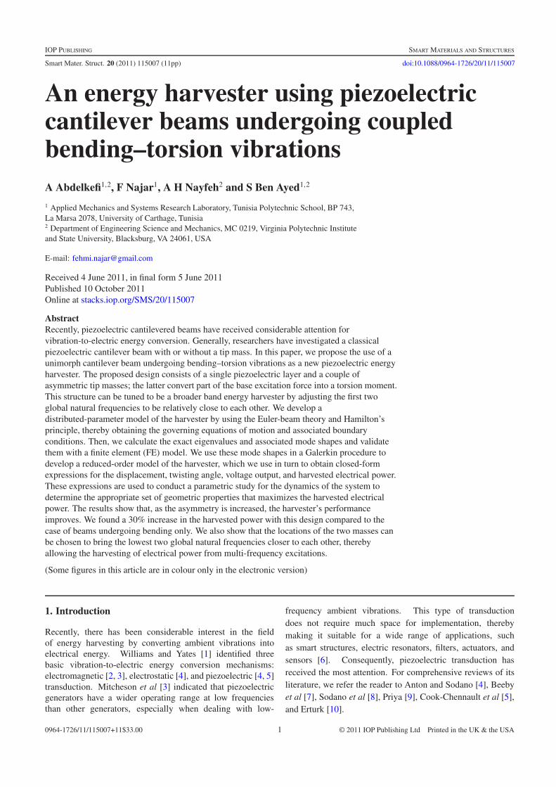
We consider a bi-layered cantilever beam in which one layer ismade of steel and the other layer is made of a piezoelectricmaterial. The piezoelectric layer is bonded to two in-planeelectrodes of negligible thickness. Two rigid masses areasymmetrically placed at the tip of the beam. These massesare interconnected using a rigid massless transverse beam, asshown in figure 1. The clamped end of the beam is subjected
Figure 1. Schematic of the bending–torsion unimorph cantileverbeam.
Table 1. Physical and geometric properties of the unimorphcantilever beam.
Es Steel Young’s modulus (N m−2) 193 × 109
Ep Piezo Young’s modulus (N m−2) 66 × 109
Gs Steel Coulomb’s modulus (N m−2) 74.81 × 10⁹
Gp Piezo Coulomb’s modulus (N m−2) 25.19 × 10⁹
ρs Steel density (kg m−3) 8000ρp Piezo density (kg m−3) 7800L Length of the beam (mm) 25Lc = a
2 Tip mass offset (mm) 3.5b Width of the beam (mm) 3.2hs Steel layer thickness (mm) 0.1hp Piezo layer thickness (mm) 0.4e31 Piezoelectric coupling coefficient (C m−2) −12.54∈s
33 Piezoelectric permittivity (F m−1) 1.328 × 10⁻⁸
to a transverse harmonic displacement Y (t) = Y0 sin(�t). Thegeometric and physical properties of the unimorph beam aregiven in table 1.
The cantilever beam is flexible and undergoes coupledbending–torsion motions. The tip masses and their attachmentsare supposed to be rigid and asymmetric, thereby creating thecoupling between the bending and torsion motions. Next, weuse Hamilton’s principle
∫ t
0(δT − δ�) dt = 0 (1)
to derive the governing equations of motion of the system andtheir associated boundary conditions, where T is the system’skinetic energy and � is its potential energy. In the following,the subscript s refers to the steel layer and the subscript p refersto the piezoelectric layer.
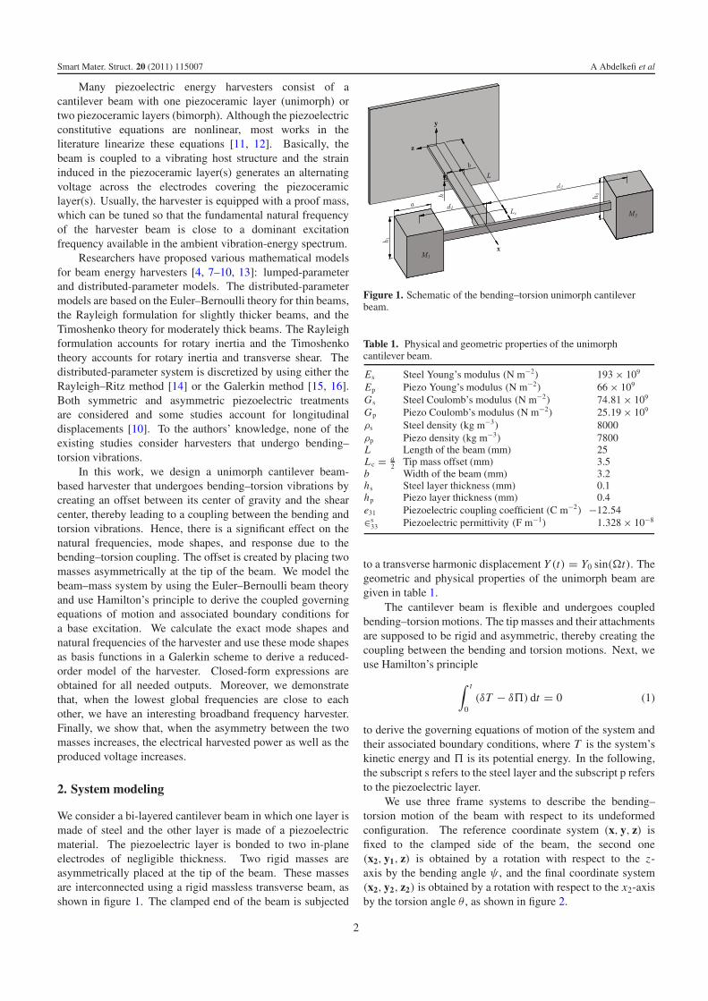
We use three frame systems to describe the bending–torsion motion of the beam with respect to its undeformedconfiguration. The reference coordinate system (x, y, z) isfixed to the clamped side of the beam, the second one(x2, y1, z) is obtained by a rotation with respect to the z-axis by the bending angle ψ , and the final coordinate system(x2, y2, z2) is obtained by a rotation with respect to the x2-axisby the torsion angle θ , as shown in figure 2.
2
Smart Mater. Struct. 20 (2011) 115007 A Abdelkefi et al
Figure 2. Rotation angles of the beam section.
We model the beam as an Euler–Bernoulli beam of lengthL, width b, and height h, which comprises the thickness ofthe steel layer hs and the thickness of the piezoelectric layerhp. We let v(x, t) be the component of the local displacementvector along the y-axis and assume relatively small rotationangles so that ψ(x, t) = v′(x, t), where the prime denotes thepartial derivative with respect to x . For cylindrical bending andtorsion, we represent the local displacement vector associatedwith an arbitrary point on the beam’s cross-section as
R = (Y + v)y + yy2 + zz2. (2)
The kinetic energy of the system is the sum of the kineticenergies of the beam (T1) and the asymmetric masses (T2).Variation of T1 is given by
δT1 = −∫ L
0
∫Aρ(y)RδR dA dx = −
∫ L
0(Avδv + Aθ1δθ) dx
(3)where the over dot denotes the derivative with respect to timet , ρ(y) is the beam density, A is the beam cross-section area,
Av = m(v + Y ), Aθ1 = J1θ ,
J1 =2∑
i=1
∫ yi
yi−1
∫ 12 b
− 12 bρ(y)(y2 + z2) dy dz
and the beam’s rotary inertia is assumed to be negligible.The asymmetric masses M1 and M2 are assumed to be
rigid and located at the distances d1 and d2 from the x-axis(figure 1). They have a similar square cross-section area (a2)in the (x2, y2) plane, but have different heights h1 and h2. Theircenter of mass is located at x = L+Lc and their kinetic energyis given as follows:
T2 = 12 M(vL + Y + Lcv
′L )
2 + 12 I0θ
2L
+ Mt θL(vL + Y + Lcv′L)+ 1
2 I1v′2L (4)
where the subscript L denotes variables calculated at x = L,I1 = 1
12 (a2 + h2
1)M1 + 112 (a
2 + h22)M2, M = M1 + M2 is
the total tip mass, I0 = I1 + (M1d21 + M2d2
2 ) is the effectivepolar second moment of area of the tip masses with respectto the reference frame, and Mt = M1d1 − M2d2 describesthe asymmetry of the tip masses. Therefore, it follows fromequation (3) and variation of equation (4) that variation of thetotal kinetic energy of the system is given by
δT = −∫ L
0(Avδv + Aθ1δθ) dx
+ [M(vL + Y + Lcv′L )+ Mt θL ]δvL
+ [M Lc(vL + Y + Lcv′L )+ Mt LcθL + I1v
′L ]δv′
L
+ [I0θL + Mt (vL + Y + Lcv′L )]δθL . (5)
Variation of the potential energy of the whole system canbe expressed as
δ� =∫ L
0
∫Aσ11δε11 dA dx
︸ ︷︷ ︸δ�1
+∫ L
0
∫Aσ12δγ12 + σ13δγ13 dA dx
︸ ︷︷ ︸δ�2
(6)
where the strains and stresses in the steel and piezoelectriclayers are, respectively, given by
ε11 = zθv′′ − yv′′, γ12 = 2ε12 = −zθ ′,
and γ13 = 2ε13 = yθ ′,
σ s11 = Esε11, σ s
12 = 2Gsε12,
and σ s13 = 2Gsε13,
σp11 = Epε11 − e31 E2, σ
p12 = 2Gpε12,
and σp13 = 2Gpε13.
(7)
Here, Es and Ep are the Young’s moduli at constant electricfield, Gs and Gp are the shear moduli, and E2(t) = − V (t)
hpis
the electric field in the poling direction (V (t) is the potential ofthe upper electrode and thus represents the voltage between thepiezoelectric’s electrodes). The electric displacement vector Dis related to the strains by
D =[ D1 = e15ε12
D2 = e31ε11+ ∈s33 E2
D3 = e15ε13
](8)
where the ei j are the piezoelectric stress coefficients and the∈s
i j are the permittivities at constant strain.Substituting equations (7) into (6) and integrating twice
the first integral by parts, we rewrite variation of the bendingpotential energy δ�1 as
δ�1 =∫ L
0[−M ′′
b δv] dx + [M ′bδv − Mbδv
′]L0 (9)
where Mb is the bending moment given by
Mb = −Ey3v′′ + 1
2 e31b(y1 + y2)V [H (x)− H (x − L)],
Ey3 = 13 Esb(y
31 − y3
0)+ 13 Epb(y3
2 − y31)
3
Smart Mater. Struct. 20 (2011) 115007 A Abdelkefi et al
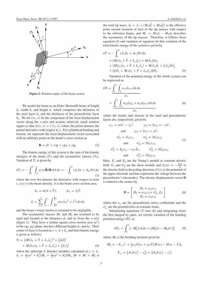
Figure 3. Neutral axis position.
and H is the Heaviside step function. The positions of thelayers are defined in figure 3; they are given with respect to theposition of the neutral axis
y = (hp + hs)Ephp
2(Ephp + Eshs)+ hs
2
as follows:
y0 = −y, y1 = hs − y, y2 = (hs + hp)− y.
Variation of the torsion potential energy δ�2 is obtainedfrom equations (6) and (7) as
δ�2 = −∫ L
0C ′δθ dx + [Cδθ ]L
0 (10)
where C is the torsion moment given by
C = Ex2θ′ = Gsθ
′[ 112 hsb
3 + 13 b(y3
1 − y30)]
+ Gpθ′[ 1
12 hpb3 + 13 b(y3
2 − y31)].
Substituting equations (5), (9), and (10) into (1) andapplying Hamilton’s principle, we obtain the followingequations of motion:
Ey3viv− 1
2 e31b(y1 + y2)V (δ′(x)−δ′(x −L))+m(v+Y ) = 0,
(11)J1θ − Ex2θ
′′ = 0 (12)
and their associated boundary conditions
v(0, t) = 0, v′(0, t) = 0, and
θ(0, t) = 0,(13)
Ey3v′′′L − M(vL + Y + Lcv
′L )− Mt θL = 0, (14)
Ey3v′′L + Lc M(vL + Y + Lcv
′L )+ I1v
′L + Lc Mt θL = 0, (15)
Ex2θ′L + I0θL + Mt (vL + Y + Lcv
′L ) = 0 (16)
where δ(x) is the Dirac function.The two electrodes are connected to an external resistance
R. Hence, applying Gauss law yields
d
dt
∫A
D ·n dA = −e31bhp
∫ L
0v′′ dx− ∈s
33
V bL
hp= V
R(17)
where n is the vector normal to the plane (x2, z2).For convenience, we introduce the following nondimen-
sional variables:
v = v
h, Y = Y
h, x → x
L, t → t
τ,
and τ = L2
√m
Ey3
into the equations of motion and boundary conditions, addviscous damping terms, drop the hats, and obtain the followingnondimensional problem:
viv + c1v + v + Y − K V [δ′(x)− δ′(x − 1)] = 0, (18)
θ + c2θ − Ex2 mL2
Ey3 J1θ ′′ = 0, (19)
v′′′1 − M
mL
(v1 + Lc
Lv′
1 + Y
)− Mt
hmLθ1 = 0, (20)
v′′1 + LcM
mL2
(v1 + Lc
Lv′
1 + Y
)+ I1
mL3v′
1 + LcMt
mhL2θ1 = 0, (21)
Ex2
Lθ ′
1 + I0
τ 2θ1 + Mt h
τ 2
(v1 + Y + Lc
Lv′
1
)= 0, (22)
− e31bhhp
Lτ
∫ 1
0v′′ dx− ∈s
33
V bL
hpτ= V
R(23)
where K = 12 e31b(y1 + y2)
L2
hEy3and the subscript 1 indicates
variables calculated at x = 1.
3. Reduced-order model and analytical solution
To determine the electrical power produced by the proposeddesign and to compare it with classical cantilever designs, wesolve the coupled structural–electrical equations (18), (19),and (23) subject to the boundary conditions (20)–(22) fora given base excitation Y (t). To accomplish this, we firstdiscretize the system using the Galerkin procedure. We haveat least two choices for the basis functions: the cantilevermode shapes and the structural mode shapes that account forthe coupling between the bending and torsion motions causedby the tip masses. Nayfeh et al [17] showed that, in such aconfiguration, the cantilever mode shapes produce inaccurateresults for the asymmetric tip mass case. Therefore, weemploy the mode shapes that account for the bending–torsionmotions.
3.1. Structural natural frequencies and mode shapes
To investigate the dynamic response of the system, we startby computing the structural natural frequencies and associatedmode shapes, taking into account the bending and torsioncoupling caused by the tip masses. To this end, we drop thedamping, forcing, and polarization from equations (18)–(23),and let v(x, t) = φ(x)eiωt and θ(x, t) = ψ(x)eiωt . Theresulting eigenvalue problem is given by
φiv − ω2φ = 0, (24)
ψ ′′ + Ey3 J1
Ex2 mL2ω2ψ = 0 (25)
and associated boundary conditions
φ(0) = 0, φ′(0) = 0, ψ(0) = 0, (26)
φ′′′(1)+ M
mLω2
(φ(1)+ Lc
Lφ′(1)+ Mt
Mhψ(1)
)= 0, (27)
4
Smart Mater. Struct. 20 (2011) 115007 A Abdelkefi et al
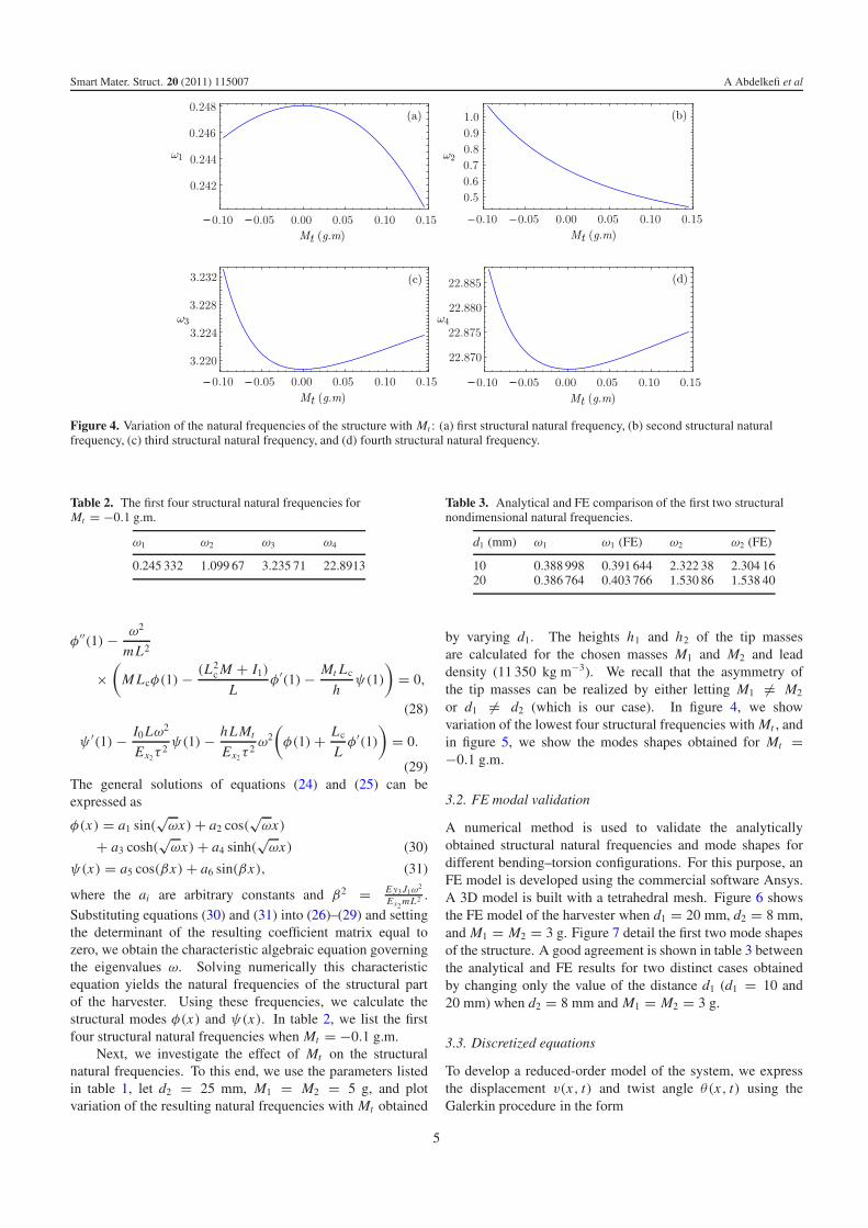
Figure 4. Variation of the natural frequencies of the structure with Mt : (a) first structural natural frequency, (b) second structural naturalfrequency, (c) third structural natural frequency, and (d) fourth structural natural frequency.
Table 2. The first four structural natural frequencies forMt = −0.1 g.m.
ω1 ω2 ω3 ω4
0.245 332 1.099 67 3.235 71 22.8913
φ′′(1)− ω2
mL2
×(
M Lcφ(1)− (L2c M + I1)
Lφ′(1)− Mt Lc
hψ(1)
)= 0,
(28)
ψ ′(1)− I0 Lω2
Ex2τ2ψ(1)− hL Mt
Ex2τ2ω2
(φ(1)+ Lc
Lφ′(1)
)= 0.
(29)The general solutions of equations (24) and (25) can beexpressed as
φ(x) = a1 sin(√ωx)+ a2 cos(
√ωx)
+ a3 cosh(√ωx)+ a4 sinh(
√ωx) (30)
ψ(x) = a5 cos(βx)+ a6 sin(βx), (31)
where the ai are arbitrary constants and β2 = E y3 J1ω2
Ex2 mL2 .
Substituting equations (30) and (31) into (26)–(29) and settingthe determinant of the resulting coefficient matrix equal tozero, we obtain the characteristic algebraic equation governingthe eigenvalues ω. Solving numerically this characteristicequation yields the natural frequencies of the structural partof the harvester. Using these frequencies, we calculate thestructural modes φ(x) and ψ(x). In table 2, we list the firstfour structural natural frequencies when Mt = −0.1 g.m.
Next, we investigate the effect of Mt on the structuralnatural frequencies. To this end, we use the parameters listedin table 1, let d2 = 25 mm, M1 = M2 = 5 g, and plotvariation of the resulting natural frequencies with Mt obtained
Table 3. Analytical and FE comparison of the first two structuralnondimensional natural frequencies.
d1 (mm) ω1 ω1 (FE) ω2 ω2 (FE)
10 0.388 998 0.391 644 2.322 38 2.304 1620 0.386 764 0.403 766 1.530 86 1.538 40
by varying d1. The heights h1 and h2 of the tip massesare calculated for the chosen masses M1 and M2 and leaddensity (11 350 kg m−3). We recall that the asymmetry ofthe tip masses can be realized by either letting M1 �= M2
or d1 �= d2 (which is our case). In figure 4, we showvariation of the lowest four structural frequencies with Mt , andin figure 5, we show the modes shapes obtained for Mt =−0.1 g.m.
3.2. FE modal validation
A numerical method is used to validate the analyticallyobtained structural natural frequencies and mode shapes fordifferent bending–torsion configurations. For this purpose, anFE model is developed using the commercial software Ansys.A 3D model is built with a tetrahedral mesh. Figure 6 showsthe FE model of the harvester when d1 = 20 mm, d2 = 8 mm,and M1 = M2 = 3 g. Figure 7 detail the first two mode shapesof the structure. A good agreement is shown in table 3 betweenthe analytical and FE results for two distinct cases obtainedby changing only the value of the distance d1 (d1 = 10 and20 mm) when d2 = 8 mm and M1 = M2 = 3 g.
3.3. Discretized equations
To develop a reduced-order model of the system, we expressthe displacement v(x, t) and twist angle θ(x, t) using theGalerkin procedure in the form
5

Smart Mater. Struct. 20 (2011) 115007 A Abdelkefi et al
Figure 5. The first four mode shapes of the structure.
Figure 6. FE model of the bending–torsion unimorph cantileverbeam when d1 = 20 mm, d2 = 8 mm and M1 = M2 = 3 g.
v(x, t) =2∑
i=1
φi(x)qi(t) and
θ(x, t) =2∑
i=1
ψi (x)qi(t)
(32)
where the test functions are the structural mode shapescomputed by the procedure in section 3.2. The choiceof two structural mode shapes to discretize the system isrelated to the choice of applied excitation frequencies, whichare, in general, low compared to the third and higherstructural natural frequencies. To reduce the algebra, weperform the discretization by substituting equation (32) intothe nondimensional Lagrangian � = T − � of the system,carrying out the spatial integration, and then writing down theEuler–Lagrange equations
d
dt
∂�
∂ qi− ∂�
∂qi= 0, i = 1, 2. (33)
Then, we add a linear damping term in each equation. Thedamping coefficient is determined using the relation ci = ωi
Q ,where Q = 50 is the quality factor. The resulting discretized
equations can be expressed as
Ai qi + ci qi + Bi qi − Ki V + Fi Y = 0, i = 1, 2 (34)
where
Ai =∫ 1
0φi (x)
2 dx + J1
mh2
∫ 1
0ψi (x)
2 dx + I0
mLh2ψi (1)
2
+ I1
mL3φ′
i (1)2 + M
mL
(φi(1)+ Lc
Lφ′
i(1)
)2
+ 2Mt
mLhψi (1)
(φi (1)+ Lc
Lφ′
i (1)
),
Bi =∫ 1
0φ′′
i (x)2 dx + Ex2 L2
Ey3h2
∫ 1
0ψ ′
i (x)2 dx,
Ki = Kφ′i (1),
Fi =∫ 1
0φi (x) dx + M
mL
(φi(1)+ Lc
Lφ′
i(1)
)+ Mt
mLhψi (1).
Discretizing the Gauss law, equation (23), yields
e31bhph
τ L[q1φ
′1(1)+ q2φ
′2(1)]+ ∈s
33
V bL
hpτ+ V
R= 0. (35)
3.4. Analytical solution
We use the discretized equations to determine closed-formexpressions for the displacement, twist angle, voltage, andharvested power for a harmonic base excitation Y (t) =Y0 sin(�t), where � is the excitation frequency and Y0 is itsnondimensional amplitude. We note that Y = Im(Y0ei�t ),where Im stands for the imaginary part. Consequently, weseek the solution of equations (34) and (35) in the form q1 =Im(Q1ei�t ), q2 = Im(Q2ei�t ), and V = Im(V0ei�t ) and obtainthe following system of algebraic equations:[ B1 − A1�
2 + i�c1 0 −K1
0 B2 − A2�2 + i�c2 −K2
A3i� A4i� 1R + i�B3
]
×[ Q1
Q2
V0
]= �2Y0
[ F1
F2
0
](36)
6
Smart Mater. Struct. 20 (2011) 115007 A Abdelkefi et al
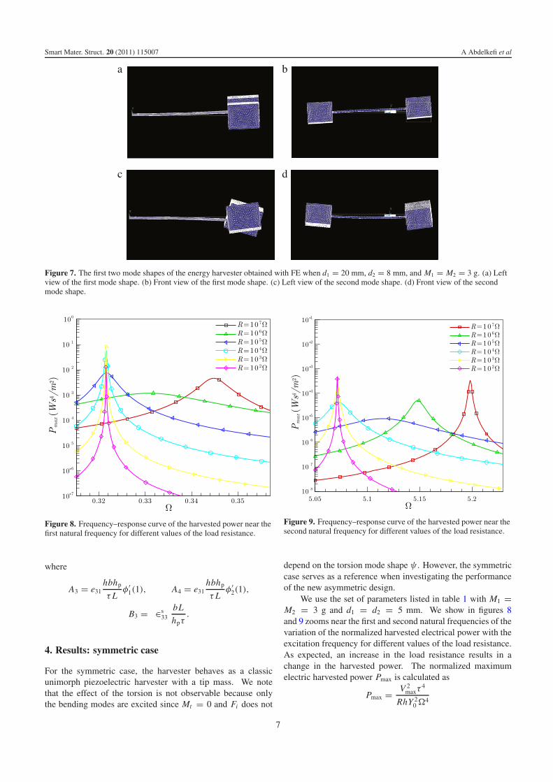
Figure 7. The first two mode shapes of the energy harvester obtained with FE when d1 = 20 mm, d2 = 8 mm, and M1 = M2 = 3 g. (a) Leftview of the first mode shape. (b) Front view of the first mode shape. (c) Left view of the second mode shape. (d) Front view of the secondmode shape.
Figure 8. Frequency–response curve of the harvested power near thefirst natural frequency for different values of the load resistance.
where
A3 = e31hbhp
τ Lφ′
1(1), A4 = e31hbhp
τ Lφ′
2(1),
B3 = ∈s33
bL
hpτ.
4. Results: symmetric case
For the symmetric case, the harvester behaves as a classicunimorph piezoelectric harvester with a tip mass. We notethat the effect of the torsion is not observable because onlythe bending modes are excited since Mt = 0 and Fi does not
Figure 9. Frequency–response curve of the harvested power near thesecond natural frequency for different values of the load resistance.
depend on the torsion mode shape ψ . However, the symmetriccase serves as a reference when investigating the performanceof the new asymmetric design.
We use the set of parameters listed in table 1 with M1 =M2 = 3 g and d1 = d2 = 5 mm. We show in figures 8and 9 zooms near the first and second natural frequencies of thevariation of the normalized harvested electrical power with theexcitation frequency for different values of the load resistance.As expected, an increase in the load resistance results in achange in the harvested power. The normalized maximumelectric harvested power Pmax is calculated as
Pmax = V 2maxτ
4
RhY 20�
4
7

Smart Mater. Struct. 20 (2011) 115007 A Abdelkefi et al
Figure 10. Variation of the normalized maximum harvestedelectrical power with the load resistance for the open-circuit andshort-circuit global frequencies.
Table 4. Global natural frequencies for open- and short-circuitconfigurations when M1 = M2 = 3 g and d1 = d2 = 5 mm.
ω1 ω2
Open-circuit frequency (R = 107 �) 0.344 81 5.148 75Short-circuit frequency (R = 102 �) 0.321 53 5.071 30
where Vmax is the maximum value of the harvested voltage atsteady state.
The global natural frequencies (obtained from thefrequency–response curves) of the harvester in open- andshort-circuit configurations corresponding to the resonancefrequency of the system when R = 107 and 102 � are listed intable 4. We note that the maximum harvested electrical powerthat could be generated is obtained for R = 1420 �, whichcorresponds to Pmax = 0.135 61 W s4 m−2 at � = 0.321 53(short-circuit frequency). However, this configuration doesnot correspond necessarily to the best configuration because,at this resistance load, the harvested power has a sharp peakat the resonance frequency and drops drastically for all otherexcitation frequencies, as observed in figures 8 and 9. Forpractical applications, because the excitation is, in general, notharmonic, another resistance might be more suitable to harvestthe maximum power.
Next, we investigate the dependence of the maximumharvested electrical power Pmax on the load resistance R; wevary it from open-circuit to short-circuit values. In figure 10,we show variation of Pmax with R for two fixed excitationfrequencies, namely those corresponding to the open- andshort-circuit configurations given in table 4.
5. Results: asymmetric case
In this section, we investigate the influence of the asymmetryMt of the tip masses on the dynamic behavior of the harvester
Figure 11. Variation of the first four structural natural frequencieswith Mt .
and thus on the harvested electrical power. The results ofthe asymmetric case are compared with those obtained in thesymmetric case. We vary the asymmetry parameter Mt of thetip masses by keeping M1 = M2 = 3 g and d2 = 5 mm andonly vary d1.
We start by showing, in figure 11, variation of the firstfour structural natural frequencies of the system with thetip asymmetry parameter Mt , which is varied by varying d1
from −50 to 50 mm. We note here that negative values ofd1 correspond to placing both masses on the same side ofthe cantilever beam. When Mt = 0, the structural naturalfrequencies are ω1 = 0.321 53, ω2 = 3.870, ω3 = 5.071 28,ω4 = 23.6480. When Mt is increased positively, the secondfrequency is greatly affected because it is dominated by thetorsion motion, as seen in the mode shapes in figure 5. Fromfigure 11, we also observe three different regions. Startingfrom d1 = 50 mm, first, the curve of the second naturalfrequency comes very close to that of the third frequency,but without crossing it; that is, the two curves veer from oneanother. Then, the second natural frequency asymptotes aconstant value and the third natural frequency increases. Thethird region corresponds to a reduction in the second naturalfrequency only. The first and fourth natural frequencies seemto be slightly affected by variations in Mt . We note that thethird natural frequency is not affected by positive variationsin d1 but greatly affected by small negative values of d1. Tovalidate the proposed analytical dynamic solution, we comparethe frequency–response curves of the asymmetric system whend1 = 20 mm, d2 = 8 mm and M1 = M2 = 3 g. Thecorresponding natural frequencies obtained using the analyticaland FE approaches are shown in table 3. In figure 12,we show the variation of the maximum nondimensional tipdeflection as a function of the normalized excitation frequency.The normalization of the excitation frequency is obtained bydividing � by the corresponding natural frequency to thecalculation method chosen from table 3. We note that there
8

Smart Mater. Struct. 20 (2011) 115007 A Abdelkefi et al
Figure 12. Variation of the maximum nondimensional tip deflection when d1 = 20 mm, d2 = 8 mm and M1 = M2 = 3 g near (a) the firstpeak and (b) the second peak for two different approaches: analytical prediction (continuous lines) and FE Ansys model (red points).
Figure 13. Frequency–response curve of the maximumnondimensional tip deflection for different values of d1 whenR = 104 �.
is a good agreement between both methods for excitationfrequency values close to resonance.
Next, we study the dynamic behavior of the asymmetricsystem for different values of d1 ranging from 10 to 50 mmwhen the electrical load resistance is equal to 104 �. Infigures 13–16, we show, respectively, variations of thenondimensional tip deflection, nondimensional tip rotation,normalized harvested voltage, and Pmax with the excitationfrequency �. In these figures, we note the appearance of asecond peak, in the frequency–response curves, correspondingto the global natural frequency of the second mode, which isdominated by torsion. Variation of d1 is accompanied witha shift in the global natural frequencies, as seen in figure 11.The two peaks are separated by an antiresonance for the casesof the tip deflection, the voltage, and the harvested electricalpower. On the other hand, the antiresonance occurs outside theband of the two peaks in the case of the tip rotation except ford1 = 10 mm where it is inside the band.
We note that increasing d1 results in (a) an increasein the maxima of all of the system responses (i.e., tip
Figure 14. Frequency–response curve of the maximum tip rotationfor different values of d1 when R = 104 �.
displacement, tip rotation, voltage, and harvested power) and(b) a decrease in the difference between the lowest twoglobal natural frequencies and hence the frequency differencebetween the two peaks in the responses, as seen in figures 13–16. Consequently, the asymmetry not only increases theharvested power from a single-frequency environment, but alsofrom a multi-frequency environment.
In figure 17, we show the effect of the load resistanceon the normalized maximum harvested electrical power by anasymmetric harvester for a fixed excitation frequency whenM1 = M2 = 3 g, d1 = 45 mm, and d2 = 5 mm. We chosetwo frequencies, namely those corresponding to the open- andshort-circuit global natural frequencies shown in table 5. Weobserve results similar to those found for the symmetric casefor both frequencies.
To compare the efficiency of the proposed design with tipmass asymmetry with that of the symmetric case, we plot infigure 18 variations of the maximum normalized maximumharvested electrical power Pmax at resonance with the tip massasymmetry parameter Mt . For the harvested power at the first
9

Smart Mater. Struct. 20 (2011) 115007 A Abdelkefi et al
Figure 15. Frequency–response curve of the maximum normalizedharvested voltage for different values of d1 when R = 104 �.
Figure 16. Frequency–response curve of the normalized maximumharvested electrical power for different values of d1 whenR = 104 �.
Table 5. Natural frequencies for open- and short-circuitconfigurations when M1 = M2 = 3 g, d1 = 45 mm and d2 = 5 mm.
ω1 ω2
Open-circuit frequency 0.327 06 0.906 29Short-circuit frequency 0.306 86 0.898 82
natural frequency, the benefit of the tip mass asymmetry is veryclear because the minimum value of Pmax is obtained for thesymmetric case (Mt = 0). For the case when d1 = −50 mm(Mt = −0.165 g.m), an increase of 30% in Pmax is observed.For the harvested power at the second natural frequency, amore complex behavior is observed. In fact, at d1 = −20 mm
Figure 17. Variation of the normalized maximum harvestedelectrical power with the load resistance for the open-circuit andshort-circuit global natural frequencies.
(Mt = −0.075 g.m) and d1 = 10 mm (Mt = 0.015 g.m), weobserve a drastic drop in Pmax. In these configurations, the firstmass M1 is located symmetrically with respect to the secondmass M2. For these specific values, the antiresonance is locatedon top of the second natural frequency and thus destroys thecontribution of the torsion motion.
6. Conclusion
We propose the use of a unimorph piezoelectric cantileverbeam undergoing bending–torsion vibrations induced byasymmetric tip masses for energy harvester application.Using the Euler–Bernoulli beam theory and Hamilton’sprinciple, we derive the governing coupled equations of motionand associated boundary conditions under harmonic baseexcitations. We compute the structural natural frequenciesand associated mode shapes accounting for bending–torsioncoupling and validate them using the FE software Ansys.These mode shapes are used as basis functions in a Galerkinprocedure to obtain a reduced-order model of the coupledstructural–electrical system, which provides the global naturalfrequencies and mode shapes of the harvester. Then, closed-form expressions are obtained for the displacement, twistingangle, voltage output, and harvested electrical power. Theanalytical expressions are used to demonstrate enhancementof the harvester by the asymmetry of the mass distribution.A parametric study is performed to ascertain the influence ofthe load resistance and asymmetry on the tip displacement,twisting angle, voltage, and harvested power. We found that theimprovement in the harvester’s performance increases as theasymmetry increases. In fact, we found mass distributions thatincrease the harvested power by as much as 30%. Moreover,we found that the lowest two global natural frequencies movecloser to each other as the asymmetry increases, implying theability of the harvester to harvest power from a broader rangeof excitation frequencies.
10

Smart Mater. Struct. 20 (2011) 115007 A Abdelkefi et al
Figure 18. Variation of the normalized maximum harvested electrical power at resonance with the asymmetry for the first (a) and second (b)global natural frequencies when R = 104 �.
Acknowledgment
The authors would like to thank Prof. Mohammad R Hajj(Department of Engineering Science and Mechanics, VirginiaTech) for his assistance concerning the ANSYS simulations.
References
[1] Williams C B and Yates R B 1996 Analysis of a micro-electricgenerator for microsystems Sensors Actuators A 52 8–11
[2] Arnold D 2007 Review of microscale magnetic powergeneration IEEE Trans. Magn. 43 3940–51
[3] Mitcheson P, Miao P, Start B, Yeatman E, Holmes A andGreen T 2004 MEMS electrostatic micro-power generatorfor low frequency operation Sensors Actuators A 115 523–9
[4] Anton S R and Sodano H A 2007 A review of power harvestingusing piezoelectric materials (2003–2006) Smart Mater.Struct. 16 R1–21
[5] Cook-Chennault K A, Thambi N and Sastry A M 2008Powering MEMS portable devices—a review ofnon-regenerative and regenerative power supply systemswith emphasis on piezoelectric energy harvesting systemsSmart Mater. Struct. 17 043001
[6] Rogers C A 1993 Intelligent material systems—the dawn of anew materials age J. Intell. Mater. Syst. Struct. 4 4–12
[7] Beeby S P, Tudor M J and White N M 2006 Energy harvestingvibration sources for microsystems applications Meas. Sci.Technol. 17 R175–95
[8] Sodano H, Park G and Inman D J 2004 A Review of powerharvesting from vibration using piezoelectric materialsShock Vib. Dig. 36 197–205
[9] Priya S 2007 Advances in energy harvesting using low profilepiezoelectric transducers J. Electroceram. 19 167–84
[10] Erturk A 2009 Electromechanical modeling of piezoelectricenergy harvesters PhD Dissertation Virginia PolytechnicInstitute and State University
[11] Tiersten H F 1969 Linear Piezoelectric Plate Vibrations(New York: Plenum)
[12] Crawley E F and de Luis J 1987 Use of actuators as elements ofintelligent structures AIAA J. 25 1373–85
[13] Erturk A and Inman D J 2008 Issues in mathematical modelingof piezoelectric energy harvesters Smart Mater. Struct.17 065016
[14] Sodano H A, Park G and Inman D J 2004 Estimation of electriccharge output for piezoelectric energy harvesting Strain40 49–58
[15] Erturk A and Inman D J 2009 An experimentally validatedbimorph cantilever model for piezoelectric energy harvestingfrom base excitations Smart Mater. Struct. 18 025009
[16] Erturk A and Inman D J 2008 A distributed parameterelectromechanical model for cantilevered piezoelectricenergy harvesters ASME J. Vib. Acoust. 130 041002
[17] Nayfeh A H, Hammad B K and Hajj M R 2011 Discretizationeffects on flutter aspects and control of wing/storeconfigurations J. Vib. Control published online(doi:10.1177/1077546311408468)
11