Applying the torsion formula Ans. Allowable Shear Stress
70
© 2011 Pearson Education, Inc., Upper Saddle River, NJ. All rights reserved. This material is protected under all copyright laws as they currently exist. No portion of this material may be reproduced, in any form or by any means, without permission in writing from the publisher. 592 Allowable Shear Stress: Applying the torsion formula Ans. Allowable Shear Stress: Applying the torsion formula Ans. t r = 0.5 in = T¿ r J t max = t allow = T¿ c J t max = t allow = Tc J A shaft is made of a steel alloy having an allowable transmitted. What would be the maximum torque if a shear-stress distribution along a radial line in each case. T¿ T T ¿ shear stress of t allow = 84 MPa. If the diameter of the shaft is 37.5 mm, determine the maximum torque T that can be 25-mm -diameter hole is bored through the shaft? Sketch the 84 5 T(18.75) p 2 (18.75 2 ) T 5 0.87 kN · m 84 5 T9 (18.75) p 2 (18.75 4 – 12.5 4 ) T9 5 697961 N · mm = 0.698 kN · m 5 097961(12.5) p 2 (18.75 4 – 12.5 4 ) 5 56.0 MPa 18.75 mm 84 MPa 84 MPa 56 MPa 12.5 mm •10–1. SM_CH10.indd 592 4/11/11 9:56:33 AM
-
Upload
khangminh22 -
Category
Documents
-
view
2 -
download
0
Transcript of Applying the torsion formula Ans. Allowable Shear Stress
© 2011 Pearson Education, Inc., Upper Saddle River, NJ. All rights reserved. This material is protected under all copyright laws as they currently exist. No portion of this material may be reproduced, in any form or by any means, without permission in writing from the publisher.
592214
© 2010 Pearson Education, Inc., Upper Saddle River, NJ. All rights reserved. This material is protected under all copyright laws as they currentlyexist. No portion of this material may be reproduced, in any form or by any means, without permission in writing from the publisher.
Allowable Shear Stress: Applying the torsion formula
Ans.
Allowable Shear Stress: Applying the torsion formula
Ans.
tr=0.5 in =T¿rJ
=6.381(0.5)
p2 (0.754 - 0.54)
= 8.00 ksi
T¿ = 6.381 kip # in. = 6.38 kip # in.
12 =T¿ (0.75)
p2 (0.754 - 0.54)
tmax = tallow =T¿cJ
T = 7.95 kip # in.
12 =T (0.75)p2 (0.754)
tmax = tallow =Tc
J
•5–1. A shaft is made of a steel alloy having an allowableshear stress of If the diameter of the shaft is1.5 in., determine the maximum torque T that can betransmitted. What would be the maximum torque if a1-in.-diameter hole is bored through the shaft? Sketch theshear-stress distribution along a radial line in each case.
T¿
tallow = 12 ksi.T
T ¿
05 Solutions 46060 5/28/10 1:01 PM Page 214
215
© 2010 Pearson Education, Inc., Upper Saddle River, NJ. All rights reserved. This material is protected under all copyright laws as they currentlyexist. No portion of this material may be reproduced, in any form or by any means, without permission in writing from the publisher.
a)
Since
Ans.
b)
Ans.r¿ =r
214
= 0.841r
T
2=
4Tr4 L
r¿
0r3 dr
Lr2
0dT = 2pL
r¿
0
r
r a 2Tpr3br2 dr
Lr2
0dT = 2pL
r¿
0
r
r tmax r
2 dr
Lr2
0dT = 2pL
r¿
0tr2 dr
r¿ =r
214
= 0.841 r
t =r¿r
tmax ; T
p(r¿)3 =r¿r
a 2Tpr3b
t =(T2)r¿p2 (r¿)4 =
T
p(r¿)3
tmax =Tc
J=Trp2 r4
=2Tp r3
5–2. The solid shaft of radius r is subjected to a torque T.Determine the radius of the inner core of the shaft thatresists one-half of the applied torque . Solve theproblem two ways: (a) by using the torsion formula, (b) byfinding the resultant of the shear-stress distribution.
1T>22r¿ r¿
r
T
05 Solutions 46060 5/28/10 1:01 PM Page 215
shear stress of tallow = 84 MPa. If the diameter of the shaft is 37.5 mm, determine the maximum torque T that can be
25-mm -diameter hole is bored through the shaft? Sketch the
84 5 T(18.75)p2(18.752)
T 5 0.87 kN · m
84 5 T9 (18.75)
p2(18.754 – 12.54)
T9 5 697961 N · mm = 0.698 kN · m
5 097961(12.5)
p2(18.754 – 12.54)
5 56.0 MPa
18.75 mm
84 MPa
84 MPa56 MPa
12.5 mm
•10–1.
SM_CH10.indd 592 4/11/11 9:56:33 AM

© 2011 Pearson Education, Inc., Upper Saddle River, NJ. All rights reserved. This material is protected under all copyright laws as they currently exist. No portion of this material may be reproduced, in any form or by any means, without permission in writing from the publisher.
593214
© 2010 Pearson Education, Inc., Upper Saddle River, NJ. All rights reserved. This material is protected under all copyright laws as they currentlyexist. No portion of this material may be reproduced, in any form or by any means, without permission in writing from the publisher.
Allowable Shear Stress: Applying the torsion formula
Ans.
Allowable Shear Stress: Applying the torsion formula
Ans.
tr=0.5 in =T¿rJ
=6.381(0.5)
p2 (0.754 - 0.54)
= 8.00 ksi
T¿ = 6.381 kip # in. = 6.38 kip # in.
12 =T¿ (0.75)
p2 (0.754 - 0.54)
tmax = tallow =T¿cJ
T = 7.95 kip # in.
12 =T (0.75)p2 (0.754)
tmax = tallow =Tc
J
•5–1. A shaft is made of a steel alloy having an allowableshear stress of If the diameter of the shaft is1.5 in., determine the maximum torque T that can betransmitted. What would be the maximum torque if a1-in.-diameter hole is bored through the shaft? Sketch theshear-stress distribution along a radial line in each case.
T¿
tallow = 12 ksi.T
T ¿
05 Solutions 46060 5/28/10 1:01 PM Page 214
215
© 2010 Pearson Education, Inc., Upper Saddle River, NJ. All rights reserved. This material is protected under all copyright laws as they currentlyexist. No portion of this material may be reproduced, in any form or by any means, without permission in writing from the publisher.
a)
Since
Ans.
b)
Ans.r¿ =r
214
= 0.841r
T
2=
4Tr4 L
r¿
0r3 dr
Lr2
0dT = 2pL
r¿
0
r
r a 2Tpr3br2 dr
Lr2
0dT = 2pL
r¿
0
r
r tmax r
2 dr
Lr2
0dT = 2pL
r¿
0tr2 dr
r¿ =r
214
= 0.841 r
t =r¿r
tmax ; T
p(r¿)3 =r¿r
a 2Tpr3b
t =(T2)r¿p2 (r¿)4 =
T
p(r¿)3
tmax =Tc
J=Trp2 r4
=2Tp r3
5–2. The solid shaft of radius r is subjected to a torque T.Determine the radius of the inner core of the shaft thatresists one-half of the applied torque . Solve theproblem two ways: (a) by using the torsion formula, (b) byfinding the resultant of the shear-stress distribution.
1T>22r¿ r¿
r
T
05 Solutions 46060 5/28/10 1:01 PM Page 215
10–2.
SM_CH10.indd 593 4/11/11 9:56:34 AM
© 2011 Pearson Education, Inc., Upper Saddle River, NJ. All rights reserved. This material is protected under all copyright laws as they currently exist. No portion of this material may be reproduced, in any form or by any means, without permission in writing from the publisher.
594
The internal torques developed at Cross-sections pass through point B and A areshown in Fig. a and b, respectively.
The polar moment of inertia of the shaft is . For
point B, Thus,
Ans.
From point A, .
Ans.tA =TArAJ
=6(103)(0.05)
49.70 (10-6)= 6.036(106) Pa = 6.04 MPa.
rA = 0.05 m
tB =TB c
J=
4(103)(0.075)
49.70(10-6)= 6.036(106) Pa = 6.04 MPa
rB = C = 0.075
J =p
2 (0.0754) = 49.70(10-6) m4
5–3. The solid shaft is fixed to the support at C andsubjected to the torsional loadings shown. Determine theshear stress at points A and B and sketch the shear stress onvolume elements located at these points.
216
© 2010 Pearson Education, Inc., Upper Saddle River, NJ. All rights reserved. This material is protected under all copyright laws as they currentlyexist. No portion of this material may be reproduced, in any form or by any means, without permission in writing from the publisher.
C 75 mm
10 kN�m
75 mm50 mm
A B 4 kN�m
05 Solutions 46060 5/28/10 1:01 PM Page 216
217
© 2010 Pearson Education, Inc., Upper Saddle River, NJ. All rights reserved. This material is protected under all copyright laws as they currentlyexist. No portion of this material may be reproduced, in any form or by any means, without permission in writing from the publisher.
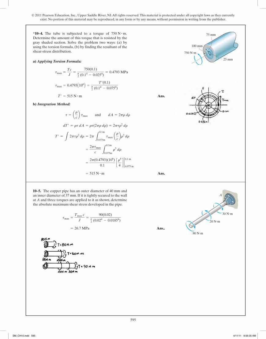
a) Applying Torsion Formula:
Ans.
b) Integration Method:
Ans. = 515 N # m
=2p(0.4793)(106)
0.1 cr4
4d 2 0.1 m
0.075 m
=2ptmax
c L
0.1m
0.075m r3 dr
T¿ = L 2ptr2 dr = 2p L0.1m
0.075m tmax arc br2 dr
dT¿ = rt dA = rt(2pr dr) = 2ptr2 dr
t = arcb tmax and dA = 2pr dr
T¿ = 515 N # m
tmax = 0.4793 A106 B =T¿(0.1)
p2 (0.14 - 0.0754)
tmax =Tc
J=
750(0.1)p2 (0.14 - 0.0254)
= 0.4793 MPa
*5–4. The tube is subjected to a torque of Determine the amount of this torque that is resisted by thegray shaded section. Solve the problem two ways: (a) byusing the torsion formula, (b) by finding the resultant of theshear-stress distribution.
750 N # m. 75 mm
100 mm
25 mm
750 N�m
Ans.. = 26.7 MPa
tmax =Tmax c
J=
90(0.02)p2 (0.024 - 0.01854)
5–5. The copper pipe has an outer diameter of 40 mm andan inner diameter of 37 mm. If it is tightly secured to the wallat A and three torques are applied to it as shown, determinethe absolute maximum shear stress developed in the pipe.
A
80 N�m
20 N�m
30 N�m
05 Solutions 46060 5/28/10 1:01 PM Page 217
10–3.
SM_CH10.indd 594 4/11/11 9:56:34 AM
© 2011 Pearson Education, Inc., Upper Saddle River, NJ. All rights reserved. This material is protected under all copyright laws as they currently exist. No portion of this material may be reproduced, in any form or by any means, without permission in writing from the publisher.
595
The internal torques developed at Cross-sections pass through point B and A areshown in Fig. a and b, respectively.
The polar moment of inertia of the shaft is . For
point B, Thus,
Ans.
From point A, .
Ans.tA =TArAJ
=6(103)(0.05)
49.70 (10-6)= 6.036(106) Pa = 6.04 MPa.
rA = 0.05 m
tB =TB c
J=
4(103)(0.075)
49.70(10-6)= 6.036(106) Pa = 6.04 MPa
rB = C = 0.075
J =p
2 (0.0754) = 49.70(10-6) m4
5–3. The solid shaft is fixed to the support at C andsubjected to the torsional loadings shown. Determine theshear stress at points A and B and sketch the shear stress onvolume elements located at these points.
216
© 2010 Pearson Education, Inc., Upper Saddle River, NJ. All rights reserved. This material is protected under all copyright laws as they currentlyexist. No portion of this material may be reproduced, in any form or by any means, without permission in writing from the publisher.
C 75 mm
10 kN�m
75 mm50 mm
A B 4 kN�m
05 Solutions 46060 5/28/10 1:01 PM Page 216
217
© 2010 Pearson Education, Inc., Upper Saddle River, NJ. All rights reserved. This material is protected under all copyright laws as they currentlyexist. No portion of this material may be reproduced, in any form or by any means, without permission in writing from the publisher.
a) Applying Torsion Formula:
Ans.
b) Integration Method:
Ans. = 515 N # m
=2p(0.4793)(106)
0.1 cr4
4d 2 0.1 m
0.075 m
=2ptmax
c L
0.1m
0.075m r3 dr
T¿ = L 2ptr2 dr = 2p L0.1m
0.075m tmax arc br2 dr
dT¿ = rt dA = rt(2pr dr) = 2ptr2 dr
t = arcb tmax and dA = 2pr dr
T¿ = 515 N # m
tmax = 0.4793 A106 B =T¿(0.1)
p2 (0.14 - 0.0754)
tmax =Tc
J=
750(0.1)p2 (0.14 - 0.0254)
= 0.4793 MPa
*5–4. The tube is subjected to a torque of Determine the amount of this torque that is resisted by thegray shaded section. Solve the problem two ways: (a) byusing the torsion formula, (b) by finding the resultant of theshear-stress distribution.
750 N # m. 75 mm
100 mm
25 mm
750 N�m
Ans.. = 26.7 MPa
tmax =Tmax c
J=
90(0.02)p2 (0.024 - 0.01854)
5–5. The copper pipe has an outer diameter of 40 mm andan inner diameter of 37 mm. If it is tightly secured to the wallat A and three torques are applied to it as shown, determinethe absolute maximum shear stress developed in the pipe.
A
80 N�m
20 N�m
30 N�m
05 Solutions 46060 5/28/10 1:01 PM Page 217
*10–4.
10–5.
SM_CH10.indd 595 4/11/11 9:56:35 AM
© 2011 Pearson Education, Inc., Upper Saddle River, NJ. All rights reserved. This material is protected under all copyright laws as they currently exist. No portion of this material may be reproduced, in any form or by any means, without permission in writing from the publisher.
596218
© 2010 Pearson Education, Inc., Upper Saddle River, NJ. All rights reserved. This material is protected under all copyright laws as they currentlyexist. No portion of this material may be reproduced, in any form or by any means, without permission in writing from the publisher.
Ans.
Ans.(tDE)max =TDE c
J=
25(12)(0.375)p2 (0.375)4 = 3621 psi = 3.62 ksi
(tBC)max =TBC c
J=
35(12)(0.375)p2 (0.375)4 = 5070 psi = 5.07 ksi
5–6. The solid shaft has a diameter of 0.75 in. If it issubjected to the torques shown, determine the maximumshear stress developed in regions BC and DE of the shaft.The bearings at A and F allow free rotation of the shaft.
A
B
C
D
EF
40 lb�ft25 lb�ft
20 lb�ft
35 lb�ft
Ans.
Ans. = 2173 psi = 2.17 ksi
(tCD)max =TCD c
J=
15(12)(0.375)p2 (0.375)4
(tEF)max =TEF c
J= 0
5–7. The solid shaft has a diameter of 0.75 in. If it issubjected to the torques shown, determine the maximumshear stress developed in regions CD and EF of the shaft.The bearings at A and F allow free rotation of the shaft.
A
B
C
D
EF
40 lb�ft25 lb�ft
20 lb�ft
35 lb�ft
05 Solutions 46060 5/28/10 1:01 PM Page 218
219
© 2010 Pearson Education, Inc., Upper Saddle River, NJ. All rights reserved. This material is protected under all copyright laws as they currentlyexist. No portion of this material may be reproduced, in any form or by any means, without permission in writing from the publisher.
Internal Torque: As shown on torque diagram.
Maximum Shear Stress: From the torque diagram . Then, applyingtorsion Formula.
Ans. =400(0.015)p2 (0.0154)
= 75.5 MPa
t absmax
=Tmax c
J
Tmax = 400 N # m
*5–8. The solid 30-mm-diameter shaft is used to transmitthe torques applied to the gears. Determine the absolutemaximum shear stress on the shaft.
300 N m�
A200 N m�
500 N m�
300 mm
400 mm
500 mm
400 N m�
B
D
C
Ans.tmax =Tc
J=
800(0.038)
2.545(10-6)= 11.9 MPa
J = 2.545(10-6) m4
J =p
2 ((0.038)4 - (0.032)4) +
p
2 ((0.030)4 - (0.026)4) +
p
2 ((0.025)4 - (0.020)4)
•5–9. The shaft consists of three concentric tubes, eachmade from the same material and having the inner andouter radii shown. If a torque of is applied tothe rigid disk fixed to its end, determine the maximum shearstress in the shaft.
T = 800 N # mT � 800 N�m
2 m ri � 20 mmro � 25 mm
ri � 26 mmro � 30 mm
ri � 32 mmro � 38 mm
05 Solutions 46060 5/28/10 1:01 PM Page 219
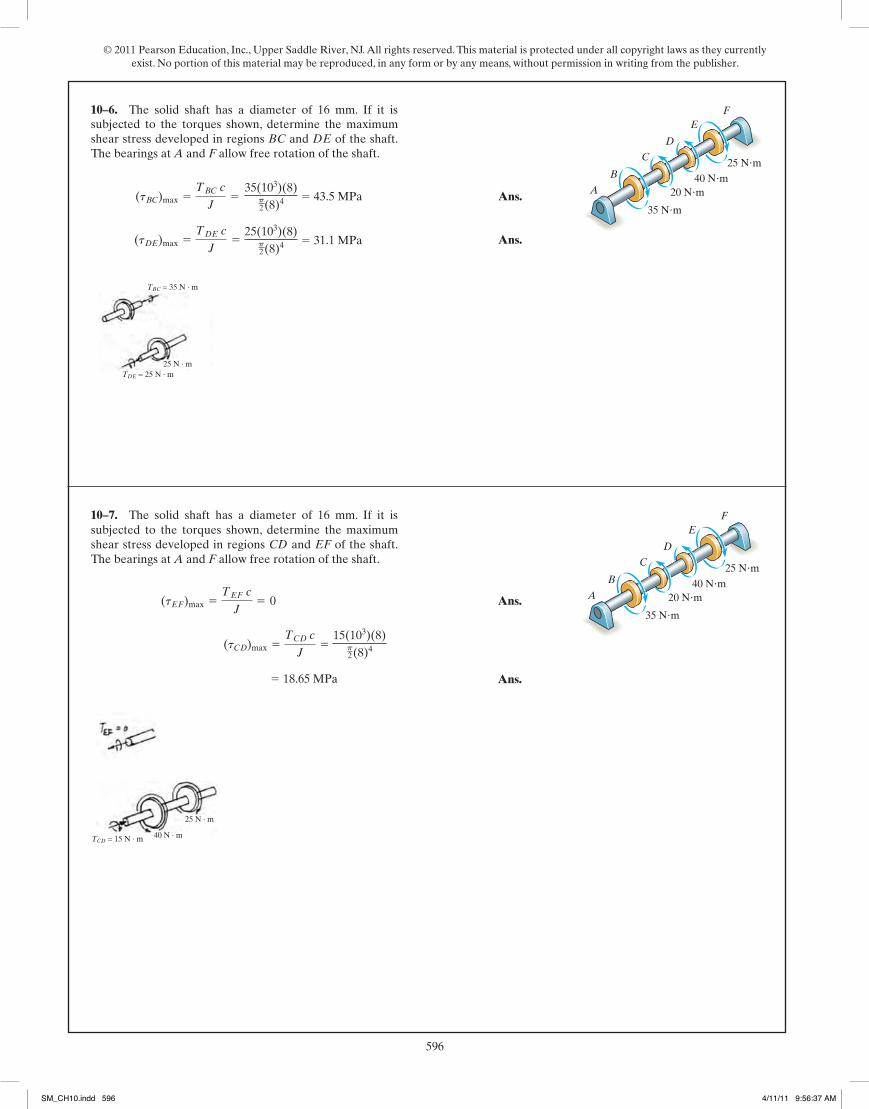
10–6. The solid shaft has a diameter of 16 mm. If it is
A
B
C
D
EF
40 Nm25 Nm
20 Nm
35 Nm
35(103)(8)p2(8)4 5 43.5 MPa
25(103)(8)p2(8)4 5 31.1 MPa
TBC = 35 N · m
TDE = 25 N · m25 N · m
10–7. The solid shaft has a diameter of 16 mm. If it is
15(103)(8)p2(8)4
5 18.65 MPa
A
B
C
D
EF
40 Nm25 Nm
20 Nm
35 Nm
TCD = 15 N · m
25 N · m
40 N · m
SM_CH10.indd 596 4/11/11 9:56:37 AM

© 2011 Pearson Education, Inc., Upper Saddle River, NJ. All rights reserved. This material is protected under all copyright laws as they currently exist. No portion of this material may be reproduced, in any form or by any means, without permission in writing from the publisher.
597218
© 2010 Pearson Education, Inc., Upper Saddle River, NJ. All rights reserved. This material is protected under all copyright laws as they currentlyexist. No portion of this material may be reproduced, in any form or by any means, without permission in writing from the publisher.
Ans.
Ans.(tDE)max =TDE c
J=
25(12)(0.375)p2 (0.375)4 = 3621 psi = 3.62 ksi
(tBC)max =TBC c
J=
35(12)(0.375)p2 (0.375)4 = 5070 psi = 5.07 ksi
5–6. The solid shaft has a diameter of 0.75 in. If it issubjected to the torques shown, determine the maximumshear stress developed in regions BC and DE of the shaft.The bearings at A and F allow free rotation of the shaft.
A
B
C
D
EF
40 lb�ft25 lb�ft
20 lb�ft
35 lb�ft
Ans.
Ans. = 2173 psi = 2.17 ksi
(tCD)max =TCD c
J=
15(12)(0.375)p2 (0.375)4
(tEF)max =TEF c
J= 0
5–7. The solid shaft has a diameter of 0.75 in. If it issubjected to the torques shown, determine the maximumshear stress developed in regions CD and EF of the shaft.The bearings at A and F allow free rotation of the shaft.
A
B
C
D
EF
40 lb�ft25 lb�ft
20 lb�ft
35 lb�ft
05 Solutions 46060 5/28/10 1:01 PM Page 218
219
© 2010 Pearson Education, Inc., Upper Saddle River, NJ. All rights reserved. This material is protected under all copyright laws as they currentlyexist. No portion of this material may be reproduced, in any form or by any means, without permission in writing from the publisher.
Internal Torque: As shown on torque diagram.
Maximum Shear Stress: From the torque diagram . Then, applyingtorsion Formula.
Ans. =400(0.015)p2 (0.0154)
= 75.5 MPa
t absmax
=Tmax c
J
Tmax = 400 N # m
*5–8. The solid 30-mm-diameter shaft is used to transmitthe torques applied to the gears. Determine the absolutemaximum shear stress on the shaft.
300 N m�
A200 N m�
500 N m�
300 mm
400 mm
500 mm
400 N m�
B
D
C
Ans.tmax =Tc
J=
800(0.038)
2.545(10-6)= 11.9 MPa
J = 2.545(10-6) m4
J =p
2 ((0.038)4 - (0.032)4) +
p
2 ((0.030)4 - (0.026)4) +
p
2 ((0.025)4 - (0.020)4)
•5–9. The shaft consists of three concentric tubes, eachmade from the same material and having the inner andouter radii shown. If a torque of is applied tothe rigid disk fixed to its end, determine the maximum shearstress in the shaft.
T = 800 N # mT � 800 N�m
2 m ri � 20 mmro � 25 mm
ri � 26 mmro � 30 mm
ri � 32 mmro � 38 mm
05 Solutions 46060 5/28/10 1:01 PM Page 219
*10–8.
231
© 2010 Pearson Education, Inc., Upper Saddle River, NJ. All rights reserved. This material is protected under all copyright laws as they currentlyexist. No portion of this material may be reproduced, in any form or by any means, without permission in writing from the publisher.
Shear stress is maximum when r is the smallest, i.e. . Hence,
Ans.tmax =T
2p ri 2
h
r = ri
t =F
A=
Tr
2 p r h=
T
2p r2 h
5–26. A cylindrical spring consists of a rubber annulusbonded to a rigid ring and shaft. If the ring is held fixed anda torque T is applied to the shaft, determine the maximumshear stress in the rubber.
Th
ro ri
The internal torque developed in segments AB and BC are shown in theirrespective FBDs, Figs. a and b.
The polar moment of inertia of the shaft is . Thus,
Ans.
Ans.AtBC Bmax =TBC c
J=
200(0.02)
80(10-9)p= 15.92(106) Pa = 15.9 MPa
AtAB Bmax =TAB c
J=
300(0.02)
80(10-9)p= 23.87(106)Pa = 23.9 MPa
J =p
2(0.024) = 80(10-9)p m4
5–27. The A-36 steel shaft is supported on smoothbearings that allow it to rotate freely. If the gears aresubjected to the torques shown, determine the maximumshear stress developed in the segments AB and BC. Theshaft has a diameter of 40 mm.
300 N m�
100 N m�
200 N m�A
B
C
05 Solutions 46060 5/28/10 1:01 PM Page 231
10–9.
SM_CH10.indd 597 4/11/11 9:56:38 AM
© 2011 Pearson Education, Inc., Upper Saddle River, NJ. All rights reserved. This material is protected under all copyright laws as they currently exist. No portion of this material may be reproduced, in any form or by any means, without permission in writing from the publisher.
598 221
© 2010 Pearson Education, Inc., Upper Saddle River, NJ. All rights reserved. This material is protected under all copyright laws as they currentlyexist. No portion of this material may be reproduced, in any form or by any means, without permission in writing from the publisher.
Equilibrium:
a
a
Ans.
Internal Torque: As shown on FBD.
Maximum Shear Stress: Applying torsion Formula.
Ans.
Ans.(tCD)max =TCDc
J=
125(0.0175)p2 (0.01754)
= 14.8 MPa
(tAB)max =TAB c
J=
50.0(0.015)p2 (0.0154)
= 9.43 MPa
T¿ = 125 N # m+©MF = 0; T¿ - 1000(0.125) = 0
+©ME = 0; 50 - F(0.05) = 0 F = 1000 N
*5–12. The motor delivers a torque of to the shaftAB. This torque is transmitted to shaft CD using the gearsat E and F. Determine the equilibrium torque T� on shaftCD and the maximum shear stress in each shaft. Thebearings B, C, and D allow free rotation of the shafts.
50 N # m
50 mm
B
30 mm
35 mm 125 mmD
CE
FT ¿
A
Equilibrium:
a
a
Internal Torque: As shown on FBD.
Maximum Shear Stress: Applying the torsion formula
Ans.
Ans.(tCD)max =TCDc
J=
75.0(0.0175)p2 (0.01754)
= 8.91 MPa
(tEA)max =TEA c
J=
30.0(0.015)p2 (0.0154)
= 5.66 MPa
TA = 30.0 N # m +©ME = 0; 600(0.05) - TA = 0
+©MF = 0; 75 - F(0.125) = 0; F = 600 N
•5–13. If the applied torque on shaft CD is determine the absolute maximum shear stress in each shaft.The bearings B, C, and D allow free rotation of the shafts,and the motor holds the shafts fixed from rotating.
75 N # m,T¿ =
50 mm
B
30 mm
35 mm 125 mmD
CE
FT ¿
A
05 Solutions 46060 5/28/10 1:01 PM Page 221
232
© 2010 Pearson Education, Inc., Upper Saddle River, NJ. All rights reserved. This material is protected under all copyright laws as they currentlyexist. No portion of this material may be reproduced, in any form or by any means, without permission in writing from the publisher.
The internal torque developed in segments AB and BC are shown in theirrespective FBDs, Fig. a and b
Here, segment AB is critical since its internal torque is the greatest. The polar
moment of inertia of the shaft is . Thus,
Ans. d = 0.02942 m = 30 mm
tallow =TCJ
; 60(106) =300(d>2)
pd4>32
J =p
2 ad
2b4
=pd4
32
*5–28. The A-36 steel shaft is supported on smoothbearings that allow it to rotate freely. If the gears aresubjected to the torques shown, determine the requireddiameter of the shaft to the nearest mm if .tallover = 60 MPa
300 N m�
100 N m�
200 N m�A
B
C
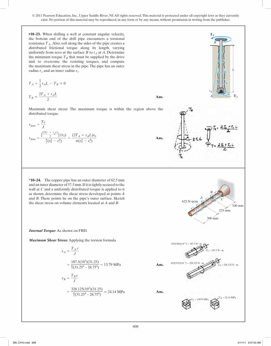
Ans.
Maximum shear stress: The maximum torque is within the region above thedistributed torque.
Ans.tmax =[(2TA + t
AL)
2 ] (r0)p2(r0
4 - ri4)=
(2TA + tAL)r0p(r0
4 - ri4)
tmax =Tc
J
TB =2TA + tAL
2
TA +12
tAL - TB = 0
•5–29. When drilling a well at constant angular velocity,the bottom end of the drill pipe encounters a torsionalresistance Also, soil along the sides of the pipe creates adistributed frictional torque along its length, varyinguniformly from zero at the surface B to at A. Determinethe minimum torque that must be supplied by the driveunit to overcome the resisting torques, and computethe maximum shear stress in the pipe. The pipe has an outerradius and an inner radius ri .ro
TB
tA
TA .
TA
L
B
TB
tAA
05 Solutions 46060 5/28/10 1:01 PM Page 232
220
© 2010 Pearson Education, Inc., Upper Saddle River, NJ. All rights reserved. This material is protected under all copyright laws as they currentlyexist. No portion of this material may be reproduced, in any form or by any means, without permission in writing from the publisher.
n is the number of bolts and F is the shear force in each bolt.
Maximum shear stress for the shaft:
Ans.n =2 r3
Rd2
tavg = tmax ; 4TnRpd2 =
2Tp r3
tmax =T c
J=T rp2 r4
=2Tpr3
tavg =F
A=
TnR
(p4)d2 =4TnRpd2
T - nFR = 0; F =T
nR
5–10. The coupling is used to connect the two shaftstogether. Assuming that the shear stress in the bolts isuniform, determine the number of bolts necessary to makethe maximum shear stress in the shaft equal to the shearstress in the bolts. Each bolt has a diameter d.
T
r
T
R
5–11. The assembly consists of two sections of galvanizedsteel pipe connected together using a reducing coupling at B.The smaller pipe has an outer diameter of 0.75 in. and an innerdiameter of 0.68 in., whereas the larger pipe has an outerdiameter of 1 in. and an inner diameter of 0.86 in. If the pipe istightly secured to the wall at C, determine the maximum shearstress developed in each section of the pipe when the coupleshown is applied to the handles of the wrench.
C
B
A
15 lb 6 in.
15 lb
8 in.
Ans.
Ans.tBC =Tc
J=
210(0.5)p2 (0.54 - 0.434)
= 2.36 ksi
tAB =Tc
J=
210(0.375)p2 (0.3754 - 0.344)
= 7.82 ksi
05 Solutions 46060 5/28/10 1:01 PM Page 220
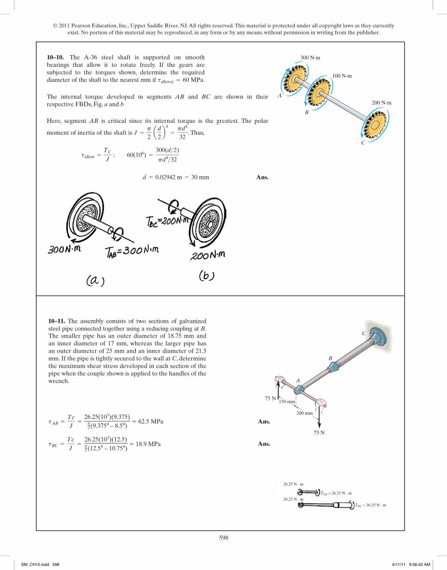
The smaller pipe has an outer diameter of 18.75 mm and an inner diameter of 17 mm, whereas the larger pipe has an outer diameter of 25 mm and an inner diameter of 21.5 mm. If the pipe is tightly secured to the wall at C, determine the maximum shear stress developed in each section of the pipe when the couple shown is applied to the handles of the wrench.
26.25(103)(9.375)p2(9.3754 – 8.54)
5 62.5 MPa
26.25(103)(12.5)p2(12.54 – 10.754)
5 18.9 MPa
C
B
A
75 N150 mm
75 N
200 mm
26.25 N · m
26.25 N · mTBC = 26.25 N · m
TAB = 26.25 N · m
10–11.
10–10.
SM_CH10.indd 598 4/11/11 9:56:42 AM

© 2011 Pearson Education, Inc., Upper Saddle River, NJ. All rights reserved. This material is protected under all copyright laws as they currently exist. No portion of this material may be reproduced, in any form or by any means, without permission in writing from the publisher.
599221
© 2010 Pearson Education, Inc., Upper Saddle River, NJ. All rights reserved. This material is protected under all copyright laws as they currentlyexist. No portion of this material may be reproduced, in any form or by any means, without permission in writing from the publisher.
Equilibrium:
a
a
Ans.
Internal Torque: As shown on FBD.
Maximum Shear Stress: Applying torsion Formula.
Ans.
Ans.(tCD)max =TCDc
J=
125(0.0175)p2 (0.01754)
= 14.8 MPa
(tAB)max =TAB c
J=
50.0(0.015)p2 (0.0154)
= 9.43 MPa
T¿ = 125 N # m+©MF = 0; T¿ - 1000(0.125) = 0
+©ME = 0; 50 - F(0.05) = 0 F = 1000 N
*5–12. The motor delivers a torque of to the shaftAB. This torque is transmitted to shaft CD using the gearsat E and F. Determine the equilibrium torque T� on shaftCD and the maximum shear stress in each shaft. Thebearings B, C, and D allow free rotation of the shafts.
50 N # m
50 mm
B
30 mm
35 mm 125 mmD
CE
FT ¿
A
Equilibrium:
a
a
Internal Torque: As shown on FBD.
Maximum Shear Stress: Applying the torsion formula
Ans.
Ans.(tCD)max =TCDc
J=
75.0(0.0175)p2 (0.01754)
= 8.91 MPa
(tEA)max =TEA c
J=
30.0(0.015)p2 (0.0154)
= 5.66 MPa
TA = 30.0 N # m +©ME = 0; 600(0.05) - TA = 0
+©MF = 0; 75 - F(0.125) = 0; F = 600 N
•5–13. If the applied torque on shaft CD is determine the absolute maximum shear stress in each shaft.The bearings B, C, and D allow free rotation of the shafts,and the motor holds the shafts fixed from rotating.
75 N # m,T¿ =
50 mm
B
30 mm
35 mm 125 mmD
CE
FT ¿
A
05 Solutions 46060 5/28/10 1:01 PM Page 221
*10–12.
•10–13.
SM_CH10.indd 599 4/11/11 9:56:44 AM

© 2011 Pearson Education, Inc., Upper Saddle River, NJ. All rights reserved. This material is protected under all copyright laws as they currently exist. No portion of this material may be reproduced, in any form or by any means, without permission in writing from the publisher.
600222
© 2010 Pearson Education, Inc., Upper Saddle River, NJ. All rights reserved. This material is protected under all copyright laws as they currentlyexist. No portion of this material may be reproduced, in any form or by any means, without permission in writing from the publisher.
5–14. The solid 50-mm-diameter shaft is used to transmitthe torques applied to the gears. Determine the absolutemaximum shear stress in the shaft.
A
250 N m�
325 N m�
75 N m�
500 mm
400 mm
500 mm
150 N m�B
D
C
The internal torque developed in segments AB , BC and CD of the shaft are shownin Figs. a, b and c.
The maximum torque occurs in segment AB. Thus, the absolute maximum shear
stress occurs in this segment. The polar moment of inertia of the shaft is
. Thus,
Ans.Atmax Babs =TAB c
J=
250(0.025)
0.1953p(10-6)= 10.19(106)Pa = 10.2 MPa
J =p
2 (0.0254) = 0.1953p(10-6)m4
05 Solutions 46060 5/28/10 1:01 PM Page 222
223
© 2010 Pearson Education, Inc., Upper Saddle River, NJ. All rights reserved. This material is protected under all copyright laws as they currentlyexist. No portion of this material may be reproduced, in any form or by any means, without permission in writing from the publisher.
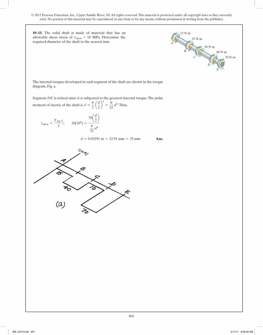
The internal torques developed in each segment of the shaft are shown in the torquediagram, Fig. a.
Segment DE is critical since it is subjected to the greatest internal torque. The polar
moment of inertia of the shaft is . Thus,
Ans. d = 0.03291 m = 32.91 mm = 33 mm
tallow =TDE c
J; 10(106) =
70ad2b
p
32 d4
J =p
2 ad
2b4
=p
32 d4
5–15. The solid shaft is made of material that has anallowable shear stress of MPa. Determine therequired diameter of the shaft to the nearest mm.
tallow = 10 25 N�m
15 N�m
70 N�m
30 N�m
60 N�m
A
B
C
D
E
05 Solutions 46060 5/28/10 1:01 PM Page 223
10–14.
SM_CH10.indd 600 4/11/11 9:56:45 AM
© 2011 Pearson Education, Inc., Upper Saddle River, NJ. All rights reserved. This material is protected under all copyright laws as they currently exist. No portion of this material may be reproduced, in any form or by any means, without permission in writing from the publisher.
601222
© 2010 Pearson Education, Inc., Upper Saddle River, NJ. All rights reserved. This material is protected under all copyright laws as they currentlyexist. No portion of this material may be reproduced, in any form or by any means, without permission in writing from the publisher.
5–14. The solid 50-mm-diameter shaft is used to transmitthe torques applied to the gears. Determine the absolutemaximum shear stress in the shaft.
A
250 N m�
325 N m�
75 N m�
500 mm
400 mm
500 mm
150 N m�B
D
C
The internal torque developed in segments AB , BC and CD of the shaft are shownin Figs. a, b and c.
The maximum torque occurs in segment AB. Thus, the absolute maximum shear
stress occurs in this segment. The polar moment of inertia of the shaft is
. Thus,
Ans.Atmax Babs =TAB c
J=
250(0.025)
0.1953p(10-6)= 10.19(106)Pa = 10.2 MPa
J =p
2 (0.0254) = 0.1953p(10-6)m4
05 Solutions 46060 5/28/10 1:01 PM Page 222
223
© 2010 Pearson Education, Inc., Upper Saddle River, NJ. All rights reserved. This material is protected under all copyright laws as they currentlyexist. No portion of this material may be reproduced, in any form or by any means, without permission in writing from the publisher.
The internal torques developed in each segment of the shaft are shown in the torquediagram, Fig. a.
Segment DE is critical since it is subjected to the greatest internal torque. The polar
moment of inertia of the shaft is . Thus,
Ans. d = 0.03291 m = 32.91 mm = 33 mm
tallow =TDE c
J; 10(106) =
70ad2b
p
32 d4
J =p
2 ad
2b4
=p
32 d4
5–15. The solid shaft is made of material that has anallowable shear stress of MPa. Determine therequired diameter of the shaft to the nearest mm.
tallow = 10 25 N�m
15 N�m
70 N�m
30 N�m
60 N�m
A
B
C
D
E
05 Solutions 46060 5/28/10 1:01 PM Page 223
10–15.
SM_CH10.indd 601 4/11/11 9:56:46 AM
© 2011 Pearson Education, Inc., Upper Saddle River, NJ. All rights reserved. This material is protected under all copyright laws as they currently exist. No portion of this material may be reproduced, in any form or by any means, without permission in writing from the publisher.
602224
© 2010 Pearson Education, Inc., Upper Saddle River, NJ. All rights reserved. This material is protected under all copyright laws as they currentlyexist. No portion of this material may be reproduced, in any form or by any means, without permission in writing from the publisher.
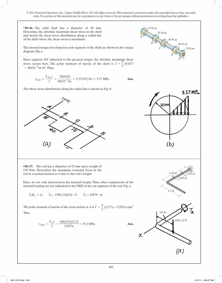
The internal torque developed in each segment of the shaft are shown in the torquediagram, Fig. a.
Since segment DE subjected to the greatest torque, the absolute maximum shearstress occurs here. The polar moment of inertia of the shaft is
. Thus,
Ans.
The shear stress distribution along the radial line is shown in Fig. b.
tmax =TDE c
J=
70(0.02)
80(10-9)p= 5.57(106) Pa = 5.57 MPa
= 80(10-9)p m4J =
p
2 (0.024)
*5–16. The solid shaft has a diameter of 40 mm.Determine the absolute maximum shear stress in the shaftand sketch the shear-stress distribution along a radial lineof the shaft where the shear stress is maximum.
25 N�m
15 N�m
70 N�m
30 N�m
60 N�m
A
B
C
D
E
Here, we are only interested in the internal torque. Thus, other components of theinternal loading are not indicated in the FBD of the cut segment of the rod, Fig. a.
The polar moment of inertia of the cross section at A is .
Thus
Ans.tmax =TA c
J=
960 (0.5)
0.03125p= 4889.24 psi = 4.89 ksi
J =p
2 (0.54) = 0.03125p in4
©Mx = 0; TA - 10(4)(2) = 0 TA = 80 lb # ft a12in1ftb = 960 lb # in.
•5–17. The rod has a diameter of 1 in. and a weight of10 lb/ft. Determine the maximum torsional stress in the rodat a section located at A due to the rod’s weight.
4 ft
1.5 ft
4.5 ft A
B1.5 ft
05 Solutions 46060 5/28/10 1:01 PM Page 224
225
© 2010 Pearson Education, Inc., Upper Saddle River, NJ. All rights reserved. This material is protected under all copyright laws as they currentlyexist. No portion of this material may be reproduced, in any form or by any means, without permission in writing from the publisher.
Here, we are only interested in the internal torque. Thus, other components of theinternal loading are not indicated in the FBD of the cut segment of the rod, Fig. a.
The polar moment of inertia of the cross-section at B is . Thus,
Ans.tmax =TB c
J=
1440(0.5)
0.03125p= 7333.86 psi = 7.33 ksi
= 0.03125p in4J =
p
2 (0.54)
©Mx = 0; TB - 15(4)(2) = 0 TB = 120 lb # ft a 12 in1ftb = 1440 lb # in.
5–18. The rod has a diameter of 1 in. and a weight of15 lb/ft. Determine the maximum torsional stress in the rodat a section located at B due to the rod’s weight.
4 ft
1.5 ft
4.5 ft A
B1.5 ft
05 Solutions 46060 5/28/10 1:01 PM Page 225
•10–17. The rod has a diameter of 25 mm and a weight of 150 N/m. Determine the maximum torsional stress in the rod at a section located at A due to the rod’s weight.
TA – 150(1.2)(0.6) = 0 TA = 108 N · m
(12.54) = 12207p mm4
108(103)(12.5)12207p
5 35.2 MPa
0.6 m
150(1.2) N
1.2 m
0.45 m
1.35 m A
B0.45 m
*10–16.
SM_CH10.indd 602 4/11/11 9:56:47 AM

© 2011 Pearson Education, Inc., Upper Saddle River, NJ. All rights reserved. This material is protected under all copyright laws as they currently exist. No portion of this material may be reproduced, in any form or by any means, without permission in writing from the publisher.
603224
© 2010 Pearson Education, Inc., Upper Saddle River, NJ. All rights reserved. This material is protected under all copyright laws as they currentlyexist. No portion of this material may be reproduced, in any form or by any means, without permission in writing from the publisher.
The internal torque developed in each segment of the shaft are shown in the torquediagram, Fig. a.
Since segment DE subjected to the greatest torque, the absolute maximum shearstress occurs here. The polar moment of inertia of the shaft is
. Thus,
Ans.
The shear stress distribution along the radial line is shown in Fig. b.
tmax =TDE c
J=
70(0.02)
80(10-9)p= 5.57(106) Pa = 5.57 MPa
= 80(10-9)p m4J =
p
2 (0.024)
*5–16. The solid shaft has a diameter of 40 mm.Determine the absolute maximum shear stress in the shaftand sketch the shear-stress distribution along a radial lineof the shaft where the shear stress is maximum.
25 N�m
15 N�m
70 N�m
30 N�m
60 N�m
A
B
C
D
E
Here, we are only interested in the internal torque. Thus, other components of theinternal loading are not indicated in the FBD of the cut segment of the rod, Fig. a.
The polar moment of inertia of the cross section at A is .
Thus
Ans.tmax =TA c
J=
960 (0.5)
0.03125p= 4889.24 psi = 4.89 ksi
J =p
2 (0.54) = 0.03125p in4
©Mx = 0; TA - 10(4)(2) = 0 TA = 80 lb # ft a12in1ftb = 960 lb # in.
•5–17. The rod has a diameter of 1 in. and a weight of10 lb/ft. Determine the maximum torsional stress in the rodat a section located at A due to the rod’s weight.
4 ft
1.5 ft
4.5 ft A
B1.5 ft
05 Solutions 46060 5/28/10 1:01 PM Page 224
225
© 2010 Pearson Education, Inc., Upper Saddle River, NJ. All rights reserved. This material is protected under all copyright laws as they currentlyexist. No portion of this material may be reproduced, in any form or by any means, without permission in writing from the publisher.
Here, we are only interested in the internal torque. Thus, other components of theinternal loading are not indicated in the FBD of the cut segment of the rod, Fig. a.
The polar moment of inertia of the cross-section at B is . Thus,
Ans.tmax =TB c
J=
1440(0.5)
0.03125p= 7333.86 psi = 7.33 ksi
= 0.03125p in4J =
p
2 (0.54)
©Mx = 0; TB - 15(4)(2) = 0 TB = 120 lb # ft a12 in1ftb = 1440 lb # in.
5–18. The rod has a diameter of 1 in. and a weight of15 lb/ft. Determine the maximum torsional stress in the rodat a section located at B due to the rod’s weight.
4 ft
1.5 ft
4.5 ft A
B1.5 ft
05 Solutions 46060 5/28/10 1:01 PM Page 225
10–18. The rod has a diameter of 25 mm and a weight of 225 N/m. Determine the maximum torsional stress in the rod at a section located at B due to the rod’s weight.
1.2 m
0.45 m
1.35 m A
B0.45 m
TB – 225(1.2)(0.6) = 0 TB = 162 N · m
(12.54)= 12207p mm4. Thus,
162(103)(12.5)12207p
5 52.8 MPa
0.6 m
12.5 mm225(1.2) N
Tmax = 52.8 MPa
TB = 162 N · m
SM_CH10.indd 603 4/11/11 9:56:47 AM
© 2011 Pearson Education, Inc., Upper Saddle River, NJ. All rights reserved. This material is protected under all copyright laws as they currently exist. No portion of this material may be reproduced, in any form or by any means, without permission in writing from the publisher.
604
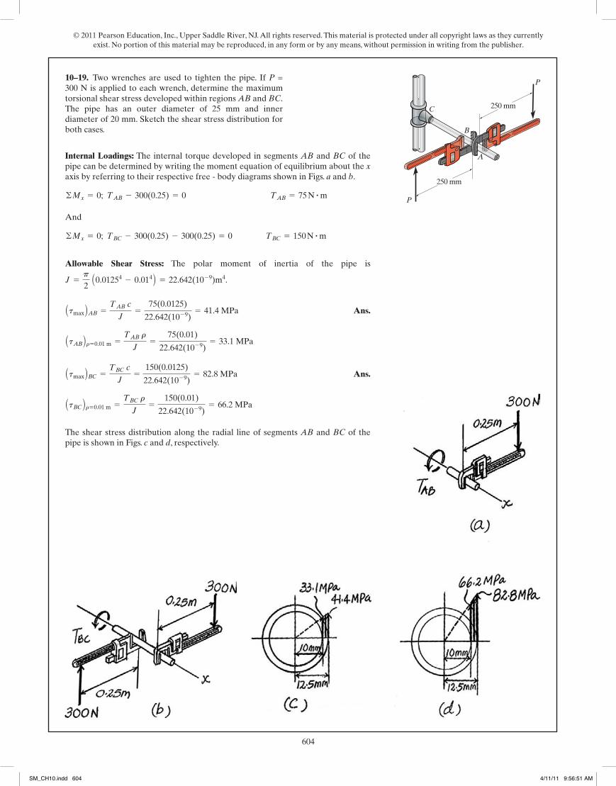
Internal Loadings: The internal torque developed in segments AB and BC of thepipe can be determined by writing the moment equation of equilibrium about the xaxis by referring to their respective free - body diagrams shown in Figs. a and b.
And
Allowable Shear Stress: The polar moment of inertia of the pipe is
.
Ans.
Ans.
The shear stress distribution along the radial line of segments AB and BC of thepipe is shown in Figs. c and d, respectively.
AtBC Br=0.01 m =TBC r
J=
150(0.01)
22.642(10-9)= 66.2 MPa
Atmax BBC =TBC c
J=
150(0.0125)
22.642(10-9)= 82.8 MPa
AtAB Br=0.01 m =TAB r
J=
75(0.01)
22.642(10-9)= 33.1 MPa
Atmax BAB =TAB c
J=
75(0.0125)
22.642(10-9)= 41.4 MPa
J =p
2 A0.01254 - 0.014 B = 22.642(10-9)m4
©Mx = 0; TBC - 300(0.25) - 300(0.25) = 0 TBC = 150 N # m
©Mx = 0; TAB - 300(0.25) = 0 TAB = 75 N # m
5–19. Two wrenches are used to tighten the pipe. If P =300 N is applied to each wrench, determine the maximumtorsional shear stress developed within regions AB and BC.The pipe has an outer diameter of 25 mm and innerdiameter of 20 mm. Sketch the shear stress distribution forboth cases.
226
© 2010 Pearson Education, Inc., Upper Saddle River, NJ. All rights reserved. This material is protected under all copyright laws as they currentlyexist. No portion of this material may be reproduced, in any form or by any means, without permission in writing from the publisher.
250 mm
250 mm
A
P
P
B
C
05 Solutions 46060 5/28/10 1:01 PM Page 226
227
© 2010 Pearson Education, Inc., Upper Saddle River, NJ. All rights reserved. This material is protected under all copyright laws as they currentlyexist. No portion of this material may be reproduced, in any form or by any means, without permission in writing from the publisher.
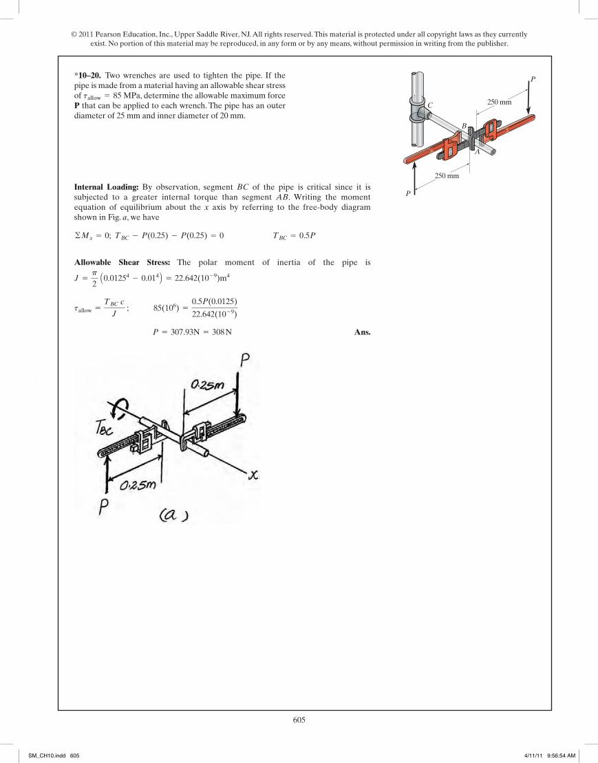
Internal Loading: By observation, segment BC of the pipe is critical since it issubjected to a greater internal torque than segment AB. Writing the momentequation of equilibrium about the x axis by referring to the free-body diagramshown in Fig. a, we have
Allowable Shear Stress: The polar moment of inertia of the pipe is
Ans. P = 307.93N = 308 N
tallow =TBC c
J ; 85(106) =
0.5P(0.0125)
22.642(10-9)
J =p
2 A0.01254 - 0.014 B = 22.642(10-9)m4
©Mx = 0; TBC - P(0.25) - P(0.25) = 0 TBC = 0.5P
*5–20. Two wrenches are used to tighten the pipe. If thepipe is made from a material having an allowable shear stressof MPa, determine the allowable maximum forceP that can be applied to each wrench. The pipe has an outerdiameter of 25 mm and inner diameter of 20 mm.
tallow = 85250 mm
250 mm
A
P
P
B
C
05 Solutions 46060 5/28/10 1:01 PM Page 227
10–19.
SM_CH10.indd 604 4/11/11 9:56:51 AM
© 2011 Pearson Education, Inc., Upper Saddle River, NJ. All rights reserved. This material is protected under all copyright laws as they currently exist. No portion of this material may be reproduced, in any form or by any means, without permission in writing from the publisher.
605
Internal Loadings: The internal torque developed in segments AB and BC of thepipe can be determined by writing the moment equation of equilibrium about the xaxis by referring to their respective free - body diagrams shown in Figs. a and b.
And
Allowable Shear Stress: The polar moment of inertia of the pipe is
.
Ans.
Ans.
The shear stress distribution along the radial line of segments AB and BC of thepipe is shown in Figs. c and d, respectively.
AtBC Br=0.01 m =TBC r
J=
150(0.01)
22.642(10-9)= 66.2 MPa
Atmax BBC =TBC c
J=
150(0.0125)
22.642(10-9)= 82.8 MPa
AtAB Br=0.01 m =TAB r
J=
75(0.01)
22.642(10-9)= 33.1 MPa
Atmax BAB =TAB c
J=
75(0.0125)
22.642(10-9)= 41.4 MPa
J =p
2 A0.01254 - 0.014 B = 22.642(10-9)m4
©Mx = 0; TBC - 300(0.25) - 300(0.25) = 0 TBC = 150 N # m
©Mx = 0; TAB - 300(0.25) = 0 TAB = 75 N # m
5–19. Two wrenches are used to tighten the pipe. If P =300 N is applied to each wrench, determine the maximumtorsional shear stress developed within regions AB and BC.The pipe has an outer diameter of 25 mm and innerdiameter of 20 mm. Sketch the shear stress distribution forboth cases.
226
© 2010 Pearson Education, Inc., Upper Saddle River, NJ. All rights reserved. This material is protected under all copyright laws as they currentlyexist. No portion of this material may be reproduced, in any form or by any means, without permission in writing from the publisher.
250 mm
250 mm
A
P
P
B
C
05 Solutions 46060 5/28/10 1:01 PM Page 226
227
© 2010 Pearson Education, Inc., Upper Saddle River, NJ. All rights reserved. This material is protected under all copyright laws as they currentlyexist. No portion of this material may be reproduced, in any form or by any means, without permission in writing from the publisher.
Internal Loading: By observation, segment BC of the pipe is critical since it issubjected to a greater internal torque than segment AB. Writing the momentequation of equilibrium about the x axis by referring to the free-body diagramshown in Fig. a, we have
Allowable Shear Stress: The polar moment of inertia of the pipe is
Ans. P = 307.93N = 308 N
tallow =TBC c
J ; 85(106) =
0.5P(0.0125)
22.642(10-9)
J =p
2 A0.01254 - 0.014 B = 22.642(10-9)m4
©Mx = 0; TBC - P(0.25) - P(0.25) = 0 TBC = 0.5P
*5–20. Two wrenches are used to tighten the pipe. If thepipe is made from a material having an allowable shear stressof MPa, determine the allowable maximum forceP that can be applied to each wrench. The pipe has an outerdiameter of 25 mm and inner diameter of 20 mm.
tallow = 85250 mm
250 mm
A
P
P
B
C
05 Solutions 46060 5/28/10 1:01 PM Page 227
*10–20.
SM_CH10.indd 605 4/11/11 9:56:54 AM

© 2011 Pearson Education, Inc., Upper Saddle River, NJ. All rights reserved. This material is protected under all copyright laws as they currently exist. No portion of this material may be reproduced, in any form or by any means, without permission in writing from the publisher.
606
The internal torque for segment BC is Constant , Fig. a. However,the internal for segment AB varies with x, Fig. b.
The minimum shear stress occurs when the internal torque is zero in segment AB.By setting ,
Ans.
And
Ans.
Ans.
The maximum shear stress occurs when the internal torque is the greatest. Thisoccurs at fixed support A where
Ans.
At this location,
The polar moment of inertia of the rod is . Thus,
Ans.tmax =(TAB)max c
J=
1800(0.03)
0.405(10-6)p= 42.44(106)Pa = 42.4 MPa
J =p
2 (0.034) = 0.405(10-6)p
(TAB)max = 2000(1.5) - 1200 = 1800 N # m
d = 0
tmin = 0
d = 1.5 m - 0.6 m = 0.9 m
0 = 2000x - 1200 x = 0.6 m
TAB = 0
TAB - 2000x + 1200 = 0 TAB = (2000x - 1200) N # m
TBC = 1200 N # m
•5–21. The 60-mm-diameter solid shaft is subjected to thedistributed and concentrated torsional loadings shown.Determine the absolute maximum and minimum shearstresses on the outer surface of the shaft and specify theirlocations, measured from the fixed end A.
228
© 2010 Pearson Education, Inc., Upper Saddle River, NJ. All rights reserved. This material is protected under all copyright laws as they currentlyexist. No portion of this material may be reproduced, in any form or by any means, without permission in writing from the publisher.
1.5 m
0.8 mC
B
A
1200 N�m
2 kN�m/m
05 Solutions 46060 5/28/10 1:01 PM Page 228
229
© 2010 Pearson Education, Inc., Upper Saddle River, NJ. All rights reserved. This material is protected under all copyright laws as they currentlyexist. No portion of this material may be reproduced, in any form or by any means, without permission in writing from the publisher.
The internal torque for segment BC is constant , Fig. a. However,the internal torque for segment AB varies with x, Fig. b.
For segment AB, the maximum internal torque occurs at fixed support A where. Thus,
Since , the critical cross-section is at A.The polar moment of inertia
of the rod is . Thus,
Ans. d = 0.05681 m = 56.81 mm = 57 mm
tallow =Tc
J ; 50(106) =
1800(d>2)
pd4>32
J =p
2 ad
2b4
=pd4
32
ATAB Bmax 7 TBC
ATAB Bmax = 2000(1.5) - 1200 = 1800 N # mx = 1.5 m
TAB - 2000x + 1200 = 0 TAB = (2000x - 1200) N # m
TBC = 1200 N # m
5–22. The solid shaft is subjected to the distributed andconcentrated torsional loadings shown. Determine therequired diameter d of the shaft to the nearest mm if theallowable shear stress for the material is tallow = 50 MPa.
1.5 m
0.8 mC
B
A
1200 N�m
2 kN�m/m
05 Solutions 46060 5/28/10 1:01 PM Page 229
•10–21.
SM_CH10.indd 606 4/11/11 9:56:58 AM
© 2011 Pearson Education, Inc., Upper Saddle River, NJ. All rights reserved. This material is protected under all copyright laws as they currently exist. No portion of this material may be reproduced, in any form or by any means, without permission in writing from the publisher.
607
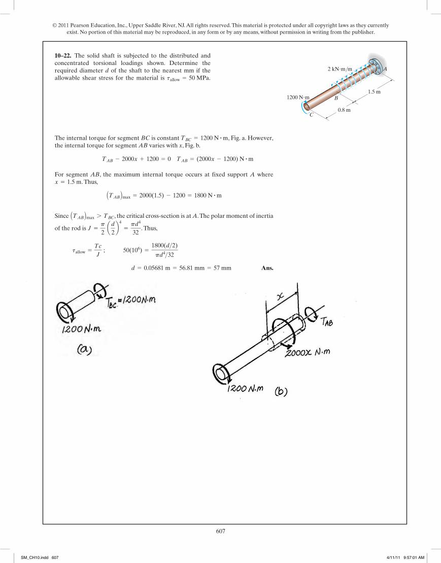
The internal torque for segment BC is Constant , Fig. a. However,the internal for segment AB varies with x, Fig. b.
The minimum shear stress occurs when the internal torque is zero in segment AB.By setting ,
Ans.
And
Ans.
Ans.
The maximum shear stress occurs when the internal torque is the greatest. Thisoccurs at fixed support A where
Ans.
At this location,
The polar moment of inertia of the rod is . Thus,
Ans.tmax =(TAB)max c
J=
1800(0.03)
0.405(10-6)p= 42.44(106)Pa = 42.4 MPa
J =p
2 (0.034) = 0.405(10-6)p
(TAB)max = 2000(1.5) - 1200 = 1800 N # m
d = 0
tmin = 0
d = 1.5 m - 0.6 m = 0.9 m
0 = 2000x - 1200 x = 0.6 m
TAB = 0
TAB - 2000x + 1200 = 0 TAB = (2000x - 1200) N # m
TBC = 1200 N # m
•5–21. The 60-mm-diameter solid shaft is subjected to thedistributed and concentrated torsional loadings shown.Determine the absolute maximum and minimum shearstresses on the outer surface of the shaft and specify theirlocations, measured from the fixed end A.
228
© 2010 Pearson Education, Inc., Upper Saddle River, NJ. All rights reserved. This material is protected under all copyright laws as they currentlyexist. No portion of this material may be reproduced, in any form or by any means, without permission in writing from the publisher.
1.5 m
0.8 mC
B
A
1200 N�m
2 kN�m/m
05 Solutions 46060 5/28/10 1:01 PM Page 228
229
© 2010 Pearson Education, Inc., Upper Saddle River, NJ. All rights reserved. This material is protected under all copyright laws as they currentlyexist. No portion of this material may be reproduced, in any form or by any means, without permission in writing from the publisher.
The internal torque for segment BC is constant , Fig. a. However,the internal torque for segment AB varies with x, Fig. b.
For segment AB, the maximum internal torque occurs at fixed support A where. Thus,
Since , the critical cross-section is at A.The polar moment of inertia
of the rod is . Thus,
Ans. d = 0.05681 m = 56.81 mm = 57 mm
tallow =Tc
J ; 50(106) =
1800(d>2)
pd4>32
J =p
2 ad
2b4
=pd4
32
ATAB Bmax 7 TBC
ATAB Bmax = 2000(1.5) - 1200 = 1800 N # mx = 1.5 m
TAB - 2000x + 1200 = 0 TAB = (2000x - 1200) N # m
TBC = 1200 N # m
5–22. The solid shaft is subjected to the distributed andconcentrated torsional loadings shown. Determine therequired diameter d of the shaft to the nearest mm if theallowable shear stress for the material is tallow = 50 MPa.
1.5 m
0.8 mC
B
A
1200 N�m
2 kN�m/m
05 Solutions 46060 5/28/10 1:01 PM Page 229
10–22.
SM_CH10.indd 607 4/11/11 9:57:01 AM
© 2011 Pearson Education, Inc., Upper Saddle River, NJ. All rights reserved. This material is protected under all copyright laws as they currently exist. No portion of this material may be reproduced, in any form or by any means, without permission in writing from the publisher.
608
Internal Torque: As shown on FBD.
Maximum Shear Stress: Applying the torsion formula
Ans.
Ans. =218.75(12)(1.25)p2 (1.254 - 1.154)
= 3.02 ksi
tB =TB c
J
=125.0(12)(1.25)p2 (1.254 - 1.154)
= 1.72 ksi
tA =TA c
J
230
© 2010 Pearson Education, Inc., Upper Saddle River, NJ. All rights reserved. This material is protected under all copyright laws as they currentlyexist. No portion of this material may be reproduced, in any form or by any means, without permission in writing from the publisher.
*5–24. The copper pipe has an outer diameter of 2.50 in.and an inner diameter of 2.30 in. If it is tightly secured to thewall at C and a uniformly distributed torque is applied to itas shown, determine the shear stress developed at points Aand B. These points lie on the pipe’s outer surface. Sketchthe shear stress on volume elements located at A and B. 125 lb�ft/ft
4 in.
C
9 in.
12 in.
B
A
Internal Torque: The maximum torque occurs at the support C.
Maximum Shear Stress: Applying the torsion formula
Ans.
According to Saint-Venant’s principle, application of the torsion formula should beas points sufficiently removed from the supports or points of concentrated loading.
=260.42(12)(1.25)p2 (1.254 - 1.154)
= 3.59 ksi
t absmax
=Tmax c
J
Tmax = (125 lb # ft>ft)a 25 in.12 in.>ft b = 260.42 lb # ft
•5–25. The copper pipe has an outer diameter of 2.50 in.and an inner diameter of 2.30 in. If it is tightly secured tothe wall at C and it is subjected to the uniformly distributedtorque along its entire length, determine the absolutemaximum shear stress in the pipe. Discuss the validity ofthis result. 125 lb�ft/ft
4 in.
C
9 in.
12 in.
B
A
05 Solutions 46060 5/28/10 1:01 PM Page 230
*10–24. The copper pipe has an outer diameter of 62.5 mm and an inner diameter of 57.5 mm. If it is tightly secured to the
187.5(103)(31.25)p2(31.254 – 28.754)
5 13.79 MPa
328.125(103)(31.25)p2(31.254 – 28.754)
5 24.14 MPa
625 Nm/m100 mm
C
225 mm
300 mm
B
A
625(300)(10–3) = 187.5 N · m
625(525)(10–3) = 328.125 N · mTB = 328.125 N · m
TA = 187.5 N · m
YA = 13079 MPaYB = 24.14 MPa
232
© 2010 Pearson Education, Inc., Upper Saddle River, NJ. All rights reserved. This material is protected under all copyright laws as they currentlyexist. No portion of this material may be reproduced, in any form or by any means, without permission in writing from the publisher.
The internal torque developed in segments AB and BC are shown in theirrespective FBDs, Fig. a and b
Here, segment AB is critical since its internal torque is the greatest. The polar
moment of inertia of the shaft is . Thus,
Ans. d = 0.02942 m = 30 mm
tallow =TCJ
; 60(106) =300(d>2)
pd4>32
J =p
2 ad
2b4
=pd4
32
*5–28. The A-36 steel shaft is supported on smoothbearings that allow it to rotate freely. If the gears aresubjected to the torques shown, determine the requireddiameter of the shaft to the nearest mm if .tallover = 60 MPa
300 N m�
100 N m�
200 N m�A
B
C
Ans.
Maximum shear stress: The maximum torque is within the region above thedistributed torque.
Ans.tmax =[(2TA + t
AL)
2 ] (r0)p2(r0
4 - ri4)=
(2TA + tAL)r0p(r0
4 - ri4)
tmax =Tc
J
TB =2TA + tAL
2
TA +12
tAL - TB = 0
•5–29. When drilling a well at constant angular velocity,the bottom end of the drill pipe encounters a torsionalresistance Also, soil along the sides of the pipe creates adistributed frictional torque along its length, varyinguniformly from zero at the surface B to at A. Determinethe minimum torque that must be supplied by the driveunit to overcome the resisting torques, and computethe maximum shear stress in the pipe. The pipe has an outerradius and an inner radius ri .ro
TB
tA
TA .
TA
L
B
TB
tAA
05 Solutions 46060 5/28/10 1:01 PM Page 232
•10–23.
SM_CH10.indd 608 4/11/11 9:57:03 AM
© 2011 Pearson Education, Inc., Upper Saddle River, NJ. All rights reserved. This material is protected under all copyright laws as they currently exist. No portion of this material may be reproduced, in any form or by any means, without permission in writing from the publisher.
609
Internal Torque: As shown on FBD.
Maximum Shear Stress: Applying the torsion formula
Ans.
Ans. =218.75(12)(1.25)p2 (1.254 - 1.154)
= 3.02 ksi
tB =TB c
J
=125.0(12)(1.25)p2 (1.254 - 1.154)
= 1.72 ksi
tA =TA c
J
230
© 2010 Pearson Education, Inc., Upper Saddle River, NJ. All rights reserved. This material is protected under all copyright laws as they currentlyexist. No portion of this material may be reproduced, in any form or by any means, without permission in writing from the publisher.
*5–24. The copper pipe has an outer diameter of 2.50 in.and an inner diameter of 2.30 in. If it is tightly secured to thewall at C and a uniformly distributed torque is applied to itas shown, determine the shear stress developed at points Aand B. These points lie on the pipe’s outer surface. Sketchthe shear stress on volume elements located at A and B. 125 lb�ft/ft
4 in.
C
9 in.
12 in.
B
A
Internal Torque: The maximum torque occurs at the support C.
Maximum Shear Stress: Applying the torsion formula
Ans.
According to Saint-Venant’s principle, application of the torsion formula should beas points sufficiently removed from the supports or points of concentrated loading.
=260.42(12)(1.25)p2 (1.254 - 1.154)
= 3.59 ksi
t absmax
=Tmax c
J
Tmax = (125 lb # ft>ft)a 25 in.12 in.>ft b = 260.42 lb # ft
•5–25. The copper pipe has an outer diameter of 2.50 in.and an inner diameter of 2.30 in. If it is tightly secured tothe wall at C and it is subjected to the uniformly distributedtorque along its entire length, determine the absolutemaximum shear stress in the pipe. Discuss the validity ofthis result. 125 lb�ft/ft
4 in.
C
9 in.
12 in.
B
A
05 Solutions 46060 5/28/10 1:01 PM Page 230
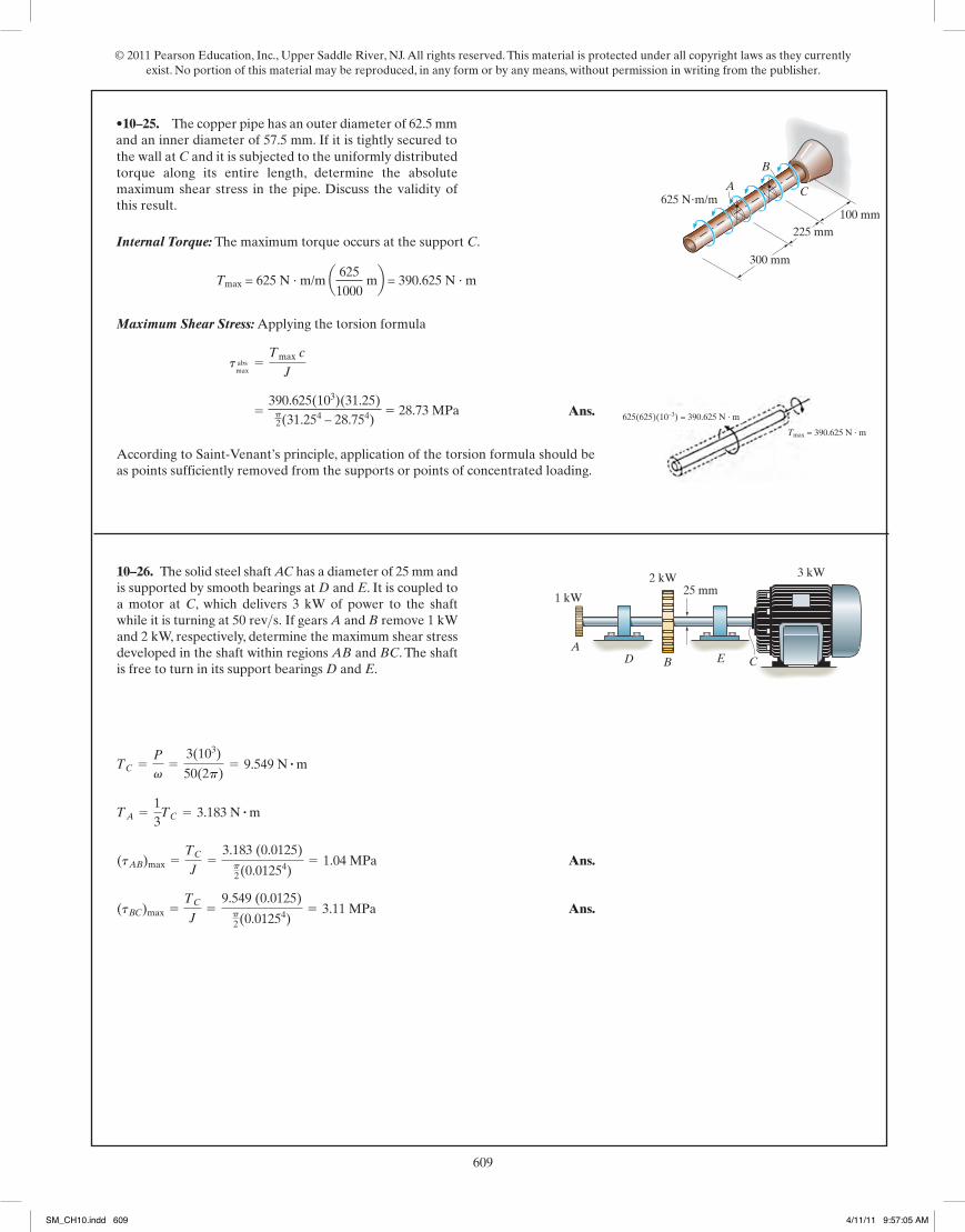
625 Nm/m100 mm
C
225 mm
300 mm
B
A
625(625)(10–3) = 390.625 N · m
Tmax = 390.625 N · m
•10–25. The copper pipe has an outer diameter of 62.5 mm and an inner diameter of 57.5 mm. If it is tightly secured to
Tmax = 625 N · m/m a 6251000
mb = 390.625 N · m
390.625(103)(31.25)p2(31.254 – 28.754)
5 28.73 MPa
233
© 2010 Pearson Education, Inc., Upper Saddle River, NJ. All rights reserved. This material is protected under all copyright laws as they currentlyexist. No portion of this material may be reproduced, in any form or by any means, without permission in writing from the publisher.
Ans.c = (2.98 x) mm
c3 = 26.526(10-9) x3
t =Tc
J ; 80(106) =
(103 )x3 cp2 c4
T = Lt dx = Lx
010 x2dx =
103x3
5–30. The shaft is subjected to a distributed torque alongits length of where x is in meters. If themaximum stress in the shaft is to remain constant at80 MPa, determine the required variation of the radius c ofthe shaft for 0 … x … 3 m.
t = 110x22 N # m>m,
cx
3 m
t � (10x2) N�m/m
Ans.
Ans.(tBC)max =TCJ
=9.549 (0.0125)p2(0.01254)
= 3.11 MPa
(tAB)max =TCJ
=3.183 (0.0125)p2(0.01254)
= 1.04 MPa
TA =13TC = 3.183 N # m
TC =P
v=
3(103)
50(2p)= 9.549 N # m
5–31. The solid steel shaft AC has a diameter of 25 mm andis supported by smooth bearings at D and E. It is coupled toa motor at C, which delivers 3 kW of power to the shaftwhile it is turning at If gears A and B remove 1 kWand 2 kW, respectively, determine the maximum shear stressdeveloped in the shaft within regions AB and BC. The shaftis free to turn in its support bearings D and E.
50 rev>s.
ACB ED
1 kW
2 kW 3 kW
25 mm
05 Solutions 46060 5/28/10 1:01 PM Page 233
10–26.
SM_CH10.indd 609 4/11/11 9:57:05 AM
© 2011 Pearson Education, Inc., Upper Saddle River, NJ. All rights reserved. This material is protected under all copyright laws as they currently exist. No portion of this material may be reproduced, in any form or by any means, without permission in writing from the publisher.
610234
© 2010 Pearson Education, Inc., Upper Saddle River, NJ. All rights reserved. This material is protected under all copyright laws as they currentlyexist. No portion of this material may be reproduced, in any form or by any means, without permission in writing from the publisher.
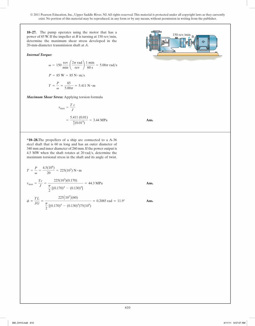
Internal Torque:
Maximum Shear Stress: Applying torsion formula
Ans. =5.411 (0.01)p2(0.014)
= 3.44 MPa
tmax =T cJ
T =P
v=
855.00p
= 5.411 N # m
P = 85 W = 85 N # m>sv = 150
revmin
¢2p radrev
≤ 1 min60 s
= 5.00p rad>s
*5–32. The pump operates using the motor that has apower of 85 W. If the impeller at B is turning at determine the maximum shear stress developed in the20-mm-diameter transmission shaft at A.
150 rev>min,A
B150 rev/min
The angular velocity of the shaft is
and the power is
Then
The polar moment of inertia of the shaft is . Thus,
Ans.tmax =T cJ
=280.11 (0.5)
0.03125p= 1426.60 psi = 1.43 ksi
J =p
2 (0.54) = 0.03125p in4
T =P
v=
110015p
= 23.34 lb # ft a12 in1ftb = 280.11 lb # in
P = 2 hp ¢550 ft # lb>s1 hp
≤ = 1100 ft # lb>s
v = ¢450 revmin≤ ¢2p rad
1 rev≤ ¢1 min
60 s≤ = 15p rad>s
•5–33. The gear motor can develop 2 hp when it turns atIf the shaft has a diameter of 1 in., determine
the maximum shear stress developed in the shaft.450 rev>min.
05 Solutions 46060 5/28/10 1:01 PM Page 234
10–27.
242
© 2010 Pearson Education, Inc., Upper Saddle River, NJ. All rights reserved. This material is protected under all copyright laws as they currentlyexist. No portion of this material may be reproduced, in any form or by any means, without permission in writing from the publisher.
Ans.
Ans.f =TL
JG=
225 A103 B(60)
p
2 [(0.170)4 - (0.130)4)75(109)
= 0.2085 rad = 11.9°
tmax =Tc
J=
225(103)(0.170)
p
2 [(0.170)4 - (0.130)4]
= 44.3 MPa
T =P
v=
4.5(106)
20= 225(103) N # m
5–47. The propellers of a ship are connected to a A-36steel shaft that is 60 m long and has an outer diameter of340 mm and inner diameter of 260 mm. If the power output is4.5 MW when the shaft rotates at determine themaximum torsional stress in the shaft and its angle of twist.
20 rad>s,
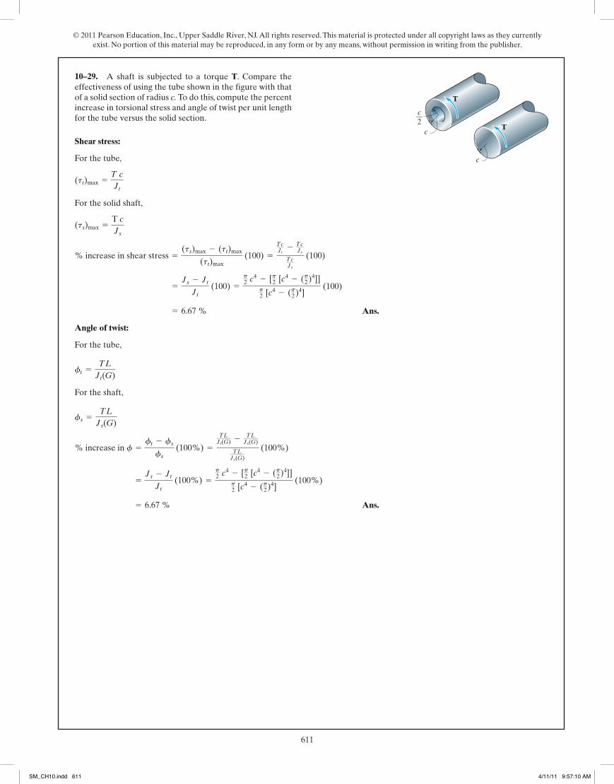
Shear stress:
For the tube,
For the solid shaft,
Ans.
Angle of twist:
For the tube,
For the shaft,
Ans. = 6.67 %
=Js - JtJt
(100%) =p2 c4 - [p2 [c4 - (p2)4]]
p2 [c4 - (p2)4]
(100%)
% increase in f =ft - fsfs
(100%) =TLJt(G) - TL
Js(G)
TLJs(G)
(100%)
fs =TL
Js(G)
ft =TL
Jt(G)
= 6.67 %
=Js - JtJt
(100) =p2 c4 - [p2 [c4 - (p2)4]]
p2 [c4 - (p2)4]
(100)
% increase in shear stress =(ts)max - (tt)max
(tt)max (100) =
TcJt
- TcJs
TcJs
(100)
(ts)max =T cJs
(tt)max =T cJt
*5–48. A shaft is subjected to a torque T. Compare theeffectiveness of using the tube shown in the figure with thatof a solid section of radius c. To do this, compute the percentincrease in torsional stress and angle of twist per unit lengthfor the tube versus the solid section.
T
T
c
c
c2
05 Solutions 46060 5/28/10 1:01 PM Page 242
*10–28.
SM_CH10.indd 610 4/11/11 9:57:07 AM
© 2011 Pearson Education, Inc., Upper Saddle River, NJ. All rights reserved. This material is protected under all copyright laws as they currently exist. No portion of this material may be reproduced, in any form or by any means, without permission in writing from the publisher.
611234
© 2010 Pearson Education, Inc., Upper Saddle River, NJ. All rights reserved. This material is protected under all copyright laws as they currentlyexist. No portion of this material may be reproduced, in any form or by any means, without permission in writing from the publisher.
Internal Torque:
Maximum Shear Stress: Applying torsion formula
Ans. =5.411 (0.01)p2(0.014)
= 3.44 MPa
tmax =T cJ
T =P
v=
855.00p
= 5.411 N # m
P = 85 W = 85 N # m>sv = 150
revmin
¢2p radrev
≤ 1 min60 s
= 5.00p rad>s
*5–32. The pump operates using the motor that has apower of 85 W. If the impeller at B is turning at determine the maximum shear stress developed in the20-mm-diameter transmission shaft at A.
150 rev>min,A
B150 rev/min
The angular velocity of the shaft is
and the power is
Then
The polar moment of inertia of the shaft is . Thus,
Ans.tmax =T cJ
=280.11 (0.5)
0.03125p= 1426.60 psi = 1.43 ksi
J =p
2 (0.54) = 0.03125p in4
T =P
v=
110015p
= 23.34 lb # ft a12 in1ftb = 280.11 lb # in
P = 2 hp ¢550 ft # lb>s1 hp
≤ = 1100 ft # lb>s
v = ¢450 revmin≤ ¢2p rad
1 rev≤ ¢1 min
60 s≤ = 15p rad>s
•5–33. The gear motor can develop 2 hp when it turns atIf the shaft has a diameter of 1 in., determine
the maximum shear stress developed in the shaft.450 rev>min.
05 Solutions 46060 5/28/10 1:01 PM Page 234
242
© 2010 Pearson Education, Inc., Upper Saddle River, NJ. All rights reserved. This material is protected under all copyright laws as they currentlyexist. No portion of this material may be reproduced, in any form or by any means, without permission in writing from the publisher.
Ans.
Ans.f =TL
JG=
225 A103 B(60)
p
2 [(0.170)4 - (0.130)4)75(109)
= 0.2085 rad = 11.9°
tmax =Tc
J=
225(103)(0.170)
p
2 [(0.170)4 - (0.130)4]
= 44.3 MPa
T =P
v=
4.5(106)
20= 225(103) N # m
5–47. The propellers of a ship are connected to a A-36steel shaft that is 60 m long and has an outer diameter of340 mm and inner diameter of 260 mm. If the power output is4.5 MW when the shaft rotates at determine themaximum torsional stress in the shaft and its angle of twist.
20 rad>s,
Shear stress:
For the tube,
For the solid shaft,
Ans.
Angle of twist:
For the tube,
For the shaft,
Ans. = 6.67 %
=Js - JtJt
(100%) =p2 c4 - [p2 [c4 - (p2)4]]
p2 [c4 - (p2)4]
(100%)
% increase in f =ft - fsfs
(100%) =TLJt(G) - TL
Js(G)
TLJs(G)
(100%)
fs =TL
Js(G)
ft =TL
Jt(G)
= 6.67 %
=Js - JtJt
(100) =p2 c4 - [p2 [c4 - (p2)4]]
p2 [c4 - (p2)4]
(100)
% increase in shear stress =(ts)max - (tt)max
(tt)max (100) =
TcJt
- TcJs
TcJs
(100)
(ts)max =T cJs
(tt)max =T cJt
*5–48. A shaft is subjected to a torque T. Compare theeffectiveness of using the tube shown in the figure with thatof a solid section of radius c. To do this, compute the percentincrease in torsional stress and angle of twist per unit lengthfor the tube versus the solid section.
T
T
c
c
c2
05 Solutions 46060 5/28/10 1:01 PM Page 242
10–29.
SM_CH10.indd 611 4/11/11 9:57:10 AM

© 2011 Pearson Education, Inc., Upper Saddle River, NJ. All rights reserved. This material is protected under all copyright laws as they currently exist. No portion of this material may be reproduced, in any form or by any means, without permission in writing from the publisher.
612243
© 2010 Pearson Education, Inc., Upper Saddle River, NJ. All rights reserved. This material is protected under all copyright laws as they currentlyexist. No portion of this material may be reproduced, in any form or by any means, without permission in writing from the publisher.
•5–49. The A-36 steel axle is made from tubes AB and CDand a solid section BC. It is supported on smooth bearingsthat allow it to rotate freely. If the gears, fixed to its ends, aresubjected to torques, determine the angle of twistof gear A relative to gear D. The tubes have an outerdiameter of 30 mm and an inner diameter of 20 mm. Thesolid section has a diameter of 40 mm.
85-N # m
400 mm
400 mm
250 mm85 N m�
85 N m�
A
B
C
D
Ans. = 0.01534 rad = 0.879°
=2(85)(0.4)
p2 (0.0154 - 0.014)(75)(109)
+(85)(0.25)
p2 (0.024)(75)(109)
fND = ©TL
JG
Internal Torque:
Maximum Shear Stress: Applying torsion Formula.
Ans.
Angle of Twist:
Ans. = 0.07725 rad = 4.43°
f =TL
JG=
7723.7(12)(100)(12)p2 (44 - 3.6254)11.0(106)
=7723.7(12)(4)p2 (44 - 3.6254)
= 2.83 ksi
tmax =T cJ
T =P
v=
1 375 00056.67p
= 7723.7 lb # ft
P = 2500 hp a550 ft # lb>s1 hp
b = 1 375 000 ft # lb>s
v = 1700 revmin
a2p radrev
b 1 min60 s
= 56.67p rad>s
5–50. The hydrofoil boat has an A-36 steel propellershaft that is 100 ft long. It is connected to an in-line dieselengine that delivers a maximum power of 2500 hp andcauses the shaft to rotate at 1700 rpm. If the outerdiameter of the shaft is 8 in. and the wall thickness is determine the maximum shear stress developed in theshaft. Also, what is the “wind up,” or angle of twist in theshaft at full power?
38 in.,
100 ft
05 Solutions 46060 5/28/10 1:01 PM Page 243
5–31. The hydrofoil boat has an A-36 steel propeller shaft that is 30 m long. It is connected to an in-line diesel engine that delivers a maximum power of 2000 kW and causes the shaft to rotate at 1700 rpm. If the outer diameter of the shaft is 200 mm and the wall thickness is 10 mm, determine the maximum shear stress developed in the shaft. Also, what is the “wind up,” or angle of twist in the shaft at full power?
30 m
56.667p rad/s
P 5 2000 kW
200056.667
5 11.2344 kN · m
11.2344(106)(100)p2(1004 – 904)
5 20.797 MPa
11.2344(106)(30)(103)p2(1004 – 904)75(103)
0.0832 rad 5 4.766°
•10–30.
10–31.
SM_CH10.indd 612 4/11/11 9:57:11 AM

© 2011 Pearson Education, Inc., Upper Saddle River, NJ. All rights reserved. This material is protected under all copyright laws as they currently exist. No portion of this material may be reproduced, in any form or by any means, without permission in writing from the publisher.
613243
© 2010 Pearson Education, Inc., Upper Saddle River, NJ. All rights reserved. This material is protected under all copyright laws as they currentlyexist. No portion of this material may be reproduced, in any form or by any means, without permission in writing from the publisher.
•5–49. The A-36 steel axle is made from tubes AB and CDand a solid section BC. It is supported on smooth bearingsthat allow it to rotate freely. If the gears, fixed to its ends, aresubjected to torques, determine the angle of twistof gear A relative to gear D. The tubes have an outerdiameter of 30 mm and an inner diameter of 20 mm. Thesolid section has a diameter of 40 mm.
85-N # m
400 mm
400 mm
250 mm85 N m�
85 N m�
A
B
C
D
Ans. = 0.01534 rad = 0.879°
=2(85)(0.4)
p2 (0.0154 - 0.014)(75)(109)
+(85)(0.25)
p2 (0.024)(75)(109)
fND = ©TL
JG
Internal Torque:
Maximum Shear Stress: Applying torsion Formula.
Ans.
Angle of Twist:
Ans. = 0.07725 rad = 4.43°
f =TL
JG=
7723.7(12)(100)(12)p2 (44 - 3.6254)11.0(106)
=7723.7(12)(4)p2 (44 - 3.6254)
= 2.83 ksi
tmax =T cJ
T =P
v=
1 375 00056.67p
= 7723.7 lb # ft
P = 2500 hp a550 ft # lb>s1 hp
b = 1 375 000 ft # lb>s
v = 1700 revmin
a2p radrev
b 1 min60 s
= 56.67p rad>s
5–50. The hydrofoil boat has an A-36 steel propellershaft that is 100 ft long. It is connected to an in-line dieselengine that delivers a maximum power of 2500 hp andcauses the shaft to rotate at 1700 rpm. If the outerdiameter of the shaft is 8 in. and the wall thickness is determine the maximum shear stress developed in theshaft. Also, what is the “wind up,” or angle of twist in theshaft at full power?
38 in.,
100 ft
05 Solutions 46060 5/28/10 1:01 PM Page 243
612
© 2011 Pearson Education, Inc., Upper Saddle River, NJ. All rights reserved. This material is protected under all copyright laws as they currentlyexist. No portion of this material may be reproduced, in any form or by any means, without permission in writing from the publisher.
Ans.
Shear - stress failure
Angle of twist limitation
Shear - stress failure controls the design.
Use Ans.d = 2.75 in.
d = 2c = 2 (1.3586) = 2.72 in.
c = 0.967 in.
0.05 =2626.06(12)(2)(12)p2 c4(11.0)(106)
f =TL
JG
c = 1.3586 in.
8(103) =2626.06(12)c
p2 c4
tallow =Tc
J
T = 2626.06 lb # ft600(550) = T(125.66)
P = Tv
v =1200(2)(p)
60= 125.66 rad>s
= 0.07725 rad = 4.43°
f =TL
JG=
7723.7(12)(100)(12)p2 (44 - 3.6254)11.0(106)
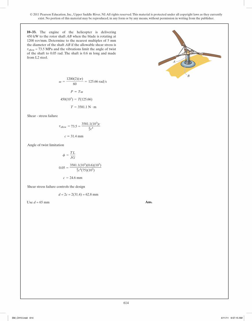
*10–32. The engine of the helicopter is delivering 600 hpto the rotor shaft AB when the blade is rotating at1200 Determine to the nearest the diameterof the shaft AB if the allowable shear stress is and the vibrations limit the angle of twist of the shaft to0.05 rad. The shaft is 2 ft long and made from L2 steel.
tallow = 8 ksi
18 in.rev>min.
A
B
*10–32. The engine of the helicopter is delivering 450 kW to the rotor shaft AB when the blade is rotating at 1200 rev/min. Determine to the nearest 5 mm the diameter of the shaft AB if the allowable shear stress is tallow = 56 MPa and the vibration limit the angle of twist of the shaft to 0.05 rad. The shaft is 0.6 m long and made from L2 steel.
450(103)
3581.1 N · m
3581.1(103)cp2c4
c 5 34.4 mm
3581.1(103)(0.6)(103)p2c4(75)(103)
c 5 24.6 mm
2(34.4) 5 68.8 mm
70 mm
SM_CH10.indd 613 4/11/11 9:57:13 AM
© 2011 Pearson Education, Inc., Upper Saddle River, NJ. All rights reserved. This material is protected under all copyright laws as they currently exist. No portion of this material may be reproduced, in any form or by any means, without permission in writing from the publisher.
614245
© 2010 Pearson Education, Inc., Upper Saddle River, NJ. All rights reserved. This material is protected under all copyright laws as they currentlyexist. No portion of this material may be reproduced, in any form or by any means, without permission in writing from the publisher.
Shear - stress failure
Angle of twist limitation
Shear stress failure controls the design
Use Ans.d = 2.50 in.
d = 2c = 2 (1.2408) = 2.48 in.
c = 0.967 in.
0.05 =2626.06(12)(2)(12)p2 c4 (11.0)(106)
f =TL
JG
c = 1.2408 in.
tallow = 10.5(10)3 =2626.06(12)c
p2 c4
T = 2626.06 lb # ft 600(550) = T(125.66)
P = Tv
v =1200(2)(p)
60= 125.66 rad>s
*5–52. The engine of the helicopter is delivering 600 hpto the rotor shaft AB when the blade is rotating at1200 Determine to the nearest the diameter ofthe shaft AB if the allowable shear stress is and the vibrations limit the angle of twist of the shaft to0.05 rad. The shaft is 2 ft long and made from L2 steel.
tallow = 10.5 ksi
18 in.rev>min.
A
B
05 Solutions 46060 5/28/10 1:01 PM Page 245
*5–33. The engine of the helicopter is delivering 450 kW to the rotor shaft AB when the blade is rotating at 1200 rev/mm. Determine to the nearest multiples of 5 mm the diameter of the shaft AB if the allowable shear stress is tallow = 73.5 MPa and the vibrations limit the angle of twist of the shaft to 0.05 rad. The shaft is 0.6 m long and made from L2 steel.
450(103) 5 T(125.66)
T 5 3581.1 N · m
73.5 5 3581.1(103)c
p2c4
c 5 31.4 mm
0.05 5 3581.1(103)(0.6)(103)
p2c4(75)(103)
c 5 24.6 mm
d = 2c = 2(31.4) = 62.8 mm
Use d = 65 mm
10–33.
246
© 2010 Pearson Education, Inc., Upper Saddle River, NJ. All rights reserved. This material is protected under all copyright laws as they currentlyexist. No portion of this material may be reproduced, in any form or by any means, without permission in writing from the publisher.
Internal Torque: As shown on FBD.
Angle of Twist:
Ans. = -0.1002 rad = | 5.74° |
=1
p2 (0.014)(75.0)(109)
[-80.0(0.8) + (-60.0)(0.6) + (-90.0)(0.2)]
fB = a TL
JG
•5–53. The 20-mm-diameter A-36 steel shaft is subjected tothe torques shown. Determine the angle of twist of the end B.
A
80 N�m
20 N�m
30 N�mB
D
C
800 mm
600 mm200 mm
5–54. The assembly is made of A-36 steel and consists of asolid rod 20 mm in diameter fixed to the inside of a tube usinga rigid disk at B. Determine the angle of twist at D. The tubehas an outer diameter of 40 mm and wall thickness of 5 mm.
0.4 mB
D
C
0.3 m
0.1 m
60 N�m
150 N�m
A
The internal torques developed in segments AB and BD of the assembly are shownin Fig. a and b
The polar moment of inertia of solid rod and tube are
and . Thus,
Ans. = -0.01758 rad = 1.01°
=90(0.4)
54.6875(10-9)p [75(109)]+
-60 (0.4)
5(10-9)p [75(109)]
fD = © Ti LiJi Gi
=TAB LABJAB Gst
+TBD LBDJBD Gst
JBD =p
2 (0.014) = 5(10-9)p m4= 54.6875(10-9)p m4
JAB =p
2 (0.024 - 0.0154)
05 Solutions 46060 5/28/10 1:01 PM Page 246
SM_CH10.indd 614 4/11/11 9:57:15 AM
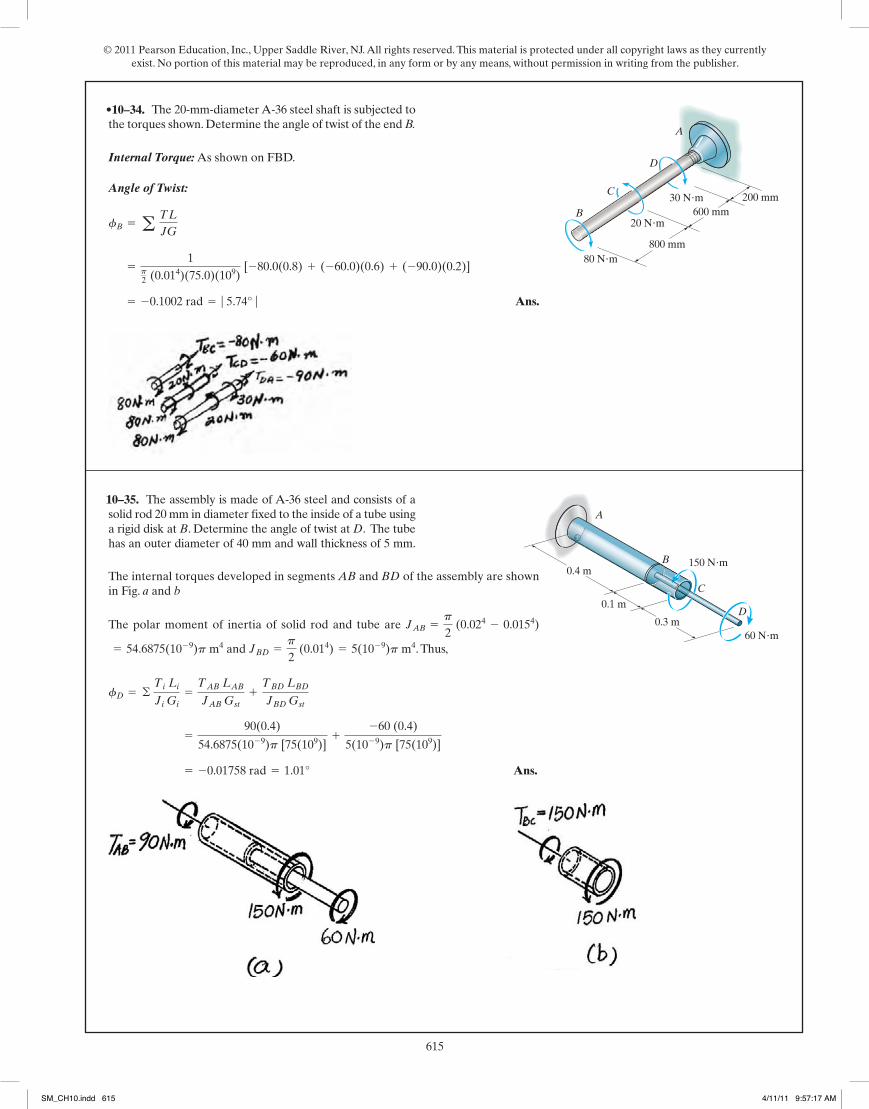
© 2011 Pearson Education, Inc., Upper Saddle River, NJ. All rights reserved. This material is protected under all copyright laws as they currently exist. No portion of this material may be reproduced, in any form or by any means, without permission in writing from the publisher.
615245
© 2010 Pearson Education, Inc., Upper Saddle River, NJ. All rights reserved. This material is protected under all copyright laws as they currentlyexist. No portion of this material may be reproduced, in any form or by any means, without permission in writing from the publisher.
Shear - stress failure
Angle of twist limitation
Shear stress failure controls the design
Use Ans.d = 2.50 in.
d = 2c = 2 (1.2408) = 2.48 in.
c = 0.967 in.
0.05 =2626.06(12)(2)(12)p2 c4 (11.0)(106)
f =TL
JG
c = 1.2408 in.
tallow = 10.5(10)3 =2626.06(12)c
p2 c4
T = 2626.06 lb # ft 600(550) = T(125.66)
P = Tv
v =1200(2)(p)
60= 125.66 rad>s
*5–52. The engine of the helicopter is delivering 600 hpto the rotor shaft AB when the blade is rotating at1200 Determine to the nearest the diameter ofthe shaft AB if the allowable shear stress is and the vibrations limit the angle of twist of the shaft to0.05 rad. The shaft is 2 ft long and made from L2 steel.
tallow = 10.5 ksi
18 in.rev>min.
A
B
05 Solutions 46060 5/28/10 1:01 PM Page 245
246
© 2010 Pearson Education, Inc., Upper Saddle River, NJ. All rights reserved. This material is protected under all copyright laws as they currentlyexist. No portion of this material may be reproduced, in any form or by any means, without permission in writing from the publisher.
Internal Torque: As shown on FBD.
Angle of Twist:
Ans. = -0.1002 rad = | 5.74° |
=1
p2 (0.014)(75.0)(109)
[-80.0(0.8) + (-60.0)(0.6) + (-90.0)(0.2)]
fB = a TL
JG
•5–53. The 20-mm-diameter A-36 steel shaft is subjected tothe torques shown. Determine the angle of twist of the end B.
A
80 N�m
20 N�m
30 N�mB
D
C
800 mm
600 mm200 mm
5–54. The assembly is made of A-36 steel and consists of asolid rod 20 mm in diameter fixed to the inside of a tube usinga rigid disk at B. Determine the angle of twist at D. The tubehas an outer diameter of 40 mm and wall thickness of 5 mm.
0.4 mB
D
C
0.3 m
0.1 m
60 N�m
150 N�m
A
The internal torques developed in segments AB and BD of the assembly are shownin Fig. a and b
The polar moment of inertia of solid rod and tube are
and . Thus,
Ans. = -0.01758 rad = 1.01°
=90(0.4)
54.6875(10-9)p [75(109)]+
-60 (0.4)
5(10-9)p [75(109)]
fD = © Ti LiJi Gi
=TAB LABJAB Gst
+TBD LBDJBD Gst
JBD =p
2 (0.014) = 5(10-9)p m4= 54.6875(10-9)p m4
JAB =p
2 (0.024 - 0.0154)
05 Solutions 46060 5/28/10 1:01 PM Page 246
•10–34.
10–35.
SM_CH10.indd 615 4/11/11 9:57:17 AM

© 2011 Pearson Education, Inc., Upper Saddle River, NJ. All rights reserved. This material is protected under all copyright laws as they currently exist. No portion of this material may be reproduced, in any form or by any means, without permission in writing from the publisher.
616247
© 2010 Pearson Education, Inc., Upper Saddle River, NJ. All rights reserved. This material is protected under all copyright laws as they currentlyexist. No portion of this material may be reproduced, in any form or by any means, without permission in writing from the publisher.
5–55. The assembly is made of A-36 steel and consists of asolid rod 20 mm in diameter fixed to the inside of a tube usinga rigid disk at B. Determine the angle of twist at C. The tubehas an outer diameter of 40 mm and wall thickness of 5 mm.
0.4 mB
D
C
0.3 m
0.1 m
60 N�m
150 N�m
A
Ans. = 0.01008 rad = 0.578°
=190JG
=190
p2 (0.024)(75)(109)
fB>A = © TL
JG=
-300(0.3)
JG+
200(0.4)
JG+
400(0.5)
JG
*5–56. The splined ends and gears attached to the A-36steel shaft are subjected to the torques shown. Determinethe angle of twist of end B with respect to end A. The shafthas a diameter of 40 mm.
300 N�m
A200 N�m
500 N�m
300 mm
400 mm
500 mm
400 N�m
B
D
C
The internal torques developed in segments AB and BC of the assembly are shownin Figs. a and b.
The polar moment of inertia of the tube is . Thus,
Ans. = 0.003958 rad = 0.227°
=1
54.6875(10-9)p [75(109)] C90(0.4) + 150(0.1) D
fC = © Ti LiJi Gi
=TAB LABJGst
+TBC LBCJ Gst
= 54.6875 (10-9)p m4J =
p
2 (0.024 - 0.0154)
05 Solutions 46060 5/28/10 1:01 PM Page 247
*10–36.
•10–37.
248
© 2010 Pearson Education, Inc., Upper Saddle River, NJ. All rights reserved. This material is protected under all copyright laws as they currentlyexist. No portion of this material may be reproduced, in any form or by any means, without permission in writing from the publisher.
External Applied Torque: Applying , we have
Internal Torque: As shown on FBD.
Allowable Shear Stress: Assume failure due to shear stress. By observation, sectionAC is the critical region.
Angle of Twist: Assume failure due to angle of twist limitation.
Use Ans.d = 114
in.
d = 1.137 in. (controls !)
0.2(p)
180=
65.65(12)(8)
p2 Ad2 B4 (11.0)(106)
fC>D =TCDLCDJG
d = 1.102 in.
8(103) =175.07(12) Ad2 B
p2 Ad2 B4
tmax = tallow =Tc
J
TD =15(550)
2p(20)= 65.65 lb # ft
TM =40(550)
2p(20)= 175.07 lb # ft TC =
25(550)
2p(20)= 109.42 lb # ft
T =P
2pf
•5–57. The motor delivers 40 hp to the 304 stainless steelshaft while it rotates at 20 Hz. The shaft is supported onsmooth bearings at A and B, which allow free rotation ofthe shaft.The gears C and D fixed to the shaft remove 25 hpand 15 hp, respectively. Determine the diameter of theshaft to the nearest if the allowable shear stress is
and the allowable angle of twist of C withrespect to D is 0.20 .°tallow = 8 ksi
18 in.
6 in.
8 in.
10 in.
A
B
C
D
05 Solutions 46060 5/28/10 1:01 PM Page 248
SM_CH10.indd 616 4/11/11 9:57:18 AM
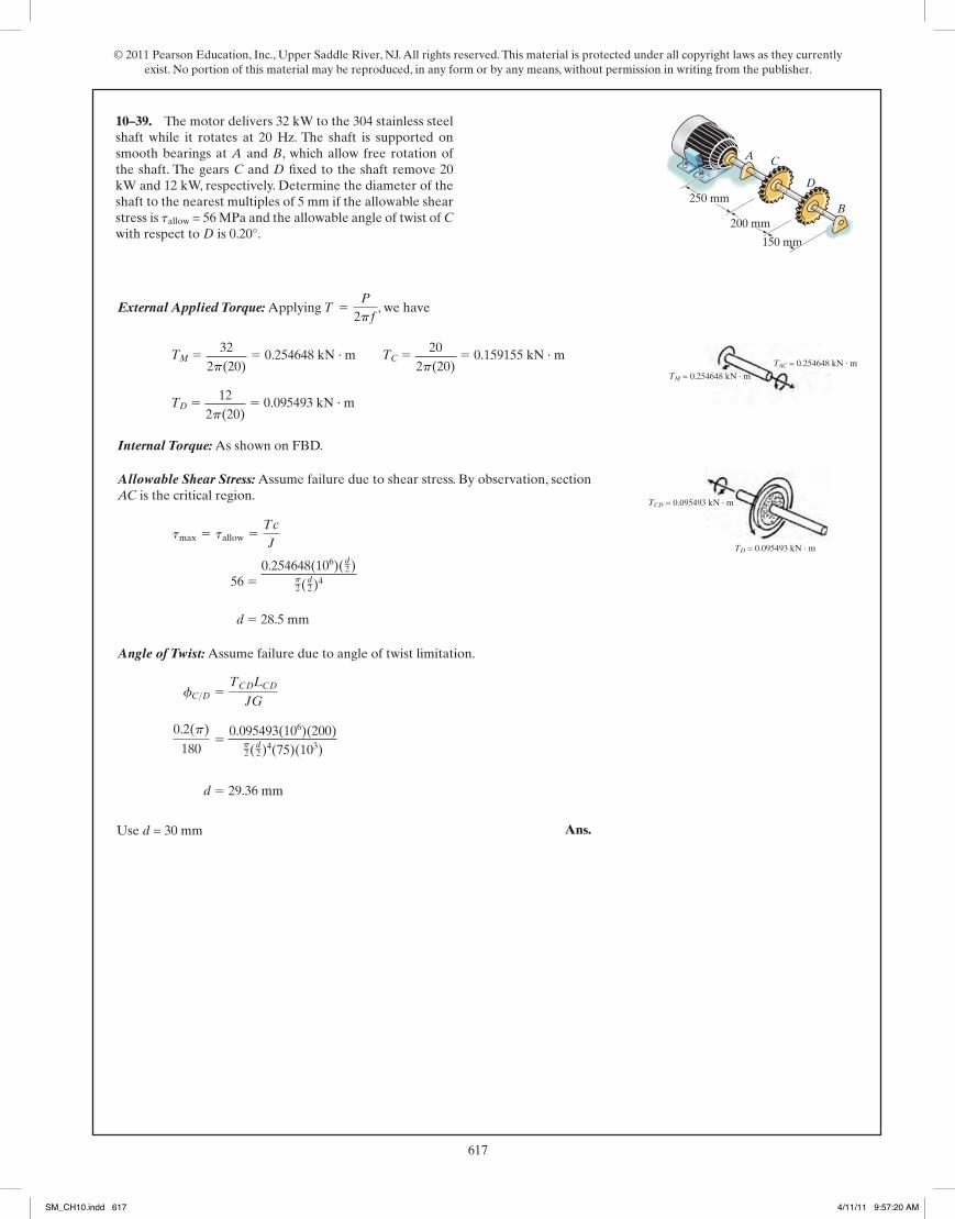
© 2011 Pearson Education, Inc., Upper Saddle River, NJ. All rights reserved. This material is protected under all copyright laws as they currently exist. No portion of this material may be reproduced, in any form or by any means, without permission in writing from the publisher.
617247
© 2010 Pearson Education, Inc., Upper Saddle River, NJ. All rights reserved. This material is protected under all copyright laws as they currentlyexist. No portion of this material may be reproduced, in any form or by any means, without permission in writing from the publisher.
5–55. The assembly is made of A-36 steel and consists of asolid rod 20 mm in diameter fixed to the inside of a tube usinga rigid disk at B. Determine the angle of twist at C. The tubehas an outer diameter of 40 mm and wall thickness of 5 mm.
0.4 mB
D
C
0.3 m
0.1 m
60 N�m
150 N�m
A
Ans. = 0.01008 rad = 0.578°
=190JG
=190
p2 (0.024)(75)(109)
fB>A = © TL
JG=
-300(0.3)
JG+
200(0.4)
JG+
400(0.5)
JG
*5–56. The splined ends and gears attached to the A-36steel shaft are subjected to the torques shown. Determinethe angle of twist of end B with respect to end A. The shafthas a diameter of 40 mm.
300 N�m
A200 N�m
500 N�m
300 mm
400 mm
500 mm
400 N�m
B
D
C
The internal torques developed in segments AB and BC of the assembly are shownin Figs. a and b.
The polar moment of inertia of the tube is . Thus,
Ans. = 0.003958 rad = 0.227°
=1
54.6875(10-9)p [75(109)] C90(0.4) + 150(0.1) D
fC = © Ti LiJi Gi
=TAB LABJGst
+TBC LBCJ Gst
= 54.6875 (10-9)p m4J =
p
2 (0.024 - 0.0154)
05 Solutions 46060 5/28/10 1:01 PM Page 247
248
© 2010 Pearson Education, Inc., Upper Saddle River, NJ. All rights reserved. This material is protected under all copyright laws as they currentlyexist. No portion of this material may be reproduced, in any form or by any means, without permission in writing from the publisher.
External Applied Torque: Applying , we have
Internal Torque: As shown on FBD.
Allowable Shear Stress: Assume failure due to shear stress. By observation, sectionAC is the critical region.
Angle of Twist: Assume failure due to angle of twist limitation.
Use Ans.d = 114
in.
d = 1.137 in. (controls !)
0.2(p)
180=
65.65(12)(8)
p2 Ad2 B4 (11.0)(106)
fC>D =TCDLCDJG
d = 1.102 in.
8(103) =175.07(12) Ad2 B
p2 Ad2 B4
tmax = tallow =Tc
J
TD =15(550)
2p(20)= 65.65 lb # ft
TM =40(550)
2p(20)= 175.07 lb # ft TC =
25(550)
2p(20)= 109.42 lb # ft
T =P
2pf
•5–57. The motor delivers 40 hp to the 304 stainless steelshaft while it rotates at 20 Hz. The shaft is supported onsmooth bearings at A and B, which allow free rotation ofthe shaft.The gears C and D fixed to the shaft remove 25 hpand 15 hp, respectively. Determine the diameter of theshaft to the nearest if the allowable shear stress is
and the allowable angle of twist of C withrespect to D is 0.20 .°tallow = 8 ksi
18 in.
6 in.
8 in.
10 in.
A
B
C
D
05 Solutions 46060 5/28/10 1:01 PM Page 248
10–39. The motor delivers 32 kW to the 304 stainless steel shaft while it rotates at 20 Hz. The shaft is supported on smooth bearings at A and B, which allow free rotation of the shaft. The gears C and D fixed to the shaft remove 20 kW and 12 kW, respectively. Determine the diameter of the shaft to the nearest multiples of 5 mm if the allowable shear stress is tallow = 56 MPa and the allowable angle of twist of C with respect to D is 0.20°.
TM 5 322p(20)
5 0.254648 kN · m TC 5 202p(20)
5 0.159155 kN · m
TD 5 122p(20)
5 0.095493 kN · m
56 5 0.254648(106)(d
2)p2(d
2)4
d 5 28.5 mm
0.095493(106)(200)p2(d
2)4(75)(103)
d 5 29.36 mm
Use d = 30 mm
150 mm
200 mm
250 mm
A
B
C
D
TM = 0.254648 kN · m
TAC = 0.254648 kN · m
TCD = 0.095493 kN · m
TD = 0.095493 kN · m
SM_CH10.indd 617 4/11/11 9:57:20 AM
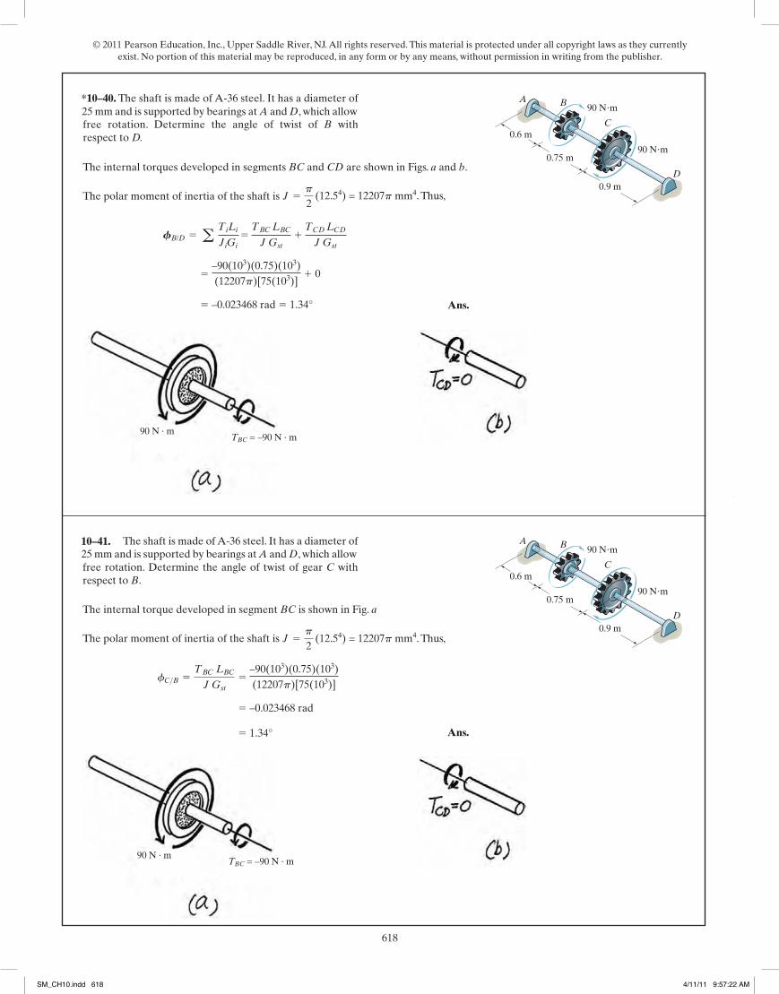
© 2011 Pearson Education, Inc., Upper Saddle River, NJ. All rights reserved. This material is protected under all copyright laws as they currently exist. No portion of this material may be reproduced, in any form or by any means, without permission in writing from the publisher.
618250
© 2010 Pearson Education, Inc., Upper Saddle River, NJ. All rights reserved. This material is protected under all copyright laws as they currentlyexist. No portion of this material may be reproduced, in any form or by any means, without permission in writing from the publisher.
The internal torques developed in segments BC and CD are shown in Figs. a and b.
The polar moment of inertia of the shaft is . Thus,
Ans. = -0.02000 rad = 1.15°
=-60(12)(2.5)(12)
(0.03125p)[11.0(106)]+ 0
FB/D = a TiLiJiGi
= TBC LBCJ Gst
+ TCD LCDJ Gst
J =p
2 (0.54) = 0.03125p in4
5–59. The shaft is made of A-36 steel. It has a diameter of1 in. and is supported by bearings at A and D, which allowfree rotation. Determine the angle of twist of B withrespect to D.
A
60 lb�ft
60 lb�ft
2 ft
2.5 ft
3 ftD
B
C
The internal torque developed in segment BC is shown in Fig. a
The polar moment of inertia of the shaft is . Thus,
Ans. = 1.15°
= -0.02000 rad
fC>B =TBC LBCJ Gst
=-60(12)(2.5)(12)
(0.03125p)[11.0(106)]
J =p
2 (0.54) = 0.03125p in4
*5–60. The shaft is made of A-36 steel. It has a diameter of1 in. and is supported by bearings at A and D, which allowfree rotation. Determine the angle of twist of gear C withrespect to B.
A
60 lb�ft
60 lb�ft
2 ft
2.5 ft
3 ftD
B
C
05 Solutions 46060 5/28/10 1:01 PM Page 250
25 mm and is supported by bearings at A and D, which allow
(12.54) = 12207p mm4. Thus,
5 –90(103)(0.75)(103)(12207p)[75(103)]
1 0
5 –0.023468 rad 5 1.34°
90 N · mTBC = –90 N · m
A
90 Nm
90 Nm
0.6 m
0.75 m
0.9 mD
B
C
A
90 Nm
90 Nm
0.6 m
0.75 m
0.9 mD
B
C25 mm and is supported by bearings at A and D, which allow
(12.54) = 12207p mm4. Thus,
5 –90(103)(0.75)(103)(12207p)[75(103)]
5 –0.023468 rad
5 1.34°
90 N · mTBC = –90 N · m
*10–40.
10–41.
251
© 2010 Pearson Education, Inc., Upper Saddle River, NJ. All rights reserved. This material is protected under all copyright laws as they currentlyexist. No portion of this material may be reproduced, in any form or by any means, without permission in writing from the publisher.
Internal Torque: As shown on FBD.
Angle of Twist:
Since there is no torque applied between F and B then
Ans.fB = fF = 0.02667 rad = 1.53°
fF =64
fE =64
(0.01778) = 0.02667 rad
= -0.01778 rad = 0.01778 rad
=1
p2 (0.54)(11.0)(105)
[-60.0(12)(30) + 20.0(12)(10)]
fE = a TL
JG
•5–61. The two shafts are made of A-36 steel. Each has adiameter of 1 in., and they are supported by bearings at A,B, and C, which allow free rotation. If the support at D isfixed, determine the angle of twist of end B when thetorques are applied to the assembly as shown.
A 40 lb�ft
80 lb�ft
8 in.
10 in.
12 in.4 in.
D
C
10 in.
30 in.
6 in.B
05 Solutions 46060 5/28/10 1:01 PM Page 251
SM_CH10.indd 618 4/11/11 9:57:22 AM

© 2011 Pearson Education, Inc., Upper Saddle River, NJ. All rights reserved. This material is protected under all copyright laws as they currently exist. No portion of this material may be reproduced, in any form or by any means, without permission in writing from the publisher.
619250
© 2010 Pearson Education, Inc., Upper Saddle River, NJ. All rights reserved. This material is protected under all copyright laws as they currentlyexist. No portion of this material may be reproduced, in any form or by any means, without permission in writing from the publisher.
The internal torques developed in segments BC and CD are shown in Figs. a and b.
The polar moment of inertia of the shaft is . Thus,
Ans. = -0.02000 rad = 1.15°
=-60(12)(2.5)(12)
(0.03125p)[11.0(106)]+ 0
FB/D = a TiLiJiGi
= TBC LBCJ Gst
+ TCD LCDJ Gst
J =p
2 (0.54) = 0.03125p in4
5–59. The shaft is made of A-36 steel. It has a diameter of1 in. and is supported by bearings at A and D, which allowfree rotation. Determine the angle of twist of B withrespect to D.
A
60 lb�ft
60 lb�ft
2 ft
2.5 ft
3 ftD
B
C
The internal torque developed in segment BC is shown in Fig. a
The polar moment of inertia of the shaft is . Thus,
Ans. = 1.15°
= -0.02000 rad
fC>B =TBC LBCJ Gst
=-60(12)(2.5)(12)
(0.03125p)[11.0(106)]
J =p
2 (0.54) = 0.03125p in4
*5–60. The shaft is made of A-36 steel. It has a diameter of1 in. and is supported by bearings at A and D, which allowfree rotation. Determine the angle of twist of gear C withrespect to B.
A
60 lb�ft
60 lb�ft
2 ft
2.5 ft
3 ftD
B
C
05 Solutions 46060 5/28/10 1:01 PM Page 250
251
© 2010 Pearson Education, Inc., Upper Saddle River, NJ. All rights reserved. This material is protected under all copyright laws as they currentlyexist. No portion of this material may be reproduced, in any form or by any means, without permission in writing from the publisher.
Internal Torque: As shown on FBD.
Angle of Twist:
Since there is no torque applied between F and B then
Ans.fB = fF = 0.02667 rad = 1.53°
fF =64
fE =64
(0.01778) = 0.02667 rad
= -0.01778 rad = 0.01778 rad
=1
p2 (0.54)(11.0)(105)
[-60.0(12)(30) + 20.0(12)(10)]
fE = a TL
JG
•5–61. The two shafts are made of A-36 steel. Each has adiameter of 1 in., and they are supported by bearings at A,B, and C, which allow free rotation. If the support at D isfixed, determine the angle of twist of end B when thetorques are applied to the assembly as shown.
A 40 lb�ft
80 lb�ft
8 in.
10 in.
12 in.4 in.
D
C
10 in.
30 in.
6 in.B
05 Solutions 46060 5/28/10 1:01 PM Page 251
diameter of 25 mm, and they are supported by bearings at A,
A 60 Nm
120 Nm
200 mm
250 mm
300 mm100 mm
D
C
250 mm
750 mm
150 mmB
F = 600.100 = 600 N
0.100 m60 N · m
60 N · m
TAF = –60 N · m
0.150 m
F = 600 N
F = 600 N
0.150 m
TCA = –60(0.150) = –90 N · m
TBA = 30 N · m120 N · m
5 1
p2(12.54)(75)(103)
[–90(103)(750) + 30(103)(250)]
= –0.020861 = 0.020861 rad
= 150100
fE = 150100
(0.020861) = 0.031291 rad
0.031291 rad = 1.793°
•10–42.
SM_CH10.indd 619 4/11/11 9:57:24 AM

© 2011 Pearson Education, Inc., Upper Saddle River, NJ. All rights reserved. This material is protected under all copyright laws as they currently exist. No portion of this material may be reproduced, in any form or by any means, without permission in writing from the publisher.
620252
© 2010 Pearson Education, Inc., Upper Saddle River, NJ. All rights reserved. This material is protected under all copyright laws as they currentlyexist. No portion of this material may be reproduced, in any form or by any means, without permission in writing from the publisher.
Internal Torque: As shown on FBD.
Angle of Twist:
Ans. = 0.03111 rad = 1.78°
= 0.02667 + 0.004445
fA = fF + fA>F
= -0.004445 rad = 0.004445 rad
=-40(12)(10)
p2 (0.54)(11.0)(106)
fA>F =TGF LGFJG
fF =64
fE =64
(0.01778) = 0.02667 rad
= -0.01778 rad = 0.01778 rad
=1
p2 (0.54)(11.0)(106)
[-60.0(12)(30) + 20.0(12)(10)]
fE = a TL
JG
5–62. The two shafts are made of A-36 steel. Each has adiameter of 1 in., and they are supported by bearings at A,B, and C, which allow free rotation. If the support at D isfixed, determine the angle of twist of end A when thetorques are applied to the assembly as shown.
A 40 lb�ft
80 lb�ft
8 in.
10 in.
12 in.4 in.
D
C
10 in.
30 in.
6 in.B
05 Solutions 46060 5/28/10 1:01 PM Page 252
A 60 Nm
120 Nm
200 mm
250 mm
300 mm100 mm
D
C
250 mm
750 mm
150 mmB
diameter of 25 mm, and they are supported by bearings at A,
5 1
p2(12.54)(75)(103)
[–90(103)(750) + 30(103)(250)]
= –0.020861 = 0.020861 rad
= 150100
fE = 150100
(0.020861) = 0.031291 rad
5 –60(103)(250)
p2(12.54)(75)(103)
5 –0.0052152 rad 5 0.0052152 rad
5 0.031291 + 0.0052152
5 0.036506 rad = 2.092°
F = 600.100 = 600 N
0.100 m60 N · m
60 N · m
TAF = –60 N · m
0.150 m
F = 600 N
F = 600 N
0.150 m
TCA = –600(0.150) = –90 N · m
TBA = 30 N · m120 N · m
10–43.
253
© 2010 Pearson Education, Inc., Upper Saddle River, NJ. All rights reserved. This material is protected under all copyright laws as they currentlyexist. No portion of this material may be reproduced, in any form or by any means, without permission in writing from the publisher.
Internal Torque: As shown on FBD.
Maximum Shear Stress:
Ans.
Ans.
Angle of Twist:
Ans. = 0.04648 rad = 2.66°
= 0.002032 + 0.044448
fC = fB + fC>B
=2.00(24)
p2 (0.54)11.0(103)
= 0.044448 rad
fC>B =TBC LBCJG
=(2.00)(12)
p2 (14 - 0.754)11.0(103)
= 0.002032 rad
fB =TBA LBAJG
(tBA)max =TBA c
J=
2.00(1)p2 (14 - 0.754)
= 1.86 ksi
(tBC)max =TBC c
J=
2.00(0.5)p2 (0.54)
= 10.2 ksi
5–63. The device serves as a compact torsional spring. It ismade of A-36 steel and consists of a solid inner shaft CBwhich is surrounded by and attached to a tube AB using arigid ring at B. The ring at A can also be assumed rigidand is fixed from rotating. If a torque of isapplied to the shaft, determine the angle of twist at the end Cand the maximum shear stress in the tube and shaft.
T = 2 kip # in.
12 in.
1 in.
0.75 in.12 in.
0.5 in.
A
T
C
B
05 Solutions 46060 5/28/10 1:01 PM Page 253
SM_CH10.indd 620 4/11/11 9:57:25 AM

© 2011 Pearson Education, Inc., Upper Saddle River, NJ. All rights reserved. This material is protected under all copyright laws as they currently exist. No portion of this material may be reproduced, in any form or by any means, without permission in writing from the publisher.
621253
© 2010 Pearson Education, Inc., Upper Saddle River, NJ. All rights reserved. This material is protected under all copyright laws as they currentlyexist. No portion of this material may be reproduced, in any form or by any means, without permission in writing from the publisher.
Internal Torque: As shown on FBD.
Maximum Shear Stress:
Ans.
Ans.
Angle of Twist:
Ans. = 0.04648 rad = 2.66°
= 0.002032 + 0.044448
fC = fB + fC>B
=2.00(24)
p2 (0.54)11.0(103)
= 0.044448 rad
fC>B =TBC LBCJG
=(2.00)(12)
p2 (14 - 0.754)11.0(103)
= 0.002032 rad
fB =TBA LBAJG
(tBA)max =TBA c
J=
2.00(1)p2 (14 - 0.754)
= 1.86 ksi
(tBC)max =TBC c
J=
2.00(0.5)p2 (0.54)
= 10.2 ksi
5–63. The device serves as a compact torsional spring. It ismade of A-36 steel and consists of a solid inner shaft CBwhich is surrounded by and attached to a tube AB using arigid ring at B. The ring at A can also be assumed rigidand is fixed from rotating. If a torque of isapplied to the shaft, determine the angle of twist at the end Cand the maximum shear stress in the tube and shaft.
T = 2 kip # in.
12 in.
1 in.
0.75 in.12 in.
0.5 in.
A
T
C
B
05 Solutions 46060 5/28/10 1:01 PM Page 253
and is fixed from rotating. If a torque of T = 0.25 kN · m is
0.25 kN · m
TBC = 0.25 kN · m
TBA = 0.25 kN · m
0.25 kN · m
300 mm
25 mm
18.75 mm300 mm
12.5 mm
A
T
C
B
5 0.25(106)(12.5)
p2(12.54)
= 81.49 MPa
5 0.25(106)(25)p2(254 – 18.754)
= 14.9 MPa
5 0.25(106)(300)
p2(254 – 18.754)75(103)
= 0.002384 rad
5 0.25(106)(600)p2(12.54)75(103)
= 0.052152 rad
5 0.002384 + 0.0052152
5 0.054536 rad = 3.125°
*10–44.
SM_CH10.indd 621 4/11/11 9:57:26 AM
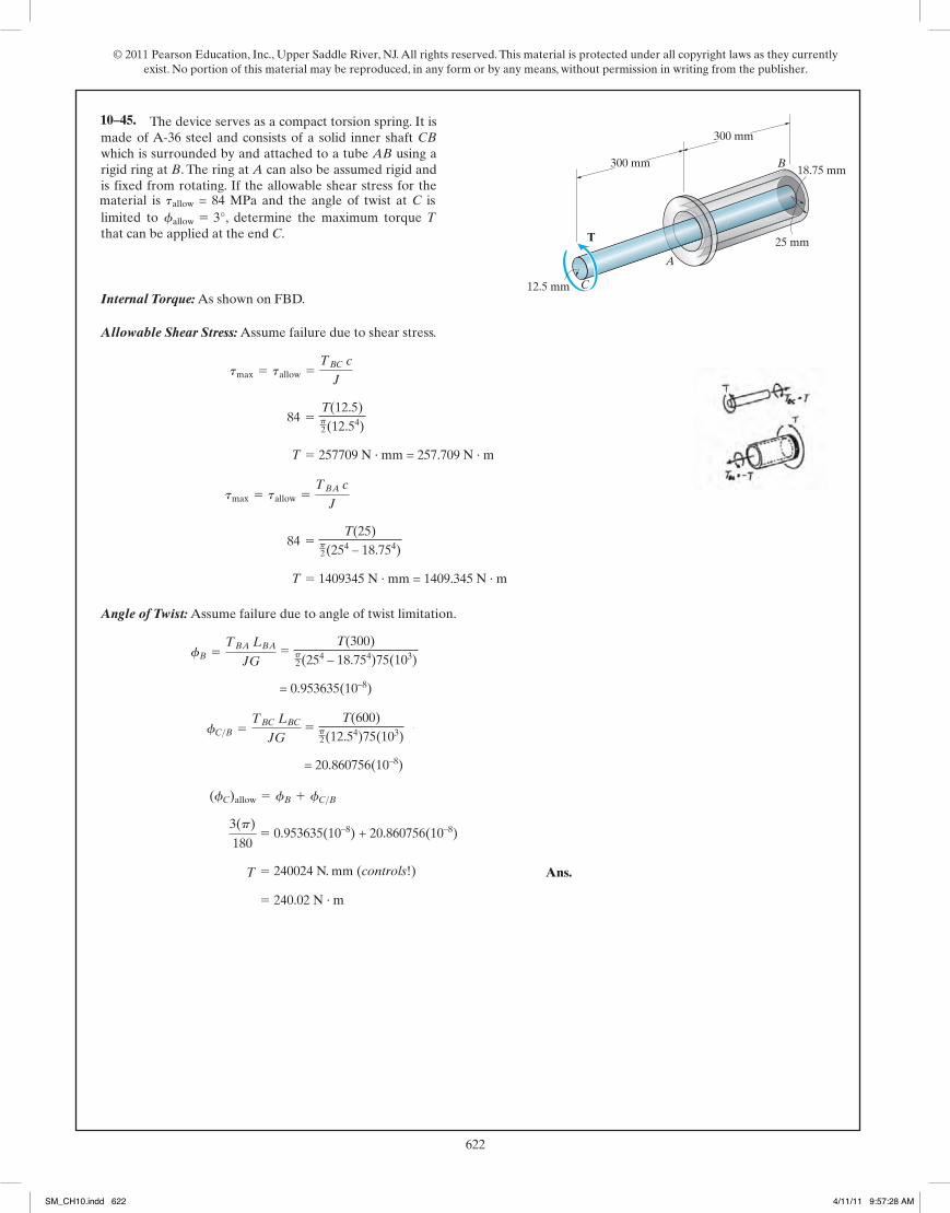
© 2011 Pearson Education, Inc., Upper Saddle River, NJ. All rights reserved. This material is protected under all copyright laws as they currently exist. No portion of this material may be reproduced, in any form or by any means, without permission in writing from the publisher.
622254
© 2010 Pearson Education, Inc., Upper Saddle River, NJ. All rights reserved. This material is protected under all copyright laws as they currentlyexist. No portion of this material may be reproduced, in any form or by any means, without permission in writing from the publisher.
Internal Torque: As shown on FBD.
Allowable Shear Stress: Assume failure due to shear stress.
Angle of Twist: Assume failure due to angle of twist limitation.
Ans. T = 2.25 kip # in (controls !)
3(p)
180= 0.001016T + 0.022224T
(fC)allow = fB + fC>B
= 0.022224T
fC>B =TBC LBCJG
=T(24)
p2 (0.54)11.0(103)
= 0.001016T
fB =TBA LBAJG
=T(12)
p2 (14 - 0.754) 11.0(103)
T = 12.89 kip # in
12.0 =T (1)
p2 (14 - 0.754)
tmax = tallow =TBA c
J
T = 2.356 kip # in
12.0 =T (0.5)p2 (0.54)
tmax = tallow =TBC c
J
*5–64. The device serves as a compact torsion spring. It ismade of A-36 steel and consists of a solid inner shaft CBwhich is surrounded by and attached to a tube AB using arigid ring at B. The ring at A can also be assumed rigid andis fixed from rotating. If the allowable shear stress for thematerial is and the angle of twist at C islimited to , determine the maximum torque that can be applied at the end C.
Tfallow = 3°tallow = 12 ksi
12 in.
1 in.
0.75 in.12 in.
0.5 in.
A
T
C
B
05 Solutions 46060 5/28/10 1:01 PM Page 254
material is tallow = 84 MPa and the angle of twist at C is
300 mm
25 mm
18.75 mm300 mm
12.5 mm
A
T
C
B
84 5 T(12.5)p2(12.54)
T 5 257709 N · mm = 257.709 N · m
84 5 T(25)
p2(254 – 18.754)
T 5 1409345 N · mm = 1409.345 N · m
5 T(300)
p2(254 – 18.754)75(103)
= 0.953635(10–8)
5 T(600)
p2(12.54)75(103)
= 20.860756(10–8)
5 0.953635(10–8) + 20.860756(10–8)
5 240024 N. mm (controls!)
5 240.02 N · m
10–45.
255
© 2010 Pearson Education, Inc., Upper Saddle River, NJ. All rights reserved. This material is protected under all copyright laws as they currentlyexist. No portion of this material may be reproduced, in any form or by any means, without permission in writing from the publisher.
Ans. = 0.001964 rad = 0.113°
= 0.001852 + 0.0001119
fC = fB + fC>B
fC>B =TCBL
JG=
-200(4)p2 (14 - 0.8754)(11.0)(106)
= -0.0001119 rad
fB =TABL
JG=
200(10)p2 (0.5)4(11.0)(106)
= 0.001852 rad
•5–65. The A-36 steel assembly consists of a tube havingan outer radius of 1 in. and a wall thickness of 0.125 in. Usinga rigid plate at B, it is connected to the solid 1-in-diametershaft AB. Determine the rotation of the tube’s end C if atorque of 200 lb in. is applied to the tube at this end. Theend A of the shaft is fixed supported.
#
6 in.
4 in.
A
C
B
200 lb�in.
05 Solutions 46060 5/28/10 1:01 PM Page 255
SM_CH10.indd 622 4/11/11 9:57:28 AM
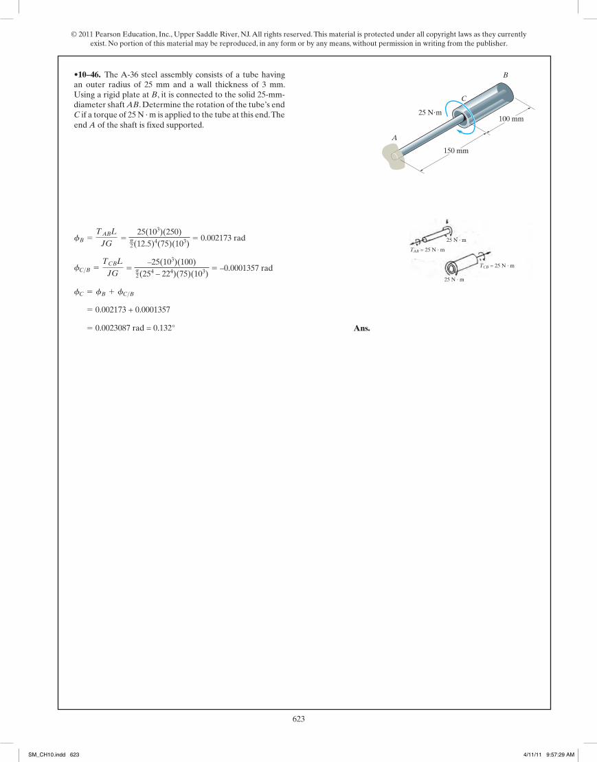
© 2011 Pearson Education, Inc., Upper Saddle River, NJ. All rights reserved. This material is protected under all copyright laws as they currently exist. No portion of this material may be reproduced, in any form or by any means, without permission in writing from the publisher.
623254
© 2010 Pearson Education, Inc., Upper Saddle River, NJ. All rights reserved. This material is protected under all copyright laws as they currentlyexist. No portion of this material may be reproduced, in any form or by any means, without permission in writing from the publisher.
Internal Torque: As shown on FBD.
Allowable Shear Stress: Assume failure due to shear stress.
Angle of Twist: Assume failure due to angle of twist limitation.
Ans. T = 2.25 kip # in (controls !)
3(p)
180= 0.001016T + 0.022224T
(fC)allow = fB + fC>B
= 0.022224T
fC>B =TBC LBCJG
=T(24)
p2 (0.54)11.0(103)
= 0.001016T
fB =TBA LBAJG
=T(12)
p2 (14 - 0.754) 11.0(103)
T = 12.89 kip # in
12.0 =T (1)
p2 (14 - 0.754)
tmax = tallow =TBA c
J
T = 2.356 kip # in
12.0 =T (0.5)p2 (0.54)
tmax = tallow =TBC c
J
*5–64. The device serves as a compact torsion spring. It ismade of A-36 steel and consists of a solid inner shaft CBwhich is surrounded by and attached to a tube AB using arigid ring at B. The ring at A can also be assumed rigid andis fixed from rotating. If the allowable shear stress for thematerial is and the angle of twist at C islimited to , determine the maximum torque that can be applied at the end C.
Tfallow = 3°tallow = 12 ksi
12 in.
1 in.
0.75 in.12 in.
0.5 in.
A
T
C
B
05 Solutions 46060 5/28/10 1:01 PM Page 254
255
© 2010 Pearson Education, Inc., Upper Saddle River, NJ. All rights reserved. This material is protected under all copyright laws as they currentlyexist. No portion of this material may be reproduced, in any form or by any means, without permission in writing from the publisher.
Ans. = 0.001964 rad = 0.113°
= 0.001852 + 0.0001119
fC = fB + fC>B
fC>B =TCBL
JG=
-200(4)p2 (14 - 0.8754)(11.0)(106)
= -0.0001119 rad
fB =TABL
JG=
200(10)p2 (0.5)4(11.0)(106)
= 0.001852 rad
•5–65. The A-36 steel assembly consists of a tube havingan outer radius of 1 in. and a wall thickness of 0.125 in. Usinga rigid plate at B, it is connected to the solid 1-in-diametershaft AB. Determine the rotation of the tube’s end C if atorque of 200 lb in. is applied to the tube at this end. Theend A of the shaft is fixed supported.
#
6 in.
4 in.
A
C
B
200 lb�in.
05 Solutions 46060 5/28/10 1:01 PM Page 255
an outer radius of 25 mm and a wall thickness of 3 mm. Using a rigid plate at B, it is connected to the solid 25-mm-diameter shaft AB. Determine the rotation of the tube’s end C if a torque of 25 N · m is applied to the tube at this end. The
150 mm
100 mm
A
C
B
25 Nm
25 N · m
25 N · m
TAB = 25 N · m
TCB = 25 N · m
5 25(103)(250)
p2(12.5)4(75)(103)
5 0.002173 rad
5 –25(103)(100)
p2(254 – 224)(75)(103)
5 –0.0001357 rad
5 0.002173 + 0.0001357
5 0.0023087 rad = 0.132°
•10–46.
SM_CH10.indd 623 4/11/11 9:57:29 AM
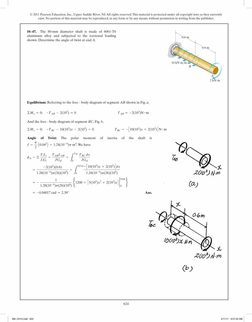
© 2011 Pearson Education, Inc., Upper Saddle River, NJ. All rights reserved. This material is protected under all copyright laws as they currently exist. No portion of this material may be reproduced, in any form or by any means, without permission in writing from the publisher.
624263
© 2010 Pearson Education, Inc., Upper Saddle River, NJ. All rights reserved. This material is protected under all copyright laws as they currentlyexist. No portion of this material may be reproduced, in any form or by any means, without permission in writing from the publisher.
*5–72. The 80-mm diameter shaft is made of 6061-T6aluminum alloy and subjected to the torsional loadingshown. Determine the angle of twist at end A.
B
A
C
0.6 m
0.6 m
2 kN�m
10 kN�m/m
Equilibrium: Referring to the free - body diagram of segment AB shown in Fig. a,
And the free - body diagram of segment BC, Fig. b,
©Mx = 0; -TBC - 10(103)x - 2(103) = 0 TBC = - C10(103)x + 2(103) D N # m
©Mx = 0; -TAB - 2(103) = 0 TAB = -2(103)N # m
Angle of Twist: The polar moment of inertia of the shaft is
. We have
Ans. = -0.04017 rad = 2.30°
= - 1
1.28(10-6)p(26)(109) b1200 + C5(103)x2 + 2(103)x D 2 0.6m
0r
=-2(103)(0.6)
1.28(10-6)p(26)(109)+ L
0.6 m
0
- C10(103)x + 2(103) Ddx1.28(10-6)p(26)(109)
fA = © TiLiJiGi
=TABLABJGal
+ LLBC
0 TBC dx
JGal
J =p
2 A0.042 B = 1.28(10-6)p m4
05 Solutions 46060 5/28/10 1:01 PM Page 263
10–47.
264
© 2010 Pearson Education, Inc., Upper Saddle River, NJ. All rights reserved. This material is protected under all copyright laws as they currentlyexist. No portion of this material may be reproduced, in any form or by any means, without permission in writing from the publisher.
Geometry:
Angle of Twist:
Ans. =7TL
12p r4G
=2TL4
p r4G c -
13(L + x)3 d 2 L
0
=2TL4
p r4G L
L
0 dx
(L + x)4
f = LL
0 T dxJ(x)G
J(x) =p
2 a r L + r x
Lb4
=p r4
2L4 (L + x)4
r(x) = r +r
L x =
r L + r xL
•5–73. The tapered shaft has a length L and a radius r atend A and 2r at end B. If it is fixed at end B and is subjectedto a torque T, determine the angle of twist of end A. Theshear modulus is G.
T
r
r2
A
B
L
Equilibrium: Referring to the free-body diagram of the entire rod shown in Fig. a,
Ans.
Internal Loading: The distributed torque expressed as a function of x, measured
from the left end, is . Thus, the resultant
torque within region x of the shaft is
Referring to the free - body diagram shown in Fig. b,
Referring to the free - body diagram shown in Fig. c,
©Mx = 0; Pd - TAB = 0 TAB = Pd
©Mx = 0; TBC -4PdL2 x2 = 0 TBC =
4PdL2 x2
TR =12
tx =12
B ¢ 8PdL2 ≤xRx =
4PdL2 x2
t = ¢ toL>2 ≤x = ¢ 4Pd>L
L>2 ≤x = ¢8PdL2 ≤x
to =4PdL
©Mx = 0; Pd -12
(t0)aL2 b = 0
5–74. The rod ABC of radius c is embedded into a mediumwhere the distributed torque reaction varies linearly fromzero at C to t0 at B. If couple forces P are applied to the leverarm, determine the value of t0 for equilibrium. Also, find theangle of twist of end A. The rod is made from materialhaving a shear modulus of G.
L2
L2
d2
d2
P
PA
B
t0C
05 Solutions 46060 5/28/10 1:01 PM Page 264
SM_CH10.indd 624 4/11/11 9:57:32 AM

© 2011 Pearson Education, Inc., Upper Saddle River, NJ. All rights reserved. This material is protected under all copyright laws as they currently exist. No portion of this material may be reproduced, in any form or by any means, without permission in writing from the publisher.
625263
© 2010 Pearson Education, Inc., Upper Saddle River, NJ. All rights reserved. This material is protected under all copyright laws as they currentlyexist. No portion of this material may be reproduced, in any form or by any means, without permission in writing from the publisher.
*5–72. The 80-mm diameter shaft is made of 6061-T6aluminum alloy and subjected to the torsional loadingshown. Determine the angle of twist at end A.
B
A
C
0.6 m
0.6 m
2 kN�m
10 kN�m/m
Equilibrium: Referring to the free - body diagram of segment AB shown in Fig. a,
And the free - body diagram of segment BC, Fig. b,
©Mx = 0; -TBC - 10(103)x - 2(103) = 0 TBC = - C10(103)x + 2(103) D N # m
©Mx = 0; -TAB - 2(103) = 0 TAB = -2(103)N # m
Angle of Twist: The polar moment of inertia of the shaft is
. We have
Ans. = -0.04017 rad = 2.30°
= - 1
1.28(10-6)p(26)(109) b1200 + C5(103)x2 + 2(103)x D 2 0.6m
0r
=-2(103)(0.6)
1.28(10-6)p(26)(109)+ L
0.6 m
0
- C10(103)x + 2(103) Ddx1.28(10-6)p(26)(109)
fA = © TiLiJiGi
=TABLABJGal
+ LLBC
0 TBC dx
JGal
J =p
2 A0.042 B = 1.28(10-6)p m4
05 Solutions 46060 5/28/10 1:01 PM Page 263
264
© 2010 Pearson Education, Inc., Upper Saddle River, NJ. All rights reserved. This material is protected under all copyright laws as they currentlyexist. No portion of this material may be reproduced, in any form or by any means, without permission in writing from the publisher.
Geometry:
Angle of Twist:
Ans. =7TL
12p r4G
=2TL4
p r4G c -
13(L + x)3 d 2 L
0
=2TL4
p r4G L
L
0 dx
(L + x)4
f = LL
0 T dxJ(x)G
J(x) =p
2 a r L + r x
Lb4
=p r4
2L4 (L + x)4
r(x) = r +r
L x =
r L + r xL
•5–73. The tapered shaft has a length L and a radius r atend A and 2r at end B. If it is fixed at end B and is subjectedto a torque T, determine the angle of twist of end A. Theshear modulus is G.
T
r
r2
A
B
L
Equilibrium: Referring to the free-body diagram of the entire rod shown in Fig. a,
Ans.
Internal Loading: The distributed torque expressed as a function of x, measured
from the left end, is . Thus, the resultant
torque within region x of the shaft is
Referring to the free - body diagram shown in Fig. b,
Referring to the free - body diagram shown in Fig. c,
©Mx = 0; Pd - TAB = 0 TAB = Pd
©Mx = 0; TBC -4PdL2 x2 = 0 TBC =
4PdL2 x2
TR =12
tx =12
B ¢8PdL2 ≤xRx =
4PdL2 x2
t = ¢ toL>2 ≤x = ¢4Pd>L
L>2 ≤x = ¢8PdL2 ≤x
to =4PdL
©Mx = 0; Pd -12
(t0)aL2 b = 0
5–74. The rod ABC of radius c is embedded into a mediumwhere the distributed torque reaction varies linearly fromzero at C to t0 at B. If couple forces P are applied to the leverarm, determine the value of t0 for equilibrium. Also, find theangle of twist of end A. The rod is made from materialhaving a shear modulus of G.
L2
L2
d2
d2
P
PA
B
t0C
05 Solutions 46060 5/28/10 1:01 PM Page 264
*10–48.
10–49.
SM_CH10.indd 625 4/11/11 9:57:34 AM
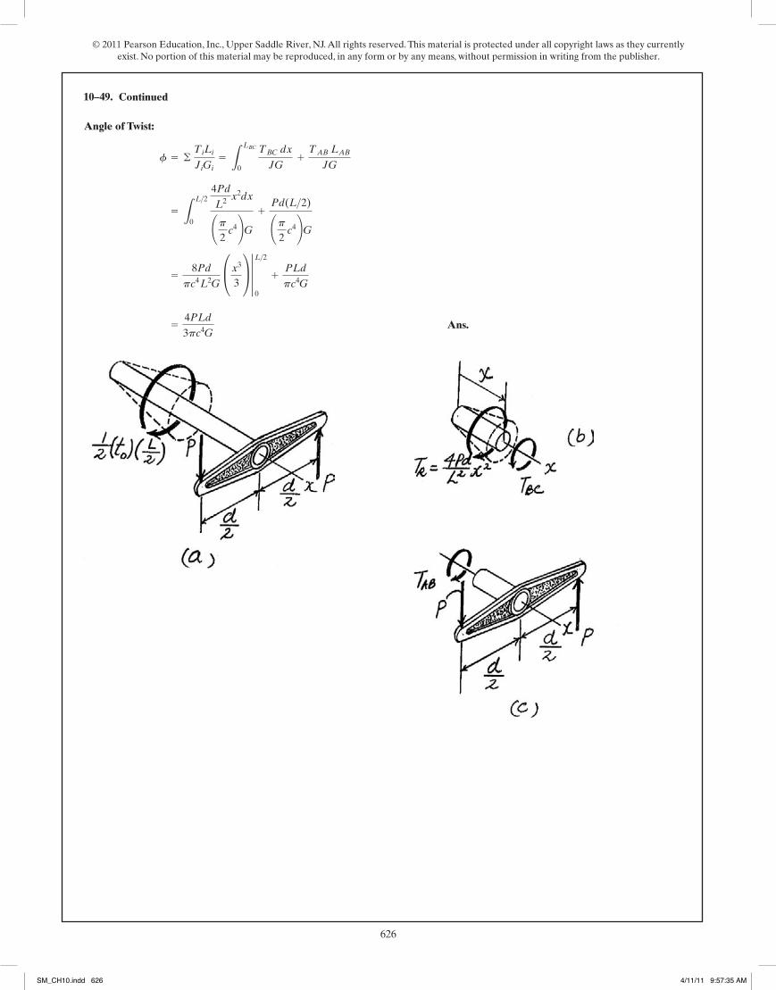
© 2011 Pearson Education, Inc., Upper Saddle River, NJ. All rights reserved. This material is protected under all copyright laws as they currently exist. No portion of this material may be reproduced, in any form or by any means, without permission in writing from the publisher.
626265
© 2010 Pearson Education, Inc., Upper Saddle River, NJ. All rights reserved. This material is protected under all copyright laws as they currentlyexist. No portion of this material may be reproduced, in any form or by any means, without permission in writing from the publisher.
Angle of Twist:
Ans. =4PLd3pc4G
=8Pdpc4 L2G
£x3
3≥ 3 L>2
0
+PLd
pc4G
= LL>2
0
4PdL2 x
2dx¢p2
c4≤G +Pd(L>2)¢p
2 c4≤G
f = © TiLiJiGi
= LLBC
0 TBC dx
JG+TAB LABJG
5–74. Continued
05 Solutions 46060 5/28/10 1:01 PM Page 265
10–49.
266
© 2010 Pearson Education, Inc., Upper Saddle River, NJ. All rights reserved. This material is protected under all copyright laws as they currentlyexist. No portion of this material may be reproduced, in any form or by any means, without permission in writing from the publisher.
Ans.
However,
Ans.f =2L(t0 L + 3TA)
3p(ro 4 - ri 4)G
J =p
2 (ro
4 - ri 4)
=t0 L
2 + 3TAL
3JG
=1JG
c t0 L + 2TA2
x -t0
6L x3 d ƒL
0
=1J G
LL
0 (t0L + 2TA
2-t0
2L x2) dx
f = L T(x) dx
J G
T(x) =t0 L + 2TA
2-t0
2L x2
T(x) +t0
2L x2 -
t0L + 2TA2
= 0
TB =t0L + 2TA
2
12
t0 L + TA - TB = 0
5–75. When drilling a well, the deep end of the drill pipeis assumed to encounter a torsional resistance Furthermore, soil friction along the sides of the pipe createsa linear distribution of torque per unit length, varying fromzero at the surface B to at A. Determine the necessarytorque that must be supplied by the drive unit to turnthe pipe. Also, what is the relative angle of twist of one endof the pipe with respect to the other end at the instant thepipe is about to turn? The pipe has an outer radius and aninner radius The shear modulus is G.ri .
ro
TB
t0
TA .
t0
L
A
BTB
TA
05 Solutions 46060 5/28/10 1:01 PM Page 266
SM_CH10.indd 626 4/11/11 9:57:35 AM

© 2011 Pearson Education, Inc., Upper Saddle River, NJ. All rights reserved. This material is protected under all copyright laws as they currently exist. No portion of this material may be reproduced, in any form or by any means, without permission in writing from the publisher.
627265
© 2010 Pearson Education, Inc., Upper Saddle River, NJ. All rights reserved. This material is protected under all copyright laws as they currentlyexist. No portion of this material may be reproduced, in any form or by any means, without permission in writing from the publisher.
Angle of Twist:
Ans. =4PLd3pc4G
=8Pdpc4 L2G
£x3
3≥ 3 L>2
0
+PLd
pc4G
= LL>2
0
4PdL2 x
2dx¢p2
c4≤G +Pd(L>2)¢p
2 c4≤G
f = © TiLiJiGi
= LLBC
0 TBC dx
JG+TAB LABJG
5–74. Continued
05 Solutions 46060 5/28/10 1:01 PM Page 265
266
© 2010 Pearson Education, Inc., Upper Saddle River, NJ. All rights reserved. This material is protected under all copyright laws as they currentlyexist. No portion of this material may be reproduced, in any form or by any means, without permission in writing from the publisher.
Ans.
However,
Ans.f =2L(t0 L + 3TA)
3p(ro 4 - ri 4)G
J =p
2 (ro
4 - ri 4)
=t0 L
2 + 3TAL
3JG
=1JG
c t0 L + 2TA2
x -t0
6L x3 d ƒL
0
=1J G
LL
0 (t0L + 2TA
2-t0
2L x2) dx
f = L T(x) dx
J G
T(x) =t0 L + 2TA
2-t0
2L x2
T(x) +t0
2L x2 -
t0L + 2TA2
= 0
TB =t0L + 2TA
2
12
t0 L + TA - TB = 0
5–75. When drilling a well, the deep end of the drill pipeis assumed to encounter a torsional resistance Furthermore, soil friction along the sides of the pipe createsa linear distribution of torque per unit length, varying fromzero at the surface B to at A. Determine the necessarytorque that must be supplied by the drive unit to turnthe pipe. Also, what is the relative angle of twist of one endof the pipe with respect to the other end at the instant thepipe is about to turn? The pipe has an outer radius and aninner radius The shear modulus is G.ri .
ro
TB
t0
TA .
t0
L
A
BTB
TA
05 Solutions 46060 5/28/10 1:01 PM Page 266
10–50.
SM_CH10.indd 627 4/11/11 9:57:36 AM

© 2011 Pearson Education, Inc., Upper Saddle River, NJ. All rights reserved. This material is protected under all copyright laws as they currently exist. No portion of this material may be reproduced, in any form or by any means, without permission in writing from the publisher.
628267
© 2010 Pearson Education, Inc., Upper Saddle River, NJ. All rights reserved. This material is protected under all copyright laws as they currentlyexist. No portion of this material may be reproduced, in any form or by any means, without permission in writing from the publisher.
(1)
From Prob. 5-26,
From (1),
Ans. =T
4p hG c 1ri
2 -1r2od
=T
2p hG c -
12ro
2 +1
2r2id
u =T
2p hG L
ro
ri
dr
r3=
T
2p hG c -
12 r2d |rori
du =T
2p hG dr
r3
g =T
2p r2hG
t =T
2p r2h and g =
t
G
du =gdr
r
r du = g dr
*5–76. A cylindrical spring consists of a rubber annulusbonded to a rigid ring and shaft. If the ring is held fixed anda torque T is applied to the rigid shaft, determine the angleof twist of the shaft. The shear modulus of the rubber is G.Hint: As shown in the figure, the deformation of theelement at radius r can be determined from Usethis expression along with from Prob. 5–26,to obtain the result.
t = T>12pr2h2 rdu = drg.
r
dr
g
du
gdr � rdu
T
h
ro
ri
r
05 Solutions 46060 5/28/10 1:01 PM Page 267
10–51.
268
© 2010 Pearson Education, Inc., Upper Saddle River, NJ. All rights reserved. This material is protected under all copyright laws as they currentlyexist. No portion of this material may be reproduced, in any form or by any means, without permission in writing from the publisher.
Equilibrium:
[1]
Compatibility:
[2]
Solving Eqs. [1] and [2] yields:
Maximum Shear stress:
Ans.
Ans.(tCB)max =TBc
J=
100(0.025)p2 (0.0254)
= 4.07 MPa
(tAC)max =TAc
J=
200(0.025)p2 (0.0254)
= 8.15 MPa
TA = 200 N # m TB = 100 N # m
TA = 2.00TB
TA(0.4)
JG=TB(0.8)
JG
fC>A = fC>B
TA + TB - 300 = 0
•5–77. The A-36 steel shaft has a diameter of 50 mm and isfixed at its ends A and B. If it is subjected to the torque,determine the maximum shear stress in regions AC and CBof the shaft.
A
C0.4 m
0.8 m
300 N�m
B
05 Solutions 46060 5/28/10 1:01 PM Page 268
SM_CH10.indd 628 4/11/11 9:57:36 AM

© 2011 Pearson Education, Inc., Upper Saddle River, NJ. All rights reserved. This material is protected under all copyright laws as they currently exist. No portion of this material may be reproduced, in any form or by any means, without permission in writing from the publisher.
629267
© 2010 Pearson Education, Inc., Upper Saddle River, NJ. All rights reserved. This material is protected under all copyright laws as they currentlyexist. No portion of this material may be reproduced, in any form or by any means, without permission in writing from the publisher.
(1)
From Prob. 5-26,
From (1),
Ans. =T
4p hG c 1ri
2 -1r2od
=T
2p hG c -
12ro
2 +1
2r2id
u =T
2p hG L
ro
ri
dr
r3=
T
2p hG c -
12 r2d |rori
du =T
2p hG dr
r3
g =T
2p r2hG
t =T
2p r2h and g =
t
G
du =gdr
r
r du = g dr
*5–76. A cylindrical spring consists of a rubber annulusbonded to a rigid ring and shaft. If the ring is held fixed anda torque T is applied to the rigid shaft, determine the angleof twist of the shaft. The shear modulus of the rubber is G.Hint: As shown in the figure, the deformation of theelement at radius r can be determined from Usethis expression along with from Prob. 5–26,to obtain the result.
t = T>12pr2h2 rdu = drg.
r
dr
g
du
gdr � rdu
T
h
ro
ri
r
05 Solutions 46060 5/28/10 1:01 PM Page 267
268
© 2010 Pearson Education, Inc., Upper Saddle River, NJ. All rights reserved. This material is protected under all copyright laws as they currentlyexist. No portion of this material may be reproduced, in any form or by any means, without permission in writing from the publisher.
Equilibrium:
[1]
Compatibility:
[2]
Solving Eqs. [1] and [2] yields:
Maximum Shear stress:
Ans.
Ans.(tCB)max =TBc
J=
100(0.025)p2 (0.0254)
= 4.07 MPa
(tAC)max =TAc
J=
200(0.025)p2 (0.0254)
= 8.15 MPa
TA = 200 N # m TB = 100 N # m
TA = 2.00TB
TA(0.4)
JG=TB(0.8)
JG
fC>A = fC>B
TA + TB - 300 = 0
•5–77. The A-36 steel shaft has a diameter of 50 mm and isfixed at its ends A and B. If it is subjected to the torque,determine the maximum shear stress in regions AC and CBof the shaft.
A
C0.4 m
0.8 m
300 N�m
B
05 Solutions 46060 5/28/10 1:01 PM Page 268
*10–52.
SM_CH10.indd 629 4/11/11 9:57:37 AM
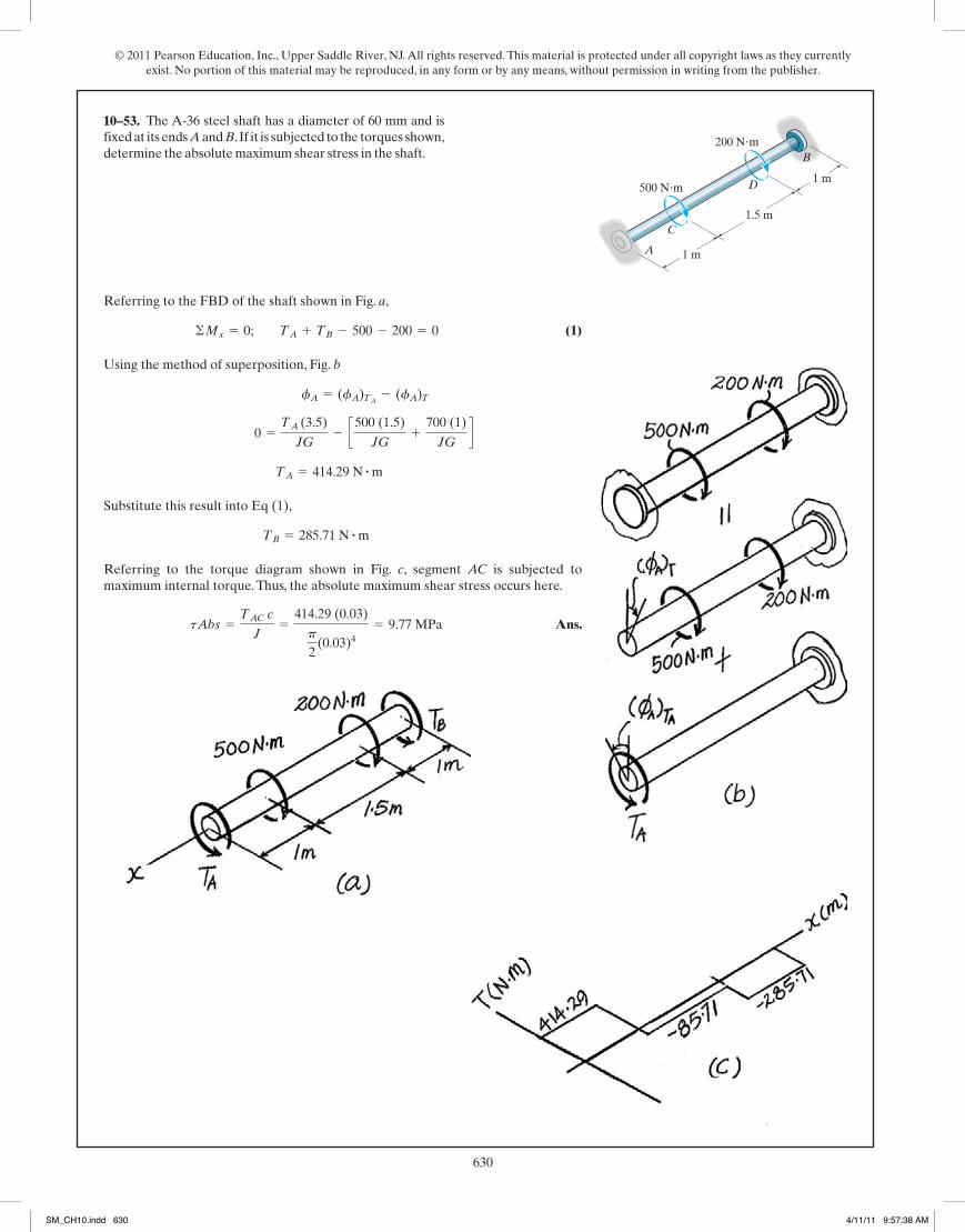
© 2011 Pearson Education, Inc., Upper Saddle River, NJ. All rights reserved. This material is protected under all copyright laws as they currently exist. No portion of this material may be reproduced, in any form or by any means, without permission in writing from the publisher.
630269
© 2010 Pearson Education, Inc., Upper Saddle River, NJ. All rights reserved. This material is protected under all copyright laws as they currentlyexist. No portion of this material may be reproduced, in any form or by any means, without permission in writing from the publisher.
Referring to the FBD of the shaft shown in Fig. a,
(1)
Using the method of superposition, Fig. b
Substitute this result into Eq (1),
Referring to the torque diagram shown in Fig. c, segment AC is subjected tomaximum internal torque. Thus, the absolute maximum shear stress occurs here.
Ans.tAbs =TAC c
J=
414.29 (0.03)
p
2(0.03)4
= 9.77 MPa
TB = 285.71 N # m
TA = 414.29 N # m
0 =TA (3.5)
JG- c500 (1.5)
JG+
700 (1)
JGd
fA = (fA)TA - (fA)T
©Mx = 0; TA + TB - 500 - 200 = 0
5–78. The A-36 steel shaft has a diameter of 60 mm and isfixed at its ends A and B.If it is subjected to the torques shown,determine the absolute maximum shear stress in the shaft.
A
C
D 1 m
1 m
1.5 m
200 N�m
500 N�m
B
05 Solutions 46060 5/28/10 1:01 PM Page 269
10–53.
270
© 2010 Pearson Education, Inc., Upper Saddle River, NJ. All rights reserved. This material is protected under all copyright laws as they currentlyexist. No portion of this material may be reproduced, in any form or by any means, without permission in writing from the publisher.
Equilibrium:
(1)
Compatibility condition:
(2)
Solving Eqs. (1) and (2) yields
Ans.
tDB =TCJ
=440(12)(0.5)p2 (0.54)
= 26.9 ksi
tAC =TCJ
=60(12)(0.25)p2 (0.254)
= 29.3 ksi (max)
TA = 60 lb # ft TB = 440 lb # ft
1408 TA = 192 TB
TA(5)p2 (0.254)G
+TA(8)
p2 (0.54)G
=TB(12)p2 (0.54)G
fD>A = fD>B
TA + TB - 500 = 0
5–79. The steel shaft is made from two segments: AC has adiameter of 0.5 in, and CB has a diameter of 1 in. If it isfixed at its ends A and B and subjected to a torque of determine the maximum shear stress in the shaft.Gst = 10.811032 ksi. 5 in.
8 in.
12 in.
1 in.
0.5 in.A
B
C
D 500 lb�ft
05 Solutions 46060 5/28/10 1:01 PM Page 270
SM_CH10.indd 630 4/11/11 9:57:38 AM
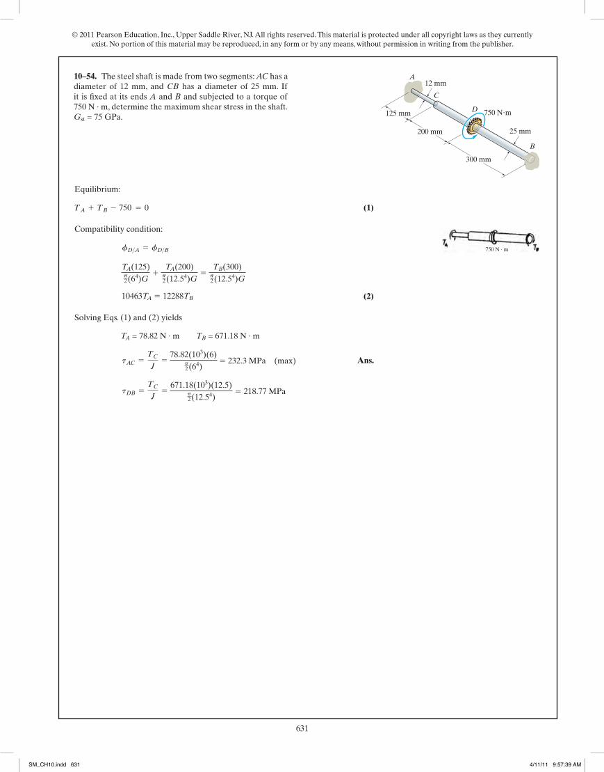
© 2011 Pearson Education, Inc., Upper Saddle River, NJ. All rights reserved. This material is protected under all copyright laws as they currently exist. No portion of this material may be reproduced, in any form or by any means, without permission in writing from the publisher.
631269
© 2010 Pearson Education, Inc., Upper Saddle River, NJ. All rights reserved. This material is protected under all copyright laws as they currentlyexist. No portion of this material may be reproduced, in any form or by any means, without permission in writing from the publisher.
Referring to the FBD of the shaft shown in Fig. a,
(1)
Using the method of superposition, Fig. b
Substitute this result into Eq (1),
Referring to the torque diagram shown in Fig. c, segment AC is subjected tomaximum internal torque. Thus, the absolute maximum shear stress occurs here.
Ans.tAbs =TAC c
J=
414.29 (0.03)
p
2(0.03)4
= 9.77 MPa
TB = 285.71 N # m
TA = 414.29 N # m
0 =TA (3.5)
JG- c500 (1.5)
JG+
700 (1)
JGd
fA = (fA)TA - (fA)T
©Mx = 0; TA + TB - 500 - 200 = 0
5–78. The A-36 steel shaft has a diameter of 60 mm and isfixed at its ends A and B.If it is subjected to the torques shown,determine the absolute maximum shear stress in the shaft.
A
C
D 1 m
1 m
1.5 m
200 N�m
500 N�m
B
05 Solutions 46060 5/28/10 1:01 PM Page 269
270
© 2010 Pearson Education, Inc., Upper Saddle River, NJ. All rights reserved. This material is protected under all copyright laws as they currentlyexist. No portion of this material may be reproduced, in any form or by any means, without permission in writing from the publisher.
Equilibrium:
(1)
Compatibility condition:
(2)
Solving Eqs. (1) and (2) yields
Ans.
tDB =TCJ
=440(12)(0.5)p2 (0.54)
= 26.9 ksi
tAC =TCJ
=60(12)(0.25)p2 (0.254)
= 29.3 ksi (max)
TA = 60 lb # ft TB = 440 lb # ft
1408 TA = 192 TB
TA(5)p2 (0.254)G
+TA(8)
p2 (0.54)G
=TB(12)p2 (0.54)G
fD>A = fD>B
TA + TB - 500 = 0
5–79. The steel shaft is made from two segments: AC has adiameter of 0.5 in, and CB has a diameter of 1 in. If it isfixed at its ends A and B and subjected to a torque of determine the maximum shear stress in the shaft.Gst = 10.811032 ksi. 5 in.
8 in.
12 in.
1 in.
0.5 in.A
B
C
D 500 lb�ft
05 Solutions 46060 5/28/10 1:01 PM Page 270
diameter of 12 mm, and CB has a diameter of 25 mm. If it is fixed at its ends A and B and subjected to a torque of 750 N · m, determine the maximum shear stress in the shaft. Gst = 75 GPa. 125 mm
200 mm
300 mm
25 mm
12 mmA
B
C
D 750 Nm
750 N · m
750
TA(125)p2(64)G
1 TA(200)p2(12.54)G
5 TB(300)p2(12.54)G
10463TA 5 12288TB
TA = 78.82 N · m TB = 671.18 N · m
78.82(103)(6)p2(64)
5 232.3 MPa (max)
671.18(103)(12.5)p2(12.54)
5 218.77 MPa
10–54.
SM_CH10.indd 631 4/11/11 9:57:39 AM

© 2011 Pearson Education, Inc., Upper Saddle River, NJ. All rights reserved. This material is protected under all copyright laws as they currently exist. No portion of this material may be reproduced, in any form or by any means, without permission in writing from the publisher.
632271
© 2010 Pearson Education, Inc., Upper Saddle River, NJ. All rights reserved. This material is protected under all copyright laws as they currentlyexist. No portion of this material may be reproduced, in any form or by any means, without permission in writing from the publisher.
*5–80. The shaft is made of A-36 steel, has a diameter of80 mm, and is fixed at B while A is loose and can rotate0.005 rad before becoming fixed. When the torques areapplied to C and D, determine the maximum shear stress inregions AC and CD of the shaft.
A600 mm
600 mm
600 mm
B
2 kN�m
4 kN�m
C
D
Referring to the FBD of the shaft shown in Fig. a,
(1)
Using the method of superposition, Fig. b,
Substitute this result into Eq (1),
Referring to the torque diagram shown in Fig. c, segment CD is subjected to amaximum internal torque. Thus, the absolute maximum shear stress occurs here.
Ans.tAB = =TCD c
J=
2.838 (103)(0.04)p2 (0.04)4 = 28.23 (106) Pa = 28.2 MPa
TB = 0.838 kN # m
TA = 1162.24 N # m = 1.162 kN # m
0.005 = B 4(103)(0.6)p2 (0.044) C75(109) D +
2(103)(0.6)p2 (0.044) C75(109) D R -
TA (1.8)p2 (0.044) C75(109) D
fA = (fA)T - (uA)TA
©Mx = 0; TA + TB + 2 - 4 = 0
05 Solutions 46060 5/28/10 1:01 PM Page 271
10–55.
272
© 2010 Pearson Education, Inc., Upper Saddle River, NJ. All rights reserved. This material is protected under all copyright laws as they currentlyexist. No portion of this material may be reproduced, in any form or by any means, without permission in writing from the publisher.
•5–81. The shaft is made of A-36 steel and has a diameterof 80 mm. It is fixed at B and the support at A has a torsionalstiffness of If it is subjected to the geartorques shown, determine the absolute maximum shear stressin the shaft.
k = 0.5 MN # m>rad.
A600 mm
600 mm
600 mm
B
2 kN�m
4 kN�m
C
D
Referring to the FBD of the shaft shown in Fig. a,
(1)
Using the method of superposition, Fig. b,
Substituting this result into Eq (1),
Referring to the torque diagram shown in Fig. c, segment CD subjected to maximuminternal torque. Thus, the maximum shear stress occurs here.
Ans.tCD =TCD C
J=
2.502(103)(0.04)p2(0.04)4 = 24.9 MPa
TB = 0.502 kN # m
TA = 1498.01 N # m = 1.498 kN # m
TA
0.5(106)= D 4(103)(0.6)
p2 (0.044) C75(109) D +
2(103)(0.6)p2 (0.044) C75(109) D T -
TA(1.8)p2 (0.044) C75(109) D
fA = (fA)T - (fA)TA
©Mx = 0; TA + TB + 2 - 4 = 0
05 Solutions 46060 5/28/10 1:01 PM Page 272
SM_CH10.indd 632 4/11/11 9:57:40 AM

© 2011 Pearson Education, Inc., Upper Saddle River, NJ. All rights reserved. This material is protected under all copyright laws as they currently exist. No portion of this material may be reproduced, in any form or by any means, without permission in writing from the publisher.
633271
© 2010 Pearson Education, Inc., Upper Saddle River, NJ. All rights reserved. This material is protected under all copyright laws as they currentlyexist. No portion of this material may be reproduced, in any form or by any means, without permission in writing from the publisher.
*5–80. The shaft is made of A-36 steel, has a diameter of80 mm, and is fixed at B while A is loose and can rotate0.005 rad before becoming fixed. When the torques areapplied to C and D, determine the maximum shear stress inregions AC and CD of the shaft.
A600 mm
600 mm
600 mm
B
2 kN�m
4 kN�m
C
D
Referring to the FBD of the shaft shown in Fig. a,
(1)
Using the method of superposition, Fig. b,
Substitute this result into Eq (1),
Referring to the torque diagram shown in Fig. c, segment CD is subjected to amaximum internal torque. Thus, the absolute maximum shear stress occurs here.
Ans.tAB = =TCD c
J=
2.838 (103)(0.04)p2 (0.04)4 = 28.23 (106) Pa = 28.2 MPa
TB = 0.838 kN # m
TA = 1162.24 N # m = 1.162 kN # m
0.005 = B 4(103)(0.6)p2 (0.044) C75(109) D +
2(103)(0.6)p2 (0.044) C75(109) D R -
TA (1.8)p2 (0.044) C75(109) D
fA = (fA)T - (uA)TA
©Mx = 0; TA + TB + 2 - 4 = 0
05 Solutions 46060 5/28/10 1:01 PM Page 271
272
© 2010 Pearson Education, Inc., Upper Saddle River, NJ. All rights reserved. This material is protected under all copyright laws as they currentlyexist. No portion of this material may be reproduced, in any form or by any means, without permission in writing from the publisher.
•5–81. The shaft is made of A-36 steel and has a diameterof 80 mm. It is fixed at B and the support at A has a torsionalstiffness of If it is subjected to the geartorques shown, determine the absolute maximum shear stressin the shaft.
k = 0.5 MN # m>rad.
A600 mm
600 mm
600 mm
B
2 kN�m
4 kN�m
C
D
Referring to the FBD of the shaft shown in Fig. a,
(1)
Using the method of superposition, Fig. b,
Substituting this result into Eq (1),
Referring to the torque diagram shown in Fig. c, segment CD subjected to maximuminternal torque. Thus, the maximum shear stress occurs here.
Ans.tCD =TCD C
J=
2.502(103)(0.04)p2(0.04)4 = 24.9 MPa
TB = 0.502 kN # m
TA = 1498.01 N # m = 1.498 kN # m
TA
0.5(106)= D 4(103)(0.6)
p2 (0.044) C75(109) D +
2(103)(0.6)p2 (0.044) C75(109) D T -
TA(1.8)p2 (0.044) C75(109) D
fA = (fA)T - (fA)TA
©Mx = 0; TA + TB + 2 - 4 = 0
05 Solutions 46060 5/28/10 1:01 PM Page 272
*10–56.
SM_CH10.indd 633 4/11/11 9:57:41 AM
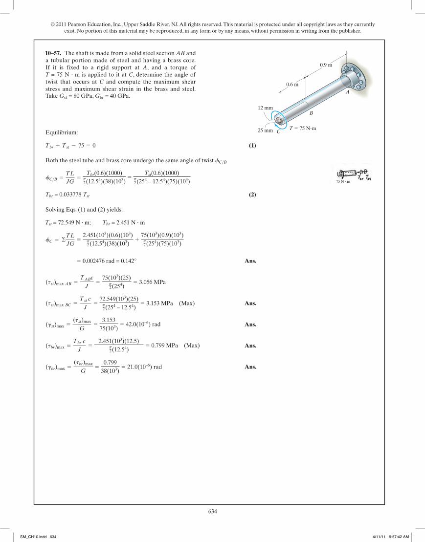
© 2011 Pearson Education, Inc., Upper Saddle River, NJ. All rights reserved. This material is protected under all copyright laws as they currently exist. No portion of this material may be reproduced, in any form or by any means, without permission in writing from the publisher.
634273
© 2010 Pearson Education, Inc., Upper Saddle River, NJ. All rights reserved. This material is protected under all copyright laws as they currentlyexist. No portion of this material may be reproduced, in any form or by any means, without permission in writing from the publisher.
Equilibrium:
(1)
Both the steel tube and brass core undergo the same angle of twist
(2)
Solving Eqs. (1) and (2) yields:
Ans.
Ans.
Ans.
Ans.
Ans.(gbr)max =(tbr)max
G=
96.07
5.6(106)= 17.2(10-6) rad
(tbr)max =Tbr c
J=
1.572(12)(0.5)p2 (0.54)
= 96.07 psi = 96.1 psi (Max)
(gst)max =(tst)max
G=
394.63
11.5(106)= 343.(10-6) rad
(tst)max BC =Tst c
J=
48.428(12)(1)p2 (14 - 0.54)
= 394.63 psi = 395 psi (Max)
(tst)max AB =TABc
J=
50(12)(1)p2 (14)
= 382 psi
= 0.002019 rad = 0.116°
fC = ©TL
JG=
1.572(12)(2)(12)p2 (0.54)(5.6)(106)
+50(12)(3)(12)p2(14)(11.5)(106)
Tst = 48.428 lb # ft; Tbr = 1.572 lb # ft
Tbr = 0.032464 Tst
fC>B =TL
JG=
Tst (2)(12)p2 (0.54)(5.6)(104)
=Tst (2)(12)
p2 (14 - 0.54)(11.5)(106)
fC>B
Tbr + Tst - 50 = 0
5–82. The shaft is made from a solid steel section AB anda tubular portion made of steel and having a brass core.If it is fixed to a rigid support at A, and a torque of
is applied to it at C, determine the angle oftwist that occurs at C and compute the maximum shearstress and maximum shear strain in the brass and steel.Take Gst = 11.511032 ksi, Gbr = 5.611032 ksi.
T = 50 lb # ft
A
0.5 in.
1 in.
2 ft
3 ft
B
CT � 50 lb�ft
05 Solutions 46060 5/28/10 1:01 PM Page 273
Take Gst = 80 GPa, Gbr = 40 GPa.A
12 mm
25 mm
0.6 m
0.9 m
B
CT 75 Nm
T = 75 N · m is applied to it at C, determine the angle of
75 N · m
75
Tbr(0.6)(1000)p2(12.54)(38)(103)
5 Tst(0.6)(1000)
p2(254 – 12.54)(75)(103)
Tbr = 0.033778 Tst
Tst = 72.549 N · m; Tbr = 2.451 N · m
5 2.451(103)(0.6)(103)p2(12.54)(38)(103)
1 75(103)(0.9)(103)p2(254)(75)(103)
5 0.002476 rad = 0.142°
5 75(103)(25)p2(254)
5 3.056 MPa
5 72.549(103)(25)p2(254 – 12.54)
5 3.153 MPa (Max)
5 3.153
75(103) 5 42.0(10–6) rad
5 2.451(103)(12.5)
p2(12.54)
5 0.799 MPa (Max)
5 0.799
38(103) 5 21.0(10–6) rad
10–57.
274
© 2010 Pearson Education, Inc., Upper Saddle River, NJ. All rights reserved. This material is protected under all copyright laws as they currentlyexist. No portion of this material may be reproduced, in any form or by any means, without permission in writing from the publisher.
Equilibrium:
(1)
Compatibility condition:
(2)
Solving Eqs. (1) and (2), yields
Ans.
Ans.
Ans.f =192.86(12)(4)(12)p2 (14)(12)(106)
= 0.00589 rad = 0.338°
(tBD)max =257.14(12)(1)
p2 (14)
= 1.96 ksi
(tBC)max =192.86(12)(1)
p2 (14)
= 1.47 ksi
TC = 192.86 lb # ftTD = 257.14 lb # ft
TC = 0.75 TD
TC(4)
JG=TD(3)
JG
fB>C = fB>D
TC + TD - 450 = 0
5–83. The motor A develops a torque at gear B of which is applied along the axis of the 2-in.-diameter steel shaftCD. This torque is to be transmitted to the pinion gears at Eand F. If these gears are temporarily fixed, determine themaximum shear stress in segments CB and BD of the shaft.Also, what is the angle of twist of each of these segments? Thebearings at C and D only exert force reactions on the shaftand do not resist torque.Gst = 1211032 ksi.
450 lb # ft,
4 ft 3 ft
B
DC
A
E F
450 lb�ft
05 Solutions 46060 5/28/10 1:01 PM Page 274
SM_CH10.indd 634 4/11/11 9:57:42 AM
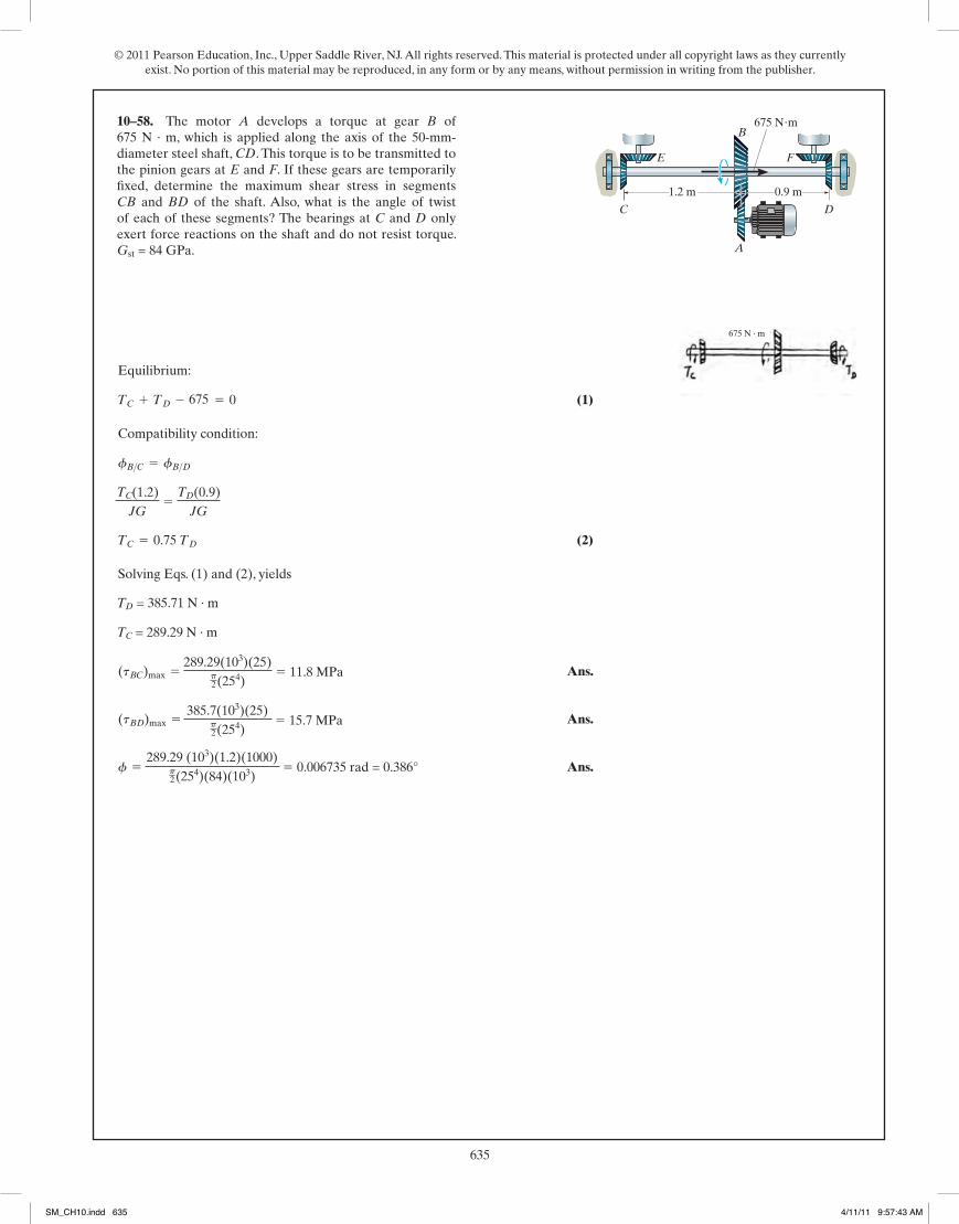
© 2011 Pearson Education, Inc., Upper Saddle River, NJ. All rights reserved. This material is protected under all copyright laws as they currently exist. No portion of this material may be reproduced, in any form or by any means, without permission in writing from the publisher.
635273
© 2010 Pearson Education, Inc., Upper Saddle River, NJ. All rights reserved. This material is protected under all copyright laws as they currentlyexist. No portion of this material may be reproduced, in any form or by any means, without permission in writing from the publisher.
Equilibrium:
(1)
Both the steel tube and brass core undergo the same angle of twist
(2)
Solving Eqs. (1) and (2) yields:
Ans.
Ans.
Ans.
Ans.
Ans.(gbr)max =(tbr)max
G=
96.07
5.6(106)= 17.2(10-6) rad
(tbr)max =Tbr c
J=
1.572(12)(0.5)p2 (0.54)
= 96.07 psi = 96.1 psi (Max)
(gst)max =(tst)max
G=
394.63
11.5(106)= 343.(10-6) rad
(tst)max BC =Tst c
J=
48.428(12)(1)p2 (14 - 0.54)
= 394.63 psi = 395 psi (Max)
(tst)max AB =TABc
J=
50(12)(1)p2 (14)
= 382 psi
= 0.002019 rad = 0.116°
fC = ©TL
JG=
1.572(12)(2)(12)p2 (0.54)(5.6)(106)
+50(12)(3)(12)p2(14)(11.5)(106)
Tst = 48.428 lb # ft; Tbr = 1.572 lb # ft
Tbr = 0.032464 Tst
fC>B =TL
JG=
Tst (2)(12)p2 (0.54)(5.6)(104)
=Tst (2)(12)
p2 (14 - 0.54)(11.5)(106)
fC>B
Tbr + Tst - 50 = 0
5–82. The shaft is made from a solid steel section AB anda tubular portion made of steel and having a brass core.If it is fixed to a rigid support at A, and a torque of
is applied to it at C, determine the angle oftwist that occurs at C and compute the maximum shearstress and maximum shear strain in the brass and steel.Take Gst = 11.511032 ksi, Gbr = 5.611032 ksi.
T = 50 lb # ft
A
0.5 in.
1 in.
2 ft
3 ft
B
CT � 50 lb�ft
05 Solutions 46060 5/28/10 1:01 PM Page 273
274
© 2010 Pearson Education, Inc., Upper Saddle River, NJ. All rights reserved. This material is protected under all copyright laws as they currentlyexist. No portion of this material may be reproduced, in any form or by any means, without permission in writing from the publisher.
Equilibrium:
(1)
Compatibility condition:
(2)
Solving Eqs. (1) and (2), yields
Ans.
Ans.
Ans.f =192.86(12)(4)(12)p2 (14)(12)(106)
= 0.00589 rad = 0.338°
(tBD)max =257.14(12)(1)
p2 (14)
= 1.96 ksi
(tBC)max =192.86(12)(1)
p2 (14)
= 1.47 ksi
TC = 192.86 lb # ftTD = 257.14 lb # ft
TC = 0.75 TD
TC(4)
JG=TD(3)
JG
fB>C = fB>D
TC + TD - 450 = 0
5–83. The motor A develops a torque at gear B of which is applied along the axis of the 2-in.-diameter steel shaftCD. This torque is to be transmitted to the pinion gears at Eand F. If these gears are temporarily fixed, determine themaximum shear stress in segments CB and BD of the shaft.Also, what is the angle of twist of each of these segments? Thebearings at C and D only exert force reactions on the shaftand do not resist torque.Gst = 1211032 ksi.
450 lb # ft,
4 ft 3 ft
B
DC
A
E F
450 lb�ft
05 Solutions 46060 5/28/10 1:01 PM Page 274
10–58. The motor A develops a torque at gear B of 675 N · m, which is applied along the axis of the 50-mm-diameter steel shaft, CD. This torque is to be transmitted to the pinion gears at E and F. If these gears are temporarily fixed, determine the maximum shear stress in segments CB and BD of the shaft. Also, what is the angle of twist of each of these segments? The bearings at C and D only exert force reactions on the shaft and do not resist torque. Gst = 84 GPa.
1.2 m 0.9 m
B
DC
A
E F
675 Nm
675
675 N · m
TC(1.2)JG
5 TD(0.9)
JG
TD = 385.71 N · m
TC = 289.29 N · m
289.29(103)(25)p2(254)
5 11.8 MPa
385.7(103)(25)p2(254)
5 15.7 MPa
289.29 (103)(1.2)(1000)p2(254)(84)(103)
5 0.006735 rad = 0.386°
SM_CH10.indd 635 4/11/11 9:57:43 AM
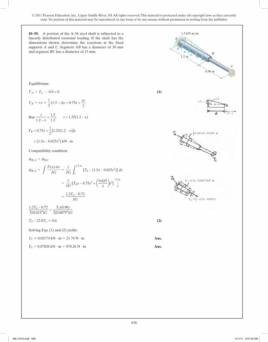
© 2011 Pearson Education, Inc., Upper Saddle River, NJ. All rights reserved. This material is protected under all copyright laws as they currently exist. No portion of this material may be reproduced, in any form or by any means, without permission in writing from the publisher.
636275
© 2010 Pearson Education, Inc., Upper Saddle River, NJ. All rights reserved. This material is protected under all copyright laws as they currentlyexist. No portion of this material may be reproduced, in any form or by any means, without permission in writing from the publisher.
Equilibrium:
(1)
But
Compatibility condition:
(2)
Solving Eqs. (1) and (2) yields:
Ans.
Ans.TA = 8782.6 lb # in. = 732 lb # ftTC = 217.4 lb # in. = 18.1 lb # ft
60TA - 768TC = 360 000
60TA - 360 000p2 (0.754)G
=TC(48)
p2 (0.3754)G
=60TA - 360 000
JG
=1JG
[TAx - 150x2 + 0.8333x3] |60
0
fB>A = L T(x) dx
JG=
1JG
L60
0[TA - (300x - 2.5x2)] dx
fB>A = fB>C
= (300x - 2.5x2) lb # in.
TR = 150 x +12
[5(60 - x)]x
t
60 - x=
30060
; t = 5(60 - x)
TR = t x +12
(300 - t)x = 150x +t x
2
TA + TC - 9000 = 0
*5–84. A portion of the A-36 steel shaft is subjected to alinearly distributed torsional loading. If the shaft has thedimensions shown, determine the reactions at the fixedsupports A and C. Segment AB has a diameter of 1.5 in. andsegment BC has a diameter of 0.75 in.
A
B60 in.
48 in.
C
300 lb�in./in.
05 Solutions 46060 5/28/10 1:01 PM Page 275
supports A and C. Segment AB has a diameter of 30 mm and segment BC has a diameter of 15 mm.
A
B1.2 m
0.96 m
C
1.5 kNm/m
1.5 – t1.5
1.2 – x
12 (1.5)(1.2) = 0.9 kN · m
TA = (1.5x – 0.625x2) kN · m
T(x) =TA – (1.5x – 0.625x2)
0.9 = 0
(1.5 – t)x = 0.75x + tx
2
t
1.2 – x =
1.51.2
; t = 1.25(1.2 – x)
TR = 0.75x + 12
[1.25(1.2 – x)]x
= (1.5x – 0.625x2) kN · m
1.2 m
0 [TA – (1.5x – 0.625x2)] dx
[TAx – 0.75x2 + a0.6253bx3]
1.2 m
0
1.2TA – 0.72JG
1.2TA – 0.72p2(0.0154)G
5 TC(0.96)
p2(0.00754)G
TA – 12.8TC 5 0.6
TC 5 0.02174 kN · m 5 21.74 N · m
TA 5 0.87826 kN · m 5 878.26 N · m
10–59.
276
© 2010 Pearson Education, Inc., Upper Saddle River, NJ. All rights reserved. This material is protected under all copyright laws as they currentlyexist. No portion of this material may be reproduced, in any form or by any means, without permission in writing from the publisher.
Equilibrium:
(1)
But
Compatibility condition:
(2)
Solving Eqs. (1) and (2) yields:
For segment BC:
Ans.
For segment AB,
Ans.t absmax
= 13.3 ksi
tmax =TCJ
=8782.6(0.75)p2 (0.75)4 = 13.3 ksi
tmax =TCJ
=217.4(0.375)p2 (0.375)4 = 2.62 ksi
fB = 1.75°
fB = fB>C =TCL
JG=
217.4(48)p2 (0.375)4(11.0)(106)
= 0.030540 rad
TA = 8782.6 lb # in. = 732 lb # ftTC = 217.4 lb # in. = 18.1 lb # ft
60TA - 768TC = 360 000
60TA - 360 000p2 (0.754)G
=TC(48)
p2 (0.3754)G
=60TA - 360 000
JG
=1JG
[TAx - 150x2 + 0.8333x3] |60
0
fB>A = L T(x) dx
JG=
1JG
L60
0 [TA - (300x - 2.5x2)] dx
fB>A = fB>C
= (300x - 2.5x2) lb # in.
TR = 150x +12
[5(60 - x)]x
t
60 - x=
30060
; t = 5(60 - x)
TR = tx +12
(300 - t)x = 150x +tx
2
TA + TC - 9000 = 0
•5–85. Determine the rotation of joint B and the absolutemaximum shear stress in the shaft in Prob. 5–84. A
B60 in.
48 in.
C
300 lb�in./in.
05 Solutions 46060 5/28/10 1:01 PM Page 276
SM_CH10.indd 636 4/11/11 9:57:45 AM
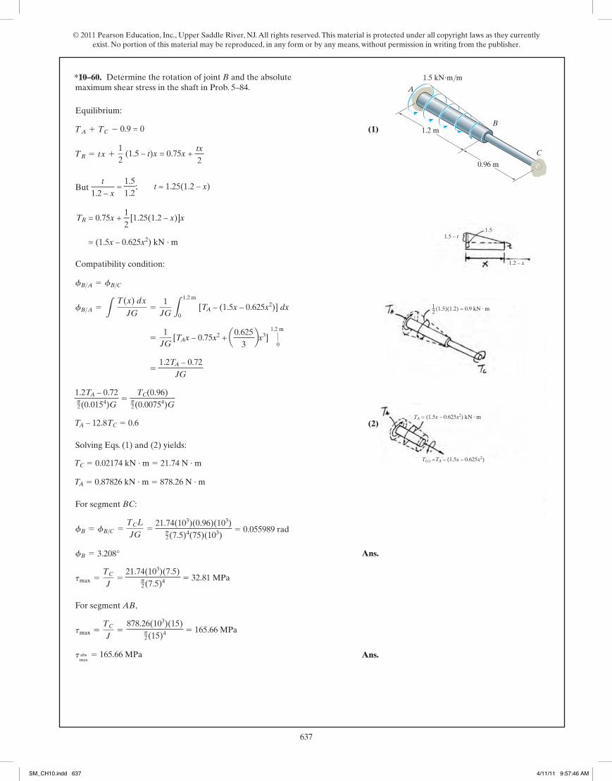
© 2011 Pearson Education, Inc., Upper Saddle River, NJ. All rights reserved. This material is protected under all copyright laws as they currently exist. No portion of this material may be reproduced, in any form or by any means, without permission in writing from the publisher.
637275
© 2010 Pearson Education, Inc., Upper Saddle River, NJ. All rights reserved. This material is protected under all copyright laws as they currentlyexist. No portion of this material may be reproduced, in any form or by any means, without permission in writing from the publisher.
Equilibrium:
(1)
But
Compatibility condition:
(2)
Solving Eqs. (1) and (2) yields:
Ans.
Ans.TA = 8782.6 lb # in. = 732 lb # ftTC = 217.4 lb # in. = 18.1 lb # ft
60TA - 768TC = 360 000
60TA - 360 000p2 (0.754)G
=TC(48)
p2 (0.3754)G
=60TA - 360 000
JG
=1JG
[TAx - 150x2 + 0.8333x3] |60
0
fB>A = L T(x) dx
JG=
1JG
L60
0[TA - (300x - 2.5x2)] dx
fB>A = fB>C
= (300x - 2.5x2) lb # in.
TR = 150 x +12
[5(60 - x)]x
t
60 - x=
30060
; t = 5(60 - x)
TR = t x +12
(300 - t)x = 150x +t x
2
TA + TC - 9000 = 0
*5–84. A portion of the A-36 steel shaft is subjected to alinearly distributed torsional loading. If the shaft has thedimensions shown, determine the reactions at the fixedsupports A and C. Segment AB has a diameter of 1.5 in. andsegment BC has a diameter of 0.75 in.
A
B60 in.
48 in.
C
300 lb�in./in.
05 Solutions 46060 5/28/10 1:01 PM Page 275
276
© 2010 Pearson Education, Inc., Upper Saddle River, NJ. All rights reserved. This material is protected under all copyright laws as they currentlyexist. No portion of this material may be reproduced, in any form or by any means, without permission in writing from the publisher.
Equilibrium:
(1)
But
Compatibility condition:
(2)
Solving Eqs. (1) and (2) yields:
For segment BC:
Ans.
For segment AB,
Ans.t absmax
= 13.3 ksi
tmax =TCJ
=8782.6(0.75)p2 (0.75)4 = 13.3 ksi
tmax =TCJ
=217.4(0.375)p2 (0.375)4 = 2.62 ksi
fB = 1.75°
fB = fB>C =TCL
JG=
217.4(48)p2 (0.375)4(11.0)(106)
= 0.030540 rad
TA = 8782.6 lb # in. = 732 lb # ftTC = 217.4 lb # in. = 18.1 lb # ft
60TA - 768TC = 360 000
60TA - 360 000p2 (0.754)G
=TC(48)
p2 (0.3754)G
=60TA - 360 000
JG
=1JG
[TAx - 150x2 + 0.8333x3] |60
0
fB>A = L T(x) dx
JG=
1JG
L60
0 [TA - (300x - 2.5x2)] dx
fB>A = fB>C
= (300x - 2.5x2) lb # in.
TR = 150x +12
[5(60 - x)]x
t
60 - x=
30060
; t = 5(60 - x)
TR = tx +12
(300 - t)x = 150x +tx
2
TA + TC - 9000 = 0
•5–85. Determine the rotation of joint B and the absolutemaximum shear stress in the shaft in Prob. 5–84. A
B60 in.
48 in.
C
300 lb�in./in.
05 Solutions 46060 5/28/10 1:01 PM Page 276
A
B1.2 m
0.96 m
C
1.5 kNm/m
1.5 – t1.5
1.2 – x
12 (1.5)(1.2) = 0.9 kN · m
TA = (1.5x – 0.625x2) kN · m
T(x) =TA – (1.5x – 0.625x2)
0.9 = 0
(1.5 – t)x = 0.75x + tx
2
t
1.2 – x =
1.51.2
; t = 1.25(1.2 – x)
TR = 0.75x + 12
[1.25(1.2 – x)]x
= (1.5x – 0.625x2) kN · m
1.2 m
0 [TA – (1.5x – 0.625x2)] dx
[TAx – 0.75x2 + a0.6253bx3]
1.2 m
0
1.2TA – 0.72JG
1.2TA – 0.72p2(0.0154)G
5 TC(0.96)
p2(0.00754)G
TA – 12.8TC 5 0.6
TC 5 0.02174 kN · m 5 21.74 N · m
TA 5 0.87826 kN · m 5 878.26 N · m
21.74(103)(0.96)(103)p2(7.5)4(75)(103)
5 0.055989 rad
3.208°
21.74(103)(7.5)p2(7.5)4 5 32.81 MPa
878.26(103)(15)p2(15)4 5 165.66 MPa
165.66 MPa
*10–60.
SM_CH10.indd 637 4/11/11 9:57:46 AM
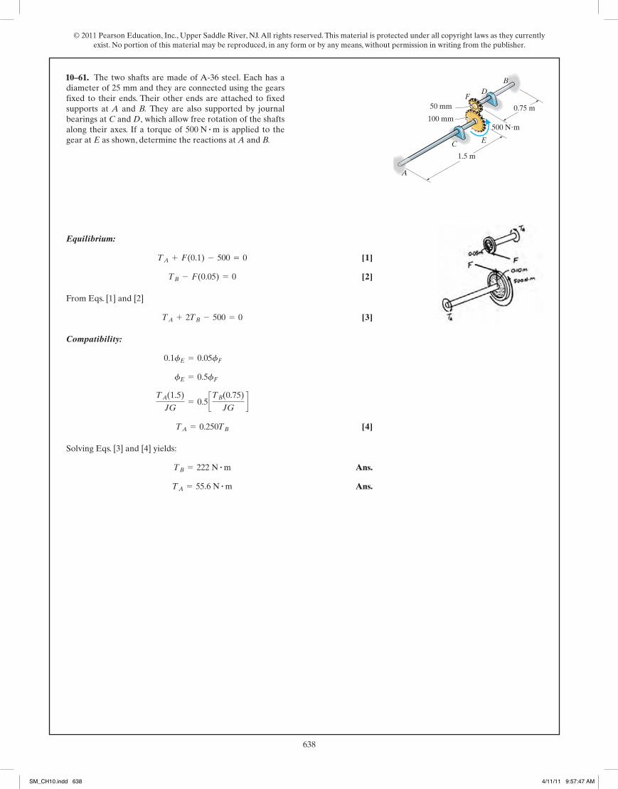
© 2011 Pearson Education, Inc., Upper Saddle River, NJ. All rights reserved. This material is protected under all copyright laws as they currently exist. No portion of this material may be reproduced, in any form or by any means, without permission in writing from the publisher.
638277
© 2010 Pearson Education, Inc., Upper Saddle River, NJ. All rights reserved. This material is protected under all copyright laws as they currentlyexist. No portion of this material may be reproduced, in any form or by any means, without permission in writing from the publisher.
Equilibrium:
[1]
[2]
From Eqs. [1] and [2]
[3]
Compatibility:
[4]
Solving Eqs. [3] and [4] yields:
Ans.
Ans.TA = 55.6 N # mTB = 222 N # m
TA = 0.250TB
TA(1.5)
JG= 0.5 cTB(0.75)
JGd
fE = 0.5fF
0.1fE = 0.05fF
TA + 2TB - 500 = 0
TB - F(0.05) = 0
TA + F(0.1) - 500 = 0
5–86. The two shafts are made of A-36 steel. Each has adiameter of 25 mm and they are connected using the gearsfixed to their ends. Their other ends are attached to fixedsupports at A and B. They are also supported by journalbearings at C and D, which allow free rotation of the shaftsalong their axes. If a torque of is applied to thegear at E as shown, determine the reactions at A and B.
500 N # m
B
50 mm
100 mm
A
C
D
1.5 m
0.75 m
500 N�m
F
E
05 Solutions 46060 5/28/10 1:01 PM Page 277
10–61.
278
© 2010 Pearson Education, Inc., Upper Saddle River, NJ. All rights reserved. This material is protected under all copyright laws as they currentlyexist. No portion of this material may be reproduced, in any form or by any means, without permission in writing from the publisher.
Equilibrium:
[1]
[2]
From Eqs. [1] and [2]
[3]
Compatibility:
[4]
Solving Eqs. [3] and [4] yields:
Angle of Twist:
Ans. = 0.02897 rad = 1.66°
fE =TAL
JG=
55.56(1.5)p2 (0.01254)(75.0)(109)
TB = 222.22 N # m TA = 55.56 N # m
TA = 0.250TB
TA(1.5)
JG= 0.5 cTB(0.75)
JGd
fE = 0.5fF
0.1fE = 0.05fF
TA + 2TB - 500 = 0
TB - F(0.05) = 0
TA + F(0.1) - 500 = 0
5–87. Determine the rotation of the gear at E in Prob. 5–86.
B
50 mm
100 mm
A
C
D
1.5 m
0.75 m
500 N�m
F
E
05 Solutions 46060 5/28/10 1:01 PM Page 278
SM_CH10.indd 638 4/11/11 9:57:47 AM

© 2011 Pearson Education, Inc., Upper Saddle River, NJ. All rights reserved. This material is protected under all copyright laws as they currently exist. No portion of this material may be reproduced, in any form or by any means, without permission in writing from the publisher.
639277
© 2010 Pearson Education, Inc., Upper Saddle River, NJ. All rights reserved. This material is protected under all copyright laws as they currentlyexist. No portion of this material may be reproduced, in any form or by any means, without permission in writing from the publisher.
Equilibrium:
[1]
[2]
From Eqs. [1] and [2]
[3]
Compatibility:
[4]
Solving Eqs. [3] and [4] yields:
Ans.
Ans.TA = 55.6 N # mTB = 222 N # m
TA = 0.250TB
TA(1.5)
JG= 0.5 cTB(0.75)
JGd
fE = 0.5fF
0.1fE = 0.05fF
TA + 2TB - 500 = 0
TB - F(0.05) = 0
TA + F(0.1) - 500 = 0
5–86. The two shafts are made of A-36 steel. Each has adiameter of 25 mm and they are connected using the gearsfixed to their ends. Their other ends are attached to fixedsupports at A and B. They are also supported by journalbearings at C and D, which allow free rotation of the shaftsalong their axes. If a torque of is applied to thegear at E as shown, determine the reactions at A and B.
500 N # m
B
50 mm
100 mm
A
C
D
1.5 m
0.75 m
500 N�m
F
E
05 Solutions 46060 5/28/10 1:01 PM Page 277
278
© 2010 Pearson Education, Inc., Upper Saddle River, NJ. All rights reserved. This material is protected under all copyright laws as they currentlyexist. No portion of this material may be reproduced, in any form or by any means, without permission in writing from the publisher.
Equilibrium:
[1]
[2]
From Eqs. [1] and [2]
[3]
Compatibility:
[4]
Solving Eqs. [3] and [4] yields:
Angle of Twist:
Ans. = 0.02897 rad = 1.66°
fE =TAL
JG=
55.56(1.5)p2 (0.01254)(75.0)(109)
TB = 222.22 N # m TA = 55.56 N # m
TA = 0.250TB
TA(1.5)
JG= 0.5 cTB(0.75)
JGd
fE = 0.5fF
0.1fE = 0.05fF
TA + 2TB - 500 = 0
TB - F(0.05) = 0
TA + F(0.1) - 500 = 0
5–87. Determine the rotation of the gear at E in Prob. 5–86.
B
50 mm
100 mm
A
C
D
1.5 m
0.75 m
500 N�m
F
E
05 Solutions 46060 5/28/10 1:01 PM Page 278
10–62.
SM_CH10.indd 639 4/11/11 9:57:48 AM
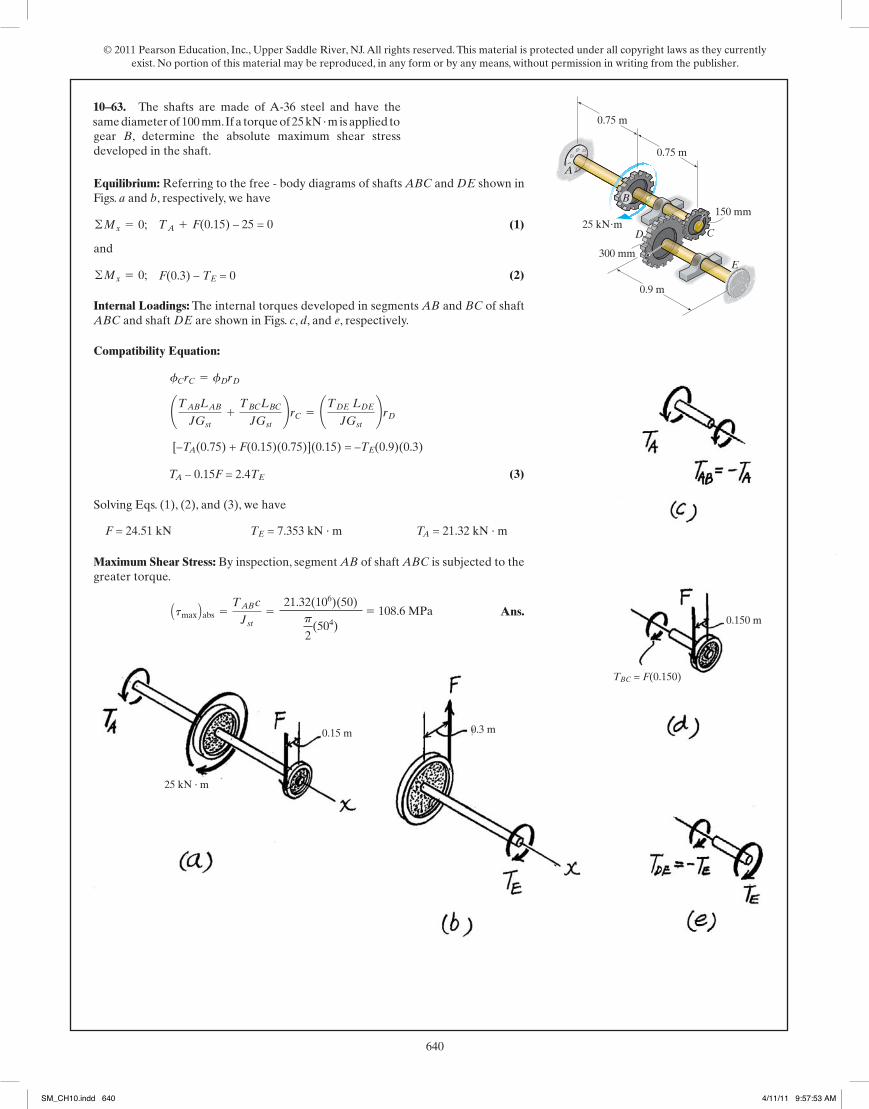
© 2011 Pearson Education, Inc., Upper Saddle River, NJ. All rights reserved. This material is protected under all copyright laws as they currently exist. No portion of this material may be reproduced, in any form or by any means, without permission in writing from the publisher.
640
© 2010 Pearson Education, Inc., Upper Saddle River, NJ. All rights reserved. This material is protected under all copyright laws as they currentlyexist. No portion of this material may be reproduced, in any form or by any means, without permission in writing from the publisher.
Equilibrium: Referring to the free - body diagrams of shafts ABC and DE shown inFigs. a and b, respectively, we have
(1)
and
(2)
Internal Loadings: The internal torques developed in segments AB and BC of shaftABC and shaft DE are shown in Figs. c, d, and e, respectively.
Compatibility Equation:
(3)
Solving Eqs. (1), (2), and (3), we have
Maximum Shear Stress: By inspection, segment AB of shaft ABC is subjected to thegreater torque.
Ans.Atmax Babs =TAB c
Jst=
12.79(12)(2)
p
2a24b
= 12.2 ksi
F = 4.412 kip TE = 4.412 kip # ft TA = 12.79 kip # ft
TA - 0.5F = 2.4TE
C -TA(2.5) + F(0.5)(2.5) D(0.5) = -TE(3)(1)
¢TABLABJGst
+TBCLBCJGst
≤rC = ¢TDE LDEJGst
≤rDfCrC = fDrD
©Mx = 0; F(1) - TE = 0
©Mx = 0; TA + F(0.5) - 15 = 0
*5–88. The shafts are made of A-36 steel and have thesame diameter of 4 in. If a torque of 15 kip ft is applied togear B, determine the absolute maximum shear stressdeveloped in the shaft.
#
2.5 ft
15 kip�ft
3 ft
12 in.
6 in.
2.5 ft
A
D
B
C
E
05 Solutions 46060 5/28/10 1:01 PM Page 279
same diameter of 100 mm. If a torque of 25 kN · m is applied to
F(0.15) – 25 = 0
F(0.3) – TE = 0
[–TA(0.75) + F(0.15)(0.75)](0.15) = –TE(0.9)(0.3)
TA – 0.15F = 2.4TE
TA = 21.32 kN · mTE = 7.353 kN · mF = 24.51 kN
21.32(106)(50)p
2(504)
5 108.6 MPa
0.75 m
25 kNm
0.9 m
300 mm
150 mm
0.75 m
A
D
B
C
E
25 kN · m
0.15 m 0.3 m
0.150 m
TBC = F(0.150)
10–63.
280
© 2010 Pearson Education, Inc., Upper Saddle River, NJ. All rights reserved. This material is protected under all copyright laws as they currentlyexist. No portion of this material may be reproduced, in any form or by any means, without permission in writing from the publisher.
Equilibrium: Referring to the free - body diagrams of shafts ABC and DE shown inFigs. a and b, respectively,
(1)
and
(2)
Internal Loadings: The internal torques developed in segments AB and BC of shaftABC and shaft DE are shown in Figs. c, d, and e, respectively.
Compatibility Equation: It is required that
(3)
Solving Eqs. (1), (2), and (3),
Angle of Twist: Here,
Ans. = -0.01666 rad = 0.955°
fB =TAB LABJGst
=-12.79(12)(2.5)(12)
p
2 a24b(11.0)(103)
TAB = -TA = -12.79 kip # ft
F = 4.412 kip TE = 4.412 kip # ft TA = 12.79 kip # ft
TA - 0.5F = 2.4TE
C -TA(2.5) + F(0.5)(2.5) D(0.5) = -TE(3)(1)
¢TAB LABJGst
+TBC LBCJGst
≤rC = ¢TDE LDEJGst
≤rDfCrC = fDrD
©Mx = 0; F(1) - TE = 0
©Mx = 0; TA + F(0.5) - 15 = 0
•5–89. The shafts are made of A-36 steel and have thesame diameter of 4 in. If a torque of 15 kip ft is applied togear B, determine the angle of twist of gear B.
#
2.5 ft
15 kip�ft
3 ft
12 in.
6 in.
2.5 ft
A
D
B
C
E
05 Solutions 46060 5/28/10 1:01 PM Page 280
SM_CH10.indd 640 4/11/11 9:57:53 AM
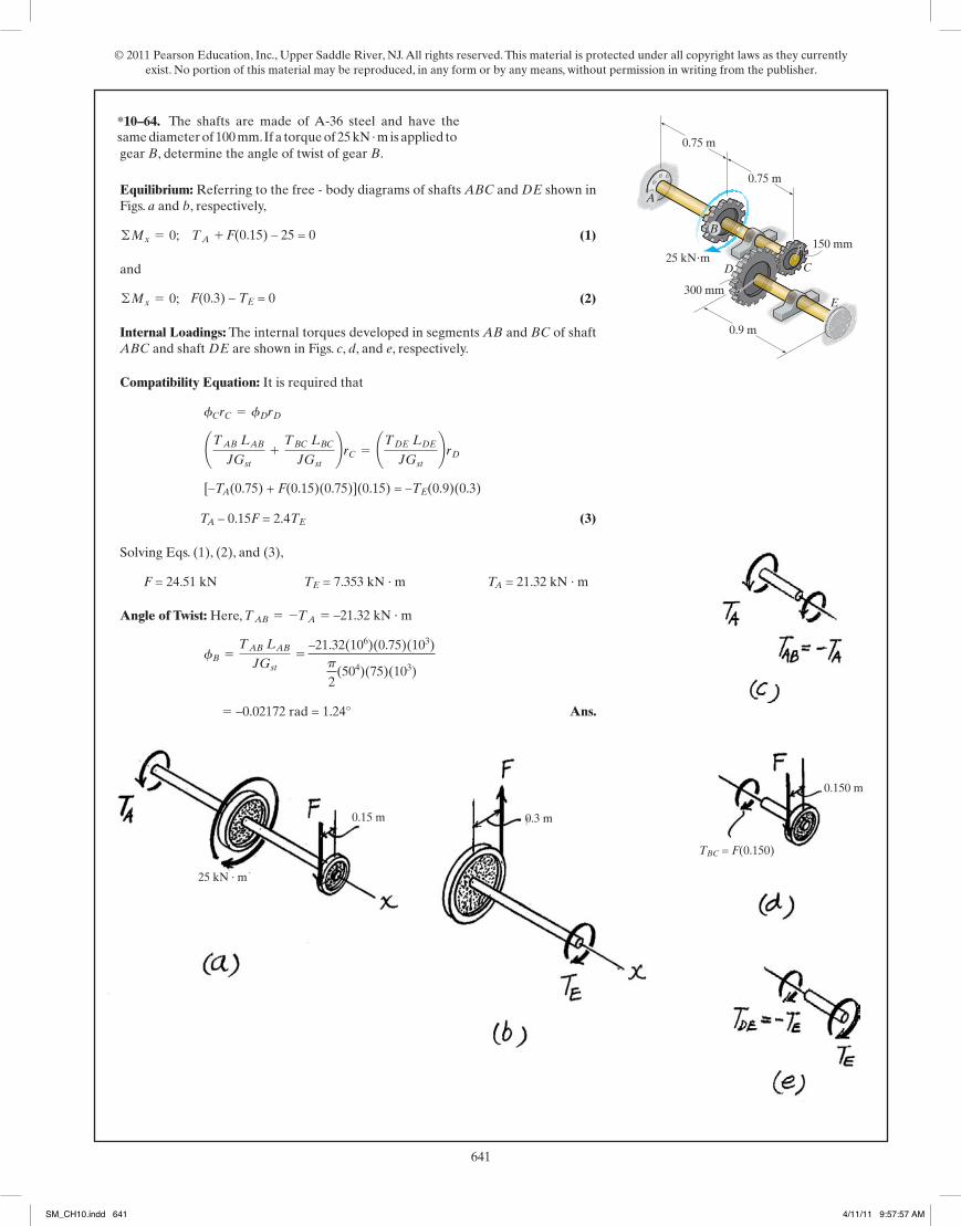
© 2011 Pearson Education, Inc., Upper Saddle River, NJ. All rights reserved. This material is protected under all copyright laws as they currently exist. No portion of this material may be reproduced, in any form or by any means, without permission in writing from the publisher.
641
© 2010 Pearson Education, Inc., Upper Saddle River, NJ. All rights reserved. This material is protected under all copyright laws as they currentlyexist. No portion of this material may be reproduced, in any form or by any means, without permission in writing from the publisher.
Equilibrium: Referring to the free - body diagrams of shafts ABC and DE shown inFigs. a and b, respectively, we have
(1)
and
(2)
Internal Loadings: The internal torques developed in segments AB and BC of shaftABC and shaft DE are shown in Figs. c, d, and e, respectively.
Compatibility Equation:
(3)
Solving Eqs. (1), (2), and (3), we have
Maximum Shear Stress: By inspection, segment AB of shaft ABC is subjected to thegreater torque.
Ans.Atmax Babs =TAB c
Jst=
12.79(12)(2)
p
2a24b
= 12.2 ksi
F = 4.412 kip TE = 4.412 kip # ft TA = 12.79 kip # ft
TA - 0.5F = 2.4TE
C -TA(2.5) + F(0.5)(2.5) D(0.5) = -TE(3)(1)
¢TABLABJGst
+TBCLBCJGst
≤rC = ¢TDE LDEJGst
≤rDfCrC = fDrD
©Mx = 0; F(1) - TE = 0
©Mx = 0; TA + F(0.5) - 15 = 0
*5–88. The shafts are made of A-36 steel and have thesame diameter of 4 in. If a torque of 15 kip ft is applied togear B, determine the absolute maximum shear stressdeveloped in the shaft.
#
2.5 ft
15 kip�ft
3 ft
12 in.
6 in.
2.5 ft
A
D
B
C
E
05 Solutions 46060 5/28/10 1:01 PM Page 279
280
© 2010 Pearson Education, Inc., Upper Saddle River, NJ. All rights reserved. This material is protected under all copyright laws as they currentlyexist. No portion of this material may be reproduced, in any form or by any means, without permission in writing from the publisher.
Equilibrium: Referring to the free - body diagrams of shafts ABC and DE shown inFigs. a and b, respectively,
(1)
and
(2)
Internal Loadings: The internal torques developed in segments AB and BC of shaftABC and shaft DE are shown in Figs. c, d, and e, respectively.
Compatibility Equation: It is required that
(3)
Solving Eqs. (1), (2), and (3),
Angle of Twist: Here,
Ans. = -0.01666 rad = 0.955°
fB =TAB LABJGst
=-12.79(12)(2.5)(12)
p
2 a24b(11.0)(103)
TAB = -TA = -12.79 kip # ft
F = 4.412 kip TE = 4.412 kip # ft TA = 12.79 kip # ft
TA - 0.5F = 2.4TE
C -TA(2.5) + F(0.5)(2.5) D(0.5) = -TE(3)(1)
¢TAB LABJGst
+TBC LBCJGst
≤rC = ¢TDE LDEJGst
≤rDfCrC = fDrD
©Mx = 0; F(1) - TE = 0
©Mx = 0; TA + F(0.5) - 15 = 0
•5–89. The shafts are made of A-36 steel and have thesame diameter of 4 in. If a torque of 15 kip ft is applied togear B, determine the angle of twist of gear B.
#
2.5 ft
15 kip�ft
3 ft
12 in.
6 in.
2.5 ft
A
D
B
C
E
05 Solutions 46060 5/28/10 1:01 PM Page 280
0.75 m
25 kNm
0.9 m
300 mm
150 mm
0.75 m
A
D
B
C
E
0.150 m
TBC = F(0.150)
0.3 m
same diameter of 100 mm. If a torque of 25 kN · m is applied to
F(0.15) – 25 = 0
F(0.3) – TE = 0
[–TA(0.75) + F(0.15)(0.75)](0.15) = –TE(0.9)(0.3)
TA – 0.15F = 2.4TE
F = 24.51 kN TE = 7.353 kN · m TA = 21.32 kN · m
–21.32(106)(0.75)(103)p
2(504)(75)(103)
5 –0.02172 rad = 1.24°
–21.32 kN · m
0.15 m
25 kN · m
*10–64.
SM_CH10.indd 641 4/11/11 9:57:57 AM

© 2011 Pearson Education, Inc., Upper Saddle River, NJ. All rights reserved. This material is protected under all copyright laws as they currently exist. No portion of this material may be reproduced, in any form or by any means, without permission in writing from the publisher.
642281
© 2010 Pearson Education, Inc., Upper Saddle River, NJ. All rights reserved. This material is protected under all copyright laws as they currentlyexist. No portion of this material may be reproduced, in any form or by any means, without permission in writing from the publisher.
(1)
(2)
From Eqs. (1) and (2)
(3)
(4)
Solving Eqs. (3) and (4) yields:
Ans.
Ans.(tAC)max =TA c
J=
120(12)(0.75)p2(0.754)
= 2.17 ksi
(tBD)max =TB c
J=
240(12)(0.75)p2(0.754)
= 4.35 ksi
TB = 240 lb # ft; TA = 120 lb # ft
TAL
JG= 0.5aTBL
JGb ; TA = 0.5TB
4(fE) = 2(fF); fE = 0.5fF
TA + 2TB - 600 = 0
TB - Fa 212b = 0
TA + Fa 412b - 600 = 0
5–90. The two 3-ft-long shafts are made of 2014-T6aluminum. Each has a diameter of 1.5 in. and they areconnected using the gears fixed to their ends. Their otherends are attached to fixed supports at A and B. They arealso supported by bearings at C and D, which allow freerotation of the shafts along their axes. If a torque ofis applied to the top gear as shown, determine the maximumshear stress in each shaft.
600 lb # ft600 lb�ft
3 ft
A
B
C
DE
F
4 in.
2 in.
05 Solutions 46060 5/28/10 1:01 PM Page 281
10–65. The two 1-m-long shafts are made of 2014-T6 aluminum. Each has a diameter of 30 mm and they are
rotation of the shafts along their axes. If a torque of 900 N · m
F a 801000
b – 900 = 0
F a 401000
b = 0
900
80(fE) = 40(fF);
TB = 360 N · m; TA = 180 N · m
360(103)(15)p2(154)
5 67.91 MPa
180(103)(15)p2(154)
5 33.95 MPa
900 Nm
1 m
A
B
C
DE
F
80 mm
40 mm
900 N · m
80 mm
40 mm
282
© 2010 Pearson Education, Inc., Upper Saddle River, NJ. All rights reserved. This material is protected under all copyright laws as they currentlyexist. No portion of this material may be reproduced, in any form or by any means, without permission in writing from the publisher.
Equilibrium:
(1)
Compatibility condition:
(2)
Solving Eqs. (1) and (2) yields:
Ans.t absmax
= 5.50 ksi
(tmax)AC =TA c
J=
120.0(0.25)p2(0.254)
= 4.89 ksi
(tmax)BC =TB c
J=
1080(0.5)p2(0.54)
= 5.50 ksi
TA = 120.0 lb # in. ; TB = 1080 lb # in.
18.52TB - 74.08TA = 11112
18.52(10-6)TB - 74.08(10-6)TA = 0.011112
18.52(10-6)TB - 0.011112 =TA(5)
p2(0.254)(11.0)(106)
= 18.52(10-6)TB - 0.011112
fC>B = L T(x) dx
JG= L
20
0
(TB - 60x) dxp2(0.54)(11.0)(106)
fC>B = fC>A
TA + TB - 60(20) = 0
5–91. The A-36 steel shaft is made from two segments: AChas a diameter of 0.5 in. and CB has a diameter of 1 in. If the shaft is fixed at its ends A and B and subjected to a uniformdistributed torque of along segment CB,determine the absolute maximum shear stress in the shaft.
60 lb # in.>in.5 in.
20 in.1 in.
0.5 in.A
B
C
60 lb�in./ in.
05 Solutions 46060 5/28/10 1:01 PM Page 282
SM_CH10.indd 642 4/11/11 9:57:59 AM

© 2011 Pearson Education, Inc., Upper Saddle River, NJ. All rights reserved. This material is protected under all copyright laws as they currently exist. No portion of this material may be reproduced, in any form or by any means, without permission in writing from the publisher.
643281
© 2010 Pearson Education, Inc., Upper Saddle River, NJ. All rights reserved. This material is protected under all copyright laws as they currentlyexist. No portion of this material may be reproduced, in any form or by any means, without permission in writing from the publisher.
(1)
(2)
From Eqs. (1) and (2)
(3)
(4)
Solving Eqs. (3) and (4) yields:
Ans.
Ans.(tAC)max =TA c
J=
120(12)(0.75)p2(0.754)
= 2.17 ksi
(tBD)max =TB c
J=
240(12)(0.75)p2(0.754)
= 4.35 ksi
TB = 240 lb # ft; TA = 120 lb # ft
TAL
JG= 0.5aTBL
JGb ; TA = 0.5TB
4(fE) = 2(fF); fE = 0.5fF
TA + 2TB - 600 = 0
TB - Fa 212b = 0
TA + Fa 412b - 600 = 0
5–90. The two 3-ft-long shafts are made of 2014-T6aluminum. Each has a diameter of 1.5 in. and they areconnected using the gears fixed to their ends. Their otherends are attached to fixed supports at A and B. They arealso supported by bearings at C and D, which allow freerotation of the shafts along their axes. If a torque ofis applied to the top gear as shown, determine the maximumshear stress in each shaft.
600 lb # ft600 lb�ft
3 ft
A
B
C
DE
F
4 in.
2 in.
05 Solutions 46060 5/28/10 1:01 PM Page 281
282
© 2010 Pearson Education, Inc., Upper Saddle River, NJ. All rights reserved. This material is protected under all copyright laws as they currentlyexist. No portion of this material may be reproduced, in any form or by any means, without permission in writing from the publisher.
Equilibrium:
(1)
Compatibility condition:
(2)
Solving Eqs. (1) and (2) yields:
Ans.t absmax
= 5.50 ksi
(tmax)AC =TA c
J=
120.0(0.25)p2(0.254)
= 4.89 ksi
(tmax)BC =TB c
J=
1080(0.5)p2(0.54)
= 5.50 ksi
TA = 120.0 lb # in. ; TB = 1080 lb # in.
18.52TB - 74.08TA = 11112
18.52(10-6)TB - 74.08(10-6)TA = 0.011112
18.52(10-6)TB - 0.011112 =TA(5)
p2(0.254)(11.0)(106)
= 18.52(10-6)TB - 0.011112
fC>B = L T(x) dx
JG= L
20
0
(TB - 60x) dxp2(0.54)(11.0)(106)
fC>B = fC>A
TA + TB - 60(20) = 0
5–91. The A-36 steel shaft is made from two segments: AChas a diameter of 0.5 in. and CB has a diameter of 1 in. If the shaft is fixed at its ends A and B and subjected to a uniformdistributed torque of along segment CB,determine the absolute maximum shear stress in the shaft.
60 lb # in.>in.5 in.
20 in.1 in.
0.5 in.A
B
C
60 lb�in./ in.
05 Solutions 46060 5/28/10 1:01 PM Page 282
has a diameter of 10 mm and CB has a diameter of 20 mm. If
distributed torque of 300 N · m/m along segment CB,
300 a 4001000
b = 0
400 mm
0 aTB –
300x
1000b(103) dx
p2(104)(75)(103)
339.531(10–6)TB – 20.3718(10–3)
339.531(10–6)TB – 20.3718(10–3) 5 TA(100)(103)p2(54)(75)(103)
339.531(10–6)TB – 1358.122(10–6)TA = 20.3718(10–3)
3.39531TB – 13.58122TA = 203.718
Solving Eqs. (1) and (2) yields:
TA = 12 N · m; TB = 108 N · m
108(103)(10)p2(104)
5 68.75 MPa
12(103)(5)p2(54)
5 61.12 MPa
68.75 MPa
100 mm
400 mm20 mm
10 mmA
B
C
300 Nm/m
300 a 4001000b = 120 N · m
T(A) = TB = 300x1000 300x
1000
x mm
10–66.
SM_CH10.indd 643 4/11/11 9:58:01 AM
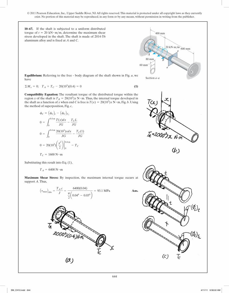
© 2011 Pearson Education, Inc., Upper Saddle River, NJ. All rights reserved. This material is protected under all copyright laws as they currently exist. No portion of this material may be reproduced, in any form or by any means, without permission in writing from the publisher.
644283
© 2010 Pearson Education, Inc., Upper Saddle River, NJ. All rights reserved. This material is protected under all copyright laws as they currentlyexist. No portion of this material may be reproduced, in any form or by any means, without permission in writing from the publisher.
*5–92. If the shaft is subjected to a uniform distributedtorque of , determine the maximum shearstress developed in the shaft. The shaft is made of 2014-T6aluminum alloy and is fixed at A and C.
t = 20 kN # m>m
A
B
Section a–a
80 mm
60 mma
a600 mm
400 mm
C
20 kN�m/m
Equilibrium: Referring to the free - body diagram of the shaft shown in Fig. a, wehave
(1)
Compatibility Equation: The resultant torque of the distributed torque within theregion x of the shaft is . Thus, the internal torque developed inthe shaft as a function of x when end C is free is , Fig. b. Usingthe method of superposition, Fig. c,
Substituting this result into Eq. (1),
Maximum Shear Stress: By inspection, the maximum internal torque occurs atsupport A. Thus,
Ans.Atmax Babs =TA c
J=
6400(0.04)
p
2a0.044 - 0.034b
= 93.1 MPa
TA = 6400 N # m
TC = 1600 N # m
0 = 20(103)¢x2
2≤ 2 0.4 m
0- TC
0 = L0.4 m
0 20(103)xdx
JG-TC(1)
JG
0 = L0.4 m
0 T(x)dx
JG-TCL
JG
fC = AfC B t - AfC BTCT(x) = 20(103)x N # m
TR = 20(103)x N # m
©Mx = 0; TA + TC - 20(103)(0.4) = 0
05 Solutions 46060 5/28/10 1:01 PM Page 283
10–67.
284
© 2010 Pearson Education, Inc., Upper Saddle River, NJ. All rights reserved. This material is protected under all copyright laws as they currentlyexist. No portion of this material may be reproduced, in any form or by any means, without permission in writing from the publisher.
Equilibrium:
[1]
Section Properties:
Angle of Twist:
Compatibility:
Ans.
Substituting the result into Eq. [1] yields:
Ans.TA =152189
T
TB =37189
T
0 =37TL
324pc4G-
7TBL
12pc4G
0 = fT - fB
=7TB L
12pc4G
= -2TBL
4
3pc4G c 1
(L + x)3 d 2 L0
=2TBL
4
pc4G L
L
0 dx
(L + x)4
fB = LTdx
J(x)G= L
L
0
TBdxpc4
2L4 (L + x)4G
=37TL
324 pc4 G
= -2TL4
3pc4 G c 1
(L + x)3 d 2 L p2
=2TL4
pc4 G L
L
p2
dx
(L + x)4
fT = L Tdx
J(x)G= L
L
p2
Tdxpc4
2L 4 (L + x)4 G
J(x) =p
2c cL
(L + x) d4 =pc4
2L4 (L + x)4
r(x) = c +c
Lx =
c
L (L + x)
TA + TB - T = 0
•5–93. The tapered shaft is confined by the fixed supportsat A and B. If a torque T is applied at its mid-point,determine the reactions at the supports.
L/2
T
c
A2c
B
L/2
05 Solutions 46060 5/28/10 1:01 PM Page 284
SM_CH10.indd 644 4/11/11 9:58:02 AM

© 2011 Pearson Education, Inc., Upper Saddle River, NJ. All rights reserved. This material is protected under all copyright laws as they currently exist. No portion of this material may be reproduced, in any form or by any means, without permission in writing from the publisher.
645283
© 2010 Pearson Education, Inc., Upper Saddle River, NJ. All rights reserved. This material is protected under all copyright laws as they currentlyexist. No portion of this material may be reproduced, in any form or by any means, without permission in writing from the publisher.
*5–92. If the shaft is subjected to a uniform distributedtorque of , determine the maximum shearstress developed in the shaft. The shaft is made of 2014-T6aluminum alloy and is fixed at A and C.
t = 20 kN # m>m
A
B
Section a–a
80 mm
60 mma
a600 mm
400 mm
C
20 kN�m/m
Equilibrium: Referring to the free - body diagram of the shaft shown in Fig. a, wehave
(1)
Compatibility Equation: The resultant torque of the distributed torque within theregion x of the shaft is . Thus, the internal torque developed inthe shaft as a function of x when end C is free is , Fig. b. Usingthe method of superposition, Fig. c,
Substituting this result into Eq. (1),
Maximum Shear Stress: By inspection, the maximum internal torque occurs atsupport A. Thus,
Ans.Atmax Babs =TA c
J=
6400(0.04)
p
2a0.044 - 0.034b
= 93.1 MPa
TA = 6400 N # m
TC = 1600 N # m
0 = 20(103)¢x2
2≤ 2 0.4 m
0- TC
0 = L0.4 m
0 20(103)xdx
JG-TC(1)
JG
0 = L0.4 m
0 T(x)dx
JG-TCL
JG
fC = AfC B t - AfC BTCT(x) = 20(103)x N # m
TR = 20(103)x N # m
©Mx = 0; TA + TC - 20(103)(0.4) = 0
05 Solutions 46060 5/28/10 1:01 PM Page 283
284
© 2010 Pearson Education, Inc., Upper Saddle River, NJ. All rights reserved. This material is protected under all copyright laws as they currentlyexist. No portion of this material may be reproduced, in any form or by any means, without permission in writing from the publisher.
Equilibrium:
[1]
Section Properties:
Angle of Twist:
Compatibility:
Ans.
Substituting the result into Eq. [1] yields:
Ans.TA =152189
T
TB =37
189 T
0 =37TL
324pc4G-
7TBL
12pc4G
0 = fT - fB
=7TB L
12pc4G
= -2TBL
4
3pc4G c 1
(L + x)3 d 2 L0
=2TBL
4
pc4G L
L
0 dx
(L + x)4
fB = LTdx
J(x)G= L
L
0
TBdxpc4
2L4 (L + x)4G
=37TL
324 pc4 G
= -2TL4
3pc4 G c 1
(L + x)3 d 2 L p2
=2TL4
pc4 G L
L
p2
dx
(L + x)4
fT = L Tdx
J(x)G= L
L
p2
Tdxpc4
2L 4 (L + x)4 G
J(x) =p
2c cL
(L + x) d4 =pc4
2L4 (L + x)4
r(x) = c +c
Lx =
c
L (L + x)
TA + TB - T = 0
•5–93. The tapered shaft is confined by the fixed supportsat A and B. If a torque T is applied at its mid-point,determine the reactions at the supports.
L/2
T
c
A2c
B
L/2
05 Solutions 46060 5/28/10 1:01 PM Page 284
*10–68.
SM_CH10.indd 645 4/11/11 9:58:04 AM

© 2011 Pearson Education, Inc., Upper Saddle River, NJ. All rights reserved. This material is protected under all copyright laws as they currently exist. No portion of this material may be reproduced, in any form or by any means, without permission in writing from the publisher.
646285
© 2010 Pearson Education, Inc., Upper Saddle River, NJ. All rights reserved. This material is protected under all copyright laws as they currentlyexist. No portion of this material may be reproduced, in any form or by any means, without permission in writing from the publisher.
(1)
By superposition:
Ans.
From Eq. (1),
Ans. TA =3t0 L
4
TA +7t0 L
12-
4t0 L
3= 0
TA = t0 aL +L3
3L2 b =4t0 L
3
TB =7t0 L
12
0 = LL
0 t0ax + x
3
3L2b dx
JG-TB(L)
JG=
7t0L2
12- TB(L)
0 = fB - fB
T(x) = Lx
0t0 a1 +
x2
L2 b dx = t0 ax +x2
3L2 b
5–94. The shaft of radius c is subjected to a distributedtorque t, measured as of shaft. Determine thereactions at the fixed supports A and B.
torque>lengthB
x
L A
)t0
2t0
)((t � t0 1 � 2xL
05 Solutions 46060 5/28/10 1:01 PM Page 285
10–69.
286
© 2010 Pearson Education, Inc., Upper Saddle River, NJ. All rights reserved. This material is protected under all copyright laws as they currentlyexist. No portion of this material may be reproduced, in any form or by any means, without permission in writing from the publisher.
Maximum Shear Stress:
For circular shaft
Ans.
For rectangular shaft
Ans.
Angle of Twist:
For circular shaft
Ans.
For rectangular shaft
Ans.
The rectangular shaft has a greater maximum shear stress and angle of twist.
= 0.001147 rad = 0.0657°
fr =7.10 TLa4 G
=7.10(4000)(36)
34(11.0)(106)
= 0.001015 rad = 0.0582°
fc =TL
JG=
4000(36)p2 A 9p B2 11.0(106)
(tr)max =4.81Ta3 =
4.81(4000)
33 = 713 psi
A = a2 = 9 ; a = 3 in.
(tc)max =Tc
J=Tcp2 c4
=2Tp c3 =
2(4000)
p A9x B 12 = 525 psi
A = pc2 = 9; c = a 9pb
12
5–95. Compare the values of the maximum elastic shearstress and the angle of twist developed in 304 stainless steelshafts having circular and square cross sections. Each shafthas the same cross-sectional area of length of 36 in.,and is subjected to a torque of 4000 lb # in.
9 in2,
A
r
a
a A
05 Solutions 46060 5/28/10 1:01 PM Page 286
SM_CH10.indd 646 4/11/11 9:58:05 AM

© 2011 Pearson Education, Inc., Upper Saddle River, NJ. All rights reserved. This material is protected under all copyright laws as they currently exist. No portion of this material may be reproduced, in any form or by any means, without permission in writing from the publisher.
647286
© 2010 Pearson Education, Inc., Upper Saddle River, NJ. All rights reserved. This material is protected under all copyright laws as they currentlyexist. No portion of this material may be reproduced, in any form or by any means, without permission in writing from the publisher.
Maximum Shear Stress:
For circular shaft
Ans.
For rectangular shaft
Ans.
Angle of Twist:
For circular shaft
Ans.
For rectangular shaft
Ans.
The rectangular shaft has a greater maximum shear stress and angle of twist.
= 0.001147 rad = 0.0657°
fr =7.10 TLa4 G
=7.10(4000)(36)
34(11.0)(106)
= 0.001015 rad = 0.0582°
fc =TL
JG=
4000(36)p2 A 9p B2 11.0(106)
(tr)max =4.81Ta3 =
4.81(4000)
33 = 713 psi
A = a2 = 9 ; a = 3 in.
(tc)max =Tc
J=Tcp2 c4
=2Tp c3 =
2(4000)
p A9x B 12 = 525 psi
A = pc2 = 9; c = a 9pb
12
5–95. Compare the values of the maximum elastic shearstress and the angle of twist developed in 304 stainless steelshafts having circular and square cross sections. Each shafthas the same cross-sectional area of length of 36 in.,and is subjected to a torque of 4000 lb # in.
9 in2,
A
r
a
a A
05 Solutions 46060 5/28/10 1:01 PM Page 286
has the same cross-sectional area of 5600 mm2, length of 900 mm and is subjected to a torque of 500 N · m.
5600; c = a5600pb
12
2(500)(103)
p a5600pb
32
5 4.23 MPa
5600; a = 74.833 mm
4.81(500)(103)74.8333 5 5.74 MPa
5 500(103)(900)p2(5600
2 )2(75)(103)
5 0.00120214 rad = 0.0689°
5 7.10(500)(103)(900)
74.8334(75)(103)
5 0.00135843 rad = 0.0778°
10–70.
SM_CH10.indd 647 4/11/11 9:58:05 AM
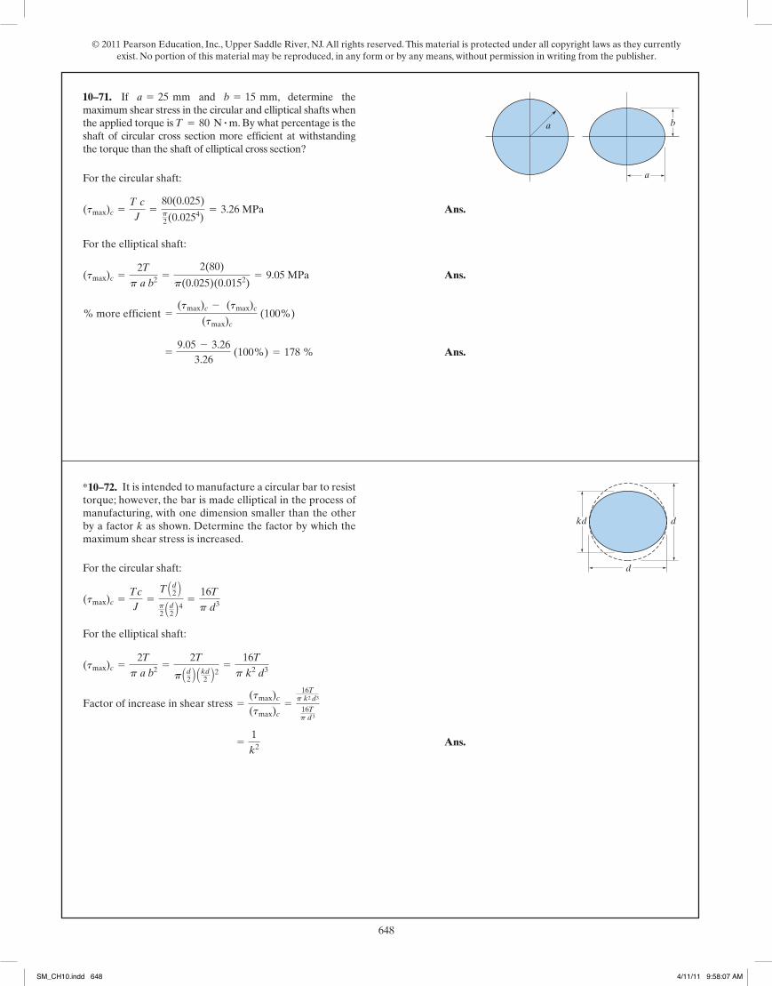
© 2011 Pearson Education, Inc., Upper Saddle River, NJ. All rights reserved. This material is protected under all copyright laws as they currently exist. No portion of this material may be reproduced, in any form or by any means, without permission in writing from the publisher.
648287
© 2010 Pearson Education, Inc., Upper Saddle River, NJ. All rights reserved. This material is protected under all copyright laws as they currentlyexist. No portion of this material may be reproduced, in any form or by any means, without permission in writing from the publisher.
For the circular shaft:
Ans.
For the elliptical shaft:
Ans.
Ans. =9.05 - 3.26
3.26 (100%) = 178 %
% more efficient =(tmax)c - (tmax)c
(tmax)c (100%)
(tmax)c =2Tp a b2 =
2(80)
p(0.025)(0.0152)= 9.05 MPa
(tmax)c =T cJ
=80(0.025)p2(0.0254)
= 3.26 MPa
*5–96. If and , determine themaximum shear stress in the circular and elliptical shafts whenthe applied torque is . By what percentage is theshaft of circular cross section more efficient at withstandingthe torque than the shaft of elliptical cross section?
T = 80 N # mb = 15 mma = 25 mm
a
a b
For the circular shaft:
For the elliptical shaft:
Ans. =1k2
Factor of increase in shear stress =(tmax)c(tmax)c
=16Tp k2
d3
16Tp d3
(tmax)c =2Tp a b2 =
2T
p Ad2 B Akd2 B2 =16Tp k2 d3
(tmax)c =Tc
J=T Ad2 Bp2 Ad2 B4 =
16Tp d3
•5–97. It is intended to manufacture a circular bar to resisttorque; however, the bar is made elliptical in the process ofmanufacturing, with one dimension smaller than the otherby a factor k as shown. Determine the factor by which themaximum shear stress is increased.
kd d
d
05 Solutions 46060 5/28/10 1:01 PM Page 287
10–71.
*10–72.
288
© 2010 Pearson Education, Inc., Upper Saddle River, NJ. All rights reserved. This material is protected under all copyright laws as they currentlyexist. No portion of this material may be reproduced, in any form or by any means, without permission in writing from the publisher.
Maximum Shear Stress:
Ans.
Ans.
Angle of Twist:
Ans. = -0.003618 rad = 0.207°
=(0.052 + 0.022)
p(0.053)(0.023)(37.0)(109) [(-30.0)(1.5) + (-50.0)(2)]
fB>A = a (a2 + b2)T L
p a3b3 G
= 1.59 MPa
(tAC)max =2TACp a b2 =
2(50.0)
p(0.05)(0.022)
= 0.955 MPa
(tBC)max =2TBCp a b2 =
2(30.0)
p(0.05)(0.022)
5–98. The shaft is made of red brass C83400 and has anelliptical cross section. If it is subjected to the torsionalloading shown, determine the maximum shear stress withinregions AC and BC, and the angle of twist of end Brelative to end A.
f
20 mm50 mm
2 m
1.5 m
20 N�m
B
30 N�m
50 N�m
A
C
5–99. Solve Prob. 5–98 for the maximum shear stresswithin regions AC and BC, and the angle of twist of end Brelative to C.
f
20 mm50 mm
2 m
1.5 m
20 N�m
B
30 N�m
50 N�m
A
CMaximum Shear Stress:
Ans.
Ans.
Angle of Twist:
Ans. = -0.001123 rad = | 0.0643°|
=(0.052 + 0.022)(-30.0)(1.5)
p(0.053)(0.023)(37.0)(109)
fB>C =(a2 + b2) TBC L
p a3 b3 G
= 1.59 MPa
(tAC)max =2TACp a b2 =
2(50.0)
p(0.05)(0.022)
= 0.955 MPa
(tBC)max =2TBCp a b2 =
2(30.0)
p(0.05)(0.022)
05 Solutions 46060 5/28/10 1:01 PM Page 288
SM_CH10.indd 648 4/11/11 9:58:07 AM
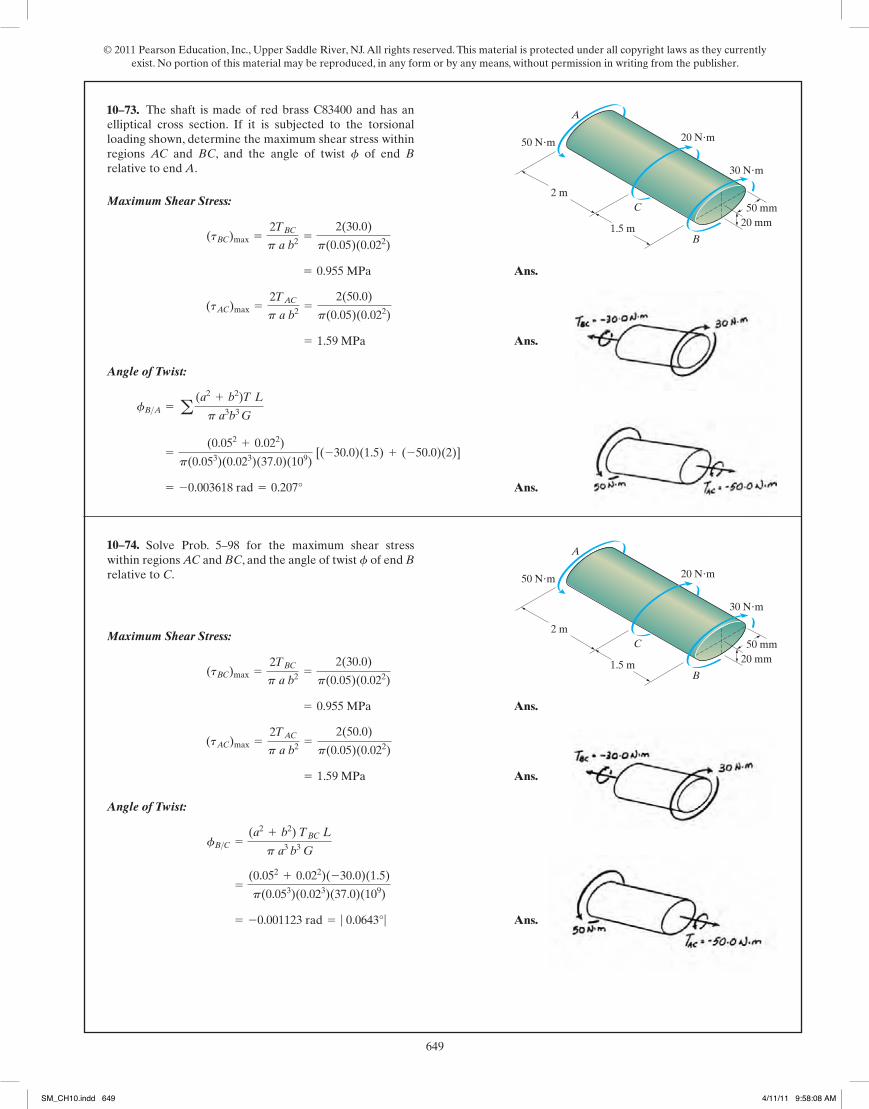
© 2011 Pearson Education, Inc., Upper Saddle River, NJ. All rights reserved. This material is protected under all copyright laws as they currently exist. No portion of this material may be reproduced, in any form or by any means, without permission in writing from the publisher.
649287
© 2010 Pearson Education, Inc., Upper Saddle River, NJ. All rights reserved. This material is protected under all copyright laws as they currentlyexist. No portion of this material may be reproduced, in any form or by any means, without permission in writing from the publisher.
For the circular shaft:
Ans.
For the elliptical shaft:
Ans.
Ans. =9.05 - 3.26
3.26 (100%) = 178 %
% more efficient =(tmax)c - (tmax)c
(tmax)c (100%)
(tmax)c =2Tp a b2 =
2(80)
p(0.025)(0.0152)= 9.05 MPa
(tmax)c =T cJ
=80(0.025)p2(0.0254)
= 3.26 MPa
*5–96. If and , determine themaximum shear stress in the circular and elliptical shafts whenthe applied torque is . By what percentage is theshaft of circular cross section more efficient at withstandingthe torque than the shaft of elliptical cross section?
T = 80 N # mb = 15 mma = 25 mm
a
a b
For the circular shaft:
For the elliptical shaft:
Ans. =1k2
Factor of increase in shear stress =(tmax)c(tmax)c
=16Tp k2
d3
16Tp d3
(tmax)c =2Tp a b2 =
2T
p Ad2 B Akd2 B2 =16Tp k2 d3
(tmax)c =Tc
J=T Ad2 Bp2 Ad2 B4 =
16Tp d3
•5–97. It is intended to manufacture a circular bar to resisttorque; however, the bar is made elliptical in the process ofmanufacturing, with one dimension smaller than the otherby a factor k as shown. Determine the factor by which themaximum shear stress is increased.
kd d
d
05 Solutions 46060 5/28/10 1:01 PM Page 287
288
© 2010 Pearson Education, Inc., Upper Saddle River, NJ. All rights reserved. This material is protected under all copyright laws as they currentlyexist. No portion of this material may be reproduced, in any form or by any means, without permission in writing from the publisher.
Maximum Shear Stress:
Ans.
Ans.
Angle of Twist:
Ans. = -0.003618 rad = 0.207°
=(0.052 + 0.022)
p(0.053)(0.023)(37.0)(109) [(-30.0)(1.5) + (-50.0)(2)]
fB>A = a (a2 + b2)T L
p a3b3 G
= 1.59 MPa
(tAC)max =2TACp a b2 =
2(50.0)
p(0.05)(0.022)
= 0.955 MPa
(tBC)max =2TBCp a b2 =
2(30.0)
p(0.05)(0.022)
5–98. The shaft is made of red brass C83400 and has anelliptical cross section. If it is subjected to the torsionalloading shown, determine the maximum shear stress withinregions AC and BC, and the angle of twist of end Brelative to end A.
f
20 mm50 mm
2 m
1.5 m
20 N�m
B
30 N�m
50 N�m
A
C
5–99. Solve Prob. 5–98 for the maximum shear stresswithin regions AC and BC, and the angle of twist of end Brelative to C.
f
20 mm50 mm
2 m
1.5 m
20 N�m
B
30 N�m
50 N�m
A
CMaximum Shear Stress:
Ans.
Ans.
Angle of Twist:
Ans. = -0.001123 rad = | 0.0643°|
=(0.052 + 0.022)(-30.0)(1.5)
p(0.053)(0.023)(37.0)(109)
fB>C =(a2 + b2) TBC L
p a3 b3 G
= 1.59 MPa
(tAC)max =2TACp a b2 =
2(50.0)
p(0.05)(0.022)
= 0.955 MPa
(tBC)max =2TBCp a b2 =
2(30.0)
p(0.05)(0.022)
05 Solutions 46060 5/28/10 1:01 PM Page 288
10–73.
10–74.
SM_CH10.indd 649 4/11/11 9:58:08 AM

© 2011 Pearson Education, Inc., Upper Saddle River, NJ. All rights reserved. This material is protected under all copyright laws as they currently exist. No portion of this material may be reproduced, in any form or by any means, without permission in writing from the publisher.
650289
© 2010 Pearson Education, Inc., Upper Saddle River, NJ. All rights reserved. This material is protected under all copyright laws as they currentlyexist. No portion of this material may be reproduced, in any form or by any means, without permission in writing from the publisher.
*5–100. Segments AB and BC of the shaft have circular andsquare cross sections, respectively. If end A is subjected to atorque of , determine the absolute maximumshear stress developed in the shaft and the angle of twist ofend A.The shaft is made from A-36 steel and is fixed at C.
T = 2 kN # m
B
C
A
600 mm
30 mm90 mm
90 mm
600 mm
TInternal Loadings: The internal torques developed in segments AB and BC areshown in Figs. a, and b, respectively.
Maximum Shear Stress: For segment AB,
Ans.
For segment BC,
Angle of Twist:
Ans. = 0.01431 rad = 0.820°
=2(103)(0.6)
p
2 a0.034b(75)(109)
+7.10(2)(103)(0.6)
(0.09)4(75)(109)
fA =TABLABJG
+7.10TBCLBCa4G
Atmax BBC =4.81TBCa3 =
4.81 C2(103) D(0.09)3 = 13.20 MPa
Atmax BAB =TAB c
J-
2(103)(0.03)
p
2 a0.034b
= 47.2 MPa (max)
05 Solutions 46060 5/28/10 1:01 PM Page 289
•10–75.
290
© 2010 Pearson Education, Inc., Upper Saddle River, NJ. All rights reserved. This material is protected under all copyright laws as they currentlyexist. No portion of this material may be reproduced, in any form or by any means, without permission in writing from the publisher.
•5–101. Segments AB and BC of the shaft have circular andsquare cross sections, respectively. The shaft is made fromA-36 steel with an allowable shear stress of ,and an angle of twist at end A which is not allowed to exceed0.02 rad. Determine the maximum allowable torque T thatcan be applied at end A.The shaft is fixed at C.
tallow = 75 MPa
B
C
A
600 mm
30 mm90 mm
90 mm
600 mm
T
Internal Loadings: The internal torques developed in segments AB and BC areshown in Figs. a, and b, respectively.
Allowable Shear Stress: For segment AB,
For segment BC,
Angle of Twist:
Ans.T = 2795.90 N # m = 2.80 kN # m (controls)
0.02 =T(0.6)
p
2 a0.034b(75)(109)
+7.10T(0.6)
(0.09)4 (75)(109)
fA =TABLABJG
+7.10TBC LBCa4G
T = 11 366.94 N # m
tallow =4.81TBCa3 ; 75(106) =
4.81T(0.09)3
T = 3180.86 N # m
tallow =TAB c
J; 75(106) =
T(0.03)
p
2 a0.034b
By superposition:
Ans.
Ans.
Ans.fC =7.10(32)(12)(3)(12)
(24)(3.8)(106)= 0.00161 rad = 0.0925°
TA = 48 lb # ftTA + 32 - 80 = 0
TB = 32 lb # ft
0 =7.10(80)(2)
a4 G-
7.10(TB)(5)
a4 G
0 = f - fB
5–102. The aluminum strut is fixed between the two wallsat A and B. If it has a 2 in. by 2 in. square cross section, andit is subjected to the torque of at C, determine thereactions at the fixed supports. Also, what is the angle oftwist at C? Gal = 3.811032 ksi.
80 lb # ft
2 ft
3 ft
80 lb�ft
A
C
B
05 Solutions 46060 5/28/10 1:01 PM Page 290
SM_CH10.indd 650 4/11/11 9:58:09 AM
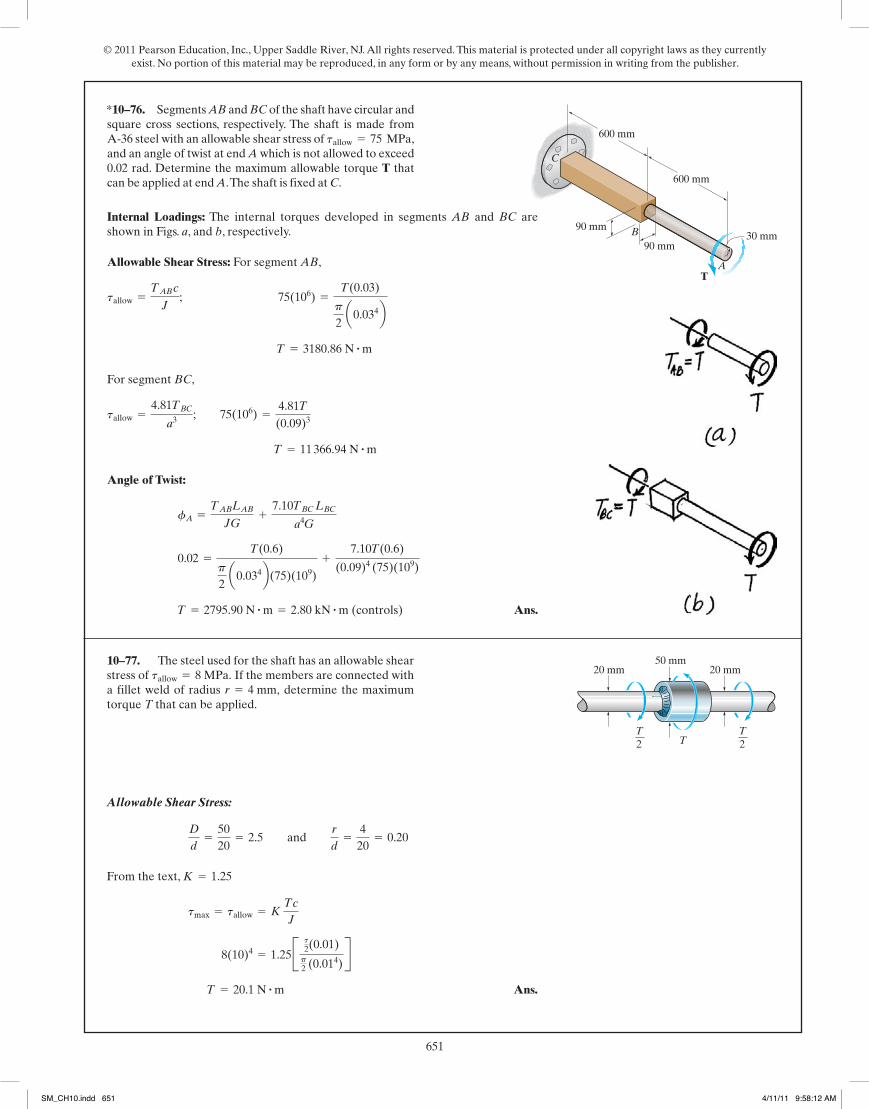
© 2011 Pearson Education, Inc., Upper Saddle River, NJ. All rights reserved. This material is protected under all copyright laws as they currently exist. No portion of this material may be reproduced, in any form or by any means, without permission in writing from the publisher.
651289
© 2010 Pearson Education, Inc., Upper Saddle River, NJ. All rights reserved. This material is protected under all copyright laws as they currentlyexist. No portion of this material may be reproduced, in any form or by any means, without permission in writing from the publisher.
*5–100. Segments AB and BC of the shaft have circular andsquare cross sections, respectively. If end A is subjected to atorque of , determine the absolute maximumshear stress developed in the shaft and the angle of twist ofend A.The shaft is made from A-36 steel and is fixed at C.
T = 2 kN # m
B
C
A
600 mm
30 mm90 mm
90 mm
600 mm
TInternal Loadings: The internal torques developed in segments AB and BC areshown in Figs. a, and b, respectively.
Maximum Shear Stress: For segment AB,
Ans.
For segment BC,
Angle of Twist:
Ans. = 0.01431 rad = 0.820°
=2(103)(0.6)
p
2 a0.034b(75)(109)
+7.10(2)(103)(0.6)
(0.09)4(75)(109)
fA =TABLABJG
+7.10TBCLBCa4G
Atmax BBC =4.81TBCa3 =
4.81 C2(103) D(0.09)3 = 13.20 MPa
Atmax BAB =TAB c
J-
2(103)(0.03)
p
2 a0.034b
= 47.2 MPa (max)
05 Solutions 46060 5/28/10 1:01 PM Page 289
290
© 2010 Pearson Education, Inc., Upper Saddle River, NJ. All rights reserved. This material is protected under all copyright laws as they currentlyexist. No portion of this material may be reproduced, in any form or by any means, without permission in writing from the publisher.
•5–101. Segments AB and BC of the shaft have circular andsquare cross sections, respectively. The shaft is made fromA-36 steel with an allowable shear stress of ,and an angle of twist at end A which is not allowed to exceed0.02 rad. Determine the maximum allowable torque T thatcan be applied at end A.The shaft is fixed at C.
tallow = 75 MPa
B
C
A
600 mm
30 mm90 mm
90 mm
600 mm
T
Internal Loadings: The internal torques developed in segments AB and BC areshown in Figs. a, and b, respectively.
Allowable Shear Stress: For segment AB,
For segment BC,
Angle of Twist:
Ans.T = 2795.90 N # m = 2.80 kN # m (controls)
0.02 =T(0.6)
p
2 a0.034b(75)(109)
+7.10T(0.6)
(0.09)4 (75)(109)
fA =TABLABJG
+7.10TBC LBCa4G
T = 11 366.94 N # m
tallow =4.81TBCa3 ; 75(106) =
4.81T(0.09)3
T = 3180.86 N # m
tallow =TAB c
J; 75(106) =
T(0.03)
p
2 a0.034b
By superposition:
Ans.
Ans.
Ans.fC =7.10(32)(12)(3)(12)
(24)(3.8)(106)= 0.00161 rad = 0.0925°
TA = 48 lb # ftTA + 32 - 80 = 0
TB = 32 lb # ft
0 =7.10(80)(2)
a4 G-
7.10(TB)(5)
a4 G
0 = f - fB
5–102. The aluminum strut is fixed between the two wallsat A and B. If it has a 2 in. by 2 in. square cross section, andit is subjected to the torque of at C, determine thereactions at the fixed supports. Also, what is the angle oftwist at C? Gal = 3.811032 ksi.
80 lb # ft
2 ft
3 ft
80 lb�ft
A
C
B
05 Solutions 46060 5/28/10 1:01 PM Page 290
*10–76.
301
© 2010 Pearson Education, Inc., Upper Saddle River, NJ. All rights reserved. This material is protected under all copyright laws as they currentlyexist. No portion of this material may be reproduced, in any form or by any means, without permission in writing from the publisher.
Ans.(tavg)A = (tavg)B =40
2(0.005)(0.0112)= 357 kPa
tavg =T
2 t Am
Am = 4(0.04)(0.06) + (0.04)2 = 0.0112 m2
5–119. The symmetric tube is made from a high-strengthsteel, having the mean dimensions shown and a thickness of5 mm. If it is subjected to a torque of determine the average shear stress developed at points Aand B. Indicate the shear stress on volume elements locatedat these points.
T = 40 N # m, 60 mm
20 mm30 mm
40 N�m
AB
Allowable Shear Stress:
From the text,
Ans. T = 20.1 N # m
8(10)4 = 1.25B t2(0.01)p2 (0.014)
R tmax = tallow = K
Tc
J
K = 1.25
D
d=
5020
= 2.5 and r
d=
420
= 0.20
*5–120. The steel used for the shaft has an allowable shearstress of If the members are connected witha fillet weld of radius determine the maximumtorque T that can be applied.
r = 4 mm,tallow = 8 MPa. 20 mm 20 mm
T
50 mm
T2
T2
05 Solutions 46060 5/28/10 1:01 PM Page 301
10–77.
SM_CH10.indd 651 4/11/11 9:58:12 AM

© 2011 Pearson Education, Inc., Upper Saddle River, NJ. All rights reserved. This material is protected under all copyright laws as they currently exist. No portion of this material may be reproduced, in any form or by any means, without permission in writing from the publisher.
652302
© 2010 Pearson Education, Inc., Upper Saddle River, NJ. All rights reserved. This material is protected under all copyright laws as they currentlyexist. No portion of this material may be reproduced, in any form or by any means, without permission in writing from the publisher.
From Fig. 5-32,
Check:
No, it is not possible. Ans.
D - d2
=75 - 60
2=
152
= 7.5 mm 6 7.98 mm
r
60= 0.133 ; r = 7.98 mm
r
d= 0.133
D
d=
7560
= 1.25
tmax = K Tc
J ; 12(106) = K c 397.89(0.03)
p2 (0.034)
d ; K = 1.28
T =P
v=
30(103)
24 p= 397.89 N # m
v = 720 revmin
a 2p rad1 rev
b 1 min60 s
= 24 p rad>s
•5–121. The built-up shaft is to be designed to rotateat 720 rpm while transmitting 30 kW of power. Is thispossible? The allowable shear stress is tallow = 12 MPa.
75 mm
60 mm
From Fig. 5-32,
Ans.P = Tv = 1794.33(18p) = 101466 W = 101 kW
v = 540 revmin
a 2p rad1 rev
b 1 min60 s
= 18 p rad>s
tmax = K Tc
J ; 55(106) = 1.30 c [ T(0.03)
p2 (0.034)
d ; T = 1794.33 N # m
K = 1.30
D
d=
7560
= 1.25; r
d=
7.260
= 0.12
5–122. The built-up shaft is designed to rotate at 540 rpm.If the radius of the fillet weld connecting the shaftsis and the allowable shear stress for thematerial is determine the maximum powerthe shaft can transmit.
tallow = 55 MPa,r = 7.20 mm,
75 mm
60 mm
05 Solutions 46060 5/28/10 1:01 PM Page 302
10–78.
10–79.
303
© 2010 Pearson Education, Inc., Upper Saddle River, NJ. All rights reserved. This material is protected under all copyright laws as they currentlyexist. No portion of this material may be reproduced, in any form or by any means, without permission in writing from the publisher.
For the fillet:
From Fig. 5-32,
Ans. = 50.6 MPa (max)
(tmax)f = K TABc
J= 1.325 c 60(0.01)
p2 (0.014)
d K = 1.325
D
d=
5020
= 2.5; r
d=
2.820
= 0.14
= 4.07 MPa
(tmax)CD =TCDc
J=
100(0.025)p2 (0.0254)
5–123. The steel shaft is made from two segments: AB andBC, which are connected using a fillet weld having a radiusof 2.8 mm. Determine the maximum shear stress developedin the shaft.
50 mm
20 mm 100 N�m
60 N�m
A
C
B
40 N�m
D
Allowable Shear Stress:
From the text,
Ans. T = 8.16 N # m
8(106) = 1.3C A r2 B (0.0075)p2 (0.00754)
S tmax = tallow = K
Tc
J
K = 1.30
D
d=
3015
= 2 and r
d=
2.2515
= 0.15
*5–124. The steel used for the shaft has an allowable shearstress of If the members are connectedtogether with a fillet weld of radius determinethe maximum torque T that can be applied.
r = 2.25 mm,tallow = 8 MPa.
30 mm 30 mm15 mm
TT2
T2
05 Solutions 46060 5/28/10 1:01 PM Page 303
SM_CH10.indd 652 4/11/11 9:58:13 AM
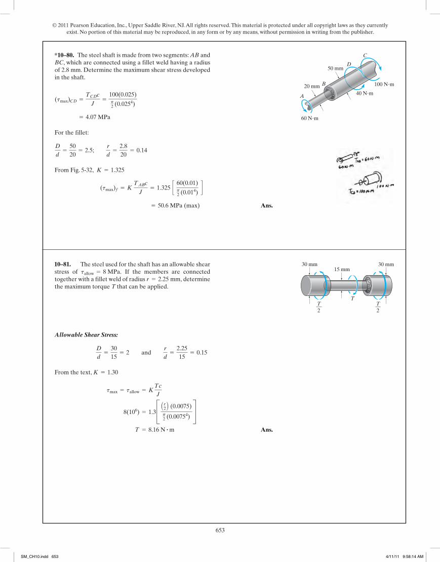
© 2011 Pearson Education, Inc., Upper Saddle River, NJ. All rights reserved. This material is protected under all copyright laws as they currently exist. No portion of this material may be reproduced, in any form or by any means, without permission in writing from the publisher.
653302
© 2010 Pearson Education, Inc., Upper Saddle River, NJ. All rights reserved. This material is protected under all copyright laws as they currentlyexist. No portion of this material may be reproduced, in any form or by any means, without permission in writing from the publisher.
From Fig. 5-32,
Check:
No, it is not possible. Ans.
D - d2
=75 - 60
2=
152
= 7.5 mm 6 7.98 mm
r
60= 0.133 ; r = 7.98 mm
r
d= 0.133
D
d=
7560
= 1.25
tmax = K Tc
J ; 12(106) = K c 397.89(0.03)
p2 (0.034)
d ; K = 1.28
T =P
v=
30(103)
24 p= 397.89 N # m
v = 720 revmin
a 2p rad1 rev
b 1 min60 s
= 24 p rad>s
•5–121. The built-up shaft is to be designed to rotateat 720 rpm while transmitting 30 kW of power. Is thispossible? The allowable shear stress is tallow = 12 MPa.
75 mm
60 mm
From Fig. 5-32,
Ans.P = Tv = 1794.33(18p) = 101466 W = 101 kW
v = 540 revmin
a 2p rad1 rev
b 1 min60 s
= 18 p rad>s
tmax = K Tc
J ; 55(106) = 1.30 c [ T(0.03)
p2 (0.034)
d ; T = 1794.33 N # m
K = 1.30
D
d=
7560
= 1.25; r
d=
7.260
= 0.12
5–122. The built-up shaft is designed to rotate at 540 rpm.If the radius of the fillet weld connecting the shaftsis and the allowable shear stress for thematerial is determine the maximum powerthe shaft can transmit.
tallow = 55 MPa,r = 7.20 mm,
75 mm
60 mm
05 Solutions 46060 5/28/10 1:01 PM Page 302
303
© 2010 Pearson Education, Inc., Upper Saddle River, NJ. All rights reserved. This material is protected under all copyright laws as they currentlyexist. No portion of this material may be reproduced, in any form or by any means, without permission in writing from the publisher.
For the fillet:
From Fig. 5-32,
Ans. = 50.6 MPa (max)
(tmax)f = K TABc
J= 1.325 c 60(0.01)
p2 (0.014)
d K = 1.325
D
d=
5020
= 2.5; r
d=
2.820
= 0.14
= 4.07 MPa
(tmax)CD =TCDc
J=
100(0.025)p2 (0.0254)
5–123. The steel shaft is made from two segments: AB andBC, which are connected using a fillet weld having a radiusof 2.8 mm. Determine the maximum shear stress developedin the shaft.
50 mm
20 mm 100 N�m
60 N�m
A
C
B
40 N�m
D
Allowable Shear Stress:
From the text,
Ans. T = 8.16 N # m
8(106) = 1.3C A r2 B (0.0075)p2 (0.00754)
S tmax = tallow = K
Tc
J
K = 1.30
D
d=
3015
= 2 and r
d=
2.2515
= 0.15
*5–124. The steel used for the shaft has an allowable shearstress of If the members are connectedtogether with a fillet weld of radius determinethe maximum torque T that can be applied.
r = 2.25 mm,tallow = 8 MPa.
30 mm 30 mm15 mm
TT2
T2
05 Solutions 46060 5/28/10 1:01 PM Page 303
*10–80.
10–81.
SM_CH10.indd 653 4/11/11 9:58:14 AM

© 2011 Pearson Education, Inc., Upper Saddle River, NJ. All rights reserved. This material is protected under all copyright laws as they currently exist. No portion of this material may be reproduced, in any form or by any means, without permission in writing from the publisher.
654304
© 2010 Pearson Education, Inc., Upper Saddle River, NJ. All rights reserved. This material is protected under all copyright laws as they currentlyexist. No portion of this material may be reproduced, in any form or by any means, without permission in writing from the publisher.
From Fig. 5-32,
Ans.
Check:
OKD - d
2=
1.5 - 0.752
= 0.375 7 0.075 in.
r
d= 0.1; r = 0.1(0.75) = 0.075 in.
D
d=
1.50.75
= 2
K = 1.40
12(103) =K(710)(0.375)p2 (0.3754)
tmax = tallow = KTc
J
•5–125. The assembly is subjected to a torque of 710 If the allowable shear stress for the material is ksi,determine the radius of the smallest size fillet that can be usedto transmit the torque.
tallow = 12lb # in.
710 lb�ft
1.5 in.
0.75 in.
710 lb�in.A
B
C
(1)
When ,
From Eq. (1),
(2)
Dividing Eq. (1) by Eq. (2) yields:
(3)
Use Eq. 5-26 from the text.
Use Eq. 5-24, from the text and Eq. (3)
QEDT =43TYa1 -
fY3
4 f3 b
TY =p
2 tYc
3
T =p tY
6 (4 c3 - rY3 ) =
2p tYc3
3 a1 -
rY3
4 c3)b
rY
c=fY
f
c =gYL
fY
f = fYrY = c
rY =gYL
f
f =gL
r=gY
rYL
5–126. A solid shaft is subjected to the torque T, whichcauses the material to yield. If the material is elastic plastic,show that the torque can be expressed in terms of the angleof twist of the shaft as where and are the torque and angle of twist when the materialbegins to yield.fY
TYT = 43 TY11 - f3
Y>4f32,f
05 Solutions 46060 5/28/10 1:01 PM Page 304
•10–82. The assembly is subjected to a torque of 90 N · m. If the allowable shear stress for the material is tallow = 84 MPa, determine the radius of the smallest size fillet that can be used to transmit the torque.
84 5 K(90)(103)(10)
p2(104)
K 5 1.466
4020
= 2
r = 0.1(20) = 2 mm
40 – 202
= 10 > 2 mm
90 Nm
40 mm
20 mm
90 NmA
B
C
5-36,
321
© 2010 Pearson Education, Inc., Upper Saddle River, NJ. All rights reserved. This material is protected under all copyright laws as they currentlyexist. No portion of this material may be reproduced, in any form or by any means, without permission in writing from the publisher.
Ans.tmax = kg16max =
19T12p r3
gmax = a 19T12p kr3
b6
= 2pLr
0 kagmax
rb
16
r136 dr = 2pkagmax
rb
16a 6
19b r
196 =
12p kg16max r
3
19
T = 2pLr
0 tr2 dr
t = kg16 = kagmax
rb
16
r16
g =r
c gmax =
r
r gmax
5–142. A torque is applied to the shaft of radius r. If thematerial has a shear stress–strain relation of ,where k is a constant, determine the maximum shear stressin the shaft.
t = kg1>6
T
r
As , then
QED =T
2 t Am
tmax =T(1r + 0)
2p r t(1 + 0)=
T
2p r2 t
tr : 0
r
t : q
=T( 2r
2r2 + t2 r2)
2p r t c r2r2 + 14 t
2
r2 d
=T(2 r + t
2 )p32[64 r3 t + 16 r t3]
=T(2 r + t
2 )
2p r t[r2 + 14t
2]
tmax =Tc
J ; c = ro =
2r + t2
=p
32 [(2r + t)4 - (2r - t)4] =
p
32 [64 r3 t + 16 r t3]
J =p
2 c a2r + t
2b4
- a2r - t2b4 d
ro = r +t
2=
2r + t2
; ri = r -t
2=
2r - t2
5–143. Consider a thin-walled tube of mean radius r andthickness t. Show that the maximum shear stress in the tubedue to an applied torque T approaches the average shearstress computed from Eq. 5–18 as r>t: q .
t
r
05 Solutions 46060 5/28/10 1:01 PM Page 321
10–83.
322
© 2010 Pearson Education, Inc., Upper Saddle River, NJ. All rights reserved. This material is protected under all copyright laws as they currentlyexist. No portion of this material may be reproduced, in any form or by any means, without permission in writing from the publisher.
Internal Torque:
Allowable Shear Stress: Assume failure due to shear stress.
Angle of Twist: Assume failure due to angle of twist limitation.
Choose the smallest value of
Ans.t = ro - ri = 30 - 28.4033 = 1.60 mm
ri = 28.4033 mm
ri = 0.0284033 m = 28.4033 mm
0.08 =500(3)
p2 A0.034 - ri4 B(75.0)(109)
f =TL
JG
ri = 0.0293923 m = 29.3923 mm
150(106) =500(0.03)
p2(0.034 - ri4)
tmax = tallow =Tc
J
T =P
v=
30(103)
60= 500 N # m
P = 30(103) Wa 1 N # m>sW
b = 30(103) N # m>s
*5–144. The 304 stainless steel shaft is 3 m long and has anouter diameter of 60 mm. When it is rotating at ittransmits 30 kW of power from the engine E to thegenerator G. Determine the smallest thickness of the shaftif the allowable shear stress is and theshaft is restricted not to twist more than 0.08 rad.
tallow = 150 MPa
60 rad>s,E G
05 Solutions 46060 5/28/10 1:01 PM Page 322
SM_CH10.indd 654 4/11/11 9:58:16 AM
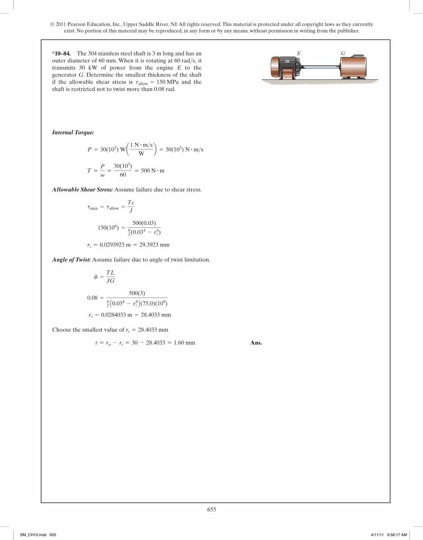
© 2011 Pearson Education, Inc., Upper Saddle River, NJ. All rights reserved. This material is protected under all copyright laws as they currently exist. No portion of this material may be reproduced, in any form or by any means, without permission in writing from the publisher.
655304
© 2010 Pearson Education, Inc., Upper Saddle River, NJ. All rights reserved. This material is protected under all copyright laws as they currentlyexist. No portion of this material may be reproduced, in any form or by any means, without permission in writing from the publisher.
From Fig. 5-32,
Ans.
Check:
OKD - d
2=
1.5 - 0.752
= 0.375 7 0.075 in.
r
d= 0.1; r = 0.1(0.75) = 0.075 in.
D
d=
1.50.75
= 2
K = 1.40
12(103) =K(710)(0.375)p2 (0.3754)
tmax = tallow = KTc
J
•5–125. The assembly is subjected to a torque of 710 If the allowable shear stress for the material is ksi,determine the radius of the smallest size fillet that can be usedto transmit the torque.
tallow = 12lb # in.
710 lb�ft
1.5 in.
0.75 in.
710 lb�in.A
B
C
(1)
When ,
From Eq. (1),
(2)
Dividing Eq. (1) by Eq. (2) yields:
(3)
Use Eq. 5-26 from the text.
Use Eq. 5-24, from the text and Eq. (3)
QEDT =43TYa1 -
fY3
4 f3 b
TY =p
2 tYc
3
T =p tY
6 (4 c3 - rY3 ) =
2p tYc3
3 a1 -
rY3
4 c3)b
rY
c=fY
f
c =gYL
fY
f = fYrY = c
rY =gYL
f
f =gL
r=gY
rYL
5–126. A solid shaft is subjected to the torque T, whichcauses the material to yield. If the material is elastic plastic,show that the torque can be expressed in terms of the angleof twist of the shaft as where and are the torque and angle of twist when the materialbegins to yield.fY
TYT = 43 TY11 - f3
Y>4f32,f
05 Solutions 46060 5/28/10 1:01 PM Page 304
322
© 2010 Pearson Education, Inc., Upper Saddle River, NJ. All rights reserved. This material is protected under all copyright laws as they currentlyexist. No portion of this material may be reproduced, in any form or by any means, without permission in writing from the publisher.
Internal Torque:
Allowable Shear Stress: Assume failure due to shear stress.
Angle of Twist: Assume failure due to angle of twist limitation.
Choose the smallest value of
Ans.t = ro - ri = 30 - 28.4033 = 1.60 mm
ri = 28.4033 mm
ri = 0.0284033 m = 28.4033 mm
0.08 =500(3)
p2 A0.034 - ri4 B(75.0)(109)
f =TL
JG
ri = 0.0293923 m = 29.3923 mm
150(106) =500(0.03)
p2(0.034 - ri4)
tmax = tallow =Tc
J
T =P
v=
30(103)
60= 500 N # m
P = 30(103) Wa1 N # m>sW
b = 30(103) N # m>s
*5–144. The 304 stainless steel shaft is 3 m long and has anouter diameter of 60 mm. When it is rotating at ittransmits 30 kW of power from the engine E to thegenerator G. Determine the smallest thickness of the shaftif the allowable shear stress is and theshaft is restricted not to twist more than 0.08 rad.
tallow = 150 MPa
60 rad>s,E G
05 Solutions 46060 5/28/10 1:01 PM Page 322
*10–84.
SM_CH10.indd 655 4/11/11 9:58:17 AM

© 2011 Pearson Education, Inc., Upper Saddle River, NJ. All rights reserved. This material is protected under all copyright laws as they currently exist. No portion of this material may be reproduced, in any form or by any means, without permission in writing from the publisher.
656323
© 2010 Pearson Education, Inc., Upper Saddle River, NJ. All rights reserved. This material is protected under all copyright laws as they currentlyexist. No portion of this material may be reproduced, in any form or by any means, without permission in writing from the publisher.
Shear Stress:
Applying Eq. 5-7,
Ans.
Applying Eq. 5-18,
Ans.
Angle of Twist:
Applying Eq. 5-15,
Ans.
Applying Eq. 5-20,
Ans. = 0.0786 rad = 4.503°
=2p(10)(103)(4)(0.06)
4[(p)(0.062)]2 (75.0)(109)(0.005)
=2pTLr
4A2mG t
=TL
4A2mG t
Lds Where Lds = 2pr
f =TL
4A2mG
Lds
t
= 0.0785 rad = 4.495°
=10(103)(4)
p2(0.06254 - 0.05754)(75.0)(109)
f =TL
JG
tavg =T
2 t Am=
10(103)
29(0.005)(p)(0.062)= 88.42 MPa
tr=0.06 m =Tr
J=
10(103)(0.06)p2(0.06254 - 0.05754)
= 88.27 MPa
ro = 0.06 +0.005
2= 0.0625 m ri = 0.06 -
0.0052
= 0.0575 m
•5–145. The A-36 steel circular tube is subjected to atorque of Determine the shear stress at the meanradius and compute the angle of twist of thetube if it is 4 m long and fixed at its far end. Solve theproblem using Eqs. 5–7 and 5–15 and by using Eqs. 5–18and 5–20.
r = 60 mm10 kN # m.
4 m
t � 5 mm
r � 60 mm
10 kN�m
05 Solutions 46060 5/28/10 1:01 PM Page 323
•10–85.
324
© 2010 Pearson Education, Inc., Upper Saddle River, NJ. All rights reserved. This material is protected under all copyright laws as they currentlyexist. No portion of this material may be reproduced, in any form or by any means, without permission in writing from the publisher.
Internal Loading: The internal torque developed in rod AB and tube BC are shownin Figs. a and b, respectively.
Allowable Shear Stress: The polar moment of inertia of rod AB and tube
BC are and
. We have
and
Angle of Twist:
T = 988.13 N # m
Atallow Bmg =TBC cBCJBC
; 45(106) =T(0.03)
0.2096875(10-6)p
T = 397.61 N # m
Atallow B st = TAB cABJAB
; 75(106) =T(0.015)
25.3125(10-9)p
= 0.2096875(10-6)p m4
JBC =p
2 a0.034 - 0.0254bJAB =
p
2 a0.0154b = 25.3125(10-9)p m4
5–146. Rod AB is made of A-36 steel with an allowableshear stress of , and tube BC is made ofAM1004-T61 magnesium alloy with an allowable shearstress of . The angle of twist of end C isnot allowed to exceed 0.05 rad. Determine the maximumallowable torque T that can be applied to the assembly.
1tallow2mg = 45 MPa
1tallow2st = 75 MPa
a
a
A
B
C
T
0.4 m
0.3 m
60 mm
50 mm
30 mmSection a–a
and
fB>A =TAB LABJAB Gst
=-T(0.7)
25.3125(10-9)p(75)(109)= -0.11737(10-3)T = 0.11737(10-3)T
It is required that . Thus,
Ans.T = 331 N # m Acontrols B0.05 = 0.11737(10-3)T + 0.03373(10-3)T
fC>A = fB>A + fC>B
fC>A = 0.05 rad
fC>B =TBC LBCJBC Gmg
=T(0.4)
0.2096875(10-6)p(18)(109)= 0.03373(10-3)T
05 Solutions 46060 5/28/10 1:01 PM Page 324
SM_CH10.indd 656 4/11/11 9:58:19 AM

© 2011 Pearson Education, Inc., Upper Saddle River, NJ. All rights reserved. This material is protected under all copyright laws as they currently exist. No portion of this material may be reproduced, in any form or by any means, without permission in writing from the publisher.
657323
© 2010 Pearson Education, Inc., Upper Saddle River, NJ. All rights reserved. This material is protected under all copyright laws as they currentlyexist. No portion of this material may be reproduced, in any form or by any means, without permission in writing from the publisher.
Shear Stress:
Applying Eq. 5-7,
Ans.
Applying Eq. 5-18,
Ans.
Angle of Twist:
Applying Eq. 5-15,
Ans.
Applying Eq. 5-20,
Ans. = 0.0786 rad = 4.503°
=2p(10)(103)(4)(0.06)
4[(p)(0.062)]2 (75.0)(109)(0.005)
=2pTLr
4A2mG t
=TL
4A2mG t
Lds Where Lds = 2pr
f =TL
4A2mG
Lds
t
= 0.0785 rad = 4.495°
=10(103)(4)
p2(0.06254 - 0.05754)(75.0)(109)
f =TL
JG
tavg =T
2 t Am=
10(103)
29(0.005)(p)(0.062)= 88.42 MPa
tr=0.06 m =Tr
J=
10(103)(0.06)p2(0.06254 - 0.05754)
= 88.27 MPa
ro = 0.06 +0.005
2= 0.0625 m ri = 0.06 -
0.0052
= 0.0575 m
•5–145. The A-36 steel circular tube is subjected to atorque of Determine the shear stress at the meanradius and compute the angle of twist of thetube if it is 4 m long and fixed at its far end. Solve theproblem using Eqs. 5–7 and 5–15 and by using Eqs. 5–18and 5–20.
r = 60 mm10 kN # m.
4 m
t � 5 mm
r � 60 mm
10 kN�m
05 Solutions 46060 5/28/10 1:01 PM Page 323
324
© 2010 Pearson Education, Inc., Upper Saddle River, NJ. All rights reserved. This material is protected under all copyright laws as they currentlyexist. No portion of this material may be reproduced, in any form or by any means, without permission in writing from the publisher.
Internal Loading: The internal torque developed in rod AB and tube BC are shownin Figs. a and b, respectively.
Allowable Shear Stress: The polar moment of inertia of rod AB and tube
BC are and
. We have
and
Angle of Twist:
T = 988.13 N # m
Atallow Bmg =TBC cBCJBC
; 45(106) =T(0.03)
0.2096875(10-6)p
T = 397.61 N # m
Atallow B st = TAB cABJAB
; 75(106) =T(0.015)
25.3125(10-9)p
= 0.2096875(10-6)p m4
JBC =p
2 a0.034 - 0.0254bJAB =
p
2 a0.0154b = 25.3125(10-9)p m4
5–146. Rod AB is made of A-36 steel with an allowableshear stress of , and tube BC is made ofAM1004-T61 magnesium alloy with an allowable shearstress of . The angle of twist of end C isnot allowed to exceed 0.05 rad. Determine the maximumallowable torque T that can be applied to the assembly.
1tallow2mg = 45 MPa
1tallow2st = 75 MPa
a
a
A
B
C
T
0.4 m
0.3 m
60 mm
50 mm
30 mmSection a–a
and
fB>A =TAB LABJAB Gst
=-T(0.7)
25.3125(10-9)p(75)(109)= -0.11737(10-3)T = 0.11737(10-3)T
It is required that . Thus,
Ans.T = 331 N # m Acontrols B0.05 = 0.11737(10-3)T + 0.03373(10-3)T
fC>A = fB>A + fC>B
fC>A = 0.05 rad
fC>B =TBC LBCJBC Gmg
=T(0.4)
0.2096875(10-6)p(18)(109)= 0.03373(10-3)T
05 Solutions 46060 5/28/10 1:01 PM Page 324
10–86.
SM_CH10.indd 657 4/11/11 9:58:20 AM

© 2011 Pearson Education, Inc., Upper Saddle River, NJ. All rights reserved. This material is protected under all copyright laws as they currently exist. No portion of this material may be reproduced, in any form or by any means, without permission in writing from the publisher.
658
259
© 2010 Pearson Education, Inc., Upper Saddle River, NJ. All rights reserved. This material is protected under all copyright laws as they currentlyexist. No portion of this material may be reproduced, in any form or by any means, without permission in writing from the publisher.
Solving Eqs. (1) and (2),
Ans.
Ans.T2 = 3283.47 N # m = 3.28 kN # mT1 = 2188.98 N # m = 2.19 kN # m
5–67. Continued
Internal Torque: As shown on FBD.
Angle of Twist:
Ans.
Ans.fB =7550
fC = 0.729°
= 0.008488 rad = 0.486°
=67.5(0.75)
p2 (0.0154)75.0(103)
fC =TCE LCEJG
*5–68. The 30-mm-diameter shafts are made of L2 toolsteel and are supported on journal bearings that allow theshaft to rotate freely. If the motor at A develops a torque of
on the shaft AB, while the turbine at E is fixedfrom turning, determine the amount of rotation of gears Band C.
T = 45 N # m45 N�m
A
0.75 m
50 mm1.5 m
0.5 m
B
C
E
D
75 mm
05 Solutions 46060 5/28/10 1:01 PM Page 259
10–87.
326
© 2010 Pearson Education, Inc., Upper Saddle River, NJ. All rights reserved. This material is protected under all copyright laws as they currentlyexist. No portion of this material may be reproduced, in any form or by any means, without permission in writing from the publisher.
Equilibrium:
[1]
Compatibility:
[2]
Solving Eqs. [1] and [2] yields:
Maximum Shear Stress:
Ans.
Ans.
Angle of Twist:
Ans. = 0.003572 rad = 0.205°
=285.71(12)(1.5)(12)p2 (14)(11.0)(106)
fCB = fBD =TD LBDJG
(tBD)max =TDc
J=
285.71(12)(1)p2 (14)
= 2.18 ksi
(tCB)max =TCc
J=
214.29(12)(1)p2 (14)
= 1.64 ksi
TD = 285.71 lb # ft TC = 214.29 lb # ft
TC = 0.75TD
TC(2)
JG=TD(1.5)
JG
fB>C = fB>D
TC + TD - 500 = 0
*5–148. The motor A develops a torque at gear B of500 which is applied along the axis of the 2-in.-diameter A-36 steel shaft CD. This torque is to betransmitted to the pinion gears at E and F. If these gears aretemporarily fixed, determine the maximum shear stress insegments CB and BD of the shaft. Also, what is the angle oftwist of each of these segments? The bearings at C and Donly exert force reactions on the shaft.
lb # ft,
2 ft 1.5 ft
B
DC
A
E F
500 lb ft·
05 Solutions 46060 5/28/10 1:01 PM Page 326
SM_CH10.indd 658 4/11/11 9:58:22 AM
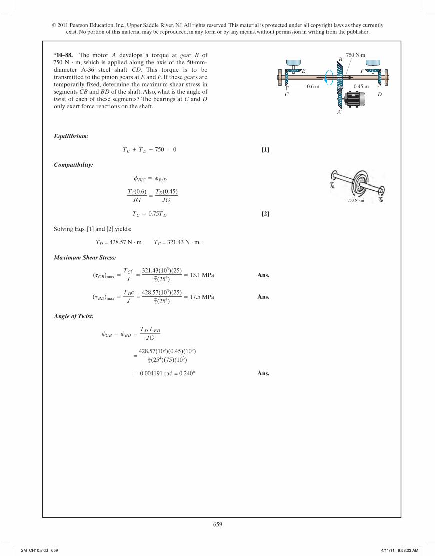
© 2011 Pearson Education, Inc., Upper Saddle River, NJ. All rights reserved. This material is protected under all copyright laws as they currently exist. No portion of this material may be reproduced, in any form or by any means, without permission in writing from the publisher.
659326
© 2010 Pearson Education, Inc., Upper Saddle River, NJ. All rights reserved. This material is protected under all copyright laws as they currentlyexist. No portion of this material may be reproduced, in any form or by any means, without permission in writing from the publisher.
Equilibrium:
[1]
Compatibility:
[2]
Solving Eqs. [1] and [2] yields:
Maximum Shear Stress:
Ans.
Ans.
Angle of Twist:
Ans. = 0.003572 rad = 0.205°
=285.71(12)(1.5)(12)p2 (14)(11.0)(106)
fCB = fBD =TD LBDJG
(tBD)max =TDc
J=
285.71(12)(1)p2 (14)
= 2.18 ksi
(tCB)max =TCc
J=
214.29(12)(1)p2 (14)
= 1.64 ksi
TD = 285.71 lb # ft TC = 214.29 lb # ft
TC = 0.75TD
TC(2)
JG=TD(1.5)
JG
fB>C = fB>D
TC + TD - 500 = 0
*5–148. The motor A develops a torque at gear B of500 which is applied along the axis of the 2-in.-diameter A-36 steel shaft CD. This torque is to betransmitted to the pinion gears at E and F. If these gears aretemporarily fixed, determine the maximum shear stress insegments CB and BD of the shaft. Also, what is the angle oftwist of each of these segments? The bearings at C and Donly exert force reactions on the shaft.
lb # ft,
2 ft 1.5 ft
B
DC
A
E F
500 lb ft·
05 Solutions 46060 5/28/10 1:01 PM Page 326
750 N · m, which is applied along the axis of the 50-mm-
750
TC(0.6)JG
5 TD(0.45)
JG
TD = 428.57 N · m TC = 321.43 N · m
321.43(103)(25)p2(254)
5 13.1 MPa
428.57(103)(25)p2(254)
5 17.5 MPa
= 428.57(103)(0.45)(103)
p2(254)(75)(103)
5 0.004191 rad = 0.240°
0.6 m 0.45 m
B
DC
A
E F
750 N m·
750 N · m
*10–88.
SM_CH10.indd 659 4/11/11 9:58:23 AM

© 2011 Pearson Education, Inc., Upper Saddle River, NJ. All rights reserved. This material is protected under all copyright laws as they currently exist. No portion of this material may be reproduced, in any form or by any means, without permission in writing from the publisher.
660327
© 2010 Pearson Education, Inc., Upper Saddle River, NJ. All rights reserved. This material is protected under all copyright laws as they currentlyexist. No portion of this material may be reproduced, in any form or by any means, without permission in writing from the publisher.
Equilibrium:
Ans.
Maximum Shear Stress:
Ans.tmax =Tc
J=
71.5(0.0125)p2 (0.01254)
= 23.3 MPa
T = 71.5 N # m ©Mx = 0; T - 550(0.13) = 0
5–149. The coupling consists of two disks fixed to separateshafts, each 25 mm in diameter. The shafts are supported onjournal bearings that allow free rotation. In order to limitthe torque T that can be transmitted, a “shear pin” P is usedto connect the disks together. If this pin can sustain anaverage shear force of 550 N before it fails, determine themaximum constant torque T that can be transmitted fromone shaft to the other. Also, what is the maximum shearstress in each shaft when the “shear pin” is about to fail?
25 mmP
25 mm
130 mm
T
T
Angle of Twist:
Maximum Shear Stress:
Ans.tmax =Tc
J=
510.82(0.0175)p2 (0.01754 - 0.01254)
= 82.0 MPa
T = 510.82 N # m
0.125 =T(2)
p2 (0.01754 - 0.01254)(75.0)(109)
f =TL
JG Where f =
1080
= 0.125 rad
5–150. The rotating flywheel and shaft is brought to asudden stop at D when the bearing freezes. This causes theflywheel to oscillate clockwise–counterclockwise, so that apoint A on the outer edge of the flywheel is displacedthrough a 10-mm arc in either direction. Determine themaximum shear stress developed in the tubular 304 stainlesssteel shaft due to this oscillation. The shaft has an innerdiameter of 25 mm and an outer diameter of 35 mm. Thejournal bearings at B and C allow the shaft to rotate freely.
2 m C
B
D
A
80 mm
05 Solutions 46060 5/28/10 1:01 PM Page 327
10–89.
10–90.
328
© 2010 Pearson Education, Inc., Upper Saddle River, NJ. All rights reserved. This material is protected under all copyright laws as they currentlyexist. No portion of this material may be reproduced, in any form or by any means, without permission in writing from the publisher.
Ans.
Ans. = 0.03243 rad = 1.86°
f =TL
JG=
7.85(0.15)p2 (0.005)4(37)(109)
T = 0.3F = 7.85 N # mF = 26.18 N = 26.2 N
40(106) =0.3F(0.005)p2 (0.005)4
tmax = tallow =Tc
J
5–151. If the solid shaft AB to which the valve handle isattached is made of C83400 red brass and has a diameter of10 mm, determine the maximum couple forces F that can beapplied to the handle just before the material starts to fail.Take What is the angle of twist of thehandle? The shaft is fixed at A.
tallow = 40 MPa.
F
150 mm
150 mm
F
A
150 mm
B
05 Solutions 46060 5/28/10 1:01 PM Page 328
SM_CH10.indd 660 4/11/11 9:58:24 AM
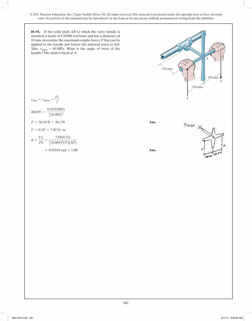
© 2011 Pearson Education, Inc., Upper Saddle River, NJ. All rights reserved. This material is protected under all copyright laws as they currently exist. No portion of this material may be reproduced, in any form or by any means, without permission in writing from the publisher.
661327
© 2010 Pearson Education, Inc., Upper Saddle River, NJ. All rights reserved. This material is protected under all copyright laws as they currentlyexist. No portion of this material may be reproduced, in any form or by any means, without permission in writing from the publisher.
Equilibrium:
Ans.
Maximum Shear Stress:
Ans.tmax =Tc
J=
71.5(0.0125)p2 (0.01254)
= 23.3 MPa
T = 71.5 N # m ©Mx = 0; T - 550(0.13) = 0
5–149. The coupling consists of two disks fixed to separateshafts, each 25 mm in diameter. The shafts are supported onjournal bearings that allow free rotation. In order to limitthe torque T that can be transmitted, a “shear pin” P is usedto connect the disks together. If this pin can sustain anaverage shear force of 550 N before it fails, determine themaximum constant torque T that can be transmitted fromone shaft to the other. Also, what is the maximum shearstress in each shaft when the “shear pin” is about to fail?
25 mmP
25 mm
130 mm
T
T
Angle of Twist:
Maximum Shear Stress:
Ans.tmax =Tc
J=
510.82(0.0175)p2 (0.01754 - 0.01254)
= 82.0 MPa
T = 510.82 N # m
0.125 =T(2)
p2 (0.01754 - 0.01254)(75.0)(109)
f =TL
JG Where f =
1080
= 0.125 rad
5–150. The rotating flywheel and shaft is brought to asudden stop at D when the bearing freezes. This causes theflywheel to oscillate clockwise–counterclockwise, so that apoint A on the outer edge of the flywheel is displacedthrough a 10-mm arc in either direction. Determine themaximum shear stress developed in the tubular 304 stainlesssteel shaft due to this oscillation. The shaft has an innerdiameter of 25 mm and an outer diameter of 35 mm. Thejournal bearings at B and C allow the shaft to rotate freely.
2 m C
B
D
A
80 mm
05 Solutions 46060 5/28/10 1:01 PM Page 327
328
© 2010 Pearson Education, Inc., Upper Saddle River, NJ. All rights reserved. This material is protected under all copyright laws as they currentlyexist. No portion of this material may be reproduced, in any form or by any means, without permission in writing from the publisher.
Ans.
Ans. = 0.03243 rad = 1.86°
f =TL
JG=
7.85(0.15)p2 (0.005)4(37)(109)
T = 0.3F = 7.85 N # mF = 26.18 N = 26.2 N
40(106) =0.3F(0.005)p2 (0.005)4
tmax = tallow =Tc
J
5–151. If the solid shaft AB to which the valve handle isattached is made of C83400 red brass and has a diameter of10 mm, determine the maximum couple forces F that can beapplied to the handle just before the material starts to fail.Take What is the angle of twist of thehandle? The shaft is fixed at A.
tallow = 40 MPa.
F
150 mm
150 mm
F
A
150 mm
B
05 Solutions 46060 5/28/10 1:01 PM Page 328
10–91.
SM_CH10.indd 661 4/11/11 9:58:25 AM