
Alternatives to in the refrigeration and air conditioning sector
82
ALTERNATIVES TO HCFCS IN THE REFRIGERATION AND AIR CONDITIONING SECTOR Practical Guidelines and Case Studies for Equipment Retrofit and Replacement UNITED NATIONS ENVIRONMENT PROGRAMME
-
Upload
khangminh22 -
Category
Documents
-
view
0 -
download
0
Transcript of Alternatives to in the refrigeration and air conditioning sector

Alternatives to hcfcs in the refrigeration and air conditioning sector
Practical Guidelines and Case Studies for Equipment Retrofit and Replacement
Un
ite
d n
at
ion
s e
nv
iro
nm
en
t P
ro
gr
am
me

2
Copyright© United Nations Environment Programme 2010
This publication may be reproduced in whole or in part and in any form for educational
or non-profit purposes without special permission from the copyright holder, provided
acknowledgement of the source is made. UNEP would appreciate receiving a copy of
any publication that uses this publication as a source.
No use of this publication may be made for resale or for any other commercial prupose
whatsoever without prior permission in writing from the United Nations Environment
Programme.
DisclaimerThe designations employed and the presentation of the material in this publication do
not imply the expression of any opinion whatsoever on the part of the United Nations
Environment Programme concerning the legal status of any country, territory, city or area
or if its authorities, or concerning delimitation of its frontiers or boundaries. Moreover, the
views expressed do not necessarily represent the decision or the stated policy of the
United Nations Environment Programme, nor does citing of trade names or commercial
processes constitute endorsement.

3

4 UNITED NATIONS ENVIRONMENTAL PROGRAM
Acknowledgements
This publication was produced by the UNEP Division of Technology, Industry and Economics (DTIE) OzonAction Branch with financial support of the Swedish Environmental Protection Agency. It was produced in the framework of the “HCFC Help Desk” project to encourage developing countries to achieve compliance with their HCFC phase-out obligations and adopt environmentally friendly alternatives to HCFCs.The project was managed by the following team in the OzonAction Branch, UNEP DTIE, France:
mr. Rajendra shendeHead
mr. James s. curlinInterim Network and Policy Manager
ms. Barbara HuberProgramme Assistant
mr. Ruperto de JesusProgramme Assistant
ms. mugure kibe UrsuletDocumentation Assistant
THIS PUBlICATION wAS wrITTEN By:
mr. klas BerglofOwner, Berglof refrigerationTechnology ltd, Sweden
THE rEvIEwErS:
dr. Husamuddin Ahmadzai Senior AdviserSwedish Environmental Protection Agency
dr. Janusz kozakiewiczAssociate Professor, Head of Ozone layer and Climate Protection Unit, ICrI, Poland
dr. ezra clarkProgramme Officer, OzonAction Branch, UNEP DTIE, France
DESIgN:
Atomo designAmsterdam
PHOTO CrEDITS:Photos used in figures © Klas BerglofPhoto of r-22 cylinder on page 17 © Environmental Investigation Agency
JOB NUMBEr: DTI/1282/PA

section 01Alternatives to HcFcs in the refrigeration and Air Conditioning Sector
5
Practical Guidelines and Case Studies For Equipment Retrofit and Replacement
Alternatives to HCFCs in the Refrigeration and Air conditioning Sector
United nAtions enviRonment PRogRAmmeDivision of Technology, Industry & Economics
OzonAction Programme
15, rue de Milan
75441 Paris CEDEX 09
France
swedisH enviRonmentAl PRotection Agency106 48 Stockholm, Sweden
Visiting address:
Valhallavägen 195, Stockholm
Telephone: +46-8-698 10 00.
Fax: +46-8-20 29 25
Internet: www.naturvardsverket.se

section 01 Alternatives to HcFcs in the refrigeration and Air Conditioning Sector
6
Introduction
Alternatives to HCFCs in the refrigeration and air conditioning sectorPractical guidelines and case studies for equipment conversion, Retrofit and Replacement
HydRocHloRoFlUoRocARBons (HcFcs) are ozone
depleting sub stances (ODS) controlled by the Montreal
Protocol on Substances that Deplete the Ozone Layer that
are widely used in refrigeration and air conditioning, foam
blowing and solvent applications.
In September 2007, the Parties to the Protocol accelerated
the phase-out schedule for these chemicals through
Decision XIX/6. Developing countries operating under Article
5 of the Protocol (Article 5 countries) now have to freeze by
2013 their HCFC production and consumption to the average
of their 2009-2010 levels, followed by a 10 percent reduction
by 2015, by 35 percent by 2020, by 67.5 percent by 2025, and a
100 percent phase-out by 2030 (with 2.5 percent allowed, if
necessary, for servicing existing equipment until 2040). The
same decision requires developed countries to accelerate
their phase-out schedule by 10 years to completely eliminate
HCFCs by 2020) with 0.5 percent allowed, if necessary, for
servicing existing equipment until 2030).
Action on HCFCs is important in that these chemicals have
an impact on both ozone depletion and climate change. In
terms of direct impact, the most commonly-used HCFCs
have ozone depleting potentials (ODPs) ranging from 0.02
(HCFC-123) to 0.11 (HCFC-141b) and global warming potentials
(GWPs) ranging from 76 (HCFC-123) to 2270 (HCFC-142b).
Equipment using HCFCs consumes energy, which
contributes to indirect global warming impacts.
The refrigeration and air conditioning (RAC) sector was the
biggest consumer of CFCs and in preparation for the total
CFC phase-out on January 1, 2010, it gradually shifted to the
alternative refrigerants, including HCFCs. Today the sector
has become one of the primary consumers of HCFCs and will
need appropriate assistance to enable it to comply with the
accelerated phase out.
UNEP DTIE in cooperation with the Swedish Environmental
Protection Agency (SEPA) has produced this publication to
provide decision makers in Article 5 countries, the end-users
and the service technicians a comprehensive source of
information on alternative technologies that can be adopted
to phase out HCFCs in the RAC.
The report contains a section on alternative technologies
including technical aspects and information on current
market situation in developed countries (Article 2
countries) and Article 5 countries. Another section covers a
collection of industry case studies that exemplifies state-of-
the-art solutions using different technologies for different
market segments.

7
Guide to the ReadeRA summary of the topic can be found at the
beginning of most chapters. Each summary,
including the main conclusions of the case being
described, is highlighted in a blue box.
Detailed information, particularly that which
should be taken into consideration when
adopting new technologies that are energy
efficient, safe and reliable are highlighted in a
yellow box.
In this report, information from different
manufacturers is quoted in several places and
websites that give additional information on
relevant issues are provided in the Reference
list. This does not imply that the author or UNEP
recommend any manufacturers in preference to
others or certify that statements made by these
companies are correct in any other sense than
the mentioned products/manufacturers are
present on many markets. As some products are
not known/available in many Article 5 countries,
it has been considered relevant to provide
information about the existence of these types
of products and where to find more information
about the technologies, although such a list can
never be complete.
sUmmARy
tecHnicAl inFoRmAtion

section 01 Alternatives to HcFcs in the refrigeration and Air Conditioning Sector
8
Executive Summary
tHe PHAse-oUt of chlorofluorocarbons (CFCs), one of the
most aggressive Ozone Depleting Substances (ODS), is now
almost completed in accordance with the Montreal Protocol.
The focus is now gradually shifting towards the phase-out
hydrochlorofluorocarbons (HCFCs) whose phase-out
schedule has been accelerated by the Parties to the Protocol
in Spetember 2007 through Decision XIX/6. Developing
countries operating under Article 5 of the Protocol (Article 5
countries) now have to freeze by 2013 their HCFC production
and consumption to the average of their 2009-2010 levels
followed by a 10 percent reduction by 2015; 35 percent by
2020; 67.5 percent by 2025 and a 100 percent phase-out by
2030 (with 2.5 percent allowed, if necessary, for servicing
existing equipment until 2040). The same decision requires
developed countries to accelerate their phase-out schedule
by 10 years to completely eliminate HCFCs by 2020) with
0.5 percent allowed, if necessary, for servicing existing
equipment until 2030).
HCFCs are widely used as a refrigerant in refrigeration and air
conditioning systems and equipment as well as a blowing
agent in the flexible and rigid foam sector.
The first target in the refrigeration and air conditioning
sector should be to minimize the installation of new HCFC
systems. Considering that the pre-charged air conditioning
systems constitute the biggest sub-sector, minimising
their production will create a specific challenge in non-
producing Article 5 countries. the amount of HcFcs contained in these systems when imported will not be included in the calculation of the importing country’s HcFc consumption baseline for the years of 2009-2010. However as these systems grow old, demand for HcFcs to service them will increase significantly, particularly after the freeze in 2013 and throughout the phase-out period. On the other hand, countries that export pre-
charged systems will start with a high HCFC consumption
baseline but they will be able to comply easily with the
phase-out schedule by simply converting their production
processes to use non–ODS technologies.
There are well established alternative substances to R-22
applications in the refrigeration and air conditioning sector.
The prominent group of alternative substances are HFCs
which are synthetic refrigerants with similar characteristics
to HCFCs but no ozone depleting potential (ODP).
As HFCs have a high global warming potential (GWP)
there is a strong interest to minimize the introduction
and emissions of HFCs. Other alternatives with lower or
near zero ODP are available but are all associated with
challenges that have to be overcome in order for them
to play a major role on the market. Alternatives with

section 01Alternatives to HcFcs in the refrigeration and Air Conditioning Sector
9
negligible or zero GWP are ammonia, carbon dioxide and
hydrocarbons. These are often called “natural refrigerants”.
Only hydrocarbons have similar technical characteristics
to HFCs that could allow them to be used without major
technology changes. Hydrocarbons are flammable and
safety precautions need to be considered during design,
manufacturing, installation, service and decommissioning.
For larger systems ammonia is well established on many
markets but several Article 5 countries lack qualified
technicians. Most countries need to increase the focus on
training for all technologies and good practice to facilitate
the use of the best alternatives for different applications.
There is no “one-size-fits-all” solution.
All the HCFC alternative technologies require Article 5
countries to upgrade the capacity of the servicing sector.
In spite of the activities conducted during the phase out
of CFCs, most of the Article 5 countries have a workforce
that, to a large extent, still do not work according to
internationally accepted good refrigeration and air
conditioning paractises. The shortcomings in training,
tools and enforcement of good practises cost industry
and consumers large amounts of money in increased
failure rates and unnecessary high energy consumption.
The strong focus on initial cost often results in poorly
optimised systems and little interest to train staff.
The industrialised countries have in most cases introduced
certification schemes and restrictions on who can do certain
activities related to ODS as well as HFCs. The alternatives all
require special competencies to be used in an environmentally
acceptable and safe way. A significant upgrade of the
competence level has taken place during the last 10 years in
many non-Article 5 countries, where the use of virgin HCFCs
have mostly been eliminated or totally phased out. Due
to the challenges in upgrading the industry which mainly
consists of small and medium enterprises (SMEs) most Article
5 countries are only beginning this process. In order to phase
out HCFCs and improve reliability as well as energy efficiency,
it is important for the industry to upgrade its competence in
all alternative technologies as there is no single technology
to date that can provide the ideal solution for all applications.
To justify investment in tools and training in alternative
technologies, it is important to create an environment
where it is good business to do good practise. Providing clear
regulatory frameworks and information to equipment owners
is important to make necessary investments attractive for the
industry. If purchasing environmentally hazardous refrigerants
and working in the industry with little training and tools persist,
the change will be very slow as there are many equipment
owners with limited awareness and competence. Moreover,
the high energy consumption and unnecessary short lifespan
of equipment are factors that are often unknown to many.

10 UNITED NATIONS ENVIRONMENTAL PROGRAM

section 01Alternatives to HcFcs in the refrigeration and Air Conditioning Sector
11
Contents Introduction 6
Guide to the Reader 7
Executive summary 8
Contents 11
1 Alternatives to HCFCs in refrigeration and air conditioning 12
1.1 Background 13
1.2 HCFCs used in the refrigeration and air conditioning sector 15
1.2.1 Air conditioning and industrial refrigeration –traditional R-22 sub-sectors. 16
1.2.2 Split and unitary air conditioning sector (including air-to-air heat pumps) 16
1.2.3 VRV/VRF/multi-split systems (including heat pumps) 19
1.2.4 Chillers in air conditioning and cooling applications (including heat pumps with indirect systems) 19
1.2.5 HCFCs in commercial refrigeration 20
1.2.6 Other HCFC-using sub-sectors in the RAC sector 20
1.3 Energy efficiency of air conditioning equipment 20
1.4 Alternatives to HCFCs in air conditioning and refrigeration 21
1.4.1 Ammonia 25
1.4.2 Hydrocarbons 25
1.4.3 Carbon dioxide (CO2) 27
1.4.4 HFC alternatives used in new and retrofitted systems with new oil 29
1.4.5 HFC “service blends” used in existing systems 32
1.5 Oils in refrigeration and air conditioning sytems 34
1.6 Retrofit procedures 36
1.6.1 Documentation of status and performance 38
1.6.2 How to replace the oil? 39
1.6.3 Retrofit with the “oil change method” 41
1.6.4 Retrofit through flushing with the “old” refrigerant 41
1.6.5 Retrofit through flushing with a solvent 41
1.6.6 Number of oil changes required 43
1.6.7 Methods of oil analysis and moisture content in oil 44
1.6.8 Laboratory tests 44
1.6.9 Refractometer test 44
1.6.10 Test kit 44
2 Case studies – Alternative technologies in different applications 46
2.1 The transition in the unitary and split air conditioning market 48
2.1.1 Retrofit of split air conditioning from R-22 to R-407C with oil-change through “flushing” 48
2.2 Chillers with HFCs 52
2.2.1 Large low pressure chillers 52
2.2.2 Medium-sized and small chillers 52
2.3 Fruit Storage with hydrocarbon chillers at Nickle farm in UK 53
2.4 Cold store with low charge ammonia chiller 55
2.5 Retrofit of R-22 chiller to R-422D (oil change not required) 58
2.5.1 Description of conversion procedures. 59
2.6 Carbon dioxide heat pumps for domestic heating and tap water 60
2.7 Carbon dioxide in supermarkets 62
2.7.1 Evaluation of carbon dioxide supermarket in Sweden 63
2.7.2 Evaluation of three carbon dioxide stores in Norway 66
2.7.3 Market situation for CO2 as a refrigerant in supermarkets 67
2.8 Retrofit of R-22 supermarket in Romania to R-404A 67
2.8.1 Results obtained for the refrigeration circuit operating at medium temperature 69
2.8.2 Results obtained for the freezing circuit (LT) 71
Appendix I - List of refrigerants 72
Appendix II - References 77
Appendix II - Abbreviations and definitions 79

12 UNITED NATIONS ENVIRONMENTAL PROGRAM

section 01Alternatives to HcFcs in the refrigeration and Air Conditioning Sector
13
UndeR tHe montReAl PRotocol on Substances
that Deplete the Ozone Layer, developing countries (i.e.
countries that operate under Article 5 of that agreement)
have developed strategies and successfully implemented
measures which have phased out chlorofluorocarbons
(CFCs) - ODS with high ODP – by 1 January 2010. In
the coming years, the focus will be to move away from
the HCFCs, substances with lower ODP values which
have been used as transitional replacements while CFCs
were being phased out. In Article 5 countries, HCFCs are
scheduled to be completely phased out by 2030 (with a
small servicing tail of only 2.5% allowed from 2030-2040).
This might seem to be a long time, but many countries are
increasing their consumption of HCFCs rapidly and risk
building an HCFC-based infrastructure that can be costly
and complicated to convert to non–ODS refrigerants
in the future. The freeze in 2013 (baseline is the average
HCFC consumption between 2009 and 2010) will become
a challenge if measures are not initiated immediately.
It is important to ensure that all HCFC consumption
(production and import - export) is correctly reported
prior to baseline of 2009-2010 and freeze year of 2013,
and that early actions are taken to reduce new HCFC
consumption to a minimum.
The first priority should be to stop all new installations using
HCFCs as soon as possible. There is a special challenge for
countries importing HCFC-22 (R-22) equipment as they
are shipped pre-charged with the refrigerant and does not
count in the calculation of the country’s HCFC consumption
baseline. As these equipment become old and servicing
needs increase, only a limited quantity of HCFCs will be
available on the market. Many Article 5 countries have
no HCFC equipment production, but imports of R-22 air
conditioning units are quickly increasing. Equipment that
use alternative refrigerants are readily available for a slightly
higher price, but it should also be kept in mind that R-22
equipment on the market are of an older design, whereas
newer models have been redesigned to meet much higher
energy efficiency standards. Therefore the installation of such
equipment, while slightly higher in cost, will lead to additional
energy savings in the long run. Many of the substances
used to replace HCFCs have a significant GWP which should
be taken into account when alternative technologies are
evaluated. The selection of alternative substances and
technologies will significantly affect the future impact on
the climate from this sector. Both the direct impact from the
chosen substances and the energy consumed will depend on
the technologies selected.
1.1 Background
01 Alternatives to HCFCs in refrigeration and air conditioning

section 01 Alternatives to HcFcs in the refrigeration and Air Conditioning Sector
14
the installation of HCFCs has been in place since 2004 and a
total ban on the use of virgin HCFCs began in 2010.
The following HCFCs are the most commonly used in the
different sectors:
HCFCs have traditionally been the global solution in sectors
that are now rapidly growing in many developing countries,
such as stationary air conditioning and large commercial
and industrial refrigeration. In the later applications, HCFCs
have been competing with ammonia, another well-proven
“mature” technology. Other applications are new, since
HCFC has been used as a replacement to facilitate the phase-
out of CFC. Traditionally the retail food sector mostly uses
R-12 (CFC) and R-502 (containing CFC) but moved to R-22 as
a transitional product before non-ODS alternatives such as
R-134a and R-404A/R-507 were accepted.
HCFCs are used as a component in a large number of
refrigerant blends, often designed to match the behaviour
and performance of R-12 and R-502. These are often called
service or drop-in blends as they are intended to facilitate
an easy replacement of CFCs in existing plants with minimal
changes to the system.
Technologies to move away from HCFCs are well-known
and proven in the industrialised countries and many of the
alternatives are already partly introduced in developing
countries due to influences from neighbouring markets and
international companies. The strongest incentive for the
continuous growth of markets for HCFCs is the lower initial
price of both the substance and the equipment intended for
use with HCFC (although this is often only in a short –time
perspective as long-term energy and future retrofit cost
will be high). R-22 is also a product that the entire industry is
familiar with. Alternatives with less environmental impact are
often associated with slightly higher initial cost and a need
for technical know-how to be dispersed to a large number
of technicians. This creates an uncertainty in the market
that can be taken advantage of by competing companies
by preserving “old technologies” at minimal cost. For some
of the environmentally-preferred solutions, there are also
safety barriers to be addressed to make these alternatives
viable solutions. A more extensive list of alternatives to
HCFCs are listed in Appendix I - List of refrigerants. In
Article 2 (i.e. developed country) markets, the transition has
been happening over the last 15 years, so the commercial
alternatives are well-proven. For example, in Europe a ban on
sectoR tyPe oF HcFc
Refrigeration (manufacturing and service)
Domestic refrigeration limited use of service drop-in blends (never used in equipment production)
(HCFC-141b in appliance insulation foam)
Commercial refrigeration HCFC blends in service, (HCFC-141b in foam)
Industrial refrigeration HCFC-22, r-502 (a blend of CFC/HCFC), HCFC blends, (HCFC-141b in foam)
Transport refrigeration HCFC-22, r-502, HCFC blends, (HCFC-141b foam)
stationary Air conditioning
residential and commercial AC HCFC-22
Chillers HCFC-22, HCFC-123
mobile air conditioning None or minimal (poor compatibility with hoses)
Foams HCFC-141b, HCFC-142b, HCFC-22
medical Aerosols None
non-medical Aerosols HCFC-22, HCFC-141b, HCFC-142b
Fire Protection HCFC-123, HCFC-124, HCFC-22 (blends)
solvents HCFC-141b, HCFC-225ca, HCFC-225cb
Different sectors where HCFCs are most commonly used.

section 01Alternatives to HcFcs in the refrigeration and Air Conditioning Sector
15
1.2 HCFCs used in the refrigeration and air conditioning sector
sUmmARy HcFcs Use in tHe RAc sectoRHCFCs are widely used over the entire industrial and commercial refrigeration sector including for food processing,
distribution, storage and retail (shops and supermarkets). In air conditioning, HCFCs have played a dominant role
in unitary-, split- and chiller- type systems for air conditioning in private homes, hotels, office buildings, restaurants
and other public buildings.
r-22 is by far the most commonly-used HCFC in this sector. Other HCFCs such as r-124 and r-123 have been used in
smaller quantities for special applications. Still other HCFCs such as HCFC-141b and HCFC-142b have been used as
blowing agents in refrigeration equipment insulation after the phase out of CFCs, sometimes in mixtures with r-22.
refrigeration and air conditioning equipment is globally one of the sectors with the highest electrical power consumption.
The rapid growth in this sector in many countries will result in a need to expand power production and distribution systems.
The energy consumption of countries in this sector also contributes significantly to global warming. with the expected
requirements in the global agreements on reduction of green house gases the emissions of refrigerants such as HCFCs and
HFCs as well as energy consumption in this sector will play a significant role in whether these agreements achieve its targets.
Aside FRom Being one of the major ODS-consuming
sectors the refrigeration and air conditioning sector (RAC)
including heat pumps and dehumidifiers, also uses 15% to
20% (IIR, 2002) of global electrical energy. The economic
growth in many Article 5 countries in hot climates results in
a corresponding growth of the RAC sector. The applications
where HCFCs are used are important to reduce the losses
in the food production and distribution chain. There are
also many applications that are essential for industrial
production and human comfort where HCFCs play an
important role today. The growth will result in increasing
energy consumption if measures to improve efficiency
– including the introduction of more energy-efficient
technologies - are not implemented effectively/appropriately. there are well-proven technologies available to replace HcFcs with non-ozone depleting substances as well as to improve energy efficiency in all refrigeration and air conditioning applications. Alternatives such as HFCs can
be used with minimal changes to the existing technology, but
have a high GWP. Refrigerants with a low or zero GWP should
be the preferred solution when they can be used in a safe
and cost-effective manner without resulting in higher energy
consumption. High GWP refrigerants should only be used when
technical, economic or safety reasons require them, and in such
cases they should be used in systems with minimized leakage
and emissions during service and at the end of equipment life.
HCFC is also used as feedstock for the production of plastics
and other chemicals.
When replacing HCFCs it is important to evaluate the envi-
ronmental impact of the alternatives since the most com-
mon replacements are hydrofluorocarbons (HFCs) which
have a significant Global Warming Potential. The impact
of alternative refrigerants and the energy consumption of
selected system solutions should also be evaluated
to minimize their total impact on the environment.
Adopting measures to reduce the refrigeration and
air conditioning loads through good building design
and processes are obviously the most efficient way
of reducing the environmental impact of these
technologies.

section 01 Alternatives to HcFcs in the refrigeration and Air Conditioning Sector
16
The emissions should be minimized through implementation
of good servicing practices and effective re-use schemes.
The main HCFC commonly used in air conditioning and
refrigeration applications before 1985 was R-22. The main
sectors where R-22 was the preferred refrigerant were in the
air conditioning and industrial systems sectors where it was
also competing with ammonia. When CFCs were identified
as powerful ODS and a global phase-out was agreed under
the Montreal Protocol in 1987, HCFCs were identified as less
harmful substances and introduced in several sub-sectors
tHe PHysicAl PRoPeRties of R-22 result in good
performance in a wide range of applications but with a
limiting factor caused by the high temperatures occurring
during compression. In refrigeration applications where the
temperature difference between the desired temperature
and the surroundings is high, the risk of unacceptable
conditions and failures increases. In hot climates, the
challenge in commercial refrigeration applications increases
significantly more than in air conditioning systems. In
industrial applications R-22 was an alternative to ammonia
where it provided better cooling capacities than R-12 and
was more readily available and cost less than R-502. In large
installations the high temperatures could be handled with
different technical solutions, but it was not as cost-effective
in smaller commercial systems where R-12 and R-502 were
more common.
1.2.2 sPlit And UnitARy AiR conditioning sectoR (inclUding AiR-to-AiR HeAt PUmPs)
that were not traditional HCFC applications. As a result,
R-22 and HCFC-containing drop-in blends are now found
in commercial refrigeration and to some extent in transport
refrigeration. The result is that replacement of HCFCs
will have an impact on many sectors and to some extent
the alternatives used will sometimes be the alternatives
designed to replace CFCs rather than those designed for
R-22 applications. The main focus in this report will be on
segments where R-22 has a significant market share but in
order to give a more complete “update”, other sectors will
also be covered, although with less attention.
1.2.1 AiR conditioning And indUstRiAl ReFRigeRAtion – tRAditionAl R-22 sUB-sectoRs.
sUmmARy sPlit And UnitARy systemsr-22 is used mainly in split and unitary air conditioning equipment (see Figure 1.2). The quantity used in this
application is sometimes underrated because in the manufacturing/exporting country the initial charge is
considered ‘consumption’ whereas it is not considered as such in the importing country where the equipment will
be installed and serviced.
In new systems alternatives are readily available. Most often r-22 is replaced with r-410A or r-407C. large volumes
of r-22 systems are still being installed in some markets due to lower investment outlay and less-informed
customers. As these units age, they can be expected to play a significant role in the consumption of HCFCs, once the
freeze in HCFC consumption (this is usually equivalent to “imports” in most Article 5 countries) in 2013 takes effect.
One of the priorities should be to stop the introduction of new r-22 equipment. The sooner legislation to ban the
import, marketing and installation of new r-22 systems is established, the easier the transition will be. The cost for
transition will be lower as the added initial cost is much lower than the cost to retrofit the system.
Fig. 1.1 (opposite page) HCFCs are used in all refrigeration and air conditioning equipment that in turn is used everywhere in society.

17
section 01 Alternatives to HcFcs in the refrigeration and Air Conditioning Sector
18
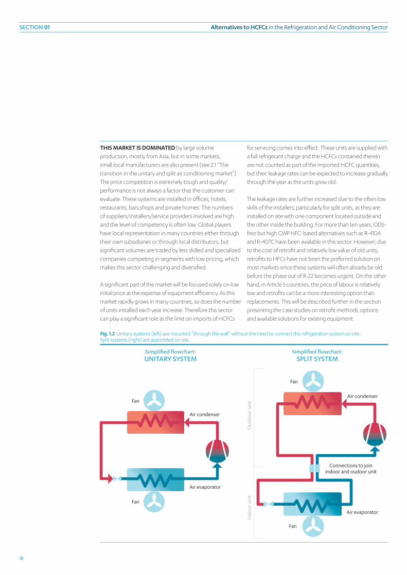
tHis mARket is dominAted by large volume
production, mostly from Asia, but in some markets,
small local manufacturers are also present (see 2.1 “The
transition in the unitary and split air conditioning market”).
The price competition is extremely tough and quality/
performance is not always a factor that the customer can
evaluate. These systems are installed in offices, hotels,
restaurants, bars,shops and private homes. The numbers
of suppliers/installers/service providers involved are high
and the level of competency is often low. Global players
have local representation in many countries either through
their own subsidiaries or through local distributors, but
significant volumes are traded by less skilled and specialised
companies competing in segments with low pricing, which
makes this sector challenging and diversified.
A significant part of the market will be focused solely on low
initial price at the expense of equipment efficiency. As this
market rapidly grows in many countries, so does the number
of units installed each year increase. Therefore this sector
can play a significant role as the limit on imports of HCFCs
for servicing comes into effect. These units are supplied with
a full refrigerant charge and the HCFCs contained therein
are not counted as part of the imported HCFC quantities,
but their leakage rates can be expected to increase gradually
through the year as the units grow old.
The leakage rates are further increased due to the often low
skills of the installers, particularly for split units, as they are
installed on site with one component located outside and
the other inside the building. For more than ten years, ODS-
free but high GWP HFC-based alternatives such as R-410A
and R-407C have been available in this sector. However, due
to the cost of retrofit and relatively low value of old units,
retrofits to HFCs have not been the preferred solution on
most markets since these systems will often already be old
before the phase out of R-22 becomes urgent. On the other
hand, in Article 5 countries, the price of labour is relatively
low and retrofits can be a more interesting option than
replacements. This will be described further in the section
presenting the case studies on retrofit methods, options
and available solutions for existing equipment.
Fan
Fan
Air evaporator
Air condenser
Air condenser
Air evaporator
Connections to joinindoor and oudoor unit
Fan
Fan
Out
door
uni
tIn
door
uni
t
Fig. 1.2 Unitary systems (left) are mounted “through the wall” without the need to connect the refrigeration system on site.Split systems (right) are assembled on site.
simplified flowchart: UnitARy system
simplified flowchart: sPlit system

section 01Alternatives to HcFcs in the refrigeration and Air Conditioning Sector
19
cHilleRs ARe systems tHAt indiRectly cool a
building or a process. Typically they are used in larger
systems and the “cooling” distributed with water or a
mixture of water and anti-freeze when it is necessary to
work at low temperatures. Chillers are mainly factory-built
units that are intended to cool a liquid such as water or, if
a lower temperature is desired, fluids with lower freezing
points. Chillers can be air-cooled, i.e. where the condenser
is directly cooled by air, or water-cooled, where the
condenser is cooled by circulating water (possibly with
freeze depression if the climate is such that the water would
risk freezing in the winter). Their main applications are
for air conditioning in larger buildings, i.e. hotels, offices,
hospitals, military complexes, etc. or for process cooling in
various industries. This solution is often associated with a
higher investment cost than solutions with split systems for
air conditioning or smaller units for each object in need of
cooling in the industry. In many cases, small non-chiller RAC
units can be installed gradually and often by tenants, thus
eliminating the need for the owner to invest and charge
costs to the tenants. Central systems with chillers are often
preferred in larger systems where the possibilities of more
stable operation by balancing cooling loads over time (as
the loads are not occurring simultaneously over the whole
building), reducing maintenance cost are preferred as it also
avoids noise and/or esthetical drawbacks of having large
numbers of split/unitary systems. This option is often used
in larger buildings operated by owners with the capability
to invest in more long term solutions. Chillers are globally
used in central air conditioning systems where R-22 is one
of the most commonly used refrigerants, apart from CFCs
1.2.4 cHilleRs in AiR conditioning And cooling APPlicAtions (inclUding HeAt PUmPs witH indiRect systems).
1.2.3 vRv/vRF/mUlti-sPlit systems (inclUding HeAt PUmPs)
which are still present in large quantities in the old chiller
equipment in both developed and developing countries.
Apart from their use in the air conditioning sector, HCFC
chillers using R-22 are also common in the food processing
industry as well as in other industries where processes need
to be cooled. At one point a large chiller segment using R-11
was to some extent converted to R-123 which is an HCFC,
but has low ODP and low GWP. At the time this report was
Pumpsecondary fluid i.e.
water/glychol/brine/CO2
Refrigerant inside: NH3, HC or HFC
Air or liquidcondenser
Fig. 1.3 Chillers use secondary fluid to indirectly cool the room or object.
tHese ARe systems that have been developed from the
split systems (Daikin Industries developed and launched
“Variable Refrigerant Volume” and protected the use of
the acronym “VRV” so other manufacturers use “VRF”
for Variable Refrigerant Flow). These system designs
are characterised by one unit cooling (and sometimes
heating) several rooms and adapting its capacity to
the variations in the demand. These units have a lot
in common with split systems, but are dependent on
complex electronic controls and have an intricate design,
which will make them more difficult to retrofit. This is
because oil transport and control behaviour could be
affected and difficult to predict unless there is access to
design info and proper test facilities or support from the
manufacturer. For obvious reasons, the manufacturers are
rarely interested in investing the resources required to
extend the life of existing equipment.
simplified flowchart: cHilleR

section 01 Alternatives to HcFcs in the refrigeration and Air Conditioning Sector
20
smAlleR volUmes of HCFCs are used in almost all other
RAC sectors. Both R-22 and HCFC-containing service blends
are used to replace R-12 and R-502. In transport refrigeration
some manufacturers have converted to R-22 while the
majority went directly to R-134a and R-404A. In some niche
markets such as the high temperature air conditioning in the
industry, there are applications where CFC refrigerant R-114
was replaced with R-124, which is an HCFC.
1.2.6 otHeR HcFc-Using sUB-sectoRs in tHe RAc sectoR
1.2.5 HcFcs in commeRciAl ReFRigeRAtion
in mAny ARticle 5 coUntRies, commercial refrigeration
has traditionally been dominated by smaller plug-in systems
and display cases cooled by individual condensing units. The
introduction of larger central systems was limited to newer
and larger supermarkets.
These systems in stores and shops were often cooled with
R-12 and to some extent R-502 in the low temperature
applications. With increasing pressure to phase out
CFCs, transition to R-22 had occurred in many countries
before R-404A or R-507 were accepted as the refrigerants
for this sector. In the process of phasing out R-22 from
commercial systems, R-404A and R-507 are being used
as alternatives more frequently than in air conditioning.
The use of R-22 in commercial refrigeration is significantly
more challenging than the refrigerants it replaced and the
non-ODS alternatives developed for this sector. This is due
to the properties of R-22 which cause higher compressor
temperatures requiring significant changes to the system’s
design or “quick fixes” such as installing water sprays for the
condensers as shown in Fig. 1.4.
Fig. 1.4 A commercial refrigeration installation using r-22 in a hot climate. This model requires a water spray on the condenser to avoid high presssure and overheating of the compressors. However this causes corrosion and wastes water that is often in short supply. In this case increased electrical hazards are obvious and ‘good Practice’ has not been properly considered.
written, there were no known alternatives to R-123 suitable
for existing systems.
R-245fa is an HFC alternative that can be used in low pressure
chiller applications but has a higher pressure making it
unsuitable for most existing systems. With the current
information it can be expected that in this sector existing
systems using R-123 will be maintained with minimum leakages
until the end of their life. In most developing countries the
introduction of R-123 has been limited although in some
markets low pressure R-123 chillers could be a segment that
will require special attention due to the challenges to replace
it. As there are only a few suppliers that produce R-123 chillers,
six according to James M. Calm (James M. Calm, 2002), it
would be possible to identify exactly how many units of this
system are in operation and where they were installed by
contacting the manufacturers/importers.
As the use of indirect systems make it possible to more
freely locate refrigeration units with toxic or flammable
refrigerant, chillers using ammonia and hydrocarbon
refrigerants are becoming more common.
the-art, non-ODS equipment then has to compete with the
low cost R-22 equipment. The price difference is not mainly
due to the change of refrigerant but rather to the larger heat
exchangers and often to design improvements that reduce
energy consumption and noise to meet international market
demands. A report of the International Energy Agency (IEA)
one ReAson wHy R-22 still prevails in the new installa-
tion market in many Article 5 countries is the lack of energy
efficiency requirements and the low awareness of customers
about the cost of running the systems. In this situation, the
equipment purchase price becomes the only criterion for
equipment selection. The more energy efficient state-of-
1.3 Energy efficiency of air conditioningequipment

section 01Alternatives to HcFcs in the refrigeration and Air Conditioning Sector
21
[IEA, SATORU KOIZUMI, 2007] evaluated the impact on
energy consumption of increased efficiency requirements
in Article 5 countries. The report gave the example of Ghana,
an Article 5 country which imports its AC equipment and
needs stronger national energy efficiency requirements. It
demonstrated why the efficiency of installed equipment in
the country is lower than that of the equipment available on
the market.
sUmmARy AlteRnAtives to HcFcsThere is not and will most likely never be one refrigerant that can be used to replace all HCFC applications, since
the use is so widespread and the requirement for better energy efficiency will result in an increased demand to
adapt the technologies to the actual operating conditions.
Each system, or at least each type of system, needs to be evaluated from several perspectives to find
the environmentally and technically best option that can be used safely at an acceptable investment
and operating cost.
when evaluating the impact of rAC equipment on the climate, the direct gwP of the refrigerant used as well
1.4 Alternatives to HCFCs in air conditioningand refrigeration
Fig. 1.6 Development of energy efficiency of AC equipment in Japan.
6.0
5.0
4.0
3.0
2.0
1.0
0.0
eeR
1997 1998 1999 2000 2001 2002 2003 2004 2005
Fig. 1.5 Development of energy efficiency of AC equipment in ghana. The country has no domestic equipment production.
3.0
2.5
2.0
1.5
1.0
0.5
0.0 2000 2001 2003 2004 2005
eeR
In comparison, Japan, which has clear and strict energy
efficiency requirements, showed a rapid improvement of
energy efficiency despite the fact that from the beginning
the country already had a significantly better performance
rate than Ghana. The Japanese air conditioners used 50%
less electricity than those installed in Ghana. The expected
rapid increase in use of air conditioning systems in many
Article 5 countries will result in drastically higher electricity
consumption. The use of low efficiency equipment will be
costly in terms of energy consumption. Furthermore, the
often weak infrastructure used in producing and distributing
electricity will be frequently overloaded by excessive
energy demands coming from high air conditioning loads.
An introduction of efficiency requirements and labelling
schemes to improve efficiency is vital for Article 5 countries.
For Ghana, an enforcement of minimum energy standards in
installed air conditioning units was estimated to reduce the
country’s total need for generated electrical power by 8%.
The report contains an evaluation of barriers and possible
counter-measures to introduce higher efficiency equipment.

section 01 Alternatives to HcFcs in the refrigeration and Air Conditioning Sector
22
dUe to tHe HUge nUmBeR of applications for
refrigeration and air conditioning systems with different
operating conditions and requirements, it is practically
impossible to find a single ideal refrigerant. The ideal
refrigerant would need to have the following properties and
characteristics, among others:
Zero Ozone Depleting Potential (ODP)■■
Energy efficient = have high Coefficient of Performance ■■
(COP), i.e. low indirect Global Warming Impact
Zero or low Global Warming Potential (GWP), i.e. low Direct ■■
Global Warming Impact
Chemically stable at all temperatures and environments■■
including contaminated systems■■
Compatible with all materials■■
metals■■
elastomers (plastic/rubber materials)■■
oil, including suitable miscibility/solubility with oil■■
Non-toxic■■
Non-flammable■■
Low cost■■
Commercially available■■
The above list does not reflect an order of priority as this
cannot be defined on a general level. Obviously, refrigerants
with high flammability and toxicity can be easily handled in
some applications and may be more or less impossible to
be applied in others, at least without a significant increase
in energy consumption and/or cost. Zero ODP is a legal
requirement in many countries already. The total warming
impact of a refrigeration air conditioning system will consist
of a direct effect from released refrigerants and an indirect
effect from carbon dioxide emissions during the production
of energy used to operate the system. The combined effect
of Direct and Indirect warming effect is often calculated
as the total equivalent warming impact or tewi (see
Abbreviations and definitions)
TEWI takes into consideration leakage rates, emissions
from the site where systems are scrapped and energy
consumption. As these factors are different for each system
and difficult to estimate, TEWI is often calculated based on
statistical values and experience. The result will be affected by
how the different factors are estimated. Factors like leakage
and recovery rate are dependent on the quality of installation
and service. This will change over time as service is improved
through training in combination with regulations that require
end-users and contractors to keep records, discourage
emissions and enforcement actions. To assume leakage
rates of 30% common on many markets or 5% achieved in
others will drastically change the balance between direct
emissions from leakage and indirect emissions from energy
consumption. Few Article 5 countries have so far been
successful in implementing functional refrigerant re-use
as the system’s total energy efficiency should be measured. A system using a refrigerant with a higher gwP can
be more energy efficient and have a lower total impact on the climate.
Using a lower gwP refrigerant in a safe and energy efficient way at an acceptable cost is a preferable solution to using high gwP alternatives such as HFcs. HFc emissions must be minimised and should only be used in systems with minimum leaks and where leak controls and recovery schemes are in place. HFcs are among the controlled substances under the kyoto Protocol and can be expected to be charged with increased regulatory controls in the future.
There is always a number of alternative technologies that can be used. The easiest route would seem to be
to choose the alternatives that require no or minimal system changes but it is important to realise that new
technologies are continually being introduced and that the industry will eventually have to keep its knowledge
abreast with these new technologies. An evaluation of environmental impact including energy efficiency, cost,
technical as well as safety risks is required. The outcome will be different for different operating conditions and
will depend on where the equipment is installed and how it is used. generalisations often result in poor decisions
and that is why it is important to establish industry standards to have acceptable service availability and to make
the required training of the service sector manageable.

section 01Alternatives to HcFcs in the refrigeration and Air Conditioning Sector
23
schemes that reprocess significant volumes. As the average
recovery rate in Article 5 countries is currently low the relative
impact of direct emissions is high. With a strong focus on
the introduction of good practice, the relative impact of
GWP is expected to decrease although energy consumption
also decreases with improved service practice. If a low-GWP
refrigerant can be used safely at the same or lower energy
consumption level with an acceptable investment, this will
obviously be the solution with the lowest TEWI.
Energy efficiency is becoming more and more the focus
when selecting refrigerants but it is important to realise that
efficiency is only, to a small part, a result of the refrigerant
selection. Typically the different refrigerants’ theoretical
impact on the total performance varies within a few
percent, whereas the difference between various technical
solutions of equipment design with a given refrigerant can
be 20-30% or more. The solution that is 20% better in one
application can also be significantly worse at other operating
conditions. Simplified generalisations of performance that is
not specifically referring to a specific application should be
viewed with scepticism. “if it sounds too good to be true, it probably isn’t”.
In the technical sections and case studies below, a number
of technical and commercial aspects to be considered will
be covered. In many countries there is a need to establish or
increase local capacity to evaluate the suitability of different
alternatives and to implement them in different systems.
It is important to evaluate not only the lowest investment
options but also the energy efficiency and cost effectiveness
of the different options.
Therefore, it is easy to conclude that the ideal “one-size-
fits-all” refrigerant does not exist and that some refrigerants
will be more suitable in some applications than others. All
refrigerants have their advocates on the market and there
are interest groups promoting the different technologies.
It is important that the refrigeration and air conditioning
sector and equipment owners do a proper evaluation
of the total environmental impact of using different
alternatives. Any attempt to come up with one solution for
all applications will with almost certainly not be the most
environmental nor the most cost-effective option.
The opportunity to make improvements to the system in
terms of efficiency when they are replaced or retrofitted
tHeRe ARe FoUR mAin RoUtes to RePlAcing HcFcs in tHe RAc sectoR
1 Ammonia NH3 (r-717)
2 Hydrocarbons Isobutane (r-600a), propane (r-290), propylene (r-1270),
blends, etc.
3 Carbon dioxide CO2 (r-744)
4 Hydrofluorocarbons HFCs (i.e. r-134a and blends such as r-407C, r-410A)
should not be neglected. The pay off time for such
improvements is often short when done in connection with
other work on the plant. Ensuring a proper commissioning
and adjustment of controls can often in itself save a
significant amount of energy.
Due to the phase-out of R-134a in the automotive air
conditioning sector, a new low-GWP HFC alternative
named HFO-1234yf has been developed by DuPont and
Honeywell. At this stage it is not clear if the automotive
industry will go this way or move to CO2. As of March 2010
several HFO (hydrofluoroolefine) components are also
being considered/studied for RAC applications. There
is no sufficient information available to date whether
HFO1234yf, by itself or in mixtures with other refrigerants, is
a good solution for the RAC sector or if and when it will be
commercially available. If the automotive industry takes this
route it will require large amount and production capacity:
It will take time to establish this to satisfy MAC demand
increasing from 2011 as the quantities required in this
sector are significant. Introducing additional products in
the stationary sector will not be the highest priority in that
scenario. It can be expected that the development work in
the RAC sector, if it takes place, will require several years of
additional research and development. The interest on the
market will be dependent on how cost effectively these
substances are in design of highly efficient equipment.

section 01 Alternatives to HcFcs in the refrigeration and Air Conditioning Sector
24
‘ANy ATTEMPT TO COME UP wITH ONE SOlUTION FOr All APPlICATIONS wIll AlMOST CErTAINly NOT BE THE MOST ENvIrONMENTAlly-FrIENDly NOr THE MOST COST-EFFECTIvE OPTION’

section 01Alternatives to HcFcs in the refrigeration and Air Conditioning Sector
25
AmmoniA is A well-PRoven refrigerant in larger
commercial and industrial applications. Ammonia has
technical properties that make it considered incompatible
with copper which is a preferred material for tubing and
motor winding for mass produced hermetic systems.
The toxicity and risk to human safety if released, limit the
applications where ammonia can be used safely and at an
acceptable cost. The extremely strong and irritating odour
emitted by ammonia when released may incite people
to panic as they try to evacuate the area. On the positive
side however, this odour also acts as a useful early warning
signal in case of system leakage. The use of ammonia in its
traditional sectors has increased on many markets due to
the desire to avoid the use of high GWP refrigerants such
as HFCs. Ammonia is still used mainly in the traditional
application of larger industrial refrigeration systems although
it has also been introduced in certain new segments
such as large central air conditioning systems and smaller
commercial systems on some markets. One way of reducing
the risk when using ammonia is to minimize the charge by
building compact chillers that can be placed in machine
rooms specially designed for the purpose of eliminating the
risks. There are also systems designed to absorb any releases
of ammonia in water sprays before it can reach the area with
public access.
The introduction of soluble oils for ammonia resulted in the
development of “dry expansion” systems with lower charge
and simplified oil return versus flooded systems with non-
miscible oil.
1.4.1 AmmoniA
1.4.2 HydRocARBons
sUmmARy AmmoniAAmmonia is a well-established refrigerant requiring special personnel competencies and system design. There are
a number of experienced companies and technicians with these competencies. An increased use of ammonia will
depend on more technicians and engineers receiving training in this sector.
There are environmental benefits from the use of ammonia because it has zero ODP and negligible gwP.
Technically it is a good refrigerant, but it has some safety drawbacks and technical challenges associated with
material compatibility and high temperatures occurring during compression.
The investment cost is typically higher than for conventional systems, at least in lower capacities. well designed
systems can have very good energy efficiency and new designs are extending the application range with lower
charge and new oils suitable for non-flooded evaporators. The flooded systems typically require procedures for oil
return and are typically used in locations where there are qualified personnel on site.
sUmmARy HydRocARBonsHydrocarbons are good refrigerants with zero ODP and negligible gwP. Their flammability requires specific
competencies in design, manufacturing and service. To ensure safe use, there are restrictions on where and how
they can be applied. Hydrocarbons as refrigerants are gradually being covered in International Standards detailing
the necessary requirements for safe use (i.e. in EN 378 and ISO5149).
Isobutane (r-600a) has become the standard refrigerant in new domestic appliances in many markets. The small
amounts used in a domestic appliance are not considered to be a significant risk after redesign of the refrigerators
Fig. 1.7 Ammonia installation typical for industrial applications.

section 01 Alternatives to HcFcs in the refrigeration and Air Conditioning Sector
26
where all switches (e.g. thermostats and lamp switches) have been removed from the refrigerated compartment.
A leak into the room where the unit is placed will disperse and not result in dangerous concentration.
Propane (r-290) and Propylene (r-1270) have more appropriate properties to replace r-22. Several hydrocarbon
mixtures were also introduced as replacements for CFCs and HCFCs. On several markets hydrocarbons have been
used in smaller commercial refrigeration equipment and air-cooled chillers.
Safe use of hydrocarbons requires training of those involved in the design, installation and servicing the equipment.
Standards and regulations adapted for use in rAC systems are important so as to avoid the exposure of technicians
and users to danger due to irresponsible practice.
Today there are international product standards that cover small hermetic systems (having a charge of
approximately less than 150 grams) that allow them to be installed in most places provided that proper design
precautions have been taken. For larger systems the product standards refer to “relevant national and international
standards i.e. EN378 and ISO 5149” (gTz-Proklima, 2008).
If the charge of hydrocarbons can be kept low versus the air volume in the room (typically 8 grams/m3) the risk of
creating flammable mixtures is eliminated.
The compatibility of oils in connection with hydrocarbons is sometimes an underestimated question since high
levels of miscibility have caused many system failures when hydrocarbons have been introduced without proper
redesign.
This report will not discuss the retrofit of existing HCFC systems to hydrocarbons as the evaluation of an old unit
designed and located without consideration to the refrigerant flammability is in most cases complex and will need
to be done in accordance with international as well as national legislation. It can be said that there is obviously much
less risk involved in systems with a charge below that which can create an explosive environment in the room or if
the whole refrigeration system is placed outside i.e. air cooled chillers. The information on design of hydrocarbon
systems presented here will be relevant in considering when hydrocarbons are used, but additional requirements
will often apply. Safety related to operation as well as service must always be carefully evaluated before a flammable
refrigerant is applied. There are several markets where retrofits are carried out and the information is often available
on the internet. See www.Hydrocarbons21.com.
inteRnAtionAl stAndARds have to some extent
been adapted to accommodate safety requirements
for hydrocarbons but uncertainty on regulations still
remain in some applications. There is a significant interest
in hydrocarbons on the market since they are good
refrigerants, and as a result the number of components
and systems is gradually increasing. However due to safety
considerations and the small market outside domestic
appliances, many components are not approved by the
manufacturers. There are concerns over liability and unclear
regulations even if the components function. Due to the
potential damage a failure can cause the requirements
are higher, in many cases, for components for flammable
refrigerants than for those that are non flammable. If there is
a lack of approvals the challenges for the technicians involved
increase as they cannot fully rely on manufacturers’ validation
which specifies that the particular component fulfils all
relevant pressure and safety standards. For most applications
the relevant components are available from some source, but
they can be more difficult to find and the cost is sometimes
higher. For systems with refrigerant charges above 150 grams
and/or a charge over approximately 8 grams/m3 air in the
room (charge limitations can vary depending on country and
application) the safety requirements increase and it often

section 01Alternatives to HcFcs in the refrigeration and Air Conditioning Sector
27
becomes necessary to make a risk assessment to ensure
that risks are acceptable. On most markets hydrocarbons
are rarely introduced in existing equipment as electrical
systems and controls are often not suitable and need to be
redesigned. There are systems that after careful evaluation
can be modified to be safe but the challenges are much
bigger than in new systems designed for a flammable
refrigerant. Extensive presentation of hydrocarbons as an
option in RAC systems can be found in (GTZ-Proklima, 2008).
The hydrocarbons most commonly used in traditional HCFC
applications are:
Propane (R-290) having characteristics similar to those of
R-22 has been introduced in a wide range of commercial
and air conditioning applications. The cooling capacity is
typically significantly lower than R-22 and performance
(COP) in the range of -2 to +6% relative to R-22 [Bitzer,
2008]. Propane has been introduced in a wide range
of applications and when proper consideration of high
solubility in oils has been taken good operating experiences
are reported.
Propylene (R-1270) has higher cooling capacity and lower
boiling temperature than propane and is the preferred
option by some manufacturers. The higher pressures
and discharge temperatures need to be taken into
consideration especially for use in hot climates.
Hydrocarbons are often claimed to be compatible with all
commonly used oil (mineral, alkyl benzene and ester oils).
This statement is very questionable as not all oils will give a
reliable function with hydrocarbons. Use of hydrocarbons
with traditional oils without changing oil viscosity and/
or making system design modifications has in many
cases resulted in high failure rates caused by the extreme
miscibility between oils and hydrocarbons resulting
in increased wear in compressor. Besides redesign or
relocation of electrical systems and controls, it is often
advisable to also increase the viscosity of the oil and
ensure sufficient superheat through a suction gas heat
exchanger [Bitzer, 2008].
tecHnicAl inFoRmAtionFor an unventilated area the allowed refrigerant charge in kilograms to avoid flammability is:
mmax = 0.25 x lFl x A x 2.2 [T. JABBOUr, D. ClODIC]
where lFl is the lower Flammability limit in kg/m3
and A is room area in m2.
For propane (r-290) lFl = 0.038 kg/m3
For Isobutane (r-600a) lFl = 0.043 kg/m3
The safety limit of 0.25 is used to compensate for
the differences in density resulting in an increased
concentration near the floor.
For example, in a room that is 3x4 meters the
maximum allowed charge of r-290 is 250.8 grams, not
taking into account the increased safety measures
according to standard IEC 60335-2-40 [IEC, 2005].
1.4.3 cARBon dioxide (co2)
sUmmARy cARBon dioxideCarbon dioxide technology is currently the most innovative area in refrigeration. CO2 is not a new technology, but
it has been widely used in the rAC sector for a long time because there have been easier and lower cost competing
technologies. However, with an increased movement to reduce the use of HFCs and the search for non-flammable,
non-toxic refrigerants, CO2 has become an interesting alternative with zero ODP and insignificant gwP. The two
main challenges involved are the high system pressure at normal operating temperatures and the low energy
efficiency (COP) for a standard refrigeration cycle.
It is possible to design new equipment to make it suitable for higher pressures and more and more manufacturers

section 01 Alternatives to HcFcs in the refrigeration and Air Conditioning Sector
28
are offering components and systems for CO2 making it possible to design a wider range of applications.
CO2 is introduced in different applications both as single stage “supercritical” refrigerant, part of a cascade with a
second refrigerant and as secondary fluid in indirect systems with a different refrigerant in the compression cycle.
The challenge and what is going to define the future market share for CO2 is determining at what cost it will be
possible to achieve competitive energy efficiency in field conditions.
The special characteristics of CO2 and the need to design the systems with consideration to the local conditions
to achieve competitive COP will (even more than for conventional technologies) make it necessary to evaluate
solutions application by application. Discussion is ongoing if supercritical CO2 system will be energy efficient in
warm climates.
Special training is required to design, build and service systems for CO2 and high pressures. This includes not only
dealing with the high pressures but also the technical know how to make the system energy efficient.
cARBon dioxide has a negligible GWP but will operate
under significant higher pressure than the traditional
refrigerants and cannot be used in existing equipment. As
CO2 has a low “critical point” the behaviour will be different
to traditional refrigeration systems. Above 31°C the system
will work in “supercritical” (sometimes called “trans-critical”)
conditions, i.e. traditional condensing will not take place.
There are several applications where CO2 can be considered
as a commercially-available alternative although the price
level is often higher than that of conventional technologies.
The ongoing discussion is in which applications the energy
efficiency will be comparable with the one achieved in other
alternative technologies. In the commercial refrigeration
sector, much of the development is focused on this
refrigerant due to the negligible direct GWP. The applications
with the longest experience are where CO2 is used as
secondary fluid in indirect systems and at low temperature
industrial/commercial refrigeration in “cascade system” with
ammonia (or HFC) in the high stage. A significant number
of supercritical CO2 systems have been installed and several
reports on the coefficient of performance (COP) of these
systems have been published. The statements on efficiency
vary depending on the source, and further development
and more documentation from commercial installations is
needed before actual COP, cost and reliability in different
systems and conditions are established. It should be noted
that the relative energy efficiency versus other technologies
will depend on the climate where the system operates
(warm climate will have a more negative effect on COP in
supercritical CO2 than in conventional HFC systems).
In Japan, CO2 heat pumps with supercritical operation
for domestic hot water have found a large market (their
development and introduction have been promoted
with the help of subsidies from government and utility
companies). This technology has also been introduced in
Refrigerant inside: CO2
Gas condenser
Fig. 1.8 Supercritical CO2 system with gas cooler operating at pressures 2 to 3 times that of conventional systems.

section 01Alternatives to HcFcs in the refrigeration and Air Conditioning Sector
29
refrigerant charges and leak risk significantly and is preferred
in several applications on some markets. Indirect systems
also give more flexibility in the selection of refrigerants as
the risks and costs of using flammable (HCs) and toxic (NH3)
refrigerants decrease.
CO2 is also a leading candidate as an alternative to R-134a in
automotive air conditioning as the latter will be phased out in
new car models in the EU from 2011.
Europe where these heat pumps are used for combined hot
water and space heating.
CO2 is also used as a secondary fluid in low temperature
applications as it can reduce the energy consumptions for
pumps and tube dimensions in indirect cooling systems.
The use of indirect systems is increasing as it reduces the
Sub critical CO2
Refrigerant inside: NH3 or HFC
Air or liquidcondenser
CO2 Pump
“Standard” chillerRefrigerant inside: NH
3 or HFC
Air or liquidcondenser
Fig. 1.9 CO2 in sub-critical operation in cascade with hydrocarbon, ammonia, or HFC refrigerant.
Fig. 1.10 CO2 as secondary fluid in an indirect system.
1.4.4 HFc AlteRnAtives Used in new And RetRoFitted systems witH new oil
sUmmARy HFcsHFCs are by far the most common replacement of HCFCs in new equipment and a wide range of such equipment
has been available on the market for the past 15 years.
The relatively high gwP of HFCs have increased the pressure on finding alternatives with lower impact on climate and
the development efforts have increased as climate change has become the number one environmental challenge.
The arguments used in favour of HFCs are that they can be used safely and cost effectively in all applications where
CFCs and HCFCs have been used with minimal technical changes. As the focus on climate change increased, this
also resulted in an increased focus on energy efficiency. In many applications the energy efficiency of today’s HFCs

30 UNITED NATIONS ENVIRONMENTAL PROGRAM

section 01Alternatives to HcFcs in the refrigeration and Air Conditioning Sector
31
tHe only mARket segments where ODS have been
replaced widely by non-HFC alternatives are domestic
appliances and some “plug-in” display cases that have
changed from R-12 to isobutane (R-600a). In markets where
flammability and toxicity have been considered difficult
and/or costly to handle safely the transition has been to
HFCs. As new technologies are developed and mature and
more technicians receive training and become familiar with
non-HFC alternatives, these “not-in-kind” alternatives can be
expected to increase their market share. As the HFCs are not
compatible with traditional refrigeration oils the introduction
of HFC normally requires a change to ester-oils (e.g. PAG-oils
are used with R-134a in the automotive sector). There is a
special range of HFC refrigerants called “drop-in” or “service-
blends” that are tailored to allow the use of HFCs with
traditional mineral oils by adding a component to address oil
transport characteristics (see service blends below).
In most R-22 applications the two dominating HFC
alternatives for new installations are R-407C and R-410A.
The former is closest to R-22 in terms of capacity and
pressure. Provided the change to an ester oil has been made,
R-407C gives a similar capacity and performance as R-22 but
presents a special characteristic. As it is a zeotropic blend
– i.e. it has a gliding temperature during condensation and
evaporation (glide) - it is less suitable for some applications.
R-410A was introduced later and it requires redesign to
handle the higher pressure but has an advantage of higher
capacity and insignificant glide. R-407C has lost a significant
part of its initial markets to R-410A, but is still the preferred
solution in several segments such as small- and medium-
sized chillers and water/brine heat-pumps. R-410A, on the
other hand, has taken most of the market in smaller air
conditioning systems of unitary and split type.
In commercial applications that traditionally used R-12 and
R-502, R-22 is normally replaced by R-404A/R-507.
In some traditional R-22 segments such as larger chillers
R-134a has taken a significant market share.
systems is much higher than that of the HCFCs systems they are replacing. In many sectors there are requirements
on minimum efficiencies expressed as Seasonal Energy Efficiencies, for example. In some markets, the government
offers tax exemptions or subsidies to high energy efficiency solutions.
In most applications the energy consumption will be the major contributor to global warming from a rAC system.
TEwI (see Abbreviations and definitions) as well as the life Cycle Analysis (lCA) of cost and environmental impact are
important factors to consider when comparing different alternatives.
The most common HFC alternatives in new applications and retrofits with change of oil to a polyol ester oil are:
Split and unitary air conditioning units r-407C and r-410A
Heat pumps r-134a, r-407C and r-410A
Display cases and small systems r-134a and r-404A/r-507
Chillers, air conditioning r-134a, r-407C and r-410A
Chillers, commercial r-134a and r-404A/r-507
Central system commercial r-404A/r-507
Industrial r-404A and r-507
Out of the HFC refrigerants listed above only r-410A requires components designed for significantly higher pressure.
Service blends intended for use in existing systems are listed in the next section.
the introduction of “good practice” and functional re-use schemes is essential to achieve minimal emission and high energy efficiency.

section 01 Alternatives to HcFcs in the refrigeration and Air Conditioning Sector
32
tHe FiRst so cAlled R-22 “drop-in” alternatives or “service
blends” was the R-417A, but lately R-422A, R-422D, R-424A,
R-427A, R-428A and R-434A have been launched to offer
alternatives tailored to general or specific R-22 applications.
Almost all service blends (except R-427A) have a similar
sUmmARy HFc seRvice Blends“Service blends” are developed to offer a “drop-in” technology that lowers cost as compared to changing the oil,
which is required, when adopting the same HFC alternatives used in new systems.
“retrofit” is the term often used to describe the procedure in which the refrigerant and the oil are changed (and, if nec-
essary, certain parts of the equipment are also replaced). In this report,”retrofit” refers only to this procedure and not to
the one using service blends. Most service blends are proprietary products marketed as a low-cost, easy-to-use solution,
so sometimes the technicians using them do not have a full understanding of their characteristics and limitations.
To overcome the need to change to ester oils when ODS are replaced by HFCs, a number of service blends have been
developed to replace the HCFCs. One component (often a hydrocarbon), which changes the characteristics of the oil-
refrigerant mixture in the system, is added. These alternatives are sold with the advantage that they offer a cost effective
option to replacing ODS. A change in refrigerant will result in a change in the characteristics of the oil which affect oil
transport and lubricity. It is recommended that before any decision to introduce a service blend is taken, an evaluation be
conducted to determine whether the system will be significantly affected by the change in oil transport and lubrication.
The first criteria when evaluating options for replacing HCFCs is to define the status of the existing system. Always
check that the existing system is in sufficiently good shape to justify the required investment.
Investment, even if limited, in equipment that is about to fail is a waste of money. The energy efficiency and historical
leakage rates are important factors to consider before any decisions are made. If the equipment’s condition is such
that replacement with a service blend is deemed the best option, additional measures to be taken in connection with
the change should also be evaluated in order to minimize leaks and extend the equipment’s life time.
The service availability during the remaining life time of the equipment should be ensured to avoid that a future
lack of availability forces additional investments. The number of blends offered on the market makes the storage of
service quantities a challenge for the service providers unless some standardisation occurs in the market.
Below are the most commonly considered service blends for replacing r-22.
r-417A r-22 replacements targeting small direct expansion systems
r-422A r-502 and low temperature r-22 replacement
r-422D r-22 replacements in for example chiller applications
r-424A r-22 replacements targeting small direct expansion systems
r-427A r-22 replacements
r-428A r-502 and low temperature r-22 replacement
r-434A r-22 replacements in for example chiller applications
r-438A r-22 replacement targeting a wide range of operating conditions
1.4.5 HFc “seRvice Blends” Used in existing systems
approach in composition where one or two components
are added (often hydrocarbon). This part of the blend
composition is extremely soluble in the oil which results
in the viscosity of the oil not increasing when the HCFC is
replaced with a non-soluble HFC. This strategy has proved

section 01Alternatives to HcFcs in the refrigeration and Air Conditioning Sector
33
problems that should be avoided. Several factors should
be taken into account when evaluating the service blend
option and when deciding to what extent case studies can be
considered relevant for the applications under consideration.
tecHnicAl inFoRmAtionFactors to consider besides capacity, coP and discharge temperature with service blends are:
The component (often a hydrocarbon) absorbed by the oil does not make the oil miscible with the refrigerant, but it “adjusts”
the viscosity to be more similar to the old oil/refrigerant mixture for which the compressor was designed and to improve oil
transport, particularly in the evaporator and suction line where a “thicker” oil increases the risk of poor oil return. Since in
most cases the component introduced to decrease the oil’s viscosity is a flammable substance, there are limits on how much
of this component can be added before there is a risk of explosion, especially if leakage outside the equipment occurs.
At the same time the ratio between oil and refrigerant will affect how diluted the oil is, e.g. if the oil charge is relatively
small as compared to the refrigerant charge, the oil-refrigerant mixture will have lower viscosity than if the oil content
is significantly higher relative to the refrigerant charge.
The oil that is circulated normally has a lower density than the refrigerant and if there are stable liquid levels, e.g. in the
receiver, tube or shell condenser, the oil will tend to float on top of the refrigerant liquid and can accumulate to an
extent where the compressor will eventually fail.
In complex refrigeration systems there are cases that have been reported where the oil accumulated in the
evaporator and suction lines.
In systems with tubes with rifles/grooves to enlarge tube surface and improve heat transfer, there have been reports
where heat transfer was drastically affected due to blocking of the grooves with oil.
Therefore, the claims that service blends are easy to use and do not require the same careful evaluation as a retrofit to
standard HFC refrigerants can often be questioned.
Some of the differences in recommendations between suppliers of different service blends can probably be more
related to policies and risk assessment rather than technical differences between the alternatives.
Some compressor and/or refrigerant manufacturers recommend that alkylbenzene oils be used with HFC service
blends and/or that a part of the old oil is replaced with ester oils. The importance of clean and dry systems and the
risks associated with converting old systems of often questionable condition should not be underestimated. The
consequence of these aspects is not that service blends cannot be used; rather their suitability should be evaluated
versus the system in question to avoid risk of failures. The evaluation of the different commercially-available options
is difficult to do as objective information is lacking. All suppliers of service blends are focusing on success stories and
there is a tendency to try to minimize any concerns.
In operations on mixtures of old and new oils, there is the risk of a chemical break down of the oil caused by
contaminants in the old oil. There is also a risk that new oil will dissolve and transport deposits to the compressor.
Suction filters during the change over procedure can be used to reduce this problem.
to be functional in many systems, but there also have been
reports of problems in some applications. There is limited
unbiased information readily available and it is obvious that
success stories are more widespread than those describing

section 01 Alternatives to HcFcs in the refrigeration and Air Conditioning Sector
34
wHen evAlUAting AlteRnAtive refrigerants for
different applications, careful consideration should be
paid to the oil properties and how they are affected by
the different refrigerants. How a refrigerant behaves in a
system is significantly easier to predict than how the mixture
of oil and refrigerant will behave. It is easy to define the
properties of a refrigerant or pure oil at different pressures
and temperatures. It much more complex to predict and test
lubrication properties in the compressor and oil transport
in the system after the refrigerant and oil has mixed. The
selection of oil must take into account all aspects to ensure
long term reliability of the system. Many systems have failed
because end users have not considered the interaction
between the oil and the refrigerant.
1.5 Oils in refrigeration and air conditioning systems
sUmmARy oils in RAc systemswith a few exceptions, rAC systems contain an oil to seal and lubricate the compressor. A small amount of oil will
always leave the compressor and will be transported around the system (even with oil separators, a small amount will
circulate in the system).
In most systems, oil return requires that the oil is miscible with the refrigerant. The miscibility also decreases the
negative impact of oil in the heat exchangers.
The oils used with CFCs and HCFCs are not miscible with HFCs, which makes an oil change required to achieve the
same characteristics.
The Mineral oil (MO), alkylbenzene (AB) and sometimes Poly-alfa-olefins (PAO) oils used with CFC or HCFC
refrigerants are most commonly replaced with Polyolester (POE) oils when HFCs are used. Also Polyalkylene glycols
(PAg) oils and Polyvinylethers (PvE) are used for HFCs. PAg is the oil used in automotive air conditioning.
“Service” or “drop-in” blends are designed to achieve a behaviour similar to that of HFC/MO or HCFC/MO to avoid
the cost of changing the oil to a miscible oil. It should be noted that there will be significant differences that will affect
some systems considerably.
the new oils for HFcs are hygroscopic and require training and proper handling to avoid increased failure rates. large cans of oil that cannot be emptied at one installation should not be used unless oil is moved to a pressure
vessel, i.e. a two port refrigerant cylinder where it can be kept under overpressure with nitrogen.

section 01Alternatives to HcFcs in the refrigeration and Air Conditioning Sector
35
tHe need to ensure lubrication and oil transport
creates a challenge in RAC systems as the lubricating
properties will vary greatly, depending on operating
conditions. It is therefore not uncommon that compressor
manufacturers will recommend different oils for different
applications. Neglecting the importance of oil properties
has resulted in a large number of failures in systems that
use alternatives to R-22 including HFCs, service blends and
hydrocarbons. There have been serial problems in new HFC
and new hydrocarbon systems, as well as in connection
with different service blends. The oil behaviour in the
refrigeration systems is often significantly more complex
and challenging than the refrigerant’s behaviour.
When a system is modified, it is important to consider how
this will impact lubrication and oil transport. When there is
information from the compressor and/or oil manufacturer,
this should be taken into account. System manufacturers
should be consulted if they are aware of any problems with
their particular system although some do not consider it
to be in their own interest to extend the life of old (often
inefficient) equipment or to assume responsibility for advice
that will involve some risk of problems.
Ester oils and HFCs act as a solvent in the system and
there is a risk that debris and contaminants that have
accumulated in the system over time are dissolved
tecHnicAl inFoRmAtionsome key properties are listed below:
■■ lubricating properties are important to create a reliable system with a long life. The lubrication is strongly affected
by the refrigerant in the system when there is a miscible oil-refrigerant mixture. The miscibility is important due to
the requirement to have acceptable oil transport throughout the system. The amount of the refrigerant dissolved
in the oil is affected by pressure and temperature, which means that the lubrication varies with the operating
conditions. Sometimes compressor manufacturers require different oil based on the operating conditions. The
miscibility of the refrigerant in oil is an important factor to provide the right lubrication properties when the
refrigerant is dissolved in the oil at all pressures and temperatures that can occur in the compressor’s operating
envelope. Also, the CFC or HCFC refrigerant by itself affects the lubrication properties as the chlorine from the CFC
or HCFC acts as an anti-wear additive.
■■ chemical stability in the system in the presence of refrigerant and all materials that could be used over the whole
operating envelope. This must also take into account the presence of moisture and contaminants that can occur
in a refrigeration/air conditioning system. This is a key concern as contaminants drastically decrease stability. Poor
practices applied during manufacturing, installation and servicing results in a decreased life expectancy for the
system. Unless practices are improved, the phase out of ODS will result in an increased failure rate as the new oils
are more sensitive to poor handling. On the other hand, with the introduction of good servicing practices, the life
of rAC systems can often be many times what was expected with CFC or HCFCs and old servicing methods.
■■ miscibility - oil transport. As there will always be a small amount of oil that leaves the compressor with the
compressed refrigerant it is essential to ensure that it comes back. If the oil is not transported around the system, the
compressor will eventually run out of oil and fail. Oil in the heat exchangers will also have a negative impact on the
heat transfer and decrease the energy efficiency. Normally the oil transport problem will be critical at low evaporation
temperatures and low capacity and could occur after a long time when the system operates under specific conditions.
elastomers compatibility■■ with oils is an important issue, in particular in old systems where O-rings and other seals
can be affected by a change of oil. There are some commonly used materials like viton™ (a trade name of special
fluoropolymer offered by DuPont) that are not recommended together with POE and PAg oils. If these oils are
introduced in systems with unsuitable elastomers, the risk of increased leaks is obvious. These elastomers are often
used in gaskets/seals in solenoid and other valves. They can also be used on sight glasses applied in liquid lines
and receivers. There are also elastomers used in the service ports (so-called Schrader valves) and in the caps for
these. As a rule these caps and/or cap seals should be replaced when refrigerant and oil are replaced with new combinations that can be more aggressive to elastomers.

section 01 Alternatives to HcFcs in the refrigeration and Air Conditioning Sector
36
tHe PRocess oF changing a refrigerant should in theory
be an easy operation, but in a reality the situation is more
complex because the alternatives to ODS developed for new
systems require a different type of oil. This report uses the term
“retrofit” to describe the process of changing refrigerant and
oil; it uses the term “conversion to non-HCFC” to describe the
change of service blends that do not require oil change.
The retrofit of an old system is a challenging task in many
respects, since the status of the old system is often unknown
from the start and the new refrigerant as well as the oil has
different properties. Equipment owners consider replacing
the refrigerant for different reasons. The policies of the
equipment owner as well as his/her economic situation
often play a major role when it comes to the evaluation of
the available options. The owners often decide to change the
refrigerant in a system for the following reasons:
An urgent need to do major repairs of the system, which ■■
makes a conversion at the same time easier.
The equipment owner is dissatisfied with leak rates of ■■
regulated substances and their high costs, and therefore
wants to avoid releases of large amounts of ODS.
The equipment owner has environmental policies and ■■
wants to make a long-term plan to move out of ODS.
Multinational companies often have global policies to
reduce their carbon footprint, and improving their RAC
systems can have a significant positive impact.
The equipment owner wants to avoid the risk of a work ■■
standstill due to future shortage of ODSs when they have
an urgent servicing need.
The equipment owner is pushed by authorities and/or ■■
regulations to phase out all ODSs.
The age of the equipment, the time perspective and financial
situation of the system owner will result in anything from low
cost “fix it cheap” solution to the replacement of the whole
system to obtain a high energy efficiency.
It is always important to evaluate the suitability of the existing
plant before a retrofit is made. The age and status of the
system are key factors in the decision-making process.
For the first project, a carefully followed procedure might
take some extra time but it will quickly pay off, since a failure
to do the proper “homework” tends to result in an increased
failure rate. If the documentation of performance and
operation is not done prior to retrofit, there is no possibility
to build experience for the future. If a failure or problem
occurs it is often impossible to know afterwards if the cause
of the failure was due to the change of refrigerant, the
servicing methods used or if the problem existed before the
refrigerant change started, in which case the system would
have failed anyway. The contractor, refrigerant or method
used can then be incorrectly blamed even if the reason was
that, for example, the compressor was in poor shape.
The following steps should be considered before
undertaking any retrofit (adapted to the size, status and cost
of equipment):
1.6 Retrofit procedures
and transported around the system. This can result in
compressor failures or poor functioning of expansion and
solenoid valves. The use of filters in the suction line, and
replacement of both the filters and the filter driers, are
often recommended. If retrofits are done with flushing
(as described in the following sections) the risk from old
contaminants decreases.
It would be an advantage to avoid oil totally, and there are a
few types of oil-free systems on the market. These designs
have been used in large centrifugal compressors that operate
without oil (except for small amounts in shaft seals that can
enter into the system in small quantities). Lately a new type
of smaller (a few hundred kW cooling capacity) oil-free semi
hermetic centrifugal compressors with magnetic bearings
has been introduced in the RAC market.
P. 1.11 For old plants in poor condition and/or with high leakage rates, retrofits might not be a justified option even if the cost is limited. Often the better energy efficiency of a new system can quickly compensate for the additional capital investment.

section 01Alternatives to HcFcs in the refrigeration and Air Conditioning Sector
37
‘IT IS AlwAyS IMPOrTANT TO EvAlUATE THE SUITABIlITy OF
THE ExISTINg PlANT BEFOrE
A rETrOFIT IS MADE’

section 01 Alternatives to HcFcs in the refrigeration and Air Conditioning Sector
38
Before refrigerant change A “Performance Inspection” or at least a careful status 01. check of the old system will document if there are
components that are not functional and should be
changed during the retrofit process. For systems that are
old and/or in poor shape, it might be more cost effective
to replace them than spend money when the remaining
life time is short and the energy efficiency is poor.
A leak inspection will make it possible to correct leaks at 02. the lowest possible cost during the retrofit procedure to
decrease emissions and cost after the retrofit.
It will be necessary to check with suppliers about 03. the list of components to determine if there are any
incompatibilities between the components and the
new refrigerant and oil. This inspection should include
validating that the pressure vessels are compatible with
the new pressures of the system. This is particularly true if
there is a change from R-22 to R-404A, which has a higher
pressure level than R-22 in the condenser. Each pressure
vessel should have a label stating maximum allowed
pressure. A failure to ensure a compatible pressure level
can be dangerous.
Plan the change and consider what measures to reduce 04. leaks and improve efficiency are cost effective in
connection with a change of refrigerant.
If a retrofit (e.g. an oil change) is the preferred route, 05. select the method of oil change and set a target for the
remaining content of the old oil remaining in the system
(e.g. 1-5°C). If a service blend will be used, check what the
refrigerant and compressor suppliers recommend with
respect to the oil.
Refrigerant change Change the oil either with repeated oil changes or by 06. “flushing” if this was the route chosen (see the section
on oil change).
Correct problems and leaks, if any.07. Replace the drier and any incompatible or defective 08. components.
Evacuate the system carefully, using the dry nitrogen and 09. double vacuum method.
Start up with care.10.
After the refrigerant change Measure the performance/behaviour and adjust the 11. system to optimize the performance and reliability
Document all relevant parameters of the operation so they 12. are available for reference before future servicing.
Label the system with correct refrigerant, charge and oil 13. type and content.
It can advisable to take oil sample after approximately 14. 100 hours of operation. This sample can be analysed
later if a problem occurs or it can be sent for analysis
at once. Keep a sample of the oil can: if there is an
indication of a problem, it is important to validate that
the retrofit was performed to an acceptable standard.
Fig. 1.12 r-22 plant in a warm climate might not have pressure vessels with sufficient design pressure to be used with r-404A. In those cases these vessels should be changed if a retrofit to r-404A is to be done. All pressure vessels should have a plate stating the maximum allowed pressure as shown above.
mAny seRvice journals are not useful for evaluating how a
system works since they lack information on how the values
were taken and provide no information on the stability of the
system’s operation. There are options to do the evaluation
with a more detailed commissioning sheet or in more
detailed way with a “Performance Analyser” so that the pre-
and post-retrofit status of the system can be documented.
1.6.1 docUmentAtion oF stAtUs And PeRFoRmAnce
This can be done manually with a protocol like the one below,
or - as presented in some of the case studies of conversions/
retrofits - with a computerised “Performance Analyser” that
measures the pressures and temperatures in the system
and analyse them on-line, so (for example) cooling capacity,
COP, compressor efficiency and adjustment parameters are
documented before and after the retrofit.

section 01Alternatives to HcFcs in the refrigeration and Air Conditioning Sector
39
1.6.2 How to RePlAce tHe oil dURing RetRoFits
sUmmARy oil cHAnge metHodsThe change of the oil is the major obstacle to retrofit an HCFC system to the “standard” HFC refrigerants used in new
plants, since it is not easy to get the old oil out of the system.
The oil in a refrigeration system is distributed over the whole system even if a majority will typically be in the
compressor. Most small systems have no ports designed to drain the oil out of the compressor. On larger systems,
ports or valves are common, however only 40 to 80% of the oil can be drained through these.

section 01 Alternatives to HcFcs in the refrigeration and Air Conditioning Sector
40
tHe mAin tecHnicAl challenge is neither to recover the
old refrigerant nor to charge the new refrigerant. The issues
the technicians and end-users need to deal with are the
evaluation of the best option for a particular system and how
to cost effectively go through the required steps. The main
question is often whether the existing oil can be used or if it
has to be removed. If an oil change is necessary or preferred,
the challenge is how to remove the old oil. The complexity
and cost of replacing the old oil is often the main factor in the
decision whether the “standard” refrigerants commonly used
in new systems of the same type (e.g. R-407C or R-404A)
could be used, or if a “service” refrigerant blend should be
used. From the point of view of service availability, it is an
advantage to move directly to the same refrigerants that
are used in new systems if it can be done at an acceptable
cost. Also, some of the uncertainties with oil transport in
connection with service blends are avoided.
The oil in an RAC system will mainly be in the compressor,
but a significant amount will be distributed around the
system. In larger systems there are frequently oil plugs
or valves, but even in those cases 20 to 50% of the oil
will often remain after the oil has been drained through
these ports. For hermetic compressors there are rarely
any possibilities to drain any oil. Some components such
as oil separators and receivers can sometimes contain
more oil than in the compressor and frequently there
are no possibilities to drain them without application of
special methods. The maximum level of mineral oil for
safe operation, when changing from HCFCs to HFCs, is
system-dependent and affected by the status of the oil
remaining in the system. “The cleaner the better” rule
is valid, 1% is considered as a preferred level whereas 5%
is often deemed acceptable if the old oil is not heavily
contaminated with acid, moisture or wear particles.
For a retrofit to a standard HFC refrigerant, the refrigerant manufacturers recommend that 95- 99% of the old oil
should be replaced, by using polyolester oil, e.g. only 1-5% of mineral oil should remain after the retrofit.
Oil changes can be performed through one of the following methods:
repeated oil change. The number of changes are determined by the targeted maximum content of the old oil. A. Typically the number of oil changes vary between three and eight, depending on configuration of system.
Flushing with the old refrigerant using a “flushing unit” designed for this purpose. This method requires that B. the technicians have access to equipment and are specially trained to apply it. The advantage with this method
against the one described below is that no cleaning solvent is introduced and that the waste is separated in a
recycled HCFC fraction and an oil fraction on site. The HCFC can then be re-used after validation of the quality.
Flushing with solvent using a flushing unit designed for this purpose requires that technicians have access to the
equipment and are properly trained on this procedure. The solvents often contain HFC (and/or HCFC) and need to
be handled in a responsible way after use. National and international regulations apply for the use and transports
of different solvents. Some of the solvents can be reprocessed by the manufacturer. The responsible use must be
ensured in each market to make this option an acceptable solution. The service company and/or equipment owner
should verify the compatibility of any solvent used with all components, refrigerant and oil. Some proposals to flush
with nitrogen have been made but no documentation of this method have been found by the author. Additionally,
since nitrogen will be injected as vapor it cannot be expected to move much of the oil out of the systems unless
there are small diameter tubes where a sufficient velocity can be created. Moreover, it cannot be used to move oil or
contaminants that have accumulated below the drainage points which is the benefit of flushing. Obviously nitrogen
can be used in connection with oil change to speed up the oil drain.

section 01Alternatives to HcFcs in the refrigeration and Air Conditioning Sector
41
tHe FiRst metHod to remove the mineral oil from the
system and replace it with ester oil was to conduct repeated
oil changes. The advantage of this method is that all servicing
technicians are familiar with how oil is changed. There are
also some obvious disadvantages:
The oil is expensive.■■
It is often time consuming to travel repeatedly to the site ■■
to do the oil changes.
During the oil change process, the new ester oil is mixed ■■
with a sometimes heavily contaminated mineral oil and
may start deteriorating quickly.
During the oil change, the system is normally run on the ■■
old refrigerant until the mineral oil content is sufficiently
low. During that time viscosity of the ester oil can decrease
due to excessive miscibility with CFC or HCFC.
tHeRe ARe FlUsHing units/methods designed to circulate
the “old” refrigerant through the system and bring the oil
and contaminants to the flushing machine, which is also a
recycling unit that can separate the contaminants before the
cleaned refrigerant is re-injected again (fri3oil). With properly
trained technicians, this method has proven to effectively
clean refrigeration systems to low levels of mineral oil in
a limited period of time, thus reducing the number of oil
changes required. In many systems, levels of 1-2% of mineral
tHeRe ARe seveRAl flushing agents available on the
market often based on HFCs or HCFCs. As these are
controlled substances it is important to ensure what national
regulations stipulate on their use. There can be national
regulations controlling the use of these substances as
solvents and how to handle the material after use. Some
flushing units are developed to separate contaminants from
the solvent used to facilitate repeated reuse of the solvent
1.6.3 RetRoFit witH tHe “oil cHAnge metHod”
1.6.4 RetRoFit tHRoUgH FlUsHing witH tHe “old” ReFRigeRAnt
1.6.5 RetRoFit tHRoUgH FlUsHing witH A solvent
An often discussed issue is how many oil changes are
required to achieve a given target for mineral oil content.
Sometimes different sources generalise the number of oil
changes more or less regardless of system design, which
would result in very different results. It is important to adapt
the number of oil changes to what is needed to achieve
the targeted mineral oil content. As discussed in section
1.6.2 the target should be set first and then appropriate
method to achieve it should be selected. The number of oil
changes required can vary between one and seven or more,
depending on methods and system design. Oil changes and
the flushing methods below can also be used in combination
with each other to achieve the most cost effective retrofit.
oil can be achieved in one flushing. In systems with 10-20 kg
of refrigerants this can often be done in less than one or two
hours. This method can also be used to flush the system after
compressor burnout. After the flushing is completed the
mineral oil will be separated from the refrigerant that is also
recycled. In some markets this has been a commonly used
method to retrofit R-12 and R-502 systems during the
CFC phase out.
(Honeywell, 2009) and adapted flushing units that separate
oil from the flushing agent so it can be reused (Ekotez). After
flushing, the solvent will be contaminated with chlorine-
contaminated oil and must be handled in accordance with
national regulations on waste products. If the waste product
needs to be exported for proper handling, the transports
need to be done with appropriate permits from the
authorities of the exporting, transit and importing countries.

42 UNITED NATIONS ENVIRONMENTAL PROGRAM

section 01Alternatives to HcFcs in the refrigeration and Air Conditioning Sector
43
it is PossiBle to calculate the number of oil changes
required to achieve a targeted level of remaining mineral oil.
The number of oil changes or flushes required to achieve the
target level can be calculated based on two sets of information:
The amount of oil in the system. A. How much oil that can be removed during one oil change B. or flush.
The lower the target of remaining mineral oil is set the safer
the system will be for future problems but the cost to achieve
the target will increase. Factors affecting the selection of target
level are how much acidity, moisture and other contaminants
there is in the old oil and how high temperatures the system
will work on. This together with the age and value of the
equipment and cost to achieve a certain level of remaining
mineral oil will define the cost effective target.
The relative quantity of oil that can be removed will depend on:
The oil plug position.■■
The evaporator design and suction line length and size.■■
Whether oil separators/receivers and suction ■■
accumulators are used.
A maximum level of 1% is by most sources considered a
ideal level.
A level of 5% is considered acceptable by several compressor
manufacturers if the old oil is of acceptable quality, e.g. it
does not contain too many contaminants that can trigger
chemical reactions in system after retrofit.
Two clean oils in a dry system under normal temperatures
are not expected to cause chemical stability problems,
so the level of contaminants in the old system is an
important factor.
If properly done, the repeated oil changes should then lead
to < 1 to 5 % remaining mineral oil (based on the target set).
More precisely, the required number of oil changes or
number of flushes with refrigerant or solvent is a function of
the amount of the total oil volume that can be removed in
each change/flush.
1.6.6 nUmBeR oF oil cHAnges ReqUiRed
sUmmARy nUmBeR oF RePeAted oil cHAnges oR FlUsHes ReqUiRedIt is possible to calculate the number of oil changes required to achieve a targeted level of remaining mineral oil.
The lower the target of remaining mineral oil is set, the more the system will be protected from future problems
but the cost to achieve the target will increase. Factors affecting the selection of the target level include how
much acidity, moisture and other contaminants there are in the old oil, and how high the temperatures will be for
the system’s operation. This, together with the age and value of the equipment and cost to achieve a certain level
remaining mineral oil, will define the cost effective target.
A level of maximum 1% is by most sources considered an ideal level.
A level of 5% is considered acceptable by several compressor manufacturers if the old oil is of acceptable quality, e.g.
it does not contain too many contaminants that can trigger chemical reactions in the system after retrofit.
Two clean oils in a dry system under normal temperatures are not expected to cause chemical stability problems, so
the level of contaminants in the old system is an important factor.
Removed %
oF oil
cHARge
ReqUiRed no.
cHAnges/FlUsHes
to ReAcH 1%
tyPicAl instAllAtions
50 % 7 Supermarket direct expansion with oil separators
60 % 5 large chillers and heat pumps
70 % 4 Small chillers and condensing units
90 % 2 Flushing large direct expansion systems with oil separators
99 % 1 Flushing compact systems (unitary/split/chillers)

section 01 Alternatives to HcFcs in the refrigeration and Air Conditioning Sector
44
stAtistics FRom a database of 1000 oil samples from
retrofitted systems showed a very clear correlation between
two factors and successful retrofits. Systems with a low humidity
level in the oil and low degree of contaminants would give
reliable operation whereas systems with both high humidity
and presence of contaminants would have a high likelihood to
have a rapid breakdown. The interaction between moisture and
contaminants was obvious, so it is worth trying to ensure clean
and dry systems as far as possible (Herbe Lars, 1997).
It is easy to apply a simplified retrofit procedure with
minimum requirements and in most cases there will be no
immediate effects of operating with ester oils with high
concentrations of mineral oil. Some systems will run well even
in the long term if the oils are of good quality, the system is
1.6.7 metHods oF oil AnAlysis And moistURe content in oil
1.6.8 lABoRAtoRy tests
1.6.9 ReFRActometeR test
1.6.10 test kit
dry and oil transport is easy. In the other systems where the
old oil contains some acid or/and moisture and working at
high temperatures may be expected, a failure is very likely.
Sight-glasses have an indicator for moisture, but old sight
glasses for CFCs and HCFCs cannot be expected to be
reliable for new oils and refrigerants, so whenever possible a
change of sight glass should be evaluated.
Test kits to detect moisture in refrigeration systems are
available from suppliers of servicing equipment.
There are also three commonly-used methods to analyse
how much of the old mineral or alkylbenzene oil remains in
the system after oil change.
tHe most AccURAte and reliable method is to send
samples to a laboratory. This is associated with a cost
but this cost is minimal as compared to a compressor
failure or losses of goods that a work standstill can cause.
Laboratories doing oil tests for the industry are often
capable of testing an ester oil for the remains of mineral
oil. For these tests one sample of the old oil and one of
the pure new oil as references are needed. These tests
also often include a test of the moisture level in the oil
A ReFRActometeR is an easy-to-use tool that can
determine in the field the level of mineral/Alkyl benzene oil in
an ester oil.
which is a key parameter for long term chemical stability
of the system. These oil laboratories also offer analysis of
equipment wear which is valuable to evaluate the status
of larger equipment before decisions on repair, retrofit or
replacement are taken. Note that oil samples should never
be exposed to ambient air as they absorb moisture (in
particular ester and PAG oils). Careful sampling procedures
are important and proper sample bottles must be used.
Contact oil laboratories for advice.
Fig. 1.13 refractometer is an excellent tool to measure remaining mineral oil content in the field.
By comparing a sample of the clean ester oil with a sample
taken after oil change the level of mineral oil can be
determined.
some sUPPlieRs of oil and service equipment offer test
kits where you add a sample taken after oil change and get
a pass or fail indication. These kits are typically specific for a
particular oil and will not give a correct result on other oils.
1.52
1.51
1.50
1.49
1.48
1.47
1.46
1.45
1.44
1.52
1.51
1.50
1.49
1.48
1.47
1.46
1.45
1.44
RefractiveIndex
nD

section 01Alternatives to HcFcs in the refrigeration and Air Conditioning Sector
45
‘ENErgy EFFICIENCy
IS BECOMINg MOrE AND MOrE THE
FOCUS wHEN SElECTINg
rEFrIgErANTS’

46 UNITED NATIONS ENVIRONMENTAL PROGRAM

Alternatives to HcFcs in the refrigeration and Air Conditioning Sector
47
section 02
Introduction
years, the cases selected for these sectors are more of a general
nature. These non-ODS systems can be used to replace R-22 in
new installations with minimal technology and cost differences.
The remaining case studies have been selected to illustrate
alternatives for replacement in existing equipment, and how
non-HFC alternatives (often called “natural refrigerants”) can be
used. Each case has some elements that have been considered
to be of special interest to illustrate the technologies that are
now entering the commercial market after often extensive
research and field testing. When it comes to hydrocarbons and
carbon dioxide these products are proven in several applica-
tions, but there are divided opinions on their cost effectiveness
and energy efficiency in different applications. There are strong
commercial interests in favour and against different solutions,
and un-biased information is often hard to find. The case stud-
ies presented here represent technologies currently offered on
the commercial market, even if they do not have big market
shares at present. The descriptions, results and arguments for
the selection of the particular technology have been supplied
by companies that have been involved in the projects, and
this information, although edited, has not been validated by
the author or UNEP. To reflect the arguments used, it was
considered important to describe the complexity of situation in
the market where several new technologies are competing for
market shares, with an overall drive for decreased environmen-
tal impact including improved energy efficiency.
tHis section PRovides examples of the application of
alternatives to HCFCs in the air conditioning and refrigeration
sector. Since the most widely used HCFC refrigerant is R-22, the
focus is on applications where R-22 is commonly used. In many
applications where CFCs were used prior to the CFC phase
out, a change to HCFCs took place. In these applications, e.g.
commercial refrigeration, the alternatives designed for com-
mercial refrigeration (e.g. to replace R-12 and R-502) will be a
preferred solution rather than those developed for R-22, e.g. air
conditioning applications. The technology used to retrofit from
HCFC is to a large extent the same as when retrofitting from
CFC-based systems. One major difference is that the proper-
ties of currently-available HFC alternatives are not as close to
R-22 as R-134a is to R-12 and R-404A/R-507 is to R-502.
As the development of refrigeration systems for low-GWP
alternatives such as hydrocarbons, ammonia and carbon
dioxide progressed, their market presence increased rapidly
although starting from a very low market share. The case stud-
ies do not reflect the market shares of the respective technolo-
gies, but are selected to show the technologies available on the
commercial market today.
Since the alternative HFC technologies for two main R-22 sec-
tors, i.e. split air conditioning and chillers are well established
and have been readily available on the market for more than ten
02 Case studies Alternative technologies in different applications

Alternatives to HcFcs in the refrigeration and Air Conditioning Sector
48
section 02
2.1 The transition in the unitary and split air conditioning market
tHis segment RePResents the largest number of systems
using R-22. The annual global production is around 50 million
“mini splits” a year, half of which are produced in China (BSRIA,
2009). This market was traditionally 100% R-22 but there has
been a gradual change to R-410A and R-407C in this segment.
For more than ten years, a wide range of non-ODS products
have been available, but at a premium in terms of cost.
Often the initial higher cost is more related to the enhanced
energy efficiency than to the refrigerant. These systems are
charged with refrigerant in the factory and will not result
in consumption at the time of installation in an importing
country, and thus will not affect the baseline consumption
of 2009-2010. On the other hand, future consumption
related to servicing can be expected to be significant during
the phase out period after 2013. The consumption in the
exporting country is obviously less of a problem from a
compliance perspective as it usually contributes to a high
baseline consumption that can be decreased by converting
the manufacturers to alternative refrigerants, which is
generally fairly easy. The phase out of production of split air
conditioning equipment containing HCFCs gives the RAC
equipment producing countries a significant quota to cover
servicing needs whereas the importing countries need to take
serious actions to avoid future shortages. In many Article 5
countries, this sector increases drastically with 10-30% increase
per year, and due to a slightly lower cost and lack of awareness
of future challenges, R-22 is often still the preferred option.
The risk of quickly increasing the stock of installed R-22 in
this segment will be a major challenge during the phase out
period when the stock of equipment reaches an age when
the leakage rate can be expected to rise. It is extremely
difficult to raise the awareness of this sector as a standard
split air conditioning unit often contains only 0.5 to 1.5 kg of
refrigerant, and such units are owned by consumers, small
businesses as well as hotels and other more professional
operators. Companies that have a large number of units
will be easier to target with information about different
options and more capable to evaluate the competencies of
technicians they hire for servicing. Awareness about the high
leakage rates of some equipment, as well as of the need of
taking the energy efficiency into account, can be improved
by ensuring that technicians apply good servicing practices.
The first target in this market segment should be to
minimize or avoid the installation of new HcFc systems, because it will result in increased demand for HcFcs for servicing after the freeze period starts in 2013.
Fig. 2.1 Service of a split system rarely includes recovery in most Article 5 countries. “release, service and recharge” is common, but should be avoided.
2.1.1 tHe tRAnsition in tHe UnitARy And sPlit AiR conditioning mARket
sUmmARy RetRoFit oF R-22 to R-407c witH oil cHAnge tHRoUgH FoRced FlUsHing witH R-22
Split and unitary air conditioning systems are numerically the largest sector by far using r-22. In many markets, this sector
has been increasing drastically in the last years, posing a significant challenge for the future since the systems are now
new and can be expected to have average low leaks and limited service needs. After the freeze year 2013, the amount
of refrigerant required to service these units can be expected to increase. The limitations on consumption can thus be
expected to force a change of refrigerant in a significant number of these systems. There are two routes available if r-22
should be replaced: either to use the drop-in/service blends or to replace the refrigerant with r-407C and the existing
oil with an ester oil. The service blends are perhaps the most commonly proposed route with the advantage of an easier
recommended procedure that mainly involves the replacement of the refrigerant and filter drier.

Alternatives to HcFcs in the refrigeration and Air Conditioning Sector
49
section 02
tHis RetRoFit wAs PeRFoRmed to demonstrate the
feasibility of retrofitting a standard R-22 split system to
R-407C (one of the HFCs blends used in manufacturing
of new units) without doing repeated oil changes. The
method implemented was “forced flushing” with a flushing
unit developed to use the existing refrigerant to remove
the old oil and contaminants from the system. This method
has been used extensively on some markets (in particular
Sweden, Norway, Germany and Spain) in the transition from
CFC/HCFCs to HFCs as well as for flushing after compressor
failures (so-called “burn outs”). The method minimizes
the number of oil-changes required and makes it in many
cases possible to perform a complete retrofit to the new oil
and refrigerant in one visit. As the old oil often can contain
contaminants from many years operation, it is an advantage
to minimize the amount of the old oil mixed with the new.
In most cases there is no need to use suction line filters if
the system is efficiently flushed clean prior to the change of
oil and refrigerant.
In this particular case, the system retrofitted was a
Hitecsa unit (model ACHB 1001 – 1011013) with a nominal
cooling capacity of 29.6 kW. The nominal charge of
refrigerant was 7.8 kg.
To ensure that the system was in good shape before
initiating the retrofit, it was analysed with a Performance
Analyser system that can be connected in 20 minutes on
site without pre-installed equipment (ClimaCheck™).
To document the performance before the retrofit is
important to ensure that the system is in good shape and
has acceptable performance to ensure that a retrofit is
really justified – see chapter 1.6.1 for more details. In case
there are problems in the system, it is important and cost
effective to correct these in connection with the retrofit.
In case of serious problem or low efficiency it is better to
invest in new equipment rather than spending money on
an inefficient unit.
The case described below shows the method for a change to r-407C, which is an alternative used for new systems (the
most similar in capacity and pressure to r-22 in air conditioning applications). The advocates of this method argue that
the advantage of flushing is that you start with a minimal level of old contaminants in the system in a cost effective way.
If by doing this the old oil can be removed more cost-effectively than with repeated oil-changes, and if the system is
also cleaned, there is no reason not to use the “standard” refrigerants and ester oil. These retrofits with flushing can
be done in the field or by bringing the systems in for upgrading and do the retrofit in a workshop. A conversion with a
drop-in/service blend is described later in this report in the case study describing the retrofit of a chiller.
It should also be noted that in a new system, the additional cost for non-HCFC technology is minimal and significantly
lower than any future conversion/retrofit. A continued installation of r-22 equipment - in spite of the availability of
alternatives - will increase the challenge to achieve the freeze level in 2013, since regardless of retrofit method there is
a cost and some risk of decreased performance.
Background data/information given for this installation comes from the CSF, SA in Spain. The description is based on
the data received from the company, but as regards the selection of information and interpretation, the responsibility
is with the author of this report.
Fig. 2.2 Flushing unit designed to flush out the oil from the system with the “old” refrigerant.

Alternatives to HcFcs in the refrigeration and Air Conditioning Sector
50
section 02
The measurements before the retrofit showed acceptable
operation so the retrofit was carried out.
The conclusion of the retrofit and performance analysis
was that the unit behaved with similar performance after
the retrofit. The differences documented were a slightly
lower COP (3%) and a capacity (9%) below that of R-22. But
a closer look also show that the incoming air (SecC Evap in)
temperature is one degree lower than before the retrofit
which affect the evaporation and thus the performance
as well as a two degree higher superheat. There are
Fig. 2.3 Documentation of performance prior to retrofit to ensure that system may be retrofitted
Fig. 2.4 Documentation of performance after retrofit shows slight differences in capacity and COP largely explained by slight differences in operating conditions. By optimisation of superheat control the system could be further enhanced
possibilities to optimise the operation further by adjusting
the superheat control for the new refrigerant to achieve the
same performance in this particular system.
Another conclusion is that documentation of performance
offers a potential to improve energy efficiency and
reliability of systems in connection with retrofits.
With this type of flushing unit the R-22 is recycled and can be
available for re-use. The oil is degassed and should be dealt
with according to regulations for waste oil in the country.
Fig. 2.5 A performance analyser device was used to ensure that the system was in good working order before retrofit and was correctly functioning after the work had been completed.

section 01Alternatives to HcFcs in the refrigeration and Air Conditioning Sector
51
‘MINIMIzE Or AvOID THE INSTAllATION
OF NEw HCFC SySTEMS, BECAUSE
IT wIll rESUlT IN INCrEASED DEMAND
FOr HCFCs FOr SErvICINg AFTEr
THE FrEEzE PErIOD STArTS IN 2013’

Alternatives to HcFcs in the refrigeration and Air Conditioning Sector
52
section 02
tRAditionAlly tHe mARket for larger chillers (from
around 500 - 1000 kW) was dominated by R-11. R-11, which is a
CFC, operates at lower pressures than other used refrigerants
in centrifugal compressors. With the phase out of CFCs, some
manufacturers replaced R-11 with R-123, which is an HCFC.
There are currently no suggested replacements for R-123 so
these systems will most likely have to be kept operating with
R-123 until they are decommissioned at their end of life. Due
to technical designs less suitable for this refrigerant, as well
as concerns about toxicity and a reluctance to introduce
a transitional HCFC product, most manufacturers have
converted their production to R-134a chillers. For these larger
systems, screws and centrifugal compressors are typically used.
Due to the low efficiency of many old chillers and the lack
of options for direct replacements retrofits in these type of
chillers, they are more often replaced by new chillers: a state-
of-the-art chiller system will often use 30% less energy than
an old chiller installation, which often result in a short payback
time on the additional investment to replace rather than
retrofit an old unit (Gartland, Lisa, Positive Energy).
2.2 Chillers with HFCs
sUmmARy cHilleRs witH HFcsr-22 is one of the most common alternative refrigerants in small and medium-sized chillers. For more than 10
years, a wide range of non-HCFC chillers has been available on the market. This includes chillers using HFCs,
hydrocarbons and ammonia. These new chillers are often developed to have higher efficiencies than older chiller
designs. Chillers are used mainly in centralised air conditioning systems and process cooling. For most chillers
(except for those with r-123) there are several options: either to retrofit to the HFCs used in new systems or make
a conversion to service blends. Before a decision to invest in a retrofit is taken, the status and performance of the
existing plant should be evaluated. State-of-the-art designs often have 20-40% lower energy consumption than
10 year old designs. In the new system, the additional cost for non-HCFC technology is limited and significantly
lower than that of a future retrofit. A continued installation of r-22 equipment will increase the country’s challenge
to achieve the HCFC freeze in 2013.
cHilleRs ARe often (but not always) factory-built units that
are intended to cool a liquid that can be water, or if at a lower
temperature than approximately 5°C, a glycol or brine fluid.
They can be air-cooled (i.e. the condenser is directly cooled by
air) or water-cooled (i.e. the condenser is cooled by circulating
water) with freeze protection if the climate is such that the
water would risk freezing in winter. Their main application is
for air conditioning in larger buildings, e.g. hotels, offices and
public buildings such as hospitals and military complexes, and
for process cooling in industries.
2.2.1 lARge low PRessURe cHilleRs
2.2.2 mediUm-sized And smAll cHilleRs
in tHe segment of lower capacity chillers that traditionally
used R-22 or R-12, non-ODS chillers have been available for
the last 15 years, at the same time as R-22 chillers were still
being introduced in some markets. The main alternatives are
R-134a, R-407C and to some extent R-410A. R-134a is most
common in equipment of larger cooling capacity and is
Fig. 2.6 An older model of an air-cooled chiller assembled from “condensing units” used for wine production in georgia.
Fig. 2.7 Older standard air-cooled chiller manufactured in Europe with r-22, installed in Montenegro.

Alternatives to HcFcs in the refrigeration and Air Conditioning Sector
53
section 02
Fig. 2.9 Standard water cooled chiller at an IKEA store in Sweden. The system uses r-134a and is indirect for the evaporator and condenser, minimizing the charge of HFC. It operates as a heat pump in winter and as an air conditioner in summer. To minimize energy consumption, a ground “storage” with drilled holes is used for “free cooling” until the ground temperature increases in late summer when the chiller must start.
Fig. 2.8 A smaller sized standard air-cooled chiller installation with r-407C installed in 2005 in Montenegro to air condition a public building.
often used with screw or centrifugal chillers, where the larger
volume flow required does not affect the cost as much as
it does with reciprocating compressors. R-134a also has the
advantage that it is suitable for use in flooded evaporators,
which is not the case with R-407C that has a significant
temperature glide. This temperature glide is not a significant
technical challenge when used in counter flow heat
exchangers with dry expansion, i.e. plate heat exchangers, as
well as in many air heat exchangers that are not designed to
be reversible. In systems that are designed to be used as both
air conditioners and heat pumps, the challenge to use glide
refrigerants becomes much more significant and R-134a or
R-410A becomes a more attractive alternative. The challenge
with R-410A is the significantly higher pressure, which might
not be an issue for small split air-to-air systems but requires
significant redesign of the pressure vessels. The designs for
non-HCFC chillers are well-proven, not only in industrialised
countries, but also in most Article 5 countries where have
been commonly installed for several years in parallel with the
old systems based on R-22 technology. The price difference is
small and the HFC technology is more often developed with
today’s energy efficiency requirements taken into account.
Newer development of equipment with higher energy
efficiency has also introduced technologies to minimize leaks
and reduce charge.
2.3 Fruit Storage with hydrocarbon chillers at Nickle farm in UK
sUmmARy HydRocARBon cHilleR witH HydRocARBons Used in FRUit stoRAge
A hydrocarbon chiller was selected to minimize the direct global warming impact from the refrigerant. By using an
indirect system, the primary refrigerant charge could be minimized (each circuit contained 5.5 kg). with chillers placed
outside the building the risks are reduced. The remaining risks are associated with ensuring that a leak into the water
circuit cannot be vented inside a space where it could form flammable concentrations, or that improperly trained service
technicians might make mistakes that could be dangerous. These risks are not considered to be difficult to handle.
The use of an indirect system and the proper design of the electrical installation on the chiller eliminated most risks
associated with the use of a flammable refrigerant. The drawback was the introduction of an extra heat transfer that - if
not compensated - would in theory result in a higher indirect global warming from energy consumption.
By using a salt brine (potassium acetate) instead of glycols, the energy consumption for pumps and extra heat
transfer was minimized. At the same time, a factory-assembled indirect system can often be more tightly optimised
and more easily controlled, which can result in an improved total efficiency in spite of extra heat transfer and pumps.
The fact that the refrigerant circuit was compact, factory made and easy to control was an important factor to
improve reliability and decrease service costs.
Background data/information given for this installation comes from Alan Colbourne, from the contractor SrS in UK
(SrS). The description is based on the data received from the contractor, but as regards the selection of information
and interpretation, the responsibility is with the author of this report.

Alternatives to HcFcs in the refrigeration and Air Conditioning Sector
54
section 02
tHese Five hydrocarbon-based chillers with a total capacity
of 1175 kW are used in a fruit storage and handling facility
with a capacity of 260 000 tonnes of apples per year. The
hydrocarbon used is propylene (R-1270). The chiller cools a
potassium formate brine solution.
Presented with the opportunity of specifying the refrigeration
for its new factory and being conscious of the failings of the
DX (Direct Expansion) refrigeration systems, the customer
was determined to ensure that any future system should
provide the best in energy efficiency, flexibility, reliability
and minimise the long-term environmental impact of HFC
refrigerant gases with high-GWPs.
The company - a food production factory – was subject to
the CCL (Climate Change Levy) taxes imposed in the UK
which heavily affected its production costs and had to be
minimized. Furthermore, the company was within a very
competitive marketplace and therefore the allowable capital
cost envelope for the whole installation was tightly controlled
and presented a challenge to meet the given criteria.
With a storage capacity of 20 000 mt, the new building
comprised refrigerated food preparation areas and various chill
cold rooms operations, which narrowed down the options
for systems that fully met the client’s required specification.
The options considered included the traditional refrigeration
systems designed on DX which use the HFC refrigerant R-404A
or the natural refrigerant ammonia (NH3). However, the
alternative that was finally selected was an indirect refrigeration
system with propylene as the refrigerant in the chiller.
Because HFC refrigerants are now subject to the new
European Union F-Gas Regulation, some industries are
now becoming reluctant to use these synthetic gases due
to pressure to ensure their environmental credentials.
Furthermore, the prospect of future EU Directives imposing
increased restrictions on the use of such synthetic
refrigerants encourages the industry to further consider the
use of secondary refrigerant system engineering.
Ammonia (NH3) is considered to be one of the most
effective natural refrigerants available, but does present
some challenges. It is toxic, caustic and hazardous, and
therefore sometimes not considered as user friendly as the
CFCs/HCFCs/HFCs. Ammonia systems also have additional
requirements (which vary from country to country) to
address the refrigerant’s flammability.
After careful consideration of all pros and cons, the selection
of an indirect system gave the food plant owner (F.W.
Mansfield and Son) the opportunity to comply with criteria
they considered important, such as:
The potential for reducing energy consumption by ■■
selecting state-of-the-art chillers - in this case, standard
hydrocarbon chillers with a COP of 3.5 at 7°C exiting water
and 30°C ambient temperature were used, manufactured
by Frigadon, Sweden.
Lower service and maintenance costs compared to DX ■■
systems.
Operation with an environmentally friendly refrigeration ■■
system.
Opportunity of using natural refrigerants such as ■■
hydrocarbon R-1270.
Using five standard hydrocarbon chillers allowing for a ■■
low charge per circuit, close control of temperature, and
redundancy in case one system stops.
Opportunity of using biodegradable, non-toxic heat ■■
transfer fluids - in this case, food safe Hycool® fluid
was used.
Minimisation of the carbon footprint.■■
Opportunity to demonstrate the system’s environmental ■■
responsibility to its clients.
The indirect system technology using hydrocarbons
proposed by SRS Refrigeration Engineering was believed to
provide the most cost-effective approach for reducing the
overall climate impact.
The benefits gained from choosing this refrigeration
engineering technique resulted from the way in which all
equipment was brought together in one compatible design.
The introduction of the hydrocarbon chillers was facilitated
by the fact that the installer offered a complete design
service taking into account all necessary requirements to use
the system in a safe and energy efficient way. Each of the five
hydrocarbon chillers has four refrigerant circuits with 5.5 kg of
R-1270 each. Each such unit has a cooling capacity of 235 kW
at temperatures 32°C (ambient) and 0 to -4°C (in brine).
Fig. 2.10 State-of-the-art cold store design to minimize the carbon footprint by using energy efficient hydrocarbon chillers.
Fig. 2.11 Five air cooled chillers with potassium acetate as brine and hydrocarbon r-1270 as. refrigerant.

Alternatives to HcFcs in the refrigeration and Air Conditioning Sector
55
section 02
tHis cold stoRAge is operated by one of the major
cold store/transport companies in Sweden and located in
Jordbro, a suburb of Stockholm. The system was cooled by
an installation with semi hermetic screw compressors chillers
and a secondary fluid to cool the storage areas.
The chiller had been moved to this site and retrofitted from
R-22 to R-404A in 2001. The maximum cooling demand is
approximately 350 kW. They operated with R-404A for several
years but there were significant leakage rates due to leaks
around the electrical connection of the motor. The local
authorities required the operator to take action to reduce the
leaks of the high-GWP refrigerant R-404A. When it turned
out to be difficult to fix this problem, the company decided
to install a new refrigeration plant. To achieve a redundancy
and capacity for potential changes in the future, it was
decided that two chillers would be installed.
After evaluating several options, a solution with a
combination of several relatively new but commercially
available and proven technologies was selected.
It was desired to use a low-GWP refrigerant in line with the A. policies of the companies to minimize their environmental
impact, so ammonia was selected.
As there was also a concern for the risk associated with B. ammonia, it was decided to minimize the charge in the
chillers by using welded plate heat exchangers with dry
expansion technology, with electronic expansion valves.
The charge reduction is significant compared to the
flooded evaporators traditionally used with ammonia.
To do this, it is necessary to use a soluble oil that can be
transported back to the compressor automatically. The
charge and associated risks of using ammonia could thus
be minimized. The oil used is a PAG oil. These chillers have
each a total charge of 30 kg while for a direct evaporation
system the ammonia charge could be around 1000 kg on
2.4 Cold store with low charge ammonia chillers
Fig. 2.12 The cold store. The “dry” coolers are on the roof and the low charge anmmonia chillers inside.
Fig. 2.13 low charge ammonia chiller with dry expansion, welded plate heat exchangers and a variable speed drive on the compressor.
sUmmARyA large cold store company selected two low charge ammonia chillers to replace two old R-22 chillers that had been retrofitted to R-404A six years earlier. A key factor in the company’s decision to change to ammonia was the high leakage rates of the old retrofitted R-22 chillers.
In cold stores, HCFCs has been extensively used in some markets, whereas ammonia has remained a preferred
alternative in others. The use of ammonia requires special training and in some markets, there is a lack of trained staff
and training facilities, which can limit the possibility of a transition to ammonia unless the training capability is initiated
or strengthened.
New developments in this sector include minimum charge chillers with compact design. In the case presented here,
the low ammonia charges minimized the risks. The charges could be minimized with plate heat exchangers and dry
expansion (use of expansion valves and soluble oils). This case also shows how variable motor speed was applied to
optimise performance and allow stable control of the cooling process.
Background data/information given for this installation comes from Kenneth weber, from the contractor ETM
Kylteknik, (ETM Kylteknik AB). The description is based on the data received from the contractor, but as regards
the selection of information and interpretation, the responsibility is with the author of this report.

section 01 Alternatives to HcFcs in the refrigeration and Air Conditioning Sector
56
‘IN COlD STOrES, HCFCs HAS BEEN ExTENSIvEly USED IN SOME MArKETS, wHErEAS AMMONIA HAvE rEMAINED A PrEFErrED AlTErNATIvE IN OTHErS’

Alternatives to HcFcs in the refrigeration and Air Conditioning Sector
57
section 02
such a plant and for chillers with a flooded system it could
be expected to be 140 to 150 kg ammonia.
c. To improve the energy efficiency, the chillers were
equipped with inverters which facilitate a stable operation,
thus avoiding start and stop operation as well as minimising
the temperature differences in the heat exchangers.
To optimise the energy efficiency and get early warning if d. any component’s performance deteriorates, a web-based
remote monitoring system was installed. This allows the
contractor as well as end user to monitor efficiency and
also receive alarms if any values went out of normal range.
Fig. 2.15 shows that the close control of temperatures in the
system is possible with the inverter controlled compressor.
The evaporation varies by approximately one degree with
an average of -11.4 °C at a secondary temperature of -6.1 °C
leaving the evaporator.
The two ammonia chillers installed had been in operation
for two years showing an improved energy efficiency
and reliability relative to the old system. As the systems
are factory-built, compact units with remote monitoring
required little from the local operators. Supervision is
mainly done remotely on the internet and the local staff
can, if needed, request support from the manufacturer or
contractor at any time if any value is out of limits or to discuss
opportunities for energy optimisation.
The COP of the ammonia chillers when supplying -6°C brine
at condensing temperature 30°C is in average 3.0. The two
compact low charge ammonia chillers operate reliably with
minimum service requirements.
Fig. 2.15 graph of evaporation (green) and secondary temperatures show a stable operation during 24 hours without any compressor start/stops.
45
40
35
30
25
20
15
10
5
0
-5
-10
-15
11:4
1:4
2
12:4
3:4
3
13:4
5:4
4
14:4
6:4
4
15:4
7:4
4
16:4
8:4
4
17:5
0:4
5
18:5
1:4
5
19:5
5:4
8
20:5
6:4
8
21:5
8:49
22:5
9:49
23:5
7:4
6
00
:58:
46
02:
02:
49
03:
06:
52
04:
07:
52
05:
11:5
5
06:
12:5
5
07:
16:5
8
08:
17:5
8
09:
19:5
9
10:2
0:5
9
11:2
3:0
0
12:2
7:0
3
Brine inBrine outEvaporation tempCoolant inCoolant outCondensing tempCompressor discharge
28.1 OC
29.7 OC
5.7 OC -3.3 OC
-5.5 OC
Power in = 39.1 kW
COP = 3.3Cooling cap. = 179 kW
29.9 OC
58.9 OC
1.71 Bar
11.32 Bar
20.9 OC
20.7 OC
-2.9 OC -2.8 OC
-0.2 OC
Power in = 0 kW
COP = 0Cooling cap. = 0 kW
21.8 OC
22.8 OC
2.66 Bar
8.06 Bar
0.0 %72.4 %
Fig. 2.14 Schematic flow chart from a web-based monitoring system showing relevant parameters for supervision and performance optimisation.

Alternatives to HcFcs in the refrigeration and Air Conditioning Sector
58
section 02
Fig. 2.16 Chiller used for 20 years with r-22 that was retrofitted to r-422D.
2.5 Retrofit of R-22 chiller to R-422D (oil change not required)
in london A lARge R-22 chiller with an inverter
was retrofitted to R-422D with good performance
documentation before and after. The change of refrigerant
was conducted on a machine originally installed in 1988 and
the machine has run successfully 24 hours/7 days a week for
20 years. The machine comprises two Bock compressors,
each driven by 37.5 kW motors with power inverters to allow
variable speed. The approximate cooling capacity is 400
kW. This case describes the retrofit project, which has been
executed in London by the Business Edge Technical Team in
June 2008.
The machine is water cooled and is served by large
cooling towers on the roof of the building. This water
chiller is unusual insofar as it is probably the only Variable
Refrigeration Flow (VRF) water chiller to have been
constructed in the UK at that time. Even now it is fairly
unique as it is such a large machine and features variable
speed reciprocating compressors rather than screw, scroll
or centrifugal compressors.
The control technology provides for full floating suction
and floating head pressure control and delivers water at
8°C to a very precise steady state accuracy, this being a
requirement of the project in order to prevent excess
latent cooling within the machine/data rooms that it
serves. These data rooms are critical to the large financial
institution, which rely on this machine extensively to
support their business.
Following initial research, it was agreed that the most
appropriate refrigerant would be Isceon™ MO29 (ASHRAE
Reference Number R-422D).
Given the critical nature of the application, it was decided
that it would be wise to prepare all tools and equipment,
consumables and recovery cylinders in such a way as
to enable the machine to be retrofitted with R-422D
and then run a performance evaluation test using
ClimaCheck™ Performance Analyser. If this would identify
that there was a problem with the R-422D, either in terms
of its thermal performance, power input, COP and so on,
or even worse, problems with oil return at low refrigerant
velocity when the machine runs at prolonged low capacity
and low speed, it would then be possible to recover the
R-422D and reinstitute the R-22 immediately, in order to
sUmmARy A FinAnciAl institUtion RePlAced its R-22 in cHilleR witH A vARiABle sPeed to “dRoP-in”/”seRvice” Blend develoPed to minimize cost oF RetRoFit
This case describes the conversion of a 20 year old r-22 close control chiller that the end user decided not to replace
(due to its good track record), but instead to extend its life by changing to a non-ODS service blend. After evaluating
available alternatives, the decision was to replace the r-22 with r-422D - a service blend that can be used with the
existing oil. The change was done according to the recommendation of the refrigerant supplier. The result was that
r-422D worked well in this application and the method could be carried out in a cost effective way. The system has
been running trouble free for one year after the change.
Background data/information given for this installation comes from Mike Creamer, Business Edge ltd (Business Edge
ltd) located in waterlooville, UK. The description is based on the data received from the company, but as regards the
selection of information and interpretation, the responsibility is with the author of this report.

Alternatives to HcFcs in the refrigeration and Air Conditioning Sector
59
section 02
keep the machine running.
The VRF technology uses a special lubricating oil and a
special expansion valve, in order to allow the compressors
to run at only a few hundred RPMs for extended periods.
Oil separators are fitted to each compressor. The return
of oil to the compressor crank-cases is vital and given
that the large shell and tube evaporator is below the
compressors, the lift of this oil via adequate suction pipe
velocity and miscibility was very important to consider.
2.5.1 descRiPtion oF conveRsion PRocedURes
PRioR to RetRoFit, the performance of the chiller was
documented with a ClimaCheck™ Performance Analyser
to ensure that the system was in good shape. To initiate a
retrofit if the compressor has a low efficiency already or heat
exchangers are fouled can risk that the contractor would
assume responsibility for a problem already existing but not
detected in the system. It is also interesting to have a baseline
performance to compare before and after retrofit.
Recovery of the R-22 refrigerant was first undertaken to
make the machine ready for the first stage of work, which
included the replacement of a number of peripheral items
such as shut off valves, oil line pipe work, oil line filters, high
and low pressure switches, etc. These measures was done
partly in line with normal maintenance and partly to upgrade
the system to minimize leaks. To change filters are good
practice in connection with oil and refrigerant change. The
replacement of tubes an pressure switches were done as many
lines to controls were old capillary tubes that are vulnerable
to vibrations and not considered good practice. Old pressure
switches are a significant risk for large losses of refrigerant
as the bellows can burst often with loss of total charge so it
was deemed worth to replace these lines and switches in
connection with the change of refrigerant. Some of the old
valves had O-rings that are not optimal for HFCs which can
result in increased leakage (Viton™ that was commonly used
for CFC/HCFC is not a preferred solution with HFC). The
replacement refrigerant lines were run in copper with suitable
anti-vibration loops or were run in flexible plastic tubing.
Flexible plastic tubing is quick and easy to use to connect, i.e.
pressure switches gauges and similar equipment and they will
not break because of vibrations. It is a more expensive solution,
but it is one way of reducing the problem of loss of refrigerant
from broken capillary tubes. The replacement of certain
equipment components described above was not inevitable
in the operation of changing the R-22 refrigerant to a drop-in
blend, but inspection of the equipment before conversion
revealed that certain components would need replacement
even if the refrigerant was not changed.
Once all the replacement of auxiliary components and
interconnecting pipe work had been fitted, a pressure
tightness test was applied to the system as a whole. However,
the compressors were isolated via their service valves for the
following reasons:
The compressors were known to be sound in terms of their ■■
leak-tightness as a result of recent and regular service visits.
It had been previously noted that the compressor shaft ■■
seals can leak when subject to nitrogen pressure testing,
yet do not leak when under refrigerant/oil pressure. It was
decided that these would be checked with an electronic
leak detector, once the system had been charged,
re-commissioned and put into service.
After the pressure test of the refrigerant system the
condenser water flow switch had been observed sticking on
occasion and this was replaced.
A leak test pressure of 8 bars was applied over an extended
time period and, in addition, all new joints were checked
with leak test solution. A minor leak was detected at a
compression joint at a T-connection for the flexible tubing.
This was repaired and the system again pressurised for the
final pressure tightness test.
Once all the joints had been leak tested, the leak test solution
residue was carefully cleaned up.
Three high performance vacuum pumps were used
to evacuate and dehydrate the system to less than
4 mbar / 6 Torr.
Having achieved a satisfactory vacuum and having held this
for a Vacuum Rise Test, charging with the new refrigerant
R-422D started.
The refrigerant was supplied in cylinders with a single valve/
single port type arrangement with a dip tube to enable liquid
to be drawn from the cylinder without the need to invert.

Alternatives to HcFcs in the refrigeration and Air Conditioning Sector
60
section 02
Fig. 2.17 The CO2 hot water heater pumps have a design very similar to the external part of a split air conditioner.
one oF FiRst mass-produced products with CO2 as a
refrigerant was a heat pump marketed under the name
Eco-cute™, which was introduced on the market 2001
designed for hot water production by the Denso Company
in Japan. This heat pump was developed through a project
sponsored by utility companies and the government to
reduce the energy consumption for domestic hot water
production. In 2005, there were 225 000 of these heat
pumps supplied to the Japanese markets through several
of the leading brands. There were several cultural and
2.6 Carbon dioxide heat pumps for domestic heating and tap water
The ClimaCheck™ Performance Analyser was set up to
monitor the refrigerant charging process and the general
operating condition of the water chiller.
The machine was operated under controlled speed
conditions after injecting the first liquid charge directly at
the large liquid line drier Schrader valve connection. This
was done after ensuring that the chilled water pumps and
condenser water pumps were operational and that the
cooling towers were also functional.
As the operating conditions settled towards normal levels, it
was immediately apparent that discharge temperature was low
when compared to that of refrigerant R-22. While it was too
early to finalise the commissioning and associated readings at
this point, the first impressions were very favourable.
The refrigerant charge and superheat was gradually adjusted
and came under excellent and steady control initially to 7°C.
The final refrigerant charge was recorded at 61kg, but this was
with only one of the two compressors running and then at
only 780 rpm, as opposed to its full capability of 1800 rpm.A
validation of the commissioning at high ambient will be done
with the ClimaCheck™ Performance Analyser and if required
adjustment of the refrigerant charge to meet higher load
conditions.
sUmmARy HeAt PUmP Used FoR HeAting And Hot wAteR PRodUction witH sUPeRcRiticAl oPeRAtion witH co2 (R-744)
There is much interest in carbon dioxide as a low-gwP refrigerant that can replace CFCs, HCFCs and HFCs as an
alternative refrigerant with a lower impact on the environment. The discussions focus on which applications CO2
can be used with a good energy efficiency as the indirect contribution to the global warming from the consumed
energy is significantly bigger than that of the refrigerant. A low-gwP refrigerant is preferable when it can be used with
comparable energy efficiency. The ongoing research and field tests are now focusing on establishing the application
where the technology has reached a level where it can compete as an environmentally good and cost effective
solution. In several applications CO2 has reached acceptance in the market.
Background data/information for this case on CO2 heat pumps comes from yang Chen, from the Department of
Energy at the royal Institute of Technology in Stockholm [yang et al. , 2009]
NB:The description is based on the data received from the researcher, but as regards the selection of information and
interpretation, the responsibility is with the author of this report.

UneP RePoRt Alternatives to HCFCs in refrigeration and air conditioning sector
61
section 02
economic reasons why this development and rapid market
introduction took place in Japan:
The normally large hot water consumption in Japanese ■■
families due to the habit of taking hot baths.
A dense population in many areas living in relatively small ■■
apartments with a high square meter price.
High electricity prices and competition on the energy ■■
market from natural gas.
Pressure and subsidises from government to reduce ■■
fossil fuel.
Utility companies wanting to compete with natural gas ■■
supporting the development and subsidising installation.
CO2 offers an attractive solution as it can generate very high
water temperatures reducing the required storage volume
significantly versus HCFC/HFC options. The unit is physically
similar to the external unit of a split air conditioner.
The performance of supercritical operation with CO2
compared to the HCFC/HFCs will be relatively better if high
water temperature is required. In the case of water being
heated from 10°C to 90°C hot water, CO2 will work well
whereas it would not easily be achieved with conventional
technologies. It would be possible to achieve maximum
around 70°C with R-134a in standard systems. The COP of
lower temperature lift will increase significantly more for
HFC than for CO2 and the higher direct global warming
would need to be evaluated versus the lower direct energy
consumption i.e. indirect effect on global warming.
The compressors used in these heat pumps are two-stage
compressors with a direct current (DC) motor designed for
variable speed.
The heat pumps marketed in northern Europe are modified
specially to adjust to the hot water tank and be more suitable
for the application in buildings where the larger part of the
energy is used for heating rather than for hot water.
The hot water tank used for the heat pump in the tested
system had a volume of 223 liters.
These heat pumps have been evaluated in detail in a project
at the Department of Energy at The Royal Institute of
Technology in Stockholm [Yang et al. , 2009].
Some of the conclusions are highlighted below. The test
aimed at evaluating the CO2 heat pump with a heating
capacity of 4.7 kW versus a traditional heat pump used for
space heating and hot water production under Northern
European conditions. The experiences of that test give
indications under which conditions CO2 with the technology
available today could be competitive and how standards (e.g.
EN 14511) developed to test traditional systems might not give
a good or “fair” indication on the possible benefits of a new
technology. CO2 has different characteristics from traditional
systems so the performance will be less dependent on the
exiting temperature of air or water in the condenser but more
dependent on the inlet temperature. Current standards are
developed for the existing systems and are not adapted for
products that would benefit from a changed strategy to
operate the system. These different characteristics change
the optimum design of the whole system where the CO2 heat
pump is applied. Without changing the test conditions and/or
system, design tests will not give a good indication on how the
heat pump would work in neither new nor existing systems.
It is important not to evaluate new technologies based only
on old standards. At the same time many published
comparative tests use references that might not describe the
best available alternative technology. It is easy to find a poor
system to compare with and generalise based on a specific
case (authors comment).
Heatpump
Radiator
Fig. 2.18 Heat pump system with CO2 and tank for hot water production.

Alternatives to HcFcs in the refrigeration and Air Conditioning Sector
62
section 02
The conclusions of the independent analyses performed in
this test are that for conventional northern European houses
with a relatively high heating demand, this CO2 design does
not achieve the same annual COP, but if the main demand is
hot water production, the characteristics are more favourable
and good COPs can be achieved with CO2. Measured COP at
0°C ambient temperature and 31°C water in to gas cooler and
61°C water out was 2.51 which at this water temperatures would
be acceptable relative conventional technologies. The water
flow in these tests was much lower than what would be used in
most systems. If the same heat rejection would be desired in the
radiators with a higher flow the conventional heat pump would
use 20% less energy whereas the CO2 heat pump would not
increase its performance due to higher return temperature. With
the ongoing development of low energy housing, the amount
of heating needed is decreasing which will make the ratio of
hot water versus heating more favourable than in most existing
houses. Future optimisation of installations in the house and CO2
heat pumps will show where they will be competitive, but carbon
dioxide is expected to be one of the refrigerants used in future
heat pumps in particular if high water temperatures are required.
More and more compressors and other components
designed for carbon dioxide systems are becoming
available in the market and the products for new segments
are being developed.
2.7 Carbon dioxide in supermarkets
sUmmARy ReseARcH PRoJect evAlUAting two sUPeRmARkets witH cARBon dioxide ReFRigeRAtion oPeRAting in sUPeRcRiticAl systems in sweden, And A Field test in six stoRes in noRwAy
The reports evaluate the technology and environmental impact of these systems, and also provide an LCC analysis.
At higher temperatures, carbon dioxide as a primary refrigerant is one of the more innovative technologies developed to
reduce the use of high-GWP refrigerants such as HCFCs and HFCs. This has required the development of new components
for the high pressure side including compressors, heat exchangers and control valves. There are two main characteristics to
take into consideration the low critical point (31.3°C) and the high pressures. The low critical point and high pressure result in a
need to redesign the heat exchanger and a rethink on how to use CO2 without causing increased energy consumption.
CO2 supercritical systems are introduced in many countries in supermarket refrigeration and many evaluations are
on-going. Different studies and reports are showing different results.
The development is rapid and further improvements of the technology can be expected as it becomes more established.
The conclusion of one independent evaluation reported below is that the tested stores would have higher energy
consumption than those using conventional technologies and that calculations indicated that the use of CO2 in the low
temperature stage and another refrigerant in the high temperature stage would have a better energy performance. This
solution would often result in a more complex system and thus be less attractive than a single stage system. The COP
of a CO2 supercritical system will depend on the climate where the installation is installed. A warmer climate will have a
more negative impact on COP in these systems than on a conventional system making it more difficult to make them

Alternatives to HcFcs in the refrigeration and Air Conditioning Sector
63
section 02
tHe ReseARcH project “Evaluation of two stores with
supercritical systems with CO2 as refrigerant” (Arias et al,
Energiteknik, 2007) collected and evaluated data from two
supermarkets, one store owned by COOP in the northern
part of Sweden, Luleå and one ICA store in the southern part,
Gothenburg. The work was carried out in a research project
sponsored by the three leading supermarket chains in
Sweden and the Swedish Energy Agency. The result reported
here is from the COOP store in Luleå where they had most
recorded data.
competitive from energy consumption point of view. Due to the characteristics of the supercritical process the possibility
for heat recovery is very good which can be beneficial for the total system efficiency if it can be used.
One cited evaluation of a number of Norwegian stores with CO2 indicate a better performance than similar stores with
conventional systems. CO2 will - when used in supercritical systems - operate at higher pressures than other refrigerants
traditionally used in the RAC industry. Moreover, the supercritical process requires a different control strategy to achieve
an acceptable performance. To introduce CO2 on the market will require that these and other competencies to use CO2
are spread to the RAC servicing sector.
A full range of systems for CO2 both with cascade and supercritical systems are commercially available today.
Background data/information given for this case comes from a report by Jaime Arias et al., from the Department of Energy
at the Royal Institute of Technology in Stockholm (Arias et al, Energiteknik, 2007). Information is also from Green&Cool and
their Norwegian partner Kulde Teknisk regarding the six Norwegian stores. The description is based on the data received from
these sources, butas regards the selection of information and interpretation , the responsibility is with the author of this report.
2.7.1 evAlUAtion oF cARBon dioxide sUPeRmARket in sweden
Fig. 2.19 Schematic flow chart of type of supercritical supermarket CO2 system installed in luleå. The system is also connected to the heat recovery system (not shown).
Machine room
Evaporators
Medium temperatureDisplay cases/rooms
Chilled food
One stagecompression
Gas cooler
Evaporators
Low temperatureDisplay cases/rooms
Frozen food
Two stagecompression
Gas cooler
Dry Cooler

64 UNITED NATIONS ENVIRONMENTAL PROGRAM

Alternatives to HcFcs in the refrigeration and Air Conditioning Sector
65
section 02
The measurements from the plant were logged on site and a
model of the plant built up in a simulation tool “CyperMart”
developed by the Department of Energy, Royal Institute of
Technology in Stockholm.
Calculations of the TEWI value show the impact of how
the electricity is produced. The factor used for power
generation depends on the production mix. The average
for Sweden is low due to the fact that most of the electricity
in the country is produced from nuclear or hydroelectric
power plants. Also the Nordic mixture is low for the
same reason. The European production mix results in
a significantly higher value as the production is more
dependent on fossil fuels.
indiRect system R-404A diRect system sUPeRcRiticAl co2
Region sweden nordic europe sweden nordic europe
CO2 kg/kwh 0.041 0.15 0.50 0.041 0.15 0.50
Indirect emissions 165 312 604 800 2 016 000 192 290 703 500 2 345 000
Direct emissions 317 856 317 853 317 856 336 336 336
totAl emissions 483 168 922 656 2 333 856 192 626 703 836 2 345 336
diRect/totAl 65.8% 34.5% 13.6% 0.2% 0.0% 0.0%
Fig. 2.20 TEwI calculations for the supercritical system and an indirect system with r-404A. The leakage rate was assumed to be 12% for the indirect r-404A system and 15% for the direct CO2 system.
The installation cost of the CO2 installation was, as stated
by supermarket owner, approximately 20% higher than the
indirect R-404A plant. The LCC analysis based on a 10 year
perspective showed an 18% higher cost with CO2 than for
indirect solution.
The conclusions made in the survey were that with the
technology installed in this plant (2006) the CO2 system was
more expensive and could be expected to have a slightly
lower efficiency than the theoretical reference system used
for comparison. Since the original installation of this plant
there has been an ongoing development of supercritical
as well as cascade systems with CO2, so the situation is
changing. Also, the installation in this plant has been
modified and the manufacturer, Green&Cool, claims that the
average COP of this plant now is better than a conventional
R-404A indirect plant. It is also expected that the price on
CO2 components and systems will decrease relative to
conventional technologies.
It should always be considered that in refrigeration and air
conditioning there are many technical options and climate
as well as possible heat recovery can drastically change the
outcome of any comparisons. Neither the CO2 solution
selected nor the indirect R-404A system used in this
comparison might be considered the lowest cost or most
energy efficient options in a particular market (author’s
comment). The local climate and need for heat recovery will
have an impact on the comparison of different technologies.
In general, the carbon dioxide process as a one –stage
supercritical process will have relatively better COP at low
ambient temperatures. In the case where there is a need for
high temperature in the heat recovery this is often beneficial
for CO2 in a comparison with conventional alternatives.

Alternatives to HcFcs in the refrigeration and Air Conditioning Sector
66
section 02
to test tHe eFFiciency of supercritical CO2 systems, the
Norwegian supermarket chain “Rema” selected six medium
sized stores for comparison between three supercritical
CO2 systems compared to three direct evaporation R-404A
systems. The result is presented in a presentation by the
contractor (Kuldeteknisk AS, 2009).
The design was with air cooled gas-coolers and built in
heat exchanger for heat recovery (desuper heater) with
2.7.2 evAlUAtion oF tHRee cARBon dioxide stoRes in noRwAy
Fig. 2.21 Comparison of energy (kwh) consumption in six medium-sized supermarkets in Norway.
Fig. 2.22 Factory-built CO2 system with combined low and medium temperature circuit.
the intention to make cost effective installations with good
energy efficiency.
The results show that the total energy consumption in the
three stores using CO2 were all lower that in similar stores
using R-404A (of which one is using significantly more
energy without clear explanation and was not used in the
comparisons).
The plants are factory-built packs with the tubing to the
display cases and cold rooms built on site. The operating
experience of these plants are reported to be positive and
the higher cost of the CO2 packs are compensated by the
lower installation cost of the tubing (which have smaller
dimensions with CO2 compared to tubes required for
R-404A) and lower energy costs. The LCC is reported to be
favourable with CO2. To handle standstill without increase of
pressure above acceptable limits the systems are equipped
with “stand by” cooling units supplied with back-up power
(UPS) in case of power failure. This will cool the system
to avoid the pressure to increase at stand still. A pressure
increase could result in that safety valves open and require
recharge of system.
Machine room
Evaporators
Medium temperatureDisplay cases/rooms
Chilled food
One stagecompression
Gas cooler
Evaporators
Low temperatureDisplay cases/rooms
Frozen food
Two stagecompression
Gas coolerMedium
temp
Low temp
supercritical co2
direct evaporation R-404A
90000,0
80000,0
70000,0
60000,0
50000,0
40000,0
30000,0
20000,0
10000,0
0,0 Rema 1000 Rema 1000 Rema 1000 Rema 1000 Rema 1000 Rema 1000 Hesseng Ankenes storsvingen storsteines skjervøy lyngseidet

Alternatives to HcFcs in the refrigeration and Air Conditioning Sector
67
section 02
2.7.3 mARket sitUAtion FoR co2 As A ReFRigeRAnt in sUPeRmARkets
tHeRe ARe seveRAl suppliers of factory-built CO2 systems
and a significant number of supermarkets have installed
them on many different markets in industrialized countries.
The challenges with CO2 increases at high ambient and
the high pressure requires that staff of installation and
service companies are trained to work with these systems.
The currently higher investment has also been a negative
factor when it comes to the introduction in Article 5
countries. The product development is continuing and
several different system designs are in production, including
both supercritical and sub critical systems in cascade with
other refrigerants. In cascade systems, the CO2 is used sub
critical in combination with any type of refrigerant such
as hydrocarbons, ammonia or HFCs in the high stage. By
using the CO2 as a low cost and environmentally benign
medium to distribute the cooling in the store, the charge
and leakage risk of the media in the high temperature
stage can be minimized. This reduces the potential leakage
problems associated with using hydrocarbons, ammonia,
and HFCs. As the charge of ammonia or hydrocarbon would
be low, the risks are easier to manage and with use of CO2 as
media to transport the cooling the systems can be placed
in safe areas where the risks of flammability or toxicity are
relatively easy to handle and servicing is easy to perform. By
combining the CO2 designs with improved control systems
and effective heat recovery, good energy efficiency have
been reported. Nevertheless, there is a debate on the cost
aspects and what system will give the best efficiency, in
particular in hot climates. In any case, development gradual
improvements can be expected as well as decreased prices
as the technology matures. Some argue that if an additional
investment is made, there could be other improvements
that would change the TEWI and/or LCC analyses between
the different design options, so the discussion on CO2
competiveness in the supermarket and other sectors is
ongoing. It can be expected that this technology will mature
and stabilise during the next few years. With a standardisation
and increasing volumes the prices should also decrease.
2.8 Retrofit of R-22 supermarket in Romania to R-404A
sUmmARy RetRoFit oF R-22 systems in sUPeRmARket to R-404AThe supermarket had two central systems for cooling. One system was medium temperature (chilled food at
approximately 4°C) and one low temperature (freezing at approximately -20°C).
The transition to r-404A was chosen as the oil change and use with a “standard” refrigerant with a soluble oil was
considered a better option than using a drop-in replacement with the existing oil. The uncertainty of the oil transport
and requirement to secure future service availability with a service blend not widely used was considered more
important than the cost to replace the oil.
The oil change was done first once when the system was decommissioned by draining at all available taps/valves and
then with a follow up the oil change.
The system was found to work well on r-404A after the retrofit.
In this case, several seals and components were replaced but no pressure vessels had to be changed on this installation.

Alternatives to HcFcs in the refrigeration and Air Conditioning Sector
68
section 02
constAntA is A port town on the coast of the Black
sea in Romania. The supermarket in the Tomis Mall had
two central refrigeration plants operating on R-22: one for
medium temperature (MT) and one for low temperature
(LT). Both systems had four semi hermetic compressors.
The supermarket owner wanted to select an alternative
technology that would allow them to be in line with their
environmental strategies and to avoid a future unplanned
retrofits to replace R-22 in case of a failure or large leak.
The decision was to retrofit to R-404A so that they would be
using the same refrigerant as they use in new plants. Drop-in
blends were not considered to be a viable option due to lack
of experience and uncertainty of future availability and price.
The retrofit was carried out through traditional oil changes.
The retrofit was done during a renovation of the store while it
was out of use.
The first step was to evaluate the system and replace a
number of gaskets and stop valves. The oil was replaced
during the major upgrade of the plant. As the last step before
restarting the plant, the oil was changed through drainage
from oil reservoir, suction-, and liquid receiver through their
drain plugs.
The new polyol ester oil (Triton™ SEZ 32) was introduced in
the oil reservoir by applying a vacuum.
After two days of running the plants, the oil was changed
once again. Approximately 50 litres of oil was required.
The results of the pre-retrofit calculations and the follow up
after retrofit are shown in the two tables below, one for the
medium and for the low temperature system.
Background data/information given for this installation comes from Adrian Balaoi. The description is based on the
data received from the company, but as regards the selection of information and interpretation, the responsibility
is with the author of this report.
Fig. 2.23 Typical supermarket display cases for a central system with “low temperature” cases in the front and “medium temperature” in the back.
cold roomshop area
display cases
Fig. 2.24 Supercritical CO2 system with gas cooler operating at pressures 2 to 3 times that of conventional systems.

Alternatives to HcFcs in the refrigeration and Air Conditioning Sector
69
section 02
2.8.1 ResUlts oBtAined FoR tHe ReFRigeRAtion ciRcUit oPeRAting At mediUm temPeRAtURe
nR. cRt eqUiPment cURRent - R 22 PRoPosed – R 404A ResUlt AFteR RetRoFit
1 Evaporators –
refrigerating rooms
roller
To = -8oC
DT = 8oC
Qo = 2,17Kw
roller
To = -8oC
DT = 8oC
Qo = 2,26Kw
qo r 404A= +4%
2 Evaporators –
refrigeration cabinets
Asim roller DHN 602l
To = -7oC
DT = 8oC
Qo = 4,50Kw
To = -7oC
DT = 8oC
Qo = 4,68Kw
qo r 404A= +4%
3 group of compressors 4 x copeland discus,
d3dc4 – 1000 each
To = - 12oC
Tc = + 45oC
T subcooling = 3oC
Qo = 18Kw/buc
Pel = 7,16Kw/buc
COP = 2,51
4 x copeland discus,
d3dc4 – 1000 each
To = - 12oC
Tc = + 45oC
T subcooling = 3oC
Qo = 19,1Kw/buc
Pel = 8,0Kw/buc
COP = 2,39
qo grup r 404A = +6%
Pel grup r 404A = +12%
4 Condensers 1 buc - 2 x 3 fans
Asim guntner gvv
050.1C / 2 x 3 lwE
Tc = + 45oC
Text = + 35oC
1 buc - 2 x 3 fans
Asim guntner gvv
050.1C / 2 x 3 lwE
Tc = + 45oC
Text = + 35oC
qc r 404A = -2%
5 required refrigeration
power / circuit
Qo required circuit = 65,42Kw Qo required circuit = 65,42Kw qo required circuit /qo grup r 404A = 65,42/76,4 = 86%
6required condensing
power / circuit
Qc required circuit =
86%x 1.02 x 108,4Kw = 95Kw
safety factor (r 404A) = 100,6 / 95kw = 1.059% (+6%)
conclUsions FoR tHe mediUm temPeRAtURe stAge: Existing equipment parts are, from a mechanical point of
view, completely functional with the R-404A refrigerant,
provided that the technician follows the proper cleaning
procedures, oil changes, filters, settings on the mechanical
safety and control elements. The air cooled condenser may
be used in the installation, with R-404A, up to temperatures
of the external air (coil inlet) at most equal to +36oC, and only
in case all fans are functional, and the surface of the coil is
maintained under normal cleaning conditions.

70 UNITED NATIONS ENVIRONMENTAL PROGRAM

Alternatives to HcFcs in the refrigeration and Air Conditioning Sector
71
section 02
nR. cRt eqUiPment cURRent - R 22 PRoPosed – R 404A ResUlt AFteR RetRoFit
1 Evaporators –
refrigerating rooms
roller
To = -28oC
DT = 8oC
Qo = 2,31Kw
roller
To = -28oC
DT = 8oC
Qo = 2,36Kw
qo R-404A = -2%..+2%
2 Evaporators –
refrigeration cabinets
Asim
To =-32oC
DT = 8oC
Qo = 3,20Kw
To = -32oC
DT = 8oC
Qo = 3,17Kw
qo R-404A = -2%..+2%
3 group of compressors 4 x copeland discus,
d3dA4 – 500
To = - 37oC
Tc = + 45oC
T subcooling = 20oC
T super heating = 20oC
Qo = 3,77Kw/buc
Pel = 3,16Kw/buc
COP = 1,19
4 x copeland discus,
d3dA4 – 500
To= - 37oC
Tc = + 45oC
T subcooling = 20oC
T superheating = 20oC
Qo = 5,03Kw/buc
Pel = 3,78Kw/buc
COP = 1,33
qo grup R-404A = +33%
Pel grup R-404A = +20%
4 Condensers 1 buc - 1 x 3 fans
Tc = + 45oC
Text = + 35oC
1 buc - 1 x 3 fans
Tc = + 45oC
Text = + 35oC
qc R-404A = -2%
5 required refrigeration
power / circuit
Qo required circuit = 14,74Kw Qo required circuit = 14,74Kw qo required circuit /qo grup R-404A = 14,74/20,65 = 71%
6required condensing
power / circuit
Qc required circuit =
71% x 1.02 x 29,6Kw = 21,55Kw
safety factor (R-404A) = 21,08 / 21,55kw = 0.98% (-2%)
2.8.2 ResUlt oBtAined FoR tHe FReezing ciRcUit (lt)
conclUsions FoR the low temperature stage:
Existing equipment parts are, from a mechanical point of
view, functional with the R-404A refrigerant, under the
condition of proper execution of the cleaning procedures,
oil changes, filters, settings on the mechanical safety and
control elements.

Alternatives to HcFcs in the refrigeration and Air Conditioning Sector
72
APPendix i
common sUBstAnces witH R nUmBeRsThe following numbering is based on the standard ISO
817:2003 (also ASHRAE Standard 34). The lists do not
Appendix i List of refrigerants
ReFRigeRAnt nUmBeR
comPosition designAting PReFix
cHemicAl nAme
cHemicAl FoRmUlA
molecUlAR mAss (g/mole)
noRmAl Boiling Pointa (°c)
odP gwP(100 yeAR) iPcc 1996
Ethane series
r-170 HC ethane CH3CH3 30.0 −89 0 3
Propane series
r-290 HC Propane CH3CH2CH3 44.0 −42 0 3
Unsaturated organic compound in propane series
r-1270 HCpropene
(propylene)CH3CH = CH2 42.1 −48 0 0
Butane series
r-600 HC n-Butane CH3CH2CH2CH3 30.0 −89 0 3
r-600a HC Isobutane (CH3)2CH2CH3 30.0 −89 0 3
Inorganic compounds
r-717 ammonia NH3 17.0 −33 0 0
r-723ammonia/
dimethyl ether*NH3/DME 23 -26 0 8
r-744 carbon dioxide CO2 44.0 −78 0 1
*a mixture of inorganic and organic compounds
low-gwP “natural” refrigerants
include all refrigerants, but aim to reflect those that are
commonly used or discussed as replacements to HCFCs
in the RAC sector.
common sUBstAnces witH R nUmBeRsRed indicate ODS that will be phased out.
gReen indicate alternatives with neglectable environmental impact (can be flammable or toxic).
BlUe indicates substances with zero ODP that are most common alternatives in the rAC sector today.
wHite are non-ODS which are mainly used as a components in blends or blends that have limited market presence at this time.

Alternatives to HcFcs in the refrigeration and Air Conditioning Sector
73
APPendix i
HigH-gwP ReFRigeRAnts – syntHetic ReFRigeRAnts cFc, HcFc And HFc Used As HcFc AlteRnAtivesNumbering based on standard ISO 817:2003 also ASHRAE
Standard 34, the lists are not complete but aim to
reflect those that are commonly used or discussed as
replacements in the RAC sector.
Below the list is separated between products with and
without glide as this is an important factor in evaluation
of what product to use and if any consideration to glide is
required. Glide means that the boiling point of the different
components will be noticeable during condensing and
evaporation. These refrigerant has a R-4xx number. Mixtures
that behave like one substance without glide are called
azeotropic blends and will be listed as R-5xx refrigerants.
low-gwP synthetic refrigerants
ReFRigeRAnt nUmBeR
low-gwP replacements to R-134a proposed by duPont/Honeywell for mobile air conditioning where eU has a future ban. currently not commercially-available/tested in stationary RAc systems but could possibly be a future alternative
group Chemical name Chemical formula ODP gwP group ISO 817
HFO-1234yf HFO 2,3,3,3-tetrafluoropropene CF3CF=CH2 0 4 A2l (slightly flammable)
Several other HFOs are under evaluation and there are also evaluated mixtures with HFO1234yf to achieve better match with existing products.
ReFRigeRAnt nUmBeR
gRoUP cHemicAl nAme cHemicAl FoRmUlA
noRmAl Boiling Pointa °c
odP gwP (100 yeAR) iPcc 2001
r-22 HCFC chlorodifluoromethane CHClF2 −41 0.055 1700
r-124 HCFC 2-chloro-1,1,1,2-tetrafluoroethane CHClFCF3 −12 0.022 620
r-32* HFC Dichlorodifluoromethane (methylene fluoride) CH2F2 0 550
r-125 HFC pentafluoroethane CHF2CF3 −49 0 3400
r-134a HFC 1,1,1,2-tetrafluoroethane CH2FCF3 −26 0 1300
r-141b HCFC 1,1-dichloro-1-fluoroethane CH3CCl2F 32 0.11 700
r-142b HCFC 1-chloro-1,1-difluoroethane CH3CClF2 −10 0.065 2400
r-143a HFC 1,1,1-trifluoroethane CH3CF3 −47 0 4300
r-152a* HFC 1,1-difluoroethane CH3CHF2 −25 0 120
r-507A HFC r-125/143a (50%/50%) 0 3850
* Classified as A2/A2 = slightly flammable
PURe sUBstAnces And non-AzeotRoPic Blends (e.g. Blends witHoUt A temPeRAtURe “glide”)Red indicate ODS that will be phased out.
gReen indicate alternatives with neglectable environmental impact (can be flammable or toxic).
BlUe indicates substances with zero ODP that are most common alternatives in the rAC sector today.
yellow are the so called service blends intended for use in existing systems with no or partial oil change.
wHite are non-ODS which are mainly used as a components in blends or blends that have limited market presence at this time.

Alternatives to HcFcs in the refrigeration and Air Conditioning Sector
74
APPendix i
non-AzeotRoPic Blends (e.g. Blends witH A temPeRAtURe “glide”) gwP data can vary slightly depending on source as calculations are based on different integrations and periods and has been updated in different sources at different times
ReFRigeRAntnUmBeR
gRoUP nominAl comPosition
comPositionmAss (%)
BUBBle Point/ dew Point (°c)
odP gwP(100 yeAR) iPcc 2001)excePt *
r-401A HCFC/HFC/HC r-22/152a/124 (53/13/34) -34.4/-28.8 0.037 1130
r-401B HCFC/HFC/HC r-22/152a/124 (61/11/28) -35.7/-30.8 0.040 1220
r-401C HCFC/HFC r-22/152a/124 (33/15/52) -30.5/-23.8 0.030 830*
r-402A HCFC/HFC/HC r-125/290/22 (60/2/38) -49.2/-47.0 0.021 2690
r-402B HCFC/HFC/HC r-125/290/22 (38/2/60) -47.2/-44.9 0.033 2310
r-403A HCFC/PFC/HC r-290/22/218 (5/75/20) -44.0/-42.3 0.041 2680*
r-403B HCFC/PFC/HC r-290/22/218 (5/56/39) -43.8/-42.3 0.031 4310
r-404A HFC r-125/143a/134a (44/52/4) -46.6/-45.8 0 3780
r-406A HCFC/HFC/HC r-22/600a/142b (55/4/41) -32.7/-23.5 0.057 1760*
r-407A HFC r-32/125/134a (20/40/40) -45.2/-38.7 0 1990
r-407B HFC r-32/125/134a (10/70/20) -46.8/-42.4 0 2700
r-407C HFC r-32/125/134a (23/25/52) -43.8/-36.7 0 1650
r-407D HFC r-32/125/134a (15/15/70) -39.4/-32.7 0 1420*
r-407E HFC r-32/125/134a (25/15/60) -42.8/-35.6 0 1360*
r-408A HCFC/HFC r-125/143a/22 (7/46/47) -45.5/-45.0 0.026 3820
r-409A HCFC r-22/124/142b (60/25/15) -35.4/-27.5 0.048 1540
r-409B HCFC r-22/124/142b (65/25/10) -36.5/-29.7 0.048 1430*
r-410A HFC r-32/125 (50/50) -51.6/-51.5 0 1980
r-410B HFC r-32/125 (45/55) (1.5/87.5/11.0) -51.5/-51.4 0 1835*
r-411A HCFC/HFC/HC r-1270/22/152a (3/94/3) -39.7/-37.2 0.078 1503*
r-411B HCFC/HFC/HC r-1270/22/152a -41.6/-41.3 0.052 1602*
r-412A HCFC/PFC r-22/218/142b (70/5/25) -36.4/-28.8 0.055 2040*
r-413A HFC/PFC/HC r-218/134a/600a (9/88/3) -29.3/-27.6 0 1920
r-414A HCFC/HC r-22/124/600a/142b (51.0/28.5/4.0/16.5) -34.0/-25.8 0.045 1200*
r-414B HCFC/HC r-22/124/600a/142b (50.0/39.0/1.5/9.5) -34.4/-26.1 0.042 1100*
r-415A HCFC/HFC r-22/152a (82.0/18.0) -37.5/-34.7 550*
r-416A HCFC/HC r-134a/124/600 (59.0/39.5/1.5) -23.4/-21.8 950*
r-417A HFC/HC r-125/134a/600 (46.6/50.0/3.4) -38.0/-32.9 0 2240
r-418A HCFC/HFC/HC r-290/22/152a (1.5/96.0/2.5) -41.2/-40.1 1740*
r-422A HFC/HC r-134a/125/600a (11.5/85.1/3.4) 0 3040
r-422D HFC/HC r-125/134a/600a (65.1/31.5/3.4) 0 2620
r-424A HFC/HC r-125/134a/600a/600/601a (50.5/47.0/0.9/1.0/0.6) 0 2440*
r-427A HFC r-32/125/143a/134a (15.0/25.0/10.0/50.0) 0 2010
r-428A HFC/HC r-125/143a/290/600a (77.5/20.0/0.6/1.9) 0 3600*
r-434A HFC/HC r-125/143a/134a/600a 0 3238*
r-438A HFC/HC r-32/125/134a/n-butane/i-pentane 8.5/45/44.2/1.7/0.6 0 2100*

Alternatives to HcFcs in the refrigeration and Air Conditioning Sector
75
APPendix i
Data from Swedish Code of Practice referring to ISO standard
and Bitzer Refrigerant Report (Bitzer, 2008) or supplier data.
Data is based on IPCC 2001 100)year integration unless there
is an * when for unusual or new products where this data has
not been available often then IPCC1996 is the bases.
These are not all options on the market but they are the
most commonly discussed. As the R-22 is the largest
volume product in the industry there are a significant
number of alternatives proposed - many more than the
industry can handle from the point of service availability.
There is a need for stakeholders in the industry to carefully
evaluate the offerings from all perspectives and avoid
premature decisions based on promotional material that
often present a simplified information.

76 UNITED NATIONS ENVIRONMENTAL PROGRAM

Alternatives to HcFcs in the refrigeration and Air Conditioning Sector
77
APPendix ii
References
ARiAs et Al, Energiteknik. 2007. Evaluation of two
supermarkets with transcritical CO2 as refrigerant.
Original title “Utvärdering av två butiker med transkritiska
kylsystemmed CO2 som köldmedium”. Stockholm: Dep.
Energy Technologies Royal Institute of Technology, 2007.
ARkemA. Arkema Forane, from http://www.arkema-inc.
com/index.cfm?pag=26
BAlAoi, AdRiAn. Analysis Report Refrigeration Installations
regarding replacement of the refrigerant for store Tomis Mall.
SCAB Technic Profesional srl.
BitzeR. 2008. Bitzer Refrigeration Report no. 15. 2008, from
www.bitzer.de/download/download.php?P=/
doc/&N=a-501-15.pdf&ccode=DE
BsRiA. 2009. Review of the World Air Conditioning Market
2007. 2009, from www.bsria.co.uk
BUsiness edge ltd., from www.businessedgeltd.co.uk
climAcHeck™. ClimaCheckTM Performance Analyser,
from www.climacheck.com
dUPont. DuPont Refrigerants. http://refrigerants.dupont.
com/Suva/en_US/index.html
ekotez. Ekotez flushing, from www.ekotez.cz/flushing/4/en
/?PHPSESSID=438890e1ce9312c3592fc208c11c605d
etm kylteknik AB, from www.etmkylteknik.se
eU 842/2006. 2006. Regulation (EC) No 842/2006 of
the European Parliament and of the Council of 17 May
2006 on certain fluorinated greenhouse gases. 2006,
from http://eur-lex.europa.eu/smartapi/cgi/sga_doc?sm
artapi!celexplus!prod!CELEXnumdoc&lg=EN&numdoc=
32006R0842
eU diRective 2006/40. 2006. Directive 2006/40/EC of the
European Parliament and of the Council. 2006, from http://
eur-lex.europa.eu/LexUriServ/LexUriServ.do?uri=OJ:L:2006:16
1:0012:0018:EN:PDF
eU diRective 2037/2000. 2000. Regulation (EC) No
2037/2000 of the European Parliament and of the Council
of 29 June 2000 on substances that deplete the ozone layer.
2000, from http://eur-lex.europa.eu/LexUriServ/LexUriServ.
do?uri=CELEX:02000R2037-20070101:EN:NOT
eURAmmon. www.eurammon.com/englisch/html/
index.html
fri3oil. Fri3oil deFinitions. www.fri3oilsystem.com/ingles/
fri3oilsystem_definicion.html
gARtlAnd, lisA, Positive eneRgy. Overview of
collected Integrated Chiller Retrofit Case Studies.
Cool $ense. http://ateam.lbl.gov/coolsense
gtz-PRoklimA. 2008. Natural Refrigerants, Sustainable
Ozone- and Climate-Friendly Alternatives to HCFCs. 2006,
from www.gtz.de/de/dokumente/en-gtz-proklima-natural-
refrigerants.pdf
HeRBe, lARs. 1997. CFC and HCFC Refrigerant Retrofit.
Stockholm: Department of Energy Technology, The Royal
Institute of Technology, 1997.
Honeywell. 2009. Honeywell genesolv. www.
honeywell.com. June 2009, from www51.honeywell.com/
sm/chemicals/refrigerants/eu/en/common/documents/
ekoflush-cleaning.pdf
ieA, sAtoRU koizUmi. 2007. Energy Efficiency of Air
Conditioners in Developing Countries and the
Role of CDM. 2007 from www.iea.org/papers/2007/Energy_
Efficiency_Air_Conditioners.pdf.

Alternatives to HcFcs in the refrigeration and Air Conditioning Sector
78
APPendix ii
iec. 2005. IEC 60335-2-40, Household and similar electrical
appliances - Safety - Part 2-40: Particular requirements for
electrical heat pumps, air conditioners and dehumidifiers.
IEC, 2005.
iiR. 2002. International Institute of Refrigeration,
Refrigeration Report. Paris: IIR.
JAveRscHeck, BitzeR. 2009. Commercial refrigeration
systems with CO2 as refrigerant. ScanRef. April 2009,
pp. 30-34.
kU ldeteknisk As. 2009. FOKU 2009 (only in Norwegian).
Tromsö, 2009.
R-744. R-744. www.r744.com. July 2009.
Refrigerant Solutions Ltd. www.refsols.com. June 2009.
sRs. Secondary Refrigerant Systems: Natural cooling for a
better environment. July 2009, from
www.srs-comp.com
t. JABBoUR, d. clodic. Ignition Tests of Flammable
Refrigerant Leaks. Paris: Center for Energy
Studies, Ecole des Mines de Paris.
UneP. 2009. TEAP Task Force report on HFC. 2009, from
http://ozone.unep.org/Assessment_Panels/TEAP/Reports/
TEAP_Reports/teapmay-2009-decisionXX-8-task-force-
report.pdf
UneP. 2006. Technical Options Committee, 2006
Assessment. 2006, from http://ozone.unep.org/Assessment_
Panels/TEAP/Reports/RTOC/rtoc_assessment_report06.pdf
Us ePA. SNAP web page with alternative refrigerants.
www.epa.gov/ozone/snap/index.html
yAng et Al. 2009. CO2 heat pump for the Swedish market.
Test and analysis of the Sanyo Eco-Cute™ heat pump
modified for Swedish conditions. Stockholm: Department of
Energy Technology, Royal Institute of Technology, 2009.

Alternatives to HcFcs in the refrigeration and Air Conditioning Sector
79
APPendix ii
AB Alkyl benzene
Article 2 countries Parties to the Montreal Protocol that do not
operate under Article 5. “Article 2 countries” refer
to developed countries.
Article 5 countries Developing country Parties to the Montreal
Protocol whose annual per capita consumption
and production of ozone depleting substances
(ODS) is less than 0.3 kg to comply with the
control measures of the Protocol, are referred
to as Article 5 countries. Currently, 147 of the 196
Parties to the Montreal Protocol meet these
criteria. Article 5 countries are eligible to receive
technical and financial assistance from the
Multilateral Fund Secretariat, as per Article 10 of
the Protocol.
Azeotrope refrigerant A refrigerant that is a blend of several
components and will behave as a single
component refrigerant.
cFcs Chlorofluorocarbons
coP Coefficient of Performance (how much energy is
required to create a unit of cooling or heating)
elastomer Polymer with the property of elasticity (rubber/
plastic often used to seal).
glide See Temperature glide
gwP Global Warming Potential
Hcs Hydrocarbons
HcFcs Hydrochlorofluorocarbons
HFcs Hydrofluorocarbons
ieA International Energy Agency
iiR International Institute of Refrigeration
lcA Life Cycle Analyses
lcc Life Cycle Cost
mo Mineral Oil
odP Ozone Depletion Potential
PAg Polyalkylene glycols
Poe Polyolester Oil
Pve Polyvinylether Oil
RAc Refrigeration and Air conditioning
temperature glide For a refrigerant that consist of two or more
components that do not behave as a single
component (non-azeotrope = zeotrope). The
difference between dew point and bubble point
of a “zeotrope” refrigerant at a given pressure. In
a condenser this is the correct definition. For an
evaporator the definition according to the AREP
(Alternative Refrigerant Evaluation Program)
is the difference between temperature at
evaporator inlet and dew point. The evaporation
is slightly higher than bubble point.
tewi Total Equivalent Warming Impact
TEWI = ( GWP * L * n ) + ( GWP * m [1-αrecover]) + (n * Εannual *β)
gwP = Global warming potential [ CO2-related ]
l = Leakage rate per year [ kg ]
n = System operating time [ Years ]
m = Refrigerant charge [ kg ]
αrecover = Recycling factor
Εannual = Energy Consumption per year [ kWh ]
β = CO2-Emissions per kWh [ Energy – Mix ]
vRF Variable Refrigerant Flow, abbreviations used to
describe systems with variable capacity.
vRv Variable Refrigerant Volume (Daikin’s name for VRF)
zeotropic (non-azeotropic) refrigerant A refrigerant that has a temperature “glide” during
condensing and evaporation. The consequence of
the “glide” is that system designs need to take this
into account and be designed with counter flow
heat exchangers. Zeotropic blends also need to
be handled with care to during charging to avoid
concentration shift. Leaks and repeated recharge
can also affect the composition.
Abbreviations and definitions
Indirect global warming potential
direct global warming potential
leakage recovery loss Energy cons.

80
About the Swedish Environmental Protection Agency
The Swedish Environmental Protection Agency, created in 1967, is the national
agency for environmental protection and nature conservation as well as
outdoor recreation and hunting issues. Its key tasks are to present proposals for
environmental policy and legislation to the Swedish Government and ensure that
environmental policy decisions are implemented. The Agency complies with the ISO
14001 environmental management standard and EMAS for both direct and indirect
environmental impact.
The Swedish EPA supplies expert knowledge and proposals to central government in
its national, EU and international work on environmental issues. Nationally the Agency
regulates, sets standards and acts as a guide, coordinator and evaluator. Some 100
Swedish EPA employees are involved as experts and Swedish representatives in EU-related
work and in international multilateral or bilateral cooperation.
Funded by central government, the Swedish EPA is an independent authority acting on the
basis of a government ordinance that defines its terms of reference.
Areas of responsibility:
> Providing guidance on environmental and regulatory issues to other national agencies as
well as to regional and local authorities
> Evaluating the effectiveness of different measures in attaining the National Environmental
Quality Objectives and proposing new measures where necessary
> Monitoring and reporting on the state of the environment
> Developing environmental policy instruments, including environmental legislation
> Appearing in courts of law (principally on licensing matters)
> Promoting sustainable treatment of waste
> Funding environmental research
> Communicating expert knowledge
> Funding environmental protection (i.e. liming of acidified lakes, site remediation and grants
to local climate investment programmes)
> Protecting land and water (including Natura 2000 sites)
> Dealing with hunting and wildlife issues
> Promoting outdoor recreation
> Cooperating multilaterally and bilaterally with other countries
For more information, see www.naturvardsverket.se

81
For more information, see www.unep.fr
About the UNEP Division of Technology, Industry and Economics
The UNEP Division of Technology, Industry and Economics (DTIE) helps
governments, local authorities and decision-makers in business and
industry to develop and implement policies and practices focusing on
sustainable development.
The Division works to promote:
> sustainable consumption and production,
> the efficient use of renewable energy,
> adequate management of chemicals,
> the integration of environmental costs in development policies.
The Office of the Director, located in Paris, coordinates activities
through:
> The International Environmental Technology Centre - IETC (Osaka, Shiga),
which implements integrated waste, water and disater management programmes,
focusing in particular on Asia.
> Production and Consumption (Paris), which promotes sustainable consumption
and production patterns as a contribution to human development through global
markets.
> Chemicals (Generva), which catalyzes global actions to bring about the sound
management of chemicals and the improvement of chemical safety worldwide.
> Energy (Paris), which fosters energy and transport policies for sustainable
development and encourages investment in renewable energy and energy efficiency.
> OzonAction (Paris), which supports the phase-out of ozone depleting substances
in developing countries and countries with economies in transition to ensure
implementation of the Montreal Protocol.
> Economics and Trade (Generva), which helps contries to integrate enviromental
consideration sinto econimic and trade policies, and works with the finace sector to
incorporate sustainable development policies.
UNEP DTIE activities focus on raising awareness, improving
the transfer of knowledge and information, fostering
technological cooperation and partnerships, and
implementing international conventions and agreements.

www.unep.org
United Nations Environment ProgrammeP.O.Box 30552 Nairobi, Kenya
Tel: ++254-(0)20-62 1234Fax: ++254-(0)20-62 3927E-mail: [email protected]
DTI/1282/PA
Hydrochlorofluorocarbons (HCFCs) are chemicals controlled by the Montreal Protocol on Substances that Deplete the Ozone Layer, which are widely used in refrigeration and air conditioning around the world. Developing countries must freeze their HCFC consumption and production by 2013 then make step-wise reductions in 2015, 2020, and 2025 until HCFCs are totally phased out in 2030. Early action to reduce HCFCs is important since these chemicals have an impact on both ozone depletion and climate change. UNEP OzonAction in cooperation with the Swedish Environmental Protection Agency has produced this publication to provide decision makers, end-users and servicing technicians in developing countries with information on alternative technologies that can be adopted to phase out HCFCs in refrigeration and air conditioning. The report provides information on technical information on the technologies, details about their current market situation in developed and developing countries, and industry case studies that exemplify state-of-the-art solutions using different technologies in different market segments.
For more information, contact:
UNEP DTIE OzonAction Branch 15, rue de Milan75441 Paris CEDEx 09 FranceTel: +33 1 4437 1450Fax: +33 1 4437 1474E-mail: [email protected]/ozonaction
Swedish Environmental Protection Agency106 48 Stockholm, SwedenVisiting address: Valhallavägen 195, StockholmTelephone: +46-8-698 10 00Fax: +46-8-20 29 25www.naturvardsverket.se