All-Products-Catalog.pdf - Flow-Zone
135
Our History In the mid 1940’s Cullen Crawford founded the Crawford Fitting Company. Mr. Crawford developed & patented the original flareless fitting (nut & two ferrule system), for the Crawford Fitting Company. Thus, a new & innovative industry was born, making it far easier to make tubing connections. Since his innovation, End Users from all corners of the globe have made billions of connections. This system provides leak-proof seals and thus Mr. Crawford has been named “The Founder of the Flareless Fitting.” Our Mission It is our mission, at Tylok International, Inc., to continuously strive for and achieve total customer satisfaction with both our products & services. Our Goal Tylok’s aggressive goal is to establish ourselves as an industry leader & expand our market share. This is maintained in every department within the organization. Our “total effort” will guard against losing the personal touch that makes our business enjoyable & prosperous for all involved.
-
Upload
khangminh22 -
Category
Documents
-
view
1 -
download
0
Transcript of All-Products-Catalog.pdf - Flow-Zone

Our History
In the mid 1940’s Cullen Crawford founded the Crawford Fitting Company. Mr. Crawford developed & patented the original flareless fitting (nut & two ferrule system), for the Crawford Fitting Company. Thus, a new & innovative industry was born, making it far easier to make tubing connections. Since his innovation, End Users from all corners of the globe have made billions of connections. This system provides leak-proof seals and thus Mr. Crawford has been named “The Founder of the Flareless Fitting.”
Our Mission
It is our mission, at Tylok International, Inc., to continuously strive for and achieve total customer satisfaction with both our products & services.
Our Goal
Tylok’s aggressive goal is to establish ourselves as an industry leader & expand our market share. This is maintained in every department within the organization. Our “total effort” will guard against losing the personal touch that makes our business enjoyable & prosperous for all involved.

Limited Warranty
Notice
In designing a system incorporating tube fittings & valves,it is the designer’s or user’s obligation & responsibility to determine the appropriate fittings & valves to be used for each application and to ensure proper installation & maintenance.
Limited Lifetime Warranty
Tylok Fittings & Valves are warranted solely against defects in material and workmanship in the performance of the specific functions for which they are designed, as set forth in the published specifications for the life of the product. Should any fitting & valve or its component fail due to a defect in material or workmanship, Tylok will replace said fitting & valve without charge upon return of the failed part and evidence of its failure being due to materials or workmanship. The Warranty above set forth is the only warranty applicable to Tylok products, and is in lieu of any and all other warranties either expressed or implied, including any warranty of merchantability or fitness. Tylok’s sole responsibility or liability as a result of any loss or damage due to failure shall be to replace the failed part or fitting & valve, and it shall bear no liability for any incidental or consequential damages to person or property.
Products

3
65
77
89
101
105
111
115
129
133
CBC / CS-Lok
Pipe Fittings
Ball Valves
Needle Valves
Plug Valves
Quick Connects
Check Valves
Hose & Connectors
Pressure Gauge
Instrumentation Tubing
2

3
CBC/CS-Lok
CBC-LOK® CS-LOK®
TUBE FITTINGS

®
ASTM F1387
Canadian Registration
CBC/
CS-
Lok
4

CREATION OF AN INDUSTRYIn the mid 1940’s, Cullen Crawford developed and patented the original flareless fitting (nut & doubleferrule system), making it easier and more efficient to make tubing connections. Based on this innovation, he founded the Crawford Fitting Company, creating an industry for compression fittings.
At Tylok, out mission is total customer satisfaction with both products & services. Our knowledgeable staff is readily available to answer questions and respond in a timely manner. We continue to develop new products that expand the Tylok brand. If you have a unique product need, Tylok would like to be yourengineered-solutions provider.
OPERATIONCBC-Lok® Tube Fittings are comprised of four components: Body, Front Ferrule (Collet), Rear Ferrule (Collet) & Nut. A leak-proof seal is obtained through proper ferrule action as the ferrules are tightened onto the tubing via axial thrust provided by the nut. The front ferrule provides the leak-proof seal, when the nut & ferrules are properly drawn up the specified number of turns. The rear ferrule grips the tubing preventing pull-off. The stainless steel nuts are silver plated and dry film lubricant is applied, reducing torque and ensuring proper sealing.
CS-Lok® Tube Fittings are comprised of three components: Body, Single Ferrule (Collet), & Nut. A leak-proof seal is obtained through proper ferrule action as the ferrules are tightened onto the tubing via axial thrust provided by the nut. The ferrule provides the leak-proof seal, when the nut & ferrule are properly drawn up the specified number of turns. The stainless steel nuts have molybdenum disulfide coating, reducing torque and ensuring proper sealing.
TY-COR™ PROCESSTy-Cor™ refers to the treatment that diffuses carbon into the surface of the stainless steel, thereby increasing the surface hardness without affecting the quality of the metal treated. In fact, when AISI 316 stainless steel is treated, the corrosion resistance is equal to or better than non-treated 316 stainless steel. The increase in corrosion resistance to pitting and stress corrosion is very pronounced in media that contain chlorides (e.g., sea water, bleach, HCI, etc.). The Ty-Cor™ process applied to the rear ferrule also helps eliminate galling and ensures proper sealing on the tube end make-ups.
FEATURES
CBC-Lok® Tube Fittings• Double ferrule swaging action• Total component interchangeability• Heat Code traceable• ASTM material construction
CS-Lok® Tube Fittings• Single ferrule swaging action• Total component interchangeability• Heat Code traceable• ASTM material construction
The quality system complies with the international standard ISO 9001. Tylok strives to continuously improve the effectiveness of the Quality Management System by each member within the organization.
Tylok has received the Certificate of Type Approval from the American from the American Bureau of Shipping (ABS). The following Part Families are ABS approved: DFC - Female Connector,
DMC - Male Connector, DU - Union, DELU - Elbow Union, DME - Male Elbow, and DTTT - Union Tee.
CBC/CS-Lok
®
5
INTRODUCTIONCBC-LOK® Tube Fittings are fully interchangeable with Swagelok® & Parker A-Lok®. Although it is always recommended to use all CBC-Lok® components intermixing CBC-Lok® bodies and/or components parts with that of other manufacturers will not adversely affect sealing ability. CBC-Lok® Tube Fittings are made to strict quality control standards. CBC-Lok® Tube Fittings are proudly made in the U.S.A.
CS-Lok® Tube Fittings are fully interchangeable with Parker CPI™. Although it is always recommended to use all CS-Lok® components, intermixing CS-Lok® bodies and/or component parts with those of other manufacturers will not adversely affect sealing ability. CS-Lok® Tube Fittings are made strict quality control standards. CS-Lok® Tube Fittings are proudly made in the U.S.A.

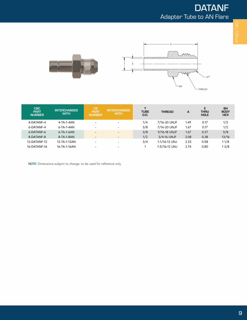
DATANFSATANFAdapter Tubeto AN Flare
9
DATPFSATPF
Adapter Tubeto Female Pipe
10
DATPMSATPMAdapter Tubeto Male Flare
11
DBHASBHABulkheadAdapter
12
DBHFPSBHFP
Bulkhead FemalePipe Connector
13
DBHMPSBHMPBulkhead MalePipe Connector
14
DBHUSBHUBulkhead
Union
15
SBUANFDBUANF
Bulkhead toAN Flare Union
1616
SCAPDCAP
Cap
17
DMCSMC
MaleConnector
20-21
DMC-ORSSMC-ORS
O-Ring StraightThread MaleConnector
22
DMC-ORTSMC-ORT
O-Ring TaperedThread MaleConnector
23
DF PLUGSF PLUG
FittingPlug
18
DFCSFCFemale
Connector
19
Straight ThreadBoss MaleConnector
DMC-STBSMC-STB
25
Port ConnectorUnion
DPCUSPCU
26
Reducer AdapterTube to Tube
DRATTSTRATT
27
Reducing PortConnector
DRPCSRPC
28
ReducingUnion
DRUSRU
29
Tube to ButtWeld Connector
DTBWSTBW
30
DTSWSTSW
Tube to SocketWeld Connector
31
DELU45SELU45
Union 45˚Elbow
35
DUSUUnion
32
DUANFSUANF
Tube to ANFlare Union
33
DELUSELU
UnionElbow
34
DFESFEFemaleElbow
36
DMESME
MaleElbow
37
DME45SME45
Male 45˚Elbow
38
CBC/
CS-
Lok
6
Table of Contents

TYLOKPRODUCTS
55
INSTALLATIONINSTRUCTIONS
56
TUBINGSELECTION
AND PREPARATION
57
SAFETYAND
QUALITY
58
TECHNICALDATA
59
MATERIALSPECIFICATIONS
60
TUBEINSERTION
CHART
61
TIBarbedInsert
48
DCRSCRUnionCross
47
DNSNNut
49
DKNSKNKnurled
Nut
50
Front Collet(Ferrule)
51
DFCRear Collet
(Ferrule)
51
DRC SCSingle Collet
(Ferrule)
51
DCSETSCSETCollet Sets
52
1MDFMud
Dauber
54
DGGGap
Gage
53
Nut Collet Sets
52
SNCSETDNCSET
62
LEAKDETECTOR
CBC/CS-Lok
7
Table of Contents
Tube to Butt Weld Elbow
39
DTBWESTBWE
Tube to Socket Weld Elbow
40
DTSWESTSWE
Female RunTee
41
DTFTSTFT
UnionTee
45-46
DTTTSTTT
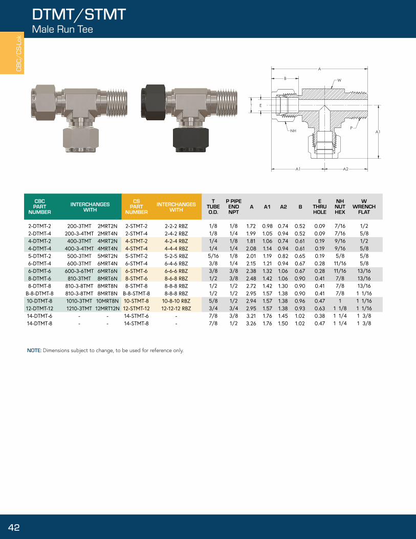
Male RunTee
42
DTMTSTMT
Female BranchTee
43
DTTFSTTF
Male BranchTee
44
DTTMSTTM

TUBE OR PIPE AN /STB DESIGNATOR HOSE OD THREAD TUBE SIZE
PIPE THREAD
(INCHES) (NPT) (INCHES)BSPP/BSPT
B Brass
SS Stainless Steel 1 1/16 1/16 - 27 1/16 - 282 1/8 1/8 - 27 5/16-24 1/8 - 28
S Steel 3 3/164 1/4 1/4 - 18 7/16-20 1/4 - 195 5/166 3/8 3/8 - 18 9/16-18 3/8 - 19
D CBC-Lok® 8 1/2 1/2 - 14 3/4-16 1/2 - 1410 5/8S CS-Lok®
12 3/4 3/4 - 14 1-1/16-12 3/4 - 1414 7/816 1 1 - 11 1/2 1-5/16-12 1 - 11
ATANF Adapter Tube to AN Flare TBWATPF Adapter Tube to Female Pipe TSWATPM Adapter Tube to Male Pipe UBHA Bulkhead Adapter UANFBHFP Bulkhead Female Pipe Connector ELUBHMP Bulkhead Male Pipe Connector ELU45BHU Bulkhead Union FE
BUANF Bulkhead to AN Flare Union ME45CAP Cap ME
F PLUG Fitting Plug TBWEFC Female Connector TSWEMC Male Connector TFT
MC-ORS O Ring Straight Thread Male Connector TMTMC-ORT O Ring Pipe Thread Male Connector TTFMC-STB
PCURATTRPCDRU
Straight Thread Boss Male Connector TTMPort Connector Union TTT
Reducer Adapter Tube to Tube CRReducing Port Connector N
Reducing Union KN
Tube to Butt Weld ConnectorTube to Socket Weld Connector
UnionTube to AN Flare Union
Union ElbowUnion 45º Elbow
Female ElbowMale 45º Elbow
Male ElbowTube to Butt Weld Elbow
Tube to Socket Weld ElbowFemale Run TeeMale Run Tee
Female Branch TeeMale Branch Tee
Union TeeUnion Cross
NutKnurled Nut
CHART 2 - TUBE O.D./THREAD SIZES
CHART 1 - MATERIAL
CHART 3 - STYLE
CHART 4 - DESCRIPTION CHART 4 - DESCRIPTION
CBC/
CS-L
ok
8
How to OrderCBC/CS-Lok®
CBC-Lok®/CS-Lok® Tube Fittings are ordered as listed in this catalog by inserting the material code before the part number. CBC-Lok®/CS-Lok® Tube Fittings can be identified through the part number as to material, tube size, configuration, and thread connection. The part number describes a complete fitting assembly.
The size nomenclature to describe a tee fitting is from left (1) to right (2) and down (3).
Special Configurations available upon request.
Example: A Stainless Steel Female Run Tee, 3/8” Tube Size to 1/4” Female Pipe to 3/8” Tube is designated as follows:
SS - D TFT 4
Material Tube O.D. Odd End Size
Chart 1 Chart 2 Chart 3 Chart 4 Chart 23
6 - -
Style escriptionD
- 1 2
CBCPART
NUMBERINTERCHANGES
WITH
4-DATANF-4 6-DATANF-46-DATANF-68-DATANF-8
12-DATANF-1216-DATANF-16
4-TA-1-4AN 6-TA-1-4AN6-TA-1-6AN8-TA-1-8AN
12-TA-1-12AN16-TA-1-16AN
CSPART
NUMBERINTERCHANGES
WITH
------
------
TTUBEO.D.
1/43/83/81/23/4
1
THREAD
7/16-20 UNJF7/16-20 UNJF9/16-18 UNJF3/4-16 UNJF1-1/16-12 UNJ1-5/16-12 UNJ
A
1.491.671.672.082.332.74
ETHRUHOLE
0.170.170.270.380.580.80
BHBODYHEX
1/21/25/8
13/161 1/81 3/8
A
ET
BH
37
THREAD
CBC/CS-Lok
NOTE: Dimensions subject to change, to be used for reference only.
9
DATANFAdapter Tube to AN Flare

CBCPART
NUMBERINTERCHANGES
WITH
2-DATPF-22-DATPF-44-DATPF-24-DATPF-44-DATPF-64-DATPF-86-DATPF-26-DATPF-46-DATPF-66-DATPF-88-DATPF-48-DATPF-68-DATPF-88-DATPF-1210-DATPF-812-DATPF-812-DATPF-1216-DATPF-1216-DATPF-16
CSPART
NUMBERINTERCHANGES
WITHT
TUBEO.D.
1/81/81/41/41/41/43/83/83/83/81/21/21/21/25/83/43/4
11
A
1.371.521.391.551.641.891.531.691.771.981.892.032.272.272.242.242.302.612.66
ETHRUHOLE
0.080.080.170.170.170.170.270.270.270.270.380.380.380.380.470.580.580.800.80
BHBODYHEX
9/163/49/163/47/8
1 1/169/163/47/8
1 1/163/47/8
1 1/161 5/161 1/161 1/161 5/161 5/161 5/8
PPIPE END
NPT
2FA2N 2FA4N4FA2N4FA4N4FA6N4FA8N6FA2N6FA4N6FA6N6FA8N8FA4N8FA6N8FA8N
-10FA8N12FA8N12FA12N16FA12N16FA16N
2-TA-7-22-TA-7-44-TA-7-24-TA-7-44-TA-7-64-TA-7-86-TA-7-26-TA-7-46-TA-7-66-TA-7-88-TA-7-48-TA-7-68-TA-7-88-TA-7-1210-TA-7-812-TA-7-812-TA-7-1216-TA-7-1216-TA-7-16
2-SATPF-22-SATPF-44-SATPF-24-SATPF-44-SATPF-64-SATPF-86-SATPF-26-SATPF-46-SATPF-66-SATPF-88-SATPF-48-SATPF-68-SATPF-88-SATPF-1210-SATPF-812-SATPF-812-SATPF-1216-SATPF-1216-SATPF-16
2-2 T2HG2-4 T2HG4-2 T2HG4-4 T2HG4-6 T2HG4-8 T2HG6-2 T2HG6-4 T2HG6-6 T2HG6-8 T2HG8-4 T2HG8-6 T2HG8-8 T2HG
-10-8 T2HG12-8 T2HG12-12 T2HG16-12 T2HG16-16 T2HG
1/81/41/81/43/81/21/81/43/81/21/43/81/23/41/21/23/43/4
1
A
T E
BH
P
CBC/
CS-L
ok
NOTE: Dimensions subject to change, to be used for reference only.
10
DATPF/SATPFAdapter Tube to Female Pipe

TTUBEO.D.
1/81/81/41/41/41/45/163/83/83/83/81/21/21/21/25/85/83/43/43/47/8
11
A
1.291.511.331.551.581.801.611.481.691.701.921.921.952.172.171.992.212.212.212.522.212.522.83
ETHRUHOLE
0.090.090.170.170.170.170.250.190.270.270.270.280.380.380.380.380.470.470.580.590.470.630.80
BHBODYHEX
7/169/167/169/1611/167/89/167/169/1611/167/89/1611/167/8
1 1/1611/167/87/8
1 1/161 3/815/161 1/161 3/8
PPIPE END
NPT
CBCPART
NUMBERINTERCHANGES
WITH
2-DATPM-22-DATPM-44-DATPM-24-DATPM-44-DATPM-64-DATPM-85-DATPM-46-DATPM-26-DATPM-46-DATPM-66-DATPM-88-DATPM-48-DATPM-68-DATPM-88-DATPM-1210-DATPM-610-DATPM-812-DATPM-812-DATPM-1212-DATPM-1614-DATPM-816-DATPM-1216-DATPM-16
CSPART
NUMBERINTERCHANGES
WITH
2MA2N2MA4N4MA2N4MA4N4MA6N4MA8N5MA4N6MA2N6MA4N6MA6N6MA8N8MA4N8MA6N8MA8N
--
10MA8N12MA8N12MA12N12MA16N
-16MA12N16MA16N
2-TA-1-22-TA-1-44-TA-1-24-TA-1-44-TA-1-64-TA-1-85-TA-1-46-TA-1-26-TA-1-46-TA-1-66-TA-1-88-TA-1-48-TA-1-68-TA-1-88-TA-1-12
-10-TA-1-812-TA-1-812-TA-1-1212-TA-1-16
-16-TA-1-1216-TA-1-16
2-SATPM-22-SATPM-44-SATPM-24-SATPM-44-SATPM-64-SATPM-85-SATPM-46-SATPM-26-SATPM-46-SATPM-66-SATPM-88-SATPM-48-SATPM-68-SATPM-88-SATPM-1210-SATPM-610-SATPM-812-SATPM-812-SATPM-1212-SATPM-1614-SATPM-816-SATPM-1216-SATPM-16
2-2 T2HF2-4 T2HF4-2 T2HF4-4 T2HF4-6 T2HF4-8 T2HF5-4 T2HF6-2 T2HF6-4 T2HF6-6 T2HF6-8 T2HF8-4 T2HF8-6 T2HF8-8 T2HF8-12 T2HF
-10-8 T2HF12-8 T2HF12-12 T2HF12-16 T2HF
-16-12 T2HF16-16 T2HF
1/81/41/81/43/81/21/41/81/41/81/21/43/81/23/43/81/21/23/4
11/23/4
1
EA
A
BH
P
CBC/CS-Lok
11
DATPM/SATPMAdapter Tube to Male Pipe
NOTE: Dimensions subject to change, to be used for reference only.

TTUBEO.D.
1/43/81/2
A
2.272.563.04
ETHRUHOLE
0.170.270.90
BHBODYHEX
5/83/4
15/16
CBCPART
NUMBERINTERCHANGES
WITH
4-DBHA-46-DBHA-68-DBHA-8
CSPART
NUMBERINTERCHANGES
WITH
4TUBC46TUBC68TUBC8
400-R1-4600-R1-6810-R1-8
4-SBHA-46-SBHA-68-SBHA-8
4-4 T2H2BZ6-6 T2H2BZ8-8 T2H2BZ
1/43/81/2
T1TUBEO.D.
B
0.610.670.90
JNHJAM NUTHEX
5/83/4
15/16
NHNUTHEX
9/1611/167/8
PANELHOLE
29/6437/6449/64
T1E
A
B
T
BHJNH
NH
CBC/
CS-L
okDBHA/SBHABulkhead Adapter
12
NOTE: Dimensions subject to change, to be used for reference only.

TTUBEO.D.
1/81/41/45/163/83/81/21/25/8
1
A
1.771.852.041.962.172.232.432.622.653.68
ETHRUHOLE
0.090.190.190.250.280.280.410.410.500.88
BHBODYHEX
9/165/83/4
11/163/47/8
15/161 1/161 1/161 5/8
CBCPART
NUMBERINTERCHANGES
WITH
2-DBHFP-24-DBHFP-24-DBHFP-45-DBHFP-26-DBHFP-46-DBHFP-68-DBHFP-68-DBHFP-810-DBHFP-816-DBHFP-16
CSPART
NUMBERINTERCHANGES
WITH
2FBC2N4FBC2N4FBC4N5FBC2N6FBC4N
-8FBC6N8FBC8N10FBC8N16FBC16N
200-71-2400-71-2400-71-4
-600-71-4600-71-6810-71-6810-71-8
-1610-71-16
2-SBHFP-24-SBHFP-24-SBHFP-45-SBHFP-26-SBHFP-46-SBHFP-68-SBHFP-68-SBHFP-810-SBHFP-816-SBHFP-16
1/81/81/41/81/43/83/81/21/21
P PIPEENDNPT B
0.520.610.610.650.670.670.900.900.961.24
JNHJAM NUTHEX
1/25/85/8
11/163/43/4
15/1615/161 1/161 5/8
NHNUTHEX
7/169/169/165/8
11/1611/167/87/8
11 1/2
PANELHOLE
21/6429/6429/6433/6437/6437/6449/6449/6457/641 21/64
2-2 GH2BZ4-2 GH2BZ4-4 GH2BZ5-2 GH2BZ6-4 GH2BZ
-8-6 GH2BZ8-8 GH2BZ10-8 GH2BZ16-16 GH2BZ
E
A
T
B JNHBH
NH
P
CBC/CS-Lok
13
DBHFP/SBHFPBulkhead Female Pipe Connector
NOTE: Dimensions subject to change, to be used for reference only.

TTUBEO.D.
1/81/41/41/43/83/83/81/21/21/23/4
A
1.831.952.132.172.262.262.512.492.492.713.26
ETHRUHOLE
0.090.190.190.190.280.280.280.280.380.410.63
BHBODYHEX
1/25/85/8
11/163/43/47/8
15/1615/1615/161 3/8
CBCPART
NUMBERINTERCHANGES
WITH
2-DBHMP-24-DBHMP-24-DBHMP-44-DBHMP-66-DBHMP-46-DBHMP-66-DBHMP-88-DBHMP-48-DBHMP-68-DBHMP-8
12-DBHMP-16
CSPART
NUMBERINTERCHANGES
WITH
2MBC2N4MBC2N4MBC4N4MBC6N6MBC4N6MBC6N6MBC8N8MBC4N8MBC6N8MBC8N
200-11-2400-11-2400-11-4
-600-11-4600-11-6600-11-8810-11-4810-11-6810-11-8
2-SBHMP-24-SBHMP-24-SBHMP-44-SBHMP-66-SBHMP-46-SBHMP-66-SBHMP-88-SBHMP-48-SBHMP-68-SBHMP-8
12-SBHMP-12
1/81/81/43/81/43/81/21/43/81/21
P PIPEENDNPT
B
0.520.610.610.610.670.670.670.900.900.900.63
JNHJAM NUTHEX
1/25/85/85/83/43/43/4
15/1615/1615/161 3/16
NHNUTHEX
7/169/169/169/1611/1611/1611/167/87/87/8
1 1/8
PANELHOLE
21/6429/6429/6429/6437/6437/6437/6449/6449/6449/641 1/64
2-2 FH2BZ4-2 FH2BZ4-4 FH2BZ4-6 FH2BZ6-4 FH2BZ6-6 FH2BZ6-8 FH2BZ8-4 FH2BZ8-6 FH2BZ8-8 FH2BZ
E
A
T
B
JNH
NH
BHP
CBC/
CS-L
ok
14
DBHMP/SBHMPBulkhead Male Pipe Connector
NOTE: Dimensions subject to change, to be used for reference only.

TTUBEO.D.
1/161/83/161/45/163/81/25/83/4
1
A
1.252.032.112.272.422.462.802.863.113.80
ETHRUHOLE
0.050.090.130.190.250.280.410.500.630.88
BHBODYHEX
5/161/29/165/8
11/163/4
15/161 1/161 3/161 5/8
B
0.340.520.540.610.650.670.900.960.961.24
JNHJAM NUTHEX
5/161/29/165/8
11/163/4
15/161 1/161 3/161 5/8
NHNUTHEX
5/167/161/29/165/8
11/167/8
11 1/81 1/2
PANELHOLE
13/6421/6425/6429/6433/6437/6449/6457/641 1/641 21/64
CBCPART
NUMBERINTERCHANGES
WITH
1-DBHU-12-DBHU-23-DBHU-34-DBHU-45-DBHU-56-DBHU-68-DBHU-8
10-DBHU-1012-DBHU-1216-DBHU-16
CSPART
NUMBERINTERCHANGES
WITH
1BC12BC23BC34BC45BC56BC68BC8
10BC1012BC1216BC16
100-61200-61300-61400-61500-61600-61810-611010-611210-611610-61
1-SBHU-12-SBHU-23-SBHU-34-SBHU-45-SBHU-56-SBHU-68-SBHU-8
10-SBHU-1012-SBHU-1216-SBHU-16
1-1 WBZ2-2 WBZ3-3 WBZ4-4 WBZ5-5 WBZ6-6 WBZ8-8 WBZ
10-10 WBZ12-12 WBZ16-16 WBZ
E
A
T
B
JNHBH
NH
CBC/CS-Lok
15
DBHU/SBHUBulkhead Union
NOTE: Dimensions subject to change, to be used for reference only.

TTUBEO.D.
1/43/81/23/4
1
A
2.122.262.593.123.65
ETHRUHOLE
0.170.280.390.610.85
BHBODYHEX
5/83/4
15/161 3/161 5/8
7/16-209/16-183/4-16
1-1/16-121-5/6-12
THREAD B
0.610.670.900.961.24
JNHJAM NUTHEX
5/83/4
15/161 3/161 5/8
NHNUTHEX
9/1611/167/8
1 1/81 1/2
PANELHOLE
29/6437/6449/641 1/641 21/64
CSPART
NUMBERINTERCHANGES
WITH
4-4 XH2BZ6-6 XH2BZ8-8 XH2BZ
12-12 XH2BZ16-16 XH2BZ
4-SBUANF-46-SBUANF-68-SBUANF-8
12-SBUANF-1216-SBUANF-16
CBCPART
NUMBERINTERCHANGES
WITH
4-DBUANF-46-DBUANF-68-DBUANF-8
12-DBUANF-1216-DBUANF-16
4XABC46XABC68XABC8
12XABC1216XABC16
400-61-4AN600-61-6AN810-61-8AN
1210-61-12AN1610-61-16AN
E
A
T
B
JNH
BH
NH
THREAD
37
CBC/
CS-L
ok
16
DBUANF/SBUANFBulkhead to AN Flare Union
NOTE: Dimensions subject to change, to be used for reference only.

T
TUBEO.D.
1/161/83/161/45/163/81/25/83/47/8
1
A
0.590.800.840.920.981.011.151.181.241.331.52
BHBODYHEX
5/167/167/161/29/165/8
13/1615/161 1/161 3/161 3/8
CBCPART
NUMBERINTERCHANGES
WITH
1-DCAP2-DCAP3-DCAP4-DCAP5-DCAP6-DCAP8-DCAP10-DCAP12-DCAP14-DCAP16-DCAP
CSPART
NUMBERINTERCHANGES
WITH
1BLEN12BLEN23BLEN34BLEN45BLEN56BLEN68BLEN8
10BLEN1012BLEN1214BLEN1416BLEN16
100-C200-C300-C400-C500-C600-C810-C1010-C1210-C1410-C1610-C
B
0.340.520.540.610.650.670.900.960.961.021.24
NHNUTHEX
5/167/161/29/165/8
11/167/8
11 1/81 1/41 1/2
1 PNBZ2 PNBZ3 PNBZ4 PNBZ5 PNBZ6 PNBZ8 PNBZ10 PNBZ12 PNBZ14 PNBZ16 PNBZ
1-SCAP2-SCAP3-SCAP4-SCAP5-SCAP6-SCAP8-SCAP10-SCAP12-SCAP14-SCAP16-SCAP
T
A
B
NH
BH
CBC/CS-Lok
17
DCAP/SCAPCap
NOTE: Dimensions subject to change, to be used for reference only.
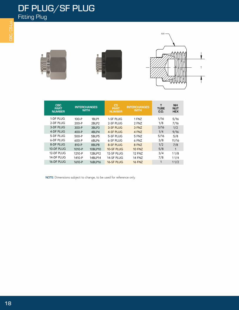
T
TUBEO.D.
1/161/83/161/45/163/81/25/83/47/8
1
CBCPART
NUMBERINTERCHANGES
WITH
1-DF PLUG2-DF PLUG3-DF PLUG4-DF PLUG5-DF PLUG6-DF PLUG8-DF PLUG10-DF PLUG12-DF PLUG14-DF PLUG16-DF PLUG
CSPART
NUMBERINTERCHANGES
WITH
1BLP12BLP23BLP34BLP45BLP56BLP68BLP8
10BLP1012BLP1214BLP1416BLP16
100-P200-P300-P400-P500-P600-P810-P1010-P1210-P1410-P1610-P
NHNUTHEX
5/167/161/29/165/8
11/167/8
11 1/81 1/41 1/2
1 FNZ2 FNZ3 FNZ4 FNZ5 FNZ6 FNZ8 FNZ10 FNZ12 FNZ14 FNZ16 FNZ
1-SF PLUG2-SF PLUG3-SF PLUG4-SF PLUG5-SF PLUG6-SF PLUG8-SF PLUG10-SF PLUG12-SF PLUG14-SF PLUG16-SF PLUG
T
NH
CBC/
CS-L
ok
18
DF PLUG/SF PLUGFitting Plug
NOTE: Dimensions subject to change, to be used for reference only.

TTUBEO.D.
AE
THRUHOLE
BHBODYHEX
CBCPART
NUMBERINTERCHANGES
WITH
2-DFC-22-DFC-42-DFC-63-DFC-23-DFC-44-DFC-24-DFC-44-DFC-64-DFC-85-DFC-25-DFC-45-DFC-65-DFC-86-DFC-26-DFC-46-DFC-66-DFC-86-DFC-128-DFC-48-DFC-68-DFC-88-DFC-128-DFC-1610-DFC-410-DFC-610-DFC-810-DFC-1212-DFC-612-DFC-812-DFC-1212-DFC-1614-DFC-814-DFC-1216-DFC-616-DFC-816-DFC-1216-DFC-16
CSPART
NUMBERINTERCHANGES
WITH
2FSC2N2FSC4N
-3FSC2N
-4FSC2N4FSC4N4FSC6N4FSC8N5FSC2N5FSC4N
--
6FSC2N6FSC4N6FSC6N6FSC8N6FSC12N8FSC4N8FSC6N8FSC8N8FSC12N
--
10FSC6N10FSC8N10FSC12N
-12FSC8N12FSC12N
--
14FSC12N--
16FSC12N16FSC16N
200-7-2200-7-4
-300-7-23FSC4N400-7-2400-7-4400-7-6400-7-8500-7-2500-7-45FSC6N
-600-7-2600-7-4600-7-6600-7-8600-7-12810-7-4810-7-6810-7-8810-7-12810-7-16
-1010-7-61010-7-81010-7-121210-7-61210-7-81210-7-121210-7-16
-1410-7-12
-1610-7-81610-7-121610-7-16
P PIPEENDNPT
BNH
NUTHEX
2-2 GBZ2-4 GBZ
-3-2 GBZ3-4 GBZ4-2 GBZ4-4 GBZ4-6 GBZ4-8 GBZ5-2 GBZ5-4 GBZ5-6 GBZ
-6-2 GBZ6-4 GBZ6-6 GBZ6-8 GBZ6-12 GBZ8-4 GBZ8-6 GBZ8-8 GBZ8-12 GBZ
--
10-6 GBZ10-8 GBZ10-12 GBZ
-12-8 GBZ12-12 GBZ
--
14-12 GBZ--
16-12 GBZ16-16 GBZ
2-SFC-22-SFC-42-SFC-63-SFC-23-SFC-44-SFC-24-SFC-44-SFC-64-SFC-85-SFC-25-SFC-45-SFC-65-SFC-86-SFC-26-SFC-46-SFC-66-SFC-86-SFC-128-SFC-48-SFC-68-SFC-88-SFC-128-SFC-1610-SFC-410-SFC-610-SFC-810-SFC-1212-SFC-612-SFC-812-SFC-1212-SFC-1614-SFC-814-SFC-1216-SFC-616-SFC-816-SFC-1216-SFC-16
1/8 1/8 1/83/16 3/16 1/41/41/41/45/16 5/16 5/165/163/83/83/83/83/81/21/21/21/21/25/85/85/85/83/43/43/43/47/87/8
1111
1/81/43/81/81/41/81/43/81/21/81/43/81/21/81/43/81/23/41/43/81/23/4
11/43/81/23/43/81/23/4
11/23/43/81/23/4
1
1.14 1.33 1.39 1.16 1.35 1.23 1.42 1.48 1.67 1.27 1.46 1.52 1.71 1.29 1.48 1.54 1.73 1.89 1.59 1.65 1.84 1.90 2.27 1.80 1.65 1.83 1.90 1.67 1.84 1.90 2.28 1.83 1.96 2.15 2.15 2.12 2.46
0.520.520.520.540.540.610.610.610.610.650.650.650.650.670.670.670.670.670.900.900.900.900.900.960.960.960.960.960.960.960.961.021.021.241.241.241.24
0.09 0.09 0.09 0.13 0.13 0.190.190.190.190.250.250.250.250.280.280.280.280.280.410.410.410.410.410.440.500.500.500.560.630.630.630.700.720.560.700.880.88
7/167/167/161/21/29/169/169/169/165/85/85/85/8
11/1611/1611/1611/1611/167/87/87/87/87/8
1111
1 1/81 1/81 1/81 1/81 1/41 1/41 1/21 1/21 1/21 1/2
9/163/47/89/163/49/163/47/8
1 1/169/163/47/8
1 1/165/83/47/8
1 1/161 5/1613/167/8
1 1/161 5/161 5/815/1615/161 1/161 5/161 1/161 1/161 5/161 5/81 3/161 3/81 3/81 3/81 3/81 5/8
E
A
B
T
NH
BH
P
CBC/CS-Lok
19
DFC/SFCFemale Connector
NOTE: Dimensions subject to change, to be used for reference only.

1-DMC-11-DMC-22-DMC-12-DMC-22-DMC-42-DMC-62-DMC-83-DMC-23-DMC-44-DMC-14-DMC-24-DMC-44-DMC-64-DMC-84-DMC-125-DMC-25-DMC-45-DMC-65-DMC-86-DMC-26-DMC-46-DMC-66-DMC-86-DMC-126-DMC-168-DMC-28-DMC-48-DMC-68-DMC-88-DMC-128-DMC-16
CBC PART
NUMBER
100-1-1100-1-2200-1-1200-1-2200-1-3200-1-6200-1-8300-1-2300-1-4400-1-1400-1-2400-1-4400-1-6400-1-8400-1-12500-1-2500-1-4500-1-6500-1-8600-1-2600-1-4600-1-6600-1-8600-1-12600-1-16810-1-2810-1-4810-1-6810-1-8810-1-12810-1-16
INTERCHANGESWITH
1MSC1N 1MSC2N 2MSC1N 2MSC2N 2MSC4N 2MSC6N 2MSC8N 3MSC2N 3MSC4N 4MSC1N 4MSC2N 4MSC4N 4MSC6N 4MSC8N 4MSC12N 5MSC2N 5MSC4N 5MSC6N 5MSC8N 6MSC2N 6MSC4N 6MSC6N 6MSC8N 6MSC12N
- 8MSC2N 8MSC4N 8MSC6N 8MSC8N 8MSC12N 8MSC16N
CSPART
NUMBER
1-SMC-11-SMC-22-SMC-12-SMC-22-SMC-42-SMC-62-SMC-83-SMC-23-SMC-44-SMC-14-SMC-24-SMC-44-SMC-64-SMC-84-SMC-125-SMC-25-SMC-45-SMC-65-SMC-86-SMC-26-SMC-46-SMC-66-SMC-86-SMC-126-SMC-168-SMC-28-SMC-48-SMC-68-SMC-88-SMC-128-SMC-16
INTERCHANGESWITH
1-1 FBZ1-2 FBZ2-1 FBZ2-2 FBZ2-4 FBZ2-6 FBZ2-8 FBZ3-2 FBZ3-4 FBZ4-1 FBZ4-2 FBZ4-4 FBZ4-6 FBZ4-8 FBZ4-12 FBZ5-2 FBZ5-4 FBZ5-6 FBZ5-8 FBZ6-2 FBZ6-4 FBZ6-6 FBZ6-8 FBZ6-12 FBZ
- 8-2 FBZ8-4 FBZ8-6 FBZ8-8 FBZ8-12 FBZ8-16 FBZ
1/161/161/81/81/81/81/83/163/161/41/41/41/41/41/45/165/165/165/163/83/83/83/83/83/81/21/21/21/21/21/2
TTUBEO.D.
1/161/81/161/81/43/81/21/81/41/161/81/43/81/23/41/81/43/81/21/81/43/81/23/4
11/81/43/81/23/4
1
P PIPEENDNPT
0.95 1.03 1.17 1.20 1.41 1.42 1.67 1.23 1.43 1.29 1.29 1.49 1.51 1.76 1.82 1.35 1.54 1.56 1.77 1.39 1.57 1.57 1.83 1.89 2.14 1.52 1.71 1.71 1.93 1.99 2.26
A
0.340.340.520.520.520.520.520.540.540.610.610.610.610.610.610.650.650.650.650.670.670.670.670.670.670.900.900.900.900.900.90
B
0.050.050.090.090.090.090.090.130.130.130.190.190.190.190.190.190.250.250.250.190.280.280.280.280.280.190.280.380.410.410.41
E THRUHOLE
5/165/167/167/167/167/167/161/21/29/169/169/169/169/169/165/85/85/85/8
11/1611/1611/1611/1611/1611/167/87/87/87/87/87/8
NHNUTHEX
5/167/167/167/169/1611/167/87/169/161/21/29/1611/167/8
1 1/169/169/1611/167/85/85/8
11/167/8
1 1/161 3/8 13/16 13/16 13/167/8
1 1/161 3/8
BHBODYHEX
ET
A
B
NH
BH P
CBC/
CS-L
ok
20
DMC/SMCMale Connector
NOTE: Dimensions subject to change, to be used for reference only.

CSPART
NUMBERINTERCHANGES
WITH
10-DMC-410-DMC-610-DMC-810-DMC-1212-DMC-412-DMC-612-DMC-812-DMC-1212-DMC-1614-DMC-614-DMC-814-DMC-1214-DMC-1616-DMC-816-DMC-1216-DMC-16
CBCPART
NUMBER
1010-1-4 1010-1-6 1010-1-8 1010-1-12 1210-1-4 1210-1-6 1210-1-8 1210-1-12 1210-1-16
1410-1-8 1410-1-12 1410-1-16 1610-1-8 1610-1-12 1610-1-16
INTERCHANGESWITH
- 10MSC6N10MSC8N10MSC12N
- -
12MSC8N12MSC12N12MSC16N
- -
14MSC12N14MSC16N16MSC8N16MSC12N16MSC16N
10-SMC-410-SMC-610-SMC-810-SMC-1212-SMC-412-SMC-612-SMC-812-SMC-1212-SMC-1614-SMC-614-SMC-814-SMC-1214-SMC-1616-SMC-816-SMC-1216-SMC-16
- 10-6 FBZ10-8 FBZ10-12 FBZ
- -
12-8 FBZ12-12 FBZ12-16 FBZ
- -
14-12 FBZ14-16 FBZ16-8 FBZ16-12 FBZ16-16 FBZ
5/85/85/85/83/43/43/43/43/47/87/87/87/8
111
T TUBE O.D.
1/43/81/23/41/43/81/23/4
13/81/23/4
11/23/4
1
P PIPEENDNPT
1.74 1.74 1.93 1.99 1.81 1.81 1.99 1.99 2.26 1.80 1.99 1.99 2.26 2.27 2.27 2.46
A
0.960.960.960.960.960.960.960.960.961.021.021.021.021.241.241.24
B
0.28 0.38 0.47 0.50 0.28 0.38 0.47 0.63 0.63 0.38 0.47 0.63 0.72 0.47 0.63 0.88
E THRU HOLE
1111
1 1/8 1 1/81 1/8 1 1/81 1/81 1/4 1 1/4 1 1/4 1 1/4 1 1/2 1 1/2 1 1/2
NH NUT HEX
15/1615/1615/161 1/161 1/161 1/161 1/161 1/161 3/81 3/161 3/161 3/161 3/81 3/81 3/81 3/8
BHBODYHEX
ET
A
B
NH
BH P
CBC/CS-Lok
21
DMC/SMCMale Connector
NOTE: Dimensions subject to change, to be used for reference only.

TTUBEO.D.
AE
THRUHOLE
BHBODYHEX
CBCPART
NUMBERINTERCHANGES
WITHCS
PARTNUMBER
INTERCHANGESWITH THREAD B
NHNUTHEX
O-RING
2-DMC-ORS4-DMC-ORS6-DMC-ORS8-DMC-ORS12-DMC-ORS16-DMC-ORS
200-1-OR2 M2SC2400-1-OR4 M2SC4600-1-OR6 M2SC6810-1-OR8 M2SC81210-1-OR 12M2SC121610-1-OR 16M2SC16
2-SMC-ORS4-SMC-ORS6-SMC-ORS8-SMC-ORS12-SMC-ORS16-SMC-ORS
2-2 ZHBA54-4 ZHBA56-6 ZHBA58-8 ZHBA5
12-12 ZHBA516-16 ZHBA5
1/81/43/81/23/4
1
5/16-247/16-209/16-183/4-16
1-1/16-121-5/16-12
1.30 1.51 1.67 1.80 2.06 2.30
0.520.610.670.900.961.24
0.090.190.280.410.630.88
7/169/1611/167/8
1 1/81 1/2
9/163/4
15/161 1/81 1/21 3/4
AS-011AS-111AS-113AS-116AS-215AS-219
E
A
T
B
NH
BH
O-RING
THREAD
CBC/
CS-L
ok
22
DMC-ORS/SMC-ORSO-Ring Straight Thread Male Connector
NOTE: Dimensions subject to change, to be used for reference only. Standard O-Ring material is Buna-N, 70 durometer.

TTUBEO.D.
AE
THRUHOLE
BHBODYHEX
CBCPART
NUMBERINTERCHANGES
WITHCS
PARTNUMBER
INTERCHANGESWITH
PPIPE ENDNPT
BNH
NUTHEX
O-RING
4-DMC-2-ORT4-DMC-4-ORT6-DMC-6-ORT6-DMC-8-ORT8-DMC-4-ORT8-DMC-8-ORT
400-1-2-OR400-1-4-OR600-1-6-OR600-1-8-OR
- 810-1-8-OR
4M3SC24M3SC46M3SC66M3SC88M3SC48M3SC8
4-SMC-2-ORT4-SMC-4-ORT6-SMC-6-ORT6-SMC-8-ORT8-SMC-4-ORT8-SMC-8-ORT
4-2 ZHBF54-4 ZHBF56-6 ZHBF56-8 ZHBF58-4 ZHBF58-8 ZHBF5
1/41/43/83/81/21/2
1/81/43/81/21/4 1/2
1.381.511.641.861.681.96
0.61 0.61 0.67 0.67 0.90 0.90
0.190.190.280.280.280.41
9/169/16 11/1611/167/87/8
3/4 15/16 1 1/8
1 5/1615/16 1 5/16
AS-111AS-113AS-116AS-212AS-113AS-212
ET
B
A
NH
BH
O-RING
P
CBC/CS-Lok
23
DMC-ORT/SMC-ORTO-Ring Tapered Thread Male Connector
NOTE: Dimensions subject to change, to be used for reference only.

B
D
1
A
1
C
E
18 "
1
1 Allow clearance for (1) full thread.
5/16-24 - 0.50 0.59 0.66 0.09 0.16 5/16-24 - 0.50 0.59 0.66 0.09 0.22
- 1/8 0.69 0.78 0.88 0.16 0.28 3/8-24 - 0.56 0.66 0.75 0.09 0.22 7/16-20 - 0.69 0.78 0.88 0.16 0.28
- 1/8 0.69 0.78 0.88 0.16 0.28- 1/4 0.87 0.97 1.09 0.16 0.31
1/2-20 - 0.75 0.91 1.03 0.16 0.31 9/16-18 - 0.81 0.97 1.09 0.16 0.31
- 1/4 0.87 0.97 1.09 0.16 0.31- 3/8 1.00 1.16 1.31 0.16 0.34- 1/2 1.22 1.34 1.53 0.22 0.44
3/4-16 - 1.00 1.16 1.31 0.16 0.34- 1/2 1.22 1.34 1.53 0.22 0.44
1-1/16-12 - 1.41 1.53 1.75 0.22 0.50 1-5/16-12 - 1.69 1.78 2.03 0.22 0.56
CBC/
CS-L
ok
24
MOUNTING DIMENSIONSfor ORS/ORT Fittings
RAISED SURFACEMinimum diameter is larger than the O-Ring sealing diameter to prevent O-Ring extrusion.
RECESSED HOLE(SHOULDER CLEARANCE)Minimum diameter allows clearance for round shoulder of fitting into recess.
RECESSED HOLE(HEX CLEARANCE)Minimum diameter allows clearance for hex of fitting into recess.
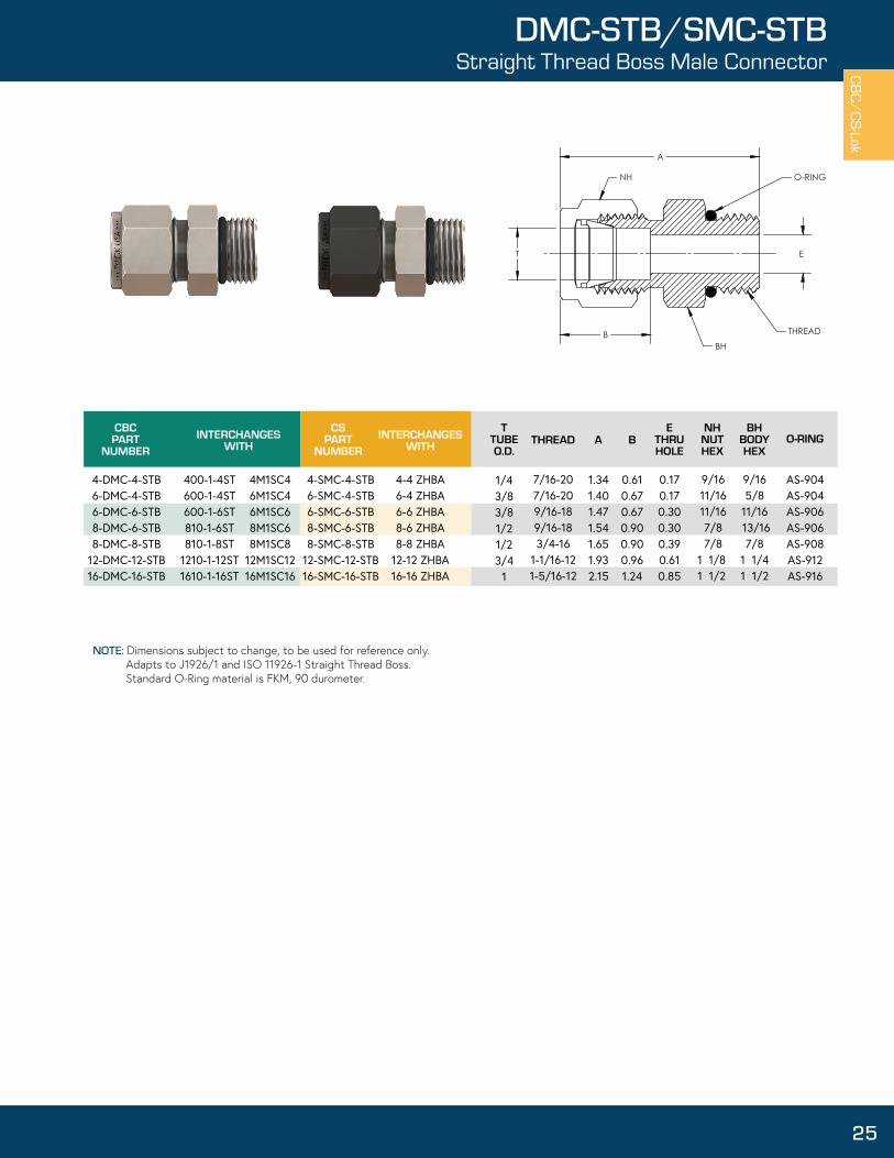
1.341.401.471.541.651.932.15
TTUBEO.D.
AE
THRUHOLE
BHBODYHEX
CBCPART
NUMBERINTERCHANGES
WITHCS
PARTNUMBER
INTERCHANGESWITH THREAD B
NHNUTHEX
O-RING
4-DMC-4-STB6-DMC-4-STB6-DMC-6-STB8-DMC-6-STB8-DMC-8-STB
12-DMC-12-STB16-DMC-16-STB
400-1-4ST600-1-4ST600-1-6ST810-1-6ST810-1-8ST
1210-1-12ST1610-1-16ST
4M1SC46M1SC46M1SC68M1SC68M1SC8
12M1SC1216M1SC16
4-SMC-4-STB6-SMC-4-STB6-SMC-6-STB8-SMC-6-STB8-SMC-8-STB
12-SMC-12-STB16-SMC-16-STB
4-4 ZHBA6-4 ZHBA6-6 ZHBA8-6 ZHBA8-8 ZHBA
12-12 ZHBA16-16 ZHBA
1/43/83/81/21/23/4
1
7/16-207/16-209/16-189/16-183/4-16
1-1/16-121-5/16-12
0.610.670.670.900.900.961.24
0.170.170.300.300.390.610.85
9/1611/1611/167/87/8
1 1/8 1 1/2
9/165/8
11/16 13/167/8
1 1/41 1/2
AS-904AS-904AS-906AS-906AS-908AS-912AS-916
E
A
T
B
NH
BH
O-RING
THREAD
CBC/CS-Lok
25
DMC-STB/SMC-STBStraight Thread Boss Male Connector
NOTE: Dimensions subject to change, to be used for reference only. Adapts to J1926/1 and ISO 11926-1 Straight Thread Boss. Standard O-Ring material is FKM, 90 durometer.

TTUBEO.D.
AE
THRUHOLE
CBCPART
NUMBERINTERCHANGES
WITHCS
PARTNUMBER
INTERCHANGESWITH
2-DPCU4-DPCU6-DPCU8-DPCU12-DPCU16-DPCU
U201-PC401-PC601-PC811-PC 1211-PC1611-PC
2PC24PC46PC68PC8
12PC1216PC16
2-SPCU4-SPCU6-SPCU8-SPCU12-SPCU16-SPCU
2-2 ZPC4-4 ZPC6-6 ZPC8-8 ZPC
12-12 ZPC16-16 ZPC
1/81/43/81/23/4
1
1.08 1.13 1.28 1.69 1.75 2.10
0.080.170.270.380.580.80
E T
A
CBC/
CS-L
ok
26
DPCU/SPCUPort Connector Union
NOTE: Dimensions subject to change, to be used for reference only.

TTUBEO.D.
AE
THRUHOLE
BHBODYHEX
CBCPART
NUMBERINTERCHANGES
WITHCS
PARTNUMBER
INTERCHANGESWITH
T1TUBEO.D.
BNH
NUTHEX
1-DRATT-22-DRATT-12-DRATT-22-DRATT-42-DRATT-64-DRATT-24-DRATT-44-DRATT-64-DRATT-85-DRATT-66-DRATT-46-DRATT-66-DRATT-86-DRATT-106-DRATT-128-DRATT-48-DRATT-68-DRATT-88-DRATT-108-DRATT-128-DRATT-148-DRATT-1610-DRATT-1210-DRATT-1412-DRATT-812-DRATT-1614-DRATT-1616-DRATT-16
100-R-2200-R-1200-R-2200-R-4200-R-6400-R-2400-R-4400-R-6400-R-8500-R-6600-R-4600-R-6600-R-8600-R-10600-R-12810-R-4810-R-6810-R-8810-R-10810-R-12
- 810-R-161010-R-121010-R-141210-R-81210-R-16
- -
2TUR11TUR22TUR24TUR26TUR22TUR44TUR46TUR48TUR46TUR54TUR66TUR68TUR610TUR612TUR64TUR86TUR8
- 10TUR812TUR8
- 16TUR812TUR1014TUR108TUR1216TUR12
- -
1-SRATT-22-SRATT-12-SRATT-22-SRATT-42-SRATT-64-SRATT-24-SRATT-44-SRATT-64-SRATT-85-SRATT-66-SRATT-46-SRATT-66-SRATT-86-SRATT-106-SRATT-128-SRATT-48-SRATT-68-SRATT-88-SRATT-108-SRATT-128-SRATT-148-SRATT-1610-SRATT-1210-SRATT-1412-SRATT-812-SRATT-1614-SRATT-1616-SRATT-16
2-1 TRBZ1-2 TRBZ2-2 TRBZ4-2 TRBZ6-2 TRBZ2-4 TRBZ4-4 TRBZ6-4 TRBZ8-4 TRBZ6-5 TRBZ4-6 TRBZ6-6 TRBZ8-6 TRBZ10-6 TRBZ12-6 TRBZ4-8 TRBZ6-8 TRBZ
- 10-8 TRBZ12-8 TRBZ
- 16-8 TRBZ12-10 TRBZ14-10 TRBZ8-12 TRBZ16-12 TRBZ
- -
1/161/81/81/81/81/41/41/41/45/163/83/83/83/83/81/21/21/21/21/21/21/25/85/83/43/47/8
1
1/81/161/81/43/81/81/43/81/23/81/43/81/25/83/41/43/81/25/83/47/8
13/47/81/2111
1.291.241.461.501.631.581.621.741.991.811.711.842.092.132.131.851.982.232.262.262.302.572.292.302.322.672.672.95
0.340.520.520.520.520.610.610.610.610.650.670.670.670.670.670.900.900.900.900.900.900.900.960.960.960.961.021.24
0.05 0.03 0.08 0.09 0.09 0.08 0.17 0.19 0.19 0.25 0.17 0.27 0.28 0.28 0.28 0.17 0.27 0.38 0.41 0.41 0.41 0.41 0.50 0.50 0.38 0.63 0.72 0.80
5/16 7/16 7/16 7/16 7/16 9/16 9/16 9/16 9/16 5/8
11/16 11/16 11/16 11/16 11/16 7/8 7/8 7/8 7/8 7/8 7/8 7/8
11
1 1/8 1 1/8 1 1/4 1 1/2
5/167/167/167/167/161/21/21/29/169/165/85/85/8
11/1613/1613/1613/1613/1613/1613/1615/161 1/1615/1615/161 1/161 1/161 3/161 3/8
E T1
A
T
B
NH
BH
CBC/CS-Lok
27
DRATT/SRATTReducer Adapter Tube to Tube
NOTE: Dimensions subject to change, to be used for reference only.

TTUBEO.D.
AE
THRUHOLE
CBCPART
NUMBERINTERCHANGES
WITHCS
PARTNUMBER
INTERCHANGESWITH
T1TUBEO.D.
4-DRPC-26-DRPC-48-DRPC-48-DRPC-612-DRPC-8
401-PC-2601-PC-4811-PC-4811-PC-61211-PC-8
2PC44PC64PC86PC88PC12
4-SRPC-26-SRPC-48-SRPC-48-SRPC-612-SRPC-8
2-4 ZPC4-6 ZPC4-8 ZPC6-8 ZPC8-12 ZPC
1/43/81/21/23/4
1/8 1/4 1/4 3/81/2
1.08 1.12 1.32 1.43 1.71
0.080.170.170.270.38
E T1T
A
CBC/
CS-L
ok
28
DRPC/SRPCReducing Port Connector
NOTE: Dimensions subject to change, to be used for reference only.

CBCPART
NUMBERINTERCHANGES
WITHCS
PARTNUMBER
INTERCHANGESWITH
TTUBEO.D.
AE
THRUHOLE
BHBODYHEX
T1TUBEO.D.
BNH
NUTHEX
B1NH1NUTHEX
2-DRU-14-DRU-14-DRU-24-DRU-35-DRU-25-DRU-46-DRU-16-DRU-26-DRU-46-DRU-58-DRU-28-DRU-48-DRU-610-DRU-610-DRU-812-DRU-412-DRU-612-DRU-812-DRU-1016-DRU-816-DRU-12
200-6-1400-6-1400-6-2400-6-3500-6-2500-6-4600-6-1600-6-2600-6-4600-6-5810-6-2810-6-4810-6-61010-6-61010-6-81210-6-41210-6-61210-6-81210-6-101610-6-81610-6-12
2RU14RU14RU24RU35RU25RU46RU16RU26RU46RU58RU28RU48RU610RU610RU812RU412RU612RU812RU1016RU816RU12
2-SRU-14-SRU-14-SRU-24-SRU-35-SRU-25-SRU-46-SRU-16-SRU-26-SRU-46-SRU-58-SRU-28-SRU-48-SRU-610-SRU-610-SRU-812-SRU-412-SRU-612-SRU-812-SRU-1016-SRU-816-SRU-12
2-1 HBZ4-1 HBZ4-2 HBZ4-3 HBZ5-2 HBZ5-4 HBZ6-1 HBZ6-2 HBZ6-4 HBZ6-5 HBZ8-2 HBZ8-4 HBZ8-6 HBZ10-6 HBZ10-8 HBZ12-4 HBZ12-6 HBZ12-8 HBZ12-10 HBZ16-8 HBZ16-12 HBZ
1/81/41/41/45/165/163/83/83/83/81/21/21/25/85/83/43/43/43/4
11
1/161/161/83/161/81/41/161/81/45/161/81/43/83/81/21/43/81/25/81/23/4
1.231.351.521.551.591.681.451.621.711.761.791.851.911.942.051.942.012.112.112.482.49
0.520.610.610.610.650.650.670.670.670.670.900.900.900.960.960.960.960.960.961.241.24
0.340.340.520.540.520.610.340.520.610.650.520.610.670.670.900.610.670.900.960.900.96
0.050.050.090.130.090.190.050.090.190.250.090.190.280.280.410.190.280.410.500.410.63
7/169/169/169/165/85/8
11/1611/1611/1611/167/87/87/8
11
1 1/81 1/81 1/81 1/81 1/21 1/2
5/165/167/161/27/169/165/167/169/165/87/169/1611/1611/167/89/1611/167/8
17/8
1 1/8
7/161/21/21/29/169/165/85/85/85/8
13/1613/1613/1615/1615/161 1/161 1/161 1/161 1/161 3/81 3/8
ET T1
A
B B1
NH NH1
BH
CBC/CS-Lok
29
DRU/SRUReducer Union
NOTE: Dimensions subject to change, to be used for reference only.

TTUBEO.D.
AE
THRUHOLE
BHBODYHEX
CBCPART
NUMBERINTERCHANGES
WITHCS
PARTNUMBER
INTERCHANGESWITH
PIPEWELDSIZE
BNH1NUTHEX
F
4-DTBW-46-DTBW-46-DTBW-66-DTBW-88-DTBW-68-DTBW-88-DTBW-1612-DTBW-1216-DTBW-1216-DTBW-16
400-1-4W
600-1-4W
600-1-6W
600-1-8W
810-1-6W
810-1-8W
810-1-16W
1210-1-12W
1610-1-12W
1610-1-16W
4-1/4 ZHLW2
6-1/4 ZHLW2
6-3/8 ZHLW2
6-1/2 ZHLW2
8-3/8 ZHLW2
8-1/2 ZHLW2
-
12-3/4 ZHLW2
- 16-1-ZHLW2
4-STBW-46-STBW-46-STBW-66-STBW-88-STBW-68-STBW-88-STBW-1612-STBW-1216-STBW-1216-STBW-16
4-1/4 ZHBW26-1/4 ZHBW26-3/8 ZHBW26-1/2 ZHBW28-3/8 ZHBW28-1/2 ZHBW2
- 12-3/4 ZHBW2
- 16-1-ZHBW2
1/43/83/83/81/21/21/23/4
11
1/4 1/4 3/8 1/2 3/8 1/2 1
3/4 3/4
1
1.481.581.581.831.711.932.181.992.242.46
0.610.670.670.670.900.900.900.961.241.24
0.19 0.28 0.28 0.28 0.41 0.41 0.41 0.63 0.63 0.88
0.540.540.680.840.680.841.321.051.051.32
9/1611/1611/1611/167/87/87/8
1 1/81 1/21 1/2
9/165/83/47/8
13/167/8
1 3/81 1/161 3/81 3/8
E F
37.5°
A
T
B
NH
BH
CBC/
CS-L
ok
30
DTBW/STBWTube to Pipe Butt Weld Connector
NOTE: Dimensions subject to change, to be used for reference only. Wall Thickness at weld end is based ob schedule 80 pipe. *Fittings may have a larger ID on weld end.

CBCPART
NUMBERINTERCHANGES
WITHCS
PARTNUMBER
INTERCHANGESWITH
TTUBEO.D.
AE
THRUHOLE
BHBODYHEX
T1TUBEO.D.
B FNH1NUTHEX
G
4-DTSW-48-DTSW-8
12-DTSW-1216-DTSW-16
400-6-4W 4-4 ZHLW
810-6-8W 8-8 ZHLW
1210-6-12W1 2-12 ZHLW
1610-6-16W1 6-16 ZHLW
4-STSW-48-STSW-8
12-STSW-1216-STSW-16
4-4 ZHBW8-8 ZHBW
12-12 ZHBW16-16 ZHBW
1/41/23/4
1
1/41/23/4
1
1.321.621.712.09
0.610.900.961.24
0.19 0.41 0.63 0.88
0.48 0.73 1.04 1.36
0.280.380.440.62
9/167/8
1 1/81 1/2
1/213/161 1/161 3/8
FE T1T
B
A
G
NH
BH
CBC/CS-Lok
31
DTSW/STSWTube to Tube Socket Weld Connector
NOTE: Dimensions subject to change, to be used for reference only.

CBCPART
NUMBERINTERCHANGES
WITHCS
PARTNUMBER
INTERCHANGESWITH
TTUBEO.D.
AE
THRUHOLE
BHBODYHEX
BNH
NUTHEX
1-DU2-DU3-DU4-DU5-DU6-DU8-DU10-DU12-DU14-DU16-DU
100-6200-6300-6400-6500-6600-6810-61010-61210-61410-61610-6
1SC1 2SC2 3SC3 4SC4 5SC5 6SC6 8SC8
10SC10 12SC12 14SC14 16SC16
1-SU2-SU3-SU4-SU5-SU6-SU8-SU10-SU12-SU14-SU16-SU
1-1 HBZ2-2 HBZ3-3 HBZ4-4 HBZ5-5 HBZ6-6 HBZ8-8 HBZ
10-10 HBZ12-12 HBZ14-14 HBZ16-16 HBZ
1/161/83/161/4 5/163/8 1/2 5/8 3/4 7/8
1
1.001.411.471.611.721.782.022.042.112.172.58
0.34 0.52 0.54 0.61 0.65 0.67 0.90 0.96 0.96 1.02 1.24
0.050.090.130.190.250.280.410.500.630.720.88
5/167/161/29/165/8
11/167/8
11 1/81 1/41 1/2
5/167/167/161/29/165/8
13/1615/161 1/161 3/161 3/8
E
A
T
B BH
NHCBC/
CS-L
ok
32
DU/SUUnion
NOTE: Dimensions subject to change, to be used for reference only.

TTUBEO.D.
AE
THRUHOLE
BHBODYHEX
CBCPART
NUMBERINTERCHANGES
WITHCS
PARTNUMBER
INTERCHANGESWITH THREAD B
NHNUTHEX
2-DUANF-22-DUANF-44-DUANF-45-DUANF-55-DUANF-66-DUANF-46-DUANF-68-DUANF-8
10-DUANF-1012-DUANF-1216-DUANF-16
2XASC2 4XASC2 4XASC4 5XASC5
- 4XASC6 6XASC6 8XASC8
10XASC10 12XASC12 16XASC16
2-SUANF-22-SUANF-44-SUANF-45-SUANF-55-SUANF-66-SUANF-46-SUANF-68-SUANF-8
10-SUANF-1012-SUANF-1216-SUANF-16
2-2 XHBZ4-2 XHBZ4-4 XHBZ5-5 XHBZ
- 4-6 XHBZ6-6 XHBZ8-8 XHBZ
10-10 XHBZ12-12 XHBZ16-16 XHBZ
1/81/81/45/165/163/8 3/8 1/25/8 3/4
1
5/16-24 UNJF7/16-20 UNJF7/16-20 UNJF1/2-20 UNJF9/16-18 UNJF7/16-20 UNJF9/16-18 UNJF3/4-16 UNJF7/8-14 UNJF1-1/16-12 UNJ1-5/16-12 UNJ
1.251.391.481.531.541.561.561.801.932.102.43
0.520.520.610.650.650.670.670.900.960.961.24
0.060.090.170.230.250.170.300.390.480.610.85
7/167/169/165/8 5/8 11/1611/167/8
11 1/8 1 1/2
7/161/21/29/165/85/85/8
13/1615/161 1/81 3/8
E
A
T
B
NH
BH
37
THREAD
CBC/CS-Lok
33
DUANF/SUANFTube to AN Flare Union
NOTE: Dimensions subject to change, to be used for reference only.

TTUBEO.D.
AE
THRUHOLE
CBCPART
NUMBERINTERCHANGES
WITHCS
PARTNUMBER
INTERCHANGESWITH B
NHNUTHEX
WWRENCH
FLAT
1-DELU-12-DELU-23-DELU-34-DELU-45-DELU-56-DELU-68-DELU-8
10-DELU-1012-DELU-1214-DELU-1416-DELU-16
100-9200-9300-9400-9500-9600-9810-9 1010-91210-9 1410-9 1610-9
1EE1 2EE2 3EE3 4EE4 5EE5 6EE6 8EE8
10EE10 12EE12 14EE14 16EE16
1-SELU-12-SELU-23-SELU-34-SELU-45-SELU-56-SELU-68-SELU-8
10-SELU-1012-SELU-1214-SELU-1416-SELU-16
1-1 EBZ2-2 EBZ3-3 EBZ4-4 EBZ5-5 EBZ6-6 EBZ8-8 EBZ
10-10 EBZ12-12 EBZ14-14 EBZ16-16 EBZ
1/161/83/161/45/163/81/25/83/47/8
1
0.800.981.001.061.181.201.421.501.571.761.95
0.340.520.540.610.650.670.900.960.961.021.24
0.05 0.09 0.13 0.19 0.25 0.28 0.41 0.50 0.63 0.72 0.88
5/16 7/16 1/2 9/165/8
11/167/8
11 1/8 1 1/4 1 1/2
1/21/21/21/25/85/8
13/1615/161 1/161 3/81 3/8
T
A
A
B
E
W
NH
CBC/
CS-L
ok
34
DELU/SELUUnion Elbow
NOTE: Dimensions subject to change, to be used for reference only.

TTUBEO.D.
AE
THRUHOLE
CBCPART
NUMBERINTERCHANGES
WITHCS
PARTNUMBER
INTERCHANGESWITH B
NHNUTHEX
WWRENCH
FLAT
4-DELU45-46-DELU45-68-DELU45-8
12-DELU45-12
400-95-
810-95
4-SELU45-46-SELU45-68-SELU45-8
12-SELU45-12
- - -
1/43/81/23/4
0.97 1.11 1.26 1.33
0.610.670.900.96
0.190.280.410.63
9/1611/167/8
1 1/8
1/25/8
13/161 1/16
T
A
A
E
B
W
NH
CBC/CS-Lok
35
DELU45/SELU45Union 45° Elbow
NOTE: Dimensions subject to change, to be used for reference only.

2-DFE-2B-2-DFE-22-DFE-4
B-2-DFE-44-DFE-2
B-4-DFE-2 4-DFE-4
B-4-DFE-4 4-DFE-64-DFE-85-DFE-25-DFE-4
B-5-DFE-4 6-DFE-26-DFE-4
B-6-DFE-4 6-DFE-66-DFE-88-DFE-28-DFE-48-DFE-68-DFE-88-DFE-1210-DFE-610-DFE-812-DFE-812-DFE-1214-DFE-1216-DFE-16
200-8-2200-8-2200-8-4200-8-4400-8-2400-8-2400-8-4400-8-4400-8-6400-8-8500-8-2500-8-4500-8-4600-8-2600-8-4600-8-4600-8-6600-8-8
- 810-8-4810-8-6810-8-8810-8-121010-8-61010-8-81210-8-81210-8-121410-8-121610-8-16
2FEL2N 2FEL2N 2FEL4N 2FEL4N 4FEL2N 4FEL2N 4FEL4N 4FEL4N 4FEL6N 4FEL8N 5FEL2N 5FEL4N 5FEL4N 6FEL2N 6FEL4N 6FEL4N 6FEL6N 6FEL8N
8FEL4N 8FEL6N 8FEL8N
10FEL6N 10FEL8N 12FEL8N 12FEL12N 14FEL12N 16FEL16N
CBCPART
NUMBERINTERCHANGES
WITHCS
PARTNUMBER
INTERCHANGESWITH
TTUBEO.D.
AE
THRUHOLE
WWRENCH
FLAT
P PIPE END NPT
A1NH
NUTHEX
B
2-SFE-2B-2-SFE-22-SFE-4
B-2-SFE-44-SFE-2
B-4-SFE-24-SFE-4
B-4-SFE-44-SFE-64-SFE-85-SFE-25-SFE-4
B-5-SFE-46-SFE-26-SFE-4
B-6-SFE-46-SFE-66-SFE-88-SFE-28-SFE-48-SFE-68-SFE-88-SFE-1210-SFE-610-SFE-812-SFE-812-SFE-1214-SFE-1216-SFE-16
2-2 DBZ2-2 DBZ2-4 DBZ2-4 DBZ4-2 DBZ4-2 DBZ4-4 DBZ4-4 DBZ4-6 DBZ4-8 DBZ5-2 DBZ5-4 DBZ5-4 DBZ6-2 DBZ6-4 DBZ6-4 DBZ6-6 DBZ6-8 DBZ
8-4 DBZ8-6 DBZ8-8 DBZ
10-6 DBZ10-8 DBZ12-8 DBZ12-12 DBZ14-12 DBZ16-16 DBZ
1/8 1/8 1/8 1/8 1/4 1/4 1/4 1/4 1/4 1/4 5/16 5/16 5/16 3/8 3/8 3/8 3/8 3/8 1/21/21/21/21/25/85/83/43/47/8
1
1/81/81/41/41/81/81/41/43/81/21/81/41/41/81/41/43/81/21/81/43/81/23/43/81/21/23/43/4
1
0.981.051.091.161.061.141.171.251.251.401.181.221.301.201.241.321.321.471.421.421.421.571.761.501.571.571.761.762.12
0.750.750.880.880.750.750.880.880.881.130.750.880.880.750.880.880.881.130.880.880.881.131.250.881.131.131.251.251.50
0.52 0.52 0.52 0.52 0.61 0.61 0.61 0.61 0.61 0.61 0.65 0.65 0.65 0.67 0.67 0.67 0.67 0.67 0.90 0.90 0.90 0.90 0.90 0.96 0.96 0.96 0.96 1.02 1.24
0.09 0.09 0.09 0.09 0.19 0.19 0.19 0.19 0.19 0.19 0.25 0.25 0.25 0.28 0.28 0.28 0.28 0.28 0.33 0.41 0.41 0.41 0.41 0.50 0.50 0.63 0.63 0.72 0.88
7/167/167/167/169/169/169/169/169/169/165/85/85/8
11/1611/1611/1611/1611/167/87/87/8 7/87/8
11
1 1/81 1/81 1/41 1/2
1/25/8
11/1613/161/25/8
11/1613/1613/161 1/16
5/811/1613/165/8
11/1613/1613/161 1/1613/1613/1613/161 1/161 3/815/161 1/161 1/161 3/81 3/81 5/8
E
A
T
B
A1
W
NH
P
CBC/
CS-L
ok
36
DFE/SFEFemale Elbow
NOTE: Dimensions subject to change, to be used for reference only.

CBCPART
NUMBERINTERCHANGES
WITHCS
PARTNUMBER
INTERCHANGESWITH
TTUBEO.D.
AE
THRUHOLE
WWRENCH
FLAT
P PIPE END NPT
A1NH
NUTHEX
B
1-DME-11-DME-22-DME-12-DME-22-DME-4
B-2-DME-42-DME-6
B-2-DME-63-DME-23-DME-4
B-3-DME-44-DME-14-DME-24-DME-4
B-4-DME-44-DME-6
B-4-DME-64-DME-84-DME-125-DME-25-DME-45-DME-6
B-5-DME-66-DME-26-DME-46-DME-6
B-6-DME-66-DME-86-DME-128-DME-28-DME-48-DME-68-DME-88-DME-128-DME-1610-DME-410-DME-610-DME-810-DME-1212-DME-412-DME-612-DME-812-DME-1212-DME-1614-DME-814-DME-1216-DME-816-DME-1216-DME-16
100-2-1100-2-2200-2-1200-2-2200-2-4200-2-4200-2-6200-2-6300-2-2300-2-4300-2-4400-2-1400-2-2400-2-4400-2-4400-2-6400-2-6400-2-8400-2-12500-2-2500-2-4500-2-6500-2-6600-2-2600-2-4600-2-6600-2-6600-2-8600-2-12810-2-2810-2-4810-2-6810-2-8810-2-12810-2-16
- 1010-2-61010-2-81010-2-12
- -
1210-2-81210-2-121210-2-16
- 1410-2-12
- 1610-2-121610-2-16
1MSEL1N 1MSEL2N 2MSEL1N 2MSEL2N 2MSEL4N 2MSEL4N
- -
3MSEL2N 3MSEL4N 3MSEL4N 4MSEL1N 4MSEL2N 4MSEL4N 4MSEL4N 4MSEL6N 4MSEL6N 4MSEL8N
- 5MSEL2N 5MSEL4N
- -
6MSEL2N 6MSEL4N 6MSEL6N 6MSEL6N 6MSEL8N 6MSEL12N
- 8MSEL4N 8MSEL6N 8MSEL8N 8MSEL12N
- -
10MSEL6N 10MSEL8N 10MSEL12N
- -
12MSEL8N 12MSEL12N
- -
14MSEL12N -
16MSEL12N 16MSEL16N
1-SME-11-SME-22-SME-12-SME-22-SME-4
B-2-SME-42-SME-6
B-2-SME-63-SME-23-SME-4
B-3-SME-44-SME-14-SME-24-SME-4
B-4-SME-44-SME-6
B-4-SME-64-SME-84-SME-125-SME-25-SME-45-SME-6
B-5-SME-66-SME-26-SME-46-SME-6
B-6-SME-66-SME-86-SME-128-SME-28-SME-48-SME-68-SME-88-SME-128-SME-1610-SME-410-SME-610-SME-810-SME-1212-SME-4 12-SME-6 12-SME-812-SME-1212-SME-1614-SME-8 14-SME-1216-SME-8 16-SME-1216-SME-16
1-1 CBZ1-2 CBZ2-1 CBZ2-2 CBZ2-4 CBZ2-4 CBZ
--
3-2 CBZ3-4 CBZ3-4 CBZ4-1 CBZ4-2 CBZ4-4 CBZ4-4 CBZ4-6 CBZ4-6 CBZ4-8 CBZ
- 5-2 CBZ5-4 CBZ
- -
6-2 CBZ6-4 CBZ6-6 CBZ6-6 CBZ6-8 CBZ6-12 CBZ
- 8-4 CBZ8-6 CBZ8-8 CBZ8-12 CBZ
- -
10-6 CBZ10-8 CBZ10-12 CBZ
- -
12-8 CBZ12-12 CBZ
- -
14-12 CBZ-
16-12 CBZ16-16 CBZ
1/16 1/16 1/8 1/8 1/8 1/8 1/81/83/163/16 3/16 1/41/41/41/41/41/41/41/45/165/16 5/165/163/83/83/83/83/83/81/21/21/21/21/21/25/85/85/85/83/43/43/43/43/47/87/8
111
1/161/81/161/81/41/43/83/81/81/41/41/161/81/41/43/83/81/23/41/81/43/83/81/81/43/83/81/23/41/81/43/81/23/4
11/4 3/81/23/41/43/81/23/4
11/23/41/23/4
1
0.80 0.80 0.98 0.98 0.98 1.05 1.09 1.16 1.00 1.00 1.07 1.06 1.06 1.06 1.14 1.17 1.25 1.25 1.40 1.18 1.18 1.22 1.30 1.20 1.20 1.24 1.32 1.32 1.47 1.42 1.42 1.42 1.42 1.57 1.76 1.50 1.50 1.50 1.57 1.57 1.57 1.57 1.57 1.76 1.76 1.76 1.95 1.95 1.95
0.74 0.74 0.74 0.74 0.93 1.00 1.03 1.11 0.74 0.93 1.00 0.74 0.74 0.93 1.00 1.03 1.11 1.30 1.45 0.82 1.00 1.03 1.11 0.82 1.00 1.03 1.11 1.30 1.45 0.92 1.11 1.11 1.30 1.45 1.83 1.19 1.19 1.38 1.45 1.25 1.25 1.45 1.45 1.83 1.64 1.64 1.64 1.64 1.83
0.34 0.34 0.52 0.52 0.52 0.52 0.52 0.52 0.54 0.54 0.54 0.61 0.61 0.61 0.61 0.61 0.61 0.61 0.61 0.65 0.65 0.65 0.65 0.67 0.67 0.67 0.67 0.67 0.67 0.90 0.90 0.90 0.90 0.90 0.90 0.96 0.96 0.96 0.96 0.96 0.96 0.96 0.96 0.96 1.02 1.02 1.24 1.24 1.24
0.05 0.05 0.09 0.09 0.09 0.09 0.09 0.09 0.13 0.13 0.13 0.13 0.19 0.19 0.19 0.19 0.19 0.19 0.19 0.19 0.25 0.25 0.25 0.19 0.28 0.28 0.28 0.28 0.28 0.19 0.28 0.38 0.41 0.41 0.41 0.28 0.38 0.47 0.50 0.28 0.38 0.47 0.63 0.63 0.47 0.63 0.47 0.63 0.88
5/16 5/16 7/16 7/16 7/16 7/16 7/16 7/16 1/2 1/2 1/2 9/16 9/16 9/16 9/16 9/16 9/16 9/16 9/16 5/8 5/8 5/8 5/8
11/16 11/16 11/16 11/16 11/16 11/16 7/8 7/8 7/8 7/8 7/8 7/8
1111
1 1/8 1 1/8 1 1/8 1 1/8 1 1/8 1 1/4 1 1/4 1 1/2 1 1/2 1 1/2
1/21/21/21/21/25/8
11/1613/161/21/25/81/21/21/25/8
11/1613/1613/161 1/16
5/85/8 11/1613/165/85/8
11/1613/1613/161 1/1613/1613/1613/1613/161 1/161 3/815/1615/1615/161 1/161 1/161 1/161 1/161 1/161 3/81 3/81 3/81 3/81 3/81 3/8
E
T
A
B
A1
NH
W
P
CBC/CS-Lok
37
DME/SMEMale Elbow
NOTE: Dimensions subject to change, to be used for reference only.

CBCPART
NUMBERINTERCHANGES
WITHCS
PARTNUMBER
INTERCHANGESWITH
TTUBEO.D.
AE
THRUHOLE
WWRENCH
FLAT
P PIPE END NPT
A1NH
NUTHEX
B
4-DME45-24-DME45-46-DME45-46-DME45-68-DME45-8
400-5-2400-5-4600-5-4600-5-6810-5-8
4MVEL2N4MVEL4N6MVEL4N6MVEL6N
-
4-SME45-24-SME45-46-SME45-46-SME45-68-SME45-8
4-2 VBZ 4-4 VBZ 6-4 VBZ 6-6 VBZ
-
1/41/43/83/81/2
1/81/41/43/81/2
0.970.971.111.151.26
0.650.830.900.951.14
0.61 0.61 0.67 0.67 0.90
0.19 0.19 0.28 0.28 0.41
9/169/1611/1611/167/8
1/21/25/8
13/1613/16
T
E
A
B
A1
NH
W
P
CBC/
CS-L
ok
38
DME45/SME45Male 45° Elbow
NOTE: Dimensions subject to change, to be used for reference only.

CBCPART
NUMBERINTERCHANGES
WITHCS
PARTNUMBER
INTERCHANGESWITH
TTUBEO.D.
AE
THRUHOLE
WWRENCH
FLAT
P PIPE END NPT
A1NH1NUTHEX
B F
6-DTBWE-48-DTBWE-812-DTBWE-12
600-2-4W
810-2-8W1210-2-12W
6-1/4 ZELW2
8-1/2 ZELW212-3/4 ZELW2
6-STBWE-48-STBWE-8
12-STBWE-12
6-1/4 ZEBW28-1/2 ZEBW212-3/4 ZEBW2
3/81/23/4
1/41/23/4
1.201.421.57
1.001.311.48
0.670.900.96
0.28 0.41 0.63
0.54 0.84 1.05
11/167/8
1 1/8
5/813/161 1/16
T
A
B
F
E
37.5°
A1
W
NH
CBC/CS-Lok
39
DTBWE/STBWETube to Pipe Butt Weld Elbow
NOTE: Dimensions subject to change, to be used for reference only. Wall Thickness at weld end is based on schedule 80 pipe. *Fittings may have a larger ID on weld end

CBCPART
NUMBERINTERCHANGES
WITHCS
PARTNUMBER
INTERCHANGESWITH
TTUBEO.D.
AE
THRUHOLE
WWRENCH
FLAT
T1TUBEO.D.
A1NH1NUTHEX
B G
6-DTSWE-6 600-9-6W 6-6 ZELW 6-STSWE-6 6-6 ZEBW 3/8 3/8 1.20 0.91 0.67 0.28 0.31 11/16 5/8
A
T
G
E
B
A1
T1
NH
W
CBC/
CS-L
ok
40
DTSWE/STSWETube to Tube Socket Weld Elbow
NOTE: Dimensions subject to change, to be used for reference only.

CSPART
NUMBERINTERCHANGES
WITHT
TUBEO.D.
AE
THRUHOLE
WWRENCH
FLAT
P PIPE END NPT
A1NH
NUTHEX
A2 B
2-STFT-24-STFT-24-STFT-46-STFT-46-STFT-6
B-6-STFT-68-STFT-48-STFT-6
B-8-STFT-68-STFT-810-STFT-812-STFT-1216-STFT-1216-STFT-16
2-2-2 MBZ4-2-4 MBZ4-4-4 MBZ6-4-6 MBZ
- -
8-4-8 MBZ8-6-8 MBZ8-6-8 MBZ8-8-8 MBZ
10-8-10 MBZ12-12-12 MBZ16-12-16 MBZ16-16-16 MBZ
1/8 1/4 1/4 3/8 3/83/81/21/21/21/25/83/4
11
1/81/81/41/43/83/81/43/83/81/21/23/43/4
1
1.801.892.132.192.192.302.302.302.572.702.693.013.203.62
1.051.141.251.321.321.431.421.421.571.571.571.761.952.12
0.750.750.880.880.880.880.880.881.001.131.131.251.251.50
0.520.610.610.670.670.670.900.900.900.900.960.961.241.24
0.09 0.19 0.19 0.28 0.28 0.28 0.41 0.41 0.41 0.41 0.50 0.63 0.88 0.88
7/169/169/1611/1611/1611/167/87/87/87/8
11 1/81 1/21 1/2
5/85/8
13/1613/1613/16
113/1613/161 1/161 1/161 1/161 3/81 3/81 5/8
CBCPART
NUMBERINTERCHANGES
WITH
2-DTFT-24-DTFT-24-DTFT-46-DTFT-46-DTFT-6
B-6-DTFT-68-DTFT-48-DTFT-6
B-8-DTFT-68-DTFT-810-DTFT-812-DTFT-1216-DTFT-1216-DTFT-16
200-3TFT400-3TFT
400-3-4TFT600-3TFT
600-3-3TFT600-3-3TFT
- 810-3TFT810-3TFT
810-3-3TFT-
1210-3TFT1610-3-12TFT
1610-3TFT
2FRT2N4FRT2N4FRT4N6FRT4N
- -
8FRT4N8FRT6N8FRT6N8FRT8N10FRT8N12FRT12N16FRT12N16FRT16N
T
A
B
A1
A1
E
A2
P
W
NH
CBC/CS-Lok
41
DTFT/STFTFemale Run Tee
NOTE: Dimensions subject to change, to be used for reference only.
CBCPART
NUMBERINTERCHANGES
WITHCS
PARTNUMBER
INTERCHANGESWITH
TTUBEO.D.
AE
THRUHOLE
WWRENCH
FLAT
P PIPE END NPT
A1NH
NUTHEX
A2 B
2-DTMT-22-DTMT-44-DTMT-24-DTMT-45-DTMT-26-DTMT-46-DTMT-68-DTMT-68-DTMT-8
B-8-DTMT-810-DTMT-812-DTMT-1214-DTMT-614-DTMT-8
200-3TMT200-3-4TMT400-3TMT
400-3-4TMT500-3TMT600-3TMT
600-3-6TMT810-3TMT
810-3-8TMT810-3-8TMT1010-3TMT1210-3TMT
- -
2MRT2N2MRT4N4MRT2N4MRT4N5MRT2N6MRT4N6MRT6N8MRT6N8MRT8N8MRT8N10MRT8N12MRT12N
- -
2-STMT-22-STMT-44-STMT-24-STMT-45-STMT-26-STMT-46-STMT-68-STMT-68-STMT-8
B-8-STMT-810-STMT-812-STMT-1214-STMT-614-STMT-8
2-2-2 RBZ2-4-2 RBZ4-2-4 RBZ4-4-4 RBZ5-2-5 RBZ6-4-6 RBZ6-6-6 RBZ8-6-8 RBZ8-8-8 RBZ8-8-8 RBZ
10-8-10 RBZ12-12-12 RBZ
- -
1/8 1/8 1/4 1/4 5/16 3/8 3/8 1/2 1/2 1/2 5/8 3/4 7/87/8
1/81/41/81/41/81/43/83/81/21/21/23/43/81/2
1.72 1.99 1.81 2.08 2.01 2.15 2.38 2.48 2.72 2.95 2.94 2.95 3.21 3.26
0.981.051.061.141.191.211.321.421.421.571.571.571.761.76
0.74 0.94 0.74 0.94 0.82 0.94 1.06 1.06 1.30 1.38 1.38 1.38 1.45 1.50
0.520.520.610.610.650.670.670.900.900.900.960.931.021.02
0.090.090.190.190.190.280.280.410.410.410.470.630.380.47
7/167/169/169/165/8
11/1611/167/87/87/8
11 1/81 1/41 1/4
1/25/81/25/85/85/8
13/1613/1613/161 1/161 1/161 1/161 3/81 3/8
T
B
A
A1
E
A1 A2
NH
W
P
CBC/
CS-L
ok
42
DTMT/STMTMale Run Tee
NOTE: Dimensions subject to change, to be used for reference only.

CSPART
NUMBERINTERCHANGES
WITH
2-STTF-24-STTF-24-STTF-44-STTF-64-STTF-86-STTF-46-STTF-68-STTF-48-STTF-6
B-8-STTF-68-STTF-810-STTF-812-STTF-1214-STTF-614-STTF-1216-STTF-1216-STTF-16
2-2-2 OBZ4-4-2 OBZ4-4-4 OBZ
- -
6-6-4 OBZ-
8-8-4 OBZ8-8-6 OBZ8-8-6 OBZ8-8-8 OBZ
10-10-8 OBZ12-12-12 OBZ
- 14-14-12 OBZ16-16-12 OBZ16-16-16 OBZ
CBCPART
NUMBERINTERCHANGES
WITH
2-DTTF-24-DTTF-24-DTTF-44-DTTF-64-DTTF-86-DTTF-46-DTTF-68-DTTF-48-DTTF-6
B-8-DTTF-68-DTTF-810-DTTF-812-DTTF-1214-DTTF-614-DTTF-1216-DTTF-1216-DTTF-16
200-3TTF400-3TTF
400-3-4TTF- -
600-3TTF600-3-6TTF810-3-4TTF810-3TTF810-3TTF
810-3-8TTF1010-3TTF1210-3TTF
- -
1610-3-12TTF1610-3TTF
2FBT2N4FBT2N4FBT4N
- -
6FBT4N-
8FBT4N8FBT6N8FBT6N8FBT8N10FBT8N12FBT12N
- 14BFT12N16BFT12N16BFT16N
TTUBEO.D.
AE
THRUHOLE
WWRENCH
FLAT
P PIPE END NPT
A1NH
NUTHEX
A2 B
1/8 1/4 1/4 1/41/43/83/81/21/21/21/25/83/47/87/8
11
1/8 1/81/43/81/21/43/81/43/83/81/21/23/43/83/43/4
1
2.112.292.512.512.802.632.632.842.843.143.143.143.523.513.513.894.23
1.05 1.14 1.25 1.25 1.40 1.32 1.32 1.42 1.42 1.57 1.57 1.57 1.76 1.76 1.76 1.95 2.12
0.75 0.75 0.88 0.88 1.13 0.88 0.88 0.88 0.88 1.13 1.13 1.13 1.25 1.25 1.25 1.25 1.50
0.52 0.61 0.61 0.61 0.61 0.67 0.67 0.90 0.90 0.90 0.90 0.96 0.96 1.02 1.02 1.24 1.24
0.090.190.190.190.190.280.280.410.410.410.410.500.630.560.720.880.88
7/169/169/169/169/1611/1611/167/87/87/87/8
11 1/81 1/41 1/41 1/21 1/2
5/85/8
13/1613/161 1/1613/1613/1613/1613/161 1/161 1/161 1/161 3/81 3/81 3/81 3/81 5/8
A
A1
B
T E
A2
NH
W
P
CBC/CS-Lok
43
DTTF/STTFFemale Branch Tee
NOTE: Dimensions subject to change, to be used for reference only.
CBCPART
NUMBERINTERCHANGES
WITHCS
PARTNUMBER
INTERCHANGESWITH
2-DTTM-22-DTTM-43-DTTM-24-DTTM-24-DTTM-45-DTTM-25-DTTM-46-DTTM-46-DTTM-68-DTTM-48-DTTM-6
B-8-DTTM-68-DTTM-8
B-8-DTTM-810-DTTM-812-DTTM-12
200-3TTM200-3-4TTM 300-3TTM400-3TTM
400-3-4TTM 500-3TTM
- 600-3TTM
600-3-6TTM 810-3-4TTM810-3TTM810-3TTM
810-3-8TTM 810-3-8TTM 1010-3TTM 1210-3TTM
2MBT2N 2MBT4N3MBT2N 4MBT2N 4MBT4N5MBT2N 5MBT4N6MBT4N6MBT6N
- 8MBT6N 8MBT6N 8MBT8N8MBT8N 10MBT8N 12MBT12N
2-STTM-22-STTM-43-STTM-24-STTM-24-STTM-45-STTM-25-STTM-46-STTM-46-STTM-68-STTM-48-STTM-6
B-8-STTM-68-STTM-8
B-8-STTM-810-STTM-812-STTM-12
2-2-2 SBZ2-2-4 SBZ3-3-2 SBZ4-4-2 SBZ4-4-4 SBZ5-5-2 SBZ5-5-4 SBZ6-6-4 SBZ6-6-6 SBZ
- 8-8-6 SBZ8-8-6 SBZ8-8-8 SBZ8-8-8 SBZ
10-10-8 SBZ12-12-12 SBZ
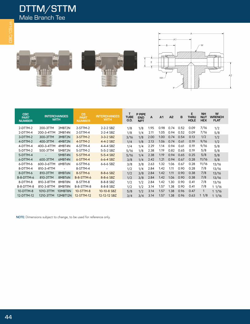
TTUBEO.D.
AE
THRUHOLE
WWRENCH
FLAT
P PIPE END NPT
A1NH
NUTHEX
A2 B
1/8 1/8 3/16 1/4 1/4 5/16 5/16 3/8 3/8 1/21/21/21/21/25/83/4
1/81/41/81/81/41/81/41/43/81/43/83/81/21/21/23/4
1.952.112.002.132.292.382.382.422.632.842.842.842.843.143.143.14
0.981.051.001.061.141.191.191.211.321.421.421.421.421.571.571.57
0.74 0.94 0.74 0.74 0.94 0.82 0.94 0.94 1.06 1.11 1.11 1.06 1.30 1.38 1.38 1.38
0.52 0.52 0.54 0.61 0.61 0.65 0.65 0.67 0.67 0.90 0.90 0.90 0.90 0.90 0.96 0.96
0.090.090.130.190.190.190.250.280.280.280.380.380.410.410.470.63
7/167/161/29/169/165/85/8
11/1611/167/87/87/87/87/8
11 1/8
1/25/81/21/25/85/85/85/8
13/1613/1613/1613/1613/161 1/161 1/161 1/16
T
A
E
A1
B
A2NH
W
P
CBC/
CS-L
ok
44
DTTM/STTMMale Branch Tee
NOTE: Dimensions subject to change, to be used for reference only.

CBCPART
NUMBERINTERCHANGES
WITHCS
PARTNUMBER
INTERCHANGESWITH
TTUBEO.D.
AE
THRUHOLE
WWRENCH
FLATA1
NH1NUTHEX
A2 BNH
NUTHEX
B1
1-DTTT-12-DTTT-23-DTTT-34-DTTT-45-DTTT-56-DTTT-68-DTTT-8
10-DTTT-1012-DTTT-1214-DTTT-1416-DTTT-16
100-3200-3300-3400-3500-3600-3810-3 1010-31210-31410-31610-3
1ET1 2ET2 3ET3 4ET4 5ET5 6ET6 8ET8
10ET10 12ET12 14ET14 16ET16
1-STTT-12-STTT-23-STTT-34-STTT-45-STTT-56-STTT-68-STTT-8
10-STTT-1012-STTT-1214-STTT-1416-STTT-16
1-1-1 JBZ2-2-2 JBZ3-3-3 JBZ4-4-4 JBZ5-5-5 JBZ6-6-6 JBZ8-8-8 JBZ
10-10-10 JBZ12-12-12 JBZ14-14-14 JBZ16-16-16 JBZ
1/16 1/8 3/16 1/4 5/16 3/8 1/2 5/8 3/4 7/8
1
1.61 1.95 2.00 2.13 2.38 2.42 2.84 3.14 3.14 3.51 3.89
0.800.981.001.061.191.211.421.571.571.761.95
- - - - - - - - - - -
0.340.520.540.610.650.670.900.960.961.021.24
- - - - - - - - - - -
0.050.090.130.190.250.280.410.500.630.720.88
5/167/161/29/165/8
11/167/8
11 1/81 1/41 1/2
- - - - - - - - - - -
1/21/21/21/25/85/8
13/161 1/161 1/161 3/81 3/8
A
A1
B
A1
T E
NH
F
CBC/CS-Lok
DTTT/STTTUnion Tee
45
NOTE: Dimensions subject to change, to be used for reference only.

CBCPART
NUMBERINTERCHANGES
WITHCS
PARTNUMBER
INTERCHANGESWITH
TTUBEO.D.
AE
THRUHOLE
WWRENCH
FLATA1
NH1NUTHEX
A2 BNH
NUTHEX
B1T1
TUBEO.D.
4-DTTT-4-26-DTTT-6-48-DTTT-8-48-DTTT-8-6
12-DTTT-12-612-DTTT-12-816-DTTT-16-416-DTTT-16-616-DTTT-16-816-DTTT-16-12
400-3-4-2600-3-6-4810-3-8-4810-3-8-6
1210-3-12-61210-3-12-81610-3-16-41610-3-16-61610-3-16-81610-3-16-12
4-4-2 JLZ6-6-4 JLZ8-8-4 JLZ8-8-6 JLZ
12-12-6 JLZ12-12-8 JLZ16-16-4 JLZ16-16-6 JLZ16-16-8 JLZ16-16-12 JLZ
4-STTT-4-26-STTT-6-48-STTT-8-48-STTT-8-6
12-STTT-12-612-STTT-12-816-STTT-16-416-STTT-16-616-STTT-16-816-STTT-16-12
4-4-2 JBZ6-6-4 JBZ8-8-4 JBZ8-8-6 JBZ
12-12-6 JBZ12-12-8 JBZ16-16-4 JBZ16-16-6 JBZ16-16-8 JBZ16-16-12 JBZ
1/43/81/21/23/43/4
1111
1/8 1/4 1/4 3/8 3/8 1/2 1/4 3/8 1/2 3/4
2.132.422.842.843.143.143.893.893.893.89
1.06 1.21 1.42 1.42 1.57 1.57 1.95 1.95 1.95 1.95
0.981.141.251.321.471.571.591.651.761.58
0.61 0.67 0.90 0.90 0.96 0.96 1.24 1.24 1.24 1.24
0.520.610.610.670.670.900.610.670.900.96
0.19 0.19 0.19 0.28 0.28 0.41 0.19 0.28 0.41 0.63
9/16 11/167/87/8
1 1/81 1/8 1 1/21 1/2 1 1/21 1/2
7/16 9/16 9/16 11/1611/167/89/16 11/167/8
1 1/8
1/25/8
13/1613/161 1/161 1/161 3/81 3/81 3/81 3/8
CBCPART
NUMBERINTERCHANGES
WITHT
TUBEO.D.
AE
THRUHOLE
WWRENCH
FLATA1
NH1NUTHEX
A2 BNH
NUTHEX
B1T1
TUBEO.D.
6-DTTT-4-66-DTTT-6-8
600-3-4-6600-3-6-8
6-4-6 JLZ-
3/8 3/8
1/41/2
2.352.63
1.211.32
1.141.42
0.670.67
0.61 0.90
0.190.28
11/1611/16
9/16 7/8
5/813/16
CSPART
NUMBERINTERCHANGES
WITH
6-STTT-4-66-STTT-6-8
6-4-6 JBZ-
A
B
T
A2
A1
T1
E
B1
T
NH
F
NH1
A
B
A1
T
A
E
A2
T1
T
B1
NH
F
NH1
CBC/
CS-L
ok
46
DTTT/STTTReducing Branch Tee, Reducing Run Tee
NOTE: Dimensions subject to change, to be used for reference only.
NOTE: Dimensions subject to change, to be used for reference only.

CBCPART
NUMBERINTERCHANGES
WITHCS
PARTNUMBER
INTERCHANGESWITH
TTUBEO.D.
AE
THRUHOLE
WWRENCH
FLATA1
NHNUTHEX
B
2-DCR4-DCR
B-4-DCR6-DCR8-DCR12-DCR
200-4400-4400-4600-4810-41210-4
2ECR24ECR44ECR46ECR68ECR8
12ECR12
2-SCR4-SCR
B-4-SCR6-SCR8-SCR12-SCR
2 KBZ 4 KBZ 4 KBZ 6 KBZ 8 KBZ 12 KBZ
1/81/41/43/81/23/4
1.842.112.332.402.833.14
0.921.061.171.201.411.57
0.520.610.610.670.900.96
0.09 0.19 0.19 0.28 0.41 0.63
7/169/169/1611/167/8
1 1/8
1/21/25/85/8
13/161 1/16
A
A
A1
B
T E
WNH
CBC/CS-Lok
DCR/SCRUnion Cross
47
NOTE: Dimensions subject to change, to be used for reference only.

CBCPART
NUMBERINTERCHANGES
WITHCS
PARTNUMBER
INTERCHANGESWITH
TTUBEO.D.
ETHRUHOLE
FTUBE
IDW
REF
3-TI-24-TI-206
4-TI-34-TI-1704-TI-25-TI-45-TI-35-TI-2
6-TI-2776-TI-46-TI-38-TI-68-TI-410-TI-810-TI-612-TI-1012-TI-816-TI-12
305-2-
405-3405-170405-2505-4505-3505-2
605-277605-4605-3815-6815-4 1015-8 1015-6 1215-10 1215-8 1615-12
- - - - - - - - - - - - - - - - - -
- - - - - - - - - - - - - - - - - -
3/16 1/4 1/4 1/4 1/4 5/16 5/16 5/16 3/8 3/8 3/8 1/2 1/2 5/8 5/8 3/4 3/4
1
0.09 0.16 0.14 0.11 0.09 0.19 0.13 0.09 0.22 0.19 0.13 0.31 0.19 0.44 0.31 0.56 0.44 0.69
0.031 0.022 0.031 0.040 0.062 0.031 0.062 0.094 0.049 0.062 0.094 0.062 0.125 0.062 0.125 0.062 0.125 0.125
1/80.2063/160.171/81/43/161/8
0.2771/43/163/81/4 1/23/85/81/23/4
ET F
W
CBC/
CS-L
ok
48
TITubing Insert
NOTE: Dimensions subject to change, to be used for reference only.

CBCPART
NUMBERINTERCHANGES
WITHCS
PARTNUMBER
INTERCHANGESWITH
TTUBEO.D.
ANH
NUTHEX
DN-1 DN-2 DN-3 DN-4 DN-5 DN-6 DN-8 DN-10 DN-12 DN-14 DN-16
102-1202-1302-1402-1502-1602-1812-1 1012-11212-11412-11612-1
1NU1 2NU2 3NU3 4NU4 5NU5 6NU6 8NU8
10NU10 12NU12 14NU14 16NU16
SN-1SN-2SN-3SN-4SN-5SN-6SN-8SN-10SN-12SN-14SN-16
1 BZ 2 BZ 3 BZ 4 BZ 5 BZ 6 BZ 8 BZ 10 BZ 12 BZ 14 BZ 16 BZ
1/161/83/161/45/163/81/25/83/47/8
1
0.31 0.47 0.47 0.50 0.53 0.56 0.69 0.69 0.69 0.69 0.81
5/167/161/29/165/8
11/167/8
11 1/81 1/41 1/2
E
A
NH
CBC/CS-Lok
DN/SNNut
49
NOTE: Dimensions subject to change, to be used for reference only. Tylok CS-Lok® nuts are coated with moldisulfide for reduced galling and lower installation torque. Tylok CBC-Lok® nuts are silver etched on the inside and coated with a proprietary ??? to reduce galling and lower installation torque.

CBCPART
NUMBERINTERCHANGES
WITHCS
PARTNUMBER
INTERCHANGESWITH
TTUBEO.D.
ANH
NUTHEX
DKN-1 DKN-2 DKN-3 DKN-4 DKN-5 DKN-6 DKN-8 DKN-10 DKN-12 DKN-14 DKN-16
102-1K202-1K302-1K402-1K502-1K602-1K812-1K 1012-1K1212-1K1412-1K1612-1K
1 BZP 2 BZP 3 BZP 4 BZP 5 BZP 6 BZP 8 BZP 10 BZP
- - -
SKN-1 SKN-2 SKN-3 SKN-4 SKN-5 SKN-6 SKN-8 SKN-10 SKN-12SKN-14SKN-16
1 BZP 2 BZP 3 BZP 4 BZP 5 BZP 6 BZP 8 BZP 10 BZP
- - -
1/161/83/16 1/45/16 3/8 1/2 5/83/47/8
1
0.31 0.47 0.47 0.50 0.53 0.56 0.69 0.69 0.69 0.69 0.81
5/167/161/29/165/8
11/167/8
11 1/81 1/41 1/2
E
A
NH
CBC/
CS-L
ok
50
DKN/SKNKnurled Nut
NOTE: Dimensions subject to change, to be used for reference only.

CBCPART
NUMBERINTERCHANGES
WITH
TTUBEO.D.
CBCPART
NUMBERINTERCHANGES
WITH
TTUBEO.D.
DFC-1 DFC-2 DFC-3DFC-4DFC-5DFC-6DFC-8DFC-10DFC-12DFC-14DFC-16
103-1203-1303-1403-1503-1603-1813-11013-11213-11413-11613-1
1FF12FF23FF34FF45FF56FF68FF8
10FF1012FF1214FF1416FF16
1/161/83/161/45/163/81/25/83/47/8
1
DRC-1DRC-2DRC-3DRC-4DRC-5DRC-6DRC-8DRC-10DRC-12DRC-14DRC-16
104-1204-1304-1404-1504-1604-1814-11014-11214-11414-11614-1
1BF12BF23BF34BF45BF56BF68BF8
10BF1012BF1214BF1416BF16
1/161/83/161/45/163/81/25/83/47/8
1
T T
TT
CBC/CS-Lok
CSPART
NUMBERINTERCHANGES
WITHT
TUBEO.D.
SC-1SC-2SC-3SC-4SC-5SC-6SC-8SC-10SC-12SC-14SC-16
1 TZ2 TZ3 TZ4 TZ5 TZ6 TZ8 TZ10 TZ12 TZ14 TZ16 TZ
1/161/83/161/45/163/81/25/83/47/8
1
ColletsFerrule
51
NOTE: Dimensions subject to change, to be used for reference only. NOTE: Dimensions subject to change, to be used for reference only.
COMPONENT REPLACEMENT PARTSCollet sets and Nut/Collet sets make for easy storage and handling of nuts and collets. CBC-Lok® & CS-Lok® components are precision made and should be handled with care. The components can be ordered on an arbor, which aids in careful handling and prevents them from coming off. Pinch the end of the arbor to release the components.
NOTE: Dimensions subject to change, to be used for reference only.

CBC/
CS-L
ok
52
COLLET /NUT & COLLET SETS
CBCPART
NUMBERINTERCHANGES
WITHCS
PARTNUMBER
INTERCHANGESWITH
TTUBEO.D.
DCSET-4-10 DCSET-6-10 DCSET-8-10 DCSET-12-10 DCSET-16-10
400-SET600-SET810-SET
- -
4 ALOK-*-SET 6 ALOK-*-SET 8 ALOK-*-SET 12 ALOK-*-SET 16 ALOK-*-SET
SCSET-4-10SCSET-6-10SCSET-8-10SCSET-12-10SCSET-16-10
4-CPI-*-SET 6-CPI-*-SET 8-CPI-*-SET 12-CPI-*-SET 16-CPI-*-SET
1/43/81/23/4
1
CBCPART
NUMBERINTERCHANGES
WITHCS
PARTNUMBER
INTERCHANGESWITH
TTUBEO.D.
DNCSET-4-5 DNCSET-6-5 DNCSET-8-5 DNCSET-12-5 DNCSET-16-5
400-NFSET600-NFSET810-NFSET
- -
- - - - -
SNCSET-4-5SNCSET-6-5SNCSET-8-5 SNCSET-12-5SNCSET-16-5
- - - - -
1/43/81/23/4
1
COMPONENT REPLACEMENT PARTSCollet sets and Nut/Collet sets make for easy storage and handling of nuts and collets. CBC-Lok® & CS-Lok® components are precision made and should be handled with care. The components can be ordered on an arbor, which aids in careful handling and prevents them from coming off. Pinch the end of the arbor to release the components.
NOTE: Dimensions subject to change, to be used for reference only.
NOTE: Dimensions subject to change, to be used for reference only.

CBC/CS-Lok
DGGGap Gage
53
CBCPART
NUMBER
TTUBEO.D.
1-DGG2-DGG3-DGG4-DGG5-DGG6-DGG8-DGG10-DGG12-DGG14-DGG16-DGG
468-DGG
1/161/83/161/45/163/81/25/83/47/8
11/4, 3/8, 1/26 mm, 12 mm
NOTE: Dimensions subject to change, to be used for reference only.

A
E
PBH
A
E
P
BH
CBC/
CS-L
ok
54
1MDFMud Dauber
AE
THRUHOLE
BHBODYHEX
CBCPART
NUMBERINTERCHANGES
WITHPIPE
WELDSIZE
4-1MDF6-1MDF8-1MDF
PP-4-2MDF
PP-6-2MDF
MD-42 MDF MD-66 MDF MD-88 MDF
- -- -
1/43/81/21/43/8
.81
.811.031.441.44
.28.41.50.28.28
9/1611/167/85/8
11/16
NOTE: Dimensions subject to change, to be used for reference only.
• Tylok Mud Daubers, also known as Vent Protector fittings, protect open ends of tubing, instruments, outlet vents and exhaust lines.
• Each Vent Protector has a 300 series stainless steel 40-mesh wire screen to prevent obstructive foreign objects, such as insects, from entering and clogging a system.
• Straight Vent Protectors are available in either Stainless Steel or Brass. Add an SS or B in front of part number to specify the desired material.
• Angled Vent Protectors are available in Polypropylene (PP) only.

CBC/CS-Lok
TYLOKProducts
55
DE-RATINGFACTOR
0.750.500.25
SIZE
Up to 1/2” (Size 8)1/2”-3/4” (Size 8 thru 12)7/8” - 1” (Size 14 and 16)
THERMOCOUPLE BORE THROUGH
A Thermocouple Connector can be furnished already bored through for an additional charge.
When Ordering:
1. Select required size male connector. See DMC/SMC pages for a listing of available Male Connectors.
2. Add the letters “BT” to designate bore through. Example: 4-DMC-2-BT
NOTE: Multiply tube pressure rating (see Suggested Allowable Working Pressure tables) by de-rating factor to determine safe working pressure.

1 1/16”2 1/8” 3/43 3/16”4 1/4”5 5/16”6 3/8”8 1/2”
1-1/410 5/8”12 3/4”14 7/8”16 1”
Finger tight plus 3/4 turn
Finger tight plus 1-1/4 turn
NOTE: DF Plugs, -NF (Nut & Ferrule Pre-Assembles) require only 1/4 turn make-up.
Simply insert the tubing into the assembly, making sure the tubing seats firmly against the shoulder of the body and the nut is finger tight. High pressure applications and high safety-factor systems: Further tighten the nut until the tube will not turn by hand or move axially in the fitting.
Tighten nut with wrench the additional number of turns indicated above, while holding the fitting body with a second wrench.
CBC/
CS-L
ok
56
INSTALLATION INSTRUCTIONS
CBC-LOK®/CS-LOK® INSTALLATION INSTRUCTIONS
CBC-Lok®/CS-Lok® Tube Fittings come completely assembled & ready for use, no disassembly required. Although there are some general guidelines to follow, no special preparation of the tubing is necessary. In overhead applications, Tylok recommends using a Pre-Set Tool.
NOTE: DF Plugs, -NF (Nut & Ferrule Pre-Assembles) require only 1/4 turn make-up.
TO REMOVE TUBE & RE-CONNECT TUBE FITTING
Mark the location of the nut with reference to the body before disassembly. For assembly, re-insert the tubing into the body until it is seated. With proper size wrench, re-tighten nut to original location by realigning previous marks. A noticeable amount or torque will develop when the nut is turned to original position. Next, rotate the nut slightly past original position to fully re-set the seal.Back off the nut until it is clear of the body and remove the tubing from the fitting.

CBC/CS-Lok
TUBINGSelection & Preparation
57
Values in reverse text are not recommended for Gas Service.
75,000 PSI TensileNote: For welded and drawn tubing, a derating factor must be utilized. For double welded tube, multiply the above pressure rating by .85; and for single welded tube by .80 (ASME B31.3).
SUGGESTED ALLOWABLE WORKINGPRESSURE TABLES (psig)
TubeSize
Tube Wall Thickness (inches)
O.D. .028 .035 .049 .065 .083 .095 .109 .1201/8” 2700 36003/16” 1800 2300 3400 1/4” 1300 1600 2500 3500 5/16” 1300 1900 2700 3/8” 1000 1600 22001/2” 800 1100 1600 21005/8” 900 1200 1600 19003/4” 700 1000 1300 1500 18007/8” 600 800 1100 1300 1500
1” 500 700 1100 1300 1500
Tube Size O.D. .028 .035 .049 .065 .083 .095 .109 .1201/8” 8000 102003/16” 5100 6600 9600 1/4” 3700 4800 7000 9600 5/16” 3700 5500 7500 3/8” 3100 4500 62001/2” 2300 3200 4500 5900 5/8” 2600 3500 4600 5300 3/4” 2100 2900 3700 4300 5100 7/8” 1800 2400 3200 3700 4300
1” 2100 2700 3200 3700 4100
STAINLESS STEELTubeSizeO.D. .028 .035 .049 .065 .083 .095 .109 .120
1/8” 8500 109003/16” 5400 7000 10200 1/4” 4000 5100 7500 10200 5/16” 4000 5800 8000 3/8” 3300 4800 6500 1/2” 2600 3700 5100 67005/8” 2900 4000 5200 60003/4” 2400 3300 4200 4900 58007/8” 2000 2800 3600 4200 4800
1” 2400 3100 3600 4200 4700
COPPER
Tube Wall Thickness (inches)
CARBON STEEL
Tube Wall Thickness (inches)
1500
900
CBC-LOK® TUBING SELECTION & PREPARATIONProper selection of tubing is key to the performance of the fitting. When selecting the proper wall thickness and material, all tubing should be compatible with the process fluid, temperature, application, flow, and system pressure.
For proper sealing, it is recommended that tubing and fitting be of like material to allow for positive sealing (i.e., stainless on stainless, brass on copper, steel on steel). Galvanic corrosion could occur if the tubing and fitting are not of like material, with the exception of a brass fitting on copper tubing.
When using stainless steel tubing, Tylok recommends using Type 304 or 316 fully annealed, seamless or welded redrawn meeting ASTM A213, ASTM A269 or equivalent, with a suggested maximum hardness of 80 Rb.
For copper tubing, Tylok suggests using soft annealed, seamless tubing per ASTM B75 or equivalent. Copper water tube type K or L, soft annealed (Temper O) per ASTM B88 can also be used.
When using carbon steel, all tubing should be fully annealed and conform to ASTM A-179, or equivalent, with a maximum hardness of 72 Rb.
In general, all tubing should be free of nicks, scratches, or imperfections of any kind and should be suitable for bending. Tubing that does not easily go through fitting components should not be used. It is recommended that the charts be used for tube selection. Ideally, the tube end should be cut square so that when it bottoms out inside the fitting, an extra seal is provided. Avoid installing contaminated tubing into your system. For elevated temperatures, see Tube Pressure Derating Factors at Elevated Temperatures Chart.
CBC-Lok®/CS-Lok® Tube Fitting swage the tubing to achieve sealing. Thin wall tubing (wall thickness with working pressures highlighted in reverse text in the charts) is not recommended for Gas Service. See “Gas Service” on page 58.
When using tubing of a thinner or thicker wall than shown, it is always recommended that you consult with your local Distributor or contact Tylok International directly if there is any doubt of selecting tubing.
It is the responsibility of the Engineer to refer to the technical pages in this catalog to ensure selection of the proper tubing material, tubing compatibility with the fitting, media and tubingwall thickness.
Note: Tables, calculated to the right, are suggested maximum working pressure ratings, in accordance with ASME B31.3, but should be used for reference only. Tylok International Inc., is not responsible for its accuracy nor designs using these figures.
Following the stated recommendations will result in a safe application, free of leaks. The entire system must be considered when selecting the tube. Tylok tube fittings are designed to work to the tubing pressure ratings found in the charts below.

CBC/
CS-L
ok
Values in reverse text are not recommended for Gas Service.
58
SAFETY & QUALITYGas Service
GAS SERVICEExtra care must be taken when tubing is used in gas service applications. Small gas molecules easily escape through minute leak paths; therefore, the tubing must be free of nicks, scratches and imperfections of any kind. When using large diameter tubing, the possibility of surface defects is increased further due to greater surface area. It is strongly recommended that the heavier wall thickness be selected. Penetration of the ferrules on thin wall tubing or soft material may not offer enough radial resistance for sealing.
GAP GAGEGap Gage can be purchased to ensure the Installer and Inspector that the nut has been properly tightened.
When fitting is properly tightened, gap gage should not fit between nut and shoulder of body.
QUALITY CONTROLAll components are manufactured & inspected to meet strict quality control standards in each phase of production. All employees are thoroughly trained to follow procedures, in accordance with the ISO 9001 Quality Standard, to ensure a quality product from the start of each job through completion.
PRECAUTIONS FOR WELD ENDCBC-Lok®/CS-Lok® Tube Fittings with weld ends offer the same positive sealing as all other Tylok fittings. Welding could deform the assembly, making pull ups or disassembly difficult. Some precautions should be taken:
• Remove the nut & ferrules from the fitting.• It is important that the fitting threads and sealing surfaces be protected from weld splatter.• A heat sink should be used to dissipate heat.• Ensure alignment by track welding symmetrically.• Once welded, remove the weld splatter protection and reassemble nut & ferrules on fitting.
SAFETY GUIDELINES• Never connect, disconnect or remake a fitting with pressure in the system• Make sure all fittings are properly installed, reference Installation Instructions - page 56, before pressurizing the system.• Tubing material should be softer than fitting material• Tylok recommends using only Tylok replacement parts• Although the fittings will hold to the pressure rating of the tubing, it is not recommended to go beyond this rating. Elongation could occur in the tubing, shrinking the wall thickness and causing potential harm to anyone in the area.• Always use proper thread lubricants and sealants on tapered pipe threads.• If process fluids are toxic and/or hazardous, exercise extra caution• Never bleed a system by loosening a fitting• For proper sealing it is recommended that the tubing and fitting be of like material

Suggested Maximum Operating Pressures for Pipe Threads (psig)
Copper
100 38 1.00 150 66 0.85 200 93 0.80 250 121 0.80
300 149 0.78 350 177 0.66 400 204 0.50
Carbon Steel 316 SS
200 93 0.95 1.00 1.00300 149 0.90 1.00 1.00400 204 0.87* 0.93 0.96500 260 0.87 0.89600 316 0.82 0.85700 371 0.8 0.81800 427 0.76 0.79900 482 0.73 0.771000 538 0.69 0.76
NPT Size Brass 316 SS & Carbon Steel Male Female Male Female
1/16” 11000 55006700 33001/8” 10000 50006500 32001/4” 8000 40006600 33003/8” 7800 39005300 26001/2” 7700 38004900 24003/4” 7300 36004600 2300
1” 5300 26004400 2200
Tylok Instrumentation Fittings are rated at the following temperatures:
316 Stainless
Brass
Steel
-325°F to 1000°F(-198°C to 648°C)
-40°F to 400°F(-40°C to 204°C)
-65°F to 375°F(-54°C to 190°C)
CBC/CS-Lok
TECHNICAL DATA
59
PIPE THREAD SPECIFICATIONSTylok Pipe Fittings are manufactured from materials meeting applicable ASTM or ASME specifications, with pipe threads which meet or exceed ANSI B1.20.1 requirements. Strict quality control procedures are followed throughout production to provide the finest possible product.
Materials: Brass • 316 Stainless Steel • Steel
These charts are to be used as a guide only and are based on normal wall thicknesses, used for the various sizes. These ratings may vary widely from effects such as the proper use of sealants, size of stock, temperature, corrosion factors, etc. Therefore, Tylok International, Inc. assumes no responsibility for its accuracy in any individual design.
Pressure ratings for Tylok tube fittings that have differing end connection styles shall use the lowest of the pressure rating.
TUBE PRESSURE DERATING FACTORSELEVATED TEMPERATURESThe table lists de-rating factors that must be considered in applications above that of ambient temperatures.
Example:Type 316 Stainless Steel 1/4” O.D.x.0.49” wall at 800°F is 7,500 PSI x .79 = 5,925 psig.
Therefore, the suggested allowable working pressure for 316 Stainless Steel (1/4” O.D. with .049” tube wall) at 800°F is 5,925 psig.

PART NUMBER TUBE SIZE1-DPST 1/16”2-DPST 1/8”3-DPST 3/16”4-DPST 1/4”5-DPST 5/16”6-DPST 3/8”8-DPST 1/2”10-DPST 5/8”12-DPST 3/4”14-DPST 7/8”16-DPST 1”
CBC/
CS-L
ok
Place Pre-Set Tool in a vice and tighten nut have swaged into the tubing. Now take tubing to installation area.
60
MATERIAL SPECIFICATIONSPre-setting Tool
HEAT TRACEABILITYTylok® Tube Fittings are completely heat code traceable back to the original mill heat from which they were made. Starting with the original billet, the mill creates a certificate that completely describes the chemical & physical makeup. For any one of the four components (body, front ferrule, rear ferrule, nut), the material certifications can be provided. Call Tylok and provided the heat code stamp marked on the part itself, along the part number to obtain the certificate.
TYLOK PRE-SET TOOLThe CBC-Lok®/CS-lok® product line offers a Pre-Set Tool when fittings need to be installed in hard to reach places. The Pre-Set Tool is designed to be used in any tabletop vise. After tightening the nut the specified number of turns, as stated in the included installation instructions, loosen the nut from the Pre-Set Tool. Once the ferrules have swaged into the tubing surface, the assembly is ready for installation. When ordering the CBC-Lok®/CS-Lok® Pre-Set Tool, reference the part number in the chart. The Pre-Set Tool s is hardened for maximum durability. The Pre-Set Tool can be used repeatedly to set the ferrules onto the tubing for easy installation.
*Reference Tubing Selection & Preparation
FITTING BARMATERIAL STOCK
FORGINGTUBING
SPECIFICATION*
ASTM B16 Alloy 360 ASTM B75Brass ASTM B453 Alloy 345
ASTM B124 Alloy 377 Copper(Temper O)
Stainless ASTM A276 ASME SA-182 ASTM A213Steel ASME SA479 Type 316-SS ASTM A269
Type 316-SS
Steel ASTM A108 ASTM A179
RAW MATERIAL SPECIFICATIONS

TUBINGMATERIAL
GENERAL APPLICATIONS
Carbon Steel Air Lines, High Pressure, High Temperature, Oil, Air, Specialty Chemicals, Hydraulic Gases
Copper Low Temperature, Low Pressure Water, Oil, Air, Pneumatic Controls, Lube Lines
Stainless SteelHigh Pressure, High Temperature, Nitrogen, Helium,
Flammable Gases, Hydraulic, Gases, generally corrosive media
1 1/16 0.342 1/8 0.523 3/16 0.544 1/4 0.615 5/16 0.656 3/8 0.678 1/2 0.9010 5/8 0.9612 3/4 0.9614 7/8 1.0216 1 1.24
NOTE: Dimensions subject to change, to be used for reference only.
CBC/CS-Lok
TUBEINSERTION
TUBE INSERTION CHARTApplications
61
TUBE INSERTION CHARTFor pre-cutting tubing to length, the following chart shows the additional length inside the fitting assembly.
TUBING-GENERAL APPLICATIONSTylok Tube Fittings are designed to perform in a variety of applications that demand high performance. The CBC-Lok® & CS-Lok® product lines have been engineered to provide optimal performance. However, tubing should always be considered as an important factor in the design stages of any system. Below is a table that describes some general uses for different types of materials. The table is provided as an reference to the Engineer in the design process. Tylok suggests the use of seamless, fully annealed tubing. Welded tubing may be used with Tylok fittings. However, due to the manufacturing of welded tubing, variables may be encountered. The media flowing through the tubing must be compatible with the tubing itself. It is always a good rule to use like tubing material on like fitting material. If this format is not followed, the ferrules may have difficulty penetrating the tubing, adversely affecting the sealing ability addition, dissimilar materials in contact may be sensitive to galvanic corrosion. Tylok recommends ordering tubing material to meet ASTM specifications to ensure that it will be dimensionally, physically, and chemically within precise limits.(See Raw Materials Specifications charts on page 60).
NOTICEIn designing a system incorporating tube fittings and valves, it is the designer’s or user’s obligation & responsibility to determine the appropriate fittings and valves to be used for each application and to insure proper installation and maintenance.
LIMITED WARRANTYTylok Fittings and Valves are warranted solely against defects in material & workmanship in the performance of the specific functions for which they are designed, as set forth in the published specifications for the life of the product. Should any fitting & valve or its component fail due to a defect in material or workmanship, Tylok will replace said fitting & valve without charge upon return of the failed part and evidence of its failure being due to materials or workmanship.
The Warranty above set forth is the only warranty applicable to Tylok products, and is in lieu of any and all other warranties either expressed or implied, including any warranty of merchantability or fitness. Tylok’s sole responsibility or liability as a result of any loss or damage due to failure shall be to replace the failed part or fitting & valve, and it shall bear no liability for any incidental or consequential damages to person or property.

CBC/
CS-L
ok
62
PRODUCTSLeak Detector
Container Pull OutPart Number Size Tube Length
LEAK DETECTOR-8oz 12 inch (30.48cm)LEAK DETECTOR-Gal 1 Gallon
LEAK DETECTOR COOL-8oz 12 inch (30.48cm) LEAK DETECTOR COOL-Gal 1 Gallon
8 fl oz. (236ml)
8 fl oz. (236ml)
Tylok Liquid Leak Detectors• Tylok Liquid Leak Detector detect gas leaks in hard-to-reach areas.• Safe for oxygen systems• Sustainable bubble action works even on very small leaks and vertical surfaces• Flexible tube extends for hard-to-reach areas• Formulas dries clean, without staining
TYLUBE™ THREAD LUBRICANT
Tylube™ is an anti-gall compound to be used on stainless steel, steel and nickel-based alloys. Temperature range to 500°F. Not recommended for plastic and aluminum products.
Tylube™ is made from distilled water with inert ingredients and contains no silicones, heavy metals, chlorine or sulfur. Safe for oxygen applications.
For a complete list of ingredients, request an MSDS to be sure of its compatibility with your installation. Available in 8 oz. plastic bottles.
TYLOK LIQUID LEAK DETECTOR
• Temperature rating: Can be used over a temperature range of 27° to 200°F (-2 to 93°C).Specifications: Meets the performance requirements of:
• MIL-PRF-25567 Leak Detector Compound, Oxygen Systems, Type l, 1 to 70°C (33 to 158°F)•NFPA 52 Section 6-12.2 Leak Testing Compressed Natural Gas Vehicular Fuel System• EPA Part 60, Appendix A, Method 21, Section 4.3.3 Alternative Screening Procedures Using Soap Solutions• Nontoxic, noncorrosive, nonflammable
TYLOK LOW TEMPERATURE LIQUID LEAK DETECTOR
• Temperature rating: Can be used over a temperature range of -65° to 200°F (-54 to 93°C).Specifications: Meets the performance requirements of:
• MIL-PRF-25567 Leak Detector Compound, Oxygen Systems, Type ll, -54° to 1°C (-65 to 33°F)• NFPA 52 Section 6-12.2 Leak Testing Compressed Natural Gas Vehicular Fuel System• EPA Part 60, Appendix A, Method 21, Section 4.3.3 Alternative Screening Procedures Using Soap Solutions• Noncorrosive, nonflammable

CBC/CS-Lok
Dielectric Fitting
63
Tylok Dielectric Fittings are insulated connections used to protect sensitive electrical components from electrical current potentially carried through tubing systems.
Typical Application - Gas Transmission
A typical application for a dielectric fitting is in the transmission of natural gas. The dielectric fitting insulates electric current flow that results from Current Cathodic Protection systems, static electricity, ground currents, stray currents from instruments, etc.
Features
• Dielectric Strength x107 Ohms at 10 VDC• Voltage Breakdown resistance 4000 VDC• Blow-out Proof Stem• Stainless Steel Construction• PEEK Insulators• Over-torque Prevention Ring• Pressure Rating: - 5000 psi (344 bar) at 100°F (37°C)• Temperature Rating: -40°F (-40°C) to 200°F (93°C)• Size Range - 3/8”, 1/4”, 1/2”• End Connections - Tylok Tube End straight or elbow - Male NPT straight or elbow - Female NPT straight or elbow
1st Connection: See table for size & Configuration
Aluminum Over-Torque Prevention Ring
PEEK Fitting Insulator
PEEK Nut Insulator
3/8” Stainless Steel Dielectric Adapter
2nd Connection: See table for size & Configuration
Configuration shown above: SS-6-DMC-4-DE

End Connection
Inlet / Outlet Tube Size
Pipe Size
Ordering NumberA B C E F Fx G
Dimensions, Inches
CBC-Lok
CBC-Lok / Male NPT
CS-Lok
CS-Lok / Male NPT
1/4”
3/8”
1/2”
1/4”
3/8”
3/8”
1/2”
1/4”
3/8”
1/2”
1/4”
3/8”
3/8”
1/2”
-
-
-
1/4”
1/4”
3/8”
3/8”
-
-
-
1/4”
1/4”
3/8”
3/8”
SS-4-DU-4-DE
SS-6-DU-6-DE
SS-8-DU-8-DE
SS-4-DMC-4-DE
SS-6-DMC-4-DE
SS-6-DMC-6-DE
SS-8-DMC-6-DE
SS-4-SU-4-DE
SS-6-SU-6-DE
SS-8-SU-8-DE
SS-4-SMC-4-DE
SS-6-SMC-4-DE
SS-6-SMC-6-DE
SS-8-SMC-6-DE
4.02
4.14
4.38
3.93
3.99
3.99
4.09
4.02
4.09
4.38
3.93
3.99
3.99
4.09
2.80
2.80
2.58
0.61
0.67
0.90
2.80
2.80
2.58
0.61
0.67
0.90
N/A N/A
N/A N/A
0.28 0.81 0.69
0.56
0.69
0.88
0.56
0.69
0.69
0.88
0.56
0.69
0.88
0.56
0.69
0.69
0.88
CBC/
CS-L
ok
64
Dielectric Fitting
Material1st
Connection SizeFitting
Configuration2nd
Connection SizeDielectric Identifier Description
SS-4 = 1/4”6 = 3/8”8 = 1/2”
-DU--DRU--DRU-
4 = 1/4”6 = 3/8”8 = 1/2”
-DE Tylok Tube End Straight
SS- 4, 6, 8 -DELU- 4, 6, 8 -DE Tube End Elbow
SS- 4, 6, 8 -DMC- 4, 6, 8 -DE MNPT Straight
SS- 4, 6, 8 -DME- 4, 6, 8 -DE MNPT Elbow
SS- 4, 6, 8 -DFC- 4, 6, 8 -DE FNPT Straight
SS- 4, 6, 8 -DFE- 4, 6, 8 -DE FNPT Elbow
Ordering Information
For Single Ferrule, CS-Lok, change the “D” in the configuration section to “S”

Pipe Fittings® Instrumentation Pipe Fittings
65

Pipe
Fitt
ings
1FMAFemale to Male
Adapter
69
1FPCFemale
Pipe Cap
69
1FPRUFemale Pipe
Reducer Union
69
1FPUFemale
Pipe Union
70
1HNHex Nipple
70
1HRNHex
Reducing Nipple
71
1MPPMale Pipe
Plug
71
1RAFMReducer Adapter -
Female to Male
71
1RBMF Reducer Bushing -
Male to Female
72
2FFFemale Pipe
Elbow
72
2FMFemale - Male
Pipe Elbow
72
2FMRFemale - Male
Reducer Pipe Elbow
73
2MMMale Pipe
Elbow
73
3FFFAll Female Pipe Elbow
73
3FFM Pipe Tee - Female -
Female - Male
74
3FMF Pipe Tee - Female -
Male - Female
74
3MMMAll Male Pipe Tee
74
4FPCRFemale Pipe Cross
74
66
Instrumentation Pipe Fittings
1HLNHex
Long Nipple
70

Pipe FittingsInstrumentation Pipe Fittings
67
Instrumentation Pipe Fittings
Tylok Instrumentation Pipe Fittings are offered in popular configurations such as reducing adapters, reducing bushings, pipe unions, elbows, tees, crosses, etc.
Fittings are manufactured to the same high quality standards as other Tylok Fittings. Each fitting is thoroughly cleaned to eliminate system contamination and features an attractive surface finish to enhance the appearance of modern scientific instrumentation and equipment.
Fittings are manufactured from materials meeting applicable ASTM or ASME specifications, with pipe threads which meet or exceed ANSI/ASME B1.20.1 requirements. Strict quality controls procedures are followed throughout production.
Pipe thread connections are very common in today’s industry. They are relatively easy to work with because of the common sizes and dimensions throughout manufacturing. It is important to use a thread sealant.
These products range from pipe “dopes” to Teflon tape, all of which can be purchased through your local Tylok Distributor.
Design/Features
Tylok Instrumentation Pipe Fittings are manufactured to the same high quality standards as other Tylok Fittings. Each fitting is thoroughly cleaned to eliminate system contamination and features an attractive surface finish to enhance the appearance of modern scientific instrumentation and equipment.
Technical Support & Training
Tylok Instrumentation Inc. ensures all of its Distributors are trained on the proper installation of fittings and valves. Tylok Distributors are trained to provide the technical support you deserve. Additionally, our Distributors will help in finding solutions for specific applications. Contact your local Tylok Distributor for further information.
Quality Management System
SAI Global has registered Tylok International’s Quality Management System to ISO 9001. The quality system complies with the international standard ISO 9001 and its technical equivalent, ANSI/ISO/ASQ 9001. Tylok strives to continuously improve the effectiveness of the Quality Management System.

B Brass
SS Stainless Steel
S Steel
Pipe Thread Pipe Thread) BSPP/BSPT
Chart 3 - Style1 Straight2 E lbow3 Tee
4 Cross
Chart 4 - Description1FMA Female To Male Adapter1FPC Female Pipe Cap
1FPRU Female Pipe Reducer Union1HLN Hex Long Nipple1HN Hex Nipple1HRN Hex Reducing Nipple1MPP Male Pipe Plug
1RAFM Reducer Adapter - Female to Male1RBMF Reducer Bushing - Male To Female
Chart 4 - Description2FF Female Pipe Elbow2FM Female - Male Pipe Elbow2FMR Female - Male Reducer Pipe Elbow2MM Male Pipe Elbow3FFF All Female Pipe Tee3FMF Pipe Tee - Female - Male - Female
3MMM All Male Pipe Tee
4FPCR Female Pipe Cross1MDF Mud Dauber Fitting
123456810121416
1/16-271/8-27
-1/4-18
-3/8-181/2-14
-3/4-14
-1.0-11 1/2
1/16-281/8-28
-1/4-19
-3/8-191/2-14
-3/4-14
-1.0-11
1 2
3
SS - 6 - 1 RAFM - 4
Material Pipe Size Style Description Odd End SizeChart 1 Chart 2 Chart 3 Chart 4 Chart 2
Pipe
Fitt
ings
How to Order
68
Tylok Instrumentation Pipe Fittings are ordered as listed in this catalog by inserting the material code before the part number.
Tylok Instrumentation Pipe Fittings can be identified through the part number as to material, pipe size, configuration, and thread connection. The part number describes a complete fitting. The size nomenclature to describe a tee fitting is from left (1) to right (2) and down (3).
Special Configurations available upon request.

2-1FMA 9/16
4-1FMA 1/4 1/4 1.375 .281 3/4
6-1FMA 3/8 3/8 1.562 .375 7/88-1FMA 1/2 1/2 1.906 .468 1-1/1612-1F MA 3/4 3/4 1.937 .625 1-5/1616-1F MA 1 1 2.281 .875 1-5/8
1/8 1/8 1.062 .187
2-1FPC 1/8 .750 9/16
4-1FPC .906 3/46-1FPC 3/8 7/88-1FPC 1/2 1.343 1-1/1612-1FPC 3/4 1.437 1-5/16
16-1FPC 1 1.625 1-5/8
1/41.031
4-1FPRU-2 3/4
6-1FPRU-4 3/8 1/4 1.375 .421 7/8
8-1FPRU-2 1/2 1/8 1.562 .328 1-1/16
8-1FPRU-4 1/2 1/4 1.750 .421 1-1/168-1FPRU-6 1/2 3/8 1.781 .562 1-1/1612-1FPRU-4 3/4 1/4 1.812 .421 1-5/1612-1FPRU-8 3/4 1/2 2.062 .687 1-5/16
16-1FPRU-8 1 1/2 2.187 .687 1-5/8
16- 1FPRU-12 1 3/4 2.250 .890 1-5/8
1/4 1/8 1.218 .328
1FMA
Female to Male Adapter
1FPC
Female Pipe Cap
1FPRU
Female Pipe Reducer Union
Pipe Fittings
BThru.Hole
MalePipeSizeC-HEX
FemalePipeSize
A
1FMA, 1FPC, 1FPRU
69

2-1FPU 1/8 .812 .328 9/164-1FPU 1/4 1.187 .421 3/46-1FPU 3/8 1.312 .562 7/88-1FPU 1/2 1.625 .687 1-1/1612- 1FPU 3/4 1.687 .890 1-5/1616- 1FPU 1 2.000 1.125 1-5/8
PartNo.
FemalePipeSize
AB
ThruHole
CHex
1/8 .187 7/161/4 Made .281 9/163/8 To Order .3751 1/161/2 Specify .468 7/83/4 Size .625 1-1/16
1 .875 1-3/8
PartNo.
MalePipeSize
AB
ThruHole
CHex
2-1HLN4-1HLN6- 1HLN8-1HLN12- 1HLN16- 1HLN
1/16 .937 .125 3/81-1HN
2-1HN 1/8 1.000 .187 7/16
4-1HN 1/4 1.375 .281 9/16
6-1HN 3/8 1.406 .375 11/16
8-1HN 1/2 1.781 .468 7/8
NH1 -21 3/4 1.812 .625 1-1/16
NH1 -61 1 2.281 .875 1-3/8
PartNo.
MalePipeSize
BThruHole
CHexA
1FPU
Female Pipe Union
1HLN
He x Long Nipple
1HN
Hex Nipple
Pipe
Fitt
ings
1FPU, 1HLN, 1HN
70

2-1HRN-1 1/8 1/16 1.000 .125 7/164-1HRN-2 1/4 1/8 1.187 .187 9/166-1HRN-2 3/8 1/8 1.218 .1871 1/166-1HRN-4 3/8 1/4 1.406 .281 11/168-1HRN-2 1/2 1/8 1.406 .187 7/88-1HRN-4 1/2 1/4 1.593 .281 7/88-1HRN-6 1/2 3/8 1.625 .375 7/812-1HRN-4 3/4 1/4 1.625 .281 1-1/16
12-1HRN-8 3/4 1/2 1.812 .468 1-1/16
16-1HRN-4 1 1/4 1.906 .281 1-3/8
16-1HRN-8 1 1/2 2.093 .468 1-3/8
16-1HRN-12 1 3/4 2.093 .625 1-3/8
1/16 .750 3/81-1MPP2-1MPP 1/8 .750 7/164-1MPP 1/4 1.000 9/166-1MPP 3/8 1.000 11/168-1MPP 1/2 1.312 7/812-1MPP 3/4 1.375 1-1/1616-1MPP 1 1.500 1-3/8
No.
1-MFA R1-2 1/8 1/16 1.093 .125 9/162-MFA R1-4 1/4 1/8 1.250 .187 3/42-MFA R1-6 3/8 1/8 1.437 .187 7/84-MFA R1-6 3/8 1/4 1.562 .281 7/82-MFA R1-8 1/2 1/8 1.687 .187 1-1/164-MFA R1-8 1/2 1/4 1.812 .281 1-1/166-MFA R1-8 1/2 3/8 1.812 .375 1-1/164-MFA R1-21 3/4 1/4 1.968 .281 1-5/166-MFA R1-21 3/4 3/8 1.968 .375 1-5/168-MFA R1-21 3/4 1/2 2.062 .468 1-5/164-MFA R1-61 1 1/4 2.125 .281 1-5/88-MFA R1-61 1 1/2 2.250 .468 1-5/8
16-1RAFM-12 1 3/4 2.250 .625 1-5/8
*Note: All dimensions subject to change, to be used for reference only.
1HRN
Hex Reducing Nipple
1MPP
Male Pipe Plug
1RAFM
Reducer Adapter-Female to Male
Pipe Fittings1HRN, 1MPP, 1RAFM
71

1-FMBR1 -2 1/8 1/16 1.000 .187 7/162-FMBR1 -4 1/4 1/8 1.000 .281 9/162-FMBR1 -6 3/8 1/8 .843 .328 11/164-FMBR1 -6 3/8 1/4 1.125 .375 3/42-FMBR1 -8 1/2 1/8 1.062 .328 7/84-FMBR1 -8 1/2 1/4 1.062 .421 7/86-FMBR1 -8 1/2 3/8 1.312 .468 7/8
3/4 1/4 1.062 .421 1-1/163/4 3/8 1.062 .562 1-1/163/4 1/2 1.562 .625 1-1/16
16- 1RBMF-4 1 1/4 1.343 .421 1-3/816- 1RBMF-6 1 3/8 1.343 .562 1-3/8
1 1/2 1.343 .687 1-3/821-FMBR1 -61 1 3/4 1.750 .875 1-3/8
PartNo.
MalePipeSize
ReducedFemale
PipeSize
CHex
BThruHole
A
2-2FF-2 1/8 .843 .328
4-2FF-4 .421
6-2FF-6 3/8 1.000 .5628-2FF-8 1/2 1.125 .687
12-2FF-12 3/4 1.437 .890
PartNo.
FemalePipeSize
AB
ThruHole
1/4 .968
1/16 .750 .718 .1252FM-1
2FM-2 1/8 .843 .843 .187
4-2FM-4 1/4 .843 1.093 .2816-2FM-6 3/8 1.000 1.125 .375
8-2FM-8 1/2 1.125 1.375 .46812-2FM-12 3/4 1.437 1.562 .625
16-2FM-16 .875
PartNo.
PipeSizes A B
CThruHole
1 1.906 1.906
1RBMF
Reducer Bushing-Male to Female
2FF
Female Pipe Elbow
2FM
Female - Male Pipe Elbow
68
6 8
Pipe
Fitt
ings
1RBMF, 2FF, 2FM
72

2-2FMR-1 1/8 1/16 .750 .750 .125
4-2FMR-2 1/4 1/8 .843 .937 .187
6-2FMR-4 3/8 1/4 1.062 1.062 .281
8-2FMR-4 1/2 1/4 1.125 1.250 .281
8-2FMR-6 1/2 3/8 1.125 1.250 .375
2-2MM-2 .1874-2MM -4 1/4 1.000 .2816-2MM -6 3/8 1.093 .3758-2MM -8 1/2 1.375 .468
12-2MM -12 3/4 1.500 .62516-2MM -16 1 1.875 .875
1/8 .750
2-3FFF-2 .328
4-3FFF-4 1/4 1.687 .843 .421
6- 3FFF-6 3/8 2.000 1.000 .562
8- 3FFF-8 1/2 2.250 1.125 .687
12-3FFF-12 3/4 2.625 1.312 .890
16-3FFF-16 1 3.250 1.6251 .125
1/8 1.687 .843
2FMR
Female - Male Reducer Pipe Elbow
2MM
Male Pipe Elbow
3FFF
All Female Pipe Tee
Pipe Fittings2FMR, 2MM, 3FFF
73

2-3FFM-2 .1874-3FFM-4 1/4 1.875 .937 1.000 .2816-3FFM-6 3/8 2.000 1.000 1.125 .3758-3FFM-8 1/2 2.250 1.125 1.375 .468
3/4 2.750 1.375 1.625 .625
PartNo.
PipeSizes A B C
DThruHole
1/8 1.687 .843 .843
2-3FMF-2 .187
4-3FMF-4 1/4 1.890 .843 1.046 .281
6-3FMF-6 3/8 2.125 1.000 1.125 .375
8-3FMF-8 1/2 2.500 1.125 1.375 .468
12-3FMF-12 3/4 2.937 1.437 1.500 .625
PartNo.
PipeSizes A B C
DThruHole
1/8 1.687 .843 .843
.1874-3MMM-4 1/4 1.875 .937 .2816-3MMM-6 3/8 2.000 1.000 .3758-3MMM-8 1/2 2.750 1.375 .468
12-3MMM-12 3/4 2.750 1.375 .625
PartNo.
MalePipeSize
A BC
ThruHole
2-3MMM-2 1/8 1.437 .718
3FFMPipe Tee - Female - Female - Male
3FMF
Pipe Tee - Female - Male - Female
3MMM
All Male Pipe Tee
12-3FFM-12
Pipe
Fitt
ings
3FFM, 3FMF, 3MMM
2-4FPCR 1/8 1.687 .843 .3284-4FPCR 1/4 1.687 .843 .4216-4FPCR 3/8 2.125 1.062 .5628-4FPCR 1/2 2.250 1.125 .68712-4FPCR 3/4 2.875 1.437 .89016-4FPCR 1 3.250 1.625 1.125
4FPCR
Female Pipe CrossA
A
B B
B
B
CThru.Hole
FemalePipe Size
3FFM, 3FMF, 3MMM
74

Pipe FittingsInstrumentation Pipe Fittings
75
Suggested Maximum Operating Pressures for Pipe Threads (psig)
Copper
100 38 1.00 150 66 0.85 200 93 0.80 250 121 0.80
300 149 0.78 350 177 0.66 400 204 0.50
Carbon Steel 316 SS
200 93 0.95 1.00 1.00300 149 0.90 1.00 1.00400 204 0.87* 0.93 0.96500 260 0.87 0.89600 316 0.82 0.85700 371 0.8 0.81800 427 0.76 0.79900 482 0.73 0.771000 538 0.69 0.76
NPT Size Brass 316 SS & Carbon Steel Male Female Male Female
1/16” 11000 55006700 33001/8” 10000 50006500 32001/4” 8000 40006600 33003/8” 7800 39005300 26001/2” 7700 38004900 24003/4” 7300 36004600 2300
1” 5300 26004400 2200
Tylok Instrumentation Fittings are rated at the following temperatures:
316 Stainless
Brass
Steel
-325°F to 1000°F(-198°C to 648°C)
-40°F to 400°F(-40°C to 204°C)
-65°F to 375°F(-54°C to 190°C)
PIPE THREAD SPECIFICATIONSTylok Pipe Fittings are manufactured from materials meeting applicable ASTM or ASME specifications, with pipe threads which meet or exceed ANSI B1.20.1 requirements. Strict quality control procedures are followed throughout production to provide the finest possible product.
Materials: Brass • 316 Stainless Steel • Steel
These charts are to be used as a guide only and are based on normal wall thicknesses, used for the various sizes. These ratings may vary widely from effects such as the proper use of sealants, size of stock, temperature, corrosion factors, etc. Therefore, Tylok International, Inc. assumes no responsibility for its accuracy in any individual design.
Pressure ratings for Tylok tube fittings that have differing end connection styles shall use the lowest of the pressure rating.
TUBE PRESSURE DERATING FACTORSELEVATED TEMPERATURESThe table lists de-rating factors that must be considered in applications above that of ambient temperatures.
Example:Type 316 Stainless Steel 1/4” O.D.x.0.49” wall at 800°F is 7,500 PSI x .79 = 5,925 psig.
Therefore, the suggested allowable working pressure for 316 Stainless Steel (1/4” O.D. with .049” tube wall) at 800°F is 5,925 psig.

Pipe
Fitt
ings
®
Temperature Ratings
Tylok Instrumentation Pipe Fittings are rated at the following temperatures:
316 Stainless: -325°F to 1000°F Brass: -40°F to 375°F Steel: -20°F to 400°F (-198°C to 538°C) (-40°C to 204°C) (-28°C to 204°C)
Note: Consideration should be given to maximum temperature ratings and/or tubing are coated or plated
Heat Traceability
Tylok Instrumentation Pipe Fittings are completely heat code traceable back to the original mill heat from which it was made. Starting with the original billet, the mill creates a certificate which completely describes the chemical & physical makeup. The material certifications can be provided when calling Tylok and giving the heat code stamp marked on the part itself, along with the part number.
Material
ASTM-B16 Alloy 360Brass
ASTM-B453 Alloy 345ASTM-B124 Alloy 377
StainlessASTM-A276
ASME-SA-182Steel
ASME-SA-479Type 316-SSType 316-SS
Steel ASTM-A108 -
Raw Material Specifications
76

77
Ball ValvesGeneral Purpose Ball Valves
The GP Series Ball Valve is an instrumentation valve solution for tubing & piping systems. It is available from 1/4” to 1” with tube end connections and from 1/4” to 1/2” with female pipe threads for female to female applications.
Tylok General Purpose Ball Valve Series is a moderate pressure ball valve for general service. They are designed for tight shut-off, long service life, and low operating torque.
• 2,000 psig (138 bar) Pressure Rating• 400°F (204°C) Temperature Rating• Built-in actuator mounting holes for ease of automation• Bi-directional flow• Compact in size but with high flow capacity• Locking Handle in both On and Off position• Oval or Butterfly Handles available (locking devices not available on butterfly handles)
Features• Blow out Proof Stem
• Stainless Steel Construction
• Locking Handles in On & Off positions
• Mounting Holes Available for Automation
• Material: Stainless Steel Cast “CF8M
• Pressure Rating: 2000 psi (138 bar) at 100°F (38°C)
• Temperature Rating: 400°F (204°C) max.
• Seat Material: TFM 1600
• Flow Coefficient (Cv) 1.20 to 17.35
• Size Range 1/4” to 1”
• Integral Tube Fitting (Both Twin [CBC-Lok® & Single [CS-Lok®] Ferrule Designs)
• Female NPT x Female NPT
• 100% factory leak tested with Nitrogen at 1000 psi
• Maximum allowable leak rate is 0.1 std cc/min.

-34 2041499338-18 204
-30 4003002001000 500
2200
1200
1400
1600
18002000
400
600
8001000
2000
151.8
82.8
96.6
110.4
124.2
138
27.6
41.4
55.2
69
13.80
1
4
23
5
6
7
1112
13
1415
16
Ball
Valve
s
End ConnectionSize (ØD) A B E H
Female NPT toFemale NPT
CBC-Lok®Tube Fitting
CS-Lok®Tube Fitting
Type1/4
3/8
1/2
1/4
3/8
1/2
3/4
1
1/4
3/8
1/2
3/4
1
SS-GP4-F4F4
SS-GP6-F6F6
SS-GP8-F8F8
SS-GP4-D4D4
SS-GP6-D6D6
SS-GP8-D8D8
SS-GP12-D12D12
SS-GP16-D16D16
SS-GP4-S4S4
SS-GP6-S6S6
SS-GP8-S8S8
SS-GP12-S12S12
SS-GP16-S16S16
1.20
2.40
4.27
1.25
2.50
9.25
12.65
17.35
1.25
2.50
9.25
12.65
17.35
.20
.28
.36
.20
.28
.36
.49
.59
.20
.28
.36
.49
.59
.50
.50
.50
.50
.50
.50
.50
.87
.50
.50
.50
.50
.87
1.12
1.12
1.12
1.12
1.12
1.12
1.12
1.37
1.12
1.12
1.12
1.12
1.37
2.44
3.15
3.23
2.44
3.15
3.23
3.74
4.02
2.44
3.15
3.23
3.74
4.02
1.38
1.46
1.69
1.38
1.46
1.69
3.74
2.05
1.38
1.46
1.69
3.74
2.05
1.89
2.09
2.48
2.95
3.15
3.75
4.34
4.91
2.95
3.16
3.76
4.35
4.89
3/4
7/8
1-1/16
3/4
7/8
1-1/16
1-5/16
1-5/8
3/4
7/8
1-1/16
1-5/16
1-5/8
®
78
Cv Orifice L Body HexPart No.
Temp (°C)
Temp (°F)
Pres
sure
(psi
g) Pressure (bar)
NO. DESCRIPTION QTY. MATERIAL
1Hex Lock Nut
(with Nylon Insert) 1 SS304
2 Handle 1 SS304
3 Locking Device 1 SS304
4 Belleville Washer 1 SS301
5 Washer 1 SS304
6 Stem Packing 1 PTFE
Thrust Washer 17 PTFE
8 Stem
Body
Ball
Seat
Gasket
End Cap
Front Ferrule
Rear Ferrule
CBC-lok/CS-LokR Nut
BOM Description
BOM Description
9
10
11
12
13
14
15
16
17
18
1
1
1
2
1
1
2
2
1
1
2
SS316
ASTM A351 Gr. CF8M
CF8M
TFM1600
PTFE
SS316
SS316
SS316
AISI SS316
ASTM A351 Gr. CF8M
Material (not specified)

Ball Valves
79
High Pressure Ball Valves

Stainless Steel BrassTFE KEL-F TFE KEL-FSPECIFICATIONS
Pressure Rating* 1500 psig 5000 psig 1500 psig 3000 psig(103 bar) (344 bar) (103 bar) (206 bar)
Temperature Rating* 0 to 400º F -300 to 300º F 0 to 400º F -300 to 300º F(-18 to 204º C) (-148 to 149º C) (-18 to 204º C) (-148 to 149º C)
# Component BrassSteelStainless
1 Handle Nylon with Brass Insert
2 Screw Stainless Steel
3 Gland Nut 316 SS Brass
4 Stem Washer Nylat
5 Stem 316 Stainless Steel
6 Stem Back-Up Ring TFE
7 Stem O-Ring Fluorocarbon FKM
8 Panel Lock Nut Brass
9 Body 316 SS Brass
10 Ball 316 Stainless Steel
11 Seat TFE, KEL-F
12 End Connector O-Ring Fluorocarbon FKM
13 End Connector 316 SS Brass
* For tubing and pipe fitting working pressures see CBC-Lok®/CS-Lok® Combined Catalog.
Materials of Construction
316 SS
* Lubrication is Silicone-free.
Ball
Valve
s®
• Reliable, simple, operation for on-off service
• Fast acting, one quarter turn fully opens or closes the valve
• Maximum performance, straight through flow for minimum turbulence and pressure drop
• Positive leak tight shut off, even with fluctuating pressures.
• Panel mounting capabilities standard
• Bi-Directional Flow
• Handle direction indicates position of valve and
flow direction
• Micro finished ball provides positive seal
• Free floating ball design compensates for seat wear
• Available in CBC-Lok®, CS-Lok®, or Tylok Standard Tube Fittings and NPT pipe end connections
Valve Options
80

81
Valve Dimension Table
* Reduced Port
Serie
s 8
Serie
s 6
Serie
s 4
0.188 (4.8)
0.250 (6.4)
0.375 (9.5)
1.54 1.54
1.63 1.63
1.21 1.211.46 1.461.30 1.301.49 1.49
1.65 1.65
1.71 1.71
1.83 1.83
1.51 1.51
1.70 1.70
1.51 1.51
1.70 1.70
1.85 1.85
1.96 1.96
1.97 1.97
1.61 1.611.78 1.781.90 1.901.65 1.651.84 1.84
0.56 0.47 1/8 1.89 1.70 0.75
0.54 5/320.56 1.91 1.70 0.75
0.65
0.81 5/32 2.29 1.96 0.88
0.72
0.65
BASIC PART CONNECTION ORIFICE DIMENSIONS (INCHES)NUMBER PORT A PORT B INCH (MM) A B C D E F G PANEL HOLE
G
H
0.88
0.94
1.13
4-DTT-2-2*4-STT-2-2*4-DTT-4-44-STT-4-44-1FF-2-24-1FF-4-44-1MM-2-24-1MM-4-46-DTT-4-4*6-STT-4-4*6-DTT-6-66-STT-6-66-DTT-8-86-STT-8-86-1FF-4-46-1FF-6-66-1FF-8-8
6-1MM-4-46-1MM-6-66-1MM-8-88-DTT-6-6*8-STT-6-6*8-DTT-8-88-STT-8-8
8-DTT-12-128-STT-12-128-1FF-6-68-1FF-8-8
8-1FF-12-128-1MM-6-68-1MM-8-8
1/8” CBC-Lok1/8” CS-Lok
1/4” CBC-Lok1/4” CS-Lok
1/8” Female NPT1/4” Female NPT1/8” Male NPT1/4” Male NPT1/4” CBC-Lok1/4” CS-Lok
3/8” CBC-Lok3/8” CS-Lok1/2” CBC-Lok1/2” CS-Lok
1/4” Female NPT3/8” Female NPT1/2” Female NPT1/4” Male NPT3/8” Male NPT1/2” Male NPT3/8” CBC-Lok3/8” CS-Lok1/2” CBC-Lok1/2” CS-Lok
3/4” CBC-Lok3/4” CS-Lok
3/8” Female NPT1/2” Female NPT3/4” Female NPT3/8” Male NPT1/2” Male NPT
PANEL NUT HEX
7/8
7/8
1 - 1/16
Ball ValvesHigh Pressure Ball Valves
Part Number Shown:SS-6-DTT-6-6-K
CBC-Lok® double ferrule tube ends are completely interchangeable with Swagelok® & Parker A-Lok® tube ends.
CS-Lok® single ferrule tube ends are completely interchangeable with Parker CPI® tube ends.

- - - 8 - 6 - K
Port A / Port B Size Seat
8
Valve Series
Chart 2
D
Style
Chart 3
F T
Port A / Port B
Chart 4 Chart 5 Chart 6
SS
Material
Chart 1
SS Stainless SteelB Brass
4 0.188” Orifice6 0.250” Orifice8 0.375” Orifice
D CBC-LokS CS-Lok1 Tylok Standard
Type Port A Port BTT Tube Tube
MM * Male NPT Male NPTFF* Female NPT Female NPTMF * Male NPT Female NPTFM * Female NPT Male NPTTM Tube Male NPT
Male NPT TubeTF Tube Female NPT
Female NPT Tube
Designator Tube OD (Inches) Pipe Thread (NPT)2 1/8" 1/8-274 1/4" 1/4-186 3/8" 3/8-188 1/2" 1/2-1412 3/4" 3/4-14
See dimension chart for available sizes.
T PTFE (Teflon) K KEL-F
MT
FT
*Use Style 1 from Chart 3 for this type of configuration. Example: B-4-DTT-4-4-TDesignates a 1500 PSI Brass ball valve, 0.188” orifice, with 1/4” CBC-Lok end connectionsand PTFE seats.
Example: SS-6-1FF-6-4-KDesignates a 5000 PSI Stainless Steel ball valve, 0.250” orifice, with a 3/8” female NPT end connections for port A and a 1/4” female NPT end connection for port B and PCTFE seats.
Ball
Valve
s
HP Series Ball Valve are ordered as listed in this catalog by inserting the material code before the part number. HP Series Valves can be identified through the part number as to material, valve series, style, valve configurations, port size, and seat material. The part number describes a complete ball valve assembly.
Special Configurations available upon request.
Example: A 5000 psi Stainless Steel ball valve, 0.375” orifice, with a 1/2” female NPT end connection for outlet A and a 3/8” CBC-Lok® end connection for outlet B and PCTFE seats, is designed as follows.
®
82

83
Red -RD
Blue -BL
Green -GR
Orange -OG
Black -BK
Handle Color Designator
Yellow -YW
Ball Valves
High Pressure Ball Valves
Handles & Locking DeviceAssembled standard with black handle.For other colors add the designator as a suffix to the order number.
Lock-Out DeviceA Lock-out device allows the user to lock the valve in either the fully opened or fully closed position. Lock-out devices are available factory installed only.
Add the suffix -LD to the ordering number
Example: SS-6-DTT-6-6-K-LD
Tylok is proud to announce a newly-redesigned handle and locking device for our HP Series Ball Valves.
The handle comes in various colors: black, red, blue, green, orange, and yellow. These color choices will make it easy to identify different process lines and can help customers who want their valves handles to conform to ASME A13.1, Scheme for the Identification of Piping Systems.
Our new lock-out device is designed specifically to work with the new handles, and allows the valve to be locked in fully open or fully closed positions.
For example, a 1/2” stainless steel valve with 1/2” CBC-Lok Tube Ends, a PCTFE seat, lock out valve, and a green handle would have the part number: SS-8-DTT-8-8-K-LD-GR
To order an handle for field assembly, use the following part numbers:
NY-HPBV-46-BK
NY-HPBV-46-RD
NY-HPBV-46-BL
NY-HPBV-46-GR
NY-HPBV-46-OG
NY-HPBV-46-YW
NY-HPBV-8-BK
NY-HPBV-8-RD
NY-HPBV-8-BL
NY-HPBV-8-GR
NY-HPBV-8-OG
NY-HPBV-8-YW

Kit Number Description Handle Set Screw Locking Bracket
KIT-46-BK* 4/6 Series Ball Valve Black Handle Kit 6-BV-16-BK BV-16B N/AKIT-8-BK* 8 Series Ball Valve Black Handle Kit 8-BV-16-BK BV-16B N/A
- - - - -KIT-46-HPBV-LD 4/6 Series Locking Device N/A N/A SS-6-BV-17KIT-8-HPBV-LD 8 Series Locking Device N/A N/A SS-8-BV-17
- - - - -KIT-46-HPBV-LDH** 4/6 Series Ball Valve Black Handle Kit with Locking Device 6-BV-16-BK BV-16B SS-6-BV-17KIT-8-HPBV-LDH** 8 Series Ball Valve Black Handle Kit with Locking Device 8-BV-16-BK BV-16B SS-8-BV-17
* “BK” designates black colored handle, other color handles are available and should be verified against part number.** By default “LDH” kits contain black handles, however other color handles are available and should be verified against part number.
4 & 6 Series 8 Series
2
1
3
2
1
3
Ball
Valve
s®
84

85
Ball Valves3 Piece Ball Valves
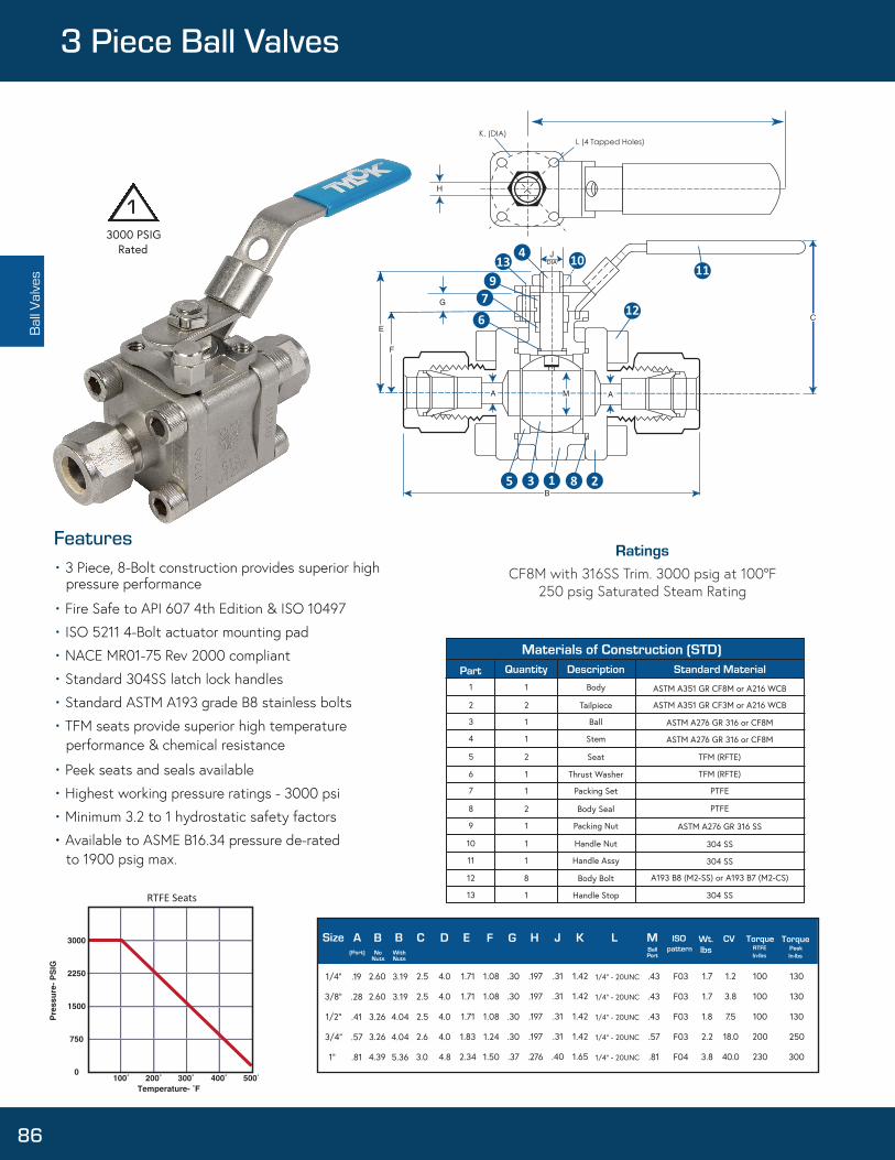
Ball
Valve
s
3000 PSIG Rated
Body
Tailpiece
Ball
Stem
Seat
Thrust Washer
Packing Set
Body Seal
Packing Nut
Handle Nut
Handle Assy
Body Bolt
Handle Stop
1
2
1
1
2
1
1
2
1
1
1
8
1
1
2
3
4
5
6
7
8
9
10
11
12
13
304 SS
304 SS
304 SS
A193 B8 (M2-SS) or A193 B7 (M2-CS)
ASTM A276 GR 316 SS
PTFE
PTFE
TFM (RFTE)
TFM (RFTE)
ASTM A276 GR 316 or CF8M
ASTM A276 GR 316 or CF8M
ASTM A351 GR CF3M or A216 WCB
ASTM A351 GR CF8M or A216 WCB
Size A B B C D E F G H J K L M ISOpattern
Wt.lbs
CV TorqueRTFEIn-lbs
TorquePeekIn-lbs(Port) No
NutsWithNuts
BallPort
1/4”
3/8”
1/2”
3/4”
1”
.19
.28
.41
.57
.81
2.60
2.60
3.26
3.26
4.39
3.19
3.19
4.04
4.04
5.36
2.5
2.5
2.5
2.6
3.0
4.0
4.0
4.0
4.0
4.8
1.71
1.71
1.71
1.83
2.34
1.08
1.08
1.08
1.24
1.50
.30
.30
.30
.30
.37
.197
.197
.197
.197
.276
.31
.31
.31
.31
.40
1.42
1.42
1.42
1.42
1.65
1/4” - 20UNC
1/4” - 20UNC
1/4” - 20UNC
1/4” - 20UNC
1/4” - 20UNC
.43
.43
.43
.57
.81
F03
F03
F03
F03
F04
1.7
1.7
1.8
2.2
3.8
1.2
3.8
7.5
18.0
40.0
100
100
100
200
230
130
130
130
250
300
Features• 3 Piece, 8-Bolt construction provides superior high
pressure performance
• Fire Safe to API 607 4th Edition & ISO 10497
• ISO 5211 4-Bolt actuator mounting pad
• NACE MR01-75 Rev 2000 compliant
• Standard 304SS latch lock handles
• Standard ASTM A193 grade B8 stainless bolts
• TFM seats provide superior high temperature performance & chemical resistance
• Peek seats and seals available
• Highest working pressure ratings - 3000 psi
• Minimum 3.2 to 1 hydrostatic safety factors
• Available to ASME B16.34 pressure de-rated to 1900 psig max.
3 Piece Ball Valves
RatingsCF8M with 316SS Trim. 3000 psig at 100°F
250 psig Saturated Steam Rating
1
86
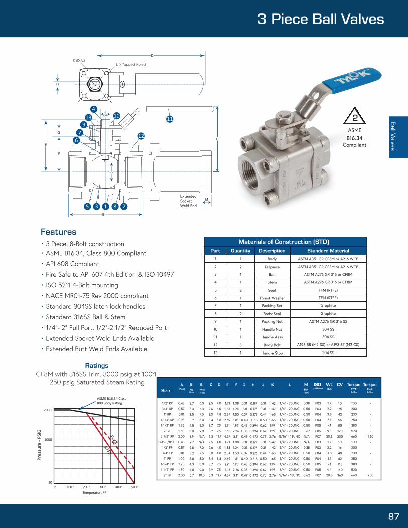
Ball Valves3 Piece Ball Valves
ASME B16.34
Compliant
ASTM A351 GR CF8M or A216 WCB
ASTM A351 GR CF3M or A216 WCB
ASTM A276 GR 316 or CF8M
ASTM A276 GR 316 or CF8M
TFM (RTFE)
TFM (RTFE)
Graphite
Graphite
ASTM A276 GR 316 SS
304 SS
304 SS
304 SS
A193 B8 (M2-SS) or A193 B7 (M2-CS)
Body
Tailpiece
Ball
Stem
Seat
Thrust Washer
Packing Set
Body Seal
Packing Nut
Handle Nut
Handle Assy
Body Bolt
Handle Stop
1
2
1
1
2
1
1
2
1
1
1
8
1
1
2
3
4
5
6
7
8
9
10
11
12
13
0° 100° 200° 300° 400° 500 ºF
50°
1/2” RP
3/4” RP
1” RP
1-1/4” RP
1/2” RP
2” RP
1/2” RP
1/4”-3/8” FP
1/2” FP
3/4” FP
1” FP
1-1/4” FP
1-1/2” FP
2” FP
0.43
0.57
0.81
0.98
1.25
1.50
2.00
0.43
0.57
0.81
1.00
1.25
1.50
2.00
2.7
3.0
3.5
3.9
4.5
5.0
6.9
2.7
2.8
3.2
3.8
4.3
4.8
5.7
2.5
2.6
3.0
3.4
3.7
3.9
5.3
2.5
2.6
3.0
3.4
3.7
3.9
5.3
4.0
4.0
4.8
5.8
7.5
7.5
11.7
4.0
4.0
4.8
5.8
7.5
7.5
11.7
1.71
1.83
2.34
2.69
2.91
3.15
4.37
1.71
1.83
2.34
2.69
2.91
3.15
4.37
1.08
1.24
1.50
1.81
1.95
2.26
3.11
1.08
1.24
1.50
1.81
1.95
2.26
3.11
0.31
0.31
0.37
0.40
0.43
0.35
0.49
0.31
0.31
0.37
0.40
0.43
0.35
0.49
0.197
0.276
0.315
0.394
0.394
0.472
0.197
0.197
0.276
0.315
0.394
0.394
0.472
0.31
0.31
0.44
0.50
0.62
0.62
0.75
0.31
0.31
0.44
0.50
0.62
0.62
0.75
1.42
1.42
1.65
1.65
1.97
1.97
2.76
1.42
1.42
1.65
1.65
1.97
2.76
1.97
1/4” - 20UNC
1/4” - 20UNC
1/4” - 20UNC
1/4” - 20UNC
1/4” - 20UNC
1/4” - 20UNC
5/16” - 18UNC
1/4” - 20UNC
1/4” - 20UNC
1/4” - 20UNC
1/4” - 20UNC
1/4” - 20UNC
1/4” - 20UNC
5/16” - 18UNC
M
0.38
0.50
0.50
0.50
0.50
0.62
N/A
N/A
0.38
0.50
0.50
0.50
0.50
0.62
F03
F03
F04
F04
F05
F05
F07
F03
F03
F04
F04
F05
F05
F07
1.7
2.2
3.8
5.1
20.8
1.7
2.2
3.8
5.1
20.8
7.1
9.8
7.1
9.8
10
25
42
55
85
120
300
10
16
40
62
115
140
360
100
200
230
250
380
520
660
100
200
230
250
380
520
660
-
-
-
-
-
-
950
-
-
-
-
-
-
950
0.197
With Nuts
6.0
8.0
8.0
N/A
N/A
8.0
8.0
10.0
7.0
7.5
9.0
7.0
7.5
9.0
Features• 3 Piece, 8-Bolt construction• ASME B16.34, Class 800 Compliant
• API 608 Compliant
• Fire Safe to API 607 4th Edition & ISO 10497
• ISO 5211 4-Bolt mounting
• NACE MR01-75 Rev 2000 compliant
• Standard 304SS latch lock handles
• Standard 316SS Ball & Stem
• 1/4”- 2” Full Port, 1/2”-2 1/2” Reduced Port
• Extended Socket Weld Ends Available
• Extended Butt Weld Ends Available
CF8M with 316SS Trim. 3000 psig at 100°F250 psig Saturated Steam Rating
2
87
ExtendedSocketWeld End
7

Chart 4 Chart 2 Chart 5 Chart 6
Seats Seals
R R8 --
Chart 1
SSMaterial
-
Chart 2
8Inlet Size
-
Chart 3
5Style
TTDescription Outlet Size
Chart 7
Options
K-
*optional
4 1 /4"
6 3/8"
8 1 /2"
1 2 3/4"1 6 1 "
*other size upon request
Valve Size
Chart 2 - Valve SizeDesignator
5
Chart 3 - Style3 Piece Ball Valve, 2 way,
bi- directional flowI
K
L
Chart 7 - OptionsOval Handle
ASME B.16.34 Compliant
*Full Port
R
P
Chart 5 - Seats
Reinforced PTFE
PEEK
EE 1 /4" – 1 "FF 1 /4" – 4"II 1 /4" – 1 "
TT 1 /4" – 1 "XX 1 /4" – 4"
ZZ 1 /4" – 1 "
Chart 4 - Description
Extended Butt Weld (Schedule 80)
Female NPTPipe Socket Weld
Instrumentation Tube End (CBC-Lok)Extended Pipe Socket Weld
Instrumentation Tube End (CS-Lok)
End De scriptionCode Size Range
G
R
Chart 6 - SealsGraphite
Reinforced PTFE
SS
Chart 1 - MaterialStainless Steel
3 Piece Ball Valves are ordered as listed in this catalog by inserting the material code before the part number.3 Piece Ball Valves can be identified through the part number as to material, end sizes, end configuration, seat & seal type, and special options. The standard Ball & Stem are in Stainless Steel unless otherwise requested.
Example: A Stainless Steel, 1/2” Inlet to 1/2” Outlet, 3 Piece Ball Valve, with CBC-Lok Instrumentation Tube Ends, Reinforced PTFE Seats & Seals, with the following option: ASME B16.34 compliant is designated as follows:
* Full Port is only available in NPT configurations.
* Special cleaning and packaging is available. Contact authorized Tylok Representative for more information.
* Tube ended valves come standard with -RR (Reinforced PTFE Seats & Seal). * Pipe ended valves come standard with -RG (Reinforced Ptfe Seats & Seals).
Due to continuous development of our product range we reserve the right to change the dimensions and information contained in the catalog as required.
Ball
Valve
s3 Piece Ball Valves
88

Needle ValvesScrewed Bonnet Needle Valves
89

Specifications 316 Stainless Brass SteelHard Seat Soft Seat Hard Seat Soft Seat Hard Seat Soft Seat
Pressure Rating 1
psig (bar)10,000 6,000 6,000 3,000 10,000 6,000(689) (413) (413) (206) (689) (413)
Temperature Rating 2
°F (°C)-10 to 200(-23 to 93)
-10 to 200(-23 to 93)
-10 to 200(-23 to 93)
# Component 316 SS Brass Steel1a Mini “T” Handle 316 SS N/A Steel1b “T” Handle 316 SS N/A Steel1c Round Knurled Handle 316 SS Brass Steel1d 1-3/8” Plastic Handle Phenolic1e 1-3/4” Plastic Handle Phenolic2 Set Screw 316 SS Steel3 Dust Cap 1 Vinyl4 Valve Bonnet 316 SS Brass Steel
5 Valve Stem Chrome-plated 316 SS 316 SS
6 Bonnet Lock Pin 1 316 SS N/A Steel7 Stem Back-up Ring PTFE
8 Stem O-Ring Fluorocarbon FKM9 Valve Body 316 SS Brass Steel
Materials of Construction
1a
1c
1e
3
6
*
* Steel valves are Zinc, Nickel plated for corrosion resistance
Nee
dle
Valve
s®
Design & Features
• Hard (Vee) or Delrin® Soft Seat/Tip• Orifice sizes from 0.172 to 0.438 in.• Flow Coefficients (Cv) from 0.37 to 2.70• Straight or angle flow patterns• Optional panel mount• Handle options available• Non-wetted stem threads
• For pressure ratings of valves with the tube fitting end connections, see CBC-Lok® or CS-Lok® catalogs
• Temperature ratings based on working temperatures of standard stem seals See o-ring/packing options for temperature ratings of optional stem seals and soft seat valve
• Valves with PTFE packings have a max pressure rating of 6000 psi.
TestingTylok Screwed Needle Valves are 100% Helium leak tested to 1x10⁻⁴ ml/s ensuring performance and reliability
90
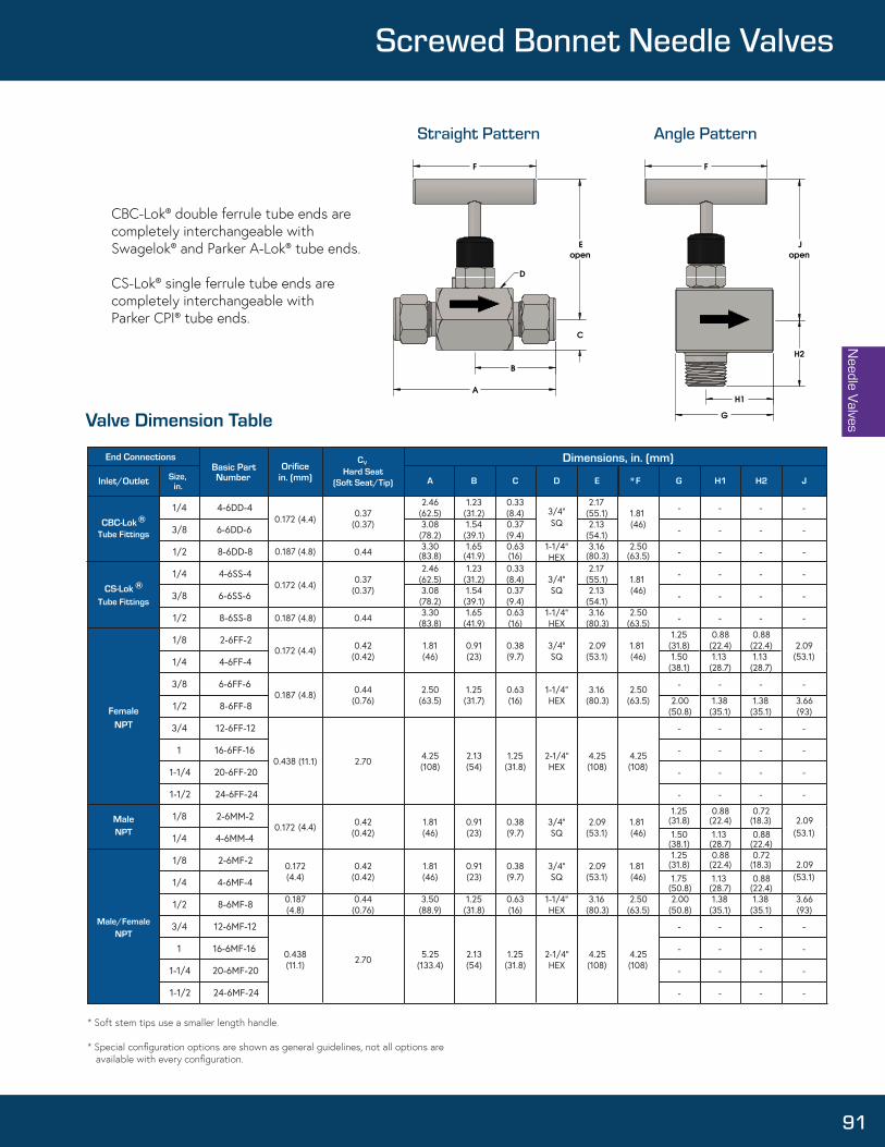
End ConnectionsBasic Part Number
Orificein. (mm)
VC Hard Seat
(Soft Seat/Tip)Inlet/Outlet Size, in. A B C D E F G H1 H2 J
CBC-Lok ®Tube Fittings
1/4 4-6DD-40.172 (4.4)
0.37(0.37)
2.46(62.5)
1.23(31.2)
0.33(8.4)
2.17(55.1) 1.81
(46)
- - - -
3/8 6-6DD-6 3.08(78.2)
1.54(39.1)
0.37(9.4)
2.13(54.1) - - - -
1/2 8-6DD-8 0.187 (4.8) 0.44 3.30(83.8)
1.65(41.9)
0.63(16)
1-1/4”HEX
3.16(80.3)
2.50(63.5) - - - -
CS-Lok ®
Tube Fittings
1/4 4-6SS-40.172 (4.4) 0.37
(0.37)
2.46(62.5)
1.23(31.2)
0.33(8.4)
2.17(55.1) 1.81
(46)
- - - -
3/8 6-6SS-6 3.08(78.2)
1.54(39.1)
0.37(9.4)
2.13(54.1) - - - -
1/2 8-6SS-8 0.187 (4.8) 0.44 3.30(83.8)
1.65(41.9)
0.63(16)
1-1/4”HEX
3.16(80.3)
2.50(63.5) - - - -
FemaleNPT
1/8 2-6FF-20.172 (4.4) 0.42
(0.42)1.81(46)
0.91(23)
0.38(9.7)
3/4”SQ
2.09(53.1)
1.81(46)
1.25(31.8)
0.88(22.4)
0.88(22.4) 2.09
(53.1)1/4 4-6FF-4 1.50(38.1)
1.13(28.7)
1.13(28.7)
3/8 6-6FF-60.187 (4.8) 0.44
(0.76)2.50
(63.5)1.25(31.7)
0.63(16)
1-1/4”HEX
3.16(80.3)
2.50(63.5)
- - - -
1/2 8-6FF-8 2.00(50.8)
1.38(35.1)
1.38(35.1)
3.66(93)
3/4 12-6FF-12
0.438 (11.1) 2.70 4.25(108)
2.13(54)
1.25(31.8)
2-1/4”HEX
4.25(108)
4.25(108)
- - - -
1 16-6FF-16 - - - -
1-1/4 20-6FF-20 - - - -
1-1/2 24-6FF-24 - - - -
Male NPT
1/8 2-6MM-20.172 (4.4) 0.42
(0.42)1.81(46)
0.91(23)
0.38(9.7)
3/4”SQ
2.09(53.1)
1.81(46)
1.25(31.8)
0.88(22.4)
0.72(18.3) 2.09
(53.1)1/4 4-6MM-4 1.50(38.1)
1.13(28.7)
0.88(22.4)
Male/Female NPT
1/8 2-6MF-2 0.172(4.4)
0.42(0.42)
1.81(46)
0.91(23)
0.38(9.7)
3/4”SQ
2.09(53.1)
1.81(46)
1.25(31.8)
0.88(22.4)
0.72(18.3) 2.09
(53.1)1/4 4-6MF-4 1.75(50.8)
1.13(28.7)
0.88(22.4)
1/2 8-6MF-8 0.187(4.8)
0.44(0.76)
3.50(88.9)
1.25(31.8)
0.63(16)
1-1/4”HEX
3.16(80.3)
2.50(63.5)
2.00(50.8)
1.38(35.1)
1.38(35.1)
3.66(93)
3/4 12-6MF-12
0.438(11.1) 2.70 5.25
(133.4)2.13(54)
1.25(31.8)
2-1/4”HEX
4.25(108)
4.25(108)
- - - -
1 16-6MF-16 - - - -
1-1/4 20-6MF-20 - - - -
1-1/2 24-6MF-24 - - - -
Dimensions, in. (mm)
Valve Dimension Table
SQ3/4”
SQ3/4”
*
* Soft stem tips use a smaller length handle.
* Special configuration options are shown as general guidelines, not all options are available with every configuration.
Needle Valves
F F
G
A
openE
C
openJ
H2
H1
B
D
Straight pattern Angle patternStraight Pattern Angle Pattern
Screwed Bonnet Needle Valves
CBC-Lok® double ferrule tube ends are completely interchangeable with Swagelok® and Parker A-Lok® tube ends.
CS-Lok® single ferrule tube ends are completely interchangeable with Parker CPI® tube ends.
91

Panel Mount Details15/16 Hex Nut
.16 Thick5/8-18 Thread
1/8 MaxPanel
7/8
7/16
Dimensions for: • Square Bar Stock
• 1/4” and Smaller Angle Valves
15/16 Hex Nut.16 Thick
5/8-18 Thread
3/16 MaxPanel
1-1/32
1/2
Dimensions for:• Hex Bar Stock
• 1/2” Angle Valves
Standard Handles 316 SS Brass SteelSquare Bar Stock and 1/4” and Smaller Angle Valves H1 H3 H1
Hex Bar Stock and 1/2” Angle Valves H2 N/A H2
The handle material will always match the valve body, unless otherwise specified.
Nee
dle
Valve
s
1-13/16”
H1 1/4”
1 3/8”
H4 1/4”
27/32”
H2 1/4”
2-1/2”4-1/4” (3/4” & Up Valves)
H3 5/32”
3/8”
1” RD
H5 1/4”
1 3/8”
1 1/16”
Handle Options
®
92

6,000
5,000
4,000
3,000
2,000
1,000
00 200 400 600 800 1000
Temperature (°F)
Pres
sure
(psi
)Pressure vs. Temperature:
Steel Needle Valve with Graphoil ® packing
Steel or Stainless Steel Needle Valve with PTFE packing
Stainless Steel Needle Valve with Graphoil ®packing
Brass Needle Valve with PTFE or Graphoil ® packing
Needle ValvesScrewed Bonnet Needle Valves
93

# Turns Open
Orifice (0.187) Soft Seat t at
at
Orifice (0.172) Hard & Soft (NPT) Orifice (0.187) Hard Seat
0 1 2 3 4 5 6 7 8 90
0.5
1
1.5
2
2.5
3
0 1 2 3 4 5 60
0.05
0.1
0.15
0.2
0.25
0.3
0.35
0.45
0.4
0.5
0 1 2 3 4 5 60
0.05
0.1
0.15
0.2
0.25
0.3
0.35
0.45
0.4
0 1 2 3 4 50
0.1
0.2
0.3
0.4
0.5
0.6
0.7
0.8
Nee
dle
Valve
s®
Packing Screw enables easy adjustments
Packing Washers fully support
packingPacking
Teflon® & Graphoil®
Flow Data at 100°F (37°C)
Orifice (0.172) Hard & Soft Seat (NPT) Orifice (0.172) Hard & Soft Seat (Tube Fittings)
O-Ring/Packing OptionsTemperature Ratings:
•-10°F to 200°F with Fluorocarbon FKM O-Ring• -65°F to 150°F with EPDM O-Ring• -13°F to 300°F with Kalrez® O-Ring• -65°F to 250°F with Teflon® O-Ring• -20°F to 400°F with Graphoil® Packing• -200°F max with Soft Seat/Tip Valves
94

SS↓
Material
8↓
Inlet Size
6↓
Style
DD↓
Inlet/Outlet
8↓
Inlet Size
↓P2
Options
↓G
Seal Handle
↓H5
SS Stainless SteelB BrassS Steel
2 1/8”4 1/4”6 3/8”8 1/2”12 3/4”16 1”20 1-1/4”24 1-1/2”
6 Needle Valve
A Angle PatternL Delrin® Soft Stem/SeatP1 Panel Mount (1 nut)P2 Panel Mount (2 nuts)
*Fluorocarbon FKM O-Ring is Standard
EM1 EPDM 80 O-RingKZ1 Kalrez®3018 O-RingG Graphoil® PackingT PTFE Packing
Chart 7- Handle OptionsH1 Mini “T” HandleH2 “T” HandleH3 Round Knurled HandleH4 1-3/8” Phenolic HandleH5 1-3/4” Phenolic Handle
*See handle options section for standard handles
DD CBC-Lok® Tube FittingSS CS-Lok® Tube FittingMM Male NPTFF Female NPTMF Male NPT
CBC-Lok® Tube FittingCS-Lok® Tube Fitting
Male NPTFemale NPTFemale NPT
* Special configuration options are shown as general guidelines, not all options are available with every configuration. Consult factory for details.
Needle ValvesScrewed Bonnet Needle Valves
Screwed Needle Valves are ordered as listed in this catalog by inserting the material code before the part number.
Special configurations available upon request.
Example: A Stainless Steel Needle Valve with 1/2” CBC-Lok® Tube Fitting inlet to 1/2” CBC-Lok® Tube Fitting outlet with 2 nut panel mount option, Graphoil® Packing and 1-3/4” phenolic handle is designed as follows.
Example: SS-6-6DD-6-P2-T
Designates a Stainless Steel Needle Valve with 3/8” CBC-Lok® Tube Fitting inlet to 3/8” CBC-Lok® Tube Fitting outlet with 2 nut panel mount option, and optional Teflon® Packing.
95

Nee
dle
Valve
sIntegral Bonnet Needle Valves
96

Needle Valves
®
Typical Applications:• Instrument air lines• Instrumentation panels• Test Stands• Analytical systems• General flow control service• A complete series from 1/4”, 3/8”, 1/2”, 3/4” with integral tube end connections.• Designed for regulation and tight shut off• Compare with Swagelok 0, 1 and 18 Series Integral Bonnet Needle Valves• Panel Mountable• Live-Loaded, Chevron-Style packing
Features:• Stainless Steel Construction• Pressure Rating 5000 psi (345 bar)• Temperature Rating: 400°F (204°C) max• Packing Material: PTFE• Flow coefficient (Cv) 0.30 to 1.80• Integral tube fitting (both twin & single ferrule designs)• Male NPT x Tube• Female NPT• Male NPT x Female NPT• 100% factory tested
97

21c1a
1b
2
3
4
6
7
8
9
10
1115
14
13
12
5
Chevron (2) piece sliding provides improved ID/OD sealing and wear compensation.
Belleville washers provide active compensation for wear, improved sealing and reduce manual adjustment.
Stem chrome plated for wear and corrosion resistance.
*1R8 Series valves are only available with Tee (Bar) handles
Aluminum
Black PhenolicStainless316 SS304 SS304 SS304 SS304 SS
316 SSChrome-plated 316 SS
304 SS316L SS316L SS316L SS316L SS
TFM 1600 PTFE(Polytetrafluoroethylene)
1a
1b
1c
2
3
4
5
6
7
8
9
10
11
12
13
14
15
Tee Handle*Round Handle
Handle PinSet Screw
Packing NutGland
Packing SpringsPacking Gland
Upper PackingLower PackingLower Gland
StemPanel Nut
BodyFront ColletRear Collet
Nut
Nee
dle
Valve
sIntegral Bonnet Needle Valves
98

0
1000
2000
3000
4000
5000
6000
-100 0 100 200 300 400 500
PRES
SURE
(psi
g)
TEMPERATURE (F°)
Pressure - Temperature
Temperature (F°) Pressure (psig)
-600
100190200300400400
5000500050005000475030001250
0
Needle Valves
®
99

In designing a system incorporating tube fittings and valves, it is the designer’s or user’s obligation and responsibility to determine the appropriate fittings and valves to be used for each application and to insure proper installation and maintenance.
End Connections Ordering Part #Type Size
CBC -Lok Tube Fitting
CS -Lok Tube Fitting
Male NPT to CBC -Lok Male NPT to
CS -Lok
TPN elameF
Cv Orifice DimensionsB C D E F G H
Male NPT to Female NPT
A
1/4
3/8
1/2
1/2
3/4
1/4
3/8
1/2
1/2
3/4
1/4
1/4
1/4
3/8
1/2
1/4
1/2
SS-1R4-D4D4
SS-1R6-D6D6
SS-1R6-D8D8
SS--1R8-D8D8
SS-1R8-D12D12
SS-1R4-S4S4
SS-1R6-S6S6
SS-1R6-S8S8
SS-1R8-S8S8
SS-1R8-S12S12
SS-1R4-M4D4
SS-1R4-M4S4
SS-1R6-F4F4
SS-1R8-F6F6
SS-1R8-F8F8
SS-1R6-M4F4
SS-1R8-M8F8
0.37
0.73
0.73
1.80
1.80
0.37
0.73
0.73
1.80
1.80
0.37
0.37
0.37
1.80
1.80
0.73
1.80
0.158
0.250
0.250
0.375
0.375
0.158
0.250
0.250
0.375
0.375
0.158
0.158
0.158
0.375
0.375
0.250
0.375
2.27
2.58
2.80
3.80
3.80
2.27
2.60
2.81
3.80
3.80
1.95
1.95
2.12
3.00
3.00
2.19
3.00
1.13
1.29
1.40
1.90
1.90
1.14
1.30
1.40
1.90
1.90
0.82
0.82
1.06
1.50
1.50
1.13
1.50
0.44
0.50
0.50
0.75
0.75
0.44
0.50
0.50
0.75
0.75
0.44
0.44
0.55
0.75
0.75
0.50
0.75
0.41
0.56
0.56
0.75
0.75
0.41
0.56
0.56
0.75
0.75
0.38
0.38
0.50
0.75
0.75
0.50
0.75
1.38
1.88
1.88
3.00
3.00
1.38
1.88
1.88
3.00
3.00
1.38
1.38
1.88
3.00
3.00
1.88
3.00
0.53
0.78
0.78
1.03
1.03
0.53
0.78
0.78
1.03
1.03
0.53
0.53
0.53
1.03
1.03
0.53
1.03
2.50
2.97
2.97
3.91
3.91
2.50
2.97
2.97
3.91
3.91
2.50
2.50
2.97
3.88
3.88
2.97
3.88
0.63
0.88
1.13
1.13
1.13
0.63
0.88
1.13
1.13
1.13
0.63
0.63
0.63
1.13
1.13
0.63
1.13
Nee
dle
Valve
sIntegral Bonnet Needle Valves
100

Plug ValvesPlug Valves
101

Dimensions
Dimensions are shown with tube fitting ends finger-tight and in standard configurations.Dimensions are subject to change.
End Connections Dimensions, in. (mm)
Basic Part SwagelokNumber Number Series
Inlet/Outlet
Size Orifice A¹ B¹
1/8” SS-P4-DTT-2-2 SS-2P4T P4 0.093 (2.3) 1.99 (50.5) 0.98 (24.9)CBC-Lok/
Tube Fitting 1/4” SS-P4-DTT-4-4 SS-4P4T P4 0.172 (4.4) 2.17 (55.1) 1.08 (27.4)
3/8” SS-P4-DTT-6-6 SS-6P4T P4 0.172 (4.4) 2.29 (58.2) 1.14 (29.0)
1/8” SS-P4-STT-2-2 - P4 0.093 (2.3) 1.99 (50.5) 0.98 (24.9)CS-Lok/
Tube Fitting 1/4” SS-P4-STT-4-4 - P4 0.172 (4.4) 2.17 (55.1) 1.08 (27.4)
3/8” SS-P4-STT-6-6 - P4 0.172 (4.4) 2.29 (58.2) 1.14 (29.0)
1/8” SS-P4-1FF-2-2 SS-2P4T4 P4 0.172 (4.4) 1.78 (45.2) 0.89 (22.6)Female NPT
1/4” SS-P4-1FF-4-4 SS-4P4T4 P4 0.172 (4.4) 2.09 (53.1) 1.05 (26.7)
1/8” SS-P4-1MM-2-2 SS-2P4T2 P4 0.172 (4.4) 1.53 (38.9) 0.76 (19.3)Male NPT
1/4” SS-P4-1MM-4-4 SS-4P4T2 P4 0.172 (4.4) 1.90 (48.3) 0.95 (24.1)
Male NPT/CBC-Lok 1/4” SS-P4-DMT-4-4 SS-4P4T1 P4 0.172 (4.4) 2.03 (51.2) 0.95 (24.1)
Tube Fitting
Male NPT/CS-Lok 1/4” SS-P4-SMT-4-4 - P4
Tube Fitting
Male NPT/Female NPT 1/4” SS-P4-1MF-4-4 SS-4P4T5 P4 0.172 (4.4) 2.00 (5 0.8) 0 .95 ( 24.1)
0.172 (4.4) 2.03 (51.2) 0.95 (24.1)
1.89 47.928.91.14
1.56 39.6
.38 9.5
.47 11.9B
A
.7519.1
P4 Series
Plug
Val
ves
®
Design & Features:• Working Pressure up to 3000 psig (206 bar)• 316 Stainless Steel material• 1/8 through 3/8 inch sizes• CBC-Lok® interchanges with Swagelok® & Parker A-Lok®• CS-Lok® interchanges with Parker CPI®• Positive leak tight shut off• Every valve tested for shut off at 1000 psi (41.3 bar)• Simple design, easy to clean and maintain - One piece body construction - Replaceable plug assembly - O-Ring seal to atmosphere - Fast acting, one quarter turn fully actuates the valve - Handle direction indicates valve position & flow direction
Dimensions
102

3500
3000
2500
2000
1500
1000
500
00 100 200 300 400 500
Temperature (F°)
Pres
sure
(psi
g)
Pressure - Temperature
Temperature (F°) Pressure (psig)0
100150200250300350400400
30003000300030002000100010001000
0
Plug ValvesPlug Valves
103

Component Material
1 Handle Nylon 6/62 Pin 316 SS3 Plug² PTFE-coated 316 SS/A4794 O-rings²5 Pin 316 SS6 Body² 316 SS/A4797 Snap Ring PH 15-7 Mo® SS
Lubricant²
*² Wetted components
8
PTFE-coated Fluorocarbon FKM
Perfluoropolyether Based
SS - P4 - D TT - 4 - 4 - KZ - BK↓ ↓ ↓ ↓ ↓ ↓ ↓ ↓
Material Valve Series Style Inlet/Outlet
Port Port Size Port Size O-Ring Options
Handle Options
*optional *optional
SS Stainless SteelP4 4 Series
P4V 4 Series, Vented
D CBC-LokS CS-Lok1 Threaded
Type Port A Port BTT Tube Tube
MM* Male NPT Male NPTFF* Female NPT Female NPTMF* Male NPT Female NPTMT Male NPT Tube
Designator Tube OD (Inches)2 1/8"4 1/4"6 3/8"
KZ Kalrez
TB PTFE Coated Buna N TE PTFE Coated EP TN PTFE Coated Neoprene
BK Black BL Blue
RD Red
(Material Grade / ASTM Specification)
Plug
Val
ves
®
Plug Valve Options
Downstream VentVented Plug Valves allow downstream pressure to release to atmosphere when the valve is closed. They have a 150 psig (10.3 bar) maximum operating pressure.
Optional O-Ring MaterialsTylok Plug Valves ordinarily come with PTFE-coated Fluorocarbon FKM O-Rings. For a different material, add an O-Ring material designator from Chart 6 to the valve ordering number.
Optional Handle ColorsTylok Plug Valves ordinarily come with a dark green handle. For a different color, add a handle color designator from Chart 7 to the valve ordering number.
Locking HandlesContact manufacturer for availability.
Panel MountContact manufacturer for availability.
104

Quick Connects
QC Series Quick Connects
105

Body Size 1/4" 3/8"
Connected Position 3000 (207) 1500 (103)
Disconnected Position 3000 (207) 1500 (103)
Connect Under Pressure 250 (17) 250 (17)
Machined Parts Stainless Steel, ANSI Type 316
Springs & Retaining Rings Stainless Steel, ANSI Type 316
Seals Viton O-Rings, good from -15°F to 400°F
Seal Lubricant Perfluoropolyether Based
in. (mm) in. (mm) in.
Dust Caps
in. (mm) in. (mm) in.
Dust Plugs
QC4 1/4 SS-QC4-P 1.88 (47.8) 0.62 (15.7) 9/16
QC6 3/8 SS-QC6-P 1.84 (46.7) 0.74 (18.8) 11/16
QC4 1/4
3/8
SS-QC4-C
SS-QC6-C
3.00
3.25
(72.6)
(82.6)
0.92
1.03
(23.4)
(26.2)
5/8
3/4QC6
Qui
ck C
onne
cts
®
Design & Features:• Redundant Fluorocarbon FKM O-Ring Seals provide quick leak tight sealing in vacuum or pressure systems.
• Dependable poppet valves with integral Fluorocarbon FKM O-Ring Seals are standard in all quick connect bodies and valved plugs.
• Positive valve stops prevent flow checking in the quick connect. Valve guides improve reliability by providing precise alignment to the seat.
• Smooth entrance and positive engagement, firmly gripping the plug, is insured by Teflon® bonded locking “dogs”.
• All quick connect valve springs are made 316 Stainless Steel.
• Tylok CBC-Lok® double ferrule tube ends are completely interchangeable with Swagelok® & Parker A-Lok® Tube Ends.
• Tylok CS-Lok® single ferrule tube ends are completely interchangeable with Parker CPI® Tube Ends.
Vacuum Specifications50 Millitor=0.05mm of Hg, absolute pressure=27.9 inches Hg, gauge pressure
TestingTylok Quick Connects are 100% leak tested
106

OALSeries Fitting Ordering B Flat
Size Number in. (mm) in. (mm) in.
CBC-Lok® Tube Fitting End
in. (mm) in. (mm) in.
CS-Lok® Tube Fitting End
in. (mm) in. (mm) in.
Male Pipe End
in. (mm) in. (mm) in.
Female Pipe End
in. (mm) in. (mm) in.
CBC-L ok® Bulkhead Tube Fitting End
Series Fitting Ordering OAL B FlatSize Number in. (mm) in. (mm) in.
CS-Lok® Bulkhead Tube Fitting End
Quick Connects
QC4 1/8
1/4
3/8
SS-QC4-B-2D
SS-QC4-B-4D
SS-QC6-B-6D
2.35
2.38
2.86
(59.7)
(60.5)
(72.6)
0.92
0.92
1.03
(23.4)
(23.4)
(26.2)
5/8
5/8
3/4
QC6
QC6
QC4 1/8
1/4
3/8
SS-QC4-B-2S
SS-QC4-B-4S
SS-QC6-B-6S
2.34
2.39
2.87
(59.4)
(60.7)
(72.9)
0.92
0.92
1.03
(23.4)
(23.4)
(26.2)
5/8
5/8
3/4
QC6
QC6
QC41/8
1/4
1/4
3/8
SS-QC4-B-2M
SS-QC4-B-4M
SS-QC6-B-4M
SS-QC6-B-6M
2.06
2.25
2.62
2.62
(52.3)
(57.2)
(66.5)
(66.5)
0.92
0.92
1.03
1.03
(23.4)
(23.4)
(26.2)
(26.2)
5/8
5/8
3/4
3/4
QC6
QC6
QC4
QC4
1/8
1/4
1/4
3/8
SS-QC4-B-2F
SS-QC4-B-4F
SS-QC6-B-4F
SS-QC6-B-6F
2.20
2.49
2.80
2.82
(55.9)
(63.2)
(71.1)
(71.6)
0.92
0.92
1.03
1.03
(23.4)
(23.4)
(26.2)
(26.2)
5/8
5/8
3/4
7/8QC6
QC6
QC4
QC4 1/4
3/8
SS-QC4-B1-4S
SS-QC6-B1-6S
3.00
3.25
(72.6)
(82.6)
0.92
1.03
(23.4)
(26.2)
5/8
3/4QC6
QC4 1/4
3/8
SS-QC4-B1-4S
SS-QC6-B1-6S
3.01
3.26
(76.5)
(82.8)
0.92
1.03
(23.4)
(26.2)
5/8
3/4QC6
QC Series Quick Connects
107

OALSeries Fitting Ordering B Flat
Size Number in. (mm) in. (mm) in.
CBC-Lok® Tube Fitting End
QC4
QC4
QC6
in. (mm) in. (mm) in.
CS-Lok® Tube Fitting End
in. (mm) in. (mm) in.
Male Pipe End
in. (mm) in. (mm) in.
Female Pipe End
Fitting Ordering OAL BSeries Flat
Size Number in. (mm) in. (mm) in.
CBC-Lok® Bulkhead Tube Fitting End
in. (mm) in. (mm) in.
CS-Lok® Bulkhead Tube Fitting End
Qui
ck C
onne
cts
1/8
1/4
3/8
SS-QC4-S-2D
SS-QC4-S-4D
SS-QC6-S-6D
2.74
2.35
2.56
(69.6)
(59.7)
(65.0)
0.62
0.62
0.74
(15.7)
(15.7)
(18.8)
5/8
9/16
11/16
QC4
QC4
QC6
1/8
1/4
3/8
SS-QC4-S-2S
SS-QC4-S-4S
SS-QC6-S-6S
2.73
2.36
2.57
(69.3)
(59.9)
(65.3)
0.62
0.62
0.74
(15.7)
(15.7)
(18.8)
5/8
9/16
11/16
QC4
QC4
QC6
1/8
1/4
1/4
3/8
SS-QC4-S-2M
SS-QC4-S-4M
SS-QC6-S-4M
SS-QC6-S-6M
2.03
2.22
2.33
2.33
(51.6)
(56.4)
(59.2)
(59.2)
0.62
0.62
0.74
0.74
(15.7)
(15.7)
(18.8)
(18.8)
9/16
9/16
3/4
3/4QC6
1/8
1/4
1/4
3/8
SS-QC4-S-2F
SS-QC4-S-4F
SS-QC6-S-4F
SS-QC6-S-6F
2.09
2.33
2.50
2.50
(53.1)
(59.2)
(63.5)
(63.5)
0.62
0.62
0.74
0.74
(15.7)
(15.7)
(18.8)
(18.8)
9/16
3/4
3/4
7/8
QC4
QC4
QC6
QC6
QC4 1/4
3/8
SS-QC4-S1-4D
SS-QC6-S1-6D
3.39
3.61
(86.1)
(91.7)
0.62
0.74
(15.7)
(18.8)
5/8
3/4QC6
QC4 1/4
3/8
SS-QC4-S1-4S
SS-QC6-S1-6S
3.40
3.62
(86.4)
(91.9)
0.62
0.74
(15.7)
(18.8)
5/8
3/4QC6
Instrumentation Quick Connect Plugs, Non-Valved
®
108

OALSeries Fitting Ordering B Flat
Size Number in. (mm) in. (mm) in.
CBC-Lok® Tube Fitting End
OAL BSeries Fitting Ordering Flat
Size Number in. (mm) in. (mm) in.
CS-Lok® Tube Fitting End
OAL BSeries Fitting Ordering Flat
Size Number in. (mm) in. (mm) in.
Male Pipe End
OAL BSeries Fitting Ordering Flat
Size Number in. (mm) in. (mm) in.
Female Pipe End
Fitting Ordering OAL BSeries Flat
Size Number in. (mm) in. (mm) in.
CBC-Lok ® Bulkhead Tube Fitting End
Series Fitting Ordering OAL B FlatSize Number in. (mm) in. (mm) in.
CS-Lok® Bulkhead ube Fitting End
Quick Connects
QC4
QC4
QC6
1/8
1/4
3/8
SS-QC4-D-2D
SS-QC4-D-4D
SS-QC6-D-6D
2.74
2.35
2.56
(69.6)
(59.7)
(65.0)
0.62
0.62
0.74
(15.7)
(15.7)
(18.8)
5/8
9/16
11/16
QC4
QC4
QC6
1/8
1/4
3/8
SS-QC4-D-2S
SS-QC4-D-4S
SS-QC6-D-6S
2.73
2.36
2.57
(69.3)
(59.9)
(65.3)
0.62
0.62
0.74
(15.7)
(15.7)
(18.8)
5/8
9/16
11/16
QC4
QC4
QC6
1/8
1/4
1/4
3/8
SS-QC4-D-2M
SS-QC4-D-4M
SS-QC6-D-4M
SS-QC6-D-6M
2.03
2.22
2.33
2.33
(51.6)
(56.4)
(59.2)
(59.2)
0.62
0.62
0.74
0.74
(15.7)
(15.7)
(18.8)
(18.8)
9/16
9/16
3/4
3/4
QC4
QC4
QC4
QC6
1/8
1/4
1/4
3/8
SS-QC4-D-2F
SS-QC4-D-4F
SS-QC6-D-4F
SS-QC6-D-6F
2.09
2.33
2.50
2.50
(53.1)
(59.2)
(63.5)
(63.5)
0.62
0.62
0.74
0.74
(15.7)
(15.7)
(18.8)
(18.8)
9/16
3/4
3/4
7/8
QC4
QC4
QC6
1/4
3/8
SS-QC4-D1-4D
SS-QC6-D1-6D
3.39
3.61
(86.1)
(91.7)
0.62
0.74
(15.7)
(18.8)
5/8
3/4
QC4
QC6
1/4
3/8
SS-QC4-D1-4S
SS-QC6-D1-6S
3.40
3.62
(86.4)
(91.9)
0.62
0.74
(15.7)
(18.8)
5/8
3/4
Instrumentation Quick Connect Plugs, Valved
QC Series Quick Connects
109

SS - QC4 - B - D - KZ↓ ↓ ↓ ↓ ↓ ↓
Series Component End Size Style O-Ring
SS Stainless Steel
QC4 4 Series (1/4”)
QC6 6 Series (3/8”)
B Body
B1 Bulkhead Body
S Non-Valved Plug
S1 Non-Valved Bulkhead Plug
D Valved Plug
D1 Valved Bulkhead Plug
C Dust Cap
P Dust Plug
2 1/8"
4 1/4"
6 3/8"
D CBC-Lok
S CS-Lok
1 Tylok Standard
M Male NPT
F Female NPT
* Fluorocarbon FKM (Standard)
B Buna N
E EPDM
KZ Kalrez®
N Neoprene
6
Material
4
Qui
ck C
onne
cts
®
Quick Connects are ordered as listed in this catalog providing the ordering number.
Special Configurations available upon request
Example: A Stainless Steel, QC4 series quick connect body with a 1/4” CBC-Lok® Tube Fitting End.
110

Check ValvesCH Series Check Valves
111

(
-10ºF (-23ºC) to 100ºF (37ºC)
200ºF (93ºC)
250ºF (121ºC)
300ºF (148ºC)
375ºF (190ºC)
6000 psig (413 bar)
5160 psig (355 bar)
4910 psig (338 bar)
4660 psig (321 bar)
4280 psig (295 bar)
1/3 psig (0.02 bar)
1 psig (0.06 bar)
5 psig (0.34 bar)
10 psig (0.68 bar)
1/3 to 3 psig (0.02 to 0.20 bar)
1 to 4 psig (0.06 to 0.27 bar)
3 to 9 psig (0.20 to 0.62 bar)
7 to 15 psig (0.48 to 1.00 bar)
Up to 6 psig (0.41 bar) differential pressure
Up to 6 psig (0.41 bar) differential pressure
Up to 2 psig (0.14 bar) differential pressure
Up to 3 psig (0.20 bar) differential pressure
25 psig (1.07 bar) 20 to 30 psig (1.04 to 2.01 bar) Up to 17 psig (1.02 bar) differential pressure
Chec
k Va
lves
®
CH Series Check Valves for Instrumentation
Tylok Check Valves are poppet-style valves made of 316 Stainless Steel, and feature a compact design that is perfect for instrumentation systems. These directional valves are normally closed, but open when the differential pressure between the inlet and outlet exceed the spring pressures.
Features:
• 6000 psig (413 bar) maximum pressure rating
• -10°F (-23°C) to 400°F (204°C) temperature rating
• 1/3 to 10 psig cracking pressure
• Fluorocarbon FKM Seals
• End Connections - Integral Tube Fittings (both twin [CBC-Lok®] & Single [CS-Lok®] ferrule designs)
• Available in sizes 1/4”, 3/8”, 1/2”, 3/4” and 1"
112

0 3.5 7.1 10.6 14.1 17.7 21.2 24.7 28.3 31.8 35.3 38.8 42.4 45.9 49.4
00.69
1.38
2.07
2.76
3.45
4.14
4.83
5.52
6.21
6.89
7.58
8.27
8.96
9.65
0
10
20
30
40
50
60
70
80
90
100
110
120
130
140
0 100 200 300 400 500 600 700 800 900 1000 1 100 1200 1300 1400
Air Flow (std ft3/min)
Inlet Pressure, bar
Inle
t Pre
ssur
e, p
sig
Air Flow (std L/min)
0 0.26 0.53 0.79 1.06 1.32 1.59 1.85 2.1 1
0
0.69
1.38
2.07
2.76
3.45
4.14
4.83
5.52
0
10
20
30
40
50
60
70
80
0 1 2 3 4 5 6 7 8
Water Flow (U.S. gal/min)
Inlet Pressure, bar
Inle
t Pre
ssur
e, p
sig
Water Flow (L/min)
0 7.1 14.1 21.2 28.3 35.3 42.4 49.4 56.5 63.6 70.6 77.7 84.8 91.8 98.9
0
0.69
1.38
2.07
2.76
3.45
4.14
4.83
5.52
6.21
6.89
0
10
20
30
40
50
60
70
80
90
100
0 200 400 600 800 1000 1200 1400 1600 1800 2000 2200 2400 2600 2800
Air Flow (std ft 3/min)
Inlet Pressure, bar
Inle
t Pre
ssur
e, p
sig
Air Flow (std L/min)
0 0.53 1.06 1.59 2.1 1 2.64 3.17 3.70 4.23 4.76 5.28
0
0.34
0.69
1.03
1.38
1.72
2.07
2.41
2.76
3.10
3.45
0
5
10
15
20
25
30
35
40
45
50
0 2 4 6 8 10 12 14 16 18 20
Water Flow (U.S. gal/min)
Inlet Pressure, bar
Inle
t Pre
ssur
e, p
sig
Water Flow (L/min)
Check ValvesCH Series Check Valves
113
12
34
56
71
2
3
4
5
6
7
Inlet Body
Bonded Poppet
Poppet Stop
Spring
O-Ring
Backup Ring
Outlet Body
316SS / A479
Fluorocarbon FKM - Bonded 316SS / A479
316SS / A240
302SS / A313
Fluorocarbon FKM
PTFE / D1710
316SS / A479
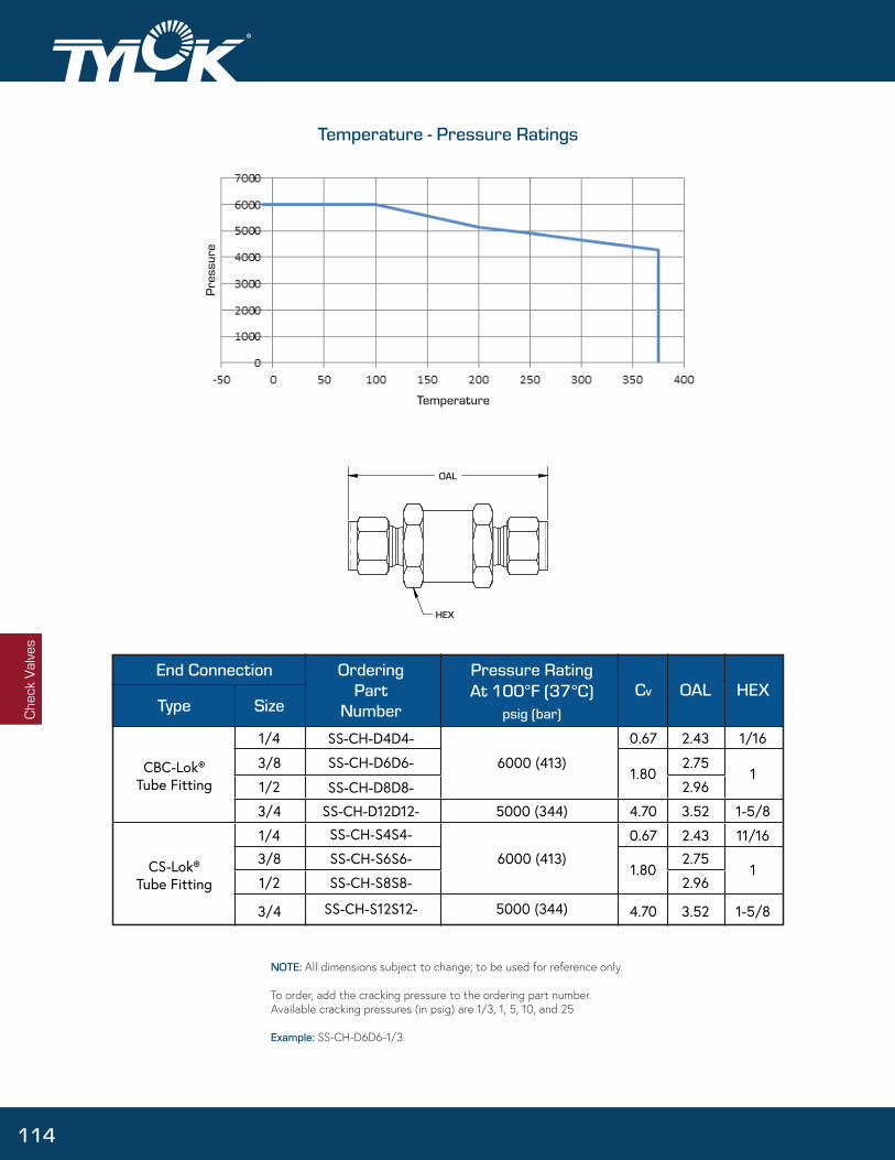
Chec
k Va
lves
®
End Connection
Type SizeCv OAL HEX
CBC-Lok®Tube Fitting
CS-Lok®Tube Fitting
1/4
3/8
1/2
3/4
1/4
3/8
1/2
3/4
SS-CH-D4D4-
SS-CH-D6D6-
SS-CH-D8D8-
SS-CH-D12D12-
SS-CH-S4S4-
SS-CH-S6S6-
SS-CH-S8S8-
SS-CH-S12S12-
0.67
1.80
4.70
0.67
1.80
4.70
2.43
2.75
2.96
3.52
2.43
2.75
2.96
3.52
1/16
1
1-5/8
11/16
1
1-5/8
Pressure RatingAt 100°F (37°C)
psig (bar)
OrderingPart
Number
6000 (413)
5000 (344)
6000 (413)
5000 (344)
NOTE: All dimensions subject to change; to be used for reference only.
To order, add the cracking pressure to the ordering part number.Available cracking pressures (in psig) are 1/3, 1, 5, 10, and 25
Example: SS-CH-D6D6-1/3.
114
Temperature - Pressure Ratings
Temperature
Pres
sure

Hose
Connectors
Flexible Metal Hoses • Stainless Steel Braided Hoses • Hose Assembly • Hose Connectors
Hose & Hose Connectors
115

Hos
e Co
nnec
tors
Weld Collar(304 SS)
End Connection (316 SS)
Over-Braid (304 SS)
Convoluted Core (316 SS)
Adapter Hose Minimum Inside Diameter
Maximum Outside DimensionTube Size A
Size ni (mm) in (mm) in (mm)
1/4
3/8
1/2
3/4
1
4
6
8
12
16
Available Sizes
1.63
1.84
2.09
2.31
2.81
(41.3)
(46.8)
(53.2)
(58.7)
(71.4)
0.16
0.28
0.39
0.63
0.88
(4.0)
(7.1)
(9.9)
(15.9)
(22.2)
0.56
0.78
0.93
1.32
1.63
(14.3)
(19.8)
(23.6)
(33.5)
(41.4)
Flexible Metal Hose
Design Features:
• Working pressures from vacuum to 4600 psig (317 bar).
-L Series (standard pressure) & H Series (high pressure)
• Medium-pressure applications where permeation is unacceptable.
• End Connections are available in 1/4” to 1” sizes.
• Stainless Steel core for corrosion resistance
• Stainless Steel braid contains hose pressure in dynamic applications
• End Connections weld meets ASME Boiler and Pressure Vessel Code Section IX.
• Assembly number and pressure rating are etched onto weld collar.
• Hose covers, identification tags, and additional leak testing options are available.
TestingEvery Tylok L & H series hose assembly is helium leak tested to a maximum leak rate of 1x10⁻⁶ std cm3/s. See additional test options in the ordering section.
Available End ConnectionsTube Adapter; CBC-Lok Tube Fitting; CS-Lok Tube Fitting; Male Pipe Fitting; Female Pipe Fitting; Male JIC,37° Flare; Female Swivel JIC, 37° flare
116

The working pressure must be de-rated when PTFE-lined hose operates outside of ambient temperatures.
Pulsating or shock pressures, like those encountered with fast-operating valves, can severely damage a hose. If your application experiences pulsating pressures, use a de-rating factor of 0.50. If your application experiences shock pressures, use a de-rating factor of 0.17.
Temperature °F (°C) De-Rating Factor
-325 to 300 (-198 to 149) 1.00
400 (204) 0.93
500 (260) 0.86
600 (316) 0.81
650 (343) 0.79
700 (371) 0.77
750 (399) 0.75
800 (427) 0.74
850 (454) 0.72
SS-L4A4A4-12 1/4” Hose, 1/4” Adapter Ends, 12” OAL
SS-L6A6A6-12 3/8” Hose, 3/8” Adapter Ends, 12” OAL
SS-L8A8A8-12 1/2” Hose, 1/2” Adapter Ends, 12” OAL
SS-L4A4A4-18 1/4” Hose, 1/4” Adapter Ends, 18” OAL
SS-L6A6A6-18 3/8” Hose, 3/8” Adapter Ends, 18” OAL
SS-L8A8A8-18 1/2” Hose, 1/2” Adapter Ends, 18” OAL
SS-L4A4A4-24 1/4” Hose, 1/4” Adapter Ends, 24” OAL
SS-L6A6A6-24 3/8” Hose, 3/8” Adapter Ends, 24” OAL
SS-L8A8A8-24 1/2” Hose, 1/2” Adapter Ends, 24” OAL
L Series
SS-H4A4A4-12 1/4” Hose, 1/4” Adapter Ends, 12” OAL
SS-H6A6A6-12 3/8” Hose, 3/8” Adapter Ends, 12” OAL
SS-H8A8A8-12 1/2” Hose, 1/2” Adapter Ends, 12” OAL
SS-H4A4A4-18 1/4” Hose, 1/4” Adapter Ends, 18” OAL
SS-H6A6A6-18 3/8” Hose, 3/8” Adapter Ends, 18” OAL
SS-H8A8A8-18 1/2” Hose, 1/2” Adapter Ends, 18” OAL
SS-H4A4A4-24 1/4” Hose, 1/4” Adapter Ends, 24” OAL
SS-H6A6A6-24 3/8” Hose, 3/8” Adapter Ends, 24” OAL
SS-H8A8A8-24 1/2” Hose, 1/2” Adapter Ends, 24” OAL
H Series
Hose
Connectors
Static Temperature Range
Hose
Hos e
Designator°F (°C)in (mm) in
(mm) psig (bar) psig (bar)
H
Ser
ies
L Ser
ies 0.47
0.71
0.83
1.22
1.53
0.52
0.70
0.82
1.19
1.39
(11.9)
(18.0)
(21.1)
(31.0)
(38.9)
(13.2)
(17.8)
(20.8)
(30.2)
(35.9)
4
6
8
12
16
4
6
8
12
16
1.0 (25.4)
1.2 (30.5)
1.5 (38.1)
2.1 (53.3)
2.7 (68.6)
1.1 (27.9)
1.4 (35.6)
1.6 (40.6)
2.8 (71.1)
3.5 (88.9)
4.5 (114)
5.0 (127)
5.5 (140)
8.0 (203)
9.0 (229)
5.0 (127)
5.5 (140)
5.7 (145)
6.5 (165)
7.9 (201)
-325 to 850 (-200 to 454)
-325 to 850 (-200 to 454)
-325 to 850 (-200 to 454)
-325 to 850 (-200 to 454)
-325 to 850 (-200 to 454)
-325 to 850 (-200 to 454)
-325 to 850 (-200 to 454)
-325 to 850 (-200 to 454)
-325 to 850 (-200 to 454)
-325 to 850 (-200 to 454)
1800 (124)
1558 (107)
1186 (82)
898 (62)
718 (50)
4600 (317)
3800 (162)
2600 (179)
2000 (138)
1500 (103)
7233 (499)
6230 (430)
4743 (327)
3591 (248)
2872 (198)
18400 (1268)
15200 (1048)
10400 (717)
8000 (552)
6000 (414)
0.11 (0.16)
0.20 (0.30)
0.22 (0.33)
0.37 (0.55)
0.50 (0.74)
0.21 (0.31)
0.36 (0.54)
0.43 (0.64)
0.64 (0.95)
0.78 (1.16)
Technical Data
Pressure Temperature De-Rating
Dynamic Pressure De-Rating
Standard Assemblies
Hose & Hose Connectors
117

AdapterTube
Hose
SizeSize
in . (mm) in . (mm) in . (mm)
MaximumA
DiameterInside
Minimum
DimensionOutside
CBC-Lok® Tube Adapter¹
Fitting HoseSize Size in. (mm)
in. (mm) in. (mm)
MaximumA
DiameterInside
CBC-Lok® Tube Fitting ¹Minimum
DimensionOutside
JICFlare HoseSize Size in. (mm) in. (mm) in. (mm)
Maximum
ADiameter
Inside
Male JIC, 37° FlareMinimum
DimensionOutside
Fitting HoseSize Size in. (mm) in. (mm) in. (mm)
Maximum
ADiameter
Inside
CS-Lok® Tube Fitting ²Minimum
DimensionOutside NPT Hose
Size Size in. (mm) in. (mm) in. (mm)
Maximum
ADiameter
Inside
Female Pipe Fitting
Dimension
MinimumOutside
Hos
e
Conn
ecto
rs
1/43/81/23/4
1
4681216
1.63 (41.3)1.84 (46.8)2.09 (53.2)2.31 (58.7)2.81 (71.4)
0.160.280.390.630.88
(4.0)(7.1)(9.9)(15.9)(22.2)
0.560.780.931.321.63
(14.3)(19.8)(23.6)(33.5)(41.4)
1/43/81/23/4
1
4681216
1.661.892.022.252.65
(42.3)(48.0)(51.3)(57.0)(67.2)
0.190.280.380.630.88
(4.7)(7.1)(9.5)(15.9)(22.2)
0.650.791.011.321.73
(16.5)(20.1)(25.7)(33.5)(44.0)
1/43/81/23/4
1
4681216
1.671.892.022.242.64
(42.4)(48.1)(51.4)(56.9)(67.0)
0.190.280.380.630.88
(4.7)(7.1)(9.5)(15.9)(22.2)
0.650.791.011.321.73
(16.5)(20.1)(25.7)(33.5)(44.0)
NPT HoseSize Size in. (mm) in. (mm) in. (mm)
Maximum
ADiameter
Inside
Male Pipe Fitting
Dimension
MinimumOutside
1/43/81/23/4
1
4681216
1.561.721.912.062.47
(39.7)(43.6)(48.4)(52.4)(62.7)
0.250.380.470.630.88
(6.4)(9.5)(11.9)(15.9)(22.2)
0.650.791.011.321.63
(16.5)(20.1)(25.7)(33.5)(41.4)
1/43/81/23/4
1
4681216
1.561.882.032.192.47
(39.7)(47.6)(51.6)(55.5)(62.7)
0.250.380.470.630.88
(6.4)(9.5)(11.9)(15.9)(22.2)
0.871.011.231.511.88
(22.0)(25.7)(31.1)(38.5)(47.7)
1/43/81/23/4
1
4681216
1.301.401.501.701.90
(33.0)(35.6)(38.1)(43.2)(48.3)
0.170.300.390.610.84
(4.32)(7.62)(9.91)(15.5)(21.3)
0.600.780.931.321.63
(15.2)(19.8)(23.6)(33.5)(41.4)
JICFlare HoseSize Size in. (mm) in. (mm) in. (mm)
Maximum
ADiameter
Inside
Female Swivel JIC, 37° Flare
Dimension
MinimumOutside
1/43/81/23/4
1
4681216
1.371.611.732.032.26
(34.8)(40.8)(43.8)(51.6)(57.3)
0.170.300.390.610.84
(4.32)(7.62)(9.91)(15.5)(21.3)
0.650.791.011.441.73
(16.5)(20.1)(25.7)(36.7)(44.0)
¹ CBC-Lok® double ferrule tube ends are completely interchangeable with Swagelok® and Parker A-Lok® tube ends.
² CS-Lok® single ferrule tube ends are completely interchangeable with Parker CPI® tube ends.
®
118

Hose
Connectors
*optional
SS - L 4 A 4 A 4 - 18 - P
Chart 3 Chart 4 Chart 7
Chart 1 - Material
SS Stainless Steel
Chart 2 - Hose Type
L L Series Metal Hose
H H Series Metal Hose
D Chart 5 - End Connection Size
4 1/4 in
3/8 in6
8 1/2 in
12 3/4 in
16 1 in
Chart 6 - Total Assembly Length
Inches, and ordered in whole number increments.
Chart 3 - Hose Size
4 1/4 in
6
8
12
16 1 in
3/8 in
1/2 in
3/4 in
Chart 4 - End Connection TypeTube Adapter
D CBC-Lok® Tube Fitting
S CS-Lok® Tube Fitting
Male Pipe Threads
F Female Pipe Threads
A
AN
AS
M
Male JIC, 37° Flare
Female Swivel JIC, 37° Flare
D Chart 7 - Options
-TAG Tag (customer specified text)
Helium Leak Test (1 x 10^-9 std cm^3/s)H
N Nitrogen Pressure Test
P Hydrostatic Test
How to Order
Example:
A 1/4" L Series Flexible Metal Hose with 1/4" CBC-Lok Tube Adapter ends, 18" overall length and optional hydrostatic test is designated as follows:
119

Hos
eCo
nnec
tors
Smooth Bore Core
(PTFE)
PTFE-Lined, Stainless Steel Braided Hose
Design Features:
• PTFE core made from fine powder PTFE resin.
• Stainless Steel end connections are available in 1/4” to 1” sizes.
• Custom lengths and optional cover accessories are available.
• Assembly meets or exceeds requirements of SAE 100R14.
• PTFE meets FDA 21CFR part 177.1550 for contact with food, water and beverages.
• Carbon black-filled core tube is available to provide static charge dissipation.
TestingTylok PTFE-lined hose assemblies are hydrostatically pressure tested at 1.5 times the working pressure, with a requirement of no visible leakage.
AdapterTubeSize
HoseSize
A in (mm)
in (mm)
1/4 4 1.58 (40.1) 0.15 (3.8) 0.56 (14.2)
3/8 6 1.74 (44.2) 0.28 (7.0) 0.68 (17.3)
1/2 8 2.09 (53.1) 0.36 (9.0) 0.81 (20.5)
3/4 12 2.35 (59.7) 0.59 (15.0) 1.06 (26.9)
1 16 2.77 (70.4) 0.81 (20.6) 1.37 (34.8)
Inside
in (mm)
Available Sizes
Available End ConnectionsTube Adapter; CBC-Lok Tube Fitting; CS-Lok Tube Fitting; Male Pipe Fitting; Female Pipe Fitting; Male JIC,37° Flare; Female Swivel JIC, 37° flare
120

The working pressure must be de-rated when PTFE-lined hose operates outside of ambient temperatures.
Temperature °F (°C)
Description Ordering Number
1/4” PTFE hose, 1/4” CBC-Lok® Tube Adapter Ends, 12” long overall SS-TH4A4A4-12
1/4” PTFE hose, 1/4” CBC-Lok® Tube Adapter Ends, 18” long overall SS-TH4A4A4-18
1/4” PTFE hose, 1/4” CBC-Lok® Tube Adapter Ends, 24” long overall SS-TH4A4A4-24
3/8” PTFE hose, 3/8” CBC-Lok® Tube Adapter Ends, 12” long overall SS-TH6A6A6-12
3/8” PTFE hose, 3/8” CBC-Lok® Tube Adapter Ends, 18” long overall SS-TH6A6A6-18
3/8” PTFE hose, 3/8” CBC-Lok® Tube Adapter Ends, 24” long overall SS-TH6A6A6-24
1/2” PTFE hose, 1/2” CBC-Lok® Tube Adapter Ends, 12” long overall SS-TH8A8A8-12
1/2” PTFE hose, 1/2” CBC-Lok® Tube Adapter Ends, 18” long overall SS-TH8A8A8-18
1/2” PTFE hose, 1/2” CBC-Lok® Tube Adapter Ends, 24” long overall SS-TH8A8A8-24
Hose
Nominal Hose Size
in (mm)
Minimum Bend Radius Temperature Range Working Pressure at70°F (21°C)
psig (bar)
Burst Pressure at Hose WeightHose SizeDesignator
in (mm) ° F ( ° C) 70°F (21°C)psig (bar) lb/ft (kg/m)
3000 (206)
2500 (172)
2000 (137)
1200 (82.7)
1000 (68.9)
Continuous:-65 to 400 (-53 to 204)
Intermittent:-100 to 500 (-73 to 260)
4
6
8
12
16
1/4
3/8
1/2
3/4
1
(6.4)
(9.5)
(12.7)
(19.0)
(25.4)
2.0
4.0
5.2
7.7
9.0
(50.8)
(101.6)
(132.1)
(195.6)
(228.6)
12000 (827)
10000 (689)
8000 (551)
4800 (331)
4000 (275)
0.07
0.11
0.12
0.17
0.27
(0.10)
(0.16)
(0.18)
(0.25)
(0.41)
-65 to 100 (-53 to 37)
200 (93)
300 (148)
400 (204)
1.00
0.90
0.83
0.75
Example:
What is the pressure rating of Size 6 hose at 200°F (93°C)?
Technical Data gives a working pressure of 3000 psig (206 bar).Pressure Temperature De-Rating gives a de-rating factor of .90.3000 psig x 0.90 = 2700 psig and 206 bar x 0.90 = 186 bar.
The working pressure at 200°F (93°C) is 2700 psig (186 bar).
Technical Data
Pressure Temperature De-Rating
Standard Assemblies
®
121

NPT HoseSize Size in. (mm) in. (mm) in. (mm)
DimensionOutside
Maximum
A DiameterInside
Female Pipe Fitting (316 SS)Minimum
JICHoseFlare
Size Size in. (mm) in. (mm) in. (mm)Dimension
OutsideMaximum
ADiameter
InsideMinimum
Female Swivel JIC, 37° Flare (303 SS)
Hos
e
1/43/81/23/4
Fitting HoseSize Size in. (mm) in. (mm) in. (mm)
A DiameterInside
CBC-Lok® Tube Fitting¹ (316 SS)Minimum Maximum
DimensionOutside
1/4
3/8
1/2
3/4
4
6
8
12
1.65
1.81
2.07
2.29
(41.9)
(46.0)
(52.6)
(58.2)
0.15
0.27
0.35
0.59
(3.8)
(6.9)
(8.9)
(15.0)
0.65
0.80
1.02
1.30
(16.5)
(20.3)
(25.9)
(33.0)
46812
1.561.562.061.99
(39.6)(39.6)(52.3)(50.5)
0.150.270.350.59
(3.8)(6.9)(8.9)(15.0)
0.871.021.231.52
(22.1)(25.8)(31.3)(38.7)
1/43/81/2
468
1.521.711.88
(38.7)(43.4)(47.8)
0.150.270.35
(3.8)(6.9)(8.9)
1.650.791.01
(16.5)(20.1)(25.7)
¹ CBC-Lok® double ferrule tube ends are completely interchangeable with Swagelok® and Parker A-Lok® tube ends.
² CS-Lok® single ferrule tube ends are completely interchangeable with Parker CPI® tube ends.
Fitting HoseSize Size in. (mm) in. (mm) in. (mm)
Maximum
A DiameterInside
Minimum
Dimension
CS-Lok® Tube Fitting² (316 SS)
Outside
1/4
3/8
1/2
3/4
4
6
8
12
1.65
1.81
2.07
2.29
(41.9)
(46.0)
(52.6)
(58.2)
0.15
0.27
0.35
0.59
(3.8)
(6.9)
(8.9)
(15.0)
0.65
0.80
1.02
1.30
(16.5)
(20.3)
(25.9)
(33.0)
JICHoseFlare
Size Size in. (mm) in. (mm) in. (mm)Dimension
OutsideMaximum
A DiameterInside
MinimumMale JIC, 37° Flare (316 SS)
1/43/81/2
468
1.561.521.89
(39.6)(38.6)(48.0)
0.150.270.35
(3.8)(6.9)(8.9)
0.580.720.93
(14.7)(18.3)(23.6)
NPT HoseSize Size in. (mm) in. (mm) in. (mm)
DimensionOutside
MaximumA
DiameterInside
Male Pipe Fitting (303 SS)Minimum
1/43/81/23/4
1
4681216
1.521.681.982.262.61
(38.6)(42.7)(50.3)(57.4)(66.3)
0.150.270.350.590.81
(3.8)(6.9)(8.9)(15.0)(20.6)
0.650.791.011.231.59
(16.5)(20.0)(25.7)(31.2)(40.4)
TubeHoseAdapter
Size Size in. (mm) in. (mm) in. (mm)Dimension
OutsideMaximum
ADiameter
InsideMinimum
CBC-Lok® Tube Adapter¹ (316 SS)
1/43/81/23/4
1
4681216
1.581.742.092.352.77
(40.1)(44.2)(53.1)(59.7)(70.4)
0.150.270.350.590.81
(3.8)(6.9)(8.9)(15.0)(20.6)
0.550.680.801.051.37
(14.0)(17.3)(20.3)(26.7)(34.8)
Overall Length
A A
Hose & Hose Connectors
122

Hose
ConnectorsHow to Order
*optional
SS - TH 4 A 4 A 4 - 12 - P
Chart 7
Example:
A 1/4" PTFE-Lined Stainless Steel Braided Hose with 1/4" CBC-Lok Tube Adapter ends, 12" overall length and optional hydrostatic test is designated as follows:
Chart 1 - Material
SS Stainless Steel
Chart 2 - Hose Type
TH PTFE Hose
TC Carbon Black Filled PTFE Hose
D Chart 5 - End Connection Size
2 1/8 in
1/4 in4
6 3/8 in
8 1/2 in
12 3/4 in
16 1 in
Chart 6 - Total Assembly Length
Inches, and ordered in whole number increments.
Chart 3 - Hose Size
4 1/4 in
6
8
12
16 1 in
3/8 in
1/2 in
3/4 in
Chart 4 - End Connection TypeTube Adapter
D CBC-Lok® Tube Fitting
S CS-Lok® Tube Fitting
Male Pipe Threads
F Female Pipe Threads
A
AN
AS
M
Male JIC, 37° Flare
Female Swivel JIC, 37° Flare
D Chart 7 - Options
-TAG Tag (customer specified text)
Helium Leak Test (1 x 10^-9 std cm^3/s)H
N Nitrogen Pressure Test
P Hydrostatic Test
123

Hose Size Designator
MinimumBend Radius
Staticin (mm)
TemperatureRange°F °C
WorkingPressure at70°F (21°C)
psig (bar)
NominalHose Sizein (mm)
HoseWeight
lb/ft (kg/m)
4
6
8
12
0.50 (12.7)
0.67 (17.0)
0.76 (19.3)
1.06 (26.9)
3.0 (76.2)
3.0 (76.2)
5.0 (127)
7.0 (178)
400 (27.6)
400 (27.6)
400 (27.6)
400 (27.6)
0.08 (0.12)
0.13 (0.19)
0.14 (0.21)
0.24 (0.36)
-40 to 200
(-40 to 93)
Chart 1 - Hose Type
Push-On HosePH
Chart 3 - Hose Length
Feet, and ordered in whole number increments (10’ min)
Chart 2 - Hose Size
4 1/4 in
6
8
12
3/8 in
1/2 in
3/4 in
PH - 4 - 10
Chart 3
Connection
Finishing Cap CoverReinforcement(Rayon)
Core(Buna N)
Multi-Purpose Push-On Hose
Hose Connectors• Sizes from 1/4 to 3/4 in.
Design Features• Flame-resistant cover meets Part 18 of 30CFR
• Single-braided reinforcement maximizes strength and hose connector retention.
• Stainless Steel and Brass HB Series hose connectors are available 1/4 to 3/4 inch sizes (sold separately).
• Assembly does not require clamps or specialized tools.
• Hose connectors are reusable.
Available End ConnectionsTube Adapter; CBC-Lok Tube Fitting; CS-Lok Tube Fitting; Male Pipe Fitting; Female Pipe Fitting; Union.
Pressure Temperature De-Rating
The working pressure of multipurpose push-on hose does not de-rate when used in its normal operating range: -40 to 200 °F (-40 to 93 °C). It is not recommended that this hose be used outside of this range.
How To Order
Example 1: A 12 ft (3.7m) piece of 1/4" hose = PH4-12
Example 2: A 20 ft (6.1m) piece of 1/2" hose = PH8-20
124

FittingSize
in.
HoseSize
in.
BasicOrderingNumber
A
in. (mm)
B
in. (mm)
Minimum Inside
Dimension in. (mm)
Maximum Outside
Dimension in. (mm)
CBC -Lok® Tube Adapter1
1/43/81/23/4
0.15 (3.8)0.24 (6.1)0.34 (8.7)0.57 (14.5)
0.68 (17.3)0.87 (22.1)0.98 (24.9)1.27 (32.3)
CBC -Lok® Tube Fitting 1
0.15 (3.8)0.27 (6.9)0.37 (9.5)
0.68 (17.3)0.87 (22.1)0.98 (24.9)
1 A-Lok® tube ends.CBC-Lok® double ferrule tube ends are completely interchangeable with Swagelok® & Parker
CS -Lok® Tube Adapter 2
CS -Lok® Tube Fitting 2
2
Male Pipe Threads
CS -Lok® single ferrule tube ends are completely interchangeable with Parker CPI® tube ends.
Female Pipe Threads
To order, select a basic ordering number and add SS for 316 stainless steel or B for brass. Example: SS -4-DATHB-4
Dimensions
Hose
1/43/81/23/4
-4-DATHB-4-6-DATHB-6-8-DATHB-8
-12-DATHB-12
1.91 (48.5)2.00 (50.8)2.42 (61.5)3.10 (78.7)
1.51 (29.2)0.13 (28.7)1.37 (34.8)1.43 (36.2)
1/43/81/2
1/43/81/2
-4-DTHB-4-6-DTHB-6-8-DTHB-8
1.97 (50.0)2.11 (53.6)2.47 (62.7)
1.21 (30.7)1.24 (31.5)1.42 (36.1)
0.15 (3.8) 0.68 (17.3)0.24 (6.1) 0.87 (22.1)0.34 (8.7) 0.98 (24.9)
1/43/81/23/4 0.57 (14.5) 1.27 (32.3)
1/43/81/23/4
-4-SATHB-4-6-SATHB-6-8-SATHB-8
-12-SATHB-12
1.91 (48.5)2.00 (50.8)2.42 (61.5)3.10 (78.7)
1.51 (29.2)0.13 (28.7)1.37 (34.8)1.43 (36.2)
0.15 (3.8)0.27 (6.9)0.37 (9.5)
0.68 (17.3)0.87 (22.1)0.98 (24.9)
1/43/81/2
1/43/81/2
-4-STHB-4-6-STHB-6-8-STHB-8
1.97 (50.0)2.11 (53.6)2.47 (62.7)
1.21 (30.7)1.24 (31.5)1.42 (36.1)
1/43/81/23/4
1/43/81/23/4
-4-1MPHB-4-6-1MPHB-6-8-1MPHB-8
-12-1MPHB-12
1.67 (42.7)1.80 (45.7)2.19 (55.6)2.81 (71.4)
0.92 (23.4)0.93 (23.9)1.14 (29.0)1.15 (29.2)
0.15 (3.8)0.27 (6.9)0.37 (9.5)0.61 (15.6)
0.68 (17.3)0.87 (22.1)0.98 (24.9)1.27 (32.3)
1/43/81/2
1/43/81/2
-4-1FPHB-4-6-1FPHB-6-8-1FPHB-8
1.53 (38.9)1.77 (45.0)2.06 (52.3)
0.77 (19.6)0.90 (22.7)1.02 (25.9)
0.15 (3.8)0.27 (6.9)0.37 (9.5)
0.87 (22.0)1.01 (25.7)1.23 (31.2)
Union 1/43/81/23/4
1/43/81/23/4
-4-1HBU-6-1HBU-8-1HBU-12-1HBU
2.07 (52.6)2.25 (57.2)2.61 (66.3)3.83 (97.3)
1.31 (33.3)1.38 (35.1)1.56 (39.6)2.18 (55.4)
0.15 (3.8)0.27 (6.9)0.37 (9.5)0.61 (15.6)
0.68 (17.3)0.87 (22.1)0.98 (24.9)1.27 (32.3)
Hose & Hose Connectors
125

Design Features• Allow for easy installation of soft rubber or plastic tubing
• Stainless steel and brass end connection are available in1/4 to 3/4 inch sizes
• End Connection are reusable
Use of hose clamp with HC Series fittings is recommended for secure connection
For field assembly, subtract dimension B from the desired overall assembly length for each end.
FittingSizein.
HoseSizein.
BasicOrderingNumber
A B
in. (mm) in. (mm)
Minimum Inside
Dimension in. (mm)
OutMaximum
side Dimension
in. (mm)
CBC -Lok® Tube Adapter 1
CBC -Lok® Tube Fitting1
1 A-Lok® tube ends.CBC-Lok® double ferrule tube ends are completely interchangeable with Swagelok® and Parker
CS -Lok® Tube Adapter 2
CS -Lok® Tube Fitting 2
2
Male Pipe Threads
CS -Lok® single ferrule tube ends are completely interchangeable with Parker CPI® tube ends.
Female Pipe Threads
Hos
e
1/43/81/23/4
1/43/81/23/4
-4-DATHC-4-6-DATHC-6-8-DATHC-8
-12-DATHC-12
1.85 (47.0)1.99 (50.5)2.32 (58.9)2.49 (63.3)
1.06 (26.9)1.10 (28.0)1.38 (35.1)1.44 (36.6)
0.15 (3.8)0.28 (7.0)0.38 (9.7)0.58 (14.7)
0.51 (12.9)0.65 (16.6)0.80 (20.3)1.23 (31.3)
1/43/81/2
1/43/81/2
-4-DATHC-4-6-DATHC-6-8-DATHC-8
1.92 (48.8)2.06 (52.3)2.24 (56.9)
1.13 (28.7)1.19 (30.2)1.30 (33.0)
0.18 (4.6)0.28 (7.1)0.38 (9.7)
0.65 (16.6)0.87 (22.1)1.01 (25.7)
1/43/81/23/4
1/43/81/23/4
-4-SATHC-4-6-SATHC-6-8-SATHC-8
-12-SATHC-12
1.85 (47.0)1.99 (50.5)2.32 (58.9)2.49 (63.3)
1.06 (26.9)1.10 (28.0)1.38 (35.1)1.44 (36.6)
0.15 (3.8)0.28 (7.0)0.38 (9.7)0.58 (14.7)
0.51 (12.9)0.65 (16.6)0.80 (20.3)1.23 (31.3)
1/43/81/2
1/43/81/2
-4-STHC-4-6-STHC-6-8-STHC-8
1.92 (48.8)2.06 (52.3)2.24 (56.9)
1.13 (28.7)1.19 (30.2)1.30 (33.0)
0.18 (4.6)0.28 (7.1)0.38 (9.7)
0.65 (16.6)0.87 (22.1)1.01 (25.7)
1/43/81/23/4
1/43/81/23/4
-4-1MPHC-4-6-1MPHC-6-8-1MPHC-8
-12-1MPHC-12
1.61 (40.9)1.78 (45.2)1.95 (49.5)1.97 (50.0)
0.82 (20.8)0.89 (22.6)1.06 (26.9)1.08 (27.4)
0.18 (4.6)0.28 (7.1)
0.40 (10.1)0.62 (15.7)
0.65 (16.6)0.79 (20.2)1.01 (25.7)1.23 (31.3)
1/43/81/2
1/43/81/2
-4-1FPHC-4-6-1FPHC-6-8-1FPHC-8
1.69 (42.9)1.81 (46.0)2.08 (52.8)
0.90 (22.9)0.92 (23.4)1.19 (30.2)
0.18 (4.6)0.28 (7.1)
0.40 (10.1)
0.87 (22.1)1.01 (25.7)1.23 (31.3)
HC Series End Connections
126

Hose
Hose Selection
Consider the following categories below when selecting a hose.
S T A M P E DSize Temperature Application Media Pressure Ends Delivery
Outer Cover
Reinforcement
Inner Tube
I.D.
SizeDash Numbers is a system to indicate hose and fitting size. The dash number, is the measure of a hose’s Inner Diameter (I.D.) in sixteenths of an inch.
The hose I.D. should be sized accurately to obtain the proper flow velocity. A flow that’s too slow results in sluggish system performance, while a flow that’s too high causes excessive pressure drops, system damage, and leaks.
TemperatureThere are two temperatures you need to identify. One is the ambient temperature, which is the temperature that is outside the hose where it is being used; the other is the media temperature which is the temperature of the media conveyed through the hose.
Very high or low ambient temperatures can have affects on the hose cover and reinforcementmaterials, resulting in reduced service life.
ApplicationBefore selecting a hose, it is important to consider how the hose assembly will be used. Some applications require a specific type of hose. Industry standards set specific requirements concerning construction type, size, tolerances, burst pressure, and impulse cycles of hoses.
127

Hos
e Co
nnec
tors
Media
Pressure
Hose Selection
Also consider what the hose will hold, some applications require the use of specialized oils or chemicals. The hose must be compatible with the medium used. Compatibility must cover the inner tube, the cover, hose fittings, and o-rings.
With hose pressure, it’s important to know both the system working pressure and any surge pressures and spikes. Surge pressures or peak transient pressures in the system must be below the published maximum working pressure for the hose. A hose assembly is rated at the maximum working pressure of the hose and the fitting component.
End ConnectionsConsider the style, type, etc. as well when selecting a hose. Clarify any space constraints. Hose assemblies with elbow or union ball joints may help solve these issues.
DeliverySpecial delivery requirements or specific quality, testing, and packaging needs should be decided during selection process.
Typical Applications Include:• Hydraulic Presses & Machinery
• Process Tool Cooling Lines
• Testing Equipment
• High Vibration Dissipation
• Portable Measurement Equipment
128

Pressure Gauge
Pressure Gauges
129

Pres
sure
Gau
ge®
Machined groove in the tube adapter ensures a positive seat for the front ferrule.
Features and Benefits
• Gauge Orientation made easy with tube stub connection.
• NPT threads and PTFE tape eliminated from system.
• Reduces potential for improper installations as most installers screw the gauge on by hand.
• All welded design through to the bourdon tube eliminates potential leakage due to mechanical connections.
• All gauges are 100% tested
• Specials available upon request
• 2 1/2” stainless pressure gauges
• Many pressure range available
• Standard glycerin liquid filled case dry/liquid fillable cases are also available.
Liquid filled used for:
• Dampening vibration
• Dampening pressure pulsations
• Permanent lubrication
Technical Specifications
• Accuracy: ± 1.6% Full Scale
• Maximum Temperature Rating:
- Liquid filled gauges 150°F (65°C)
- Dry gauges 250°F (121°C)
130

Pressure Gauge
Material of Construction
Case
Ring
Window
Dial Face
Pointer
Fill Fluid
Movement
Bourdon Tube
End Connection
304 Stainless Steel
304 Stainless Steel
Acrylic
Aluminum
Aluminum
Glycerin
316 Stainless Steel
316 Stainless Steel
316 Stainless Steel
Connection C E
PG25-A4
PG25-A6
1/4”
3/8”
2.22
2.35
2.68
2.68
1.38
1.38
2.44
2.44
0.51
0.51
A
EE
DB
C
Pressure Gauges
131

Pres
sure
Gau
ge
Part NumberPG25-A4-(1/4”) Series
Part NumberPG25-A6-(3/8”) Series Range
SS-PG25-A4-30VAC
SS-PG25-A4-15
SS-PG25-A4-30
SS-PG25-A4-60
SS-PG25-A4-100
SS-PG25-A4-160
SS-PG25-A6-30VAC
SS-PG25-A6-15
SS-PG25-A6-30
SS-PG25-A6-60
SS-PG25-A6-100
SS-PG25-A6-160
30” Hg to 0
0 to 15 psi
0 to 30 psi
0 to 60 psi
0 to 100 psi
0 to 160 psi
SS-PG25-A4-200
SS-PG25-A4-300
SS-PG25-A4-600
SS-PG25-A4-1000
SS-PG25-A4-3000
SS-PG25-A6-200
SS-PG25-A6-300
SS-PG25-A6-600
SS-PG25-A6-1000
SS-PG25-A6-3000
0 to 200 psi
0 to 300 psi
0 to 600 psi
0 to 1000 psi
0 to 3000 psi
N It is important that the maximum continuous operating pressure of the application not exceed 75% of the selected measurement range. A range should be selected that is approximatley twice the normal working pressure.
®
132

Instrumentation
TubingInstrumentation Tubing
For the best in Stainless Steel instrumentation tubing, turn to Tylok. We offer the quality, reliability, and value that you trust for over 50 years.
Tylok offers all types of Stainless Steel instrumentation tubing, ensuring accurate, straight, and distortion free cut length to the tolerances you require.
Tylok’s Stainless Steel tubing is the perfect compliment to our CBC-Lok® & CS-Lok® Tube Fitting offering.
Fitting LinesCBC-Lok® double ferrule tube fittings are completely interchangeable with tube fittings of Swagelok® and Parker A-Lok®
CS-Lok® single ferrule tube fittings are completely interchangeable with tube fittings of Parker CPI®.
Customer CareAt Tylok, we strive for total satisfaction of our customers. Your inquires will be responded to within 24 hours. Our team features a knowledgeable staff to answer your questions quickly. We have the ability to make special items for you at a reasonable price, with a fast delivery. Fast delivery is key to our success. Realizing this, delivery is constantly being measured via our ISO 9001 Quality Management System.
133

Inst
rum
enta
tion
Tubi
ng
*Cold Drawn Seamless Tube, A&P Polished, ASTM A269/A213 Other Sizes Available Upon Request.
Outside Wall Nomina aterialPart No. Diameter Thickness Type Length Standard
(inches inches) (feet)
4-T-035-S-304/L-A269 Seamless
4-T-035-W-304/L-A269.035
Welded
4-T-035-S-316/L-A269 Seamless
4-T-035-W-316/L-A269 Welded
4-T-049-S-304/L-A269 Seamless
4-T-049-W-304/L-A269 1/4.049
Welded
4-T-049-S-316/L-A269 Seamless
4-T-049-W-316/L-A269 Welded
4-T-065-S-304/L-A269 Seamless
4-T-065-W-304/L-A269.065
Welded
4-T-065-S-316/L-A269 Seamless
4-T-065-W-316/L-A269 Welded
6-T-035-S-304/L-A269 Seamless
6-T-035-W-304/L-A269.035
Welded
6-T-035-S-316/L-A269 Seamless
6-T-035-W-316/L-A269 Welded
6-T-049-S-304/L-A269 Seamless20 A269*
6-T-049-W-304/L-A269 3/8.049
Welded
6-T-049-S-316/L-A269 Seamless
6-T-049-W-316/L-A269 Welded
6-T-065-S-304/L-A269 Seamless
6-T-065-W-304/L-A269.065
Welded
6-T-065-S-316/L-A269 Seamless
6-T-065-W-316/L-A269 Welded
8-T-035-S-304/L-A269 Seamless
8-T-035-W-304/L-A269.035
Welded
8-T-035-S-316/L-A269 Seamless
8-T-035-W-316/L-A269 Welded
8-T-049-S-304/L-A269 Seamless
8-T-049-W-304/L-A269 1/2.049
Welded
8-T-049-S-316/L-A269 Seamless
8-T-049-W-316/L-A269 Welded
8-T-065-S-304/L-A269 Seamless
8-T-065-W-304/L-A269.065
Welded
8-T-065-S-316/L-A269 Seamless
8-T-065-W-316/L-A269 Welded
) )
l M
(feet)
®
134