
Hi-Force-Catalog.pdf - Southern Industrial Tool
124
-
Upload
khangminh22 -
Category
Documents
-
view
2 -
download
0
Transcript of Hi-Force-Catalog.pdf - Southern Industrial Tool

2
ACP
AHP
AHP11
AHP2
ATDP
BoltRight
CF
CFD
CH
CM
CMD
CT
HA
HAP2
HAT
HBW
HC
HCC
HCH
HCJ
HD
HDA
HDT
HEP1
HEP103
HEP2
HEP3
HEP5
HF
HFG
HFL
HFO
HFS
HFV
HG
HGA
HGS
HH
HHP
HHR
HHS
HKP
HLS
HM
HMNS
HMP
HP
HPB
HPF
HPP
HPS
HPV
HRS
HSP
HSS
HSWC
74
44
29
45
46
100
39, 89
39
57
39, 89
39
55
20
30
20
65
36
54
55
50
20
16
78
24
25
26
27
28
39
18
17
36
60
40
37, 43
37
19
36
58
15
14
58
11
38
59
42, 43
23
63
64, 65
31
10
40
43
32
12, 13
52
HT
HTW
HTWH
HTWP
HVB
HVL
HWC
HWRC
IB
IS
IW
JAH
JAL
JAS
JS
JSL
JSS
LiftRight
MB
MFS
MPK
MS
NS
PCS
PG
PKC
PKS
PMV
PPC
PT
REX
RMV
RSC
RSH
RSM
RSS
RSX
SC
SCP
SDC
SJS
SLT
SP
STFC
STMC
STN
STS
STS-CK
STU
TS
TWH-N
TWH-NRH
TWS-N
XHC
XHP
77
76
89
89
65
9
52
53
87
82
90
48
49
49
62
49
50
100
88
61
70
83
59
34
79
73
72
40
39
80
68
40
67
67
66
67
68
56
71
86
62
77
80
98
98
98
92, 93
94, 95
96
20
84
85
81
98
97
Auto centre pullers
Air driven Hydrotest pumps
Air driven single stage pumps
Air driven Hydrotest pumps, high flow
Air driven twin double acting Hydrotest pumps
Torque tool and tensioner software suite
Female couplers
Metal dust cap for female coupler
Cable crimper heads
Male couplers
Metal dust cap for male coupler
Self-contained cutters
Cylinder saddles
Air driven two stage pumps
Cylinder tilting saddles
Mechanical bed winches for presses
Hydraulic hoses complete with coupler
Chain cutters
Hydraulic cutter heads
Steel toe jack
Cylinder saddles
Double acting cylinders
Heavy duty manual torque multipliers
Electric driven mini pumps
Electric driven two stage compact pumps
Electric driven two stage pumps - standard flow
Electric driven two stage pumps - medium flow
Electric driven two stage pumps - high flow
Fittings and adaptors
Single acting Failsafe lock ring cylinders
Single acting Failsafe lock ring cylinders - low height
Premium grade hydraulic oil
Hydraulic flange spreaders
Check valves
Pressure gauges
Mounting blocks for pressure gauges
Single acting load return cylinders
Hydraulic hoses without coupler
Hydraulic hole puncher
Double acting hollow piston cylinders
Single acting hollow piston cylinders
Hydraulic knock out puncher
Single acting low height cylinders
Manifolds
Self-contained nut splitters
Manually operated Hydrotest pumps
Manually operated pumps
Bench presses
Workshop floor presses
Petrol engine driven pumps
Single acting low height pad cylinders
Adjustable pressure relief valve
Oil reservoirs for HMP series pumps
Electric driven split flow pumps
Single acting multi-purpose cylinders
Self-contained hydraulic wire rope cutters
Manual torque multipliers
Manual torque wrenches
Torque hose sets including couplers
Torque wrench pumps
Multi-position V-Blocks for workshop presses
Single acting very low height pancake cylinders
Hammer blow wire rope cutters
Double acting wire rope cutters
Imperial hexagon reducer bushes
Imperial impact sockets
Pneumatic impact wrenches
Aluminium jacks
Aluminium compact jacks
Aluminium multi-purpose jacks
Hydraulic jaw spreaders
Steel compact jack
Steel bottle jacks
Cylinder and pump selection software suite
Metric hexagon reducer bushes
Mechanical flange spreaders
Mechanical pullers
Metric impact sockets
Nut splitters
Pump and cylinder sets
Pistol grip pneumatic torque multipliers
Comprehensive hydraulic puller kits
Hydraulic 2 and 3-way puller kits
Directional control valves - pump mounted
Universal dust cap
Pneumatic torque multipliers
Heavy duty skates with grooved guide
Directional control valves - remote mounted
Multi-purpose skate kits
Heavy duty skates
Nylon multi-roller steerable skates
Multi-purpose skates
Heavy duty twin-roller skates with grooved guide
Self-contained crimping tools
Self-contained hydraulic pullers
Square drive conversion kits for TWH-N
Hydraulic step jaw spreader
Slimline manual torque multipliers
Slimline pneumatic torque multipliers
Female coupler for bolt tensioners
Male coupler for bolt tensioners
Nipple
Topside stud bolt tensioners
Stud bolt tensioner conversion kits
Sub-sea stud bolt tensioners
Cylinder tilting saddles
Hydraulic torque wrenches - hexagon drive
Ratchet heads for TWH-N torque wrenches
Hydraulic torque wrenches - square drive
Bolt tensioner hydraulic hoses
Ultra high pressure manually operated pumps
ModelNumber Description Page
ModelNumber Description Page
MODEL NUMBER INDEX

General
Cylinders
Pumps
System Components
Hydrotest Pumps
Jacks
Tools
Puller Kits
Torque Tools
Bolt Tensioners
Software
Services
The Information Pages
A
B
C
D
E
F
G
H
I
J
K
L
Information about the company, products, quality and safety
Low height, multi-purpose, hollow piston, double acting, high tonnage cylinders and saddles
Manual, electric, air, petrol enginedriven and split flow electric pumps
Hoses, oil, pressure gauges, manifolds,couplers, fittings and control valves
Manually operated and air driven Hydrotest pumps
Industrial aluminium jacks, compact jacks,steel bottle jacks
Cutters, crimpers, hole punchers, nut splitters,flange spreaders, workshop presses and skates
Mechanical and hydraulic pullers,auto-centre pullers and puller kits
Manual, pneumatic and hydraulic torque wrenches, pumps and accessories
Hydraulic topside and sub-sea tensioners,manual and air driven pumps and accessories
The BoltRight and LiftRight software suite for easy tool selection
Equipment rental, on-site services,maintenance and training
3
Safety instructions, basic hydraulic principles and conversion charts
Pages4 - 6
Pages7 - 20
Pages21 - 32
Pages35 - 40
Pages41 - 46
Pages47 - 50
Pages51 - 68
Pages69 - 74
Pages75 - 90
Pages91 - 98
Pages99 - 100
Pages101 - 108
Pages109 - 121
M
N
Pump & Cylinder Sets Selection of pump and cylinder combination sets
Pages33 - 34
CATALOGUE SECTIONS INDEX
4
A Since its launch in the early 1980’s, Hi-Force has continued to expand at a tremendous pace. From its UK Headquarters in Daventry, England the Company initially established itself as the leading manufacturer and supplier of hydraulic tools in the UK market. Then from 1991 onwards a major global expansion took place and today Hi-Force operates from strategically placed Regional Offices and Distribution Centres located in Europe, Middle East, South East Asia, Australia and South Africa. Continual expansion of our Regional Office network is central to our future plans.
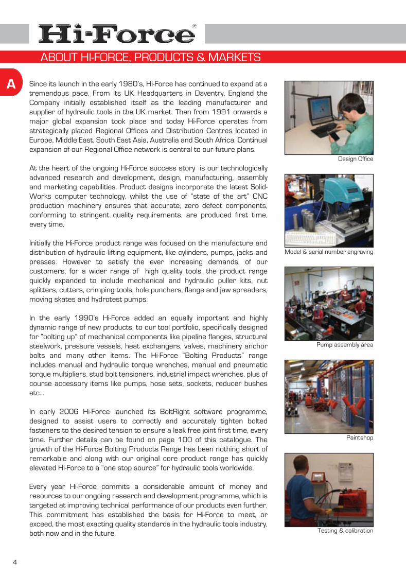
At the heart of the ongoing Hi-Force success story is our technologically advanced research and development, design, manufacturing, assembly and marketing capabilities. Product designs incorporate the latest Solid-Works computer technology, whilst the use of “state of the art” CNC production machinery ensures that accurate, zero defect components, conforming to stringent quality requirements, are produced first time, every time.
Initially the Hi-Force product range was focused on the manufacture and distribution of hydraulic lifting equipment, like cylinders, pumps, jacks and presses. However to satisfy the ever increasing demands, of our customers, for a wider range of high quality tools, the product range quickly expanded to include mechanical and hydraulic puller kits, nut splitters, cutters, crimping tools, hole punchers, flange and jaw spreaders, moving skates and hydrotest pumps.
In the early 1990’s Hi-Force added an equally important and highly dynamic range of new products, to our tool portfolio, specifically designed for “bolting up” of mechanical components like pipeline flanges, structural steelwork, pressure vessels, heat exchangers, valves, machinery anchor bolts and many other items. The Hi-Force “Bolting Products” range includes manual and hydraulic torque wrenches, manual and pneumatic torque multipliers, stud bolt tensioners, industrial impact wrenches, plus of course accessory items like pumps, hose sets, sockets, reducer bushes etc...
In early 2006 Hi-Force launched its BoltRight software programme, designed to assist users to correctly and accurately tighten bolted fasteners to the desired tension to ensure a leak free joint first time, every time. Further details can be found on page 100 of this catalogue. The growth of the Hi-Force Bolting Products Range has been nothing short of remarkable and along with our original core product range has quickly elevated Hi-Force to a “one stop source” for hydraulic tools worldwide.
Every year Hi-Force commits a considerable amount of money and resources to our ongoing research and development programme, which is targeted at improving technical performance of our products even further. This commitment has established the basis for Hi-Force to meet, or exceed, the most exacting quality standards in the hydraulic tools industry, both now and in the future.
Design Office
Model & serial number engraving
Pump assembly area
Paintshop
Testing & calibration
ABOUT HI-FORCE, PRODUCTS & MARKETS
5
A
This is why we say :Hi-Force ...
Precisely !Hi-Force ...
Precisely ! Kevin P. BrownGroup Managing Director
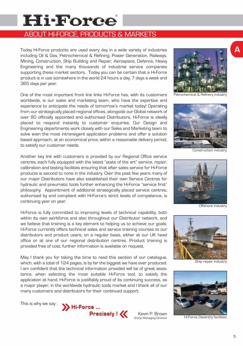
Today Hi-Force products are used every day in a wide variety of industries including Oil & Gas, Petrochemical & Refining, Power Generation, Railways, Mining, Construction, Ship Building and Repair, Aerospace, Defence, Heavy Engineering and the many thousands of industrial service companies supporting these market sectors. Today you can be certain that a Hi-Force product is in use somewhere in the world 24 hours a day, 7 days a week and 365 days per year.
One of the most important front line links Hi-Force has, with its customers worldwide, is our sales and marketing team, who have the expertise and experience to anticipate the needs of tomorrow’s market today! Operating from our strategically placed regional offices, alongside our Global network of over 80 officially appointed and authorised Distributors, Hi-Force is ideally placed to respond instantly to customer enquiries. Our Design and Engineering departments work closely with our Sales and Marketing team to solve even the most intransigent application problems and offer a solution based approach, at an economical price, within a reasonable delivery period, to satisfy our customer needs.
Another key link with customers is provided by our Regional Office service centres, each fully equipped with the latest “state of the art” service, repair, calibration and testing facilities ensuring that after sales service for Hi-Force products is second to none in the industry. Over the past few years many of our major Distributors have also established their own Service Centres for hydraulic and pneumatic tools further enhancing the Hi-Force “service first” philosophy. Appointment of additional strategically placed service centres, authorised by and compliant with Hi-Force’s strict levels of competence, is continuing year on year.
Hi-Force is fully committed to improving levels of technical capability, both within its own workforce and also throughout our Distributor network, and we believe that training is a key element to helping us to achieve our goals. Hi-Force currently offers technical sales and service training courses to our distributors and product users, on a regular basis, either at our UK head office or at one of our regional distribution centres. Product training is provided free of cost, further information is available on request.
May I thank you for taking the time to read this section of our catalogue, which, with a total of 124 pages, is by far the biggest we have ever produced. I am confident that the technical information provided will be of great assis-tance, when selecting the most suitable Hi-Force tool, to satisfy the application at hand. Hi-Force is justifiably proud of its continuing success, as a major player, in the worldwide hydraulic tools market and I thank all of our many customers and distributors for their continued support.
Petrochemical & Refinery industry
Construction industry
Offshore industry
Ship repair industry
Hi-Force Daventry facilities
ABOUT HI-FORCE, PRODUCTS & MARKETS

6
A All Hi-Force products are designed and manufactured to meet or exceed the requirements of current national and international standards and codes of practice, which are essential to ensure that Hi-Force manufactures hydraulic tools and equipment of the highest possible quality, both today, and in the future. All items are manufactured in accordance with the quality assurance requirements of ISO9001:2000 as verified by our certificate of registration number A21 438, originally issued in January 1998 and valid until January 2010.
All Hi-Force tools are permanently marked with their respective model number and a unique serial number, which are both traceable to an individually issued test certificate. Every Hi-Force tool manufactured is individually tested in accordance with the latest international, test procedures, applicable to hydraulic tools and equipment.
All Hi-Force products are covered by a comprehensive warranty against material and/or workmanship defects. All warranty claims must first be approved either by Hi-Force UK, a Hi-Force Regional Office or an approved Hi-Force Service Centre.
High pressure hydraulic power provides one of the simplest means of applying high force in confined spaces, however respect for common sense safety precautions is essential at all times.
Every Hi-Force employee is fully conversant with all Hi-Force safety procedures, applicable to the safe operation and use of our products, and we feel it is our duty to ensure that all users of hydraulic tools are equally aware of these proce-dures. We therefore request you to study pages 110 and 111 of this catalogue and also ensure that all of your employees are equally aware of these safety issues.
QUALITY & SAFETY

Hydraulic Cylinders
HVL Range
HPS Range
HSS Range
HHS Range
HHR Range
HDA Range
HFL Range
HFG Range
HGS Range
Saddles
B
Selection table
Single acting very low height pancake cylinders
Single actng low height pad cylinders
Single acting multi-purpose cylinders
Single acting hollow piston cylinders
Double acting hollow piston cylinders
Double acting cylinders
Single acting low height Failsafe lock ring cylinders
Single acting Failsafe lock ring cylinders
Single acting load return cylinders
Cylinder saddles and piston rod thread details
7
Page8
Page9
Page10
Pages12 - 13
Page14
Page15
Page16
Page17
Page18
Page19
Page20
HLS Range Single acting low height cylindersPage
11
INDEX - CYLINDERS

8
B
M a i n c h a r a c t e r i s t i c s o f H i - F o r c e c y l i n d e r r a n g eRangeCylinder
HVL
HDA
HFGHFL
HGS
HHRHHS
HPS
HSSHLS
Cylinder principlesingle acting
double acting
single acting
single acting
single acting
double acting
single acting
single acting
single acting
single acting
Piston featuresolid piston
solid piston
threaded piston & lock ring
threaded piston & lock ring
solid piston
hollow piston
hollow piston
solid piston
solid piston
solid piston
Return actionload/gravity return
hydraulic return
load/gravity return
load/gravity return
load/gravity return
hydraulic return
spring assisted return
spring assisted return
spring assisted return
spring assisted return
Stroke limiter devicestop ring
stop ring
restriction port
restriction port
stop ring
stop ring
stop ring
stop ring
stop ring
stop ring
Saddleintegrated
several options available
tilting saddle
tilting saddle
tilting saddle
several options available
several options available
integrated
several options available
integrated
With 10 series, 109 standard models and unlimited specials made to order, Hi-Force will provide the best cylinder for the job !
Page
9
10
11
12-13
14
15
16
17
18
19
5 10 - 11 15 20 - 25 30 - 33 50 - 61 73 - 109 150 200 250stroke
Cylinder N o m i n a l l i f t i n g c a p a c i t y i n t o n n e s o f c y l i n d e r
610111215
162525404445505050515660757676
100102102125150150150151152152152153
in mmHPS50
HPS51
HSS51
HSS52
HSS53
HSS54
HSS55
HVL10
HPS100
HSS101HHS101
HLS101
HHS102
HSS102
HSS104
HSS106
HSS152
HSS154
HSS156
HVL30
HPS300
HLS301
HHS302
HHR302
HLS302
HHR306
HHS306
HSS252
HSS254
HSS256
HDA256
HVL50
HPS500
HLS501
HFL502
HFG502
HLS502
HSS504
HFG506
HSS506
HDA506
HHS603
HHR603
HHS606
HHR606
HPS750
HSS756
HVL100
HPS1000
HLS1001
HHR1002
HFL1002
HFG1002
HLS1002
HHS1003
HHR1003
HFG1004
HSS1004
HHS1006
HHR1006
HFG1006
HDA1006
HSS1006
HPS1500
HLS1501
HLS1502
HFL1502
HFG1502
HFG1504
HFG1506
HDA1506
HGS1506
HGS2002
HDA2006
HFG2006
HGS2006
HFL2502
HHR2508
HVL20
HPS200
HLS201
HHS202
HHS206
HFG504
325 400 520
HGS3002
HFL5002
HFG3006
HFG4006
HDA3006
HGS3006
HDA4006 HDA5006
HFG5006
16
203205206250254305330330
457
HSS108
HSS1010
HSS1012
HSS1510
HSS308
HHR3012
HSS2510
HSS2518
HSS508
HSS5013
HDA5013
HHR6010 HSS10010
HDA10013
HDA20012
356 HSS2514
SELECTION TABLE FOR HI-FORCE STANDARD RANGE CYLINDERS

9
B
Modelnumber
HVL10
HVL20
HVL30
HVL50
HVL100
Dimensions in mm
Capacities from 10 to 104 tonnes
Stroke length 6mm
Working pressure 700 Bar
The HVL Pancake cylinder range combines a very low closed height with a 6mm stroke, providing a precise adjusting and lifting force in very confined work areas. Ideally suited for applications requiring alignment of machinery, turbines, heavy structures etc... All models are single acting, load return design. The base of all HVL cylinders must be fully supported during use.
Single acting load returnSurface treated piston rodLow friction bearing surfacesAnti-extrusion seals
Capacitytonnes
Strokemm
Oil cap.cm³
Cyl. eff. areacm²
Weightkg
10
20
32
50
104
6
6
6
6
6
14.4
28.6
45.6
71.3
146.5
9
17
27
43
88
1.6
2.6
3.0
7.2
15.6
B
87
104
120
158
200
A
28
32
34
45
65
C
38
52
60
75
100
Did you know .....
Hi-Force HVL pancake cylinders are the lowest closed height hydraulic cylinders available on the market. If you don’t have the space, we have the solution !
A
B
CD
E
D
100
100
100
100
65
E
16.0
19.0
19.5
29.0
37.0
HVL10HVL20
HVL50
HVL - SINGLE ACTING VERY LOW HEIGHT PANCAKE CYLINDERS

10
B
HPS50
HPS51
HPS100
HPS200
HPS300
HPS500
HPS750
HPS1000
HPS1500
Dimensions in mmModelnumber
Capacities from 4.5 to 147 tonnes
Stroke lengths from 6 to 16mm
Working pressure 700 Bar
The HPS pad cylinder range offers the best capacity, closed height and stroke length combination, spring assisted return cylinders in the industry. Ideally suited for applications where a low closed height and maximum possible stroke is of prime importance, these highly versatile cylinders are extensively used for maintenance, structural weld positioning, rigging, flange separating and many other applications.
Single acting, spring assisted returnSurface treated piston rodLow friction bearing surfacesAnti-extrusion seals
Capacitytonnes
Strokemm
Oil cap.cm³
Cyl. eff. areacm²
Weightkg
4.5
4.5
10
20
32
50
73
109
147
6
16
10
11
12
15
16
16
16
0.8
0.9
1.6
2.6
4.2
6.6
10.4
23.2
28.5
6.4
6.4
14.4
28.6
45.6
71.3
102.7
153.4
206.2
4
10
14
31
55
107
164
245
330
A
32
42
45
52
59
67
81
91
100
B
60
60
81
100
115
140
165
215
215
C
38
38
56
76
95
114
140
180
191
D
24
24
38
51
60
70
82
114
114
E
20
20
34
40
46
54
67
75
83
H
26
26
37
50
52
67
76
130
117
G1
5.6
5.6
6.8
8.8
8.8
10.8
13.0
12.8
13.0
Handle (HPS1000 & HPS1500)
65mm
A
B
C
D
E
G1
H
G2
F
I
F
19
19
28
39
48
60
70
90
95
G2
9.75
9.75
11.25
14.25
14.25
17.25
19.00
19.00
19.00
I
19
19
19
19
19
20
21
29
29
HPS500
HPS200 HPS100
HPS - SINGLE ACTING LOW HEIGHT PAD CYLINDERS

11
B
Capacities from 10 to 147 tonnes
Stroke lengths from 25 to 60mm
Working pressure 700 Bar
The HLS low height cylinder range is the most widely used design in the world today. All models have spring assisted return pistons and combine low closed height with optimum stroke lengths. Offering a compact, powerful force for a wide variety of applications in many industries including power generation, ship building & repair, construction, railways, mining, steel works, oil & gas and many others. The HLS range offers a compact, portable option in an inexpensive package.
Spring assisted returnSurface treated piston rodLow friction bearing surfacesAnti-extrusion sealsOptional tilting saddles (see page 20)
HLS101
HLS201
HLS301
HLS302
HLS501
HLS502
HLS1001
HLS1002
HLS1501HLS1502
10
20
32
32
50
50
109
109
147147
40
44
25
60
25
60
25
60
2550
2.4
4.8
5.0
7.0
8.4
10.4
19.8
24.0
37.0
42.0
14.4
28.6
45.6
45.6
71.3
71.3
153.4
153.4
206.2
206.2
58
126
114
274
178
428
384
921
516
1031
Dimensions in mmModelnumber
Capacitytonnes
Strokemm
Oil cap.cm³
Cyl. eff. areacm²
Weightkg
95
102
83
119
91
126
108
143
130
155
A
70
90
102
102
127
127
178
178
216
216
B
38
51
60
60
70
70
114
114
114
114
C
M8
M8
M8
M8
M8
M8
M12
M12
M12
M12
D
40
60
80
80
80
80
140
140
165
165
E
M4
M5
M5
M5
M5
M5
M8
M8
M8
M8
F
26
40
40
40
40
40
55
55
75
75
G
A
B
C
D
E
FG65mm
H
45 degrees (*)
19
19
19
19
20
20
30
30
41
41
H
(*) = HLS101 features 2 base mounting holes at 90° from coupler
HLS101
HLS201
HLS502HLS301
HLS - SINGLE ACTING LOW HEIGHT CYLINDERS
12
B
Modelnumber
HSS51
HSS52
HSS53
HSS54
HSS55
HSS101
HSS102
HSS104
HSS106
HSS108
HSS1010
Dimensions in mm (unless otherwise stated)
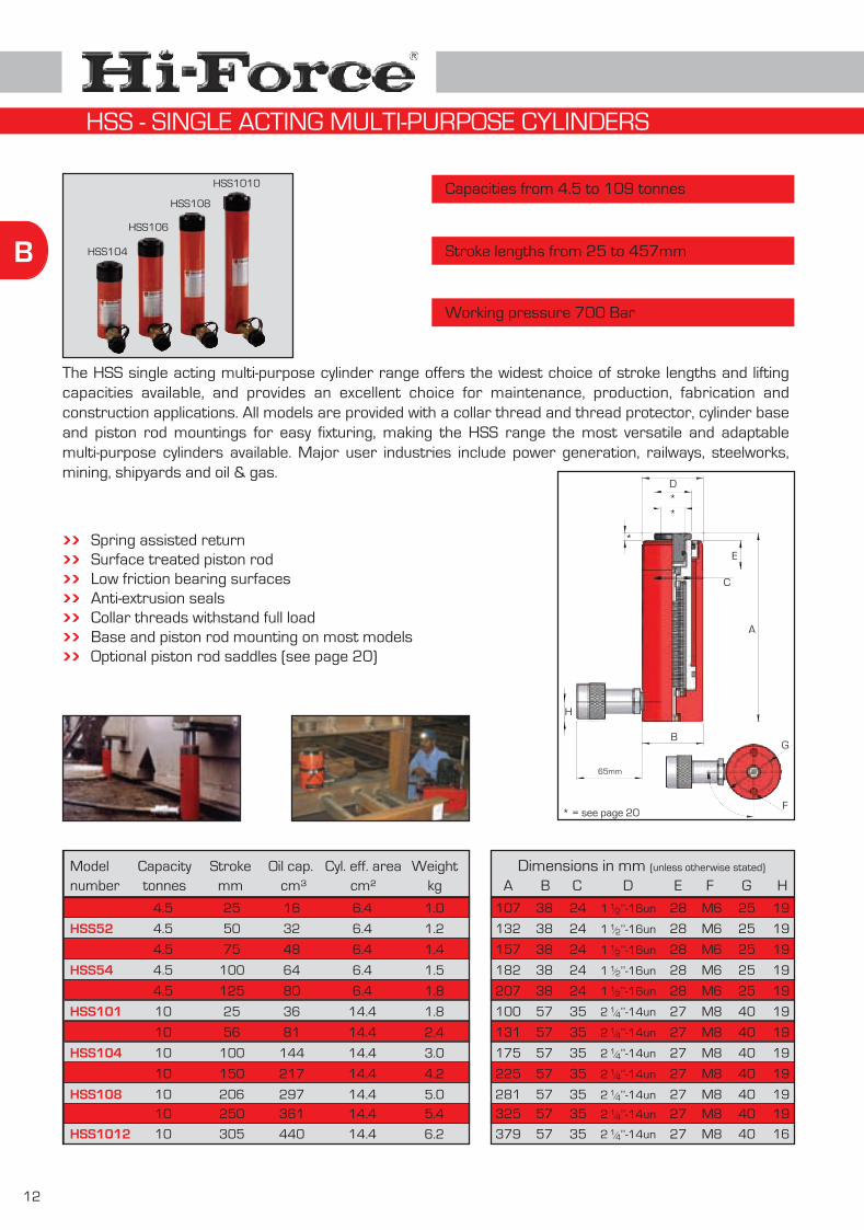
Capacities from 4.5 to 109 tonnes
Stroke lengths from 25 to 457mm
Working pressure 700 Bar
The HSS single acting multi-purpose cylinder range offers the widest choice of stroke lengths and lifting capacities available, and provides an excellent choice for maintenance, production, fabrication and construction applications. All models are provided with a collar thread and thread protector, cylinder base and piston rod mountings for easy fixturing, making the HSS range the most versatile and adaptable multi-purpose cylinders available. Major user industries include power generation, railways, steelworks, mining, shipyards and oil & gas.
Spring assisted returnSurface treated piston rodLow friction bearing surfacesAnti-extrusion sealsCollar threads withstand full loadBase and piston rod mounting on most modelsOptional piston rod saddles (see page 20)
Capacitytonnes
Strokemm
Oil cap.cm³
Cyl. eff. areacm²
Weightkg
4.5
4.5
4.5
4.5
4.5
10
10
10
10
10
10
10HSS1012
25
50
75
100
125
25
56
100
150
206
250
305
16
32
48
64
80
36
81
144
217
297
361
440
6.4
6.4
6.4
6.4
6.4
14.4
14.4
14.4
14.4
14.4
14.4
14.4
1.0
1.2
1.4
1.5
1.8
1.8
2.4
3.0
4.2
5.0
5.4
6.2
A
107
132
157
182
207
100
131
175
225
281
325
379
B
38
38
38
38
38
57
57
57
57
57
57
57
C
24
24
24
24
24
35
35
35
35
35
35
35
E
28
28
28
28
28
27
27
27
27
27
27
27
F
M6
M6
M6
M6
M6
M8
M8
M8
M8
M8
M8
M8
G
25
25
25
25
25
40
40
40
40
40
40
40
D
2 ’’-14un14/
1 ’’-16un12/
1 ’’-16un12/
1 ’’-16un12/
1 ’’-16un12/
1 ’’-16un12/
2 ’’-14un14/
2 ’’-14un14/
2 ’’-14un14/
2 ’’-14un14/
2 ’’-14un14/
2 ’’-14un14/
65mm
A
B
C
D
E
F
G
**
*
* = see page 20
H
H
19
19
19
19
19
19
19
19
19
19
19
16
HSS104
HSS106
HSS108
HSS1010
HSS - SINGLE ACTING MULTI-PURPOSE CYLINDERS

13
B
HSS256
HSS2510
150
250
524
874
34.9
34.9
9.6
12.6
HSS152
HSS154
HSS156
HSS1510
HSS252
25
25
14.5
14.5
14.5
14.5
25
25HSS254
50
100
150
250
51
102
101
203
304
507
178
356
20.3
20.3
20.3
20.3
34.9
34.9
3.4
5.0
6.6
8.8
6.5
8.0
273
374
A
154
204
254
354
174
225
86
86
B
70
70
70
70
86
86
54
54
C
41
41
41
41
54
54
49
49
E
39
39
39
39
49
49
M12
M12
F
M10
M10
M10
M10
M12
M12
See pages 21-32 for pumpssuitable for use with all Hi-Force cylinders
See page 35-40 for the fullrange of system components
3 ’’-12un516/
3 ’’-12un516/
D
2 ’’-16un34/
2 ’’-16un34/
2 ’’-16un34/
2 ’’-16un34/
3 ’’-12un516/
3 ’’-12un516/
Modelnumber
Dimensions in mm (unless otherwise stated)Capacitytonnes
Strokemm
Oil cap.cm³
Cyl. eff. areacm²
Weightkg
F
G
* = see page 20
65mm
A
B
C
D
E
**
*
H
HSS2518
HSS308
457
205
1597
860
34.9
41.9
21.4
18.6
25
29
611
374
86
102
54
57
49
50
M12
-
3 ’’-12un516/
HSS504
HSS506
HSS508
HSS5013
HSS756
HSS1004
HSS1006HSS10010
102
152
203
330
152
102
153
254
728
1084
1448
2354
1561
1565
2347
3896
71.3
71.3
71.3
71.3
102.7
153.4
153.4
153.4
16.8
20.0
23.2
33.6
31.0
41.6
49.8
65.5
50
50
50
50
73
109
109
109
201
251
302
429
272
223
274
375
127
127
127
127
146
185
185
185
79
79
79
79
95
114
114
114
55
55
55
55
45
50
50
50
M12
M12
M12
M12
M12
M12
M12
M12
5 ’’-12un34/
6 ’’-12un78/
6 ’’-12un78/
6 ’’-12un78/
5’’-12un
5’’-12un
5’’-12un
5’’-12un
HSS2514 356 1242 34.9 16.825 480 86 54 49 M123 ’’-12un516/
HSS502 51 364 71.3 13.050 150 127 79 55 M12
60
60
G
48
48
48
48
60
60
60
-
85
85
85
85
115
146
146
146
60
855’’-12un
25.0
25.0
25.0
50.0
20.0
20.0
20.0
20.0
31.5
32.0
32.0
32.0
H
19.0
19.0
19.0
19.0
25.0
25.0
25.0
20.0
3 ’’-12un516/
HSS - SINGLE ACTING MULTI-PURPOSE CYLINDERS

14
B
Modelnumber
HHS101
HHS102
HHS106
HHS202
HHS206
HHS302
HHS306
HHS603
HHS606
HHS1003
HHS1006
Dimensions in mm (unless otherwise stated)
Capacities from 11 to 102 tonnes
Stroke lengths from 25 to 152mm
Working pressure 700 Bar
The HHS single acting hollow piston cylinder range is extremely versatile for use in tooling, maintenance and tensioning applications. Specifically designed with a hollow piston to enable a rod or cable to be passed through the entire cylinder length for applications where a pulling force is required, the HHS range is used extensively in post-tensioning and pre-stressing applications as well as testing of various bonded or mechanical anchoring systems. HHS cylinders can also be used for general lifting applications, when fitted with readily available interchangeable hardened steel piston rod saddles.
Spring assisted returnSurface treated piston rodLow friction bearing surfacesAnti-extrusion sealsOptional piston rod saddles (see page 20)
11
11
11
23
23
33
33
61
61
102
102
Capacitytonnes
Oil cap.cm³
Cyl. eff. area cm²
Weightkg
Strokemm
25
50
152
50
150
50
152
76
150
76
150
15.8
15.8
15.8
33.3
33.3
46.7
46.7
85.7
85.7
143.1
143.1
2.8
3.0
10.2
7.0
13.8
10.6
19.2
28.0
40.6
64.0
75.0
39
79
240
167
500
233
710
651
1285
1088
2147
A
110
140
297
160
306
165
320
226
315
276
350
B
70
70
70
100
100
115
115
160
160
213
213
C
38
38
38
51
51
60
60
92
92
127
127
D
20
20
20
30
30
35
35
55
55
81
81
H
51
51
51
82.5
82.5
92
92
130
130
178
178
G
M8
M8
M8
M8
M8
M8
M8
M12
M12
M16
M16
F
30
30
30
40
40
40
40
59
59
60
60
E
2 ’’-16un34/
2 ’’-16un34/
2 ’’-16un34/
3 ’’-12un78/
3 ’’-12un78/
8 ’’-12un38/
8 ’’-12un38/
6 ’’-12un14/
6 ’’-12un14/
4 ’’-12un12/
4 ’’-12un12/
A
B
C
D
*
* = see page 20
E
F
G
H
I
65mm
90°
I
19
19
19
31
31
31
31
31
31
45
45
HHS202HHS302
HHS - SINGLE ACTING HOLLOW PISTON CYLINDERS

15
B
HHR302
HHR306
HHR603
HHR606
HHR1002
HHR1003
HHR1006
HHR2508
Dimensions in mm (unless otherwise stated)
Capacities from 33 to 247 tonnes
Stroke lengths from 50 to 305mm
Working pressure 700 Bar
The HHR double acting hollow piston cylinder range incorporates all of the design features of the HHS range with the added benefit of double acting design, which greatly enhances speed of operation and performance particularly in the longer length stroke options. Additionally a substantial hydraulic pulling force is available in the piston retraction mode of operation. Standard range models are featured in this catalogue, however other stroke and tonnage options are available on request.
Double acting designSurface treated piston rodAnnular area overload protection valveLow friction bearing surfacesAnti-extrusion sealsOptional piston rod saddles (see page 20)
Modelnumber
CapacityStroke
mmOil cap.
cm³Cyl. eff.
area cm²Weight
kgPush Pull
33
33
61
61
102
102
102
247
24
24
38
38
43
43
43
89
51
150
76
152
50
76
152
203
238
701
652
1304
715
1087
2174
6946
46.7
46.7
85.7
85.7
143.1
143.1
143.1
346.5
12.2
17.6
30.6
41.6
61.3
68.5
90.0
269.0
HHR6010 61 38 254 2179 85.7 52.5
HHR3012 33 24 305 1424 46.7 25.7
A
180
279
239
315
284
308
387
500
417
434
B
115
115
160
160
213
213
213
340
160
115
C
60.3
60.3
92
92
140
140
140
250
92
60.3
D
35
35
55
55
80
80
80
150
55
35
F
40
40
45
45
40
40
40
-
45
40
G
M8
M8
M12
M12
M16
M16
M16
Optional
M12
M8
H
92
92
130
130
178
178
178
-
130
92
E
8 ’’-12un38/
8 ’’-12un38/
6 ’’-12un14/
6 ’’-12un14/
4 ’’-12un12/
4 ’’-12un12/
8 ’’-12un38/
Optional
4 ’’-12un12/
6 ’’-12un14/
tonnes
A
B
*
C
D
E
G
H45°
65mm
F
* = see page 20
I
J
I
28
28
31
31
82
82
82
98
31
28
J
119
218
166
242
208
234
310
389
344
373
Note : 33 & 61 tonne models feature 2 base mounting holes at 90° from coupler
HHR306 HHR302
HHR - DOUBLE ACTING HOLLOW PISTON CYLINDERS

16
B
HDA256
HDA506
HDA5013
HDA1006
HDA10013
HDA1506
HDA2006
HDA20012
HDA3006
HDA4006
HDA5006
Dimensions in mm (unless otherwise stated)
Capacities from 25 to 520 tonnes
Stroke lengths from 152 to 330mm
Working pressure 700 Bar
The HDA double acting cylinder range offers the utmost in versatility and durability. Specifically designed for heavy duty lifting, construction and maintenance applications as well as presswork and industrial production, the double acting design provides substantial pulling force in the piston retraction mode as well as providing fast, controlled retraction for continuous duty cycle operation. All models up to 203 tonnes are supplied with flat saddle, piston rod threads and collar threads as standard. Models from 326 tonnes and upwards are supplied without collar thread and piston rod thread, however include replaceable tilting saddle as standard. Standard range models are featured in this catalogue, however other stroke and tonnage options are available on request.
Internal annular area overload protection valveLow friction bearing surfacesSurface treated piston rodAnti-extrusion sealsBase mounting holes
25
50
50
109
109
152
203
203
326
398
520
Flat saddlePiston rod thread Collar thread
Tilting saddlePiston without threadExcluding collar thread
Up to 203 tonnes : From 326 tonnes :
10
15
15
36
36
79
94
94
-
-
-
152
152
330
152
330
152
152
305
152
152
152
0.53
1.08
2.35
2.33
5.06
3.26
4.33
8.69
6.95
8.49
11.09
34.9
71.3
71.3
153.3
153.3
214.2
285.2
285.2
457.4
558.9
729.9
15.0
28.4
42.6
64.5
89.0
90.0
127.4
165.0
214.2
312.7
413.5
HDA15012 152
A
287
295
473
304
482
310
327
480
366
394
435
463
B
92
127
127
178
178
210
254
254
312
360
397
210
C
50
79
79
114
114
114
140
140
165
216
203
114
F
M10
M12
M12
M12
M12
M16
M20
M20
M20
M24
M24
M1679 305 6.53 214.2 120.5
G
60
85
85
146
146
160
185
185
158
203
203
160
E
53
55
55
51
51
55
65
65
Optional
Optional
Optional
55
D
3 ’’-12un516/
5’’-12un
5’’-12un
6 ’’-12un78/
6 ’’-12un78/
8’’-12un
9 ’’-12un34/
9 ’’-12un34/
Optional
Optional
Optional
8’’-12un
Modelnumber
CapacityStroke
mmOil cap.litres
Cyl. eff. areacm²
Weightkg
Push Pulltonnes H
30
20
20
30
30
35
43
43
50
55
65
35
I
212
216
394
226
404
231
238
391
262
277
300
384
A
B
C
D
E
FG
H
I
65mm
HDA506
HDA5013
HDA - DOUBLE ACTING CYLINDERS

17
B
Capacities from 50 to 520 tonnes
Stroke lengths from 45 to 51mm
Working pressure 700 Bar
The HFL low height single acting failsafe lock ring cylinder range combines all the versatility and efficiency of hydraulic power with the safety of mechanical load support, offering a sustainable lifting force in very confined work areas. Ideally suited for applications requiring load holding for extended periods, such as bridge support work. The HFL range features a single acting load return piston, threaded throughout it’s stroke length to suit the integral threaded mechanical load holding lock ring. All models are suitable for vertical lifting only and are supplied with tilting saddles as standard.
HFL502
HFL1002
HFL1502
HFL2502
HFL5002
Dimensions in mm Modelnumber
Capacitytonnes
50
109
152
260
520
Strokemm
51
50
45
45
45
Weightkg
14.2
25.1
44.0
69.4
186.0
Cyl. eff. areacm²
71.3
153.4
214.3
366.1
729.9
Oil cap.cm³
363
770
1070
1647
3287
A
125
137
150
159
192
B
127
178
216
273
400
C
95
140
165
216
305
Single acting load return designSurface treated cylinder boreLow friction bearing surfacesSurface treated piston rodAnti-extrusion sealsTilting saddle fitted as standardOverstroke restrictor port
A
B
C
D
E
65mm
D
70
115
135
130
180
E
19
20
28
31
43
See pages 21-32 for pumps suitable for use with all
Hi-Force cylinders
HFL1002
HFL - SINGLE ACTING LOW HEIGHT FAILSAFE LOCK RING CYLINDERS

18
B
Capacities from 50 to 520 tonnes
Stroke lengths from 50 to 152mm
Working pressure 700 Bar
The HFG single acting failsafe lock ring cylinder range combines all the versatility and efficiency of hydraulic power with the safety of mechanical load support. Ideally suited for applications requiring sustained load holding for extended periods, such as bridge support work, the HFG range features a single acting, load return piston, threaded throughout it’s stroke length to suit the integral threaded mechanical load holding lock ring. Simply jack up the load, wind down the mechanical lock ring until it comes into contact with the cylinder body, release the hydraulic pressure and sustain the load mechanically. All models are suitable for vertical lifting only and are supplied with tilting saddles as standard to reduce the risk of side loading the cylinder. Standard models are featured in this catalogue, however other stroke and tonnage options are available on request.
HFG504
HFG506
HFG1004
HFG1006
HFG1504
Dimensions in mm Modelnumber
Single acting load return designSurface treated cylinder boreLow friction bearing surfacesSurface treated piston rodAnti-extrusion sealsTilting saddle fitted as standardOverstroke restrictor port
HFG1506
HFG2006
HFG3006
HFG4006
HFG5006
HFG502
HFG1002
HFG1502
50
50
109
109
152
Capacitytonnes
152
203
326
398
520
50
109
152
102
150
100
150
100
Strokemm
150
152
150
151
152
50
50
50
20.6
25.0
47.5
61.5
84.0
Weightkg
89.5
137.0
228.5
308.5
457.0
15.4
33.5
69.5
71.3
71.3
153.4
153.4
214.3
Cy. eff. areacm²
214.3
285.1
457.7
559.0
729.9
71.3
153.4
214.3
0.73
1.07
1.53
2.30
2.14
Oil cap.litres
3.21
4.33
6.87
8.44
11.10
0.36
0.77
1.07
224
272
240
311
288
A
338
362
417
459
498
172
184
238
127
127
178
178
216
B
216
254
310
342
400
127
178
216
C
95
95
140
140
165
165
190
241
267
305
95
140
165
D
70
70
115
115
135
135
135
150
180
180
70
115
135
E
25.0
25.0
27.5
27.5
42.0
42.0
50.0
50.0
70.0
80.0
25.0
27.5
42.0
A
B
C
D
E
65mm
HFG1004 HFG504
HFG - SINGLE ACTING FAILSAFE LOCK RING CYLINDERS

19
B
Capacities from 152 to 326 tonnes
Stroke lengths from 50 to 152mm
Working pressure 700 Bar
The HGS load return cylinder range is specifically designed for lifting and maintenance applications. These economically priced single acting cylinders are supplied with a tilting saddle to reduce the risk of damage caused by side loading. The integral stop ring provides extra guidance for the piston and acts as an over stroke restrictor to ensure that the piston is only extended to it’s designed stroke length. Standard range models are featured in this catalogue, however other stroke and tonnage options are available on request.
Stop ring to prevent over extensionSingle acting load return designSurface treated cylinder boreLow friction bearing surfacesSurface treated piston rodAnti-extrusion sealsTilting saddle fitted as standard
HGS1506
HGS2002
HGS2006
HGS3002
HGS3006
Dimensions in mm Modelnumber
Capacitytonnes
152
203
203
326
326
Strokemm
152
50
152
50
152
Weightkg
90
98
127
174
214
Cyl. eff. areacm²
214.3
285.1
285.1
457.7
457.7
Oil cap.litres
3.26
1.45
4.33
2.29
6.87
A
331
224
345
297
398
B
210
254
254
310
310
C
114
140
140
165
165
Although other stroke length and tonnage combinations are available on request, please consider the following alternative Hi-Force cylinder ranges :
For lower capacities :
For higher capacities :
(page 11)(page 12-13)(page 17)(page 18)
HLS low height range HSS multi-purpose range HFL Failsafe range HFG Failsafe range
D
100
135
135
150
150
E
35
43
43
50
50
A
B
C
D
E
Removablelifting eyes
HGS3002HGS2002
HGS - SINGLE ACTING LOAD RETURN CYLINDERS
20
B
Cylinderrange
F i t t e d a s s t a n d a r d A v a i l a b l e o p t i o n s
HLSHLSHLSHLSHLSHLSHSSHSSHSSHSSHSSHSSHSSHSSHHSHHS
HHS/RHHS/RHHS/R
HHRHDAHDAHDAHDAHDAHDAHDAHDAHFGHFGHFGHFGHFGHFGHFGHFLHFLHFLHFLHFLHGSHGSHGS
Saddlemodel No.
-----
-
HA5HA10HA15HA25HA25HA50HA75
HA100HA102HA202HA302HA603
HA1003HA2508
HD25HD50
HD100HD150HD200
HD300THD400THD500T
TS50TS100TS150TS200TS300TS400TS500TS50
TS100TS150TS250TS500TS150TS200TS300
Seefigure
-----
-
1111122244444433333666777777777777777
HAT51HAT51HAT51
HAT101HAT150
-
HAT11
HAT50HAT75
HAT100HA102THA202THA302THA603T
HA1003THA2508T
HD25THD50T
HD100THD150THD200T
-----
-
-----
-
--
-
HAT10-
HAT25-
66666-
6
66655555588888
-----
-
-----
-
--
-
8-8-
Cylindercapacity
10203250
1091474.510
14.525295073
10911233361
1022472550
10915220332639852050
10915220332639852050
109152260520152203326
Cylinderrange
Saddlemodel No.
Seefigure
Cylindercapacity
HLSHLSHLSHLSHLSHLSHSSHSSHSSHSSHSSHSSHSSHSSHHSHHS
HHS/RHHS/RHHS/R
HHRHDAHDAHDAHDAHDAHDAHDAHDAHFGHFGHFGHFGHFGHFGHFGHFLHFLHFLHFLHFLHGSHGSHGS
10203250
1091474.510
14.525295073
10911233361
1022472550
10915220332639852050
10915220332639852050
109152260520152203326
Fig. 1
Fig. 2
Fig. 3
Fig. 4
Fig. 5
Fig. 6
Fig. 7
A
B
C
D
C
D
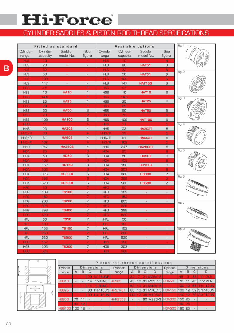
CYLINDER SADDLES & PISTON ROD THREAD SPECIFICATIONS
Fig. 8
HD300HD400HD500
222
P i s t o n r o d t h r e a d s p e c i f i c a t i o n s
HSS5HSS10HSS15HSS25HSS30HSS50HSS75HSS100
Cylinderrange
HHS11HHS23HHS/R33HHS/R61HHS/R102HHR2508
Cylinderrange
D i m e n s i o n s D i m e n s i o n sA
-----
7080
100
B
-----
111212
C
2014143030
---
D
¾”-16UNF1”-8UNC1”-8UNC
1½”-16UN1½”-16UN
---
A
32435280
114-
B
710101012
-
C
213131313860
D
M28x1.5M39x1.5M48x1.5M70x1.5M105x2M220x3
HDA25HDA50HDA100HDA150HDA200HDA300HDA400HDA500
Cylinderrange
D i m e n s i o n sA
4570
100100110150180180
B
911121212252525
C
3545555270
---
D
1”-12UN1”-12UN
1¾”-12UN3 ”-16UN2½”-12UN
---
38/
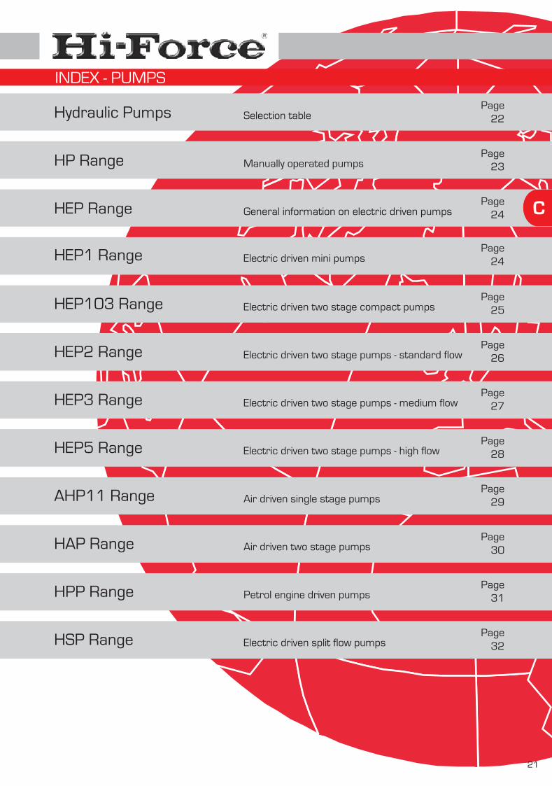
Hydraulic Pumps
HP Range
HEP Range
HEP103 Range
HEP2 Range
HEP3 Range
HEP5 Range
AHP11 Range
HAP Range
HPP Range
HSP Range
C
Selection table
Manually operated pumps
General information on electric driven pumps
Electric driven two stage compact pumps
Electric driven two stage pumps - standard flow
Electric driven two stage pumps - medium flow
Electric driven two stage pumps - high flow
Air driven single stage pumps
Air driven two stage pumps
Petrol engine driven pumps
Electric driven split flow pumps
21
Page22
Page23
Page24
Page25
Page26
Page27
Page28
Page29
Page30
Page31
Page32
HEP1 Range Electric driven mini pumpsPage
24
INDEX - PUMPS

22
C
Low pressure flow rate in litres per minute
Hig
h pr
essu
re fl
ow r
ate
in li
tres
per
min
ute
0.25 -
0.50 -
0.75 -
1.00 -
1.25 -
1.50 -
1.75 -
2.00 -
0.00 -
1.0 2.0 3.0 4.0 5.0 6.0 7.0 8.0 9.0 10.0 11.0 12.0 13.0 14.0 15.0 16.0 17.00.0
POWERED PUMPS
MANUAL PUMPS
- - - - - - - - - - - - - - - - - -
Nominal cylinder capacity in tonnes5
-
10
-
15
-
20
-
25
-
30
-
100
-
250
-
400
-
500
-
250 -
150 -
200 -
300 -
10 -
400 -
450 -
350 -
500 -
Cyl
inde
r st
roke
in m
m
100 -
50 -
75 -
25 -
200
-
325-
50
-
75
-
150
-
175 -
5 -
125 -
Note : for double acting manual pumps,please add suffix ‘D’.
(not applicable for HP145 & HP110)
HP145 - HP110HP227 - HP232HP252 - HP257
HP235
HP110 - HP227HP232 - HP252HP257 - HP235
HP227 - HP232HP252 - HP257
HP235
HP252 - HP257HP235
HP235
HEP5See page 28
HAP2/HPPSee page 30/31
HEP3See page 27
HEP2See page 26HEP103
See page 25
HEP12See page 24
SELECTION TABLE FOR HI-FORCE HYDRAULIC PUMPS

C
23
Single or two speed operation
Choice of control valves
Working pressure 700 Bar
The HP manually operated pump range offers a choice of single or two speed operation, and all models are supplied complete with a pre-filled oil reservoir, ready for immediate use. All models have a maximum working pressure of 700 bar and the range includes pump models suitable for use with either single or double acting cylinders. The HP range offers the ideal solution for applications where completely independent, portable hydraulic power is required. With low handle effort characteristics for easy operation and lightweight design, all models are of strong durable construction. Hi-Force HP manually operated pumps have a proven track record industry wide and offer excellent value for money in portable hydraulic power. A full range of system components suitable for use with HP manually operated pumps is detailed on pages 35 - 40.
Oil reservoir capacity up to 10 litresDurable steel or lightweight aluminium External pressure release valveFactory set safety relief valve
Dimensions in mmModelnumber
Valvetype
per stroke cm³1 stage 2 stage
oil cap.litres
Weightkg
Displacement Usable
Material A CB D
”-18NPT38/
st ndeffort
kg
Handle
A
B
CD
E
EHP145 2-way 2.4 4.60.45 360 145135 130- Steel50 45
HP110 2-way 2.4 5.61.0 560 145135 130- Steel50 45
HP227 2-way 11.7 10.52.32.1 547 142170 136Steel38 53
HP232 2-way 14.2 6.92.02.0 587 155160 140Alum.40 50
HP252 2-way 14.2 11.65.02.1 587 150160 140Alum.40 50
HP257 2-way 11.7 15.25.02.1 570 155170 136Steel38 53
HP227D 4-way 11.7 12.32.32.1 650 142170 136Steel38 53
HP232D 4-way 14.2 8.72.02.0 700 155160 140Alum.40 50
HP252D 4-way 14.2 13.65.02.0 700 150160 140Alum.40 50
HP257D 4-way 11.7 17.25.02.1 675 142170 136Steel38 53
HP235 2-way 103.0 27.010.03.5 705 206245 206Steel40 220
HP235D 4-way 103.0 27.210.03.5 705 206245 206Steel40 240
HP227FP footoperated pump
HP110
HP235
HP227D
HP257
HP - MANUALLY OPERATED PUMPS
HP227FP 2-way 11.7 12.52.32.1 716 142170 200Steel38 53

24
C
HEP1211S
HEP1212S
Modelnumber
Motorvoltage
240 V
110 V
Maximumpressure
bar700
700
Valve type2-way
2-way
Usableoil cap.litres0.8
0.8
Maximum flow ratel/min
1 stage 2 stage2.00 0.25
2.00 0.25
Weight
5.8
5.8
Two-stage design, changeover pressure 10 Bar
Working pressure 700 Bar
Extremely compact, lightweight & powerful
HEP1 - ELECTRIC DRIVEN MINI PUMPS
Length Width HeightDimensions in mm
322 125 111
322 125 111
HEP1212S
Hi-Force offers a full range of electric driven pumps with either a 110 or 240 Volt single phase motor, or a 380/440 Volt three phase motor. Depending on the required usage, please refer to following guidelines for correct pump range selection.
HEP1Page 24
HEP103Page 25
HEP2Page 26
HEP3Page 27
HEP5Page 28
Ligh
tIn
term
edia
teS
tand
ard
Con
tinuo
usH
eavy
dut
y
The HEP1 series two stage electric driven hydraulic mini pump range offers a choice of 110 or 240 Volt motor, with both models being suitable for 700 bar maximum working pressure. The two stage design offers a low pressure flow rate up to 2 litres/min with automatic changeover to high pressure, with a flow rate up to 0.25 litres/min. Incorporating a 2-way solenoid valve, internal safety overload valve, both models are extremely compact & lightweight, suitable for use with single acting Hi-Force cylinders or tools.
110 or 240V single phase motor options
Internal safety overload valve
Supplied with carrying strap
The HEP103 series two stage powered hydraulic pump range offers a choice of 110 or 240 Volt electric driven motors. All models are suitable for 700 bar maximum working pressure. The two stage design offers a low pressure flow rate up to 2.5 litres/min with automatic changeover to high pressure, with a flow rate up to 0.35 litres/min. Available with manual or solenoid valve options, suitable for both single acting and double acting cylinders and tools in a wide variety of applications
The HEP2 series two stage electric driven hydraulic pump range offers a low pressure flow rate of 7 litres/min with automatic changeover to 700 bar high pressure flow rate of 0.65 litres/min. Choice of 110, 240 or 380/440 Volt motor options with 2, 3 or 4-way manual or electric solenoid valve options. Suitable for a wide range of applications, the HEP2 series is the most commonly selected Hi-Force electric pump. Fitted with an externally adjustable pressure relief valve, for easy adjustment of working pressure up to 700 bar maximum.
The HEP3 series two stage electric driven hydraulic pump range has all the features of the HEP2 series, but with an increased flow of 10 litres/min in low pressure and 1 litres/min in high pressure (up to 700 bar). Particularly useful when operating high tonnage or long stroke cylinders. Both HEP2 and HEP3 range electric pumps are fitted with totally enclosed, fan cooled, low noise, electric motors, making them ideal for quiet in-works operation or outdoor site use in most environments.
The HEP5 series two stage electric driven hydraulic pump range offers the highest flow rate combination in the Hi-Force range. Offering a low pressure flow rate of 17 litres/min with automatic changeover to a superb high pressure flow rate of 2 litres/min. The HEP5 offers all the features of the HEP2 and HEP3 series with the addition of a 2.2 kW high speed, heavy duty motor, making it the ideal pump unit for all heavy duty applications, requiring a high flow and intensive usage over longer time periods.
st nd
Note : see page 32 for HSP series split-flow pumps for synchronised lifting
kg
HEP - GENERAL INFORMATION

C
25
Choice of valve options
Working pressure 700 Bar
Compact, lightweight & powerful
HEP103442LS
Modelnumber
Motorvoltage
Usableoil capacity
litresWeight
Did you know .....
Hi-Force manufactures powered pumps with flow rates up to 17 litres per minute in low pressure and 2 litres per minute up to 700 bar.See pages 26 to 32 for more details
kg
HEP103 - ELECTRIC DRIVEN TWO STAGE COMPACT PUMPS
Modelnumber
Maximumpressure
barRemote pendant
functions
Changeoverpressure
bar
Maximum flow ratel/min
1 stage 2 stagest nd
HEP10324*LS
HEP10324*S
HEP10334*
HEP10344*
HEP10344*LS
Control valve type Typical usage
3-way manual valve
2-way solenoid valve, normally closed (hold function)
2-way solenoid valve, normally open (auto retract)
4-way manual valve
4-way solenoid valve, locking feature on A & B port
Single acting cylinders and tools
SIngle acting cylinders and tools, requiring hold
Single acting cylinders and tools, requiring auto-retract
Double acting cylinders and tools
Double acting cylinders and tools, requiring hold
Specifications :
Directional control valve options and typical usage (* denotes 110/240V motor options):
Note : Add suffix ‘PS’ to model number for adjustable pressure switch for automatic pressure control.Add suffix ‘HB’ to model number for pendant control with self-hold button.
Integrated carrying handle
Pressure gauge and remote control fitted as standard
Suitable for single acting and double acting cylinders,
tools and torque wrenchesDimensions 245 x 260 x 350 mm (LxWxH)
HEP103242LS 240 V advance/retract 4 19.2700 702.50 0.35
HEP103242S 240 V advance/retract 4 20.5700 702.50 0.35
HEP103342 240 V motor on/off 4 18.1700 702.50 0.35
HEP103442 240 V motor on/off 4 18.1700 702.50 0.35
HEP103442LS 240 V advance/retract 4 20.5700 702.50 0.35
HEP103241LS 110 V advance/retract 4 19.2700 702.50 0.35
HEP103241S 110 V advance/retract 4 20.5700 702.50 0.35
HEP103341 110 V motor on/off 4 18.1700 702.50 0.35
HEP103441 110 V motor on/off 4 18.1700 702.50 0.35
HEP103441LS 110 V advance/retract 4 20.5700 702.50 0.35

26
C
Modelnumber
HEP207111
HEP207112
HEP207114
HEP207121
HEP207122
HEP207124
HEP207211
HEP207212
HEP207214
HEP207221
HEP207222
HEP207224
HEP207311
HEP207312
HEP207314
HEP207321
HEP207322
HEP207324
HEP207411
HEP207412
HEP207414
HEP207421
HEP207422
HEP207424
High pressure flow rate 0.65 litres/min.
Low pressure flow rate 7 litres/min. up to 70 Bar
Working pressure 700 Bar
Two stage hydraulic pump unit
Compact & heavy duty
Manual or solenoid valve options
Notes: All 3-way and 4-way manual valves are supplied with load holding feature as standard.Add suffix ‘H’ to model number for 60 Hz electric motor.Add suffix ‘P’ to model number for protective roll frame.Add suffix ‘S’ to model number for 3-way and 4-way low voltage solenoid valve including pendant control.
Valvetype
P-T Plate
2-way
3-way
4-way
P-T Plate
P-T Plate
P-T Plate
P-T Plate
P-T Plate
2-way
2-way
2-way
2-way
2-way
3-way
3-way
3-way
3-way
3-way
4-way
4-way
4-way
4-way
4-way
Oil cap.litres
10
25
10
10
25
25
10
25
10
10
25
25
10
25
10
10
25
25
10
25
10
10
25
25
MotorkW
1.5
1.5
1.5
1.5
1.5
1.5
1.5
1.5
1.5
1.5
1.5
1.5
1.5
1.5
1.5
1.5
1.5
1.5
1.5
1.5
1.5
1.5
1.5
1.5
Motorvoltage
110 / 115
220 / 240
380 / 440
110 / 115
220 / 240
380 / 440
110 / 115
220 / 240
380 / 440
110 / 115
220 / 240
380 / 440
110 / 115
220 / 240
380 / 440
110 / 115
220 / 240
380 / 440
110 / 115
220 / 240
380 / 440
110 / 115
220 / 240
380 / 440
Weightkg
47.0
47.0
47.0
63.0
63.0
63.0
47.5
47.5
47.5
63.5
63.5
63.5
47.5
47.5
47.5
63.5
63.5
63.5
47.5
47.5
47.5
63.5
63.5
63.5
Externally adjustable pressure relief valve
A
B CD E
F
G3
8”-NPT/
Dimensions in mmA B C E GD F
HEP207422
498 198 230 246 221 368 438
498 198 230 246 221 368 438
498 198 230 246 221 368 438
527 227 259 306 281 490 570
527 227 259 306 281 490 570
527 227 259 306 281 490 570
498 198 230 246 221 368 438
498 198 230 246 221 368 438
498 198 230 246 221 368 438
527 227 259 306 281 490 570
527 227 259 306 281 490 570
527 227 259 306 281 490 570
498 198 230 246 221 368 438
498 198 230 246 221 368 438
498 198 230 246 221 368 438
527 227 259 306 281 490 570
527 227 259 306 281 490 570
527 227 259 306 281 490 570
498 198 230 246 221 368 438
498 198 230 246 221 368 438
498 198 230 246 221 368 438
527 227 259 306 281 490 570
527 227 259 306 281 490 570
527 227 259 306 281 490 570
HEP2 - ELECTRIC DRIVEN TWO STAGE PUMPS - STANDARD FLOW

C
27
Modelnumber
HEP310121
HEP310122
HEP310124
HEP310141
HEP310142
HEP310144
HEP310221
HEP310222
HEP310224
HEP310241
HEP310242
HEP310244
HEP310321
HEP310322
HEP310324
HEP310341
HEP310342
HEP310344
HEP310421
HEP310422
HEP310424
HEP310441
HEP310442
HEP310444
High pressure flow rate 1 litres/min
Low pressure flow rate 10 litres/min up to 70 Bar
Working pressure 700 Bar
Two stage hydraulic pump unit
Heavy duty pump for continuous usage
Externally adjustable pressure relief valve
Manual or solenoid valve options
Notes: All 3-way and 4-way manual valves are supplied with load holding feature as standard.Add suffix ‘H’ to model number for 60 Hz electric motor.Add suffix ‘P’ to model number for protective roll frame.Add suffix ‘S’ to model number for 3-way and 4-way low voltage solenoid valve including pendant control.
Valvetype
P-T Plate
2-way
3-way
4-way
P-T Plate
P-T Plate
P-T Plate
P-T Plate
P-T Plate
2-way
2-way
2-way
2-way
2-way
3-way
3-way
3-way
3-way
3-way
4-way
4-way
4-way
4-way
4-way
Oil cap.litres
25
40
25
25
40
40
25
40
25
25
40
40
25
40
25
25
40
40
25
40
25
25
40
40
MotorkW
2.2
2.2
2.2
2.2
2.2
2.2
2.2
2.2
2.2
2.2
2.2
2.2
2.2
2.2
2.2
2.2
2.2
2.2
2.2
2.2
2.2
2.2
2.2
2.2
Motorvoltage
110 / 115
220 / 240
380 / 440
110 / 115
220 / 240
380 / 440
110 / 115
220 / 240
380 / 440
110 / 115
220 / 240
380 / 440
110 / 115
220 / 240
380 / 440
110 / 115
220 / 240
380 / 440
110 / 115
220 / 240
380 / 440
110 / 115
220 / 240
380 / 440
Weightkg
63.5
63.5
63.5
88.5
88.5
88.5
64.0
64.0
64.0
89.0
89.0
89.0
64.0
64.0
64.0
89.0
89.0
89.0
64.0
64.0
64.0
89.0
89.0
89.0
A
B CD E
F
G3
8”-NPT/
Dimensions in mmA B C E GD F
HEP310444
527 227 259 306 281 490 570
527 227 259 306 281 490 570
527 227 259 306 281 490 570
636 336 368 306 281 490 560
636 336 368 306 281 490 560
636 336 368 306 281 490 560
527 227 259 306 281 490 570
527 227 259 306 281 490 570
527 227 259 306 281 490 570
636 336 368 306 281 490 560
636 336 368 306 281 490 560
636 336 368 306 281 490 560
527 227 259 306 281 490 570
527 227 259 306 281 490 570
527 227 259 306 281 490 570
636 336 368 306 281 490 560
636 336 368 306 281 490 560
636 336 368 306 281 490 560
527 227 259 306 281 490 570
527 227 259 306 281 490 570
527 227 259 306 281 490 570
636 336 368 306 281 490 560
636 336 368 306 281 490 560
636 336 368 306 281 490 560
HEP3 - ELECTRIC DRIVEN TWO STAGE PUMPS - MEDIUM FLOW

28
C
Modelnumber
HEP517142
HEP517144
HEP517162
HEP517164
HEP517242
HEP517244
HEP517262
HEP517264
HEP517342
HEP517344
HEP517362
HEP517364
HEP517442
HEP517444
HEP517462
HEP517464
High pressure flow rate 2 litres/min
Low pressure flow rate 17 litres/min up to 70 Bar
Working pressure 700 Bar
Two stage hydraulic pump unit
Durable, heavy duty & powerful
Externally adjustable pressure relief valve
Manual or solenoid valve options
Notes: All 3-way and 4-way manual valves are supplied with load holding feature as standard.Add suffix ‘H’ to model number for 60 Hz electric motor.Add suffix ‘P’ to model number for protective roll frame.Add suffix ‘S’ to model number for 3-way and 4-way low voltage solenoid valve including pendant control.
Valvetype
P-T Plate
P-T Plate
P-T Plate
P-T Plate
2-way
2-way
2-way
2-way
3-way
3-way
3-way
3-way
4-way
4-way
4-way
4-way
Oil cap.litres
40
40
60
60
40
40
60
60
40
40
60
60
40
40
60
60
MotorkW
2.2
2.2
2.2
2.2
2.2
2.2
2.2
2.2
2.2
2.2
2.2
2.2
2.2
2.2
2.2
2.2
Motorvoltage
220 / 240
380 / 440
220 / 240
380 / 440
220 / 240
380 / 440
220 / 240
380 / 440
220 / 240
380 / 440
220 / 240
380 / 440
220 / 240
380 / 440
220 / 240
380 / 440
Weightkg
88.5
88.5
120.0
120.0
89.0
89.0
120.0
120.0
89.0
89.0
120.0
120.0
89.0
89.0
120.0
120.0
A
B CD E
F
G3
8”-NPT/
Dimensions in mmA B C E GD F
HEP517462
636 336 368 306 281 490 560
636 336 368 306 281 490 560
657 357 389 406 381 513 583
657 357 389 406 381 513 583
636 336 368 306 281 490 560
636 336 368 306 281 490 560
657 357 389 406 381 513 583
657 357 389 406 381 513 583
636 336 368 306 281 490 560
636 336 368 306 281 490 560
657 357 389 406 381 513 583
657 357 389 406 381 513 583
636 336 368 306 281 490 560
636 336 368 306 281 490 560
657 357 389 406 381 513 583
657 357 389 406 381 513 583
HEP5 - ELECTRIC DRIVEN TWO STAGE PUMPS - HIGH FLOW

C
29
Operates from standard 7 bar air supply
Working pressure 700 Bar
Choice of 2-way or 4-way control valvesInternal safety overload valveReservoir oil sight level gaugeStandard oil reservoir capacities up to 10 litres
Modelnumber
AHP1120
AHP1121
AHP1122
Dimensions in mm
Note : AHP1141 & AHP1142 includes 4-way manual directional control valve (not pictured)
The AHP11 single stage air powered hydraulic pump range provides an economical, portable alternative to manually operated hydraulic pumps. Designed to operate from a standard 7 bar compressed air supply, these versatile compact pumps are ideally suited for use with Hi-Force hydraulic cylinders and tools in maintenance and construction applications. The ergonomically designed pump treadle can be operated by hand or foot for better versatility. With a choice of reservoir capacities, all models are supplied pre-filled with hydraulic oil, ready for immediate use. A full range of system components suitable for use with AHP11 series pumps is detailed on pages 35 - 40.
Compact, lightweight & powerful
AHP1141
A
319
319
319
319
B
364
364
364
364
C
87
-
-
-
D
155
-
-
-
E
108
-
-
-
F
127
-
-
-
G
209
-
-
-
H
-
420
460
420
I
-
198
210
198
J
-
87
87
87
K
-
155
155
155
L
-
240
-
240
M
-
40
-
40
N
-
41
-
41
O
-
120
171
120
P
-
104
155
104
Q
-
139
180
139
R
-
221
271
221
ABH
I J K L
M
N
OP
QR
AB
C D
E F
G
AHP1120
AHP1121AHP1122AHP1141AHP1142
AHP1141
Modelnumber
AHP1120
AHP1121
AHP1122
AHP1142700
Maximumpressure
bar
700
700
700
700
0.8
Maximumflow rate
l/min
0.8
0.8
0.8
0.8
4-way
Valvetype
2-way
2-way
2-way
4-way
5.0
Usableoil capacity
litres
2.4
5.0
10.0
10.0
1/4"
Air inletconnection
G
1/4"
1/4"
1/4"
1/4"
3/8"
Oil outletconnection
NPTF
3/8"
3/8"
3/8"
3/8"
AHP1142 319 364 - - - - - 460 210 87 155 - - - 171 155 180 271
9.5
Weight
4.7
9.0
17.8
18.3
kg
AHP1120
AHP1141
AHP11 - AIR DRIVEN SINGLE STAGE PUMPS

30
C
Modelnumber
HAP21011
HAP21012
HAP21014
HAP21016
HAP21021
HAP21022
HAP21024
HAP21026
HAP21031
HAP21032
HAP21034
HAP21036
HAP21041
HAP21042
HAP21044
HAP21046
High pressure flow rate 1 litres/min
Low pressure flow rate 10 litres/min up to 70 Bar
Working pressure 700 Bar
Two stage hydraulic pump unit Powerful air motorExternally adjustable pressure relief valveChoice of control valves
Notes: All 3-way and 4-way manual valves are supplied with load holding feature as standard.Add suffix ‘P’ to model number for protective roll frame.Add suffix ‘R’ to model number for 3-way and 4-way air operated valve including pendant control.
Valvetype
P-T Plate
2-way
4-way
P-T Plate
P-T Plate
P-T Plate
2-way
2-way
2-way
3-way
3-way
3-way
3-way
4-way
4-way
4-way
Oil cap.litres
10
60
25
40
10
25
40
25
60
10
40
60
10
60
25
40
MotorkW
3.0
3.0
3.0
3.0
3.0
3.0
3.0
3.0
3.0
3.0
3.0
3.0
3.0
3.0
3.0
3.0
Weightkg
41.5
57.5
71.5
96.5
42.0
58.0
72.0
97.0
42.0
58.0
72.0
97.0
42.0
58.0
72.0
97.0
The HAP two stage air powered hydraulic pump range offers a low pressure flow of 10 litres/min with automatic changeover to 700 bar high pressure flow rate of 1.3 litres/min. Driven by a powerful 3 kW rotary air motor, with a maximum air consumption of 2.4 m per minute at 7 bar inlet air pressure, the HAP range offers a choice of pump mounted or remote control valves (page 40) and oil reservoirs, all fitted with filler and drain plugs. A full range of system components suitable for use with HAP pump units is detailed on pages 35 - 40.
HAP21042
3
Dimensions in mmA B C E GD F
A
B CD E
F
G3
8”-NPT/
393 198 230 246 221 368 438
422 227 259 306 281 490 570
531 336 368 306 281 490 560
552 357 389 406 381 513 583
393 198 230 246 221 368 438
422 227 259 306 281 490 570
531 336 368 306 281 490 560
552 357 389 406 381 513 583
393 198 230 246 221 368 438
422 227 259 306 281 490 570
531 336 368 306 281 490 560
552 357 389 406 381 513 583
393 198 230 246 221 368 438
422 227 259 306 281 490 570
531 336 368 306 281 490 560
552 357 389 406 381 513 583
HAP - AIR DRIVEN TWO STAGE PUMPS
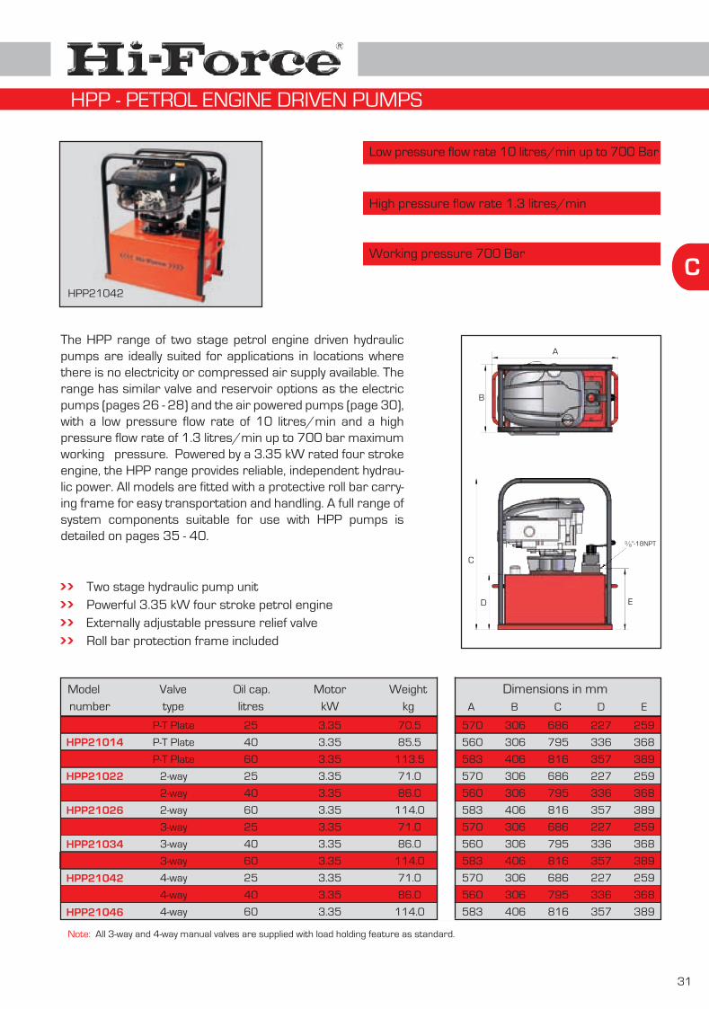
C
31
Modelnumber
HPP21012
HPP21014
HPP21016
HPP21022
HPP21024
HPP21026
HPP21032
HPP21034
HPP21036
HPP21042
HPP21044
HPP21046
Dimensions in mm
High pressure flow rate 1.3 litres/min
Low pressure flow rate 10 litres/min up to 700 Bar
Working pressure 700 Bar
Two stage hydraulic pump unit Powerful 3.35 kW four stroke petrol engineExternally adjustable pressure relief valveRoll bar protection frame included
Note: All 3-way and 4-way manual valves are supplied with load holding feature as standard.
Valvetype
P-T Plate
3-way
P-T Plate
P-T Plate
2-way
2-way
2-way
3-way
3-way
4-way
4-way
4-way
Oil cap.litres
25
25
40
60
40
60
25
25
40
60
40
60
MotorkW
3.35
3.35
3.35
3.35
3.35
3.35
3.35
3.35
3.35
3.35
3.35
3.35
Weightkg
70.5
85.5
113.5
71.0
86.0
114.0
71.0
86.0
114.0
71.0
86.0
114.0
A B C D E
The HPP range of two stage petrol engine driven hydraulic pumps are ideally suited for applications in locations where there is no electricity or compressed air supply available. The range has similar valve and reservoir options as the electric pumps (pages 26 - 28) and the air powered pumps (page 30), with a low pressure flow rate of 10 litres/min and a high pressure flow rate of 1.3 litres/min up to 700 bar maximum working pressure. Powered by a 3.35 kW rated four stroke engine, the HPP range provides reliable, independent hydrau-lic power. All models are fitted with a protective roll bar carry-ing frame for easy transportation and handling. A full range of system components suitable for use with HPP pumps is detailed on pages 35 - 40.
HPP21042
A
B
C
D E
”-18NPT38/
570 306 686 227 259
560 306 795 336 368
583 406 816 357 389
570 306 686 227 259
560 306 795 336 368
583 406 816 357 389
570 306 686 227 259
560 306 795 336 368
583 406 816 357 389
570 306 686 227 259
560 306 795 336 368
583 406 816 357 389
HPP - PETROL ENGINE DRIVEN PUMPS

32
C
Modelnumber
HSP23E104
HSP24E104
HSP43E104
HSP44E104
Dimensions in mm
Choice of control valves
Working pressure 700 bar
Internal safety overload device
Externally adjustable pressure relief valve
fitted to each outlet
Customized models are available on request
Length Width Height
The HSP split flow pump range offers single speed operation with a choice of 2 or 4 split flow outlets and flow rates from 1.1 to 2.2 litres/min per outlet. Unique within the Hi-Force range, these latest technology pumps are designed to deliver equal amounts of oil from each outlet regardless of different pressures in the system. Ideally suited for lifting and positioning of heavy, unevenly distributed loads, from multiple jacking positions, the split flow design ensures an even lift regardless of the weight distribution amongst the chosen number of Hi-Force cylinders. Maximum working pressure is 700 bar however each valve outlet has an externally adjustable pressure relief valve fitted as standard. A full range of system components suitable for use with HSP pumps is detailed on pages 35 - 40.
Reservoir capacity 100 litres
HSP23M104
HSP24M104
HSP43M104
HSP44M104
configuration
2 x 3-way
4 x 4-way
2 x 4-way
4 x 3-way
Valve
2 x 3-way
4 x 4-way
2 x 4-way
4 x 3-way
Valvetype
solenoid
solenoid
solenoid
solenoid
manual
manual
manual
manual
Weightkg
184
184
188
188
184
184
188
188
Motorvoltage
380 / 440
380 / 440
380 / 440
380 / 440
380 / 440
380 / 440
380 / 440
380 / 440
Oil flowper outlet
2.2
2.2
1.1
1.1
l/min
2.2
2.2
1.1
1.1
Choice of manual or electric solenoid valves
complete with push button pendant control
720 570 740
720 570 740
720 570 740
720 570 740
720 570 740
720 570 740
720 570 740
720 570 740
HSP44M104
HSP - ELECTRIC DRIVEN SPLIT FLOW PUMPS

D
33
Pump & Cylinder sets Selection of pumps and cylinders available as a ready to use set
Page34
PCS502
INDEX - PUMP AND CYLINDER SETS

34
D
Capacities from 4.5 to 109 tonnes
Working pressure 700 bar
Stroke lengths from 10 to 153mm
Hi-Force PCS pump and cylinder sets provide the simplest and most cost effective way to start your job immediately. All sets comprise of a Hi-Force hydraulic cylinder (wide choice available), suitable Hi-Force manual pump and a two metre length interconnecting hose with high flow, quick release coupler.
Note : Models PCS202H, PCS302H & PCS603H include a hollow piston cylinder.
Take advantage of the cost savings by selecting these PCS sets, which include standard components at reduced prices. Gauges and gauge blocks, suitable for use with PCS sets, are detailed on page 37.
Savings ...
Modelnumber
PCS50
PCS53
PCS100
PCS101
PCS102
PCS106
PCS200
PCS201
PCS256
PCS300
PCS302
PCS502
PCS506
PCS1002
PCS202H
PCS302H
capacitytonnes
Modelnumber
Capacitylitres
Modelnumber
Strokemm
heightmm
Modelnumber
Lengthmm
Weightkg
P u m p C y l i n d e r H o s e
HP110
HP110
HP110
HP110
HP110
HP110
HP110
HP110
HP110
HP110
HP110
HP110
HP227
HP227
HP110
HP110
HPS51
HSS53
HPS100
HLS101
HSS102
HSS106
HPS200
HLS201
HSS256
HPS300
HLS302
HLS502
HSS506
HLS1002
HHS202
HHS302
HC2
HC2
HC2
HC2
HC2
HC2
HC2
HC2
HC2
HC2
HC2
HC2
HC2
HC2
HC2
HC2
4.5
4.5
10
10
10
10
20
20
25
32
32
50
50
109
23
33
1.0
1.0
1.0
1.0
1.0
1.0
1.0
1.0
1.0
1.0
1.0
1.0
2.3
2.3
1.0
1.0
16
75
10
40
56
150
11
44
150
12
60
60
152
60
50
50
42
157
45
95
131
225
52
102
273
59
119
126
251
143
160
165
2.0
2.0
2.0
2.0
2.0
2.0
2.0
2.0
2.0
2.0
2.0
2.0
2.0
2.0
2.0
2.0
7.4
8.0
8.2
9.0
9.0
10.8
9.4
11.3
16.0
10.8
13.6
17.0
31.0
35.5
13.9
17.2
Cylinder Closed
S e t
Eighteen standard sets
Optional piston rod (tilting) saddles are available for most cylinder models (see page 20)
Cylinders are spring assisted return designManual pumps include factory set relief valve
PCS1006 HP257 HSS1006 HC2109 5.0 153 274 2.0 66.0
PCS603H HP227 HHS603 HC261 2.3 76 226 2.0 34.6
PCS200
PCS - PUMP & CYLINDER SETS

Hydraulic Hoses
Hydraulic Oil
Pressure Gauges
Couplers and Fittings
Control Valves
E
High pressure hydraulic hoses
Premium grade hydraulic oil
Pressure gauges and gauge mounting blocks
High pressure couplers, fittings and adaptors
Directional and flow control valves
35
Page36
Page36
Page37
Page39
Page40
Manifolds Distribution blocks and controlled manifoldsPage
38
INDEX - SYSTEM COMPONENTS

36
E
4:1 Factor of safety
Working pressure 700 bar
Special lengths available on request
Hi-Force high pressure hydraulic hoses provide the vital, high quality, safe connection for your hydraulic equipment. Available in black and red and supplied complete with an ergonomically designed protective strain reliever at both ends, Hi-Force high pressure hoses are suitable for working pressures up to 700 bar with a 4 : 1 safety factor.
By using black hoses for the advance lines and red hoses for the retract lines, identification is made easy and the possibility of incorrectly connected hoses is reduced.
Tip for double acting systems ...
0.5
1.0
2.0
3.0
4.0
5.0
6.0
10.0
12.0
15.0
20.0
25.0
30.0
Lengthmetres
Model number
HH0.5
HH1
HH2
HH3
HH4
HH5
HH6
HH10
HH12
HH15
HH20
HH25
HH30
Black
HH0.5R
HH1R
HH2R
HH3R
HH4R
HH5R
HH6R
HH10R
HH12R
HH15R
HH20R
HH25R
HH30R
RedHose end
thread
/ ”-18NPT3 8
/ ”-18NPT3 8
/ ”-18NPT3 8
/ ”-18NPT3 8
/ ”-18NPT3 8
/ ”-18NPT3 8
/ ”-18NPT3 8
/ ”-18NPT3 8
/ ”-18NPT3 8
/ ”-18NPT3 8
/ ”-18NPT3 8
/ ”-18NPT3 8
/ ”-18NPT3 8
Hoses with threaded endsLengthmetres
Model numberBlack Red
Hose endA
Hoses with one male couplerHose end
B
HC0.5
HC1
HC2
HC3
HC4
HC5
HC6
HC10
HC12
HC15
HC20
HC25
HC30
HC0.5R
HC1R
HC2R
HC3R
HC4R
HC5R
HC6R
HC10R
HC12R
HC15R
HC20R
HC25R
HC30R
0.5
1.0
2.0
3.0
4.0
5.0
6.0
10.0
12.0
15.0
20.0
25.0
30.0
/ ”-18NPT3 8
/ ”-18NPT3 8
/ ”-18NPT3 8
/ ”-18NPT3 8
/ ”-18NPT3 8
/ ”-18NPT3 8
/ ”-18NPT3 8
/ ”-18NPT3 8
/ ”-18NPT3 8
/ ”-18NPT3 8
/ ”-18NPT3 8
/ ”-18NPT3 8
/ ”-18NPT3 8
CM1 coupler
CM1 coupler
CM1 coupler
CM1 coupler
CM1 coupler
CM1 coupler
CM1 coupler
CM1 coupler
CM1 coupler
CM1 coupler
CM1 coupler
CM1 coupler
CM1 coupler
HYDRAULIC OIL
Hi-Force premium grade hydraulic oil is specially formulated for use with Hi-Force hydraulic tools, providing optimum performance throughout all working conditions.
1
5
25
1
5
25
HFO32-1
HFO32-5
HFO32-25
HFO46-1
HFO46-5
HFO46-25
Capacitylitres
Modelnumber For use with
Manually operated pumps
Manually operated pumps
Manually operated pumps
Powered pumps
Powered pumps
Powered pumps
Note : for hoses with CM1 quick connect coupler on both ends, please add suffix ‘C’ to model number, e.g. HC2C
HC2
HFO46-5 HFO32-1
HIGH PRESSURE HYDRAULIC HOSES

E
37
Modelnumber
HG63G
HG1
HG1G
HG5
HG10
HG11
HG20
HG23
HG25
HG32
HG33
HG50
HG61
HG102
HG109
HG2
Manufactured to EN837-1
Clear precise dual scale readings
Calibration certificates on request
Hi-Force hydraulic pressure gauges are your “window” to the system and are recommended for use within all hydraulic systems to allow the user to constantly monitor the system pressure. Hi-Force hydraulic pressure gauges are manufactured to EN837-1 and are accurate to +/- 1% of full scale. Standard range models up to 109 tonnes are featured in this catalogue, however gauges to suit Hi-Force high tonnage cylinders & digital pressure gauges are available on request. Always specify Hi-Force gauges for use with your Hi-Force hydraulic tools.
HG2G
Reading
Gauges :
Gauge mounting blocks :
Modelnumber
DimensionsWeight
kg
HGA1
HGA2
HGA1-25
Gaugediameter
mm
63100
150
100100100100100100100100100100100100100150
typeGauge
glycerinedry
glycerine
glycerine
drydrydrydrydrydrydrydrydrydrydrydrydry
scaleInner
0-700 Bar0-16.000 Psi
0-700 Bar0-700 Bar0-700 Bar0-700 Bar0-700 Bar0-700 Bar0-700 Bar0-700 Bar0-700 Bar0-700 Bar0-700 Bar0-700 Bar0-700 Bar0-700 Bar0-700 Bar
scaleOuter
0-1.000 Bar0-10.000 Psi
0-10.000 Psi0-10.000 Psi
0-10.000 Psi0-4.5 tonnes0-10 tonnes0-11 tonnes0-20 tonnes0-23 tonnes
0-109 tonnes0-102 tonnes0-61 tonnes0-50 tonnes0-33 tonnes0-32 tonnes0-25 tonnes
Inletthread
½”-14NPT½”-14NPT½”-14NPT½”-14NPT½”-14NPT½”-14NPT½”-14NPT½”-14NPT½”-14NPT½”-14NPT½”-14NPT½”-14NPT½”-14NPT½”-14NPT½”-14NPT½”-14NPT
¼”-18NPT
Weightkg
0.91.00.90.90.90.90.90.90.90.90.90.90.90.91.61.7
0.2
CompatibleHi-Force cylinders
All modelsAll modelsAll models
All modelsAll models
All 4.5 tonnes modelsAll 10 tonnes modelsAll 11 tonnes modelsAll 20 tonnes modelsAll 23 tonnes modelsAll 25 tonnes modelsAll 32 tonnes modelsAll 33 tonnes modelsAll 50 tonnes modelsAll 61 tonnes modelsAll 102 tonnes modelsAll 109 tonnes models
Lengthmm
7517075
mmWidth
323232
mmHeight
323232
threadGauge
½”-14NPT½”-14NPT¼”-18NPT
Inletthread
83 ”-18NPT male/
83 ”-18NPT male/
83 ”-18NPT male/
Outletthread
83 ”-18NPT female/
83 ”-18NPT female/
83 ”-18NPT female/
0.250.850.30
HGA2 HGA1-25
HG63G
HG1
HG1GHG10
PRESSURE GAUGES & GAUGE MOUNTING BLOCKS
Reading

38
EModelnumber
Choice of open or controlled manifolds
Working pressure 700 bar
2, 4, 5, 6 or 8 outlet port models available
Hi-Force manifolds are designed specifically to allow easy control of the direction of flow of the system’s hydraulic fluid. Supplied either as open manifold blocks or with individual needle type shut off/throttle valves on each 3/8” NPT outlet, Hi-Force manifolds provide even greater versatility in your hydraulic system. The range offers 9 models with a choice of up to 8 outlets per manifold and is suitable for 700 bar maximum working pressure. Always specify Hi-Force manifolds for use with your Hi-Force hydraulic tools.
Dimensions in mmModelnumber
Typeof
outlets
NumberInlet
threadOutletthread
WeightkgDesign
HM2 manifold 2 83 ”-18NPT/ 832 x ”-18NPT/ 1.0parallel
HM4 manifold 4 83 ”-18NPT/ 834 x ”-18NPT/ 1.5parallel
HM5 manifold 5 83 ”-18NPT/ 835 x ”-18NPT/ 0.7hexagon
HM6 manifold 6 83 ”-18NPT/ 836 x ”-18NPT/ 2.0parallel
HM6L manifold 6 83 ”-18NPT/ 836 x ”-18NPT/ 3.7extended parallel
HM2C controlled manifold 2 83 ”-18NPT/ 832 x ”-18NPT/ 2.0parallel
HM4C controlled manifold 4 83 ”-18NPT/ 834 x ”-18NPT/ 3.5parallel
HM4L manifold 4 83 ”-18NPT/ 834 x ”-18NPT/ 2.4extended parallel
HM8 manifold 8 83 ”-18NPT/ 838 x ”-18NPT/ 2.5parallel
HM2
HM4
HM5
HM6
HM8
HM4L
HM6L
HM2C
HM4C
A B C D F
HM* & HM*L HM5 HM*C
A
B
C
DE F
E
B
C
A
B
CD
D
114
214
-
314
414
394
614
122
270
32
32
41
32
32
32
32
40
65
32
32
51
32
32
32
32
50
40
50
50
-
50
50
110
110
50
51
-
-
M6
-
-
-
-
-
-
-
-
38
-
-
-
-
-
-
HM2
HM4
HM6
HM4C
MANIFOLDS

E
39
Working pressure 700 bar
Large selection of standard adaptors
Hi-Force high pressure couplers and fittings are designed for easy system connection and assembly of your Hi-Force hydraulic equipment. All Hi-Force couplers and fittings are suitable for 700 bar maximum working pressure. Hi-Force recommends the use of threaded dust caps with quick connect couplers to protect the thread of the coupler and at the same time prevent any contaminants entering your hydraulic system. Always specify Hi-Force couplers and fittings for use with your Hi-Force hydraulic tools.
Safety first !
Be sure to use genuine Hi-Force couplers and fittings which are designed to withstand the full 700 bar working pressure.
HIGH PRESSURE COUPLERS AND FITTINGS
Modelnumber Description Thread specification
Seepicture
1
2
3
4
5
6
7
8
9
10
11
12
13
HF7
HF10
HF12
HF13
HF14
HF15
HF16
HF17
HF19
HF24
CF1
CM1
CMF1
CF2
CM2
CMF2
CFD1
CMD1
CFD2
CMD2
PPC1
HF30
HF31
HF33
HF55
HF69
HF27
Nipple
Elbow
Equal tee
Cross
Adaptor
Reducer
Elbow
Nipple
Long nipple
Adaptor
Female coupler
Male coupler
Complete coupler
Female coupler
Male coupler
Complete coupler
Metal dust cap for CF1
Metal dust cap for CM1
Metal dust cap for CF2
Metal dust cap for CM2
Moulded universal dust cap to suit CF1 & CM1
Reducer
Tee
Reducer
Reducer
Adaptor
Nipple
” NPT male to ” NPT male14/ 1
4/
” NPT male to ” NPT male38/ 3
8/
” NPT male to ” NPT male38/ 3
8/
” NPT female to ” NPT female38/ 3
8/
” NPT female38/
” NPT female38/
” NPT female to ” NPT female38/ 3
8/
” NPT female to ” NPT female38/ 1
4/
” NPT female to ” NPT male38/ 3
8/
” NPT male to ” BSP female38/ 3
8/
” NPT male to ” NPT female38/ 1
4/
” NPT female to ” NPT male38/ 3
8/
” NPT male to ” BSPT female38/ 1
4/
” NPT female to ” NPT male38/ 1
4/
” BSP male to ” NPT female12/ 3
8/
” NPT male to ” NPT male14/ 3
8/
” NPT male38/
” NPT female38/
” NPT38/
” NPT male14/
” NPT female14/
” NPT14/
1
2
3
4
5
5
6
1
1
7
9
10
9 + 10
9
10
9 + 10
11
12
11
12
13
7
8
7
7
7
1

40
E
Modelnumber
HM1C
HFV66
HFV17
HPV152
HFV42
Pump or remote mounted design
Working pressure 700 bar
Manual or solenoid options available
Hi-Force control valves are designed to provide precise control of the hydraulic system either by accurate pressure or directional flow control. The PMV range of pump mounted valves is identical to the valves fitted to the Hi-Force powered pumps featured on pages 26 - 32 and can be easily interchanged, making your powered pump even more versatile. The RMV range allows for remote mounting away from the pump. Other Hi-Force control valves featured on this page include adjustable pressure relief, shut off and check valves. Always specify Hi-Force control valves for use with your Hi-Force hydraulic tools.
Directional control valves :
Model number
Flow control valves :
Description
Manual shut off valve, needle type controlManual check valveSafety check valveAdjustable pressure relief valvePilot operated check valve
Usage
Load holding & throttling functionsAutomatic load locking, manually openedPrevents shock load & pressure dropsPressure setting below pump pressureSafety valve for double acting cylinders
Description
PMV2
PMV3
PMV4
RMV3
RMV4
Manual valveno load holding
-
PMV3L
PMV4L
RMV3L
RMV4L
Manual valvewith load holding
-
PMV3S
PMV4S
RMV3S
RMV4S
Solenoid valve24V incl. control
-
PMV3C
PMV4C
RMV3C
RMV4C
Manual valveclosed centre
Pump mounted, 2-way, 2 position valvePump mounted, 3-way, 3 position valvePump mounted, 4-way, 3 position valveRemote mounted, 3-way, 3 position valveRemote mounted, 4-way, 3 position valve
PMV2 PMV3RMV3
PMV3LRMV3L
PMV3CRMV3C
PMV4RMV4
PMV4CRMV4C
PMV4LRMV4L
PMV2
HFV66HM1C
HFV42
DIRECTIONAL & FLOW CONTROL VALVES
A
P T
A
P T
A B
P T
A
P T
A
P T
A B
P T
A B
P T
HM1C HFV66 HFV17 HPV152 HFV42

HMP Range
AHP Range
AHP2 Range
F
Manually operated Hydrotest pumps
Air driven Hydrotest pumps - standard flow
Air driven Hydrotest pumps - high flow
41
Page42 - 43
Page44
Page45
ATDP Range Air driven twin double acting Hydrotest pumpsPage
46
AHP Pump with on board chart recorder
INDEX - HYDROTEST PUMPS

42
F
Modelnumber
Up to 1000 Bar working pressure
Suitable for use with a wide variety of fluids
Two stage design with easy push button changeover
The Hi-Force HMP series of manually operated two speed hydraulic pumps is suitable for use with a wide variety of fluids including water. Manufactured predominantly from high quality aluminium alloy, the HMP series are lightweight and extremely versatile. The pump’s two stage piston design offers a superb 49 cm³ delivery per stroke at low pressure (up to 52 Bar) with a push button changeover valve for operating the high pressure piston. The pump unit is available with a choice of seven high pressure capacities ranging from 110 to 1000 Bar working pressure, and is supplied complete with a 610mm operating lever. For optional adjustable pressure relief valve suffix the model number with ‘R’.
HMP100 with HG100-K
Lightweight aluminium design with stainless steel pistons
Optional pressure gauges available (see page 43)
Needle type design release valve for precise pressure controlLow cost replaceable valve seatsEasily accessible fluid system filterStandard 10 litre capacity fluid reservoir (see page 43 for options)Optional, factory fitted, externally adjustable pressure relief valveIdeally suited for pressure testing valves, pipework and vessels
Workingpressure
barValvetype
Displacementper stroke cm³
1 stagest 2 stagend
Changeoverpressure
barSuction
portOutletport
Weightkg
HMP160 110 2-way 49 20 52 ” BSP3 8/” BSP1 2/ 15
HMP250 172 2-way 49 13 52 ” BSP3 8/” BSP1 2/ 15
HMP450 310 2-way 49 7 52 ” BSP3 8/” BSP1 2/ 15
HMP650 448 2-way 49 5 52 ” BSP3 8/” BSP1 2/ 15
HMP800 552 2-way 49 4 52 ” BSP3 8/” BSP1 2/ 15
HMP100 700 2-way 49 3 52 ” BSP3 8/” BSP1 2/ 15
HMP150 1000 2-way 49 2 52 ” BSP3 8/” BSP3 8/ 15
HMP - MANUALLY OPERATED HYDROTEST PUMPS

F
43
The Hi-Force HMP-PU series offers the same features as the HMP range on page 42 however these are supplied without a fluid reservoir. Ideally suited for applications where a large volume of fluid is required, the pump unit is supplied complete with mounting kit for easy attachment to any specially designed fluid reservoir. For optional pressure relief valve, please add suffix ‘R’ to model number.
Modelnumber
HMP160PU
HMP250PU
HMP450PU
HMP650PU
HMP800PU
HMP100PU
HMP150PU
110
172
310
448
552
700
1000
Workingpressure
bar
2-way
2-way
2-way
2-way
2-way
2-way
2-way
Valvetype
Displacementper stroke cm³
49494949494949
1 stagest
201375432
2 stagend
52
52
52
52
52
52
52
Changeoverpressure
barSuctionport(s)
” BSP3 8/
” BSP3 8/
” BSP3 8/
” BSP3 8/
” BSP3 8/
” BSP3 8/
” BSP3 8/
Outletport(s)
” BSP1 2/
” BSP3 8/
Weightkg
5.9
5.9
5.9
5.9
5.9
5.9
5.9
” BSP1 2/
” BSP1 2/
” BSP1 2/
” BSP1 2/
” BSP1 2/
HMP250PU
Dimensions :
A
C
E
Choice of standard 10 or 20 litre capacity reservoirs. Alternative capacity reservoirs available on request.
RESERVOIRS
Complete range of 100 mm diameter pressure gauges manufactured to EN837-1 and compatible for use with HMP series pumps. Supplied complete with gauge mounting kit.
PRESSURE GAUGES
B
D
F
Modelnumber
Modelnumber
Description
Pressure rangebar
HRS10HRS20
10 litre standard reservoir
20 litre standard reservoir
HG16K
HG25K
HG45K
HG65K
HG80K
HG100K
HG150K
0-110
0-172
0-310
0-448
0-552
0-700
0-1000
A
D
BE
C F
½” BSP (excluding HMP150PU)Reservoir capacity10 litres 20 litres
714
210
286
420
185
264
929
210
286
615
185
264
HMP - MANUALLY OPERATED HYDROTEST PUMPS

44
F
Air consumption 28 scfm (0,79m3/minute)Infinitely variable output pressure and flow
Output pressures from 6 to 2931 Bar
Suitable for use with various fluids.
150 mm dual scale vibra pressure gauge
Modelnumber
Max. output pressure (bar)at airline input pressure
Oil volumedisplacement
per stroke (cm3)
Outletport
thread Length Width HeightWeight
kg10 PSI 50 PSI 100 PSI Dimensions in mm
AHP10AHP26AHP36AHP58
AHP187
6141728
97
3490
122200
638
69181250400
1293
42.316.012.37.6
2.2
450450450450
450
23212020
20
The Hi-Force AHP series of lubricant free air driven hydrostatic pressure testing pumps offers a choice of eight models with output pressure capacities ranging from 69 Bar (1000 PSI) to 2933 Bar (42500 PSI). All models are suitable for use with various fluids, including water and are supplied with a 150mm diameter hydraulic pressure gauge (calibrated on request), inlet airline filter & pressure regulator unit, lightweight fluid reservoir, pump start/stop valve and a robust stainless steel skid mounted framework. Optional extras available also include stainless steel fluid reservoirs, stroke counter plunger assembly with IP65 microswitch & digital impulse counter, pressure isolation valve and onboard circular chart recorders. All units are of compact design with a maximum weight of 23 kg.
Hydraulic pressure Approximate rate of discharge (L/min) at air input pressure 100 PSI (7 Bar)PSI Bar
”-18UNF916/
12/ ” NPT
12/ ” NPT
12/ ” NPT
12/ ” NPT
AHP58
AHP107
AHP275AHP425
62
155345
373
9311448
738
18972931
4.0
1.61.0
450
450450
20
2020 ”-18UNF9
16/
12/ ” NPT
395395395395
395395
395395
395395395395
395395
395395
”-18UNF916/
AHP10 AHP26 AHP36 AHP58 AHP187AHP107 AHP275 AHP425
0500
1000
2000
3000
50007500
100001500020000250003000040000
1500
2500
4000
03569
138
207
345517690
10341379172420692760
104
173
276
23.1012.00
*
*
*
********
*
*
*
8.805.854.72
3.00
*
********
3.90
1.21
*
6.004.393.80
3.00
1.95
********
3.34
2.56
*
3.563.052.51
2.25
1.85
1.02
*******
2.38
2.05
1.56
1.971.501.28
1.21
1.16
0.950.760.44
*****
1.25
1.18
1.02
1.151.051.00
0.78
0.73
0.670.600.520.39
****
0.90
0.75
0.70
0.720.680.65
0.55
0.48
0.420.400.370.330.300.21
**
0.60
0.50
0.45
0.430.400.38
0.34
0.31
0.260.250.240.210.200.160.130.05
0.36
0.33
0.29
* Pressure exceeds pump capacity.
0.69 Bar 3.45 Bar 6.9 Bar
AHP - AIR DRIVEN HYDROTEST PUMPS - STANDARD FLOW
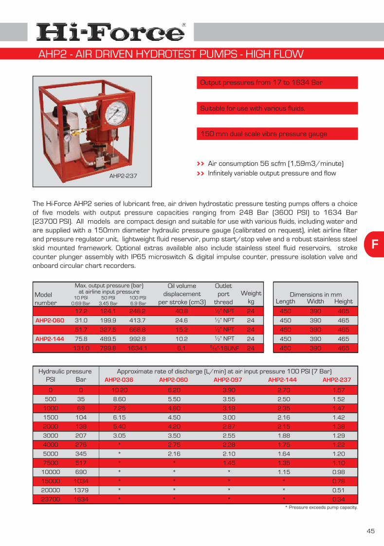
F
45
Air consumption 56 scfm (1,59m3/minute)Infinitely variable output pressure and flowAHP2-237
Output pressures from 17 to 1634 Bar
Suitable for use with various fluids.
150 mm dual scale vibra pressure gauge
Modelnumber
Oil volumedisplacement
per stroke (cm3)
Outletport
thread Length Width HeightWeight
kgDimensions in mm
AHP2-036
AHP2-060
AHP2-097
AHP2-144
AHP2-237
17.2
31.0
51.7
75.8
131.0
124.1
199.9
327.5
489.5
799.8
248.2
413.7
668.8
992.8
1634.1
40.8
24.6
15.2
10.2
6.1
450
450
450
450
450
24
24
24
24
24
390
390
390
390
390
465
465
465
465
465
The Hi-Force AHP2 series of lubricant free, air driven hydrostatic pressure testing pumps offers a choice of five models with output pressure capacities ranging from 248 Bar (3600 PSI) to 1634 Bar (23700 PSI). All models are compact design and suitable for use with various fluids, including water and are supplied with a 150mm diameter hydraulic pressure gauge (calibrated on request), inlet airline filter and pressure regulator unit, lightweight fluid reservoir, pump start/stop valve and a robust stainless steel skid mounted framework. Optional extras available also include stainless steel fluid reservoirs, stroke counter plunger assembly with IP65 microswitch & digital impulse counter, pressure isolation valve and onboard circular chart recorders.
Hydraulic pressure Approximate rate of discharge (L/min) at air input pressure 100 PSI (7 Bar)AHP2-036 AHP2-060 AHP2-097 AHP2-144 AHP2-237PSI
0
500
1000
1500
2000
3000
4000
5000
7500
10000
15000
20000
23700
Bar
0
35
69
104
138
207
276
345
517
690
1034
1379
1634
10.20
8.60
7.25
6.15
5.40
3.05
*
*
*
*
*
*
*
6.20
5.50
4.80
4.50
4.20
3.50
2.75
2.16
*
*
*
*
*
3.90
3.55
3.19
3.00
2.87
2.55
2.28
2.10
1.45
*
*
*
*
2.70
2.50
2.35
2.16
2.15
1.88
1.75
1.64
1.35
1.15
*
*
*
1.57
1.52
1.47
1.42
1.38
1.29
1.22
1.20
1.10
0.98
0.78
0.51
0.34
”-18UNF916/
12/ ” NPT
12/ ” NPT
12/ ” NPT
12/ ” NPT
Max. output pressure (bar)at airline input pressure
10 PSI 50 PSI 100 PSI0.69 Bar 3.45 Bar 6.9 Bar
* Pressure exceeds pump capacity.
AHP2 - AIR DRIVEN HYDROTEST PUMPS - HIGH FLOW

46
FOptional extras include stainless steel frame-
onboard chart recorder, pressure isolationvalve, wheel mounting and framework painted
work, stroke counter, digital impulse counter,Suitable for use with various fluids including waterAir consumption 212 scfm (6m3/minute)
Infinitely variable output pressure and flow150 mm diameter dual scale gauge
Fitted with inlet air filter, regulator & lubricator
Output pressures from 87 to 1489 Bar
Suitable for use with various fluids.
Twin double acting design offering high volume flow
Modelnumber
Oil volumedisplacement
per stroke (cm³)
Outletport
thread Length Width HeightWeight
kgDimensions in mm
ATDP63
ATDP125
ATDP216
87
172
298
260
517
894
434
862
1489
275
140
79
765
765
765
96
96
96
570
570
570
700
700
700
The Hi-Force ATDP series of twin double acting air driven hydrostatic pressure testing pumps offers a choice of 3 models with output pressure capacities ranging from 434 Bar (6300 PSI) to 1489 Bar (21600 PSI). The twin double acting design offers a much higher displacement volume per stroke than the smaller AHP & AHP2 series, making it ideal for prefill as well as pressure testing. All models are supplied with a 150mm diameter vibra-gauge, air inlet filter regulator lubricator unit, pump start/stop valve and fluid strainer. Viton and ethylene propylene seals for handling special fluids or chemicals can be factory fitted prior to delivery if required. Other seal materials are available on request.
Hydraulic pressure Approximate rate of discharge (L/min) at air input pressure 100 PSI (7 Bar)PSI
0
1000
2000
3000
4000
5000
6000
8000
10000
12000
16000
20000
Bar
0
69
138
207
276
345
414
552
690
828
1103
1379
ATDP63
32.2
25.7
20.5
16.2
12.5
8.0
2.8
*
*
*
*
*
ATDP125
16.9
14.0
12.3
10.6
9.4
8.3
7.3
4.8
3.0
0.4
*
*
ATDP216
9.5
8.8
8.0
7.4
6.9
6.4
6.1
5.5
4.9
4.3
3.2
1.6
12/ ” NPT
12/ ” NPT
to offshore specifications.
* Pressure exceeds pump capacity
ATDP125
”-12UNF18/1
Max. output pressure (bar)at airline input pressure
20 PSI 60 PSI 100 PSI1.38 Bar 4.14 Bar 6.9 Bar
ATDP - AIR DRIVEN TWIN DOUBLE ACTING HYDROTEST PUMPS

JAH Range
JAL Range
JSL Range
JSS Range
G
Aluminium jacks
Aluminium compact jacks
Steel compact jacks
Steel bottle jacks
47
Page48
Page49
Page49
Page50
JAS Range Aluminium multi-purpose jacksPage
49
HCJ Range Steel claw jackPage
50
INDEX - JACKS

48
G
Modelnumber
JAH1230
JAH660
JAH1260
Jack with plain piston & lifting claw
JAH620C
JAH1220C
JAH630C
JAH1230C
JAH660C
JAH1260C
Jack with “failsafe” locking ring
JAH620SR
JAH1220SR
JAH630SR
JAH1230SR
JAH660SR
Dimensions in mm
Capacities from 20 to 60 tonnes
Stroke lengths from 152 to 305mm
Internal safety overload device
The JAH range of lightweight aluminium jacks offers a wide variety of capacities and lift height options. Available as either plain ram lifting jacks, with or without “failsafe” mechanical lock ring, or optional low height claw lifting design. All models are constructed predominantly of lightweight aluminium alloy with all critical functioning parts manufactured from high quality steel. Used extensively in maintenance, construction, heavy plant and machinery applications, these high quality jacks are the proven industry standard.
Lightweight constructionSafestop stroke limiting deviceOptional pressure gaugeAvailable as plain ram jack, claw jack or“failsafe” locking ring design
Jack with plain piston
JAH620
JAH1220
JAH630
JAH1260SR
Jackcapacity
Clawcapacity Stroke
mmWeight
kgtonnes tonnes
30
60
60
20
20
30
30
60
60
20
20
30
30
60
20
20
30
60
-
-
-
8
8
12
12
24
24
-
-
-
-
-
-
-
-
-
305
152
305
152
305
152
305
152
305
152
305
152
305
152
152
305
152
305
23.4
27.4
43.7
14.5
22.2
20.3
31.0
43.1
64.9
12.5
18.0
16.5
24.5
30.0
10.9
16.7
15.4
44.0
Baselength
Basewidth
Closedheight
Toeheight
451
293
500
276
452
281
470
327
533
289
464
292
479
330
263
438
263
536
-
-
-
67
67
73
73
73
73
-
-
-
-
-
-
-
-
-
273
251
339
246
246
273
273
339
339
178
246
197
273
251
178
246
197
339
140
190
190
121
121
140
140
190
190
121
121
140
140
190
121
121
140
190
JAH1230
JAH1230SR JAH1230C
JAH630SR
JAH630JAH630C
For your information ...
Optional pressure gauges complete with mounting kits are available. More details on request
JAH - ALUMINIUM JACKS

G
49
Capacities from 10 to 20 tonnes
Operate in any position
Lightweight and compact
The Hi-Force JAL & JSL range of compact jacks is ideally suited for applications requiring a lifting or positioning force in confined spaces. Lightweight, easy to operate and available in steel or durable aluminium versions, all models incorporate a spring assisted, hard chrome plated piston. The pumping mechanism rotates through 360°, providing maximum versatility in any application. With the removable operating handle measuring only 210mm in length, these compact lifting jacks will fit in any toolbox.
Spring assisted return pistonMulti-position pump mechanismInternal safety overload valve
Modelnumber
Dimensions in mmWeight
kgClosedheight
Bodylength
Bodywidth
JSL10 4.4 76 212 70
JAL10 3.2 79 212 70
JAL20
Capacitytonnes
10
10
20
Strokemm
38
38
44 5.0 99 233 90
JSL10
Wear plated piston rodSealed hydraulic systemChoice of aluminium or steel versions
JAS - ALUMINIUM MULTI-PURPOSE JACKS
Capacity 10 tonnes
Operate in any position
Lightweight and compact
The Hi-Force JAS range of lightweight multi-purpose jacks is manufactured predominantly from high quality aluminium alloy and offers a full 10 tonnes of hydraulic force with a 75 or 125mm stroke. The sealed hydraulic system avoids the need for breather valves, enabling the jack to operate in any position. Jacks are fitted with integral stop ring and spring assisted return hard chromed piston rods.
Modelnumber
JAS103
Dimensions in mm
JAS105
Capacitytonnes
10
10
Strokemm
75
125
Weightkg
4.3
5.7
Closedheight
Bodylength
Bodywidth
131
181
162
162
75
75
JAS105
JAS103
Construction
Steel
Aluminium
Aluminium
JAL & JSL - COMPACT JACKS
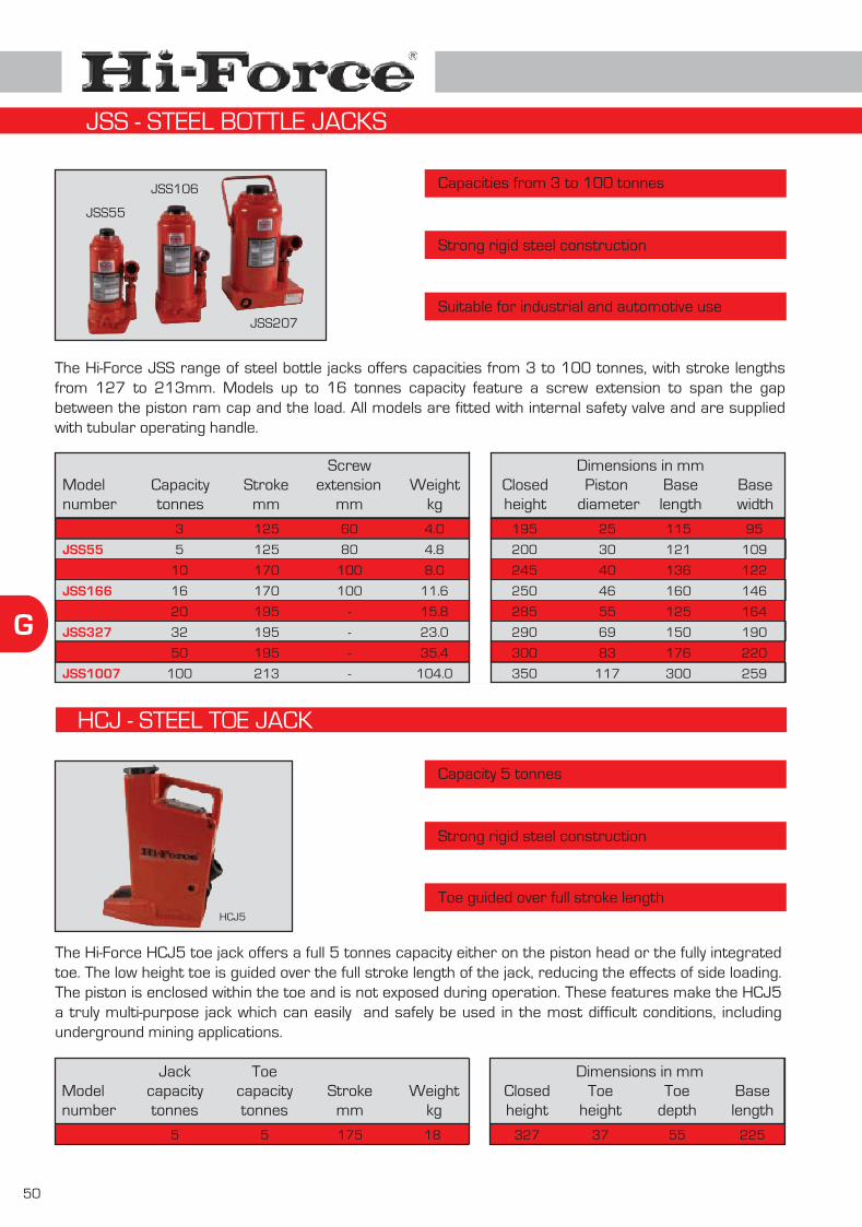
50
G
HCJ - STEEL TOE JACK
Capacities from 3 to 100 tonnes
Strong rigid steel construction
Suitable for industrial and automotive use
The Hi-Force JSS range of steel bottle jacks offers capacities from 3 to 100 tonnes, with stroke lengths from 127 to 213mm. Models up to 16 tonnes capacity feature a screw extension to span the gap between the piston ram cap and the load. All models are fitted with internal safety valve and are supplied with tubular operating handle.
Modelnumber
JSS35
JSS55
JSS106
JSS166
JSS207
JSS327
JSS507
Dimensions in mm
JSS1007
3
5
10
16
20
32
50
100
Capacitytonnes
Strokemm
125
125
170
170
195
195
195
213
Weightkg
4.0
4.8
8.0
11.6
15.8
23.0
35.4
104.0
-
-
-
-
Screw
mm
60
80
100
100
extension Closedheight
Baselength
Basewidth
Piston diameter
195
200
245
250
285
290
300
350
25
30
40
46
55
69
83
117
115
121
136
160
125
150
176
300
95
109
122
146
164
190
220
259
Capacity 5 tonnes
Strong rigid steel construction
Toe guided over full stroke length
Modelnumber
HCJ5
Dimensions in mmWeight
kg
18
Strokemm
175
The Hi-Force HCJ5 toe jack offers a full 5 tonnes capacity either on the piston head or the fully integrated toe. The low height toe is guided over the full stroke length of the jack, reducing the effects of side loading. The piston is enclosed within the toe and is not exposed during operation. These features make the HCJ5 a truly multi-purpose jack which can easily and safely be used in the most difficult conditions, including underground mining applications.
5
Jackcapacitytonnes
5
Toecapacitytonnes
Closedheight
327
Toeheight
37
Toedepth
55
Baselength
225
HCJ5
JSS55
JSS106
JSS207
JSS - STEEL BOTTLE JACKS

HWC & HSWC Range
HWRC Range
HCC Range
SC Range
CH Range
HHP & HKP Range
NS & HMNS Range
HFS Range
MFS Range
JS & SJS Range
HPB Range
HPF Range
Moving skates
H
Hammer blow & single acting wire rope cutters
Double acting wire rope cutters
Chain cutters
Self-contained cable crimping tools
Cable crimping tools
Hole punchers
Nut splitters
Hydraulic flange spreaders
Mechanical flange spreaders
Jaw spreaders
Bench presses
Workshop floor presses
51
Multi purpose & heavy duty moving skates
Page52
Page53
Page54
Page56
Page57
Page58
Page59
Page60
Page61
Page62
Page63
Pages64 - 65
Pages66 - 68
CT & HCH Range CuttersPage
55
INDEX - HYDRAULIC TOOLS

52
H
Highly cost efficient impact design
Cutting capacity up to 38mm diameter wire rope
Portable and lightweight
The Hi-Force HWC range of highly cost effective cutters are manufactured from high quality, shock resistant, ductile iron and are fitted with replaceable cutting blades made from tool steel. The cutting blades are retained in the housing at the moment of impact, ensuring absolute safety. These cutters offer a considerable time saving over conventional axe, chisel and hacksaw methods.
Modelnumber
HWC90
Dimensions in mm
HWC91
HeightBase
diameter
168
187
89
162
HSWC - SELF-CONTAINED HYDRAULIC WIRE ROPE CUTTERS
Cutting capacities from 19 to 44mm diameter
Strong rigid steel construction
Easy to use with minimum operator effort
The Hi-Force range of self-contained portable hydraulic wire rope and cable cutters comprises of three models with cutting capacities from 19 to 44mm diameter. Approved and specified by many major industries throughout the world, these high quality cutters are precision engineered to give a good, clean cut with minimum effort, time after time. The self-contained design of the cutter enables easy transportation to the job site with minimum of fuss. The shear blades are manufactured using high quality tool steel, which is heat treated and ground to very tight tolerances, ensuring superior performance and long-life. Customers include wire rope manufacturers, earthmoving and construction contractors, rigging shops, elevator manufacturers and repairers and many others. Also suitable for use under water by divers.
HWC92
Wire rope Ømm
25
27
38
Electric cablemcm
250
300
750
Weightkg
3.2
7.0
13.0 241 200
Cutting capacity
HWC90HWC91HWC92
Modelnumber
HSWC19
Dimensions in mm
HSWC28
HSWC44
Cutting capacity wire ropemm Ø
19
28
44
Weightkg
9.5
15.5
30.0
Length
305
355
470
Height
153
178
203
Width
92
105
127
HWC - HAMMER BLOW WIRE ROPE AND CABLE CUTTERS
HSWC44

H
53
Working pressure 700 Bar
Double acting design
Smooth guillotine cutting action
The HWRC range of hydraulic cutters is specifically designed and manufactured for cutting high tensile locked coil wire rope and solid steel bar. Maximum cutting capacities range from 38 to 90mm diameter wire rope and 25 to 50mm diameter 28 tonnes tensile solid steel bar. All models incorporate a double acting hydraulic cylinder, suitable for working pressures up to 700 bar and an open jaw design cutting head (see pictures below) for easy access to the material to be cut. Cutting blades and jaws are manufactured from specially toughened high tensile steel and the smooth guillotine action of the cutter greatly reduces the risk of blade jamming.
Modelnumber
HWRC1115
Dimensions in mm
HWRC1125
HWRC1136
Wire ropemm Ø
38
63
90
Solid steel barmm Ø
25
50
50
Weightkg
26
65
75
Length
305
419
495
Height
254
330
356
Cutting capacity
Width
195
245
245
Cuts high tensile locked coil wire rope and steel barCutting capacities from 38 to 90mm diameter wire ropeCutting capacities from 25 to 50mm diameter steel bar
HWRC1115
Step 1: Step 2: Step 3:
To open the cutter, swivel cutting headforward.
Position material to be cut in the cuttinghead slot.
Close the cutting head byswivelling it back to it’soriginal postion and secure behind the latch.
capacitycm³
267
874
1242
Oil
Hand and powered pumps suitable for these cutters are detailed on pages 21 to 32.
HWRC - DOUBLE ACTING WIRE ROPE CUTTERS

54
H
Working pressure 700 Bar
Single acting design
Fitted with locking guard
The HCC range of hydraulic cutters is specifically designed and manufactured for cutting high tensile chain and reinforcing bar. The easily replaceable cutter blades are manufactured from specially toughened high tensile steel and the choice of models available offer maximum cutting capacities up to 46mm diameter. All models are suitable for working pressures up to 700 Bar and incorporate a single acting cylinder fitted with a powerful piston retraction spring. The swivel action design of the locking safety guard (see pictures below) allows easy access for the material to be cut.
Modelnumber
HCC26
Dimensions in mm
HCC34
HCC46
Weightkg
23
40
72
Length
440
410
565
Height
180
250
345
capacitymm Ø
26
34
46
Cutting
Width
180
460
635
Cuts high tensile grade 80 chain and reinforcing barCutting capacities from 26 to 46mm diameterOverload protection valve fitted as standard
Picture 1: Picture 2:
HCC26 cutter shown withswivel action locking &safety guard opened.
HCC26 cutter shown withswivel action locking &safety guard closed.
capacitycm³
276
492
980
Oil
Hand and powered pumps suitable for these cutters are detailed on pages 21 to 32.
HCC34
forcetonnes
72
100
140
Cutting
HCC - CHAIN CUTTERS

H
55
Cutting capacity up to 40mm diameter
Cuts a wide variety of materials
Self-contained hydraulic design
The CT self-contained hydraulic cutter range offers a choice of 2 models with cutting capacities up to 25mm steel wire rope and 40mm cable. These versatile cutters are suitable for cutting wire rope, round bar, wire strands and electrical cable.
Modelnumber U
nder
grou
ndca
ble
20
40
Cutting capacity up to 120mm diameter
Working pressure 700 Bar
Compact and lightweight
The HCH cutter head range cuts a wide range of materials and offers 2 models with similar features to the CT range of self-contained cutters. A comprehensive range of suitable manually operated and powered hydraulic pumps suitable for use with Hi-Force HCH cutters is detailed on pages 21 to 32.
Modelnumber
CT20
CT40
HCH40
HCH120
WIRE ROPE
WIRE ROPE
ROUND BAR
ROUND BAR
WIRE STRANDS
WIRE STRANDS
CABLE
CABLE
Und
ergr
ound
cabl
e
6X
7
Hem
pcor
e
20
20
6X
7
Hem
pcor
e
20
25
6X
12
H
empc
ore
20
25
6X
12
H
empc
ore
25
30
6X
19
H
empc
ore
20
25
6X
19
H
empc
ore
25
30
Sof
tco
pper
bar
20
25
Sof
tco
pper
bar
25
35
Sof
tal
umin
ium
bar
20
22
Sof
tal
umin
ium
bar
22
28
Sof
tst
eel b
ar
16
16
Sof
tst
eel b
ar
16
22
Rei
nfor
ced
bar
13
13
Rei
nfor
ced
bar
13
*
Bar
eco
pper
str
ands
20
40
Bar
eco
pper
str
ands
32
125
Bar
e al
umin
ium
stra
nds
20
40
Bar
e al
umin
ium
stra
nds
32
125
AC
SR
20
40
AC
SR
40
125
1x7
Guy
ste
elw
ire
stra
nds
15
15
1x7
Guy
ste
elw
ire
stra
nds
15
15
1x1
9 G
uy s
teel
wir
e st
rand
s
16
20
1x1
9 G
uy s
teel
wir
e st
rand
s
20
20
Tele
phon
eca
ble
CC
P
20
*
Tele
phon
eca
ble
CC
P
*
*
Lead
she
athe
dca
ble
20
*
Lead
she
athe
dca
ble
*
*
*125
HCH - HYDRAULIC CUTTER HEADS
Maximum diameter cutting capacity in mm :
Maximum diameter cutting capacity in mm :
* Not suitable
* Not suitable
CT40
HCH40
CT - SELF CONTAINED HYDRAULIC CUTTERS
Length
mm
Cuttingforce
tonnesWeight
kg
Length
mm
Cuttingforce
tonnesWeight
kg
6
6
6
15
390
630
247
600
2.8
6.0
2.8
14.0

56
H
Choice of 7 available models
Supplied complete with die sets
Automatic pressure release valve
The SC self-contained hydraulic cable crimping tool range offers 7 models with a choice of open “C” jaw or parallel guide design. All models are fitted with an automatic pressure release valve and are supplied complete with standard die sets and a carrying case. Models with 180° rotating head are designed for easy access into confined spaces.
Models SC30, SC40 & SC60 are suitable for crimping connectors from 35 to 630mm²
Models SC15, SC18X, SC21 & SC32 are suitable for crimping non-insulated terminals from 10 to 400mm²
Models SC30 & SC40 incorporate 180° rotating head
Modelnumber
C - Jawopening
Applicable rangeDIN mm²
Standard diesmm²
Weightkg
Lengthmm
With die
With die
With die
With dieFemale die
With die
With dieFemale die
With dieFemale die
10-16, 25-35, 50-70,95-120, 150, 185
35, 50, 70, 95, 120, 150,185, 240, 300, 400, 500, 630
35, 50, 70, 95, 120, 150,185, 240, 300, 400
(4pcs) 16, 25-35, 50-120, 150-400(8pcs) 16-25, 35-70, 95-120, 150,185, 240, 300, 400
35, 50, 70, 95, 120, 150,185, 240, 300, 400
(4pcs) 25, 35-50, 70-185, 240(1pc) 25-35, 50-70, 95-120,150-185, 240
(3pcs) 16-25, 35-70, 70-185(1pc) 16, 25-35, 50-6070-120, 150-185
SC15
SC21
SC30
SC32
SC40
SC60
SC18X
Outputtonnes
10
10
12
18
12
18
6
notapplicable
notapplicable
30 mm
notapplicable
38 mm
notapplicable
notapplicable
16-185
25-240
35-400
16-400
35-400
35-630
10-185
528
528
610
650
636
650
370
5.2
5.2
6.3
6.2
7.7
6.5
2.0
Note : Models SC15, SC21 & SC32 are supplied with single indent dies, all other models are supplied with hexagonal dies.
SC40
SC30
SC60
SC18XSC21
SC - SELF-CONTAINED CABLE CRIMPING TOOLS

H
57
Choice of 7 available models
Supplied complete with die sets
Working pressure 700 Bar
The CH hydraulic cable crimping tool range offers 7 models with a choice of open “C” jaw or parallel guide design. All models are supplied complete with standard die sets and a carrying case. Models with 180° rotating head are designed for easy access into confined spaces. Pump units include HP227FPC foot operated pump set which includes elbow fitting, gauge, gauge block, 3 metre hose and male coupler, as shown below. All models, excluding HC1000, are available as a complete kit, comprising of HP227FPC, MB1 metal storage case and selected crimping tool with die sets.
Models CH30, CH40 & CH63 suitable for crimpingconnectors up to 630mm²Models CH21 & CH32 are suitable for crimping non-insulated terminals up to 400mm²Models CH80 & CH1000 are suitable for crimpingdistribution and transmission lines up to 1000mm²
Modelnumber
C-Jawopening
Standard diesmm²
Weightkg
Lengthmm
Outputtonnes
Hi-Force foot operated manual pump unit complete with accessories.
For pump specifications, please seepage 23, model HP227FP.
Note : Models CH21 & CH32 supplied with single indent dies, all other models supplied with hexagon dies.
With die
Female die
With die
With die
With die
With die
With die
Female dieWith die
500, 630, 800, 1000
35, 50, 70, 95, 120, 150, 185240, 300, 400, 500, 630
35, 50, 70, 95, 120, 150, 185240, 300, 400, 500, 630
35, 50, 70, 95, 120, 150, 185240, 300, 400
(4pcs) 16, 25-35, 50-120, 150-400(8pcs) 16-25, 35-70, 95-120, 150185, 240, 300, 400
35, 50, 70, 95, 120, 150, 185240, 300, 400
(4pcs) 16-25, 35-70, 70-185, 240(1pc) 25-35, 50-70, 95-120,150-185, 240
CH21
CH30
CH32
CH40
CH63
CH80
CH1000
10
12
18
12
18
15
50
not applicable
30 mm
not applicable
38 mm
not applicable
50 mm
not applicable
Applicable rangeDIN mm²
16-240
35-400
16-400
35-400
35-630
35-630
500-1000
210
220
210
245
240
300
420
3.0
4.0
3.6
4.8
4.8
7.0
38.0
CH40
CH30
CH63
CH32
CH - CABLE CRIMPING TOOLS
HP227FPC

58
HHKP - KNOCK OUT PUNCHER
Punching force 30 tonnes
Throat depth 70mm
Working pressure 700 Bar
The HHP hole puncher delivers 30 tonnes of full punching power and is capable of punching up to 20.5mm diameter holes in 10mm thick steel plates. Designed and manufactured with a spring assisted return piston for easy removal from the steel plate and an integral positioning and carrying handle. Unit supplied with standard set of four punch and dies in a handy storage and carrying case. See pages 21 to 32 for detailed information on suitable pumps for use with the HHP30 hydraulic hole puncher.
Capacity 10 tonnes
Spring return hydraulic cylinder
Working pressure 700 Bar
Supplied complete with carrying caseIdeal for punching holes in electriccontrol panels & steel plates
Note: pump supplied separately
Modelnumber
Maximumforce
tonnes
Standard punch/diesets included
mm
Recommended pump & hose Weightexcl. pump
kg
HHP30 30
Steelplate
Hole punchdiameter
Punch capacity (mm)
10.0 up to 20.510.5, 13.517.5, 20.5
Manuallyoperated
HP227complete withHC3 3m hose
Pneumaticallyoperated
AHP1120complete withHC3 3m hose
19.8
Modelnumber
Standard punch/die set (10 sizes) included
HKP10
Maximumforce
tonnes
10
Stainlesssteel
Mildsteel
Plate capacity (mm)
1.6 3.2
Weightexcl. pump
kg
35.8Hole Ø (mm)
The HKP knock out puncher is supplied as a complete set and includes all standard sizes of punches/dies, manually operated pump and hose complete with quick release coupler. Ideal for on-site hole punching in electric control panels and metal plates.
Throatdepth
70
mm
HHP30
HHP - HOLE PUNCHER
Conduit Ø (inch)
:
:
Also included in HKP10 set :Manually operated pump HP110 (see page 23)
Hose and coupling assy HC2 (see page 36)
21.8 27.6 34.1 42.7 48.7 60.5 76.1 88.9 102.8 115.5
½” ¾” 1” 1¼” 1½” 2” 2½” 3” 3½” 4”
HKP10

H
59
HMNS126
HMNS161
Modelnumber
NS75
NS95
NS126
NS161
NS197
NS236
NS296
Dimensions in mm
Capacities from 10 to 75mm AF
Working pressure 700 Bar
Compact & easy to use
The NS & HMNS range of hydraulic nut splitters offers a choice of 10 models suitable for hexagon nut AF sizes from 10 to 75mm (M6 to M48 bolt sizes). Designed to easily split corroded nuts up to Rc44 hardness, Hi-Force nut splitters offer the ideal “cold cut” solution for removing worn and corroded fasteners, especially in applications where “hot work” permits are not allowed. All NS models are supplied fitted with a unique 360° positional swivel coupling for easy adjustment and fitment in confined spaces. Suitable pumps for the NS models are detailed on pages 21 to 32. The HMNS models incorporate an integral hydraulic pump with multi-positional lever for even greater versatility. All models have an angled body design to provide the necessary clearance on flanges and flat surfaces, and the splitter blades are manufactured from high quality tool steel which must be re-sharpened or replaced, as and when required.
HMNS hydraulic nut splitters with integral manually operated pump
NS hydraulic nut splitters
A
C
D
E
B
NS Models
A
C
D
E
F
B
45° Approx.
Handle rotates freelythrough 360° and is removable
HMNS Models
Hexagon AF sizesmm
Thread sizesmm
Weightkg A B C D E F
Modelnumber
Dimensions in mmHexagon AF sizesmm
Thread sizesmm
Weightkg A B C D E F
HMNS197
24 - 32
32 - 41
10 - 19
19 - 24
24 - 32
32 - 41
41 - 50
50 - 60
60 - 75
41 - 50
M16 - M22
M22 - M27
M6 - M12
M12 - M16
M16 - M22
M22 - M27
M27 - M33
M33 - M39
M39 - M48
M27 - M33
5.5
7.0
1.5
2.3
4.0
6.5
10.6
14.6
33.5
13.4
64
78
40
54
64
78
94
105
156
94
93
103
113
119
128
136
145
155
177
120
12.5
20.0
7.5
10.0
12.5
20.0
21.0
24.5
27.0
21.0
30.0
37.0
19.5
24.0
30.0
37.0
45.0
54.0
75.0
45.0
328
357
121
150
188
217
271
313
356
410
447
465
30
41
52
69
78
91
110
540
NS161NS197
HMNS161
NS95
NS75
NS & HMNS - NUT SPLITTERS
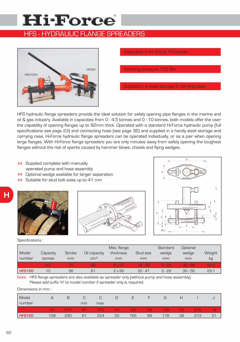
60
H
Capacities from 4.5 to 10 tonnes
Working pressure 700 Bar
Supplied in a steel storage & carrying case
HFS hydraulic flange spreaders provide the ideal solution for safely opening pipe flanges in the marine and oil & gas industry. Available in capacities from 0 - 4.5 tonnes and 0 - 10 tonnes, both models offer the user the capability of opening flanges up to 92mm thick. Operated with a standard Hi-Force hydraulic pump (full specifications see page 23) and connecting hose (see page 36) and supplied in a handy steel storage and carrying case, Hi-Force hydraulic flange spreaders can be operated individually, or as a pair when opening large flanges. With Hi-Force flange spreaders you are only minutes away from safely opening the toughest flanges without the risk of sparks caused by hammer blows, chisels and flying wedges.
Supplied complete with manuallyoperated pump and hose assemblyOptional wedge available for larger separationSuitable for stud bolt sizes up to 41 mm
HFS100H
HFS50
Modelnumber
Dimensions in mm :
Modelnumber
HFS50
Specifications :
A
B
C
D
E
H
G
F
J I
Capacitytonnes
Strokemm
Oil capacitycm³
thicknessmm
Max. flangeStud size
mmwedge
mm
Standardwedge
mm
Optional
HFS100
4.5
10
75
56
48
81
2 x 57
2 x 92
19 - 29
32 - 41
3 - 29
3 - 29
30 - 56
30 - 56
HFS50
HFS100
A B C C D E F G H I Jmin max
76
108
210
290
61
61
155
224
10
30
192
165
69
89
129
178
25
38
206
273
18
31
Weightkg
22.5
29.1
HFS - HYDRAULIC FLANGE SPREADERS
HFS flange spreaders are also available as spreader only (without pump and hose assembly).Please add suffix ‘H’ to model number if spreader only is required.
Note:

H
61
Modelnumber
Suitable for bolt diameters up to 31mm
Maximum spread 231mm
No external power source required
The MFS range of mechanical flange spreaders comprises of 6 models, each offering a safe and economical way to open flanges without the risk of sparks. The threaded spindle can be operated using a standard spanner, allowing the user to apply a controlled force without damaging the flange. Due to the mechanical design of these flange spreaders, no external power source is needed and therefore, they can be used anywhere on-site.
Choice of six models availableDrop forged EN9 spreading wedgeHigh grade steel construction with high tensile cross bolt
MFS16
MFS19
MFS22
MFS25
MFS28
MFS31
Maximum bolt diameter Maximum spread
MFS31
MFS16
MFS25
mm
16
19
22
25
28
31
mm
70
95
124
155
181
231
Weightkg
2.2
2.7
4.1
6.4
8.2
9.6
inch5
8/ ”3
4/ ”7
8/ ”
11
8/ ”11
4/ ”1
inch
34/ ”3
34/ ”2
78/ ”4
18/ ”6
18/ ”7
18/ ”9
Modelnumber
MFS16
MFS19
MFS22
MFS25
MFS28
MFS31
A C DB E F G HCmax. max.min.
25
30
30
30
30
32
28
50
50
85
80
84
185
185
247
247
275
275
232
254
318
353
382
385
65
65
80
80
90
90
40
50
50
50
60
60
25
25
30
30
40
40
30
30
36
36
46
46
66
81
97
113
130
157
A
B
C
DE
F
H
Spread
G
MFS - MECHANICAL FLANGE SPREADERS

62
H
Capacities up to 0.9 tonnes
Working pressure 700 Bar
Maximum spread 292mm
The JS range of hydraulic spreaders offers the ideal solution for spreading, wedging and prising operations in a wide variety of industrial applications. With a choice of two models available, Hi-Force hydraulic jaw spreaders are of compact, low weight, spring assisted return design and operate within a minimum space of 9.7mm up to a maximum spread of 292mm. With a powerful spreading capacity of up to 0.9 tonnes available, Hi-Force hydraulic jaw spreaders are ideal for use in applications where maximum force is required in a confined space. All models are manufactured from high-strength steel, are suitable for operating at 700 bar working pressure and are supplied complete with quick release female half coupling for easy attachment to a Hi-Force manually operated or powered hydraulic pump unit.
Modelnumber
JS4
JS15
Choice of three modelsSingle acting, spring assisted returnCompact & lightweight design
JS4 JS15A
E
C
A
E C
Capacitytonnes
Dimensions in mm
0.90
0.68
Oil capacitycm³
10.0
64.1
Weightkg
2.2
11.3
A
223
550
C
9.7
32.0
F
-
-
JS15
JS4
B
-
-
D
-
-
E
94
292
JS - HYDRAULIC SPREADERS

H
63
Modelnumber
HPB1020
HPB1020F
HPB1026
HPB1026F
HPB1030
HPB1036
Dimensions in mm
Capacity 10 tonnes
Stroke lengths from 150 to 250mm
Working pressure 700 Bar
The HPB range of hydraulic bench presses offers 6 models available with a choice of manually operated hand or foot pumps or air powered foot pumps. The compact design enables easy positioning of the press frame on a workshop bench and the easily detachable hydraulic components, make these presses an extremely versatile hydraulic tool. Also suitable for mounting in small vehicles for on-site testing applications.
HPB1020
Choice of 6 models with manually operatedor air powered pumpsDetachable hydraulics for use in otherapplicationsHorizontally adjustable cylinder blockVertical or horizontal operationSupplied complete with pump, hose, gauge,gauge block and quick release couplers
See pages 64 - 65 for our comprehensive range of workshop floor presses up to 100 tonnes capacity
A
B
C
D
E
A B C D E
10
10
10
10
10
10
Capacitytonnes
Pumpmodel no.
Pumpoperation
Strokemm
Weightkg
250
250
150
150
250
150
HP110
HP227FP
HP110
HP227FP
AHP1120
AHP1120
hand operated
foot operated
hand operated
foot operated
air powered
air powered
78
83
77
82
78
77
675
675
675
675
675
675
545
545
545
545
545
545
478
478
478
478
478
478
394
394
394
394
394
394
280
280
280
280
280
280
HPB - BENCH PRESSES

64
H
Modelnumber
HPF1020
HPF1030
HPF2520
HPF2530
HPF2541
HPF2542
HPF2544
HPF5020S
HPF5020D
HPF5030S
HPF5030D
HPF5041S
HPF5041D
HPF5042S
HPF5042D
HPF5044S
HPF5044D
HPF10020
HPF10030
HPF10041
HPF10042
HPF10044
10
10
25
25
25
25
25
50
50
50
50
50
50
50
50
50
50
100
100
100
100
100
Capacitytonnes
250
250
250
250
250
250
250
330
330
330
330
330
330
330
330
330
330
330
330
330
330
330
Strokemm
Pumpoperation
Cylindermodel no. ¹
Cylinderprinciple
Weightkg95
85
145
138
160
160
160
470
500
505
505
505
481
512
518
518
518
1011
1029
1043
1043
1043
Pumpmodel no. ²
HP110
AHP1120
HP227
AHP1120
HEP103341
HEP103342
HEP207314
HP257
HP257D
AHP1121
AHP1141
HEP207311
HEP207411
HEP207312
HEP207412
HEP207314
HEP207414
HP235D
HAP21042
HEP207421
HEP207422
HEP207424
manual
air driven 7 bar
manual
air driven 7 bar
electric driven 110 V
electric driven 240 V
electric driven 415 V
manual
manual
air driven 7 bar
air driven 7 bar
electric driven 110 V
electric driven 110 V
electric driven 240 V
electric driven 240 V
electric driven 415 V
electric driven 415 V
manual
air driven 7 bar
electric driven 110 V
electric driven 240 V
electric driven 415 V
HSS1010
HSS1010
HSS2510
HSS2510
HSS2510
HSS2510
HSS2510
HSS5013
HDA5013
HSS5013
HDA5013
HSS5013
HDA5013
HSS5013
HDA5013
HSS5013
HDA5013
HDA10013
HDA10013
HDA10013
HDA10013
HDA10013
single acting
single acting
single acting
single acting
single acting
single acting
single acting
single acting
double acting
single acting
double acting
single acting
double acting
single acting
double acting
single acting
double acting
double acting
double acting
double acting
double acting
double acting
Notes: ¹) For detailed specification on applicable cylinders, see pages 12-13 for HSS range and page 16 for HDA range.²) For detailed specification on applicable pumps, see page 23 for HP range, page 25 for HEP range, page 29 for AHP range and page 30 for HAP range.
Capacities from 10 to 100 tonnes
Stroke length 250 or 330mm
Working pressure 700 Bar
Choice of manual, air or electric powered pumpsAdjustable work tableSupplied complete with pressure gaugeOther configurations available on request
For further product details, frame dimensions and optional available accessories, please see opposite page
HPF - WORKSHOP FLOOR PRESSES
HPF10042

H
65
Modelnumber
HPF1000
HPF2500
Frame dimensions in mm
The HPF range of workshop presses offers a choice of 22 models with either single acting or double acting cylinders and manually operated, air powered or electric powered pumps. All presses incorporate an adjustable work table and dual scale pressure gauge. Factory mounted optional accessories include a mechanical bed winch for easy adjustment of the work table and multi-position V-blocks. All presses are supplied completely assembled, ready for use. Hi-Force workshop presses are manu-factured to the highest quality standards, and are suitable for the most demanding jobs.
HPF5000
Capacitytonnes
10
25
50
100HPF10000
A
742
742
1000
1000
C
508
508
800
1000
J
660
660
1000
1240
H
152
152
298
388
G
-
-
258
338
D (max)
1560
1370
E(max)
1010
1010
815
830
F
E
G
HB
AD
C
Mechanical bed winches
Multi-position V-blocks
Factory fitted optionLifts and lowers work tableAvailable for 50 and 100 tonnes presses
With flat bed and V-shape press surfacesAvailable for 10, 25, 50 and 100 tonnes presses
Modelnumber
HBW50
HBW100
Applicable for
All Hi-Force 50 tonnes workshop presses, HPF range
All Hi-Force 100 tonnes workshop presses, HPF range
Modelnumber
HVB2500
HVB5000
HVB10000
Cap. per settonnes
10 - 25
50
100
Dimensions in mmA B C D E F G H
204
365
425
154
265
325
20
25
35
45
50
60
155
190
265
45
60
85
20
25
35
8
10
10
HPF - WORKSHOP FLOOR PRESSES
A
C
D
B
E
F
G
H
J
B
1448
1448
2055
1980
D (min)
1258
1258
1140
1090
E(min)
260
260
395
550
F
150
150
140
140
Note: Press bed and press head are adjustable in steps of ‘F’,50 tonne has 4 positions, 100 tonne has 3 positions.10 and 25 tonne press frame has fixed press head and adjustable press bed.

66
H
Modelnumber
RSM6
RSM9
RSM12
RSM20
RSM30
Dimensions in mm
Capacities from 6 to 30 tonnes
Steerable front skate for total control
Low weight, compact size
The RSM nylon multi-roller steerable skate range is ideal for use on tiled floors and is available with capacities from 6 to 30 tonnes. These skates consist of 3 major parts: 1 steerable turntable front skate and 2 adjustable rear skates. This modular design allows the system to be easily assembled and dismantled without the use of tools. All models are fitted with low rolling resistance wheels with ball bearings and non-slip Neoprene pads on each load surface.
RSM6 - RSM9
A
DC
G
F
E
H
B
I
RSM12 - RSM20 - RSM30AD
CE
I
B
G
H
Capacity perskate settonnes
Weightincl. box
kg
6
9
12
20
30
A
330
330
413
413
413
B
210
310
614
673
990
C
109
109
110
110
110
I
1150
1150
1500
1500
1500
Hmax
1500
1500
1500
1500
1500
G
210
310
130
242
354
F
110
160
-
-
-
E
240
240
180
180
188
D
110
160
190
190
190
No. of wheelsfront
steerable
4 no. 82 mm x 48 mm
8 no. 82 mm x 48 mm
8 no. 82 mm x 48 mm
16 no. 82 mm x 48 mm
24 no. 82 mm x 48 mm
No. of wheelsrearskate
8 no. 82 mm x 48 mm
16 no. 82 mm x 48 mm
8 no. 82 mm x 48 mm
16 no. 82 mm x 48 mm
24 no. 82 mm x 48 mm
51
64
95
118
135
RSM12
RSM - NYLON MULTI-ROLLER STEERABLE SKATES

H
67
Capacities from 5 to 100 tonnes
Available as complete kit or as individual skates
Endless hardened roller chain
The RSC and RSS range of industrial, low profile skates offer the safest, fastest and most economical method of moving heavy equipment. Four models are available with capacities of up to 37.5 tonnes per skate. Designed with an endless hardened roller chain which revolves around the skate. At least 5 rollers remain in contact with the floor at any one time, ensuring smooth travel even over cracked concrete floors. With a range of turntables, stabilisers, spacer bars and steering handles available, Hi-Force skates can move and position heavy and irregular shaped loads easily and more economically than other lifting devices. Hi-Force skates are also ideal for use in confined spaces. Typical applications include bridge building, oil rig installation, transformers, generators, turbines, heavy machinery and many others.
Modelnumber
RSC20
RSC50
Cap. per settonnes
20
50
Complete kits :
SkatesQty: 4
TurntablesQty: 2
StabilisersQty: 2
Spacer barsQty: 4
HandlesQty: 2
Wooden boxQty: 1
Weightkg
RSS20
RSS50
RT20
RT50
RS20
RS50
RB20
RB50
RH20
RH50
WB1
WB2
41
94
Modelnumber
RSS20
RSS50
Cap. per skatetonnes
5.0
12.5
Individual skate selection chart :
Weightkg
4.0
11.0
210
271
102
125
59
95
94
143
51
87
18
30
RSS100
RSS150
25.0
37.5
27.0
42.0
370
502
175
186
130
152
179
206
90
90
42
42
Length Width Height less t/table
Height incl. t/table
Rollerwidth
Rollerdia
Dimensions in mm
The RSH heavy duty range of moving skates are ideal for movement of heavy loads such as transformers, generators, turbines and machinery. Available with capacities ranging from 15 to 100 tonnes each skate.
Modelnumber
RSH15
RSH20
RSH40
RSH50
RSH65
RSH100
Capacitytonnes
15
20
40
50
65
100
Rollersin contact
5
4
4
6
4
6
Rollerstotal
15
13
13
17
13
17
Weightkg
9
12
19
29
51
92
Dimensions in mmA
210
220
270
320
380
530
B
100
113
130
140
168
182
C
175
190
210
220
270
300
D
18
24
30
30
42
50
E
51
60
68
68
76
86
F
6
10
10
10
19
19
G
13
14
14
18
19
19
H
76
87
104
115
145
165
I
14
14
18
18
22
22
J
140
155
175
180
220
240
K
150
150
190
240
280
410
RSC & RSS - MULTI-PURPOSE SKATES
RSH - HEAVY DUTY SKATES
Note : Turntables for RSS100 (RT100) and RSS150 (RT150) are available on request.
RSC20

68
H
Modelnumber
Dimensions in mm
Capacities from 40 to 400 tonnes
Heat treated load bearing centre plate
Heat treated, special chrome alloy chains
The REX heavy duty range of single roller moving skates incorporates a chain groove cut into the centre member of the skate, which helps to keep the chain running parallel with the body and is specially suited for moving loads over long distances. Available with capacities up to 200 tonnes each skate.The RSX range offers the same features, however has a double roller design, capable of transporting loads up to 400 tonnes per skate.
All models feature high quality, heat treated components and are supplied with 4 mounting bolt holes for easy attachment to the load.
Drawing shows the RSX double-roller design, with the guide groove for the chain. REX features single-roller with guide groove.
REX40
REX50
REX65
REX100
REX150
REX200
RSX80
RSX100
RSX130
RSX200
RSX300
RSX400
Capacitytonnes
40
50
65
100
150
200
80
100
130
200
300
400
Rollersin contact
4
6
4
6
9
13
2 x 4
2 x 6
2 x 4
2 x 6
2 x 9
2 x 13
Rollerstotal
13
17
13
17
23
31
2 x 13
2 x 17
2 x 13
2 x 17
2 x 23
2 x 31
Weightkg
20
29
52
93
162
266
36
57
96
175
305
485
REX Range - Single-roller design
RSX Range - Double-roller design
B
C
E
I
KA
DF
G
H
L
A
270
320
380
530
600
900
270
320
380
530
600
900
B
130
140
168
182
205
205
260
280
336
364
410
410
C
210
220
270
300
350
380
340
360
440
480
560
590
D
30
30
42
50
50
50
30
30
42
50
50
50
E
68
68
76
86
100
100
68
68
76
86
100
100
F
10
10
19
19
20
20
10
10
19
19
20
20
G
14
18
19
19
28
38
14
18
19
19
28
38
H
104
115
145
165
190
200
104
115
145
165
190
200
I
18
18
22
22
26
33
18
18
22
22
26
33
K
175
180
220
240
280
300
305
325
390
430
490
500
L
190
240
280
410
480
720
190
240
300
420
480
720
Side view REX and RSX models
REX65
RSX80
REX & RSX - HEAVY DUTY SKATES WITH GROOVED GUIDE
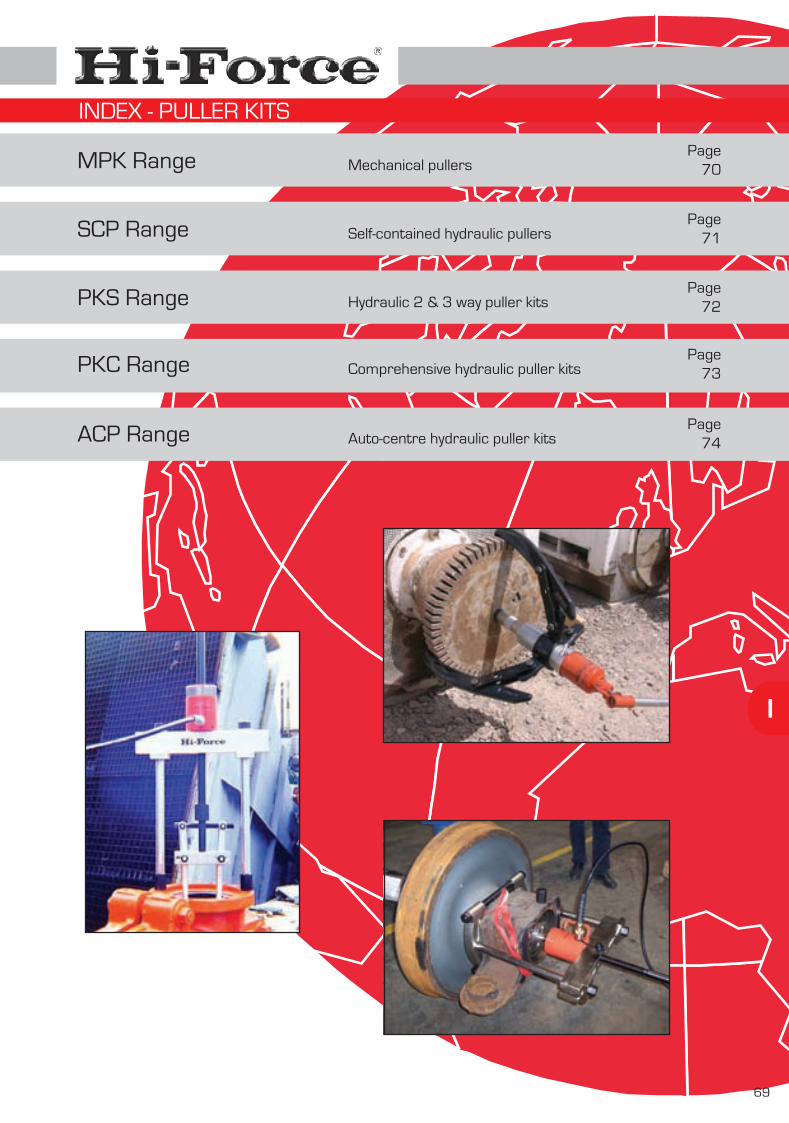
MPK Range
SCP Range
PKS Range
ACP Range
I
Mechanical pullers
Self-contained hydraulic pullers
Hydraulic 2 & 3 way puller kits
Auto-centre hydraulic puller kits
69
Page70
Page71
Page72
Page74
PKC Range Comprehensive hydraulic puller kitsPage
73
INDEX - PULLER KITS

70
I
2-WAY BEAM PULLERS
Modelnumber
Dimensions in mm
MPK104MPK103MPK102MPK101
MPK105MPK106
MPK108MPK107
MPK109MPK110
Type ofpuller
2-way beam2-way beam2-way beam2-way beam
2-way beam2-way beam
2-way beam2-way beam
2-way beam2-way beam
Weightkg
1.31.11.21.0
2.44.0
4.43.6
10.513.0
Reach
13580
13580
160220
220160
260260
Dia min
15151515
2525
6030
10530
Dia max
1251258080
150145
195195
250380
MPK106
Dia
Reac
h
COMBINATION BEAM EXTERNAL & INTERNAL PULLERS
Model Dimensions in mmType ofpuller
Weightkg
MPK402MPK401
combi beamcombi beam
6.02.7
Reach
182140
Dia max
250173
MPK401
Dia
Reac
h
2-JAW AND 3-JAW MINI PULLERS & COMBI-KIT
MPK509Modelnumber
Dimensions in mm
MPK504MPK503MPK502MPK501
Type ofpuller
3-way jaw2-way jaw3-way jaw2-way jaw
Weightkg
0.70.40.30.2
MPK509 MPK501 to MPK504 set 1.8
Reach
85855555
See individual components
Dia min
1001007070
Tip point
2.52.51.51.5
Tip height
6.06.04.54.5
Rea
ch
Dia
Tip pointTip height
MPK - MECHANICAL PULLERS
3-JAW AUTO-CENTRE PULLERS
Modelnumber
Dimensions in mmType ofpuller
Weightkg
MPK303
MPK301
3-way jaw
3-way jaw
5.1
1.9
Reach
235
105
Dia max
295
MPK302 3-way jaw 4.0150 230
130
MPK303
Reac
h
Dia
(Maximum extraction force : 4.6 tonnes)
(Maximum extraction force : 10.2 tonnes)
(Maximum extraction force : 10.2 tonnes)
number

I
71
Modelnumber
Dimensions in mm
Capacities from 10 to 30 tonnes
Sealed hydraulic system
Operates in any position
The SCP range of self-contained hydraulic pullers is designed and manufactured to the highest industry standards and has proven to be an extremely versatile tool for a wide variety of applications, including removing press fitted parts, such as wheels, gears, sprockets, sleeves, pulleys and other similar items. The range offers 3 models, each with integral manually operated hydraulic pump and multi-position operating handle. The completely sealed hydraulic system of the SCP pullers enables use of the tool in any position and all models are easy to operate and provide an efficient solution for many pulling applications. Each unit is supplied with a safety cover, to prevent flying debris during pulling operation.
High quality, dropped forged steel componentsSafe & easy to use Quick set-up timeSupplied in handy transport and storage case
SCP103
SCP303
Capacitytonnes
10
20
30
SCP203
Type ofpuller
3-way jaw puller
3-way jaw puller
3-way jaw puller
Weightkg
11.6
23.7
50.0
Did you know .....
The Hi-Force hydraulic puller range offers pulling capacities up to 50 tonnes. Please see pages 72, 73 and 74 for additional hydraulic puller kits within the Hi-Force range.
Hydraulicstroke (mm)
82 - 130
82 - 180
110 - 260
Reach
195
275
405
Dia min.
30
50
100
Tip depth
22
29
38
Tip height
6
10
36
Dia max.
250
360
410
SCP103SCP203
SCP - SELF-CONTAINED HYDRAULIC PULLERS

72
I
Modelnumber
Dimensions in mm
Capacities from 4.5 to 50 tonnes
Quick set-up time, easy to use
High quality, drop forged steel components
The PKS heavy duty hydraulic puller range is designed for removing stubborn parts such as wheels, gears, sprockets, sleeves, pulleys and other similar items. The range offers a selection of 8 models with pulling capacities up to 50 tonnes. All models are supplied complete with a full set of versatile detachable hydraulic components. All models are fast, safe and easy to operate and avoid the need for heating and hammering.
Working pressure 700 barMulti-purpose hollow piston cylinder (excl. PKS5-2-3)Complete with all hydraulic components (pump, cylinder, hose, gauge, etc.)Supplied complete with carrying case
PKS5-2-3
A
B
C
D
Capacitytonnes
Type ofpuller
Weightkg
Cylindermodel no.
Pumpmodel no. A B C D
PKS5-2-3
PKS10-2-3
PKS20-2
PKS20-3
PKS30-2
PKS30-3
PKS50-2
PKS50-3
PK202
PK302
PK502
4.5
10
20
20
30
30
50
50
20
30
50
2 & 3 jaw
2 & 3 jaw
2 jaw
3 jaw
2 jaw
3 jaw
2 jaw
3 jaw
2 jaw beam
2 jaw beam
2 jaw beam
HSS53
HHS102
HHS202
HHS202
HHS302
HHS302
HHS603
HHS603
*
*
*
HP145
HP110
HP110
HP110
HP110
HP110
HP227
HP227
*
*
*
18
19
29
34
49
58
105
130
3
4
7
225
296
320
*407
*727
*
*
*
*
240
350
480
*580
*920
*
*
*
*
225
296
*320
*
407
*727
*
*
*
240
350
*480
*
580
*920
*
*
*Note: PK202, PK302 & PK502 are 2-jaw beam only (not complete kit). * = not applicable. Dimensions calculated with 15° outward angled puller legs.
PKS - HYDRAULIC 2 & 3 WAY PULLER KITS
PKS30-3

I
73
Modelnumber
PKC10
PKC20
PKC30
PKC50
Dimensions in mm
Capacities from 10 to 50 tonnes
Combination of 4 different pullers in one set
Quick set-up time, easy to use
The PKC heavy duty, multi-purpose hydraulic puller kit range is extremely versatile and includes 2-way and 3-way grip pullers (as detailed on page 72), bearing pullers, bearing cup pullers and cross head pullers. All models are designed for pulling, pushing, installing and removing all press fitted or heat fitted parts such as gears, bearings, sleeves, cogs, internal bearings, wheels, sprockets, flywheels, etc. The range offers a selection of 4 models with pulling capacities up to 50 tonnes, all supplied complete with a full set of versatile, detachable hydraulic components.
Working pressure 700 BarComplete hydraulic system supplied, including gaugeHigh quality, drop-forged steel componentsSupplied complete with carrying case
PKC30
A
B
C
D
E
F
G
HI
Dimensions A, B, C & D calculated with 15° outward angled puller legs.
Capacitytonnes
10
20
30
50
Cylindermodel no.
HHS102
HHS202
HHS302
HHS603
Pumpmodel no.
HP110
HP110
HP110
HP227
Weightkg
25
60
116
268
A
Reach
220
205
363
422
B
Dia
300
408
660
915
C
Reach
200
305
528
732
D
Dia
475
508
865
1118
E
Min
115
135
200
230
E
Max
250
325
413
546
F
110
152
260
300
G
Min
10
13
35
31
G
Max
105
130
250
330
H
115
135
148
147
I
Min
38
38
38
76
I
Max
153
153
180
230
PKC - COMPREHENSIVE HYDRAULIC PULLER KITS

74
I
Modelnumber
Dimensions in mm
Capacities from 10 to 50 tonnes
Quick set-up time, easy to use
High quality, drop forged steel components
The ACP heavy duty, auto-centering hydraulic puller kit range offers a choice of 4 models, with capacities from 10 to 50 tonnes. The three legs of these pullers are linked together by a self centering system, ensuring that all puller legs move simultaneously, ensuring equal alignment from the centre-point. The 20 to 50 tonne versions are 3 way pullers, whereas the 10 tonne unit includes a combination of both 2-way and 3-way puller design. All models are supplied complete with a detachable hollow ram cylinder, manually operated pump, hydraulic hose and a 100mm diameter pressure gauge. These models are easy to set up and are the ideal tool for all pulling, pushing, installing and removing applications required for press fitted or heat fitted parts, including wheels, sprockets, flywheels, gears and bearings.
A B
ACP10
ACP20
ACP30
ACP50
Capacitytonnes
10
20
30
50
Type ofpuller
2 & 3 jaw
3 jaw
3 jaw
3 jaw
Cylindermodel no.
HHS102
HHS202
HHS302
HHS603
Pumpmodel no.
HP110
HP110
HP110
HP227
Weightkg
24.5
44.0
76.5
181.0
296 350
320
407
727
480
580
920
ACP10
Working pressure 700 barAuto-centering puller legsMulti-purpose hollow piston cylinder Automatic central alignment of the hydraulic cylinderComplete with all hydraulic components, includingmanually operated pump, hollow piston cylinder, hoseand 100mm pressure gauge and gauge block.Supplied complete with carrying case
ACP hydraulic pullers can be operated by powered pumps if required. Please see pages 21 to 32 for our full range of manually operated and powered hydraulic pump units. B
A
ACP - AUTO-CENTRE HYDRAULIC PULLER KITS
picture on the left is showing the auto-centre puller including hollow ram hydraulic cylinder. All ACP puller kits are supplied complete with manually operated pump, 2 metre hose with coupling, gauge, gauge block and carrying case.
Note:

HT & SLT Range
HDT Range
SP & PT Range
TWS-N Range
TWH-N Range
TWH-NRH Range
IB & MB Range
HTWP Range
IW Range
Accessories
J
Manual torque multipliers
Manual torque multipliers - heavy duty
Pneumatic torque multipliers
Hydraulic torque wrenches - square drive
Hydraulic torque wrenches - hexagon drive
Ratchet heads for TWH-N range wrenches
Imperial & metric hexagon reducer bushes
Torque wrench pumps & Accessories
Pneumatic impact wrenches
75
High quality accessories
HTW Range Manual torque wrenchesPage
76
Page77
Page78
Page80
Page81
Page84
Page85
Pages87 - 88
Page89
Page90
IS & MS Range Imperial & metric impact socketsPages
82 - 83
SDC Range Square drive conversion kitsPage
86
Page90
PG Range Pistol grip pneumatic torque multipliersPage
79
INDEX - TORQUE TOOLS

76
J
Modelnumber
HTW200R
HTW330R
HTW400R
HTW500B
HTW800B
HTW1500B
HTW800B
HTW200R
HTW330R
HTW400R Capacities from 40 to 1500 Nm
Repeatable accuracy
Dual scale Nm & lbf. ft.
The HTW range of industrial manual torque wrenches offers 6 models with torque capacities from 40 to 1500 Nm (30 to 1000 lbf. ft) with square drive sizes from to . All models are designed and manufactured to meet or exceed the highest demands of industry and are supplied marked with a unique serial number and calibration certificate. All models are ideally suited for applications requiring a repeatable, accurate torquing of bolts and nuts. The push-through square drive allows the wrench to be used for torque control in both clockwise and anti-clockwise directions. The HTW-R models incorporate a soft feel grip and integrated locking mechanism to prevent accidental alteration of the torque setting during operation. The click system is activated immediately when the required torque is achieved. The HTW-B break-type models provide a large break angle, to improve the accuracy by reducing the possibility of over torquing. The cam control of the internal mechanism will ensure a controlled “break” which will not throw the operator off balance. All wrenches automatically reset when the hand pressure is released.
Torque rangeNm
Torque rangelbf. ft
Lengthmm
Ratchet diamm
Weightkg
442
570
683
915
1140
1470
42
49
49
72
72
72
1.0
1.4
2.1
5.2
6.4
10.4
40
60
80
100
200
700
-
-
-
-
-
-
200
330
400
500
800
1500
30
45
60
70
150
500
-
-
-
-
-
-
150
220
300
350
600
1000
Squaredrive1
2/ ”1
2/ ”3
4/ ”3
4/ ”3
4/ ”3
4/ ”
12/ ” 3
4/ ”
Heavy duty ratchet headAccuracy +/- 3% (HTW-R models)Accuracy +/- 4% (HTW-B models)Push-through square driveSupplied with calibration certificateComplete with carrying & storage case
Need a higher torque capacity .....
Please check our manual torque multipliers on pages 77 & 78. Alternatively see our pneumatic torque multipliers and hydraulic torque wrenches, as featured on pages 79 to 85.
HTW - MANUAL TORQUE WRENCHES
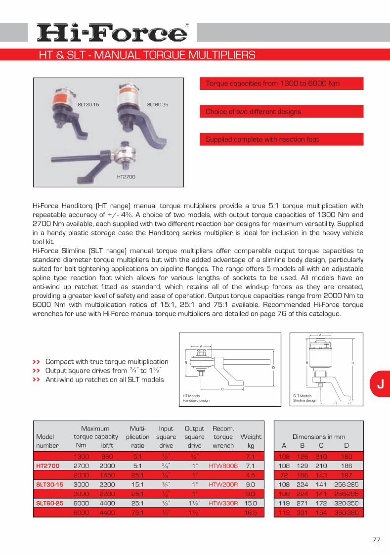
J
77
Modelnumber
Dimensions in mm
Torque capacities from 1300 to 6000 Nm
Choice of two different designs
Supplied complete with reaction foot
Hi-Force Handitorq (HT range) manual torque multipliers provide a true 5:1 torque multiplication with repeatable accuracy of +/- 4%. A choice of two models, with output torque capacities of 1300 Nm and 2700 Nm available, each supplied with two different reaction bar designs for maximum versatility. Supplied in a handy plastic storage case the Handitorq series multiplier is ideal for inclusion in the heavy vehicle tool kit.Hi-Force Slimline (SLT range) manual torque multipliers offer comparable output torque capacities to standard diameter torque multipliers but with the added advantage of a slimline body design, particularly suited for bolt tightening applications on pipeline flanges. The range offers 5 models all with an adjustable spline type reaction foot which allows for various lengths of sockets to be used. All models have an anti-wind up ratchet fitted as standard, which retains all of the wind-up forces as they are created, providing a greater level of safety and ease of operation. Output torque capacities range from 2000 Nm to 6000 Nm with multiplication ratios of 15:1, 25:1 and 75:1 available. Recommended Hi-Force torque wrenches for use with Hi-Force manual torque multipliers are detailed on page 76 of this catalogue.
A
B
C
D
SLT ModelsSlimline design
A
B
C
D
HT ModelsHanditorq design
Compact with true torque multiplicationOutput square drives from to 1 Anti-wind up ratchet on all SLT models
34/ ” 1
2/ ”
Weightkg
torque capacityMaximum
SLT30-15 SLT60-25
HT2700
HT1300
HT2700
SLT20-25
SLT30-15
SLT30-25
SLT60-25
SLT60-75
7.1
7.1
4.5
9.0
9.0
15.0
16.5
torquewrench
Recom.
HTW330R
HTW800B
HTW200R
HTW200R
HTW200R
HTW330R
HTW200R
squaredrive
Output
1”
1”
1”
1”
squaredrive
Inputplication
ratio
Multi-
5:1
5:1
25:1
15:1
25:1
25:1
75:1
lbf.ft
960
2000
1450
2200
2200
4400
4400
Nm
1300
2700
2000
3000
3000
6000
6000
108
108
72
108
108
119
119
A
126
129
166
224
224
271
301
B
210
210
143
141
141
172
154
C
180
186
197
256-285
256-285
320-350
350-380
D3
4/ ”
12/ ”1
12/ ”1
34/ ”
12/ ”
12/ ”
12/ ”
12/ ”
12/ ”
12/ ”
HT & SLT - MANUAL TORQUE MULTIPLIERS

78
J
Modelnumber
Dimensions in mm
Torque capacities from 1700 to 9500 Nm
Heavy duty design
Supplied complete with reaction foot
The Hi-Force HDT range of heavy duty manual torque multipliers are available in a choice of 6 models with output capacities from 1700 to 9500 Nm and multiplication ratios of 25:1 and 125:1. All models are fitted as standard with an anti-wind up ratchet, retaining all of the wind-up forces as they are created, providing a greater level of safety and ease of operation. Models HDT17-25 and HDT34-25 are fitted as standard with a flat type reaction foot as pictured above. All other models feature a box type reaction foot as per the detailed dimensional drawing (shown below). Flat, modified or special reaction plates can be designed and supplied on request.
Compact with true torque multiplicationOutput square drives from 1” to 1 Anti-wind up ratchet on all models
12/ ”
HDT17-25
HDT34-25
HDT60-25
HDT60-125
HDT95-25
HDT95-125
Weightkg
7.8
10.1
17.0
18.5
25.7
27.2
torquewrench
Recom.
HTW200R
HTW200R
HTW330R
HTW200R
HTW400R
HTW200R
tionratio
Multiplica-
25:1
25:1
25:1
125:1
25:1
125:1
torque capacityMaximum
lbf.ft
1250
2500
4400
4400
7000
7000
Nm
1700
3400
6000
6000
9500
9500
108
119
144
144
184
184
A
156
187
226
240
209
234
B
83-217
86-264
146-333
146-333
171-351
171-351
Csquaredrive
Input
34/ ”
12/ ”
12/ ”
12/ ”
12/ ”
12/ ”
HDT34-25
HDT - Shown withbox type reaction foot
A
B
C
squaredrive
Output
1”
1”
12/ ”1
12/ ”1
12/ ”1
12/ ”1
See page 76 for detailed specifications of the recommended Hi-Force manual torque wrenches for use with HDT multipliers.
HDT - HEAVY DUTY MANUAL TORQUE MULTIPLIERS

J
79
Modelnumber
Dimensions in mm
Torque capacities from 90 to 2000 Nm
Repeatable accuracy of +/- 5%
Choice of 5 models
The PG pistol grip pneumatic torque mulitiplier range is designed to provide smooth bolt tightening without impacting or pulsing. Offering a repeatable torque accuracy of +/- 5% these low noise level tools reduce operator fatigue, increase safety and ensure fast, accurate tightening of bolted components. Incorporating a powerful, reversible air motor suitable for tightening and loosening operations, the non-impacting design of the planetary gears ensures minimum wear to sockets and bolted components. All models are supplied complete with an airline pressure and lubrication control unit in a handy carrying frame and a 3 metre length connecting hose. Accurate preset torque can easily be achieved by adjusting the airline input pressure in conjunction with the calibration graph supplied with each tool. Air consumption is 11 litres per second from a standard airline pressure of 5 bar (23 cubic feet per minute @ 70 PSI).
Slim 72mm diameter gear box allows excellent accessSensitive trigger control allows for easy reaction plate positioningSmooth, quiet, non-impacting design with reversible air motorWide range of attachments and accessories availableTwo speed models available on request
A
B
C
D
PG500
PG1075
PG1000
PG1500
PG2000
Torque capacityNm
90-500
190-1000
190-1000
300-1500
400-2000
lbf.ft
66-370
140-740
140-740
220-1100
300-1450
Squaredrive size
1”
1”
1”
34/ ”
34/ ”
R.P.M. at max pressure
35
15
15
9
6
Weightkg
8.1
8.1
8.1
8.1
8.1
A
72
72
72
72
72
B
301
301
301
301
301
C
223
223
223
223
223
D
334
334
334
334
334
PG - PISTOL GRIP PNEUMATIC TORQUE MULTIPLIERS
PG1500

80
J
Torque capacities up to 47000 Nm
Smooth, quiet, non-impacting design
Repeatable accuracy of +/- 5%
The SP & PT pneumatic torque multiplier range offers a choice of 10 models, suitable for almost every bolting application and are supplied with an airline pressure and lubrication control unit. Maximum torque output capacities range from 680 to 47000 Nm with a choice of square drives from to . As with all Hi-Force pneumatic torque multipliers a repeatable, accurate torque of +/- 5% can be easily achieved using the calibration graph supplied with each tool. Both SP models are designed with a reduced body diameter, particularly suited where a limitation of space exists and are fitted with an adjustable spline type reaction foot which allows for use with various length sockets. The PT models are supplied with a flat type reaction plate, with the exception of the PT6000 and PT9500 which incorporate a box type reaction foot. Optional special designed reaction plates can be supplied on request. The smooth and continuous torque output of Hi-Force pneumatic torque multipliers make them suitable for a wide range of bolting applications including wheel nuts on trucks and large machinery, structural steelwork, high pressure joints e.g. pipelines, boiler feed pumps and pressure vessels, heat exchangers and many other applications.
Powerful reversible air motor with safety triggerAdjustable spline type reaction foot (SP models only)Wide range of attachments and accessories availableTwo speed models available on request
SP2700
A
B
C
D
A
B
D
SP PT
Modelnumber
Dimensions in mm
SP2700
SP5500
PT1200
PT1700
Torque capacity
PT3400
PT6000
PT9500
PT17000
PT47000
Nm
880-2700
1200-5500
270-1200
515-1700
880-3400
1762-6000
2710-9500
4400-17000
13550-47000
lbf.ft
650-2000
885-4060
200-900
380-1250
650-2500
1300-4500
2000-7000
3250-12500
10000-35000
R.P.M. at max pressure
5.0
2.5
15.0
9.0
5.0
2.5
1.8
1.2
0.3
Weightkg
16.5
21.9
13.3
13.3
16.5
26.0
32.7
51.9
109.1
A
108
119
108
108
119
144
184
212
315
B
437
512
373
373
423
457
452
546
629
C
140
172
-
-
-
-
-
-
-
D max
498
592
217
217
264
333
351
500
Blank plate
D min
469
566
83
83
86
146
169
34/ ” 1
2/ ”2
Squaredrive size
1”
1”
112/ ”
1”
PT680 - ¾ 160-680 120-500 30.0 12.8 108 368 - 2178334/ ”
1”
112/ ”
112/ ”
212/ ”
212/ ”
SP & PT - PNEUMATIC TORQUE MULTIPLIERS
PT680 - 1 160-680 120-500 30.0 12.8 108 368 - 217831”

J
81
Compact, lightweight, aluminium construction
Working pressure 700 bar
Fitted with 360° Uni-Swivel quick release couplings
Allen Hex Drive
Optional allen hex driveadaptors are available in
metric and imperial sizes.Further details on request.
Accurate to +/- 3% with calibration chart supplied
Multi-position reaction foot with safety lock feature
Reversible square drive for tightening and loosening applications
Suitable for continuous operation at maximum pressure
Body shroud engraved with torque/pressure chart
TWS370
TWS150N
TWS45N
H1
H2L2
H3
H4
L1
R
Hi-Force TWS-N series lightweight aluminium hydraulic torque wrenches are designed to handle the toughest bolting jobs accurately and quickly. All models provide a torque accuracy of +/- 3% with a handy torque chart clearly engraved on the tool. The internal reaction arm spline allows the operator to easily position the tool and, if necessary, react directly off the tool body in very confined access applications. All models incorporate an easily reversible high grade alloy steel square drive enabling the operator to quickly switch from tightening to loosening applications. Uni-Swivel quick release couplers are fitted as standard to all models enabling easy positioning of the hydraulic hoses away from any possible “pinch points”. Optional allen hex drives are available (see below) along with a comprehensive range of high quality torque wrench sockets (see pages 82 - 83).
Dimensions in mmModelnumber Nm Ibf .ft
TWS45N 3320 162 68 122 34
TWS17N 1254 127 51 90 25
TWS100N 7375 222 92 163 46
TWS370N 27290 329 137 240 66
TWS150N
4500
1700
10000
37000
15000 11063
1"
3/4"
1 1/2"
2 1/2"
1 1/2" 246 100 177 50
4.8
1.9
9.0
32.5
14.8
213
167
292
431
322
95
73
132
200
138
170
124
211
289
226
L1 H1 H3 RL2 H2 H4
Torque capacity(nominal) Square drive
size
Weight incl.reaction foot
kg
TWS-N - HYDRAULIC TORQUE WRENCHES - SQUARE DRIVE
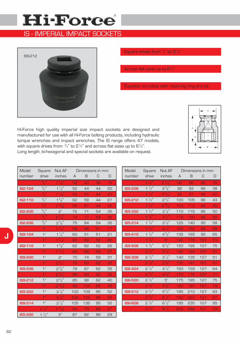
82
J
Modelnumber
Square drives from to
Across flat sizes up to
12/”23
4/”
78/”6
Hi-Force high quality imperial size impact sockets are designed and manufactured for use with all Hi-Force bolting products, including hydraulic torque wrenches and impact wrenches. The IS range offers 47 models, with square drives from to and across flat sizes up to . Long length, bi-hexagonal and special sockets are available on request.
34/” 1
2/”2 78/”6
A
B
C
D
Dimensions in mmB C DA
Modelnumber
Dimensions in mmB C DA
IS2-101
IS2-104
IS2-107
IS2-110
IS2-113
IS2-200
IS2-203
IS2-206
IS9-101
IS9-104
IS9-107
IS9-110
IS9-113
IS9-200
IS9-203
IS9-206
IS9-209
IS9-212
IS9-215
IS9-302
IS9-308
IS9-314
IS5-113
IS5-200
IS5-203
IS5-206
IS5-209
IS5-212
IS5-215
IS5-302
IS5-308
IS5-314
IS5-404
IS5-410
IS5-500
IS5-506
Squaredrive
34/”
34/”
34/”
34/”
34/”
34/”
34/”
34/”
1”
1”
1”
1”
1”
1”
1”
1”
1”
1”
1”
1”
1”
1”1
2/”11
2/”1
52
52
56
62
68
72
74
75
58
60
62
62
64
70
72
78
80
85
95
100
105
105
84
87
40
44
51
58
67
71
77
84
44
51
56
62
68
74
80
87
93
98
104
109
125
136
76
82
38
44
44
44
44
54
54
54
51
51
52
52
58
58
62
62
62
62
86
86
86
95
86
86
16
20
23
27
32
35
35
35
17
21
26
26
27
31
32
35
36
40
48
52
52
52
27
29
90
92
95
100
103
110
118
125
125
135
140
150
86
93
97
105
110
116
130
140
150
165
179
195
86
86
86
86
86
86
86
95
95
95
127
127
36
38
40
43
45
50
55
58
58
65
70
75
Squaredrive
12/”1
12/”1
12/”1
12/”1
12/”1
12/”1
12/”1
12/”1
12/”1
12/”1
12/”1
12/”1
Nut AFinches
116/ ”1
14/”1
716/ ”1
58/”1
1316/ ”1
2”3
16/ ”23
8/”21
16/ ”11
4/”17
16/ ”15
8/”113
16/ ”1
2”3
16/ ”23
8/”29
16/ ”23
4/”215
16/ ”21
8/”31
2/”37
8/”313
16/ ”1
2”
Nut AFinches
316/ ”2
38/”2
916/ ”2
34/”2
1516/ ”2
18/”3
12/”3
78/”3
14/”4
58/”4
5”3
8/”5
IS6-302
IS6-308
IS6-314
IS6-404
IS6-410
IS6-500
IS6-506
IS6-512
IS6-602
IS6-608
IS6-614
140
140
150
160
170
175
180
185
190
195
200
124
135
147
159
172
185
197
210
223
235
248
127
127
127
127
127
127
127
127
127
127
127
51
51
57
64
71
75
79
83
91
95
105
12/”2
12/”2
12/”2
12/”2
12/”2
12/”2
12/”2
12/”2
12/”2
12/”2
12/”2
18/”3
12/”3
78/”3
14/”4
58/”4
5”3
8/”53
4/”51
8/”61
2/”67
8/”6
IS9-212
Supplied complete with retaining ring and pin
IS - IMPERIAL IMPACT SOCKETS

J
83
Modelnumber
12/”23
4/”
Hi-Force high quality metric size impact sockets are designed and manufactured for use with all Hi-Force bolting products, including hydraulic torque wrenches and impact wrenches. The MS range offers 53 models, with square drives from to and across flat sizes up to 145mm. Long length, bi-hexagonal and special sockets are available on request.
34/” 1
2/”2
Square drives from to
Across flat sizes up to 145mm
A
B
C
D
Dimensions in mmB C DA
Modelnumber
Dimensions in mmB C DA
MS2-24
MS2-27
MS2-30
MS2-36
MS2-41
MS2-46
MS2-50
MS2-55
MS2-60
MS9-24
MS9-27
MS9-30
MS9-36
MS9-41
MS9-46
MS9-50
MS9-55
MS9-60
MS9-65
MS9-70
MS9-75
MS9-80
MS9-85
MS9-90
MS5-41
MS5-46
MS5-50
MS5-55
MS5-60
MS5-65
MS5-70
MS5-75
MS5-80
MS5-85
MS5-90
MS5-95
MS5-100
MS5-105
MS5-110
MS5-115
MS5-130
MS6-80
MS6-85
MS6-90
MS6-95
MS6-100
MS6-105
MS6-110
Nut AFmm
MS9-95
MS9-100
50
54
54
56
58
63
72
74
75
58
58
60
65
67
74
80
84
87
90
96
98
100
105
105
115
115
MS6-115
MS6-130
MS6-145
84
87
90
92
95
100
103
110
118
118
118
125
125
125
135
140
140
140
145
145
150
155
160
165
175
185
80
46
50
55
60
65
70
75
80
85
90
95
100
105
110
115
130
80
85
90
95
100
105
110
115
130
145
41
27
29
36
38
40
43
45
50
55
55
55
58
58
58
65
70
51
51
54
54
57
61
64
67
75
83
26
86
86
86
86
86
86
86
86
86
86
95
95
95
95
95
127
127
127
127
127
127
127
127
127
127
127
86
76
81
86
93
97
105
110
116
125
130
137
140
150
156
160
185
124
130
136
143
149
155
161
167
188
208
70
Nut AFmm
24
27
30
36
41
46
50
55
60
24
27
30
36
41
46
50
55
60
65
70
75
80
85
90
95
100
39
43
47
54
60
67
71
78
84
42
46
50
56
63
69
74
80
86
92
99
106
112
118
125
131
137
44
44
44
44
44
44
54
54
54
54
54
54
54
54
54
54
54
54
54
54
86
86
86
86
86
95
16
16
23
23
24
30
32
35
37
17
17
21
30
31
36
42
44
44
46
51
45
48
52
52
52
58
Squaredrive
34/”
34/”
34/”
34/”
34/”
34/”
34/”
34/”
1”
1”
1”
1”
1”
1”
1”
1”
1”
1”
1”
1”
1”
34/”
1”
1”
1”
1”
Squaredrive
12/”1
12/”1
12/”1
12/”1
12/”1
12/”1
12/”1
12/”1
12/”1
12/”1
12/”1
12/”1
12/”1
12/”2
12/”2
12/”2
12/”2
12/”2
12/”2
12/”2
12/”2
12/”2
12/”2
12/”1
12/”1
12/”1
12/”1
MS9-70
Supplied complete with retaining ring and pin
MS - METRIC IMPACT SOCKETS

84
J
Working pressure 700 bar
Fitted with 360° x 360° Uni-Swivel couplings
Hi-Force TWH-N series female hexagon cassette head hydraulic torque wrenches offer a choice of 5 models, with output torque capacities from 2700 Nm to 48181 Nm (1990 to 35536 lbf.ft). Manufactured from high grade aluminium (except TWH430N), all models provide direct in-line reaction and a minimal radius clearance for easy fitment in confined spaces. The user friendly design of the tool simply requires the operator to withdraw/insert a single pin to change the ratchet head. Ratchet heads are available in all standard metric and imperial AF sizes from 24 to 145mm (1 ” to 6 ”) with low cost hexagon reducer bushes also available (see pages 87 - 88). Uni-Swivel quick release couplers are fitted as standard to all models, enabling easy positioning of the hydraulic hoses.
Torque capacity Hexagon AF size Dimensions in mm Modelnumber
min maxNm lbf. ftMetric Imperial
min - max
Powerful and low clearance design
Accurate to +/- 3% with standard torque chart supplied
Low profile design for limited access applications
Minimum radius cassette head for fitment in confined spaces
Suitable for continuous operation at maximum pressure
All Models
TWH27N, TWH54NTWH120N, TWH210N
TWH430N
L
H2H
1
D
H2H
1
L
DW2
W1
H2 W1 W2 DL H1
TWH27N
TWH54N
TWH120N
TWH210N
TWH430N
2700
5400
12000
23124
48181
3068
6037
14349
21000
43000
1990
3983
8850
17055
35536
2263
4453
10583
15489
31715
24
30
50
105
130
50
70
85
70
80
to
to
to
to
to
to
to
to
to
to
97
125
157
204
260
108
136
182
191
242
32
41
52
64
83
32
41
52
64
83
51
64
78
97
93
51
64
78
97
93
10 - 15
11 - 20
14 - 17
19 - 23
25 - 32
10 - 12
12 - 24
16 - 21
18 - 21
26 - 31
Approx.weight
kg3.0
6.0
11.5
16.0
28.0
3.0
6.0
11.516.0
28.0
193
250
310
378
425
193
250
310
378
405
125
158
189
236
309
136
169
214
223
291
46
65
115
145
60
80
100
115
80
100
(nominal)
Compact, lightweight, aluminium drive unit (except TWH430N)
min maxto
to
to
to
to
to
to
to
to
to
Note: Above selection table is for drive unit only. Ratchet head(s) to be ordered separately - see page 85. Exact weight & radius size (D) varies according to ratchet AF size selected.
5"
1 1/16"
2"
1 1/16"
2 3/4"
2 3/16"
3 1/2"
2 3/4"
4 1/4"
3 1/8"
113/16"
2 9/16"
3 1/8"
3 7/8"
3 7/8"
4 5/8"
4 5/8"
2 3/8"
3 1/8"
6 7/8 "
116/ 7
8/
(drive unit)
Note :Drawing shows drivecylinder, including ratchet head as detailed on page 85.
Drive cylinder and ratchet head are seperate items and must be ordered separately.
TWH210N
TWH210NRH Ratchet head(Order separately)
TWH-N - HYDRAULIC TORQUE WRENCH - DRIVE CYLINDERS
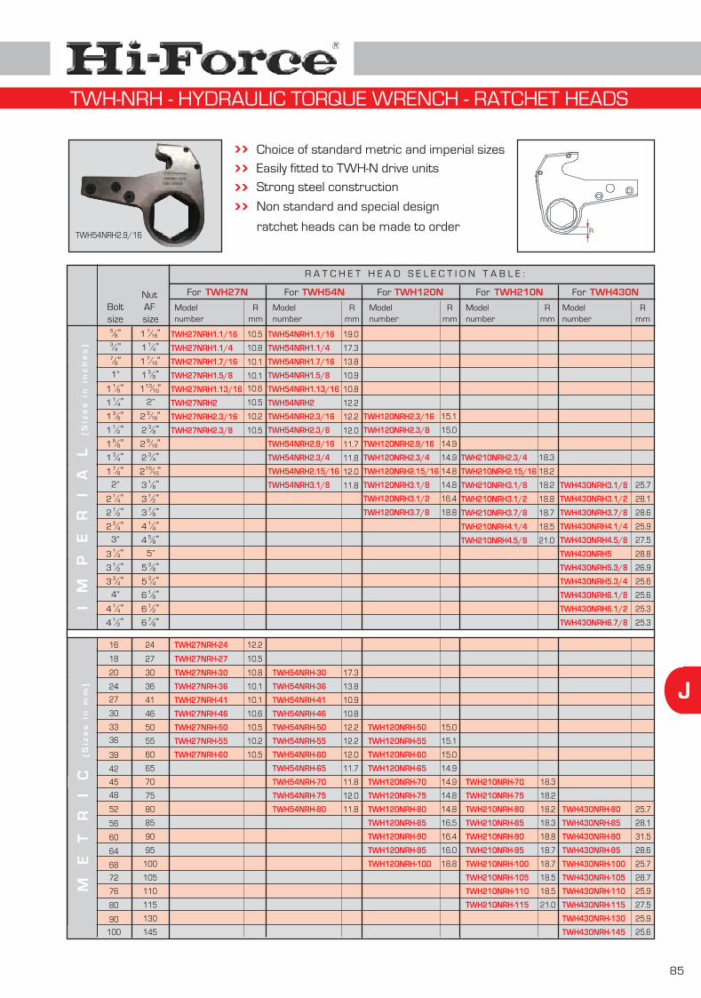
J
85
D
Choice of standard metric and imperial sizesEasily fitted to TWH-N drive unitsStrong steel construction
Non standard and special design
ratchet heads can be made to order
R A T C H E T H E A D S E L E C T I O N T A B L E :
Rmm
Modelnumber
15.1
15.0
14.9
14.9
14.8
14.8
18.8
TWH210NRH2.3/4
TWH210NRH3.1/8
TWH210NRH3.7/8
TWH210NRH4.1/4
TWH210NRH4.5/8
TWH27NFor TWH54NFor TWH120NFor TWH210NFor TWH430NFor
16.4 TWH210NRH3.1/2
52 80
56 85
14.8
16.5
TWH210NRH-80
TWH210NRH-85
48 75 14.8 TWH210NRH-75
45 70 14.9 TWH210NRH-70
42 65 14.9
39 60 15.0
36 55 15.1
33 50 15.0
30 46
60 90 16.4 TWH210NRH-90
68 100
64 95
Modelnumber
TWH120NRH2.3/16
TWH120NRH2.3/8
TWH120NRH2.9/16
TWH120NRH2.3/4
TWH120NRH3.1/8
TWH120NRH3.7/8
TWH120NRH3.1/2
TWH120NRH-80
TWH120NRH-85
TWH120NRH-75
TWH120NRH-70
TWH120NRH-65
TWH120NRH-60
TWH120NRH-55
TWH120NRH-50
TWH120NRH-90
TWH120NRH-95
TWH120NRH-100
16.0
18.8
TWH210NRH-95
TWH210NRH-100
72 105 TWH210NRH-105
76 110 TWH210NRH-110
80 115 TWH210NRH-115
Rmm
18.3
18.2
18.2
18.7
18.5
21.0
18.8
18.2
18.3
18.2
18.3
18.8
18.7
18.7
18.5
18.5
21.0
90 130
100 145
Modelnumber
TWH430NRH3.7/8
TWH430NRH4.1/4
TWH430NRH4.5/8
TWH430NRH5
TWH430NRH5.3/8
TWH430NRH3.1/8
TWH430NRH3.1/2
TWH430NRH5.3/4
TWH430NRH6.1/8
TWH430NRH6.1/2
TWH430NRH-80
TWH430NRH-85
TWH430NRH-90
TWH430NRH-95
TWH430NRH-100
TWH430NRH-105
TWH430NRH-110
TWH430NRH-115
TWH430NRH-130
TWH430NRH-145
Rmm
28.6
25.9
27.5
28.8
26.9
25.7
28.1
25.6
25.6
25.3
25.3
25.7
28.1
31.5
28.6
25.7
28.7
25.9
27.5
25.9
25.6
27 41
24 36
20 30
Modelnumber
TWH54NRH1.7/16
TWH54NRH1.5/8
TWH54NRH2
TWH54NRH2.3/16
TWH54NRH2.3/8
TWH54NRH2.9/16
TWH54NRH2.3/4
TWH54NRH3.1/8
TWH54NRH1.1/16
TWH54NRH1.1/4
TWH54NRH-80
TWH54NRH-75
TWH54NRH-70
TWH54NRH-65
TWH54NRH-60
TWH54NRH-55
TWH54NRH-50
TWH54NRH-46
TWH54NRH-41
TWH54NRH-36
TWH54NRH-30
Rmm
13.8
10.9
10.8
12.2
12.2
12.0
11.7
11.8
12.0
11.8
19.0
17.3
11.8
12.0
11.8
11.7
12.0
12.2
12.2
10.8
10.9
13.8
17.3
16 24
numberModel
TWH27NRH-60
TWH27NRH-55
TWH27NRH-50
TWH27NRH-46
TWH27NRH-41
TWH27NRH-36
TWH27NRH-30
TWH27NRH-24
Rmm
10.1
10.1
10.6
10.5
10.2
10.5
10.5
10.8
10.5
10.2
10.5
10.6
10.1
10.1
10.8
12.2
I M
P E
R I
A L
(S
ize
s i
n i
nc
he
s)
ME
TR
IC
(Siz
es
in
mm
)
Nut AF size
116/ ”1
14/”1
716/ ”1
58/”1
1316/ ”1
2”3
16/ ”23
8/”29
16/ ”23
4/”215
16/ ”21
8/”31
2/”37
8/”31
4/”45
8/”4
5”3
8/”53
4/”51
8/”61
2/”67
8/”6
Boltsize5
8/”3
4/”7
8/”1”1
8/”11
4/”13
8/”11
2/”15
8/”13
4/”17
8/”1
2”1
4/”21
2/”23
4/”2
3”1
4/”31
2/”33
4/”3
4”1
4/”41
2/”4
TWH27NRH1.7/16
TWH27NRH1.5/8
TWH27NRH2
TWH27NRH2.3/16
TWH27NRH2.3/8
TWH27NRH1.1/16
TWH27NRH1.1/4
TWH27NRH1.13/16 TWH54NRH1.13/16
TWH54NRH2.15/16 TWH120NRH2.15/16 TWH210NRH2.15/16
RTWH54NRH2.9/16
TWH-NRH - HYDRAULIC TORQUE WRENCH - RATCHET HEADS
TWH430NRH6.7/8
18 27 TWH27NRH-27 10.5

86
J
Suitable for TWH-N range up to 23124 Nm
Square drive sizes from 1” to 2½”
Easily fitted, no special tools needed
Hi-Force SDC square drive conversion kits, suitable for Hi-Force TWH-N hexagon drive hydraulic torque wrenches (see page 84) are available for all models, excluding TWH430N. All imperial and metric models are supplied complete with easily attachable reaction foot and a standard hexagon AF size, suitable for fitment to a commonly used size of ratchet head, per tool type (see table for more details). These SDC square drive conversion kits provide the most flexible and cost effective method of transforming a female hexagon drive hydraulic torque wrench into a square drive unit.
Supplied complete with reaction footEasily fittedMakes your hexagon drive torque wrench even more versatileFull range of impact sockets available (see pages 82 & 83) Flexibility ...
The combination of a Hi-Force drive unit, standard ratchet heads and square drive conversion kit gives the user maximum flexibility. Whether a low height or square drive unit is required, this combination provides it all !
Modelnumber
SDC27-M
SDC54-M
SDC120-M
SDC210-M
SDC27-I
SDC54-I
SDC120-I
SDC210-I
Squaredrive
1”
1½”
1½”
2½”
1”
1½”
1½”
2½”
Maximumtorque Nm
3068
6037
14349
23124
3068
6037
14349
23124
Maximumtorque lbf.ft
2263
4453
10583
17055
2263
4453
10583
17055
Suitable fordrive cylinder incl. ratchet head
TWH27N
TWH54N
TWH120N
TWH210N
TWH27N
TWH54N
TWH120N
TWH210N
Weightkg
1.1
3.0
4.4
9.1
1.1
3.0
4.4
9.1
HexagonAF Size
46mm
65mm
80mm
100mm
1316/ ”1
916/ ”2
18/”3
78/”3
TWH27NRH-46
TWH54NRH-65
TWH120NRH-80
TWH210NRH-100
TWH27NRH- 1316/ ”1
TWH54NRH- 916/ ”2
TWH120NRH- 18/”3
TWH210NRH- 78/”3
SDC - SQUARE DRIVE CONVERSION KITS FOR TWH-N WRENCHES
SDC54-M

J
87
To reduce the female hexagon AF size of the TWH-NRH ratchet heads (see page 85), these Hi-Force imperial hexagon reducer bushes offer an easy and economical solution. Just select your outside AF size (= ratchet head AF size) and the required inside AF size to determine the model number. Please note that wall thickness (specified below as ‘W’ dimension), must be added to the minimum radius dimension of your ratchet head, when using a reducer bush.
OutsideAF size
InsideAF size
For TWH27NRH For TWH54NRH For TWH120NRH For TWH210NRH For TWH430NRH
Model number Model number Model number Model number Model numberW mmW mm W mm W mm W mm
IB27-104-101IB27-107-101IB27-107-104IB27-110-104IB27-110-107IB27-113-107IB27-113-110IB27-200-110IB27-200-113IB27-203-110IB27-203-113IB27-203-200IB27-206-113IB27-206-200IB27-206-203
14/”1 1
16/ ”17
16/ ”1 116/ ”1
716/ ”1 1
4/”15
8/”15
8/”113
16/ ”113
16/ ”1
2”
2”3
16/ ”23
16/ ”23
16/ ”23
8/”23
8/”23
8/”29
16/ ”29
16/ ”29
16/ ”23
4/”23
4/”23
4/”215
16/ ”215
16/ ”215
16/ ”21
8/”31
8/”31
8/”31
2/”31
2/”37
8/”37
8/”31
4/”41
4/”45
8/”45
8/”4
5”
5”3
8/”53
8/”53
4/”53
4/”51
8/”61
8/”61
2/”61
2/”67
8/”67
8/”6
14/”1
716/ ”1
716/ ”1
58/”1
58/”1
58/”1
1316/ ”1
1316/ ”1
2”13
16/ ”1
2”3
16/ ”2
2”3
16/ ”23
8/”23
16/ ”23
8/”29
16/ ”23
8/”29
16/ ”23
4/”29
16/ ”23
4/”215
16/ ”215
16/ ”21
8/”31
8/”31
2/”31
2/”37
8/”37
8/”31
4/”41
4/”45
8/”45
8/”4
5”
5”3
8/”53
8/”53
4/”53
4/”51
8/”61
8/”61
2/”6
IB54-110-104IB54-110-107IB54-113-107IB54-113-110IB54-200-110IB54-200-113IB54-203-110IB54-203-113IB54-203-200IB54-206-113IB54-206-200IB54-206-203IB54-209-200IB54-209-203IB54-209-206IB54-212-203IB54-212-206IB54-212-209IB54-215-206IB54-215-209IB54-215-212IB54-302-209IB54-302-212IB54-302-215
IB430-308-302IB430-314-302IB430-314-308IB430-404-308IB430-404-314IB430-410-314IB430-410-404IB430-500-404IB430-500-410IB430-506-410IB430-506-500IB430-512-500IB430-512-506IB430-602-506IB430-602-512IB430-608-512IB430-608-602IB430-614-602IB430-614-608
IB120-206-203
IB120-209-203IB120-209-206IB120-212-203IB120-212-206IB120-212-209IB120-215-206IB120-215-209IB120-215-212IB120-302-209IB120-302-212IB120-302-215IB120-308-215IB120-308-302IB120-314-302IB120-314-308
IB210-215-212
IB210-302-212IB210-302-215IB210-308-215IB210-308-302IB210-314-302IB210-314-308IB210-404-308IB210-404-314IB210-410-314IB210-410-404
2.44.82.44.82.44.82.44.82.47.24.82.47.24.82.4
4.82.44.82.44.82.47.24.82.47.24.82.47.24.82.47.24.82.47.24.82.47.24.82.4
2.4
4.82.47.24.82.47.24.82.47.24.82.47.24.89.54.8
2.4
4.82.47.24.89.54.89.54.89.54.8
4.89.54.89.54.89.54.89.54.89.54.89.54.89.54.89.54.89.54.8
not available -
not available -
IB - IMPERIAL HEXAGON REDUCER BUSHES
IB54-206-113

88
J
OutsideAF size
InsideAF size
For TWH27NRH For TWH54NRH For TWH120NRH For TWH210NRH For TWH430NRH
Model number Model number Model number Model number Model numberW mmW mm W mm W mm W mm
To reduce the female hexagon AF size of the TWH-NRH ratchet heads (see page 85), these Hi-Force imperial hexagon reducer bushes offer an easy and economical solution. Just select your outside AF size (= ratchet head AF size) and the required inside AF size to determine the model number. Please note that wall thickness (specified below as ‘W’ dimension), must be added to the minimum radius dimension of your ratchet head, when using a reducer bush.
30364146465050555555606060656565707070757575808080858585909090959595
100100100105105105110110110115115115130130130145145145
243036364141464146504650555055605560656065706570757075807580858085908590959095
10095
100105100105110105110115110115130
MB27-30-24
MB27-60-55MB27-60-50MB27-60-46MB27-55-50MB27-55-46MB27-55-41MB27-50-46MB27-50-41MB27-46-41MB27-46-36MB27-41-36MB27-36-30
3.0
2.55.07.02.54.57.02.04.52.55.02.53.0
MB54-60-55MB54-60-50MB54-60-46MB54-55-50MB54-55-46MB54-55-41MB54-50-46MB54-50-41MB54-46-41MB54-46-36MB54-41-36MB54-36-30
MB54-65-50
MB54-80-75MB54-80-70MB54-80-65MB54-75-70MB54-75-65MB54-75-60MB54-70-65MB54-70-60MB54-70-55MB54-65-60MB54-65-55
3.0
7.52.55.07.02.54.57.02.04.52.55.02.5
5.0
2.55.07.52.55.07.52.55.07.52.5
MB120-60-55MB120-60-50
MB120-65-50
MB120-80-75MB120-80-70MB120-80-65MB120-75-70MB120-75-65MB120-75-60MB120-70-65MB120-70-60MB120-70-55MB120-65-60MB120-65-55
MB120-85-75MB120-85-70
MB120-85-80
MB120-100-95MB120-100-90MB120-100-85MB120-95-90MB120-95-85MB120-95-80MB120-90-85MB120-90-80MB120-90-75
7.52.55.0
5.0
2.55.07.52.55.07.52.55.07.52.5
2.55.07.5
7.5
2.55.07.52.55.07.52.55.0
2.55.0
2.5
2.55.07.5
7.5
2.55.07.52.55.07.52.55.0
7.55.0
2.55.07.52.55.07.52.5
2.5
2.55.07.52.55.07.52.55.0
7.55.0
2.55.07.52.55.07.52.5
7.515.017.57.5
10.012.5
MB210-80-75MB210-80-70
MB210-75-70
MB210-85-75MB210-85-70
MB210-85-80
MB210-100-95MB210-100-90MB210-100-85MB210-95-90MB210-95-85MB210-95-80MB210-90-85MB210-90-80MB210-90-75
MB210-105-90
MB210-115-110MB210-115-105MB210-115-100MB210-110-105MB210-110-100MB210-110-95MB210-105-100MB210-105-95
not available -
MB430-85-80
MB430-100-95MB430-100-90MB430-100-85MB430-95-90MB430-95-85MB430-95-80MB430-90-85MB430-90-80
MB430-105-90
MB430-115-110MB430-115-105MB430-115-100MB430-110-105MB430-110-100MB430-110-95MB430-105-100MB430-105-95
MB430-145-130MB430-145-115MB430-145-110MB430-130-115MB430-130-110MB430-130-105
not available -
MB - METRIC HEXAGON REDUCER BUSHES
MB54-70-55

J
89
Dimensions in mm
Working pressure 700 bar
Hi-Force hydraulic torque wrench pumps are compatible for use with all Hi-Force hydraulic torque wrenches. All models are 700 bar maximum working pressure, fitted with an easily accessible and adjustable torque setting pressure relief valve, and are available as air driven or electric driven options. All pumps are supplied with a remote operation, push button hand pendant directional controller with three metres of control line cable. Glycerine filled, easy to read, dual scale (0-700 bar/0-10000 psi) hydraulic pressure gauges are fitted as standard to all models. Air driven versions also include an integral inline filter, regulator, lubricator system with airline pressure gauge, and an exhaust air cooling system.
Choice of air or electric power options
Dual scale glycerine filled pressure gauge fitted as standardTwo speed operation with choice of standard length hoses availableExternally adjustable torque setting pressure relief valve fitted as standard
Supplied complete with hand pendant controller
Protective carrying frame and oil sight level gaugeAir pressure gauge and filter-regulator-lubricator unit (air powered pumps only)
Note: Always check for the required thread size when ordering spares orreplacement couplings. If different thread size is required, please check available reducers and adaptors on page 39 of this catalogue.
QUICK CONNECT COUPLINGS
HTWP2142P HTWP3140P-A
Note: Alternative length hosesavailable on request.
Modelnumber Length Width Height
Maxpressure
bar
700
700
700
700
700
700
Powersupply
7.0 bar
110 volt
240 volt
7.0 bar
110 volt
240 volt
Changeoverpressure
bar
70
70
70
60
60
60
Motorrating
kW
1.50
0.55
0.55
3.70
1.50
1.50
Displacement l/minlow
pressure
7.95
3.90
3.90
14.4
7.20
7.20
highpressure
0.72
0.36
0.36
2.40
1.20
1.20
HTWP2140P
HTWP2141P
HTWP2142P
HTWP3140P-A
HTWP3141P-A
HTWP3142P-A
370 205 450
370 205 450
370 205 450
400 360 570
400 360 570
400 360 570
Weightkg
28.0
28.0
28.0
43.0
45.0
44.0
HTWP2140P
HYDRAULIC HOSES
HTWH4
HTWH5
HTWH6
HTWH8
HTWH10
Modelnumber
Lengthmetres
4
5
6
8
10
Modelnumber
CF4F
CM4F
Thread type1/4" NPT Female 1/4" NPT Female
Description
Female half coupler
Male half coupler CM4F
CF4F
HTWP - TORQUE WRENCH PUMPS
Integral oil cooling system (air powered pumps only)
HTWH4

90
J
Modelnumber
Industrial heavy duty design
Square drive sizes from ½” to 1½”
Excellent power to weight ratio
The IW range of heavy duty pneumatic impact wrenches is designed for high volume production, heavy maintenance and construction work. A choice of four models in square drive sizes ½”, ¾”, 1” or 1½” is available all offering an excellent power to weight ratio, compact design and low vibration. Available with pistol grip (models IW13P and IW19P) and back handle grip (models IW25B and IW38B) these high quality tools offer increased durability, low noise level and reduced operator fatigue. All models can be used
Choice of four models Minimal noise and vibration featuresOperates from standard 6 bar air pressure
IW19P
IW25B
Weightkg
ACCESSORIES
Type ofaccessories Range description
Imperial sockets
Metric sockets
Extension bars
Square drive adaptors
Reducers
Universal joints
Complete range of high quality impact sockets.Square drive sizes from to and AF sizes up to 3
4/” 12/”2 7
8/”6Complete range of high quality impact sockets.Square drive sizes from to and AF sizes up to 145 mm 3
4/” 12/”2
Available from to drive size in lengths from 150 to 500 mmPlease contact Hi-Force for more information
34/” 1
2/”2
All possible combinations from to square drivePlease contact Hi-Force for more information
34/” 1
2/”2
All possible combinations from to square drivePlease contact Hi-Force for more information
34/” 1
2/”2
All possible combinations from to square drivePlease contact Hi-Force for more information
34/” 1
2/”2
IW - PNEUMATIC IMPACT WRENCHES
for tightening and loosening applications and incorporate a four position adjustable power output device. A full range of impact quality sockets in both imperial and metric sizes, for use with Hi-Force impact wrenches is detailed on pages 82 and 83.
IW13P
IW19P
IW25B
IW38B
Free speedR.P.M. I.P.M.
3800
3700
6300
3000
1100
700
1200
600
Recommended torqueNm lbf.ft
250-870
1000-2450
90-350
1000-3200
180-630
740-1772
65-250
740-2370
6.2
10.7
2.8
16.0
Bolt capacitymm inch
22
45
16
50
34/ ”1
2”
78/ ”
58/ ”
Square drive size
12/ ”1
1”
34/ ”
12/ ”
Max. torqueNm
870
2750
350
3500
lbf.ft
630
1980
250
2600
Pistol grip versions
Back handle grip versions
Air Consumptionm³/min cfm
0.60
0.75
0.35
0.82
21.4
26.7
12.5
29.2
IW13P

STS Range
STS-CK Range
STU Range
AHP Range
Hoses & Couplers
K
Topside stud bolt tensioners
Stud bolt tensioner conversion kits
Sub-sea stud bolt tensioners
Air driven pump for bolt tensioners
Bolt tensioner hoses & couplers
91
Pages92 - 93
Pages94 - 95
Page96
Page97
Page98
XHP Range Manually operated pumps for bolt tensionersPage
97
INDEX - BOLT TENSIONERS

92
K
Modelnumber
Dimensions in mm
Capacities from 234 to 2649 kN
Working pressure 1500 Bar
Single acting design
The STS stud bolt tensioner range is designed for topside operation in a wide variety of applications including pipeline flanges, heat exchangers, pressure vessels, compressor covers, boiler feed pumps, anchor bolts and many others. The range comprises of 23 imperial and 29 metric models, all suitable for working pressures up to 1500 Bar. Imperial models cover all standard bolt sizes from ¾” to 4”, metric versions (detailed on page 93) are available for bolt sizes from M16 to M100. Each of the hydraulic cylinders can be used with a variety of interchangeable nut rotating sockets and threaded pullers, available as individual parts or as convenient conversion kits (see pages 94 and 95 for more specific details). This will ensure that the maximum number of bolt diameters can be accommodated using the minimum number of cylinders. All Hi-Force hydraulic stud bolt tensioners are designed and manufactured to include a wear coated piston, maximum piston stroke indicator, self-energising high pressure seals, dual quick connect couplings for easy multiple tensioner connection and a user friendly operation and maintenance procedure. Additional or spare bridges, threaded pullers and nut rotating sockets can be supplied as and when required. Suitable manual and air driven hydraulic pumps, high pressure hoses and couplings for use with Hi-Force stud bolt tensioners are detailed on pages 97 & 98.
STS2-125
STS2-150
STS3-175STS3-187STS3-200STS4-187STS4-200STS4-225STS4-250STS5-250STS5-275STS5-300STS6-300STS6-325STS6-350STS6-375STS6-400
STS1-075STS1-087STS1-100STS1-112
STS2-137
STS3-162
For further details and dimensional drawings, please see facing page.
Stud boltthread
size3
4/”
1”
12/”1
34/”1
78/”1
14/”2
12/”2
12/”2
18/”1
58/”1
14/”1
38/”1
2”
34/”2
12/”3
14/”3
4”
3”
34/”3
78/”
78/”1
2”
3”
CapacitykN Tonnes
457
457
822822822
126412641264126418331833183326492649264926492649
234234234234
457
822
46.6
46.6
83.883.883.8
128.9128.9128.9128.9186.9186.9186.9270.0270.0270.0270.0270.0
23.923.923.923.9
46.6
83.8
Effectiveareacm²
30.5
30.5
54.854.854.884.384.384.384.3
122.2122.2122.2176.6176.6176.6176.6176.6
15.615.615.615.6
30.5
54.8
Strokemm
15
15
151515151515151515151515151515
10101010
15
15
Note: Weight is for load cell and bridge only. Total weight of complete assembly depends on size of puller and nut rotating socket selected.
3.5
3.5
6.16.16.1
10.610.610.610.616.016.016.023.523.523.523.523.5
1.71.71.71.7
3.5
6.1
Weightkg A
102
102
133133133163163163163193193193233233233233233
74747474
102
133
B
39
39
47475050626262737373848484
105105
28283030
39
47
C min
103
103
115115117119119135135145145145178178178205205
74748080
103
115
D
128
128
150150155149149165165187187187216216216257257
90909898
128
150
E
54
54
565656575757576060606464646464
45454545
54
56
F
74
80
9397
104104106121127134140147161167172191196
51546164
77
92
STS1-100
STS3-175 STS4-250
STS - IMPERIAL TOPSIDE STUD BOLT TENSIONERS
Threadsperinch
8
8
888888888888888
10988
8
8

K
93
Modelnumber
Dimensions in mm
STS3-M42
STS3-M48
STS4-M48STS4-M52STS4-M56STS4-M60STS4-M64STS5-M64STS5-M68STS5-M72STS5-M76STS6-M76STS6-M80STS6-M85STS6-M90STS6-M95STS6-M100
STS2-M30STS2-M33STS2-M36STS2-M39
STS3-M45
STS3-M52
Stud boltthread
size
Note: Weight is for load cell and bridge only. Total weight of complete assembly depends on size of puller and nut rotating socket selected.
6.1
6.1
10.610.610.610.610.616.016.016.016.023.523.523.523.523.523.5
3.53.53.53.5
6.1
6.1
Weightkg A B
47
47
50506262627373737384848484
105105
39393939
47
50
C
115
115
119119135135135145145145145178178178178205205
103103103103
115
117
D
150
150
149149165165165187187187187216216216216257257
128128128128
150
155
E
56
56
575757575760606060646464646464
54545454
56
56
F
91
97
105108120124126134136139142158160162170184190
71747780
94
105
STS1-M24
STS1-M16STS1-M18STS1-M20STS1-M22
STS1-M27
CapacitykN
822
822
126412641264126412641833183318331833264926492649264926492649
457457457457
822
822
234
234234234234
234
Tonnes
83.8
83.8
128.9128.9128.9128.9128.9186.9186.9186.9186.9270.0270.0270.0270.0270.0270.0
46.646.646.646.6
83.8
83.8
23.9
23.923.923.923.9
23.9
Effectiveareacm²
54.8
54.8
84.384.384.384.384.3
122.2122.2122.2122.2176.6176.6176.6176.6176.6176.6
30.530.530.530.5
54.8
54.8
15.6
15.615.615.615.6
15.6
Strokemm
15
15
151515151515151515151515151515
15151515
15
15
10
10101010
101.7
1.71.71.71.7
1.7
133
133
163163163163163193193193193233233233233233233
102102102102
133
133
74
74747474
7430
28282830
3080
74747480
8098
90909098
9845
45454545
4559
47495156
61
M42
M48
M48M52M56M60M64M64M68M72M76M76M80M85M90M95
M100
M30M33M36M39
M45
M52
M24
M16M18M20M22
M27
STS3-M52
Wear plated pistonMaximum piston stroke indicatorSuitable for single or multi-tensioning applicationsSpecially designed tensioners available on requestAvailable in imperial (page 92) and metric versionsUser friendly operating and maintenance procedureChoice of manually operated or air powered pumps available (see page 97)
F
Threaded pullerPiston
Cylinder
Oil inlet port
Bridge
Tommy bar
Turn direction
Nut rotatingsocket
STS - METRIC TOPSIDE STUD BOLT TENSIONERS
* Dimension D may vary, depending on bridge size used
A
E D
C
B
Force
Threadpitch
4.5
5
55
5.55.566666666666
3.53.544
4.5
5
3
22.52.52.5
3

94
K
The modular design of Hi-Force STS series topside hydraulic stud bolt tensioners enables the user to adapt an existing STS tensioner assembly to another thread size, within the tensioner range, by purchasing a simple conversion kit. Comprising of a threaded puller and compatible nut rotating socket, Hi-Force STS-CK conversion kits offer the user even greater versatility at an economical cost.
Typical conversion kit
Threaded puller
STS1-075STS1-087STS1-100STS1-112
STS6-300STS6-325STS6-350STS6-375STS6-400
STS2-125STS2-137STS2-150
STS3-162STS3-175STS3-187STS3-200
STS4-187STS4-200STS4-225STS4-250
STS5-250STS5-275STS5-300
FromTensioner
To convert tensioner model in left hand column to another size within it’s applicable range, select from the below table of conversion kits
not applicableSTS6-CK300STS6-CK300STS6-CK300STS6-CK300
STS6-CK325not applicableSTS6-CK325STS6-CK325STS6-CK325
STS6-CK350STS6-CK350not applicableSTS6-CK350STS6-CK350
STS6-CK375STS6-CK375STS6-CK375not applicableSTS6-CK375
STS6-CK400STS6-CK400STS6-CK400
not applicableSTS6-CK400
34/” 1”
12/”1
34/”1 7
8/”1
14/”2 1
2/”2
12/”2
18/”1
58/”1
14/”1 3
8/”1
2”
34/”2
12/”31
4/”3 4”
3”
34/”3
78/”
78/”1 2”
3”
not applicableSTS5-CK250STS5-CK250
STS5-CK275not applicableSTS5-CK275
STS5-CK300STS5-CK300not applicable
not applicableSTS4-CK187STS4-CK187STS4-CK187
STS4-CK200not applicableSTS4-CK200STS4-CK200
STS4-CK225STS4-CK225not applicableSTS4-CK225
STS4-CK250STS4-CK250STS4-CK250not applicable
not applicableSTS3-CK162STS3-CK162STS3-CK162
STS3-CK175not applicableSTS3-CK175STS3-CK175
STS3-CK187STS3-CK187not applicableSTS3-CK187
STS3-CK200STS3-CK200STS3-CK200not applicable
not applicableSTS2-CK125STS2-CK125
STS2-CK137not applicableSTS2-CK137
STS2-CK150STS2-CK150not applicable
not applicableSTS1-CK075STS1-CK075STS1-CK075
STS1-CK087not applicableSTS1-CK087STS1-CK087
STS1-CK100STS1-CK100not applicableSTS1-CK100
STS1-CK112STS1-CK112STS1-CK112not applicable
Important note: Tensioner models STS1, STS3, STS4 & STS6 are available with two different bridge sizes, hence always check that the correct bridge is available on your existing STS tensioner prior to ordering a conversion kit. Bridges are available as individual components if required, see table below.
Bridge identification table :
Conversion kit selection table :
Tensionermodel
Bridgenumber
Compatiblestud bolt size
STS1 series
STS3 series
STS2 series
STS1-B1STS1-B2STS2-B1STS3-B1STS3-B2
34/” 7
8/”1” 1
8/”11
2/”114/”1 3
8/”13
4/”1 78/”1
58/”1
34/”1 7
8/”1 2”
Tensionermodel
Bridgenumber
Compatiblestud bolt size
STS4 series
STS6 series
STS5 series
STS4-B1STS4-B2STS5-B1STS6-B1STS6-B3
78/”1 2”
14/”2 1
2/”22”1
2/”2 34/”2 3”
12/”31
4/”33”4”3
4/”3
Nut rotating socket
Note: Imperial models STS3-175, STS3-187 & STS4-200 and metric models (facing page) STS3-M45, STS3-M48 & STS4-M52 are all supplied with the smaller size bridge (B1), so that fitment in confined spaces is assured. Should these models be required to be supplied with the larger size bridge (B2), please add suffix ‘B2’ to the model number of the tensioner, e.g. STS3-175B2.
bolt size bolt size bolt size bolt size
bolt size bolt size bolt size
bolt size bolt size bolt size bolt size
bolt size bolt size bolt size bolt size
bolt size bolt size bolt size
bolt size bolt size bolt size bolt size bolt size
STS-CK - CONVERSION KITS FOR IMPERIAL STUD BOLT TENSIONERS

K
95
Similar to the imperial thread conversion kits (page 94), the Hi-Force metric topside hydraulic stud bolt tensioners are also modular design and can be adapted to another thread size, within the tensioner range, by purchasing a simple conversion kit. Comprising of a threaded puller and nut rotating socket, Hi-Force STS-CK conversion kits offer the user even greater versatility at an economical cost.
Threadedpuller
Cylinder
Bridge
Nut rotatingsocket
FromTensioner
To convert tensioner model in left hand column to another size within it’s applicable range, select from the below table of conversion kits
STS1-M16STS1-M18STS1-M20STS1-M22STS1-M24STS1-M27
STS2-M30STS2-M33STS2-M36STS2-M39
STS3-M42STS3-M45STS3-M48STS3-M52
STS4-M48STS4-M52STS4-M56STS4-M60STS4-M64
STS5-M64STS5-M68STS5-M72STS5-M76
STS6-M76STS6-M80STS6-M85STS6-M90STS6-M95STS6-M100
not applicableSTS1-CKM16STS1-CKM16STS1-CKM16STS1-CKM16STS1-CKM16
STS1-CKM18not applicableSTS1-CKM18STS1-CKM18STS1-CKM18STS1-CKM18
STS1-CKM20STS1-CKM20not applicableSTS1-CKM20STS1-CKM20STS1-CKM20
STS1-CKM22STS1-CKM22STS1-CKM22not applicableSTS1-CKM22STS1-CKM22
STS1-CKM24STS1-CKM24STS1-CKM24STS1-CKM24not applicableSTS1-CKM24
STS1-CKM27STS1-CKM27STS1-CKM27STS1-CKM27STS1-CKM27not applicable
not applicableSTS2-CKM30STS2-CKM30STS2-CKM30
STS2-CKM33not applicableSTS2-CKM33STS2-CKM33
STS2-CKM36STS2-CKM36not applicableSTS2-CKM36
STS2-CKM39STS2-CKM39STS2-CKM39not applicable
not applicableSTS3-CKM42STS3-CKM42STS3-CKM42
STS3-CKM45not applicableSTS3-CKM45STS3-CKM45
STS3-CKM48STS3-CKM48not applicableSTS3-CKM48
STS3-CKM52STS3-CKM52STS3-CKM52not applicable
not applicableSTS4-CKM48STS4-CKM48STS4-CKM48STS4-CKM48
STS4-CKM52not applicableSTS4-CKM52STS4-CKM52STS4-CKM52
STS4-CKM56STS4-CKM56not applicableSTS4-CKM56STS4-CKM56
STS4-CKM60STS4-CKM60STS4-CKM60not applicableSTS4-CKM60
STS4-CKM64STS4-CKM64STS4-CKM64STS4-CKM64not applicable
not applicableSTS5-CKM64STS5-CKM64STS5-CKM64
STS5-CKM68not applicableSTS5-CKM68STS5-CKM68
STS5-CKM72STS5-CKM72not applicableSTS5-CKM72
STS5-CKM76STS5-CKM76STS5-CKM76not applicable
not applicableSTS6-CKM76STS6-CKM76STS6-CKM76STS6-CKM76STS6-CKM76
STS6-CKM80not applicableSTS6-CKM80STS6-CKM80STS6-CKM80STS6-CKM80
STS6-CKM85STS6-CKM85not applicableSTS6-CKM85STS6-CKM85STS6-CKM85
STS6-CKM90STS6-CKM90STS6-CKM90not applicableSTS6-CKM90STS6-CKM90
STS6-CKM95STS6-CKM95STS6-CKM95STS6-CKM95not applicableSTS6-CKM95
STS6-CKM100STS6-CKM100STS6-CKM100STS6-CKM100
not applicableSTS6-CKM100
M16 bolt size M18 bolt size M20 bolt size M22 bolt size M24 bolt size M27 bolt size
M30 bolt size M33 bolt size M36 bolt size M39 bolt size
M42 bolt size M45 bolt size M48 bolt size M52 bolt size
M48 bolt size M52 bolt size M56 bolt size M60 bolt size M64 bolt size
M76 bolt size M80 bolt size M85 bolt size M90 bolt size M95 bolt size M100 bolt size
M64 bolt size M68 bolt size M72 bolt size M76 bolt size
Important note: Tensioner models STS1, STS3, STS4 & STS6 are available with two different bridge sizes, hence always check that the correct bridge is available on your existing STS tensioner prior to ordering a conversion kit. Bridges are available as individual components if required, see table below.
Bridge identification table :
Tensionermodel
Bridgenumber
Compatiblestud bolt size
STS1 series
STS3 series
STS2 series
STS1-B1STS1-B2STS2-B1STS3-B1STS3-B2
Tensionermodel
Bridgenumber
Compatiblestud bolt size
STS4 series
STS6 series
STS5 series
STS4-B1STS4-B2STS5-B1STS6-B1STS6-B3
Conversion kit selection table :
M16 M18 M20
M22 M24 M27
M30 M33 M36 M39 M64 M68 M72 M76
M76 M80 M85 M90
M95 M100
M42 M45
M45 M48 M52
M48 M52
M52 M56 M60 M64
M48
STS-CK - CONVERSION KITS FOR METRIC STUD BOLT TENSIONERS

96
K
Modelnumber
Dimensions in mm
Hi-Force STU series sub-sea stud bolt tensioners are designed and manufactured to suit the demanding require-ments of divers operating in harsh sub-sea environments. With an easy to use two part construction, a quick release and fit threaded puller fitted as standard and an extra long stroke length, to reduce re-setting operations, Hi-Force STU sub-sea tensioners offer a consistent, reliable and cost effective method of tensioning sub-sea bolted joints.
Working pressure 1500 Bar
Available for imperial and metric stud bolts
Easy to use two part construction
Extra long piston stroke to reduce re-setting timeSingle acting design with failsafe stroke limiting device
Dual hose connection for easy hook up
Corrosion protected for operation in sub-sea environments
A C
B
D E
F
IMPERIAL SUB-SEA TENSIONERS
METRIC SUB-SEA TENSIONERS
Stud boltthread
sizeCapacity
kN Tonnes
Effectiveareacm²
Weightkg A B C D E F
STU2-36
STU3-42
STU4-48STU5-52STU5-56STU6-64STU6-72
STU7-85STU7-90
STU7-76
STU1-24STU1-27STU2-30STU2-33
STU3-39
STU4-45
28.69
36.89
50.4277.8877.88
109.94109.94
165.56165.56
165.56
17.0717.0728.6928.69
36.89
50.42
30
30
3030303030
3030
30
30303030
30
30
4.8
6.2
8.512.212.219.219.2
29.029.0
29.0
3.23.24.84.8
6.2
8.5
102
114
128148148176176
215215
215
8282
102102
114
128
30
35
4148486060
9494
94
22223030
35
41
140
142
151164164183183
215215
215
129129140140
142
151
140
142
151164164183183
215215
215
129129140140
142
151
164
169
181202202231231
260260
260
150150164164
169
181
78
85
98112116136141
175175
164
61647375
82
94
STU3-150
STU4-175
STU5-200STU5-225STU6-250STU6-275STU7-300
STU7-350STU7-325
STU1-100STU1-112STU2-125STU2-137
STU3-162
STU4-187
533.39
756.30
1168.191168.191649.121649.122483.44
2483.442483.44
256.04256.04430.36430.36
533.39
756.30
56.41
77.09
119.08119.08168.11168.11253.15
253.15253.15
26.1026.1043.8743.87
56.41
77.09
36.89
50.42
77.8877.88
109.94109.94165.56
165.56165.56
17.0717.0728.6928.69
36.89
50.42
30
30
3030303030
3030
30303030
30
30
6.2
8.5
12.212.219.219.229.0
29.029.0
3.23.24.84.8
6.2
8.5
114
128
148148176176215
215215
8282
102102
114
128
35
41
4848606089
8989
22223030
35
41
142
151
164164183183215
215215
129129140140
142
151
142
151
164164183183215
215215
129129140140
142
151
169
181
202202231231260
260260
150150164164
169
181
82
94
112116136141162
175173
61647375
85
98
Strokemm
M36 x 4
M42 x 4.5
M48 x 5M52 x 5M56 x 5.5M64 x 6M72 x 6
M85 x 6M90 x 6
M76 x 6
M24 x 2M27 x 3M30 x 3.5M33 x 3.5
M39 x 4
M45 x 4.5
1”
12/”1
34/”1
78/”1
14/”2
12/”2
18/”1
58/”1
14/”1
38/”1
2”
3”1
4/”31
2/”3
34/”2
Topview Hi-Force quickfit threaded pullerSTU3-162
STU - SUB-SEA STUD BOLT TENSIONERS
STU7-80
430.36
553.39
756.301168.191168.191649.121649.12
2483.442483.44
2483.44
256.04256.04430.36430.36
553.39
756.30
2483.44
43.87
56.41
77.09119.08119.08168.11168.11
253.15253.15
253.15
26.1026.1043.8743.87
56.41
77.09
253.15 165.56 30 29.0 215 94 215 215 260 164M80 x 6
- 8UN
- 8UN
- 8UN
- 8UN
- 8UN
- 8UN
- 8UN
- 8UN
- 8UN
- 8UN
- 8UN
- 8UN
- 8UN
- 8UN
- 8UN

K
97
XHP - MANUALLY OPERATED PUMP FOR BOLT TENSIONERS
Model number
AHP275BTU
Dimensions in mm
AHP275BTU
The Hi-Force AHP275BTU air driven hydraulic pump is compatible for use with Hi-Force STS and STU stud bolt tensioners. The pump unit is easy to operate and is supplied complete with a vibra-gauge and quick release outlet coupling. The complete system, including an inlet air filter & regulator unit is fitted in a robust stainless steel frame.
Operates from standard 7 bar air supply
Air consumption 28 scfm (0.79 m³/minute)
Working pressure 1500 Bar
Compact & lightweight design
Complete with pressure gauge
Working pressure 1500 Bar
Hi-Force XHP range of manually operated high pressure hydraulic pump is compatible for use with STS and STU stud bolt tensioners. Lightweight, compact and independent from any required power source, it is suited for all applications on-site requiring reliable hydraulic power. The pump is easy to operate and supplied complete with a pressure gauge and quick release outlet coupling.
XHP1500
Outletcoupler
Weightkg
Workingpressure
bar
Usable oilcapacity
litres
1500 8 STFC4 22
Length Width Height
450 395 395
XHP1500
Model number
Dimensions in mmOutletcoupler
Weightkg
Workingpressure
bar
Usable oilcapacity
litres
1500 0.7 STFC4 7.0
Length Width Height
610 170 180
Displacementper stroke (cm³)
1 stagest 2 stagend
12.5 0.75
AHP - AIR DRIVEN PUMP FOR BOLT TENSIONERS

98
K
Modelnumber
Ultra high pressure hoses
Couplings, nipples and sealing washers
Safety factor 3 : 1
Working pressure up to 1500 Bar
Hi-Force ultra-high pressure hoses are compatible for use with all Hi-Force bolt tensioning products up to a maximum of 1500 bar working pressure. Each hose is supplied complete with quick connect couplings on each end (male/female) and has a safety factor of 3:1 on maximum working pressure. Four standard lengths are available with special lengths available on request.
Spare couplings, nipples and sealing washers are also available (see below).
Description
XHC1.5B
XHC3B
XHC5B
XHC10B
STFC4
STMC4
STN1P4
Link hose complete with quick connect couplings, length 1.5 metres
Mainline hose complete with quick connect couplings, length 10.0 metres
Mainline hose complete with quick connect couplings, length 5.0 metres
Link hose complete with quick connect couplings, length 3.0 metres
Female coupling
¼” BSP nipple
Male coupling
Maximumworking pressure
1500 bar
1500 bar
1500 bar
1500 bar
1500 bar
1500 bar
1500 bar
XHC1.5B
XHC3B
STFC4
STMC4
BOLT TENSIONER HOSES & COUPLERS

BoltRight ®
LiftRight ®
L
The ultimate software package for calculationof the correct torque and tension values
A digital assistant for selecting the correctcylinder or pump for your application
99
Page100
Page100
INDEX - SOFTWARE

100
L Modelnumber
BR30E-F
BR30E-C
BR30M-F
BR30M-C
LR10E-F
LR10E-C
BoltRight for bolting applications
LiftRight for lifting applications
Easy to use, minimal computer knowledge required
Description
BoltRight V3.0 English - Free version for Hi-Force bolting product usersBoltRight V3.0 English - Commercial version with possibility to disable references to Hi-Force toolsBoltRight V3.0 Multi-language - Free version for Hi-Force bolting product usersBoltRight V3.0 Multi-language - Commercial version with possibility to disable reference to Hi-Force toolsLiftRight V1.0 English - Free version for Hi-Force usersLiftRight V1.0 English - Commercial version for non Hi-Force users
The “BoltRight” software programme is designed to assist engineers, in the Oil, Gas and Petro-Chemical industries, by calculating accurate bolt torque and tension figures for a wide variety of bolted joints in pipelines, compressors, condensers, heat exchangers etc… Suitable for running on the Microsoft Windows operating systems, the programme allows the user to input key joint data i.e. flange class and size, operating temperature, bolt material, bolt size and clamp length, gasket material and type, and thread lubricant (for torquing) along with the applicable friction co-efficient when using hydraulic stud bolt tensioners. The BoltRight programme also allows the user to generate a bolt torque or bolt tensioning procedure, dependent on the method of tightening selected, and includes options to print or store this traceable procedure within the PC. The procedure can also include critical joint information such as location, joint tag reference, organisation details and person carrying out the bolt tightening work. A Hi-Force recommended bolt tightening procedure using Hi-Force bolting tools is also included in the report.
A new addition to the Hi-Force software family, is “LiftRight”. This software package will help users to select the correct cylinder and/or pump unit, starting from selection criteria specified by the user, such as requested capacity, stroke and closed height. The software will automatically select the most suitable equipment from the extensive range of Hi-Force products available. Output will include essential information such as outline dimensions and product weight. The software can also be used to provide detailed information on a specific product, by entering the model number.
Both “BoltRight” and “LiftRight” are available free of charge to Hi-Force customers by download from our website. Commercial versions for non Hi-Force customers are also available on CD and by download, after obtaining a download link and password.
BoltRight V2.1EnglishHi-Force Limited
Bentley Way - Daventry
NN11 8QH Northants - England
Tel : +44 1327 301000
Designed for :
LiftRight V1.0
English
Hi-Force LimitedBentley Way - Daventry
NN11 8QH Northants - EnglandTel : +44 1327 301000
Designed for :
BoltRight V3.0
Multi-Language
Hi-Force Limited
Bentley Way - Daventry
NN11 8QH Northants - England
Tel : +44 1327 301000
Designed for :
BOLTRIGHT & LIFTRIGHT - THE EASY ANSWER !
Designed for :

Rental
On-Site
Maintenance
Contracts
Equipment rental
On-Site services
Repair services
Testing & service contracts information
101
Page102
Page103
Page104
Page106
M
Calibration Torque tool calibrationPage105
Training Product & service trainingPages
107 - 108
INDEX - SERVICES
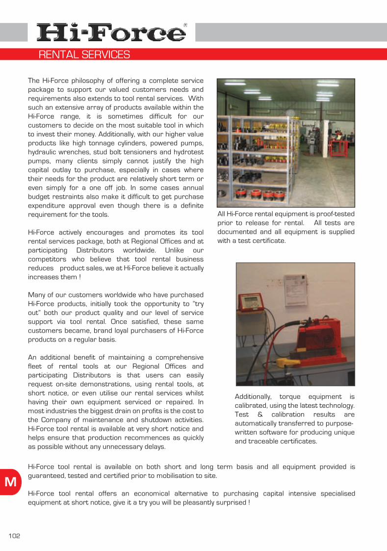
102
M
The Hi-Force philosophy of offering a complete service package to support our valued customers needs and requirements also extends to tool rental services. With such an extensive array of products available within the Hi-Force range, it is sometimes difficult for our customers to decide on the most suitable tool in which to invest their money. Additionally, with our higher value products like high tonnage cylinders, powered pumps, hydraulic wrenches, stud bolt tensioners and hydrotest pumps, many clients simply cannot justify the high capital outlay to purchase, especially in cases where their needs for the product are relatively short term or even simply for a one off job. In some cases annual budget restraints also make it difficult to get purchase expenditure approval even though there is a definite requirement for the tools.
Hi-Force actively encourages and promotes its tool rental services package, both at Regional Offices and at participating Distributors worldwide. Unlike our competitors who believe that tool rental business reduces product sales, we at Hi-Force believe it actually increases them !
Many of our customers worldwide who have purchased Hi-Force products, initially took the opportunity to “try out” both our product quality and our level of service support via tool rental. Once satisfied, these same customers became, brand loyal purchasers of Hi-Force products on a regular basis.
An additional benefit of maintaining a comprehensive fleet of rental tools at our Regional Offices and participating Distributors is that users can easily request on-site demonstrations, using rental tools, at short notice, or even utilise our rental services whilst having their own equipment serviced or repaired. In most industries the biggest drain on profits is the cost to the Company of maintenance and shutdown activities. Hi-Force tool rental is available at very short notice and helps ensure that production recommences as quickly as possible without any unnecessary delays.
Hi-Force tool rental is available on both short and long term basis and all equipment provided is guaranteed, tested and certified prior to mobilisation to site.
Hi-Force tool rental offers an economical alternative to purchasing capital intensive specialised equipment at short notice, give it a try you will be pleasantly surprised !
All Hi-Force rental equipment is proof-tested prior to release for rental. All tests are documented and all equipment is supplied with a test certificate.
Additionally, torque equipment is calibrated, using the latest technology. Test & calibration results are automatically transferred to purpose-written software for producing unique and traceable certificates.
RENTAL SERVICES

103
M
In addition to the tool rental services offered by Hi-Force and detailed on page 102, we also offer a first class on-site services package. Utilising Hi-Force tools drawn from our extensive global rental tool inventory, Hi-Force is also able to offer a first class on-site bolting and jacking service. Available globally via Hi-Force Regional Offices and participating Distributors, the Hi-Force on-site services package combines the expertise of our highly trained and experienced crews with the high quality reputation of Hi-Force products.
For on-site bolting services we are able to carry out jobs ranging from a simple bolt up of a single flange joint to major construction and maintenance shut down projects. Our record and past experience of working with many major multi-national companies is second to none and our crews have established an excellent reputation for meeting and beating critical time deadlines, even in the most demanding conditions. Major customer industries include oil & gas, power generation, cement plants, civil and mechanical construction and maintenance.
We also offer on-site lifting and jacking services usually related to heavy lift applications involving multiple numbers of Hi-Force high tonnage cylinders, pumps, hoses and accessories. Past jobs undertaken and successfully completed include bridge lifting, cantilever and steel structure weighing and a variety of lift and shift applications.
Our crews have received many verbal and written testimonials for their excellent performance and copies of these are available on request. Our on-site safety record remains unblemished with zero lost time incidents.
Hi-Force is very proud of its excellent reputation for carrying out efficient, safe, competitively priced on-site jobs, within the clients specified time period. Please do not hesitate to contact us if you have a requirement for Hi-Force on-site services.
ON-SITE SERVICES

104
M
Every year huge amounts of money are lost to industries worldwide due to the breakdown of capital intensive hydraulic and pneumatic tools. This extensive loss of revenue could be drastically reduced if users and owners were always in a position to call upon specialist repairers, at short notice, to identify the faults and carry out fast, reliable, guaranteed repairs.
Hi-Force is at your service!! We have built our success on our “service first philosophy” and a long history of providing customers with a comprehensive repair service for a wide range of hydraulic and pneumatic tools.
All Hi-Force offices worldwide, along with participating Hi-Force Distributors operate a fully equipped workshop repair facility, using the latest “state of the art” repair and testing equipment and techniques, carried out by trained and qualified workshop technicians. Our global network of Hi-Force service centres is modelled on our highly successful and wholly owned UK Distributor company, H.E.S. Sales Limited, who have been offering repair services along with the other services, detailed in this section of the catalogue, from three strategically placed locations in England, since the early 1970’s.
All Hi-Force service centres carry good stocks of commonly used spare parts and are able to offer a first class guaranteed repair service for all Hi-Force products as well as most international competitor brands. All items repaired carry a 90 day warranty against faulty materials or workmanship and each item is returned to the customer with an individual test/calibration certificate.
Make the most of your investment in tools through regular servicing and repair, at an economical cost, through the Hi-Force service network.
REPAIR SERVICES

105
M
As part of our ever improving after sales and service support facilities, Hi-Force has recently added a comprehensive calibration service for all makes of hand, pneumatic and hydraulic torque tools to our services portfolio. Available from selected Hi-Force Regional Offices and Distributors worldwide, this fast expanding activity is currently receiving considerable attention from our customer base.
All of our in house calibration equipment has valid, independently approved “NAMAS” calibration certificates which are renewed annually. All items calibrated are returned with an individual test and calibration certificate traceable to our “NAMAS” certification.
This service is particularly focused on tools used for accurate bolt tightening, which according to industry standards, recommends that they are calibrated, at least once per year and in some cases more often if used extensively. When did you last have your critical bolt tightening tools calibrated? Check and contact Hi-Force for a first class calibration service at a competitive price.
Hi-Force is also able to offer a limited calibration service for other hydraulic and pneumatic tools. Contact your local Hi-Force Regional Office or Distributor for more information.
Calibration of a hand torque wrench
Hydraulic torquewrench calibration
Sample calibration certificate
CALIBRATION SERVICES
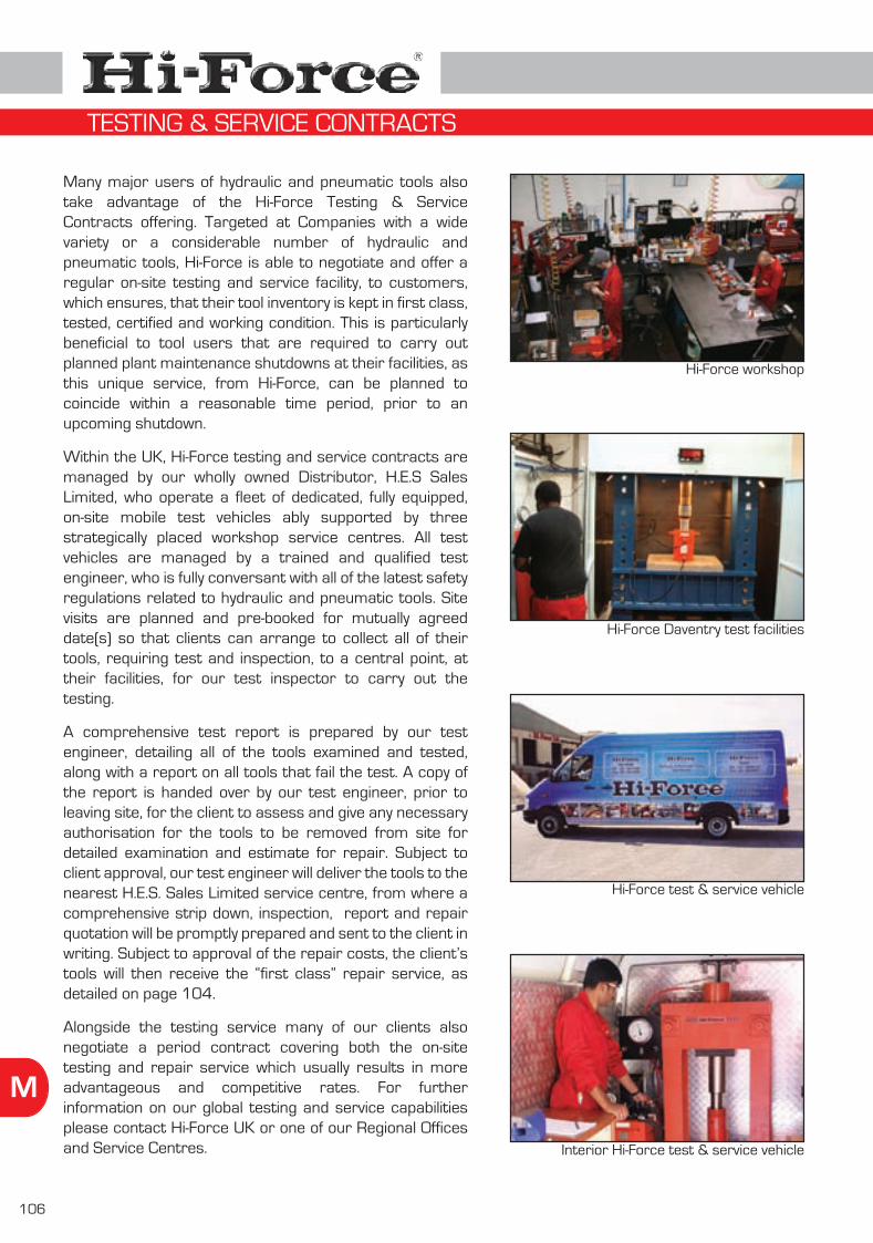
106
M
Many major users of hydraulic and pneumatic tools also take advantage of the Hi-Force Testing & Service Contracts offering. Targeted at Companies with a wide variety or a considerable number of hydraulic and pneumatic tools, Hi-Force is able to negotiate and offer a regular on-site testing and service facility, to customers, which ensures, that their tool inventory is kept in first class, tested, certified and working condition. This is particularly beneficial to tool users that are required to carry out planned plant maintenance shutdowns at their facilities, as this unique service, from Hi-Force, can be planned to coincide within a reasonable time period, prior to an upcoming shutdown.
Within the UK, Hi-Force testing and service contracts are managed by our wholly owned Distributor, H.E.S Sales Limited, who operate a fleet of dedicated, fully equipped, on-site mobile test vehicles ably supported by three strategically placed workshop service centres. All test vehicles are managed by a trained and qualified test engineer, who is fully conversant with all of the latest safety regulations related to hydraulic and pneumatic tools. Site visits are planned and pre-booked for mutually agreed date(s) so that clients can arrange to collect all of their tools, requiring test and inspection, to a central point, at their facilities, for our test inspector to carry out the testing.
A comprehensive test report is prepared by our test engineer, detailing all of the tools examined and tested, along with a report on all tools that fail the test. A copy of the report is handed over by our test engineer, prior to leaving site, for the client to assess and give any necessary authorisation for the tools to be removed from site for detailed examination and estimate for repair. Subject to client approval, our test engineer will deliver the tools to the nearest H.E.S. Sales Limited service centre, from where a comprehensive strip down, inspection, report and repair quotation will be promptly prepared and sent to the client in writing. Subject to approval of the repair costs, the client’s tools will then receive the “first class” repair service, as detailed on page 104. Alongside the testing service many of our clients also negotiate a period contract covering both the on-site testing and repair service which usually results in more advantageous and competitive rates. For further information on our global testing and service capabilities please contact Hi-Force UK or one of our Regional Offices and Service Centres.
Hi-Force test & service vehicle
Interior Hi-Force test & service vehicle
Hi-Force Daventry test facilities
Hi-Force workshop
TESTING & SERVICE CONTRACTS

107
M
Hi-Force is fully committed to providing sales and service training in the safe and proper use of hydraulic and pneumatic tools to all of its employees, authorised distributors and end users. In support of this initiative Hi-Force holds regular sales and service training courses at its UK Head Office and Regional Offices worldwide.
All delegates are provided with a mixture of classroom theoretical and “hands on” practical training and subject to achieving a satisfactory level of competence, are awarded a prestigious Hi-Force Training Certificate.
Courses are divided into two product areas, namely hydraulic tools and bolting products (see page 108), and both courses are separately covered under Sales Application Training and the more detailed Service and Repair Training.
Hi-Force believes that in our business “knowledge is everything” and our commitment to training is key to our future growth as a pioneering company in our industry.
PRODUCT TRAINING HYDRAULIC TOOLS

108
M
The tremendous growth in Hi-Force “Bolting Tools” business over the past 10 years is a result of several key points. Firstly, the requirements for correctly and accurately tightened threaded components, in many indus-tries and applications, has increased immensely since the turn of the century. More and more Companies are now realising that critical bolted joints must be correctly and accurately tensioned in accordance with the equipment designer/manufacturer specifications. Incorrectly tightened bolts can cause a variety of serious environmental, health and safety and financial loss situations, and in an ever changing world these issues are becoming more and more critical.
Secondly, Hi-Force is now able to offer the most comprehensive range of “Bolting Tools” from a single source, anywhere in the world, resulting in many clients selecting Hi-Force as their preferred “one stop” supplier. However knowing how and why it is important to correctly connect bolted components together, requires a considerable amount of technical knowledge and to assist our own sales teams, our distributors and product users, the third and final key point, as to why we are experiencing such tremendous growth levels is the Hi-Force bolting products training courses. Designed to offer delegates training in the safe and proper use, application, maintenance and repair of Hi-Force bolting products, all courses can be specially structured to satisfy individual requirements. Whether it be bolt torquing or bolt tensioning or a mixture of both, our courses provide a combination of classroom theoretical and “hands on” practical training. All delegates who achieve a satisfactory level of competence are awarded a prestigious Hi-Force Training Certificate directly related to the theoretical and practical disciplines achieved. For further details on all Hi-Force training courses please contact your local Hi-Force office or authorised distributor.
Theoretical classroom training on Hi-Force bolting products at Hi-Force Dubai facilities.
All Hi-Force training courses can be held at Hi-Force Head Office, Regional Offices, Authorised Distributors or at end user locations. Practical workshop
training.
PRODUCT TRAINING BOLTING EQUIPMENT

Twenty steps to safety
Basic principles of hydraulics
Basic principles of torque tools and bolt tensioners
Recommended torque value chart
Metric to imperial conversion chart
For contact details of all Hi-Force offices, please see the back cover of this catalogue
109
Pages110 - 111
Pages112 - 113
Pages118 - 119
Page120
Page121
N
Tightening sequence & bolting procedure for flange bolts
Pages114 - 117
Cylinders, pumps & jacks :
Torque wrenches & bolt tensioners :
General information :
THE INFORMATION PAGES

110
N
DO
DO
NOT
1 1 2 2
5 5 6 6
9 9 1 10 0
1 14 4
1 18 8
1 13 3
1 17 7
DO
DO
NOT
DO
DO
NOT
DO
DO
NOT
DO
DO
NOT
DO
DO
NOT
DO
DO
NOT
DO
DO
NOT
DO
DO
NOT
DO
DO
NOT
Always support the loadmechanically before working underneath
Work under a load supported only by
hydraulic equipment
Ensure cylinder piston rods are fully retracted before
disconnecting hoses
Pistons fullyretracted
Disconnect hose(s)without first retractingthe cylinder piston rod
Pistons notretracted
Always avoid kinks orsharp bends in hydraulic hoses
Drive over, kink or dropheavy objects on hydraulic hoses
700 BAR CYLINDER700 BAR PUMP
350 BAR GAUGE
350 BAR HOSE
700 BAR PUMP700 BAR CYLINDER
700 BAR GAUGE
700 BAR HOSE
Ensure that all systemcomponents have
matching capacity /pressure ratings
Mix components ofdifferent capacity /pressure ratings
Always read the instructionmanual prior to use
Ignore or discard theinstruction manual
Select equipment of a capacity in excess of your
requirements
Use equipment aboveit’s maximum working
capacity
Operate your equipmentunloaded several times
before attempting the task
Attempt to use equipmentwithout first getting a
“feel” for how it operates
32 TONNESCAPACITY
20 TONNESCAPACITY
Let’s hope it works
Use the correct hydraulicfluid as specified by
Hi-Force
Use incorrect fluids inhydraulic equipment
Hi-Force hydraulicoil only
Say Noto otherfluids
TO JOB SITE
Great, let’sgo to site
It’sworking
fine Harry
Release the hydraulicpressure before discon-necting or re-connecting
the hoses
Disconnect or re-connectany hose(s) or fitting(s)whilst under pressure
Always raise the cylinderpiston to the load
hydraulically
Allow the load to dropon to extended cylinder pistons
LOWERAWAY
TWENTY STEPS TO SAFETY - CYLINDERS & PUMPS

111
N
3 3 4 4
7 7 8 8
1 11 1
1 12 2
2 20 0
1 16 6
1 15 5
1 19 9
DO
DO
NOT
DO
DO
NOT
DO
DO
NOT
DO
DO
NOT
DO
DO
NOT
DO
DO
DO
DO
DO
DO
NOT
DO
NOT
DO
NOT
DO
NOT
DO
NOT
LOAD SPREADER PLATE
OIL LEAK
Provide suitablesupport under the load
Operate lifting equipmenton uneven or soft ground
Always inspect all systemcomponents before you
use them
Use damaged, worn orleaking equipment
Always transport heavyhydraulic equipmentby suitable means
Carry or drag hydraulicequipment by the hoses
Always store hydraulicequipment in a suitable
place
Leave hydraulic equipment at the mercy
of the elements
Keep hydraulic equipmentaway from temperatures
above 65° C.
Allow heat or nakedflames near to hydraulic tools
Ensure that the lifting device is fully under theload and that lifting is
parallel
Operate lifting equipmentwith the piston only
partially under the load
Use a suitable pressuregauge to monitor the
system pressure
Attempt to override thefactory set safety
pressure relief valve
700 barmaximumpressure
Dangersystemoverload
If I could just increase
pressure a bit
OIL LEAK
STOP !
OIL LEAK
Nearlydone
Investigate immediatelyany trace of oil leaks in
the system
Try to continue usingequipment that is
leaking oil
Have your Hi-Force equipment serviced by an
accredited Hi-Force service centre
Have your Hi-Forceequipment “fixed” by
unqualified companies
Think safety and if in doubtseek professional help
from Hi-Force
Gamble with safety, you will always lose !
THINKSAFETY
SEEKADVICE
TWENTY STEPS TO SAFETY - CYLINDERS & PUMPS

112
N
Introduction
The basic principles of hydraulics are not difficult to understand, knowing how and why hydraulic tools work will help the user to best select the most suitable Hi-Force tools for the job, ensuring maximum performance at the most economical cost
If the “Basic Principles of Hydraulics” detailed in this section of the catalogue are really of assistance to the reader, then its purpose of helping with the selection of the correct Hi-Force tool for the job has been achieved.
Using hydraulic fluid pressure to generate a force
a) Hydraulic PressureHydraulic power provides one of the simplest and most powerful forms of producing considerable amounts of force within a confined space using hydraulic fluid pressure to generate a force.Since the early inventions of low pressure, heavy hydraulic lifting jacks through to the latest state of the art high pressure hydraulic systems of today, hydraulic power remains an extensively used and widely respected assistant to mankind’s drive for even greater power and knowledge. Pascal’s law states that pressure applied at any point upon a confined fluid (liquid) is transmitted undiminished in all directions within the fluid (see figure 1). This means that by using hydraulic pressure as a medium a small force can be converted into an appreciable multiple of itself.The actual fluid pressure involved plays a very important role in this “Multiplication of Force” and in this context there are two features of hydraulic pressure which are important to remember.1. Hydraulic pressure is measured as a force per unit of area e.g. Bar (= kg/cm²) or PSI (Pounds per Square Inch).2. The hydraulic pressure at any point within the fluid is the same in all directions provided of course that the fluid is static (non moving) - see figure 1.
b) The Industry StandardThe accepted International Standard for maximum working pressure in the high pressure hydraulic tools industry is 700 Bar (10.000 PSI) and the majority of the products detailed in this catalogue have a maximum working pressure of 700 Bar (10.000 PSI). Therefore where a particular cylinder is specified in this catalogue as having a 10 tonnes maximum capacity, it must be noted that the maximum capacity is calculated at the maximum working pressure.
Fig. 1
BASIC PRINCIPLES OF HYDRAULICS
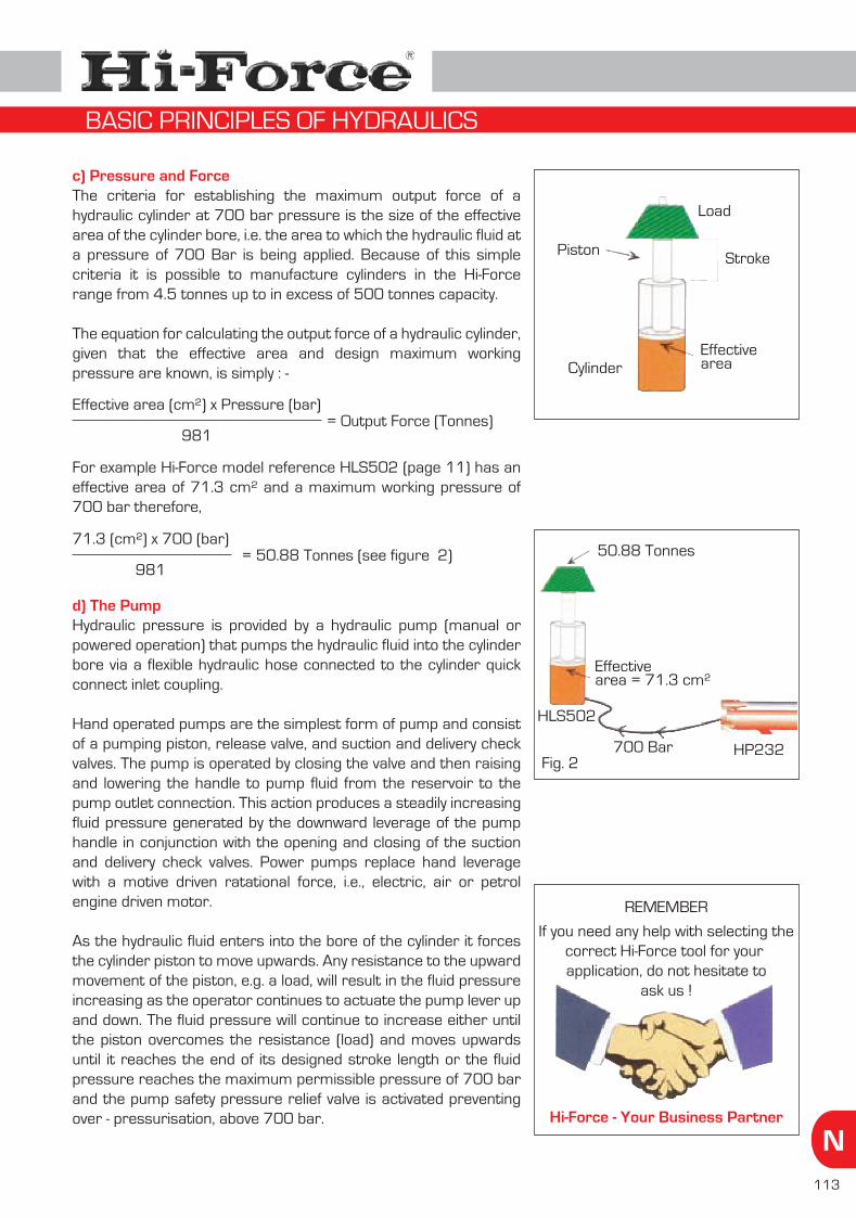
113
N
c) Pressure and ForceThe criteria for establishing the maximum output force of a hydraulic cylinder at 700 bar pressure is the size of the effective area of the cylinder bore, i.e. the area to which the hydraulic fluid at a pressure of 700 Bar is being applied. Because of this simple criteria it is possible to manufacture cylinders in the Hi-Force range from 4.5 tonnes up to in excess of 500 tonnes capacity.
The equation for calculating the output force of a hydraulic cylinder, given that the effective area and design maximum working pressure are known, is simply : -
For example Hi-Force model reference HLS502 (page 11) has an effective area of 71.3 cm² and a maximum working pressure of 700 bar therefore,
d) The PumpHydraulic pressure is provided by a hydraulic pump (manual or powered operation) that pumps the hydraulic fluid into the cylinder bore via a flexible hydraulic hose connected to the cylinder quick connect inlet coupling.
Hand operated pumps are the simplest form of pump and consist of a pumping piston, release valve, and suction and delivery check valves. The pump is operated by closing the valve and then raising and lowering the handle to pump fluid from the reservoir to the pump outlet connection. This action produces a steadily increasing fluid pressure generated by the downward leverage of the pump handle in conjunction with the opening and closing of the suction and delivery check valves. Power pumps replace hand leverage with a motive driven ratational force, i.e., electric, air or petrol engine driven motor.
As the hydraulic fluid enters into the bore of the cylinder it forces the cylinder piston to move upwards. Any resistance to the upward movement of the piston, e.g. a load, will result in the fluid pressure increasing as the operator continues to actuate the pump lever up and down. The fluid pressure will continue to increase either until the piston overcomes the resistance (load) and moves upwards until it reaches the end of its designed stroke length or the fluid pressure reaches the maximum permissible pressure of 700 bar and the pump safety pressure relief valve is activated preventing over - pressurisation, above 700 bar.
Effective area (cm²) x Pressure (bar)
981= Output Force (Tonnes)
71.3 (cm²) x 700 (bar)
981= 50.88 Tonnes (see figure 2)
Piston
Cylinder
Stroke
Effective area
Load
Fig. 2
HLS502
50.88 Tonnes
HP232700 Bar
Effective area = 71.3 cm²
REMEMBER
If you need any help with selecting thecorrect Hi-Force tool for your application, do not hesitate to
ask us !
Hi-Force - Your Business Partner
BASIC PRINCIPLES OF HYDRAULICS

114
N
Figure 1
Tension
Bolt tension
Torque
Since the invention of using threaded bolts and nuts to join various components together was introduced centuries ago, the methods of bolt tensioning and the tool design technology have improved tremendously to the extent that Hi-Force offers the most comprehensive range of bolting products available from a single source anywhere in the world !
From basic high quality, calibrated hand torque wrenches to the latest “State of the Art” hydraulic torque wrenches and stud bolt tensioners, Hi-Force can deliver the right tool for the job on time, every time !
This section of the catalogue provides basic information about the methods of applying tension to a bolted connection. There are three possible methods to tighten threaded fasteners, by torque which is rotation of the nut or bolt head, by direct tension to stretch the fastener, or by heat to expand the fastener.
Torque and tensioning (see figure 1) probably cover 99 percent of bolting applications, and it is these two methods that are detailed in this catalogue.
What is tension and how does it affect a bolted fastener ?
As with most materials, steel which is predominantly used in the manufacture of bolts and nuts has an inherent “elasticity” i.e. it can be stretched between two points and the tension that is imparted into the bolt acts as a clamping force to hold the bolted components together. Care must always be taken when stretching the bolt to ensure that its “yield point” is not exceeded which will cause the bolt to lose its physical properties of elasticity.
Hooke’s law states that the amount of distortion (lengthening, shortening, bending or twisting) applied will be directly proportional to the applied force, provided the applied force is kept within the material’s elastic limits. For most industrial applications, a fastener should be tightened until it has a retained tension of 40 to 70 percent of its elastic limit.
For a threaded fastener to correctly hold (clamp) components together it must be “stretched” (tensioned) to a known accurate amount. A threaded fastener that is under-tightened could work loose and come apart, resulting in a “shearing force” developing between the mating parts which could cut the bolt in two. A loose fastener may also lead to further mechanical looseness of surrounding machinery parts causing unnecessary vibration and wear. Fluid and gas leaks could also occur due to incorrect sealing in pressure joints, which could be extremely dangerous if any of the materials to be sealed are toxic, flammable or explosive.
An over-tightened fastener could cause damage to the bolted components, excessive over-tightening will cause the bolt and/or nut to deform causing loss of tension in the fastener as it exceeds its elastic limit. (yield point).
For most industrial applications, the equipment manufacturers, as well as structural and piping component designers will provide the torque or tension specifications for the relevant fastener(s) to be used to connect the component parts. It is vitally important to adhere to these specifications to ensure a correctly tensioned joint is achieved.
BASIC PRINCIPLES OF TORQUE WRENCHES & BOLT TENSIONERS

115
N
How do we generate tension in the bolt ?
As mentioned earlier the two most common methods to impart tension into a threaded fastener are by torque (see figure 2) or by direct tension (see figure 3).
Torque is defined as the turning or twisting force exerted on a nut or bolt head and it is the product of two measurements i.e. force and distance (see figure 4). Force is measured in units of Pounds or Newtons and is quite simply the amount of force applied at a given distance from the centre of the item being turned or twisted. Distance is measured in units of length i.e. inches, feet, centimetres or metres. Torque is expressed as a combination of the relevant units of force and distance i.e. pounds feet (lbf.ft) in the imperial measurement system or Newton metres (Nm) in the metric system. Torque is applied to a threaded fastener by a variety of manual and power driven types of torque wrenches.
Newton’s law states that for every applied force there is an equal and opposite reactive force. Therefore as the torque is applied to the nut, by turning it increases, it will create a tension in the stud bolt which will act as a “clamping force” within the effective thread length. Initially this clamping force will pull the two bolted components together and subsequently it will build up and retain a known tension (load) within the fastener to maintain the joint integrity.
The amount of torque to be applied to a threaded fastener will depend on several factors including the design application, type of joint, size, length and quantity of fasteners to be used and the type of thread lubricant. In the absence of specific torque figures from the equipment designer or manufacturer, Hi-Force has provided a chart, on page 120 of this catalogue, detailing recom-mended torque figures for both metric and imperial fasteners in standard grade material using commonly applied thread lubricants. These figures are calculated based on 70% of the minimum yield point of the bolt, which is the maximum recommended by Hi-Force. Alternatively Hi-Force also offers it’s recently launched BoltRight software programme (see page 100).
Figure 2
Torque
Tension
Figure 4
Torque Force
Lever lengthdistance
Figure 3Threaded
pullerPiston
Cylinder
Bridge
Oil inletport
Tommybar
Nut rotatingsocket
Turn direction
Direct tension is applied to the fastener using a hydraulic tensioning device commonly known as a hydraulic stud bolt tensioner (see figure 3). This is a high pressure hydraulic cylinder, with accessories, designed to seat against the joint, grip the fastener thread using a compatible threaded puller, and via applied hydraulic pressure extend the cylinder piston against the puller, to pull (stretch) the bolt or stud to a known tension in tonnes or kN. When the pull force equals the desired bolt preload, plus an additional amount to compensate for bolt relaxation, the nut is run down the thread using a short tommy bar until it is tight against the joint face. The hydraulic pressure is then released and the threaded fastener is prevented from returning to it’s original length, by the tightened nut, subsequently leaving the required tension retained in the fastener.
BASIC PRINCIPLES OF TORQUE WRENCHES & BOLT TENSIONERS

116
N
Hydraulic stud bolt tensioners are commonly used in multiples linked to a single hydraulic pump unit particularly in applications where reliable leak free joints are required. By using a number of tensioners simultaneously the operator is able to ensure an even pull down of the joint components, resulting in uniformity of gasket compression and consistent leak free joints. As with torque the actual amount of tension, to be directly applied to the threaded fastener by the hydraulic stud bolt tensioner, should be confirmed by the equipment manufacturer or designer. The majority of hydraulic stud bolt tensioners operate at a maximum hydraulic pressure of 1500 bar and certainly this maximum pressure/tension load should never be exceeded.
Correct Tool SelectionHaving now understood the two most common methods of applying tension to the fastener (torque or direct tension) let us now look at the various types of tools available to accurately and successfully complete the given task, along with other bolting products available from Hi-Force.
Hand Torque WrenchesProbably the most commonly used tool, for accurately tightening threaded fasteners, in the world!! Hand torque wrenches are designed and manufactured on the basis of Hooke’s Law i.e. force x distance. Hi-Force hand torque wrenches incorporate a reversible ratchet design drive head and a clear, easily adjustable torque setting scale. All Hi-Force hand torque wrenches are designed and manufactured to International Standard ISO 6789:2003. Each model is supplied marked with a unique serial number, trace-able to an individual test and calibration certificate, and provides a repeatable accuracy of +/- 3% for HTW-R models and +/- 4% for the HTW-B models. Full technical specification on the Hi-Force range of hand torque wrenches can be found on page 76 of this catalogue.
Hand Torque MultipliersA hand torque multiplier is a mechanical device that multiplies the preset amount of input torque applied by the operator using a calibrated hand torque wrench. Hi-Force hand torque multipliers incorporate a “planetary” gear train which has one or more stages, each of which increases the input torque applied by a factor of 5. The greater the number of stages within the planetary gear train, the higher the output torque achieved, relative to the input torque applied. Due to the greater output torque produced using hand torque multipliers it is necessary to incorporate an integral reaction foot to absorb the opposing reactive force generated (Hooke’s Law). Great care must be taken to ensure that the reaction foot is correctly located against a suitably strong reaction point prior to operating the tool. Because the power output cannot exceed the power input, the number of output rotations will be lower than the number of input rotations. Hi-Force hand torque multipliers are available with multiplication ratios of 5:1, 25:1, 75:1 and 125:1 and full technical details can be found on pages 77 - 78 of this catalogue.
Pneumatic Torque MultipliersA pneumatic torque multiplier operates in the same way as a hand torque multiplier except that the input motive force is provided by a pneumatically driven air motor instead of a manually operated hand torque wrench, making the tool both faster and easier to operate. Torque output is preset and adjusted by regulating the input air pressure, supplied to the pneumatic motor, which will control the amount of input torque applied to the planetary gear train. As the torque output increases the air motor will gradually slow down, until it eventually stalls i.e. the opposite reactive force generated becomes equivalent to the input torque of the air motor. Each tool is supplied with an airline filter, regulator, lubricator unit in a handy carry-ing frame with integral air line pressure gauge and 3 metre connecting hose. Repeatable accuracy of +/- 5% can easily be achieved in conjunction with the individual torque calibration chart supplied with each tool. Full technical details can be found on pages 79 - 80 of this catalogue.
BASIC PRINCIPLES OF TORQUE WRENCHES & BOLT TENSIONERS
117
N
Hydraulic Torque WrenchesHydraulic torque wrenches are specifically designed for applications where limitation of space and/or particularly high output torque is required. The design of a hydraulic torque wrench utilises the far higher leverage forces generated from a hydraulic piston, using high pressure hydraulic power supplied from an air or electric driven pump. The hydraulic piston is connected to a ratchet via a reaction pawl assembly which allows it to engage the ratchet teeth in the advance mode to rotate the nut or bolt head, and subsequently release during piston retraction to re-engage in the next forward push position. All Hi-Force hydraulic torque wrenches operate at 700 bar maximum hydraulic pressure, incorporate a double acting heavy duty hydraulic piston for fast and easy operation, and can be used for accurately tightening or loosening nuts/bolts. A choice of standard square drive tools, suitable for use with a variety of sizes of torque wrench sockets, or hexagon drive cassette head tools that locate directly on to the nut/bolt are available. Full technical specifications can be found on pages 81 to 89 of this catalogue.
Hydraulic Stud Bolt TensionersHydraulic stud bolt tensioners provide the most consistent and accurate method of applying tension to bolted connections. Comprising of four component parts (subsea tensioners just two) i.e. bridge, nut rotating socket, threaded puller and cylinder, hydraulic stud bolt tensioners offer a safe, accurate method of ensuring consistent joint integrity. Designed to directly stretch the bolt by applying a known load to the fastener using a hydraulic cylinder and threaded puller, the securing nut is rotated using a short tommy bar, whilst the thread is being stretched, until it is firmly tightened against the joint face. Immediately after the hydraulic pressure (load) is released, the bolt tension is retained because the threaded fastener is prevented from returning to its original length by the tightened nut. Hydraulic stud bolt tensioners can be linked together in multiples to ensure an even “pull down” or tension is applied to all bolts simultaneously, this is particularly critical in applications where a sealing gasket is used and consistent leak free connections are required. Full technical specification can be found on pages 91 to 98 of this catalogue.
Nut splittersHydraulic nut splitters provide the perfect answer for removal of worn, damaged or corroded fasteners that cannot be opened using torque or tensioning tools. The nut splitter design incorporates a powerful hydraulic piston to drive a precision engineered, angled splitting wedge into the flat face of the nut. The splitting wedge is manufactured from high grade tool steel for maximum life and can be easily removed for re-sharpening or replacement. The angled design of the splitting wedge allows the nut to be split with minimal damage to the threads on the bolt or stud. Full details can be found on page 59 of this catalogue.
Impact WrenchesAir driven (pneumatic) impact wrenches are probably one of the most commonly used tools in the bolting industry today. Ideally suited for run down or fast removal of bolted connections, all models operate using a standard 6 bar air line pressure. Hi-Force industrial quality impact wrenches have a four position adjustable power output device, however torque accuracy cannot be measured or guaranteed due to the impact design of these tools. Full technical details can be found on page 90 of this catalogue.
Flange SpreadersFlange spreaders provide the perfect answer for separating flange joints for maintenance etc..... after bolt removal. Hi-Force flange spreaders are available in both mechanical and hydraulic options. Full technical details can be found on pages 60 and 61 of this catalogue.
Sockets and AccessoriesMost of the bolting products detailed in this catalogue will also require a selection of high quality impact sockets and accessories to assist with the relevant bolting application. Hi-Force offers an extensive range of sockets, extension bars, square drive adaptors, reducers and universal joints. Full specifications and available options in both imperial and metric standard sizes are detailed on pages 82, 83 and 90 of this catalogue.
BASIC PRINCIPLES OF TORQUE WRENCHES & BOLT TENSIONERS

118
N
Hi-Force hydraulic stud bolt tensioners offer the quickest, safest and most accurate means of applying a specific residual load to stud bolts. Stud bolt tensioners can be used to easily achieve an accurate and pre-determined bolt loading in a single, simultaneous operation, providing the uniform gasket compression, essential for the integrity of critical bolted connections. Ideally all bolts in the joint should be tensioned simultaneously (100%), however 50%, 33% or even 25% simultaneous tensioning can be carried out, which then requires the operator to make two, three or four tensioning operations by moving around the bolts in diametrically opposed fashion. Whilst partial tensioning will take longer to complete the task, it enables the user to optimise between the cost of the equipment and the available time.
Hi-Force hydraulic stud bolt tensioners are designed to directly stretch the bolt by applying a known load to the fastener using a hydraulic cylinder and threaded puller. The securing nut is then rotated using a short tommy bar, whilst the thread is being stretched, until it is firmly tightened against the joint face. Immediately the hydraulic pressure (load) is released the bolt tension (residual load) is retained, within the clamp length of the stud bolt, because it is prevented from returning to its original length by the tightened nut.
To operate hydraulic stud bolt tensioners, on bolted connections safely, an extra length of threaded stud, above the nut, of at least one x bolt diameter, is required to facilitate easy fitment of the equipment (see figure 1).
Assembly of the tensioners to the stud bolt is quick and easy, provided of course that the stud bolts and nuts are clean, lubricated and in good condition (see figures 2 -5).
Hi-Force has considerable experience in providing precise calculations of the correct bolt load to be applied to ensure an accurate residual load is imparted into the bolts, whether they be tightened using a 100%, 50%, 33% or 25% simultaneous tensioning procedure (see figures 6-9).
Please refer to page 100 for further details on the Hi-Force BoltRight software programme. If 100% tensioning cannot be achieved by attaching all
bolt tensioners, to one side of the flange, due to a lack of
space, then alternate the tensioners on opposite side.
Note :
Figure 1
Figure 2 Figure 3
Figure 4 Figure 5
Figure 6 Figure 7
Figure 8 Figure 9
Bolt diameter
Min. 1 x bolt
diameter
100%Tensioning
50%Tensioning
33%Tensioning
25%Tensioning
TIGHTENING SEQUENCE & BOLTING PROCEDURE FOR FLANGE BOLTS

119
N
1 3
4 2
4 Bolt
Flange
2
3 6
5 4
7
1 8
8 Bolt
Flange
110
3
8
116 2
9
4
7
125
12 Bolt
Flange
1 105
15
3
11
7
1329
6
16
4
12
8
14
16 Bolt
Flange
120
12
8
16
4
18
106 13 2
1911
7
15
3
17
9514
20 Bolt
Flange
7
116
24
8
20
12
4
14
226
17 9 215
23
19
11
3
13
215
1810
24 Bolt
Flange
120
11
27
16
8
2424
4
18
10
1426
6 21 219
12
28
15
7
23
3
17
9
2513
522
28 Bolt
Flange
As explained on page 116, the two most common methods for tightening of bolted flange joints are either by torque using torque wrenches or by direct tension using hydraulic stud bolt tensioners. Regardless of the method selected a pre-bolting inspection is essential if an accurate and leak free joint is to be achieved first time, every time. The inspection must include checking for any damage to the gasket and sealing surfaces, ensuring that the stud bolts and nuts are the correct size and material, are not damaged in any way and that the correct lubricant is to be used. Additionally it is vitally important that the two flanges are correctly aligned to each other and that the stud bolts can be easily fitted through the bolt holes. If any of the above checks are not satisfactory immediate remedial action must take place before starting to bolt up the joint.
Tightening using torque wrenchesInsert the stud bolts through both flanges and hand tighten the nuts on both sides ensuring that there is full thread engagement on both nuts of every stud bolt. Square up the joint and ensure that all stud bolts are freely moving through the bolt holes and that the nuts are hand tightened against the outer flange faces. Number all bolts sequentially in a diametrically opposed fashion as shown in the illustrations on the right. Commence tightening of the bolts sequentially starting with a first pass at 25% of the final specified and required torque figure, a second pass at 50% and then a third pass at 100%. Finally a check pass should be carried out in either a clockwise or anti-clockwise direction at 100% of the required torque to ensure all bolts are uniformly tightened.
Tensioning procedure using hydraulic stud bolt tensionersInsert the stud bolts through both flanges and hand tighten the nuts on both sides ensuring that there is full thread engagement on both sides. Take care to ensure that on the selected flange face, to which the tensioners are to be affixed, that there is at least 1 x diameter of the stud bolt thread protruding above the nut face. This is required for the tensioner puller to attach to and if insufficient thread is exposed then the tensioning procedure must not proceed. The exact number and positioning of the hydraulic stud bolt tensioners must then be ascertained i.e. 25%, 33%, 50% or 100% simultaneous tensioning of all the bolts in the respective joint. After deciding the number of stud bolt tensioners to be used simultaneously, affix them to the exposed thread end of the stud bolts, equally spaced around the flange for 25%, 33% or 50% simultaneous tensioning, or on every stud bolt in the case of 100% simultaneous tensioning. Please refer to the comprehensive Hi-Force operating manual for stud bolt tensioners for more detailed instructions. After correctly assembling all of the stud bolt tensioners, on to the flange, hook up the interconnecting hydraulic hoses and the mainline hose to the air driven pump unit and apply the applicable hydraulic pressure, as specified by either the joint equipment manufacturer or the BoltRight software (see page 100). In cases other than 100% simultaneous tensioning there will be two different hydraulic pump pressures to be applied to the bolt tensioners and these should be strictly adhered to. Once all of the stud bolts have been tensioned using the Hi-Force stud bolt tensioners the joint is ready for testing. Take note that it is normal to have to make 2 or 3 passes around the stud bolts when tensioning at 50% or less and usually the lower the number of tensioners being used simultaneously, the more passes will need to be done and hence it will take more time to complete the joint tightening.
Whether tightening the bolts using a torque wrench or stud bolt tensioners it is a good idea to carry out a final check for tightness of all the bolts by simply tapping each nut with a hammer and listen to see if a high pitched ringing sound is achieved. A dull sound indicates that the respective bolt is still loose.
TIGHTENING SEQUENCE & BOLTING PROCEDURE FOR FLANGE BOLTS

120
N
5/8 1.1/16 67 (15,218) 99 (73) 150 (110) 179 (131)
20 30 99 (24,730) 202 (148) 305 (224) 363 (267)
24 36 159 (35,634) 346 (254) 526 (387) 621 (457)
27 41 210 (47,153) 505 (372) 774 (569) 913 (672)
30 46 255 (57,302) 687 (505) 1,051 (773) 1,177 (866)
33 50 319 (71,695) 928 (682) 1,428 (1,050) 1,592 (1,171)
36 55 374 (84,088) 1.198 (881) 1,837 (1,351) 2,067 (1,520)
39 60 451 (101,353) 1,546 (1,364) 2.384 (1,753) 2,646 (1,946)
42 65 517 (116,220) 1,967 (1,446) 3,037 (2,233) 3,386 (2,490)
45 70 606 (136,153) 2,388 (1,756) 3,690 (2,714) 4,096 (3,012)
48 75 680 (153,016) 2,881 (2,119) 4,444 (3,267) 4,933 (3,627)
52 80 819 (184,051) 3,690 (2,713) 5,718 (4,204) 6,347 (4,667)
2.1/4 3.1/2 1,168 (262,571) 5,250 (3,860) 8,372 (6,156) 9,297 (6,836)
2.1/2 3.7/8 1,458 (327,737) 7,223 (5,311) 11,561 (8,501) 12,827 (9,432)
68 100 1,435 (322,736) 8,328 (6,123) 12,961 (9,530) 14,387 (10,578)
72 105 1,633 (367,081) 9,820 (7,220) 15,326 (11,269) 16,935 (12,452)
80 115 1,870 (420,273) 12,264 (9,018) 19,251 (14,155) 21,272 (15,641)
3.1/2 5.3/8 2,659 (597,647) 18,081 (13,295) 29,257 (21,513) 32,311 (23,758)
3.3/4 5.3/4 3,066 (689,249) 22,252 (16,362) 36,075 (26,526) 39,834 (29,290)
4 6.1/8 3,503 (787,381) 27,024 (19,871) 43,883 (32,267) 48,444 (35,621)
4.1/2 6.7/8 4,146 (932,023) 30,423 (22,370) 49,538 (36,425) 54,641 (40,177)
Boltdiameter
(see note 1)
Nut AF size
(see note 2)
Bolt tension
(see note 3)
Torque for specified lubricantNm (lbf .ft)
(See note 4)mm ins mm ins kN (lbs .force) Moly Copper Machine Oil
(friction=0.06) (friction=0.10) (friction=0.15)
16 24 60 (15,760) 102 (75) 155 (114) 184 (136)
3/4 1.1/4 96 (21,652) 175 (129) 263 (194) 314 (231)
7/8 1.7/16 134 (30,135) 277 (204) 423 (311) 501 (368)
1 1.5/8 199 (44,981) 416 (307) 631 (464) 746 (549)
1.1/8 1.13/16 261 (58,622) 629 (463) 965 (709) 1,081 (795)
1.1/4 2 329 (74,068) 872 (642) 1,348 (991) 1,505 (1,107)
1.3/8 2.3/16 407 (91,316) 1,169 (860) 1,820 (1,338) 2,026 (1,490)
1.1/2 2.3/8 492 (110,369) 1,526 (1,122) 2,352 (1,729) 2,654 (1,951)
1.5/8 2.9/16 584 (131,226) 1,949 (1,433) 2,388 (1,756) 2,650 (1,949)
1.3/4 2.3/4 684 (153,888) 2,444 (1,797) 3,856 (2,835) 4,301 (3,163)
1.7/8 2.15/16 793 (178,353) 3,021 (2,221) 4,781 (3,515) 5,317 (3.910)
2 3.1/8 910 (204,621) 3,676 (2,703) 5,835 (4,291) 6,482 (4,766)
56 85 944 (212,237) 4,578 (3,366) 7,081 (5,207) 7,860 (5,779)
60 90 1,105 (258,590) 5,707 (4,196) 8,838 (6,499) 9,810 (7,213)
64 95 1,250 (281,106) 6,835 (5,026) 10,595 (7,791) 11,760 (8,647)
2.3/4 4.1/4 1,611 (362,012) 8,735 (6,423) 14,031 (10,317) 15,519 (11,411)
3 4.5/8 1,931 (434,028) 11,343 (8,340) 18,273 (13,436) 20,226 (14,872)
3.1/4 5 2,280 (512,574) 14,451 (10,626) 23,335 (17,158) 25,796 (18,968)
90 130 2,424 (545,035) 27,654 (12,981) 27,881 (20,501) 30,809 (22,653)
100 145 3,050 (685,695) 24,410 (17,949) 38,742 (54,239) 42,810 (31,478)
4.1/4 6.1/2 3,133 (704,242) 25,605 (18,830) 41,647 (30,633) 45,956 (33,791)
Notes:
Use this chart as a guideline to the correct torque to be applied to standard size metric and imperial bolts in grades 8.8 (metric) and ASTM A193 grade B7 (imperial) or similar. The torque figures are calculated in both metric (Nm) and imperial (lbf.ft) values using a choice of three commonly used bolt thread lubricants. Always consider the coefficient of friction applicable for the chosen bolt lubricant. For grade 10.9 bolts add 40% and grade 12.9 bolts add 70% to the figure detailed against the relevant 8.8 grade metric stud bolt size.
Remember these torque values are for guidance purposes only! Always check the equipment/bolt manufacturer for the actual torque required and specified for bolted components within the particular equipment design.
1 = Bolt Material Grades 8.8 (Metric) and ASTM A193/BS4882 Grade B7 (Imperial) or similar2 = AF size based on heavy series nuts3 = Bolt tension equates to a bolt stress of 70% of the minimum yield strength4 = Torque figures detailed are based on 70% of the minimum bolt yield stress
RECOMMENDED TORQUE VALUE CHART

121
N
PressureBar x 14.5 PSI x 0.069 Bar
Bar x 14.5 lbf.in² x 0.069 Bar
kPA x 0.145 PSI x 6.89 Bar
mPA x 145 PSI x .00689 Bar
Volumecm³ x 0.061 inch³ x 16.4 cm³
litre x 61 inch³ x 0.016 litre
litre x 0.22 gallon x 4.54 litre
m³ x 1.3 yard³ x 0.76 m³
Areamm² x 0.00155 inch² x 645 cm³
cm² x 0.155 inch² x 6.45 litre
m2 x 10.8 foot² x 0.0929 litre
Lengthmm x 0.03937 inch x 25.4 mm
cm x 0.3937 inch x 2.54 cm
m x 3.28 foot x 0.305 m
ForceN x 0.225 pound x 4.45 N
kN x 225 pound x 0.00445 kN
TorqueNm x 0.738 lbf.ft x 1.356 Nm
Nm x 8.9 lbf.in x 0.113 Nm
kgf.m x 7.2345 lbf.ft x 0.1382 kgf.m
Massg x 0.035 ounce x 28.3 g
kg x 2.2046 pound x 0.4536 kg
t x 1.1 ton (short) x 0.907 t
Flow
cm³/min x 0.61 inch³/min x 16.4 cm³/min
litres/min x .2642 gallon/min x 3.785 litres/min
Powerkw x 1.34 hp x 0.746 kw
kw x 0.948 Btu/s x 1.055 kw
w x 0.74 ft lb/s x 1.36 w
Temperature
To calculate Celcius to Fahrenheit : (°F - 32) / 1.8 = °C
To calculate Fahrenheit to Celcius : (°C x 1.8) + 32 = °F
SI UnitSystem International
ConversionFactor
ImperialEquivalent
ConversionFactor
SI UnitSystem International
METRIC TO IMPERIAL CONVERSION CHART

122
N
NOTES

123
N
NOTES

Cat. Ref. HF0508E
Hi-Force Caspian3 Salyan Highway
20th ZoneBaku
AzerbaijanTel: +994 12 447 4100Fax: +994 12 447 4106Email: [email protected]
Hi-Force Hydraulics (Asia) S.B.9, Jalan Pentadbir U1/30
Hicom-Glenmarie Industrial Park40150 Shah Alam, Selangor
MalaysiaTel: +603 5569 4209Fax: +603 5569 4207
Email: [email protected]
P.T. Hi-Force IndonesiaCilandak Commercial Estate
Building Nr. 110, NECJakarta Selatan
IndonesiaTel: +62 21 781 6860Fax: +62 21 781 6861
Email: [email protected]
Hi-Force Hydraulics (Pty) LtdP.O. Box 50496
Randjesfontein 1683Midrand
South AfricaTel: +27 11 314 0555Fax: +27 11 314 5797
Email: [email protected]
Hi-Force LimitedBentley Way
DaventryNorthants, NN11 8QH
United KingdomTel: +44 1327 301 000Fax: +44 1327 706 555
Email: [email protected]
UK Head Office
Represents Hi-Force Regional Office
Represents Authorised Hi-Force distributor
Hi-Force FZCOFG01, R/A 8
Jebel Ali Free ZoneP.O. Box 17012, DubaiUnited Arab Emirates
Tel: +971 4 883 6012Fax: +971 4 883 6021
Email: [email protected]
Hi-Force LimitedUnit 24 / M-43
Mussaffah Industrial AreaP.O. Box 9722, Abu Dhabi
United Arab EmiratesTel: +971 2 551 3100Fax: +971 2 551 3232
Email: [email protected]
Hi-Force Australia Pty. LtdUnit 2, 7 McCamey Avenue
RockinghamWA 6168Australia
Tel: +61 8 9591 1288Fax: +61 8 9591 1688
Email: [email protected]
4321
5
9 1110 12
www.hi-force.comwww.hi-force.com
4
32
5
9
11
10
12
1
8
7
6
6 87
Hi-Force LKLAvenida Principal 355Enseada das Gaivotas
Rio das Ostras - RJCep 28890-000 Brazil
Tel: +55 2227 6011 09Fax: +55 2227 6011 10Email: [email protected]
Hi-Force France357 Chemin de la Tour
38260Pommier de Beaurepaire
FranceT : +33 474 54 3506F: +31 474 54 3599
Email: [email protected]
Hi-Force Nederland BVA. van Leeuwenhoekstraat 18
3261 Lt Oud BeijerlandNetherlands
Tel: +31 186 617940Fax: +31 186 614081
Email: [email protected]
Hi-Force Hydraulic Equipment(Shanghai) Ltd. Co.
1088, 128 Jinian RoadBaoshan District - Shanghai
ChinaTel: +86 21 Fax: +86 21
Email: [email protected]