keithley-2013-catalog.pdf - Test Equipment Depot
392
RESEARCH n NANOTECHNOLOGY n SEMICONDUCTOR n WIRELESS n ELECTRONIC COMPONENTS A Greater Measure of Confidence Test & Measurement product catalog 99 Washington Street Melrose, MA 02176 Phone 781-665-1400 Toll Free 1-800-517-8431 Visit us at www.TestEquipmentDepot.com
-
Upload
khangminh22 -
Category
Documents
-
view
0 -
download
0
Transcript of keithley-2013-catalog.pdf - Test Equipment Depot

research n nanotechnology n semiconductor n wireless n electronic componentsresearch n nanotechnology n semiconductor n wireless n electronic components
www.keithley.com
Test & M
easurement product catalog
A Greater Measure of Confidence
Test & Measurement product catalog
KEITHLEY INSTRUMENTS, INC.
n 28775 AURORA RD. n CLEVELAND, OH 44139-1891 n 440-248-0400 n Fax: 440-248-6168 n 1-888-KEITHLEY n www.keithley.com
A Greater Measure of Confidence
© Copyright 2013 Keithley Instruments, Inc. No. 2184 / Jan.13
Specifications are subject to change without notice. All Keithley trademarks and trade names are the property of Keithley Instruments, Inc. All other trademarks and trade names are the property of their respective companies.
99 Washington Street Melrose, MA 02176 Phone 781-665-1400Toll Free 1-800-517-8431
Visit us at www.TestEquipmentDepot.com

IND
EX
A Greater Measure of Confidence
IND
EX
Tab
lE o
f C
oN
TEN
Ts
Table of Contents
Source Measure Unit (SMU) Instruments . . . . . . . . . 1
Semiconductor Test . . . . . . . . . . . . . . . . . . . . . . . . . . 49
Parametric Test Systems . . . . . . . . . . . . . . . . . . . . . . 68
Low Level Measurements and Sourcing . . . . . . . . 109
Switching and Control . . . . . . . . . . . . . . . . . . . . . . . 159
Digital Multimeters and Systems . . . . . . . . . . . . . . 229
DC Power Supplies . . . . . . . . . . . . . . . . . . . . . . . . . 295
Accessories . . . . . . . . . . . . . . . . . . . . . . . . . . . . . . . . 337
Customer Service . . . . . . . . . . . . . . . . . . . . . . . . . . 375 How to Purchase . . . . . . . . . . . . . . . . . . . . . . . . 376
Equipment Services . . . . . . . . . . . . . . . . . . . . . . 377 Safety Considerations . . . . . . . . . . . . . . . . . . . . . 378 Replacement Products . . . . . . . . . . . . . . . . . . . . 380
i Test Equipment Depot - 800.517.8431 - 99 Washington Street Melrose, MA 02176 - TestEquipmentDepot.com

IND
EX
Prod
ucts
and
gen
eral
Accessories . . . . . . . . . . . . . . . . . . . . . . 337–374
ACS Automated Characterization Suite Systems . . . . . . . . . . . . . . . . . . . . . . 76–82
Adapter, Cable, and Stabilizer Kits . . . . 365–366
Adapters . . . . . . . . . . . . . . . . . . . . . . . . . 354–364
Airbag Test System . . . . . . . . . . . . . . . . 288–292
Audio Analyzing Multimeters . . . . . . . . 255–262
Battery/Charger Simulator . . . . . . . . . . 310–330
Battery Simulator . . . . . . . . . . . . . . . . . 310–330
Bench Kits . . . . . . . . . . . . . . . . . . . . . . . . . . . . 369
Cables . . . . . . . . . . . . . . . . . . . . . . . . . . . 342–353
Calibration Services . . . . . . . . . . . . . . . . . . . . 378
Charger Simulator . . . . . . . . . . . . . . . . . 310–330
Connectors . . . . . . . . . . . . . . . . . . . . . . 354–364
Current Sources . . . . . . . . . . 103–108, 121–125
Customer Support . . . . . . . . . . . . . . . . 375–382
DC Power Supplies . . . . . . . . . . . . . . . . 295–336
Digital Multimeters . . . . . . . . . . . . . . . . 229–289
Electrometers . . . . . . . . . . . . . . . . . . . . 144–152
Ethernet Multimeter/Data Acquisition/Switch Systems . . . . . . . . . . . . . . . . . . . 264–272
ExceLINX-1A Excel Add-In . . . . . . . . . . . 286, 287
Fiber Alignment Photodiode Meter . . . 141–143
GPIB Communications . . . . . . . . . . . . . 373–374
Hall Effect Solutions . . . . . . . . . . . . . . . . 153, 211
IEEE-488 Communications . . . . . . . . . . 373–374
Integra Systems Multimeter/Data Acquisition/Switch Systems . . . . . . . . . 264–272
Integra Systems Plug-In Modules and Accessories . . . . . . . . . . . . . . . . . . . 273–285
Integrating Sphere . . . . . . . . . . 90–92, 100–102
Laser Diode LIV Test System . . . . . . . . . . 93–95
Laser Diode Mounts . . . . . . . . . . . . . . . . . . . . 107
Low Current/High Resistance Measurement Products . . . . . . . . . . . . . 127–155
Low Voltage/Low Resistance Measurement Products . . . . . . . . . . . . . 109–126
LXI Products . . . . . 154–157, 162–171, 214–219
Multimeter/Data Acquisition/ Switch Systems . . . . . . . . . . . . . . . . . . . 264–272
Multimeters . . . . . . . . . . . . . . . . . . . . . . 229–289
Nanovoltmeter . . . . . . . . . . . . . . . . . . . 115–120
Ordering Information . . . . . . . . . . . . . . 376–377
Parametric Test Systems . . . . . . . . . . . . . . 68–79
Photodiode Meter . . . . . . . . . . . . . . 99, 141–143
Picoammeters . . . . . . . . . . . . . . . . . . . . 134–143
Probes . . . . . . . . . . . . . . . . . . . . . . . . . . 338–341
Pulsed Laser Diode Test System . . . . . . . 85–89
Rack Mount Kits . . . . . . . . . . . . . . . . . . 369–371
Remote PreAmp Mounting Accessories . . . . 372
Repair Services . . . . . . . . . . . . . . . . . . . . . . . . 378
Replacement Products . . . . . . . . . . . . . . . . . . 381
Safety Considerations . . . . . . . . . . . . . . 379–380
Screw Terminals . . . . . . . . . . . . . . . . . . 357–358
Selector Guide—Cables . . . . . . . . . . . . 342–343
Selector Guide—Connectors, Adapters, and Tools . . . . . . . . . . . . . . . 354–355
Selector Guide—Digital Multimeters . . 232–233
Selector Guide—IEEE-488 Interface Boards 373
Selector Guide—Integra System Plug-In Modules . . . . . . . . . . . . . . . . . . . . . . . 272–273
Selector Guide—Integra Systems . . . . . . . . . . 268
Selector Guide—Low Current/High Resistance Measurement Products . . . 129–130
Selector Guide—Low Voltage/Low Resistance Measurement Products . . . . 114
Selector Guide—Optoelectronics Test Solutions . . . . . . . . . . . . . . . . . . . . . . . . . . 84
Selector Guide—Plug-In Cards for Series 3700A . . . . . . . . . . . . . . . . . . . . . 173–174
Selector Guide—Rack Mount Kits . . . . . . . . . 369
Selector Guide—Switch Card Accessories for 7001, 7002 . . . . . . . . . . . . . . . . . . . . . . . . . 203
Selector Guide—Switch Cards and Accessories for 707B, 708B, 707A, and 708A 219
Selector Guide—Switch Cards for 7001, 7002 . . . . . . . . . . . . . . . . . . . . . . . 202–203
Selector Guide—Test Leads and Probes . . . . 338
Semiconductor Characterization Systems 50–63
Semiconductor Parametric Test and Device Characterization . . . . . . . . . . . . . . 49–77
Software . . . . . . . . . . . . . . . . . . . . . . . . . 286–287
Source-Measure Unit (SMU) Instruments . . . . . . . . . . . . . . 103–108, 288–293
SourceMeter® SMU Instruments . . . . . 288–293
Switching and Control . . . . . . . . . . . . . 159–228
TEC SourceMeter® SMU Instruments . 103–108
Test Fixtures . . . . . . . . . . . . . . . . . . . . . . 366, 367
Test Leads and Probes . . . . . . . . . . . . . 338–341
THD Multimeters . . . . . . . . . . . . . . . . . 255–262
Trigger Accessories . . . . . . . . . . . . . . . . 368–369
Voltage Sources . . . . . . 1–48, 103–108, 137–140
Index Products and General
ii Test Equipment Depot - 800.517.8431 - 99 Washington Street Melrose, MA 02176 - TestEquipmentDepot.com

IND
EX
A Greater Measure of Confidence
Mod
el n
umbe
rs
25 Laser Diode Test System Kit . . . . . . . . . . . . . . . . . . . . . . . . . 9346 RF/Microwave Switch System . . . . . . . . . . . . . . . . . . . . . . . 22446T RF/Microwave Switch System . . . . . . . . . . . . . . . . . . . . . . . 227213-CON Analog Output Connector . . . . . . . . . . . . . . . . . . . . . . . . . 355236-ILC-3 Safety Interlock Cable . . . . . . . . . . . . . . . . . . . . . . . . . . . . 344237-ALG-2 Low Noise Triax Cable . . . . . . . . . . . . . . . . . . . . . . . . . . . . 344237-BAN-3A Triax to Banana Plug . . . . . . . . . . . . . . . . . . . . . . . . . . . . . 355237-BNC-TRX Male BNC to 3-lug Female Triax Adapter . . . . . . . . . . . . . 355237-TRX-BAR 3-lug Triax Barrel . . . . . . . . . . . . . . . . . . . . . . . . . . . . . . . . 355237-TRX-NG 3-slot Triax to 3-lug Female Triax Adapter . . . . . . . . . . . . 355237-TRX-T 3-slot Male to Dual 3-lug Female Triax Tee Adapter . . . . . 355237-TRX-TBC 3-lug Female Triax Bulkhead Connector . . . . . . . . . . . . . 356248 High Voltage Supply . . . . . . . . . . . . . . . . . . . . . . . . . . . . . . 335248-MHV RG-8A/U Coax Cable . . . . . . . . . . . . . . . . . . . . . . . . . . . . . 344248-RMK-* Fixed Rack Mount Kit . . . . . . . . . . . . . . . . . . . . . . . . . . . . . 369248-SHV RG-8A/U Coax Cable . . . . . . . . . . . . . . . . . . . . . . . . . . . . . 344707B Six-slot Semiconductor Switch Mainframe . . . . . . . . . . . . 214708B Single-slot Semiconductor Switch Mainframe . . . . . . . . . 2141600A High Voltage Probe . . . . . . . . . . . . . . . . . . . . . . . . . . . . . . 3381651 50 Ampere Shunt . . . . . . . . . . . . . . . . . . . . . . . . . . . . . . . . 3381681 Clip-on Test Lead Set . . . . . . . . . . . . . . . . . . . . . . . . . . . . . 3381751 Safety Test Leads . . . . . . . . . . . . . . . . . . . . . . . . . . . . . . . . 3381752 Premium Safety Test Lead Kit . . . . . . . . . . . . . . . . . . . . . . 3391754 Universal Test Lead Kit . . . . . . . . . . . . . . . . . . . . . . . . . . . . 3392000 6½-Digit Multimeter . . . . . . . . . . . . . . . . . . . . . . . . . . . . . . 2422000/2000-SCAN . . . . . . . . . . . . . . . . . . . . . . . . . . . . . . . . . . . . . . . . . . . .
6½-Digit DMM/Scanner Combination . . . . . . . . . . . . . . . . 2422000-Benchkit Benchtop Restore Kit . . . . . . . . . . . . . . . . . . . . . . . . . . . . . 3692000-MTC-2 Cable Assembly . . . . . . . . . . . . . . . . . . . . . . . . . . . . . . . . . 3442000-MTCD-2 Cable Assembly . . . . . . . . . . . . . . . . . . . . . . . . . . . . . . . . . 3442000-SCAN 10-channel, General-Purpose Scanner Card . . . . . . 242, 2482001 7½-Digit High Performance Multimeter . . . . . . . . . . . . . . 2472001/MEM1 High Performance 7½-Digit DMM with 32K Memory . . . . 2482001/MEM2 High Performance 7½-Digit DMM with 128K Memory . . . 2482001-SCAN 10-channel Scanner Card with two high-speed
channels . . . . . . . . . . . . . . . . . . . . . . . . . . . . . . . . . . 242, 2482001-TCSCAN 9-channel, Thermocouple Scanner Card w
ith built-in cold junction . . . . . . . . . . . . . . . . . . . . . 242, 2532002 8½-Digit High Performance Multimeter . . . . . . . . . . . . . . 2472002/MEM1 High Performance 8½-Digit DMM with 32K Memory . . . . 2482002/MEM2 High Performance 8½-Digit DMM with 128K Memory . . . 2482010 Low Noise 7½-Digit Autoranging Multimeter . . . . . . . . . . 2532015 6½-Digit THD Multimeter . . . . . . . . . . . . . . . . . . . . . . . . . 2552015-P 6½-Digit Audio Analyzing DMM . . . . . . . . . . . . . . . . . . . . 2552016 6½-Digit Audio Analyzing Multimeter
w/9V Source Output . . . . . . . . . . . . . . . . . . . . . . . . . . . . . . 2552016-P Audio Analyzing DMM w/9V Source Output . . . . . . . . . . . 2552100 6½-Digit USB Digital Multimeter . . . . . . . . . . . . . . . . . . . . 2382107-* Low-Thermal Input Cables with Spade Lugs . . . . . . . . . . . 3452110 5½-Digit Dual-Display Digital Multimeter . . . . . . . . . . . . . 2342182-325A Silver Solder . . . . . . . . . . . . . . . . . . . . . . . . . . . . . . . . . . . . 356
2182A Nanovoltmeter . . . . . . . . . . . . . . . . . . . . . . . . . . . . . . . . . . 1152182-KIT Low-Thermal Connector with Strain Relief . . . . . . . . . . . . 3562187-4 Test Lead Kit . . . . . . . . . . . . . . . . . . . . . . . . . . . . . . . . . . . . 3392188 Low-Thermal Calibration Shorting Plug . . . . . . . . . . . . . . 3562200-20-5 Programmable DC Power Supply, 20V, 5A . . . . . . . . . . . . 3022200-30-5 Programmable DC Power Supply, 30V, 5A . . . . . . . . . . . . . 3022200-32-3 Programmable DC Power Supply, 32V, 3A . . . . . . . . . . . . . 3022200-60-2 Programmable DC Power Supply, 60V, 2 .5A . . . . . . . . . . . 3022200-72-1 Programmable DC Power Supply, 72V, 1 .2A . . . . . . . . . . . 3022220-30-1 Multi-Channel Programmable DC Power Supply . . . . . . . 3062230-30-1 Multi-Channel Programmable DC Power Supply . . . . . . . 3062302 Battery Simulator . . . . . . . . . . . . . . . . . . . . . . . . . . . . . . . . 3172303 High Speed Precision Readback Power Supply (45W) . . . 3312303-PJ High Speed Precision Readback Power Supply (45W,
500mA range replaces 5mA range) . . . . . . . . . . . . . . . . . . 3312304A High Speed Precision Readback Power Supply (100W) . . 3312306 Battery/Charger Simulator . . . . . . . . . . . . . . . . . . . . . . . . . 3172306-PJ Battery/Charger Simulator with 500mA Range . . . . . . . . . 3172306-VS Dual-Channel Battery/Charger Simulator with
External Triggering . . . . . . . . . . . . . . . . . . . . . . . . . . . . . . 3232308 Portable Device Battery/Charger Simulator . . . . . . . . . . . 3102400 200V, 1A, 20W SourceMeter® SMU Instrument . . . . . . . . . 362400-C 200V, 1A, 20W SourceMeter SMU Instrument with
Contact Check . . . . . . . . . . . . . . . . . . . . . . . . . . . . . . . . . . . 362400-LV 20V, 1A, 20W SourceMeter SMU Instrument . . . . . . . . . . . . 362401 20V, 1A, 20W SourceMeter Instrument . . . . . . . . . . . . . . . . 362410 1100V, 1A, 20W SourceMeter SMU Instrument . . . . . . . . . . 362410-C 1100V, 1A, 20W SourceMeter SMU Instrument with
Contact Check . . . . . . . . . . . . . . . . . . . . . . . . . . . . . . . . . . . 362420 60V, 3A, 60W SourceMeter SMU Instrument . . . . . . . . . . . . 362420-C 60V, 3A, 60W SourceMeter SMU Instrument
with Contact Check . . . . . . . . . . . . . . . . . . . . . . . . . . . . . . . 362425 100V, 3A, 100W SourceMeter SMU Instrument . . . . . . . . . . 362425-C 100V, 3A, 100W SourceMeter SMU Instrument with
Contact Check . . . . . . . . . . . . . . . . . . . . . . . . . . . . . . . . . . . 362430 100V, 10A, 1000W Pulse Mode SourceMeter SMU
Instrument . . . . . . . . . . . . . . . . . . . . . . . . . . . . . . . . . . . . . . 362430-C 100V, 10A, 1000W Pulse Mode SourceMeter SMU
Instrument with Contact Check . . . . . . . . . . . . . . . . . . . . . 362440 40V, 5A, 50W SourceMeter SMU Instrument . . . . . . . . . . . . 362440-C 40V, 5A, 50W SourceMeter SMU Instrument
with Contact Check . . . . . . . . . . . . . . . . . . . . . . . . . . . . . . . 362499-DIGIO Digital I/O Expansion Module . . . . . . . . . . . . . . . . . . . . . . 3562500INT-2-Ge Integrating Sphere with Germanium Detector . . . . . . . . . 1002500INT-2-IGAC
Integrating Sphere with Cooled Indium Gallium Arsenide Detector . . . . . . . . . . . . . . . . . . . . . . . . . . . . . . . 100
2500INT-2-Si Integrating Sphere with Silicon Detector . . . . . . . . . . . . . 1002500INT-FC/APC
FC/APC Connector for 2500-INT Integrating Sphere . . . . 3562500INT-FC/PC FC/PC Connector for 2500-INT Integrating Sphere . . . . . 3562500INT-SMA SMA Connector for 2500-INT Integrating Sphere . . . . . . . 3562502 Dual-Channel Picoammeter . . . . . . . . . . . . . . . . . . . . . 99, 141
Index Model Numbers
iii Test Equipment Depot - 800.517.8431 - 99 Washington Street Melrose, MA 02176 - TestEquipmentDepot.com

IND
EX
Mod
el n
umbe
rs
2510-AT Autotuning TEC SourceMeter SMU Instrument . . . . . . . . 1032510 TEC SourceMeter SMU Instrument . . . . . . . . . . . . . . . . . . 1032520INT Integrating Sphere for Pulsed Measurements . . . . . . . . . . . 902520/KIT1 Pulsed Laser Diode Measurement Kit . . . . . . . . . . . . . 86, 912520 Pulsed Laser Diode Test System . . . . . . . . . . . . . . . . . . . . . 852600-ALG-2 2m (6 .6 ft .) Cable . . . . . . . . . . . . . . . . . . . . . . . . . . . . . . . . 3452600-BAN Banana Test Leads/Adapter Cable . . . . . . . . . . . . . . . . . . . 3392600-KIT Screw Terminal Connector . . . . . . . . . . . . . . . . . . . . . . . . 3562600-PCT-x Parametric Curve Tracer Configurations . . . . . . . . . . . . . . 642600-TLINK 25-pin Digital I/O Port to Trigger Link Adapter . . . . . . . . 3682600-TRIAX Triax Adapter . . . . . . . . . . . . . . . . . . . . . . . . . . . . . . . . . . . 3562601B Single-channel System SourceMeter SMU Instrument
(3A DC, 10A Pulse) . . . . . . . . . . . . . . . . . . . . . . . . . . . . . . . . 102602B Dual-channel System SourceMeter SMU Instrument
(3A DC, 10A Pulse) . . . . . . . . . . . . . . . . . . . . . . . . . . . . . . . . 102604B Dual-channel System SourceMeter SMU Instrument
(3A DC, 10A Pulse, Benchtop Version . . . . . . . . . . . . . . . . . 102611B Single-channel System SourceMeter SMU Instrument
(200V, 10A Pulse) . . . . . . . . . . . . . . . . . . . . . . . . . . . . . . . . . 102612B Dual-channel System SourceMeter SMU Instrument
(200V, 10A Pulse) . . . . . . . . . . . . . . . . . . . . . . . . . . . . . . . . . 102614B Dual-channel System SourceMeter SMU Instrument
(200V, 10A Pulse, Benchtop Version) . . . . . . . . . . . . . . . . . 102634B Dual-channel System SourceMeter SMU Instrument
(1fA, 10A Pulse, Benchtop Version) . . . . . . . . . . . . . . . . . . . 102635B Single-channel System SourceMeter SMU Instrument
(0 .1fA, 10A Pulse) . . . . . . . . . . . . . . . . . . . . . . . . . . . . . . . . . 102636B Dual-channel System SourceMeter SMU Instrument
(0 .1fA, 10A Pulse . . . . . . . . . . . . . . . . . . . . . . . . . . . . . . . . . 102651A 50A, High Power System SourceMeter SMU Instrument . . 252651A-KIT High Current, Low Impedance, Coaxial Cable Assembly . 3452657A High Power System SourceMeter SMU Instrument . . . . . . . 322657A-LIM-3 Low Interconnect Module . . . . . . . . . . . . . . . . . . . . . . . . . 3572657A-PM-200 200V protection module . . . . . . . . . . . . . . . . . . . . . . . . . . 3572700 DMM, Data Acquisition, Datalogging System w/2 Slots . . 2642701 DMM, Data Acquisition, Datalogging System w/2 Slots
and Ethernet Support . . . . . . . . . . . . . . . . . . . . . . . . . . . . 2642750 DMM, Data Acquisition, Switching, Datalogging
System w/5 Slots . . . . . . . . . . . . . . . . . . . . . . . . . . . . . . . . . 2642790 SourceMeter Airbag Test System . . . . . . . . . . . . . . . . . . . . 2883390 50MHz Arbitrary Waveform/Function Generator . . . . . . . 1543700A System Switch/Multimeter and Plug-In Cards . 126, 162, 2633706A-NFP Six-slot System Switch with High Performance DMM,
without front panel display and keypad . . . . . . . . . . . . . . 1623706A Six-slot System Switch with High Performance DMM . . . . 1623706A-SNFP Six-slot System Switch, without front panel display
and keypad . . . . . . . . . . . . . . . . . . . . . . . . . . . . . . . . . . . . . 1623706A-S Six-slot System Switch . . . . . . . . . . . . . . . . . . . . . . . . . . . . 1623706-BAN Banana Test Leads/Adapter Cable, 1 .4m (4 .6 ft) . . . . . . . . 3393706-BKPL Analog Backplane Extender Board . . . . . . . . . . . . . . . . . . 3573706-TLK Test Lead Kit . . . . . . . . . . . . . . . . . . . . . . . . . . . . . . . . . . . . 3393720 Dual 1×30 Multiplexer Card . . . . . . . . . . . . . . . . . . . . . . . 174
3720-MTC-1 .5 78-pin D-sub Female to 78-pin D-sub Male Cable, 1 .5m (5 ft .) . . . . . . . . . . . . . . . . . . . . . . . . . . . . . . . . . . . . . 345
3720-MTC-3 78-pin D-sub Female to 78-pin D-sub Male Cable, 3m (10 ft .) . . . . . . . . . . . . . . . . . . . . . . . . . . . . . . . . . . . . . . 345
3720-MTC-* 78-pin D-sub Female to 78-pin D-sub Male Cable . . . . . . 3453720-ST Screw Terminal Block . . . . . . . . . . . . . . . . . . . . . . . . . . . . 3573721 Dual 1×20 Multiplexer Card . . . . . . . . . . . . . . . . . . . . . . . 1763721-MTC-1 .5 50-pin D-sub Female to 50-pin D-sub Male Cable,
1 .5m (5 ft .) . . . . . . . . . . . . . . . . . . . . . . . . . . . . . . . . . . . . . 3453721-MTC-3 50-pin D-sub Female to 50-pin D-sub Male Cable,
3m (10 ft) . . . . . . . . . . . . . . . . . . . . . . . . . . . . . . . . . . . . . . 3453721-ST Screw Terminal Block . . . . . . . . . . . . . . . . . . . . . . . . . . . . 3573722 Dual 1×48, High Density, Multiplexer Card . . . . . . . . . . . 1783722-MTC-1 .5 104-pin D-sub Male to 104-pin D-sub Female Cable,
1 .5m (5 ft) . . . . . . . . . . . . . . . . . . . . . . . . . . . . . . . . . . . . . . 3453722-MTC-1 .5/MM
104-pin D-sub Male to 104-pin D-sub Male Cable, 1 .5m (5 ft) . . . . . . . . . . . . . . . . . . . . . . . . . . . . . . . . . . . . . . 345
3722-MTC-3 104-pin D-sub Male to 104-pin D-sub Female Cable, 3m (10 ft) . . . . . . . . . . . . . . . . . . . . . . . . . . . . . . . . . . . . . . 345
3722-MTC-3/MM 104-pin D-sub Male to 104-pin D-sub Male Cable, 3m (10 ft) . . . . . . . . . . . . . . . . . . . . . . . . . . . . . . . . . . . . . . 345
3723 Dual 1×30, High Speed, Reed Relay, Multiplexer Card . . 1803723-ST-1 Screw Terminal Block . . . . . . . . . . . . . . . . . . . . . . . . . . . . 3573723-ST Screw Terminal Block . . . . . . . . . . . . . . . . . . . . . . . . . . . . 3573724 Dual 1×30 FET Multiplexer Card . . . . . . . . . . . . . . . . . . . . 1823724-ST Screw Terminal Block . . . . . . . . . . . . . . . . . . . . . . . . . . . . 3573730 6×16, High Density, Matrix Card . . . . . . . . . . . . . . . . . . . 1853730-ST Screw Terminal Block . . . . . . . . . . . . . . . . . . . . . . . . . . . . 3573731 6×16 High Speed Reed, Reed Relay, Matrix Card . . . . . . . 1873731-ST Screw Terminal Block . . . . . . . . . . . . . . . . . . . . . . . . . . . . 3583732 Quad 4×28, Ultra-High Density, Reed Relay Matrix Card 1893732-ST-C Screw Terminal Block . . . . . . . . . . . . . . . . . . . . . . . . . . . . 3583732-ST-R Screw Terminal Block . . . . . . . . . . . . . . . . . . . . . . . . . . . . 3583740 General Purpose Card with 32 Independent Channels . . 1933740-ST Screw Terminal Block . . . . . . . . . . . . . . . . . . . . . . . . . . . . 3583750 Multifunction Control Card . . . . . . . . . . . . . . . . . . . . . . . . 1953750-ST Screw Terminal Block . . . . . . . . . . . . . . . . . . . . . . . . . . . . 3583790-KIT50-R 50-pin Female D-sub Connector Kit . . . . . . . . . . . . . . . . . 3583791-CIT Contact Insertion and Extraction Tool . . . . . . . . . . . . . . . 3583791-KIT78-R 78-pin Female D-sub Connector Kit . . . . . . . . . . . . . . . . . 3583792-KIT104-R 104-pin Male D-sub Connector Kit . . . . . . . . . . . . . . . . . . 3583792-KIT104-R/F
Female D-sub Connector Kit . . . . . . . . . . . . . . . . . . . . . . . 3594200-BTI-1A Ultra-Fast NBTI/PBTI Package for the Model 4200-SCS . . . 574200-CASE Transport Case for 4200-SCS . . . . . . . . . . . . . . . . . . . . . . . 3724200-CVU-PROBER-KIT
Accessory Kit . . . . . . . . . . . . . . . . . . . . . . . . . . . . . . . . . . . 3654200-CVU-PWR Adapter Kit . . . . . . . . . . . . . . . . . . . . . . . . . . . . . . . . . . . . . 3654200-KEY-RM Rack Mount Kit . . . . . . . . . . . . . . . . . . . . . . . . . . . . . . . . . . 3694200-MAG-BASE
Magnetic Base . . . . . . . . . . . . . . . . . . . . . . . . . . . . . . . . . . 372
Index Model Numbers
iv Test Equipment Depot - 800.517.8431 - 99 Washington Street Melrose, MA 02176 - TestEquipmentDepot.com

IND
EX
A Greater Measure of Confidence
Mod
el n
umbe
rs
4200-MTRX-* Ultra Low Noise SMU Triax Cable . . . . . . . . . . . . . . . . . . . 3464200-PA Remote PreAmp Option for 4200-SMU and 4210-SMU . . . . 514200-PCT-x Parametric Curve Tracer Configurations . . . . . . . . . . . . . . 644200-PRB-C SMA to SSMC Y Adapter Cable . . . . . . . . . . . . . . . . . . . . . . 3464200-RM Fixed Rack Mount Kit . . . . . . . . . . . . . . . . . . . . . . . . . . . . . 3694200-RPC-* Remote PreAmp Cable . . . . . . . . . . . . . . . . . . . . . . . . . . . . 3464200-SCS Semiconductor Characterization System . . . . . . . . . . . . . . 484200-TMB Triax Mounting Bracket . . . . . . . . . . . . . . . . . . . . . . . . . . . 3724200-TRX-* Ultra Low Noise PreAmp Triax Cable . . . . . . . . . . . . . . . . 3464200-VAC-BASE Vacuum Base . . . . . . . . . . . . . . . . . . . . . . . . . . . . . . . . . . . 3724210-CVU Integrated C-V Instrument . . . . . . . . . . . . . . . . . . . . . . . . . . 524210-MMPC-C Multi-measurement Cable Set . . . . . . . . . . . . . . . . . . 54, 3654210-MMPC-S Multi-measurement Cable Set . . . . . . . . . . . . . . . . . . 54, 3654210-SMU High Power Source-Measure Unit . . . . . . . . . . . . . . . . . . . . 514220-PGU High Voltage Pulse Generator . . . . . . . . . . . . . . . . . . . . . . . 514225-PMU Ultra-Fast I-V Module . . . . . . . . . . . . . . . . . . . . . . . . . . . . . . 534225-RPM Remote Amplifier/Switch . . . . . . . . . . . . . . . . . . . . . . . . . . . 514288-1 Fixed Rack Mount Kit . . . . . . . . . . . . . . . . . . . . . . . . . . . . . 3694288-2 Fixed Rack Mount Kit . . . . . . . . . . . . . . . . . . . . . . . . . . . . . 3694288-4 Fixed Rack Mount Kit . . . . . . . . . . . . . . . . . . . . . . . . . . . . . 3704288-5 Fixed Rack Mount Kit . . . . . . . . . . . . . . . . . . . . . . . . . . . . . 3704288-7 Rear Support Mount Kit . . . . . . . . . . . . . . . . . . . . . . . . . . . 3704288-9 Fixed Rack Mount Kit . . . . . . . . . . . . . . . . . . . . . . . . . . . . . 3704288-10 Rear Support Mount Kit . . . . . . . . . . . . . . . . . . . . . . . . . . . 3704299-1 Heavy Duty, Single Rack Mount Kit . . . . . . . . . . . . . . . . . . 3704299-2 Heavy Duty, Dual Rack Mount Kit . . . . . . . . . . . . . . . . . . . 3704299-3 Universal Single Unit Rack Mount Kit . . . . . . . . . . . . 370, 3714299-4 Universal Dual Unit Rack Mount Kit . . . . . . . . . . . . . . . . . 3714299-5 1U Vent Panel . . . . . . . . . . . . . . . . . . . . . . . . . . . . . . . . . . . 3714801 Low Noise Coax Cable . . . . . . . . . . . . . . . . . . . . . . . . . . . . 3464802-10 Low Noise Coax Cable . . . . . . . . . . . . . . . . . . . . . . . . . . . . 3464803 Low Noise Coax Cable Kit . . . . . . . . . . . . . . . . . . . . . . . . . 3464851 BNC Shorting Plug . . . . . . . . . . . . . . . . . . . . . . . . . . . . . . . 3595804 Test Lead Set . . . . . . . . . . . . . . . . . . . . . . . . . . . . . . . . . . . . 3405805 Kelvin Probes . . . . . . . . . . . . . . . . . . . . . . . . . . . . . . . . . . . 3405806 Kelvin Clip Lead Set . . . . . . . . . . . . . . . . . . . . . . . . . . . . . . 3405807-7 Helical Spring Point Test Leads . . . . . . . . . . . . . . . . . . . . . 3405808 Low Cost, Single Pin, Kelvin Probes . . . . . . . . . . . . . . . . . 3405809 Low Cost, Kelvin Clip Lead Set . . . . . . . . . . . . . . . . . . . . . 3406011 2-slot Triax Cable . . . . . . . . . . . . . . . . . . . . . . . . . . . . . . . . 3476171 3-slot Male to 2-lug Female Triax Adapter . . . . . . . . . . . . . 3596172 2-slot Male to 3-lug Female Triax Adapter . . . . . . . . . . . . . 3596220/2182A Complete Delta Mode System, w/DC Current Source,
Nanovoltmeter, and all necessary cables . . . . . . . . . . . . . . 1216220/6514/2000/7001
High Impedance Semiconductor Resistivity and Hall Effect Test System . . . . . . . . . . . . . . . . . . . . . . . . . . . . . . . . 153
6220 DC Precision Current Source . . . . . . . . . . . . . . . . . . . . . . . 1216221/2182A Complete Delta Mode System, w/AC and DC Current
Source, Nanovoltmeter, and all necessary cables . . . . . . . 1216221 AC and DC Current Source . . . . . . . . . . . . . . . . . . . . . . . . 121
6430 Sub-femtoamp Remote SourceMeter SMU Instrument . . . . 446482 Dual-Channel Picoammeter/Voltage Source . . . . . . . . . . . 1316485 Picoammeter . . . . . . . . . . . . . . . . . . . . . . . . . . . . . . . . . . . 1346487 Picoammeter/Voltage Source . . . . . . . . . . . . . . . . . . . . . . . 1376514 Programmable Electrometer . . . . . . . . . . . . . . . . . . . . . . . 1446517B Electrometer/High Resistance Meter . . . . . . . . . . . . . . . . . 1496517B-ILC-3 Interlock Cable . . . . . . . . . . . . . . . . . . . . . . . . . . . . . . . . . . 3476517-ILC-3 Interlock Cable . . . . . . . . . . . . . . . . . . . . . . . . . . . . . . . . . . 3476517-RH Humidity Probe . . . . . . . . . . . . . . . . . . . . . . . . . . . . . . . . . 3416517-TP Thermocouple Bead Probe . . . . . . . . . . . . . . . . . . . . . . . . 3416521 Low Current, 10-channel Scanner Card
(for Model 6517B) . . . . . . . . . . . . . . . . . . . . . . . . . . . . . . . 1526522 Low Current, High Impedance Voltage, High
Resistance, 10-channel Scanner Card (for Model 6517B) . 1527001 80-channel Switch/Control Mainframe . . . . . . . . . . . . . . . 1987001-PNL Blank Panel for Model 7001 . . . . . . . . . . . . . . . . . . . . . . . . 3597002 400-channel Switch/Control Mainframe . . . . . . . . . . . . . . 2007002-RMK-1 Fixed Rack Mount Kit . . . . . . . . . . . . . . . . . . . . . . . . . . . . . 3717002-RMK-2 Slide Rack Mount Kit . . . . . . . . . . . . . . . . . . . . . . . . . . . . . 3717006-* Single-Shielded GPIB Cable . . . . . . . . . . . . . . . . . . . . . . . . 3747007-* Double-Shielded Premium GPIB Cable . . . . . . . . . . . . . . . 3747009-5 Shielded RS-232 Cable . . . . . . . . . . . . . . . . . . . . . . . . . . . . 3477010 Shielded IEEE-to-IEEE Adapter . . . . . . . . . . . . . . . . . . . . . 3747011-C Quad 1×10 Multiplexer with 96-pin Mass Terminated
Connector Board . . . . . . . . . . . . . . . . . . . . . . . . . . . . . . . . 2047011-KIT-R 96-pin Female DIN Connector . . . . . . . . . . . . . . . . . . . . . 3597011-MTC-1 1m (3 .3 ft) Mass Terminated Cable Assembly . . . . . . . . . . 3477011-S Quad 1×10 Multiplexer with Screw Terminal
Connector Board . . . . . . . . . . . . . . . . . . . . . . . . . . . . . . . . 2047011-ST Extra Quick Disconnect Screw Terminal Board . . . . . . . . 3597012-C 4×10, 2-Pole Matrix with 96-pin Mass Terminated
Connector Board . . . . . . . . . . . . . . . . . . . . . . . . . . . . . . . . 2057012-S 4×10, 2-Pole Matrix with Screw Terminal
Connector Board . . . . . . . . . . . . . . . . . . . . . . . . . . . . . . . . 2057012-ST Extra Quick Disconnect Screw Terminal Board . . . . . . . . 3597013-C 20-channel, 2-pole Independent Switch with 96-pin
Mass Terminated Connector Board . . . . . . . . . . . . . . . . . . 2067013-S 20-channel, 2-pole Independent Switch with Screw
Terminal Connector Board . . . . . . . . . . . . . . . . . . . . . . . . 2067013-ST Extra Quick Disconnect Screw Terminal Board . . . . . . . . 3597015-C 40-channel, 2-pole Independent Switch with 96-pin
Mass Terminated Connector Board . . . . . . . . . . . . . . . . . . 2067015-S 40-channel, 2-pole Independent Switch with Screw
Terminal Connector Board . . . . . . . . . . . . . . . . . . . . . . . . 2067015-ST Extra Quick Disconnect Screw Terminal Board . . . . . . . . 3607018-C Quad 1×10 Multiplexer with 96-pin Mass Terminated
Connector Board . . . . . . . . . . . . . . . . . . . . . . . . . . . . . . . . 2077018-S Dual 1×14 Multiplexer with Screw Terminal
Connector Board . . . . . . . . . . . . . . . . . . . . . . . . . . . . . . . . 2077018-ST Extra Quick Disconnect Screw Terminal Board . . . . . . . . 3607019C-MTCI-2 6-wire Kelvin Extender and Instrument Cable . . . . . . . . . 3477020-D Digital I/O Card with D-sub Connectors . . . . . . . . . . . . . . 208
Index Model Numbers
v Test Equipment Depot - 800.517.8431 - 99 Washington Street Melrose, MA 02176 - TestEquipmentDepot.com

IND
EX
Mod
el n
umbe
rs
7020 Digital I/O Card with 96-pin Mass Terminated Connector Board . . . . . . . . . . . . . . . . . . . . . . . . . . . . . . . . 208
7020-MTC-2 2m (6 .6 ft) Mass Terminated Cable Assembly . . . . . . . . . . 3477024-* 2-slot Triax Cable . . . . . . . . . . . . . . . . . . . . . . . . . . . . . . . . 3487025-10 2-slot Triax Cable . . . . . . . . . . . . . . . . . . . . . . . . . . . . . . . . 3487035 9 Bank 1×4 Multiplexer Switching Card . . . . . . . . . . . . . . 2077035-MTC-2 2m (6 .6 ft) Mass Terminated Cable Assembly . . . . . . . . . . 3487036-MTC-2 2m (6 .6 ft) Mass Terminated Cable Assembly . . . . . . . . . . 3487036 Single-Pole Relay Card . . . . . . . . . . . . . . . . . . . . . . . . . . . . 2097037-D Single-Pole Relay Digital I/O Card with
D-Sub Connectors . . . . . . . . . . . . . . . . . . . . . . . . . . . . . . . 2097051-* General Purpose BNC to BNC Cable . . . . . . . . . . . . . . . . . 3487053 10-channel High Current Scanner with
Screw Terminal Connections . . . . . . . . . . . . . . . . . . . . . . 2107065 Hall Effect Card . . . . . . . . . . . . . . . . . . . . . . . . . . . . . . . . . 2117072 8×12 Semiconductor Matrix Card . . . . . . . . . . . . . . . . . . . 2207072-HV 8×12 High Voltage Semiconductor Matrix Card . . . . . . . . 2217072-TRT Triax Removal Tool . . . . . . . . . . . . . . . . . . . . . . . . . . . . . . 3607074-CIT Contact Extraction Tool . . . . . . . . . . . . . . . . . . . . . . . . . . . 3607078-CIT Contact Insertion and Extraction Tool . . . . . . . . . . . . . . . 3607078-DIN 1 .8m (6 ft) Cable . . . . . . . . . . . . . . . . . . . . . . . . . . . . . . . . . 3487078-HCT Contact Crimping Pliers . . . . . . . . . . . . . . . . . . . . . . . . . . . 3607078-KIT 38-pin Plug Assembly . . . . . . . . . . . . . . . . . . . . . . . . . . . . . 3607078-MTC-5 1 .5m (5 ft) Mass Terminated Cable Assembly . . . . . . . . . . 3487078-MTR 38-pin Bulkhead Mount Receptacle . . . . . . . . . . . . . . . . . 3607078-TRX-* 3-slot Triax Cable . . . . . . . . . . . . . . . . . . . . . . . . . . . . . . . . 3487078-TRX-6IN 3-slot Triax Cable . . . . . . . . . . . . . . . . . . . . . . . . . . . . . . . . 3497078-TRX-BNC 3-slot Male Triax to BNC Adapter . . . . . . . . . . . . . . . . . . . 3607078-TRX-GND 3-slot Male Triax to BNC Adapter . . . . . . . . . . . . . . . . . . . 3617078-TRX-TBC 3-lug Female Triax Bulkhead Connector . . . . . . . . . . . . . 3617079 Slide Rack Mount Kit . . . . . . . . . . . . . . . . . . . . . . . . . . . . . 3717111-S Quad 1×10 Form C Multiplexer with
Screw Terminal Connector Board . . . . . . . . . . . . . . . . . . . 2047152 4×5 Low Current Matrix Card . . . . . . . . . . . . . . . . . . . . . . 2107152-HCT Contact Crimping Pliers . . . . . . . . . . . . . . . . . . . . . . . . . . . 3617152-KIT 6-pin Plug Assembly with Strain Relief and Contacts . . . . 3617152-MTC-* Five Low Noise Triax Cables . . . . . . . . . . . . . . . . . . . . . . . 3497152-MTR 6-pin Bulkhead Mount Receptacle . . . . . . . . . . . . . . . . . . 3617152-TRX-10 Five 3m (10 ft) Low Noise Triax Cables . . . . . . . . . . . . . . . 3497153 4×5 High Voltage Low Current Matrix Card . . . . . . . . . . . 2127153-TRX 2m (6 .6 ft) Low Noise Cable Assembly . . . . . . . . . . . . . . . 3497154 High Voltage Scanner Card . . . . . . . . . . . . . . . . . . . . . . . . 2127158 Low Current Scanner Card . . . . . . . . . . . . . . . . . . . . . . . . 2137168 8-channel Nanovolt Scanner Card . . . . . . . . . . . . . . . . . . . 2137173-50 4×12, High Frequency Two-pole Matrix Card . . . . . . . . . 2227173-50-CSEP Cable Set . . . . . . . . . . . . . . . . . . . . . . . . . . . . . . . . . . . . . . . 3497174A 8×12 High Speed, Low Current Matrix . . . . . . . . . . . . . . . 2237401 Type K Thermocouple Wire . . . . . . . . . . . . . . . . . . . . . . . . 3417700 20-channel, Differential Multiplexer Module w/
Automatic CJC and Screw Terminals . . . . . . . . . . . . . . . . . 2747701 32-channel, Differential Multiplexer Module . . . . . . . . . . 275
7702 40-channel Differential Multiplexer Module with Screw Terminals . . . . . . . . . . . . . . . . . . . . . . . . . . . . . . . . . . . . . . 276
7703 32-channel, High Speed, Differential Multiplexer Module 2777703-306A DB50 Male Connector Kit (solder cup) with Shell . . . . . . 3617705 40-channel, Single-pole Control Module . . . . . . . . . . . . . 2787705-MTC-2 2m (6 .6 ft) 50-conductor Male to Female D-sub
Cable Assembly . . . . . . . . . . . . . . . . . . . . . . . . . . . . . . . . . 3497706 All-in-One I/O Module . . . . . . . . . . . . . . . . . . . . . . . . . . . . 2797707 32-channel Digital I/O Module with 10-channel
Differential Multiplexer . . . . . . . . . . . . . . . . . . . . . . . . . . . 2807707-MTC-2 2m (6 .6 ft) 25-conductor Male to Female D-sub
Cable Assembly . . . . . . . . . . . . . . . . . . . . . . . . . . . . . . . . . 3507708 40-channel Differential Multiplexer Module with
Automatic CJC and Screw Terminals . . . . . . . . . . . . . . . . . 2817709 6×8 Matrix Module . . . . . . . . . . . . . . . . . . . . . . . . . . . . . . 2827709-308A DB25 Male Connector Kit (solder cup) with Shell . . . . . . 3617710 20-channel Solid-state Differential Multiplexer Module . 2837711 2GHz 50W RF Module . . . . . . . . . . . . . . . . . . . . . . . . . . . . 2847711-BNC-SMA Male SMA to Female BNC Cables . . . . . . . . . . . . . . . . . . . . 3507712 3 .5GHz 50W RF Module . . . . . . . . . . . . . . . . . . . . . . . . . . 2857712-SMA-1 SMA Cable, Male to Male, 1m (3 .3 ft) . . . . . . . . . . . . . . . . 3507712-SMA-N Female SMA to Male N-Type Adapter . . . . . . . . . . . . . . . . . 3617751 High Voltage Source/Switch Module . . . . . . . . . . . . . . . . . 2937752 Low Voltage, Current-Source-Only
Source/Switch Module . . . . . . . . . . . . . . . . . . . . . . . . . . . . 2937753 1MW High Voltage Source/Switch Module . . . . . . . . . . . . 2937754-3 BNC to Alligator Cable: 0 .9m (3 ft) . . . . . . . . . . . . . . . . . . 3507755 50W Feed-Through Terminator . . . . . . . . . . . . . . . . . . . . . 3617788 50-pin D Subminiature Connector Kit . . . . . . . . . . . . . . . 3627789 50-pin/25-pin (both male) D-Shell Kit . . . . . . . . . . . . . . . 3627790 50-pin Male, 50-pin Female, 25-pin Male IDC D-Shell
Connector Kit . . . . . . . . . . . . . . . . . . . . . . . . . . . . . . . . . . . 3628007-GND-3 Safety Ground Wire . . . . . . . . . . . . . . . . . . . . . . . . . . . . . . 3508009 Resistivity Chamber . . . . . . . . . . . . . . . . . . . . . . . . . . . . . . 3668010-CTB Customizable Test Board . . . . . . . . . . . . . . . . . . . . . . . . . . 3728010-DTB-220 Device Test Board with TO-220 Socket (1 .5kV) . . . . . . . . 3728010-DTB Device Test Board for TO-247 Devices (3kV, 100A) . . . . . . 3728011 Test Socket Kit . . . . . . . . . . . . . . . . . . . . . . . . . . . . . . . . . . 3678101-4TRX 4-pin Transistor Fixture . . . . . . . . . . . . . . . . . . . . . . . . . . . 3678101-PIV DC and Pulse I-V Demo Fixture . . . . . . . . . . . . . . . . . . . . . 3678501-* Trigger Link Cable . . . . . . . . . . . . . . . . . . . . . . . . . . . . . . . 3688503 DIN-to-BNC Trigger Cable . . . . . . . . . . . . . . . . . . . . . . . . . 3688505 Male to 2 Female Y-DIN Cable . . . . . . . . . . . . . . . . . . . . . . 3688530 Centronics Adapter . . . . . . . . . . . . . . . . . . . . . . . . . . . . . . 3748542-301 1 .8m (6 ft) LIV Test System Cable . . . . . . . . . . . . . . . . . . . 3508544 Butterfly Telecom Laser Diode Mount Bundle with
8542-301 and CA-321-1 cables . . . . . . . . . . . . . . . . . . . . . . 1078544-TEC Butterfly Telecom Laser Diode Mount Bundle with
TEC, thermistor, and AD592CN temperature sensor, with 8542-301 and CA-322-1 cables . . . . . . . . . . . . . . . . . . 107
8605 High Performance Modular Test Leads . . . . . . . . . . . . . . . 3418606 High Performance Modular Probe Kit . . . . . . . . . . . . . . . . 341
Index Model Numbers
vi Test Equipment Depot - 800.517.8431 - 99 Washington Street Melrose, MA 02176 - TestEquipmentDepot.com

IND
EX
A Greater Measure of Confidence
Mod
el n
umbe
rs
8607 1kV Source Banana Cable Set . . . . . . . . . . . . . . . . . . . . . . 3508610 Low Thermal Shorting Plug . . . . . . . . . . . . . . . . . . . . . . . . 3628620 Four-Wire DMM Shorting Plug . . . . . . . . . . . . . . . . . . . . . . 3628680 RTD Probe Adapter . . . . . . . . . . . . . . . . . . . . . . . . . . . . . . 3628681 Low Cost RTD . . . . . . . . . . . . . . . . . . . . . . . . . . . . . . . . . . 341
AACS-2600-RTM Wafer Level Reliability option to ACS . . . . . . . . . . . . . . . . . 81ACS Automated Characterization Suite Systems . . . . . . . . . . . . . 76ACS Basic Edition
Semiconductor Parametric Test Software for Component and Discrete Devices . . . . . . . . . . . . . . . . . . . . 79
BBG-18 Dual Banana to BNC Coaxial Adapter . . . . . . . . . . . . . . . . 362
CCA-18-1 1 .2m (4 ft) Shielded Cable, Dual Banana Plug . . . . . . . . . 350CA-19-2 RG58 Cable, 1 .5m (5 ft) . . . . . . . . . . . . . . . . . . . . . . . . . . . 350CA-109A Test Lead Set . . . . . . . . . . . . . . . . . . . . . . . . . . . . . . . . . . . . 341CA-126-1 Digital I/O Cable, 1 .5m (5 ft) . . . . . . . . . . . . . . . . . . . . . . . 351CA-180-3A CAT5 Crossover Cable . . . . . . . . . . . . . . . . . . . . . . . . . . . . 351CA-321-1 Temperature Control Cable . . . . . . . . . . . . . . . . . . . . . . . . 351CA-322-1 Dual Temperature Control Cable . . . . . . . . . . . . . . . . . . . 351CA-404B RG188 Coax Cable, 2m (6 .5 ft) . . . . . . . . . . . . . . . . . . . . . . 351CA-405B RG188 Coax Cable, 15cm (6 in) . . . . . . . . . . . . . . . . . . . . . 351CA-406B RG188 Coax Cable, 33cm (13 in) . . . . . . . . . . . . . . . . . . . . 351CA-446A Coax Cable, 3m (9 .8 ft) . . . . . . . . . . . . . . . . . . . . . . . . . . . 351CA-447A Coax Cable, 1 .5m (4 .9 ft) . . . . . . . . . . . . . . . . . . . . . . . . . . 351CA-451A RG188 Coax Cable, 10 .8cm (4 .25 in) . . . . . . . . . . . . . . . . . 351CA-452A RG188 Coax Cable, 20 .4cm (8 in) . . . . . . . . . . . . . . . . . . . 352CA-557-* 8-pin Male to 8-pin Male Cable Assembly . . . . . . . . . . . . . 352CA-558-2 25-pin DSUB Interlock Cable . . . . . . . . . . . . . . . . . . . . . . . 352CA-559-0A Banana to Banana Jumper (102mm) . . . . . . . . . . . . . . . . . 352CA-559-2A Banana to Banana Jumper (102mm) . . . . . . . . . . . . . . . . . 352CA-560-0A Banana to Banana Jumper (203mm) . . . . . . . . . . . . . . . . . 352CA-560-2A Banana to Banana Jumper (203mm) . . . . . . . . . . . . . . . . . 352CA-561-0A Banana to Banana Jumper (305mm) . . . . . . . . . . . . . . . . . 352CA-561-2A Banana to Banana Jumper (305mm) . . . . . . . . . . . . . . . . . 352CA-563C BNC to Banana Jumper (240mm) . . . . . . . . . . . . . . . . . . . 352CA-568-xA Protective Earth Safety Ground Cable with Eye Lugs . . . . 352CAP-18 Protective Shield/Cap for BNC Connectors . . . . . . . . . . . . 362CAP-31 Protective Shield/Cap for 3-lug Triax Connectors . . . . . . . 362CS-400 DB25 Male Solder Cup . . . . . . . . . . . . . . . . . . . . . . . . . . . . 362CS-458 Interlock Connector Kit . . . . . . . . . . . . . . . . . . . . . . . . . . . 362CS-565 BNC Barrel . . . . . . . . . . . . . . . . . . . . . . . . . . . . . . . . . . . . . 363CS-630 3-lug Female Triax Bulkhead Connector . . . . . . . . . . . . . 363CS-631 3-slot Male Triax Cable Mount Connector . . . . . . . . . . . . 363CS-701 BNC Tee Adapter . . . . . . . . . . . . . . . . . . . . . . . . . . . . . . . . 363CS-719 3-lug Triax Jack Receptacle . . . . . . . . . . . . . . . . . . . . . . . . 363CS-846 Eight Position Connector with Screw Terminals . . . . . . . 363CS-970 High Voltage Bulkhead Connector . . . . . . . . . . . . . . . . . . 363
CS-1247 SMA Female to BNC Male Adapter . . . . . . . . . . . . . . . . . . 363CS-1249 SMA Female to SMB Plug Adapter . . . . . . . . . . . . . . . . . . . 363CS-1251 BNC Female to SMB Plug Adapter . . . . . . . . . . . . . . . . . . . 363CS-1252 SMA Male to BNC Female Adapter . . . . . . . . . . . . . . . . . . 363CS-1281 SMA Female to SMA Female Adapter . . . . . . . . . . . . . . . . . 363CS-1305 Interlock Connector . . . . . . . . . . . . . . . . . . . . . . . . . . . . . . 363CS-1390 Male LEMO Triax to Female SMA Adapter . . . . . . . . . . . . 364CS-1391 SMA Tee Adapter . . . . . . . . . . . . . . . . . . . . . . . . . . . . . . . . 364CS-1423-3 Miniature Mating Connector . . . . . . . . . . . . . . . . . . . . . . . 364CS-1479 SMA Male to BNC Male Adapter . . . . . . . . . . . . . . . . . . . . 364CS-1592-2 2-pin Male Screw Terminal Connector Plug . . . . . . . . . . . 364CS-1626-2 2-pin Female Screw Terminal Connector Block . . . . . . . . 364CS-1629-8 8-pin Female Cable Termination Block . . . . . . . . . . . . . . . 364CS-1638-12 12-pin Rear Panel Output Connector . . . . . . . . . . . . . . . . 364CS-1655-15 15-pin Rear Panel Output Connector . . . . . . . . . . . . . . . . 364
EEM-50A Modified Power Splitter . . . . . . . . . . . . . . . . . . . . . . . . . . . 372ExceLINX-1A Excel Add-In . . . . . . . . . . . . . . . . . . . . . . . . . . . . . . . . . . . . 287
HHV-CA-554-x High Voltage Triax to Triax Cable (3kV rated) . . . . . . . . . 352HV-CA-571-3 High Voltage Triax to Unterminated Cable . . . . . . . . . . . . 352HV-CS-1613 High Voltage Triax Feed Through Connector/Barrel
(female to female) (3kV rated) . . . . . . . . . . . . . . . . . . . . . . 364
KKPCI-488LPA IEEE-488 .2 Interface Board for the PCI Bus . . . . . . . . . . . 373KUSB-488B IEEE-488 .2 USB-to-GPIB Interface Adapter for USB Port . 373
LLR8028 Component Test Fixture . . . . . . . . . . . . . . . . . . . . . . . . . . 367
SS46-SMA-0 .5 SMA Cable, Male to Male, 0 .15m (0 .5 ft) . . . . . . . . . . . . . . 353S46-SMA-1 SMA Cable, Male to Male, 0 .3m (1 ft) . . . . . . . . . . . . . . . . 353S500 Integrated Test System . . . . . . . . . . . . . . . . . . . . . . . . . . . . . 74SC-9 Low Noise Coax Cable . . . . . . . . . . . . . . . . . . . . . . . . . . . . 353SC-22 Low Noise Triax Cable . . . . . . . . . . . . . . . . . . . . . . . . . . . . 353SC-93 Low Thermal, 2-Conductor Shielded Cable . . . . . . . . . . . 353SC-182 Low Inductance Coaxial Cable . . . . . . . . . . . . . . . . . . . . . 353SC-200 Shielded Twisted Pair Cable . . . . . . . . . . . . . . . . . . . . . . . . 353Series 2200 Programmable DC Power Supplies . . . . . . . . . . . . . . . . . . 302Series 2400 SourceMeter Line . . . . . . . . . . . . . . . . . . . . . . . . . . . . . 36, 96Series 2600B System SourceMeter SMU
(Source-Measure Unit) Instruments . . . . . . . . . . . . . . . . . . 10Series 3700A System Switch/Multimeter and Plug-In Cards . . . . . . . . . . 162SHV-CA-533-x High Voltage Triax to SHV Cable . . . . . . . . . . . . . . . . . . . . 353System 25 Laser Diode Test System Kit . . . . . . . . . . . . . . . . . . . . . . . . . 93System 46 RF/Microwave Switch System, 32 Channels, Unterminated 224System 46T RF/Microwave Switch System, 32 Channels, Terminated . 227
TTL-24 SMA Torque Wrench . . . . . . . . . . . . . . . . . . . . . . . . . . . . . . 364
Index Model Numbers
vii Test Equipment Depot - 800.517.8431 - 99 Washington Street Melrose, MA 02176 - TestEquipmentDepot.com

a g r e a t e r m e a s u r e o f c o n f i d e n c e a g r e a t e r m e a s u r e o f c o n f i d e n c e
NEW PRODUCTS from Keithley
Models 2220 and 2230 Multi-Channel Power Supplies: Accurate, Versatile, Multi-Output Power Supplies at an Unbeatable Price
Model 6482 Dual-Channel Picoammeter/Voltage Source: Two-channel convenience for twice the density in a bench instrument and lower cost of ownership
Model 2110 5½-Digit Dual-Display Digital Multimeter: high performance capabilities now at 5½ Digits and an unbeatable price
Model 2657A High Power System SourceMeter® SMU Instrument: High voltage, fast response, and precise measurements of voltage and current
See page 306 for more information. See page 131 for more information. See page 234 for more information. See page 32 for more information.
Dual and triple output models with two 30V/1.5A (45W) channels and a 6V/5A(30W) channel on the triple output supply
All channels are independently controlled and have isolated outputs for maximum flexibility
All channels have remote sensing to ensure that programmed voltage is accurately applied to the load
Characterize electronic materials and devices for low current operation in labs, R&D, and production
Measure currents up to 20mA, measurement resolution as low as 1fA (10-15A)
Dual independent ±30V voltage source channels
10x faster and 2x more accurate than leading competitor
Thermocouple input with built-in CJC
Capacitance and 10 Amp functions
USB-TMC and GPIB (option)
2000-point memory buffer
Source or sink up to 180W of DC or pulsed power (±3000V@20mA, ±1500V@120mA)
1fA low current resolution
Dual 22-bit precision ADCs and dual 18-bit 1μs per point digitizers for high accuracy and high speed transient capture
See page 10 for more information.
Series 2600B System SourceMeter® SMU Instruments: Industry’s most powerful, fastest, and highest resolution SMU instruments
Four quadrant source/measure with 6½-digit resolution
Built-in “Plug & Play” Java-based I-V characterization and test software
TSP® (Test Script Processing) technology embeds complete test programs inside the instruments
TSP-Link® expansion technology for multi-channel parallel test
Software emulation for Keithley’s Model 2400 SourceMeter SMU Instrument
Test Equipment Depot - 800.517.8431 - 99 Washington Street Melrose, MA 02176 - TestEquipmentDepot.com

a g r e a t e r m e a s u r e o f c o n f i d e n c e a g r e a t e r m e a s u r e o f c o n f i d e n c e
Full-Featured Bench Instruments
Bench and System Digital Multimeters (DMM): Large family from 5½- to 8½-digit resolution with exceptional performance for any budget
SourceMeter® SMU Instruments: DMM + power supply + much more!
Programmable power supplies: Exceptional performance, versatility, and ease of use Data Acquisition and Switching: Precision measurement,
switching, and control in a tightly-integrated enclosure
See page 229 for more information. See page 264 for more information. See page 162 for more information. See page 198 for more information.
Superior accuracy and repeatability, particularly at higher reading rates
Advanced measurements functions increase test result accuracy and utility
Many offer front and rear user inputs to easily switch between bench or rack applications
Single channel Series 2400 line and dual channel Models 2604B, 2614B, and 2634B models
Optimized to maintain Keithley performance and priced to offer industry-best value to fit tighter budgets
Designed for R&D, teaching labs, and other benchtop applications
Use where precision measurements are important but system-level test automation is not
Series 2200 Single and Multi-Channel Power Supplies
Single channel programmable supplies with 0.1mA current resolution
Multi-channel supplies with isolated output
Battery simulating power supplies for wireless device testing
Series 2700 Data Acquisition/Switch System and Plug-in Cards
Full-featured 6½-digit DMM provides 14 built-in measurement functions
Integrated pathway between DMM and plug-in card-s ensures signal routing fidelity
Choice of three mainframe variations and 12 switch/control plug-in modules
Series 3700A System Switch with High Performance Digital Multimeter
Six slot mainframe with option low noise, 7.5 digit DMM
Up to 576 two-wire switch channels
Choice of four mainframe variations and 10 switch/control plug-in modules
Model 7001 Switch/Control Mainframe
DC, RF, and optical switch capability: Supports the widest range of signals in the test and measurement industry
Integrates easily with DMM and SourceMeter SMU instruments
See page 10 and 36 for more information. See page 302 for more information.
Test Equipment Depot - 800.517.8431 - 99 Washington Street Melrose, MA 02176 - TestEquipmentDepot.com
a g r e a t e r m e a s u r e o f c o n f i d e n c e a g r e a t e r m e a s u r e o f c o n f i d e n c e
Sensitive Measurements Beyond the DMM
Current Sources: Source both low-current AC and DC with exceptionally low-current noise
Sub-femtoamp Remote SourceMeter® SMU Instrument: Broad functionality and exceptional measurement integrity
Nanovoltmeter: Characterize highly conductive materials
Electrometer/High Resistance Meter: Characterize insulating materials (up to 1018W )
See page 121 for more information. See page 115 for more information.See page 148 and 144 for more information.
Models 6220/6221 100fA programming resolution
1014W output impedance
Arbitrary waveform generator (6221)
Models 6482/6485/6487 10fA sensitivity
<200μV voltage burden
Built-in 500V source (6487)
Model 6430 0.4fA p – p (4E – 16A) noise (typical)
Remote preamp can be located at the signal source to minimize cable noise
>1016W input resistance on voltage measurements
Model 2182A 15nVp–p noise
1nV resolution
Measure 10nW with 6220/6221
Model 6517B/6514 100aA sensitivity
200TW input impedance
10fC charge measurement sensitivity
See page 131 for more information. See page 44 for more information.
Picoammeters: Measure low currents with ease
Specialized Low Level Instruments
Test Equipment Depot - 800.517.8431 - 99 Washington Street Melrose, MA 02176 - TestEquipmentDepot.com

a g r e a t e r m e a s u r e o f c o n f i d e n c e a g r e a t e r m e a s u r e o f c o n f i d e n c e
CMOS and MOSFET Devices Solar Cells and Photovoltaic Devices Non-volatile Memory Process Control/Monitoring Wafer Level Reliability Die Sorting and Binning
See page 64 for more information. See page 50 for more information.
Semiconductor Characterization and Parametric Test SystemsFrom Lab to Fab
See page 68 for more information.
Scalable SMU Solutions Series 2600B System
SourceMeter® SMU Instruments
High Power Parametric Curve Tracer Model 2651A High Power System
SourceMeter SMU Instrument
Model 2657A High Power System SourceMeter SMU Instrument
Model 8010 High Power Device Test Fixture
S500 Integrated Test System powered by ACS Software
S530 Low Current or High Voltage Parametric Test Systems
Model 707B Semiconductor Switching Matrix
See page 74 for more information.
Model 4200-SCS Parameter Analyzer
I-V, C-V, and pulse
Pulsed I-V
Test Equipment Depot - 800.517.8431 - 99 Washington Street Melrose, MA 02176 - TestEquipmentDepot.com

SM
U I
NS
TRU
ME
NTS
A Greater Measure of Confidence
Technical Information . . . . . . . . . . . . . . . . . . . . . . . . . 2
selector Guide Source Measure Unit (SMU) Instruments . . . . . . . . . 8
series 2600b System SourceMeter Multi-Channel I-V Test Solutions . . . . . . . . . . . . . . . . 10 2601b Single-Channel System SourceMeter SMU Instrument (3A DC, 10A Pulse)
2602b Dual-Channel System SourceMeter SMU Instrument (3A DC, 10A Pulse)
2604b Dual-Channel System SourceMeter SMU Instrument (3A DC, 10A Pulse, Benchtop Version)
2611b Single-Channel System SourceMeter SMU Instrument (200V, 10A Pulse)
2612b Dual-Channel System SourceMeter SMU Instrument (200V, 10A Pulse)
2614b Dual-Channel System SourceMeter SMU Instrument (200V, 10A Pulse, Benchtop Version)
2634b Dual-Channel System SourceMeter SMU Instrument (1fA, 10A Pulse, Benchtop Version)
2635b Single-Channel System SourceMeter SMU Instrument (0 .1fA, 10A Pulse)
2636b Dual-Channel System SourceMeter SMU Instrument (0 .1fA, 10A Pulse)
2651a High Power System SourceMeter SMU Instrument . . . . . . . . . . . . . . . . . . . . . . . . . . . . . . . . . 25
2657a High Power System SourceMeter SMU Instrument . . . . . . . . . . . . . . . . . . . . . . . . . . . . . . . . . 32
series 2400 SourceMeter SMU Instruments . . . . . . . . . . . . . . . . . 36 2400 General-Purpose SourceMeter SMU Instrument
2401 21V SourceMeter SMU Instrument
2410 High Voltage SourceMeter SMU Instrument
2420 High Current SourceMeter SMU Instrument
2425 100W SourceMeter SMU Instrument
2430 1kW Pulse Mode SourceMeter SMU Instrument
2440 5A SourceMeter SMU Instrument
6430 Sub-Femtoamp Remote SourceMeter SMU Instrument . . . . . . . . . . . . . . . . . . . . . . . . . . . . . . . . . 44
4200-sCs Parameter Analyzer . . . . . . . . . . . . . . . . . . . . . . . . . . 48
SourceMeter® SMU Instruments
so
ur
CE
ME
TEr
® (
sM
u)
INs
Tru
ME
NTs
1 Test Equipment Depot - 800.517.8431 - 99 Washington Street Melrose, MA 02176 - TestEquipmentDepot.com

SM
U I
NS
TRU
ME
NTS
All of Keithley’s source measure unit (SMU) instruments can source voltage while measuring current and source current while measuring voltage . Some also measure resistance . All are fully programmable instruments that can stand alone as complete source, measurement, and automation solutions . They are also easy to inte-grate into larger systems .
Keithley’s SMU instruments are faster, easier to use, and more economical than using individual power supplies and measurement instruments that are harnessed together . Additionally, they provide more accurate and repeatable results . Keithley’s SMU instruments are ideal for produc-tion and automation, yet precise and sensitive enough for laboratory applications .
Keithley’s SMU instruments include our Series 2400 SourceMeter® SMU instruments, Series 2600B System SourceMeter SMU instru-ments, and Model 4200-SCS Semiconductor Characterization System .
How does an sMu instrument work?SMU instruments can be used as stand-alone constant voltage or constant current sources and as stand-alone voltmeters or ammeters . However, their real strength is their ability to simultane-ously source and measure—applying voltage to a device under test (load) and measuring the cur-rent flowing through it, or supplying current to a load and measuring the voltage drop across it .
The SMU instrument topology (Figure 1) pro-tects the device under test (DUT) from damage due to accidental overloads, thermal runaway, and other problems . Both the current and volt-age source are programmable with readback to maximize device measurement integrity . If the readback reaches a programmed compliance limit, then the source is clamped at the limit, providing fault protection .
I
I meter
V V meter
figure 1. basic sMu instrument topology
V meter/limit
I = desiredloadcurrent Sense LO
Sense HI
HI
LO
PowerSource
Power Load Configuration
I meter/limit
V
Sense LO
Sense HI
HI
LO
Load
Power Supply Configuration
V meterI = testcurrent
Sense LO
Sense HI
HI
LO
Ohmmeter Configuration
V = 0V Vburden
+HI
LO
Ammeter Configuration
Sink I = Desired load current, Measure V, Remote Sense ON
Source V, Measure I, Remote Sense ON
Source I = test current, Measure V and I, Remote Sense ON
Source V = 0V, Measure I
I meter
V
I meter
–
I = 0A
Ileakage
HI
LO
Voltmeter Configuration
Source I = 0A, Measure V
V meter
figure 2. sMu instrument configurations
Technical Tip: use the low-est current range setting to minimize Ileakage.
Technical Tip: use the low-est voltage source range to minimize voltage burden.
Technical Tip: The auto ohms feature in series 2400 sourceMeter sMu instruments automatically selects the best test current and voltage range for optimal resistance measurements. use 4-wire remote sensing (Kelvin sensing) for the best accuracy.
Technical Tip: use 4-wire remote sensing to deliver an accurate voltage to the load at high output current levels.
Technical Tip: Make sure the voltage limit is set above the maximum voltage output of the power source. use 4-wire remote sensing to assure an accurate voltage measurement with a large sink current.
Technical Information
SourceMeter® SMU Instruments
Tech
nica
l inf
orm
atio
n: S
ourc
e M
easu
re U
nit (
SMU
) In
stru
men
ts
Tech
nica
l inf
orm
atio
n: S
ourc
e M
easu
re U
nit (
SMU
) In
stru
men
ts
2 Test Equipment Depot - 800.517.8431 - 99 Washington Street Melrose, MA 02176 - TestEquipmentDepot.com

SM
U I
NS
TRU
ME
NTS
A Greater Measure of Confidence
advantagesMany advantages are achieved by combin-ing source and measurement circuitry into a single unit:
• Supports faster test times with improved accuracy and repeatability
• Allows you to source voltage or current while making time-stamped voltage, current, and resistance measurements without changing connections
• Eliminates many of the complex synchronization, connection, and programming issues associated with using multiple instruments
• Minimizes the time required for test station development, setup, and maintenance
• Lowers the overall cost of system ownership
What are the most popular sMu instrument configurations?The fully isolated, floating configuration of Keithley’s SMU instruments provide maximum flexibility in configuring test setups . SMU instru-ments can be configured as many different instruments (Figure 2) . This makes them invalu-able tools in flexible product test racks and in R&D test bench tools .
How does an sMu instrument compare to a precision power supply?The power supply capabilities of Keithley’s SMU instruments surpass those provided by conventional power supplies . This is illustrated in Figure 3 . In addition to the highly stable DC power source, low noise, and readback, Keithley’s SMU instruments include other features not usually available on conventional power supplies . For example, most SMU instru-
ments offer a Pulse mode, include program-mable delays, and provide a test sequencer that allows you to set up and execute tests without PC intervention . Figure 4 illustrates a typical precision power supply test that uses an SMU instrument .
I-V characterizationKeithley’s SMU instruments are core instruments for I-V characterization tests . Their ability to source voltage while simultaneously measuring current or source current while simultaneously measuring voltage can be combined with both DC and sweep operations to perform measure-ments such as forward voltage (VF), reverse leak-age, and reverse breakdown voltage (VB) without changing a single connection to the device under test (Figure 5) .
Built-in features allow multiple SMU instruments to be synchronized for parametric measure-
10µA measurementuncertainty = 5nA
1µV 40V
Voltage
1pA
+I
+V–V
–I
+I
+V–V
–I
II I
III IV
II I
III IV
3A
Current
Source + Sink
2602B SourceMeter SMU Instrument
Speed
Source/MeasurePrecision
Voltage andCurrentResolution
4 QuadrantOperation
10µA measurementuncertainty = 2500nA
1µV 40V
Voltage
1pA 3A
Current
Source Only
Typical Power Supply
1mV
1mA
0 1 2 3 4 5 6 7ms
0 1 2 3 4 5 6 7ms
figure 3. Precision power supplies vs. sMu instruments
sMu instruments are optimized for speed and precision. In most models, both the source voltages and source currents settle to within 0.01% of the specified accuracy in as little as 50µs. This is 50 times faster than what a conventional power supply can provide.
sMu instruments offer a much broader range of voltage and current resolution than conventional power supplies. This allows you to use sMu instruments in many more types of applications.
a conventional power supply sources (supplies) voltage and/or current. an sMu instrument also sources power, but it can additionally sink (dissipate) power. It provides four-quadrant operation. In quadrants I and III it sources power to a load and in quadrants II and IV it sinks power from a load. (Voltage, current, and resistance can be measured during source or sink operations.) a conventional power supply only functions in quadrant IV.
Technical Information
SourceMeter® SMU InstrumentsTe
chni
cal i
nfor
mat
ion:
Sou
rce
Mea
sure
Uni
t (SM
U)
Inst
rum
ents
Tech
nica
l inf
orm
atio
n: S
ourc
e M
easu
re U
nit (
SMU
) In
stru
men
ts
3 Test Equipment Depot - 800.517.8431 - 99 Washington Street Melrose, MA 02176 - TestEquipmentDepot.com

SM
U I
NS
TRU
ME
NTS
ments like threshold voltage, beta, and transcon-ductance . Output interlocks provide controlled access to a test fixture, which is particularly important for the extended voltage range of the Model 2657A (up to 3000V) . Guarded 4-wire connections provide high quality measurements over a wide range (0 .1fA to 10A) .
A family of semiconductor curves can be obtained with just two SMU instruments (Figure 6) . At each step of base current from SMU1, SMU2 sweeps VCE and measures IC . An SMU instrument can store data from a sweep in its buffer, thus reducing data transfer time to a com-puter . A family of curves could also be produced using pulse-sweeps to reduce power dissipation within a device .
Built-In SweepsKeithley’s SMU instruments simplify capturing the data needed to characterize a wide range of devices with the SMU instruments’ built-in pulsed and DC sweeps, including linear staircase, logarithmic staircase, and custom sweeps (Figure 7) . Sweeps coupled with other throughput enhancements like built-in limit inspection, digital I/O, and a component han-dling interface are ideal for high speed, nonstop production environments . All sweep configura-tions can be programmed for single-event or continuous operation .
Instrumentation and software solutions for I-V characterizationFigure 8 illustrates various hardware and soft-ware solutions for I-V characterization . In the first example, Series 2400 SourceMeter SMU instruments are connected to a PC .
In the second example, selected Series 2600B SourceMeter SMU instruments are connected with TSP-Link Technology technology . TSP-Link Technology seamlessly integrates multiple Series 2600B SMU instruments into a single system that can be programmed and controlled as a single instrument through the master 2600B SMU instrument or the PC .
The third example is the Model 4200-SCS Parameter Analyzer . This system includes an embedded PC, Windows® operating system, and mass storage . It is a complete DC characteriza-tion solution for semiconductor devices and test structures . It supports up to nine SMU modules and provides an array of Windows based soft-ware that is so intuitive that even a novice can use the system with ease . This point-and-click software supplies a full range of functionality,
including: managing tests, generating reports, automating test sequencing, and creating user libraries . The Model 4200-SCS is a complete one box solution that combines sub-femtoamp resolution with real-time plotting and analysis . Key capabilities include instrument and prober drivers, interfaces to popular modeling/circuit simulation software, and WLR test capabilities .
High-speed I-V functional TestingKeithey’s SMU instruments are designed for maximum throughput on the production floor . Each SMU instrument provides high-speed measurements, an internal pass/fail comparator, programmable test sequencing, and digital I/O to control material handlers (Figure 9) . Single- or multi-point pass/fail testing can be performed on a wide range of components, such as: net-work devices, circuit protection devices, active discrete devices, and sensors . The onboard pass/fail comparator simplifies high-speed pass/fail tests by avoiding the delay caused by computer and GPIB bus interaction . The buffer memory stores results, again avoiding the computer/GPIB bus interaction delay .
V meter
SMU
I (Amps)+I
–I
–100 +100+V–V
figure 5. Typical diode characterization
V meter
IC
VCE
I source
SMU
c
e
b
I meter
V SourceV
SMU Ib4
Ib3
Ib2
Ib1
figure 6. Typical family of curves for transistors
V
V
SMU Instrument
Vbias
VD
GND
IC
figure 4. Typical precision power supply tests
Test Description readingIdd ON (5V) Power supply current,
VD = 5V, device active14 .294 mA
Idd OFF (5V) Power supply current, VD = 5V, device in standby
50 .361 nA
Idd ON (3.3V) Power supply current, VD = 3 .3V, device active
12 .871 mA
Idd ON (3.3V) Power supply current, VD = 3 .3V, device in standby
42 .198 nA
IIL Input leakage current 1 .2358 µA
Technical Information
SourceMeter® SMU Instruments
Tech
nica
l inf
orm
atio
n: S
ourc
e M
easu
re U
nit (
SMU
) In
stru
men
ts
Tech
nica
l inf
orm
atio
n: S
ourc
e M
easu
re U
nit (
SMU
) In
stru
men
ts
4 Test Equipment Depot - 800.517.8431 - 99 Washington Street Melrose, MA 02176 - TestEquipmentDepot.com

SM
U I
NS
TRU
ME
NTS
A Greater Measure of Confidence
Fixed LevelBias
Delay Mea
s.
Delay Mea
s.Level
Bias
Linear Stair
Bias
Stop
Bias
Step
Start
Logarithmic Stair
BiasBias
Start
Stop
PulseBiasBias
t off t onLevel
Linear Stair PulseBiasBias
StartStep Stop
Logarithmic Stair PulseBiasBias
StartStop
Custom
LEVEL, COUNT (number of DELAY-MEASURE cycles), DELAY, BIAS
START, STOP, STEP, DELAY, BIAS
START, STOP, POINTS/DECADE(5, 10, 25, or 50), DELAY, BIAS
LEVEL, COUNT, ton , toff , BIAS
START, STOP, STEP, ton , toff , BIAS
START, STOP, POINTS/DECADE(5, 10, 25, or 50), ton , toff , BIAS
Custom sweeps allow the user toprogram individual steps to createwaveforms
figure 7. Various sweeps supported by sMu instruments.
Pulsed sweeps greatly reduce the power dissipation within a device, so the effects of temperature (drift, device failure, etc.) are virtually eliminated.
The linear staircase sweep goes from the start level to the stop level in equal linear steps.
a fixed level sweep outputs a single level of voltage and current with multiple measurements to bias and/or stress devices.
The logarithmic staircase sweep is similar to the linear staircase sweep, but it is done on a log scale with a specified number of steps per decade.
The custom sweep allows you to construct special sweeps by specifying the number of measurement points and the source level at each point.
Technical Information
SourceMeter® SMU InstrumentsTe
chni
cal i
nfor
mat
ion:
Sou
rce
Mea
sure
Uni
t (SM
U)
Inst
rum
ents
Tech
nica
l inf
orm
atio
n: S
ourc
e M
easu
re U
nit (
SMU
) In
stru
men
ts
5 Test Equipment Depot - 800.517.8431 - 99 Washington Street Melrose, MA 02176 - TestEquipmentDepot.com

SM
U I
NS
TRU
ME
NTS
Need more test pins?
Keithley’s new TSP-Link Technology is a high speed interface for system expansion . It allows you to connect a virtually unlimited number of Series 2600B SourceMeter SMU instruments in a master/slave c onfiguration (Figure 10) . All connected Series 2600B SMU instruments can be pro-grammed and operated under the control of the master instrument . TSP-Link Technology provides an easy way to scale your system’s chan-nel count up or down to match changing application needs . There is no chassis involved .
In Series 2400 SourceMeter SMU instruments, Trigger Link can be used to coordinate multiple instruments with hardware triggers .
Parallel test capability
Series 2600B SMU instruments support true parallel testing . Each 2600B in a system can run its own test sequences, so the number of devices that can be tested in parallel is equivalent to the number of 2600B SMU instru-ments in the system . Parallel testing coupled with the 20,000 rdgs/s of each 2600B creates a system that offers extremely high throughput .
Advanced automation for system throughput
Series 2600B TSP® Technology
Any Series 2600B SMU instrument or 2600B-based system can run high speed, embedded test scripts with Test Script Processor (TSP) technology . TSP technology eliminates more than 90% of GPIB/LAN traffic and per-forms advanced tests without PC intervention (Figure 11) . TSP test scripts allow throughput gains of up to 10× over equivalent PC-based programs controlling the same instruments via GPIB . TSP test scripts can be loaded and run from the front panel or over the system’s GPIB interface . A single TSP test script, running on the master 2600B unit, can control all Series 2600B channels and acquire data from any Series 2600B SMU instrument connected to the system with TSP-Link Technology .
A Series 2600B-based system can stand alone as a complete measurement and automation solution for semiconductor device or component testing with the master 2600B unit controlling sourcing, measurements, pass/fail decisions, test sequence flow control, binning, the component handler, prober, and much more .
Source-Memory List
The Source-Memory List in Series 2400 SourceMeter SMU instruments, now available in emulation mode on Series 2600B SourceMeter SMU instruments, is a key feature for production testing . This programmable sequencer lets you set up a complete sequence of up to 100 tests . Each test can contain totally different test conditions, measurements, math, pass/fail, and binning criteria . The tests are executed sequentially without additional external commands . Conditional branching leads to different points on the test list, depending on the results .The Source-Memory Sweep feature allows you to store up to 100 unique source and measure configurations in nonvolatile memory . This feature makes it possible to sweep through a group of source memory locations and execute a complete test sequence all at one time .
Digital I/O
Digital communication is one of the most common requirements of a pro-duction test system because of the need to communicate with handlers, binning equipment, and user controls . The SMU instruments’ digital I/O can also be used to interact with racks of instruments to trigger events, start readings, and collect results . Digital triggering and response enable fast and reliable results that are not dependent on the communication bus in use . (Digital I/O is not available on the Model 2401, 2604B, 2614B, and 2634B .)
Contact check
The optional Contact Check function eliminates measurement errors and false product failures by verifying good connections to the DUT quickly and easily before testing begins . In just 350µs (Series 2400) or 1ms (Series 2600B), this function’s verification and notification routine ensures that you have good contact to a device before sending energy through it and spending time testing it (Figure 12) . (The Contact Check function is not available on Models 2401, 2604B, 2614B, and 2634B .)
Some of the problems this function can detect while verifying connector, fixture, and test harness integrity are contact fatigue, breakage, contamina-tion, corrosion, loose or broken connections, and relay failures . If a bad contact is detected, it can abort the measurement, protecting the DUT . Three methods of fault notification are provided .
Discrete instruments withremote control capability
Turnkey SMU systems withbuilt-in Graphical User Interface (GUI)
PC
PC
Series 2600B
Series 2600B
Series 2400
Series 2400
Series 2400
Series 2600B
Model4200-SCS
SMUModules
Low Cost• Modular• PC control with
LabVIEW, Labtracer, or ACS Basic
Parallel Test• Expands test systems
without cost of mainframe
• PC control or self-contained execution for highest throughput
Performance + Capability• Complete
semiconductor characterization system
• Congurable SMU/Pulse/C-V channels with remote low current preamps
Scalable, flexible instruments with TSP-Link
figure 8. Examples of I-V characterization solutions
Technical Information
SourceMeter® SMU Instruments
6
Tech
nica
l inf
orm
atio
n: S
ourc
e M
easu
re U
nit (
SMU
) In
stru
men
ts
Tech
nica
l inf
orm
atio
n: S
ourc
e M
easu
re U
nit (
SMU
) In
stru
men
ts
Test Equipment Depot - 800.517.8431 - 99 Washington Street Melrose, MA 02176 - TestEquipmentDepot.com

SM
U I
NS
TRU
ME
NTS
A Greater Measure of Confidence
figure 10. series 2600b back panel
V meter
SMU Instrument I
V
Test B
Test A
Test CTest D
figure 9. Typical high speed I-V functional test
Pass/fail Test Description readingTest Time If Passes Test If a Test fails
Test A Check Vf(A) at 100mA against pass/fail limits
Forward voltage test at 0 .1A
0 .6534 V 300 µs Go to Test B
1 . Bin part to bad bin .2 . Transmit data to
computer while handler is placing new part .
3 . Return to Test A .
Test B Check Vf(B) at 1A against pass/fail limits
Forward voltage test at 1 .0A
0 .7268 V 300 µs Go to Test C
Test C Check leakage current, Ir(C), at–10V and test against pass/fail limits
Reverse leakage current at –10V bias
10 .122 nA 5 ms Go to Test D
Test D Check Vbr(D) Breakdown voltage
146 .12 V 1 ms 1 . Bin part to good bin .2 . Transmit readings to
computer while handler is placing new part .
3 . Return to Test A .
figure 11. series 2600b test script
• Conditional branching
• Advanced calculations and flow control
• Variable Pass/Fail test
• Prober/Handler control
• Datalogging/ Formatting
Test Script
DUT
figure 12. series 2400 contact check
V or ISource
Guard
Guard Sense
In/Out HI
Sense HI
DUTSense LO
In/Out LO
350µsContactCheck
(optional)
Pass
Pass
Fail
+
–
V meter
I meter
SMU Instument
Technical Information
SourceMeter® SMU Instruments
The Contact Check function was designed for high throughput 4-wire and 6-wire test applications . In Series 2400 SourceMeter SMU instruments, three reference value choices (2W, 15W, and 50W) are supplied . If the resistance of good connections normally exceeds 50W, then the built-in
contact check function is not suitable for that application and alternative approaches should be considered . Series 2600B SMU instruments provide more flexibility with programmable values .
7
Tech
nica
l inf
orm
atio
n: S
ourc
e M
easu
re U
nit (
SMU
) In
stru
men
ts
Tech
nica
l inf
orm
atio
n: S
ourc
e M
easu
re U
nit (
SMU
) In
stru
men
ts
Test Equipment Depot - 800.517.8431 - 99 Washington Street Melrose, MA 02176 - TestEquipmentDepot.com

SM
U I
NS
TRU
ME
NTS
Selector Guide SourceMeter® SMU Instruments
Sele
ctor
gui
de: S
ourc
e M
easu
re U
nit (
SMU
) In
stru
men
ts
20–100W BENCH SMU INSTRUMENTS 20–100W SYSTEM SMU INSTRUMENTS
20–100W SYSTEM SMU INSTRUMENTS 100–200W POWER SMU INSTRUMENTS LOW CURRENT SMU INSTRUMENTS
MODEL
2400, 24012400-C2400-LV
24102410-C
24202420-C
2425 2425-C
2440 2440-C
2601B2602B2604B
2611B2612B2614B
2430 2430-C 2651A 2657A
2634B2635B2636B 6430
Page 36 36 36 36 36 10 10 36 25 32 10 44
POWER OUTPUT 22 W 22 W 66 W 110W 55 W 40 W/channel 30 W/channel 1100 W 1 2,000W pulsed/200W DC 180 W 30 W/channel 2 W
CURRENT CAPABILITY
Min. ±1 pA ±1 pA ±10 pA ±10 pA ±10 pA ±100 fA ±100 fA ±10 pA ±100 fA ±1 fA ±0.1 fA (2635B, 2636B)±1 fA (2634B) ±0.01 fA
Max ±1.05 A ±1.05 A ±3.15 A ±3.15 A ±5.25 A ±3 A DC/10 A pulsed per channel
±1.5 A DC/10 A pulsed per channel ±10.5 A 1
±50A (±100 A when two units are connected
in parallel)±120 mA ±1.5 A DC/10 A pulsed
per channel ±105 mA
VOLTAGE CAPABILITYMin. ±100 nV ±100 nV ±100 nV ±100 nV ±100 nV ±100 nV ±100 nV ±100 nV ±100 nV ±100 nV ±100 nV ±1 µV
Max. ±21/±210 V 2 ±1100 V ±63 V ±105 V ±42 V ±40 V ±200 V ±105 V ±40 V ±3000 V ±200 V ±210 V
OHMS RANGE 3 <0.2 W to >200 MW <0.2 W to >200 MW <0.2 W to >200 MW <0.2 W to >200 MW <2.0 W to >200 MW 0.5 µW to 40 TW 0.5 µW to 100 TW <0.2 W to >200 MW <0.1 µW to 20 TW <0.4 W to 100 PW 0.5 µW to 10 PW <2.0 W to >20 TW
BASIC ACCURACYI 0.035% 0.035% 0.035% 0.035% 0.035% 0.02 % 0.02 % 0.035% 0.02 % 0.02 % 0.02 % 0.035%
V 0.015% 0.015% 0.015% 0.015% 0.015% 0.015% 0.015% 0.015% 0.015% 0.015% 0.015% 0.012%
W 0.06 % 0.07 % 0.06 % 0.06 % 0.06 % Based on V and I range Based on V and I range 0.06 % Based on V and I range Based on V and I range Based on V and I range 0.063%
READING SPEED 2,081 rdgs/s 2,081 rdgs/s 2,081 rdgs/s 2,081 rdgs/s 2,081 rdgs/s 20,000 rdgs/s 20,000 rdgs/s 2,081 rdgs/s 38,500 rdgs/s and 1µs per pt digitzer
38,500 rdgs/s and 1µs per pt digitzer 20,000 rdgs/s 256 rdgs/s
FEATURE SUMMARYPulse Mode No No No No No Yes Yes Yes Yes Yes Yes No
Embedded Scripting/Execution Source-Memory List Source-Memory List Source-Memory List Source-Memory List Source-Memory List Test Script Processor
(TSP®) TechnologyTest Script Processor
(TSP®) Source-Memory List Test Script Processor (TSP®)
Test Script Processor (TSP®)
Test Script Processor (TSP®) Source-Memory List
Contact Check -C version -C version -C version -C version -C version Yes (not available for 2604B)
Yes (not available for 2614B) -C version Yes Yes Yes (not available for 2634B) No
Selectable Front/Rear Inputs Yes Yes Yes Yes Yes Rear only Rear only Yes Rear only Rear Only Rear only Rear and Preamp
Test Leads/Cables Banana Banana Banana Banana Banana Screw terminal; adapters available for banana /or
triax
Screw terminal; adapters available for banana /or
triax Banana
Screw terminal; adapters available for banana /or
triax HV triax Triax Triax
Computer Interface IEEE-488, RS-232 IEEE-488, RS-232 IEEE-488, RS-232 IEEE-488, RS-232 IEEE-488, RS-232 USB 2.0, LAN/LXI-C, IEEE-488, RS-232
USB 2.0, LAN/LXI-C, IEEE-488, RS-232 IEEE-488, RS-232 LAN/LXI, IEEE-488,
RS-232LAN/LXI-C, IEEE-488,
RS-232USB 2.0, LAN/LXI, IEEE-488, RS-232 IEEE-488, RS-232
Digital I/O
1 In/4 Out with built-in component handler interfaces
(except Model 2401).
1 In/4 Out with built-in component handler interfaces.
1 In/4 Out with built-in component handler interfaces.
1 In/4 Out with built-in component handler interfaces.
1 In/4 Out with built-in component handler interfaces.
14 digital I/O-trigger lines (no digital I/O available
for 2604B)
14 digital I/O-trigger lines (no digital I/O available
for 2614B)
1 In/4 Out with built-in component handler
interfaces (except Model 2401).
14 digital I/O trigger lines 14 digital I/O trigger lines14 digital I/O-trigger lines (no digital I/O available
for 2634B)
1 In/4 Out with built-in component handler
interfaces
Other6½-digit resolution. 6 wire ohms mode.
LabView drivers.
6½-digit resolution. 6 wire ohms mode.
LabView drivers.
6½-digit resolution. 6 wire ohms mode.
LabView drivers.
6½-digit resolution. 6 wire ohms mode.
LabView drivers.
6½-digit resolution. 6 wire ohms mode.
LabView drivers.
6½-digit resolution. Scalable to 64 channels with TSP-Link Technology (not available for 2604B). Built-in Web-based characterization software.
LabView driver.
6½-digit resolution. Scalable to 64 channels
with TSP-Link Technology (not available for 2614B.)
Built-in Web-based characterization software.
LabView driver.
6½-digit resolution. 6 wire ohms mode.
LabView drivers.
6½-digit resolution. Scalable to 32 channels
with TSP-Link Technology. 6 wire ohms mode. Built-in Web-based
characterization software. LabView drivers.
6½-digit resolution. Scalable to 32 channels
with TSP-Link Technology. 6 wire ohms mode. Built-in Web-based
characterization software. LabView drivers.
6½-digit measurement resolution. Scalable to 64+
channels with TSP-Link Technology (not available for 2634B.) Built-in Web-based characterization software.
LabView driver.
6½-digit resolution. 6 wire ohms mode.
LabView drivers.
Compliance CE, UL CE CE CE CE CE, UL CE, UL CE CE, UL CE, ETL CE, UL CE
1. In pulse mode.2. Models 2401 and 2400-LV 21V max.3. Ohms measurements on Series 2600 instruments are user-calculated.
8 Test Equipment Depot - 800.517.8431 - 99 Washington Street Melrose, MA 02176 - TestEquipmentDepot.com

SM
U I
NS
TRU
ME
NTS
A Greater Measure of Confidencewww.keithley.com
1.888.KEITHLEY (U.S. only)
Selector Guide SourceMeter® SMU Instruments
Sele
ctor
gui
de: S
ourc
e M
easu
re U
nit (
SMU
) In
stru
men
ts
20–100W BENCH SMU INSTRUMENTS 20–100W SYSTEM SMU INSTRUMENTS
20–100W SYSTEM SMU INSTRUMENTS 100–200W POWER SMU INSTRUMENTS LOW CURRENT SMU INSTRUMENTS
MODEL
2400, 24012400-C2400-LV
24102410-C
24202420-C
2425 2425-C
2440 2440-C
2601B2602B2604B
2611B2612B2614B
2430 2430-C 2651A 2657A
2634B2635B2636B 6430
Page 36 36 36 36 36 10 10 36 25 32 10 44
POWER OUTPUT 22 W 22 W 66 W 110W 55 W 40 W/channel 30 W/channel 1100 W 1 2,000W pulsed/200W DC 180 W 30 W/channel 2 W
CURRENT CAPABILITY
Min. ±1 pA ±1 pA ±10 pA ±10 pA ±10 pA ±100 fA ±100 fA ±10 pA ±100 fA ±1 fA ±0.1 fA (2635B, 2636B)±1 fA (2634B) ±0.01 fA
Max ±1.05 A ±1.05 A ±3.15 A ±3.15 A ±5.25 A ±3 A DC/10 A pulsed per channel
±1.5 A DC/10 A pulsed per channel ±10.5 A 1
±50A (±100 A when two units are connected
in parallel)±120 mA ±1.5 A DC/10 A pulsed
per channel ±105 mA
VOLTAGE CAPABILITYMin. ±100 nV ±100 nV ±100 nV ±100 nV ±100 nV ±100 nV ±100 nV ±100 nV ±100 nV ±100 nV ±100 nV ±1 µV
Max. ±21/±210 V 2 ±1100 V ±63 V ±105 V ±42 V ±40 V ±200 V ±105 V ±40 V ±3000 V ±200 V ±210 V
OHMS RANGE 3 <0.2 W to >200 MW <0.2 W to >200 MW <0.2 W to >200 MW <0.2 W to >200 MW <2.0 W to >200 MW 0.5 µW to 40 TW 0.5 µW to 100 TW <0.2 W to >200 MW <0.1 µW to 20 TW <0.4 W to 100 PW 0.5 µW to 10 PW <2.0 W to >20 TW
BASIC ACCURACYI 0.035% 0.035% 0.035% 0.035% 0.035% 0.02 % 0.02 % 0.035% 0.02 % 0.02 % 0.02 % 0.035%
V 0.015% 0.015% 0.015% 0.015% 0.015% 0.015% 0.015% 0.015% 0.015% 0.015% 0.015% 0.012%
W 0.06 % 0.07 % 0.06 % 0.06 % 0.06 % Based on V and I range Based on V and I range 0.06 % Based on V and I range Based on V and I range Based on V and I range 0.063%
READING SPEED 2,081 rdgs/s 2,081 rdgs/s 2,081 rdgs/s 2,081 rdgs/s 2,081 rdgs/s 20,000 rdgs/s 20,000 rdgs/s 2,081 rdgs/s 38,500 rdgs/s and 1µs per pt digitzer
38,500 rdgs/s and 1µs per pt digitzer 20,000 rdgs/s 256 rdgs/s
FEATURE SUMMARYPulse Mode No No No No No Yes Yes Yes Yes Yes Yes No
Embedded Scripting/Execution Source-Memory List Source-Memory List Source-Memory List Source-Memory List Source-Memory List Test Script Processor
(TSP®) TechnologyTest Script Processor
(TSP®) Source-Memory List Test Script Processor (TSP®)
Test Script Processor (TSP®)
Test Script Processor (TSP®) Source-Memory List
Contact Check -C version -C version -C version -C version -C version Yes (not available for 2604B)
Yes (not available for 2614B) -C version Yes Yes Yes (not available for 2634B) No
Selectable Front/Rear Inputs Yes Yes Yes Yes Yes Rear only Rear only Yes Rear only Rear Only Rear only Rear and Preamp
Test Leads/Cables Banana Banana Banana Banana Banana Screw terminal; adapters available for banana /or
triax
Screw terminal; adapters available for banana /or
triax Banana
Screw terminal; adapters available for banana /or
triax HV triax Triax Triax
Computer Interface IEEE-488, RS-232 IEEE-488, RS-232 IEEE-488, RS-232 IEEE-488, RS-232 IEEE-488, RS-232 USB 2.0, LAN/LXI-C, IEEE-488, RS-232
USB 2.0, LAN/LXI-C, IEEE-488, RS-232 IEEE-488, RS-232 LAN/LXI, IEEE-488,
RS-232LAN/LXI-C, IEEE-488,
RS-232USB 2.0, LAN/LXI, IEEE-488, RS-232 IEEE-488, RS-232
Digital I/O
1 In/4 Out with built-in component handler interfaces
(except Model 2401).
1 In/4 Out with built-in component handler interfaces.
1 In/4 Out with built-in component handler interfaces.
1 In/4 Out with built-in component handler interfaces.
1 In/4 Out with built-in component handler interfaces.
14 digital I/O-trigger lines (no digital I/O available
for 2604B)
14 digital I/O-trigger lines (no digital I/O available
for 2614B)
1 In/4 Out with built-in component handler
interfaces (except Model 2401).
14 digital I/O trigger lines 14 digital I/O trigger lines14 digital I/O-trigger lines (no digital I/O available
for 2634B)
1 In/4 Out with built-in component handler
interfaces
Other6½-digit resolution. 6 wire ohms mode.
LabView drivers.
6½-digit resolution. 6 wire ohms mode.
LabView drivers.
6½-digit resolution. 6 wire ohms mode.
LabView drivers.
6½-digit resolution. 6 wire ohms mode.
LabView drivers.
6½-digit resolution. 6 wire ohms mode.
LabView drivers.
6½-digit resolution. Scalable to 64 channels with TSP-Link Technology (not available for 2604B). Built-in Web-based characterization software.
LabView driver.
6½-digit resolution. Scalable to 64 channels
with TSP-Link Technology (not available for 2614B.)
Built-in Web-based characterization software.
LabView driver.
6½-digit resolution. 6 wire ohms mode.
LabView drivers.
6½-digit resolution. Scalable to 32 channels
with TSP-Link Technology. 6 wire ohms mode. Built-in Web-based
characterization software. LabView drivers.
6½-digit resolution. Scalable to 32 channels
with TSP-Link Technology. 6 wire ohms mode. Built-in Web-based
characterization software. LabView drivers.
6½-digit measurement resolution. Scalable to 64+
channels with TSP-Link Technology (not available for 2634B.) Built-in Web-based characterization software.
LabView driver.
6½-digit resolution. 6 wire ohms mode.
LabView drivers.
Compliance CE, UL CE CE CE CE CE, UL CE, UL CE CE, UL CE, ETL CE, UL CE
1. In pulse mode.2. Models 2401 and 2400-LV 21V max.3. Ohms measurements on Series 2600 instruments are user-calculated.
9 Test Equipment Depot - 800.517.8431 - 99 Washington Street Melrose, MA 02176 - TestEquipmentDepot.com

SM
U I
NS
TRU
ME
NTS
The Series 2600B System SourceMeter SMU Instruments are the industry’s leading current/voltage source and measure solutions, and are built from Keithley’s third generation SMU technology . The Series 2600B offers single- and dual-channel models that combine the capabilities of a precision power supply, true current source, 6½-digit DMM, arbitrary waveform generator, pulse generator, and electronic load – all into one tightly integrated instrument . The result is a powerful solution that significantly boosts productivity in applications ranging from bench-top I-V characterization through highly automated production test . For bench-top use, Series 2600B SMU instruments feature built-in, Java-based software that enables plug & play I-V testing through any browser, on any computer, from anywhere in the world . For automated system applications, the Series 2600B’s Test Script Processor (TSP®) runs complete test programs from inside the instrument for industry-best through-put . In larger, multi-channel applications, Keithley’s TSP-Link® Technology works together with TSP Technology to enable high-speed, SMU-per-pin parallel testing . Because Series 2600B SourceMeter SMU Instruments have fully isolated channels that do not require a mainframe, they can be easily reconfigured and re-deployed as your test applications evolve .
Java-based Plug & Play I-V Test softwareThe Series 2600B are the only SMU instruments to feature built-in, Java-based test software that enables true plug & play I-V characterization through any browser, on any computer, from anywhere in the world . This unique capability boosts productivity across a wide range of applications such as R&D, education, QA/FA, and more . Simply connect the 2600B to the internet via the supplied LAN cable, open a browser, type in the 2600B’s I .P . address, and begin testing . Resulting data can be downloaded to a spreadsheet such as Excel for further analysis and formatting, or for inclusion in other documents or presentations .
• Tightly integrated, 4-quadrant voltage/current source and measure instruments offer best in class performance with 6½-digit resolution
• family of models offer industry’s widest dynamic range: 10a pulse to 0.1fa and 200V to 100nV
• built-in, Java-based test software enables true plug & play I/V characterization and test through any browser.
• TsP (Test script Processing) technology embeds complete test programs inside the instrument for best-in-class system-level throughput
• TsP-link expansion technology for multi-channel parallel test without a mainframe
• software emulation for Keithley’s Model 2400 sourceMeter sMu Instrument
• usb 2.0, lXI-C, GPIb, rs-232, and digital I/o interfaces
• free software drivers and development/debug tools
• optional aCs-basic semiconductor component characterization software
series 2600b System SourceMeter® SMU Instruments
Scal
able
, int
egra
ted
sour
ce a
nd m
easu
re s
olut
ions
Scal
able
, int
egra
ted
sour
ce a
nd m
easu
re s
olut
ions
built-in, Java-based test software runs directly from any web browser to boost productivity.
10 Test Equipment Depot - 800.517.8431 - 99 Washington Street Melrose, MA 02176 - TestEquipmentDepot.com

SM
U I
NS
TRU
ME
NTS
A Greater Measure of Confidence
ordering Information2601b single-channel system
sourceMeter sMu Instrument (3a DC, 10a Pulse)
2602b Dual-channel system sourceMeter sMu Instrument (3a DC, 10a Pulse)
2604b Dual-channel system sourceMeter sMu Instrument (3a DC, 10a Pulse, benchtop Version)
2611b single-channel system sourceMeter sMu Instrument (200V, 10a Pulse)
2612b Dual-channel system sourceMeter sMu Instrument (200V, 10a Pulse)
2614b Dual-channel system sourceMeter sMu Instrument (200V, 10a Pulse, benchtop Version)
2634b Dual-channel system sourceMeter sMu Instrument (1fa, 10a Pulse, benchtop Version)
2635b single-channel system sourceMeter sMu Instrument (0.1fa, 10a Pulse)
2636b Dual-channel system sourceMeter sMu Instrument (0.1fa, 10a Pulse)
accessories suppliedoperators and Programming Manuals
2600-alG-2: low Noise Triax Cable with alligator Clips, 2m (6.6 ft.) (two supplied with 2634b and 2636b, one with 2635b)
2600-Kit: screw Terminal Connector Kit (2601b/ 2602b/2604b/2611b/2612b/2614b)
2600b-800a: series 2400 Emulation script for series 2600b (supplied on usb memory stick)
7709-308a: Digital I/o Connector
Ca-180-3a: TsP-link/Ethernet Cable (two per unit)
TsP Express software Tool (embedded)
Test script builder software (supplied on CD)
labVIEW Driver (supplied on CD)
aCs basic Edition software (optional)
unmatched Throughput for automated Test with TsP TechnologyFor test applications that demand the highest levels of automation and throughput, the Model 2600B’s TSP technology delivers industry-best performance . TSP technology goes far beyond traditional test command sequencers… it fully embeds then executes complete test programs from within the SMU instrument itself . This virtually eliminates all the time-consuming bus communications to and from the PC control-ler, and thus dramatically improves overall test times .
• Conditional branching• Advanced calculations
and flow control• Variables
• Pass/Fail test• Prober/Handler control
• Datalogging/ Formatting
Test Script
DUT
TsP technology executes complete test pro-grams from the 2600b’s non-volatile memory.
sMu-Per-Pin Parallel Testing with TsP-link TechnologyTSP-Link is a channel expansion bus that enables multiple Series 2600B’s to be inter-connected and function as a single, tightly-synchronized, multi-channel system . The 2600B’s TSP-Link Technology works together with its TSP technol-ogy to enable high-speed, SMU-per-pin parallel testing . Unlike other high-speed solutions such as large ATE systems, the 2600B achieves parallel test performance without the cost or burden of a mainframe . The TSP-Link based system also enables superior flexibility, allowing for quick and easy system re-configuration as test require-ments change .
Model 2400 software EmulationThe Series 2600B is compatible with test code developed for Keithley’s Model 2400 SourceMeter SMU instrument . This enables an easier upgrade from Model 2400-based test systems to Series 2600B, and can improve test speeds by as much as 80% . In addition, it provides a migration path from SCPI program-ming to Keithley’s TSP technology, which when implemented can improve test times even more . For complete support of legacy test systems, the Model 2400’s Source-Memory-List test sequencer is also fully supported in this mode .
Third-generation sMu Instrument Design Ensures faster Test TimesBased on the proven architecture of earlier Series 2600 instruments, the Series 2600B’s SMU instru-ment design enhances test speed in several ways . For example, while earlier designs used a parallel current ranging topology, the Series 2600B uses a patented series ranging topology, which provides faster and smoother range changes and outputs that settle more quickly .
SMU1
<500ns
SMU2SMU3
SMU4
all channels in the TsP-link system are synch ronized to under 500ns.
Scal
able
, int
egra
ted
sour
ce a
nd m
easu
re s
olut
ions
Scal
able
, int
egra
ted
sour
ce a
nd m
easu
re s
olut
ions
series 2600b System SourceMeter® SMU Instruments
Test 1running
ToDevice 1
GPIB, USB, or EthernetTSP-Link
Test 2running
ToDevice 2
Test 3running
ToDevice 3
sMu-Per-Pin Parallel Testing using TsP and TsP-link improves test throughput and lowers the cost of test.
11 Test Equipment Depot - 800.517.8431 - 99 Washington Street Melrose, MA 02176 - TestEquipmentDepot.com

SM
U I
NS
TRU
ME
NTS
The Series 2600B SMU instrument design sup-ports two modes of operation for use with a vari-ety of loads . In normal mode, the SMU instru-ment provides high bandwidth performance for maximum throughput . In high capacitance (high-C) mode, the SMU instrument uses a slow-er bandwidth to provide robust performance with higher capacitive loads .
simplify semiconductor Component Test, Verification, and analysisThe optional ACS Basic Edition software maximizes the productivity of customers who perform packaged part characterization dur-ing development, quality verification, or failure analysis . Key features include:• Rich set of easy-to-access test libraries• Script editor for fast customization of
existing tests• Data tool for comparing results quickly• Formulator tool that analyzes captured curves
and provides a wide range of math functions
For more information about the ACS Basic Edition software, please refer to the ACS Basic Edition data sheet .
Powerful software ToolsIn addition to the embedded Java-based plug & play software and optional ACS Basic Edition software, the free Test Script Builder software tool is provided to help users create, modify, debug, and store TSP test scripts . Table 1 describes key features of Series 2600B soft-ware tools .
Three New Dual-Channel bench-Top Models of series 2600b offer Industry-best Value and PerformanceFor applications that do not require leading-edge system-level automation capabilities, Keithley has expanded the Series 2600B to include 3 new value-priced “bench-top” models – the 2604B, 2614B, and 2634B . These models offer similar performance to Models 2602B, 2612B, and 2636B, respectively, however do not include TSP-Link, Contact Check, and Digital I/O capabilities .
Complete automated system solutionsKeithley’s S500 Integrated Test Systems are highly configurable, instrument-based systems for semiconductor characterization at the device, wafer, or cassette level . Built on our proven Series 2600B System SourceMeter SMU instruments, our S500 Integrated Test Systems
Scal
able
, int
egra
ted
sour
ce a
nd m
easu
re s
olut
ions
Scal
able
, int
egra
ted
sour
ce a
nd m
easu
re s
olut
ions
series 2600b System SourceMeter® SMU Instruments
When you need to acquire data on a packaged part quickly, the wizard-based user interface of aCs basic Edition makes it easy to find and run the test you want, like this common fET curve trace test.
Table 1. series 2600b software toolsfeature/
functionality aCs basic Edition Java-based Plug & Play Test script builder (Tsb)
Description
Semiconductor characterization software for component test, verification,
and analysis
Quick Start Java-based Plug & Play Tool for fast and easy I-V
testing, primarily for bench and lab users
Custom script writing tool for TSP instruments
Supported hardware
Series 2400, Series 2600B, 4200-SCS
Series 2600B Series 2600B, Series 3700
Supported buses GPIB, LAN/LXI LAN/LXI GPIB, RS-232, LAN/LXI, USB
FunctionalityIntuitive, wizard-based GUI,
Rich set of test libraries, curve trace capability
Linear/Log Sweeps, Pulsing, Custom sweeps, Single point source-measures . Note: Uses new 2600B’s new API’s for
precision timing and channel synchronization
Custom scripts with total flexibility, full featured
debugger
Data management
Formulator tool with wide range of math functions
.csv export User defined
Installation Optional purchaseNot necessary .
Embedded in the instrument .Free Download or CD Install
on PC .
The flexible software architecture of aCs basic Edition allows configuring systems with a wide range of controllers and test fixtures, as well as the exact number of sourceMeter sMu instruments the application requires.
provide innovative measurement features and system flexibility, scalable to your needs . The unique measurement capability, combined with the powerful and flexible Automated Characterization Suite (ACS) software, provides a comprehensive range of applications and fea-tures not offered on other comparable systems on the market .
12 Test Equipment Depot - 800.517.8431 - 99 Washington Street Melrose, MA 02176 - TestEquipmentDepot.com

SM
U I
NS
TRU
ME
NTS
A Greater Measure of Confidence
TYPICal aPPlICaTIoNs
I-V functional test and characterization of a wide range of devices, including:
• Discrete and passive components
– Two-leaded – Sensors, disk drive heads, metal oxide varistors (MOVs), diodes, zener diodes, sensors, capacitors, thermistors
– Three-leaded – Small signal bipolar junction transistors (BJTs), field-effect transistors (FETs), and more
• Simple ICs – Optos, drivers, switches, sensors, converters, regulators
• Integrated devices – small scale integrated (SSI) and large scale integrated (LSI)
– Analog ICs
– Radio frequency integrated circuits (RFICs)
– Application specific integrated circuits (ASICs)
– System on a chip (SOC) devices
• Optoelectronic devices such as light-emitting diodes (LEDs), laser diodes, high brightness LEDs (HBLEDs), vertical cavity surface-emitting lasers (VCSELs), displays
• Wafer level reliability
– NBTI, TDDB, HCI, electromigration
• Solar Cells
• Batteries
• And more...
series 2600b System SourceMeter® SMU InstrumentsSc
alab
le, i
nteg
rate
d so
urce
and
mea
sure
sol
utio
ns
Scal
able
, int
egra
ted
sour
ce a
nd m
easu
re s
olut
ions
+1.5A
+3A
+5A
–3A
–5A
+10A
–10A
–1A
+1A
–1.5A
+40V+6V–6V +20V–20V 0V
0A
+35V–35V–40V
DC
Pulse
+1.5A
+10A
–10A
–1A
+1A
+0.1A
–0.1A
–1.5A
+200V+5V–5V +20V–20V 0V
0A
+180V–180V–200V
DC
Pulse
+1.5A
+10A
–10A
–1A
+1A
+0.1A
–0.1A
–1.5A
+200V+5V–5V +20V–20V 0V
0A
+180V–180V–200V
DC
Pulse
Models 2601b, 2602b, and 2604b I-V capability
Models 2611b, 2612b, and 2614b I-V capability
Models 2634b, 2635b, and 2636b I-V capability
In the first and third quadrants, Series 2600B SMU instruments operate as a source, delivering power to a load . In the second and fourth quadrants, they operate as a sink, dissipating power internally .
Model 2604b/2614b rear panel(single channels 2601b, 2611b, 2635b not shown)
Model 2636b rear panel
13 Test Equipment Depot - 800.517.8431 - 99 Washington Street Melrose, MA 02176 - TestEquipmentDepot.com

SM
U I
NS
TRU
ME
NTS
sPECIfICaTIoN CoNDITIoNsThis document contains specifications and supplemental information for the Models 2601B, 2602B, and 2604B System SourceMeter® SMU instruments . Specifications are the standards against which the Models 2601B, 2602B, and 2604B are tested . Upon leaving the factory, the 2601B, 2602B, and 2604B meet these specifications . Supplemental and typical values are non- warranted, apply at 23°C, and are provided solely as useful information .Accuracy specifications are applicable for both normal and high capacitance modes .The source and measurement accuracies are specified at the SourceMeter CHANNEL A (2601B, 2602B, and 2604B) or SourceMeter CHANNEL B (2602B and 2604B) terminals under the following conditions:1 . 23°C ± 5°C, <70% relative humidity2 . After 2 hour warm-up3 . Speed normal (1 NPLC)4 . A/D auto-zero enabled5 . Remote sense operation or properly zeroed local operation6 . Calibration period = 1 year
sourCE sPECIfICaTIoNs
VolTaGE sourCE sPECIfICaTIoNsVolTaGE ProGraMMING aCCuraCY1
rangeProgramming
resolution
accuracy (1 Year) 23°C ±5°C
±(% rdg. + volts)
Typical Noise (peak-peak) 0.1Hz–10Hz
100 mV 5 µV 0 .02% + 250 µV 20 µV 1 V 50 µV 0 .02% + 400 µV 50 µV 6 V 50 µV 0 .02% + 1 .8 mV 100 µV 40 V 500 µV 0 .02% + 12 mV 500 µV
TEMPERATURE COEFFICIENT (0°–18°C and 28°–50°C) 2: ±(0 .15 × accuracy specification)/°C . Applicable for normal mode only . Not applicable for high capacitance mode .
MAXIMUM OUTPUT POWER AND SOURCE/SINK LIMITS 3: 40 .4W per channel maximum . ±40 .4V @ ±1 .0A, ±6 .06V @ ±3 .0A, four quadrant source or sink operation .
VOLTAGE REGULATION: Line: 0 .01% of range . Load: ±(0 .01% of range + 100µV) .NOISE 10Hz–20MHz: <20mV peak-peak (typical), <3mV RMS (typical), 6V range .CURRENT LIMIT/COMPLIANCE 4: Bipolar current limit (compliance) set with single value .
Minimum value is 10nA . Accuracy same as current source .OVERSHOOT: <±(0 .1% + 10mV) typical . Step size = 10% to 90% of range, resistive load,
maximum current limit/compliance .GUARD OFFSET VOLTAGE: <4mV typical . Current <10mA .
CurrENT sourCE sPECIfICaTIoNsCurrENT ProGraMMING aCCuraCY
rangeProgramming
resolution
accuracy (1 Year) 23°C ±5°C
±(% rdg. + amps)
Typical Noise (peak-peak) 0.1Hz–10Hz
100 nA 2 pA 0 .06% + 100 pA 5 pA 1 µA 20 pA 0 .03% + 800 pA 25 pA 10 µA 200 pA 0 .03% + 5 nA 60 pA 100 µA 2 nA 0 .03% + 60 nA 3 nA 1 mA 20 nA 0 .03% + 300 nA 6 nA 10 mA 200 nA 0 .03% + 6 µA 200 nA 100 mA 2 µA 0 .03% + 30 µA 600 nA 1 A 5 20 µA 0 .05% + 1 .8 mA 70 µA 3 A 5 20 µA 0 .06% + 4 mA 150 µA 10 A 5, 6 200 µA 0 .5 % + 40 mA (typical)
TEMPERATURE COEFFICIENT (0°–18°C and 28°–50°C) 7: ±(0 .15 × accuracy specification)/°C .MAXIMUM OUTPUT POWER AND SOURCE/SINK LIMITS8: 40 .4W per channel maximum .
±1 .01A @ ±40 .0V , ±3 .03A @ ±6 .0V , four quadrant source or sink operation .CURRENT REGULATION: Line: 0 .01% of range . Load: ±(0 .01% of range + 100pA) .VOLTAGE LIMIT/COMPLIANCE 9: Bipolar voltage limit (compliance) set with a single value .
Minimum value is 10mV . Accuracy is the same as voltage source .OVERSHOOT: <±0 .1% typical (step size = 10% to 90% of range, resistive load; see Current Source
Output Settling Time for additional test conditions) .
aDDITIoNal sourCE sPECIfICaTIoNsTRANSIENT RESPONSE TIME: <70µs for the output to recover to within 0 .1% for a 10% to 90%
step change in load .
VOLTAGE SOURCE OUTPUT SETTLING TIME: Time required to reach within 0 .1% of final value after source level command is processed on a fixed range .
100mV, 1V Ranges: <50µs typical .
6V Range: <100µs typical .
40V Range 10: <150µs typical .
CURRENT SOURCE OUTPUT SETTLING TIME: Time required to reach within 0 .1% of final value after source level command is processed on a fixed range . Values below for Iout × Rload = 1V unless noted .
3A Range: <80µs typical (current less than 2 .5A, Rload >2W) . 1A–10mA Ranges: <80µs typical (Rload >6W) . 1mA Range: <100µs typical . 100µA Range: <150µs typical . 10µA Range: <500µs typical . 1µA Range: <2 .5ms typical . 100nA Range: <25ms typical .
DC FLOATING VOLTAGE: Output can be floated up to ±250VDC from chassis ground .
REMOTE SENSE OPERATING RANGE 11: Maximum voltage between HI and SENSE HI = 3V . Maximum voltage between LO and SENSE LO = 3V .
VOLTAGE OUTPUT HEADROOM:40V Range: Max . output voltage = 42V – total voltage drop across source leads (maximum 1W
per source lead) .6V Range: Max . output voltage = 8V – total voltage drop across source leads (maximum 1W per
source lead) .
OVER TEMPERATURE PROTECTION: Internally sensed temperature overload puts unit in standby mode .
VOLTAGE SOURCE RANGE CHANGE OVERSHOOT: <300mV + 0 .1% of larger range (typical) . Overshoot into an 100kW load, 20MHz BW .
CURRENT SOURCE RANGE CHANGE OVERSHOOT: <5% of larger range + 300mV/Rload (typical with source settling set to SETTLE_SMOOTH_100NA) . See Current Source Output Settling Time for additional test conditions .
NoTEs1 . Add 50µV to source accuracy specifications per volt of HI lead drop .2 . High Capacitance Mode accuracy is applicable at 23°C ±5°C only .3 . Full power source operation regardless of load to 30°C ambient . Above 30°C and/or power sink operation,
refer to “Operating Boundaries” in the Series 2600B Reference Manual for additional power derating information .
4 . For sink mode operation (quadrants II and IV), add 0 .06% of limit range to the corresponding current limit accuracy specifications . Specifications apply with sink mode operation enabled .
5 . Full power source operation regardless of load to 30°C ambient . Above 30°C and/or power sink operation, refer to “Operating Boundaries” in the Series 2600B Reference Manual for additional power derating information .
6 . 10A range accessible only in pulse mode .7 . High Capacitance Mode accuracy is applicable at 23°C ±5°C only .8 . Full power source operation regardless of load to 30°C ambient . Above 30°C and/or power sink operation,
refer to “Operating Boundaries” in the Series 2600B Reference Manual for additional power derating information .
9 . For sink mode operation (quadrants II and IV), add 10% of compliance range and ±0 .02% of limit setting to corresponding voltage source specification . For 100mV range add an additional 60mV of uncertainty .
10 . Add 150µs when measuring on the 1A range .11 . Add 50µV to source accuracy specifications per volt of HI lead drop .
series 2600b System SourceMeter® SMU Instruments
Serie
s 26
00B
spec
ifica
tions
Serie
s 26
00B
spec
ifica
tions
14 Test Equipment Depot - 800.517.8431 - 99 Washington Street Melrose, MA 02176 - TestEquipmentDepot.com

SM
U I
NS
TRU
ME
NTS
A Greater Measure of Confidence
sourCE sPECIfICaTIoNs (continued)
PulsE sPECIfICaTIoNs
regionMaximum
Current limitMaximum
Pulse Width 12Maximum
Duty Cycle 13
1 1 A @ 40 V DC, no limit 100%1 3 A @ 6 V DC, no limit 100%2 1 .5 A @ 40 V 100 ms 25%3 5 A @ 35 V 4 ms 4%4 10 A @ 20 V 1 .8 ms 1%
MINIMUM PROGRAMMABLE PULSE WIDTH 14, 15: 100µs . NOTE: Minimum pulse width for settled source at a given I/V output and load can be longer than 100µs .
PULSE WIDTH PROGRAMMING RESOLUTION: 1µs .
PULSE WIDTH PROGRAMMING ACCURACy 15: ±5µs .
PULSE WIDTH jITTER: 2µs (typical) .
QUADRANT DIAGRAM:
+1.5A
+3A
+5A
–3A
–5A
+10A
–10A
–1A
+1A
–1.5A
+40V+6V–6V +20V–20V 0V
0A
+35V–35V–40V
DC
Pulse
Pulse
Pulse
4
4
3
3
3
3
2
2
1
2
2
NoTEs12 . Times measured from the start of pulse to the start off-time; see figure below .
Pulse Level
Bias Level
Start ton Start toff
90%
10%
ton toff
10%
13 . Thermally limited in sink mode (quadrants II and IV) and ambient temperatures above 30°C . See power equa-tions in the reference manual for more information .
14 . Typical performance for minimum settled pulse widths:
source Value loadsource settling
(% of range) Min. Pulse Width
6 V 2 W 0 .2% 150 µs 20 V 2 W 1% 200 µs 35 V 7 W 0 .5% 500 µs 40 V 27 W 0 .1% 400 µs 1 .5 A 27 W 0 .1% 1 .5 ms 3 A 2 W 0 .2% 150 µs 5 A 7 W 0 .5% 500 µs 10 A 2 W 0 .5% 200 µs
Typical tests were performed using remote operation, 4W sense, and best, fixed measurement range . For more information on pulse scripts, see the Series 2600B Reference Manual .
15 . Times measured from the start of pulse to the start off-time; see figure below .
Pulse Level
Bias Level
Start ton Start toff
90%
10%
ton toff
10%
2601b, 2602b, 2604b
System SourceMeter® SMU Instruments
METEr sPECIfICaTIoNs
VolTaGE MEasurEMENT aCCuraCY 16, 17
rangeDefault Display
resolution 18Input
resistance
accuracy (1 Year) 23°C ±5°C
±(% rdg. + volts) 100 mV 100 nV >10 GW 0 .015% + 150 µV 1 V 1 µV >10 GW 0 .015% + 200 µV 6 V 10 µV >10 GW 0 .015% + 1 mV 40 V 10 µV >10 GW 0 .015% + 8 mV
TEMPERATURE COEFFICIENT (0°–18°C and 28°–50°C) 19: ±(0 .15 × accuracy specification)/°C .Applicable for normal mode only . Not applicable for high capacitance mode .
CurrENT MEasurEMENT aCCuraCY 17
rangeDefault Display
resolution 20Voltage
burden 21
accuracy (1 Year) 23°C ±5°C
±(% rdg. + amps) 100 nA 100 fA <1 mV 0 .05% + 100 pA
1 µA 1 pA <1 mV 0 .025% + 500 pA 10 µA 10 pA <1 mV 0 .025% + 1 .5 nA 100 µA 100 pA <1 mV 0 .02% + 25 nA 1 mA 1 nA <1 mV 0 .02% + 200 nA 10 mA 10 nA <1 mV 0 .02% + 2 .5 µA 100 mA 100 nA <1 mV 0 .02% + 20 µA 1 A 1 µA <1 mV 0 .03% + 1 .5 mA 3 A 1 µA <1 mV 0 .05% + 3 .5 mA 10 A 22 10 µA <1 mV 0 .4% + 25 mA (typical)
CURRENT MEASURE SETTLING TIME (Time for measurement to settle after a Vstep) 23: Time required to reach within 0 .1% of final value after source level command is processed on a fixed range . Values for Vout = 1V unless noted . Current Range: 1mA . Settling Time: <100µs (typical) .
TEMPERATURE COEFFICIENT (0°–18°C and 28°–50°C) 24: ±(0 .15 × accuracy specification/°C .Applicable for normal mode only . Not applicable for high capacitance mode .
CoNTaCT CHECK 25 (not available on Model 2604b)
speed
Maximum Measurement Time To Memory for 60Hz (50Hz)
accuracy (1 Year) 23°C ±5°C
±(%rdg. + ohms)
FAST 1 (1 .2) ms 5% + 10 W
MEDIUM 4 (5) ms 5% + 1 W
SLOW 36 (42) ms 5% + 0 .3 W
aDDITIoNal METEr sPECIfICaTIoNsMAXIMUM LOAD IMPEDANCE:
Normal Mode: 10nF (typical) . High Capacitance Mode: 50µF (typical) .COMMON MODE VOLTAGE: 250VDC .COMMON MODE ISOLATION: >1GW, <4500pF .OVERRANGE: 101% of source range, 102% of measure range .MAXIMUM SENSE LEAD RESISTANCE: 1kW for rated accuracy .
SENSE INPUT IMPEDANCE: >10GW.
NoTEs16 . Add 50µV to source accuracy specifications per volt of HI lead drop .17 . De-rate accuracy specifications for NPLC setting < 1 by increasing error term .
Add appropriate % of range term using table below .
NPlC setting100mV range
1V–40V ranges
100na range
1µa–100ma ranges
1a–3a ranges
0 .1 0 .01% 0 .01% 0 .01% 0 .01% 0 .01%0 .01 0 .08% 0 .07% 0 .1% 0 .05% 0 .05%0 .001 0 .8 % 0 .6 % 1% 0 .5 % 1 .1 %
18 . Applies when in single channel display mode .19 . High Capacitance Mode accuracy is applicable for 23°C ±5°C only .20 . Applies when in single channel display mode .21 . Four-wire remote sense only with current meter mode selected . Voltage measure set to 100mV or 1V range only .22 . 10A range accessible only in pulse mode .23 . Compliance equal to 100mA .24 . High Capacitance Mode accuracy is applicable for 23°C ±5°C only .25 . Includes measurement of SENSE HI to HI and SENSE LO to LO contact resistances .
Serie
s 26
00B
spec
ifica
tions
Serie
s 26
00B
spec
ifica
tions
15 Test Equipment Depot - 800.517.8431 - 99 Washington Street Melrose, MA 02176 - TestEquipmentDepot.com

SM
U I
NS
TRU
ME
NTS
2601b, 2602b, 2604b
System SourceMeter® SMU Instruments
GENEral
HIGH CaPaCITaNCE MoDE26, 27, 28
VOLTAGE SOURCE OUTPUT SETTLING TIME: Time required to reach 0 .1% of final value after source level command is processed on a fixed range . Current limit = 1A .
Voltage Source Range Settling Time with Cload = 4.7µF 100 mV 200 µs (typical) 1 V 200 µs (typical) 6 V 200 µs (typical) 40 V 7 ms (typical)
CURRENT MEASURE SETTLING TIME: Time required to reach 0 .1% of final value after voltage source is stabilized on a fixed range . Values below for Vout = 1V unless noted .
Current Measure Range Settling Time 3 A – 1 A <120 µs (typical) (R load > 2W) 100 mA – 10 mA <100 µs (typical) 1 mA < 3 ms (typical) 100 µA < 3 ms (typical) 10 µA < 230 ms (typical) 1 µA < 230 ms (typical)
CAPACITOR LEAKAGE PERFORMANCE USING HIGH-C SCRIPTS 29: Load = 5µF||10MW . Test: 5V step and measure . 200ms (typical) @ 50nA .
MODE CHANGE DELAy:100µA Current Range and Above:
Delay into High Capacitance Mode: 10ms .Delay out of High Capacitance Mode: 10ms .
1µA and 10µA Current Ranges:Delay into High Capacitance Mode: 230ms .Delay out of High Capacitance Mode: 10ms .
VOLTMETER INPUT IMPEDANCE: 10GW in parallel with 3300pF .
NOISE, 10Hz–20MHz (6V Range): <30mV peak-peak (typical) .
VOLTAGE SOURCE RANGE CHANGE OVERSHOOT: <400mV + 0 .1% of larger range (typical) . Overshoot into a 100kW load, 20MHz BW .
NoTEs26 . High Capacitance Mode specifications are for DC measurements only . 27 . 100nA range is not available in High Capacitance Mode .28 . High Capacitance Mode utilizes locked ranges . Auto Range is disabled .29 . Part of KI Factory scripts . See reference manual for details .
IEEE-488: IEEE-488 .1 compliant . Supports IEEE-488 .2 common commands and status model topology .
USB CONTROL (REAR): USB 2 .0 device, TMC488 protocol .RS-232: Baud rates from 300bps to 115200bps .
ETHERNET: RJ-45 connector, LXI Class C, 10/100BT, no auto MDIX .
EXPANSION INTERFACE: The TSP-Link expansion interface allows TSP enabled instruments to trigger and communicate with each other . (Not available on Model 2604B .)
Cable Type: Category 5e or higher LAN crossover cable .
Length: 3 meters maximum between each TSP enabled instrument .
LXI COMPLIANCE: LXI Class C 1 .4 .
LXI TIMING: Total Output Trigger Response Time: 245µs min ., 280µs typ ., (not specified) max . Receive LAN[0-7] Event Delay: Unknown . Generate LAN[0-7] Event Delay: Unknown .
DIGITAL I/O INTERFACE: (Not available on Model 2604B)
+5VDC
5.1kΩ100Ω
Solid StateFuse
Read byfirmware
Written byfirmware
+5V Pins(on DIGITAL I/O
connector)
Digital I/O Pin(on DIGITAL I/O
connector)
GND Pin(on DIGITAL I/O
connector)Rear Panel
Connector: 25-pin female D .Input/Output Pins: 14 open drain I/O bits .
Absolute Maximum Input Voltage: 5 .25V .Absolute Minimum Input Voltage: –0 .25V .Maximum Logic Low Input Voltage: 0 .7V, +850µA max .Minimum Logic High Input Voltage: 2 .1V, +570µA .Maximum Source Current (flowing out of Digital I/O bit): +960µA .Maximum Sink Current @ Maximum Logic Low Voltage (0.7V): –5 .0mA .Absolute Maximum Sink Current (flowing into Digital I/O pin): –11mA (not including
Model 2604B) .5V Power Supply Pins: Limited to 250mA total for all three pins, solid state fuse protected .Output Enable: Active high input pulled down internally to ground with a 10kW resistor;
when the output enable input function has been activated, each SourceMeter channel will not turn on unless the output enable pin is driven to >2 .1V (nominal current = 2 .1V/10kW = 210µA) .
USB FILE SySTEM (FRONT): USB 2.0 Host: Mass storage class device .POWER SUPPLy: 100V to 250VAC, 50–60Hz (auto sensing), 240VA max .
COOLING: Forced air . Side intake and rear exhaust . One side must be unobstructed when rack mounted .
EMC: Conforms to European Union Directive 2004/108/EEC, EN 61326-1 .
SAFETy: Conforms to European Union Directive 73/23/EEC, EN 61010-1, and UL 61010-1 .
DIMENSIONS: 89mm high × 213mm wide × 460mm deep (3½ in × 83⁄8 in × 17½ in) . Bench Configuration (with handle and feet): 104mm high × 238mm wide × 460mm deep (41⁄8 in × 93⁄8 in × 17½ in) .
WEIGHT: 2601B: 4 .75kg (10 .4 lbs) . 2602B, 2604B: 5 .50kg (12 .0 lbs) .
ENVIRONMENT: For indoor use only .Altitude: Maximum 2000 meters above sea level .Operating: 0°–50°C, 70% R .H . up to 35°C . Derate 3% R .H ./°C, 35°–50°C .Storage: –25°C to 65°C .
Serie
s 26
00B
spec
ifica
tions
Serie
s 26
00B
spec
ifica
tions
16
sEE PaGEs 23 aND 24 for MEasurEMENT sPEEDs aND oTHEr sPECIfICaTIoNs.
Test Equipment Depot - 800.517.8431 - 99 Washington Street Melrose, MA 02176 - TestEquipmentDepot.com

SM
U I
NS
TRU
ME
NTS
A Greater Measure of Confidence
aDDITIoNal sourCE sPECIfICaTIoNsTRANSIENT RESPONSE TIME: <70µs for the output to recover to within 0 .1% for a 10% to 90%
step change in load .VOLTAGE SOURCE OUTPUT SETTLING TIME: Time required to within reach 0 .1% of final value
after source level command is processed on a fixed range . Range Settling Time 200 mV <50 µs (typical) 2 V <50 µs (typical) 20 V <110 µs (typical) 200 V <700 µs (typical)CURRENT SOURCE OUTPUT SETTLING TIME: Time required to reach within 0 .1% of final value after
source level command is processed on a fixed range . Values below for Iout · Rload = 2V unless noted . Current Range Settling Time 1 .5 A – 1 A <120 µs (typical) (Rload > 6W) 100 mA – 10 mA <80 µs (typical) 1 mA <100 µs (typical) 100 µA <150 µs (typical) 10 µA <500 µs (typical) 1 µA <2 ms (typical) 100 nA <20 ms (typical)DC FLOATING VOLTAGE: Output can be floated up to ±250VDC from chassis ground .REMOTE SENSE OPERATING RANGE 11: Maximum voltage between HI and SENSE HI = 3V .
Maximum voltage between LO and SENSE LO = 3V .VOLTAGE OUTPUT HEADROOM:
200V Range: Max . output voltage = 202 .3V – total voltage drop across source leads (maximum 1W per source lead) .
20V Range: Max . output voltage = 23 .3V – total voltage drop across source leads (maximum 1W per source lead) .
OVER TEMPERATURE PROTECTION: Internally sensed temperature overload puts unit in standby mode .
VOLTAGE SOURCE RANGE CHANGE OVERSHOOT: <300mV + 0 .1% of larger range (typical) . Overshoot into a 200kW load, 20MHz BW .
CURRENT SOURCE RANGE CHANGE OVERSHOOT: <5% of larger range + 300mV/Rload (typical – With source settling set to SETTLE_SMOOTH_100NA) . See Current Source Output Settling Time for additional test conditions .
NoTEs1 . Add 50µV to source accuracy specifications per volt of HI lead drop .2 . High Capacitance Mode accuracy is applicable at 23°C ±5°C only . 3 . Full power source operation regardless of load to 30°C ambient . Above 30°C and/or power sink operation,
refer to “Operating Boundaries” in the Series 2600B Reference Manual for additional power derating information .4 . For sink mode operation (quadrants II and IV), add 0 .06% of limit range to the corresponding current limit
accuracy specifications . Specifications apply with sink mode operation enabled .5 . Accuracy specifications do not include connector leakage . Derate accuracy by Vout/2E11 per °C when operating
between 18°–28°C . Derate accuracy by Vout/2E11 + (0 .15·Vout/2E11) per °C when operating <18°C and >28°C .6 . Full power source operation regardless of load to 30°C ambient . Above 30°C and/or power sink operation,
refer to “Operating Boundaries” in the Series 2600B Reference Manual for additional power derating information .7 . 10A range accessible only in pulse mode .8 . High Capacitance Mode accuracy is applicable at 23°C ±5°C only . 9 . Full power source operation regardless of load to 30°C ambient . Above 30°C and/or power sink operation,
refer to “Operating Boundaries” in the Series 2600B Reference Manual for additional power derating information .10 . For sink mode operation (quadrants II and IV), add 10% of compliance range and ±0 .02% of limit setting to
corresponding voltage source specification . For 200mV range add an additional 120mV of uncertainty .11 . Add 50µV to source accuracy specifications per volt of HI lead drop .
PulsE sPECIfICaTIoNs
regionMaximum
Current limitMaximum
Pulse Width 12Maximum
Duty Cycle 13
1 100 mA @ 200 V DC, no limit 100%1 1 .5 A @ 20 V DC, no limit 100%2 1 A @ 180 V 8 .5 ms 1%3 14 1 A @ 200 V 2 .2 ms 1%4 10 A @ 5 V 1 ms 2 .2%
MINIMUM PROGRAMMABLE PULSE WIDTH 15, 16: 100µs . NOTE: Minimum pulse width for settled source at a given I/V output and load can be longer than 100µs .
PULSE WIDTH PROGRAMMING RESOLUTION: 1µs .
PULSE WIDTH PROGRAMMING ACCURACy 16: ±5µs .
PULSE WIDTH jITTER: 2µs (typical) .
sPECIfICaTIoN CoNDITIoNsThis document contains specifications and supplemental information for the Models 2611B, 2612B, and 2614B System SourceMeter® SMU instruments . Specifications are the standards against which the Models 2611B, 2612B, and 2614B are tested . Upon leaving the factory the 2611B, 2612B, and 2614B meet these specifications . Supplemental and typical values are non- warranted, apply at 23°C, and are provided solely as useful information .
Accuracy specifications are applicable for both normal and high capacitance modes .
The source and measurement accuracies are specified at the SourceMeter CHANNEL A (2611B, 2612B, and 2614B) or SourceMeter CHANNEL B (2612B, 2614B) terminals under the following conditions:
1 . 23°C ± 5°C, <70% relative humidity .2 . After 2 hour warm-up .3 . Speed normal (1 NPLC) .4 . A/D auto-zero enabled .5 . Remote sense operation or properly zeroed local sense operation .6 . Calibration period = 1 year .
sourCE sPECIfICaTIoNs
VolTaGE sourCE sPECIfICaTIoNsVolTaGE ProGraMMING aCCuraCY1
rangeProgramming
resolution
accuracy (1 Year) 23°C ±5°C
±(% rdg. + volts)
Typical Noise (Peak-Peak) 0.1Hz–10Hz
200 mV 5 µV 0 .02% + 375 µV 20 µV 2 V 50 µV 0 .02% + 600 µV 50 µV 20 V 500 µV 0 .02% + 5 mV 300 µV 200 V 5 mV 0 .02% + 50 mV 2 mV
TEMPERATURE COEFFICIENT (0°–18°C and 28°–50°C) 2: ±(0 .15 × accuracy specification)/°C . Applicable for normal mode only . Not applicable for high capacitance mode .
MAXIMUM OUTPUT POWER AND SOURCE/SINK LIMITS 3: 30 .3W per channel maximum . ±20 .2V @ ±1 .5A, ±202V @ ±100mA, four quadrant source or sink operation .
VOLTAGE REGULATION: Line: 0 .01% of range . Load: ±(0 .01% of range + 100µV) .NOISE 10Hz–20MHz: <20mV peak-peak (typical), <3mV RMS (typical), 20V range .CURRENT LIMIT/COMPLIANCE 4: Bipolar current limit (compliance) set with single value .
Minimum value is 10nA . Accuracy is the same as current source .OVERSHOOT: <±(0 .1% + 10mV) (typical) . Step size = 10% to 90% of range, resistive load, maxi-
mum current limit/compliance .GUARD OFFSET VOLTAGE: <4mV (current <10mA) .
CurrENT sourCE sPECIfICaTIoNsCurrENT ProGraMMING aCCuraCY 5
rangeProgramming
resolution
accuracy (1 Year) 23°C ±5°C
±(% rdg. + amps)
Typical Noise (Peak-Peak) 0.1Hz–10Hz
100 nA 2 pA 0 .06% + 100 pA 5 pA 1 µA 20 pA 0 .03% + 800 pA 25 pA 10 µA 200 pA 0 .03% + 5 nA 60 pA 100 µA 2 nA 0 .03% + 60 nA 3 nA 1 mA 20 nA 0 .03% + 300 nA 6 nA 10 mA 200 nA 0 .03% + 6 µA 200 nA 100 mA 2 µA 0 .03% + 30 µA 600 nA 1 A 6 20 µA 0 .05% + 1 .8 mA 70 µA 1 .5 A 6 50 µA 0 .06% + 4 mA 150 µA 10 A 6, 7 200 µA 0 .5% + 40 mA (typical)
TEMPERATURE COEFFICIENT (0°–18°C and 28°–50°C) 8: ±(0 .15 × accuracy specification)/°C . Applicable for normal mode only . Not applicable for high capacitance mode .
MAXIMUM OUTPUT POWER AND SOURCE/SINK LIMITS9: 30 .3W per channel maximum . ±1 .515A @ ±20V , ±101mA @ ±200V , four quadrant source or sink operation .
CURRENT REGULATION: Line: 0 .01% of range . Load: ±(0 .01% of range + 100pA) .VOLTAGE LIMIT/COMPLIANCE 10: Bipolar voltage limit (compliance) set with a single value .
Minimum value is 20mV . Accuracy is the same as voltage source .OVERSHOOT: <±0 .1% (typical) . Step size = 10% to 90% of range, resistive load; see Current
Source Output Settling Time for additional test conditions .
2611b, 2612b, 2614b
System SourceMeter® SMU InstrumentsSe
ries
2600
B sp
ecifi
catio
ns
Serie
s 26
00B
spec
ifica
tions
17 Test Equipment Depot - 800.517.8431 - 99 Washington Street Melrose, MA 02176 - TestEquipmentDepot.com

SM
U I
NS
TRU
ME
NTS
METEr sPECIfICaTIoNs
VolTaGE MEasurEMENT aCCuraCY 17, 18
rangeDefault Display
resolution 19Input
resistance
accuracy (1 Year) 23°C ±5°C
±(% rdg. + volts) 200 mV 100 nV >10 GW 0 .015% + 225 µV 2 V 1 µV >10 GW 0 .02% + 350 µV 20 V 10 µV >10 GW 0 .015% + 5 mV 200 V 100 µV >10 GW 0 .015% + 50 mV
TEMPERATURE COEFFICIENT (0°–18°C and 28°–50°C) 20: ±(0 .15 × accuracy specification)/°C . Applicable for normal mode only . Not applicable for high capacitance mode .
CurrENT MEasurEMENT aCCuraCY 18, 21
rangeDefault Display
resolution 22Voltage
burden 23
accuracy (1 Year) 23°C ±5°C
±(% rdg. + amps) 100 nA 100 fA <1 mV 0 .06% + 100 pA 1 µA 1 pA <1 mV 0 .025% + 500 pA 10 µA 10 pA <1 mV 0 .025% + 1 .5 nA 100 µA 100 pA <1 mV 0 .02% + 25 nA 1 mA 1 nA <1 mV 0 .02% + 200 nA 10 mA 10 nA <1 mV 0 .02% + 2 .5 µA 100 mA 100 nA <1 mV 0 .02% + 20 µA 1 A 1 µA <1 mV 0 .03% + 1 .5 mA 1 .5 A 1 µA <1 mV 0 .05% + 3 .5 mA 10 A 24 10 µA <1 mV 0 .4% + 25 mA (typical)
CURRENT MEASURE SETTLING TIME (Time for measurement to settle after a Vstep) 25: Time required to reach 0 .1% of final value after source level command is processed on a fixed range . Values for Vout = 2V unless noted . Current Range: 1mA . Settling Time: <100µs (typical) .
TEMPERATURE COEFFICIENT (0°–18°C and 28°–50°C) 26: ±(0 .15 × accuracy specfication)/°C . Applicable for normal mode only . Not applicable for high capacitance mode .
CoNTaCT CHECK 27 (not available on Model 2614b)
speed
Maximum Measurement Time to Memory for 60Hz (50Hz)
accuracy (1 Year) 23°C ±5°C
±(%rdg. + ohms)
FAST 1 (1 .2) ms 5% + 10 W
MEDIUM 4 (5) ms 5% + 1 W
SLOW 36 (42) ms 5% + 0 .3 W
aDDITIoNal METEr sPECIfICaTIoNsMAXIMUM LOAD IMPEDANCE:
Normal Mode: 10nF (typical) . High Capacitance Mode: 50µF (typical) .
COMMON MODE VOLTAGE: 250VDC .
COMMON MODE ISOLATION: >1GW, <4500pF .
OVERRANGE: 101% of source range, 102% of measure range .
MAXIMUM SENSE LEAD RESISTANCE: 1kW for rated accuracy .
SENSE INPUT IMPEDANCE: >10GW.
sourCE sPECIfICaTIoNs (continued)
PulsE sPECIfICaTIoNs (continued)QUADRANT DIAGRAM:
+1.5A
+10A
–10A
–1A
+1A
+0.1A
–0.1A
–1.5A
+200V+5V–5V +20V–20V 0V
0A
+180V–180V–200V
DC
Pulse
Pulse
Pulse
2
2
2
2
4
4
1
3
3
3
3
NoTEs12 . Times measured from the start of pulse to the start off-time; see figure below .
Pulse Level
Bias Level
Start ton Start toff
90%
10%
ton toff
10%
13 . Thermally limited in sink mode (quadrants II and IV) and ambient temperatures above 30°C . See power equations in the reference manual for more information .
14 . Voltage source operation with 1 .5 A current limit .15 . Typical performance for minimum settled pulse widths:
source Value loadsource settling
(% of range) Min. Pulse Width
5 V 0 .5 W 1% 300 µs20 V 200 W 0 .2% 200 µs
180 V 180 W 0 .2% 5 ms200 V (1 .5 A Limit) 200 W 0 .2% 1 .5 ms
100 mA 200 W 1% 200 µs1 A 200 W 1% 500 µs1 A 180 W 0 .2% 5 ms10 A 0 .5 W 0 .5% 300 µs
Typical tests were performed using remote operation, 4W sense, and best, fixed measurement range . For more information on pulse scripts, see the Series 2600B Reference Manual .
16 . Times measured from the start of pulse to the start off-time; see figure below .
Pulse Level
Bias Level
Start ton Start toff
90%
10%
ton toff
10%
2611b, 2612b, 2614b
System SourceMeter® SMU Instruments
Serie
s 26
00B
spec
ifica
tions
Serie
s 26
00B
spec
ifica
tions
18 Test Equipment Depot - 800.517.8431 - 99 Washington Street Melrose, MA 02176 - TestEquipmentDepot.com

SM
U I
NS
TRU
ME
NTS
A Greater Measure of Confidence
2611b, 2612b, 2614b
System SourceMeter® SMU Instruments
GENEral
IEEE-488: IEEE-488 .1 compliant . Supports IEEE-488 .2 common commands and status model topology .
USB CONTROL (REAR): USB 2 .0 device, TMC488 protocol .RS-232: Baud rates from 300bps to 115200bps .ETHERNET: RJ-45 connector, LXI Class C, 10/100BT, no auto MDIX .EXPANSION INTERFACE: The TSP-Link expansion interface allows TSP enabled instruments
to trigger and communicate with each other . (Not available on Model 2614B .)Cable Type: Category 5e or higher LAN crossover cable .Length: 3 meters maximum between each TSP enabled instrument .
LXI COMPLIANCE: LXI Class C 1 .4 .LXI TIMING: Total Output Trigger Response Time: 245µs min ., 280µs typ ., (not speci-
fied) max . Receive LAN[0-7] Event Delay: Unknown . Generate LAN[0-7] Event Delay: Unknown .
DIGITAL I/O INTERFACE: (Not available on Model 2614B)
+5VDC
5.1kΩ100Ω
Solid StateFuse
Read byfirmware
Written byfirmware
+5V Pins(on DIGITAL I/O
connector)
Digital I/O Pin(on DIGITAL I/O
connector)
GND Pin(on DIGITAL I/O
connector)Rear Panel
Connector: 25-pin female D .Input/Output Pins: 14 open drain I/O bits .Absolute Maximum Input Voltage: 5 .25V .Absolute Minimum Input Voltage: –0 .25V .Maximum Logic Low Input Voltage: 0 .7V, +850µA max .Minimum Logic High Input Voltage: 2 .1V, +570µA .Maximum Source Current (flowing out of Digital I/O bit): +960µA .Maximum Sink Current @ Maximum Logic Low Voltage (0.7V): –5 .0mA .Absolute Maximum Sink Current (flowing into Digital I/O pin): –11mA .
5V Power Supply Pins: Limited to 250mA total for all three pins, solid state fuse protected .Safety Interlock Pin: Active high input . >3 .4V @ 24mA (absolute maximum of 6V) must
be externally applied to this pin to ensure 200V operation . This signal is pulled down to chassis ground with a 10kW resistor . 200V operation will be blocked when the INTERLOCK signal is <0 .4V (absolute minimum –0 .4V) . See figure below:
*
10kΩ
CoilResistance
145Ω ±10%
Read by firmware
INTERLOCK Pin(on DIGITAL I/O
connector)
Rear Panel
ChassisGround To output stage
+220V Supply–220V Supply
USB FILE SySTEM (FRONT): USB 2.0 Host: Mass storage class device .POWER SUPPLy: 100V to 250VAC, 50–60Hz (auto sensing), 240VA max .COOLING: Forced air . Side intake and rear exhaust . One side must be unobstructed when
rack mounted .EMC: Conforms to European Union Directive 2004/108/EEC, EN 61326-1 .SAFETy: Conforms to European Union Directive 73/23/EEC, EN 61010-1, and UL 61010-1 .DIMENSIONS: 89mm high × 213mm wide × 460mm deep (3½ in × 83⁄8 in × 17½ in) . Bench
Configuration (with handle and feet): 104mm high × 238mm wide × 460mm deep (41⁄8 in × 93⁄8 in × 17½ in) .
WEIGHT: 2611B: 4 .75kg (10 .4 lbs) . 2612B, 2614B: 5 .50kg (12 .0 lbs) .ENVIRONMENT: For indoor use only . Altitude: Maximum 2000 meters above sea level .
Operating: 0°–50°C, 70% R .H . up to 35°C . Derate 3% R .H ./°C, 35°–50°C .Storage: –25°C to 65°C .
METEr sPECIfICaTIoNs (continued)
NoTEs17 . Add 50µV to source accuracy specifications per volt of HI lead drop .18 . De-rate accuracy specifications for NPLC setting <1 by increasing error term . Add appropriate % of range term
using table below .
NPlC setting200mV range
2V–200V ranges
100na range
1µa–100ma ranges
1a–1.5a ranges
0 .1 0 .01% 0 .01% 0 .01% 0 .01% 0 .01%0 .01 0 .08% 0 .07% 0 .1% 0 .05% 0 .05%0 .001 0 .8 % 0 .6 % 1% 0 .5 % 1 .1 %
19 . Applies when in single channel display mode .20 . High Capacitance Mode accuracy is applicable at 23°C ±5°C only .21 . Accuracy specifications do not include connector leakage . De-rate accuracy by Vout/2E11 per °C when operating
between 18°–28°C . Derate accuracy by Vout/2E11 + (0 .15 * Vout/2E11) per °C when operating <18° and >28°C .22 . Applies when in single channel display mode .23 . Four-wire remote sense only and with current meter mode selected . Voltage measure set to 200mV or
2V range only .24 . 10A range accessible only in pulse mode .25 . Compliance equal to 100mA .26 . High Capacitance Mode accuracy is applicable at 23°C ±5°C only .27 . Includes measurement of SENSE HI to HI and SENSE LO to LO contact resistances .
HIGH CaPaCITaNCE MoDE 28, 29, 30
VOLTAGE SOURCE OUTPUT SETTLING TIME: Time required to reach within 0 .1% of final value after source level command is processed on a fixed range . Current limit = 1A .
Voltage Source Range Settling Time with Cload = 4.7µF 200 mV 600 µs (typical) 2 V 600 µs (typical) 20 V 1 .5 ms (typical) 200 V 20 ms (typical)
CURRENT MEASURE SETTLING TIME: Time required to reach within 0 .1% of final value after voltage source is stabilized on a fixed range . Values below for Vout = 2V unless noted .
Current Measure Range Settling Time 1 .5 A – 1 A <120 µs (typical) (Rload >6W) 100 mA – 10 mA <100 µs (typical) 1 mA < 3 ms (typical) 100 µA < 3 ms (typical) 10 µA < 230 ms (typical) 1 µA < 230 ms (typical)
CAPACITOR LEAKAGE PERFORMANCE USING HIGH-C SCRIPTS 31: Load = 5µF||10MW . Test: 5V step and measure . 200ms (typical) @ 50nA .
MODE CHANGE DELAy:100µA Current Range and Above:
Delay into High Capacitance Mode: 10ms .Delay out of High Capacitance Mode: 10ms .
1µA and 10µA Current Ranges:Delay into High Capacitance Mode: 230ms .Delay out of High Capacitance Mode: 10ms .
VOLTMETER INPUT IMPEDANCE: 30GW in parallel with 3300pF .
NOISE, 10Hz–20MHz (20V Range): <30mV peak-peak (typical) .
VOLTAGE SOURCE RANGE CHANGE OVERSHOOT (for 20V range and below): <400mV + 0 .1% of larger range (typical) . Overshoot into a 200kW load, 20MHz BW .
NoTEs28 . High Capacitance Mode specifications are for DC measurements only .29 . 100nA range is not available in High Capacitance Mode .30 . High Capacitance Mode utilizes locked ranges . Auto Range is disabled .31 . Part of KI Factory scripts, See reference manual for details .
Serie
s 26
00B
spec
ifica
tions
Serie
s 26
00B
spec
ifica
tions
19
sEE PaGEs 23 aND 24 for MEasurEMENT sPEEDs aND oTHEr sPECIfICaTIoNs.
Test Equipment Depot - 800.517.8431 - 99 Washington Street Melrose, MA 02176 - TestEquipmentDepot.com

SM
U I
NS
TRU
ME
NTS
aDDITIoNal sourCE sPECIfICaTIoNsTRANSIENT RESPONSE TIME: <70µs for the output to recover to within 0 .1% for a 10% to 90%
step change in load .
VOLTAGE SOURCE OUTPUT SETTLING TIME: Time required to reach within 0 .1% of final value after source level command is processed on a fixed range .
Range Settling Time 200 mV <50 µs (typical) 2 V <50 µs (typical) 20 V <110 µs (typical) 200 V <700 µs (typical)CURRENT SOURCE OUTPUT SETTLING TIME: Time required to reach within 0 .1% of final value after
source level command is processed on a fixed range . Values below for Iout · Rload = 2V unless noted . Current Range Settling Time 1 .5 A – 1 A <120 µs (typical) (Rload > 6W) 100 mA – 10 mA <80 µs (typical) 1 mA <100 µs (typical) 100 µA <150 µs (typical) 10 µA <500 µs (typical) 1 µA <2 ms (typical) 100 nA <20 ms (typical) 10 nA <40 ms (typical) 1 nA <150 ms (typical)DC FLOATING VOLTAGE: Output can be floated up to ±250VDC .REMOTE SENSE OPERATING RANGE 10: Maximum voltage between HI and SENSE HI = 3V .
Maximum voltage between LO and SENSE LO = 3V .VOLTAGE OUTPUT HEADROOM:
200V Range: Max . output voltage = 202 .3V – total voltage drop across source leads (maximum 1W per source lead) .
20V Range: Max . output voltage = 23 .3V – total voltage drop across source leads (maximum 1W per source lead) .
OVER TEMPERATURE PROTECTION: Internally sensed temperature overload puts unit in standby mode .
VOLTAGE SOURCE RANGE CHANGE OVERSHOOT: <300mV + 0 .1% of larger range (typical) . Overshoot into a 200kW load, 20MHz BW .
CURRENT SOURCE RANGE CHANGE OVERSHOOT: <5% of larger range + 300mV/Rload (typical – With source settling set to SETTLE_SMOOTH_100NA) . See Current Source Output Settling Time for additional test condtions .
PulsE sPECIfICaTIoNs
regionMaximum
Current limitMaximum
Pulse Width 11Maximum
Duty Cycle 12
1 100 mA @ 200 V DC, no limit 100%1 1 .5 A @ 20 V DC, no limit 100%2 1 A @ 180 V 8 .5 ms 1%3 13 1 A @ 200 V 2 .2 ms 1%4 10 A @ 5 V 1 ms 2 .2%
MINIMUM PROGRAMMABLE PULSE WIDTH 14, 15: 100µs . NOTE: Minimum pulse width for settled source at a given I/V output and load can be longer than 100µs .
PULSE WIDTH PROGRAMMING RESOLUTION: 1µs .
PULSE WIDTH PROGRAMMING ACCURACy 15: ±5µs .
PULSE WIDTH jITTER: 50µs (typical) .
QUADRANT DIAGRAM:
+1.5A
+10A
–10A
–1A
+1A
+0.1A
–0.1A
–1.5A
+200V+5V–5V +20V–20V 0V
0A
+180V–180V–200V
DC
Pulse
Pulse
Pulse
2
2
2
2
4
4
1
3
3
3
3
sPECIfICaTIoN CoNDITIoNsThis document contains specifications and supplemental information for the Models 2634B, 2635B, and 2636B System SourceMeter® SMU instruments . Specifications are the standards against which the Models 2634B, 2635B, and 2636B are tested . Upon leaving the factory the 2634B, 2635B, and 2636B meet these specifications . Supplemental and typical values are non- warranted, apply at 23°C, and are provided solely as useful information .Accuracy specifications are applicable for both normal and high capacitance modes .The source and measurement accuracies are specified at the SourceMeter CHANNEL A (2634B, 2635B, and 2636B) or SourceMeter CHANNEL B (2634B, 2636B) terminals under the following conditions:1 . 23°C ± 5°C, <70% relative humidity .2 . After 2 hour warm-up3 . Speed normal (1 NPLC)4 . A/D auto-zero enabled5 . Remote sense operation or properly zeroed local sense operation6 . Calibration period = 1 year
sourCE sPECIfICaTIoNs
VolTaGE sourCE sPECIfICaTIoNsVolTaGE ProGraMMING aCCuraCY1
rangeProgramming
resolution
accuracy (1 Year) 23°C ±5°C
±(% rdg. + volts)
Typical Noise (peak-peak) 0.1Hz–10Hz
200 mV 5 µV 0 .02% + 375 µV 20 µV 2 V 50 µV 0 .02% + 600 µV 50 µV 20 V 500 µV 0 .02% + 5 mV 300 µV 200 V 5 mV 0 .02% + 50 mV 2 mV
TEMPERATURE COEFFICIENT (0°–18°C and 28°–50°C) 2: ±(0 .15 × accuracy specification)/°C . Applicable for normal mode only . Not applicable for high capacitance mode .
MAXIMUM OUTPUT POWER AND SOURCE/SINK LIMITS 3: 30 .3W per channel maximum . ±20 .2V @ ±1 .5A, ±202V @ ±100mA, four quadrant source or sink operation .
VOLTAGE REGULATION: Line: 0 .01% of range . Load: ±(0 .01% of range + 100µV) .NOISE 10Hz–20MHz: <20mV pk-pk (typical), <3mV rms (typical), 20V range .CURRENT LIMIT/COMPLIANCE 4: Bipolar current limit (compliance) set with single value .
Minimum value is 100pA . Accuracy is the same as current source .OVERSHOOT: <±(0 .1% + 10mV) typical (step size = 10% to 90% of range, resistive load,
maximum current limit/compliance) .GUARD OFFSET VOLTAGE: <4mV (current <10mA) .
CurrENT sourCE sPECIfICaTIoNsCurrENT ProGraMMING aCCuraCY
rangeProgramming
resolution
accuracy (1 Year) 23°C ±5°C
±(% rdg. + amps)
Typical Noise (peak-peak) 0.1Hz–10Hz
1 nA 20 fA 0 .15% + 2 pA 800 fA 10 nA 200 fA 0 .15% + 5 pA 2 pA 100 nA 2 pA 0 .06% + 50 pA 5 pA 1 µA 20 pA 0 .03% + 700 pA 25 pA 10 µA 200 pA 0 .03% + 5 nA 60 pA 100 µA 2 nA 0 .03% + 60 nA 3 nA 1 mA 20 nA 0 .03% + 300 nA 6 nA 10 mA 200 nA 0 .03% + 6 µA 200 nA 100 mA 2 µA 0 .03% + 30 µA 600 nA 1 A 5 20 µA 0 .05% + 1 .8 mA 70 µA 1 .5 A 5 50 µA 0 .06% + 4 mA 150 µA 10 A 5, 6 200 µA 0 .5 % + 40 mA (typical)
TEMPERATURE COEFFICIENT (0°–18°C and 28°–50°C) 7: ±(0 .15 × accuracy specification)/°C . Applicable for normal mode only . Not applicable for high capacitance mode .
MAXIMUM OUTPUT POWER AND SOURCE/SINK LIMITS 8: 30 .3W per channel maximum . ±1 .515A @ ±20V, ±101mA @ ±200V, four quadrant source or sink operation .
CURRENT REGULATION: Line: 0 .01% of range . Load: ±(0 .01% of range + 100pA) .VOLTAGE LIMIT/COMPLIANCE 9: Bipolar voltage limit (compliance) set with a single value .
Minimum value is 20mV . Accuracy is the same as voltage source .OVERSHOOT: <±0 .1% typical (step size = 10% to 90% of range, resistive load, maximum
current limit/compliance; see Current Source Output Settling Time for additional test conditions) .
2634b, 2635b, 2636b
System SourceMeter® SMU Instruments
Serie
s 26
00B
spec
ifica
tions
Serie
s 26
00B
spec
ifica
tions
20 Test Equipment Depot - 800.517.8431 - 99 Washington Street Melrose, MA 02176 - TestEquipmentDepot.com

SM
U I
NS
TRU
ME
NTS
A Greater Measure of Confidence
METEr sPECIfICaTIoNs
VolTaGE MEasurEMENT aCCuraCY 16, 17
rangeDefault Display
resolution 18Input
resistance
accuracy (1 Year) 23°C ±5°C
±(% rdg. + volts) 200 mV 100 nV >1014 W 0 .015% + 225 µV 2 V 1 µV >1014 W 0 .02% + 350 µV 20 V 10 µV >1014 W 0 .015% + 5 mV 200 V 100 µV >1014 W 0 .015% + 50 mV
TEMPERATURE COEFFICIENT (0°–18°C and 28°–50°C) 19: ±(0 .15 × accuracy specification)/°C .Applicable for normal mode only . Not applicable for high capacitance mode .
CurrENT MEasurEMENT aCCuraCY 17
rangeDefault Display
resolution 20Voltage
burden 21
accuracy (1 Year) 23°C ±5°C
±(% rdg. + amps) *100 pA 22, 23 0 .1 fA <1 mV 0 .15% + 120 fA
1 nA 22, 24 1 fA <1 mV 0 .15% + 240 fA
10 nA 10 fA <1 mV 0 .15% + 3 pA
100 nA 100 fA <1 mV 0 .06% + 40 pA 1 µA 1 pA <1 mV 0 .025% + 400 pA 10 µA 10 pA <1 mV 0 .025% + 1 .5 nA 100 µA 100 pA <1 mV 0 .02% + 25 nA 1 mA 1 nA <1 mV 0 .02% + 200 nA 10 mA 10 nA <1 mV 0 .02% + 2 .5 µA 100 mA 100 nA <1 mV 0 .02% + 20 µA 1 A 1 µA <1 mV 0 .03% + 1 .5 mA 1 .5 A 1 µA <1 mV 0 .05% + 3 .5 mA 10 A 25 10 µA <1 mV 0 .4 % + 25 mA
* 100 pA range not available on Model 2634B .
CURRENT MEASURE SETTLING TIME (Time for measurement to settle after a Vstep) 26: Time required to reach within 0 .1% of final value after source level command is processed on a fixed range . Values for Vout = 2V unless noted . Current Range: 1mA . Settling Time: <100µs (typical) .
TEMPERATURE COEFFICIENT (0°–18°C and 28°–50°C) 27: ±(0 .15 × accuracy specfication)/°C . Applicable for normal mode only . Not applicable for high capacitance mode .
CoNTaCT CHECK 28 (Not available on Model 2634b)
speed
Maximum Measurement Time to Memory for 60Hz (50Hz)
accuracy (1 Year) 23°C ±5°C
±(%rdg. + ohms)
FAST 1 (1 .2) ms 5% + 10 W
MEDIUM 4 (5) ms 5% + 1 W
SLOW 36 (42) ms 5% + 0 .3 W
aDDITIoNal METEr sPECIfICaTIoNsMAXIMUM LOAD IMPEDANCE:
Normal Mode: 10nF (typical) . High Capacitance Mode: 50µF (typical) .
COMMON MODE VOLTAGE: 250VDC .
COMMON MODE ISOLATION: >1GW, <4500pF .
OVERRANGE: 101% of source range, 102% of measure range .
MAXIMUM SENSE LEAD RESISTANCE: 1kW for rated accuracy .
SENSE INPUT IMPEDANCE: >1014W.
sourCE sPECIfICaTIoNs (continued)NoTEs1 . Add 50µV to source accuracy specifications per volt of HI lead drop .2 . High Capacitance Mode accuracy is applicable at 23°C ±5°C only .3 . Full power source operation regardless of load to 30°C ambient . Above 30°C and/or power sink operation, refer
to “Operating Boundaries” in the Series 2600B Reference Manual for additional power derating information .4 . For sink mode operation (quadrants II and IV), add 0 .06% of limit range to the corresponding current limit
accuracy specifications . Specifications apply with sink mode operation enabled .5 . Full power source operation regardless of load to 30°C ambient . Above 30°C and/or power sink operation, refer
to “Operating Boundaries” in the Series 2600B Reference Manual for additional power derating information .6 . 10A range accessible only in pulse mode .7 . High Capacitance Mode accuracy is applicable at 23°C ±5°C only .8 . Full power source operation regardless of load to 30°C ambient . Above 30°C and/or power sink operation,
refer to “Operating Boundaries” in the Series 2600B Reference Manual for additional power derating information .
9 . For sink mode operation (quadrants II and IV), add 10% of compliance range and ±0 .02% of limit setting to corresponding voltage source specification . For 200mV range add an additional 120mV of uncertainty .
10 . Add 50µV to source accuracy specifications per volt of HI lead drop .11 . Times measured from the start of pulse to the start off-time; see figure below .
Pulse Level
Bias Level
Start ton Start toff
90%
10%
ton toff
10%
12 . Thermally limited in sink mode (quadrants II and IV) and ambient temperatures above 30°C . See power equa-tions in the Reference Manual for more information .
13 . Voltage source operation with 1 .5 A current limit .14 . Typical performance for minimum settled pulse widths:
source Value loadsource settling
(% of range) Min. Pulse Width
5 V 0 .5 W 1% 300 µs20 V 200 W 0 .2% 200 µs
180 V 180 W 0 .2% 5 ms200 V (1 .5 A Limit) 200 W 0 .2% 1 .5 ms
100 mA 200 W 1% 200 µs1 A 200 W 1% 500 µs1 A 180 W 0 .2% 5 ms10 A 0 .5 W 0 .5% 300 µs
Typical tests were performed using remote operation, 4W sense, and best, fixed measurement range . For more information on pulse scripts, see the Series 2600B Reference Manual .
15 . Times measured from the start of pulse to the start off-time; see figure below .
Pulse Level
Bias Level
Start ton Start toff
90%
10%
ton toff
10%
2634b, 2635b, 2636b
System SourceMeter® SMU InstrumentsSe
ries
2600
B sp
ecifi
catio
ns
Serie
s 26
00B
spec
ifica
tions
21 Test Equipment Depot - 800.517.8431 - 99 Washington Street Melrose, MA 02176 - TestEquipmentDepot.com

SM
U I
NS
TRU
ME
NTS
2634b, 2635b, 2636b
System SourceMeter® SMU Instruments
METEr sPECIfICaTIoNs (continued)
NoTEs16 . Add 50µV to source accuracy specifications per volt of HI lead drop .17 . De-rate accuracy specifications for NPLC setting <1 by increasing error term . Add appropriate % of range term
using table below .
NPlC setting200mV range
2V–200V ranges
100na range
1µa–100ma ranges
1a–1.5a ranges
0 .1 0 .01% 0 .01% 0 .01% 0 .01% 0 .01%0 .01 0 .08% 0 .07% 0 .1% 0 .05% 0 .05%0 .001 0 .8 % 0 .6 % 1% 0 .5 % 1 .1 %
18 . Applies when in single channel display mode .19 . High Capacitance Mode accuracy is applicable at 23°C ±5°C only .20 . Applies when in single channel display mode .21 . Four-wire remote sense only and with current meter mode selected . Voltage measure set to 200mV or
2V range only .22 . 10-NPLC, 11-Point Median Filter, <200V range, measurements made within 1 hour after zeroing . 23°C ± 1°C23 . Under default specification conditions: ±(0 .15% + 750fA) .24 . Under default specification conditions: ±(0 .15% + 1pA) .25 . 10A range accessible only in pulse mode .26 . Delay factor set to 1 . Compliance equal to 100mA .27 . High Capacitance Mode accuracy is applicable at 23°C ±5°C only .28 . Includes measurement of SENSE HI to HI and SENSE LO to LO contact resistances .
HIGH CaPaCITaNCE MoDE29, 30, 31
VOLTAGE SOURCE OUTPUT SETTLING TIME: Time required to reach within 0 .1% of final value after source level command is processed on a fixed range . Current limit = 1A .
Voltage Source Range Settling Time with Cload = 4.7µF 200 mV 600 µs (typical) 2 V 600 µs (typical) 20 V 1 .5 ms (typical) 200 V 20 ms (typical)
CURRENT MEASURE SETTLING TIME: Time required to reach within 0 .1% of final value after voltage source is stabilized on a fixed range . Values below for Vout = 2V unless noted .
Current Measure Range Settling Time 1 .5 A – 1 A <120 µs (typical) (Rload >6W) 100 mA – 10 mA <100 µs (typical) 1 mA < 3 ms (typical) 100 µA < 3 ms (typical) 10 µA < 230 ms (typical) 1 µA < 230 ms (typical)
CAPACITOR LEAKAGE PERFORMANCE USING HIGH-C SCRIPTS 32: Load = 5µF||10MW . Test: 5V step and measure . 200ms (typical) @ 50nA .
MODE CHANGE DELAy:100µA Current Range and Above:
Delay into High Capacitance Mode: 10ms .Delay out of High Capacitance Mode: 10ms .
1µA and 10µA Current Ranges:Delay into High Capacitance Mode: 230ms .Delay out of High Capacitance Mode: 10ms .
VOLTMETER INPUT IMPEDANCE: 30GW in parallel with 3300pF .
NOISE, 10Hz–20MHz (20V Range): <30mV peak-peak (typical) .
VOLTAGE SOURCE RANGE CHANGE OVERSHOOT (for 20V range and below): <400mV + 0 .1% of larger range (typical) . Overshoot into a 200kW load, 20MHz BW .
NoTEs29 . High Capacitance Mode specifications are for DC measurements only . 30 . 100nA range and below are not available in high capacitance mode .31 . High Capacitance Mode utilizes locked ranges . Auto Range is disabled .32 . Part of KI Factory scripts . See reference manual for details .
GENEralIEEE-488: IEEE-488 .1 compliant . Supports IEEE-488 .2 common commands and status
model topology .
USB CONTROL (REAR): USB 2 .0 device, TMC488 protocol .RS-232: Baud rates from 300bps to 115200bps . Programmable number of data bits, parity
type, and flow control (RTS/CTS hardware or none) .
ETHERNET: RJ-45 connector, LXI Class C, 10/100BT, no auto MDIX .
EXPANSION INTERFACE: The TSP-Link expansion interface allows TSP enabled instruments to trigger and communicate with each other . (Not available on Model 2614B .)
Cable Type: Category 5e or higher LAN crossover cable .
Length: 3 meters maximum between each TSP enabled instrument .
LXI COMPLIANCE: LXI Class C 1 .4 .
LXI TIMING: Total Output Trigger Response Time: 245µs min ., 280µs typ ., (not specified) max . Receive LAN[0-7] Event Delay: Unknown . Generate LAN[0-7] Event Delay: Unknown .
DIGITAL I/O INTERFACE: (Not available on Model 2614B)
+5VDC
5.1kΩ100Ω
Solid StateFuse
Read byfirmware
Written byfirmware
+5V Pins(on DIGITAL I/O
connector)
Digital I/O Pin(on DIGITAL I/O
connector)
GND Pin(on DIGITAL I/O
connector)Rear Panel
Connector: 25-pin female D .Input/Output Pins: 14 open drain I/O bits .Absolute Maximum Input Voltage: 5 .25V .Absolute Minimum Input Voltage: –0 .25V .Maximum Logic Low Input Voltage: 0 .7V, +850µA max .Minimum Logic High Input Voltage: 2 .1V, +570µA .Maximum Source Current (flowing out of Digital I/O bit): +960µA .Maximum Sink Current @ Maximum Logic Low Voltage (0.7V): –5 .0mA .Absolute Maximum Sink Current (flowing into Digital I/O pin): –11mA .
5V Power Supply Pins: Limited to 250mA total for all three pins, solid state fuse protected .Safety Interlock Pin: Active high input . >3 .4V @ 24mA (absolute maximum of 6V) must
be externally applied to this pin to ensure 200V operation . This signal is pulled down to chassis ground with a 10kW resistor . 200V operation will be blocked when the INTERLOCK signal is <0 .4V (absolute minimum –0 .4V) . See figure below:
*
10kΩ
CoilResistance
145Ω ±10%
Read by firmware
INTERLOCK Pin(on DIGITAL I/O
connector)
Rear Panel
ChassisGround To output stage
+220V Supply–220V Supply
USB FILE SySTEM (FRONT): USB 2.0 Host: Mass storage class device .POWER SUPPLy: 100V to 250VAC, 50–60Hz (auto sensing), 240VA max .
COOLING: Forced air . Side intake and rear exhaust . One side must be unobstructed when rack mounted .
EMC: Conforms to European Union Directive 2004/108/EEC, EN 61326-1 .
SAFETy: Conforms to European Union Directive 73/23/EEC, EN 61010-1, and UL 61010-1 .
DIMENSIONS: 89mm high × 213mm wide × 460mm deep (3½ in × 83⁄8 in × 17½ in) . Bench Configuration (with handle and feet): 104mm high × 238mm wide × 460mm deep (41⁄8 in × 93⁄8 in × 17½ in) .
WEIGHT: 2635B: 4 .75kg (10 .4 lbs) . 2634B, 2636B: 5 .50kg (12 .0 lbs) .
ENVIRONMENT: For indoor use only . Altitude: Maximum 2000 meters above sea level .Operating: 0°–50°C, 70% R .H . up to 35°C . Derate 3% R .H ./°C, 35°–50°C .Storage: –25°C to 65°C .
sEE PaGEs 23 aND 24 for MEasurEMENT sPEEDs aND oTHEr sPECIfICaTIoNs.
Serie
s 26
00B
spec
ifica
tions
Serie
s 26
00B
spec
ifica
tions
22 Test Equipment Depot - 800.517.8431 - 99 Washington Street Melrose, MA 02176 - TestEquipmentDepot.com

SM
U I
NS
TRU
ME
NTS
A Greater Measure of Confidence
MEasurEMENT sPEED sPECIfICaTIoNs 1, 2, 3
MaXIMuM sWEEP oPEraTIoN raTEs (operations per second) for 60Hz (50Hz):
a/D Converter speed Trigger origin
Measure To Memory using
user scripts
Measure To GPIb using user scripts
source Measure To Memory using
user scripts
source Measure To GPIb using user scripts
source Measure To Memory using
sweep aPI
source Measure To GPIb using
sweep aPI0 .001 NPLC Internal 20000 (20000) 10500 (10500) 7000 (7000) 6200 (6200) 12000 (12000) 5900 (5900)0 .001 NPLC Digital I/O 8100 (8100) 7100 (7100) 5500 (5500) 5100 (5100) 11200 (11200) 5700 (5700)0 .01 NPLC Internal 5000 (4000) 4000 (3500) 3400 (3000) 3200 (2900) 4200 (3700) 3100 (2800)0 .01 NPLC Digital I/O 3650 (3200) 3400 (3000) 3000 (2700) 2900 (2600) 4150 (3650) 3050 (2775)0 .1 NPLC Internal 580 (490) 560 (475) 550 (465) 550 (460) 575 (480) 545 (460)0 .1 NPLC Digital I/O 560 (470) 450 (460) 545 (460) 540 (450) 570 (480) 545 (460)1 .0 NPLC Internal 59 (49) 59 (49) 59 (49) 59 (49) 59 (49) 59 (49)1 .0 NPLC Digital I/O 58 (48) 58 (49) 59 (49) 59 (49) 59 (49) 59 (49)
series 2600b System SourceMeter® SMU Instruments
applicable to Models 2601b, 2602b, 2604b, 2611b, 2612b, 2614b, 2634b, 2635b, and 2636b.
MaXIMuM sINGlE MEasurEMENT raTEs (operations per second) for 60Hz (50Hz):
a/D Converter speed Trigger origin
Measure To GPIb
source Measure To GPIb
source Measure Pass/fail To GPIb
0 .001 NPLC Internal 1900 (1800) 1400 (1400) 1400 (1400)0 .01 NPLC Internal 1450 (1400) 1200 (1100) 1100 (1100)0 .1 NPLC Internal 450 (390) 425 (370) 425 (375)1 .0 NPLC Internal 58 (48) 57 (48) 57 (48)
MAXIMUM MEASUREMENT RANGE CHANGE RATE: <150µs for ranges >10µA, typical . When changing to or from a range ≥1A, maximum rate is <450µs, typical .
MAXIMUM SOURCE RANGE CHANGE RATE: <2 .5ms for ranges >10µA, typical . When changing to or from a range ≥1A, maximum rate is <5 .2ms, typical .
MAXIMUM SOURCE FUNCTION CHANGE RATE: <1ms, typical .
COMMAND PROCESSING TIME: Maximum time required for the output to begin to change following the receipt of the smux .source .levelv or smux .source .leveli command . <1ms typical .
NoTEs1 . Tests performed with a 2602B, 2612B, or 2636B on Channel A using the following equipment: PC Hardware (Pentium® 4 2 .4GHz, 512MB RAM,
National Instruments PCI-GPIB) . Driver (NI-486 .2 Version 2 .2 PCI-GPIB) . Software (Microsoft® Windows® 2000, Microsoft Visual Studio 2005, VISA version 4 .1) .
2 . Exclude current measurement ranges less than 1mA .3 . 2635B/2636B with default measurement delays and filters disabled .
Serie
s 26
00B
spec
ifica
tions
Serie
s 26
00B
spec
ifica
tions
TrIGGErING aND sYNCHroNIZaTIoN sPECIfICaTIoNs 1
TRIGGERING: Trigger in to trigger out: 0 .5µs, typical . Trigger in to source change:2 10 µs, typical . Trigger Timer accuracy: ±2µs, typical . Source change2 after LXI Trigger: 280µs, typical .
SyNCHRONIzATION: Single-node synchronized source change:4 <0 .5µs, typical . Multi-node synchronized source change:4 <0 .5µs, typical .
NoTEs1 . TSP-Link not available on Models 2604B, 2614B, and 2634B .2 . Fixed source range, with no polarity change .
23 Test Equipment Depot - 800.517.8431 - 99 Washington Street Melrose, MA 02176 - TestEquipmentDepot.com

SM
U I
NS
TRU
ME
NTS
ACCESSORIES AVAILABLE
SOftwAREACS-BASIC Component Characterization Software
RACk MOunt kItS4299-1 Single Rack Mount Kit with front and rear support
4299-2 Dual Rack Mount Kit with front and rear support
4299-5 1U Vent Panel
CABLES And COnnECtORS2600-BAN Banana Test Leads/Adapter Cable. For a
single 2601B/2602B/2604B/2611B/2612B/2614B SMU instrument channel
2600-KIT Extra screw terminal connector, strain relief, and cover for a single SourceMeter channel (one supplied with 2601B/2611B, two with 2602B/2604B/2612B/2614B)
2600-FIX-TRIAX Phoenix-to-Triax Adapter for 2 wire sensing
2600-TRIAX Phoenix-to-Triax Adapter for 4 wire sensing
7078-TRX-* 3-Slot, Low Noise Triax Cable, 0.3m–6.1m. For use with 2600-TRIAX Adapter
7078-TRX-GND 3-Slot male triax to BNC adapter (guard removed)
7709-308A Digital I/O Connector (model specific)
8606 High Performance Modular Probe Kit. For use with 2600B-BAN
GPIB IntERfACES And CABLES7007-1 Double Shielded GPIB Cable, 1m (3.3 ft.)
7007-2 Double Shielded GPIB Cable, 2m (6.6 ft.)
KPCI-488LPA IEEE-488 Interface/Controller for the PCI Bus
dIGItAL I/O, tRIGGER LInk, And tSP-LInk2600-TLINK Digital I/O to TLINK Adapter Cable, 1m
CA-126-1A Digital I/O and Trigger Cable, 1.5m
CA-180-3A CAT5 Crossover Cable for TSP-Link and direct Ethernet connection (two supplied)
tESt fIXtuRES8101-PIV DC, Pulse I-V and C-V Component Test Fixture
8101-4TRX 4 Pin Transistor Fixture
LR8028 Component Test Fixture – Optimized for device testing at up to 200V/1A
SwItChInGSeries 3700A DMM/Switch Systems
707B Semiconductor Switching Matrix Mainframe
CALIBRAtIOn And VERIfICAtIOn2600-STD-RES Calibration Standard 1GW Resistor for
Models 2634B, 2635B, and 2636B
SERVICES AVAILABLE fOR ALL SERIES 2600B MOdELS
EXtEndEd wARRAntIES26xxB-EW 1 Year Factory Warranty extended to 2 years
26xxB-3Y-EW 1 Year Factory Warranty extended to 3 years
26xxB-5Y-EW 1 Year Factory Warranty extended to 5 years
CALIBRAtIOn COntRACtSC/26xxB-3Y-STD 3 Calibrations within 3 years
C/26xxB-5Y-STD 5 Calibrations within 5 years
C/26xxB-3Y-DATA 3 Calibrations within 3 years and includes calibration data before and after adjustment
C/26xxB-5Y-DATA 5 Calibrations within 5 years and includes calibration data before and after adjustment
C/26xxB-3Y-17025 3 IS0-17025 accredited calibrations within 3 years
C/26xxB-5Y-17025 5 IS0-17025 accredited calibrations within 5 years
SuPPLEMEntAL InfORMAtIOn
FRONT PANEL INTERFACE: Two-line vacuum fluorescent display (VFD) with keypad and rotary knob.Display:
Show error messages and user defined messagesDisplay source and limit settingsShow current and voltage measurementsView measurements stored in dedicated reading buffers
Keypad Operations:Change host interface settingsSave and restore instrument setupsLoad and run factory and user defined test scripts (i.e. sequences) that prompt for input and send
results to the displayStore measurements into dedicated reading buffers
PROGRAMMING: Embedded Test Script Processor (TSP) accessible from any host interface. Responds to individual instrument control commands. Responds to high speed test scripts comprised of instrument control commands and Test Script Language (TSL) statements (e.g. branching, looping, math, etc.). Able to execute high speed test scripts stored in memory without host intervention.Minimum Memory Available: 16MB (approximately 250,000 lines of TSL code).Test Script Builder: Integrated development environment for building, running, and managing TSP
scripts. Includes an instrument console for communicating with any TSP enabled instrument in an interactive manner. Requires:VISA (NI-VISA included on CD) Pentium III 800MHz or faster personal computerMicrosoft .NET Framework (included on CD) Microsoft Windows 98, NT, 2000, or XPKeithley I/O Layer (included on CD)
Software Interface: TSP Express (embedded), Direct GPIB/VISA, READ/WRITE for VB, VC/C++, LabVIEW, LabWindows/CVI, etc.
READING BUFFERS: Dedicated storage area(s) reserved for measurement data. Reading buffers are arrays of measurement elements. Each element can hold the following items:Measurement Source setting (at the time the measurement was taken)Measurement status Range informationTimestampTwo reading buffers are reserved for each SourceMeter channel. Reading buffers can be filled using the front panel STORE key and retrieved using the RECALL key or host interface.
Buffer Size, with timestamp and source setting: >60,000 samples.Buffer Size, without timestamp and source setting: >140,000 samples.
SYSTEM EXPANSION: The TSP-Link expansion interface allows TSP enabled instruments to trigger and communicate with each other. Not applicable for Models 2604B, 2614B, and 2634B. See figure below:
Each SourceMeter SMU instrument has two TSP-Link connectors to facilitate chaining instru-
ments together.Once SourceMeter SMU instruments are interconnected via TSP-Link, a computer can access
all of the resources of each SourceMeter SMU instrument via the host interface of any SourceMeter SMU instrument.
A maximum of 32 TSP-Link nodes can be interconnected. Each SourceMeter SMU instrument consumes one TSP-Link node.
TIMER: Free running 47-bit counter with 1MHz clock input. Reset each time instrument powers up. Rolls over every 4 years.Timestamp: TIMER value automatically saved when each measurement is triggered.Resolution: 1µs.
Accuracy: ±100ppm.
Series 2600B System SourceMeter® SMU Instruments
Applicable to Models 2601B, 2602B, 2604B, 2611B, 2612B, 2614B, 2634B, 2635B, and 2636B.
Serie
s 26
00B
spec
ifica
tions
24
Serie
s 26
00B
spec
ifica
tions
Test Equipment Depot - 800.517.8431 - 99 Washington Street Melrose, MA 02176 - TestEquipmentDepot.com

SM
U I
NS
TRU
ME
NTS
A Greater Measure of Confidence
The high power Model 2651A SourceMeter SMU Instrument is specifically designed to characterize and test high power electronics . This SMU instrument can help you improve productivity in applica-tions across the R&D, reliability, and production spectrums, including high brightness LEDs, power semiconductors, DC-DC converters, batteries, solar cells, and other high power materials, compo-nents, modules, and subassemblies .
The Model 2651A offers a highly flexible, four-quadrant voltage and current source/load coupled with precision voltage and current meters . It can be used as a:
• Semiconductor characterization instrument• V or I waveform generator• V or I pulse generator• Precision power supply• True current source• Digital multimeter (DCV, DCI, ohms, and power with 6½-digit resolution)• Precision electronic load
+20A
+50A
–50A
–10A
+10A+5A
–5A
–20A
+10V–10V +20V–20V 0V
0A
+40V–40V
DC andPulse
Pulseonly
The Model 2651a can source or sink up to ±40V and ±50a.
Two Measurement Modes: Digitizing or IntegratingPrecisely characterize transient and steady-state behavior, including rapidly changing thermal effects, with the two measurement modes in the Model 2651A . Each mode is defined by its independent analog-to-digital (A/D) converters .
The Digitizing Measurement mode enables 1µs per point measurements . Its 18-bit A/D converters allow you to precisely measure transient characteristics . For more accurate measurements, use its Integrating Measurement mode, which is based on 22-bit A/D converters .
2651a 50A, High Power System SourceMeter® SMU Instrument
• source or sink: – 2,000W of pulsed power (±40V, ±50a)
– 200W of DC power (±10V@±20a, ±20V@±10a, ±40V@±5a)
• Easily connect two units (in series or parallel) to create solutions up to ±100a or ±80V
• 1pa resolution enables precise measurement of very low leakage currents
• 1µs per point (1MHz), 18-bit sampling, accurately characterizes transient behavior
• 1% to 100% pulse duty cycle for pulse width modulated (PWM) drive schemes and device- specific drive stimulus
• Combines a precision power supply, current source, DMM, arbitrary waveform generator, V or I pulse generator with measurement, electronic load, and trigger controller—all in one instrument
• Includes TsP® Express I-V characterization software, labVIEW® driver, and Keithley’s Test script builder software development environment
aPPlICaTIoNs
• Power semiconductor, HblED, and optical device characterization and testing
• solar cell characterization and testing
• Characterization of GaN, siC, and other compound materials and devices
• semiconductor junction temperature characterization
• High speed, high precision digitization
• Electromigration studies
• High current, high power device testing
Hig
h po
wer
Sys
tem
Sou
rceM
eter
SM
U in
stru
men
t
25
Hig
h po
wer
Sys
tem
Sou
rceM
eter
SM
U in
stru
men
t
Test Equipment Depot - 800.517.8431 - 99 Washington Street Melrose, MA 02176 - TestEquipmentDepot.com

SM
U I
NS
TRU
ME
NTS
2651a 50A, High Power System SourceMeter® SMU Instrument
Two A/D converters are used with each measurement mode (one for current and the other for voltage), which run simultaneously for accurate source readback that does not sacrifice test throughput .
7
6
5
4
3
2
1
00 25 50 75 100 125 150 175 200
Volta
ge (
V)
Cur
rent
(A)
Time (µs)Volts Current
60
50
40
30
20
10
0
The dual digitizing a/D converters sample at up to 1µs/point, enabling full simultaneous characterization of both current and voltage waveforms.
High speed PulsingThe Model 2651A minimizes the unwanted effects of self heating during tests by accurately sourcing and measuring pulses as short as 100µs . Additional control flexibility enables you to program the pulse width from 100µs to DC and the duty cycle from 1% to 100% . A single
unit can pulse up to 50A; combine two units to pulse up to 100A .
Expansion CapabilitiesThrough TSP-Link Technology technology, mul-tiple Model 2651As and selected Series 2600B SMU instruments can be combined to form a larger integrated system with up to 64 channels . Precision timing and tight channel synchroniza-tion are guaranteed with built-in 500ns trigger controllers . True SMU instrument-per-pin testing is assured with the fully isolated, independent channels of the SourceMeter SMU instruments .
26xxB
2651A
2651A
Up to100A
TSP-Link
LXI or GPIBto PC
Controller
Keithley’s TsP and TsP-link Technologies enable true sMu-per-pin testing without the power and/or channel limitations of a mainframe-based system.
Also, when two Model 2651As are connected in parallel with TSP-Link Technology, the current range is expanded from 50A to 100A . When two units are connected in series, the voltage range is expanded from 40V to 80V . Built-in intel-ligence simplifies testing by enabling the units to be addressed as a single instrument, thus creating an industry-best dynamic range (100A to 1pA) . This capability enables you to test a much wider range of power semiconductors and other devices .
60
50
40
30
20
10
00 0.5 1.0 1.5 2.0 2.5 3.0 3.5 4.0
Vgs = 2.01VVgs = 2.25VVgs = 2.50VVgs = 2.75VVgs = 3.00VVgs = 3.25VVgs = 3.51V
Vds (V)
Id (A
)
Precision measurements to 50a (100a with two units) enable a more complete and accurate characterization.
standard Capabilities of series 2600b sMu InstrumentsEach Model 2651A includes all the features and capabilities provided in most Series 2600B SMU instruments, such as:• Ability to be used as either a bench-top
I-V characterization tool or as a building block component of multiple-channel I-V test systems
• TSP Express software to quickly and easily perform common I-V tests without programming or installing software
• ACS Basic Edition software for semiconductor component characterization (optional) . ACS Basic now features a Trace mode for generating a suite of characteristic curves .
• Keithley’s Test Script Processor (TSP®) Technology, which enables creation of custom user test scripts to further automate testing, and also supports the creation of programming sequences that allow the instrument to operate asynchronously without direct PC control .
• Parallel test execution and precision timing when multiple SMU instruments are connected together in a system
• LXI compliance
• 14 digital I/O lines for direct interaction with probe stations, component handlers, or other automation tools
• USB port for extra data and test program storage via USB memory device
ordering Information2651a High Power system
sourceMeter® sMu Instrument
accessories supplied2651a-KIT-1a: low Impedance Cable assembly (1m)Cs-1592-2: High Current Phoenix Connector (male)Cs-1626-2: High Current Phoenix Connector (female)Ca-557-1: sense line Cable assembly (1m)7709-308a: Digital I/o ConnectorCa-180-3a: TsP-link/Ethernet CableDocumentation CDsoftware Tools and Drivers CD
0.020
0.018
0.016
0.014
0.012
0.010
0.008
0.006
0.004
0.002
0.0002.0 2.5 3.0 3.5 4.0 4.5 5.0 5.5 6.0 6.5
Vgs (V)
Rds
(ohm
s)
Id = 10AId = 20AId = 30AId = 40AId = 50A
1µV measurement resolution and current sourcing up to 50a (100a with two units) enable low-level rds measurements to support next-generation devices.
aCCEssorIEs aVaIlablE2600-KIT Screw Terminal Connector Kit
ACS-BASIC Component Charaterization Software
4299-6 Rack Mount Kit
8011 Test Socket Kit
Hig
h po
wer
Sys
tem
Sou
rceM
eter
SM
U in
stru
men
t
Hig
h po
wer
Sys
tem
Sou
rceM
eter
SM
U in
stru
men
t
26 Test Equipment Depot - 800.517.8431 - 99 Washington Street Melrose, MA 02176 - TestEquipmentDepot.com

SM
U I
NS
TRU
ME
NTS
A Greater Measure of Confidence
2651a 50A, High Power System SourceMeter® SMU Instrument
specification ConditionsThis document contains specifications and supplemental information for the Model 2651A High Power System SourceMeter SMU instrument . Specifications are the standards against which the Model 2651A is tested . Upon leaving the factory, the Model 2651A meets these specifications . Supplemental and typical values are non-warranted, apply at 23°C, and are provided solely as useful information .
Accuracy specifications are applicable for both normal and high-capacitance modes .
Source and measurement accuracies are specified at the Model 2651A terminals under these conditions:
• 23° ±5°C, <70 percent relative humidity
• After two-hour warm-up
• Speed normal (1 NPLC)
• A/D autozero enabled
• Remote sense operation or properly zeroed local operation
• Calibration period: One year
VolTaGE aCCuraCY sPECIfICaTIoNs 1, 2
sourCE MEasurE
rangeProgramming
resolutionaccuracy
±(% reading + volts)Noise (Vpp) (typical)
0.1 Hz to 10 Hz
Default Display
resolutionIntegrating aDC accuracy 3
±(% reading + volts)High-speed aDC accuracy 4
±(% reading + volts)100 .000 mV 5 µV 0 .02% + 500 µV 100 µV 1 µV 0 .02% + 300 µV 0 .05% + 600 µV1 .00000 V 50 µV 0 .02% + 500 µV 500 µV 10 µV 0 .02% + 300 µV 0 .05% + 600 µV10 .0000 V 500 µV 0 .02% + 5 mV 1 mV 100 µV 0 .02% + 3 mV 0 .05% + 8 mV20 .0000 V 500 µV 0 .02% + 5 mV 1 mV 100 µV 0 .02% + 5 mV 0 .05% + 8 mV40 .0000 V 500 µV 0 .02% + 12 mV 2 mV 100 µV 0 .02% + 12 mV 0 .05% + 15 mV
CurrENT aCCuraCY sPECIfICaTIoNs 5
sourCE MEasurE
rangeProgramming
resolutionaccuracy
±(% reading + amps)Noise (Ipp) (typical)
0.1Hz to 10Hz
Default Display
resolutionIntegrating aDC accuracy 3
±(% reading + amps)High-speed aDC accuracy 4
±(% reading + amps) 100 .000 nA 2 pA 0 .1 % + 500 pA 50 pA 1 pA 0 .08% + 500 pA 0 .08% + 800 pA 1 .00000 µA 20 pA 0 .1 % + 2 nA 250 pA 10 pA 0 .08% + 2 nA 0 .08% + 4 nA 10 .0000 µA 200 pA 0 .1 % + 10 nA 500 pA 100 pA 0 .08% + 8 nA 0 .08% + 10 nA 100 .000 µA 2 nA 0 .03% + 60 nA 5 nA 1 nA 0 .02% + 25 nA 0 .05% + 60 nA 1 .00000 mA 20 nA 0 .03% + 300 nA 10 nA 10 nA 0 .02% + 200 nA 0 .05% + 500 nA 10 .0000 mA 200 nA 0 .03% + 8 µA 500 nA 100 nA 0 .02% + 2 .5 µA 0 .05% + 10 µA 100 .000 mA 2 µA 0 .03% + 30 µA 1 µA 1 µA 0 .02% + 20 µA 0 .05% + 50 µA 1 .00000 A 200 µA 0 .08% + 3 .5 mA 300 µA 10 µA 0 .05% + 3 mA 0 .05% + 5 mA 5 .00000 A 200 µA 0 .08% + 3 .5 mA 300 µA 10 µA 0 .05% + 3 mA 0 .05% + 5 mA 10 .0000 A 500 µA 0 .15% + 6 mA 500 µA 100 µA 0 .12% + 6 mA 0 .12% + 12 mA 20 .0000 A 500 µA 0 .15% + 8 mA 500 µA 100 µA 0 .08% + 8 mA 0 .08% + 15 mA 50 .0000 A 6 2 mA 0 .15% + 80 mA N/A 100 µA 0 .05% + 50 mA 7 0 .05% + 90 mA 8
NoTEs1 . Add 50µV to source accuracy specifications per volt of HI lead drop .2 . For temperatures 0° to 18°C and 28° to 50°C, accuracy is degraded by ±(0 .15 × accuracy specification)/°C .
High-capacitance mode accuracy is applicable at 23° ±5°C only .3 . Derate accuracy specification for NPLC setting <1 by increasing error term .
Add appropriate typical percent of range term for resistive loads using the table below .
NPlC setting 100mV range 1V to 40V ranges 100na range 1µa to 100ma ranges 1a to 20a ranges0 .1 0 .01% 0 .01% 0 .01% 0 .01% 0 .01%0 .01 0 .08% 0 .07% 0 .1 % 0 .05% 0 .1 %0 .001 0 .8 % 0 .6 % 1 % 0 .5 % 1 .8 %
4 . 18-bit ADC . Average of 1000 samples taken at 1µs intervals .5 . At temperatures 0° to 18°C and 28° to 50°C; 100nA to 10µA accuracy is degraded by ±(0 .35 × accuracy specification)/°C .
100µA to 50A accuracy is degraded by ±(0 .15 × accuracy specification)/°C . High-capacitance mode accuracy is applicable at 23° ±5°C only .
6 . 50A range accessible only in pulse mode .7 . 50A range accuracy measurements are taken at 0 .008 NPLC .8 . Average of 100 samples taken at 1µs intervals .
Mod
el 2
651A
spe
cific
atio
ns
Mod
el 2
651A
spe
cific
atio
ns
27 Test Equipment Depot - 800.517.8431 - 99 Washington Street Melrose, MA 02176 - TestEquipmentDepot.com

SM
U I
NS
TRU
ME
NTS
2651a 50A, High Power System SourceMeter® SMU Instrument
DC PoWEr sPECIfICaTIoNsMAXIMUM OUTPUT POWER: 202W maximum .
SOURCE/SINK LIMITS 1:
Voltage: ±10 .1V at ±20 .0A, ±20 .2V at ±10 .0A, ±40 .4V at ±5 .0A 2 . Four-quadrant source or sink operation .
Current: ±5 .05A at ±40V 2, ±10 .1A at ±20V, ±20 .2A at ±10V Four-quadrant source or sink operation .
CAUTION: Carefully consider and configure the appropriate output-off state and source and compliance levels before connecting the Model 2651A to a device that can deliver energy . Failure to consider the output-off state and source and compliance levels may result in damage to the instru-ment or to the device under test .
PulsE sPECIfICaTIoNsMINIMUM PROGRAMMABLE PULSE WIDTH 3: 100µs . Note: Minimum pulse width for settled
source at a given I/V output and load can be longer than 100µs .
PULSE WIDTH PROGRAMMING RESOLUTION: 1µs .
PULSE WIDTH PROGRAMMING ACCURACy 3: ±5µs .
PULSE WIDTH jITTER: 2µs (typical) .
PULSE RISE TIME (TyPICAL):
Current range rload rise Time (typical)50 A 0 .05 W 26 µs50 A 0 .2 W 57 µs50 A 0 .4 W 85 µs20 A 0 .5 W 95 µs50 A 0 .8 W 130 µs20 A 1 W 180 µs10 A 2 W 330 µs 5 A 8 .2 W 400 µs
+20A
+30A
+50A
–50A
–10A
+10A+5A
–5A
–20A
–30A
+10V–10V +20V–20V 0V
0A
+40V–40V
Pulse
DC
34
7
65
2
1
regionregion
Maximums Maximum
Pulse Width 3Maximum
Duty Cycle 4
1 5 A at 40 V DC, no limit 100%1 10 A at 20 V DC, no limit 100%1 20 A at 10 V DC, no limit 100%2 30 A at 10 V 1 ms 50%3 20 A at 20 V 1 .5 ms 40%4 10 A at 40 V 1 .5 ms 40%5 50 A at 10 V 1 ms 35%6 50 A at 20 V 330 µs 10%7 50 A at 40 V 300 µs 1%
NoTEs1 . Full power source operation regardless of load to 30°C ambient . Above 30°C or power sink operation, refer to
“Operating Boundaries” in the Model 2651A Reference manual for additional power derating information .2 . Quadrants 2 and 4 power envelope is trimmed at 36V and 4 .5A .3 . Times measured from the start of pulse to the start off-time; see figure below .
Pulse Level
Bias Level
Start ton Start toff
90%
10%
ton toff
10%
4 . Thermally limited in sink mode (quadrants 2 and 4) and ambient temperatures above 30°C . See power equa-tions in the Model 2651A Reference Manual for more information .
Mod
el 2
651A
spe
cific
atio
ns
Mod
el 2
651A
spe
cific
atio
ns
The Model 2651a supports GPIb, lXI, Digital I/o, and Keithley’s TsP-link Technology for multi-channel synchronization.
28 Test Equipment Depot - 800.517.8431 - 99 Washington Street Melrose, MA 02176 - TestEquipmentDepot.com

SM
U I
NS
TRU
ME
NTS
A Greater Measure of Confidence
2651a 50A, High Power System SourceMeter® SMU Instrument
aDDITIoNal sourCE sPECIfICaTIoNsNOISE (10Hz to 20MHz): <100mV peak-peak (typical), <30mV RMS (typical), 10V range with a
20A limit .
OVERSHOOT:Voltage: <±(0 .1% + 10mV) (typical) . Step size = 10% to 90% of range, resistive load, maximum
current limit/compliance .Current: <±(0 .1% + 10mV) (typical) . Step Size = 10% to 90% of range, resistive load . See
Current Source Output Settling Time specifications for additional test conditions .
RANGE CHANGE OVERSHOOT:Voltage: <300mV + 0 .1% of larger range (for <20V ranges) (typical) .
<400mV + 0 .1% of larger range (for ≥20V ranges) (typical) . Overshoot into a 100kW load, 20MHz bandwidth .
Current: <5% of larger range + 360mV/Rload (for >10µA ranges) (typical) . Iout × Rload = 1V .
VOLTAGE SOURCE OUTPUT SETTLING TIME: Time required to reach within 0 .1% of final value after source level command is processed on a fixed range . 1
range settling Time (typical) 1 V < 70 µs10 V <160 µs20 V <190 µs40 V <175 µs
CURRENT SOURCE OUTPUT SETTLING TIME: Time required to reach within 0 .1% of final value after source level command is processed on a fixed range . Values below for Iout × Rload .Current range rload settling time (typical)
20 A 0 .5 W <195 µs 10 A 1 .5 W <540 µs 5 A 5 W <560 µs 1 A 1 W < 80 µs 100 mA 10 W < 80 µs 10 mA 100 W <210 µs 1 mA 1 kW <300 µs 100 µA 10 kW <500 µs 10 µA 100 kW < 15 ms 1 µA 1 MW < 35 ms 100 nA 10 MW <110 ms
TRANSIENT RESPONSE TIME:10V and 20V Ranges: <70µs for the output to recover to within 0 .1% for a 10% to 90% step
change in load .40V Range: <110µs for the output to recover to within 0 .1% for a 10% to 90% step change in load .
GUARD OFFSET VOLTAGE: <4mV, current <10mA .
REMOTE SENSE OPERATING RANGE 2: Maximum Voltage between HI and SENSE HI: 3V . Maximum Voltage between LO and SENSE LO: 3V .
MAXIMUM IMPEDANCE PER SOURCE LEAD:Maximum impedance limited by 3V drop by remote sense operating range .Maximum resistance = 3V/source current value (amperes) (maximum of 1W per source lead) .3V = L di/dt .
VOLTAGE OUTPUT HEADROOM:5A Range: Maximum output voltage = 48 .5V – (Total voltage drop across source leads) .10A Range: Maximum output voltage = 24 .5V – (Total voltage drop across source leads) .20A Range: Maximum output voltage = 15 .9V – (Total voltage drop across source leads) .
OVERTEMPERATURE PROTECTION: Internally sensed temperature overload puts unit in standby mode .
LIMIT/COMPLIANCE: Bipolar limit (compliance) set with single value .Voltage 3: Minimum value is 10mV; accuracy is the same as voltage source .Current 4: Minimum value is 10nA; accuracy is the same as current source .
NoTEs1 . With measure and compliance set to the maximum current for the specified voltage range .2 . Add 50µV to source accuracy specifications per volt of HI lead drop .3 . For sink mode operation (quadrants II and IV), add 0 .6% of limit range to the corresponding voltage source
accuracy specifications . For 100mV range add an additional 60mV of uncertainty . Specifications apply with sink mode enabled .
4 . For sink mode operation (quadrants II and IV), add 0 .6% of limit range to the corresponding current limit accuracy specifications . Specifications apply with sink mode enabled .
Mod
el 2
651A
spe
cific
atio
ns
Mod
el 2
651A
spe
cific
atio
ns
aDDITIoNal MEasurEMENT sPECIfICaTIoNs
CoNTaCT CHECK 1
speedMaximum Measurement
Time to Memory for 60Hz (50Hz)
accuracy (1 Year) 23° ±5°C
±(% reading + ohms)Fast 1 .1 ms (1 .2 ms) 5% + 15 W
Medium 4 .1 ms (5 ms) 5% + 5 WSlow 36 ms (42 ms) 5% + 3 W
NoTEs1 . Includes measurement of SENSE HI to HI and SENSE LO to LO contact resistances .
aDDITIoNal METEr sPECIfICaTIoNsMAXIMUM LOAD IMPEDANCE:
Normal Mode: 10nF (typical), 3µH (typical) . High-Capacitance Mode: 50µF (typical), 3µH (typical) .
COMMON MODE VOLTAGE: 250V DC .
COMMON MODE ISOLATION: >1GW, <4500pF .
MEASURE INPUT IMPEDANCE: >10GW.
SENSE HIGH INPUT IMPEDANCE: >10GW.
MAXIMUM SENSE LEAD RESISTANCE: 1kW for rated accuracy .
OVERRANGE: 101% of source range, 102% of measure range .
HIGH-CaPaCITaNCE MoDE 1,2
ACCURACy SPECIFICATIONS 3: Accuracy specifications are applicable in both normal and high-capacitance modes .
VOLTAGE SOURCE OUTPUT SETTLING TIME: Time required to reach within 0 .1 % of final value after source level command is processed on a fixed range . 4
Voltage source range
settling Time with Cload = 4.7µf (typical)
1 V 75 µs10 V 170 µs20 V 200 µs40 V 180 µs
MODE CHANGE DELAy:100µA Current Range and Above:
Delay into High-Capacitance Mode: 11ms . Delay out of High-Capacitance Mode: 11ms .
1µA and 10µA Current Ranges: Delay into High-Capacitance Mode: 250ms . Delay out of High-Capacitance Mode: 11ms .
MEASURE INPUT IMPEDANCE: >10GW in parallel with 25nF .
VOLTAGE SOURCE RANGE CHANGE OVERSHOOT: <400mV + 0 .1% of larger range (typical) . Overshoot into a 100kW load, 20MHz bandwidth .
NoTEs1 . High-capacitance mode specifications are for DC measurements only and use locked ranges . Autorange is dis-
abled .2 . 100nA range is not available in high-capacitance mode .3 . Add an additional 2nA to the source current accuracy and measure current accuracy offset for the 1µA range .4 . With measure and compliance set to the maximum current for the specified voltage range .
29 Test Equipment Depot - 800.517.8431 - 99 Washington Street Melrose, MA 02176 - TestEquipmentDepot.com

SM
U I
NS
TRU
ME
NTS
2651a 50A, High Power System SourceMeter® SMU Instrument
MEasurEMENT sPEED sPECIfICaTIoNs 1, 2
MaXIMuM sWEEP oPEraTIoN raTEs (operations per second) for 60Hz (50Hz):
a/D Converter speed Trigger origin
Measure To Memory using
user scripts
Measure To GPIb using user scripts
source Measure To Memory using
user scripts
source Measure To GPIb using user scripts
source Measure To Memory using
sweep aPI
source Measure To GPIb using
sweep aPI0 .001 NPLC Internal 20000 (20000) 9800 (9800) 7000 (7000) 6200 (6200) 12000 (12000) 5900 (5900)0 .001 NPLC Digital I/O 8100 (8100) 7100 (7100) 5500 (5500) 5100 (5100) 11200 (11200) 5700 (5700)0 .01 NPLC Internal 4900 (4000) 3900 (3400) 3400 (3000) 3200 (2900) 4200 (3700) 4000 (3500)0 .01 NPLC Digital I/O 3500 (3100) 3400 (3000) 3000 (2700) 2900 (2600) 4150 (3650) 3800 (3400)0 .1 NPLC Internal 580 (480) 560 (470) 550 (465) 550 (460) 560 (470) 545 (460)0 .1 NPLC Digital I/O 550 (460) 550 (460) 540 (450) 540 (450) 560 (470) 545 (460)1 .0 NPLC Internal 59 (49) 59 (49) 59 (49) 59 (49) 59 (49) 59 (49)1 .0 NPLC Digital I/O 58 (48) 58 (49) 59 (49) 59 (49) 59 (49) 59 (49)
HS ADC Internal 38500 (38500) 18000 (18000) 10000 (10000) 9500 (9500) 14300 (14300) 6300 (6300)HS ADC Digital I/O 12500 (12500) 11500 (11500) 7500 (7500) 7000 (7000) 13200 (13200) 6000 (6000)
HIGH sPEED aDC bursT MEasurEMENT raTEs 3
burst length (readings)
readings per second bursts per second
100 1,000,000 400 500 1,000,000 801000 1,000,000 402500 1,000,000 165000 1,000,000 8
MaXIMuM sINGlE MEasurEMENT raTEs (operations per second) for 60Hz (50Hz)
a/D Converter speed
Trigger origin
Measure To GPIb
source Measure To GPIb
source Measure Pass/fail To GPIb
0 .001 NPLC Internal 1900 (1800) 1400 (1400) 1400 (1400)0 .01 NPLC Internal 1450 (1400) 1200 (1100) 1100 (1100)0 .1 NPLC Internal 450 (390) 425 (370) 425 (375)1 .0 NPLC Internal 58 (48) 57 (48) 57 (48)
MAXIMUM MEASUREMENT RANGE CHANGE RATE: >4000 per second for >10µA (typical) .
MAXIMUM SOURCE RANGE CHANGE RATE: >325 per second for >10µA, typical . When chang-ing to or from a range ≥1A, maximum rate is >250 per second, typical .
COMMAND PROCESSING TIME: Maximum time required for the output to begin to change fol-lowing the receipt of the smua .source .levelv or smua .source .leveli command . <1ms typical .
NoTEs1 . Tests performed with a Model 2651A on channel A using the following equipment: Computer hardware (Intel®
Pentium® 4 2 .4GHz, 2GB RAM, National Instruments™ PCI-GPIB) . Driver (NI-488 .2 Version 2 .2 PCI-GPIB) . Software (Microsoft® Windows® XP, Microsoft Visual Studio® 2010, VISA™ version 4 .1) .
2 . Exclude current measurement ranges less than 1mA .3 . smua .measure .adc has to be enabled and the smua .measure .count set to the burst length .
TrIGGErING aND sYNCHroNIZaTIoN sPECIfICaTIoNsTRIGGERING:
Trigger In to Trigger Out: 0 .5µs (typical) . Trigger In to Source Change 1: 10µs (typical) . Trigger Timer Accuracy: ±2µs (typical) . Source Change 1 After LXI Trigger: 280µs (typical) .
SyNCHRONIzATION: Single-Node Synchronized Source Change 1: <0 .5µs (typical) . Multi-Node Synchronized Source Change 1: <0 .5µs (typical) .
NoTEs1 . Fixed source range with no polarity change .
Mod
el 2
651A
spe
cific
atio
ns
Mod
el 2
651A
spe
cific
atio
ns
30 Test Equipment Depot - 800.517.8431 - 99 Washington Street Melrose, MA 02176 - TestEquipmentDepot.com

SM
U I
NS
TRU
ME
NTS
A Greater Measure of Confidence
2651a 50A, High Power System SourceMeter® SMU Instrument
suPPlEMENTal INforMaTIoNFRONT PANEL INTERFACE: Two-line vacuum fluorescent display (VFD) with keypad and
navigation wheel .
DISPLAy:Show error messages and user defined messages . Display source and limit settings .Show current and voltage measurements
(6½-digit to 4½-digit) .View measurements stored in dedicated
reading buffers .
KEyPAD OPERATIONS:Change host interface settings .Save and restore instrument setups .Load and run factory and user defined test scripts that prompt for input and send results to
the display .Store measurements into dedicated reading buffers .
PROGRAMMING: Embedded Test Script Processor (TSP®) scripting engine is accessible from any host interface .Responds to individual instrument control commands .Responds to high speed test scripts comprised of instrument control commands and Test Script
Language (TSL) statements (for example, branching, looping, and math) .Able to execute high speed test scripts stored in memory without host intervention .
MINIMUM USER MEMORy AVAILABLE: 16MB (approximately 250,000 lines of TSP code) .
TEST SCRIPT BUILDER: Integrated development environment for building, running, and managing TSP scripts . Includes an instrument console for communicating with any TSP enabled instrument in an interactive manner . Requires:VISA (NI-VISA included on CD),Microsoft® .NET Framework (included on CD),Keithley I/O Layer (included on CD),Intel® Pentium III 800MHz or faster personal computer,Microsoft Windows® 2000, XP, Vista®, or 7 .
TSP EXPRESS (embedded): Tool that allows users to quickly and easily perform common I-V tests without programming or installing software . To run TSP Express, you need:Java™ Platform, Standard Edition 6,Microsoft Internet Explorer®, Mozilla® Firefox®, or another Java-compatible web browser .
SOFTWARE INTERFACE: TSP Express (embedded), direct GPIB/VISA, read/write with Microsoft Visual Basic®, Visual C/C++®, Visual C#®, LabVIEW™, CEC TestPoint™ Data Acquisition Software Package, NI LabWindows™/CVI, etc .
READING BUFFERS: Nonvolatile memory uses dedicated storage areas reserved for measurement data . Reading buffers are arrays of measurement elements . Each element can hold the following items:MeasurementMeasurement statusTimestamp
Source setting (at the time the measurement was taken)Range information
Two reading buffers are reserved for each Model 2651A channel . Reading buffers can be filled using the front panel STORE key and retrieved using the RECALL key or host interface .Buffer Size, with timestamp and source setting: >60,000 samples .Buffer Size, without timestamp and source setting: >140,000 samples .
SySTEM EXPANSION: The TSP-Link expansion interface allows TSP-enabled instruments to trigger and communicate with each other . See figure below .
To Additional Nodes
Node 1
Node 2
To Host Computer
Each Model 2651A has two TSP-Link connectors to make it easier to connect instruments together in sequence .Once source-measure instruments are interconnected through the TSP-Link expansion interface,
a computer can access all the resources of each source-measure instrument through the host interface of any Model 2651A .
A maximum of 32 TSP-Link nodes can be interconnected . Each source-measure instrument consumes one TSP-Link node .
TIMER: Free-running 47-bit counter with 1MHz clock input . Resets each time instrument power is turned on . If the instrument is not turned off, the timer is reset to zero every 4 years .Timestamp: TIMER value is automatically saved when each measurement is triggered .Resolution: 1µs .Timestamp Accuracy: ±100ppm .
Mod
el 2
651A
spe
cific
atio
ns
Mod
el 2
651A
spe
cific
atio
ns
GENEralDIGITAL I/O INTERFACE:
+5VDC
5.1kΩ100Ω
600mASolid State
Fuse
Read byfirmware
Written byfirmware
+5V Pin(on DIGITAL I/O
connector)
Digital I/O Pin(on DIGITAL I/O
connector)
GND Pin(on DIGITAL I/O
connector)Rear Panel
Connector: 25-pin female D .Input/Output Pins: 14 open drain I/O bits .Absolute Maximum Input Voltage: 5 .25V .Absolute Minimum Input Voltage: –0 .25V .Maximum Logic Low Input Voltage: 0 .7V, +850µA max .Minimum Logic High Input Voltage: 2 .1V, +570µA .Maximum Source Current (flowing out of digital I/O bit): +960µA .Maximum Sink Current At Maximum Logic Low Voltage (0.7): –5 .0mA .Absolute Maximum Sink Current (flowing into digital I/O pin): –11mA .5V Power Supply Pin: Limited to 250mA, solid-state fuse protected .Output Enable Pin: Active high input pulled down internally to ground with a 10kW
resistor; when the output enable input function has been activated, the Model 2651A channel will not turn on unless the output enable pin is driven to >2 .1V (nominal current = 2 .1V/10kW = 210µA) .
IEEE-488: IEEE-488 .1 compliant . Supports IEEE-488 .2 common commands and status model topology .
RS-232: Baud rates from 300bps to 115200bps . Programmable number of data bits, parity type, and flow control (RTS/CTS hardware or none) . When not programmed as the active host interface, the Model 2651A can use the RS-232 interface to control other instrumentation .
ETHERNET: RJ-45 connector, LXI, 10/100BT, Auto MDIX .
LXI COMPLIANCE: LXI Class C 1 .2 .Total Output Trigger Response Time: 245µs minimum, 280µs (typical), (not specified)
maximum .Receive Lan[0-7] Event Delay: Unknown .Generate Lan[0-7] Event Delay: Unknown .
EXPANSION INTERFACE: The TSP-Link Technology expansion interface allows TSP-enabled instruments to trigger and communicate with each other .Cable Type: Category 5e or higher LAN crossover cable . 3 meters maximum between each
TSP-enabled instrument .
USB: USB 2 .0 host controller .
POWER SUPPLy: 100V to 250V AC, 50Hz to 60Hz (autosensing), 550VA maximum .
COOLING: Forced air; side and top intake and rear exhaust .
WARRANTy: 1 year .
EMC: Conforms to European Union EMC Directive .
SAFETy: UL listed to UL61010-1:2004 . Conforms to European Union Low Voltage Directive .
DIMENSIONS: 89mm high × 435mm wide × 549mm deep (3 .5 in . × 17 .1 in . × 21 .6 in .) .
BENCH CONFIGURATION (with handle and feet): 104mm high × 483mm wide × 620mm deep (4 .1 in . × 19 in . × 24 .4 in .) .
WEIGHT: 9 .98kg (22 lbs) .
ENVIRONMENT: For indoor use only .
ALTITUDE: Maximum 2000 meters above sea level .
OPERATINg: 0° to 50°C, 70% relative humidity up to 35°C . Derate 3% relative humidity/°C, 35° to 50°C .
STORAGE: –25° to 65°C .
31 Test Equipment Depot - 800.517.8431 - 99 Washington Street Melrose, MA 02176 - TestEquipmentDepot.com

SM
U I
NS
TRU
ME
NTS
2657a High Power System SourceMeter® SMU Instrument
The Model 2657A is a high voltage, high power, low current source measure unit (SMU) instrument that delivers unprecedented power, precision, speed, flexibility, and ease of use to improve produc-tivity in R&D, production test, and reliability environments . The Model 2657A is designed specifically for characterizing and testing high voltage electronics and power semiconductors, such as diodes, FETs, and IGBTs, as well as other components and materials in which high voltage, fast response, and precise measurements of voltage and current are required . The Model 2657A offers the highest power and best low current performance in the industry . It is supported by the industry’s most powerful parametric characterization software platforms to grow with you as your applications evolve .
The Model 2657A offers highly flexible, four-quadrant voltage and current source/load coupled with precision voltage and current meters . It can be used as a:
• Semiconductor characterization instrument
• source or sink up to 180W of DC or pulsed power (±3000V@20ma, ±1500V@120ma)
• 1fa low current resolution
• Dual 22-bit precision aDCs and dual 18-bit 1µs per point digitizers for high accuracy and high speed transient capture
• fully TsP® compliant for easy system integration with series 2600b system sourceMeter models
• Combines a precision power supply, current source, DMM, arbitrary waveform generator, V or I pulse generator, electronic 18-bit load, and trigger controller – all in one instrument
• Includes TsP® Express characterization software, labVIEW® driver, and Keithley’s Test script builder software development environment
TYPICal aPPlICaTIoNs
• Power semiconductor device characterization and testing
• Characterization of GaN, siC, and other compound materials and devices
• breakdown and leakage testing to 3kV
• Characterization of sub-millisecond transients
+20 mA
–20 mA
–60 mA
–120 mA
+60 mA
+120 mA
–1.5 kV–3 kV 0 kV
0 mA
+3 kV+1.5 kV
The Model 2657a can source or sink up to 3000V @ 20ma or 1500V @ 120ma.
• V or I waveform generator• V or I pulse generator• Precision power supply with V and I readback• True current source
• Digital multimeter (DCV, DCI, ohms, and power with 6½-digit resolution)
• Precision electronic load
Hig
h po
wer
Sou
rceM
eter
SM
U in
stru
men
t
Hig
h po
wer
Sou
rceM
eter
SM
U in
stru
men
t
32 Test Equipment Depot - 800.517.8431 - 99 Washington Street Melrose, MA 02176 - TestEquipmentDepot.com

SM
U I
NS
TRU
ME
NTS
A Greater Measure of Confidence
Two Measurement Modes: Digitizing or IntegratingPrecisely characterize transient and steady-state behavior, including rapidly changing thermal effects, with the two measurement modes in the Model 2657A . Each mode is defined by its independent analog-to-digital (A/D) converters .
The digitizing measurement mode provides speeds up to 1µs per sample . The dual 18-bit digitizers allow you to capture voltage and current transients simultaneously . In the integrating measurement mode, the dual 22-bit integrating analog to digital converters allow more precise measurement of volt-age and current . Two A/D converters are used with each measurement mode, one for current and the other for voltage, that run simultaneously for accurate source readback that does not sacrifice test throughput .
0.0010
0.0008
0.0006
0.0004
0.0002
0.0000
–0.0002
–0.0004
–0.0006
–0.0008
–0.0010
–0.0012
0.000 0.005 0.010 0.015 0.020 0.025 0.030
Volta
ge (
V)
Cur
rent
(A)
Time (seconds)
700
600
500
400
300
200
100
0
–100
CurrentVoltage
The dual high speed a/D converters sample as fast as 1µs per point, enabling full simultaneous characterization of both voltage and current.
Expansion CapabilitiesThrough TSP-Link Technology technology, the Model 2657A can be linked with Series 2600B SMU instruments to form a larger integrated system with up to 32 nodes . Precision timing and tight chan-nel synchronization are guaranteed with built-in 500ns trigger controllers . The fully isolated, inde-pendent channels of the SourceMeter SMU instruments make true SMU-per-pin testing possible .
High Power Device Test fixtureThe Model 8010 High Power Device Test Fixture provides safe and easy connections for testing packaged high power devices at up to 3000V or 100A . The Model 8010 provides connections for a high voltage SourceMeter SMU instrument (Model 2657A), one or two high current SourceMeter SMU instruments (Model 2651A), and three low power SourceMeter SMU instruments (Series 2600B or Model 4200-SCS SMU instruments) . This allows devices with two terminals (diodes) or three termi-nals (transistors) or even four or five terminals to be characterized safely and accurately . The Model 8010 has full interlock capability for up to six SourceMeter SMU instruments . The Model 8010 has integrated protection circuits that protect the low voltage SourceMeter SMU instruments from high voltages the Model 2657A can output should a device fault occur . The Model 8010 includes both a high current (100A) and a high voltage (3000V) test socket . Various replacement test socket modules are available, including TO-247, TO-220, axial lead, and a blank socket module that allows building a custom socket . In addition to standard banana jumpers, the Model 8010 has rear-panel scope and thermal probe ports to simplify system integration .
ordering Information2657a High Power system
sourceMeter sMu Instrument
8010 High Power Device Test fixture
accessories supplied7709-308a Digital I/o and
Interlock ConnectorCa-180-3a TsP-link/Ethernet CableDocumentation CDsoftware tools and drivers CD
2657a High Power System SourceMeter SMU Instrument
aCCEssorIEs aVaIlablE2657A-LIM-3 Low Interconnect Module2657A-PM-200 200V Protection Module4299-6 Fixed Rack Mount KitSHV-CA-553-x High Voltage Triax to SHV Cable (1, 2, 3m)HV-CA-554-x High Voltage Triax to Triax Cable (0 .5, 1, 2, 3m)HV-CA-571-3 High Voltage Triax to Unterminated CableHV-CS-1613 High Voltage Triax Feedthrough Connector
aCCEssorIEs suPPlIED WITH THE 8010CA-558-2 25-pin D-sub Interlock Cable for 26xxA
CA-560-x 4mm Black and Red Banana Cables, 8 in .
CA-562-x 6mm Black and Red Banana Cables, 10 in .
CA-563 BNC to Banana Cable, 9 .5 in .
CA-568-120 Safety Earth Ground Cable
8010-DTB Device Test Board with TO-247 Socket
aCCEssorIEs aVaIlablE for THE 80108010-CTB Customizable Test Board
8010-DTB-220 Device Test Board with TO-220 Socket (1 .5kV)
The Model 2657a can be combined with series 2600b and Model 4200-sCs sMu instruments to support multi-terminal test capability. The Models 2657a-PM-200 Protection Module and 2657a-lIM-3 low Interconnect Module make it easier to con-nect multiple instruments to a probe station safely (not required for connecting to the Model 8010 High Power Device Test fixture).
2657A-LIM-3
2657A-PM-200 2657A
26xxB
Hig
h po
wer
Sou
rceM
eter
SM
U in
stru
men
t
Hig
h po
wer
Sou
rceM
eter
SM
U in
stru
men
t
33 Test Equipment Depot - 800.517.8431 - 99 Washington Street Melrose, MA 02176 - TestEquipmentDepot.com

SM
U I
NS
TRU
ME
NTS
2657a High Power System SourceMeter SMU Instrument
standard Capabilities of series 2600b sMu instrumentsEach Model 2657A includes all the features and capabilities provided in Series 2600B SourceMeter SMU instruments:• Flexibility for use as either a bench-top
I-V characterization tool or as a building block component of multiple channel I-V test systems .
• TSP Express software to perform common I-V tests quickly and easily without programming or installing software .
• ACS Basic Edition software for semiconductor component characterization (optional) . ACS Basic Edition now features a “Trace” mode for generating a suite of characteristic curves .
• Keithley’s Test Script Processor (TSP) technology supports creating and running custom user test scripts for high speed test automation, as well as creating programming sequences that allow the instrument to operate asynchronously without direct PC control .
• Parallel test execution and precision timing when multiple Series 2600B SMU instruments are connected together in a system .
• LXI Class C compliance .• 14 digital I/O lines for direct connection to a
probe station, component handler, or other automation tools .
• USB port for extra data and test program storage via USB memory device .
Model 2657a Condensed specifications
VolTaGE aCCuraCY sPECIfICaTIoNs 1
sourCE MEasurE
rangeProgramming
resolutionaccuracy
±(% rdg + volts)Display
resolution
Integrating aDC accuracy 2
±(% rdg + volts)
High speed aDC accuracy 3
±(% rdg + volts)200 V 5 mV 0 .03% + 50 mV 100 µV 0 .025% + 50 mV 0 .05% + 100 mV500 V 10 mV 0 .03% + 125 mV 100 µV 0 .025% + 100 mV 0 .05% + 200 mV
1500 V 40 mV 0 .03% + 375 mV 1 mV 0 .025% + 300 mV 0 .05% + 600 mV3000 V 80 mV 0 .03% + 750 mV 1 mV 0 .025% + 600 mV 0 .05% + 1 .2 V
CurrENT aCCuraCY sPECIfICaTIoNs 4
sourCE MEasurE
rangeProgramming
resolutionaccuracy
±(% rdg + amps)Display
resolution
Integrating aDC accuracy 2
±(% rdg + amps)
High speed aDC accuracy 3
±(% rdg + amps)1 nA 30 fA 0 .1% + 2E–12 + VoE–15 1 fA 0 .1% + 6E–13 + VoE–15 0 .2% + 6E–13 + VoE–15
10 nA 300 fA 0 .1% + 5E–12 + VoE–15 10 fA 0 .1% + 5E–12 + VoE–15 0 .2% + 5E–12 + VoE–15
100 nA 3 pA 0 .1% + 6E–11 + VoE–13 100 fA 0 .1% + 6E–11 + VoE–13 0 .2% + 6E–11 + VoE–13
1 µA 30 pA 0 .03% + 700 pA 1 pA 0 .025% + 400 pA 0 .08% + 800 nA10 µA 300 pA 0 .03% + 5 nA 10 pA 0 .025% + 1 .5 nA 0 .08% + 3 nA
100 µA 3 nA 0 .03% + 60 nA 100 pA 0 .02 % + 25 nA 0 .05% + 50 nA1 mA 30 nA 0 .03% + 300 nA 1 nA 0 .02 % + 200 nA 0 .05% + 400 nA2 mA 60 nA 0 .03% + 1 .2 µA 1 nA 0 .02 % + 500 nA 0 .05% + 1 µA
20 mA 600 nA 0 .03% + 12 µA 10 nA 0 .02 % + 5 µA 0 .05% + 10 µA120 mA 3 µA 0 .03% + 36 µA 100 nA 0 .02 % + 24 µA 0 .05% + 50 µA
1 . For temperatures 0° to 18°C and 28° to 50°C, accuracy is degraded by ±(0 .15 × accuracy specification)/°C .2 . Derate accuracy specification for NPLC setting <1 by increasing error term . Add appropriate typical percent of range term for resistive loads using the
table below .
NPlC setting
200 V and 500 V ranges
1500 V and 3000 V ranges 100 na range
1 µa to 120 ma ranges
0 .1 0 .01% 0 .01% 0 .01% 0 .01%0 .01 0 .08% 0 .07% 0 .1 % 0 .05%0 .001 0 .8 % 0 .6 % 1 % 0 .5 %
3 . 18-bit ADC . Average of 1000 samples taken at 1µs intervals .4 . For temperatures 0° to 18°C and 28° to 50°C, accuracy is degraded by ±(0 .35 × accuracy specification)/°C .
suPPlEMENTal CHaraCTErIsTICsTyPICAL VOLTAGE SOURCE NOISE: 0 .005% of range .
TyPICAL CURRENT SOURCE NOISE: 0 .08% of range .
TyPICAL VOLTAGE SOURCE SETTLING: <1ms to 200V, <7ms to 3000V .
TyPICAL CURRENT SOURCE SETTLING: <5ms to 120mA, <200ms to 1µA .
Specifications are subject to change without notice .
Mod
el 2
657A
spe
cific
atio
ns
Mod
el 2
657A
spe
cific
atio
ns
34
Model 2657a rear panelModel 8010 High Power Device Test fixture
Test Equipment Depot - 800.517.8431 - 99 Washington Street Melrose, MA 02176 - TestEquipmentDepot.com

SM
U I
NS
TRU
ME
NTS
A Greater Measure of Confidence
2657a High Power System SourceMeter SMU Instrument
TrIGGErING aND sYNCHroNIZaTIoN sPECIfICaTIoNsTRIGGERING: Trigger In to Trigger Out: 0 .5µs, typical .
SyNCHRONIzATION: Single- or multi-node synchronized source change: <0 .5µs, typical .
ProGraMMINGTEST SCRIPT BUILDER: Integrated development environment for building, running, and
managing TSP scripts .
TSP EXPRESS (Embedded): Tool that allows users to perform common I-V tests quickly and easily without programming or installing software .
SOFTWARE INTERFACE: TSP Express (Embedded), Direct GPIB/VISA, Read/Write with VB, VC/C++, VC#, LabVIEW™, TestPoint™, LabWindows™/CVI, etc .
sYsTEM EXPaNsIoNThe TSP-Link expansion interface allows TSP-enabled instruments to trigger and communicate with each other . See figure below:
GENEralUSB: USB 2 .1 Host Controller, supports external data storage .
CONTACT CHECK: ±50W .
PC INTERFACE: IEEE-488 .1 and .2; LXI Ethernet; RS-232 .
DIGITAL I/O INTERFACE: Input/Output Pins: 14 open drain I/O bits . 5 .25V max .
POWER SUPPLy: 100V to 250VAC, 50Hz–60Hz (auto sensing), 550VA max .
COOLING: Forced air . Side and top intake and rear exhaust .
EMC: Conforms to European Union EMC Directive .
SAFETy: ETL listed (PENDING) . Conforms to European Union Low Voltage Directive .
WARRANTy: 1 year .
DIMENSIONS: 89mm high × 435mm wide × 549mm deep (3 .5 in × 17 .1 in × 21 .6 in) . Bench Configuration (with handle and feet): 104mm high × 483mm wide × 620mm deep (4 .1 in × 19 in × 24 .4 in) .
WEIGHT: 9 .98kg (22 lbs) .
ENVIRONMENT: For indoor use only .
CALIBRATION PERIOD: One year .
To Nodes 3–32
Node 1
Node 2
To Host Computer
Mod
el 2
657A
spe
cific
atio
ns
Mod
el 2
657A
spe
cific
atio
ns
35 Test Equipment Depot - 800.517.8431 - 99 Washington Street Melrose, MA 02176 - TestEquipmentDepot.com

SM
U I
NS
TRU
ME
NTS
Keithley’s Series 2400 Source Measure Unit (SMU) Instruments are designed specifically for test applications that demand tightly coupled sourcing and measurement . All SourceMeter models pro-vide precision voltage and current sourcing as well as measure-ment capabilities . Each SourceMeter SMU instrument is both a highly stable DC power source and a true instrument-grade 6½-digit multimeter . The power source characteristics include low noise, precision, and readback . The multimeter capabilities include high repeatability and low noise . The result is a compact, single-channel, DC parametric tester . In operation, these instru-ments can act as a voltage source, a current source, a voltage meter, a current meter, and an ohmmeter . Manufacturers of components and modules for the communications, semiconduc-tor, computer, automotive, and medical industries will find the SourceMeter SMU instruments invaluable for a wide range of characterization and production test applications .
advantages of a Tightly Integrated InstrumentBy linking source and measurement circuitry in a single unit, these instruments offer a variety of advantages over systems configured with separate source and measurement instruments . For example, they minimize the time required for test station development, setup, and maintenance, while lowering the overall cost of system ownership . They simplify the test process itself
by eliminating many of the complex synchronization and connection issues associated with using multiple instruments . And, their compact half-rack size conserves precious “real estate” in the test rack or bench .
Power of five Instruments in one (IV source, IVr Measure)The tightly coupled nature of a SourceMeter SMU instrument provides many advantages over solu-tions configured from separate instruments, such as a precision power supply and a digital multime-ter . For example, it provides faster test times by reducing GPIB traffic and simplifies the remote pro-gramming interface . It also protects the device under test from damage due to accidental overloads, thermal runaway, etc . Both the current and voltage source are programmable with readback to help maximize device measurement integrity . If the readback reaches a programmed compliance limit, then the source is clamped at the limit, providing fault protection .
• five instruments in one (IV source, IVr Measure)
• seven models: 20–100W DC, 1000W pulsed, 1100V to 1µV, 10a to 10pa
• source and sink (4-quadrant) operation
• 0.012% basic measure accuracy with 6½-digit resolution
• 2-, 4-, and 6-wire remote V-source and measure sensing
• 1700 readings/second at 4½ digits via GPIb
• Pass/fail comparator for fast sorting/binning
• available high speed sense lead contact check function
• Programmable DIo port for automation/handler/prober control (except Model 2401)
• standard sCPI GPIb, rs-232 and Keithley Trigger link interfaces
• Keithley labTracer 2.0 I-V curve tracing application software (download)
aCCEssorIEs aVaIlablETEsT lEaDs aND ProbEs1754 2-Wire Universal 10-Piece Test Lead Kit5804 Kelvin (4-Wire) Universal 10-Piece Test Lead Kit5805 Kelvin (4-Wire) Spring-Loaded Probes5808 Low Cost Single-pin Kelvin Probe Set5809 Low Cost Kelvin Clip Lead Set 8607 2-Wire, 1000V Banana Cables, 1m (3 .3 ft)CA-18-1 Shielded Dual Banana Cable, 1 .2m (4 ft)
sWITCHING HarDWarE7001 Two-Slot Switch System7002 Ten-Slot Switch System7019-C 6-Wire Ohms Switch Card7053 High-Current Switch Card
CablEs/aDaPTErs7007-1 Shielded GPIB Cable, 1m (3 .3 ft)7007-2 Shielded GPIB Cable, 2m (6 .6 ft)7009-5 RS-232 Cable8620 Shorting Plug
CoMMuNICaTIoN INTErfaCEKPCI-488LPA IEEE-488 Interface/Controller for the PCI BusKUSB-488B IEEE-488 USB-to-GPIB Interface Adapter
TrIGGErING aND CoNTrol2499-DIGIO Digital I/O Expander Assembly
(not for Model 2401)8501-1 Trigger Link Cable, DIN-to-DIN, 1m (3 .3 ft)8501-2 Trigger Link Cable, DIN-to-DIN, 2m (6 .6 ft)8502 Trigger Link to BNC Breakout Box8503 Trigger Link Cable, DIN-to-Dual BNC, 1m (3 .3 ft)8505 Male to 2-Female Y-DIN Cable for Trigger Link
raCK MouNT KITs4288-1 Single Fixed Rack Mount Kit4288-2 Dual Fixed Rack Mount Kit4288-4 Dual Fixed Rack Mount Kit4288-5 Shelf Type Side by Side Rack Mounting Kit4288-9 Dual Fixed Rack Mounting Kit
sofTWarELabTracer 2 .0 Curve Tracing Software (downloadable)
series 2400 SourceMeter® SMU Instruments
Tigh
tly c
oupl
ed p
reci
sion
sou
rcin
g an
d m
easu
rem
ent
Tigh
tly c
oupl
ed p
reci
sion
sou
rcin
g an
d m
easu
rem
ent
36 Test Equipment Depot - 800.517.8431 - 99 Washington Street Melrose, MA 02176 - TestEquipmentDepot.com

SM
U I
NS
TRU
ME
NTS
A Greater Measure of Confidence
ordering Information2400 200V, 1a, 20W
sourceMeter sMu Instrument
2400-C 200V, 1a, 20W sourceMeter sMu Instrument with Contact Check
2401 20V, 1a, 20W sourceMeter sMu Instrument
2410 1100V, 1a, 20W sourceMeter sMu Instrument
2410-C 1100V, 1a, 20W sourceMeter sMu Instrument with Contact Check
2420 60V, 3a, 60W sourceMeter sMu Instrument
2420-C 60V, 3a, 60W sourceMeter sMu Instrument with Contact Check
2425 100V, 3a, 100W sourceMeter sMu Instrument
2425-C 100V, 3a, 100W sourceMeter sMu Instrument with Contact Check
2430 100V, 10a, 1000W Pulse Mode sourceMeter sMu Instrument
2430-C 100V, 10a, 1000W Pulse Mode sourceMeter sMu Instrument with Contact Check
2440 40V, 5a, 50W sourceMeter sMu Instrument
2440-C 40V, 5a, 50W sourceMeter sMu Instrument with Contact Check
accessories suppliedModel 8605 Test leadslabVIEW software Driver (downloadable)labTracer software (downloadable)
Local
Remote
Remote
Local
DUT
IN/OUT HI
SENSE HI
SENSE LO
IN/OUT LO
Imeter
Isource
Vmeter/Compliance
Local
Remote
Remote
Local
DUT
IN/OUT HI
SENSE HI
SENSE LO
IN/OUT LO
Imeter/Compliance
Vsource Vmeter
Feedback toAdjust Vsource
source I–Measure V, I, or W configuration source V–Measure I, V, or W configuration
I-V CharacteristicsAll SourceMeter SMU instruments provide four-quadrant operation . In the first and third quadrants they operate as a source, delivering power to a load . In the second and fourth quadrants they oper-ate as a sink, dissipating power internally . Voltage, current, and resistance can be measured during source or sink operation .
series 2400 SourceMeter® SMU Instruments
+1A
–1A
+100mA
+20V–20V +200V–200V
–100mA
2400only
2400only
+1A
–1A
+100mA
+20V–20V +200V–200V
–100mA
+1A
–1A
+200mA
+20V–20V +200V–200V
–100mA
+20mA
–20mA
+1100V–1100V
+1A
+20V–20V
–1A
+100mA
–100mA
+3A
–60V +60V
–3A
+1A
+60
–100mA
+20–20–60 +100V–100V
+3A
+100mA
–1A
–3A
+1A
+60
–100mA
+20–20–60 +100V
+3A
+100mA
+10A
–1A
–3A
–10A
–100V
5A
3A
100mA
–10V +10V
–100mA
–3A
–5A
–40V +40V
1A
–1A
Duty cyclelimited
Duty cyclelimited
Duty cyclelimited
Duty cycle limitedDuty cycle limited
Duty cycle limited
Duty cycle limitedPulse mode only
Model 2400SourceMeterSMU Instrument
Series 2400 SourceMeter SMU Instruments
Model 2410High-VoltageSourceMeterSMU Instrument
Model 24301kW Pulse ModeSourceMeterSMU Instrument
Model 24405A SourceMeterSMU Instrument
Model 24203A SourceMeterSMU Instrument
Model 2425100W SourceMeterSMU Instrument
Model 2401Low-VoltageSourceMeterSMU Instrument
Tigh
tly c
oupl
ed p
reci
sion
sou
rcin
g an
d m
easu
rem
ent
Tigh
tly c
oupl
ed p
reci
sion
sou
rcin
g an
d m
easu
rem
ent
37 Test Equipment Depot - 800.517.8431 - 99 Washington Street Melrose, MA 02176 - TestEquipmentDepot.com

SM
U I
NS
TRU
ME
NTS
automation for speedA SourceMeter SMU instrument streamlines production testing . It sources voltage or current while making measurements without needing to change connections . It is designed for reliable operation in non-stop production environments . To provide the throughput demanded by production applica-tions, the SourceMeter SMU instrument offers many built-in features that allow it to run complex test sequences without computer control or GPIB communications slowing things down .
standard and Custom sweepsSweep solutions greatly accelerate testing with automation hooks . Three basic sweep waveforms are provided that can be programmed for single-event or continuous operation . They are ideal for I/V, I/R, V/I, and V/R characterization .
• Linear Staircase Sweep: Moves from the start level to the stop level in equal linear steps
• Logarithmic Staircase Sweep: Done on a log scale with a specified number of steps per decade
• Custom Sweep: Allows construction of special sweeps by specifying the number of measurement points and the source level at each point
• Up to 1700 readings/second at 4½ digits to the GPIB bus
• 5000 readings can be stored in the non-volatile buffer memory
built-In Test sequencer (source Memory list)The Source Memory list provides faster and easier testing by allowing you to setup and execute up to 100 different tests that run without PC intervention .
• Stores up to 100 instrument configurations, each containing source settings, measurement settings, pass/fail criteria, etc .
• Pass/fail limit test as fast as 500µs per point
• Onboard comparator eliminates the delay caused when sending data to the computer for analysis
• Built-in, user definable math functions to calculate derived parameters
Start
Start
Start
Bias Bias
Bias Bias
Bias Bias
User defined steps
Stop
Stop
Stop
linear staircase sweep
logarithmic staircase sweep
Custom sweep
TYPICal aPPlICaTIoNs
Devices:• Discrete semiconductor devices• Passive devices• Transient suppression devices• ICs, rfICs, MMICs• laser diodes, laser diode
modules, lEDs, photodetectors• Circuit protection devices: TVs,
MoV, fuses, etc.• airbags• Connectors, switches, relays• High brightness lEDs
(DC and pulse)
Tests:• leakage• low voltage/resistances• lIV• IDDQ• I-V characterization• Isolation and trace resistance• Temperature coefficient• forward voltage, reverse
breakdown, leakage current• DC parametric test• DC power source• HIPoT• Photovoltaic cell efficiency
(source and sink)• Dielectric withstanding
Test Pass/fail Test If Passes Test If fails Test
Test 1 Check VF1 at 100mA against pass/fail limits
Go to Test 2
1. Bin part to bad bin2. Transmit data to
computer while handler is placing new part
3. Return to Test 1
Test 2 Check VF2 at 1A against pass/fail limits
Go to Test 3
Test 3 Check leakage current at –500V and test against pass/fail limits
1. Bin part to good bin2. Transmit readings to
computer while handler is placing new part
3. Return to Test 1
Example Test sequence
Test 3
Test 2
V
I
Test 1IR
VF2VF1
series 2400 SourceMeter® SMU Instruments
Tigh
tly c
oupl
ed p
reci
sion
sou
rcin
g an
d m
easu
rem
ent
Tigh
tly c
oupl
ed p
reci
sion
sou
rcin
g an
d m
easu
rem
ent
38 Test Equipment Depot - 800.517.8431 - 99 Washington Street Melrose, MA 02176 - TestEquipmentDepot.com

SM
U I
NS
TRU
ME
NTS
A Greater Measure of Confidence
Digital I/o InterfaceThe digital I/O interface can link a SourceMeter SMU instrument to many popular component handlers, including Aetrium, Aeco, and Robotronics . Other capabilities of the interface include:
• Tight systems integration for applications such as binning and sorting
• Built-in component handler interface
• Start of test and end of test signals
• 5V, 300mA power supply
• Optional expander accessory (Model 2499-DIGIO) adds 16 digital I/O lines
The digital I/O interface is available on all Series 2400 SoourceMeter instruments except the Model 2401 .
Trigger link InterfaceAll SourceMeter SMU instruments include Keithley’s unique Trigger Link interface which provides high-speed, seamless communications with many of Keithley’s other instruments . For example, use the Trigger Link interface to connect a SourceMeter SMU instrument with a Series 7000 Switching System for a complete multi-point test solution . With Trigger Link, the Series 7000 Switching Systems can be controlled by a SourceMeter SMU instrument during a high-speed test sequence independent of a computer and GPIB .
optional Contact Check functionThe Contact Check function makes it simple to verify good connections quickly and easily before an automated test sequence begins . This elimi-nates measurement errors and false product failures associated with con-tact fatigue, breakage, contamination, loose or broken connection, relay failures, etc . Some capabilities of this function are:• 350µs verification and notification process time• The output of the SourceMeter SMU instrument is automatically shut
off after a fault and is not re-activated until good contact is verified, protecting the device under test from damage and the operator from potential safety hazards .
• 3 pass/fail threshold values: 2W, 15W, and 50W• No energy passes through the device under test during the operation .• Enabled either from the front panel or remotely over the GPIB• 3 fault notification methods
unique 6-Wire ohms TechniqueSourceMeter SMU instruments can make standard 4-wire, split Kelvin, and 6-wire, guarded ohms measurements and can be configured for either the constant current or constant voltage method . The 6-wire ohms technique:
• Uses guard and guard sense leads in addition to the 4-wire sense and source leads .
• Locks out parallel current paths when measuring resistor networks or hybrid circuits to isolate the component under test .
• Allows users to configure and plot data easily from Series 2400 SourceMeter SMU instruments, making characterization of two, three, and four terminal devices a snap .
+
-
Imeter
VmeterV or I
Source
350µsContact Check
(optional)
GUARD
GUARD SENSE
IN/OUT HI
SENSE HI
SENSE LO
IN/OUT LO
Pass
Pass
Fail
Contact check option for 4-wire or 6-wire applications free labTracer 2.0 device characterization software (downloadable)
+
-GUARD
GUARD SENSE
IN/OUT HI
SENSE HI
SENSE LO
IN/OUT LO
DUT
R2R1
R3
Vmeter
Imeter
Isource
6-Wire ohms Circuit. all test current flows through r1 because the high current guard drives the voltage across r2 to 0V.
series 2400 SourceMeter® SMU InstrumentsTi
ghtly
cou
pled
pre
cisi
on s
ourc
ing
and
mea
sure
men
t
Tigh
tly c
oupl
ed p
reci
sion
sou
rcin
g an
d m
easu
rem
ent
39 Test Equipment Depot - 800.517.8431 - 99 Washington Street Melrose, MA 02176 - TestEquipmentDepot.com
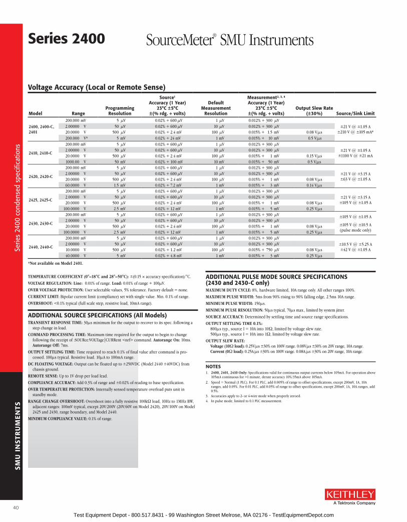
SM
U I
NS
TRU
ME
NTS
Voltage accuracy (local or remote sense)
Model rangeProgramming
resolution
source1
accuracy (1 Year)23°C ±5°C
±(% rdg. + volts)
Default Measurement
resolution
Measurement2, 3, 4 accuracy (1 Year)
23°C ±5°C ±(% rdg. + volts)
output slew rate (±30%) source/sink limit
2400, 2400-C, 2401
200 .000 mV 5 µV 0 .02% + 600 µV 1 µV 0 .012% + 300 µV±21 V @ ±1 .05 A
±210 V @ ±105 mA* 2 .00000 V 50 µV 0 .02% + 600 µV 10 µV 0 .012% + 300 µV 20 .0000 V 500 µV 0 .02% + 2 .4 mV 100 µV 0 .015% + 1 .5 mV 0 .08 V/µs 200 .000 V* 5 mV 0 .02% + 24 mV 1 mV 0 .015% + 10 mV 0 .5 V/µs
2410, 2410-C
200 .000 mV 5 µV 0 .02% + 600 µV 1 µV 0 .012% + 300 µV±21 V @ ±1 .05 A
±1100 V @ ±21 mA 2 .00000 V 50 µV 0 .02% + 600 µV 10 µV 0 .012% + 300 µV 20 .0000 V 500 µV 0 .02% + 2 .4 mV 100 µV 0 .015% + 1 mV 0 .15 V/µs 1000 .00 V 50 mV 0 .02% + 100 mV 10 mV 0 .015% + 50 mV 0 .5 V/µs
2420, 2420-C
200 .000 mV 5 µV 0 .02% + 600 µV 1 µV 0 .012% + 300 µV±21 V @ ±3 .15 A±63 V @ ±1 .05 A
2 .00000 V 50 µV 0 .02% + 600 µV 10 µV 0 .012% + 300 µV 20 .0000 V 500 µV 0 .02% + 2 .4 mV 100 µV 0 .015% + 1 mV 0 .08 V/µs 60 .0000 V 1 .5 mV 0 .02% + 7 .2 mV 1 mV 0 .015% + 3 mV 0 .14 V/µs
2425, 2425-C
200 .000 mV 5 µV 0 .02% + 600 µV 1 µV 0 .012% + 300 µV±21 V @ ±3 .15 A±105 V @ ±1 .05 A
2 .00000 V 50 µV 0 .02% + 600 µV 10 µV 0 .012% + 300 µV 20 .0000 V 500 µV 0 .02% + 2 .4 mV 100 µV 0 .015% + 1 mV 0 .08 V/µs 100 .0000 V 2 .5 mV 0 .02% + 12 mV 1 mV 0 .015% + 5 mV 0 .25 V/µs
2430, 2430-C
200 .000 mV 5 µV 0 .02% + 600 µV 1 µV 0 .012% + 300 µV ±105 V @ ±1 .05 A
±105 V @ ±10 .5 A (pulse mode only)
2 .00000 V 50 µV 0 .02% + 600 µV 10 µV 0 .012% + 300 µV 20 .0000 V 500 µV 0 .02% + 2 .4 mV 100 µV 0 .015% + 1 mV 0 .08 V/µs 100 .0000 V 2 .5 mV 0 .02% + 12 mV 1 mV 0 .015% + 5 mV 0 .25 V/µs
2440, 2440-C
200 .000 mV 5 µV 0 .02% + 600 µV 1 µV 0 .012% + 300 µV±10 .5 V @ ±5 .25 A±42 V @ ±1 .05 A
2 .00000 V 50 µV 0 .02% + 600 µV 10 µV 0 .012% + 300 µV 10 .0000 V 500 µV 0 .02% + 1 .2 mV 100 µV 0 .015% + 750 µV 0 .08 V/µs 40 .0000 V 5 mV 0 .02% + 4 .8 mV 1 mV 0 .015% + 3 mV 0 .25 V/µs
*Not available on Model 2401.
TEMPERATURE COEFFICIENT (0°–18°C and 28°–50°C): ±(0 .15 × accuracy specification)/°C .
VOLTAGE REGULATION: Line: 0 .01% of range . Load: 0 .01% of range + 100µV .
OVER VOLTAGE PROTECTION: User selectable values, 5% tolerance . Factory default = none .
CURRENT LIMIT: Bipolar current limit (compliance) set with single value . Min . 0 .1% of range .
OVERSHOOT: <0 .1% typical (full scale step, resistive load, 10mA range) .
aDDITIoNal sourCE sPECIfICaTIoNs (all Models)TRANSIENT RESPONSE TIME: 30µs minimum for the output to recover to its spec . following a
step change in load .
COMMAND PROCESSING TIME: Maximum time required for the output to begin to change following the receipt of :SOURce:VOLTage|CURRent <nrf> command . Autorange On: 10ms . Autorange Off: 7ms .
OUTPUT SETTLING TIME: Time required to reach 0 .1% of final value after command is pro-cessed . 100µs typical . Resistive load . 10µA to 100mA range .
DC FLOATING VOLTAGE: Output can be floated up to ±250VDC (Model 2440 ±40VDC) from chassis ground .
REMOTE SENSE: Up to 1V drop per load lead .
COMPLIANCE ACCURACy: Add 0 .3% of range and ±0 .02% of reading to base specification .
OVER TEMPERATURE PROTECTION: Internally sensed temperature overload puts unit in standby mode .
RANGE CHANGE OVERSHOOT: Overshoot into a fully resistive 100kW load, 10Hz to 1MHz BW, adjacent ranges: 100mV typical, except 20V/200V (20V/60V on Model 2420), 20V/100V on Model 2425 and 2430, range boundary, and Model 2440 .
MINIMUM COMPLIANCE VALUE: 0 .1% of range .
aDDITIoNal PulsE MoDE sourCE sPECIfICaTIoNs (2430 and 2430-C only)MAXIMUM DUTy CyCLE: 8%, hardware limited, 10A range only . All other ranges 100% .
MAXIMUM PULSE WIDTH: 5ms from 90% rising to 90% falling edge, 2 .5ms 10A range .
MINIMUM PULSE WIDTH: 150µs .
MINIMUM PULSE RESOLUTION: 50µs typical, 70µs max ., limited by system jitter .
SOURCE ACCURACy: Determined by settling time and source range specifications .
OUTPUT SETTLING TIME 0.1%: 800µs typ ., source I = 10A into 10W, limited by voltage slew rate . 500µs typ ., source I = 10A into 1W, limited by voltage slew rate .
OUTPUT SLEW RATE: Voltage (10W load): 0 .25V/µs ±30% on 100V range . 0 .08V/µs ±30% on 20V range, 10A range . Current (0W load): 0 .25A/µs ±30% on 100V range . 0 .08A/µs ±30% on 20V range, 10A range .
NoTEs1 . 2400, 2401, 2410 Only: Specifications valid for continuous output currents below 105mA . For operation above
105mA continuous for >1 minute, derate accuracy 10%/35mA above 105mA .2 . Speed = Normal (1 PLC) . For 0 .1 PLC, add 0 .005% of range to offset specifications, except 200mV, 1A, 10A
ranges, add 0 .05% . For 0 .01 PLC, add 0 .05% of range to offset specifications, except 200mV, 1A, 10A ranges, add 0 .5% .
3 . Accuracies apply to 2- or 4-wire mode when properly zeroed .4 . In pulse mode, limited to 0 .1 PLC measurement .
series 2400 SourceMeter® SMU Instruments
Serie
s 24
00 c
onde
nsed
spe
cific
atio
ns
Serie
s 24
00 c
onde
nsed
spe
cific
atio
ns
40 Test Equipment Depot - 800.517.8431 - 99 Washington Street Melrose, MA 02176 - TestEquipmentDepot.com

SM
U I
NS
TRU
ME
NTS
A Greater Measure of Confidence
Current accuracy (local or remote sense)
Model rangeProgramming
resolution
source 1, 3 accuracy (1 Year)
23°C ±5°C ±(% rdg. + amps)
Default Measurement resolution
Measurement 5, 6, 7 accuracy (1 Year)
23°C ±5°C ±(% rdg. + amps) source/sink limit
2400, 2400-C, 2401
1 .00000 µA 50 pA 0 .035% + 600 pA 10 pA 0 .029% + 300 pA
±1 .05A @ ±21 V±105 mA @ ±210 V 8
10 .0000 µA 500 pA 0 .033% + 2 nA 100 pA 0 .027% + 700 pA100 .000 µA 5 nA 0 .031% + 20 nA 1 nA 0 .025% + 6 nA1 .00000 mA 50 nA 0 .034% + 200 nA 10 nA 0 .027% + 60 nA10 .0000 mA 500 nA 0 .045% + 2 µA 100 nA 0 .035% + 600 nA100 .000 mA 5 µA 0 .066% + 20 µA 1 µA 0 .055% + 6 µA1 .00000 A2 50 µA 0 .27 % + 900 µA 10 µA 0 .22 % + 570 µA
2410, 2410-C
1 .00000 µA 50 pA 0 .035% + 600 pA 10 pA 0 .029% + 300 pA
±1 .05A @ ±21 V±21 mA @ ±1100 V
10 .0000 µA 500 pA 0 .033% + 2 nA 100 pA 0 .027% + 700 pA100 .000 µA 5 nA 0 .031% + 20 nA 1 nA 0 .025% + 6 nA1 .00000 mA 50 nA 0 .034% + 200 nA 10 nA 0 .027% + 60 nA20 .0000 mA 500 nA 0 .045% + 4 µA 100 nA 0 .035% + 1 .2 µA100 .000 mA 5 µA 0 .066% + 20 µA 1 µA 0 .055% + 6 µA1 .00000 A2 50 µA 0 .27 % + 900 µA 10 µA 0 .22 % + 570 µA
2420, 2420-C
10 .0000 µA 500 pA 0 .033% + 2 nA 100 pA 0 .027% + 700 pA
±3 .15A @ ±21 V±1 .05 A @ ±63 V
100 .000 µA 5 nA 0 .031% + 20 nA 1 nA 0 .025% + 6 nA1 .00000 mA 50 nA 0 .034% + 200 nA 10 nA 0 .027% + 60 nA10 .0000 mA 500 nA 0 .045% + 2 µA 100 nA 0 .035% + 600 nA100 .000 mA 5 µA 0 .066% + 20 µA 1 µA 0 .055% + 6 µA1 .00000 A2 50 µA 0 .067% + 900 µA 10 µA 0 .066% + 570 µA3 .00000 A2 50 µA 0 .059% + 2 .7 mA 10 µA 0 .052% + 1 .71 mA
2425, 2425-C
10 .0000 µA 500 pA 0 .033% + 2 nA 100 pA 0 .027% + 700 pA
±3 .15A @ ±21 V±1 .05 A @ ±105 V
100 .000 µA 5 nA 0 .031% + 20 nA 1 nA 0 .025% + 6 nA1 .00000 mA 50 nA 0 .034% + 200 nA 10 nA 0 .027% + 60 nA10 .0000 mA 500 nA 0 .045% + 2 µA 100 nA 0 .035% + 600 nA100 .000 mA 5 µA 0 .066% + 20 µA 1 µA 0 .055% + 6 µA1 .00000 A2 50 µA 0 .067% + 900 µA 10 µA 0 .060% + 570 µA3 .00000 A2 50 µA 0 .059% + 2 .8 mA 10 µA 0 .052% + 1 .71 mA
2430, 2430-C
10 .0000 µA 500 pA 0 .033% + 2 nA 100 pA 0 .027% + 700 pA
±1 .05A @ ±105 V
±10 .5 A @ ±105 V(pulse mode only)
100 .000 µA 5 nA 0 .031% + 20 nA 1 nA 0 .025% + 6 nA1 .00000 mA 50 nA 0 .034% + 200 nA 10 nA 0 .027% + 60 nA10 .0000 mA 500 nA 0 .045% + 2 µA 100 nA 0 .035% + 600 nA100 .000 mA 5 µA 0 .066% + 20 µA 1 µA 0 .055% + 6 µA1 .00000 A 50 µA 0 .067% + 900 µA 10 µA 0 .060% + 570 µA3 .00000 A2 10 .00000 A4
500 µA500 µA
0 .059% + 2 .8 mA0 .089% + 5 .9 mA
10 µA 10 µA
0 .052% + 1 .71 mA0 .082% + 1 .71 mA
2440, 2440-C
10 .0000 µA 500 pA 0 .033% + 2 nA 100 pA 0 .027% + 700 pA
±5 .25A @ ±10 .5 V±1 .05 A @ ±42 V
100 .000 µA 5 nA 0 .031% + 20 nA 1 nA 0 .025% + 6 nA1 .00000 mA 50 nA 0 .034% + 200 nA 10 nA 0 .027% + 60 nA10 .0000 mA 500 nA 0 .045% + 2 µA 100 nA 0 .035% + 600 nA100 .000 mA 5 µA 0 .066% + 20 µA 1 µA 0 .055% + 6 µA1 .00000 A 50 µA 0 .067% + 900 µA 10 µA 0 .060% + 570 µA5 .00000 A 50 µA 0 .10 % + 5 .4 mA 10 µA 0 .10 % + 3 .42 mA
TEMPERATURE COEFFICIENT (0°–18°C and 28°–50°C): ±(0 .15 × accuracy specification)/°C .
CURRENT REGULATION: Line: 0 .01% of range . Load: 0 .01% of range (except Model 2440 5A range 0 .05%) + 100pA .
VOLTAGE LIMIT: Bipolar voltage limit (compliance) set with single value . Min . 0 .1% of range .
OVERSHOOT: <0 .1% typical (1mA step, RL = 10kW, 20V range for Model 2400, 2401, 2410, 2420, 2425, 2430), (10V range for Model 2440) .
CoNTaCT CHECK sPECIfICaTIoNs (requires -C version)(Not available for Model 2401)
SPEED: 350µs for verification and notification .
CONTACT CHECK: 2 W 15 W 50 W
No contact check failure <1 .00 W <13 .5 W <47 .5 WAlways contact check failure >3 .00 W >16 .5 W >52 .5 W
NoTEs1 . 2400, 2401, 2410 Only: Specifications valid for continuous output currents below 105mA . For operation above
105mA continuous for >1 minute, derate accuracy 10%/35mA above 105mA .2 . Full operation (1A) regardless of load to 30°C (50°C for Model 2420 and 2440) . Above 30°C (50°C for Model
2420 and 2440) ambient, derate 35mA/°C and prorate 35mA/W load . 4-wire mode . For current sink operation on 1A, 3A, or 5A ranges, maximum continuous power is limited to approximately 1/2 rated power or less, depending on current, up to 30°C ambient . See power equations in the User’s Manual to calculate allowable duty cycle for specific conditions .
3 . For sink mode, 1µA to 100mA range, accuracy is: Model 2400, 2401: ±(0 .15% + offset*4) . Models 2410, 2420, 2425, 2430, 2440: ±(0 .5% + offset*3) .
For 1A range, accuracy is: Model 2400, 2401: ±(1 .5% + offset*8) . Models 2410, 2420, 2425, 2430, 2440: ±(1 .5% + offset*3) .
4 . 10A range only in pulse mode . Limited to 2 .5ms pulse width maximum . 10% duty cycle maximum .5 . Speed = Normal (1 PLC) . For 0 .1 PLC, add 0 .005% of range to offset specifications, except 200mV, 1A, 10A
ranges, add 0 .05% . For 0 .01 PLC, add 0 .05% of range to offset specifications, except 200mV, 1A, 10A ranges, add 0 .5% .
6 . Accuracies apply to 2- or 4-wire mode when properly zeroed .7 . In pulse mode, limited to 0 .1 PLC measurement .8 . Model 2400 and 2400-C only .
series 2400 SourceMeter® SMU InstrumentsSe
ries
2400
con
dens
ed s
peci
ficat
ions
Serie
s 24
00 c
onde
nsed
spe
cific
atio
ns
41 Test Equipment Depot - 800.517.8431 - 99 Washington Street Melrose, MA 02176 - TestEquipmentDepot.com

SM
U I
NS
TRU
ME
NTS
NoTEs1 . Speed = Normal (1 PLC) . For 0 .1 PLC, add 0 .005% of range to offset specifications, except 200mV, 1A, 10A ranges, add 0 .05% . For
0 .01 PLC, add 0 .05% of range to offset specifications, except 200mV, 1A, 10A ranges, add 0 .5% .2 . Accuracies apply to 2- or 4-wire mode when properly zeroed .3 . Manual ohms only – except 2420, 2425, 2430, 2440 for 2W range and 2400, 2401, or 2410 for 200MW range .4 . Source readback enabled, offset compensation ON . Also available on 2410, 2420, 2425, 2430, and 2440 with similar accuracy
enhancement .5 . In pulse mode, limited to 0 .1 PLC measurement .6 . Except 2440; default test current is 5µA .7 . Except 2440; default test current is 0 .5µA .
TEMPERATURE COEFFICIENT (0°–18°C and 28°–50°C): ±(0 .15 × accuracy specification)/°C .
SOURCE I MODE, MANUAL OHMS: Total uncertainty = I source accuracy + V measure accuracy (4-wire remote sense) .
SOURCE V MODE, MANUAL OHMS: Total uncertainty = V source accuracy + I measure accuracy (4-wire remote sense) .
6-WIRE OHMS MODE: Available using active ohms guard and guard sense . Max . Guard Output Current: 50mA (except 1A range) . Accuracy is load dependent . Refer to White Paper no . 2033 for calculation formula .
GUARD OUTPUT IMPEDANCE: <0 .1W in ohms mode .
series 2400 SourceMeter® SMU Instruments
sErVICEs aVaIlablE2400-3Y-EW 1-year factory warranty extended to 3 years from date of shipment
2400-C-3Y-EW 1-year factory warranty extended to 3 years from date of shipment
2401-3Y-EW 1-year factory warranty extended to 3 years from date of shipment
2410-3Y-EW 1-year factory warranty extended to 3 years from date of shipment
2410-C-3Y-EW 1-year factory warranty extended to 3 years from date of shipment
2420-3Y-EW 1-year factory warranty extended to 3 years from date of shipment
2420-C-3Y-EW 1-year factory warranty extended to 3 years from date of shipment
2425-3Y-EW 1-year factory warranty extended to 3 years from date of shipment
2425-C-3Y-EW 1-year factory warranty extended to 3 years from date of shipment
2430-3Y-EW 1-year factory warranty extended to 3 years from date of shipment
2430-C-3Y-EW 1-year factory warranty extended to 3 years from date of shipment
2440-3Y-EW 1-year factory warranty extended to 3 years from date of shipment
2440-C-3Y-EW 1-year factory warranty extended to 3 years from date of shipment
C/2400-3Y-ISO 3 (ISO-17025 accredited) calibrations within 3 years of purchase for Models 2400, 2400-C, 2400-LV*
C/2401-3Y-ISO 3 (ISO-17025 accredited) calibrations within 3 years of purchase for Model 2401*
C/2410-3Y-ISO 3 (ISO-17025 accredited) calibrations within 3 years of purchase for Models 2410, 2410-C*
C/2420-3Y-ISO 3 (ISO-17025 accredited) calibrations within 3 years of purchase for Models 2420, 2420-C*
C/2425-3Y-ISO 3 (ISO-17025 accredited) calibrations within 3 years of purchase for Models 2425, 2425-C*
C/2430-3Y-ISO 3 (ISO-17025 accredited) calibrations within 3 years of purchase for Models 2430, 2430-C*
C/2440-3Y-ISO 3 (ISO-17025 accredited) calibrations within 3 years of purchase for Models 2440, 2440-C*
TRN-2400-1-C Course: Unleashing the Power of Your SourceMeter SMU Instrument
*Not available in all countries
resistance Measurement accuracy (local or remote sense)1, 2, 5
rangeDefault
resolution
Default Test Current
2400, 2401, 2410
Default Test Current
2420, 2425, 2430, 2440
Normal accuracy (23°C ±5°C) 1 Year, ±(% rdg. + ohms)
Enhanced accuracy (23°C ±5°C)4
1 Year, ±(% rdg. + ohms)
2400, 2401 2410 2420, 2425, 2430, 2440 2400, 2401
<0 .20000 W3 – – – Source IACC + Meas . VACC Source IACC + Meas . VACC Source IACC + Meas . VACC Source IACC + Meas . VACC
2 .00000 W3 10 µW – 1 A Source IACC + Meas VACC Source IACC + Meas . VACC 0 .17% + 0 .0003 W Source IACC + Meas . VACC
20 .0000 W 100 µW 100 mA 100 mA 0 .10% + 0 .003 W 0 .11% + 0 .006 W 0 .10% + 0 .003 W 0 .07% + 0 .001 W
200 .000 W 1 mW 10 mA 10 mA 0 .08% + 0 .03 W 0 .09% + 0 .1 W 0 .08% + 0 .03 W 0 .05% + 0 .01 W
2 .00000 kW 10 mW 1 mA 1 mA 0 .07% + 0 .3 W 0 .08% + 0 .6 W 0 .07% + 0 .3 W 0 .05% + 0 .1 W
20 .0000 kW 100 mW 100 µA 100 µA 0 .06% + 3 W 0 .07% + 6 W 0 .06% + 3 W 0 .04% + 1 W
200 .000 kW 1 W 10 µA 10 µA 0 .07% + 30 W 0 .07% + 60 W 0 .07% + 30 W 0 .05% + 10 W
2 .00000 MW6 10 W 1 µA 1 µA 0 .11% + 300 W 0 .12% + 600 W 0 .11% + 300 W 0 .05% + 100 W
20 .0000 MW7 100 W 1 µA 1 µA 0 .11% + 1 kW 0 .12% + 2 .4 kW 0 .11% + 1 kW 0 .05% + 500 W
200 .000 MW3 1 kW 100 nA – 0 .66% + 10 kW 0 .66% + 24 kW Source IACC + Meas . VACC 0 .35% + 5 kW
>200 .000 MW3 – – – Source IACC + Meas . VACC Source IACC + Meas . VACC Source IACC + Meas . VACC Source IACC + Meas . VACC
Serie
s 24
00 c
onde
nsed
spe
cific
atio
ns
Serie
s 24
00 c
onde
nsed
spe
cific
atio
ns
42 Test Equipment Depot - 800.517.8431 - 99 Washington Street Melrose, MA 02176 - TestEquipmentDepot.com

SM
U I
NS
TRU
ME
NTS
A Greater Measure of Confidence
GENEral
system speedsMEasurEMENT1
MAXIMUM RANGE CHANGE RATE: 75/second .
MAXIMUM MEASURE AUTORANGE TIME: 40ms (fixed source) .2
sweep operation3 reading rates (rdg./second) for 60Hz (50Hz):
Measure source-Measure source-Measure5
Pass/fail Test4, 5 source-Memory4
speed NPlC/Trigger origin To Mem. To GPIb To Mem. To GPIb To Mem. To GPIb To Mem. To GPIbFast 0 .01 / internal 2081 (2030) 1754 1551 (1515) 1369 902 (900) 981 165 (162) 165IEEE-488.1 Mode 0 .01 / external 1239 (1200) 1254 1018 (990) 1035 830 (830) 886 163 (160) 163Fast 0 .01 / internal 2081 (2030) 1198 (1210) 1551 (1515) 1000 (900) 902 (900) 809 (840) 165 (162) 164 (162)IEEE-488.2 Mode 0 .01 / external 1239 (1200) 1079 (1050) 1018 (990) 916 (835) 830 (830) 756 (780) 163 (160) 162 (160)Medium 0 .10 / internal 510 (433) 509 (433) 470 (405) 470 (410) 389 (343) 388 (343) 133 (126) 132 (126)IEEE-488.2 Mode 0 .10 / external 438 (380) 438 (380) 409 (360) 409 (365) 374 (333) 374 (333) 131 (125) 131 (125)Normal 1 .00 / internal 59 (49) 59 (49) 58 (48) 58 (48) 56 (47) 56 (47) 44 (38) 44 (38)IEEE-488.2 Mode 1 .00 / external 57 (48) 57 (48) 57 (48) 57 (47) 56 (47) 56 (47) 44 (38) 44 (38)
single reading operation reading rates (rdg./second) for 60Hz (50Hz):
speed NPlC/Trigger originMeasure To GPIb
source-Measure5
To GPIbsource-Measure Pass/fail Test4,5
To GPIbFast (488.1) 0 .01 / internal 537 140 135Fast (488.2) 0 .01 / internal 256 (256) 79 (83) 79 (83)Medium (488.2) 0 .10 / internal 167 (166) 72 (70) 69 (70)Normal (488.2) 1 .00 / internal 49 (42) 34 (31) 35 (30)
Component for 60Hz (50Hz):4, 6
speed NPlC/Trigger origin Measure To GPIb source Pass/fail Testsource-Measure Pass/fail Test5, 7
To GPIbFast 0 .01 / external 1 .04 ms (1 .08 ms) 0 .5 ms (0 .5 ms) 4 .82 ms (5 .3 ms)Medium 0 .10 / external 2 .55 ms (2 .9 ms) 0 .5 ms (0 .5 ms) 6 .27 ms (7 .1 ms)Normal 1 .00 / external 17 .53 ms (20 .9 ms) 0 .5 ms (0 .5 ms) 21 .31 ms (25 .0 ms)
1 Reading rates applicable for voltage or current measurements . Auto zero off, autorange off, filter off, display off, trigger delay = 0, and binary reading format .
2 Purely resistive lead . 1µA and 10µA ranges <65ms .3 1000 point sweep was characterized with the source on a fixed range .
4 Pass/Fail test performed using one high limit and one low math limit .5 Includes time to re-program source to a new level before making measurement .6 Time from falling edge of START OF TEST signal to falling edge of END OF TEST signal .7 Command processing time of :SOURce:VOLTage|CURRent:TRIGgered <nrf> command not included .
Noise rejection: NPlC NMrr CMrr
Fast 0 .01 — 80 dBMedium 0 .1 — 80 dBSlow 1 60 dB 100 dB1
1 Except lowest 2 current ranges = 90dB .
LOAD IMPEDANCE: Stable into 20,000pF typical .
COMMON MODE VOLTAGE: 250V DC (40V DC for Model 2440) .
COMMON MODE ISOLATION: >109W, <1000pF .
OVERRANGE: 105% of range, source and measure .
MAX. VOLTAGE DROP BETWEEN INPUT/OUTPUT AND SENSE TERMINALS: 5V .
MAX. SENSE LEAD RESISTANCE: 1MW for rated accuracy .
SENSE INPUT IMPEDANCE: >1010W .
GUARD OFFSET VOLTAGE: <150µV, typical (300µV for Models 2430, 2440) .
SOURCE OUTPUT MODES: Pulse (Model 2430 only) Fixed DC level Memory List (mixed function) Stair (linear and log)
MEMORy BUFFER: 5,000 readings @ 5 digits (two 2,500 point buffers) . Includes selected measured value(s) and time stamp . Lithium battery backup (3 yr+ battery life) .
SOURCE MEMORy LIST: 100 points max .
PROGRAMMABILITy: IEEE-488 (SCPI-1995 .0), RS-232, 5 user-definable power-up states plus factory default and *RST .
DIGITAL INTERFACE:Interlock: Active low input .Handler Interface: Start of test, end of test, 3 category bits . +5V@ 300mA supply .
Not available on Model 2401 .Digital I/O: 1 trigger input, 4 TTL/Relay Drive outputs (33V @ 500mA, diode clamped) .
Not available on Model 2401 .
POWER SUPPLy: 100V to 240V rms, 50–60Hz (automatically detected at power up) . Model 2400, 2401: 190VA . Model 2410: 210VA . Model 2420: 220VA . Model 2425, 2430: 250VA . Model 2440: 240VA .
COOLING: Model 2401: Convection . Model 2410, 2420, 2425, 2430, 2440: Forced air, variable speed .
EMC: Conforms to European Union Directive 89/336/EEC, EN 61326-1 .
SAFETy: UL listed to UL 61010B-1:2003: Conforms to European Union Low Voltage Directive .
VIBRATION: MIL-PRF-28800F Class 3 Random .
WARM-UP: 1 hour to rated accuracies .
DIMENSIONS: 89mm high × 213mm wide × 370mm deep (3½ in × 83⁄8 in × 149⁄16 in) . Bench Configuration (with handle and feet):104mm high × 238mm wide × 370mm deep (41⁄8 in × 93⁄8 in × 149⁄16 in) .
WEIGHT: 3 .21kg (7 .08 lbs) (Model 2425, 2430, 2440: 4 .1kg, 9 .0 lbs) .
ENVIRONMENT: Operating: 0°–50°C, 70% R .H . up to 35°C . Derate 3% R .H ./°C, 35°–50°C . Storage: –25°C to 65°C .
series 2400 SourceMeter® SMU Instruments
NoTEs
Serie
s 24
00 c
onde
nsed
spe
cific
atio
ns
Serie
s 24
00 c
onde
nsed
spe
cific
atio
ns
43 Test Equipment Depot - 800.517.8431 - 99 Washington Street Melrose, MA 02176 - TestEquipmentDepot.com
SM
U I
NS
TRU
ME
NTS
The Model 6430 Sub-Femtoamp Remote SourceMeter SMU Instrument combines the voltage and current sourcing and measurement functions of Keithley’s popular SourceMeter SMU instruments with sensitivity, noise, and input resistance specifications superior to electrometers . This unique combination of broad functionality and exceptional measurement integrity is made possible by the Model 6430’s Remote PreAmp, which offers a very sensitive bi-directional amplifier with sensitive feedback elements for measuring or sourcing currents at the device being tested . The high level signals output by the Remote PreAmp are sent to the controlling mainframe via a two-meter cable . This allows the user to make a direct or very short connection to the signal, minimizing the effects of cable noise .
The Model 6430 makes voltage, current, and resistance measurements at speeds no electrom-eter can match . It can read up to 2000 source/
measure readings per second into internal memory . Currents can be measured in as little as 5ms on the 100nA range, decreasing to just a few hundred microseconds on the higher ranges .
The Model 6430’s distinguishing features include its excellent low current sensitivity and the Remote PreAmp, which makes this sensitivity useful by eliminating long input cables . The Remote PreAmp is an integral part of the Model 6430’s feedback measuring system that cannot be operated indepen-dently from the measurement mainframe, although it can be separated from the mainframe by up to two meters of connection cable carrying high level signals .
applicationsThe Model 6430’s capabilities make it equally useful for research work and for evaluating sophisticated components in test labs for low-current, high-resistance, or sensitive semicon-ductor measurements . The low noise and drift performance of the Model 6430 also makes it well suited for research studies in single electron devices, highly resistive nanowires and nano-tubes, polymers, highly resistive nanomaterials, and electrochemical amperometry applications .
High speed Data HandlingThe Model 6430 can read more than 2000 read-ings per second into its internal memory buffer . The IEEE-488 bus output can transmit up to 75 source/measure readings per second to an external computer controller, including pass/fail indication .
• 0.4fa p-p (4E–16a) noise (typical)
• remote Preamp can be located at the signal source to minimize cable noise
• >1016W input resistance on voltage measurements
• High speed — up to 2000 readings/second
• up to 6½-digit resolution
• fast characterization of components with programmable digital I/o and interfaces
+100mA
–100mA
+10mA
+20V–20V +200V–200V
–10mA
The Model 6430 provides four-quadrant sourcing of up to 2.2W, as well as measure-ment sensitivity down to sub-femtoamp and microvolt levels. It can measure currents from the 1pa range (with just 0.4fa p-p noise typical) up to the 100ma range at up to 20V. Voltage ranges from 200mV to 200V are available. Current and voltage range settings define the maximum source or sink voltage or current.
6430 Sub-femtoamp Remote SourceMeter® SMU Instrument
Com
bine
s br
oad
func
tiona
lity
with
exc
eptio
nal m
easu
rem
ent i
nteg
rity
Com
bine
s br
oad
func
tiona
lity
with
exc
eptio
nal m
easu
rem
ent i
nteg
rity
44 Test Equipment Depot - 800.517.8431 - 99 Washington Street Melrose, MA 02176 - TestEquipmentDepot.com

SM
U I
NS
TRU
ME
NTS
A Greater Measure of Confidence
ordering Information6430 sub-femtoamp
remote sourceMeter sMu Instrument
accessories supplied6430-322-1b
low Noise Triax Cable, 3-slot triax to alligator clips, 20cm (8 in)
8607 safety High Voltage Dual Test leads
Ca-176-1E Preamp Cable, 2m (6.6 ft)
Ca-186-1b banana lead to screw Terminal adapter
CaP-31 3-lug Protective Cap (2)
Instruction Manual
2x10–15A
1x10–15A
0
–1x10–15A
–2x10–15A
0 1 2 3 4 5Hours
1 fA
1x10–15A
0
–1x10–15A
1 fA
0 10 20 30 40 50 60 70 80 90 100Seconds
Typical applications: Semiconductor measurementsGate leakage or channel leakage in FET-based com-ponents can generate errors in MOSFETs, JFETs, analog switches, and many other circuits . By allowing research-ers to measure extremely low-level currents and voltag-es, the Model 6430 can help them understand the design limitations of these components and investigate alternative device structures or materials .
SET research The Model 6430’s superior low current measurement ability (0 .4fA p-p noise typical) makes it extremely useful for single electron transistor (SET) and quantum-dot research . Using a technique similar to a lock-in, the 6430 can measure currents with 1aA sensitivity (10–18A = 6 electrons/second) .
The Measurement Industry’s lowest Noise and DriftThis data illustrates the Model 6430’s impressive stability over a five-hour period, as well as its low short-term noise performance . This signal trace was acquired using the instrument’s AUTOFILTER with a 5- second rise time on the 1pA range . The inset close-up is a snapshot of the filtered signal, showing the Model 6430’s low noise during the first 100-second period . The data was taken in a laboratory environment where temperature varied about 1°C, with the instrument’s IN/OUT HI and SENSE leads capped .
Measuring fET Gate leakage and Channel Currents
Model 6430 Model 6430
D
GGA
IG
VGS
VDS
ID
A
S S
D
+
+
6430 Sub-Femtoamp Remote SourceMeter® SMU Instrument
aCCEssorIEs aVaIlablE7007-1 Shielded GPIB Cable, 1m (3 .3 ft)7007-2 Shielded GPIB Cable, 2m (6 .6 ft)7007-4 Shielded GPIB Cable, 4m (13 .1 ft)7007-05 Shielded GPIB Cable, 0 .5m (1 .6 ft)7078-TRX-6IN 3-slot, Low Noise, 0 .15m (0 .5 ft) Guarded
Triax Cable 8501-1 Trigger Link Cable, 1m (3 .3 ft .)8501-2 Trigger Link Cable, 2m (6 .6 ft .)8502 Trigger Link Adapter Box8503 Trigger Link DIN-to-BNC Trigger CableKPCI-488LPA IEEE-488 Interface/Controller for the PCI BusKUSB-488B IEEE-488 USB-to-GPIB Interface Adapter
sErVICEs aVaIlablETRN-2400-1-C Course: Unleashing the Power of Your
SourceMeter SMU Instrument6430-3Y-EW 1-year factory warranty extended to 3 years
from date of shipmentC/6430-3Y-ISO 3 (ISO-17025 accredited) calibrations within 3
years of purchase**Not available in all countries
Com
bine
s br
oad
func
tiona
lity
with
exc
eptio
nal m
easu
rem
ent i
nteg
rity
Com
bine
s br
oad
func
tiona
lity
with
exc
eptio
nal m
easu
rem
ent i
nteg
rity
45 Test Equipment Depot - 800.517.8431 - 99 Washington Street Melrose, MA 02176 - TestEquipmentDepot.com

SM
U I
NS
TRU
ME
NTS
VolTaGE MEasurEMENT aCCuraCY (4-WIrE sENsE)3
range Max. resolutionInput2
resistanceaccuracy (23°C ± 5°C) 1 Year, ±(%rdg + volts)
200 .000 mV 1 µV >1016W 0 .012% + 350 µV 2 .00000 V 10 µV >1016W 0 .012% + 350 µV 20 .0000 V 100 µV >1016W 0 .015% + 1 .5 mV 200 .000 V 1 mV >1016W 0 .015% + 10 mV
TEMPERATURE COEFFICIENT (0°–18°C and 28°–40°C): ±(0 .15 × accuracy specification)/°C .
aDDITIoNal MEasurE sPECIfICaTIoNsOUTPUT SETTLING TIME (typical to 10% of final value): <2s, 1pA and 10pA ranges; <50ms,
100pA through 10nA ranges; <5ms, 100nA through 100mA ranges .
CURRENT NOISE: When observed over 1 minute intervals, peak to peak noise will be within 400aA (typical) during 90% of the intervals using Autofilter (5s 10% to 90% rise time), with triax connectors capped, Autozero OFF, Source Delay = 0, on the 1pA range for at least 3 minutes .
CurrENT MEasurEMENT aCCuraCY (2- or 4-WIrE sENsE)4
rangeMax.
resolutionVoltage burden5
accuracy (23°C ± 5°C)
1 Year ±(%rdg + amps)
1 .00000 pA 10 aA < 1mV 1 .0 % + 7 fA10 .0000 pA 100 aA < 1mV 0 .50 % + 7 fA100 .000 pA 1 fA < 1mV 0 .15 % + 30 fA1 .00000 nA 10 fA < 1mV 0 .050 % + 200 fA10 .0000 nA 100 fA < 1mV 0 .050 % + 2 pA100 .000 nA 1 pA < 1mV 0 .050 % + 20 pA1 .00000 µA 10 pA < 1mV 0 .050 % + 300 pA10 .0000 µA 100 pA < 1mV 0 .050 % + 2 nA100 .000 µA 1 nA < 1mV 0 .025 % + 6 nA1 .00000 mA 10 nA < 1mV 0 .027 % + 60 nA10 .0000 mA 100 nA < 1mV 0 .035 % + 600 nA100 .000 mA 1 µA < 1mV 0 .055 % + 6 µA
TEMPERATURE COEFFICIENT (0°–18°C and 28°–40°C): ±[(0 .15 × accuracy specification) + 1fA]/°C .
INPUT CURRENT: <3fA at 23°C, <40% RH; typically ±0 .5fA/°C around 23°C, <40% RH .
CoNDENsED MEasurE sPECIfICaTIoNs 1
rEsIsTaNCE MEasurEMENT aCCuraCY (4-WIrE sENsE WITH rEMoTE PrEaMP)Source I Mode, Auto Ohms Normal accuracy Enhanced accuracy Max. Default (23°C ± 5°C) (23°C ± 5°C) 7 range resolution Test Current 1 Year, ±(%rdg + ohms) 1 Year, ±(%rdg + ohms) <2 .00000 W 6 1 µW — Source IACC + Measure VACC Measure IACC + Measure VACC
20 .0000 W 100 µW 100 mA 0 .098% + 0 .003 W 0 .068% + 0 .001 W 200 .000 W 1 mW 10 mA 0 .077% + 0 .03 W 0 .048% + 0 .01 W 2 .00000 kW 10 mW 1 mA 0 .066% + 0 .3 W 0 .040% + 0 .1 W 20 .0000 kW 100 mW 100 µA 0 .063% + 3 W 0 .038% + 1 W 200 .000 kW 1 W 10 µA 0 .082% + 30 W 0 .064% + 10 W 2 .00000 MW 10 W 1 µA 0 .082% + 300 W 0 .064% + 100 W 20 .0000 MW 100 W 1 µA 0 .085% + 1 kW 0 .067% + 500 W 200 .000 MW 1 kW 100 nA 0 .085% + 10 kW 0 .068% + 5 kW 2 .00000 GW 10 kW 10 nA 0 .085% + 100 kW 0 .070% + 50 kW 20 .0000 GW 100 kW 1 nA 0 .085% + 1 MW 0 .070% + 500 kW 200 .000 GW 1 MW 100 pA 0 .205% + 10 MW 0 .185% + 5 MW 2 .00000 TW 10 MW 10 pA 0 .822% + 100 MW 0 .619% + 50 MW 20 .0000 TW 100 MW 1 pA 2 .06% + 1 GW 1 .54% + 500 MW >20 .0000 TW 6 — — Source IACC + Measure VACC Measure IACC + Measure VACC
TEMPERATURE COEFFICIENT (0°–18°C and 28°–40°C): ±(0 .15 × accuracy specification)/°C .
SOURCE I MODE, MANUAL OHMS: Total uncertainty = I source accuracy + V measure accuracy (4-wire sense) .
SOURCE V MODE: Total uncertainty = V source accuracy + I measure accuracy (4-wire sense) .
6-WIRE OHMS MODE: Available using active ohms guard and guard sense (mainframe rear panel ONLY) . Max. Guard Output Current: 50 mA . Accuracy is load dependent . Refer to manual for calculation formula .
MAINFRAME GUARD OUTPUT RESISTANCE: 0 .1W in ohms mode .
NoTEs1 . Speed = 10 PLC, Autofilter ON, properly zeroed and settled .2 . Source I mode, I = 0 .3 . Voltage measurement accuracy is not affected by the remote preamp .4 . Current measurement accuracy is not affected by the remote preamp; however, the 1pA through 100nA ranges
are available only when using a preamp .5 . 4-wire mode .6 . Manual ohms mode only .7 . Source readback enabled, offset compensation ON . Source delay must be pro grammed such that the source is
fully settled for each reading .
6430 Sub-Femtoamp Remote SourceMeter® SMU Instrument
Mod
el 6
430
spec
ifica
tions
Mod
el 6
430
spec
ifica
tions
46 Test Equipment Depot - 800.517.8431 - 99 Washington Street Melrose, MA 02176 - TestEquipmentDepot.com

SM
U I
NS
TRU
ME
NTS
A Greater Measure of Confidence
CoNDENsED sourCE sPECIfICaTIoNs4
VolTaGE ProGraMMING aCCuraCY (4-WIrE sENsE)5
accuracy (1 Year) Noise Programming 23°C ±5°C (peak-peak) range resolution ±(% rdg. + volts) 0.1Hz – 10Hz 200 .000 mV 5 µV 0 .02% + 600 µV 5 µV 2 .00000 V 50 µV 0 .02% + 600 µV 50 µV 20 .0000 V 500 µV 0 .02% + 2 .4 mV 500 µV 200 .000 V 5 mV 0 .02% + 24 mV 5 mV
TEMPERATURE COEFFICIENT (0°–18°C and 28°–40°C): ±(0 .15 × accuracy specification)/°C .
MAX. OUTPUT POWER: 2 .2W (four quadrant source or sink operation) .
SOURCE/SINK LIMITS: ±21V @ ±105mA, ±210V @ ±10 .5mA .
VOLTAGE REGULATION: Line: 0 .01% of range . Load: 0 .01% of range + 100µV .
NOISE 10Hz–1MHz (p-p): 10mV .
OVER VOLTAGE PROTECTION: User selectable values, 5% tolerance . Factory default = None .
CURRENT LIMIT: Bipolar current limit (compliance) set with single value . Min . 0 .1% of range .
CurrENT ProGraMMING aCCuraCY (WITH rEMoTE PrEaMP) accuracy (1 Year)4 Noise Programming 23°C ±5°C (peak-peak) range resolution ±(% rdg. + amps) 0.1Hz – 10Hz 1 .00000 pA 50 aA 1 .0 % + 10 fA 5 fA 10 .0000 pA 500 aA 0 .50 % + 30 fA 10 fA 100 .000 pA 5 fA 0 .15 % + 40 fA 20 fA 1 .00000 nA 50 fA 0 .050 % + 200 f A 50 fA 10 .0000 nA 500 fA 0 .050 % + 2 pA 500 fA 100 .000 nA 5 pA 0 .050 % + 20 pA 3 pA 1 .00000 µA 50 pA 0 .050 % + 300 pA 20 pA 10 .0000 µA 500 pA 0 .050 % + 2 nA 200 pA 100 .000 µA 5 nA 0 .031 % + 20 nA 500 pA 1 .00000 mA 50 nA 0 .034 % + 200 nA 5 nA 10 .0000 mA 500 nA 0 .045 % + 2 µA 50 nA 100 .000 mA 5 µA 0 .066 % + 20 µA 500 nA
TEMPERATURE COEFFICIENT (0°–18°C and 28°–40°C): ±(0 .15 × accuracy specification)/°C .
MAX. OUTPUT POWER: 2 .2W (four quadrant source or sink operation) .
SOURCE/SINK LIMITS: ±10 .5mA @ ±210V, ±105mA @ ±21V .
CURRENT REGULATION: Line: 0 .01% of range . Load: 0 .01% of range + 1fA .
VOLTAGE LIMIT: Bipolar voltage limit (compliance) set with single value . Min . 0 .1% of range .
CoNDENsED sYsTEM sPEEDs
NoTEs1 . Reading rates applicable for voltage or current measurements . Auto zero off, autorange off, filter off, display
off, trigger delay = 0, source auto clear off, and binary reading format .2 . Pass/Fail test performed using one high limit and one low math limit .3 . Includes time to re-program source to a new level before making measurement .4 . For sink mode, 1pA to 100mA range, accuracy is ±(0 .15% + offset*4) . 5 . Voltage source accuracies are not affected by the remote preamp .
GENEral
Noise rejection: NPlC NMrr CMrr Fast 0 .01 — 80 dB Medium 0 .1 — 80 dB Normal 1 60 dB 90 dB
LOAD IMPEDANCE: Stable into 20,000pF on the 100mA through 100µA ranges, 470pF on the 10µA and 1µA ranges, and 100pF on the nA and pA ranges . Refer to the User’s Manual for details on measuring large capacitive loads .
COMMON MODE VOLTAGE: ±42VDC maximum .
COMMON MODE ISOLATION: >109W, <1000pF .
OVERRANGE: 105% of range, source and measure .
MAX. VOLTAGE DROP BETWEEN INPUT/OUTPUT AND SENSE TERMINALS: 5V . (To meet specified accuracy with 4-wire sense, refer to the User’s Manual .)
MAX. SENSE LEAD RESISTANCE: 10W for rated accuracy .
SENSE INPUT RESISTANCE: 1MW .
MAINFRAME GUARD OFFSET VOLTAGE: 300µV, typical .
PREAMP GUARD OFFSET VOLTAGE: 1mV, typical .
PREAMP GUARD OUTPUT RESISTANCE: 110kW .
SOURCE OUTPUT MODES: Fixed DC level, Memory List (mixed function), Stair (linear and log) .
SOURCE MEMORy LIST: 100 points max .
MEMORy BUFFER: 5,000 readings @ 5½ digits (two 2,500 point buffers) . Includes selected measured value(s) and time stamp . Lithium battery backup (3 yr+ battery life) .
DIGITAL INTERFACE:
Safety Interlock: Active low input .
Handler Interface: Start of test, end of test, 3 category bits . +5V @ 300mA supply .
Digital I/O: 1 trigger input, 4 TTL/Relay Drive outputs (33V @ 500mA sink, diode clamped) .
PROGRAMMABILITy: IEEE-488 (SCPI-1995 .0), RS-232, 5 user-definable power-up states plus factory default and *RST .
POWER SUPPLy: 100V–240V rms, 50–60Hz (automatically detected at power up), 100VA max .
EMC: Conforms with European Union Directive 89/336/EEC EN 55011, EN 50082-1, EN 61000-3-2 and 61000-3-3, FCC part 15 class B .
SAFETy: Conforms with European Union Directive 73/23/EEC EN 61010-1 .
VIBRATION: MIL-PRF-28800F, Class 3 .
WARM-UP: 1 hour to rated accuracies .
DIMENSIONS: 89mm high × 213mm wide × 370mm deep (3½ in × 83⁄8 in × 14 9⁄16 in) . Bench Configuration (with handle and feet): 104mm high × 238mm wide × 370mm deep (41 ⁄8 in × 93⁄8 in × 149⁄16 in) . Amplifier: 20mm high × 57mm wide × 97mm deep (0 .783 in × 2 .225 in × 3 .75 in) .
WEIGHT: 5 .9kg (13 lbs) .
ENVIRONMENT: Operating: 0°–40°C, 60% R .H . (non-condensing) up to 35°C . Derate 5% R .H ./°C, 35°–40°C . Storage: –25°C to 65°C . Non-condensing humidity .
MEasurEMENT1
MAXIMUM RANGE CHANGE RATE: 75/second .
SINGLE READING OPERATION READING RATES (rdg/second) FOR 60Hz (50Hz):
speedNPlC/
Trigger originMeasure To GPIb
source- Measure3
To GPIb
source-Measure Pass/fail Test2, 3
To GPIbFast 0 .01 / internal 256 (256) 83 (83) 83 (83)Medium 0 .10 / internal 181 (166) 73 (70) 73 (70)Normal 1 .00 / internal 49 (42) 35 (31) 34 (30)
6430 Sub-Femtoamp Remote SourceMeter® SMU Instrument
Mod
el 6
430
spec
ifica
tions
Mod
el 6
430
spec
ifica
tions
47 Test Equipment Depot - 800.517.8431 - 99 Washington Street Melrose, MA 02176 - TestEquipmentDepot.com

SM
U I
NS
TRU
ME
NTS
The easy-to-use Model 4200-SCS performs labo-ratory grade DC I-V, C-V, and pulse device char-acterization, real-time plotting, and analysis with high precision and sub-femtoamp resolution . It is the best tool available for interactive paramet-ric analysis and device characterization . It offers the most advanced capabilities available in a fully integrated characterization system, includ-ing a complete, embedded PC with Windows operating system and mass storage . Its self- documenting, point-and-click interface speeds and simplifies the process of taking data, so users can begin analyzing their results sooner .
Its Keithley Interactive Test Environment (KITE) is so intuitive that even a novice can use the system with ease . This point-and-click software offers a full range of functionality, from manag-ing tests, organizing results, and generating reports to creating user libraries . Sophisticated and simple test sequencing and external instru-ment drivers make it simple to perform auto-mated testing with combined DC I-V, pulse, and C-V measurements .
The modular design of the Model 4200-SCS pro-vides you with tremendous flexibility . It supports up to nine internal source measure unit (SMU) instruments and optional Remote PreAmps that extend the resolution of any SMU from 100fA to 0 .1fA . Its hardware options also include four switch matrix configurations, meters, pulse generators, and more .
Optional instruments can be integrated into the Model 4200-SCS, such as dual-channel pulse generators, a dual-channel digital oscillo scope, and a C-V instrument, which is a capacitance-voltage instrument that performs capacitance measurements from femtofarads to nanofarads at frequencies from 1kHz to 10MHz .
The C-V option includes the new C-V Power package, which supports high power C-V measurements up to 400V and 300mA, up to 60V of differential DC bias, and quasistatic C-V measurements .
The exceptional low current performance of the Model 4200-SCS makes it the perfect solution for research studies of single electron transis-tors (SETs), molecular electronic devices, and other nanoelectronic devices that require I-V characterization . The 4200-SCS can also be used to make four-probe van der Pauw resistivity and Hall voltage measurements .
For more information on the Model 4200-SCS, see page 50 .
• Characterize devices with up to 9 source measure unit (sMu) instruments
• sub-femtoamp resolution measurements with optional preamps
• ultra-fast I-V module for pulse and pulse I-V capabilities
• C-V instrument makes C-V measurements as easy as DC I-V
• ultra low frequency C-V measurement capability
• familiar, point-and-click Windows® environment and intuitive GuI
• Easy to use for both interactive and automated tests
• real-time plotting and analysis allow users to view results before a test has completed and to take preemptive action as needed
• Embedded PC provides the additional benefits of a networked instrument including mapping network drives and making test results available to the corporate network
• simultaneously acquires data, analyzes plots, and prints reports
• Ideal for device character iza tion, device modeling, reliability testing, and failure analysis
• Includes instrument and prober drivers as well as interfaces to popular modeling and circuit simulation software
aPPlICaTIoNs:
semiconductor Devices
• on-wafer parametric test
• Wafer level reliability
• Packaged device characterization
• High κ gate charge trapping
• Isothermal testing of devices and materials subject to self-heating effects
• Charge pumping to characterize interface state densities in MosfET devices
• resistive or capacitive MEMs drive characterization
optoelectronic Devices
• semiconductor laser diode DC/CW characterization
• DC/CW characterization of transceiver modules
• PIN and aPD characterization
Technology Development
• Carbon nanotube characterization
• Materials research
• Electrochemistry
4200-sCs Parameter Analyzer
Lab
grad
e D
C de
vice
cha
ract
eriz
atio
n
Lab
grad
e D
C de
vice
cha
ract
eriz
atio
n
48 Test Equipment Depot - 800.517.8431 - 99 Washington Street Melrose, MA 02176 - TestEquipmentDepot.com

SE
MIC
ON
DU
CTO
R
A Greater Measure of Confidence
4200-sCs Parameter Analyzer . . . . . . . . . . . . . . . . . . . . . . . . . . 50 4200-bTI-a Ultra-Fast NBTI/PBTI Package for the Model 4200-SCS . . . . . . . . . . . . . . . . . . . . . . 57 2600-PCT-x Parametric Curve Tracer Configurations . . . . . . . . . 64 4200-PCT-x series s530 Parametric Test Systems . . . . . . . . . . . . . . . . . . . . . . 68 s500 Integrated Test Systems . . . . . . . . . . . . . . . . . . . . . . 74 aCs Automated Characterization Suite Software . . . . . . 76 aCs basic Edition Semiconductor Parametric Test Software for Component and Discrete Devices . . . . . . . . . . . . . . 79 aCs-2600-rTM Wafer Level Reliability Option for ACS . . . . . . . . . . 81
Related Products Series 2600B System SourceMeter® Multi-Channel I-V Test Solutions . . . . . . . . . . . . . . . 10 Series 2400 SourceMeter Line . . . . . . . . . . . . . . . . . 36 Semiconductor Switch Matrix Mainframes . . . . . . 214
Optoelectronics Test Technical Information . . . . . . . . . . . . . . . . . . . . . . . . 82 Selector Guide . . . . . . . . . . . . . . . . . . . . . . . . . . . . . . 84 2520 Pulsed Laser Diode Test System . . . . . . . . . . . . . . . . 85 2520INT Integrating Sphere for Pulsed Measurements . . . . . 90 system 25 Laser Diode LIV Test System . . . . . . . . . . . . . . . . . . . 93 series 2400 SourceMeter® SMU Instruments . . . . . . . . . . . . . . . 96 2502 Dual-Channel Picoammeter for Photodiode Measurements . . . . . . . . . . . . . . . . . 99 2500INT Integrating Sphere . . . . . . . . . . . . . . . . . . . . . . . . . . 100 2510 TEC SourceMeter SMU Instrument . . . . . . . . . . . . 103 2510-aT Autotuning TEC SourceMeter SMU Instrument . . . . . . . . . . . . . . . . . . . . . . . . . . . . . . . . 103 8544, 8544-TEC Laser Diode Mounts for LIV Test Systems . . . . . . . 107
Semiconductor Test
49 Test Equipment Depot - 800.517.8431 - 99 Washington Street Melrose, MA 02176 - TestEquipmentDepot.com

SE
MIC
ON
DU
CTO
R
a Total Parametric analysis systemThe 4200-SCS with KITE software is a modular, fully integrated param-eter analyzer that performs electrical characterization of materials, semiconductor devices, and processes . From basic I-V and C-V measure-ment sweeps to advanced ultra-fast pulsed I-V, waveform capture, and transient I-V measurements, the 4200-SCS provides the researcher or engineer with critical parameters needed for design, development, pro-duction, or reliability testing .
With a Microsoft® Windows® operating system, the 4200-SCS with KITE software provides sophisticated test capabilities with the ease of a graphical user interface, powerful graphing, and parameter extraction, enabling you to get to your results faster with minimal training .
Modular Design accommodates Changing Test requirements and Protects Your Investment
With nine measurement slots and a wide variety of instrument modules, you can configure the Model 4200-SCS precisely to your test requirements .
• Precision DC I-V measurements are the cornerstone of device and material testing . Up to nine medium or high power DC Source Measurement Units (SMUs) can source and measure voltage or current from 100fA to 1A and from 1µV to 210V . The current measurement resolution can be extended to 100aA with the addition of a Model 4200-PA pre-amplifier .
• AC impedance testing is easy with the most comprehensive C-V solutions in the market . The 4200-SCS can be configured to support multi-frequency, quasistatic, and very low frequency (VLF) C-V . The Model 4210-CVU Multi-Frequency C-V Module offers test frequencies from 1kHz to 10MHz and measures capacitance from attofarads to microfarads . The VLF C-V technique operates from 10mHz–10Hz .
• Pulse and transient measurements add a time domain dimension and allow for dynamic characteristics to be explored . The Model 4225-PMU Ultra-Fast I-V module has two independent voltage sources that can slew the voltage at 1V/ns while simultaneously measuring both the voltage and the current . When multiple modules are installed, they are internally synchronized to less than 3ns .
Model 4200-sCs-PK1 4200-sCs-PK2 4200-sCs-PK3 4200-sCs
Description2-channel, high resolution I-V
2-channel, high resolution I-V
and C-V
4-channel, high resolution, high
power I-V and C-VConfigured by user
Total # of SMUs 2 medium power 2 medium power 2 medium power, 2 high power
Up to 9 high or medium power
Total No. of PAs 1 1 2 Optional
Current Range and Resolution
100 mA / 0 .1 fA 100 mA / 0 .1 fA 1 A / 0 .1 fA 1 A / 0 .1 fA
Voltage Range and Resolution
±210 V / 1 µV ±210 V / 1 µV ±210 V / 1 µV ±210 V / 1 µV
Capacitance-Voltage Module
No Yes Yes Optional
Pulse No No No Optional
Test FixtureYes
8101-PIVYes
8101-PIVYes
8101-PIV Optional
• over 450 application tests and data supplied for quick startup
• Performs DC I-V, C-V, and Pulsed I-V measurements
• ultra-fast I-V modules synchronized for transient, waveform capture and pulsed I-V capabilities
• High speed, simultaneous data acquisition of I and V at 200Ms/s
• Intuitive GuI for fast test setup, data analysis, graphing, and printing of test results
• Test sequencing and looping control without programming
• JEDEC-compliant reliability sample tests for stress/measure, looping, and data analysis
• Easily integrate switching matrixes or other external equipment
• analytical prober and cryogenic temperature controller drivers included
4200-sCs Parameter Analyzer
50
Lab
grad
e D
C de
vice
cha
ract
eriz
atio
n
Lab
grad
e D
C de
vice
cha
ract
eriz
atio
n
Test Equipment Depot - 800.517.8431 - 99 Washington Street Melrose, MA 02176 - TestEquipmentDepot.com

SE
MIC
ON
DU
CTO
R
A Greater Measure of Confidence
KITE simplifies Complex TestingThe Keithley Interactive Test Environment (KITE) provides a unified parameter measurement interface that allows characterization tests to be performed without complex programming . With the largest library of user-modifiable application tests on the market, more than 450 and growing, KITE makes it easy to begin making complex measurements immediately . Conveniently organized, libraries let you easily create a single test or a sequence of tests for:
• MOSFETs
• BJT transistors
• Diodes
• Resistors
• Capacitors
• Solar cells
• Carbon nanotubes
• Non-volatile memory (NVM)
• Nanoscale devices
• Reliability
• Failure analysis
• LED and OLED
• MEMS
• Biological devices
• Electrochemistry
• Modeling
Because you want test results quickly, real-time results are available numerically or graphically on the front panel display or can be saved to any drive connected to the 4200-SCS . Additionally, you can export data to a network drive and view the results at your convenience . During the research phase, KITE’s built-in parameter extraction tools enable calculated parameters and test data to be graphed in KITE’s sophisticated, report-ready graphing tool .
Effortless Test sequencingKITE provides “point and click” test sequencing on a device, a group of devices, or a number of probe sites on a wafer . One sequence can include DC I-V, C-V, and pulse tests .
Probe station ControlKeithley provides integrated prober control for popular semiautomatic wafer probe stations . A “manual” prober mode prompts the operator to perform prober operations during a test sequence .
Providing unparalleled flexibilityIn addition to KITE, three other software tools enable you to configure and operate the 4200-SCS:
• Keithley Configuration Utility (KCON) – Allows test engineers to define the configuration of GPIB instruments, switch matrices, and analytical probers connected to the 4200-SCS . It also provides diagnostic functions .
• Keithley User Library Tool (KULT) – Assists test engineers to create custom test routines as well as use existing Keithley and third-party C-language subroutine libraries . Users can edit and compile
ordering Information4200-sCs Customize to your test
needs, or select from popular configured solutions tailored to your application.
Instrument Modules4200-sMu Medium Power
source-Measure unit4210-sMu High Power
source-Measure unit4200-Pa remote Preamp option for
4200-sMu and 4210-sMu4210-CVu Integrated C-V Instrument4225-PMu ultra-fast I-V Module4225-rPM remote amplifier/switch4220-PGu High Voltage Pulse
Generator
Probe station Cable KitsMulti-measurement Performance Cables
4210-MMPC-C for Cascade Microtech
4210-MMPC-l for lucas signatone
4210-MMPC-s for suss MicroTec
4210-MMPC-W for Wentworth
The Keithley Interactive Test Environment (KITE) is designed to let users understand device behavior quickly. When running a test sequence, users can view results and plots for completed tests while the sequence is still running.
4200-sCs Parameter Analyzer
51
Lab
grad
e D
C de
vice
cha
ract
eriz
atio
n
Lab
grad
e D
C de
vice
cha
ract
eriz
atio
n
Test Equipment Depot - 800.517.8431 - 99 Washington Street Melrose, MA 02176 - TestEquipmentDepot.com

SE
MIC
ON
DU
CTO
R
subroutines, then integrate libraries of subroutines with KITE, allowing the 4200-SCS to control an entire test rack from a single user interface . (Note: Requires optional Model 4200-Compiler .)
• Keithley External Control Interface (KXCI) – Controls the 4200-SCS from an external computer via GPIB bus .
Model 4200-sMu Medium Power and 4210-sMu High Power sMu instrumentsPrecision DC I-V measurements are the corner-stone of device and materials electrical charac-terization . The SMU instruments in the 4200-SCS can source either voltage or current, and can simultaneously measure both the voltage and current . Typically, the DC I-V measurements performed by these SMU instruments are used for very precise (0 .01%) or very sensitive (1fA, 1µV) measurements in the timeframe of mil-liseconds to seconds . The SMU instruments can also provide continuous power output, allowing tests to run for hours, or even weeks, without interruption .
The SMU instruments in the 4200-SCS are fully integrated in the 4200-SCS chassis and incor-porate the latest measurement technologies including:
• 24-bit A/D converters on every SMU
• Full remote sense (Kelvin) capability
• Broadest dynamic range of current, from <1fA to 1A
• Broadest dynamic range of voltage from <1µV to 200V
• Up to nine medium or high power SMU instruments can source/measure simultaneously
The 4200-SCS has been used by thousands of engineers and researchers around the world to electrically characterize their devices and materi-als . This has resulted in the largest library of standard tests available . More than 400 different libraries are supplied, demonstrating precision DC I-V tests on:
• CMOS MOSFETS and devices
• Bipolar devices
• Diodes and pn junctions
• Solar cells
• Nanotech devices
• And nearly every other material and device imaginable
Additional capabilities include:
• Data for most types of tests can be acquired and plotted in real time with a resolution of milli seconds to seconds
• Wide variety of standard sweep types are available, including linear and log sweeps, voltage and current sweeps, and even arbitrary custom sweeps
• Up to nine SMU instruments can be installed in a single chassis, and all nine can be used simultaneously or independently .
Model 4210-CVu C-V InstrumentC-V measurements are as easy to perform as I-V measurements with the integrated C-V instru-ment . This optional capacitance-voltage instru-ment performs capacitance measurements from femtoFarads (fF) to microFarads (µF) at frequen-cies from 1kHz to 10MHz . Also available is the 4200-CVU-PWR option that supports:
• High power C-V measurements up to 400V (200V per device terminal)—for testing high power devices, such as MEMs, LDMOS devices, displays, etc .
• DC currents up to 300mA—for measuring capacitance when a transistor is on .
The innovative design of the 4210-CVU has eight patents pending and is complemented by the broadest C-V test and analysis library available in any commercial C-V measurement solution . It also supplies diagnostic tools that ensure the validity of your C-V test results .
With this system, you can configure linear or custom C-V and C-f sweeps with up to 4096 data points . In addition, through the open environ-ment of the 4200-SCS, you can modify any of the included tests, such as:
• C-V, C-t, and C-f measurements and analysis of:
– Complete solar cell libraries, including DLCP
– High and low κ structures
– MOSFETs
– BJTs
– Diodes
– III-V compound devices
– Carbon nanotube (CNT) devices
• Doping profiles, TOX, and carrier lifetime tests
• Junction, pin-to-pin, and interconnect capacitance measurements
The C-V instrument integrates directly into the Model 4200-SCS chassis . It can be purchased as an upgrade to existing systems or as an option for new systems .
4200-sCs Parameter Analyzer
C-V curve from a MosfET transistor measured with the 4210-CVu
52
Lab
grad
e D
C de
vice
cha
ract
eriz
atio
n
Lab
grad
e D
C de
vice
cha
ract
eriz
atio
n
Test Equipment Depot - 800.517.8431 - 99 Washington Street Melrose, MA 02176 - TestEquipmentDepot.com

SE
MIC
ON
DU
CTO
R
A Greater Measure of Confidence
4200-sCs Parameter Analyzer
Model 4225-PMu ultra-fast I-V ModuleThe Model 4225-PMU Ultra Fast I-V Module is the latest addition to the growing range of instrumen-tation options for the Model 4200-SCS Parameter Analyzer . It integrates ultra-fast voltage waveform generation and signal observation capabilities into the Model 4200-SCS’s already powerful test envi-ronment to deliver unprecedented I-V testing performance, expanding the system’s materials, device, and process characterization potential dramatically . Just as important, it makes ultra-fast I-V sourcing and measurement as easy as making DC measurements with a traditional high-resolution source measure unit (SMU) .
Three types of measurements are necessary to characterize a device, material, or process thoroughly . The first two are precision DC I-V measurements (usually made with the Model 4200-SCS’s SMU instruments) and AC impedance measurements (which can be made with the Model 4210-CVU C-V Instrument) . The Model 4225-PMU represents the last segment of this characterization triangle—ultra-fast I-V or transient I-V measurements .
Some of the functionality provided by the Model 4225-PMU includes:
• Voltage outputs with programmable timing from 60ns to DC in 10ns steps
• Measuring I and V simultaneously, at acquisition rates of up to 200 megasamples/second (MS/s)
• Choosing from two voltage source ranges (±10V or ±40V) and four current measurement ranges (800mA, 200mA, 10mA, 100µA)
• Also, each module provides two channels of integrated simultaneous I-V sourcing and measurement; plug in up to six modules in a single chassis for twelve synchronized channels .
Two optional instruments offer addional functionality:
• The optional Model 4220-PGU Pulse Generator Unit offers a voltage-sourcing-only alternative to the 4225-PMU .
• The optional Model 4225-RPM Remote Amplifier/Switch expands current ranges (10mA, 1mA, 100µA, 10µA, 1µA, 100nA), switches sourcing/measurement between the Model 4225-PMU, Model 4210-CVU, Model 4200-SMU, and 4210-SMU .
Each plug-in 4225-PMU module provides two channels of integrated sourcing and measurement but occupies only a single slot in the Model 4200-SCS’s nine-slot chassis . Unlike competitive solutions, each channel of the 4225-PMU combines high speed voltage outputs (with pulse widths ranging from 60 nanoseconds to DC) with simultaneous current and voltage .
Model 4225-PMu applications• Ultra-fast general-purpose I-V measurements
• Pulsed I-V and transient I-V measurements
• Flash, PCRAM, and other non-volatile memory tests
• Isothermal testing of medium-sized power devices
• Materials testing for scaled CMOS, such as high-κ dielectrics
• NBTI/PBTI reliability tests
Each Model 4200-sCs chassis can accom-modate up to six Model 4225-PMu modules to provide up to twelve ultra-fast source and measure channels.
Cascade probe station with a Model 4225-rPM remote amplifier/switch
53
Lab
grad
e D
C de
vice
cha
ract
eriz
atio
n
Lab
grad
e D
C de
vice
cha
ract
eriz
atio
n
Test Equipment Depot - 800.517.8431 - 99 Washington Street Melrose, MA 02176 - TestEquipmentDepot.com
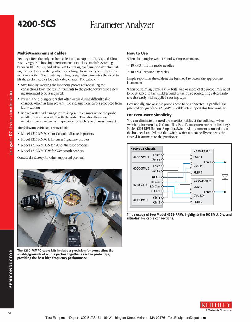
SE
MIC
ON
DU
CTO
R
4200-sCs Parameter Analyzer
Multi-Measurement CablesKeithley offers the only prober cable kits that support I-V, C-V, and Ultra-Fast I-V signals . These high performance cable kits simplify switching between DC I-V, C-V, and Ultra-Fast I-V testing configurations by eliminat-ing the need for re-cabling when you change from one type of measure-ment to another . Their patent-pending design also eliminates the need to lift the probe needles for each cable change . The cable kits:
• Save time by avoiding the laborious process of re-cabling the connections from the test instruments to the prober every time a new measurement type is required .
• Prevent the cabling errors that often occur during difficult cable changes, which in turn prevents the measurement errors produced from faulty cabling .
• Reduce wafer pad damage by making setup changes while the probe needles remain in contact with the wafer . This also allows you to maintain the same contact impedance for each type of measurement .
The following cable kits are available:
• Model 4210-MMPC-C for Cascade Microtech probers
• Model 4210-MMPC-L for Lucas Signatone probers
• Model 4210-MMPC-S for SUSS MicroTec probers
• Model 4210-MMPC-W for Wentworth probers
Contact the factory for other supported probers .
How to useWhen changing between I-V and C-V measurements:
• DO NOT lift the probe needles
• DO NOT replace any cables
Simply reposition the cable at the bulkhead to access the appropriate instrument .
When performing Ultra-Fast I-V tests, one or more of the probes may need to be attached to the shield/ground of the pulse source . The cables facili-tate this easily with supplied shorting caps .
Occasionally, two or more probes need to be connected in parallel . The patented design of the 4210-MMPC cable sets support this functionality .
for Even More simplicityYou can eliminate the need to reposition cables at the bulkhead when switching between I-V, C-V and Ultra-Fast I-V measurements with Keithley’s Model 4225-RPM Remote Amplifier/Switch . All instrument connections at the bulkhead are fed into the switch, which automatically connects the desired instrument to the positioner .
The 4210-MMPC cable kits include a provision for connecting the shields/grounds of all the probes together near the probe tips, providing the best high frequency performance.
Force4200-SMU2
Sense
Ch. 14225-PMU
Ch. 2
HI Pot
4210-CVUHI CurrLO CurrLO Pot
ForceSMU 14200-SMU1
4225-RPM 14200-SCS Chassis
CVU HI
PMU 1
SenseForce
SMU 2
4225-RPM 2
CVU LO
PMU 2
Force
This closeup of two Model 4225-rPMs highlights the DC sMu, C-V, and ultra-fast I-V cable connections.
54
Lab
grad
e D
C de
vice
cha
ract
eriz
atio
n
Lab
grad
e D
C de
vice
cha
ract
eriz
atio
n
Test Equipment Depot - 800.517.8431 - 99 Washington Street Melrose, MA 02176 - TestEquipmentDepot.com

SE
MIC
ON
DU
CTO
R
A Greater Measure of Confidence
4200-sCs Parameter Analyzer
4200-sCs Condensed specifications (Note: see the 4200 Technical Data sheet for complete specifications.)
4200-sCs CHassIs CorE CaPabIlITIEsIntegrate Intel Core2Duo processor, 2Gb Ram, 500Gb HDD, 1024X768 LCD, 9 slots, USB, Ethernet, GPIB, external monitor, over 200W of measurement power .
4200-sMu MEDIuM PoWEr sourCE-MEasurE uNIT (2.1 watts max.)MAXIMUM NUMBER OF UNITS PER CHASSIS: 9 .
VOLTAGE RANGE: ±200V, 4 ranges from 200mV to 200V full scale .
BASIC VOLTAGE ACCURACy: 0 .01% measure, 0 .02% source .
VOLTAGE RESOLUTION: 0 .1µV to 100µV .
CURRENT RANGE: ±100mA, 7 ranges from 100nA to 100mA full scale .
BASIC CURRENT ACCURACy: 0 .03% measure, 0 .04% source .
CURRENT RESOLUTION: 0 .1pA to 100pA .
WITH OPTIONAL 4200-PA: Adds 5 low current ranges with resolution down to 0 .1fA .
4210-sMu HIGH PoWEr sourCE-MEasurE uNIT (21 watts max.)MAXIMUM NUMBER OF UNITS PER CHASSIS: 9 .
VOLTAGE RANGE: ±200V, 4 ranges from 200mV to 200V full scale .
BASIC VOLTAGE ACCURACy: 0 .01% measure, 0 .02% source .
VOLTAGE RESOLUTION: 0 .1µV to 100µV .
CURRENT RANGE: ±1A, 8 ranges from 100nA to 1A full scale .
BASIC CURRENT ACCURACy: 0 .03% measure, 0 .04% source .
CURRENT RESOLUTION: 0 .1pA to 100pA .
WITH OPTIONAL 4200-PA: adds 5 low current ranges with resolution down to 0 .1fA .
4210-CVu MulTI-frEQuENCY CaPaCITaNCE-VolTaGE uNITMAXIMUM NUMBER OF UNITS PER CHASSIS: 1 (consult factory for more) .
MEASUREMENT PARAMETERS: Cp, Cs, G, R, D, Z, theta .
FREQUENCy RANGE: 1kHz to 10MHz variable .
MEASUREMENT RANGES: 100fF to 100µF typical full scale .
TyPICAL RESOLUTION: 1aF, 1nanoSiemens, 0 .001 degree .
AC SIGNAL: 10mV to 100mV programmable .
DC BIAS: ±30V on either High or Low outputs (±60V differential), 10mA max current .
OPTIONAL 4200-CVU-PWR-PKG: Utilizes SMU instruments for ±200V (400V differential) up to 300mA .
raMP raTE QuasIsTaTIC C-VMAXIMUM NUMBER OF UNITS PER CHASSIS: Requires two SMU instruments per channel .
MEASUREMENT PARAMETERS: Cp, DCV, timestamp .
RANGING: 1pF to 1nF .
RAMP RATES: 0 .1V/s to 1V/s .
DCV: ±200V .
TyPICAL ACCURACy: 5% at 1V/s ramp rate .
VErY loW frEQuENCY C-V (Vlf-CV)MAXIMUM UNITS PER CHASSIS: Requires two SMU instruments (either Model 4200-SMU or
4210-SMU) and two Model 4200-PA Remote Preamplifiers . Any two SMU instruments/PAs can be used for a VLF C-V measurement .
MEASUREMENT PARAMETERS: CP-GP, Cp-D, Cs-Rs, Cs-D, R-jX, Z-Theta, DCV, Timestamp .
FREQUENCy RANGE: 10mHz to 10Hz .
MEASUREMENT RANGE: 1pF to 10nF .
TyPICAL RESOLUTION: 3 .5 digits, minimum typical 10fF .
AC SIGNAL: 10mV to 3V rms .
DC BIAS: ±20V on the High terminal, 1µA maximum .
4225-PMu ulTra-fasT I-V uNITMAXIMUM NUMBER OF UNITS PER CHASSIS: 6 .
CHANNELS PER UNIT: 2 independent or synchronized .
VOLTAGE RANGE: ±40V, 2 ranges of 10V and 40V .
BASIC VOLTAGE ACCURACy: 0 .25% .
VOLTAGE RESOLUTION: 250µV, 750µV .
CURRENT RANGE: ±800mA, 4 ranges from 100µA to 800mA .
BASIC CURRENT ACCURACy: 0 .25% .
CURRENT RESOLUTION: 14 bits, 10nA to 10mA .
WITH OPTIONAL 4225-RPM REMOTE AMPLIFIER/SWITCH: Adds 3 low current ranges 100nA, 1µA, 10µA .
CORE A/D CONVERTER: Two per channel, 4 per unit, 5ns, 200MHz, 14 bits, 1GB memory .
CORE VOLTAGE SLEW RATE: 1V/ns .
BEST VOLTAGE PULSE WIDTH: 20ns to 10V .
TyPICAL CURRENT MEASURE PULSE WIDTH: 60ns .
EXTENDED WarraNTIEs aND CalIbraTIoN sErVICEs
EXTENDED WarraNTIEs CalIbraTIoN sErVICEsThe 1 year factory warranty is extended 3 or 5 years from date of shipment . Includes calibration and return shipping .
The calibration service provides 3 or 5 calibrations per year with before and after, ANSI/NCSL Z540-1 compliant data reports .
4200-3y-EW or 4200-5y-EW
Includes 4200-SCS mainframe including all SMUs and preamplifiers .
4200-3y-CAL or 4200-5y-CAL
Includes the 4200-SCS mainframe, all SMUs and preamplifiers .
4210-3y-EW or 4210-5y-EW
Includes 4210-CVU module . Requires purchase of 4200-3Y or 4200-5Y extended warranty .
4200-CVU-3y-CAL or 4200-CVU-5y-CAL
Includes 4210-CVU module . Requires purchase of 4200-3Y-CAL or 4200-5Y-CAL .
4225-3y-EW or 4225-5y-EW
Includes 4225-PMU module . Requires purchase of 4200-3Y or 4200-5Y extended warranty .
4200-PMU-3y-CAL or 4200-PMU-5y-CAL
Includes 4225-PMU module . Requires purchase of 4200-3Y-CAL or 4200-5Y-CAL .
4225-RPM-3y-EW or 4225-RPM-5y-EW
Includes 4225-RPM module . Requires purchase of 4200-3Y or 4200-5Y extended warranty .
4200-RPM-3y-CAL or 4200-RPM-5y-CAL
Includes 4225-RPM module . Requires purchase of 4200-3Y-CAL or 4200-5Y-CAL .
55
Mod
el 4
200-
SCS
spec
ifica
tions
Mod
el 4
200-
SCS
spec
ifica
tions
Test Equipment Depot - 800.517.8431 - 99 Washington Street Melrose, MA 02176 - TestEquipmentDepot.com

SE
MIC
ON
DU
CTO
R
oPTIoNal aCCEssorIEs
CONNECTORS AND ADAPTERSCS-565 Female BNC to Female BNC AdapterCS-701 BNC Tee Adapter (female, male, female) CS-719 3-lug Triax Jack ReceptacleCS-1247 SMA Female to BNC Male AdapterCS-1249 SMA Female to SMB Plug AdapterCS-1251 BNC Female to SMB Plug AdapterCS-1252 SMA Male to BNC Female AdapterCS-1281 SMA Female to SMA Female AdapterCS-1382 Female MMBX Jack to Male SMA Plug Adapter CS-1390 Male LEMO Triax to Female SMA AdapterCS-1391 SMA Tee Adapter (female, male, female)CS-1479 SMA Male to BNC Male Adapter237-BAN-3A Triax Cable Center Conductor terminated in a
safety banana plug 237-BNC-TRX Male BNC to 3-lug Female Triax Adapter 237-TRX-BAR 3-lug Triax Barrel Adapter (female to female) 237-TRX-T 3-slot Male to Dual 3-lug Female Triax
Tee Adapter 7078-TRX-BNC 3-Slot Male Triax to BNC Adapter 7078-TRX-GND 3-Slot Male Triax to Female BNC Connector
(guards removed)
TEST FIXTURES8101-4TRX 4-pin Transistor Fixture8101-PIV Pulse I-V Demo FixtureLR8028 Component Test Fixture
CABINET MOUNTING ACCESSORIES4200-RM Fixed Cabinet Mount Kit
CABLES AND CABLE SETSNOTE: All 4200-SCS systems and instrument options are supplied with required cables, 2m (6.5 ft.) length.CA-19-2 BNC to BNC Cable, 1 .5m CA-404B SMA to SMA Coaxial Cable, 2m CA-405B SMA to SMA Coaxial Cable, 15cm CA-406B SMA to SMA Coaxial Cable, 33cm CA-446A SMA to SMA Coaxial Cable, 3m CA-447A SMA to SMA Coaxial Cable, 1 .5m CA-451A SMA to SMA Coaxial Cable, 10 .8cm CA-452A SMA to SMA Coaxial Cable, 20 .4cm 236-ILC-3 Safety Interlock Cable, 3m 237-ALG-2 Low Noise Triax Input Cable terminated with 3
alligator clips, 2m 4210-MMPC-C Multi-Measurement (I-V, C-V, Pulse) Prober Cable
Kit for Cascade Microtech 12000 prober series 4210-MMPC-S Multi-Measurement (I-V, C-V, Pulse) Prober Cable
Kit for SUSS MicroTec PA200/300 prober series 4200-MTRX-* Ultra Low Noise SMU Triax Cable: 1m, 2m, and 3m
options4200-PRB-C SMA to SSMC Y Cable with local ground 4200-RPC-* Remote PreAmp Cable: 0 .3m, 2m, 3m, 6m options4200-TRX-* Ultra Low Noise PreAmp Triax Cable: 0 .3m, 2m,
3m options7007-1 Double-Shielded Premium GPIB Cable, 1m 7007-2 Double-Shielded Premium GPIB Cable, 2m
ADAPTER, CABLE, AND STABILIzER KITS4200-CVU-PWR CVU Power Package for ±200V C-V4200-CVU-PROBER-KIT
Accessory Kit for connection to popular analytical probers
4200-PMU-PROBER-KIT General Purpose Cable/Connector Kit . For connecting the 4225-PMU to most triax and coax probe stations . One kit required per 4225-PMU module .
4200-Q-STBL-KIT Addresses oscillation when performing pulse I-V tests on RF transistors
REMOTE PREAMP MOUNTING ACCESSORIES4200-MAG-BASE Magnetic Base for mounting 4200-PA on a
probe platen4200-TMB Triaxial Mounting Bracket for mounting
4200-PA on a triaxial mounting panel4200-VAC-BASE Vacuum Base for mounting 4200-PA on a
prober platen
SOFTWAREACS-BASIC Component Characterization Software
DRIVERS4200ICCAP-6 .0 IC-CAP Driver and Source Code for 4200-SCS:
UNIX/Windows (shareware only)
OTHER ACCESSORIESEM-50A Modified Power SplitterTL-24 SMA Torque Wrench4200-CART Roll-Around Cart for 4200-SCS4200-CASE Transport Case for 4200-SCS4200-MAN Printed Manual Set
4200-sCs Parameter Analyzer
Instrument Modules Description supplied accessories4200-SMU Medium Power Source-Measure Unit for 4200-SCS,
100mA to 100fA, 200V to 1µV, 2 WattsIf configured with a preamp:(4) 4200-TRX-2 Ultra Low Noise Triax Cables, 2m (6 .6 ft)(1) 236-ILC-3 Interlock Cable, 3m (10 ft)
If configured without a preamp:(2) 4200-TRX-2 Ultra Low Noise Triax Cables, 2m (6 .6 ft)(2) 4200-MTRX-2 Mini Ultra Low Noise Triax Cables, 2m (6 .6 ft .)(1) 236-ILC-3 Interlock Cable, 3m (10 ft)
4210-SMU High Power Source-Measure Unit for 4200-SCS, 1A to 100fA, 200V to 1µV, 20 Watts
If configured with a preamp:(4) 4200-TRX-2 Ultra Low Noise Triax Cables, 2m (6 .6 ft)(1) 236-ILC-3 Interlock Cable, 3m (10 ft)
If configured without a preamp:(2) 4200-TRX-2 Ultra Low Noise Triax Cables, 2m (6 .6 ft)(2) 4200-MTRX-2 Mini Ultra Low Noise Triax Cables, 2m (6 .6 ft .)(1) 236-ILC-3 Interlock Cable, 3m (10 ft)
4200-PA Remote PreAmp Option for 4200-SMU and 4210-SMU, extends SMU to 0 .1fA resolution
(1) 4200-RPC remote preamp cable, 2m (6 .6 ft)
4210-CVU Capacitance-Voltage (C-V) Module (4) CA-447A SMA Cables, male to male, 100W, 1 .5m (5 ft) • (4) CS-1247 Female SMA to Male BNC Adapters(2) CS-701 BNC Tee Adapters • (1) TL-24 SMA Torque Wrench
4225-PMU Ultra-Fast I-V Module (4) SMA-to-SMA 50W cables, 2m (6 .6 ft)(2) SMA-to-SSMC Y-Cable Assembly, 6 in .
4225-RPM Remote Amplifier/Switch (1) SMA-to-SMA 50W Cable, 20cm (7 .9 in), (1) Triax-to-BNC Adapter, (1) BNC-to-SMA Adapter, (1) RPM Cable, 2 .1m (6 .9 ft)
4220-PGU High Voltage Pulse Generator (4) SMA-to-SMA 50W cables, 2m (6 .6 ft), (2) SMA-to-SSMC Y-Cable Assembly, 6 in .
switching systems and Cards
Description supplied accessories707B 6-slot Switching Matrix Mainframe CA-180-4A CAT 5 Ethernet Crossover Cable, 1m (3 .3 ft) • CA-179-2A CAT 5 Ethernet Cable 3m (10 ft)
CO-7 Line Cord • Rear Fixed Rack Mount Hardware
708B Single-slot Switching Matrix Mainframe CA-180-4A CAT 5 Ethernet Crossover Cable, 1m (3 .3 ft) • CA-179-2A CAT 5 Ethernet Cable 3m (10 ft) • CO-7 Line Cord
7072 8×12, Semiconductor Matrix Card
7072-HV 8×12, High Voltage, Semiconductor Matrix Card
7173-50 4×12, Two-Pole, High Frequency, Matrix Card
7174A 8×12, High Speed, Low Leakage Current, Matrix Card
56
Mod
el 4
200-
SCS
optio
nal i
nstr
umen
tatio
n an
d ac
cess
orie
s
Mod
el 4
200-
SCS
spec
ifica
tions
Test Equipment Depot - 800.517.8431 - 99 Washington Street Melrose, MA 02176 - TestEquipmentDepot.com

SE
MIC
ON
DU
CTO
R
A Greater Measure of Confidence
The Model 4200-BTI-A Ultra-Fast BTI Package combines Keithley’s advanced DC I-V and ultra-fast I-V measurement capabilities with automatic test executive software to provide the most advanced NBTI/PBTI test platform available in the semiconductor test industry . The 4200-BTI-A package, which builds on the Model 4200-SCS semiconductor parameter analyzer’s powerful test environment, includes all the instruments, interconnects, and software needed to make the most sophisticated NBTI and PBTI measure-ments on leading-edge silicon CMOS technology:
• One Model 4225-PMU Ultra-Fast I-V Module
• Two Model 4225-RPM Remote Amplifier/Switches
• Automated Characterization Suite (ACS) Software
• Ultra-Fast BTI Test Project Module
• Cabling
• best-in-class test speed allows faster, more complete device characterization
– begin measuring bTI degradation as soon as 30ns after stress is removed
– Measure transistor VT in less than 1µs using ID–VG sweep method
• Model 4225-rPM remote amplifier/switch
– switches automatically between low-level precision DC I-V (via standard sMus) and ultra-fast I-V measurements with no need for re-cabling
– Improves single-pulse source and measurement performance by minimizing cable parasitic effects and increasing low current sensitivity
• best high-speed, low-current measurement sensitivity available in a single-box integrated solution
– supports sub-microsecond pulse characterization of drain current at reduced drain voltage, minimizing drain-to-source fields that could otherwise skew test results
– Ensures the source/measure instrumentation won’t be the limiting factor when making low-level measurements
– Detects degradation trends sooner during the test, reduces the time needed to perform process reliability monitoring
• simple, predictable interconnect scheme prevents measurement problems due to incorrect DuT connections
4200-bTI-a Ultra-Fast NBTI/PBTI Package for the Model 4200-SCS
aPPlICaTIoNs
• single-Pulse Charge Trapping/high-κ dielectric characterization
• silicon-on-Insulator testing
• lDMos/Gaas isothermal characterization
• flash rTs ID
• Phase-change random access memory (PCraM) testing
• ultra-fast NbTI characterization
• Charge pumping measurements
• Thermal impedance characterization
• MEMs capacitor testing
• random telegraph signal (rTs) CMos
• Charge-based capacitance measurement (CbCM)Materials testing for scaled CMos, such as high-κ dielectrics
• NbTI/PbTI reliability tests
57
Har
dwar
e an
d so
ftw
are
pack
age
optim
ized
for N
BTI/
PBTI
cha
ract
eriz
atio
n
Har
dwar
e an
d so
ftw
are
pack
age
optim
ized
for N
BTI/
PBTI
cha
ract
eriz
atio
n
Test Equipment Depot - 800.517.8431 - 99 Washington Street Melrose, MA 02176 - TestEquipmentDepot.com

SE
MIC
ON
DU
CTO
R
4200-bTI-a Ultra-Fast NBTI/PBTI Package for the Model 4200-SCS
Model 4225-PMu ultra-fast I-V ModuleThis module is the hardware core of the ultra-fast I-V measurement capability essential for character-izing NBTI and PBTI degradation in microseconds, allowing for more accurate lifetime measurements for Designed-In Reliability (DIR) that support modeling for device and circuit design . It integrates a sophisticated two-channel waveform generator with high-speed voltage and current measurement capabilities, a deep measurement buffer, and a real-time test execution engine .
Unlike traditional pulse generation solutions, the Model 4225-PMU can be programmed to output the complex waveforms required in ultra-fast BTI testing . And, unlike traditional Arbitrary Waveform Generators (AWGs), the waveforms’ duration and complexity aren’t limited by bitmap or memory depth . Instead, the 4225-PMU employs a high-level waveform description language that uses the concept of segments, segment libraries, and looping . In addition, the waveform description speci-fies exactly when measurements must be made during the waveform and the type of measurement to be made .
Spot, step sweep, smooth sweep, and sample measurement types are supported and multiple measurement types can be linked to form a test sequence . The programmable sample period can be set as fast as 5ns, so most measurements will include multiple samples . The system’s real-time test execution engine automatically calculates the mathematical mean of the samples, which reduces the volume of data that must be transferred and parsed during the course of the test . The resulting measurements are streamed back to the high-level test module for near-real-time analysis and test termination .
For additional information on this module’s capabilities and specifications, consult the Model 4225-PMU data sheet .
• optional Multi-Measurement Performance Cables (MMPC) optimize measurement performance of configurations that combine DC I-V, C-V, and ultra-fast I-V capabilities
• aCs software supports building complex test sequences including up to 20 measurement sequences and full prober integration
– DC I-V and ultra-fast I-V measurements can be easily integrated into a stress-measure sequence
– Degradation and recovery behaviors can be characterized using either aC or DC stress
– Combine spot measurements with precision sMu sweeps in pretesting and posttesting
– Incorporate single pulse charge trapping (sPCT) measurements into longer stress-measure sequences
• support for handling large data sets required in device reliability modeling and process monitoring applications
• support for hot chucks and fully and semi automatic probers, including wafer maps, wafer- and cassette-level sample plans
The Model 4225-PMu/4225-rPM’s combination of superior speed and sensitivity allow characterizing voltage threshold (VT) directly with high-speed ID–VG sweeps. Measuring VT directly makes it unnecessary to correlate the single-point ID measurement to actual VT levels.
58
Har
dwar
e an
d so
ftw
are
pack
age
optim
ized
for N
BTI/
PBTI
cha
ract
eriz
atio
n
Har
dwar
e an
d so
ftw
are
pack
age
optim
ized
for N
BTI/
PBTI
cha
ract
eriz
atio
n
Test Equipment Depot - 800.517.8431 - 99 Washington Street Melrose, MA 02176 - TestEquipmentDepot.com
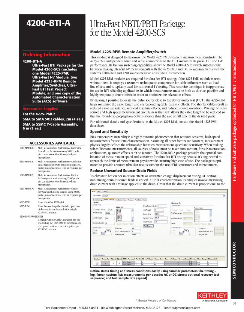
SE
MIC
ON
DU
CTO
R
A Greater Measure of Confidence
ordering Information4200-bTI-a
ultra-fast bTI Package for the Model 4200-sCs (includes one Model 4225-PMu ultra-fast I-V Module, two Model 4225-rPM remote amplifier/switches, ultra-fast bTI Test Project Module, and one copy of the automated Characterization suite (aCs) software
accessories suppliedfor the 4225-PMu:sMa to sMa 50W cables, 2m (4 ea.)sMa to ssMC Y-Cable assembly, 6 in (2 ea.)
aCCEssorIEs aVaIlablE4210-MMPC-C Multi Measurement Performance Cables for
Cascade probe stations using SSMC probe pin connections . One kit required per manipulator .
4210-MMPC-L Multi Measurement Performance Cables for Lucas Signatone probe stations using SSMC probe pin connections . One kit required per manipulator .
4210-MMPC-S Multi Measurement Performance Cables for Suss probe stations using SSMC probe pin connections . One kit required per manipulator .
4210-MMPC-W Multi Measurement Performance Cables for Wentworth probe stations using SSMC probe pin connections . One kit required per manipulator .
4225-PMU Extra Ultra-Fast I-V Module
4225-RPM Extra Remote Amplifier/Switch . Up to two of these units can be used with a single 4225-PMU module .
4200-PMU-PROBER-KIT General Purpose Cable/Connector Kit . For connecting the 4225-PMU to most triax and coax probe stations . One kit required per 4225-PMU module .
4200-bTI-a Ultra-Fast NBTI/PBTI Package for the Model 4200-SCS
Model 4225-rPM remote amplifier/switchThis module is designed to maximize the Model 4225-PMU’s current measurement sensitivity . The 4225-RPM’s independent force and sense connections to the DUT maximize its pulse, DC, and C-V performance . Its built-in switching capabilities allow the Model 4200-SCS to switch automatically between making ultra-fast I-V measurements with the 4225-PMU and DC I-V measurements with the system’s 4200-SMU and 4210 source-measure units (SMU instruments) .
Model 4225-RPM modules are required for ultra-fast BTI testing; if the 4225-PMU module is used without them, it employs a recursive technique to compensate for cable influences such as load line effects and is typically used for isothermal I-V testing . This recursive technique is inappropriate for use in BTI reliability applications in which measurements must be both as short as possible and highly temporally deterministic in order to minimize the relaxation effects .
By making it possible to locate the pulse source close to the device under test (DUT), the 4225-RPM helps minimize the cable length and corresponding cable parasitic effects . The shorter cables result in reduced cable capacitance, reduced load-line effects, and reduced source overshoot . Placing the pulse source and high speed measurement circuits near the DUT allows the cable length to be reduced so that the round-trip propagation delay is shorter than the rise or fall time of the desired pulse .
For additional details and specifications on the Model 4225-RPM, consult the Model 4225-PMU data sheet .
speed and sensitivityBias temperature instability is a highly dynamic phenomenon that requires sensitive, high-speed measurements for accurate characterization . Assuming all other factors are constant, measurement physics largely defines the relationship between measurement speed and sensitivity . When making sub-millisecond measurements, all sources of noise must be taken into account; for sub-microsecond applications, quantum effects can’t be ignored . The 4200-BTI-A package provides the optimal com-bination of measurement speed and sensitivity for ultra-fast BTI testing because it’s engineered to approach the limits of measurement physics while ensuring high ease of use . The package is opti-mized to provide accurate ultra-fast results without the use of RF structures and interconnects .
reduce unwanted source-Drain fieldsTo eliminate hot carrier injection effects or unwanted charge displacement during BTI testing, minimizing drain-to-source fields is critical . All BTI characterization techniques involve measuring drain current with a voltage applied to the drain . Given that the drain current is proportional to the
Define stress timing and stress conditions easily using familiar parameters like timing – log, linear, custom list; measurements per decade; aC or DC stress; optional recovery test sequence; and test sample rate (speed).
59
Har
dwar
e an
d so
ftw
are
pack
age
optim
ized
for N
BTI/
PBTI
cha
ract
eriz
atio
n
Har
dwar
e an
d so
ftw
are
pack
age
optim
ized
for N
BTI/
PBTI
cha
ract
eriz
atio
n
Test Equipment Depot - 800.517.8431 - 99 Washington Street Melrose, MA 02176 - TestEquipmentDepot.com

SE
MIC
ON
DU
CTO
R
drain-to-source field, the more sensitive the drain current measurement is, the lower the required drain voltage must be . The 4200-BTI-A package’s superior low current measurement capability allows the use of lower drain voltages to produce more accurate results .
reduced relaxation TimeThe 4225-BTI-A package’s superior speed and sensitivity allow making degradation measure-ments faster than any other commercial test system available . Single-point ID spot measure-ments can be completed in less than 1µs and ten-point ID-VG step sweeps can be made in less than 10µs . A sub-microsecond smooth sweep can be performed in less than 1µs .
softwareThe Ultra-Fast BTI test software module brings together the measurement capabilities of the Model 4225-PMU and 4225-RPM through an intuitive interface that doesn’t compromise test flexibility . It makes it easy to define stress timing, stress conditions, and a wide range measurement sequences from spot ID, On-The-Fly (OTF), or ID-VG sweeps . The test module allows measuring recovery effects as well as degradation . It also offers prestress and poststress measurement options that incorporate the Model 4200-SCS’s DC SMU instruments for high-precision low-level measurements .
stress settingsThe Ultra-Fast BTI Test Module employs familiar parameter setting for building stress–measure timing sequences . The stress set-up screen makes defining log or linear timing or building a custom list of time intervals to trigger intra-stress measurements both easy and quick .
Intuitive Test sequence DevelopmentThe Ultra-Fast BTI Test Module makes creating a powerful test sequence as uncomplicated as selecting one or more measurement types, then entering the appropriate values for voltage levels and measurement parameters in the intuitive interface . No coding or script writing is required . Select from four measurement types and chain up to 20 measurements together to form a ready-to-run measurement sequence:
• Spot. The spot measurement is a single measurement made while the gate and drain are pulsed . The measurement result is the mean value of the samples taken after the drain settles and before the pulse ends .
• Step Sweep. The step sweep is very similar to a conventional DC SMU sweep, in which
4200-bTI-a Ultra-Fast NBTI/PBTI Package for the Model 4200-SCS
Disadvantages of bTI systems developed in house
Until now, some researchers have been forced to configure their own ultra-fast BTI test systems . These in-house-developed systems typically combine a pulse generator or arbitrary waveform gen-erator with an oscilloscope equipped with current probes or some type of transimpedance ampli-fier to help measure low current . Although it is possible to build a BTI system that is suitable for a very specific set of electrical conditions if the instruments and interconnect are carefully selected, several major technical challenges remain:
• Waveform generation. Standard pulse generators and arbitrary waveform generators are designed to generate a waveform on a fixed recurring interval, rather than the Log(time) scale required for most reliability tests, including NBTI and PBTI testing .
• Measurement timing and data storage. Although oscilloscopes can be configured to trigger based on a waveform feature (such as a falling edge, for example), they are not designed to store samples selectively for specific portions of the waveform . This makes it necessary to store very large data sets for postprocessing . Only the most expensive oscilloscopes or those with costly memory expansion options can store enough data to compensate for these shortcomings .
• Precision, accuracy, and sensitivity. Oscilloscopes, current probes, and transimpedance amplifiers all have independently defined performance specifications and they are not necessarily optimized to work together . It is often very difficult to combine these components in a way that provides optimal performance across a wide dynamic range in order to achieve precise and accurate current measurements at high speeds .
• Interconnect. Systems built in house typically use splitters and bias tees, which limit the performance of the test setup . For example, a bias tee might limit bandwidth from 100ns to 10µs . Although this is suitable for high speed measurements, it prevents making any meaningful prestress and poststress DC measurements as part of the stress–measure sequence . It also prevents making measurements in the intermediate range of 10µs to DC .
• Test control and data management. Traditional oscilloscopes don’t support data streaming, so results transfer must wait until the test ends . Once the test is complete, massive amounts of data must be transferred to the control computer for postprocessing, which requires parsing complex waveforms into individual test results, followed by further reduction of the data into actual measurements .
• Test termination. Given that the test results can’t be analyzed until the data is transferred from the oscilloscope, the test duration must be determined prior to test initiation . This makes it impossible to terminate the test based in parametric shifts or to detect catastrophic failures in real time .
• Automation. Wafer- or cassette-level automation requires control of both the test instruments and the wafer probe station, which systems built in house typically wouldn’t provide . Also, incorporating sophisticated features like conditional test termination would add considerable complexity to the custom software necessary to run a system of this type .
• Higher channel count. Even for an in-house-built system that works well, pressures to increase the channel or test system count may arise . Typical test system maintenance issues such as calibration, operation, and correlation related to these custom setups can easily consume a disproportionate amount of the available resources .
60
Har
dwar
e an
d so
ftw
are
pack
age
optim
ized
for N
BTI/
PBTI
cha
ract
eriz
atio
n
Har
dwar
e an
d so
ftw
are
pack
age
optim
ized
for N
BTI/
PBTI
cha
ract
eriz
atio
n
Test Equipment Depot - 800.517.8431 - 99 Washington Street Melrose, MA 02176 - TestEquipmentDepot.com
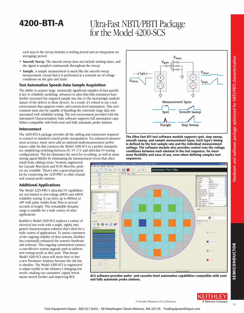
SE
MIC
ON
DU
CTO
R
A Greater Measure of Confidence
4200-bTI-a Ultra-Fast NBTI/PBTI Package for the Model 4200-SCS
each step in the sweep includes a settling period and an integration (or averaging) period .
• Smooth Sweep. The smooth sweep does not include settling times, and the signal is sampled continuously throughout the sweep .
• Sample. A sample measurement is much like the smooth sweep measurement, except that it is performed at a constant set of voltage conditions on the gate and drain .
Test automation speeds Data sample acquisitionThe ability to acquire large, statistically significant samples of data quickly is key to reliability modeling . Advances in ultra thin film transistors have further increased the required sample size due to the increasingly random nature of the defects in these devices . As a result, it’s critical to use a test environment that supports wafer- and cassette-level automation . This envi-ronment must also be capable of handling the extremely large data sets associated with reliability testing . The test environment provided with the Automated Characterization Suite software supports full automation capa-bilities compatible with both semi and fully automatic probe stations .
InterconnectThe 4200-BTI-A package provides all the cabling and connectors required to connect to standard coaxial probe manipulators . For enhanced measure-ment accuracy, many users add an optional multi-measurement perfor-mance cable kit that connects the Model 4200-SCS to a prober manipula-tor, simplifying switching between DC I-V, C-V, and ultra-fast I-V testing configurations . This kit eliminates the need for re-cabling, as well as maxi-mizing signal fidelity by eliminating the measurement errors that often result from cabling errors . Versions engineered for Cascade Microtech and SUSS MicroTec prob-ers are available . There’s also a general-purpose kit for connecting the 4225-PMU to other triaxial and coaxial probe stations .
additional applicationsThe Model 4225-PMU’s ultra-fast I-V capabilities are not limited to low- voltage pMOS and nMOS reliability testing . It can drive up to 800mA or 40V with pulse widths from 30ns to several seconds in length . This remarkable dynamic range is suitable for a wide variety of other applications .
Keithley’s Model 4200-SCS replaces a variety of electrical test tools with a single, tightly inte-grated characterization solution that’s ideal for a wide variety of applications . To assure customers of the ongoing viability of their systems, Keithley has continually enhanced the system’s hardware and software . This ongoing commitment ensures a cost-effective system upgrade path to address new testing needs as they arise . That means Model 4200-SCS users will never have to buy a new Parameter Analyzer because the old one is obsolete . The Model 4200-SCS is engineered to adapt readily to the industry’s changing test needs—making our customers’ capital invest-ments stretch further and improving ROI . aCs software provides wafer- and cassette-level automation capabilities compatible with semi
and fully automatic probe stations.
Vgate
Vstress
1µs
Vdrain
Vdrain
Idrain
V
Measurement Types
Spot Smooth Sweep
Triangle Step Sweep
I
The ultra-fast bTI test software module supports spot, step sweep, smooth sweep, and sample measurement types. Each type’s timing is defined by the test sample rate and the individual measurement settings. The software module also provides control over the voltage conditions between each element in the test sequence, for maxi-mum flexibility and ease of use, even when defining complex test sequences.
61
Har
dwar
e an
d so
ftw
are
pack
age
optim
ized
for N
BTI/
PBTI
cha
ract
eriz
atio
n
Har
dwar
e an
d so
ftw
are
pack
age
optim
ized
for N
BTI/
PBTI
cha
ract
eriz
atio
n
Test Equipment Depot - 800.517.8431 - 99 Washington Street Melrose, MA 02176 - TestEquipmentDepot.com

SE
MIC
ON
DU
CTO
R
4200-bTI-a Ultra-Fast NBTI/PBTI Package for the Model 4200-SCS
specifications
4225-rPM rEMoTE aMPlIfIEr/sWITCH optional accessory for the 4225-PMuThe 4225-RPM provides lower current measurement ranges to the 4225-PMU .
Low current measure ranges supports wide range of measure-ments, from nanotechnology to BTI (Bias Temperature Instability) on leading-edge CMOS devices
This is a single-channel accessory; order two Model 4225-RPMs to support the two channels of the Model 4225-PMU .
Supports switching to the Model 4200-SCS’s SMU instruments or 4210-CVU, allowing for a wide range of tests without re-cabling .
Built-in bypass mode allows access to the Model 4225-PMU’s higher current measurement ranges .
PulsE/lEVEl 1
4225-PMu with 4225-rPM
VOUT –10 V to +10 V
Accuracy 2 into open load ±(0 .5% ±10 mV)
Resolution < 0 .5 mV
Output Connectors Triaxes, source and sense
Baseline Noise ±(0 .39% + 1 mV) RMS typical
Overshoot/Pre-shoot/Ringing 3 ±2% of amplitude ±20 mV
4225-rPM rEMoTE aMPlIfIEr/sWITCH (must be used in conjunction with 4225-PMu)
TYPICal MINIMuM TIMING ParaMETEr for CurrENT MEasurEMENT
range 100 na 1 µa 10 µa 100 µa 1 ma 10 maRecommended Minimum Pulse Width 4, 5 134 µs 20 .4 µs 8 .36 µs 1 .04 µs 370 ns 160 ns
Recommended Minimum Measure Window 5 10 µs 1 .64 µs 1 µs 130 ns 40 ns 20 ns
Accuracy (DC) ±(0 .5% + 1nA) ±(0 .5% + 1nA) ±(0 .5% + 30nA) ±(0 .5% + 100nA) ±(0 .5% + 1µA) ±(0 .5% + 10µA)
Recommended Minimum Transition Time 5, 6 1 µs 360 ns 360 ns 40 ns 30 ns 20 ns
Noise 5, 7 200 pA 2 nA 5 nA 50 nA 300 nA 1 .5 µA
Settling Time 5, 8 100 µs 15 µs 6 µs 750 ns 250 ns 100 ns
VolTaGE MEasurE±10V
RECOMMENDED MINIMUM PULSE WIDTH 4, 5: 160ns .
RECOMMENDED MINIMUM MEASURE WINDOW 5: 20ns .
ACCURACy (DC): 0 .25% + 10mV .
RECOMMENDED MINIMUM TRANSITION TIME 5, 6: 20ns .
NOISE 5, 7: 1mV .
SETTLING TIME 5, 8: 100ns .
NoTEs1 . Performance at the triax output connectors of the 4225-RPM when using a 2m RPM interconnect cable between the 4225-PMU and 4225-RPM Remote
Pulse Measure unit .2 . 100mV to 10V .3 . Typical, with transistion time of 100ns (0-100%) .4 . Recommended minimum pulse width = (Setting Time)/0 .755 . Typical values, into an open .6 . Recommended rise/fall time to minimize overshoot .7 . RMS noise measured over the Recommended Minimum Measure Window for the given voltage or current range, typical .8 . Time necessary for the signal to settle to the DC accuracy level . (Example: the 10mA measurement range’s settling time refers to the period required for
the signal to settle to within 0 .35% of the final value . Calculated as Accuracy = 0 .25% + 10µA = 0 .25% + (10µA/10mA) = 0 .25% + 0 .1% = 0 .35%) .
All specifications apply at 23° ±5°C, within one year of calibration, RH between 5% and 60%, after 30 minutes of warmup .
62
Mod
el 4
200-
BTI-A
spe
cific
atio
ns
Mod
el 4
200-
BTI-A
spe
cific
atio
ns
Test Equipment Depot - 800.517.8431 - 99 Washington Street Melrose, MA 02176 - TestEquipmentDepot.com

SE
MIC
ON
DU
CTO
R
A Greater Measure of Confidence
4200-bTI-a Ultra-Fast NBTI/PBTI Package for the Model 4200-SCS
This top-down view of a Cascade Microtech analytical probe station illustrates best practices for interconnecting the Model 4225-rPM remote amplifier/switch to the prober using the blue Multi-Measurement Performance cables.
This closeup of two Model 4225-rPMs highlights the DC sMu, C-V, and ultra-fast I-V cable connections.
63
Har
dwar
e an
d so
ftw
are
pack
age
optim
ized
for N
BTI/
PBTI
cha
ract
eriz
atio
n
Har
dwar
e an
d so
ftw
are
pack
age
optim
ized
for N
BTI/
PBTI
cha
ract
eriz
atio
n
Test Equipment Depot - 800.517.8431 - 99 Washington Street Melrose, MA 02176 - TestEquipmentDepot.com
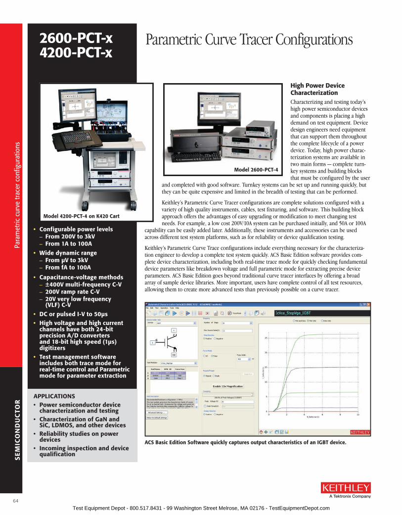
SE
MIC
ON
DU
CTO
R
• Configurable power levels – from 200V to 3kV – from 1a to 100a
• Wide dynamic range – from µV to 3kV – from fa to 100a
• Capacitance-voltage methods – ±400V multi-frequency C-V – 200V ramp rate C-V – 20V very low frequency (Vlf) C-V
• DC or pulsed I-V to 50µs• High voltage and high current
channels have both 24-bit precision a/D converters and 18-bit high speed (1µs) digitizers
• Test management software includes both trace mode for real-time control and Parametric mode for parameter extraction
High Power Device Characterization Characterizing and testing today’s high power semiconductor devices and components is placing a high demand on test equipment . Device design engineers need equipment that can support them throughout the complete lifecycle of a power device . Today, high power charac-terization systems are available in two main forms — complete turn-key systems and building blocks that must be configured by the user
and completed with good software . Turnkey systems can be set up and running quickly, but they can be quite expensive and limited in the breadth of testing that can be performed .
Keithley’s Parametric Curve Tracer configurations are complete solutions configured with a variety of high quality instruments, cables, test fixturing, and software . This building block approach offers the advantages of easy upgrading or modification to meet changing test needs . For example, a low cost 200V/10A system can be purchased initially, and 50A or 100A
capability can be easily added later . Additionally, these instruments and accessories can be used across different test system platforms, such as for reliability or device qualification testing .
Keithley’s Parametric Curve Trace configurations include everything necessary for the characteriza-tion engineer to develop a complete test system quickly . ACS Basic Edition software provides com-plete device characterization, including both real-time trace mode for quickly checking fundamental device parameters like breakdown voltage and full parametric mode for extracting precise device parameters . ACS Basic Edition goes beyond traditional curve tracer interfaces by offering a broad array of sample device libraries . More important, users have complete control of all test resources, allowing them to create more advanced tests than previously possible on a curve tracer .
aPPlICaTIoNs• Power semiconductor device
characterization and testing• Characterization of GaN and
siC, lDMos, and other devices• reliability studies on power
devices• Incoming inspection and device
qualification
aCs basic Edition software quickly captures output characteristics of an IGbT device.
Model 4200-PCT-4 on K420 Cart
Model 2600-PCT-4
2600-PCT-x4200-PCT-x
Parametric Curve Tracer Configurations
64
Para
met
ric c
urve
trac
er c
onfig
urat
ions
Para
met
ric c
urve
trac
er c
onfig
urat
ions
Test Equipment Depot - 800.517.8431 - 99 Washington Street Melrose, MA 02176 - TestEquipmentDepot.com

SE
MIC
ON
DU
CTO
R
A Greater Measure of Confidence
2600-PCT-x4200-PCT-x
Parametric Curve Tracer Configurations
ordering Information2600-PCT-1 low Power2600-PCT-2 High Current2600-PCT-3 High Voltage2600-PCT-4 High Voltage
and Current4200-PCT-2 High Current + C-V4200-PCT-3 High Voltage + C-V4200-PCT-4 High Voltage and
Current + C-V
accessories suppliedaCs-basIC Component Test software8010 High Power Device Test fixture (includes 8010-CTB, 8010-DTB, and 8010-DTB-220)
Kusb-488b usb to GPIb adapter (Series 2600B configurations only)
all cables and adapterssample parts4200-CVu-PWr (4200-sCs configurations only)Note: Computer and monitor not included with 2600-PCT-x configurations
The Keithley Parametric Curve Trace configurations are complete characterization tools that include all of the key elements necessary for power device characterization .
The measurement channels consist of high quality Keithley SourceMeter (trademark) and/or Semiconductor Characterization instruments . The dynamic range and accuracy of these instruments is orders of magnitude beyond what a traditional curve tracer could offer .
To achieve this performance, Keithley has developed a set of precision cables to connect the instru-ments to the test fixture . For the high voltage channel, custom triax cables provide a guarded path-way that enables fast settling and very low currents, even at the full 3kV . For the high current chan-nel, special low inductance cables provide fast rise time pulses to minimize device self heating effects .
Equally critical is a safe, efficient test fixture . The 8010 provides an interlocked, shielded environ-ment that allows for both low current, high voltage testing and high current, low voltage testing . Included with the test fixture are the same high performance connectors that mate with the precision cables . Also included are protection circuits to prevent the high voltage channel from destroying the base/gate channel in the event of a device fault .
Configuration selector Guide
Model 1
Collector/ Drain supply 2 step Generatorbase/Gate
supplyauxiliary supply
High Voltage Mode
High Current Mode
Low Power 2600-PCT-1 200 V/10 A 200 V/10 A 200 V/10 A N/A
High Current
2600-PCT-2 200 V/10 A 40 V/50 A 200 V/10 A 200 V/10 A
4200-PCT-2plus C-V
200 V/1 A 40 V/50 A 200 V/1 A 200 V/1 A
High Voltage
2600-PCT-3 3 kV/120 mA 200 V/10 A 200 V/10 A 200 V/10 A
4200-PCT-3plus C-V
3 kV/120 mA 200 V/1 A 200 V/1 A 200 V/1 A
High Current and
High Voltage
2600-PCT-4 3 kV/120 mA 40 V/50 A 200 V/10 A 200 V/10 A
4200-PCT-4plus C-V
3 kV/120 mA 40 V/50 A 200 V/1 A 200 V/1 A
1 . Contact your Keithley field applications engineer for custom configurations2 . Add a Model 2651A to increase High Current Mode to either 50A or 100A .
aCCEssorIEs aVaIlablE2651A High Power System SourceMeter
(adds 50A to any system, max 100A)
2657A High Power System SourceMeter (adds 3kV to any system, max of one unit per system)
8010-CTB Customizable Test Board
8010-DTB Device Test Board with TO-247 socket
8010-DTB-220 Device Test Board with TO-220 socket
70161-MSA Keyboard/Monitor Arm for K420 and K475 Carts
HV-CA-554-1 HV Triax Cables (three required for 2657A)
K475 Workstation Tower Mobile cart for all PCT configurations
K420 Workbench Cart Mobile cart for smaller PCT configurations
Model 4200-sCsModel 2600-PCT-4
65
Para
met
ric c
urve
trac
er c
onfig
urat
ions
Para
met
ric c
urve
trac
er c
onfig
urat
ions
Test Equipment Depot - 800.517.8431 - 99 Washington Street Melrose, MA 02176 - TestEquipmentDepot.com

SE
MIC
ON
DU
CTO
R
2600-PCT-x4200-PCT-x
Parametric Curve Tracer Configurations
Typical Power Transistor Parameters
Parameter symbol Test Method 1 Maximum rangeTypical best resolution Typical accuracy
Breakdown Voltage Bvdss, Bvceo Id–Vd or Id (pulse) ±3000 V 2 100 µV, 10 fA 0 .05% rdg + 0 .05% rng
On-State Current (DC) Vdson, Vcesat, Vf Id–Vd ±20 A 4 , Optional: ±40 A 4 100 nA, 1 µV 0 .05% rdg + 0 .05% rng
On-State Current (Pulse) Vdson, Vcesat, Vf Id–Vd ±50 A 4, Optional: ±100 A 4 100 µA, 1 µV 0 .05% rdg + 0 .05% rng
Drain/Collector Leakage Current Idss, Ir/Icbo, Iceo Id–Vd ±20 mA @ 3000 2, 5 10 fA, 1 µV 0 .2% rdg + 1% rng
Gate/Base Leakage Current Igss, Ib Ig–Vg ±1 A or, ±10 A Pulsed 3 10 fA, 1 µV 0 .2% rdg + 1% rng
On-State Threshold Voltage or Cutoff Voltage
Vth, Vf, Vbeon, Vcesat Id–Vg ±200 V 3 10 fA, 1 µV 0 .2% rdg + 0 .5% rng
Forward Transfer Admittance or Forward Transconductance
|yfs| Gfs, Hfe, gain Vd–Id @ Vds 1 ms ~ 1000 s 6 1 pA, 1 µV 1%
On-State Resistance RDS(on), Vcesat Vd–Vg @ Id <100 µW 7 10 µW, 1 µV 1%
Input Capacitance Ciss C–V 100 kHz 10 nF 8 ±200 V 10 fF, 10 µV Better than 1% at C<10 nF
Output Capacitance Coss C–V 100 kHz 10 nF 8 ±200 V 10 fF, 10 µV Better than 1% at C<10 nF
Reverse Transfer Capacitance Crss C–V 100 kHz 10 nF 8 ±200 V 10 fF, 10 µV Better than 1% at C<10 nF
1 . Test method used for extracting the parameter . Only typical MOSFET listed, but similar method for other devices .2 . Model 2657A High Power System SourceMeter® SMU Instrument .3 . Model 2636A SourceMeter SMU Instrument or Model 4210-SMU .4 . Model 2651A High Power System SourceMeter SMU Instrument or optional dual Model 2651A High Power System SourceMeter SMU Instruments .5 . Maximum 20mA at 3000V, 120mA at 1500V .6 . Typical extracted capability (Example: 1mA/1V ~ 1A/1mV) .7 . Typical extracted capability (Example: 1mV/10A) .8 . Max . ±200VDC (±400VDC differential) bias with 4210-CVU and 4200-CVU-PWR .
High current, low inductance cables High voltage, low noise triaxial cables
flexible, safe test fixture for 3kV and 100a
8010 Test fixture
66
Para
met
ric c
urve
trac
er c
onfig
urat
ions
Para
met
ric c
urve
trac
er c
onfig
urat
ions
Test Equipment Depot - 800.517.8431 - 99 Washington Street Melrose, MA 02176 - TestEquipmentDepot.com

SE
MIC
ON
DU
CTO
R
A Greater Measure of Confidence
suMMarY of TYPICal TEsTsDevice leakage breakdown Gain on-state
Bipolar junction Transistor
IEBO, IECO, IEVEB, ICVCB
BVCBO, BVCEI, BVCEO, BVCEV, BVEBO, BVECO
HFE
IBCO, IBEO, IBICVBE, IBVBE, ICBO, ICEV, ICVCE_BiasIB, ICVCE_BiasVB, ICVCE_StepIB, ICVCE_StepVB, VBCO, VCE
MOSFET IDL,
IDS_ISD, IGL, ISL
BVDSS, BVDSV, BVGDO, BVGDS,
BVGSOGM
IDVD_BiasVG, IDVD_StepVG, IDVG_BiasVD, IDVG_StepVD, IDVG_StepVSUB, IGVG, VTCI, VTEXT, VTEXT_IISQ
Diode IRDVRD VBRIRD NADYNAMICZ, IFDVFD, VFDIFD, VRDIRD
Resistor NA NA NA IV
Capacitor IV NA
forMulaTor fuNCTIoN suMMarYType
Math ABS, AVG, DELTA, DIFF, EXP, LN, LOG, LOG10, SQRT
Parametric Extractions
GMMAX, RES, RES_4WIRE, RES_AVG, SS, SSVTCI, TTF_DID_LGT, TTF_LGDID_T, TTF_DID_T, TTF_LGDID_LGT, VTCI, VTLINGM, VTSATGM
Fitting
EXPFIT, EXPFITA, EXPFITB, LINFIT, LINFITSLP, LINFITXINT, LINFITYINT, REGFIT, REGFITSLP, REGFITXINT, REGFITYINT, REGFIT_LGX_LGY, REGFIT_LGX_Y, REGFIT_X_LGY, TANFIT, TANFITSLP,TANFITXINT, TANFITYINT
ManipulationAT, FINDD, FINDLIN, FINDU, FIRSTPOS, JOIN, LASTPOS, MAX, MAXPOS, MIN, MINPOX, POW, SMOOTH
Multi test mode allows multiple tests to be performed on a device.
Trace mode supports interactive testing of a device.
semiconductor Parametric Test software for Component and Discrete DevicesACS Basic Edition software is specifically tuned to take advantage of the high perfor-mance capabilities of the Keithley instrumentation and includes several sample libraries for performing common high power device tests . Unlike other systems, the software allows the user almost unlimited flexibility in configuring all of the measurement channels to create tests far beyond what a traditional curve tracer could achieve .
2600-PCT-x4200-PCT-x
Parametric Curve Tracer Configurations
67
Para
met
ric c
urve
trac
er c
onfig
urat
ions
Para
met
ric c
urve
trac
er c
onfig
urat
ions
Test Equipment Depot - 800.517.8431 - 99 Washington Street Melrose, MA 02176 - TestEquipmentDepot.com

SE
MIC
ON
DU
CTO
R
Keithley’s S530 Parametric Test Systems can address all the DC and C-V measurements required in process control monitoring, process reliability monitoring, and device characterization because they are built on proven sourcing and measurement technology .
optimized for High-Mix Test EnvironmentsS530 Parametric Test Systems are designed for production and lab environments that must handle a broad range of devices and technologies, offering industry-leading test plan flexibility, automation, probe station integration, and test data management capabilities . Keithley has brought more than 30 years of expertise in delivering a wide range of standard and custom parametric testers to customers around the world to the design of these test solutions .
simple software Migration and High Hardware reuseS530 systems are designed with capabilities that speed and simplify system startups and maximize reuse of your existing test resources . For example, the software that controls these systems is compat-ible with many new and legacy automatic probe stations, so you may be able to eliminate the cost of a new one . In addition, the S530’s cabled-out configuration typically allows continued use of your exist-ing probe card library . Several optional applications services can help you keep getting the full value of your existing prober and probe card investments . Keithley can also provide assistance to speed the development, conversion, or repurposing of your existing test recipes for use with S530 systems .
semiconductor Industry’s Most Powerful standard Parametric Test systemTwo different system configurations are available to address different parametric test application environments . The S530 Low Current System, which is configurable from two to eight source meas-ure unit (SMU) channels, provides sub-picoamp measurement resolution and low current guarding all the way to the probe card, which makes it ideal for characterizing sub-micron silicon MOS tech-nologies . The S530 High Voltage System, configurable from three to seven SMU channels, can source up to 1000V for use in the difficult breakdown and leakage tests that automotive electronics and power management devices demand .
• semiconductor industry’s most cost-effective fully automatic parametric testers
• optimized for use in environments with a broad mix of products, where high flexibility and system speed are critical
• Choice of low current or high voltage system configurations
– low current configuration supports measurement of low current characteristics such as sub-threshold leakage, gate leakage, etc.
– High voltage configuration is optimized for monitoring processes used for GaN, siC, and si lDMos power devices
• Compatible with popular fully automatic probe stations
• Instrument options for sourcing pulses, frequency measurements, and low voltage measurements
• Cabled-out tester configuration maximizes prober interface flexibility and expands voltage range
– Compatible with Keithley’s Model 9139a Probe Card adapter
– supports reuse of existing five-inch probe card libraries
• Proven instrumentation technology ensures high measurement accuracy and repeatability in both the lab and the fab
s530 Parametric Test Systems
68
Para
met
ric te
st s
yste
ms
Para
met
ric te
st s
yste
ms
Test Equipment Depot - 800.517.8431 - 99 Washington Street Melrose, MA 02176 - TestEquipmentDepot.com

SE
MIC
ON
DU
CTO
R
A Greater Measure of Confidence
s530 Parametric Test Systems
All Series S530 systems are equipped with Keithley’s proven high power SMU instruments, which provide up to 20W source or sink capability on both the 200V and 20V ranges . This level of power is essential for complete characterization of the high power devices and circuits prevalent in today’s mobile devices . Whether the application is testing LDMOS Si or GaN BJTs, this higher power capabil-ity provides greater visibility into device performance . That means S530 systems can handle high power device testing without compromising the low current sub-picoamp sensitivity needed to monitor mainstream device processes . In contrast, competitive parametric test systems are limited to medium power 2W SMU instruments, so they cannot match the S530 systems’ range of applications .
full Kelvin standard ConfigurationsAll too often, currents higher than a few milliamps lead to measurement errors as a result of voltage drops across the interface cables and pathways . To prevent this drop in measurement integrity, both the low current and high voltage S530 systems provide full Kelvin measurements (also known as remote voltage sense) at the probe card . Full Kelvin measurements are particularly critical to ensur-ing measurement accuracy given the 20W capability of the high power SMU instruments used in S530 systems .
Table 1. s530 system selector Guide
system Capabilities Key range and offset PerformanceS530 Low CurrentSystem
• Source up to 200V or 1A
• Measure current with femto-amp resolution and sub pico-amp offset
• 2 to 8 SMU channels1
• Options for C-V, pulse sourcing, frequency measurements, and low-voltage measurements
• Up to 48 pins full Kelvin plus connection for chuck
Voltage Source (V)
Cur
rent
Mea
sure
(A)
1E-12
1E-9
1E-6
1E+0
1E-3
1E-3 1E-2 1E-1 1E0 1E+1 1E+2 1E+3
100mA
1A
200V
20V
S530 High Voltage System
• Source up to 1000V or 1A
• Use 200V SMU to measure current with femto-amp resolution and pico-amp offset
• Use 1000V SMU to measure current with ten pico-amp resolution and nano-amp offset
• 3 to 7 SMU channels1
• Options for C-V, pulse sourcing, frequency measurements, and low-voltage measurements
• Up to 24 pins full Kelvin plus connection for chuck
Voltage Source (V)
Cur
rent
Mea
sure
(A)
1E-12
1E-9
1E-6
1E+0
1E-3
1E-3 1E-2 1E-1 1E0 1E+1 1E+2 1E+3
100mA
1A
200V
20V
20mA
High Voltage SMU
100
0V
1 . Depending on instrument options within the system .
Industry’s Most Powerful High Voltage Parametric Test systemThe S530 High Voltage Semiconductor Parametric Test System is the only parametric tester available that’s capable of full Kelvin high voltage performance on up to 24 pins, a capabil-ity that’s invaluable for characterizing today’s higher power devices . The system incorporates a high voltage SMU that sources up to 1000V at 20mA (20W max .) . Two high voltage pathways allow making either direct high-side current measurements (in which a single SMU is used to both source and measure the high side of the DUT) or higher sensitivity low-side low current measurements (in which one SMU is used to source high voltage to the high side of the DUT and a different SMU is used to force 0V and measure the current of the low side) .
system architectureEach S530 system configuration is made up of five layers:
• Instruments layer – In addition to SMU instruments, the S530 offers options for sourcing pulses or making C-V, frequency, or low voltage measurements .
• Pathways layer – S530 systems provide high fidelity signal pathways that can be dynamically reconfigured to allow any instrument to be connected to any pin or set of pins during test .
• Cable interface layer – All system interconnects are constructed of fully shielded and guarded triaxial low leakage, high voltage cables to ensure higher measurement integrity .
• Probe card adapter (PCA) layer – This layer extends the shield and guard to the probe card to ensure measurement integrity . Also, the PCA provides auxiliary inputs for instruments that require direct access to the probe card and must bypass the signal path switch matrix .
• Probe card layer – This layer includes the custom cards supplied by your probe card vendors .
69
Para
met
ric te
st s
yste
ms
Para
met
ric te
st s
yste
ms
Test Equipment Depot - 800.517.8431 - 99 Washington Street Melrose, MA 02176 - TestEquipmentDepot.com
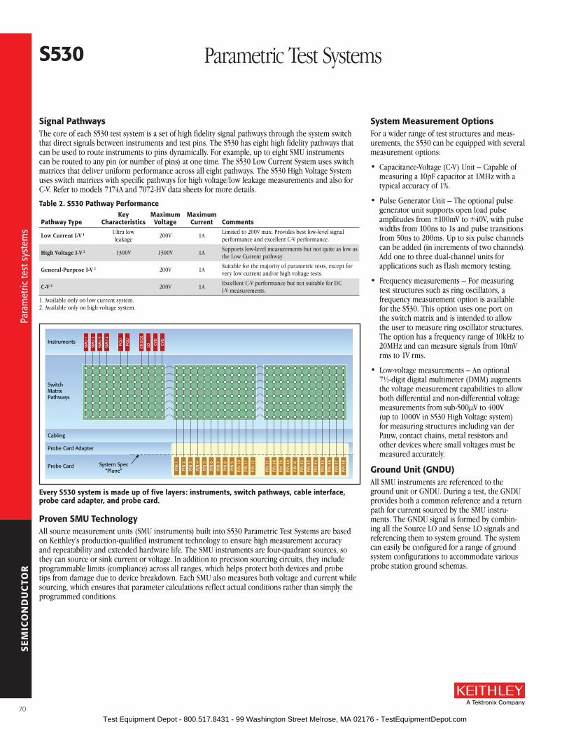
SE
MIC
ON
DU
CTO
R
s530 Parametric Test Systems
signal PathwaysThe core of each S530 test system is a set of high fidelity signal pathways through the system switch that direct signals between instruments and test pins . The S530 has eight high fidelity pathways that can be used to route instruments to pins dynamically . For example, up to eight SMU instruments can be routed to any pin (or number of pins) at one time . The S530 Low Current System uses switch matrices that deliver uniform performance across all eight pathways . The S530 High Voltage System uses switch matrices with specific pathways for high voltage/low leakage measurements and also for C-V . Refer to models 7174A and 7072-HV data sheets for more details .
Table 2. s530 Pathway Performance
Pathway TypeKey
CharacteristicsMaximum
VoltageMaximum
Current Comments
Low Current I-V 1 Ultra low leakage
200V 1ALimited to 200V max . Provides best low-level signal performance and excellent C-V performance .
High Voltage I-V 2 1300V 1300V 1ASupports low-level measurements but not quite as low as the Low Current pathway .
General-Purpose I-V 2 200V 1ASuitable for the majority of parametric tests, except for very low current and/or high voltage tests .
C-V 2 200V 1AExcellent C-V performance but not suitable for DC I-V measurements .
1 . Available only on low current system .2 . Available only on high voltage system .
Cabling
Probe Card Adapter
Probe Card
SwitchMatrixPathways
System Spec“Plane”
Instruments
SMU
1
SMU
2
SMU
3
SMU
4
PGU
PGU
PIN
1
PIN
2
PIN
3
PIN
4
PIN
5
PIN
6
PIN
7
PIN
8
PIN
9
PIN
10
PIN
11
PIN
12
PIN
37
PIN
38
PIN
39
PIN
40
PIN
41
PIN
42
PIN
43
PIN
44
PIN
45
PIN
46
PIN
47
PIN
48
CH
UC
K
LO CVU
CVU
Every s530 system is made up of five layers: instruments, switch pathways, cable interface, probe card adapter, and probe card.
Proven sMu TechnologyAll source measurement units (SMU instruments) built into S530 Parametric Test Systems are based on Keithley’s production-qualified instrument technology to ensure high measurement accuracy and repeatability and extended hardware life . The SMU instruments are four-quadrant sources, so they can source or sink current or voltage . In addition to precision sourcing circuits, they include programmable limits (compliance) across all ranges, which helps protect both devices and probe tips from damage due to device breakdown . Each SMU also measures both voltage and current while sourcing, which ensures that parameter calculations reflect actual conditions rather than simply the programmed conditions .
system Measurement optionsFor a wider range of test structures and meas-urements, the S530 can be equipped with several measurement options:
• Capacitance-Voltage (C-V) Unit – Capable of measuring a 10pF capacitor at 1MHz with a typical accuracy of 1% .
• Pulse Generator Unit – The optional pulse generator unit supports open load pulse amplitudes from ±100mV to ±40V, with pulse widths from 100ns to 1s and pulse transitions from 50ns to 200ms . Up to six pulse channels can be added (in increments of two channels) . Add one to three dual-channel units for applications such as flash memory testing .
• Frequency measurements – For measuring test structures such as ring oscillators, a frequency measurement option is available for the S530 . This option uses one port on the switch matrix and is intended to allow the user to measure ring oscillator structures . The option has a frequency range of 10kHz to 20MHz and can measure signals from 10mV rms to 1V rms .
• Low-voltage measurements – An optional 7½-digit digital multimeter (DMM) augments the voltage measurement capabilities to allow both differential and non-differential voltage measurements from sub-500µV to 400V (up to 1000V in S530 High Voltage system) for measuring structures including van der Pauw, contact chains, metal resistors and other devices where small voltages must be measured accurately .
Ground unit (GNDu)All SMU instruments are referenced to the ground unit or GNDU . During a test, the GNDU provides both a common reference and a return path for current sourced by the SMU instru-ments . The GNDU signal is formed by combin-ing all the Source LO and Sense LO signals and referencing them to system ground . The system can easily be configured for a range of ground system configurations to accommodate various probe station ground schemas .
70
Para
met
ric te
st s
yste
ms
Para
met
ric te
st s
yste
ms
Test Equipment Depot - 800.517.8431 - 99 Washington Street Melrose, MA 02176 - TestEquipmentDepot.com

SE
MIC
ON
DU
CTO
R
A Greater Measure of Confidence
s530 Parametric Test Systems
standard 9139a Probe Card adapterThe standard probe card adapter (PCA) for the S530 parametric test systems is the proven Model 9139A . Several key features and performance advantages have made it the industry’s leading choice of PCA for more than 20 years:
• Low offset currents that maximize low current performance .
• Low noise performance that helps ensure the integrity of low-level voltage measurements .
• Minimally invasive, low profile design that allows easy camera integration .
• 64 inputs – Configurable to support both standard cable connections from the tester and auxiliary inputs for instruments that bypass the pathway matrix .
• 500V pin-to-pin isolation (1000V when connecting only to every other pin) .
High flexibility cabled-out configurationS530 systems are “cabled-out” configurations to provide the broad interconnect flexibility that high-mix fab and lab environments demand . These systems can be interfaced to a variety of probing solu-tions, including high performance circular probe cards, cost-effective rectangular edge-connector probe cards, and even special high performance cards for applications that involve extreme tempera-tures or demand high durability .
Table 4. s530 system Cabling optionsCabling options Probe Card Type features benefitsStandard Keithley 9139A PCA (S400-type)
Circular ceramic Extends driven guard to probe pin
Superior low current measurements . Supports up to 64 pins; easily configured for auxiliary inputs for additional instrument options
Custom Cabled to Existing PCA Type
Typically for five-inch rectangu-lar probe cards using edge card connectors
Compatible with existing probe card library
Reduces migration cost by reusing existing probe cards
Unterminated Cables Cables connected to pathway output with unterminated cable ends
Ready to cable to existing interface or fixture
Provides recommended cable to optimize system performance
No Cables Custom probe card No need to purchase a cable solution
Use cable system provided by custom probe card vendor
alternative Probe Card adapters (PCas)Optional probe card adapters are available for all S530 configurations . In the simplest form, the edge connector used to interface to a rectangular probe card (typically referred to as five-inch probe cards) is a PCA . This type of PCA provides the most cost-effective solution for applications involving mid-range signal levels . If desired, the Model 9139A PCA can be configured into any S530 system as an option . This PCA is designed for interfacing the system to circular probe cards (from Keithley-approved vendors) via pogo pin connections . Probe-station-specific adapter plates can be specified during ordering to ensure the Model 9139A’s compatibility with a variety of popular probe stations .
Probe CardsUnlike testhead-based systems, S530 systems are easily adaptable for use with a wide range of probe card types, so you likely won’t need to
replace your existing (and expensive) probe card library . Although Keithley recommends the use of the Model 9193A PCA and approved probe card vendors, we recognize you have made a major investment in your current cards . If probe card reuse is critical to your capital equipment strategy, consult an applications team member to learn about connection options that can protect your probe card investment .
system softwareKeithley’s S530 system relies on the Keithley Test Environment (KTE) software for test develop-ment and execution . Hosted a standard industri-al PC with a Linux OS, KTE incorporates decades of Keithley parametric test experience into its latest generation test system . Measurement routines and test plans can be easily written, converted, or re-used, helping you get up and running faster . That simplifies using your S530 system effectively in conjunction with existing test systems . S530 software includes all the key system software operations:
• Wafer description
• Test macro development
• Test plan development
• Limits setting
• Wafer or cassette level testing with automatic prober control
• Test data management
user access Points (uaPs) for added flexibilityUser Access Points or UAPs can be used to modify the operational flow of the test sequence at key events like “load wafer,” “start test,” “end cassette,” etc . They are useful for adding system capabilities like reading wafer cassette RFID tags or reading wafer IDs using an OCR system . During test operation, an enabled UAP triggers the execution of one or more custom operations defined in a script or executable program .
system Diagnostics and reliability ToolsDiagnostics can be performed routinely to ensure the system is performing as expected and won’t generate false failures or false passes . The S530 systems’ diagnostics capability verifies system functionality quickly and easily . Key steps in the diagnostics process include configuration verification, communications pathway tests, signal pathway testing, and SMU source-measure tests . Even the cable interface
The Model 9139a Probe Card adapter has been trusted by the industry for more than 10 years. Its combination of low current performance and high voltage capability makes it the ideal companion to the s530 Parametric Test systems.
71
Para
met
ric te
st s
yste
ms
Para
met
ric te
st s
yste
ms
Test Equipment Depot - 800.517.8431 - 99 Washington Street Melrose, MA 02176 - TestEquipmentDepot.com

SE
MIC
ON
DU
CTO
R
s530 Parametric Test Systems
and PCA are included in the diagnostics process to ensure complete system functionality . This diagnostics process is designed to detect and localize a wide range of system problems, speed troubleshooting, and maximize uptime .
High Voltage Instrument Protection ModulesThe S530 High Voltage System contains a 1kV SMU that might be used on one terminal of a DUT while applying a 200V SMU or the CVU to another terminal . If a test sequence or a failed DUT presents too much voltage to one of these lower voltage instruments, serious instrument damage is possible . To minimize the potential for these problems, Keithley engineers have developed protection modules that prevent damaging voltages from harming the 200V SMU instruments and CVU without compromising their low-level measurement capabilities .
Industrial PC with raID Mirror Drive
Even the highest quality disk drives are subject to routine failures, so regular system backups are critical . S530 systems incorporate a high
reliability industrial controller including the RAID (Redundant Array of Independent Disks) option, designed to maintain a mirror of the master drive at all times . In the event of a drive failure, the mirror drive becomes the master and the user is notified that a drive replacement should be scheduled immediately . With a RAID mirror drive, a failed drive represents a sched-uled repair rather than a downed system .
support services and Contracts
Keithley’s worldwide network of service and applications professionals provides expert support services ranging from initial installation and calibration to repairs and test plan migration services . These services maximize system utilization and uptime while reducing your overall cost of ownership .
• Installation and Probe Station Integration Services – Includes the setup and verification of the system, as well as probe station integration . This includes setting up probe station communications and installing the probe card adapter .
• Calibration Services – All S530 Parametric Test Systems are calibrated onsite by a certified Keithley field service engineer .1 Keithley provides a range of internationally recognized accredited calibration services, including A2LA (American Association for Laboratory Accreditation) accredited calibration .2
• Repair Services – Repair services ranging from on-site service contracts to self-service module-swaps are available .
• Test Plan Migration Services – Keithley’s experienced applications engineers are skilled at converting your existing test plans to the S530 system software environment . This includes conversion of data objects like user test libraries, wafer description files, cassette plans, etc .
• Correlation Studies – Keithley applications engineers can perform correlation studies, comparing your existing parametric test system’s capability to the S530’s and analyzing the underlying performance differences .
1 . While most components of the system are calibrated on site, certain components are calibrated at one of Keithley’s worldwide network of service facilities .
2 . A2LA accredited calibration services are available in the United States and Germany .
Condensed specifications
low Current systemCurrent range
Max. Voltage
MEasurE sourCEresolution accuracy resolution accuracy
1 A 200 V 10 µA 0 .03% + 1 .5 mA + 1 .3 pA/V 20 µA 0 .05% + 1 .8 mA + 1 .3 pA/V 100 mA 200 V 1 µA 0 .02% + 20 .0 µA + 1 .3 pA/V 2 µA 0 .03% + 30 .0 µA + 1 .3 pA/V 10 mA 200 V 100 µA 0 .02% + 2 .5 µA + 1 .3 pA/V 200 nA 0 .03% + 6 .0 µA + 1 .3 pA/V 1 mA 200 V 10 nA 0 .02% + 200 .0 nA + 1 .3 pA/V 20 nA 0 .03% + 300 .0 nA + 1 .3 pA/V 100 µA 200 V 1 nA 0 .02% + 25 .0 nA + 1 .3 pA/V 2 nA 0 .03% + 60 .0 nA + 1 .3 pA/V 10 µA 200 V 100 nA 0 .03% + 1 .5 nA + 1 .3 pA/V 200 pA 0 .03% + 5 .0 nA + 1 .3 pA/V 1 µA 200 V 10 pA 0 .03% + 500 .6 pA + 1 .3 pA/V 20 pA 0 .03% + 800 .6 pA + 1 .3 pA/V 100 nA 200 V 1 pA 0 .06% + 100 .6 pA + 1 .3 pA/V 2 pA 0 .06% + 100 .6 pA + 1 .3 pA/V 10 nA 200 V 100 fA 0 .15% + 3 .6 pA + 1 .3 pA/V 200 fA 0 .15% + 5 .6 pA + 1 .3 pA/V 1 nA 200 V 10 fA 0 .15% + 880 .0 fA + 1 .3 pA/V 20 fA 0 .15% + 2 .6 pA + 1 .3 pA/V 100 pA 200 V 1 fA 0 .15% + 760 .0 fA + 1 .3 pA/V
Voltage range
Max. Current
MEasurE sourCEresolution accuracy resolution accuracy
200 V 100 mA 1 mV 0 .02% + 50 mV 5 mV 0 .02% + 50 mV 20 V 1 A 100 µV 0 .02% + 5 mV 500 µV 0 .02% + 5 mV 2 V 1 A 10 µV 0 .02% + 480 µV 50 µV 0 .02% + 730 µV 200 mV 1 A 1 µV 0 .02% + 355 µV 5 µV 0 .02% + 505 µV
Capacitance 10kHz 100kHz 1MHz 10 pF 0 .50% 0 .50% 1 .00% 100 pF 0 .50% 0 .50% 1 .00% 1 nF 0 .50% 0 .50% 4 .00% 10 nF 0 .50% 0 .50% 5 .00% 100 nF 1 .00% 1 .00% 5 .00%
specification Conditions23°C ±5°C, 1 year .
RH between 5% and 60% after 1 hour warm-up .
System-level specifications are to the end of the Keithley PCA .
All specs are based on 1 year calibration cycle for individual instru-ments .
Measurement Specifications @ 1 PLC (Power Line Cycle) unless otherwise noted .
Capacitance Specifications are typical @ quiet mode .
General I/V source specificationsMAXIMUM OUTPUT POWER PER SMU: 20W (four quadrant
source or sink operation) .
COMPLIANCE: Compliance resolution and accuracy are deter-mined by the corresponding range used .
72
S530
spe
cific
atio
ns
S530
spe
cific
atio
ns
Test Equipment Depot - 800.517.8431 - 99 Washington Street Melrose, MA 02176 - TestEquipmentDepot.com

SE
MIC
ON
DU
CTO
R
A Greater Measure of Confidencewww.keithley.com
1.888.KEITHLEY (U.S. only)
s530 Parametric Test Systems
PulsE GENEraTor uNIT oPTIoNNUMBER OF CHANNELS PER PGU: 2 .
MAXIMUM VOLTAGE: ±40V .
TyPICAL PULSE WIDTH RANGE: 100ns to 1s .
TyPICAL PULSE TRANSITIONS: 50ns to 200ms .
frEQuENCY aNalYsIs oPTIoNTyPICAL FREQUENCy MEASUREMENT RANGE:
10kHz to 20MHz .
TyPICAL AMPLITUDE MEASUREMENT RANGE: 10mVRMS to 1VRMS .
loW-VolTaGE DMM oPTIoN7 .5 digit resolution .
LOWEST RANGES: 100mV with 10nV resolution . 1V with 100nV resolution .
Capacitance 10 kHz 100 kHz 1 MHz 10 pF 0 .50% 0 .50% 3 .00% 100 pF 0 .50% 0 .50% 2 .00% 1 nF 0 .50% 0 .50% 7 .00% 10 nF 0 .50% 0 .50% 5 .00% 100 nF 1 .00% 1 .00% 5 .00%
Using dedicated C-V paths .
High Voltage system 1
Current range
Max. Voltage
MEasurE sourCEresolution accuracy resolution accuracy
1 A 200 V 10 µA 0 .03% + 1 .5 mA + 0 .94 pA/V 20 µA 0 .05% + 1 .8 mA + 0 .94 pA/V 100 mA 200 V 1 µA 0 .02% + 20 .0 µA + 0 .94 pA/V 2 µA 0 .03% + 30 .0 µA + 0 .94 pA/V 20 mA 1100 V 100 µA 0 .04% + 1 .2 µA + 0 .94 pA/V 500 nA 0 .05% + 4 .0 µA + 0 .94 pA/V 10 mA 200 V 100 µA 0 .02% + 2 .5 µA + 0 .94 pA/V 200 nA 0 .03% + 6 .0 µA + 0 .94 pA/V 1 mA 1100 V 10 nA 0 .03% + 200 .0 nA + 0 .94 pA/V 50 nA 0 .03% + 300 .0 nA + 0 .94 pA/V 100 µA 1100 V 1 nA 0 .03% + 25 .0 nA + 0 .94 pA/V 5 nA 0 .03% + 60 .0 nA + 0 .94 pA/V 10 µA 1100 V 100 nA 0 .03% + 1 .5 nA + 0 .94 pA/V 500 pA 0 .03% + 5 .0 nA + 0 .94 pA/V 1 µA 1100 V 10 pA 0 .03% + 504 .1 pA + 0 .94 pA/V 50 pA 0 .04% + 804 .1 nA + 0 .94 pA/V 100 nA 200 V 1 pA 0 .06% + 104 .1 pA + 0 .94 pA/V 2 pA 0 .06% + 104 .1 pA + 0 .94 pA/V 10 nA 200 V 100 fA 0 .15% + 7 .1 pA + 0 .94 pA/V 200 fA 0 .15% + 9 .1 pA + 0 .94 pA/V 1 nA 200 V 10 fA 0 .15% + 4 .4 pA + 0 .94 pA/V 20 fA 0 .15% + 6 .1 pA + 0 .94 pA/V 100 pA 200 V 1 fA 0 .15% + 4 .3 pA + 0 .94 pA/V
1 Specifications using high peprformance pathways . When the general purpose pathways are used:– Maximum voltage is lilmited to 200V .– Leakage increases by 3 .6pA/V .– Less accuracy in lower ranges (100pA through 1µA) .
Voltage range
Max. Current
MEasurE sourCEresolution accuracy resolution accuracy
1000 V 20 mA 10 mV 0 .015% + 50 .2 mV 50 mV 0 .02% + 100 .2 mV 200 V 1 A 1 mV 0 .015% + 50 .0 mV 5 mV 0 .02% + 50 .1 mV 20 V 1 A 100 µV 0 .015% + 5 .0 mV 500 µV 0 .02% + 5 .1 mV 2 V 1 A 10 µV 0 .02 % + 374 .0 µV 50 µV 0 .02% + 680 .0 mV 200 mV 1 A 1 µV 0 .015% + 324 .0 µV 5 µV 0 .02% + 680 .0 mV
GENEralCABINET WIDTH AND DEPTH: 60 .2cm × 91 .2cm (23 .7 in .
× 35 .9 in .) .
NOMINAL LINE POWER: 100V, 115V, 220V, 240V (50Hz, 60Hz) .
POWER CONSUMPTION: Rated at 2 .4kVA for the 2kW power distribution unit .
RECOMMENDED OPERATING CONDITIONS:.
Temperature: 23° ±5°C (73 .4°F ±9°F) .
Humidity: 30% to 60% relative humidity, non-condens-ing, after a two hour warm up time .
Refer to S530 Administrative Guide for more system and facilities details .
73
S530
spe
cific
atio
ns
S530
spe
cific
atio
ns
Test Equipment Depot - 800.517.8431 - 99 Washington Street Melrose, MA 02176 - TestEquipmentDepot.com

SE
MIC
ON
DU
CTO
R
s500 Integrated Test System
Versatile systems with the Instrument advantageS500 Integrated Test Systems are highly configu-rable, instrument-based systems for semiconduc-tor characterization at the device, wafer, or cas-sette level . Built on our proven instrumentation, S500 Integrated Test Systems provide innovative measurement features and system flexibility, scalable to your needs . The unique measure-ment capability, combined with the powerful and flexible Automated Characterization Suite (ACS) software, provides a comprehensive range of applications and features not offered on other comparable systems on the market . Specific capabilities and system configurations include:
• Full-range source measure unit (SMU) instrument specifications, including sub-femtoamp measurement, ensure a wide range of measurements on almost any device .
• Pulse generation and ultra-fast I-V for memory characterization, charge pumping, single-pulse PIV (charge trap analysis), and PIV sweeps (self-heating avoidance) .
• Low or high channel-count sytems, including parallel test, with Keithley’s system-enabling and scalable SMU instruments .
• High voltage, current, and power source-measure instrumentation for testing devices such as power MOSFETs and display drivers .
• Switching, probe cards, and cabling take the system all the way to your DUT .
flexibility Combined with applications ExperienceS500 Integrated Test Systems are designed around three standard Keithley principles: configuration, integration, and customization . What this means to you is that you will receive a comprehensive test system for semiconductor characterization with both industry-leading Keithley hardware and highly configurable ACS software applications that include device characterization, reliability/WLR, para-metric, and component functional test . With Keithley’s proven instrumentation and user-friendly ACS software, the S500 is configured, integrated, and customized with the applications experience that only Keithley can provide .
Value-focused systems and service• Assessment of individual application needs for customization
• Proposal of integrated system configuration
• Installation and system user support
• Management of system-out cabling and probe card adaptation
• Implement training, test code development, and applications services
• Assurance of turnkey solutions for future applications
• Highly configurable, instrument-based system
• Ideal for sMu-per-pin Wafer level reliability (Wlr) testing, high speed parallel test, die sorting and binning, NbTI, Process Control Monitoring (PCM)
• Intuitive test setup, data gathering and analysis with aCs software
• Keithley’s TsP-link Technology backplane provides high speed measurement throughput
• flexible solution to meet emerging and mature testing needs
• full control of automated and semi-automated probers
• Develop and execute tests at the device, site, wafer, and cassette level
74
Para
met
ric te
st s
yste
ms
Para
met
ric te
st s
yste
ms
Test Equipment Depot - 800.517.8431 - 99 Washington Street Melrose, MA 02176 - TestEquipmentDepot.com

SE
MIC
ON
DU
CTO
R
A Greater Measure of Confidence
s500 Integrated Test System
flexible and user-friendly software EnvironmentEach comprehensive S500 test system includes advanced components and productivity features to make workflow smooth and easy . The ACS application software is designed to perform complex functions, such as:
• Wafer description
• Test setup
• Prober control
• Test execution
• Real-time and post-test analysis
The integrated test plan and wafer description function allows the user to set up single or mul-tiple test plans on one wafer and selectively exe-cute them later, either manually or automatically . Additionally, the user has maximum flexibility for performing applications—easily switching between lab use (manual) and production (fully automated) using the same test plan .
High Throughput WlrSMU-per-pin configuration is especially benefi-cial in scaled CMOS reliability testing .
• Ideal for DC “on-the-fly” NBTI testing
• High speed measurements produce lifetime predictions from two to five times faster than conventional WLR solutions
• Embedded Test Script Processor (TSP®) technology and deep measurement buffers ensure deterministic timing on all pins
• Up to 200V stress and picoamp measurements provide a wide range of capabilities and technologies
• Real-time plotting provides visibility into tests as they occur
automated Device CharacterizationExceptional balance of high precision testing and automated data gathering .
• Flexible configurations to meet current and emerging test needs
• Powerful analysis, presentation, and reporting tools
• Control full and semi-automatic probers with intuitive setup and operation
Parametric Die sortUniquely suited for multi-site parallel testing for die sort and other high throughput applications .
• Multi-group testing allows groups of SMU instruments to execute in parallel on different devices, structures, or dies
• True parallel test is enabled through distributed processing with embedded Test Script Processor (TSP®) technology in each SMU .
• High voltage and high current capabilities provide capabilities across a wide range of technologies
• Large library of ready-to-use tests and parameter extractions
Key system Components
• 4200-sCs lab-grade parameter analyzer characterizes devices using unique instrumentation modules such as sub-femtoamp sMu instruments, capacitance-voltage units, pulse generators, and ultra-fast I-V units
• series 2600b family of system sourceMeter sMu Instruments offering a wide dynamic range of 1fa to 10a and 1µV to 200V, combines into a high channel-count system via the Keithley TsP-link interface
• Model 707b high speed switch matrix integrates seamlessly with series 2600b system sourceMeter sMu Instruments via the Keithley TsP-link interface for a complete multipoint test solution
• Model 2410 High Voltage 20W sourceMeter unit sources up to 1100V, 1a
• Model 2651a High Power system sourceMeter sMu Instrument offers 2000W pulsed power, 200W DC power, and up to 50a @ 40V with pa and µV resolution
• aCs software provides intuitive test setup, data gathering and analysis for parametric characterization from single die to full cassette
• full control of automated and semi-automated probers, as well as other test instruments, further simplifies device test and characterization
75
Para
met
ric te
st s
yste
ms
Para
met
ric te
st s
yste
ms
Test Equipment Depot - 800.517.8431 - 99 Washington Street Melrose, MA 02176 - TestEquipmentDepot.com

SE
MIC
ON
DU
CTO
R
one Powerful software solution—a Wide range of Hardware ConfigurationsKeithley’s Automated Characterization Suite (ACS) is a flexible, interactive software test environment designed for device character-ization, parametric test, reli-ability test, and even simple functional tests . ACS supports a wide array of Keithley instrumentation and systems, hardware configurations, and test settings, from a few bench-top instruments for use in a QA lab to fully inte-grated and automated rack-based parametric testers .
ACS offers exceptional testing and analysis flexibility, plus its intuitive GUI helps novice users be productive almost immediately, regardless of their level of programming experience . The GUI simplifies configuring test instrumentation, making I-V measurements, getting results, and analyzing them quickly because no coding is required . Even if you’re an infrequent user, you can go from creating a new test setup to characterizing new devices in a fraction of the time required by older test development approaches . Just as important, ACS provides all the tools you need to set up tests, analyze data, and export your results—without ever leaving the ACS environment .
• supports a wide array of instruments and probers
• Intuitive GuI simplifies I-V tests, analysis, and results from bench-top to fully automated parametric testers
• Develop and execute tests at the device, site, wafer, and cassette level
• Intuitive GuI for test plan development and interactive operation
• Interactive and real-time data plotting
• Highly portable test projects with minimal or no modifications
• supports multiple sMus for parallel testing
• flexible, modular software accommodates evolving and mature test requirements
aCs Automated Characterization Suite Software
aPPlICaTIoNs
Compatible with emerging and mature testing needs for:
• Component characterization
• Device characterization
• Parametric test
• reliability test
• Die sort
ACS – From Lab to Fab
Series 2600B Series 2600B Series 2600B Series 2600B
Model 707B
Series 2600A Series 2600A
Series 2600A Series 2600A
Series 2600A Series 2600A
Series 2600A Series 2600A
Series 2600A Series 2600A
Series 2600 SourceMeter®
SMU Instruments*4200-SCSParameterAnalyzer
707B SwitchMainfrane
S500Integrated
Test System
S530 SemiParametricTest System
ordering InformationaCs automated
Characterization suite software
* Excludes Models 2604B, 2614B, and 2634B .
76
Max
imiz
e th
e va
lue
of y
our K
eith
ley
hard
war
e in
vest
men
t
Max
imiz
e th
e va
lue
of y
our K
eith
ley
hard
war
e in
vest
men
t
Test Equipment Depot - 800.517.8431 - 99 Washington Street Melrose, MA 02176 - TestEquipmentDepot.com

SE
MIC
ON
DU
CTO
R
A Greater Measure of Confidence
aCs Automated Characterization Suite Software
Choose aCs for What It Gives You that others Don’tThere are many alternatives on the market for creating characterization applications, but ACS offers major advantages that competitive solutions can’t match, such as a choice of three powerful project development options . With ACS, you can create the tests you need in the way that best suits your application’s requirements and your own programming preferences .
• You say you’re a researcher and you just need to make a quick test of common parameters and properties on a single device? We’ve packaged the same tests that our semiconductor customers use to verify their products into easy-to-use applications libraries . These libraries help
you get the data you need to validate your work quickly so you can get back to your research sooner .
• Need more test development flexibility? Our interactive test development GUI lets you select bias and sweep conditions, acquire raw data, then use the built-in formulator tool to extract meaningful results—all without writing code .
• For the ultimate test development flexibility, modify one of the existing test scripts in our applications libraries using the embedded script editing and debugging tools .
automate Your Data Gathering ProcessesNeed the throughput advantages of a semi-automatic or fully automatic wafer probe station to get a lot of data fast? The wafer prober automation option for ACS makes it easy to interface a variety of popular probe sta-tions into your test setup . This option includes a wafer description utility (for creating a virtual wafer to use in creating wafer-level sampling plans), real-time wafer maps with binning capabilities (for designating a device’s disposition before it’s packaged, in die sorting, etc .), a cassette sample plan utility (for designating which wafers are to be tested), and a post-test cassette and wafer review utility (for exploring and comparing test results from multiple wafers interactively) .
Many of the tools and capabilities built into ACS enhance automated device characterization:
• Wafer- and cassette-level automation
• Limits file generation tool
• Test results binning, including interactive binning plot
• Test map—map device and tests to sites and subsites
• Interactive probe station control mode
• Real-time plotting
• Single or per-wafer Keithley data file
• SQLite™ database and binning file output options
• Lot summary report generator
• Integrated support for Keithley Series 2600 1 and Series 2650A High Power System SourceMeter® SMU instruments
• Integrated scripting editor and GUI builder
• Integrated support for C (with Model 4200-SCS Parameter Analyzer only), Python, and Lua (for Series 2600 1) programming languages
share Test Projects and resultsACS offers a common set of key elements that work across a wide range of hardware configurations, which saves time and increases productiv-ity . Systems perform consistently from one hardware implementation to another, so, for example, it’s easy to transfer your knowledge of an ACS-based system used in single-device component characterization to another designed for wafer level testing .
Similarly, test projects and sequences you create for one Keithley ACS hardware configuration will run on compatible setups in other test set-tings with little or no modification . This portability across a range of
Interactive probe station control speeds and simplifies test development and debugging by combining interactive testing with manual probe station control.
aCs lets you map devices and tests to sites and subsites, eliminating the need to duplicate each test for each subsite and reducing your test development time significantly.
77
Max
imiz
e th
e va
lue
of y
our K
eith
ley
hard
war
e in
vest
men
t
Max
imiz
e th
e va
lue
of y
our K
eith
ley
hard
war
e in
vest
men
t
Test Equipment Depot - 800.517.8431 - 99 Washington Street Melrose, MA 02176 - TestEquipmentDepot.com

SE
MIC
ON
DU
CTO
R
c onfigurations reduces the effort involved in transferring a new device from one lab or department to another and simplifies comparing results obtained in various test settings . This is possible because ACS employs common open-standard file interfaces for projects, wafer maps, output files, etc . as well as common test librar-ies and instrument drivers, which also means you can be confident of high results correlation whether your tests are run on a system with a single Series 2600 1 SMU instrument or a fully automated custom die sort tool with dozens of these instruments .
Maximize the Productivity of Your Keithley HardwareThe tools in ACS simplify test development and maximize the speed of each Keithley instru-ment linked into the system . For example, ACS builds on the throughput advantages inherent in Keithley’s newest family of high performance source measurement units, the Series 2600B System SourceMeter® SMU instruments . These advantages include:
• The on-board Test Script Processor (TSP®) technology in each instrument that allows each 2600 1 to operate independently of the ACS system’s controller
• The TSP-Link® Technology high speed communications bus used to network multiple Series 2600 1 SMU instruments together
• True parallel test execution
• Precision timing
Together, ACS and Keithley TSP-based hardware offer the highest throughput in the industry to lower the cost of test without requiring you to spend time learning new programming concepts or languages before getting the data needed to accomplish your goals .
add More Hardware to adapt to Changing NeedsHigh scalability and a flexible architecture sim-plify configuring an ACS system to match your specific testing requirements or to upgrade an existing system to handle new test needs as they evolve . Our wide range of source-measure and switching capabilities provides a solid foundation for configuring customized applications because ACS software can control virtually any instru-ment or peripheral with a standard hardware interface . For example, third-party LCR meters can be easily integrated into any ACS system and drivers are available for popular instruments . Also, ACS’s integrated scripting environment can control any GPIB instrument the application may require, such as a hot chuck controller .
Many ACS systems are configured using one or more of Keithley’s innovative Series 2600 1 System SourceMeter SMU instruments, which are optimized for precision sourcing and measure-ment synchronization to capture high speed events . These systems offer unmatched testing speed and accuracy because they provide an SMU-per-pin architecture . ACS system configura-tions can support any number from two to more than 40 SMU instruments in a single rack for true parallel characterization applications .
ACS also makes it easy to integrate other types of Keithley hardware into your system to meet specialized test requirements, such as:
• High channel count switching—Model 707B Six-slot Switch Mainframe
• Combination of switching and measurement—Series 3700A Switch/Multimeters
• Higher resolution, lower current, or other capabilities such as C-V or pulse testing—Model 4200-SCS Parameter Analyzer
• 40V/50A range (80V/100A when connecting two units) of Model 2651A or 3kV/120mA range of Model 2657A High Power System SourceMeter SMU instruments
broad range of applicationsACS-based Integrated Test Systems are complete solutions for applications such as parametric die sort, high power semiconductor component characterization, and wafer level reliability testing . When paired with appropriate semi-automatic and fully-automatic probe stations, their hardware configurations and test project development can be easily optimized for specific tasks . ACS leverages the on-board test script processors in Series 2600 1 System SourceMeter SMU instruments into a multi-processor environ-ment that’s ideal for true parallel test in both single- and multi-site configurations . This multi-processor environment provides high parallel throughput while speeding and simplifying test project development . Multi-site testing capabili-ties are embedded throughout ACS from the wafer description utility to the test results output file or binning file, for example:
• Multi-site parallel testing brings the highest possible throughput for both parametric die sort and WLR applications
• Configurable for special applications like MEMS testing
• Easily customize test flows with user access points (UAPs) that execute scripts or call custom utilities
aCs Automated Characterization Suite Software
Wafer and binning map tools allow you to browse through the test results on either a wafer-by-wafer or site-by-site basis. You can also overlay traces from multiple sites to make quick comparisons.
1 Excludes Models 2604B, 2614B, and 2634B .
78
Max
imiz
e th
e va
lue
of y
our K
eith
ley
hard
war
e in
vest
men
t
Max
imiz
e th
e va
lue
of y
our K
eith
ley
hard
war
e in
vest
men
t
Test Equipment Depot - 800.517.8431 - 99 Washington Street Melrose, MA 02176 - TestEquipmentDepot.com

SE
MIC
ON
DU
CTO
R
A Greater Measure of Confidence
aCs basic Edition
Semiconductor Parametric Test Software for Component and Discrete Devices
ACS
syst
ems
optim
ized
for c
ompo
nent
cha
ract
eriz
atio
n ap
plic
atio
ns
ACS
syst
ems
optim
ized
for c
ompo
nent
cha
ract
eriz
atio
n ap
plic
atio
ns
Optimized for parametric testing of component and discrete (packaged) semiconductor devices, ACS Basic Edition maximizes the productivity of technicians and engineers in research and development . The versatile architecture of this software allows it to meet the wide ranging and ever changing requirements of semiconductor device testing . It supports all of Keithley’s source and measure instrument products, including Series 2600B, Series 2400, and Model 2651A and Model 2657A SourceMeter® SMU instruments .
This powerful, yet cost effective solution includes Keithley’s rich set of proven parametric libraries . Simply choose the desired test and begin running it to immediately start gathering data and analyzing it . Users also have the option of customizing any test with the embedded script editor .
The built-in data analysis tools allow users to quickly analyze the parametric data . For example, place device curves developed from newly collect-ed data over “golden” curves for fast comparisons . To perform specialized calculations on raw data, use the mathematical formulator tool to create customized parameter calculations . Data can be easily saved in graphical and/or tabular formats .
ACS Basic offers three modes of operation:
• Single Test Mode—for single device, single test operations
• Multi Test Mode—for multiple test operations on a single device
• Trace Mode—for mapping out the operating range and characteristics of a semiconductor device while minimizing the risk of damage to it . This mode offers an interactive method of controlling the voltage level of a sweep with a slide bar or the arrow keys on the PC keyboard .
related Products For applications requiring wafer level testing, use ACS Integrated Test Systems or ACS Wafer Level Reliability Systems . These systems supply a wafer map, prober automation capabilities, and analysis options for yield monitoring as well as related statistical calculations for maximizing productivity in wafer level test environments .
• Designed for packaged devices (MosfETs, bJTs, IGbTs, diodes, resistors, etc.)
• rich set of test libraries for fast and easy test setup and execution without programming
• built-in data analysis tools for quick analysis of parametric data
• supports Keithley’s series 2600b, series 2400, and Model 2651a and Model 2657a system sourceMeter sMu instruments
• frEE optional off-line version for developing test setups on a different PC
• Windows® 7 and XP compatible
KEY aPPlICaTIoNs
• Materials and device development
• Quality assurance
• Device inspection
ordering InformationaCs-basIC Component Characterization Software
aCs-basIC-uPGraDE (available for existing ACS Basic customers)
aCCEssorIEs aVaIlablE2600-FIX-TRX Grounded Phoenix-to-Triax Cable Adapter
8101-4TRX Leaded Component Test Fixture
ACS-COMP PC for Installed and Bench-top ACS Systems
KUSB-488A IEEE-488 .2 USB-to-GPIB Interface Adapter for USB Port
LR:8028 DIP Component Test Fixture
79 Test Equipment Depot - 800.517.8431 - 99 Washington Street Melrose, MA 02176 - TestEquipmentDepot.com

SE
MIC
ON
DU
CTO
R
aCs basic Edition
Semiconductor Parametric Test Software for Component and Discrete Devices
ACS
syst
ems
optim
ized
for c
ompo
nent
cha
ract
eriz
atio
n ap
plic
atio
ns
ACS
syst
ems
optim
ized
for c
ompo
nent
cha
ract
eriz
atio
n ap
plic
atio
ns
suMMarY of TYPICal TEsTsDevice leakage breakdown Gain on-state
Bipolar junction Transistor
IEBO, IECO, IEVEB, ICVCB
BVCBO, BVCEI, BVCEO, BVCEV, BVEBO, BVECO
HFE
IBCO, IBEO, IBICVBE, IBVBE, ICBO, ICEV, ICVCE_BiasIB, ICVCE_BiasVB, ICVCE_StepIB, ICVCE_StepVB, VBCO, VCE
MOSFET IDL,
IDS_ISD, IGL, ISL
BVDSS, BVDSV, BVGDO, BVGDS,
BVGSOGM
IDVD_BiasVG, IDVD_StepVG, IDVG_BiasVD, IDVG_StepVD, IDVG_StepVSUB, IGVG, VTCI, VTEXT, VTEXT_IISQ
Diode IRDVRD VBRIRD NADYNAMICZ, IFDVFD, VFDIFD, VRDIRD
Resistor NA NA NA IV
Capacitor IV NA
forMulaTor fuNCTIoN suMMarYType
Math ABS, AVG, DELTA, DIFF, EXP, LN, LOG, LOG10, SQRT
Parametric Extractions
GMMAX, RES, RES_4WIRE, RES_AVG, SS, SSVTCI, TTF_DID_LGT,TTF_LGDID_T, TTF_DID_T, TTF_LGDID_LGT, VTCI, VTLINGM, VTSATGM
Fitting
EXPFIT, EXPFITA, EXPFITB, LINFIT, LINFITSLP, LINFITXINT, LINFITYINT, REGFIT, REGFITSLP, REGFITXINT, REGFITYINT, REGFIT_LGX_LGY, REGFIT_LGX_Y, REGFIT_X_LGY, TANFIT, TANFITSLP,TANFITXINT, TANFITYINT
ManipulationAT, FINDD, FINDLIN, FINDU, FIRSTPOS, JOIN, LASTPOS, MAX, MAXPOS, MIN, MINPOX, POW, SMOOTH
Multi Test Mode allows multiple tests to be performed on a device.
Trace Mode supports interactive testing of a device.
80 Test Equipment Depot - 800.517.8431 - 99 Washington Street Melrose, MA 02176 - TestEquipmentDepot.com

SE
MIC
ON
DU
CTO
R
A Greater Measure of Confidence
Keithley has taken the power of its Automated Characterization Suite (ACS) software and focused it on wafer level reliability (WLR) test-ing . ACS-2600-RTM is an option to ACS that leverages the measurement speed and system integration capabilities of Keithley’s Series 2600 System SourceMeter® SMU instruments . The result—you can produce lifetime predictions from two to five times faster than you can with conventional WLR test solutions, allowing you to accelerate your technology development, process integration, and process monitoring for faster time to market .
With the ACS-2600-RTM option, ACS offers com-prehensive single- and parallel-device WLR testing capability . Integrated with our innovative Series 2600 SourceMeter SMU instruments, your WLR system will provide unmatched testing speed and accuracy via an SMU-per-pin architecture . A single 2600 dual-channel source measure unit (SMU) is suitable for single-device reliability testing . Or take advantage of the TSP-Link® Technology bus on the Series 2600 SMU instruments for systems with as many as 44 SMU channels (2 for each 2600) for testing large numbers of devices in par-allel and increasing overall system productivity . In
addition to precise low-level measurements, the Series 2600 SMU instruments can supply high voltage (200V) and high current (1 .5A) sourcing and measurement to every test structure pad . This maximizes system flexibility, so you don’t need one solution for gate oxide integrity and a different system for metal interconnect reliability . Looking for a complete system solution? Keithley offers ACS with its highly configurable S500 Integrated Test Systems and application development services .
Extensive software CapabilitiesNo coding is required to take full advantage of the source-measure capability of the Series 2600s or the tools included in the ACS software environment . The ACS-2600-RTM option pro-vides a powerful stress/measure sequencing tool with an interac-tive interface for testing device reliability, gate oxide integrity, and metal interconnects (EM) . Its flexible test sequencing capa-bilities support pre- and post-testing, as well as intra-stress testing and stress monitoring . During testing, you can log raw reliability data into the database and/or plot it in real time . This real-time plotting provides a “sneak peek” at a test’s outcome to let you know whether time-consum-ing tests are on track to deliver meaningful results . After testing, use the easy point-and-click analysis offered by the integrated Formulator, which is populated with standard parametric extraction calcula-tions . In addition, a variety of modeling, line fitting, and standard math functions allow custom data manipulation without programming .
aCs-2600-rTM Wafer Level Reliability Option to ACS
• leverages unique strengths of Keithley series 2600 system sourceMeter® sMu instruments – including system scalability and measurement speed
• system configurations from 2 to 44 channels
• Comprehensive JEDEC-compliant test suite
• optimized for both emerging and mature technologies
• supports both sequential and parallel testing
• fully automatic single-site and multi-site capability
• Compatible with all popular wafer probe stations
• real-time plotting and wafer mapping
aPPlICaTIoNs
• Device reliability – HCI, NbTI, PbTI
• Gate oxide integrity – TDDb, VraMP, JraMP
• Metal interconnect – Isothermal electromigration
– Poly heater
– Constant current
– IlD TDDb
Waf
er le
vel r
elia
bilit
y op
tion
to A
CS
Waf
er le
vel r
elia
bilit
y op
tion
to A
CS
ordering InformationaCs-2600-rTM
Wafer level reliability oPtion to aCs
81 Test Equipment Depot - 800.517.8431 - 99 Washington Street Melrose, MA 02176 - TestEquipmentDepot.com

SE
MIC
ON
DU
CTO
RTe
chni
cal i
nfor
mat
ion:
Opt
oele
ctro
nics
test
active optoelectronic device characterization requires more than a current source
Forward Current (IF) mA
ForwardVoltage
(VF) V
Back FacetDetectorCurrent(IBD) A
Light PowerOutput(L) mW
L
dL/dIF
Kink Test(dL/dIF)
IF
VF
IBD
figure 1. Classic lIV curves associated with semiconductor laser diodes.
Active optoelectronic devices are basic semicon-ductor junctions . To be fully tested, they require not only forward I-V characterization, but also reverse I-V characterization . While conventional laser diode drivers are valuable for providing drive current in the optics lab, these current sources aren’t suitable for developing a com-plete understanding of a semiconductor device . The SourceMeter® line provides a full range of source and measure capability optimized for semiconductor characterization .
V testR
I testL
V testF
V
I
figure 2. Characterization of semiconductor junctions requires measuring reverse break-down (Vr), leakage current (Il), and forward voltage (Vf).
A complete characterization of an active opto-electronic device requires forcing both forward and reverse currents and voltages . For instance, the reverse breakdown test requires sourcing
a very small, precise reverse current (10nA) while measuring the voltage . The limited cur-rent prevents permanent damage to the device, while allowing a precise breakdown voltage to be measured . Given the breakdown voltage, it’s now possible to force a reverse bias that won’t harm the device while leakage is measured . This leakage current value is often used to qualify the device for further testing .
four-quadrant source capabilities+1A
–1A
+100mA
+20V–20V +200V–200V
–100mA
2400only
2400only
Duty cyclelimited
figure 3. The Model 2400 can source or sink either current or voltage. other sourceMeter sMu instruments offer different ranges, pro-viding a very wide dynamic range from as low as a 1µa range or 200mV to 5a or 1000V.
The SourceMeter product line combines a full four-quadrant precision source (see Figure 3) with measurement capability . Source and meas-ure ranges provide a very wide dynamic range from as low as a 1µA range or 200mV to 5A or 1000V . These very wide dynamic ranges allow testing diverse devices from delicate AlGaAs laser diodes to silicon avalanche photodiodes .
Local
Remote
Remote
Local
DUT
IN/OUT HI
SENSE HI
SENSE LO
IN/OUT LO
Imeter
Isource Vmeter/Compliance
figure 4. In current source mode, a sourceMeter sMu instrument can force current while measuring voltage. The remote voltage sense ensures the programmable voltage compliance isn’t exceeded.
Local
Remote
Remote
Local
DUT
IN/OUT HI
SENSE HI
SENSE LO
IN/OUT LO
Imeter/Compliance
Vsource Vmeter
Feedback toAdjust Vsource
figure 5. In voltage source mode, a sourceMeter sMu instrument forces a voltage and measures current. remote sense of the voltage ensures the desired voltage at the DuT.
Verifying device connectionsSeries 2400 SourceMeter SMU instruments all offer the Contact Check option, which automati-cally verifies all test leads are connected to the DUT prior to energizing the test leads or execut-ing a test sequence . Figure 6 shows Contact Check identifying a disconnected remote sense test lead . Without the sense test lead connected, the voltage compliance couldn’t be controlled during test execution .
+
-
Imeter
VmeterV or I
Source
350µsContact Check
(optional)
GUARD
GUARD SENSE
IN/OUT HI
SENSE HI
SENSE LO
IN/OUT LO
Pass
Pass
Fail
figure 6. The contact check option verifies the force, sense, and guard test leads are properly connected to the DuT before testing begins.
remote voltage measurementSourceMeter SMU instruments offer two- or four-wire measurement configurations . Two-wire voltage measurement shares test leads with the source as shown in Figure 7a . When sourcing high currents, the voltage drop across the test lead becomes significant with respect to the for-ward voltage across the DUT .
Technical Information
Optoelectronics Test
82 Test Equipment Depot - 800.517.8431 - 99 Washington Street Melrose, MA 02176 - TestEquipmentDepot.com

SE
MIC
ON
DU
CTO
R
A Greater Measure of Confidence
Tech
nica
l inf
orm
atio
n: O
ptoe
lect
roni
cs te
st
SourceMeter
OutputHI
OutputLO
SenseLO
SenseHI
+
-
figure 7a. Two-wire measurement
SourceMeter
OutputHI
OutputLO
SenseLO
SenseHI
+
-
figure 7b. four-wire or Kelvin measurement
Four-wire voltage measurement uses dedicated test leads for measuring the voltage drop across the DUT . Since the voltage measurement circuit has very high impedance inputs, the current through the measuring test leads is low . The IR drop across the measurement test leads is an extremely small fraction of the voltage dropped across the DUT .
RL1
Standoffs
RL2
Metal Plate
Metal CaseSourceMeter
x1
A
Guard
Output LO
Output HI
figure 8. The cable guard circuit drives the guard conductor at the same potential as the output HI conductor.
low level current measure-ments require a driven guardUnique to precision measurement equipment, the driven guard minimizes the electrical poten-tial difference between the conductors that sur-round the source test lead and the test lead (see Figure 8) . When the electrical potential between the source test lead and guard test lead is low,
the potential leakage paths are neutralized . This technique requires an additional instrumenta-tion amplifier that senses the output of the programmed source and drives the guard circuit with the same potential with enough current to overcome any leakage between the guard com-ponents and ground .
Deterministic trigger I/oConventional instruments typically support a simple trigger in/trigger out convention . The challenge to the engineer is controlling the trigger interaction between instruments . It is often that case that simple trigger I/O doesn’t allow for differences in instrument behaviors or synchronization of multiple instruments . Figure 9 shows the trigger scheme available on most optoelectronic instrumentation .
InputTrigger
OutputTrigger
Meter Operation(A/D, Close Channel, etc.)
figure 9. Typical trigger input/output scheme
A Series 2400 instrument breaks the measure-ment cycle into three parts, as shown in Figure 10 . The three components are the source phase, delay phase, and measurement phase (also known as the SDM cycle .) The Series 2400 trig-ger model allows each phase in the SDM cycle to be programmed so that it can be gated by an input trigger and also to be programmed so that completion of each phase generates an output trigger .
While many instruments are limited to a single trigger in and single trigger out, Series 2400 instruments use a Trigger Link .
SSource
DDelay
MMeasure
Series 2400Input Triggers
Series 2400Output Triggers
BeforeSource
BeforeDelay
BeforeMeasure
AfterSource
AfterDelay
AfterMeasure
(Sense)
figure 10. series 2400 instrument’s trigger input/output scheme
Precision characterization of active optoelectron-ic components often requires multiple instru-ments working together . For instance, two Series 2400 instruments can be used together: one SourceMeter SMU instrument to drive the device
and another SourceMeter SMU instrument con-nected to a photodiode to record the optical output of the active device . Figure 11 shows two Series 2400 instruments working synchronously together to characterize an LED .
2400 #1(LED) 2400 #2(PD)
S D MS D M
INITTRIG:INP SOURLine #2
TRIG:OUTP SOURLine #2
TRIG:INP SENSLine #1
TRIG:OUTP DELLine #1
figure 11. sDM triggers to synchronize two series 2400 instruments.
Notice how trigger in and trigger out are tied to different parts of the SDM cycle to ensure that measurements on the LED and the PD are made at the same time . This same technique can be applied to ensure that the source current is stable prior to making an optical spectrum measurement with an additional instrument .
Complete DuT protectionDUT protection is a major concern for optoelec-tronic devices . SourceMeter SMU instruments are ideal for providing a safe electrical environ-ment for delicate active optoelectronic devices .
• Normal output off mode drives the output terminals toward 0V . This action de-energizes the device and more importantly the inductive test leads . The rate of discharge can be controlled with the source range settings . This provides a better environment than shorting relays in conventional laser diode drivers .
• SourceMeter SMU instruments provide programmable compliance, range compliance, and voltage protection settings to ensure that the DUT isn’t subjected to excess voltages or currents .
• Contact check ensures all test leads are in contact with the DUT prior to energizing the device .
In addition, the SourceMeter family is built on a heritage of precision semiconductor test and characterization of much more sensitive devices than active optoelectronic components .
Technical Information
Optoelectronics Test
83 Test Equipment Depot - 800.517.8431 - 99 Washington Street Melrose, MA 02176 - TestEquipmentDepot.com

SE
MIC
ON
DU
CTO
RSe
lect
or g
uide
: Opt
oele
ctro
nics
test
sol
utio
ns
laser Diode and lED Current Drivers
2601b 2611b 2401 2420 2440 25206220 6221
Page 10 10 96, 36 96 36 96 36 85 85
CurrENT sourCEFrom 5 pA 5 pA ±10 pA ±500 pA ±500 pA 70 µA 80 fA
To 3 A DC / 10 A pulsed per channel
1 .5 A DC / 10 A pulsed per channel ±1 .05 A ±3 A ±5A + 5A ±100 mA
Type DC/Pulse DC/Pulse DC DC DC DC/Pulse DC/Pulse
VolTaGE MEasurEFrom 1 µV 1 µV 1 µV 10 µV 10 µV 60 µV 10 nV (w/2182A)To 40 V 200 V 21 V 60 V 40 V 10 V 100 V (w/2182A)
fEaTurEsInstrument Connection Screw Terminal Screw Terminal Banana Banana Banana 10W BNC 3-slot Triax
Communication GPIB/RS-232, TSP, Ethernet (LXI)
GPIB/RS-232, TSP, Ethernet (LXI) GPIB/RS-232 GPIB/RS-232 GPIB/RS-232 GPIB/RS-232
GPIB/RS-232, Ethernet
(6221 only)
optical Power MeasurementPhotodiode
Measurement2502 6487 6485 2635b/2636b
Page 99 137 57 10
CurrENT MEasurEFrom 15 fA 20 fA 20 fA 120 fATo 20 mA 20 mA 20 mA 10 A
PHoToDIoDE VolTaGE bIas
100V (each channel) 500 V none 200 V
fEaTurEs
Optical Measurement Head2500INT Series
(Si & Ge) (190nm – 1800nm)
2500INT Series (Si & Ge)
(190nm – 1800nm)
2500INT Series (Si & Ge)
(190nm – 1800nm)Number of Channels 2 1 1 1/2Instrument Connection 3-slot Triax 3-slot Triax BNC 3-slot Triax
Communication GPIB, RS-232 GPIB, RS-232 GPIB, RS-232 GPIB, RS-232, Ethernet (LXI)
lIV Test systems
2602b 2612b system 25 2520Page 10 10 93 85
Max. Drive Current 3 A DC / 10 A pulsed per channel
1 .5 A DC / 10 A pulsed per channel 5 A 5 A
Source Mode DC (Continuous Wave)
Pulse / DC (Continuous Wave)
DC (Continuous Wave)
Pulse / DC (Continuous Wave)
Number of Channels 1 Laser Drive, 1 Photodiode
1 Laser Drive, 1 Photodiode
1 Laser Drive, 2 Photodiode
1 Laser Drive, 2 Photodiode
selector Guide Optoelectronics Test
84 Test Equipment Depot - 800.517.8431 - 99 Washington Street Melrose, MA 02176 - TestEquipmentDepot.com

SE
MIC
ON
DU
CTO
R
A Greater Measure of Confidence
Mul
ti-ch
anne
l pul
sed
test
of l
aser
dio
des
The Model 2520 Pulsed Laser Diode Test System is an integrated, synchronized system for testing laser diodes early in the manufacturing process, when proper temperature control cannot be easily achieved . The Model 2520 provides all sourcing and measurement capabilities needed for pulsed and continuous LIV (light-current-voltage) testing of laser diodes in one compact, half-rack instrument . The tight synchronization of source and measure capabilities ensures high measurement accuracy, even when testing with pulse widths as short as 500ns .
lIV Test CapabilityThe Model 2520 can perform pulsed LIV testing up to 5A and continuous LIV testing up to 1A . Its pulsed testing capability makes it suitable for testing a broad range of laser diodes, including the pump laser designs for Raman amplifiers . The instrument’s ability to perform both DC and pulsed LIV sweeps on the same device simplifies analyzing the impact of thermal transients on the LIV characteristics of the laser diode .
Maximize Throughput and Eliminate Production bottlenecks
By working in cooperation with leading laser diode manufacturers, Keithley designed the Model 2520 specifically to enhance chip- and bar-level test stand yield and throughput . Its inte-grated design, ease of use, high speed, and high accuracy provides a complete solution to help laser diode manufacturers meet their production schedules . Producers of laser diodes face con-stant pressure to increase test throughput and optimize return on investment for their capital equipment used in production testing . Until
recently, these producers were forced to use relatively slow and cumbersome test stands for testing laser diodes at the chip and bar level, which often led to production bottlenecks .
Higher resolution for Higher YieldsTo achieve the required signal-to-noise ratio, traditional chip- and bar-level LIV testing solu-tions have required the use of boxcar averagers or test system control software modifications to allow averaging several pulsed measurements . The resolution of these measurements is criti-cal for the “kink” test and threshold current calculations . With earlier test system designs, particularly when performing the kink test, low resolution and poor linearity of the analog digitizer made it extremely difficult to discrimi-nate between noise in the measurement and an actual device kink . The Model 2520’s unique DSP-based meas urement approach automatically
aPPlICaTIoNs
Production testing of:
• Telecommunication laser diodes
• optical storage read/write head laser diodes
• Vertical Cavity surface-Emitting lasers (VCsEls)
• Thermal impedance
• Junction temperature response
remote Electrical Test Head included
• simplifies laser diode lIV testing prior to packaging or active temperature control
• Integrated solution for in-process lIV production testing of laser diodes at the chip or bar level
• sweep can be programmed to stop on optical power limit
• Combines high accuracy source and measure capabilities for pulsed and DC testing
• synchronized DsP based measurement channels ensure highly accurate light intensity and voltage measurements
• Programmable pulse on time from 500ns to 5ms up to 4% duty cycle
• Pulse capability up to 5a, DC capability up to 1a
• 14-bit measurement accuracy on three measurement channels (Vf, front photodiode, back photodiode)
• Measurement algorithm increases the pulse measure ment’s signal-to-noise ratio
• up to 1000-point sweep stored in buffer memory eliminates GPIb traffic during test, increasing throughput
• Digital I/o binning and handling operations
• IEEE-488 and rs-232 interfaces
2520 Pulsed Laser Diode Test System
85 Test Equipment Depot - 800.517.8431 - 99 Washington Street Melrose, MA 02176 - TestEquipmentDepot.com

SE
MIC
ON
DU
CTO
R
identifies the settled region of the pulsed waveforms measured . This means the Model 2520 stores only that portion of the pulse that is “flat” and contains meaning ful data . All measurements made in the flat portion of the pulse are averaged to improve the Signal-to-Noise ratio still further . If greater resolution is required, the Model 2520 can be programmed to perform several pulse and measure cycles at the same pulse amplitude . By making it possible to conduct more thorough testing at the bar or chip level, the Model 2520 also eliminates the wasted time and costs associated with assem-bling then scrapping modules with non-compliant diodes .
simple, one-box Test solutionThe Model 2520 offers three channels of source and measurement circuitry . All three channels are controlled by a single digital signal processor (DSP), which ensures tight synchronization of the sourcing and measuring functions . The laser diode drive channel provides a current source coupled with voltage measurement capability . Each of the two photodetector channels supplies an adjustable voltage bias and voltage compliance, in addition to current measurement capability . These three channels provide all the source and measure capabilities needed for full LIV characterization of laser diodes prior to integration into temperature controlled modules . By eliminating the need for GPIB commands to perform test sweeps with multiple separate instruments, the Model 2520’s integrated sourcing and measurement allows a significant improvement in throughput .
remote Test Head Maximizes signal-to-Noise ratioThe mainframe and remote test head architecture of the Model 2520 is designed to enhance pulsed measurement accuracy, even at the sub-microsecond level . The remote test head ensures the meas-urement circuitry is located near the DUT, mounted on the fixture, minimizing cable effects . As the schematic in Figure 1 shows, traditional semi-custom systems typically employed in the past require significant integration . The architecture of the Model 2520 (Figure 2) offers a far more compact and ready-to-use solution .
High speed Pulse and Measure to Minimize Thermal EffectsThe Model 2520 can accurately source and measure pulses as short as 500 nanoseconds to minimize unwanted thermal effects during LIV testing . Users can program the pulse width from 500ns to 5ms and pulse off time from 20µs to 500ms . There is a software duty cycle limit of 4% for currents higher than 1A . To ensure greater accuracy, the instrument provides pulse width programming resolution levels of 10µs (off time) and 100ns (on time) .
Prior to the introduction of the Model 2520, test instrument limitations often placed barriers on test per formance . However, with the Model 2520, the limiting factor is not the test instrument, but the
Sequencingand SignalAnalysis
Computer
High-SpeedMulti-ChannelOscilloscope
PulseSource
High-SpeedCurrent to
VoltageConverter
High-SpeedCurrent to
VoltageConverter
GPIB
FrontFacet
Detector
RearFacet
Detector
Laser DiodeChip or Bar
figure 1. This schematic reflects the current testing practices of major laser diode manufacturers. Note that the use of discrete test components increases the integration and programming effort, while severely limiting the flexibility of the test system.
Sequencingand SignalAnalysis
DSP
High-SpeedMulti-Channel
Digitizer
Pulse ISource
High-SpeedCurrent to
VoltageConverter
High-SpeedCurrent to
VoltageConverter
Parallel Custom Bus
2520INT
RearFacet
Detector
Laser DiodeChip or Bar
Voltage Measure
Model 2520 Remote Test Head
figure 2. The Model 2520 integrates synchronization, source, and measure capabilities in a single half-rack instrument (with remote test head) to provide maximum flexibility and test throughput.
ordering Information2520 Pulsed laser Diode
Test system with remote Test Head
2520/KIT1 Pulsed laser Diode Measurement Kit (includes 2520, 2520INT, and 3 ft. triax cable)
accessories supplieduser’s Manual, Quick reference Guide, Triax Cables (2), bNC 10W Coaxial Cables (4)
aCCEssorIEs aVaIlablE2520INT-1-GE Integrating Sphere (1 inch) with Germanium
Detector
7007-1 Double Shielded GPIB Cable, 1m (3 .3 ft .)
7007-2 Double Shielded GPIB Cable, 2m (6 .6 ft .)
KPCI-488LPA IEEE-488 Interface/Controller for the PCI Bus
KUSB-488B IEEE-488 USB-to-GPIB Adapter for USB Port
sErVICEs aVaIlablE2520-3Y-EW 1-year factory warranty extended to 3 years from
date of shipment
C/2520-3Y-DATA 3 (Z540-1 compliant) calibrations within 3 years of purchase*
*Not available in all countries
2520 Pulsed Laser Diode Test System
Mul
ti-ch
anne
l pul
sed
test
of l
aser
dio
des
86 Test Equipment Depot - 800.517.8431 - 99 Washington Street Melrose, MA 02176 - TestEquipmentDepot.com

SE
MIC
ON
DU
CTO
R
A Greater Measure of Confidence
Mul
ti-ch
anne
l pul
sed
test
of l
aser
dio
des
physics of the connections to the device . Keithley’s optoelectronics applica-tions engineers have addressed these issues by studying and documenting the optimum cable configuration to en hance measurement accuracy with extremely fast pulses . Figure 3 illustrates the results of a typical pulse LIV sweep test with the Model 2520 . In this test, a 100-point pulsed LIV sweep using a 1µs pulse width, at 1% duty cycle, was completed in just 110ms (including data transfer time), several orders of magnitude faster than existing, semi-custom test systems .
EsD ProtectionA laser diode’s material make-up, design, and small size make it extremely sensitive to temperature increases and electrostatic discharges (ESDs) . To prevent damage, prior to the start of the test and after test completion, the Model 2520 shorts the DUT to prevent transients from destroying the device . The instrument’s 500 nano second pulse and measure test cycle minimizes device heating during test, especially when a short duty cycle is used .
Test sequencing and optimizationUp to five user-definable test setups can be stored in the Model 2520 for easy recall . The Model 2520’s built-in Buffer Memory and Trigger Link interface can reduce or even eliminate time- consuming GPIB traffic during a test sequence . The Buffer Memory can store up to 1000 points of meas urement data during the test sweep . The Trigger Link combines six independent soft-ware selectable trigger lines on a single connector for simple, direct control over all instruments in a system . This interface allows the Model 2520 to operate autonomously following an input trigger . The Model 2520 can be programmed to output a trigger to a compatible OSA or wavelength meter several nano seconds prior to outputting a programmed drive current value to initiate spectral measurements .
accessories and optionsThe Model 2520 comes with all the interconnecting cables required for the main instrument and the remote test head . Production test practices vary widely (automated vs . semi-automated vs . manual), so the cable assemblies from the remote test head to the DUT can vary significantly . To accommo-date these differing requirements, Keithley has developed the Model 2520 RTH to DUT Cable Config ura tion Guide to help customers determine the proper cable assemblies to use to connect the remote test head (RTH) to the DUT .
Interface optionsThe Model 2520 provides standard IEEE-488 and RS-232 interfaces to speed and simplify system integration and control . A built-in digital I/O interface can be used to simplify external handler control and binning operations .
additional lIV Test solutionsFor production testing laser diodes after they have been packaged in temperature controlled modules, Keithley offers the Laser Diode LIV Test System with increased 28-bit core measurement resolution, allowing for more detailed characterization . This flexible system combines all the DC measurement capabilities required to test these modules with tight temper-ature control over the DUT in a modular instrument package . Configured from proven Keithley instrumentation, the basic configuration can be easily modified to add new measurement functions as new testing needs evolve .
figure 3. This plot illustrates the Model 2520’s pulsed lIV sweep capabil-ity. The sweep was programmed from 0 to 100ma in 1ma steps. Pulse width was programmed at 1µs at 1% duty cycle, providing for a complete sweep in just 10ms (excluding data transfer time).
figure 4. Model 2520 remote Test Head
2520 Pulsed Laser Diode Test System
87 Test Equipment Depot - 800.517.8431 - 99 Washington Street Melrose, MA 02176 - TestEquipmentDepot.com

SE
MIC
ON
DU
CTO
RM
odel
252
0 sp
ecifi
catio
ns
lasEr DIoDE PulsE or DC CurrENT sourCE sPECIfICaTIoNs
TEMPERATURE COEFFICIENT (0°–18°C & 28°–50°C): ±(0 .15 × accuracy specification)/°C .
PULSE ON TIME19: 500ns to 5ms, 100ns programming resolution .
PULSE OFF TIME19: 20µs to 500ms, 10µs programming resolution .
PULSE DUTy CyCLE19, 20, 21: 0 to 99 .6% for ≤1 .0A; 0 to 4% for >1 .0A .
VOLTAGE COMPLIANCE: 3V to 10V, 10mV programming resolution5 .
POLARITy: 1 quadrant source, polarity reversal available through internal relay inversion .
OUTPUT OFF: <200mW short across laser diode; measured at Remote Test Head connector .
setting and range load7
Pulse Mode
Pulse overshoot Max.6, 8, 9
rise/fall Time6, 8, 9, 10
Typical Max.
500 mA 10 W 1⁄4 Watt Fast 1 .0% 55 ns 80 ns
500 mA 10 W 1⁄4 Watt Slow 0 .1% 1 µs 1 .3 µs
5 .00 A 1 .5 W 1 Watt Fast 1 .0% 100 ns 130 ns
5 .00 A 1 .5 W 1 Watt Slow 0 .1% 1 µs 1 .3 µs
DrIVE CurrENT off CurrENT4
source range
Programming resolution
approx. Electrical
resolutionaccuracy1, 6
±(%rdg. + ma)2, 3
rMs Noise (typical)
(1kHz–20MHz) rangeProgramming
resolution
approx. Electrical
resolutionaccuracy1
±(%rdg. + ma)
0–500 mA 10 µA 8 µA 0 .2 + 0 .45 70 µA 0–15 mA 1 µA 7 nA typ . 0 .2 + 0 .45
0–1 .0 A DC0–5 .0 A Pulse
100 µA 80 µA 0 .2 + 4 .5 800 µA 0–150 mA 10 µA 70 nA typ . 0 .2 + 4 .5
lasEr DIoDE VolTaGE MEasurE sPECIfICaTIoNs
TEMPERATURE COEFFICIENT (0°–18°C & 28°–50°C): ±(0 .15 × accuracy specification)/°C .
MAX. LEAD RESOLUTION: 100W for rated accuracy .
INPUT IMPEDANCE: 2MW differential, 1MW from each input to common . Input bias current ±7 .5µA max .
PHoToDIoDE VolTaGE bIas sourCE sPECIfICaTIoNs (each channel)RANGE: 0 to ±20VDC .
PROGRAMMING RESOLUTION: 10mV .
ACCURACy: ±(1% + 50mV) .
CURRENT: 160mA max . with V-Bias shorted to I-Measure .
RMS NOISE (1kHz to 5MHz): 1mV typical .
PHoToDIoDE CurrENT MEasurE sPECIfICaTIoNs (each channel)
TEMPERATURE COEFFICIENT (0°–18°C & 28°–50°C): ±(0 .15 × accuracy specification)/°C .
INPUT PROTECTION: The input is protected against shorting to the associated channel’s internal bias supply . The input is protected for shorts to external supplies up to 20V for up to 1 second with no damage, although calibration may be affected .
sYsTEM sPEEDsREADING RATES (ms)15, 16 Number of
source Points17To
MemoryTo
GPIb 1 5 .3 6 .8 10 18 9 .5 18 100 18 48 120 1000 18 431 1170
rangeMinimum
resolution4DC Input
Impedanceaccuracy
±(%rdg. + current)1, 2rMs Noise (typical)3
10 .00 mA 0 .7 µA < 10 W 0 .3% + 20 µA 90 nA
20 .00 mA
1 .4 µA < 6 W 0 .3% + 65 µA 180 nA
50 .00 mA
3 .4 µA < 3 W 0 .3% + 90 µA 420 nA
100 .00 mA 6 .8 µA <2 .5 W 0 .3% + 175 µA 840 nA
rangeMinimum resolution
accuracy ±(%rdg. + volts)1, 12
rMs Noise (typical)13
5 .00 V 0 .33 mV 0 .3% + 6 .5 mV 60 µV
10 .00 V 0 .66 mV 0 .3% + 8 mV 120 µV
GENEralDC FLOATING VOLTAGE: User may float common ground up to ±10VDC from chassis
ground .
COMMON MODE ISOLATION: >109W .
OVERRANGE: 105% of range on all measurements and voltage compliance .
SOURCE OUTPUT MODES: Fixed DC Level Fixed Pulse Level DC Sweep (linear, log, and list) Pulse Sweep (linear, log, and list) Continuous Pulse (continuous – low jitter)
PROGRAMMABILITy: IEEE-488 (SCPI-1995 .0), RS-232, 5 user-definable power-up states plus factory default and *RST .
DIGITAL INTERFACE:
Safety Interlock: External mechanical contact connector and removable key switch .
Aux. Supply: +5V @ 300mA supply .
Digital I/O: 2 trigger input, 4 TTL/Relay Drive outputs (33V @ 500mA max ., diode clamped) .
Trigger Link: 6 programmable trigger input/outputs .
Pulse Trigger Out BNC: +5V, 50W output impedance, output trigger corresponding to current source pulse; pulse to trigger delay <100ns . See Figure 3 .
MAINS INPUT: 100V to 240V rms, 50–60Hz, 140VA .
EMC: Conforms to European Union Directive 89/336/EEC (EN61326-1) .
SAFETy: Conforms to European Union Directive 73/23/EEC (EN61010-1) CAT 1 .
VIBRATION: MIL-PRF-28800F Class 3, Random .
WARM-UP: 1 hour to rated accuracy .
DIMENSIONS, WEIGHT:
Main Chassis, bench configuration (with handle & feet): 105mm high × 238mm wide × 416mm deep (41⁄8 in . × 93⁄8 in . × 163⁄8 in .) . 2 .67kg (5 .90 lbs) .
Remote Test Head: 95mm high × 178mm deep (with interlock key installed) × 216mm wide (3½ in . × 7 in . × 8½ in .) . 1 .23kg (2 .70 lbs) .
ENVIRONMENT:
Operating: 0°–50°C, 70% R .H . up to 35°C . Derate 3% R .H ./°C, 35°–50°C .
Storage: –25° to 65°C .
2520 Pulsed Laser Diode Test System
88 Test Equipment Depot - 800.517.8431 - 99 Washington Street Melrose, MA 02176 - TestEquipmentDepot.com
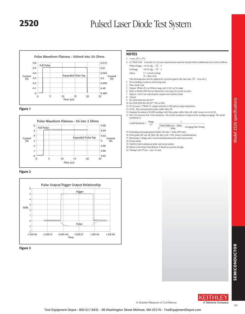
SE
MIC
ON
DU
CTO
R
A Greater Measure of Confidence
Mod
el 2
520
spec
ifica
tions
figure 1
Pulse Output/Trigger Output Relationship
-2
-1
0
1
2
3
4
5
6
-1.00E-06 -5.00E-07 0.00E+00 5.00E-07 1.00E-06 1.50E-06Time
Volts
Pulse
Trigger
NoTEs1 . 1 year, 23°C ±5°C .
2 . If Duty Cycle · I exceeds 0 .2, accuracy specifications must be derated with an additional error term as follows:
500mA Range: ±0 .1% rdg . · D · I
5A Range: ±0 .3% rdg . · D · I
where: I = current setting D = duty cycle This derating must also be applied for a period equal to the time that D · I was ≥0 .2 .3 . Not including overshoot and setting time .4 . Pulse mode only .5 . Output: 500mA DC on 500mA range and 1A DC on 5A range .6 . Refer to Model 2520 Service Manual for test setup of current accuracy .7 . Figures 1 and 2 are typical pulse outputs into resistive loads .8 . Typical .9 . Per ANSI/IEEE Std 181-1977 .10 . Per ANSI/IEEE Std 181-1977 10% to 90% .11 . DC accuracy ±700mV @ output terminal . 0 .2W typical output impedance .12 . At DC, 10µs measurement pulse width, filter off .13 . Standard deviation of 10,000 readings with 10µs pulse width, filter off, with I source set to 0A DC .14 . The A/D converter has 14 bit resolution . The useful resolution is improved by reading averaging . The useful
resolution is:
Useful Resolution =Range
214
1
Pulse Width (ns) – 400ns100ns
· Averaging Filter Setting
·
15 . Excluding total programmed (Pulse ON time + Pulse OFF time) .16 . Front panel off, calc off, filter off, duty cycle <10%, binary communications .17 . Returning 1 voltage and 2 current measurements for each source point .18 . Sweep mode .19 . Valid for both continuous pulse and sweep modes .20 . Shown is the Power Distribution % based on current settings .21 . Timing Cycle (pw⁄(pw + pd)): 4% max .
figure 2
Pulse Waveform Flatness - 500mA into 20 Ohms
0
0.1
0.2
0.3
0.4
0.5
0.6
0 5 10 15 20 25Time (µs)
0.485
0.49
0.495
0.5
0.505
0.51
0.515Full Pulse
Current(A)
Current(A)
Expanded Pulse Top
figure 3
Pulse Waveform Flatness - 5A into 2 Ohms
0
1
2
3
4
5
6
0 5 10 15 20 25Time (µs)
4.94
4.96
4.98
5
5.02
5.04
5.06
Expanded Pulse Top
Full Pulse
Current(A)
Current(A)
2520 Pulsed Laser Diode Test System
89 Test Equipment Depot - 800.517.8431 - 99 Washington Street Melrose, MA 02176 - TestEquipmentDepot.com

SE
MIC
ON
DU
CTO
R
The Model 2520INT Integrating Sphere is designed to optimize the Model 2520 Pulsed Laser Diode Test System’s optical power measurement capabilities . It allows the testing of devices with pulse widths as short as 500ns . The short pulses of the Model 2520 combined with the speed of the Model 2520INT make them ideal for measuring the optical power of laser diodes at the bar or chip level, before these devices are integrated into temperature-controlled modules . When connected to the Model 2520 via a low noise triax cable, the Model 2520INT allows the Model 2520 to make direct, high accuracy measurements of a laser diode’s optical power . The results are expressed in milliwatts .
Designed specifically for Pulsed laser Diode TestingKeithley developed the Model 2520INT to address the challenges specific to pulse testing laser diodes, which include short pulse periods and fast rise times . For example, when testing laser diodes in pulse mode, the opti-cal head used must provide a response that’s fast enough to measure light pulses as short as 500ns . Many optical power detectors are hampered by long rise times, so they can only measure a portion of the laser diode’s light output . Even when using a “fast” detector, many detectors are not good for analog signal measurement . By linking the Model 2520 with the optimum combination of sphere and detector characteristics, Keithley provides the low-level sensitivity needed to ensure accurate pulse measure-ments .
Easier laser Diode Power MeasurementsAn integrating sphere is inherently insensitive to variations in the beam profile produced by a device under test (DUT) . The Model 2520INT’s
interior is highly reflective Spectralon, which scatters, reflects, and diffuses the source beam the DUT produces . This spreads the light from the DUT uniformly over the sphere’s interior surface with minimal absorption loss . The detector, which reads the amount of optical power produced by the DUT, is mounted on the interior surface . Due to the multiple diffuse reflections within the sphere, the amount of optical radiation that strikes the detector is the same as that which falls on any other point on the sphere’s interior . To convert the attenuated signal measured by the detector into an accurate optical power measurement, the sphere and detector are calibrated as a unit .
simplifies beam alignmentIn a typical laser diode manufacturing line, the laser diode is not coupled to an optical fiber until the final stages of the packaging process . Therefore, any pulse testing performed on a laser diode at the bar- or chip-level would require a difficult and time-consuming beam alignment process in order to focus all of the diode’s output on the optical detector .
To ensure acceptance of the complete beam with maximum divergence angles, the sphere can be located up to 3 millimeters from the DUT, posi-tioned so the diode’s light output enters the 1⁄4-inch port on the sphere’s side . Any light that enters the sphere is captured in the measure-ment taken by the Model 2520 .
• optimized for laser diode pulse testing
• suitable for production and laboratory environments
• built-in germanium detector
• Works seamlessly with the Model 2520 Pulsed laser Diode Test system
aPPlICaTIoNs
bar- or chip-level lIV production testing of:
• 980 or 1480 EDfa pump lasers
• raman amplifiers
• Telecommunication laser diodes
• High power telecommunication VCsEls
aCCEssorIEs rEQuIrED2520 Pulsed Laser Diode Test System
7078-TRX Low Noise Triax Cable
2520INT Integrating Sphere for Pulsed Measurements
Sim
plifi
es p
ulse
d m
easu
rem
ents
of o
ptic
al p
ower
90 Test Equipment Depot - 800.517.8431 - 99 Washington Street Melrose, MA 02176 - TestEquipmentDepot.com

SE
MIC
ON
DU
CTO
R
A Greater Measure of Confidence
Sim
plifi
es p
ulse
d m
easu
rem
ents
of o
ptic
al p
ower
attenuation of laser Diode outputDetectors usually have a maximum power limit of a few milliwatts before the detector is over- saturated . The Model 2520INT Integrating Sphere’s highly reflective Spectralon interior surface elimi-nates the problem of detector saturation . This coating reflects and diffuses the light output from the DUT uniformly over the interior surface of the sphere, which inherently attenuates the level of power read by the built-in detector . The power level at any point on the sphere’s interior surface is far less than the power level of a beam that falls directly on the detector . This allows testing much higher power devices without risking detector damage . The Model 2520INT’s design attenuates the power output of a laser diode by approximately 100:1 .
optimized for Telecommunications WavelengthsThe Model 2520INT’s germanium detector is capable of detecting wavelengths from 800–1700nm . The detector and the sphere are calibrated as a unit in 10nm increments at wavelengths that are of particular interest for laser diode testing (950–1010nm and 1280–1620nm) . Calibration constants are provided in printed form as well as in CSV format on a floppy diskette to simplify programming them into a test system . When combined with the Model 2520INT, the Model 2520 Pulsed Laser Diode Test system is capable of measuring power ranging from 14 .5mW to 7W, depending on the wavelength (see the specifications for power ranges by wavelengths of interest) .
fiber Tap for additional MeasurementsThe Model 2520INT offers production test engineers the flexibility to decrease overall testing time by supporting multiple optical measurements simultaneously . An additional port on the sphere is compatible with an SMA connector; together, the port and fiber tap can be used to output a fraction of the measured light to an external instrument (such as a spectrometer) via a multimode fiber for additional optical measurements .
Eliminates back reflectionsDuring testing, the stability of a laser diode can be significantly affected by back reflections from objects in the optical path . The geometry of the Model 2520INT and the diffusing properties of its reflective interior help prevent back reflection and ensure greater device stability during testing .
Production or laboratory EnvironmentsA slight curvature on the face of the sphere makes Model 2520INT easier to integrate into an automated test system . This curvature allows additional room to connect the sphere to the DUT electrically and simplifies integration with other system components .
The Model 2520INT is designed with four stra-tegically located mounting holes for flexible mounting on laboratory tables or in automated test fixtures . Two of the holes are sized to accommodate metric fixtures, while the other two are designed for use with English fixtures . The Model 2520INT comes with a 1/4–20 base and post .
ordering Information2520INT-1-Ge
1 inch Integrating sphere with Germanium Detector
2520/KIT1 Pulsed laser Diode Measurement Package (Includes 2520, 2520INT, and 3-foot triax cable)
accessories suppliedQuick start Guide, calibration data (supplied as a printed chart and in CsV format on a floppy diskette), base and 1/4–20 post for mounting
2520INT
VCSEL Wafer
Probe Tip
A slight curvature on the face of the sphere allowsadditional room to connect the DUT electrically inclose quarters, such as in wafer probing.
a slight curvature on the face of the sphere allows additional room to connect the DuT electrically in close quarters, such as in wafer probing.
2520INT Integrating Sphere for Pulsed Measurements
91 Test Equipment Depot - 800.517.8431 - 99 Washington Street Melrose, MA 02176 - TestEquipmentDepot.com

SE
MIC
ON
DU
CTO
RM
odel
252
0IN
T sp
ecifi
catio
ns
specificationsFULL ACCEPTANCE ANGLE1: 90° vertical, 50° horizontal (max .) .
TriaxConnector
90° Full AngleIndicator
50° Full AngleIndicator
SMAConnector
frontal View of Integrating sphere showing full acceptance angle Indicators
OPERATING WAVELENGTH RANGE: 800–1700nm .
CONTINUOUS WAVE (CW) CALIBRATION WAVELENGTH RANGE2: 950–1010nm and 1280–1620nm .
Wavelength (nm)Measurable optical
Power range 3
Typical responsivity 4
(ma/W)resolution 5
(mW) 980 29mW–7W 3 .5 0 .21310 17mW–4W 6 .0 0 .11480 14 .5mW–3 .5W 7 .0 0 .11550 13 .5mW–3W 7 .5 0 .1
MAXIMUM REVERSE BIAS: 5V (recommended) .
DARK CURRENT AT MAX REVERSE BIAS: 4µA (typ .); 10µA (max .) .
PHOTODIODE ELECTRICAL CONNECTIONS ON 3 LUG TRIAX 6:
Center Conductor(Cathode)
Inner Shield(Anode)
Outermost Shield (not connected)(isolated from chassis)
Photodiode
PULSED OPERATION: The 2520INT supports the pulse capabilities of the 2520 Pulsed Laser Diode Test System .
FIBER TAP PORT: Connector Type: SMA . Numerical Aperature (NA): 0 .22 (typ .) .
Multi-Mode Patch Cord Core Diameter 7 (µm)
Typical attenuation (db)
400 39 .5100 53
62 .5 58 .250 63
GENEralINPUT PORT DIAMETER: 0 .25 in (6 .35mm) .
RECOMMENDED CALIBRATION CyCLE: 1 year .
OPERATING TEMPERATURE: 0°–50°C .
STORAGE TEMPERATURE: –25°C–65°C .
DIMENSIONS 8: 60 .0mm long × 86 .4mm high × 45 .7mm deep (2 .36 in × 3 .40 in × 1 .80 in) .
WEIGHT 8: 0 .15kg (0 .33 lbs) .
NoTEs1 Maximum distance from input port to accept at full maximum acceptance angle: 3 .1mm (0 .12 in) .2 Calibration performed at 10nm wavelength intervals .3 Based on detector being linear to up to 25mA photocurrent and on a signal to noise ratio (SNR) ≥ 100:1 .4 Calibration of the 2520INT is performed with an open fiber tap port . The power measurement will increase by
approximately 1% with an SMA patch cord attached to the port .5 Based on resolution of Model 2520 at 10mA (lowest) current measurement range .6 This configuration MUST have a NEGATIVE (reverse) bias voltage applied . If a positive (forward) bias is
applied, the detector (photodiode) will become damaged .7 Use of single mode fiber is not recommended .8 Only for integrating head, does not include post and base .
0.0025
0.0035
0.0045
0.0055
0.0065
0.0075
950 1050 1150 1250 1350 1450 1550 1650
Wavelength, nm
Res
pons
ivit
y, A
/W
Typical responsivity of the Model 2520INT
2520INT Integrating Sphere for Pulsed Measurements
92 Test Equipment Depot - 800.517.8431 - 99 Washington Street Melrose, MA 02176 - TestEquipmentDepot.com

SE
MIC
ON
DU
CTO
R
A Greater Measure of Confidence
Com
plet
e te
st s
olut
ions
for i
ndiv
idua
l app
licat
ion
need
s
Complete DC Test system with Temperature ControlKeithley’s LIV (light-current-voltage) Test System Kit is designed to help manufacturers of laser diode modules (LDMs) keep pace with produc-tion demands by allowing them to boost yield and throughput . The LIV test system combines all the DC measurement capabilities required to test these modules with optical power measure-ment and tight temperature control over the device under test in an integrated instrument package . The LIV test system is configured from proven Keithley instrumentation; the basic configuration can be easily modified to add new meas urement functions or to allow for new connections .
Tight Integration Ensures Higher Test speedsThe LIV test system allows for fast, easy integra-tion and high test speeds because all the build-ing blocks come from the same supplier . All
newer Keithley instruments include the Trigger Link feature and digital I/O lines, as well as standard IEEE-488 (GPIB) and RS-232 interfaces, to speed and simplify system integration and control . The Trigger Link feature combines independent software selectable trigger lines on a single connector for simple, direct control over all instruments in a system without the need for constant traffic over the GPIB . This feature is particularly useful for reducing total test time if the test involves a sweep . The digital I/O lines simplify external handler control and binning operations .
Source memory and buffer memory, provided by Models 2400-LV, 2420, 2440, and 2502, enable elimination of GPIB traffic during sweep testing . Source memory is a built-in “programmable test sequencer” for configuring up to 100 different tests . The buffer memory stores data that can be downloaded to the PC via the GPIB after an LIV test sweep is complete . Source memory, buffer memory, and Trigger Link work in concert to form an autonomous test system—all it takes to begin the test sequence is a “start of test” command from the PC . Benchmark testing has demonstrated that these features allow the system to complete a 400-point LIV test sweep with data transfer to the PC in less than eight seconds .
Easy to Program, Easy to useEach kit comes complete with the necessary cables and hardware to use the system . Having all the instrumentation supplied by the same vendor simplifies system programming and improves ease of use . All instruments in the standard system respond to the same SCPI command structure . LabVIEW® and Visual Instrument drivers and demonstration software are also available to simplify application development .
flexible system Configuration optionsIn addition to the standard system configurations, LIV test systems can be customized to accommo-date virtually any test sequence or setup requirement . Adding new capabilities or expanding existing ones is as simple as adding a new Keithley instrument or switch system . For example, to add isola-tion resistance measurements, just include any of Keithley’s Series 2000 Digital Multi meters in the configuration .
To accommodate multiple pin-out schemes, choose a Series 7000 Switch Mainframe and plug in one or more switch cards, such as the Model 7012 4×10 Matrix Card or the Model 7053 High Current Scanner Card for switching up to 5A . Automated switching makes it simple to accommodate future pin-out configuration changes .
• Programmable lIV test system for laser diode modules
• sweep and measure 400 points in <8s
• Very low noise current source (50µa) for laser diode drive
• up to 5a laser diode drive current
• Measures optical power directly
• 1fa resolution for dark current measurements
• fully digital P-I-D loop for temperature control
• ±0.005°C temperature stability, ±0.001°C setpoint resolution
• Trigger link, source memory, and buffer memory support automatic test sequencing, which greatly reduces GPIb bus traffic to improve test throughput
• Expandable and flexible for future requirements
shown: s25-22224 fully assembled and installed in optional 8000-10 equipment rack (laser diode module not included)
system 25 Laser Diode Test System Kit
93 Test Equipment Depot - 800.517.8431 - 99 Washington Street Melrose, MA 02176 - TestEquipmentDepot.com

SE
MIC
ON
DU
CTO
R
A custom configuration and ordering guide is available to simplify selecting all the critical items needed to complete a system .
single Vendor solutionIn addition to the assurance of hardware and software compatibility, systems integrators can be confident they’ll get all the technical support they need to complete and maintain their systems from a single source . Keithley’s applications engineers can help systems integrators optimize the performance of each instrument in the system to ensure high speed and accuracy from the system as a whole .
High accuracy building blocksThe standard LIV test system provides a fast, flexible solution for testing LDMs by combining the functions of several high speed, high accuracy Keithley instruments:
• Model 2400-LV, 2401, 2420, or 2440 SourceMeter® SMU instrument. During LIV testing, the SourceMeter SMU instrument provides a current sweep to drive the laser diode . It also synchronizes the measurements made by other instruments in the system . The Models 2400-LV, 2420, and 2440 SourceMeter SMU instruments are part of Keithley’s SourceMeter family and were developed specifically for test applications that demand tightly coupled precision voltage and current sourcing and measurement . Selecting the instrument’s high current range eliminates the potential for range change glitches if currents higher than 1A are needed during the LIV sweep . The Model 2420 offers drive current of up to 3A . The Model 2440 offers up to 5A of drive current for demanding pump laser control .
• Model 2502 Dual Photodiode Meter. The Model 2502 measures the current flow in the back facet photo detector and combines with the Model 2500INT Integrating Sphere to directly measure optical power . Both optical power measurement channels are fully independent . The measurement timing circuitry is shared between both channels to provide simultaneous measurements to optimize LIV performance . Each channel has eight measurement ranges and provides a resolution high enough to measure dark currents of the photodiode . The isolated bias sources provide up to 100V of bias . The Model 2502 has a high speed analog output that allows the LIV system to be combined with a fiber alignment system .
• Model 2510-AT TEC SourceMeter SMU instrument. The Model 2510-AT is a 50W bipolar instrument that controls the operation of an LDM’s Thermo-Electric Cooler or TEC (sometimes called a “Peltier device”) during LIV testing . During testing, the Model 2510-AT meas ures the internal temperature of the LDM from any of a variety of temperature sensors, then drives power through the TEC in order to maintain the LDM’s temperature at the desired setpoint .
The Model 2510-AT’s software-based, fully digital P-I-D (proportional-integral-differential) control provides excellent temperature stability . This high stability allows for very fine control over the output wavelength and over the optical power of the LDM during testing . Another Model 2510-AT can be added to include ambient fixture control, if the test will be done under a variety of ambient conditions . The instrument includes a low-level TEC resistance meas ure ment function to check TECs for mechanical damage during module assembly .
The Model 2510-AT offers autotuning capability . P, I, and D (proportional, integral, and derivative) values for closed loop temperature control are determined by the instrument using a modified Zeigler-Nichols algorithm . This eliminates the need for users to experiment by inputting various P, I, and D coefficients repeatedly in order to determine the optimal values .
• Model 2500INT Integrating Sphere. This accessory for the Model 2502 accepts direct optical input and provides for accurate L measurement without being sensitive to polarization mode or beam profile at the end of the fiber . The integrating sphere is available with a silicon, germanium, or cooled indium gallium arsenide detector to ensure accurate optical power measurements at any wavelength .
• Model 854x. The 854x Laser Diode Mount Series makes it easier than ever to configure a complete laser diode LIV test system for continuous wave test applications . These fixtures provide highly stable temperature control for all telecommunications laser diodes . They offer an easy-to-use platform for testing laser diodes used in telecommunications . They are designed to speed and simplify setting up test systems for all laser diode/photodiode/thermoelectric cooler/thermistor configurations .
For additional information on any of the building blocks of the LIV test system, refer to the data sheet for that instrument .
a demonstration software package, written in Visual basic, is available with the lIV test system to give programmers a head start on creating their own applications. using the demon stra tion package, users can set a variety of test parameters, including NPlC (integration time), source Delay (settling time before measurement), start Current, stop Current, and step Current. These parameters allow users to define the current sweep range and make speed and accuracy trade-offs by adjust ing source Delay and NPlC. The result ing data can be analyzed to deter mine threshold current and kink statis tics. The total test time includes the instrument setup, lIV sweep, and data transfer times (but not the computation times).
system 25 Laser Diode LIV Test System Kit
Com
plet
e te
st s
olut
ions
for i
ndiv
idua
l app
licat
ion
need
s
94 Test Equipment Depot - 800.517.8431 - 99 Washington Street Melrose, MA 02176 - TestEquipmentDepot.com

SE
MIC
ON
DU
CTO
R
A Greater Measure of Confidence
Syst
em 2
5 La
ser D
iode
LIV
Sys
tem
spe
cific
atio
ns
figure 1. The standard lIV test system is designed for applications that require the highest measurement accuracy. The Model 2420 sourceMeter sMu instrument drives the laser diode, sweeping the drive current from 0a up to 3a in programmable steps. at each step in the sweep, the Model 2420 records the current and voltage measurements, while the Model 2502 measures and records the current flow in the photodiodes. When the sweep is complete, the raw measurement data from the Model 2420 and the Model 2502 is uploaded to the PC for analysis. The lIV Demo software can calculate first and second derivatives of the back facet monitor diode or the external photo detector.
Thermistor Peltier
2510-AT
2502
Fiber
2500INT
ComputerGPIB
Trigger LinkTemperature Control
Source/Measure Measure
2400-LV, 2401, 2420, or 2440
ordering Information
select the instrument and accesory for your application. review the detailed specifications of each instrument in individual catalog sections.
aCCEssorIEs INCluDED IN EaCH oPTIoNsourCE/MEasurEIncludes: 2400-LV, 2401, 2420, or 2440 SourceMeter SMU Instrument 2502 Photodiode Meter (2) GPIB Interface Cables Trigger Link Cable Integrating Sphere Cable and adapter (Triax, 6172 adapter) DUT Cables (terminated in Alligator clips) Rackmount Conversion Kit
TEMPEraTurE CoNTrolIncludes: 2510-AT SourceMeter SMU Instrument(s) GPIB Interface Cable(s) DUT Cables Rackmount Conversion Kit
INTEGraTING sPHErEIncludes: 2500INT Integrating Sphere ½ open input port Post Stand
lasEr DIoDE MouNTIncludes: 854x Laser Diode Mount Easy Connect Multi Terminated Laser Diode Cables Easy Connect Multi Terminated Temperature Cables
CusToM sYsTEMsCustom systems are available . Contact your local Keithley sales person .
assEMblY sErVICEsThe S25 Systems are not assembled . If you would like assembly service, contact your local Keithley salesperson .
S25-
Source/Measure0 2400-LV or
General Purpose 2401/25022 2420/2502 Transmitter/Pump4 2440/2502 Pump Laser
Temperature Control0 None1 2510-AT Single Temp. Control2 2510-AT/2510-AT Dual Temp. Control
Integrating Spheres00 None21 2500INT-2-SI 2˝ Sphere, Silicon22 2500INT-2-GE 2˝ Sphere, Germanium23 2500INT-2-IGAC 2˝ Sphere, Cooled InGaAs
Laser Diode Mounts0 None4 8544 14-Pin Butterfly Mount4t 8544-TEC 14-Pin Butterfly w/TEC Control
aCCEssorIEs aVaIlablECablEs7007-1 Double Shielded GPIB Cable, 1m (3 .3 ft .)
7007-2 Double Shielded GPIB Cable, 2m (6 .6 ft .)
CabINETs(System kit is supplied with all necessary rack mount hardware . Purchase appropriate cabinet and assembly services separately .)
8000-10 Equipment Cabinet 10˝ high (holds 4 instruments)
8000-14A Equipment Cabinet 14 high
8000-17A Equipment Cabinet 17 .5 high
GPIb CarDs(GPIB communication required for complete LIV capabilities .)
KPCI-488LPA IEEE-488 Interface/Controller for the PCI Bus
KUSB-488B IEEE-488 USB-to-GPIB Adapter for USB Port
system 25 Laser Diode LIV Test System Kit
95 Test Equipment Depot - 800.517.8431 - 99 Washington Street Melrose, MA 02176 - TestEquipmentDepot.com

SE
MIC
ON
DU
CTO
R
The SourceMeter family was developed specifically for test applications that demand tightly coupled precision voltage and current sourcing and concurrent measure-ment, including source read back . This family of instru-ments can be easily programmed to drive laser diodes throughout the characterization process . Any of them can also be programmed to act as a synchronization controller to ensure simultaneous measurements during the test sequence . Selecting a fixed current range elimi-nates the potential for range offsets that appear as kinks during the LIV sweep testing . The Models 2400-LV and 2401 offer a drive current of up to 1A, ideal for testing VCSEL devices .
The Model 2420 offers a tighter accuracy specification that allows for precise control of transmitter laser devic-
es . In addition to higher accuracy, the Model 2420 offers a drive current of up to 3A for devices that need drive currents greater than 1A, such as pump lasers used in EDFA amplifiers .
The Model 2440 5A SourceMeter SMU Instrument further broadens the capabilities offered by the popular SourceMeter line . The dynamic range and functionality of the Model 2440 makes it ideal for applications such as testing high power pump lasers for use in optical amplifiers, laser bar tests, and testing other higher power components . Manufacturers of Raman pump laser modules and optical amplifiers will find it invaluable for a wide range of design and production test applications .
A Keithley SourceMeter SMU instrument provides a complete, economical, high throughput solution for component production testing, all in one compact, half-rack box . It combines source, measure, and control capabilities in a form factor that’s unique to the industry . The SourceMeter is also suit-able for making a wide range of low power DC measurements, including resistance at a specified cur-rent or voltage, breakdown voltage, leakage current, and insulation resistance .
single box solutionBy linking source and measurement circuitry in a single unit, a SourceMeter SMU instrument offers a variety of advantages over systems configured with separate source and measurement instruments . For example, it minimizes the time required for test station development, setup, and maintenance, while lowering the overall cost of system ownership . It simplifies the test process itself by eliminating many of the complex synchronization and connection issues associated with using multiple instru-ments . Its compact, half-rack size conserves “real estate” in the test rack or bench .
• Designed for production testing of VCsEls, transmitter, high power pump lasers, and other high current electronic components
• Key building block for programmable lIV test system for laser diode modules
• Very low noise current source (50µa) for laser diode drive
• up to 5a laser diode drive current
• Trigger link, source Memory, and buffer memory support automatic test sequencing
• reduced GPIb bus traffic improves test throughput
• Expandable and flexible for future requirements
• built-in comparator for fast pass/fail testing
• Digital I/o handler interface
• 1000 readings/second at 4½ digits
• optional contact check function
aCCEssorIEs aVaIlablElasEr DIoDE MouNTs8542 Dual In-Line Telecom Laser Diode Mount Bundle
8544 Butterfly Telecom Laser Diode Mount Bundle
8544-TEC Butterfly Telecom Laser Diode Mount Bundle with TEC, thermistor, and AD592CN temperature sensor
CoMMuNICaTIoN INTErfaCEKPCI-488LPA IEEE-488 Interface/Controller for the PCI Bus
KUSB-488B IEEE-488 USB-to-GPIB Adapter for USB Port
sWITCHING HarDWarE7001 Two-Slot Switch System
7002 Ten-Slot Switch System
7053 High-Current Switch Card
TEsT lEaDs aND ProbEs5806 Kelvin Clip Lead Set
CablEs/aDaPTErs2499-DIGIO Digital I/O Expansion Assembly
7007-1 Shielded GPIB Cable, 1m (3 .3 ft)
7007-2 Shielded GPIB Cable, 2m (6 .6 ft)
7009-5 RS-232 Cable
8501-1 Trigger Link Cable, 1m (3 .3 ft)
8501-2 Trigger Link Cable, 2m (6 .6 ft)
8502 Trigger Link Adapter Box
raCK MouNT KITs4288-1 Single Fixed Rack Mount Kit
4288-2 Dual Fixed Rack Mount Kit
2400-lV, 2400-C, 2401, 2420, 2420-C, 2440, 2440-C
SourceMeter® SMU Instruments for Optoelectronic I-V Testing
Tigh
tly c
oupl
ed s
ourc
e an
d m
easu
re fo
r act
ive
com
pone
nt te
stin
g
96 Test Equipment Depot - 800.517.8431 - 99 Washington Street Melrose, MA 02176 - TestEquipmentDepot.com

SE
MIC
ON
DU
CTO
R
A Greater Measure of Confidence
Tigh
tly c
oupl
ed s
ourc
e an
d m
easu
re fo
r act
ive
com
pone
nt te
stin
g
High Throughput to Meet Demanding Production Test schedulesA SourceMeter SMU instrument’s highly integrated architecture offers significant throughput advan-tages . Many features of this family enable them to “take control” of the test process, eliminating additional system bus traffic and maximizing total throughput . Built-in features that make this pos-sible include:
• Source Memory List test sequencer with conditional branching
• Handler/prober interface
• Trigger Link compatibility with switching hardware and other instruments from Keithley
• High speed comparator, pass/fail limits, mathematical scaling
• Deep memory buffer
The SourceMeter SMU instruments also offer standard RS-232 and GPIB interfaces for integration with a PC . Adding one of Keithley’s versatile switch systems enables fast, synchronized multi-point testing .
Testing optoelectronic ComponentsUse a SourceMeter SMU instrument to measure a component’s electrical performance characteristics and to drive laser diodes and other components .
ordering Information2400-lV low Voltage
sourceMeterMeasurements up to 20V and 1a, 20W Power output
2400-C General-Purpose sourceMeter
Contact Check, Measurements up to 200V and 1a, 20W Power output
2401 low Voltage sourceMeter
Measurements up to 20V and 1a, 20W Power output
2420 High-Current sourceMeter
Measurements up to 60V and 3a, 60W Power output
2420-C High-Current sourceMeter
Contact Check, Measurements up to 60V and 3a, 60W Power output
2440 5a sourceMeterMeasurements up to 40V and 5a, 50W Power output
2440-C 5a sourceMeterContact Check, Measurements up to 40V and 5a, 50W Power output
accessories suppliedTest leads, user’s Manual, service Manual, and labVIEW® Drivers
Choose the Model 2420 for testing higher powerresistors, thermistors, IDDQ, solar cells, batteries, andhigh-current or medium power diodes, includingswitching and Schottky diodes.
The Model 2440’s wide dynamic range is well-suitedfor applications such as testing high-power pump lasersfor use in optical amplifiers and laser bar tests, as wellas testing other higher power components.
+1A
= duty cycle limited
–100mA
+20V–20V
+100mA
–1A
Models 2400-LV/2401SourceMeterInstruments
+1A
+60V
–100mA
+20V–20V–60V
+3A
+100mA
–1A
–3A
Model 24203A SourceMeterInstrument
+1A
+40V
–100mA
+10V–10V–40V
+3A
+100mA
+5A
–1A
–3A
–5A
Model 24405A SourceMeterInstrumentI
V V V
II
The Models 2400-LV and 2401 are ideal for testing a wide variety of devices, including diodes, resistors, resistor networks, active circuit protection devices, and portable battery-powered devices and components.
Model 2400-lV/2400-C/2401 2420/2420-C 2440/2440-CDescription General Purpose 3 A 5 APower Output 20 W 60 W 50 WVoltage Range ±1 µV to ±20 V ±1 µV to ±63 V ±1 µV to ±42 VCurrent Range ±50 pA to ±1 .05 A ±500 pA to ±3 .15 A ±500 pA to ±5 .25 AOhms Range <0 .2 W to >200 W <0 .2 W to >200 MW <2 .0 W to >200 MW
ApplicationsOptoelectronic components .
VCSELs .Transmitter modules .
EDFA pumps .5A pump laser diodes .
Raman amplifiers .
Types of Optoelectronic Components
• Laser diodes
• Laser diode modules
• Photodetectots
• Light-emitting diodes (LEDs)
• Photovoltaic cells
Typical Tests
• LIV test (laser diodes and LEDs)
• Kink test (laser diode)
• I-V characterization
2400-lV, 2400-C, 2401, 2420, 2420-C, 2440, 2440-C
SourceMeter® SMU Instruments for Optoelectronic I-V Testing
97 Test Equipment Depot - 800.517.8431 - 99 Washington Street Melrose, MA 02176 - TestEquipmentDepot.com

SE
MIC
ON
DU
CTO
R24
00, 2
420,
244
0 sp
ecifi
catio
ns
sourCEMETEr sMu INsTruMENT sPECIfICaTIoNsThe following tables summarize the capabilities of the Models 2400-LV, 2420, and 2440 .
2400-lV sourCEMETEr (I-V MEasurEMENTs)Current Programming accuracy Voltage Measurement accuracy
accuracy (1 Year) Default Input 23°C ±5°C range resolution resistance ± (% rdg. + volts) 200 .000 mV 1 µV > 10 GW 0 .01 % + 300 µV 2 .00000 V 10 µV > 10 GW 0 .012% + 300 µV 20 .0000 V 100 µV > 10 GW 0 .015% + 1 .5 mV
accuracy (1 Year) Programming 23°C ± 5°C range resolution ± (% rdg. + amps) 1 .00000 µA 50 pA 0 .035% + 600 pA 10 .0000 µA 500 pA 0 .033% + 2 nA 100 .000 µA 5 nA 0 .031% + 20 nA 1 .00000 mA 50 nA 0 .034% + 200 nA 10 .0000 mA 500 nA 0 .045% + 2 µA 100 .000 mA 5 µA 0 .066% + 20 µA 1 .00000 A 50 µA 0 .27 % + 900 µA
faster, Easier, and More Efficient Testing and automation
Coupled Source and Measure CapabilitiesThe tightly coupled nature of a SourceMeter SMU instrument provides many advantages over separate instruments . The ability to fit a source and a meter in a single half-rack enclosure saves valuable rack space and simpli-fies the remote programming interface . Also, the tight control and a single GPIB address inherent in a single instrument result in faster test times for ATE applications due to reduced GPIB traffic .
Standard and Custom SweepsSourceMeter SMU instruments provide sweep solutions that greatly acceler-ate testing with automation hooks for additional throughput improvement .
2420 sourCEMETEr (I-V MEasurEMENTs)Current Programming accuracy accuracy (1 Year) Programming 23°C ± 5°C range resolution ± (% rdg. + amps) 10 .0000 µA 500 pA 0 .033% + 2 nA 100 .000 µA 5 nA 0 .031% + 20 nA 1 .00000 mA 50 nA 0 .034% + 200 nA 10 .0000 mA 500 nA 0 .045% + 2 µA 100 .000 mA 5 µA 0 .066% + 20 µA 1 .00000 A 50 µA 0 .067% + 900 µA 3 .00000 A 50 µA 0 .059% + 2 .7 mA
Voltage Measurement accuracy accuracy (1 Year) Default Input 23°C ±5°C range resolution resistance ± (% rdg. + volts) 200 .000 mV 1 µV > 10 GW 0 .012% + 300 µV 2 .00000 V 10 µV > 10 GW 0 .012% + 300 µV 20 .0000 V 100 µV > 10 GW 0 .015% + 1 mV 60 .0000 V 1 mV > 10 GW 0 .015% + 3 mV
2440 sourCEMETEr (I-V MEasurEMENTs)Current Programming accuracy accuracy (1 Year)3 Programming 23°C ± 5°C range resolution ± (% rdg. + amps) 10 .0000 µA 500 pA 0 .033% + 2 nA 100 .000 µA 5 nA 0 .031% + 20 nA 1 .00000 mA 50 nA 0 .034% + 200 nA 10 .0000 mA 500 nA 0 .045% + 2 µA 100 .000 mA 5 µA 0 .066% + 20 µA 1 .00000 A 50 µA 0 .067% + 900 µA 5 .00000 A 50 µA 0 .10 % + 5 .4 mA
Voltage Measurement accuracy accuracy (1 Year) Default Input 23°C ±5°C range resolution resistance ± (% rdg. + volts) 200 .000 mV 1 µV > 10 GW 0 .012% + 300 µV 2 .00000 V 10 µV > 10 GW 0 .012% + 300 µV 10 .0000 V 100 µV > 10 GW 0 .015% + 750 µV 40 .0000 V 1 mV > 10 GW 0 .015% + 3 mV
optional Contact CheckThe Contact Check option available on all Series 2400 SourceMeter SMU instruments allows quick verification of a good connection to the DUT before functional testing proceeds . This feature helps prevent the loss of precious test time due to damaged, corroded, or otherwise faulty contacts in a test fixture . The innovative contact check design completes the verifi-cation and notification process in less than 350µs; comparable capabilities in other test equipment can require up to 5ms to perform the same func-tion . Contact check failure is indicated on the instrument’s front panel and over the GPIB bus . The digital I/O interface can also be used to communi-cate contact failure to the component handler in automated applications .
2400-lV, 2400-C, 2401, 2420, 2420-C, 2440, 2440-C
SourceMeter® SMU Instruments for Optoelectronic I-V Testing
98 Test Equipment Depot - 800.517.8431 - 99 Washington Street Melrose, MA 02176 - TestEquipmentDepot.com

SE
MIC
ON
DU
CTO
R
A Greater Measure of Confidence
Dua
l-cha
nnel
opt
ical
pow
er m
easu
rem
ent
• Dual-channel instrument for low current measurements
• ±100V bias source
• Measure current from 1fa to 20ma
• 1fa current measurement resolution
• 0–10V analog output for high resolution optical power feedback
• 3000-point buffer memory on each channel allows data transfer after test completion
• Digital I/o and Trigger link for binning and sweep test operations
• IEEE-488 and rs-232 interfaces
The Model 2502 combines Keithley’s expertise in low-level current measurements with high speed current measurement capabilities . Each channel of this instrument consists of a voltage source paired with a high speed picoammeter . Each of the two channels has an independent picoam-meter and voltage source with measurements made simultaneously across both channels .
Wide Dynamic Measurement rangeThe Model 2502 offers current measurement ranges from 2nA to 20mA in decade steps . This provides for all photodetector current measure-ment ranges for testing laser diodes and LEDs in applications such as LIV testing, LED total radi-ance measurements, measurements of cross-talk and insertion loss on optical switches, and many others . The Model 2502 meets industry testing requirements for the transmitter as well as pump laser modules .
High accuracy Dark Current MeasurementsThe Model 2502’s 2nA current measurement range is ideal for measuring dark currents with 1fA resolution . Once the level of dark current has been determined, the instrument’s REL function automatically subtracts the dark current as an offset so the measured values are more accurate for optical power measurements .
Voltage bias CapabilityThe Model 2502 provides a choice of voltage bias ranges: ±10V or ±100V . This choice gives the system integrator the ability to match the bias range more closely to the type of photodetector being tested, typically ±10V for large area photodetectors and ±100V for avalanche-type photodetectors . This abil-ity to match the bias to the photodetector ensures improved measurement linearity and accuracy .
ratio and Delta MeasurementsThe Model 2502 can provide ratio or delta measurements between the two completely isolated channels, such as the ratio of the back facet monitor detector to the fiber-coupled photodetector at varying levels of input current . These functions can be accessed via the front panel or the GPIB interface . For test setups with multiple detectors, this capability allows for targeted control capabilities for the laser diode module .
Interface optionsTo speed and simplify system integration and control, the Model 2502 includes the Trigger Link feature and digital I/O lines, as well as standard IEEE-488 and RS-232 interfaces . The Trigger Link feature combines six independent software selectable trigger lines on a single connector for simple, direct control over all instruments in a system . This feature is especially useful for reducing total test time if the test involves a sweep . The Model 2502 can sweep through a series of measure-ments based on triggers received from the SourceMeter® SMU Instrument . The digital I/O lines simplify external handler control and bin-ning operations .
For additional information and detailed specifications, see page 141.
ordering Information2502 Dual-Channel
Picoammeter
accessories supplieduser’s Manual
Model 2502 rear panel
2502 Dual-Channel Picoammeter for Photodiode Measurements
sErVICEs aVaIlablE2502-3Y-EW 1-year factory warranty extended to 3 years
from date of shipment
C/2502-3Y-DATA 3 (Z540-1 compliant) calibrations within 3 years of purchase*
*Not available in all countries
99 Test Equipment Depot - 800.517.8431 - 99 Washington Street Melrose, MA 02176 - TestEquipmentDepot.com

SE
MIC
ON
DU
CTO
R
The Model 2500INT Integrating Sphere is the latest addition to Keithley’s growing line of solutions for LIV (light-current-volt-age) testing . When connected via a low noise triax cable to the Model 2502 Dual Photodiode Meter included in Keithley’s LIV Test System, the integrating sphere allows the system to make direct measurements of optical power, with results expressed in watts . The integrating sphere simplifies production testing of laser diodes (LDs), light emitting diodes (LEDs), and other opti-cal components by eliminating common optical power measure-ment problems related to detector alignment, beam profile, polarization, and back reflection .
Choice of Three Detector TypesThe Model 2500INT is available with a silicon (2500INT-2-Si), germanium (2500INT-2-Ge), or cooled indium gallium arsenide (InGaAs) detector (2500INT-2-IGAC), each calibrated with the sphere . Spheres equipped with cooled indium gallium arse-nide detectors include a controller to regulate the detector’s temperature .
unaffected by DuT beam ProfileLaser diodes can produce non-gaussian beam profiles, which can lead to inaccurate optical power measurements due to underfill or overfill of the detector . While a number of methods are available to correct for underfill and overfill, these methods can add to the overall inaccuracy of the measure ment .
In contrast, an integrating sphere is inherently insensitive to beam profiles . The interior of the Model 2500INT integrating sphere has a highly reflective Spectralon surface, which scatters, reflects, and diffuses the source beam produced by the device under test (DUT) . This spreads the light from the DUT uniformly over the interior surface of the sphere with minimal absorption loss . A detector can be placed on the interior surface of the sphere, then the sphere/detector combination can be cali-brated . The amount of optical radiation striking the detector is the same as any other point on the sphere interior due to the multiple diffuse reflections within the sphere . Therefore, the calibration and resulting measurement accuracy are independent of beam profile .
The Model 2500INT’s Spectralon surface offers a variety of other advantages . It is a nearly perfect diffuse reflector, exhibiting Lambertian reflectance properties, so it reflects equally in all directions, regardless of viewing angle . This eliminates the inaccuracies associated with less diffuse materi-als by distributing the optical radiation more evenly over the interior of the sphere . In addition, a Spectralon surface offers high reflectance for wavelengths from 250–2500nm, which makes it ideal for laser diode measurement applications . It is also chemically inert, which helps ensure stable meas-urements in harsh environments .
Eases beam alignmentIf an integrating sphere is not used in laser diode testing, the entire beam from the laser must shine directly onto the detector in order to measure optical power accurately . However, it is difficult to align a laser and detector with the high degree of precision required, particularly when the laser is operating outside of the visible spectrum . With the use of an integrating sphere, beam alignment is trivial because any light that enters the sphere will be spread evenly across its interior surface . Simply stated, it is easier to direct a laser into a ½-inch port than it is to direct a laser onto a 5mm detector . The sphere
aPPlICaTIoNs
Production testing of:
• laser diode modules
• Chip on submount laser diodes
• laser diode bars
• lEDs
• Passive optical components
ordering Information2500INT-2-si
Integrating sphere with silicon Detector
2500INT-2-Ge Integrating sphere with Germanium Detector
2500INT-2-IGaC Integrating sphere with Cooled Indium Gallium arsenide Detector
accessories supplied
Quick start Guide, Calibration Chart for each sphere, TEC Controller (included with 2500INT-2-IGaC)
• Choose from silicon, germanium, or cooled indium gallium arsenide detectors
• spectralon® sphere interior ensures high reflectivity
• Part of Keithley’s high through put system for production testing of laser diodes and lEDs
2500INT Integrating Sphere
Enab
les
dire
ct o
ptic
al p
ower
mea
sure
men
t in
wat
ts w
ith th
e M
odel
250
2
100 Test Equipment Depot - 800.517.8431 - 99 Washington Street Melrose, MA 02176 - TestEquipmentDepot.com

SE
MIC
ON
DU
CTO
R
A Greater Measure of Confidence
Enab
les
dire
ct o
ptic
al p
ower
mea
sure
men
t in
wat
ts w
ith th
e M
odel
250
2
is insensitive to input beam alignment up to 40° off normal or divergences up to 40° half-angle .
Minimizes Polarization ConcernsThe randomizing effects of multiple reflections within Keithley’s integrat-ing sphere minimize beam polarization problems that can affect optical measurement accuracy when measuring polarized sources . Beam polariza-tion is of particular concern for manufacturers of distributed feedback lasers (DFBs) and Vertical Cavity Surface Emitting Lasers (VCSELs) .
Eliminates back reflectionThe stability of a laser diode is significantly affected by back reflections from objects in the optical path . The geometric nature of the integrating sphere and the diffusing properties of the sphere’s reflective material help prevent back reflection and ensure greater device stability during testing .
attenuates High Power laser Diode outputsDetectors have specified maximum power capability, which is typically just a few milliwatts . By spreading the output power evenly over its interior surface, an integrating sphere automatically attenuates the power from the source; therefore, the power level at any point on the sphere surface is far less than that of a beam that falls directly on the detector . The Model 2500INT sphere is particularly useful for testing high-power laser diodes because it provides calibrated attenuation of the laser diode output, which prevents damage to the detector due to the high density of the output or other problems associated with saturation of the detector .
Designed specifically for laser Diode TestingThe design of the Model 2500INT Integrating Sphere is optimized for measuring the optical power of laser diodes . Each sphere is two inches in diameter with a ½-inch input port suitable for fiber or direct light (as in chip on submount applications) . The port and detector are positioned so there is no need to use a baffle to prevent the input from shining directly onto the detector .
Thermistor Peltier
2510 or2510-AT
2400/2420 2502
Fiber
2500INT
ComputerGPIB
Trigger Link
The Model 2500INT allows the lIV Test system to measure opti-cal inputs directly and to display power measurements in watts. other instruments in the lIV Test system include the Model 2502 Dual Photodiode Meter, the Model 2510 TEC sourceMeter® sMu Instrument, and either the Model 2400 or Model 2420 sourceMeter sMu Instrument. Each integrating sphere is characterized at the fac-tory and provided with a calibration constant for every 25 nanometers in the detector’s range. Prior to testing, the user simply enters the constant in the Model 2502 Dual Photodiode Meter to ensure accurate meas ure ments of optical power for that wavelength.
silicon Detector Germanium Detector
Cooled InGaas Detector
Wavelength Range 190–1100 nm 800–1800 nm 900–1670 nmPeak Wavelength (λp) 960 nm 1550 nm 1550 nmSensitivity at Peak Wavelength Excellent at 960 nm Good at 1550 nm Excellent at 1550 nmSensitivity at Certain Wavelengths
Visible *** N/A N/A980 nm *** ** **
1310 nm N/A ** ***1550 nm N/A ** ***
>1550 nm N/A ** ***Speed *** * **Calibration Accuracy/Stability Spectral response changes
rapidly with temperature at wavelengths >1000nm .
Spectral response changes rapidly with temperature and
λ above λp .
Extremely stable (Spectral response is stable because λ calibration is fixed at constant operating
temperatures, i .e ., –10°C .)Cost $ $$ $$$
* = Good ** = Better *** = Best N/A = not applicable
Detector selection CriteriaWhen choosing the most appropriate detector for a specific application, consider the following selection criteria:
• Wavelengths of maximum interest
• Sensitivity at wavelength of interest
• Speed
• Cost
• Calibration accuracy/stability
2500INT Integrating Sphere
101 Test Equipment Depot - 800.517.8431 - 99 Washington Street Melrose, MA 02176 - TestEquipmentDepot.com

SE
MIC
ON
DU
CTO
RM
odel
250
0IN
T sp
ecifi
catio
ns
sPECIfICaTIoNs
PHYsICal, THErMo-oPTICal, aND ElECTroNIC ProPErTIEs of sPECTraloN MaTErIal
Property asTM Test ValueDensity N/A 1 .25–1 .5g/cm3
Water Permeability D-570 <0 .001% (hydrophobic)Hardness D-785 20–30 Shore DThermal Stability N/A Decomposes at >400°CCoefficient of Linear Expansion D-696 5 .5–6 .5 × 10–5 in/in –°F; 10–4 °C–1
Vacuum Stability N/A No outgassing except for entrained air
Flammability N/ANon-flammable (UL rating V-O) Incompatible
with non-polar solvents and greasesYield Stress D-638 208psiUltimate Stress D-638 891psiYoung’s Modulus N/A 35774psiElongation in 2 in . D-638 42 .8%Elongation at Failure E-132 91 .3%Poisson’s Ratio D-621 0 .296
Deformation under Load D-62113 .3% @ 250 lbs . 22 .6% @ 500 lbs .
Absorbance (ax) N/A 0 .07Emittance (e) N/A 0 .88Volume Resistivity N/A >1018W/cmDielectric Strength D-149 18V/µmRefractive Index D-542 1 .35Flammability Rating UL-94 V-O
PHoToDIoDE sPECIfICaTIoNs
silicon GermaniumCooled Indium Gallium
arsenideWavelength Range 190–1100nm 800–1800nm 900–1670nmPeak Sensitivity Wavelength 960nm 1550nm 1550nmOperating Temperature –20° to +60°C –55° to +60°C –40° to +70°CStorage Temperature –55° to +80°C –55° to +80°C –55° to +85°CActive Area 2 .4mm × 2 .4mm 5 .0mm (diameter) 3 .0mm (diameter)Measurement Temperature — — –10°CThermistor Allowable Dissipation — — 0 .2mWPeltier Element — — 1 .5AAllowable Current — — 1 .0A
TYPICal rEflECTaNCE DaTa for sPECTraloN MaTErIal
Wavelength (nm) spectralon500 0 .991600 0 .992700 0 .992800 0 .991900 0 .992
1000 0 .9931100 0 .9921200 0 .9921300 0 .9921400 0 .9911500 0 .9901600 0 .9891700 0 .9861800 0 .987
aCCEssorIEs aVaIlablE(Appropriate cables and connectors are required to operate the Model 2500INT Integrating Sphere and must be ordered sepa-rately . They are not included with the instrument .)
7078-TRX-1 Low-Noise Triax Cable, 0 .3m (1 ft)
7078-TRX-3 Low-Noise Triax Cable, 0 .9m (3 ft)
7078-TRX-5 Low-Noise Triax Cable, 1 .5m (5 ft)
7078-TRX-10 Low-Noise Triax Cable, 3 .0m (10 ft)
7078-TRX-12 Low-Noise Triax Cable, 3 .5m (12 ft)
7078-TRX-20 Low-Noise Triax Cable, 6 .0m (20 ft)
2500INT-FC/APC FC/APC Connector for 2500INT
2500INT-FC/PC FC/PC Connector for 2500INT
2500INT-SMA SMA Connector for 2500INT
6172 2-Slot Male to 3-Lug Female Triax Adapter
2500INT Integrating Sphere
102 Test Equipment Depot - 800.517.8431 - 99 Washington Street Melrose, MA 02176 - TestEquipmentDepot.com

SE
MIC
ON
DU
CTO
R
A Greater Measure of Confidence
Prec
isio
n te
mpe
ratu
re c
ontro
l for
TEC
s w
ith a
utot
unin
g PI
D fo
r opt
imal
per
form
ance
The Models 2510 and 2510-AT TEC SourceMeter SMU instruments enhance Keithley’s CW (Continuous Wave) test solution for high speed LIV (light-current-voltage) testing of laser diode modules . These 50W bipolar instruments were developed in close cooperation with leading manufacturers of laser diode modules for fiber-optic telecommunications networks . Designed to ensure tight temperature control for the device under test, the Model 2510 was the first in a line of highly specialized instruments created for telecommunications laser diode testing . It brings together Keithley’s expertise in high speed DC sourcing and measurement with the ability to control the operation of a laser diode module’s Thermo-Electric Cooler or TEC (sometimes called a Peltier device) accurately .
The Model 2510-AT expands the capability of the Model 2510 by offering autotuning capability . P,
I, and D (proportional, integral, and derivative) values for closed loop temperature control are deter-mined by the instrument using a modified Zeigler-Nichols algorithm . This eliminates the need for users to determine the optimal values for these coefficients experimentally . In all other respects, the Model 2510 and Model 2510-AT provide exactly the same set of features and capabilities .
The sourceMeter ConceptThe Model 2510 and Model 2510-AT draw upon Keithley’s unique Source Meter concept, which combines precision voltage/current sourcing and measurement functions into a single instrument . SourceMeter SMU instruments provide numerous advantages over the use of separate instruments, including lower acquisition and maintenance costs, the need for less rack space, easier system integra-tion and programming, and a broad dynamic range .
Part of a Comprehensive lIV Test systemIn a laser diode CW test stand, the Model 2510 or Model 2510-AT can control the temperature of actively cooled optical components and assemblies (such as laser diode modules) to within ±0 .005°C of the user-defined setpoint . During testing, the instrument measures the internal temperature of the laser diode module from any of a variety of temperature sensors, then drives power through the TEC within the laser diode module in order to maintain its temperature at the desired setpoint .
figure 1. The capabilities of the Models 2510 and 2510-aT are intended to complement those of other Keithley instruments often used in laser diode module lIV testing, including the Model 2400 and 2420 sourceMeter sMu instruments, the Model 2502 Dual Photo diode Meter, and the Model 2500INT Integrating sphere.
Thermistor Peltier
2510 or2510-AT
2400/2420 2502
Fiber
2500INT
ComputerGPIB
Trigger Link
ordering Information2510 TEC sourceMeter2510-aT autotuning TEC
sourceMeter sMu Instrument
accessories supplieduser’s Manual, Input/output Connector
aCCEssorIEs aVaIlablE2510-RH Resistive Heater Adapter for Model 2510
2510-CAB 4-Wire Unshielded Cable, Phoenix Connector to Unterminated End
7007-1 Shielded IEEE-488 Cable, 1m (3 .3 ft)
7007-2 Shielded IEEE-488 Cable, 2m (6 .6 ft)
KPCI-488LPA IEEE-488 Interface/Controller for the PCI Bus
KUSB-488B IEEE-488 USB-to-GPIB Adapter for USB Port
sErVICEs aVaIlablE2510-3Y-EW 1-year factory warranty extended to 3 years from
date of shipment
2510-AT-3Y-EW 1-year factory warranty extended to 3 years from date of shipment
C/2510-3Y-DATA 3 (Z540-1 compliant) calibrations within 3 years of purchase for Models 2510, 2510-AT*
*Not available in all countries
25102510-aT
TEC SourceMeter® SMU InstrumentAutotuning TEC SourceMeter SMU Instrument
103 Test Equipment Depot - 800.517.8431 - 99 Washington Street Melrose, MA 02176 - TestEquipmentDepot.com

SE
MIC
ON
DU
CTO
R
Active temperature control is very important due to the sensitivity of laser diodes to temperature changes . If the temperature var-ies, the laser diode’s dominant output wavelength may change, leading to signal overlap and crosstalk problems .
autotuning functionThe Model 2510-AT Autotuning TEC SourceMeter SMU instru-ment offers manu facturers the ability to automatically tune the
temperature control loop required for CW test-ing of optoelectronic components such as laser diode modules and thermo-optic switches . This capability eliminates the need for time-consum-ing experimentation to determine the optimal P-I-D coefficient values .
The Model 2510-AT’s P-I-D Auto-Tune software employs a modified Ziegler-Nichols algorithm to determine the coefficients used to control the P-I-D loop . This algorithm ensures that the final settling perturbations are damped by 25% each cycle of the oscillation . The autotuning process begins with applying a voltage step input to the system being tuned (in open loop mode) and measuring several parameters of the system’s response to this voltage step function . The system’s response to the step function is illus-trated in Figure 2 . The lag time of the system response, the maximum initial slope, and the TAU [63% (1/e)] response time are measured, then used to generate the Kp (proportional gain constant), Ki (integral gain constant), and Kd (derivative gain constant) coefficients .
The autotuning function offers users a choice of a minimum settling time mode or a minimum overshoot mode, which provides the Model 2510-AT with the flexibility to be used with a variety of load types and devices . For example, when controlling a large area TEC in a test fix-ture optimized for P, I, and D values, minimum overshoot protects the devices in the fixture from damage (Figure 3) . For temperature setpoints that do not approach the maximum specified temperature for the device under test, the minimum settling time mode can be used to speed up the autotuning function (Figure 4) .
50W outputAs the complexity of today’s laser diode modules increases, higher power levels are needed in temperature controllers to address the module’s cooling needs during production test . The 50W
• 50W TEC Controller combined with DC measurement functions
• fully digital P-I-D control
• autotuning capability for the thermal control loop (2510-aT)
• Designed to control temperature during laser diode module testing
• Wide temperature setpoint range (–50°C to +225°C) and high setpoint resolution (±0.001°C) and stability (±0.005°C)
• Compatible with a variety of temperature sensor inputs—thermistors, rTDs, and IC sensors
• Maintains constant temperature, current, voltage, and sensor resistance
• aC ohms measurement function verifies integrity of TEC
• Measures and displays TEC parameters during the control cycle
• 4-wire open/short lead detection for thermal feedback element
• IEEE-488 and rs-232 interfaces
• Compact, half-rack design
Temp
TMAX
Max.InitialSlope
63%
Time
TSTART
TSL
tL te
figure 2.
figure 4.
figure 3.
Laser Diode TEC Minimum Overshoot
Time (s)
Tem
p (°
C)
27
26
25
24
230 5 10 15 20 25
Laser Diode TEC Minimum Settling Time
Time (s)
Tem
p (°
C)
27
26
25
24
230 5 10 15 20 25
aPPlICaTIoNs
Control and production testing of thermoelectric coolers (Peltier devices) in:
• laser diode modules
• Ir charge-coupled device (CCD) arrays and charge- injection devices (CID)
• Cooled photodetectors
• Thermal-optic switches
• Temperature controlled fixtures
25102510-aT
TEC SourceMeter® SMU InstrumentAutotuning TEC SourceMeter SMU Instrument
Prec
isio
n te
mpe
ratu
re c
ontro
l for
TEC
s w
ith a
utot
unin
g PI
D fo
r opt
imal
per
form
ance
104 Test Equipment Depot - 800.517.8431 - 99 Washington Street Melrose, MA 02176 - TestEquipmentDepot.com
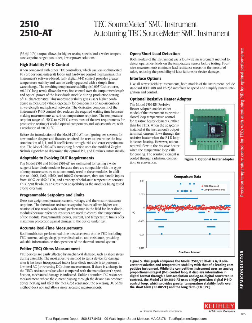
SE
MIC
ON
DU
CTO
R
A Greater Measure of Confidence
Prec
isio
n te
mpe
ratu
re c
ontro
l for
TEC
s w
ith a
utot
unin
g PI
D fo
r opt
imal
per
form
ance
(5A @ 10V) output allows for higher testing speeds and a wider tempera-ture setpoint range than other, lower-power solutions .
High stability P-I-D ControlWhen compared with other TEC controllers, which use less sophisticated P-I (proportional-integral) loops and hardware control mechanisms, this instrument’s software-based, fully digital P-I-D control provides greater temperature stability and can be easily upgraded with a simple firm-ware change . The resulting temperature stability (±0 .005°C short term, ±0 .01°C long term) allows for very fine control over the output wavelength and optical power of the laser diode module during production testing of DC characteristics . This improved stability gives users higher confi-dence in measured values, especially for components or sub-assemblies in wavelength multiplexed networks . The derivative component of the instrument’s P-I-D control also reduces the required waiting time between making measurements at various temperature setpoints . The temperature setpoint range of –50°C to +225°C covers most of the test requirements for production testing of cooled optical components and sub-assemblies, with a resolution of ±0 .001°C .
Before the introduction of the Model 2510-AT, configuring test systems for new module designs and fixtures required the user to determine the best combination of P, I, and D coefficients through trial-and-error experimenta-tion . The Model 2510-AT’s autotuning function uses the modified Zeigler-Nichols algorithm to determine the optimal P, I, and D values automatically .
adaptable to Evolving DuT requirementsThe Model 2510 and Model 2510-AT are well suited for testing a wide range of laser diode modules because they are compatible with the types of temperature sensors most commonly used in these modules . In addi-tion to 100W, 1kW, 10kW, and 100kW thermistors, they can handle inputs from 100W or 1kW RTDs, and a variety of solid-state temperature sensors . This input flexibility ensures their adaptability as the modules being tested evolve over time .
Programmable setpoints and limitsUsers can assign temperature, current, voltage, and thermistor resistance setpoints . The thermistor resistance setpoint feature allows higher cor-relation of test results with actual performance in the field for laser diode modules because reference resistors are used to control the temperature of the module . Programmable power, current, and temperature limits offer maximum protection against damage to the device under test .
accurate real-Time MeasurementsBoth models can perform real-time measurements on the TEC, including TEC current, voltage drop, power dissipation, and resistance, providing valuable information on the operation of the thermal control system .
Peltier (TEC) ohms MeasurementTEC devices are easily affected by mechanical damage, such as sheer stress during assembly . The most effective method to test a device for damage after it has been incorporated into a laser diode module is to perform a low-level AC (or reversing DC) ohms measurement . If there is a change in the TEC’s resistance value when compared with the manufacturer’s speci-fication, mechanical damage is indicated . Unlike a standard DC resistance measurement, where the current passing through the device can produce device heating and affect the measured resistance, the reversing DC ohms method does not and allows more accurate measurements .
open/short lead DetectionBoth models of the instrument use a four-wire measurement method to detect open/short leads on the temperature sensor before testing . Four-wire measure ments eliminate lead resistance errors on the measured value, reducing the possibility of false failures or device damage .
Interface optionsLike all newer Keithley instruments, both models of the instrument include standard IEEE-488 and RS-232 interfaces to speed and simplify system inte-gration and control .
optional resistive Heater adapterThe Model 2510-RH Resistive Heater Adapter enables either model of the instrument to provide closed loop temperature control for resistive heater elements, rather than for TECs . When the adapter is installed at the instrument’s output terminal, current flows through the resistive heater when the P-I-D loop indicates heating . However, no cur-rent will flow to the resistive heater when the temperature loop calls for cooling . The resistive element is cooled through radiation, conduc-tion, or convection .
figure 5. This graph compares the Model 2510/2510-aT’s a/D con-verter resolution and temperature stability with that of a leading com-petitive instrument. While the competitive instrument uses an analog proportional-integral (P-I) control loop, it displays information in digital format through a low-resolution analog-to-digital converter. In contrast, the Model 2510/2510-aT uses a high-precision digital P-I-D control loop, which provides greater temperature stability, both over the short term (±0.005°C) and the long term (±0.01°C).
Comparison Data
-0.015
-0.01
-0.005
0
0.005
0.01
One Hour Interval
°C
2510 Measured
Competitor Measured
25102510-aT
TEC SourceMeter® SMU InstrumentAutotuning TEC SourceMeter SMU Instrument
figure 6. optional heater adapter
105 Test Equipment Depot - 800.517.8431 - 99 Washington Street Melrose, MA 02176 - TestEquipmentDepot.com

SE
MIC
ON
DU
CTO
RM
odel
251
0, 2
510-
AT s
peci
ficat
ions
THErMal fEEDbaCK ElEMENT sPECIfICaTIoNs3
sensor Type rTD Thermistor solid state
100 W 1 kW 100 W 1 kW 10 kW 100 kWCurrent
output (Iss)Voltage
output (Vss)
Excitation13 2 .5 mA 4 V max
833 µA2 .5 mA 8 V max
833 µA 8 V max
100 µA 8 V max
33 µA 6 .6 V max
+13 .5 V 833 µA
2 .5 mA 15 .75V max
Nominal Resistance Range 0–250 W 0–2 .50 kW 0–1 kW 0–10 kW 0–80 kW 0–200 kWExcitation Accuracy1,3 ±1 .5% ±2 .9% ±2 .9% ±2 .9% ±2 .9% ±2 .9% ±12% ±2 .9%Nominal Sensor Temperature Range
–50° to +250°C –50° to +250°C –50° to +250°C –50° to +250°C –50° to +250°C –50° to +250°C –40° to +100°C–40° to +100°C
Calibration α, β, δ settable α, β, δ settable A, B, C settable A, B, C settable A, B, C settable A, B, C settable Slope & offset Slope & offsetMeasurement Accuracy1,3
±(% rdg + offset)0 .04 + 0 .07 W2 0 .04 + 0 .04 W2 0 .04 + 0 .07 W2 0 .04 + 0 .4 W2 0 .02 + 3 W 0 .04 + 21 W 0 .03 + 100 nA 0 .03 + 500 µV
THErMIsTor MEasurEMENT aCCuraCY19
Nominal Thermistorresistance
accuracy vs. Temperature0°C 25°C 50°C 100°C
100 W 0 .021°C 0 .035°C 0 .070°C 0 .27°C 1 kW 0 .015°C 0 .023°C 0 .045°C 0 .18°C 10 kW 0 .006°C 0 .012°C 0 .026°C 0 .15°C 100 kW 0 .009°C 0 .014°C 0 .026°C 0 .13°C
oPEN/sHorTED ElEMENT DETECTIoNSOFTWARE LINEARIzATION FOR THERMISTOR
AND RTD
Common Mode Voltage: 30VDC .Common Mode Isolation: >109W, <1000pF .Max. Voltage Drop Between Input/Output Sense
Terminals: 1V .Max. Sense Lead Resistance: 100W for rated accuracy .Sense Input Impedance: >108W .
GENEralNOISE REjECTION:
sPEED NPlC NMrr16 CMrr17
Normal 1 .00 60 dB 120 dB1
SOURCE OUTPUT MODES: Fixed DC level .
PROGRAMMABILITy: IEEE-488 (SCPI-1995 .0), RS-232, 3 user- definable power-up states plus factory default and *RST .
POWER SUPPLy: 90V to 260V rms, 50–60Hz, 75W .
EMC: Complies with European Union Directive 98/336/EEC (CE marking require ments), FCC part 15 class B, CTSPR 11, IEC 801-2, IEC 801-3, IEC 801-4 .
VIBRATION: MIL-PRF-28800F Class 3 Random Vibration .
WARM-UP: 1 hour to rated accuracies .
DIMENSIONS, WEIGHT: 89mm high × 213 mm high × 370mm deep (3½ in × 83⁄8 in × 149 ⁄16 in) . Bench configu-ration (with handle and feet): 104mm high × 238mm wide × 370mm deep (41 ⁄8 in × 93⁄8 in × 149 ⁄16 in) . Net Weight: 3 .21kg (7 .08 lbs) .
ENVIRONMENT: Operating: 0°–50°C, 70% R .H . up to 35°C . Derate 3% R .H ./°C, 35°–50°C . Storage: –25° to 65°C .
TEC ouTPuT sPECIfICaTIoNsOUTPUT RANGE: ±10VDC at up to ±5ADC .15
OUTPUT RIPPLE: <5mV rms9 .
AC RESISTANCE EXCITATION: ±(9 .6mA ± 90µA) .14
TEC MEasurEMENT sPECIfICaTIoNs3
function 1 Year, 23°C ±5°COperating Resistance 2, 10, 11, 12 ±(2 .0% of rdg + 0 .1W)Operating Voltage 2,10 ±(0 .1% of rdg + 4mV)Operating Current10 ±(0 .4% of rdg + 8mA)AC Resistance 2, 18 ±(0 .10% of rdg + 0 .02W)
OPEN SHORTED THERMOELECTRIC DETECTION
LOAD IMPEDANCE: Stable into 1µF typical .
COMMON MODE VOLTAGE: 30VDC maximum .
COMMON MODE ISOLATION: >109W, <1500pF .
MAX. VOLTAGE DROP BETWEEN INPUT/OUTPUT SENSE TERMINALS: 1V .
MAX. SENSE LEAD RESISTANCE: 1W for rated accuracy .
MAX. FORCE LEAD RESISTANCE: 0 .1W .
SENSE INPUT IMPEDANCE: >400kW .
sPECIfICaTIoNsThe Models 2510 and 2510-AT TEC SourceMeter SMU instruments are designed to:
Control the power to the TEC to maintain a constant temperature, current, voltage, or thermistor resistance .
Measure the resistance of the TEC .
Provide greater control and flexibility through a software P-I-D loop .
CoNTrol sYsTEM sPECIfICaTIoNsSET: Constant Peltier Temperature, Constant Peltier Voltage, Constant Peltier Current . Constant
Thermistor Resistance .
CONTROL METHOD: Programmable software PID loop . Proportional, Integral, and Derivative gains independently program mable .
SETPOINT SHORT TERM STABILITy: ±0 .005°C rms1,6,7 .
SETPOINT LONG TERM STABILITy: ±0 .01°C1,6,8 .
SETPOINT RANGE: –50°C to 225°C .
UPPER TEMPERATURE LIMIT: 250°C max .
LOWER TEMPERATURE LIMIT: –50°C max .
SETPOINT RESOLUTION: ±0 .001°C, <±400µV, <±200µA 0 .01% of nominal (25°C) thermistor resistance .
HARDWARE CURRENT LIMIT: 1 .0A to 5 .25A ±5% .
SOFTWARE VOLTAGE LIMIT:±0 .5 to 10 .5V ±5% .
NoTEs1 . Model 2510 and device under test in a regulated ambient temperature
of 25°C .2 . With remote voltage sense .3 . 1 year, 23°C ±5°C .4 . With ILoad = 5A and VLoad = 0V .5 . With ILoad = 5A and VLoad = 10V .6 . With 10kW thermistor as sensor .7 . Short term stability is defined as 24 hours with Peltier and Model 2510
at 25°C ±0 .5°C .8 . Long term stability is defined as 30 days with Peltier and Model 2510 at
25°C ±0 .5°C .9 . 10Hz to 10MHz measured at 5A output into a 2W load .10 . Common mode voltage = 0V (meter connect enabled, connects Peltier
low output to thermistor measure circuit ground) . ±(0 .1% of rdg . + 0 .1W) with meter connect disabled .
11 . Resistance range 0W to 20W for rated accuracy .12 . Current through Peltier > 0 .2A .13 . Default values shown, selectable values of 3µA, 10µA, 33µA, 100µA,
833µA, 2 .5mA . Note that temperature control performance will degrade at lower currents .
14 . AC ohms is a dual pulsed meas urement using current reversals avail-able over bus only .
15 . Settable to <400µV and <200µA in constant V and constant I mode respectively .
16 . For line frequency ±0 .1% .17 . For 1kW unbalance in LO lead .18 . Resistance range 0W to 100W for rated accuracy .19 . Accuracy figures represent the uncertainty that the Model 2510 may add
to the temperature measurement, not including thermistor uncertainty . These accuracy figures are for thermistors with typical A,B,C constants .
25102510-aT
TEC SourceMeter® SMU InstrumentAutotuning TEC SourceMeter SMU Instrument
106 Test Equipment Depot - 800.517.8431 - 99 Washington Street Melrose, MA 02176 - TestEquipmentDepot.com

SE
MIC
ON
DU
CTO
R
A Greater Measure of Confidence
Lase
r dio
de fi
xtur
es fo
r LIV
test
sys
tem
s
sPECIfICaTIoNsThis series covers the offering of Laser Diode Mounts (LDM) for use with Continuous LIV Test Solutions . The following products: 2400-LV/2420/2440, 2500/2502, and 2510/2510AT are recom-mended for use with these products .
lasEr TEMPEraTurE CoNTrolTEMPERATURE RANGE: 0° to +80°C .
SENSOR TyPE 2 (Model 8544-TEC Only): 10kW thermistor, AD592CN .
rEfErENCED MouNT sPECIfICaTIoNs
lasEr DIoDE PaCKaGE
Model 8544 8544-TECSocket Butterfly 14 pin Butterfly 14 pin
Base Plate 0 .1 centers 0 .1 centers
NoTEs1 . The other SourceMeter offerings from Keithley, Models 2400, 2410,
2425, and 2430, are not recommended for use with the 8542-301 and Laser Diode Mounts unless proper interlock and safety precautions are observed (especially voltage protection) .
2 . The 8544-TEC unit is shipped with the 10kW thermistor wired . This is the more commonly requested configuration . The AD592CN sensor wires are available but not connected .
3 . The triax inner shield is available on pin 2 of the 8542-301A . This will allow flexibility for the customer to exchange the wire in the LDM from pin 6 to pin 2 .
4 . To use the second 2510 (DB-15 pins 9–15), the customer must internally wire the 8544-TEC Mount to the DUT thermocouple . See the Quick Start Guide for wiring configuration .
5 . Ratings are based on use of mount with provided cables and average majority of laser diode characteristics .
6 . The weight and dimension is the mounting unit without the cables .
The 8544 Laser Diode Mount Series makes it easier than ever to configure a complete laser diode LIV test system for con-tinuous wave test applications . These fixtures provide highly stable temperature control for all telecommunications laser diodes . They offer an easy-to-use platform for testing laser diodes used in telecommunications . They are designed to speed and simplify setting up test systems for all laser diode/photodiode/ thermoelectric cooler/thermistor configurations .
Three different fixture bundle designs are available, all of which are compatible with Keithley’s popu-lar laser diode LIV test systems . Each bundle includes all cabling required to connect the test instru-mentation to the test fixture . Cables are also available separately .
All 14 pin DIL and butterfly laser packages can be mounted on the 8544 Series . For higher power butterfly packages without integral ther-moelectric coolers (TECs), the Model 8544-TEC offers a TEC and both thermistor and AD592CN sensors .
lasers not included
• Compatible with Keithley laser diode lIV test solutions
• simplifies configuration of lIV test systems
• Choice of three fixture designs, all with necessary cables
• Cables also available separately
• ambient temperature control on TEC version
ordering Information8544 butterfly Telecom
laser Diode Mount bundle with 8542-301 and Ca-321-1 cables
8544-TEC butterfly Telecom laser Diode Mount bundle with TEC, thermistor, and aD592CN temperature sensor, with 8542-301 and Ca-322-1 cables
accessories supplied8542-301 lIV Cable to connect
Model 2500 and 24XX to the fixture, 1.8m (6 ft.) (supplied with 8544 and 8544-TEC)
Ca-321-1 Temp Control Cable to connect Model 2510 to fixture, 1.8m (6 ft.) (supplied with 8544)
Ca-322-1 Dual Temp Control Cable to connect (2) Model 2510 to fixture, 1.8m (6 ft.) (supplied with 8544-TEC)
aPPlICaTIoNs
• Continuous wave laser diode lIV characterization
aCCEssorIEs aVaIlablE2400-LV/2420/2440 SourceMeter® SMU Instruments1
2502 Dual Photodiode Meter
2510/2510AT TEC Control Meters (AT: Auto Tune feature)
8544, 8544-TEC
Laser Diode Mounts for LIV Test Systems
GENEralRECOMMENDED MAXIMUM RATINGS5:
Drive Current (Amps): 2 . Measured Voltage (Volts): 3 .
WEIGHT6: 1 .0 lbs (0 .45kg) .
DIMENSIONS6: 32mm high × 95mm wide × 140mm deep (1 .2in × 3 .75 in × 5 .5 in) .
107 Test Equipment Depot - 800.517.8431 - 99 Washington Street Melrose, MA 02176 - TestEquipmentDepot.com

SE
MIC
ON
DU
CTO
R
108 Test Equipment Depot - 800.517.8431 - 99 Washington Street Melrose, MA 02176 - TestEquipmentDepot.com

LOW
LE
VE
L M
EA
SU
RE
& S
OU
RC
E
A Greater Measure of Confidence
low Voltage/low resistance Measurements
Technical Information . . . . . . . . . . . . . . . . . . . . . . . 110
Selector Guide . . . . . . . . . . . . . . . . . . . . . . . . . . . . . 114
2182a Nanovoltmeter . . . . . . . . . . . . . . . . . . . . . . . . . . . . . 115
6220 DC Current Source . . . . . . . . . . . . . . . . . . . . . . . . . 121
6221 AC and DC Current Source . . . . . . . . . . . . . . . . . . . 121
series 3700a System Switch/Multimeter and Plug-In Cards . . . . 126
low Current/High resistance Measurements
Technical Information . . . . . . . . . . . . . . . . . . . . . . . 127
Selector Guide . . . . . . . . . . . . . . . . . . . . . . . . . . . . . 129
6482 Dual-Channel Picoammeter/Voltage Source . . . . . 131
6485 Picoammeter . . . . . . . . . . . . . . . . . . . . . . . . . . . . . . 134
6487 Picoammeter/Voltage Source . . . . . . . . . . . . . . . . . 137
2502 Dual-Channel Picoammeter . . . . . . . . . . . . . . . . . . . 99
6514 Programmable Electrometer . . . . . . . . . . . . . . . . . 144
6517b Electrometer/High Resistance Meter . . . . . . . . . . . 148
6521 Low Current, 10-channel Scanner Card (for Model 6517x Electrometer) . . . . . . . . . . . . . . . 152
6522 Low Current, High Impedance Voltage, High Resistance, 10-channel Scanner Card (for Model 6517x Electrometer) . . . . . . . . . . 152
6220/6514/2000/7001 High Impedance Semiconductor Resistivity and Hall Effect Test Configurations . . . . . . . . . . . . 153
arbitrary Waveform/function Generator
3390 50MHz Arbitrary Waveform/Function Generator . 154
Low Level Measurements and Sourcing
109 Test Equipment Depot - 800.517.8431 - 99 Washington Street Melrose, MA 02176 - TestEquipmentDepot.com

LOW
LE
VE
L M
EA
SU
RE
& S
OU
RC
ETe
chni
cal i
nfor
mat
ion:
Low
vol
tage
/low
resi
stan
ce m
easu
rem
ent p
rodu
cts
Technical Information
Low Voltage/Low Resistance Measurements
How to select a Voltmeter Many kinds of instruments can measure voltage, including digital multimeters (DMMs), electrometers, and nanovoltmeters . Making voltage measurements successfully requires a voltmeter with significantly higher input impedance than the internal impedance (source impedance) of the device under test (DUT) . Without it, the voltmeter will measure less potential difference than existed before the voltmeter was connected . Electrometers have very high input impe-dance (typically in the order of 100TW [1014W]), so they’re the instrument of choice for high impedance voltage measurements . DMMs and nanovoltmeters can typically be used for measuring voltages from 10MW sources or lower . Nanovoltmeters are appro-priate for measuring low voltages (microvolts or less) from low impedance sources .
low Voltage MeasurementsSignificant errors may be introduced into low voltage measurements by offset voltage and noise sources that can normally be ignored when measuring higher signal levels . Steady offsets can generally be nulled out by shorting the ends of the test leads together, then enabling the instrument’s zero (relative) feature . The following paragraphs discuss non-steady types of error sources that can affect low voltage measurement accuracy and how to minimize their impact on the measurements .
Thermoelectric EMFsThe most common sources of error in low voltage measurements are thermoelectric voltages (thermo-electric EMFs) generated by temperature differences between junctions of conductors (Figure 1) .
Nanovoltmeter
T2
VAB
HI
LO
T1ABA
VAB = QAB ( T1 – T2 )
The thermoelectric voltage developed by dissimilarmetals A and B in a circuit is:
Temperatures of the twojunctions in °C
Seebeck coefficient ofmaterial A with respectto B, µV/°C
figure 1. Thermoelectric EMfs
Constructing circuits using the same material for all conductors minimizes thermoelectric EMF genera-tion . For example, connections made by crimping copper sleeves or lugs on copper wires results in cold-welded copper-to-copper junctions, which generate minimal thermoelectric EMFs . Also, con-nections must be kept clean and free of oxides .
Experiment(source) VS R
VIN
HI
Nanovoltmeter
LO
IGround 2
Ground bus
VG
Input voltage to the nanovoltmeter is:VIN = VS + I R
Resistance of input LO connection(typically around 100mΩ)
Current passing through input LOconnection due to groundvoltages (VG) in the ground bus(magnitude may be amperes).
Source voltage (desired signal)
IR may exceed VS by orders of magnitude.
Ground 1
figure 2a. Multiple grounds (ground loops)
Experiment(source) VS R
VIN
HI
Nanovoltmeter
LO
ZCM
I
SingleSystemGround
Ground bus
VG
Input voltage to the nanovoltmeter is:VIN = VS + I R
Current passing through ZCM (MΩ orGΩ) due to VG and currents in thesource (magnitude is typically nA’s).
VIN ≈ VS, since IR is now insignificant compared to VS.
figure 2b. single system ground
Minimizing temperature gradients within the circuit also reduces thermoelectric EMFs . A way to minimize such gradients is to place all junctions in close proximity and provide good thermal coupling to a common, massive heat sink . If this is impracti-cal, thermally couple each pair of corresponding junctions of dissimilar materials to minimize their temperature differentials which will also help minimize the thermoelectric EMFs .
johnson NoiseThe ultimate limit to how well the voltmeter can resolve a voltage is defined by Johnson (thermal) noise . This noise is the voltage associated with the motion of electrons due to their thermal energy . All sources of voltage will have internal resistance and thus produce Johnson noise . The noise voltage developed by any resistance can be calculated from t he following equation:
V = 4kTBR
k = Boltzmann’s constant (1 .38 × 10–23 J/K)
T = absolute temperature of the source in Kelvin
B = noise bandwidth in Hz
R = resistance of the source in ohms
From this equation, it can be observed that Johnson noise may be reduced by lowering the temperature and by decreasing the bandwidth of the measurement . Decreasing the bandwidth of the measurement is equivalent to increasing the response time of the instrument; thus, in addition to increasing filtering, the bandwidth can be reduced by increasing instrument integration (typic ally in multiples of power line cycles) .
Ground LoopsWhen both the signal source and the measurement instrument are connected to a common ground bus, a ground loop is created (Figure 2a) . This is the case when, for instance, a number of instruments are plugged into power strips on different instrument racks . Frequently, there is a difference in potential between the ground points . This potential differ-ence—even though it may be small—can cause large currents to circulate and create unexpected voltage drops . The cure for ground loops is to ground the entire measurement circuit at only one point . The easiest way to accomplish this is to isolate the DUT (source) and find a single, good earth-ground point for the measuring system, as shown in Figure 2b . Avoid grounding sensitive measurement circuits to the same ground system used by other instruments, machinery, or other high power equipment .
Magnetic FieldsMagnetic fields generate spurious voltages in two circumstances: 1) if the field is changing with time, and 2) if there is relative motion between the circuit and the field (Figure 3a) . Changing magnetic fields can be generated from the motion of a conductor in a magnetic field, from local AC currents caused by components in the test system, or from the deliberate ramping of the magnetic field, such as for magnetoresistance measurements .
Voltmeter
b.
a.
Voltmeter
Area A (enclosed)
The voltage developed due to a field passingthrough a circuit enclosing a prescribed area is:
B
VB =dφdt
d (BA)dt
dAdt
dBdt
= = B + A
DUT
DUT
figure 3. Minimizing interference from magnetic fields with twisted leads
To minimize induced magnetic voltages, leads must be run close together and should be tied down to minimize movement . Twisted pair cabling reduces the effects of magnetic fields in two ways: first, it reduces the loop area through which the magnetic
110 Test Equipment Depot - 800.517.8431 - 99 Washington Street Melrose, MA 02176 - TestEquipmentDepot.com

LOW
LE
VE
L M
EA
SU
RE
& S
OU
RC
E
A Greater Measure of Confidence
Tech
nica
l inf
orm
atio
n: L
ow v
olta
ge/l
ow re
sist
ance
mea
sure
men
t pro
duct
s
field is interfering; second, a magnetic field will create voltages of opposite polarities for neighboring loops of the twisted pair that will cancel each other . (Figure 3b)
low resistance MeasurementsLow resistances (<10W) are typically best measured by sourcing current and measuring voltage . For very low resistances (micro-ohms or less) or where there are power limitations involved, this method will require measuring very low voltages, often using a nanovoltmeter . Therefore, all the low voltage techniques and error sources described previously also apply here . Low resistance measurements are subject to additional error sources . The next sections describe methods to minimize some of these .
Lead Resistance and Four-Wire Method
Resistance measurements in the normal range (>10W) are generally made using the two-wire meth-od shown in Figure 4a . The main problem with the two-wire method for low resistance measurements (<10W) is the error caused by lead resistance . The voltage measured by the meter will be the sum of the voltage directly across the test resistance
MeasuredResistance I
VM
= RS + (2 × RLEAD)
=
= RS
Test Current (I)RLEAD
I VM
HI
LO
VM
RLEAD
VR RS ResistanceUnder Test
LeadResistances
DMM
VM = Voltage measured by meterVR = Voltage across resistor
figure 4a. Two-wire resistance measurement: lead resistance error
= RS
Test Current (I)
RLEAD
I VM
Sense HI
Sense LO
VM
RLEAD
VR RS ResistanceUnder Test
LeadResistances
DMM or Micro-ohmmeter
Because sense current is negligible, VM = VR
RLEAD
RLEADSource HI
Source LO
Sense Current(pA)
=I
VMand measured resistance =I
VR
figure 4b. four-wire resistance measurement
and the voltage drop across the leads . Typical lead resistances lie in the range of 1mW to 100mW . Therefore, the four-wire (Kelvin) connection method shown in Figure 4b is preferred for low resistance measurements . In this configuration, the test current is forced through the DUT through one set of test leads while the voltage is measured using a second set of leads called the sense leads . There is very little current running through the sense leads, so the sense lead resistance has effectively been eliminated .
Thermoelectric EMFs
Thermoelectric voltages can seriously affect low resistance measurement accuracy . Given that resist-ance measurements involve controlling the current through the DUT, there are ways to overcome these unwanted offsets in addition to those mentioned in the low voltage measurement section, namely, the offset- compensated ohms method and the current-reversal method .
• Offset Compensation Technique (Figure 5a) applies a source current to the resistance being measured only for part of the measurement cycle . When the source current is on, the total voltage measured by the instrument is the sum of the voltage due to the test current and any thermoelectric EMFs present in the circuit . During the second half of the measurement cycle, the source current is turned off and the only voltage measured is that due to the thermoelectric EMF . This unwanted offset voltage can now be subtracted from the voltage measurement made during the first half of the delta mode cycle .
• With the Offset Compensation technique, the source current is decided by the instrument . To characterize at a specific current or a variety of currents, the Current Reversal technique/Two-step Delta technique (described below) will provide more flexibility .
• Current Reversal Technique/Two-Step Delta Technique (Figure 5b)
• Thermoelectric EMFs can also be cancelled by taking two voltages with test currents of opposite polarity . The voltage due to the test current can now be calculated using the formula shown in Figure 5b . This method provides 2× better signal-to-noise ratio and, therefore, better accuracy than the offset compensation technique . (This is the method employed by the Model 2182A Nanovoltmeter/Model 622x Current Source combination.)
For these methods to be effective, the consecutive measurements need to be made rapidly when compared with the thermal time constant of the circuit under test . If the instruments’ response speed is too low, changes in the circuit temperature during the measurement cycle will cause changes in the thermoelectric EMFs, with the result that the thermoelectric EMFs are no longer fully cancelled .
Technical Information
Low Voltage/Low Resistance Measurements
a. offset compensationmeasurement cycle
SourceCurrent
Thermal offset measurement
On
Onemeasurement
cycle
Off
b. Voltage measurementwith source current on
RS
VEMF
ISVM1
VM1 = VEMF + IS RS
c. Voltage measurementwith source current off
RS
VEMF
VM2
VM2 = VEMF
VM = (VM1– VM2) = IS RS
figure 5a. subtracting thermoelectric EMfs with offset Compensation
VM = = IS RSVM+ – VM–
2
a. Measurement with Positive Polarity
RS
VEMF
IS VM+
VM+ = VEMF + IS RS
b. Measurement with Negative Polarity
RS
VEMF
IS VM–
VM– = VEMF – IS RS
figure 5b. Canceling thermoelectric EMfs with Current reversal
111 Test Equipment Depot - 800.517.8431 - 99 Washington Street Melrose, MA 02176 - TestEquipmentDepot.com

LOW
LE
VE
L M
EA
SU
RE
& S
OU
RC
ETe
chni
cal i
nfor
mat
ion:
Low
resi
stan
ce m
easu
rem
ents
on
the
nano
scal
e
Technical Information
Resistance Measurementson the Nanoscale
Three-Step Delta TechniqueThe three-step delta technique eliminates errors due to changing thermo electric voltages (offsets and drifts) and significantly reduces white noise . This results in more accurate low resistance measurements (or more accurate resistance measurements of any type when it is necessary to apply very low power to DUTs that have limited power handling capability) . This technique offers three advantages over the two-step delta technique .
A delta reading is a pair of voltage measurements made at a positive test current and a negative test current . Both the two-step and three-step delta techniques can cancel constant thermoelectric voltage by alternating the test current . The three-step technique can also cancel changing thermoelectric voltages by alternating the current source three times to make two delta measurements: one at a negative-going step and one at a positive going step . This eliminates errors caused by changing thermoelectric EMFs 10× better than the two-step technique (Figure 6) .
The three-step technique provides accurate volt-age readings of the intended signal unimpeded by thermoelectric offsets and drifts only if the current source alternates quickly and the volt-meter makes accurate voltage measurements within a short time interval . The Model 622x Current Source paired with the Model 2182A Nano volt meter is optimized for this applica-tion . These products implement the three-step
technique in a way that offers better white noise immunity than the two-step technique by spend-ing over 90% of its time performing measure-ments . In addition, the three-step technique is faster, providing 47 readings/second to support a wider variety of applications . Interestingly, the formula used for the three-step technique is identical to that used for differential conduc-tance (Figure 10) .
Pulsed, low Voltage MeasurementsShort test pulses are becoming increasingly important as modern electronics continue to shrink in size . Short pulses mean less power put into the DUT . In very small devices, sometimes even a small amount of power is enough to destroy them . In other devices, a small amount of power could raise the temperature significant-ly, causing the measurements to be invalid .
With superconducting devices, a small amount of heat introduced while making measurements can raise the device temperature and alter the results . When sourcing current and measuring voltage, the sourced current dissipates heat (I2R) into the device and leads . With the lowest resist-ance devices (<10µW), the power dissipated dur-ing the measurement may be primarily at contact points, etc ., rather than in the device itself . It is important to complete the measurement before this heat can be conducted to the device itself, so fast pulsed measurements are critical even at these lowest resistances .
With higher resistance devices, significant power is dissipated within the device . Therefore, with these devices, it is even more important to reduce the measurement power by reducing the source current or the source pulse width . Many tests measure device properties across a range of currents, so reducing the current is not usually an option . Shorter pulses are the only solution .
The Model 6221 Current Source was designed with microsecond rise times on all ranges to enable short pulses . The Model 2182A Nanovoltmeter offers a low latency trigger, so that a measurement can begin as little as 10µs after the Model 6221 pulse has been applied . The entire pulse, including a complete nanovolt measurement, can be as short as 50µs . In addi-tion, all pulsed measurements of the 6221/2182A are line synchronized . This line synchroniza-tion, combined with the three-step delta tech-nique, causes all 50/60Hz noise to be rejected (Figure 7) .
Dry Circuit Testing
Applications that involve measuring contact resistance may require that existing oxide layers remain unbroken during the measurement . This can be done by limiting the test current to less than 100mA and the voltage drop across the sample to no more than 20mV . Most low resist-ance meters have this “dry circuit” measurement technique built in .
figure 6. 1000 delta resistance readings using 100W resistor and 10na source current.
figure 7. operating at low voltage levels, measurements are suscep-tible to line frequency interference. using line synchronization elimi-nates line frequency noise.
1ms0.6µA
DCV offset level(e.g. 0.5mV)
Time
MeasuredV
SourcedI
60Hz (50Hz) linefrequency noise(e.g. 0.4mV rms)
2pt Delta Resistance 3pt Delta Resistance
0.00
20.00
40.00
60.00
80.00
100.00
120.00
140.00
160.00
Time
res
ista
nce
(Ω)
112 Test Equipment Depot - 800.517.8431 - 99 Washington Street Melrose, MA 02176 - TestEquipmentDepot.com

LOW
LE
VE
L M
EA
SU
RE
& S
OU
RC
E
A Greater Measure of Confidence
Tech
nica
l inf
orm
atio
n: L
ow re
sist
ance
mea
sure
men
ts o
n th
e na
nosc
ale
Nanovolt Level Resistance MeasurementsIn the macroscopic world, conductors may have obeyed Ohm’s Law (Figure 8a), but in the nanoscale, Ohm’s definition of resistance is no longer relevant (Figure 8b) . Because the slope of the I-V curve is no longer a fundamental con-stant of the material, a detailed measurement of the slope of that I-V curve at every point is need-ed to study nanodevices . This plot of differential conductance (dG = dI/dV) is the most important measurement made on small scale devices, but presents a unique set of challenges .
Differential conductance measurements are per-formed in many areas of research, though some-times under different names, such as: electron energy spectroscopy, tunneling spectroscopy, and density of states . The fundamental reason that differential conductance is interesting is that the conductance reaches a maximum at volt-ages (or more precisely, at electron energies in eV) at which the electrons are most active . This explains why dI/dV is directly proportional to the density of states and is the most direct way to measure it .
Existing Methods of Performing Differential Conductance
The I-V Technique:The I-V technique performs a current-voltage sweep (I-V curve) and takes the mathematical derivative . This technique is simple, but noisy . It only requires one source and one measure-ment instrument, which makes it relatively easy to coordinate and control . The fundamental problem is that even a small amount of noise becomes a large noise when the measurements are differentiated (Figure 9) . To reduce this noise, the I-V curve and its derivative must be measured repeatedly . Noise will be reduced by √N, where N is the number of times the curve is measured . figure 10. Detail of applied current and measured device voltage
4th Cycle3rd Cycle
2nd Cycle1st Cycle
MeasV1 Meas
V2
MeasV3 Meas
V4
MeasV5 Meas
V6
2182aV-Meas
622XI-source
DelaydI dI
Each A/D conversionintegrates (averages)voltage over a fixed time.
1st Reading ∆V = [(V1–V2) + (V3–V2)]/4
2
1
0
–1
–2–0.01 –0.005 0 0.005 0.01
I (µA)
V
300
200
100
0
–100–0.01 –0.005 0 0.005 0.01
dI/dV(µs)
V
figure 9a. I-V curve figure 9b. Differentiated I-V curve. True dI/dV curve obscured by noise.
V V
I I
figure 8a. Macroscopic scale (Classical)
figure 8b. Nanoscale (Quantum)
The AC Technique:
The AC technique superimposes a low ampli-tude AC sine wave on a stepped DC bias to the sample . It then uses lock-in amplifiers to obtain the AC voltage across and AC current through the DUT . The problem with this method is that while it provides a small improvement in noise over the I-V curve technique, it imposes a large penalty in system complexity, which includes precise coordination and computer control of six to eight instruments . Other reasons for the complexity of the system include the challenges of mixing the AC signal and DC bias, of ground loops, and of common mode current noise .
Keithley has developed a new technique that is both simple and low noise: the four-wire, Source Current–Measure Voltage technique .
four-Wire, source Current – Measure Voltage TechniqueNow there is another approach to differential con ductance . This technique is performed by adding an alternating current to a linear stair-case sweep . The amplitude of the alternating portion of the current is the differential cur-rent, dI (Figure 10) . The differential current is constant throughout the test . After the voltage is measured at each current step, the delta voltage between consecutive steps is calculated . Each delta voltage is averaged with the previous delta voltage to calculate the differential voltage, dV . The differential conductance, dG, can now be derived using dI/dV . This technique requires only one measurement sweep when using the Model 2182A Nano volt meter and a Model 622x Current Source, so it is faster, quieter, and simpler than any previous method .
Technical Information
Resistance Measurementson the Nanoscale
113 Test Equipment Depot - 800.517.8431 - 99 Washington Street Melrose, MA 02176 - TestEquipmentDepot.com

LOW
LE
VE
L M
EA
SU
RE
& S
OU
RC
ESe
lect
or g
uide
: Low
vol
tage
and
low
resi
stan
ce in
stru
men
ts
selector Guide Low Voltage/Low Resistance Meters
Model 2182a 6220/6221 3706a 2750 2010 2002Page 115 121 126 264 253 247
VolTaGE raNGE (full scale)From 10 mV N/A 100 mV 100 mV 100 mV 200 mVTo 100 V N/A 300 V 1000 V 1000 V 1000 VInput Voltage Noise 1 .2 nV rms N/A 100 nV rms <1 .5 µV rms 100 nV rms 150 nV rms
CurrENT raNGE
From N/A100 fA DC
(also 2 pA peak AC, 6221 only)
N/A N/A N/A N/A
To N/A
±105 mA DC (also 100 mA peak AC, 6221
only)
N/A N/A N/A N/A
rEsIsTaNCE raNGE
From1 10 nW 3 10 nW (when used with 2182A) 0 .9 mW 0 .4 mW 0 .9 mW 1 .2 mW
To2 100 MW 3 100 MW (when used with 2182A) 100 MW 100 MW 100 MW 1 GW
THErMoCouPlE TEMPEraTurEFrom –200°C N/A –150°C –200°C –200°C –200°C To 1820°C N/A 1820°C 1820°C 1372°C 1820°C
fEaTurEsIEEE-488 • • • • • •RS-232 • • • • •CE • • • • • •Input Connection Special low thermoelectric
w/copper pins . Optional 2187-4 Modular Probe Kit adds banana plugs, spring clips, needle probes, and
alligator clips .
Trigger Link, Digital I/O, Ethernet
Rear panel 15 pin D-SUB . Optional
accessories: 3706-BAN, 3706-BKPL, 3706-TLK
Banana jacks (4) Banana jacks (4) Banana jacks (4)
Special Features Delta mode and differential conductance with Model
6220 or 6221 . Pulsed I-V with Model 6221 . Analog output .
IEEE-488 . RS-232 .
Controls Model 2182A for low-power
resistance and I-V measurements .
Dry circuit . Offset compensation . Plug-in switch/relay modules . USB . LXI Class B/Ethernet with
IEEE-1588 protocol . Digital I/O .
Dry circuit .Offset
compensation . DMM . IEEE-488 .
RS-232 . Digital I/O . Plug-in modules .
Dry circuit .Offset
compensation . DMM . IEEE-488 . RS-232 . Plug-in scanner cards .
8½ digits . DMM . Plug-in scanner
cards .
NoTEs
1 . Lowest resistance measurable with better than 10% accuracy .2 . Highest resistance measurable with better than 1% accuracy .3 . Delta mode, offset voltage compensation with external current source . 10nW if used with 5A test current with Model 2440 .
114 Test Equipment Depot - 800.517.8431 - 99 Washington Street Melrose, MA 02176 - TestEquipmentDepot.com
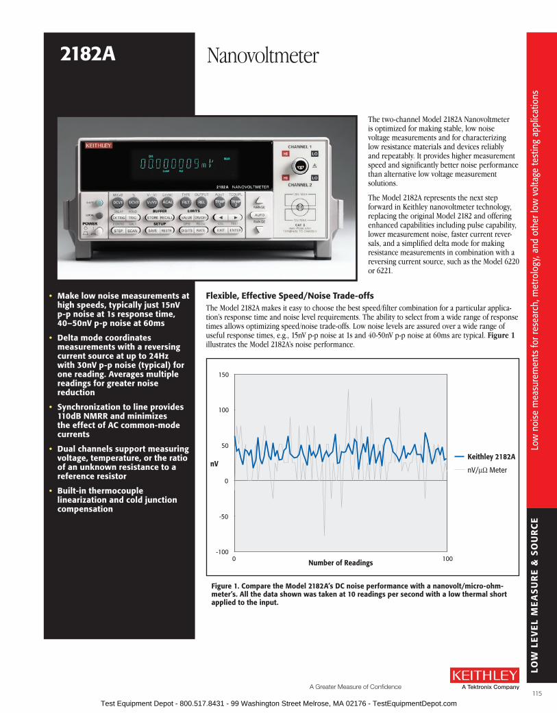
LOW
LE
VE
L M
EA
SU
RE
& S
OU
RC
E
A Greater Measure of Confidence
Low
noi
se m
easu
rem
ents
for r
esea
rch,
met
rolo
gy, a
nd o
ther
low
vol
tage
test
ing
appl
icat
ions
The two-channel Model 2182A Nanovoltmeter is optimized for making stable, low noise voltage measurements and for characterizing low resistance materials and devices reliably and repeatably . It provides higher measurement speed and significantly better noise performance than alternative low voltage measurement solutions .
The Model 2182A represents the next step forward in Keithley nanovoltmeter technology, replacing the original Model 2182 and offering enhanced capabilities including pulse capability, lower measurement noise, faster current rever-sals, and a simplified delta mode for making resistance measurements in combination with a reversing current source, such as the Model 6220 or 6221 .
• Make low noise measurements at high speeds, typically just 15nV p-p noise at 1s response time, 40–50nV p-p noise at 60ms
• Delta mode coordinates measurements with a reversing current source at up to 24Hz with 30nV p-p noise (typical) for one reading. averages multiple readings for greater noise reduction
• synchronization to line provides 110db NMrr and minimizes the effect of aC common-mode currents
• Dual channels support measuring voltage, temperature, or the ratio of an unknown resistance to a reference resistor
• built-in thermocouple linearization and cold junction compensation
figure 1. Compare the Model 2182a’s DC noise performance with a nanovolt/micro-ohm-meter’s. all the data shown was taken at 10 readings per second with a low thermal short applied to the input.
-100
-50
0
50
100
150
Keithley 2182A
nV/µΩ Meter
0 100Number of Readings
nV
flexible, Effective speed/Noise Trade-offsThe Model 2182A makes it easy to choose the best speed/filter combination for a particular applica-tion’s response time and noise level requirements . The ability to select from a wide range of response times allows optimizing speed/noise trade-offs . Low noise levels are assured over a wide range of useful response times, e .g ., 15nV p-p noise at 1s and 40-50nV p-p noise at 60ms are typical . Figure 1 illustrates the Model 2182A’s noise performance .
2182a Nanovoltmeter
115 Test Equipment Depot - 800.517.8431 - 99 Washington Street Melrose, MA 02176 - TestEquipmentDepot.com

LOW
LE
VE
L M
EA
SU
RE
& S
OU
RC
ELo
w n
oise
mea
sure
men
ts fo
r res
earc
h, m
etro
logy
, and
oth
er lo
w v
olta
ge te
stin
g ap
plic
atio
ns
reliable resultsPower line noise can compromise measurement accuracy significantly at the nanovolt level . The Model 2182A reduces this interference by synchronizing its measurement cycle to line, which minimizes variations due to readings that begin at different phases of the line cycle . The result is exceptionally high immunity to line interference with little or no shielding and filtering required .
optimized for use with Model 6220/6221 Current sourcesDevice test and characterization for today’s very small and power-efficient electronics requires sourc-ing low current levels, which demands the use of a precision, low current source . Lower stimulus currents produce lower—and harder to measure—voltages across the devices . Linking the Model 2182A Nanovoltmeter with a Model 6220 or 6221 Current Source makes it possible to address both of these challenges in one easy-to-use configuration .
When connected, the Model 2182A and Model 6220 or 6221 can be operated like a single instrument . Their simple connections eliminate the isolation and noise current problems that plague other solu-tions . The Model 2182A/622X combination allows making delta mode and differential conductance measurements faster and with less noise than the original Model 2182 design allowed . The Model 2182A will also work together with the Model 6221 to make pulse-mode measurements .
The 2182A/622X combination is ideal for a variety of applications, including resistance measure-ments, pulsed I-V measurements, and differential conductance measurements, providing significant advantages over earlier solutions like lock-in amplifiers or AC resistance bridges . The 2182A/622X combination is also well suited for many nanotechnology applications because it can measure resistance without dissipating much power into the device under test (DUT), which would otherwise invalidate results or even destroy the DUT .
an Easy-to-use Delta ModeKeithley originally created the delta mode method for measuring voltage and resistance for the Model 2182 and a triggerable external current source, such as the Model 2400 SourceMeter® SMU instrument . Basically, the delta mode automatically triggers the current source to alternate the signal polarity, and then triggers a nanovoltmeter reading at each polarity . This current reversal technique
ordering Information2182a Nanovoltmeter
accessories supplied2107-4 low Thermal Input Cable with spade lugs, 1.2m (4 ft).user manual, service manual, contact cleaner, line cord, alligator clips.
DCMeasurement
Delta ModeMeasurement
4µV
5nV
aPPlICaTIoNs
research• Determining the transition
temperature of superconductive materials
• I-V characterization of a material at a specific temperature
• Calorimetry• Differential thermometry• superconductivity• NanomaterialsMetrology• Intercomparisons of standard cells• Null meter for resistance bridge
measurements
aCCEssorIEs aVaIlablE2107-30 Low Thermal Input Cable with spade lugs,
9 .1m (30 ft)
2182-KIT Low Thermal Connector with strain relief
2187-4 Low Thermal Test Lead Kit
2188 Low Thermal Calibration Shorting Plug
4288-1 Single Fixed Rack Mount Kit
4288-2 Dual Fixed Rack Mount Kit
7007-1 Shielded GPIB Cable, 1m (3 .2 ft)
7007-2 Shielded GPIB Cable, 2m (6 .5 ft)
7009-5 Shielded RS-232 Cable, 1 .5m (5 ft)
8501-1 Trigger Link Cable, 1m (3 .2 ft)
8501-2 Trigger Link Cable, 2m (6 .5 ft)
8503 Trigger Link Cable to 2 male BNC connectors
KPCI-488LPA IEEE-488 Interface/Controller for the PCI Bus
KUSB-488B IEEE-488 USB-to-GPIB Interface Adapter
sErVICEs aVaIlablE2182A-3Y-EW 1-year factory warranty extended to 3 years
from date of shipment
C/2182A-3Y-ISO 3 (ISO-17025 accredited) calibrations within 3 years of purchase*
* Not available in all countries
figure 2. results from a Model 2182a/6220 using the delta mode to measure a 10mW resistor with a 20µa test current. The free Model 6220/6221 instrument control example start-up software used here can be downloaded from www.keithley.com.
2182a Nanovoltmeter
116 Test Equipment Depot - 800.517.8431 - 99 Washington Street Melrose, MA 02176 - TestEquipmentDepot.com

LOW
LE
VE
L M
EA
SU
RE
& S
OU
RC
E
A Greater Measure of Confidence
Low
noi
se m
easu
rem
ents
for r
esea
rch,
met
rolo
gy, a
nd o
ther
low
vol
tage
test
ing
appl
icat
ions
2182a Nanovoltmeter
cancels out any constant thermoelectric offsets, so the results reflect the true value of the voltage being measured . The improved delta mode for the Model 2182A and the Model 622X current sources uses the same basic technique, but the way in which it’s implemented has been simplified dra-matically . The new technique can cancel thermoelectric offsets that drift over time (not just static offsets), produces results in half the time of the original technique, and allows the current source to control and configure the Model 2182A . Two key presses are all that’s required to set up the measurement . The improved cancellation and higher reading rates reduce measurement noise to as little as 1nV .
Differential Conductance MeasurementsCharacterizing non-linear tunneling devices and low temperature devices often requires measuring differential conductance (the derivative of a device’s I-V curve) . When used with a Model 622X current source, the Model 2182A is the industry’s fastest, most complete solution for differen-tial conductance measurements, providing 10X the speed and significantly lower noise than other instrumentation options . There’s no need to average the results of multiple sweeps, because data can be obtained in a single measurement pass, reducing test time and minimizing the potential for measurement error .
Pulsed Testing with the Model 6221When measuring small devices, introducing even tiny amounts of heat to the DUT can raise its temperature, skewing test results or even destroying the device . When used with the Model 2182A, the Model 6221’s pulse capability minimizes the amount of power dissipated into a DUT . The Model 2182A/6221 combination synchronizes the pulse and measurement . A measurement can begin as soon as 16µs after the Model 6221 applies the pulse . The entire pulse, including a complete nanovolt measure-ment, can be as short as 50µs .
In the delta, differential conductance, and pulse modes, The Model 2182A produces virtually no transient currents, so it’s ideal for characterizing devices that can be easily disrupted by current spikes (see Figure 4) .
Metrology applicationsThe Model 2182A combines the accuracy of a digital multimeter with low noise at high speeds for high-precision metrology applications . Its low noise, high signal observation time, fast measurement rates, and 2ppm accuracy provide the most cost-effective meter available today for applications such as intercomparison of voltage standards and direct measurements of resistance standards .
Nanotechnology applicationsThe Model 2182A combined with the Model 622X current source or Series 2400 SourceMeter® SMU instrument is a highly accurate and repeatable solution for measuring resistances on carbon nanotube based materials and silicon nanowires .
figure 3. It’s simple to connect the Model 2182a to the Model 6220 or 6221 to make a variety of measurements. The instrument control example start-up software available for the Model 622X current sources includes a step-by-step guide to setting up the instrumentation and making proper connections.
GPIB orEthernet
RS-232
Trigger Link
DUT
2182A NANOVOLTMETER 6220 DC AND AC CURRENT SOURCE
Model 2182A Model 622X
0.5µA100µs
figure 4. The Model 2182a produces the lowest transient currents of any nanovoltmeter available.
Competition 2182a 2182a in delta mode
research applicationsThe Model 2182A’s 1nV sensitivity, thermoelectric EMF cancellation, direct display of “true” voltage, ability to perform calculations, and high measure-ment speed makes it ideal for determining the characteristics of materials such as metals, low resistance filled plastics, and high and low temperature superconductors .
117 Test Equipment Depot - 800.517.8431 - 99 Washington Street Melrose, MA 02176 - TestEquipmentDepot.com

LOW
LE
VE
L M
EA
SU
RE
& S
OU
RC
ELo
w n
oise
mea
sure
men
ts fo
r res
earc
h, m
etro
logy
, and
oth
er lo
w v
olta
ge te
stin
g ap
plic
atio
ns
optional accessory: Model 2187-4 low Thermal Test lead Kit
The standard cabling provided with the Model 2182A Nano volt meter and Model 622X Current Sources provides everything normally needed to connect the instruments to each other and to the DUT . The Model 2187-4 Low Thermal Test Lead Kit is required when the cabling provided may not be sufficient for specific applications, such as when the DUT has special connection requirements . The kit includes an input cable with banana terminations, banana extensions, sprung-hook clips, alligator clips, needle probes, and spade lugs to accommodate virtually any DUT . The Model 2187-4 is also helpful when the DUT has roughly 1GW impedance or higher . In this case, measuring with the Model 2182A directly across the DUT will lead to loading errors . The Model 2187-4 Low Thermal Test Lead Kit provides a banana cable and banana jack extender to allow the Model 2182A to connect easily to the Model 622X’s low impedance guard output, so the Model 2182A can measure the DUT voltage indirectly . This same configuration also removes the Model 2182A’s input capacitance from the DUT, so it improves device response time, which may be critical for pulsed measurements .
Three Ways to Measure Nanovolts
DC nanovoltmeters. DC nanovoltmeters and sensitive DMMs both provide low noise DC voltage measurements by using long integration times and highly filtered readings to minimize the bandwidth near DC . Unfortunately, this approach has limitations, particularly the fact that thermal voltages develop in the sample and connections vary, so long integration times don’t improve measurement precision . With a noise specification of just 6nV p-p, the Model 2182A is the lowest noise digital nanovolt meter available .
AC technique. The limitations of the long integration and filtered readings technique have led many people to use an AC technique for measuring low resistances and voltages . In this method, an AC excitation is applied to the sample and the voltage is detected syn chronously at the same frequency and an optimum phase . While this technique removes the varying DC component, in many experiments at high frequencies, users can experience problems related to phase shifts caused by spurious capacitance or the L/R time constant . At low frequencies, as the AC frequency is reduced to minimize phase shifts, amplifier noise increases .
The current reversal method. The Model 2182A is optimized for the current reversal method, which combines the advantages of both earlier approaches . In this technique, the DC test current is reversed, then the difference in voltage due to the difference in current is determined . Typically, this measure ment is performed at a few hertz (a frequency just high enough for the current to be reversed before the thermal voltages can change) . The Model 2182A’s low noise performance at measurement times of a few hundred milliseconds to a few seconds means that the reversal period can be set quite small in comparison with the thermal time constant of the sample and the con-nections, effectively reducing the impact of thermal voltages .
180
185
190
195
200
205
210
215
220
0 8 17 25 33 42 50 58 67 75 83 92 100 108 117 125
Voltage(nV)
Temperature(°C)
Minutes
–10
–5
0
5
10
15
20
25
30
figure 5. The Model 2182a’s delta mode provides extremely stable results, even in the pres-ence of large ambient temperature changes. In this challenging example, the 200nV signal results from a 20µa current sourced by a Model 6221 through a 10mW test resistor.
2182a Nanovoltmeter
figure 7. Model 2182a rear panel
figure 6. Model 2187-4 Test lead Kit
118 Test Equipment Depot - 800.517.8431 - 99 Washington Street Melrose, MA 02176 - TestEquipmentDepot.com

LOW
LE
VE
L M
EA
SU
RE
& S
OU
RC
E
A Greater Measure of Confidence
Mod
el 2
182A
spe
cific
atio
ns
Volts specifications (20% over range)CONDITIONS: 1PLC with 10 reading digital filter or 5PLC with 2 reading digital filter . accuracy: ±(ppm of reading + ppm of range) (ppm = parts per million) (e.g., 10ppm = 0.001%) TemperatureChannel 1 Input 24 Hour 1 90 Day 1 Year 2 Year Coefficient range resolution resistance TCal ±1°C TCal ±5°C TCal ±5°C TCal ±5°C 0°–18°C & 28°–50°C 10 .000000 mV 2, 3, 4 1 nV >10 GW 20 + 4 40 + 4 50 + 4 60 + 4 (1 + 0 .5)/°C 100 .00000 mV 10 nV >10 GW 10 + 3 25 + 3 30 + 4 40 + 5 (1 + 0 .2)/°C 1 .0000000 V 100 nV >10 GW 7 + 2 18 + 2 25 + 2 32 + 3 (1 + 0 .1)/°C 10 .000000 V 1 µV >10 GW 2 + 1 5 18 + 2 25 + 2 32 + 3 (1 + 0 .1)/°C 100 .00000 V 4 10 µV 10 MW ±1% 10 + 3 25 + 3 35 + 4 52 + 5 (1 + 0 .5)/°C
Channel 2 6, 10
100 .00000 mV 10 nV >10 GW 10 + 6 25 + 6 30 + 7 40 + 7 (1 + 1 )/°C 1 .0000000 V 100 nV >10 GW 7 + 2 18 + 2 25 + 2 32 + 3 (1 + 0 .5)/°C 10 .000000 V 1 µV >10 GW 2 + 1 5 18 + 2 25 + 2 32 + 3 (1 + 0 .5)/°C
CHANNEL 1/CHANNEL 2 RATIO: For input signals ≥1% of the range, Ratio Accuracy = ±[Channel 1 ppm of Reading + Channel 1 ppm of Range * (Channel 1 Range/Channel 1 Input)] + [Channel 2 ppm of Reading + Channel 2 ppm of Range * (Channel 2 Range/Channel 2 Input)] .
DELTA (hardware-triggered coordination with Series 24XX, Series 26XXA, or Series 622X current sources for low noise R measurement): Accuracy = accuracy of selected Channel 1 range plus accuracy of I source range .
DELTA MEASUREMENT NOISE WITH 6220 or 6221: Typical 3nVrms / Hz (10mV range)21 . 1Hz achieved with 1PLC, delay = 1ms, RPT filter = 23 (20 if 50Hz) .
PULSE-MODE (WITH 6221): Line synchronized voltage measurements within current pulses from 50µs to 12ms, pulse repetition rate up to 12Hz .
PULSE MEASUREMENT NOISE (typical rms noise, RDUT<10W): ±(0 .009ppm of range*) / meas_time / pulse_avg_count + 3nV** / (2 · meas_time · pulse_avg_count) for 10mV range .
* 0 .0028ppm for the 100mV range, 0 .0016ppm for ranges 1V and above .** 8nV/ Hz for ranges above 10mV . meas_time (seconds) = pulsewidth – pulse_meas_delay in 33µs incr .
DC Noise Performance 7 (DC noise expressed in volts peak-to-peak)
Response time = time required for reading to be settled within noise levels from a stepped input, 60Hz operation .
Channel 1 response range Time NPlC, filter 10 mV 100 mV 1 V 10 V 100 V NMrr 8 CMrr 9
25 .0 s 5, 75 6 nV 20 nV 75 nV 750 nV 75 µV 110 dB 140 dB 4 .0 s 5, 10 15 nV 50 nV 150 nV 1 .5 µV 75 µV 100 dB 140 dB 1 .0 s 1, 18 25 nV 175 nV 600 nV 2 .5 µV 100 µV 95 dB 140 dB 667 ms 1, 10 or 5, 2 35 nV 250 nV 650 nV 3 .3 µV 150 µV 90 dB 140 dB 60 ms 1, Off 70 nV 300 nV 700 nV 6 .6 µV 300 µV 60 dB 140 dB
Channel 2 6, 10
25 .0 s 5, 75 — 150 nV 200 nV 750 nV — 110 dB 140 dB 4 .0 s 5, 10 — 150 nV 200 nV 1 .5 µV — 100 dB 140 dB 1 .0 s 1, 10 or 5, 2 — 175 nV 400 nV 2 .5 µV — 90 dB 140 dB 85 ms 1, Off — 425 nV 1 µV 9 .5 µV — 60 dB 140 dB
VolTaGE NoIsE Vs. sourCE rEsIsTaNCE 11
(DC noise expressed in volts peak-to-peak) source analog Digital resistance Noise filter filter 0 W 6 nV Off 100 100 W 8 nV Off 100 1 kW 15 nV Off 100 10 kW 35 nV Off 100 100 kW 100 nV On 100 1 MW 350 nV On 100
TEMPEraTurE (Thermocouples) 12 aCCuraCY (Displayed in °C, °f, or K. accuracy based on 90 Day/1 Year ITs-90, exclusive of thermocouple errors.) 23° ±5°C relative to simulated TYPE raNGE rEsoluTIoN reference Junction J –200 to +760°C 0 .001 °C ±0 .2 °C K –200 to +1372°C 0 .001 °C ±0 .2 °C N –200 to +1300°C 0 .001 °C ±0 .2 °C T –200 to +400°C 0 .001 °C ±0 .2 °C E –200 to +1000°C 0 .001 °C ±0 .2 °C R 0 to +1768°C 0 .1 °C ±0 .2 °C S 0 to +1768°C 0 .1 °C ±0 .2 °C B +350 to +1820°C 0 .1 °C ±0 .2 °C
2182a Nanovoltmeter
operating Characteristics 13, 14 60Hz (50Hz) operation
function Digits readings/s PlCs DCV Channel 1, 7 .5 3 (2) 5 Channel 2, 7 .5 17, 19 6 (4) 5 Thermocouple 6 .5 18, 19 18 (15) 1 6 .5 18, 19, 20 45 (36) 1 5 .5 17, 19 80 (72) 0 .1 4 .5 16, 17, 19 115 (105) 0 .01
Channel 1/Channel 2 (Ratio), 7 .5 1 .5 (1 .3) 5 Delta with 24XX, Scan 7 .5 17, 19 2 .3 (2 .1) 5 6 .5 18 8 .5 (7 .5) 1 6 .5 18, 20 20 (16) 1 5 .5 17 30 (29) 0 .1 4 .5 17 41 (40) 0 .01 Delta with 622X 6 .5 47 (40 .0) 22 1
system speeds 13, 15
RANGE CHANGE TIME: 14 <40 ms (<50 ms) .FUNCTION CHANGE TIME: 14 <45 ms (<55 ms) .AUTORANGE TIME: 14 <60 ms (<70 ms) .ASCII READING TO RS-232 (19.2K Baud): 40/s (40/s) .MAX. INTERNAL TRIGGER RATE: 16 120/s (120/s) .MAX. EXTERNAL TRIGGER RATE: 16 120/s (120/s) .
119 Test Equipment Depot - 800.517.8431 - 99 Washington Street Melrose, MA 02176 - TestEquipmentDepot.com

LOW
LE
VE
L M
EA
SU
RE
& S
OU
RC
EM
odel
218
2A s
peci
ficat
ions
Measurement CharacteristicsA/D LINEARITy: ±(0 .8ppm of reading + 0 .5ppm of range) .
FRONT AUTOzERO OFF ERROR 10mV–10V: Add ±(8ppm of range + 500µV) for <10 minutes and ±1°C . NOTE: Offset voltage error does not apply for Delta Mode .
AUTOzERO OFF ERROR 10mV: Add ±(8ppm of range + 100nV) for <10 minutes and ±1°C . 100mV–100V: Add ±(8ppm of range + 10µV) for <10 minutes and ±1°C . NOTE: Offset voltage error does not apply for Delta Mode .
INPUT IMPEDANCE 10mV–10V: >10GW, in parallel with <1 .5nF (Front Filter ON) . 10mV–10V: >10GW, in parallel with <0 .5nF (Front Filter OFF) . 100V: 10MW ±1% .
DC INPUT BIAS CURRENT: <60pA DC at 23°C, –10V to 5V . <120pA @ 23°C, 5V to 10V .
COMMON MODE CURRENT: <50nA p-p at 50Hz or 60Hz .
INPUT PROTECTION: 150V peak to any terminal . 70V peak Channel 1 LO to Channel 2 LO .
CHANNEL ISOLATION: >10GW .
EARTH ISOLATION: 350V peak, >10GW and <150pF any terminal to earth . Add 35pF/ft with Model 2107 Low Thermal Input Cable .
analog outputMAXIMUM OUTPUT: ±1 .2V .
ACCURACy: ±(0 .1% of output + 1mV) .
OUTPUT RESISTANCE: 1kW ±5% .
GAIN: Adjustable from 10–9 to 106 . With gain set to 1, a full range input will produce a 1V output .
OUTPUT REL: Selects the value of input that represents 0V at output . The reference value can be either programmed value or the value of the previous input .
Triggering and MemoryWINDOW FILTER SENSITIVITy: 0 .01%, 0 .1%, 1%, 10%, or full scale of range (none) .
READING HOLD SENSITIVITy: 0 .01%, 0 .1%, 1%, or 10% of reading .
TRIGGER DELAy: 0 to 99 hours (1ms step size) .
EXTERNAL TRIGGER DELAy: 2ms + <1ms jitter with auto zero off, trigger delay = 0 .
MEMORy SIzE: 1024 readings .
Math functionsRel, Min/Max/Average/Std Dev/Peak-to-Peak (of stored reading), Limit Test, %, and mX+b with user-
defined units displayed .
remote InterfaceKeithley 182 emulation .
GPIB (IEEE-488 .2) and RS-232C .
SCPI (Standard Commands for Programmable Instruments) .
GENEralPOWER SUPPLy: 100V/120V/220V/240V .
LINE FREQUENCy: 50Hz, 60Hz, and 400Hz, automatically sensed at power-up .
POWER CONSUMPTION: 22VA .
MAGNETIC FIELD DENSITy: 10mV range 4 .0s response noise tested to 500 gauss .
OPERATING ENVIRONMENT: Specified for 0° to 50°C . Specified to 80% RH at 35°C .
STORAGE ENVIRONMENT: –40° to 70°C .
EMC: Complies with European Union Directive 89/336/EEC (CE marking requirement), FCC part 15 class B, CISPR 11, IEC 801-2, IEC-801-3, IEC 801-4 .
SAFETy: Complies with European Union Directive 73/23/EEC (low voltage directive); meets EN61010-1 safety standard . Installation category I .
VIBRATION: MIL-T-28800E Type III, Class 5 .
WARM-UP: 2 .5 hours to rated accuracy .
DIMENSIONS: Rack Mounting: 89mm high × 213mm wide × 370mm deep (3 .5 in × 8 .375 in × 14 .563 in) . Bench Configuration (with handles and feet): 104mm high × 238mm wide × 370mm deep (4 .125 in × 9 .375 in ×14 .563 in) .
SHIPPING WEIGHT: 5kg (11 lbs) .
2182a Nanovoltmeter
NoTEs1 . Relative to calibration accuracy .2 . With Analog Filter on, add 20ppm of reading to listed specification .3 . When properly zeroed using REL function . If REL is not used, add 100nV to the range accuracy .4 . Specifications include the use of ACAL function . If ACAL is not used, add 9ppm of reading/°C
from TCAL to the listed specification . TCAL is the internal temperature stored during ACAL .5 . For 5PLC with 2-reading Digital Filter . Use ±(4ppm of reading + 2ppm of range) for 1PLC with
10-reading Digital Filter .6 . Channel 2 must be referenced to Channel 1 . Channel 2 HI must not exceed 125% (referenced
to Channel 1 LO) of Channel 2 range selected .7 . Noise behavior using 2188 Low Thermal Short after 2 .5 hour warm-up . ±1°C . Analog Filter off .
Observation time = 10× response time or 2 minutes, whichever is less .8 . For LSYNC On, line frequency ±0 .1% . If LSYNC Off, use 60dB .9 . For 1kW unbalance in LO lead . AC CMRR is 70dB .10 . For Low Q mode On, add the following to DC noise and range accuracy at stated response
time: 200nV p-p @ 25s, 500nV p-p @ 4 .0s, 1 .2µV p-p @ 1s, and 5µV p-p @ 85ms .11 . After 2 .5 hour warm-up, ±1°C, 5PLC, 2 minute observation time, Channel 1 10mV range only .12 . For Channel 1 or Channel 2, add 0 .3°C for external reference junction . Add 2°C for internal
reference junction .13 . Speeds are for 60Hz (50Hz) operation using factory defaults operating conditions (*RST) .
Autorange Off, Display Off, Trigger Delay = 0, Analog Output off .14 . Speeds include measurements and binary data transfer out the GPIB . Analog Filter On, 4
readings/s max .15 . Auto Zero Off, NPLC = 0 .01 .16 . 10mV range, 80 readings/s max .17 . Sample count = 1024, Auto Zero Off .18 . For LSYNC On, reduce reading rate by 15% .19 . For Channel 2 Low Q mode Off, reduce reading rate by 30% .20 . Front Auto Zero off, Auto Zero off .21 . Applies to measurements of room temperature resistances <10W, Isource range ≤20µA .22 . Display off, delay 1ms .
120 Test Equipment Depot - 800.517.8431 - 99 Washington Street Melrose, MA 02176 - TestEquipmentDepot.com
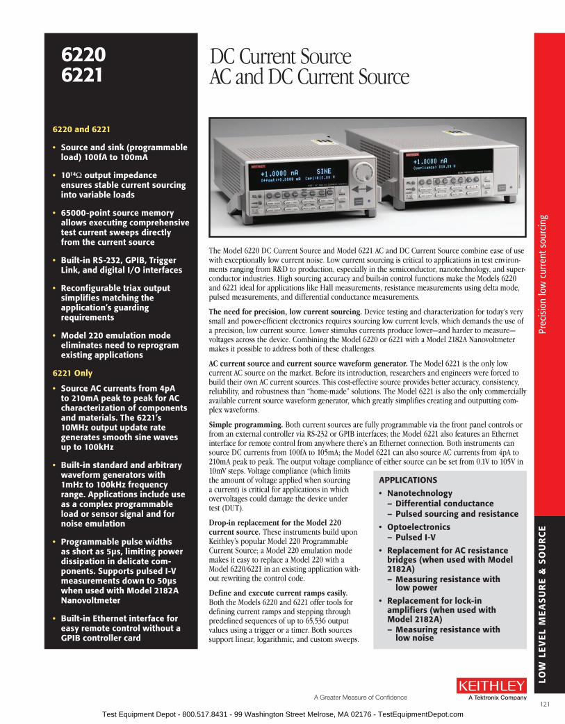
LOW
LE
VE
L M
EA
SU
RE
& S
OU
RC
E
A Greater Measure of Confidence
Prec
isio
n lo
w c
urre
nt s
ourc
ing
6220 and 6221
• source and sink (programmable load) 100fa to 100ma
• 1014W output impedance ensures stable current sourcing into variable loads
• 65000-point source memory allows executing comprehensive test current sweeps directly from the current source
• built-in rs-232, GPIb, Trigger link, and digital I/o interfaces
• reconfigurable triax output simplifies matching the application’s guarding requirements
• Model 220 emulation mode eliminates need to reprogram existing applications
6221 only
• source aC currents from 4pa to 210ma peak to peak for aC charac ter iza tion of components and materials. The 6221’s 10MHz output update rate generates smooth sine waves up to 100kHz
• built-in standard and arbitrary waveform generators with 1mHz to 100kHz frequency range. applications include use as a complex programmable load or sensor signal and for noise emulation
• Programmable pulse widths as short as 5µs, limiting power dissipation in delicate com-ponents. supports pulsed I-V measurements down to 50µs when used with Model 2182a Nanovoltmeter
• built-in Ethernet interface for easy remote control without a GPIb controller card
The Model 6220 DC Current Source and Model 6221 AC and DC Current Source combine ease of use with exceptionally low current noise . Low current sourcing is critical to applications in test environ-ments ranging from R&D to production, especially in the semiconductor, nanotechnology, and super-conductor industries . High sourcing accuracy and built-in control functions make the Models 6220 and 6221 ideal for applications like Hall measurements, resistance measurements using delta mode, pulsed measurements, and differential conductance measurements .
The need for precision, low current sourcing. Device testing and characterization for today’s very small and power-efficient electronics requires sourcing low current levels, which demands the use of a precision, low current source . Lower stimulus currents produce lower—and harder to measure—voltages across the device . Combining the Model 6220 or 6221 with a Model 2182A Nanovoltmeter makes it possible to address both of these challenges .
AC current source and current source waveform generator. The Model 6221 is the only low current AC source on the market . Before its introduction, researchers and engineers were forced to build their own AC current sources . This cost-effective source provides better accuracy, consistency, reliability, and robustness than “home-made” solutions . The Model 6221 is also the only commercially available current source waveform generator, which greatly simplifies creating and outputting com-plex waveforms .
Simple programming. Both current sources are fully programmable via the front panel controls or from an external controller via RS-232 or GPIB interfaces; the Model 6221 also features an Ethernet interface for remote control from anywhere there’s an Ethernet connection . Both instruments can source DC currents from 100fA to 105mA; the Model 6221 can also source AC currents from 4pA to 210mA peak to peak . The output voltage compliance of either source can be set from 0 .1V to 105V in 10mV steps . Voltage compliance (which limits the amount of voltage applied when sourcing a current) is critical for applications in which overvoltages could damage the device under test (DUT) .
Drop-in replacement for the Model 220 current source. These instruments build upon Keithley’s popular Model 220 Programmable Current Source; a Model 220 emulation mode makes it easy to replace a Model 220 with a Model 6220/6221 in an existing application with-out rewriting the control code .
Define and execute current ramps easily. Both the Models 6220 and 6221 offer tools for defining current ramps and stepping through predefined sequences of up to 65,536 output values using a trigger or a timer . Both sources support linear, logarithmic, and custom sweeps .
aPPlICaTIoNs
• Nanotechnology– Differential conductance– Pulsed sourcing and resistance
• optoelectronics– Pulsed I-V
• replacement for aC resistance bridges (when used with Model 2182a)– Measuring resistance with
low power
• replacement for lock-in amplifiers (when used with Model 2182a)– Measuring resistance with
low noise
62206221
DC Current SourceAC and DC Current Source
121 Test Equipment Depot - 800.517.8431 - 99 Washington Street Melrose, MA 02176 - TestEquipmentDepot.com

LOW
LE
VE
L M
EA
SU
RE
& S
OU
RC
E
The Model 6221’s combination of high source resolution and megahertz update rates makes it capable of emulating high fidelity current signals that are indistinguishable from analog current ramps .
free Instrument Control Example start-up softwareThe instrument control example software available for the sources simplifies both performing basic sourcing tasks and coordinating complex measurement functions with the Keithley Model 2182A . The software, developed in the LabVIEW® programming environment, includes a step-by-step measure-ment guide that helps users set up their instruments and make proper connections, as well as pro-gram basic sourcing functions . The advanced tools in the package support delta mode, differential conductance, and pulse mode measurements . From this package, users can print out the instrument commands for any of the pre-programmed functions, which provides a starting point for incorporat-ing these functions into customized applications .
Differential ConductanceDifferential conductance measurements are among the most important and critical measurements made on non-linear tunneling devices and on low temperature devices . Mathematically, differential conductance is the derivative of a device’s I-V curve . The Model 6220 or 6221, combined with the Model 2182A Nano voltmeter, is the industry’s most complete solution for differential conductance measurements . Together, these instruments are also the fastest solution available, providing 10× the speed and significantly lower noise than other options . Data can be obtained in a single measure-ment pass, rather than by averaging the result of multiple sweeps, which is both time-consuming and prone to error . The Model 622X and Model 2182A are also easy to use because the combination can be treated as a single instrument . Their simple connections eliminate the isolation and noise current problems that plague other solutions .
figure 1. Perform, analyze, and display differential conductance measurements.
Delta ModeKeithley originally developed the delta mode method for making low noise measurements of voltages and resistances for use with the Model 2182 Nanovoltmeter and a triggerable external current source . Essentially, the delta mode automatically triggers the current source to alternate the signal polarity, then triggers a nanovoltmeter reading at each polarity . This current reversal technique cancels out any constant thermoelectric offsets, ensuring the results reflect the true value of the voltage .
This same basic technique has been incorporated into the Model 622X and Model 2182A delta mode, but its implementation has been dramatically enhanced and simplified . The technique can now cancel thermoelectric offsets that drift over time, produce results in half the time of the previ-ous technique, and allow the source to control and configure the nanovoltmeter, so setting up the measurement takes just two key presses . The improved cancellation and higher reading rate reduces measurement noise to as little as 1nV .
ordering Information6220 DC Precision Current source6221 aC and DC Current source6220/2182a
Complete Delta Mode system, w/DC Current source, Nanovoltmeter, and all necessary cables (GPIb cables not included)
6221/2182a Complete Delta Mode system, w/aC and DC Current source, Nano volt-meter, and all necessary cables (GPIb cables not included)
accessories supplied 237-alG-2 6.6 ft (2m), low Noise,
Input Cable with Triax-to-alligator Clips
8501-2 6.6 ft (2m) Trigger link Cable to connect 622x to 2182a
Ca-180-3a Ethernet Crossover Cable (6221 only)
Ca-351 Communication Cable between 2182a and 622x
Cs-1195-2 safety Interlock Connector
Instruction manual on CDGetting started manual (hardcopy)software (downloadable)
aCCEssorIEs aVaIlablE7006-* GPIB Cable with Straight-On Connector
7007-1 Shielded IEEE-488 Cable, 1m (3 .3 ft)
7007-2 Shielded IEEE-488 Cable, 2m (6 .6 ft)
7078-TRX-5 5 ft (1 .5m), Low Noise, Triax-to-Triax Cable (Male on Both Ends)
KPCI-488LPA IEEE-488 Interface/Controller for the PCI Bus
KUSB-488B IEEE-488 USB-to-GPIB Interface Adapter
sErVICEs aVaIlablE6220-3Y-EW 1-year factory warranty extended to 3 years from
date of shipment
6221-3Y-EW 1-year factory warranty extended to 3 years from date of shipment
C/6220-3Y-ISO 3 (ISO-17025 accredited) calibrations within 3 years of purchase*
C/6221-3Y-ISO 3 (ISO-17025 accredited) calibrations within 3 years of purchase*
*Not available in all countries
62206221
DC Current SourceAC and DC Current Source
Prec
isio
n lo
w c
urre
nt s
ourc
ing
122 Test Equipment Depot - 800.517.8431 - 99 Washington Street Melrose, MA 02176 - TestEquipmentDepot.com

LOW
LE
VE
L M
EA
SU
RE
& S
OU
RC
E
A Greater Measure of Confidence
Prec
isio
n lo
w c
urre
nt s
ourc
ing
The delta mode enables measuring low voltages and resistances accurately . Once the Model 622X and the Model 2182A are connected properly, the user simply presses the current source’s Delta button, followed by the Trigger button, which starts the test . The Model 622X and the Model 2182A work together seamlessly and can be controlled via the GPIB interface (GPIB or Ethernet with the Model 6221) . The free example control software available for the Model 622X includes a tutorial that “walks” users through the delta mode setup process .
Pulsed TestsEven small amounts of heat introduced by the measurement process itself can raise the DUT’s tem-perature, skewing test results or even destroying the device . The Model 6221’s pulse measurement capability minimizes the amount of power dissipated into a DUT by offering maximum flexibility when making pulsed measurements, allowing users to program the optimal pulse current amplitude, pulse interval, pulse width, and other pulse parameters .
The Model 6221 makes short pulses (and reductions in heat dissipation) possible with microsecond rise times on all ranges . The Model 6221/2182A combination synchronizes the pulse and measure-ment—a measurement can begin as soon as 16µs after the Model 6221 applies the pulse . The entire pulse, including a complete nanovolt measurement, can be as short as 50µs . Line synchronization between the Model 6221 and Model 2182A eliminates power line related noise .
standard and arbitrary Waveform GeneratorThe Model 6221 is the only low current AC source on the market . It can be programmed to gen-erate both basic waveforms (sine, square, triangle, and ramp) and customizable waveforms with an arbitrary waveform generator (ARB) that supports defining waveforms point by point . It can generate waveforms at frequencies ranging from 1mHz to 100kHz at an output update rate of 10 megasamples/ second .
Performance superior to aC resistance bridges and lock-In amplifiersThe Model 622X/2182A combination provides many advantages over AC resistance bridges and lock-in amplifiers, including lower noise, lower current sourcing, lower voltage measurements, less power dissipation into DUTs, and lower cost . It also eliminates the need for a current pre-amplifier .
Models 6220 and 6221 vs. Homemade Current sourcesMany researchers and engineers who need a current source attempt to get by with a volt-age source and series resistor instead . This is often the case when an AC current is needed . This is because, until the introduction of the Model 6220/6221, no AC current sources were available on the market . However, homemade current sources have several disadvantages vs . true current sources:• Homemade Current Sources Don’t Have
Voltage Compliance. You may want to be sure the voltage at the terminals of your homemade “current source” never exceeds a certain limit (for example, 1–2V in the case of many optoelectronic devices) . The most straightforward way to accomplish this is to reduce the voltage source to that level . This requires the series resistor to be reduced to attain the desired current . If you want to program a different current, you must change the resistor while the voltage is held constant! Another possibility is to place a protection circuit in parallel with the DUT . These do not have precise voltage control and always act as a parallel device, stealing some of the programmed current intended for the DUT .
• Homemade Current Sources Can’t Have Predictable Output. With a homemade “current source” made of a voltage source and series resistor, the impedance of the DUT forms a voltage divider . If the DUT resistance is entirely predictable, the current can be known, but if the DUT resistance is unknown or changes, as most devices do, then the current isn’t a simple function of the voltage applied . The best way to make the source predictable is to use a very high value series resistor (and accordingly high voltage source), which is in direct contradiction with the need for compliance .
• While it’s possible to know (if not control) the actual current coming from such an unpredictable source, this also comes at a cost . This can be done with a supplemental measurement of the current, such as using a voltmeter to measure the voltage drop across the series resistor . This measurement can be used as feedback to alter the voltage source or simply recorded . Either way, it requires additional equipment, which adds complexity or error . To make matters worse, if the homemade current source is made to be moderately predictable by using a large series resistor, this readback would require using an electrometer to ensure accuracy .
DCMeasurement
Delta ModeMeasurement
4µV
5nV
figure 2. Delta mode offers 1000-to-1 noise reduction.
62206221
DC Current SourceAC and DC Current Source
123 Test Equipment Depot - 800.517.8431 - 99 Washington Street Melrose, MA 02176 - TestEquipmentDepot.com

LOW
LE
VE
L M
EA
SU
RE
& S
OU
RC
E
figure 4. The Model 6221 and the free example start-up control software make it easy to create complex waveforms by adding, multiplying, stringing together, or applying filters to standard wave shapes.
The Model 6221 can also expand the capabilities of lock-in amplifiers in applications that already employ them . For example, its clean signals and its output synchronization signal make it an ideal output source for lock-in applications such as measuring second and third harmonic device response .
Model 2182a NanovoltmeterThe Model 2182A expands upon the capabilities of Keithley’s original Model 2182 Nano volt-meter . Although the Model 6220 and 6221 are compatible with the Model 2182, delta mode and differential conductance measurements require approximately twice as long to complete with the Model 2182 as with the Model 2182A . Unlike the Model 2182A, the Model 2182 does not sup-port pulse mode measurements .
Source Current
1/60 second (1/50 when operating off 50Hz power)
Programmable: 50µs to 12ms
Measurement integration period
Measuring difference voltage eliminatesline frequency noise, DC offsets
Voltage measurement noise at line frequency
Measured response voltage
Pulsed measurement without line sync Line synchronized pulse measurements
figure 3. Measurements are line synchronized to minimize 50/60Hz interference.
• aPPlICaTIoNs of 622X/2182a CoMbINaTIoN:
• Easy instrument coordination and intuitive example software simplifies setup and operation in many applications.
• Measure resistances from 10nW to 100MW. One measurement system for wide ranging devices.
• Low noise alternative to AC resistance bridges and lock-in amplifiers for measuring resistances.
• Coordinates pulsing and measurement with pulse widths as short as 50µs (6221 only).
• Measures differential conduc-tance up to 10× faster and with lower noise than earlier solutions allow. Differential conductance is an important parameter in semi-con ductor research for describing density of states in bulk material.
• Delta mode reduces noise in low resistance measurements by a factor of 1000.
• For low impedance Hall measure-ments, the delta mode operation of the Model 622X/2182A combination provides industry-leading noise performance and rejection of contact potentials. For higher impedance Hall measurements (greater than 100MW), the Model 4200-SCS can replace the current source, switching, and multiple high impedance voltage measurement channels. This provides a complete solution with pre-programmed test projects.
62206221
DC Current SourceAC and DC Current Source
Prec
isio
n lo
w c
urre
nt s
ourc
ing
124 Test Equipment Depot - 800.517.8431 - 99 Washington Street Melrose, MA 02176 - TestEquipmentDepot.com

LOW
LE
VE
L M
EA
SU
RE
& S
OU
RC
E
A Greater Measure of Confidence
Mod
el 6
220
and
6221
spe
cific
atio
ns
source specifications
range (+5% over
range)
accuracy (1 Year)
23°C ±5°C ±(% rdg. + amps)
Programming resolution
Temperature Coefficient/°C
0°–18°C & 28°–50°C
Typical Noise (peak-peak)/rMs 3
0.1Hz–10Hz
6221 onlysettling Time 1, 2
(1% of final Value)
Typical Noise (peak-peak)/rMs 3
10Hz–(bw)
output response bandwidth (bW) Into
short
output response
fast (Typical3) (6221 only)
6220, 6221 with output response
slow (Max.)
2 nA 0 .4 % + 2 pA 100 fA 0 .02 % + 200 fA 400 / 80 fA 250 / 50 pA 10 kHz 90 µs 100 µs
20 nA 0 .3 % + 10 pA 1 pA 0 .02 % + 200 fA 4 / 0 .8 pA 250 / 50 pA 10 kHz 90 µs 100 µs
200 nA 0 .3 % + 100 pA 10 pA 0 .02 % + 2 pA 20 / 4 pA 2 .5 / 0 .5 nA 100 kHz 30 µs 100 µs
2 µA 0 .1 % + 1 nA 100 pA 0 .01 % + 20 pA 200 / 40 pA 25 / 5 .0 nA 1 MHz 4 µs 100 µs
20 µA 0 .05% + 10 nA 1 nA 0 .005% + 200 pA 2 / 0 .4 nA 500 / 100 nA 1 MHz 2 µs 100 µs
200 µA 0 .05% + 100 nA 10 nA 0 .005% + 2 nA 20 / 4 nA 1 .0 / 0 .2 µA 1 MHz 2 µs 100 µs
2 mA 0 .05% + 1 µA 100 nA 0 .005% + 20 nA 200 / 40 nA 5 .0 / 1 µA 1 MHz 2 µs 100 µs
20 mA 0 .05% + 10 µA 1 µA 0 .005% + 200 nA 2 / 0 .4 µA 20 / 4 .0 µA 1 MHz 2 µs 100 µs
100 mA 0 .1 % + 50 µA 10 µA 0 .01 % + 2 µA 10 / 2 µA 100 / 20 µA 1 MHz 3 µs 100 µs
aDDITIoNal sourCE sPECIfICaTIoNsOUTPUT RESISTANCE: >1014W (2nA/20nA range) .
OUTPUT CAPACITANCE: <10pF, <100pF Filter ON (2nA/20nA range) .
LOAD IMPEDANCE: Stable into 10µH typical, 100µH for 6220, or for 6221 with Output Response SLOW .
VOLTAGE LIMIT (Compliance): Bipolar voltage limit set with single value . 0 .1V to 105V in 0 .01V programmable steps .
MAX. OUTPUT POWER: 11W, four quadrant source or sink operation .
GUARD OUTPUT ACCURACy: ±1mV for output currents <2mA (excluding output lead voltage drop) .
PROGRAM MEMORy: Number of Locations: 64K . Offers point-by-point control and triggering, e .g . sweeps .
MAX. TRIGGER RATE: 1000/s .
RMS NOISE 10Hz–20MHz (2nA–20mA Range): Less than 1mVrms, 5mVp-p (into 50W load) .
sourCE NoTEs1 . Settling times are specified into a resistive load, with a maximum
resistance equal to 2V/ I full scale of range . See manual for other load conditions .
2 . Settling times to 0 .1% of final value are typically <2× of 1% settling times .
3 . Typical values are non warranted, apply at 23°C, represent the 50th percentile, and are provided solely as useful information .
2182a MEasurEMENT fuNCTIoNsDUT RESISTANCE: Up to 1GW (1ns) (100MW limit for
pulse mode) .
DELTA MODE RESISTANCE MEASUREMENTS AND DIFFERENTIAL CONDUCTANCE: Controls Keithley Model 2182A Nanovoltmeter at up to 24Hz reversal rate (2182 at up to 12Hz) .
PULSE MEASUREMENTS (6221 ONLy):
Pulse Widths: 50µs to 12ms, 1pA to 100mA .
Repetition Interval: 83 .3ms to 5s .
arbITrarY fuNCTIoN GENEraTor (6221 only)WAVEFORMS: Sine, Square, Ramp, and 4 user defined arbitrary
waveforms .
FREQUENCy RANGE: 1mHz to 100kHz .5
FREQUENCy ACCURACy4: ±100ppm (1 year) .
SAMPLE RATE: 10 MSPS .
AMPLITUDE: 4pA to 210mA peak-peak into loads up to 1012W .
AMPLITUDE RESOLUTION: 16 bits (including sign) .
AMPLITUDE ACCURACy (<10kHz): 5 Magnitude: ±(1% rdg + 0 .2% range) . Offset: ±(0 .2% rdg + 0 .2% range) .
SINE WAVE CHARACTERISTICS:
Amplitude Flatness: Less than 1dB up to 100kHz .6
SQUARE WAVE CHARACTERISTICS:
Overshoot: 2 .5% max .6
Variable Duty Cycle: 4 Settable to 1µs min . pulse duration, 0 .01% programming resolution .
jitter (RMS): 100ns + 0 .1% of period .6
RAMP WAVE CHARACTERISTICS:
Linearity: <0 .1% of peak output up to 10kHz .6
ARBITRARy WAVE CHARACTERISTICS:
Waveform Length: 2 to 64K points .
jitter (RMS): 100ns + 0 .1% of period .6
WaVEforM NoTEs4 . Minimum realizable duty cycle is limited by current range
response and load impedance .
5 . Amplitude accuracy is applicable into a maximum resistive load of 2V/ I full scale of range . Amplitude attenuation will occur at higher frequencies dependent upon current range and load impedance .
6 . These specifications are only valid for the 20mA range and a 50W load .
GENEralCOMMON MODE VOLTAGE: 250V rms, DC to 60Hz .COMMON MODE ISOLATION: >109W, <2nF .SOURCE OUTPUT MODES: Fixed DC level, Memory List .REMOTE INTERFACE:
IEEE-488 and RS-232C .SCPI (Standard Commands for Programmable
Instruments) .DDC (command language compatible with Keithley
Model 220) .PASSWORD PROTECTION: 11 characters .DIGITAL INTERFACE:
Handler Interface: Start of test, end of test, 3 category bits, +5V@300mA supply .
Digital I/O: 1 trigger input, 4 TTL/Relay Drive outputs (33V@500mA, diode clamped) .
OUTPUT CONNECTIONS:Teflon insulated 3-lug triax connector for output .Banana safety jack for GUARD, OUTPUT LO .Screw terminal for CHASSIS .DB-9 connector for EXTERNAL TRIGGER INPUT,
OUTPUT, and DIGITAL I/O .Two position screw terminal for INTERLOCK .
INTERLOCK: Maximum 10W external circuit impedance .POWER SUPPLy: 100V to 240V rms, 50–60Hz .POWER CONSUMPTION: 120VA .ENVIRONMENT:
For Indoor Use Only: Maximum 2000m above sea level .Operating: 0°–50°C, 70%R .H . up to 35°C . Derate
3% R .H ./°C, 35°–50°C .Storage: –25°C to 65°C, guaranteed by design .
EMC: Conforms to European Union Directive 89/336/EEC, EN 61326-1 .
SAFETy: Conforms to European Union Directive 73/23/EEC, EN61010-1 .
VIBRATION: MIL-PRF-28800F Class 3, Random .WARMUP: 1 hour to rated accuracies .
Passive Cooling: No fan .DIMENSIONS:
Rack Mounting: 89mm high × 213mm wide × 370mm deep (3 .5 in . × 8 .375 in . × 14 .563 in .) .
Bench Configuration (with handle and feet): 104mm high × 238mm wide × 370mm deep (4 .125 in . × 9 .375 in . × 14 .563 in .) .
62206221
DC Current SourceAC and DC Current Source
125 Test Equipment Depot - 800.517.8431 - 99 Washington Street Melrose, MA 02176 - TestEquipmentDepot.com

LOW
LE
VE
L M
EA
SU
RE
& S
OU
RC
E
A Series 3700A system combines the functionality of an instrument grade relay switching system with a high per-formance multimeter . Integrating the multimeter within the mainframe ensures you of a high quality signal path from each channel to the multimeter . This tightly integrated switch and measurement system can meet the demanding application requirements of a functional test system or provide the flexibility needed in stand-alone data acquisi-tion and measurement applications . It is ideal for multiple pin count applications where relay switching can be used to connect multiple devices to source and measurement instruments .
The high performance multimeter in the Series 3700A offers low noise, high stability 3½- to 7½-digit readings for leading-edge measurement performance . This flex-ible resolution sup plies a DC reading rate from >14,000 readings/second at 3½ digits to 60 readings/second at 7½ digits, offering customers maximum reading throughput and accuracy . The multimeter also provides an expanded low ohms (1W) range, low current (10µA) range, and dry circuit (1W to 1kW) range, extending utility beyond typical DMM applications .
The multimeter supports 13 built-in measure ment functions, including: DCV, ACV, DCI, ACI, frequen-cy, period, two-wire ohms, four-wire ohms, three-wire RTD temperature, four-wire RTD temperature, thermocouple temperature, thermistor temperature, and continuity . In-rack calibration is sup ported, which reduces both maintenance and calibration time . Onboard memory can store up to 650,000 readings, and the USB device port provides easy transfer of data to memory sticks .
single-Channel reading rates
resolutionDCV/
2-Wire ohms 4-Wire ohms7½ Digits (1 NPLC) 60 296½ Digits (0 .2 NPLC) 295 1205½ Digits (0 .06 NPLC) 935 2854½ Digits (0 .006 NPLC) 6,200 5803½ Digits (0 .0005 NPLC) 14,000 650
series 3700a System Switch/Multimeter and Plug-In Cards
• Combines the functions of a system switch and a high performance multimeter
• lXI Class b compliance with IEEE 1588 time synchronization
• 3½- to 7½-digit measurement resolution
• Embedded Test script Processor (TsP®) offers unparalleled system automation, throughput, and flexibility
• Extended low ohms (1W) range with 100nW resolution
• Extended low current (10µa) range with 1pa resolution
• >14,000 readings/second
• low noise, <0.1ppm rms noise on 10VDC range
• Expanded dry circuit range (2kW)
• four-wire open lead detection (source and sense lines)
• aPPlICaTIoNs
• system- and rack-level signal referencing
• Power supply burn-in testing (PC, network, telecom)
• low ohms testing (contacts, connectors, relays)
• Temperature profiling
• Plant/environment monitoring and control
• automotive and aerospace systems
• Consumer product certification/testing laboratories
for more information about series 3700a systems, see page 162.
Syst
em s
witc
h w
ith h
igh
perfo
rman
ce m
ultim
eter
Leading CompetitorKeithley 3706A
Low Noise PerformanceModel 3706A vs. Leading Competitor
–4.0
–3.0
–2.0
–1.0
0.0
1.0
2.0
3.0
4.0
0.0 5.0 10.0 15.0 20.0 25.0 30.0 35.0
1000 Readings at 1PLC
10VD
C N
oise
(pp
m o
f ra
nge)
Compare the Model 3706a’s 10V DC noise and speed performance with that of the leading competitor. all the data was taken at 1PlC with a low thermal short applied to the input, which resulted in 10× lower noise and 7× faster measurements for the Model 3706a.
126 Test Equipment Depot - 800.517.8431 - 99 Washington Street Melrose, MA 02176 - TestEquipmentDepot.com

LOW
LE
VE
L M
EA
SU
RE
& S
OU
RC
E
A Greater Measure of Confidence
Tech
nica
l inf
orm
atio
n: L
ow c
urre
nt/h
igh
resi
stan
ce m
easu
rem
ents
Technical Information
Low Current/High Resistance Measurements
An ammeter is an instrument for measuring electric current flow, calibrated in amperes . There are two main types of ammeter architectures: shunt amme-ters and feedback ammeters .
shunt vs. feedback ammetersShunt ammeters are the most common type and work in many applications; feedback ammeters are more appropriate when measuring small currents; their use is growing because the typical magnitude of the test currents used today is decreasing . However, choosing the proper ammeter depends not only on the magnitude of the current, but also on character-istics (most typically, the impedance) of the device under test (DUT) .
shunt ammeters: DMMsShunt ammeters are the most common ammeter type and are found in almost all digital multimeters (DMMs) . These meters measure current by develop-ing a voltage at the input terminal that is proportion-al to the current being measured (Figure 1) .
VBURDEN= 200mV at
full scale
–
+A/D
DMM (shunt) ammeter
RSHUNTI
figure 1
The main drawback associated with shunt ammeters is their fundamentally high input impedance design . This drawback becomes more significant with decreasing current, because a larger shunt resistor must be used in order to develop a measurable voltage . However, as long as the shunt resistor is significantly smaller than the resistance of the DUT and the currents to be measured are not very small (not much lower than microamp level [10–6A]), shunt ammeters work fine .
Voltage burdenThe terminal voltage of an ammeter is called the volt-age burden . This voltage burden developed across the meter could result in significantly lower current through the load than before the meter was inserted, therefore, the ammeter can’t read the current it was intended to measure .
An ideal ammeter would not alter the current flowing in the circuit path, so it would have zero resistance and zero voltage burden . A real ammeter will always introduce a non-zero voltage burden . In general, the error term caused by an ammeter is stated as the ammeter’s voltage burden divided by the resistance
of the DUT . A shunt ammeter’s voltage burden is typi-cally on the order of hundreds of millivolts .
Picoammeter/Electrometer
–+
VOFFSET
A/D
CAL VOFFSET
Total voltageburden<0.2mV
I
figure 2
feedback ammeterFeedback ammeters are closer to “ideal” than shunt ammeters, and should be used for current measure-ments of microamps or less (10–6A) or where it is especially critical to have an ammeter with low input impedance . Instead of developing a voltage across the terminals of the ammeter, a feedback ammeter devel-ops a voltage across the feedback path of a high gain operational amplifier (Figure 2) . This voltage is also proportional to the current to be measured; however, it is no longer observed at the input of the instru-ment, but only through the output voltage of the op-amp . The input voltage is equal to the output voltage divided by the op-amp gain (typically 100,000), so the voltage burden has now typically been reduced to microvolts . The feedback ammeter architecture results in low voltage burden, so it produces less error when measuring small currents and when measuring currents generated by low impedance devices . Keithley electrometers and picoammeters employ feedback ammeter technology .
1V
0.7V I VBURDEN
300mV – VBURDEN
figure 3
Figure 3 illustrates the problems caused by high volt-age burden when measuring the emitter current of a transistor . Even though the basic current measure-ment could be well within the measuring capability of the DMM, the DMM’s voltage burden significantly reduces the voltage applied to the DUT, resulting in
lower measured emitter current than intended . If a picoammeter or electrometer were used instead, the voltage burden would cause a negligible change in emitter current .
sources of Generated Current Error
Low current measurements are subject to a number of error sources that can have a serious impact on measurement accuracy . All ammeters will generate some small current that flows even when the input is open . These offset currents can be partially nulled by enabling the instrument current suppress . External leakage currents are additional sources of error; therefore, making properly guarded and/or shielded connections is important . The source impedance of the DUT will also affect the noise performance of the ammeter . In addition, there are other extraneous generated currents in the test system that could add to the desired current, causing errors . The follow-ing paragraphs discuss various types of generated currents and how to minimize their impact on the measuremen ts .
Insulation
OuterShield
OuterJacket
+
– –
+
Conductivelubricant inlow noise
cable
CoaxialCable
Frictional motionat boundary dueto cable motion
InnerConductor
I
I
figure 4
Triboelectric effects are created by charge imbal-ance due to frictional effects between a conductor and an insulator, as shown in Figure 4 . Keithley’s low noise cables greatly reduce this effect by intro-ducing an inner insulator of polyethylene coated with graphite underneath the outer shield . The graphite provides lubrication and a conducting equipotential cylinder to equalize charges and minimize the charge generated .
Piezoelectric currents are generated when mechani-cal stress is applied to certain crystalline materials when used for insulated terminals and interconnect-ing hardware . In some plastics, pockets of stored charge cause the material to behave in a manner similar to piezoelectric materials . An example of a terminal with a piezoelectric insulator is shown in Figure 5 . To minimize the current due to this effect, remove mechanical stresses from the insulator and use insulating materials with minimal piezoelectric and stored charge effects .
127 Test Equipment Depot - 800.517.8431 - 99 Washington Street Melrose, MA 02176 - TestEquipmentDepot.com

LOW
LE
VE
L M
EA
SU
RE
& S
OU
RC
ETe
chni
cal i
nfor
mat
ion:
Low
cur
rent
/hig
h re
sist
ance
mea
sure
men
ts
Technical Information
Low Current/High Resistance Measurements
I
PrintedWiring
Epoxy PrintedCircuit Board
Flux orother chemical
“track” andmoisture+
–
I
figure 6
Contamination and humidity can produce error currents, which arise from electrochemical effects that occur when contaminants (in the form of ionic chemicals) create weak “batteries” between two con-ductors on a circuit board . For example, commonly used epoxy printed circuit boards, if not thoroughly cleaned of etching solution, flux, oils, salts (e .g ., fingerprints) or other contaminants, can generate currents of a few nanoamps between conductors (see Figure 6) . To avoid the effects of contamination and humidity, select insulators that resist water absorp-
tion and keep humidity to moderate levels . Also, keep all insulators clean and free of contamination .
Figure 7 summarizes approximate magnitudes of the various currents .
High resistance MeasurementsFor high resistance measurements (>1GW), a constant voltage is most often applied across the unknown resistance . The resulting current is measured from an ammeter placed in series, and the resistance can be found using Ohm’s law (R= V/I) . This method of applying a voltage and measuring the current (as opposed to applying a current and measuring the voltage), is preferred for high resist-ance measurements, because high resistances often change as a function of applied voltage . Therefore, it’s important to measure the resistance at a relevant and controllable voltage . This method most often requires measuring low currents using an electrom-eter or picoammeter . All the low current techniques and error sources described in previous paragraphs also apply here .
Leakage currents are typical sources of error in high resistance measurements . They are generated by unwanted high resistance paths (leakage resistance) between the measurement circuit and nearby voltage sources; they can be reduced by employing proper guarding techniques, using clean, quality insulators, and minimizing humidity .
Typical resistance values of various insulating materials are shown in Figure 8 . Absorbed moisture may also change the
resistance of certain insulators by orders of magni-tude . Table 1 shows a qualitative description of water absorption and other effects .
alternating Polarity MethodWhen measuring materials with very high resistivity, background currents may cause significant measure-ment errors . They may be due to charge stored in the material (dielectric absorption), static or triboelectric charge, or piezoelectric effects .
The Alternating Polarity Method can virtually eliminate the effects of background currents in the sample . In this method, a bias voltage of positive polarity is applied, then the current is measured after a predetermined delay . Next, the polarity is reversed and the current is measured again, using the same delay . The polarity reversal process can be repeated any number of times . The resistance is calculated based on a weighted average of the most recent cur-rent measurements .
10–7 A
10–8
10–9
10–10
10–11
10–12
10–13
10–14
10–15
TriboelectricEffects
PiezoelectricEffects
ElectrochemicalEffects
ResistorNoisein 1Hz
Bandwidth
LowNoiseCable
StandardCable
TeflonCeramics
Cleansurface
Dirtysurface
Epoxyboard
1012Ω
109Ω
Current-Generating Phenomena
TypicalCurrent
Generated
figure 7
1018 Ω
1017 Ω
1016 Ω
1015 Ω
1014 Ω
1013 Ω
1012 Ω
1011 Ω
1010 Ω
109 Ω
108 Ω
Epox
ybo
ard
Cer
amic
sN
ylon
Insulating Material
Resistance
G-10
Pape
r PVC
Phen
olic
Teflo
n
Sapp
hire
Poly
ethy
lene
Poly
styr
ene
figure 8
VolumeResistivity(Ohm-cm) Material
Resistanceto Water
Absorption
MinimalPiezoelectric
Effects
MinimalTriboelectric
Effects
PROPERTY
SapphireTeflon®
PolyethylenePolystyreneKel-F®
CeramicNylonGlass EpoxyPVCPhenolic
++00+–––+–
+–+000000+
0–0––+––0+
1016 – 1018Ω1017 – 1018Ω1014 – 1018Ω1012 – 1018Ω1017 – 1018Ω1012 – 1014Ω1012 – 1014Ω1010 – 1017Ω1010 – 1015Ω105 – 1012Ω
KEY: + Material very good in regard to the property.0 Material moderately good in regard to the property.– Material weak in regard to the property.
Table 1
PiezoelectricInsulator
ConductivePlate
AppliedForce
MetalTerminal
I
+
+– –
I
figure 5
128 Test Equipment Depot - 800.517.8431 - 99 Washington Street Melrose, MA 02176 - TestEquipmentDepot.com

LOW
LE
VE
L M
EA
SU
RE
& S
OU
RC
E
A Greater Measure of Confidence
Sele
ctor
gui
de: P
icoa
mm
eter
s, e
lect
rom
eter
s, s
ourc
e-m
easu
re u
nits
(m
easu
rem
ent)
Picoammeters Electrometers
source Measure
unit (sMu) Instruments
MoDEl 6482 6485 6487 2502 6514 6517b 6430
Page 131 134 137 99 144 148 44
CurrENT MEasurE From1 20 fA 20 fA 20 fA 15 fA <1 fA <1 fA 400 aA
To 20 mA 20 mA 20 mA 20 mA 20 mA 20 mA 100 mA
VolTaGE MEasurE From2 10 µV 10 µV 10 µV
To 200 V 200 V 200 V
rEsIsTaNCE MEasurE4
From5 10 W 10 W 100 W 100 µW
To6 1 PW 200 GW 10 PW3 10 PW3
CHarGE MEasurE From2 10 fC 10 fC
To 20 µC 2 µC
fEaTurEsInput Connection 3 Slot Triax BNC 3 Slot Triax 3 Slot Triax 3 Slot Triax 3 Slot Triax 3 Slot Triax
IEEE-488 • • • • • • •
RS-232 • • • • • • •
Guard • • •
CE • • • • • • •
Other 6½ digits . Dual ±30V
bias sources .
5½ digits . Autoranging . 1000 rdg/s .
5½ digits . Built-in 500V source .
Alternating voltage method for
HI-R sweeps .
5½ digits . Dual channel . Built-in 100V source per
channel .
5½ digits . Replaces Models 6512,
617-HIQ .
5½ digits . Built-in ±1kV source . Temperature,
RH measurements . Alternating polarity
method for HI-R . Plug-in switch
cards available . Replaces 6517A .
SourceMeter with Remote PreAmp to
minimize cable noise .
NoTEs
1 . Includes noise .2 . Digital resolution limit . Noise may have to be added .3 . PW (Petaohms) = 1015W .4 . Resistance is measured with the Model 237 using Source V/Measure I or Source I/Measure V, but not directly displayed .5 . Lowest resistance measurable with better than 1% accuracy .6 . Highest resistance measurable with better than 10% accuracy .
selector Guide Low Current/High Resistance Measurements
selector Guide: Picoammeters, Electrometers, source Measure unit (sMu) Instruments (Measurement)
129 Test Equipment Depot - 800.517.8431 - 99 Washington Street Melrose, MA 02176 - TestEquipmentDepot.com

LOW
LE
VE
L M
EA
SU
RE
& S
OU
RC
ESe
lect
or g
uide
: Sou
rces
and
sou
rce-
mea
sure
uni
ts (
sour
cing
)
selector Guide: sources and source Measure unit (sMu) Instruments (Sourcing)
Current sources Voltage source source Measure unit (sMu) Instruments
MoDEl 6220 6221 248 2657a 6430Page 121 121 335 32 44
Current Source • • 120 mA •
Voltage Source • 3000 V •
Sink • • • 180 W •
CurrENT ouTPuT
Accuracy1 2 pA 2 pA DC 4 pA AC 0 .03% 10 fA
Resolution2 100 fA 100 fA (DC & AC) 1 fA 50 aA
Maximum ±105 mA ±105 mA ±120 mA ±105 mA
VolTaGE ouTPuT From ±1 .5 V ±100 µV ±5 µV
To ±5000 V ±3000 V ±210 V
PoWEr ouTPuT 11 W 11 W 25 W 180 W 2 .2 W
CurrENT lIMIT 5 .25 mA 120 mA 1 fA to 105 mA
VolTaGE lIMIT 105 V 105 V 0 to 5000 V 3000 V 0 .2 mV to 210 V
aCCuraCY (±setting) I 0 .05% 0 .05% 0 .03% 0 .03%
V 0 .01% 0 .03% 0 .02%
fEaTurEs
Output Connector 3 Slot Triax 3 Slot Triax SHV High Voltage Coax HV Triax 3 Slot Triax
Ethernet • LXI compliant
RS-232 • • •
IEEE-488 • • • • •
Memory 65,000 pt . 65,000 pt . 250K readings 2500 pt .
Remote Sense • •
Current Source Guard • • • •
CE • • • • • Other Controls 2182A for
low-power resistance and I-V measurements .
AC and DC current source . ARB waveforms up to 100kHz . Controls 2182A like 6220, adds
pulsed I-V .
Voltage monitor output .
Programmable voltage limit .
Source/measure capability . Pulse mode . USB port .
1 . Best absolute accuracy of source .2 . Resolution for lowest range, smallest change in current that source can provide .
selector Guide Low Current/High Resistance Measurements
130 Test Equipment Depot - 800.517.8431 - 99 Washington Street Melrose, MA 02176 - TestEquipmentDepot.com

LOW
LE
VE
L M
EA
SU
RE
& S
OU
RC
E
A Greater Measure of Confidence
• Dual-channel, 6½-digit measurement capability
• Dual ±30V bias sources
• Measure currents up to 20ma
• Measure currents with 1fa resolution
• 0–10V analog output for high resolution measurement feedback
• supports assembly process, final testing, parts binning, and specification
• 3000-point buffer memory on each channel allows data transfer after test completion
• Trigger link for binning and sweep test operations
• IEEE-488 and rs-232 interfaces
The Model 6482 Dual-Channel Picoammeter/Voltage Source provides two independent picoammeter/voltage source channels for a wide range of low-level measurement applications that require dual-channel measurements . Building off of the proven measure-ment capabilities of Keithley’s Model 6485 5½-digit Picoammeter, the Model 6482 adds higher measure-ment resolution, a second measurement channel, and dual, independent 30V voltage bias sources .
With its dual channel measurement capabilities, the Model 6482 is a great measurement tool for analyz-ing multi-channel devices, monitoring currents in multiple locations on materials, and recording data from multiple sensors at once . The dual chan-nels facilitate easier control and data aggregation . The greater channel density increases the number of instruments (and channels) that can fit in con-fined spaces .
Programmable limits and filtersAs with most Keithley instruments, the Model 6482’s current and voltage limits can be programmed to ensure device protection during critical points, such as start of test . These instruments also pro-vide average and median filters, which can be applied to the data stored in the buffer memory .
ratio and Delta MeasurementsThe Model 6482 can provide ratio or delta measurements between the two completely isolated chan-nels . These functions can be accessed via either the front panel or the GPIB interface . For test setups with multiple detectors, this capability enables targeted control capabilities .
features that Expand Test and Measurement flexibility• Scaled voltage analog output. The Model 6482 can transmit measurement results to devices such
as DMMs, data acquisition boards, oscilloscopes, or strip chart recorders .
• 220V overload protection. With this high overload protection and a robust design, the Model 6482 can withstand abusive overflows .
• One-touch front panel design. Functions can be configured easily with the push of a button - without complicated function menus .
• Built-in Trigger Link interface. The Trigger Link interface simplifies synchronizing the Model 6482 with other instruments and voltage sources and combines six independent selectable trigger lines on a single connector for simple, direct control over all instruments in a system .
• RS-232 and IEEE-488 interfaces. These interfaces make it easy to integrate the Model 6482 into automated test and measurement systems .
• Display on/off switch. For research on light-sensitive components, such as measuring the dark currents of photodiodes, the front panel display can be switched off to avoid introducing light that could significantly reduce the accuracy of the results .
• REL and LOG functions. The Model 6482 can make relative readings with respect to a baseline value or display the logarithm of the absolute value of the measured current .
• Rear panel triax inputs. Triax inputs ensure premium noise protection . Triax-to-BNC adapters, which are included, allow inexpensive, easy-to-use BNC cables to be employed in situations where noise is less of a concern .
6482 Dual-Channel Picoammeter/Voltage Source
Dua
l-cha
nnel
pic
oam
met
er/v
olta
ge s
ourc
e
Dua
l-cha
nnel
pic
oam
met
er/v
olta
ge s
ourc
eaPPlICaTIoNs
• Manufacturing component test
• Dual diode testing
• semiconductor component testing
• Multi-pin component testing
• Ion beam monitoring
• Electron microscopy
131 Test Equipment Depot - 800.517.8431 - 99 Washington Street Melrose, MA 02176 - TestEquipmentDepot.com

LOW
LE
VE
L M
EA
SU
RE
& S
OU
RC
E
ordering Information6482 Dual Channel
Picoammeter/Voltage source (120V line power voltage)
6482/E Dual Channel Picoammeter/Voltage source (220-240V line power voltage)
6482/J Dual Channel Picoammeter/Voltage source (100V line power voltage)
accessories supplied7078-TrX-bNC
Triax-to-bNC Connector (2×)
aCCEssorIEs aVaIlablECablEs237-ALG-* Low Noise Triax Cable with Alligator Clips
4802-10 Low Noise BNC Input Cable, 3m (10 ft)
4803 Low Noise Cable Kit
7007-1 Shielded IEEE-488 Cable, 1m (3 .3 ft)
7007-2 Shielded IEEE-488 Cable, 2m (6 .6 ft)
7007-4 Shielded IEEE-488 Cable, 4m (13 .1 ft)
7078-TRX-* 3-Slot Triax Cable
7009-5 RS-232 Cable
7754-3 BNC to Alligator Cable, 0 .9m (3 ft)
8607 Banana Cable set for Analog Output
8501-1 Trigger Link Cable with Male Micro-DIN Connectors at each End, 1m (3 .3 ft)
8501-2 Trigger Link Cable with Male Micro-DIN Connectors at each End, 2m (6 .6 ft)
8503 DIN-to-BNC Trigger Cable
aDaPTErs237-TRX-BAR 3-lug Triax Barrel
7078-TRX-BNC Female BNC to 3-Slot Male Triax for connecting BNC cable into triax fixture
CS-565 BNC Barrel
raCK MouNT KITs4288-1 Single Fixed Rack Mounting Kit
4288-2 Dual Fixed Rack Mounting Kit
GPIb INTErfaCEsKPCI-488LPA IEEE-488 Interface/Controller for the PCI Bus
KUSB-488B IEEE-488 USB-to-GPIB Interface Adapter
sErVICEs aVaIlablE6482-3Y-EW 1 Year Factory Warranty extended to 3 years
from date of shipment
6482-5Y-EW 1 Year Factory Warranty extended to 3 years from date of shipment
C/6482-3Y-DATA 3 (Z-540-1 compliant) calibrations within 3 years of purchase for Model 6482
C/6482-5Y-DATA 5 (Z-540-1 compliant) calibrations within 5 years of purchase for Model 6482
C/6482-3Y-ISO 3 (ISO-17025 accredited) calibrations within 3 years of purchase for Model 6482
C/6482-5Y-ISO 5 (ISO-17025 accredited) calibrations within 5 years of purchase for Model 6482
6482 Dual-Channel Picoammeter/Voltage Source
Dua
l-cha
nnel
pic
oam
met
er/v
olta
ge s
ourc
e
Dua
l-cha
nnel
pic
oam
met
er/v
olta
ge s
ourc
e
132 Test Equipment Depot - 800.517.8431 - 99 Washington Street Melrose, MA 02176 - TestEquipmentDepot.com
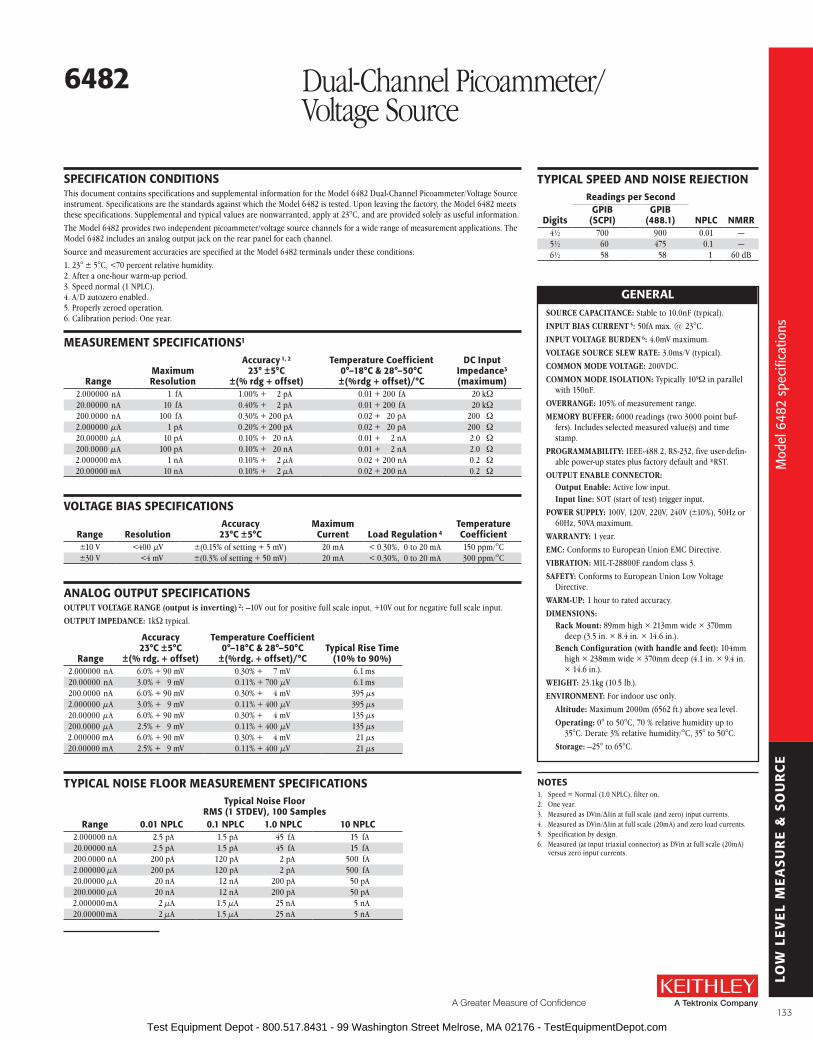
LOW
LE
VE
L M
EA
SU
RE
& S
OU
RC
E
A Greater Measure of Confidence
6482 Dual-Channel Picoammeter/Voltage Source
Dua
l-cha
nnel
pic
oam
met
er/v
olta
ge s
ourc
e
Mod
el 6
482
spec
ifica
tions
sPECIfICaTIoN CoNDITIoNsThis document contains specifications and supplemental information for the Model 6482 Dual-Channel Picoammeter/Voltage Source instrument . Specifications are the standards against which the Model 6482 is tested . Upon leaving the factory, the Model 6482 meets these specifications . Supplemental and typical values are nonwarranted, apply at 23°C, and are provided solely as useful information .
The Model 6482 provides two independent picoammeter/voltage source channels for a wide range of measurement applications . The Model 6482 includes an analog output jack on the rear panel for each channel .
Source and measurement accuracies are specified at the Model 6482 terminals under these conditions:
1 . 23° ± 5°C, <70 percent relative humidity . 2 . After a one-hour warm-up period . 3 . Speed normal (1 NPLC) . 4 . A/D autozero enabled . 5 . Properly zeroed operation . 6 . Calibration period: One year .
MEasurEMENT sPECIfICaTIoNs1
rangeMaximum resolution
accuracy 1, 2 23° ±5°C
±(% rdg + offset)
Temperature Coefficient 0°–18°C & 28°–50°C ±(%rdg + offset)/°C
DC Input Impedance3 (maximum)
2 .000000 nA 1 fA 1 .00% + 2 pA 0 .01 + 200 fA 20 kW20 .00000 nA 10 fA 0 .40% + 2 pA 0 .01 + 200 fA 20 kW200 .0000 nA 100 fA 0 .30% + 200 pA 0 .02 + 20 pA 200 W2 .000000 µA 1 pA 0 .20% + 200 pA 0 .02 + 20 pA 200 W20 .00000 µA 10 pA 0 .10% + 20 nA 0 .01 + 2 nA 2 .0 W200 .0000 µA 100 pA 0 .10% + 20 nA 0 .01 + 2 nA 2 .0 W2 .000000 mA 1 nA 0 .10% + 2 µA 0 .02 + 200 nA 0 .2 W20 .00000 mA 10 nA 0 .10% + 2 µA 0 .02 + 200 nA 0 .2 W
VolTaGE bIas sPECIfICaTIoNs
range resolutionaccuracy 23°C ±5°C
Maximum Current load regulation 4
Temperature Coefficient
±10 V <400 µV ±(0 .15% of setting + 5 mV) 20 mA < 0 .30%, 0 to 20 mA 150 ppm/°C±30 V <4 mV ±(0 .3% of setting + 50 mV) 20 mA < 0 .30%, 0 to 20 mA 300 ppm/°C
aNaloG ouTPuT sPECIfICaTIoNsOUTPUT VOLTAGE RANGE (output is inverting) 2: –10V out for positive full scale input, +10V out for negative full scale input .
OUTPUT IMPEDANCE: 1kW typical .
range
accuracy 23°C ±5°C
±(% rdg. + offset)
Temperature Coefficient 0°–18°C & 28°–50°C
±(%rdg. + offset)/°CTypical rise Time
(10% to 90%)2 .000000 nA 6 .0% + 90 mV 0 .30% + 7 mV 6 .1 ms20 .00000 nA 3 .0% + 9 mV 0 .11% + 700 µV 6 .1 ms200 .0000 nA 6 .0% + 90 mV 0 .30% + 4 mV 395 µs2 .000000 µA 3 .0% + 9 mV 0 .11% + 400 µV 395 µs20 .00000 µA 6 .0% + 90 mV 0 .30% + 4 mV 135 µs200 .0000 µA 2 .5% + 9 mV 0 .11% + 400 µV 135 µs2 .000000 mA 6 .0% + 90 mV 0 .30% + 4 mV 21 µs20 .00000 mA 2 .5% + 9 mV 0 .11% + 400 µV 21 µs
TYPICal NoIsE floor MEasurEMENT sPECIfICaTIoNs
range
Typical Noise floor rMs (1 sTDEV), 100 samples
0.01 NPlC 0.1 NPlC 1.0 NPlC 10 NPlC2 .000000 nA 2 .5 pA 1 .5 pA 45 fA 15 fA20 .00000 nA 2 .5 pA 1 .5 pA 45 fA 15 fA200 .0000 nA 200 pA 120 pA 2 pA 500 fA2 .000000 µA 200 pA 120 pA 2 pA 500 fA20 .00000 µA 20 nA 12 nA 200 pA 50 pA200 .0000 µA 20 nA 12 nA 200 pA 50 pA2 .000000 mA 2 µA 1 .5 µA 25 nA 5 nA20 .00000 mA 2 µA 1 .5 µA 25 nA 5 nA
TYPICal sPEED aND NoIsE rEJECTIoN
Digits
readings per second
NPlC NMrrGPIb
(sCPI)GPIb
(488.1)4½ 700 900 0 .01 —5½ 60 475 0 .1 —6½ 58 58 1 60 dB
GENEralSOURCE CAPACITANCE: Stable to 10 .0nF (typical) .
INPUT BIAS CURRENT 5: 50fA max . @ 23°C .
INPUT VOLTAGE BURDEN 6: 4 .0mV maximum .
VOLTAGE SOURCE SLEW RATE: 3 .0ms/V (typical) .
COMMON MODE VOLTAGE: 200VDC .
COMMON MODE ISOLATION: Typically 109W in parallel with 150nF .
OVERRANGE: 105% of measurement range .
MEMORy BUFFER: 6000 readings (two 3000 point buf-fers) . Includes selected measured value(s) and time stamp .
PROGRAMMABILITy: IEEE-488 .2, RS-232, five user-defin-able power-up states plus factory default and *RST .
OUTPUT ENABLE CONNECTOR:Output Enable: Active low input .Input line: SOT (start of test) trigger input .
POWER SUPPLy: 100V, 120V, 220V, 240V (±10%), 50Hz or 60Hz, 50VA maximum .
WARRANTy: 1 year .
EMC: Conforms to European Union EMC Directive .
VIBRATION: MIL-T-28800F random class 3 .
SAFETy: Conforms to European Union Low Voltage Directive .
WARM-UP: 1 hour to rated accuracy .
DIMENSIONS:Rack Mount: 89mm high × 213mm wide × 370mm
deep (3 .5 in . × 8 .4 in . × 14 .6 in .) .Bench Configuration (with handle and feet): 104mm
high × 238mm wide × 370mm deep (4 .1 in . × 9 .4 in . × 14 .6 in .) .
WEIGHT: 23 .1kg (10 .5 lb .) .
ENVIRONMENT: For indoor use only .
Altitude: Maximum 2000m (6562 ft .) above sea level .
Operating: 0° to 50°C, 70 % relative humidity up to 35°C . Derate 3% relative humidity/°C, 35° to 50°C .
Storage: –25° to 65°C .
NoTEs1 . Speed = Normal (1 .0 NPLC), filter on .2 . One year .3 . Measured as DVin/∆Iin at full scale (and zero) input currents .4 . Measured as DVin/∆Iin at full scale (20mA) and zero load currents .5 . Specification by design .6 . Measured (at input triaxial connector) as DVin at full scale (20mA)
versus zero input currents .
133 Test Equipment Depot - 800.517.8431 - 99 Washington Street Melrose, MA 02176 - TestEquipmentDepot.com

LOW
LE
VE
L M
EA
SU
RE
& S
OU
RC
E
• Cost-effective low current measurement solution
• 10fa resolution
• 5½-digit resolution
• <200µV burden voltage
• up to 1000 readings/second
• built-in Model 485 emulation mode
• IEEE-488 and rs-232 interfaces
• analog output
The 5½-digit Model 6485 Picoammeter combines Keithley’s expertise in sensitive current measure-ment instrumentation with enhanced speed and a robust design . With eight current measurement ranges and high speed autoranging, this cost-effective instrument can measure currents from 20fA to 20mA, taking measurements at speeds up to 1000 readings per second .
The Model 6485’s 10fA resolution and superior sensitivity make it well suited for characterizing low current phenomena, while its 20mA range lets it measure currents high enough for applications such as measuring 4-20mA sensor loops .
Although it employs the latest current measurement technology, it is significantly less expensive than other instruments that perform similar functions, such as optical power meters, competitive pico-
ammeters, or user-designed solutions . With a price that’s comparable to a general purpose DMM, the Model 6485 makes picoamp-level measurements affordable for virtually any laboratory or production floor .
low Voltage burden and Higher accuracyWhile DMMs typically employ shunt ammeter circuitry to measure current, the Model 6485 is a feed-back picoammeter . This design reduces voltage burden by several orders of magnitude, resulting in a voltage burden of less than 200µV on the lower measurement ranges . The low voltage burden makes the Model 6485 function much more like an ideal ammeter than a DMM, so it can make current measurements with high accuracy, even in circuits with very low source voltages .
successor to the Model 485The Model 6485 builds on the strengths of one of Keithley’s most popular picoammeters, the Model 485, offering an additional 20mA measurement range, as well as much higher measurement speeds . With a top speed of up to 1000 readings per second, the Model 6485 is the fastest picoammeter Keithley has ever made . It offers ten times greater resolution than the Model 485 on every range . A time-stamped 2500-reading data buffer provides minimum, maximum, and standard deviation statistics . A built-in emulation mode simplifies upgrading existing applications originally configured with a Model 485 . This emulation mode makes it possible to control the Model 6485 with any custom code written to control the Model 485 . Refer to the comparison table for additional information .
Model 485 Model 6485Current Ranges 2nA–2mA 2nA–20mA
Voltage Burden 200µV200µV (1mV on
20mA range)Reading Rate 3/s 1000/sDigits 4½ 5½Analog Output Yes YesBattery Option Yes NoStorage Buffer 100 points 2500 points
When do you need a picoammeter?
Measuring low DC currents often demands a lot more than a digital multimeter (DMM) can deliver. Generally, DMMs lack the sensitivity required to measure currents less than 100nA. Even at higher currents, a DMM’s input voltage drop (voltage burden) of hundreds of millivolts can make accurate current measurements impossible. Electrometers can measure low currents very accurately, but the circuitry needed to measure extremely low currents, combined with functions like voltage, resistance, and charge measurement, can increase an electrometer’s cost signifi cantly. The Model 6485 Picoammeter combines the economy and ease of use of a DMM with low current sensitivity near that of an electrometer.
6485 Picoammeter
Mea
sure
s lo
w c
urre
nts
quic
kly,
accu
rate
ly, a
nd e
cono
mic
ally
Mea
sure
s lo
w c
urre
nts
quic
kly,
accu
rate
ly, a
nd e
cono
mic
ally
134 Test Equipment Depot - 800.517.8431 - 99 Washington Street Melrose, MA 02176 - TestEquipmentDepot.com

LOW
LE
VE
L M
EA
SU
RE
& S
OU
RC
E
A Greater Measure of Confidence
features that Expand Test and Measurement flexibility• Scaled voltage analog output. This output allows the Model 6485 to transmit measurement
results to devices like DMMs, data acquisition boards, oscilloscopes, or strip chart recorders .
• 220V overload protection. This high overload protection and a robust design let the Model 6485 withstand abusive overflows .
• One-touch front panel design. Functions can be configured easily with the push of a button, without complicated function menus .
• Built-in Trigger Link interface. The Trigger Link interface simplifies synchronizing the Model 6485 with other instruments and voltage sources . This interface combines six independent selectable trigger lines on a single connector for simple, direct control over all instruments in a system .
• RS-232 and IEEE-488 interfaces. These interfaces make it easy to integrate the Model 6485 into automated test and measurement systems .
• Display on/off switch. For research on light-sensitive components, such as measuring the dark currents of photodiodes, the front panel display can be switched off to avoid introducing light that could significantly reduce the accuracy of the results .
• REL and LOG functions. The Model 6485 can make relative readings with respect to a baseline value or display the logarithm of the absolute value of the measured current .
• Resistance calculations. The Model 6485 can calculate resistance by dividing an externally sourced voltage value by the measured current .
• Rear panel BNC inputs. Inexpensive, easy-to-use BNC cables can be employed, rather than more expensive triax cables .aPPlICaTIoNs
• beam monitoring and radiation monitoring
• leakage current testing in insulators, switches, relays, and other components
• sEM beam current measurements
• Galvanic coupling measurements
• optoelectronic device testing and characterization
• optical fiber alignment
• Circuit test and analysis in DClf circuits
• sensor characterization
• I-V measurements of semiconductors and other devices
• Nanoelectronic device characterization
• Capacitor leakage
• Teaching labs
ordering Information6485 Picoammeter
accessories suppliedCaP-18 Protective shield/
Cap (2-lug)4801 low Noise bNC Input
Cable, 1.2m (4 ft)
aCCEssorIEs aVaIlablECablEs4802-10 Low Noise BNC Input Cable, 3m (10 ft)
4803 Low Noise Cable Kit
7007-1 Shielded IEEE-488 Cable, 1m (3 .3 ft)
7007-2 Shielded IEEE-488 Cable, 2m (6 .6 ft)
7007-4 Shielded IEEE-488 Cable, 4m (13 .1 ft)
7009-5 RS-232 Cable
7754-3 BNC to Alligator Cable, 0 .9m (3 ft)
8607 Banana Cable set for Analog Output
8501-1 Trigger Link Cable with Male Micro-DIN Connectors at each End, 1m (3 .3 ft)
8501-2 Trigger Link Cable with Male Micro-DIN Connectors at each End, 2m (6 .6 ft)
8503 DIN-to-BNC Trigger Cable
aDaPTErsCS-565 BNC Barrel
7078-TRX-BNC Female BNC to 3-Slot Male Triax for connecting BNC cable into triax fixture
raCK MouNT KITs4288-1 Single Fixed Rack Mounting Kit
4288-2 Dual Fixed Rack Mounting Kit
GPIb INTErfaCEsKPCI-488LPA IEEE-488 Interface/Controller for the PCI Bus
KUSB-488B IEEE-488 USB-to-GPIB Interface Adapter
sErVICEs aVaIlablE6485-3Y-EW 1-year factory warranty extended to 3 years from
date of shipment
C/6485-3Y-ISO 3 (ISO-17025 accredited) calibrations within 3 years of purchase*
*Not available in all countries
6485 PicoammeterM
easu
res
low
cur
rent
s qu
ickl
y, ac
cura
tely
, and
eco
nom
ical
ly
Mea
sure
s lo
w c
urre
nts
quic
kly,
accu
rate
ly, a
nd e
cono
mic
ally
135 Test Equipment Depot - 800.517.8431 - 99 Washington Street Melrose, MA 02176 - TestEquipmentDepot.com
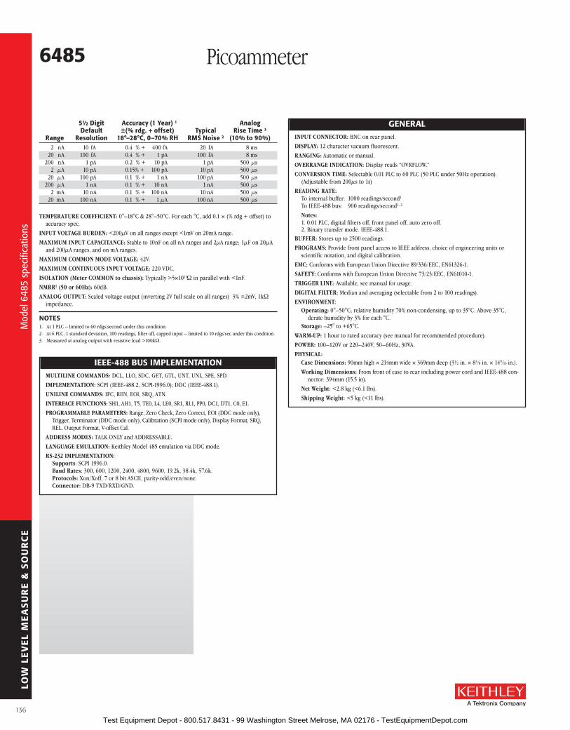
LOW
LE
VE
L M
EA
SU
RE
& S
OU
RC
E
GENEralINPUT CONNECTOR: BNC on rear panel .
DISPLAy: 12 character vacuum fluorescent .
RANGING: Automatic or manual .
OVERRANGE INDICATION: Display reads “OVRFLOW .”
CONVERSION TIME: Selectable 0 .01 PLC to 60 PLC (50 PLC under 50Hz operation) . (Adjustable from 200µs to 1s)
READING RATE: To internal buffer: 1000 readings/second1 To IEEE-488 bus: 900 readings/second1, 2
Notes:1 . 0 .01 PLC, digital filters off, front panel off, auto zero off .2 . Binary transfer mode . IEEE-488 .1 .
BUFFER: Stores up to 2500 readings .
PROGRAMS: Provide front panel access to IEEE address, choice of engineering units or scientific notation, and digital calibration .
EMC: Conforms with European Union Directive 89/336/EEC, EN61326-1 .
SAFETy: Conforms with European Union Directive 73/23/EEC, EN61010-1 .
TRIGGER LINE: Available, see manual for usage .
DIGITAL FILTER: Median and averaging (selectable from 2 to 100 readings) .
ENVIRONMENT:Operating: 0°–50°C; relative humidity 70% non-condensing, up to 35°C . Above 35°C,
derate humidity by 3% for each °C .Storage: –25° to +65°C .
WARM-UP: 1 hour to rated accuracy (see manual for recommended procedure) .
POWER: 100–120V or 220–240V, 50–60Hz, 30VA .
PHySICAL:Case Dimensions: 90mm high × 214mm wide × 369mm deep (3½ in . × 83 ⁄8 in . × 149 ⁄16 in .) .
Working Dimensions: From front of case to rear including power cord and IEEE-488 con-nector: 394mm (15 .5 in) .
Net Weight: <2 .8 kg (<6 .1 lbs) .
Shipping Weight: <5 kg (<11 lbs) .
IEEE-488 bus IMPlEMENTaTIoNMULTILINE COMMANDS: DCL, LLO, SDC, GET, GTL, UNT, UNL, SPE, SPD .
IMPLEMENTATION: SCPI (IEEE-488 .2, SCPI-1996 .0); DDC (IEEE-488 .1) .
UNILINE COMMANDS: IFC, REN, EOI, SRQ, ATN .
INTERFACE FUNCTIONS: SH1, AH1, T5, TE0, L4, LE0, SR1, RL1, PP0, DC1, DT1, C0, E1 .
PROGRAMMABLE PARAMETERS: Range, Zero Check, Zero Correct, EOI (DDC mode only), Trigger, Terminator (DDC mode only), Calibration (SCPI mode only), Display Format, SRQ, REL, Output Format, V-offset Cal .
ADDRESS MODES: TALK ONLY and ADDRESSABLE .
LANGUAGE EMULATION: Keithley Model 485 emulation via DDC mode .
RS-232 IMPLEMENTATION: Supports: SCPI 1996 .0 . Baud Rates: 300, 600, 1200, 2400, 4800, 9600, 19 .2k, 38 .4k, 57 .6k . Protocols: Xon/Xoff, 7 or 8 bit ASCII, parity-odd/even/none . Connector: DB-9 TXD/RXD/GND .
5½ Digit accuracy (1 Year) 1 analog Default ±(% rdg. + offset) Typical rise Time 3 range resolution 18°–28°C, 0–70% rH rMs Noise 2 (10% to 90%) 2 nA 10 fA 0 .4 % + 400 fA 20 fA 8 ms 20 nA 100 fA 0 .4 % + 1 pA 100 fA 8 ms 200 nA 1 pA 0 .2 % + 10 pA 1 pA 500 µs 2 µA 10 pA 0 .15% + 100 pA 10 pA 500 µs 20 µA 100 pA 0 .1 % + 1 nA 100 pA 500 µs 200 µA 1 nA 0 .1 % + 10 nA 1 nA 500 µs 2 mA 10 nA 0 .1 % + 100 nA 10 nA 500 µs 20 mA 100 nA 0 .1 % + 1 µA 100 nA 500 µs
TEMPERATURE COEFFICIENT: 0°–18°C & 28°–50°C . For each °C, add 0 .1 × (% rdg + offset) to accuracy spec .
INPUT VOLTAGE BURDEN: <200µV on all ranges except <1mV on 20mA range .
MAXIMUM INPUT CAPACITANCE: Stable to 10nF on all nA ranges and 2µA range; 1µF on 20µA and 200µA ranges, and on mA ranges .
MAXIMUM COMMON MODE VOLTAGE: 42V .
MAXIMUM CONTINUOUS INPUT VOLTAGE: 220 VDC .
ISOLATION (Meter COMMON to chassis): Typically >5×10¹¹W in parallel with <1nF .
NMRR1 (50 or 60Hz): 60dB .
ANALOG OUTPUT: Scaled voltage output (inverting 2V full scale on all ranges) 3% ±2mV, 1kW impedance .
NoTEs1 . At 1 PLC – limited to 60 rdgs/second under this condition .2 . At 6 PLC, 1 standard deviation, 100 readings, filter off, capped input – limited to 10 rdgs/sec under this condition .3 . Measured at analog output with resistive load >100kW .
6485 Picoammeter
Mod
el 6
485
spec
ifica
tions
Mod
el 6
485
spec
ifica
tions
136 Test Equipment Depot - 800.517.8431 - 99 Washington Street Melrose, MA 02176 - TestEquipmentDepot.com

LOW
LE
VE
L M
EA
SU
RE
& S
OU
RC
E
A Greater Measure of Confidence
• 10fa resolution
• 5½-digit resolution
• <200µV burden voltage
• alternating Voltage method ohms measurements
• automated voltage sweeps for I-V characterization
• floating measurements up to 500V
• up to 1000 readings/second
• built-in Model 486 and 487 emulation mode
• IEEE-488 and rs-232 interfaces
• analog output
• Digital I/o
The 5½-digit Model 6487 Picoammeter/Voltage Source improves on the measurement capability of the award-winning Model 6485, and adds a high resolution 500V source . It provides higher accuracy and faster rise times than the 6485, as well as a damping function for use with capaci-tive devices . With eight current measurement ranges and high speed autoranging, this cost-effective instrument can measure currents from 20fA to 20mA, take measure ments at speeds up to 1000 readings per second, and source voltage from 200µV to 505V .
The Model 6487’s 10fA resolution, superior sen-sitivity, voltage sweeping, and Alternating Voltage resistance measurements make it well suited for characterizing low current devices . Using the latest current measurement technology, it is sig-nificantly less expensive than other instruments that perform similar functions, such as optical power meters, tera-ohmmeters, competitive picoammeters, or user-designed solutions . With
a price that’s comparable to a high-end DMM, the Model 6487 makes picoamp-level measurements affordable for virtually any laboratory or production floor .
low Voltage burden and Higher accuracyWhile DMMs typically employ shunt ammeter circuitry to measure current, the Model 6487 is a feed-back picoammeter . This design reduces voltage burden by several orders of magnitude, resulting in a voltage burden of less than 200µV on the lower measurement ranges . The low voltage burden makes the Model 6487 function much more like an ideal ammeter than a DMM, so it can make current measurements with high accuracy, even in circuits with very low source voltages .
successor to the Model 487The Model 6487 builds on the strengths of one of Keithley’s most popular picoammeters, the Model 487, offering an additional 20mA measurement range, as well as much higher measurement speeds, up to 1000 readings per second . It simplifies device characterization with built-in voltage sweeping capability and the Alternating Voltage method for high resistances . A time-stamped 3000-reading data buffer pro-vides minimum, maximum, and standard devia-tion statistics . A built-in emulation mode makes it possible to control the Model 6487 with any custom code written to control the Model 487 .
features that Expand Test and Measurement flexibility• Direct resistance measurements. Optimized for resistances from 50W to 5×10¹⁴W using the
Source Voltage/Measure Current method .
• Alternating Voltage method resistance measurements. This method improves resistance measurements on devices with high background current or high noise . It extends the measurable resistance range up to 1016W .
• 500V overload protection. This high overload protection and a robust design let the Model 6487 tolerate abusive overflows, including accidentally shorting the voltage source directly into the ammeter .
Model 487 Model 6487Current Ranges 2 nA–2 mA 2 nA–20 mA
Voltage Burden 200 µV200 µV (1 mV on
20 mA range)Reading Rate Up to 180/s Up to 1000/sVoltage Sweeps No YesAlternating Voltage Ohms
No Yes
Analog OutputYes
(non-inverting)Yes
(inverting)Storage Buffer 512 points 3000 pointsBest V Source Resolution
1 mV 0 .2 mV
6487 Picoammeter/ Voltage SourceM
easu
res
low
cur
rent
s an
d hi
gh re
sist
ance
s qu
ickl
y, ac
cura
tely
, and
eco
nom
ical
ly
Mea
sure
s lo
w c
urre
nts
and
high
resi
stan
ces
quic
kly,
accu
rate
ly, a
nd e
cono
mic
ally
137 Test Equipment Depot - 800.517.8431 - 99 Washington Street Melrose, MA 02176 - TestEquipmentDepot.com

LOW
LE
VE
L M
EA
SU
RE
& S
OU
RC
E
• Rear panel triax input. This allows the picoammeter to be used in floating operation, up to 500V . When not floating, the addition of a triax to BNC adapter allows inexpensive, easy-to-use BNC cables to be employed, rather than more expensive triaxial cables .
• RS-232 and IEEE-488 interfaces. These interfaces make it easy to integrate the Model 6487 into automated test and measurement systems .
• Scaled voltage analog output. This output allows the Model 6487 to transmit measurement results to devices like DMMs, data acquisition cards, oscilloscopes, or strip chart recorders .
• Built-in Trigger Link interface. The Trigger Link interface simplifies synchronizing the Model 6487 with other instruments and voltage sources . This interface combines six independent selectable trigger lines on a single connector for simple, direct control over all instruments in a system .
• Display on/off switch. For research on light-sensitive components, such as measuring the dark currents of photodiodes or I-V measurements on unpackaged semiconductors, the front panel display can be switched off to avoid introducing light that could significantly reduce the accuracy of the results .
• One-touch front panel design. Functions can be configured easily with the push of a button, without complicated function menus .
a broad range of low Current applicationsWafer-level Photodiode TestingThe Model 6487 Picoammeter/Voltage Source can be paired with a calibrated light source and a probing fixture to create a cost-effective photodiode test system . Multiple Model 6487s can be con-nected to the DUT’s probe pads to provide photocurrent readings or, with the addition of a switch matrix, one pico ammeter can take current measurements from multiple pads . In the first step of the measurement process, performed in total darkness, the Model 6487 produces a voltage sweep and then measures the resulting dark current . In the second step, a voltage bias is applied and the result-ing photocurrent is meas ured while the light level is increased in calibrated steps . The same basic test configuration can be used for testing positive intrinsic negative (PIN) and avalanche photodiodes (APDs) . The 6487’s high resolution on the 10V source range provides superior sweeping and biasing when small biases are required . The 500V source capability is necessary to bias APDs .
ordering Information6487 Picoammeter/
Voltage source
accessories suppliedCa-186-1b
Ground Connection Cable, banana to screw-lug
CaP-31 Protective shield/Cap (3-lug)
Cs-459 safety Interlock Plug7078-TrX-3
low Noise Triax Input Cable, 1m (3 ft)
8607 High Voltage banana Cable set for Voltage source output
Photo Diode
AmmeterVsource
Calibrated Light Source
ProbeNeedles
Wafer
Pads
Probe Needles
6487 Picoammeter/Voltage Source
aPPlICaTIoNs
• resistance/resistivity measurements
• beam monitoring and radiation monitoring
• leakage current testing in insulators, switches, relays, and other components
• Galvanic coupling measurements
• I-V characterization on semiconductor and optoelectronic devices
• fiber alignment
• Circuit test and analysis in DClf circuits
• sensor characterization
• Capacitor leakage
6487 Picoammeter/ Voltage Source
Mea
sure
s lo
w c
urre
nts
and
high
resi
stan
ces
quic
kly,
accu
rate
ly, a
nd e
cono
mic
ally
Mea
sure
s lo
w c
urre
nts
and
high
resi
stan
ces
quic
kly,
accu
rate
ly, a
nd e
cono
mic
ally
138 Test Equipment Depot - 800.517.8431 - 99 Washington Street Melrose, MA 02176 - TestEquipmentDepot.com

LOW
LE
VE
L M
EA
SU
RE
& S
OU
RC
E
A Greater Measure of Confidence
When do you need a picoammeter?
Measuring low DC currents often demands a lot more than a digital multimeter can deliver. Generally, DMMs lack the sensitivity required to measure currents less than 100nA. Even at higher currents, a DMM’s input voltage drop (voltage burden) of hun dreds of millivolts can make accurate current measurements impossible. Electrometers can measure low currents very accu rately, but the circuitry needed to measure extremely low currents, combined with functions like voltage, resistance, and charge measure-ment, can increase an electrom-eter’s cost significantly. The Model 6487 Picoammeter/Voltage Source combines the economy and ease of use of a DMM with low current sensitivity near that of an electrometer.
Monitoring and Control of focused Ion beam CurrentsIn semiconductor fabrication, focused ion beam systems are often used for nanometer-scale imaging, micromachining, and mapping . Careful monitoring of the magnitude of the beam current with an ion detector is critical . The ion detector generates a secondary current that’s proportional to the current of the primary ion beam . When this secondary current is measured, it can be used to control the intensity of the primary beam . However, this secondary current is very low, often just a few picoamps, so the instrumentation measuring it must provide high measurement accuracy and repeat-ability, as well as sub-picoamp resolution . The Model 6487’s wide measurement range and 5½-digit resolution make it ideal for this application . Signal connections to the Model 6487 are made through the instrument’s triax connector . Often, a detector may require high voltage to attract ions, making the 6487’s 500V source a necessity .
6487Picoammeter/Voltage Source
IonDetector Ion Beam
IM
6487 Picoammeter/Voltage SourceMetal Shield
R HI
LO
Ammeter
HI
LOVsource
aCCEssorIEs aVaIlablE
6487 Picoammeter/ Voltage Source
High resistance MeasurementsThe Model 6487 Picoammeter can be used to measure high resistances (>1GW) in applications such as insulation resistance testing . A constant voltage is placed in series with the unknown resistance and the picoammeter . The voltage drop across the picoammeter is negligible, so all the voltage appears across the unknown resistance . The resulting current is measured by the picoammeter and the resistance is calculated using Ohm’s Law (R = V/I) . To prevent generated current due to electrostatic interference, the unknown resistance is housed in a shielded test fixture . A small series resistor may be added to reduce noise if the un known resistor has high stray capacitance across it .
sErVICEs aVaIlablE6487-3Y-EW 1-year factory warranty extended to 3 years
from date of shipment
C/6487-3Y-ISO 3 (ISO-17025 accredited) calibrations within 3 years of purchase*
*Not available in all countries
CablEs6517-ILC-3 Interlock Cable for 8009 Resistivity Test Fixture
7007-1 Shielded IEEE-488 Cable, 1m (3 .3 ft)
7007-2 Shielded IEEE-488 Cable, 2m (6 .6 ft)
7007-4 Shielded IEEE-488 Cable, 4m (13 .1 ft)
7078-TRX-10 Low Noise Triax Cable, 3 .0m (10 ft)
7078-TRX-20 Low Noise Triax Cable, 6 .0m (20 ft)
8501-* Trigger Link Cable with male Micro-DIN connectors at each end, 1m or 2m (3 .3 ft or 6 .6 ft)
aDaPTErs237-TRX-BAR Triax Barrel
7078-TRX-BNC Triax-to-BNC Adapter
TEsT fIXTurEs8009 Resistivity Test Fixture
raCK MouNT KITs4288-* Single or Dual Fixed Rack Mounting Kit
GPIb INTErfaCEsKPCI-488LPA IEEE-488 Interface/Controller for the PCI Bus
KUSB-488B IEEE-488 USB-to-GPIB Interface Adapter
Mea
sure
s lo
w c
urre
nts
and
high
resi
stan
ces
quic
kly,
accu
rate
ly, a
nd e
cono
mic
ally
Mea
sure
s lo
w c
urre
nts
and
high
resi
stan
ces
quic
kly,
accu
rate
ly, a
nd e
cono
mic
ally
139 Test Equipment Depot - 800.517.8431 - 99 Washington Street Melrose, MA 02176 - TestEquipmentDepot.com

LOW
LE
VE
L M
EA
SU
RE
& S
OU
RC
E
GENEralAMMETER INPUT CONNECTOR: Three lug triaxial on
rear panel .
ANALOG OUTPUT CONNECTOR: Two banana jacks on rear panel .
VOLTAGE SOURCE OUTPUT CONNECTOR: Two banana jacks on rear panel .
INTERLOCK CONNECTOR: 4 pin DIN .
TRIGGER LINE: Available, see manual for usage .
DISPLAy: 12 character vacuum fluorescent .
DIGITAL FILTER: Median and averaging (selectable from 2 to 100 readings) .
RANGING: Automatic or manual .
AUTORANGING TIME3: <250ms (analog filter off, 1PLC) .
OVERRANGE INDICATION: Display reads “OVRFLOW .”
CONVERSION TIME: Selectable 0 .01PLC to 60PLC (50PLC under 50Hz operation) . (Adjustable from 200µs to 1s)
READING RATE: To internal buffer 1000 readings/second1 To IEEE-488 bus 900 readings/second1, 2
BUFFER: Stores up to 3000 readings .
PROGRAMS: Provide front panel access to IEEE address, choice of engineering units or scientific notation, and digital calibration .
EMC: Conforms with European Union Directive 89/336/EEC, EN61326-1 .
SAFETy: Conforms with European Union Directive 73/23/EEC, EN61010-1, CAT I .
ENVIRONMENT:
Operating: 0°–50°C; relative humidity 70% non-condensing, up to 35°C . Above 35°C, derate humidity by 3% for each °C .
Storage: –10°C to +65°C .
WARM-UP: 1 hour to rated accuracy (see manual for rec-ommended procedure) .
POWER: 100–120V or 220–240V, 50–60Hz, (50VA) .
PHySICAL:
Case Dimensions: 90mm high × 214mm wide × 369mm deep (3½ in . × 83⁄8 in . × 149⁄16 in .) .
Working Dimensions: From front of case to rear including power cord and IEEE-488 connector: 394mm (15 .5 inches) .
NET WEIGHT: <4 .7 kg (<10 .3 lbs) .
NoTEs1 . 0 .01PLC, digital filters off, front panel off, auto zero off .2 . Binary transfer mode . IEEE-488 .1 .3 . Measured from trigger in to meter complete .
Typical analog 5½ Digit accuracy (1 Year) 1 rise Time (10% to 90%)3
Default ±(% rdg. + offset) Typical Damping4 range resolution 18°–28°C, 0–70% rH rMs Noise 2 off on 2 nA 10 fA 0 .3 % + 400 fA 20 fA 4 ms 80 ms 20 nA 100 fA 0 .2 % + 1 pA 20 fA 4 ms 80 ms 200 nA 1 pA 0 .15% + 10 pA 1 pA 300 µs 1 ms 2 µA 10 pA 0 .15% + 100 pA 1 pA 300 µs 1 ms 20 µA 100 pA 0 .1 % + 1 nA 100 pA 110 µs 110 µs 200 µA 1 nA 0 .1 % + 10 nA 100 pA 110 µs 110 µs 2 mA 10 nA 0 .1 % + 100 nA 10 nA 110 µs 110 µs 20 mA 100 nA 0 .1 % + 1 µA 10 nA 110 µs 110 µs
TEMPERATURE COEFFICIENT: 0°–18°C & 28°–50°C . For each °C, add 0 .1 × (% rdg + offset) to accuracy spec .
INPUT VOLTAGE BURDEN: <200µV on all ranges except <1mV on 20mA range .
MAXIMUM INPUT CAPACITANCE: Stable to 10nF on all nA ranges and 2µA range; 1µF on 20µA and 200µA ranges, and on mA ranges .
MAXIMUM CONTINUOUS INPUT VOLTAGE: 505 VDC .
NMRR1: (50 or 60Hz): 60dB .
ISOLATION (Ammeter Common or Voltage Source to chassis): Typically >1×10¹¹W in parallel with <1nF .
MAXIMUM COMMON MODE VOLTAGE (between chassis and voltage source or ammeter): 505 VDC .
ANALOG OUTPUT: Scaled voltage output (inverting 2V full scale on all ranges): 2 .5% ±2mV .
ANALOG OUTPUT IMPEDANCE3: <100W, DC–2kHz .
VOLTAGE SOURCE: accuracy 5 Noise Typical Typical range step size ±(% prog. + offset) (p-p) Temperature rise Time 6, 8 fall Time 7, 8 (Max.) (typical) 18°–28°C, 0–70% r.H. 0.1–10 Hz Coefficient (10%–90%) (90%–10%) ±10 .100 200 µV 0 .1 % + 1 mV <50 µV (0 .005% + 20 µV)/°C 250 µs 150 µs ±50 .500 1 mV 0 .1 % + 4 mV <150 µV (0 .005% + 200 µV)/°C 250 µs 300 µs ±505 .00 10 mV 0 .15% + 40 mV <1 .5 mV (0 .008% + 2 mV)/°C 4 .5 ms 1 ms
SELECTABLE CURRENT LIMIT: 2 .5mA, 250µA, 25µA for 50V and 500V ranges, 25mA additional limit for 10V range . All current lim-its are –20%/+35% of nominal .
WIDEBAND NOISE 9: <30mVp-p 0 .1Hz–20MHz .
TyPICAL TIME STABILITy: ±(0 .003% + 1mV) over 24 hours at constant temperature (within 1°C, between 18°–28°C, after 5 minute settling) .
OUTPUT RESISTANCE: <2 .5W .
VOLTAGE SWEEPS: Supports linear voltage sweeps on fixed source range, one current or resistance measurement per step . Maximum sweep rate: 200 steps per second . Maximum step count 3000 . Optional delay between step and measure .
RESISTANCE MEASUREMENT (V/I): Used with voltage source; resistance calculated from voltage setting and measured current . Accuracy is based on voltage source accuracy plus ammeter accuracy . Typical accuracy better than 0 .6% for readings between 1kW and 1TW .
ALTERNATING VOLTAGE RESISTANCE MEASUREMENT: Offers alternating voltage resistance measurements for resistances from 109W to 1015W . Alternates between 0V and user-selectable voltage up to ±505V .
NoTEs1 . At 1 PLC – limited to 60 rdgs/s under this condition .2 . At 6 PLC, 1 standard deviation, 100 readings, filter off, capped input – limited to 10 rdgs/sec under this condition .3 . Measured at analog output with resistive load >2kW .4 . Maximum rise time can be up to 25% greater .5 . Accuracy does not include output resistance/load regulation .6 . Rise Time is from 0V to ± full-scale voltage (increasing magnitude) .7 . Fall Time is from ± full-scale voltage to 0V (decreasing magnitude) .8 . For capacitive loads, add C·∆V/ILimit to rise time, and C·∆V/1mA to fall time .9 . Measured with LO connected to chassis ground .
rEMoTE oPEraTIoNIEEE-488 BUS IMPLEMENTATION: SCPI (IEEE-488 .2,
SCPI-1996 .0); DDC (IEEE-488 .1) .
LANGUAGE EMULATION: Keithley Model 486/487 emulation via DDC mode .
RS-232 IMPLEMENTATION:Supports: SCPI 1996 .0 .Baud Rates: 300, 600, 1200, 2400, 4800, 9600, 19 .2k,
38 .4k, 57 .6k .Protocols: Xon/Xoff, 7 or 8 bit ASCII, parity-odd/even/
none .Connector: DB-9 TXD/RXD/GND .
6487 Picoammeter/ Voltage Source
Mod
el 6
487
spec
ifica
tions
Mod
el 6
487
spec
ifica
tions
140 Test Equipment Depot - 800.517.8431 - 99 Washington Street Melrose, MA 02176 - TestEquipmentDepot.com

LOW
LE
VE
L M
EA
SU
RE
& S
OU
RC
E
A Greater Measure of Confidence
• Dual-channel instrument for optical power measurements, beam measurements, and nanoscale materials and device research
• ±100V source for bias requirements
• Measure photodetector current from 1fa to 20ma
• 1fa current measurement resolution
• Measure optical power directly when used with Model 2500INT Integrating sphere
• 0–10V analog output for high resolution optical power feedback
• Provides a high accuracy, high speed fiber alignment solution
• supports assembly process, final testing, parts binning, and specification
• allows faster alignment of the fiber with the laser diode’s optimum light emitting region
• Combines fiber alignment and device characterization processes
• user-programmable photodetector calibration coefficients
• 3000-point buffer memory on each channel allows data transfer after test completion
• Digital I/o and Trigger link for binning and sweep test operations
• IEEE-488 and rs-232 interfaces
The Model 2502 Dual-Channel Picoammeter provides two independent picoammeter-voltage source channels for a wide range of low level measurement applications including laser diode testing . The Model 2502 is also designed to increase the throughput of Keithley’s LIV (light-current-voltage) test system for production test-ing of laser diode modules (LDMs) . Developed in close cooperation with leading manufacturers of LDMs for fiberoptic telecommunication networks, this dual-channel instrument has features that make it easy to synchronize with other system elements for tight control over optical power measurements . The Model 2502 features a high speed analog output that allows using the LIV test system at the fiber alignment stage of the LDM manufacturing process . Through the use of buffer memory and a Trigger
Link interface that’s unique to Keithley instruments, the Model 2502 can offer the fastest throughput available today for LIV testing of laser diode modules . These instruments are ruggedly engineered to meet the reliability and repeatability demands of continuous operation in round-the-clock production environments .
low-level, High speed MeasurementsThe Model 2502 combines Keithley’s expertise in low-level current measurements with high speed current measurement capabilities . Each channel of this instrument consists of a voltage source paired with a high speed picoammeter . Each of the two channels has an independent picoammeter and volt-age source with measurements made simultaneously across both channels .
Part of a High speed lIV Test systemIn a laser diode module DC/CW test stand, the Model 2502 provides the voltage bias to both the back facet monitor diode and a Model 2500INT Integrating Sphere or to a fiber-coupled photodetector . At the same time it applies the voltage biases, it measures the current outputs of the two photodetectors and converts these outputs to measurements of optical power . The conversion is performed with the user-programmed calibration coefficient for the wavelength of the laser diode module . Fast, accurate measurements of optical power are critical for analyzing the coupling efficiency and optical power characteristics of the laser diode being tested . When testing modules with multiple detectors, the Model 2502 packs more testing capabilities into less test rack space .
fiber alignmentThe Model 2502’s built-in high speed analog output makes it suitable for precision fiber alignment tasks . This instrument combines the ability to align the optical fiber quickly and accurately with a laser diode’s optimum light emitting region and the capability to make precision LIV measurements, all in the same test fixture . The Model 2502’s wide dynamic range allows early beam skirt detection, reducing the time required for fiber alignment . An LIV sweep can be performed during the alignment process to optimize fiber location for an entire operating range . High speed feedback minimizes delays in the alignment process, so it’s unneces-sary to sacrifice alignment speed to ensure accurate device characterization .
Wide Dynamic Measurement rangeThe Model 2502 offers low current measurement ranges from 2nA to 20mA in decade steps . This provides for all photodetector current measurement ranges for testing laser diodes and LEDs in applications such as LIV testing, LED total radiance measurements, measurements of cross-talk and insertion loss on optical switches,
2502 Dual-Channel Picoammeter
Model 2502 rear panel
Mea
sure
s lo
w c
urre
nts
and
high
resi
stan
ces
quic
kly,
accu
rate
ly, a
nd e
cono
mic
ally
Mea
sure
s lo
w c
urre
nts
and
high
resi
stan
ces
quic
kly,
accu
rate
ly, a
nd e
cono
mic
ally
141 Test Equipment Depot - 800.517.8431 - 99 Washington Street Melrose, MA 02176 - TestEquipmentDepot.com

LOW
LE
VE
L M
EA
SU
RE
& S
OU
RC
E
and many others . The Model 2502 meets industry testing requirements for the transmitter as well as pump laser modules . The extensive current measurement range pro-vides excellent sensitivity and resolution for beam current and radiation monitoring measurements .
High accuracy Dark Current MeasurementsThe Model 2502’s 2nA current measurement range is ideal for measuring dark currents and other low currents with 1fA resolution . Once the level of dark current has been determined, the instrument’s REL function automatically subtracts the dark current as an offset so the measured values are more accurate for optical power measurements .
Voltage bias CapabilityThe Model 2502 provides a choice of voltage bias ranges: ±10V or ±100V . This choice gives the system integrator the ability to match the bias range more closely to the type of photodetector being tested, typically ±10V for large area photodetectors and ±100V for avalanche-type photodetectors . This ability to match the bias to the photodetector ensures improved measurement linearity and accuracy . Also, the 100V range provides a source voltage for an SEM target bias supply .
High Testing ThroughputThe Model 2502 is capable of taking 900 readings/second per channel at 4½-digit resolution . This speed is comparable with the measurement speed of the Model 2400 SourceMeter SMU instrument, which is often used in conjunction with the Model 2502 to perform opto electronic device test and characterization . Both instruments support Trigger Link (a proprietary “hardware handshaking” triggering system that’s unique to Keithley products) and buffer memory . When programmed to execute a sweep, Trigger Link ensures measurement integrity by keeping the source and measure-ment functions working in lock step while the buffer memories record the measurements . Together, source memory, buffer memory, and Trigger Link eliminate GPIB traffic during a test sweep, improv-
ing test throughput dramatically .
ratio and Delta MeasurementsThe Model 2502 can provide ratio or delta measurements between the two completely isolated channels, such as the ratio of the back facet monitor detector to the fiber-coupled photodetector at varying levels of input current . These functions can be accessed via the front panel or the GPIB interface . For test setups with multiple detectors, this capability allows for targeted control capabilities for the laser diode module .
Programmable limits and filtersAs with most Keithley instruments, the Model 2502’s current and voltage limits can be programmed to ensure device protection during critical points such as start of test, etc . These instruments also provide Average and Median filters, which can be applied to the data stored in the buffer memory .
adaptable to Evolving DuT requirementsUnlike optical power meters with integrated detectors, the Model 2502 allows the user to choose from a wide range of measurement capabilities simply by selecting an appropriate photodetector and programming the calibration coefficient of this detector at the wavelength of choice .
Interface optionsTo speed and simplify system integration and control, the Model 2502 includes the Trigger Link feature and digital I/O lines, as well as standard IEEE-488 and RS-232 interfaces . The Trigger Link feature combines six
The Model 2502 is designed for tight integration with other Keithley instruments that are often used in lIV test systems for laser diode modules. These other instruments include the Model 2400 sourceMeter® and Model 2510 TEC sourceMeter sMu instruments.
ordering Information2502 Dual-Channel
Picoammeter
accessories supplieduser’s Manual
aPPlICaTIoNs• scanning electron
microscope (sEM) beam measurements
• Production testing of:• laser diode modules• Chip on submount laser
diodes• lEDs• Passive optical
components• laser diode bars• fiber alignment
Thermistor Peltier
2510
2400/2420
2502
Fiber
2500INT Integrating Sphere
ComputerGPIB
Trigger Link
2502 Dual-Channel Picoammeter
aCCEssorIEs aVaIlablE7007-1 Shielded IEEE-488 Cable, 1m (3 .3 ft)
7007-2 Shielded IEEE-488 Cable, 2m (6 .6 ft)
7009-5 Shielded RS-232 Cable
7078-TRX-3 Low Noise Triax Cable, 0 .9m (3 ft)
8501-1 Trigger Link Cable, 1m (3 .3 ft)
KPCI-488LPA IEEE-488 Interface/Controller for the PCI Bus
KUSB-488B IEEE-488 USB-to-GPIB Interface Adapter
sErVICEs aVaIlablE2502-3Y-EW 1-year factory warranty extended to 3 years
from date of shipment
C/2502-3Y-DATA 3 (Z540-1 compliant) calibrations within 3 years of purchase*
*Not available in all countries
Mea
sure
s lo
w c
urre
nts
and
high
resi
stan
ces
quic
kly,
accu
rate
ly, a
nd e
cono
mic
ally
Mea
sure
s lo
w c
urre
nts
and
high
resi
stan
ces
quic
kly,
accu
rate
ly, a
nd e
cono
mic
ally
142 Test Equipment Depot - 800.517.8431 - 99 Washington Street Melrose, MA 02176 - TestEquipmentDepot.com

LOW
LE
VE
L M
EA
SU
RE
& S
OU
RC
E
A Greater Measure of Confidence
2502 Dual-Channel Picoammeter
independent software selectable trigger lines on a single connector for simple, direct control over all instruments in a system . This feature is especially useful for reducing total test time if the test involves a sweep . The Model 2502 can sweep through a series of measurements based on triggers received from other instruments . The digital I/O lines simplify external handler control and binning operations .
The Model 2502 Dual-Channel Picoammeter can measure and display either photo-diode current or optical power for two photodiodes with appropriate user- supplied optical power gain/wavelength calibration factors .
The Model 2502 includes an analog output jack on the rear panel for each channel .
Measurement specifications Temperature accuracy1, 2 Coefficient Dc Input Maximum 23°C ±5°C 0°–18°C & 28°–50°C Impedance3 range resolution ±(% rdg. + offset) ±(%rdg. + offset)/°C (Maximum) 2 .000000 nA 1 fA 1 .00% + 2 pA 0 .01 + 200 fA 20 kW 20 .00000 nA 10 fA 0 .40% + 2 pA 0 .01 + 200 fA 20 kW 200 .0000 nA 100 fA 0 .30% + 200 pA 0 .02 + 20 pA 200 W 2 .000000 µA 1 pA 0 .20% + 200 pA 0 .02 + 20 pA 200 W 20 .00000 µA 10 pA 0 .10% + 20 nA 0 .01 + 2 nA 2 .0 W 200 .0000 µA 100 pA 0 .10% + 20 nA 0 .01 + 2 nA 2 .0 W 2 .000000 mA 1 nA 0 .10% + 2 µA 0 .02 + 200 nA 0 .2 W 20 .00000 mA 10 nA 0 .10% + 2 µA 0 .02 + 200 nA 0 .2 W
MAXIMUM INPUT: ±20 .0mA .
TYPICal sPEED aND NoIsE rEJECTIoN4
readings/s Digits GPIb (sCPI) GPIb (488.1) NPlC NMrr 4½ 700 900 0 .01 — 5½ 460 475 0 .1 — 6½ 58 58 1 60 dB
PHoToDIoDE VolTaGE bIas sPECIfICaTIoNs2
accuracy Maximum load Temperature range resolution 23°C ±5°C Current regulation5 Coefficient 0 to ±10 V <400 µV ±(0 .15% of setting 20 mA < 0 .30%, 150 ppm/°C + 5 mV) 0 to 20 mA 0 to ±100 V <4 mV ±(0 .3% of setting 20 mA < 0 .30%, 300 ppm/°C + 50 mV) 0 to 20 mA
GENEral
Typical Noise floor Measurement specification6
Typical Noise floor rMs (1 sTDEV), 100 samples
range 0.01 NPlC 0.1 NPlC 1.0 NPlC 10 NPlC2 .000000 nA 2 pA 1 pA 40 fA 15 fA20 .00000 nA 2 pA 1 pA 40 fA 15 fA200 .0000 nA 200 pA 100 pA 2 pA 500 fA2 .000000 µA 200 pA 100 pA 2 pA 500 fA20 .00000 µA 20 nA 10 nA 200 pA 50 pA200 .0000 µA 20 nA 10 nA 200 pA 50 pA2 .000000 mA 2 µA 1 µA 25 nA 5 nA20 .00000 mA 2 µA 1 µA 25 nA 5 nA
SOURCE CAPACITANCE: Stable to 10 .0nF typical .INPUT BIAS CURRENT7: 50fA max . @ 23°C .INPUT VOLTAGE BURDEN8: 4 .0mV max .VOLTAGE SOURCE SLEW RATE: 3 .0ms/V typical .COMMON MODE VOLTAGE: 200VDC .COMMON MODE ISOLATION: Typically 109W in parallel with 150nF .OVERRANGE: 105% of measurement range .MEMORy BUFFER: 6000 readings (two 3000 point buffers) . Includes selected
measured value(s) and time stamp . PROGRAMMABILITy: IEEE-488 (SCPI-1995 .0), RS-232, five user- definable
power-up states plus factory default and *RST .DIGITAL INTERFACE:
Enable: Active low input .Handler Interface: Start of test, end of test, 3 category bits . +5V @ 300mA
supply .Digital I/O: 1 trigger input, 4 TTL/Relay Drive outputs (33V @ 500mA,
diode clamped) .POWER SUPPLy: 100V/120V/220V/240V ±10% .LINE FREQUENCy: 50, 60Hz .POWER DISSIPATION: 60VA .EMC: Complies with European Union Directive 89/336/EEC .VIBRATION: MIL-T-28800F Random Class 3 .SAFETy: Complies with European Directive 73/23/EEC .WARM-UP: 1 hour to rated accuracy .DIMENSIONS: 89mm high × 213mm wide × 370mm deep (3½ in × 83⁄8 in ×
149⁄16 in) . Bench configuration (with handle and feet): 104mm high × 238mm wide × 370mm deep (41⁄8 in × 93⁄8 in × 149⁄16 in) .
WEIGHT: 23 .1kg (10 .5 lbs) .ENVIRONMENT:
Operating: 0°–50°C, 70% R .H . up to 35°C non-condensing . Derate 3% R .H ./°C, 35°–50°C .
Storage: –25° to 65°C, non-condensing .
NoTEs1 . Speed = Normal (1 .0 NPLC), Filter On .2 . 1 year .3 . Measured as ∆Vin/∆Iin at full scale (and zero) input currents .4 . Dual channel, internal trigger, measure only, display off, Autorange off, Auto Zero off, source
delay = 0, filters off, limits off, CALC5 and CALC6 off, 60Hz .5 . Measured as ∆Vin/∆Iin at full scale (20mA) and zero load currents .6 . Noise floor measured as rms (1 standard deviation), 100 samples, Filter off, open (capped)
input .7 . Specification by design .8 . Measured (at input triax) as ∆Vin at full scale (20mA) vs . zero input currents .9 . The analog output voltage for each channel is referenced to that channel’s floating ground .
aNaloG ouTPuT sPECIfICaTIoNs
OUTPUT VOLTAGE RANGE9: Output is inverting: –10V out for positive full scale input . +10V out for negative full scale input .
OUPUT IMPEDANCE: 1kW typical .
range
accuracy 23°C ±5°C
±(%output + offset)
Temperature Coefficient 0°–18°C & 28°–50°C
±(%output + offset)/°C
rise Time Typical
(10% to 90%)2 .000000 nA 6 .0% + 90 mV 0 .30% + 7 mV 6 .1 ms20 .00000 nA 3 .0% + 9 mV 0 .11% + 700 µV 6 .1 ms200 .0000 nA 6 .0% + 90 mV 0 .30% + 4 mV 395 µs2 .000000 µA 3 .0% + 9 mV 0 .11% + 400 µV 395 µs20 .00000 µA 6 .0% + 90 mV 0 .30% + 4 mV 135 µs200 .0000 µA 2 .5% + 9 mV 0 .11% + 400 µV 135 µs2 .000000 mA 6 .0% + 90 mV 0 .30% + 4 mV 21 µs20 .00000 mA 2 .5% + 9 mV 0 .11% + 400 µV 21 µs
Mod
el 2
502
spec
ifica
tions
Mod
el 2
502
spec
ifica
tions
143 Test Equipment Depot - 800.517.8431 - 99 Washington Street Melrose, MA 02176 - TestEquipmentDepot.com

LOW
LE
VE
L M
EA
SU
RE
& S
OU
RC
E
6514 Programmable Electrometer
The Model 6514 Electrometer combines flexible interfacing capabilities with current sensitivity, charge measure ment capabilities, resolution, and speed that are equal or superior to our earlier electrometers . The Model 6514’s built-in IEEE-488, RS-232, and digital I/O interfaces make it simple to configure fully automated, high speed systems for low-level testing .
The 5½-digit Model 6514 is designed for applica-tions that demand fast, yet precise measurements of low currents, voltages from high resistance sources, charges, or high resistances .
The Model 6514’s exceptional measurement perfor-mance comes at an affordable price . While its cost is comparable with that of many high end DMMs, the Model 6514 offers far greater current sensitivity and sig nificantly lower voltage burden (as low as 20µV) than other instruments can provide .
r&D on a budgetThe Model 6514 offers the flexibility and sensitivity needed for a wide array of experiments, provid-ing better data far faster than older electrometer designs . Applications include measuring currents from light detectors and other sensors, beam experiments, and measuring resistances using a current source . In addition to use by researchers in areas such as physics, optics, and materials science, the Model 6514’s affordable price makes it an attractive alternative to high end DMMs for low current measurement applications, such as testing resistance and leakage current in switches, relays, and other components . For more information on how the Model 6514 does this, refer to the section titled “Low Voltage Burden .”
The Model 6514 builds on the features and capabilities of the Keithley electrometers that preceded it . For example, like those instruments, a built-in constant current source simplifies measuring resistance .
Two analog outputs—a 2V output and a preamp output—are available for recording data with strip-chart recorders .
• <1fa noise
• >200TW input impedance on voltage measurements
• Charge measurements from 10fC to 20µC
• High speed—up to 1200 readings/second
• Interfaces readily with switches, computers, and component handlers
• Cancels voltage and current offsets easily
ordering Information6514 Programmable
Electrometer
accessories supplied237-alG-2 low Noise Triax Cable, 3-slot Triax to alligator Clips, 2m (6.6 ft)
aCCEssorIEs aVaIlablECablEs237-ALG-2 Low Noise Triax Cable, 3-Slot Triax to Alligator
Clips
7007-1 Shielded IEEE-488 Cable, 1m (3 .3 ft)
7007-2 Shielded IEEE-488 Cable, 2m (6 .6 ft)
7009-5 RS-232 Cable
7078-TRX-3 Low Noise Triax Cable, 3-Slot Triax Connectors, 0 .9m (3 ft)
7078-TRX-10 Low Noise Triax Cable, 3-Slot Triax Connectors, 3m (10 ft)
7078-TRX-20 Low Noise Triax Cable, 3-Slot Triax Connectors, 6m (20 ft)
8501-1 Trigger-Link Cable, 1m (3 .3 ft)
8501-2 Trigger-Link Cable, 2m (6 .6 ft)
raCK MouNT KITs4288-1 Single Fixed Rack Mounting Kit
4288-2 Dual Fixed Rack Mounting Kit
aDaPTErs7078-TRX-BNC 3-Lug Triax to BNC Adapter
237-TRX-NG Triax Male-Female Adapter with Guard Disconnected
237-TRX-T 3-Slot Male Triax to Dual 3-Lug Female Triax Tee Adapter
237-TRX-TBC 3-Lug Female Triax Bulkhead Connector (1 .1kV rated)
7078-TRX-TBC 3-Lug Female Triax Bulkhead Connector with Cap
GPIb INTErfaCEsKPCI-488LPA IEEE-488 Interface/Controller for the PCI Bus
KUSB-488B IEEE-488 USB-to-GPIB Interface AdaptersErVICEs aVaIlablE6514-3Y-EW 1-year factory warranty extended to 3 years
from date of shipment
C/6514-3Y-ISO 3 (ISO-17025 accredited) calibrations within 3 years of purchase*
TRN-LLM-1-C Course: Making Accurate Low-Level Measurements
*Not available in all countries
Fast
, pre
cise
cur
rent
, cha
rge,
vol
tage
, and
resi
stan
ce m
easu
rem
ents
Fast
, pre
cise
cur
rent
, cha
rge,
vol
tage
, and
resi
stan
ce m
easu
rem
ents
144 Test Equipment Depot - 800.517.8431 - 99 Washington Street Melrose, MA 02176 - TestEquipmentDepot.com

LOW
LE
VE
L M
EA
SU
RE
& S
OU
RC
E
A Greater Measure of Confidence
6514 Programmable Electrometer
Economical Component TestingOnce, electrometers were simply considered too slow to keep up with the high throughput that production test applications demand . The Model 6514 is designed for fast, sensitive measurements, providing speeds up to 1200 readings per second with fast integration or 17 measurements per second with 60Hz line-cycle integration . It offers 10fA resolution on 2nA signals, settling to within 10% of the final value in just 15ms . A normal-mode rejec-tion ratio (NMRR) of 60dB allows making accurate low current measure-ments, even in the presence of line frequency induced currents, which is a common concern in production floor environments . The instrument’s sen-sitivity makes it easy to determine the leakage resistance on capacitances up to 10nF or even on higher capacitances when a series resistor is used .
While the Model 6514 can be easily operated manually using the front panel controls, it can also be externally controlled for automated test applications . Built-in IEEE-488 and RS-232 interfaces make it possible
ID
6514 Electrometer
RL
IL = 0
Photodiode(no incident
light)
–+
VBURDEN
CAL VOFFSET
Total offsetvoltage = 0
A/D
figure 2. Dark Current Measurement with burden Voltage Corrected
LeakageResistance
RL
IL
(error currentdue to
VBURDEN)
Photodiode(no incident
light)
–+
VBURDEN
A/D
ID
Electrometer
figure 1. Dark Current Measurement with burden Voltage uncorrected
to program all instrument functions over the bus through a computer controller . The instrument’s interfaces also simplify integrating external hardware, such as sources, switching systems, or other instruments, into the test system . A digital I/O interface can be used to link the Model 6514 to many popular component handlers for tight systems integration in bin-ning, sorting, and similar applications .
These features make the Model 6514 a powerful, low cost tool for systems designed to test optical devices and leakage resistance on low-value capaci-tors, switches, and other devices, particularly when the test system already includes a voltage source or when the source current/measure voltage technique is used to determine resistance .
low Voltage burdenThe Model 6514’s feedback ammeter design minimizes voltage offsets in the input circuitry, which can affect current measurement accuracy . The instrument also allows active cancellation of its input voltage and current offsets, either manually via the front panel controls or over the bus with IEEE-488 commands .
Dark Current MeasurementsWhen measuring dark currents (Figure 1) from a device such as a photodiode, the ammeter reads the sum of two different currents . The first current is the dark current (I D) generated by the detector with no light falling upon the device (in other words, the signal of interest); the second one is the leakage current (I L) generated by the voltage burden (VBURDEN) appearing at the terminals of the ammeter . In a feedback ammeter, the primary “voltage burden” is the amplifier offset voltage . This leakage current represents an error current . Without the use of cancellation techniques, I L = VBURDEN/RL . Figure 2 illustrates how the Model 6514’s CAL VOFFSET is adjusted to cancel VBURDEN to within the voltage noise level of a few microvolts, so the measured current is only the true dark current (ID) of the photodiode . In a similar manner, offset currents can also be cancelled . Earlier electrometers used an internal numerical correction technique in which the voltage burden was still present, so the measured dark current included the error term I L = VBURDEN/R L .
Voltage burden and Measurement ErrorElectrometers provide current measurement with lower terminal voltage than is possible when making DMM meas urements . As shown in Figure 3, DMMs measure current using a shunt resistance that develops a voltage (typically 200mV full-range) in the input circuit . This creates a terminal voltage (VBURDEN) of about 200mV, thereby lowering the measured current . Electrometers reduce this terminal voltage by using the feedback ammeter configuration illustrated in Figure 1 . The Model 6514 lowers this terminal voltage still further—to the level of the voltage noise—by canceling out the small offset voltage that remains, as shown in Figure 2 . Any error signals that remain are negligible in comparison to those that can occur when measuring current with a DMM .
Fast
, pre
cise
cur
rent
, cha
rge,
vol
tage
, and
resi
stan
ce m
easu
rem
ents
Fast
, pre
cise
cur
rent
, cha
rge,
vol
tage
, and
resi
stan
ce m
easu
rem
ents
145 Test Equipment Depot - 800.517.8431 - 99 Washington Street Melrose, MA 02176 - TestEquipmentDepot.com

LOW
LE
VE
L M
EA
SU
RE
& S
OU
RC
E
6514 Programmable Electrometer
VSOURCE
+– A/D
R
VBURDEN= 200mV atfull range
Desired Current Reading: I =VSOURCE
R
DMM’s Actual Current Reading: I =VSOURCE – VBURDEN
R
DMM
I
figure 3. Errors Due to burden Voltage when Measuring with a DMM
VolTs accuracy Temperature (1 Year)1 Coefficient 5½-Digit 18°–28°C 0°–18°C & 28°–50°C range resolution ±(%rdg+counts) ±(%rdg+counts)/°C 2 V 10 µV 0 .025 + 4 0 .003 + 2 20 V 100 µV 0 .025 + 3 0 .002 + 1 200 V 1 mV 0 .06 + 3 0 .002 + 1
NoTEs1 . When properly zeroed, 5½-digit . Rate: Slow (100ms integration time) .
NMRR: 60dB on 2V, 20V, >55dB on 200V, at 50Hz or 60Hz ±0 .1% .
CMRR: >120dB at DC, 50Hz or 60Hz .
INPUT IMPEDANCE: >200TW in parallel with 20pF, <2pF guarded (10MW with zero check on) .
SMALL SIGNAL BANDWIDTH AT PREAMP OUTPUT: Typically 100kHz (–3dB) .
aMPs accuracy Temperature (1 Year)1 Coefficient 5½-Digit 18°–28°C 0°–18°C & 28°–50°C range resolution ±(%rdg+counts) ±(%rdg+counts)/°C 20 pA 100 aA2 1 + 30 0 .1 + 5 200 pA 1 fA2 1 + 5 0 .1 + 1 2 nA 10 fA 0 .2 + 30 0 .1 + 2 20 nA 100 fA 0 .2 + 5 0 .03 + 1 200 nA 1 pA 0 .2 + 5 0 .03 + 1 2 µA 10 pA 0 .1 + 10 0 .005 + 2 20 µA 100 pA 0 .1 + 5 0 .005 + 1 200 µA 1 nA 0 .1 + 5 0 .005 + 1 2 mA 10 nA 0 .1 + 10 0 .008 + 2 20 mA 100 nA 0 .1 + 5 0 .008 + 1
NoTEs1 . When properly zeroed, 5½-digit . Rate: Slow (100ms integration time) .2 . aA =10–18A, fA=10–15A .
INPUT BIAS CURRENT: <3fA at TCAL (user adjustable) . Temperature coefficient = 0 .5fA/°C .INPUT BIAS CURRENT NOISE: <750aA p-p (capped input), 0 .1Hz to 10Hz bandwidth, damping
on . Digital filter = 40 readings .INPUT VOLTAGE BURDEN at TCAL ±1°C (user adjustable):
<20µV on 20pA, 2nA, 20nA, 2µA, 20µA ranges . <100µV on 200pA, 200nA, 200µA ranges . <2mV on 2mA range . <4mV on 20mA range .
TEMPERATURE COEFFICIENT OF INPUT VOLTAGE BURDEN: <10µV/°C on pA, nA, µA ranges .PREAMP SETTLING TIME (to 10% of final value): 2 .5s typical on pA ranges, damping off, 3s typi-
cal on pA ranges damping on, 15ms on nA ranges, 5ms on µA and mA ranges .NMRR: >95dB on pA, 60dB on nA, µA, and mA ranges at 50Hz or 60Hz ±0 .1% . Digital Filter = 40 .
oHMs ac cu ra cy Temperature (1 Year)1 Coefficient Test 5½-Digit 18°–28°C 0°–18°C & 28°–50°C Current range resolution ±(% rdg+counts) ±(% rdg+counts)/°C (nominal) 2 kW 10 mW 0 .20 + 10 0 .01 + 2 0 .9 mA 20 kW 100 mW 0 .15 + 3 0 .01 + 1 0 .9 mA 200 kW 1 W 0 .25 + 3 0 .01 + 1 0 .9 mA 2 MW 10 W 0 .25 + 4 0 .02 + 2 0 .9 µA 20 MW 100 W 0 .25 + 3 0 .02 + 1 0 .9 µA 200 MW 1 kW 0 .30 + 3 0 .02 + 1 0 .9 µA 2 GW 10 kW 1 .5 + 4 0 .04 + 2 0 .9 nA 20 GW 100 kW 1 .5 + 3 0 .04 + 1 0 .9 nA 200 GW 1 MW 1 .5 + 3 0 .04 + 1 0 .9 nA
NoTEs1 . When properly zeroed, 5½-digit . Rate: Slow (100ms integration time) .
MAXIMUM OPEN CIRCUIT VOLTAGE: 250V DC .PREAMP SETTLING TIME (To 10% of final reading with <100pF input capacitance): 2kW
through 200kW: 2ms; 20MW through 200MW: 90ms . 2GW through 200GW: 1s .
The example below compares a DMM’s voltage burden errors with the 6514’s .
DMM offset CurrentsTypically, offset currents in DMMs are tens or hundreds of picoamps, which severely limits their low current measuring capabilities compared to the Model 6514 with 3fA input bias current .
If:
The desired current reading is: I = 1V50kΩ
= 20µA
VSOURCE = 1V, R = 50kΩ
Actual Reading(20µA range on DMM): I = 1V – 200mV
50kΩ= 800mV
50kΩ= 16µA = 20% Burden error
with a DMM
VBURDEN = 200mV
6514 Actual Reading:
I = 0 .999990V50kΩ
= 19 .9998µA = 0.001% Burden errorwith the 6514
VBURDEN = 10µV
Refer to Figure 3.
Refer to Figure 2.
aPPlICaTIoNs
• High resistivity measurements
• leakage currents
• Ion selective electrode measurements
• pH measurements
• Conductivity cells
• Potentiometry
Mod
el 6
514
spec
ifica
tions
Mod
el 6
514
spec
ifica
tions
146 Test Equipment Depot - 800.517.8431 - 99 Washington Street Melrose, MA 02176 - TestEquipmentDepot.com

LOW
LE
VE
L M
EA
SU
RE
& S
OU
RC
E
A Greater Measure of Confidence
6514 Programmable Electrometer
GENEralOVERRANGE INDICATION: Display reads “OVRFLOW .”
RANGING: Automatic or manual .
CONVERSION TIME: Selectable 0 .01PLC to 10PLC .
PROGRAMS: Provide front panel access to IEEE address, choice of engineering units or scientific notation, and digital calibration .
MAXIMUM INPUT: 250V peak, DC to 60Hz sine wave; 10s per minute maximum on mA ranges .
MAXIMUM COMMON MODE VOLTAGE (DC to 60Hz sine wave): Electrometer, 500V peak .
ISOLATION (Meter COMMON to chassis): Typically 1010W in parallel with 500pF .
INPUT CONNECTOR: Three lug triaxial on rear panel .
2V ANALOG OUTPUT: 2V for full range input . Inverting in Amps and Coulombs mode . Output impedance 10kW .
PREAMP OUTPUT: Provides a guard output for Volts mea sure ments . Can be used as an inverting output or with external feedback in Amps and Coulombs modes .
DIGITAL INTERFACE: Handler Interface: Start of test, end of test, 3 category bits . Digital I/O: 1 Trigger input, 4 outputs with 500mA sink capability . Connector: 9 pin D subminiature, male pins .
EMC: Conforms with European Union Directive 89/336/EEC EN55011, EN50082-1, EN61000-3-2, EN61000-3-3, FCC part 15 class B .
SAFETy: Conforms with European Union Directive 73/23/EEC EN61010-1 .
GUARD: Switchable voltage and ohm guard available .
TRIGGER LINE: Available, see manual for usage .
READING STORAGE: 2500 readings .
READING RATE: To internal buffer 1200 readings/second1 To IEEE-488 bus 500 readings/second1, 3
To front panel 17 readings/second at 60Hz;2 15 readings/second at 50Hz .2
Notes:
1 0 .01PLC, digital filters off, front panel off, auto zero off . 2 1 .00PLC, digital filters off . 3 Binary transfer mode .
DIGITAL FILTER: Median and averaging (selectable from 2 to 100 readings) .
DAMPING: User selectable on Amps function .
ENVIRONMENT: Operating: 0°–50°C; relative humidity 70% non-condensing, up to 35°C . Storage: –25° to +65°C .
WARM-UP: 1 hour to rated accuracy (see manual for recommended procedure) .
POWER: 90–125V or 210–250V, 50–60Hz, 60VA .
PHySICAL:Case Dimensions: 90mm high × 214mm wide × 369mm deep (3½ in . × 83 ⁄8 in . × 149 ⁄16 in .) .Working Dimensions: From front of case to rear including power cord and IEEE-488 con-
nector: 15 .5 inches .Net Weight: <4 .6kg (<10 .1 lbs) .Shipping Weight: <9 .5kg (<21 lbs) .
IEEE-488 bus IMPlEMENTaTIoNMULTILINE COMMANDS: DCL, LLO, SDC, GET, GTL, UNT, UNL, SPE, SPD .
IMPLEMENTATION: SCPI (IEEE-488 .2, SCPI-1996 .0); DDC (IEEE-488 .1) .
UNILINE COMMANDS: IFC, REN, EOI, SRQ, ATN .
INTERFACE FUNCTIONS: SH1, AH1, T5, TE0, L4, LE0, SR1, RL1, PP0, DC1, DT1, C0, E1 .
PROGRAMMABLE PARAMETERS: Function, Range, Zero Check, Zero Correct, EOI (DDC mode only), Trigger, Terminator (DDC mode only), Data Storage 2500 Storage, Calibration (SCPI mode only), Display Format, SRQ, REL, Output Format, Guard, V-offset Cal, I-offset Cal .
ADDRESS MODES: TALK ONLY and ADDRESSABLE .
LANGUAGE EMULATION: 6512, 617, 617-HIQ emulation via DDC mode .
TRIGGER TO READING DONE: 150ms typical, with external trigger .
RS-232 IMPLEMENTATION: Supports: SCPI 1996 .0 . Baud Rates: 300, 600, 1200, 2400, 4800, 9600, 19 .2k, 38 .4k, 57 .6k . Protocols: Xon/Xoff, 7 or 8 bit ASCII, parity-odd/even/none . Connector: DB-9 TXD/RXD/GND .
CouloMbs accuracy Temperature (1 Year)1, 2 Coefficient 6½-Digit 18°–28°C 0°–18°C & 28°–50°C range resolution ±(%rdg+counts) ±(%rdg+counts)/°C 20 nC 10 fC 0 .4 + 50 0 .04 + 10 200 nC 100 fC 0 .4 + 50 0 .04 + 10 2 µC 1 pC 1 + 50 0 .05 + 10 20 µC 10 pC 1 + 50 0 .05 + 10
Notes:1 . Charge acquisition time must be <1000s, derate 2% for each additional 10,000s .2 . When properly zeroed, 6½-digit . Rate: Slow (100ms integration time) .
INPUT BIAS CURRENT: <4fA at TCAL . Temperature coefficient = 0 .5fA/°C .
Model 6514 rear panel
Mod
el 6
514
spec
ifica
tions
Mod
el 6
514
spec
ifica
tions
147 Test Equipment Depot - 800.517.8431 - 99 Washington Street Melrose, MA 02176 - TestEquipmentDepot.com

LOW
LE
VE
L M
EA
SU
RE
& S
OU
RC
E
• Measures resistances up to 1016W
• 1fa–20ma current measurement range
• <20µV burden voltage on lowest current ranges
• 200TW input impedance
• <3fa bias current
• up to 425 rdgs/s
• 0.75fa p-p noise
• built-in ±1kV voltage source
• unique voltage reversal method for high resistance measurements
• optional plug-in scanner cards
Keithley’s 5½-digit Model 6517B Electrometer/High Resistance Meter offers accuracy and sensitivity speci-fications unmatched by any other meter of this type . It also offers a variety of features that simplify measur ing high resistances and the resistivity of insulating materi-als . With reading rates of up to 425 read ings/second, the Model 6517B is also significantly faster than competitive electrometers, so it offers a quick, easy way to measure low-level currents .
Exceptional Performance specificationsThe half-rack-sized Model 6517B has a special low current input amplifier with an input bias current of <3fA with just 0 .75fA p-p (peak-to-peak) noise and <20µV burden voltage on the lowest range . The input impedance for voltage and resistance measurements is 200TW for near-
ideal circuit loading . These speci fi ca tions ensure the accuracy and sensitivity needed for accurate low current and high imped ance volt age, resistance, and charge measure ments in areas of re search such as physics, optics, nanotechnology, and materials science . A built-in ±1kV voltage source with sweep capability simplifies performing leak age, break down, and resis tance testing, as well as volume (W-cm) and surface resistivity (W/square) mea sure ments on insulating materials .
Wide Measurement rangesThe Model 6517B offers full autoranging over the full span of ranges on current, resistance, voltage, and charge mea sure ments:• Current measurements from 1fA to 20mA• Voltage measurements from 10µV to 200V• Resistance measurements from 50W to 1016W• Charge measurements from 10fC to 2µC
Improved High resistivity MeasurementsMany test applications require measuring high levels of resistivity (surface or volume) of materials . The conventional method of making these measurements is to apply a sufficiently large voltage to a sample, measure the current that flows through the sample, then calculate the resistance using Ohm’s Law (R=V/I) . While high resistance materials and devices produce very small currents that are difficult to measure accurately, Keithley’s electrometers and picoammeters are used successfully for such measurements .
Even with high quality instrumentation, inherent background currents in the material can make these measurements difficult to perform accurately . Insulating materials, polymers, and plastics typically exhibit background currents due to piezoelectric effects, capacitive elements charged by static electricity, and polarization effects . These back-ground currents are often equal to or greater than the current stimulated by the applied voltage . In these cases, the result is often unstable, providing inaccurate resistance or resistivity readings or even erroneous negative values . Keithley’s Model 6517B is designed to solve these problems and provides consistent, repeatable, and accurate measurements for a wide variety of materials and components, especially when used in combination with the Model 8009 Resistivity Test Fixture .
alternating Polarity MethodThe Model 6517B uses the Alternating Polarity method, which virtually eliminates the effect of any background currents in the sample . First and second order drifts of the background currents are also canceled out . The Alternating Polarity method applies a voltage of positive polarity, then the current is measured after a specified delay (Measure Time) . Next, the polarity is reversed and the current measured again, using the same delay . This process is repeated continuously, and the resistance is calculated based on a weighted average of the four most recent current measurements . This method typically
6517b Electrometer/High Resistance Meter
Sim
plifi
es m
easu
ring
high
resi
stan
ces
and
the
resi
stiv
ity o
f ins
ulat
ing
mat
eria
ls
Sim
plifi
es m
easu
ring
high
resi
stan
ces
and
the
resi
stiv
ity o
f ins
ulat
ing
mat
eria
ls
148 Test Equipment Depot - 800.517.8431 - 99 Washington Street Melrose, MA 02176 - TestEquipmentDepot.com

LOW
LE
VE
L M
EA
SU
RE
& S
OU
RC
E
A Greater Measure of Confidence
6517b Electrometer/High Resistance Meter
produces a highly repeatable, accurate measure-ment of resistance (or resistivity) by the seventh reversal on most materials (i .e ., by discarding the first three readings) . For example, a 1mm-thick sample of 1014W-cm material can be measured with 0 .3% repeatability in the Model 8009 test fixture, provided the background current chang-es less than 200fA over a 15-second period .
simple DMM-like operationThe Model 6517B is designed for easy, DMM-like operation via the front panel, with single-button control of im por tant functions such as resistance measurement . It can also be controlled via a built-in IEEE-488 inter face, which makes it possible to program all func tions over the bus through a computer controller .
High accuracy High resistance MeasurementsThe Model 6517B offers a number of features and capabili ties that help ensure the accuracy of high resistance mea sure ment applications . For example, the built-in volt age source simplifies determining the relation ship between an insula-tor’s resistivity and the level of source voltage used . It is well suit ed for capacitor leakage and insulation resistance mea sure ments, tests of the surface insula tion resis tance of printed circuit boards, voltage coefficient test ing of resistors, and diode leakage characteriza tion .
Temperature and Humidity stampingHumidity and temperature can influence the resist ivity values of materials significantly . To help you make ac curate comparisons of readings acquired un der varying conditions, the Model 6517B offers a built-in type K thermo couple and an optional Model 6517-RH Relative Humidity Probe . A built-in data storage bu f fer allows recording and recalling read ings stamped with the time, tempera ture, and relative humidity at which they were acquired .
accessories Extend Measurement CapabilitiesA variety of optional accessories can be used to extend the Model 6517B’s applications and enhance its performance .
Scanner Cards. Two scan ner cards are avail-able to simplify scan ning multiple signals . Either card can be easily inserted in the option slot of the instru ment’s back panel . The Model 6521 Scan ner Card offers ten channels of low-level cur rent scanning . The Model 6522 Scanner Card
provides ten channels of high impedance vol t age switching or low current switching .
Test Fixture. The Model 8009 Resistivity Chamber is a guard ed test fixture for measuring vol ume and sur face resistivities of sam ple mat-er ials . It has stain less-steel elec trodes built to ASTM stan dards . The fixture’s elec trode dimensions are pre- programmed into the Model 6517B, so there’s no need to calculate those values then enter them man ually . This accessory is designed to protect you from contact with potentially hazardous voltages —opening the lid of the cham ber automatically turns off the Model 6517B’s volt age source .
applicationsThe Model 6517B is well suited for low current and high impedance voltage, resistance, and charge meas ure ments in areas of re search such as physics, optics, and mater ials science . Its extremely low voltage bur den makes it particu-larly appropriate for use in solar cell applica-tions, and its built-in voltage source and low current sensitivity make it an excellent solution for high resistance measurements of nanomateri-als such as polymer based nanowires . Its high speed and ease of use also make it an ex cellent choice for quality control, product engineering, and production test appli ca tions involving leak-age, breakdown, and resistance testing . Volume and sur face resistivity measurements on non-conduc tive mater ials are particularly enhanced by the Model 6517B’s voltage reversal method . The Model 6517B is also well suited for electro-chemistry applications such as ion selective elec-trode and pH measurements, conductivity cells, and potentiometry .
Model 6517b EnhancementsThe Model 6517B is an updated version, replac-ing the earlier Model 6517A, which was intro-duced in 1996 . Software applications created for the Model 6517A using SCPI commands can run without modifications on the Model 6517B . However, the Model 6517B does offer some useful enhancements to the earlier design . Its internal battery-backed memory buffer can now store up to 50,000 readings, allowing users to log test results for longer periods and to store more data associated with those readings . The new model also provides faster reading rates to the internal buffer (up to 425 readings/ second) and to external memory via the IEEE bus (up to 400 readings/ second) . Several connector modifica-tions have been incorporated to address modern connectivity and safety requirements .
ordering Information6517b Electrometer/High
resistance Meter
accessories supplied237-alG-2 low Noise Triax Cable, 3-slot Triax to alligator Clips, 2m (6.6 ft)8607 safety High Voltage Dual Test leads6517-TP Thermocouple bead ProbeCs-1305 Interlock Connector
aCCEssorIEs aVaIlablECablEs6517B-ILC-3 Interlock Cable7007-1 Shielded IEEE-488 Cable, 1m (3 .2 ft)7007-2 Shielded IEEE-488 Cable, 2m (6 .5 ft)7009-5 RS-232 Cable7078-TRX-3 Low Noise Triax Cable, 3-Slot Triax Connectors,
0 .9m (3 ft)7078-TRX-10 Low Noise Triax Cable, 3-Slot Triax Connectors,
3m (10 ft)7078-TRX-20 Low Noise Triax Cable, 3-Slot Triax Connectors,
6m (20 ft)8501-1 Trigger Link Cable, 1m (3 .3 ft)8501-2 Trigger Link Cable, 2m (6 .6 ft)8503 Trigger Link Cable to 2 male BNCs, 1m (3 .3 ft)8607 1kV Source Banana Cables
ProbEs6517-RH Humidity Probe with Extension Cable6517-TP Temperature Bead Probe (included with 6517B)
TEsT fIXTurE8009 Resistivity Test Fixture
oTHErCS-1305 Interlock Connector
aDaPTErs237-BNC-TRX Male BNC to 3-Lug Female Triax Adapter237-TRX-NG Triax Male-Female Adapter with Guard
Disconnected237-TRX-T 3-Slot Male Triax to Dual 3-Lug Female Triax
Tee Adapter237-TRX-TBC 3-Lug Female Triax Bulkhead Connector
(1 .1kV rated)7078-TRX-BNC 3-Slot Male Triax to BNC Adapter7078-TRX-GND 3-Slot Male Triax to BNC Adapter with guard
removed7078-TRX-TBC 3-Lug Female Triax Bulkhead Connector
with Cap
raCK MouNT KITs4288-1 Single Fixed Rack Mounting Kit4288-2 Dual Fixed Rack Mounting Kit
sCaNNEr CarDs6521 Low Current Scanner Card6522 Voltage/Low Current Scanner Card
GPIb INTErfaCEsKPCI-488LPA IEEE-488 Interface/Controller for the PCI BusKUSB-488B IEEE-488 USB-to-GPIB Interface Adapter
Sim
plifi
es m
easu
ring
high
resi
stan
ces
and
the
resi
stiv
ity o
f ins
ulat
ing
mat
eria
ls
Sim
plifi
es m
easu
ring
high
resi
stan
ces
and
the
resi
stiv
ity o
f ins
ulat
ing
mat
eria
ls
149 Test Equipment Depot - 800.517.8431 - 99 Washington Street Melrose, MA 02176 - TestEquipmentDepot.com
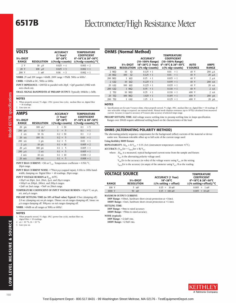
LOW
LE
VE
L M
EA
SU
RE
& S
OU
RC
E
6517b Electrometer/High Resistance Meter
VolTs aCCuraCY TEMPEraTurE (1 Year)1 CoEffICIENT 5½-DIGIT 18°–28°C 0°–18°C & 28°–50°C raNGE rEsoluTIoN ±(%rdg+counts) ±(%rdg+counts)/°C 2 V 10 µV 0 .025 + 4 0 .003 + 2 20 V 100 µV 0 .025 + 3 0 .002 + 1 200 V 1 mV 0 .06 + 3 0 .002 + 1
NMRR: 2V and 20V ranges >60dB, 200V range >55dB . 50Hz or 60Hz2 .
CMRR: >120dB at DC, 50Hz or 60Hz .
INPUT IMPEDANCE: >200TW in parallel with 20pF, <2pF guarded (1MW with zero check on) .
SMALL SIGNAL BANDWIDTH AT PREAMP OUTPUT: Typically 100kHz (–3dB) .
NoTEs1 . When properly zeroed, 5½-digit, 1 PLC (power line cycle), median filter on, digital filter
= 10 readings .2 . Line sync on .
aMPs aCCuraCY TEMPEraTurE (1 Year)1 CoEffICIENT 5½-DIGIT 18°–28°C 0°–18°C & 28°–50°C raNGE rEsoluTIoN ±(%rdg+counts) ±(%rdg+counts)/°C 20 pA 100 aA 2 1 + 30 0 .1 + 5 200 pA 1 fA 2 1 + 5 0 .1 + 1 2 nA 10 fA 0 .2 + 30 0 .1 + 2 20 nA 100 fA 0 .2 + 5 0 .03 + 1 200 nA 1 pA 0 .2 + 5 0 .03 + 1 2 µA 10 pA 0 .1 + 10 0 .005 + 2 20 µA 100 pA 0 .1 + 5 0 .005 + 1 200 µA 1 nA 0 .1 + 5 0 .005 + 1 2 mA 10 nA 0 .1 + 10 0 .008 + 2 20 mA 100 nA 0 .1 + 5 0 .008 + 1
INPUT BIAS CURRENT: <3fA at TCAL . Temperature coefficient = 0 .5fA/°C, 20pA range .
INPUT BIAS CURRENT NOISE: <750aA p-p (capped input), 0 .1Hz to 10Hz band-width, damping on . Digital filter = 40 readings, 20pA range .
INPUT VOLTAGE BURDEN at TCAL ±1°C: <20µV on 20pA, 2nA, 20nA, 2µA, and 20µA ranges . <100µV on 200pA, 200nA, and 200µA ranges . <2mV on 2mA range . <5mV on 20mA range .
TEMPERATURE COEFFICIENT OF INPUT VOLTAGE BURDEN: <10µV/°C on pA, nA, and µA ranges .
PREAMP SETTLING TIME (to 10% of final value) Typical: 0 .5sec (damping off) 2 .0 sec (damping on) on pA ranges . 15msec on nA ranges damping off, 1msec on µA ranges damping off . 500µsec on mA ranges damping off .
NMRR: >60dB on all ranges at 50Hz or 60Hz3 .
NoTEs1 . When properly zeroed, 5½-digit, 1PLC (power line cycle), median filter on,
digital filter = 10 readings .2 . aA = 10–18A, fA = 10–15A .3 . Line sync on .
oHMs (Normal Method) TEMPEraTurE aCCuraCY1 CoEffICIENT (10–100% range) (10–100% range) 5½-DIGIT 18°–28°C (1 Year) 0°–18°C & 28°–50°C auTo aMPs raNGE rEsoluTIoN ±(% rdg+counts) ±(% rdg+counts) V sourCE raNGE 2 MW 10 W 0 .125 + 1 0 .01 + 1 40 V 200 µA 20 MW 100 W 0 .125 + 1 0 .01 + 1 40 V 20 µA 200 MW 1 kW 0 .15 + 1 0 .015 + 1 40 V 2 µA 2 GW 10 kW 0 .225 + 1 0 .035 + 1 40 V 200 nA 20 GW 100 kW 0 .225 + 1 0 .035 + 1 40 V 20 nA 200 GW 1 MW 0 .35 + 1 0 .110 + 1 40 V 2 nA 2 TW 10 MW 0 .35 + 1 0 .110 + 1 400 V 2 nA 20 TW 100 MW 1 .025 + 1 0 .105 + 1 400 V 200 pA 200 TW 1 GW 1 .15 + 1 0 .125 + 1 400 V 20 pA
NoTEs1 . Specifications are for auto V-source ohms, when properly zeroed, 5½-digit, 1PLC, median filter on, digital filter = 10 readings . If
user selectable voltage is required, use manual mode . Manual mode displays resistance (up to 1018W) calculated from measured current . Accuracy is equal to accuracy of V-source plus accuracy of selected Amps range .
PREAMP SETTLING TIME: Add voltage source settling time to preamp settling time in Amps specification . Ranges over 20GW require additional settling based on the characteristics of the load .
oHMs (alTErNaTING PolarITY METHoD)The alternating polarity sequence compensates for the background (offset) currents of the material or device
under test . Maximum tolerable offset up to full scale of the current range used .
Using Keithley 8009 fixture
REPEATABILITy: ∆IBG × R/VALT + 0 .1% (1σ) (instrument temperature constant ±1°C) .
ACCURACy: (VSRCErr + IMEASErr × R)/VALT
where: ∆IBG is a measured, typical background current noise from the sample and fixture .
VALT is the alternating polarity voltage used .
VSRCErr is the accuracy (in volts) of the voltage source using VALT as the setting .
IMEASErr is the accuracy (in amps) of the ammeter using VALT /R as the reading .
VolTaGE sourCE TEMPEraTurE aCCuraCY (1 Year) CoEffICIENT 5½-DIGIT 18°–28°C 0°–18°C & 28°–50°C raNGE rEsoluTIoN ±(% setting + offset) ±(% setting+offset)/°C 100 V 5 mV 0 .15 + 10 mV 0 .005 + 1 mV 1000 V 50 mV 0 .15 + 100 mV 0 .005 + 10 mV
MAXIMUM OUTPUT CURRENT: 100V Range: ±10mA, hardware short circuit protection at <14mA . 1000V Range: ±1mA, hardware short circuit protection at <1 .4mA .
SETTLING TIME: 100V Range: <8ms to rated accuracy . 1000V Range: <50ms to rated accuracy .
NOISE (typical): 100V Range: <2 .6mV rms . 1000V Range: <2 .9mV rms .
Mod
el 6
517B
spe
cific
atio
ns
Mod
el 6
517B
spe
cific
atio
ns
150 Test Equipment Depot - 800.517.8431 - 99 Washington Street Melrose, MA 02176 - TestEquipmentDepot.com
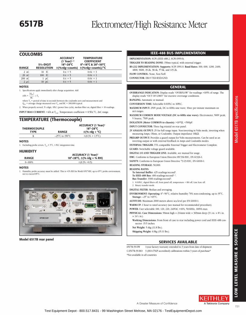
LOW
LE
VE
L M
EA
SU
RE
& S
OU
RC
E
A Greater Measure of Confidence
6517b Electrometer/High Resistance Meter
IEEE-488 bus IMPlEMENTaTIoNIMPLEMENTATION: SCPI (IEEE-488 .2, SCPI-1999 .0) .
TRIGGER TO READING DONE: 150ms typical, with external trigger .
RS-232 IMPLEMENTATION: Supports: SCPI 1991 .0 . Baud Rates: 300, 600, 1200, 2400, 4800, 9600, 19 .2k, 38 .4k, 57 .6k, and 115 .2k .
FLOW CONTROL: None, Xon/Xoff .
CONNECTOR: DB-9 TXD/RXD/GND .
GENEralOVERRANGE INDICATION: Display reads “OVERFLOW” for readings >105% of range . The
display reads “OUT OF LIMIT” for excesive overrange conditions .
RANGING: Automatic or manual .
CONVERSION TIME: Selectable 0 .01PLC to 10PLC .
MAXIMUM INPUT: 250V peak, DC to 60Hz sine wave; 10sec per minute maximum on mA ranges .
MAXIMUM COMMON MODE VOLTAGE (DC to 60Hz sine wave): Electrometer, 500V peak; V Source, 750V peak .
ISOLATION (Meter COMMON to chassis): >1010W, <500pF .
INPUT CONNECTOR: Three lug triaxial on rear panel .
2V ANALOG OUTPUT: 2V for full range input . Non-inverting in Volts mode, inverting when measuring Amps, Ohms, or Coulombs . Output impedance 10kW .
PREAMP OUTPUT: Provides a guard output for Volts measurements . Can be used as an inverting output or with external feedback in Amps and Coulombs modes .
EXTERNAL TRIGGER: TTL compatible External Trigger and Electro meter Complete .
GUARD: Switchable voltage guard available .
DIGITAL I/O AND TRIGGER LINE: Available, see manual for usage .
EMC: Conforms to European Union Directive 89/336/EEC, EN 61326-1 .
SAFETy: Conforms to European Union Directive 73/23/EEC, EN 61010-1 .
READING STORAGE: 50,000 .
READING RATES: To Internal Buffer: 425 readings/second1 . To IEEE-488 Bus: 400 readings/second1, 2 . Bus Transfer: 3300 readings/second2 .1 . 0 .01PLC, digital filters off, front panel off, temperature + RH off, Line Sync off .2 . Binary transfer mode .
DIGITAL FILTER: Median and averaging .
ENVIRONMENT: Operating: 0°–50°C; relative humidity 70% non-condensing, up to 35°C . Storage: –25° to +65°C .
ALTITUDE: Maximum 2000 meters above sea level per EN 61010-1 .
WARM-UP: 1 hour to rated accuracy (see manual for recommended procedure) .
POWER: User selectable 100, 120, 220, 240VAC ±10%; 50/60Hz, 100VA max .
PHySICAL: Case Dimensions: 90mm high × 214mm wide × 369mm deep (3½ in . × 8½ in . × 14½ in .) .
Working Dimensions: From front of case to rear including power cord and IEEE-488 con-nector: 15 .5 inches .
Net Weight: 5 .4kg (11 .8 lbs .) .
Shipping Weight: 6 .9kg (15 .11 lbs .) .
CouloMbs aCCuraCY TEMPEraTurE (1 Year)1, 2 CoEffICIENT 5½-DIGIT 18°–28°C 0°–18°C & 28°–50°C raNGE rEsoluTIoN ±(%rdg+counts) ±(%rdg+counts)/°C 2 nC 10 fC 0 .4 + 5 0 .04 + 3 20 nC 100 fC 0 .4 + 5 0 .04 + 1 200 nC 1 pC 0 .4 + 5 0 .04 + 1 2 µC 10 pC 0 .4 + 5 0 .04 + 1
NoTEs1 . Specifications apply immediately after charge acquisition . Add |QAV|
(4fA + _____ ) TA RC
where TA = period of time in seconds between the coulombs zero and meas urement and QAV = average charge measured over TA, and RC = 300,000 typical .
2 . When properly zeroed, 5½-digit, 1PLC (power line cycle), median filter on, digital filter = 10 readings .
INPUT BIAS CURRENT: <4fA at TCAL . Temperature coefficient = 0 .5fA/°C, 2nC range .
TEMPEraTurE (Thermocouple)
aCCuraCY (1 Year)1 THErMoCouPlE 18°–28°C TYPE raNGE ±(% rdg + °C) K –25°C to 150°C ±(0 .3% + 1 .5°C)
NoTEs1 . Excluding probe errors, Tcal ± 5°C, 1 PLC integration time .
HuMIDITY aCCuraCY (1 Year)1 raNGE 18°–28°C, ±(% rdg + % rH) 0–100% ±(0 .3% +0 .5)
NoTEs1 . Humidity probe accuracy must be added . This is ±3% RH for Model 6517-RH, up to 65°C probe environment,
not to exceed 85°C .
sErVICEs aVaIlablE6517B-3Y-EW 1-year factory warranty extended to 3 years from date of shipment
C/6517B-3Y-ISO 3 (ISO-17025 accredited) calibrations within 3 years of purchase*
*Not available in all countries
Model 6517b rear panel
Mod
el 6
517B
spe
cific
atio
ns
Mod
el 6
517B
spe
cific
atio
ns
151 Test Equipment Depot - 800.517.8431 - 99 Washington Street Melrose, MA 02176 - TestEquipmentDepot.com

LOW
LE
VE
L M
EA
SU
RE
& S
OU
RC
E
Two optional 10-channel plug-in scanner cards are available to extend the measurement performance of the Model 6517B Electrometer/High Resistance Meter . The cards install directly into the option slot in the back panel of the Model 6517B . The cards are also compatible with the Models 6517A and 6517 .
The Model 6521 Low Current Scanner Card is a 10-channel multiplexer, designed for switching low currents in multipoint testing applications or when the test configuration must be changed . Offset current on each channel is <1pA and high isolation is maintained between each channel (>1015W) . The Model 6521 main tains the current path even when the channel is deselected, making it a true current switch . BNC input con nectors help provide shielding for sensitive measurements and make the card compatible with low noise co axial cables . The Model 6521 is well suited for automating reverse leakage tests on semiconductor junc tions or gate leakage tests on FETs .
The Model 6522 Voltage/Low Current Scanner Card can provide up to ten channels of low-level current, high impedance voltage, high resistance, or charge switching . Although it is similar to the Model 6521 in many ways, the Model 6522’s input connectors are 3-lug triax . The card can be soft-ware configured for high im pe dance voltage switching of up to 200V . Triaxial connectors make it possible to float the card 500V above ground and drive guard to 200V .
• 10 channels of multiplex switching
• Install directly in 6517b’s option slot
• Choose from low current scanning or high impedance voltage switching with low current switching
• <200µV contact potential
• <1pa offset current
• Compatible with Keithley’s Model 6517 and 6517a Electrometers
ordering Information6521 low Current,
10-channel scanner Card
6522 low Current, High Impedance Voltage, High resistance, 10-channel scanner Card
MoDEl 6521 sPECIfICaTIoNsCHANNELS PER CARD: 10 .
FUNCTIONS: Amps .
CONTACT CONFIGURATION: Single pole, “break-before-make” for signal HI input . Signal LO is common for all 10 channels and output . When a channel is off, sig nal HI is connected to signal LO .
CONNECTOR TyPE: Inputs BNC, Outputs Triaxial .
SIGNAL LEVEL: 30V, 500mA, 10VA (resistive load) .
CONTACT LIFE: >106 closures at maximum signal level; >107 closures at low signal levels .
CONTACT RESISTANCE: <1W .
CONTACT POTENTIAL: <200µV .
OFFSET CURRENT: <1pA (<30fA typical at 23°C, <60% RH) .
ACTUATION TIME: 2ms .
COMMON MODE VOLTAGE: <30V peak .
ENVIRONMENT: Operating: 0° to 50°C up to 35°C at 70% R .H . Storage: –25° to 65°C .
MoDEl 6522 sPECIfICaTIoNsCHANNELS PER CARD: 10 .
FUNCTIONS: Volts, Amps .
CONTACT CONFIGURATION: Single pole, “break-before-make” for signal HI input . Signal LO is common for all 10 channels and output . When a channel is off, signal HI is connected to signal LO . 6517B can also configure chan-nels as voltage switches .
CONNECTOR TyPE: Inputs: Triaxial . Outputs: Triaxial .
SIGNAL LEVEL: 200V, 500mA, 10VA (resistive load) .
CONTACT LIFE: >106 closures at maximum signal level; >107 closures at low signal levels .
CONTACT RESISTANCE: <1W .
CONTACT POTENTIAL: <200µV .
OFFSET CURRENT: <1pA (<30fA typical at 23°C, <60% RH) .
CHANNEL ISOLATION: >1013W, <0 .3pF .
INPUT ISOLATION: >1010W, <125pF (Input HI to Input LO) .
ACTUATION TIME: 2ms .
COMMON MODE VOLTAGE: <300V peak .
ENVIRONMENT: Operating: 0° to 50°C up to 35°C at 70% R .H . Storage: –25° to 65°C .
OUT
H
L
H
LIN 1
H
LIN 10
IN 2...9
G
OUT
H
L
H
L IN 1
H
L IN 10
IN 2...9
G
G
G
6521 6522
Low Current, 10-channelScanner Cards for 6517B
sErVICEs aVaIlablE6521-3Y-EW 1-year factory warranty extended to 3 years
from date of shipment
6522-3Y-EW 1-year factory warranty extended to 3 years from date of shipment
Conv
enie
nt p
lug-
in s
cann
er c
ards
for t
he M
odel
651
7B/6
517A
Conv
enie
nt p
lug-
in s
cann
er c
ards
for t
he M
odel
651
7B/6
517A
152 Test Equipment Depot - 800.517.8431 - 99 Washington Street Melrose, MA 02176 - TestEquipmentDepot.com

LOW
LE
VE
L M
EA
SU
RE
& S
OU
RC
E
A Greater Measure of Confidence
The equipment configuration with manual switching (above) was developed for very high resistance van der Pauw or Hall Effect measurements. This measurement system includes a Model 6220 current source, two Model 6514 electrometers (used as unity-gain buffers), and a Model 2000 digital multimeter (DMM). The current source has a built-in guard, which minimizes the time constant of the current source and cable. The insulation resistance of the leads and supporting fixtures for the sample should be at least 100 times the DuT resistance (r). The entire sample holder must be shielded to avoid electrostatic pickup. If the sample is in a dewar, this should be part of the shield.
The Model 6220 Current source offers material researchers ±0.1pa/step to ±105ma DC output, combined with 1014W output resistance.
The Model 6514 Electrometer provides >200TW input impedance and <3fa input bias current.
The Model 2000 6½-Digit Multimeter provides 0.1µV of sensitivity.
The Model 7001 switch/Control Mainframe controls the 7152 4×5 low Current Matrix Card, which provides contacts with <1pa offset current.
R
R
R R
HI
LO
R = 1TΩ
DUT
2000DMM
6514
6514
6220 V
HI
1 2
4 3HI
LO
LO
Preamp Out
Preamp Out
HI
LO
V2
V1
one Model 7152 Matrix Card, housed in a Model 7001 mainframe, is used to connect the electrometers and the current source to the sample. Two Model 6514 electrometers are used as unity gain buffers, and their output difference is measured with a Model 2000 DMM. To ensure faster measurement time, guarded measurements are made by turning the Guard switch oN for both of the Model 6514s, and by guarding the Model 6220 output. Call Keithley’s applications Department for cabling information.
6514
DUT
6514
2000HI
LO
PreampOut
PreampOut
6220
HI
LO
HI
LO
HI
LO
1 3
2
4
1 2 3 4 5
1
2
3
47152 Low Current Matrix Card
in 7001 Mainframe
alternative Eco nom i cal ap proach es to Heall Coefficient and resistivity MeasurementsOccasionally, when working with samples with very high resistivity, semi-insulating GaAs, and similar materials with resistivities above 108W, alternative system configurations may be able to produce more reliable data than stan-dard, pre-configured Hall Effect systems . Such systems demand careful shielding and guard ing, and typically include a current source, two electrometer buffers, and an isolated voltmeter . The schemat-ics show two suggested con fig u ra tions for these high resistivity applications: one that requires manual switching and one with automated switching .
The range of the systems shown here is very wide . The high resistance end is limited by the minimum output of the current source . A current of 100pA can be supplied with an accuracy of about 2% . If the resistance of each leg of the sample is no more than 1TW, the maximum voltage developed will be 100V, within the range of the Model 6220 current source and the Model 6514 electrometer . This system will provide good results with samples as low as 1W per leg, if a test current level of 100mA is acceptable . Even at 100mW per leg, accuracy is approximately 2% .
Leakage currents are the most important sources of error, especially at very high resistances . One important advantage of this circuit is that a guard voltage is avail able for three of the sample termi-nals, which virtually eliminates both leakage currents and line capacitance . The fourth terminal is at circuit LO or ground potential and does not need guarding .
Call Keithley for additional guidance in selecting equipment for specific high resistivity applications .
ordering Information6220 DC Current source6514 Programmable
Electrometer2000 Digital Multimeter
options7001 switch system 7152 4×5 low Current
Matrix Card
aCCEssorIEs aVaIlablE7007-1 Shielded IEEE-488 Cable, 1m (3 .3 ft)
7007-2 Shielded IEEE-488 Cable, 2m (6 .6 ft)
7078-TRX-10 Triax Cable, 3m (10 ft)
KPCI-488LPA IEEE-488 Interface/Controller for the PCI Bus
KUSB-488B IEEE-488 USB-to-GPIB Interface Adapter
6220/6514/ 2000/7001
High Impedance Semiconductor Resistivity and Hall Effect Test Configurations
Hal
l Effe
ct s
yste
ms
for h
igh
resi
stiv
ity a
pplic
atio
ns
Hal
l Effe
ct s
yste
ms
for h
igh
resi
stiv
ity a
pplic
atio
ns
153 Test Equipment Depot - 800.517.8431 - 99 Washington Street Melrose, MA 02176 - TestEquipmentDepot.com

LOW
LE
VE
L M
EA
SU
RE
& S
OU
RC
E
• bEsT IN Class PErforMaNCE
• 50MHz sine wave frequency
• 25MHz square wave frequency
• arbitrary waveform generator with 256k-point, 14-bit resolution
• built-in function generator capability includes: sine, square, triangle, noise, DC, etc.
• Precision pulses and square waves with fast (5ns) rise/fall times
• built-in 10MHz external time base for multiple unit synchronization
• built-in aM, fM, PM, fsK, PWM modulation
• frequency sweep and burst capability
• Waveform creation software, KiWaVE, included
• lXI Class C compliance
Keithley has paired the best-in-class performance of the Model 3390 Arbitrary Waveform/Function Generator with the best price in the industry to provide your applications with superior wave-form generation functionality and flexibility at an unparalleled price .
From its fully featured Arbitrary Waveform Generator (ARB) to its high speed and ease-of-use, the Model 3390 is a complete signal genera-tion solution for all your waveform application needs up to 50MHz .
Versatile Waveform Creation CapabilitiesThe Model 3390 generates highly stable and accurate waveforms that allow you to create almost any desired shape . It uses direct digital
synthesis (DDS) techniques to achieve this level of performance and functionality .
The exceptional signal quality of the Model 3390 is a result of its high resolution, fast rise and fall times, and deep memory . This combined with its low price makes it the ideal solution for applications that use the 50MHz bandwidth and below . Lower speed instruments cannot provide the signal accu-racy of the Model 3390, even at bandwidths they were specifically designed for .
arbitrary Waveform Generation (arb)With the Model 3390, you can precisely replicate real world signals . This 14-bit ARB provides the ability to define waveforms with up to 256,000 data points and generate them at a sampling rate of 125MSamples/second . For ease of use, up to four user-defined waveforms can be stored in the onboard non-volatile memory .
function GenerationStandard output waveforms can be created by pressing one button on the front panel . Ten standard waveforms are provided, including the basic sine, square, ramp, and triangle shapes . The Model 3390 offers the highest repetition rates of any instrument in its class, allowing you to better emulate the signals you need to test .
Pulse GenerationPulse capabilities have become critically important as devices being tested have become smaller, more sensitive, and more complex . To accurately duplicate the signals these tiny devices receive, very clean pulses with crisp edges are mandatory, which is why the Model 3390 offers the fastest rise time (5ns) and cleanest pulse shapes for this class of instrument .
Modulating WaveformsThe ability of the Model 3390 to modulate at high internal frequencies allows you to accu-rately simulate real-world conditions . Modulate any of your signals with the built-in AM, FM, PM, PWM, or FSK source, or use your own external modulation source .
Noise GenerationInject noise into your device under test with the press of a button . The adjustable amplitude and offset parameters control how much or how little noise is produced . The fast rise times and high speed capability provides the precise noise simulation your applications require .
3390 50MHz Arbitrary Waveform/Function Generator
The faster rise time results in cleaner pulses.
50M
Hz
arbi
trary
wav
efor
m/f
unct
ion
gene
rato
r
50M
Hz
arbi
trary
wav
efor
m/f
unct
ion
gene
rato
r
154 Test Equipment Depot - 800.517.8431 - 99 Washington Street Melrose, MA 02176 - TestEquipmentDepot.com

LOW
LE
VE
L M
EA
SU
RE
& S
OU
RC
E
A Greater Measure of Confidence
3390 50MHz Arbitrary Waveform/Function Generator
The 20MHz noise bandwidth of the Model 3390 is 2× better than the competition’s.
Pattern GenerationThe Model 3390 is the only instrument in its class with a Digital Pattern mode . It provides the ability to transmit arbitrary 16-bit patterns via a multi-pin connector located on the rear panel of the instrument . This feature can be used for applications such as testing clock and data sig-nals directly, sending simple protocols to devices under test, and simulating simple control func-tions . With Keithley’s KiWAVE software package, you can easily create complex and long patterns, which the Model 3390 can generate at varying speeds and amplitudes .
10MHz External reference Expands flexibilityThe built-in 10MHz external time base is includ-ed at no extra cost . This external time base makes it simple to control multiple instruments from the same source, connect multiple Model
3390s together, and synchronize multiple signals of any shape .
Ease of useThis instrument is easy to use . In most cases, pressing one button on the front panel or per-forming one or two mouse clicks on your PC is all that is necessary to generate or modify a waveform . The KiWAVE software package helps you define and manage waveforms, apply filters to waveforms, and display waveforms on a PC . In addition, the GPIB, USB, LAN, and LXI interfaces can connect the Model 3390 to most devices under test, instruments, and test fixtures .
KiWaVE Waveform Editing utility
lXI Class C ComplianceThe Model 3390 supports the physical, program-mable, LAN, and Web portions of the emerging LAN eXtensions for Instrumentation (LXI) stan-dard . The instrument can be monitored and con-trolled from any location on the LAN network via its LXI Web page .
Model 3390 rear panel
ordering Information3390 50MHz arbitrary
Waveform/function Generator
accessories suppliedarbitrary Waveform Generator with power cordone universal serial bus (usb) cable (usb-b-1)one pattern generator cable (005-003-00003)one Ethernet crossover cable (Ca-180-3a)CD-roM containing user’s manual
aCCEssorIEs aVaIlablE4299-3 Single Rack Mount Kit
4299-4 Dual Rack Mount Kit
7755 50W Feed Through Terminator
7051-2 General Purpose BNC to BNC Cable (2ft)
7007-1 Shielded GPIB Cable, 1m
USB-B-3 USB cable, Type A to Type B, 3m (10ft)
KPCI-488LPA IEEE-488 Interface/Controller for the PCI bus
KUSB-488B IEEE-488 USB-to-GPIB Interface Adapter
sErVICEs aVaIlablE3390-3Y-EW 1-year factory warranty extended to 3 years
from date of shipment
C/3390-3Y-DATA 3 (Z540-1 compliant) calibrations within 3 years of purchase*
*Not available in all countries
50M
Hz
arbi
trary
wav
efor
m/f
unct
ion
gene
rato
r
50M
Hz
arbi
trary
wav
efor
m/f
unct
ion
gene
rato
r
155 Test Equipment Depot - 800.517.8431 - 99 Washington Street Melrose, MA 02176 - TestEquipmentDepot.com

LOW
LE
VE
L M
EA
SU
RE
& S
OU
RC
E
3390 50MHz Arbitrary Waveform/Function Generator
DISPLAy: Graph mode for visual verification of signal settings .
CAPABILITy: Standard Waveforms: Sine, Square, Ramp, Triangle, Pulse, Noise, DC . Built-in Arbitrary Waveforms: Exponential Rise and Fall, Negative ramp, Sin(x)/x, Cardiac .
Waveform Characteristics
sINEFREQUENCy: 1µHz to 50MHz .
AMPLITUDE FLATNESS 1, 2 0 .1dB (<100kHz)(Relative to 1kHz): 0 .15dB (<5MHz)
0 .3dB (<20MHz) 0 .5dB (<50MHz) .
HARMONIC DISTORTION 2, 3 (Unit: dBc): DC to 20kHz: –65(<1Vpp) –65(≥1Vpp) 20kHz to 100kHz: –65(<1Vpp) –60(≥1Vpp) 100kHz to 1MHz: –50(<1Vpp) –45(≥1Vpp) 1MHz to 20MHz: –40(<1Vpp) –35(≥1Vpp) 20MHz to 50MHz: –30(<1Vpp) –30(≥1Vpp) .
TOTAL HARMONIC DISTORTION 2, 3: DC to 20kHz, V ≥ 0 .5Vpp THD ≤ 0 .06% (typical) .
SPURIOUS 2, 4 (non–harmonic): DC to 1MHz: –70dBc . 1MHz to 50MHz: –70dBc + 6dB/octave .
PHASE NOISE (10K Offset): –115 dBC/Hz, typical when f ≥ 1MHz, V ≥ 0 .1Vpp .
sQuarEFREQUENCy: 1µHz to 25MHz .
RISE/FALL TIME: <10ns .
OVERSHOOT: <2% .
VARIABLE DUTy CyCLE: 20% to 80% (to 10MHz), 40% to 60% (to 25MHz) .
ASyMMETRy: 1% of period + 5ns (@ 50% duty) .
jITTER (RMS): 1ns + 100ppm of period .
raMP, TrIaNGlEFREQUENCy: 1µHz to 200kHz .
LINEARITy: <0 .1% of peak output .
SyMMETRy: 0 .0% ~ 100 .0% .
PulsEFREQUENCy: 500µHz to 10MHz .
PULSE WIDTH: 20ns minimum, 10ns res . (period ≤10s) .
VARIABLE EDGE TIME: <10ns to 100ns .
OVERSHOOT: <2% .
jITTER (RMS): 300ps + 0 .1ppm of period .
NoIsEBANDWIDTH: 20MHz typical .
arbITrarYFREQUENCy: 1µHz to 10MHz .
LENGTH: 2 to 256K .
RESOLUTION: 14 bits (including sign) .
SAMPLE RATE: 125Msamples/s .
MIN RISE/FALL TIME: 30ns typical .
LINEARITy: <0 .1% of peak output .
SETTLING TIME: <250ns to 0 .5% of final value .
jITTER(RMS): 6ns + 30ppm .
NON-VOLATILE MEMORy: 4 waveforms * 256K points .
CoMMoN CHaraCTErIsTICFREQUENCy RESOLUTION: 1µHz .
AMPLITUDE RANGE: 10mVpp to 10Vpp in 50W 20mVpp to 20Vpp in Hi-Z .
AMPLITUDE ACCURACy 1, 2 (at 1kHz): ±1% of setting ±1mVpp .
AMPLITUDE UNITS: Vpp, Vrms, dBm .
AMPLITUDE RESOLUTION: 4 digits .
DC OFFSET RANGE (Peak AC + DC): ±5V in 50W, ±10V in Hi-Z .
DC OFFSET ACCURACy 1, 2
±2% of offset setting, ±0 .5% of amplitude setting .
DC OFFSET RESOLUTION: 4 digits .
MAIN OUTPUT IMPEDANCE: 50W typical .
MAIN OUTPUT ISOLATION: 42Vpk maximum to earth .
MAIN OUTPUT PROTECTION: Short-circuit protected; over-load automatically disables main output .
INTERNAL FREQUENCy REFERENCE ACCURACy 5: ±10ppm in 90 days, ±20ppm in 1 year .
EXTERNAL FREQUENCy REFERENCE STANDARD/OPTION: Standard .
EXTERNAL FREQUENCy INPUT: Lock Range: 10MHz ±500Hz . Level: 100mVpp ~ 5Vpp . Impedance: 1kW typical, AC coupled . Lock Time: <2 seconds .
EXTERNAL LOCK RANGE: 10MHz .
FREQUENCy OUTPUT: Level: 632mVpp (0dBm), typical . Impedance: 50W typical, AC coupled .
PHASE OFFSET: Range: –360° to +360° . Resolution: 0 .001° . Accuracy: 8ns .
MoDulaTIoNMODULATION TyPE: AM, FM, PM, FSK, PWM, Sweep,
and Burst .
aMCARRIER: Sine, Square, Ramp, ARB .
SOURCE: Internal/External .
INTERNAL MODULATION: Sine, Square, Ramp, Triangle, Noise, ARB .
FREQUENCy (Internal): 2mHz to 20kHz .
DEPTH: 0 .0% ~ 120 .0% .
fMCARRIER: Sine, Square, Ramp, ARB .
SOURCE: Internal/External .
INTERNAL MODULATION: Sine, Square, Ramp, Triangle, Noise, ARB .
FREQUENCy (Internal): 2mHz to 20kHz .
DEVIATION: DC ~ 25MHz .
PMCARRIER: Sine, Square, Ramp, ARB .
SOURCE: Internal/External .
INTERNAL MODULATION: Sine, Square, Ramp, Triangle, Noise, ARB .
FREQUENCy (INTERNAL): 2mHz to 20kHz .
DEVIATION: 0 .0° to 360° .
PWMCARRIER: Pulse .
SOURCE: Internal/External .
INTERNAL MODULATION: Sine, Square, Ramp, Triangle, Noise, ARB .
FREQUENCy (INTERNAL): 2mHz to 20kHz .
DEVIATION: 0% ~ 100% of pulse width .
fsKCARRIER: Sine, Square, Ramp, ARB .
SOURCE: Internal/External .
INTERNAL MODULATION: 50% duty cycle Square .
FREQUENCy (INTERNAL): 2mHz to 100kHz .
EXTErNal MoDulaTIoN INPuT6
VOLTAGE RANGE: ±5V full scale .
INPUT RESISTANCE: 8 .7kW typical .
BANDWIDTH: DC to 20kHz .
sWEEPWAVEFORMS: Sine, Square, Ramp, ARB .
TyPE: Linear or logarithmic .
DIRECTION: Up or down .
SWEEP TIME: 1ms ~ 500s .
TRIGGER: Internal, External, or Manual .
MARKER: Falling edge of sync signal (programmable frequency) .
specifications
Mod
el 3
390
spec
ifica
tions
Mod
el 3
390
spec
ifica
tions
156 Test Equipment Depot - 800.517.8431 - 99 Washington Street Melrose, MA 02176 - TestEquipmentDepot.com

LOW
LE
VE
L M
EA
SU
RE
& S
OU
RC
E
A Greater Measure of Confidence
3390 50MHz Arbitrary Waveform/Function Generator
GENEralPOWER SUPPLy: CAT II 110–240VAC ±10% .
POWER CORD FREQUENCy: 50Hz to 60Hz .
POWER CONSUMPTION: 50VA max .
OPERATING ENVIRONMENT: 0° to 50°C .
STORAGE TEMPERATURE: –30° to 70°C .
INTERFACE: USB, LAN, LXI-C, GPIB .
LANGUAGE: SCPI-1993, IEEE-488 .2 .
DIMENSIONS: 107mm high × 224mm wide × 380mm deep (4 .2 in . × 8 .8 in . × 15 in .) .
WEIGHT: 4 .08kg .
SAFETy: Conforms with European Union Directive 73/23/EEC, EN 61010-1 .
EMC: Conforms with European Union Directive 89/336/EEC, EN 61326-1 .
WARM-UP: 1 hour .
NoTEs1 . Add 10%/°C of spec for offset and amplitude for operation outside the
range of 18° to 28°C .2 . Autorange enabled .3 . DC offset set to 0V .4 . Spurious output at low amplitude is –75dBm typical .5 . Add 1ppm/°C average for operation outside the range of 18° to 28°C .6 . FSK uses trigger input (1MHz maximum) .7 . Sine and square waveforms above 10MHz are allowed only with an
“infinite” burst count .
bursT7
WAVEFORMS: Sine, Square, Ramp, Triangle, Noise, ARB .
TyPE: Internal/External .
START/STOP PHASE: –360° to +360° .
INTERNAL PERIOD: 1µs ~ 500s .
GATED SOURCE: External trigger .
TRIGGER SOURCE: Internal, External, or Manual .
TrIGGEr INPuTLEVEL: TTL compatible .
SLOPE: Rising or falling (selectable) .
PULSE WIDTH: >100ns .
IMPEDANCE: >10kW, DC coupled .
LATENCy: <500ns .
TrIGGEr ouTPuTLEVEL: TTL compatible into ≥1kW.
PULSE WIDTH: >400ns .
OUTPUT IMPEDANCE: 50W typical .
MAXIMUM RATE: 1MHz .
FAN-OUT: ≤4 Keithley 3390s .
PaTTErN MoDECLOCK MAXIMUM RATE: 50MHz .
OUTPUT: Level: TTL compatible into ≥2kW. Output Impedance: 110W typical .
PATTERN LENGTH: 2 to 256K .
Mod
el 3
390
spec
ifica
tions
Mod
el 3
390
spec
ifica
tions
157 Test Equipment Depot - 800.517.8431 - 99 Washington Street Melrose, MA 02176 - TestEquipmentDepot.com

LOW
LE
VE
L M
EA
SU
RE
& S
OU
RC
E
158 Test Equipment Depot - 800.517.8431 - 99 Washington Street Melrose, MA 02176 - TestEquipmentDepot.com

SW
ITC
HIN
G A
ND
CO
NTR
OL
A Greater Measure of Confidence
Technical Information . . . . . . . . . . . . . . . . . . . . . . . 160
series 3700a System Switch/Multimeter and Plug-In Cards . . . . 162
selector Guide Plug-In Cards and Accessories for Series 3700A . . 172
Plug-In Cards for Series 3700A . . . . . . . . . . . . 174–195
7001 80-channel Switch/Control Mainframe . . . . . . . . . 198
7002 400-channel Switch/Control Mainframe . . . . . . . . 200
selector Guide Switch Cards for 7001, 7002 . . . . . . . . . . . . . . 202–203
selector Guide Switch Card Accessories for 7001, 7002 . . . . . . . . 203
Switch Cards for 7001, 7002 . . . . . . . . . . . . . . 204–213
707b Six-slot Semiconductor Switching Matrix Mainframe . . . . . . . . . . . . . . . . . . 214
708b Single-slot Semiconductor Switching Matrix Mainframe . . . . . . . . . . . . . . . . . . 214
selector Guide Switch Cards and Accessories for 707B, 708B . . . 219
Switch Cards for 707B, 708B . . . . . . . . . . . . . 219–223
system 46 32-channel, Unterminated, RF/Microwave Switch System . . . . . . . . . . . . . . . . . . . . . . . . . . . . . 224
system 46T 32-channel, Terminated, RF/Microwave Switch System . . . . . . . . . . . . . . . . . . . . . . . . . . . . . 227
Switching and Control
159 Test Equipment Depot - 800.517.8431 - 99 Washington Street Melrose, MA 02176 - TestEquipmentDepot.com

SW
ITC
HIN
G A
ND
CO
NTR
OL
Technical Information
Switching and Control
Achieving required system accuracies and precision requires selection of appropriate instruments, creativity in designing test methods, and careful attention to specifications and error terms . Most test system designs are complex enough that it is in the designer’s best interest to minimize the number of uncontrolled variables . To accomplish this, the system switch performance should be tightly specified .
Special consideration should be given to tests that approach the specified limits of accuracy, resolu-tion, or sensitivity of the measurement or sourcing instruments . These generally represent the “most critical test requirements,” and switching should be selected to support these tests . A system designed to perform against the “most critical test require-ments” will usually satisfy other test requirements as well .
How Do I specify a switch system for My application?Whether you are designing your own switching system or preparing to contact Keithley’s applica-tions department for assistance, you need to define certain parameters for your test system and under-stand how you want everything interconnected .
First, define your parameters . This includes:
• Measurements—List all the required measurement types and accuracies .
• Sources—List all the sources required .
• Quantity—List the number of terminals on the DUT and how many devices are involved .
• Signal characteristics—List signal types, levels and frequency, and impedance requirements .
• Speed—What are the speed requirements?
• Environment—Temperature, humidity, etc .
• Communication interface—GPIB, RS-232, Ethernet, USB
Next, sketch the system . Given the number of terminals on the device and the number of instru-ments (source and measure), develop a picture of what type of switch and configuration will be needed . This is likely to be an iterative process as you identify what types of switching equipment are actually available .
Once you have done the groundwork, you are ready to configure the switching for your test system:
• Determine the appropriate switch and switch card configurations
• Select the appropriate switch system
• Select source and measure equipment
• Select cables and/or other accessories
• Identify need for fuses, limit resistors, diodes, etc .
• Determine the uncertainties and compare them with the required accuracies
switching ConfigurationsThe variety and size of switching configurations available determine the efficiency of the final switching design, including the amount and com-plexity of cabling and interconnect at the time of system integration . These are the basic building blocks of any switching system .
RS
VSDUT orMeter
Voltage SourceForm ALow output impedance• Power supplies• Function generators• Pattern generators• Amplifiers
Current SourceForm CHigh output impedance
RS
DUT orMeter
figure 2. Example switching Configurations
A switching configuration can be described by the electrical property being switched, its mechani-cal construction, or its function in the test system (Figure 2) . These descriptions of the signal paths or electrical interconnects are necessary for laying out and wiring the test system .
A matrix switch (Figure 3) is the most versatile type of system switching . But first, a word on ter-minology here — Do not confuse a switch matrix
(often called a switching mainframe) with a matrix switch . With a matrix switch, any input can be connected to any output, singly or in combination . This helps minimize the need for complex wiring and interconnect systems and can simplify the DUT interface . Although a matrix switch will work in vir-tually any switching application, it should not nec-essarily be your first choice of switch configuration .
Column 1Row 1
2
3
4
2 3 4 5
V-Source
I-Source
DMM
Electrometer
DUT
HILO
Guard
Crosspoint
figure 3. Matrix switch
Consider an example where you need to connect four different instruments to ten different test points on a device-under-test . If you need to be able to connect any combination of instruments to any combination of test points at any time, then you do need a matrix switch . But, if you only need to connect one instrument to one test point at any time, then you can combine a four-to-one multi-plexer with a one-to-ten multiplexer to make your connections . The multiplexer approach only uses 14 relays, while the full matrix uses 40 . If you sim-ply choose a matrix switch for the second example, you will end up paying for 26 relay channels you don’t need . Careful planning can result in a more compact and economical switch system .
•
Voltage/CurrentSource
PowerSupplies
Function/Pulse
Generator
Electrometer
Counter/Timer
DMM
Device Under Test
SYSTEM SWITCHING
InstrumentController
figure 1. General Purpose Test system
MeasuringDevice
DUT#2
DUT#3
DUT#1
figure 4. Multiplex switch
160
Tech
nica
l inf
orm
atio
n: S
witc
hing
and
con
trol
Tech
nica
l inf
orm
atio
n: S
witc
hing
and
con
trol
Test Equipment Depot - 800.517.8431 - 99 Washington Street Melrose, MA 02176 - TestEquipmentDepot.com

SW
ITC
HIN
G A
ND
CO
NTR
OL
A Greater Measure of Confidence
Technical Information
Switching and Control
A multiplex switch (Figure 4) connects one instru-ment to multiple devices under test or multiple instruments to one device under test . The multi-plex switch is useful in combination with matrix or other configurations to expand switching capacity by sharing electrical paths, to provide additional isolation and reduce crosstalk between channels, or to build special configurations .
MeasuringDevice
DUT#2
DUT#3
DUT#1
figure 5. scanner switch
A scanner (Figure 5) is a special case of multiplex switching in which switch closures are sequential or serial, sometimes with the capability to skip channels .
The isolated switch configuration consists of indi-vidual uncommitted relays, often with multiple poles . Isolated switches are not connected to any other circuit, and are therefore free for building very flexible and unique combinations of input/output configurations with the addition of some external wiring . This type of switch can be useful for creating additional isolation between circuits, providing safety interlock, actuating other relays or circuits, or building special topologies such as binary ladders and tree structures .
Electrical specificationsElectrical specifications of the switching cards contribute significantly to the overall performance and signal integrity in the test system . When trying to achieve high accuracy, resolution, and sensitivity or to route high frequency signals, high currents, and high voltages with minimum degradation in the test signal, the electrical performance of the switch card must be known . Match the system’s critical test requirements against the specified performance of the switch . If the requirement is to measure a one-volt reference to one microvolt, be certain that the contact potential of the switch is not hundreds of microvolts . If switching of power supply voltage is required, be certain that the switch has sufficient current carrying capacity . When measuring resis-tances of less than one kW, be certain the switch will support four-wire measurements .
The switching card specifications represent the performance of a single card . If additional cards are connected together, actual performance param-eters such as offset current and insertion loss will be a function of the entire system, not just a single card . Each extra card and connecting cable adds some degradation . It may be necessary to charac-terize the entire system (including switching) in some applications .
Figure 6 describes a few performance charac-teristics and where they apply to improve system performance . There are many other character-istics to consider, depending on the type and level of signal being switched and the expected performance from the test system . The switching selector guides group switching cards according to key performance features . Many switches actually fit into multiple categories and you should look carefully at all of the switch card specifications before making a final selection . Refer to Keithley’s Switching Handbook for a more in-depth discus-sion of switching specifications and their effect on measurement performance .
Mainframe CapabilitiesA switching mainframe provides a convenient mechanical and programming environment for Keithley switching cards and can be selected to suit the size of the system . The Model 3706A offers six slots in a full rack 2U high enclosure and is compatible with a growing family of high density and high speed switching cards . For more diverse signal ranges the Models 7001 (two-slot) and 7002 (ten-slot) switch systems are compatible with the full range of more than 30 cards .
For low level semiconductor applications, the Model 707B (six slots) and 708B (one slot) main-
frames are compatible with six specialized high density configurations including high speed, low leakage matrix configurations .
switching Density
The high channel capacity Keithley mainframes provide reduces the complexity of a switch appli-cation by minimizing the number of mainframes and cards required . The Model 3706A is our highest density switching mainframe offering up to 576 two-wire multiplexer channels in a single 2U high, full rack mainframe . The half-rack 7001 has a capacity of up to 80 two-pole channels, and the ten-slot 7002 can accommodate 400 two-pole channels . The 707B can handle up to 576 channels or matrix crosspoints, while the 708B can accom-modate up to 96 channels or crosspoints . The high density cards for each of these mainframes are designed for easy interconnect and wiring .
Channel status
The Series 3700A with its LXI class B compliance offers an elaborate embedded web browser inter-face for intuitive point and click control and moni-toring of all switch positions . The Series 7000 and 700 switch mainframes provide a visual display of each switch position on the front panel .
Expansion
The mainframe Models 3706A, 7001, 7002, and 707B each provide an analog backplane that can be used to make connections between cards when building large matrix or multiplexer configurations that require several cards . The backplane elimi-nates intercard wiring and increases configuration flexibility .
CHaraCTErIsTICs NECEssarY for:
Contact potential (limits low voltage signal switching)
Precision measurement of voltage signals of less than 1V, as in reference testing, drift testing, and temperature coefficient testing .
Current offset (limits low current signal switching)
Measurement of signals of less than 1mA, as in semiconductor characterization and insulation resistance tests .
Characteristic impedance Signal integrity in RF switching .Thermocouple cold junction reference Accurate measurements of thermocouple sensor devices .Four-wire (automatic pairing of channels to facilitate switching of source and sense leads)
Precision measurement of resistance less than 1kW and switching of remote sensing voltage supplies .
Maximum current Switching of power supplies and high power circuits .Maximum voltage Isolation and safety in high voltage systems .Maximum power Determining maximum current and/or maximum voltage that a
relay can switch to prevent damaging the printed circuit board and relays .
Switch life Determining maximum switch activations that can be expected under hot or cold switching .
figure 6. switching Performance Characteristics
161
Tech
nica
l inf
orm
atio
n: S
witc
hing
and
con
trol
Tech
nica
l inf
orm
atio
n: S
witc
hing
and
con
trol
Test Equipment Depot - 800.517.8431 - 99 Washington Street Melrose, MA 02176 - TestEquipmentDepot.com
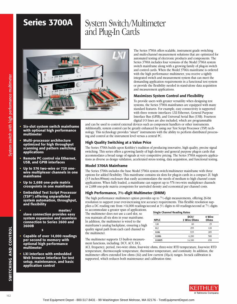
SW
ITC
HIN
G A
ND
CO
NTR
OL
• six-slot system switch mainframe with optional high performance multimeter
• Multi-processor architecture optimized for high throughput scanning and pattern switching applications
• remote PC control via Ethernet, usb, and GPIb interfaces
• up to 576 two-wire or 720 one-wire multiplexer channels in one mainframe
• up to 2,688 one-pole matrix crosspoints in one mainframe
• Embedded Test script Processor (TsP®) offering unparalleled system automation, throughput, and flexibility
• TsP-link Technology master/slave connection provides easy system expansion and seamless connection to series 2600 and 2600b sourceMeter® sMu instruments
• Capable of over 14,000 readings per second to memory with optional high performance multimeter
• lXI interface with embedded Web browser interface for test setup, maintenance, and basic application control
The Series 3700A offers scalable, instrument grade switching and multi-channel measurement solutions that are optimized for automated testing of electronic products and components . The Series 3700A includes four versions of the Model 3706A system switch mainframe along with a growing family of plug-in switch and control cards . When the Model 3706A mainframe is ordered with the high performance multimeter, you receive a tightly integrated switch and measurement system that can meet the demanding application requirements in a functional test system or provide the flexibility needed in stand-alone data acquisition and measurement applications .
Maximizes system Control and flexibilityTo provide users with greater versatility when designing test systems, the Series 3700A mainframes are equipped with many standard features . For example, easy connectivity is supported with three remote interfaces: LXI/Ethernet, General Purpose Interface Bus (GPIB), and Universal Serial Bus (USB) . Fourteen digital I/O lines are also included, which are programmable
and can be used to control external devices such as component handlers or other instruments . Additionally, system control can be greatly enhanced by using our Test Script Processor (TSP) tech-nology . This technology provides “smart” instruments with the ability to perform distributed process-ing and control at the instrument level versus a central PC .
High Quality switching at a Value PriceThe Series 3700A builds upon Keithley’s tradition of producing innovative, high quality, precise signal switching . This series offers a growing family of high density and general purpose plug-in cards that accommodates a broad range of signals at very competitive pricing . The Series 3700A supports applica-tions as diverse as design validation, accelerated stress testing, data acquisition, and functional testing .
Model 3706a MainframeThe Series 3700A includes the base Model 3706A system switch/multimeter mainframe with three options for added flexibility . This mainframe contains six slots for plug-in cards in a compact 2U high (3 .5 inches/89mm) enclosure that easily accommodates the needs of medium to high channel count applications . When fully loaded, a mainframe can support up to 576 two-wire multiplexer channels or 2,688 one-pole matrix crosspoints for unrivaled density and economical per channel costs .
High Performance, 7½-digit Multimeter (DMM)The high performance multimeter option provides up to 7½-digit measurements, offering 26-bit resolution to support your ever-increasing test accuracy requirements . This flexible resolution sup-plies a DC reading rate from >14,000 readings/second at 3½ digits to 60 readings/second at 7½ digits to accommodate a greater span of applications . The multimeter does not use a card slot, so you maintain all six slots in your mainframe . In addition, the multimeter is wired to the mainframe’s analog backplane, ensuring a high quality signal path from each card channel to the multimeter .
The multimeter supports 13 built-in measure-ment functions, including: DCV, ACV, DCI, ACI, frequency, period, two-wire ohms, four-wire ohms, three-wire RTD temperature, four-wire RTD temperature, thermocouple temperature, thermistor temperature, and continuity . In addition, the multimeter offers extended low ohms (1W) and low current (10µA) ranges . In-rack calibration is supported, which reduces both maintenance and calibration time .
series 3700a System Switch/Multimeter and Plug-In Cards
single Channel reading rates
NPlCDCV/
2 Wire ohms4 Wire ohms
1.0 60 29
0.2 295 120
0.06 935 285
0.006 6,200 580
0.0005 14,100 650
Syst
em s
witc
h w
ith h
igh
perfo
rman
ce m
ultim
eter
Syst
em s
witc
h w
ith h
igh
perfo
rman
ce m
ultim
eter
162 Test Equipment Depot - 800.517.8431 - 99 Washington Street Melrose, MA 02176 - TestEquipmentDepot.com

SW
ITC
HIN
G A
ND
CO
NTR
OL
A Greater Measure of Confidence
ordering InformationMainframes3706a six-slot system
switch with high performance DMM
3706a-NfP six-slot system switch with high performance DMM, without front panel display and keypad
3706a-s six-slot system switch3706a-sNfP
six-slot system switch, without front panel display and keypad
Plug-in Cards3720 Dual 1×30 multiplexer
card (auto CJC when used with 3720-sT)
3721 Dual 1×20 multiplexer card (auto CJC when used with 3721-sT)
3722 Dual 1×48, high density, multiplexer card
3723 Dual 1×30, high speed, reed relay multiplexer card
3724 Dual 1×30 fET multiplexer card
3730 6×16, high density, matrix card
3731 6×16 high speed, reed relay matrix card
3732 Quad 4×28, ultra-high density, reed relay matrix card
3740 32 channel isolated switch card
3750 Multifunction control card
accessories suppliedTest script builder software suite CDEthernet Crossover Cable (Ca-180-3a)series 3700a Product CD (includes labVIEW®, IVI C, and IVI.CoM drivers)
Temperature–RTDTemperature–TCTemperature–ThermistorLinear scale
1n 1m 1 1k 1M 1G
DC VoltageAC VoltageDC CurrentAC CurrentFrequencyPeriodResistance (2-Wire)Resistance (4-Wire)
Logarithmic scale
Measurement Capability
1p
Dry Circuit Resistance
500kHz
330ms2µs
1µ
Measurement capabilities of the high performance multimeter
aCCEssorIEs aVaIlablEGPIb INTErfaCEs aND CablEs
7007-1 Shielded GPIB Cable, 1m (3 .5ft)
7007-2 Shielded GPIB Cable, 2m (6 .6ft)
KPCI-488LPA IEEE-488 Interface/Controller for the PCI Bus
KUSB-488B IEEE-488 USB-to-GPIB Interface Adapter
DIGITal I/o, TrIGGEr lINK, aND TsP-lINK
2600-TLINK Trigger I/O to Trigger Link Interface Cable, 1m (3 .3 ft)
CA-126-1 Digital I/O and Trigger Cable, 1 .5m (4 .9 ft)
CA-180-3A CAT5 Crossover Cable for TSP-Link
MulTIMETEr CoNNECTors
3706-BAN DMM Adapter Cable, 15-pin D-sub to banana jacks, 1 .4m (4 .6 ft)
3706-BKPL Analog Backplane Extender Board, 15-pin D-sub to terminal block
3706-TLK Test Lead Kit, includes 3706-BAN and plug-in test lead accessories
8620 Shorting Plug
raCK MouNT KIT
4288-10 Fixed Rear Rack Mount Kit
sErVICEs aVaIlablEMainframe Models 3706A and 3706A-NFP
3706A-3Y-EW 1 Year Factory Warranty Extended to 3 Years
3706A-5Y-EW 1 Year Factory Warranty Extended to 5 Years
C/3706A-3Y-STD Calibration Contract, 3 Years, Standard Calibration*
C/3706A-3Y-DATA Calibration Contract, 3 Years, Z540 Compliant Calibration with Data*
C/3706A-3Y-ISO Calibration Contract, 3 Years, ISO 17025 Accredited Calibration*
C/3706A-5Y-STD Calibration Contract, 5 Years, Standard Calibration*
C/3706A-5Y-DATA Calibration Contract, 5 Years, Z540 Compliant Calibration with Data*
C/3706A-5Y-ISO Calibration Contract, 5 Years, ISO 17025 Accredited Calibration*
Mainframe Models 3706A-S and 3706A-SNFP
3706A-S-3Y-EW 1 Year Factory Warranty Extended to 3 Years
3706A-S-5Y-EW 1 Year Factory Warranty Extended to 5 Years
sofTWarE sErVICEs sYsTEM DEVEloPMENT or IMPlEMENTaTIoNOther service contracts are available; please contact us for details .
*Not available in all countries .
series 3700a System Switch/Multimeter and Plug-In Cards
Syst
em s
witc
h w
ith h
igh
perfo
rman
ce m
ultim
eter
Syst
em s
witc
h w
ith h
igh
perfo
rman
ce m
ultim
eter
163 Test Equipment Depot - 800.517.8431 - 99 Washington Street Melrose, MA 02176 - TestEquipmentDepot.com

SW
ITC
HIN
G A
ND
CO
NTR
OL
TsP Distributed Control Increases Test speed and lowers Test CostTSP technology enhances instrument control by allowing users the choice of using standard PC control or of creating embedded test scripts that are executed on microprocessors within the instrument . By using TSP test scripts instead of a PC for instrument control, you avoid communica-tion delays between the PC controller and instrument, which results in improved test throughput . Test scripts can contain math and decision-making rules that further reduce the interaction between a host PC and the instrument .
This form of distributed control supports the autonomous operation of individual instruments or groups of instruments and can possibly remove the need for a high level PC controller, which lowers test and ownership costs . This is the same proven TSP technology found in our innovative Series 2600B System SourceMeter® SMU instruments .
TsP-link Technology for Easy and seamless system Coordination and ExpansionIf your channel density requirements grow or if you need to process more signal types, use TSP-Link Technology to expand your system . The TSP-Link master/slave connection offers easy system expansion between Series 3700A mainframes . You can also use TSP-Link Technology to connect to other TSP-Link enabled instruments such as Series 2600B SourceMeter SMU instruments . Everything connected with TSP-Link can be controlled by the master unit, just as if they were all housed in the same chassis .
This high speed system expansion interface lets users avoid the complex and time consuming task of expanding their remote interfaces to another mainframe . There is no need to add external triggers and remote com-munication cables to individual instruments, since all TSP-Link connected devices can be controlled from a single master unit .
Test script builder software suiteTest Script Builder is a software tool that is provided with all Series 3700A instruments to help users easily create, modify, debug, and store TSP test scripts . It supplies a project/file manager window to store and organize test scripts, a text-sensitive program editor to create and modify test TSP code, and an immediate instrument control window to send Ethernet, GPIB, and USB commands and to receive data from the instrument . The immediate window also allows users to see the output of a given test script and sim-plifies debugging .
Version 1.4LXI Core 2011 with LXI Clock Synchronization, LXI Timestamped Data, LXI Event Messaging, LXI Event Log .
Transportable Memory, usb 2.0 Device PortAll Model 3706A mainframes contain a USB device port for easy transfer of readings, configurations, and test scripts to memory sticks . This port, which is located on the front panel, provides you with easy access to and portability of measurement results . Simply plug in a memory stick and, with a few simple keystrokes, gain access to virtually unlimited memory storage . Additional capabilities include: saving and recalling system con-figurations and storage for TSP scripts .
Test script builder software suite
store and organize test scripts in the file manager window.
Create and modify test TsP code in the context sensitive editor window.
The immediate window displays test script output and assists in debugging.
series 3700a System Switch/Multimeter and Plug-In Cards
164
Syst
em s
witc
h w
ith h
igh
perfo
rman
ce m
ultim
eter
Syst
em s
witc
h w
ith h
igh
perfo
rman
ce m
ultim
eter
Test Equipment Depot - 800.517.8431 - 99 Washington Street Melrose, MA 02176 - TestEquipmentDepot.com

SW
ITC
HIN
G A
ND
CO
NTR
OL
A Greater Measure of Confidence
series 3700a System Switch/Multimeter and Plug-In Cards
Embedded Web serverThe built-in Web interface offers a quick and easy method to control and analyze measurement results . Interactive schematics of each card in the mainframe support point-and-click control for opening and closing switch-es . A scan list builder is provided to guide users through the requirements of a scan list (such as trigger and looping definitions) for more advanced applications . When the mainframe is ordered with the multimeter, addi-tional Web pages are included for measurement configuration and viewing, including a graphing toolkit .
built-in Web server Interface
1. Configure your switch channels and measurement functions. Configure the DMM to make your measurements at the desired speed, resolution, etc. and assign them to the desired channels.
2. build and run your automated scan list. The toolkit makes it easy to build and execute an automated sequence of channel-open and channel-close commands and triggered multimeter measurements.
Model 3706a-NfP and Model 3706a-sNfP front panel
Model 3706a front panel
Model 3706a-s front panel
Model 3706a rear panel
3. analyze your data. View your results in real-time or historical mode with point-and-click simplicity. Data can be exported directly to your PC in either numerical or graphical formats for presentation or other applications.
165
Syst
em s
witc
h w
ith h
igh
perfo
rman
ce m
ultim
eter
Syst
em s
witc
h w
ith h
igh
perfo
rman
ce m
ultim
eter
Test Equipment Depot - 800.517.8431 - 99 Washington Street Melrose, MA 02176 - TestEquipmentDepot.com
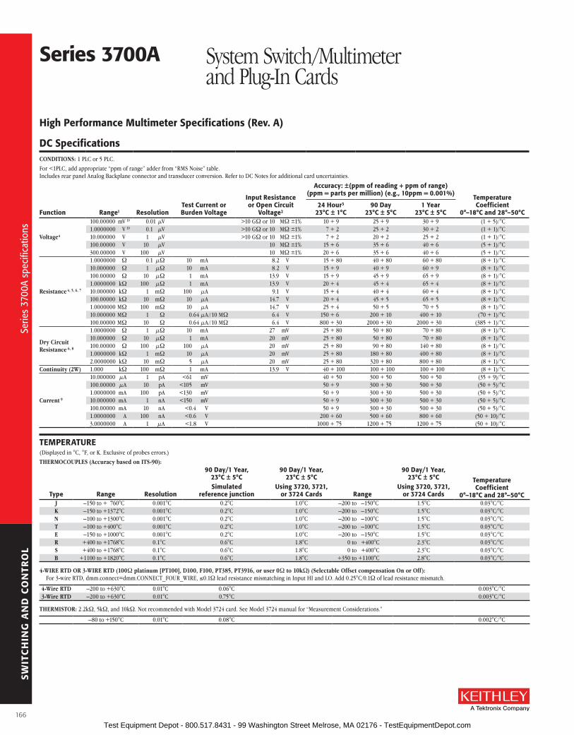
SW
ITC
HIN
G A
ND
CO
NTR
OL
High Performance Multimeter specifications (rev. a)
DC specificationsCONDITIONS: 1 PLC or 5 PLC .
For <1PLC, add appropriate “ppm of range” adder from “RMS Noise” table .Includes rear panel Analog Backplane connector and transducer conversion . Refer to DC Notes for additional card uncertainties .
Input resistance or open Circuit
Voltage2
accuracy: ±(ppm of reading + ppm of range) (ppm = parts per million) (e.g., 10ppm = 0.001%)
TemperatureCoefficient
0°–18°C and 28°–50°Cfunction range1 resolutionTest Current or burden Voltage
24 Hour3
23°C ± 1°C90 Day
23°C ± 5°C1 Year
23°C ± 5°C
Voltage4
100 .00000 mV 19 0 .01 µV >10 GW or 10 MW ±1% 10 + 9 25 + 9 30 + 9 (1 + 5)/°C1 .0000000 V 19 0 .1 µV >10 GW or 10 MW ±1% 7 + 2 25 + 2 30 + 2 (1 + 1)/°C10 .000000 V 1 µV >10 GW or 10 MW ±1% 7 + 2 20 + 2 25 + 2 (1 + 1)/°C100 .00000 V 10 µV 10 MW ±1% 15 + 6 35 + 6 40 + 6 (5 + 1)/°C300 .00000 V 100 µV 10 MW ±1% 20 + 6 35 + 6 40 + 6 (5 + 1)/°C
Resistance 4, 5, 6, 7
1 .0000000 W 0 .1 µW 10 mA 8 .2 V 15 + 80 40 + 80 60 + 80 (8 + 1)/°C10 .000000 W 1 µW 10 mA 8 .2 V 15 + 9 40 + 9 60 + 9 (8 + 1)/°C100 .00000 W 10 µW 1 mA 13 .9 V 15 + 9 45 + 9 65 + 9 (8 + 1)/°C1 .0000000 kW 100 µW 1 mA 13 .9 V 20 + 4 45 + 4 65 + 4 (8 + 1)/°C10 .000000 kW 1 mW 100 µA 9 .1 V 15 + 4 40 + 4 60 + 4 (8 + 1)/°C100 .00000 kW 10 mW 10 µA 14 .7 V 20 + 4 45 + 5 65 + 5 (8 + 1)/°C1 .0000000 MW 100 mW 10 µA 14 .7 V 25 + 4 50 + 5 70 + 5 (8 + 1)/°C10 .000000 MW 1 W 0 .64 µA//10 MW 6 .4 V 150 + 6 200 + 10 400 + 10 (70 + 1)/°C100 .00000 MW 10 W 0 .64 µA//10 MW 6 .4 V 800 + 30 2000 + 30 2000 + 30 (385 + 1)/°C
Dry Circuit Resistance 6, 8
1 .0000000 W 1 µW 10 mA 27 mV 25 + 80 50 + 80 70 + 80 (8 + 1)/°C10 .000000 W 10 µW 1 mA 20 mV 25 + 80 50 + 80 70 + 80 (8 + 1)/°C100 .00000 W 100 µW 100 µA 20 mV 25 + 80 90 + 80 140 + 80 (8 + 1)/°C1 .0000000 kW 1 mW 10 µA 20 mV 25 + 80 180 + 80 400 + 80 (8 + 1)/°C2 .0000000 kW 10 mW 5 µA 20 mV 25 + 80 320 + 80 800 + 80 (8 + 1)/°C
Continuity (2W) 1 .000 kW 100 mW 1 mA 13 .9 V 40 + 100 100 + 100 100 + 100 (8 + 1)/°C
Current 9
10 .000000 µA 1 pA <61 mV 40 + 50 300 + 50 500 + 50 (35 + 9)/°C100 .00000 µA 10 pA <105 mV 50 + 9 300 + 30 500 + 30 (50 + 5)/°C1 .0000000 mA 100 pA <130 mV 50 + 9 300 + 30 500 + 30 (50 + 5)/°C10 .000000 mA 1 nA <150 mV 50 + 9 300 + 30 500 + 30 (50 + 5)/°C100 .00000 mA 10 nA <0 .4 V 50 + 9 300 + 30 500 + 30 (50 + 5)/°C1 .0000000 A 100 nA <0 .6 V 200 + 60 500 + 60 800 + 60 (50 + 10)/°C3 .0000000 A 1 µA <1 .8 V 1000 + 75 1200 + 75 1200 + 75 (50 + 10)/°C
TEMPEraTurE(Displayed in °C, °F, or K . Exclusive of probes errors .)
THERMOCOUPLES (Accuracy based on ITS-90):
Type range resolution
90 Day/1 Year, 23°C ± 5°Csimulated
reference junction
90 Day/1 Year, 23°C ± 5°C
using 3720, 3721, or 3724 Cards range
90 Day/1 Year, 23°C ± 5°C
using 3720, 3721, or 3724 Cards
Temperature Coefficient
0°–18°C and 28°–50°Cj –150 to + 760°C 0 .001°C 0 .2°C 1 .0°C –200 to –150°C 1 .5°C 0 .03°C/°CK –150 to +1372°C 0 .001°C 0 .2°C 1 .0°C –200 to –150°C 1 .5°C 0 .03°C/°CN –100 to +1300°C 0 .001°C 0 .2°C 1 .0°C –200 to –100°C 1 .5°C 0 .03°C/°CT –100 to +400°C 0 .001°C 0 .2°C 1 .0°C –200 to –100°C 1 .5°C 0 .03°C/°CE –150 to +1000°C 0 .001°C 0 .2°C 1 .0°C –200 to –150°C 1 .5°C 0 .03°C/°CR +400 to +1768°C 0 .1°C 0 .6°C 1 .8°C 0 to +400°C 2 .3°C 0 .03°C/°CS +400 to +1768°C 0 .1°C 0 .6°C 1 .8°C 0 to +400°C 2 .3°C 0 .03°C/°CB +1100 to +1820°C 0 .1°C 0 .6°C 1 .8°C +350 to +1100°C 2 .8°C 0 .03°C/°C
4-WIRE RTD OR 3-WIRE RTD (100W platinum [PT100], D100, F100, PT385, PT3916, or user 0W to 10kW) (Selectable Offset compensation On or Off): For 3-wire RTD, dmm .connect=dmm .CONNECT_FOUR_WIRE, ≤0 .1W lead resistance mismatching in Input HI and LO . Add 0 .25°C/0 .1W of lead resistance mismatch .
4-Wire RTD –200 to +630°C 0 .01°C 0 .06°C 0 .003°C/°C3-Wire RTD –200 to +630°C 0 .01°C 0 .75°C 0 .003°C/°C
THERMISTOR: 2 .2kW, 5kW, and 10kW . Not recommended with Model 3724 card . See Model 3724 manual for “Measurement Considerations .”
–80 to +150°C 0 .01°C 0 .08°C 0 .002°C/°C
series 3700a System Switch/Multimeter and Plug-In Cards
166
Serie
s 37
00A
spec
ifica
tions
Serie
s 37
00A
spec
ifica
tions
Test Equipment Depot - 800.517.8431 - 99 Washington Street Melrose, MA 02176 - TestEquipmentDepot.com
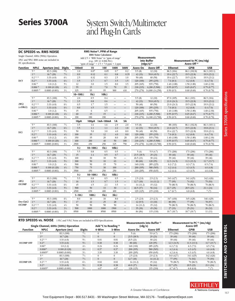
SW
ITC
HIN
G A
ND
CO
NTR
OL
A Greater Measure of Confidence
DC sPEEDs vs. rMs NoIsESingle Channel, 60Hz (50Hz) Operation .
1PLC and 5PLC RMS noise are included in DC specifications .
rMs Noise16, PPM of rangeRMS Noise Calculator:
Add 2 .5 × “RMS Noise” to “ppm of range”(e .g ., 10V @ 0 .006 PLC)
“ppm of range” = 2 .5 × 7 .0 ppm + 2 ppm
Measurements into buffer (rdgs/s)13
Measurement to PC (ms/rdg) azero off 13
function NPlC aperture (ms) Digits 100mV 1V 10V 100V 300V azero on azero off Ethernet GPIb usb
DCV
5 14 83 .3 (100) 7½ 1 .0 0 .07 0 .05 0 .7 0 .2 9 .5 (8) 12 (10) 86 .3 (104) 86 .1 (102 .8) 86 .3 (103 .1)1 14 16 .7 (20) 7½ 0 .9 0 .12 0 .1 0 .8 0 .35 42 (33) 59 .8 (49 .5) 19 .4 (22 .7) 19 .5 (22 .8) 19 .9 (23 .2)0 .2 12, 14 3 .33 (4 .0) 6½ 2 .5 0 .32 0 .3 2 .5 1 .0 50 (40) 60 (50) 19 .4 (22 .7) 19 .5 (22 .8) 19 .9 (23 .2)0 .2 14 3 .33 (4 .0) 6½ 3 .5 1 .7 0 .7 3 .5 1 .5 120 (100) 295 (235) 7 .6 (8 .3) 6 .2 (6 .8) 6 .4 (7 .0)0 .06 15 1 .0 (1 .2) 5½ 12 3 .0 1 .5 8 .0 3 .5 205 (165) 935 (750) 1 .40 (1 .80) 1 .50 (1 .80) 1 .60 (2 .30)0 .006 15 0 .100 (0 .120) 4½ 55 15 7 .0 70 35 218 (215) 6,200 (5,500) 0 .55 (0 .57) 0 .65 (0 .67) 0 .75 (0 .77)0 .0005 15 0 .0083 (0 .001) 3½ 325 95 95 900 410 270 (270) 14,600 (14,250) 0 .50 (0 .5) 0 .60 (0 .60) 0 .70 (0 .70)
2WW(≤10kW)
10–100W 1kW 10kW5 14 83 .3 (100) 7½ 2 .0 0 .5 0 .4 — — 9 .5 (8) 12 (10) 87 .0 (105) 86 .1 (103) 86 .5 (104)1 14 16 .7 (20) 7½ 3 .5 0 .8 0 .6 — — 42 (33) 59 .8 (49 .5) 21 .0 (24 .3) 19 .5 (22 .8) 19 .9 (23 .2)0 .2 12, 14 3 .33 (4 .0) 6½ 6 .5 1 .7 1 .5 — — 50 (40) 60 (50) 21 .0 (24 .3) 19 .5 (22 .8) 19 .9 (23 .2)0 .2 14 3 .33 (4 .0) 6½ 8 .0 4 .5 5 .5 — — 120 (100) 295 (235) 7 .6 (8 .3) 6 .2 (6 .8) 6 .4 (7 .0)0 .06 15 1 .0 (1 .2) 5½ 15 6 6 .5 — — 205 (165) 935 (750) 1 .40 (1 .80) 1 .50 (1 .80) 1 .60 (2 .30)0 .006 15 0 .100 (0 .120) 4½ 60 15 15 — — 218 (215) 6,200 (5,500) 0 .55 (0 .57) 0 .65 (0 .67) 0 .75 (0 .77)0 .0005 15 0 .0083 (0 .001) 3½ 190 190 190 — — 270 (270) 14,100 (13,700) 0 .50 (0 .5) 0 .60 (0 .60) 0 .70 (0 .70)
DCI
10µa 100µa 1ma–100ma 1a 3a5 14 83 .3 (100) 7½ 3 .5 1 .6 1 .6 2 .9 2 .0 9 .5 (8) 12 (10) 88 (103) 86 .1 (102 .8) 86 .3 (103 .1)1 14 16 .7 (20) 6½ 3 .5 1 .1 1 .1 2 .2 1 .8 42 (33) 59 .8 (49 .5) 21 .0 (22 .7) 19 .5 (22 .8) 19 .8 (23 .1)0 .2 12, 14 3 .33 (4 .0) 5½ 50 5 .0 3 .0 4 .0 8 .0 50 (40) 60 (50) 19 .4 (22 .7) 19 .5 (22 .8) 19 .8 (23 .1)0 .2 14 3 .33 (4 .0) 4½ 100 35 12 4 .0 8 .0 120 (100) 295 (235) 7 .6 (8 .3) 6 .2 (6 .8) 6 .4 (7 .0)0 .06 15 1 .0 (1 .2) 4½ 350 35 20 8 .0 20 205 (165) 935 (750) 1 .40 (1 .80) 1 .50 (1 .80) 1 .60 (2 .30)0 .006 15 0 .100 (0 .120) 4½ 400 200 40 50 100 218 (215) 6,200 (5,500) 0 .55 (0 .57) 0 .65 (0 .67) 0 .75 (0 .77)0 .0005 15 0 .0083 (0 .001) 3½ 2500 450 250 325 750 270 (270) 14,100 (13,700) 0 .50 (0 .5) 0 .60 (0 .60) 0 .70 (0 .70)
4WW
1W 10–100W 1kW 10kW5 14 83 .3 (100) 7½ 5 .5 0 .8 0 .5 0 .5 — 5 (4) 5 .9 (4 .7) 173 (206) 173 (206) 173 (206)1 14 16 .7 (20) 7½ 15 1 .4 0 .5 0 .7 — 23 .5 (18 .5) 29 (23) 39 (46) 39 (46) 39 (46)0 .2 12, 14 3 .33 (4 .0) 5½ 100 30 10 50 — 26 .5 (21) 30 (24) 39 (46) 39 (46) 39 (46)0 .2 14 3 .33 (4 .0) 5½ 300 50 10 63 — 80 (60) 120 (95) 12 .3 (14 .5) 11 .3 (13 .3) 11 .7 (13 .7)0 .06 15 1 .0 (1 .2) 4½ 500 50 15 70 — 140 (110) 285 (225) 6 .2 (7 .2) 6 .3 (7 .3) 6 .5 (7 .6)0 .006 15 0 .100 (0 .120) 4½ 750 75 30 100 — 200 (195) 580 (565) 4 .2 (4 .4) 4 .3 (4 .5) 4 .6 (4 .8)0 .0005 15 0 .0083 (0 .001) 3½ 3500 450 250 250 — 210 (205) 650 (645) 4 .2 (4 .4) 4 .3 (4 .5) 4 .6 (4 .8)
4WWOCOMP
1W 10–100W 1kW 10kW5 14 83 .3 (100) 7½ 5 .5 0 .8 0 .5 0 .5 — 2 .5 (2 .0) 2 .9 (2 .3) 343 (427) 341 (425) 342 (426)1 14 16 .7 (20) 7½ 16 1 .5 0 .7 1 .5 — 12 .7 (10) 14 (11 .2) 77 (95) 74 (92) 75 (93)0 .2 12, 14 3 .33 (4 .0) 6½ 45 4 .5 2 .1 3 .5 — 14 (11 .2) 15 (12) 70 (86 .5) 70 (86 .5) 70 (86 .5)0 .2 14 3 .33 (4 .0) 5½ 500 50 13 30 — 46 .5 (37) 56 (44) 22 .7 (25) 20 .5 (23) 21 .1 (24)0 .0005 15 0 .0083 (0 .001) 3½ 4500 650 400 400 — 129 (125) 215 (210) 6 .7 (6 .7) 6 .8 (6 .8) 7 (7)
Dry-CktWOCOMP
1–10W 100W 1kW 2kW5 14 83 .3 (100) 6½ 8 .0 10 10 8 .0 — 2 .5 (2 .0) 2 .9 (2 .3) 347 (430) 345 (428) 346 (429)1 14 16 .7 (20) 5½ 17 22 25 28 — 12 (9 .5) 13 (10) 80 (99) 77 (95) 78 (97)0 .2 12, 14 3 .33 (4 .0) 4½ 50 50 50 50 — 14 (11 .2) 15 (12) 70 (86 .5) 70 (86 .5) 70 (86 .5)0 .2 14 3 .33 (4 .0) 3½ 500 1000 1000 1500 — 35 (30) 45 (36) 27 (33) 25 (31) 26 (32)0 .0005 15 0 .0083 (0 .001) 2½ 8500 8500 8500 8500 — 84 (84) 115 (110) 10 .7 (10 .7) 10 .7 (10 .7) 11 (11)
rTD sPEEDs vs. NoIsE 1 PLC and 5 PLC Noise are included in RTD Specifications .
single Channel, 60Hz (50Hz) operation add °C to reading 16Measurements into buffer 13
(rdg/s)Measurement to PC 13 (ms/rdg)
azero offfunction NPlC aperture (ms) Digits 4-Wire 3-Wire azero on azero off Ethernet GPIb usb
OCOMP OFF
5 14 83 .3 (100) 7½ 0 0 5 (4) 5 .9 (4 .7) 173 (206) 173 (206) 173 (206)114 16 .7 (20) 7½ 0 0 23 .5 (18 .5) 29 (23) 39 (46) 39 (46) 39 (46)0 .212, 14 3 .33 (4 .0) 5½ 0 .01 0 .01 26 .5 (21) 30 (24) 39 (46) 39 (46) 39 (46)0 .214 3 .33 (4 .0) 5½ 0 .18 0 .18 80 (60) 120 (95) 12 .3 (14 .5) 11 .3 (13 .3) 11 .7 (13 .7)0 .0615 1 .0 (1 .2) 4½ 0 .24 0 .24 140 (110) 285 (225) 6 .2 (7 .2) 6 .3 (7 .3) 6 .5 (7 .6)0 .00615 0 .100 (0 .120) 4½ 0 .37 0 .37 200 (195) 580 (565) 4 .2 (4 .4) 4 .3 (4 .5) 4 .6 (4 .8)0 .000515 0 .0083 (0 .001) 3½ 3 .10 3 .10 209 (205) 650 (645) 4 .2 (4 .4) 4 .3 (4 .5) 4 .6 (4 .8)
OCOMP ON
5 14 83 .3 (100) 7½ 0 0 2 .5 (2 .0) 2 .9 (2 .3) 343 (427) 341 (425) 342 (426)114 16 .7 (20) 7½ 0 0 12 .7 (10) 14 (11 .2) 77 (95) 74 (92) 75 (93)0 .212, 14 3 .33 (4 .0) 6½ 0 .02 0 .02 14 (11 .2) 15 (12) 70 (86 .5) 70 (86 .5) 70 (86 .5)0 .214 3 .33 (4 .0) 5½ 0 .38 0 .38 46 .0 (37) 56 (44) 22 .7 (25) 20 .5 (23) 21 .1 (24)0 .000515 0 .0083 (0 .001) 3½ 4 .67 4 .67 128 (125) 215 (210) 6 .7 (6 .7) 6 .8 (6 .8) 7 (7)
series 3700a System Switch/Multimeter and Plug-In Cards
167
Serie
s 37
00A
spec
ifica
tions
Serie
s 37
00A
spec
ifica
tions
Test Equipment Depot - 800.517.8431 - 99 Washington Street Melrose, MA 02176 - TestEquipmentDepot.com

SW
ITC
HIN
G A
ND
CO
NTR
OL
sYsTEM PErforMaNCE 13, 14
3½-Digit Mode, Azero off, nPLC = 0 .0005 . Time includes function change from either DCV or 2WW to listed function .
functionfunction
Change (ms)range
Change (ms)auto-range
(ms)DCV or 2WW (<10kW) 10 10 10
4WW (<10kW) 20 20 20
DCI 10 10 10
Frequency or Period 17 110 10 —
ACV or ACI 17 20 85 300
buffer Transfer speed Ethernet GPIb usbAverage for 1000 readings 2450/s 2000/s 1800/s
Average for 1000 readings with timestamp 2300/s 1800/s 1600/s
single Command Excecution Time (ms)
Card Command Ethernet GPIb usb3720, 3721, 3722, 3730
channel .close (ch_list) or channel .open (ch_list)
5 .7 5 .8 6 .1
3723, 3724 3731, 3732 18
channel .close (ch_list) or channel .open (ch_list)
2 .3 2 .4 2 .7
3740
channel .close (ch_list 1-28) or channel .open (ch_list 1-28)
10 .7 10 .8 11 .1
channel .close (ch_list 29-32) or channel .open (ch_list 29-32)
22 .7 22 .8 23 .1
DC MEasurEMENT CHaraCTErIsTICs
DC VolTsA-D LINEARITy: 1 .0ppm of reading + 2 .0 ppm of range .
INPUT IMPEDANCE: 100mV–10V Ranges: Selectable >10GW // <400pF or 10MW ±1% . 100V–300V Ranges: 10MW ±1% .
INPUT BIAS CURRENT: <50pA at 23°C with dmm .autozero=dmm .OFF or dmm .inputdivider=dmm .ON .
COMMON MODE CURRENT: <500nA p-p for ≤1MHz .
AUTOzERO OFF ERROR: For DCV ±1°C and ≤10 minutes, add ±(8ppm of reading + 5µV) .
INPUT PROTECTION: 300V all ranges .
COMMON MODE VOLTAGE: 300V DC or 300Vrms (425V peak for AC waveforms) between any terminal and chassis .
rEsIsTaNCEMAX. 4WW LEAD RESISTANCE: 5W per lead for 1W range; 10% of range per lead for 10W–1kW
ranges; 1kW per lead for all other ranges .
MAX. 4WW LEAD RESISTANCE (DRy CKT): 0 .5W per lead for 1W range; 10% of range per lead for 10W–100W ranges; 50W per lead for 1kW–2kW ranges .
INPUT IMPEDANCE: 1W–10W Ranges: 99kW ±1% // <1µF . 100W–2kW Ranges: 10MW ±1% // <0 .015µF .
OFFSET COMPENSATION: Selectable on 4WW 1W–10kW ranges .
OPEN LEAD DETECTOR: Selectable per channel . 1 .5µA, ±20% sink current per DMM SHI and SLO lead . Default on .
CONTINUITy THRESHOLD: Adjustable 1 to 1000W .
AUTOzERO OFF ERROR: For 2WW ±1°C and ≤10 minutes, add ±(8ppm of reading + 0 .5mW) for 10W and 5mW for all other ranges .
INPUT PROTECTION: 300V all ranges .
DC MEasurEMENT CHaraCTErIsTICs (continued)
DC CurrENTAUTOzERO OFF ERROR: For ±1°C and ≤10 minutes, add ±(8ppm of reading + range error) .
Refer to table below .
range 3 a 1 a 100 ma 10 ma 1 ma 100 µa 10 µaShunt Resistance guaranteed by design 0 .05 W 0 .05 W 1 W 10 W 100 W 1 kW 6 kW
Burden Voltage <1 .75 V <0 .55 V <0 .4 V <150 mV <130 mV <105 mV <61 mVBurden Voltage with 3721 card <2 .35 V <1 .15 V <0 .4 V <150 mV <130 mV <105 mV <61 mV
Autozero OFF “of range” Error 100 µA 100 µA 5 µA 0 .5 µA 50 nA 5 nA 0 .85 nA
For each additional amp after ±1 .5A input, add the following to ppm of range:— 120 60 60 60 60 95
INPUT PROTECTION: 3A, 250V fuse .
THErMoCouPlEsCONVERSION: ITS-90 .
REFERENCE jUNCTION: Internal, External, or Simulated (Fixed) .
OPEN LEAD DETECTOR: Selectable per channel . Open >1 .15kW ±50W . Default on .
COMMON MODE ISOLATION: 300V DC or 300Vrms (425V peak for AC waveforms), >10GW and <350pF any terminal to chassis .
DC NoTEs1 . 20% overrange on DC functions except 1% on 300V range and 3 .33% on 3A range .2 . ±5% (measured with 10MW input resistance DMM, >10GW DMM on 10MW and 100MW ranges) . Refer to
table for other 2W/4W configurations . For Dry Circuit, +20%, <1mV with dmm .offsetcompensation=ON for 100W–2kW ranges .
range 2W 4W 4W–Kelvin ocomp 4W ocomp 4W–Kelvin1, 10W 8 .2 V 8 .2 V 8 .2 V 12 .1 V 12 .1 V100, 1kW 13 .9 V 14 .1 V 13 .9 V 15 .0 V 12 .7 V10kW 9 .1 V 9 .1 V 9 .1 V 0 .0 V 0 .0 V100k, 1MW 12 .7 V 14 .7 V 12 .7 V — —10M, 100MW 6 .4 V 6 .4 V 6 .4 V — —
3 . Relative to calibration accuracy .4 . Add the following additional uncertainty with -ST accessory:
±(ppm of range) ±(ppm of reading + ppm of range)
Card 100 mV 1 V 10 V 100 kW 1 MW 10 MW 100 MW3720, 3721, 3722, and 3730 45 4 .5 – 8 + 5 8 + 0 .5 — —3723 60 6 .0 – 8 + 6 8 + 0 .5 — —3724 45 4 .5 – 8 + 5 80 + 0 .5 250 + 1 5000 + 13731 800 80 8 8 + 80 40 + 8 0 + 25 0 + 153732 (Quad 4×28) 200 20 2 8 + 20 40 + 2 0 + 7 0 + 4
5 . Specifications are for 4-wire W, 1W–1kW with offset compensation on . For Series 3700A plug-in cards, L SYNC and offset compensation on . 1W range is 4-wire only . Model 3724 card: 1kW–100MW ranges only . Model 3731 card: 100W–100MW ranges only .
For 2-wire W specifications, add the following to “ppm of range” uncertainty:
DMM Connect relays rel Enablerear Panel Connector
or 3700 Card 3724 Card 3731 CardCONNECT_ALL ON 100 mW 500 mW 900 mWCONNECT_ALL OFF 1 .5 W 64 W 2 .3 WCONNECT_TWO_WIRE ON 700 mW 1 .2 W 1 .5 WCONNECT_TWO_WIRE OFF 1 .5 W 64 W 2 .3 W
6 . Test current with dmm .offsetcompensation=OFF, ±5% .7 . Add the following to “ppm of reading” uncertainty when using Series 3700A Plug-in Cards in Operating
Environment ≥50%RH .Card 10 kW 100 kW 1 MW 10 MW 100 MW3720, 3721, 3724, 3730, 3731, 3732 (Quad 4×28) with MTC D-Shell connector 1 ppm 10 ppm 0 .01% 0 .1% 1%
3720, 3721, 3724, 3730, 3731, 3732 (Quad 4×28) with -ST screw terminal module 10 ppm 100 ppm 0 .1% 1% 10%
3722 and 3723 10 ppm 100 ppm 0 .1% 1% 10%
Series 3700A Plug-in Cards Operating Environment: Specified for 0° to 50°C, ≤70%RH at 35°C .8 . Dry-Ckt W is 4-wire only . Specifications with offset compensation and LSYNC on .
Card ranges3720, 3721, and 3730 1 W – 2 kW3722, 3723, and 3732 10 W – 2 kW3724 1 kW – 2 kW3731 100 W – 2 kW
series 3700a System Switch/Multimeter and Plug-In Cards
168
Serie
s 37
00A
spec
ifica
tions
Serie
s 37
00A
spec
ifica
tions
Test Equipment Depot - 800.517.8431 - 99 Washington Street Melrose, MA 02176 - TestEquipmentDepot.com

SW
ITC
HIN
G A
ND
CO
NTR
OL
A Greater Measure of Confidence
DC NoTEs (continued)9 . Includes Analog Backplane 15-pin rear panel connector . For 3721, refer to DC Current table for additional
uncertainties .10 . For LSYNC On, line frequency ±0 .1% .
nPlC 5 1 <0.2 <0.01LSyNC On NMRR 110 dB 90 dB 45 dB —LSyNC Off NMRR 60 dB, ±2 dB 60 dB, ±2 dB — —
11 . For 1kW unbalance in LO lead . AC CMRR is 70dB .
nPlC 5 1 0.2 12 ≤0.2CMRR 140 dB 140 dB 120 dB 80 dB
12 . For LSYNC On .13 . Reading rates are for 60Hz (50Hz) operation using factory defaults operating conditions dmm .reset(“all”),
Autorange off, dmm .autodelay=dmm .OFF, dmm .opendetector=dmm .OFF, format .data .=format .SREAL . Ranges as follows: DCV = 10V, 2WW/4WW = 1kW, DCI = 1mA, Dry-Ckt W = 10W, ACI = 1mA, and ACV = 1V .
For Dry-Ckt W with Offset Comp OFF 2kW, 60 rdg/s max . Dry-Ckt W with Offset Comp ON 2kW, 29 .5 rdg/s max . For temperature reading rates use DCV for T/C and 2WW for Thermistor . Speeds are typical and include measurements and data transfer out the Ethernet, GPIB, or USB .
14 . DMM configured for single reading, dmm .measurecount=1, and print(dmm .measure()) . May require additional settling delays for full accuracy, depending on measurement configuration .
15 . DMM configured for multisample readings and single buffer transfer, dmm .measurecount=1000, buf=dmm .makebuffer(1000), dmm .measure(buf), and printbuffer(1,1000,buf) .
16 . dmm .autozero=dmm .ON . RMS noise using low thermal short for DCV, 2WW, 4WW, and Dry-Ckt W . For DCI, dmm .connect=dmm .CONNECT_NONE or 0 . For RTD, noise using low thermal 190W precision resistor . Includes Model 3721 card accuracies . RMS noise values are typical .
17 . For DCV or 2WW to Frequency or Period, dmm .nplc=0 .2 and dmm .aperture=0 .01 sec . For ACI or ACV, dmm .detectorbandwidth=300 . For ACI or ACV with dmm .autodelay=dmm .ON, best speed is 65ms .
18 . Speeds are within same multiplexer bank . Add an additional 8ms when changing banks or slots .
19 . When properly zeroed using REL function .
aC specifications
Calibration Cycle
accuracy: ±(% of reading + % of range) 23°C ± 5°Cfunction range1 resolution 3 Hz–5 Hz 5 Hz–10 Hz 10 Hz –20 kHz 20 kHz–50 kHz 50 kHz–100 kHz 100 kHz–300 kHz
Voltage2
100 .0000 mV 0 .1 µV 90 Day(100mV–100V) 1 .0 + 0 .03 0 .30 + 0 .03 0 .05 + 0 .03 0 .11 + 0 .05 0 .6 + 0 .08 4 .0 + 0 .5
1 .000000 V 1 µV10 .00000 V 10 µV 1 year
(100mV–100V) 1 .0 + 0 .03 0 .30 + 0 .03 0 .06 + 0 .03 0 .12 + 0 .05 0 .6 + 0 .08 4 .0 + 0 .5100 .0000 V 100 µV300 .0000 V 1 mV 90 Day 1 .0 + 0 .05 0 .30 + 0 .05 0 .05 + 0 .05 0 .11 + 0 .08 0 .6 + 0 .11 4 .0 + 0 .8300 .0000 V 1 mV 1 year 1 .0 + 0 .05 0 .30 + 0 .05 0 .06 + 0 .05 0 .12 + 0 .08 0 .6 + 0 .11 4 .0 + 0 .8
Temp. Coeff. /°C3 (all ranges) 0 .010 + 0 .003 0 .030 + 0 .003 0 .005 + 0 .003 0 .006 + 0 .005 0 .01 + 0 .006 0 .03 + 0 .01
Current2
3 Hz–5 Hz 5 Hz–10 Hz 10Hz –2 kHz 2 kHz –5 kHz 5 kHz –10 kHz1 .000000 mA7 1 nA
90 Day/1 year
1 .0 + 0 .04 0 .30 + 0 .04 0 .08 + 0 .03 0 .09 + 0 .03 0 .09 + 0 .0310 .00000 mA 10 nA 1 .0 + 0 .04 0 .30 + 0 .04 0 .08 + 0 .03 0 .09 + 0 .03 0 .09 + 0 .03100 .0000 mA 100 nA 1 .0 + 0 .04 0 .30 + 0 .04 0 .08 + 0 .03 0 .09 + 0 .03 0 .09 + 0 .031 .000000 A 1 µA 1 .0 + 0 .04 0 .30 + 0 .04 0 .20 + 0 .04 0 . 88 + 0 .04 2 .0 + 0 .043 .000000 A 10 µA 1 .0 + 0 .05 0 .30 + 0 .05 0 .20 + 0 .05 0 . 88 + 0 .05 2 .0 + 0 .05
Temp. Coeff. /°C3 (all ranges) 0 .10 + 0 .004 0 .030 + 0 .004 0 .005 + 0 .003 0 .006 + 0 .005 0 .006 + 0 .005
Frequency4 and Period
accuracy: ±(ppm of reading + offset ppm)
3 Hz–500 kHz 3 Hz–500 kHz 333 ms–2 µs
100 .0000 mVto
300 .0000 V
0 .333 ppm90 Day/1 year
(all ranges)
80 + 0 .333 80 + 0 .333 (0 .25 s gate) 3 .33 ppm 80 + 3 .33 80 + 3 .33 (100 ms gate) 33 .3 ppm 80 + 33 .3 80 + 33 .3 (10 ms gate)
aDDITIoNal uNCErTaINTY ±(% of reading)
low frequency uncertainty
Detector bandwidth3 (3 Hz–300 kHz) 30 (30 Hz–300 kHz) 300 (300 Hz–300 kHz)
20 Hz–30 Hz 0 0 .3 –30 Hz–50 Hz 0 0 –50 Hz–100 Hz 0 0 4 .0
100 Hz–200 Hz 0 0 0 .72200 Hz–300 Hz 0 0 0 .18300 Hz–500 Hz 0 0 0 .07
>500 Hz 0 0 0
series 3700a System Switch/Multimeter and Plug-In Cards
additional uncertainty ±(% of reading)
Detector bandwidth
Crest factor5 Maximum Crest factor: 5 at full-scale
1–2 2–3 3–4 4–55 Hz–10 Hz 3 0 .50 1 .20 1 .30 1 .40
10 Hz–30 Hz 3 0 .20 0 .30 0 .60 0 .9030 Hz–100 Hz 3 or 30 0 .20 0 .30 0 .60 0 .90
>100 Hz 3 or 30 0 .05 0 .15 0 .30 0 .40300 Hz–500 Hz 300 only 0 .50 1 .20 1 .30 1 .40
≥500 Hz 300 only 0 .05 0 .15 0 .30 0 .40
169
Serie
s 37
00A
spec
ifica
tions
Serie
s 37
00A
spec
ifica
tions
Test Equipment Depot - 800.517.8431 - 99 Washington Street Melrose, MA 02176 - TestEquipmentDepot.com

SW
ITC
HIN
G A
ND
CO
NTR
OL
aC MEasurEMENT CHaraCTErIsTICs
aC VolTsMEASUREMENT METHOD: AC-coupled, True RMS .
INPUT IMPEDANCE: 1MW ±2% // by <150pF .
INPUT PROTECTION: 300VDC or 300Vrms rear inputs or 37xx cards .
aC CurrENTMEASUREMENT METHOD: AC-coupled, True RMS .
range 3 a 1 a 100 ma 10 ma 1 maShunt Resistance guaranteed by design 0 .05 W 0 .05 W 1 .0 W 10 W 100 W
Burden Voltage Rear Panel <1 .75 V rms <0 .55 V rms <0 .4 V rms <150 mV rms <125 mV rms
Burden Voltage 3721 Card <2 .4 V rms <1 .0 V rms <0 .6 V rms <200 mV rms <130 mV rms
INPUT PROTECTION: 3A, 250V fuse .
frEQuENCY aND PErIoDMEASUREMENT METHOD: Reciprocal Counting technique .
GATE TIME: dmm .aperture=0 .273→0 .01 . Default 0 .01s .
aC GENEralAC CMRR6: 70dB .
VOLT·HERTz PRODUCT: ≤8×10⁷ Volt·Hz (guaranteed by design), ≤2 .1×107 Volt·Hz verified . Input frequency verified for ≤3×10⁵ Hz .
aC NoTEs1 . 20% overrange on AC functions except 1% on 300V and 3 .33% on 3A . Default resolution is 5½ digits, maximum
useable resolution is 6½ with 7½ digits programmable .2 . Specification are for Detector Bandwidth 3 and sinewave inputs >5% of range . Detector Bandwidth 3 and 30
are multi-sample A/D conversions . Detector bandwidth 300 is a single A/D conversion, programmable from 0 .0005PLC to 15PLC . Default condition set to 1PLC .
3 . Applies to 0°–18°C and 28°–50°C .4 . Specified for square wave inputs . Input signal must be >10% of ACV range . If input is <20mV on the 100mV
range then the frequency must be >10Hz . For sinewave inputs, frequency must be >100Hz .5 . Applies to non-sinewave inputs 5Hz–>10kHz, and DC content ≤3% of range .6 . For 1kW unbalance in LO lead .7 . For Model 3721, 1mA ACI, add 0 .05% to “of reading” uncertainty from 250Hz → 10kHz .8 . Shunt resistance guaranteed by design .9 . Reading rates are for 60Hz (50Hz) operation using factory defaults operating conditions dmm .reset(“all”),
Autorange off, dmm .autodelay=dmm .OFF, dmm .opendetector=dmm .OFF, format .data .=format .SREAL . Ranges as follows: DCV = 10V, 2WW/4WW = 1kW, DCI = 1mA, Dry-Ckt W = 10W, ACI = 1mA, and ACV = 1V . For Dry-Ckt W with Offset Comp OFF 2kW, 60 rdg/s max . Dry-Ckt W with Offset Comp ON 2kW, 29 .5 rdg/s max . For temperature reading rates use DCV for T/C and 2WW for Thermistor . Speeds are typical and include measure-ments and data transfer out the Ethernet, GPIB, or USB .
10 . DMM configured for single reading, dmm .measurecount=1, and print(dmm .measure()) . May require additional settling delays for full accuracy, depending on measurement configuration .
11 . DMM configured for multisample readings and single buffer transfer, dmm .measurecount=1000, buf=dmm .makebuffer(1000), dmm .measure(buf), and printbuffer(1,1000,buf) .
series 3700a System Switch/Multimeter and Plug-In Cards
aC sPEEDs Single Channel, 60Hz (50Hz) Operation
Detector bandwidth
Measurements into buffer 9 (rdg/s) Measurement to PC 9 (ms/rdg)
function NPlC aperture (ms) Digits azero on azero off Ethernet GPIb usb
ACI / ACV
3 N/A N/A 6½ 0 .45 (0 .45) N/A 2150 (2150) 2150 (2150) 2150 (2150)30 N/A N/A 6½ 2 .5 (2 .5) N/A 400 (400) 400 (400) 400 (400)
300 1 .0 10 16 .67 (20) 6½ 42 (33) 59 .5 (50) 19 .4 (22 .7) 19 .5 (22 .8) 19 .8 (23 .1)300 0 .2 10 3 .33 (4 .0) 6½ 120 (100) 295 (235) 7 .6 (8 .3) 6 .2 (6 .8) 6 .4 (7 .0)300 0 .06 11 1 .0 (1 .2) 5½ 170 (165) 935 (750) 1 .40 (1 .80) 1 .50 (1 .80) 1 .60 (2 .30)300 0 .006 11 0 .100 (0 .120) 4½ 218 (215) 6,200 (5,500) 0 .55 (0 .57) 0 .65 (0 .67) 0 .75 (0 .77)300 0 .0005 11 0 .0083 (0 .001) 3½ 218 (215) 14,600 (14,250) 0 .50 (0 .5) 0 .60 (0 .60) 0 .70 (0 .70)
Frequency/Period N/A N/A 10–273 N/A 2× input period + gate time N/A 2× input period +
gate time + 2 .7ms2× input period + gate time + 2 .8ms
2× input period + gate time + 3 .1ms
Serie
s 37
00A
spec
ifica
tions
Serie
s 37
00A
spec
ifica
tions
170 Test Equipment Depot - 800.517.8431 - 99 Washington Street Melrose, MA 02176 - TestEquipmentDepot.com

SW
ITC
HIN
G A
ND
CO
NTR
OL
A Greater Measure of Confidence
GENEral
EXPANSION SLOTS: 6 .
POWER LINE: Universal, 100V to 240V .
LINE FREQUENCy: 50Hz and 60Hz, automatically sensed at power-up .
POWER CONSUMPTION: 28VA with DMM and display, up to 140VA with six 37xx cards .
REAL TIME CLOCK: Battery backed, 10 years typical life .
EMC: Conforms to European Union EMC Directive .
SAFETy: Conforms to European Union Low Voltage Directive .
VIBRATION: MIL-PRF-28800F Class 3, Random .
WARM-UP: 2 hours to rated accuracy .
DIGITAL I/O: 25-pin female D-shell .
I/o 1–9 I/o 10–14 VextISINK, max. 5 mA 250 mA —
Absolute VIN 5 .25 V to –0 .25 V 5 .25 V to –0 .25 V 5 V to 33 V
VIH min 2 .2 V 2 .2 V —
VIL max 0 .7 V 0 .7 V —
VOL max at 5mA Isink 0 .7 V 0 .7 V —
VOL max at Isink max — 2 .3 V —
VOH min, 0.4mA source 2 .7 V 2 .4 V —
Min VIN pulse 2 µs 10 µs —
Min VO pulse 1 µs 50 µs —
5kΩ
+5V
100ΩRead
Write
IN/OUT
GND
I/O 1–9
I/O 10–14
GND
5kΩ
+5V
100ΩRead
Write
IN/OUT
Vext
TRIGGERING AND MEMORy:Window Filter Sensitivity: 0 .01%, 0 .1%, 1%, 10%, or full-scale of range (none) .Trigger Delay: 0 to 99 hrs . (10µs step size) .External Trigger Delay: <10µs .Memory: Up to 650,000 time-stamped readings with Web page disabled . Additional memory
available with external “thumb drive .”Non-volatile Memory: Single user save setup, with up to 75 DMM configurations and ≥600
channel patterns (dependent on name length, DMM function and configuration, and pattern image size) . Additional memory available with external “thumb drive .”
MATH FUNCTIONS: Rel, dB, Limit Test, %, 1/x, and mX+b with user defined displayed .
REMOTE INTERFACE:Ethernet: RJ-45 connector, LXI Class B Version 2, 10/100BT, no auto MDIX .GPIB: IEEE-488 .1 compliant . Supports IEEE-488 .2 common commands and status model
topology .USB Device (rear panel, type B): Full speed, USBTMC compliant .USB Host (front panel, type A): USB 2 .0, support for thumb drives .
LXI COMPLIANCE: LXI Class B Version 2 with IEEE 1588 precision time protocol .
LXI TIMING (applies to scanning) and SPECIFICATION:
Receive LAN[0–7] Event Delay: n/s (not specified) min ., 800µs typ ., n/s max .
Alarm to Trigger Delay: 25µs min ., 50µs typ ., n/s max .
Generate LAN[0–7] Event: n/s min ., 800µs typ ., n/s max . (minimums are probabilistic and represent a 95% confidence factor) .
Clock Accuracy: 25ppm .
Synchronization Accuracy: <150ns (probabilistic and represents a 95% confidence factor) .
Timestamp Accuracy: 100µs .
Timestamp Resolution: 20ns .
LANGUAGE: Embedded Test Script Processor (TSP) accessible from any host interface . Responds to individual Instrument Control Library (ICL) commands . Responds to high-speed test scripts comprised of ICL commands and Test Script Language (TSL) statements (e .g ., branching, looping, math, etc .) . Able to execute high-speed test scripts stored in memory without host intervention .
IP CONFIGURATION: Static or DHCP .
PASSWORD PROTECTION: 11 characters
MINIMUM PC HARDWARE: Intel Pentium 3, 800MHz, 512Mbyte RAM, 210Mbyte disk space or better .
OPERATING SySTEMS/SOFTWARE: Windows® 2000 and XP compatible, supports Web browsers with Java plug-in (requires Java plug-in 1 .6 or higher) . Web pages served by 3706A .
OPERATING ENVIRONMENT: Specified for 0° to 50°C, ≤80%RH at 35°C, altitude up to 2000 meters .
STORAGE ENVIRONMENT: –40° to 70°C .
DIMENSIONS:
Rack Mounted: 89mm high × 483mm wide × 457mm deep (3 .5 in . × 19 in . × 18 in .) .
Bench Configuration (includes handle and feet): 104mm high × 483mm wide × 457mm deep (4 .125 in . × 19 in . × 18 in .)
SHIPPING WEIGHT: 13kg (28 lbs) .
series 3700a System Switch/Multimeter and Plug-In Cards
Serie
s 37
00A
spec
ifica
tions
Serie
s 37
00A
spec
ifica
tions
171 Test Equipment Depot - 800.517.8431 - 99 Washington Street Melrose, MA 02176 - TestEquipmentDepot.com

SW
ITC
HIN
G A
ND
CO
NTR
OL
specifications for Plug-In CardsAdditional Series 3700A cards are currently in development . For a current list of cards and specifications, visit www .keithley .com .
3720 3721 3722 3723 3724 3730 3731 3732 3740 3750Page 174 176 178 180 182 185 187 189 193 195
No. of Channels 60 (Dual 1×30) 40 (dual 1×20) 96 (dual 1×48)60 (dual 1×30) or
120 single pole (dual 1×60)
60 (dual 1×30) 6×16 6×16 448 crosspoints (Quad 4×28) 32
40 digital I/O, 4 counter/totalizers,
and 2 isolated analog outputs
Card Config. Multiplexer Multiplexer Multiplexer Multiplexer Multiplexer Matrix Matrix Matrix Independent Independent
Type of RelayLatching
electromechanicalLatching
electromechanicalLatching
electromechanical Dry reed FET solid-state Latching electromechanical Dry reed Dry reed Latching
electromechanical N/A
Contact Configuration 2 Form A 2 Form A 2 Form A 1 Form A 2 Form A 2 Form A 2 Form A 1 Form A 28 Form C, 4 Form A N/A
Max. Voltage 300 V 300 V (ch 1–40), 60 V (ch 41–42) 300 V 200 V 200 V 300 V 200 V 200 V 300 VDC/250 VAC
(Form A) N/A
Max. Current Switched 1 A 2 A (ch 1–40), 3 A (ch 41–42) 1 A 1 A 0 .1 A 1 A 1 A 0 .75 A 2 A (Form C), 7 A
(Form A) N/A
Comments 2 independent 1×30 multiplexers . Automatic temperature reference when used with screw
terminal accessory (Model 3720-ST)
2 independent 1×20 multiplexers . Automatic temperature reference when used with screw
terminal accessory (Model 3721-ST)
2 independent 1×48 multiplexers
2 independent 1×30 multiplexers
2 independent 1×30 multiplexers .
Automatic temperature
reference when used with screw terminal
accessory (Model 3724-ST)
Columns can be expanded through the backplane or isolated by relays
Relay actuation time of 0 .5ms . Columns can be expanded
through the backplane or isolated
by relays
Banks can be connected
together via bank configuration relays
to create a single 4×112 or dual 4×56
matrix . Analog backplane relays also
included for card to card expansion .
Row expansion with 3732-ST-R accessory
to create a dual 8×28 or single 16×28
matrix .
32 general purpose independent
channels .
All-in-one card design . 40
bidirectional I/O . Four 32-bit
counter/totalizers . 2 programmable analog (V or I)
outputs .
Plug-in Card accessories
3720 3721 3722 3723 3724 3730 3731 3732 3740 3750
Cables3720-MTC-1 .5, 3720-MTC-3
3721-MTC-1 .5, 3721-MTC-3
3722-MTC-1 .5, 3722-MTC-1 .5/MM,
3722-MTC-3, 3722-MTC-3/MM
3720-MTC-1 .5, 3720-MTC-3
3720-MTC-1 .5, 3720-MTC-3
3721-MTC-1 .5, 3721-MTC-3
3721-MTC-1 .5, 3721-MTC-3
3732-MTC-1 .5, 3732-MTC-3
3721-MTC-1 .5, 3721-MTC-3
3721-MTC-1 .5, 3721-MTC-3
Screw Terminal Block 3720-ST 3721-ST 3723-ST, 3723-ST-1 3724-ST 3730-ST 3731-ST 3732-ST-C, 3732-ST-R 3740-ST 3750-ST
Connector Kits 3791-KIT78-R 3790-KIT50-R 3792-KIT104-R, 3792-KIT104-R/F 3791-KIT78-R 3791-KIT78-R 3790-KIT50-R 3790-KIT50-R 3791-KIT78-R 3790-KIT50-R 3790-KIT50-R
Tools 3791-CIT 3791-CIT 3791-CIT 3791-CIT 3791-CIT
series 3700a Plug-in Cards for Series 3700A Mainframes
• Multiplexer, matrix, and I/o cards
• relay closures automatically counted and stored in each card’s onboard memory
• unlimited contact life with solid-state relay (Model 3724)
• automatic CJC for temperature measurements when used with screw terminal accessory (Models 3720, 3721, 3724)
ordering Information3720 Dual 1×30
Multiplexer Card. . . . . . .174
3721 Dual 1×20 Multiplexer Card. . . . . . .176
3722 Dual 1×48, High Density, Multiplexer Card. . . . . . .178
3723 Dual 1×30, High speed, reed relay, Multiplexer Card. . . . . . .180
3724 Dual 1×30 fET Multiplexer Card. . . . . . .182
3730 6×16, High Density, Matrix Card . . . . . . . . . . .185
3731 6×16, High speed, reed relay, Matrix Card . . . . .187
3732 Quad 4×28, ultra-High Density, reed relay, Matrix Card . . . . . . . . . . .189
3740 General Purpose Card with 32 Independent Channels . . . . . . . . . . . . .193
3750 Multifunction Control Card . . . . . . . . . .195
Plug
-in c
ards
for S
erie
s 37
00A
mai
nfra
mes
172 Test Equipment Depot - 800.517.8431 - 99 Washington Street Melrose, MA 02176 - TestEquipmentDepot.com

SW
ITC
HIN
G A
ND
CO
NTR
OL
A Greater Measure of Confidence
specifications for Plug-In CardsAdditional Series 3700A cards are currently in development . For a current list of cards and specifications, visit www .keithley .com .
3720 3721 3722 3723 3724 3730 3731 3732 3740 3750Page 174 176 178 180 182 185 187 189 193 195
No. of Channels 60 (Dual 1×30) 40 (dual 1×20) 96 (dual 1×48)60 (dual 1×30) or
120 single pole (dual 1×60)
60 (dual 1×30) 6×16 6×16 448 crosspoints (Quad 4×28) 32
40 digital I/O, 4 counter/totalizers,
and 2 isolated analog outputs
Card Config. Multiplexer Multiplexer Multiplexer Multiplexer Multiplexer Matrix Matrix Matrix Independent Independent
Type of RelayLatching
electromechanicalLatching
electromechanicalLatching
electromechanical Dry reed FET solid-state Latching electromechanical Dry reed Dry reed Latching
electromechanical N/A
Contact Configuration 2 Form A 2 Form A 2 Form A 1 Form A 2 Form A 2 Form A 2 Form A 1 Form A 28 Form C, 4 Form A N/A
Max. Voltage 300 V 300 V (ch 1–40), 60 V (ch 41–42) 300 V 200 V 200 V 300 V 200 V 200 V 300 VDC/250 VAC
(Form A) N/A
Max. Current Switched 1 A 2 A (ch 1–40), 3 A (ch 41–42) 1 A 1 A 0 .1 A 1 A 1 A 0 .75 A 2 A (Form C), 7 A
(Form A) N/A
Comments 2 independent 1×30 multiplexers . Automatic temperature reference when used with screw
terminal accessory (Model 3720-ST)
2 independent 1×20 multiplexers . Automatic temperature reference when used with screw
terminal accessory (Model 3721-ST)
2 independent 1×48 multiplexers
2 independent 1×30 multiplexers
2 independent 1×30 multiplexers .
Automatic temperature
reference when used with screw terminal
accessory (Model 3724-ST)
Columns can be expanded through the backplane or isolated by relays
Relay actuation time of 0 .5ms . Columns can be expanded
through the backplane or isolated
by relays
Banks can be connected
together via bank configuration relays
to create a single 4×112 or dual 4×56
matrix . Analog backplane relays also
included for card to card expansion .
Row expansion with 3732-ST-R accessory
to create a dual 8×28 or single 16×28
matrix .
32 general purpose independent
channels .
All-in-one card design . 40
bidirectional I/O . Four 32-bit
counter/totalizers . 2 programmable analog (V or I)
outputs .
Plug-in Card accessories
3720 3721 3722 3723 3724 3730 3731 3732 3740 3750
Cables3720-MTC-1 .5, 3720-MTC-3
3721-MTC-1 .5, 3721-MTC-3
3722-MTC-1 .5, 3722-MTC-1 .5/MM,
3722-MTC-3, 3722-MTC-3/MM
3720-MTC-1 .5, 3720-MTC-3
3720-MTC-1 .5, 3720-MTC-3
3721-MTC-1 .5, 3721-MTC-3
3721-MTC-1 .5, 3721-MTC-3
3732-MTC-1 .5, 3732-MTC-3
3721-MTC-1 .5, 3721-MTC-3
3721-MTC-1 .5, 3721-MTC-3
Screw Terminal Block 3720-ST 3721-ST 3723-ST, 3723-ST-1 3724-ST 3730-ST 3731-ST 3732-ST-C, 3732-ST-R 3740-ST 3750-ST
Connector Kits 3791-KIT78-R 3790-KIT50-R 3792-KIT104-R, 3792-KIT104-R/F 3791-KIT78-R 3791-KIT78-R 3790-KIT50-R 3790-KIT50-R 3791-KIT78-R 3790-KIT50-R 3790-KIT50-R
Tools 3791-CIT 3791-CIT 3791-CIT 3791-CIT 3791-CIT
series 3700a Plug-in Cards for Series 3700A Mainframes
Plug
-in c
ards
for S
erie
s 37
00A
mai
nfra
mes
173 Test Equipment Depot - 800.517.8431 - 99 Washington Street Melrose, MA 02176 - TestEquipmentDepot.com
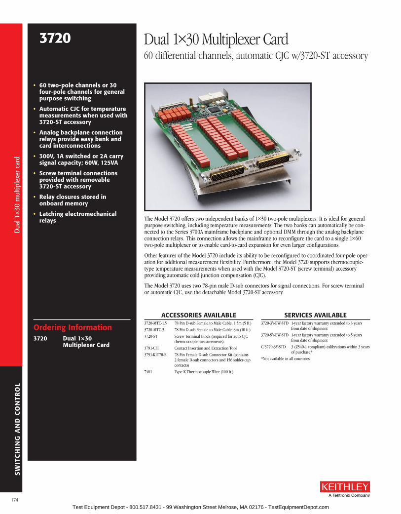
SW
ITC
HIN
G A
ND
CO
NTR
OL
• 60 two-pole channels or 30 four-pole channels for general purpose switching
• automatic CJC for temperature measurements when used with 3720-sT accessory
• analog backplane connection relays provide easy bank and card interconnections
• 300V, 1a switched or 2a carry signal capacity; 60W, 125Va
• screw terminal connections provided with removable 3720-sT accessory
• relay closures stored in onboard memory
• latching electromechanical relays The Model 3720 offers two independent banks of 1×30 two-pole multiplexers . It is ideal for general
purpose switching, including temperature measurements . The two banks can automatically be con-nected to the Series 3700A mainframe backplane and optional DMM through the analog backplane connection relays . This connection allows the mainframe to reconfigure the card to a single 1×60 two-pole multiplexer or to enable card-to-card expansion for even larger configurations .
Other features of the Model 3720 include its ability to be reconfigured to coordinated four-pole oper-ation for additional measurement flexibility . Furthermore, the Model 3720 supports thermo couple-type temperature measurements when used with the Model 3720-ST (screw terminal) accessory providing automatic cold junction compensation (CJC) .
The Model 3720 uses two 78-pin male D-sub connectors for signal connections . For screw terminal or automatic CJC, use the detachable Model 3720-ST accessory .
ordering Information3720 Dual 1×30
Multiplexer Card
aCCEssorIEs aVaIlablE3720-MTC-1 .5 78 Pin D-sub Female to Male Cable, 1 .5m (5 ft .)
3720-MTC-3 78 Pin D-sub Female to Male Cable, 3m (10 ft .)
3720-ST Screw Terminal Block (required for auto CJC thermocouple measurements)
3791-CIT Contact Insertion and Extraction Tool
3791-KIT78-R 78 Pin Female D-sub Connector Kit (contains 2 female D-sub connectors and 156 solder-cup contacts)
7401 Type K Thermocouple Wire (100 ft .)
3720 Dual 1×30 Multiplexer Card60 differential channels, automatic CJC w/3720-ST accessory
sErVICEs aVaIlablE3720-3Y-EW-STD 1-year factory warranty extended to 3 years
from date of shipment
3720-5Y-EW-STD 1-year factory warranty extended to 5 years from date of shipment
C/3720-3Y-STD 3 (Z540-1 compliant) calibrations within 3 years of purchase*
*Not available in all countries
Dua
l 1×3
0 m
ultip
lexe
r car
d
Dua
l 1×3
0 m
ultip
lexe
r car
d
174 Test Equipment Depot - 800.517.8431 - 99 Washington Street Melrose, MA 02176 - TestEquipmentDepot.com

SW
ITC
HIN
G A
ND
CO
NTR
OL
A Greater Measure of Confidence
MULTIPLEXER CONFIGURATION: Two independent 1×30 2-pole multiplexers . Banks can be isolated from the backplane by relays . Card can be configured for 2 and 4 wire .
CONTACT CONFIGURATION: 2 pole form A .
CONNECTOR TyPE: Two 78 pin male D-shells .
MODEL 3720-ST SCREW TERMINAL OPTION: #22 AWG typical wire size with 0 .062 inch O .D . 124 conductors maximum . #16 AWG maximum wire size with 0 .092 inch O .D . 36 conductors per card maximum .
MAXIMUM SIGNAL LEVEL: Channels 1–60: 300V DC or RMS, 1A switched (2A carry), 60W, 125VA .
COMMON MODE VOLTAGE: 300V DC or RMS between any terminal and chassis .
VOLT-HERTz LIMIT: 8×10⁷ .
CONTACT LIFE: >105 operations at maximum signal level . >108 operations no load .1
Dual 1×30 3 single 1×60 2, 3 Channel Resistance (end of contact life) <1 .0 W <1 .5 W Contact Potential (differential) <±1 µV <± 3 µVOffset Current <±250 pA <±250 pAIsolation
Differential 109 W, 250 pF 109 W, 450 pFBank-Bank 1010 W, 75 pF —Channel-channel 109 W, 75 pF 109 W, 75 pFCommon Mode 109 W, 200 pF 109 W, 400 pF
Crosstalk Channel-channel300kHz <–60 dB <–55 dB1MHz <–50 dB <–50 dB20MHz: <–25 dB <–20 dB
Bandwidth 30 MHz 10 MHz
TyPICAL SCANNING SPEEDS:
Switch Only 4: Sequential scanning, single channel, immediate trigger advance: >120 ch/s .
With Measurements Into Memory 5: DCV (10V range) or 2W Ohms (1kW range): >110 ch/s . Thermocouple: >110 ch/s . 3- or 4-Wire RTD: >100 ch/s . 4-Wire Ohms (1kW range): >100 ch/s . ACV (10V range): >110 ch/s .
HILO
HILO
HILO
HILO
HILO
HILO
HILO
Output 1
HILO
Channel 1
HILO
Channel 30
Channels 2–29
Multiplexer Bank 1AnalogBackplane 1(DMM Input)AnalogBackplane 2(DMM Sense)
AnalogBackplane 3
AnalogBackplane 4
AnalogBackplane 5
AnalogBackplane 6
HILO
HILO
HILO
HILO
HILO
HILO
HILO
Output 2
HILO
Channel 31
HILO
Channel 60
Channels 32–59
Multiplexer Bank 2AnalogBackplane 1(DMM Input)AnalogBackplane 2(DMM Sense)
AnalogBackplane 3
AnalogBackplane 4
AnalogBackplane 5
AnalogBackplane 6
To Series 3700A
Mainfram
e Analog B
ackplane
GENEralACTUATION TIME: 4ms .
TEMPERATURE ACCURACy using Automatic CjC with 3720-ST accessory: 1°C for J, K, T and E types (see mainframe specification for details) .
RELAy TyPE: Latching electromechanical .
RELAy DRIVE SCHEME: Matrix .
INTERLOCK: Backplane relays disabled when interlock connection is removed .
OPERATING ENVIRONMENT: Specified for 0° to 50°C . Specified to 70% R .H . at 35°C .
STORAGE ENVIRONMENT: –25° to 65°C .
WEIGHT: 2 .5 lbs .
SAFETy: Conforms to European Union Directive 73/23/EEC, EN61010-1 .
EMC: Conforms to European Union Directive 2004/108/EC, EN61326-1 .
NoTEs1 . Open detector enabled during thermocouple measurements . Minimum signal level 10mV, 10µA .2 . 3706A mainframe with all DMM backplane relays disconnected . Maximum two card backplane relays closed .3 . Connections made using 3720-ST accessory .4 . Scanning script local to 3706A mainframe, within same bank, and break before make switching .5 . 3706A mainframe with autorange off, limits off, dmm .autozero=0, dmm .autodelay=0, 4½ digits (NPLC=0 .006),
for ACV dmm .detectorbandwidth=300, for OHMs dmm .offsetcompensation=off, dmm .opendetector=off . Scanning script local to mainframe, sequential scan within same bank (2 pole) or card (4 pole), and break before make switching .
3720 Dual 1×30 Multiplexer Card60 differential channels, automatic CJC w/3720-ST accessory
100% duty50% duty25% duty10% duty5% duty1 shot
20
10
10.1 1 10 100
Pulse Width (ms)
1. Model 3706A ambient temperature <28°C.2. One shot repetition rate > 10 seconds.3. Signal path routed only through one card (not through backplane).4. Only one channel closed at a time.5. Contact life specification unaffected if pulse width and carry current are not exceeded.
Max
imum
Car
ryin
g C
urre
nt (
A)
Maximum Carrying Current for Pulses
1000 10000
Mod
el 3
720
spec
ifica
tions
Mod
el 3
720
spec
ifica
tions
175 Test Equipment Depot - 800.517.8431 - 99 Washington Street Melrose, MA 02176 - TestEquipmentDepot.com

SW
ITC
HIN
G A
ND
CO
NTR
OL
• 40 two-pole or 20 four-pole channels for general purpose switching
• 2 dedicated channels for current measurements, 3a capacity
• automatic CJC for temperature measurements when used with 3721-sT accessory
• 4-wire common side ohms input supports 40 channels of 4-wire ohms measurements
• analog backplane connection relays provide easy bank and card interconnections
• 300V, 2a switched or 3a carry signal capacity; 60W, 125Va
• latching electromechanical relays
The Model 3721 offers two independent banks of 1×20 two-pole multiplexers that are ideal for general purpose switching, including temperature measurements . The two banks can automatically be connected to the Series 3700A mainframe backplane and optional DMM through the analog back-plane connection relays . This connection allows the mainframe to reconfigure the Model 3721 as a single 1×40 two-pole multiplexer or to enable card-to-card expansion for even larger configurations .
The Model 3721 provides a number of other features . In addition to the 40 channels, two fused chan-nels are supplied for current measurements . Also, the Model 3721 includes dedicated inputs that enable 40 channels of four-wire common side ohms measurements . For thermocouple type measure-ments, automatic cold junction compensation (CJC) is supported when used with the Model 3721-ST (screw terminal) accessory .
The Model 3721 uses two 50-pin male D-sub connectors for signal connections . For screw terminal or automatic CJC, use the detachable Model 3721-ST accessory .
ordering Information3721 Dual 1×20
Multiplexer Card
aCCEssorIEs aVaIlablE3721-MTC-1 .5 50 Pin D-sub Female to Male Cable, 1 .5m (5 ft .)
3721-MTC-3 50 Pin D-sub Female to Male Cable, 3m (10 ft .)
3721-ST Screw Terminal Block (required for auto CJC thermocouple measurements)
3790-KIT50-R 50 Pin Female D-sub Connector Kit (contains 2 female D-sub connectors and 100 solder-cup contacts)
7401 Type K Thermocouple Wire (100 ft .)
3721 Dual 1×20 Multiplexer Card40 differential channels, automatic CJC w/3721-ST accessory
sErVICEs aVaIlablE3721-3Y-EW-STD 1-year factory warranty extended to 3 years
from date of shipment
3721-5Y-EW-STD 1-year factory warranty extended to 5 years from date of shipment
C/3721-3Y-STD 3 (Z540-1 compliant) calibrations within 3 years of purchase*
*Not available in all countries
Dua
l 1×2
0 m
ultip
lexe
r car
d
Dua
l 1×2
0 m
ultip
lexe
r car
d
176 Test Equipment Depot - 800.517.8431 - 99 Washington Street Melrose, MA 02176 - TestEquipmentDepot.com

SW
ITC
HIN
G A
ND
CO
NTR
OL
A Greater Measure of Confidence
MULTIPLEXER CONFIGURATION: Two independent 1×20 2-pole multiplexers . Banks can be connected together via relay creating a single 1×40 multiplexer . Banks can be iso-lated from the backplane by relays . Card can be configured for common side Ohms measurement via backplane relays . Channel 41–42: Multiplex one of two 2-pole current signals into DMM .
CONTACT CONFIGURATION: 2 pole form A .
CONNECTOR TyPE: Two 50 pin male D-shells . Removable screw terminal option .
MAXIMUM SIGNAL LEVEL: Channels 1–40: 300V DC or RMS, 2A switched (3A carry), 60W, 125VA maximum . Channels 41–42: 60V DC or 30V RMS, 3A switched, 60W, 125VA maxi-mum . Fused 3A, 250V RMS .
COMMON MODE VOLTAGE: Channels 1–40: 300V DC or RMS between any terminal and chassis .
VOLT-HERTz LIMIT: 8×10⁷ .
CONTACT LIFE: >105 operations at maximum signal level . >108 operations no load .1
TyPICAL SCANNING SPEEDS:Switch Only 4: Sequential scanning, single channel, immedi-
ate trigger advance: >120 ch/s .
With Measurements Into Memory 5:DCV (10V range) or 2W Ohms (1kW range): >110 ch/sThermocouple: >110 ch/s .3- or 4-Wire RTD: >100 ch/s .4-Wire Ohms (1kW range): >100 ch/s .ACV (10V, 400Hz range) or ACI (1A, 400Hz range): >110 ch/s .
Dual 1×20 3
single 1×40 2, 3
Channel Resistance (end of contact life)
<1 .0 W <1 .5 W
Contact Potential (differential)
<±1 µV <±3 µV
Offset Current <±250 pA <±250 pAIsolation
Differential 109 W, 280 pF 109 W, 530 pFBank-Bank 1011 W, 60 pF —Channel-channel 109 W, 50 pF 109 W, 50 pFCommon Mode 109 W, 180 pF 109 W, 480 pF
Crosstalk Channel-channel300kHz <–60 dB <–60 dB1MHz <–50 dB <–50 dB20MHz: <–25 dB <–15 dB
Bandwidth 28 MHz 9 MHz
GENEralACTUATION TIME: 4ms .
TEMPERATURE ACCURACy using Automatic CjC with 3721-ST accessory: 1°C for J, K, T, and E types (see mainframe specification for details) .
RELAy TyPE: Latching electromechanical .
RELAy DRIVE SCHEME: Direct .
INTERLOCK: Backplane relays disabled when interlock connection is removed .
OPERATING ENVIRONMENT: Specified for 0° to 50°C . Specified to 70% R .H . at 35°C .
STORAGE ENVIRONMENT: –25° to 65°C .
WEIGHT: 2 .25 lbs .
SAFETy: Conforms to European Union Directive 73/23/EEC, EN61010-1 .
EMC: Conforms to European Union Directive 2004/108/EC, EN61326-1 .
NoTEs1 . Open detector enabled during thermocouple measurements . Minimum
signal level 10mV, 10µA .2 . 3706A mainframe with all DMM backplane relays disconnected .
Maximum two card backplane relays closed .3 . Connections made using 3721-ST accessory .4 . Scanning script local to 3706A mainframe, within same bank, and
break before make switching .5 . 3706A mainframe with autorange off, limits off, dmm .autozero=0,
dmm .autodelay=0, 4½ digits (NPLC=0 .006), for ACV dmm .detec-torbandwidth=300, for OHMs dmm .offsetcompensation=off, dmm .opendetector=off . Scanning script local to mainframe, sequential scan within same bank (2 pole) or card (4 pole), and break before make switching .
HILO
HILO
HILO
HILO
HILO
HILO
HILO
Output 1
HILO
Channel 1
HILO
Channel 20
Channels 2–19
Multiplexer Bank 1AnalogBackplane 1(DMM Input)AnalogBackplane 2(DMM Sense)
AnalogBackplane 3
AnalogBackplane 4
AnalogBackplane 5
AnalogBackplane 6
HILO
HILO
HILO
HILO
HILO
HILO
HILO
Output 2
HILO
Channel 21
HILO
Channel 40
Channels 22–39
Multiplexer Bank 2AnalogBackplane 1(DMM Input)AnalogBackplane 2(DMM Sense)
AnalogBackplane 3
AnalogBackplane 4
AnalogBackplane 5
AnalogBackplane 6
To Series 3700A
Mainfram
e Analog B
ackplane
HI
LOChannel 41
3A
HI
LOChannel 42
3A
Amps
AnalogBackplane 1(DMM Input LO)
LOLO Sense
HILO
Channel 1
HILO
Channel 20
Channels 2–19
Multiplexer Bank 1
DMM
To Series 3700A
Mainfram
e Analog B
ackplane
4 WireCommon Side
Ohms
LOLO Sense
HILO
Channel 21
HILO
Channel 40
Channels 22–39
Multiplexer Bank 2
DMM
HIHI Sense
HIHI Sense
Common DMM
Two pole mode
four-wire common side ohm mode
3721 Dual 1×20 Multiplexer Card40 differential channels, automatic CJC w/3721-ST accessory
100% duty50% duty25% duty10% duty5% duty1 shot
20
10
10.1 1 10 100
Pulse Width (ms)
1. Model 3706A ambient temperature <28°C.2. One shot repetition rate > 10 seconds.3. Signal path routed only through one card (not through backplane).4. Only one channel closed at a time.5. Contact life specification unaffected if pulse width and carry current are not exceeded.
Max
imum
Car
ryin
g C
urre
nt (
A)
Maximum Carrying Current for Pulses
1000 10000
Mod
el 3
721
spec
ifica
tions
Mod
el 3
721
spec
ifica
tions
177 Test Equipment Depot - 800.517.8431 - 99 Washington Street Melrose, MA 02176 - TestEquipmentDepot.com

SW
ITC
HIN
G A
ND
CO
NTR
OL
• 96 two-pole or 48 four-pole channels for general purpose measurements
• analog backplane connection relays provide easy bank and card interconnections
• 300V, 1a switched or 2a carry signal capacity; 60W, 125Va
• 1µV and 100pa offsets
• 25MHz bandwidth
• relay closures stored in onboard memory
• latching electromechanical relays
• scan and measure over 110 channels/second
The Model 3722 offers two independent banks of 1×48 two-pole multiplexers, which is ideal for applications that require a high channel count . The two banks can automatically be connected to the Series 3700A mainframe backplane and optional DMM through the analog backplane connection relays . This connection allows the mainframe to reconfigure the card as a single 1×96 two-pole mul-tiplexer or to enable card-to-card expansion for even larger configurations . Another feature of this card is the latching electromechanical relays . They can accommodate 300V, 1A switched signal levels .
The Model 3722 uses two 104-pin D-sub connectors for signal connections . A solder style connec-tor kit (Model 3792-KIT104-R) and pre-assembled cables (Model 3722-MTC-1 .5 and 3722-MTC-3) are available for card connections .
ordering Information3722 Dual 1×48, High
Density, Multiplexer Card
aCCEssorIEs aVaIlablE3722-MTC-1 .5 104-pin D-sub Male to Female Cable, 1 .5m (5 ft .)
3722-MTC-1 .5/MM 104-pin D-sub Male to Male Cable, 1 .5m (5 ft .)
3722-MTC-3 104-pin D-sub Male to Female Cable, 3m (10 ft .)
3722-MTC-3/MM 104-pin D-sub Male to Male Cable, 3m (10 ft .)
3791-CIT Contact Insertion and Extraction Tool
3792-KIT104-R 104-pin Male D-sub Connector kit (contains 2 male D-sub connectors with housings and 208 solder-cup contacts)
3792-KIT104-R/F 104-pin Female D-sub Connector kit (contains 2 female D-sub connectors with housings and 208 solder-cup contacts)
3722 Dual 1×48, High Density, Multiplexer Card96 differential channels, 300 Volts/1 Amp
sErVICEs aVaIlablE3722-3Y-EW-STD 1-year factory warranty extended to 3 years
from date of shipment
3722-5Y-EW-STD 1-year factory warranty extended to 5 years from date of shipment
C/3722-3Y-STD 3 (Z540-1 compliant) calibrations within 3 years of purchase*
*Not available in all countries
Hig
h de
nsity
dua
l 1×
48 m
ultip
lexe
r car
d
Hig
h de
nsity
dua
l 1×
48 m
ultip
lexe
r car
d
178 Test Equipment Depot - 800.517.8431 - 99 Washington Street Melrose, MA 02176 - TestEquipmentDepot.com

SW
ITC
HIN
G A
ND
CO
NTR
OL
A Greater Measure of Confidence
To Series 3700A
Mainfram
e Analog B
ackplane
MULTIPLEXER CONFIGURATION: Two independent 1×48 2-pole multiplexers . Banks can be connected together via relays creating a single 1×96 multiplexer . Banks can be isolated from the backplane by relays . Card can be configured for 2- and 4-wire mode .
CONTACT CONFIGURATION: 2 pole form A .
CONNECTOR TyPE: Two 104 pin female D-shells .
MAXIMUM SIGNAL LEVEL: 300V DC or RMS, 1A switched (2A carry), 60W, 125VA .
COMMON MODE VOLTAGE: 300V DC or RMS between any terminal and chassis .
VOLT-HERTz LIMIT: 8×10⁷ .
CONTACT LIFE: >105 operations at maximum signal level . >108 operations no load .1
Dual 1×48 2 single 1×96 Channel Resistance (end of contact life) <1 .5 W <2 .5 W Contact Potential (differential) <±1 µV <± 2 µVOffset Current <100 pA <100 pAIsolation
Differential 5×10⁹ W, 200 pF 5×10⁹ W, 400 pFBank-Bank 109 W, 50 pF —Channel-channel 109 W, 50 pF 109 W, 50 pFCommon Mode 1010 W, 200 pF 1010 W, 400 pF
Crosstalk Channel-channel300kHz <–65 dB <–65 dB1MHz <–55 dB <–55 dB20MHz <–30 dB <–30 dB
Bandwidth 25 MHz 15 MHz
TyPICAL SCANNING SPEEDS:
Switch Only 3: Sequential scanning, single channel, immediate trigger advance: >120 ch/s .
With Measurements Into Memory 4: DCV (10V range) or 2W Ohms (1kW range): >110 ch/s . 3- or 4-Wire RTD: >100 ch/s . 4-Wire Ohms (1kW range): >100 ch/s . ACV (10V, 400Hz range): >110 ch/s .
GENEralACTUATION TIME: 4ms .
RELAy TyPE: Latching electromechanical .
RELAy DRIVE SCHEME: Matrix .
OPERATING ENVIRONMENT: Specified for 0° to 50°C . Specified to 70% R .H . at 35°C .
STORAGE ENVIRONMENT: –25° to 65°C .
WEIGHT: 2 .5 lbs .
SAFETy: Conforms to European Union Directive 73/23/EEC, EN61010-1 .
EMC: Conforms to European Union Directive 2004/108/EC, EN61326-1 .
NoTEs1 . Minimum signal level 10mV, 10µA .2 . 3706A mainframe with all DMM backplane relays disconnected . Maximum two card backplane relays closed .3 . Scanning script local to 3706A mainframe, within same bank, and break before make switching .4 . 3706A mainframe with autorange off, limits off, dmm .autozero=0, dmm .autodelay=0, 4½ digits (NPLC= .006),
for ACV dmm .detectorbandwidth=300, for OHMs dmm .offsetcompensation=off . Scanning script local to main-frame, sequential scan within same bank (2 pole) or card (4 pole), and break before make switching .
3722 Dual 1×48, High Density, Multiplexer Card96 differential channels, 300 Volts/1 Amp
Mod
el 3
722
spec
ifica
tions
Mod
el 3
722
spec
ifica
tions
179 Test Equipment Depot - 800.517.8431 - 99 Washington Street Melrose, MA 02176 - TestEquipmentDepot.com

SW
ITC
HIN
G A
ND
CO
NTR
OL
• 60 two-pole or 30 four-pole channels for high speed scanning
• 120 channel single-pole mode for one-wire (common side) measurements
• analog backplane connection relays provide easy bank and card interconnections
• 200V, 1a switched or 1.25a carry signal capacity; 15W
• relay actuation time <0.5ms
• 20MHz bandwidth
• Ideal for multi-channel I-V testing with series 2600b sourceMeter® sMu instruments
• long life dry reed relays (>109 operations)
The Model 3723 offers two independent banks of high speed 1×30 two-pole multiplexers that are ideal for high speed scanning applications . The two banks can automatically be connected to the Series 3700A mainframe backplane and optional DMM through the analog backplane connection relays . This connection allows the mainframe to reconfigure the Model 3723 as a single 1×60 two-pole multiplexer or as a single 1×120 single-pole multiplexer . It also enables card-to-card expansion for even larger configurations .
By using high speed reed relays with actuation times of less than 0 .5ms, this card can meet demand-ing throughput applications . Another feature of the Model 3723 is its single-ended, one-pole mode, which supports up to 120 channels of single-wire measurements .
The Model 3723 uses two 78-pin D-sub connectors for signal connections . For screw terminal con-nections, use the Model 3723-ST for two- and four-pole configurations or the Model 3723-ST-1 for single-wire applications .
ordering Information3723 Dual 1×30, High
speed, reed relay, Multiplexer Card
aCCEssorIEs aVaIlablE3720-MTC-1 .5 78 Pin D-sub Female to Male Cable, 1 .5m (5 ft .)
3720-MTC-3 78 Pin D-sub Female to Male Cable, 3m (10 ft .)
3723-ST Screw Terminal Block
3723-ST-1 Screw Terminal Block for single-pole applications
3791-CIT Contact Insertion and Extraction Tool
3791-KIT78-R 78 Pin Female D-sub Connector Kit (contains 2 female D-sub connectors and 156 solder-cup contacts)
3723 Dual 1×30, High Speed, Multiplexer Card60 differential channels, long life reed relays
sErVICEs aVaIlablE3723-3Y-EW-STD 1-year factory warranty extended to 3 years
from date of shipment
3723-5Y-EW-STD 1-year factory warranty extended to 5 years from date of shipment
C/3723-3Y-STD 3 (Z540-1 compliant) calibrations within 3 years of purchase*
*Not available in all countries
Hig
h sp
eed,
dua
l 1×3
0 m
ultip
lexe
r car
d
Hig
h sp
eed,
dua
l 1×3
0 m
ultip
lexe
r car
d
180 Test Equipment Depot - 800.517.8431 - 99 Washington Street Melrose, MA 02176 - TestEquipmentDepot.com

SW
ITC
HIN
G A
ND
CO
NTR
OL
A Greater Measure of Confidence
MULTIPLEXER CONFIGURATION: Two independent 1×30 2-pole multiplexers . Banks can be connected together via relay creating a single 1×60 multiplexer . Banks can be isolated from the backplane by relays . Card can be configured for 1-, 2-, and 4-wire .
CONTACT CONFIGURATION: 2 pole form A .
CONNECTOR TyPE: Two 78-pin male D-shells .
MODEL 3723-ST SCREW TERMINAL OPTION: #22 AWG typical wire size with 0 .062 inch O .D . 124 conductors maximum . #16 AWG maximum wire size with 0 .092 inch O .D . 36 conductor per card maximum .
MAXIMUM SIGNAL LEVEL: 200V DC or RMS, 1A switched (1 .25A carry), 15W .
COMMON MODE VOLTAGE: 300V DC or RMS between any terminal and chassis .
VOLT-HERTz LIMIT: 8×10⁷ .
CONTACT LIFE: Reed: >109 operations, no load . 107 operations @100V, 10mA . EMR: >108 operations @ 5V, 10mA . 105 operations @ maximuum signal level .
Dual 1×30 1 single 1×60 1, 2 Channel Resistance (end of contact life) <1 .5 W <2 .0 W Contact Potential: Differential Single-Ended
<±6 µV <±12 µV
<±6 µV <±12 µV
Offset Current <250 pA <250 pAIsolation
Differential 1010 W, 260 pF 1010 W, 500 pFBank-Bank 1010 W, 75 pF —Channel-channel 1010 W, 75 pF 1010 W, 75 pFCommon Mode 1010 W, 280 pF 109 W, 625 pF
Crosstalk Channel-channel300kHz <–55 dB <–55 dB1MHz <–50 dB <–45 dB20MHz <–20 dB <–20 dB
Bandwidth 20 MHz 10 MHz
TyPICAL SCANNING SPEEDS:
Switch Only 3: Sequential scanning, single channel, immediate trigger advance: >1000 ch/s .
With Measurements Into Memory 4: DCV (10V range) or 2W Ohms (1kW range): >800 ch/s . 3- or 4-Wire RTD: >450 ch/s . 4-Wire Ohms (1kW range): >450 ch/s . ACV (10V, 400Hz range): >800 ch/s .
GENEralACTUATION TIME: <0 .5ms .
RELAy TyPE: Dry reed .
RELAy DRIVE SCHEME: Direct .
RELAy DRIVE CURRENT: 10mA .
INTERLOCK: Backplane relays disabled when interlock connection is removed .
OPERATING ENVIRONMENT: Specified for 0° to 50°C . Specified to 70% R .H . at 35°C .
STORAGE ENVIRONMENT: –25° to 65°C .
WEIGHT: 3 .0 lbs .
SAFETy: Conforms to European Union Directive 73/23/EEC, EN61010-1 .
EMC: Conforms to European Union Directive 2004/108/EC, EN61326-1 .
NoTEs1 . Connections made using 3723-ST accessory .2 . 3706A mainframe with all DMM backplane relays disconnected . Maximum two card backplane relays closed .3 . Scanning script local to 3706A mainframe, within same bank, and break before make switching .4 . 3706A mainframe with autorange off, limits off, dmm .autozero=0, dmm .autodelay=0, 4½ digits (NPLC=0 .006),
for ACV dmm .detectorbandwidth=300, for OHMs dmm .offsetcompensation=off . Scanning script local to main-frame, sequential scan within same bank (2 pole) or card (4 pole), and break before make switching .
HILO
HILO
HILO
HILO
HILO
HILO
HILO
Output 1
HILO
Channel 1
HILO
Channel 30
Channels 2–29
Multiplexer Bank 1
HILO
HILO
HILO
HILO
HILO
HILO
HILO
Output 2
HILO
Channel 31
HILO
Channel 60
Channels 32–59
Multiplexer Bank 2
Analog Backplane 1(DMM Input)
Analog Backplane 2(DMM Sense)
Analog Backplane 3
Analog Backplane 4
Analog Backplane 5
Analog Backplane 6
Analog Backplane 1(DMM Input)
Analog Backplane 2(DMM Sense)
Analog Backplane 3
Analog Backplane 4
Analog Backplane 5
Analog Backplane 6To Series 3700A M
ainframe Analog B
ackplane
HI
LO
HI
LO
HI
LO
HI
LO
HI
LO
HI
LO
HI
LO
HI
LO
HI
LO
HI
LO
HI
LO
HI
LO
To Series 3700A Mainfram
e Analog Backplane
Output 1
Multiplexer Bank 1
HI
LO
Analog Backplane 1(DMM Input)
Analog Backplane 2(DMM Sense)
Analog Backplane 3
Analog Backplane 4
Analog Backplane 5
Analog Backplane 6
Channel 30
Single PoleConfiguration Relay
(internal control only)
Channels 2–29
Channel 1
Channel 31
Channel 61
Channel 90
Channels 62–89
Output 2
Multiplexer Bank 2
HI
LO
Analog Backplane 1(DMM Input)
Analog Backplane 2(DMM Sense)
Analog Backplane 3
Analog Backplane 4
Analog Backplane 5
Analog Backplane 6
Channel 60
Single PoleConfiguration Relay
(internal control only)
Channels 32–59
Channel 91
Channel 120
Channels 92–119
Two-pole mode
single-pole mode
3723 Dual 1×30, High Speed, Multiplexer Card60 differential channels, long life reed relays
Mod
el 3
723
spec
ifica
tions
Mod
el 3
723
spec
ifica
tions
181 Test Equipment Depot - 800.517.8431 - 99 Washington Street Melrose, MA 02176 - TestEquipmentDepot.com

SW
ITC
HIN
G A
ND
CO
NTR
OL
3724 Dual 1×30 FET Multiplexer Card 60 differential channels, automatic CJC with 3724-ST accessory
The Model 3724 provides two independent banks of solid-state relays arranged as 1×30 two-pole multiplexers that are ideal for high reliability, high speed multipoint measurement applications including temperature . The two banks can automatically be connected to the Series 3700A main-frame backplane and optional DMM through the analog backplane connection relays . This connec-tion allows the mainframe to reconfigure the card to a single 1×60 two-pole multiplexer or to enable card-to-card expansion for even larger configurations .
The solid-state FET relay technology supports fast switching times with scanning rates of greater than 1250 channels/second and provides unlimited contact life . In addition, the Model 3724 supports thermo couple temperature measurements when used with the Model 3724-ST (screw terminal) acces-sory providing automatic cold junction compensation (CJC) .
The Model 3724 uses two 78-pin male D-sub connectors for signal connections . For screw terminal or automatic CJC, use the detachable Model 3724-ST accessory .
• 60 two-pole or 30 four-pole solid-state channels
• scanning speeds greater than 1250 channels/second (switch only)
• optically isolated, solid-state fET relays provide unlimited contact life
• 200V, 0.1a switch/carry signal capacity; 800mW
• automatic CJC for temperature measurements when used with 3724-sT accessory
• analog backplane connection relays provide easy bank and card interconnections
• screw terminal connections provided with removable 3724-sT accessory
• Ideal for maintenance-free, long-life thermocouple temperature measurements
ordering Information3724 Dual 1×30 fET
Multiplexer Card
aCCEssorIEs aVaIlablE3720-MTC-1 .5 78-pin female-to-male D-sub Cable Assembly,
1 .5m (4 .9 ft)
3720-MTC-3 78-pin female-to-male D-sub Cable Assembly, 3m (9 .8 ft)
3724-ST Screw Terminal Block (required for auto CJC thermocouple measurements)
3791-CIT Contact Insertion and Extraction Tool
3791-KIT78-R 78-pin female D-sub Connector Kit (contains 2 female D-sub connectors and 156 solder-cup contacts)
sErVICEs aVaIlablE3724-3Y-EW-STD 1-year factory warranty extended to 3 years
from date of shipment
3724-5Y-EW-STD 1-year factory warranty extended to 5 years from date of shipment
C/3724-3Y-DATA 3 (Z540-1 compliant) calibrations within 3 years of purchase*
*Not available in all countries
Dua
l 1×3
0 FE
T m
ultip
lexe
r car
d
Dua
l 1×3
0 FE
T m
ultip
lexe
r car
d
182 Test Equipment Depot - 800.517.8431 - 99 Washington Street Melrose, MA 02176 - TestEquipmentDepot.com

SW
ITC
HIN
G A
ND
CO
NTR
OL
A Greater Measure of Confidence
Model 3724 specificationsMULTIPLEXER CONFIGURATION: Two independent 1×30, 2-pole multiplexers . Banks can be
connected together via relay creating a single 1×60 multiplexer . Banks can be isolated from the backplane by relays . Card can be configured for 2- and 4-wire .
CONTACT CONFIGURATION: 2-pole form A .
CONNECTOR TyPE: Two 78-pin male D-shells .
MODEL 3724-ST SCREW TERMINAL OPTION: #22AWG typical wire size with 0 .062 inch O .D . 124 conductors maximum . 16 AWG maximum wire size with 0 .092 inch O .D . 36 conductor per card maximum .
MAXIMUM SIGNAL LEVEL: 200V DC or 141V RMS between any terminal, 0 .1A switched (0 .1A carry), 800mW .
COMMON MODE VOLTAGE: 300V DC or RMS between any terminal and chassis .
VOLT-HERTz LIMIT: 107 .
CONTACT LIFE: Solid State: > unlimited . EMR (Backplane): >1×10⁸ operations @ 5V, 10mA . 1×10⁵ operations @ max . signal level .
Dual 1×301 single 1×601, 2
Channel Resistance <62W (54W @ 23ºC) <64W (58W @ 23ºC)Contact Potential (differential) <±2 µV <±2 .5 µV
Offset Current<10 nA
(<±100 pA @ 23ºC/60% R .H .)
<10 nA (<±100 pA @
23ºC/60% R .H .)Isolation
Differential 109W, 500 pF 109W, 1100 pFBank-Bank 109W, 100 pF —CH–CH 109W, 125 pF 109W, 125 pFCommon Mode 109W, 150 pF 109W, 700 pF
Crosstalk CH-CH300 kHz –40 dB –40 dB1 MHz –30 dB –30 dB
Bandwidth 2 MHz 1 MHz
NoTEs1 . Connections made using 3724-ST .2 . 3706A mainframe with all DMM backplane relays disconnected . Maximum two card backplane relays closed .
3724 Dual 1×30 FET Multiplexer Card 60 differential channels, automatic CJC with 3724-ST accessory
HILO
HILO
HILO
HILO
HILO
HILO
HILO
Output 1
HILO
Channel 1
HILO
Channel 30
Channels 2–29
Multiplexer Bank 1
HILO
HILO
HILO
HILO
HILO
HILO
HILO
Output 2
HILO
Channel 31
HILO
Channel 60
Channels 32–59
Multiplexer Bank 2
Analog Backplane 1(DMM Input)
Analog Backplane 2(DMM Sense)
Analog Backplane 3
Analog Backplane 4
Analog Backplane 5
Analog Backplane 6
Analog Backplane 1(DMM Input)
Analog Backplane 2(DMM Sense)
Analog Backplane 3
Analog Backplane 4
Analog Backplane 5
Analog Backplane 6
To Series 3700A Mainfram
e Analog Backplane
Mod
el 3
724
spec
ifica
tions
Mod
el 3
724
spec
ifica
tions
183 Test Equipment Depot - 800.517.8431 - 99 Washington Street Melrose, MA 02176 - TestEquipmentDepot.com

SW
ITC
HIN
G A
ND
CO
NTR
OL
3724 Dual 1×30 FET Multiplexer Card 60 differential channels, automatic CJC with 3724-ST accessory
3724 Card/3706a Multimeter Condensed specifications
TEMPEraTurEDisplayed in °C, °F, or K . Exclusive of probe errors .
Displayed in °C, °F, or K . Exclusive of probe errors .
THErMoCouPlEs (accuracy based on ITs-90)
Type range resolution90 Day/1 Year
23°C ± 5°J –150 to +760°C 0 .001°C 1 .0°CK –150 to +1372°C 0 .001°C 1 .0°CN –100 to +1300°C 0 .001°C 1 .0°CT –100 to +400°C 0 .001°C 1 .0°CE –150 to +1000°C 0 .001°C 1 .0°CR +400 to +1768°C 0 .1°C 1 .8°CS +400 to +1768°C 0 .1°C 1 .8°CB +1100 to +1820°C 0 .1°C 1 .8°C
DC sPECIfICaTIoNs
3724 CarD/3706a MulTIMETEr uNCErTaINTY sPECIfICaTIoNs:
function range NotesVoltage All Add 4 .5 µV to PPM “of range”Resistance 100 kW Add 8 PPM to “of reading”Resistance 1 MW Add 80 PPM to “of reading”Resistance 10 MW Add 250 PPM to “of reading”Resistance 100 MW Add 5000 PPM to “of reading”
Resistance 2-wire 1 kW through 100 MWAdd 1 .2 W (with REL) to PPM “of range” Add 64W (without REL) to PPM “of range”
Resistance 4-wire and Dry Circuit
1 W, 10 W, and 100 WRanges Not Available (maximum lead resistance exceeded, see manual for measurement considerations)
CONDITIONS: 1 PLC or 5 PLC .
ACCURACy: ±(ppm of reading + ppm of range) (ppm = parts per million; e .g ., 10ppm = 0 .001%) .
GENEralACTUATION TIME: <0 .2ms .
TEMPERATURE ACCURACy USING AUTOMATIC CjC WITH 3724-ST ACCESSORy: 1ºC for J, K, T, and E type (see mainframe specification for details) .
RELAy TyPE: Optically isolated FET .
RELAy DRIVE SCHEME: Direct .
INTERLOCK: Backplane relays disabled when interlock connection removed .
RELAy DRIVE CURRENT: 4mA .
OPERATING ENVIRONMENT: Specified for 0ºC to 50ºC . Specified to 70% R .H . at 35ºC .
STORAGE ENVIRONMENT: –25ºC to 65ºC .
WEIGHT: 1 .13 kg (2 .5 lbs .) .
SAFETy: Conforms to European Union Directive 73/23/EEC, EN61010-1 .
EMC: Conforms to European Union Directive 2004/108/EC, EN61326-1 .
TyPICAL SCANNING SPEEDS, SWITCH ONLy1: Sequential scanning, single channel, immediate trigger advance: >1250 ch/s .
TyPICAL SCANNING SPEEDS, WITH MEASUREMENTS INTO MEMORy2: DCV (10V range) or 2WW (1kW range): >1000 ch/s . Thermocouple: >1000 ch/s . 3- or 4-Wire RTD: >450 ch/s . 4-Wire W (1kW range): >450 ch/s . ACV (10V, 400Hz range): >1000 ch/s .
POWER BUDGET INFORMATION: Quiescent Power (mW): 1150 . Channel Relay Power (mW) Each: 20 . Backplane Relay Power Consumption (mW) Each: 100 .
See Chapter 8 of the Series 3700A user’s manual for more detailed information .
NoTEs1 . Scanning script local to mainframe, within same bank, break before make .2 . 3706A mainframe with autorange off, limits off, dmm .autodelay=0, dmm .autozero=0, 4½ digits (NPLC= .006),
for ACV dmm .detectorbandwidth=300, for OHMs dmm .offsetcompensation=off, dmm .opendetector=off . Scanning script local to mainframe, sequential scan within same bank (2 pole) or card (4 pole), and break before make switching .
Mod
el 3
724
spec
ifica
tions
Mod
el 3
724
spec
ifica
tions
184 Test Equipment Depot - 800.517.8431 - 99 Washington Street Melrose, MA 02176 - TestEquipmentDepot.com

SW
ITC
HIN
G A
ND
CO
NTR
OL
A Greater Measure of Confidence
• 6 row by 16 column matrix (2-pole)
• analog backplane connection relays provide easy column expansion
• 300V, 1a switched or 2a carry signal capacity; 60W, 125Va
• screw terminal connections provided on removable 3730-sT accessory
• 2µV and 100pa offsets
• relay closures stored in onboard memory
• latching electromechanical relays
The Model 3730 is a two-pole, 6 row by 16 column matrix card . It can connect up to six differential instrument channels to any combination of 16 DUTs (devices under test) . Any row can be connected to the Series 3700A mainframe backplane by using the analog backplane connection relays . This allows for easy matrix column expansion . A matrix of up to 6 rows by 96 columns can be supported within a single Model 3706A mainframe (with six Model 3730 cards) .
The Model 3730 uses two 50-pin male D-sub connectors for signal connections . For screw terminal connections, use the detachable Model 3730-ST accessory .
ordering Information3730 6×16, High Density,
Matrix Card
aCCEssorIEs aVaIlablE3721-MTC-1 .5 50 Pin D-sub Female to Male Cable, 1 .5m (5 ft .)
3721-MTC-3 50 Pin D-sub Female to Male Cable, 3m (10 ft .)
3730-ST Screw Terminal Block
3790-KIT50-R 50 Pin Female D-sub Connector Kit (contains 2 female D-sub connectors and 100 solder-cup contacts)
3730 6×16, High Density, Matrix Card96 two-pole crosspoints with column expansion relays
sErVICEs aVaIlablE3730-3Y-EW-STD 1-year factory warranty extended to 3 years
from date of shipment
3730-5Y-EW-STD 1-year factory warranty extended to 5 years from date of shipment
C/3730-3Y-STD 3 (Z540-1 compliant) calibrations within 3 years of purchase*
*Not available in all countries
Hig
h de
nsity
6×1
6 m
atrix
car
d
Hig
h de
nsity
6×1
6 m
atrix
car
d
185 Test Equipment Depot - 800.517.8431 - 99 Washington Street Melrose, MA 02176 - TestEquipmentDepot.com
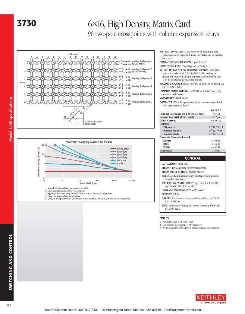
SW
ITC
HIN
G A
ND
CO
NTR
OL
HILO
HILO
HILO
HILO
HILO
HILO
Analog Backplane 1(DMM Input)
Analog Backplane 2(DMM Sense)
Analog Backplane 3
Analog Backplane 4
Analog Backplane 5
Analog Backplane 6
16151413121110987654321
1
2
3
4
5
6
Rows
Columns
Matrix CrosspointRelay Detail
HI
LO
HI
LO
MATRIX CONFIGURATION: 6 row by 16 column matrix . Columns can be expanded using the backplane or isolated by relays .
CONTACT CONFIGURATION: 2 pole form A .
CONNECTOR TyPE: Two 50 pin male D-shells .
MODEL 3730-ST SCREW TERMINAL OPTION: #22 AWG typical wire size with 0 .062 inch O .D . 88 conductors maximum . #16 AWG maximum wire size with 0 .092 inch O .D . 44 conductor per card maximum .
MAXIMUM SIGNAL LEVEL: 300V DC or RMS, 1A switched (2A carry), 60W, 125VA .
COMMON MODE VOLTAGE: 300V DC or RMS between any terminal and chassis .
VOLT-HERTz LIMIT: 8×10⁷ .
CONTACT LIFE: >105 operations @ maximuum signal level . >108 operations no load .1
6×16 2, 3
Channel Resistance (end of contact life) <1 .0 WContact Potential (differential) <±2 µVOffset Current <±100 pAIsolation
Differential 1010 W, 250 pFChannel-channel 1010 W, 75 pFCommon Mode 1010 W, 150 pF
Crosstalk Channel-channel300kHz <–65 dB1MHz <–55 dB20MHz <–30 dB
Bandwidth 27 MHz
GENEralACTUATION TIME: 4ms .
RELAy TyPE: Latching electromechanical .
RELAy DRIVE SCHEME: Hybrid Matrix .
INTERLOCK: Backplane relays disabled when terminal assembly is removed .
OPERATING ENVIRONMENT: Specified for 0° to 50°C . Specified to 70% R .H . at 35°C .
STORAGE ENVIRONMENT: –25° to 65°C .
WEIGHT: 2 .5 lbs .
SAFETy: Conforms to European Union Directive 73/23/EEC, EN61010-1 .
EMC: Conforms to European Union Directive 2004/108/EC, EN61326-1 .
NoTEs1 . Minimum signal level 10mV, 10µA .2 . Connections made using 3730-ST accessory .3 . 3706A mainframe with all DMM backplane relays disconnected .
3730 6×16, High Density, Matrix Card96 two-pole crosspoints with column expansion relays
100% duty50% duty25% duty10% duty5% duty1 shot
20
10
10.1 1 10 100
Pulse Width (ms)
1. Model 3706A ambient temperature <28°C.2. One shot repetition rate > 10 seconds.3. Signal path routed only through one card (not through backplane).4. Only one channel closed at a time.5. Contact life specification unaffected if pulse width and carry current are not exceeded.
Max
imum
Car
ryin
g C
urre
nt (
A)
Maximum Carrying Current for Pulses
1000 10000
Mod
el 3
730
spec
ifica
tions
Mod
el 3
730
spec
ifica
tions
186 Test Equipment Depot - 800.517.8431 - 99 Washington Street Melrose, MA 02176 - TestEquipmentDepot.com

SW
ITC
HIN
G A
ND
CO
NTR
OL
A Greater Measure of Confidence
• 6 row by 16 column matrix (2-pole) using high speed, long life reed relays
• analog backplane connection relays provide easy column expansion
• 200V, 1a switched or 2a carry signal capacity; 10W, 10Va
• screw terminal connections provided on removable 3731-sT accessory
• relay actuation time of 0.5ms
• Ideal for multi-channel I-V testing with series 2600b systems
• long life dry reed relays (>109 operations)
The Model 3731 is a two-pole, 6 row by 16 column reed relay matrix card . By using high speed reed relays with actuation times of 0 .5ms, this card meets the requirements of demanding throughput applications while offering users the additional benefit of long life, exceeding one billion operations . The card can connect up to six differential instrument channels to any combination of 16 DUTs (devices under test) . Any row can be connected to the Series 3700A mainframe backplane by using the analog backplane connection relays . This allows for easy matrix column expansion . A matrix of up to 6 rows by 96 columns can be supported within a single 3706A mainframe (with six Model 3731 cards) .
The Model 3731 uses two 50-pin male D-sub connectors for signal connections . For screw terminal connections, use the detachable Model 3731-ST accessory .
ordering Information3731 6×16 High speed, reed
relay, Matrix Card
aCCEssorIEs aVaIlablE3721-MTC-1 .5 50-pin D-sub Female to Male Cable, 1 .5m (5 ft .)
3721-MTC-3 50-pin D-sub Female to Male Cable, 3m (10 ft .)
3731-ST Screw Terminal Block
3790-KIT50-R 50-pin Female D-sub Connector Kit (contains 2 female D-sub connectors and 100 solder-cup contacts)
3731 6×16 High Speed, Reed Relay, Matrix Card96 two-pole crosspoints with column expansion relays
sErVICEs aVaIlablE3731-3Y-EW-STD 1-year factory warranty extended to 3 years
from date of shipment
3731-5Y-EW-STD 1-year factory warranty extended to 5 years from date of shipment
C/3731-3Y-STD 3 (Z540-1 compliant) calibrations within 3 years of purchase*
*Not available in all countries
Hig
h sp
eed
6×16
reed
mat
rix c
ard
Hig
h sp
eed
6×16
reed
mat
rix c
ard
187 Test Equipment Depot - 800.517.8431 - 99 Washington Street Melrose, MA 02176 - TestEquipmentDepot.com

SW
ITC
HIN
G A
ND
CO
NTR
OL
3731 6×16 High Speed, Reed Relay, Matrix Card96 two-pole crosspoints with column expansion relays
96 Two-Pole Crosspoints with Column Expansion relaysMATRIX CONFIGURATION: 6 row by 16 column matrix .
Columns can be expanded using the backplane or isolated by relays .
CONTACT CONFIGURATION: 2-pole form A .CONNECTOR TyPE: Two 50-pin male D-shells .MODEL 3731-ST SCREW TERMINAL OPTION:
Typical wire size: #22 AWG with .062 inch O .D .; 88 conductors maximum Maximum wire size: #16 AWG with .092 inch O .D .; 44 conductors per card maximum .
MAXIMUM SIGNAL LEVEL: 200V DC or peak AC, 1A switched (2A carry), 10W, 10VA .
COMMON MODE VOLTAGE: 200V DC or peak AC between any signal path to a signal path or ground .
VOLT-HERTz LIMIT: 8×10⁷ .CONTACT LIFE:
Reed: >109 operations no load . >8×10⁶ operations @ 100V, 10mA .
EMR (Backplane): >108 operations @ 5V, 10mA and 105 operations @ maximum signal level .
6×16 1, 2
Channel Resistance (end of contact life) <1 .5 WContact Potential (differential) <±80 µVOffset Current <±500 pAIsolation
Differential 3×10⁹ W, 300 pFChannel-channel 3×10⁹ W, 100 pFCommon Mode 3×10⁹ W, 150 pF
Crosstalk Channel-channel300kHz <–60 dB1MHz <–50 dB15MHz <–20 dB
Bandwidth 19 MHz
GENEralACTUATION TIME: 0 .5ms .RELAy TyPE: Reed .RELAy DRIVE SCHEME: Direct drive .INTERLOCK: Backplane relays disabled when terminal
assembly is removed .OPERATING ENVIRONMENT: Specified for 0° to 50°C .
Specified to 70% R .H . at 35°C .STORAGE ENVIRONMENT: –25° to 65°C .WEIGHT: 2 .2 lbs .SAFETy: Compliant with European Union Low Voltage
DirectiveEMC: Compliant with European Union EMC Directive
2004/108/EC, EN61326-1 .
NoTEs1 . Connections made using 3731-ST .2 . 3706A mainframe with all DMM backplane relays disconnected .
HILOHILOHILOHILOHILOHILO
Analog Backplane 1(DMM Input) Analog Backplane 2(DMM Sense) Analog Backplane 3
Analog Backplane 4
Analog Backplane 5
Analog Backplane 6
16151413121110987654321
1
2
3
4
5
6
Rows
Columns
Matrix CrosspointRelay Detail
HILO
HI
LO
Mod
el 3
731
spec
ifica
tions
Mod
el 3
731
spec
ifica
tions
188 Test Equipment Depot - 800.517.8431 - 99 Washington Street Melrose, MA 02176 - TestEquipmentDepot.com

SW
ITC
HIN
G A
ND
CO
NTR
OL
A Greater Measure of Confidence
• four independent banks of 4×28 single pole matrices
• 200V, 1.2a carry or 0.75a switched signal capacity; 15W, 15Va
• bank configuration relays enable alternative matrix sizes, including:
– Dual 4×56 (1 wire)
– single 4×112 (1 wire)
– single 4×56 (2 wire)
• optional accessory, Model 3732-sT-r, enables screw terminal access and additional matrix sizes including:
– Dual 8×28 (1 wire)
– single 16×28 (1 wire)
– single 8×28 (2 wire)
• analog backplane connection relays provide easy card-to-card column expansion
• long life dry reed relays (>109 operations)
• Ideal for high channel count I-V testing with series 2600b systems
The ultra-high density Model 3732 matrix card is comprised of four banks, each with 4 rows by 28 columns of reed relays . This provides 448 single-pole crosspoints for maximum connection versatil-ity in high channel count applications . For even greater flexibility, bank configuration relays are mounted on the card . They offer an automated method of connecting banks to enable two additional matrix configurations: single 4×112 and dual 4×56 . This feature allows the matrix size to be easily adapted to existing or future applications . For differential (2-wire) measurements, a two-pole mode can be selected that enables automatic pairing of crosspoints to create a dual 4×28 or single 4×56 configuration . For larger matrix sizes, analog backplane relays are provided that enable rows to con-nect to the Series 3700A mainframe backplane . This allows, for example, a matrix of up to 4 rows by 672 columns within a single 3706A mainframe using six Model 3732 cards .
The card uses optimized reed relays that offer both low contact potential and low current offset to minimize the switching errors that often accompany this relay technology . Additionally, these relays provide greater signal voltage (200V) and current (1 .2A carry) dynamic range while supporting the long life and fast actuation times necessary in many automated test applications .
The Model 3732 uses two 78-pin male D-sub connectors for signal and configuration connections . For screw terminal connections, two accessories are offered . Use the 3732-ST-R for the 16×28 or dual 8×28 matrix configurations . Use the 3732-ST-C for the 4×112, dual 4×56, or base quad 4×28 matrix configurations .
ordering Information3732 Quad 4×28, ultra-
High Density, reed relay Matrix Card
aCCEssorIEs aVaIlablE3732-ST-C Screw Terminal Block for matrix configurations: Quad 4×28 (1 wire) Dual 4×28 (2 wire) Single 4×56 (2 wire) Dual 4×56 (1 wire) Single 4×112 (1 wire)
3732-ST-R Screw Terminal Block for matrix configurations: Dual 8×28 (1 wire) Single 8×28 (2 wire) Single 16×28 (1 wire)
3732-MTC-1 .5 78-pin, D-sub Female-to-Male Cable, 1 .5m (5 ft .)
3732-MTC-3 78-pin, D-sub Female-to-Male Cable, 3m (10 ft .)
3791-CIT Contact Insertion and Extraction Tool
3791-KIT78-R 78-pin, Female D-sub Connector Kit (contains 2 female D-sub connectors and 156 solder-cup contacts)
3732 Quad 4×28, Ultra-High Density, Reed Relay Matrix Card448 one-pole crosspoints with bank configuration and backplane connection relays
sErVICEs aVaIlablE3732-3Y-EW-STD 1-year factory warranty extended to 3 years
from date of shipment
3732-5Y-EW-STD 1-year factory warranty extended to 5 years from date of shipment
C/3732-3Y-STD 3 (Z540-1 compliant) calibrations within 3 years of purchase*
*Not available in all countries
Qua
d 4×
28, u
ltra-
high
den
sity
, ree
d re
lay
mat
rix c
ard
Qua
d 4×
28, u
ltra-
high
den
sity
, ree
d re
lay
mat
rix c
ard
189 Test Equipment Depot - 800.517.8431 - 99 Washington Street Melrose, MA 02176 - TestEquipmentDepot.com

SW
ITC
HIN
G A
ND
CO
NTR
OL
3732 Quad 4×28, Ultra-High Density, Reed Relay Matrix Card448 one-pole crosspoints with bank configuration and backplane connection relays
Matrix Bank 1
1
Row
s 234
To AnalogBackplane
Relaysof Card
1 2Columns
27 28
Matrix Bank 2
1
Row
s 234
To AnalogBackplane
Relaysof Card
1 2Columns
27 28
Matrix Bank 3
1
Row
s 234
To AnalogBackplane
Relaysof Card
1 2Columns
27 28
Matrix Bank 4
1
Row
s 23
To AnalogBackplane
Relaysof Card
1 2Columns
27 28
Matrix CrosspointRelay Detail
AnalogBackplane
AnalogBackplane
MatrixRows
Bank 1
1
2
MatrixRows
Bank 3
To Series 3700AMainframe
AnalogBackplane
3
4
5
6
MatrixRows
Bank 2
MatrixRows
Bank 4
Analog Backplane Connection Relays
4
Matrix CrosspointRelay Detail
Matrix CrosspointRelay Detail
Matrix CrosspointRelay Detail
Quad 4×28 (1-wire) or Dual 4×28 (2-wire) Matrix Configuration
Mod
el 3
732
spec
ifica
tions
Mod
el 3
732
spec
ifica
tions
190 Test Equipment Depot - 800.517.8431 - 99 Washington Street Melrose, MA 02176 - TestEquipmentDepot.com

SW
ITC
HIN
G A
ND
CO
NTR
OL
A Greater Measure of Confidence
3732 Quad 4×28, Ultra-High Density, Reed Relay Matrix Card448 one-pole crosspoints with bank configuration and backplane connection relays
1
1 2Columns
Rows2
27 28
3
4
Matrix Bank 1
3732-ST-RScrew Terminal
Block*
5
Rows6
7
8
Matrix Bank 2
1
1 2Columns
Rows2
27 28
3
4
Matrix Bank 3
5
Rows6
7
8
Matrix Bank 4
*Automatically connects columns
Dual 8×28 (1-wire) or single 8×28 (2-wire) matrix configuration using one Model 3732-sT-r screw terminal block
single 16×28 (1-wire) matrix configuration using one Model 3732-sT-r screw terminal block
1
1 2Columns
Rows2
27 28
3
4
Matrix Bank 1
5
Rows6
7
8
Matrix Bank 2
9
Rows10
11
12
Matrix Bank 3
13
Rows14
15
16
Matrix Bank 4
3732-ST-R Screw Term
inal Block*
*Automatically connects columns
Additional Matrix Configurations Using the Model 3732-ST-R Screw Terminal Block
Dual 4×56 (1-wire) or single 4×56 (2-wire) matrix configuration using bank configuration relays
single 4×112 (1-wire) matrix configuration using bank configuration relays
1
1 2Columns
Rows2
27 28 29 30Columns
55 56 1 2Columns
27 28 29 30Columns
55 56
3
4
MatrixBank 1
MatrixBank 2
Bank Configuration Relays
MatrixBank 3
MatrixBank 4
1
1 2Columns
Rows2
27 28 29 30Columns
55 56 57 58Columns
83 84 85 86Columns
111112
3
4
MatrixBank 1
MatrixBank 2
Bank Configuration Relays
MatrixBank 3
MatrixBank 4
Additional Matrix Configurations Using Bank Configuration Relays
Mod
el 3
732
spec
ifica
tions
Mod
el 3
732
spec
ifica
tions
191 Test Equipment Depot - 800.517.8431 - 99 Washington Street Melrose, MA 02176 - TestEquipmentDepot.com

SW
ITC
HIN
G A
ND
CO
NTR
OL
3732 Quad 4×28, Ultra-High Density, Reed Relay Matrix Card448 one-pole crosspoints with bank configuration and backplane connection relays
MATRIX CONFIGURATION: Four banks, each with 4 rows by 28 columns of reed relays . Bank configuration and analog backplane relays are included for additional matrix configura-tions . Banks can be connected together via relays creating dual 4×56 matrices or a single 4×112 matrix . Row expansion is available using optional screw terminal accessories .
CONTACT CONFIGURATION: Single-pole form A .
CONNECTOR TyPE: Two 78-pin male D-shells .
MODEL 3732-ST-R SCREW TERMINAL OPTION: Provides ter-minal block access and column jumper blocks for extended row configurations including Dual 8×28 (1W), Single 8×28 (2W), and Single 16×28 (1W) .Typical Wire Size: #22 AWG with 0 .062 inch O .D .; 88 con-
ductors per card maximum .Maximum Wire Size: #16 AWG with 0 .092 inch O .D .; 44
conductors per card maximum .
MODEL 3732-ST-C SCREW TERMINAL OPTION: Provides terminal block access for Quad 4×28 (1W), Dual 4×28 (2W), Dual 4×56 (1W), Single 4×56 (2W), and Single 4×112 (1W) matrix configurations .Typical Wire Size: #22 AWG with 0 .062 inch O .D .; 88 con-
ductors per card maximum .Maximum Wire Size: #16 AWG with 0 .092 inch O .D .; 44
conductors per card maximum .
MAXIMUM SIGNAL LEVEL: 200VDC or peak AC, 0 .75A switched (1 .2A carry), 15W/15VA max . switch power .
COMMON MODE VOLTAGE: 200VDC or peak AC between any signal path to a signal path or ground .
VOLT-HERTz LIMIT: 8×10⁷ .
CONTACT LIFE: Reed: >109 operations no load, >8×10⁶ opera-tions @ 100V, 10mA .
EMR (Backplane): >108 operations @ 5V, 10mA and 105 opera-tions at maximum signal level .
MoDEl 3732 ParaMETErsParameter Quad 4×28 1, 2 Dual 4×56 1, 2 single 4×112 1, 2 Dual 8×28 2, 3 single 16×28 2, 3
Channel Resistance (end of life) <1 .5 W <2 .0 W <2 .5 W <1 .6 W <2 .0 W
Contact Potential (differential) <±10 µV <±20 µV N/A <±15 µV N/A
Contact Potential (single ended) <±20 µV <±40 µV <±65 µV <± 20 µV <±20 µV
Offset Current <±0 .5 nA <±1 .0 nA <±2 .0 nA <±1 .0 nA <±2 .0 nAIsolation CH-CH 3×10⁹ W/150 pF 1 .5×109 W/300 pF 7 .5×108 W/600 pF 2×10⁹ W/200 pF 1 .5×109 W/300 pF Common mode 1 .5×109 W/300 pF 1 .5×109 W/300 pF 7 .5×108 W/600 pF 2×10⁹ W/200 pF 1 .5×109 W/300 pFCrosstalk Ch-Ch 300 kHz <–37 dB <–37 dB <–37 dB <–37 dB <–37 dB 1 MHz <–26 dB <–26 dB <–26 dB <–26 dB <–26 dB 15 MHz < –7 dB < –7 dB < –7 dB < –7 dB < –7 dBBandwidth 15 MHz 15 MHz 10 MHz 15 MHz 15 MHz
1 . Connections made using Model 3732-ST-C .2 . Model 3706A mainframe with all DMM backplane relays disconnected .3 . Connections made using Model 3732-ST-R .
GENEralPOWER BUDGET INFORMATION:
Quiescent Power Usage:Mode Quiescent Power
Quad 4×28 780 mWDual 4×56 916 mW
Single 4×112 984 mWDual 8×28 780 mW
Single 16×28 780 mW
Channel Relay Power Consumption (each): 17mW .
Backplane Relay Power Consumption (each): 100mW .
For additional power-budgeting information, refer to the Series 3700A Module Schematics and Connections section in the Series 3700A User’s Manual (part no . 3700S-900-01) .
ACTUATION TIME: 0 .6ms .
RELAy TyPE: Reed (signal relays); EMR (backplane relays)
RELAy DRIVE SCHEME: Direct drive .
RELAy DRIVE CURRENT: 3 .2mA .
INTERLOCK: Backplane relays disabled when terminal assembly interlock signal removed . When asserted allows system to read and save ID configuration bits .
EMC: Compliant with European Union EMC Directive .
SAFETy: Compliant with European Union Law Voltage Directive .
OPERATING ENVIRONMENT: Specified for 0° to 50°C . Specified to 70% relative humidity at 35°C .
STORAGE ENVIRONMENT: –25° to 65°C .
WEIGHT: 3 .40 lbs (1 .54kg) .
192
Mod
el 3
732
spec
ifica
tions
Mod
el 3
732
spec
ifica
tions
Test Equipment Depot - 800.517.8431 - 99 Washington Street Melrose, MA 02176 - TestEquipmentDepot.com

SW
ITC
HIN
G A
ND
CO
NTR
OL
A Greater Measure of Confidence
• 28 general purpose form C relays rated for 300V, 2a switched or 3a carry signal capacity; 60W, 125Va
• 4 high current form a relays rated for 250VaC, 7a or 30VDC, 7a switched capacity; 210W
• analog backplane connection relays provided for user interconnections
• screw terminal connections provided on removable 3740-sT accessory
• relay closures stored in onboard memory
• latching electromechanical relays
The Model 3740 offers 28 general-purpose form C channels that are ideal for routing power or other control devices . For higher power applications of up to 7A, four additional high current form A chan-nels are provided .
If any general purpose signal requires routing to the Series 3700A mainframe backplane, terminal blocks are located on the card, which are enabled with jumpers . Custom configurations can be created with the user accessible terminal blocks . For additional protection, an onboard temperature sensor will notify the mainframe when the card’s operating temperature exceeds 70°C, compromising system specifications .
The Model 3740 uses two 50-pin male D-sub connectors for signal connections . For screw terminal connections, use the detachable Model 3740-ST accessory .
ordering Information3740 General Purpose Card
with 32 Independent Channels
aCCEssorIEs aVaIlablE3721-MTC-1 .5 50-pin D-sub Female to Male Cable, 1 .5m (5 ft .)
3721-MTC-3 50-pin D-sub Female to Male Cable, 3m (10 ft .)
3740-ST Screw Terminal Block
3790-KIT50-R 50-pin Female D-sub Connector Kit (contains 2 female D-sub connectors and 100 solder cup contacts)
3740 32-channel Isolated Switch Card28 Form C relays and 4 high power Form A relays
sErVICEs aVaIlablE3740-3Y-EW-STD 1-year factory warranty extended to 3 years
from date of shipment
3740-5Y-EW-STD 1-year factory warranty extended to 5 years from date of shipment
C/3740-3Y-STD 3 (Z540-1 compliant) calibrations within 3 years of purchase*
*Not available in all countries
193
32 c
hann
el is
olat
ed s
witc
h ca
rd
32 c
hann
el is
olat
ed s
witc
h ca
rd
Test Equipment Depot - 800.517.8431 - 99 Washington Street Melrose, MA 02176 - TestEquipmentDepot.com

SW
ITC
HIN
G A
ND
CO
NTR
OL
HILO
HILO
HILO
HILO
HILO
HILO
Analog Backplane 1(DMM Input)
Analog Backplane 2(DMM Sense)
Analog Backplane 3
Analog Backplane 4
Analog Backplane 5
Analog Backplane 6
NCNOChannel 13
COM
NCNOChannel 28
COM
Channels 14–27
NCNOChannel 1
COM
NCNOChannel 12
COM
Channels 2–11
Channel 29
Channel 32
Channels 30–31
TerminalBlocks
To Series 3700A Mainfram
e Analog Backplane
RELAy SWITCH CONFIGURATION: 32 general purpose independent channels . 28 channels of Form C switching at 2A and 4 channels of Form A switching at 7A . Relays can be connected to each other and backplane via removable terminal blocks .
CONTACT CONFIGURATION: General Purpose: 1 pole Form C . High Current: 1 pole Form A .
CONNECTOR TyPE: Two 50 pin male D-shells .
MODEL 3740-ST SCREW TERMINAL OPTION: #22 AWG typical wire size with 0 .062 inch O .D . 84 conductors maximum . #16 AWG maximum wire size with 0 .092 inch O .D . 44 conductors per card maximum .
MAXIMUM SIGNAL LEVEL: Form C: 300V DC or RMS, 2A switched (3A carry), 60W, 125VA . Form A: 250VAC 7A, 30VDC 7A, 210W .
COMMON MODE VOLTAGE: 300V DC or RMS between any terminal and chassis .
VOLT-HERTz LIMIT: 8×10⁷ .
CONTACT LIFE: Form C: >105 operations at maximum signal level . >108 operations no load .1 Form A: >105 operations at maximum signal level, >5×10⁷ operations no load .1
CHANNEL RESISTANCE (end of contact life): <0 .5W .
CONTACT POTENTIAL: <±3µV typical per contact .
ISOLATION: Channel-channel: 109W, <200pF . Common Mode: >1010W, <150pF .
Crosstalk (Channel-channel, 50W load–50W source): 100kHz: <–50dB . 1MHz: <–35dB . 10MHz: <–15dB .
BANDWIDTH: 30MHz .
GENEralOVER-TEMPERATURE: Temperature sensor indicates over temperature .
ACTUATION TIME: Form C: 4ms . Form A: 10ms .
RELAy TyPE: Form C: Latching electromechanical . Form A: Nonlatching electromechanical .
RELAy DRIVE SCHEME: Direct .
INTERLOCK: Backplane relays disabled when interlock connection is removed .
OPERATING ENVIRONMENT: Specified for 0° to 50°C . Specified to 70% R .H . at 35°C .
STORAGE ENVIRONMENT: –25° to 65°C .
WEIGHT: 2 .5 lbs .
SAFETy: Conforms to European Union Directive 73/23/EEC, EN61010-1 .
EMC: Conforms to European Union Directive 2004/108/EC, EN61326-1 .
NoTEs1 . Minimum signal level 10mV, 10µA .
3740 32-channel Isolated Switch Card28 Form C relays and 4 high power Form A relays
Mod
el 3
740
spec
ifica
tions
Mod
el 3
740
spec
ifica
tions
194 Test Equipment Depot - 800.517.8431 - 99 Washington Street Melrose, MA 02176 - TestEquipmentDepot.com

SW
ITC
HIN
G A
ND
CO
NTR
OL
A Greater Measure of Confidence
3750 Multifunction Control Card 40 digital I/O bits, 2 analog output channels, and 4 counters
Use the Model 3750 to monitor and control your automated test system . The flexibility and speed provided by the 40 digital I/O bits, four counters, and two analog outputs make it well-suited for a wide variety of system control applications .
Digital I/oThe Model 3750 offers 40 digital I/O bits arranged in five banks . Each bank is comprised of eight bits each, and each bank can be programmed as either input or output . Digital I/O is often used to control processes and monitor the status of switches, contacts, and other control points . Additional features include scanning capabilities, such as writing a unique output pattern or reading banks of inputs at rates up to 1000 rdgs/second . Also, pattern matching is available, making it ideal for complex event algorithms .
Further versatility is provided by supporting external voltage levels of up to 30V and output current sink levels of 300mA for control of external devices like RF/microwave relays .
analog outputsThe two analog outputs of the Model 3750 are designed for general purpose applications such as setpoint control or as bias supplies to your device under test . For maximum utility, these outputs are programmable as voltage (±12V) or current (0–20mA or 4–20mA) . A number of protection features are provided, including monitoring for current and/or voltage compliance and the ability to disconnect automatically during fault conditions . Output relays are supplied for each channel, ensuring mechanical isolation between your control device and the analog output .
CountersFour 32-bit counters are provided with a maximum input rate of 1MHz . Each counter has a gate input that offers precise control of event counting and totalizing for a broad range of system components, such as: fixtures, limit switches, pass/fail indicators, revolutions, or time-related quantities . The counters, like the digital I/O, can be used in scanning operations and pattern matching as well as s upporting reading rates of up to 1000 rdgs/second .
self-calibrationWhen your Model 3706A mainframe is equipped with the high performance multimeter option, hardware and software is provided for self-calibration of analog outputs (voltage and current) and counter thresholds .
• 40 bidirectional digital input/output bits
• High current driver outputs for sinking (300ma)
• Internal 5V, 50ma logic supply for powering external logic circuits
• 2 isolated analog output channels, programmable to ±12V, 0–20ma, or 4–20ma
• 4 gated 32-bit counters with 1MHz input rate
• screw terminal connections provided with removable 3750-sT accessory
• External supply voltage supported on digital I/o
ordering Information3750 Multifunction
Control Card
aCCEssorIEs aVaIlablE3721-MTC-1 .5 50-pin female-to-male D-sub Cable Assembly,
1 .5m (4 .9 ft)
3721-MTC-3 50-pin female-to-male D-sub Cable Assembly, 3m (9 .8 ft)
3750-ST Screw Terminal Block
3790-KIT50-R 50-pin female D-sub Connector Kit (contains 2 D-sub connectors and 100 solder cup contacts)
sErVICEs aVaIlablE3750-3Y-EW-STD 1-year factory warranty extended to 3 years
from date of shipment
3750-5Y-EW-STD 1-year factory warranty extended to 5 years from date of shipment
C/3750-3Y-DATA 3 (Z540-1 compliant) calibrations within 3 years of purchase*
*Not available in all countries
Mul
tifun
ctio
n co
ntro
l car
d
Mul
tifun
ctio
n co
ntro
l car
d
195 Test Equipment Depot - 800.517.8431 - 99 Washington Street Melrose, MA 02176 - TestEquipmentDepot.com

SW
ITC
HIN
G A
ND
CO
NTR
OL
3750 Multifunction Control Card 40 digital I/O bits, 2 analog output channels, and 4 counters
Channels 1–5: Bidirectional, high current digital I/O (40 bits)Channels 6–9: 32-bit counters (4 counters)Channels 10–11: Isolated voltage or current analog outputs (2 each)
DigitalInputs
orDigital
Outputs
Total of 5 banks8 bits per bank
Channels1–5
12348 Bits
5678
Bank 1
Counter
Total of 4 counters
Gate +Gate –
32 BitCount
Input +Input –
Counter 1
TTLorAC
Channels6–9
Total of 2 analog outputs(isolated from earth)
Channels10–11
VOUT±12V
(0–20mA)(4–20mA)
VCOM
IOUT
ICOM
Analog Output 1
16 BitsDAC
VOUT
IOUT
10mA max.Sourcing Only
300mA max.Sinking Only
Optional Jumper
SelfResetting
Input
Simplified Digital I/O Schematic
System 5V
Output
Pull-upResistor~68kΩ
Pull-up Voltage(8 DIO)
+–
DIO n
Logic Supply(50mA max.)
V EXTERNAL(VEXT1, VEXT2)(30V max.)
specifications
DIGITal I/o1
CONFIGURATION: 40 bidirectional digital I/O bits arranged in 5 banks of 8 bits each . Each bank can be configured for either input or output capability . 1 bank of I/O is equivalent to 1 system channel .
DIGITal INPuT sPECIfICaTIoNsAn internal weak pull-up resistor of approximately 68kW is provided on the card for each I/O . This pull-up resistor can be removed via onboard jumper on a channel (8 bit) basis . The pull-up voltage can either connect to the internally supplied 5V or an externally supplied voltage of up to 30V via onboard jumper . An internal 5V supply connection is separately available to run external logic circuits .
DIGITAL INPUT LOGIC LOW VOLTAGE: 0 .8V max .
DIGITAL INPUT LOGIC HIGH VOLTAGE: 2V min .
DIGITAL INPUT LOGIC LOW CURRENT: –600µA max @ 0V .
DIGITAL INPUT LOGIC HIGH CURRENT: 50µA max @ 5V .
LOGIC: Positive true .
SySTEM INPUT MINIMUM READ SPEED2: 1000 readings/second .
MAXIMUM EXTERNALLy SUPPLIED PULL-UP VOLTAGE: 30V .
MAXIMUM EXTERNALLy SUPPLIED VOLTAGE TO ANy DIGITAL I/O LINE: Pull-up voltage (5V internal or up to 30V external) .
DIGITal ouTPuT sPECIfICaTIoNsEach output has an internal fly-back diode for driving inductive loads . Each output is protected against continuous short circuits and over temperature . An internal 5V supply connection is separately available to run external logic circuits .
DIGITAL OUTPUT LOGIC HIGH VOLTAGE: 2 .4V minimum @ Iout = 10mA, sourcing only .
DIGITAL OUTPUT LOGIC LOW VOLTAGE: 0 .5V maximum @ Iout = -300mA, sinking only .
MAXIMUM OUTPUT SINK CURRENT: 300mA per output, 3 .0A total per card .
LOGIC: Positive true .
SySTEM OUTPUT MINIMUM WRITE SPEED3: 1000 readings/second .
MAXIMUM EXTERNALLy SUPPLIED VOLTAGE TO ANy DIGITAL I/O LINE: Pull-up voltage (5V internal or up to 30V external) .
ALARM: Trigger generation is supported for a maskable pattern match or state change on any of channels 1 through 5 .
PROTECTION: Optional disconnect (set to inputs) during output fault conditions .
INTERNAL 5V LOGIC SUPPLy: The internal logic supply is designed for powering external logic circuits of up to 50mA maximum . The logic supply is internally protected with a self-resetting fuse . Fuse reset time < 1 hour .
NoTEs1 . All channels power up configured as inputs .2 . All channels configured as inputs .3 . All channels configured as outputs .
figure 2. simplified I/o schematic
figure 1. block diagram
196
Mod
el 3
750
spec
ifica
tions
Mod
el 3
750
spec
ifica
tions
Test Equipment Depot - 800.517.8431 - 99 Washington Street Melrose, MA 02176 - TestEquipmentDepot.com

SW
ITC
HIN
G A
ND
CO
NTR
OL
A Greater Measure of Confidence
3750 Multifunction Control Card 40 digital I/O bits, 2 analog output channels, and 4 counters
VCOM
VCOM
<100pF
Test Circuit for Voltage OutputChannels 10 and 11
DACVOUT
1.2kΩ
+–
ICOM
<100pF
Test Circuit for Current OutputChannels 10 and 11
DACIOUT
500Ω
CouNTEr/ToTalIZEr INPuTMAXIMUM COUNT: 232 – 1 .
MAXIMUM INPUT RATE: 1MHz, rising or falling edge, programmable .
MINIMUM INPUT PULSE WIDTH: 500ns .
INPUT SIGNAL LEVEL: 200mV p-p (minimum), 42V peak (maximum) .
THRESHOLD: AC (0V) or TTL logic level .
GATE INPUT: TTL–HI (Gate+), TTL–LO (Gate–) or NONE .
MINIMUM GATE INPUT SETUP TIME: 1µs .
COUNT RESET: Manual or Read + Reset .
SySTEM INPUT MINIMUM READ SPEED: 1000 readings/second .
ALARM: Trigger generation is supported for a count match or counter overflow on any of channels 6 though 9 .
aNaloG VolTaGE ouTPuTThe isolated analog voltage output is designed for general purpose, low power applications .
OUTPUT AMPLITUDE1: ±12V up to 10mA .
OVERLOAD CURRENT: 21mA minimum .
RESOLUTION: 1mV .
FULL SCALE SETTLING TIME2: 1ms to 0 .1% of output .
DC ACCURACy3 ±(% of output + mV): 1 year 23° ±5°C: 0 .15% + 16mV . 90 Day 23° ±5°C: 0 .1% + 16mV . 24 Hour 23° ±5°C: 0 .04% + 16mV .
TEMPERATURE COEFFICIENT: ±(0 .02% + 1 .2mV)/°C .
10mV MAXIMUM UPDATE RATE: 350µs to 1% accuracy . System limited .
OUTPUT FAULT DETECTION: System fault detection is available for short circuit output/current compliance .
ISOLATION: 300V peak channel to channel or channel to chassis .
PROTECTION: Optional disconnect during output fault conditions .
MINIMUM GUARANTEED STABLE CAPACITIVE LOAD: 10nF .
NoTEs1 . Programming up to 1% over full scale range is supported .2 . Measured with standard load shown in Figure 3 .3 . Measured with >10MW input DMM (DCV, filter, 1 PLC rate) .
Warm-up time is 1 hour @ 10mA load with 3750-ST .
aNaloG CurrENT ouTPuTThe isolated analog current output is designed for 0–20mA or 4–20mA unipolar modes of operation .
OUTPUT AMPLITUDE: 0 to 20mA or 4 to 20mA .
COMPLIANCE VOLTAGE: 11V minimum .
MAXIMUM OPEN CIRCUIT VOLTAGE: 16V .
RESOLUTION: 1µA .
FULL SCALE SETTLING TIME1: 1ms to 0 .1% of output .
DC ACCURACy2 ±(% of output + µA): 1 year 23° ±5°C: 0 .15% + 18µA . 90 Day 23° ±5°C: 0 .1% + 18µA . 24 Hour 23° ±5°C: 0 .04% + 18µA .
TEMPERATURE COEFFICIENT: ±(0 .02% + 1 .6µA)/°C .
OUTPUT FAULT DETECTION: System fault detection is available for open circuit output/voltage compliance .
ISOLATION: 300V peak channel to channel or channel to chassis .
PROTECTION: Optional disconnect during output fault conditions .
NoTEs1 . Measured with standard load shown in Figure 3 .2 . Measured with <2W shunt DMM (DCI, filter, 1 PLC rate) . Warm-up time is 1 hour with 3750-ST .
figure 3. standard load test circuits
GENEralCONNECTOR TyPE: Two 50-pin male D-shells .
OPERATING ENVIRONMENT: Specified for 0ºC to 50ºC . Specified to 70% R .H . at 35ºC .
STORAGE ENVIRONMENT: –25ºC to 65ºC .
WEIGHT: 1 .27kg (2 .80 lbs .) .
SAFETy: Conforms to European Union Directive 73/23/EEC, EN61010-1 .
EMC: Conforms to European Union Directive 2004/108/EC, EN61326-1 .
POWER BUDGET INFORMATION: Quiescent Power: 3300mW . Digital Outputs Each Channel (1 through 5): 325mW . Analog Channel Each (10 and 11): 820mW . Totalizer Channel All (6 through 9): 730mW .
Analog channels and counter channels may optionally be turned off to conserve system power .
See Chapter 8 of the Series 3700A user’s manual for more detailed information .
197
Mod
el 3
750
spec
ifica
tions
Mod
el 3
750
spec
ifica
tions
Test Equipment Depot - 800.517.8431 - 99 Washington Street Melrose, MA 02176 - TestEquipmentDepot.com

SW
ITC
HIN
G A
ND
CO
NTR
OL
7001 Switch/Control Mainframe 80-channel
The Model 7001 is a half-rack, high density, two-slot mainframe that sup-ports the widest range of signals in the test and measurement industry . DC switching capabilities from nanovolts to 1100V and femtoamps to 5A, as well as RF and optical switch support, make the Model 7001 a versatile production test tool for a wide array of applications .
Built-in scan control eliminates the need for the computer to control ev ery step of the test pro ce dure . Simply program the 7001 to control channel spacing, scan spacing, and the number of scans . A built-in non-volatile memory stores up to 100 complete switch patterns . You can include these memory lo ca tions as part of the scan list .
Up to 80 channels of 2-pole switching. Each slot of the 7001 can accommodate up to 40 chan nels . This means fewer switch cards are
required, reducing the amount of switching hard ware needed . Higher den si ty also pro vides extra capacity and flex i bil i ty .
Analog backplane. The 7001’s analog backplane is used by the high density switch cards . The back-plane eliminates intercard wiring and in creas es configuration flex i bil i ty . Two cards can be con nect ed through the backplane to create a 1×80 mul ti plex er, a 4×20 ma trix, or a multiplexer/matrix com bi na-tion that pro vides matrix row ex pan sion .
Channel status display. See the status of every channel si mul ta neous ly . The vacuum fluorescent display of the 7001 shows the open/close status of each chan nel in the main frame si mul ta neous ly . The graphical display pat tern makes it much easier to configure a test system, make modifications, or debug an ex ist ing program . The status of the cards in both slots is dis played side by side on the same screen .
Easy to set up and use. The 7001 has a number of built-in features that make it easy to set up, run, change, or modify . It con forms to IEEE-488 .2 and SCPI (Standard Com mands for Pro gram ma ble Instru-ments) . All aspects of the in stru ment can be programmed from the front panel and over the IEEE bus .
Trigger Link. Trigger Link is a high speed trigger bus that provides simple trigger coordination between the Model 7001 and other instruments . This bus eliminates GPIB communication delays during scanning to increase overall system throughput dramatically .
17 switch/control cards available. The 7001 switch cards accommodate a broad range of signals, maintain very high accuracy, and will not degrade signal quality . By minimizing signal errors, these cards will prevent degradation due to offset voltage, isolation resistance, and leakage current .
With its broad range of available cards, the 7001 provides multi-pole switching . Cards such as the 7011 can be used in either 2- or 4-pole con fig u ra tion . If a card does not have the pole capacity
required, the 7001 can still accommodate the application—just select the CARD PAIR function . It allows the channel closures in both slots to be synch ronized for up to 8-pole switching .
ordering Information7001 80-channel switch/
Control Mainframe
Matrix cards are dis-played in row-column for mat. only the available rows and columns of the card are displayed. rows are horizontal and col-umns are vertical.
Matrix crosspoints are entered in row-column format. The first num-ber selects the card, the second is the row, and the third number is the column.
open channel Closed channel
Display indicates scan-ning. as a scan sequence is executed, the display updates to show the scanning action.
scan in any order. a scan does not have to be a con tig u ous set of channels. scan forward, backward, or skip channels.
Multiplexer card dis-play. The first row across represents channels 1 to 10. The second row is channels 11 to 20. only the available channels are displayed.
• supports industry’s broadest range of signals
• Integrates easily with DMM and sourceMeter® sMu instruments
• full channel status display
• 2 card slots
• supports 17 switch/control cards
aCCEssorIEs aVaIlablE CoMMuNICaTIoN INTErfaCEs aND CablEs7007-1 Double Shielded, Premium
GPIB Cable, 1m7007-2 Double Shielded, Premium
GPIB Cable, 2m KPCI-488LPA IEEE-488 Interface/Controller
for the PCI BusKUSB-488B IEEE-488 USB-to-GPIB
Interface Adapter
raCK MouNT KITs4288-1 Single Fixed Rack Mount Kit4288-2 Dual Fixed Rack Mount Kit
TrIGGErING8501-1 Trigger Link Cable, DIN-to-DIN, 1m8501-2 Trigger Link Cable, DIN-to-DIN, 2m8503 Trigger Link Cable, DIN-to-dual BNC,
1m8505 Male to 2-Female Y-DIN Cable for
Trigger Link
sErVICEs aVaIlablE7001-3Y-EW 1-year factory warranty extended to 3 years from date of shipment
198
Two-
slot
hig
h de
nsity
sw
itch
mai
nfra
me
Two-
slot
hig
h de
nsity
sw
itch
mai
nfra
me
Test Equipment Depot - 800.517.8431 - 99 Washington Street Melrose, MA 02176 - TestEquipmentDepot.com

SW
ITC
HIN
G A
ND
CO
NTR
OL
A Greater Measure of Confidence
7001 Switch/Control Mainframe 80-channel
analog backplaneSIGNALS: Four 3-pole rows (Hi, Lo, Guard) . These signals pro-
vide matrix and multiplexer expansion between cards within one mainframe .
MAXIMUM VOLTAGE: 250V DC, 250V rms, 350V AC peak, sig-nal path to signal path or signal path to chassis .
MAXIMUM CURRENT: 1A peak .
PATH ISOLATION:
>1010W, <50pF path to path (any Hi, Lo, Guard to another Hi, Lo, Guard) .
>1010W, <50pF differential (Hi to Lo or Hi, Lo to Guard) .
>109W, <75pF path to chassis .
CHANNEL CROSSTALK: <–65dB @ 1MHz (50W load) .
BANDWIDTH: <3dB loss at 100MHz (50W load) .
systemCAPACITy: 2 plug-in cards per mainframe .
MEMORy: Battery backed-up storage for 100 switch patterns .
SWITCH SETTLING TIME: Automatically selected by the main-frame for each card . Additional time from 0 to 99999 .999 seconds can be added in 1ms increments .
TRIGGER SOURCES:
External Trigger (TTL-compatible, programmable edge, 600ns minimum pulse, rear panel BNC) .
IEEE-488 bus (GET, *TRG)
Trigger Link
Manual (front panel)
Internal Timer, programmable from 1ms to 99999 .999 seconds in 1ms increments .
STATUS OUTPUT: Channel Ready (TTL-compatible signal, rear panel BNC) . Low going pulse (10µs typical) issued after relay settling time . For two different switch cards, 7001 will be set to the slowest relay settling time .
SWITCHING SEQUENCE: Automatic break-before-make .
MAINFRAME DIGITAL I/O: 4 open-collector outputs (30V maximum pull-up voltage, 100mA maximum sink current, 10W output impedance), 1 TTL compatible input, 1 common .
RELAy DRIVE: 700mA maximum for both card slots .
CARD SIzE: 32mm high × 114mm wide × 272mm long (11⁄4 in × 4½ in × 103 ⁄4 in) .
CARD COMPATIBILITy: Fully compatible with all 7XXX cards .
ThroughputEXECUTION SPEED OF SCAN LIST1:
7011 Card 7015 CardIndividual Channels: 130/second 500/secondMemory Setups: 125/second 450/second
TRIGGER EXECUTION TIME (maximum time from activation of Trigger Source to start of switch open or close2):
source latency Jitter GET3 200 µs <50 µs*TRG3 5 .0 ms Trigger Link 200 µs <13 µs External 200 µs <13 µs
NoTEs1 . Rates include switch settling time of cards: 3ms for 7011 and 500µs for
7015 cards .2 . Excluding switch settling time .3 . Assuming no IEEE-488 commands are pending execution .
IEEE-488 Command Execution Time
Execution Time1
Command Display off Display onOPEN (@1!1) 7 .5 ms 8 .5 msCLOS (@1!1) 7 .5 ms 8 .5 msMEM:REC M1 5 .0 ms 6 .0 ms
NoTEs1 . Measured from the time at which the command terminator is taken
from the bus to the time at which the relay begins to open or close .
IEEE-488 bus IMPlEMENTaTIoNSTANDARDS CONFORMANCE: Conforms to SCPI-1990,
IEEE-488 .2, and IEEE-488 .1 .
MULTILINE COMMANDS: DCL, LLO, SDC, GET, GTL, UNT, UNL, SPE, SPD .
UNILINE COMMANDS: IFC, REN, EOI, SRQ, ATN .
INTERFACE FUNCTIONS: SH1, AH1,T5, TE0, L4, LE0, SR1, RL1, PP0, DC1, DT1, C0, E1 .
GENEralDISPLAy: Dual-line vacuum fluorescent .
1st line: 20-character alphanumeric .
2nd line: 32-character alphanumeric .
REAR PANEL CONNECTORS:
IEEE-488
8-pin micro-DIN connector for digital I/O
8-pin micro-DIN for Trigger Link
8-pin micro-DIN for Trigger Link expansion
BNC for External Trigger
BNC for Channel Ready
POWER: 100V to 240Vrms, 50/60Hz, 50VA maximum .
EMC: Conforms to European Union Directive 89/336/EEC, EN61326-1 .
SAFETy: Conforms to European Union Directive 73/23/EEC, EN61010-1 .
EMI/RFI: Meets VDE 0871B and FCC Class B .
ENVIRONMENT:
Operating: 0°–50°C, <80% relative humidity (0°–35°C) .
Storage: –25° to +65°C .
DIMENSIONS, WEIGHT: 89mm high × 216mm wide × 375mm deep (3½ in × 8½ in × 143 ⁄4 in) . Net weight 3 .4kg (7½ lbs) .
Model 7001 rear panel
199
Mod
el 7
001
spec
ifica
tions
Mod
el 7
001
spec
ifica
tions
Test Equipment Depot - 800.517.8431 - 99 Washington Street Melrose, MA 02176 - TestEquipmentDepot.com

SW
ITC
HIN
G A
ND
CO
NTR
OL
The Model 7002 Switch System is a 10-slot main frame that supports up to 400 2-pole mul ti plex er channels or 400 matrix crosspoints . The front panel includes a unique in ter ac tive display of chan nel status for quick pro gram-ming . Scanning speeds of up to 300 channels per second are possible with the high density switch cards . The wide selection of more than 30 different switch cards makes the 7002 one of the most flexible switch ing main-frames avail able .
reduce the size and Cost of Your switching application.Up to 400 channels of 2-pole switching. A single Model 7002 mainframe can accommodate up to ten 40-channel cards . That’s 400 channels in a
single full-rack package that is only 178mm high (7 in) . This level of density provides some impor-tant advantages . First, it reduces the amount of switching hardware required for a given ap pli ca tion . Second, it provides high flexibility . The high density cards can be used with the special signal cards to cover all your signal needs for a large application with one mainframe .
Switch a wide range of signals. The 7002 is fully compatible with all 7001 switch cards . From this broad selection of 17 cards, you can assemble a switch configuration that will ensure signal integrity and minimize errors . These cards allow the 7002 to switch DC signals from femtoamps to amps, nanovolts to kilovolts, as well as RF and optical signals .
Analog backplane. The analog backplane used by the high density cards adds con fig u ra tion flex i bil-i ty and eliminates intercard wiring . For ex am ple, the outputs of a mul ti plex er card can be connected to the row inputs of a matrix card . Or, the outputs of ten mul ti plex er cards can be con nect ed to form one large 1×400 mul ti plex er . Intercard wiring is eliminated by using the an a log backplane to form these configurations .
faster Test DevelopmentUnique channel status display. The interactive front panel display helps shorten the time required to configure the 7002 and develop test software . The display indicates the open/close status of each channel in the main frame . This information is very useful when programming the 7002 and develop-ing ap pli ca tion software . Knowing the channel status also helps to verify proper operation during the debug phase .
Light pen programming. An optional light pen provides point and click pro gram ming from the front panel . By selecting the desired channels or range of channels, the scan list can be built, matrix patterns created, channels opened or closed, and patterns stored in memory . The 7002’s non-volatile memory stores up to 500 com plete switch patterns .
Automatic card configuration. When the high density cards are installed, the 7002 au to mat i cal ly configures each slot independently for the proper card . The channel status display on the front panel adjusts to show each card’s capacity and con fig u ra tion .
Front panel Info key. At the touch of a button, the operator receives con-text-sensitive, on-line information to help configure the system . This infor-mation is displayed on a 52-character alphanumeric display for clear and readable messages . There is no need to refer constantly to the operator’s manual . All information messages, operating instructions, and prompts are available in English, German, and French . Just select the desired language in the con fig u ra tion menu .
Programmable channel closure restrictions. The 7002 allows specific channels to be locked out from closure . This restriction can be conditional based on the open/close state of other channels or crosspoints . This capa-bility is useful to prevent certain signals from being accidentally connected to high power circuits, for example .
ordering Information7002 400-channel switch/
Control Mainframe
• Interactive channel status display
• optional light pen for front panel programming
• Integrates easily with DMM and sourceMeter® sMu instruments
• full channel status display
• 10 card slots
• supports 17 switch/control cards
CoMMuNICaTIoN INTErfaCEs aND CablEs7007-1 Double Shielded, Premium
GPIB Cable, 1m
7007-2 Double Shielded, Premium GPIB Cable, 2m
7078-PEN Programming Light Pen (includes holder)
KPCI-488LPA IEEE-488 Interface/Controller for the PCI Bus
KUSB-488B IEEE-488 USB-to-GPIB Interface Adapter
raCK MouNT KITs7002-RMK-1 Fixed Rack Mount Kit
7002-RMK-2 Slide Rack Mount Kit
TrIGGErING8501-1 Trigger Link Cable, DIN-to-DIN, 1m
8501-2 Trigger Link Cable, DIN-to-DIN, 2m
8503 Trigger Link Cable, DIN-to-dual BNC, 1m
8505 Male to 2 Female Y-DIN Cable for Trigger Link
aCCEssorIEs aVaIlablE
7002 Switch/Control Mainframe 400-channel
sErVICEs aVaIlablE7002-3Y-EW 1-year factory warranty extended to 3 years from date of shipment
200
Ten-
slot
hig
h de
nsity
sw
itch
mai
nfra
me
Ten-
slot
hig
h de
nsity
sw
itch
mai
nfra
me
Test Equipment Depot - 800.517.8431 - 99 Washington Street Melrose, MA 02176 - TestEquipmentDepot.com

SW
ITC
HIN
G A
ND
CO
NTR
OL
A Greater Measure of Confidence
7002 Switch/Control Mainframe 400-channel
system Throughput300 channel per second scanning. The 7002 can scan through up to 300 chan-nels per second . This scan process can be controlled by the internal time base of the 7002 or through external triggers . The scan sequence is con trolled by what appears in the scan list . The scan list can include channels, ranges of channels, and memory locations . This ap proach gives max i mum flexibility while obtaining maximum through put .Built-in Scan Control and Trigger Link. The built-in scan control eliminates the need for the computer to control every step of the test pro-cedure . Simply program the 7002 to control the channel spacing, scan spacing, and number of scans . Trigger Link gives you access to six inde-pen dent hardware trigger lines on a single cable .
Closed channel
open channel
“light Pen Keys” provide func-tional pro gram ming with point and click.
Point and click the light pen on the desired channel or cross point.
Matrix cards are displayed in row-Column format. only the available rows and columns of the card are displayed. rows are horizontal and columns are vertical.
Multiplexer card display. The first row across rep re sents channels 1 to 10. The second row is channels 11 to 20. only the available chan-nels are dis played.
sYsTEMCAPACITy: 10 plug-in cards per mainframe .MEMORy: Battery backed-up storage for 500 switch pat terns . SWITCH SETTLING TIME: Automatically selected by the main-
frame . For different switchcards, 7002 will be set to the slow-est relay settling time . Additional time from 0 to 99999 .999 seconds can be added in 1ms increments .
TRIGGER SOURCES: External Trigger (TTL-compatible, programmable edge,
600ns min i mum pulse, rear panel BNC) .IEEE-488 bus (GET, *TRG)Trigger LinkManual (front panel)Internal Timer, programmable from 1 .0ms to 99999 .999
seconds in 1 .0ms increments .STATUS OUTPUT: Channel Ready (TTL-compatible signal, rear
panel BNC) . Low going pulse (10µs typical) issued after relay settling time .
SWITCHING SEQUENCE: Break-before-make (pro gram ma ble) .MAINFRAME DIGITAL I/O: Four open collector outputs (30V
maximum, 100mA maximum sink current, 10W output impe-dance), one TTL compatible input, one com mon, one +5V .
RELAy DRIVE: 3 .5A maximum for all 10 card slots . CARD SIzE: 32mm high × 114mm wide × 272mm long (11⁄4 in ×
4½ in × 103 ⁄4 in) .CARD COMPATIBILITy: Fully compatible with all 7001 cards .
aNaloG baCKPlaNESIGNALS: Four 3-pole rows (Hi, Lo, Guard) . These signals pro-
vide matrix and mul ti plex er ex pan sion between cards within one mainframe .
MAXIMUM VOLTAGE: 250V DC, 250V rms, 350V AC peak, signal path to signal path or signal path to chassis .
MAXIMUM CURRENT: 1A peak .PATH ISOLATION:
>1010W, <50pF path to path (any Hi, Lo, Guard to another Hi, Lo, Guard)
>1010W, <50pF differential (Hi to Lo or Hi, Lo to Guard) .>109W, <75pF path to chassis .
CHANNEL CROSSTALK: <–65dB @ 1MHz (50W load) .BANDWIDTH: <3dB loss at 100MHz (50W load) .
THrouGHPuTEXECUTION SPEED OF SCAN LIST (channels or memory locations
per second):
Channels Memories
Break-Before-MakeOFF 300 243ON 270 189
TRIGGER EXECUTION TIME (maximum time from ac ti va tion of Trig ger Source to start of switch open or close2):
source latency Jitter GET1 200 µs <15 µs*TRG2, 3 3 .0 ms Trigger Link 200 µs <10 µs External 200 µs <10 µs Timer <25 µs
NoTEs1 . Excluding switch settling time .2 . Assuming no IEEE-488 commands are pending execution .3 . Display off .
IEEE-488 CoMMaND EXECuTIoN TIME Command Execution Time1
CLOS (@1!1) <8 ms + Relay Settle TimeOPEN (@1!1) <8 ms + Relay Settle TimeMEM:REC M1 <9 ms + 2× Relay Settle Time (BBM ON)
<9 ms + Relay Settle Time (BBM OFF)
NoTEs1 . Measured from the time at which the command terminator is taken
from the bus to relay energize . With display OFF .
IEEE-488 bus IMPlEMENTaTIoNSTANDARDS CONFORMANCE: Conforms to SCPI-1990,
IEEE-488 .2, and IEEE-488 .1 .
MULTILINE COMMANDS: DCL, LLO, SDC, GET, GTL, UNT, UNL, SPE, SPD .
UNILINE COMMANDS: IFC, REN, EOI, SRQ, ATN .
INTERFACE FUNCTIONS: SH1, AH1, T5, TE0, L4, LE0, SR1, RL1, PP0, DC1, DT1, C0, E1 .
All aspects of 7002 op er a tion are available from the front panel or over the IEEE-bus interface . The 7002 conforms to IEEE-488 .2 and the SCPI (Standard Com mands for Programmable Instru ments) command language protocol .
• Scan List
• Scan Spacing
• Channel Spacing
• Number of Scans
• Number of Channels
• Trigger Source
• Single Channel Mode
• Channel Restrictions
• Save Mainframe Con fig u ra tion Setups
• Digital I/O
• Card Pair
• Channel Delay
• Number of Poles
• Channel Pattern Memory
GENEralDISPLAy: Dual-line vacuum fluorescent . 1st line: 20-char-
ac ter alphanumeric . 2nd line: 32-character alphanu-meric . Chan nel status LED grid .
LIGHT PEN OPTION: Provides interactive programming of channels, cross points, scan lists, and memory .
REAR PANEL CONNECTORS: IEEE-488; 9-pin DB9 Female; 8-pin micro DIN for Trigger Link; 8-pin micro DIN for Trigger Link expansion; BNC for External Trigger; BNC for Channel Ready
POWER: 100V to 240Vrms, 50/60Hz, 110VA max i mum .
EMC: Complies with European Union Directive 89/336/ EEC, EN61326-1 .
SAFETy: Conforms to European Union Directive 73/23/EEC, EN61010-1) .
EMI/RFI: Meets VDE 0871B and FCC Class B .
ENVIRONMENT: Operating: 0°C to 50°C, <80% RH (0°C to 35°C) . Storage: –25°C to +65°C .
DIMENSIONS, WEIGHT: 178mm high × 438mm wide × 448mm deep (7 in × 171⁄4 in × 175⁄8 in) . Net weight 9 .1kg (20 lb) .
201
Mod
el 7
002
spec
ifica
tions
Mod
el 7
002
spec
ifica
tions
Test Equipment Depot - 800.517.8431 - 99 Washington Street Melrose, MA 02176 - TestEquipmentDepot.com

SW
ITC
HIN
G A
ND
CO
NTR
OL
selector Guide Switch Cards for 7001, 7002
No. of Channels Card Config.
Contact Config.
Max. Voltage
Max. Current
Max. Power
Contact Potential
Max. off set
Cur rentrecomm. frequency
Connection Type CE Comments
HIGH DENsITY
7011-C 40 Multiplexer 2 form A 110V 1A 60VA <1µV <100pA 2MHz Connector YesFour independent 1×10 multiplexers, connection to backplane
7011-S 40 Multiplexer 2 form A 110V 1A 60VA <500nV <100pA 2MHz Screw term . YesFour independent 1×10 multiplexers, connection to backplane
7012-C 4×10 Matrix 2 form A 110V 1A 60VA <1µV <100pA 2MHz Connector Yes Rows connect to analog backplane
7012-S 4×10 Matrix 2 form A 110V 1A 60VA <500nV <100pA 2MHz Screw term . Yes Rows connect to analog backplane
7013-C 20 Isolated Switch 2 form A 110V 1A 60VA <1µV <100pA 10MHz Connector Yes
7013-S 20 Isolated Switch 2 form A 110V 1A 60VA <500nV <100pA 10MHz Screw term . Yes
7015-C 40 Multiplexer 2 form A 175V 34mA 0 .3VA <5µV <1nA 500kHz Connector Yes Solid state switch for high reliability
7015-S 40 Multiplexer 2 form A 175V 34mA 0 .3VA <5µV <1nA 500kHz Screw term . Yes Solid state switch for high reliability
7018-C 28 Multiplexer 3 form A 110V 1A 60VA <5µV <100pA 2MHz Connector Yes 3 pole switching
7018-S 28 Multiplexer 3 form A 110V 1A 60VA <5µV <100pA 2MHz Screw term . Yes 3 pole switching
7035 36 Multiplexer 2 form A 60V 1A 30VA <1µV <100pA 10MHz Connector Yes 9 independent 1×4 multiplexers
7036 40 Isolated Switch 1 form A 60V 1A 30VA <4µV <100pA 10MHz Connector Yes40 independent channels of 1-pole switching
7111-S 40 Multiplexer 1 form C 110V 1A 60VA <500nV <100pA 2MHz Screw term . YesFour independent 1×10 multiplexers, connection to backplane
Control7020 7020-D*
80 Digital I/O Connector Yes 40 inputs/40 outputs
7037-D* 30/20Isolated/
Digital I/O1 form A 110V 1A 30VA <4µV <100pA 10MHz Connector Yes
30 independent channels of 1-pole switching, 10 digital inputs, 10 digital outputs
7065 See page 211 for details . Hall Effect measurement buffer card
HIGH CurrENT7053 10 Multiplexer 2 form A 300V 5A 100VA <1mV 1MHz Screw term .
HIGH VolTaGE7154 10 Multiplexer 2 form A 1100V 500mA 10VA <35µV 1MHz Screw term . Yes
loW CurrENT7152 4×5 Matrix 2 form A 200V 500mA 10VA <20µV <1pA 60MHz Connector Yes
7153 4×5 Matrix 2 form A 1300V 500mA 10VA <50µV <1pA 60MHz Connector Yes
7158 10 Multiplexer 1 form C 30V 100mA <200µV <1pA 1MHz BNC Yes
loW VolTaGE7168 8 Multiplexer 2 form A 10V 50mA <30nV 1kHz Screw term . Yes
202
Sele
ctor
gui
de: S
witc
h ca
rds
for 7
001,
700
2
Sele
ctor
gui
de: S
witc
h ca
rds
for 7
001,
700
2
Test Equipment Depot - 800.517.8431 - 99 Washington Street Melrose, MA 02176 - TestEquipmentDepot.com

SW
ITC
HIN
G A
ND
CO
NTR
OL
A Greater Measure of Confidence
selector Guide Switch Card Accessories
7001, 7002, 705, 706 switch Card accessoriesCables Connectors adapters Tools
7011-C 7011-MTC-1 7011-MTC-2 7011-KIT-R
7011-S 7111-S
7011-ST
7012-C 7011-MTC-1 7011-MTC-2 7011-KIT-R
7012-S 7012-ST
7013-C 7011-MTC-1 7011-MTC-2 7011-KIT-R
7013-S 7013-ST
7015-C 7011-MTC-1 7011-MTC-2 7011-KIT-R
7015-S 7015-ST
7018-C 7011-MTC-1 7011-MTC-2 7011-KIT-R
7018-S 7018-ST
7020 7020-MTC-2 7011-KIT-R (incl .)
7020-D 7020-DT
7035 7035-MTC-2 7011-KIT-R (incl .)
7036 7036-MTC-2 7011-KIT-R (incl .)
7037-D 7037-DT
7152 7152-MTC-2, -10 7152-TRX-107152-KIT 7152-MTR
7152-HCT 7074-HCT
7074-CIT
7153 7153-TRX
7158 4801 4802-10 4803 4804
203
Sele
ctor
gui
de: S
witc
h ca
rds
for 7
001,
700
2
Sele
ctor
gui
de: S
witc
h ca
rds
for 7
001,
700
2
Test Equipment Depot - 800.517.8431 - 99 Washington Street Melrose, MA 02176 - TestEquipmentDepot.com

SW
ITC
HIN
G A
ND
CO
NTR
OL
• Quad 1×10 multiplexer for 2-, 4-, or 8-pole operation
• Connects to 7001/7002 backplane for easy expandability
• 500nV, 100pa offsetsMULTIPLEX CONFIGURATION: Four in de pen dent 1×10 2-pole multiplex banks or two in de pen dent 1×10 4-pole multiplex banks .
Ad ja cent banks can be connected together . Jump ers can be removed to isolate any bank from the backplane .
CONTACT CONFIGURATION: 2-pole Form A (Hi, Lo) (1-pole form C for 7111-S) .
CONNECTOR TyPE:
7011-C: 96-pin male DIN connector .
7011-S and 7111-S: Screw terminal, #16AWG maximum wire size, with 0 .092 inch O .D . 28 conductors per card maximum . #22AWG typical wire size with 0 .062 inch O .D . 88 conductors per card maximum .
MAXIMUM SIGNAL LEVEL:DC Signals: 110V DC between any two pins, 1A switched . 30VA (re sis tive load) .AC Signals: 125V rms and 175V AC peak, between any two pins, 1A switched, 60VA (resistive load) .
COMMON MODE VOLTAGE: 175V peak, any pin to chassis .
CONTACT LIFE: Cold Switching: 108 closures . At Maximum Signal Levels: 105 closures .
CHANNEL RESISTANCE (per conductor): <1W .
CONTACT POTENTIAL: 7011-C: <1µV per channel contact pair 7011-S, 7111-S: <2µV per contact pair <3µV typical per single contact . <5µV typical per single contact .
OFFSET CURRENT: <100pA .
ACTUATION TIME: 3ms .
ISOLATION:
Bank: >109W, <25pF .
Channel to Channel: >109W, <50pF .
Differential: Configured as 1×10: >109W, <100pF . Configured as 1×40: >109W, <200pF .
Common Mode: Configured as 1×10: >109W, <200pF . Configured as 1×40: >109W, <600pF .
CROSSTALK (1MHz, 50W Load): Bank: <–40dB . Channel: <–40dB .
INSERTION LOSS (50W Source, 50W Load): <0 .1dB below 1MHz, <3dB below 2MHz .
RELAy DRIVE CURRENT (per relay): 7011-C, -S: 16mA 7111-S: 28mA
aCCEssorIEs aVaIlablEfor 7011-C:7011-KIT-R 96-pin Female Connector Kit7011-MTC-1 96-pin Mass Terminated Cable, Female to
Female, 1m7011-MTC-2 96-pin Mass Terminated Cable, Female to
Female, 2m
for 7011-s aND 7111-s:7011-ST Extra Screw Terminal Connection Board
sErVICEs aVaIlablE7011-C-3Y-EW 1-year factory warranty extended to 3 years
from date of shipment7011-S-3Y-EW 1-year factory warranty extended to 3 years
from date of shipment7111-S-3Y-EW 1-year factory warranty extended to 3 years
from date of shipment
ordering Information7011-C Quad 1×10 Multiplexer
with 96-pin Mass Terminated Connector board
7011-s Quad 1×10 Multiplexer with screw Terminal Connector board
7111-s Quad 1×10 form C Multiplexer with screw Terminal Connector board
Channel 1HI
LOBank A Channels 2-9
HI
LO
Channel 10
HI
Output
LO
J
J
HI
LOBackplane
Channel 1HI
LOBank D Channels 2-9
HI
LO
Channel 10
HI
Output
LO
J
J
HI
LOBackplane
Banks B – C
J J
J J
7011-C
The Model 7011 40-channel multiplexer has four independent banks of 1×10 switching . Each channel is 2-pole . These four banks can be combined for a wide variety of switching configurations—for example, dual 1×20, or 1×10 and 1×30, or one large 1×40 . The 7001 main frame can au to mat i cal ly configure the 7011 to switch 4-pole signals by combining channel pairs . This gives you a dual 1×10 4- pole mul ti plex er or a single 1×20 4-pole multiplexer .
Each of the four multiplexer outputs on this card connects to the 7001/7002 analog back plane through removable jumpers for even greater flexibility . Two 7011 cards can be used to make a single 1×80 multiplexer with all intercard connections through the backplane . The 7011 mul ti plex er outputs can also be connected to the rows of the 7012 via the backplane for row expansion .
The Model 7111-S is a form C version of the 7011-S . The 7111-S is a low- voltage, quad 1×10, single-pole form C multiplexer card . The 7111-S assembly consists of a screw terminal connector card and a relay card . External test circuits are wired directly to the screw terminals of the connector card .
These cards automatically configure the 7001 or 7002 mainframe . Two con nec-tion options are available, screw terminal for maximum flex i bil i ty or a single 96-pin quick disconnect con nector .
7011-C, 7011-s, 7111-s
40-channel Multiplexer CardsQuad 1×10 Multiplexer Configuration
204
Use
with
700
1 an
d 70
02 s
witc
h m
ainf
ram
es
Use
with
700
1 an
d 70
02 s
witc
h m
ainf
ram
es
Test Equipment Depot - 800.517.8431 - 99 Washington Street Melrose, MA 02176 - TestEquipmentDepot.com

SW
ITC
HIN
G A
ND
CO
NTR
OL
A Greater Measure of Confidence
1 2 3 4 5 6 7 8 9 10
J
BackplaneAJ
BackplaneBJ
BackplaneCJ
BackplaneD
Matrix Crosspoint
HI
LO
• 4×10 2-pole matrix
• available with screw terminal or mass terminated connections
• rows connect to 7001/7002 backplane for easy matrix expandability
• 500nV, 100pa offsets
The 7012 provides 4 rows by 10 columns of 2-pole matrix switching . The four rows of this card can be connected to the analog backplane within the 7001 or 7002 to make a larger matrix (4×20) or use it with the 7011 multiplexer card for greater flexibility through row expansion . Each row is connected to the backplane with its own jumpers that can be removed to isolate an individual row from the backplane .
MATRIX CON FIG U RA TION: 4 rows by 10 columns . Jumpers can be removed to isolate any row from the backplane .
CONTACT CON FIG U RA TION: 2-pole Form A (Hi, Lo) .
CONNECTOR TyPE:
7012-C: 96-pin male DIN connector .
7012-S: Screw terminal, #16AWG maximum wire size, with .092 inch O .D . 28 conductors per card maximum . #22AWG typical wire size with .062 inch O .D . 88 conductors per card maximum .
MAXIMUM SIGNAL LEVEL:
DC Signals: 110V DC between any two pins, 1A switched . 30VA (re sis tive load) .
AC Signals: 125V rms and 175V AC peak, between any two pins, 1A switched, 60VA (resistive load) .
COMMON MODE VOLTAGE: 175V peak, any pin to chassis .
CONTACT LIFE: Cold Switching: 108 closures . At Maximum Signal Levels: 105 closures .
CHANNEL RESISTANCE (per conductor): <1W .
CONTACT POTENTIAL: 7012-C: <1µV per channel contact pair 7012-S: <500nV per channel contact pair <3µV typical per single contact . <1 .5µV typical per single contact .
OFFSET CURRENT: <100pA .
ACTUATION TIME: 3ms .
ISOLATION: Path: >109W, <50pF . Differential: >109W, <200pF . Common Mode: >109W, <400pF .
CROSSTALK (1MHz, 50W Load): <–40dB .
INSERTION LOSS (50W Source, 50 Load): <0 .1dB below 1MHz, <3dB below 2MHz .
RELAy DRIVE CURRENT (per relay): 16mA .
EMC: Conforms to European Union Directive 89/336/EEC .
SAFETy: Conforms to European Union Directive 73/23/EEC (meets EN61010-1/IEC 1010) .
ENVIRONMENT: Operating: 0° to 50°C, up to 35°C <80% RH . Storage: –25°C to 65°C .
aCCEssorIEs aVaIlablEfor 7012-C7011-KIT-R 96-pin Female Connector Kit
7011-MTC-1 96-pin Mass Terminated Cable, Female to Female, 1m
7011-MTC-2 96-pin Mass Terminated Cable, Female to Female, 2m
sErVICEs aVaIlablE7012-C-3Y-EW 1-year factory warranty extended to 3 years
from date of shipment7012-S-3Y-EW 1-year factory warranty extended to 3 years
from date of shipment
ordering Information7012-C 4×10, 2-Pole
Matrix with 96-pin Mass Terminated Connector board
7012-s 4×10, 2-Pole Matrix with screw Terminal Connector board
7012-C7012-s
4×10 Matrix Cards
205
Use
with
700
1 an
d 70
02 s
witc
h m
ainf
ram
es
Use
with
700
1 an
d 70
02 s
witc
h m
ainf
ram
es
Test Equipment Depot - 800.517.8431 - 99 Washington Street Melrose, MA 02176 - TestEquipmentDepot.com

SW
ITC
HIN
G A
ND
CO
NTR
OL
The Model 7015 40-channel solid state multi-plexer is designed for multipoint meas urement applications that require high reliability and increased scanning speeds . With an MTBF of more than 30,000 hours, the 7015 can handle applications that require con tin u ous use over longer periods of time . The solid state switch technology also provides fast switching times for scanning rates of over 300 channels/mea sure-ments per second when used with the 7002/2001 or 7001/2001 combination .MULTIPLEX CON FIG U RA TION: 4 in de pen dent 1×10 2-pole
multiplex banks or 2 independent 1×10 4-pole multi plex banks . Adjacent banks can be connected together . Jumpers can be removed to isolate any bank from the backplane .
CONTACT CONFIGURATION: 2-pole Form A (Hi, Lo) .CONNECTOR TyPE:
7015-C: 96-pin male DIN connector .7015-S: Screw terminal, #16AWG maximum wire size, with
0 .092 inch O .D . 28 conductors per card maximum . #22AWG typical wire size with 0 .062 inch O .D . 88 conductors per card maximum .
MAXIMUM SIGNAL LEVEL: 175V peak between any two pins, 34mA resistive load, 0 .3VA max ., 1×10⁶V·Hz max .
COMMON MODE VOLTAGE: 175V peak, any pin to chassis .CONTACT TyPE: Solid state switch .CHANNEL RESISTANCE (per conductor): <210W .
CONTACT POTENTIAL: 7015-C: <5µV per channel contact pair . 7015-S: <4µV per channel contact pair .
OFFSET CURRENT: <1nA .ACTUATION TIME: <500µs .ISOLATION: Bank: >109W, <25 pF .
Channel to Channel: >109W, <50 pF . Differential: Configured as 1×10: >109W, <100pF . Configured as 1×40: >109W, <200pF . Common Mode: Configured as 1×10: >109W, <375pF . Configured as 1×40: >109W, <1100pF .
INSERTION LOSS (50W Source, 1MW Load): <0 .1dB below 250kHz, <3dB below 500kHz .
• Quad 1×10 (40-channel) solid-state multiplexer
• 30,000 hours MTbf
• scan/measure over 300 ch/s
aCCEssorIEs aVaIlablEfor 7015-C7011-KIT-R 96-pin Female Connector Kit7011-MTC-1 96-pin Mass Terminated Cable, Female to Female, 1m7011-MTC-2 96-pin Mass Terminated Cable, Female to Female, 2m
sErVICEs aVaIlablE7015-C-3Y-EW 1-year factory warranty extended to 3 years
from date of shipment7015-S-3Y-EW 1-year factory warranty extended to 3 years
from date of shipment
ordering Information7015-C 40-channel, 2-pole
Independent switch with 96-pin Mass Terminated Connector board
7015-s 40-channel, 2-pole Independent switch with screw Terminal Connector board
7015-C7015-s
40-channel Solid State Multiplexer CardsQuad 1×10 Configuration
ordering Information7013-C 20-channel, 2-pole
Indepen dent switch with 96-pin Mass Terminated Connector board
7013-s 20-channel, 2-pole Inde-pendent switch with screw Terminal Connector board
This isolated switch card contains 20 in de pen-dent channels that can be connected in a wide variety of configurations . Each channel is 2-pole . The isolated switch configuration provides the greatest flexibility because the switches can be connected as needed . Both sides of each 2-pole relay are available for connection .
RELAy SWITCH CONFIGURATION: 20 independent channels of 2-pole switching .
CONTACT CONFIGURATION: 2-pole Form A (Hi, Lo) .CONNECTOR TyPE: 7013-C: 96-pin male DIN connector .
7013-S: Screw terminal, #16AWG maximum wire size, with 0 .092 inch O .D . 28 conductors per card maximum . #22AWG typical wire size with 0 .062 inch O .D . 88 conductors per card maximum .
MAXIMUM SIGNAL LEVEL: DC Signals: 110V DC between any two pins, 1A switched . 30VA (resistive load) . AC Signals: 125V rms and 175V AC peak, between any two pins, 1A switched, 60VA (resistive load) .
COMMON MODE VOLTAGE: 175V peak, any pin to chassis .CONTACT LIFE: Cold Switching: 108 closures .
At Maximum Signal Levels: 105 closures .CHANNEL RESISTANCE (per conductor): <1W .OFFSET CURRENT: <100pA .CONTACT POTENTIAL: 7013-C: <2µV per channel contact pair
(HI, LO); <5µV per single contact . 7013-S: <2µV per contact pair (HI, LO); <5µV per single contact .
ACTUATION TIME: 3ms .
• 20 independent 2-pole switches
• 500nV, 100pa offsets
ISOLATION: Channel to Channel: >1010W, <25pF . Differential: >1010W, <50pF . Common Mode: >1010W, <100pF .
CROSSTALK (1MHz, 50W Load): <–50dB .INSERTION LOSS (50W Source, 50W Load): <0 .1dB below
1MHz, <3dB below 10MHz .RELAy DRIVE CURRENT (per relay): 16mA .EMC: Conforms to European Union Directive 89/336/EEC .SAFETy: Conforms to European Union Directive 73/23/
EEC (meets EN61010-1/IEC 1010) .ENVIRONMENT: Operating: 0° to 50°C, up to 35°C <80% RH .
Storage: –25°C to 65°C .
aCCEssorIEs aVaIlablEfor 7013-C7011-KIT-R 96-pin Female Connector Kit7011-MTC-1 96-pin Mass Terminated Cable, Female to Female, 1m7011-MTC-2 96-pin Mass Terminated Cable, Female to Female, 2m
for 7013-s7013-ST Extra Screw Terminal Connection Board
sErVICEs aVaIlablE7013-C-3Y-EW 1-year factory warranty extended to 3 years
from date of shipment7013-S-3Y-EW 1-year factory warranty extended to 3 years
from date of shipment
7013-C7013-s
20-channel Isolated Switch Cards
206
Use
with
700
1 an
d 70
02 s
witc
h m
ainf
ram
es
Use
with
700
1 an
d 70
02 s
witc
h m
ainf
ram
es
Test Equipment Depot - 800.517.8431 - 99 Washington Street Melrose, MA 02176 - TestEquipmentDepot.com

SW
ITC
HIN
G A
ND
CO
NTR
OL
A Greater Measure of Confidence
• Dual 1×14 (28-channel) multiplexer for 3- or 6-pole operation
• Connects to 7001/7002 backplane for easy expandability aCCEssorIEs aVaIlablE
for 7018-C7011-KIT-R 96-pin Female Connector Kit7011-MTC-1 96-pin Mass Terminated Cable, Female to
Female, 1m7011-MTC-2 96-pin Mass Terminated Cable, Female to
Female, 2m
for 7018-s7018-ST Extra Screw Terminal Connection Board
sErVICEs aVaIlablE7018-C-3Y-EW 1-year factory warranty extended to 3 years
from date of shipment7018-S-3Y-EW 1-year factory warranty extended to 3 years
from date of shipment
The Model 7018 28-channel multiplexer has two independent banks of 1×14 switching . Each channel is 3-pole . The two banks can be com-bined for a variety of different switching con-figurations . Used separately, they provide a dual 1×14 3-pole configuration . Onboard jumpers can connect the outputs together for a single 1×28 3-pole arrangement . Both the 7001 and 7002 switch systems can use the two banks in parallel for 6-pole operation in a 1×14 configuration .
MULTIPLEX CONFIGURATION: 2 independent 1×14 3-pole multiplex banks or one 1×14 6-pole multiplexer . Jumpers can be removed to isolate any bank from the backplane .
CONTACT CONFIGURATION: 3-pole Form A .CONNECTOR TyPE: 7018-C: 96-pin male DIN connector .
7018-S: Screw terminal, #16AWG maximum wire size, with 0 .092 inch O .D . 28 conductors per card maximum . #22AWG typical wire size with 0 .062 inch O .D . 90 conductors per card maximum .
MAXIMUM SIGNAL LEVEL: DC Signals: 110V DC between any two pins, 1A switched, 30VA (resistive load) . AC Signals: 125V rms or 175V AC peak, between any two pins, 1A switched, 60VA (resistive load) .
COMMON MODE VOLTAGE: 175V peak, any pin to chassis .CONTACT LIFE: Cold Switching: 108 closures .
At Maximum Signal Levels: 105 closures .CHANNEL RESISTANCE (per conductor): <1 .5W .CONTACT POTENTIAL: <5µV per single contact .OFFSET CURRENT: <100pA .ACTUATION TIME: 3ms .CROSS TALK (1MHz, 50W Load): Bank: <–40dB .
Channel: <–40dB .ISOLATION: Bank: >109W, <25pF .
Channel to Channel: >109W, <50pF . Differential: Configured as 1×14 >109W, <100pF . Configured as 1×28 >109W, <200pF . Common Mode: Configured as 1×14 >109W, <400pF Configured as 1×28 >109W, <650pF .
INSERTION LOSS (50W Source, 50W Load): <0 .2dB below 1MHz, <3dB below 2MHz .
RELAy DRIVE CURRENT (per channel): 59mA . (Maximum of 11 channels on at same time .)
EMC: Conforms to European Union Directive 89/336/EEC .SAFETy: Conforms to European Union Directive 73/23/
EEC (meets EN61010-1/IEC 1010) .ENVIRONMENT: Operating: 0°C to 50°C, up to 35°C at 80% RH . Storage: –25°C to 65°C .
ordering Information7018-C Quad 1×10 Multiplexer
with 96-pin Mass Terminated Connector board
7018-s Dual 1×14 Multiplexer with screw Terminal Connector board
7018-C7018-s
28-channel 3-Pole Multiplexer
• Great fit for low frequency telecom test
The Model 7035 9-Bank Multiplexer Card has nine 1×4 multiplexers . The switch contact configuration for each channel is 2-pole form A . The card’s nine banks can be combined for a wide variety of switching configurations using external connections . This flexibility makes the Model 7035 well-suited for production testing of a variety of telecommunications products and systems and low power portable devices .
MULTIPLEX CONFIGURATION: 9 independent 1×4 2-pole multiplex banks .
CONTACT CONFIGURATION: 2-pole Form A (Hi, Lo) .
CONNECTOR TyPE: 96-pin male DIN connector (7011-KIT-R mating connector included) .
MAXIMUM SIGNAL LEVEL: 60V DC, 30V rms, 42V peak between any two inputs or chassis, 1A switched . 30VA (resistive load) .
CONTACT LIFE: Cold Switching: 108 closures . At Maximum Signal Levels: 105 closures .
CHANNEL RESISTANCE (per conductor): <1W .
CONTACT POTENTIAL: <2µV per channel contact pair . <5µV typical per single contact .
OFFSET CURRENT: <100pA .
ACTUATION TIME: 3ms .
ISOLATION: Bank: >109W, <25 pF . Channel to Channel: >109W, <50 pF . Differential: >109W, <100pF . Common Mode: >109W, <200pF .
CROSSTALK (1MHz, 50W Load): Bank: <–40dB . Channel: <–40dB .
INSERTION LOSS (50W Source, 50 Load): <0 .25dB below 1MHz, <3dB below 10MHz .
RELAy DRIVE CURRENT (per relay): 16mA .
aCCEssorIEs aVaIlablE7011-KIT-R 96-pin Female Connector Kit
sErVICEs aVaIlablE7035-3Y-EW 1-year factory warranty extended to 3 years
from date of shipment
ordering Information7035 9 bank 1×4 Multiplexer
switching Card
accessories supplied7011-KIT-r 96-pin female
Connector Kit
7035 10MHz 1×4 Multiplexer Card9 Independent 1×4 2-Pole Multiplexers
207
Use
with
700
1 an
d 70
02 s
witc
h m
ainf
ram
es
Use
with
700
1 an
d 70
02 s
witc
h m
ainf
ram
es
Test Equipment Depot - 800.517.8431 - 99 Washington Street Melrose, MA 02176 - TestEquipmentDepot.com

SW
ITC
HIN
G A
ND
CO
NTR
OL
aCCEssorIEs aVaIlablEfor 70207011-KIT-R 96-pin Female Connector Kit
7020-MTC-2 96-pin Mass Terminated Cable, Female to Female, 2m
sErVICEs aVaIlablE7020-3Y-EW 1-year factory warranty extended to 3 years
from date of shipment
7020-D-3Y-EW 1-year factory warranty extended to 3 years from date of shipment
Output18Ω
10kΩ
5.3V VEXTERNAL
GND
output Channel
Input100kΩ
5V
GND
Input Channel
10kΩ
ordering Information7020 Digital I/o Card with
96-pin Mass Terminated Connector board
7020-D Digital I/o Card with D-sub Connectors
accessories suppliedWith 7020: 7011-KIT-r 96-pin female Connector Kit
The Model 7020 and 7020-D Digital I/O Interface Cards provide high-den-sity digital input/output capabilities in an easy-to-control form . The 7020 and 7020-D both have 40 independent inputs and 40 independent outputs, so they’re well-suited for monitoring and controlling large automated test applications compactly and cost-effectively . The 7020 provides a 96-pin mass terminated connector . The 7020-D has two heavy duty 50-pin D-sub connectors at the ends of short cables . The D-sub connector version is designed for industrial/production applications where repeated connects/disconnects with external cables are required .
CONNECTOR:7020: 96-pin male DIN connector .7020-D: Cables with 50-pin male and female D-sub
connectors .7020-DT: Mass terminated card with D-sub connectors .
DIGITAL I/O CAPABILITy: 40 independent inputs . 40 indepen-dent outputs .
ouTPuT sPECIfICaTIoNs:CONFIGURATION: 40 open-collector drivers with factory
installed 10kW pull-up resistors . Pull-up resistors can be removed when driving external pull-up devices . Each driver has an internal flyback diode .
PULL UP VOLTAGE: 5 .3V internally supplied, external connection provided for user supplied voltage 25V max . Removal of inter-nal jumper allows use of two different pull-up voltages .
MAXIMUM SINK CURRENT: Per Channel: 65mA . Per Bank (8 bits): 500mA . Per Card: 1A .
CURRENT LIMIT: Positive Temperature Coefficient circuit protector in series with each output . Output protection resistance <18W .
COLLECTOR-EMITTER SATURATION VOLTAGE: <0 .75V @ 1mA . <1V @ 65mA .
INPuT sPECIfICaTIoNs:CONFIGURATION: 40 inputs with internal 10kW pull-up
resistors .
CHARACTERISTICS: Input logic low voltage: 0 .8 V max . Input logic high voltage: 2 V min . Input logic low current: –600 µA max . @ 0V Input logic high current: 50 µA max . @ 5V
MAXIMUM VOLTAGE LEVEL: 42V peak .
• 80-bit control – 40 in/40 out
• Input and output protection
• use internal 5.3V power supply or external power supply
70207020-D
Digital I/O Cards40 Inputs, 40 Outputs
208
Use
with
700
1 an
d 70
02 s
witc
h m
ainf
ram
es
Para
met
ric te
st s
yste
ms
Test Equipment Depot - 800.517.8431 - 99 Washington Street Melrose, MA 02176 - TestEquipmentDepot.com

SW
ITC
HIN
G A
ND
CO
NTR
OL
A Greater Measure of Confidence
IN
Each Channel
OUT
5V
Output
VEXT
GND
Output Channel 1 of 10
5V
Input
GND
Input Channel 1 of 10
10K
10K
10K
relay switch configuration for Models 7036 and 7037-D
Digital I/o configuration for Model 7037-D
MoDEl 7036 sPECIfICaTIoNs
rElaY sWITCH sPECIfICaTIoNsRELAy SWITCH CONFIGURATION: 40 independent channels
of 1-pole switching .
CONTACT CONFIGURATION: 1 pole Form A .
CONNECTOR TyPE: 96-pin male DIN card connector .
MAXIMUM SIGNAL LEVEL: 60V DC, 30V rms, 42V peak betwen any two inputs or chassis, 1A switched . 30VA (resistive load) .
CONTACT LIFE: Cold Switching: 108 closures . At Maximum Signal Levels: 105 closures .
CHANNEL RESISTANCE (per conductor): <1W .
CONTACT POTENTIAL: <4µV per contact .
OFFSET CURRENT: <100pA .
ACTUATION TIME: 3ms .
ISOLATION: Channel to Channel: >109W, <25pF . Common Mode: >109W, <100pF .
CROSSTALK (1MHz, 50W Load) <–40dB .
INSERTION LOSS (50W Source, 50W Load): <0 .3dB below 1MHz, <3dB below 10MHz .
RELAy DRIVE CURRENT (per relay): 16mA .
MoDEl 7037-D sPECIfICaTIoNs
rElaY sWITCH sPECIfICaTIoNsRELAy SWITCH CONFIGURATION: 30 independent channels
of 1-pole switching .
CONTACT CONFIGURATION: 1 pole Form A .
CONNECTOR TyPE: Cables with 50-pin male and female D-sub connectors .
MAXIMUM SIGNAL: 110V DC, 110V rms, 155V peak between any two inputs or chassis, 1A switched, 30VA (resistive load) .
CONTACT LIFE: Cold Switching: 108 closures . At Maximum Signal Levels: 105 closures .
CHANNEL RESISTANCE (per conductor): <1 .25W .
CONTACT POTENTIAL: <4µV per contact .
OFFSET CURRENT: <100pA .
ACTUATION TIME: 3ms .
ISOLATION: Channel to Channel: >109W, <25pF . Common Mode: >109W, <100pF .
CROSSTALK (1MHz, 50W Load): <–40dB .
INSERTION LOSS (50W Source, 50W Load): <0 .25dB below 1MHz, <3dB below 10MHz .
RELAy DRIVE CURRENT (per relay): 16mA .
DIGITal I/o sPECIfICaTIoNsDIGITAL I/O CAPABILITy: 10 independent inputs . 10 indepen-
dent outputs .
OUTPUT:
Configuration: 10 open-collector drivers with factory installed 10kW pull-up resistors . Each driver has an inter-nal flyback diode .
Pull-Up Voltage: 5V internally supplied, external connection provided for user-supplied voltage up to 42V max . Outputs short circuit protected up to 25V .
Maximum Sink Current: Per Channel: 250mA . Per Card: 1A .
Logic: Hardware user configurable for negative or positive true logic levels .
INPUT:
Configuration: 10 inputs with internal 10kW pull-up resis-tors provided . Input resistors can be set for pull-up or pull-down configuration .
MAXIMUM VOLTAGE LEVEL: 42V peak .
LOGIC: Positive true .
7036/7037-D GENEralEMC: Conforms to European Union Directive
89/336/EEC .
SAFETy: Conforms to European Union Directive 73/23/EEC (meets EN61010-1/IEC 1010) .
ENVIRONMENT: Operating: 0° to 50°C, up to 35°C <80% RH . Storage: –25° to 65°C .
• Mass terminated connection
• 1a switch rating
• <100pa offset current
• <4µV contact potential
The Model 7036 and 7037-D single-pole relay switching cards are well-suited for configuring automated test systems for portable devices . The Model 7036 offers 40 independent channels of 1-pole Form A switching, while the Model 7037-D provides 30 channels, plus ten independent digital inputs and ten independent digital outputs for control applications . The 7036 provides a 96-pin mass terminated connector . The 7037-D has two heavy duty 50-pin D-sub connectors at the ends of short cables . The D-sub connector version is designed for industrial/production applications where repeated connects/ disconnects with external cables are required . The 7037-DT is an extra connector board for the 7037-D card that can be used to upgrade a standard 7037-D to a mass terminated connector .
ordering Information7036 single-Pole relay Card7037-D single-Pole relay
Digital I/o Card with D-sub Connectors
aCCEssorIEs aVaIlablE7011-KIT-R 96-pin Female Connector Kit
(included)
7036-MTC-2 Mass Ter mi nat ed Cable Assembly
sErVICEs aVaIlablE7036-3Y-EW 1-year factory warranty
extended to 3 years from date of shipment
7037-D-3Y-EW 1-year factory warranty extended to 3 years from date of shipment
70367037-D
40-channel Isolated Switch Card30-channel Digital I/O Card
209
Use
with
700
1 an
d 70
02 s
witc
h m
ainf
ram
es
Use
with
700
1 an
d 70
02 s
witc
h m
ainf
ram
es
Test Equipment Depot - 800.517.8431 - 99 Washington Street Melrose, MA 02176 - TestEquipmentDepot.com
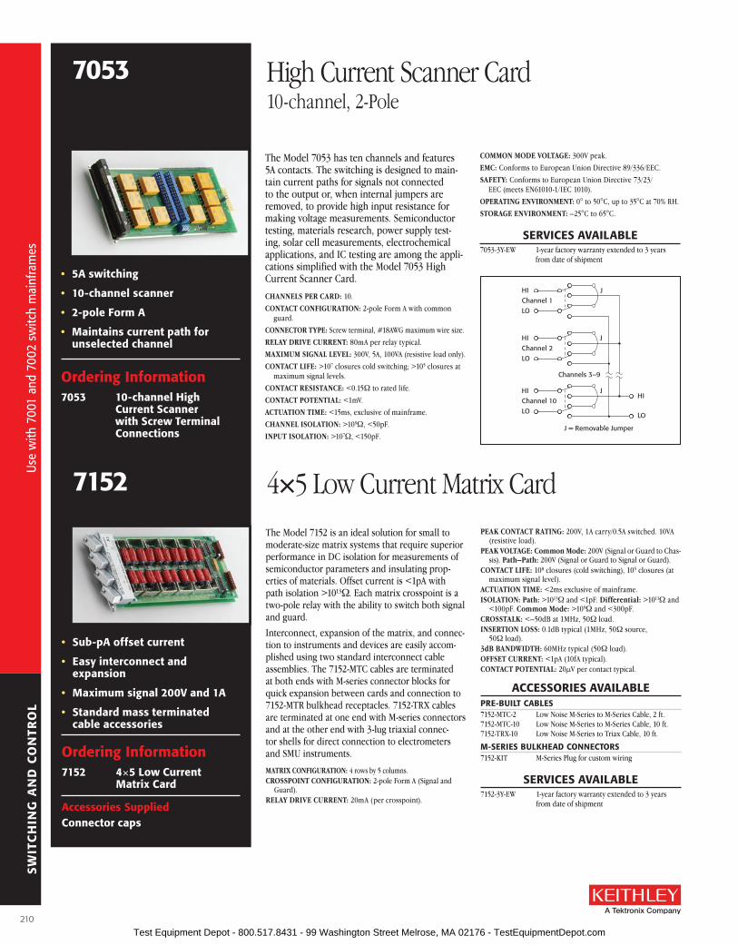
SW
ITC
HIN
G A
ND
CO
NTR
OL
The Model 7053 has ten channels and features 5A contacts . The switch ing is designed to main-tain current paths for signals not con nect ed to the output or, when internal jumpers are removed, to provide high input resistance for making voltage meas ure ments . Semiconductor testing, materials research, power sup ply test-ing, solar cell meas ure ments, elec tro chem i cal ap pli ca tions, and IC testing are among the appli-cations sim pli fied with the Model 7053 High Current Scan ner Card .
CHANNELS PER CARD: 10 .
CONTACT CONFIGURATION: 2-pole Form A with common guard .
CONNECTOR TyPE: Screw terminal, #18AWG maximum wire size .
RELAy DRIVE CURRENT: 80mA per relay typical .
MAXIMUM SIGNAL LEVEL: 300V, 5A, 100VA (resistive load only) .
CONTACT LIFE: >107 closures cold switching; >105 closures at maximum signal levels .
CONTACT RESISTANCE: <0 .15W to rated life .
CONTACT POTENTIAL: <1mV .
ACTUATION TIME: <15ms, exclusive of mainframe .
CHANNEL ISOLATION: >109W, <50pF .
INPUT ISOLATION: >107W, <150pF .
COMMON MODE VOLTAGE: 300V peak .
EMC: Conforms to European Union Directive 89/336/EEC .
SAFETy: Conforms to European Union Directive 73/23/EEC (meets EN61010-1/IEC 1010) .
OPERATING ENVIRONMENT: 0° to 50°C, up to 35°C at 70% RH .
STORAGE ENVIRONMENT: –25°C to 65°C .
sErVICEs aVaIlablE7053-3Y-EW 1-year factory warranty extended to 3 years
from date of shipment
HIChannel 2LO
HIChannel 10LO
Channels 3–9
J = Removable Jumper
HIChannel 1LO
HI
LO
J
J
J
• 5a switching
• 10-channel scanner
• 2-pole form a
• Maintains current path for unselected channel
ordering Information7053 10-channel High
Current scanner with screw Terminal Connections
7053 High Current Scanner Card10-channel, 2-Pole
ordering Information7152 4×5 low Current
Matrix Card
accessories suppliedConnector caps
The Model 7152 is an ideal solution for small to mod er ate-size matrix systems that require superior per for mance in DC isolation for meas ure ments of semiconductor parameters and insulating prop-er ties of materials . Offset current is <1pA with path iso la tion >1013W . Each matrix cros s point is a two-pole relay with the ability to switch both signal and guard .
Interconnect, expansion of the matrix, and con nec-tion to instruments and devices are easily ac com-plished using two stan dard in ter con nect cable as sem blies . The 7152-MTC cables are ter mi nat ed at both ends with M-series con nec tor blocks for quick ex pan sion be tween cards and con nec tion to 7152-MTR bulk head re cep ta cles . 7152-TRX ca bles are ter mi nat ed at one end with M-se ries con nec tors and at the oth er end with 3-lug tri ax i al con nec-tor shells for direct con nec tion to elec trom e ters and SMU instruments .
MATRIX CONFIGURATION: 4 rows by 5 columns .CROSSPOINT CON FIGU RA TION: 2-pole Form A (Signal and
Guard) .RELAy DRIVE CURRENT: 20mA (per cros s point) .
• sub-pa offset current
• Easy interconnect and expansion
• Maximum signal 200V and 1a
• standard mass terminated cable accessories
PEAK CONTACT RATING: 200V, 1A carry/0 .5A switched . 10VA (resistive load) .
PEAK VOLTAGE: Common Mode: 200V (Signal or Guard to Chas-sis) . Path–Path: 200V (Signal or Guard to Signal or Guard) .
CONTACT LIFE: 108 closures (cold switching), 105 closures (at maximum signal level) .
ACTUATION TIME: <2ms exclusive of main frame .ISOLATION: Path: >1013W and <1pF . Differential: >1011W and
<100pF . Common Mode: >109W and <300pF .CROSSTALK: <–50dB at 1MHz, 50W load .INSERTION LOSS: 0 .1dB typical (1MHz, 50W source,
50W load) .3dB BAND WIDTH: 60MHz typical (50W load) .OFFSET CUR RENT: <1pA (10fA typical) .CONTACT POTENTIAL: 20µV per contact typical .
aCCEssorIEs aVaIlablEPrE-buIlT CablEs7152-MTC-2 Low Noise M-Series to M-Series Cable, 2 ft .7152-MTC-10 Low Noise M-Series to M-Series Cable, 10 ft .7152-TRX-10 Low Noise M-Series to Triax Cable, 10 ft .
M-sErIEs bulKHEaD CoNNECTors7152-KIT M-Series Plug for custom wiring
sErVICEs aVaIlablE7152-3Y-EW 1-year factory warranty extended to 3 years
from date of shipment
7152 4×5 Low Current Matrix Card
210
Use
with
700
1 an
d 70
02 s
witc
h m
ainf
ram
es
Use
with
700
1 an
d 70
02 s
witc
h m
ainf
ram
es
Test Equipment Depot - 800.517.8431 - 99 Washington Street Melrose, MA 02176 - TestEquipmentDepot.com

SW
ITC
HIN
G A
ND
CO
NTR
OL
A Greater Measure of Confidence
GENEralMAXIMUM COMMON MODE VOLTAGE (analog ground
to earth ground): 30V peak, DC to 60Hz sine wave .
ISOLATION: Analog ground to earth ground: >109W in parallel with 150pF .
WARM-UP: 1 hour to rated specifications .
ENVIRONMENT: Operating: 0°–35°C, up to 70% R .H . Storage: –25° to +65°C .
CONNECTORS:
Current Source Input: Two-lug female triaxial . Input HI to LO clamped at ±12V . Maximum Input: 100mA .
Sample Inputs: Four two-lug female triaxial . Outer shell is analog ground . Inner shield is driven guard . Maximum Input Overload (HI to analog ground or GUARD to analog ground): ±12V .
Current Monitor Output: Insulated female BNC .
Measurement Outputs: Spring-loaded terminals . Accepts AWG #18 to #24 wire . Maximum Load: 1mA .
DIMENSIONS, WEIGHT: 32mm high × 114mm wide × 272mm long (1 in × 4 in × 10 in) . Net weight: 434kg (15½ oz) .
All specifications are 1 year, 0°–35°C, installed in scanner mainframe .
loW rEsIsTIVITY MoDE
INPUT VOLTAGE OPERATING RANGE: +8 to –8V .
INPUT IMPEDANCE: >10GW in parallel with <420pF .
INPUT BIAS CURRENT: <100pA .
INPUT VOLTAGE NOISE: <50nV p-p, 0 .1 to 10Hz bandwidth .
INPUT TO OUTPUT RESISTANCE: <30W .
HIGH rEsIsTIVITY MoDE
INPUT VOLTAGE OPERATING RANGE: +8 to –8V .
INPUT IMPEDANCE: >100TW in parallel with <3pF .
INPUT BIAS CURRENT: <150fA at 23°C . Doubles approxi-mately every 10°C rise in ambient room temperature .
INPUT VOLTAGE NOISE: <10µV p-p, 0 .1 to 10Hz bandwidth .
OUTPUT RESISTANCE: <60W .
CoNfIGuraTIoN
Input characteristics and output matrix configuration for van der Pauw or Hall bar measurements . Input char ac ter is tics select-able for either low resistivity or high re sis tiv i ty samples .
ordering Information7065 Hall Effect Card7001 switch system
building blocks for an eco nom i cal mea sure ment systemThe Model 7065 Hall Effect Card is intended for those who want to assemble their own economical Hall test systems . It also can form the foundation of a Hall Effect system . The sensitivity and capabilities of this card are unmatched by any other system or Hall Effect electronics package .
The Model 7065 is a signal conditioning card designed to buffer test signals from the Hall sample to the measurement instrumentation and to switch current from a source to the Hall sample . When used with Keithley’s Model 7001 scanner mainframe, the Model 7065 provides the switch ing capability to measure Hall voltages as low as 50nV and sample resistances in excess of 1012W .
All the accessories needed to connect the sam ple holder, scanner, instruments, and controller are included, simplifying con nec tions . The Model 7065 is connected directly to the sample, and all in stru ments are connect-ed via the IEEE-488 bus to the controller . Examples of resistivity and Hall voltage measurement pro grams are included in the Model 7065 Instruction Manual .
The Model 7065 can be operated in either a low resistivity or a high resistivity mode . In the high resistivity mode, input impedance is greater than 100TW, input bias current is less than 150fA, and output resistance is less than 60W . Input voltage ranges in both operating modes is +8V to –8V . If higher voltage is desired, Keithley recommends using a 6220/6514 system . Cabling and sample connections must be carefully de signed to make full use of the Model 7065’s ca pa bil i ties . Refer to Keithley’s Low Level Measurements handbook for guidance in designing these connections .
+–
+–
+–
+–
I 12
34
Sample
Buffers Columns
Rows
1 2 3 4 51
2
3
4
2000DMM
Used for bartype samplesOptional
6485pA
Meter
6220CurrentSource
LO R
HI R
HI LO
Model 7065 Hall Effect Card
V
aCCEssorIEs suPPlIED4801 Low Noise Input Cable
7078-TRX-10 3-slot Triax Cable (10 ft .)
6172 2-slot Male to 3-Lug Female Triax Adapter
7025-10 Triaxial Input Cable (10 ft .) (4 supplied)
4851 BNC Shorting Plug
Wire Kit Including:SC-72-0 Single Conductor Insulated Wire, black (4 ft .)
(2 supplied)SC-72-9 Single Conductor Insulated Wire, white (4 ft .)BG-5 Single Banana Plug, black (2 supplied)BG-10-1 Single Banana Plug, whiteBG-7 Double Banana Plug, blackSC-8 2-conductor Cable w/shield (10 ft .)7007-2 Double Shielded Premium Cable (6 ft .)
sErVICEs aVaIlablE7065-3Y-EW 1-year factory warranty extended to 3 years
from date of shipment
7065 Hall Effect Card
211
The
foun
datio
n of
a H
all E
ffect
sys
tem
The
foun
datio
n of
a H
all E
ffect
sys
tem
Test Equipment Depot - 800.517.8431 - 99 Washington Street Melrose, MA 02176 - TestEquipmentDepot.com

SW
ITC
HIN
G A
ND
CO
NTR
OL
ordering Information7153 4×5 High Voltage low
Current Matrix Card
The Model 7153 is designed to switch low level, high voltage, and high impedance signals for ap pli ca tions such as parametric tests on semi-con duc tor devices . The 7153 allows signal levels up to 1300V while maintaining offset cur rent of <1pA (typ i cal ly 10fA) and path isolation >1013W . Each cros s point is a 2-pole relay to switch both signal and guard . Interconnect between the matrix and in stru ments such as the Model 237 SMU is done with the 7153-TRX cable . This cable has an M-se ries con nec tor for the ma trix and five 3-slot male triax con nec tors at the op po site end . The cable will mate with the row or column con-nec tors of the Model 7153 .
MATRIX CONFIGURATION: 4 rows by 5 columns .CROSSPOINT CONFIGURATION: 2-pole Form A (Signal and
Guard) .CONNECTOR TyPE: Miniature coax, M-series plug .RELAy DRIVE CURRENT: 40mA (per cros s point) .MAXIMUM SIGNAL LEVEL: 1300V between any 2 signal pins or
chassis; 200V between Signal and Guard . 1A carry/0 .5A switched . 10VA peak (re sis tive load) .
CONTACT LIFE: 108 closures (cold switching) . 105 closures (at maximum signal level) .
PATH RESISTANCE: <1W per contact to rated life .ACTUATION TIME: <2ms exclusive of mainframe .ISOLATION: Path: >1013W and <1pF . Differential: >1011W and
<100pF . Common Mode: >109W and <300pF .
CROSSTALK: <–50dB at 1MHz, 50W load .INSERTION LOSS: 0 .1dB typical (1MHz, 50W source, 50W load) .3dB BANDWIDTH: 60MHz typical (50W load) .OFFSET CURRENT: <1pA (10fA typical) .CONTACT POTENTIAL: <50µV typical .
aCCEssorIEs aVaIlablE7153-TRX Low Noise M-Series to Triax Cable, 5 ft .
sErVICEs aVaIlablE7153-3Y-EW 1-year factory warranty extended to 3 years
from date of shipment
Chassis
SignalGuard
SignalGuard
SignalGuard
SignalGuard
Sign
alGu
ard
Sign
alGu
ard
Sign
alGu
ard
Sign
alGu
ard
Sign
alGu
ard
Row 1
Row 2
Row 3
Row 4
Col. 1 Col. 2 Col. 3 Col. 4 Col. 5
• 1300V switching
• sub-pa offset current
• 2-pole switching
• Mass termination connectors
7153 4×5 Low Current Matrix CardHigh Voltage
The Model 7154 switches voltages to 1100V peak or cur rents to 0 .5A . The current carry ca pac i ty of each relay contact is 1A . Two-pole relays switch both circuit High and Low for full floating mea-sure ments and each input line is fuse pro tect ed against current overload . A Guard input com mon to all channels is provided for shielding or as a Guard driven from a single in stru ment . Guards may be isolated by re mov ing jump ers installed at each input . Multiple switched guard circuits can be achieved by re mov ing the jumper and con-nect ing circuit Guard to the Low input ter mi nal .
CHANNELS PER CARD: 10 .CONTACT CONFIGURATION: 2-pole Form A with user-
selectable shield or driven Guard . Each pole is fused using #38AWG magnet wire .
CONNECTOR TyPE: Screw terminals, #16AWG maximum wire size .
RELAy DRIVE CURRENT: 57mA per relay typical .MAXIMUM SIGNAL LEVEL: 1100V peak, 0 .5A DC or rms
switched, 1A DC or rms carry, 10W .CONTACT LIFE: >108 closures (cold switching); >5×10⁶ clo-
sures (at maximum signal level) .CONTACT RESISTANCE: <200mW initial, 2W to rated life .
CONTACT POTENTIAL: <35µV per contact pair with copper leads .ACTUATION TIME: <2ms exclusive of mainframe .CHANNEL ISOLATION: 1010W, <10pF .INPUT ISOLATION: Differential: >109W, <10pF .
Common Mode: >109W, <150pF .COMMON MODE VOLTAGE: 1100V peak .ENVIRONMENT: Operating: 0° to 50° up to 35°C at 70% R .H .
Storage: –5° to +65°C .
sErVICEs aVaIlablE7154-3Y-EW 1-year factory warranty extended to 3 years
from date of shipment• 1100 volts peak
• 2-pole switching
• High and low fused H
L
G
Ch. 1
J1
H
L
G
Ch. 10
J10
Ch. 2 - 9
H
L
G
ordering Information7154 High Voltage
scanner Card
7154 High Voltage Scanner Card10-channel
212
Use
with
700
1 an
d 70
02 s
witc
h m
ainf
ram
es
Use
with
700
1 an
d 70
02 s
witc
h m
ainf
ram
es
Test Equipment Depot - 800.517.8431 - 99 Washington Street Melrose, MA 02176 - TestEquipmentDepot.com

SW
ITC
HIN
G A
ND
CO
NTR
OL
A Greater Measure of Confidence
ordering Information7158 low Current
scanner Card
accessories supplied4801 low Noise Male to
Male bNC Input Cable
• sub-picoamp offset current
• Maintains current path for unselected channel
• bNC connectors
The Model 7158 provides quality low-current switching at an affordable price . The offset current error generated is specified <1pA, with typical performance at <30fA . When used with a voltage source and electrometer or picoammeter, this card can easily au to mate insulation resistance tests, reverse leakage tests on semiconductor junctions, or gate leak age tests on FETs .
The Model 7158 is designed to maintain the current path even when the channel is deselected . Input connectors are BNC for shielding of the sensitive measurements and for com pat i bil i ty with low noise coaxial cables such as Keithley accessory cables Models 4801 and 4803 . Two out puts are provided to allow for chaining several scanner cards to one measurement in stru ment, and an isolation relay in the out put HI minimizes in ter ac-tion between cards .
CHANNELS PER CARD: 10 .CONTACT CONFIGURATION: Single pole, simultaneous break
and make for signal HI input . Signal LO is common for all 10 channels and output . When a channel is off, signal HI is con-nected to signal LO .
CONNECTOR TyPE: BNC .RELAy DRIVE CURRENT: 100mA per card typical (regardless
of channel closures selected) .MAXIMUM SIGNAL LEVEL: 30V, 100mA peak (re sis tive load) .
CONTACT LIFE: >106 closures at maximum signal levels; >107 closures at low signal levels .
CONTACT RESISTANCE: <1W .CON TACT POTENTIAL: <200µV .OFF SET CUR RENT: <1pA (<30fA typ i cal) .3dB BAND WIDTH: 1MHz typ i cal .AC TU A TION TIME: <1ms, exclusive of mainframe .CHANNEL ISOLATION: >1014W .INPUT ISOLATION: Differential: >109W, <50pF .
Common Mode: >109W, <150pF .COMMON MODE VOLTAGE: <30V maxi mum .
aCCEssorIEs aVaIlablE4801 Low Noise Male to Male BNC Input Cable4802-10 Low Noise BNC to Unterminated Cable, 10 ft .4803 Low Noise BNC Cable Kit for 7158
sErVICEs aVaIlablE7158-3Y-EW 1-year factory warranty extended to 3 years
from date of shipment
Ch. 1
Ch. 2 – 9
Ch. 10
Output1
Output2
7158 Low Current Scanner Card10-channel
The Model 7168 is an 8-channel, 2-pole card with <30nV of thermal offset . It will switch any one of eight signals to one output in less than 3ms . Channel offset leakage current is <50pA at 23°C . When the 7168 is used with the Mod el 2182A, the noise and drift per for mance of the 2182A is not de grad ed .
CHANNELS PER CARD: 8 .CONFIGURATION: Two poles per channel, input HI and LO .CONNECTOR TyPE: Screw terminal to bare copper printed
circuit pad .MAX. SIGNAL LEVEL: 10V, 50mA peak (resistive load only) .CONTACT RESISTANCE: <12W .CONTACT POTENTIAL (HI to LO) BE TWEEN CHANNELS: <30nV when properly zeroed with supplied leads (see manual
for rec om mend ed procedure) . Typically <60nV without ze roing .
CONTACT TyPE: Solid state JFET switch .ACTUATION TIME: <3ms, exclusive of mainframe .INPUT LEAKAGE: <50pA per channel at 23°C .INPUT ISOLATION: >109W, <40pF between any input ter mi nals
or between any input terminal and earth .COMMON MODE VOLTAGE: 30V peak .MAXIMUM VOLTAGE BETWEEN ANy TWO TERMINALS: 10V .WARM-UP: 2 hours in mainframe for thermal stability .
OPERATING ENVIRONMENT: 0°–40°C; up to 35°C at 70% R .H .STORAGE ENVIRONMENT: –25° to 60°C .
aCCEssorIEs suPPlIED 2107-4 Low Thermal Input Cable for 2182A (1 supplied)
7168-316 Low Thermal Input Cables for 7166 (8 supplied)
sErVICEs aVaIlablE7168-3Y-EW 1-year factory warranty extended to 3 years from
date of shipment
• <30nV contact potential
• bare copper terminal connections
Ch. 1
HI
LO
Ch. 2
Ch. 8 Output
Ch. 3 – 7
HI
LO
HI
LO
HI
LO
ordering Information7168 8-channel Nanovolt
scanner Card
7168 Nanovolt Scanner Card8-channel, 2-pole
213
Use
with
700
1 an
d 70
02 s
witc
h m
ainf
ram
es
Use
with
700
1 an
d 70
02 s
witc
h m
ainf
ram
es
Test Equipment Depot - 800.517.8431 - 99 Washington Street Melrose, MA 02176 - TestEquipmentDepot.com

SW
ITC
HIN
G A
ND
CO
NTR
OL
The six-slot Model 707B and single-slot Model 708B Semiconductor Switch Matrix Mainframes extend Keithley’s decades-long commitment to innovation in switch systems optimized for semiconductor test applications . These mainframes build upon the strengths of their popular predecessors, the Models 707/707A and 708/708A, adding new features and capabilities designed to speed and simplify system integration and test development . New control options and interfaces offer system builders even greater flexibility when configuring high performance switching systems for use in both lab and production environments . Just as important, both new mainframes are compatible with the popular switch cards developed for the Models 707A and 708A, simplifying and minimizing the cost of switch system migration .
faster Command-to-ConnectHigh performance Model 707B and 708B semiconductor switch matrix mainframes slash the time from command to connection, offering significantly faster test sequences and overall system through-put than Keithley’s earlier 707A and 708A mainframes .
• significantly faster command-to-connect speeds than earlier series 700 mainframes
• 708b mainframe controls a single 8×12 matrix card
• 707b mainframe controls up to six 8×12 matrix cards
• Compatible with the popular plug-in cards designed for the 707a/708a mainframes
• support for both remote (via lXI, usb, and GPIb interfaces) and manual (via front panel) programming
• Integrates seamlessly with the Model 4200-sCs for semiconductor I-V and C-V characterization via GPIb interface
• stores hundreds of switching configurations and channel patterns in non-volatile memory for reuse
• lXI interface supports remote programming and control
• Embedded TsP® processor and TsP-link Technology interface make it easy to integrate series 2600b system sourceMeter® sMu instruments into a high speed, self-contained tester
• 14 bits of digital I/o
707b 708b
Semiconductor Switch Matrix MainframesSix-slot and Single-slot Versions
aPPlICaTIoNs
• support for semiconductor device characterization and process control monitoring
• fully automated testing of a wide range of electronic components in both lab and production environments
Model 707b six-slot semiconductor switch Matrix Mainframe
Model 708b single-slot semiconductor switch Matrix Mainframe
214
Sem
icon
duct
or s
witc
h sy
stem
s
Sem
icon
duct
or s
witc
h sy
stem
s
Test Equipment Depot - 800.517.8431 - 99 Washington Street Melrose, MA 02176 - TestEquipmentDepot.com
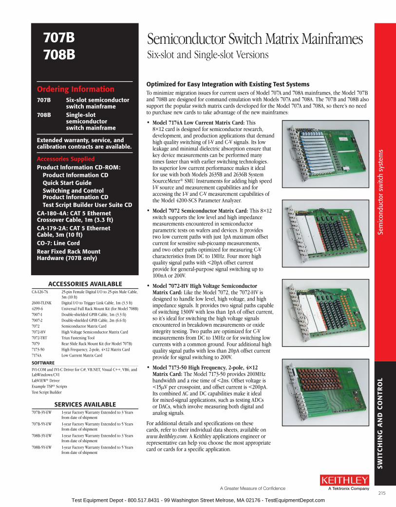
SW
ITC
HIN
G A
ND
CO
NTR
OL
A Greater Measure of Confidence
707b 708b
Semiconductor Switch Matrix MainframesSix-slot and Single-slot Versions
optimized for Easy Integration with Existing Test systemsTo minimize migration issues for current users of Model 707A and 708A mainframes, the Model 707B and 708B are designed for command emulation with Models 707A and 708A . The 707B and 708B also support the popular switch matrix cards developed for the Model 707A and 708A, so there’s no need to purchase new cards to take advantage of the new mainframes:
• Model 7174A Low Current Matrix Card: This 8×12 card is designed for semiconductor research, development, and production applications that demand high quality switching of I-V and C-V signals . Its low leakage and minimal dielectric absorption ensure that key device measurements can be performed many times faster than with earlier switching technologies . Its superior low current performance makes it ideal for use with both Models 2635B and 2636B System SourceMeter® SMU Instruments for adding high speed I-V source and measurement capabilities and for accessing the I-V and C-V measurement capabilities of the Model 4200-SCS Parameter Analyzer .
• Model 7072 Semiconductor Matrix Card: This 8×12 switch supports the low level and high impedance measurements encountered in semiconductor parametric tests on wafers and devices . It provides two low current paths with just 1pA maximum offset current for sensitive sub-picoamp measurements, and two other paths optimized for measuring C-V characteristics from DC to 1MHz . Four more high quality signal paths with <20pA offset current provide for general-purpose signal switching up to 100nA or 200V .
• Model 7072-HV High Voltage Semiconductor Matrix Card: Like the Model 7072, the 7072-HV is designed to handle low level, high voltage, and high impedance signals . It provides two signal paths capable of switching 1300V with less than 1pA of offset current, so it’s ideal for switching the high voltage signals encountered in breakdown measurements or oxide integrity testing . Two paths are optimized for C-V measurements from DC to 1MHz or for switching low currents with a common ground . Four additional high quality signal paths with less than 20pA offset current provide for signal switching to 200V .
• Model 7173-50 High Frequency, 2-pole, 4×12 Matrix Card: The Model 7173-50 provides 200MHz bandwidth and a rise time of <2ns . Offset voltage is <15µV per crosspoint, and offset current is <200pA . Its combined AC and DC capabilities make it ideal for mixed-signal applications, such as testing ADCs or DACs, which involve measuring both digital and analog signals .
For additional details and specifications on these cards, refer to their individual data sheets, available on www.keithley.com . A Keithley applications engineer or representative can help you choose the most appropriate card or cards for a specific application .
ordering Information707b six-slot semiconductor
switch mainframe708b single-slot
semiconductor switch mainframe
Extended warranty, service, and calibration contracts are available.
accessories suppliedProduct Information CD-roM:
Product Information CDQuick start Guideswitching and Control Product Information CDTest script builder user suite CD
Ca-180-4a: CaT 5 Ethernet Crossover Cable, 1m (3.3 ft)Ca-179-2a: CaT 5 Ethernet Cable, 3m (10 ft)Co-7: line Cordrear fixed rack Mount Hardware (707b only)
aCCEssorIEs aVaIlablECA-126-7A 25-pin Female Digital I/O to 25-pin Male Cable,
3m (10 ft) 2600-TLINK Digital I/O to Trigger Link Cable, 1m (3 .3 ft)4299-6 Universal Full Rack Mount Kit (for Model 708B)7007-1 Double-shielded GPIB Cable, 1m (3 .3 ft)7007-2 Double-shielded GPIB Cable, 2m (6 .6 ft)7072 Semiconductor Matrix Card7072-HV High Voltage Semiconductor Matrix Card7072-TRT Triax Fastening Tool7079 Rear Slide Rack Mount Kit (for Model 707B)7173-50 High Frequency, 2-pole, 4×12 Matrix Card7174A Low Current Matrix Card
sofTWarE IVI-COM and IVI-C Driver for C#, VB .NET, Visual C++, VB6, and LabWindows/CVILabVIEW® DriverExample TSP® ScriptsTest Script Builder
sErVICEs aVaIlablE707B-3Y-EW 1-year Factory Warranty Extended to 3 Years
from date of shipment
707B-5Y-EW 1-year Factory Warranty Extended to 5 Years from date of shipment
708B-3Y-EW 1-year Factory Warranty Extended to 3 Years from date of shipment
708B-5Y-EW 1-year Factory Warranty Extended to 5 Years from date of shipment
215
Sem
icon
duct
or s
witc
h sy
stem
s
Sem
icon
duct
or s
witc
h sy
stem
s
Test Equipment Depot - 800.517.8431 - 99 Washington Street Melrose, MA 02176 - TestEquipmentDepot.com

SW
ITC
HIN
G A
ND
CO
NTR
OL
707b 708b
Semiconductor Switch Matrix MainframesSix-slot and Single-slot Versions
In addition, the Models 707B and 708B offer a number of features to ensure their compatibility with Keithley instrumentation already at work in labs and on test floors around the world . For example, these semiconductor switch matrix mainframes are compatible with the Model 4200-SCS semicon-ductor Parameter Analyzer’s existing matrix driver and GPIB interface, which allows them to become drop-in switch matrix replacements for many applications . The new mainframes also provide electri-cal performance that correlates closely with that of the Model 707A and Model 7174A switch card, the previous industry-standard switching solution .
suited for both lab and fabLike their predecessors, the Models 707B/708B are specifically designed for the requirements of both semiconductor lab and production test environments, delivering ultra low current switching performance using standard triax connectors and cables . For automating smaller test systems with a limited number of pins and instruments, the Model 708B supports a single switch card with up to 8 rows and 12 columns (8×12) . For applications requiring higher switch counts, the Model 707B can accommodate up to six 8×12 cards, which can be connected via an internal backplane or jumpers to form larger matrices . Both mainframes also support mixed signal switching for both DC and RF (up to 200MHz) signals .
Choice of Manual operation or remote ProgrammingBoth mainframes offer a variety of manual operation and remote programming functions via either the front panel controls or a choice of interfaces . For example, for manual operation, such as when experimenting with a new switching configuration, the updated front panel interface allows labeling switch card rows (instruments) and columns (pins) alphanumerically, which simplifies keeping track of what’s connected to each crosspoint . An LED crosspoint display makes it easy to identify whether a Se
mic
ondu
ctor
sw
itch
syst
ems
The Models 707b and 708b include a built-in Web interface that offers a quick and easy method to control the instrument remotely. Interactive schematics of each card in the mainframe support point-and-click control for opening and closing switches.
specific channel is open or closed, as well as to determine which slots are occupied and which cards are currently in use . A two-line display shows both error messages and user-defined messages, and displays control menus and open/closed channel messages .
An intuitive navigation/control knob allows scrolling through and opening/closing chan-nels . Key pad controls support scrolling through menus, changing host interface settings, saving and restoring instrument setups, and load-ing and running factory and user-defined test scripts, etc .
Test system integrators can choose from several instrument communication interfaces and tools for remote programming and control of the Model 707B or 708B:
• TSP-Link Technology is a high speed system expansion and coordination interface that simplifies linking instruments and switches for faster inter-unit communication and control . It provides a high speed, low
216
Sem
icon
duct
or s
witc
h sy
stem
s
Test Equipment Depot - 800.517.8431 - 99 Washington Street Melrose, MA 02176 - TestEquipmentDepot.com

SW
ITC
HIN
G A
ND
CO
NTR
OL
A Greater Measure of Confidence
advantages of TsP® Technology for switch ThroughputThe test script processor (TSP) tech-nology embedded in these upgraded mainframes allows for distributed processing and control rather than relying exclusively on a central PC to direct their operation, increas-ing test speed and lowering overall test cost. The TSP is a full-featured test sequence engine that allows unprecedented control of the test sequence. In addition to responding to individual ICL commands, it can store a user-defined test script or sequence in memory and execute it on command, which limits the set-up and configuration time for each step in the test sequence and increases throughput by decreasing communication time.
Test scripts are complete test programs based on Lua, an easy-to-use but highly efficient and compact scripting language. Because test scripts can contain any sequence of routines that are executable by conventional programming languages (including decision-making algorithms and control of the digital I/O), the mainframe can manage the operation of entire tests without sending readings back to a PC for use in decision making. The TSP can even access the mainframe’s 14-bit digital I/O on the fly, increasing throughput by allowing instrument and binning equip ment such as handlers to run without PC interference. This eliminates delays due to GPIB traffic congestion and greatly improves overall test times.
TSP control allows individual switches and instruments or groups of them to operate autonomously, often eliminating the need for a high-level PC system controller altogether. This same proven TSP technology has already been suc-cessfully incorporated into Keithley’s innovative Series 2600B System SourceMeter SMU instruments and Series 3700A Multimeter/Switch System.
latency interface to other TSP (Test Script Processor)-based hardware, enabling simple multi-box and multi-instrument software control, as well as simplified test system scaling as new requirements evolve .
• With TSP-Link, there’s no need to add external triggers and remote communication cables to individual units because all TSP-Link connected devices can be controlled from a single master unit . Up to 16 Model 707B/708B chassis can be linked together to form a larger switching matrix using TSP-Link . Each mainframe has two TSP-Link connectors to facilitate chaining instruments together . They can also be used to connect Model 707B/708B semiconductor switch matrix mainframes to other TSP-Link enabled instruments, such as Keithley’s Series 2600B System SourceMeter® SMU instruments . Every piece of instrumentation connected via TSP-Link can be controlled by a single master unit, just as though they were all housed in the same chassis .
• Like all instruments compliant with the LXI (LAN eXtensions for Instrumentation) standard, the Models 707B and 708B have a built-in switch control Web page that is accessible via any standard Web browser . In conjunction with a 10/100M Base-T Ethernet connection and LAN-based triggering, this Web interface offers a quick and easy method to program switching patterns . Interactive schematics of each card in the mainframe support point-and-click control for opening and closing switches . A scan list builder is provided to guide users through the requirements of a scan list (such as trigger and looping definitions) for more advanced applications . The Web page’s point-and-click design provides easy switch system control, as well as basic switch system troubleshooting and diagnostics capabilities .
• TSB (Test Script Builder) Embedded is an application with a reduced feature set that resides in the mainframe and can be accessed through its web page . Like the full Test Script Builder programming tool, it offers script-building functions and can be used to run example scripts provided with the mainframe . It also includes a command line interface that can be used to issue single-line ICL commands .
• For those replacing Keithley’s earlier 707A/708A mainframes and who prefer to minimize the levels of changes to their test systems, the Models 707B and 708B offer a GPIB interface and 707A/708A DDC command emulation capabilities to simplify the migration process . These users can incorporate the “B” models into their test systems without making any changes to their legacy code or hardware interface . However, these users will not be able to take full advantage of many of the throughput gains that TSP control provides, such as the new GPIB interface that allows you to control additional GPIB-compatible instruments and systems .
• A rear panel Universal Serial Bus (USB) port allows a host computer to communicate with and control the 707B/708B over a USB interface .
optimized for Easy Integration with series 2600b-based systemsThe Models 707B and 708B are ideal companion products for systems that incorporate Series 2600B instrumentation, such as Keithley’s ACS and S530 integrated test systems . These mainframes share the same TSP, Lua scripting language, and TSP-Link interface as the Series 2600B and support an ultra low current switch matrix (the Model 7174A) that complements the Model 2636B’s low current sensitivity . The Models 707B/708B offer test system builders a switch matrix that is fast, scriptable, and works seamlessly with all Series 2600B models .
In common with Series 2600B SMU instruments, the Models 707B/708B provide system builders with the advantages of the Keithley Test Script Builder (TSB) Integrated Development Environment (IDE) . TSB IDE is a programming tool provided on the CD that accompanies each mainframe . It can be used to create, modify, debug, and store TSP scripts . It provides a project/file manager window to store and organize test scripts, a text-sensitive program editor (like Visual Basic) to create and modify test TSP code, and an immediate instrument control window to send GPIB commands and receive data from the instrument . The immediate window allows viewing the output of a given test script and simplifies debugging .
707b 708b
Semiconductor Switch Matrix MainframesSix-slot and Single-slot Versions
217
Sem
icon
duct
or s
witc
h sy
stem
s
Sem
icon
duct
or s
witc
h sy
stem
s
Test Equipment Depot - 800.517.8431 - 99 Washington Street Melrose, MA 02176 - TestEquipmentDepot.com

SW
ITC
HIN
G A
ND
CO
NTR
OL
707b 708b
Semiconductor Switch Matrix MainframesSix-slot and Single-slot Versions
supported Cards7072 8×12 Semiconductor Matrix 200V, 1A
7072-HV 8×12 HV Semiconductor Matrix 1300V, 0 .1A
7173-50 4×12, 2-pole, High-Frequency Matrix Card
7174A 8×12 Low-Current, High-Speed Matrix Card, with 3-lug Triax Row and Column connects
Execution speed
sYsTEM PErforMaNCE 1
COMMAND: channel .close (‘ch_list’) or channel .open (‘ch_list’)
single Command Execution Time (ms)Card Ethernet GPIb TsP-link usb7072 15 .9 15 .9 20 .5 15 .97072-HV 15 .9 15 .9 20 .5 15 .97173-50 7 .9 7 .9 11 .5 7 .97174A 1 .9 1 .9 5 .5 1 .9
1 . Time between the start of a single digio .writebit (1, 1), channel .close (‘ch_list’) or channel .open (‘ch_list’) which includes relay settle time, and digio .writebit (1, 0) command .
TrIGGEr rEsPoNsE TIMEMAXIMUM TRIGGER RATE (setups per second)1:
7072: ≥65 . 7072-HV: ≥65 . 7173-50: ≥160 . 7174A: ≥815 .
TRIGGER IN TO START OF MATRIX READy PULSE (DDC Mode): ≤85µs .
TRIGGER IN TO TRIGGER OUT: ≤0 .5µs .
TRIGGER TIMER ACCURACy: ≤0 .5µs .
NoTEs1 . Includes scan .scancount = 100, scan .stepcount ≥3, channel .
connectrule = channel .OFF or 0, and relay settle time .
GENEralEMULATION: 707A/708A Device Dependent Commands
(DDC) . Since the architecture of the Model 707B/708B differs from the Model 707A/708A, some commands are different . Refer to notes in the 707B-901 Reference manual for additional details .
BREAK BEFORE MAKE: channel .connectrule= channel .BREAK_BEFORE_MAKE or 1 .
MAKE BEFORE BREAK: channel .connectrule= channel .MAKE_BEFORE_BREAK or 2 .
NONE: channel .connectrule= channel .OFF or 0, the system will close relays as it is able to without adhering to a rule .
IEEE-488: IEEE-488 .1 compliant . Supports IEEE-488 .2 com-mon commands and status model topology .
USB 2.0 DEVICE (rear panel type B): Full and high speed, USBTMC compliant .
DIGITAL I/O INTERFACE Connector: 25-pin female D .Input/Output Pins: 14 open drain I/O bits .Absolute Maximum Input Voltage: 5 .25V .Absolute Minimum Input Voltage: –0 .25V .Maximum Logic Low Input Voltage: 0 .7V, +850µA max .Maximum Logic High Input Voltage: 2 .1V, +570µA .Maximum Source Current (flowing out of Digital I/O
bit): 960µA .Maximum Sink Current @ Maximum Logic Low
Voltage (0.7V): –5 .0mA .Absolute Maximum Sink Current (flowing into Digital
I/O pin): –11mA .5V Power Supply Pin: Limited to 600mA, solid state fuse
protected .
ETHERNET: RJ-45 connector, 10/100BaseT, Auto-MDIX .
LXI COMPLIANCE: LXI Version 1 .2 .
POWER SUPPLy: 707B: 100V to 240VAC, 50Hz–60Hz, 210VA max . 708B: 100V to 240VAC, 50Hz–60Hz, 110VA max .
RELAy DRIVE:707B: 30W (6V at 5 .0A) max . per slot, 162W (6V at 27A)
max . for all slots .708B: 30W (6V at 5 .0A) max .
SAFETy: Conforms to European Union Low Voltage Directive .
DIMENSIONS:707B: 356mm high × 432mm wide × 574mm deep (14 .0 in
× 17 .0 in × 22 .6 in) .708B: 90mm high × 432mm wide × 574mm deep (3 .5 in ×
17 .0 in × 22 .6 in) .
DIMENSIONS WITH CARD INSTALLED:707B: 356mm high × 432mm wide × 612mm deep (14 .0 in
× 17 .0 in × 24 .1 in) .708B: 90mm high × 432mm wide × 612mm deep (3 .5 in ×
17 .0 in × 24 .1 in) .
WEIGHT: 707B: 14 .5kg (32 lbs) . 708B: 7 .3kg (16 lbs) .
SHIPPING WEIGHT: 707B: 27 .2kg (60 lbs) . 708B: 16 .4 kg (36 lbs) .
ENVIRONMENT: For indoor use only .Altitude: Maximum 2000 meters above sea level .Operating: 0°– 50°C, 80% R .H . up to 35°C . Derate to 3%
R .H ./°C, 35°– 50°C .Storage: – 25°C to 65°C .
Model 708b rear panel
Model 707b rear panel
218
707B
/708
B sp
ecifi
catio
ns
707B
/708
B sp
ecifi
catio
ns
Test Equipment Depot - 800.517.8431 - 99 Washington Street Melrose, MA 02176 - TestEquipmentDepot.com

SW
ITC
HIN
G A
ND
CO
NTR
OL
A Greater Measure of Confidence
selector Guide Switch Cards and Accessoriesfor 707B, 708B, 707A, 708A
707b, 708b, 707a, 708a switch Card accessories Cables adapters
7072 7078-TRX-3 7078-TRX-10 237-TRX-T 7078-TRX-BNC
7174a 7078-TRX-3 7078-TRX-10 237-TRX-T 7078-TRX-BNC
7072-HV 7078-TRX-3 7078-TRX-10 7078-TRX-BNC 7078-TRX-GND
237-TRX-T 237-TRX-TBC
7073 4801
7173-50 7173-50-CSEP
loW CurrENTHIGH
frEQuENCY7072 7072-HV 7174a 7173-50
Page 220 221 223 222
Number of Channels 8×12 8×12 8×12 4×12
Card Configuration Matrix Matrix Matrix Matrix
Contact Configuration 2 form A 2 form A 2 form A 2 form C
Max. Voltage 200 V 1300 V 200 V 30 V
Max. Current 1 A 1 A 2 A 0 .5 A
Max. Power 10 VA 10 VA 10 VA
Contact Potential <20 µV <20 µV <15 µV
Max. off set Current <1 pA <1 pA <100 fA <200 pA
recommended frequency 15 MHz 4 MHz 30 MHz 200 MHz
Connection Type 3-lug triax 3-lug triax 3-lug triax BNC
CE Yes Yes YesComments Optimized for semiconductor applications . 707b-708b Compatible Yes Yes Yes Yes
707a-708a Compatible Yes Yes Yes Yes
Keithley Instruments recently introduced two new semiconductor switch matrix mainframes: the Model 707B six-slot mainframe and the Model 708B one-slot mainframe. The two
new mainframes replace the Models 707A and 708A that were introduced more than 20 years ago. The new models provide important new capabilities and are compatible with the most
popular switch cards. The table shows the important differences between the new and old models.
NEWModel 707b
replacesModel 707a
NEWModel 708b
replacesModel 708a
New 707/8b
legacy 707/8a
GPIB/DDC 4 4
GPIB/ICL 4
Ethernet (LXI) 4
TSP/TSP-Link 4
Webpage (LXI) 4
Light Pen 4
Compatible with 7174A, 7072, 7072-HV, 7173-50 switch cards
4 4
Compatible with 7071, 7071-4 switch cards
4
New Models 707b and 708b replace Models 707a and 708a
219
Sele
ctor
gui
des:
Sw
itch
card
s an
d ac
cess
orie
s fo
r Mod
els
707B
, 708
B, 7
07A,
and
708
A
Sele
ctor
gui
des:
Sw
itch
card
s an
d ac
cess
orie
s fo
r 707
B, 7
08B,
707
A, 7
08A
Test Equipment Depot - 800.517.8431 - 99 Washington Street Melrose, MA 02176 - TestEquipmentDepot.com

SW
ITC
HIN
G A
ND
CO
NTR
OL
The Model 7072 Semiconductor Matrix Card is designed specifically to handle low-level and high-impedance measurements encountered in semiconductor parametric tests on wafers and devices . This unique design provides two low-current circuits with specified 1pA maxi mum offset cur-rent for sensitive sub-picoamp meas ure ment resolution and two C-V paths for meas ure ment of Capacitance Voltage char ac ter is tics from DC to 1MHz . Four additional high-quality signal paths with <20pA offset current provide for general-purpose signal switching up to 100nA or 200V .
Connections are 3-lug triax with the outer shell connected to chassis for safety and noise shield ing . The center conductor is fully surrounded by the inner conducting shield, so that fully guarded measurements can be made to achieve higher isolation and to improve measurement speed and accuracy .
Isolation relays on the low-current and C-V paths automatically disconnect unused circuits to achieve minimum interference and peak per form ance . The 707A or 708A mainframe allows each row (signal path) to be pro-grammed for Break-Before-Make or Make-Before-Break operation .
For applications requiring connections
to a large number of devices or test points, the 7072 matrix can be expanded with additional cards . The low-current and C-V rows can be extended to other cards with coaxial jumpers . The other four high-quality signal paths connect directly to the 707A backplane for expansion .
low-Current (rows a - b)
General-Purpose (rows C - f)
C-V (rows G - H)
CROSSPOINT CONFIGURATION: 2-pole Form A 2-pole Form A 1-pole Form A, Common GuardOFFSET CURRENT: <1 pA <20 pA <20 pAPATH ISOLATION: Resistance: Capacitance (nominal):
>1013 W 0 .4 pF
>1012 W 1 pF
>1012 W 0 .6 pF
CROSSTALK 1 MHz, 50W load (typical): 3dB BANDWIDTH (typical), 50W Load:
<–50 dB
15 MHz
<–40 dB
8 MHz
<–50 dB
5 MHz
MATRIX CON FIGU RA TION: 8 rows by 12 columns .CONNECTOR TyPE: 3-lug triaxial (Signal, Guard, Chassis) .MAXIMUM SIGNAL LEVEL: 200V, 1A carry/0 .5A switched, 10VA peak (resistive load) .COMMON MODE VOLT AGE: 200V maximum be tween any 2 pins or chassis .CONTACT LIFE:
Cold Switching: 107 closures . At Maximum Signal Level: 105 closures .
PATH RE SIS TANCE (per conductor): <1W initial, <3 .5W at end of contact life .CONTACT POTENTIAL: <40µV per cross point (Signal to Guard) .RELAy SET TLING TIME: <15ms .INSERTION LOSS (1MHz, 50W source, 50W load): 0 .1dB typical .EMC: Conforms to European Union Directive 89/336/EEC .SAFETy: Conforms to European Union Direc tive 73/23/EEC (meets EN61010-1/IEC 1010) .ENVIRONMENT:
OFFSET CUR RENT and PATH ISOLATION Spec i fi ca tions: 23°C, <60% R .H .Operating: 0° to 50°C, up to 35°C at 70% R .H .Storage: –25° to +65°C .
• Two sub-picoamp current paths
• Two DC to 1MHz C-V paths
• four high isolation signal paths
• 3-lug triaxial connection
• Compatible with Models 707a, 707b, 708a, and 708b
H G C H G C H G C H G C H G C H G C H G C H G C H G C H G C H G C H G C
22
22
22
22
22
22
22
22
22
22
22
22
22
22
22
22
22
22
22
22
22
22
22
22
HGC
HGC
HGC
HGC
HGC
HGC
HGC
HGC
Low IPaths
GeneralPurposePaths
C-VPaths
Userconnections
and backplaneexpansion
22
22
22
22
22
22
22
22
22
22
22
22
22
22
22
22
22
22
22
22
22
22
22
22
22
22
22
22
22
22
22
22
22
22
22
22
22
22
22
22
22
22
22
22
22
22
22
22
11
11
11
11
11
11
11
11
11
11
11
11
11
11
11
11
11
11
11
11
11
11
11
11
ordering Information7072 8×12 semiconductor
Matrix Card
accessories suppliedInstruction manual and four sMb expansion cables (Ca-54-1)
aCCEssorIEs aVaIlablE237-TRX-T 3-Lug Triax Tee Adapter7078-TRX-BNC 3-Lug Triax to BNC Adapter7078-TRX-3 3-Lug Triax Cable, 0 .9m (3 ft)7078-TRX-10 3-Lug Triax Cable, 3m (10 ft)7078-TRX-TBC 3-Lug Female Triax Bulkhead Connector with Cap
sErVICEs aVaIlablE7072-3Y-EW 1-year factory warranty extended to 3 years from
date of shipment
7072 Semiconductor Matrix Card8×12
220
Use
with
Mod
els
707B
, 708
B, 7
07A,
and
708
A sw
itchi
ng m
atrix
mai
nfra
mes
Use
with
Mod
els
707B
, 708
B, 7
07A,
and
708
A sw
itchi
ng m
atrix
mai
nfra
mes
Test Equipment Depot - 800.517.8431 - 99 Washington Street Melrose, MA 02176 - TestEquipmentDepot.com

SW
ITC
HIN
G A
ND
CO
NTR
OL
A Greater Measure of Confidence
MATRIX CONFIGURATION: 8 rows by 12 columns.
CONNECTOR TYPE: Three-lug triaxial (Signal, Guard, Chas sis).
CONTACT LIFE: Cold Switching: 107 closures. At Maximum Signal Level: 105 closures.
PATH RESISTANCE (per conductor): <1W initial, <3.5W at end of contact life.
RELAY SETTLING TIME: <15ms.
INSERTION LOSS (1MHz, 50W source, 50W load): 0.1dB typical.
EMC: Conforms to European Union Directive 89/336/EEC.
SAFETY: Conforms to European Union Direc tive 73/23/EEC (meets EN61010-1/IEC 1010).
ENVIRONMENT:OFFSET CURRENT and PATH ISOLATION Spec i fi ca tions:
23°C, <60% R.H.Operating: 0° to 50°C, up to 35°C at 70% R.H. Storage: –25°
to +65°C.
The Model 7072-HV is designed to switch low-level, high-voltage, and high-impedance signals for semiconductor parametric tests on wafers and devices. This unique design provides two signal paths capable of switching 1300V with less than 1pA of offset current. The two C-V paths may be used for measurement of capacitance voltage characteristics from DC to 1MHz or for switching low currents with a common ground. Four additional high quality signal paths with less than 20pA offset current provide for signal switching to 200V.
Connections are 3-lug triax with the outer shell connected to chassis for safety and noise shielding. The center conductor is fully surrounded by the inner conducting shield to provide fully guarded mea s ure ments with higher isolation and improved meas ure ment speed and accuracy.
7072-HV ApplicationsThe Model 7072-HV is typically used with the Model 2410 SourceMeter SMU Instrument, Series 2600B SourceMeter SMU Instruments, and the 4200-SCS Parameter Analyzer to address a wide variety of semiconductor device and material characterization needs.
The high voltage signals en coun tered in break-down mea sure ments or oxide integrity testing can be easily switched with this matrix card. Signals connected to the High V, Low I paths are automatically isolated from the rest of the card.
For applications requiring connections to a large number of devices or test points, the 7072-HV matrix can be expanded with ad di tional cards. The high voltage and C-V rows can be extended to other cards with coaxial jumpers. The other four high-quality signal paths connect directly to the 707A or 708A backplane for expansion.
• Two 1300V, sub-picoamp current paths
• Six 200V, 20pA paths
• For use with Model 2410 SourceMeter SMU Instrument, Series 2600B SourceMeter SMU Instruments, and the 4200-SCS Parameter Analyzer
• 3-lug triaxial connections
• Compatible with Models 707A, 707B, 708A, and 708B
H G C H G C H G C H G C H G C H G C H G C H G C H G C H G C H G C H G C
HGC
HGC
HGC
HGC
HGC
HGC
HGC
HGC
High VLow IPaths
ToJumpers
GeneralPurpose
PathsTo
Backplane
C-VPaths
ToJumpers
COLUMNS
22
22
22
22
22
22
22
22
22
22
22
22
22
22
22
22
22
22
22
22
22
22
22
22
22
22
22
22
22
22
22
22
22
22
22
22
22
22
22
22
22
22
22
22
22
22
22
22
22
22
22
22
22
22
22
22
22
22
22
22
22
22
22
22
22
22
22
22
22
22
22
22
11
11
11
11
11
11
11
11
11
11
11
11
11
11
11
11
11
11
11
11
11
11
11
11
Row Connectionsand Backplane
Expansion
Ordering Information7072-HV 8×12 High Voltage
Semiconductor Matrix Card
ACCESSORIES AVAILABLE237-TRX-T 3-Lug Triax Tee Adapter
237-TRX-TBC 3-Lug High Voltage Female Triax Bulkhead Connector
7078-TRX-3 3-Lug Triax Cable, 0.9m (3 ft)
7078-TRX-10 3-Lug Triax Cable, 3m (10 ft)
7078-TRX-BNC 3-Lug Triax to BNC Adapter
FOR USE AT 200V OR LESS7078-TBC 3-Lug Female Triax Bulkhead Connector with Cap
SERVICES AVAILABLE7072-HV-3Y-EW 1-year factory warranty extended to 3 years from
date of shipment
Low Current
(Rows A—B)
General Purpose
(Rows C—F)C-V
(Rows G—H)
CROSSPOINT CONFIGURATION 2-pole Form A 2-pole Form A 1-pole Form A,
Common GuardOFFSET CURRENT <1 pA <20 pA <20 pAPATH ISOLATION:
Resistance Capacitance (nominal)
>1013 W0.4 pF
>1012 W1 pF
>1012 W0.6 pF
CROSSTALK: 1 MHz, 50W load (typical) <–60 dB <–40 dB <–50 dB
3dB BANDWIDTH (typical), 50W Load 4 MHz 8 MHz 5 MHz
MAXIMUM SIGNAL LEVELMaximum between
any 2 pins or chassis: 1300 V 200 V 200 V
Maximum between signal & guard: 1A carry/0.5A switched, 10VA peak (resistive load)
200 V 200 V 200 V
CONTACT POTENTIAL (Signal to Guard): <50 µV <20 µV <40 µV
7072-HV High Voltage Semiconductor Matrix Card8×12
221
Use
with
Mod
els
707B
, 708
B, 7
07A,
and
708
A sw
itchi
ng m
atrix
mai
nfra
mes
Use
with
Mod
els
707B
, 708
B, 7
07A,
and
708
A sw
itchi
ng m
atrix
mai
nfra
mes
Test Equipment Depot - 800.517.8431 - 99 Washington Street Melrose, MA 02176 - TestEquipmentDepot.com

SW
ITC
HIN
G A
ND
CO
NTR
OL
50Ω VSWR (typical)
10MHz 100MHz
2.20
1.90
1.60
1.304x36 co
nfiguration (3
cards)
4x12 configuration
50Ω Crosstalk (typical, dB)
100kHz 1MHz 10MHz 100MHz
–40
–60
–80
–100
–120
4x36 configuration (3 cards)
4x12 configuration
50Ω Insertion Loss (typical, dB)
100kHz 1MHz 10MHz 100MHz
0
–1
–2
–3
4x36 configuration (3 cards)
4x12 configuration
The Model 7173-50 combines high fre quen cy per for mance with ex cel lent DC switching char ac ter is-tics . It provides 200MHz band width in a 4×12 configuration . Offset voltage is <15µV per cross point, and offset current is <200pA . The com bined AC and DC ca pa bil i ties make it ideal for mixed signal appli ca tions where both high fre quen cy and low level DC signals must be switched—for example, testing ADCs or DACs, which involves mea sur ing both digital and analog signals .
The Model 7153-50 has a rise time of <2ns . It also fea tures 2-pole switching at each cross point–HI and Shield–useful in 4-wire ca pac i tance meas urements where it is important to tie the shields of each connection together at the capac itance meter . BNC card con nec tions are com pat i ble with a wide vari-ety of test equip ment .
The Model 7173-50-CSEP expansion cables are four 25-inch cables and can expand a switching con-fig u ra tion to include more than one Model 7173-50 . One cable is required to expand each row or column con nec tion be tween adjacent cards . For example, connect the rows of two 7173-50 cards to cre ate a 4×24 ma trix or connect the columns to create an 8×12 matrix .
• 200MHz bandwidth
• <2ns rise time
• 50W impedance
• <15µV offset
• <200pa offset current
• 2-pole switching
• Compatible with Models 707a, 707b, 708a, and 708b
MATRIX CONFIGURATION: 4 rows by 12 columns .
CROSSPOINT CON FIG U RA TION: 2-pole Form C with Row Isolator (HI, LO) .
CHARACTERISTIC IM PED ANCE: 50W nom i nal .
CONNECTOR TyPE: BNC .
MAXIMUM SIGNAL LEVEL: 30V, 0 .5A switched, 10VA .
COMMON MODE VOLTAGE: 42V peak (LO to Chassis) .
CONTACT LIFE: Cold Switching: 5×10⁶ closures . At Maximum Signal Level: 3×10⁵ closures .
PATH RESISTANCE: HI: <2 .0W initial, <4 .0W at end of contact life . LO: <0 .10W initial, <0 .15W at end of contact life .
CONTACT POTENTIAL: <15µV per crosspoint (HI to LO) .
RELAy SETTLING TIME: <6ms .
OFFSET CURRENT: <200pA (HI to LO) .
AC PERFORMANCE (50W load and 50W source): 1MHz 10MHz 100MHz 200MHz
Crosstalk:1 <–85dB <–50dB <–35dB Insertion Loss: <0 .2dB <0 .4dB <1 .5dB <3 .0dB VSWR (typical): 1 .4 1 .7
1Closed crosspoint to closed crosspoint
ISOLATION: Path: >1010W, <0 .040pF . Differential: >109W, 150pF nominal . Common Mode: >109W, 9400pF nominal .
RISE TIME (50W load and 50W source): <2ns .
EMC: Conforms to European Union Directive 89/336/EEC .
SAFETy: Conforms to European Union Directive 73/23/EEC (meets EN61010-1/IEC 1010) .
ENVIRONMENT: Operating: 0° to 50°C, up to 35°C at 70% R .H . Storage: –25° to 65°C .
Specifications apply for one 7173-50 with all row isolators in automatic mode .
HIA LO
HI LO HI LO HI LO HI LO HI LO HI LO HI LO HI LO HI LO HI LO HI LO HI LOHILO
HIB LO
HILO
HIC LO
HILO
HID LO
HILO
HI LO
1
HI LO
2
HI LO
3
HI LO
4
HI LO
5
HI LO
6
HI LO
7
HI LO
8
HI LO
9
HI LO
10
HI LO
11
HI LO
12
Columns Expand (On-Card SMBs)
Columns (Rear Panel BNCs)
Rows(RearPanelBNCs)
RowsExpand
(On-CardSMBs)
HI
LO
HI LO
HI LO
To other rows
LO SwitchingContact
IsolatorContact
HI SwitchingContact
Crosspoint(shown open)
To othercolumns
ROW ISOLATOR BNCs
Automatic Mode: Isolator contactopens when crosspoint (HI and LOcontact) is closed.
Manual Mode: Isolator contact iscontrolled independently ofcrosspoint (HI and LO contacts).
ordering Information7173-50 4×12, High frequency
Two-pole Matrix Card
7173-50 High Frequency Matrix Card4×12, Two-pole
sErVICEs aVaIlablE7173-50-3Y-EW 1-year factory warranty extended to 3 years from
date of shipment
222
Use
with
Mod
els
707B
, 708
B, 7
07A,
and
708
A sw
itchi
ng m
atrix
mai
nfra
mes
Use
with
Mod
els
707B
, 708
B, 7
07A,
and
708
A sw
itchi
ng m
atrix
mai
nfra
mes
Test Equipment Depot - 800.517.8431 - 99 Washington Street Melrose, MA 02176 - TestEquipmentDepot.com

SW
ITC
HIN
G A
ND
CO
NTR
OL
A Greater Measure of Confidence
MATRIX CONFIGURATION: Single 8 rows×12 columns . Expanding the columns can be done internally by connecting the rows of multiple 7174A cards together with coax jumpers .
CROSSPOINT CONFIGURATION: 2-pole Form A (Signal Guard) .CONNECTOR TyPE: 3-lug triax (Signal, Guard, Chassis) .MAXIMUM SIGNAL LEVEL:
Pin-to-pin or Pin-to-Chassis: 200V . 2A carry current .CONTACT LIFE: Cold Switching: 108 closures .OFFSET CURRENT: 100fA max ., 10fA typical (with 0V applied
to inputs and outputs) .ISOLATION: Path (Signal to Signal): >2×10¹⁴W, 1pF .
Common (Signal to Chassis): >1014W, <10pF .
SETTLING TIME: <2 .5s to 400fA (all pathways) after 10V applied (typical) .
CROSSTALK (1MHz, 50W Load): <–70dB .INSERTION LOSS (1MHz, 50W Load): <–0 .2dB typical .3dB BANDWIDTH:
(50W Load, 50W Source): 30MHz typical . (1MW Load, 50W Source): 40MHz typical .
RELAy SETTLING TIME: <1ms .EMC: Conforms to European Union Directive 89/336/EEC .SAFETy: Conforms to European Union Directive 73/23/
EEC (meets EN61010-1/IEC 1010) .ENVIRONMENT:
Offset Current and Path Isolation Specifications: 23°C, <60% R .H .
Operating: 0° to 50°C, up to 35°C at 70% R .H .Storage: –25° to +65°C .
MAXIMUM LEAKAGE: Pin to Ground: 0 .01pA/V . Pin to Pin: 0 .005pA/V .
INSULATION RESISTANCE: 6 .7×1013W minimum .CAPACITANCE: (Guard Driven): Path to Ground: <10pF .
Path to Path: 1pF typical .
aCCEssorIEs aVaIlablE237-TRX-T 3-Lug Triax Tee Adapter
7078-TRX-TBC 3-Lug Triax to BNC Adapter
7078-TRX-3 3-Lug Triax Cable, 0 .9m (3 ft .)
7078-TRX-10 3-Lug Triax Cable, 3m (10 ft .)
7078-TBC 3-Lug Female Triax Bulkhead Connector with Cap
sErVICEs aVaIlablE7174A-3Y-EW 1-year factory warranty extended to 3 years from
date of shipment
The Model 7174A Low Current Matrix Card is designed for semiconductor research, de vel-op ment, and production applications requiring high quality, high performance switching of I-V and C-V signals . The Model 7174A is ideal for use with Keithley Models 2635B and 2636B System SourceMeter® SMU Instruments, Model 4200-SCS, and the Agilent B1500 . The card’s configuration is 8 rows × 12 columns, with signal and guard switched at each crosspoint . Offset cur rent has been reduced dra mat i cal ly to <100fA on all pathways . Significant reductions in the level of parasitic ca pac i tanc es in the Model 7174A help speed the process of making low level mea sure ments .
The Model 7174A provides an optimum so lu tion to switching the lower level signals com-mon to today’s semiconductor char ac ter iza tion tests . The card’s low leakage and minimal dielectric ab sorp tion ensure that key device mea sure ments can be performed many times faster than with current switch ing technologies . Connections are 3-lug triax with the outer shell connected to chassis for safety and noise shielding . The center con duc tor is fully
surrounded by the inner conducting shield allowing fully guard ed mea sure ments to be made with higher iso la tion and improved speed and accuracy .
For applications that require making con nec tions to a large number of devices or test points, the Model 7174A matrix can be ex pand ed with ad di tion al cards . On-card connectors are provided to connect the rows (column ex pan sion) between other 7174A cards in adjacent slots of the Model 707B switching mainframe . Eight female-to-female cables are provided with each 7174A to simplify ex pan-sion . Up to six 7174A cards can be connected in a single 707A switch ing main frame to form an 8×72 or 12×60 matrix .
• fast time to measurement• low leakage (<100fa offset on all
signal paths)• 2-pole switching, signal, and guard• 200V, 2a signal levels• Designed for use with Keithley
Model 4200-sCs, 2635b and 2636b system sourceMeter® sMu Instruments, and agilent b1500
• Compatible with Models 707a, 707b, 708a, and 708b
22
22
22
22
22
22
22
22
22
22
22
22
22
22
22
22
22
22
22
22
22
22
22
22
22
22
22
22
22
22
22
22
22
22
22
22
22
22
22
22
22
22
22
22
22
22
22
22
22
22
22
22
22
22
22
22
22
22
22
22
22
22
22
22
22
22
22
22
22
22
22
22
22
22
22
22
22
22
22
22
22
22
22
22
22
22
22
22
22
22
22
22
22
22
22
22
H G C H G C H G C H G C H G C H G C H G C H G C H G C H G C H G C H G C
HGC
HGC
HGC
HGC
HGC
HGC
HGC
HGC
Columns
Rows
Userconnections
and expansion
ordering Information7174a 8×12 High speed,
low Current Matrix
accessories suppliedEight row interconnect cables for card to card matrix expansion
7174a High Speed, Low Leakage Current Matrix8×12
223
Use
with
Mod
els
707B
, 708
B, 7
07A,
and
708
A sw
itchi
ng m
atrix
mai
nfra
mes
Use
with
Mod
els
707B
, 708
B, 7
07A,
and
708
A sw
itchi
ng m
atrix
mai
nfra
mes
Test Equipment Depot - 800.517.8431 - 99 Washington Street Melrose, MA 02176 - TestEquipmentDepot.com

SW
ITC
HIN
G A
ND
CO
NTR
OL
flexible solutions in a Compact PackageThe S46 Microwave Switch System is designed to simplify the automated switching needed to test a wide range of telecommunications prod-ucts and devices . The S46 can control 32 relay contacts in a package as small as a 2U high (3 .5 in) full-rack enclosure . Standard configurations make it simple to select a system that meets the specifications of the testing application without the expense of unnecessary switches or other features . This “just what you need and no more” design philosophy allows S46 systems to provide outstanding price/performance value .
The enclosures used in standard S46 configurations can accommodate eight SPDT unterminated coaxial micro wave relays and four multi-pole, unterminated, coaxial microwave relays . Any of these multi-pole unterminated relays can be one of the following relay types: SP4T or SP6T . S46 switching systems can be used as multiplexers, matrices, independent relays, or a combination of configura-tions . To order a standard system, simply select the number of relays and their location on the front panel . As test requirements change, relays can be easily added to the system to create a new switch configuration .
frequency rangeTo accommodate the rapidly evolving test requirements in RF/microwave applications, the S46 has ordering provisions for frequency ranges up to 40GHz . Configuration options include DC to 18GHz, DC to 26 .5GHz, and DC to 40GHz .
simple operationThe S46 switch system’s 32 control channels can be operated via the IEEE-488 interface bus with a minimal set of instructions . This small instruction set ensures the system can be set up and running quickly . Front panel LEDs indicate the status of all relay contacts continuously to allow the user to monitor system operation easily .
Excellent Microwave switching PerformanceKeithley’s experience and partnerships with leading manufacturers in the microwave relay industry allow Keithley to offer the lowest insertion loss, VSWR, and crosstalk performance specifications available . Low-loss, semi-flexible RF cables are available as accessories to maximize signal integrity .
Maximum system up-Time and Enhanced system PerformanceThe S46 controller automatically counts relay contact closures to allow equipment maintenance personnel to assess when the relays are nearing the end of their mechanical life . In this way, preventive maintenance can be performed in a timely way during scheduled shutdowns, avoiding unplanned shutdowns and the resulting loss of production time .
In addition to counting contact closures, the S46 has a portion of its memory available to store S-parameters or calibration constants for each relay contact or each pathway . If a specific perfor-mance parameter is critical, such as Voltage Standing Wave Ratio (VSWR) or insertion loss, the parameter can be stored in memory for use in trend analysis between scheduled maintenance shutdowns . Stored parameters can also be used for compensation to enhance accuracy during RF measurements .
• Compact rf/microwave switching system only 2u high
• built-in contact closure counter to monitor switch cycles
• standard configuration allows up to 32 channels of switching
• simple control with built-in GPIb/IEEE-488 interface bus
• Channel characterization data storage
• frequency ranges up to 40GHz
aPPlICaTIoNs
• Cellular and cordless phones
• specialized mobile radios
• base stations
• specialized antenna systems
• rf components, including rfICs
• Wireless peripherals, including bluetooth devices
• broadband wireless transceivers
• High speed digital communica-tions, including soNET speeds 3Gbps and 10Gbps
system 46 RF/Microwave Switch System32-channel, Unterminated
Des
igne
d fo
r tes
t app
licat
ions
that
requ
ire h
igh
qual
ity R
F/m
icro
wav
e si
gnal
rout
ing
Des
igne
d fo
r tes
t app
licat
ions
that
requ
ire h
igh
qual
ity R
F/m
icro
wav
e si
gnal
rout
ing
224 Test Equipment Depot - 800.517.8431 - 99 Washington Street Melrose, MA 02176 - TestEquipmentDepot.com

SW
ITC
HIN
G A
ND
CO
NTR
OL
A Greater Measure of Confidence
1×8
1×12
1×18Multiplexers2×2 Non-Blocking
Matrices
2×4 Non-Blocking
2×6 Non-Blocking
Examples of standard system switch Configurations
MAXIMUM CONFIGURATION: (8) – Unterminated SPDT relays . (4) – Unterminated multi-pole relays (SP4T, SP6T) .
2.00
1.90
1.80
1.70
1.60
1.50
1.40
1.30
1.20
1.10
1.00
VSWR
Typical VSWRPath includes: SPDT relay – 12 in (30.48cm) cable – SP6T relay
Frequency GHz1.0 2.0 3.0 4.0 5.0 6.0 7.0 8.0 9.0 10.0 11.0 12.0 13.0 14.0 15.0 16.0 17.0 18.0
standard Performance Data of an 18GHz, 1×12 Multiplexer
0.00
–0.20
–0.40
–0.60
–0.80
–1.00
–1.20
–1.40
InsertionLossdB
Typical Insertion LossPath includes: SPDT relay – 12 in (30.48cm) cable – SP6T relay
Frequency GHz1.0 2.0 3.0 4.0 5.0 6.0 7.0 8.0 9.0 10.0 11.0 12.0 13.0 14.0 15.0 16.0 17.0 18.0
aCCEssorIEs aVaIlablECablINGS46-SMA-0 .5 DC–18GHz, Low Loss, Semi-Flex SMA-SMA Cable Assembly, 0 .152m (6 in .)
S46-SMA-1 DC–18GHz, Low Loss, Semi-Flex SMA-SMA Cable Assembly, 0 .305m (12 in .)
S46-SMA-1 .7 DC–18GHz, Low Loss, Semi-Flex SMA-SMA Cable Assembly, 0 .518m (20 .4 in .)
S46-SMA26-0 .5 DC–26 .5GHz, Low Loss, Semi-Flex SMA-SMA Cable Assembly, 0 .152m (6 in .)
S46-SMA26-1 DC–26 .5GHz, Low Loss, Semi-Flex SMA-SMA Cable Assembly, 0 .305m (12 in .)
S46-SMA26-1 .7 DC–26 .5GHz, Low Loss, Semi-Flex SMA-SMA Cable Assembly, 0 .518m (20 .4 in .)
TL-24 SMA Cable Torque Wrench
sWITCH KITsS46-SPDT-KIT Standard Performance 18GHz Unterminated SPDT Relay and Control
Cable Assembly
S46-SP4T-KIT Standard Performance 18GHz Unterminated SP4T Relay and Control Cable Assembly
S46-SP6T-KIT Standard Performance 18GHz Unterminated SP6T Relay and Control Cable Assembly
S46-SPDT-KIT-R High Performance 18GHz Unterminated SPDT Relay and Control Cable Assembly
S46-SP4T-KIT-R High Performance 18GHz Unterminated SP4T Relay and Control Cable Assembly
S46-SP6T-KIT-R High Performance 18GHz Unterminated SP6T Relay and Control Cable Assembly
S46-SPDT-KIT-26 High Performance 26 .5GHz Unterminated SPDT Relay and Control Cable Assembly
S46-SP4T-KIT-26 High Performance 26 .5GHz Unterminated SP4T Relay and Control Cable Assembly
S46-SP6T-KIT-26 High Performance 26 .5GHz Unterminated SP6T Relay and Control Cable Assembly
S46-SPDT-KIT-40 High Performance 40GHz Unterminated SPDT Relay and Control Cable Assembly
S46-SP4T-KIT-40 High Performance 40GHz Unterminated SP4T Relay and Control Cable Assembly
S46-SP6T-KIT-40 High Performance 40GHz Unterminated SP6T Relay and Control Cable Assembly
system 46 RF/Microwave Switch System32-channel, Unterminated
225
Syst
em 4
6 sp
ecifi
catio
ns
Syst
em 4
6 sp
ecifi
catio
ns
Test Equipment Depot - 800.517.8431 - 99 Washington Street Melrose, MA 02176 - TestEquipmentDepot.com

SW
ITC
HIN
G A
ND
CO
NTR
OL
ordering Informationspecifying standard s46 Model Numbers
accessories suppliedPower cord, instruction manual, and rack mount kit
GENEralCONTACT CLOSURE COUNTERS: 1 counter per channel,
up to 10 million counts each, maintained in non-volatile memory .
NON-VOLATILE STORAGE: 32 separate locations; each location up to 68 bytes long, for user-definable channel and system parameters .
NUMBER OF RELAy CONTROL LINES: 32, each open col-lector driver capable of 300mA sink current (max .) .
INTERFACE: GPIB (IEEE-488 .2) and SCPI .
INDICATORS: Power, relay position status, and error LED .
POWER: 100–240VAC, 50/60Hz .
MAXIMUM COMMON MODE: 42V peak, any terminal to earth .
ENVIRONMENT: Operating: 0° to 40°C, up to 35°C < 80% RH . Storage: –25° to 65°C .
EMC: Conforms to European Union Directive 89/336/EEC .
SAFETy: Conforms with European Union Directive 73/23/EEC .
DIMENSIONS: 89mm high × 485mm wide × 370mm . deep (3 .5 × 19˝ × 14 .563 ) .
SHIPPING WEIGHT: 13kg (28 lbs) .
Enter:Blank = DC–18GHz,
Standard PerformanceA = DC–18GHz,
High PerformanceB = DC–26.5GHzC = DC–40GHz
Enter:0 = None4 = SP4T6 = SP6T
All four positionsmust be listed.
Only positions usedmust be listed.
1 2 3 4 5 6 7 8a b C D frequencyrange
s46-
SP4T or SP6TRelay Locations
SPDTRelay Locations
Enter:1–8 Position Number
1 2 3 4 5 6 7 8
a b C D
unterminated relay specifications
optionNone a b C
std. Performance High PerformanceFREQUENCy RANGE DC–18 GHz DC–18 GHz DC–26 .5 GHz DC–40 GHzCONNECTOR TyPE SPDT SP4T, SP6T
SMASMA
SMASMA
SMA SMA 2 .9
SMA 2 .9SMA 2 .9
IMPEDANCE 50W 50W 50W 50WCONTACT LIFE SPDT SP4T, SP6T
2 × 10⁶
2 × 1061 × 107
5 × 1061 × 107
2 × 1061 × 107
2 × 10⁶
VSWR (max.) DC–6 GHz: 1 .25 6–12 GHz: 1 .40 12–18 GHz: 1 .50
DC–3 GHz: 1 .20 3–8 GHz: 1 .30 8–12 .4 GHz: 1 .40 12 .4–18 GHz: 1 .50
DC–6 GHz: 1 .30 6–12 .4 GHz: 1 .40 12 .4–18 GHz: 1 .50 18–26 .5 GHz: 1 .70
DC–6 GHz: 1 .30 6–12 .4 GHz: 1 .40 12 .4–18 GHz: 1 .50 18–26 .5 GHz: 1 .70 26 .5–40 GHz: 2 .20
INSERTION LOSS (max.) dB DC–6 GHz: 0 .2 6–12 GHz: 0 .4 12–18 GHz: 0 .5
DC–3 GHz: 0 .2 3–8 GHz: 0 .3 8–12 .4 GHz: 0 .4 12 .4–18 GHz: 0 .5
DC–6 GHz: 0 .2 6–12 .4 GHz: 0 .4 12 .4–18 GHz: 0 .5 18–26 .5 GHz: 0 .7
DC–6 GHz: 0 .2 6–12 .4 GHz: 0 .4 12 .4–18 GHz: 0 .5 18–26 .5 GHz: 0 .7 26 .5–40 GHz: 1 .1
ISOLATION (min.) dB DC–6 GHz: 70 6–12 GHz: 60 12–18 GHz: 60
DC–3 GHz: 80 3–8 GHz: 70 8–12 .4 GHz: 60 12 .4–18 GHz: 60
DC–6 GHz: 70 6–12 .4 GHz: 60 12 .4–18 GHz: 60 18–26 .5 GHz: 55
DC–6 GHz: 70 6–12 .4 GHz: 60 12 .4–18 GHz: 60 18–26 .5 GHz: 55 26 .5–40 GHz: 50
ACTUATION TIME (max.) ms SPDT SP4T, SP6T
2015
1015
1015
1015
Multipole relay locations A–D: Enter a “4” for an SP4T relay or a “6” for a SP6T relay in the required location . Enter a “0” in unused multi-pole locations . There must be digits in all four positions .SPDT relay locations 1–8: Indicate the position number of all locations where an SPDT switch is required . Only locations used are required .
Example 1: Model Number s46-0604356Includes: SP6T in position B, SP4T in position D, SPDTs in positions 3, 5, and 6 . Frequency range “Blank,” standard performance DC–18GHz .
Example 2: Model Number s46-0440123bIncludes: SP4T in positions B and C, SPDTs in positions 1, 2, and 3 . Frequency range “B,” high performance DC–26 .5GHz .
system 46 RF/Microwave Switch System32-channel, Unterminated
226
Syst
em 4
6 sp
ecifi
catio
ns
Syst
em 4
6 sp
ecifi
catio
ns
Test Equipment Depot - 800.517.8431 - 99 Washington Street Melrose, MA 02176 - TestEquipmentDepot.com

SW
ITC
HIN
G A
ND
CO
NTR
OL
A Greater Measure of Confidence
Terminated switching solutionsIf your application requires a terminated configuration, the System 46T will meet your needs . This compact switching system leverages the same design technology of our standard unterminated System 46 . This terminated version can accommodate up to eight terminated SPDT coaxial microwave relays and four terminated multi-pole coaxial microwave relays .
Maximum flexibilityIn addition to the terminated configurations, the System 46T also has provisions to accommodate up to four
transfer switches (DPDT) as well as frequency ranges up to 26 .5GHz . Other options include adding unterminated multi-throw and SPDT switches . Please review the Ordering Information section for allowable configurations .
simple operationThe S46T switch system’s 32 control channels can be operated via the IEEE-488 interface bus with a minimal set of instructions . This small instruction set ensures the system can be set up and running quickly . Front panel LEDs indicate the status of all relay contacts continuously to allow the user to monitor system operation easily .
Excellent Microwave switching PerformanceKeithley’s experience and partnerships with leading manufacturers in the microwave relay industry allow Keithley to offer the lowest insertion loss, VSWR, and crosstalk performance specifications available . Low-loss, semi-flexible RF cables are available as accessories to maximize signal integrity .
Maximum system up-Time and Enhanced system PerformanceThe S46T controller automatically counts relay contact closures to allow equipment maintenance per-sonnel to assess when the relays are nearing the end of their mechanical life . In this way, preventive maintenance can be performed in a timely way during scheduled shutdowns, avoiding unplanned shutdowns and the resulting loss of production time .
In addition to counting contact closures, the S46T has a portion of its memory available to store S-parameters or calibration constants for each relay contact or each pathway . If a specific perfor-mance parameter is critical, such as Voltage Standing Wave Ratio (VSWR) or insertion loss, the param-eter can be stored in memory for use in trend analysis between scheduled maintenance shutdowns . Stored parameters can also be used for compensation to enhance accuracy during RF measurements .
• Compact rf/microwave switching system only 2u high
• built-in contact closure counter to monitor switch cycles
• standard configuration allows up to 32 channels of switching
• simple control with built-in GPIb/IEEE-488 interface bus
• Channel characterization data storage
• Terminated switching configurations
• frequency ranges up to 26.5GHz
aCCEssorIEs aVaIlablECablEs, aDaPTErs, Tools7007-1 Shielded GPIB Cable, 1m (3 .3 ft .)7007-2 Shielded GPIB Cable, 2m (6 .6 ft .)7712-SMA-1 SMA Cable, male to male, 1m (3 .3 ft .)CA-404-B SMA Cable, male to male, RG188 cable, 2m (6 .5 ft) .KPCI-488LPA IEEE-488 Interface/Controller for the PCI BusKUSB-488B IEEE-488 USB-to-GPIB Interface AdapterS46-SMA-0 .5 DC-18GHz, Low Loss, Semi-Flex SMA-SMA Cable
Assembly, 0 .152m (6 in .)S46-SMA-1 DC-18GHz, Low Loss, Semi-Flex SMA-SMA Cable
Assembly, 0 .305m (12 in .)S46-SMA-1 .7 DC-18GHz, Low Loss, Semi-Flex SMA-SMA Cable
Assembly, 0 .518m (20 .4 in .)S46-SMA26-0 .5 DC-26 .5GHz, Low Loss, Semi-Flex SMA-SMA Cable
Assembly, 0 .152m (6 in .)S46-SMA26-1 DC-26 .5GHz, Low Loss, Semi-Flex SMA-SMA Cable
Assembly, 0 .305m (12 in .)S46-SMA26-1 .7 DC-26 .5GHz, Low Loss, Semi-Flex SMA-SMA Cable
Assembly, 0 .518m (20 .4 in .)
TL-24 SMA Cable Torque Wrench
sWITCH KITsS46T-MSPDT-KIT Quantity 2, 18GHz Unterminated SPDT
Relays, Mounting Plate, and Control Cable Assembly (Note: Kit applicable only for relay A-D mounting locations)
S46T-SPDT-KIT 18GHz Unterminated SPDT Relay, Spacer Block, and Control Cable Assembly
S46T-SPDT-KIT-T 18 GHz Terminated SPDT Relay and Control Cable Assembly
S46T-SP4T-KIT 18GHz Unterminated SP4T Relay, Mounting Plate, and Control Cable Assembly
S46T-SP4T-KIT-T 18GHz Terminated SP4T Relay, Mounting Plate, and Control Cable Assembly
S46T-SP6T-KIT 18GHz Unterminated SP6T Relay, Mounting Plate, and Control Cable Assembly
S46T-SP6T-KIT-T 18 GHz Terminated SP6T Relay, Mounting Plate, and Control Cable Assembly
S46T-XFR-KIT 18GHz Transfer Switch, Mounting Plate, and Control Cable Assembly
S46T-SPDT-KIT-26 26 .5GHz Unterminated SPDT Relay, Spacer Block, and Control Cable Assembly
S46T-SPDT-KIT-26T 26 .5GHz Terminated SPDT Relay and Control Cable Assembly
S46T-MSPDT-KIT-26 Quantity 2, 26 .5GHz Unterminated SPDT Relays, Mounting Plate, and Control Cable Assembly (Note: Kit applicable only for relay A-D mounting locations)
S46T-SP4T-KIT-26 26 .5GHz Unterminated SP4T Relay, Mounting Plate, and Control Cable Assembly
S46T-SP4T-KIT-26T 26 .5GHz Terminated SP4T Relay and Control Cable Assembly
S46T-SP6T-KIT-26 26 .5GHz Unterminated SP6T Relay, Mounting Plate, and Control Cable Assembly
S46T-SP6T-KIT-26T 26 .5GHz Terminated SP6T Relay and Control Cable Assembly
S46T-XFR-KIT-26 26 .5GHz Transfer Switch, Mounting Plate, and Control Cable Assembly
system 46T RF/Microwave Switch System32-channel, Terminated
227
Des
igne
d fo
r tes
t app
licat
ions
that
requ
ire h
igh
qual
ity R
F/m
icro
wav
e si
gnal
rout
ing
Des
igne
d fo
r tes
t app
licat
ions
that
requ
ire h
igh
qual
ity R
F/m
icro
wav
e si
gnal
rout
ing
Test Equipment Depot - 800.517.8431 - 99 Washington Street Melrose, MA 02176 - TestEquipmentDepot.com

SW
ITC
HIN
G A
ND
CO
NTR
OL
ordering Informationspecifying standard s46T Model Numbers
accessories suppliedPower cord, instruction manual, and rack mount kit
aPPlICaTIoNs
• Cellular and cordless phones
• specialized mobile radios
• base stations
• specialized antenna systems
• rf components, including rfICs
• Wireless peripherals, including bluetooth devices
• broadband wireless transceivers
• High speed digital communica-tions, including soNET speeds 3Gbps and 10Gbps
Terminated relay specificationsfrequency range DC–18 GHz DC–26.5 GHzCONNECTOR TyPE SMA SMAIMPEDANCE 50W 50WCONTACT LIFE: SPDT SP4T, SP6T
2 × 10⁶
2 × 1062 × 106
2 × 10⁶
VSWR (max.) DC–3 GHz: 1 .20 3–8 GHz: 1 .30 8–12 .4 GHz: 1 .40 12 .4–18 GHz: 1 .50
DC–3 GHz: 1 .20 3–8 GHz: 1 .30 8–12 .4 GHz: 1 .40 12 .4–18 GHz: 1 .50 18–26 .5 GHz: 1 .80
INSERTION LOSS(max.) dB
DC–3 GHz: 0 .2 3–8 GHz: 0 .3 8–12 .4 GHz: 0 .4 12 .4–18 GHz: 0 .5
DC–3 GHz: 0 .2 3–8 GHz: 0 .3 8–12 .4 GHz: 0 .4 12 .4–18 GHz: 0 .5 18–26 .5 GHz: 0 .7
ISOLATION (min.) dB DC–3 GHz: 80 3–8 GHz: 70 8–12 .4 GHz: 60 12 .4–18 GHz: 60
DC–3 GHz: 80 3–8 GHz: 70 8–12 .4 GHz: 60 12 .4–18 GHz: 60 18–26 .5 GHz: 50
ACTUATION TIME (max.) ms SPDT SP4T, SP6T
1015
1015
See page 226 for unterminated relay specifications .
Transfer switch specificationsfrequency range DC–18 GHz DC–26.5 GHzCONNECTOR TyPE SMA SMA 2 .9IMPEDANCE 50W 50WCONTACT LIFE 2 .5 × 106 2 .5 × 106
VSWR (max.) DC–3 GHz: 1 .20 3–8 GHz: 1 .30 8–12 .4 GHz: 1 .40 12 .4–18 GHz: 1 .50
DC–3 GHz: 1 .20 3–8 GHz: 1 .30 8–12 .4 GHz: 1 .40 12 .4–18 GHz: 1 .50 18–26 .5 GHz: 1 .70
INSERTION LOSS (max.) dB
DC–3 GHz: 0 .2 3–8 GHz: 0 .3 8–12 .4 GHz: 0 .4 12 .4–18 GHz: 0 .5
DC–3 GHz: 0 .2 3–8 GHz: 0 .3 8–12 .4 GHz: 0 .4 12 .4–18 GHz: 0 .5 18–26 .5 GHz: 0 .7
ISOLATION (min.) dB DC–3 GHz: 80 3–8 GHz: 70 8–12 .4 GHz: 60 12 .4–18 GHz: 60
DC–3 GHz: 80 3–8 GHz: 70 8–12 .4 GHz: 60 12 .4–18 GHz: 60 18–26 .5 GHz: 50
ACTUATION TIME (max.) ms
15 15
Example 1: Model Number s46T-0a0X00TT0000aIncludes: Terminated SP4T in position B, transfer switch in position D, terminated SPDTs in positions 3 and 4 . DC–18GHz frequency range .
Example 2: Model Number s46T-abC4uu00TTTTbIncludes: Terminated SP4T in position A, terminated SP6T in position B, two unterminated SPDTs in position C, and unterminated SP4T in position D . Unterminated SPDTs in positions 1 and 2, termi-nated SPDTs in positions 5, 6, 7, and 8 . DC–26 .5GHz frequency range .
Enter:0 = NoneA = Terminated, SP4TB = Terminated, SP6TC = Unterminated, SPDT (2)4 = Unterminated, SP4T6 = Unterminated, SP6TX = Transfer Switch, DPDT
Enter:0 = NoneT = Terminated, SPDTU = Unterminated, SPDT
Enter:A = DC–18GHzB = DC–26.5GHz
All four positionsmust be listed.
All eight positionsmust be listed.
1 2 3 4 5 6 7 8a b C D frequencyrange
s46T-
SP4T or SP6TRelay Locations
SPDTRelay Locations
Must be specified.
a b C D
123
456
78
system 46T RF/Microwave Switch System32-channel, Terminated
228
Syst
em 4
6T s
peci
ficat
ions
Syst
em 4
6T s
peci
ficat
ions
Test Equipment Depot - 800.517.8431 - 99 Washington Street Melrose, MA 02176 - TestEquipmentDepot.com

DIG
ITA
L M
ULT
IME
TER
S &
SY
STE
MS
A Greater Measure of Confidence
Technical Information . . . . . . . . . . . . . . . . . . . . . . . 230
selector Guide Digital Multimeters . . . . . . . . . . . . . . . . . . . . . . . . . 232
2110 5½-Digit Dual-Display Digital Multimeter . . . . . . . 234
2100 6½-Digit USB Digital Multimeter . . . . . . . . . . . . . . 238
2000 6½-Digit Multimeter . . . . . . . . . . . . . . . . . . . . . . . . 242
2001 High Performance 7½-Digit Multimeter . . . . . . . . . 247
2002 High Performance 8½-Digit Multimeter . . . . . . . . . 247
2010 Low Noise 7½-Digit Autoranging Multimeter . . . . 253
2015 6½-Digit THD Multimeter . . . . . . . . . . . . . . . . . . . . 255
2015-P 6½-Digit Audio Analyzing Multimeter . . . . . . . . . . 255
2016 6½-Digit THD Multimeter w/9V Source Output . . 255
2016-P 6½-Digit Audio Analyzing Multimeter w/9V Source Output . . . . . . . . . . . . . . . . . . . . . . . . 255
series 3700a System Switch/Multimeter and Plug-In Cards . . . . 263
2700 Multimeter/Data Acquisition System . . . . . . . . . . . 264
2701 Ethernet DMM/Data Acquisition System . . . . . . . . 264
2750 Multimeter/Switch System . . . . . . . . . . . . . . . . . . . . 264
selector Guide Plug-In Modules for Integra Systems . . . . . . . . . . . 273
Plug-In Modules and Accessories for Integra Systems . . . . . . . . . . . . . . . . . . . . . 273–285
free software Free Bundled Software . . . . . . . . . . . . . . . . . . . . . . 286
ExceLINXTM
-1A Excel Add-In . . . . . . . . . . . . . . . . . . 287
2790 SourceMeter® Airbag Test System . . . . . . . . . . . . . 288
7751 High Voltage Source/Switch Module . . . . . . . . . . . 293
7752 Low Voltage, Current-Source-Only Source/Switch Module . . . . . . . . . . . . . . . . . . . . . . . 293
7753 1MW High Voltage Source/Switch Module . . . . . . . 293
Digital Multimeters and Systems
229 Test Equipment Depot - 800.517.8431 - 99 Washington Street Melrose, MA 02176 - TestEquipmentDepot.com

DIG
ITA
L M
ULT
IME
TER
S &
SY
STE
MS
Digital multimeters convert analog signals to digital information . In general, DMMs have a minimum of five typical functions . They are DC voltage, AC voltage, DC current, AC current, and resistance . While specifications vary, most DMMs can be described with block diagrams similar to Figure 1 .
analog to Digital ConversionThe A/D converts the analog input signal to a digital output and is primarily responsible for key instrument characteristics of reading speed, linearity, resolution, normal mode rejection, and precision . The digital output is shown or obtained in several ways . One way is visually, via the front panel with a display of digits and other information . Another way is electronically, with results sent via a port (GPIB, RS-232, USB, or Ethernet) to a computer for further processing .
resolutionResolution is defined as the smallest detectable change on any range referenced to full scale . For example, if an instrument displays a maximum of 19,999 on any range, and the smallest detect-able change in the input signal is ±1 least signifi-cant digit (LSD), then the resolution is 1/19999 or 0 .005% .
Resolution is commonly expressed as a whole number plus a fraction, e .g ., 5½ digits . The whole number represents the number of digits that can display the numbers from 0 to 9 . The fraction indicates that the most significant digit has one or more non-zero states, that is, it can display 0, 1, or 2 .
sensitivitySensitivity is similar to resolution in that it deals with the smallest change of the input signal the instrument can detect . However, sensitivity is not referenced to full scale, so it is expressed in absolute terms and applies to the lowest range on any function . The sensitivity of a 7½-digit DMM is 10nV if its lowest measurement range is 200mV .
accuracyAccuracy is specified as a two-term specification: ±(% of reading + % of range) or as (ppm of reading + ppm of range) . The closer to zero on the range that the percent of range term of the specification is, the greater the weight it has in the accuracy calculation . The closer to full scale on the range the percent of reading term of the specification is, the greater the weight it has in the accuracy calculation . The best accuracy is obtained near full scale .
Accuracy is also generally stated under several conditions, including ±1°C, ±5°C operating tem-perature, and 24-hour, 90-day, and one-year cali-bration intervals . The expected accuracy can be improved by controlling temperature variations in the environment and by electing more fre-quent calibration intervals . Figure 2 illustrates the effect on accuracy at various levels of input signal within the measurement range . Accuracy for both meters is specified at ±(0 .1% + 1 count) .
loading and Input Impedance
Loading is the disturbance to the circuit being measured caused by the finite input impedance of the DMM . Input impedance is the equivalent resistance and capacitance of the input terminals of the DMM .
Loading error (Figure 3) is the difference between the voltage measured by the meter (VM) and the voltage of an ideal source (VS) .
Voltage burden error (Figure 4) is the differ-ence between the expected current through the load (RL) and the measured current (IM) caused by the finite voltage drop of the measuring instrument .
Two-Wire vs. four-Wire ohms Two-terminal DMMs source test current through the measuring test leads, terminating at the HI-LO inputs of the DMM . This two-wire ohms system works fine for most resistance measure-ment applications . However, the I-R drop in the test leads (RL) can cause inaccuracies that become apparent in lower resistance measure-ments (Figure 5) .
Four-wire ohms or Kelvin measurements bypass the voltage drop across RL by bringing two high impedance voltage sense leads out to the unknown RX . There is very little current in the sense circuit because of the high input impedance, so there's effectively no I-R drop in the leads, and the voltage seen by the sense
50% 100%
Input as % of Full Scale
Accuracy ±(0.1% + 1 count)
± %
Unc
erta
inty
51⁄2
61⁄2
0.0075
0.0060
0.0045
0.0030
0.0015
Ohms
HI
INPUT
LO
Amps
DC
DigitalDisplay
A/DConverter
PrecisionReference
DigitalOutputPorts(IEEE-488,USB,RS-232,Ethernet)
AC
DCAC
Ohms
ACAttenuator
ACConverter
DCAttenuator
OhmsConverterPrecision
Shunts
figure 1: DMM block Diagram
figure 2: Expected reading uncertainty: 5½- vs. 6½-Digit DMMs
Technical Information
Digital Multimeters
Tech
nica
l inf
orm
atio
n: D
igita
l mul
timet
ers
Tech
nica
l inf
orm
atio
n: D
igita
l mul
timet
ers
230 Test Equipment Depot - 800.517.8431 - 99 Washington Street Melrose, MA 02176 - TestEquipmentDepot.com

DIG
ITA
L M
ULT
IME
TER
S &
SY
STE
MS
A Greater Measure of Confidence
terminals is the same as the voltage developed across RX .
speed and settling TimeEvery meter has a settling time associated with its input circuit . The reading rates or measure-ment speeds of instruments are independent of the settling times . For high resolution meters, it may be necessary to allow time for input settling to achieve full rated accuracy .
Several parameters affect measurement speed, including integration rate (NPLC), filter setting, ranging, AutoZero, trigger delays, and display settings . For maximum measurement speed, set these parameters: Integration rate = 0 .01 Filter = disabled Range = fixed (no auto range) AutoZero = disabled Trigger Delay = 0 .0 Display = disabled
Note that maximum speed settings do not pro-duce the greatest accuracy .
Normal and Common Mode rejectionNormal mode interference is the interference mixed in with the incoming signal . Most normal mode interference is at line frequency and its harmonics . NMRR (Normal Mode Rejection Ratio) is specified in dB at line frequencies of 50Hz and 60Hz . Normal mode interference is detected as a peak noise or deviation in a DC signal .
(peak measurement deviation) NMRR = 20 log ____________________________ (peak normal mode interference)
CMRR (Common Mode Rejection Ratio) specifies the ability of a meter to reject signals common to both input HI and LO . This term is generally measured with a 1kW imbalance in one of the leads . A larger imbalance will cause CMRR to be worse . CMRR is specified at DC, 50Hz, or 60Hz, and (like NMRR) is expressed in dB . CMRR applies to both DC and AC measurements and appears as an offset error to the desired signal .
overload ProtectionThis is a measure of electrical ruggedness and should be sufficient to protect the meter from commonly encountered line voltages . Typically, the ranges most susceptible to high voltage are the lowest voltage range (e .g ., 100mV) and the
ohms ranges . Similar to overload protection is the maximum common mode voltage at which the meter can be used . This is the maximum voltage from earth ground that the input LO or COMMON terminal can withstand safely . The input terminal should always be at the lowest impedance .
RL
VM
+
–
Source Meter
RM+
–
where VB is the maximumburden voltage and IFS isthe full scale current.
1. IS = for VM = 0VS
RL2. IM =
VS – VM
RL
Voltage Burden Error = = –IM – IS
IS
VM
VS
VM ∝ VBIFS
IM
VS IM
RXDMM
HI
LO
2-Wire Ohms
DMM
Source HISense HI
Source LOSense LO
4-Wire Ohms
Error I–R Dropin Test Leads
Test Current
Test Current
TrueVoltageDrop
pA
RX
RL
RL
+
–
Source Meter
Loading Error = and =–
Function IncreaseEffect on
Loading Error
ACV or DCVACV or DCV
ACVACV
RSRMZM
Frequency
IncreaseDecreaseIncreaseIncrease
RS RM X M
RS + ZMZM
RMXM
VM
RS
RM + XM
VS
figure 5: 2-Wire vs. 4-Wire ohms
figure 3: loading Error figure 4: Voltage burden Error
Technical Information
Digital MultimetersTe
chni
cal i
nfor
mat
ion:
Dig
ital m
ultim
eter
s
Tech
nica
l inf
orm
atio
n: D
igita
l mul
timet
ers
231 Test Equipment Depot - 800.517.8431 - 99 Washington Street Melrose, MA 02176 - TestEquipmentDepot.com

DIG
ITA
L M
ULT
IME
TER
S &
SY
STE
MS
Model 2110 2100 2000 2010 2001 2002Page 234 238 242 253 247 247Digits 5½ 6½ 6½ 7½ 7½ 8½Expansion Channels N/A N/A 10 10 10 10
DC VoltsSensitivity 1 µV 0 .1 µV 100 nV 10 nV 10 nV 1 nVMaximum Reading 1000 V 1000 V 1000 V 1000 V 1100 V 1100 VBasic Accuracy 0 .012% 0 .0038% 0 .002% 0 .0018% 0 .0018% 0 .0006%Ratio • • Option OptionDC Peak Spikes • •
aC Volts (TrMs)Sensitivity 1 µV 0 .1 µV 100 nV 100 nV 100 nV 100 nVMaximum Reading 750 V 750 V 750 V 750 V 775 V (1100 V pk) 775 V (1100 V pk) Basic Accuracy 0 .12% 0 .08% 0 .05% 0 .05% 0 .03% 0 .02%Bandwidth 10 Hz–300 kHz 3 Hz–300 kHz 3 Hz–300 kHz 3 Hz–300 kHz 1 Hz–2 MHz 1 Hz–2 MHzdB, dBm • • • • •Frequency, Period • • • • • •Peak/Avg/RMS RMS RMS • •AC, AC + DC AC AC • •
ohms (2/4 Wire)Sensitivity 1 mW 100 µW 100 µW 1 µW 1 µW 100 nWMaximum Reading 100 MW 100 MW 120 MW 120 MW 1 GW 1 GWBasic Accuracy 0 .02% 0 .015% 0 .008% 0 .0032% 0 .0032% 0 .0007%Continuity Test • • • •Diode Test • • • •Offset Compensation • • •Dry Circuit •Constant Current • • • • • •Open Source Detect •
DC ampsSensitivity 0 .1 µA 10 nA 10 nA 1 nA 10 pA 10 pARange Span 10 mA–10 A 10 mA–3 A 10 mA–3 A 10 mA–3 A 200 µA–2 A 200 µA–2 ABasic Accuracy 0 .15% 0 .055% 0 .03% 0 .03% 0 .03% 0 .027%In Circuit Current • •
aC amps (TrMs)Sensitivity 10 µA 1 µA 1 µA 1 µA 100 pA 100 pARange Span 1 A–10 A 1 A–3 A 1 A–3 A 1 A–3 A 200 µA–2 A 200 µA–2 ABasic Accuracy 0 .3% 0 .15% 0 .1% 0 .1% 0 .1% 0 .1%Bandwidth 10 Hz–5 kHz 3 Hz–5 kHz 3 Hz–5 kHz 3 Hz–5 kHz 20 Hz–100 kHz 20 Hz–100 kHz
General featuresInterface USB, GPIB (opt .) USB GPIB, RS-232 GPIB, RS-232 GPIB GPIBReading Hold • • • •Digital I/O Trigger In/Out • • •Reading Memory 2000 rdg . 2000 rdg . 1024 rdg . 1024 rdg . Opt to 30,000 Opt to 30,000Maximum Speed 50K rdg/s 2000 rdg/s 2000 rdg/s 2000 rdg/s 2000 rdg/s 2000 rdg/sTemperature Meas. T/C, RTD, Thermistor RTD T/C T/C, RTD T/C, RTD T/C, RTDLanguage Emulation 34401A 8840/42, 196/199 196/199 HP 3458
selector Guide Digital Multimeters
Sele
ctor
gui
de: D
igita
l mul
timet
ers
Sele
ctor
gui
de: D
igita
l mul
timet
ers
232 Test Equipment Depot - 800.517.8431 - 99 Washington Street Melrose, MA 02176 - TestEquipmentDepot.com

DIG
ITA
L M
ULT
IME
TER
S &
SY
STE
MS
A Greater Measure of Confidence
Model 3706a 2015, 2016 2700 2701 2750Page 263, 162 255 264 264 264Digits 7½ 6½ 6½ 6½ 6½Expansion Channels 576 80 80 200
DC VoltsSensitivity 10 nV 100 nV 100 nV 100 nV 100 nVMaximum Reading 300 V 1000 V 1000 V 1000 V 1000 VBasic Accuracy 0 .002% 0 .002% 0 .002% 0 .002% 0 .002%Ratio w/MUX card w/MUX card w/MUX cardDC Peak Spikes
aC Volts (TrMs)Sensitivity 100 nV 100 nV 100 nV 100 nV 100 nVMaximum Reading 300 V 750 V 750 V 750 V 750 VBasic Accuracy 0 .05% 0 .05% 0 .06% 0 .06% 0 .06%Bandwidth 3 Hz–300 kHz 3 Hz–300 kHz 3 Hz–300 kHz 3 Hz–300 kHz 3 Hz–300 kHzdB, dBm • •Frequency, Period • • • • •THD, Harmonics 20 Hz–20 kHzSpectrum Peaks -P versionsSine Source 4V/9V (10 Hz–20 kHz)
ohms (2/4 Wire)Sensitivity 100 nW 100 µW 100 µW 100 µW 1 µWMaximum Reading 100 MW 120 MW 120 MW 120 MW 120 MWBasic Accuracy 0 .004% 0 .008% 0 .008% 0 .008% 0 .008%Continuity Test • • • •Diode Test •Offset Compensation • • • • •Dry Circuit • •Constant Current • • • • •
DC ampsSensitivity 1 pA 10 nA 10 nA 10 nA 10 nARange Span 10 µA–3 A 10 mA–3 A 20 mA–3 A 20 mA–3 A 20 mA–3 ABasic Accuracy 0 .03% 0 .03% 0 .03% 0 .03% 0 .03%
aC amps (TrMs)Sensitivity 1 nA 1 µA 1 µA 1 µA 1 µARange Span 1 mA–3 A 1 A–3 A 1 A–3 A 1 A–3 A 1 A–3 ABasic Accuracy 0 .08% 0 .1% 0 .15% 0 .16% 0 .15%Bandwidth 3 Hz–10 kHz 3 Hz–5 kHz 3 Hz–5 kHz 3 Hz–5 kHz 3 Hz–5 kHz
General features
Interface GPIB, LXI/Ethernet, USB GPIB, RS-232 GPIB, RS-232 Ethernet, RS-232 GPIB, RS-232
Reading Hold • • •Digital I/O 14 2 in/5 out (TTL) 2 in/5 out (TTL)Reading Memory 650,000 rdg . 1024 rdg . 55,000 rdg . 450,000 rdg . 110,000 rdg .Maximum Speed >14,000 rdg/s 2000 rdg/s 2000 rdg/s 3500 rdg/s 2500 rdg/sTemperature Meas. T/C, RTD, Thermistor T/C T/C, RTD, Thermistor T/C, RTD, Thermistor T/C, RTD, Thermistor
selector Guide Digital MultimetersSe
lect
or g
uide
: Dig
ital m
ultim
eter
s
Sing
le-s
lot,
larg
e fo
rmat
sw
itch
syst
em
233 Test Equipment Depot - 800.517.8431 - 99 Washington Street Melrose, MA 02176 - TestEquipmentDepot.com

DIG
ITA
L M
ULT
IME
TER
S &
SY
STE
MS
The Model 2110 5½-Digit Dual-Display Digital Multimeter combines a compelling price with a comprehensive set of capabilities, superior measurement accuracy, and high speed for a broad range of applications . It features 15 measurement functions and 7 math functions and has dual-line display capability, which allows it to display two different measurements concurrently . The Model 2110 is an unbeatable value for production, R&D, and test engineers, scientists, and students making a wide variety of measurements in portable, bench, and system applications .
High accuracy, abundant Capabilities, low CostThe Model 2110 provides precision and a rich set of capabilities at a value price . It has 0 .012% one-year basic DC voltage accuracy and 0 .020% one-year basic resistance accuracy up to the 100kW range .
The Model 2110 provides a wide number of measurement ranges and functions:• DC voltage: 0 .1V, 1V, 10V, 100V, and 1000V• AC voltage: 0 .1V, 1V, 10V, 100V, and 750V• DC current: 10mA, 100mA, 1A, 3A, and 10A• AC current: 1A, 3A, and 10A• Two- and four-wire resistance: 100W, 1kW,
10kW, 100kW, 1MW, 10MW, and 100MW• Frequency: From 10Hz to 300kHz• Capacitance measurement: 1nF, 10nF, 100nF,
1µF, 10µF, 100µF• Thermocouple measurement: J-, R-, S-, T-, E-,
N-, B-, C-, and K-type thermocouples• Temperature (RTD and NTC Thermistor)
measurements• Diode measurement• Continuity test• Programmable A-D converter and filter
settings for signal to noise optimization . Additionally, seven mathematical operations can be performed on measurement readings: percentage, average, min/max, NULL, limits, mX+b, dB, and dBm testing .
speedAt 5½ digits, the Model 2110 delivers up to 200 readings/s via the USB remote interface . At the fast 4½-digit setting, it reads up to 50,000 readings/s and up to 30,000 readings/s into the buffer, making it ideal for production and monitoring applications in which speed is critical .
• High accuracy, high speed for general purpose measurements
• 15 measurement functions, including capacitance and thermocouple measurements
• Dual-line display allows concurrent measurements
• TMC-compliant usb 2.0 interface for use with sCPI test commands
• GPIb option for use in system applications
• Includes PC software utilities for graphing and data sharing in both Microsoft® Word and Excel
• rugged construction for durability in bench/portable applications
• Includes all accessories, such as start-up software, usb cable, power cable, and safety test leads
• CE compliant and listed
• Three year warranty
Low
-cos
t 5½
-dig
it D
MM
for s
yste
m, b
ench
, or p
orta
ble
appl
icat
ions
Low
-cos
t 5½
-dig
it D
MM
for s
yste
m, b
ench
, or p
orta
ble
appl
icat
ions
2110 5½-Digit Dual-Display Digital Multimeter
aPPlICaTIoNsbuilt for Production TestingThe Model 2110 Digital Multimeter is ideal for applications in manual, semi-automatic, and automatic testing of low-cost electronic devices, circuits, modules, electrical components, and semiconductor components. Key features include:• speed: up to 50,000 readings
per second• Control: GPIb (optional) and usb
interfaces, accepting sCPI (IEEE-488.2) commands
• External bNC trigger lines• NIsT traceability (with included
calibration certificate)
built for General Purpose usesThe Model 2110 Digital Multimeter is also ideal for bench uses such as research, development, service, calibration, and teaching. Bench-oriented features include:• accuracy: 0.012% basic
DCV accuracy• Easy-to-operate panel• Easy waveform plotting and
data collection with KI-Tool and KI-link
• store up to 2000 readings
234 Test Equipment Depot - 800.517.8431 - 99 Washington Street Melrose, MA 02176 - TestEquipmentDepot.com

DIG
ITA
L M
ULT
IME
TER
S &
SY
STE
MS
A Greater Measure of Confidence
2110 5½-Digit Dual-Display Digital Multimeter
simplicityThe Model 2110 is operational and intuitive to use right out of the box . The functions on the front panel are user friendly and easy to read . Its KI-Tool and KI-Link software allow users to quickly con-trol the instrument over GPIB (if equipped) or USB, record measurements, and display time-series plots of the data . Its LabView® and IVI drivers give more-advanced customers even more control over the instrument . Both the TMC-compliant USB remote interface and the GPIB interface allow easy re-use of existing SCPI programs .
startup software, PC utilities IncludedThe KI-Tool application provides charting and graphing capabilities without programming to simplify setup, checkout, and basic measurement applications requiring graphical data representation . Scale, offset, and level can be adjusted to fine-tune images for visual evaluation of signal and noise elements over time . It also includes tabular data and SCPI command prompt windows for maximum flexibility . Data sets can also be saved to disk files .
The Microsoft Excel Add-In utility is also included and provides quick data import into a standard Microsoft Excel spreadsheet, including selectable graphing, instrument settings, and number of data points collected . Data can then be analyzed through standard or optional Microsoft Excel functions,
including graphical, statistical, and trend charting . A version supporting Microsoft Word is also included for direct data import into reports .
LabView, IVI-C, and IVI-COM drivers are also supplied to allow for increased flexibility in integrating the Model 2110 into new and existing systems and test routines .
Low
-cos
t 5½
-dig
it D
MM
for s
yste
m, b
ench
, or p
orta
ble
appl
icat
ions
Low
-cos
t 5½
-dig
it D
MM
for s
yste
m, b
ench
, or p
orta
ble
appl
icat
ions
ordering Information2110-100: 5½-digit usb Digital
Multimeter (100V)2110-120: 5½-digit usb Digital
Multimeter (120V)2110-220: 5½-digit usb Digital
Multimeter (220V)2110-240: 5½-digit usb Digital
Multimeter (240V)2110-100-GPIb: 5½-digit
usb and GPIb Digital Multimeter (100V)
2110-120-GPIb: 5½-digit usb and GPIb Digital Multimeter (120V)
2110-220-GPIb: 5½-digit usb and GPIb Digital Multimeter (220V)
2110-240-GPIb: 5½-digit usb and GPIb Digital Multimeter (240V)
accessories suppliedreference Manual on CD, specifications, labVIEW® Driver, Keithley I/o layer, usb Cable, Power Cable, safety Test leads, KI-Tool, and KI-link add-in (both Microsoft Word and Excel versions), Calibration Certificate
all accessories, such as start-up software, usb cable, power cable, and safety test leads, are included with the Model 2110.
KI-Tool simplifies basic measurement applications through every setup and graphical data representation.
235 Test Equipment Depot - 800.517.8431 - 99 Washington Street Melrose, MA 02176 - TestEquipmentDepot.com

DIG
ITA
L M
ULT
IME
TER
S &
SY
STE
MS
specifications
DC CHaraCTErIsTICs
DC VolTaGE accuracy1
±(% of reading + % of range)
1 Year, 23° ±5°C
Temperature Coefficient
0°–18°C & 28°–40°Crange resolutionInput
resistance100 .000 mV 1 µV
10 MW
0 .012 + 0 .004 0 .001 + 0 .00051 .00000 V 10 µV 0 .012 + 0 .001 0 .0009 + 0 .000510 .0000 V 0 .1 mV 0 .012 + 0 .002 0 .0012 + 0 .0005100 .000 V 1 mV 0 .012 + 0 .002 0 .0012 + 0 .00051000 .00 V 10 mV 0 .02 + 0 .003 0 .002 + 0 .0015
DCI (DC CurrENT) accuracy1
±(% of reading + % of range)
1 Year, 23° ±5°C
Temperature Coefficient
0°–18°C & 28°–40°Crange resolutionshunt
resistance10 .0000 mA 0 .1 µA 5 .1 W 0 .05 + 0 .020 0 .005 + 0 .002100 .000 mA 1 µA 5 .1 W 0 .05 + 0 .010 0 .005 + 0 .0011 .00000 A 10 µA 0 .1 W 0 .150 + 0 .020 0 .008 + 0 .0013 .0000 A 100 µA 0 .1 W 0 .200 + 0 .030 0 .008 + 0 .00110 .0000 A 100 µA 5 mW 0 .250 + 0 .050 0 .008 + 0 .001
rEsIsTaNCE2 accuracy1
±(% of reading + % of range)
1 Year, 23° ±5°C
Temperature Coefficient
0°–18°C & 28°–40°Crange resolutionTest
Current 100 .000 W 1 mW 1 mA 0 .020 + 0 .020 0 .003 + 0 .0005 1 .00000 kW 10 mW 1 mA 0 .020 + 0 .003 0 .003 + 0 .0005 10 .0000 kW 100 mW 100 µA 0 .020 + 0 .002 0 .003 + 0 .0005 100 .000 kW 1 W 10 µA 0 .020 + 0 .002 0 .003 + 0 .0005 1 .00000 MW 10 W 1 µA 0 .030 + 0 .004 0 .005 + 0 .0005 10 .0000 MW 100 W 0 .1 µA 0 .200 + 0 .004 0 .05 + 0 .0005 100 .000 MW 1 kW 0 .1 µA 2 .000 + 0 .005 0 .5 + 0 .0005
DIoDE TEsT accuracy1
±(% of reading + % of range)
1 Year, 23° ±5°C
Temperature Coefficient
0°–18°C & 28°–40°Crange resolutionTest
Current1 .0000V 10 µV 1 mA 0 .020 + 0 .030 0 .002 + 0 .0005
CoNTINuITY accuracy1
±(% of reading + % of range)
1 Year, 23° ±5°C
Temperature Coefficient
0°–18°C & 28°–40°Crange resolutionTest
Current1000W 10 mW 1 mA 0 .020 + 0 .020 0 .002 + 0 .0005
1 . Specifications valid after two hour warm-up .a . ADC set for continuous trigger operation .b . Input bias current <30pA at 25°C .c . Measurement rate set to 10 PLC .
2 . Specifications for 4W ohms mode . For 2W ohms, use zero null or subtract lead resistance from displayed reading .a . Maximum lead resistance 10% of range per lead for 100W and 1kW ranges; add 1kW per lead for all
other ranges .
MEasurEMENT NoIsE rEJECTIoN DC (60Hz/50Hz) at 5.5 DIGITsCMRR: 120dB for 1kW unbalance in LO lead .
NMRR: 60dB for line frequency ±0 .1% .
TEMPEraTurE (THErMoCouPlE) CHaraCTErIsTICsThermocouple
Type rangeaccuracy1 ±°C
1 Year, exclusive of lead accuracyB 600 to 1800°C 1 .5C 0 to 2300°C 1 .5E –250 to 1000°C 1 .5J –200 to 1200°C 1 .0K –200 to 1350°C 1 .0N –200 to 1300°C 1 .0R 0 to 1750°C 1 .5S 0 to 1750°C 1 .5T –250 to 400°C 1 .5
1 . Specifications valid after two hour warm-up; a . ADC set for continuous trigger operation .
RTD and NTC Thermistor Measurements: Accuracy ±0 .8˚C, 1 year, exclusive of lead accuracy . PT100, D100, F100, PT385, PT3916, SPRTD (R-Zero, A4, B4, Ax, Bx, Cx, and Dx), NTCT (A, B, and C), and user-definable RTD .
CaPaCITaNCE CHaraCTErIsTICs
rangeTest
Current
accuracy1 ±(% of reading + % of range)
1 Year, 23° ±5°C 1 .000 nF 10 µA 2 .0 + 0 .80 10 .00 nF 10 µA 1 .0 + 0 .50 100 .0 nF 100 µA 1 .0 + 0 .50 1 .000 µF 100 µA 1 .0 + 0 .50 10 .00 µF 100 µA 1 .0 + 0 .50 100 .0 µF 1 mA 1 .0 + 0 .50
1 . Specifications valid after two hour warm-up .a . ADC set for continuous trigger operation .b . Null enabled .
Mod
el 2
110
spec
ifica
tions
Mod
el 2
110
spec
ifica
tions
2110 5½-Digit Dual-Display Digital Multimeter
aCCEssorIEs aVaIlablE4299-3 Single Rack Mount Kit
4299-4 Dual Rack Mount Kit
4299-7 Fixed Rack Mount Kit
5805 Kelvin Probes, 0 .9m (3ft)
5805-12 Kelvin Probes, 3 .6m (12ft)
5808 Low Cost, Single Pin, Kelvin Probes
5809 Low Cost, Kelvin Clip Lead Set
6517-TP Thermocouple Bead Probe (K-Type)
7007-1 Shielded GPIB Cable, 1m (3 .3 ft)
7007-2 Shielded GPIB Cable, 2m (6 .6 ft)
8605 High Performance Modular Test Leads
8606 High Performance Modular Probe Kit
8680 RTD Probe Adapter
8681 Low Cost RTD
sErVICEs aVaIlablEC/2110-3Y-DATA 3 (Z-540-1 compliant) calibrations within 3 years of purchase for Model 2110
C/2110-5Y-DATA 5 (Z-540-1 compliant) calibrations within 5 years of purchase for Model 2110
C/2110-3Y-ISO 3 (ISO-17025 accredited) calibrations within 3 years of purchase for Model 2110
C/2110-5Y-ISO 5 (ISO-17025 accredited) calibrations within 5 years of purchase for Model 2110
236 Test Equipment Depot - 800.517.8431 - 99 Washington Street Melrose, MA 02176 - TestEquipmentDepot.com

DIG
ITA
L M
ULT
IME
TER
S &
SY
STE
MS
A Greater Measure of Confidence
aC CHaraCTErIsTICs
frEQuENCY aND PErIoD accuracy1 ±(% of reading + % of range)
1 Year, 23° ±5°C
Temperature Coefficient
0°–18°C & 28°–40°Crangefrequency
(Hz)100 .000 mV to
750 .000 V 2
10–40 0 .03 0 .00240–300k 0 .02 0 .002
aCV (aC TrMs VolTaGE) accuracy1 ±(% of reading +
% of range) 1 Year, 23° ±5°C
TemperatureCoefficient
0°–18°C & 28°–40°Crange resolution frequency
100 .000 mV to
750 .000 V 2
1 µV to
10 mV
10 Hz–20 kHz 0 .12 + 0 .05 0 .01 + 0 .0120 kHz–50 kHz 0 .25 + 0 .05 0 .02 + 0 .0250 kHz–100 kHz 0 .65 + 0 .08 0 .04 + 0 .02
100 kHz–300 kHz 5 .00 + 0 .50 0 .2 + 0 .02
aCI (aC TrMs CurrENT) accuracy1 ±(% of reading +
% of range) 1 Year, 23° ±5°C
TemperatureCoefficient
0°–18°C & 28°–40°Crange resolution frequency1 .0000 A to 3 .00000 A
10 µA to 100 µA
10 Hz–900 Hz 0 .30 + 0 .06 0 .02 + 0 .01900 Hz–5 kHz 1 .50 + 0 .15 0 .02 + 0 .01
10 .0000 A 100 µA10 Hz–900 Hz 0 .50 + 0 .12 0 .02 + 0 .01900 Hz–5 kHz 2 .50 + 0 .20 0 .02 + 0 .01
1 . Specifications valid after two hour warm-up .a . Slow AC filter (3Hz bandwidth) .b . Pure sine wave input greater than 5% of range .
2 . 750VAC range is limited to 100kHz .
2110 5½-Digit Dual-Display Digital Multimeter
Model 2110 rear panel.
GENEralInput bias current: <30pA at 25°C .
Input protection: 1000V all ranges (2W input) .
AC CMRR: 70dB (for 1kW unbalance LO lead) .
Power Supply: 100V/120V/220V/240V .
Power Line Frequency: 50/60Hz auto detected .
Power Consumption: 25VA max .
Digital I/O interface: USB-compatible Type B connection, GPIB (option) .
Environment: For indoor use only .
Operating Temperature: 0° to 40°C .
Operating Humidity: Maximum relative humidity 80% for temperature up to 31°C .
Storage Temperature: –40° to 70°C .
Operating Altitude Up to 2000 m above sea level .
Bench Dimensions (with handles and bumpers): 107 mm high × 252 .8 mm wide × 305 mm deep (3 .49 in . × 9 .95 in . × 12 .00 in .) .
Weight: 2 .23 kg ( 4 .92 lbs .) .
Safety: Conforms to European Union Low Voltage Directive, EN61010-1 . Measurement Cat 1 1000V and CAT II 600V .
EMC: Conforms to European Union Directive 89/336/EEC, EN61326-1 .
Warranty: Three years .
237 Test Equipment Depot - 800.517.8431 - 99 Washington Street Melrose, MA 02176 - TestEquipmentDepot.com

DIG
ITA
L M
ULT
IME
TER
S &
SY
STE
MS
2100 6½-Digit USB Digital Multimeter
• High precision 6½-digit DMM for critical measurements at a 5½-digit price
• 11 measurement functions cover most commonly measured parameters
• fully specified accuracies on all functions for Iso-compliant results
• Included PC software utilities for graphing and data sharing in both Microsoft® Word and Excel
• rugged construction for durability in bench/portable applications
• selectable front/rear inputs facilitate bench or rack use
• Includes all accessories, such as startup software, usb cable, power cable, and safety test lead, for lowest total cost
• CE compliant and ul listed
• TMC compliant usb 2.0 interface for use with sCPI test programs
The Model 2100 USB Digital Multimeter is the newest member of Keithley’s family of high performance DMMs . Its high accuracy (38ppm), 6½-digit resolution is ideal for critical measure-ments . The Model 2100 features 11 measurement functions and 8 math functions to easily accom-modate the most commonly measured param-eters . All accessories, such as USB cable, probes, and software, are included with the Model 2100 . With its unique combination of high precision and low total cost of ownership, the Model 2100 is an unbeatable value for R&D engineers, test engineers, scientists, and students making basic precision measurements on the bench and in system applications .
High Precision, low CostThe Model 2100 provides stability, accuracy, and speed at a very low cost . It has 0 .0038% 1-year
basic DC voltage accuracy on the 10V range and 0 .013% 1-year basic resistance accuracy on the 10kW range . At 6½ digits, the Model 2100 delivers 50 triggered rdgs/s via the USB remote interface . At the fast 4½ digit setting, it reads over 2000 rdgs/s into its 2000 reading internal buffer .
The Model 2100 provides a wide number of measurement ranges and functions:
• DC voltage: 0 .1V, 1V, 10V, 100V, and 1000V
• AC voltage: 0 .1V, 1V, 10V, 100V, and 750V
• DC current: 10mA, 100mA, 1A, and 3A
• AC current: 1A and 3A
• Two- and four-wire resistance: 100W, 1kW, 10kW, 100kW, 1MW, 10MW, and 100MW
• Frequency: From 3Hz to 300kHz
• Period measurement
• Diode measurement
• Programmable A-D converter and filter settings for signal to noise optimization
Additionally, eight mathematical operations can be performed on measurement readings: RATIO, %, Min/Max, NULL, Limits, mX+b, dB, and dBm testing . Microsoft Office, Word, and Excel add-in tools allow remote storage and recall of the measured values from these applications . A graphing utility enables charting of measurements versus time for trending and noise observations .
The TMC compliant USB remote interface enables control from a PC for consistent test/calibration procedure execution and easy re-use of existing SCPI programs, including Agilent Model 34401A command emulation .
simple to useThe Model 2100 can be setup quickly and is very easy to use . It has a high contrast front panel and keypad that are intuitive and user-friendly . An easy to read 5×7 dot matrix, vacuum fluorescent dis-play (VFD) offers three-color annunciators so users can easily distinguish each function symbol by its color .
strength and VersatilityWith its rugged construction and rubber bumpers, the Model 2100 has the durability to withstand bench, portable, or stacking applications . A sturdy carrying handle facilitates transportability .
Low
cos
t 6½
-dig
it D
MM
for p
orta
ble,
ben
ch, a
nd U
SB-b
ased
sys
tem
app
licat
ions
Low
cos
t 6½
-dig
it D
MM
for p
orta
ble,
ben
ch, a
nd U
SB-b
ased
sys
tem
app
licat
ions
238 Test Equipment Depot - 800.517.8431 - 99 Washington Street Melrose, MA 02176 - TestEquipmentDepot.com

DIG
ITA
L M
ULT
IME
TER
S &
SY
STE
MS
A Greater Measure of Confidence
2100 6½-Digit USB Digital Multimeter
applicationsThe Model 2100 USB Digital Multimeter is ideal for applications in: electronic device, circuit, module, and product testing; low cost production testing of electrical and electronic components, sub-assem-blies, and end products; and student lab assignments . Typical applications include:
• Test Engineers: Manual and semi-automatic electrical functional test
• Development Engineers: Electrical/electronic circuit and product validation
• Service/Calibration Technicians: Electronic product repair and calibration
• Research Scientists: Electrical and physics experiments testing
• Engineering Students: Electronic device and circuits experiment testing
ordering Information2100/100 6½-digit usb Digital
Multimeter (100V)2100/120 6½-digit usb Digital
Multimeter (120V)2100/220 6½-digit usb Digital
Multimeter (220V)2100/230-240
6½-digit usb Digital Multimeter (230-240V)
accessories suppliedInstruction manual on CD, specifications, labVIEW® Driver, Keithley I/o layer, usb Cable, Power Cable, safety Test leads, KI-Tool, and KI-link add-in (both Microsoft Word and Excel versions)
aCCEssorIEs aVaIlablEraCK MouNT KITs4299-3 Single Rack Mount Kit
4299-4 Dual Rack Mount Kit
8605 High Performance Modular Test Leads
8606 High Performance Modular Probe Kit
sErVICEs aVaIlablE2100/120-3Y-EW 1 Year Factory Warranty extended to 3 years
from date of shipment
C/2100/120-3Y-DATA 3 (Z540-1 compliant) Calibrations within 3 years of purchase for Model 2100/120*
C/2100/120-3Y-ISO 3 (ISO-17025 accredited) Calibrations within 3 years of purchase for Model 2100/120*
*Not available in all countries
startup software, PC utilities IncludedThe KI-Tool application provides charting and graphing capabilities without programming to simplify setup, checkout, and basic measurement applica-tions requiring graphical data representation . Scale, offset, and level can be adjusted to fine tune images for visual evaluation of signal and noise ele-ments over time . It also includes tabular data and SCPI command prompt windows for maximum flexibility . Data sets can also be saved to disk files .
The Microsoft Excel Add-In utility is also included and provides quick data import into a standard Microsoft Excel spreadsheet, including selectable graphing, instrument settings, and number of data points collected . Data can then be analyzed through standard or optional Microsoft Excel func-tions, including graphical, statistical, and trend charting . A version support-ing Microsoft Word is also included for direct data import into reports .
Low
cos
t 6½
-dig
it D
MM
for p
orta
ble,
ben
ch, a
nd U
SB-b
ased
sys
tem
app
licat
ions
Low
cos
t 6½
-dig
it D
MM
for p
orta
ble,
ben
ch, a
nd U
SB-b
ased
sys
tem
app
licat
ions
239 Test Equipment Depot - 800.517.8431 - 99 Washington Street Melrose, MA 02176 - TestEquipmentDepot.com

DIG
ITA
L M
ULT
IME
TER
S &
SY
STE
MS
2100 6½-Digit USB Digital Multimeter
specifications
DC CHaraCTErIsTICs: accuracy1 ±(% of reading + % of range)function range resolution Input resistance 1 Year, 23°C ±5°C
DC Voltage
100 .0000 mV 0 .1 µV >10 GW 0 .0055 + 0 .0040
1 .000000 V 1 .0 µV >10 GW 0 .0045 + 0 .0008
10 .00000 V 10 µV >10 GW 0 .0038 + 0 .0006
100 .0000 V 100 µV 10 MW 0 .0050 + 0 .0007
1000 .000 V 1 mV 10 MW 0 .0055 + 0 .0010
function range resolution shunt resistance 1 Year, 23°C ±5°C
DCI (DC Current)
10 .00000 mA 10 nA 5 .1 W 0 .055 + 0 .025
100 .0000 mA 100 nA 5 .1 W 0 .055 + 0 .006
1 .000000 A 1 µA 0 .1 W 0 .120 + 0 .015
3 .00000 A 10 µA 0 .1 W 0 .150 + 0 .025
function range resolution Test Current 1 Year, 23°C ±5°C
Resistance2
100 .0000 W 100 µW 1 mA 0 .015 + 0 .005
1 .000000 kW 1 mW 1 mA 0 .015 + 0 .002
10 .00000 kW 10 mW 100 µA 0 .013 + 0 .002
100 .0000 kW 100 mW 10 µA 0 .015 + 0 .002
1 .000000 MW 1 W 5 µA 0 .017 + 0 .002
10 .00000 MW 10 W 500 nA 0 .045 + 0 .002
100 .0000 MW 100 W 500 nA||10 MW 1 .00 + 0 .020
Diode Test 1 .0000 V 10 µV 1 mA 0 .040 + 0 .020
Continuity 1000 .00 W 10 mW 1 mA 0 .024 + 0 .030
DC NoTEs1 . Specifications valid after two hour warm-up .
a . ADC set for continuous trigger operation .b . Input bias current <30pA at 25°C .c . Input protection 1000V all ranges (2W input) .d . Measurement rate set to 1 PLC .
2 . Specifications for 4W ohms mode . For 2W ohms, use zero null or subtract lead resistance from displayed reading .a . Maximum lead resistance 10% of range per lead for 100W and 1kW ranges; add 1kW per lead for all other ranges .
MEasurEMENT NoIsE rEJECTIoN DC (60Hz/50Hz)
rate Digits CMrr1 NMrr2 10PLC 6½ 140 dB 60 dB1PLC 5½ 140 dB 60 dB
1 . For 1kW unbalance in LO lead .2 . For line frequency ±0 .1% .
TEMPEraTurE (rTD)
range resolution4-Wire accuracy1,
1 Year–100°C to +100°C 0 .001°C ±0 .1°C–200°C to +630°C 0 .001°C ±0 .2°C
RTD TyPE: 100W platinum (PT100), D100, F100, PT385, or PT3916 .
MAXIMUM LEAD RESISTANCE (each lead): 12W (to achieve rated accuracy) .
SENSOR CURRENT: 1mA (pulsed) .1 . Excluding probe errors . 23°C ±5°C .
Mod
el 2
100
spec
ifica
tions
Mod
el 2
100
spec
ifica
tions
240 Test Equipment Depot - 800.517.8431 - 99 Washington Street Melrose, MA 02176 - TestEquipmentDepot.com

DIG
ITA
L M
ULT
IME
TER
S &
SY
STE
MS
A Greater Measure of Confidence
2100 6½-Digit USB Digital Multimeter
aC CHaraCTErIsTICs: accuracy1 ±(% of reading + % of range)
function rangefrequency
(Hz)
1 Year (% of reading)
23°C ±5°C
Frequency and Period
100 mV to 750 V2
3–5 0 .10
5–40 0 .05
40–300k 0 .01
function range resolutionfrequency
(Hz)1 Year
(23°C ±5°C)
ACV(AC TRMSVoltage)
100 .0000 mV 0 .1 µV
3 – 5 1 .15 + 0 .05
5 – 10 0 .45 + 0 .05
10 – 20k 0 .08 + 0 .05
20k – 50k 0 .15 + 0 .06
50k – 100k 0 .70 + 0 .09
100k – 300k 4 .25 + 0 .60
1 .000000 V to
750 .000 V2
1 .0 µV to
1 mV
3 – 5 1 .10 + 0 .04
5 – 10 0 .4 + 0 .04
10 – 20k 0 .08 + 0 .04
20k – 50k 0 .14 + 0 .06
50k – 100k 0 .70 + 0 .08
100k – 300k 4 .35 + 0 .50
ACI(AC TRMSCurrent)
1 .000000 A 1 µA
3 – 5 1 .10 + 0 .05
5 – 10 0 .40 + 0 .05
10 – 5k 0 .15 + 0 .05
3 .000000 A 10 µA
3 – 5 1 .25 + 0 .07
5 – 10 0 .45 + 0 .07
10 – 5k 0 .20 + 0 .07
aC NoTEs1 . Specifications valid for two hour warm-up at 6½ digits .
a . Slow AC filter (3Hz bandwidth) .b . Pure sine wave input greater than 5% of range .
2 . 750VAC range is limited to 100kHz .
GENEralAC CMRR: 70dB (for 1kW unbalance LO lead) .
POWER SUPPLy: 120V/220V/240V .
POWER LINE FREQUENCy: 50/60Hz auto detected .
POWER CONSUMPTION: 25VA max .
DIGITAL I/O INTERFACE: USB-compatible Type B connection .
ENVIRONMENT: For indoor use only .
OPERATING TEMPERATURE: 5° to 40°C .
OPERATING HUMIDITy: Maximum relative humidity 80% for temperature up to 31°C, decreasing linearly to 50% relative humidity at 40°C .
STORAGE TEMPERATURE: –25° to 65°C .
OPERATING ALTITUDE: Up to 2000m above sea level .
BENCH DIMENSIONS (with handles and feet): 112mm high × 256mm wide × 375mm deep (4 .4 in . × 10 .1 in . × 14 .75 in .) .
WEIGHT: 4 .1kg (9 lbs .) .
SAFETy: Conforms to European Union Directive 73/23/ECC, EN61010-1, UL61010-1:2004 .
EMC: Conforms to European Union Directive 89/336/EEC, EN61326-1 .
WARRANTy: One year .
Model 2100 rear panel
Mod
el 2
100
spec
ifica
tions
Mod
el 2
100
spec
ifica
tions
241 Test Equipment Depot - 800.517.8431 - 99 Washington Street Melrose, MA 02176 - TestEquipmentDepot.com

DIG
ITA
L M
ULT
IME
TER
S &
SY
STE
MS
• 13 built-in measurement functions
• 2000 readings/second at 4½ digits
• optional scanner cards for multipoint measurements
• GPIb and rs-232 interfaces
• fluke 8840/42 command set
The Model 2000 6½-Digit Multimeter is part of Keithley’s family of high performance DMMs . Based on the same high speed, low noise A/D converter technology as the Model 2001 and 2002, the 2000 is a fast, accurate, and highly stable instrument that’s as easy to operate as it is to afford . It combines broad measurement rang-es with superior accuracy specifications — DC voltage from 100nV to 1kV (with 0 .002% 90-day basic accuracy) and DC resistance from 100µW to 100MW (with 0 .008% 90-day basic accuracy) . Optional switch cards enable multiplexing up to 20 different input signals for multipoint meas-urement applications .
High ThroughputThe 2000 offers exceptional measurement speed at any reso lution . At 6½ digits, it delivers 50 triggered rdgs/s over the IEEE-488 bus . At 4½ digits, it can read up to 2000 rdgs/s into its internal 1024 reading buf fer, making it an excel-lent choice for applications where throughput is critical .
For benchtop or stand-alone applications, the 2000 has a front panel design that’s simple to understand and easy to use . The 2000 has 13 built-in measurement functions, including DCV, ACV, DCI, ACI, 2WW, 4WW, temper ature, frequency, period, dB, dBm, continuity mea sure-ment, and diode testing . A built-in RS-232 inter-face con nects to a notebook or full-sized PC’s serial port to take, store, process, and dis play meas ure ments auto matically .
ordering Information2000 6½-Digit DMM2000/2000-sCaN
6½-Digit DMM/scanner Combination
accessories suppliedInstruction Manual and Model 1751 safety Test leads
aCCEssorIEs aVaIlablE2000-SCAN 10-channel, General-Purpose Scanner Card
2001-SCAN 10-channel Scanner Card with two high-speed channels
2001-TCSCAN 9-channel, Thermocouple Scanner Card with built-in cold junction
CablEs/aDaPTErs7007-1 Shielded IEEE-488 Cable, 1m (3 .3 ft)
7007-2 Shielded IEEE-488 Cable, 2m (6 .6 ft)
7009-5 RS-232 Cable
raCK MouNT KITs4288-1 Single Fixed Rack Mount Kit
4288-2 Dual Fixed Rack Mount Kit
GPIb INTErfaCEsKPCI-488LPA IEEE-488 Interface/Controller for the PCI Bus
KUSB-488B IEEE-488 USB-to-GPIB Interface Adapter
2000 6½-Digit Multimeter
sErVICEs aVaIlablE2000-SCAN-3Y-EW
1-year factory warranty extended to 3 years from date of shipment
2000-3Y-EW 1-year factory warranty extended to 3 years from date of shipment
2001-TCSCAN-3Y-EW 1-year factory warranty extended to 3 years from date of shipment
C/2000-3Y-ISO 3 (ISO-17025 accredited) calibrations within 3 years of purchase for Models 2000, 2000-SCAN*
C/2001-3Y-ISO 3 (ISO-17025 accredited) calibrations within 3 years of purchase for Model 2001-TCSCAN*
*Not available in all countries
Gen
eral
-pur
pose
inst
rum
ent t
hat’s
as
easy
to o
pera
te a
s it
is to
affo
rd
Gen
eral
-pur
pose
inst
rum
ent t
hat’s
as
easy
to o
pera
te a
s it
is to
affo
rd
242 Test Equipment Depot - 800.517.8431 - 99 Washington Street Melrose, MA 02176 - TestEquipmentDepot.com

DIG
ITA
L M
ULT
IME
TER
S &
SY
STE
MS
A Greater Measure of Confidence
sCaNNEr oPTIoN 2000-sCaNGENERAL: 10 channels of 2-pole relay input . All channels con-
figurable to 4-pole .
CAPABILITIES: Multiplex one of ten 2-pole or one of five 4-pole signals into DMM .
INPUTS
Maximum Signal Level:
DC Signals: 110V DC, 1A switched, 30VA maximum (resis-tive load) .
AC Signals: 125V AC rms or 175V AC peak, 100kHz maxi-mum, 1A switched, 62 .5VA maximum (resistive load) .
Contact Life: >105 operations at maximum signal level; >108 operations cold switch ing .
Contact Resistance: <1W at end of contact life .
Actuation Time: 2 .5ms maximum on/off .
Contact Potential: <±500nV typical per contact, 1µV max . <±500nV typical per contact pair, 1µV max .
Connector Type: Screw terminal, #22 AWG wire size .
Isolation Between Any Two Terminals: >109W, <75pF .
Isolation Between Any Terminal and Earth: >109W, <150pF .
Common Mode Voltage: 350V peak between any terminal and earth .
Maximum Voltage Between Any Two Terminals: 200V peak .
Maximum Voltage Between Any Terminal and Model 2001 Input LO: 200V peak .
ENVIRONMENTAL: Meets all Model 2000 environmental specifications .
DIMENSIONS, WEIGHT: 21mm high × 72mm wide × 221mm deep (0 .83 in . × 2 .83 in . × 8 .7 in .) . Adds 0 .4kg (10 oz .) .
HILO
HILO
HILO
HILO
HILO
HILO
4-pole 2-pole
Out A
Out B
Ch. 2–4
Ch. 1
Ch. 5
Ch. 7–9
Ch. 6
Ch. 10
*
*
* Solid-state relays in the 2001-SCAN only.
scanner Configuration for Models 2000-sCaN and 2001-sCaN
optional Multiplexer CardsCreating a self-contained multipoint measure-ment solution is as simple as plugging a scanner card into the option slot on the 2000’s back panel . This ap proach eliminates the complexities of triggering, timing, and processing issues and helps reduce test time significantly . For appli-cations involving more than 10 measurement points, the 2000 is com patible with Keithley’s Series 7000 switch matrices and cards .
Model 2000-sCaN scanner Card• Ten analog input channels (2-pole)
• Configurable as 4-pole, 5-channel
Model 2001-sCaN scanner Card• Ten analog input channels
• Two channels of 2-pole, high-speed, solid-state switching
Model 2001-TCsCaN Thermocouple scanner Card• Nine analog input channels
• Built-in temperature reference for thermo-couple cold-junction compensation
2000 6½-Digit MultimeterG
ener
al-p
urpo
se in
stru
men
t tha
t’s a
s ea
sy to
ope
rate
as
it is
to a
fford
Gen
eral
-pur
pose
inst
rum
ent t
hat’s
as
easy
to o
pera
te a
s it
is to
affo
rd
243 Test Equipment Depot - 800.517.8431 - 99 Washington Street Melrose, MA 02176 - TestEquipmentDepot.com

DIG
ITA
L M
ULT
IME
TER
S &
SY
STE
MS
DC oPEraTING CHaraCTErIsTICs 2
function Digits readings/s PlCs 8
DCV (all ranges), 6½ 3, 4 5 10DCI (all ranges), and 6½ 3, 7 30 1Ohms (<10M range) 6½ 3, 5 50 1
5½ 3, 5 270 0 .15½ 5 500 0 .15½ 5 1000 0 .044½ 5 2000 0 .01
DC sYsTEM sPEEDs 2, 6
RANGE CHANGE 3: 50/s .
FUNCTION CHANGE 3: 45/s .
AUTORANGE TIME 3, 10: <30ms .
ASCII READINGS TO RS-232 (19.2K BAUD): 55/s .
MAX. INTERNAL TRIGGER RATE: 2000/s .
MAX. EXTERNAL TRIGGER RATE: 400/s .
DC GENEralLINEARITy OF 10VDC RANGE: ±(1ppm of reading + 2ppm of range) .
DCV, W, TEMPERATURE, CONTINUITy, DIODE TEST INPUT PROTECTION: 1000V, all ranges .
MAXIMUM 4WW LEAD RESISTANCE: 10% of range per lead for 100W and 1kW ranges; 1kW per lead for all other ranges .
DC CURRENT INPUT PROTECTION: 3A, 250V fuse .
SHUNT RESISTOR: 0 .1W for 3A, 1A, and 100mA ranges . 10W for 10mA range .
CONTINUITy THRESHOLD: Adjustable 1W to 1000W .
AUTOzERO OFF ERROR: Add ±(2ppm of range error + 5µV) for <10 minutes and ±1°C change .
OVERRANGE: 120% of range except on 1000V, 3A, and diode .
sPEED aND NoIsE rEJECTIoN
rate readings/s DigitsrMs Noise 10V
range NMrr 12 CMrr 13
10 PLC 5 6½ < 1 .5 µV 60 dB 140 dB 1 PLC 50 6½ < 4 µV 60 dB 140 dB 0 .1 PLC 500 5½ < 22 µV — 80 dB0 .01 PLC 2000 4½ < 150 µV — 80 dB
DC NoTEs1 . Add the following to “ppm of range” uncertainty:1V and 100V, 2ppm; 100mV, 15ppm; 100W, 15ppm; 1kW–
<1MW, 2ppm; 10mA and 1A, 10ppm; 100mA, 40ppm .2 . Speeds are for 60Hz operation using factory default operating conditions (*RST) . Autorange off, Display off,
Trigger delay = 0 .3 . Speeds include measurement and binary data transfer out the GPIB .4 . Auto zero off .5 . Sample count = 1024, auto zero off .6 . Auto zero off, NPLC = 0 .01 .7 . Ohms = 24 readings/second .8 . 1 PLC = 16 .67ms @ 60Hz, 20ms @ 50Hz/400Hz . The frequency is automatically determined at power up .9 . For signal levels >500V, add 0 .02ppm/V uncertainty for the portion exceeding 500V .10 . Add 120ms for ohms .11 . Must have 10% matching of lead resistance in Input HI and LO .12 . For line frequency ±0 .1% .13 . For 1kW unbalance in LO lead .14 . Relative to calibration accuracy .15 . Specifications are for 4-wire ohms . For 2-wire ohms, add 1W additional uncertainty . 16 . For rear inputs, add the following to temperature coefficient “ppm of reading” uncertainty 10MW 95ppm,
100MW 900ppm . Operating environment specified for 0º to 50ºC and 50% RH at 35ºC .
2000 6½-Digit Multimeter
DC Characteristics
Conditions: MED (1 PlC)1 or sloW (10 PlC) or MED (1 PlC) with filter of 10
accuracy: ±(ppm of reading + ppm of range) (ppm = parts per million) (e.g., 10ppm = 0.001%)
function range resolution
Test Current or burden Voltage
(±5%)Input
resistance
Temperature Coefficient
0°–18°C and 28°–50°C24 Hour 14
23°C ± 1°90 Day
23°C ± 5°1 Year
23°C ± 5°
Voltage 100 .0000 mV 0 .1 µV > 10 GW 30 + 30 40 + 35 50 + 35 2 + 61 .000000 V 1 .0 µV > 10 GW 15 + 6 25 + 7 30 + 7 2 + 110 .00000 V 10 µV > 10 GW 15 + 4 20 + 5 30 + 5 2 + 1100 .0000 V 100 µV 10 MW ±1% 15 + 6 30 + 6 45 + 6 5 + 11000 .000 V9 1 mV 10 MW ±1% 20 + 6 35 + 6 45 + 6 5 + 1
Resistance 15 100 .0000 W 100 µW 1 mA 30 + 30 80 + 40 100 + 40 8 + 61 .000000 kW 1 mW 1 mA 20 + 6 80 + 10 100 + 10 8 + 110 .00000 kW 10 mW 100 µA 20 + 6 80 + 10 100 + 10 8 + 1100 .0000 kW 100 mW 10 µA 20 + 6 80 + 10 100 + 10 8 + 11 .000000 MW16 1 W 10 µA 20 + 6 80 + 10 100 + 10 8 + 1 10 .00000 MW11, 16 10 W 700 nA // 10MW 150 + 6 200 + 10 400 + 10 95 + 1 100 .0000 MW11, 16 100 W 700 nA // 10MW 800 + 30 1500 + 30 1500 + 30 900 + 1
Current 10 .00000 mA 10 nA < 0 .15 V 60 + 30 300 + 80 500 + 80 50 + 5100 .0000 mA 100 nA < 0 .03 V 100 + 300 300 + 800 500 + 800 50 + 501 .000000 A 1 µA < 0 .3 V 200 + 30 500 + 80 800 + 80 50 + 5
3 .00000 A 10 µA < 1 V 1000 + 15 1200 + 40 1200 + 40 50 + 5Continuity 2W 1 kW 100 mW 1 mA 40 + 100 100 + 100 120 + 100 8 + 1Diode Test 3 .00000 V 10 µV 1 mA 20 + 6 30 + 7 40 + 7 8 + 1
10 .00000 V 10 µV 100 µA 20 + 6 30 + 7 40 + 7 8 + 110 .00000 V 10 µV 10 µA 20 + 6 30 + 7 40 + 7 8 + 1
Mod
el 2
000
spec
ifica
tions
Mod
el 2
000
spec
ifica
tions
244 Test Equipment Depot - 800.517.8431 - 99 Washington Street Melrose, MA 02176 - TestEquipmentDepot.com

DIG
ITA
L M
ULT
IME
TER
S &
SY
STE
MS
A Greater Measure of Confidence
HIGH CrEsT faCTor aDDITIoNal Error ±(% of reading) 7
CREST FACTOR: 1–2 2–3 3–4 4–5
ADDITIONAL ERROR: 0 .05 0 .15 0 .30 0 .40
aC oPEraTING CHaraCTErIsTICs 2
function Digits readings/s rate bandwidthACV (all ranges), and 6½ 3 2s/reading SLOW 3 Hz–300 kHz
ACI (all ranges) 6½ 3 1 .4 MED 30 Hz–300 kHz
6½ 4 4 .8 MED 30 Hz–300 kHz
6½ 3 2 .2 FAST 300 Hz–300 kHz
6½ 4 35 FAST 300 Hz–300 kHz
aDDITIoNal loW frEQuENCY Errors ±(% of reading)slow Med fast
20 Hz – 30 Hz 0 0 .3 —
30 Hz – 50 Hz 0 0 —
50 Hz – 100 Hz 0 0 1 .0
100 Hz – 200 Hz 0 0 0 .18
200 Hz – 300 Hz 0 0 0 .10
> 300 Hz 0 0 0
aC sYsTEM sPEEDs 2, 5
FUNCTION/RANGE CHANGE 6: 4/s .
AUTORANGE TIME: <3s .
ASCII READINGS TO RS-232 (19.2K BAUD) 4: 50/s .
MAX. INTERNAL TRIGGER RATE 4: 300/s .
MAX. EXTERNAL TRIGGER RATE 4: 300/s .
aC GENEralINPUT IMPEDANCE: 1MW ±2% paralleled by <100pF .
ACV INPUT PROTECTION: 1000Vp .
MAXIMUM DCV: 400V on any ACV range .
ACI INPUT PROTECTION: 3A, 250V fuse .
BURDEN VOLTAGE: 1A Range: <0 .3V rms . 3A Range: <1V rms .
SHUNT RESISTOR: 0 .1W on all ACI ranges .
AC CMRR: >70dB with 1kW in LO lead .
MAXIMUM CREST FACTOR: 5 at full scale .
VOLT HERTz PRODUCT: ≤8 × 10⁷ V·Hz .
OVERRANGE: 120% of range except on 750V and 3A ranges .
aC NoTEs1 . Specifications are for SLOW rate and sinewave inputs >5% of range . 2 . Speeds are for 60Hz operation using factory default operating conditions (*RST) . Auto zero off, Auto range off,
Display off, includes measurement and binary data transfer out the GPIB .3 . 0 .01% of step settling error . Trigger delay = 400ms .4 . Trigger delay = 0 .5 . DETector:BANDwidth 300, NPLC = 0 .01 .6 . Maximum useful limit with trigger delay = 175ms .7 . Applies to non-sinewaves >5Hz and <500Hz (guaranteed by design for crest factors >4 .3) .8 . Applies to 0°–18°C and 28°–50°C .9 . For signal levels >2,2A, add additional 0 .4% to “of reading” uncertainty .10 . Typical uncertainties . Typical represents two sigma or 95% of manufactured units measure <0 .35% of reading
and three sigma or 99 .7% measure <1 .06% of reading .
2000 6½-Digit Multimeter
True rMs aC Voltage and Current Characteristics
accuracy 1: ±(% of reading + % of range), 23°C ±5 °CVoltage range resolution Calibration Cycle 3 Hz–10 Hz 10 10 Hz–20 kHz 20 kHz–50 kHz 50 kHz–100 kHz 100 kHz–300 kHz
100 .0000 mV 0 .1 µV
1 .000000 V 1 .0 µV 90 Days 0 .35 + 0 .03 0 .05 + 0 .03 0 .11 + 0 .05 0 .60 + 0 .08 4 + 0 .5
10 .00000 V 10 µV
100 .0000 V 100 µV 1 Year 0 .35 + 0 .03 0 .06 + 0 .03 0 .12 + 0 .05 0 .60 + 0 .08 4 + 0 .5
750 .000 V 1 mV
Temperature Coefficient/°C 8 0 .035 + 0 .003 0 .005 + 0 .003 0 .006 + 0 .005 0 .01 + 0 .006 0 .03 + 0 .01
Current range resolution Calibration Cycle 3 Hz–10 Hz 10 Hz–3 kHz 3 kHz–5 kHz
1 .000000 A 1 µA 90 Day/1 Year 0 .30 + 0 .04 0 .10 + 0 .04 0 .14 + 0 .04
3 .00000 A 9 10 µA 90 Day/1 Year 0 .35 + 0 .06 0 .15 + 0 .06 0 .18 + 0 .06
Temperature Coefficient/°C 8 0 .035 + 0 .006 0 .015 + 0 .006 0 .015 + 0 .006
Mod
el 2
000
spec
ifica
tions
Mod
el 2
000
spec
ifica
tions
245 Test Equipment Depot - 800.517.8431 - 99 Washington Street Melrose, MA 02176 - TestEquipmentDepot.com

DIG
ITA
L M
ULT
IME
TER
S &
SY
STE
MS
Temperature CharacteristicsThermocouple 2, 3, 4 accuracy 1
90 Day/1 Year (23°C ± 5°C)
Type range resolutionrelative to
reference Junctionusing
2001-TCsCaN 5
J –200 to + 760°C 0 .001°C ±0 .5°C ±0 .65°C
K –200 to +1372°C 0 .001°C ±0 .5°C ±0 .70°C
T –200 to + 400°C 0 .001°C ±0 .5°C ±0 .68°C
TEMPEraTurE NoTEs1 . For temperatures <–100°C, add ±0 .1°C and >900°C add ±0 .3°C .2 . Temperature can be displayed in °C, K or °F .3 . Accuracy based on ITS-90 .4 . Exclusive of thermocouple error .5 . Specifications apply to channels 2–6 . Add 0 .06°C/channel from channel 6 .
2000 6½-Digit Multimeter
GENEral POWER SUPPLy: 100V / 120V / 220V / 240V .
LINE FREQUENCy: 50Hz to 60Hz and 400Hz, automatically sensed at power-up .
POWER CONSUMPTION: 22VA .
VOLT HERTz PRODUCT: ≤8 × 10⁷V·Hz .
OPERATING ENVIRONMENT: Specified for 0°C to 50°C . Specified to 80% R .H . at 35°C and at an altitude of up to 2000m .
STORAGE ENVIRONMENT: –40°C to 70°C .
SAFETy: Conforms to European Union Low Voltage Directive .
EMC: Conforms to European Union EMC Directive .
WARMUP: 1 hour to rated accuracy .
VIBRATION: MIL-PRF-2800F Class 3 Random .
DIMENSIONS: Rack Mounting: 89mm high × 213mm wide × 370mm deep (3 .5 in × 8 .38 in × 14 .56 in) . Bench Configuration (with handle and feet): 104mm high × 238mm wide × 370mm deep (4 .13 in × 9 .38 in × 14 .56 in) .
NET WEIGHT: 2 .9kg (6 .3 lbs) .
SHIPPING WEIGHT: 5kg (11 lbs) .
Triggering and MemoryREADING HOLD SENSITIVITy: 0 .01%, 0 .1%, 1%, or 10% of reading .
TRIGGER DELAy: 0 to 99 hrs (1ms step size) .
EXTERNAL TRIGGER LATENCy: 200µs + <300µs jitter with autozero off, trigger delay = 0 .
MEMORy: 1024 readings .
Math functionsRel, Min/Max/Average/StdDev (of stored reading), dB, dBm, Limit Test, %, and mX+b with user defined units displayed .
DBM REFERENCE RESISTANCES: 1 to 9999W in 1W increments .
standard Programming languagesSCPI (Standard Commands for Programmable Instruments)
Keithley 196/199
Fluke 8840A, Fluke 8842A
remote InterfaceGPIB (IEEE-488 .1, IEEE-488 .2) and RS-232C .
frequency and Period Characteristics 1, 2
aCV range
frequency range
Period range Gate Time
resolution ±(ppm of reading)
accuracy 90 Day/1 Year
±(% of reading)100 mV to 750 V
3 Hz to 500 kHz
333 ms to 2 µs
1 s (SLOW) 0 .3 0 .01
frEQuENCY NoTEs1 . Specifications are for square wave inputs only . Input signal must be >10% of ACV range . If input is <20mV on
the 100mV range, then frequency must be >10Hz .2 . 20% overrange on all ranges except 750V range .
Mod
el 2
000
spec
ifica
tions
Mod
el 2
000
spec
ifica
tions
246 Test Equipment Depot - 800.517.8431 - 99 Washington Street Melrose, MA 02176 - TestEquipmentDepot.com

DIG
ITA
L M
ULT
IME
TER
S &
SY
STE
MS
A Greater Measure of Confidence
DMM users whose applications demand exceptional resolution, accuracy, and sensitivity combined with high throughput now have two attractive alternatives to high priced, high end DMMs . Keithley’s 7½-digit Model 2001 and 8½-digit Model 2002 High Performance Digital Multimeters not only deliver performance specifications usually associated with instruments that cost thousands more, but they also offer a broad range of functions not typically available from DMMs . The 2002 is based on the same superior measurement technology as the 2001, and the front panels of both instru-ments have the same look, feel, and response .
True 7½- (or 8½-) Digit resolutionWhile other DMMs may claim 7½- or 8½-digit resolution, they must aver-age multiple readings to extend their resolution . The resolution speci-fications of the 2001 and 2002 are based on a 28-bit A/D converter that provides the resolution needed to discern smaller changes . This higher resolution also provides greater dynamic range, making it possible to measure from 1µV to 20V on a single range, thus avoiding range-shift errors and delays .
built-In scanner (Multiplexer) optionsWith the addition of a plug-in scanner card, the 2001 or 2002 becomes a complete scan and measure system for applications involving up to ten measurement points . The additional resolution and measurement ranges pro-vided by the 2002 make it an excellent choice for production test, design verifi-
cation, and metrology applications where high accuracy is critical .
High accuracy aCV MeasurementsA patented circuit design makes the 2001 and 2002’s AC measurements several times more accurate than competitive DMMs . In this circuit, the signal bypasses the prime error-contributing section of conventional rms converters . This increases the accuracy at almost any voltage level, and also increas-es sensitivity down to a guaranteed 1% of the selected range, compared to 5–10% for most other DMMs . The result is highly accurate measurements over a broad range of inputs .
Applications involving vibration, servo, guidance, shock, and control systems often require accu-rate low frequency ACV measurements . The 2001 and 2002 maintain very good accuracy (better than 0 .1%) down to 1Hz . The wide bandwidth of these DMMs allows for accurate measurements of high frequency AC signals without the need for a special AC meter . Both the 2001 and 2002 feature TRMS AC, average AC, peak AC, AC+DC, and crest factor measurement capability for a wide variety of applications .
High speed for High ThroughputIn applications where high throughput is critical, both the 2001 and 2002 provide more than 2000 readings per second at 4½-digit resolution . At 7½ digits, the 2002 maintains full rated accuracy at reading rates up to 44/second on DCV and ohms .
High speed, High Precision resistance MeasurementsThe Model 2002 uses a unique single-phase method for 4-wire ohms measurements . This makes it twice as fast for a given power line cycle rate . This also eliminates errors due to changing lead resis-tances that can result from fast test handlers . A built-in open-lead detection circuit also eliminates many production test problems .
fast, flexible TriggeringTrigger latency—the delay between trigger and measurement—is often a barrier to higher throughput . Also, variability in latency can complicate predicting measurement timing . The 2001 and 2002 trigger is less than 2µs±1µs, which is much faster than typical system DMMs .
• True 7½- (Model 2001) or 8½-digit (Model 2002) resolution
• Exceptional measurement integrity with high speed
• High speed function and range changing
• broad range of built-in measurement functions
• Multiple measurement display
• built-in 10 channel scanner option
• GPIb interface
• HP3458a emulation mode (Model 2002)
2001 7½-Digit High Performance Multimeter 2002 8½-Digit High Performance Multimeter
Hig
h re
solu
tion,
hig
h ac
cura
cy D
MM
s
Hig
h re
solu
tion,
hig
h ac
cura
cy D
MM
s
247 Test Equipment Depot - 800.517.8431 - 99 Washington Street Melrose, MA 02176 - TestEquipmentDepot.com

DIG
ITA
L M
ULT
IME
TER
S &
SY
STE
MS
ordering Information2001 High Performance 7½-Digit
DMM with 8K Memory2002 High Performance 8½-Digit
DMM with 8K Memory2000-sCaN
10-channel scanner Card2001-sCaN
10-channel scanner Card with two high-speed channels
2001-TCsCaN 9-channel Thermocouple scanner Card
2001/MEM1 High Performance 7½-Digit DMM with 32K Memory
2001/MEM2 High Performance 7½-Digit DMM with 128K Memory
2002/MEM1 High Performance 8½-Digit DMM with 32K Memory
2002/MEM2 High Performance 8½-Digit DMM with 128K Memory
accessories suppliedModel 8605 High Performance Modular Test leads, user’s manual, option slot cover, and full calibration data.
20012002
7½-Digit High Performance Multimeter 8½-Digit High Performance Multimeter
The unique Trigger-Link feature included in the Model 2001 and 2002 and most Keithley test and measurement products can be used to coordinate the operation of two or more instruments . Trigger-Link combines six independent software selectable trigger lines on a single connector for simple, direct control over all instruments in a system .
spot Trends with the bar-Graph DisplayThe ability to track reading trends around a target value easily can be just as important as the abso-lute readings . A unique bar-graph display function in the 2001 and 2002 indicates data as a percent-age of the selected range from ±0 .01% to ±100% . Whether adjusting about zero or any other desired value, this display can replace a nulling differential voltmeter .
Capture spikes Down to 1µsBoth the 2001 and 2002 have internal peak detectors that can catch 1µs spikes such as power supply spikes and transients, AC line power surges, and short-duration dropouts on components . These peak detectors operate up to 1MHz for repetitive signals or down to 1µs for single spikes, so there is no need for a separate scope . The DMMs can automatically display and store the highest value or display the maximum and minimum values of spikes .
built-in features and CapabilitiesThe 2001 and 2002 offer many built-in measurements that are typically unavailable in instruments of this type, including in-circuit current, temperature with thermocouples or RTDs, and peak spikes . Four separate outputs linked to limits simplify configuring the DMMs for use in binning operations .
DC Voltage 1nV 1100V 10nV 1100V
AC Voltage 100nV 775Vrms
AC Voltage Bandwidth 1Hz 2MHz
DC Current 10pA 2.1A
DC In-Circuit Current 100µA 12A
AC Current 100pA 2.1A
Frequency 1Hz 15MHz
Frequency Sensitivity 60mV 775Vrms
Period 67ns 1s
Crest Factor 20Hz 1MHz
Peak Spikes–Repetitive 500ns 16s
Peak Spikes–Single 2µs 16s
Resistance 2-Wire 100nΩ 1GΩ 1µΩ 1GΩ
Resistance 4-Wire 100nΩ 2.1MΩ 1µΩ 210kΩ
Temperature–RTD –200° 630°C
Temperature–TC –200° 1820°C
Model 2002 Model 2001
Logarithmic scale
1p 1n 1µ 1m 1 1k 1M 1G 10–12 10–9 10–6 10–3 100 103 106 109
Linear scale
—500 0 500 1000 1500 2000
both the 2001 and 2002 provide exceptional measurement range. In addition, the 2002 offers extended DCV and resistance measurement capabilities.
for more information, request the Model 2001 and 2002 Technical specifications books.
Hig
h re
solu
tion,
hig
h ac
cura
cy D
MM
s
Hig
h re
solu
tion,
hig
h ac
cura
cy D
MM
s
248 Test Equipment Depot - 800.517.8431 - 99 Washington Street Melrose, MA 02176 - TestEquipmentDepot.com

DIG
ITA
L M
ULT
IME
TER
S &
SY
STE
MS
A Greater Measure of Confidence
20012002
7½-Digit High Performance Multimeter 8½-Digit High Performance Multimeter
sErVICEs aVaIlablE2000-SCAN-3Y-EW 1-year factory warranty extended to 3 years
from date of shipment
2001/MEM1-3Y-EW 1-year factory warranty extended to 3 years from date of shipment
2001/MEM2-3Y-EW 1-year factory warranty extended to 3 years from date of shipment
2001-SCAN-3Y-EW 1-year factory warranty extended to 3 years from date of shipment
2001-TCSCAN-3Y-EW 1-year factory warranty extended to 3 years from date of shipment
2001-3Y-EW 1-year factory warranty extended to 3 years from date of shipment
2002/MEM1-3Y-EW 1-year factory warranty extended to 3 years from date of shipment
2002/MEM2-3Y-EW 1-year factory warranty extended to 3 years from date of shipment
2002-3Y-EW 1-year factory warranty extended to 3 years from date of shipment
C/2000-3Y-ISO 3 (ISO-17025 accredited) calibrations within 3 years of purchase for Model 2000-SCAN*
C/2001-3Y-ISO 3 (ISO-17025 accredited) calibrations within 3 years of purchase for Models 2001, 2001/MEM1, 2001/MEM2, 2001-SCAN, 2001-TCSCAN*
C/2002-3Y-ISO 3 (ISO-17025 accredited) calibrations within 3 years of purchase for Models 2002, 2002/MEM1, 2002/MEM2*
*Not available in all countries
The built-in AC crest factor measurement helps ensure the accuracy of AC measurements . Other DMMs typically perform AC measurements for signals without excessive crest factor—the ratio of peak value to rms values . However, when crest factor rises, measurements may not meet specs . With a 2001 or 2002, there is no need for an oscilloscope to determine if the crest factor is acceptable—the DMM measures it directly .
While some DMMs calculate average AC from the rms value, these calculations apply only to sine wave inputs . The 2001 and 2002 measure peak value, average and true rms directly to obtain a complete characterization of the signal . This capability makes these DMMs ideal for AC circuit design or test applications and for verifying test voltages specified only in averages .
When measuring AC or digital signals, frequency is critical . The 2001 and 2002 accurately meas-ure frequency up to 15MHz . Accurate triggering on the signal is critical to measure frequency reliably . The frequency counters in the 2001
and 2002 have a fully adjustable trigger level for good measurements of noisy signals .
Multiple Measurement DisplayThe 2001 and 2002 can display DC and AC volts and the AC frequency from a single measure-ment connection simultaneously . Several other multiple-measurement displays are available, including crest factor and bar graph . By meas-uring sequentially and displaying simultaneously, the 2001/2002 operates as if three different meters are working together .
option slot Extends DMM PerformanceAn option slot in the back of the 2001 and 2002 opens the door to a wide range of measurement capabilities . Choose a 10-channel general-pur-pose scanner card or a 9-channel thermocouple scanner card to make measurements on multiple test points or devices . This can eliminate the need for a separate scanner and significantly reduce programming and setup time .
aCCEssorIEs aVaIlablETEsT lEaDs aND ProbEs 5805 Kelvin Probes, 0 .9m (3ft)
5805-12 Kelvin Probes, 3 .6m (12ft)
5808 Low Cost, Single Pin, Kelvin Probes
5809 Low Cost, Kelvin Clip Lead Set
8502 Micro-DIN to 6 BNCs Adapter Box with 8501-1 Cable
8530 Centronics Adapter
8605 High Performance 2-Wire Modular Test Leads
8606 High Performance Modular Probe Kit
8610 Low Thermal Shorting Plug
8680 RTD Probe Adapter
8681 Low Cost RTD
CablEs/aDaPTErs 7007-1 Shielded GPIB Cable, 1m (3 .3 ft)
7007-2 Shielded GPIB Cable, 2m (6 .6 ft)
8501-1 Trigger-Link Cable, 1m (3 .3 ft)
8501-2 Trigger Link Cable, 2m (6 .6 ft)
8502 Trigger Link Adapter Box
8610 Low Thermal Shorting Plug
8620 4-Wire DMM Shorting Plug
raCK MouNT KITs4288-1 Single Fixed Rack Mount Kit
4288-4 Side-by-Side Rack Mount Kit
GPIb INTErfaCEsKPCI-488LPA IEEE-488 Interface Controller for the PCI Bus
KUSB-488B IEEE-488 USB-to-GPIB Interface Adapter
Hig
h re
solu
tion,
hig
h ac
cura
cy D
MM
s
Hig
h re
solu
tion,
hig
h ac
cura
cy D
MM
s
249 Test Equipment Depot - 800.517.8431 - 99 Washington Street Melrose, MA 02176 - TestEquipmentDepot.com

DIG
ITA
L M
ULT
IME
TER
S &
SY
STE
MS
2001 Condensed specifications
DC VolTsDCV INPuT CHaraCTErIsTICs aND aCCuraCY
Default resolution
Input resistance
accuracy ±(ppm of reading + ppm of range)
range full scale resolution5
Minutes424
Hours190
Days21
Year22
Years2 200 mV 3 ±210 .00000 mV 10 nV 100 nV >10 GW 3 + 3 10 + 6 25 + 6 37 + 6 50 + 6 2 V ±2 .1000000 V 100 nV 1 µV >10 GW 2 + 1 .5 7 + 2 18 + 2 25 + 2 32 + 2 20 V ±21 .000000 V 1 µV 10 µV >10 GW 2 + 1 .5 7 + 4 18 + 4 24 + 4 32 + 4 200 V ±210 .00000 V 10 µV 100 µV 10 MW ±1% 2 + 1 .5 13 + 3 27 + 3 38 + 3 52 + 3 1000 V ±1100 .0000 V 100 µV 1 mV 10 MW ±1% 10 + 1 .5 17 + 6 31 + 6 41 + 6 55 + 6
20012002
7½-Digit High Performance Multimeter 8½-Digit High Performance Multimeter
DC VolTs NoTEs1 . For TCAL ±1°C, following 55-minute warm-up . TCAL is ambient tempera-
ture at calibration, which is 23°C from factory .2 . For TCAL ±5°C, following 55-minute warm-up . Specifications include
factory traceability to US NIST .3 . When properly zeroed using REL function .4 . DCV Transfer Stability typical applications are standard cell com-
parisons and relative accuracy measurements . Specs apply for 10 power line cycles, 20-reading digital filter, autozero on with type synchronous, fixed range following 2-hour warm-up at full scale to 10% of full scale, at TREF ±1°C (TREF is the initial ambient temperature) . Specifications on the 1000V range are for measurements within 5% of the initial measurement value and following measurement settling .
aC VolTs Normal Mode rMs1
90 Days, ±2°C from last aC self-cal for 1% to 100% of range2 ±(% of reading + % of range)
range 20–50Hz 50–100Hz 0.1–2kHz 2–10kHz 10–30kHz 30–50kHz 50–100kHz 100–200kHz 0.2–1MHz 1–2MHz 200 mV 0 .25 + 0 .015 0 .07 + 0 .015 0 .03 + 0 .015 0 .03 + 0 .015 0 .035 + 0 .015 0 .05 + 0 .015 0 .3 + 0 .015 0 .75 + 0 .025 2 + 0 .1 5 + 0 .2 2 V 0 .25 + 0 .015 0 .07 + 0 .015 0 .03 + 0 .015 0 .03 + 0 .015 0 .035 + 0 .015 0 .05 + 0 .015 0 .3 + 0 .015 0 .75 + 0 .025 2 + 0 .1 5 + 0 .2 20 V 0 .25 + 0 .015 0 .07 + 0 .015 0 .04 + 0 .015 0 .06 + 0 .015 0 .08 + 0 .015 0 .1 + 0 .015 0 .3 + 0 .015 0 .75 + 0 .025 4 + 0 .2 7 + 0 .2 4
200 V 3 0 .25 + 0 .015 0 .07 + 0 .015 0 .04 + 0 .015 0 .06 + 0 .015 0 .08 + 0 .015 0 .1 + 0 .015 0 .3 + 0 .015 0 .75 + 0 .025 4 4 + 0 .2 4
750 V 3 0 .25 + 0 .015 0 .1 + 0 .015 0 .08 + 0 .015 0 .09 + 0 .015 0 .12 + 0 .015 0 .15 + 0 .015 4 0 .5 + 0 .015 4
aC VolTs NoTEs1 . Specifications apply for sinewave input, AC + DC coupling, 1 power line cycle, digital filter off, following 55 minute warm-up .2 . For 1% to 5% of range below 750V range, and for 1% to 7% of 750V range, add 0 .01% to range uncertainty . For inputs from 200kHz to 2MHz, specifications apply above 10% of range .3 . Add 0 .001% of reading × (VIN/100V)2 additional uncertainty above 100V rms .4 . Typical values .
oHMsTWo-WIrE aND four-WIrE oHMs (2W and 4W ohms functions) 6
Default resolution
Current source 1
resistance accuracy 3 ±(ppm of reading + ppm of range)
range full scale resolution 24 Hours 4 90 Days 5 1 Year 5 2 Years 5
20 W 21 .000000 W 1 µW 10 µW 9 .2 mA 29 + 7 52 + 7 72 + 7 110 + 7 200 W 210 .00000 W 10 µW 100 µW 0 .98 mA 24 + 7 36 + 7 56 + 7 90 + 7 2 kW 2100 .0000 kW 100 µW 1 mW 0 .98 mA 22 + 4 33 + 4 50 + 4 80 + 4 .5 20 kW 21 .000000 kW 1 mW 10 mW 89 µA 19 + 4 32 + 4 50 + 4 80 + 4 .5 200 kW 210 .00000 kW 10 mW 100 mW 7 µA 20 + 4 .5 72 + 4 .5 90 + 4 .5 130 + 5 2 MW 2 2 .1000000 MW 100 mW 1 W 770 nA 50 + 4 .5 110 + 4 .5 160 + 4 .5 230 + 5 20 MW 2 21 .000000 MW 1 W 10 W 70 nA 160 + 4 .5 560 + 4 .5 900 + 4 .5 1100 + 5 200 MW 2 210 .00000 MW 10 W 100 W 4 .4 nA 3000 + 100 10000 +100 20000 + 100 30000 + 100 1 GW 2 1 .0500000 GW 100 W 1 kW 4 .4 nA 9000 + 100 20000 +100 40000 + 100 60000 + 100
oHMs NoTEs1 . Current source is typically ±9% absolute accuracy .2 . For 2-wire mode .3 . Specifications are for 1 power line cycle, 10 reading digital filter,
Auto Zero on, 4-wire mode, offset compensation on (for 20W to 20kW ranges) .
4 . For TCAL ±1°C, following 55 minute warm-up . TCAL is ambient tempera-ture at calibration (23°C at the factory) .
5 . For TCAL ±5°C, following 55-minute warm-up . Specifications include traceability to US NIST .
6 . When measuring resistance of inductive loads, the inductance of that load must be 10mH or less .
DC aMPsDCI INPuT CHaraCTErIsTICs aND aCCuraCY4
range full scale resolutionDefault
resolution
Maximum burden Voltage6
accuracy1 ±(ppm of reading + ppm of range)
24 Hours2 90 Days3 1 Year3 2 Years3 200 µA 210 .00000 µA 10 pA 100 pA 0 .25 V 63 + 25 300 + 25 500 + 25 1350 + 25 2 mA 2 .1000000 mA 100 pA 1 nA 0 .31 V 64 + 20 300 + 20 400 + 20 750 + 20 20 mA 21 .000000 mA 1 nA 10 nA 0 .4 V 65 + 20 300 + 20 400 + 20 750 + 20 200 mA 210 .00000 mA 10 nA 100 nA 0 .5 V 96 + 20 300 + 20 500 + 20 750 + 20 2 A 2 .1000000 A 100 nA 1 µA 1 .5 V 500 + 20 600 + 20 900 + 20 1350 + 20
DC aMPs NoTEs1 . Specifications are for 1 power line cycle, Auto Zero on, 10 reading
digital filter .2 . For TCAL ±1°C, following 55 minute warm-up .3 . For TCAL ±5°C, following 55 minute warm-up . Specifications include
traceability to US NIST .4 . Add 50 ppm of range for current above 0 .5A for self heating .6 . Actual maximum voltage burden = (maximum voltage burden) ×
(IMEASURED/IFULL SCALE) .
Mod
el 2
001
and
2002
spe
cific
atio
ns
Mod
el 2
001
and
2002
spe
cific
atio
ns
250 Test Equipment Depot - 800.517.8431 - 99 Washington Street Melrose, MA 02176 - TestEquipmentDepot.com

DIG
ITA
L M
ULT
IME
TER
S &
SY
STE
MS
A Greater Measure of Confidence
20012002
7½-Digit High Performance Multimeter 8½-Digit High Performance Multimeter
2001 Condensed specifications (continued)
aC aMPsaCI aCCuraCY1, 2
90 Days, 1 Year or 2 Years, TCal ±5°C, for 5% to 100% of range, ±(% of reading + % of range)
raNGE20Hz– 50Hz
50Hz– 200Hz
200Hz– 1kHz
1kHz– 10kHz
10kHz–30kHz3
30kHz–50kHz3
50kHz–100kHz3
200 µA 0 .35 + 0 .015 0 .2 + 0 .015 0 .4 + 0 .015 0 .5 + 0 .015 2 mA 0 .3 + 0 .015 0 .15 + 0 .015 0 .12 + 0 .015 0 .12 + 0 .015 0 .25 + 0 .015 0 .3 + 0 .015 0 .5 + 0 .015 20 mA 0 .3 + 0 .015 0 .15 + 0 .015 0 .12 + 0 .015 0 .12 + 0 .015 0 .25 + 0 .015 0 .3 + 0 .015 0 .5 + 0 .015 200 mA 0 .3 + 0 .015 0 .15 + 0 .015 0 .12 + 0 .015 0 .15 + 0 .015 0 .5 + 0 .015 1 + 0 .015 3 + 0 .015 2 A 0 .35 + 0 .015 0 .2 + 0 .015 0 .3 + 0 .015 0 .45 + 0 .015 1 .5 + 0 .015 4 + 0 .015
aC aMPs NoTEs1 . Specifications apply for sinewave input, AC+DC coupling, 1 power line
cycle, digital filter off, following 55 minute warm-up .2 . Add 0 .005% of range uncertainty for current above 0 .5A rms for self-
heating .3 . Typical values .
frEQuENCY CouNTErAC VOLTAGE INPUT: 1Hz–15MHz .
ACCURACy: ±(0 .03% of reading) .
DC IN-CIrCuIT CurrENTTyPICAL RANGES: Current: 100µA to 12A . Trace Resistance: 1mW to 10W typical .
ACCURACy: ±(5% + 2 counts) . For 1 power line cycle, Auto Zero on, 10 reading digital filter, TCAL ±5°C, after being properly zeroed . 90 days, 1 year or 2 years .
TEMPEraTurEBuilt-in linearization for J, K, N, T, E, R, S, B thermocouple types to ITS-90 and 100W platinum
RTDs DIN 43 760 or IPTS-68 .
GENEralPOWER: Voltage: 90–134V and 180–250V, universal self-selecting . Frequency: 50Hz, 60Hz,
or 400Hz self-identifying . Consumption: <55VA .
ENVIRONMENTAL: Operating Temperature: 0° to 50°C . Storage Temperature: –40° to 70°C . Humidity: 80% R .H ., 0° to 35°C, per MIL-T-28800E1 Para 4 .5 .5 .1 .2 .
PHySICAL: Case Dimensions: 90mm high × 214mm wide × 369mm deep (3½ in . × 8½ in . × 14½ in .) . Net Weight: <4 .2kg (<9 .2 lbs .) . Shipping Weight: <9 .1kg (<20 lbs .) .
STANDARDS
EMI/RFI: Conforms to VDE 0871B (per Vfg 1046/1984), IEC 801-2 . Meets FCC part 15 Class B, CISPR-22 (EN55022) .
Safety: Conforms to IEC348, CAN/CSA-C22 .2 . No . 231, MIL-T-28800E1 . Designed to UL1244 .
Note 1: For MIL-T-28800E, applies to Type III, Class 5, Style E .
For complete specifications, refer to the 2001 Technical Data book .
2002 Condensed specifications
DC VolTsDCV INPuT CHaraCTErIsTICs aND aCCuraCY
Enhanced accuracy 1 – 10PlC, DfIlT 10 relative accuracy ±(ppm of reading + ppm of range)
range full scale resolutionInput
resistance Transfer 5 24 Hours 2 90 Days 3 1 Year 3 2 Years 3 200 mV 4 ±210 .000000 mV 1 nV >100 GW 0 .4 + 1 .5 3 .5 + 3 15 + 8 19 + 9 23 + 10 2 V 4 ±2 .10000000 V 10 nV >100 GW 0 .2 + 0 .15 1 .2 + 0 .3 6 + 0 .8 10 + 0 .9 14 + 1 20 V ±21 .0000000 V 100 nV >100 GW 0 .1 + 0 .05 1 .2 + 0 .1 6 + 0 .15 10 + 0 .15 14 + 0 .15 200 V ±210 .000000 V 1 µV 10 MW ±1% 0 .5 + 0 .08 5 + 0 .4 14 + 2 22 + 2 30 + 2 1000 V 6 ±1100 .00000 V 10 µV 10 MW ±1% 1 + 0 .05 5 + 0 .08 14 + 0 .4 22 + 0 .4 30 + 0 .4
Normal accuracy 7 – 1PlC, DfIlT offrelative accuracy
±(ppm of reading + ppm of range)
range full scale resolutionInput
resistance 24 Hours2 90 Days3 1 Year3 2 Years3 200 mV 4 ±210 .00000 mV 10 nV >100 GW 3 .5 + 6 15 + 11 19 + 12 23 + 13 2 V 4 ±2 .1000000 V 100 nV >100 GW 1 .2 + 0 .6 6 + 1 .1 10 + 1 .2 14 + 1 .3 20 V ±21 .000000 V 1 µV >100 GW 3 .2 + 0 .35 8 + 0 .4 12 + 0 .4 16 + 0 .4 200 V ±210 .00000 V 10 µV 10 MW ±1% 5 + 1 .2 14 + 2 .8 22 + 2 .8 30 + 2 .8 1000 V 6 ±1100 .0000 V 100 µV 10 MW ±1% 5 + 0 .4 14 + 0 .7 22 + 0 .7 30 + 0 .7
DC VolTs NoTEs1 . Specifications are for 10 power line cycles, synchronous autozero,
10-reading repeat digital filter, autorange off, except as noted .2 . For TCAL ±1°C, following 4-hour warm-up . TCAL is ambient temperature
at calibration (23°C at the factory) . Add 0 .5ppm of reading uncertainty if the unit is power cycled during this interval .
3 . For TCAL ±5°C, following 4-hour warm-up .4 . Care must be taken to minimize thermal offsets due to operator cables .5 . Specifications apply for 20-reading repeat digital filter, TREF ±0 .5°C
(TREF is the initial ambient temperature), and for measurements within 10% of the initial measurement value and within 10 minutes of the initial measurement time .
6 . Add 20ppm × (VIN/1000V)2 additional uncertainty for inputs above 200V, except in transfer accuracy specifications .
7 . Specifications are for 1 power line cycle, normal autozero, digital filter off, autorange off .
aC VolTs Normal Mode rMs1
90 Days, 1 Year or 2 Years, ±2°C from last aC self-cal, for 1% to 100% of range 2 ±(% of reading + % of range)
range 20–50Hz 50–100Hz 0.1–2kHz 2–10kHz 10–30kHz 30–50kHz 50–100kHz 100–200kHz 0.2–1MHz 1–2MHz 200 mV 0 .25 + 0 .015 0 .07 + 0 .015 0 .02 + 0 .02 0 .02 + 0 .02 0 .025 + 0 .02 0 .05 + 0 .01 0 .3 + 0 .015 0 .75 + 0 .025 2 + 0 .1 5 + 0 .2 2 V 0 .25 + 0 .015 0 .07 + 0 .015 0 .02 + 0 .02 0 .02 + 0 .02 0 .025 + 0 .02 0 .05 + 0 .01 0 .3 + 0 .015 0 .75 + 0 .025 2 + 0 .1 5 + 0 .2 20 V 0 .25 + 0 .015 0 .07 + 0 .015 0 .03 + 0 .015 0 .04 + 0 .015 0 .05 + 0 .015 0 .07 + 0 .015 0 .3 + 0 .015 0 .75 + 0 .025 4 + 0 .2 7 + 0 .2 4
200 V 3 0 .25 + 0 .015 0 .07 + 0 .015 0 .03 + 0 .015 0 .04 + 0 .015 0 .05 + 0 .015 0 .07 + 0 .015 0 .3 + 0 .015 0 .75 + 0 .025 4 4 + 0 .2 4
750 V 3 0 .25 + 0 .015 0 .1 + 0 .015 0 .05 + 0 .015 0 .06 + 0 .015 0 .08 + 0 .015 0 .1 + 0 .015 4 0 .5 + 0 .015 4
aC VolTs NoTEs1 . Specifications apply for sinewave input, AC +
DC coupling, 1 power line cycle, autozero on, digital filter off, following 55-minute warm-up .
2 . For 1% to 5% of range below 750V range, and for 1% to 7% of 750V range, add 0 .01% of range uncertainty . For inputs from 200kHz to 2MHz, specifications apply above 10% of range .
3 . Add 0 .001% of reading × (VIN/100V)2 addi-tional uncertainty for inputs above 100V rms .
4 . Typical values .
Mod
el 2
001
and
2002
spe
cific
atio
ns
Mod
el 2
001
and
2002
spe
cific
atio
ns
251 Test Equipment Depot - 800.517.8431 - 99 Washington Street Melrose, MA 02176 - TestEquipmentDepot.com

DIG
ITA
L M
ULT
IME
TER
S &
SY
STE
MS
2002 Condensed specifications (continued)
oHMsTWo-WIrE aND four-WIrE oHMs
range full scale resolutionCurrent source 1
relative accuracy 3 ±(ppm of reading + ppm of range)
Transfer 7 24 Hours 4 90 Days 5 1 Year 5 2 Years 5
20 W 21 .000000 W 100 nW 7 .2 mA 2 .5 + 3 5 + 4 .5 15 + 6 17 + 6 20 + 6 200 W 210 .00000 W 1 µW 960 µA 2 .5 + 2 5 + 3 15 + 4 17 + 4 20 + 4 2 kW 2100 .0000 kW 10 µW 960 µA 1 .3 + 0 .2 2 .5 + 0 .3 7 + 0 .4 9 + 0 .4 11 + 0 .4 20 kW 21 .000000 kW 100 µW 96 µA 1 .3 + 0 .2 2 .5 + 0 .3 7 + 0 .4 9 + 0 .4 11 + 0 .4 200 kW 210 .00000 kW 1 mW 9 .6 µA 2 .5 + 0 .4 5 .5 + 0 .5 29 + 0 .8 35 + 0 .9 40 + 1 2 MW 2 .1000000 MW 10 mW 1 .9 µA 5 + 0 .2 12 + 0 .3 53 + 0 .5 65 + 0 .5 75 + 0 .5 20 MW 2 21 .000000 MW 100 mW 1 .4 µA 6 15 + 0 .1 50 + 0 .2 175 + 0 .6 250 + 0 .6 300 + 0 .6 200 MW 2 210 .00000 MW 1 W 1 .4 µA 6 50 + 0 .5 150 + 1 500 + 3 550 + 3 600 + 3 1 GW 2 1 .0500000 GW 10 W 1 .4 µA 6 250 + 2 .5 750 + 5 2000 + 15 2050 + 15 2100 + 15
20012002
7½-Digit High Performance Multimeter 8½-Digit High Performance Multimeter
oHMs NoTEs1 . Current source has an absolute accuracy of ±5% .2 . For 2-wire mode .3 . Specifications are for 10 power line cycles, 10-reading repeat digital
filter, synchronous autozero, autorange off, 4-wire mode, offset com-pensation on (for 20W to 20kW ranges), except as noted .
4 . For TCAL ±1°C, following 4-hour warm-up . TCAL is ambient temperature at calibration (23°C at the factory) .
5 . For TCAL ±5°C, following 4-hour warm-up .6 . Current source is paralleled with a 10MW resistance .7 . Specifications apply for 20-reading repeat digital filter, TREF ±0 .5°C
(TREF is the initial ambient temperature), and for measurements within 10% of the initial measurement value and within 10 minutes of the initial measurement time .
DC aMPsDCI INPuT CHaraCTErIsTICs aND aCCuraCY
range full scale resolutionMaximum
burden Voltage 3
relative accuracy ±(ppm of reading + ppm of range)
24 Hours 1 90 Days 2 1 Year 2 2 Years 2 200 µA 210 .00000 µA 10 pA 0 .25 V 50 + 6 275 + 25 350 + 25 500 + 25 2 mA 2 .1000000 mA 100 pA 0 .3 V 50 + 5 275 + 20 350 + 20 500 + 20 20 mA 21 .000000 mA 1 nA 0 .35 V 50 + 5 275 + 20 350 + 20 500 + 20 200 mA 210 .00000 mA 10 nA 0 .35 V 75 + 5 300 + 20 375 + 20 525 + 20 2 A 2 .1000000 A 100 nA 1 .1 V 350 + 5 600 + 20 750 + 20 1000 + 20
DC aMPs NoTEs1 . For TCAL ±1°C, following 55-minute warm-up . TCAL is ambient tempera-
ture at calibration (23°C at the factory) .2 . For TCAL ±5°C, following 55-minute warm-up .3 . Actual maximum burden voltage = (maximum burden voltage) ×
(I MEASURED/I FULL SCALE) .
aC aMPsaCI accuracy 1, 2
90 Days, 1 Year or 2 Years, TCal ±5°C, for 5% to 100% of range, ±(% of reading + % of range)
range20Hz– 50Hz
50Hz– 200Hz
200Hz– 1kHz
1kHz– 10kHz
10kHz–30kHz3
30kHz–50kHz3
50kHz–100kHz3
200 µA 0 .35 + 0 .015 0 .2 + 0 .015 0 .4 + 0 .015 0 .5 + 0 .015 2 mA 0 .3 + 0 .015 0 .15 + 0 .015 0 .12 + 0 .015 0 .12 + 0 .015 0 .25 + 0 .015 0 .3 + 0 .015 0 .5 + 0 .015 20 mA 0 .3 + 0 .015 0 .15 + 0 .015 0 .12 + 0 .015 0 .12 + 0 .015 0 .25 + 0 .015 0 .3 + 0 .015 0 .5 + 0 .015 200 mA 0 .3 + 0 .015 0 .15 + 0 .015 0 .12 + 0 .015 0 .15 + 0 .015 0 .5 + 0 .015 1 + 0 .015 3 + 0 .015 2 A 0 .35 + 0 .015 0 .2 + 0 .015 0 .3 + 0 .015 0 .45 + 0 .015 1 .5 + 0 .015 4 + 0 .015
aC aMPs NoTEs1 Specifications apply for sinewave input, AC+DC coupling, 1 power line
cycle, autozero on, digital filter off, following 55-minute warm-up .2 Add 0 .005% of range uncertainty for current above 0 .5A rms for
self-heating .3 . Typical values .
frEQuENCY CouNTErAC VOLTAGE INPUT: 1Hz–15 MHz .
ACCURACy: ±(0 .03% of reading) .
DC IN-CIrCuIT CurrENTTyPICAL RANGES: Current: 100µA to 12A . Trace Resistance: 1mW to 10W .
ACCURACy: ±(5% + 500µA) . For 1 power line cycle, autozero on, 10-reading digital filter, TCAL ±5°C, 90 days, 1 year or 2 years .
TEMPEraTurEBuilt-in linearization for J, K, N, T, E, R, S, B thermocouple types to ITS-90 and 100W platinum RTDs DIN 43760, IPTS-68, and ITS-90 .
GENEral POWER: Voltage: 90–134V and 180–250V, universal self-selecting . Frequency: 50Hz, 60Hz,
or 400Hz self-identifying at power-up . Consumption: <55VA .
ENVIRONMENTAL: Operating Temperature: 0° to 50°C . Storage Temperature: –40° to 70°C . Humidity: 80% R .H ., 0° to 35°C .
PHySICAL: Case Dimensions: 90mm high × 214mm wide × 369mm deep (3½ in . × 8½ in . × 14½ in .) . Net Weight: <4 .2kg (<9 .2 lbs .) . Shipping Weight: <9 .1kg (<20 lbs .) .
STANDARDS
EMI/RFI: Conforms to European Union EMC directive .
Safety: Conforms to European Union Low Voltage directive .
Note 1: For MIL-T-28800E, applies to Type III, Class 5, Style E .
Mod
el 2
001
and
2002
spe
cific
atio
ns
Mod
el 2
001
and
2002
spe
cific
atio
ns
252 Test Equipment Depot - 800.517.8431 - 99 Washington Street Melrose, MA 02176 - TestEquipmentDepot.com

DIG
ITA
L M
ULT
IME
TER
S &
SY
STE
MS
A Greater Measure of Confidence
The 7½-digit Model 2010 Low Noise Multi meter combines high resolution with the high speed and accuracy needed for produc-tion applications such as testing precision sensors, transducers, A/D and D/A con verters, regulators, references, connectors, switches, and relays . It is based on the same high speed, low noise A/D converter technology as the Models 2000, 2001, and 2002 .
High Measurement flexibilityThe 2010 has 15 built-in measurement functions, including DCV, ACV, DCI, ACI, 2WW, 4WW, dry circuit resistance, temperature (with either thermocouples or RTDs), frequency, period, ratio, continuity meas ure ment, and diode testing . This multi-functional design minimizes added equip ment costs .
Creating a self-contained multipoint measurement solution is as simple as plugging a 2000-SCAN or 2001-TCSCAN scanner card into the option slot in the 2010’s back panel . This “plug-in” approach eliminates the need for a separate scanner and significantly reduces programming and setup time in applications involving a limited number of test points . For larger applications, the 2010 is compatible with Keithley’s Series 7000 switch matrices and cards .
unique resistance Measurement functionsCharacterizing the resistance, linearity, or isolation of contacts, connectors, switches, or relays complete ly and efficiently demands an uncommon combination of ohms measurement capa bilities . The 2010 offers:• Low-power ohms measurement mode. Low-level resistance measurements can be made with
source current as low as 100µA, an order of magnitude lower than is possible with other DMMs, so device self-heating is minimized . Among other benefits, this low-power measurement capability makes the 2010 suitable for end-of-life contact testing per ASTM B539-90 .
• Dry circuit test function. When measuring contact and connector resistances, it is important to control the test voltage carefully in order to avoid puncturing any oxides or films that may have formed . A built-in clamp limits the open circuit test voltage to 20mV to ensure dry circuit conditions .
• Offset compensated ohms function. This function eliminates thermal effects that can create errors in low-level resistance measurements in system environments .
• Extended ohms measurement capability. The 2010 provides a 10W range for more precise measurements of low resistances .
optional Multiplexer CardsCreating a self-contained multipoint measure-ment solution is as simple as plugging a scanner card into the option slot on the 2010’s back panel . This ap proach eliminates the complexities of triggering, timing, and processing issues and helps reduce test time significantly . For appli-cations involving more than 10 measurement points, the 2010 is com patible with Keithley’s Series 7000 switch matrices and cards .
Model 2000-sCaN scanner Card• Ten analog input channels (2-pole)• Configurable as 4-pole, 5-channel
• 7½-digit resolution
• 100nV rms noise floor
• 7ppm DCV repeatability
• built-in 10-channel scanner mainframe
• Dry circuit and low power measurement mode
• 15 measurement functions including support for rTD and thermocouple temperature measurements
• built-in ratio measurement function
• GPIb and rs-232 interfaces
ordering Information2010 autoranging DMM
accessories suppliedModel 1751 safety Test leads, user Manual, service Manual
aCCEssorIEs aVaIlablETEsT lEaDs5804/5 4-Wire/Kelvin Test Lead Sets
sWITCH/sCaNNEr CarDs2000-SCAN 10-channel Scanner
2001-TCSCAN 9-channel Thermocouple Scanner
CablEs/aDaPTErs7007-1 Shielded IEEE-488 Cable, 1m (3 .3 ft)7007-2 Shielded IEEE-488 Cable, 2m (6 .6 ft)7009-5 RS-232 Cable
raCK MouNT KITs4288-1 Single Fixed Rack Mount Kit4288-2 Dual Fixed Rack Mount Kit
GPIb INTErfaCEsKPCI-488LPA IEEE-488 Interface/Controller for the PCI Bus
KUSB-488B IEEE-488 USB-to-GPIB Interface Adapter
2010 Low Noise 7½-Digit Autoranging Multimeter
sErVICEs aVaIlablE2000-SCAN-3Y-EW 1-year factory warranty extended to 3 years
from date of shipment
2001-TCSCAN-3Y-EW 1-year factory warranty extended to 3 years from date of shipment
2010-3Y-EW 1-year factory warranty extended to 3 years from date of shipment
C/2000-3Y-ISO 3 (ISO-17025 accredited) calibrations within 3 years of purchase for Model 2000-SCAN*
C/2001-3Y-ISO 3 (ISO-17025 accredited) calibrations within 3 years of purchase for Model 2001-TCSCAN*
C/2010-3Y-ISO 3 (ISO-17025 accredited) calibrations within 3 years of purchase for Model 2010*
*Not available in all countries
DM
M o
ptim
ized
for r
esis
tanc
e m
easu
rem
ent a
pplic
atio
ns
DM
M o
ptim
ized
for r
esis
tanc
e m
easu
rem
ent a
pplic
atio
ns
253 Test Equipment Depot - 800.517.8431 - 99 Washington Street Melrose, MA 02176 - TestEquipmentDepot.com

DIG
ITA
L M
ULT
IME
TER
S &
SY
STE
MS
TruE rMs aC VolTaGE aND CurrENT CHaraCTErIsTICs
Voltage range resolutionfrequency
range
accuracy (1 Year)
23°C ±5°C ±(% of reading + % of range)
100 mV to 750 V 0 .1 µV to 1 mV
3 Hz–10 Hz 0 .35 + 0 .0310 Hz–20 kHz 0 .06 + 0 .03
20 kHz–50 kHz 0 .12 + 0 .0550 kHz–100 kHz 0 .60 + 0 .08
100 kHz–300 kHz 4 + 0 .5
aC oPEraTING CHaraCTErIsTICsfunction Digits readings/s rate bandwidth
ACV (all ranges), andACI (all ranges)
6½ 0 .5 (0 .4) SLOW 3 Hz–300 kHz6½ 1 .4 (1 .5) MED 30 Hz–300 kHz6½ 4 .0 (4 .3) MED 30 Hz–300 kHz6½ 2 .2 (2 .3) FAST 300 Hz–300 kHz6½ 35 (30) FAST 300 Hz–300 kHz
frEQuENCY aND PErIoD CHaraCTErIsTICs
aCV range
frequency range
Period range
Gate Time
resolution ±(ppm of reading)
accuracy 90 Day/1 Year
±(% of reading)100 mV to
750 V3 Hz to 500 kHz
333 ms to 2 µs 1 s 0 .3 0 .01
TEMPEraTurE CHaraCTErIsTICsThermocouple accuracy 1
90 Day/1 Year (23°C ± 5°C)
Type range resolutionrelative to
reference JunctionusING
2001-TCsCaN2
J –200 to + 760°C 0 .001°C ±0 .5°C ±0 .65°CK –200 to + 1372°C 0 .001°C ±0 .5°C ±0 .70°CN –200 to + 1300°C 0 .001°C ±0 .5°C ±0 .70°CT –200 to + 400°C 0 .001°C ±0 .5°C ±0 .68°C
4-WIrE rTD accuracy 3
90 Day/1 Year (23°C ± 5°C)
accuracy 3
2 Years (23°C ± 5°C)range resolution
–100° to +100°C 0 .001°C ±0 .08°C ±0 .12°C–200° to +630°C 0 .001°C ±0 .14°C ±0 .18°C
TEMPEraTurE NoTEs1 . For temperatures <–100°C, add ±0 .1°C and >900°C add ±0 .3°C .2 . Specifications apply to channels 2–6 . Add 0 .06°C/channel from channel 6 .3 . Excluding probe errors .
2010 Low Noise 7½-Digit Autoranging Multimeter
GENEralPOWER SUPPLy: 100V / 120V / 220V / 240V .
LINE FREQUENCy: 50Hz to 60Hz and 440Hz, automatically sensed at power-up .
POWER CONSUMPTION: 22VA .
VOLT HERTz PRODUCT: ≤8 × 10⁷V·Hz .
OPERATING ENVIRONMENT: Specified for 0° to 50°C . Specified to 80% R .H . at 35°C .
STORAGE ENVIRONMENT: –40° to 70°C .
ALTITUDE: Up to 2000 meters .
SAFETy: Conforms to European Union Directive 73/23/EEC EN 61010-1, Cat II .
EMC: Complies with European Union Directive 89/336/EEC, EN 61326-1 .
VIBRATION: MIL-PRF-28800F Class 3 Random .
WARMUP: 2 hours to rated accuracy .
DIMENSIONS:
Rack Mounting: 89mm high × 213mm wide × 370mm deep (3½ in × 83⁄8 in × 149⁄16 in) .
Bench Configuration (with handle and feet): 104mm high × 238mm wide × 370mm deep (41⁄8 in × 93⁄8 in × 149⁄16 in) .
SHIPPING WEIGHT: 5kg (11 lbs) .
DC VolTaGEaccuracy 23°C ± 5°C
±(ppm of rdg. + ppm of range) Input resistancerange resolution 90 Day 1 Year
100 .00000 mV 10 nV 25 + 9 37 + 9 > 10 GW 1 .0000000 V 100 nV 18 + 2 25 + 2 > 10 GW 10 .000000 V 1 µV 18 + 4 24 + 4 > 10 GW 100 .00000 V 10 µV 25 + 5 35 + 5 10 MW ±1% 1000 .0000 V 100 µV 31 + 6 41 + 6 10 MW ±1%
rEsIsTaNCEaccuracy 23°C ± 5°C
±(ppm of rdg. + ppm of range)Test Currentrange resolution 90 Day 1 Year
10 .000000 W 1 µW 40 + 9 60 + 9 10 mA 100 .00000 W 10 µW 36 + 9 52 + 9 1 mA 1 .0000000 kW 100 µW 33 + 2 50 + 2 1 mA 10 .000000 kW 1 mW 32 + 2 50 + 2 100 µA 100 .00000 kW 10 mW 40 + 4 70 + 4 10 µA 1 .0000000 MW 100 mW 50 + 4 70 + 4 10 µA 10 .000000 MW 1 W 200 + 4 400 + 4 640 nA//10 MW 100 .00000 MW 10 W 1500 + 4 1500 + 4 640 nA//10 MW
DC CurrENTaccuracy 23°C ± 5°C
±(ppm of rdg. + ppm of range) burden Voltagerange resolution 90 Day 1 Year
10 .000000 mA 1 nA 300 + 80 500 + 80 < 0 .15 V 100 .00000 mA 10 nA 300 + 800 500 + 800 < 0 .18 V 1 .0000000 A 100 nA 500 + 80 800 + 80 < 0 .35 V 3 .000000 A 1 µA 1200 + 40 1200 + 40 < 1 V
CoNTINuITY 2Waccuracy 23°C ± 5°C
±(ppm of rdg. + ppm of range)Test Currentrange resolution 90 Day 1 Year
1 kW 100 mW 100 + 100 120 + 100 1 mA
DIoDE TEsTaccuracy 23°C ± 5°C
±(ppm of rdg. + ppm of range)Test Currentrange resolution 90 Day 1 Year
10 .000000 V 1 µV 30 + 7 40 + 7 1 mA4 .400000 V 1 µV 30 + 7 40 + 7 100 µA
10 .000000 V 1 µV 30 + 7 40 + 7 10 µA
DC oPEraTING CHaraCTErIsTICsfunction Digits readings/s PlCs
DCV (all ranges),DCI (all ranges), andOhms (<10M range)
7½ 4 (3) 56½ 30 (27) 16½ 50 (44) 15½ 260 (220) 0 .15½ 490 (440) 0 .15½ 1000 (1000) 0 .044½ 2000 (1800) 0 .01
DC NoIsE PErforMaNCE
rate Digits
rMs Noise 100mV range
(2 min.)
rMs Noise 10V range
(2 min.) NMrr CMrr5 PLC 7½ 110 nV 1 .2 µV 60 dB 140 dB1 PLC 6½ 125 nV 1 .4 µV 60 dB 140 dB
0 .1 PLC 5½ 1 .9 µV 11 .5 µV — 80 dB0 .01 PLC 4½ 2 .9 µV 139 µV — 80 dB
Mod
el 2
010
spec
ifica
tions
Mod
el 2
010
spec
ifica
tions
254 Test Equipment Depot - 800.517.8431 - 99 Washington Street Melrose, MA 02176 - TestEquipmentDepot.com

DIG
ITA
L M
ULT
IME
TER
S &
SY
STE
MS
A Greater Measure of Confidence
The Models 2015-P and 2016-P Audio Analyzing Digital Multimeters and the Models 2015 and 2016 Total Harmonic Distortion Multimeters combine audio band quality measurements and analysis with a full-function 6½-digit DMM . Test engineers can make a broad range of voltage, resistance, current, frequency, and distortion measurements, all with the same compact, half-rack measure-ment instrument . The Model 2016 and 2016-P have twice the sine wave generator output of the Model 2015 for applications that require test signals greater than 8Vrms . The Model 2015-P and 2016-P offer additional processing capacity for frequency spectrum analysis .
frequency Domain Distortion analysisFor applications such as assessing non-linear distor-tion in components, devices, and systems, DSP-based processing allows the Models 2015-P, 2015, 2016, and 2016-P to provide frequency domain anal-ysis in conventional time domain instru ments . They
can measure Total Harmonic Distortion (THD) over the complete 20Hz to 20kHz audio band . They also measure over a wide input range (up to 750Vrms) and have low residual distortion (–87dB) . The THD reading can be expressed either in decibels or as a percentage .
In addition to THD, the Models 2015, 2015-P, 2016, and 2016-P can com pute THD+Noise and Signal-to-Noise plus Distortion (SINAD) . For analyses in which the individual harmonics are the criteria of greatest interest, the instruments can report any of the (up to 64) harmonic magnitudes that can be included in the distortion measurements . The user can program the actual number of harmonics to be included in a computation, so accuracy, speed, and complexity can be optimized for a specific application . (See Figure 1 .)
aPPlICaTIoNs• Wireless communication device
audio quality testing
• Component linearity testing
• lighting and ballast THD limit conformance testing
• Telephone and automotive speaker testing
• THD, THD+Noise, and sINaD measurements
• 20Hz–20kHz sine wave generator
• fast frequency sweeps
• 2015-P, 2016-P: Identifies peak spectral components
• 2015, 2015-P: 4Vrms single-ended or 8Vrms differential output
• 2016, 2016-P: 9.5Vrms single-ended or 19Vrms differential output
• Individual harmonic magnitude measurements
• 5 standard audio shaping filters
• 13 DMM functions (6½ digits)
• GPIb and rs-232 interfaces
0
0.05
0.1
0.15
0.2
0.25
0.3
0.35
2 3 4 5 6 7 8 9 10 11 12 13 14 15 16 17 18 19 20 21
Harmonic
Ratio toFundamental
figure 1. frequency spectrum of 1kHz square Wave
Figure 1 shows a plot of a square wave’s harmonics (frequency components) computed and transmitted to a personal computer by the Model 2015 or 2016. a square wave’s spectral content consists of only odd harmonics whose magnitudes are (1/harmonic number × the magni tude of the fundamental). for example, the magnitude of the third harmonic is 1⁄3 the magnitude of the fundamental.
2015, 2015-P, 2016, 2016-P
6½-Digit THD Multimeters6½-Digit Audio Analyzing Multimeters
Audi
o an
alyz
ing
and
tota
l har
mon
ic d
isto
rtio
n D
MM
s
Audi
o an
alyz
ing
and
tota
l har
mon
ic d
isto
rtio
n D
MM
s
255 Test Equipment Depot - 800.517.8431 - 99 Washington Street Melrose, MA 02176 - TestEquipmentDepot.com

DIG
ITA
L M
ULT
IME
TER
S &
SY
STE
MS
optimized for Production TestingThe Models 2015, 2015-P, 2016, and 2016-P can perform fast frequency sweeps for characterizing audio-band circuitry in production test systems . For example, the instruments can execute a single sweep of 30 frequencies and transmit both rms voltage readings and THD readings to a computer in only 1 .1 seconds . With that data, a complete frequency response analysis and a harmonic distortion vs . frequency analysis can be performed in a very short time . Thus high speed testing of the audio performance of a high volume device such as a cellular telephone can be performed without reducing the number of tests or reducing the measurements in each test . With these instruments, which are optimized for production testing, test engineers can lower test times, in comparison to test speeds achievable with general purpose audio analyzers, without sacrificing production test quality .
Dual output sourceThe Models 2015, 2015-P, 2016, and 2016-P include an internal audio band sine wave source for gen-erating stimulus signals . A second output, the inverse of the first output, is also available, simplifying the testing of differential input circuits for common mode or noise cancellation performance .
Device Under Test
InputTransducer
Model 2015, 2015-P, 2016, or 2016-P
SignalInput
SourceOutput
2015 MULTIMETER
OutputTransducer
figure 2. Total Harmonic Distortion analysis and frequency response of a Portable Wireless Telecommunication Device
–100
–90
–80
–70
–60
–50
–40
–30
–20
–10
0
100 1000 10000
frequency (Hz)
relativeoutputlevel(db)
THD:
Levels relative to fundamental:2nd harmonic3rd harmonic4th harmonic
figure 3. THD and 2nd, 3rd, and 4th Harmonics as a function of frequency
–20
–15
–10
–5
0
5
10
100 1000 10000
frequency (Hz)
relativeoutput
(db)
figure 4. frequency response
Figures 2, 3, and 4 demonstrate how the Model 2015, 2015-P, 2016, or 2016-P can provide both time domain and frequency domain measurements in a single test protocol. Figure 2 shows a sample test system schematic with a telecommunication device in a loop back mode test. The audio analyzing DMM’s source provides a stimulus frequency sweep, and the audio analyzing DMM measures the response from the microphone circuit. Figure 3 shows the resulting frequency domain analysis of the THD and the first three harmonics as a function of frequency. Figure 4 shows the time domain analysis of micro phone circuit output voltage as a function of frequency.
ordering Information2015 Total Harmonic
Distortion 6½-Digit Multimeter
2015-P audio analyzing DMM2016 Total Harmonic
Distortion 6½-Digit DMM w/9V source output
2016-P audio analyzing DMM w/9V source output
accessories suppliedModel 1751 safety Test leads, user Manual, service Manual.
2015, 2015-P, 2016, 2016-P
6½-Digit THD Multimeters6½-Digit Audio Analyzing Multimeters
Audi
o an
alyz
ing
and
tota
l har
mon
ic d
isto
rtio
n D
MM
s
Audi
o an
alyz
ing
and
tota
l har
mon
ic d
isto
rtio
n D
MM
s
256 Test Equipment Depot - 800.517.8431 - 99 Washington Street Melrose, MA 02176 - TestEquipmentDepot.com
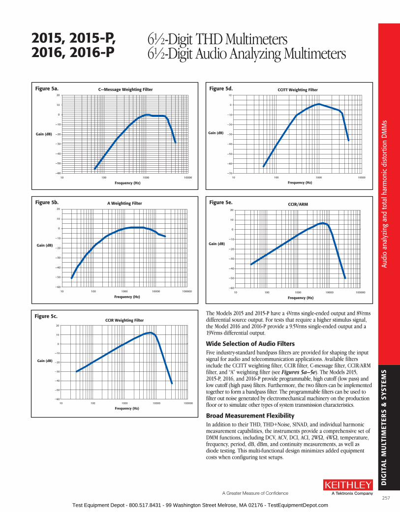
DIG
ITA
L M
ULT
IME
TER
S &
SY
STE
MS
A Greater Measure of Confidence
CCIR Weighting Filter
—60
—50
—40
—30
—20
—10
0
10
20
10 100 1000 10000 100000
Frequency (Hz)
Gain (dB)
figure 5c.
CCITT Weighting Filter
—70
—60
—50
—40
—30
—20
—10
0
10
10 100 1000 10000
Frequency (Hz)
Gain (dB)
figure 5d.
CCIR/ARM
—60
—50
—40
—30
—20
—10
0
10
20
10 100 1000 10000 100000
Frequency (Hz)
Gain (dB)
figure 5e.
C—Message Weighting Filter
—60
—50
—40
—30
—20
—10
0
10
20
10 100 1000 10000
Frequency (Hz)
Gain (dB)
figure 5a.
A Weighting Filter
—60
—50
—40
—30
—20
—10
0
10
20
10 100 1000 10000 100000
Frequency (Hz)
Gain (dB)
figure 5b.
The Models 2015 and 2015-P have a 4Vrms single-ended output and 8Vrms differential source output . For tests that require a higher stimulus signal, the Model 2016 and 2016-P provide a 9 .5Vrms single-ended output and a 19Vrms differential output .
Wide selection of audio filtersFive industry-standard bandpass filters are provided for shaping the input signal for audio and tele com mu nica tion applications . Available filters include the CCITT weighting filter, CCIR filter, C-message filter, CCIR/ARM filter, and “A” weighting filter (see Figures 5a–5e) . The Models 2015, 2015-P, 2016, and 2016-P provide programmable, high cutoff (low pass) and low cutoff (high pass) filters . Furthermore, the two filters can be implemented together to form a bandpass filter . The programmable filters can be used to filter out noise generated by electromechanical machinery on the production floor or to simulate other types of system transmission charac teristics .
broad Measurement flexibilityIn addition to their THD, THD+Noise, SINAD, and individual har monic measure ment capabilities, the instruments provide a compre hen sive set of DMM functions, including DCV, ACV, DCI, ACI, 2WW, 4WW, temperature, frequency, period, dB, dBm, and continuity measure ments, as well as diode testing . This multi-functional design minimizes added equipment costs when config uring test setups .
2015, 2015-P, 2016, 2016-P
6½-Digit THD Multimeters6½-Digit Audio Analyzing Multimeters
Audi
o an
alyz
ing
and
tota
l har
mon
ic d
isto
rtio
n D
MM
s
Audi
o an
alyz
ing
and
tota
l har
mon
ic d
isto
rtio
n D
MM
s
257 Test Equipment Depot - 800.517.8431 - 99 Washington Street Melrose, MA 02176 - TestEquipmentDepot.com

DIG
ITA
L M
ULT
IME
TER
S &
SY
STE
MS
Wide band or Narrow band Noise MeasurementsThe Models 2015, 2015-P, 2016, and 2016-P are capable of measuring both wide band noise and narrow band noise . Alternatively, these instruments’ DSP (digital signal processing) capabilities allow users to make frequency domain measurements of RMS voltage noise over the 20Hz–20kHz frequency audio band or a narrow portion of the band . Furthermore, noise measurements can be extracted in the presence of a stimulus signal for fast signal-to-noise computations .
spectrum analysisThe Model 2015-P and 2016-P have internal computational capabilities that allow them to characterize an acquired signal spectrum . These instruments can identify and report the frequency and amplitude of the highest value in a complete spectrum or within a specified frequency band . It can also identify additional peaks in descending order of magnitude (see Figure 6) . The Model 2015-P’s and 2016-P’s on-board capabilities make it simple to obtain a thorough analysis of a frequency spectrum more quickly and with little or no need for external analysis software .
Frequency Spectrum
Mag
nitu
de (
dBV)
–20
–40
–60
–80
–100
–1201.0kHz 1.1kHz 1.2kHz 1.3kHz 1.4kHz
Frequency
Between 1.0kHz and 1.4kHz
Maximum2nd peak
3rd peak
4th peakMaximum right of 4th peak
Maximum left of 4th peak
figure 6. The Model 2015-P and 2016-P directly identify peak values of the frequency spectrum.
aCCEssorIEs aVaIlablECablEs/aDaPTErs7007-1 Shielded IEEE-488 Cable, 1m (3 .3 ft)
7007-2 Shielded IEEE-488 Cable, 2m (6 .6 ft)
8501-1, 8501-2 Trigger-Link Cables, 1m (3 .3 ft), 2m (6 .6 ft)
8502 Trigger Link Adapter Box
8503 Trigger Link Cable to 2 male BNCs, 1m (3 .3 ft)
7009-5 RS-232 Cable
raCK MouNT KITs4288-1 Single Fixed Rack Mount Kit
4288-2 Dual Fixed Rack Mount Kit
GPIb INTErfaCEs KPCI-488LPA IEEE-488 Interface/Controller for the PCI Bus
KUSB-488B IEEE-488 USB-to-GPIB Interface Adapter
figure 7. rear panel of all models
2015, 2015-P, 2016, 2016-P
6½-Digit THD Multimeters6½-Digit Audio Analyzing Multimeters
sErVICEs aVaIlablE2015-3Y-EW 1-year factory warranty extended to 3 years
from date of shipment
2015-P-3Y-EW 1-year factory warranty extended to 3 years from date of shipment
2016-3Y-EW 1-year factory warranty extended to 3 years from date of shipment
2016-P-3Y-EW 1-year factory warranty extended to 3 years from date of shipment
C/2015-3Y-ISO 3 (ISO-17025 accredited) calibrations within 3 years of purchase for Models 2015, 2015-P*
C/2016-3Y-ISO 3 (ISO-17025 accredited) calibrations within 3 years of purchase for Models 2016, 2016-P*
*Not available in all countries
Audi
o an
alyz
ing
and
tota
l har
mon
ic d
isto
rtio
n D
MM
s
Audi
o an
alyz
ing
and
tota
l har
mon
ic d
isto
rtio
n D
MM
s
258 Test Equipment Depot - 800.517.8431 - 99 Washington Street Melrose, MA 02176 - TestEquipmentDepot.com

DIG
ITA
L M
ULT
IME
TER
S &
SY
STE
MS
A Greater Measure of Confidence
2015, 2015-P, 2016, 2016-P
6½-Digit THD Multimeters6½-Digit Audio Analyzing Multimeters
DIsTorTIoN CHaraCTErIsTICsVOLTAGE RANGE: 100mV, 1V, 10V, 100V, 750V (user selectable) .
INPUT IMPEDANCE: 1MW paralleled by <100pF .
DISPLAy RANGE: 0–100% or 0–100 .00dB .
RESOLUTION: 0 .0001% or 0 .00001dB .
FUNDAMENTAL FREQUENCy RANGE: 20Hz–20kHz .
HARMONIC FREQUENCy RANGE: 40Hz–50kHz .
FREQUENCy RESOLUTION: 0 .008Hz .
FREQUENCy ACCURACy: ±0 .01% of reading .
FREQUENCy TEMPERATURE COEFFICIENT: ≤100ppm over operating temperature range .
Measurement accuracy residual Mode (1 Year, 23°C ±5°C) Distortion1
THD and individual ±0 .8 dB, 0 .004% or –87 dB harmonic magnitudes 20 Hz to 20 kHz2 20 Hz to 20 kHz
THD + n ±1 .5 dB, 0 .056% or –65 dB 100 Hz to 20 kHz2 20 Hz to 20 kHz
SINAD ±1 .5 dB +65 dB 100 Hz to 20 kHz2 20 Hz to 20 kHz
AC Level ±(0 .13% of reading + V rms 0 .009% of range) 20 Hz to 20 kHz
DIsTorTIoN MEasurEMENT auDIo fIlTErsNone C-MessageCCITT Weighting CCIR/ARMCCIR “A” Weighting
NUMBER OF HARMONICS INCLUDED IN THD CALCULATION: 2 to 64 (user selectable) .
HI AND LO CUTOFF FILTERS (bus settable): 20Hz–50kHz . Can be combined to form brickwall bandpass filter .
DIsTorTIoN MEasurEMENT rEaDING raTE3
fundamental Minimum frequency fundamental readings acquisition frequency Per Mode range second
Single acquisition 20 Hz to 100 Hz 14 or stored value 100 Hz to 1 kHz 24 1 kHz to 20 kHz 28
Automatic 20 Hz to 30 Hz 5 .5 30 Hz to 400 Hz 6 400 Hz to 20 kHz 6 .6
frEQuENCY sWEEP rEaDING raTE Number of frequencies Time (seconds)4
5 0 .2 30 1 .1 100 3 .5 200 6 .9
NoTEs1 . Input signal at full scale .2 . VIN ≥20% of range and harmonics > –65dB .3 . Speeds are for default operating conditions (*RST), and display off, auto range off, binary data transfer,
trig delay = 0 .4 . Typical times: frequencies in 400–4kHz range, binary data transfer, TRIG DELAY = 0, Display OFF, Auto
Range OFF . Data returned is THD measurement plus AC voltage .
GENEraTor CHaraCTErIsTICsFREQUENCy RANGE: 10–20kHz .
FREQUENCy RESOLUTION: 0 .007Hz .
FREQUENCy ACCURACy: ±(0 .015% of reading + 0 .007Hz)1 .
FREQUENCy TEMPERATURE COEFFICIENT: <100ppm over operating temperature range .
sourCE ouTPuT:WAVEFORM: Sinewave .
AMPLITUDE RANGE: 2015, 2015-P: 2V rms (50W and 600W) or 4V rms (HI Z) . 2016, 2016-P: 4 .75V rms (50W and 600W) or 9 .5V rms (HI Z) .
AMPLITUDE RESOLUTION: 2015, 2015-P: 0 .5mV rms (50W and 600W) or 1mV rms (HI Z) . 2016, 2016-P: 1 .25mV rms (50W and 600W) or 2 .5mV rms (HI Z) .
AMPLITUDE ACCURACy: 2015, 2015-P: ±(0 .3% of setting + 2mV)1, 4 . 2016, 2016-P: ±(0 .3% of setting + 5mV)1, 4 .
AMPLITUDE TEMPERATURE COEFFICIENT: Typically 0 .015%/°C .
AMPLITUDE FLATNESS: ±0 .1dB1, 4, 5 .
OUTPUT IMPEDANCE: 50W ± 1W or 600W ± 10W, user selectable .
THD: –64dB6 .
NOISE: 2015, 2015-P: 100µV rms2 . 2016, 2016-P: 250µV rms2 .
DC OFFSET VOLTAGE: 2015, 2015-P: ±1 .2mV1 . 2016, 2016-P: ±3mV1 .
INV/PulsE ouTPuT (sINEWaVE MoDE):FREQUENCy: Same as source output .
AMPLITUDE RANGE: 2015, 2015-P: 2V rms (50W and 600W) or 4V rms (HI Z) . 2016, 2016-P: 4 .75V rms (50W and 600W) or 9 .5V rms (HI Z) .
AMPLITUDE RESOLUTION: 2015, 2015-P: 0 .5mV (50W and 600W) or 1mV rms (HI Z) . 2016, 2016-P: 1 .25mV rms (50W and 600W) or 2 .5mV rms (HI Z) .
AMPLITUDE ACCURACy: 2015, 2015-P: ±(2 .0% of setting + 2mV)1, 4 . 2016, 2016-P: ±(2 .0% of setting + 5mV)1, 4 .
AMPLITUDE FLATNESS: ±0 .1dB1, 4, 5 .
OUTPUT IMPEDANCE: Same as Source Output setting .
THD: –64dB6 .
NOISE: 2015, 2015-P: 100µV rms2 . 2016, 2016-P: 250µV rms2 .
DC OFFSET VOLTAGE: 2015, 2015-P: ±1 .1mV typ ., ±13mV max .1 2016, 2016-P: ±3mV typ ., ±13mV max .1
INV/PulsE ouTPuT (PulsE MoDE):FREQUENCy: Same as source output .
DUTy CyCLE: 45% ±3% .
OUTPUT IMPEDANCE: Same output impedance as the source output .
AMPLITUDE: 0 .0V ±0 .07V to 4 .9V ±0 .12V pulse open circuit1, 3 . 0 .0V ±0 .05V to 3 .3V ±0 .08V pulse 100W load1, 3 .
OVERSHOOT: 1 .0V maximum pulse open circuit3 . 0 .2V maximum with 100W load pulse open circuit3 .
UNDERSHOOT: 1 .1V maximum pulse open circuit3 . 0 .45V maximum with 100W load pulse open circuit3 .
NoTEs1 . 1 year, 23°C ±5°C .2 . Measured at VOUT = 0V with gain 100 amplifier and 2-pole 50kHz low pass filter, Inv/Pulse in sinewave
mode, HI Z output impedance, and no load .3 . With HI Z output impedance and 1m 50W coaxial cable .4 . HI Z output impedance, no load .5 . 4V output .6 . THD measurement includes harmonics 2 through 5, 1V rms output, HI Z, no load .
Mod
el 2
015,
201
5-P,
201
6, 2
016-
P sp
ecifi
catio
ns
Mod
el 2
015,
201
5-P,
201
6, 2
016-
P sp
ecifi
catio
ns
259 Test Equipment Depot - 800.517.8431 - 99 Washington Street Melrose, MA 02176 - TestEquipmentDepot.com

DIG
ITA
L M
ULT
IME
TER
S &
SY
STE
MS
2015, 2015-P, 2016, 2016-P
6½-Digit THD Multimeters6½-Digit Audio Analyzing Multimeters
DC CharacteristicsCONDITIONS: MED (1 PLC)1 or SLOW (10 PLC) or MED (1 PLC) with filter of 10 . accuracy: ±(ppm of reading + ppm of range)
(ppm = parts per million) (e.g., 10ppm = 0.001%) Temperature Coefficient
0°–18°C & 28°–50°Cfunction range resolution
Test Current or burden Voltage
(±5%)Input
resistance24 Hour 14 23°C ± 1°
90 Day 23°C ± 5°
1 Year 23°C ± 5°
Voltage 100 .0000 mV 0 .1 µV > 10 GW 30 + 30 40 + 35 50 + 35 2 + 6 1 .000000 V 1 .0 µV > 10 GW 15 + 6 25 + 7 30 + 7 2 + 1 10 .00000 V 10 µV > 10 GW 15 + 4 20 + 5 30 + 5 2 + 1 100 .0000 V 100 µV 10 MW ±1% 15 + 6 30 + 6 45 + 6 5 + 1 1000 .000 V 9 1 mV 10 MW ±1% 20 + 6 35 + 6 45 + 6 5 + 1
Resistance 15 100 .0000 W 100 µW 1 mA 30 + 30 80 + 40 100 + 40 8 + 6 1 .000000 kW 1 mW 1 mA 20 + 6 80 + 10 100 + 10 8 + 1 10 .00000 kW 10 mW 100 µA 20 + 6 80 + 10 100 + 10 8 + 1 100 .0000 kW 100 mW 10 µA 20 + 6 80 + 10 100 + 10 8 + 1 1 .000000 MW 16 1 W 10 µA 20 + 6 80 + 10 100 + 10 8 + 1 10 .00000 MW 11, 16 10 W 700 nA // 10MW 300 + 6 450 + 10 600 + 10 95 + 1 100 .0000 MW 11, 16 100 W 700 nA // 10MW 1600 + 30 2000 + 30 2200 + 30 900 + 1
Current 10 .00000 mA 10 nA < 0 .15 V 60 + 30 300 + 80 500 + 80 50 + 5 100 .0000 mA 100 nA < 0 .03 V 100 + 300 300 + 800 500 + 800 50 + 50 1 .000000 A 1 µA < 0 .3 V 200 + 30 500 + 80 800 + 80 50 + 5 3 .00000 A 10 µA < 1 V 1000 + 15 1200 + 40 1200 + 40 50 + 5
Continuity 2W 1 kW 100 mW 1 mA 40 + 100 100 + 100 120 + 100 8 + 1Diode Test 3 .00000 V 10 µV 1 mA 20 + 6 30 + 7 40 + 7 8 + 1
10 .00000 V 10 µV 100 µA 20 + 6 30 + 7 40 + 7 8 + 1 10 .00000 V 10 µV 10 µA 20 + 6 30 + 7 40 + 7 8 + 1
DC oPEraTING CHaraCTErIsTICs 2
function Digits readings/s PlCs 8
DCV (all ranges),DCI (all ranges),
2W Ohms (<10M ranges)
6½ 3, 4 5 106½ 3, 7 30 16½ 3, 5 50 15½ 3, 5 270 0 .15½ 5 500 0 .15½ 5 1000 0 .044½ 5 2000 0 .01
DC sYsTEM sPEEDs 2, 6
RANGE CHANGE3 : 50/s .
FUNCTION CHANGE 3: 45/s .
AUTORANGE TIME 3, 10: <30ms .
ASCII READINGS TO RS-232 (19.2K baud): 55/s .
MAX. INTERNAL TRIGGER RATE: 2000/s .
MAX. EXTERNAL TRIGGER RATE: 400/s .
DC GENEralLINEARITy OF 10VDC RANGE: ±(1ppm of reading + 2ppm of range) .
DCV, W, TEMPERATURE, CONTINUITy, DIODE TEST INPUT PROTECTION: 1000V, all ranges .
MAXIMUM 4WW LEAD RESISTANCE: 10% of range per lead for 100W and 1kW ranges; 1kW per lead for all other ranges .
DC CURRENT INPUT PROTECTION: 3A, 250V fuse .
SHUNT RESISTOR: 0 .1W for 3A, 1A, and 100mA ranges . 10W for 10mA range .
CONTINUITy THRESHOLD: Adjustable 1W to 1000W .
AUTOzERO OFF ERROR: Add ±(2ppm of range error + 5µV) for <10 minutes and ±1°C change .
OVERRANGE: 120% of range except on 1000V, 3A, and Diode .
sPEED aND NoIsE rEJECTIoN
rate readings/s DigitsrMs Noise 10V range NMrr 12 CMrr 13
10 PLC 5 6½ < 1 .5 µV 60 dB 140 dB1 PLC 50 6½ < 4 µV 60 dB 140 dB
0 .1 PLC 500 5½ < 22 µV — 80 dB0 .01 PLC 2000 4½ < 150 µV — 80 dB
DC NoTEs1 . Add the following to ppm of range accuracy specification based on range:1V and 100V, 2ppm; 100mV, 15ppm;
100W, 15ppm; 1kW–1MW, 2ppm; 10mA and 1A, 10ppm; 100mA, 40ppm .2 . Speeds are for 60Hz operation using factory default operating conditions (*RST) . Autorange off, Display off,
Trigger delay = 0 .3 . Speeds include measurement and binary data transfer out the GPIB .4 . Auto zero off .5 . Sample count = 1024, auto zero off .6 . Auto zero off, NPLC = 0 .01 .7 . Ohms = 24 readings/second .8 . 1 PLC = 16 .67ms @ 60Hz, 20ms @ 50Hz/400Hz . The frequency is automatically determined at power up .9 . For signal levels >500V, add 0 .02ppm/V uncertainty for the portion exceeding 500V .10 . Add 120ms for ohms .11 . Must have 10% matching of lead resistance in Input HI and LO .12 . For line frequency ±0 .1% .13 . For 1kW unbalance in LO lead .14 . Relative to calibration accuracy .15 . Specifications are for 4-wire ohms . For 2-wire ohms, add 1W additional uncertainty .16 . For rear inputs . Add the following to Temperature Coefficient "ppm of reading" uncertainty: 10MW 70ppm,
100MW 385ppm . Operating environment specified for 0° to 50°C, 50% RH at 35°C .
Mod
el 2
015,
201
5-P,
201
6, 2
016-
P sp
ecifi
catio
ns
Mod
el 2
015,
201
5-P,
201
6, 2
016-
P sp
ecifi
catio
ns
260 Test Equipment Depot - 800.517.8431 - 99 Washington Street Melrose, MA 02176 - TestEquipmentDepot.com

DIG
ITA
L M
ULT
IME
TER
S &
SY
STE
MS
A Greater Measure of Confidence
2015, 2015-P, 2016, 2016-P
6½-Digit THD Multimeters6½-Digit Audio Analyzing Multimeters
True rMs aC Voltage and Current Characteristics
accuracy 1: ±(% of reading + % of range), 23°C ±5 °C
Voltage range resolution Calibration Cycle 3 Hz– 10 Hz 10 10 Hz– 20 kHz 20 kHz– 50 kHz 50 kHz– 100 kHz 100 kHz– 300 kHz 100 .0000 mV 0 .1 µV 1 .000000 V 1 .0 µV
90 Days 0 .35 + 0 .03 0 .05 + 0 .03 0 .11 + 0 .05 0 .60 + 0 .08 4 + 0 .5 10 .00000 V 10 µV 100 .0000 V 100 µV
1 Year 0 .35 + 0 .03 0 .06 + 0 .03 0 .12 + 0 .05 0 .60 + 0 .08 4 + 0 .5
750 .000 V 1 mV Temperature
Coefficient/°C 8 0 .035 + 0 .003 0 .005 + 0 .003 0 .006 + 0 .005 0 .01 + 0 .006 0 .03 + 0 .01
Current range resolution Calibration Cycle 3 Hz–10 Hz 10 Hz–3 kHz 3 kHz–5 kHz1 .000000 A 1 µA 90 Day/1 Year 0 .30 + 0 .04 0 .10 + 0 .04 0 .14 + 0 .043 .00000 A 9 10 µA 90 Day/1 Year 0 .35 + 0 .06 0 .15 + 0 .06 0 .18 + 0 .06
Temperature Coefficient/°C 8 0 .035 + 0 .006 0 .015 + 0 .006 0 .015 + 0 .006
HIGH CrEsT faCTor aDDITIoNal Error ±(% of reading) 7
CREST FACTOR: 1–2 2–3 3–4 4–5
ADDITIONAL ERROR: 0 .05 0 .15 0 .30 0 .40
aC oPEraTING CHaraCTErIsTICs 2
function Digits readings/s rate bandwidth
ACV (all ranges), and ACI (all ranges)
6½ 3 2s/reading SLOW 3 Hz–300 kHz6½ 3 1 .4 MED 30 Hz–300 kHz6½ 4 4 .8 MED 30 Hz–300 kHz6½ 3 2 .2 FAST 300 Hz–300 kHz6½ 4 35 FAST 300 Hz–300 kHz
aDDITIoNal loW frEQuENCY Errors ±(% of reading)slow Med fast
20 Hz – 30 Hz 0 0 .3 —30 Hz – 50 Hz 0 0 —50 Hz – 100 Hz 0 0 1 .0
100 Hz – 200 Hz 0 0 0 .18200 Hz – 300 Hz 0 0 0 .10
> 300 Hz 0 0 0
aC sYsTEM sPEEDs 2, 5
FUNCTION/RANGE CHANGE 6: 4/s .
AUTORANGE TIME: <3s .
ASCII READINGS TO RS-232 (19.2k baud) 4: 50/s .
MAX. INTERNAL TRIGGER RATE 4: 300/s .
MAX. EXTERNAL TRIGGER RATE 4: 260/s .
aC GENEralINPUT IMPEDANCE: 1MW ±2% paralleled by <100pF .
ACV INPUT PROTECTION: 1000Vp .
MAXIMUM DCV: 400V on any ACV range .
ACI INPUT PROTECTION: 3A, 250V fuse .
BURDEN VOLTAGE: 1A Range: <0 .3V rms . 3A Range: <1V rms .
SHUNT RESISTOR: 0 .1W on all ACI ranges .
AC CMRR: >70dB with 1kW in LO lead .
MAXIMUM CREST FACTOR: 5 at full scale .
VOLT HERTz PRODUCT: ≤8 × 10⁷V·Hz .
OVERRANGE: 120% of range except on 750V and 3A ranges .
aC NoTEs1 . Specifications are for SLOW rate and sinewave inputs >5% of range . 2 . Speeds are for 60Hz operation using factory default operating conditions (*RST) . Auto zero off, Auto range off,
Display off, includes measurement and binary data transfer out the GPIB .3 . 0 .01% of step settling error . Trigger delay = 400ms .4 . Trigger delay = 0 .5 . DETector:BANDwidth 300, NPLC = 0 .01 .6 . Maximum useful limit with trigger delay = 175ms .7 . Applies to non-sinewaves >5Hz and <500Hz . (Guaranteed by design for crest factors >4 .3 .)8 . Applies to 0°–18°C and 28°–50°C .9 . For signal levels >2 .2A, add additional 0 .4% to "of reading" uncertainty .10 . Typical uncertainties . Typical represents two sigma or 95% of manufactured units measure <0 .35% of reading
and three sigma or 99 .7% <1 .06% of reading .
Mod
el 2
015,
201
5-P,
201
6, 2
016-
P sp
ecifi
catio
ns
Mod
el 2
015,
201
5-P,
201
6, 2
016-
P sp
ecifi
catio
ns
261 Test Equipment Depot - 800.517.8431 - 99 Washington Street Melrose, MA 02176 - TestEquipmentDepot.com
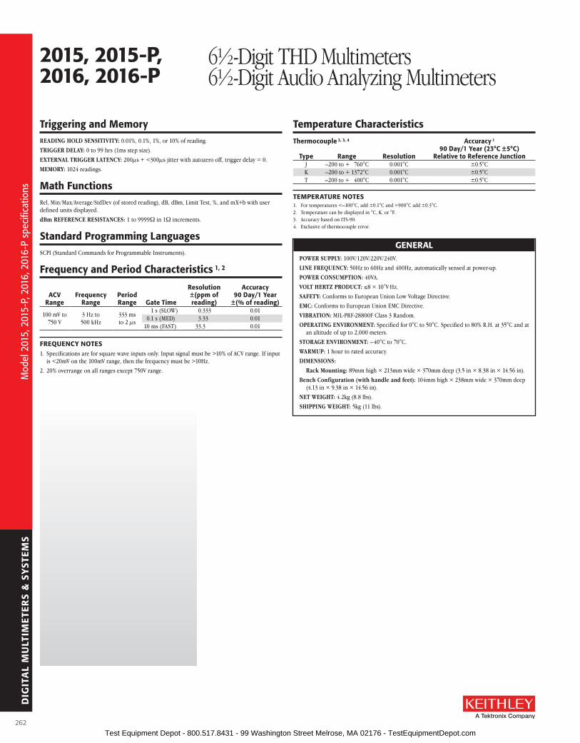
DIG
ITA
L M
ULT
IME
TER
S &
SY
STE
MS
Triggering and MemoryREADING HOLD SENSITIVITy: 0 .01%, 0 .1%, 1%, or 10% of reading .
TRIGGER DELAy: 0 to 99 hrs (1ms step size) .
EXTERNAL TRIGGER LATENCy: 200µs + <300µs jitter with autozero off, trigger delay = 0 .
MEMORy: 1024 readings .
Math functionsRel, Min/Max/Average/StdDev (of stored reading), dB, dBm, Limit Test, %, and mX+b with user defined units displayed .
dBm REFERENCE RESISTANCES: 1 to 9999W in 1W increments .
standard Programming languagesSCPI (Standard Commands for Programmable Instruments) .
frequency and Period Characteristics 1, 2
aCV range
frequency range
Period range Gate Time
resolution ±(ppm of reading)
accuracy 90 Day/1 Year
±(% of reading)
100 mV to 750 V
3 Hz to 500 kHz
333 ms to 2 µs
1 s (SLOW) 0 .333 0 .010 .1 s (MED) 3 .33 0 .01
10 ms (FAST) 33 .3 0 .01
frEQuENCY NoTEs1 . Specifications are for square wave inputs only . Input signal must be >10% of ACV range . If input
is <20mV on the 100mV range, then the frequency must be >10Hz .
2 . 20% overrange on all ranges except 750V range .
2015, 2015-P, 2016, 2016-P
6½-Digit THD Multimeters6½-Digit Audio Analyzing Multimeters
Temperature CharacteristicsThermocouple 2, 3, 4 accuracy 1
90 Day/1 Year (23°C ±5°C)
relative to reference JunctionType range resolutionJ –200 to + 760°C 0 .001°C ±0 .5°CK –200 to + 1372°C 0 .001°C ±0 .5°CT –200 to + 400°C 0 .001°C ±0 .5°C
TEMPEraTurE NoTEs1 . For temperatures <–100°C, add ±0 .1°C and >900°C add ±0 .3°C .2 . Temperature can be displayed in °C, K, or °F .3 . Accuracy based on ITS-90 .4 . Exclusive of thermocouple error .
GENEralPOWER SUPPLy: 100V/120V/220V/240V .
LINE FREQUENCy: 50Hz to 60Hz and 400Hz, automatically sensed at power-up .
POWER CONSUMPTION: 40VA .
VOLT HERTz PRODUCT: ≤8 × 10⁷V·Hz .
SAFETy: Conforms to European Union Low Voltage Directive .
EMC: Conforms to European Union EMC Directive .
VIBRATION: MIL-PRF-28800F Class 3 Random .
OPERATING ENVIRONMENT: Specified for 0°C to 50°C . Specified to 80% R .H . at 35°C and at an altitude of up to 2,000 meters .
STORAGE ENVIRONMENT: –40°C to 70°C .
WARMUP: 1 hour to rated accuracy .
DIMENSIONS:
Rack Mounting: 89mm high × 213mm wide × 370mm deep (3 .5 in × 8 .38 in × 14 .56 in) .
Bench Configuration (with handle and feet): 104mm high × 238mm wide × 370mm deep (4 .13 in × 9 .38 in × 14 .56 in) .
NET WEIGHT: 4 .2kg (8 .8 lbs) .
SHIPPING WEIGHT: 5kg (11 lbs) .
Mod
el 2
015,
201
5-P,
201
6, 2
016-
P sp
ecifi
catio
ns
Mod
el 2
015,
201
5-P,
201
6, 2
016-
P sp
ecifi
catio
ns
262 Test Equipment Depot - 800.517.8431 - 99 Washington Street Melrose, MA 02176 - TestEquipmentDepot.com

DIG
ITA
L M
ULT
IME
TER
S &
SY
STE
MS
A Greater Measure of Confidence
A Series 3700A system combines the functionality of an instrument grade relay switching system with a high per-formance multimeter . Integrating the multimeter within the mainframe ensures you of a high quality signal path from each channel to the multimeter . This tightly integrated switch and measurement system can meet the demanding application requirements of a functional test system or provide the flexibility needed in stand-alone data acquisi-tion and measurement applications . It is ideal for multiple pin count applications where relay switching can be used to connect multiple devices to source and measurement instruments .
The high performance multimeter in the Series 3700A offers low noise, high stability 3½- to 7½-digit readings for leading-edge measurement performance . This flex-ible resolution sup plies a DC reading rate from >14,000 readings/second at 3½ digits to 60 readings/second at 7½ digits, offering customers maximum reading throughput and accuracy . The multimeter also provides an expanded low ohms (1W) range, low current (10µA) range, and dry circuit (1W to 1kW) range, extending utility beyond typical DMM applications .
The multimeter supports 13 built-in measure ment functions, including: DCV, ACV, DCI, ACI, frequen-cy, period, two-wire ohms, four-wire ohms, three-wire RTD temperature, four-wire RTD temperature, thermocouple temperature, thermistor temperature, and continuity . In-rack calibration is sup ported, which reduces both maintenance and calibration time . Onboard memory can store up to 650,000 readings, and the USB device port provides easy transfer of data to memory sticks .
single Channel reading rates
resolutionDCV/
2-Wire ohms 4-Wire ohms7½ Digits (1 NPLC) 60 296½ Digits (0 .2 NPLC) 295 1205½ Digits (0 .06 NPLC) 935 2854½ Digits (0 .006 NPLC) 6,300 5803½ Digits (0 .0005 NPLC) 14,000 650
series 3700a System Switch/Multimeter and Plug-In Cards
• Combines the functions of a system switch and a high performance multimeter
• lXI compliance with IEEE-1588 time synchronization
• 3½- to 7½-digit measurement resolution
• Embedded Test script Processor (TsP®) offers unparalleled system automation, throughput, and flexibility
• Extended low ohms (1W) range with 100nW resolution
• Extended low current (10µa) range with 1pa resolution
• >14,000 readings/second
• low noise, <0.1ppm rms noise on 10VDC range
• Expanded dry circuit range (2kW)
• four-wire open lead detection (source and sense lines)
aPPlICaTIoNs
• system- and rack-level signal referencing
• Power supply burn-in testing (PC, network, telecom)
• low ohms testing (contacts, connectors, relays)
• Temperature profiling
• Plant/environment monitoring and control
• automotive and aerospace systems
• Consumer product certification/testing laboratories
Leading CompetitorKeithley 3706A
Low Noise PerformanceModel 3706A vs. Leading Competitor
–4.0
–3.0
–2.0
–1.0
0.0
1.0
2.0
3.0
4.0
0.0 5.0 10.0 15.0 20.0 25.0 30.0 35.0
1000 Readings at 1PLC
10VD
C N
oise
(pp
m o
f ra
nge)
Compare the Model 3706a's 10V DC noise and speed performance with that of the leading competitor. all the data was taken at 1PlC with a low thermal short applied to the input, which resulted in 10× lower noise and 7× faster measurements for the Model 3706a.
for more information about series 3700a systems, see page 162.
Syst
em s
witc
h w
ith h
igh
perfo
rman
ce m
ultim
eter
Syst
em s
witc
h w
ith h
igh
perfo
rman
ce m
ultim
eter
263 Test Equipment Depot - 800.517.8431 - 99 Washington Street Melrose, MA 02176 - TestEquipmentDepot.com

DIG
ITA
L M
ULT
IME
TER
S &
SY
STE
MS
Integra Series systems (2700, 2701, 2750) com-bine precision measurement, switching, and control in a single, tightly integrated enclosure for either rack-mounted or benchtop applica-tions . These cost-effective, high performance test platforms offer affordable alternatives to separate DMMs and switch systems, dataloggers/recorders, plug-in card data acquisition equip-ment, and VXI/PXI systems . The Integra Series plug-in switching and control modules offer unmatched flexibility and testing efficiency for a wide range of industries and applications . System builders can create test solutions with a combination of channel count, cost per channel, and system performance unmatched by any other single-box measurement system . The input modules provide the flexibility to vary the channel count from 20 to 200 (2-pole), apply a stimulus to the device under test, route signals, control system components, and make precision measurements with up to 14 functions . Robust digital I/O capabilities can be used for triggering, handshaking with other automation equipment, and alarm limit outputs . Scan rates of up to 500 channels/second (up to 3500 readings/second on a single channel) will increase test productivity .
fast setup and operationThe Integra systems are fully integrated, off-the-shelf measurement and control systems . Their DMM-like interfaces make it easy for users to collect data and/or perform troubleshooting within minutes of installation and startup . Once sensor or DUT leads are hooked to the instrument’s input, use the front panel controls to select the measurement function, range, filtering, scaling, trigger source, scan-ning sequence, alarms, and more . The free ExceLINX-1A software makes it easy to configure and use the system in a graphical “point-and-click” environment . This gives developers the basic tools needed to create a simple application without writing program code .
The advantage of Integrated DesignThe Integra systems offer a variety of advantages over existing solutions for ATE and data acquisition applications . For example, their flexible modular architecture and integrated measurement, switch-ing, and control capabilities save rack space by reducing the number of separate instruments needed . This design also simplifies expanding the system as the number of channels grows or re-purposing it as new test requirements evolve . Integrated signal conditioning, scaling, stimulus, filtering and I/O capabilities eliminate the need for external circuitry when designing and building data acquisition systems . The Integra systems offer accuracy and repeatability superior to plug-in data acquisition boards, while providing faster test times than typical DMM/switch systems . This makes it possible to combine higher test yields with higher test throughput .
EthernetThe Model 2701 offers a 10/100 BaseT Ethernet connection for high speed and long distance communication between a computer and a virtu-ally infinite number of instruments . Any PC with an Ethernet port can connect to a single Model
• Combines functions of DMM, switch system, and datalogger
• True 6½-digit (22-bit) resolution
• Choice of 12 switch/control plug-in modules
• up to 200 differential input channels (with 300V isolation) for measurement and control
• Convenient front panel inputs
• free labVIEW®, labWindows/ CVI, Visual basic, and C/C++ drivers (IVI style)
• Ethernet, GPIb, rs-232 communications capabilities
• free ExcelINX™-1a datalogging software
2700, 2701, 2750
Multimeter/Data Acquisition/ Switch Systems
built-in measurement functions include:• DCV • aCV • DCI • aCI• resistance (2- or 4-wire, offset
compensation selectable)• Dry circuit ohms (20mV
clamp) 2750 only• Temperature (with thermo-
couples, rTDs, or thermistors)• frequency/Period• Continuity
Inte
gra
Serie
s in
tegr
ated
sw
itchi
ng, m
easu
rem
ent,
and
data
logg
ing
solu
tions
Inte
gra
Serie
s in
tegr
ated
sw
itchi
ng, m
easu
rem
ent,
and
data
logg
ing
solu
tions
264 Test Equipment Depot - 800.517.8431 - 99 Washington Street Melrose, MA 02176 - TestEquipmentDepot.com

DIG
ITA
L M
ULT
IME
TER
S &
SY
STE
MS
A Greater Measure of Confidence
Install up to five input modules in the 2750 mainframe (or up to two in the 2700 and 2701 mainframes). all switch/control modules are fully enclosed in impact-resistant plastic for exceptional ruggedness. Three connector alternatives simplify connecting the modules to DuTs. rugged D-sub connectors allow quick, secure connections and are especially convenient when performing routine maintenance or when the system is installed in a rack. IDC ribbon cable adapters are supplied with the Model 7701, 7707, and 7709 modules for fast, uncomplicated hookups in production test and process monitoring applications. oversize screw-terminal connectors simplify setup in applications that require the greatest connection flexibility. additional D-sub and IDC ribbon cable connector kits and pre-wired cable assemblies are sold separately.
2701 in a point-to-point configuration, to multiple Model 2701s through a hub, or to multiple Model 2701s distributed on a network .
The Model 2701 Ethernet port uses the industry-standard TCP/IP socket interface . This provides data rates up 100Mbits/sec . and allows the instrument to be located up to 100 meters from the nearest computer or network hub in hardwired systems and miles in wireless Ethernet systems . The maxi-mum distances between a control PC and the instruments are limited only by the size of the network . The instrument also provides a built-in diagnostic Web page for easy remote access to the Model 2701 . Entering the instrument’s IP address in the URL line of Microsoft Internet Explorer will allow communication with and control of the Model 2701 . This Web page allows users to read and set net-work parameters, such as IP address, subnet mask, gateway, MAC address, and calibration dates, and to send commands to and query data from the Model 2701 .
Temperature CapabilitiesIntegra Series mainframes support three major types of temperature sensors with built-in signal conditioning and 300V isolation: thermocouples, RTDs, and thermistors . To begin using a sensor, simply hook it up and the instrument does the rest . If a thermocouple is broken or disconnected, the instrument will alert the operator . The mainframes also support three methods for cold-junction compensation (CJC): automatic (built-in), external (built-in), and simulated .
ordering Information2700 DMM, Data acquisition,
Datalogging system w/2 slots
2701 DMM, Data acquisition, Datalogging system w/2 slots and Ethernet support
2750 DMM, Data acquisition, switching, Datalogging system w/5 slots
accessories suppliedlabVIEW, labWindows/ CVI, Visual basic, and C/C++ drivers; manual; and Model 1751 safety Test leads.
2700, 2701, 2750
Multimeter/Data Acquisition/ Switch Systems
sErVICEs aVaIlablE2700-3Y-EW 1-year factory warranty extended to 3 years
from date of shipment
2701-3Y-EW 1-year factory warranty extended to 3 years from date of shipment
2750-3Y-EW 1-year factory warranty extended to 3 years from date of shipment
C/2700-3Y-ISO 3 (ISO-17025 accredited) calibrations within 3 years of purchase*
C/2701-3Y-ISO 3 (ISO-17025 accredited) calibrations within 3 years of purchase*
C/2750-3Y-ISO 3 (ISO-17025 accredited) calibrations within 3 years of purchase*
*Not available in all countries
aCCEssorIEs aVaIlablE2750-321A Extra slot cover
7007-1 Shielded IEEE-488 Cable, 1m (3 .3 ft .) (Models 2700, 2750 only)
7007-2 Shielded IEEE-488 Cable, 2m (6 .6 ft .) (Models 2700, 2750 only)
7788 50-Pin D-Shell Connector Kit (2 each)(for Models 7703, 7705 Modules w/D-sub Connectors)
7789 50-Pin/25-Pin D-Shell Kit (1 each)
7790 50-Pin Male, 50-Pin Female, and 25-Pin Male IDC D-Shell Connector Kit (1 each) (Ribbon Cable not Included)
7797 Calibration Extender Board (for Model 2750)
7705-MTC-2 50-Pin Male to Female D-Sub Cable, 2m
7707-MTC-2 25-Pin Male to Female D-Sub Cable, 2m
KPCI-488LPA IEEE-488 Interface/Controller for the PCI Bus (Models 2700, 2750 only)
KUSB-488B IEEE-488 USB-to-GPIB Interface Adapter (Models 2700, 2750 only)
TYPICal aPPlICaTIoNs
• Production test of electronic products and devices
• accelerated stress testing (asT)
• Process monitor and control
• Device characterization/r&D
• low ohms, multichannel measurements
Inte
gra
Serie
s in
tegr
ated
sw
itchi
ng, m
easu
rem
ent,
and
data
logg
ing
solu
tions
Inte
gra
Serie
s in
tegr
ated
sw
itchi
ng, m
easu
rem
ent,
and
data
logg
ing
solu
tions
265 Test Equipment Depot - 800.517.8431 - 99 Washington Street Melrose, MA 02176 - TestEquipmentDepot.com

DIG
ITA
L M
ULT
IME
TER
S &
SY
STE
MS
Web-Enabled Data acquisition and Control via standard EthernetA built-in 10/100BaseTX Ethernet interface makes the Model 2701 the best choice for distributed data acquisition applications that demand stable, high precision measurements . Just connect it directly to an Ethernet port—there’s no need for additional interface cards, proprietary cables, or software . The Model 2701 is a cost-effective solu-tion for industrial monitoring and control appli-cations . It combines remote communications with high measurement precision for research and development tasks, such as remote equip-ment diagnostics and economical monitoring of lab environments .
Immediate alarm notification independent of the PC provided by built-in open- collector digital I/o lines for control, external triggering, and HI/lo alarm/limit outputs.
fast and convenient 10/100baseTX Ethernet with TCP/IP protocol (Model 2701).
built-in relay cycle counters on each module for ease of maintenance.
a variety of measurement and control modules makes it simple to mix, match, and change input signals or control lines as needed. Get up to 80 differential channels and scanning rates of up to 500 channels per second.
2700, 2701, 2750
Multimeter/Data Acquisition/ Switch Systems
free built-In Web diagnostic tool (2701 only)• read and set network
parameters• send command strings
and receive data• DebugTo start communicating with the Integra Series instrument, simply connect the 2701 to a PC Ethernet port using the supplied RJ-45 cross-over cable, start Microsoft® Internet Explorer version 5 .0 or later, and type the instrument’s IP address into the URL line . The built-in web diagnostic interface allows for easy communication and debugging, without the need to install external software . This interface makes it easy to read and set network parameters such as IP address, sub-net mask, gateway, MAC address, calibration dates, and other data stored in the Integra Series instru-ment . It also takes readings from the instrument and allows the user to send command strings and receive data .
Inte
gra
Serie
s in
tegr
ated
sw
itchi
ng, m
easu
rem
ent,
and
data
logg
ing
solu
tions
Inte
gra
Serie
s in
tegr
ated
sw
itchi
ng, m
easu
rem
ent,
and
data
logg
ing
solu
tions
266 Test Equipment Depot - 800.517.8431 - 99 Washington Street Melrose, MA 02176 - TestEquipmentDepot.com

DIG
ITA
L M
ULT
IME
TER
S &
SY
STE
MS
A Greater Measure of Confidence
ordering Information7700 20-channel Differential
Multiplexer Module with up to 50MHz bandwidth, automatic CJC, and screw Terminals
7701 32-channel Differential Multiplexer Module with a 25- and 50-Pin female D-sub Connector. supplied with Male IDC ribbon Cable Connectors
7702 40-channel Differential Multiplexer Module w/screw Terminals
7703 32-channel, High speed, Differential Multiplexer Module with 2 50-Pin female D-sub Connectors. Includes 2 Mating Connectors
7705 40-channel, single-pole Control Module with 2 50-Pin female D-sub Connectors. Includes 2 Mating Connectors
7706 all-in-one I/o Module: 20-channel Differential Multiplexer w/automatic CJC, 16 Digital outputs, 2 analog outputs, a Counter/Totalizer, and screw Terminals
7707 32-channel Digital I/o w/10-channel Differential Multiplexer Module with a 25-Pin female and 50-Pin Male D-sub Connectors. supplied with Mating IDC ribbon Cable Connectors
7708 40-channel Differential Multiplexer Module w/automatic CJC and screw Terminals
7709 6×8 Matrix Module with 25- and 50-Pin female D-sub Connectors. supplied with Male IDC ribbon Cable Connectors
7710 20-channel solid-state/long life Differential Multiplexer w/automatic CJC and screw Terminals
7711 2GHz 50W rf Module with Dual 1×4 Configuration and sMa Connections
7712 3.5GHz 50W rf Module with Dual 1×4 Configuration and sMa Connections
rugged 50-pin D-sub connectors ensure dependability and quick setup/teardown in production test racks.
screw terminals use oversize connectors for easier, mistake-free wiring. Easy-to-use removable terminals are available on some models.
software solutionsWhether the task calls for a simple start-up package to acquire several channels of data or the tools to create a fully custom acquisition and analysis solution, Keithley has the software needed to get the most performance from a Model 2700, 2701, or 2750 Multimeter/Switch System . Our broad range of software solutions makes it easy to get applications “Up & Running” quickly and economically .
Measurement ranges for the Integra series systems
Temperature—rTDTemperature—TCTemperature—ThermistorLinear scale
1n 1 1m 1 1k 1M 1G
100nV 1000V100nV 750V
10nA 3A1µA 3A
3Hz 500kHz2µs 333ms
—200°C 630°C—200°C 1820°C
—80°C 150°C
10µΩ 120MΩ1µΩ 120MΩ
DC VoltageaC VoltageDC CurrentaC CurrentfrequencyPeriodresistance (2-Wire)resistance (4-Wire)Logarithmic scale
Measurement ranges
—500 0 500 1000 1500 2000
Model 2750 only
2700, 2701, 2750
Multimeter/Data Acquisition/ Switch Systems
Inte
gra
Serie
s in
tegr
ated
sw
itchi
ng, m
easu
rem
ent,
and
data
logg
ing
solu
tions
Inte
gra
Serie
s in
tegr
ated
sw
itchi
ng, m
easu
rem
ent,
and
data
logg
ing
solu
tions
267 Test Equipment Depot - 800.517.8431 - 99 Washington Street Melrose, MA 02176 - TestEquipmentDepot.com

DIG
ITA
L M
ULT
IME
TER
S &
SY
STE
MS
Important features and benefits• full per-channel configurability—Each channel can be
independently configured for making measurements. The parameters that can be chosen for each channel include speed, range, resolution, number of power line cycles (NPLC), filtering type, offset compensation, math functions to be displayed, CJC type, RTD type, frequency gate time, “m” and “b” values in mX + b format, HI/LO limits, low W (Model 2750 only), ratio calculation, and thermistor type.
• Channel monitor feature—Monitor any specific input channel on the front panel display during a scan. This feature can also serve as an analog trigger to initiate a scan sequence based on some external factor, such as a temperature rising above a pre-set limit. Only the data of interest is acquired, so there’s no need to spend hours searching through reams of normal readings to find anomalous data.
• front/rear switch—Switching between the front and rear panel measurement inputs is as easy as pressing a button. Users can select the front panel inputs for tasks such as system setup and verification, manual probing, troubleshooting, and calibration, while the rear panel inputs through the modules allow fast, automated multiplexing and control.
• battery-backed setup memory—Up to four different setup configurations can be stored in onboard memory. If the line power fails during a scan, the system will resume scanning where it stopped once power is restored.
• relay counting—Provides preventive maintenance of the system and switches.
• Memory buffer—The mainframe’s non-volatile wrap-around reading memory allows continuous, unattended datalogging over long periods. Data in the buffer can be transferred to a PC controller automatically as new data is acquired. The real-time clock can be used to time- and date-stamp readings for later review and interpretation.
• 2 TTl-level digital inputs—Use to implement external triggers to initiate a scan sequence.
• 5 “per-channel” HI/lo alarm limit TTl outputs—Trigger external alarms or perform other control functions without a PC controller.
• Dry circuit ohms (20mV clamp)—Protects sensitive devices from damage and prevents self-heating errors during testing (Model 2750 only).
• Virtual channel—Stores the results of channel-to channel ratio and average math operations.
• onboard statistical analysis—Mathematical functions available at the push of a button are channel average, mX+b scaling, minimum, maximum, average, and standard deviation.
• GPIb and rs-232 interfaces (Models 2700 and 2750)
• Ethernet and rs-232 interface (Model 2701 only)
2700 2701 2750No . of differential input channels 80 80 200Matrix crosspoints 96 96 240Ohms resolution 100 µW 100 µW 1 µWDry circuit ohms (20mV clamp) No No YesNo . of slots 2 2 5Memory buffer 55,000 rdgs 450,000 rdgs 110,000 rdgsSize (2U height) Half-rack width Half-rack width Full-rack width (19˝)Communications GPIB, RS-232 Ethernet, RS-232 GPIB, RS-232Scan-Rate (memory) 180/s 500/s 230/sScan-Rate (bus) 145/s 440/s 210/sMax . Internal Trigger Rate 2000/s 2800/s 2000/sMax . External Trigger Rate 375/s 2000/s 375/s
Which Integra Mainframe is the best Choice for the application?Use this selector guide to decide which Integra Series mainframe offers the combination of features and capacity that’s right for a specific application . If testing requirements change in the future, switch/control modules and test code can be easily re-used .
2700, 2701, 2750
Multimeter/Data Acquisition/ Switch Systems
Inte
gra
Serie
s in
tegr
ated
sw
itchi
ng, m
easu
rem
ent,
and
data
logg
ing
solu
tions
Inte
gra
Serie
s in
tegr
ated
sw
itchi
ng, m
easu
rem
ent,
and
data
logg
ing
solu
tions
268 Test Equipment Depot - 800.517.8431 - 99 Washington Street Melrose, MA 02176 - TestEquipmentDepot.com

DIG
ITA
L M
ULT
IME
TER
S &
SY
STE
MS
A Greater Measure of Confidence
DC CHaraCTErIsTICs1
Conditions: MED (1 PlC)2 or 10 PlC or MED (1 PlC) with Digital filter of 10
Test Current ±5% or burden Voltage
Input resistance or open Circuit Voltage3
accuracy: ±(ppm of reading + ppm of range) (ppm = parts per million) (e.g., 10ppm = 0.001%) Temperature
Coefficient 0°–18°C & 28°–50°C
24 Hour 4
23°C ±1°90 Day
23°C ±5°1 Year
23°C ±5°function range resolution 2700/2701 2750
Voltage 11
100 .0000 mV 0 .1 µV >10 GW >10 GW 15 + 30 25 + 35 30 + 35 (1 + 5)/°C 1 .000000 V 1 .0 µV >10 GW >10 GW 15 + 6 25 + 7 30 + 7 (1 + 1)/°C 10 .00000 V 10 µV >10 GW >10 GW 10 + 4 20 + 5 30 + 5 (1 + 1)/°C 100 .0000 V 100 µV 10 MW ±1% 10 MW ±1% 15 + 6 35 + 9 45 + 9 (5 + 1)/°C 1000 .000 V5 1 mV 10 MW ±1% 10 MW ±1% 20 + 6 35 + 9 50 + 9 (5 + 1)/°C
Resistance 6, 8
1 .000000 W24 1 µW 10 mA 5 .9 V 80 + 40 80 + 40 100 + 40 (8 + 1)/°C 10 .00000 W24 10 µW 10 mA 5 .9 V 20 + 20 80 + 20 100 + 20 (8 + 1)/°C 100 .0000 W 100 µW 1 mA 6 .9 V 12 .2 V 20 + 20 80 + 20 100 + 20 (8 + 1)/°C 1 .000000 kW 1 mW 1 mA 6 .9 V 12 .2 V 20 + 6 80 + 6 100 + 6 (8 + 1)/°C 10 .00000 kW 10 mW 100 µA 6 .9 V 6 .8 V 20 + 6 80 + 6 100 + 6 (8 + 1)/°C 100 .0000 kW 100 mW 10 µA 12 .8 V 12 .8 V 20 + 6 80 + 10 100 + 10 (8 + 1)/°C 1 .000000 MW23 1 .0 W 10 µA 12 .8 V 12 .8 V 20 + 6 80 + 10 100 + 10 (8 + 1)/°C 10 .00000 MW7, 23 10 W 0 .7 µA//10 MW 7 .0 V 7 .0 V 150 + 6 200 + 10 400 + 10 (70 + 1)/°C 100 .0000 MW7, 23 100 W 0 .7 µA//10 MW 7 .0 V 7 .0 V 800 + 30 2000 + 30 2000 + 30 (385 + 1)/°C
Dry CircuitResistance 21, 24
1 .000000 W 1 µW 10 mA 20 mV 80 + 40 80 + 40 100 + 40 (8 + 1)/°C 10 .00000 W 10 µW 1 mA 20 mV 25 + 40 80 + 40 100 + 40 (8 + 1)/°C 100 .0000 W 100 µW 100 µA 20 mV 25 + 40 90 + 40 140 + 40 (8 + 1)/°C 1 .000000 kW 1 mW 10 µA 20 mV 25 + 90 180 + 90 400 + 90 (8 + 1)/°C
Continuity (2W) 1 .000 kW 100 mW 1 mA 6 .9 V 12 .2 V 40 + 100 100 + 100 100 + 100 (8 + 1)/°C
Current
20 .00000 mA 10 nA < 0 .2 V 60 + 30 300 + 80 500 + 80 (50 + 5)/°C 100 .0000 mA 100 nA < 0 .1 V 100 + 300 300 + 800 500 + 800 (50 + 50)/°C 1 .000000 A 1 .0 µA < 0 .5 V 9 200 + 30 500 + 80 800 + 80 (50 + 5)/°C 3 .000000 A 10 µA < 1 .5 V 9 1000 + 15 1200 + 40 1200 + 40 (50 + 5)/°C
Channel (Ratio) 10 Ratio Accuracy = Accuracy of selected Channel Range + Accuracy of Paired Channel RangeChannel (Average) 10 Average Accuracy = Accuracy of selected Channel Range + Accuracy of Paired Channel Range
TEMPEraTurE 19 (Displayed in °C, °f, or K. Exclusive of probe errors.)
Thermocouples (Accuracy based on ITS-90)
90 Day/1 Year (23°C ± 5°C)
Temperature Coefficient
0°–18°C & 28°–50°CType range resolution
relative to simulated
reference Junction
using 77XX
Module*J –200 to + 760°C 0 .001 °C 0 .2°C 1 .0°C 0 .03°C/°CK –200 to +1372°C 0 .001 °C 0 .2°C 1 .0°C 0 .03°C/°CN –200 to +1300°C 0 .001 °C 0 .2°C 1 .0°C 0 .03°C/°CT –200 to + 400°C 0 .001 °C 0 .2°C 1 .0°C 0 .03°C/°CE –200 to +1000°C 0 .001 °C 0 .2°C 1 .0°C 0 .03°C/°CR 0 to +1768°C 0 .1 °C 0 .6°C 1 .8°C 0 .03°C/°CS 0 to +1768°C 0 .1 °C 0 .6°C 1 .8°C 0 .03°C/°CB +350 to +1820°C 0 .1 °C 0 .6°C 1 .8°C 0 .03°C/°C
* Using 7710 Module: J: 2 .5°C; K: 1°C . N, T, E Types: 1 .5°C . R, S, B Types: 2 .7°C .
4-Wire rTD:
(100W platinum [PT100], D100, F100, PT385, PT3916, or user type. Offset compensation On.)
–200° to +630°C 0 .01°C 0 .06°C 0 .003°C/°C
Thermistor: (2.2kW, 5kW, and 10kW)20
–80° to +150°C 0 .01°C 0 .08°C 0 .002°C/°C
DC sYsTEM sPEEDs15,18
2700/2750 2701RANGE CHANGES (excludes 4WW)16: 50/s (42/s) 50/s (42/s)FUNCTION CHANGES16: 50/s (42/s) 50/s (42/s)AUTORANGE TIME16: <30 ms <30 msASCII READINGS TO RS-232 (19.2k baud): 55/s 300/sMAX. EXTERNAL TRIGGER RATE: 375/s 2000/s
DC MEasurEMENT sPEEDs15 single Channel, 60Hz (50Hz) operationfunction Digits readings/s PlCs
DCV, DCI, W (<10M),Thermocouple,Thermistor
6 .5 12,16 5 (4) 106 .516 35 (28) 16 .5 12,16 45 (36) 15 .5 12,16 150 (120) 0 .15 .5 16, 17 300 (240) 0 .15 .5 17 500 (400) 0 .1
2700 and 2750 only 4 .5 17 2500 (2000) 0 .012701 only 3 .5 3500 (3500) 0 .002
4WW (<10M)6 .516 1 .4 (1 .1) 106 .516 15 (12) 15 .5 17 33 (25) 0 .1
4WW OComp, RTD 22
6 .516 0 .9 (0 .7) 106 .516 8 (6 .4) 15 .5 16, 17 18 (14 .4) 0 .1
Channel (Ratio),Channel (AVG)
6 .516 2 .5 (2) 106 .516 15 (12) 15 .5 17 25 (20) 0 .1
Multiple Channels, Into Memory 18 Channels/s2700 2701 2750
7710 Scanning DCV 180/s 500/s 230/s7710 Scanning DCV with Limits or Time Stamp On 170/s 500/s 230/s7710 Scanning DCV alternating 2WW 45/s 115/s 60/s
Multiple Channels, Into and Out of Memory to GPIB 16, 18 or Ethernet
Channels/s2700 2701 2750
7702 Scanning DCV 65/s 75/s 65/s7700 and 7708 Scanning Temperature (T/C) 50/s 50/s 50/s7710 Scanning DCV 145/s 440/s 210/s7710 Scanning DCV with Limits or Time Stamp On 145/s 440/s 210/s7710 Scanning DCV alternating 2WW 40/s 115/s 55/s
2700, 2701, 2750
Multimeter/Data Acquisition/ Switch Systems
Inte
gra
Serie
s co
nden
sed
spec
ifica
tions
Inte
gra
Serie
s co
nden
sed
spec
ifica
tions
269 Test Equipment Depot - 800.517.8431 - 99 Washington Street Melrose, MA 02176 - TestEquipmentDepot.com

DIG
ITA
L M
ULT
IME
TER
S &
SY
STE
MS
DC NoTEs1 . 20% overrange except on 1000V and 3A .2 . Add the following to “ppm of range” uncertainty; 100mV 15ppm; 1V and 100V 2ppm; for Model 2750 1W and Dry Circuit
W 40ppm; 10→1MW 2ppm, for Models 2700/2701 100W 30ppm, 20mA and 1A 10ppm, 100mA 40ppm .3 . ±2% (measured with 10MW input resistance DMM, >10GW DMM on 10MW and 100MW ranges) . For Dry Circuit W,
±25% with Input HI connected to Sense HI; with Sense HI disconnected add 30mV .4 . Relative to calibration accuracy .5 . For signal levels >500V, add 0 .02ppm/V uncertainty for portion exceeding 500V .6 . Specifications are for 4-wire W, 1W, 10W, and 100W with offset compensation on . With 77XX plug-in modules, LSYNC
on . With offset compensation on, OPEN CKT . VOLTAGE is 12 .8V . For 2-wire W add 1 .5W to “ppm of range” uncertainty . 1W range is 4-wire only .
7 . Must have 10% matching of lead resistance in Input HI and LO .8 . Add the following to “ppm of reading” uncertainty when using plug in modules:
10 kW 100 kW 1 MW 10 MW 100 MW All Modules: 220 ppm 2200 ppm 7701, 7703, 7707, 7709 Modules: 10 ppm 100 ppm 1000 ppm 1% 10% 7706, 7708, 7710 Modules: 5 ppm 50 ppm 500 ppm 5000 ppm 5% 7710 Module 23°C ±5°C: 11 ppm 110 ppm 1100 ppm 1 .1% 11%
9 . Add 1 .5V when used with plug in modules .10 . For RATIO, DCV only . For AVERAGE, DCV, and Thermocouples only . Avail able with plug in modules only .11 . Add 6µV to “of range” uncertainty when using Models 7701, 7703, and 7707, and 3µV for Models 7706 and 7709 .12 . Auto zero off .13 . For LSYNC On, line frequency ±0 .1 % . For LSYNC Off, use 60dB for ≥ 1PLC .14 . For 1kW unbalance in LO lead . AC CMRR is 70dB .15 . Speeds are for 60Hz (50Hz) operation using factory defaults operating conditions (*RST) . Autorange off, Display off,
Limits off, Trigger delay = 0 .16 . Speeds include measurements and binary data transfer out the GPIB or ASCII data transfer for Ethernet and RS-232
(reading element only) .17 . Sample count = 1000, auto zero off (into memory buffer) .18 . Auto zero off, NPLC = 0 .01 (Models 2700 and 2750), NPLC = 0 .002 (Model 2701) .19 . Additional Uncertainty: Plug-In Modules front Terminals 7709 7701, 7703, 7707 7700, 7708, 7706
simulated simulated simulated 7710 using using Type range ref. Junction ref. Junction ref. Junction CJC CJC
J –200 to 0°C 0 .1 0 .1 0 .3 0 .8 1 .6 K –200 to 0°C 0 .2 0 .2 0 .4 0 .8 1 .6 N –200 to 0°C 0 .3 0 .3 0 .6 0 .8 1 .6 T –200 to 0°C 0 .2 0 .1 0 .4 0 .8 1 .6 E –200 to 0°C – 0 .1 0 .3 0 .8 1 .6 R 0 to +400°C 0 .4 0 .6 1 .2 0 .5 1 .0 S 0 to +400°C 0 .4 0 .6 1 .2 0 .5 1 .0 B +350 to +1100°C 0 .8 0 .3 1 .7 0 .5 1 .0
20 . For lead resistance >0W, add the following uncertainty/W for measurement temperatures of:
70°–100°C 100°–150°C2.2 kW (44004) 0 .22°C 1 .11°C5.0 kW (44007) 0 .10°C 0 .46°C10 kW (44006) 0 .04°C 0 .19°C
21 . For 4-wire W only, offset compensation on, LSYNC on .22 . For Dry Circuit 1kW range, 2 readings/s max .23 . For 2750 Front Inputs, add the following to Temperature Coefficient “ppm of reading” uncertainty: 1MW 25ppm, 10MW
250ppm, 100MW 2500ppm . Operating environment specified for 0°C to 50°C and 50% RH at 35°C .24 . Model 2750 only .25 . Front panel resolution is limited to 0 .1W .
DC sPEED vs. NoIsE rEJECTIoN
readings/s12
rMs Noise 10V range
rate filter Digits 2700,2750 2701 NMrr CMrr14
10 50 0 .1 (0 .08) 6 .5 <1 .2 µV <2 .5 µV 110 dB13 140 dB1 Off 15 (12) 6 .5 <4 µV <6 µV 90 dB13 140 dB0 .1 Off 500 (400) 5 .5 <22 µV <40 µV — 80 dB0 .01 Off 2500 (2000) 4 .5 <150 µV <300 µV — 80 dB0 .002 Off 3500 (2800) 3 .5 — <1 mV — 60 dB
DC MEasurEMENT CHaraCTErIsTICsDC VolTsA-D LINEARITy: 2 .0 ppm of reading + 1 .0 ppm of range .
INPUT IMPEDANCE: 100mV–10V Ranges: Selectable >10GW // with <400pF or 10MW ±1% . 100V, 1000V Ranges: 10MW ±1% .
Dry Circuit: 100kW ± 1% // <1µF .
EARTH ISOLATION: 500V peak, >10GW and <300pF any terminal to chassis .
INPUT BIAS CURRENT: <75pA at 23°C .
COMMON MODE CURRENT: <500nApp at 50Hz or 60Hz .
AUTOzERO ERROR: Add ±(2ppm of range error + 5µV) for <10 minutes and ±1°C .
INPUT PROTECTION: 1000V, all ranges . 300V with plug in modules .
rEsIsTaNCEMAXIMUM 4WW LEAD RESISTANCE: 80% of range per lead (Dry Ckt mode) . 5W
per lead for 1W range; 10% of range per lead for 10W, 100W, and 1kW ranges; 1kW per lead for all other ranges .
OFFSET COMPENSATION: Selectable on 4WW, 1W, 10W, 100W, 1kW, and 10kW ranges .
CONTINUITy THRESHOLD: Adjustable 1 to 1000W.
INPUT PROTECTION: 1000V, all Source Inputs, 350V Sense Inputs . 300V with plug-in modules .
DC CurrENTSHUNT RESISTORS: 100mA–3A, 0 .1W . 20mA, 5W .
INPUT PROTECTION: 3A, 250V fuse .
THErMoCouPlEsCONVERSION: ITS-90 .
REFERENCE jUNCTION: Internal, External, or Simulated (Fixed) .
OPEN CIRCUIT CHECK: Selectable per channel . Open >11 .4kW ±200W .
2700, 2701, 2750
Multimeter/Data Acquisition/ Switch Systems
aC sPECIfICaTIoNs1
Calibration Cycleaccuracy: ±(% of reading + % of range), 23°C ± 5°C
function range resolution 3 Hz–10 Hz 10 Hz–20 kHz 20 kHz–50 kHz 50 kHz–100 kHz 100 kHz–300 kHz
Voltage 2
100 .0000 mV 0 .1 µV90 Days (all ranges) 0 .35 + 0 .03 0 .05 + 0 .03 0 .11 + 0 .05 0 .6 + 0 .08 4 .0 + 0 .5
1 .000000 V 1 .0 µV 10 .00000 V 10 µV
1 Year (all ranges) 0 .35 + 0 .03 0 .06 + 0 .03 0 .12 + 0 .05 0 .6 + 0 .08 4 .0 + 0 .5 100 .0000 V 100 µV 750 .000 V 1 .0 µV
(Temp. Coeff.)/°C3 0 .035 + 0 .003 0 .005 + 0 .003 0 .006 + 0 .005 0 .01 + 0 .006 0 .03 + 0 .01
Current 2
3 Hz–10 Hz 10 Hz–3 kHz 3 kHz–5 kHz1 .000000 A 1 .0 µA
90 Day/1 Year0 .30 + 0 .04 0 .10 + 0 .04 0 .14 + 0 .04
3 .00000 A 14 10 µA 0 .35 + 0 .06 0 .16 + 0 .06 0 .18 + 0 .06(Temp. Coeff.)/°C3 0 .035 + 0 .006 0 .015 + 0 .006
Frequency 4
and Period
(3 Hz–500 kHz) (333 ms–2 µs)
100 mV to 750 V 0 .333 ppm
90 Day/1 Year100 ppm + 0 .333 ppm (SLOW, 1s gate)
3 .33 ppm 100 ppm + 3 .33 ppm (MED, 100ms gate) 33 .3 ppm 100 ppm + 33 .3 ppm (FAST, 10ms gate)
Inte
gra
Serie
s co
nden
sed
spec
ifica
tions
Inte
gra
Serie
s co
nden
sed
spec
ifica
tions
270 Test Equipment Depot - 800.517.8431 - 99 Washington Street Melrose, MA 02176 - TestEquipmentDepot.com

DIG
ITA
L M
ULT
IME
TER
S &
SY
STE
MS
A Greater Measure of Confidence
aDDITIoNal uNCErTaINTY ±(% of reading)low frequency uncertainty Med fast 20 Hz – 30 Hz 0 .3 — 30 Hz – 50 Hz 0 — 50 Hz – 100 Hz 0 1 .0 100 Hz – 200 Hz 0 0 .18 200 Hz – 300 Hz 0 0 .10
>300 Hz 0 0
CREST FACTOR: 5 1–2 2–3 3–4 4–5 Additional Uncertainty: 0 .05 0 .15 0 .30 0 .40 Max. Fundamental Freq.: 50kHz 50kHz 3kHz 1kHz Maximum Crest Factor: 5 at full-scale .
aC MEasurEMENT CHaraCTErIsTICs
aC VolTsMEASUREMENT METHOD: AC-coupled, True RMS .
INPUT IMPEDANCE: 1MW ±2% // by <100pF .
INPUT PROTECTION: 1000Vp or 400VDC . 300Vrms with plug in modules .
aC CurrENTMEASUREMENT METHOD: AC-coupled, True RMS .
SHUNT RESISTANCE: 0 .1W .
BURDEN VOLTAGE: 1A <0 .5Vrms, 3A <1 .5Vrms . Add 1 .5Vrms when used with plug in modules .
INPUT PROTECTION: 3A, 250V fuse .
frEQuENCY aND PErIoDMEASUREMENT METHOD: Reciprocal counting technique .
GATE TIME: SLOW 1s, MED 100ms, and FAST 10ms .
aC GENEralAC CMRR6: 70dB .
VOLT HERTz PRODUCT: ≤8 × 10⁷ .
aC MEasurEMENT sPEEDs 7, 13
Single Channel, 60Hz (50Hz) Operationfunction Digits readings/s rate bandwidth
ACV, ACI6 .5 2s/Reading SLOW 3 Hz–300 kHz6 .5 4 .8 (4) MED 30 Hz–300 kHz6 .5 9 40 (32) FAST 300 Hz–300 kHz
Frequency,Period
6 .5 1 (1) SLOW 3 Hz–300 kHz5 .5 9 (9) MED 30 Hz–300 kHz4 .5 35 (35) FAST 300 Hz–300 kHz4 .5 10 65 (65) FAST 300 Hz–300 kHz
Multiple Channel7710 SCANNING ACV 10, 11: 500/s .
7710 SCANNING ACV WITH AUTO DELAy ON : 2s/reading .
aC sYsTEM sPEEDs 7, 9, 11
2700/2750 2701AC System Speed: (19 .2K) (115 .2K)Range Changes:12 4/s (3/s) 4/s (3/s)Function Changes:12 4/s (3/s) 4/s (3/s)Autorange Time: < 3s < 3sASCII Readings to RS-232 (19 .2k baud): 50/s 300/sMax . External Trigger Rate: 250/s 2000/s
aC NoTEs 1 . 20% overrange except on 750V and 3A . 2 . Specification are for SLOW mode and sine wave inputs >5% of range . SLOW and MED are multi-sample A/D conversions .
FAST is DETector:BANDwidth 300 with nPLC = 1 .0 . 3 . Applies to 0°–18°C and 28°–50°C . 4 . For square wave inputs >10% of ACV range, except 100mV range . 100mV range frequency must be >10Hz if input is
<20mV . 5 . Applies to non-sine waves >5Hz . 6 . For 1kW unbalance in LO lead . 7 . Speeds are for 60Hz (50Hz) operation using factory defaults operating conditions (*RST) . Autorange off, Display off,
Limits off, Trigger delay=0 . 8 . For ACV inputs at frequencies of 50 or 60Hz (±10%), add the following to “% of Range” uncertainty: 100mV 0 .25%, 1V
0 .05%, 10V 0 .13%, 100V 0 .03%, 750V 0 .015 (Model 2701 only) . 9 . Auto Zero off .10 . Sample count = 1024 .11 . DETector:BANDwidth 300 with nPLC = 0 .006 (2701 only) .12 . Maximum useful limit with trigger delay = 175ms .13 . Includes measurement and binary data transfer out GPIB or ASCII data transfer for Ethernet and RS-232 (Reading Element only) .
GENEral
EXPANSION SLOTS: 2 (2700, 2701), 5 (2750) .
POWER SUPPLy: 100V / 120V / 220V / 240V ±10% .
LINE FREQUENCy: 45Hz to 66Hz and 360Hz to 440Hz, automatically sensed at power-up .
POWER CONSUMPTION: 28VA (2700), 80VA (2701, 2750) .
OPERATING ENVIRONMENT: Specified for 0°C to 50°C . Specified to 80% RH at 35°C .
STORAGE ENVIRONMENT: –40°C to 70°C .
BATTERy: Lithium battery-backed memory, 3 years @ 23°C (Models 2700, 2750) Lithium Ion battery-backed memory, 30 days of buffer storage @ 23°C and >4 hours charge time . Battery lifetime: >3 years @ 23°C, >1 .5 years @ 50°C (Model 2701)
EMC: Conforms to European Union Directive 89/336/EEC EN61326-1 .
SAFETy: Conforms to European Union Directive 73/23/EEC EN61010-1, CAT I .
VIBRATION: MIL-PRF-28800F Class 3, Random .
WARM-UP: 2 hours to rated accuracy .
DIMENSIONS:
Rack Mounting: 89mm high × 213mm wide (2700, 2701) or 485mm wide (2750) × 370mm deep (3 .5 in × 8 .375 in or 19 in × 14 .563 in) .
Bench Configuration (with handle and feet): 104mm high × 238mm wide (2700, 2701) or 485mm wide (2750) × 370mm deep (4 .125 in × 9 .375 in (2700, 2701) or 19 in (2750) × 14 .563 in) .
SHIPPING WEIGHT: 6 .5kg (14 lbs .) (2700, 2701) or 13kg (28 lbs .) (2750) .
DIGITAL I/O: 2 inputs, 1 for triggering and 1 for hardware interlock . 5 outputs, 4 for Reading Limits and 1 for Master Limit . Outputs are TTL compatible or can sink 250mA, diode clamped to 40V .
TRIGGERING AND MEMORy:
Window Filter Sensitivity: 0 .01%, 0 .1%, 1%, 10%, or Full-scale of range (none) .
Reading Hold Sensitivity: 0 .01%, 0 .1%, 1%, or 10% of reading .
Trigger Delay: 0 to 99 hrs (1ms step size) .
External Trigger Delay: <2ms (2700), <1ms (2701, 2750) .
External Trigger jitter: <1ms (2700), <500µs (2701), <500µs (2750) .
Memory Size: 55,000 readings (2700), 450,000 readings (2701), 110,000 readings (2750) .
MATH FUNCTIONS: Rel, Min/Max/Average/Std Dev/Peak-to-Peak (of stored reading), Limit Test, %, 1/x, and mX+b with user defined units displayed .
REMOTE INTERFACE: GPIB (IEEE-488 .2) (2700, 2750), RS-232C (2700, 2701, and 2750) . Ethernet TCP/IP (10bT and 100bT) (2701) SCPI (Standard Commands for Programmable Instruments) LabVIEW Drivers
FOR MODEL 2701:
Ethernet: RJ-45 connector, TCP/IP, 10bT and 100bTx autosensed .
IP Configuration: Static or DHCP .Password Protection: 11 Characters .Software: Windows 98, NT, 2000, ME, and XP compatible . Internet Explorer 5 .0 or higher required .
Web page server by 2701 .
2700, 2701, 2750
Multimeter/Data Acquisition/ Switch Systems
Inte
gra
Serie
s co
nden
sed
spec
ifica
tions
Inte
gra
Serie
s co
nden
sed
spec
ifica
tions
271 Test Equipment Depot - 800.517.8431 - 99 Washington Street Melrose, MA 02176 - TestEquipmentDepot.com

DIG
ITA
L M
ULT
IME
TER
S &
SY
STE
MS
switch/Control Module CapabilitiesAll plug-in modules are compatible with the two-slot Model 2700 and Model 2701 Multimeter/Data Acquisition Systems and the five-slot Model 2750 Multimeter/Switch System . When the application’s needs change, sim-ply change modules . Integra systems reconfigure themselves automatically .
Module Capabilities overview 7700 7701 7702 7703 7705 7706 7707 7708 7709 7710 7711 7712DC Volts
DC Current
Temperature T/C w/Automatic CJC
T/C w/External CJC
RTD
Thermistor
Resistance (2- or 4-wire)
Continuity
AC Volts
AC Current
Frequency
Event Counter/Totalizer
Signal Routing/Control
Digital Input
Digital Output
Analog Output
RF Switching
Integra Plug-In Modules
2700, 2701, 2750
Multimeter/Data Acquisition/ Switch Systems
Inte
gra
Serie
s sw
itch/
cont
rol m
odul
es
Inte
gra
Serie
s sw
itch/
cont
rol m
odul
es
272 Test Equipment Depot - 800.517.8431 - 99 Washington Street Melrose, MA 02176 - TestEquipmentDepot.com

DIG
ITA
L M
ULT
IME
TER
S &
SY
STE
MS
A Greater Measure of Confidence
Module selector GuideThis selector guide may prove helpful in identifying the best module for a specific application . Install up to five modules at a time in the Model 2750 mainframe or two modules in the Model 2700 or 2701 mainframe . Modules can be disconnected from internal DMM for routing external signals . Max. # analog Type of Max. switched Contact switch Module Inputs Configuration Connector Voltage Current bandwidth life 1 speed other
7700 20 Multiplexer 1×20 or Screw 300 V 1 50 MHz 108 3 ms Maximum power = 125VA . w/CJC two 1×10 terminals 2 current measure channels .
7701 32 Multiplexer 1×32 or D-sub 150 V 1 A 2 MHz 108 3 ms Maximum power = 125VA . two 1×16
7702 40 Multiplexer 1×40 or Screw 300 V 1 A 2 MHz 108 3 ms Maximum power = 125VA . two 1×20 terminals 2 current measure channels .
7703 32 Multiplexer 1×32 or D-sub 300 V 500 mA 2 MHz 108 1 ms Reed relays . two 1×16
7705 40 Independent N/A D-sub 300 V 2 A 10 MHz 108 3 ms Maximum power = 125VA . SPST
7706 20 Multiplexer 1×20 or Screw 300 V 1 A 2 MHz 108 3 ms 2 analog outputs . w/CJC two 1×10 terminals 16 digital outputs . Maximum power = 125VA .
7707 10 Digital I/O/ 1×10 or D-sub 300 V 1 A 2 MHz 108 3 ms 32 digital I/O . Multiplexer two 1×5 Maximum power = 125VA .
7708 40 Multiplexer 1×40 or Screw 300 V 1 A 2 MHz 108 3 ms Maximum power = 125VA . w/CJC two 1×20 terminals
7709 48 Matrix 6×8 D-sub 300 V 1 A 2 MHz 108 3 ms Connects to internal DMM . Daisy chain multiple cards for up to a 6×40 matrix . Maximum power = 125VA .
7710 20 Multiplexer 1×20 or Removable 60 V 0 .1 A 2 MHz 1010 0 .5 ms Solid state relays, 60V max . w/CJC two 1×10 screw 500 channels/second scan rate . terminals
7711 8 Multiplexer Dual 1×4 SMA 60 V 0 .5 A 2 GHz 106 10 ms Insertion loss <1 .0dB @ 1GHz . VSWR <1 .2 @ 1GHz .
7712 8 Multiplexer Dual 1×4 SMA 42 V 0 .5 A 3 .5 GHz 106 10 ms Insertion loss <1 .1dB @ 2 .4GHz .
1 . No load contact life . See card data sheet for additional specifications .
Integra Plug-In Module accessoriesModule Connector Type supplied accessories available accessories7700 Oversized Screw Terminal Strain Relief 7401 T/C wire7701 50-pin female D-sub & 25-pin female D-sub 7789 connector kit 7790 connector kit, 7705-MTC-2 & 7707-MTC-2 cables7702 Oversized Screw Terminal Strain Relief —7703 Two 50-pin female D-sub 7788 connector kit 7705-MTC-2 cable7705 Two 50-pin female D-sub 7788 connector kit 7705-MTC-2 cable7706 Screw Terminal Strain Relief 7401 T/C wire kit7707 50-pin male D-sub & 25-pin female D-sub 7790 connector kit 7789 connector kit, 7705-MTC-2 & 7707-MTC-2 cables7708 Oversized Screw Terminal Strain Relief 7401 T/C wire kit7709 50-pin female D-sub & 25-pin female D-sub 7790 connector kit 7789 connector kit, 7705-MTC-2 & 7707-MTC-2 cables7710 Quick Disconnect Screw Terminal Strain Relief 7401 T/C wire kit
7711 SMA —7711-BNC-SMA and 7712-SMA-N adapters, 7712-SMA-1 and S46-SMA-0 .5, -1 SMA cables, 7051-2, -5,- 10 BNC cables
7712 SMA — 7712-SMA-N adaptor, 7712-SMA-1 & S46-SMA-0 .5,-1 SMA cables
selector Guide Plug-In Modules for 2700, 2701, 2750 Integra Mainframes
Use
with
Inte
gra
Serie
s m
ainf
ram
es: 2
700,
270
1, 2
750
Use
with
Inte
gra
Serie
s m
ainf
ram
es: 2
700,
270
1, 2
750
273 Test Equipment Depot - 800.517.8431 - 99 Washington Street Melrose, MA 02176 - TestEquipmentDepot.com

DIG
ITA
L M
ULT
IME
TER
S &
SY
STE
MS
ordering Information7700 20-channel, Differential
Multiplexer Module with automatic CJC and screw Terminals
• 20 channels for general-purpose measurements, plus two channels to measure current
• oversize screw terminal connection blocks are standard for easier connections
• 50MHz bandwidth• 300V, 1a capacity for voltage
channels; 60W, 125Va• 3a capacity for current channels• low insertion loss of up to
50MHz• relay closures stored in
onboard memory
The Model 7700 plug-in module offers 20 chan-nels of 2-pole or 10 channels of 4-pole multi-plexer switching that can be configured as two independent banks of multiplexers . There are two additional protected channels for current measurements . Automatic CJC is provided so that no other accessories are required to make thermocouple temperature measurements . In addition, the Model 7700 contains latching electromechanical relays that enable signal bandwidths of up to 50MHz . The Model 7700 is ideal for RTD, thermistor, and thermocouple temperature applications .
CaPabIlITIEs CHANNELS 1-20: Multiplex one of 20 2-pole or one of 10 4-pole
signals into DMM .
CHANNELS 21-22: Multiplex one of 2 2-pole current signals into DMM .
INPuTsMAXIMUM SIGNAL LEVEL:
Channels (1-20): 300V DC or 300V rms (425V peak) for AC waveforms, 1A switched, 60W, 125VA maximum .
Channels (21-22): 60V DC or 30V rms, 3A switched, 60W, 125VA maximum .
CONTACT LIFE (typ.): >105 operations at max . signal level . >108 operations no load 1 .1 Open thermocouple detector on during thermocouple measurements .
Minimum signal level 10mV, 10µA .
CONTACT RESISTANCE: <1W at end of contact life .
CONTACT POTENTIAL: <±500nV typical per contact, 1µV max . <±500nV typical per contact pair, 1µV max .
OFFSET CURRENT: <100pA .
CONNECTOR TyPE: Screw terminal, #20 AWG wire size .
ISOLATION BETWEEN ANy TWO TERMINALS: >1010W, <100pF .
ISOLATION BETWEEN ANy TERMINAL AND EARTH: >109W, <200pF .
INSERTION LOSS (50W Source, 50W Load): w/Internal DMM w/o Internal DMM* <0.1 dB: 1 MHz 1 MHz <3 dB: 2 MHz 50 MHz
CROSSTALK (50W Load): w/Internal DMM w/o Internal DMM*
10 MHz: <–40 dB <–40 dB 25 MHz: ** <–25 dB
COMMON MODE VOLTAGE: 300V or 300V rms (425V peak) for AC waveforms between any terminal and chassis .
TEMPERATURE ACCURACy USING INTERNAL CjC: 1 .0°C (see mainframe specification for details) .
* Channels 24 and 25 are open . Refer to ROUTe:MULTiple command in 27XX User Manual .
** Not valid .
GENEral20 CHANNELS: 20 channels of 2-pole relay input . All channels
configur able to 4-pole .
2 CHANNELS: 2 channels of current only input .
RELAy TyPE: Latching electromechanical .
ACTUATION TIME: <3ms .
FIRMWARE: Specified for Model 2700 rev . A01, 2701 rev . A01, and 2750 rev . A01 or higher .
ENVIroNMENTalOPERATING ENVIRONMENT: Specified for 0°C to 50°C .
Specified to 80% R .H . at 35°C .
STORAGE ENVIRONMENT: –25°C to 65°C .
WEIGHT: 0 .45kg (1 lb) .
ACCESSORy AVAILABLE: Model 7401 Type K Thermocouple Wire, 30 .5m (100 ft) .
Cold junctionRef x3
Channel 1HI
LO
Channel 10HI
LO
(Channels 2–9)
Channel 11HI
LO
Channel 20HI
LO
(Channels 12–19)
Channel 21HI
LO
Channel 22HI
LO
AMPS
HI
LOSense
HI
LOInput
Channel 232-Pole (Open)
4-Pole (Closed)(see Note)
3A
3A
To Model 2700,2701, or 2750Backplane
Channel 25(see Note)Backplaneisolation
Channel 24(see Note)Backplaneisolation
NOTE: Channels 23–25 in this schematicrefer to the designations used forcontrol and not actual available channels.
For more information, refer to theROUTe:MULTiple command sectionin the Model 2700, 2701, or 2750 User’s Manual.
Channels 24 and 25 can be individuallycontrolled using ROUTe:MULTiple if themodule is not to be connected to theinternal DMM.
Card AMPSLO
Card SenseHI
LO
Card InputHI
LO
Cold junctionRef x3
7700 20-channel, Differential Multiplexer Modulewith Automatic CJC, Screw Terminals, and up to 50MHz Bandwidth
sErVICEs aVaIlablE7700-3Y-EW 1-year factory warranty extended to 3 years
from date of shipment
Use
with
Inte
gra
Serie
s m
ainf
ram
es: 2
700,
270
1, 2
750
Use
with
Inte
gra
Serie
s m
ainf
ram
es: 2
700,
270
1, 2
750
274 Test Equipment Depot - 800.517.8431 - 99 Washington Street Melrose, MA 02176 - TestEquipmentDepot.com

DIG
ITA
L M
ULT
IME
TER
S &
SY
STE
MS
A Greater Measure of Confidence
ordering Information7701 32-channel, Differential
Multiplexer Module
accessories suppliedTwo mating IDC connectors for ribbon cable
• Configurable for 32 channels of differential measurements, with up to 16 channels of 4-pole measurements
• Two female D-shell connectors are standard for secure hook-up and quick teardown
• 150V, 1a capacity for voltage channels; 60W, 125Va
• relay closures stored in onboard memory
• screw terminal jumpers allow user-configurable DMM connections
CaPabIlITIEsCHANNELS 1–32: Multiplex one of 32 2-pole or one of 16
4-pole signals into DMM . Configuration supports dual 1×16 independent multi plexers .
INPuTsMAXIMUM SIGNAL LEVEL: Any channel to Any Channel
(1–32): 150V DC or 150Vrms (212V peak) for AC waveforms, 1A switched, 60W, 125VA maximum .
SAFETy: Conforms to European Union Directive 73/23/EEC EN61010-1, CAT I .
CONTACT LIFE (typ): >105 operations at max . signal level . >108 operations no load1 .
1 Minimum signal level 10mV, 10µA .
CONTACT RESISTANCE: <1W any path and additional 1W at end of contact life .
CONTACT POTENTIAL: <6µV per contact pair .
OFFSET CURRENT: <100pA .
CONNECTOR TyPE: 50-pin female D-shell, Channels 1–24 . 25-pin female D-shell, Channels 25–32 . Supplied with male IDC ribbon cable connectors .
ISOLATION BETWEEN ANy TWO TERMINALS: >109W, <200pF .
ISOLATION BETWEEN ANy TERMINAL AND EARTH: >109W, <400pF .
CROSS TALK (1MHz, 50W Load): <–35dB .
INSERTION LOSS (50W Source, 50W Load): <0 .35dB below 1MHz . <3dB below 2MHz .
COMMON MODE VOLTAGE: 300VDC or 300Vrms (425V peak) for AC waveforms between any terminal and chassis .
GENEral32 CHANNELS: 32 channels of 2-pole relay input . All channels
configur a ble to 4-pole .
RELAy TyPE: Latching electromechanical .
ACTUATION TIME: <3ms .
FIRMWARE: Specified for Model 2700 rev . B03, Model 2701 rev . A01, and Model 2750 rev . A01 or higher .
DMM CONNECTIONS: Screw terminals provide internal DMM connections to channels 34 and 35 and connections to exter-nal wiring access .
ENVIroNMENTalOPERATING ENVIRONMENT: Specified for 0°C to 50°C .
Specified to 50% R .H . at 35°C .
STORAGE ENVIRONMENT: –25°C to 65°C .
WEIGHT: <0 .52kg (1 .16 lb) .
aCCEssorIEs aVaIlablE7789 50/25 Pin Male D-Shell Solder Cup Connectors
7790 50/50/25 Pin Female/Male D-Shell IDC Connectors
7705-MTC-2 50 Pin Male to Female D-sub Cable, 2m (6 .6 ft) .
7707-MTC-2 25 Pin Male to Female D-sub Cable, 2m (6 .6 ft) .
The Model 7701 plug-in module offers 32 channels of 2-pole or 16 channels of 4-pole multiplexer switching . Its 32 channels can be configured for common-side 4-wire ohms . They can also be configured as two independent banks of multiplexers . It is ideal for RTD or thermistor temperature applications .
Channel 1HI
LO
Channel 16HI
LO
(Channels 2–15)
Channel 17
HI
LO
Channel 32HI
LO
(Channels 18–31)
BackplaneIsolation
HI
LO
BackplaneIsolation
HI
LO
DMM Input
Channel 332-Pole (Open)4-Pole (Closed)
(see Note)
ToInternalDMM
NOTE: Channels 33–35 in this schematic refer to the designationsused for control and not actual available channels.
For more information, refer to the ROUTE:MULT commandsection in the Model 2700, 2701, or 2750 User’s Manual.
Channel 35(see Note)
Channel 34(see Note)
Multiplexer 1HI
LO
ScrewTerminals
ScrewTerminals
The Model 7701 is rated for low-voltage applications.When connecting the 7701 to the internal DMM viathe screw terminals, all other modules in themainframe must be derated to 150VDC or 150Vrms(212V peak) for AC waveforms.
HI
LO
HI
LODMM Sense
Multiplexer 2HI
LO
ExternalWiring Access
UserConfigurableScrewTerminals
7701 32-channel Differential Multiplexer Module
sErVICEs aVaIlablE7701-3Y-EW 1-year factory warranty extended to 3 years
from date of shipment
Use
with
Inte
gra
Serie
s m
ainf
ram
es: 2
700,
270
1, 2
750
Use
with
Inte
gra
Serie
s m
ainf
ram
es: 2
700,
270
1, 2
750
275 Test Equipment Depot - 800.517.8431 - 99 Washington Street Melrose, MA 02176 - TestEquipmentDepot.com
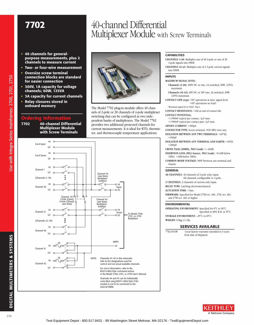
DIG
ITA
L M
ULT
IME
TER
S &
SY
STE
MS
ordering Information7702 40-channel Differential
Multiplexer Module with screw Terminals
• 40 channels for general-purpose measurements, plus 2 channels to measure current
• Two- or four-wire measurement• oversize screw terminal
connection blocks are standard for easier connection
• 300V, 1a capacity for voltage channels; 60W, 125Va
• 3a capacity for current channels• relay closures stored in
onboard memory
CaPabIlITIEsCHANNELS 1-40: Multiplex one of 40 2-pole or one of 20
4-pole signals into DMM .
CHANNELS 41-42: Multiplex one of 2 2-pole current signals into DMM .
INPuTsMAXIMUM SIGNAL LEVEL:
Channels (1-40): 300V DC or rms, 1A switched, 60W, 125VA maximum .
Channels (41-42): 60V DC or 30V rms, 3A switched, 60W, 125VA maximum .
CONTACT LIFE (typ): >105 operations at max . signal level . >108 operations no load1 .
1 Minimum signal level 10mV, 10µA .
CONTACT RESISTANCE: <1W at end of contact life .
CONTACT POTENTIAL: <±500nV typical per contact, 1µV max . <±500nV typical per contact pair, 1µV max .
OFFSET CURRENT: <100pA .
CONNECTOR TyPE: Screw terminal, #20 AWG wire size .
ISOLATION BETWEEN ANy TWO TERMINALS: >1010W, <100pF .
ISOLATION BETWEEN ANy TERMINAL AND EARTH: >109W, <200pF .
CROSS TALK (10MHz, 50W Load): <–40dB .
INSERTION LOSS (50W Source, 50W Load): <0 .1dB below 1MHz . <3dB below 2MHz .
COMMON MODE VOLTAGE: 300V between any terminal and chassis .
GENEral40 CHANNELS: 40 channels of 2-pole relay input .
All channels configurable to 4-pole .
2 CHANNELS: 2 channels of current only input .
RELAy TyPE: Latching electromechanical .
ACTUATION TIME: <3ms .
FIRMWARE: Specified for Model 2700 rev . A01, 2701 rev . A01, and 2750 rev . A01 or higher .
ENVIroNMENTalOPERATING ENVIRONMENT: Specified for 0°C to 50°C .
Specified to 80% R .H . at 35°C .
STORAGE ENVIRONMENT: –25°C to 65°C .
WEIGHT: 0 .5kg (1 .1 lb) .
The Model 7702 plug-in module offers 40 chan-nels of 2-pole or 20 channels of 4-pole multiplexer switching that can be configured as two inde-pendent banks of multiplexers . The Model 7702 provides two additional protected channels for current measurements . It is ideal for RTD, thermis-tor, and thermocouple temperature applications .
Channel 1HI
LO
Channel 20HI
LO
(Channels 2–19)
Channel 21HI
LO
Channel 40HI
LO
(Channels 22–39)
Channel 41HI
LO
Channel 42HI
LO
AMPS
HI
LOSense
HI
LOInput
Channel 432-Pole (Open)
4-Pole (Closed)(see Note)
3A
3A
To Model 2700,2701, or 2750Backplane
Channel 45(see Note)Backplaneisolation
Channel 44(see Note)Backplaneisolation
NOTE: Channels 43–45 in this schematicrefer to the designations used forcontrol and not actual available channels.
For more information, refer to theROUTe:MULTiple command sectionin the Model 2700, 2701, or 2750 User’s Manual.
Channels 44 and 45 can be individuallycontrolled using ROUT e:MULTiple if themodule is not to be connected to theinternal DMM.
Card SenseHI
LO
Card InputHI
LO
7702 40-channel Differential Multiplexer Module with Screw Terminals
sErVICEs aVaIlablE7702-3Y-EW 1-year factory warranty extended to 3 years
from date of shipment
Use
with
Inte
gra
Serie
s m
ainf
ram
es: 2
700,
270
1, 2
750
Use
with
Inte
gra
Serie
s m
ainf
ram
es: 2
700,
270
1, 2
750
276 Test Equipment Depot - 800.517.8431 - 99 Washington Street Melrose, MA 02176 - TestEquipmentDepot.com

DIG
ITA
L M
ULT
IME
TER
S &
SY
STE
MS
A Greater Measure of Confidence
ordering Information7703 32-channel, High
speed, Differential Multiplexer Module
accessories suppliedTwo mating connectors with solder cup (Model 7788)
• 32 channels for general purpose measurements
• relay actuation time of less than 1ms for high-speed scanning
• Two- or four-wire measurement
• Two 50-pin female D-sub connectors are standard for secure hook-up and quick teardown
CaPabIlITIEsCHANNELS 1–32: Multiplex one of 32 2-pole or one of 16
4-pole signals into DMM .
INPuTsMAXIMUM SIGNAL LEVEL:
Channels (1–32): 300V DC or rms, 0 .5A switched, 10W maximum .
Contact Life (typ): >5×10⁴ operations at max . signal level . >108 operations cold switching .
CONTACT RESISTANCE: <1W at end of contact life .
CONTACT POTENTIAL: <±3µV typical per contact, 6µV max . <±3µV typical per contact pair, 6µV max .
OFFSET CURRENT: <100pA .
CONNECTOR TyPE: 50 pin D-sub ×2 .
RELAy DRIVE CURRENT: 20mA per channel .
ISOLATION BETWEEN ANy TWO TERMINALS: >109W, <200pF .
ISOLATION BETWEEN ANy TERMINAL AND EARTH: >109W, <400pF .
CROSS TALK (1 MHz, 50W Load): <–40dB .
INSERTION LOSS (50W Source, 50W Load): <0 .35dB below 1MHz . <3dB below 2MHz .
COMMON MODE VOLTAGE: 300V between any terminal and chassis .
GENEral32 CHANNELS: 32 channels of 2-pole relay input .
All channels configurable to 4-pole .
RELAy TyPE: Reed .
ACTUATION TIME: <1ms .
FIRMWARE: Specified for Model 2700 rev . A01, 2701 rev . A01, and 2750 rev . A01 or higher .
ENVIroNMENTalOPERATING ENVIRONMENT: Specified for 0°C to 50°C .
Specified to 80% R .H . at 35°C .
STORAGE ENVIRONMENT: –25°C to 65°C .
WEIGHT: 0 .8kg (1 .75 lbs) .
aCCEssorIEs aVaIlablE7705-MTC-2 50 Pin Male to Female D-sub Cable, 2m (6 .6 ft) .
The Model 7703 plug-in module offers 32 channels of 2-pole or 16 channels of 4-pole multiplexer switching that can be configured as two independent banks of multiplexers . The non-latching reed relays provide high speeds and are designed for 300 volt, 500mA; 10VA . The relay closures are stored in onboard memory . The Model 7703 is ideal for RTD and thermistor temperature applications .
Channel 1
HI
LO
Channel 16
HI
LO
(Channels 2–15)
Channel 17
HI
LO
Channel 32
HI
LO
(Channels 18–31)
Backplaneisolation
HI
LO
Sense
Backplaneisolation
HI
LO
Input
Channel 352-Pole (Closed)4-Pole (Open)
(see Note)To Model 2700,2701, or 2750Backplane
NOTE: Channels 33–35 in this schematicrefer to the designations used forcontrol and not actual available channels.
For more information, refer to theROUTE:MULT command sectionin the Model 2700, 2701, or 2750 User’s Manual.
Channel 33(see Note)
Channel 34(see Note)
Card SenseHI
LO
Card InputHI
LO
7703 32-channel, High Speed, Differential Multiplexer Module
sErVICEs aVaIlablE7703-3Y-EW 1-year factory warranty extended to 3 years
from date of shipment
Use
with
Inte
gra
Serie
s m
ainf
ram
es: 2
700,
270
1, 2
750
Use
with
Inte
gra
Serie
s m
ainf
ram
es: 2
700,
270
1, 2
750
277 Test Equipment Depot - 800.517.8431 - 99 Washington Street Melrose, MA 02176 - TestEquipmentDepot.com

DIG
ITA
L M
ULT
IME
TER
S &
SY
STE
MS
ordering Information7705 40-channel, single-
pole Control Module
accessories suppliedTwo mating connectors with solder cup (Model 7788)
• 300V, 2a capacity
• Two 50-pin female D-sub connectors are standard for secure hook-up and quick teardown
• relay closures stored in onboard memory
INPuTsMAXIMUM SIGNAL LEVEL: 300VDC or rms, 2A switched,
60W (DC, resistive), 125VA (AC, resistive) .
CONTACT LIFE: No Load1: 108 closures . At Maximum Signal Levels: 105 closures .
1 Minimum signal level 10mV, 10µA .
CHANNEL RESISTANCE (per conductor): <1W .
CONTACT POTENTIAL: ≤4µV per contact .
OFFSET CURRENT: <100pA .
ACTUATION TIME: 3ms .
ISOLATION: Channel to Channel: >109W, <50pF . Common Mode: >109W, <100pF .
CROSSTALK (1MHz, 50W load): <–35dB .
INSERTION LOSS (50W source, 50W load): <0 .3dB below 1MHz, <3dB below 10MHz .
COMMON MODE VOLTAGE: 300V between any terminal and chassis .
GENEralRELAy SWITCH CONFIGURATION: 40 independent channels
of 1-pole switching . Isolated from internal DMM .
CONTACT CONFIGURATION: 1 pole Form A .
RELAy TyPE: Latching electromechanical .
CONNECTOR TyPE: Two 50-pin female D-sub connectors .
FIRMWARE: Specified for Model 2700 rev . A01, 2701 rev . A01, and 2750 rev . A01 or higher .
ENVIroNMENTalOPERATING ENVIRONMENT: Specified for 0°C to 50°C .
Specified to 80% R .H . at 35°C .
STORAGE ENVIRONMENT: –25°C to 65°C .
WEIGHT: 0 .45kg (1 lb) .
aCCEssorIEs aVaIlablE7705-MTC-2 50 Pin Male to Female D-sub Cable, 2m (6 .6 ft) .
The Model 7705 plug-in module offers 40 chan-nels of independent switching . These channels are designed to control power to the DUT and switching loads . They can also directly control light indicators, relays, etc .
Channel 1IN
OUT
Channel 40IN
OUT
(Channels 2–39)
7705 40-channel, Single-pole Control Module
sErVICEs aVaIlablE7705-3Y-EW 1-year factory warranty extended to 3 years
from date of shipment
Use
with
Inte
gra
Serie
s m
ainf
ram
es: 2
700,
270
1, 2
750
Use
with
Inte
gra
Serie
s m
ainf
ram
es: 2
700,
270
1, 2
750
278 Test Equipment Depot - 800.517.8431 - 99 Washington Street Melrose, MA 02176 - TestEquipmentDepot.com
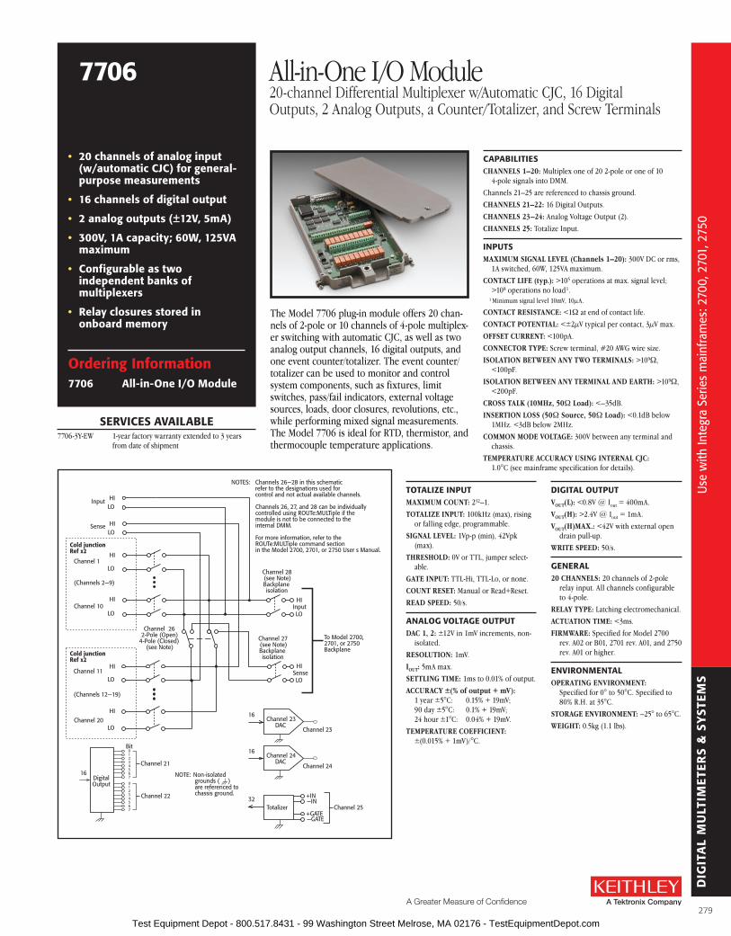
DIG
ITA
L M
ULT
IME
TER
S &
SY
STE
MS
A Greater Measure of Confidence
ordering Information7706 all-in-one I/o Module
• 20 channels of analog input (w/automatic CJC) for general-purpose measurements
• 16 channels of digital output
• 2 analog outputs (±12V, 5ma)
• 300V, 1a capacity; 60W, 125Va maximum
• Configurable as two independent banks of multiplexers
• relay closures stored in onboard memory
CaPabIlITIEsCHANNELS 1–20: Multiplex one of 20 2-pole or one of 10
4-pole signals into DMM .
Channels 21–25 are referenced to chassis ground .
CHANNELS 21–22: 16 Digital Outputs .
CHANNELS 23–24: Analog Voltage Output (2) .
CHANNELS 25: Totalize Input .
INPuTsMAXIMUM SIGNAL LEVEL (Channels 1–20): 300V DC or rms,
1A switched, 60W, 125VA maximum .
CONTACT LIFE (typ.): >105 operations at max . signal level; >108 operations no load1 .
1 Minimum signal level 10mV, 10µA .
CONTACT RESISTANCE: <1W at end of contact life .
CONTACT POTENTIAL: <±2µV typical per contact, 3µV max .
OFFSET CURRENT: <100pA .
CONNECTOR TyPE: Screw terminal, #20 AWG wire size .
ISOLATION BETWEEN ANy TWO TERMINALS: >109W, <100pF .
ISOLATION BETWEEN ANy TERMINAL AND EARTH: >109W, <200pF .
CROSS TALK (10MHz, 50W Load): <–35dB .
INSERTION LOSS (50W Source, 50W Load): <0 .1dB below 1MHz . <3dB below 2MHz .
COMMON MODE VOLTAGE: 300V between any terminal and chassis .
TEMPERATURE ACCURACy USING INTERNAL CjC: 1 .0°C (see mainframe specification for details) .
The Model 7706 plug-in module offers 20 chan-nels of 2-pole or 10 channels of 4-pole multiplex-er switching with automatic CJC, as well as two analog output channels, 16 digital outputs, and one event counter/totalizer . The event counter/ totalizer can be used to monitor and control system components, such as fixtures, limit switches, pass/fail indicators, external voltage sources, loads, door closures, revolutions, etc ., while performing mixed signal measurements . The Model 7706 is ideal for RTD, thermistor, and thermocouple temperature applications .
Channel 22
NOTE: Non-isolatedgrounds ( )are referenced tochassis ground.
Channel 23DAC
Channel 23
16
Channel 24DAC
Channel 24
16
Totalizer
+IN —IN
+GATE—GATE
Channel 2532
Cold junctionRef x2
Channel 1HI
LO
Channel 10HI
LO
(Channels 2—9)
Channel 11HI
LO
Channel 20HI
LO
(Channels 12—19)
HI
LOSense
HI
LOInput
Channel 262-Pole (Open)
4-Pole (Closed)(see Note)
To Model 2700,2701, or 2750Backplane
Channel 28(see Note)Backplaneisolation
Channel 27(see Note)Backplaneisolation
NOTES: Channels 26—28 in this schematicrefer to the designations used forcontrol and not actual available channels.
Channels 26, 27, and 28 can be individuallycontrolled using ROUTe:MULTiple if themodule is not to be connected to theinternal DMM.
For more information, refer to theROUTe:MULTiple command sectionin the Model 2700, 2701, or 2750 User s Manual.
Sense HILO
Input HILO
Cold junctionRef x2
Bit
16
Channel 21
DigitalOutput
01234567
01234567
ToTalIZE INPuTMAXIMUM COUNT: 232–1 .
TOTALIzE INPUT: 100kHz (max), rising or falling edge, programmable .
SIGNAL LEVEL: 1Vp-p (min), 42Vpk (max) .
THRESHOLD: 0V or TTL, jumper select-able .
GATE INPUT: TTL-Hi, TTL-Lo, or none .
COUNT RESET: Manual or Read+Reset .
READ SPEED: 50/s .
aNaloG VolTaGE ouTPuTDAC 1, 2: ±12V in 1mV increments, non-
isolated .
RESOLUTION: 1mV .
IOUT: 5mA max .
SETTLING TIME: 1ms to 0 .01% of output .
ACCURACy ±(% of output + mV): 1 year ±5°C: 0 .15% + 19mV; 90 day ±5°C: 0 .1% + 19mV; 24 hour ±1°C: 0 .04% + 19mV .
TEMPERATURE COEFFICIENT: ±(0 .015% + 1mV)/°C .
DIGITal ouTPuTVOUT(L): <0 .8V @ Iout = 400mA .
VOUT(H): >2 .4V @ Iout = 1mA .
VOUT(H)MAX.: <42V with external open drain pull-up .
WRITE SPEED: 50/s .
GENEral20 CHANNELS: 20 channels of 2-pole
relay input . All channels configurable to 4-pole .
RELAy TyPE: Latching electromechanical .
ACTUATION TIME: <3ms .
FIRMWARE: Specified for Model 2700 rev . A02 or B01, 2701 rev . A01, and 2750 rev . A01 or higher .
ENVIroNMENTalOPERATING ENVIRONMENT:
Specified for 0° to 50°C . Specified to 80% R .H . at 35°C .
STORAGE ENVIRONMENT: –25° to 65°C .
WEIGHT: 0 .5kg (1 .1 lbs) .
7706 All-in-One I/O Module20-channel Differential Multiplexer w/Automatic CJC, 16 Digital Outputs, 2 Analog Outputs, a Counter/Totalizer, and Screw Terminals
sErVICEs aVaIlablE7706-3Y-EW 1-year factory warranty extended to 3 years
from date of shipment
Use
with
Inte
gra
Serie
s m
ainf
ram
es: 2
700,
270
1, 2
750
Use
with
Inte
gra
Serie
s m
ainf
ram
es: 2
700,
270
1, 2
750
279 Test Equipment Depot - 800.517.8431 - 99 Washington Street Melrose, MA 02176 - TestEquipmentDepot.com

DIG
ITA
L M
ULT
IME
TER
S &
SY
STE
MS
ordering Information7707 32-channel Digital I/o
Module with 10-channel Differential Multiplexer
accessories suppliedTwo mating IDC connectors
• 300V, 1a capacity; 60W, 125Va maximum (analog)
• 33V, 100ma capacity (digital)
• Digital outputs are short circuit protected
• relay closures stored in onboard memory
CaPabIlITIEsCHANNELS 1–10: Multiplex one of 10 2-pole or one of 5 4-pole
signals into DMM .CHANNELS 11–14: 32 Digital Inputs/Outputs referenced to
chassis ground .THERMAL PROTECTION: Channels 11–14 are thermally
protected to 1A .
INPuTs (Channels 1–10)MAXIMUM SIGNAL LEVEL: Any Channel to Any Channel
(1–10): 300VDC or 300Vrms (425V peak) for AC waveforms, 1A switched, 60W, 125VA maximum .
SAFETy CATEGORy: Conforms to European Union Directive 73/23/EEC EN 61010-1, CAT I .
CONTACT LIFE (typ.): >105 operations at max . signal level: >108 operations no load1 .
1 Minimum signal level 10mV, 10µA .
CONTACT RESISTANCE: <1W any path and additional 1W at end of contact life .
CONTACT POTENTIAL: <6µV typical per contact pair and addi-tional 5µV with Channels 11–14 at rate VOUT(L) .
OFFSET CURRENT: <100pA .CONNECTOR TyPE: 50-pin male D-shell, Channels 11–14 .
25-pin female D-shell, Channels 1–10 . Supplied with female and male IDC ribbon cable connectors .
ISOLATION BETWEEN ANy TWO TERMINALS: >109W, <100pF with isolation channels 16 and 17 open .
ISOLATION BETWEEN ANy TERMINAL AND EARTH: >109W, <200pF .
CROSS TALK (10MHz, 50W Load): <–35dB .INSERTION LOSS (50W Source, 50W Load): <0 .1dB below
1MHz . <3dB below 2MHz .COMMON MODE VOLTAGE: 300VDC or 300Vrms (425V peak)
for AC waveforms between any terminal and chassis .
DIGITal INPuT/ouTPuT (Channels 11–14)VIN(L): <0 .8V (TTL) .VIN(H): >2V (TTL) .VOUT(L): <1 .0V @ IOUT = 100mA .VOUT(H): >2 .4V @ IOUT = 1mA .VOUT(H)MAX.: <40V with external open drain pull-up .READ/WRITE SPEED: 50/s .
GENEral10 CHANNELS: 10 channels of 2-pole relay input .
All channels configurable to 4-pole .RELAy TyPE: Latching electromechanical .ACTUATION TIME: <3ms .FIRMWARE: Specified for Model 2700 rev . B03, 2701 rev . A01,
and 2750 rev . A01 or higher .CAPACITy: Model 2700: (1) 7707 and (1) 77XX, except 7706 .
Model 2701: Any combination of 77XX modules . Model 2750: (4) 7707 and (1) 77XX, except 7706 . A 7706 module may be substituted for a 7707 module .
ENVIroNMENTalOPERATING ENVIRONMENT: Specified for 0°C to 50°C .
Specified to 50% R .H . at 35°C .STORAGE ENVIRONMENT: –25°C to 65°C .WEIGHT: <0 .5kg (1 .1 lbs) .
aCCEssorIEs aVaIlablE7790 50/50/25 Pin Female/Male D-Shell IDC Connectors
7705-MTC-2 50 Pin Male to Female D-sub Cable, 2m (6 .6 ft) .
7707-MTC-2 25 Pin Male to Female D-sub Cable, 2m (6 .6 ft) .
The Model 7707 plug-in module offers 10 chan-nels of 2-pole or 5 channels of 4-pole multi-plexer switching that can be configured as two independent banks of multiplexers . The Model 7707 also provides 32 digital input/output chan-nels (four 8-bit ports) for I/O control . Connect the Model 7707 to industry standard solid-state relays to switch up to 980VA .
Channel 12 Channel 14
HI
LOSense
HI
LOInput
ToInternalDMM
Channel 17(see Note)Backplaneisolation
Channel 16(see Note)Backplaneisolation
NOTES: Channels 15—17 in this schematicrefer to the designations used forcontrol and not actual available channels.
For more information, refer to theROUTe:MULT command sectionin the Model 2700, 2701, or 2750 User s Manual.
Bit
1—16
Channel 11
DIO
01234567
01234567
Digital I/OBit
17—32
Channel 13
DIO
01234567
01234567
Digital I/O
Channel 1HI
LO
Channel 5HI
LO
(Channels 2—4)
Channel 6HI
LO
Channel 10HI
LO
(Channels 7—9)
Channel 152-Pole (Open)
4-Pole (Closed)(see Note)
Card Sense HILO
Card Input HILO
7707 32-channel Digital I/O Modulewith 10-channel Differential Multiplexer
sErVICEs aVaIlablE7707-3Y-EW 1-year factory warranty extended to 3 years
from date of shipment
Use
with
Inte
gra
Serie
s m
ainf
ram
es: 2
700,
270
1, 2
750
Use
with
Inte
gra
Serie
s m
ainf
ram
es: 2
700,
270
1, 2
750
280 Test Equipment Depot - 800.517.8431 - 99 Washington Street Melrose, MA 02176 - TestEquipmentDepot.com

DIG
ITA
L M
ULT
IME
TER
S &
SY
STE
MS
A Greater Measure of Confidence
ordering Information7708 40-channel Differential
Multiplexer Module with automatic CJC and screw Terminals
• 40 differential channels for general-purpose measurements
• Two- or four-wire measurements
• 300V, 1a capacity for voltage channels; 60W, 125Va
• oversize screw terminal connection blocks are standard for easier connection
• relay closures stored in onboard memory
CaPabIlITIEsCHANNELS 1–40: Multiplex one of 40 2-pole or one of 20
4-pole signals into DMM .
INPuTsMAXIMUM SIGNAL LEVEL:
Channels (1–40): 300V DC or rms, 1A switched, 60W, 125VA maximum .
CONTACT LIFE (typ): >105 operations at max . signal level . >108 operations no load1 .1 Open thermocouple detector on during thermocouple measurements .
Minimum signal level 10mV, 10µA .
CONTACT RESISTANCE: <1W at end of contact life .
CONTACT POTENTIAL: <±500nV typical per contact, 1µV max . <±500nV typical per contact pair, 1µV max .
OFFSET CURRENT: <100pA .
CONNECTOR TyPE: Screw terminal, #20 AWG wire size .
ISOLATION BETWEEN ANy TWO TERMINALS: >1010W, <100pF .
ISOLATION BETWEEN ANy TERMINAL AND EARTH: >109W, <200pF .
CROSS TALK (10MHz, 50W Load): <–40dB .
INSERTION LOSS (50W Source, 50W Load): <0 .1dB below 1MHz . <3dB below 2MHz .
COMMON MODE VOLTAGE: 300V between any terminal and chassis .
TEMPERATURE ACCURACy USING INTERNAL CjC: 1 .0°C (see mainframe specification for details) .
GENEral40 CHANNELS: 40 channels of 2-pole relay input . All channels
configurable to 4-pole .
RELAy TyPE: Latching electromechanical .
ACTUATION TIME: <3ms .
FIRMWARE: Specified for Model 2700 rev . B02, 2701 rev . A01, and 2750 rev . A01 or higher .
ENVIroNMENTalOPERATING ENVIRONMENT: Specified for 0°C to 50°C .
Specified to 80% R .H . at 35°C .
STORAGE ENVIRONMENT: –25°C to 65°C .
WEIGHT: 0 .52kg (1 .16 lb) .
aCCEssorIEs aVaIlablE 7401 Type K Thermocouple Wire, 30 .5m (100 ft) .
The Model 7708 plug-in module offers 40 channels of 2-pole or 20 channels of 4-pole multiplexer switching that can be configured as two independent banks of multiplexers . The built-in CJC sensors automatically linearize thermocouples, making the Model 7708 ideal for RTD, thermistor, and thermocouple temperature applications . It is also well suited for mixed-signal measurement applications that require multi-point monitoring, such as environmental stress screening .
Channel 1HI
LO
Channel 20HI
LO
(Channels 2–19)
Channel 21HI
LO
Channel 40HI
LO
(Channels 22–39)
HI
LOSense
HI
LOInput
Channel 412-Pole (Open)4-Pole (Closed)
(see Note)
To Model 2700,2701, or 2750Backplane
Channel 43(see Note)Backplaneisolation
Channel 42(see Note)Backplaneisolation
NOTE:
Card SenseHI
LO
Card InputHI
LO
Cold JunctionRef ×5
Cold JunctionRef ×4
Channels 41–43 in this schematic refer to thedesignations used for control and not actualavailable channels.
For more information, refer to the ROUTe:MULTiplecommand section in the Model 2700, 2701, or2750 User’s Manual.
Channels 42 and 43 can be individually controlledusing ROUTe:MULTiple if the module is not to beconnected to the internal DMM.
7708 40-channel Differential Multiplexer Modulewith Automatic CJC and Screw Terminals
sErVICEs aVaIlablE7708-3Y-EW 1-year factory warranty extended to 3 years
from date of shipment
Use
with
Inte
gra
Serie
s m
ainf
ram
es: 2
700,
270
1, 2
750
Use
with
Inte
gra
Serie
s m
ainf
ram
es: 2
700,
270
1, 2
750
281 Test Equipment Depot - 800.517.8431 - 99 Washington Street Melrose, MA 02176 - TestEquipmentDepot.com

DIG
ITA
L M
ULT
IME
TER
S &
SY
STE
MS
ordering Information7709 6×8 Matrix Module
accessories suppliedTwo mating IDC connectors
• automatic two- or four-wire connection to DMM
• 6 row × 8 column matrix
• Expandable to larger switch configurations by daisy-chaining or cascading multiple modules
• Two female D-sub connectors are standard for secure hook-up and quick teardown
• 300V, 1a capacity
• relay closures stored in onboard memory
CaPabIlITIEsDMM CONNECTION:
2-Wire Functions
Row 1, channels 1–8, through channel 50 .
4-Wire Functions
Row 1, channels 1–4 (Source) through channel 50 and Row 2, channels 13–16 (Sense), through channel 49 .
CLOSE CHANNEL: CLOSE command connects channels 1–8 to DMM . For 4-wire, channels 1–4 are automatically paired with channels 13–16 . ROUTe:MULTiple allows any combination of rows and columns to be connected at the same time .
INPuTsMAXIMUM SIGNAL LEVEL: Any Channel to Any Channel
(1–48): 300VDC or 300Vrms (425V peak) for AC waveforms, 1A switched, 60W, 125VA maximum .
SAFETy: Conforms to European Union Directive 73/23/EEC EN61010-1, CAT I .
CONTACT LIFE (typ): >105 operations at max . signal level . >108 operations no load1 .
1 Minimum signal level 10mV, 10µA .
CONTACT RESISTANCE: <1W any path and additional 1W at end of contact life .
CONTACT POTENTIAL: <3µV per contact pair .
OFFSET CURRENT: <100pA .
CONNECTOR TyPE: 50-pin female D-shell for rows and columns . 25-pin female D-shell for “daisy-chain” rows . Supplied with male IDC ribbon cable connectors .
ISOLATION BETWEEN ANy TWO TERMINALS: >109W, <200pF .
ISOLATION BETWEEN ANy TERMINAL AND EARTH: >109W, <400pF .
CROSS TALK (1MHz, 50W Load): <–35dB .
INSERTION LOSS (50W Source, 50W Load): <0 .35dB below 1MHz . <3dB below 2MHz .
COMMON MODE VOLTAGE: 300VDC or 300Vrms (425V peak) for AC waveforms between any terminal and chassis .
GENEralMATRIX CONFIGURATION: 6 rows × 8 columns .
CONTACT CONFIGURATION: 2 pole Form A .
FIRMWARE: Specified for Model 2700 rev . B03, Model 2701 rev . A01, and Model 2750 rev . A01 or higher .
RELAy TyPE: Latching electromechanical .
ACTUATION TIME: <3ms .
ENVIroNMENTalOPERATING ENVIRONMENT: Specified for 0°C to 50°C .
Specified to 50% R .H . at 35°C .
STORAGE ENVIRONMENT: –25°C to 65°C .
WEIGHT: <0 .52kg (1 .16 lb) .
aCCEssorIEs aVaIlablE7789 50/25 Pin Male D-Shell Solder Cup Connectors
7790 50/50/25 Pin Female/Male D-Shell IDC Connectors
7705-MTC-2 50 Pin Male to Female D-sub Cable, 2m (6 .6 ft) .
7707-MTC-2 25 Pin Male to Female D-sub Cable, 2m (6 .6 ft) .
sErVICEs aVaIlablE7709-3Y-EW 1-year factory warranty extended to 3 years
from date of shipment
The Model 7709 plug-in module is a two-pole, 6×8 matrix module . It can connect any combination of six differential channels of instrumentation to any combination of eight differential device-under-test channels . The instrumentation can be AC and DC sources, internal or external meters, oscilloscopes, etc . This matrix configuration allows wide flexibility for complex test systems .
1 2 3 4 5
1
2
3
4
Matrix Crosspoint
HI
LO
6 7 8
5
6
HILO
Input
HILO
Sense
To DMMBackplane
Columns
Rows
9 10 11 12 13 14 15 16
17 18 19 20 21 22 23 24
25 26 27 28 29 30 31 32
33 34 35 36 37 38 39 40
41 42 43 44 45 46 47 48
50
49
1 2 3 4 5 6 7 8
7709 6×8 Matrix ModuleU
se w
ith In
tegr
a Se
ries
mai
nfra
mes
: 270
0, 2
701,
275
0
Use
with
Inte
gra
Serie
s m
ainf
ram
es: 2
700,
270
1, 2
750
282 Test Equipment Depot - 800.517.8431 - 99 Washington Street Melrose, MA 02176 - TestEquipmentDepot.com
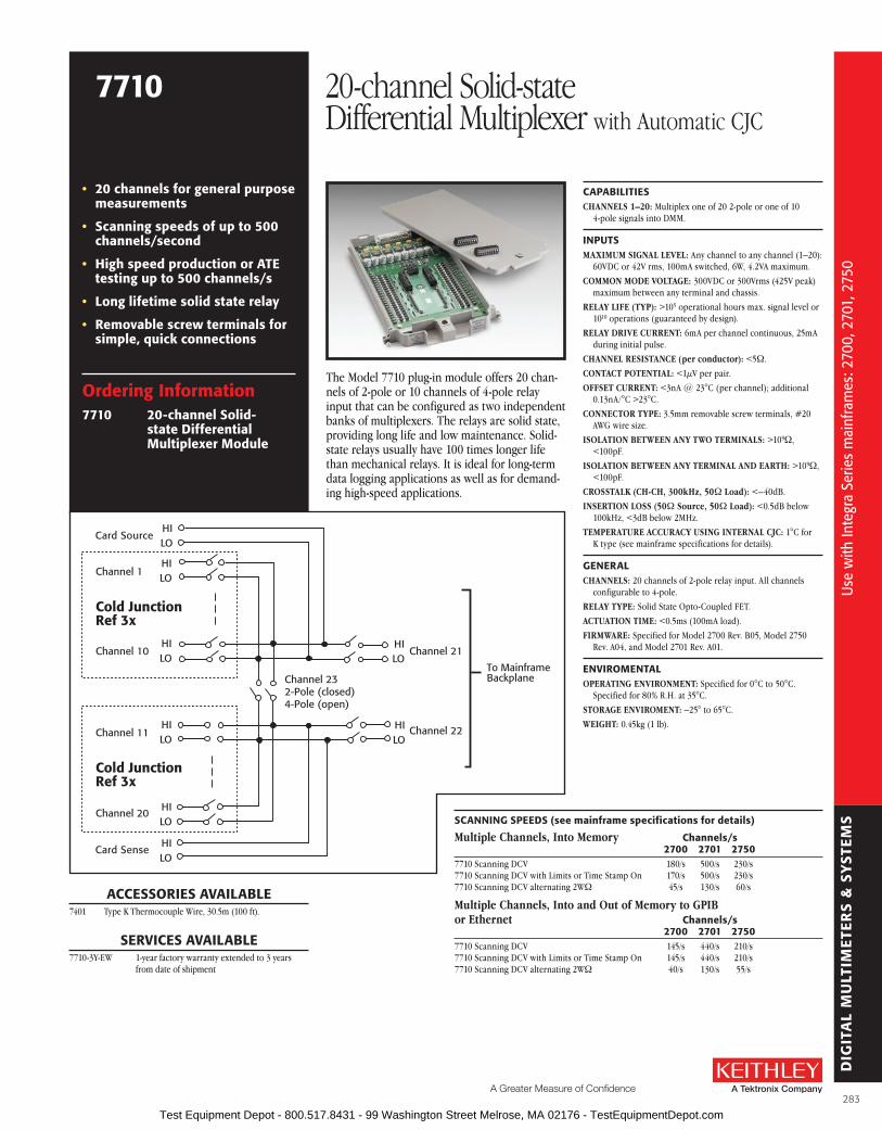
DIG
ITA
L M
ULT
IME
TER
S &
SY
STE
MS
A Greater Measure of Confidence
ordering Information7710 20-channel solid-
state Differential Multiplexer Module
• 20 channels for general purpose measurements
• scanning speeds of up to 500 channels/second
• High speed production or aTE testing up to 500 channels/s
• long lifetime solid state relay
• removable screw terminals for simple, quick connections
CaPabIlITIEsCHANNELS 1–20: Multiplex one of 20 2-pole or one of 10
4-pole signals into DMM .
INPuTsMAXIMUM SIGNAL LEVEL: Any channel to any channel (1–20):
60VDC or 42V rms, 100mA switched, 6W, 4 .2VA maximum .
COMMON MODE VOLTAGE: 300VDC or 300Vrms (425V peak) maximum between any terminal and chassis .
RELAy LIFE (TyP): >105 operational hours max . signal level or 1010 operations (guaranteed by design) .
RELAy DRIVE CURRENT: 6mA per channel continuous, 25mA during initial pulse .
CHANNEL RESISTANCE (per conductor): <5W .
CONTACT POTENTIAL: <1µV per pair .
OFFSET CURRENT: <3nA @ 23°C (per channel); additional 0 .13nA/°C >23°C .
CONNECTOR TyPE: 3 .5mm removable screw terminals, #20 AWG wire size .
ISOLATION BETWEEN ANy TWO TERMINALS: >109W, <100pF .
ISOLATION BETWEEN ANy TERMINAL AND EARTH: >109W, <100pF .
CROSSTALK (CH-CH, 300kHz, 50W Load): <–40dB .
INSERTION LOSS (50W Source, 50W Load): <0 .5dB below 100kHz, <3dB below 2MHz .
TEMPERATURE ACCURACy USING INTERNAL CjC: 1°C for K type (see mainframe specifications for details) .
GENEralCHANNELS: 20 channels of 2-pole relay input . All channels
configurable to 4-pole .
RELAy TyPE: Solid State Opto-Coupled FET .
ACTUATION TIME: <0 .5ms (100mA load) .
FIRMWARE: Specified for Model 2700 Rev . B05, Model 2750 Rev . A04, and Model 2701 Rev . A01 .
ENVIroMENTalOPERATING ENVIRONMENT: Specified for 0°C to 50°C .
Specified for 80% R .H . at 35°C .
STORAGE ENVIROMENT: –25° to 65°C .
WEIGHT: 0 .45kg (1 lb) .
The Model 7710 plug-in module offers 20 chan-nels of 2-pole or 10 channels of 4-pole relay input that can be configured as two independent banks of multiplexers . The relays are solid state, providing long life and low maintenance . Solid-state relays usually have 100 times longer life than mechanical relays . It is ideal for long-term data logging applications as well as for demand-ing high-speed applications .
sCaNNING sPEEDs (see mainframe specifications for details)
Multiple Channels, Into Memory Channels/s 2700 2701 27507710 Scanning DCV 180/s 500/s 230/s7710 Scanning DCV with Limits or Time Stamp On 170/s 500/s 230/s7710 Scanning DCV alternating 2WW 45/s 130/s 60/s
Multiple Channels, Into and Out of Memory to GPIBor Ethernet Channels/s 2700 2701 27507710 Scanning DCV 145/s 440/s 210/s7710 Scanning DCV with Limits or Time Stamp On 145/s 440/s 210/s7710 Scanning DCV alternating 2WW 40/s 130/s 55/s
Card Source
Card Sense
Channel 1
Channel 21
Channel 22
Channel 10
Channel 11
Channel 20
HILO
HILO
HILO
HILO
HILO
HILO
HILO
HILO
To MainframeBackplaneChannel 23
2-Pole (closed)4-Pole (open)
Cold JunctionRef 3x
Cold JunctionRef 3x
aCCEssorIEs aVaIlablE7401 Type K Thermocouple Wire, 30 .5m (100 ft) .
sErVICEs aVaIlablE7710-3Y-EW 1-year factory warranty extended to 3 years
from date of shipment
7710 20-channel Solid-state Differential Multiplexer with Automatic CJC
Use
with
Inte
gra
Serie
s m
ainf
ram
es: 2
700,
270
1, 2
750
Use
with
Inte
gra
Serie
s m
ainf
ram
es: 2
700,
270
1, 2
750
283 Test Equipment Depot - 800.517.8431 - 99 Washington Street Melrose, MA 02176 - TestEquipmentDepot.com
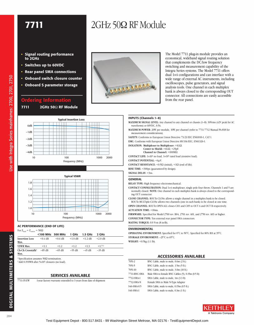
DIG
ITA
L M
ULT
IME
TER
S &
SY
STE
MS
ordering Information7711 2GHz 50W rf Module
• signal routing performance to 2GHz
• switches up to 60VDC
• rear panel sMa connections
• onboard switch closure counter
• onboard s parameter storage
aC PErforMaNCE (END of lIfE)For Zload = Zsource = 50W
<100 MHz 500 MHz 1 GHz 1.5 GHz 2 GHzInsertion Loss <0 .4 dB <0 .6 dB <1 .0 dB <1 .2 dB <2 .0 dB Max.
VSWR Max. <1 .1 <1 .2 <1 .2 <1 .3 <1 .7 2
Ch-Ch Crosstalk1 –85 dB –65 dB –55 dB –45 dB –35 dB Max.
1 Specification assumes 50W termination .2 Add 0 .1VSWR after 5×10⁵ closures (no load) .
INPuTs (Channels 1–8)MAXIMUM SIGNAL LEVEL: Any channel to any channel or chassis (1–8): 30Vrms (42V peak for AC
waveforms) or 60VDC, 0 .5A .
MAXIMUM POWER: 20W per module, 10W per channel (refer to 7711/7712 Manual PA-818 for meas ure ment considerations) .
SAFETy: Conforms to European Union Directive 73/23/EEC EN61010-1, CAT I .
EMC: Conforms with European Union Directive 89/336/EEC; EN61326-1 .
ISOLATION: Multiplexer to Multiplexer: >1GW . Center to Shield: >1GW, <25pF . Channel to Channel: >100MW .
CONTACT LIFE: 1×10⁶ no load, 1×10⁵ rated load (resistive load) .
CONTACT POTENTIAL: <6µV .
CONTACT RESISTANCE: <0 .5W (initial), <1W (end of life) .
RISE TIME: <300ps (guaranteed by design) .
SIGNAL DELAy: <3ns .
GENEralRELAy TyPE: High frequency electromechanical .
CONTACT CONFIGURATION: Dual 1×4 multiplexer, single pole four throw, Channels 1 and 5 are normally closed . NOTE: One channel in each multiplex bank is always closed to the correspond-ing OUT connector .
CLOSE CHANNEL: ROUTe:CLOSe allows a single channel in a multiplex bank to be closed . ROUTe:MULTiple:CLOSe allows two channels (one in each bank) to be closed at one time .
OPEN CHANNEL: ROUTe:OPEN:ALL closes CH1 and CH5 to OUT A and OUT B respectively .
ACTUATION TIME: <10ms .
FIRMWARE: Specified for Model 2700 rev . B04, 2701 rev . A01, and 2750 rev . A03 or higher .
CONNECTOR TyPE: Ten external rear panel SMA connectors .
MATING TORQUE: 0 .9 N·m (8 in-lb) .
ENVIroNMENTalOPERATING ENVIRONMENT: Specified for 0°C to 50°C . Specified for 80% RH at 35°C .
STORAGE ENVIRONMENT: –25°C to 65°C .
WEIGHT: <0 .5kg (1 .1 lb) .
aCCEssorIEs aVaIlablE7051-2 BNC Cable, male to male, 0 .6m (2 ft .)
7051-5 BNC Cable, male to male, 1 .5m (5 ft .)
7051-10 BNC Cable, male to male, 3 .0m (10 ft .)
7711-BNC-SMA Male SMA to female BNC Cables (5), 0 .15m (0 .5 ft)
7712-SMA-1 SMA Cable, male to male, 1m (3 .3 ft)
7712-SMA-N Female SMA to Male N-Type Adapter
S46-SMA-0 .5 SMA Cable, male to male, 0 .15m (0 .5 ft .)
S46-SMA-1 SMA Cable, male to male, 0 .3m (1 ft .)
sErVICEs aVaIlablE7711-3Y-EW 1-year factory warranty extended to 3 years from date of shipment
The Model 7711 plug-in module provides an economical, wideband signal routing solution that complements the DC/low frequency switching and measurement capability of the Integra Series systems . The Model 7711 offers dual 1×4 configurations and can interface with a wide range of external AC instruments, including oscilloscopes, pulse generators, and signal analysis tools . One channel in each multiplex bank is always closed to the corresponding OUT connector . All connections are easily accessible from the rear panel .
Typical Insertion Loss
0dB
–1dB
–2dB
–3dB
–4dB
10 100 1000 2000Frequency (MHz)
Typical VSWR
1.8
1.6
1.4
1.2
1.0
10 100 1000 2000Frequency (MHz)
7711 2GHz 50W RF Module
Use
with
Inte
gra
Serie
s m
ainf
ram
es: 2
700,
270
1, 2
750
Use
with
Inte
gra
Serie
s m
ainf
ram
es: 2
700,
270
1, 2
750
284 Test Equipment Depot - 800.517.8431 - 99 Washington Street Melrose, MA 02176 - TestEquipmentDepot.com

DIG
ITA
L M
ULT
IME
TER
S &
SY
STE
MS
A Greater Measure of Confidence
ordering Information7712 3.5GHz 50W rf Module
• 3.5GHz bandwidth
• Dual 1x4 configuration
• onboard switch closure counter
• onboard s parameter storage
INPuTs (Channels 1–8)MAXIMUM SIGNAL LEVEL: Any channel to any channel or chassis (1–8): 30Vrms (42V peak for AC
waveforms) or 42VDC, 0 .5A .
MAXIMUM POWER: 20W per module, 10W per channel (refer to 7711/7712 Manual PA-818 for measurement considerations) .
SAFETy: Conforms to European Union Directive 73/23/EEC EN61010-1, CAT I .
EMC: Conforms with European Union Directive 89/336/EEC; EN61326-1 .
ISOLATION: Multiplexer to Multiplexer: >1GW . Center to Shield: >1GW, <20pF . Channel to Channel: >100MW .
CONTACT LIFE: 5×10⁶ no load, 1×10⁵ rated load (resistive load) .
CONTACT POTENTIAL: <12µV .
CONTACT RESISTANCE: <0 .5W (initial), <1W (end of life) .
RISE TIME: <200ps (guaranteed by design) .
SIGNAL DELAy: <1 .5ns .
GENEralRELAy TyPE: High frequency electromechanical .
CONTACT CONFIGURATION: Dual 1×4 multiplexer, single pole four throw, Channels 1 and 5 are normally closed .
NOTE: One channel in each multiplex bank is always closed to the corresponding OUT connector .
CLOSE CHANNEL: ROUTe:CLOSe allows a single channel in a multiplex bank to be closed . ROUTe:MULTiple:CLOSe allows two channels (one in each bank) to be closed at one time .
OPEN CHANNEL: ROUTe:OPEN:ALL closes CH1 and CH5 to OUT A and OUT B respectively .
ACTUATION TIME: <10ms .
FIRMWARE: Specified for Model 2700 rev . B04, 2701 rev . A01, and 2750 rev . A03 or higher .
CONNECTOR TyPE: Ten external rear panel SMA connectors .
MATING TORQUE: 0 .9 N·m (8 in-lb) .
ENVIroNMENTalOPERATING ENVIRONMENT: Specified for 0°C to 50°C . Specified for 80% RH at 35°C .
STORAGE ENVIRONMENT: –25°C to 65°C .
WEIGHT: <0 .5kg (1 .1 lb) .
aCCEssorIEs aVaIlablE7712-SMA-1 SMA Cable, male to male, 1m (3 .3 ft)
7712-SMA-N Female SMA to Male N-Type Adapter
S46-SMA-0 .5 SMA Cable, male to male, 0 .15m (0 .5 ft .)
S46-SMA-1 SMA Cable, male to male, 0 .3m (1 ft .)
sErVICEs aVaIlablE7712-3Y-EW 1-year factory warranty extended to 3 years from date of shipment
The Model 7712 plug-in module offers a 50W dual 14 multiplexer configuration with rear panel SMA 14 connectors . Multiple multiplexers can be cascaded to build scalable matrix and multiplexer systems for a large number of devices under test and RF source/measurement instruments . One channel in each multiplex bank is always closed to the corresponding OUT connector . The 3 .5GHz RF switching capability of the Model 7712 makes it ideal for applications such as 3G telecom, wireless LAN, and Bluetooth module testing .
Typical Insertion Loss
0dB
–1dB
–2dB
–3dB
–4dB
10 100 1000 4000Frequency (MHz)
Typical VSWR
1.8
1.6
1.4
1.2
1.0
10 100 1000 4000Frequency (MHz)
aC PErforMaNCE (End of life)For Zload = Zsource = 50W
<500 MHz 1 GHz 2.4 GHz 3.5 GHzInsertion Loss <0 .5 dB <0 .65 dB <1 .1 dB <1 .3 dB Max.
VSWR MAX <1 .15 <1 .2 <1 .452 <1 .45
Ch-Ch Crosstalk1 –75 dB –70 dB –50 dB –45 dB Max.1 Specification assumes 50W termination .2 Add 0 .1VSWR after 5×10⁵ closures (no load) .
7712 3 .5GHz 50W RF ModuleU
se w
ith In
tegr
a Se
ries
mai
nfra
mes
: 270
0, 2
701,
275
0
Use
with
Inte
gra
Serie
s m
ainf
ram
es: 2
700,
270
1, 2
750
285 Test Equipment Depot - 800.517.8431 - 99 Washington Street Melrose, MA 02176 - TestEquipmentDepot.com

DIG
ITA
L M
ULT
IME
TER
S &
SY
STE
MS
IVI Drivers
• labVIEW drivers
• labWindows/CVI drivers
• Visual basic, C/C++ drivers
ExcelINX-1a
• Microsoft Excel add-in utility
• acquire data for 2700, 2701, and 2750 systems
• Configure channels, parameters, triggers, and scan lists
IVI (Interchangeable Virtual Instruments) DriversDevelopers often prefer to create their own custom applications . The Integra Series instruments supply IVI device drivers that support many application development environments including LabVIEW®, LabWindows/CVI, Visual Basic, and C/C++ . These IVI drivers are VISA based and support all the functionality of the Model 2700/2701/2750 . Numerous examples are supplied as well as an online help utility .
Free Bundled SoftwareFor the Integra Series (Models 2700, 2701, and 2750)
ExcelINX-1a is an easy-to-use add-in utility for Microsoft® Excel and Integra systems. No programming is required; enter values quickly through pop-up menus and eliminate time-consuming coding.
Minimum system requirementsWindows
2000 XP VistaWindows 7
(32-bit)Windows 7
(64-bit)IVI Instrument Drivers
Yes Yes Yes Yes Yes (but only as 32-bit applications)
ExceLINX-1A Yes Yes Yes Yes Yes (but only as 32-bit applications)
Inte
rcha
ngea
ble
virt
ual i
nstr
umen
ts (
IVIs
)
Inte
rcha
ngea
ble
virt
ual i
nstr
umen
ts (
IVIs
)
286 Test Equipment Depot - 800.517.8431 - 99 Washington Street Melrose, MA 02176 - TestEquipmentDepot.com
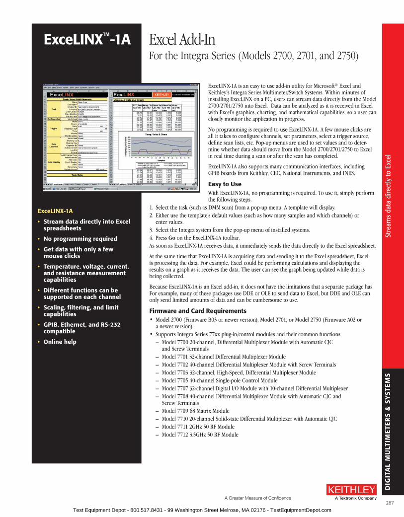
DIG
ITA
L M
ULT
IME
TER
S &
SY
STE
MS
A Greater Measure of Confidence
ExcelINX-1a
• stream data directly into Excel spreadsheets
• No programming required
• Get data with only a few mouse clicks
• Temperature, voltage, current, and resistance measurement capabilities
• Different functions can be supported on each channel
• scaling, filtering, and limit capabilities
• GPIb, Ethernet, and rs-232 compatible
• online help
ExceLINX-1A is an easy to use add-in utility for Microsoft® Excel and Keithley’s Integra Series Multimeter/Switch Systems . Within minutes of installing ExceLINX on a PC, users can stream data directly from the Model 2700/2701/2750 into Excel . Data can be analyzed as it is received in Excel with Excel’s graphics, charting, and mathematical capabilities, so a user can closely monitor the application in progress .
No programming is required to use ExceLINX-1A . A few mouse clicks are all it takes to configure channels, set parameters, select a trigger source, define scan lists, etc . Pop-up menus are used to set values and to deter-mine whether data should move from the Model 2700/2701/2750 to Excel in real time during a scan or after the scan has completed .
ExceLINX-1A also supports many communication interfaces, including GPIB boards from Keithley, CEC, National Instruments, and INES .
Easy to useWith ExceLINX-1A, no programming is required . To use it, simply perform the following steps .
1 . Select the task (such as DMM scan) from a pop-up menu . A template will display .2 . Either use the template’s default values (such as how many samples and which channels) or
enter values .3 . Select the Integra system from the pop-up menu of installed systems .4 . Press Go on the ExceLINX-1A toolbar .As soon as ExceLINX-1A receives data, it immediately sends the data directly to the Excel spreadsheet .
At the same time that ExceLINX-1A is acquiring data and sending it to the Excel spreadsheet, Excel is processing the data . For example, Excel could be performing calculations and displaying the results on a graph as it receives the data . The user can see the graph being updated while data is being c ollected .
Because ExceLINX-1A is an Excel add-in, it does not have the limitations that a separate package has . For example, many of these packages use DDE or OLE to send data to Excel, but DDE and OLE can only send limited amounts of data and can be cumbersome to use .
firmware and Card requirements• Model 2700 (Firmware B03 or newer version), Model 2701, or Model 2750 (Firmware A02 or
a newer version)• Supports Integra Series 77xx plug-in/control modules and their common functions
– Model 7700 20-channel, Differential Multiplexer Module with Automatic CJC and Screw Terminals
– Model 7701 32-channel Differential Multiplexer Module – Model 7702 40-channel Differential Multiplexer Module with Screw Terminals – Model 7703 32-channel, High-Speed, Differential Multiplexer Module – Model 7705 40-channel Single-pole Control Module – Model 7707 32-channel Digital I/O Module with 10-channel Differential Multiplexer – Model 7708 40-channel Differential Multiplexer Module with Automatic CJC and
Screw Terminals – Model 7709 68 Matrix Module – Model 7710 20-channel Solid-state Differential Multiplexer with Automatic CJC – Model 7711 2GHz 50 RF Module – Model 7712 3 .5GHz 50 RF Module
ExcelINXTM-1a Excel Add-InFor the Integra Series (Models 2700, 2701, and 2750)
Stre
ams
data
dire
ctly
to E
xcel
Stre
ams
data
dire
ctly
to E
xcel
287 Test Equipment Depot - 800.517.8431 - 99 Washington Street Melrose, MA 02176 - TestEquipmentDepot.com

DIG
ITA
L M
ULT
IME
TER
S &
SY
STE
MS
The Model 2790 SourceMeter Switch System is a high voltage, multichan-nel resistance measurement solution that speeds and simplifies electrical checks of airbag inflators and a variety of other automotive electrical test applications . It is the only commercial instrument that combines all the sourcing, measurement, and signal routing capabilities required to measure insulation resistance and conductor continuity in one compact, affordable package . Through the use of plug-in source/switch modules, the Model 2790 provides programmable high voltage and low current sourc-ing, plus multichannel switching support . This unique combination of capabilities establishes a new standard for price and performance in airbag inflator and other test applications .
Measure Extreme resistances with Constant Current or Constant VoltageThe Model 2790 uses the forced constant-current method to measure resis-tances less than 1kW . In this technique, the instrument sources a constant current (I) to the resistance and measures the resulting voltage (V) . The amount of current sourced is programmable from 0–50mA . Resistance (R) is calculated (and displayed) using the known current and measured volt-age (R = V/I) . A 20mV dry circuit clamp is available at sourcing levels up to 1mA for preserving the oxide layers on connectors and other components .
For the 1MW to 1GW resistance ranges, the forced constant-voltage method is used to measure high resistance . This technique optimizes settling
speed and reduces noise, allowing faster, high quality insulation resistance measurements . In addi-tion, by applying high voltages (50–500V), the Model 2790 stresses a dielectric while simultaneously measuring its insulation resistance .
In addition to the resistance measurement functions available through the plug-in source/switch modules, the Model 2790’s built-in DMM allows it to make a full range of high precision resistance measurements as well as AC/DC voltage and current, frequency, and temperature measurements . These DMM functions are available either through front panel jacks or through the addition of a Model 7702 40-channel scanner module . In addition to the shorts/open testing performed with the standard Model 7751, 7752, and 7753 switch/control modules, a wide range of supporting measurements can be made . These support-ing meas urements simplify creating integrated test solutions for hybrid applications, such as testing complex automotive seating systems, which increasingly combine airbag inflators and seatbelt pre- tensioners, seat heaters, switches, motors, etc .
Newly Enhanced Memory Pattern Test sequencerThe memory pattern test sequencer allows the mainframe to store and execute pre- programmed test sequences for increased testing throughput . Test setups can be stored as unique memory locations and either recalled by number as needed or scanned in sequence to maximize the number of tests per unit time without com-mand transfer delays due to communication or controller .
• single-instrument solution for continuity and hi-pot type leakage resistance measurements
• Programmable constant V source (50–500V) supports high speed, high resistance measurements
• Programmable constant I source (0–50ma) with dry circuit clamp helps prevent device stress or damage during low resistance measurements
• Modular architecture adapts easily to single or dual inflator testing and to single or dual position test stands and mixed device/signal applications
• Expandable multiplexer channels for multipin applications
• Included 6½-digit DMM with wide functionality and broad measurement ranges
• Intelligent automation support and easy integration with external test hardware
• GPIb, rs-232, and digital I/o interfaces for flexible controller options
• sCPI programmable for simple code development and future extensions
• 2-year calibration cycle of modules minimizes maintenance costs and system downtime
2790 SourceMeter® Airbag Test System
aPPlICaTIoNs
• automotive airbag inflator/ module electrical functional tests
• seatbelt pre-tensioner actuator/ module functional electrical check
• High speed, parallel soak, dual inflator, or dual test station electrical check
• Pinched wire, high voltage, insulation resistance testing in automotive seats, avionics, etc.
• Multipin connector/harness continuity and leakage resistance measurements
• Multicontact/switch dry circuit continuity and leakage tests
• automotive power/fuse center continuity and leakage resistance characterization
• PCb/PWb and general purpose short/open circuits testing
Mul
ticha
nnel
resi
stan
ce m
easu
rem
ents
for a
irbag
infla
tor,
harn
ess,
and
con
nect
or te
stin
g
Mul
ticha
nnel
resi
stan
ce m
easu
rem
ents
for a
irbag
infla
tor,
harn
ess,
and
con
nect
or te
stin
g
288 Test Equipment Depot - 800.517.8431 - 99 Washington Street Melrose, MA 02176 - TestEquipmentDepot.com
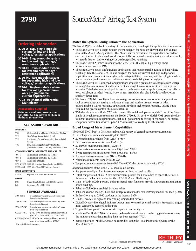
DIG
ITA
L M
ULT
IME
TER
S &
SY
STE
MS
A Greater Measure of Confidence
Match the system Configuration to the applicationThe Model 2790 is available in a variety of configurations to match specific application requirements:• The Model 2790-H is a single-module system designed for both low current and high voltage
ohms (10MW to 1GW) applications . This “base” system provides all the capabilities needed for electrical testing of either single- or dual-stage inflators in single position test stands (for example, test stands that test only one single- or dual-stage airbag at a time) .
• The Model 2790-A, which is similar to the Model 2790-H, enables high voltage ohms measurements down to 1MW .
• The Model 2790-HH is configured for applications that require parallel testing or high voltage “soaking .” Like the Model 2790-H, it is designed for both low current and high voltage ohms applications and can test either single- or dual-stage inflators . However, with two plug-in modules, it also has the capacity to test two inflators at once, maximizing test throughput .
• The Model 2790-HL is designed for applications where it is preferable to segregate high voltage sourcing/ohms measurement and low current sourcing/ohms measurement into two separate modules . This design was developed for use in combination testing applications, such as inflator electrical checks of safety steering wheel or seat assemblies that also include switch or other ancillary device tests .
• The Model 2790-L is configured for low voltage source/ohms-only measurement applications, such as continuity-only testing of side/seat airbags and seatbelt pre-tensioners or other programmable I-source resistance applications in which high voltage resistance testing is not required but precise control of source current is .
• With the addition of a Model 7702 40-channel differential multiplexer module (part of the Integra family of switch/measure solutions), the Model 2790-A, -H, or -L + Model 7702 opens the door to higher channel count applications, such as hi-pot/continuity testing of connectors, harnesses, and power distribution devices up to 500V (internally sourced) up to 40 channels .
broad range of Measurement CapabilitiesThe Model 2790’s built-in DMM can make a wide variety of general purpose measurements:• DC voltage measurements from 0 .1µV to 1000V• AC voltage measurements from 0 .1µV to 750V• DC current measurements from 10nA to 3A• AC current measurements from 1µA to 3A• 2-wire resistance measurements from 100µW to 120MW• 4-wire resistance measurements from 100µW to 120MW• Frequency measurements from 3Hz to 500kHz• Period measurements from 333ms to 2µs• Temperature measurements from –200°C to 630°C (thermistors and 4-wire RTDs)
Additional features of the Model 2790 mainframe include:• Setup storage—Up to four instrument setups can be saved and recalled .• Offset-compensated ohms—A two-measurement process for 4-wire ohms to cancel the effects of
thermoelectric EMFs . Available for the 100W, 1kW, and 10kW ranges .• Math—m/X+b, mX+b, percent, and four special math functions provide convenient manipulation
of raw readings . • Relative—Null offsets establish baseline values .• Ratio and channel average—Ratio and average calculations for two switching module channels (7702) .• Buffer—Store up to 55,000 readings in the internal buffer .• Limits—Two sets of high and low reading limits to test devices .• Digital I/O port—Five digital limit test output lines to control external circuitry . An external trigger
input can also be accessed at this port .• Trigger Link—Separate connector with input and output signals .• Monitor—The Model 2790 can monitor a selected channel . A scan can be triggered to start when
the monitor detects that a reading limit has been reached (7702) .• Remote interface—Model 2790 can be controlled using the IEEE-488 interface (GPIB) or the
RS-232 interface .
ordering Information2790-a 1MW single-module
system for low and high voltage/resistance applications
2790-H single-module system for low and high voltage/resistance applications
2790-HH Two-module system for low and high voltage/resistance applications
2790-Hl Two-module system for separating high and low voltage/resistance applications
2790-l single-module system for low voltage/resistance-only programmable current applications
7702 40-channel Differential Multiplexer
accessories suppliedreference and user manuals on CD-roM, aC line power cord, mini flathead screwdriver.
2790 SourceMeter® Airbag Test System
aCCEssorIEs aVaIlablEMoDulEs7702 40-channel General Purpose Multiplexer Module7751 High Voltage Source/Switch Module7752 Low Voltage, Current-Source-Only Source/Switch
Module7753 1MW High Voltage Source/Switch Module
(The Model 2790 supports only one Model 7753 .)
CoMMuNICaTIoN INTErfaCEs aND CablEs 7007-1 Shielded IEEE-488 Cable, 1m (3 .3 ft .) 7007-2 Shielded IEEE-488 Cable, 2m (6 .6 ft .) 7009-5 Shielded RS-232 CableKPCI-488LPA IEEE-488 Interface/Controller for the PCI BusKUSB-488B IEEE-488 USB-to-GPIB Interface Adapter
raCK MouNT KITs 4288-1, -2 Single or Dual Fixed Rack Mount Kit
oTHEr8503 Trigger Link Cable to 2 Male BNC Connector 8681 Miniature 4-Wire RTD, 100W
sErVICEs aVaIlablE2790-3Y-EW 1-year factory warranty extended to 3 years
from date of shipment2790-A-3Y-EW 1-year factory warranty extended to 3 years
from date of shipment2790-L-3Y-EW 1-year factory warranty extended to 3 years
from date of shipmentC/2790-3Y-ISO 3 (ISO-17025 accredited) calibrations within 3
years of purchase for Models 2790, 2790-L*C/2790-A-3Y-ISO 3 (ISO-17025 accredited) calibrations within 3
years of purchase for Model 2790-A*
*Not available in all countries
Mul
ticha
nnel
resi
stan
ce m
easu
rem
ents
for a
irbag
infla
tor,
harn
ess,
and
con
nect
or te
stin
g
Mul
ticha
nnel
resi
stan
ce m
easu
rem
ents
for a
irbag
infla
tor,
harn
ess,
and
con
nect
or te
stin
g
289 Test Equipment Depot - 800.517.8431 - 99 Washington Street Melrose, MA 02176 - TestEquipmentDepot.com

DIG
ITA
L M
ULT
IME
TER
S &
SY
STE
MS
Example application – Dual stage airbag Inflator Testing–one or Two
2790 Mainframe
7751/7752/7753 Source/Switch Module
CPULow Ohms Meter
A/D ConverterInterfacesDigital I/O
Power Supply
High VoltageSource
(deleted in 7752)
ProgrammableCurrent Source
0–50mA
Control LogicAnalog SignalConditioning
RelayMatrix
Dual Inflator 1
Dual Inflator 2
D
A
Optional 2nd Module
2
4
4
DUT A DUT B
DUT A DUT B
Example application – 40-channel Wiring Harness Testing
2790 Mainframe 7751/7752/7753 Source/Switch Module
CPULow Ohms Meter
A/D ConverterInterfacesDigital I/O
Power Supply
High VoltageSource
(7751 or 7753)
ProgrammableCurrent Source
0–50mA
Control LogicAnalog SignalConditioning
RelayMatrix
DUT7702 MUX Card
Model 2790 benefits• High functional integration—Sourcing,
measurement, and signal routing functions are tightly integrated in one compact enclosure . This high level of integration helps system integrators save rack space, minimize the time needed for system configuration and maintenance, and improve test throughput without sacrificing system accuracy .
• Enhanced device protection—Compared to higher powered alternatives, the Model 2790’s inherently lower power sources minimize the possibility of damaging sensitive devices under test through accidental overpowering . Automatic cold switching and active cable discharge circuitry reduce the chances for device damage still further, while the high precision DMM and A/D converter ensure high resolution and measurement accuracy .
• Reliability—The design of the Model 2790 is based on a proven Keithley technology platform . With a two-year calibration cycle for the module functions, it requires minimal maintenance over the life of the production test line . Its modular mainframe and plug-ins architecture makes module verification and calibration fast and convenient, simply by exchanging modules .
• Value—In addition to being a complete solution for airbag inflator testing and related applications, the Model 2790’s fully functional, 6½-digit DMM supports a wide variety of general purpose DC and AC measurements .
Three source/switch plug-in mod-ules provide the Model 2790 with programmable high voltage and low current sources, connection switching, and signal conditioning circuitry.
Mainframe specificationsRefer to the Model 2700 specifications on page 269 .
Key Module specifications*Refer to module specifications on page 273 .
sYsTEM THrouGHPuTHIGH OHMS: 13 rdgs/s .
LOW OHMS: 9 rdgs/s .
* The Model 7751, 7752, and 7753 plug-in modules have a two-year calibration interval; mainframe-only functions have a one-year calibration interval (max) . System warranty period is one year .
2790 SourceMeter® Airbag Test System
Mul
ticha
nnel
resi
stan
ce m
easu
rem
ents
for a
irbag
infla
tor,
harn
ess,
and
con
nect
or te
stin
g
Mul
ticha
nnel
resi
stan
ce m
easu
rem
ents
for a
irbag
infla
tor,
harn
ess,
and
con
nect
or te
stin
g
290 Test Equipment Depot - 800.517.8431 - 99 Washington Street Melrose, MA 02176 - TestEquipmentDepot.com

DIG
ITA
L M
ULT
IME
TER
S &
SY
STE
MS
A Greater Measure of Confidence
7751/7752/7753 sourCE/sWITCH MoDulE sPECIfICaTIoNs
2790 rEsIsTaNCE MoDE sPECIfICaTIoNs WITH CarDs 2, 3
(Module function accuracy specifications are for 2 years, 23°C, ±5°C .)
source Current
Maximum resistance
TypIcal open Circuit Voltage
accuracy (4W)±(%rdg.+ohms)
Temperature Coefficient
(0–18°C & 28–40°C)±(%rdg.+ohms)/°C
50 mA 20 5 .5 V 0 .09% + 2 m 0 .002% + 3 m20 mA 50 5 .5 V 0 .11% + 5 m 0 .003% + 3 m10 mA 100 5 .5 V 0 .16% + 10 m 0 .004% + 3 m
(Dry Circuit ohms 1ma max. with 7751, 7752, or 7753 card)1 mA 10 20 mV 1 .10% + 50 m (0 .026% + 3 m)/°C
(7751 Only)
source Voltage
resistance range
MaxImum short Circuit Current
accuracy±(% rdg.)
Temperature Coefficient
(0–18°C & 28–40°C)±(%rdg.)/°C
500 V 10 M <1 mA 0 .8% 0 .03%500 V 100 M <1 mA 1 .1% 0 .05%500 V 1 G <1 mA 4 .0% 0 .12%50 V 1 M <1 mA 1 .1% 0 .04%50 V 10 M <1 mA 1 .1% 0 .06%50 V 100 M <1 mA 1 .6% 0 .13%
(7753 Only)
source Voltage
resistance range
MaxImum short Circuit Current
accuracy±(% rdg.)
Temperature Coefficient
(0–18°C & 28–40°C)±(%rdg.)/°C
500 V 1 M <1 mA 0 .8% 0 .02%500 V 10 M <1 mA 0 .9% 0 .03%500 V 100 M <1 mA 1 .3% 0 .10%500 V 1 G <1 mA 6 .7% 0 .27%50 V 0 .1 M <1 mA 1 .1% 0 .03%50 V 1 M <1 mA 1 .1% 0 .04%50 V 10 M <1 mA 1 .3% 0 .11%50 V 100 M <1 mA 4 .5% 0 .30%
CurrENT sourCE ouTPuTOUTPUT LEVEL: Programmable 0 to 50mA (Ch . 27) .
PROGRAMMING RESOLUTION: 10µA .
OUTPUT VOLTAGE: 5 .5V ±10% compliance .
ACCURACy: ±(0 .06% + 10µA) (2 year specification) .
SETTLING TIME: 1ms to 0 .1% of final value (typ .) .
TEMPERATURE COEFFICIENT (0–18°C & 28–40°C): ±(0 .001% + 0 .25µA)/°C .
DRy CIRCUIT CLAMP (Ch. 24): 20mV ±10%, Isource ≤1mA .
VolTaGE sourCE ouTPuT (7751/7753 only)OUTPUT LEVEL: Programmable 50V to 500V (Ch . 28) .
PROGRAMMING RESOLUTION: 100mV .
OUTPUT CURRENT: (7751) 50µA maximum for rated accuracy, <1mA typical into short circuit . (7753) 500µA maximum for rated accuracy, <1mA typical into short circuit .
ACCURACy: ±(0 .5% + 0 .13V) (2 year specification) .
SETTLING TIME: Rise Time: 50V to 500V step, 0 .1% of final value, 250ms max . Fall Time: 500V to 50V step, 0 .1% of final value, 1000ms max .
TEMPERATURE COEFFICIENT (0–18°C & 28–40°C): ±(0 .001% + 0 .005V)/°C
SAFETy LIMIT: Current limited maximum current of 1mA .
CABLE DISCHARGE (Ch. 20): 100kW shunt .
MAXIMUM CAPACITANCE: 1nF .
CurrENT MEasurE INPuT (7751/7753 only)RANGE: 7751: 0–50µA . 7753: 0–500µA .
ACCURACy: 7751: ±(0 .5% of reading + 6nA) (2 year specification) . 7753: ±(0 .5% of reading + 60nA) (2 year specification) .
TEMPERATURE COEFFICIENT (0–18°C & 28–40°C): ±(0 .02%+0 .5nA)/°C .
VOLTAGE BURDEN: <1mV .
sWITCHING CaPabIlITIEs (bank 1–bank 4)4 CHANNELS: 1 Form A switch .
8 CHANNELS: Four 4-pole or eight 2-pole signals into DMM or I/V converter .
CONTACT CHECK: 4-wire contact check through internal DMM .
RELAy TyPE: Latching electromechanical .
ACTUATION TIME: <3ms .
CONTACT LIFE (typical): >106 operations at maximum source level . >108 operations cold switching .
CONTACT RESISTANCE: <1W at end of contact life .
CONTACT POTENTIAL: <±2µV typical per contact pair, ±3µV max .
CONNECTOR TyPE: Plugable screw terminal, #22 AWG wire size .
ISOLATION BETWEEN ANy TWO TERMINALS1: >1GW, <100pF .
ISOLATION BETWEEN TERMINALS AND EARTH1: >1GW, <200pF .
ISOLATION BETWEEN CHANNEL GROUPS1: >500GW, <100pF .
EXTERNAL COMMON MODE VOLTAGE: 42V between any terminal and chassis . (Connect no external sources .)
7751, 7752, or 7753 MoDulE NoTEs1 Isolation for channels 1–12, only one channel closed at a time, or all channels open .2 See User's Manual for ohm specifications at sources other than those specified .3 All specifications valid for 1 NPLC ADC aperture setting .
sYsTEM THrouGHPuT(Connect, source, measure, calculate)
0.01 NPLC, FILTER OFF, OVER GPIB BUS: High Ohms (Source V): 13 rdgs/s1 . Low Ohms (Source I): 9 rdgs/s .
1 NPLC, FILTER ON, OVER GPIB BUS: High Ohms (Source V): 11 rdgs/s1 . Low Ohms (Source I): 7 rdgs/s .
sYsTEM THrouGHPuT NoTEs 1 . Reset upon fixed Vsource level, no settling time .
basIC aIrbaG TEsT sEQuENCE THrouGHPuT(Body Pin + Bridgewire Continuity = Shorting Clip + Insulation Resistance)
0 .55/0 .97 seconds for single/dual stage DUT w/scan (sequential) memory patterns .
1 .0/2 .0 seconds for single/dual stage DUT w/recall (random access) memory patterns .
1 .1/1 .7 seconds for single/dual stage DUT discrete control w/GPIB I/O .
(Sequence times are totals @ 1 line cycle integration for rated accuracy .)
2790 SourceMeter® Airbag Test SystemM
odel
775
1/77
52/7
753
spec
ifica
tions
Mod
el 7
751/
7752
/775
3 sp
ecifi
catio
ns
291 Test Equipment Depot - 800.517.8431 - 99 Washington Street Melrose, MA 02176 - TestEquipmentDepot.com

DIG
ITA
L M
ULT
IME
TER
S &
SY
STE
MS
Ch. 25
Ch. 13
Ch. 14
Ch. 15
Ch. 16
Ch. 17
Ch. 18
Ch. 19
Ch. 2
Ch. 1
Ch. 3
Source
Sense
Source
Sense
A1
B1
Bank 1J101
HI
LO
Ch. 5
Ch. 4
Ch. 6
Source
Sense
Source
Sense
A2
B2
Bank 2J102
HI
LO
Ch. 8
Ch. 7
Ch. 9
Source
Sense
Source
Sense
A3
B3
Bank 3J103
HI
LO
Ch. 11
Ch. 10
Ch. 12
Source
Sense
Source
Sense
A4
B4
Bank 4J104
HI
LO
+5V+5V
InterlockSource Enable
Interlock
Guard
Guard
Source HI
Source LO
Sense HI
Sense LO
I/V In
I/V Out
I/V LO
Vsrc HI
Vsrc LO
Isrc HI
Isrc LO
Guard
Guard
10K
10K
J106
HI
LO
HI
LO
Input
Sense
ToModel 2790Backplane
J105
J108
J107
+–
50–500V
0–50mA
Ch. 24
20mVDryCkt Ch. 22 Ch. 21
1Ω
Ch. 22 Open: Isource SelectCh. 22 Close: Vsource Select
Ch. 20 100kΩ
Cable Discharge(7751 & 7753 only)
Vsource Ch. 28(7751 & 7753 only)
Isource Ch. 27
Ch. 23+
–
I/V Current/ Voltageamplifier
(7751 & 7753 only)
2790 SourceMeter® Airbag Test System
Mod
el 7
751/
7752
/775
3 sp
ecifi
catio
ns
Mod
el 7
751/
7752
/775
3 sp
ecifi
catio
ns
292 Test Equipment Depot - 800.517.8431 - 99 Washington Street Melrose, MA 02176 - TestEquipmentDepot.com

DIG
ITA
L M
ULT
IME
TER
S &
SY
STE
MS
A Greater Measure of Confidence
The Model 7751, 7752, and 7753 Source/Switch Modules are designed exclusively for use in the Model 2790 SourceMeter Switch System for elec-trical checks of airbag inflators and a variety of other automotive electrical test applications . These modules provide the programmable high volt-age and low current sourcing, plus the multichannel switching support required to measure insulation resistance and conductor continuity in these applications .
The Model 7751 and 7753 modules include programmable DC voltage (50–500V) and current (0–50mA) sources, as well as relay switching . A built-in current-to- voltage converter on these modules is used with the volt-age source to measure the insulation resistance . They can also be used to measure currents from 0–50µA . The constant current source is useful for measuring the resistance of bridgewires and shunt bars . Four banks of two-pole relays provide a sufficient number of terminals to connect two single inflator units or one dual inflator unit to the Model 2790 mainframe for testing . The mainframe will accommodate two plug-in modules, so a single Model 2790 system can be connected to two test stands and be used to test two dual inflator airbag modules . Parallel testing in the form of “voltage soak with one card, measure with the other” is possible for both single and double test stand configurations . The switch matrix of the Model 7751 and 7753 simplifies implementing contact verification tests and allows the Model 2790 to verify test voltages and currents for increased measure-ment reliability .
The Model 7752 module is identical to the Model 7751, except that it does not include the high volt-age source and current-to-voltage converter . The Model 7753 is identical to the Model 7751 except that the lowest high ohms measurement for the Model 7753 is 1MW and for the Model 7751 is 10MW .
Safety related design features that provide added protection against accidental detonation include low energy sources, a hardware source interlock, and programmable shunts that can be used in conjunc-tion with an inflator’s shunt bar .
• sourcing and switching for airbag inflator testing with the Model 2790
• Programmable 0–50ma current source
• Programmable 50–500V voltage source (7751 and 7753)
• built-in I/V converter (7751 and 7753)
• low energy sources, a hardware source interlock, and programmable shunts help prevent accidental detonations
System Connections
Inflator UnderTest
Test Station(with interlock)7751, 7752, or
7753 Module
Slot 2
Keithley 2790
Interlock
Interlock
Slot 1
Use for testsystem
expansion
2.790000 WMATH
RS-232
MechanicalConnection
Device Handler
PC(GPIB)
OR
RS-232
GPIBIEEE-488
DIGITAL I/O
Test SignalCabling
KPCI-488LPAInterface
PLCor PC
(RS-232)
Device Handler Control
7751 7752 7753
High Voltage Source/Switch ModuleLow Voltage, Current-Source-Only Source/Switch Module1MW High Voltage Source/Switch Module
sErVICEs aVaIlablE7751-3Y-EW 1-year factory warranty extended to 3 years
from date of shipment
7752-3Y-EW 1-year factory warranty extended to 3 years from date of shipment
7753-3Y-EW 1-year factory warranty extended to 3 years from date of shipment
Sour
ce/s
witc
h m
odul
es fo
r airb
ag in
flato
r tes
ting
with
the
Mod
el 2
790
Sour
ce/s
witc
h m
odul
es fo
r airb
ag in
flato
r tes
ting
with
the
Mod
el 2
790
ordering Information7751 High Voltage source/
switch Module7752 low Voltage, Current-
source-only source/switch Module
7753 1MW High Voltage source/switch Module
293 Test Equipment Depot - 800.517.8431 - 99 Washington Street Melrose, MA 02176 - TestEquipmentDepot.com

DIG
ITA
L M
ULT
IME
TER
S &
SY
STE
MS
294 Test Equipment Depot - 800.517.8431 - 99 Washington Street Melrose, MA 02176 - TestEquipmentDepot.com

DC
PO
WE
R S
UP
PLI
ES
A Greater Measure of Confidence
Technical Information . . . . . . . . . . . . . . . . . . . . . . . 296 selector Guide Programmable DC Power Supplies . . . . . . . . . . . . . 300 selector Guide Battery Simulating DC Power Supplies . . . . . . . . . 301
Single-Channel Programmable DC Power Supplies 2200-20-5 20V, 5A Programmable DC Power Supply . . . . . . . 302 2200-30-5 30V, 5A Programmable DC Power Supply . . . . . . . 302 2200-32-3 32V, 3A Programmable DC Power Supply . . . . . . . 302 2200-60-2 60V, 2 .5A Programmable DC Power Supply . . . . . . 302 2200-72-1 72V, 1 .5A Programmable DC Power Supply . . . . . . 302
Multi-Channel Programmable DC Power Supplies 2220-30-1 Programmable Dual Channel DC Power Supply . . 306 2230-30-1 Programmable Triple Channel DC Power Supply . 306
Battery Simulating DC Power Supplies 2308 50W, Fast Transient Response Battery/Charger Simulating Supply with Analog Output . . . . . . . . . .310 2302 60W, Fast Transient Response Battery Simulating Supply . . . . . . . . . . . . . . . . . . . . .317 2302-PJ 60W, Fast Transient Response Battery Simulating Supply with 500mA Range . . . .317 2306 50W, Fast Transient Response Battery/Charger Simulating Supply . . . . . . . . . . . . . .317 2306-PJ 50W, Fast Transient Response Battery/Charger Simulating Supply with 500mA Range . . . . . . . . . . .317 2306-Vs 50W, Fast Transient Response Battery/Charger Simulating Supply with External Triggering . . . . . 323 2303 45W, Fast Transient Response Supply . . . . . . . . . . . 331 2303-PJ 45W, Fast Transient Response Battery Simulating Supply with 500mA Range . . . 331 2304a 100W, Fast Transient Response Supply . . . . . . . . . . 331
High Voltage DC Power Supply 248 25W, High Voltage (5kV) Supply . . . . . . . . . . . . . . . 335
DC Power Supplies
295 Test Equipment Depot - 800.517.8431 - 99 Washington Street Melrose, MA 02176 - TestEquipmentDepot.com

DC
PO
WE
R S
UP
PLI
ES
Programmable DC Power SuppliesDC power supplies provide a regulated DC output to power a component, a module, or a device . A power supply must deliver voltage and current that is stable and precise, with minimal noise to any type of load: resistive, inductive, low impedance, high impedance, steady-state, or variable . How well the power supply fulfills this mission and where it reaches its limits are defined in its specifications .
Power supplies have two main settings, the output voltage and the current limit . How they are set in combination with the load determines how the power supply will operate .
Most DC power supplies have two modes of operation . In Constant Voltage (CV) mode, the power supply controls the output voltage based on the user settings . In Constant Current (CC) mode, the power supply regulates the current . Whether the power supply is in CV or CC mode depends on both the user settings and the resistance of the load .
• CV mode is the typical operating state of a power supply . It controls voltage . The output voltage is constant and is determined by the user’s voltage setting . The output current is determined by the impedance of the load .
• CC mode is typically considered a safety mode, but can be used in other ways . In CC mode, the output current is constant and is determined by the user’s current limit setting . The voltage is determined by the impedance of the load . If the power supply is in CV mode and its current exceeds the user’s current limit setting, then the power supply will automatically switch to CC mode . The power supply can also revert back to CV mode if the load current falls below the current limit setting .
The most important parameters for any application are the maximum volt-age, maximum current, and maximum power that the power supply can generate . It is essential to ensure that the power supply can deliver the power at the required voltage and current levels . These three parameters are the first specifications that must be investigated .
accuracy and resolutionHistorically, the DC power supply user turned potentiometers to set output voltage or current . Today, microprocessors receive input from the user interface or from a remote interface . A digital-to-analog converter (DAC) takes the digital setting and translates this into an analog value, which is used as the reference for the analog regulator . The setting resolution and accuracy values are determined by the quality of this conversion and regu-lation process .
Voltage and current settings (sometimes called limits or programmed val-ues) each have resolution and accuracy specifications associated with them . The resolution of these settings determines the minimum increment in which the output can be adjusted, and the accuracy describes the extent to which the value of the output matches international standards . In addition to output settings, there are measurement or readback specifications that are independent of the output specifications .
Most DC power supplies provide built-in measurement circuits for meas-uring both voltage and current . These circuits measure the voltage and current being delivered by the power supply output . Since the circuits read the voltage and current that is fed back into the power supply, the meas-urements produced by the circuits are often called readback values . Most professional power supplies incorporate circuits that use analog-to-digital converters, and for these internal instruments the specifications are similar to those of a digital multimeter . The power supply displays measured val-ues on its front panel and can also transmit them over its remote interface, if it is equipped with one .
setting accuracySetting accuracy determines how close the regulated parameter is to its theoretical value as defined by an international standard . Output uncer-tainty in a power supply is largely due to error terms in the DAC, including quantization error . Setting accuracy is tested by measuring the regulated variable with a traceable, precision measurement system connected to the output of the power supply . Setting accuracy is given as:
±(% of setting + offset)
For example, consider a power supply with a voltage setting accuracy speci-fication of ±(0 .03% + 3mV) . When it is set to deliver 5V, the uncertainty in the output value is (5V)(0 .0003 + 3mV), or 4 .5mV . Current setting accuracy is specified and calculated similarly .
setting resolution and Programming resolutionSetting resolution is the smallest change in voltage or current settings that can be selected on the power supply . This parameter is sometimes called programming resolution if operating over an interface bus such as GPIB .
readback accuracy and resolutionReadback accuracy is sometimes called meter accuracy . It determines how close the internally measured values are to the theoretical value of the output voltage (after setting accuracy is applied) . Like a digital multimeter, this is tested using a traceable reference standard . Readback accuracy is expressed as:
±(% of measured value + offset)
Readback resolution is the smallest change in internally measured output voltage or current that a power supply can discern .
Technical Information
DC Power Supplies
BusInterface Keypad
Microprocessor
Isolation
LinearRegulator
Transformerand AC-DCConverter
UnregulatedDC
ADCs
AC In
DACs
OVP
Display
FeedbackControl
Output(Regulated DC)
figure 1. simplified block diagram of a programmable linear power supply showing the digital and analog control circuit blocks
Tech
nica
l inf
orm
atio
n: D
C po
wer
sup
plie
s
Tech
nica
l inf
orm
atio
n: D
C po
wer
sup
plie
s
296 Test Equipment Depot - 800.517.8431 - 99 Washington Street Melrose, MA 02176 - TestEquipmentDepot.com

DC
PO
WE
R S
UP
PLI
ES
A Greater Measure of Confidence
load regulation (Voltage and Current)Load regulation is a measure of the ability of the output voltage or output current to remain constant during changes in the load . It is expressed as:
±(% of setting + offset)
line regulation (Voltage and Current)Line regulation is a measure of the ability of the power supply to maintain its output voltage or output current while its AC line input voltage and fre-quency vary over the full allowable range . It is expressed as:
±(% of setting + offset)
ripple and NoiseSpurious AC components on the output of a DC supply are called ripple and noise, or periodic and random deviation (PARD) . PARD specifications must be specified with a bandwidth and should be specified for both cur-rent and voltage . Current PARD is relevant when using a power supply in CC mode, and it is often specified as an RMS value . Because the shape of PARD is indeterminate, voltage PARD is usually expressed both as a root mean square voltage, which can provide a sense of the noise power, and also as a peak-to-peak voltage, which can be relevant when driving high impedance loads .
RLead
+VLead
Output +
Sense + Sense
Source
Source
Sense
Output –
Sense –
ILoad
VProgrammed VLoad
Load
–
+
RLead
RLead
RLead
ISense = 0A
figure 2. remote sensing technique
Regardless of the accuracy of your power supply, you cannot guarantee that the programmed output voltage is the same as the voltage at the DUT’s load . This is because a power supply with two source output terminals regulates its output only at its output terminals . However, the voltage you want regulated is at the DUT’s load, not at the power supply’s output terminals . The power supply and the load are separated by lead wires that have a resistance, RLead, which is determined by the length of the lead, the conductivity of the conductor material, and the geometry of the conductor . The voltage at the load is:
VLoad = VProgrammed – 2*VLead = VProgrammed – 2*ILoad*RLead
If the load requires high current, then ILoad is high and VLead can easily be a few tenths of a volt, especially if the power supply leads are long, as can be the case in an automated test rack . A voltage at the load could be 80mV to 160mV lower than the desired voltage (with 2A to 4A flowing through a 16-gauge wire) .
The remote sensing technique solves the problem of the voltage drop in the test lead wires by extending the power supply feedback loop to the load . Two sense lines are connected between the DUT’s load and the high
impedance voltage measuring circuit in the power supply . Since this is a high input impedance circuit, the voltage drop in the sense leads is negli-gible and becomes the feedback control loop for the power supply .
Fast Transient Response Power SuppliesThe Keithley Series 2300 special-purpose power supplies are designed to maintain a stable output voltage under the most difficult loading conditions, such as the large, instantaneous load changes generated by cellular phones, cordless phones, mobile radios, wireless modems, and other portable, wireless com mu nication devices . These devices typically transition from standby current levels of 100–200mA to 800mA–1 .5A, which represents load changes of 800% and higher . A conventional power supply typically specifies a transient recovery to a 50% load change . The Keithley Series 2300 power supplies specify transient response to 1000% load changes .
stable During fast load ChangesWhen the mobile communication device transitions to a full power trans-mit state, the output voltage of a conventional power supply drops substan-tially until its control circuitry can respond to the transient . Conventional power supplies trade off stability for all kinds of loads against transient response . As a result, the large voltage drop and long recovery time of a conventional power supply can cause the output voltage to fall below the low battery voltage threshold of the device under test (DUT) . The DUT could turn off during testing and register a false failure, affecting yield and production costs .
Series 2300 fast transient response power supplies have transient voltage droops of less than 200mV under large load changes, even with the added impe dance of long wire runs between the power supply and the DUT . Thus, the Series 2300 power supplies will keep the DUT powered under all test conditions and prevent false failures . See Figure 3 .
accurate four-Wire MeasurementsTo maintain an accurate voltage at the DUT load, the Series 2300 power supplies use a four-wire source circuit in which two outputs provide the power and the other two lines sense the voltage directly at the DUT load .
Technical Information
DC Power Supplies
Wireless PhoneLoad Current
PhoneLow BatteryTurnoffThreshold
PhoneLow BatteryTurnoffThreshold
General-PurposePower SupplyResponse
Keithley Series 2300Fast TransientResponse PowerSupplies
IStandby
VPower Supply
IRX, TX
figure 3. Comparison of general-purpose power supply’s response with the response of a Keithley series 2300 fast transient power supply.
Tech
nica
l inf
orm
atio
n: D
C po
wer
sup
plie
s
Tech
nica
l inf
orm
atio
n: D
C po
wer
sup
plie
s
297 Test Equipment Depot - 800.517.8431 - 99 Washington Street Melrose, MA 02176 - TestEquipmentDepot.com

DC
PO
WE
R S
UP
PLI
ES
Sensing the voltage at the load compensates for any voltage drops in long test lead runs between the power supply and the load . Furthermore, the power supplies use a wide band output stage to obtain the low voltage transient droop and the fast transient recovery time . See Figure 4 .
These types of power supplies often incorporate techniques for detecting if a sense lead is open or broken . An open sense lead interrupts the feedback control to the power supply, and uncontrolled, unstable output can provide improper voltages to a DUT . Series 2300 supplies either revert to internal local sensing or indicate an error condition and turn the output off .
battery Emulation with Variable output resistanceMobile communication devices are powered by batteries, so the Models 2302 and 2306 power supplies are de signed to emulate the performance of a battery accurately . These supplies incorporate a variable output resistance feature, which enables a test engineer to test his DUT under actual operat-ing conditions .
Furthermore, these supplies can sink current to simulate the battery in the discharged state . Thus, test engineers can use one instrument both to source the DUT and to act as a load for testing the charging control cir-cuitry of the DUT and its charger .
The Models 2302 and 2306 have the ability to vary their output impedance . This allows them to simulate the internal impedance of a battery . Thus, the voltage response of a battery that must support pulsed current loads from portable products such as mobile phones can be simulated . This enables manufacturers of portable devices to test their devices under the most realistic conditions .
With a pulse-like increase in load current, the battery output voltage will drop by the product of the current change and the battery’s internal resistance . The battery voltage could fall (for the length of the pulse) below the low battery voltage threshold level of the device, and the device could turn off . Since the internal impedance increases as a battery discharges, the low voltage threshold level can be reached earlier than expected due to the combination of a lower battery voltage due to discharge time and the voltage drop across the internal resistance of the battery . Therefore, a device’s battery life could be shorter than the desired specification .
Battery impedance must be considered when evaluating mobile phone handset talk time and standby performance, because voltage levels below the operating threshold of a handset’s circuitry for periods as short as 100 to 200µs are enough to shut off the handset . This phenomenon is com-mon in TDMA (Time Division Multiple Access) phones such as GSM mobile phones where the magnitude of the high and low current levels during an RF transmission pulse vary by as much as a factor of 7 to 10 . Designers need to simulate the actual performance of a battery to define an appro-priate low battery threshold level . Test engineers need to simulate actual battery performance to test that the low voltage threshold level is reached with the specified battery voltage and not at a higher voltage level .
The battery simulating characteristics of the Models 2302 and 2306 can be used to test components as well as end products . For example, the power consumption characteristics of an RF power amplifier designed for use in portable products can be characterized for operation from a battery power source . As a battery discharges, its voltage decreases and its internal impe-dance increases . The RF amplifier draws a constant amount of power to maintain the required output . Thus, as the battery voltage falls and the internal resistance increases, the RF amplifier draws increasing amounts of current from the battery . Both peak current and average current rise significantly with increases in battery internal impedance . See Figure 5 . The RF power amplifier must specify power consumption . The portable device designer must be aware of how the RF power amplifier performs as the battery discharges so that the designer can select an appropriate battery pack to ensure both that an adequate current supply is available
Technical Information
DC Power Supplies
Aver
age
Cur
rent
(am
ps)
Tran
smit
Puls
e C
urre
nt (
Amps
)
1.40
1.45
1.50
1.55
1.60
1.65
1.70
0 0.1 0.2 0.3 0.4 0.5
Output Impedance (ohms)
0.25
0.255
0.26
0.265
0.27
0.275
0.28
Transmit CurrentAverage Current
figure 5. The transmit and average current consumption of an rf power amplifier used in a pulsed output mode with a Model 2302/2306 simulating a battery with a nominal output voltage of 3.60V and output impedance from 0.00 to 0.51W.
+
–DUT
IEEE-488Interface
µP
Control
WideBandwidthPower OutputStage
VoltageFeedback
V+
V–
Sense +
Sense –
+
–
Twisted Wire
DUT
Rwire
Rwire
Rwire
Rwire
V+
V–
Sense +
Sense –
Series 2300PowerSupply
Series 2300Power Supply
DC Model for Test Leads
Series 2300 Block Diagram with connection to DUT
figure 4. four-wire sensing with series 2300 power supplies ensures that an accurate voltage is applied to the load.Te
chni
cal i
nfor
mat
ion:
DC
pow
er s
uppl
ies
Tech
nica
l inf
orm
atio
n: D
C po
wer
sup
plie
s
298 Test Equipment Depot - 800.517.8431 - 99 Washington Street Melrose, MA 02176 - TestEquipmentDepot.com

DC
PO
WE
R S
UP
PLI
ES
A Greater Measure of Confidence
Technical Information
DC Power Supplies
and that the battery supplies suitable operating time between replacement or charges .
The mathematics of this effect is provided below (also see Figures 6a and 6b) . They show that the voltage drop produced by pulsed current loads can have a significant effect on battery output voltage .
Vcell = An ideal voltage source
Ri(t) = The internal impedance
Rinterconnect = Resistance of cables and interconnections to the DUT
1) If Rinterconnect is small compared to Ri(t), and if
2) Ri(t) is assumed to be relatively constant during the length of the pulse, Ri(t) ≈ Ri, then
3) The voltage across the DUT can be expressed as:
V(t) ≈ Vcell – I(t)Ri(t) ≈ Vcell – I(t)Ri
where I(t) is the time varying current through the battery .
Rinterconnect
Rinterconnect
Ri(t)
VcellDUT
I(t)
V(t)Cell orBattery Pack+
–
I(t)
V(t)
Vcell
Vcell – I(t)Ri
a) b)
figure 6a. schematic of a battery represented by an ideal voltage source and a time varying internal impedance connected to a DuT.figure 6b. resulting output voltage with a pulsed load current.
Pulse Current and low Current MeasurementsUsing a conventional (slow transient response) power supply for testing wireless devices requires that a large capacitor be placed in the circuit to stabilize the voltage during a load transition . As a result, load current meas urements require using a sense resistor and a DMM to monitor load currents . The sense resistor adds resistance to the line, which further aggravates the load droop problem . The Keithley fast transient response power supplies eliminate the need for the capacitor and enable the power supply current readback circuitry to measure the load currents . See Figure 7 . Keithley low current expertise enables the meas urement of sleep currents with 0 .1µA resolution . These supplies can also measure load current pulses from digital transmission devices . Current pulses as short as 60µs can be captured .
ConventionalSlow-ResponsePower Supply
RsenseIloadIsupply
C
Voltage StabilizingCapacitor
V+
–DUT
DMM
Series 2300Fast Transient
ResponsePower Supply
Isupply = Iload
V+
–DUT
figure 7. a Keithley series 2300 fast transient response power supply measures load currents without additional devices and components.
Tech
nica
l inf
orm
atio
n: D
C po
wer
sup
plie
s
Tech
nica
l inf
orm
atio
n: D
C po
wer
sup
plie
s
299 Test Equipment Depot - 800.517.8431 - 99 Washington Street Melrose, MA 02176 - TestEquipmentDepot.com

DC
PO
WE
R S
UP
PLI
ES
selector Guide Programmable DC Power Supplies
single-Channel Power suppliesMulti-Channel Power supplies
Model 2200-20-5 2200-30-5 2200-32-3 2200-60-2 2200-72-12220-30-1, 2220J-30-1
2230-30-1, 2230J-30-1
Page 302 302 302 302 302 306 306
Number of Channels 1 1 1 1 1 2 3
Power output 100 W 150 W 96 W 150 W 86 W 90 W 120 W
Voltage output 0 to 20 V 0 to 30 V 0 to 32 V 0 to 60 V 0 to 72 V Ch . 1 and 2: 0 to 30 V
Ch . 1 and 2: 0 to 30 V
Ch . 3: 0 to 6 V
Current output 0 to 5 A 0 to 5 A 0 to 3 A 0 to 2 .5 A 0 to 1 .2 A Ch . 1 and 2: 0 to 1 .5 A
Ch . 1 and 2: 0 to 1 .5 A
Ch . 3: 0 to 5 A
operating Mode CV/CC* CV/CC* CV/CC* CV/CC* CV/CC* CV/CC* CV/CC*setting and readback resolution:
Voltage 1 mV 1 mV 1 mV 1 mV 1 mV 1 mV 1 mV
Current 0 .1 mA 0 .1 mA 0 .1 mA 0 .1 mA 0 .1 mA 1 mA 1 mAbasic accuracy:
Voltage ±0 .03% ±0 .03% ±0 .03% ±0 .03% ±0 .03% ±0 .03% ±0 .03%
Current ±0 .05% ±0 .05% ±0 .05% ±0 .05% ±0 .05% ±0 .1% ±0 .1%features:
Programming IEEE-488 and USB
IEEE-488 and USB
IEEE-488 and USB
IEEE-488 and USB
IEEE-488 and USB USB USB
Remote Sense Yes Yes Yes Yes Yes Yes Yes
External Trigger Yes Yes Yes Yes Yes No NoFront and Rear Connectors Yes Yes Yes Yes Yes Yes Yes
Setup Storage 40 locations 40 locations 40 locations 40 locations 40 locations 30 locations 30 locations
List Mode7 lists,
80 steps/list7 lists,
80 steps/list7 lists,
80 steps/list7 lists,
80 steps/list7 lists,
80 steps/listNo No
Track Mode No No No No No Yes Yes
Output Timer Yes Yes Yes Yes Yes Yes YesPassword Protection Yes Yes Yes Yes Yes Yes Yes
Remote Inhibit Yes Yes Yes Yes Yes No NoDiscrete Fault Indication Yes Yes Yes Yes Yes No No
Approvals CSA/CE CSA/CE CSA/CE CSA/CE CSA/CE CSA/CE CSA/CE
*CV is Constant Voltage mode and CC is Constant Current mode
300
Sele
ctor
gui
de: P
rogr
amm
able
DC
pow
er s
uppl
ies
Sele
ctor
gui
de: P
rogr
amm
able
DC
pow
er s
uppl
ies
Test Equipment Depot - 800.517.8431 - 99 Washington Street Melrose, MA 02176 - TestEquipmentDepot.com

DC
PO
WE
R S
UP
PLI
ES
A Greater Measure of Confidence
fast Transient response, battery simulating Power supplies
High Voltage supply
Model 2302 2303 2303-PJ 2304a 2306 2306-PJ 2306-Vs 2308 248Page 317 331 331 331 317 317 323 310 335
No. of Channels 1 1 1 1 2 2 2 2 1
Power output
60W maximum,function of
V; optimized for maximum
current at low V
45 W 45 W 100 W
50W maximum,function of
V and power consumed by
other channel; optimized
for maximum current at low V
50W maximum,function of
V and power consumed by
other channel; optimized
for maximum current at low V
50W maximum,function of
V and power consumed by
other channel; optimized
for maximum current at low V
50W maximum,function of
V and power consumed by
other channel; optimized
for maximum current at low V
25 W
Voltage output 0–15 V 0–15 V 0–15 V 0–20 V 0–15 V 0–15 V 0–15 V 0–15 V 0–±5000 V
Maximum Continuous Current output
5 A @ 4 V 5 A @ 9 V 5 A @ 9 V 5 A @ 20 V 5 A @ 4 V 5 A @ 4 V 5 A @ 4 V 5 A @ 4 V 5 mA
Variable resistance output
0–1 W10 mW
resolution
0–1 W10 mW
resolution(in channel 1)
0–1 W10 mW
resolution(in channel 1)
0–1 W10 mW
resolution(in channel 1)
0–1 W10 mW
resolution(in channel 1)
Current sink Capacity 3 A 2 A 2 A 3 A 3 A 3 A 3 A 3 A
DC Current Measurement sensitivity
100 nA 100 nA 10 µA 100 nA 100 nA 10 µA (Ch . 1)100 nA (Ch . 2) 100 nA 100 nA
Dynamic Current Measurement
5 A range:33 µs–833 ms
integration times
5 A range:33 µs–833 ms
integration times
500 mA and5 A ranges:
33 µs–833 ms integration
times
5 A range:33 µs–833 ms
integration times
5 A range:33 µs–833 ms
integration times
500 mA and5 A ranges:
33 µs–833 ms integration
times
5 A range:33 µs–833 ms
integration times
5 A, 500 mA,50mA and 5mA
ranges:33 µs–833 ms
integration times
External Triggering for Voltage outputs and Current Measurement
No No No No No No Yes No No
accuracy
V 0 .05% 0 .05% 0 .05% 0 .05% 0 .05% 0 .05% 0 .05% 0 .05% 0 .01%
I 0 .2% 0 .2% 0 .2% 0 .2% 0 .2% 0 .2% 0 .2% 0 .2% 0 .01%
features:
Programming IEEE-488 included
IEEE-488 included
IEEE-488 included
IEEE-488 included
IEEE-488 included
IEEE-488 included
IEEE-488 included
IEEE-488 included
IEEE-488 included
Open Sense Lead Detection Yes Yes Yes Yes Yes No
DVM Yes Yes Yes Yes Yes, 1 per channel
Yes, 1 per channel
Yes, 1 per channel
Yes, on channel 2 No
Analog Output 1 analog output
Relay Control Port 4 1 1 2 4 4 No 4 No
Remote Display Module Yes Yes Yes Yes Yes Yes No Yes No
CE Yes Yes Yes Yes Yes Yes Yes Yes Yes
selector Guide Specialized DC Power Supplies
Sele
ctor
gui
de: S
peci
aliz
ed D
C po
wer
sup
plie
s
301
Sele
ctor
gui
de: S
peci
aliz
ed D
C po
wer
sup
plie
s
Test Equipment Depot - 800.517.8431 - 99 Washington Street Melrose, MA 02176 - TestEquipmentDepot.com
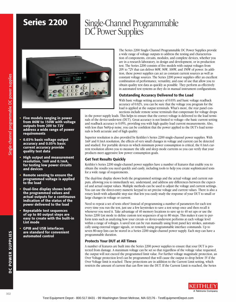
DC
PO
WE
R S
UP
PLI
ES
series 2200 Single-Channel Programmable DC Power Supplies
The Series 2200 Single-Channel Programmable DC Power Supplies provide a wide range of voltage outputs to address the testing and characteriza-tion of components, circuits, modules, and complete devices, whether you are in a research laboratory, in design and development, or in production test . The Series 2200 consists of five models with output voltages from 20V to 72V that can deliver 86W, 96W, 100W, and 150W of power . In addi-tion, these power supplies can act as constant current sources as well as constant voltage sources . The Series 2200 power supplies offer an excellent combination of performance, versatility, and ease of use that allow you to obtain quality test data as quickly as possible . They perform as effectively in automated test systems as they do in manual instrument configurations .
outstanding accuracy Delivered to the loadWith basic voltage setting accuracy of 0 .03% and basic voltage readback accuracy of 0 .02%, you can be sure that the voltage you program for the load is applied at the output terminals . What’s more, the rear panel con-nections include remote sense terminals that compensate for voltage drops
in the power supply leads . This helps to ensure that the correct voltage is delivered to the load termi-nals of the device-under-test (DUT) . Great accuracy is not limited to voltage—the basic current setting and readback accuracy is 0 .05%, providing you with high quality load current measurements . Also, with less than 5mVp-p noise, you can be confident that the power applied to the DUT’s load termi-nals is both accurate and of high quality .
Superior resolution is also provided by Keithley’s Series 2200 single-channel power supplies . With 1mV and 0 .1mA resolution, the effects of very small changes in voltage and current can be detected and studied . For portable devices in which minimum power consumption is critical, the 0 .1mA cur-rent resolution allows you to measure the idle and sleep mode currents so you can verify that your products meet aggressive low power consumption goals .
Get Test results QuicklyKeithley’s Series 2200 single-channel power supplies have a number of features that enable you to obtain the results you need quickly and easily, including tools to help you create sophisticated tests for a wide range of requirements .
The dual-line display shows both the programmed settings and the actual voltage and current out-puts, allowing you to immediately see, understand, and address any differences between the expect-ed and actual output values . Multiple methods can be used to adjust the voltage and current settings . You can use the direct-entry numeric keypad to set precise voltage and current values . There is also a rotary knob with adjustable step size that lets you easily study the response of your DUT to small or large changes in voltage or current .
Need to repeat a set of tests often? Instead of programming a number of parameters for each test every time you run the test, just use a few keystrokes to save a test setup once and then recall it whenever you need it . Take advantage of 40 memory locations to save up to 40 set ups or use the Series 2200 List mode to define custom test sequences of up to 80 steps . This makes it easy to per-form tests such as analyzing how your circuit- or device-under-test performs at each voltage level within a range of voltages . A saved test can be run manually using front panel key strokes, automati-cally using external trigger signals, or remotely using programmable interface commands . Up to seven 80-step lists can be stored in a Series 2200 single-channel power supply . Each step can have a programmable duration .
Protects Your DuT at all TimesA number of features are built into the Series 2200 power supplies to ensure that your DUT is pro-tected from damage . A maximum voltage can be set so that regardless of the voltage value requested, the output will not exceed the programmed limit value . For further voltage magnitude protection, an Over Voltage protection level can be programmed that will cause the output to drop below 1V if the Over Voltage limit is reached . These protections are in addition to the Current Limit setting, which restricts the amount of current that can flow into the DUT . If the Current Limit is reached, the Series
• five models ranging in power from 86W to 150W with voltage outputs from 20V to 72V address a wide range of power requirements
• 0.03% basic voltage output accuracy and 0.05% basic current accuracy provide quality test data
• High output and measurement resolution, 1mV and 0.1ma, for testing low power circuits and devices
• remote sensing to ensure the programmed voltage is applied to the load
• Dual-line display shows both the programmed values and actual outputs for a continuous indication of the status of the power delivered to the load
• repeatable test sequences of up to 80 output steps are easy to create with the built-in list mode
• GPIb and usb interfaces are standard for convenient automated control
Sing
le-c
hann
el p
rogr
amm
able
DC
pow
er s
uppl
ies
Sing
le-c
hann
el p
rogr
amm
able
DC
pow
er s
uppl
ies
302 Test Equipment Depot - 800.517.8431 - 99 Washington Street Melrose, MA 02176 - TestEquipmentDepot.com

DC
PO
WE
R S
UP
PLI
ES
A Greater Measure of Confidence
2200 power supplies convert from constant voltage to constant current operation in which the cur-rent is controlled at the Current Limit setting and the voltage varies based on the load resistance .
In addition to the limit settings, you can set a timer to turn off the output after a specified time inter-val, allowing you to setup a test on your bench and let it to run unattended knowing that power will automatically be removed from the DUT after the programmed time has elapsed .
Ensures that Test Parameters are Not accidentally ChangedPrevent accidental changes to settings to avoid collecting incorrect test data and wasting time repeat-ing tests by taking advantage of the Series 2200’s front panel lock-out functions . You can disable the front panel knob or disable all the front panel data entry controls . When all the front panel data entry keys are disabled, the Series 2200 prompts for a password to re-activate the keys .
select a Convenient InterfaceThe Series 2200 DC power supplies can be an integral part of your automated test system . You have the option to control each power supply over a GPIB interface or a USB interface . The USB interface is test and measurement class (TMC) compliant so you can use the standard SCPI command syntax . Standard drivers are included with the Series 2200 to simplify interfacing them into an automated test environment .
ordering Information2200-20-5 Programmable DC
Power supply, 20V, 5a2200-30-5 Programmable DC
Power supply, 30V, 5a2200-32-3 Programmable DC
Power supply, 32V, 3a2200-60-2 Programmable
DC Power supply, 60V, 2.5a
2200-72-1 Programmable DC Power supply, 72V, 1.2a
accessories supplied213-CoN rear Panel Mating
Connector with HandleCs-1638-12 rear Panel Mating ConnectorDocumentation and Driver CD
series 2200 Single-Channel Programmable DC Power Supplies
aCCEssorIEs aVaIlablECS-1638-12 Rear Panel Mating ConnectorKPCI-488LPA IEEE-488 .2 Interface Board for the PCI BusUSB-B-1 USB Cable4299-7 Fixed Rack Mount Kit7007-05 Double Shielded Premium IEEE-488 Interface
Cables, 0 .5m (1 .6 ft)7007-1 Double Shielded Premium IEEE-488 Interface
Cables, 1m (3 .2 ft)7007-2 Double Shielded Premium IEEE-488 Interface
Cables, 2m (6 .5 ft)7007-3 Double Shielded Premium IEEE-488 Interface
Cables, 3m (10 ft)7007-4 Double Shielded Premium IEEE-488 Interface
Cables, 4m (13 ft)
sErVICEs aVaIlablEModel Number-EW (Example: 2200-20-5-EW)
1 additional year of factory warranty
C/Model Number-3Y-STD 3 calibrations within 3 years of purchase
C/Model Number-3Y-DATA 3 (ANSI-Z540-1 compliant) calibrations within 3 years of purchase
C/Model Number-5Y-STD 5 calibrations within 5 years of purchase
C/Model Number-5Y-DATA 5 (ANSI-Z540-1 compliant) calibrations within 5 years of purchase
RLeadISense = 0A
ILoadSource
Sense
Source
Sense
RLead
+ VLead –
RLead
RLead
VLoad Load+
–
No matter how accurate your power supply output is, you cannot guarantee that the pro-grammed output voltage is the same as the voltage at the DUT’s load. This is because a power supply with two source output terminals regulates its output only at its output terminals. However, the voltage you want regulated is at the DUT’s load, not at the power supply’s output terminals. The power supply and the load are separated by lead wires that have a resistance, RLead, determined by the length of the lead, the conductivity of the conductor material, and the geometry of the conductor. The voltage at the load is: VLoad = VProgrammed – 2*VLead = VProgrammed – 2*ILoad*RLead. If the load requires high current, then ILoad is high and VLead can easily be a few tenths of a volt, especially if the power supply leads are long, as can be the case in an automated test rack. A voltage at the load could be 80mV to 160mV lower than the desired voltage (with 2A to 4A flowing through a 16-gauge wire).
The remote sensing technique solves the problem of voltage drop in the leads by extending the power supply feedback loop to the input of the load. Two sense lines from the power supply are connected to the power inputs. These sense leads are voltage measuring lines that connect to a high impedance voltage measuring circuit in the power supply. Since the voltage measuring circuit is a high input impedance circuit, the voltage drop in the sense leads is negligible. The sense lead voltage measurement circuit becomes the feedback control loop for the power supply. The voltage at the load is fed back to the power supply by the sense leads. The power supply raises its output to overcome the voltage drop in the source leads and VLoad = VProgrammed.
Thus, only with remote sensing can the accuracy of the power supply be applied to the load.
Sing
le-c
hann
el p
rogr
amm
able
DC
pow
er s
uppl
ies
Sing
le-c
hann
el p
rogr
amm
able
DC
pow
er s
uppl
ies
3-Year
Warranty
303 Test Equipment Depot - 800.517.8431 - 99 Washington Street Melrose, MA 02176 - TestEquipmentDepot.com

DC
PO
WE
R S
UP
PLI
ES
series 2200 Single-Channel Programmable DC Power Supplies
2200-20-5 2200-30-5 2200-32-3 2200-60-2 2200-72-1DC ouTPuT raTINGVoltage 0 to 20 V 0 to 30 V 0 to 32 V 0 to 60 V 0 to 72 V
Current 0 to 5 A 0 to 5 A 0 to 3 A 0 to 2 .5 A 0 to 1 .2 A
MaXIMuM PoWEr 100 W 150 W 96 W 150 W 86 W
loaD rEGulaTIoNVoltage <0 .01% + 2 mV <0 .01% + 2 mV <0 .01% + 2 mV <0 .01% + 2 mV <0 .01% + 2 mV
Current <0 .05% + 0 .1 mA <0 .05% + 1 .5 mA <0 .05% + 0 .1 mA <0 .05% + 0 .5 mA <0 .05% + 0 .5 mA
lINE rEGulaTIoNVoltage < 0 .01% + 1 mV <0 .01% + 1 mV <0 .01% + 1 mV <0 .01% + 2 mV <0 .01% + 1 mV
Current <0 .05% + 0 .1 mA <0 .05% + 0 .1 mA <0 .05% + 0 .1 mA <0 .05% + 0 .05 mA <0 .05% + 0 .1 mA
rIPPlE aND NoIsE (20 Hz to 7 MHz)
Voltage<1 mVRMS
<3 mVP-P
<1 mVRMS
<4 mVP-P
<1 mVRMS
<4 mVP-P
<1 mVRMS
<5 mVP-P
<1 mVRMS
<3 mVP-P
Current <3 mARMS <4 mARMS <3 mARMS <3 mARMS <3 mARMS
sETTING rEsoluTIoNVoltage 1 mV 1 mV 1 mV 1 mV 1 mV
Current 0 .1 mA 0 .1 mA 0 .1 mA 0 .1 mA 0 .1 mA
sETTING aCCuraCY (using remote sense, 25°C ± 5°C)Voltage ±0 .03% + 3 mV ±0 .03% + 3 mV ±0 .03% + 3 mV ±0 .03% + 6 mV ±0 .03% + 6 mV
Current ±0 .05% + 2 mA ±0 .05% + 2 .5 mA ±0 .05% + 2 mA ±0 .05% + 1 .5 mA ±0 .05% + 1 mA
rEaDbaCK rEsoluTIoNVoltage 1 mV 1 mV 1 mV 1 mV 1 mV
Current 0 .1 mA 0 .1 mA 0 .1 mA 0 .1 mA 0 .1 mA
rEaDbaCK aCCuraCY (25°C ± 5°C)Voltage 0 .02% + 3 mV ±0 .02% + 2 .5 mV ±0 .02% + 3 mV ±0 .02% + 6 mV ±0 .02% + 5 mV
Current ±0 .05% + 2 mA ±0 .05% + 2 .5 mA ±0 .05% + 2 mA ±0 .05% + 1 .5 mA ±0 .05% + 1 mA
VolTaGE TraNsIENT rEsPoNsE – sETTlING TIMELoad Change <400 µs to within 75 mV following a change from 0 .1 A to 1A
Setting ChangeRising
<35 ms from beginning of excursion to within 75 mV of terminal value following a change from 1 V to 11 V with a 1 A load (Note: Specification does not include command decode time)
Falling<35 ms from beginning of excursion to within 75 mV of terminal value following a change from 11 V to 1 V with a 1 A load
(Note: Specification does not include command decode time)
oVErVolTaGE ProTECTIoNRange (typical) 1 V to 19 V 1 V to 29 V 1 V to 31 V 1 V to 59 V 1 V to 71 V
Accuracy ±0 .5% + 0 .5 V ±0 .5% + 0 .5 V ±0 .5% + 0 .5 V ±0 .5% + 0 .5 V ±0 .5% + 0 .5 V
Response Time (typical) <10 ms <10 ms <10 ms <10 ms <10 ms
Serie
s 22
00 s
peci
ficat
ions
Serie
s 22
00 s
peci
ficat
ions
304
series 2200 rear panel.
Test Equipment Depot - 800.517.8431 - 99 Washington Street Melrose, MA 02176 - TestEquipmentDepot.com

DC
PO
WE
R S
UP
PLI
ES
A Greater Measure of Confidence
series 2200 Single-Channel Programmable DC Power Supplies
GENEralCOMMUNICATIONS: USB: Type B connector, USB-TMC compatible .
GPIB: IEEE-488 .2 compliant .
DISPLAy: Vacuum fluorescent display .
MEMORy: 40 setup memories .
LIST MODE: Up to seven lists can be defined, each with up to 80 steps . Each step includes a voltage limit and a current limit . For continuous sequences each step also includes a duration .
OUTPUT, SENSE, STATUS, AND CONTROL: Removable screw terminal block carries the following signals:
Output Channel: Duplicates the front panel outputs .Remote Sense Lines: Connection for remote sense .Control Input: Multifunction TTL input which can function as a trigger input, output control
line, or digital input .Status Output: Multifunction TTL output which can function as a fault indication, or
digital output .
FLOATING VOLTAGE RATING: Up to 100V (DC + peak AC) between earth ground and any output terminal .
POWER SOURCE:110V AC Setting: 99VRMS to 132VRMS .220V AC Setting: 198VRMS to 264VRMS .Frequency: 50/60Hz .Power Consumption: 2200-20-5, 2200-32-3, 2200-72-1: 250VA .
2200-30-5, 2200-60-2: 350VA .
EMC:European Union: EN 55011, Class A; IEC 61000-3-2; IEC 61000-3-3, IEC 61000-4-2, IEC
61000-4-3, IEC 61000-4-4, IEC 61000-4-5, IEC 61000-4-6, IEC 61000-4-8, IEC 61000-4-11 .USA: FCC, CFR Title 47, Part 15, Subpart B, Class A .Australia: EMC Framework, demonstrated per Emission Standard AS/NZS 2064 (industrial,
scientific, and medical equipment) .
SAFETy:European Union: Low voltage directive 2006/95/EC; EN61010-1 2001 .USA: Nationally recognized testing laboratory listing UL61010-1-2004 .Canada: CAN/CSA C22 .2 No . 61010-1 2004 .
DIMENSIONS:With Boot: 106mm high × 242mm wide × 384mm deep (4 .15 in × 9 .52 in × 15 .12 in) .Without Boot: 91mm high × 218mm wide × 362mm deep (3 .57 in × 8 .55 in × 14 .24 in) .
SHIPPING WEIGHT: 2200-20-5, 2200-32-3, 2200-72-1: 9 .0kg . 2200-30-5, 2200-60-2: 9 .6kg .
NET WEIGHT: 2200-20-5, 2200-30-5, 2200-32-3, 2200-72-1: 7 .3kg . 2200-60-2: 7 .0kg .
ENVIRONMENT:
Altitude: Operating: Up to 2,000m above sea level . Storage: Up to 4,000m above sea level .
Operating: 0° to +40°C, 5% to 95% R .H . up to +40°C .
Storage: –20° to +70°C, 5% to 95% R .H . up to +40°C . –20° to +70°C, 5% to 60% R .H . above +40°C up to +70°C .Se
ries
2200
spe
cific
atio
ns
Serie
s 22
00 s
peci
ficat
ions
305 Test Equipment Depot - 800.517.8431 - 99 Washington Street Melrose, MA 02176 - TestEquipmentDepot.com

DC
PO
WE
R S
UP
PLI
ES
The Models 2220 and 2230 Multi-Channel Programmable DC Power Supplies combine two and three channels of output power to cost-effectively characterize and test a wide range of devices, circuit boards, modules, and products that require more than one power source . The Model 2220-30-1 supply provides two channels, with each channel capable of outputting up to 30V and up to 1 .5A . The Model 2230-30-1 includes two 30V/1 .5A channels and adds a 6V channel with up to 5A output for powering digital circuits . The Models 2220 and 2230 Multi-Channel Power Supplies offer an excellent combination of performance, versatility, and ease of use to maximize the information from charac-terization or test as quickly and as easily as possible . They perform as effectively in automated test systems as they do in manual instrument configurations .
Independent and Isolated outputsSince each channel in the Models 2220 and 2230 Multi-Channel Power Supplies is completely inde-pendent and isolated from each other, these power supplies can be used to provide power to two circuits that are optically isolated or transformer-isolated from each other and have different refer-ence points . Their isolated channels eliminate the need for a second power supply to power one of the isolated circuits .
Additionally, each channel can be independently controlled, so channels can be individually turned on and turned off at any time . Thus, these power supplies can be used to power up a circuit with multiple voltage levels (such as a dig-ital circuit) that must be turned on in a specified time sequence . Furthermore, the timer capability allows you to set up unattended tests that turn off the channels after a programmed time inter-val to protect a device-under-test (DUT) from potential damage due to the continuous appli-cation of power beyond a recommended time interval . Both isolated and independent chan-nels provide excellent versatility and flexibility to address a wide range of test applications .
accurate Power Delivery to the loadWith basic voltage setting accuracy and voltage readback accuracy of 0 .03% for each channel, the exact voltage programmed for any channel is applied at the output terminals . Plus, the rear panel connections for each channel include remote sense terminals that compensate for voltage drops in the power supply leads . This helps to ensure that the correct voltage is delivered accurately to the load terminals of the DUT . Many other multi-channel power supplies do not provide remote sensing, which reduces overall system accuracy .
• Dual and triple output models with two 30V/1.5a (45W) channels and a 6V/5a (30W) channel on the triple output supply
• all channels are independently controlled and have isolated outputs for maximum flexibility
• all channels have remote sensing to ensure that programmed voltage is accurately applied to the load
• Two 30V channels can be combined either in series to double output voltage or in parallel to double output current
• 0.03% basic voltage output accuracy and 0.1% current accuracy ensure quality test data
• low noise, linear regulation with <3mVpp ripple and noise
• Voltage and current outputs for all channels are displayed simultaneously for easy observation of each output state
• Keypad entry allows fast, precise entry of output values
• standard usb interface for automated testing
Mul
ti-ch
anne
l pro
gram
mab
le D
C po
wer
sup
plie
s
22202230
Multi-Channel Programmable DC Power Supplies
+ +– –
2230-30-1 TRIPLE CHANNEL DC POWER SUPPLY
CH1 0-30V CH2 0-30V CH3 0-5.5V
Power two isolated circuits with isolated output channels.
306
Mul
ti-ch
anne
l pro
gram
mab
le D
C po
wer
sup
plie
s
Test Equipment Depot - 800.517.8431 - 99 Washington Street Melrose, MA 02176 - TestEquipmentDepot.com
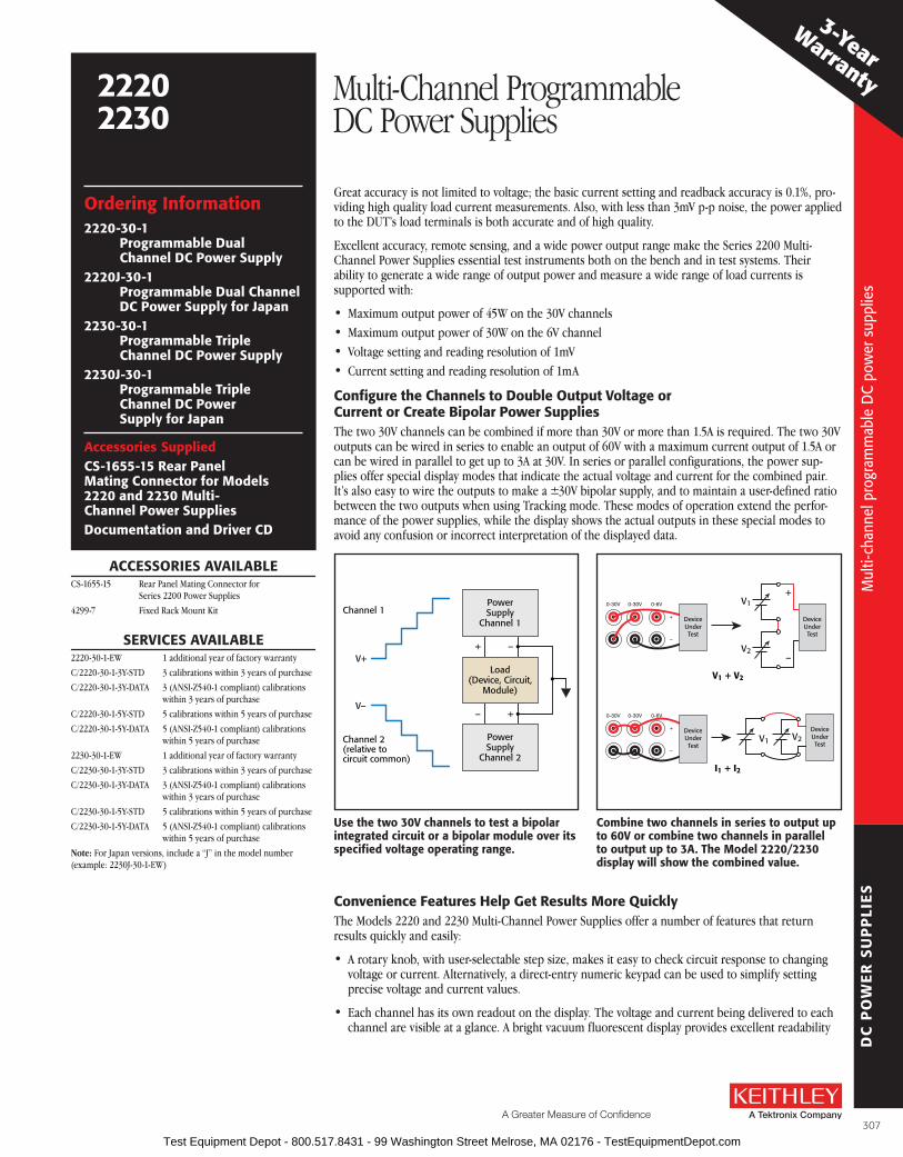
DC
PO
WE
R S
UP
PLI
ES
A Greater Measure of Confidence
22202230
Multi-Channel Programmable DC Power Supplies
Great accuracy is not limited to voltage; the basic current setting and readback accuracy is 0 .1%, pro-viding high quality load current measurements . Also, with less than 3mV p-p noise, the power applied to the DUT’s load terminals is both accurate and of high quality .
Excellent accuracy, remote sensing, and a wide power output range make the Series 2200 Multi-Channel Power Supplies essential test instruments both on the bench and in test systems . Their ability to generate a wide range of output power and measure a wide range of load currents is supported with:
• Maximum output power of 45W on the 30V channels • Maximum output power of 30W on the 6V channel• Voltage setting and reading resolution of 1mV • Current setting and reading resolution of 1mA
Configure the Channels to Double output Voltage or Current or Create bipolar Power suppliesThe two 30V channels can be combined if more than 30V or more than 1 .5A is required . The two 30V outputs can be wired in series to enable an output of 60V with a maximum current output of 1 .5A or can be wired in parallel to get up to 3A at 30V . In series or parallel configurations, the power sup-plies offer special display modes that indicate the actual voltage and current for the combined pair . It’s also easy to wire the outputs to make a ±30V bipolar supply, and to maintain a user-defined ratio between the two outputs when using Tracking mode . These modes of operation extend the perfor-mance of the power supplies, while the display shows the actual outputs in these special modes to avoid any confusion or incorrect interpretation of the displayed data .
Convenience features Help Get results More QuicklyThe Models 2220 and 2230 Multi-Channel Power Supplies offer a number of features that return results quickly and easily:
• A rotary knob, with user-selectable step size, makes it easy to check circuit response to changing voltage or current . Alternatively, a direct-entry numeric keypad can be used to simplify setting precise voltage and current values .
• Each channel has its own readout on the display . The voltage and current being delivered to each channel are visible at a glance . A bright vacuum fluorescent display provides excellent readability
Mul
ti-ch
anne
l pro
gram
mab
le D
C po
wer
sup
plie
s
ordering Information2220-30-1
Programmable Dual Channel DC Power supply
2220J-30-1 Programmable Dual Channel DC Power supply for Japan
2230-30-1 Programmable Triple Channel DC Power supply
2230J-30-1 Programmable Triple Channel DC Power supply for Japan
accessories suppliedCs-1655-15 rear Panel Mating Connector for Models 2220 and 2230 Multi-Channel Power suppliesDocumentation and Driver CD
aCCEssorIEs aVaIlablECS-1655-15 Rear Panel Mating Connector for
Series 2200 Power Supplies
4299-7 Fixed Rack Mount Kit
sErVICEs aVaIlablE2220-30-1-EW 1 additional year of factory warranty
C/2220-30-1-3Y-STD 3 calibrations within 3 years of purchase
C/2220-30-1-3Y-DATA 3 (ANSI-Z540-1 compliant) calibrations within 3 years of purchase
C/2220-30-1-5Y-STD 5 calibrations within 5 years of purchase
C/2220-30-1-5Y-DATA 5 (ANSI-Z540-1 compliant) calibrations within 5 years of purchase
2230-30-1-EW 1 additional year of factory warranty
C/2230-30-1-3Y-STD 3 calibrations within 3 years of purchase
C/2230-30-1-3Y-DATA 3 (ANSI-Z540-1 compliant) calibrations within 3 years of purchase
C/2230-30-1-5Y-STD 5 calibrations within 5 years of purchase
C/2230-30-1-5Y-DATA 5 (ANSI-Z540-1 compliant) calibrations within 5 years of purchase
Note: For Japan versions, include a “J” in the model number(example: 2230J-30-1-EW)
V+
Channel 1PowerSupply
Channel 1
Load(Device, Circuit,
Module)
PowerSupply
Channel 2
+
+
–
–
Channel 2(relative tocircuit common)
V–
use the two 30V channels to test a bipolar integrated circuit or a bipolar module over its specified voltage operating range.
0-30V 0-30V 0-6V
+
–
DeviceUnderTest
V1
V1 + V2
+
V2–
0-30V 0-30V 0-6V
+
–
DeviceUnderTest
V1
I1 + I2
V2
DeviceUnderTest
DeviceUnderTest
Combine two channels in series to output up to 60V or combine two channels in parallel to output up to 3a. The Model 2220/2230 display will show the combined value.
3-Year
Warranty
307
Mul
ti-ch
anne
l pro
gram
mab
le D
C po
wer
sup
plie
s
Test Equipment Depot - 800.517.8431 - 99 Washington Street Melrose, MA 02176 - TestEquipmentDepot.com

DC
PO
WE
R S
UP
PLI
ES
Mod
els
2220
and
223
0 sp
ecifi
catio
ns
22202230
Multi-Channel Programmable DC Power Supplies
specifications2230-30-1, 2230J-30-1 2220-30-1, 2230J-30-1
DC ouTPuT raTINGVoltage 0 to 30 V 0 to 30 V 0 to 6 V 0 to 30 V 0 to 30 V
Current 0 to 1 .5 A 0 to 1 .5 A 0 to 5 A 0 to 1 .5 A 0 to 1 .5 A
MaXIMuM PoWEr 120 W 90 W
loaD rEGulaTIoNVoltage < 0 .01% + 3 mV < 0 .01% + 3 mV < 0 .01% + 3 mV < 0 .01% + 3 mV < 0 .01% + 3 mV
Current < 0 .01% + 3 mA < 0 .01% + 3 mA < 0 .01% + 3 mA < 0 .01% + 3 mA < 0 .01% + 3 mA
lINE rEGulaTIoNVoltage < 0 .01% + 3 mV < 0 .01% + 3 mV < 0 .01% + 3 mV < 0 .01% + 3 mV < 0 .01% + 3 mV
Current < 0 .1% + 3 mA < 0 .1% + 3 mA < 0 .1% + 3 mA < 0 .1% + 3 mA < 0 .1% + 3 mA
rIPPlE aND NoIsE
Voltage (7MHz)< 1 mV rms< 3 mV p-p
< 1 mV rms< 3 mV p-p
< 1 mV rms< 3 mV p-p
< 1 mV rms< 3 mV p-p
< 1 mV rms< 3 mV p-p
Current (20MHz) < 5 mA rms < 5 mA rms < 6 mA rms < 5 mA rms < 5 mA rms
sETTING rEsoluTIoNVoltage 1 mV 1 mV 1 mV 1 mV 1 mV
Current 1 mA 1 mA 1 mA 1 mA 1 mA
sETTING aCCuraCYVoltage ± 0 .03% + 10 mV ± 0 .03% + 10 mV ± 0 .03% + 10 mV ± 0 .03% + 10 mV ± 0 .03% + 10 mV
Current ± 0 .1% + 5 mA ± 0 .1% + 5 mA ± 0 .1% + 5 mA ± 0 .1% + 5 mA ± 0 .1% + 5 mA
METEr rEsoluTIoN Voltage 1 mV 1 mV 1 mV 1 mV 1 mV
Current 1 mA 1 mA 1 mA 1 mA 1 mA
METEr aCCuraCYVoltage ± 0 .03% + 10 mV ± 0 .03% + 10 mV ± 0 .03% + 10 mV ± 0 .03% + 10 mV ± 0 .03% + 10 mV
Current ± 0 .1% + 5 mA ± 0 .1% + 5 mA ± 0 .1% + 5 mA ± 0 .1% + 5 mA ± 0 .1% + 5 mA
at a distance, at an angle, or under dim lighting conditions .
• To save time when repeating tests, instrument settings can be saved in one of 30 internal memory locations by simply pressing the Save button . To recall that setting, just push the Recall button, and choose the desired setup .
Protection for Your Device-under-TestThe Models 2220 and 2230 Multi-Channel Power Supplies include maximum voltage settings that prevent voltage from being accidentally adjusted above user-specified limits . Independent outputs allow a different limit to be specified for each output channel . With the numeric keypad, a cur-rent limit can be quickly and precisely specified before a test is started . In addition, a user- definable password allows the front panel to be locked to prevent unwanted adjustment during critical tests .
Easy Test automationEach of these power supplies includes a USB TMC-compliant device port, enabling PC control from a user-preferred programming environ-ment . For basic instrument control, data log-ging, and analysis, the Models 2220 and 2230 Multi-Channel Power Supplies can be controlled by Tektronix Edition LabVIEW SignalExpress™ from National Instruments . SignalExpress sup-ports a wide range of Tektronix bench instru-ments* and can be used to automate the entire test bench or test system . The features in each instrument are accessible from one intuitive software interface that can automate complex measurements that require multiple instruments and easily capture and analyze results—all from the user’s PC .
*For a complete listing of Tektronix instruments sup-ported by Tektronix LabVIEW Signal Express, visit www .tektronix .com/signalexpress .
aPPlICaTIoNs
series 2200 Multi-Channel Power supplies typical applications include:
• Circuit design
• Electrial engineering student labs
• Materials research
• automated test
ISOLATION VOLTAGE, OUTPUT TO CHASSIS: Any output can be floated up to 240V (DC + peak AC with AC limited to a maximum of 3Vpk-pk and a maximum frequency of 60Hz) relative to earth ground terminal .
ISOLATION VOLTAGE, OUTPUT TO OUTPUT: Any output can be floated up to 240V (DC + peak AC with AC limited to a maximum of 3Vpk-pk and a maximum frequency of 60Hz) relative to any other output terminal .
VOLTAGE TRANSIENT RESPONSE SETTLING TIME, LOAD CHANGE (typical): <150ms to within 75mV following a change from 0 .1A to 1A .
VOLTAGE TRANSIENT RESPONSE SETTLING TIME, SETTING CHANGE, RISING (typical): <150ms to within 75mV following a change from 1V to 11V into a 10W resistor (Ch . 1, 2); from 0 .4V to 4V into a 4W resistor (ch . 3 .)
VOLTAGE TRANSIENT RESPONSE SETTLING TIME, SETTING CHANGE, FALLING (typical): <150ms to within 75mV following a change from 11V to 1V into a 10W resistor (Ch . 1, 2); from 0 .4V to 4V into a 4W resistor (ch . 3 .)
DISPLAy: Vacuum fluorescent display .
MEMORy: 30 setup memories .
TRACKING AND COMBINATION MODES:Tracking Mode: Maintains the ratio on the two 30V output
channels that is present when the control is activated .Combination V1+V2 Series Mode: Deliver up to 60 V when
CH1 and CH2 are wired in series . Meter reads back com-bined voltage .
Combination I1+12 Parallel Mode: Deliver up to 3 A when CH1 and CH2 are wired in parallel . Meter reads back combined current .
REAR PANEL CONNECTIONS: USB Device Port, Type B con-nector, USBTMC compatible .
PoWEr sourCE110VAC SETTING: Standard Versions: 99 to 121V rms .
Japan (J) Versions: 90 to 110V rms .
220VAC SETTING: Standard Versions: 198 to 242V rms . Japan (J) Versions: 180 to 220V rms .
FREQUENCy: 47Hz to 63Hz .
POWER CONSUMPTION: Standard Versions: 450VA . Japan (J) Versions: 450VA .
PHYsICal CHaraCTErIsTICsPROTECTIVE BOOTS AND HANDLE INSTALLED:
Height: 105 .3mm (4 .15 in .)Width: 241 .8mm (9 .52 in .)Depth: 384 .0mm (15 .12 in .)
PROTECTIVE BOOTS AND HANDLE REMOVED:Height: 90 .7mm (3 .57 in .)Width: 217 .2mm (8 .55 in .)Depth: 361 .6mm (14 .24 in .)
NET WEIGHT: 2220-30-1: 8 .2 kg (18 lb .) 2230-30-1: 8 .5 kg (19 lb .)
SHIPPING WEIGHT: 2220-30-1: 11 kg (24 lb .) 2230-30-1: 11 kg (24 lb .)
308
Mod
els
2220
and
223
0 sp
ecifi
catio
ns
Test Equipment Depot - 800.517.8431 - 99 Washington Street Melrose, MA 02176 - TestEquipmentDepot.com

DC
PO
WE
R S
UP
PLI
ES
A Greater Measure of Confidence
ENVIroNMENTal aND safETYTemperature: Operating: 0° to +40°C .
Storage: –20° to +70°C .
Relative Humidity (non-condensing):
Operating: 5% to 95% relative humidity at up to +40°C
Storage: 5% to 95% relative humidity at up to +40°C . 5% to 60% RH above +40°C up to +70°C, non condensing .
Altitude:Operating: Up to 2000m .Storage: Up to 4000m .
Safety:European Union: Complies with European Union EMC Directive .USA: Nationally recognized testing laboratory listing UL61010-1-2004 .Canada: CAN/CSA C22 .2 No . 61010-1 2004 .
ElECTroMaGNETIC CoMPaTIbIlITYEuropean Union: Complies with European Union Low Voltage Directive .
Australia: EMC Framework, demonstrated per Emission Standard AS/NZS 2064 (Industrial, Scientific, and Medical Equipment) .
22202230
Multi-Channel Programmable DC Power Supplies
Model 2220-30-1 rear panel.
Model 2230-30-1 rear panel.
Mod
els
2220
and
223
0 sp
ecifi
catio
ns
309
Mod
els
2220
and
223
0 sp
ecifi
catio
ns
Test Equipment Depot - 800.517.8431 - 99 Washington Street Melrose, MA 02176 - TestEquipmentDepot.com
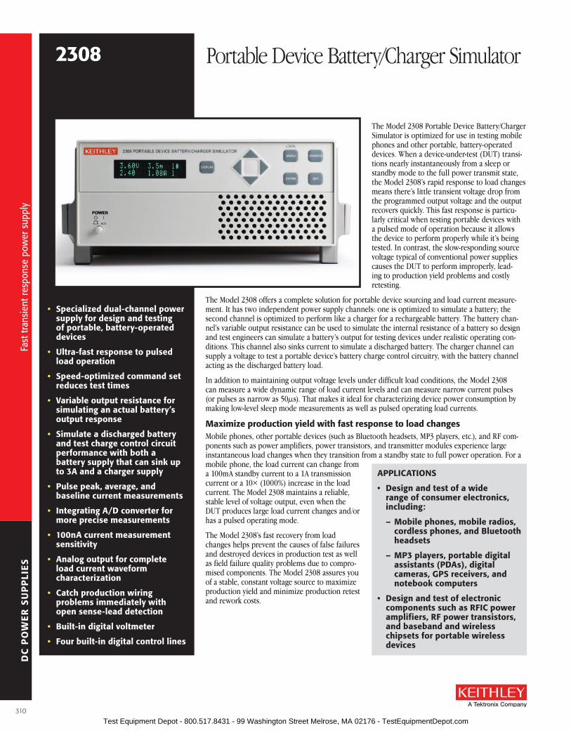
DC
PO
WE
R S
UP
PLI
ES
The Model 2308 Portable Device Battery/Charger Simulator is optimized for use in testing mobile phones and other portable, battery-operated devices . When a device-under-test (DUT) transi-tions nearly instantaneously from a sleep or standby mode to the full power transmit state, the Model 2308’s rapid response to load changes means there’s little transient voltage drop from the programmed output voltage and the output recovers quickly . This fast response is particu-larly critical when testing portable devices with a pulsed mode of operation because it allows the device to perform properly while it’s being tested . In contrast, the slow-responding source voltage typical of conventional power supplies causes the DUT to perform improperly, lead-ing to production yield problems and costly retesting .
The Model 2308 offers a complete solution for portable device sourcing and load current measure-ment . It has two independent power supply channels: one is optimized to simulate a battery; the second channel is optimized to perform like a charger for a rechargeable battery . The battery chan-nel’s variable output resistance can be used to simulate the internal resistance of a battery so design and test engineers can simulate a battery’s output for testing devices under realistic operating con-ditions . This channel also sinks current to simulate a discharged battery . The charger channel can supply a voltage to test a portable device’s battery charge control circuitry, with the battery channel acting as the discharged battery load .
In addition to maintaining output voltage levels under difficult load conditions, the Model 2308 can measure a wide dynamic range of load current levels and can measure narrow current pulses (or pulses as narrow as 50µs) . That makes it ideal for characterizing device power consumption by making low-level sleep mode measurements as well as pulsed operating load currents .
Maximize production yield with fast response to load changesMobile phones, other portable devices (such as Bluetooth headsets, MP3 players, etc .), and RF com-ponents such as power amplifiers, power transistors, and transmitter modules experience large instantaneous load changes when they transition from a standby state to full power operation . For a mobile phone, the load current can change from a 100mA standby current to a 1A transmission current or a 10× (1000%) increase in the load current . The Model 2308 maintains a reliable, stable level of voltage output, even when the DUT produces large load current changes and/or has a pulsed operating mode .
The Model 2308’s fast recovery from load changes helps prevent the causes of false failures and destroyed devices in production test as well as field failure quality problems due to compro-mised components . The Model 2308 assures you of a stable, constant voltage source to maximize production yield and minimize production retest and rework costs .
• specialized dual-channel power supply for design and testing of portable, battery-operated devices
• ultra-fast response to pulsed load operation
• speed-optimized command set reduces test times
• Variable output resistance for simulating an actual battery’s output response
• simulate a discharged battery and test charge control circuit performance with both a battery supply that can sink up to 3a and a charger supply
• Pulse peak, average, and baseline current measurements
• Integrating a/D converter for more precise measurements
• 100na current measurement sensitivity
• analog output for complete load current waveform characterization
• Catch production wiring problems immediately with open sense-lead detection
• built-in digital voltmeter
• four built-in digital control lines
2308 Portable Device Battery/Charger Simulator
aPPlICaTIoNs
• Design and test of a wide range of consumer electronics, including:
– Mobile phones, mobile radios, cordless phones, and bluetooth headsets
– MP3 players, portable digital assistants (PDas), digital cameras, GPs receivers, and notebook computers
• Design and test of electronic components such as rfIC power amplifiers, rf power transistors, and baseband and wireless chipsets for portable wireless devices
Fast
tran
sien
t res
pons
e po
wer
sup
ply
Fast
tran
sien
t res
pons
e po
wer
sup
ply
310 Test Equipment Depot - 800.517.8431 - 99 Washington Street Melrose, MA 02176 - TestEquipmentDepot.com

DC
PO
WE
R S
UP
PLI
ES
A Greater Measure of Confidence
I(500mA/
div)
V(500mV/
div)
Time 100µs/div
I(500mA/
div)
V(500mV/
div)
Time 100µs/div
Conventional Power Supply Model 2308
reduce test costs and increase throughput with high speed command structureTo minimize production test times while still giving you all the information you need to char-acterize your devices fully, the Model 2308 is designed with a command structure optimized for speed, with voltage step times as short as 6ms and DC load current measurements in just 22ms . Commands that combine range changing and current measurement let you acquire the command, make the measurement, and transfer the data in as little as 30ms . In addition, special operating modes, such as the pulse current step
mode, allow taking a number of measurements on a complex load current waveform with a single command .
Characterize load currents for power consumption verificationCharacterizing the battery life of portable devices demands the ability to measure complex current waveforms over a wide dynamic range . The Model 2308 offers a far broader range of capabilities than conventional power supplies for measuring low current levels, peak pulse current levels, long-period load current waveforms, and multi-level current waveforms . A choice of four
ordering Information2308 Portable Device battery/
Charger simulator
accessories suppliedCD with documentation, output connectors mating terminal (part no. Cs-846)
Model 2308 vs. Conventional Power suppliesLarge load changes will cause a large instan-taneous drop in a conventional power sup-ply’s voltage output . If the supply’s recovery time is long, the DUT will turn off when the supply voltage falls below the DUT’s low battery turn-off threshold—produc-ing a false failure . Even if the DUT does not turn off, the drop-off in input power prevents the output (RF or a power pulse) from meeting its specification—a specifica-tion failure . Furthermore, the conventional power supply may have an excessively large overshoot when the DUT’s load current transitions from its operating load back to its standby load . The magnitude of the tran-sient overshoot voltage could even be large enough to exceed the maximum safe input voltage, either rendering the device inoper-able or damaging some components—a device failure or a field failure.
Your DC source leads are a transmission line when your portable device operates in a narrow pulsed mode.Under pulsed operating conditions, your load circuit is an L-C-R network and that load impe-dance can cause problems for your power supply . Keithley’s fast transient power supplies are designed to maintain a stable voltage under difficult, narrow pulse, loading conditions and to maintain the output voltage, even with long lengths of wire between the power supply and the DUT . The design of your DC sourcing test circuit requires just as much effort as your AC or RF test circuits . Using a fast transient response, battery simulating power supply needs to be a key part of your DC test circuit design .
Power Source
Sense Leads
Source LeadsLoad Current
DUT
dIdt
The DC source leads become a transmission line during dynamic load swings.
Compare the response of a conventional power supply (left) with the response of a Model 2308 (right) when both are powering a device operating on the EDGE mobile phone standard. Note how the conventional power supply distorts the load current and cannot maintain a stable source voltage, which in turn distorts the rf output signal.
2308 Portable Device Battery/Charger Simulator
aCCEssorIEs aVaIlablE2306-DISP Remote DisplayCS-846 Mating Output Connector
SC-182 Low Inductance Coaxial Cable
IEEE-488 INTErfaCE CoNTrollEr CarDsKPCI-488LPA IEEE-488 .2 Interface Board for the PCI busKUSB-488B IEEE-488 .2 USB-to-GPIB Interface Adapter for USB
Port with built-in 2m (6 .6ft) cable
IEEE-488 INTErfaCE CablEs7007-05 Double Shielded Premium IEEE-488 Cable, 0 .5m (1 .6ft)7007-1 Double Shielded Premium IEEE-488 Cable, 1m (3 .2ft)7007-2 Double Shielded Premium IEEE-488 Cable, 2m (6 .5ft)7007-3 Double Shielded Premium IEEE-488 Cable, 3m (10ft)7007-4 Double Shielded Premium IEEE-488 Cable, 4m (13ft)
raCK MouNT KITs4288-1 Single Fixed Rack Mount Kit4288-2 Dual Fixed Rack Mount Kit
sErVICEs aVaIlablE2308-3Y-EW 1-Year Factory Warranty Extended to 3 Years for
the Model 23082308-3Y-17025 3 (ISO-17025 Accredited) Calibrations within 3
Years of Purchase2308-3Y-DATA 3 (ANSI-Z540-1 Compliant) Calibrations within 3
Years of Purchase
Fast
tran
sien
t res
pons
e po
wer
sup
ply
Fast
tran
sien
t res
pons
e po
wer
sup
ply
311 Test Equipment Depot - 800.517.8431 - 99 Washington Street Melrose, MA 02176 - TestEquipmentDepot.com

DC
PO
WE
R S
UP
PLI
ES
ranges (5mA, 50mA, 500mA, and 5A) allows measuring load currents with exceptional resolution and accuracy .
Measure sleep and standby currents with the accuracy of integrating a/D technologyThe Model 2308 is designed for fast and accurate measurements of devices in low power modes such as the sleep, hibernate, or standby state . It can resolve currents down to 100nA and measure them with 0 .2% accuracy . The Model 2308 uses an integrating A/D converter that continuously acquires the signal rather than capturing discrete samples; this provides a more accurate measurement than other A/D techniques . In addition, the averaging effect built into integrating A/D converters reduces noise and delivers highly stable current readings . You can measure low and high currents at the same speed with no degradation in accuracy, so the Model 2308 is equally well-suited for the test line and the design lab .
Measure load currents from pulsed-output devicesDevices like GSM-, EDGE-, WLAN-, and WiMAX-based mobile phones gen-erate pulsed outputs . Determining their total power consumption requires measuring both the baseline current and the peak of the pulsed load cur-rent . The Model 2308 can capture peak currents of pulses as short as 50µs and as long as 833ms . Programmable trigger levels allow controlled cap-ture of the pulse, then the Model 2308’s programmable measurement delay and acquisition times make it easy to avoid rising edge transients so the pulse peak can be measured accurately . The instrument can also measure the pulse baseline current and the pulse average load current .
A long integration current mode supports measuring pulse trains with periods longer than 850ms . In this mode, the Model 2308 can measure average current on a load current waveform with a period from 850ms to 60 seconds .
High current level
Trigger level
HighTime
Low current level
Low Time
Average Time(out to 60s with long integration)
The Model 2308 can measure peak pulse currents, average currents, and baseline currents.
Take multiple measurements on start-up sequences or on current levels at different voltage operating levelsNeed to analyze a device’s circuitry during the power-up phase as it transi-tions from a sleep mode or an off-state? The Model 2308’s pulse step cur-rent function has the speed needed to measure the load current start-up levels in a single device start-up so that the measurements can be per-formed in production without an increase in test time .
The pulse step current function also offers a fast way to determine load currents of different operating states . For example, as source voltage levels are varied over a device’s operating range, the corresponding operating current levels can be measured without executing multiple commands for
a significant time-savings when testing integrated circuits over their allow-able range of Vcc levels .
Capture the complete load current waveformTwo built-in analog outputs help designers of device’s verify design perfor-mance and ensure its current draw conforms to design specifications with-out the need to connect any sensing circuitry in the power supply circuit . Once these outputs are connected to an oscilloscope or a data acquisition module, the load current waveform can be displayed or digitized and ana-lyzed in a computer . When the Model 2308 is connected to a data acquisi-tion module, the data acquisition module can sample the waveform at any sampling rate to create a record of any length desired .
Test under realistic conditions with true battery simulationWhen a portable battery-operated device transitions from one load current level to another, the battery voltage supplying the current will drop by the product of the change in current and the battery’s internal resistance . During the load current pulse, the device must operate with a voltage reduced by the battery’s internal resistance . The Model 2308 allows simu-lating this resistance so its output is almost identical to a battery’s output, allowing design or production test engineers to test devices or components under realistic conditions . This patented1 technique permits the output resistance to be programmed between 0W and 1W with 10mW resolution . You can also decrease the voltage and increase the output resistance while the output is on to simulate the discharge of the battery .
I(1A/div)
V(50mV/
div)
Time 100µs/div Time 100µs/div
Lithium Ion Battery with130mΩ Internal Resistance
Model 2308 with Output ResistanceProgrammed to 130mΩ
The Model 2308’s programmable output resistance (right) allows it to simulate the output of a real battery (left), a capability conventional power supplies do not have. The 2308 output is identical to the battery’s response.
1 . U .S . Patent Number 6,204,647 B1
2308 Portable Device Battery/Charger Simulator
I1
I2
I3
I4
I5
I6
I7I8
Trigger Levels
Load Currents
With a single command, the Model 2308’s high speed pulse step current function can quickly capture varying load current levels to speed test throughput.
Fast
tran
sien
t res
pons
e po
wer
sup
ply
Fast
tran
sien
t res
pons
e po
wer
sup
ply
312 Test Equipment Depot - 800.517.8431 - 99 Washington Street Melrose, MA 02176 - TestEquipmentDepot.com

DC
PO
WE
R S
UP
PLI
ES
A Greater Measure of Confidence
Test a device’s charge control circuitryBoth channels of the Model 2308 sink up to 3A of current continuously . Therefore, the battery channel can act like a discharged re-chargeable battery . The charger channel can supply a charging voltage for use in testing the operation of the DUT’s charging control circuitry . Because the charger channel can also act as an electronic load, the battery channel can operate the device and the charger channel can act as a load to test a bat-tery capacity monitor or some other device function that requires a load .
R
+–
Battery Channel Charger Channel
Vbattery
Vcharger > Vbattery
BatteryTerminals
ChargerTerminals
+
–
II
for charger control circuit testing, the Model 2308’s battery channel can sink current to simulate a discharged battery while the charger channel simulates a charger. one instrument provides high versatility for portable device testing.
reduce testing errors and retesting costs with remote sense lead monitoringRemote sensing capabilities let the Model 2308 ensure the voltage pro-grammed is what is actually applied to the load . As DUTs are continuously inserted and removed from test fixtures, the instrument ensures this pro-grammed voltage is maintained with an open sense lead detection moni-tor—any break in a sense lead connection is detected immediately . The open sense lead detection monitor eliminates the possibility that numerous devices could be tested or calibrated at an incorrect voltage .
save with multiple instruments in one package – two power supplies, a DVM, digital controls, and a remote displayThe Model 2308 saves on both instrumentation costs and rack space by packing two independent power supply channels in one compact, 2U half-rack enclosure, along with additional capabilities power supplies rarely offer . For example, the built-in DC digital voltmeter can measure voltages in the DUT circuitry from -5VDC to +30VDC . The DVM and the battery channel voltage source can operate simultaneously . For many applications, the Model 2308 can eliminate the need for a separate DMM .
The digital outputs the Model 2308 provides can sink up to 100mA to con-trol relays . External relays can be powered either by the internal 5V source or an external source with a maximum voltage of 24V . For applications that require only a few digital control lines, the Model 2308 eliminates the need for an additional control module .
Need to reduce your test system size or want more sys-tem organization flexibility? Then mount the Model 2308 in the back of a test rack or near the test fixture—mount-ing the instrument in the test rack is unnecessary . The Model 2308’s tiny (4 .6 in . × 2 .7 in .) remote display can be mounted anywhere for easy viewing of the outputs of both channels . If the Model 2308 is inaccessible, you can control it from the remote display because it has all the front panel pushbuttons that are on the instrument itself .
reduce test system problems with low impedance cableKeithley’s SC-182 Low Inductance Coaxial Cable is designed to minimize the impedance and reduce the susceptibility to external EMI in your DC source-DUT circuit . This cable’s characteristic impedance is nominally 15W with a low 42nH/ft of inductance and a low 182pF/ft of capacitance . In con-trast, a typical coaxial cable has 50W or 75W characteristic impedance and twisted-wire pairs have at least 80W of characteristic impedance .
DVM
+
–
+
–
VOUT
VIN
–5V to +30V DC
Rsense
+
–
The Model 2308’s charger channel contains a built-in DVM, eliminating the need for a separate instrument in many test systems.
The Model 2306-DIsP display can be mounted for easy viewing when the instrument itself must be mounted in an inaccessible location.
2308 Portable Device Battery/Charger Simulator
Model 2308 rear panel
Fast
tran
sien
t res
pons
e po
wer
sup
ply
Fast
tran
sien
t res
pons
e po
wer
sup
ply
313 Test Equipment Depot - 800.517.8431 - 99 Washington Street Melrose, MA 02176 - TestEquipmentDepot.com

DC
PO
WE
R S
UP
PLI
ES
ouTPuT #1 (battery Channel):
DC VolTaGE ouTPuT (1 Year, 23°C ± 5°C)OUTPUT VOLTAGE: 0 to +15VDC .
OUTPUT ACCURACy: (0 .05% + 3mV) .
PROGRAMMING RESOLUTION: 1mV .
READBACK ACCURACy1: ±(0 .05% + 3mV) .
READBACK RESOLUTION: 1mV .
OUTPUT VOLTAGE SETTLING TIME: 5ms to within stated accuracy .
LOAD REGULATION: 0 .01% + 2mV .
LINE REGULATION: 0 .5mV .
STABILITy2: 0 .01% + 0 .5mV .
MEASUREMENT TIME CHOICES: 0 .002 to 10PLC3, in 0 .002PLC steps .
AVERAGE READINGS: 1 to 10 .
TRANSIENT RESPONSE: High Bandwidth Low Bandwidth Transient Recovery Time4 <35 µs5 <50 µs5
Transient Voltage Drop <90 mV5 <180 mV5
REMOTE SENSE: 1V max . drop in each lead . Add 2mV to the voltage load regulation specifica-tion for each 1V change in the negative output lead due to load current change . Remote sense required . Integrity of connection continually monitored . If compromised, output will turn off automatically once settable window (±0 to ±8 volts) around normal voltage exceeded .
VARIABLE OUTPUT IMPEDANCE: Range: 0 to 1 .00W in 0 .01W steps . Value can be changed with output on .
NoTEs1 . At PLC (Power Line Cycle) = 1 .2 . Following 15 minute warm-up, the change in output over 8 hours under ambient temperature, constant load,
and line operating conditions .3 . PLC = Power Line Cycle . 1PLC = 16 .7ms for 60Hz operation, 20ms for 50Hz operation .4 . Recovery to within 20mV of previous level .5 . Remote sense, at terminals 1 and 6, with 4 .5m (15 feet) 16 AWG (1 .31mm2) twisted pair, with 1 .5A load change,
(0 .15A to 1 .65A) resistive load only, typical .
DC CurrENT (1 Year, 23°C ± 5°C)
CoNTINuous aVEraGE ouTPuT CurrENTCHANNEL #2 (CHARGER) OFF: I = 50W/(Vset channel 1 + 6V); 5A max .1
CHANNEL #2 (CHARGER) ON: I = (50W – power consumed by channel #2)/(Vset channel 1 + 6V); 5A max .1
The power consumed by channel #2 is calculated as: Channel #2 Sourcing Current: Power consumed = (Vset channel 2 + 6V) × (current supplied) . Channel #2 Sinking Current: Power consumed = 5V × (sink current) .
CoNTINuous aVEraGE sINK CurrENTCHANNEL #2 (CHARGER) OFF: 0–5V: 3A max . 5–15V: Derate 0 .2A per volt above 5V . Compliance setting controls sinking .
CHANNEL #2 (CHARGER) ON: Available Current = (50W – Power consumed by channel #2)/5V; 3A max . (0–5V) . Derate 0 .2A per volt above 5V .
DC CurrENT (1 Year, 23°C ± 5°C) (continued)SOURCE COMPLIANCE ACCURACy: ±(0 .16% + 5mA) .2
PROGRAMMED SOURCE COMPLIANCE RESOLUTION: ±1 .25mA .
READBACK ACCURACy: 5A Range: ±(0 .2% + 200µA) . 500mA Range: ±(0 .2% + 100µA) . 50 mA Range: ±(0 .2% + 5µA) . 5mA Range: ±(0 .2% + 2µA) .
READBACK RESOLUTION: 5A Range: 100µA . 500mA Range: 10µA . 50 mA Range: 1µA . 5mA Range: 0 .1µA .LOAD REGULATION: 0 .01% + 1mA .LINE REGULATION: 0 .5mA .STABILITy: 0 .01% + 50µA .MEASUREMENT TIME CHOICES: 0 .002 to 10 PLC3, in 0 .002PLC steps .AVERAGE READINGS: 1 to 10 .
NoTEs1 . Peak current can be a max . of 5A provided the average current is within the stated limits and terminals 1 and 6
are used .2 . Minimum current in constant current mode is 6mA .3 . PLC = Power Line Cycle . 1PLC = 16 .7ms for 60Hz operation, 20ms for 50Hz operation .
PulsE CurrENT MEasurEMENT oPEraTIoNTRIGGER LEVEL: 5A Range: 0A to 5A, in 5mA steps . 500mA Range: 0mA to 500mA, in 0 .5mA or 500µA steps . 50mA Range: 0mA to 50mA, in 0 .05mA or 50µA steps . 5mA Range: 0mA to 5mA, in 0 .005mA or 5µA steps .TRIGGER DELAy: 0 to 100ms, in 10µs steps .INTERNAL TRIGGER DELAy: 10µs . HIGH/LOW/AVERAGE MODE: Measurement Aperture Settings: 33 .3µs to 833ms, in 33 .3µs
steps . Average Readings: 1 to 100 .PULSE CURRENT MEASUREMENT ACCURACy1 (1 year, 23°C ± 5°C):
apertureaccuracy ±(% reading + offset)
5a range 500ma range 50ma range 5ma range<100 µs 0 .3% + 2 mA 0 .3% + 1 mA 0 .3% + 700 µA 0 .3% + 200 µA
100 µs – 200 µs 0 .3% + 2 mA 0 .3% + 1 mA 0 .3% + 700 µA 0 .3% + 100 µA200 µs – 500 µs 0 .3% + 2 mA 0 .3% + 1 mA 0 .3% + 700 µA 0 .3% + 100 µA500 µs – <1 PLC 0 .3% + 900 µA 0 .3% + 900 µA 0 .3% + 500 µA 0 .3% + 90 µA
1 PLC2 0 .3% + 900 µA 0 .3% + 900 µA 0 .3% + 200 µA 0 .3% + 90 µA>1 PLC 0 .3% + 900 µA 0 .3% + 900 µA 0 .3% + 200 µA 0 .3% + 90 µA
NoTEs1 . Based on settled signal: 100µs pulse trigger delay .2 . Also applies to other apertures that are integer multiples of 1PLC .
bursT MoDE CurrENT MEasurEMENTMEASUREMENT APERTURE: 33 .3µs to 833ms, in 33 .3µs steps .CONVERSION RATE: 4100/second, typical .1
INTERNAL TRIGGER DELAy: 10µs .NUMBER OF SAMPLES: 1 to 5000 .TRANSFER SAMPLES ACROSS IEEE BUS IN BINARy MODE2: 4400 readings/s, typical (4 bytes
per reading) .
NoTEs1 . At 33 .3µs aperture .2 . Display off, Message Exchange Protocol (MEP) off, auto zero off .
loNG INTEGraTIoN MoDE CurrENT MEasurEMENTMEASUREMENT TIME, 60Hz (50Hz): 850ms (840ms) to 60 seconds in 1ms steps .
aNaloG ouTPuT5A/500mA OUTPUT: 1V/A ± 25mA (typical) .50mA/5mA OUTPUT: 1V/10mA ± 0 .25mA (typical) .INTERNAL IMPEDANCE: 1000W (nominal) .
2308 Portable Device Battery/Charger Simulator
Mod
el 2
308
spec
ifica
tions
Mod
el 2
308
spec
ifica
tions
314 Test Equipment Depot - 800.517.8431 - 99 Washington Street Melrose, MA 02176 - TestEquipmentDepot.com

DC
PO
WE
R S
UP
PLI
ES
A Greater Measure of Confidence
ouTPuT #2 (Charger Channel)
DC VolTaGE ouTPuT (1 Year, 23°C ± 5°C)OUTPUT VOLTAGE: 0 to +15VDC .
OUTPUT ACCURACy: ±(0 .05% + 10mV) .
PROGRAMMING RESOLUTION: 10mV .
READBACK ACCURACy1: ±(0 .05% + 3mV) .
READBACK RESOLUTION: 1mV .
OUTPUT VOLTAGE SETTLING TIME: 5ms to within stated accuracy .
LOAD REGULATION: 0 .01% + 2mV .
LINE REGULATION: 0 .5mV .
STABILITy2: 0 .01% + 0 .5mV .
MEASUREMENT TIME CHOICES: 0 .002 to 10 PLC3, in 0 .002 PLC steps .
AVERAGE READINGS: 1 to 10 .
TRANSIENT RESPONSE: High Bandwidth Low Bandwidth Transient Recovery Time4 <50 µs5 <60 µs5 Transient Voltage Drop <180 mV5 <500 mV5
REMOTE SENSE: 1V max . drop in each lead . Add 2mV to the voltage load regulation specifica-tion for each 1V change in the negative output lead due to load current change . Remote sense required . Integrity of connection continually monitored . If compromised, output will turn off automatically once settable window (±0 to ±8 volts) around normal voltage exceeded .
NoTEs1 . At 1PLC .2 . Following 15 minute warm-up, the change in output over 8 hours under ambient temperature, constant load,
and line operating conditions .3 . PLC = Power Line Cycle . 1PLC = 16 .7ms for 60Hz operation, 20ms for 50Hz operation .4 . Recovery to within 20mV of previous level .5 . Remote sense, with 4 .5m (15 feet) of 16 AWG (1 .31mm2) wire, 1 .5A load change (0 .15A to 1 .65A), resistive
load only .
DC CurrENT (1 YEar, 23°C ± 5°C)
CoNTINuous aVEraGE ouTPuT CurrENTCHANNEL #1 (BATTERy) OFF: I = 50W/(Vset channel 2 + 6V); 5A max .1
CHANNEL #1 (BATTERy) ON: I = (50W – power consumed by channel #1)/(Vset channel 2 + 6V); 5A max .1
The power consumed by channel #1 is calculated as: Channel #1 Sourcing Current: Power consumed = (Vset channel 1 + 6V) × (current supplied) . Channel #1 Sinking Current: Power consumed = 5V × (sink current) .
CoNTINuous aVEraGE sINK CurrENTCHANNEL #1 (BATTERy) OFF: 0–5V: 3A max . 5–15V: Derate 0 .2A per volt above 5V . Compliance setting controls sinking .
CHANNEL #1 (BATTERy) ON: Available Current = (50W – Power consumed by channel #1)/5V; 3A max . (0–5V)1 . Derate 0 .2A per volt above 5V .
DC CurrENT (1 YEar, 23°C ± 5°C) (continued)SOURCE COMPLIANCE ACCURACy: ±(0 .16% + 5mA) .2
PROGRAMMED SOURCE COMPLIANCE RESOLUTION: ±1 .25mA .
READBACK ACCURACy: 5A Range: ±(0 .2% + 200µA) . 5mA Range: ±(0 .2% + 2µA) .
READBACK RESOLUTION: 5A Range: 100µA . 5mA Range: 0 .1µA .
LOAD REGULATION: 0 .01% + 1mA .
LINE REGULATION: 0 .5mA .
STABILITy: 0 .01% + 50µA .
MEASUREMENT TIME CHOICES: 0 .002 to 10 PLC3, in 0 .002 PLC steps .
AVERAGE READINGS: 1 to 10 .
NoTEs1 . Peak current can be a max . of 5A provided the average current is within the stated limits .2 . Minimum current in constant current mode is 6mA .3 . PLC = Power Line Cycle . 1PLC = 16 .7ms for 60Hz operation, 20ms for 50Hz operation .
PulsE CurrENT MEasurEMENT oPEraTIoNTRIGGER LEVEL: 5A Range: 5mA to 5A, in 5mA steps .
TRIGGER DELAy: 0 to 100ms, in 10µs steps .
INTERNAL TRIGGER DELAy: 10µs .
HIGH/LOW/AVERAGE MODE: Measurement Aperture Settings: 33 .3µs to 833ms, in 33 .3µs steps . Average Readings: 1 to 100 .
PULSE CURRENT MEASUREMENT ACCURACy1 (1 year, 23°C ± 5°C):
apertureaccuracy ±(% reading + offset)
5a range<100 µs 0 .3% + 2 mA
100 µs – 200 µs 0 .3% + 2 mA200 µs – 500 µs 0 .3% + 2 mA500 µs – <1 PLC 0 .3% + 900 µA
1 PLC2 0 .3% + 900 µA>1 PLC 0 .3% + 900 µA
NoTEs1 . Based on settled signal: 100µs pulse trigger delay .2 . Also applies to other apertures that are integer multiples of 1PLC .
bursT MoDE CurrENT MEasurEMENTMEASUREMENT APERTURE: 33 .3µs to 833ms, in 33 .3µs steps .
CONVERSION RATE: 4100/second, typical .1
INTERNAL TRIGGER DELAy: 10µs .
NUMBER OF SAMPLES: 1 to 5000 .
TRANSFER SAMPLES ACROSS IEEE BUS IN BINARy MODE2: 4400 readings/s, typical (4 bytes per reading) .
NoTEs1 . At 33 .3µs aperture .2 . Display off, Message Exchange Protocol (MEP) off, auto zero off .
2308 Portable Device Battery/Charger SimulatorM
odel
230
8 sp
ecifi
catio
ns
Mod
el 2
308
spec
ifica
tions
315 Test Equipment Depot - 800.517.8431 - 99 Washington Street Melrose, MA 02176 - TestEquipmentDepot.com

DC
PO
WE
R S
UP
PLI
ES
GENEralISOLATION (LOW–EARTH): 22VDC max . Do not exceed 60VDC between any two terminals
of either connector .
PROGRAMMING: IEEE-488 .2 (SCPI) .
USER-DEFINABLE POWER-UP STATES: 4 .
REAR PANEL CONNECTORS: Two 8-position quick disconnect terminal blocks .
TEMPERATURE COEFFICIENT (outside 23°C ±5°C): Derate accuracy specification by (0 .1 × specification)/°C .
OPERATING TEMPERATURE: 0° to 50°C (derate to 70%) . 0° to 35°C (Full power) .
STORAGE TEMPERATURE: –20° to 70°C .
HUMIDITy: <80% @ 35°C non-condensing .
DISPLAy TyPE: 2-line × 16 character VFD .
REMOTE DISPLAy/KEyPAD OPTION: Disables standard front panel .
DIMENSIONS: 89mm high × 213mm wide × 411mm deep (3½ in × 83⁄8 in × 163⁄16 in) .
NET WEIGHT: 3 .2kg (7 .1 lbs) .
SHIPPING WEIGHT: 5 .4kg (12 lbs) .
INPUT POWER: 100–120VAC/220–240VAC, 50 or 60Hz (auto detected at power-up) .
POWER CONSUMPTION: 150VA max .
EMC: Conforms with European Union Directive 2004/108/EC .
SAFETy: Conforms with European Union Directive 2006/95/EC, EN 61010-1 .
AC LINE LEAKAGE CURRENT: 450µA @ 110VAC, typ .; 600µA @ 220V, typical .
RELAy CONTROL PORT: 4-channel, each capable of 100mA sink, 24V max . Total port sink capacity (all 4 combined) is 250mA max . Accepts DB-9 male plug . A source of +5VDC ref-erenced to output common is also provided on the port to power external 5V relays .
2308 Portable Device Battery/Charger Simulator
loNG INTEGraTIoN MoDE CurrENT MEasurEMENTMEASUREMENT TIME, 60Hz (50Hz): 850ms (840ms) to 60 seconds in 1ms steps .
DIGITal VolTMETEr INPuT (1 Year, 23°C ± 5°C)INPUT VOLTAGE RANGE: –5 to +30VDC .
INPUT IMPEDANCE: 2MW typical .
MAX. VOLTAGE (either input terminal) WITH RESPECT TO OUTPUT LOW: –5V, +30V .
READING ACCURACy: ±(0 .05% + 3mV) .
READING RESOLUTION: 1mV .
CONNECTOR: HI and LO input pair part of Output #2’s terminal block .
MEASUREMENT TIME CHOICES: 0 .002 to 10 PLC1, in 0 .002 PLC steps .
AVERAGE READINGS: 1 to 10 .
NoTEs1 . PLC = 1 .00 Power Line Cycle .
operating speeds (Typical)
Channel 1 Channel 2Voltage Step Time 1 6 ms 7 msDC Current Reading Time 1, 2, 3 22 ms 22 msDC Current Range Change and Read Time 1, 2, 3 27 msDigital Voltmeter 1, 2, 3 22 ms
NoTEs1 . Display off, message exchange protocal (MEP) off, auto zero off .2 . PLC = 1 power line cycle .3 . Includes measurement and binary data transfer out of the GPIB port .
ouTPuT #2 (Charger Channel) (continued)
Mod
el 2
308
spec
ifica
tions
Mod
el 2
308
spec
ifica
tions
316 Test Equipment Depot - 800.517.8431 - 99 Washington Street Melrose, MA 02176 - TestEquipmentDepot.com

DC
PO
WE
R S
UP
PLI
ES
A Greater Measure of Confidence
The single-channel Model 2302 Battery Simulator and dual-channel Model 2306 Battery/Charger Simulator were designed specifically for development and test applications of portable, battery-operated products, such as cellular and cordless telephones, mobile radios, and pagers . These precision power supplies have ultrafast transient response so they can have output characteristics identical to actual batteries . These supplies employ a unique variable output resistance so the voltage output can emulate a battery’s response (U .S . Patent No . 6,204,647) . They provide stable voltage outputs, even when a device-under-test (DUT) makes the rapid tran-sition from the standby (low current) state to the RF transmission (high current) state . In addition, they can monitor DUT power consumption by meas uring both DC currents and pulse load cur-rents . The Model 2302’s and the Model 2306’s battery-simulator channel can be programmed
to operate like a discharged rechargeable battery, sinking current from a separate charger or from the Model 2306’s charger- simulator channel .
Maximize Test Throughput with accurate battery simulationThe battery-output channels of the Models 2302 and 2306 are designed to simulate the output response of a battery . This capability, combined with their fast transient response, makes it possible to power the device during testing in exactly the same way as a battery will power the device during actual use. The output resistance of the Model 2302’s and the Model 2306’s battery chan-nel can be programmed (with 10mW resolution) over the range from 0W to 1W so that the out-put resistance can be set to the same level as the output resistance of the battery that powers the device . See Figure 1 .
Portable wireless devices make great demands on their battery power sources . The battery must source load currents that can jump virtually instantaneously from a standby current level (100–300mA) to a full-power RF transmission current level (1–3A) . In other words, the load current on the battery can increase rapidly by a factor of 700–1000% . As a result, the battery voltage drops by an amount equal to the value of the current change multiplied by the battery’s internal resistance . The Models 2302 and 2306 power supplies enable test systems to duplicate this voltage drop by programming their output resistance to be equivalent to that of the battery that will power the device . This allows wire-less device manufacturers to test their products under the same power conditions that they will encounter in actual use . (See Figure 2 .)
• ultrafast response to transient load currents
• Choice of single- or dual-channel supplies
• optimized for development and testing of battery-powered devices
• Variable output resistance for simulating battery response (u.s. Patent No. 6,204,647)
• Pulse peak, average, and baseline current measurements
• 100na DC current sensitivity
• Current step measure function
• sink up to 3a
• open sense lead detection
• built-in digital voltmeter
figure 1. simplified schematic of a battery and the 2302/2306.
RINT
V+–
V+
–
Battery 2302/2306
ROUT
aCCEssorIEs aVaIlablE2306-DISP Remote Display
CS-846 Mating Output Connector
CablEs7007-1 Shielded IEEE-488 Cable, 1m (3 .3 ft)
7007-2 Shielded IEEE-488 Cable, 2m (6 .6 ft)
SC-182 Low-Inductance Coaxial Cable (42nH/ft)
raCK MouNT KITs4288-1 Single Fixed Rack Mount Kit
4288-2 Dual Fixed Rack Mount Kit
IEEE-488 INTErfaCEsKPCI-488LPA IEEE-488 Interface/Controller for the PCI Bus
KUSB-488B IEEE-488 USB-to-GPIB Interface Adapter
sErVICEs aVaIlablE2302-3Y-EW 1-year factory warranty extended to 3 years
from date of shipment
2306-PJ-3Y-EW 1-year factory warranty extended to 3 years from date of shipment
2306-3Y-EW 1-year factory warranty extended to 3 years from date of shipment
2306-PJ-3Y-EW 1-year factory warranty extended to 3 years from date of shipment
C/2302-3Y-ISO 3 (ISO-17025 accredited) calibrations within 3 years of purchase for Model 2302, 2302-PJ
C/2306-3Y-ISO 3 (ISO-17025 accredited) calibrations within 3 years of purchase for Models 2306, 2306-PJ
2302, 2302-PJ,2306, 2306-PJ
Battery SimulatorBattery/Charger Simulators
Fast
tran
sien
t res
pons
e po
wer
sup
plie
s
Fast
tran
sien
t res
pons
e po
wer
sup
plie
s
317 Test Equipment Depot - 800.517.8431 - 99 Washington Street Melrose, MA 02176 - TestEquipmentDepot.com

DC
PO
WE
R S
UP
PLI
ES
In response to large load changes, the Model 2302 and the battery channel of the Model 2306 have transient voltage droops of less than 100mV and transient recovery times of less than 60µs, even when the test leads between the power supply and the DUT are long . This fast transient response, combined with the supplies’ vari-able output resistance, allows engineers to test their portable products under the most realistic operating conditions and eliminate false failures due to conventional power supplies with slow response times . (See the sidebar titled “Con-ventional Power Supplies and Wireless Device Testing .”) These supplies also eliminate the large stabilizing capacitors needed at the DUT to com-pensate for the large droop that occurs when testing with conventional power supplies . By varying the output resistance, which can be done while the output is turned on, test engineers can simulate the operation of different battery types, as well as batteries nearing the end of their useful lives .
The Models 2302 and 2306 ensure maximum production throughput when testing portable
devices by minimizing false failures, minimizing the number of test setups by performing mul-tiple tests with the same power supply, and mini-mizing test fixture complexity by eliminating the need for voltage-stabilizing capacitors .
Measure load Currents for Power Consumption Verification or analysisAs manufacturers of portable devices strive to extend their products’ battery life, measuring load currents accurately has become increasingly essential in both design and production test in order to ensure the product meets its demanding specifications . Comprehensive testing of these devices requires measuring peak currents, aver-age currents, and baseline currents in various operation modes . When testing these devices, these measurements are complicated by the pul-sating nature of load currents, such as the trans-mit and receive load currents of digital cellular phones . The Models 2302 and 2306 can measure the peak and average currents of pulses as short as 60µs and as long as 833ms . (See Figure 3 .)
ordering Information2302 battery simulator2302-PJ battery simulator
with 500ma range2306 Dual-Channel battery/
Charger simulator2306-PJ Dual-Channel battery/
Charger simulator with 500ma range
accessories supplieduser and service manuals, Cs-846 output connectors mating terminal
Conventional Power supplies and Wireless Device TestingDuring production testing, supplying power to a device that undergoes large, instantaneous load current changes can be extremely difficult . Changes like this force a conventional power supply’s output volt-age to fall instantaneously . When the power supply’s control circuitry senses the error condition (the difference in voltage between the programmed level and the actual level), it attempts to correct or restore the voltage to the programmed level . During this time, the voltage will fall or droop substantially, with the amount of the droop depending on the size of the load current change . The recovery time depends on the transient response of the power supply’s control loop . Conventional power supplies have transient voltage drops of >1V when confronted with load current changes of up to 1000%, and take up to a millisecond to recover to the programmed voltage . For portable devices such as cellular phones that operate at full power for only short intervals, the full power event is over before the conventional power supply can recover . For example, a cellular phone designed to the GSM cellular phone standard transmits and receives information in 576µs pulses . If the power supply used to test these types of phones cannot recover quickly enough, the performance of the phone during testing will be compromised by the power supply . If the power supply voltage drops below the threshold of the phone’s low battery detec-tion circuitry for long enough, then the phone will turn off during testing, giving a false indication of a failed device .
figure 2. Comparison of the voltage outputs of a lithium-ion battery (with an internal resistance of 260mW) and the Model 2306’s battery channel (programmed with an output resistance of 260mW) when powering a cellular telephone as it makes the transition from standby mode to transmit mode.
High current level
Trigger level
Average current level
HighTime
Low current level
Low Time
Average Time(out to 60s with long integration)
figure 3. built-in pulse current measurement functions allow test engineers to measure peak, average, and baseline load currents.
2302, 2302-PJ,2306, 2306-PJ
Battery SimulatorBattery/Charger Simulators
Fast
tran
sien
t res
pons
e po
wer
sup
plie
s
Fast
tran
sien
t res
pons
e po
wer
sup
plie
s
318 Test Equipment Depot - 800.517.8431 - 99 Washington Street Melrose, MA 02176 - TestEquipmentDepot.com
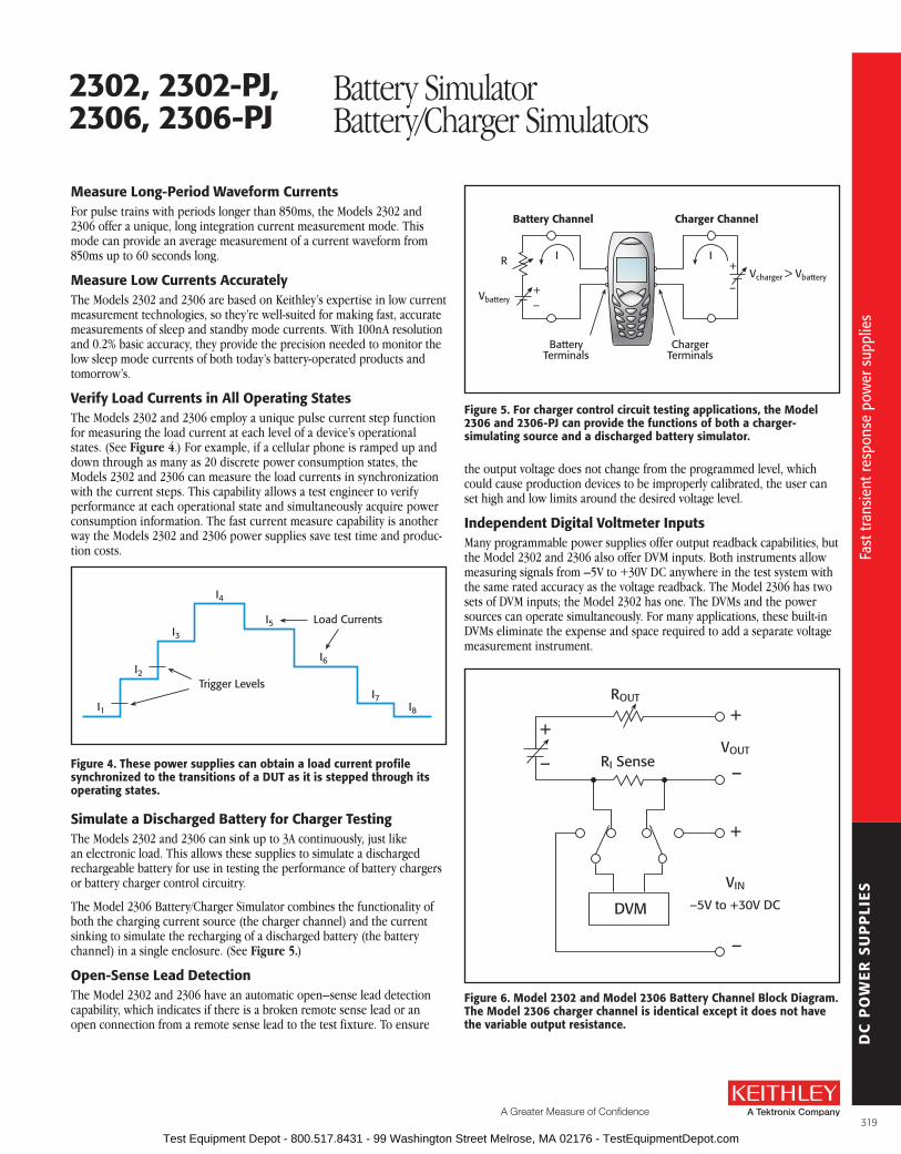
DC
PO
WE
R S
UP
PLI
ES
A Greater Measure of Confidence
Measure long-Period Waveform CurrentsFor pulse trains with periods longer than 850ms, the Models 2302 and 2306 offer a unique, long integration current measurement mode . This mode can provide an average measurement of a current waveform from 850ms up to 60 seconds long .
Measure low Currents accuratelyThe Models 2302 and 2306 are based on Keithley’s expertise in low current measurement technologies, so they’re well-suited for making fast, accurate measurements of sleep and standby mode currents . With 100nA resolution and 0 .2% basic accuracy, they provide the precision needed to monitor the low sleep mode currents of both today’s battery-operated products and tomorrow’s .
Verify load Currents in all operating statesThe Models 2302 and 2306 employ a unique pulse current step function for measuring the load current at each level of a device’s operational states . (See Figure 4 .) For example, if a cellular phone is ramped up and down through as many as 20 discrete power consumption states, the Models 2302 and 2306 can measure the load currents in synchronization with the current steps . This capability allows a test engineer to verify performance at each operational state and simultaneously acquire power consumption information . The fast current measure capability is another way the Models 2302 and 2306 power supplies save test time and produc-tion costs .
I1
I2
I3
I4
I5
I6
I7I8
Trigger Levels
Load Currents
figure 4. These power supplies can obtain a load current profile synchronized to the transitions of a DuT as it is stepped through its operating states.
simulate a Discharged battery for Charger TestingThe Models 2302 and 2306 can sink up to 3A continuously, just like an electronic load . This allows these supplies to simulate a discharged rechargeable battery for use in testing the performance of battery chargers or battery charger control circuitry .
The Model 2306 Battery/Charger Simulator combines the functionality of both the charging current source (the charger channel) and the current sinking to simulate the recharging of a discharged battery (the battery channel) in a single enclosure . (See Figure 5.)
open-sense lead DetectionThe Model 2302 and 2306 have an automatic open–sense lead detection capability, which indicates if there is a broken remote sense lead or an open connection from a remote sense lead to the test fixture . To ensure
the output voltage does not change from the programmed level, which could cause production devices to be improperly calibrated, the user can set high and low limits around the desired voltage level .
Independent Digital Voltmeter InputsMany programmable power supplies offer output readback capabilities, but the Model 2302 and 2306 also offer DVM inputs . Both instruments allow measuring signals from –5V to +30V DC anywhere in the test system with the same rated accuracy as the voltage readback . The Model 2306 has two sets of DVM inputs; the Model 2302 has one . The DVMs and the power sources can operate simultaneously . For many applications, these built-in DVMs eliminate the expense and space required to add a separate voltage measurement instrument .
R
+–
battery Channel Charger Channel
Vbattery
Vcharger > Vbattery
BatteryTerminals
ChargerTerminals
+
–
II
figure 5. for charger control circuit testing applications, the Model 2306 and 2306-PJ can provide the functions of both a charger-simulating source and a discharged battery simulator.
figure 6. Model 2302 and Model 2306 battery Channel block Diagram. The Model 2306 charger channel is identical except it does not have the variable output resistance.
DVM
+
–
+
–
VOUT
VIN
–5V to +30V DC
RI Sense
ROUT
+
–
2302, 2302-PJ,2306, 2306-PJ
Battery SimulatorBattery/Charger Simulators
Fast
tran
sien
t res
pons
e po
wer
sup
plie
s
Fast
tran
sien
t res
pons
e po
wer
sup
plie
s
319 Test Equipment Depot - 800.517.8431 - 99 Washington Street Melrose, MA 02176 - TestEquipmentDepot.com
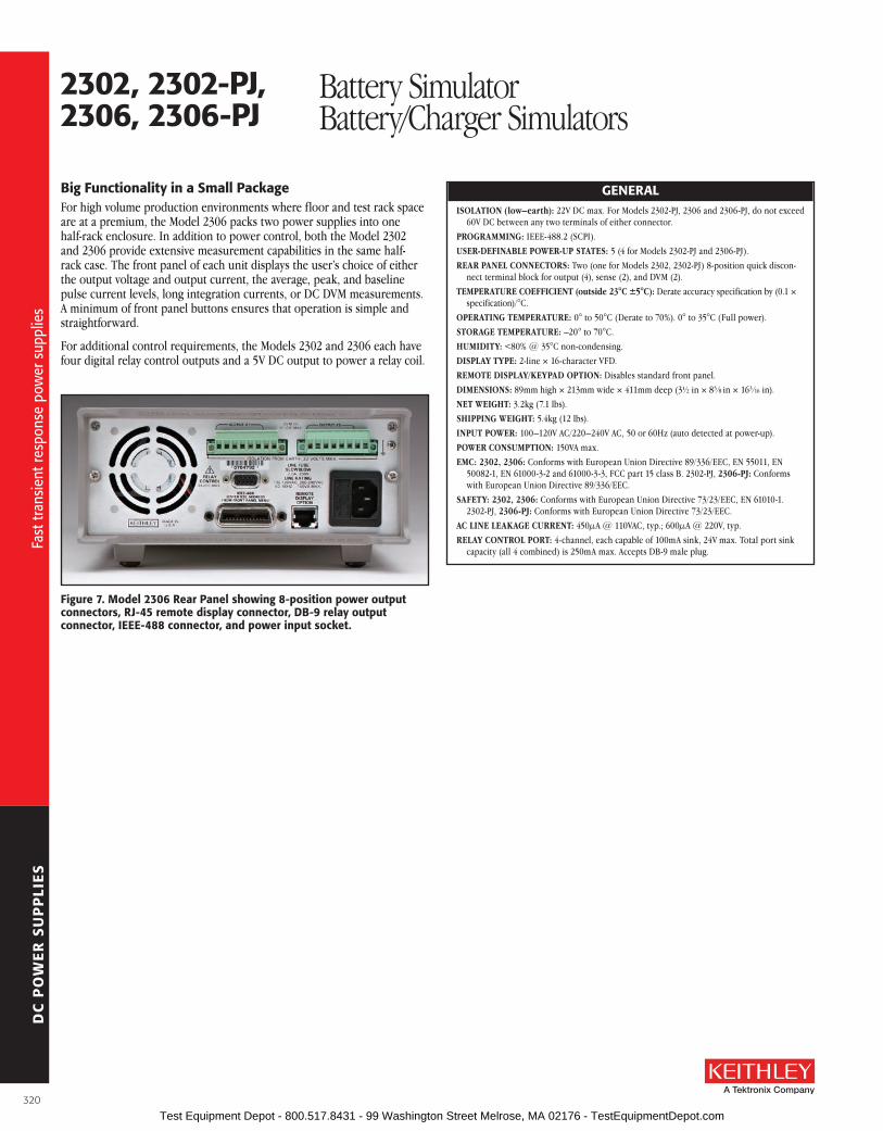
DC
PO
WE
R S
UP
PLI
ES
big functionality in a small PackageFor high volume production environments where floor and test rack space are at a premium, the Model 2306 packs two power supplies into one half-rack enclosure . In addition to power control, both the Model 2302 and 2306 provide extensive measurement capabilities in the same half-rack case . The front panel of each unit displays the user’s choice of either the output voltage and output current, the average, peak, and baseline pulse current levels, long integration currents, or DC DVM meas urements . A minimum of front panel buttons ensures that operation is simple and straightforward .
For additional control requirements, the Models 2302 and 2306 each have four digital relay control outputs and a 5V DC output to power a relay coil .
GENEralISOLATION (low–earth): 22V DC max . For Models 2302-PJ, 2306 and 2306-PJ, do not exceed
60V DC between any two terminals of either connector .
PROGRAMMING: IEEE-488 .2 (SCPI) .
USER-DEFINABLE POWER-UP STATES: 5 (4 for Models 2302-PJ and 2306-PJ) .
REAR PANEL CONNECTORS: Two (one for Models 2302, 2302-PJ) 8-position quick discon-nect terminal block for output (4), sense (2), and DVM (2) .
TEMPERATURE COEFFICIENT (outside 23°C ±5°C): Derate accuracy specification by (0 .1 × specification)/°C .
OPERATING TEMPERATURE: 0° to 50°C (Derate to 70%) . 0° to 35°C (Full power) .
STORAGE TEMPERATURE: –20° to 70°C .
HUMIDITy: <80% @ 35°C non-condensing .
DISPLAy TyPE: 2-line × 16-character VFD .
REMOTE DISPLAy/KEyPAD OPTION: Disables standard front panel .
DIMENSIONS: 89mm high × 213mm wide × 411mm deep (3½ in × 83 ⁄8 in × 163 ⁄16 in) .
NET WEIGHT: 3 .2kg (7 .1 lbs) .
SHIPPING WEIGHT: 5 .4kg (12 lbs) .
INPUT POWER: 100–120V AC/220–240V AC, 50 or 60Hz (auto detected at power-up) .
POWER CONSUMPTION: 150VA max .
EMC: 2302, 2306: Conforms with European Union Directive 89/336/EEC, EN 55011, EN 50082-1, EN 61000-3-2 and 61000-3-3, FCC part 15 class B . 2302-PJ, 2306-Pj: Conforms with European Union Directive 89/336/EEC .
SAFETy: 2302, 2306: Conforms with European Union Directive 73/23/EEC, EN 61010-1 . 2302-PJ, 2306-Pj: Conforms with European Union Directive 73/23/EEC .
AC LINE LEAKAGE CURRENT: 450µA @ 110VAC, typ .; 600µA @ 220V, typ .
RELAy CONTROL PORT: 4-channel, each capable of 100mA sink, 24V max . Total port sink capacity (all 4 combined) is 250mA max . Accepts DB-9 male plug .
figure 7. Model 2306 rear Panel showing 8-position power output connectors, rJ-45 remote display connector, Db-9 relay output connector, IEEE-488 connector, and power input socket.
2302, 2302-PJ,2306, 2306-PJ
Battery SimulatorBattery/Charger Simulators
Fast
tran
sien
t res
pons
e po
wer
sup
plie
s
Fast
tran
sien
t res
pons
e po
wer
sup
plie
s
320 Test Equipment Depot - 800.517.8431 - 99 Washington Street Melrose, MA 02176 - TestEquipmentDepot.com

DC
PO
WE
R S
UP
PLI
ES
A Greater Measure of Confidence
output #1 (battery)
DC VolTaGE ouTPuT (2 Years, 23°C ± 5°C)OUTPUT VOLTAGE: 0 to +15V DC .OUTPUT ACCURACy: ±(0 .05% + 3mV) .PROGRAMMING RESOLUTION: 1mV .READBACK ACCURACy1: ±(0 .05% + 3mV) .READBACK RESOLUTION: 1mV .OUTPUT VOLTAGE SETTLING TIME: 5ms to within stated accuracy .LOAD REGULATION: 0 .01% + 2mV .LINE REGULATION: 0 .5mV .STABILITy2: 0 .01% + 0 .5mV .MEASUREMENT TIME CHOICES: 0 .01 to 10PLC7, in 0 .01PLC steps .AVERAGE READINGS: 1 to 10 .READING TIME 1, 8, 9: 31ms, typical .TRANSIENT RESPONSE: High bandwidth low bandwidth Transient Recovery Time13 <40µs3 or <60µs4 <80µs3 or <100µs4
Transient Voltage Drop <75mV3 or <100mV4 <250mV3 or <400mV4
REMOTE SENSE: 1V max . drop in each lead . Add 2mV to the voltage load regulation specification for each 1V change in the negative output lead due to load current change . Remote sense required . Integrity of connection continually monitored . If compromised, output will turn off automatically once settable window (±0 to ±8V) around normal voltage exceeded .
VarIablE ouTPuT IMPEDaNCERANGE: 0 to 1 .00W in 0 .01W steps . Value can be changed with output on .
DC CurrENT (2 Years, 23°C ± 5°C)CONTINUOUS AVERAGE OUTPUT CURRENT (2302, 2302-Pj):
0–4V: 5A max . >4V: IMAX = 60W/(VSET +6) (not intended to be operated in parallel) . Peak currents can be a maximum of 5A provided the average current is within the above limits .
CONTINUOUS AVERAGE OUTPUT CURRENT (2306, 2306-Pj): Channel #2 (Charger) OFF: I = 50W/(VSET channel 1 + 6V); 5A max .
Channel #2 (Charger) ON: I = (50W – Power consumed by channel #2)/(VSET channel 1 + 6V); 5A max .
The power consumed by channel #2 is calculated as: Channel #2 sourcing current:
Power consumed = (VSET channel 2 + 6V) × (current supplied) Channel #2 sinking current:
Power consumed = 5 × (sink current) Peak currents can be a maximum of 5A provided the average current is within the above limits .
CONTINUOUS AVERAGE SINK CURRENT: Channel #2 (Charger) OFF: 0–5V: 3A max . 5–15V: Derate 0 .2A per volt above 5V . Compliance setting controls sinking .
Channel #2 (Charger) ON: Available current = (50W – Power consumed by channel #2)/5; 3A max . (0–5V) . Derate 0 .2A per volt above 5V .
SOURCE COMPLIANCE ACCURACy: ±(0 .16% + 5mA)5 .PROGRAMMED SOURCE COMPLIANCE RESOLUTION: 1 .25mA .READBACK ACCURACy1: 5A Range: ±(0 .2% + 200µA) .
5mA Range: ±(0 .2% + 1µA) (2302 and 2306) . 500mA Range: ±(0 .2% + 20µA) (2302-PJ and 2306-PJ only) .
READBACK RESOLUTION: 5A Range: 100µA . 5mA Range: 0 .1µA (2302 and 2306) . 500mA Range: 10µA (2302-PJ and 2306-PJ only) .
LOAD REGULATION: 0 .01% + 1mA .LINE REGULATION: 0 .5mA .STABILITy4: 0 .01% + 50µA .MEASUREMENT TIME CHOICES: 0 .01 to 10PLC7, in 0 .01PLC steps .AVERAGE READINGS: 1 to 10 .READING TIME 1, 8, 9: 31ms, typical .
PulsE CurrENT MEasurEMENT oPEraTIoNTRIGGER LEVEL:
5A CURRENT RANGE 5A Range: 5mA to 5A, in 5mA steps . 1A Range: 1mA to 1A, in 1mA steps . 100mA Range: 0 .1mA to 100mA, in 100µA steps .
500mA CURRENT RANGE (2302-Pj and 2306-Pj) 500mA Range: 0 .5mA to 500mA, in 0 .5mA steps . 100mA Range: 0 .1mA to 100mA, in 100µA steps . 10mA Range: 100µA to 10mA, in 100µA steps .
TRIGGER DELAy: 0 to 100ms, in 10µs steps .
INTERNAL TRIGGER DELAy: 15µs .
HIGH/LOW/AVERAGE MODE: Measurement Aperture Settings: 33 .3µs to 833ms, in 33 .3µs steps . Average Readings: 1 to 100 .
PULSE CURRENT MEASUREMENT ACCURACy11 (2 years, 23°C ±5°C):
aperture
accuracy ±(% reading + offset + rms noise10)
5a range500ma range
(2302-PJ and 2306-PJ)<100 µs 0 .2% + 900 µA + 2 mA 0 .2% + 90 µA + 2 mA
100 µs – 200 µs 0 .2% + 900 µA + 1 .5 mA 0 .2% + 90 µA + 1 .5 mA200 µs – 500 µs 0 .2% + 900 µA + 1 mA 0 .2% + 90 µA + 1 mA 500 µs – <1 PLC 0 .2% + 600 µA + 0 .8 mA 0 .2% + 60 µA + 0 .8 mA
1 PLC12 0 .2% + 400 µA + 0 mA 0 .2% + 40 µA + 0 mA>1 PLC 0 .2% + 400 µA + 100 µA 0 .2% + 40 µA + 100 µA
bursT MoDE CurrENT MEasurEMENTMEASUREMENT APERTURE: 33 .3µs .
CONVERSION RATE: 3650/second, typical .
INTERNAL TRIGGER DELAy: 15µs .
NUMBER OF SAMPLES: 1 to 5000 .
TRANSFER SAMPLES ACROSS IEEE BUS IN BINARy MODE: 4800 bytes/s, typical .
loNG INTEGraTIoN MoDE CurrENT MEasurEMENT2302, 2306: Available on 5A range only .
2302-Pj AND 2306-Pj: Available on both 5A and 500mA current ranges .
MEASUREMENT TIME6: 850ms (840ms) to 60 seconds in 1ms steps .
DIGITal VolTMETEr INPuT (2 Years, 23°C ± 5°C)INPUT VOLTAGE RANGE: –5 to +30V DC .
INPUT IMPEDANCE: 2MW typical .
MAXIMUM VOLTAGE (either input terminal) WITH RESPECT TO OUTPUT LOW: –5V, +30V .
READING ACCURACy1: ±(0 .05% + 3mV) .
READING RESOLUTION: 1mV .
CONNECTOR: HI and LO input pair part of Output #1’s terminal block .
MEASUREMENT TIME CHOICES: 0 .01 to 10PLC7, in 0 .01PLC steps .
AVERAGE READINGS: 1 to 10 .
READING TIME 1, 8, 9: 31ms, typical .
2302, 2302-PJ,2306, 2306-PJ
Battery SimulatorBattery/Charger Simulators
Mod
el 2
302,
230
2-PJ
, 230
6, 2
306-
PJ s
peci
ficat
ions
Mod
el 2
302,
230
2-PJ
, 230
6, 2
306-
PJ s
peci
ficat
ions
321 Test Equipment Depot - 800.517.8431 - 99 Washington Street Melrose, MA 02176 - TestEquipmentDepot.com

DC
PO
WE
R S
UP
PLI
ES
ouTPuT #2 (CHarGEr)
DC VolTaGE ouTPuT (2 Years, 23°C ± 5°C)OUTPUT VOLTAGE: 0 to +15V DC .
OUTPUT ACCURACy: ±(0 .05% + 10mV) .
PROGRAMMING RESOLUTION: 10mV .
READBACK ACCURACy1: ±(0 .05% + 3mV) .
READBACK RESOLUTION: 1mV .
OUTPUT VOLTAGE SETTLING TIME: 5ms to within stated accuracy .
LOAD REGULATION: 0 .01% + 2mV .
LINE REGULATION: 0 .5mV .
STABILITy2: 0 .01% + 0 .5mV .
MEASUREMENT TIME CHOICES: 0 .01 to 10PLC7, in 0 .01PLC steps .
AVERAGE READINGS: 1 to 10 .
READING TIME 1, 8, 9: 31ms, typical .
TRANSIENT RESPONSE: High bandwidth low bandwidth Transient Recovery Time13 <50µs3 or <80µs4 <60µs3 or <100µs4
Transient Voltage Drop <120mV3 or <150mV4 <160mV3 or <200mV4
REMOTE SENSE: 1V max . drop in each lead . Add 2mV to the voltage load regulation specification for each 1V change in the negative output lead due to load current change . Remote sense required . Integrity of connection continually monitored . If compromised, output will turn off automatically once settable window (±0 to ±8V) around normal voltage exceeded .
DC CurrENT (2 Years, 23°C ± 5°C)CONTINUOUS AVERAGE OUTPUT CURRENT:
Channel #1 (Battery) OFF: I = 50W/(VSET channel 2 + 6V); 5A max .
Channel #1 (Battery) ON: I = (50W – Power consumed by channel #1)/(VSET channel 2 + 6V); 5A max .
The power consumed by channel #1 is calculated as:
Channel #1 sourcing current: Power consumed = (VSET channel 1 + 6V) × (current supplied)
Channel #1 sinking current: Power consumed = 5 × (sink current)
Peak currents can be a maximum of 5A provided the average current is within the above limits .
CONTINUOUS AVERAGE SINK CURRENT: Channel #1 (Battery) OFF: 0–5V: 3A max . 5–15V: Derate 0 .2A per volt above 5V . Compliance setting controls sinking .
Channel #1 (Battery) ON: Available current = (50W – Power consumed by channel #1)/5; 3A max . (0–5V) . Derate 0 .2A per volt above 5V .
SOURCE COMPLIANCE ACCURACy: ±(0 .16% + 5mA)5 .
PROGRAMMED SOURCE COMPLIANCE RESOLUTION: 1 .25mA .
READBACK ACCURACy1: 5A Range: ±(0 .2% + 200µA) . 5mA Range: ±(0 .2% + 1µA) .
READBACK RESOLUTION: 5A Range: 100µA . 5mA Range: 0 .1µA .
LOAD REGULATION: 0 .01% + 1mA .
LINE REGULATION: 0 .5mA .
STABILITy4: 0 .01% + 50µA .
MEASUREMENT TIME CHOICES: 0 .01 to 10PLC7, in 0 .01PLC steps .
AVERAGE READINGS: 1 to 10 .
READING TIME 1, 8, 9: 31ms, typical .
PulsE CurrENT MEasurEMENT oPEraTIoNTRIGGER LEVEL: 5mA to 5A, in 5mA steps .
TRIGGER DELAy: 0 to 100ms, in 10µs steps .
INTERNAL TRIGGER DELAy: 15µs .
HIGH/LOW/AVERAGE MODE: Measurement Aperture Settings: 33 .3µs to 833ms, in 33 .3µs steps . Average Readings: 1 to 100 .
PULSE CURRENT MEASUREMENT ACCURACy11 (2 years, 23°C ±5°C):
apertureaccuracy
±(% reading + offset + rms noise10)<100 µs 0 .2% + 900 µA + 2 mA
100 µs – 200 µs 0 .2% + 900 µA + 1 .5 mA200 µs – 500 µs 0 .2% + 900 µA + 1 mA 500 µs – <1 PLC 0 .2% + 600 µA + 0 .8 mA
1 PLC12 0 .2% + 400 µA + 0 mA>1 PLC 0 .2% + 400 µA + 100 µA
bursT MoDE CurrENT MEasurEMENTMEASUREMENT APERTURE: 33 .3µs .
CONVERSION RATE: 2040/second, typical .
INTERNAL TRIGGER DELAy: 15µs .
NUMBER OF SAMPLES: 1 to 5000 .
TRANSFER SAMPLES ACROSS IEEE BUS IN BINARy MODE: 4800 bytes/s, typical .
loNG INTEGraTIoN MoDE CurrENT MEasurEMENTMEASUREMENT TIME6: 850ms (840ms) to 60 seconds in 1ms steps .
DIGITal VolTMETEr INPuT (2 Years, 23°C ± 5°C)INPUT VOLTAGE RANGE: –5 to +30V DC .
INPUT IMPEDANCE: 2MW typical .
MAXIMUM VOLTAGE (either input terminal) WITH RESPECT TO OUTPUT LOW: –5V, +30V .
READING ACCURACy1: ±(0 .05% + 3mV) .
READING RESOLUTION: 1mV .
CONNECTOR: HI and LO input pair part of Output #2’s terminal block .
MEASUREMENT TIME CHOICES: 0 .01 to 10PLC7, in 0 .01PLC steps .
AVERAGE READINGS: 1 to 10 .
READING TIME 1, 8, 9: 31ms, typical .
NoTEs1 . PLC = 1 .00 .2 . Following 15 minute warm-up, the change in output over 8 hours under ambient temperature, constant load,
and line operating conditions .3 . Remote sense, at output terminals, 0 .5A to 5A typical .4 . Remote sense, with 4 .5m (15 ft) of 16 gauge (1 .31mm2) wire and 1W resistance in each lead to simulate typical
test environment, 1 .5A load change (0 .15A to 1 .65A) .5 . Minimum current in constant current mode is 6mA .6 . 60Hz (50Hz) .7 . PLC = Power Line Cycle . 1PLC = 16 .7ms for 60Hz operation, 20ms for 50Hz operation . Display off .9 . Speed includes measurement and binary data transfer out of GPIB .10 . Typical values, peak-to-peak noise equals 6 times rms noise .11 . Based on settled signal: 100µs pulse trigger delay .12 . Also applies to other apertures that are integer multiples of 1PLC .13 . Recovery to within 20mV of previous level .
2302, 2302-PJ,2306, 2306-PJ
Battery SimulatorBattery/Charger Simulators
Mod
el 2
302,
230
2-PJ
, 230
6, 2
306-
PJ s
peci
ficat
ions
Mod
el 2
302,
230
2-PJ
, 230
6, 2
306-
PJ s
peci
ficat
ions
322 Test Equipment Depot - 800.517.8431 - 99 Washington Street Melrose, MA 02176 - TestEquipmentDepot.com

DC
PO
WE
R S
UP
PLI
ES
A Greater Measure of Confidencewww.keithley.com
1.888.KEITHLEY (U.S. only)
The dual-channel Model 2306-VS Battery/Charger Simulator with External Triggering is designed specifically for development and high speed production testing of DC battery-operated products, such as cellular handsets, cellular com-ponents like RFIC power amplifiers, and other high volume precision electrical components that require a DC voltage supply . Like Keithley’s original single- channel Model 2302 Battery Simulator and dual-channel Model 2306 Battery/Charger Simulator, this precision power supply has ultra-fast transient response to provide out-put characteristics identical to actual batteries . However, in addition to the capabilities offered by these models, the Model 2306-VS (voltage step) provides two external trigger inputs, which allow independent control of the instrument’s output channels . These trigger inputs speed and simplify control of the output channels by elimi-nating the time lags associated with GPIB data communications . The Model 2306-VS combines
these external trigger inputs with built-in test sequencing to create an extremely fast voltage supply and measurement instrument that minimizes the need for computer and GPIB interaction .
External Triggering allows High speed Control of output ChannelsWhen triggered, the output channels can be instructed to operate at pre-defined voltages or to initi-ate current, voltage, or pulse current measurements . The availability of two inputs makes it possible to program each channel to act independently or, if the test developer prefers, to act in parallel . For example, Channel #1 can be programmed to operate at user-specified voltage levels while Channel #2 is triggered to take measurements . Measurements are stored in a reading buffer and can be downloaded to a PC controller after the test routine is complete, minimizing GPIB command and data transfer delays . Trigger outputs indicate event completion, allowing users to minimize step delays between trigger-in sequences .
External triggering also allows the Model 2306-VS to exercise tight control over signal capture timing for greater measurement and load condition coordination . As a result, manufacturers can achieve greater confidence in their own compliance testing and can offer their customers more accurate com-ponent specifications .
This precision power supply has ultra-fast transient response to duplicate the output characteristics of actual batteries . In response to large load changes, voltage droops on the Model 2306-VS’s battery channel are less than 100mV and transient recovery times are less than 60µs, even when the instru-ment is used with long test leads . The Model 2306-VS also employs a unique variable output resist-ance so that the voltage output can emulate a battery’s true response (U .S . Patent No . 6,204,647) . By providing stable output voltage, a device-under-test (DUT) can transition from standby power (low current) to RF transmission (high current) seamlessly without nuisance tripping .
built-in Test sequencing Maximizes ThroughputThe Model 2306-VS’s built-in test sequencing capabilities allow setting up and executing up to 20 individual voltage and measurement sequences . By minimizing the need to transfer instrument commands or data over the GPIB
• External trigger inputs speed and simplify control of output channels
• built-in test sequencing reduces GPIb bus traffic and improves test throughput
• ultra-fast response to transient load currents
• selectable trigger level polarity
• Variable output resistance for simulating battery response (u.s. Patent No. 6,204,647)
• Trigger outputs provided for event handshaking
• 100na DC current sensitivity
• sink up to 3a
• open sense lead detection
• built-in digital voltmeter
aPPlICaTIoNs
Development and high speed testing of DC battery-operated products, such as:
• Cellular handsets
• Cellular components like rfIC power amplifiers
• other high volume precision electrical components
2306-Vs Dual-Channel Battery/Charger Simulator with External Triggering
Fast
tran
sien
t res
pons
e po
wer
sup
ply
Fast
tran
sien
t res
pons
e po
wer
sup
ply
323 Test Equipment Depot - 800.517.8431 - 99 Washington Street Melrose, MA 02176 - TestEquipmentDepot.com

DC
PO
WE
R S
UP
PLI
ES
bus, these test sequences support faster, easier production testing by allowing users to pre-define a variety of test configurations, such as:
• Trigger up to 20 voltage setpoints on Channel #1, Channel #2, or both
• Trigger up to 20 measurement readings on Channel #1, Channel #2, or both
• Trigger voltage setpoints on Channel #1 while triggering Channel #2 measurement readings
•
1.5V
1.0V
0.5V
0V
200µs/Div.
Channel #1Output Voltage
Trigger-InSequence
figure 1. This graph illustrates Channel #1 output voltage response times based on a four-point voltage step sequence (0.5V/1.0V/1.5V/0.5V). The Model 2306-Vs can complete this sequence within 1.5ms.
600mV
400mV
200mV
0mV
40µs/Div.
Channel #1Output Voltage
Trigger-InSequence
figure 2. This magnified view of the first 500mV voltage step from the signal shown in figure 1 illustrates how the Channel #1 output reaches the voltage setpoint within 160µs of the trigger-in pulse.
ordering Information2306-Vs Dual-Channel battery/
Charger simulator with External Triggering
accessories supplieduser and service manualsCs-846 output connectorsMating terminal
aCCEssorIEs aVaIlablE2306-DISP Remote Display
CS-846 Mating Output Connector
CablEs7007-1 Double Shielded Premium IEEE-488 Cable,
1m (3 .2 ft)
7007-2 Double Shielded Premium IEEE-488 Cable, 2m (6 .5 ft)
SC-182 Low-Inductance Coaxial Cable (42nH/ft)
raCK MouNT KITs4288-1 Single Fixed Rack Mount Kit
4288-2 Dual Fixed Rack Mount Kit
IEEE-488 INTErfaCEsKPCI-488LPA IEEE-488 Interface/Controller for the PCI Bus
KUSB-488B IEEE-488 USB-to-GPIB Interface Adapter
sErVICEs aVaIlablE2306-VS-3Y-EW 1-year factory warranty extended to 3 years from
date of shipment
C/2306-3Y-ISO 3 (ISO-17025 accredited) calibrations within 3 years of purchase*
*Not available in all countries
2306-Vs Dual-Channel Battery/Charger Simulator with External Triggering
Fast
tran
sien
t res
pons
e po
wer
sup
ply
Fast
tran
sien
t res
pons
e po
wer
sup
ply
324 Test Equipment Depot - 800.517.8431 - 99 Washington Street Melrose, MA 02176 - TestEquipmentDepot.com

DC
PO
WE
R S
UP
PLI
ES
A Greater Measure of Confidence
Measure load Currents for Power Consumption Verification or analysisThe Model 2306-VS is based on Keithley’s expertise in low current measurement technologies, so it is well-suited for making accurate measurements of load currents . With 100nA resolution and 0 .2% basic accuracy, it provides the precision needed to monitor the low sleep mode currents of today’s battery-operated products .
The Model 2306-VS can monitor DUT power consumption by measuring both DC currents and pulse load currents . The instrument’s battery-simulator channel can be programmed to operate like a dis-charged rechargeable battery, sinking up to 3A from the charger-simulator channel .
Maximize Test Throughput with accurate battery simulationThe Model 2306-VS’s battery-output channel is designed to simulate the output response of a battery . This capability, combined with its fast transient response, makes it possible to power the device during testing in exactly the same way as a battery powers the device during actual use . The output resistance of the battery channel can be programmed (with 10mW resolution) over the range from 0W to 1W so that the output resistance can be set to the same level as the output resistance of the battery that powers the device .
Portable wireless devices make great demands on their battery power sources . The battery must source load currents that can jump virtually instantaneously from a standby current level (100–300mA) to a full power RF transmission current level (1–3A) . In other words, the load current on the battery can increase rapidly by a factor of 700–1000% . As a result, the battery voltage drops by an amount equal to the value of the current change multiplied by the battery’s internal resistance . The Model 2306-VS enables test systems to duplicate this voltage drop by programming their output resistance to be equivalent to that of the battery that will power the device . This allows wireless device manufacturers to test their products under the same power conditions that they will encounter in actual use .
The Model 2306-VS also eliminates the large stabilizing capacitors needed at the DUT to compensate for the large voltage droop that occurs when testing with conventional power supplies . By varying the output resist ance, which can be done while the output is turned on, test engineers can simulate the operation of different battery types as well as batteries nearing the end of their useful lives . The Model 2306-VS ensures maximum production throughput when testing portable devices by minimizing false failures, minimizing the number of test setups by performing multiple tests with the same power supply, and minimizing test fixture complexity by eliminating the need for voltage-stabilizing capacitors .
open sense lead DetectionThe Model 2306-VS has an automatic open-sense lead detection capability, which indicates if there is a broken remote sense lead or an open connection from a remote sense lead to the test fixture . To ensure that the output voltage does not change from the pro-grammed level, which could cause production devices to be improperly calibrated, the user can set high and low limits around the desired voltage level .
Independent Digital Voltmeter InputsMany programmable power supplies offer output read-back capabilities, but the Model 2306-VS also offers two digital voltmeter (DVM) inputs . These inputs can be used to measure signals from –5V to +30V DC any-where in the test system with the same rated accuracy as the voltage readback . For many applications, this built-in DVM eliminates the expense and space other-wise required to add a separate voltage measurement instrument to the system .
Model 2306-Vs rear panel
2306-Vs Dual-Channel Battery/Charger Simulator with External Triggering
Fast
tran
sien
t res
pons
e po
wer
sup
ply
Fast
tran
sien
t res
pons
e po
wer
sup
ply
325 Test Equipment Depot - 800.517.8431 - 99 Washington Street Melrose, MA 02176 - TestEquipmentDepot.com

DC
PO
WE
R S
UP
PLI
ES
output #1 (battery)
DC VolTaGE ouTPuT (2 Years, 23°C ± 5°C)OUTPUT VOLTAGE: 0 to +15VDC .
OUTPUT ACCURACy: ±(0 .05% + 3mV) .
PROGRAMMING RESOLUTION: 1mV .
READBACK ACCURACy1: ±(0 .05% + 3mV) .
READBACK RESOLUTION: 1mV .
LOAD REGULATION: ±(0 .01% + 2mV) .
LINE REGULATION: ±0 .5mV .
STABILITy2: ±(0 .01% + 0 .5mV) .
MEASUREMENT TIME CHOICES: 0 .01 to 10 PLC7, in 0 .01PLC steps .
AVERAGE READINGS: 1 to 10 .
READING TIME1, 8, 9: 31ms, typical .
TRANSIENT RESPONSE: High Bandwidth Low Bandwidth
Transient Recovery Time13 <40 µs3 or <60 µs4 <80 µs3 or <100 µs4
Transient Voltage Drop <75 mV3 or <100 mV4 <250 mV3 or <400 mV4
REMOTE SENSE: 1V max . drop in each lead . Add 2mV to the voltage load regulation specifica-tion for each 1V change in the negative output lead due to load current change . Remote sense required . Integrity of connection continually monitored . If compromised, output will turn off automatically once settable window (±0 to ±8 volts) around normal voltage exceeded .
VarIablE ouTPuT IMPEDaNCERANGE: 0 to 1 .00W in 0 .01W steps . Value can be changed with output on if trigger external dis-
abled on channel .
DC CurrENT (2 Years, 23°C ± 5°C)CONTINUOUS AVERAGE OUTPUT CURRENT:
Channel #2 (Charger) OFF: I = 50W/(Vset channel 1 + 6V); 5A max .
Channel #2 (Charger) ON: I = (50W – Power consumed by channel #2)/(Vset channel 1 + 6V); 5A max .
The power consumed by channel #2 is calculated as:
Channel #2 sourcing current: Power consumed = (Vset channel 2 + 6V) × (current supplied) .
Channel #2 sinking current: Power consumed = 5 × (sink current) .
Peak currents can be a maximum of 5A provided the average current is within the above limits .
CONTINUOUS AVERAGE SINK CURRENT:
Channel #2 (Charger) OFF: 0–5V: 3A max . 5–15V: Derate 0 .2A per volt above 5V . Compliance setting controls sinking .
Channel #2 (Charger) ON: Available current = (50W – Power consumed by channel #2)/5; 3A max . (0–5V) . Derate 0 .2A per volt above 5V .
SOURCE COMPLIANCE ACCURACy: ±(0 .16% + 5mA)5 .
PROGRAMMED SOURCE COMPLIANCE RESOLUTION: 1 .25mA .
READBACK ACCURACy1: 5A Range: ±(0 .2% + 200µA) . 5mA Range: ±(0 .2% + 1µA) .
READBACK RESOLUTION: 5A Range: 100µA . 5mA Range: 0 .1µA .
LOAD REGULATION: ±(0 .01% + 1mA) .
LINE REGULATION: ±0 .5mA .
STABILITy4: ±(0 .01% + 50µA) .
MEASUREMENT TIME CHOICES: 0 .01 to 10 PLC7, in 0 .01PLC steps .
AVERAGE READINGS: 1 to 10 .
READING TIME1, 8, 9: 31ms, typical .
PulsE CurrENT MEasurEMENT oPEraTIoNTRIGGER LEVEL: 5A Range: 5mA to 5A, in 5mA steps .
1A Range: 1mA to 1A, in 1mA steps . 100mA Range: 0 .1mA to 100mA, in 100µA steps .
TRIGGER DELAy: 0 to 100ms, in 10µs steps .
INTERNAL TRIGGER DELAy: 15µs .
HIGH/LOW/AVERAGE MODE: Measurement Aperture Settings: 33 .3µs to 833ms, in 33 .3µs steps . Average Readings: 1 to 100 .
PULSE CURRENT MEASUREMENT ACCURACy11 (2 years, 23°C ±5°C):
apertureaccuracy
±(% reading + offset + rms noise10)<100 µs 0 .2% + 900 µA + 2 mA
100 µs – 200 µs 0 .2% + 900 µA + 1 .5 mA200 µs – 500 µs 0 .2% + 900 µA + 1 mA 500 µs – <1 PLC 0 .2% + 600 µA + 0 .8 mA
1 PLC12 0 .2% + 400 µA + 0 mA>1 PLC 0 .2% + 400 µA + 100 µA
bursT MoDE CurrENT MEasurEMENTMEASUREMENT APERTURE: 33 .3µs to 833ms, in 33 .3µs steps .
CONVERSION RATE: 3650/second at 33 .3µs meas . aper ., typical .
INTERNAL TRIGGER DELAy: 15µs with 33µs .
NUMBER OF SAMPLES: 1 to 5000 .
TRANSFER SAMPLES ACROSS IEEE BUS IN BINARy MODE: 4800 bytes/s, typical .
loNG INTEGraTIoN MoDE CurrENT MEasurEMENTMEASUREMENT TIME6: 850ms (840ms) to 60 seconds in 1ms steps .
DIGITal VolTMETEr INPuT (2 Years, 23°C ± 5°C)INPUT VOLTAGE RANGE: –5 to +30VDC .
INPUT IMPEDANCE: 2MW typical .
MAXIMUM VOLTAGE (either input terminal) WITH RESPECT TO OUTPUT LOW: –5V, +30V .
READING ACCURACy1: ±(0 .05% + 3mV) .
READING RESOLUTION: 1mV .
CONNECTOR: HI and LO input pair part of Output #1’s terminal block .
MEASUREMENT TIME CHOICES: 0 .01 to 10 PLC7, in 0 .01PLC steps .
AVERAGE READINGS: 1 to 10 .
READING TIME1, 8, 9: 31ms, typical .
VolTaGE sETTlING TIMEsVOLTAGE STEP SETTLING TIMES (typical)
Increasing Voltage 10–90% rise Time settling TimeVoltage step ≤ 7 V 50 µs 300 µsVoltage step > 7 V 50 µs to 1 .2 ms 300 µs to 1 .8 ms
Decreasing Voltage 10–90% fall Time settling Time0 V < Voltage step < 15 V 50 µs to 250 µs 300 µs
NOTE: Times are under no load condition and settling times defined at ±2% of step size .
2306-Vs Dual-Channel Battery/Charger Simulator with External Triggering
Mod
el 2
306-
VS s
peci
ficat
ions
Mod
el 2
306-
VS s
peci
ficat
ions
326 Test Equipment Depot - 800.517.8431 - 99 Washington Street Melrose, MA 02176 - TestEquipmentDepot.com

DC
PO
WE
R S
UP
PLI
ES
A Greater Measure of Confidence
output #2 (Charger)
DC VolTaGE ouTPuT (2 Years, 23°C ± 5°C)OUTPUT VOLTAGE: 0 to +15VDC .
OUTPUT ACCURACy: ±(0 .05% + 10mV) .
PROGRAMMING RESOLUTION: 10mV .
READBACK ACCURACy1: ±(0 .05% + 3mV) .
READBACK RESOLUTION: 1mV .
OUTPUT VOLTAGE SETTLING TIME: 5ms to within stated accuracy .
LOAD REGULATION: ±(0 .01% + 2mV) .
LINE REGULATION: ±0 .5mV .
STABILITy2: ±(0 .01% + 0 .5mV) .
MEASUREMENT TIME CHOICES: 0 .01 to 10 PLC7, in 0 .01PLC steps .
AVERAGE READINGS: 1 to 10 .
READING TIME1, 8, 9: 31ms, typical .
TRANSIENT RESPONSE: High Bandwidth Low Bandwidth
Transient Recovery Time13 <50 µs3 or <80 µs4 <60 µs3 or <100 µs4
Transient Voltage Drop <120 mV3 or <150 mV4 <160 mV3 or <200 mV4
REMOTE SENSE: 1V max . drop in each lead . Add 2mV to the voltage load regulation specifica-tion for each 1V change in the negative output lead due to load current change . Remote sense required . Integrity of connection continually monitored . If compromised, output will turn off automatically once settable window (±0 to ±8 volts) around normal voltage exceeded .
DC CurrENT (2 Years, 23°C ± 5°C)CONTINUOUS AVERAGE OUTPUT CURRENT:
Channel #1 (Battery) OFF: I = 50W/(Vset channel 2 + 6V); 5A max .
Channel #1 (Battery) ON: I = (50W – Power consumed by channel #1)/(Vset channel 2 + 6V); 5A max .
The power consumed by channel #1 is calculated as:
Channel #1 sourcing current: Power consumed = (Vset channel 1 + 6V) × (current supplied)
Channel #1 sinking current: Power consumed = 5 × (sink current)
Peak currents can be a maximum of 5A provided the average current is within the above limits .
CONTINUOUS AVERAGE SINK CURRENT:
Channel #1 (Battery) OFF: 0–5V: 3A max . 5–15V: Derate 0 .2A per volt above 5V . Compliance setting controls sinking .
Channel #1 (Battery) ON: Available current = (50W – Power consumed by channel #1)/5; 3A max . (0–5V) . Derate 0 .2A per volt above 5V .
SOURCE COMPLIANCE ACCURACy: ±(0 .16% + 5mA)5 .
PROGRAMMED SOURCE COMPLIANCE RESOLUTION: 1 .25mA .
READBACK ACCURACy1: 5A Range: ±(0 .2% + 200µA) . 5mA Range: ±(0 .2% + 1µA) .
READBACK RESOLUTION: 5A Range: 100µA . 5mA Range: 0 .1µA .
LOAD REGULATION: ±(0 .01% + 1mA) .
LINE REGULATION: ±0 .5mA .
STABILITy4: ±(0 .01% + 50µA) .
MEASUREMENT TIME CHOICES: 0 .01 to 10 PLC7, in 0 .01PLC steps .
AVERAGE READINGS: 1 to 10 .
READING TIME1, 8, 9: 31ms, typical .
PulsE CurrENT MEasurEMENT oPEraTIoNTRIGGER LEVEL: 5mA to 5A, in 5mA steps .
TRIGGER DELAy: 0 to 100ms, in 10µs steps .
INTERNAL TRIGGER DELAy: 15µs .
HIGH/LOW/AVERAGE MODE: Measurement Aperture Settings: 33 .3µs to 833ms, in 33 .3µs steps . Average Readings: 1 to 100 .
PULSE CURRENT MEASUREMENT ACCURACy11 (2 years, 23°C ±5°C):
apertureaccuracy
±(% reading + offset + rms noise10)<100 µs 0 .2% + 900 µA + 2 mA
100 µs – 200 µs 0 .2% + 900 µA + 1 .5 mA200 µs – 500 µs 0 .2% + 900 µA + 1 mA 500 µs – <1 PLC 0 .2% + 600 µA + 0 .8 mA
1 PLC12 0 .2% + 400 µA + 0 mA>1 PLC 0 .2% + 400 µA + 100 µA
bursT MoDE CurrENT MEasurEMENTMEASUREMENT APERTURE: 33 .3µs to 833ms, in 33µs steps .
CONVERSION RATE: 2040/second at 33 .3µs meas . aper ., typical .
INTERNAL TRIGGER DELAy: 15µs with 33µs .
NUMBER OF SAMPLES: 1 to 5000 .
TRANSFER SAMPLES ACROSS IEEE BUS IN BINARy MODE: 4800 bytes/s, typical .
loNG INTEGraTIoN MoDE CurrENT MEasurEMENTMEASUREMENT TIME6: 850ms (840ms) to 60 seconds in 1ms steps .
DIGITal VolTMETEr INPuT (2 Years, 23°C ± 5°C)INPUT VOLTAGE RANGE: –5 to +30VDC .
INPUT IMPEDANCE: 2MW typical .
MAXIMUM VOLTAGE (either input terminal) WITH RESPECT TO OUTPUT LOW: –5V, +30V .
READING ACCURACy1: ±(0 .05% + 3mV) .
READING RESOLUTION: 1mV .
CONNECTOR: HI and LO input pair part of Output #2’s terminal block .
MEASUREMENT TIME CHOICES: 0 .01 to 10 PLC7, in 0 .01PLC steps .
AVERAGE READINGS: 1 to 10 .
READING TIME1, 8, 9: 31ms, typical .
VolTaGE sETTlING TIMEs (typical)Increasing Voltage 10–90% rise Time settling Time
Voltage step ≤ 7 V 10 µs 100 µsVoltage step > 7 V 10 µs to 1 .2 ms 100 µs to 1 .5 ms
Decreasing Voltage 10–90% fall Time settling Time0 V < Voltage step < 15 V 5 µs to 40 µs 50 µs to 200 µs
NOTE: Times are under no load condition and settling times defined at ±2% of step size .
2306-Vs Dual-Channel Battery/Charger Simulator with External Triggering
Mod
el 2
306-
VS s
peci
ficat
ions
Mod
el 2
306-
VS s
peci
ficat
ions
327 Test Equipment Depot - 800.517.8431 - 99 Washington Street Melrose, MA 02176 - TestEquipmentDepot.com

DC
PO
WE
R S
UP
PLI
ES
Voltage stepping onlyTEST CONDITIONS:
1 . Trigger external is enabled on both channels .
2 . Only a single channel is externally triggered during the sequence while remaining channel stays idle .
3 . Times based on 0 programmable user delay .
ChannelTrigger In
ChannelTrigger Out
OutputVoltage
AB C
D
output #1 (battery) output #2 (Charger)A = 70 µs typical A = 55 µs typicalB = 330 µs typical B = 545 µs typicalC = Programmable user delay (0–5 seconds) C = Programmable user delay (0–5 seconds)D = 400 µs typical with C as 0 D = 600 µs typical with C as 0
auto Measurement onlyTEST CONDITIONS:
1 . Trigger external is enabled on both channels .
2 . Only a single channel is externally triggered during the sequence while remaining channel stays idle .
3 . Times based on 0 programmable user delay .
4 . Measurement time = 167µs (0 .01 PLC) .
5 . Steps points = 4 .
ChannelTrigger In
MeasurementTime
ChannelTrigger Out A B
C D
E
output #1 (battery) output #2 (Charger)A = 43 µs typical A = 43 µs typicalB = Programmable user delay (0–5 seconds) B = Programmable user delay (0–5 seconds)C = Measurement time C = Measurement timeD = 410 µs typical (steps 1, 2, and 3) D = 650 µs typical (steps 1, 2, and 3)E = 620 µs typical for steps 1, 2, and 3
with B as 0 8ms typical for step 4 with B as 0
E = 860 µs typical for steps 1, 2, and 3 with B as 0 8ms typical for step 4 with B as 0
Voltage stepping With auto MeasurementTEST CONDITIONS:
1 . Trigger external is enabled on both channels .
2 . Only a single channel is externally triggered during the sequence while remaining channel stays idle .
3 . Times based on 0 programmable user delay .
4 . Measurement time = 167µs (0 .01 PLC) .
5 . Steps points = 4 .
ChannelTrigger In
OutputVoltage
MeasurementTime
ChannelTrigger Out
A B C D E
F
output #1 (battery) output #2 (Charger)A = 70 µs typical A = 55 µs typical withinB = 43 µs typical B = 43 µs typical withinC = Programmable user delay (0–5 seconds) C = Programmable user delay (0–5 seconds)D = Measurement time D = Measurement timeE = 475 µs typical (steps 1, 2, and 3) E = 955 µs typical (steps 1, 2, and 3)F = 755 µs typical steps 1, 2, and 3 with C as 0
8 ms typical step 4 with C as 0F = 1 .22 ms typical steps 1, 2, and 3 with C as 0
8 ms typical step 4 with C as 0
Voltage stepping both Channels With Channel 1TEST CONDITIONS:
1 . Only a single channel is externally triggered during the sequence while remaining channel stays idle .
2 . Times based on 0 programmable user delay .
A B C D
E
Channel 1Trigger In
Output VoltageChannel 1
Channel 1 Trigger Out
Output VoltageChannel 2
output #1 (battery)/output #2 (Charger)A = 70 µs typicalB = 55 µs typicalC = 775 µs typicalD = Programmable user delay (0–5 seconds)E = 900 µs typical with D as 0
2306-Vs Dual-Channel Battery/Charger Simulator with External Triggering
Mod
el 2
306-
VS s
peci
ficat
ions
Mod
el 2
306-
VS s
peci
ficat
ions
328 Test Equipment Depot - 800.517.8431 - 99 Washington Street Melrose, MA 02176 - TestEquipmentDepot.com

DC
PO
WE
R S
UP
PLI
ES
A Greater Measure of Confidence
Voltage stepping both Channels With Channel 2TEST CONDITIONS:
1 . Only a single channel is externally triggered during the sequence while remaining channel stays idle .
2 . Times based on 0 programmable user delay .
A B C D
E
Channel 2Trigger In
Output VoltageChannel 2
Channel 2Trigger Out
Output VoltageChannel 1
output #1 (battery)/output #2 (Charger)A = 55 µs typicalB = 70 µs typicalC = 775 µs typicalD = Programmable user delay (0–5 seconds)E = 900 µs typical with D as 0
auto Measurement both Channels With Channel 1TEST CONDITIONS:
1 . Only a single channel is externally triggered during the sequence while remaining channel stays idle .
2 . Times based on 0 programmable user delay .
3 . Measurement time = 167µs (0 .01 PLC) .
4 . Steps points = 4 .
A B C
D
E
Channel 1Trigger In
Measurement TimeChannel 1
Channel 1Trigger Out
Measurement TimeChannel 2
F
G
output #1 (battery)/output #2 (Charger)A = 43 µs typicalB = Programmable user delay (0–5 seconds)C = 18 µs typicalD = Measurement time channel 1E = Measurement time channel 2F = 872 µs typical with steps 1, 2, and 3G = 1 .1 ms typical for steps 1, 2, and 3 with B as 0
16 .0 ms typical step 4 with B as 0
auto Measurement both Channels With Channel 2TEST CONDITIONS:
1 . Only a single channel is externally triggered during the sequence while remaining channel stays idle .
2 . Times based on 0 programmable user delay .
3 . Measurement time = 167 µs (0 .01 PLC) .
4 . Steps points = 4 .
Channel 2Trigger In
Measurement TimeChannel 2
Channel 2Trigger Out
Measurement TimeChannel 1
A B C
D
E F
G
output #1 (battery)/output #2 (Charger)A = 43 µs typicalB = Programmable user delay (0–5 seconds)C = 18 µs typicalD = Measurement time channel 2E = Measurement time channel 1F = 872 µs typical with steps 1, 2, and 3G = 1 .1 ms typical for steps 1, 2, and 3 with B as 0
16 .0 ms typical step 4 with B as 0
Voltage stepping With sync MeasurementTEST CONDITIONS:
1 . Trigger external is enabled on both channels .
2 . Only a single channel is externally triggered during the sequence while remaining channel stays idle .
3 . Times based on 0 programmable user delay .
A
ChannelTrigger In
OutputVoltage
output #1 (battery) output #2 (Charger)Channel 1 trigger in = output voltage start changing
Channel 2 trigger in = output voltage start changing
A = 70 µs typical A = 55 µs typical within4 ms typical to start search for desired pulse edge . Time for trigger out dependent on search
time for selecting edge, integration time, and storing reading in buffer
2306-Vs Dual-Channel Battery/Charger Simulator with External Triggering
Mod
el 2
306-
VS s
peci
ficat
ions
Mod
el 2
306-
VS s
peci
ficat
ions
329 Test Equipment Depot - 800.517.8431 - 99 Washington Street Melrose, MA 02176 - TestEquipmentDepot.com

DC
PO
WE
R S
UP
PLI
ES
GENEralISOLATION (LOW–EARTH): 22VDC max . Do not exceed 60VDC between any two terminals
of either connector .
PROGRAMMING: IEEE-488 .2 (SCPI) .
USER-DEFINABLE POWER-UP STATES: 3 .
REAR PANEL CONNECTORS: Two trigger in and two trigger out (BNC) connectors . Two 8- position quick disconnect terminal block for output (4), sense (2), and DVM (2) .
TRIGGER IN/OUT CONNECTORS: IN High 3–5V, IN Low ≤0 .8V, OUT High >4V, OUT Low <0 .8V .
TEMPERATURE COEFFICIENT (outside 23°C ±5°C): Derate accuracy specification by (0 .1 × specification)/°C .
OPERATING TEMPERATURE: 0° to 50°C (derate to 70%) . 0° to 35°C (full power) .
STORAGE TEMPERATURE: –20° to 70°C .
HUMIDITy: <80% @ 35°C non-condensing .
DISPLAy TyPE: 2-line × 16 character VFD .
DIMENSIONS: 89mm high × 213mm wide × 411mm deep (3½ in × 83⁄8 in × 163⁄16 in) .
NET WEIGHT: 3 .9kg (8 .6 lbs .) .
SHIPPING WEIGHT: 6 .4kg (14 lbs .) .
INPUT POWER: 100–120VAC/220–240VAC, 50 or 60Hz (auto detected at power-up) .
POWER CONSUMPTION: 165VA max .
EMC: Conforms with European Union Directive directive 89/336/EEC, EN 61326 .
SAFETy: Conforms with European Union Directive 73/23/EEC, EN 61010-1 .
VIBRATION: MIL-PRF-28800F Type III, Class 3 .
NoTEs1 . PLC = 1 .00 .2 . Following 15 minute warm-up, the change in output over 8 hours under ambient temperature, constant load,
and line operating conditions .3 . Remote sense, at output terminals, 0 .5A to 5A typical .4 . Remote sense, with 4 .5m (15 ft) of 16 gauge (1 .31mm2) wire and 1W resistance in each lead to simulate typical
test environment, 1 .5A load change (0 .15A to 1 .65A) .5 . Minimum current in constant current mode is 6mA .6 . 60Hz (50Hz) .7 . PLC = Power Line Cycle . 1PLC = 16 .7ms for 60Hz operation, 20ms for 50Hz operation .8 . Display off .9 . Speed includes measurement and binary data transfer out of GPIB .10 . Typical values, peak-to-peak noise equals 6 times rms noise .11 . Based on settled signal: 100µs pulse trigger delay .12 . Also applies to other apertures that are integer multiples of 1PLC .13 . Recovery to within 20mV of previous level .
2306-Vs Dual-Channel Battery/Charger Simulator with External Triggering
Mod
el 2
306-
VS s
peci
ficat
ions
Mod
el 2
306-
VS s
peci
ficat
ions
330 Test Equipment Depot - 800.517.8431 - 99 Washington Street Melrose, MA 02176 - TestEquipmentDepot.com

DC
PO
WE
R S
UP
PLI
ES
A Greater Measure of Confidence
The Model 2303/2304A Power Supplies provide both voltage control and power consumption moni toring for automated testing of portable, battery-operated devices . These power supplies are optimized for testing battery-operated, wire-less communication devices such as cellular phones that undergo substantial load changes for very short time intervals . These power sup-plies exhibit outstanding voltage stability during pulse load changes and can simultaneously measure load currents, even if they are short pulses . In addition, this family of power supplies can sink current and, thus, take on the charac-teristics of a discharged, rechargeable battery for testing chargers and charger-control circuitry .
5a output CapacityBoth the 100W Model 2304A and the 45W Model 2303 can supply 5A (at 20V for the Model 2304A and 9V for the Model 2303) to serve the peak pulse loading requirements of battery-oper-ated devices . In both instruments, the maximum current of 5A can be delivered continuously . The Model 2304A can supply up to 20V DC while the Model 2303 can supply up to 15V .
fast response to load Changes Keithley’s High Speed Power Supplies are designed to simu late the current drive capacity of a battery . The power supplies simulate a bat-
tery’s re sponse during a large load change by minimizing the maximum drop in voltage and recover-ing to within 100mV of the original voltage in 40µs or less .
When a portable device such as a cellular phone switches from standby mode to the full power mode of operation, the current draw on the power supply can change by as much as 1000% . While a bat-tery’s voltage will de crease by the value of the voltage drop across the battery’s low internal resist-ance, a con ven tion al power supply will have a significant voltage drop (more than one volt) and take milli seconds to recover to the original voltage level . For portable devices that operate at full power only for short intervals, the full power event is over before a conventional power supply can recover . For example, cellular phones designed in ac cor dance with the GSM cellular phone standard transmit
and receive information in 576µs pulses . If the power supply used to test them cannot re cov er quickly enough, the per for mance of the device-under-test will be compro mised by the power supply . If the power supply voltage drops below the threshold of the phone’s low- battery detec-tion circuitry for a sufficient amount of time, the phone will turn off during testing, giving a false indication of a failed device .
The Models 2303/2304A’s fast transient response to large load changes will enable test engineers to test their portable products properly and eliminate false failures due to conventional power supplies with slow re sponse times . In this way, the power supplies ensure maximum production throughput when testing portable devices .
• optimized for battery-powered device testing
• ultra-fast transient response to load changes
• 5a continuous output
• Pulse peak, average, and baseline current measurements
• 100na DC current sensitivity
MoDEl 2304a
• 100W output (20V @ 5a)
• sinks up to 3a
MoDEl 2303
• 45W output (15V @ 3a, 9V @ 5a)
• sinks up to 2a
Power SupplyVoltage
100µs/Div.
0.5 A/Div
500mV/Div.
GSM Phone CurrentGND
Power Supply Voltage
100µs/Div.
0.5 A/Div
500mV/Div.
GSM Phone CurrentGND
Typical Power supply. Transient response with 4.5m (15 ft) of cable and 1W/lead between source and GsM phone load.
Keithley’s High speed Power supply. Transient response with 4.5m (15 ft) of cable and 1W/lead between source and GsM phone load.
Model 2303 or 2304a rear panel
2303, 2304a High Speed Power SuppliesFa
st tr
ansi
ent r
espo
nse
pow
er s
uppl
ies
Fast
tran
sien
t res
pons
e po
wer
sup
plie
s
331 Test Equipment Depot - 800.517.8431 - 99 Washington Street Melrose, MA 02176 - TestEquipmentDepot.com

DC
PO
WE
R S
UP
PLI
ES
The Models 2303/2304a perform a continu-ous integration to make peak, average, and baseline measurements on complex load current waveforms. Integra tion times can be programmed with 33.3µs resolution.
TriggerLevel
33.3µs is thenarrowest (shortest)
time interval
High Low
Average
LowHighAverage
I = i dt
i
t
fast Measurements for Power Consumption analysisAs manufacturers of portable devices strive to extend battery life and the length of time between recharges, power consumption has become an im por tant performance indicator . Therefore, in production testing, accurate peak power and average power measurements are criti-cal . These mea sure ments are complicated by the fact that wireless tele com munication devices draw full load current in short pulses . The Mo dels 2303/2304A’s pulse readback mea sure ment mode makes it possible to capture peak and average values on pulses as short as 60µs . This allows the power supply to power a device-under-test and determine its current con sump tion to qualify the device for its specified power consumption .
In addition to making measurements on short pulses, the 2303/2304A power supplies can measure a current pulse peak or a current pulse train that is as long as 833ms . For random pulse trains that have periods longer than 833ms, the power supplies have a special long integra-tion mode that can make an average current measurement on up to 60s of data . To capture low current pulses from very low power devices, the Model 2303-PJ provides pulse measurement on both the 5A and 500mA ranges .
accurate low Current MeasurementsThe Models 2303/2304A are well-suited for making fast, accurate measurements of sleep and standby mode currents because they are based on Keithley’s ex per tise in low current measurement tech nol o gies . With 100nA resolution, the power supplies offer the precision needed to monitor the low sleep mode currents in today’s products and in future products . They can also measure these low currents with 0 .2% basic accuracy .
High Current sinking CapacityKeithley’s power supplies can act as an electron-ic load and sink as much as 3A (Model 2304A)
and 2A (Model 2303), so they can simu late a discharged rechargeable battery . Therefore, they can be used to verify the performance of a portable device’s charger . The power supplies’ cur rent dissipation capacity allows them to test even high-current fast chargers .
Independent Digital Voltmeter InputsWhile many programmable power supplies offer output readback ca pa bilities, Keithley’s power supplies are the only instruments available that also of fer a set of DVM inputs . These inputs allow the Model 2304A to measure signals from 0 to +20V (0 to +15V for the Model 2303) anywhere in the test system with the same rated accuracy as the voltage readback . The DVM and the power source can operate simul taneously . For many applications, the power supplies’ built-in DVM elimi nat es the expense and space that a separate voltage measurement in stru ment would require .
remote Display optionIf the Model 2303 or 2304A must be mounted in a location in which the display is not readily visible, an optional Model 2304-DISP Display Module can be mounted at a more convenient point, then plugged into the power supply unit . The display module also includes all in stru ment controls, so that the power supply can be oper-ated remotely from the more ac ces sible location .
ordering Information2304a High speed Precision
readback Power supply (100W)
2303 High speed Precision readback Power supply (45W)
2303-PJ High speed Precision readback Power supply (45W, 500ma range replaces 5ma range)
accessories supplieduser and service manuals, Cs-846 output connectors mating terminal
aCCEssorIEs aVaIlablE2304-DISP Remote Display
CS-846 Mating Output Connector
CablEs7007-1 Shielded IEEE-488 Cable, 1m (3 .3 ft)
7007-2 Shielded IEEE-488 Cable, 2m (6 .6 ft)
SC-182 Low-Inductance Coaxial Cable (42nH/ft)
raCK MouNT KITs4288-1 Single Fixed Rack Mount Kit
4288-2 Dual Fixed Rack Mount Kit
IEEE-488 INTErfaCEsKPCI-488LPA IEEE-488 Interface/Controller for the PCI Bus
KUSB-488B IEEE-488 USB-to-GPIB Interface Adapter
sErVICEs aVaIlablE2303-3Y-EW 1-year factory warranty extended to 3 years
from date of shipment
2303-PJ-3Y-EW 1-year factory warranty extended to 3 years from date of shipment
2304A-3Y-EW 1-year factory warranty extended to 3 years from date of shipment
C/2303-3Y-ISO 3 (ISO-17025 accredited) calibrations within 3 years of purchase for Models 2303, 2303-PJ*
C/2304A-3Y-ISO 3 (ISO-17025 accredited) calibrations within 3 years of purchase for Model 2304A*
*Not available in all countries
Model 2303/2304a block Diagram showing DC DVM measurement capability
DVM
+
-
+
-
Vout
Vin
0–20V DC
2303, 2304a High Speed Power Supplies
Fast
tran
sien
t res
pons
e po
wer
sup
plie
s
Fast
tran
sien
t res
pons
e po
wer
sup
plie
s
332 Test Equipment Depot - 800.517.8431 - 99 Washington Street Melrose, MA 02176 - TestEquipmentDepot.com

DC
PO
WE
R S
UP
PLI
ES
A Greater Measure of Confidence
GENEralISOLATION (low-earth): 22V DC max .
PROGRAMMING: IEEE-488 .2 (SCPI) .
USER-DEFINABLE POWER-UP STATES: 5 .
REAR PANEL CONNECTOR: 8-position quick disconnect terminal block for output (4), sense (2), and DVM (2) .
TEMPERATURE COEFFICIENT (outside 23°C ±5°C): Derate accuracy specification by (0 .1 × specification)/°C .
OPERATING TEMPERATURE: 0° to 35°C (Full power) . 0° to 50°C (Derate to 70%) .
STORAGE TEMPERATURE: –20° to 70°C .
HUMIDITy: <80% @ 35°C non-condensing .
POWER CONSUMPTION: 150VA max .
REMOTE DISPLAy/KEyPAD OPTION: Disables standard front panel .
DIMENSIONS: 89mm high × 213mm wide × 360mm deep (3½ in × 8½ in × 143⁄16 in) .
SHIPPING WEIGHT: 5 .4kg (12 lbs) .
INPUT POWER: 100V–120VAC/220–240VAC, 50 or 60Hz (auto detected at power-up) .
EMC: Conforms with European Union Directive directive 89/336/EEC EN 55011, EN 50082-1, EN 61000-3-2, and 61000-3-3, FCC part 15 class B .
SAFETy: Conforms with European Union Directive 73/23/EEC EN 61010-1, UL 3111-1 .
AC LINE LEAKAGE CURRENT: 450µA @ 110VAC, typ .; 600µA @ 220VAC, typ .
RELAy CONTROL jACK: 1-channel, sink 150mA max ., 15V max . 5V output, 100mA max ., also available on jack . Accepts 0 .173 in Bantam-type plug (CS-1003-1) .
DC Voltage output (2 Years, 23°C ± 5°C)OUTPUT VOLTAGE: 0 to +15V DC .
OUTPUT ACCURACy: ±(0 .05% + 10mV) .
PROGRAMMING RESOLUTION: 5mV .
READBACK ACCURACy1: ±(0 .05% + 3mV) .
READBACK RESOLUTION: 1mV .
OUTPUT VOLTAGE SETTLING TIME: 5ms to within stated accuracy .
LOAD REGULATION: 0 .01% + 2mV .
LINE REGULATION: 0 .5mV .
STABILITy2: 0 .01% + 0 .5mV .
TRANSIENT RESPONSE TO 1000% LOAD CHANGE:
Transient Recovery Time3,4: <40µs to within 100mV of previous level . <80µs to within 20mV of previous level .
Transient Voltage Drop: <100mV, typical .3 <200mV, typical .4
RIPPLE AND NOISE (20Hz to 20MHz): 3mV rms/8mV p-p, typical .
REMOTE SENSE: Automatic 1V max . drop in each lead . Add 2mV to the voltage load regulation specification for each 1V change in the negative output lead due to load current change .
DC Current (2 Years, 23°C ± 5°C)OUTPUT CURRENT: 0–9V: 5A max . >9V–15V: 3A max . (not intended to be operated in parallel) .
SOURCE COMPLIANCE ACCURACy: ±(0 .16% + 5mA)5 .
PROGRAMMED SOURCE COMPLIANCE RESOLUTION: 1 .25mA .
READBACK ACCURACy 23031: 5A range: ±(0 .2% + 400µA) . 5mA range: ±(0 .2% + 1µA) . 2303-Pj1: 5A range: ±(0 .2% + 400µA) . 500mA range: ±(0 .2% + 40µA) .
READBACK RESOLUTION 2303: 5A range: 100µA . 5mA range: 0 .1µA . 2303-Pj: 5A range: 100µA . 500mA range: 10µA .
CURRENT SINK CAPACITy: 0–5V: 2A max . 5V–15V: Derate 0 .1A per volt above 5V .
LOAD REGULATION: 0 .01% + 1mA .
LINE REGULATION: 0 .5mA .
STABILITy4: 0 .01% + 50µA .
Digital Voltmeter Input (2 Years, 23°C ± 5°C)INPUT VOLTAGE RANGE: 0 to +20V DC .
INPUT IMPEDANCE: 1010W typical .
MAXIMUM VOLTAGE (either input terminal) WITH RESPECT TO OUTPUT LOW: –3V, +22V .
READING ACCURACy1: ±(0 .05% + 3mV) .
READING RESOLUTION: 1mV .
DC GeneralMEASUREMENT TIME CHOICES: 0 .01 to 10 PLC7, in 0 .01PLC steps .
AVERAGE READINGS: 1 to 10 .
READING TIME 1, 8, 9: 31ms, typical .
Pulse Current Measurement operationTRIGGER LEVEL:
2303: 5mA to 5A, in 5mA steps .
2303-Pj: 5A Range: 0mA to 5A, in 5mA steps . 500mA Range: 0mA to 500mA, in 0 .5mA steps .
TRIGGER DELAy: 0 to 100ms, in 10µs steps .
INTERNAL TRIGGER DELAy: 25µs .
HIGH/LOW/AVERAGE MODE:
Measurement Aperture Settings: 33 .3µs to 833ms, in 33 .3µs steps .
Average Readings: 1 to 100 .
BURST MODE:
Measurement Aperture: 33 .3µs .
Conversion Rate: 3600/second, typical .
Number of Samples: 1 to 5000 .
Transfer Samples Across IEEE Bus in Binary Mode: 4800 bytes/second, typical .
LONG INTEGRATION MODE: Measurement Time6: 850ms (840ms) to 60 seconds in 16 .7ms (20ms) steps .
NoTEs1 PLC = 1 .00 .2 Following 15 minute warm-up, the change in output over 8 hours under ambient tem perature, constant load,
and line operating conditions .3 Remote sense, at output terminals, 1000% load change; typical .4 Remote sense, with 4 .5m (15 ft) of 16 gauge wire and 1W resistance in each source lead to simulate typical test
environment, up to 1 .5A load change .5 Minimum current in constant current mode is 6mA .6 60Hz (50Hz) .7 PLC = Power Line Cycle . 1PLC = 16 .7ms for 60Hz operation, 20ms for 50Hz operation .8 Display off .9 Speed includes measurement and binary data transfer out of GPIB .
2303, 2304a High Speed Power Supplies2303, 2303-PJ High Speed Power SuppliesM
odel
230
3, 2
303-
PJ s
peci
ficat
ions
Mod
el 2
303,
230
3-PJ
spe
cific
atio
ns
333 Test Equipment Depot - 800.517.8431 - 99 Washington Street Melrose, MA 02176 - TestEquipmentDepot.com

DC
PO
WE
R S
UP
PLI
ES
DC Voltage output (1 Year, 23°C ± 5°C)OUTPUT VOLTAGE:
0 to +20V DC (for Normal Output Response) . 0 to +15V DC (for Enhanced Output Response) .
OUTPUT ACCURACy: ±(0 .05% + 10mV) .
PROGRAMMING RESOLUTION: 5mV .
READBACK ACCURACy1: ±(0 .05% + 10mV) .
READBACK RESOLUTION: 1mV .
OUTPUT VOLTAGE SETTLING TIME: 5ms to within stated accuracy .
LOAD REGULATION: 0 .01% + 2mV .
LINE REGULATION: 0 .5mV .
STABILITy2: 0 .01% + 0 .5mV .
TRANSIENT RESPONSE TO 1000% LOAD CHANGE:
NORMAL MODE: Transient Recovery Time3: <50µs to within 100mV of previous level . <100µs to within 20mV of previous level .
ENHANCED MODE: Transient Recovery Time3,4: <40µs to within 100mV of previous level . <80µs to within 20mV of previous level .
Transient Voltage Drop: <100mV, typical .3 <200mV, typical .4
REMOTE SENSE: Automatic, 2V max . drop in each lead . Add 2mV to the voltage load regulation specification for each 1V change in the negative output lead due to load current change .
DC Current (1 Year, 23°C ± 5°C)OUTPUT CURRENT: 5A max . (not intended to be operated in parallel) .
COMPLIANCE ACCURACy: ±(0 .16% + 5mA)5 .
PROGRAMMED COMPLIANCE RESOLUTION: 1 .25mA .
READBACK ACCURACy1
5A range: ±(0 .2% + 1mA) . 5mA range: ±(0 .2% + 1µA) .READBACK RESOLUTION
5A range: 100µA . 5mA range: 0 .1µA .
CURRENT SINK CAPACITy: 3A max . (for Normal Output Response) . 1A6 (for Enhanced Output Response) .
LOAD REGULATION: 0 .01% + 1mA .
LINE REGULATION: 0 .5mA .
STABILITy4: 0 .01% + 50µA .
Digital Voltmeter Input (1 Year, 23°C ± 5°C)INPUT VOLTAGE RANGE: 0 to +20V DC .
INPUT IMPEDANCE: 1010W typical .
MAXIMUM VOLTAGE (either input terminal) WITH RESPECT TO OUTPUT LOW: –3V, +22V .
READING ACCURACy1: ±(0 .05% + 10mV) .
READING RESOLUTION: 1mV .
DC GeneralMEASUREMENT TIME CHOICES: 0 .01 to 10 PLC7, in 0 .01PLC steps .
AVERAGE READINGS: 1 to 10 .
READING TIME 1, 8, 9: 31ms, typical .
PulsE CurrENT MEasurEMENT oPEraTIoNTRIGGER LEVEL: 5mA to 5A, in 5mA steps .
TRIGGER DELAy: 0 to 100ms, in 10µs steps .
INTERNAL TRIGGER DELAy: 25µs .
HIGH/LOW/AVERAGE MODE:
Measurement Aperture Settings: 33 .3µs to 833ms, in 33 .3µs steps .
Average Readings: 1 to 100 .
BURST MODE:
Measurement Aperture: 33 .3µs .
Conversion Rate: 3600/second, typical .
Number of Samples: 1 to 5000 .
Transfer Samples Across IEEE Bus in Binary Mode: 4800 bytes/second, typical .
LONG INTEGRATION MODE11: Measurement Time: 850ms (840ms) to 60 seconds in 16 .7ms (20ms) steps .
GENEralISOLATION (low-earth): 22V DC max .
PROGRAMMING: IEEE-488 .2 (SCPI) .
USER-DEFINABLE POWER-UP STATES: 5 .
REAR PANEL CONNECTOR: 8-position quick disconnect terminal block for output (4), sense (2), and DVM (2) .
RELAy CONTROL jACK: 2-channel, sink 150mA max ., 15V max . Accepts 0 .173 in . Bantam-type plug (CS-1003-1) .
TEMPERATURE COEFFICIENT (outside 23°C ±5°C): Derate accuracy specification by (0 .1 × specification)/°C .
OPERATING TEMPERATURE: 0° to 50°C (50W10 normal response, 25W10 enhanced response) . 0° to 35°C (100W10 normal response, 75W10 enhanced response) .
STORAGE TEMPERATURE: –20° to 70°C .
HUMIDITy: <80% @ 35°C non-condensing .
POWER CONSUMPTION: 200VA max .
REMOTE DISPLAy/KEyPAD OPTION: Disables standard front panel .
DIMENSIONS: 89mm high × 213mm wide × 360mm deep (3½ in × 8½ in × 143⁄16 in) .
SHIPPING WEIGHT: 5 .4kg (12 lbs) .
INPUT POWER: 100V–240V AC, 50 or 60Hz (auto detected at power-up) .
EMC: Conforms with European Union Directive directive 89/336/EEC EN 55011, EN 50082-1, EN 61000-3-2, and 61000-3-3, FCC part 15 class B .
SAFETy: Conforms with European Union Directive 73/23/EEC EN 61010-1 .
NoTEs1 PLC = 1 .00 .2 Following 15 minute warm-up, the change in output over 8 hours under ambient tem perature, constant load,
and line operating conditions .3 Remote sense, at output terminals, 1000% load change; typical .4 Remote sense, with 4 .5m (15 ft) of 16 gauge wire and 1W resistance in each lead to simulate typical test
environment, up to 1 .5A load change .5 Minimum current in constant current mode is 6mA .6 15W typical . 0°–35°C . Derate 1W/°C up to 50°C .7 PLC = Power Line Cycle . 1PLC = 16 .7ms for 60Hz operation, 20ms for 50Hz operation .8 Display off .9 Speed includes measurement and binary data transfer out of GPIB .10 Max . continuous .11 60Hz (50Hz) .
2304a High Speed Power Supply
Mod
el 2
304A
spe
cific
atio
ns
Mod
el 2
304A
spe
cific
atio
ns
334 Test Equipment Depot - 800.517.8431 - 99 Washington Street Melrose, MA 02176 - TestEquipmentDepot.com
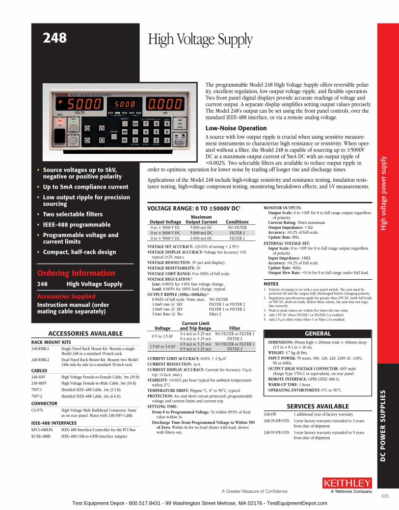
DC
PO
WE
R S
UP
PLI
ES
A Greater Measure of Confidence
The programmable Model 248 High Voltage Supply offers reversible polar-ity, excellent regulation, low output voltage ripple, and flexible operation . Two front panel digital displays provide accurate readings of voltage and current output . A separate display simplifies setting output values precisely . The Model 248’s output can be set using the front panel controls, over the standard IEEE-488 interface, or via a remote analog voltage .
low-Noise operationA source with low output ripple is crucial when using sensitive measure-ment instruments to characterize high resistance or resistivity . When oper-ated without a filter, the Model 248 is capable of sourcing up to ±5000V DC at a maximum output current of 5mA DC with an output ripple of <0 .002% . Two selectable filters are available to reduce output ripple in
order to optimize operation for lower noise by trading off longer rise and discharge times .
Applications of the Model 248 include high-voltage resistivity and resistance testing, insulation re sis -tance testing, high-voltage component testing, monitoring breakdown effects, and I-V mea sure ments .
VolTaGE raNGE: 0 To ±5000V DC1
output VoltageMaximum
output Current Conditions0 to ± 5000 V DC 5 .000 mA DC NO FILTER0 to ± 3000 V DC 5 .000 mA DC FILTER 10 to ± 5000 V DC 3 .000 mA DC FILTER 2
VOLTAGE SET ACCURACy: ±(0 .01% of setting + 2 .5V) 4 .VOLTAGE DISPLAy ACCURACy: Voltage Set Accuracy ±1V,
typical (±2V, max .) .VOLTAGE RESOLUTION: 1V (set and display) .VOLTAGE RESETTABILITy: 1V .VOLTAGE LIMIT RANGE: 0 to 100% of full scale .VOLTAGE REGULATION:2
Line: 0 .001% for ±10% line voltage change . Load: 0 .005% for 100% load change, typical .
OUTPUT RIPPLE (10Hz–100kHz):3 0 .002% of full scale, Vrms, max . NO FILTER 1 .0mV rms @ 1kV FILTER 1 or FILTER 2 2 .0mV rms @ 3kV FILTER 1 or FILTER 2 3 .0mv Rms @ 5kv Filter 2
VoltageCurrent limit
and Trip range filter
0 V to 1 .5 kV 0 .4 mA to 5 .25 mA0 .4 mA to 3 .25 mA
NO FILTER or FILTER 1 FILTER 2
1 .5 kV to 5 .0 kV 0 .5 mA to 5 .25 mA0 .5 mA to 3 .25 mA
NO FILTER or FILTER 1 FILTER 2
CURRENT LIMIT ACCURACy: 0 .01% + 2 .5µA5 .CURRENT RESOLUTION: 1µA .CURRENT DISPLAy ACCURACy: Current Set Accuracy ±1µA,
typ . (±2µA, max .) .STABILITy: ±0 .02% per hour typical for ambient temperature
within 2°C .TEMPERATURE DRIFT: 50ppm/°C, 0° to 50°C, typical .PROTECTION: Arc and short circuit protected; programmable
voltage and current limits and current trip .SETTLING TIME:
From 0 to Programmed Voltage: To within 99 .9% of final value within 3s .
Discharge Time from Programmed Voltage to Within 50V of zero: Within 6s for no load (faster with load, slower with filters on) .
sErVICEs aVaIlablE248-EW 1 additional year of factory warranty
248-3Y-EW-STD 1-year factory warranty extended to 3 years from date of shipment
248-5Y-EW-STD 1-year factory warranty extended to 5 years from date of shipment
aCCEssorIEs aVaIlablEraCK MouNT KITs248-RMK-1 Single Fixed Rack Mount Kit: Mounts a single
Model 248 in a standard 19-inch rack .248-RMK-2 Dual Fixed Rack Mount Kit: Mounts two Model
248s side-by side in a standard 19-inch rack .CablEs248-SHV High Voltage Female-to-Female Cable, 3m (10 ft)248-MHV High Voltage Female-to-Male Cable, 3m (10 ft)
7007-1 Shielded IEEE-488 Cable, 1m (3 .3 ft)
7007-2 Shielded IEEE-488 Cable, 2m (6 .6 ft)
CoNNECTorCS-970 High Voltage Male Bulkhead Connector . Same
as on rear panel . Mates with 248-SHV Cable .
IEEE-488 INTErfaCEsKPCI-488LPA IEEE-488 Interface/Controller for the PCI Bus
KUSB-488B IEEE-488 USB-to-GPIB Interface Adapter
• source voltages up to 5kV, negative or positive polarity
• up to 5ma compliance current
• low output ripple for precision sourcing
• Two selectable filters
• IEEE-488 programmable
• Programmable voltage and current limits
• Compact, half-rack design
ordering Information248 High Voltage supply
accessories suppliedInstruction manual (order mating cable separately)
MONITOR OUTPUTS:Output Scale: 0 to +10V for 0 to full range output regardless
of polarity .Current Rating: 10mA maximum .Output Impedance: <1W .Accuracy: ±0 .2% of full scale .Update Rate: 8Hz .
EXTERNAL VOLTAGE SET:Input Scale: 0 to +10V for 0 to full range output regardless
of polarity .Input Impedance: 1MW .Accuracy: ±0 .2% of full scale .Update Rate: 16Hz .Output Slew Rate: <0 .3s for 0 to full range under full load .
NoTEs1 . Polarity of output is set with a rear panel switch . The unit must be
powered off and the output fully discharged before changing polarity .2 . Regulation specifications apply for greater than 25V DC (with full load)
or 50V DC (with no load) . Below these values, the unit may not regu-late correctly .
3 . Peak to peak values are within five times the rms value .4 . Add ±5V DC when FILTER 1 or FILTER 2 is enabled .5 . Add 2 .5 µA offset when Filter 1 or Filter 2 is enabled .
GENEralDIMENSIONS: 89mm high × 206mm wide × 406mm deep
(3 .5 in × 8 .1 in × 16 in) .WEIGHT: 3 .7 kg (8 lbs) .INPUT POWER: 55 watts; 100, 120, 220, 240V AC ±10%,
50 or 60Hz .OUTPUT HIGH VOLTAGE CONNECTOR: SHV male
(Kings Type 1704-1 or equivalent), on rear panel .REMOTE INTERFACE: GPIB (IEEE-488 .1) .WARM-UP TIME: 1 hour .OPERATING ENVIRONMENT: 0°C to 50°C .
248 High Voltage SupplyH
igh
volta
ge p
ower
sup
ply
Hig
h vo
ltage
pow
er s
uppl
y
335 Test Equipment Depot - 800.517.8431 - 99 Washington Street Melrose, MA 02176 - TestEquipmentDepot.com

DC
PO
WE
R S
UP
PLI
ES
336 Test Equipment Depot - 800.517.8431 - 99 Washington Street Melrose, MA 02176 - TestEquipmentDepot.com

AC
CE
SS
OR
IES
A Greater Measure of Confidence
Accessories
Test Leads and Probes . . . . . . . . . . . . . . . . . . . . . . . 338
Cables . . . . . . . . . . . . . . . . . . . . . . . . . . . . . . . . . . . . 342
Connectors, Adapters, and Tools . . . . . . . . . . . . . . 354
Adapter, Cable, Prober, and Stabilizer Kits . . . . . . 365
Test Fixtures . . . . . . . . . . . . . . . . . . . . . . . . . . . . . . . 366
Trigger Accessories . . . . . . . . . . . . . . . . . . . . . . . . . 368
Bench Kit and Rack Mount Kits . . . . . . . . . . . . . . . 369
Cabinets . . . . . . . . . . . . . . . . . . . . . . . . . . . . . . . . . . 372
Remote PreAmp Mounting Accessories . . . . . . . . . 372
Carrying Case . . . . . . . . . . . . . . . . . . . . . . . . . . . . . . 372
IEEE-488 (GPIB) Interface Solutions . . . . . . . . . . . 373
IEEE-488 (GPIB) Accessories . . . . . . . . . . . . . . . . . 374
337 Test Equipment Depot - 800.517.8431 - 99 Washington Street Melrose, MA 02176 - TestEquipmentDepot.com

AC
CE
SS
OR
IES
Test leads and Probes
Item shipped may vary from model pictured here.
Model 1600A High Voltage ProbeMAXIMUM INPUT: 40kV DC or peak AC to 300Hz .
INPUT RESISTANCE: 1000MW .
DIVISION RATIO: 1000:1 (into 10MW) .
for use with: DMMs
Model 1651 50 Ampere Shunt: External 0 .001W ± 1%, 4-terminal shunt; extends current mea sur ing capability of Keithley DMMs to 50A .
CABLE LENGTH: 1 .4m (56 in) .
for use with: DMMs
Item shipped may vary from model pictured here.
Model 1681 Clip-On Test Lead Set: Two 1 .2m (48 in) leads terminated with banana plugs and spring action clip-on probes .
for use with: DMMs
Item shipped may vary from model pictured here.
Model 1751 Safety Test Leads: 91 .4cm (36 in) test lead set supplied with each Model 175A and 197A . Finger guards and shroud ed banana plugs help minimize the chance of making contact with live circuitry .
for use with: all DMMs, series 2400 sourceMeter® sMu Instruments
TEsT lEaDs aND ProbEs sElECTor GuIDEModel Name use With:1600A High Voltage Probe DMMs
1651 50-Ampere Shunt DMMs
1681 Clip-On Test Lead Set DMMs
1751 Safety Test Leads All DMMs, Series 2400
1752 Premium Safety Test Lead Kit All DMMs, Series 2400
1754 Safety Universal Test Lead Kit All DMMs, Series 2400
2187-4 Low Thermal Test Lead Kit 2182A, 622x Current Sources
2600-BAN Banana Test Leads/Adapter Cable 2601B, 2602B, 2611B, 2612B
3706-BAN Banana Test Leads/Adapter Cable Series 3700A Mainframes
3706-TLK Test Lead Kit Series 3700A Mainframes
5804 General-Purpose, 4-Terminal Test Lead Set Series 2400, 2750, DMMs
5805 Kelvin Probes, 0 .9m (3 ft) Series 2400, 2750, DMMs
5805-12 Kelvin Probes, 3 .6m (12 ft) Series 2400, 2750, DMMs
5806 Kelvin Clip Lead Set, 0 .9m (3 ft) Series 2400, 2750, DMMs
5807-7 Helical Spring Point Test Leads, 2 .1m (7 ft) Series 2400, 2750, DMMs
5808 Single-pin Kelvin Probe 2700, 2701, 2750, Series 2400, DMMs
5809 Kelvin Clip Lead Set 2700, 2701, 2750, Series 2400, DMMs
6517-RH Humidity Probe with Extension Cable 6517A, 6517B
6517-TP Thermocouple Bead Probe 6517A, 6517B
7401 Thermocouple Wire Kit, 30m (100 ft), Type K 2001-TCSCAN, 2110, 3720, 3721, 3724, 7057A, 7700, 7706, 7708
8605 High Performance Modular Test Leads All DMMs, Series 2400
8606 High Performance Modular Probe Kit All DMMs, Series 2400, Series 2600B, Series 3700A
8681 Low Cost RTD 2001, 2002, 2010 DMMs (with 8680)
CA-109A Test Lead Set for Output Connections 2000-SCAN, 2001-SCAN, 2001-TCSCAN
338
Test
lead
s an
d pr
obes
Tech
nica
l inf
orm
atio
n: S
ourc
e M
easu
rem
ent U
nit (
SMU
) In
stru
men
ts
Test Equipment Depot - 800.517.8431 - 99 Washington Street Melrose, MA 02176 - TestEquipmentDepot.com

AC
CE
SS
OR
IES
A Greater Measure of Confidence
Test leads and Probes
Model 1752 Premium Safety Test Lead Kit: Includes two banana leads with safety shrouds on both ends, two fully insulated alligator clips, two fully insulated needle probes, and two spring-action clip-on probes with safety blocks, in a carrying case .
for use with: all DMMs, series 2400 sourceMeter sMu Instruments
Item shipped may vary from model pictured here.
Model 1754 Universal Test Lead Kit: 10-piece test lead kit with interchangeable plug-in acces-sories . Kit includes: 1 set of test leads, 91 .4cm (36 in), 1 red and black; 2 spade lugs, 2 standard banana plugs, 2 hooks, and 2 min ia ture alligator clips with boots .
for use with: all DMMs, series 2400 sourceMeter sMu Instruments
Model 2187-4 Low Thermal Test Lead Kit: Includes an input cable with banana termina-tions, banana extensions, sprung-hook clips, alligator clips, needle probes, and spade lugs to connect the Model 2182A to virtually any DUT . The kit is also used to connect the Model 2182A directly to the Model 622X guard to improve response time for pulsed measure-ments or to reduce errors when measuring high impedance devices .
for use with: 2182a, 6220, 6221, 6220/2182a, 6221/2182a
Model 2600-BAN: 1m (3 .3 ft) banana test leads/adapter cable for a single Series 2600B SourceMeter channel (two needed for use with Model 2602B and 2612B) . Provides safety banana connections to Hi, Sense Hi, Lo, Sense Lo, and guard .
for use with: 2601b, 2602b, 2611b, 2612b
Model 3706-BAN: 1 .4m (4 .6 ft) banana test leads/adapter cable for Model 3706A mainframe with high performance multimeter option . Provides direct connection to high performance multimeter utilizing rear panel backplane con-nector . Safety banana connections to HI, LO, Sense HI, Sense LO, and AMP .
for use with: series 3700a mainframes
Model 3706-TLK Test Lead Kit: Includes 3706-BAN banana test leads/adapter cable and plug-in test lead accessories . Test lead accessories include: 4 spring hook probes, 2 needle test probes, 4 safety plug adapters, and carrying case .
for use with: series 3700a mainframes
339
Tech
nica
l inf
orm
atio
n: S
ourc
e M
easu
rem
ent U
nit (
SMU
) In
stru
men
ts
Test
lead
s an
d pr
obes
Test Equipment Depot - 800.517.8431 - 99 Washington Street Melrose, MA 02176 - TestEquipmentDepot.com

AC
CE
SS
OR
IES
Item shipped may vary from model pictured here.
Model 5804 Test Lead Set: Designed to be used with Keithley instruments that measure 4-terminal resistance . Contains: 2 test leads, 0 .9m (36 in), red and black; 2 test clips, red and black; 2 plunger clip adapters, red and black; 2 alligator clips with boots (accept standard test probe tip); 2 alligator clips with boots (barrels accept standard banana plugs) .
for use with: series 2400 sourceMeter® sMu Instruments, 2750, DMMs
Model 5805 Kelvin Probes: 2 spring-loaded test probes, red and black, 0 .9m (36 in) with banana plug termination . De signed to be used with Keithley in stru ments that measure 4-terminal re sis tance and in-circuit current . 1⁄8-in spacing between pin tips . A package of 8 re place ment contacts (P/N CS-551) is available .
Model 5805-12: Similar to 5805 but 3 .6m (12 ft) in length .
for use with: series 2400 sourceMeter sMu Instruments, 2750, DMMs
Model 5806 Kelvin Clip Lead Set: 2 clip test leads, red and black, 0 .9m (36 in) with banana plug ter mi na tion . Designed to be used with Keithley instruments that meas ure 4-terminal re sis tance . Maximum jaw opening ½ in . A package of 8 replace ment elastic bands (P/N 5806-306B) is available .
for use with: series 2400 sourceMeter sMu Instruments, 2750, DMMs
Model 5807-7 Helical Spring Point Test Leads: Two excellent Kelvin test probes for Keithley in stru ments that measure 4-terminal re sis tance . The probes have point ed tips that rotate when pressure is exerted on the handle . Good contact is assured, and the handle can be held at any angle to the mea sure ment surface . The lead wires ter mi nate in banana plugs . Lead wire length: 2m (7 ft) .
for use with: series 2400 sourceMeter sMu Instruments, 2750, DMMs
Model 5808 Low Cost, Single Pin, Kelvin Probes: Two 1 .17m (46 in) long, single fixed pin probes with source and sense leads per probe and color coded standard safety banana plugs . Designed for applications requiring Kelvin resistance measurements with the convenience of a single point of circuit contact . The Kelvin connection at the base of each probe pin results in very low resistance errors, eliminating all wire and probe body resistance . For the highest preci-sion sensing applications, use the Model 5805, 5806, or 5809 for complete control over sensing point placement .
for use with: 2700, 2701, 2750, series 2400, DMMs
Model 5809 Low Cost, Kelvin Clip Lead Set: Two 0 .94m (37 in) long probes with alligator style clips, each with opposing blade source and sense connections to color coded standard safety banana plugs . Designed for applications requir-ing Kelvin connection to wires, axial leaded components, and other terminals able to be clipped onto . The miniature blade design accom-modates narrow available width applications as well as general lighter duty applications . The maximum jaw opening is 9 .14mm (0 .36 in) and the blade width is 2 .92mmm (0 .115 in) .
for use with: 2700, 2701, 2750, series 2400, DMMs
Test leads and Probes
340
Test
lead
s an
d pr
obes
Test
lead
s an
d pr
obes
Test Equipment Depot - 800.517.8431 - 99 Washington Street Melrose, MA 02176 - TestEquipmentDepot.com

AC
CE
SS
OR
IES
A Greater Measure of Confidence
Test leads and Probes
Model 6517-RH Humidity Probe: The 6517-RH comes with a 3m (10 ft) extension cable and is designed to be used with the 6517B Electrom-eter . The 6517-RH measures the relative humidity of the testing environment .
OPERATING TEMPERATURE RANGE: –10°C to +60°C
OPERATING HUMIDITy RANGE: 0 to 100% RH
MEASURING RANGE: 10 to 90% RH
TEMPERATURE DEPENDENCE: <±2% from –10°C to +60°C
for use with: 6517a and 6517b Electrometers
Model 6517-TP Thermocouple Bead Probe: Designed to be used with the 6517B Electro m-eter, the 6517-TP measures the temperature of the testing en vi ron ment . 6517-TP is 36 in . long and has a temperature calibration (range) of 0°C to 1250°C . Type K thermocouple .
for use with: 6517a and 6517b Electrometers and 2110 DMM
Model 7401: Type K ther mo cou ple wire kit includes 30 .5m (100 ft) of type K (chromel-alumel) ther mo cou ple wire .
for use with: 2001-TCsCaN, 2110, 3720, 3721, 3724, 7057a, 7700, 7706, 7708
Model 8605 High Per for mance Modular Test Leads: Highest quality lead with sili cone insula-tion, and removable test probes . Rated to 1500V . UL listed .LENGTH: 1m (3 .3 ft) .
for use with: all DMMs, series 2400 sourceMeter® sMu Instruments
Item shipped may vary from model pictured here.
Model 8606 High Per for mance Modular Probe Kit: For use with Model 8605 High Per-for mance Modular Test Leads . Contains 2 each spade lugs, alligator clips, and re tract able hooks .
for use with: all DMMs; series 2400 and series 2600b sourceMeter sMu Instruments; series 3700a
Model 8681 Low Cost RTD: This inexpensive RTD has small size (0 .09 in × 0 .09 in) and fast thermal response time . 100W, 0 .385%/°C ele-ment . Meets or exceeds DIN 43760-1980-A, IEC 751:1983-A, BS1904: 1984-A, and JIS C1604-1981-0 .2 . Can be used with Model 8680 RTD Input Probe Adapter . Measures from –200° to +600°C .
LENGTH: 0 .9m (3 ft) .
ACCURACy: ±(0 .15°C + 0 .002 × |t|)/°C, where |t| is absolute value of temperature in °C .
for use with: 2001, 2002, 2010 DMMs (with 8680), 7700, 7702, 7706, 7708
Item shipped may vary from model pictured here.
Model CA-109A Test Lead Set: For output con-nec tions (two red, two black) .
for use with: 2000-sCaN, 2001-sCaN, 2001-TCsCaN
341
Test
lead
s an
d pr
obes
Test
lead
s an
d pr
obes
Test Equipment Depot - 800.517.8431 - 99 Washington Street Melrose, MA 02176 - TestEquipmentDepot.com

AC
CE
SS
OR
IES
Model Description Type
TErMINaTIoNs lENGTH
usE WITH:from To m ft236-ILC-3 Safety Interlock Shielded twisted pair 3-pin round 3-pin round 3 10 4200-SCS, 8007, 8008
237-ALG-2 Low Noise Input Triax 3-slot male triax Alligator clips (3) 2 6 .6 Series 2200, Series 2600B, 4200-PA, 6220, 6221, 6482, 6487, 6514, 6517A, 6517B
237-ALG-15 Low Noise Input Triax 3-slot male triax Alligator clips (3) 15 50 Series 2200, Series 2600B, 4200-PA, 6220, 6221, 6482, 6487, 6514, 6517A, 6517B
248-MHV High Voltage Coax SHV female MHV male 3 10 248
248-SHV High Voltage Coax SHV female SHV female 3 10 248, CS-970
2000-MTC-2 Cable Assembly Shielded twisted pair DB44 female Unterminated 2 6 .6 2000-20
2000-MTCD-2 Cable Assembly Shielded multiple conductors DB44 female DB50 male 2 6 .6 2000-SCAN-20
2600-ALG-2 Low Noise Input Triax 3-slot male triax Alligator clips (3) 2 6 .6 2635B, 2636B, 4200-PA
2651A-KIT-1 Cable Assembly Coax 2-pin plug 2-pin plug 1 3 .3 2651A, 8011
2651A-KIT-2 Cable Assembly Coax 2-pin plug 2-pin plug 2 6 .6 2651A, 8011
2651A-KIT-3 Cable Assembly Coax 2-pin plug 2-pin plug 3 10 2651A, 8011
2107-4 Input Cable Shielded twisted pair LEMO Copper spade lugs (4) 1 .2 4 2182A
2107-30 Input Cable Shielded twisted pair LEMO Copper spade lugs (4) 9 .1 30 2182A, Series 2200
2107-50 Input Cable Shielded twisted pair LEMO Copper spade lugs (4) 15 50 2182A, Series 2200
3720-MTC-1.5 Mass Terminated Assembly Twisted pair D-sub female 78-pin D-sub male 1 .5 5 3720, 3723, 3724
3720-MTC-3 Mass Terminated Assembly Twisted pair D-sub female 78-pin D-sub male 3 10 3720, 3723, 3724
3721-MTC-1.5 Mass Terminated Assembly Twisted pair D-sub female 50-pin D-sub male 1 .5 5 3721, 3730, 3731, 3740, 3750
3721-MTC-3 Mass Terminated Assembly Twisted pair D-sub female 50-pin D-sub male 3 10 3721, 3730, 3731, 3740, 3750
3722-MTC-1.5 Mass Terminated Assembly Twisted pair D-sub male 104-pin D-sub female 1 .5 5 3722
3722-MTC-1.5/MM Mass Terminated Assembly Twisted pair D-sub male 104-pin D-sub male 1 .5 5 3722
3722-MTC-3 Mass Terminated Assembly Twisted pair D-sub male 104-pin D-sub female 3 10 3722
3722-MTC-3/MM Mass Terminated Assembly Twisted pair D-sub male 104-pin D-sub male 3 10 3722
3732-MTC-1.5 Mass Terminated Assembly Twisted pair D-sub female 78-pin D-sub male 1 .5 5 3732
3732-MTC-3 Mass Terminated Assembly Twisted pair D-sub female 78-pin D-sub male 3 10 3732
4200-MTRX-1 Ultra Low Noise SMU triax Miniature male 3-slot male 1 3 .2 4200-SCS
4200-MTRX-2 Ultra Low Noise SMU triax Miniature male 3-slot male 2 6 .5 4200-SCS
4200-MTRX-3 Ultra Low Noise SMU triax Miniature male 3-slot male 3 9 .8 4200-SCS
4200-PRB-C Cable Assembly Y adapter cable Female SMA 2 female SSMC 4200-PIV, 4210-CVU
4200-RPC-0.3 Cable Assembly Remote PreAmp DB15 DB15 0 .3 1 4200-PA
4200-RPC-2 Cable Assembly Remote PreAmp DB15 DB15 2 6 .5 4200-PA
4200-RPC-3 Cable Assembly Remote PreAmp DB15 DB15 3 9 .8 4200-PA
4200-RPC-6 Cable Assembly Remote PreAmp DB15 DB15 6 19 .6 4200-PA
4200-TRX-0.3 Ultra Low Noise PreAmp triax 3-slot male 3-slot male 0 .3 1ft 4200-PA
4200-TRX-1 Ultra Low Noise PreAmp triax 3-slot male 3-slot male 1 3 .2 4200-PA
4200-TRX-2 Ultra Low Noise PreAmp triax 3-slot male 3-slot male 2 6 .5 4200-PA
4200-TRX-3 Ultra Low Noise PreAmp triax 3-slot male 3-slot male 3 9 .8 4200-PA
4801 Low Noise Input Coax Male BNC Male BNC 1 .2 4 6482, 6485, 7158
4802-10 Low Noise Input Coax Male BNC Unterminated 3 10 6482, 6485, 7158
4803 Low Noise Cable Kit Coax Male BNC (10) Female BNC (5) 15 .2 50 6482, 6485, 7158
6011 Input Leads Triax 2-slot male triax Alligator clips (3) 1 .5 5 Instruments with 2-slot triax connectors
6011-10 Input Leads Triax 2-slot male triax Alligator clips (3) 3 10 Instruments with 2-slot triax connectors
6517-ILC-3 4-pin Interlock Cable Shielded 4-pin female DIN 4-pin female DIN 1 3 .3 6517A, 8009
6517B-ILC-3 Interlock Cable Shielded 4-pin Phoenix 4-pin DIN 1 3 .3 6517B, 8009
7009-5 Shielded RS-232 Shielded Male DB-9 Female DB-9 1 .5 5 All RS-232 capable instruments
7011-MTC-1 Mass Terminated Assembly Twisted pair (45) 96-pin female 96-pin female 1 3 .3 7011-C, 7012-C, 7013-C, 7015-C, 7018-C
7011-MTC-2 Mass Terminated Assembly Twisted pair (45) 96-pin female 96-pin female 2 6 .6 7011-C, 7012-C, 7013-C, 7015-C, 7018-C
7019C-MTCI-2 Kelvin Instrument Cable Shielded twisted pair Card connector Shielded banana plug cables (6) 2 6 .6 Series 2400
7020-MTC-2 Mass Terminated Assembly Twisted pair (45) 96-pin female 96-pin female 2 6 .6 7020
7024-3 Low Noise Triax 2-slot male triax 2-slot male triax 0 .9 3 Instruments with 2-slot triax connectors
7024-10 Low Noise Triax 2-slot male triax 2-slot male triax 3 10 Instruments with 2-slot triax connectors
7025-10 Low Noise Input Triax 2-slot male triax Unterminated 3 10 Instruments with 2-slot triax connectors
7035-MTC-2 Mass Terminated Assembly Twisted pair (45) 96-pin female 96-pin female 2 6 .6 7035
7036-MTC-2 Mass Terminated Assembly Twisted pair (45) 96-pin female 96-pin female 2 6 .6 7036
7051-* BNC Interconnect Coax BNC BNC 2015, 2016, 3390
Cables
342
Cabl
es
Cabl
es
Test Equipment Depot - 800.517.8431 - 99 Washington Street Melrose, MA 02176 - TestEquipmentDepot.com

AC
CE
SS
OR
IES
A Greater Measure of Confidence
Cables
Model Description Type
TErMINaTIoNs lENGTH
usE WITH:from To m ft
7078-DIN 707A Master/Slave Twisted pair (9) 8-pin DIN 8-pin DIN 1 .8 6 707A
7078-MTC-5 Mass Terminated Assembly Twisted pair (12) 38-pin connector 38-pin connector 1 .5 5 7071, 7071-4, 7074-D
7078-MTC-20 Mass Terminated Assembly Twisted pair (12) 38-pin connector 38-pin connector 6 .1 20 7071, 7071-4, 7074-D
7078-TRX-1 Low Noise Triax 3-slot male triax 3-slot male triax 0 .3 1 2635B, 2636B, 6482, 6487, 6514, 6517A, 6517B, 7072, 7174A
7078-TRX-3 Low Noise Triax 3-slot male triax 3-slot male triax 0 .9 3 2635B, 2636B, 6482, 6487, 6514, 6517A, 6517B, 7072, 7174A
7078-TRX-5 Low Noise Triax 3-slot male triax 3-slot male triax 1 .5 5 2635B, 2636B, 6482, 6487, 6514, 6517A, 6517B, 7072, 7174A
7078-TRX-10 Low Noise Triax 3-slot male triax 3-slot male triax 3 10 2635B, 2636B, 6482, 6487, 6514, 6517A, 6517B, 7072, 7174A
7078-TRX-12 Low Noise Triax 3-slot male triax 3-slot male triax 4 12 2635B, 2636B, 6482, 6487, 6514, 6517A, 6517B, 7072, 7174A
7078-TRX-20 Low Noise Triax 3-slot male triax 3-slot male triax 6 .1 20 2635B, 2636B, 6482, 6487, 6514, 6517A, 6517B, 7072, 7174A
7078-TRX-6IN Low Noise Triax 3-slot male triax 3-slot triax 0 .15 0 .5 6430
7152-MTC-2 Low Noise Matrix Expansion Triax (5) 6-pin M-series coax 6-pin M-series coax 0 .6 2 7152
7152-MTC-10 Low Noise Matrix Expansion Triax (5) 6-pin M-series coax 6-pin M-series coax 3 10 7152
7152-TRX-10 Low Noise M-Series to Triax Triax (5) M-series connector 3-slot triax (5) 3 10 7152, 8006
7153-TRX Low Noise M-Series to Triax Triax (5) M-series connector 3-slot triax (5) 2 6 7153
7173-50-CSEP 4-cable Set Coax SMB female BNC male 0 .6 2 7173-50
7705-MTC-2 Mass Terminated Assembly Twisted pair (25) D-sub male D-sub female 2 6 .6 7703, 7705, 7707, 7709
7711-BNC-SMA 5 SMA to BNC Cables Coax SMA Male BNC Female 0 .15 0 .5 7711
7712-SMA-1 SMA Cables Coax SMA Male SMA Male 1 3 .3 7711, 7712, System 46, System 46T
7754-3 BNC Coax BNC Male Alligator clips 0 .9 3 Instruments with 2-slot BNC connectors
8007-GND-3 Safety Ground Wire Single wire Crimp lug Crimp lug 3 10 8007
8542-301 LIV Cable Multiple conductor DB9 femaleMultiple terminations: Triax (2500), 2 dual bananas (24XX) GND wire
1 .8 6 2500, Series 2400, System 25, 8544, 8544-TEC
8607 1kV Test Cables Single wire (2) Safety banana Safety banana 1 3 .3 2410, 6487, 6517A, 6517B
CA-18-1 Shielded Coax Dual banana plug Dual banana plug 1 .2 4 Bind ing post inputs
CA-19-2 RG58 RG58 BNC male BNC male 1 .5 5 4200-SCS
CA-126-1A Digital I/O Shielded DB25 male DB25 female 1 .5 5 Series 2600B, Series 3700A
CA-180-3A Crossover Cable Twisted pair RJ45 RJ45 3 10Series 2600B, 2701, 3390, Series 3700A, 6221, all TSP-enabled instruments
CA-321-1 Temperature Control Cable Multiple conductor DB15 female 8-position Phoenix(CS-846 equivalent) 1 .8 6 2510, 8544
CA-322-1 Dual Temperature Control Cable Multiple conductor DB15 female Y cable to two 8-position
Phoenix (CS-846) 1 .8 6 2510, 8544, 8544-TEC
CA-404B RG188 Coax SMA male SMA male 2 6 .5 4200-SCS
CA-405B RG188 Coax SMA male SMA male 0 .15 0 .5 4200-SCS
CA-406B RG188 Coax SMA male SMA male 0 .33 1 .08 4200-SCS
CA-446A Cable Assembly Coax SMA male SMA male 3 9 .8 4210-CVU
CA-447A Cable Assembly Coax SMA male SMA male 1 .5 5 4210-CVU
CA-451A RG188 Coax SMA male SMA male 0 .108 0 .35 4200-SCS
CA-452A RG188 Coax SMA male SMA male 0 .203 8 in. 4200-SCS
CA-557-1A Cable Assembly Multiple conductor 8-pin receptacle 8-pin receptacle 1 3 .3 2651A, 8011
CA-557-2A Cable Assembly Multiple conductor 8-pin receptacle 8-pin receptacle 2 6 .6 2651A, 8011
CA-557-3 Cable Assembly Multiple conductor 8-pin receptacle 8-pin receptacle 3 10 2651A, 8011
CA-558-x Interlock Cable Twisted pair (2) 25-pin D-sub 3-pin 1, 2, 33 .3, 6 .6,
10Series 2600B, 2657A
CA-559-0A Black Banana Jumper Jumper Banana Banana 0 .102 4 in . 8010
CA-559-2A Red Banana Jumper Jumper Banana Banana 0 .102 4 in . 8010
CA-560-0A Banana Plug Jumper Cable Jumper Banana Banana 0 .203 8 in . 8010
CA-560-2A Banana Plug Jumper Cable Jumper Banana Banana 0 .203 8 in . 8010
CA-561-0A Black Banana Jumper Jumper Banana Banana 0 .203 8 in . 8010
CA-561-2A Red Banana Jumper Jumper Banana Banana 0 .203 8 in . 8010
CA-562-0BBlack Safety Banana Plug Jumper Cable
Jumper Banana Banana 0 .254 10 in . 8010
CA-562-2BRed Safety Banana Plug Jumper Cable
Jumper Banana Banana 0 .254 10 in . 8010
CA-563C BNC to Banana Jumper Jumper Bnc Banana 0 .241 9 .5 in . 8010
CA-567-0A Black Banana Jumper Jumper Banana Banana 0 .203 8 in . 8010
CA-567-2A Red Banana Jumper Jumper Banana Banana 0 .203 8 in . 8010
CA-568-XA Protective Earth Ground Safety Eye lug Eye lug 0 .3, 0 .45, 3 1, 1 .5, 10 8010
343
Cabl
es
Cabl
es
Test Equipment Depot - 800.517.8431 - 99 Washington Street Melrose, MA 02176 - TestEquipmentDepot.com

AC
CE
SS
OR
IES
Model 236-ILC-3 Safety Interlock Cable: Designed to connect the lid interlock circuit of the Models 8007 and 8008 test fixtures to the interlock circuit of the Model 237 SMU and 486 and 487 Picoammeters .
for use with: 4200-sCs, 8007, 8008
Model 237-ALG-*: Low noise triax cable (SC-22) terminated with a 3-slot male triax connector on one end and 3 alligator clips on the other . 237-ALG-2 2m (6 .6 ft) length 237-ALG-15 15m (50 ft) length
for use with: series 2200, series 2600b, 4200-Pa, 6220, 6221, 6487, 6514, 6482, 6517a, 6517b
Model 248-MHV: 3m (10 ft) of RG-8A/U coax cable terminated with a SHV female connec-tor on one end and a MHV male connector on the other . Maximum operating voltage (rms) is 5,000V .
for use with: 248
Model 248-SHV: 3m (10 ft) of RG-8A/U coax cable terminated with a SHV female connector on both ends . Maximum operating voltage (rms) is 5,000V .
for use with: 248 and Cs-970
Model 2000-MTC-2 Cable Assembly: 2-meter cable with a 44-pin connector on one end that is designed to mate with the 2000-20 scanner card . The other end is unterminated for direct connec-tion to measurement fixtures or devices .
for use with: 2000-20
Model 2000-MTCD-2 Cable Assembly: 2-meter cable with a 44-pin connector on one end that is designed to mate with the 2000-SCAN-20 scanner card . The other end is equipped with a 50-pin D-sub male connector .
for use with: 2000-sCaN-20
Cables
Model Description Type
TErMINaTIoNs lENGTH
usE WITH:from To m ft
HV-CA-554-x 3kV Rated High voltage Triax Triax0 .5, 1, 2, 3
1 .6, 3 .2, 6 .6, 10
8010, 2657A
HV-CA-571-3 High Voltage Triax Triax Unterminated 2657A
S46-SMA-0.5 SMA Cable Coax SMA Male SMA Male 0 .15 0 .5 7711, 7712, System 46, System 46T
S46-SMA-1 SMA Cable Coax SMA Male SMA Male 0 .30 1 .0 7711, 7712, System 46, System 46T
SC-9 Low Noise Coax Unterminated Unterminated Sold by the foot
SC-22 Low Noise Triax Unterminated Unterminated Sold by the foot CS-631
SC-93 Low Thermal Shielded Unterminated Unterminated Sold by the foot 2182-KIT
SC-182 Low Inductance Coax Unterminated Unterminated Sold by the foot 2302, 2303, 2303-PJ, 2304A, 2306, 2306-PJ
SC-200A General Purpose Shielded twisted pair Unterminated Unterminated Sold by the inch Series 2600B
SC-206 High Current Coax Cable Coax Unterminated Unterminated Sold by the inch 2651A
SHV-CA-553-x 3kV Rated High voltage Triax SHV 1, 2, 3
3 .2, 6 .6, 10
2657A
344
Cabl
es
Cabl
es
Test Equipment Depot - 800.517.8431 - 99 Washington Street Melrose, MA 02176 - TestEquipmentDepot.com

AC
CE
SS
OR
IES
A Greater Measure of Confidence
Model 2107-* Low-Thermal Input Cables with Spade Lugs: An input cable terminated with a LEMO connector on one end and four copper spade lugs on the other . 2107-4 1 .2m (4 ft) length 2107-30 9 .1m (30 ft) length 2107-50 15m (50 ft) length
for use with: 2182a, series 2200
Model 2600-ALG-2: 2m (6 .6 ft) cable terminated with a 3-slot male triax connector on one end and 3 alligator clips on the other .
for use with: 2635b, 2636b, 4200-Pa
Model 2651A-KIT-*: High current, low impe-dance, coaxial cable assembly .2651A-KIT-1: 1m (3 .3 ft) .2651A-KIT-2: 2m (6 .6 ft) .2651A-KIT-3: 3m (10 ft) .
for use with: 2651a, 8011
Model 3720-MTC-*: 78-pin D-sub female to 78-pin D-sub male cable .3720-MTC-1.5: 1 .5m (5 ft) length3720-MTC-3: 3m (10 ft) length
for use with: 3720, 3723, 3724
Model 3721-MTC-*: 50-pin D-sub female to 50-pin D-sub male cable .3721-MTC-1.5: 1 .5m (5 ft) length3721-MTC-3: 3m (10 ft) length
for use with: 3721, 3730, 3731, 3740, 3750
Model 3722-MTC-*: 104-pin D-sub male to 104-pin D-sub female cable .3722-MTC-1.5: 1 .5m (5 ft) length3722-MTC-3: 3m (10 ft) length
for use with: 3722
Model 3722-MTC-*/MM: 104-pin D-sub male to 104-pin D-sub male cable .3722-MTC-1.5/MM: 1 .5m (5 ft) length3722-MTC-3/MM: 3m (10 ft) length
for use with: 3722
Model 3732-MTC-*: 78-pin D-sub female to 78-pin D-sub male cable .3732-MTC-1.5: 1 .5m (5 ft) length3732-MTC-3: 3m (10 ft) length
for use with: 3732
Cables
345
Cabl
es
Cabl
es
Test Equipment Depot - 800.517.8431 - 99 Washington Street Melrose, MA 02176 - TestEquipmentDepot.com

AC
CE
SS
OR
IES
Model 4200-MTRX-*: Ultra low noise SMU triax cable is terminated with a miniature male triax connector on one end and a standard 3-slot male triax connector on the other end . This cable connects a Model 4200-SMU or 4210-SMU source measurement unit installed in a Model 4200-SCS to a test fixture . (4200-MTRX-* cables are intended only for connection to an SMU that does not have a 4200-PA PreAmp installed .)4200-MTRX-1: 1m (3 .2 ft)4200-MTRX-2: 2m (6 .5 ft) (two included with each 4200-SCS SMU not configured with a 4200-PA Remote PreAmp)4200-MTRX-3: 3m (9 .8 ft)
for use with: 4200-sCs
Model 4200-PRB-C: SMA to SSMC Y adapter cable with local ground that connects the 4200-PIV package to DC probe manipulators . The cable is terminated at one end with a single female SMA . The other end splits into two gold SSMC plugs (female connectors) and a black wire with integrated connector, which is used to connect to the shield of another Model 4200-PRB-C cable .
for use with: 4200-PIV, 4210-CVu
Model 4200-RPC-*: Remote PreAmp cable terminated at each end with a high density DB15 connector . This cable connects a Model 4200-SMU or 4210-SMU source measurement unit installed in a Model 4200-SCS to a remotely mounted Model 4200-PA PreAmp .4200-RPC-0.3: 0 .3m (1 ft) (for use inside prober shield)4200-RPC-2: 2m (6 .5 ft) (one included with each 4200-PA)4200-RPC-3: 3m (9 .8 ft) 4200-RPC-6: 6m (19 .6 ft)
for use with: 4200-Pa
Model 4200-TRX-*: Ultra low noise PreAmp triax cable terminated with a standard 3-slot male triax connector on each end . This cable connects a Model 4200-PA PreAmp option installed in the Model 4200-SCS to the test fixture .4200-TRX-0.3: 0 .3m (1 ft) (recommended for remote location of the 4200-PA)4200-TRX-1: 1m (3 .2 ft)4200-TRX-2: 2m (6 .5 ft) (two included with each Model 4200-PA)4200-TRX-3: 3m (9 .8 ft)
for use with: 4200-Pa
Model 4801 Input Cable: Low noise coax cable, 1 .2m (48 in) in length, with male BNC con nec-tors on each end .for use with: 6482, 6485, 7158
Model 4802-10: 3m (10 ft) of low noise coax cable with male BNC connector at one end and unterminated at the other .for use with: 6482, 6485, 7158
Model 4803 Low Noise Cable Kit: In cludes 15m (50 ft) of low noise coax cable, 10 male BNC con nec tors, and 5 female BNC chassis-mount connectors .for use with: 6482, 6485, 7158
Cables
346
Cabl
es
Cabl
es
Test Equipment Depot - 800.517.8431 - 99 Washington Street Melrose, MA 02176 - TestEquipmentDepot.com

AC
CE
SS
OR
IES
A Greater Measure of Confidence
2 slot Triax
Model 6011 2-slot Triax Cable: 1 .5m (5 ft) of tri ax cable (SC-22) ter mi nat ed with a 2-slot triax plug on one end and three alligator clips on the other . Also available in 3m (10 ft) length (Model 6011-10).
for use with instruments with 2-slot triax connectors
Model 6517-ILC-3 Interlock Cable: De sign ed to connect the Interlock of the 6517A with the 8009 test fixture . Configuring the 6517A with the 8009 test fixture results in all the elec trode constants already being programmed into the unit .
for use with: 6517a Electrometer, 8009
Model 6517B-ILC-3 Interlock Cable: De sign ed to connect the interlock of the 6517B with the 8009 test fixture . Configuring the 6517B with the 8009 test fixture results in all the elec trode con-stants already being programmed into the unit .
for use with: 6517b Electrometer, 8009
Model 7009-5 Shielded RS-232 Cable: 1 .5m (5 ft) RS-232 cable with a male DB-9 connector at one end and a female DB-9 connector on the other end . Wired as a straight through, not as a null modem cable .
for use with: all rs-232 capable instruments
Model 7011-MTC-x: Mass terminated cable assembly for connection to 7011-C and other switching cards . The cable has 45 pairs with outer shield . The cable is terminated at each end with 96-pin female DIN connectors with strain relief . 7011-MTC-1 1m (3 .3 ft) 7011-MTC-2 2m (6 .6 ft)
for use with: 7011-C, 7012-C, 7013-C, 7015-C, 7018-C, 7022
7022Model 7019C-MTCI-2 6-wire Kelvin Ex tend er and Instru ment Cable: Used with Model 7019-C 6-Wire Ohms Matrix Card and a SourceMeter SMU instrument . The Source Meter cables are 0 .6m (2 ft) long and the DUT cables are 2m (6 .6 ft) long . The cable set is used in a basic system to test a resistor network .
for use with: series 2400 sourceMeter sMu Instruments
Model 7020-MTC-2: 2m (6 .6 ft) mass terminated cable assembly for connection to 7020 . The cable has 45 pairs with outer shield . The cable is terminated at each end with 96-pin female DIN connectors with strain relief .for use with: 7020
Cables
347
Cabl
es
Cabl
es
Test Equipment Depot - 800.517.8431 - 99 Washington Street Melrose, MA 02176 - TestEquipmentDepot.com

AC
CE
SS
OR
IES
2 slot Triax
Model 7024-* 2-slot Triax Cable: Low noise triax cable (SC-22) with 2-slot male triax connec-tors on each end . 7024-3 0 .9m (3 ft) 7024-10 3m (10 ft)
for use with instruments with 2-slot triax connectors
2 slot Triax
Model 7025-10 2-slot Triax Cable: 3m (10 ft) low noise triax input cable (SC-22) terminated on one end with 2-slot male triax connector .
for use with instruments with 2-slot triax connectors
Model 7035-MTC-2: 2m (6 .6 ft) mass terminated cable assembly for connection to 7035 . The cable has 45 pairs with outer shield . The cable is terminated at each end with 96-pin female DIN connectors with strain relief .for use with: 7035
Model 7036-MTC-2: 2m (6 .6 ft) mass terminated cable assembly for connection to 7036 . The cable has 45 pairs with outer shield . The cable is terminated at each end with 96-pin female DIN connectors with strain relief .for use with: 7036
Model 7051-*: General purpose BNC to BNC cable (G-58C) . 7051-2 0 .6m (2 ft) 7051-5 1 .5m (5 ft) 7051-10 3m (10 ft)for use with: 2015, 2016, 3390, 7711, some instrument external trigger I/o lines
Model 7078-DIN: This 1 .8m (6 ft) cable ac ces-sory connects between Model 707A main frames when operated as one unit in Master/Slave mode . One cable is required for each mainframe .for use with: 707a
Model 7078-MTC-5: 1 .5m (5 ft) mass terminated cable for connection to column inputs (7071 and 7071-4) . Also used for matrix expansion (7071, 7071-4, or 7074) . The cable has 12 sets of shielded twisted pair wires for isolation of critical circuits and noise rejection in the system . The cable is ter-minated at each end in a 38-pin connector block with strain relief . Model 7078-MTC-20 can be used as is or cut in half to make two 10 ft cables .
for use with: 7071, 7071-4, 7074-D
3 slot Triax
Model 7078-TRX-* 3-slot Triax Cables: Low noise triax cables terminated at both ends in 3-slot male triax connectors . 7078-TRX-1 0 .3m (1 ft) 7078-TRX-3 0 .9m (3 ft) 7078-TRX-5 1 .5m (5 ft) 7078-TRX-10 3 .0m (10 ft) 7078-TRX-12 3 .5m (12 ft) 7078-TRX-20 6 .0m (20 ft)
for use with: 2635b, 2636b, 6220, 6221, 6482, 6487, 6514, 6517a, 6517b, 7072, 7174a
Cables
348
Cabl
es
Cabl
es
Test Equipment Depot - 800.517.8431 - 99 Washington Street Melrose, MA 02176 - TestEquipmentDepot.com

AC
CE
SS
OR
IES
A Greater Measure of Confidence
Cables
3 slot Triax
Model 7078-TRX-6IN 3-slot Triax Cable: 0 .15m (6 inch), 3-slot, low-noise, guarded triax cable that minimizes leakage current and input capacitance when used with the Model 6430 Remote PreAmp (lower noise than 1 foot or longer versions) .
for use with: 6430
Model 7152-MTC-*: Five low noise triax cables terminated in 6-position M-series coax connec-tor blocks . Provides quick connection between 7152 matrix cards and is compatible with Model 7152-MTR connector . Also available in 3m (10 ft) length for connection between the matrix and the device under test . 7152-MTC-2 0 .6m (2 ft) 7152-MTC-10 3 .0m (10 ft)
for use with: 7152
Model 7152-TRX-10: Set of five 3m (10 ft) low noise triax cables terminated at one end in a single M-series connector block and at the other end in 3-slot triax connectors . This cable is most useful for direct connection to electrometers and Source/Measure Units .
for use with: 7152, 8006
Model 7153-TRX: 2m (6 .6 ft) low noise cable assembly with M-series connector at one end for row or column connections to the 7153, and five 3-slot male triax connectors at the other end . Two 7153-TRX cable assemblies are required to make all connections to the 7153 card .
for use with: 7153
Model 7173-50-CSEP: The 7173-50-CSEP cable set provides the capability to expand a switching configuration to include more than one 7173-50 . Each set contains four 0 .6m (25 in) cables . One cable is required to expand each row or column connection between adjacent cards . For exam-ple, using two 7173-50 cards to create a 4×24 matrix would require connecting the rows of two adjacent cards together . One 7173-50-CSEP set has enough cables to do this . Connecting the 12 columns together on two adjacent cards cre-ates an 8×12 matrix . This would require three 7173-50-CSEP sets, 12 cables .
for use with: 7173-50
Model 7705-MTC-2: 2m (6 .6 ft) 50-conductor male to female D-sub cable assembly .
for use with: 7703, 7705, 7707, 7709, 7701
349
Cabl
es
Cabl
es
Test Equipment Depot - 800.517.8431 - 99 Washington Street Melrose, MA 02176 - TestEquipmentDepot.com

AC
CE
SS
OR
IES
Cables
Model 7707-MTC-2: 2m (6 .6 ft) 25-conductor male to female D-sub cable assembly .
for use with: 7701, 7707, 7709
Model 7711-BNC-SMA: Male SMA to female BNC cables (5 each), 0 .15m (0 .5 ft) in length .
for use with: 7711
Model 7712-SMA-1: SMA cable, male to male, 1m (3 .3 ft) .
for use with: 7711, 7712, system 46, system 46T
Model 7754-3 BNC to Alligator Cable: 0 .9m (3 ft) terminated on one end with a BNC plug and on the other with two alligator clips .
for use with instruments with 2-slot bNC connections
Model 8007-GND-3: Safety ground wire, 3m (10 ft) .
for use with instruments with a safety ground connector
Model 8542-301: 1 .8m (6 ft) LIV test system cable .
for use with: series 2400, 2500, system 25, 8544, 8544-TEC
Item shipped may vary from model pictured here.
Model 8607 1kV Source Banana Cable Set: The 8607 cable set is made up of one red and one black high voltage test lead with fixed safety banana plug ends . The leads are 1 meter (3 .3 ft) long and have a voltage rating of 1500V DC .
for use with: 2410, 6487, 6517a, 6517b
Item shipped may vary from model pictured here.
CA-18-1: 1 .2m (4 ft) shielded cable te r m i nat ed with a dual banana plug on each end . For use with binding post inputs or dual banana jacks .
for use with: binding post inputs
Model CA-19-2: 1 .5m (5 ft) RG58 cable termi-nated with a BNC male plug on each end .
for use with: 4200-sCs
350
Cabl
es
Cabl
es
Test Equipment Depot - 800.517.8431 - 99 Washington Street Melrose, MA 02176 - TestEquipmentDepot.com

AC
CE
SS
OR
IES
A Greater Measure of Confidence
Cables
CA-126-1A Digital I/O Cable: 1 .5m (5 ft) of cable, from DB25 male to DB25 female .
for use with: series 2600b, series 3700a
CA-180-3A: 3m (10 ft), CAT5 crossover cable for Ethernet or TSP-Link .for use with: series 2600b, 2701, 3390, series 3700a, 6221, all TsP-link enabled instruments
CA-321-1: Temperature control cable .
for use with: 2510, 8544
CA-322-1: Dual temperature control cable .
for use with: 2510, 8544, 8544-TEC
CA-404B: 2m (6 .5 ft) RG188 coax cable termi-nated with an SMA male plug on each end, 50W impedance .
for use with: 4200-sCs, system 46, system 46T
CA-405B: 15cm (6 in) RG188 coax cable termi-nated with an SMA male plug on each end, 50W impedance .
for use with: 4200-sCs
CA-406B: 33cm (13 in) RG188 coax cable termi-nated with an SMA male plug on each end, 50W impedance .
for use with: 4200-sCs
CA-446A: 3m (9 .8 ft) coax cable terminated with an SMA male plug on each end, 100W impedance .
for use with: 4210-CVu
CA-447A: 1 .5m (4 .9 ft) coax cable terminated with an SMA male plug on each end, 100W impedance .
for use with: 4210-CVu
CA-451A: 10 .8cm (4 .25 in) RG188 coax cable terminated with an SMA male plug on each, 50W impedance .
for use with: 4200-sCs
351
Cabl
es
Cabl
es
Test Equipment Depot - 800.517.8431 - 99 Washington Street Melrose, MA 02176 - TestEquipmentDepot.com

AC
CE
SS
OR
IES
Cables
CA-452A: 20 .4cm (8 in) RG188 coax cable termi-nated with an SMA male plug on each end, 50W impedance .
for use with: 4200-sCs
CA-557-*: 8-pin male to 8-pin male cable assem-bly with straight through pin configuration .
CA-557-1: 1m (3 .3 ft)
CA-557-2: 2m (6 .6 ft)
CA-557-3: 3m (10 ft)
for use with: 2601b, 2602b, 2611b, 2612b, 2651a sourceMeter® sMu Instruments, 2600-PCT-x, 4200-PCT-x, 8010
CA-558-2: 25-pin D-sub to 3-pin interlock cable assembly .
for use with: series 2600b, 2600-PCT-x, 2651a, 2657a, 4200-sCs, 4200-PCT-x, 8010
CA-559-0A and CA-559-2A: Banana to banana jumper (102mm) .
for use with: 2600-PCT-x, 4200-PCT-x, 8010
CA-560-0A and CA-560-2A: Banana to banana jumper (203mm) .
for use with: 2600-PCT-x, 4200-PCT-x, 8010
CA-561-0A and CA-561-2A: Banana to banana jumper (305mm) .
for use with: 2600-PCT-x, 4200-PCT-x, 8010
CA-562-0B and CA-562-2B: Safety banana to banana jumper (254mm) .
for use with: 2600-PCT-x, 4200-PCT-x, 8010
CA-563C: BNC to banana jumper (240mm) .
for use with: 2600-PCT-x, 4200-PCT-x, 8010
CA-568-xA: Protective earth safety ground cable with eye lugs (x = 12, 18, or 120 inches) .
for use with: 2657a, 2657-lIM-3, 2657-PIM-200, 8010
HV-CA-554-x: High voltage triax to triax cable (3kV rated) (x = 0 .5, 1, 2, or 3m) .
for use with: 2657a, 2657-lIM-3, 2657-PIM-200, 8010
HV-CA-571-3: High voltage triax to untermi-nated cable .
for use with: 2657a, 2600-PCT-x, 4200-PCT-x
352
Cabl
es
Cabl
es
Test Equipment Depot - 800.517.8431 - 99 Washington Street Melrose, MA 02176 - TestEquipmentDepot.com
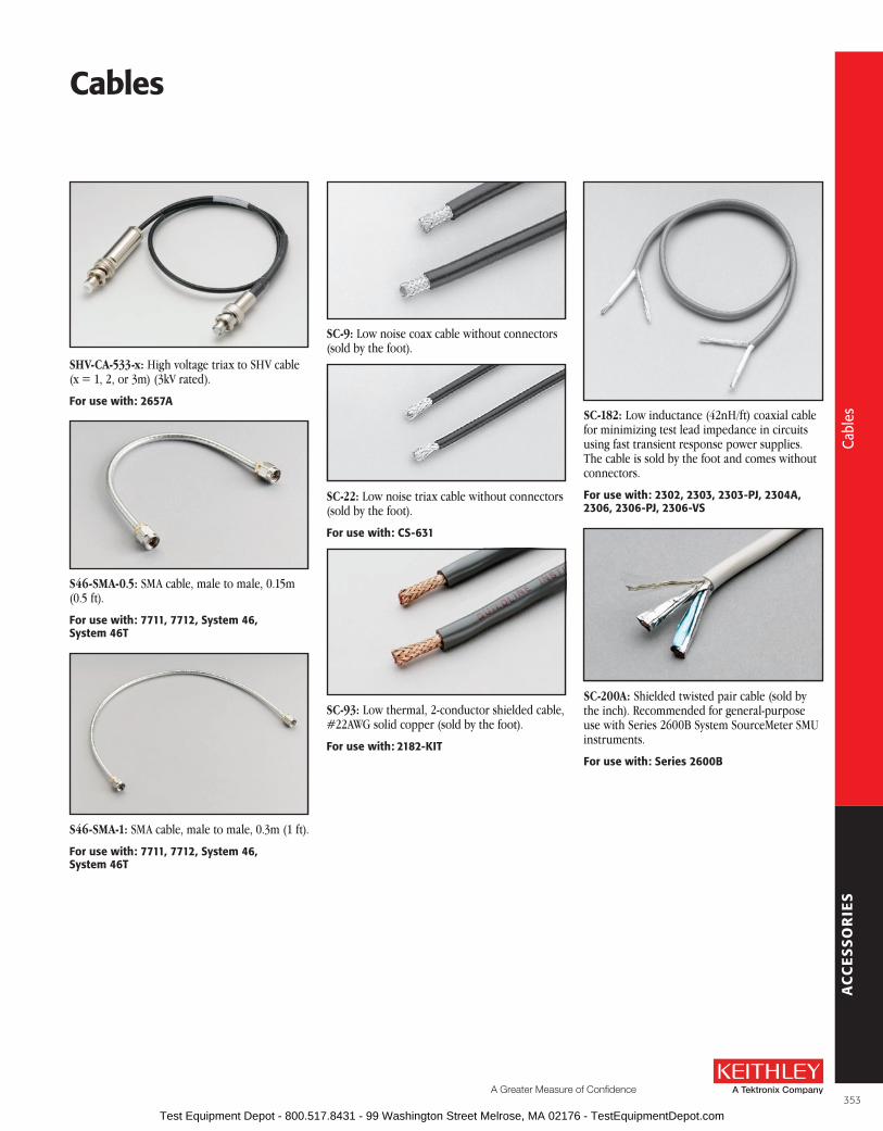
AC
CE
SS
OR
IES
A Greater Measure of Confidence
Cables
SHV-CA-533-x: High voltage triax to SHV cable (x = 1, 2, or 3m) (3kV rated) .
for use with: 2657a
S46-SMA-0.5: SMA cable, male to male, 0 .15m (0 .5 ft) .
for use with: 7711, 7712, system 46, system 46T
S46-SMA-1: SMA cable, male to male, 0 .3m (1 ft) .
for use with: 7711, 7712, system 46, system 46T
SC-9: Low noise coax cable without con nec tors (sold by the foot) .
SC-22: Low noise triax cable without con nec tors (sold by the foot) .
for use with: Cs-631
SC-93: Low thermal, 2-conductor shielded cable, #22AWG solid copper (sold by the foot) .
for use with: 2182-KIT
SC-182: Low inductance (42nH/ft) coaxial cable for minimizing test lead impedance in circuits using fast transient response power supplies . The cable is sold by the foot and comes without connectors .
for use with: 2302, 2303, 2303-PJ, 2304a, 2306, 2306-PJ, 2306-Vs
SC-200A: Shielded twisted pair cable (sold by the inch) . Recommended for general-purpose use with Series 2600B System SourceMeter SMU instruments .
for use with: series 2600b
353
Cabl
es
Cabl
es
Test Equipment Depot - 800.517.8431 - 99 Washington Street Melrose, MA 02176 - TestEquipmentDepot.com

AC
CE
SS
OR
IES
Model Name use With:
213-CON Rear Panel Mating Connector2200-20-5, 2200-30-5, 2200-32-3, 2200-60-2, 2200-72-1
237-BAN-3A Triax to Banana Plug 4200-SCS, 7072, 7072-HV, DMMs
237-BNC-TRX3-Lug Female Triax to Male BNC Connector with guard disconnected
4200-SCS, 6517A, 6517B, 7078-TRX cables
237-TRX-BAR3-Lug Triax Female to Female Barrel Adapter
2635B, 2636B, 4200-SCS, 6482, Triax interconnect
237-TRX-NGTriax Male-Female Adapter with guard disconnected
6517A, 6517B, 7072, 7072-HV
237-TRX-T3-slot Male to Dual 3-Lug Female Triax Tee Adapter
4200-SCS, 7072, 7072-HV, 7078-TRX cables
237-TRX-TBC3-Lug Female Triax Bulkhead Connector
7072, 7072-HV, 7078-TRX cables
2182-325A Silver Solder for use with 2182-KIT 2182A
2182-KITLow-Thermal Connector with Strain Relief (LEMO)
2182A, SC-93
2188 Low-Thermal Calibration Shorting Plug 2182A
2499-DIGIO Digital I/O Expansion Module SourceMeter SMU instruments
2500INT-SMA SMA Connector 2500INT integrating sphere
2500INT-FC/PC FP/PC Connector 2500INT integrating sphere
2500INT-FC/APC FP/APC Connector 2500INT integrating sphere
2600-KITScrew Terminal Connector with Strain Relief and Cover
2601B, 2602B (2 needed), 2611B, 2612B (2 needed)
2600-TRIAX 3-Lug Triax Adapter2601B, 2602B (2 needed), 2604B,2611B, 2612B (2 needed), 2614B
2657A-LIM-3 Low Interconnect Module 2657A
2657A-PM-200 200V Protection Module 2657A
3706-BKPL Analog Backplane Extender Board Series 3700A
3720-ST Screw Terminal Block 3720
3721-ST Screw Terminal Block 3721
3723-ST Screw Terminal Block 3723
3723-ST-1 Screw Terminal Block 3723
3724-ST Screw Terminal Block 3724
3730-ST Screw Terminal Block 3730
3731-ST Screw Terminal Block 3731
3740-ST Screw Terminal Block 3740
3750-ST Screw Terminal Block 3750
3790-KIT50-R 50-pin Female D-sub Connector Kit 3721, 3730, 3731, 3740, 3750
3791-CIT Contact Insertion and Extraction Tool 3720, 3722, 3723
3791-KIT78-R 78-pin Female D-sub Connector Kit 3720, 3723, 3724, 3732
3792-KIT104-R 104-pin Male D-sub Connector Kit 3722
3792-KIT104-R/F 104-pin Female D-sub Connector Kit 3722
4851 BNC Shorting Plug Instruments with BNC connectors
61713-slot Male to 2-Lug Female Triax Adapter
2-lug triax connectors
61722-slot Male to 3-Lug Female Triax Adapter
7065, 2500INT
7001-PNL Metal Plate 7001
7011-KIT-R Female 96-pin Connector Kit7011-C, 7012-C, 7013-C, 7015-C, 7018-C
7011-ST Extra Screw Terminal Board 7011-S
7012-ST Extra Screw Terminal Board 7012-S
7013-ST Extra Screw Terminal Board 7013-S
Model Name use With:7015-ST Extra Screw Terminal Board 7015-S
7018-ST Extra Screw Terminal Board 7018-S
7072-TRT Triax Removal Tool 707B, 708B
7074-CIT Contact Extraction Tool 7152-KIT, 7152-MTR
7078-CIT Contact Insertion/Extraction Tool7078-KIT, 7078-MTR, 7152-KIT, 7152-MTR
7078-HCTHand Crimping Tool for 7078-KIT, 7169-KIT
7078-KIT
7078-KIT Connector Kit 7071, 7071-4, 7074-D, 7078-MTR
7078-MTRMass Terminated Receptacle, Bulkhead Mount
7071, 7071-4, 7078-KIT, 7078-MTC
7078-TRX-BNC 3-slot Male Triax to BNC Adapter4210-CVU, 4801, 6482, 6487, 6514, 6517A, 6517B, 7072, 7072-HV
7078-TRX-GND3-slot Male Triax to BNC Adapter (guard removed)
4200-SCS, 4801, 6517A, 6517B, 7072, 7072-HV, Series 2600B
7078-TRX-TBC3-Lug Female Triax Bulkhead Connector w/Cap
7078-TRX cables
7152-HCTHand Crimp Tool for 7152-KIT, 7152-MTR
7152-KIT, 7152-MTR
7152-KIT 6-Position M-Series Plug w/Contacts 7152, 7152-MTR
7152-MTR6-Position M-Series Receptacle w/Sockets
7152, 7152-KIT, 7152-MTC-2, 7152-MTC-10
7703-306A DB50 Male Connector Kit 7701, 7703, 7705, 7709
7709-308A DB25 Male Connector Kit 7701, 7707, 7709, Series 2600B
7712-SMA-N Female SMA to Male N-Type Adapter 7711, 7712
7755 50W Feed-Through Terminator RG 58 cable, 776, 3390
7788 50-pin D Subconnector Kit7703, 7705, 77XX, modules with D sub connectors
778950-pin Male and 25-pin Male D-Shell Connector Kit
7701, 7709
779050-pin Male, 50-pin Female, and 25-pin Male IDC D-Shell Connector Kit
7701, 7703, 7705, 7707, 7709
8610 Low Thermal Shorting Plug 2000, 2001, 2002, 2010
8620 4-Wire DMM Shorting Plug2000, 2001, 2002, 2010, 2015, 2016, 2100, 2110, Series 2400, Series 2700, Series 3700A
8680 RTD Probe Adapter 2001, 2002, 2010, 2110
BG-18 Dual Banana to BNC Coaxial AdapterSeries 2000, 2100, 2110, Series 2400, 2700, 2750
CAP-18 Protective Shield/Cap BNC, 2-lug triax connectors
CAP-31 Protective Shield/Cap 3-lug triax connectors
CA-573-3A14-Pin Round Interlock Cable, Unterminated
2657A-LIM-3
CS-400 DB25 Male Solder Cup CA-126-1 cable, 213
CS-458 Interlock Connector Kit 6517-ILC-3
CS-565 BNC Barrel, 4200-SCS BNC interconnect
CS-6303-Lug Female Triax Bulkhead Connector
6487, 6517A, 6517B
CS-6313-Lug Male Triax Cable Mount Connector
4200-SCS, SC-22 cable
CS-701 BNC Tee Adapter (Female-Male-Female) 4200-SCS
CS-719 3-Lug Triax Jack Receptacle 4200-SCS
CS-846 Screw Terminal Test Lead Connector 230X, 2510, 2510-AT
CS-970 High Voltage Bulkhead Connector 248, 248-SHV cable
Connectors, adapters, and Tools
354
Conn
ecto
rs, a
dapt
ers,
and
tool
s
Conn
ecto
rs, a
dapt
ers,
and
tool
s
Test Equipment Depot - 800.517.8431 - 99 Washington Street Melrose, MA 02176 - TestEquipmentDepot.com

AC
CE
SS
OR
IES
A Greater Measure of Confidence
Model 213-CON Rear Panel Mating Connector: Quick disconnect, 12-screw termi-nal connector with handle .
for use with: 2200-20-5, 2200-30-5, 2200-32-3, 2200-60-2, 2200-72-1
Item shipped may vary from model pictured here.
Model 237-BAN-3A Triax to Banana Plug: Triax cable center conductor ter mi nat ed in a safety banana plug (guard and shield open) . For connecting DMMs and other banana jack instru-ments to a matrix or fixture .
for use with: 4200-sCs, 7072, 7072-HV, DMMs
Model 237-BNC-TRX: Male BNC to 3-lug female triax adapter (guard dis con nect ed) . Terminates triax cable in BNC plug . High voltage rating for use with 7072-HV .
for use with: 4200-sCs, 6517a, 6517b, 7078-TrX cables
Model 237-TRX-BAR: 3-lug triax barrel (female to female) for use with triax interconnect .
for use with: 2635b, 2636b, 4200-sCs, triax interconnect
Model 237-TRX-NG: 3-slot triax to 3-lug female triax adapter (guard removed) for non-guarded mea sure ments . High voltage rating for use with 7072-HV, etc .
for use with: 6517a, 6517b, 7072, 7072-HV
Model 237-TRX-T: 3-slot male to dual 3-lug female triax tee adapter for use with 7078-TRX cables and 7072/7072-HV Semi con duc t or Matrix Cards . High voltage rating for use with Model 6517B Electrometer .
for use with: 4200-sCs, 6517a, 6517b, 7072, 7072-HV, 7078-TrX cables
Connectors, adapters, and Tools
Model Name use With:CS-1247 SMA Female to BNC Male Adapter 4200-SCS
CS-1249 SMA Female to SMB Plug Adapter 4200-SCS
CS-1251 BNC Female to SMB Plug Adapter 4200-SCS
CS-1252 SMA Male to BNC Female Adapter 4200-SCS
CS-1281 SMA Female to SMA Female Adapter 4200-SCS
CS-1305 Interlock Connector 6517B
CS-1390Male LEMO Triax to Female SMA Adapter
4200-SCS
CS-1391 SMA Tee Adapter (Female-Male-Female) 4200-SCS
CS-1423-3 Miniature Mating Connector 2635B, 2636B
CS-1479 SMA Male to BNC Male Adapter 4200-SCS
Model Name use With:CS-1592-2 Screw Terminal Plug 2651A
CS-1626-2 Screw Terminal Receptacle 2651A
CS-1629-8 Screw Terminal Connector 2651A
CS-1638-12 Rear Panel Mounting Connector2200-20-5, 2200-30-5, 2200-32-3, 2200-60-2, 2200-72-1
CS-1655-15 Rear Panel Mating Connector2220-30-1, 2220j-30-1, 2230-30-1, 2230j-30-1
HV-CS-1613High Voltage Triax Feed Through Connector/Barrel (female to female)
2657A, 2600-PCT-x, 4200-PCT-x
TL-24 SMA Torque Wrench 4200-SCS, System 46, System 46T
355
Conn
ecto
rs, a
dapt
ers,
and
tool
s
Conn
ecto
rs, a
dapt
ers,
and
tool
s
Test Equipment Depot - 800.517.8431 - 99 Washington Street Melrose, MA 02176 - TestEquipmentDepot.com

AC
CE
SS
OR
IES
Model 237-TRX-TBC: 3-lug female triax bulk-head connector with cap for assembly of custom panels and interface connections . High voltage rating for use with 7072-HV, etc . Uses miniature coax cable, not triax cable, at soldered end . Bulkhead is outer shield .
for use with: 7072, 7072-HV, 7078-TrX cables
Model 2182-325A: Silver solder for making connections in experiments with the Model 2182A . 20 ft roll .
for use with: 2182a
Model 2182-KIT Low-Thermal Connector with Strain Relief: Connector kit for building a cus-tom input cable for the Model 2182A Nano volt-meter . Includes a low-thermal (LEMO) connector and a strain relief .
for use with: 2182a, sC-93
Model 2188 Low-Thermal Calibration Shorting Plug: A low-resistance, low- thermal shorting plug required to calibrate the Model 2182A Nanovoltmeter . Made of a LEMO con-nector with its pin connectors shorted together using copper wire and Sn/Ag4 silver solder .for use with: 2182a
Model 2499-DIGIO: Digital I/O expansion module that plugs onto the DB-9 connector of a SourceMeter® SMU instrument . Expands the three digital I/O lines of the SourceMeter to 16 lines . The SOT, EOT/BUSY, 5V, GND, and Interlock signals are passed through .
Services Available: 1-year factory warranty extended to 3 years from date of shipment
for use with: sourceMeter sMu Instruments
Model 2500INT-FC/APC: FC/APC connector for 2500-INT Integrating Sphere .for use with: 2500-INT
Model 2500INT-FC/PC: FC/PC connector for 2500-INT Integrating Sphere .for use with: 2500-INT
Model 2500INT-SMA: SMA connector for 2500-INT Integrating Sphere .for use with: 2500-INT
Model 2600-KIT: Screw terminal connector kit with extra screw terminal connector, strain relief, and cover for a single SourceMeter chan-nel (two needed for use with Models 2602B, 2612B, and 2614B) .
for use with: 2601b, 2602b, 2604b, 2611b, 2612b, 2614b, 2651a
Model 2600-TRIAX: Triax adapter for a single Series 2600B SourceMeter channel (two needed for use with Models 2602B and 2612B) . For use with standard 3-lug triax cables .
for use with: 2601b, 2602b, 2611b, 2612b
Connectors, adapters, and Tools
356
Conn
ecto
rs, a
dapt
ers,
and
tool
s
Conn
ecto
rs, a
dapt
ers,
and
tool
s
Test Equipment Depot - 800.517.8431 - 99 Washington Street Melrose, MA 02176 - TestEquipmentDepot.com

AC
CE
SS
OR
IES
A Greater Measure of Confidence
Model 2657A-LIM-3: Low Interconnect Module for use with 2657A, HV triax cables (3kV rated) .
for use with: series 2657a
2657A-PM-200: 200V protection module to protect standard triax instruments from 2657A, standard and HV triax cables (3kV rated) .
for use with: series 2657a
Model 3706-BKPL: Analog backplane extender board, 15-pin D-sub to terminal block .
for use with: series 3700a
Model 3720-ST: Screw Terminal Block . Required with the Model 3720 for automatic CJC thermocouple measurements .
for use with: 3720
Model 3721-ST: Screw Terminal Block . Required with the Model 3721 for automatic CJC thermo-couple measurements .
for use with: 3721
Model 3723-ST: Screw Terminal Block . Accessory for Model 3723 for two-pole applications .
for use with: 3723
Model 3723-ST-1: Screw Terminal Block . Accessory for the Model 3723 for single-pole applications .
for use with: 3723
Model 3724-ST: Screw Terminal Block .
for use with: 3724
Model 3730-ST: Screw Terminal Block .
for use with: 3730
Connectors, adapters, and Tools
357
Conn
ecto
rs, a
dapt
ers,
and
tool
s
Conn
ecto
rs, a
dapt
ers,
and
tool
s
Test Equipment Depot - 800.517.8431 - 99 Washington Street Melrose, MA 02176 - TestEquipmentDepot.com

AC
CE
SS
OR
IES
Connectors, adapters, and Tools
Model 3731-ST: Screw Terminal Block .
for use with: 3731
Model 3732-ST-C: Screw Terminal Block . Enables screw terminal access and additional matrix sizes including: quad 4×28 (1W), dual 4×28 (2W), single 4×56 (2W), dual 4×56 (1W), and single 4×112 (1W) .
for use with: 3732
Model 3732-ST-R: Screw Terminal Block . Enables screw terminal access and additional matrix sizes including: dual 8×28 (1W), single 8×28 (2W), and single 16×28 (1W) .
for use with: 3732
Model 3740-ST: Screw Terminal Block .
for use with: 3740
Model 3750-ST: Screw Terminal Block .
for use with: 3750
Model 3790-KIT50-R: 50-pin female D-sub connector kit that contains two female D-sub connectors and 100 solder cup contacts . Use for assembly of custom cable and harnesses compat-ible with Series 3700A plug-in cards .
for use with: 3721, 3730, 3731, 3740, 3750
Model 3791-CIT: Contact insertion and extrac-tion tool for assembly and maintenance of Series 3700A D-sub Connector kits .
for use with: 3791-KIT78-r, 3791-KIT104-r
Model 3791-KIT78-R: 78-pin female D-sub connector kit that contains two female D-sub connectors and 156 solder-cup contacts . Use for assembly of custom cable and harnesses compat-ible with Series 3700A plug-in cards .
for use with: 3720, 3723, 3724, 3732
Model 3792-KIT104-R: 104-pin male D-sub con-nector kit that contains two male D-sub connec-tors with housings and 208 solder-cup contacts . Use for assembly of custom cable and harnesses compatible with Series 3700A plug-in cards .
for use with: 3722
358
Conn
ecto
rs, a
dapt
ers,
and
tool
s
Conn
ecto
rs, a
dapt
ers,
and
tool
s
Test Equipment Depot - 800.517.8431 - 99 Washington Street Melrose, MA 02176 - TestEquipmentDepot.com

AC
CE
SS
OR
IES
A Greater Measure of Confidence
Model 3792-KIT104-R/F: 104-pin female D-sub connector kit that contains two female D-sub connectors with housings and 208 solder-cup contacts . Use for assembly of custom cables, har-nesses, and DUT interface compatible with Series 3700A plug-in cards .
for use with: 3722
Model 4851: BNC shorting plug .for use with: Instruments with bNC connectors
Model 6171: 3-slot male to 2-lug female triax adapter .
for use with: 2-lug triax connectors
Model 6172: 2-slot male to 3-lug female triax adapter . For use in adapting Models 7065 and 250INT inputs to 3-slot triax plugs .
for use with: 2500INT, 7065
Model 7001-PNL: Metal plate used to cover an empty card slot on the rear panel of a Model 7001 .
for use with: 7001
Model 7011-KIT-R: 96-pin female DIN con nec-tor with solder eyelets and strain relief . This kit can be used for assembly of custom cables to connect with the con nec tors on the 7011-C, 7012-C, 7013-C, 7015-C, and 7018-C switch cards . Also con nects with the 7011-MTR bulk-head mount male connector .
for use with: 7011-C, 7012-C, 7013-C, 7015-C, 7018-C
Model 7011-ST: Extra quick disconnect screw terminal board . One 7011-ST is included with each 7011-S .for use with: 7011-s
Model 7012-ST: Extra quick disconnect screw terminal board . One 7012-ST is included with each 7012-S .for use with: 7012-s
Model 7013-ST: Extra quick disconnect screw terminal board . One 7013-ST is included with each 7013-S .
for use with: 7013-s
Connectors, adapters, and Tools
359
Conn
ecto
rs, a
dapt
ers,
and
tool
s
Conn
ecto
rs, a
dapt
ers,
and
tool
s
Test Equipment Depot - 800.517.8431 - 99 Washington Street Melrose, MA 02176 - TestEquipmentDepot.com

AC
CE
SS
OR
IES
Connectors, adapters, and Tools
Model 7015-ST: Extra quick disconnect screw terminal board . One 7015-ST is included with each 7015-S .
for use with: 7015-s
Model 7018-ST: Extra quick disconnect screw terminal board . One 7018-ST is included with each 7018-S .
for use with: 7018-s
Model 7072-TRT: Triax removal tool used to connect or disconnect triax style connectors when clearance is limited making it difficult to mate or unmate a connector with your fingers .
for use with: 707b, 708b
Model 7074-CIT: Contact extraction tool for removal of contacts from cables and con nec tors .
for use with: 7152-KIT, 7152-MTr
Model 7078-CIT: Contact insertion and ex trac-tion tool for assembly and main te nance of 7078-MTC cables and connec tors .for use with: 7078-KIT, 7078-MTr, 7152-KIT, 7152-MTr
Model 7078-HCT: Contact crimping pliers for as sem bly of cables and connectors using 7078-MTR or 7078-KIT .for use with: 7078-KIT
Model 7078-KIT: 38-pin male plug assembly with strain relief and 40 con tacts for assembly of custom cable and harnesses compatible with Model 7071 8×12 Matrix Card, Model 7071- 4 Dual 4×12 Matrix Card, and 7078-MTR Mass Ter-mi nat ed Receptacle . Re quires 7078-HCT; recom-mend 7078-CIT .
for use with: 7071, 7071-4, 7074-D, 7078-MTr
Model 7078-MTR: 38-pin female bulkhead mount re cep ta cle with 40 contacts for custom interface and patch panels compatible with 7078-MTC and 7078-KIT . Requires 7078-HCT; recommend 7078-CIT .
for use with: 7078-KIT, 7078-MTC, 7071, 7071-4
Model 7078-TRX-BNC: 3-slot male triax to BNC adapter for use with 7072 Semi con duc tor Matrix Card and 4801 cables .
for use with: 4210-CVu, 4801, 6482, 6487, 6514, 6517a, 6517b, 7072, 7072-HV
360
Conn
ecto
rs, a
dapt
ers,
and
tool
s
Conn
ecto
rs, a
dapt
ers,
and
tool
s
Test Equipment Depot - 800.517.8431 - 99 Washington Street Melrose, MA 02176 - TestEquipmentDepot.com

AC
CE
SS
OR
IES
A Greater Measure of Confidence
Connectors, adapters, and Tools
Model 7078-TRX-GND: 3-slot male triax to female BNC adapter (guard removed) for adapt-ing non-guarded measurements to the Model 7072 or 7072-HV Semi con duc tor Matrix Cards or 8006 or 8008 Test Fixtures .
for use with: series 2600b, 4801, 6517a, 6517b, 7072, 7072-HV
Model 7078-TRX-TBC: 3-lug female triax bulk-head connector with cap for assembly of custom panels and in ter face connections .
for use with: 7078-TrX Cables
Model 7152-HCT: Contact crimping pliers for as sem bly of cables and con nec tor using 7152-MTR or 7152-KIT .
for use with: 7152-KIT, 7152-MTr
Model 7152-KIT: 6-pin plug assembly with strain relief and contacts for assembly of custom cable and harnesses compatible with Model 7152 4×5 Low Current Matrix Card and 7152-MTR Mass Ter mi nat ed Re cept acle . Requires 7152-HCT recommend 7074-CIT and 7074-HCT .
for use with: 7152, 7152-MTr
Model 7152-MTR: 6-pin bulkhead mount re cep ta cle with contacts for custom in ter face and patch panels com pat i ble with 7152-MTC and 7152-KIT . Re quires 7152 HCT; re commend 7074-CIT and 7074-HCT .
for use with: 7152, 7152-KIT, 7152-MTC-2, 7152-MTC-10
Model 7703-306A: DB50 male connector kit (solder cup) with shell .
for use with: 7701, 7703, 7705, 7709
Model 7709-308A: DB25 male connector kit (solder cup) with shell .
for use with: 7701, 7707, 7709, series 2600b
Model 7712-SMA-N: Female SMA to male N-type adapter .
for use with: 7711, 7712
Model 7755 50W Feed-Through Ter mi na tor: BNC-to-BNC adapter for ter mi nat ing RG58 cable in its characteristic impedance . VSWR <1 .1, DC–250MHz .
for use with: rG58 Cable, 776, 3390
361
Conn
ecto
rs, a
dapt
ers,
and
tool
s
Conn
ecto
rs, a
dapt
ers,
and
tool
s
Test Equipment Depot - 800.517.8431 - 99 Washington Street Melrose, MA 02176 - TestEquipmentDepot.com

AC
CE
SS
OR
IES
Model 7788: 50-pin D subminiature connector kit . To mate with 50-pin connector on Model 7703 and 7705 .
for use with: 7703, 7705, 77xx modules with D-sub connectors
Model 7789: 50-pin/25-pin (both male) D-Shell Kit (one of each) for 7701 or 7709 Integra mod-ules (mating connectors are supplied with these modules when purchased) .for use with: 7701, 7709
Model 7790: 50 pin male, 50 pin female, 25 pin male IDC D-Shell Connector Kit (one each) .for use with: 7701, 7703, 7705, 7707, or 7709 Integra modules
Model 8610 Low Thermal Shorting Plug: For cal i bra tion lab use, this plug provides a very low thermal offset short at front or rear inputs .
for use with: all DMMs
Model 8620 Four-Wire DMM Shorting Plug: Provides a low resistance 4-wire short to both observe and cancel DMM offset resistances and voltages to improve measurement accuracies .
for use with: all DMMs, series 2400, series 2700, series 3700a
Model 8680 RTD Probe Adapter: Provides a means of connecting RTD probes terminated in either a 4-wire in stru men ta tion connector or bare wires to safety input jacks on a 0 .5 inch spacing .
for use with: 2001, 2002, 2010, 2100, 2110, 8681
BG-18: Dual banana to BNC coaxial adapter for adapting connection on instrument with dual banana jack .
for use with: all DMMs, series 2400
CAP-18: Protective shield/cap for BNC connectors . for use with: bNC connectors
CAP-31: Protective shield/cap for 3-lug triax connectors .for use with: 3-lug triax connectors
CS-400: DB25 male solder cup .for use with: C126-1 cable, 213
CS-458: Interlock connector kit to mate with 6517-ILC-3 .for use with: 6517-IlC-3
Connectors, adapters, and Tools
362
Conn
ecto
rs, a
dapt
ers,
and
tool
s
Conn
ecto
rs, a
dapt
ers,
and
tool
s
Test Equipment Depot - 800.517.8431 - 99 Washington Street Melrose, MA 02176 - TestEquipmentDepot.com

AC
CE
SS
OR
IES
A Greater Measure of Confidence
Connectors, adapters, and Tools
CS-565: Female BNC to female BNC adapter with 50W nominal impedance .for use with: 4200-sCs, bNC in tercon nect
CS-630: 3-lug female triax bulkhead connector for soldered connection . Mates with CS-631 .for use with: fixtures, 6487, 6517a, 6517b
CS-631: 3-slot male triax cable mount con nec tor for use with SC-22 cable . Mates to Models 7072, and 8006 .for use with: 4200-sCs, sC-22 cable
CS-701: BNC tee adapter (female, male, female) .for use with: 4200-sCs
CS-719: 3-lug triax jack receptacle .for use with: 4200-sCs
CS-846: Eight position connector with screw terminals for connection to test leads .for use with: 230x, 2510, 2510-aT
CS-970: High voltage bulkhead connector .for use with: 248, 248-sHV cable
CS-1247: SMA female to BNC male adapterfor use with: 4200-sCs
CS-1249: SMA female to SMB plug adapterfor use with: 4200-sCs
CS-1251: BNC female to SMB plug adapterfor use with: 4200-sCs
CS-1252: SMA male to BNC female adapterfor use with: 4200-sCs
CS-1281: SMA female to SMA female adapterfor use with: 4200-sCs
CS-1305: Interlock connector to mate with Model 6517B .for use with: 6517b
363
Conn
ecto
rs, a
dapt
ers,
and
tool
s
Conn
ecto
rs, a
dapt
ers,
and
tool
s
Test Equipment Depot - 800.517.8431 - 99 Washington Street Melrose, MA 02176 - TestEquipmentDepot.com

AC
CE
SS
OR
IES
CS-1390: Male LEMO triax to female SMA adapterfor use with: 4200-sCs
CS-1391: SMA tee adapter (female-male-female)for use with: 4200-sCs
CS-1423-3: Miniature mating connector used as a ground connector for the Models 2635B and 2636B .
for use with: 2635b, 2636b
CS-1479: SMA male to BNC male adapter .for use with: 4200-sCs
CS-1592-2: 2-pin male screw terminal connector plug . Rated 50A . Mates with the Model CS-1626-2 screw terminal block .for use with: 2651a
CS-1626-2: 2-pin female screw terminal con-nector block . Rated 50A . Mates with Model CS-1592-2 screw terminal connector .for use with: 2651a
CS-1629-8: 8-pin female cable termination block .for use with: 2651a
CS-1638-12: 12-pin rear panel output connector .for use with: 2200-20-5, 2200-30-5, 2200-32-3, 2200-60-2, 2200-72-1
CS-1655-15: 15-pin rear panel output connector .for use with: 2200-30-1, 2220J-30-1, 2230-30-1, 2230J-30-1
HV-CS-1613: High voltage triax feed through connector/barrel (female to female) (3kV rated) .
for use with: for use with: 2600-PCT-x, 2657a, 4200-PCT-x
TL-24: SMA torque wrenchfor use with: 4200-sCs, system 46, system 46T
Connectors, adapters, and Tools
364
Conn
ecto
rs, a
dapt
ers,
and
tool
s
Conn
ecto
rs, a
dapt
ers,
and
tool
s
Test Equipment Depot - 800.517.8431 - 99 Washington Street Melrose, MA 02176 - TestEquipmentDepot.com

AC
CE
SS
OR
IES
A Greater Measure of Confidence
adapter, Cable, Prober, and stabilizer Kits
Model 4200-CVU-PROBER-KIT: Commonly used accessories for taking standard capacitance-voltage measurements on a variety of probers . Includes:CA-446A: CVU cable, 100W, 3m (9 .8 ft) (4)CS-565: Female BNC to female BNC adapter (4)CS-1247: Female SMA to male BNC adapter (4)CS-1391: SMA tee adapter (female-male-female) (2)237-TRX-BAR: Female triax to female triax
adapter (4)4200-PRB-C: SMA to SSMC Y adapter cable with
local ground (2)7078-TRX-BNC: 3-slot male triax to female BNC
adapter (4)7078-TRX-GND: 3-slot male triax to female BNC
adapter (guards removed) (4)for use with: 4200-sCs with 4200-CVu
Model 4200-CVU-PWR: Enables C-V measure-ments with a DC voltage bias of up to ±200V or 400V differential (0 to ±400V) and a current output of up to 300mA . Includes:CS-1252: SMA male to BNC female adapter (2)
CS-1391: SMA tee (female-male-female) (2)CS-1479: SMA male to BNC male adapter (2)4200-PRB-C: SMA to SSMC Y adapter cable with
local ground (2)4205-RBT: Remote bias tee (2)for use with: 4200-sCs with 4210-CVu
Model 4200-PMU-PROBER KIT: This connection kit consists of standard and custom connectors and accessories used to connect the Models 4225-PMU and 4220-PGU to a variety of common prober stations . It also supports directly connecting the PMU/PGU to the SMU instruments for Flash Memory testing without the need for an external switch . One kit required per PMU/PGU card . Includes:CA-19-2: BNC male to BNC male coax cable,
1 .5m (4)CA-451A: SMA male to SMA male coax cable,
11cm (1)CA-405B: SMA male to SMA male coax cable,
15cm (1)CA-452A: SMA male to SMA male coax cable,
20cm (2)CS-565: BNC female to BNC female barrel (2)CS-712: BNC female to triax male adapter (2)CS-1252: SMA male to BNC female adapter (4)CS-1247: SMAL female to BNC male adapter (4)CS-1390: Micro triax (LEMO) to SMA
(no guard) (2)CS-1391: SMA tee female-male-female (3)
for use with: 4200-sCs, 4225-PMu, 4220-PGu, 4225-rPM, 4210-MMPC
Model 4210-MMPC-C: This multi-measurement cable set is a collection of standard and custom connectors and accessories used to take I-V, C-V, and pulsed I-V measurements using a single prober cable setup . The set includes:
CA-533-24A: 61cm (24 in) mini triax/full triax, 100W, blue cable (2)
CA-535-4A: 10cm (4 in) prober ground jumper
CA-540-12A: 35cm (12 in) mini triax/mini triax, 100W, blue cable
CS-712: Triax male to BNC female adapters (3)
CS-737: Triax tee adapter, female-male-female
CS-1247: SMA female to BNC male adapters (3)
4210-MMPC-304A: Grounding bracket assembly
4210-MMPC-305A: Mini triax, 3-lug, shorting plug (shorts center pin to outer shield)for use with: Model 4200-sCs and Cascade Microtech 12000 prober series with DCM-200 series manipulators (requires one set per manipulator)
Model 4210-MMPC-S: This multi-measurement cable set is a collection of standard and custom connectors and accessories used to take I-V, C-V, and pulsed I-V measurements using a single prober cable setup . The set includes:
CA-532A: MMPC prober cable assembly
CA-534-24A: 61cm (24 in) male triax to male triax, 100W, blue cables (2)
CA-535-7A: 17 .8cm (7 in) prober ground jumper
CS-712: Triax male to BNC female adapters (3)
CS-737: Triax tee adapter, female-male-female
CS-751: Triax female to triax female adapters (2)
CS-1247: SMA female to BNC male adapters (3)
CS-1546: Triax shorting plug (shorts center pin to outer shield)for use with: Model 4200-sCs and suss MicroTec Pa200/300 prober series (requires one set per manipulator)
365
Conn
ecto
rs, a
dapt
ers,
and
tool
s · A
dapt
er, c
able
, and
sta
biliz
er k
its
Conn
ecto
rs, a
dapt
ers,
and
tool
s · A
dapt
er, c
able
, and
sta
biliz
er k
its
Test Equipment Depot - 800.517.8431 - 99 Washington Street Melrose, MA 02176 - TestEquipmentDepot.com

AC
CE
SS
OR
IES
Test fixtures
Model 8010 High Power Device Test Fixture: The Model 8010 High Power Device Test Fixture provides safe and easy connections for testing packaged high power devices at up to 3000V or 100A . The Model 8010 provides connections for a high voltage SourceMeter SMU instru-ment (Model 2657A), one or two high current SourceMeter SMU instruments (Model 2651A), and three low power SourceMeter SMU instru-ments (other Series 2600B or Model 4200-SCS source measure unit (SMU) instruments) . This allows devices with two terminals (diodes) or three terminals (transistors) or even four or five terminals to be characterized safely and accu-rately . The Model 8010 has full interlock capabil-ity for up to six SourceMeter SMU instruments . The Model 8010 has integrated protection circuits that protect the low voltage SourceMeter SMU instruments from high voltages the Model 2657A can output should a device fault occur . The Model 8010 includes both a high current (100A) and a high voltage (3000V) test socket . Various replacement test socket modules are available, including TO-247, TO-220, axial lead, and a blank socket module that allows building a custom socket . In addition to standard banana jumpers, the Model 8010 has rear-panel scope and thermal probe ports to simplify system integration .
aCCEssorIEs suPPlIED3 ea . CA-558-2 Three-Pin Interlock Connector Cables (2m)
12 ea CA-560-x Banana to Banana Jumper Cables (203mm)
2 ea . CA-562-x Safety Banana to Banana Jumper Cables (254mm)
6 ea . CA-563 BNC to Banana cables (241mm)
2 ea . CA-568-120 Earth Safety Ground Cables (305cm)
1 ea . 8010-317 Socket Insulating Plug Card
1 ea . 8010-CTB Customizable Test Board
2 ea . 8010-DTB Device Test Board for TO-247 Devices (3kV, 100A)
for use with: 2651a, 2657a, 4200-sCs, 26xxb, 2600-PCT-x, 4200-PCT-x
Model 8009 Resistivity Chamber: The Model 8009 is a guarded test fixture for mea sur ing volume and surface resistivities . It assures good electrostatic shielding and high insulation resistance up to 1100V . The 8009 is designed for safe operation with the 6517A or 6517B . Opening the lid of the 8009 au to mat i cal ly turns off the 6517A or 6517B voltage source . The 8009 ac com-mo dates sheet samples from 64mm to 102mm (2½ to 4 in) in diameter and up to 3 .2mm (1⁄8 in) thick . It maintains good sample contact with uniform pressure (from 6 to 10 lbs depending on thickness) on smooth parallel sam ples . With the front panel switch on the 8009, toggle between volume and surface re sis tiv i ty, with the 6517A or 6517B configured to calculate and display the appropriate result automatically . The 8009 permits direct measurement of volume resistivity up to 1018W-cm (on samples 0 .1cm thick) and surface resistivity up to 1017W/square, in accordance with ASTM pro cedures .
aCCEssorIEs suPPlIED6517-ILC-3 Interlock Cable for 6517A
6517B-ILC-3 Interlock Cable for 6517B
7078-TRX-3 Triax Cable
8007-GND-3 Safety Ground Wire
8607 Source Cable Set
ENVIRONMENTAL LIMITS: Operating: –30° to +85°C, 65% R .H . up to 35°C, derate 3% R .H ./°C above 35°C . Stor age: –25° to +85°C .
DIMENSIONS: 108mm high × 165mm wide × 140mm deep (41⁄4 in × 6½ in × 5½ in) .
WEIGHT: 1 .45kg (3 .19 lbs) .
for use with: 6487, 6517a, 6517b
366
Text
fixt
ures
Text
fixt
ures
Test Equipment Depot - 800.517.8431 - 99 Washington Street Melrose, MA 02176 - TestEquipmentDepot.com

AC
CE
SS
OR
IES
A Greater Measure of Confidence
Test fixtures
Model 8011 Test Socket Kit: A three pin, TO-247 test socket that is rated to 40V and 50A . Includes cables for connecting to Model 2651A High Power System SourceMeter® SMU instru-ment .
aCCEssorIEs suPPlIED: 8010-DTB Device Test Board for TO-247 devices
8010-CTB Customizable Test Board
CA-560-0 Banana to Banana Test Cables
CA-560-2 Banana to Banana Test Cables
CS-1629-8 Two 8-pin Female Plug Connectors with screw terminal connections (2 ea .)
CA-567-0 Banana to Banana Test Cables (4 ea .)
CA-567-2 Banana to Banana Test Cables (4 ea .)
2600-KIT 8-pin Male Phoenix Connector Kit (2 ea .)
for use with: Model 2651a High Power system sourceMeter
Model 8101-4TRX: 4-pin transistor fixture .for use with: 4200-sCs, series 2600b, 6482, any 40V rated triaxial instrument
Model 8101-PIV: DC and pulse I-V demo fixture that is a metal case with four female triax con-nectors, two SMA connectors, and a latch . Inside the test fixture are two 4-pin device holders (transistor sockets) and two plungers for parts with two leads .for use with: 4200-sCs, series 2600b, 6482, any 40V rated triaxial or sMa instrument
Model LR:8028: Component test fixture opti-mized for device testing up to 200V/1A . Includes color-coded mini jumpers for easy device con-nections .
aCCEssorIEs suPPlIED:40 ea . standard color-coded Teflon® mini jumpers, 20 red and 20 black
LR:8028 Instruction Manual
for use with: 4200-sCs, series 2600b, 6482, any 40V rated triaxial or sMa instrument
367
Text
fixt
ures
Text
fixt
ures
Test Equipment Depot - 800.517.8431 - 99 Washington Street Melrose, MA 02176 - TestEquipmentDepot.com

AC
CE
SS
OR
IES
Trigger accessories
Model 2600-TLINK: 25-pin female digital I/O port to Trigger Link adapter .
for use with: series 2600b, series 3700a
Model 8501-1: 1m (3 .3 ft) Trigger Link cable . Each end contains an 8-pin male DIN connector . Also available in 2m (6 .6 ft) length (Model 8501-2) .
for use with: all Trigger link instruments
Model 8503 DIN-to-BNC Trigger Cable: 1m (3 ft) cable used to connect BNC inputs to any instrument having Trigger Link connectors .
for use with: all Trigger link instruments
Model 8505: Male to 2 Female Y-DIN cable .for use with: all Trigger link instruments
368
Test
fixt
ure
· Trig
ger a
cces
sorie
s
Test
fixt
ure
· Trig
ger a
cces
sorie
s
Test Equipment Depot - 800.517.8431 - 99 Washington Street Melrose, MA 02176 - TestEquipmentDepot.com

AC
CE
SS
OR
IES
A Greater Measure of Confidence
bench Kits, rack Mount Kits
Model 2000-Benchkit: Benchtop Restore Kit . Rubber feet and carrying handles are removed during rack mounting . These items can be used with any of the following models to convert it back to a benchtop instrument .
for use with: series 2000, 2182a, series 2300, series 2400, series 2500, series 2600b, 2700, 2701, 6220, 6221, 6430, 6482, 6485, 6487, 6514, 6517a, 6517b, 7001
Model 248-RMK-* Fixed Rack Mount Kit: Enables rack mounting of Model 248 . 248-RMK-1 rack mounts one Model 248 . 248-RMK-2 (not pictured) rack mounts two Model 248s side by side .
for use with: 248
Model 4200-KEy-RM: Rack mount kit for cabinet mounting of standard keyboard and pointing devices .
for use with: 4200-sCs
Model 4200-RM: Fixed rack mount kit for cabi-net mounting of the 4200-SCS .
for use with: 4200-sCs
Model 4288-1 Fixed Rack Mount Kit: Single-unit rack mount kit . Height: 88mm (3½ in) .
for use with: see selector Guide.
Model 4288-2 Fixed Rack Mount Kit: Height: 88mm (3½ in) .
for use with: see selector Guide.
sElECTor GuIDE: raCK MouNT KITs
Instrument single fixed single slide1 Dual fixed Type of Mount
Series 20002182ASeries 2300Series 2200Series 2500
2700270162206221 6485
64876514
6517B7001
4288-1
4288-22
4288-43
4288-54
4288-94
4299-7
SideShelfShelfShelfSide
Series 2100 Series 2400 6430 4299-3 4299-4 Side
Series 2600B4299-14299-6
4299-2 Side
2750, System 46, System 46T 4288-7 Rear bracket
Series 3700A 4288-10 Rear bracket
248 248-RMK-1 248-RMK-2 Side
707B Included 7079 Side
708B Included Side
4200-SCS/C or /F 4200-RM
7002 7002-RMK-1 7002-RMK-2 Bracket w/handles
NoTEs1 . Slide rack mount kits are not compatible with equipment cabinet Models 8000-10, 8000-14, and 8000-17 .2 . Model 4288-2 mounts any two of the listed models, except 776 .3 . Model 4288-4 mounts: ANY ONE plus ANY ONE 230, 230-1 428-PROG, Series 2000, 2182A, Series 2300, Series 2400, Series 2500, 2700, 2701,
6220, 6221, 6430, 6485, 6487, 6514, 6517A, 6517B, 70014 . Models 4288-5 and 4288-9 mount any one or two of the listed models on a shelf-type mount .
369
Benc
h ki
ts, r
ack
mou
nt k
its
Benc
h ki
ts, r
ack
mou
nt k
its
Test Equipment Depot - 800.517.8431 - 99 Washington Street Melrose, MA 02176 - TestEquipmentDepot.com

AC
CE
SS
OR
IES
rack Mount Kits
Model 4288-4 Fixed Rack Mount Kit: Enables rack mounting of one Model 230 next to one 428-PROG, 776, Series 2000, 2182A, Series 2300, Series 2400, Series 2600B, 2700, 2701, 6220, 6221, 6514, 6485, 6487, 6517A, 6517B, or 7001 .
for use with: see selector Guide.
Model 4288-5 Fixed Rack Mount Kit: The single- and dual-instrument front panels includ-ed enable rack mounting of either one or two 3½-inch in stru ments . Height: 132mm (51⁄4 in) . Depth: 457mm(18 in) .
for use with: see selector Guide.
Model 4288-7 Rear Support Mount Kit: For rack mount applications where more than one or two card modules are installed to provide added support for the rear of the mainframe . Note that front rack mounting hardware is supplied with the Model 2750 mainframe . 88mm (3 .5 in) height .
for use with: 2750, system 46, system 46T
Model 4288-9 Fixed Rack Mount Kit: Shelf style rack mount kit with single- and dual- instrument front plates provided . Also included are extended rear support brackets and hard-ware for installation .
for use with: series 2200 Power supplies
Model 4288-10 Rear Support Mount Kit: For rack mount applications where more than one or two card modules are installed to provide added support for the rear of the mainframe . Note that front rack mounting hardware is supplied with Series 3700A mainframes . 88mm (3 .5 in) height .
for use with: series 3700a
Model 4299-1: Heavy duty, single rack mount kit with front and rear support . Height: 88mm (3 .5 in) .
for use with: series 2600b
Model 4299-2: Heavy duty, dual rack mount kit with front and rear support . Height: 88mm (3 .5 in) .
for use with: series 2600b
Model 4299-3 Universal Single Unit Rack Mount Kit: Includes all required hardware to rack mount a single Keithley or Agilent half rack instrument using front panel only mounting into a standard 19 inch equipment rack . Not compat-ible with Series 2600B . 88mm (3 .5 in) height .
for use with: Half rack instruments (excluding series 2600b)
370
Rack
mou
nt k
its
Rack
mou
nt k
its
Test Equipment Depot - 800.517.8431 - 99 Washington Street Melrose, MA 02176 - TestEquipmentDepot.com

AC
CE
SS
OR
IES
A Greater Measure of Confidence
rack Mount Kits
Model 4299-4 Universal Dual Unit Rack Mount Kit: Includes all required hardware to rack mount two Keithley and/or Agilent half-rack instruments together using front panel only mounting into a standard 19-inch equipment rack . Not compatible with Series 2600B . 88mm (3 .5 in) height .
for use with: Half-rack instruments (excluding series 2600b)
Model 4299-5: 1U vent panel .
for use with: series 2600b
Model 4299-6 Single Fixed Rack Kit: Includes all required hardware to rack-mount a Keithley full-rack instrument in a standard 19-inch equipment rack .
for use with: 2651a, 2657a
Model 4299-7 Dual Fixed Rack Mount Kit: Enables rack-mounting of Series 2200 power supplies with other instruments .
for use with: series 2200
Model 7002-RMK-1 Fixed Rack Mount Kit: Two 7 in . flanged brackets and hardware for mounting the Model 7002 in a standard 48 .3cm (19 in) equip ment cabinet . Can be used with Models 8000, 8000-10, 8000-14, or 8000-17 .
for use with: 7002
Model 7002-RMK-2 Slide Rack Mount Kit: Two sets of flanged brackets, slides, and hard-ware to mount Model 7002 in standard 48 .3cm (19 in) equipment cabinet . Can be used with Model 8000 .
for use with: 7002
Model 7079 Slide Rack Mount Kit: Two sets of flanged brackets, slides, and hard ware to mount Model 707A in standard 48 .3cm (19 in) equip-ment cabinet . Can be used with Model 8000 .
for use with: 707b
371
Rack
mou
nt k
its
Rack
mou
nt k
its
Test Equipment Depot - 800.517.8431 - 99 Washington Street Melrose, MA 02176 - TestEquipmentDepot.com
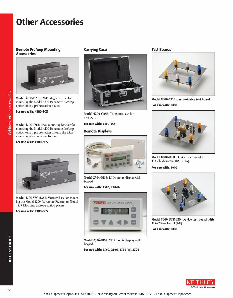
AC
CE
SS
OR
IES
other accessories
remote Preamp Mounting accessories
Model 4200-MAG-BASE: Magnetic base for mounting the Model 4200-PA remote PreAmp option onto a probe station platen .
for use with: 4200-sCs
Model 4200-TMB: Triax mounting bracket for mounting the Model 4200-PA remote PreAmp option onto a probe station or onto the triax mounting panel of a text fixture .
for use with: 4200-sCs
Model 4200-VAC-BASE: Vacuum base for mount-ing the Model 4200-PA remote PreAmp or Model 4225-RPM onto a probe station platen .
for use with: 4200-sCs
Carrying Case
Model 4200-CASE: Transport case for 4200-SCS .
for use with: 4200-sCs
remote Displays
Model 2304-DISP: LCD remote display with keypad .
for use with: 2303, 2304a
Model 2306-DISP: VFD remote display with keypad .
for use with: 2302, 2306, 2306-Vs, 2308
Test boards
Model 8010-CTB: Customizable test board.
for use with: 8010
Model 8010-DTB: Device test board for TO-247 devices (3kV, 100A).
for use with: 8010
Model 8010-DTB-220: Device test board with TO-220 socket (1.5kV).
for use with: 8010
372
Cabi
nets
, oth
er a
cces
sorie
s
Cabi
nets
, oth
er a
cces
sorie
s
Test Equipment Depot - 800.517.8431 - 99 Washington Street Melrose, MA 02176 - TestEquipmentDepot.com

AC
CE
SS
OR
IES
A Greater Measure of Confidence
KPCI-488lPaKusb-488b
IEEE-488 (GPIB) Interface Solutions
• PCI and usb bus versions
• IEEE-488.2 compatible for fast data transfer
• Windows® 7/Vista/XP/2000 drivers included
• labVIEW® and labWindows/CVI support
• Compatible with any standard GPIb instrument
Keithley’s GPIB interface solutions make it easy to add standard IEEE-488 .2 bus control to any PC system . These high speed tools can control as many as 14 GPIB instruments or other devices over a distance of up to 20 meters . They are ideal for use with automated test equipment in laboratory and industrial applications .
The Keithley Model KPCI-488LPA is a low-profile, GPIB interface plug-in card that is 32-bit/33MHz PCI bus compatible . Its PCI interface supports both 3 .3V and 5V PCI envi-ronments, making it suitable for most desktop computers and industrial PCs, including the new low-profile desktop systems . This low-cost solution supports Windows 7/Vista/XP/2000, and its driver library is command compatible with National Instruments™ and Capital Equipment Corporation™ command functions .
The Keithley Model KUSB-488B USB-to-GPIB interface turns any computer with a USB port into a fully functional GPIB controller . The KUSB-488B’s small form factor makes it per-fect for use with laptop computers in portable
applications or for other applications in which the computer has no available PCI plug-in board slots . The product is USB 2 .0 compliant and has an IEEE data transfer rate upwards of 1 .5 MB/s through the USB port . No external power is required . KUSB-488B has a built-in 2-meter USB cable .
softwareThe included utility software simplifies the setup and use of Keithley GPIB interface solutions and saves programming time . Every solution ships with 32-bit dynamic link libraries for Application Development Environments (ADEs) running under Windows 7/Vista/XP/2000 and drivers for the most current programming languages . This adds up to full compatibility with a full array of software, including:• Microsoft Visual Studio 6 .0 (Visual Basic,
Visual C++)• Microsoft Visual Studio .NET (Visual
Basic .NET, C#)• Microsoft Visual Studio 2005 and up• Borland Delphi, Borland C Builder 6 .0• LabVIEW Version 7 .0 and up (VISA and
IEEE-488 .2)• LabWindows™/CVI Version 7 .0 and up (VISA
and IEEE-488 .2)
Hardware CompatibilityThese GPIB Interface solutions are fully compat-ible with all of Keithley’s GPIB capable instru-ments . The Model 7010 adapter is required for the Model 428-PROG when used with the KUSB-488B .
ordering InformationKPCI-488lPa IEEE-488.2 Interface
board for the PCI busKusb-488b IEEE-488.2
usb-to-GPIb Interface adapter for usb Port. built in 2m (6.6 ft) cable
KPCI-488lPa Kusb-488bBus/Form Factor PCI USB
Dimensions 4 .7 × 2 .5 in (120 × 64 .5 mm) 3 .2 × 2 .6 × 1 .1 in (81 .7 × 66 .1 × 27 .8 mm)
Power (Current @ 5VDC) 400 mA typ ., 750 mA max . 500 mA
Transfer Speed 1 .5 Mbyte/s 1 .5 Mbyte/s
EMC European Directive 2004/108/EEC European Directive 2004/108/EEC
Environmental Operating: 0° to 55°C, 10% to 90% RH non-condensing
Storage: –20° to 80°C, 5% to 90% RH non-condensing
Operating: 0° to 55°C, 10% to 90% RH non-condensing
Storage: –20° to 80°C, 5% to 95% RH non-condensing
373
Add
GPI
B co
ntro
l to
any
PC
Add
GPI
B co
ntro
l to
any
PC
Test Equipment Depot - 800.517.8431 - 99 Washington Street Melrose, MA 02176 - TestEquipmentDepot.com

AC
CE
SS
OR
IES
IEEE-488 (GPIB) Accessories
Model 7006-*: Single-shielded GPIB cable ter-minated with one feed through style and one straight on IEEE-488 connector . The mating thumb screws are metric .
7006-1 1m (3 .3 ft) 7006-2 2m (6 .6 ft)
Item shipped may vary from model pictured here.
Model 7007-*: Double-shielded premium GPIB cable . Each end is terminated with a feed through style metal housing for longest life and best performance . The mating thumb screws are metric .
7007-05 0 .5m (1 .6 ft) 7007-1 1m (3 .3 ft) 7007-2 2m (6 .6 ft) 7007-3 3m (10 ft) 7007-4 4m (13 .1 ft)
for use with: IEEE-488 Interconnect
Model 7010 Shielded IEEE-to-IEEE Adapter: Pro vides additional clearance between IEEE-488 cable and rear panel, allowing easier access to switches, cables, and other con nec tors .
for use with: IEEE-488 Interconnect
Model 8530 Centronics Adapter: IEEE-488 to Cen tronics cable adapter . Connects to Model 2001/2002 IEEE-488 port and any Centronics com pat i ble print er for di rect data out put .
Cable Length: 2m (6 .6 ft) .
for use with: 2001, 2002
374
GPI
B ac
cess
orie
s, s
hiel
ded
and
unsh
ield
ed
GPI
B ac
cess
orie
s, s
hiel
ded
and
unsh
ield
ed
Test Equipment Depot - 800.517.8431 - 99 Washington Street Melrose, MA 02176 - TestEquipmentDepot.com

CU
STO
ME
R S
ER
VIC
E
A Greater Measure of Confidence
Equipment Services . . . . . . . . . . . . . . . . . . . . . . . . . 377
Safety Considerations . . . . . . . . . . . . . . . . . . . . . . . 378
Replacement Products . . . . . . . . . . . . . . . . . . . . . . 380
Customer Service
375 Test Equipment Depot - 800.517.8431 - 99 Washington Street Melrose, MA 02176 - TestEquipmentDepot.com

CU
STO
ME
R S
ER
VIC
E
A Greater Measure of Confidence
Equi
pmen
t ser
vice
s
Calibration ServicesIso 17025:2005 accreditationKeithley Instruments’ U .S . and German Service Centers have achieved ISO 17025:2005 accreditation by A2LA (American Association for Laboratory Accreditation) . Keithley offers 17025 accredited calibrations on many models .
ISO 17025 is the single most important metrology standard for test and measurement products . This international standard specifies the general requirements for the technical competence to carry out tests and/or calibrations . It is applicable to all organizations performing tests and/or calibrations .
A management system based on the standard is required, as well as adherence to very specific technical requirements . By achieving accreditation to ISO 17025, Keithley U .S . and German Service Centers proved that their management systems meet all requirements of this standard and demonstrated their technical competence to carry out very high level calibrations .
aNsI/NCsl Z540.3–2006 accreditation (u.s. only)ISO 17025 calibrations performed by the Keithley Service Center–U .S . are also accredited to ANSI/Z540 .3-2006, an important U .S . metrology standard .
Why use Keithley’s Calibration services?Quality is important to you. You understand the importance of calibration, but now you’re faced with a choice of calibration providers . Who you choose as your calibration provider depends on what’s important to you . Keithley is world-renowned for its quality and measurement expertise . Why trust your equipment with anyone else? You realize many benefits when you choose Keithley as your calibration partner, such as:
• Accuracy—Our calibration equipment is among the most advanced in the industry . This allows us to calibrate your product to a high level of accuracy . We take more measurements than most calibration providers, ensuring that your product is performing with repeatable accuracy .
• Quality—Our calibrations are traceable to national and international standards .
• Speed—We offer fast turnarounds on our calibrations to minimize your downtime .
KeithleyCare™ PlansCut costs, reduce downtime, and protect your investment with KeithleyCare Plans . They provide fast, high quality services at a fraction of the cost of per-event service . With a KeithleyCare plan, you’ll enjoy priority calibration and repair services and virtually eliminate unscheduled down-time and administrative hassles . Trust a KeithleyCare plan to take care of your equipment, so you can take care of your customers .
KeithleyCare Calibration PlanSimplify your calibration management and ensure your equipment is maintained in peak condition with Keithley’s value-added calibration plans . KeithleyCare calibration plans offer multi-year coverage in 3- or 5-year increments . KeithleyCare calibration plans feature:
• Expedited priority service reduces downtime by 2 days or more .
• Complimentary shipping one way
• Adjustment to OEM specifications included with each calibration
• Performance verification before and after adjustment
• Performance updates
KeithleyCare Gold PlanUnplanned downtime and maintenance expenses can be costly . Minimize the impact to your budget and your customers by purchasing value-added warranty coverage . KeithleyCare Gold Plan programs offer multiple years of protection in 3- and 5-year increments . KeithleyCare Gold plans feature:
• Free repairs
• Expedited priority service reduces downtime by 3 days
• Complimentary shipping both ways (within country)
• Calibration and adjustment to OEM specifications included with each repair
• Performance updates
Uptime ProgramMinimize your downtime. Keithley products are often used in applications where uptime is critical . We know how important speed of service is to you, and we are proud of our ability to consistently deliver fast turnarounds . However, we also know that there are occasions where you simply cannot afford to be without your Keithley product . To address this need, we have developed a program to allow you to get your operation up and running sooner .
Express serviceOur express service option is available for a nominal cost and is offered on most products . It provides you with “next on bench” service and a guaranteed faster turnaround time .
KeithleyCare™Plans
Equipment Services
377 Test Equipment Depot - 800.517.8431 - 99 Washington Street Melrose, MA 02176 - TestEquipmentDepot.com

CU
STO
ME
R S
ER
VIC
E
Safety Considerations
Safe
ty c
onsi
dera
tions
General safety Considerations
It is the responsibility of the test system designers, integrators, and install-ers to make sure operator and maintenance personnel protection is in place and effective .
The following safety precautions should be observed before using any Keithley product and any associated instrumentation . Although some instruments and accessories would normally be used with non-hazardous voltages, there are situations where hazardous conditions may be present . Keithley products are intended for use by qualified personnel who recog-nize shock hazards and are familiar with the safety precautions required to avoid possible injury . Read the operating information provided in each product’s manual carefully before using any Keithley product .
The types of product users are:
Responsible body is the individual or group responsible for the use and maintenance of equipment, for ensuring that the equipment is operated within its specifications and operating limits, and for ensuring that opera-tors are adequately trained and protected .
Operators use the product for its intended function . They must be trained in electrical safety procedures and proper use of the instrument . They must be protected from electric shock and contact with hazardous live circuits .
Maintenance personnel perform routine procedures on the product to keep it operating, for example, setting the line voltage or replacing consumable materials . Maintenance procedures are described in the manual . The procedures explicitly state if the operator may perform them . Otherwise, they should be performed only by service personnel .
Service personnel are trained to work on live circuits and perform safe installations and repairs of products . Only properly trained service per-sonnel may perform installation and service procedures .
Exercise extreme caution when a shock hazard is present . Lethal voltage may be present on cable connector jacks or test fixtures . The American National Standards Institute (ANSI) states that a shock hazard exists when voltage levels greater than 30V rms, 42 .4V peak, or 60VDC are present . A good safety practice is to expect that hazardous voltage is present in any unknown circuit before measuring .
Operators must be protected from electric shock at all times . The responsible body must ensure that operators are prevented access and/or insulated from every connection point . In some cases, connections must be exposed to potential human contact . Product operators in these circumstances must be trained to protect themselves from the risk of elec-tric shock . If the circuit is capable of operating at or above 1000 volts, no conductive part of the circuit may be exposed .
Keithley Instruments products are designed for use with electrical signals that are measurement, control, and data I/O connections with low tran-sient over-voltages, and must not be directly connected to mains voltage or to voltage sources with high transient over-voltages . Measurement Category II (as referenced in IEC 60664) connections require protection
for high transient over-voltages often associated with local AC mains con-nections . Certain Keithley measuring instruments may be connected to mains . These instruments will be marked as Category II or higher .
Unless explicitly allowed in the specifications, operating manual, and instrument labels, do not connect any instrument to mains .
Do not connect switching cards directly to unlimited power circuits . They are intended to be used with impedance limited sources . NEVER connect switching cards directly to AC mains . When connecting sources to switch-ing cards, install protective devices to limit fault current and voltage to the card .
Before operating an instrument, make sure the line cord is connected to a properly grounded power receptacle . Inspect the connecting cables, test leads, and jumpers for possible wear, cracks, or breaks before each use .
For rack mounted equipment in which the power cord is not accessible, in the event of fire or other catastrophic failure, the operator must have access to a separate power disconnect device or switch .
For maximum safety, do not touch the product, test cables, or any other instruments while power is applied to the circuit under test . ALWAYS remove power from the entire test system and discharge any capacitors before: connecting or disconnecting cables or jumpers, installing or removing switching cards, or making internal changes, such as installing or removing equipment .
Do not touch any object that could provide a current path to the common side of the circuit under test or power line (earth) ground . Always make measurements with dry hands while standing on a dry, insulated surface capable of withstanding the voltage being measured .
For safety, instruments and accessories must be used in accordance with the operating instructions . If the instruments or accessories are used in a manner not specified in the operating instructions, the protection pro-vided by the equipment may be impaired .
Do not exceed the maximum signal levels of the instruments and acces-sories, as defined in the specifications and operating information, and as shown on the instrument or test fixture panels, or switching card .
When fuses are used in a product, replace with same type and rating for continued protection against fire hazard .
Chassis connections must only be used as shield connections for meas-uring circuits, NOT as safety earth ground connections .
If you are using a test fixture, keep the lid closed while power is applied to the device under test . Safe operation requires the use of a lid interlock .
If a marked terminal is present, connect it to safety earth ground using the wire recommended in the user documentation .
The symbol on an instrument means caution, risk of danger . The user must refer to the operating instructions located in the user documentation in all cases where the symbol is marked on the instrument .
378 Test Equipment Depot - 800.517.8431 - 99 Washington Street Melrose, MA 02176 - TestEquipmentDepot.com

CU
STO
ME
R S
ER
VIC
E
A Greater Measure of Confidence
Safe
ty c
onsi
dera
tions
Safety Considerations
The symbol on an instrument means caution, risk of electric shock . Use standard safety precautions to avoid personal contact with these voltages .
The symbol on an instrument shows that the surface may be hot . Avoid personal contact to prevent burns .
The symbol indicates a connection terminal to the equipment chassis .
If this symbol is on a product, it indicates that mercury is present in the display lamp . Please note that the lamp must be properly disposed of according to federal, state, and local laws .
The WARNING heading in a manual explains dangers that might result in personal injury or death . Always read the associated information very carefully before performing the indicated procedure .
The CAUTION heading in a manual explains hazards that could damage the instrument . Such damage may invalidate the warranty .
Instrumentation and accessories shall not be connected to humans .
Before performing any maintenance, disconnect the line cord and all test cables .
To maintain protection from electric shock and fire, replacement com-ponents in main circuits, including the power transformer, test leads, and input jacks, must be purchased from Keithley Instruments . Standard fuses, with applicable national safety approvals, may be used if the rating and type are the same . Other components that are not safety related may be purchased from other suppliers as long as they are equivalent to the original component . (Note that selected parts should be purchased only through Keithley Instruments to maintain accuracy and functionality of the product .) If you are unsure about the applicability of a replacement compo-nent, call a Keithley Instruments office for information .
To clean an instrument, remove power, use a damp cloth or mild, water based cleaner . Clean the exterior of the instrument only . Do not apply cleaner directly to the instrument or allow liquids to enter or spill on the instrument . Products that consist of a circuit board with no case or chassis should never require cleaning if handled according to instructions . If the board becomes contaminated and operation is affected, the board should be returned to the factory for proper cleaning/servicing .
Test system safety
Many electrical test systems or instruments are capable of measuring or sourcing hazardous voltage and power levels . It is also possible, under single fault conditions (e .g ., a programming error or an instrument fail-ure), to output hazardous levels even when the system indicates no haz-ard is present .
These high voltage and power levels make it essential to protect operators from any of these hazards at all times .
Protection methods include:
• Design test fixtures to prevent operator contact with any hazardous circuit .
• Make sure the device under test is fully enclosed to protect the operator from any flying debris .
• Double insulate all electrical connections that an operator could touch . Double insulation ensures the operator is still protected, even if one insulation layer fails .
• Use high-reliability, fail-safe interlock switches to disconnect power sources when a test fixture cover is opened .
• Where possible, use automated handlers so operators do not require access to the inside of the test fixture or have a need to open guards .
• Provide proper training to all users of the system so they understand all potential hazards and know how to protect themselves from injury .
WARNING: During power-up, the outputs states of data acquisition products are uncontrolled until hardware and software initialization has been completed . Users must make sure their designs can tolerate this or provide suitable interlocks to prevent dangerous voltages or actions from reaching users .
379 Test Equipment Depot - 800.517.8431 - 99 Washington Street Melrose, MA 02176 - TestEquipmentDepot.com

CU
STO
ME
R S
ER
VIC
E
Replacement Products
This table includes a list of older Keithley products and suggested replace ment models that can be used to upgrade the capabilities of these older products . Many of these products are at or near the end of their serviceable life . To ensure adequate replace ment, please review the replacement instrument’s specifications in this catalog or on the Keithley Web site . If the suggested replacement does not meet specific application requirements or if the model being upgraded is not listed, check the Web site FAQs for upgrade options, or contact the Keithley Applications Department or your local Keithley representative for assistance .
olDEr MoDEls DEsCrIPTIoN suGGEsTED rEPlaCEMENTssourCEMETEr INsTruMENTs237 Source-Measure Unit 2657A2600A System SourceMeter Instruments 2600B
ElECTroMETErs200, 200A, 200B, 210, 220 Electrometer Voltmeters 6514236, 487, 610, 610A, 610B, 610C, 610R Electrometers 6514, 6517B, 6487236, 487, 614, 615, 616, 617, 6512, 6517, 6517A Digital Electrometers 6514, 6517B, 6487236, 486, 603, 604, 619 Dual Electrometers 6514, 6517B, 6485640, 642, 642LN 10–17A Electrometer 6430
PICoaMMETErs409, 410, 410A, 411, 414, 414A, 414S, 415, 480, 485, 486, 487, 614 Picoammeters 6514, 6482, 6485, 6487
412, 413, 26000 Log Picoammeters 6485418, 419, 440, 445, 486, 487 Digital Picoammeters 6482, 6485, 6487
loW VolTaGE INsTruMENTs140, 147, 148, 149, 150, 181, 182, 1801 Nanovoltmeters 2182A150A, 150B, 155, 180, 181, 182, 303 Null Detectors 2182A151, 151C, 153, 155 Microvoltmeters/Null Detectors 2182A
DIGITal MulTIMETErs 190, 191, 195, 195A, 199 DMMs (5½ digits) 2000, 2100, 2110, 2700, 2701172, 172A, 173, 176, 178, 179, 179-20A DMMs (4½ digits) (10µV) 2000, 2100, 2110, 2700, 2701192, 193, 193A, 196, 197A, 199 System DMMs 2000, 2100, 2110, 2001, 2002, 2010, 2700, 2701
rEsIsTaNCE MEasurING INsTruMENTs164, 502, 502A, 505, 580 Milliohmmeters 2010, 2750, 2182A + 2400, 622x + 2182A487, 500, 501, 510, 515, 520, 6517, 6517A High-Resistance Instruments 6517B, 6487
CurrENT sourCEs220, 224, 225, 236 Current Source Series 2400, Series 2600B, 6220, 6221261, 263 Current Source 6220, 6221, 6430227, 228, 238 Current Source 2420, 2651A
VolTaGE sourCEs237, 240, 240A, 241, 242, 247, 244, 245, 246, 2004, 2004A High Voltage Supplies 248, 2410, 2657A
sWITCHEs702 Scanner 7001, 2700, 2701, 2750703, 706 Scanner 7002, 2700, 2701, 2750705 Scanner 7001, 2700, 2701, 2750707A, 708A Mainframe 707B, 708B, 7001, 2700, 2701, 27507002-HD Mainframe 3706A
sWITCHING aND CoNTrol CarDs7036-D 7001/7002 Isolated Switch Card 70367037 7001/7002 Control Card 7037-D7052 4×5 Matrix Switch Card 7012-S7054 7001/7002 High Voltage Card 71547056 General-Purpose Scanner Card 7011-S, Integra 7702
7058 Low Current Scanner Card 7158, 7152, 7153, 6521 (with 6517A or 6517B), 6522 (with 6517A or 6517B)
7059 7001/7002 Low Voltage Card 71687064 Low Voltage Scanner Card 71687066 10-Channel Isolated Switch Card 7013-S, 7036, Integra 77057071 General Purpose 8×12 Matrix Card 70727074-D 707A/708A Multiplexer Card 7001/7002 with 71587075 Two-Pole Multiplexer Card 7001/7002 with 71587156-D 7001/7002 General Purpose Card 7011-C, 77017164-D Dry Reed Scanner Card 7011-C7999-4, 7999-5 RS-232 Switch/Controller S46
sEMICoNDuCTor ProCEss MoNITorING soluTIoNsS400 Series, S600 Series, S900 Series Parametric Test Systems S530 Series
Repl
acem
ent p
rodu
cts
380 Test Equipment Depot - 800.517.8431 - 99 Washington Street Melrose, MA 02176 - TestEquipmentDepot.com

research n nanotechnology n semiconductor n wireless n electronic components
www.keithley.com
research n nanotechnology n semiconductor n wireless n electronic components
www.keithley.com
Test & M
easurement product catalog
A Greater Measure of Confidence
Test & Measurement product catalog
A Greater Measure of Confidence
© Copyright 2013 Keithley Instruments, Inc. No. 2184 / Jan.13
Specifications are subject to change without notice. All Keithley trademarks and trade names are the property of Keithley Instruments, Inc. All other trademarks and trade names are the property of their respective companies.
Test Equipment Depot - 800.517.8431 - 99 Washington Street Melrose, MA 02176 - TestEquipmentDepot.com