
Komet - Dihart Reaming Catalog.pdf - Productivity Inc
118
1 2 3 4 5 6 7 8 9 3 4 – 11 12 – 21 22 – 29 30 – 37 38 – 43 44 – 59 60 – 65 66 – 77 78 – 91 92 – 119 Program Summary · Tool Selection REAMAX® TS REAMAX ® Monomax® – Expandable Fullmax Solid Carbide Reamer Duomax & Cutting Ring PCD Reamers Special Tools Insert Reaming Technology MicroSet System DAH® Compensating Holder Taper shanks · HSK · ABS ® · DPS Preferred Sizes, Information, Cutting Data Numerical Index KOMPASS – REAMING Inch and Metric
-
Upload
khangminh22 -
Category
Documents
-
view
0 -
download
0
Transcript of Komet - Dihart Reaming Catalog.pdf - Productivity Inc

1
2
3
4
5
6
7
8
9
3
4 – 11
12 – 21
22 – 29
30 – 37
38 – 43
44 – 59
60 – 65
66 – 77
78 – 91
92 – 119
Program Summary · Tool Selection
REAMAX® TS
REAMAX ®
Monomax® – Expandable
Fullmax Solid Carbide Reamer
Duomax & Cutting Ring
PCD Reamers
Special Tools Insert Reaming TechnologyMicroSet System
DAH® Compensating HolderTaper shanks · HSK · ABS® · DPS
Preferred Sizes, Information, Cutting DataNumerical Index
KOMPASS – REAMINGInch and Metric

KomPass Reaming – BENEFITS for you
As a brand of the KOMET GROUP,
DIHART® is known for its precision reaming technology
which is sure to take you to the next level.
For the cost-effective fi nish machining of bores, DIHART® offers
a comprehensive tool program of standardized Monomax®
monobloc tools, PCD reamers, application-specifi c multiblade
stepped reamers and special tools. DIHART® reamers offer
accurate, cost-effective and reliable machining.
Innovative solutions for fi nish bore machining:
- REAMAX® TS – Modular reaming system
- Reaming with indexable insert technology
- DAH® Compensating holder for accurate concentricity
(<0.0002"/0.005 mm)

1
2
3
4
5
6
7
8
9
3
4 – 11
12 – 21
22 – 29
30 – 37
38 – 43
44 – 59
60 – 65
66 – 77
78 – 91
92 – 119
Program Summary · Tool Selection
REAMAX® TS
REAMAX ®
Monomax® – Expandable
Fullmax Solid Carbide Reamer
Duomax & Cutting Ring
PCD Reamers
Special Tools Insert Reaming TechnologyMicroSet System
DAH® Compensating HolderTaper shanks · HSK · ABS® · DPS
Preferred Sizes, Information, Cutting DataNumerical Index

4
The KOMET GROUP is a leading global provider of DIHART® reaming tools for the cost-effective, precise machining of bores. Our innovative solutions potential, comprehensive performance range and dedication are the basis for successful partnerships with our customers.
For more than 60 years DIHART® has been synonymous with high-precision reaming. We are successfully meeting the increasing demand for application-specifi c solutions and standard tools, and have been continuously expanding our solution competency and our innovative edge. Our leading market position is the result of consistently higher quality and continuous development.
The KOMET GROUP also offers the complete range of services internationally. You can fi nd us wherever you manufacture your products with a demand for quality.
The standard tool range and the application-specifi c special tools guarantee precise, cost-effective and reliable machining.
New product and solution concepts such as the modular high-speed reaming tools REAMAX® TS, set a benchmark especially for standard products. Our knowledge of application-specifi c solutions offers unique perspectives.
DIHART® is the brand of the KOMET GROUP for precision reaming in new dimensions.
DIHART® – Innovative Solutions for Precision Finishing of Bores

1
2
3
4
5
6
7
8
9
Index Page
General Information
DIHART® Tool selectionDIHART® Application ExamplesProgram Summary
6 – 89
10 – 11
Reaming Tools
REAMAX® TSREAMAX®
Monomax® – ExpandableFullmax solid carbide reamerCutting ring / DuomaxPCD Reamers
12 – 2122 – 2930 – 3738 – 4344 – 5960 – 65
Special Tools 66 – 77
DAH® Compensating Holder 78 – 91
Information
Preferred diameter rangeCutting dataCutting geometryCutting material and coatingsTolerancesSurfacesMeasuringTroubleshootingInquiries , test-results
94 – 9899 – 101
102 – 104105
106 – 107108109
110 – 112113 – 115
Numerical Index 116 – 117
5

IT tolerance class
Nominal dimension range IT 1 IT 2 IT 3 IT 4 IT 5 IT 6 IT 7 IT 8 IT 9 IT 10 IT 11 IT 12
1 – 3 mm 0.8 1.2 2 3 4 6 10 14 25 40 60 100
> 3 – 6 mm 1 1.5 2.5 4 5 8 12 18 30 48 75 120
> 6 – 10 mm 1 1.5 2.5 4 6 9 15 22 36 58 90 150
> 10 – 18 mm 1.2 2 3 5 8 11 18 27 43 70 110 180
> 18 – 30 mm 1.5 2.5 4 6 9 13 21 33 52 84 130 210
> 30 – 50 mm 1.5 2.5 4 7 11 16 25 39 62 100 160 250
> 50 – 80 mm 2 3 5 8 13 19 30 46 74 120 190 300
> 80 – 120 mm 2.5 4 6 10 15 22 35 54 87 140 220 350
> 120 – 180 mm 3.5 5 8 12 18 25 40 63 100 160 250 400
> 180 – 250 mm 4.5 7 10 14 20 29 46 72 115 185 290 460
> 250 – 315 mm 6 8 12 16 23 32 52 81 130 210 320 520
IT tolerance class
Nominal dimension range IT 1 IT 2 IT 3 IT 4 IT 5 IT 6 IT 7 IT 8 IT 9 IT 10 IT 11 IT 12
0.039 – 0.118 0.00003 0.00005 0.00008 0.00012 0.00016 0.00024 0.00039 0.00055 0.00098 0.00158 0.00236 0.00394
> 0.118 – 0.236 0.00004 0.00006 0.00010 0.00016 0.00020 0.00032 0.00047 0.00071 0.00118 0.00189 0.00295 0.00472
> 0.236 – 0.394 0.00004 0.00006 0.00010 0.00016 0.00024 0.00035 0.00059 0.00087 0.00142 0.00228 0.00354 0.00591
> 0.394 – 0.709 0.00005 0.00008 0.00012 0.00020 0.00032 0.00043 0.00071 0.00106 0.00169 0.00276 0.00433 0.00709
> 0.709 – 1.181 0.00006 0.00010 0.00016 0.00024 0.00035 0.00051 0.00083 0.00130 0.00205 0.00331 0.00512 0.00827
> 1.181 – 1.968 0.00006 0.00010 0.00016 0.00028 0.00043 0.00063 0.00098 0.00154 0.00244 0.00394 0.00630 0.00984
> 1.968 – 3.150 0.00008 0.00012 0.00020 0.00032 0.00051 0.00075 0.00118 0.00181 0.00291 0.00472 0.00748 0.01181
> 3.150 – 4.724 0.00010 0.00016 0.00024 0.00039 0.00059 0.00087 0.00138 0.00213 0.00343 0.00551 0.00866 0.01378
> 4.724 – 7.087 0.00014 0.00020 0.00032 0.00047 0.00071 0.00098 0.00158 0.00248 0.00394 0.00630 0.00984 0.01575
> 7.087 – 9.842 0.00018 0.00028 0.00039 0.00055 0.00079 0.00114 0.00181 0.00284 0.00453 0.00728 0.01142 0.01811
> 9.842 – 12.402 0.00024 0.00032 0.00047 0.00063 0.00091 0.00126 0.00205 0.00319 0.00512 0.00827 0.01260 0.02047
6
DIHART® Tool SelectionThis selection aid guides you quickly and easily to the tool system that is suitable for your requirements.
Step 1: Diameter and Tolerance Selection – Using your applications bore diameter and tolerance, select an IT class from charts below.
For rough conversion: 0.0001 inch => 0.0025 mm 0.001 mm => 0.00004 inch
• Example 1: If your application is Ø 32.5 mm with a total tolerance of 0.020 mm, this will be an IT 6 class.
• Example 1: If your application is Ø 1.357 inch with a total tolerance of 0.0008 inch, this will be an IT 6 class.
• Example 2: If your application is Ø 110 mm with a total tolerance of 0.035 mm, this will be an IT 7 class.
• Example 2: If your application is Ø 4.250 inch with a total tolerance of 0.0015 inch, this will be an IT 7 class.
Numerical values for tolerance grades in 0.001 mm
Numerical values for tolerance grades in inch
For use with metric dimensions

1
2
3
4
5
6
7
8
9
Tool series selection based on IT-tolerance
IT-Tolerance � 0.0551 – 0.2204 in (� 1.40 – 5.59 mm)
� 0.2205 – 0.4720 in(� 5.60 – 11.99 mm)
� 0.4721 – 0.7083 in(� 12.00 – 17.99 mm)
� 0.7084 – 1.5748 in(� 18 – 40 mm)
� 1.5748 – 2.5591(� 40 – 65 mm)
� 2.5591 – 4.3307 in(� 65 – 110 mm)
IT 5 – IT 6
Fullmax Solid Carbide Reamer
Monomax® expandable
Monomax® expandable
REAMAX®TSMonomax® expandable REAMAX® TS
DuomaxCutting ring
IT 7
Fullmax Solid Carbide Reamer
Monomax® expandable
REAMAX® Monomax® expandable REAMAX®TS
Monomax® expandable REAMAX® TS
DuomaxCutting ring
� IT 8
Fullmax Solid Carbide Reamer
Fullmax Solid Carbide Reamer
REAMAX® REAMAX® REAMAX® TSDuomax
Cutting ring
Note: For bore tolerance � IT7; Expandable tooling is recommended for wear compensation. Generally, bore tolerances < IT5 should be machined by another process other than reaming
7
Standard reamers overview
Series
� 0
.055
1(�
1.4
00)
� 0
.157
5(�
4.0
00)
� 0
.220
5(�
5.6
00)
� 0
.377
9(�
9.6
00)
� 0
.399
9(�
10.
159)
� 0
.472
4(�
12.
000)
� 0
.500
0(�
12.
700)
� 0
.692
9(�
17.
600)
� 0
.708
7(�
18.
000)
� 0
.744
1(�
18.
899)
� 0
.791
3(�
20.
100)
� 1
.019
6(�
25.
899)
� 1
.574
8(�
40.
000)
� 1
.968
5(�
50.
000)
� 2
.385
8(�
60.
600)
� 2
.559
1(�
65.
000)
� 4
.354
3(�
110
.599
)
� 5
.496
0(�
139
.599
)
� 1
1.83
46(�
300
.599
)Tool connection
REAMAX® TS
Cylindrical shankDAH®
ABS®
REAMAX®
Cylindrical shank
Monomax®– expandable
Cylindrical shank
FullmaxCylindrical shank
Duomax / Cutting ring
Cylindrical shankDAH®
ABS®
PCD reamer
Cylindrical shank
Step 2: Tool Selection – Based on diameter and tolerance required, choose recommended tool series.
DIHART® Tool Selection
If you do not fi nd a standard tool in this catalog for your machining needs, we are happy to offer you an application-specifi c tool.
• Example 1: Diameter 20 H7 to be machined recommends REAMAX® TS System or Monomax® Expandable
• Example 2: Diameter 1.7500" ± 0.0010"(IT8) to be machined recommends REAMAX® TS System
(..) = mm

Feed fz in/tooth (mm/tooth)
straight fl utedG03, ASG11, ASG1101
straight fl utedASG4000, ASG09B, ASG1
� 0.984 - 1.968(� 25 - 50)
> � 1.968(> � 50)
< � 0.472(< � 12)
� 0.472 - 0.984(� 12 - 25)
min-max min-max min-max min-max
0.003-0.007(0.09-0.20)
0.004-0.010(0.10-0.25)
0.003-0.005(0.07-0.14)
0.004-0.008(0.10-0.21)
0.003-0.007(0.09-0.20)
0.004-0.010(0.10-0.25)
0.003-0.005(0.07-0.14)
0.004-0.008(0.10-0.21)
Guideline for reaming Cutting speed vc ft/min (m/min)
Mat
eria
l gro
up
Stre
ngth
Rm
(lbf
/Ins²
)
Har
dnes
s H
B
MaterialMaterial exampleANSI / SAE
Reamers short / 3×D Reamers long / 5×D
HM
DS
T
TiN
DBG
-N
DB
F
DJC
DJF
DBC
PCD
HM
DS
T
TiN
DBG
-N
DB
F
DJC
DJF
DBC
min-max min-max min-max min-max min-max min-max min-max min-max min-max min-max min-max min-max min-max min-max min-max
P1.
0 � 72,500
Unalloyed steelA570.361213A573.81
19-32(6-10)
330-660(100-200)
195-460(60-140)
330-660(100-200)
19-32(6-10)
260-525(80-160)
195-390(60-120)
260-525(80-160)
2.0 72,500 -
130,000Low alloy steel
512010555115
19-32(6-10)
330-660(100-200)
195-460(60-140)
330-660(100-200)
19-32(6-10)
260-525(80-160)
195-390(60-120)
260-525(80-160)
ExampleDIHART® Cutting Data
P1.
0 � 500St37-2 / 1.0037; 9SMn28 / 1.0715; St44-2 / 1.0044
75J.93 ASG09 DST 75J.71 ASG09 TiN
2.0 500-
900
St52-2 / 1.0050,C55 / 1.0525,16MnCr5 / 1.7131
75J.93 ASG09 DST 75J.71 ASG09 TiN
2.1 < 500 9SMnPb28 / 1.0718 75J.93 ASG09 DST 75J.71 ASG09 TiN
DIHART Reamax® TS
Mat
eria
l gro
up
Stre
ngth
Rm
(N/m
m²)
Har
dnes
s H
B
MaterialMaterial examplematerial code/DIN
non-alloy steels
non-alloy /low alloy steels
lead alloys
non alloy / low alloy steels:
Tool Recommendation
High-speed machining
Order No. Cutting geometry
(ASG)
Cutting material/ coating
Order No. Cutting geometry
(ASG)
Cutting material/ coating
Example
ASG4000 ASG4000
ASG4000 ASG4000
ASG4000 ASG4000
8
DIHART® Tool SelectionThis selection aid guides you quickly and easily to the tool system that is suitable for your requirements.
Step 3: Tool Recommendation – According to the type of bore and material to be machined, you will be guided to the appropriate tool. The best cutting geometry (ASG) can be seen in the "Tool recommendation" table in each section.
Example:
Material: non-alloy steel 1010Bore type: Through bore
Tool recommendation: DST cutting materialOrder No.: 75J.93Cutting geometry: ASG4000
Recommended cutting data: Cutting speed:vc = 330 – 660 ft/min (100 – 200 m/min)Feed for �0.7874 inch (� 20.000 mm)fz = 0.004 – 0.008 in/tooth (0.10 – 0.21 mm/tooth)
Complete cutting data can be found on page 100-101.

1
2
3
4
5
6
7
8
9
999
DIHART® Application Examples
The task: Finish machining operation for cylinder liner in 34CrAlNi7V (nitride steel). Previously getting 23 ft of tool life.
Parameters: Diameter: Ø 0.9843 (Ø 25 mm) H7 Hole Length: 0.9843 inch (25 mm)Surface Finish: Rz 1.6
The task: Finish machining operation for bearing case in class 25 cast iron.
Parameters: Diameter: Ø 4.331" (Ø 110 mm) H6 Hole Length: 1.968 inch (50 mm)Surface Finish: Ra 0.4Pre-machined: Ø 4.315 inch (Ø 109.6 mm)
Machining Data:Cutting Material: HM/TlNGeometry: ASG4000Surface Finish: <Rz 1.6Tool Life: 63 ft (19.2 m)
Machining Data:Cutting Material: TlNGeometry: ASG3000Surface Finish: Ra 0.4Run-out: 0.003
Cutting data:vc = 164 SFM (50 m/min); vf = 1443 ft/min (440 m/min)n = 630 rpmf = 0.004 in/rev (0.11 mm/rev)
Cutting data:vc = 246 SFM (75 m/min); vf = 787 ft/min (240 m/min)n = 200 rpmf = 0.047 in/rev (1.2 mm/rev)
Reaming Cylinder Linerwith REAMAX® TS
Reaming Bearing Case with DIHART® Cutting Ring

10
DIHART® Program SummaryAdapters
� 84 � 87
� 84
� 85
� 86
� 86
� 86
� 86
DAH® Hydraulic chuckFor cylindrical shank tooling Reducer sleeve
DAH® AdapterFor ABS® connection tooling
DAH® Cylindrical Shank BushingFor cylindrical shank tooling
DAH® 50 HS Compensating HolderHSK adapter DIN 69893 A
taper shank DIN 69871 AD
taper shank JIS B 6339 AD
taper shank CAT 40
� 80
� 80
� 81
� 82
� 81
� 90
� 90
DAH® Compensating HolderHSK adapter DIN 69893 A
ABS® adapter
taper shank DIN 69871 AD/B
CAT / MS taper
taper shank JIS B 6339 AD/B
DPS Floating Holder
cylindrical shank similar to DIN 1835
VDI connection DIN 69880
� 87Reducer sleeve

1
2
3
4
5
6
7
8
9
11
DIHART® Program Summary
cylindrical connection DAH® connection ABS® connection
PageReaming Tools
REAMAX® TS
REAMAX®
� 53
� 64 – 65
� 54
� 52
� 42
� 43
� 34 – 37
� 20
� 27
� 19
� 18
� 17
� 0.7087 – 1.6535 inch (� 18.000 – 41.999 mm)
� 1.6535 – 2.5591 inch (� 42.000 – 65.000 mm)
� 1.3780 – 2.5591 inch (� 35.000 – 65.000 mm)
Monomax® – Expandable
Page
� 0.7087 – 2.5591 inch (� 18.000 – 65.000 mm)
� 0.4724 – 1.5748 inch (� 12.000 – 40.000 mm)
� 0.2205 – 1.0197 inch (� 5.600 – 25.899 mm)
Fullmax Solid Carbide Reamer
� 0.1181 – 0.7874 inch (� 3.000 – 20.000 mm)
� 0.1181 – 0.7874 inch (� 3.000 – 20.000 mm)
Cutting Ring & Duomax
PCD Reamer
� 0.2858 – 4.3543 inch (� 60.600 – 110.599 mm)Holder with DAH® connection
� 0.2858 – 3.9605 inch (� 60.600 – 100.599 mm)Holder with cylindrical shank similar to DIN 1835
� 0.1575 – 0.7913 inch (� 4.000 – 20.100 mm)
� 0.2858 – 4.3543 inch (� 60.600 – 110.599 mm)Holder with ABS® connection

1
12
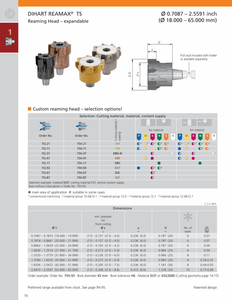
DIHART REAMAX® TS
Modular Reaming System
The fl exible and cost effective DIHART REAMAX® TS offers a precise clamping system with a standard connection for all DIHART REAMAX® TS reaming heads, offering fl exibility and cost-effectiveness thanks to fast and high-precision tool changing.
DIHART REAMAX® TS offer system modularity due to a versatile and clearly structured range of reaming heads which can handle all common diameter ranges and machining requirements. Tool costs and holder inventory are thereby reduced to a minimum.
BENEFITS for you:
High-precision manufacturing for guaranteed quality
Modular tool system for the highest fl exibility Compensation for wear through simple adjustment Integrated run-out adjustment for short lengths Can be adjusted for extremely small hole tolerances
Application:
- All current materials- Through and blind holes- Small bore tolerances- Up to 5 × D- High speed – up to 985 ft/min (300 m/min)- High feed – up to 0.094 in/rev (2.4 mm/rev)
A connection for maximum production reliability
This high-precision connection guarantees safer transfer of the torque that occurs during reaming and provides the concentricity required for precision machining. DIHART REAMAX® TS is designed for high speed machining.
Multi-fl ute tools
Wear compensating for small tolerances and able to machine bore tolerances as small as IT4, all DIHART REAMAX® TS multi-fl ute tools are adjustable. Maximum repeatable accuracy is achieved without pre-setting- Longer tool life- Maximum performance- Extremely tight bore tolerances- Less machine down time
Internal coolant system
The coolant is supplied through the tool with fl ute or blind hole coolant styles.

1
2
3
4
5
6
7
8
9
DIHART REAMAX® TS Page
Tool Recommendation 14 – 15
Reaming Head
Ø 0.7087 – 2.5591 inch (Ø 18.000 – 65.000 mm) 16
Holder
Cylindrical shankDAH® Zero adapterABS® adapterDAH® adapter
17181919
Assembly Instructions 20 – 21
Replacement parts / Accessories 21
13
10 μ
0 μ
-10 μ
USL
LSL
x
Minimal setting time
The radial clamping system allows the replaceable heads to be changed without removing the holder from the adaptor, reducing the setting time considerably.
DIHART REAMAX® TS provides maximum production reliability for the smallest tolerances.

1M
ater
ial g
roup
Stre
ngth
Rm
(lbf
/Ins²
)
Har
dnes
s H
B MaterialMaterial exampleAISI / SAE
High-speed machining
Order No.Cutting
geometry (ASG)
Cutting material/ coating
Order No.Cutting
geometry (ASG)
Cutting material/ coating
P1.
0 � 72,500 non-alloy steels101011441213
75J.93 ASG4000 DST 75J.71 ASG4000 TiN
2.0 72,500 -
130,000non-alloy /low alloy steels
105551155120
75J.93 ASG4000 DST 75J.71 ASG4000 TiN
2.1 < 72,500 lead alloys 12L14 75J.93 ASG4000 DST 75J.71 ASG4000 TiN
3.0 > 130,000
non alloy / low alloy steels: heat resistant structural, heat treated, nitride and tools steels
10644140 75J.93 ASG4000 DST 75J.71 ASG3000 TiN
4.0 > 130,000 high alloy steels H13
H21 75J.71 ASG0106 TiN 75J.71 ASG0106 TiN
4.1 HSS M10
T4
S5.
0 250 special alloys: Inconel, Hastelloy, Nimonic, stc.
Inconel® 718Nimonic® 80A
5.1 58,000 titanium,
titanium alloys Ti-6Al-4V
M6.
0 � 87,000 stainless steels 304L316 75J.47 ASG0106 DBF 75J.47 ASG0106 DBF
6.1 <130,000 stainless steels 630 75J.47 ASG0106 DBF 75J.47 ASG0106 DBF
7.0 >130,000 stainless / fi reproof steels 403
420 75J.47 ASG0106 DBF 75J.47 ASG0106 DBF
K8.
0 180 gray cast iron Class 25G3000 75J.37 ASG3000 DBG-N 75J.37 ASG3000 DBG-N
8.1 250 alloy gray cast iron A436 Type 2 75J.37 ASG3000 DBG-N 75J.37 ASG3000 DBG-N
9.0 � 87,000 130 ductile cast iron, ferritic 60-40-18
D4512 75J.93 ASG3000 DST 75J.47 ASG3000 DBF
9.1 230 ductile cast iron, ferritic /
perlitic80-55-06D5506 75J.93 ASG3000 DST 75J.47 ASG3000 DBF
10.0 > 87,000 250
spheroidal graphite cast iron, perlitic malleable iron
100-70-0307003 75J.93 ASG3000 DST 75J.47 ASG3000 DBF
10.1 200 alloyed spheroidal graphite
cast iron A43D2 75J.37 ASG3000 DBG-N 75J.37 ASG3000 DBG-N
10.2 300 vermicular cast iron 75J.37 ASG3000 DBG-N 75J.37 ASG3000 DBG-N
N12
.0 90copper alloy, brass,lead-alloy bronze, lead bronze: good cut
316 75J.93 ASG3000 DST 75J.71 ASG3000 TiN
12.1 100 copper alloy, brass,
bronze:average cut 75J.71 ASG3000 TiN 75J.71 ASG3000 TiN
13.0 60 wrought aluminum alloys 6151
7075 75J.17 ASG0706 DBC 75J.17 ASG0706
13.1 75
cast aluminum alloy: Si-content <10%magnesium alloy
380A356.0 75J.17 ASG0706 DBC 75J.17 ASG0706
14.0 100 cast aluminum alloy:
Si-content > 10%383A413.0 75J.17 ASG0706 DBC 75J.17 ASG0706
H15
.0 203,000 hardened steels< 45 HRC 75J.37 ASG0106 DBG-N
16.0 261,000 hardened steels
> 45 HRC, � 55 HRC 75J.37 ASG0106 DBG-N
14
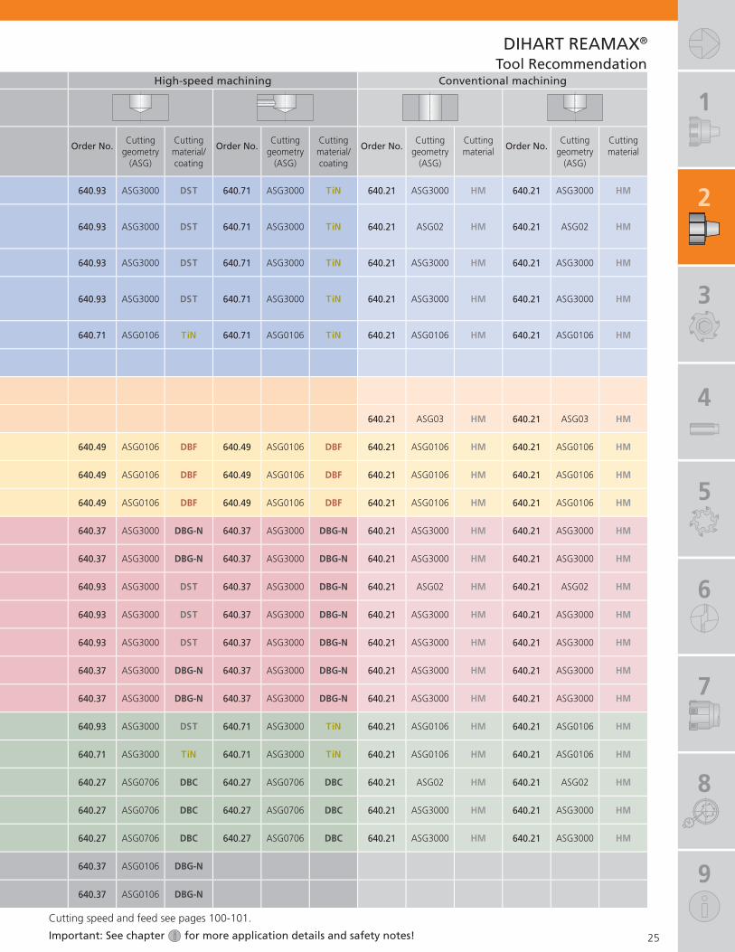
DIHART REAMAX® TSTool Recommendation
For inquiries concerning tools for materials without a recommendation, please contact us.Patent applied for inside and outside Germany (REAMAX®)

1
2
3
4
5
6
7
8
9
High-speed machining Conventional machining
Order No.Cutting
geometry (ASG)
Cutting material/ coating
Order No.Cutting
geometry (ASG)
Cutting material/ coating
Order No.Cutting
geometry (ASG)
Cutting material
Order No.Cutting
geometry (ASG)
Cutting material
75H.93 ASG3000 DST 75H.71 ASG3000 TiN 75J.21 ASG3000 HM 75H.21 ASG3000 HM
75H.93 ASG3000 DST 75H.71 ASG3000 TiN 75J.21 ASG02 HM 75H.21 ASG02 HM
75H.93 ASG3000 DST 75H.71 ASG3000 TiN 75J.21 ASG3000 HM 75H.21 ASG3000 HM
75H.93 ASG3000 DST 75H.71 ASG3000 TiN 75J.21 ASG3000 HM 75H.21 ASG3000 HM
75H.71 ASG0106 TiN 75H.71 ASG0106 TiN 75J.21 ASG0106 HM 75H.21 ASG0106 HM
75J.21 ASG03 HM 75H.21 ASG03 HM
75H.47 ASG0106 DBF 75H.47 ASG0106 DBF 75J.21 ASG0106 HM 75H.21 ASG0106 HM
75H.47 ASG0106 DBF 75H.47 ASG0106 DBF 75J.21 ASG0106 HM 75H.21 ASG0106 HM
75H.47 ASG0106 DBF 75H.47 ASG0106 DBF 75J.21 ASG0106 HM 75H.21 ASG0106 HM
75H.37 ASG3000 DBG-N 75H.37 ASG3000 DBG-N 75J.21 ASG3000 HM 75H.21 ASG3000 HM
75H.37 ASG3000 DBG-N 75H.37 ASG3000 DBG-N 75J.21 ASG3000 HM 75H.21 ASG3000 HM
75H.93 ASG3000 DST 75H.47 ASG3000 DBF 75J.21 ASG02 HM 75H.21 ASG02 HM
75H.93 ASG3000 DST 75H.47 ASG3000 DBF 75J.21 ASG3000 HM 75H.21 ASG3000 HM
75H.93 ASG3000 DST 75H.47 ASG3000 DBF 75J.21 ASG3000 HM 75H.21 ASG3000 HM
75H.37 ASG3000 DBG-N 75H.37 ASG3000 DBG-N 75J.21 ASG3000 HM 75H.21 ASG3000 HM
75H.37 ASG3000 DBG-N 75H.37 ASG3000 DBG-N 75J.21 ASG3000 HM 75H.21 ASG3000 HM
75H.93 ASG3000 DST 75H.71 ASG3000 TiN 75J.21 ASG0106 HM 75H.21 ASG0106 HM
75H.71 ASG3000 TiN 75H.71 ASG3000 TiN 75J.21 ASG0106 HM 75H.21 ASG0106 HM
75H.17 ASG0706 DBC 75H.17 ASG0706 DBC 75J.21 ASG02 HM 75H.21 ASG02 HM
75H.17 ASG0706 DBC 75H.17 ASG0706 DBC 75J.21 ASG3000 HM 75H.21 ASG3000 HM
75H.17 ASG0706 DBC 75H.17 ASG0706 DBC 75J.21 ASG3000 HM 75H.21 ASG3000 HM
75H.37 ASG0106 DBG-N
75H.37 ASG0106 DBG-N
15
DIHART REAMAX® TSTool Recommendation
Important: See chapter for more application details and safety notes!
Cutting speed and feed see pages 100-101.
1
Dimensions
min. diameter for
front cutting� D � x a l2 No. of
~ ~ ~ teeth0.7087 – 0.7873 (18.000 – 19.999) � D – 0.157 (� D – 4.0) 0.236 (6.0) 0.787 (20) 6 0.07
0.7874 – 0.8661 (20.000 – 21.999) � D – 0.157 (� D – 4.0) 0.236 (6.0) 0.787 (20) 6 0.07
0.8662 – 1.0629 (22.000 – 26.999) � D – 0.165 (� D – 4.2) 0.236 (6.0) 0.787 (20) 6 0.09
1.0630 – 1.2519 (27.000 – 31.799) � D – 0.213 (� D – 5.4) 0.236 (6.0) 0.984 (25) 6 0.09
1.2520 – 1.3779 (31.800 – 34.999) � D – 0.236 (� D – 6.0) 0.236 (6.0) 0.984 (25) 8 0.11
1.3780 – 1.6535 (35.000 – 41.999) � D – 0.272 (� D – 6.9) 0.236 (6.0) 0.984 (25) 8 0.29-0.33
1.6536 – 2.0472 (42.000 – 51.999) � D – 0.295 (� D – 7.5) 0.236 (6.0) 1.181 (30) 8 0.44-0.55
2.0473 – 2.5591 (52.000 – 65.000) � D – 0.346 (� D – 8.8) 0.315 (8.0) 1.378 (35) 10 0.77-0.99
Selection: Cutting material, material, coolant supplyC
uttin
g m
ater
ial /
co
atin
g
for material for material
Order No. Order No. P M K N S H P M K N S H
75J.21 75H.21 HM $$1) $$1) $$1) $$1) $$1) $$1) $$1) $$1) $$1) $$1)
75J.71 75H.71 TiN $$ $$ $$4) $$ §§ $$ $$5) $$75J.37 75H.37 DBG-N $$ $$ $$ $$ $$75J.47 75H.47 DBF $$ §§ $$ $$ §§75J.17 75H.17 DBC §§ §§75J.93 75H.93 DST §§ $$2) $$3)
75J.67 75H.67 DJC $$2)
75J.87 75H.87 DJF $$Selection example: material St37, cutting material DST, central coolant supply, bore without interruption = Order No. 75H.93
Custom reaming head – selection options!
1) conventional machining · 2) material group 10.0&10.1 · 3) material group 12.0 · 4) material group 12.1 · 5) material group 12.0&12.1
16
DIHART REAMAX® TS
� x
� D
a
l2
� 0.7087 – 2.5591 inch (� 18.000 – 65.000 mm)
Patented design
Reaming Head – expandable
Pull stud included with holder or available separately
(..) = mm
Preferred range available from stock. See page 94-95.
Order example: Order No. 75H.93 · Bore diameter 65 mm · Bore tolerance H6 · Material St37 or ASG3000 (Cutting geometry page 14-15)
§ main area of application $ suitable in some cases

1
2
3
4
5
6
7
8
9
Short version Long version
Ø D Order No. L b c Ø d Order No. L b c Ø d
0.7087 – 0.7873(18.000 - 19.999) 75A.40.13010 5.118
(130)3.150(80)
1.968(50)
0.787(20) 0.44 75A.40.15010 7.480
(190)5.512(140)
1.968(50)
0.787(20) 0.66
0.7874 – 0.8661(20.000 - 21.999) 75A.40.13020 5.118
(130)3.150(80)
1.968(50)
0.787(20) 0.44 75A.40.15020 7.480
(190)5.512(140)
1.968(50)
0.787(20) 0.66
0.8662 – 1.0629(22.000 - 26.999) 75A.40.13030 5.118
(130)3.150(80)
1.968(50)
0.787(20) 0.66 75A.40.15030 8.268
(210)6.299(160)
1.968(50)
0.787(20) 0.88
1.0630 – 1.2519(27.000 - 31.799)
75A.40.13040 6.929(176)
4.724(120)
2.205(56)
0.984(25) 1.10 75A.40.15040 9.291
(236)7.087(180)
2.205(56)
0.984(25) 1.54
1.2520 – 1.3779(31.800 - 34.999)1.3780 – 1.6535(35.000 - 41.999) 75A.40.13050 6.929
(176)4.724(120)
2.205(56)
0.984(25) 1.32 75A.40.15050 10.079
(256)7.874(200)
2.205(56)
0.984(25) 2.20
1.6536 – 2.0472(42.000 - 51.999) 75A.40.13060 7.087
(180)4.724(120)
2.362(60)
1.260(32) 1.98 75A.40.15060 11.024
(280)8.661(220)
2.362(60)
1.260(32) 3.31
2.0473 – 2.5591(52.000 - 65.000) 75A.40.13070 7.087
(180)4.724(120)
2.362(60)
1.260(32) 2.20 75A.40.15070 11.024
(280)8.661(220)
2.362(60)
1.260(32) 4.41
17
DIHART REAMAX® TS
L
� D
b
� d
c
� 0.7087 – 2.5591 inch (� 18.000 – 65.000 mm)
Includes: REAMAX® TS holder complete with operating key, pull stud and open-end wrench (� page 21). Please order reaming head separately.
with internal coolant supply �
Holder with cylindrical shank similar to DIN 1835
(..) = mm
Pull stud

1
Short version Long version
Ø D Order No. L b c Ø d Order No. L b c Ø d
0.7087 – 0.7873(18.000 - 19.999) 75A.41.13010 5.709
(145)3.150(80)
1.968(50)
0.787(20) 0.44 75A.41.15010 8.071
(205)5.512(140)
1.968(50)
0.787(20) 0.66
0.7874 – 0.8661(20.000 - 21.999) 75A.41.13020 5.709
(145)3.150(80)
1.968(50)
0.787(20) 0.66 75A.41.15020 8.071
(205)5.512(140)
1.968(50)
0.787(20) 0.88
0.8662 – 1.0629(22.000 - 26.999) 75A.41.13030 5.709
(145)3.150(80)
1.968(50)
0.787(20) 0.66 75A.41.15030 8.858
(225)6.299(160)
1.968(50)
0.787(20) 0.88
1.0630 – 1.3779(27.000 - 34.999) 75A.41.13040 6.929
(176)4.724(120)
2.205(56)
0.984(25) 1.10 75A.41.15040 9.291
(236)7.087(180)
2.205(56)
0.984(25) 1.54
1.3780 – 1.6535(35.000 - 41.999) 75A.41.13050 6.929
(176)4.724(120)
2.205(56)
0.984(25) 1.10 75A.41.15050 10.079
(256)7.874(200)
2.205(56)
0.984(25) 2.31
18
DIHART REAMAX® TS
L
� D
b � 0.709 – 1.062 (� 18.000 – 26.999 mm)
� d
cb � 1.063 – 2.558 (� 27.000 – 41.999 mm)
� with internal coolant supply� holder is set to a run-out of < 0.0002" (< 0.005 mm)
DAH® Zero Holder with cylindrical shank similar to DIN 1835
Includes: DAH® Zero holder complete with operating key, pull stud and open-end wrench (� page 21). Please order reaming head separately.
Adjustment screwPull stud
(..) = mm
� 0.7087 – 1.6535 inch (� 18.000 – 41.999 mm)
Patented design

1
2
3
4
5
6
7
8
9
Short version Long version
Ø D Order No. L b DAH Order No. L b DAH
1.6536 – 2.0472(42.000 - 51.999) 75A.30.13060 5.433
(138)4.724(120) 81 1.98 75A.30.15060 9.370
(238)8.661(220) 81 3.31
2.0473 – 2.5591(52.000 - 65.000) 75A.30.13070 5.433
(138)4.724(120) 81 2.20 75A.30.15070 9.370
(238)8.661(220) 81 4.41
Dimensions
Ø D Order No. L ABS
1.3780 – 1.6535 (35.000 - 41.999) 75A.60.13050 4.331 (110) 32 0.92
1.6536 – 2.0472 (42.000 - 51.999) 75A.60.13060 4.527 (115) 32 1.17
2.0473 – 2.5591 (52.000 - 65.000) 75A.60.13070 4.921 (125) 40 1.83
19
L
b
DA
H
� D
DIHART REAMAX® TS
with internal coolant supply �
with internal coolant supply �
Holder with DAH® Connection
Holder with ABS® Connection
Includes: REAMAX® TS holder with operating key, pull stud and open-end wrench (� page 21). Please order reaming head separately.
Includes: REAMAX® TS holder with operating key, pull stud and open-end wrench (� page 21). Please order reaming head separately. DAH® compensation holder see Chapter 8.
Pull stud
(..) = mm
(..) = mm
� 1.6536 – 2.5591 inch (� 42.000 – 65.000 mm)
� 1.3780 – 2.5591 inch (� 35.000 – 65.000 mm)
L
ABS� D

1
Dia. range Torque M
0.7087 – 0.7873 (18.000 - 19.999) 13 in-lbs (1.5 Nm)
0.7874 – 0.8661 (20.000 - 21.999) 22 in-lbs (2.5 Nm)
0.8662 – 1.0629 (22.000 - 26.999) 35 in-lbs (4 Nm)
1.0630 - 1.3779 (27.000 - 34.999) 44 in-lbs (5 Nm)
1.3780 - 1.6535 (35.000 - 41.999) 53 in-lbs (6 Nm)
1.6535 - 2.0472 (42.000 - 51.999) 88 in-lbs (10 Nm)
2.0473 - 2.5591 (52.000 - 65.000) 111 in-lbs (13 Nm)
20
��
��
��
M
��
��
��
��
��
��
��
��
��
DIHART REAMAX® TS Assembly instructions
Clean taper/face contact thoroughly (grease and debris free). Screw retention knob � into reaming head and tighten with open-end wrench �.
Open clamping jaws � with key . Insert reaming head .
Close clamping jaws � with key , noting recommended torque.When inserting the reaming head this is drawn into its fi nal position by the clamping jaws �.
When removing, the reaming head is pressed out of its position by the clamping jaws � which allows it to be easily removed from the holder: open the clamping jaws � with the key , remove the reaming head .
Adjusting to compensate for wear
The bore tolerances as small as IT4 can be achieved by adjusting with the hexagonal key �. Hexagonal wrench not included with REAMAX® TS heads or holders.
Patented design

1
2
3
4
5
6
7
8
9
� � �Clamping key Hexagonal
key*Retention
knobOpen-end wrenchfor retention knobL
Ø D Size Order No. L Torque M Size Order No. Size Order No.
0.7087 – 0.7873 (18.000 - 19.999) 8IP L05 01240 13.3 in-lbs (1.5 Nm) SW 4 15E.30.10010 SW 5 18589 10005
0.7874 – 0.8661 (20.000 - 21.999) SW 2.5 18050 10025 (100) 22.1 in-lbs (2.5 Nm) SW 5 15E.30.10020 SW 5 18589 10005
0.8662 – 1.0629 (22.000 - 26.999) SW 3 18050 10030 (100) 35.4 in-lbs (4 Nm) SW 5 15E.30.10030 SW 6 18589 10006
1.0630 - 1.3779 (27.000 - 34.999) SW 3 18050 10030 (100) 44.3 in-lbs (5 Nm) SW 8 15E.30.10040 SW 8 18589 10008
1.3780 - 1.6535 (35.000 - 41.999) SW 3 18050 10030 (100) 53.1 in-lbs (6 Nm) SW 6 15E.30.10050 SW 10 18589 10010
1.6535 - 2.0472 (42.000 - 51.999) SW 4 18050 10040 (100) 88.5 in-lbs (10 Nm) SW 8 15E.30.10050 SW 10 18589 10010
2.0473 - 2.5590 (52.000 - 64.999) SW 5 18050 10050 (100) 115 in-lbs (13 Nm) SW 10 15E.30.10070 SW 13 18589 10013
21
��
��
DIHART REAMAX® TS
Replacement parts / Accessories
* not included with REAMAX® TS heads or holders.
Adjusting:
• Set the indicator dial by adjusting the bezel position.
• Locate the highest run-out point on the dial by rotating the tool.
• Turn the adjustment screw clockwise using an Allen key , correcting the run-out. Over-tension by approx. 5 µm.
• Engage the opposite adjustment screws � and drive back the tool by the specifi ed over-tension value.
• Engage the two other adjustment screws.
• Align all 4 adjustment screws until concentricity is < 2 µm.
Please note:
• Only unscrew the adjustment screws by a max of ½ to 1 rotation.
• Never use the holder without the reamer head clamped and then only when the adjustment screws are tightened.
• In order to properly set this tool, an indicator with 0.002mm or 0.0001" discrimination is required.
• Indicate the tool when mounted in the machine spindle.
Operating Instruction DAH® Zero
(..) = mm

1
2
22
DIHART REAMAX®
The new dimension in high performance reaming
More performance. More fl exibility.DIHART’s high-speed reaming series, REAMAX®, provides maximum cutting performance through multiple cutting edges and offers all the advantages of replaceable cutting inserts in one system.
- Maximum effi ciency and complete process capability- High rigidity during maximum cutting speed- No size setting when blades are replaced- Maximum fl exibility for combining cutting materials and
coatings along with diameters and geometry are available and can be chosen for each specifi c application
- Made to order, short delivery time - Precise repeatability and replacement accuracy- Designed for inner coolant supply and minimal quantity
lubrication (MQL)
Reaming tools
The modular reaming tool consists of a tool holder with cylindrical shaft and the REAMAX® replaceable head. A high precision short taper ensures the connection between the replaceable head and the holder. Precise repeatability from head to head allows for minimal tool change time.
Maximum process effi ciency and accurate repeatability
Result in steel with DIHART REAMAX® -replaceable head
Replacement accuracy of the DIHART REAMAX® -connection
µ

1
2
3
4
5
6
7
8
9
DIHART REAMAX® Page
Tool Recommendation 24 – 25
Replaceable Head
Ø 0.4724 – 1.5748 inch (Ø 12.000 – 40.000 mm) 26
Holder
Cylindrical shank 27
Assembly Instructions 28
Replacement parts / Accessories 29
23
BENEFITS for you:
Precision ground modular system for guaranteed consistency
Maximum stability for the most demanding machining tasks
Extremely high repeatability through a tapered fl at bearing face
Extremely high machining performance for the maximum effi ciency
Minimum quantity lubrication (MQL) optimized for environmentally friendly use
Simple possible replacement
The DIHART REAMAX® replaceable head is fi xed on to the tool holder with a tie-rod and a clamping nut. There is no need for time and cost intensive setting to the fi nal size as the heads are manufactured specifi cally for each application to the exact diameter and tolerance. DIHART REAMAX® offers replacement time with no idle time.
Application:
- All current materials- Through and blind holes- 3 × D and 5 × D- High speed – up to 985 ft/min (300 m/min)- Feed – up to 0.094 in/rev (2.4 mm/rev)

1
2
Mat
eria
l gro
up
Stre
ngth
Rm
(lbf
/Ins²
)
Har
dnes
s H
B MaterialMaterial exampleAISI / SAE
High-speed machining
Order No.Cutting
geometry (ASG)
Cutting material/ coating
Order No.Cutting
geometry (ASG)
Cutting material/ coating
P1.
0 � 72,500 non-alloy steels101011441213
640.92 ASG05 DST 640.70 ASG05 TiN
2.0 72,500 -
130,000non-alloy /low alloy steels
105551155120
640.92 ASG05 DST 640.70 ASG05 TiN
2.1 < 72,500 lead alloys 12L14 640.92 ASG05 DST 640.70 ASG05 TiN
3.0 > 130,000
non alloy / low alloy steels: heat resistant structural, heat treated, nitride and tools steels
10644140 640.92 ASG05 DST 640.71 ASG3000 TiN
4.0 > 130,000 high alloy steels H13
H21 640.70 ASG0106 TiN 640.71 ASG0106 TiN
4.1 HSS M10
T4
S5.
0 250 special alloys: Inconel, Hastelloy, Nimonic, stc.
Inconel® 718Nimonic® 80A
5.1 58,000 titanium,
titanium alloys Ti-6Al-4V
M6.
0 � 87,000 stainless steels 304L316 640.49 ASG0106 DBF 640.49 ASG0106 DBF
6.1 <130,000 stainless steels 630 640.49 ASG0106 DBF 640.49 ASG0106 DBF
7.0 >130,000 stainless / fi reproof steels 403
420 640.49 ASG0106 DBF 640.49 ASG0106 DBF
K8.
0 180 gray cast iron Class 25G3000 640.37 ASG3000 DBG-N 640.37 ASG3000 DBG-N
8.1 250 alloy gray cast iron A436 Type 2 640.37 ASG3000 DBG-N 640.37 ASG3000 DBG-N
9.0 � 87,000 130 ductile cast iron, ferritic 60-40-18
D4512 640.93 ASG3000 DST 640.37 ASG3000 DBG-N
9.1 230 ductile cast iron, ferritic /
perlitic80-55-06D5506 640.93 ASG3000 DST 640.37 ASG3000 DBG-N
10.0 > 87,000 250
spheroidal graphite cast iron, perlitic malleable iron
100-70-0307003 640.93 ASG3000 DST 640.37 ASG3000 DBG-N
10.1 200 alloyed spheroidal graphite
cast iron A43D2 640.37 ASG3000 DBG-N 640.37 ASG3000 DBG-N
10.2 300 vermicular cast iron 640.37 ASG3000 DBG-N 640.37 ASG3000 DBG-N
N12
.0 90copper alloy, brass,lead-alloy bronze, lead bronze: good cut
316 640.93 ASG3000 DST 640.71 ASG3000 TiN
12.1 100 copper alloy, brass,
bronze:average cut 640.71 ASG3000 TiN 640.71 ASG3000 TiN
13.0 60 wrought aluminum alloys 6151
7075 640.27 ASG0706 DBC 640.27 ASG0706 DBC
13.1 75
cast aluminum alloy: Si-content <10%magnesium alloy
380A356.0 640.27 ASG0706 DBC 640.27 ASG0706 DBC
14.0 100 cast aluminum alloy:
Si-content > 10%383A413.0 640.27 ASG0706 DBC 640.27 ASG0706 DBC
H15
.0 203,000 hardened steels< 45 HRC 640.37 ASG0106 DBG-N
16.0 261,000 hardened steels
> 45 HRC, � 55 HRC 640.37 ASG0106 DBG-N
24
DIHART REAMAX®
Tool Recommendation
For inquiries concerning tools for materials without a recommendation, please contact us.Patent applied for inside and outside Germany.
1
2
3
4
5
6
7
8
9
High-speed machining Conventional machining
Order No.Cutting
geometry (ASG)
Cutting material/ coating
Order No.Cutting
geometry (ASG)
Cutting material/ coating
Order No.Cutting
geometry (ASG)
Cutting material
Order No.Cutting
geometry (ASG)
Cutting material
640.93 ASG3000 DST 640.71 ASG3000 TiN 640.21 ASG3000 HM 640.21 ASG3000 HM
640.93 ASG3000 DST 640.71 ASG3000 TiN 640.21 ASG02 HM 640.21 ASG02 HM
640.93 ASG3000 DST 640.71 ASG3000 TiN 640.21 ASG3000 HM 640.21 ASG3000 HM
640.93 ASG3000 DST 640.71 ASG3000 TiN 640.21 ASG3000 HM 640.21 ASG3000 HM
640.71 ASG0106 TiN 640.71 ASG0106 TiN 640.21 ASG0106 HM 640.21 ASG0106 HM
640.21 ASG03 HM 640.21 ASG03 HM
640.49 ASG0106 DBF 640.49 ASG0106 DBF 640.21 ASG0106 HM 640.21 ASG0106 HM
640.49 ASG0106 DBF 640.49 ASG0106 DBF 640.21 ASG0106 HM 640.21 ASG0106 HM
640.49 ASG0106 DBF 640.49 ASG0106 DBF 640.21 ASG0106 HM 640.21 ASG0106 HM
640.37 ASG3000 DBG-N 640.37 ASG3000 DBG-N 640.21 ASG3000 HM 640.21 ASG3000 HM
640.37 ASG3000 DBG-N 640.37 ASG3000 DBG-N 640.21 ASG3000 HM 640.21 ASG3000 HM
640.93 ASG3000 DST 640.37 ASG3000 DBG-N 640.21 ASG02 HM 640.21 ASG02 HM
640.93 ASG3000 DST 640.37 ASG3000 DBG-N 640.21 ASG3000 HM 640.21 ASG3000 HM
640.93 ASG3000 DST 640.37 ASG3000 DBG-N 640.21 ASG3000 HM 640.21 ASG3000 HM
640.37 ASG3000 DBG-N 640.37 ASG3000 DBG-N 640.21 ASG3000 HM 640.21 ASG3000 HM
640.37 ASG3000 DBG-N 640.37 ASG3000 DBG-N 640.21 ASG3000 HM 640.21 ASG3000 HM
640.93 ASG3000 DST 640.71 ASG3000 TiN 640.21 ASG0106 HM 640.21 ASG0106 HM
640.71 ASG3000 TiN 640.71 ASG3000 TiN 640.21 ASG0106 HM 640.21 ASG0106 HM
640.27 ASG0706 DBC 640.27 ASG0706 DBC 640.21 ASG02 HM 640.21 ASG02 HM
640.27 ASG0706 DBC 640.27 ASG0706 DBC 640.21 ASG3000 HM 640.21 ASG3000 HM
640.27 ASG0706 DBC 640.27 ASG0706 DBC 640.21 ASG3000 HM 640.21 ASG3000 HM
640.37 ASG0106 DBG-N
640.37 ASG0106 DBG-N
25
DIHART REAMAX®
Tool Recommendation
Important: See chapter for more application details and safety notes!
Cutting speed and feed see pages 100-101.

1
2
Dimensions
min. diameter for
front cutting� D � x a l2 No. of
~ ~ ~ teeth0.4724 – 0.6299 (12.000 – 15.999) � D – 0.098 (� D – 2.5) 0.354 (9.0) 0.020 (0.5) 6
0.6300 – 0.8660 (16.000 – 21.999) � D – 0.118 (� D – 3.0) 0.354 (9.0) 0.020 (0.5) 6
0.8661 – 1.0235 (22.000 – 25.999) � D – 0.118 (� D – 3.0) 0.354 (9.0) 0.020 (0.5) 8
1.0236 – 1.2598 (26.000 – 32.000) � D – 0.157 (� D – 4.0) 0.354 (9.0) 0.020 (0.5) 8
1.2599 – 1.5748 (32.001 – 40.000) � D – 0.157 (� D – 4.0) 0.354 (9.0) 0.020 (0.5) 8
Selection: Cutting material, material, coolant supply
Cutting material / coating
for material for material
Order No. Order No. P M K N S H P M K N S H
640.20 640.21 HM §§1) §§1) §§1) §§1) §§1) §§1) §§1) §§1) §§1) §§1)
640.70 640.71 TiN $$ $$ §§4) $$ §§ $$ §§5) $$640.36 640.37 DBG-N §§ $$ $$ §§ $$640.48 640.49 DBF $$ §§ $$ $$ §§640.26 640.27 DBC §§ §§640.92 640.93 DST §§ $$3)
640.66 640.67 DJC $$2)
Selection example: material St37, cutting material DST, central coolant supply, bore without interruption = Order No. 640.93
26
DIHART REAMAX® � 0.4724 – 1.5748 inch (� 12.000 – 40.000 mm)Replaceable Heads
� for through and blind hole machining Please note: do not use � 0.472 – 0.492" (�12.000 - 12.500 mm) for blind hole machining
� x
� D
� D
aa
ffor through hole machining
Patented design
(..) = mm
Preferred range available from stock. See page 94.
Order example: Order No. 640.93 · Bore diameter 21 mm · Bore tolerance H6 · Material St37 or ASG3000 (Cutting geometry page 24-25)
§ main area of application $ suitable in some cases
Custom reaming head – selection options!
1) conventional machining · 2) material group 10.0&10.1 · 3) material group 12.0 · 4) material group 12.1 · 5) material group 12.0&12.1

1
2
3
4
5
6
7
8
9
Short version Long version
forØ D Order No. L b c Ø d Order No. L b c Ø d
0.4724 – 0.6299(12.000 – 15.999)
640.01.001 4.213(107)
1.890(48)
1.890(48)
0.630(16) 0.24 640.81.001 5.394
(137)2.953(75)
1.890(48)
0.630(16) 0.29
0.6300 – 0.8660(16.000 – 21.999)
640.01.002 4.685(119)
2.520(64)
1.969(50)
0.787(20) 0.40 640.81.002 6.653
(169)4.370(111)
1.968(50)
0.787(20) 0.51
0.8661 – 1.0235(22.000 – 25.999)
640.01.003 5.512(140)
3.071(78)
2.205(56)
0.984(25) 0.75 640.81.003 7.746
(196)5.157(131)
2.205(56)
0.984(25) 0.97
1.0236 – 1.2598(26.000 – 32.000)
640.01.005 6.299(160)
4.094(104)
2.205(56)
0.984(25) 1.01 640.81.005 8.898
(226)6.693(170)
2.205(56)
0.984(25) 1.43
1.2599 – 1.5748(32.001 – 40.000)
640.01.006 7.835(199)
5.472(139)
2.362(60)
1.260(32) 1.90 640.81.006 10.630
(270)8.268(210)
2.362(60)
1.260(32) 2.49
27
DIHART REAMAX®� 0.4724 – 1.5748 inch (� 12.000 – 40.000 mm) Holder with cylindrical shank similar to DIN 1835
with internal coolant supply �suitable for minimum quantity lubrication (MQL) �
not suitable for shrink fi t �
L
� D
b
� d
c
Includes: REAMAX® holder complete with operating key, open-end wrench, tie rod, seal disc and clamping nut (page 29). Please order replaceable head separately.
(..) = mm

1
2
Dia Range Torque M
0.4724 – 0.6299 (12.000 – 15.999) 35 - 44 in-lbs (4-5 Nm)
0.6300 – 0.8660 (16.000 – 21.999) 53 - 62 in-lbs (6-7 Nm)
0.8661 – 1.0235 (22.000 – 25.999) 88 -106 in-lbs (10-12 Nm)
1.0236– 1.2598 (26.000 – 32.000) 159 - 177 in-lbs (18-20 Nm)
1.2599 – 1.5748 (32.001 – 40.000) 230 - 248 in-lbs (26-28 Nm)
28
��
��
M��
��
��
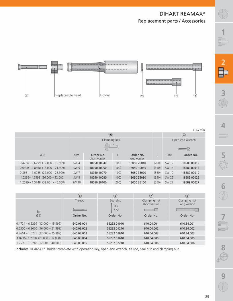
DIHART REAMAX®
Assembly instructions
Clean taper/face contact thoroughly (grease and debris free). Apply light grease on tie bar thread �.
Locate tie bar � on insert and holder. Important note: for taper size 3, 4 and 5, fi t with marking on tie bar and insert aligned.
Draw in tie bar with the clamping nut. Before tightening, turn insert and tie bar clockwise until it stops.Tighten the clamping nut as far as possible using the torque key to the recommended torque M.
Removing the replaceable head:Loosen the clamping screw.Pull tie bar from holder and head.
Locate clamping key in head and loosen insert by turning.
Patent applied for inside and outside Germany
1
2
3
4
5
6
7
8
9
� � � Tie-rod Seal disc Clamping nut Clamping nut
DIN 472
short version long version
forØ D Order No. Order No. Order No. Order No.
0.4724 – 0.6299 (12.000 – 15.999) 640.03.001 55232 01010 640.04.001 640.84.001
0.6300 – 0.8660 (16.000 – 21.999) 640.03.002 55232 01210 640.04.002 640.84.002
0.8661 – 1.0235 (22.000 – 25.999) 640.03.003 55232 01610 640.04.003 640.84.003
1.0236– 1.2598 (26.000 – 32.000) 640.03.004 55232 01610 640.04.005 640.84.005
1.2599 – 1.5748 (32.001 – 40.000) 640.03.005 55232 02210 640.04.006 640.84.006
�Clamping key Open-end wrench
L
Ø D Size Order No. L Order No. L Size Order No.short version long version
0.4724 – 0.6299 (12.000 – 15.999) SW 4 18050 10040 (100) 18050 20040 (200) SW 12 18589 00012
0.6300 – 0.8660 (16.000 – 21.999) SW 5 18050 10050 (100) 18050 10055 (350) SW 14 18589 00014
0.8661 – 1.0235 (22.000 – 25.999) SW 7 18050 10070 (100) 18050 35070 (350) SW 19 18589 00019
1.0236– 1.2598 (26.000 – 32.000) SW 8 18050 10080 (100) 18050 35080 (350) SW 22 18589 00022
1.2599 – 1.5748 (32.001 – 40.000) SW 10 18050 20100 (200) 18050 35100 (350) SW 27 18589 00027
29
DIHART REAMAX®
� � �
Replacement parts / Accessories
Replaceable head Holder
(..) = mm
Includes: REAMAX® holder complete with operating key, open-end wrench, tie rod, seal disc and clamping nut.

1
2
3
30
DIHART Monomax® – Expandable
DIHART Monomax®
One-piece tools – known as monobloc tools – are one of DIHART’s specialities. The demands which have been made over decades are refl ected in an enormous number of types and variations. This successful tool program has been completely revised with many standards available through effi cient manufacturing.
BENEFITS for you:
Designed for small hole diameters Wear compensation for extremely small hole tolerances
Extremely durable due to one piece construction Precision ground to size
Application:
- Non-alloy and low alloy steels- Stainless, heat resistant and high alloy steels- Grey cast iron and spheroidal graphite cast iron- Copper alloys, brass and bronze- Aluminum- Titanium, titanium alloys, CGI and plastic on request
Versions:
- Short and long versions- Through and blind hole coolant outlets available- Uncoated and coated carbide or DST- Diameter range 0.2205 – 1.0197 inch (5.600 – 25.899 mm)

1
2
3
4
5
6
7
8
9
DIHART Monomax® Page
Tool Recommendation 32 – 33
Monomax® – Expandable
Ø 0.2205 – 1.0197 inch (Ø 5.600 – 25.899 mm)with cylindrical shank – short version
Ø 0.2205 – 1.0197 inch (Ø 5.600 – 25.899 mm)with cylindrical shank – long version
34 – 35
36 – 37
31

1
2
3
Mat
eria
l gro
up
Stre
ngth
Rm
(lbf
/Ins²
)
Har
dnes
s H
B MaterialMaterial exampleANSI / SAE
High-speed machining
Order No.longshort
Cutting geometry
(ASG)
Cutting material/ coating
Order No.longshort
Cutting geometry
(ASG)
Cutting material/ coating
P1.
0 � 72,500 non-alloy steels101011441213
56J.9356R.93
ASG4000 DST 56J.7156R.71
ASG4000 TiN
2.0 72,500 -
130,000non-alloy /low alloy steels
105551155120
56J.9356R.93
ASG4000 DST 56J.7156R.71
ASG4000 TiN
2.1 < 72,500 lead alloys 12L14
56J.9356R.93
ASG4000 DST 56J.7156R.71
ASG4000 TiN
3.0 > 130,000
non alloy / low alloy steels: heat resistant structural, heat treated, nitride and tools steels
10644140
56J.9356R.93
ASG4000 DST 56J.7156R.71
ASG3000 TiN
4.0 > 130,000 high alloy steels H13
H2156J.7156R.71
ASG0106 TiN 56J.7156R.71
ASG0106 TiN
4.1 HSS M10
T4
S5.
0 250 special alloys: Inconel, Hastelloy, Nimonic, stc.
Inconel® 718Nimonic® 80A
5.1 58,000 titanium,
titanium alloys Ti-6Al-4V
M6.
0 � 87,000 stainless steels 304L316
56J.4756R.47
ASG0106 DBF 56J.4756R.47
ASG0106 DBF
6.1 <130,000 stainless steels 630
56J.4756R.47
ASG0106 DBF 56J.4756R.47
ASG0106 DBF
7.0 >130,000 stainless / fi reproof steels 403
42056J.4756R.47
ASG0106 DBF 56J.4756R.47
ASG0106 DBF
K8.
0 180 gray cast iron Class 25G3000
56J.3756R.37
ASG3000 DBG-N 56J.3756R.37
ASG3000 DBG-N
8.1 250 alloy gray cast iron A436 Type 2
56J.3756R.37
ASG3000 DBG-N 56J.3756R.37
ASG3000 DBG-N
9.0 � 87,000 130 ductile cast iron, ferritic 60-40-18
D451256J.9356R.93
ASG3000 DST 56J.3756R.37
ASG3000 DBG-N
9.1 230 ductile cast iron, ferritic /
perlitic80-55-06D5506
56J.9356R.93
ASG3000 DST 56J.3756R.37
ASG3000 DBG-N
10.0 > 87,000 250
spheroidal graphite cast iron, perlitic malleable iron
100-70-0307003
56J.9356R.93
ASG3000 DST 56J.3756R.37
ASG3000 DBG-N
10.1 200 alloyed spheroidal graphite
cast iron A43D256J.3756R.37
ASG3000 DBG-N 56J.3756R.37
ASG3000 DBG-N
10.2 300 vermicular cast iron
56J.3756R.37
ASG3000 DBG-N 56J.3756R.37
ASG3000 DBG-N
N12
.0 90copper alloy, brass,lead-alloy bronze, lead bronze: good cut
31656J.9356R.93
ASG3000 DST 56J.7156R.71
ASG3000 TiN
12.1 100 copper alloy, brass,
bronze:average cut56J.7156R.71
ASG3000 TiN 56J.7156R.71
ASG3000 TiN
13.0 60 wrought aluminum alloys 6151
707556J.1756R.17
ASG0706 DBC 56J.1756R.17
ASG0706 DBC
13.1 75
cast aluminum alloy: Si-content <10%magnesium alloy
380A356.0
56J.1756R.17
ASG0706 DBC 56J.1756R.17
ASG0706 DBC
14.0 100 cast aluminum alloy:
Si-content > 10%383A413.0
56J.1756R.17
ASG0706 DBC 56J.1756R.17
ASG0706 DBC
H15
.0 203,000 hardened steels< 45 HRC
56J.3756R.37
ASG0106 DBG-N
16.0 261,000 hardened steels
> 45 HRC, � 55 HRC56J.3756R.37
ASG0106 DBG-N
32
DIHART Monomax® – ExpandableTool Recommendation
For inquiries concerning tools for materials without a recommendation, please contact us.

1
2
3
4
5
6
7
8
9
High-speed machining Conventional machining
Order No.longshort
Cutting geometry
(ASG)
Cutting material/ coating
Order No.longshort
Cutting geometry
(ASG)
Cutting material/ coating
Order No.longshort
Cutting geometry
(ASG)
Cutting material
Order No.longshort
Cutting geometry
(ASG)
Cutting material
56H.9356Q.93
ASG3000 DST 56H.7156Q.71
ASG3000 TiN 56J.2156R.21
ASG3000 HM 56H.2156Q.21
ASG3000 HM
56H.9356Q.93
ASG3000 DST 56H.7156Q.71
ASG3000 TiN 56J.2156R.21
ASG02 HM 56H.2156Q.21
ASG02 HM
56H.9356Q.93
ASG3000 DST 56H.7156Q.71
ASG3000 TiN 56J.2156R.21
ASG3000 HM 56H.2156Q.21
ASG3000 HM
56H.9356Q.93
ASG3000 DST 56H.7156Q.71
ASG3000 TiN 56J.2156R.21
ASG3000 HM 56H.2156Q.21
ASG3000 HM
56H.7156Q.71
ASG0106 TiN 56H.7156Q.71
ASG0106 TiN 56J.2156R.21
ASG0106 HM 56H.2156Q.21
ASG0106 HM
56J.2156R.21
ASG03 HM 56H.2156Q.21
ASG03 HM
56H.4756Q.47
ASG0106 DBF 56H.4756Q.47
ASG0106 DBF 56J.2156R.21
ASG0106 HM 56H.2156Q.21
ASG0106 HM
56H.4756Q.47
ASG0106 DBF 56H.4756Q.47
ASG0106 DBF 56J.2156R.21
ASG0106 HM 56H.2156Q.21
ASG0106 HM
56H.4756Q.47
ASG0106 DBF 56H.4756Q.47
ASG0106 DBF 56J.2156R.21
ASG0106 HM 56H.2156Q.21
ASG0106 HM
56H.3756Q.37
ASG3000 DBG-N 56H.3756Q.37
ASG3000 DBG-N 56J.2156R.21
ASG3000 HM 56H.2156Q.21
ASG3000 HM
56H.3756Q.37
ASG3000 DBG-N 56H.3756Q.37
ASG3000 DBG-N 56J.2156R.21
ASG3000 HM 56H.2156Q.21
ASG3000 HM
56H.9356Q.93
ASG3000 DST 56H.3756Q.37
ASG3000 DBG-N 56J.2156R.21
ASG02 HM 56H.2156Q.21
ASG02 HM
56H.9356Q.93
ASG3000 DST 56H.3756Q.37
ASG3000 DBG-N 56J.2156R.21
ASG3000 HM 56H.2156Q.21
ASG3000 HM
56H.9356Q.93
ASG3000 DST 56H.3756Q.37
ASG3000 DBG-N 56J.2156R.21
ASG3000 HM 56H.2156Q.21
ASG3000 HM
56H.3756Q.37
ASG3000 DBG-N 56H.3756Q.37
ASG3000 DBG-N 56J.2156R.21
ASG3000 HM 56H.2156Q.21
ASG3000 HM
56H.3756Q.37
ASG3000 DBG-N 56H.3756Q.37
ASG3000 DBG-N 56J.2156R.21
ASG3000 HM 56H.2156Q.21
ASG3000 HM
56H.9356Q.93
ASG3000 DST 56H.7156Q.71
ASG3000 TiN 56J.2156R.21
ASG0106 HM 56H.2156Q.21
ASG0106 HM
56H.7156Q.71
ASG3000 TiN 56H.7156Q.71
ASG3000 TiN 56J.2156R.21
ASG0106 HM 56H.2156Q.21
ASG0106 HM
56H.1756Q.17
ASG0706 DBC 56H.1756Q.17
ASG0706 DBC 56J.2156R.21
ASG02 HM 56H.2156Q.21
ASG02 HM
56H.1756Q.17
ASG0706 DBC 56H.1756Q.17
ASG0706 DBC 56J.2156R.21
ASG3000 HM 56H.2156Q.21
ASG3000 HM
56H.1756Q.17
ASG0706 DBC 56H.1756Q.17
ASG0706 DBC 56J.2156R.21
ASG3000 HM 56H.2156Q.21
ASG3000 HM
56H.3756Q.37
ASG0106 DBG-N
56H.3756Q.37
ASG0106 DBG-N
33
DIHART Monomax® – ExpandableTool Recommendation
Important: See chapter for more application details and safety notes!
Cutting speed and feed see pages 100-101

1
2
3
Dimensions
Cylindricalshank
Ø D Ø d × c L b f a No. of inch inch inch ~inch ~inch teeth
0.2205 – 0.3503 (5.600 – 8.899) 0.500 × 1.772 3.346 1.575 0.004 0.374 4
0.3504 – 0.6259 (8.900 – 15.899) 0.500 × 1.772 3.740 1.969 0.004 0.374 6
0.6260 – 0.7440 (15.900 – 18.899) 0.625 × 1.969 3.937 1.969 0.004 0.374 6
0.7441 – 1.0197 (18.900 – 25.899) 0.750 × 2.362 4.724 2.362 0.004 0.374 6
Selection: Cutting material, material, coolant supply
Cutting material / coating
for material for material
Order No. Order No. P M K N S H P M K N S H
55J.21 55H.21 HM §§1) §§1) §§1) §§1) §§1) §§1) §§1) §§1) §§1) §§1)
55J.71 55H.71 TiN $$ $$ $$4) $$ §§ $$ $$5) $$55J.37 55H.37 DBG-N $$ $$ $$ $$ $$55J.47 55H.47 DBF $$ §§ $$ $$ §§55J.17 55H.17 DBC §§ §§55J.93 55H.93 DST §§ §§3)
55J.67 55H.67 DJC $$2)
Selection example: material St37, cutting material DST, central coolant supply, bore without interruption = Order No. 56H93
34
DIHART Monomax® – Expandable � 0.2205 – 1.0197 inch(� 5.600 – 25.899 mm)Short version with cylindrical shank similar to DIN 1835
� with internal coolant supply� coolant supply available for blind or through hole applications
Notes: Preferred range available from stock, see page 96-97.
Inch shank
a
� D
L
b
f
� d
c
(..) = mm
1) conventional machining · 2) material group 10.0&10.1 · 3) material group 12.0 · 4) material group 12.1 · 5) material group 12.0&12.1
Order example: Order No. 55H.93 · Bore diameter 24 mm · Bore tolerance H6 · Material St37 or ASG4000 (Cutting geometry page 32-33)
§ main area of application $ suitable in some cases
Custom reaming tool – selection options!

1
2
3
4
5
6
7
8
9
Dimensions
Cylindricalshank
Ø D Ø d × c L b f a No. of mm mm mm ~mm ~mm teeth
5.600 – 8.899 (0.2205 – 0.3503) 12 × 45 85 40 0.1 9.5 4
8.900 – 15.899 (0.3504 – 0.6259) 12 × 45 95 50 0.1 9.5 6
15.900 – 18.899 (0.6260 – 0.7440) 16 × 50 100 50 0.1 9.5 6
18.900 – 25.899 (0.7441 – 1.0197) 20 × 60 120 60 0.1 9.5 6
35
Notes: Preferred range available from stock, see page 96-97.
Metric shank
DIHART Monomax® – Expandable� 5.600 – 25.899 mm(� 0.2205 – 1.0197 inch) Short version with cylindrical shank similar to DIN 1835
with internal coolant supply �coolant supply available for blind or through hole applications �
a
� D
L
b
f
� d
c
(..) = inch
1) conventional machining · 2) material group 10.0&10.1 · 3) material group 12.0 · 4) material group 12.1 · 5) material group 12.0&12.1
Order example: Order No. 56H.93 · Bore diameter 24 mm · Bore tolerance H6 · Material St37 or ASG4000 (Cutting geometry page 32-33)
§ main area of application $ suitable in some cases
Custom reaming tool – selection options!Selection: Cutting material, material, coolant supply
Cutting material / coating
for material for material
Order No. Order No. P M K N S H P M K N S H
56J.21 56H.21 HM §§1) §§1) §§1) §§1) §§1) §§1) §§1) §§1) §§1) §§1)
56J.71 56H.71 TiN $$ $$ $$4) $$ §§ $$ $$5) $$56J.37 56H.37 DBG-N $$ $$ $$ $$ $$56J.47 56H.47 DBF $$ §§ $$ $$ §§56J.17 56H.17 DBC §§ §§56J.93 56H.93 DST §§ §§3)
56J.67 56H.67 DJC $$2)
Selection example: material St37, cutting material DST, central coolant supply, bore without interruption = Order No. 56H93

1
2
3
Dimensions
Cylindricalshank
Ø D Ø d × c L b f a No. of inch inch inch ~inch ~inch teeth
0.2205 – 0.3503 (5.600 – 8.899) 0.500 × 1.772 5.118 3.346 0.004 0.374 4
0.3504 – 0.3897 (8.900 – 9.899) 0.500 × 1.772 5.118 3.346 0.004 0.374 6
0.3898 – 0.6259 (9.900 – 15.899) 0.500 × 1.772 5.699 4.528 0.004 0.374 6
0.6260 – 0.7440 (15.900 – 18.899) 0.625 × 1.969 7.087 5.118 0.004 0.374 6
0.7441 – 1.0197 (18.900 – 25.899) 0.750 × 2.362 7.874 5.512 0.004 0.374 6
Selection: Cutting material, material, coolant supply
Cutting material / coating
for material for material
Order No. Order No. P M K N S H P M K N S H
55R.21 55Q.21 HM §§1) §§1) §§1) §§1) §§1) §§1) §§1) §§1) §§1) §§1)
55R.71 55Q.71 TiN $$ $$ $$4) $$ §§ $$ $$5) $$55R.37 55Q.37 DBG-N $$ $$ $$ $$ $$55R.47 55Q.47 DBF $$ §§ $$ $$ §§55R.17 55Q.17 DBC §§ §§55R.93 55Q.93 DST §§ §§3)
55R.67 55Q.67 DJC $$2)
Selection example: material St37, cutting material DST, central coolant supply, bore without interruption = Order No. 56H93
36
DIHART Monomax® – ExpandableLong version with cylindrical shank similar to DIN 1835
a
� D
L
b
f
� d
c
(..) = mm
� with internal coolant supply� coolant supply available for blind or through hole applications
Notes: Preferred range available from stock, see page 96-97.
1) conventional machining · 2) material group 10.0&10.1 · 3) material group 12.0 · 4) material group 12.1 · 5) material group 12.0&12.1
§ main area of application $ suitable in some cases
Inch shankCustom reaming tool – selection options!
Order example: Order No. 55Q.93 · Bore diameter 24 mm · Bore tolerance H6 · Material St37 or ASG4000 (Cutting geometry page 32-33)
� 0.2205 – 1.0197 inch(� 5.600 – 25.899 mm)

1
2
3
4
5
6
7
8
9
Dimensions
Cylindricalshank
Ø D Ø d × c L b f a No. of mm mm mm ~mm ~mm teeth
5.600 – 8.899 (0.2205 – 0.3503) 12 × 45 130 85 0.1 9.5 4
8.900 – 9.899 (0.3504 – 0.3897) 12 × 45 130 85 0.1 9.5 6
9.900 – 15.899 (0.3898 – 0.6259) 12 × 45 160 115 0.1 9.5 6
15.900 – 18.899 (0.6260 – 0.7440) 16 × 50 180 130 0.1 9.5 6
18.900 – 25.899 (0.7441 – 1.0197) 20 × 60 200 140 0.1 9.5 6
Selection: Cutting material, material, coolant supply
Cutting material / coating
for material for material
Order No. Order No. P M K N S H P M K N S H
56R.21 56Q.21 HM §§1) §§1) §§1) §§1) §§1) §§1) §§1) §§1) §§1) §§1)
56R.71 56Q.71 TiN $$ $$ $$4) $$ §§ $$ $$5) $$56R.37 56Q.37 DBG-N $$ $$ $$ $$ $$56R.47 56Q.47 DBF $$ §§ $$ $$ §§56R.17 56Q.17 DBC §§ §§56R.93 56Q.93 DST §§ §§3)
56R.67 56Q.67 DJC $$2)
Selection example: material St37, cutting material DST, central coolant supply, bore without interruption = Order No. 56H93
37
DIHART Monomax® – ExpandableLong version with cylindrical shank similar to DIN 1835
with internal coolant supply �coolant supply available for blind or through hole applications �
a
� D
L
b
f
� d
c
(..) = inch
Notes: Preferred range available from stock, see page 96-97.
Metric shank
1) conventional machining · 2) material group 10.0&10.1 · 3) material group 12.0 · 4) material group 12.1 · 5) material group 12.0&12.1
Order example: Order No. 56Q.93 · Bore diameter 24 mm · Bore tolerance H6 · Material St37 or ASG4000 (Cutting geometry page 32-33)
§ main area of application $ suitable in some cases
Custom reaming tool – selection options!
� 5.600 – 25.899 mm(� 0.2205 – 1.0197 inch)

1
2
3
4
38
DIHART® Fullmax
Universal high-performance solid carbide reaming tool
KOMET DIHART® is expanding its solid carbide reaming range with a completely overhauled universal reaming tool, available from stock in the main dimensions both with H7 tolerance and in 0.0004" (0.010 mm) size increments.
The combination of knowledge and experience gained with the previous product line has enabled us to systematically develop the cutting geometry and achieve incredibly high cutting performance in various different materials – even those hardened up to HRC62. At the same time, the modifi ed cutting edge geometry reduces chatter marks and improves chip formation. In addition to optimal cutting edge cooling, the targeted coolant also aids smooth evacuation of chips that are formed. A high-performance coating completes the new design, and can be used for various materials. This results in signifi cant improved wear resistance.
Co
nv.
Car
bid
e N
C-m
ach
ine
ream
er
DIH
AR
T® 5
26.1
7 T
iN
DIH
AR
T® F
ullm
ax
52M
.57
ft/min (m/min)in/tooth (mm/tooth)
Cos
ts p
er h
ole
in %
(Incl
uded
in c
alcu
latio
n: E
ssen
tial o
pera
ting
time,
to
ol li
fe, n
umbe
r of
hol
es, p
rice)
393.7 (120)0.003 (0.08)
49.2 (15)0.001 (0.03)
656.2 (200)0.008 (0.2)
vc =fz =
up to 60% reduction
up to 50% reduction
Practical example:
� 10H7 in 42CrMo4Blind hole with Rz < 6.3
These characteristics and properties combine to create the kind of precision for which KOMET® is known on the market, as well as its high standards of dimensional accuracy and surface fi nish quality.
Application specifi c dimensions can be supplied in the diameter range from 0.1181 – 0.7874 inch (3 to 20 mm). In addition, preferred ranges are available from stock for diameters 4, 5, 6, 8, 10, 12 mm. Additionally, blind hole and through hole coolant variations are available.

1
2
3
4
5
6
7
8
9
DIHART® Fullmax Page
Tool Recommendation 40 – 41
Fullmax
for blind hole machiningØ 0.1181 – 0.7874 inch (Ø 3.000 – 20.000 mm)
for though hole machiningØ 0.1181 – 0.7874 inch (Ø 3.000 – 20.000 mm)
42
43
39
BENEFITS for you:
Top performance for various materials New high-performance for universal use Optimized geometry for top cutting performance
Minimal costs per hole as a result of high cutting data and tool life
Available from stock with dimensions H7 and 0.0004" (0.010 mm) size increments

1
2
3
4
Mat
eria
l gro
up
Stre
ngth
Rm
(lbf
/Ins²
)
Har
dnes
s H
B MaterialMaterial exampleANSI / SAE
High-speed machining
Order No.Cutting
geometry (ASG)
Cutting material/ coating
Order No.Cutting
geometry (ASG)
Cutting material/ coating
P1.
0 � 72,500 non-alloy steels101011441213
52P.57 ASG2210 DBG-U 52P.57 ASG2210 DBG-U
2.0 72,500 -
130,000non-alloy /low alloy steels
105551155120
52P.57 ASG2210 DBG-U 52P.57 ASG2210 DBG-U
2.1 < 72,500 lead alloys 12L14 52P.57 ASG2210 DBG-U 52P.57 ASG2210 DBG-U
3.0 > 130,000
non alloy / low alloy steels: heat resistant structural, heat treated, nitride and tools steels
10644140 52P.57 ASG2210 DBG-U 52P.57 ASG2210 DBG-U
4.0 > 130,000 high alloy steels H13
H21 52P.57 ASG2210 DBG-U 52P.57 ASG2210 DBG-U
4.1 HSS M10
T4
S5.
0 250 special alloys: Inconel, Hastelloy, Nimonic, stc.
Inconel® 718Nimonic® 80A
5.1 58,000 titanium,
titanium alloys Ti-6Al-4V
M6.
0 � 87,000 stainless steels 304L316 52P.57 ASG2210 DBG-U 52P.57 ASG2210 DBG-U
6.1 <130,000 stainless steels 630 52P.57 ASG2210 DBG-U 52P.57 ASG2210 DBG-U
7.0 >130,000 stainless / fi reproof steels 403
420 52P.57 ASG2210 DBG-U 52P.57 ASG2210 DBG-U
K8.
0 180 gray cast iron Class 25G3000 52P.57 ASG2210 DBG-U 52P.57 ASG2210 DBG-U
8.1 250 alloy gray cast iron A436 Type 2 52P.57 ASG2210 DBG-U 52P.57 ASG2210 DBG-U
9.0 � 87,000 130 ductile cast iron, ferritic 60-40-18
D4512 52P.57 ASG2210 DBG-U 52P.57 ASG2210 DBG-U
9.1 230 ductile cast iron, ferritic /
perlitic80-55-06D5506 52P.57 ASG2210 DBG-U 52P.57 ASG2210 DBG-U
10.0 > 87,000 250
spheroidal graphite cast iron, perlitic malleable iron
100-70-0307003 52P.57 ASG2210 DBG-U 52P.57 ASG2210 DBG-U
10.1 200 alloyed spheroidal graphite
cast iron A43D2 52P.57 ASG2210 DBG-U 52P.57 ASG2210 DBG-U
10.2 300 vermicular cast iron 52P.57 ASG2210 DBG-U 52P.57 ASG2210 DBG-U
N12
.0 90copper alloy, brass,lead-alloy bronze, lead bronze: good cut
316 52P.57 ASG2210 DBG-U 52P.57 ASG2210 DBG-U
12.1 100 copper alloy, brass,
bronze:average cut 52P.57 ASG2210 DBG-U 52P.57 ASG2210 DBG-U
13.0 60 wrought aluminum alloys 6151
7075
13.1 75
cast aluminum alloy: Si-content <10%magnesium alloy
380A356.0
14.0 100 cast aluminum alloy:
Si-content > 10%383A413.0
H15
.0 203,000 hardened steels< 45 HRC
16.0 261,000 hardened steels
> 45 HRC, � 55 HRC
For inquiries concerning tools for materials without a recommendation, please contact us.
40
DIHART® FullmaxTool Recommendation

1
2
3
4
5
6
7
8
9
High-speed machining
Order No. Cutting geometry (ASG)Cutting material/
coatingOrder No. Cutting geometry (ASG)
Cutting material/ coating
52M.57 ASG2110 DBG-U 52M.57 ASG2110 DBG-U
52M.57 ASG2110 DBG-U 52M.57 ASG2110 DBG-U
52M.57 ASG2110 DBG-U 52M.57 ASG2110 DBG-U
52M.57 ASG2110 DBG-U 52M.57 ASG2110 DBG-U
52M.57 ASG2110 DBG-U 52M.57 ASG2110 DBG-U
52M.57 ASG2110 DBG-U 52M.57 ASG2110 DBG-U
52M.57 ASG2110 DBG-U 52M.57 ASG2110 DBG-U
52M.57 ASG2110 DBG-U 52M.57 ASG2110 DBG-U
52M.57 ASG2110 DBG-U 52M.57 ASG2110 DBG-U
52M.57 ASG2110 DBG-U 52M.57 ASG2110 DBG-U
52M.57 ASG2110 DBG-U 52M.57 ASG2110 DBG-U
52M.57 ASG2110 DBG-U 52M.57 ASG2110 DBG-U
52M.57 ASG2110 DBG-U 52M.57 ASG2110 DBG-U
52M.57 ASG2110 DBG-U 52M.57 ASG2110 DBG-U
52M.57 ASG2110 DBG-U 52M.57 ASG2110 DBG-U
52M.57 ASG2110 DBG-U 52M.57 ASG2110 DBG-U
52M.57 ASG2110 DBG-U 52M.57 ASG2110 DBG-U
52M.57 ASG2110 DBG-U
52M.57 ASG2110 DBG-U
Important: See chapter for more application details and safety notes!
Cutting speed and feed see pages 99.
41
DIHART® FullmaxTool Recommendation

1
2
3
4
Dimensions
Cylindricalshank
Ø D Ø d × c L b a No. of~ teeth
0.1165 – 0.1596 (2.959 – 4.054) 0.157 × 1.102 (4 × 28) 2.362 (60) 1.260 (32) 0.472 (12) 4
0.1597 – 0.2382 (4.055 – 6.050) 0.236 × 1.417 (6 × 36) 2.992 (76) 1.575 (40) 0.472 (12) 4
0.2383 – 0.3170 (6.051 – 8.051) 0.315 × 1.417 (8 × 36) 3.976 (101) 2.560 (65) 0.630 (16) 6
0.3171 – 0.3957 (8.052 – 10.051) 0.394 × 1.575 (10 × 40) 4.252 (108) 2.677 (68) 0.630 (16) 6
0.3958 – 0.4744 (10.052 – 12.050) 0.472 × 1.772 (12 × 45) 5.118 (130) 3.346 (85) 0.787 (20) 6
0.4745 – 0.5532 (12.051 – 14.052) 0.551 × 1.772 (14 × 45) 5.118 (130) 3.346 (85) 0.787 (20) 6
0.5533 – 0.6319 (14.053 – 16.050) 0.630 × 1.890 (16× 48) 5.906 (150) 4.016 (102) 0.787 (20) 6
0.6320 – 0.7106 (16.051 – 18.050) 0.709 × 1.890 (18 × 48) 5.906 (150) 4.016 (102) 0.787 (20) 6
0.7107 – 0.7894 (18.051 – 20.050) 0.787 × 1.969 (20 × 50) 6.230 (160) 4.331 (110) 0.787 (20) 6
Selection: material
for material
Order No. Cutting material / coating P M K N S H
52M.57 DBG-U §§ $$ $$ $$ $$ $$
42
DIHART® Fullmax � 0.1181 – 0.7874 inch(� 3.000 – 20.000 mm)with cylindrical shank DIN 6535 HA
� from Ø 0.1181" (3 mm) with internal coolant supply
for blind hole machining
(..) = mm
Custom reaming tool – selection options!
Order example: Order No. 52M.57 · Bore diameter 4.02 mm · Bore tolerance · Material GGG40 (Cutting geometry page 40-41)
§ main area of application $ suitable in some cases
a�
D
L
b
� d
h6
c
+0.05–0

1
2
3
4
5
6
7
8
9
Dimensions
Cylindricalshank
Ø D Ø d × c L b a No. of~ teeth
0.1165 – 0.1596 (2.959 – 4.054) 0.157 × 1.102 (4 × 28) 2.362 (60) 1.260 (32) 0.472 (12) 4
0.1597 – 0.2382 (4.055 – 6.050) 0.236 × 1.417 (6 × 36) 2.992 (76) 1.575 (40) 0.472 (12) 4
0.2383 – 0.3170 (6.051 – 8.051) 0.315 × 1.417 (8 × 36) 3.976 (101) 2.560 (65) 0.630 (16) 6
0.3171 – 0.3957 (8.052 – 10.051) 0.394 × 1.575 (10 × 40) 4.252 (108) 2.677 (68) 0.630 (16) 6
0.3958 – 0.4744 (10.052 – 12.050) 0.472 × 1.772 (12 × 45) 5.118 (130) 3.346 (85) 0.787 (20) 6
0.4745 – 0.5532 (12.051 – 14.052) 0.551 × 1.772 (14 × 45) 5.118 (130) 3.346 (85) 0.787 (20) 6
0.5533 – 0.6319 (14.053 – 16.050) 0.630 × 1.890 (16× 48) 5.906 (150) 4.016 (102) 0.787 (20) 6
0.6320 – 0.7106 (16.051 – 18.050) 0.709 × 1.890 (18 × 48) 5.906 (150) 4.016 (102) 0.787 (20) 6
0.7107 – 0.7894 (18.051 – 20.050) 0.787 × 1.969 (20 × 50) 6.230 (160) 4.331 (110) 0.787 (20) 6
Selection: material
for material
Order No. Cutting material / coating P M K N S H
52P.57 DBG-U §§ $$ $$ $$ $$
43
DIHART® Fullmax� 0.1181 – 0.7874 inch(� 3.000 – 20.000 mm) with cylindrical shank DIN 6535 HA
from Ø 0.1181" (3 mm) with internal coolant supply �
for through hole machining
(..) = mm
Order example: Order No. 52P.57 · Bore diameter 4.02 mm · Bore tolerance · Material GGG40 (Cutting geometry page 49-49)
§ main area of application $ suitable in some cases
Custom reaming tool – selection options!
+0.05–0
a
� D
L
b
� d
h6
c
1
2
3
4
5
44
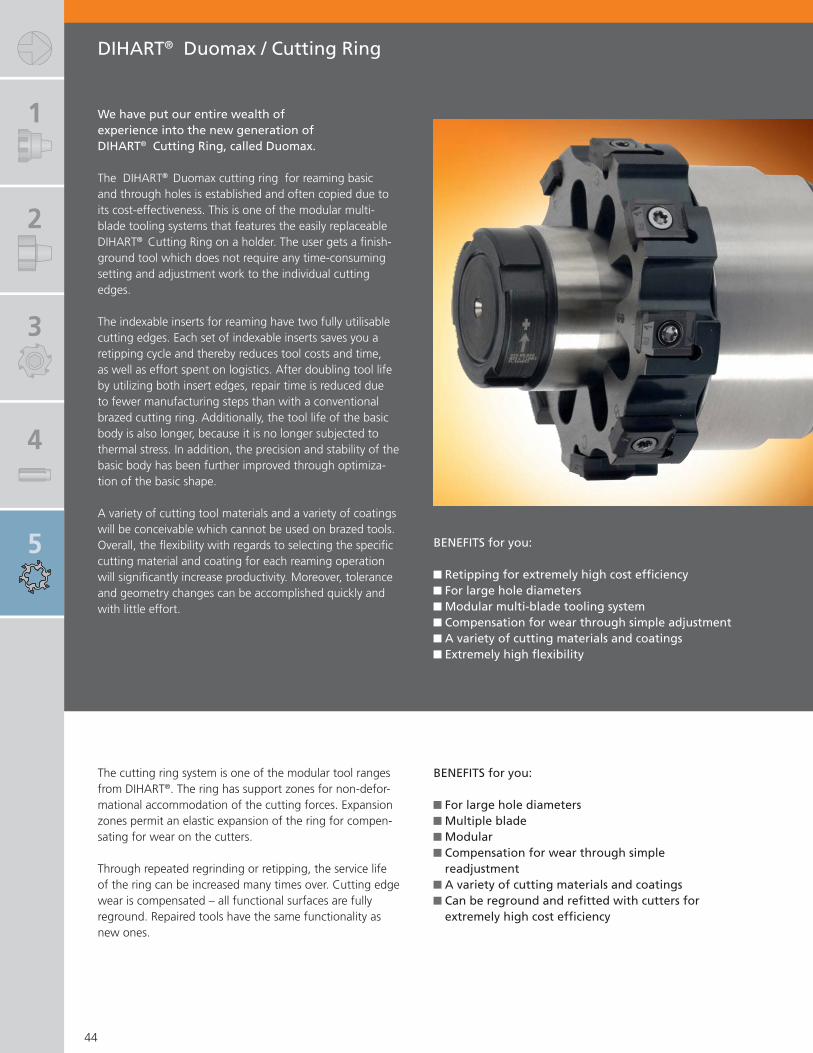
DIHART® Duomax / Cutting Ring
BENEFITS for you:
Retipping for extremely high cost effi ciency For large hole diameters Modular multi-blade tooling system Compensation for wear through simple adjustment A variety of cutting materials and coatings Extremely high fl exibility
We have put our entire wealth of experience into the new generation of DIHART® Cutting Ring, called Duomax.
The DIHART® Duomax cutting ring for reaming basic and through holes is established and often copied due to its cost-effectiveness. This is one of the modular multi-blade tooling systems that features the easily replaceable DIHART® Cutting Ring on a holder. The user gets a fi nish-ground tool which does not require any time-consuming setting and adjustment work to the individual cutting edges.
The indexable inserts for reaming have two fully utilisable cutting edges. Each set of indexable inserts saves you a retipping cycle and thereby reduces tool costs and time, as well as effort spent on logistics. After doubling tool life by utilizing both insert edges, repair time is reduced due to fewer manufacturing steps than with a conventional brazed cutting ring. Additionally, the tool life of the basic body is also longer, because it is no longer subjected to thermal stress. In addition, the precision and stability of the basic body has been further improved through optimiza-tion of the basic shape.
A variety of cutting tool materials and a variety of coatings will be conceivable which cannot be used on brazed tools. Overall, the fl exibility with regards to selecting the specifi c cutting material and coating for each reaming operation will signifi cantly increase productivity. Moreover, tolerance and geometry changes can be accomplished quickly and with little effort.
BENEFITS for you:
For large hole diameters Multiple blade Modular Compensation for wear through simple readjustment
A variety of cutting materials and coatings Can be reground and refi tted with cutters for extremely high cost effi ciency
The cutting ring system is one of the modular tool ranges from DIHART®. The ring has support zones for non-defor-mational accommodation of the cutting forces. Expansion zones permit an elastic expansion of the ring for compen-sating for wear on the cutters.
Through repeated regrinding or retipping, the service life of the ring can be increased many times over. Cutting edge wear is compensated – all functional surfaces are fully reground. Repaired tools have the same functionality as new ones.

1
2
3
4
5
6
7
8
9
DIHART® Duomax / Cutting Ring Page
Tool Recommendation 46 – 49
Duomax
Ø 2.3858 – 4.3543 inch (Ø 60.600 – 110.599 mm) 50
Cutting Ring
Ø 2.3858 – 4.3543 inch (Ø 60.600 – 110.599 mm) 51
Holder
Cylindrical shankDAH® adapterABS® adapter
525354
Replacement parts / Accessories 55
Assembly Instructions
DuomaxCutting Ring
56 - 5758 - 59
45
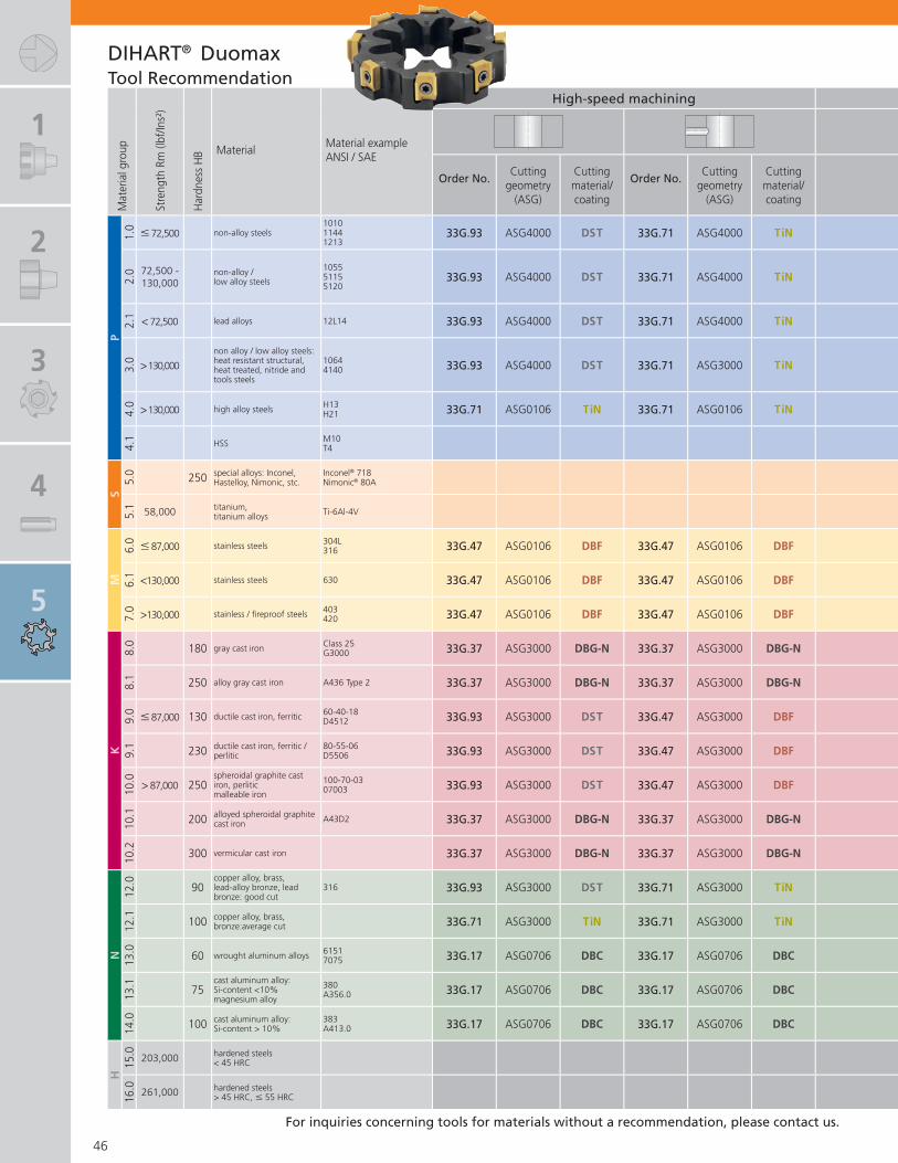
1
2
3
4
5
Mat
eria
l gro
up
Stre
ngth
Rm
(lbf
/Ins²
)
Har
dnes
s H
B MaterialMaterial exampleANSI / SAE
High-speed machining
Order No.Cutting
geometry (ASG)
Cutting material/ coating
Order No.Cutting
geometry (ASG)
Cutting material/ coating
P1.
0 � 72,500 non-alloy steels101011441213
33G.93 ASG4000 DST 33G.71 ASG4000 TiN
2.0 72,500 -
130,000non-alloy /low alloy steels
105551155120
33G.93 ASG4000 DST 33G.71 ASG4000 TiN
2.1 < 72,500 lead alloys 12L14 33G.93 ASG4000 DST 33G.71 ASG4000 TiN
3.0 > 130,000
non alloy / low alloy steels: heat resistant structural, heat treated, nitride and tools steels
10644140 33G.93 ASG4000 DST 33G.71 ASG3000 TiN
4.0 > 130,000 high alloy steels H13
H21 33G.71 ASG0106 TiN 33G.71 ASG0106 TiN
4.1 HSS M10
T4
S5.
0 250 special alloys: Inconel, Hastelloy, Nimonic, stc.
Inconel® 718Nimonic® 80A
5.1 58,000 titanium,
titanium alloys Ti-6Al-4V
M6.
0 � 87,000 stainless steels 304L316 33G.47 ASG0106 DBF 33G.47 ASG0106 DBF
6.1 <130,000 stainless steels 630 33G.47 ASG0106 DBF 33G.47 ASG0106 DBF
7.0 >130,000 stainless / fi reproof steels 403
420 33G.47 ASG0106 DBF 33G.47 ASG0106 DBF
K8.
0 180 gray cast iron Class 25G3000 33G.37 ASG3000 DBG-N 33G.37 ASG3000 DBG-N
8.1 250 alloy gray cast iron A436 Type 2 33G.37 ASG3000 DBG-N 33G.37 ASG3000 DBG-N
9.0 � 87,000 130 ductile cast iron, ferritic 60-40-18
D4512 33G.93 ASG3000 DST 33G.47 ASG3000 DBF
9.1 230 ductile cast iron, ferritic /
perlitic80-55-06D5506 33G.93 ASG3000 DST 33G.47 ASG3000 DBF
10.0 > 87,000 250
spheroidal graphite cast iron, perlitic malleable iron
100-70-0307003 33G.93 ASG3000 DST 33G.47 ASG3000 DBF
10.1 200 alloyed spheroidal graphite
cast iron A43D2 33G.37 ASG3000 DBG-N 33G.37 ASG3000 DBG-N
10.2 300 vermicular cast iron 33G.37 ASG3000 DBG-N 33G.37 ASG3000 DBG-N
N12
.0 90copper alloy, brass,lead-alloy bronze, lead bronze: good cut
316 33G.93 ASG3000 DST 33G.71 ASG3000 TiN
12.1 100 copper alloy, brass,
bronze:average cut 33G.71 ASG3000 TiN 33G.71 ASG3000 TiN
13.0 60 wrought aluminum alloys 6151
7075 33G.17 ASG0706 DBC 33G.17 ASG0706 DBC
13.1 75
cast aluminum alloy: Si-content <10%magnesium alloy
380A356.0 33G.17 ASG0706 DBC 33G.17 ASG0706 DBC
14.0 100 cast aluminum alloy:
Si-content > 10%383A413.0 33G.17 ASG0706 DBC 33G.17 ASG0706 DBC
H15
.0 203,000 hardened steels< 45 HRC
16.0 261,000 hardened steels
> 45 HRC, � 55 HRC
46
DIHART® DuomaxTool Recommendation
For inquiries concerning tools for materials without a recommendation, please contact us.

1
2
3
4
5
6
7
8
9
High-speed machining Conventional machining
Order No.Cutting
geometry (ASG)
Cutting material/ coating
Order No.Cutting
geometry (ASG)
Cutting material/ coating
Order No.Cutting
geometry (ASG)
Cutting material
Order No.Cutting
geometry (ASG)
Cutting material
33G.93 ASG3000 DST 33G.71 ASG3000 TiN 33G.21 ASG3000 HM 33G.21 ASG3000 HM
33G.93 ASG3000 DST 33G.71 ASG3000 TiN 33G.21 ASG02 HM 33G.21 ASG02 HM
33G.93 ASG3000 DST 33G.71 ASG3000 TiN 33G.21 ASG3000 HM 33G.21 ASG3000 HM
33G.93 ASG3000 DST 33G.71 ASG3000 TiN 33G.21 ASG3000 HM 33G.21 ASG3000 HM
33G.71 ASG0106 TiN 33G.71 ASG0106 TiN 33G.21 ASG0106 HM 33G.21 ASG0106 HM
33G.21 ASG03 HM 33G.21 ASG03 HM
33G.47 ASG0106 DBF 33G.47 ASG0106 DBF 33G.21 ASG0106 HM 33G.21 ASG0106 HM
33G.47 ASG0106 DBF 33G.47 ASG0106 DBF 33G.21 ASG0106 HM 33G.21 ASG0106 HM
33G.47 ASG0106 DBF 33G.47 ASG0106 DBF 33G.21 ASG0106 HM 33G.21 ASG0106 HM
33G.37 ASG3000 DBG-N 33G.37 ASG3000 DBG-N 33G.21 ASG3000 HM 33G.21 ASG3000 HM
33G.37 ASG3000 DBG-N 33G.37 ASG3000 DBG-N 33G.21 ASG3000 HM 33G.21 ASG3000 HM
33G.93 ASG3000 DST 33G.47 ASG3000 DBF 33G.21 ASG02 HM 33G.21 ASG02 HM
33G.93 ASG3000 DST 33G.47 ASG3000 DBF 33G.21 ASG3000 HM 33G.21 ASG3000 HM
33G.93 ASG3000 DST 33G.47 ASG3000 DBF 33G.21 ASG3000 HM 33G.21 ASG3000 HM
33G.37 ASG3000 DBG-N 33G.37 ASG3000 DBG-N 33G.21 ASG3000 HM 33G.21 ASG3000 HM
33G.37 ASG3000 DBG-N 33G.37 ASG3000 DBG-N 33G.21 ASG3000 HM 33G.21 ASG3000 HM
33G.93 ASG3000 DST 33G.71 ASG3000 TiN 33G.21 ASG0106 HM 33G.21 ASG0106 HM
33G.71 ASG3000 TiN 33G.71 ASG3000 TiN 33G.21 ASG0106 HM 33G.21 ASG0106 HM
33G.17 ASG0706 DBC 33G.17 ASG0706 DBC 33G.21 ASG02 HM 33G.21 ASG02 HM
33G.17 ASG0706 DBC 33G.17 ASG0706 DBC 33G.21 ASG3000 HM 33G.21 ASG3000 HM
33G.17 ASG0706 DBC 33G.17 ASG0706 DBC 33G.21 ASG3000 HM 33G.21 ASG3000 HM
47
DIHART® DuomaxTool Recommendation
Important: See chapter for more application details and safety notes!
Cutting speed and feed see pages 100-101.

1
2
3
4
5
Mat
eria
l gro
up
Stre
ngth
Rm
(lbf
/Ins²
)
Har
dnes
s H
B MaterialMaterial exampleANSI / SAE
High-speed machining
Order No.Cutting
geometry (ASG)
Cutting material/ coating
Order No.Cutting
geometry (ASG)
Cutting material/ coating
P1.
0 � 72,500 non-alloy steels101011441213
300.45 ASG4000 DST 300.05 ASG4000 TiN
2.0 72,500 -
130,000non-alloy /low alloy steels
105551155120
300.45 ASG4000 DST 300.05 ASG4000 TiN
2.1 < 72,500 lead alloys 12L14 300.45 ASG4000 DST 300.05 ASG4000 TiN
3.0 > 130,000
non alloy / low alloy steels: heat resistant structural, heat treated, nitride and tools steels
10644140 300.45 ASG4000 DST 300.05 ASG3000 TiN
4.0 > 130,000 high alloy steels H13
H21 300.05 ASG0106 TiN 300.05 ASG0106 TiN
4.1 HSS M10
T4
S5.
0 250 special alloys: Inconel, Hastelloy, Nimonic, stc.
Inconel® 718Nimonic® 80A
5.1 58,000 titanium,
titanium alloys Ti-6Al-4V
M6.
0 � 87,000 stainless steels 304L316 300.05 ASG0106 TiN 300.05 ASG0106 TiN
6.1 <130,000 stainless steels 630 300.05 ASG0106 TiN 300.05 ASG0106 TiN
7.0 >130,000 stainless / fi reproof steels 403
420 300.05 ASG0106 TiN 300.05 ASG0106 TiN
K8.
0 180 gray cast iron Class 25G3000 300.07 ASG3000 DBG-N 300.07 ASG3000 DBG-N
8.1 250 alloy gray cast iron A436 Type 2 300.07 ASG3000 DBG-N 300.07 ASG3000 DBG-N
9.0 � 87,000 130 ductile cast iron, ferritic 60-40-18
D4512 300.45 ASG3000 DST 300.07 ASG3000 DBG-N
9.1 230 ductile cast iron, ferritic /
perlitic80-55-06D5506 300.07 ASG3000 DST 300.07 ASG3000 DBG-N
10.0 > 87,000 250
spheroidal graphite cast iron, perlitic malleable iron
100-70-0307003 300.07 ASG3000 DST 300.07 ASG3000 DBG-N
10.1 200 alloyed spheroidal graphite
cast iron A43D2 300.07 ASG3000 DBG-N 300.07 ASG3000 DBG-N
10.2 300 vermicular cast iron 300.07 ASG3000 DBG-N 300.07 ASG3000 DBG-N
N12
.0 90copper alloy, brass,lead-alloy bronze, lead bronze: good cut
316 300.45 ASG3000 DST 300.05 ASG3000 TiN
12.1 100 copper alloy, brass,
bronze:average cut 300.05 ASG3000 TiN 300.05 ASG3000 TiN
13.0 60 wrought aluminum alloys 6151
7075 300.17 ASG0706 DBC 300.17 ASG0706 DBC
13.1 75
cast aluminum alloy: Si-content <10%magnesium alloy
380A356.0 300.17 ASG0706 DBC 300.17 ASG0706 DBC
14.0 100 cast aluminum alloy:
Si-content > 10%383A413.0 300.17 ASG0706 DBC 300.17 ASG0706 DBC
H15
.0 203,000 hardened steels< 45 HRC
16.0 261,000 hardened steels
> 45 HRC, � 55 HRC
48
DIHART® Cutting RingTool Recommendation
For inquiries concerning tools for materials without a recommendation, please contact us.

1
2
3
4
5
6
7
8
9
High-speed machining Conventional machining
Order No.Cutting
geometry (ASG)
Cutting material/ coating
Order No.Cutting
geometry (ASG)
Cutting material/ coating
Order No.Cutting
geometry (ASG)
Cutting material
Order No.Cutting
geometry (ASG)
Cutting material
300.45 ASG3000 DST 300.05 ASG3000 TiN 300.25 ASG3000 HM 300.25 ASG3000 HM
300.45 ASG3000 DST 300.05 ASG3000 TiN 300.25 ASG02 HM 300.25 ASG02 HM
300.45 ASG3000 DST 300.05 ASG3000 TiN 300.25 ASG3000 HM 300.25 ASG3000 HM
300.45 ASG3000 DST 300.05 ASG3000 TiN 300.25 ASG3000 HM 300.25 ASG3000 HM
300.05 ASG0106 TiN 300.05 ASG0106 TiN 300.25 ASG0106 HM 300.25 ASG0106 HM
300.25 ASG03 HM 300.25 ASG03 HM
300.05 ASG0106 TiN 300.05 ASG0106 TiN 300.25 ASG0106 HM 300.25 ASG0106 HM
300.05 ASG0106 TiN 300.05 ASG0106 TiN 300.25 ASG0106 HM 300.25 ASG0106 HM
300.05 ASG0106 TiN 300.05 ASG0106 TiN 300.25 ASG0106 HM 300.25 ASG0106 HM
300.07 ASG3000 DBG-N 300.07 ASG3000 DBG-N 300.25 ASG3000 HM 300.25 ASG3000 HM
300.07 ASG3000 DBG-N 300.07 ASG3000 DBG-N 300.25 ASG3000 HM 300.25 ASG3000 HM
300.45 ASG3000 DST 300.07 ASG3000 DBG-N 300.25 ASG02 HM 300.25 ASG02 HM
300.07 ASG3000 DST 300.07 ASG3000 DBG-N 300.25 ASG3000 HM 300.25 ASG3000 HM
300.07 ASG3000 DST 300.07 ASG3000 DBG-N 300.25 ASG3000 HM 300.25 ASG3000 HM
300.07 ASG3000 DBG-N 300.07 ASG3000 DBG-N 300.25 ASG3000 HM 300.25 ASG3000 HM
300.07 ASG3000 DBG-N 300.07 ASG3000 DBG-N 300.25 ASG3000 HM 300.25 ASG3000 HM
300.45 ASG3000 DST 300.05 ASG3000 TiN 300.25 ASG0106 HM 300.25 ASG0106 HM
300.05 ASG3000 TiN 300.05 ASG3000 TiN 300.25 ASG0106 HM 300.25 ASG0106 HM
300.17 ASG0706 DBC 300.17 ASG0706 DBC 300.25 ASG02 HM 300.25 ASG02 HM
300.17 ASG0706 DBC 300.17 ASG0706 DBC 300.25 ASG3000 HM 300.25 ASG3000 HM
300.17 ASG0706 DBC 300.17 ASG0706 DBC 300.25 ASG3000 HM 300.25 ASG3000 HM
49
DIHART® Cutting RingTool Recommendation
Important: See chapter for more application details and safety notes!
Cutting speed and feed see pages 100-101.

1
2
3
4
5
Dimensions
Ø D a l2 No. of~ ~ teeth
2.3858 – 3.1338 (60.600 – 79.599) 0.406 (10.3) 0.772 (19.6) 6
3.1339 – 3.9605 (79.600 – 100.599) 0.406 (10.3) 0.772 (19.6) 8
3.9606 – 4.3543 (100.600 – 110.599) 0.406 (10.3) 0.772 (19.6) 10
Selection: Cutting material, material
for material for material
Order No. Cutting material / coating P M K N S H P M K N S H
33G.21 HM $$1) $$1) $$1) $$1) $$1) $$1) $$1) $$1) $$1) $$1)
33G.71 TiN $$ $$ $$4) $$ §§ $$ $$5) $$33G.37 DBG-N $$ §§ $$ $$ §§33G.47 DBF $$ §§ $$ $$ §§33G.17 DBC §§ §§33G.93 DST §§ $$ $$3)
33G.67 DJC $$2)
33G.87 DJF $$Selection example: Material St37, cutting material DST, = Order No. 33G.93
Assembly parts, AccessoriesClamping
screwTorque key
Replaceable blade
Order No. Order No. Order No.Description Description
N00 57710S3090-9IP
L05 033112.25 Nm
L05 007409IP
50
a
l2
� D
� 2.3858 – 4.3543 inch (� 60.600 – 110.599 mm)
DIHART® Duomax
1) conventional machining · 2) material group 10.0&10.1 · 3) material group 12.0 · 4) material group 12.1 · 5) material group 12.0&12.1§ main area of application $ suitable in some cases
Order example: Order No. 33G.93 · Bore diameter 62 mm · Bore tolerance H7 Material St37 or ASG4000 (Cutting geometry page 46-47)
(..) = mm
Supply includes: Cutting ring Duomax mounted with inserts and clamping screws.Please order torque key and replaceable blade separately.
Face cutØ – 4.5 mm
Indexable insert cutting ring for tolerances S8-E8

1
2
3
4
5
6
7
8
9
Dimensions
min. diameter HMfor T iN DST
front cutting DBG-N DJCØ D Ø x a l2 l2 No. of
~ ~ ~ ~ teeth2.3858 – 3.1338 (60.600 – 79.599) � D – 0.331 (� D – 8.4) 0.630 (16.0) 0.728 (18.5) 0.689 (17.5) 6
3.1339 – 3.9605 (79.600 – 100.599) � D – 0.331 (� D – 8.4) 0.630 (16.0) 0.728 (18.5) 0.689 (17.5) 8
3.9606 – 4.3543 (100.600 – 110.599) � D – 0.331 (� D – 8.4) 0.630 (16.0) 0.728 (18.5) 0.689 (17.5) 10
Selection: Cutting material, material
for material for material
Order No. Cutting material / coating P M K N S H P M K N S H
300.25 HM $$1) $$1) $$1) $$1) $$1) $$1) $$1) $$1) $$1) $$1)
300.05 TiN $$ $$ $$4) $$ §§ $$ $$5) $$300.07 DBG-N $$ §§ $$ $$ §§300.47 DBF $$ §§ $$ $$ §§300.17 DBC §§ §§300.45 DST §§ $$ $$3)
300.08 DJC $$2)
Selection example: Material St37, cutting material DST, = Order No. 300.45
51
� 2.3858 – 4.3543 inch (� 60.600 – 110.599 mm)
a
l2
� x
� D
(..) = mm
Cutting ring from dia. 0.6929 to 2.3857 inch (17.600 to 60.599 mm) and � 4.3544 to 11.8346 inch (�110.600 to 300.599 mm) available by request.
DIHART® Cutting Ring
1) conventional machining · 2) material group 10.0&10.1 · 3) material group 12.0 · 4) material group 12.1 · 5) material group 12.0&12.1§ main area of application $ suitable in some cases
Order example: Order No. 300.45 · Bore diameter 70 mm · Bore tolerance H6 · Material St37 or ASG4000 (Cutting geometry page 48-49)

1
2
3
4
5
for blind hole machining short version long version
* *
for Cutting Ring / Cylindrical Duomax shank
Ø D Ø d × c Ø e f Order No. Order No. L b Order No. Order No. L b~
60.600 – 70.599(2.3858 – 3.1338)
32 × 60[1.500 × 2.756]
37.0[1.457]
1.5[0.059]
513.76.008[513.36.008]
513.81.008[513.41.008]
166.5[6.949]
105[4.134] 3.92 514.76.008
[514.36.008]514.81.008
[514.41.008]298.5
[12.146]237
[9.331] 6.39
70.600 – 79.599(3.1339 – 3.1338)
32 × 60[1.500 × 2.756]
37.0[1.457]
1.5[0.059]
513.76.009[513.36.009]
513.81.009[513.41.009]
166.5[6.949]
105 [4.134] 3.88 514.76.009
[514.36.009]514.81.009
[514.41.009]298.5
[12.146]237
[9.331] 6.63
79.600 – 90.599(3.1339 – 3.5668)
40 × 70[1.500 × 2.756]
53.2[2.094]
1.5[0.059]
513.76.010[513.36.010]
513.81.010[513.41.010]
176.5[6.949]
105[4.134] 6.90 514.76.010
[514.36.010]514.81.010
[514.41.010]311.5
[12.264]240
[9.449] 10.80
90.600 – 100.599(3.5669 – 3.9605)
40 × 70[1.500 × 2.756]
53.2[2.094]
1.5[0.059]
513.76.011[513.36.011]
513.81.011[513.41.011]
176.5[6.949]
105[4.134]
514.76.011[514.36.011]
514.81.011[514.41.011]
311.5[12.264
240[9.449] 12.24
for through hole machining short version long version
for Cutting Ring / Cylindrical
Duomax shankØ D Ø d × c Ø e f Order No. L b Order No. L b
60.600 – 70.599[2.3858 – 2.7794]
32 × 60[1.500 × 2.756]
40.0[1.575]
24.5[0.965]
503.76.008[503.81.009]
189.5[7.855]
105[4.134] 3.99 504.76.009
[504.81.009]321.5
[12.657]237
[8.937] 7.63
70.600 – 79.599[2.7795 – 3.1338]
32 × 60[1.500 × 2.756]
40.0[1.575]
24.5[0.965]
503.76.009[503.81.010]
189.5[7.855]
105[4.134] 4.41 504.76.010
[504.81.010]321.5
[12.657]237
[8.937] 8.53
79.600 – 90.599[3.1339 – 3.5668]
40 × 70[1.500 × 2.756]
56.2[2.213]
28.5[1.122]
503.76.010[503.81.011]
203.5[8.012]
105[4.134] 7.50 504.76.011
[504.81.011]338.5
[12.657]240
[9.449] 13.54
90.600 – 100.599[3.5669 – 3.9605]
40 × 70[1.500 × 2.756]
56.2[2.213]
28.5[1.122]
503.76.011[503.81.012]
203.5[8.012]
105[4.134] 13.54 504.76.012
[504.81.012]338.5
[12.657]240
[9.449]
52
� 60.600 – 100.599 mm (� 2.3858 – 3.9605 inch) Holder with inch/metric cylindrical shank similar to DIN 1835
[..] denotes inch shank tools
[..] denotes inch shank tools
Includes: Cutting ring holder with connical screw, bushing and adjusting nut (page 55). Please order cutting ring separately. (*Can also be used for through hole machining)
Includes: Cutting ring holder with connical screw, bushing and adjusting nut (page 55). Please order cutting ring separately.
L
b
� e
� D
f
� d
h6
c
L
b
� e
� D
f�
dh6
c
Duomax
Duomax
for through hole machining
for blind hole machining
Cutting ring
Cutting ring
DIHART® Duomax / Cutting Ring
� with internal coolant supply� cylindrical shank with fl at available on request

1
2
3
4
5
6
7
8
9
for through hole machining
forØ D Ø e f Order No. DAH L b Order No. DAH L b
2.3858 – 2.7794(60.600 – 70.599)
1.575(40.0)
0.964(24.5) 507.02.008 115 5.748
(146)3.779(96) 5.51 507.02.043 81 5.571
(141.5)3.898(99) 3.75
2.7795 – 3.1338(70.600 – 79.599)
1.575(40.0)
0.964(24.5) 507.02.009 115 5.748
(146)3.779(96) 6.15 507.02.044 81 5.571
(141.5)3.898(99) 4.19
3.1339 – 3.5668(79.600 – 90.599)
2.213(56.2)
1.122(28.5) 507.02.010 115 5.906
(150)3.779(96) 8.38
3.5669 – 3.9605(90.600 – 100.599)
2.213(56.2)
1.122(28.5) 507.02.011 115 5.906
(150)3.779(96) 9.30
3.9606 – 4.3543(100.600 – 110.599)
2.890(73.4)
1.398(35.5) 507.02.012 115 6.220
(158)3.819(97) 12.12
for blind hole machining*
forØ D Ø e f Order No. Order No. DAH L b
~2.3858 – 2.7794
(60.600 – 70.599)1.457(37.0)
0.059(1.5) 517.76.008 517.81.008 115 5.787
(147)4.724(120) 5.55
2.7795 – 3.1338(70.600 – 79.599)
1.457(37.0)
0.059(1.5) 517.76.009 517.81.009 115 5.787
(147)4.724(120) 5.55
3.1339 – 3.5668(79.600 – 90.599)
2.094(53.2)
0.059(1.5) 517.76.010 517.81.010 115 6.181
(157)5.118(130) 8.71
3.5669 – 3.9605(90.600 – 100.599)
2.094(53.2)
0.059(1.5) 517.76.011 514.81.011 115
6.181(157)
5.118(130) 9.55
53
� with internal coolant supply
� 2.3858 – 4.3543 inch(� 60.600 – 110.559 mm)Holder with DAH® Connection
DIHART® Duomax / Cutting Ring
Includes: Cutting ring holder with connical screw, bushing and adjusting nut (page 55). Please order cutting ring separately. DAH® adapters see chapter 9. (*Can also be used for through hole machining)
Includes: Adjusting nut, conical ring and drive pins (page 55). Please order cutting ring separately.
(..) = mm
(..) = mmL
b
� e
� D
f
DA
H
L
b
� e
� D
f
DA
H
Duomax
Duomax
for through hole machining
for blind hole machining
Cutting ring
Cutting ring

1
2
3
4
5
for through hole machining
forØ D Order No. ABS Ø e f L b
2.3858 – 2.5826 (60.600 – 65.599) 508.53.020 50 1.575 (40.0) 0.964 (24.5) 5.650 (143.5) 4.134 (105) 4.30
2.5827 – 2.7794 (65.600 – 70.599) 508.53.021 63 1.575 (40.0) 0.964 (24.5) 5.886 (149.5) 4.134 (105) 5.14
2.7795 – 3.1338 (70.600 – 79.599) 508.53.009 63 1.575 (40.0) 0.964 (24.5) 5.886 (149.5) 4.134 (105) 5.51
3.1339 – 3.5668 (79.600 – 90.599) 508.53.010 63 2.213 (56.2) 1.122 (28.5) 6.043 (153.5) 4.134 (105) 7.83
3.5669 – 3.9605 (90.600 – 100.599) 508.53.011 63 2.213 (56.2) 1.122 (28.5) 6.043 (153.5) 4.134 (105) 8.66
3.9606 – 4.3543 (100.600 – 110.599) 508.53.022 80 2.890 (73.4) 1.398 (35.5) 6.575 (167) 4.193 (106.5) 13.69
for blind hole machining*
forØ D Order No. Order No. ABS Ø e f L b
~2.3858 – 2.5826 (60.600 – 65.599) 518.78.013 518.82.013 50 1.457 (37.0) 0.059 (1.5) 4.744 (120.5) 4.134 (105) 3.86
2.5827 – 2.7794 (65.600 – 70.599) 518.78.014 518.82.014 63 1.457 (37.0) 0.059 (1.5) 4.980 (126.5) 4.134 (105) 4.74
2.7795 – 3.1338 (70.600 – 79.599) 518.78.009 518.82.009 63 1.457 (37.0) 0.059 (1.5) 4.980 (126.5) 4.134 (105) 4.92
3.1339 – 3.5668 (79.600 – 90.599) 518.78.010 518.82.010 63 2.094 (53.2) 0.059 (1.5) 4.980 (126.5) 4.134 (105) 7.25
3.5669 – 3.9605 (90.600 – 100.599) 518.78.011 518.82.011 63 2.094 (53.2) 0.059 (1.5) 4.980 (126.5) 4.134 (105) 7.94
54
� 2.3858 – 4.3543 inch(� 60.600 – 110.599 mm)Holder with ABS® Connection
DIHART® Duomax / Cutting Ring
(..) = mm
(..) = mm
Includes: Cutting ring holder with connical screw, bushing and adjusting nut (page 55). Please order cutting ring separately. (*Can also be used for through hole machining)
Includes: Adjusting nut, conical ring and drive pins (page 55). Please order cutting ring separately.
� with internal coolant supply
L
b
� e
� D
f
AB
S
Duomax
for through hole machining
Cutting ring
L
b
� e
� D
fA
BS
Duomax
for blind hole machining
Cutting ring

1
2
3
4
5
6
7
8
9
� Adjusting nut Conical ring Drive pin
for� D Order No. Order No. Order No.
2.3858 – 3.1338 (60.600 – 79.599) 099.00.090 301.80.006 300.30.007
3.1339 – 3.9605 (79.600 – 100.599) 099.00.092 301.80.007 300.30.008
3.9606 – 4.3543 (100.600 – 110.599) 099.00.095 306.20.001 300.30.008
� � �Bushing Adjusting Nut Drive Pin Conical screw Conical screw
� e
� e
for� D Order No. Order No. Order No. Order No. � e Order No. � e
2.3858 – 2.7794 (60.600 – 70.599) 510.15.008 350.23.002 350.14.002 510.45.007 1.457 (37.0) 510.55.007 1.457 (37.0)
2.7795 – 3.1338 (70.600 – 79.599) 510.15.009 350.23.002 350.14.002 510.45.007 1.457 (37.0) 510.55.007 1.457 (37.0)
3.1339 – 3.5668 (79.600 – 90.599) 510.15.010 350.23.003 350.14.003 510.45.008 2.094 (53.2) 510.55.008 2.094 (53.2)
3.5669 – 3.9605 (90.600 – 100.599) 510.15.011 350.23.003 350.14.003 510.45.008 2.094 (53.2) 510.55.008 2.094 (53.2)
55
holder for through hole machining
holder for blind hole machining
(..) = mm
(..) = mm
Replacement parts / Accessories
DIHART® Duomax / Cutting Ring
� Duomax
Cutting ring
Holder
�� �Duomax Holder
Cutting ring

1
2
3
4
5
56
����
��
����
A
+
Assembly instructions: Cutting ring holders for through hole machining
DIHART® Duomax
A
Arrow markings:light greaseFace surfaces on holder and Duomax are grease-free
Please observe the marking on holder and Duomax, check alignment of the coolant bores.
Positioning of the drive pins to the right of letter A (the measuring tooth is located at letter A and is also marked on the holder with a spot).Before tightening and adjusting, turn the Duomax against the direction of machining until hitting the drive pins.
Adjust the diameter to the middle of the tolerance (counter-clockwise thread).
The diameter can only be measured at the marked cut-ting edges (measuring tooth A) due to unequal angular position!
If the diameter was set too large, the conical ring must be loosened and the Duomax readjusted.
Assembly instructions inserts
Cleaning: Make sure that the insert seats and inserts are absolutely clean/grease-free. If necessary, remove tiny dust particles with compressed air!
Assembly:• All inserts and insert seats are marked with letters .
This ensures correct assignment to the insert seat.• The number markings � ensure that all inserts are posi-
tioned correctly.• Tighten the screw � (order no. N00 57710) to 2.25 Nm. Torque wrench order no. L05 03311
Measuring tooth
Measuring tooth

1
2
3
4
5
6
7
8
9
Dia. range(mm)
Torque M
2.4016 – 3.1102 (61 – 79) 1062 – 1239 in-lbs (120 – 140 Nm)
3.1496 – 3.9370 (80 – 100) 1593 – 1947 in-lbs (180 – 220 Nm)
57
M
+
A
Assembly instructions: Cutting ring holder for blind hole machining
DIHART® Duomax
Screw the nut onto the holder with the smooth face against the bush. Mount the Duomax with the conical screw. After fastening the conical screw check that there is space between bush and Duomax. Fasten conical screw according to index table.
Please observe the marking on holder and Duomax, check alignment of the coolant bores. Adjust the diameter to the middle of the tolerance.
The diameter can only be measured at the marked cutting edges (measuring tooth A) due to unequal angular position!
If the diameter was set too large, the nut must be loosened and the Duomax readjusted.
Measuring tooth A
Positioning of the drive pins to the right of letter A (the measuring tooth is located at letter A and is also marked on the holder with a spot). Before tightening and adjusting, turn the Duomax against the direction of machining until hitting the drive pins.
Measuring the diameter:The measuring tooth is located at letter A and is also marked on the holder with a spot �.
Caution!• Uneven fl ute spacing!• There are 2 cutters 180° opposite = measuring tooth A.• Measure the diameter at the front of the cutter (see illustration).
Measuring further back will yield an incorrect measurement as inserts are ground with back taper.
• Avoid damaging the cutting edges.• When turning the insert, the diameter must be readjusted.• Delivery status: Duomax tools delivered with inserts mounted –
ready for assembly with holder.
Arrow markings:light greaseFace surfaces on holder and Duomax are grease-free
Measuring tooth A

1
2
3
4
5
58
+
Lobe (measuring teeth)
Lobe (measuring teeth)
Greasing before assembly:Grease conical ring and I.D. cone of cutting ring � on Ø 3.150 inch (80 mm) or larger.light grease No grease and must be free of debris � & �
Assembly instructions: Cutting ring holders for through hole machining
DIHART® Cutting Ring
Align the markings on the cutting ring holder and cutting ring, to be sure that the coolant holes are aligned with the cutting edges.
Set-up the diameter utilizing the adjusting nut to the middle of the tolerance (counter-clockwise thread).
The diameter can only be measured at the marked cutting edges due to unequal fl ute spacing! (refer to page 111).
Measure the diameter
If the diameter was set too large, the adjusting nut must be loosened and the above process repeated.
The position for the drive pins is marked with a lobe or in red. Before tightening and adjusting, rotate the cutting ring against the direction of machining until contact is made with the drive pins.
�
� �

1
2
3
4
5
6
7
8
9
Dia. range(mm)
Torque M
2.3622 (60.00) 797 – 974 in-lbs (90 – 110 Nm)
2.3623 – 3.1495 (60.01 – 79.99) 1062 – 1239 in-lbs (120 – 140 Nm)
3.1496 – 3.9370 (80.00 – 100.0) 1593 – 1947 in-lbs (180 – 220 Nm)
59
M
+
Lobe (measuring teeth)
Lobe (measuring teeth)
�
�
��
Greasing before assembly:Grease conical screw and I.D. cone of cutting ring � on Ø 3.150 inch (80 mm) or larger.light grease No grease and must be free of debris �, � & �
Assembly instructions: Cutting ring holder for blind hole machining
DIHART® Cutting Ring
Screw the adjusting nut onto the holder with the smooth face away from the shank. Slide the bushing onto the holder with the wrench fl ats towards the shank. Mount the cutting ring with the conical screw.After assembling the conical screw check that there is space between the bushing and cutting ring.Tighten conical screw observing the specifi ed torque M.
Align the markings on bushing and cutting ring to be sure that the coolant holes are aligned with the cutting edges.
Set-up the diameter to the middle of the tolerance.
The diameter can only be measured at the marked cutting edges due to unequal fl ute spacing!
Measure the diameter
If the diameter was set too large, the adjusting nut must be loosened and the above process repeated.
The position for the drive pins is marked with a lobe or in red. Before tightening and adjusting, rotate the cutting ring against the direction of machining until contact is made with the drive pins.

1
2
3
4
5
6
60
DIHART® PCD Reamers
BENEFITS for you:
2 and 4 blade versions High stability from the carbide body Optimized for fi nishing pre-cast bores Through coolant supply for through
and blind holes Newest cutting geometry

1
2
3
4
5
6
7
8
9
DIHART® PCD Reamers Page
Tool Recommendation 62 – 63
PCD Reamer
2 cutting edgesØ 0.15175 – 0.7913 inch (Ø 4.000 – 20.100 mm)
4 cutting edgesØ 0.3780 – 0.7913 inch (Ø 9.601 – 20.100 mm)
64
65
61

1
2
3
4
5
6
Mat
eria
l gro
up
Stre
ngth
Rm
(lbf
/Ins²
)
Har
dnes
s H
B MaterialMaterial exampleANSI / SAE
High-speed machining
Order No.4 edges2 edges
Cutting geometry
(ASG)
Cutting material/ coating
Order No.4 edges2 edges
Cutting geometry
(ASG)
Cutting material/ coating
P1.
0 � 72,500 non-alloy steels101011441213
2.0 72,500 -
130,000non-alloy /low alloy steels
105551155120
2.1 < 72,500 lead alloys 12L14
3.0 > 130,000
non alloy / low alloy steels: heat resistant structural, heat treated, nitride and tools steels
10644140
4.0 > 130,000 high alloy steels H13
H21
4.1 HSS M10
T4
S5.
0 250 special alloys: Inconel, Hastelloy, Nimonic, stc.
Inconel® 718Nimonic® 80A
5.1 58,000 titanium,
titanium alloys Ti-6Al-4V
M6.
0 � 87,000 stainless steels 304L316
6.1 <130,000 stainless steels 630
7.0 >130,000 stainless / fi reproof steels 403
420
K8.
0 180 gray cast iron Class 25G3000
8.1 250 alloy gray cast iron A436 Type 2
9.0 � 87,000 130 ductile cast iron, ferritic 60-40-18
D4512
9.1 230 ductile cast iron, ferritic /
perlitic80-55-06D5506
10.0 > 87,000 250
spheroidal graphite cast iron, perlitic malleable iron
100-70-0307003
10.1 200 alloyed spheroidal graphite
cast iron A43D2
10.2 300 vermicular cast iron
N12
.0 90copper alloy, brass,lead-alloy bronze, lead bronze: good cut
316690.11690.10
ASG1101 PCD 690.11690.10
ASG1101 PCD
12.1 100 copper alloy, brass,
bronze:average cut
13.0 60 wrought aluminum alloys 6151
7075690.11690.10
ASG1101 PCD 690.11690.10
ASG1101 PCD
13.1 75
cast aluminum alloy: Si-content <10%magnesium alloy
380A356.0
14.0 100 cast aluminum alloy:
Si-content > 10%383A413.0
690.11690.10
ASG1101 PCD 690.11690.10
ASG1101 PCD
H15
.0 203,000 hardened steels< 45 HRC
16.0 261,000 hardened steels
> 45 HRC, � 55 HRC
62
DIHART® PCD ReamersTool Recommendation
For inquiries concerning tools for materials without a recommendation, please contact us.

1
2
3
4
5
6
7
8
9
High-speed machining Conventional machining
Order No.4 edges2 edges
Cutting geometry
(ASG)
Cutting material/ coating
Order No.4 edges2 edges
Cutting geometry
(ASG)
Cutting material/ coating
Order No.Cutting
geometry (ASG)
Cutting material
Order No.Cutting
geometry (ASG)
Cutting material
690.14690.13
ASG1101 PCD 690.14690.13
ASG1101 PCD
690.14690.13
ASG1101 PCD 690.14690.13
ASG1101 PCD
690.14690.13
ASG1101 PCD 690.14690.13
ASG1101 PCD
63
DIHART® PCD ReamersTool Recommendation
Important: See chapter for more application details and safety notes!
Cutting speed and feed see pages 100-101.

1
2
3
4
5
6
PCD Reamers
*
Cutting material / coating Order No. Order No.
PCD 690.10 690.13
Dimensions
min. diameter max stockfor allowance
front cutting on dia.Ø D Ø x L b c a Ø dh6 Ø
~ mm*0.1575 – 0.1811 (4.000 – 4.600) � D – 0.094 (� D – 2.4) 2.520 (64) 1.102 (28) 1.417 (36) 0.276 (7) 6 0.02 (0.5)
*0.1812 – 0.2008 (4.601 – 5.100) � D – 0.102 (� D – 2.6) 2.520 (64) 1.102 (28) 1.417 (36) 0.276 (7) 6 0.02 (0.5)
*0.2009 – 0.2205 (5.101 – 5.600) � D – 0.106 (� D – 2.7) 2.520 (64) 1.102 (28) 1.417 (36) 0.276 (7) 6 0.02 (0.5)
0.2206 – 0.2402 (5.601 – 6.100) � D – 0.110 (� D – 2.8) 2.795 (71) 1.378 (35) 1.417 (36) 0.276 (7) 6 0.06 (1.5)
0.2403 – 0.2598 (6.101 – 6.600) � D – 0.134 (� D – 3.4) 2.992 (76) 1.575 (40) 1.417 (36) 0.276 (7) 8 0.06 (1.5)
0.2599 – 0.2795 (6.601 – 7.100) � D – 0.134 (� D – 3.4) 2.992 (76) 1.575 (40) 1.417 (36) 0.276 (7) 8 0.06 (1.5)
0.2796 – 0.2992 (7.101 – 7.600) � D – 0.134 (� D – 3.4) 2.992 (76) 1.575 (40) 1.417 (36) 0.276 (7) 8 0.08 (2.0)
0.2993 – 0.3189 (7.601 – 8.100) � D – 0.141 (� D – 3.6) 2.992 (76) 1.575 (40) 1.417 (36) 0.276 (7) 8 0.10 (2.5)
0.3190 – 0.3386 (8.101 – 8.600) � D – 0.141 (� D – 3.6) 3.346 (85) 1.575 (40) 1.772 (45) 0.276 (7) 12 0.10 (2.5)
0.3387 – 0.3583 (8.601 – 9.100) � D – 0.161 (� D – 4.1) 3.346 (85) 1.575 (40) 1.772 (45) 0.276 (7) 12 0.12 (3.0)
0.3584 – 0.3976 (9.101 – 10.100) � D – 0.181 (� D – 4.6) 3.346 (85) 1.575 (40) 1.772 (45) 0.276 (7) 12 0.12 (3.0)
0.3977 – 0.4567 (10.101 – 11.600) � D – 0.197 (� D – 5.0) 3.740 (95) 1.969 (50) 1.772 (45) 0.276 (7) 12 0.12 (3.0)
0.4568 – 0.5552 (11.601 – 14.100) � D – 0.236 (� D – 6.0) 3.740 (95) 1.969 (50) 1.772 (45) 0.276 (7) 12 0.16 (4.0)
0.5553 – 0.5945 (14.101 – 15.100) � D – 0.260 (� D – 6.6) 3.858 (98) 1.969 (50) 1.890 (48) 0.276 (7) 16 0.16 (4.0)
0.5946 – 0.6339 (15.101 – 16.100) � D – 0.280 (� D – 7.1) 3.858 (98) 1.969 (50) 1.890 (48) 0.276 (7) 16 0.16 (4.0)
0.6340 – 0.7126 (16.101 – 18.100) � D – 0.315 (� D – 8.0) 4.252 (108) 2.362 (60) 1.890 (48) 0.276 (7) 16 0.20 (5.0)
0.7127 – 0.7913 (18.101 – 20.100) � D – 0.339 (� D – 8.6) 4.331 (110) 2.362 (60) 1.968 (50) 0.276 (7) 20 0.20 (5.0)
64
DIHART® PCD Reamers � 0.1575 – 0.7913 inch (� 4.000 – 20.100 mm)
(..) = mm
a
� D
� x
*
L
b
� d
h6
c
With 2 cutting edges
� with internal coolant supply� solid carbide body
Order example: Order No. 690.10 · Bore diameter 0.7087" · Bore tolerance +.0005/-0 · Material A360.2 (Cutting geometry page 62-63)* only available with central coolant supply.

1
2
3
4
5
6
7
8
9
PCD Reamers
Cutting material / coating Order No. Order No.
PCD 690.11 690.14
Dimensions
min. diameter max stockfor allowance
front cutting on dia.Ø D Ø x L b c a Ø dh6 Ø
~ mm0.3780 – 0.3976 (9.601 – 10.100) � D – 0.141 (� D – 3.6) 3.346 (85) 1.575 (40) 1.772 (45) 0.276 (7) 12 0.06 (1.5)
0.3977 – 0.4567 (10.101 – 11.600) � D – 0.150 (� D – 3.8) 3.740 (95) 1.969 (50) 1.772 (45) 0.276 (7) 12 0.06 (1.5)
0.4568 – 0.5552 (11.601 – 14.100) � D – 0.150 (� D – 3.8) 3.740 (95) 1.969 (50) 1.772 (45) 0.276 (7) 12 0.08 (2.0)
0.5553 – 0.5945 (14.101 – 15.100) � D – 0.154 (� D – 3.9) 3.858 (98) 1.969 (50) 1.890 (48) 0.276 (7) 16 0.08 (2.0)
0.5946 – 0.6339 (15.101 – 16.100) � D – 0.154 (� D – 3.9) 3.858 (98) 1.969 (50) 1.890 (48) 0.276 (7) 16 0.08 (2.0)
0.6340 – 0.7126 (16.101 – 18.100) � D – 0.181 (� D – 4.6) 4.252 (108) 2.362 (60) 1.890 (48) 0.276 (7) 16 0.12 (3.0)
0.7127 – 0.7913 (18.101 – 20.100) � D – 0.181 (� D – 4.6) 4.331 (110) 2.362 (60) 1.968 (50) 0.276 (7) 20 0.12 (3.0)
65
DIHART® PCD Reamers� 0.3780 – 0.7913 inch (� 9.601 – 20.100 mm) With 4 cutting edges
(..) = mm
a
� D
� x
*
L
b
� d
h6
c
with internal coolant supply �solid carbide body �
Order example: Order No. 690.11 · Bore diameter 0.7087" · Bore tolerance +.0005/-0 · Material A360.2 (Cutting geometry page 62-63)

Application specifi cReaming tools with indexable insert technology can also be combined with other tool systems, e.g. with REAMAX® TS.
Stepped toolsStepped tools are individually manufactured as special tools and are available in a fi xed design.
Monoblock toolsboth fi xed and adjustableReaming tools are available as monoblock tools with indexable insert technology from a diameter of 46 mm and are designed in either adjustable or fi xed versions.
In collaboration with the application specialists at KOMET®, it is also possible for fi xed versions and individual stepped tools as well as diameters to be designed and manufactured which can be combined with the various different tool connections from the DIHART® range.
Indexable insert reaming tools are available on request. They are designed as integral tools or as a modular tool system, depending on the application. For extremely small tolerances, they can also be produced in adjustable versions.
The tools can be supplied in single or multi-step versions from a diameter of 46 mm.
1
2
3
4
5
6
7
66
DIHART® Reaming with Insert Technology
t with MAX® TS.
noblock tools om a diameter
dj t bl

1
2
3
4
5
6
7
8
9
DIHART® Page
Insert Reaming 68 – 71
Assembly instructions, Inquiry forms
MicroSet System 72 – 75
Assembly instructions, Inquiry forms
Special Tools 76 – 77
67

1
2
3
4
5
6
7
Reaming with Indexable Insert Technology
Cut
ting
edge
2
Cut
ting
edge
1
68
The Technology
The use of indexable inserts for multi-blade reamers is revo-lutionizing reaming and setting new levels in precision and function.
Each insert has two cutting edges. Unlike boring tools, in-serts for reaming tools are ground as a complete set directly on the body in their specifi c insert pocket.
The positions of the individual cutting edges on an insert are precisely defi ned during manufacturing for the application. Cutting edges ground in a single operation ensure the de-gree of precision required for high precision bore machining.
Numerous cutting materials and coatings are available for machining a wide variety of materials.
BENEFITS for you: Ground to size for maximum precision Low cost per bore Short set-up time Maximum fl exibility
Concept can be used for an extremely wide variety of DIHART® tools
Low cost changes to tool and geometry Certain applications can be adjusted for wear compensation for extremely small bore tolerances
Two cutting edge insert
Inserts can be indexed for the shortest possible set-up without affecting the tools' precision.
Set-up time is reduced and tool life is doubled by using two cutting edges.
Precision of rotations
InsertConcentricity [µ]
1 µ
2 µ
3 µ
Cutting edge 1 – Cutting edge 2

1
2
3
4
5
6
7
8
9
A
69
��
��
����
��
��
Assembly instructions
Cleaning:
Make sure that the insert seats and indexable inserts are absolutely clean (grease and debris free). If necessary, remove tiny dust particles with compressed air!
Assembly:
• All indexable inserts and insert seats are marked with letters . This ensures correct assignment to the insert seat.
• The number markings � ensure that all indexable inserts are positioned correctly.
Tighten the screw � (order no. N00 57710) to 22 in-lbs (2.5 Nm) (torque wrench order no. L05 00940) Measuring the diameter:
The measuring inset is located at letter A and is also marked on the holder with a punch mark �. If the diameter is too large, loosen the conical screw � and turn it to the right to set the correct diameter. The conical screw � does not have to be removed completely!
Caution!
• Uneven fl ute spacing!• There are 2 inserts 180° opposed = measuring
fl ute A.• Measure the diameter at the front of the cutter
(see illustration). Measuring further back will yield an incorrect measurement as inserts are ground with a back taper.
• Avoid damaging the cutting edges.• When indexing the insert on an adjustable
holder, the diameter may need to be adjusted.
Design your own tool!
There is an inquiry form on page 70.
Enter the required dimensions and send us your inquiry. We check your specifi cations for technical feasibility and you receive a prompt reply.
Patent applied for inside and outside Germany (WSP-Reaming)

1
2
3
4
5
6
7
� CAT _____
X
� HSK _____DIN 69893 A
X
� ISO _____DIN 69871 AD/B
X
� BT _____JIS B 6339 AD/B(MAS 403 BT)
X� DAH _____
X� ABS _____
X
� � _____ inch� (� _____ mm)
similar DIN 1835
other � _____
Connection (Type and size)
� D Z
1.7953 – 3.1338 (45.600 – 79.599) 6
3.1339 – 3.9605 (79.600 – 100.599) 8
3.9606 – 4.3542 (100.600 – 110.599) 10
4.3543 – 5.4960 (110.600 – 139.599) 12
Material to be machined:
Machining method
� through hole � blind hole
Length of bore:
Interrupted cut
� yes � no
Bore tolerance:
Required surface fi nish:
Stock allo wance on dia.:
Required cutting material/coating
� carbide � TiN � DBG-N
� DST � DJC � PCD
� DBF � DBC � DJF
� other:
Other:
70
Inquiry Form: Fax to (800) 865-6638Design your own tool!
DIHART® Insert Reaming
Unique: Reaming with Indexable Insert Technology
The use of inserts is revolutionizing multiple blade reaming and setting new levels in precision, function and economy.
We'll check your specifi cations for technical feasibility and reply promptly.
Company:
Department:
Telephone:
Fax:
Date:
Contact:
E-Mail:
Customer-No.:
Distributor:
No. of inserts (Z)
for calculating the feed rate
fz inch/tooth (mm/tooth):
(� D
= _
____
mm
)
� D
= _
____
inch
(b = _____ mm)b = _____ inch
(X = _____ mm)X = _____ inch

1
2
3
4
5
6
7
8
9
� REAMAX® TS
� REAMAX®
� Monomax®
� Solid carbide reamer
� Duomax
� Cutting ring
(� D
= _
____
mm
)
(b = _____ mm)
(X = _____ mm)
� CAT _____
X
� HSK _____DIN 69893 A
X
� ISO _____DIN 69871 AD/B
X
� BT _____JIS B 6339 AD/B(MAS 403 BT)
X� DAH _____
X� ABS _____
X
� � _____ inch� (� _____ mm)
similar DIN 1835
other � _____
� D
= _
____
inch
b = _____ inch
X = _____ inch
Material to be machined:
Machining method
� through hole � blind hole
Length of bore:
Interrupted cut
� yes � no
Bore tolerance:
Required surface fi nish:
Stock allo wance on dia.:
Required cutting material/coating
� carbide � TiN � DBG-N
� DST � DJC � PCD
� DBF � DBC � DJF
� other:
Other:
71
Inquiry Form: Fax to (800) 865-6638Design your own tool!
DIHART® Easy Special
Company:
Department:
Telephone:
Fax:
Date:
Contact:
E-Mail:
Customer-No.:
Distributor:
Connection (Type and size)Reamer Style
No standard solution within our range? Dimensions not what you require?
Easy Special makes it possible for you create your own combination of standard modules in the widest variety of dimensions.
Select the series, defi ne the effective length and choose the desired adapter for the tool.
We'll check your specifi cations for technical feasibility and reply promptly.

1
2
3
4
5
6
7
72
BENEFITS for you:
Maximum fl exibility
Reduces logistics with regards to retipping
Inserts available from stock
Individually adjustable inserts
Simple handling when making adjustments and changing the inserts
Reaming with Adjustable Inserts
The new reamers from DIHART® which boast individually adjustable inserts are an alternative to the ready-to-use ground tool variants. These reamers also feature multiple blades and offer maximum fl exibility, reduce logistics with regard to retipping and enable cost savings thanks to the inserts which are available from stock.
The single-blade inserts are and set to a diameter with a back taper using a newly developed fi ne adjustment system for indexable inserts with µm accuracy. This makes hole tolerances of � IT5 easily achievable. The reference dimension is provided by two measuring blocks.
Only 14 inserts and sizes for the diameter range of 40 to 140 mm. Maximum fl exibility in terms of fi elds of application, availability and variety of cutting materials and coatings are features of this tool series, because certain components, tolerances, volumes, etc., often determine which combinations are used.
Variant:- Diameter range of 1.5748 – 5.5118 inch (40 – 140 mm)- Hole tolerances of � IT5- Use with cast metal, solutions for steel, stainless steel,
aluminum and other materials to follow
Precision and productivity
Even when the demands on a component are particularly high and the highest precision is required, the DIHART® MicroSet system gives you a special advantage: The tools can be readjusted at any time. All that needs to be done is to readjust the indexable inserts in the precision adjustment system to the required diameter. Only when the cutting edges are worn do they need to be replaced.
The special strengths of the MicroSet system can truly be seen when used with special tools, especially with stepped tools that the user can set-up themselves. Thanks to the variety of possible combinations, the user can quickly put together a suitable reamer that is ideally matched to the component with regard to its materials, tolerances and volumes.
The MicroSet tool shown uses this advantage perfectly and solves the application requirements better than the previ-ously used brazed PCD tools. An inability to correct the brazed PCD plates, particularly in the second stage, results in operating times of different lengths and irregular repair costs.
The standard indexable inserts available from stock (fi tted with PCD in this case) make up for long repair cycles and not only increase the fl exibility of the system but also the productivity and the profi tability of an application.
DIHART® MicroSet System

1
2
3
4
5
6
7
8
9
73
DIHART® MicroSet System
BENEFITS for you:
Simplifi ed logistics thanks to standard indexable inserts available from stock Can be fi tted with CBN or PCD indexable inserts for a variety of machining requirements Easy readjustment using a precision-controlled adjustment system Can be used as a repeat operation tool e.g. integrated milling and reaming Setting easily completed on an electronic presetting device

1
2
3
4
5
6
7
74
Inquiry Form: Fax to (800) 865-6638Design your own tool!
DIHART® MicroSet System
Reaming with Adjustable Inserts
The tools are specially manufactured for each application, with four to eight cutting edges on a basic body and for length/
diameter ratios up to 2×D.
We'll check your specifi cations for technical feasibility and reply promptly.
Company:
Department:
Telephone:
Fax:
Date:
Contact:
E-Mail:
Customer-No.:
Distributor:
� CAT _____
X
� HSK _____DIN 69893 A
X
� ISO _____DIN 69871 AD/B
X
� BT _____JIS B 6339 AD/B(MAS 403 BT)
X� DAH _____
other � _____
Connection (Type and size)Material to be machined:
Machining method
� through hole � blind hole
Length of bore:
Interrupted cut
� yes � no
Bore tolerance:
Required surface fi nish:
Required cutting material/coating
� carbide � TiN � DBG-N
� DST � DJC � PCD
� DBF � DBC � DJF
� other:
Other:
(� D
= _
____
mm
)
� D
= _
____
inch
(b = _____ mm)b = _____ inch
(X = _____ mm)max. 2×D
X = _____ inch

1
2
3
4
5
6
7
8
9
Insert Assembly parts Accessories Setting device
DBG
-N
Clamping screw
Wedge Torque key Replaceable blade
� D Order No. K Order No. Order No. Order No. Order No. Order No.Description Description
1.5748 – 1.7716 (40.000 – 44.999) 70W.37.01040A
§§N00 57241S3070-8IP2.25 Nm
15F.00.30001L05 03311
8IP2.25 Nm
L05 00730 059.33.4154
1.7717 – 1.9685 (45.000 – 49.999) 70W.37.01045A1.9686 – 2.1653 (50.000 – 54.999) 70W.37.01050A2.1654 – 2.3622 (55.000 – 59.999) 70W.37.01055A2.3623 – 2.5590 (60.000 – 64.999) 70W.37.01060A2.5591 – 2.7559 (65.000 – 69.999) 70W.37.01065A2.7560 – 2.9527 (70.000 – 74.999) 70W.37.01070A2.9528 – 3.1496 (75.000 – 79.999) 70W.37.01075A3.1497 – 3.5433 (80.000 – 89.999) 70W.37.01080A3.5434 – 3.9370 (90.000 – 99.999) 70W.37.01090A
3.9371 – 4.3307 (100.000 – 109.999) 70W.37.01100A4.3308 – 4.7244 (110.000 – 119.999) 70W.37.01110A4.7245 – 5.1180 (120.000 – 129.999) 70W.37.01120A5.1181 – 5.5118 (130.000 – 140.000) 70W.37.01130A
75
�
���
1
��
2
3
6
�
�
4
5
1 line = 1 µ
DIHART® MicroSet System
Patented design
Assembly parts (Fig. 1) indexable insert� clamping screw
Setting machining dia. adjusting wedge, � differential screw
Setting conicity� adjusting wedge, � differential screw
Fit the indexable insert:Make sure that the insert seat is clean. Place the indexable insert into the insert seat and tighten the clamping screw � only slightly.
Use TORX Plus® torque wrench � (2.25 Nm) (Fig.2).
Reference dia. as reference dimension "0" for setting the machining dia. and conicity (Fig. 3), reference dia. is marked on tool.
Preset the machining dia. (Fig. 4) and conicity (Fig. 5):Use an Allen key (width across fl ats SW2) to turn the differential screws � and � until the indexable insert is set to approx. 10 µm below the desired machining dia. and approx. 25 µm over the reference dia.
Secure the insert:Use a TORX Plus® torque wrench � (2.25 Nm) to secure the indexable insert at the preset tightening torque (Fig. 2).
Set the fi nal machining dia. (Fig. 4) and conicity (Fig 5):When tightened, the indexable insert is set to the machining diameter and the specifi ed conicity using the differential screws � and �.
Tool after setting (Fig 6).
Assembly instructions
� 1.5748 – 5.5118 inch (� 40.000 – 140.000 mm)

1
2
3
4
5
6
7
76
Special Solutions and Multi-Step Tools –More Possibilities, Lower Machining Costs
DIHART® Special Tools
BENEFITS for you:
Application specifi c design Reduction of cycle time Technical advice by experienced DIHART® engineers
Combination of several machining operations Highest effi ciency, productivity and cost reduction
The development of customer-specifi c solutions represents a major area of expertise for DIHART®.
It is often diffi cult to carry out machining tasks with standard tools because of the demands for form, tolerance or quality that require special process analysis and tool development work.
The form on page 114 of this catalog can be used to inquire about and order special tools.
References to applications can be found in our application examples.
Example: Finish machining operation for camshaft bearing for cylinder heads in Ck AlSi9Cu3 for automotive engines.
The task: To simplify the process on transfer lines or machining centers.
Special Applications:Machining Bearing Bores for Camshafts
The solution: Using application-specifi c tooling, machining the cylinder heads on transfer lines is reduced to one station. On machining centers, a short pilot tool, fi tted with PCD blades is initially used to pre-machine the bores for the fi rst step. The fi nishing tool (also with PCD blades), which matches the length of the engine, then reams all the bores to size: � 1.025" (�26.045 mm) H7.
The concept has now become well established in engine and vehicle manufacturing.
The cutting data is as follows: vc = 721 ft/min (220 m/min); f = 42.5 in/min (1080 mm/min)
Patent applied for inside and outside Germany

1
2
3
4
5
6
7
8
9
77
DIHART® Special Tools
Multi-fl ute stepped reaming tools and special solutions from DIHART® improve the economics of reaming. The latest generation of tools is characterized by extremely high cutting speeds and feeds.Designed to suit workpiece and material, they guarantee dimensional stability and reliable production.
Multi-step tools
Multi-step and modular reaming tools from DIHART® improve production performance. DIHART® increases the range of functions for the tools and, in doing so, reduces machining time and costs.
Special tools
Use of latest technology Tool design to suit application Technical support from DIHART® experts Multi-fl ute reaming tools for best bore quality and economy
Reduction in secondary costs

1
2
3
4
5
6
7
8
78
DIHART® Compensating Holder
DIHART DAH® compensating holders are static compensating systems; DPS fl oating holders are dynamic compensating systems. Axial and radial run-out are very easily compensated for.
Using the patented DAH® from DIHART® the concentricity of reaming tools and all rotating machining tools can be adjusted quickly, effortlessly and precisely, right on the machine.
Precision bore machining can then be executed with extremely high cutting speeds and feed values.
The bore quality achieved, such as circularity, cylindricity and surface fi nish will satisfy your production needs.
The use of the DAH® enables you to machine precision bores up to tolerance class IT 4.

1
2
3
4
5
6
7
8
9
DIHART® Compensating Holder Page
DAH® Compensating Holder
HSK-A adapterABS® adapterSK / BT taperCAT / MS taperReplacement parts / accessoriesAssembly instructions
808081828388
Adapter for DAH®
Hydraulic chuckABS®
Cylindrical shank
848485
DAH® 50 HS Compensating Holder 86
Reducer sleevefor high-speed machining
8789
DPS Floating Holder
with VDI connectionwith cylindrical shankCollets
909091
Assembly Instructions 88
79
BENEFITS for you:
Compensation systems for �m-precise concentricity
Easy correction of concentricity and axial error
High-speed machining
With internal coolant supply
Minimal run-out contributed to longer tool life

1
2
3
4
5
6
7
8
HSK-A
DAHOrder No. Ø d1 HSK-A Ø d2 l1 l2
545.07.011 63 63 1.969 (50) 2.598 (66) 0.472 (12) 3.24
545.07.002 81 40 2.559 (65) 2.047 (52) 0.472 (12) 2.14
545.07.003 81 50 2.559 (65) 2.598 (66) 0.472 (12) 3.06
545.07.004 81 63 2.559 (65) 2.598 (66) 0.472 (12) 3.92
545.07.009 81 80 2.559 (65) 2.992 (76) 0.472 (12) 5.78
545.07.010 81 100 2.559 (65) 2.992 (76) 0.472 (12) 7.89
545.07.005 115 80 3.937 (100) 2.992 (76) 0.630 (16) 3.86
545.07.006 115 100 3.937 (100) 3.110 (79) 0.630 (16) 11.42
ABS®
DAHOrder No. Ø d1 ABS Ø d2 l1 l2
545.00.001 81 40 2.559 (65) 1.969 (50) 0.472 (12) 1.98
545.00.003 81 50 2.559 (65) 1.969 (50) 0.472 (12) 3.20
545.00.002 115 63 3.937 (100) 2.126 (54) 0.630 (16) 6.06
80
DIHART DAH® Compensating Holderwith HSK Adapter DIN 69893 A
l1
DA
H �
d1
l2
� d
2
l1
DA
H �
d1
l2
� d
2
(..) = mm
(..) = mm
Includes: DAH® compensating holder complete with assembling screws and DAH® ring. DAH® replacement parts see page 83.
Includes: DAH® compensating holder complete with assembling screws and DAH® ring. DAH® replacement parts see page 83.
with ABS® Adapter� with internal coolant supply
Patented design
� with internal coolant supply

1
2
3
4
5
6
7
8
9
JIS B 6339 AD/B
DAHOrder No. Ø d1 BT taper Ø d2 l1 l2
545.77.011 63 40 1.969 (50) 2.323 (59) 0.472 (12) 3.42
545.77.001 81 40 2.559 (65) 2.323 (59) 0.472 (12) 3.95
545.77.003 81 50 2.559 (65) 2.756 (70) 0.472 (12) 10.32
545.77.004 115 50 3.937 (100) 3.464 (88) 0.630 (16) 14.55
DIN 69871 AD/B
DAHOrder No. Ø d1 SK taper Ø d2 l1 l2
545.10.010 63 30 1.969 (50) 2.008 (51) 0.472 (12) 2.16
545.10.011 63 40 1.969 (50) 2.008 (51) 0.472 (12) 3.20
545.10.001 81 40 2.559 (65) 2.008 (51) 0.472 (12) 3.57
545.10.003 81 50 2.559 (65) 2.008 (51) 0.472 (12) 8.13
545.10.004 115 50 3.937 (100) 2.716 (69) 0.630 (16) 12.37
81
DIHART DAH® Compensating Holderwith Taper Shank DIN 69871 AD/B
(..) = mm
Includes: DAH® compensating holder complete with assembling screws and DAH® ring. DAH® replacement parts see page 83.
Includes: DAH® compensating holder complete with assembling screws and DAH® ring. DAH® replacement parts see page 83.
with internal coolant supply �long version on request �
l1
DA
H �
d1
l2
� d
2
l1
DA
H �
d1
l2
� d
2
(..) = mm
with Taper Shank JIS B 6339 AD/B (MAS 403 BT)with internal coolant supply �
long version on request �

1
2
3
4
5
6
7
8
CAT / MS Taper
DAH CATOrder No. Ø d1 MS Taper Ø d2 l1 l2
545.87.010 63 30 1.969 (50) 2.008 (51) 0.472 (12)
545.87.011 63 40 1.969 (50) 2.008 (51) 0.472 (12)
545.87.001 81 40 2.559 (65) 2.008 (51) 0.472 (12)
545.87.003 81 50 2.559 (65) 2.008 (51) 0.472 (12)
545.87.004 115 50 3.937 (100) 2.716 (69) 0.630 (16)
82
DIHART DAH® Compensating Holderwith CAT / MS Taper
� with internal coolant supply through taper or fl ange (MS)
(..) = mm
l1D
AH
� d
1
l2
� d
2
Includes: DAH® compensating holder complete with assembling screws and DAH® ring. DAH® replacement parts see page 83.

1
2
3
4
5
6
7
8
9
� � �Adjusting ring Assembling screw Spring washer Radial adjusment screw Hanger point screw
Complete with� & �
forDAH� d1 Order No. Description Order No. Order No. Description Order No. Article Order No.
63 545.25.010 M5×22 545.26.001A 545.27.001 M8×6 5505108006 M6×8 5505206008
81 545.25.001 M5×22 545.26.001A 545.27.001 M8×6 5505108006 M6×10 5505206010
115 545.25.002 M8×30 545.26.002 545.27.002 M8×8 5505108008 M8×10 5505208010 (x 2)
ABS location spigot
ABS Order No.Spares assortment
32 N00 17661
40 N00 17671
50 N00 17681
63 N00 17691
80 N00 17701
HSK-A Coolant supply unit
HSK-A Order No. Order No.Spares assortment O ring
40 51391 00040 52911 00751 (x 2)
50 51391 00050 52911 00920 (x 2)
63 51391 0006352911 01025 (x 1)
52911 01020 (x 1)
80 51391 00080 52911 01320 (x 2)
100 51391 00100 52911 01430 (x 2)
ABS location hole
ABS Order No.Spares assortment
32 N00 15261
40 N00 15271
50 N00 15281
63 N00 15291
80 N00 15301
83
DIHART DAH® Compensating HolderReplacement parts / Accessories
DA
H �
d1
� ��
Replacement parts ABS® Replacement parts HSK-A
Individual spares (spares assortment) are supplied for replacement purposes only. Any other use is not permitted and represents an infringement of the patent. Includes HSK-A spares assortment:
Coolant tube, locking collar and two O rings.

1
2
3
4
5
6
7
8
Hydraulic chuck
DAHOrder No. Ø d Ø d1 Ø d2 L b c
545.62.004 0.472 (12) 63 0.945 (24) 2.756 (70) 2.047 (52) 1.378 – 1.772 (35 – 45) 0.95
545.62.015 0.630 (16) 81 1.338 (34) 2.953 (75) 2.244 (57) 1.535 – 1.929 (39 – 49)
545.62.016 0.787 (20) 81 1.457 (37) 2.953 (75) 2.244 (57) 1.614 – 2.008 (41 – 51) 1.72
545.62.017 0.984 (25) 81 1.968 (50) 4.331 (110) 3.622 (92) 1.811 – 2.205 (46 – 56) 3.15
545.62.018 1.260 (32) 81 2.362 (60) 4.527 (115) 3.819 (97) 2.008 – 2.401 (51 – 61) 3.79
ABS
ABS DAHOrder No. Ø d Ø d1 L b
545.40.006 32 63 1.653 (42) 0.945 (24)
545.40.007 32 81 1.378 (35) 0.669 (17)
545.40.001 40 81 1.378 (35) 0.669 (17) 0.97
545.40.003 50 81 2.559 (65) 1.850 (47) 1.83
545.40.004 50 115 1.811 (46) 0.807 (20.5) 2.62
545.40.002 63 115 2.047 (52) 1.043 (26.5) 3.22
84
DIHART DAH® BushingHydraulic chuck
� with internal coolant supply� easy length adjustment from outside
� with internal coolant supply
(..) = mm
c
b
� d
2
DA
H �
d1
DA
H �
d1
L
� d
L
b
ABS
� d
(..) = mm
Includes: DAH® adapter complete with length adjustment screw. Reducer sleeve see page 87.
Includes: DAH® adapter complete with ABS® hardware.
for tools with ABS® connection
Patented design

1
2
3
4
5
6
7
8
9
DAH
DAHOrder No. Ø d Ø d1 Ø d2 L
545.85.001 0.500 (12.7) 81 1.575 (40) 2.047 (52)
545.85.002 0.625 (15.9) 81 1.575 (40) 2.047 (52)
545.85.003 0.750 (19.1) 81 1.772 (45) 2.441 (62)
545.85.004 1.000 (25.4) 81 1.890 (48) 2.441 (62)
545.85.005 1.500 (38.1) 115 2.835 (72) 2.992 (76)
for Cylindrical Shank Bushing
DAHØ d1 Ø d2 Order No.
81 0.500 (12.7) 5505108012 (x2)
81 0.625 (15.9) 5505108012 (x2)
81 0.750 (19.1) 5505108012 (x2)
81 1.000 (25.4) 5505108012 (x2)
115 1.500 (38.1) 5505112016 (x2)
85
DA
H �
d1
DIHART DAH® Cylindrical Shank Bushingfor use with DIN 1835 B cylindrical shank weldon
with internal coolant supply �
L
� d
2
� d
Supply includes: DAH® adapter complete with set screw. For replacement parts, see below
Replacement parts
(..) = mm
(..) = mm
DA
H �
d1
� d

1
2
3
4
5
6
7
8
HSK
HSKOrder No. Ø d Ø d1 Ø d2 Ø d3 L L1 c
54B.10.00030 63 0.787(20)
1.614(41)
1.968(50)
4.331(110)
2.484(63.1)
2.067(52.5) 2.87
54B.10.00040 63 0.984(25)
1.988(50.5)
2.382(60.5)
5.315(135)
2.839(72.1)
2.244(57) 4.76
DIN 69871 AD
Order No. ISO Ø d1 Ø d2 Ø d3 L L1 cTaper
54B.90.00030 40 0.787(20)
1.614(41)
1.968(50)
4.331(110)
2.559(65)
1.614(41) 3.31
JIS B 6339 AD (MAS 403 BT)
Order No. BT Ø d1 Ø d2 Ø d3 L L1 cTaper
54B.91.00030 40 0.787(20)
1.614(41)
1.968(50)
4.331(110)
2.720(69.1)
1.614(41) 3.75
CAT40
Order No. CAT Ø d1 Ø d2 Ø d3 LTaper
54B.93.00030 40 0.750(19.05)
1.614(41)
1.969(50)
4.764(121)
54B.93.00035 40 0.787(20)
1.614(41)
1.969(50)
4.764(121)
86
DIHART DAH® 50 HS Compensating Holder
HSK Adapter
(..) = mm (..) = mm
(..) = mm (..) = mm
� with internal coolant supply� clamping range � 0.118 – 0.787 inch (�3 – 20 mm)
Taper Shank DIN 69871 AD/B
Taper Shank CATTaper Shank JIS B 6339 AD (MAS 403 BT)
with internal coolant supply �clamping range � 0.118 – 0.787 inch (�3 – 20 mm) �
with internal coolant supply �clamping range � 0.118 – 0.787 inch (�3 – 20 mm) �
� with internal coolant supply� clamping range � 0.118 – 0.787 inch (�3 – 20 mm)
L
L1L1
cc
� d
3
� d
2
HSK
� d
L
� d
3
� d
2
LL
� d
3
� d
3
� d
2
� d
2
� d
1
� d
1
� d
1
� d
1
Includes: DAH® 50 HS compensating holder complete with adjustment ring and adjustment screws. Reducer sleeve for clamping range � 0.118 – 0.630 inch (� 3 – 16 mm) see page 87.
L1
c

1
2
3
4
5
6
7
8
9
Reducer sleeve
Order No. Ø d Ø d1 Ø d2 L1 L2
L01 14291 0.118 (3)
0.472(12)
0.748(19)
1.772(45)
0.079(2)
0.22
L01 14301 0.157 (4)
L01 14311 0.197 (5)
L01 14321 0.236 (6)
L01 14331 0.315 (8)
L01 14261 0.118 (3)
0.787(20)
1.142(29)
1.988(50.5)
0.079(2)
0.22
L01 14271 0.157 (4)
L01 14281 0.197 (5)
L01 14201 0.236 (6)
L01 14211 0.315 (8)
L01 14221 0.394 (10)
L01 14231 0.472 (12)
L01 14241 0.551 (14)
L01 14251 0.630 (16)
L01 14400 0.236 (6)
0.984(25)
1.142(29)
2.165(55)
0.079(2)
0.22
L01 14410 0.315 (8)
L01 14420 0.394 (10)
L01 14430 0.472 (12)
L01 14440 0.551 (14)
L01 14450 0.630 (16)
L01 14460 0.709 (18)
L01 14470 0.787 (20)
L01 14501 0.236 (6)
1.260(32)
1.535(39)
2.382(60.5)
0.118(3)
0.66
L01 14511 0.315 (8)
L01 14521 0.394 (10)
L01 14531 0.472 (12)
L01 14541 0.551 (14)
L01 14551 0.630 (16)
L01 14561 0.709 (18)
L01 14571 0.787 (20)
L01 14581 0.984 (25)
87
DIHART® Reducer Sleeve
(..) = mm
� d
1
� d
� d
2
L1L2

1
2
3
4
5
6
7
8
DAH� d1
TorqueM
63 62 – 80 in-lbs (7 – 9 Nm)
81 62 – 80 in-lbs (7 – 9 Nm)
115 221 – 310 in-lbs (25 – 35 Nm)
88
M ��
��
��
��
DIHART DAH® Compensating HolderAssembly instructions
Clean grinding surfaces thoroughlydry and free of grease and debris.
Adjusting the DAH® must be done in the machine, on the spindle where the tool will be in use!Center the indicator on the gauge line as shown. KOMET recommends using an indicator with either 0.0001" or 0.002 µm increments
Determine the run-out by rotating the tool until the indicator is at its highest reading. Rotate so that the adjustment screw � is at the highest point.Tighten the adjusting screw � so that the indicated run-out is reduced in half.Repeat this procedure until the run-out error is < 5 µm (0.0002").
Tighten the assembling screws � in a cross-wise pattern. Please observe the specifi ed torque M in the index-table. After fastening, fi x the adjusting ring by locking the thread pin �.
Pre-load evenly with the 6 assembling screws �(compressing the spring washer fl at)
A fi nal check should show a run-out of < 5 µm (0.0002").
Cross-wise pattern

1
2
3
4
5
6
7
8
9
89
DIHART DAH® 50 Compensating HolderHigh-speed machining – with maximum quality
Simple handling – reduced machine down times
In comparison to previous solutions, the hydraulic chuck is integrated into the new DIHART® compensating holders: this means one less connection.
Four adjustable screws allow rapid and precise adjustment of the concentricity of the multi-blade reamer, reducing run-out to virtually zero. The extremely slim design of these new compensating holders ensures that they fi t easily into practically all tool magazines.
Connection on tool-side with hydraulic chuck
Simple, time-saving control using adjustment ring with adjustment screws.
Alignment module:1 adjustment ring, 4 adjustment screws
Tightening screwfor clamping tool
BENEFITS for you:
Proven hydraulic clamping Maximum concentricity and repeatability < 1 µ for uniform blade contact
Extremely simple run-out adjustment Compact design
Optimum vibration dampening for excellent surface quality
Reducer sleeves increase clamping Ø range. Speeds up to 25,000 rpm Compatible with minimum quantity lubrication (MQL)
For maximum precision and concentricity
DIHART's DAH® 50 HS compensating holders ensure that the tool runs concentrically. They allow precision adjustment of the tool in the µm range at the cutting edge, reducing any machine spindle error to a minimum.
Maximum concentricity guarantees reliable production for extremely close tolerances.
The quality of the bore, including surface fi nish, roundness, parallelism and above all, dimensional accuracy are improved considerably.
This signifi cantly increases the process capability of DIHART® multiple blade reamers.
The DIHART DAH® 50 HS compensating holders enable the run-out of a tool to be adjusted with µm-precision at the cutting edge, reducing to a minimum any machine spindle error.
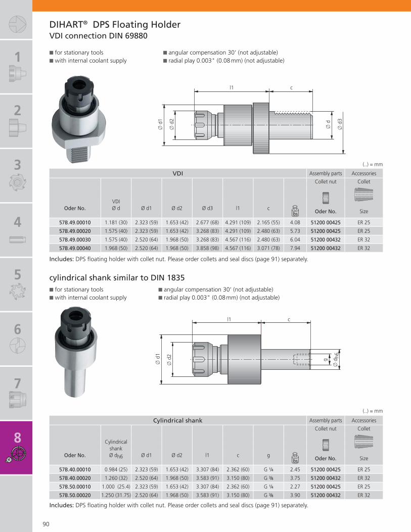
1
2
3
4
5
6
7
8
VDI Assembly parts Accessories
Collet nut Collet
VDIOder No. Ø d Ø d1 Ø d2 Ø d3 l1 c
Oder No. Size
57B.49.00010 1.181 (30) 2.323 (59) 1.653 (42) 2.677 (68) 4.291 (109) 2.165 (55) 4.08 51200 00425 ER 25
57B.49.00020 1.575 (40) 2.323 (59) 1.653 (42) 3.268 (83) 4.291 (109) 2.480 (63) 5.73 51200 00425 ER 25
57B.49.00030 1.575 (40) 2.520 (64) 1.968 (50) 3.268 (83) 4.567 (116) 2.480 (63) 6.04 51200 00432 ER 32
57B.49.00040 1.968 (50) 2.520 (64) 1.968 (50) 3.858 (98) 4.567 (116) 3.071 (78) 7.94 51200 00432 ER 32
Cylindrical shank Assembly parts Accessories
Collet nut Collet
Cylindricalshank
Oder No. Ø dh6 Ø d1 Ø d2 l1 c gOder No. Size
57B.40.00010 0.984 (25) 2.323 (59) 1.653 (42) 3.307 (84) 2.362 (60) G 1/4 2.45 51200 00425 ER 25
57B.40.00020 1.260 (32) 2.520 (64) 1.968 (50) 3.583 (91) 3.150 (80) G 3/8 3.75 51200 00432 ER 32
57B.50.00010 1.000 (25.4) 2.323 (59) 1.653 (42) 3.307 (84) 2.362 (60) G 1/4 2.27 51200 00425 ER 25
57B.50.00020 1.250 (31.75) 2.520 (64) 1.968 (50) 3.583 (91) 3.150 (80) G 3/8 3.90 51200 00432 ER 32
90
l1
� d
c
� d
3
� d
1
� d
2
DIHART® DPS Floating HolderVDI connection DIN 69880
l1g
c
� d
h6
� d
1
� d
2(..) = mm
(..) = mm
Includes: DPS fl oating holder with collet nut. Please order collets and seal discs (page 91) separately.
cylindrical shank similar to DIN 1835� for stationary tools� with internal coolant supply
� for stationary tools� with internal coolant supply
Includes: DPS fl oating holder with collet nut. Please order collets and seal discs (page 91) separately.
� angular compensation 30‘ (not adjustable)� radial play 0.003" (0.08 mm) (not adjustable)
� angular compensation 30‘ (not adjustable)� radial play 0.003" (0.08 mm) (not adjustable)

1
2
3
4
5
6
7
8
9
ER32 ER25Collet Seal disc Collet Seal disc
Ø d Ø d
� Order No. Order No. Order No. Order No.
0.157 – 0.119(4.00 – 3.01)
0.137 – 0.119 (3.50 – 3.01)A33 55000.0400
52806 32035A33 54000.0400
52806 25035
0.157 – 0.138 (4.00 – 3.51) 52806 32040 52806 25040
0.196 – 0.158(5.00 – 4.01)
0.177 – 0.158 (4.50 – 4.01)A33 55000.0500
52806 32045A33 54000.0500
52806 25045
0.196 – 0.178 (5.00 – 4.51) 52806 32050 52806 25050
0.236 – 0.197(6.00 – 5.01)
0.216 – 0.197 (5.50 – 5.01)A33 55000.0600
52806 32055A33 54000.0600
52806 25055
0.236 – 0.217 (6.00 – 5.51) 52806 32060 52806 25060
0.275 – 0.237(7.00 – 6.01)
0.255 – 0.237 (6.50 – 6.01)A33 55000.0700
52806 32065A33 54000.0700
52806 25065
0.275 – 0.256 (7.00 – 6.51) 52806 32070 52806 25070
0.314 – 0.276(8.00 – 7.01)
0.295 – 0.276 (7.50 – 7.01)A33 55000.0800
52806 32075A33 54000.0800
52806 25075
0.314 – 0.296 (8.00 – 7.51) 52806 32080 52806 25080
0.354 – 0.315(9.00 – 8.01)
0.334 – 0.315 (8.50 – 8.01)A33 55000.0900
52806 32085A33 54000.0900
52806 25085
0.354 – 0.335 (9.00 – 8.51) 52806 32090 52806 25090
0.393 – 0.355(10.00 – 9.01)
0.374 – 0.355 (9.50 – 9.01)A33 55000.1000
52806 32095A33 54000.1000
52806 25095
0.393 – 0.375 (10.00 – 9.51) 52806 32100 52806 25100
0.433 – 0.394(11.00 – 10.01)
0.413 – 0.394 (10.50 – 10.01)A33 55000.1100
52806 32105A33 54000.1100
52806 25105
0.433 – 0.414 (11.00 – 10.51) 52806 32110 52806 25110
0.472 – 0.434(12.00 – 11.01)
0.452 – 0.434 (11.50 – 11.01)A33 55000.1200
52806 32115A33 54000.1200
52806 25115
0.472 – 0.453 (12.00 – 11.51) 52806 32120 52806 25120
0.511 – 0.473(13.00 – 12.01)
0.492 – 0.473 (12.50 – 12.01)A33 55000.1300
52806 32125A33 54000.1300
52806 25125
0.511 – 0.493 (13.00 – 12.51) 52806 32130 52806 25130
0.551 – 0.512(14.00 – 13.01)
0.531 – 0.512 (13.50 – 13.01)A33 55000.1400
52806 32135A33 54000.1400
52806 25135
0.551 – 0.532 (14.00 – 13.51) 52806 32140 52806 25140
0.590 – 0.552(15.00 – 14.01)
0.570 – 0.552 (14.50 – 14.01)A33 55000.1500
52806 32145A33 54000.1500
52806 25145
0.590 – 0.571 (15.00 – 14.51) 52806 32150 52806 25150
0.630 – 0.591(16.00 – 15.01)
0.610 – 0.591 (15.50 – 15.01)A33 55000.1600
52806 32155A33 54000.1600
52806 25155
0.630 – 0.611 (16.00 – 15.51) 52806 32160 52806 25160
0.669 – 0.630(17.00 – 16.01)
0.649 – 0.630 (16.50 – 16.01)A33 55000.1700
52806 32165
0.669 – 0.650 (17.00 – 16.51) 52806 32170
0.708 – 0.670(18.00 – 17.01)
0.688 – 0.670 (17.50 – 17.01)A33 55000.1800
52806 32175
0.708 – 0.689 (18.00 – 17.51) 52806 32180
0.748 – 0.709(19.00 – 18.01)
0.728 – 0.709 (18.50 – 18.01)A33 55000.1900
52806 32185
0.748 – 0.729 (19.00 – 18.51) 52806 32190
0.787 – 0.749(20.00 – 19.01)
0.767 – 0.749 (19.50 – 19.01)A33 55000.2000
52806 32195
0.787 – 0.768 (20.00 – 19.51) 52806 32200
91
DIHART® Colletsfor DPS fl oating holder
� d
�
(..) = mm

1
2
3
4
5
6
7
8
9
92
IDEEN-FABRIK +
While the metal chips fl y down below, ideas are exchanged above. By this, we aim to demonstrate that the work here is always associated with new ideas and creative ambition.
The IDEEN-FABRIK+ and a comprehensive seminar program for customers as well as employees offer you a measurable and permanent competitive advantage in your markets.
Ask for our no-obligation specialist seminar brochure.
The Factory of Ideas
The IDEEN-FABRIK+ (Factory of Ideas) refl ects the evolution of the KOMET GROUP from a tool manufacturer into a creative expert for solutions covering all aspects of boring, reaming, thread milling and mechatronic tools.
The main objective is to offer our customers and employees scope for creative working and learning.
On a total area of 8,200 sqft, we have created a modern, multi-story factory environment. The IDEEN-FABRIK+was deliberately constructed not as a separatelydetached training building, but integrated directly above a manufacturing facility.

1
2
3
4
5
6
7
8
9
DIHART® Information Page
Tool Recommendation
Preferred diameter rangeCutting dataCutting geometryCutting material and coatingsTolerancesSurfacesMeasuring
94 – 9899 – 101
102 – 104105
106 – 107108109
Troubleshooting
Problems � possible causes � solutionsTypes of tool wearSafety notes
110111112
Inquiries, Test results and Evaluation 113 – 115
Numerical Index 116 – 117
93
The KOMET GROUP is the worldwide technology leader for innovative tool concepts and complete solutions for holemaking.
Our customers know us as a manufacturer of premium tools, and know the ideas behind our solutions. Additional creativity is still unused and remains to be discovered. We have set the objective of maximizing added value, creating benefi ts for our customers.
We call this TOOLS+IDEAS®. A new and different way of being able to offer our customers long-term, sustainable advantages through a plus in support and services.
Our IDEEN-FABRIK+ in Besigheim is the fi rst step in this direction.

1
2
3
4
5
6
7
8
9
REAMAX® TS Cutting material / coating TiN DBG-N
for material P M K N S H P M K N S H P M K N S H
Reaming head - expandable without interruption
$$ $$ $$4) $$ $$ $$ $$4) $$ $$ §§ $ § § § $ $ § $ $ $
fi nish ground to H7 tolerance with interruption
§§ $$ $$5) $$ §§ $$ $$5) $$ $$ $$ §§ $ $ § §Cutting geometry (ASG) Cutting geometry (ASG) Cutting geometry (ASG)
�������� �������
� ��������
No. of teeth
� DH7 � x a l2 Order No. Order No. Order No.(inch) ~ ~ ~
18 (0.7087) 14 6 20 6 75J.71.18H7N 75J.71.18H7D 75J.37. 18H7N
20 (0.7874) 16 6 20 6 75J.71.20H7N 75J.71.20H7D 75J.37. 20H7N
22 (0.8661) 17.8 6 20 6 75J.71.22H7N 75J.71.22H7D 75J.37. 22H7N
24 (0.9449) 19.8 6 20 6 75J.71.24H7N 75J.71.24H7D 75J.37. 24H7N
25 (0.9842) 20.8 6 20 6 75J.71.25H7N 75J.71.25H7D 75J.37. 25H7N
28 (1.1024) 22.6 6 25 6 75J.71.28H7N 75J.71.28H7D 75J.37. 28H7N
30 (1.1811) 24.6 6 25 6 75J.71.30H7N 75J.71.30H7D 75J.37. 30H7N
32 (1.2598) 26 6 25 8 75J.71.32H7N 75J.71.32H7D 75J.37. 32H7N
35 (1.3779) 28.1 6 25 8 75J.71.35H7N 75J.71.35H7D 75J.37. 35H7N
40 (1.5748) 33.1 6 25 8 75J.71.40H7N 75J.71.40H7D 75J.37. 40H7N
50 (1.9685) 42.5 6 30 8 75J.71.50H7N 75J.71.50H7D 75J.37. 50H7N
REAMAX® Cutting material / coating DBG-N DST
for material P M K N S H P M K N S H P M K N S H
Replaceable head- solid without interruption
§§ $$ §§ $$3) §§ $$3)
fi nish ground to H7 tolerance with interruption
$$ §§ $$Cutting geometry (ASG) Cutting geometry (ASG) Cutting geometry (ASG)
�������� �������� �������
�
No. of teeth
� DH7 � x a l2 Order No. Order No. Order No.(inch) ~ ~ ~
15 (0.5906) 12.5 9 0.5 6 640.37.15H7N 640.93.15H7N 640.93.15H7D
16 (0.6299) 13 9 0.5 6 640.37.16H7N 640.93.16H7N 640.93.16H7D
18 (0.7087) 15 9 0.5 6 640.37.18H7N 640.93.18H7N 640.93.18H7D
20 (0.7874) 17 9 0.5 6 640.37.20H7N 640.93.20H7N 640.93.20H7D
22 (0.8661) 19 9 0.5 6 640.37.22H7N 640.93.22H7N 640.93.22H7D
24 (0.9449) 21 9 0.5 6 640.37.24H7N 640.93.24H7N 640.93.24H7D
25 (0.9842) 22 9 0.5 8 640.37.25H7N 640.93.25H7N 640.93.25H7D
28 (1.1024) 24 9 0.5 8 640.37.28H7N 640.93.28H7N 640.93.28H7D
30 (1.1811) 26 9 0.5 8 640.37.30H7N 640.93.30H7N 640.93.30H7D
� D
a
l2
� x
*
*min. diameter for front cutting
*min. diameter for front cutting
� D
~ 9.0
f
� x
*
94
Preferred Diameter RangeDIHART REAMAX® TS / REAMAX®
Our modular reaming systems; REAMAX®, REAMAX® TS as well as the adjustable DIHART Monomax® are offered in a wide range of diameters with H7 tolerances and are currently available in preferred diameter ranges.
The new preferred diameter ranges of DIHART® reamers offer the enduser shorter delivery times.
The preferred ranges are stocked and produced in large batch sizes allowing users to benefi t
from the advantages of more cost-effective production. Initially designed for ISO H7 tolerances and for diameters of 0.2362 to 1.9685 inch (6 to 50 mm), it covers the most commonly used tolerance range in a wide machining range.
The new preferred diameter ranges are suitable for all steels up to 900 N/mm², cast metal, nodular cast iron, vermicular cast iron, light alloy and aluminum materials.

1
2
3
4
5
6
7
8
9
DBF DBC DST DJFP M K N S H P M K N S H P M K N S H P M K N S H P M K N S H
$ $ $ $ $ $ $ $ $ § $$ §§ §§ §§ $$2) $$3) §§ $$2) $$3) $$
§ $ $ $ § $ $ $ $ $ § $$ $$ §§ §§Cutting geometry (ASG) Cutting geometry (ASG) Cutting geometry (ASG) Cutting geometry (ASG) Cutting geometry (ASG)
�������� ������� �������� �������
� ��������
Order No. Order No. Order No. Order No. Order No.
75J.47.18H7N 75J.17.18H7G 75J.93.18H7N 75J.93.18H7D 75J.87.18H7N
75J.47.20H7N 75J.17.20H7G 75J.93.20H7N 75J.93.20H7D 75J.87.20H7N
75J.47.22H7N 75J.17.22H7G 75J.93.22H7N 75J.93.22H7D 75J.87.22H7N
75J.47.24H7N 75J.17.24H7G 75J.93.24H7N 75J.93.24H7D 75J.87.24H7N
75J.47.25H7N 75J.17.25H7G 75J.93.25H7N 75J.93.25H7D 75J.87.25H7N
75J.47.28H7N 75J.17.28H7G 75J.93.28H7N 75J.93.28H7D 75J.87.28H7N
75J.47.30H7N 75J.17.30H7G 75J.93.30H7N 75J.93.30H7D 75J.87.30H7N
75J.47.32H7N 75J.17.32H7G 75J.93.32H7N 75J.93.32H7D 75J.87.32H7N
75J.47.35H7N 75J.17.35H7G 75J.93.35H7N 75J.93.35H7D 75J.87.35H7N
75J.47.40H7N 75J.17.40H7G 75J.93.40H7N 75J.93.40H7D 75J.87.40H7N
75J.47.50H7N 75J.17.50H7G 75J.93.50H7N 75J.93.50H7D 75J.87.50H7N
95
Preferred Diameter Range
BENEFITS for you:
Short delivery times! High-precision manufacturing for guaranteed quality and processing Modular tooling systems for maximum fl exibility Cost per bore signifi cantly reduced
1) conventional machining · 2) material group 10.0&10.1 · 3) material group 12.0 · 4) material group 12.1 · 5) material group 12.0&12.1
Short delivery times!
Explanation of cutting material and coatings can be found on page 105.

1
2
3
4
5
6
7
8
9
Cutting material / coating TiN
for material P M K N S H P M K N S H
without interruption $$ $$ $$4) $$ $$ $$ $$4) $$ $ $ $ § § § § §
with interruption §§ $$ $$5) $$ §§ $$ $$5) $$ $ $ $ $ $ §
Cutting geometry (ASG) Cutting geometry (ASG)
�������� �������
�
No. of teeth
� DH7 � d × c L b f a Order No. Order No.(inch) ~ ~
6 (0.2362) 12 × 45 85 40 0.1 9.5 4 56J.71.06H7N 56J.71.06H7D
8 (0.3150) 12 × 45 85 40 0.1 9.5 4 56J.71.08H7N 56J.71.08H7D
10 (0.3937) 12 × 45 95 50 0.1 9.5 6 56J.71.10H7N 56J.71.10H7D
12 (0.4724) 12 × 45 95 50 0.1 9.5 6 56J.71.12H7N 56J.71.12H7D
14 (0.5512) 12 × 45 95 50 0.1 9.5 6 56J.71.14H7N 56J.71.14H7D
15 (0.5905) 12 × 45 95 50 0.1 9.5 6 56J.71.15H7N 56J.71.15H7D
16 (0.6299) 16 × 50 100 50 0.1 9.5 6 56J.71.16H7N 56J.71.16H7D
18 (0.7087) 16 × 50 100 50 0.1 9.5 6 56J.71.18H7N 56J.71.18H7D
20 (0.7874) 20 × 60 120 60 0.1 9.5 6 56J.71.20H7N 56J.71.20H7D
Cutting material / coating TiN
for material P M K N S H P M K N S H
without interruption $$ $$ $$4) $$ $$ $$ $$4) $$ $ $ $ § § § § §
with interruption §§ $$ $$5) $$ §§ $$ $$5) $$ $ $ $ $ $ §
Cutting geometry (ASG) Cutting geometry (ASG)
�������� �������
�
� DH7 � d × c L b f a Order No. Order No.(inch) ~ ~
6 (0.2362) 12 × 45 130 85 0.1 9.5 4 56R.71.06H7N 56R.71.06H7D
8 (0.3150) 12 × 45 130 85 0.1 9.5 4 56R.71.08H7N 56R.71.08H7D
10 (0.3937) 12 × 45 160 115 0.1 9.5 6 56R.71.10H7N 56R.71.10H7D
12 (0.4724) 12 × 45 160 115 0.1 9.5 6 56R.71.12H7N 56R.71.12H7D
14 (0.5512) 12 × 45 160 115 0.1 9.5 6 56R.71.14H7N 56R.71.14H7D
15 (0.5905) 12 × 45 160 115 0.1 9.5 6 56R.71.15H7N 56R.71.15H7D
16 (0.6299) 16 × 50 180 130 0.1 9.5 6 56R.71.16H7N 56R.71.16H7D
18 (0.7087) 16 × 50 180 130 0.1 9.5 6 56R.71.18H7N 56R.71.18H7D
20 (0.7874) 20 × 60 200 140 0.1 9.5 6 56R.71.20H7N 56R.71.20H7D1) conventional machining · 2) material group 10.0&10.1 · 3) material group 12.0 · 4) material group 12.1 · 5) material group 12.0&12.1
a
� D
L
b
f
� d
h6
c
96
Preferred Diameter RangeDIHART Monomax® - short & long
a
� D
L
b
f
� d
c
� Monomax® - short version
Reaming tool - expandablefi nish ground for H7 tolerancecylidrical shank similar to DIN 1835
Reaming tool - expandablefi nish ground for H7 tolerancecylidrical shank similar to DIN 1835
� Monomax® - long version

1
2
3
4
5
6
7
8
9
DBG-N DBF DSTP M K N S H P M K N S H P M K N S H P M K N S H
$ $ $ $ $ $ $ $ $$ $$ $$ §§ §§ §§3) §§ §§3)
§ $ $ $ § $ $ $ $$ $$ $$ $$ $$ §§Cutting geometry (ASG) Cutting geometry (ASG) Cutting geometry (ASG) Cutting geometry (ASG)
�������� �������� �������� �������
�
Order No. Order No. Order No. Order No.
56J.37.06H7N 56J.47.06H7N 56J.93.06H7N 56J.93.06H7D
56J.37.08H7N 56J.47.08H7N 56J.93.08H7N 56J.93.08H7D
56J.37.10H7N 56J.47.10H7N 56J.93.10H7N 56J.93.10H7D
56J.37.12H7N 56J.47.12H7N 56J.93.12H7N 56J.93.12H7D
56J.37.14H7N 56J.47.14H7N 56J.93.14H7N 56J.93.14H7D
56J.37.15H7N 56J.47.15H7N 56J.93.15H7N 56J.93.15H7D
56J.37.16H7N 56J.47.16H7N 56J.93.16H7N 56J.93.16H7D
56J.37.18H7N 56J.47.18H7N 56J.93.18H7N 56J.93.18H7D
56J.37.20H7N 56J.47.20H7N 56J.93.20H7N 56J.93.20H7D
DBG-N DBF DSTP M K N S H P M K N S H P M K N S H P M K N S H
$ $ $ $ $ $ $ $ $$ $$ $$ §§ §§ §§3) §§ §§3)
§ $ $ $ § $ $ $ $$ $$ $$ $$ $$ §§Cutting geometry (ASG) Cutting geometry (ASG) Cutting geometry (ASG) Cutting geometry (ASG)
�������� �������� �������� �������
�
Order No. Order No. Order No. Order No.
56R.37.06H7N 56R.47.06H7N 56R.93.06H7N 56R.93.06H7D
56R.37.08H7N 56R.47.08H7N 56R.93.08H7N 56R.93.08H7D
56R.37.10H7N 56R.47.10H7N 56R.93.10H7N 56R.93.10H7D
56R.37.12H7N 56R.47.12H7N 56R.93.12H7N 56R.93.12H7D
56R.37.14H7N 56R.47.14H7N 56R.93.14H7N 56R.93.14H7D
56R.37.15H7N 56R.47.15H7N 56R.93.15H7N 56R.93.15H7D
56R.37.16H7N 56R.47.16H7N 56R.93.16H7N 56R.93.16H7D
56R.37.18H7N 56R.47.18H7N 56R.93.18H7N 56R.93.18H7D
56R.37.20H7N 56R.47.20H7N 56R.93.20H7N 56R.93.20H7D
97
Preferred Diameter Range

1
2
3
4
5
6
7
8
9
Material Diameter H7 1/100 Dimensions
P M K N S H
§§ $$ $$ $$ $$ $$
������� ������ ������� ������
� DH7 � d×c L b a Order No. Order No. � D Order No. Order No.(inch) ~ mm
4(0.1575)
4 × 28 60 32 12 4 52M.57.04H7 52P.57.04H7
3.97 52M.57.0397 52P.57.03973.98 52M.57.0398 52P.57.03983.99 52M.57.0399 52P.57.03994.00 52M.57.0400 52P.57.04004.01 52M.57.0401 52P.57.04014.02 52M.57.0402 52P.57.04024.03 52M.57.0403 52P.57.0403
5(0.1969)
6 × 36 76 40 12 4 52M.57.05H7 52P.57.05H7
4.97 52M.57.0497 52P.57.04974.98 52M.57.0498 52P.57.04984.99 52M.57.0499 52P.57.04995.00 52M.57.0500 52P.57.05005.01 52M.57.0501 52P.57.05015.02 52M.57.0502 52P.57.05025.03 52M.57.0503 52P.57.0503
6(0.2362)
8 × 36 101 65 16 4 52M.57.06H7 52P.57.06H7
5.97 52M.57.0597 52P.57.05975.98 52M.57.0598 52P.57.05985.99 52M.57.0599 52P.57.05996.00 52M.57.0600 52P.57.06006.01 52M.57.0601 52P.57.06016.02 52M.57.0602 52P.57.06026.03 52M.57.0603 52P.57.0603
8(0.3150)
8 × 36 101 65 16 6 52M.57.08H7 52P.57.08H7
7.97 52M.57.0797 52P.57.07977.98 52M.57.0798 52P.57.07987.99 52M.57.0799 52P.57.07998.00 52M.57.0800 52P.57.08008.01 52M.57.0801 52P.57.08018.02 52M.57.0802 52P.57.08028.03 52M.57.0803 52P.57.0803
10(0.3937)
10 × 40 108 68 16 6 52M.57.10H7 52P.57.10H7
9.97 52M.57.0997 52P.57.09979.98 52M.57.0998 52P.57.09989.99 52M.57.0999 52P.57.099910.00 52M.57.1000 52P.57.100010.01 52M.57.1001 52P.57.100110.02 52M.57.1002 52P.57.100210.03 52M.57.1003 52P.57.1003
12(0.4724)
12 × 45 130 85 20 6 52M.57.12H7 52P.57.12H7
11.97 52M.57.1197 52P.57.119711.98 52M.57.1198 52P.57.119811.99 52M.57.1199 52P.57.119912.00 52M.57.1200 52P.57.120012.01 52M.57.1201 52P.57.120112.02 52M.57.1202 52P.57.120212.03 52M.57.1203 52P.57.1203
� D Fit sizes which can be used
.97 U7 X7
.98 N10 N11 R7
.99 M8 N7 N8 N9
.00 J7 J8 JS7 JS8 JS9
.01 G7 H8
.02 F8 H9
.03 E8 F9 H10
98
a
� D
L
b
� d
h6
c
Preferred Diameter RangeDIHART® Fullmax
� � �
Example: � 4 N8Blind holeBore diameter 4 mmBore tolerance N8Order No. 52M.57.0399
��
� �
� with cylindrical shank DIN 6535 HA� internal coolant supply� tolerance + 5 µ

1
2
3
4
5
6
7
8
9
Guideline for reaming with Fullmax vc Max. feed f in/tooth (mm/tooth)
Mat
eria
l gro
up
Stre
ngth
Rm
(lbf
/ln²)
Har
dnes
s H
B
Material
Material example,material code AISI/SAE
Cut
ting
spee
dft
/min
(m/m
in)
Feed fz
Z4
� 0.117-0.159(� 2.97-4.05)
Z4
0.160-0.238(� 4.06-6.05)
Z6
0.239-0.297(� 6.06-7.55)
Z6
0.298-0.474(� 7.56-12.05)
Z6
0.475-0.632(� 12.06-16.05)
Z6
0.633-0.789(� 16.06-20.05)
P1.
0
�72
500
non-alloy steelsA570.361213A573.81
590-820(180-250)
0.004 - 0.008(0.100 - 0.200)
0.005 - 0.010(0.125 - 0.250)
0.006 - 0.010(0.150 - 0.250)
0.007 - 0.012(0.175 - 0.300)
0.008 - 0.013(0.200 - 0.330)
0.009 - 0.015(0.230 - 0.370)
2.0
7250
0-13
0000
non-alloy /low alloy steels
512010555115
590-820(180-250)
0.004 - 0.008(0.100 - 0.200)
0.005 - 0.010(0.125 - 0.250)
0.006 - 0.010(0.150 - 0.250)
0.007 - 0.012(0.175 - 0.300)
0.008 - 0.013(0.200 - 0.330)
0.009 - 0.015(0.230 - 0.370)
2.1
<725
00
lead alloys 12L13590-820(180-250)
0.004 - 0.008(0.100 - 0.200)
0.005 - 0.010(0.125 - 0.250)
0.006 - 0.010(0.150 - 0.250)
0.007 - 0.012(0.175 - 0.300)
0.008 - 0.013(0.200 - 0.330)
0.009 - 0.015(0.230 - 0.370)
3.0
>130
000
non alloy / low alloy steels: heat resistant structural, heat treated, nitride and tools steels
41401064
590-820(180-250)
0.004 - 0.008(0.100 - 0.200)
0.005 - 0.010(0.125 - 0.250)
0.006 - 0.010(0.150 - 0.250)
0.007 - 0.012(0.175 - 0.300)
0.008 - 0.013(0.200 - 0.330)
0.009 - 0.015(0.230 - 0.370)
4.0
>130
000
high alloy steels H13H21
590-820(180-250)
0.004 - 0.008(0.100 - 0.200)
0.005 - 0.010(0.125 - 0.250)
0.006 - 0.010(0.150 - 0.250)
0.007 - 0.012(0.175 - 0.300)
0.008 - 0.013(0.200 - 0.330)
0.009 - 0.015(0.230 - 0.370)
4.1 HSS 590-820
(180-250)
S5.
0
250 special alloys: Inconel, Hastelloy,
Nimonic, stc.Inconel® 718Nimonic® 80A
130-200(40-60)
0.003 - 0.005(0.075 - 0.125)
0.004 - 0.006(0.100 - 0.150)
0.004 - 0.007(0.100 - 0.175)
0.004 - 0.007(0.100 - 0.175)
0.005 - 0.008(0.125 - 0.200)
0.005 - 0.009(0.130 - 0.230)
5.1
5800
0 titanium,titanium alloys AMS R54520
100-200(30-60)
0.003 - 0.005(0.075 - 0.125)
0.004 - 0.006(0.100 - 0.150)
0.004 - 0.007(0.100 - 0.175)
0.004 - 0.007(0.100 - 0.175)
0.005 - 0.008(0.125 - 0.200)
0.005 - 0.009(0.130 - 0.230)
M6.
0
�87
000
stainless steels 304L316
130-260(40-80)
0.003 - 0.005(0.075 - 0.125)
0.004 - 0.006(0.100 - 0.150)
0.004 - 0.007(0.100 - 0.175)
0.004 - 0.007(0.100 - 0.175)
0.005 - 0.008(0.125 - 0.200)
0.005 - 0.009(0.130 - 0.230)
6.1
<130
000
stainless steels 630130-200(40-60)
0.003 - 0.005(0.075 - 0.125)
0.004 - 0.006(0.100 - 0.150)
0.004 - 0.007(0.100 - 0.175)
0.004 - 0.007(0.100 - 0.175)
0.005 - 0.008(0.125 - 0.200)
0.005 - 0.009(0.130 - 0.230)
7.0
>130
000
stainless / fi reproof steels 420403
0.003 - 0.005(0.075 - 0.125)
0.004 - 0.006(0.100 - 0.150)
0.004 - 0.007(0.100 - 0.175)
0.004 - 0.007(0.100 - 0.175)
0.005 - 0.008(0.125 - 0.200)
0.005 - 0.009(0.130 - 0.230)
K8.
0
180
gray cast iron No 35 BNo 50 B
390-590(120-180)
0.004 - 0.008(0.100 - 0.200)
0.005 - 0.010(0.125 - 0.250)
0.006 - 0.010(0.150 - 0.250)
0.007 - 0.012(0.175 - 0.300)
0.008 - 0.013(0.200 - 0.330)
0.009 - 0.015(0.230 - 0.370)
8.1
250
alloy gray cast iron A436 Type 2
9.0
�87
000
130
ductile cast iron, ferritic 60-40-18660-820(200-250)
0.004 - 0.008(0.100 - 0.200)
0.005 - 0.010(0.125 - 0.250)
0.006 - 0.010(0.150 - 0.250)
0.007 - 0.012(0.175 - 0.300)
0.008 - 0.013(0.200 - 0.330)
0.009 - 0.015(0.230 - 0.370)
9.1
230
ductile cast iron, ferritic / perlitic 80-55-06
10.0
>870
00
250 spheroidal graphite cast iron,
perlitic malleable iron
100-70-03
70003
200-390(60-120)
0.004 - 0.008(0.100 - 0.200)
0.005 - 0.010(0.125 - 0.250)
0.006 - 0.010(0.150 - 0.250)
0.007 - 0.012(0.175 - 0.300)
0.008 - 0.013(0.200 - 0.330)
0.009 - 0.015(0.230 - 0.370)
10.1
200 alloyed spheroidal graphite
cast iron A43D2
10.2
300
vermicular cast iron
N12
.0
90
copper alloy, brass,lead-alloy bronze, lead bronze: good cut
UNS C36000330-820(100-250)
0.004 - 0.008(0.100 - 0.200)
0.005 - 0.010(0.125 - 0.250)
0.006 - 0.010(0.150 - 0.250)
0.007 - 0.012(0.175 - 0.300)
0.008 - 0.013(0.200 - 0.330)
0.009 - 0.015(0.230 - 0.370)
12.1
100 copper alloy, brass,
bronze:average cut260-490(80-150)
0.003 - 0.005(0.075 - 0.125)
0.004 - 0.006(0.100 - 0.150)
0.004 - 0.007(0.100 - 0.175)
0.004 - 0.007(0.100 - 0.175)
0.005 - 0.008(0.125 - 0.200)
0.005 - 0.009(0.130 - 0.230)
13.0
60 wrought aluminum alloys GD-AlSi12
13.1
75
cast aluminum alloy: Si-content <10%magnesium alloy
14.0
100 cast aluminum alloy:
Si-content > 10% A360.2
H15
.0
2030
00 hardened steels< 45 HRC
16.0
2610
00 hardened steels> 45 HRC, � 55 HRC
100-160(30-50)
0.001 - 0.003(0.035 - 0.075)
0.002 - 0.004(0.040 - 0.100)
0.002 - 0.004(0.050 - 0.100)
0.002 - 0.004(0.050 - 0.100)
0.002 - 0.005(0.052 - 0.130)
0.003 - 0.005(0.080 - 0.130)
Reaming allo wance in diameter (mm)P S M K N 0.10-0.20 0.10-0.20 0.20 0.20 0.20-0.30 0.30
Hto HRC48 0.10-0.20 0.10-0.20 0.20 0.20 0.20 0.20
to HRC62 0.10 0.10 0.10 0.10 0.20 0.20
99
Guideline values for reaming with FullmaxDIHART® Cutting Data
Please follow the further user and safety instructions on page 112.

1
2
3
4
5
6
7
8
9
Guideline for reaming (except Fullmax) Cutting speed vc ft/min (m/min)
Mat
eria
l gro
up
Stre
ngth
Rm
(lbf
/Ins²
)
Har
dnes
s H
B
MaterialMaterial exampleANSI / SAE
Reamers short / 3×D Reamers long / 5×D
HM
DS
T
TiN
DBG
-N
DB
F
DJC
D
JF
DBC
PCD
HM
DS
T
TiN
DBG
-N
DB
F
DJC
D
JF
DBC
PCD
min-max min-max min-max min-max min-max min-max min-max min-max min-max min-max min-max min-max min-max min-max min-max min-max
P1.
0 � 72,500
non-alloy steels101011441213
19-32(6-10)
330-660(100-200)
195-460(60-140)
330-660(100-200)
19-32(6-10)
260-525(80-160)
195-390(60-120)
260-525(80-160)
2.0 72,500 -
130,000non-alloy /low alloy steels
105551155120
19-32(6-10)
330-660(100-200)
195-460(60-140)
330-660(100-200)
19-32(6-10)
260-525(80-160)
195-390(60-120)
260-525(80-160)
2.1 <
72,500lead alloys 12L14
50-145(15-45)
330-660(100-200)
195-460(60-140)
330-660(100-200)
50-145(15-45)
260-525(80-160)
195-390(60-120)
260-525(80-160)
3.0 >
130,000
non alloy / low alloy steels: heat resistant structural, heat treated, nitride and tools steels
10644140
16-30(5-9)
260-490(80-150)
195-360(60-110)
260-490(80-150)
16-30(5-9)
260-390(80-120)
195-295(60-90)
260-390(80-120)
4.0 >
130,000high alloy steels H13
H2113-23(4-7)
50-145(15-45)
13-23(4-7)
50-145(15-45)
4.1 HSS M10
T4
S5.
0 250 special alloys: Inconel, Hastelloy, Nimonic, stc.
Inconel® 718Nimonic® 80A
5.1 58,000 titanium,
titanium alloys Ti-6Al-4V16-40(5-12)
16-40(5-12)
M6.
0 � 87,000
stainless steels 304L316
16-26(5-8)
50-130(15-40)
100-195(30-60)
16-26(5-8)
50-130(15-40)
100-195(30-60)
6.1 <130,000 stainless steels 630
13-19(4-6)
32-115(10-35)
65-165(20-50)
13-19(4-6)
32-115(10-35)
65-165(20-50)
7.0 >130,000 stainless / fi reproof
steels403420
13-19(4-6)
32-115(10-35)
65-165(20-50)
13-19(4-6)
32-15(10-35)
65-165(20-50)
K8.
0 180 gray cast iron Class 25G3000
12-82(10-25)
165-425(50-130)
260-720(80-220)
260-720(80-220)
12-82(10-25)
65-330(50-100)
260-490(80-150)
260-490(80-150)
8.1 250 alloy gray cast iron A436 Type 2
19-40(6-12)
100-295(30-90)
130-425(40-130)
130-425(40-130)
19-40(6-12)
100-295(30-90)
130-330(40-100)
130-330(40-100)
9.0 �
87,000130 ductile cast iron, ferritic 60-40-18
D451230-59(9-18)
425-980(130-300)
425-980(130-300)
425-980(130-300)
425-980(130-300)
30-59(9-18)
390-590(120-180)
390-590(120-180)
390-590(120-180)
390-590(120-180)
9.1 230 ductile cast iron, ferritic
/ perlitic80-55-06D5506
30-59(9-18)
330-820(100-250)
330-820(100-250)
330-820(100-250)
330-820(100-250)
30-59(9-18)
330-525(100-160)
330-520(100-160)
330-520(100-160)
330-525(100-160)
10.0 >
87,000250
spheroidal graphite cast iron, perlitic malleable iron
100-70-0307003
26-50(8-15)
260-590(80-180)
260-590(80-180)
260-590(80-180)
260-590(80-180)
26-50(8-15)
260-490(80-150)
260-490(80-150)
260-490(80-150)
260-490(80-150)
10.1 200 alloyed spheroidal
graphite cast iron A43D219-40(6-12)
100-195(30-60)
165-330(50-100)
165-330(50-100)
19-40(6-12)
100-195(30-60)
165-330(50-100)
165-330(50-100)
165-330(50-100)
10.2 300 vermicular cast iron
19-40(6-12)
100-230(30-70)
130-425(40-130)
130-425(40-130)
19-40(6-12)
100-230(30-70)
130-425(40-130)
130-425(40-130)
130-425(40-130)
N12
.0 90copper alloy, brass,lead-alloy bronze, lead bronze: good cut
31612-100(10-30)
330-1050(100-320)
260-660(80-200)
12-100(10-30)
330-660(100-200)
260-490(80-150)
12.1 100 copper alloy, brass,
bronze:average cut12-65
(10-20)165-490(50-150)
12-65(10-20)
165-390(50-120)
13.0 60 wrought aluminum
alloys61517075
12-100(10-30)
165-980(50-300)
360-1080(110-330)
12-100(10-30)
165-785(50-240)
330-785(100-240)
13.1 75
cast aluminum alloy: Si-content <10%magnesium alloy
380A356.0
12-100(10-30)
490-980(150-300)
360-1800(110-550)
12-100(10-30)
490-820(150-250)
330-980(100-300)
14.0 100 cast aluminum alloy:
Si-content > 10%383A413.0
26-65(8-20)
490-980(150-300)
360-1440(110-440)
26-65(8-20)
490-820(150-250)
330-820(100-250)
H15
.0 203,000 hardened steels< 45 HRC
130-195(40-60)
130-195(40-60)
16.0 261,000 hardened steels
> 45 HRC, � 55 HRC100-165(30-50)
100-165(30-50)
100
DIHART® Cutting Data

1
2
3
4
5
6
7
8
9
Feed fz in/tooth (mm/tooth)
straight fl utedASG3000, ASG0106, ASG03, ASG11, ASG1101
straight fl utedASG4000, ASG09B, ASG1402
left hand spiraledASG0501
< � 0.472(< � 12)
� 0.472 - 0.984(� 12 - 25)
� 0.984 - 1.968(� 25 - 50)
> � 1.968(> � 50)
< � 0.472(< � 12)
� 0.472 - 0.984(� 12 - 25)
� 0.984 - 1.968(� 25 - 50)
> � 1.968(> � 50)
� 0.189 - 0.500(� 4.8 - 12.7)
min-max min-max min-max min-max min-max min-max min-max min-max min-max
0.002-0.004(0.05-0.10)
0.003-0.006(0.07-0.15)
0.003-0.007(0.09-0.20)
0.004-0.010(0.10-0.25)
0.003-0.005(0.07-0.14)
0.004-0.008(0.10-0.21)
0.005-0.009(0.12-0.24)
0.005-0.012(0.13-0.30)
0.003-0.005(0.07-0.14)
0.002-0.004(0.05-0.10)
0.003-0.006(0.07-0.15)
0.003-0.007(0.09-0.20)
0.004-0.010(0.10-0.25)
0.003-0.005(0.07-0.14)
0.004-0.008(0.10-0.21)
0.005-0.009(0.12-0.24)
0.005-0.012(0.13-0.30)
0.003-0.005(0.07-0.14)
0.002-0.004(0.05-0.10)
0.003-0.006(0.07-0.15)
0.003-0.007(0.09-0.20)
0.004-0.010(0.10-0.25)
0.003-0.005(0.07-0.14)
0.004-0.008(0.10-0.21)
0.005-0.009(0.12-0.24)
0.005-0.012(0.13-0.30)
0.003-0.005(0.07-0.14)
0.001-0.003(0.04-0.08)
0.002-0.005(0.06-0.12)
0.002-0.006(0.07-0.16)
0.003-0.008(0.08-0.20)
0.002-0.004(0.06-0.11)
0.003-0.007(0.08-0.17)
0.003-0.007(0.09-0.19)
0.004-0.009(0.10-0.24)
0.002-0.004(0.06-0.11)
0.001-0.003(0.04-0.07)
0.002-0.004(0.05-0.11)
0.002-0.005(0.06-0.14)
0.003-0.007(0.07-0.18)
0.002-0.004(0.05-0.11)
0.003-0.007(0.07-0.17)
0.004-0.009(0.10-0.24)
0.004-0.012(0.11-0.30)
0.001-0.003(0.04-0.08)
0.002-0.005(0.06-0.12)
0.003-0.006(0.07-0.16)
0.003-0.008(0.08-0.20)
0.002-0.005(0.06-0.12)
0.001-0.003(0.04-0.08)
0.002-0.005(0.06-0.12)
0.003-0.006(0.07-0.16)
0.003-0.008(0.08-0.20)
0.002-0.005(0.06-0.12)
0.001-0.003(0.04-0.08)
0.002-0.005(0.06-0.12)
0.003-0.006(0.07-0.16)
0.003-0.008(0.08-0.20)
0.002-0.005(0.06-0.12)
0.002-0.005(0.06-0.13)
0.003-0.008(0.08-0.20)
0.004-0.010(0.11-0.26)
0.005-0.013(0.12-0.33)
0.003-0.008(0.08-0.20)
0.002-0.005(0.06-0.12)
0.003-0.007(0.08-0.18)
0.004-0.009(0.11-0.24)
0.005-0.012(0.12-0.30)
0.003-0.007(0.08-0.18)
0.002-0.005(0.06-0.13)
0.003-0.008(0.08-0.20)
0.004-0.010(0.11-0.26)
0.005-0.013(0.12-0.33)
0.003-0.008(0.08-0.20)
0.002-0.005(0.06-0.13)
0.003-0.008(0.08-0.20)
0.004-0.010(0.11-0.26)
0.005-0.013(0.12-0.33)
0.003-0.008(0.08-0.20)
0.002-0.005(0.06-0.12)
0.003-0.007(0.08-0.18)
0.004-0.009(0.11-0.24)
0.005-0.012(0.12-0.30)
0.003-0.007(0.08-0.18)
0.002-0.005(0.06-0.12)
0.003-0.007(0.08-0.18)
0.004-0.009(0.11-0.24)
0.005-0.012(0.12-0.30)
0.003-0.007(0.08-0.18)
0.002-0.005(0.06-0.12)
0.003-0.007(0.08-0.18)
0.004-0.009(0.11-0.24)
0.005-0.012(0.12-0.30)
0.003-0.007(0.08-0.18)
0.002-0.005(0.05-0.12)
0.003-0.007(0.07-0.18)
0.003-0.009(0.09-0.24)
0.004-0.012(0.10-0.30)
0.003-0.007(0.07-0.18)
0.002-0.005(0.05-0.12)
0.003-0.007(0.07-0.18)
0.003-0.009(0.09-0.24)
0.004-0.012(0.10-0.30)
0.003-0.007(0.07-0.18)
0.002-0.005(0.05-0.12)
0.003-0.007(0.07-0.18)
0.003-0.009(0.09-0.24)
0.004-0.012(0.10-0.30)
0.003-0.007(0.07-0.18)
0.002-0.005(0.05-0.12)
0.003-0.007(0.07-0.18)
0.003-0.009(0.09-0.24)
0.004-0.012(0.10-0.30)
0.003-0.007(0.07-0.18)
0.002-0.005(0.05-0.12)
0.003-0.007(0.07-0.18)
0.003-0.009(0.09-0.24)
0.004-0.012(0.10-0.30)
0.003-0.007(0.07-0.18)
0.001-0.003(0.04-0.08)
0.002-0.005(0.06-0.12)
0.003-0.006(0.07-0.16)
0.003-0.008(0.08-0.20)
0.001-0.003(0.04-0.08)
0.002-0.005(0.06-0.12)
0.003-0.006(0.07-0.16)
0.003-0.008(0.08-0.20)
Reaming allo wance in diameter inch (mm)0.004-0.008(0.10-0.20)
0.008-0.012(0.20-0.30)
0.008-0.016(0.20-0.40)
0.012-0.020(0.30-0.50)
0.004-0.008(0.10-0.20)
0.008-0.012(0.20-0.30)
0.008-0.016(0.20-0.40)
0.012-0.020(0.30-0.50)
0.004-0.008(0.10-0.20) 101
DIHART® Cutting Data
(..) = mm

1
2
3
4
5
6
7
8
9
Geometry Flute form Chip evacuation Bevel angles
ASG07 straight ������
ASG3000 straight ��������
ASG09 straight ������
��
ASG4000 straight �������
�
102
BENEFITS for you:
Process reliability when working with long-chipping materials
Improved chip control
Shorter, tightly twisted chips
No erosion due to chips on steel base bodies
No penetration of chips into coolant holes
ASG3000 and ASG4000 – the new chip control geometriesfor REAMAX®, REAMAX® TS, Monomax®, Cutting ring and Duomax
Long and uncontrolled chips are a common problem.
Remedying this often requires the machine operator to manually intervene, and the resulting poor process reliability in machining makes the operating times and the machining results diffi cult to estimate and calculate.
The DIHART® reaming specialists set about making systematic improvements. The ASG3000 and ASG4000 were developed.
By adding an additional fl ute, chip defl ection is defi ned and led along the cutting edge. In long-chipping materials, short and tight helical chips are formed that prevent the classic problem of "birdnesting". In addition, blockages of coolant holes and the erosion of base bodies no longer occur.
With this extra benefi t and the same or better performance in terms of drilling quality and tool life in comparison with the existing ASG07 and ASG09 geometry, the ASG3000 and ASG4000 are setting new standards. The ASG3000 is now the fi rst choice of geometry and has replaced the existing ASG07. The ASG4000 replaces the ASG09.
DIHART® ASG3000 & ASG4000

1
2
3
4
5
6
7
8
9
103
Secondary cutting edge
Primary cutting edge
Primary clearance
Rake face
Circular land
Secondary clearance
Radial clearance
NEW
ASG3000 & ASG4000

1
2
3
4
5
6
7
8
9
Standard Geometries
Geometry Flute formChip
evacuationBevel angles
ASG0106 straight�������
ASG02 straight�����
ASG03 straight������
ASG0501 left handspiraled
�������
ASG3000 straight ��������
ASG07 straight ������
ASG4000 straight �������
�
ASG09 straight ������
Special Geometries
Geometry Flute formChip
evacuationcomment
Bevel angles
ASG0703 straight front cutting��������
�����
ASG0704 straight
front cuttingfor increased
positional accuracy
��������
������
ASG0706 straight�������
ASG09B straightchip breaking< Ø 32 mm
�������
ASG1402 straightchip breaking> Ø 32 mm
�������
ASG11 straight ������
ASG1101 straight front cutting��������
�����
104
DIHART® ASG – Cutting GeometriesThe cutting geometry (ASG) defi nes:
Circular land
Radial clearance
Primary clearance
Secondary clearance
Secondary cutting edge
Primary cutting edge
Rake face
• Flute angle• Primary and secondary
clearances
• Bevel angle• Width of circular land• Back taper

1
2
3
4
5
6
7
8
9
105
DIHART® Cutting Material and Coatings
Additional high-tech coatings are available for special applications.
Cu
ttin
g m
ater
ials
HMHM is a fi ne-grained carbide, which features high abrasion resistance and achieves good results in standard materials. It is very suitable for coating, and is mainly used as cutting material for coated reamers.
DSTDST is a high-performance cutting material, very suitable for high-speed reaming. It is ideal for machining non-alloyed or low alloyed steels up to 1200 N/mm² tensile strength and is also excellent for reaming ductile iron.
Co
atin
gs
TiNTiN is an all purpose coating material. It has a very smooth surface and very little affi nity to many materials. This prevents structure deformation which gives excellent surface fi nish results when reaming, and offers considerably higher cutting data than with non coated carbide reamers.
DBG-NDBG-N is a coating which offers a very high grade of hardness. The coating also has very high oxidation resistance; making it a particularly high-performance coating that is very suitable for high cutting speeds and for use with minimum quantity lubrication (MQL) machining.
DJCDJC is a combination of the high-performance cutting material DST and the high-performance coating DBG-N. This combination offers very high tool life and higher cutting data can be achieved.
DJF DJF is an AlCrN-coated cermet that is particularly well suited for using in spheroidal iron workpieces.
DBFDBF is a coating that exhibits a very high level of hardness and a high resistance to oxidation. This makes the coating suitable for cast iron machining. A very smooth layer means that stainless materials can also be successfully machined.
DBCDBC is a coating with a very high level of hardness and an extremely smooth surface. It is suitable for machining aluminum and copper alloys.
DBG-UDBG-U: The high hot hardness and thermal cycling resistance of this TiAlN coating enable its universal use for moderate and high cutting data.

1
2
3
4
5
6
7
8
9
Form and positional tolerances
Tolerance type
Symbols and characteristics to tolerance
Drawing detailsexamples
Explanation Tolerance zone
Form
to
lera
nce
s
Straightnessof a line or axis
The axis of the cylindrical part of the pin must lie within the cylinder to t = 0.0012" (0.03 mm)
Circularityof a disc, a cylinder, a cone, etc.
The circumference line of any cross section must be contained in a circular ring with a width to t = 0.0008" (0.02 mm)
CylindricityThe surface to tolerance must lie within two coaxial cylinders which have a radial spacing to t = 0.0020" (0.05 mm)
Posi
tio
nal
to
lera
nce
s
Dir
ecti
onal
tol
eran
ces
Parallelismof a line (axis) with reference to a basic straight line
The top axis must lie in a square-shaped area, within 0.0039" (0.1 mm) in the vertical and 0.0079" (0.2 mm) in the horizontal direction. The area will lie parallel to the basic axis of bore A.
Parallelismof a surface with reference to a basic plane
Any 3.937" (100 mm) long section of the top surface must lie with a gap of 0.0004" (0.01 mm) between two parallel planes. The planes will lie parallel to the lower surface (basic surface).
Loca
tion
tol
eran
ces
Position of lines, axes or surfaces in relation to one another or to one or several basic elements
The axis of the hole must lie within a cylinder with a diameter to tolerance t = 0.0020" (0.05 mm), whose axis lies at the precise geometrical place (with dimensions as shown in boxes).
Concentricityof an axis or a point in relation to a basic axis (basic point)
The axis of the part of the shaft to tolerance must lie within a cylinder with a diameter to tolerance t = 0.0012" (0.03 mm), whose axis aligns with the base axis.
106
DIHART® Tolerances

1
2
3
4
5
6
7
8
9
107
1 / 2 T
1 / 2 D
1 / 2 D
T D
2 / 3 T
1 / 2 D
1 / 2 D
D
T
Manufacturing tolerance of expandable reamers
max. bore diameter
min. bore diameter
min. reamer diameter
max. reamer diameter
T = Tolerance fi eld of boreD = Manufacturing tolerance of reamer
The manufacturing tolerance fi eld D of expandable reamers is centered on the nominal bore tolerace T. The expansion feature of these tools allows for wear compensation.
Manufacturing tolerance of solid reamers
The manufacturing tolerance fi eld D of solid reamers is in the upper third of the bore tolerance T.
max. bore diameter
min. bore diameter
min. reamer diameter
max. reamer diameter
T = Tolerance fi eld of boreD = Manufacturing tolerance of reamer
DIHART® TolerancesManufacturing Tolerance of DIHART® Reamers

1
2
3
4
5
6
7
8
9
Mat
eria
l gro
up
Surface fi nish class N11 N10 N9 N8 N7 N6 N5 N4 N3 N2 N1RMS values in µ inch ~985 ~492.5 ~240 ~126 ~63 ~31.5 ~15.7 ~7.8 ~3.9 ~1.5 ~1.1
Mean surface fi nish Ra 25 12.5 6.3 3.2 1.6 0.8 0.4 0.2 0.1 0.05 0.025
Average surface uniformity Rz 100 63 40 25 16 10 6.3 4 2.5 1.6 1 0.63 0.25
P1.
0 –
4.0
structural steel, low alloy steels: case-hardened steels, heat-treated steel
S5.
0 special alloys: Inconel
5.1 titanium,
titanium alloys
M6.
0 –
7.0
stainless steels, fi reproof steels
K8.
0 –
10.2
gray cast iron ferritic
gray cast iron perlitic
spheroidal graphite cast iron ferritic
spheroidal graphite cast iron perlitic
N12
.0 copper alloy, brass
13.0 wrought aluminum alloys
13.1 cast aluminum alloy:
Si-content < 10%
14.0 cast aluminum alloy:
Si-content > 10%
H15
.0 hardened steels< 45 HRC
16.0 hardened steels
> 45 HRC, � 55 HRC
108
Attainable surface qualityDIHART® Surface
All other surface values on request.
achievable limited achievability

1
2
3
4
5
6
7
8
9
109
180
º
DIHART® Measuring
Unequal fl ute spacing!Only two cutting edges are 180° opposed.� These are the measuring teethThe tool's back taper means that the measurement has to be done at the front edge of the cutting edge.
PCD tipped reamers require non-contact measuring devices! Any attempt to measure a PCD tool with anything other than a non-contact measuring device may result in cutting edge damage.
Designation of measuring teeth• Drive pin, lobe• Number• Punch-mark

1
2
3
4
5
6
7
8
9
Bore too large• Run-out of the reamer in the spindle � Use DAH® compensating holder and reduce run-out• Alignment not precise, reamer cuts at the back end � Correct alignment and use DPS fl oating
holder• Built-up edge � reduce cutting speed vc for uncoated carbide cutting material, increase for DST and
coated cutting material or increase the coolant concentration• Reamer too big � have the reamer reworked
Bore too small• Worn reamer � have the reamer readjusted, replaced or repaired• Stock allowance too small � Increase stock allowance• Cutting forces too large � reduce feed or choose a different cutting geometry (ASG)• Reamer too small � have reamer readjusted, replaced or repaired
Conical bore, tapered• Poor alignment � Correct alignment and use DPS fl oating holder• Misalignment of head-stock in relation to turret � correct turret and use DPS fl oating holder
Conical bore, lipped• Poor alignment. Cutting edges press at start � Correct alignment and use DPS fl oating holder
Bore not straight• Run-out of reamer too large � correct run-out using DAH® compensation system • Poor alignment � Correct alignment and use DPS fl oating holder• Asymmetric cutting through uneven entry surface � Countersink bore• Deformation through clamping of the work piece � Correct clamping of the work piece• Bore not premachined properly � optimize premachining• Feed too high � reduce feed
Bore shows chatter marks• Cutting speed too high � reduce cutting speed• L to D ratio too large � reduce the entry speed, utilize a pilot bore or choose a different cutting
geometry (ASG)
Surface quality unsatisfactory• Cutting edge build-up � reduce cutting speed vc for uncoated carbide cutting material, increase for
DST and coated cutting material or increase the coolant concentration• Cutting edges worn � have reamers repaired or replace tool• Run-out error of reamer � correct run-out using DAH® compensation system • Failing or insuffi cient coolant, chips getting jammed � use internal coolant supply and increase
coolant pressure• Unsuitable coolant � increase the coolant concentration• Incorrect cutting data � use data according to catalog recommendation
Scoring in bore (feed marks)• Cutters worn � replace reamer or have repaired• Cutting edge build-ups � reduce cutting speed vc for uncoated carbide cutting material, and
increase for DST and coated cutting material or increase the coolant concentration
Scoring in bore (retraction marks)• Reamer is allowed to travel too far out of the bore � Only allow the reamer to travel out of the bore
2 mm more than the cutting length at the most• Material springs back � do not rapid retract, rather feed (2-3 times) out
110
DIHART® Technical Data – TroubleshootingProblems • Possible Causes � Solutions

1
2
3
4
5
6
7
8
9
Flank wearReduce cutting speed or use a cutting material or coating with higher abrasion resistance.
Major breakageReduce feed rate and stock allowance. Use carbide with coating instead of DST for interrupted bores.
Pitting of chip surfaceReduce cutting speed or use a more positive rake angle.
Edge wearIncrease cutting speed or use a more positive rake angle.
Notch wearReduce cutting speed or use a cutting material or coating with higher abrasion resistance.
Fatigue wear Reduce feed rate, increase stability of the reamer.
Build-up on chip surfaceUse positive cutting geometry, increase coolant concentration, reduce cutting speed vc for uncoated carbide cutting material, increase for DST and coated cutting material.
Micro cracks Use enough coolant and inner coolant supply, reduce cutting speed.
111
DIHART® Technical DataTypes of Tool Wear

1
2
3
4
5
6
7
8
9
ISO International Organisation for Standardisation
The International Organization for Standardization– abbreviated ISO (grade: “isos”) – is the international federation of standards organizations and develops international standards many sectors
DIN German Institute for Standardisation (Deutsches Institut für Normung e. V)
The German Institute for Standardization is the most important national standardization organisation in the Federal Republic of Germany.
JIS (MAS-BT)
Japan Industrial Standard Machine tools from Asia normally use tool holders in accordance with the JIS B standard ... (former desig-nation MAS-BT).
HSK Hollow shank taper The hollow shank taper, HSK for short, is used as a tool adaptor in machine tools (standardized according to DIN 69893).
CAT American Standard A tool taper developed by Caterpillar with equal sized lands on the outer diameter of the fl ange. Also called V-fl ange, CAT is an American standard.
SK Steep taper The steep taper is the standardized form of a tool taper for clamping tools in the main spindle of a ma-chine tool (standardized in DIN 69871 part 1).
ABS Adapter attachment system(ABS)
The KOMET ABS system is often used as a direct adapter in spindles. In contrast to steep taper adapt-ers, with the ABS System, the spindle or shank diameter is decisive for vibration stability and enables a relatively extended tool projection.
DAH DIHART compensating holder DIHART compensating holders are static compensating systems. Axis and concentricity errors are compen-sated for extremely simply.
DPS DIHART fl oating holder DIHART fl oating holders are dynamic compensating systems. Axis and concentricity errors are compen-sated for extremely simply.
ASG Cutting geometry The cutting geometry defi nes the following sizes: cutting angle, circular land, back taper, rake angle, primary and secondary relief angle.
HMVHM
CarbideSolid carbide
Carbide in this case means sintered carbide.
TiN Titanium nitride TiN is the chemical molecular formula for titanium nitride, a ceramic material with very high hardness and corrosion resistance.
DST DIHART cutting material DST is a high-performance cutting material.
DBG-N DIHART coating DBG-N is a coating that is characterised by a very high level of hardness.
DJC DIHART coating DJC is a combination of the high-performance cutting tool material DST with the high-performance coat-ing DBG-N.
DBF DIHART coating DBF is a coating that exhibits a very high level of hardness and a high resistance to oxidation.
DBC DIHART coating DBC is a coating with a very high level of hardness and an extremely smooth surface.
PCD Polycrystalline diamond Polycrystalline diamond is a synthetically manufactured, extremely hard, mass of diamond particles with random orientation sintered in a metal matrix.
Rm Tensile strength (N/mm²) Tensile strength is a material property and describes the mechanical resistance with which a material op-poses plastic deformation or separation.
HB Brinell hardness testing Hardness is the mechanical resistance with which a material opposes mechanical penetration by a harder test piece.
RaRz
Roughness depth (µm) Ra = Mean surface fi nish to DIN 3142Rz = Average surface uniformity to DIN 4768
112
DIHART® Usage and Safety NotesSafety notes:• The technical notes provided in the application details depend on the environmental and application conditions (such as
machine, environmental temperature, lubrication/coolant used and desired machining results): these are based on proper application conditions, use and compliance with the spindle speed limits given for the tools.
• To prevent damage to machine and tool, we recommend that the drive power be calculated in advance. The drive power which is actually available will be found in the machine manufacturer's spindle speed/performance diagram.
• Safety equipment should be provided to protect personnel from fl ying chips. Please see our safety note (enclosed with packing).
Abbreviations used:
Hazard warning:If using tungsten carbide-based hard metal products together with cobalt as a binder metal, please read our safety data sheets, which are available for you to download from our website.(http://www.komet.com/navigation-top/download/msds.html)
Liability information:Subject to change. The KOMET GROUP is not liable for damages resulting from selecting the incorrect tools.

1
2
3
4
5
6
7
8
9
113
DIHART® Inquiries, Test results and Performance issues
Inquiries:
In order to meet the requirements of the customers whenprocessing their enquiries following details are needed:
• A completed questionnaire (page 114)• A part drawing or hand sketch of the application in question
This will enable the quotations department to get an idea of the tools required.
Test-results and tool performance issues:
To process complaints and test-results effi ciently following details and items are needed:
• A completed evaluation sheet (page 115)• A part drawing or hand sketch of the application in question• If possible the faulty work-piece and/or tool
Then a fast and simple procedure can be provided.
Please forward this information to your local KOMET representative.
The addresses of KOMET GROUP are on the last pages of this catalogue.

1
2
3
4
5
6
7
8
9
114
QuestionnaireDIHART® For elaboration on tool and machining recommendations,please send the completed questionnaire to your local KOMET representative
DistributorDistributor Acct. No:Inquiry No:Send Quote To:Telephone:Fax:E-Mail:
Tooling Needed:
QuotationConcept Drawing Required:Date Quotation Needed:Tool Delivery Date Requested:Quantity Requested:For OEM's:
Annual Production / Batch Size:
Tool InformationMax tool weight & moment:Max tool width:Max tool length:Bore length:
Tool change:Tool set-up:
Type of connection:
Part InformationDrawing Number:Material Specifi cation:Tensile Strength (specify unit):Hardness (specify unit):Application:
Stock removal on Ø:Position Requirement:
CPK-Value:
Reaming InformationDiameter & Tolerance:Pre-machined Ø:Pre-machining Method:
Hole Type:
Length of Interruption:Bottom Machined:Surface Quality (specify unit):Roundness Requirement:
Machine InformationBrand / Type:Condition:No. of Spindles:Operation:Available Horse Power:Spindle Speed:Spindle Speed:
Feed Type:Spindle Type (CAT, HSK, etc.):Spindle Runout:
Coolant:
Coolant Pressure (psi):Coolant Type & Concentration:
Sketch or Process Description
End UserDate of Visit:Technical Contact:Telephone:Fax:E-Mail:
Sales Rep:
Sales Rep #:
Request Date:
Fixed price Budgetary price
Machine on orderMachine order expectedQuotation for project
Drilling Roughing Semi fi nish machining Finish machiningReaming Threading Milling Other
Through Spindle Flood Dry MQL
Tools rotatingParts rotating
Fixture InterferenceNone
New
Horizontal
Yes
Yes
NC
Variable
rpmmin rpmmax
Used
Vertical
No
No
Hydraulic
See Drawing
Yes No
Automatic Manual
Inside machine Outside

1
2
3
4
5
6
7
8
9
115
Evaluation Sheet DIHART® For tests and complaints, please send the completed questionnaire to your local KOMET representative
� �1) �2) �2) �1) �1) �1)2) �1)2)
Company:
Department:
Telephone:
Fax:
Date:
Contact:
E-Mail:
Customer-No.:
Distributor:
1. Work piece
Name of work piece:
Material specifi cation:
Material No.:
Tensile strength:
Heat treatment:
Additional information:
2. Bore
Diameter and tolerance:
Length of bore:
Surface fi nish CLA / Rt / Rz:
Circular error allowed:
CPK:
Diameter of pre-reaming:
Method of pre-reaming:
Number of bores, parts per year:
Type of bore
1) bottom to be reamed? � yes � no2) length of interruption: inch / (mm)
3. Machine and tool fi xing arrangement
Machine type and brand:
Attachment of spindle:
Tool fi xing arrangement:
max. speed: rpm � variable � fi x
max. feed: inch (mm) / min � variable � fi x
Circular accuracy of spindle:
Machining: � horizontal � vertical
Tool: � rotating � stationary
Coolant supply through tool shank: � yes � no
Brand and type of lubricant:
Lubricant ratio of mixture:
4. Tool
Type:
Order No.:
Cutting material / coating:
Cutting geometry (ASG):
5. Test results
Overall performance: � excellent � good � unsatisfactory
Bore: No. 1 No. 2 No. 3 No. 4 No. 5 No. 6
Cutting speed ft/min (m/min):
Speed (rpm):
Feed: � inch (mm) / rev � inch (mm) / min
Concentricity of the tool measured in the machine (µm):
Bore diameter: entrance
exit
Circular error (µm):
Surface quality: � CLA � Rt � RzNo. of reamed bores:
Tool life ft (m):
Performance:

1
2
3
4
5
6
7
8
9
Order No. Page Order No. Page Order No. Page Order No. Page Order No. Page
059.33.4154 75
099.00.090 55099.00.092 55099.00.095 55
690.13 64690.14 65
15E.30.10010 2115E.30.10020 2115E.30.10030 2115E.30.10040 2115E.30.10050 2115E.30.10070 21
15F.00.30001 75
18050 10025 2118050 10030 2118050 10040 21/2918050 10050 21/2918050 10055 2918050 10070 2918050 10080 2918050 20040 2918050 20100 2918050 35070 2918050 35080 2918050 35100 29
18589 00012 2918589 00014 2918589 00019 2918589 00022 2918589 00027 2918589 10005 2118589 10006 2118589 10008 2118589 10010 2118589 10013 21
300.05 51300.07 51300.08 51300.17 51300.25 51300.30.007 55300.30.008 55300.45 51300.47 51
301.80.006 55301.80.007 55
306.20.001 55
33G.17 5033G.21 5033G.37 5033G.47 5033G.67 5033G.71 5033G.87 5033G.93 50
350.14.002 55350.14.003 55350.23.002 55350.23.003 55
503.76.008 52503.76.009 52503.76.010 52503.76.011 52503.81.009 52503.81.010 52503.81.011 52503.81.012 52
504.76.009 52504.76.010 52504.76.011 52504.76.012 52504.81.009 52504.81.010 52504.81.011 52504.81.012 52
507.02.008 53507.02.009 53507.02.010 53507.02.011 53507.02.012 53507.02.043 53507.02.044 53
508.53.009 54508.53.010 54508.53.011 54508.53.020 54508.53.021 54508.53.022 54
510.15.008 55510.15.009 55510.15.010 55510.15.011 55510.45.007 55510.45.008 55510.55.007 55510.55.008 55
51200 00425 9051200 00432 90
513.36.008 52513.36.009 52513.36.010 52513.36.011 52513.41.008 52513.41.009 52513.41.010 52513.41.011 52513.76.008 52513.76.009 52513.76.010 52513.76.011 52513.81.008 52513.81.009 52513.81.010 52513.81.011 5251391 00040 8351391 00050 8351391 00063 8351391 00080 8351391 00100 83
514.36.008 52514.36.009 52514.36.010 52514.36.011 52514.41.008 52514.41.009 52514.41.010 52514.41.011 52514.76.008 52514.76.009 52514.76.010 52514.76.011 52514.81.008 52514.81.009 52514.81.010 52514.81.011 52/53
517.76.008 53517.76.009 53517.76.010 53517.76.011 53517.81.008 53517.81.009 53517.81.010 53
518.78.009 54518.78.010 54518.78.011 54518.78.013 54518.78.014 54518.82.009 54518.82.010 54518.82.011 54518.82.013 54518.82.014 54
52806 25035 9152806 25040 9152806 25045 9152806 25050 91
52806 25055 9152806 25060 9152806 25065 9152806 25070 9152806 25075 9152806 25080 9152806 25085 9152806 25090 9152806 25095 9152806 25100 9152806 25105 9152806 25110 9152806 25115 9152806 25120 9152806 25125 9152806 25130 9152806 25135 9152806 25140 9152806 25145 9152806 25150 9152806 25155 9152806 25160 9152806 32035 9152806 32040 9152806 32045 9152806 32050 9152806 32055 9152806 32060 9152806 32065 9152806 32070 9152806 32075 9152806 32080 9152806 32085 9152806 32090 9152806 32095 9152806 32100 9152806 32105 9152806 32110 9152806 32115 9152806 32120 9152806 32125 9152806 32130 9152806 32135 9152806 32140 9152806 32145 9152806 32150 9152806 32155 9152806 32160 9152806 32165 9152806 32170 9152806 32175 9152806 32180 9152806 32185 9152806 32190 9152806 32195 9152806 32200 91
52911 00751 8352911 00920 8352911 01020 8352911 01025 8352911 01320 8352911 01430 83
52M.57 4252M.57.0397 9852M.57.0398 9852M.57.0399 9852M.57.0400 9852M.57.0401 9852M.57.0402 9852M.57.0403 9852M.57.0497 9852M.57.0498 9852M.57.0499 9852M.57.0500 9852M.57.0501 9852M.57.0502 9852M.57.0503 9852M.57.0597 9852M.57.0598 9852M.57.0599 9852M.57.0600 9852M.57.0601 9852M.57.0602 9852M.57.0603 9852M.57.0797 9852M.57.0798 9852M.57.0799 98
52M.57.0800 9852M.57.0801 9852M.57.0802 9852M.57.0803 9852M.57.0997 9852M.57.0998 9852M.57.0999 9852M.57.1000 9852M.57.1001 9852M.57.1002 9852M.57.1003 9852M.57.1197 9852M.57.1198 9852M.57.1199 9852M.57.1200 9852M.57.1201 9852M.57.1202 9852M.57.1203 98
52P.57 4352P.57.0397 9852P.57.0398 9852P.57.0399 9852P.57.0400 9852P.57.0401 9852P.57.0402 9852P.57.0403 9852P.57.0497 9852P.57.0498 9852P.57.0499 9852P.57.0500 9852P.57.0501 9852P.57.0502 9852P.57.0503 9852P.57.0597 9852P.57.0598 9852P.57.0599 9852P.57.0600 9852P.57.0601 9852P.57.0602 9852P.57.0603 9852P.57.0797 9852P.57.0798 9852P.57.0799 9852P.57.0800 9852P.57.0801 9852P.57.0802 9852P.57.0803 9852P.57.0997 9852P.57.0998 9852P.57.0999 9852P.57.1000 9852P.57.1001 9852P.57.1002 9852P.57.1003 9852P.57.1197 9852P.57.1198 9852P.57.1199 9852P.57.1200 9852P.57.1201 9852P.57.1202 9852P.57.1203 98
545.00.001 80545.00.002 80545.00.003 80545.07.002 80545.07.003 80545.07.004 80545.07.005 80545.07.006 80545.07.009 80545.07.010 80545.07.011 80545.10.001 81545.10.003 81545.10.004 81545.10.010 81545.10.011 81545.25.001 83545.25.002 83545.25.010 83545.26.001A 83545.26.002 83545.27.001 83545.27.002 83545.40.001 84545.40.002 84545.40.003 84
545.40.004 84545.40.006 84545.40.007 84545.62.014 84545.62.015 84545.62.016 84545.62.017 84545.62.018 84545.77.001 81545.77.003 81545.77.004 81545.77.011 81545.85.001 85545.85.002 85545.85.003 85545.85.004 85545.85.005 85545.87.001 82545.87.003 82545.87.004 82545.87.010 82545.87.011 82
54B.10.00030 8654B.10.00040 8654B.90.00030 8654B.91.00030 8654B.93.00030 8654B.93.00035 86
5505108006 835505108008 835505108012 855505112016 855505206008 835505206010 835505208010 83
55232 01010 2955232 01210 2955232 01610 2955232 02210 29
55H.17 3455H.21 3455H.37 3455H.47 3455H.67 3455H.71 3455H.93 34
55J.17 3455J.21 3455J.37 3455J.47 3455J.67 3455J.71 3455J.93 34
55Q.17 3655Q.21 3655Q.37 3655Q.47 3655Q.67 3655Q.71 3655Q.93 36
55R.17 3655R.21 3655R.37 3655R.47 3655R.67 3655R.71 3655R.93 36
56H.17 3556H.21 3556H.37 3556H.47 3556H.67 3556H.71 3556H.93 35
56J.17 3556J.21 3556J.37 3556J.37.06H7N 9756J.37.08H7N 9756J.37.10H7N 97
116
Numerical Index

1
2
3
4
5
6
7
8
9
Order No. Page Order No. Page Order No. Page Order No. Page Order No. Page
56J.37.12H7N 9756J.37.14H7N 9756J.37.15H7N 9756J.37.16H7N 9756J.37.18H7N 9756J.37.20H7N 9756J.47 3556J.47.06H7N 9756J.47.08H7N 9756J.47.10H7N 9756J.47.12H7N 9756J.47.14H7N 9756J.47.15H7N 9756J.47.16H7N 9756J.47.18H7N 9756J.47.20H7N 9756J.67 3556J.71 3556J.71.06H7D 9656J.71.06H7N 9656J.71.08H7D 9656J.71.08H7N 9656J.71.10H7D 9656J.71.10H7N 9656J.71.12H7D 9656J.71.12H7N 9656J.71.14H7D 9656J.71.14H7N 9656J.71.15H7D 9656J.71.15H7N 9656J.71.16H7D 9656J.71.16H7N 9656J.71.18H7D 9656J.71.18H7N 9656J.71.20H7D 9656J.71.20H7N 9656J.93 3556J.93.06H7D 9756J.93.06H7N 9756J.93.08H7D 9756J.93.08H7N 9756J.93.10H7D 9756J.93.10H7N 9756J.93.12H7D 9756J.93.12H7N 9756J.93.14H7D 9756J.93.14H7N 9756J.93.15H7D 9756J.93.15H7N 9756J.93.16H7D 9756J.93.16H7N 9756J.93.18H7D 9756J.93.18H7N 9756J.93.20H7D 9756J.93.20H7N 97
56Q.17 3756Q.21 3756Q.37 3756Q.47 3756Q.67 3756Q.71 3756Q.93 37
56R.17 3756R.21 3756R.37 3756R.37.06H7N 9756R.37.08H7N 9756R.37.10H7N 9756R.37.12H7N 9756R.37.14H7N 9756R.37.15H7N 9756R.37.16H7N 9756R.37.18H7N 9756R.37.20H7N 9756R.47 3756R.47.06H7N 9756R.47.08H7N 9756R.47.10H7N 9756R.47.12H7N 9756R.47.14H7N 9756R.47.15H7N 9756R.47.16H7N 9756R.47.18H7N 9756R.47.20H7N 9756R.67 3756R.71 37
56R.71.06H7D 9656R.71.06H7N 9656R.71.08H7D 9656R.71.08H7N 9656R.71.10H7D 9656R.71.10H7N 9656R.71.12H7D 9656R.71.12H7N 9656R.71.14H7D 9656R.71.14H7N 9656R.71.15H7D 9656R.71.15H7N 9656R.71.16H7D 9656R.71.16H7N 9656R.71.18H7D 9656R.71.18H7N 9656R.71.20H7D 9656R.71.20H7N 9656R.93 3756R.93.06H7D 9756R.93.06H7N 9756R.93.08H7D 9756R.93.08H7N 9756R.93.10H7D 9756R.93.10H7N 9756R.93.12H7D 9756R.93.12H7N 9756R.93.14H7D 9756R.93.14H7N 9756R.93.15H7D 9756R.93.15H7N 9756R.93.16H7D 9756R.93.16H7N 9756R.93.18H7D 9756R.93.18H7N 9756R.93.20H7D 9756R.93.20H7N 97
57B.40.00010 9057B.40.00020 9057B.49.00010 9057B.49.00020 9057B.49.00030 9057B.49.00040 9057B.50.00010 9057B.50.00020 90
640.01.001 27640.01.002 27640.01.003 27640.01.005 27640.01.006 27640.03.001 29640.03.002 29640.03.003 29640.03.004 29640.03.005 29640.04.001 29640.04.002 29640.04.003 29640.04.005 29640.04.006 29640.20 26640.21 26640.26 26640.27 26640.36 26640.37 26640.37.15H7N 94640.37.16H7N 94640.37.18H7N 94640.37.20H7N 94640.37.22H7N 94640.37.24H7N 94640.37.25H7N 94640.37.28H7N 94640.37.30H7N 94640.48 26640.49 26640.66 26640.67 26640.70 26640.71 26640.81.001 27640.81.002 27640.81.003 27640.81.005 27640.81.006 27640.84.001 29
640.84.002 29640.84.003 29640.84.005 29640.84.006 29640.92 26640.93 26640.93.15H7D 94640.93.15H7N 94640.93.16H7D 94640.93.16H7N 94640.93.18H7D 94640.93.18H7N 94640.93.20H7D 94640.93.20H7N 94640.93.22H7D 94640.93.22H7N 94640.93.24H7D 94640.93.24H7N 94640.93.25H7D 94640.93.25H7N 94640.93.28H7D 94640.93.28H7N 94640.93.30H7D 94640.93.30H7N 94
690.10 64690.11 65
70W.37.01040A 7570W.37.01045A 7570W.37.01050A 7570W.37.01055A 7570W.37.01060A 7570W.37.01065A 7570W.37.01070A 7570W.37.01075A 7570W.37.01080A 7570W.37.01090A 7570W.37.01100A 7570W.37.01110A 7570W.37.01120A 7570W.37.01130A 75
75A.30.13060 1975A.30.13070 1975A.30.15060 1975A.30.15070 1975A.40.13010 1775A.40.13020 1775A.40.13030 1775A.40.13040 1775A.40.13050 1775A.40.13060 1775A.40.13070 1775A.40.15010 1775A.40.15020 1775A.40.15030 1775A.40.15040 1775A.40.15050 1775A.40.15060 1775A.40.15070 1775A.41.13010 1875A.41.13020 1875A.41.13030 1875A.41.13040 1875A.41.13050 1875A.41.15010 1875A.41.15020 1875A.41.15030 1875A.41.15040 1875A.41.15050 1875A.60.13050 1975A.60.13060 1975A.60.13070 19
75H.17 1675H.21 1675H.37 1675H.47 1675H.67 1675H.71 1675H.87 1675H.93 16
75J.17 1675J.17.18H7G 9575J.17.20H7G 9575J.17.22H7G 95
75J.17.24H7G 9575J.17.25H7G 9575J.17.28H7G 9575J.17.30H7G 9575J.17.32H7G 9575J.17.35H7G 9575J.17.40H7G 9575J.17.50H7G 9575J.21 1675J.37 1675J.37.18H7N 9475J.37.20H7N 9475J.37.22H7N 9475J.37.24H7N 9475J.37.25H7N 9475J.37.28H7N 9475J.37.30H7N 9475J.37.32H7N 9475J.37.35H7N 9475J.37.40H7N 9475J.37.50H7N 9475J.47 1675J.47.18H7N 9575J.47.20H7N 9575J.47.22H7N 9575J.47.24H7N 9575J.47.25H7N 9575J.47.28H7N 9575J.47.30H7N 9575J.47.32H7N 9575J.47.35H7N 9575J.47.40H7N 9575J.47.50H7N 9575J.67 1675J.71 1675J.71.18H7D 9475J.71.18H7N 9475J.71.20H7D 9475J.71.20H7N 9475J.71.22H7D 9475J.71.22H7N 9475J.71.24H7D 9475J.71.24H7N 9475J.71.25H7D 9475J.71.25H7N 9475J.71.28H7D 9475J.71.28H7N 9475J.71.30H7D 9475J.71.30H7N 9475J.71.32H7D 9475J.71.32H7N 9475J.71.35H7D 9475J.71.35H7N 9475J.71.40H7D 9475J.71.40H7N 9475J.71.50H7D 9475J.71.50H7N 9475J.87 1675J.87.18H7N 9575J.87.20H7N 9575J.87.22H7N 9575J.87.24H7N 9575J.87.25H7N 9575J.87.28H7N 9575J.87.30H7N 9575J.87.32H7N 9575J.87.35H7N 9575J.87.40H7N 9575J.87.50H7N 9575J.93 1675J.93.18H7D 9575J.93.18H7N 9575J.93.20H7D 9575J.93.20H7N 9575J.93.22H7D 9575J.93.22H7N 9575J.93.24H7D 9575J.93.24H7N 9575J.93.25H7D 9575J.93.25H7N 9575J.93.28H7D 9575J.93.28H7N 9575J.93.30H7D 9575J.93.30H7N 9575J.93.32H7D 9575J.93.32H7N 9575J.93.35H7D 9575J.93.35H7N 9575J.93.40H7D 95
75J.93.40H7N 9575J.93.50H7D 9575J.93.50H7N 95
A33 54000.0400 91A33 54000.0500 91A33 54000.0600 91A33 54000.0700 91A33 54000.0800 91A33 54000.0900 91A33 54000.1000 91A33 54000.1100 91A33 54000.1200 91A33 54000.1300 91A33 54000.1400 91A33 54000.1500 91A33 54000.1600 91A33 55000.0400 91A33 55000.0500 91A33 55000.0600 91A33 55000.0700 91A33 55000.0800 91A33 55000.0900 91A33 55000.1000 91A33 55000.1100 91A33 55000.1200 91A33 55000.1300 91A33 55000.1400 91A33 55000.1500 91A33 55000.1600 91A33 55000.1700 91A33 55000.1800 91A33 55000.1900 91A33 55000.2000 91
L01 14201 87L01 14211 87L01 14221 87L01 14231 87L01 14241 87L01 14251 87L01 14261 87L01 14271 87L01 14281 87L01 14291 87L01 14301 87L01 14311 87L01 14321 87L01 14331 87L01 14400 87L01 14410 87L01 14420 87L01 14430 87L01 14440 87L01 14450 87L01 14460 87L01 14470 87L01 14501 87L01 14511 87L01 14521 87L01 14531 87L01 14541 87L01 14551 87L01 14561 87L01 14571 87L01 14581 87
L05 00730 75L05 00740 50L05 01240 21L05 03311 50/75
N00 15261 83N00 15271 83N00 15281 83N00 15291 83N00 15301 83N00 17661 83N00 17671 83N00 17681 83N00 17691 83N00 17701 83N00 57241 75N00 57710 50
117
Numerical Index

KomPass Reaming – BENEFITS for you
As a brand of the KOMET GROUP,
DIHART® is known for its precision reaming technology
which is sure to take you to the next level.
For the cost-effective fi nish machining of bores, DIHART® offers
a comprehensive tool program of standardized Monomax®
monobloc tools, PCD reamers, application-specifi c multiblade
stepped reamers and special tools. DIHART® reamers offer
accurate, cost-effective and reliable machining.
Innovative solutions for fi nish bore machining:
- REAMAX® TS – Modular reaming system
- Reaming with indexable insert technology
- DAH® Compensating holder for accurate concentricity
(<0.0002"/0.005 mm)
399 02 027 03-2T-1/14 Printed in USA • © 2014 KOMET of America, Inc. • We reserve the right to make modifi cations.
www.komet.com
KOMET of America, Inc.
2050 Mitchell Blvd.Schaumburg, IL 60193-4544USAMAIN OFFICE: (847) 923-8400FAX: (800) 865-6638ORDER ENTRY: (847) [email protected]
KOMET de Mexico, S. de R. L. de C.V.
Acceso 1 Nave 8, No. 116 Fraccionamiento Industrial La Montaña,Querétaro, QRO. C.P 76138 MEXICOTEL: (52) (442) 218-2544FAX: (52) (442) [email protected]
KOMET of CanadaTooling Solutions ULC250 Harry Walker Pkwy NUnit 6BNewmarket, ON L3Y 7B4CANADATEL: (905) 954-0466FAX: (905) [email protected]