
Download-CDD-Catalog.pdf - Clancey
352
-
Upload
khangminh22 -
Category
Documents
-
view
0 -
download
0
Transcript of Download-CDD-Catalog.pdf - Clancey


© 2014 CLANCEY DESIGN DISTRIBUTOR
From the heartland of America ...
... to your factory floor.
From the heartland of America ...
... to your factory floor.
LENEXA, KS
HICKORY HILLS, IL
Clancey Company8081 FlintLenexa, KS 66214
Please Note: The contents of this catalog are for reference only.
Dimensions and drawings in this catalog may not be complete or accurate, but they will be correct the majority of the time. We encourage you to request a part number specific drawing for use on your internal quality and procurement documents. We will do our best to get you a drawing in your CAD format if it is available.
It is the customer’s responsibility to determine a part’s suitability for use in their application. We encourage you to obtain samples for your internal development and testing.
Please don’t copy this catalog, or parts of this catalog, without our permission. We will be happy to grant permission for nearly any reason that advances our goals.
Please call or e-mail us if you find any errors in this catalog. With your help, we wil make our catalog the best tool you have for mechanical component selection.
Thanks for your consideration. Enjoy using our catalog.
800.747.7405 (phone)
800.273.4508 (fax)

OUR COMPANYCOMPANY INFORMATION
www.clancey.com • 1-800-747-74051
COMPANY INFORM
ATION
Why buy from us?
Our word is our bond. We will always give you a straight answer, promptly.
We are creative. If you have a problem in our area of expertise, we can solve it.
We are fast. It does not take long to get an answer from us. All of our employees are empowered to use their skills and experience to help you.
We invest in our business. Our investments pay off for you. You get access to more inventory, a better trained sales and customer service team, technology enhancements, and new products as dividends from our investments.
We sell only high quality products. With over 80 years in business, we cannot afford to risk our reputation on a low quality product. If a quality problem happens, we will take care of it quickly and completely. We partner with the highest quality manufacturers to assure you always get a high quality product.
You will love doing business with us. Our greatest asset is our people. If you don’t feel you are being treated right, please call our Vice President of Sales, Brett Vuillemin, at 800-747-7405. We will work hard to make things right.
Primary Distribution Services: Enhanced Distribution Services:Design Assistance Custom Stocking ProgramsFace-to-face sales calls KittingQuoting “Right Size” Inventory ProgramSampling On-site Product EventsBlanket Ordering Product ModificationsConsolidated Deliveries Consigned InventoryConsolidated Billing Coordination of multiple locations or subcontractors

PICTORIAL INDEXPRODUCT OFFERING
www.clancey.com • 1-800-747-74052
PROD
UCT
OFFE
RING
, PIC
TORI
AL IN
DEX
LATCHES // Pages 38-151 // Compression • Pawl / Cam Action • Push-to-Close • Draw • Actuators
LOCKS // Pages 152-155 // Cam Action • Sealed • Fixed or Removable Core
HINGES // Pages 156-176 // Butt • Weld-On • Lift-Off • Friction • Constant Torque • Concealed • Marine
QUICK ACCESS FASTENERS // Pages 177-214 // 1/4 Turn Fasteners • Fast Lead Screws • Detent Pins • Spring Plungers
PANEL FASTENERS // Pages 215-235 // Captive Hardware • Drive Rivets • Push Fasteners • Hole Plugs
ELECTRONIC ACCESS // Pages 6-29 // Rotary Latches • Swinghandles • Keepers • Key Pads • Key Fobs • Controllers
MONITOR MOUNTS // Pages 30-37 // Tilt • Tilt & Swivel • Monitor Arm
DOOR ASSISTS // Pages 236-251 // Gas Springs • Ball Studs and Brackets • Lid Stays

PICTORIAL INDEXPRODUCT OFFERING
www.clancey.com • 1-800-747-74053
PRODUCT OFFERING, PICTORIAL INDEX
DRAWER SLIDES // Pages 252-263 // 3/4 Extension • Full Extension • Aluminum • Steel • Stainless
HYDRAULIC HOSE AND ADAPTERS // Page 343 // Hose • Fittings • Adapters
HANDLES // Pages 264-277 // Recessed • Grab • Chest • Pulls
KNOBS // Pages 278-287 // Ball • Bar • Clamping • Fluted • Knurled • Lobe • Adjustable Levers
LEVELING MOUNTS // Pages 288-298 // Non-Slip • Anti-Vibe • Stainless • Guides • Bumpers and Feet
WIRE MANAGEMENT // Pages 299-321 // Cord Clips • Liquid Tight Fittings • Conduit • Strain Reliefs • Bushings
WORK HOLDING SOLUTIONS // Pages 322-339 // Toggle Clamps • Plungers
CLAMPS // Pages 340-342 // T-Bolt • WaveSeal • SmartSeal • Pow’R Gear • Microgear

www.clancey.com • 1-800-747-74054
TERMS AND CONDITIONSCUSTOMER INFORMATION
CUST
OMER
INFO
RMAT
ION
- TER
MS
AND
COND
ITIO
NS
Shipping Terms: F.O.B. Clancey Design Distributor warehouse – Lenexa, Kansas or Hickory Hills, Illinois, unless otherwise noted on a written quotation.
Payment Terms: Net 30 days, with approved credit. For non-approved credit, we accept Visa, Mastercard, American Express, and we will ship C.O.D.
Credit Requirements: For credit approval customers must provide the following:
• Legal name and address of the Company. • Phone number and fax number. • Primary banking reference and account number. • 3 current trade references. • Company Officer’s names and titles. • Accounts payable contact. • Federal ID number. • Sales Tax Exemption number.
You may download a credit application from www.clancey.com.
Credit Notes: It generally takes 3 working days to establish an open account, please account for this time on your first order.
We reserve the right to limit the amount of credit we extend to you.
Our acceptance of your purchase order is based upon your credit account being current. If you fail to keep your account current, we may hold parts for shipment until receipt of payment.
Quotations: Quotations are valid for 30 days from date of issue, unless otherwise noted in the written quotation. We will do our best to maintain prices, but reserve the right to change prices at any time without notice.
Returns: Please call 1-800-747-7405 for a return goods authorization number. Please be prepared to describe the reason for the return and be able to provide the lot number and invoice number of the shipment. Returns will not be accepted without a return goods authorization number. Returns may be subject to a re-stocking charge.
Notes: The above statements are general disclaimers to protect our business interests. We pride ourselves on being flexible with our customers and we are will to work with you for our mutual benefit. Please call us. We can negotiate and confirm in writing terms and conditions which will work for both of us.

www.clancey.com • 1-800-747-74055
NEMA 4 PRODUCTS
NEMA 4 PRODUCTS
The following products will meet NEMA 4 standards for electrical enclosures. Please consult your application specialist to confirm suitability of use for a product in your application environment.
Vise Action latchstainless steel, small, size Vise Action latch
Vise Action latchstainless steel
Page 38 Page 39 Page 40 Page 41 Page 42-43
Sealed lever latch Wing knob cam latch
Page 45 Page 49 Page 50 Page 54 Page 75
Padlocking cam latchQuad latch
glass-filled nylonQuad latch
die castQuad latch
stainless steelDesigner
quad latch
Page 75 Page 76-77 Page 76-77 Page 76-77 Page 78-79
Wing drivercam locksPage 153 Page 154 Page 311 Page 312 Page 312
Vise Action latchsmall size
Vise Action latchlarge size
Round, Flushlift & turn latch
stainless steel, smallFlush, mediumlift & turn latch
Vise Action latchwing head style
Liquid tight fittingsright angle
Fixed core sealed cam locks
Liquid tight fittingsstraight-thru
Liquid tight fittingspig tail
Looking for the oval designating these products.

www.clancey.com • 1-800-747-74056
ROTARY LATCHELECTRONIC ACCESS
ELEC
TRON
IC A
CCES
S, R
OTAR
Y LA
TCH
R4-EM ELECTRONIC ACCESS
The efficient DC gear motor driven system releases the rotary cam under heavy loads with minimal power consumption.
The proven rotary mecha-nism provides push-to-close convenience and a secure closure.
Convenient mechanical over-ride feature for manu-al release in case of power failure. Contact Clancey for manual release cables and mounting brackets
The R4-EM Electronic Rotary Latch provides a simple, versatile electromechanical latch solution for a variety of applications. Add a 12-24 Volt DC power supply and any access control device to the R4-EM for a secure, concealed electronic access solution. The optional internal microswitch provides an output signal to remotely monitor latch status or control external systems.
• Auto re-lock and delayed re-lock version.• Push-to-close, electronic release.• Versatile rotary mechanism.• Concealed latching.• Microprocessor control.• High strength.• Minimal power draw.• Simple mechanical over-ride.• Optional internal microswitch for latch open/
close output signal.
X=1 for Auto Re-lock version X=2 for Delayed Re-lock versionDimensions in millimeters (inch) unless otherwise stated
R4EM PART NUMBER
TypeNo Microswitch** With Microswitch**
With connector Without connector With connector Without connector
1/4 - 20 Threaded mounting R4-EM-X1-131 R4-EM-X1-132 R4-EM-X1-161 R4-EM-X1-162
M6 Threaded mounting R4-EM-X2-131 R4-EM-X2-132 R4-EM-X2-161 R4-EM-X2-162
Ø 7.0 (.27) Thru hole mounting R4-EM-X3-131 R4-EM-X3-132 R4-EM-X3-161 R4-EM-X3-162
STRIKER BOLT PART NUMBERStriker bolt R4-90-121-10

www.clancey.com • 1-800-747-74057
ELECTRONIC ACCESS, ROTARY LATCH
ROTARY LATCHELECTRONIC ACCESS
DOOR OPEN
12
3
45
6
78
9
º0
#
69.0 (2.71)
18.4 (.72)
9.5 (.37)
15.0 (.59)
42.5 (1.67)
Wires
Striker bolt
Cam
Mechanicaltrigger*
2.5(.10)
65 (2.55)
150 (5.9)
1 1 2
3PIN 3PIN 2PIN 1
PIN 1 Indicator
PIN 6PIN 5PIN 4
6 (.24)
11.50 (.45) 12.5 (.49)
Ø3.28 (.129) x 2 through holes for optional mechanical over-ride mounting brackets.Accommodates standard 1/8” blind rivets. Max. insertion depth 5mm
30.5 (1.2)
Mounting holes(¼-20, M6, or Ø7.0(.276) through hole)
Mechanical over-ride cable mounting bracket. Contact Clancey for mechanical override solutions
14.3 (.56)
18.0 (.71)
16.0(.63)9.5 (.37)
5.9 (.23)12.15 (.48)
15.60±1.20(0.614±0.047)
6.0 (.24)
9.1 (.36)
430 (16.9)
3 (.12)39.68 (1.56)
16.76 (.66)
12.7 (.50) Hex
Ø 25.4 (1.00)
Ø 9.5(.37) Washer
O-Ring
M8 x 1.25Thread
38.1(1.50)
27.7(1.09)25.4
(1.00)
2.8 (.11)
Striker bolt
Striker Bolt (order separately)
Optional Latch Connector Molex Microfit 3.0 series
Mounting Kit Rivets included (Part Number R4-EM-52)
Without connector
Material & FinishMechanism Housing: Steel, zinc plated Cam, trigger: Steel, zinc plated Springs: 300 Series stainless steel Pins: Steel, zinc platedElectronic Actuator: Housing: PC/ABS Cam / follower: Acetal
Electrical SpecificationsRecommended Operating Voltage: 12 to 24 Volt DC Typical Operating Current (average at no load): Less then 600mA at 12 VDC Input Signal Current Draw: 25mA MAX at 24 VDC **Optional microswitch closes upon latch closure Microswitch Rating: 3A MAX at 12VDC
Wire Color Code / Connector Pin Assignment:PIN 1: Brown: Ground (-) PIN 2: Red: Power 8 to 26 Volts DC PIN 3: Orange: Control Signal 8 to 26 Volts DC PIN 4 Black: Microswitch Common PIN 5 Blue: Microswitch N.O. Contact PIN 6 Grey: Microswitch N.C. Contact
Wire Length: 150mm with connector, 430mm without connector
Contact Clancey for mate connector and wire harness
NotesFor mechanical release actuators and cables contact ClanceyParts are shipped individually boxed. For bulk packaging add -1 to the end of the part number

www.clancey.com • 1-800-747-74058
LIGHT DUTY ROTARY LATCHELECTRONIC ACCESS
ELEC
TRON
IC A
CCES
S, L
IGHT
DUT
Y RO
TARY
LAT
CH
R4-EM LIGHT DUTY ELECTRONIC ROTARY LATCH The R4-EM Light Duty Electronic Rotary Latch
provides a simple, versatile electromechanical latch solution for a variety of applications. Add a 12-24 Volt DC power supply and any access control device to the R4-EM for a secure, concealed electronic access solution. The optional internal microswitch provides an output signal to remotely monitor latch status or control external systems. The Light Duty R4-EM provides a 65% weight savings over the standard steel housing version.
• Auto re-lock and delayed re-lock version.• Push-to-close, electronic release.• Versatile rotary mechanism.• Concealed latching.• Microprocessor control.• Minimal power draw.• Simple mechanical over-ride.• Optional internal microswitch for latch open/
close output signal.
X=4 for Auto Re-lock version X=6 for Delayed Re-lock versionDimensions in millimeters (inch) unless otherwise stated
R4EM PART NUMBER
TypeNo Microswitch** With Microswitch**
With connector With connector
Ø 5.5 (.22) Thru hole mounting R4-EM-X3-131 R4-EM-X3-161M5 Threaded mounting R4-EM-X4-131 R4-EM-X4-161
10-24 Threaded mounting R4-EM-X5-131 R4-EM-X5-161STRIKER BOLT PART NUMBER
Striker bolt R4-90-511-20

www.clancey.com • 1-800-747-74059
ELECTRONIC ACCESS, LIGHT DUTY ROTARY LATCH
LIGHT DUTY ROTARY LATCHELECTRONIC ACCESS
DOOR OPEN
12
3
45
6
78
9
º0
#
Material & FinishHousings: PC/ABS Cam: Glass Filled Nylon Trigger: PBT Springs: Stainless Steel Pins: Steel, zinc plated
Electrical SpecificationsRecommended Operating Voltage: 12 to 24 VDC Typical Operating Current (average at no load): Less than 600mA at 12VDC Input Signal Current Draw: 25mA Max **Optional microswitch closes upon latch closure Microswitch Rating: 3A Max at 12 VDC
Wire Color Code / Connector Pin Assignment:PIN 1: Brown: Ground (-) PIN 2: Red: Power 8 to 26 Volts DC PIN 3: Orange: Control Signal 8 to 12 Volts DC (Contact Clancey for Higher Voltage Requirements) PIN 4 Black: Microswitch Common PIN 5 Blue: Microswitch N.O. Contact PIN 6 Grey: Microswitch N.C. Contact
Wire Length: 150mm (5.90) with connector
Contact Clancey for mate connector and wire harness
NotesFor mechanical release actuators and cables contact ClanceyParts are shipped individually boxed. For bulk packaging add -1 to the end of the part number (40 per box)
15.6 ±1.2(.614 ±.047)
Ø11.7 (.461)
2.5 (.099)
12.9 (.509)
11.2 (.439)
42.5 ±0.4(1.673 ±.016)
30.7 (1.207)8.6 (.337)
Ø7.5 ±0.1(.295 ±.004)
5.75 (.226)
65.3(2.571)
12.6 (.495)14.7 (.581)
6.6(.261)
3.6 (.144)
Ø 3.4 (.132)
8.5 (.335) Unlocked triggerposition
18.2 (.715)18 ±0.4(.709 ± .016)
62.2 (2.449)150 ±5 (5.906 ±.197)
16 ±0.2 (.63 ± .008)
0.5 (.02) Min Bolt flange to housing clearance, either side
Mounting holes10-24 thread,M5 X 0.8 thread,or Ø5.5 ±0.1(Ø .217± .004) thru hole
0.5 (.02) Min Bolt flange to housing clearance, either side2 X Ø2.4 (.094) Accessory mounting holes for use with M3 X 8 self tapping screws, Max length 8mm (.315)
Strike Bolt(Sold Seperately)
3 (.118)39.68 (1.562)
16.8 (.66)
16(.63)
12.5(.492)
150 (5.9)
1 1 2
3PIN 3PIN 2PIN 1
PIN 1 Indicator
PIN 6PIN 5PIN 4
Striker Bolt (order separately)
Latch Connector Molex Microfit 3.0 series
Available without connector with 430mm (16.9in) length wires (stripped and tinned). Contact Clancey for details.
Mounting Kit Screws Included (Part Number R4-EM-72) 5.60 (.614)
14 (.551)
4.0 Min (.157)
42.5(1.673)
18 (.709)
15(.591)

www.clancey.com • 1-800-747-740510
OUTDOOR ELECTRONIC ROTARY LATCHELECTRONIC ACCESS
ELEC
TRON
IC A
CCES
S, O
UTDO
OR E
LECT
RONI
C RO
TARY
LAT
CH
R4-EM OUTDOOR ELECTRONIC ROTARY LATCH
The R4-EM Electronic Rotary Latch with sealed actuator and plated-steel or stainless steel outer body construction provides a versatile electromechanical latch solution for outdoor and corrosive environments. Add a 12-24 Volt DC power supply and any access control device for a secure, concealed electronic access solution. The internal micro-switch options provide an output signal to remotely monitor latch status and control external systems.
• Push-to-close, electronic release.• Versatile rotary mechanism.• Motor actuator sealed against water and dust
ingress to IP56.• High strength plated-steel and stainless steel
options.• Concealed latching.• Microprocessor control.• Delayed re-lock functionality.• Minimal power draw.• Optional internal micro-switch for latch status.• Simple mechanical over-ride.
Part Number Selection
R4-EM - T B A - 1 S C - P M
P Packaging Options None Individually Packaged 1 Bulk Packaged
C Connector Options 1 Non-sealed Connector 2 No Connector (Stripped and Tinned) 3 Sealed Connector
S Switch Options 3 No Switch 6 Single Switch (Cam Only)
A Alternate Configurations None Light Cam Spring 2 Strong (Kick Out) Cam Spring
B Base Mounting Style 1 1/4-20 Threaded Mounting 2 M6 Threaded Mounting 3 Thru Hole Mounting
T Trigger Style 7 Delayed Relock, Side Trigger R7 Delayed Relock, Rear Trigger
M Material OptionsNone Steel, Zinc-Nickel Plated B Stainless Steel, Passivated
DOOR OPEN
12
3
45
6
78
9
º0
#

www.clancey.com • 1-800-747-740511
ELECTRONIC ACCESS, OUTDOOR ELECTRONIC ROTARY LATCH
OUTDOOR ELECTRONIC ROTARY LATCHELECTRONIC ACCESS
Material & FinishMechanism Housing, Cam, Trigger, Pins: Zinc Nickel plated steel or stainless steel Springs: 300 Series stainless steel Electronic Actuator Housing: PC/ABS Bellows, Wire Seal: Silicone Perimeter Seal: Buna Cams: Acetal Grommet: Santoprene
Electrical SpecificationsRecommended Operating Voltage: 12 to 24 Volt DC Typical Operating Current (average at no load): Less then 600mA at 12 VDC Input Signal Current Draw: 25mA MAX at 24 VDC Micro-switch Rating: 3A MAX at 12VDC
Wire Color Code / Connector Pin Assignment:PIN 1: Brown: Ground (-) PIN 2: Red: Power 12 to 24 Volts DC PIN 3: Orange: Control Signal 12 to 24 Volts DC PIN 4 Black: Microswitch Common PIN 5 Blue: Microswitch N.O. Contact PIN 6 Grey: Microswitch N.C. Contact
Contact Clancey for mate connector and wire harness options
NotesFor mechanical release actuators and cables contact Clancey
53.8 (2.12)
69.5 (2.74)
20.9 (.82)
9.5 (.37)
15.0 (.59)
42.5 (1.67)Wires
Striker bolt
Cam
Mechanicaltrigger*
2.5(.10)
69.3 (2.73)
6 (.24)
11.50 (.45) 12.5 (.49)
30.5 (1.2)
Mounting holes(¼-20, M6, or Ø7.0(.276) through hole)
Mechanical over-ride cable mounting bracket kit for side trigger latch (R4-EM-52).
Contact Clancey for mechanical over-ride solutions
14.3 (.56)
18.0 (.71)
16.0(.63)9.5 (.37)
5.9 (.23)12.15 (.48)
15.60±1.20(0.614±0.047)
6.0 (.24)
11.35 (.45)
430 (16.9)
Pin 4Pin 5Pin 6
Pin 3Pin 2Pin 1
Pin 6Pin 5Pin 4
Pin 1Pin 2Pin 3
Ø3.28 (.129) accesory mounting holes x 2 Max. insertion depth 5mm
Ø3.28 (.129) accesory mounting holes x 2 Max. insertion depth 5mm
16.0(.63)9.5 (.37)
5.9 (.23)12.15 (.48)
Mechanical trigger
Mechanical over-ride cable mounting bracket kit for rear trigger latch (R4-EM-87).Contact Clancey for mechanical over-ride solutions.
3 (.12)39.68 (1.56)
16.76 (.66)
12.7 (.50) Hex
Ø 25.4 (1.00)
Ø 9.5(.37)
7.5(.295)
Washer
O-Ring
M8 x 1.25Thread
38.1(1.50)
27.7(1.09)25.4
(1.00)2.8
(0.11)
20.7 (.816)
Striker Bolt (Order Separately) R4-90-121-10
Rear trigger Version
Side Trigger Version
No Connector
Sealed Connector
Non-sealed Connector
Connector Options
www.clancey.com • 1-800-747-740512
MECHANICAL OVERRIDE SYSTEMELECTRONIC ACCESS
ELEC
TRON
IC A
CCES
S, M
ECHA
NICA
L OV
VERR
IDE
SYST
EM
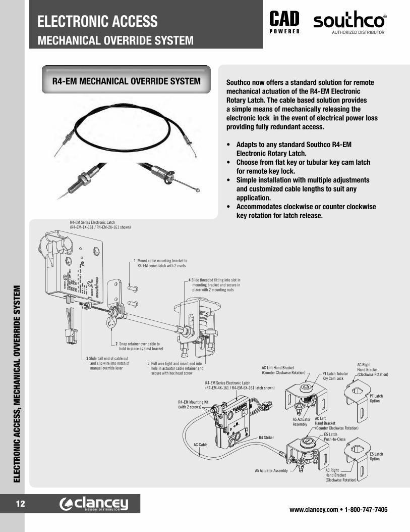
R4-EM MECHANICAL OVERRIDE SYSTEM Southco now offers a standard solution for remote mechanical actuation of the R4-EM Electronic Rotary Latch. The cable based solution provides a simple means of mechanically releasing the electronic lock in the event of electrical power loss providing fully redundant access.
• Adapts to any standard Southco R4-EM Electronic Rotary Latch.
• Choose from flat key or tubular key cam latch for remote key lock.
• Simple installation with multiple adjustments and customized cable lengths to suit any application.
• Accommodates clockwise or counter clockwise key rotation for latch release.
3 Slide ball end of cable outand slip wire into notch ofmanual override lever
2 Snap retainer over cable tohold in place against bracket
5 Pull wire tight and insert end intohole in actuator cable retainer andsecure with hex head screw
4 Slide threaded fitting into slot inmounting bracket and secure inplace with 2 mounting nuts
1 Mount cable mounting bracket toR4-EM series latch with 2 rivets
R4-EM Series Electronic Latch(R4-EM-1X-161 / R4-EM-2X-161 shown)
AC Left Hand Bracket(Counter Clockwise Rotation)
R4 Striker
AC Cable
R4-EM Mounting Kit(with 2 screws)
R4-EM Series Electronic Latch(R4-EM-4X-161 / R4-EM-6X-161 latch shown)
PT Latch Tubular Key Cam Lock
PT Latch Option
E5 Latch Option
AC Right Hand Bracket(Clockwise Rotation)
AC Right Hand Bracket(Clockwise Rotation)
AC Left Hand Bracket(Counter Clockwise Rotation)
E5 LatchPush-to-Close
A5 Actuator Assembly
A5 Actuator Assembly

www.clancey.com • 1-800-747-740513
ELECTRONIC ACCESS, MECHANICAL OVVERRIDE SYSTEM
MECHANICAL OVERRIDE SYSTEMELECTRONIC ACCESS
AC CABLE ASSEMBLY
Mechanical CableSee drawing J-AC-C AC-C0H0-4-LLLL-TTT
LLLL - Length from behind ball end to end of cable
TTT - Raw cable extension portion of LLLL length
How to Order
Step 1 Select mechanical override lock and corresponding AC actuator assembly and AC cable bracket
Step 2 Determine mechanical cable length required
Step 3 Order mechanical over ride bracket (one per R4-EM latch)
DESCRIPTION PART NUMBER
E5 Latch Push-to-Close assemblySee drawing J-E5-53-A
A5 Actuator A5-99-136
AND
AC Cable Bracket (Clockwise Rotation) AC-0-49617-11-R
OR
AC Cable Bracket (Counter Clockwise Rotation) AC-0-49617-11-L
LLLL
TTT
Mechanical Override Bracket for R4-EM-1X and R4-EM-2X
versionsSee drawing J-R4-EM-52
R4-EM-52
Mechanical Override Bracket for R4-Em-4X and R4-EM-6X
versions.See drawing J-R4-EM-72
R4-EM-72
DESCRIPTION PART NUMBER
PT LatchTubular Key cam LockSee drawing J-PT-1
A5 Actuator A5-99-157
AND
AC Cable Bracket (Clockwise Rotation) AC-0-49618-11-R
OR
AC Cable Bracket (Counter Clockwise Rotation) AC-0-49618-11-L
www.clancey.com • 1-800-747-740514
LOCKING SWINGHANDLEELECTRONIC ACCESS
ELEC
TRON
IC A
CCES
S, L
OCKI
NG S
WIN
GHAN
DLE
H3-EM ELECTRONIC LOCKING SWINGHANDLE
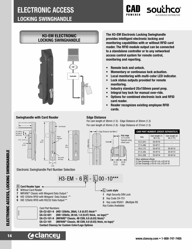
The H3-EM Electronic Locking Swinghandle provides intelligent electronic locking and monitoring capabilities with or without RFID card reader. The RFID module output can be connected to a standalone controller or to any networked access control system for remote control, monitoring and reporting.
• Remote lock and unlock.• Momentary or continuous lock actuation.• Local monitoring with multi-color LED indicator.• Lock status outputs provided for remote
monitoring.• Industry standard 25x150mm panel prep.• Integral key lock for manual over-ride.• Options for combined electronic lock and RFID
card reader.• Reader recognizes existing employee RFID
cards.
Card Reader
Statusindicator
237 ± 0.3 (9.3 ± 0.01)
25 (0.98) to top edge of panel prep.
210(8.27)
3.75(0.15)
7.9 (0.31 ) +0-0.1
+0-0.01
Din profilelock plug
37(1.46)
168 (6.6)
Swinghandle with Card Reader
Grip range(17.5 (0.69) Example using offset cam)Cam
25.75(1.01)
24.50(.96)
Edge Distance See Note 2
Frame edge
Edge DistanceFor cam length of 38mm (1.5) - Edge Distance of 30mm (1.2) For cam length of 45mm (1.8) - Edge Distance of 37mm (1.5)
CAM PART NUMBER (ORDER SEPARATELY)
Grip Cam length (1) 38 (1.5)
Cam length (2) 45 (1.77)
15.5 (.61) E5-6710 -
17.5 (.69) E5-6711 -
19.5 (.77) E5-6712 E5-6112
21.5 (.85) E5-6713 E5-6113
23.5 (.93) E5-6714 E5-6114
Other additional offsets: (1) See Drawings J-E5-67-A & J-E5-67-B (2) See Drawings J-E5-61-A & J-E5-61-B
Electronic Swinghandle Part Number Selection
Card Part Numbers EA-C2-021-9 (HID 125kHz, 26bit, 1.8 (0.07) thick** EA-C2-021 (HID 125kHz, 26 bit, 1.8 (0.07) thick, no logo)** EA-C3-101-9 (MIFARE® Classic, 4B CSN, 0.8 (0.03) thick)* EA-C3-101 (MIFARE® Classic, 4B CSN, 0.8 (0.03) thick, no logo)* Contact Clancey for Custom Color/Logo Options
L Lock style1 High Security DIN Lock2 Key Code CH-7513 Key code RS001 (Multiple RS Key Codes Available)
R Card Reader type 0 Without Card Reader 7 MIFARE® Classic with Wiegand Data Output * 8 HID 125kHz RFID with Wiegand Data Output ** 9 HID 125kHz RFID with RS232 Data Output **
H3 - EM - 6 R - L 00 - 10***
LAN
Controller

www.clancey.com • 1-800-747-740515
ELECTRONIC ACCESS, LOCKING SWINGHANDLE
LOCKING SWINGHANDLEELECTRONIC ACCESS
Connector Pin AssignmentCard Reader Module (Molex Micro Fit 3.0 Series) PIN 1: Ground (Black wire) PIN 2: Power (VCC) (Red wire) PIN 3: DATA0 or TX (Green wire) PIN 4: DATA1 or no connect (White wire) * See latch operating instructions for specifics)
5 METER WIRE HARNESSES (ORDER SEPARATELY)
PART NUMBER DESCRIPTION
EA-W01-500* From Swinghandle to Stripped and Tinned End
EA-W23-502* From RS-232 Output Card Reader to Stripped and Tinned End
EA-W23-503* From Wiegand Output Card Reader to Stripped and Tinned End
EA-W23-503-83* From Wiegand Output Card Reader to EA-P1-01X (Pin/Prox Controller)
EA-W01-23-507* From Swinghandle and Card Reader to Stripped and Tinned End
EA-W01-23-507-03* From Swinghandle and Card Reader to Hirose 8-Pin Connector
*Contact Clancey for other lengths
PIN 1PIN 3PIN 5
PIN 2PIN 4PIN 6
Pin 3
Pin 4
Pin 1
Pin 2
Card reader harness with connector
VCC1
GND2
DATA0 or TX
DATA1 or no connect
VSUPPLY1
GND2
Electronic Lock StatusMechanical Lock Status
Lock Control Signal
Electromechanical Lock Connector
Lock control harness (order separately)
(1) VCC and VSUPPLY may be connected together(2) EML and Card reader must use a common GND
ACCE
SS C
ONTR
OL U
NIT
Connection Diagram
ROD SYSTEM PART NUMBERS (ORDER SEPARATELY)*
H3-61-55-33 Left Hand Gearbox (CCW to open)
H3-61-56-33 Right Hand Gearbox (CW to open)
A5-92-201-31 Rod Adapter
A5-90-101-11 Actuator Plate
* For multi-point systems, select either the right or left hand gear box part number and rod adaptor (2 per door) part numbers or the actuator plate part number from table, then contact Clancey for rod selection.
25 (1.00)
CamRotation limiter
Connector
Cam bolt
Topmountingbracket
Rod Adapter
Optional gearbox accessoryBottom
mounting bracket
Mounting screw 14 (.55)4 x Mountingscrew 25 (1.00)150
(5.9)
Rod systems
Actuator Plate
Electronic Swinghandle (Hirose DF11 Series)PIN 1: Ground PIN 2: Power (Vsupply) PIN 3: Not Used PIN 4: Control signal PIN 5: Electronic lock status output PIN 6: Mechanical lock status output
Material & Finish Glass Filled Nylon, PC/ABS (UL94-V0)Shaft, rotation limiter: Die-cast zinc, bright sealer
Electronic SwinghandleRecommended operating voltage: 12VDC to 24VDCTypical operating current: Less than 200mA at 12VDC Peak / stall operating current: 1 Amp Standby current: 50mA Max Output Signal: 100mA Max load
Card Reader ModuleSupply voltage: 12VDC to 24VDC Operating current: 60mA Max
To Order: 1 Select required Electronic Swinghandle part number using selection guide.2 Select cam part number using cam part number table.3 For multi-point applications, select optional gear box / rod adaptors or actuator plate.4 Select optional wire harness.5 Order cards as needed.
For standalone systems order Southco EA-P1-010 controller.
Contact Clancey for details on ordering networked systems.
Note: ***Remove ‘-10’ for latch without Southco Logo
www.clancey.com • 1-800-747-740516
KEEPERELECTRONIC ACCESS
ELEC
TRON
IC A
CCES
S, K
EEPE
R
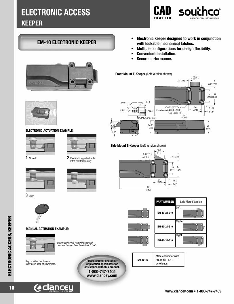
• Electronic keeper designed to work in conjunction with lockable mechanical latches.
• Multiple configurations for design flexibility.• Convenient installation.• Secure performance.
EM-10 ELECTRONIC KEEPER
Please contact one of our application specialists for
assistance with this product.
1-800-747-7405www.clancey.com
Front Mount E-Keeper (Left version shown)
Side Mount E-Keeper (Left version shown)
PART NUMBER Side Mount Version
EM-10-23-310
Left
EM-10-21-310
Center
EM-10-32-310
Right
EM-10-40Mate connector with 300mm (11.81) wire leads.
1 Closed 2 Electronic signal retracts latch bolt temporarily.
3 Open
MANUAL ACTUATION EXAMPLE:
Simply use key to rotate mechanical cam mechanism from behind latch bolt.
ELECTRONIC ACTUATION EXAMPLE:
Key provides mechanical override in case of power loss.

www.clancey.com • 1-800-747-740517
ELECTRONIC ACCESS, KEEPER
KEEPERELECTRONIC ACCESS
EM-05 MINIATURE ELECTRONIC KEEPER • Simple transition from mechanical to electronic access• “Push-to-close” convenience for any application – retrofit
or new installation.• Front mount and side mount versions.• Concealed latching.• Microprocessor controlled gear motor.• Minimal power draw.• Simple mechanical override.• Optional internal microswitch for latch open/close
output signal.• Wide operating voltage range (8-26 VDC).• Accepts signals from any electronic actuation source• Single or multi-point latching.• Works with a variety of door mounted mechanical latches.
1 1 2
3PIN 3PIN 2PIN 1
PIN 1 Indicator
PIN 6PIN 5PIN 4
* For Mechanical Version of Front Mount Style order part number EM-05-11-001 * For Mechanical Version of Side Mount Style order part number EM-05-21-001 (Mechanical version does not include drive motor or electronics)
MINIATURE ELECTRONIC KEEPER PART NUMBERS
TypeWith Mechanical Override Without Mechanical Override
With Switch Without Switch With Switch Without Switch
Front Mount Latch Bolt EM-05-11-111 EM-05-11-101* EM-05-11-110 EM-05-11-100
Side Mount Latch Bolt EM-05-21-111 EM-05-21-101* EM-05-21-110 EM-05-21-100
Latch Connector Molex Microfit 3.0 series
Ø 4.3 (0.17) thru
17.5(0.69)
17.5(0.69)
37.5(1.48)
15.5 (0.61)2.75 (0.11)
2.75 (0.11)
27(1.06)
7.76 (0.31) 7mm (0.27) travel 7.76 (0.31) 7mm (0.27) travel
10 (0.4)
10 (0.4)
5 (0.2)5.25 (0.21)
13.5 (0.53)13.5 (0.53)12 (0.47)
5 (0.2)5.25(0.21)
271.06)
12 (0.47)Mechanical Override Ball End Cable Connector(Will accept ø1.6 ± 0.15 (0.063 ± 0.006) cable with ø4.78 ± 0.13 (0.188 ± 0.005) ball)
73.5 (2.89)
145 REF (5.71)
Max Travel 8mm (.315)
8.6(0.73)
7.25 (0.29)
Side Mount Front Mount
Material & FinishEnclosure & Latch Bolt: Thermoplastic Housing Assembly Screws: Steel, Zinc Plate
Electrical SpecificationsRecommended Operating Voltage: 12 - 24 VDCTypical Operating Current: Less than 600mA at 12 VDC
Control InputRetracted Position: 12-24 VDC The latch bolt will remain retracted for as long as the signal is present or a minimum of 1 second. Input Signal Current: 25mA Max at 24 VDCExtended Position: 0 VDC
Wire Color Code / Connector Pin Assignment:PIN 1 Brown: Ground (-) PIN 2 Red: Power 8 to 26 VDC PIN 3 Orange: Control Signal 8 to 26 VDC PIN 4 Black: Microswitch Common PIN 5 Blue: Microswitch N.O. Contact PIN 6: None

www.clancey.com • 1-800-747-740518
PROXIMITY READERELECTRONIC ACCESS
ELEC
TRON
IC A
CCES
S, P
ROXI
MIT
Y RE
ADER
EA-P3 125KHZ PROXIMITY READER ELECTRONIC ACCESS
The new Southco EA-P3 Proximity Reader provides convenient, secure, non-contact access control in a compact easy to use design. The EA-P3 reads HID 125 kHz prox cards or tags and produces a standard 26 bit Wiegand output common to most access control systems. The reader can be combined with the Southco EA-P1 Pin/Prox reader for a complete access control system, or combined with any existing 26 bit Wiegand based access controller to add additional keyless entry points to existing security systems.
• Non-contact proximity based access control.• Reads HID compatible 125kHz prox cards.• Standard 26 bit Wiegand output.• Integrated LED status indicator.• Compact, low profile design.• Simple, 3 hole installation.• Sealed weather resistant design.
Wire Harness LegendWire Color Function
Red VCC (12VDC)
Black GND
White Data 1
Green Data 0
Yellow GND
Brown No Function
Orange No Function
Blue No Function
Part Number SelectionEA-P3-101-1 Proximity Reader (Gray Enclosure*)
EA-C2-021 Proximity Card (No Logo*)
* Contact Clancey for Custom Color and Logo Options
Access Controller
www.clancey.com • 1-800-747-740519
ELECTRONIC ACCESS, PROXIMITY READER
PROXIMITY READERELECTRONIC ACCESS
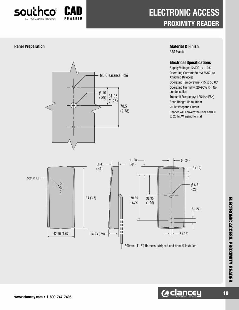
11.28(.44)
Status LED
10.41(.41)
94 (3.7)
42.50 (1.67) 14.93 (.59)
3 (.12)
Ø 6.5(.26)
3 (.12)
M3 Clearance Hole
300mm (11.8’) Harness (stripped and tinned) installed
70.5(2.78)
Ø 10(.39) 31.95
(1.26)
6 (.24)
6 (.24)
31.95(1.26)
70.35(2.77)
11.28(.44)
Status LED
10.41(.41)
94 (3.7)
42.50 (1.67) 14.93 (.59)
3 (.12)
Ø 6.5(.26)
3 (.12)
M3 Clearance Hole
300mm (11.8’) Harness (stripped and tinned) installed
70.5(2.78)
Ø 10(.39) 31.95
(1.26)
6 (.24)
6 (.24)
31.95(1.26)
70.35(2.77)
Panel Preparation Material & FinishABS Plastic
Electrical SpecificationsSupply Voltage: 12VDC +/- 10%Operating Current: 60 mA MAX (No Attached Devices)Operating Temperature: -15 to 55 0COperating Humidity: 20-90% RH, No condensationTransmit Frequency: 125kHz (FSK)Read Range: Up to 10cm 26 Bit Wiegand Output Reader will convert the user card ID to 26 bit Wiegand format

www.clancey.com • 1-800-747-740520
PIN/PROXIMITY READERELECTRONIC ACCESS
ELEC
TRON
IC A
CCES
S, P
IN\P
ROXI
MIT
Y RE
ADER
EA-P1 SERIES PIN/PROX ACCESS CONTROLLER
The self-contained PIN/Prox controllers provide basic PIN/Prox access control with the flexibility to use PIN only, Prox only, or both PIN and Prox for added convenience and security. Simply supply 12 volt DC power and connect the output to any SOUTHCO® electromechanical latch for a complete electronic access solution. Enter a valid PIN or present a programmed prox card to the controller to produce an actuation signal.
• Simple card/PIN programming.• LED indicator and audible feedback for
programming and lock status.• Up to 9,999 cards per controller.• Non-volatile memory retains data after power is
removed.• Programmable door release time and alarm time.• For use with EA-C1 series prox cards.• Custom color and logo options.
1 2 3
4 5 6
7 8 9
* 0 #
Additional FeaturesLockout output provides alarm output after multiple failed access attempts, programmable from 1-99 attempts.
Tamper switch provides output if controller is removed from mounted surface.
Auxiliary input allows for additional remote input signal to open lock for programmed time.

www.clancey.com • 1-800-747-740521
ELECTRONIC ACCESS, PIN\PROXIMITY READER
PIN/PROXIMITY READERELECTRONIC ACCESS
JBJDJC118
(4.65)
75 (2.95)
Gasket
Bezel
Housing
18.9 (.75)Not including gasket
(gasket 1.7 (.067) uncompressed)
11.6 (.46)58 (2.28) 4 (.16)Thru 5 (.20)
Thru
8.3 (.33)
84.2(3.32)
109.5(4.31)
42.1 (1.66)
67.7 (2.66)
7 (.28)
2x Countersunk slots
JA (Blue)Door access
1 2 3 4 5 6 7 8 9 1 2 3 4
1 (Red)2 (Black) 3 (Brown)4 (Orange) 5 (Yellow)6 (Green)7 (Blue)8 (Purple)9 (Grey)
+12 VDCGround
Auxiliary inputXXX
NOCOMNC
Relay Output A(Max. 2A / 30 VDC)
Relay Output B(Max. 2A / 30 VDC)
E (Green)F (Blue)
Lockout alarm output (NO)Lockout alarm output (COM)
JB (White)Lockout alarm output
A B C D E F G H
J (Blue)K (Green) L (Yellow)
NCNOCOM
JC (Blue)Tamper switch output
J K L
1 (Red)2 (Yellow) 3 (Green)4 (Black)
+12VDCData1Data0Ground
JD (White)External Wiegand Reader
JA 1243
5
X X X X X
X X X
X
76(2.99)
Bezel Attached Without Bezel
Mounting
Connector Details(Note: Mating connectors with approximately 160mm (6.3) of wiring, stripped and tinned provided with controller).
EA - P1 - 01 C - L
Part Number SelectionC Color
1 - White 2 - Cool Gray 0 - Black
L Omit - No Logo 9 - Southco Logo
Proximity card: EA - C1 - 011 (contact Clancey for custom color and logo options)
Material & FinishPolycarbonate and ABS Plastic
Electrical SpecificationsPIN Code Length: Programmable 1 to 8 digitsMonitoring Inputs: Auxiliary, case tamperingTypical Maximum Read Range: 10cm (depending on installation)Frequency of Operation: 125kHz (EM), others available upon request
Modes of Operation:* Card-only * PIN or card * PIN and card * BypassPower: 12 VDC 80mA in standby, 105mA working current (typical) Operating Temperature: 0-50 °COperating Humidity: 20-90% RH, no condensation
Connectors:Connector with approximately 160mm (6.3) of wiring, stripped and tinned provided with controller1. JA Door access connector (blue
9-pin)2. JB Lockout alarm connector
(white 8-pin)3. JC Tamper switch output
connector (blue 3-pin)4. JD Wiegand reader connector
(white 4-pin)5. Tamper switch

www.clancey.com • 1-800-747-740522
KEYPAD MEMBRANEELECTRONIC ACCESS
ELEC
TRON
IC A
CCES
S, K
EYPA
D M
EMBR
ANE
EA-KC2 SERIES MEMBRANE KEYPAD ACCESS CONTROLLER
The Membrane Keypad Access Controller simplifies access management with keyless entry in a self-contained unit. Designed to accommodate industrial equipment needs, the Membrane Keypad is easily customized and can be simply adhered to a door or frame. The remote controller can be mounted anywhere inside a cabinet and provides two outputs for independent control of two separate compartments. Flexible and easy to use, it can be customized to accommodate any look, shape or feel.
• Simplified, secure access management.• Attractive, customizable membrane style keypad.• Programmable to accommodate multiple access
arrangements.• Direct integration with electronic locks.• Controls up to two compartments independently.• Sleep mode for minimal power draw.• Up to 120 user codes.• LED indicators for keypad status & programming.
Self Service Medical Storage
Server Racks
The Membrane Keypad benefits a variety of industrial applications

www.clancey.com • 1-800-747-740523
ELECTRONIC ACCESS, KEYPAD MEM
BRANE
KEYPAD MEMBRANEELECTRONIC ACCESS
129.17 (5.08)
114.3 (4.5)
101.4 (3.99)
Ø 4.8 (.19)
2.7 (.10)
28.96(1.14)
25.73 (1.01)
Membrane Key Pad Connector
Latchconnectors(Hirose P/N: DF11-6DP-2DS)
Power inlet2.0 x 6.0mm shieldedpower jack(CUI P/N: PJ-051A)
51.5 (2.02)
LATCH WIRE HARNESS OPTIONSPart Number Description
EA-W01-200* 2 Meter Wire Harness Stripped and Tinned
EA-W20-201-01*
2 Meter Wire Harness to Connect Membrane Controller to Miniature Electronic Keeper (EM-05-XX-XXX)and/or Elec-
tronic Rotary Latch (R4-EM-XX-XXX)
EA-W01-200-01*2 Meter Wire Harness to
Connect Membrane Controller to Electronic Swing
Handle(H3-EM-XX-XXX)
Latch 2Latch 1
EA-A02-002 Power Supply
Horizontal Key Pad Part Number EA-KC2-101
EA-KC2-102 Vertical Membrane Key Pad
**EA-A02-002-1 NA 2-PIN included with EA-A02-002 Power Supply.*Contact Clancey For Custom Lengths
Control Box
PART NUMBER DESCRIPTION FUNCTION
EA-A02-002** Power Supply with NA 2-Pin
EA-A02-002 & EA-A02-002-2
Power Supply with Euro 2-Pin
EA-A02-002 & EA-A02-002-3
Power Supply with UK 3 Pin
EA-A02-002 & EA-A02-002-4
Power supply with SAA 2-Pin
Plug Adapters
167.5 (6.59)
167.5(6.59)
115 (4.52)
20 (.79)
35 (1.38)
R21 (.83)
115 (4.53)
40 (1.58)
25.4(1.0) 28 (1.10)
14 (.55)43.5 (1.71)
R25 (.98)83(3.27)
28 (1.10)
88 (3.46)
EA-KC2-104EA-KC2-103
R25(.98)
Vertical Key Pad Part Number EA-KC2-102, EA-KC2-103 & EA-KC2-104
Material & FinishMembrane Key Pads with Tactile Keys - Textured Polyester Film with PSA Tape for Mounting on Backside Controller Housing - ABS Controller Circuit Board - FR4
Electrical SpecificationsSupply Voltage: 12-24 VDC Stand By Current: 30µA Operating Current: 10mA (Typical) MAX Total Output: 4 Amps (2 Amps per Output)
How to Order1 Order one controller EA-KC2-2012. Order standard Southco
membrane EA-KC2-101, EA-KC2-102, EA-KC2-103 & EA-KC2-104. Contact Southco for custom membrane keypad design.
3. Order Southco Power Supply EA-A02-002 and select the appropriate plug adapter if needed.
4. Use latch wire harness options table to select cable to accommodate Southco EML
Controller Assembly Part Number EA-KC2-201

www.clancey.com • 1-800-747-740524
KEY FOBELECTRONIC ACCESS
ELEC
TRON
IC A
CCES
S, K
EY F
OB
EA-R01 RF CONTROLLER
12VDCPOWERGND
AOUTPUT 1B
AOUTPUT 2B
AAUXGND
12VDC Power Supply
Light/ Horn
RF CONTROLLER KIT PART NUMBER: EA-R01
Includes 1 receiver (EA-R01-201) and2 transmitters (EA-R01-101)
The EA-R01 series RF Controller provides peace of mind security with convenient and timesaving one touch remote locking and unlocking of multiple access points. With sealed electronics, high load capacity and simple installation, the controller is designed specifically for the environmental and storage needs of specialty vehicles, marine craft, recreational vehicles, off highway, and heavy duty trucks.
• Durable, water-proof construction.• Dual sequenced output outputs minimize
battery drain.• Fused 30 Amp outputs accommodate multiple
latches.• Auxiliary light/horn output for visual/audible
lock confirmation.• Labeled connections for easy setup.• Simple transmitter programming.• Integrate with any Southco Electromechanical
latch solution.

www.clancey.com • 1-800-747-740525
ELECTRONIC ACCESS, KEY FOB
KEY FOBELECTRONIC ACCESS
ScrewTerminal
GND
VCC
OUTPUT 1 A
OUTPUT 1 B
OUTPUT 2 A
OUTPUT 2 B
OUTPUT 3
GND
12VDCPOWERGND
AOUTPUT 1B
AOUTPUT 2B
AAUXGND
Fuses
127.0(5.00)
114.30(4.50)
Ø 4.95 (.195)
31.63(1.245) 22.23
(.875)
4.45(.175)
120.65 (4.750)
Nameplate/CoverLock button
Unlock button
Keyfob transmitter
Blue LED Nameplate screws
107.95 (4.250)
OperationShipped with two pre-programmed transmitters
Press transmitter “UNLOCK” button Controller will produce a 12VDC pulse for 200ms on output 1 terminal A, followed by a 300ms pause followed by a 200ms 12VDC pulse on output 2, terminal A
After another 300ms pause, the controller will produce two 400ms pulses separated by a 200ms pause on the auxiliary light/horn output
Press transmitter “LOCK” button Controller will produce a 12VDC pulse for 200ms on output 1 terminal B, followed by a 300ms pause followed by a 200 ms 12VDC pulse on output 2, terminal B
After another 300ms pause, the controller will produce one 400ms pulse on the auxiliary light/horn output
Simple push-button learn feature with LED feedback for enrolling transmitters. Note: EA-R01 shipped with 2 pre-programmed transmitters
ReceiverTransmitter SpecificationsReceiver Power: 12VDC (± 25%) Receiver Idle Current: <10mA Receiver Operating Current: <30A momentary Receiver Outputs: Output 1 & 2: 30A polarity reversing relays Aux Output: 30A single pole relay
Operating Range: up to 30.4m (100 ft)Operating Frequency: 340MHz Coding Type: Fixed Code Enclosure Rating: IP67
Transmitter Power:Type 23 12VDC battery Receiver output fuses 15A Littelfuse 297 Series Mini® Fast-Acting automotive blade fuse or equivalent.
Connection DetailsAll electrical connections are made via screw terminals accessible by removing 2 screws and name plate

www.clancey.com • 1-800-747-740526
KEY FOBELECTRONIC ACCESS
ELEC
TRON
IC A
CCES
S, K
EY F
OB
EA-R02 RF REMOTE CONTROL SYSTEMThe new EA-R02 RF Remote Control System enables remote actuation of Southco electronic locks in a basic, economical package. The EA-R02 uses a palm-size radio frequency (RF) transmitter for remote locking and unlocking of electronic locks. The keyless system consists of a receiver, two key fob style transmitters and interconnecting wire harness. The unit provides precious peace of mind with the added security and convenience that mechanical keys cannot deliver. A simple push of a button can wirelessly control multiple locks for convenient remote control. Setup and installation are both quick and easy for a smooth transition from mechanical to electronic access.
• Secure, convenient, wireless remote lock actuation.
• Quick installation and setup.• Economical and compact package.• Proven 433 MHz radio frequency technology.• Up to 4 transmitters per receiver.• 18 meter (60 feet) unobstructed open air operating
range.• Auxiliary output for horn/light indicator output.

www.clancey.com • 1-800-747-740527
ELECTRONIC ACCESS, KEY FOB
KEY FOBELECTRONIC ACCESS
93.75 (3.69)
85.75 (3.38)
65 (2.56)
28 (1.10)
77.75 (3.06)
11 (.43)
6.5 (.26) 16.88(.66)
44 (1.73)
J1J2
Ø 4.00 (.16)(2 Places)
Switch Access Tab
Red LEDUnlock Button
Lock Button30.9 (1.22)
53 (2.09)
11.9 (.47)
12 (.47)
13 (.51)
10 (.39)
12 (0.47)
External Antena(Antena length 190 (7.48)
PIN WIRE COLOR DESCRIPTION1 RED VCC (+12VDC Power Supply Input)
2 BLACK GND (Ground)
3 YELLOW Auxiliary Output (Vout = VCC)
PIN WIRE COLOR DESCRIPTION
1 BLUE/BLACK LOCK Relay – Normally Closed (typically connect to GND)
2 BLUE LOCK Relay – Common (typically connect to latch)
3 BLUE/RED LOCK Relay – Normally Open (typically connect to VCC)
4 GREEN/BLACK UNLOCK Relay – Normally Closed (typically connect to GND)
5 GREEN UNLOCK Relay – Common (typically connect to latch)
6 GREEN/RED UNLOCK Relay – Normally Open (typically connect to VCC)
Power Supply and Auxiliary Output Wire Harness (J1) LOCK & UNLOCK Relay Wire Harness (J2)
Receiver
Transmitter
10 (.39) Ref1000 (39.4)10 (.39) Ref1000 (39.4)
10 (.39) Ref1000 (39.4)10 (.39) Ref1000 (39.4)
RF REMOTE CONTROL SYSTEM PART NUMBER: EA-R02
Includes 1 Receiver, 2 Keyfobs, 1 Pair Power/Auxiliary and Lock/Unlock Relay Connector Wire Harnesses and Operating Instructions
Material & FinishABS Plastic
Electrical SpecificationsReceiver Power: 12VDC (±10%)Receiver Standby Current: 10mA MAX, No Attached Devices Receiver Operating Current: 100mA MAX, No Attached DevicesReceiver Outputs: Three Form C Relays, Rated 15A at 14VDC Receiver Lock/Unlock Output Pulse Duration: 250ms or 10 sec (Selectable)Receiver Operating Temperature: -20 to 80 0C
OperationOperating Range: Up to 60 Feet / 18 Meters (Open Air) Operating Frequency: 433.92MHzCoding Type: Fixed Code (24-Bit)Transmitter Power: Type CR2016 3VDC Battery (Qty 2 per transmitter)Switch Access Tab Switch 1 - Used to enroll transmitters Switch 2 - Used to set LOCK and UNLOCK pulse duration
Note:Individual components can be ordered separately. Contact Clancey for information.

www.clancey.com • 1-800-747-740528
CONTROLLERELECTRONIC ACCESS
ELEC
TRON
IC A
CCES
S, C
ONTR
OLLE
R
EA-A06 USB CONTROLLERThe USB Controller allows for the independent control of up to 14 different electrical devices from an existing computer. With a set of simple software commands, control and monitor connected devices via USB port. Output signals from connected locks can be captured for audit trail reporting.
• Allows computer controlled electro-mechanical latch operation via USB port.
• 14 Independent latch inputs / outputs.• Simple programming commands / easy
program interface.• Integrate with any Southco electro-mechanical
latch solution.• Plug and Play.• Labeled connections for easy set up.
-+
Medical Self Service
Server Access
The USB Controller benefits a variety of industrial applications

www.clancey.com • 1-800-747-740529
ELECTRONIC ACCESS, CONTROLLER
CONTROLLERELECTRONIC ACCESS
Material & FinishController Housing – ABS (UL94-5VA Flammability Rating)
Electrical SpecificationsOperating Voltage: 12-24 VDC Do Not Exceed Max Latch Voltage Max Output Per Latch: 2 Amps
How to Order1 Order one Controller with USB
Cable: EA-A06-0012. Order Power Supply
EA-A02-002 and select the appropriate plug adapter if needed
3. Use latch wire harness options table to select cable to accommodate electromechanical latches
129.6 (5.10)
12 11 10 9 8 7 6 5
1PWR 2
4
3
13
14
114.3 (4.5)
101.4 (3.99)
Ø 4.8 (.19)
2.7 (.10)
28.58(1.12)
25.73 (1.01)
Latchconnectors(Hirose P/N: DF11-6DP-2DS)
Latch connectors(Hirose P/N: DF11-6DP-2DS)
Mini USBconnector
Latch connectors(Hirose P/N: DF11-6DP-2DS)
Power inlet2.0 x 6.0mm shieldedpower jack(CUI P/N: PJ-051A)
51.5 (2.02)
WIRE HARNESS OPTIONS
Part Number Length Connects to
EA-W01-200* 2 Meters Stripped and Tinned
EA-W20-201-01* 2 Meters
EA-W20-201-01* 2 Meters
EA-W01-200-01* 2 Meters
EA-W02-203-01* 2 Meters
PART NUMBER
EA-A06-001
EA-A02-002 Power Supply
Controller Assembly
**EA-A02-002-1 NA 2-PIN included with EA-A02-002 Power Supply.*Contact Clancey For Custom Lengths
1 Meter USB Cable (In-cluded)
PART NUMBER DESCRIPTION FUNCTION
EA-A02-002** Power Supply with NA 2-Pin
EA-A02-002 & EA-A02-002-2
Power Supply with Euro 2-Pin
EA-A02-002 & EA-A02-002-3
Power Supply with UK 3 Pin
EA-A02-002 & EA-A02-002-4
Power supply with SAA 2-Pin
Plug Adapters

www.clancey.com • 1-800-747-740530
TILT MOUNTMONITOR MOUNT
MON
ITOR
MOU
NT, T
ILT
MOU
NT
AV SERIES DYNAMIC MOUNT TILT• Intuitive grab and move operation enhances the
user experience.• No knobs or tools required to reposition the
display.• Precise control of operating effort ensures ideal
“feel.” • Holds securely, even in applications with
dynamic loading.• Consistent repeatable operation.• Fully enclosed for optimum cleanability.
49 (1.93)
90.2 (3.55)
2.6 (0.11)
38±.02(1.49±.008)
38±.02(1.49±.008)
31±.02(1.22±.008)
31±.02(1.22±.008)
4 X M5 X 0.8i10mm
Full Thread
100 (3.9) TYP75 (2.95) TYP
115 (4.52) TYP44.6 (1.76)
Forward
Reverse
49(1.93)
19(.75)
Display Tilt ±200
range of motionfrom position shown
8 X Ø 5.2±.02(0.20±.008)
Product Detail
www.clancey.com • 1-800-747-740531
MONITOR M
OUNT, TILT MOUNT
TILT MOUNTMONITOR MOUNT
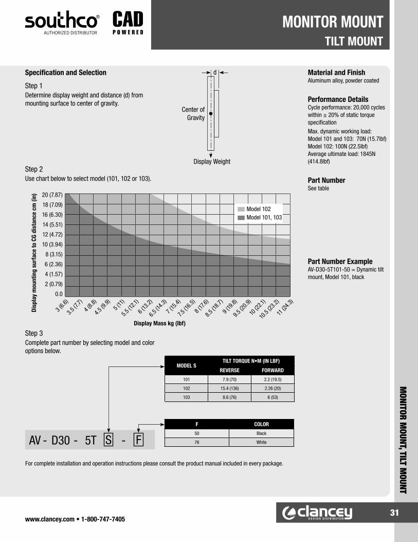
Material and FinishAluminum alloy, powder coated
Performance DetailsCycle performance: 20,000 cycles within ± 20% of static torque specificationMax. dynamic working load: Model 101 and 103: 70N (15.7lbf) Model 102: 100N (22.5lbf) Average ultimate load: 1845N (414.8lbf)
Part NumberSee table
Part Number ExampleAV-D30-5T101-50 = Dynamic tilt mount, Model 101, black
AV - D30 - 5T S - F
Step 1Determine display weight and distance (d) from mounting surface to center of gravity.
Step 2Use chart below to select model (101, 102 or 103).
Step 3Complete part number by selecting model and color options below.
Display Weight
Center of Gravity
d
Display Mass kg (lbf)
Specification and Selection
3 (6.6
)
3.5 (7
.7)4 (
8.8)
4.5 (9
.9)5 (
11)
5.5 (1
2.1)
6 (13
.2)
6.5 (1
4.3)
7 (15
.4)
7.5 (1
6.5)
8 (17.
6)
8.5 (1
8.7)
9 (19
.8)
9.5 (2
0.9)
10 (2
2.1)
10.5
(23.2)
11 (2
4.3)
20 (7.87)
18 (7.09)
16 (6.30)
14 (5.51)
12 (4.72)
10 (3.94)
8 (3.15)
6 (2.36)
4 (1.57)
2 (0.79)
0.0
Disp
lay
mou
ntin
g su
rfac
e to
CG
dist
ance
cm
(in)
F COLOR
50 Black
76 White
MODEL STILT TORQUE N•M (IN LBF)
REVERSE FORWARD
101 7.9 (70) 2.2 (19.5)
102 15.4 (136) 2.26 (20)
103 8.6 (76) 6 (53)
Model 102Model 101, 103
For complete installation and operation instructions please consult the product manual included in every package.

www.clancey.com • 1-800-747-740532
TILT & SWIVEL MOUNTMONITOR MOUNT
MON
ITOR
MOU
NT, T
ILT
& SW
IVEL
MOU
NT
100 (3.9) TYP
75 (2.95)29 (1.14)
63.6(2.50)
85.2(3.35)
8 x Ø5.2 (0.21)
R 6 (.24)
75 (2.95)R 15.0 (.60)
115 (4.52) TYP
2.6 (0.11)
39.75(1.56)
Swivel 1800
Tilt ±200
Force to move arm
M6 x 1 Thread
Reverse
Forward
Product Detail
AV SERIES DYNAMIC MOUNT TILT & SWIVEL
• Intuitive grab and move operation enhances the user experience.
• No knobs or tools required to reposition the display.
• Precise control of operating effort ensures ideal “feel” and eliminates “drift.”
• Holds securely, even in applications with dynamic loading.
• Consistent repeatable operation.• Factory assembled and ready for use.

www.clancey.com • 1-800-747-740533
MONITOR M
OUNT, TILT & SWIVEL M
OUNT
TILT & SWIVEL MOUNTMONITOR MOUNT
AV - D30 - 7K S - F
Step 1Determine display weight and distance (d) from mounting surface to center of gravity.
Step 2Use chart below to select model (101, 102 or 103).
Step 3Complete part number by selecting model and color options below.
Display Weight
Center of Gravity
d
Display Mass kg (lbf)
Specification and Selection
3 (6.6
)
3.5 (7
.7)4 (
8.8)
4.5 (9
.9)5 (
11)
5.5 (1
2.1)
6 (13
.2)
6.5 (1
4.3)
7 (15
.4)
7.5 (1
6.5)
8 (17.
6)
8.5 (1
8.7)
9 (9.8
)
9.5 (2
0.9)
10 (2
2.1)
10.5
(23.2)
11 (2
4.3)
20 (7.87)
18 (7.09)
16 (6.30)
14 (5.51)
12 (4.72)
10 (3.94)
8 (3.15)
6 (2.36)
4 (1.57)
2 (0.79)
0.0
Disp
lay
mou
ntin
g su
rfac
e to
CG
dist
ance
cm
(in)
F COLOR
50 Black
76 White
MODEL STILT TORQUE N•M (IN LBF) SWIVEL
TORQUEREVERSE FORWARD
101 7.9 (70) 1.13 (10) 2.3 (20)
102 15.4 (136) 2.26 (20) 3.4 (30)
103 8.6 (76) 6 (53) 3.4 (30)
Model 102Model 101, 103
Material and FinishAluminum alloy, powder coated
Performance DetailsCycle performance: 20,000 cycles within ± 20% of static torque specificationMax. dynamic working load: Model 101 and 103: 66N (15 lbf) Model 102: 98N (22 lbf) Average ultimate load: 178 N (450 lbf)
Part NumberSee table
Part Number ExampleAV-D30-7K101-50 = Dynamic mounting arm, Model 101, black

www.clancey.com • 1-800-747-740534
TILT & SWIVEL COMPACT MOUNTMONITOR MOUNT
MON
ITOR
MOU
NT, T
ILT
& SW
IVEL
COM
PACT
MOU
NT
Installation
Installation Notes1. Determine desired mounting location2. Attach using M8 nut (not supplied) as shown Caution: Because of the wide variety of panel materials, it is the installer’s responsibility to ensure that the materials and structure to which the product is mounted and the hardware selected will provide adequate support.3. Attach display mounting bracket using recommended self-tapping screws or equivalent
Swivel Torque
Section A-A
A A
49.5 (1.95)
24.75 (.98)
54(2.13)
3 (.12)
M8 X 1.25 Thread
Ø 30 (1.18)23 (91)
11.5 (.45)
2X Ø5(.20)
21.7(.85)
2 X 10 (.40)
2 X Ø4.1(.16)
Panel Thickness X
200 Range of Motion, Reverse
1100 Range of Motion,Forward
Tilt Torque
9.2(.36)
13 (.51)
19.4 (.76)
23 ±0.2 (.91 ±.008)
2 X 11.5 ±0.1 (.45 ± .004)
Ø8.4 (.331 )
2X Ø5.4(.213 )
M8 Nut (Not Provided, ClanceyPart Number E3-0-23971-07 or Equivalent)
Self Tapping Screw(See Table for Recommended Part Number)
Display case back or mounting plate (not supplied). Customized mounting plates available, contact Clancey for details.
+.004-.000
+.004-.000
+.0.1-0.0
+.0.1-0.0
AV SERIES DYNAMIC MOUNT TILT & SWIVEL COMPACT
• Intuitive grab and move operation enhances the user experience.
• No knobs or tools required to reposition the display.
• Consistent repeatable operation.• Factory assembled and ready for use.• Smooth operation enhances the user experience.• Adjust the display without knobs or tools.• Holds securely in every position.
Product Detail

www.clancey.com • 1-800-747-740535
MONITOR M
OUNT, TILT & SWIVEL COM
PACT MOUNT
TILT & SWIVEL COMPACT MOUNTMONITOR MOUNT
Step 1Determine display weight and distance (d) from mounting surface to center of gravity.
Step 2Use chart below to confirm suitable display weight. For weights outside the shaded area, consider Southco AV-D30 series display mounts.
Step 3Select part number and recommended display mounting hardware below:
Recommended display mounting hardware:
Display Weight
Center of Gravity
d
Display mass kg (lbm)
Disp
lay m
ount
ing
surfa
ce to
CG
dist
ance
cm
(in)
5 (2.0)
10 (3.9)
15 (5.9)
20 (7.9)
25 (9.8)
30 (11.8)
1 (2.2
)
1.5 (3
.3)2 (
4.4)
2.5 (5
.5)3 (
6.6)
3.5 (7
.7)4 (
8.8)
4.5 (9
.9)5 (
11)
5.5 (1
1.1)
6 (13
.2)
6.5 (1
4.3)
7 (15
.4)
7.5 (1
6.5)
8 (17
.6)
Specification and Selection
PANEL THICK-NESS,
X (MM)
PAN-HEAD SCREW(P/N)
FLAT-HEAD SCREW(P/N)
1-4 96-79-1 96-79-11
4-7 96-79-2 96-79-12
PART NUMBERS TILT TORQUEN-M (IN-LBF)
SWIVEL TORQUEN-M (IN-LBF)
AV-C20-K101-20 2.26 (20.0) 3.62 (32.0)
AV-C20 Series - Capacity vs. Cg Distance
Material and FinishGlass-Filled Nylon, Black; Stainless Steel
Performance DetailsCycle performance 20,000 Cycles within +/- 20% of static torque specificationMax dynamic working load: 100N (22.5lbf)Average ultimate load: 1000N (225lbf)

www.clancey.com • 1-800-747-740536
MOUNTING ARMMONITOR MOUNT
MON
ITOR
MOU
NT, M
OUNT
ING
ARM
AV SERIES DYNAMIC MOUNTING ARM TILT, SWIVEL, & SWING
• Intuitive grab and move operation enhances the user experience.
• No knobs or tools required to reposition the display.
• Precise control of operating effort ensures ideal “feel” and eliminates “drift.”
• Holds securely, even in applications with dynamic loading.
• Low profile in the stowed position.• Folds to within 50 mm of the wall.• Snap-open channels simplify wire management . • Easy display installation and replacement.• Factory assembled and ready for use.
50 (1.96)
100 (3.9) TYP115 (4.52) TYP
75 (2.95) TYP
100 (3.9)
215 (8.46)
245(9.64)
21 (.83)
49.9 (1.96)
1800Swivel 1800
Tilt ±200
L
Force to move arm
Reverse
Forward
Product Detail

www.clancey.com • 1-800-747-740537
MONITOR M
OUNT, MOUNTING ARM
MOUNTING ARMMONITOR MOUNT
AV - D30 - K A S - F
Step 1Determine display weight and distance (d) from mounting surface to center of gravity.
Step 2Use chart below to select model (101 or 102).
Step 3Complete part number by selecting length and color options below.
Display Weight
Center of Gravity
d
Display Mass kg (lbf)
3 (6.6
)
3.5 (7
.7)4 (
8.8)
4.5 (9
.9)5 (
11)
5.5 (1
2.1)
6 (13
.2)
6.5 (1
4.3)
7 (15
.4)
7.5 (1
6.5)
8 (17.
6)
8.5 (1
8.7)
9 (9.8
)
9.5 (2
0.9)
10 (2
2.1)
10.5
(23.2)
11 (2
4.3)
20 (7.87)
18 (7.09)
16 (6.30)
14 (5.51)
12 (4.72)
10 (3.94)
8 (3.15)
6 (2.36)
4 (1.57)
2 (0.79)
0.0
Disp
lay
mou
ntin
g su
rfac
e to
CG
dist
ance
cm
(in)
K LENGTH (L) AVERAGE ULTI-MATE LOAD
15 150 (5.9) 2000 (450)
25 250 (9.8) 1200 (270)
35 350 (13.8) 850 (190)
45 450 (17.7) 660 (150)
F COLOR
50 Black
76 White
MODEL S
FORCE TO MOVE
ARM N (LB)
TILT TORQUE N•M (IN LBF) SWIVEL
TORQUEREVERSE FOR-
WARD
101 22.2 (5) 7.9 (70) 1.13 (10) 2.3 (20)
102 33.8 (7.6) 15.4 (136) 2.26 (20) 3.4 (30)
Model 102Model 101
Material and FinishAluminum alloy, powder coated
Performance DetailsCycle performance: 20,000 cycles within ± 20% of static torque specificationMax. dynamic working load: Model 101: 66N (15 lbf) Model 102: 98N (22 lbf) Average ultimate load: See table
Part NumberSee table
Part Number ExampleAV-D30-25A101-50 = Dynamic mounting arm, Model 101, 250mm Length, black
Specification and Selection

www.clancey.com • 1-800-747-740538
COMPRESSIONLATCHES
LATC
HES,
COM
PRES
SION
For detailed materialspecifications and product
strength guidelines.
www.clancey.com
TOOL OPERATED, SLOTTED RECESS, AND KEY OPERATED STYLES
MOUNTING NUT5/8-24 Thread
CAP
Indicator marksalign with pawlwhen fully latched.
PAWL
80°
LOCKWASHER
HOUSING5/8-24 UNEF
LOCKWASHERS (2)
JAM NUTS (2)10 mm across flats
SHAFT,M6 thread
FRAME
GRIPRANGES
37 (1.47) 4 (.17)PULL-UP
13 (.50) MAXDoor thickness
21(.81)Ø
23(.91)
4 (5/32)HEXSOCKET
12 (.472)
6 (.23)
ACCESSORIES (ORDER SEPARATELY)KEY PULL SEALING COVER GASKET
80°
PAWL
KNOB aligns with pawlwhen fully latched.
16(.62)
23(.91)
25(1.00)
PANEL PREPARATION
KNOB STYLE
50(1.97)
39(1.54)
11.5Ø(.453)
Ø
Ø 19(.75)
.8 (.03)
13.5 (.53)
.16 (.63)
FRAME
(.69±.06)
DOOR
16 +0.2 -0.0Ø
(.625+.010 ) -.000
13.5 +0.2 -0.0
(.531+.010 ) -.000Ø
17.5±1.5
E3-27-61 (in line w/pawl)
E3-27-62 (perpendicular w/pawl)
90-1 E3-0-30268-02E3-26-819-15
VISE ACTION™ SERIES SMALL SIZE
• Compact size.• Single hole mount.• 4 mm (.170") compression “pull-up”.• Adjustable grip.• Suitable for NEMA 4 with gasket accessory.

www.clancey.com • 1-800-747-740539
LATCHES, COMPRESSION
COMPRESSIONLATCHES
STAINLESS STEEL VISE ACTION™ SERIES SMALL SIZE
PANEL PREPARATION
FRAME
(.69±.06)
DOOR
16 +0.2 -0.0Ø
(.625+.010 ) -.000
13.5 +0.2 -0.0
(.531+.010 ) -.000Ø
17.5±1.5
ACCESSORIES (ORDER SEPARATELY)KEY PULL SEALING COVER
50(1.97)
39(1.54)
11.5Ø(.453)
E3-27-61 (in line w/pawl)
E3-27-62 (perpendicular w/pawl)
90-1E3-26-819-15
• Compact size.• Single hole mount.• 4 mm (.170") compression “pull-up”.• Adjustable grip.• Suitable for NEMA 4 applications.
PAWL
KNOB aligns with pawlwhen fully latched.
16(.62)
23(.91)
25
(1.00)
80
FLANGEGASKET add 0.4(.02) compressed
6(.23)
Ø 21(.81)
MOUNTING NUT5/8-24 Thread
LOCKWASHER
HOUSING5/8-24 UNEF
LOCKWASHERS (2)JAM NUTS (2)10 mm across flats
SHAFT,M6 thread
FRAME
GRIP RANGE
37 (1.47)4 (.17)PULL-UP
DOOR thickness13 (.50) MAX
GRIP RANGE
HEAD STYLES
MIN. MAX.
6.4 (.250)9.5 (.375)
12.7 (.500)15.9 (.625)19 (.750)
22.2 (.875)25.4 (1.00)
28.6 (1.125)
E3-55-12
E3-55-22
E3-55-32
E3-55-42
E3-55-52
E3-55-62
E3-55-72
E3-55-82
E3-57-12
E3-57-22
E3-57-32
E3-57-42
E3-57-52
E3-57-62
E3-57-72
E3-57-82
E3-56-12
E3-56-22
E3-56-32
E3-56-42
E3-56-52
E3-56-62
E3-56-72
E3-56-82
E3-59-12
E3-59-22
E3-59-32
E3-59-42
E3-59-52
E3-59-62
E3-59-72
E3-59-82
KEY OPERATEDKNOB STYLE TOOL OPERATED SLOTTED RECESS
PART NUMBERS, STAINLESS STEEL, ELECTRO POLISHED FINISH3.2 (.125)6.4 (.250)9.5 (.375)
12.7 (.500)15.9 (.625)19 (.750)
22.2 (.875)25.4 (1.00)
NOTE: Sealing flange gasket is included.
For detailed materialspecifications and product
strength guidelines.
www.clancey.com

www.clancey.com • 1-800-747-740540
COMPRESSIONLATCHES
LATC
HES,
COM
PRES
SION
STAINLESS STEEL VISE ACTION™ LARGE SIZE KNOB, FIXED GRIP
For detailed materialspecifications and product
strength guidelines
www.clancey.com
STAINLESS STEEL VISE ACTION™ LARGE SIZE KNOB, ADJUSTABLE GRIP
PANEL PREPARATION (both models)
• Stainless steel design.• Single hole mount.• Internally and externally sealed.• Adjustable grip.• 6.4 mm (.250") compression “pull-up”.• Suitable for NEMA 4 applications.
• Fixed grip allows for quick installation.
PART NUMBER TOTAL GRIP PART NUMBER TOTAL
GRIP PART NUMBER TOTAL GRIP PART NUMBER TOTAL
GRIP
E3-127-0012 15 (0.39") E3-127-0512 25
(0.98") E3-127-1012 35 (1.38") E3-127-1512 45
(1.77")
E3-127-0112 17 (0.67") E3-127-0612 27
(1.06") E3-127-1112 37 (1.46") E3-127-1612 47
(1.85")
E3-127-0212 19 (0.75") E3-127-0712 29
(1.14") E3-127-1212 39 (1.53") E3-127-1712 49
(1.93")
E3-127-0312 21 (0.83") E3-127-0812 31
(1.22") E3-127-1312 41 (1.61") E3-127-1812 51
(2.01")
E3-127-0412 23 (0.91") E3-127-0912 33
(1.30") E3-127-1412 43 (1.69") E3-127-1912 53
(2.09")
GRIP RANGE (Adjustable Grip) PART NUMBER
MIN. MAX.11.4 (.45) 27.2 (1.07) E3-17-112
25.4 (1.00) 41.1 (1.62) E3-17-21238.9 (1.53) 54.6 (2.15) E3-17-312
REVERSED PAWL52.6 (68.3) 68.3 (2.69) E3-17-21266.3 (2.61) 76.2 (3.00) E3-17-112
Note: Pre-assembly available. Call for details.
www.clancey.com • 1-800-747-740541
LATCHES, COMPRESSION
COMPRESSIONLATCHES
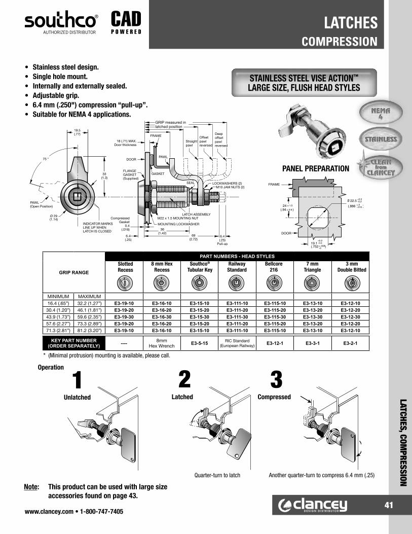
STAINLESS STEEL VISE ACTION™ LARGE SIZE, FLUSH HEAD STYLES
GRIP RANGE
PART NUMBERS - HEAD STYLES
MINIMUM MAXIMUM16.4 (.65”) 32.2 (1.27”) E3-19-10 E3-16-10 E3-15-10 E3-111-10 E3-115-10 E3-13-10 E3-12-10
30.4 (1.20”) 46.1 (1.81”) E3-19-20 E3-16-20 E3-15-20 E3-111-20 E3-115-20 E3-13-20 E3-12-2043.9 (1.73”) 59.6 (2.35”) E3-19-30 E3-16-30 E3-15-30 E3-111-30 E3-115-30 E3-13-30 E3-12-3057.6 (2.27”) 73.3 (2.89”) E3-19-20 E3-16-20 E3-15-20 E3-111-20 E3-115-20 E3-13-20 E3-12-2071.3 (2.81”) 81.2 (3.20”) E3-19-10 E3-16-10 E3-15-10 E3-111-10 E3-115-10 E3-13-10 E3-12-10
KEY PART NUMBER (ORDER SEPARATELY) ---- 8mm
Hex Wrench E3-5-15 RIC Standard (European Railway) E3-12-1 E3-3-1 E3-2-1
PANEL PREPARATION
* (Minimal protrusion) mounting is available, please call.
Operation
Note: This product can be used with large size accessories found on page 43.
SlottedRecess
8 mm Hex Recess
Southco®
Tubular KeyRailway Standard
Bellcore 216
7 mm Triangle
Quarter-turn to latch Another quarter-turn to compress 6.4 mm (.25)
Unlatched Latched Compressed
321
3 mm Double Bitted
• Stainless steel design.• Single hole mount.• Internally and externally sealed.• Adjustable grip.• 6.4 mm (.250") compression “pull-up”.• Suitable for NEMA 4 applications.

• Single hole mount.• Internally gasketed.• Adjustable to fit a wide grip range.• Suitable for NEMA 4 applications
with use of gasket accessory.
PANEL PREPARATION
KNOB STYLE LOW PROFILE HEAD STYLES (slotted recess shown)
• Creates a clean flush surface.• Accommodates all large size tool operated styles.
A PART NUMBERS MATERIAL6.6 (.26) E3-77-251-12 Galvanized steel9.3 (.37) E3-77-252-12 Galvanized steel6.6 (.26) E3-77-251-24 304 Stainless steel9.3 (3.7) E3-77-252-24 304 Stainless steel
For detailed materialspecifications and product
strength guidelines.
www.clancey.com
www.clancey.com • 1-800-747-740542
COMPRESSIONLATCHES
LATC
HES,
COM
PRES
SION
VISE ACTION™ SERIES, LARGE SIZE
FIXED BRACKET FOR FLUSH MOUNT

GRIP RANGE
HEAD STYLES
MIN. MAX.
11.4 (.45)25.4 (1.00)38.9 (1.53)52.6 (2.07)66.3 (2.61)
27.2 (1.07)41.1 (1.62)54.6 (2.15)68.3 (2.69)76.2 (3.00)
E3-15-15
E3-15-25
E3-15-35
E3-15-25
E3-15-15
E3-16-15
E3-16-25
E3-16-35
E3-16-25
E3-16-15
E3-17-15
E3-17-25
E3-17-35
E3-17-25
E3-17-15
E3-18-15
E3-18-25
E3-18-35
E3-18-25
E3-18-15
TUBULAR KEY8mm HEX RECESS KNOB T-HANDLE LOCKING
PART NUMBERSE3-11-15
E3-11-25
E3-11-35
E3-11-25
E3-11-15
T-HANDLE NON-LOCKING
KEY PART NUMBER (order separately)8mm Hex Wrench E3-5-15 None Keys Provided None
GRIP RANGE
HEAD STYLES
MIN. MAX.
11.4 (.45)25.4 (1.00)38.9 (1.53)52.6 (2.07)66.3 (2.61)
27.2 (1.07)41.1 (1.62)54.6 (2.15)68.3 (2.69)76.2 (3.00)
E3-12-15
E3-12-25
E3-12-35
E3-12-25
E3-12-15
E3-19-15
E3-19-25
E3-19-35
E3-19-25
E3-19-15
E3-13-15
E3-13-25
E3-13-35
E3-13-25
E3-13-15
E3-14-15
E3-14-25
E3-14-35
E3-14-25
E3-14-15
DOUBLE BITTEDSLOTTED RECESS 7mm TRIANGLE 7mm SQUARE
PART NUMBERSE3-110-15
E3-110-25
E3-110-35
E3-110-25
E3-110-15
8mm SQUARE
KEY PART NUMBER (order separately)None E3-2-1 E3-3-1 E3-4-1 E3-8-1
SEALING COVER
90-3*
PULL TAB
E3-27-1*
PADLOCK BRACKETS
E3-77-101-31* E3-77-102-31*
*Low profile head styles only
• 6.4 mm (.250") compression pull-up. • Most models can activate multi-point compression systems.
SPUR WASHER
90-6-875
Used for round hole installation
* Bellcore, Bellcore Electronics, and European Railway Standard head styles are also available. Please call.
GASKET
E3-24-201-18
Ø 22.6 (.89)
Ø 28.2 (1.11)
.8 (.03)
SOUTHCO® TUBULAR KEY
E3-5-15
DOUBLE BITTED
E3-2-1
SQUARE DRIVER
E3-4-1 (7mm) E3-8-1 (8mm)
TRIANGLE
E3-3-1
www.clancey.com • 1-800-747-740543
LATCHES, COMPRESSION
COMPRESSIONLATCHES
VISE ACTION™ SERIES, LARGE SIZE
KEYS (ORDER SEPARATELY)ACCESSORIES (ORDER SEPARATELY)

GRIP RANGE (Adjustable Grip) PART NUMBER
MIN. MAX.11.4 (.45) 27.2 (1.07) E3-150-15
25.4 (1.00) 41.1 (1.62) E3-150-2538.9 (1.53) 54.6 (2.15) E3-150-35
PAWL REVERSED52.6 (2.08) 68.3 (2.69) E3-150-2566.3 (2.61) 76.2 (3.00) E3-150-15
GRIP RANGE (Adjustable Grip) PART NUMBER
MIN. MAX.11.4 (.45) 27.2 (1.07) E3-158-15
25.4 (1.00) 41.1 (1.62) E3-158-2538.9 (1.53) 54.6 (2.15) E3-158-35
PAWL REVISED52.6 (2.08) 68.3 (2.69) E3-158-2566.3 (2.61) 76.2 (3.00) E3-158-15
GRIP RANGE (Adjustable Grip) PART NUMBER
MIN. MAX.11.4 (.45) 27.2 (1.07) E3-151-15
25.4 (1.00) 41.1 (1.62) E3-151-2538.9 (1.53) 54.6 (2.15) E3-151-35
PAWL REVERSED52.6 (2.08) 68.3 (2.69) E3-151-2566.3 (2.61) 76.2 (3.00) E3-151-15
PANEL PREPARATION
Non Locking Standard Locking Dust Shuttered Locking
NOTE: • Lock Plug has a black face. • Optional overmolded key
is available (see below)
NOTE: • Lock Plug has a stainless steel face.
• Easy action reversible key.
NON-LOCKING VERSION(Shown)
• Wide grip range.• Available with or without key lock.• Multiple key codes available, please call.• 6.4 mm (.250") compression “pull-up”.• Suitable for NEMA 4 applications.
PAWL(Open Position)
75
56 (2.0)
21.5(.87)
19 (.75)
33(1.31)
DOOR
6 (.24) MAX.door thickness
FRAME
GASKET
MOUNTINGLOCKWASHER
64(2.52)
M22 X 1.5 MOUNTING NUT
HOUSING Deep offset PAWL
X=16.4 (.25)PULL-UP
Lockwashers (2)M10 X 1.5 JAM NUTS (2)
StraightPawlX=3
Offset PawlReversed
X=2
Deep OffsetPawl ReversedX=1
GRIP see Table
Offset PawlX=2
9.5 (.37)
LOCKCYLINDER
FLANGE GASKET0.4 (.02) compressed
Ø 28 (1.1)
For detailed materialspecifications and product
strength guidelines.
www.clancey.com
PK-10-10-05 Single keyPK-10-01-05 Two keys ringed
www.clancey.com • 1-800-747-740544
COMPRESSIONLATCHES
LATC
HES,
COM
PRES
SION
VISE ACTION™ SERIES, WING KNOB, ADJUSTABLE GRIP

Non-Locking
PART NUMBER TOTAL GRIPE3-1250-005 15 (.59")E3-1250-015 17 (.67")E3-1250-025 19 (.75")E3-1250-035 21 (.83")E3-1250-045 23 (.91")
PART NUMBER TOTAL GRIPE3-1250-055 25 (.98")E3-1250-065 27 (1.06")E3-1250-075 29 (1.14")E3-1250-085 31 (1.22")E3-1250-095 33 (1.30")
PART NUMBER TOTAL GRIPE3-1250-105 35 (1.38")E3-1250-115 37 (1.46")E3-1250-125 39 (1.53")E3-1250-135 41 (1.61")E3-1250-145 43 (1.69")
PART NUMBER TOTAL GRIPE3-1250-155 45 (1.77")E3-1250-165 47 (1.85")E3-1250-175 49 (1.93")E3-1250-185 51 (2.01")E3-1250-195 53 (2.09")
Standard Locking
PART NUMBER TOTAL GRIPE3-1251-005 15 (.59")E3-1251-015 17 (.67")E3-1251-025 19 (.75")E3-1251-035 21 (.83")E3-1251-045 23 (.91")
PART NUMBER TOTAL GRIPE3-1251-055 25 (.98")E3-1251-065 27 (1.06")E3-1251-075 29 (1.14")E3-1251-085 31 (1.22")E3-1251-095 33 (1.30")
PART NUMBER TOTAL GRIPE3-1251-105 35 (1.38")E3-1251-115 37 (1.46")E3-1251-125 39 (1.53")E3-1251-135 41 (1.61")E3-1251-145 43 (1.69")
PART NUMBER TOTAL GRIPE3-1251-155 45 (1.77")E3-1251-165 47 (1.85")E3-1251-175 49 (1.93")E3-1251-185 51 (2.01")E3-1251-195 53 (2.09")
Dust Shuttered Locking
PART NUMBER TOTAL GRIPE3-1258-005 15 (.59")E3-1258-015 17 (.67")E3-1258-025 19 (.75")E3-1258-035 21 (.83")E3-1258-045 23 (.91")
PART NUMBER TOTAL GRIPE3-1258-055 25 (.98")E3-1258-065 27 (1.06")E3-1258-075 29 (1.14")E3-1258-085 31 (1.22")E3-1258-095 33 (1.30")
PART NUMBER TOTAL GRIPE3-1258-105 35 (1.38")E3-1258-115 37 (1.46")E3-1258-125 39 (1.53")E3-1258-135 41 (1.61")E3-1258-145 43 (1.69")
PART NUMBER TOTAL GRIPE3-1258-155 45 (1.77")E3-1258-165 47 (1.85")E3-1258-175 49 (1.93")E3-1258-185 51 (2.01")E3-1258-195 53 (2.09")
NOTES: • Lock Plug has a black face. • Optional overmolded key is available (see page 44)
NOTES: • Lock Plug has stainless steel face and shutter. • Easy action reversible key.
• Fixed grip allows for quick installation.• Minimal interior protrusion 40 mm (1.70").
PANEL PREPARATION
DUST SHUTTERED-LOCKING VERSION(Shown)
www.clancey.com • 1-800-747-740545
LATCHES, COMPRESSION
COMPRESSIONLATCHES
VISE ACTION™ SERIES, WING KNOB, FIXED GRIP

www.clancey.com • 1-800-747-740546
COMPRESSIONLATCHES
LATC
HES,
COM
PRES
SION
VISE ACTION™ SERIES 3-HOLE MOUNT
GRIP RANGE
HEAD STYLES
MIN. MAX.
.31"
.86"
1.39"
1.93"
2.47"
.93"
1.47"
2.00"
2.55"
3.00"
E3-33-15
E3-33-25
E3-33-35
E3-33-25
E3-33-15
E3-36-15
E3-36-25
E3-36-35
E3-36-25
E3-36-15
E3-34-15
E3-34-25
E3-34-35
E3-34-25
E3-34-15
E3-35-15
E3-35-25
E3-35-35
E3-35-25
E3-35-15
7mm TRIANGLE8mm HEX RECESS 7mm SQUARE TUBULAR KEY
PART NUMBERS
KEY PART NUMBER (order separately)8mm Hex Wrench E3-3-1 E3-4-1 E3-5-15
E3-38-15
E3-38-25
E3-38-35
E3-38-25
E3-38-15
T-HANDLE LOCKING
Keys Provided
E3-31-15
E3-31-25
E3-31-35
E3-31-25
E3-31-15
E3-41-15
E3-41-25
————
————
————
T-HANDLE NON-LOCKING T-HANDLE NON-LOCKING
None None
COMPACTSTANDARDSTANDARD
• Anti-rotation three hole mounting. • Most models can actuate multi-point compression systems.
PANEL PREPARATION
22(.88)
11(.42)
DOOR
WEATHERSEAL0.8 (.03)
GASKET
LATCH ASSEMBLY
FRAME
60 (2.35)
M4X0.7 Slotted hex head screw-lockwasher assembly suppliedfor 4 (.16) MAX. door thickness.
PAWL
6.4 (.25)PULL-UP
M10 JAM NUTS (2)LOCKWASHER (2)
Deep offset pawl reversed
Straight pawl
Offset pawlreversed
GRIP (measured in latched position)
75°
Pawl inopenposition
82.5 (3.25)25
(.98)
33(1.31)
FRAME
DOOR
Ø 4.8±0.1(.188±.005)
Ø 20 (.780±.010)1 HOLE
+0.0-0.5
16 (.625±.005)
+0.0-0.3 16
(.625±.005) +0.0-0.3
DOOR
24 ± 1.5(.938 ± .062)
75°
Pawl inopenposition
22(.88)
40 (1.56)11
(.42)
DOOR
WEATHERSEAL0.8 (.03)
33(1.31)
LOW PROFILE HEAD STYLES (7mm triangle shown)
KEYS (order separately)
TRIANGLE
E3-3-1
SQUARE
E3-4-1
SOUTHCO®
TUBULAR KEY
E3-5-15
For detailed materialspecifications and product
strength guidelines.
www.clancey.com
STANDARD T-HANDLE
COMPACT T-HANDLE
8mm Hex (pictured)

www.clancey.com • 1-800-747-740547
LATCHES, COMPRESSION
COMPRESSIONLATCHES
VISE ACTION™ SERIES KNOB STYLE
VISE ACTION™ SERIES FLUSH MOUNT
VISE ACTION™ SERIES, FIXED GRIP (MINIMAL PROTRUSION)
• Minimal interior protrusion of 46.4mm (1.82 in).
• Eleven access styles.
• Pre-assembled version available for thin panels.
• Single hole mount.
• Fixed grip.
• Single hole mount, large size. • Knob provides quick, unrestricted access. • Wider flange for mounting in non-metallic materials.
PANEL PREPARATIONSPUR WASHER
90-6-875
FRAMEStraight Pawl
Offset pawlreversed
Deep offset pawl reversed
LOCKWASHER (2)JAM NUT (2)
WASHER
SHAFT,5/16-24UNFthread
PAWL
MOUNTING NUT
HOUSING,7/8-20 thread
6.4 (.25)PULL-UP65 (2.55)
GRIPRANGES
DOOR
75°
34(1.34)
KNOBSPACER
37Ø (1.45)
KNOB 6.4(.25)
15.2 (.60) MAXdoor thickness
17 (.66)
FRAME
DOOR
Ø 19 +0.3 -0.0
22 (.875) MIN.25 (1.00) MAX.
OPTIONAL: Roundhole installation with spur washer
22 +0.3 -0.0Ø (.875 )+.010
-.000
(.750 )+.010-.000
ACCESSORY
• Completely flush to the outer surface of the panel.
• Seven access styles.
• Designed for use in thicker panels, such as wood or composite materials.
GRIP RANGE
MIN. MAX.
11.4 (.45)25.4 (1.00)38.9 (1.53)52.6 (2.07)66.3 (2.61)
27.2 (1.07)44.1 (1.62)54.6 (2.15)68.3 (2.69)76.2 (3.00)
E3-10-504-50
E3-10-505-50
E3-10-506-50
E3-10-505-50
E3-10-504-50
PART NUMBERS
* Used for round hole installations.
See our completeupdated offering of this
product range on our website.
www.clancey.com
For detailed material specifications
plus product installation instructions.
www.clancey.com

www.clancey.com • 1-800-747-740548
COMPRESSIONLATCHES
LATC
HES,
COM
PRES
SION
• Heavy-duty performance. • Flush profile when latched. • Easy grip adjustment. • Intuitive operation. • N2 Series also available in different sizes. • Latch also available without cup.
Performance DetailsStainless steel - Max. static load: 2000 N (450 lbf)Powder coated - Max. static load: 1000 N (225 lbf)
Installation Notes1. Insert latch and tighten 4 mounting nuts. 2. With latch in closed position, adjust jam nuts to
position cam at correct grip. Stainless steel - recommended tightening
torque: 20-25 N•m (177-221 in lbf). Powder coated - maximum tightening torque: 20 N•m (177 in lbf).
3 If using M12 cam tab washer, after cam is adjusted to correct grip, bend both tabs over the M12 nut.
KeysKey-locking keyed alike CH751 (2 keys supplied).
L Locking style0 Non-locking1 Key-locking keyed alike CH751 (2 keys supplied)
N2 - 2 - 30 L - 01 - 20
Latch part number (no cam)
Latch Part Number Selection
N2 COMPRESSION LATCH LIFT & TURN SERIES, FOLDING T-HANDLE,
FLUSH CUP STYLE, ADJUSTABLE GRIP
Part Number SelectionOrder both parts separatelyChoose latch body styleChoose cam (see table)
900
Frame
GripG
45 (1.77) Max.
open height
Door
Deep offsetCam forward
6 (.24)Compression
Straight camOffset cam reversedDeep offset cam reversed
Lock core
87 (3.43)
48(1.89)
100(3.94)
12.7 (.50) Max. Door thickness
100(3.94)
17.5(.69)
34.5(1.36)
Gasket
Lock plate
Offset cam forward
Cam (not supplied)order separately
Tab washer M12 thread
M6 Thread
Door 4 x Ø 7±0.2(.28±.01)
52 (2.05)
78±0.02(3.07±.02)
18.4(.72)
24.5±1.5(.96±.06)
78±0.4(3.07±.02)
17±1 (.67±.04)
Frame
Standard Locking Cup Shown
Deep offset
Offset Straight
Or Or
CAM PART NUMBER TABLE (ORDER SEPARATELY)
PART NUMBER G Grip Cam TypeSTAINLESS ZINC PLATED Min. Max.
N2-21-101-24 N2-21-101-1228 (1.10) 43 (1.69) Deep offset cam, forward
88 (3.46) 104 (4.09) Deep offset cam, reversed
N2-21-102-24 N2-21-102-1243 (1.69) 58 (2.28) Offset cam, forward
73 (2.87) 88 (3.46) Offset cam, reversed
N2-21-103-24 N2-21-103-12 58 (2.28) 73 (2.87) Straight
N2 - 2 - 30 L - 01 - 5
Stainless
Black Powder Coated

Panel Thickness Grip Range
2.00"Non-Locking
2.00"Locking(w/ 2 keys)
Min. Max. Short Pawl Long Pawl Short Pawl Long Pawl A B C D E F
2 (.075") to
12 (.475")
call 28 (1.10") M1-20-31-58 M1-20-31-88 M1-20-81-58 M1-20-81-88
61.5 (2.41")
70 (2.75")
56.5 (2.23")
30 (1.18")
61.5 (2.42")
4 (.16")
27 (1.06") 40 (1.57") M1-20-31-48 M1-20-31-78 M1-20-81-48 M1-20-81-7839 (1.53") 52 (2.04") M1-20-31-38 M1-20-31-68 M1-20-81-38 M1-20-81-6851 (2.01") 64 (2.52") M1-20-31-48 M1-20-31-78 M1-20-81-48 M1-20-81-7863 (2.48") 76 (3.00") M1-20-31-58 M1-20-31-88 M1-20-81-58 M1-20-81-88
12 (.475") to
22 (.885")
call 28 (1.10") M1-20-32-58 M1-20-32-88 M1-20-82-58 M1-20-82-8827 (1.06") 40 (1.57") M1-20-32-48 M1-20-32-78 M1-20-82-48 M1-20-82-7839 (1.53") 52 (2.04") M1-20-32-38 M1-20-32-68 M1-20-82-38 M1-20-82-6851 (2.01") 64 (2.52") M1-20-32-48 M1-20-32-78 M1-20-82-48 M1-20-82-7863 (2.48") 76 (3.00") M1-20-32-58 M1-20-32-88 M1-20-82-58 M1-20-82-88
Panel Thickness
Grip Range2.50"Non-Locking
2.50"Locking(w/ 2 keys)
Min. Max. Short Pawl Long Pawl Short Pawl Long Pawl A B C D E F
2 (.075") to
12 (.475")
call 25 (1.38") M1-25-31-58 M1-25-31-88 M1-25-81-58 M1-25-81-88
76 (3.00")
89 (3.50")
49.5 (1.95")
37 (1.46")
71 (2.80")
5 (.20")
34 (1.34") 48 (1.89") M1-25-31-48 M1-25-31-78 M1-25-81-48 M1-25-81-7847 (1.85") 61 (2.40") M1-25-31-38 M1-25-31-68 M1-25-81-38 M1-25-81-6860 (2.36") 75 (2.95") M1-25-31-48 M1-25-31-78 M1-25-81-48 M1-25-81-7874 (2.91") 88 (3.47") M1-25-31-58 M1-25-31-88 M1-25-81-58 M1-25-81-88
12 (.475") to
22 (.885")
call 25 (1.38") M1-25-32-58 M1-25-32-88 M1-25-82-58 M1-25-82-8834 (1.34") 48 (1.89") M1-25-32-48 M1-25-32-78 M1-25-82-48 M1-25-82-7847 (1.85") 61 (2.40") M1-25-32-38 M1-25-32-68 M1-25-82-38 M1-25-82-6860 (2.36") 75 (2.95") M1-25-32-48 M1-25-32-78 M1-25-82-48 M1-25-82-7874 (2.91") 88 (3.47") M1-25-32-58 M1-25-32-88 M1-25-82-58 M1-25-82-88
• Corrosion resistant.• 2 sizes of latches.• Key lockable or non-locking.• 2 lengths of pawls.• Suitable for NEMA 4 applications. PANEL PREPARATION
* Please call for assistance if you are trying to apply this product with a small grip range.
PANEL PREPARATION2.00" version 2.50" version
Long Pawl Short Pawl Long Pawl Short Pawl
A 60±1.5(2.38 ±.06)
48 ±1.5 (1.88 ±.06)
75 ±5 (2.95 ±.2)
40 ±1.5 (1.57 ±.06)
ØD Ø 50.8 ±0.5 (2.00 ±.02)
Ø 63.5 ±0.5 (2.50 ±.02)
2.50" Locking
2.00" Non-Locking
For detailed material specifications
plus product installation instructions.
www.clancey.com
www.clancey.com • 1-800-747-740549
LATCHES, COMPRESSION
COMPRESSIONLATCHES
ROUND, FLUSH LIFT AND TURN LATCH

• Hand, tool or key actuation. • Sealing gasket for NEMA 4 applications. • All versions use same panel preparation.
PANEL PREPARATION
73 ±0.5(2.88 ±.01))
8 (.34 ±.06)+2 -1
FRAME FOR TOP LATCHINGFRAME FOR SIDE LATCHING
DOOR OR PANEL
R 3 (.13) MAX. (RECOMMENDED for most effective sealing.)
30±0.5(1.19 ±.01)
8+2 -1 (.34 ±.06)
14.5 (.57 ±.01)
+1- 0
NEMA 4 SEALING INSTRUCTIONS
1. Seal the mounting screw threads with an anaerobic sealant.
2. Install latch with cup sealing gasket part number 62-973-431 (order cup sealing gasket separately).
60 (2.4)
FLAREDMOUNTINGBRACKET
SCREW/LOCKWASHER ASS'Y.M5 Thread–Panels thicker than6 (.25) require a longer screw/lockwasher combination (not supplied).
85(3.35)
40 (1.58)
HOUSING
KEY-LOCKING
LEVER
56 (2.20)
3 (.12)PULL-UP
4 (.16)
SHAFTM8 Thread
JAM NUT
CUP SEALINGGASKET (OPTIONAL)
Order Separately PART #: 62-973-431
34(1.34)
PAWLREVERSED
PAWL FORWARD
LOCKWASHER
PAWLRETAINING CLIPTOOL-SECURED
(No. 2 PHILLIPS)
MAX OUTER PANEL THICKNESS = 6 (.25)
GRIP RANGE (SEE TABLE)
DO NOT ALTER THISFACTORY PRE-SET NUT.
GRIP RANGEPART NUMBERS
MIN - MAX MIN - MAX
6 (.23) - 16 (.63) 56 (2.20) - 66 (2.59)
16 (.63) - 26 (1.02) 46 (1.81) - 56 (2.20)
26 (1.02) - 36 (1.41) 36 (1.41) - 46 (1.81)
6 (.23) - 16 (.63) 56 (2.20) - 66 (2.59)
16 (.63) - 26 (1.02) 46 (1.81) - 56 (2.20)
26 (1.02) - 36 (1.41) 36 (1.41) - 46 (1.81)
6 (.23) - 16 (.63) 56 (2.20) - 66 (2.59)
16 (.63) - 26 (1.02) 46 (1.81) - 56 (2.20)
26 (1.02) - 36 (1.41) 36 (1.41) - 46 (1.81)
62-40-101-3
62-40-201-3
62-40-301-3
62-40-151-3
62-40-251-3
62-40-351-3
62-40-111-3
62-40-211-3
62-40-311-3
62-42-101-3
62-42-201-3
62-42-301-3
62-42-151-3
62-42-251-3
62-42-351-3
62-43-101-3
62-43-201-3
62-43-301-3
62-43-151-3
62-43-251-3
62-43-351-3
62-42-111-3
62-42-211-3
62-42-311-3
62-43-111-3
62-43-211-3
62-43-311-3
TEXTUREDCHROME
BLACK POWDER
POLISHEDCHROME
BASI
CST
YLE
KEY-
LOCK
ING
TOOL
-SE
CURE
D
PAWLFORWARD
PAWLREVERSED
www.clancey.com • 1-800-747-740550
COMPRESSIONLATCHES
LATC
HES,
COM
PRES
SION
LIFT AND TURN® SERIES FLUSH STYLE, MEDIUM SIZE

AB
C
A
FRAMEfor sidelatching
FRAME for top latching
DOOR
• Easy to grab handle style. • Simple lift and turn operation.
PANEL PREPARATION (See table for specific mounting dimensions)
DIMEN-SIONS
A
B
C
SERIESMINI SMALL
16 (.63 .06)
23 (.93 .06)
9.5
(.375
+0.1-0.0
+.004-.000 )
16.3
(.640
+0.1-0.0
+.005-.000 )
8.1
(.320
+0.1-0.0+.004-.000 )
13.7
(.540
+0.1-0.0+.005-.000 )
+2-1
+2-1
Ø Ø
PAWLFORWARD
28 (1.10 .06)
+2-1 PAWL
REVERSED
For detailed material specifications
plus product installation instructions.
www.clancey.com
Handle can be orderedwithout “LIFT AND TURN” lettering.
Minimum order will apply.
www.clancey.com
www.clancey.com • 1-800-747-740551
LATCHES, COMPRESSION
COMPRESSIONLATCHES
LIFT AND TURN® SERIES HANDLE STYLE
21(.81)
PAWL REVERSED
PAWL FORWARD
3 (.11) PULL-UP
27(1.06)
17(.66)
13(.50)
11(.44)
9(.34)
32(1.25)
34(1.34)
GRIP (SEE TABLE)
LOCKWASHER
JAM NUT
PAWL RETAINING CLIP
MTG. LOCKWASHER
MOUNTING NUT
HANDLE
LONG PIN
SLEEVE3/8-24Thread
MAX. OUTER PANELTHICKNESS = 5 (.187)
LIFTAND
TURN
SHAFTM5 Thread
MINIATURE SIZE
GRIP PART NUMBER
MIN. MAX. Polished Chrome
Black Powder Coated
0 (0) 4 (.16) 62-20-11 62-20-154 (.16) 10 (.39) 62-20-21 62-20-25
10 (.39) 16 (.63) 62-20-31 62-20-3516 (.63) 22 (.87) 62-20-31 62-20-3522 (.87) 28 (1.10) 62-20-21 62-20-25
28 (1.10) 34 (1.34) 62-20-11 62-20-15
19(.75)
16(.63)
13 (.50) 32 (1.25) 39 (1.53)
57(2.25)
55(2.15)
MAX. OUTER PANELTHICKNESS = 6 (.234) PAWL FORWARD
GRIP (SEE TABLE)
SLEEVE5/8-24Thread
HANDLE
LONG PIN
PAWL REVERSED
LOCKWASHERJAM NUT
PAWL RETAINING CLIP
MTG. LOCKWASHER
5 (.19) PULL-UP
MOUNTING NUT
34(1.34)
LIFTAND
TURN
SHAFTM8 Thread
5°
SMALL SIZE
GRIP PART NUMBER
MIN. MAX. Polished Chrome
Brushed Chrome
Natural with Chemical Protective
Film
Black Powder Coated
2 (.08) 12 (.47) 62-10-21 62-10-22 62-10-23 62-10-2512 (.47) 22 (.87) 62-10-31 62-10-32 62-10-33 62-10-3522 (.87) 32 (1.25) 62-10-31 62-10-32 62-10-33 62-10-35
32 (1.25) 42 (1.66) 62-10-21 62-10-22 62-10-23 62-10-2542 (1.66) 52 (2.05) 62-10-11 62-10-12 62-10-13 62-10-15

• Easy to grab handle. • Simple lift and turn operation. • Handles can be ordered without “Lift and Turn” lettering (minimum order will apply).
MEDIUM SIZE
AB
C
A
FRAMEfor sidelatching
FRAME for top latching
DOOR
LARGE SIZE
PANEL PREPARATION (See table for specific mounting dimensions)
62-30-21 45 (1.77)35 (1.37)62-30-31 35 (1.37)25 (.98)62-30-31 25 (.98)15 (.59)62-30-21 15 (.59)5 (.20)
0 (0) 5 (.20) 62-30-11
MIN POLISHEDCHROME
PART NUMBER GRIP
MAX
62-30-11 55 (2.16)45 (1.77)62-30-22 62-30-32 62-30-32 62-30-22 62-30-12
62-30-12
BRUSHEDCHROME
BLACKPOWDERCOATED
62-30-25 62-30-35 62-30-35 62-30-25 62-30-15
62-30-15
PART NUMBER62-10-603-1062-10-603-20
Polished chromeBrushed chrome
PAWL REVERSEDPAWL FORWARD
LOCKWASHER
JAM NUT
PAWL RETAINING CLIP
MTG. LOCKWASHER
SLEEVE5/8-24Thread
HANDLE
LONG PIN
LIFTAND
TURN
13 (.50)
19.5(.77)
32 (1.25) 42 (1.65)
5 (.19) PULL-UP
MAX. OUTER PANELTHICKNESS = 6 (.234)
GRIP (SEE TABLE)
79(3.13)
80(3.16)
MOUNTING NUT
GASKET
34(1.34)
SHAFTM8 Thread
65.5(2.57)
51(1.97)
MOUNTING NUT
LOCKWASHER
PAWL
ACTUATOR
38(1.51)
JAM NUT
LOCKWASHERGASKET31(1.21)
133.4(5.25)
20(.78)
PIN
REVERSED PAWL
SHAFT,7/16-20Thread
NOTE: Omit this jam nut and lockwasher for minimum (or near-minimum) applicationsfor each grip range.
PAWL-POSITIONING PIN
SLEEVE7/8-20 Thread
5.5 (.22) PULL-UP
GRIP (pawl reversed)35 (1.375) MIN. to 67 (2.625) MAX.GRIP RANGE (pawl forward)
5 (.187) MIN. to 36.5 (1.437) MAX.
MAX. OUTER PANELTHICKNESS = 9.5 (.375)
FRAME
ACTUATOR2 holes,Ø 6.5 (.257)
25(1.00)
44.5 (1.75)
60 (2.37)
HANDLE
LIFTAND
TURN
A
B
C
SERIES MEDIUM LARGE
16.5 (.640
+0.1 -0.0 +.005 -.000 )
Ø 22 (.875
+0.2 -0.0 +.010 -.000 ) Ø
13.7 (.540
+0.1 -0.0 +.005 -.000 )
19 (.750
+0.2 -0.0 +.010 -.000 )
23 (.93 .06)
+2 -1 41
(1.623)
47.5 (1.875)
PAWL FORWARD
28 (1.10 .06)
+2 -1 PAWL
REVERSED
MIN.
MAX.
DIMENSIONS For detailed material specifications
plus product installation instructions.
www.clancey.com
www.clancey.com • 1-800-747-740552
COMPRESSIONLATCHES
LATC
HES,
COM
PRES
SION
LIFT AND TURN® SERIES HANDLE STYLE

RAISED TRIGGER (Shown with lock and standard grip range)
FLUSH TRIGGER (Shown with extended grip range)
PANEL PREPARATION
FRAME
5 (.20)MIN.
11 (.43)MAX.
25±1(.98±.04)
86±1(3.38±.04)
DOOR
R 3 (.12)MAX. TYP.
• Push trigger to unlatch and raise handle.• Single hole installation.• Easy grip adjustment.• Low profile when latched.
4mm HexRecess
No.2 PhillipsRecess
Railway Standard
Tool Access Styles
TRIGGER
LEVER
LEVER IN RAISED (open)POSITION
M5ADJUSTING
SCREW
MOUNTINGSCREW ASSEMBLY*MOUNTING BRACKET
HOUSING
Door Thickness1 (.04) MIN.5 (.20) MAX. 22
(.87)
41(1.61)
34(1.34)
16(.63)
93(3.66)
GRIP RANGE(Extended Grip Range Shown)23 (.91) through 43.5 (1.71) as shown.46 (1.81) MAX. with nut on the other side of the lever.
57 (2.24)
JAM NUT
* Mounting Screw assembly consists of: M5 screw with lockwasher. Use longer screws (not supplied) for thicker doors.
*See note for thicker panel
MaximumRadius84 (3.31)
TRIGGER
LEVER
LEVER IN RAISED (open)POSITION
M5ADJUSTING SCREW
MaximumRadius63 (2.48)
JAM NUT
MOUNTINGSCREW ASSEMBLY*
MOUNTING BRACKET
HOUSING
Door Thickness1 (.04) MIN.5 (.20) MAX. 22
(.87)
41(1.61)
34(1.34)
16 (.63)
93(3.66)
35(1.38)
GRIP RANGE(Standard Grip Range shown)1 (.04) through 21.5 (.85) as shown.24 (.95) MAX. with nut on the other side of the lever.
RAISED TRIGGER
OPTIONAL KEY LOCK(Available with raised trigger only).
* Mounting Screw assembly consists of: M5 screw with lockwasher. Use longer screws (not supplied) for thicker doors.
TRIGGER STYLE
PART NUMBERSGRIP RANGE
1 (.04) TO 24 (.95)GRIP RANGE
23 (.91) TO 46 (1.81)
Matte Black Coat
Textured Chrome Finish
Matte Black Coat
Textured Chrome Finish
Rais
ed T
rigge
r Railway Standard C2-99-217-125 ----------- C2-99-217-145 -----------No. 2 Phillips C2-32-215 C2-32-101 C2-33-105 C2-33-101
4mm Hex Recess C2-32-45 C2-32-41 C2-33-45 C2-33-41Keylock (w/2 keys) C2-32-25 C2-32-21 C2-33-25 C2-33-11
Without Keylock C2-32-15 C2-32-11 C2-33-15 C2-33-21Flush Trigger C2-32-35 C2-32-31 C2-33-35 C2-33-31
www.clancey.com • 1-800-747-740553
LATCHES, COMPRESSION
COMPRESSIONLATCHES
LEVER LATCH
Accessories:
Rubber BumperPart No. C2-25-301-82

For assemblies with stainless steel hardware change the sixth digit of the part number from 5 to 6. Example: C5-21-15 to C5-21-16.
90±1(3.54±.04)
0 (0) MIN. 9 (.35) MAX.
35±1 (1.38±.04)
FRAME
DOOR
R3 (.125)MAX. RadiusTYP.
PANEL PREPARATION
NEMA 4 SEALING INSTRUCTIONS
1. Seal the mounting screw threads with an anaerobic sealant.
2. Install latch with cup sealing gasket part number C5-82. (order cup sealing gasket separately)
DOORTHICKNESS
MOUNTINGHARDWARE
GRIPRANGE
MIN. MAX.
E
1(.04)
14(.55)
29(1.14)
14(.55)
29(1.14)
45(1.77)
29(1.14)
44(1.73)
60(2.35)
ABABCABCDABCD
MIN.
1 (.04)
11 (.43)
21 (.83)
1 (.04)
11 (.43)
21 (.83)
1 (.04)
11 (.43)
31 (1.22)
21 (.83)
1 (.04)
11 (.43)
31 (1.22)
MAX.
11 (.43)
21 (.83)
31 (1.22)
11 (.43)
21 (.83)
31 (1.22)
11 (.43)
21 (.83)
41 (1.61)
31 (1.22)
11 (.43)
21 (.83)
41 (1.61)
45(1.77)
57(2.25)
72(2.84)
LOCKING WITHDUST SHUTTER
LOCKING WITHOUTDUST SHUTTERNON-LOCKING
PART NUMBERS4mm HEX RECESS
No. 2 PHILLIPSRECESS
RAILWAYSTANDARD
C5-31-15C5-32-15
C5-33-25
C5-31-25
C5-32-25
C5-33-35
C5-31-35
C5-32-35
C5-34-35
C5-33-45
C5-31-45C5-32-45
C5-34-45
C5-21-15
C5-22-15
C5-23-25
C5-21-25
C5-22-25
C5-23-35
C5-21-35
C5-22-35
C5-24-35
C5-23-45
C5-21-45
C5-22-45
C5-24-45
C5-11-15
C5-12-15
C5-13-25
C5-11-25
C5-12-25
C5-13-35
C5-11-35
C5-12-35
C5-14-35
C5-13-45
C5-11-45
C5-12-45
C5-14-45
C5-41-15 C5-51-15 C5-61-15
C5-42-15 C5-52-15 C5-62-15
C5-41-25 C5-51-25 C5-61-25
C5-42-25 C5-52-25 C5-62-25
C5-43-25 C5-53-25 C5-63-25
C5-41-35 C5-51-35 C5-61-35
C5-42-35 C5-52-35 C5-62-35
C5-43-35 C5-53-35 C5-63-35
C5-44-35 C5-54-35 C5-64-35
C5-41-45 C5-51-45 C5-61-45
C5-42-45 C5-52-45 C5-62-45
C5-43-45 C5-53-45 C5-63-45
C5-44-45 C5-54-45 C5-64-45
Accessories:
Rubber BumperPart No. C5-25-301-82
www.clancey.com • 1-800-747-740554
COMPRESSIONLATCHES
LATC
HES,
COM
PRES
SION
SEALED LEVER LATCH
• Can be sealed to meet NEMA 4 standards.• Low profile when latched.• Non-locking, and 3 restricted access styles. • Easy installation and adjustment. • Latch and handle in one.

www.clancey.com • 1-800-747-740555
LATCHES, COMPRESSION
COMPRESSIONLATCHES
OVER-CENTER LEVER LATCHES• Designed for heavy-duty applications. • Provides consistent gasket compression. • Built-in leverage helps open stuck doors.
*One shim provided per latch assembly.
ADDITIONAL FEATURE: Keylockable (optional)
FINISH STYLE# 10-32 UNCx 0.38" deep
MetricM5 x 0.8
x 9.5mm deep
Satinsilvercoat
blackcoat
Chromeplated
Standard
with lock
Standard
with lock
Standard
with lock
A7-10-301-75
A7-10-302-75
A7-10-301-20
A7-10-302-20
A7-10-301-30
A7-10-302-30
A7-10-351-75
A7-10-352-75
A7-10-351-20
A7-10-352-20
A7-10-351-30
A7-10-352-30
PART NUMBERtapped mounting hole size
STYLE PART NUMBER L W
With plain handle
With yellow vinylhandle grip
With black vinylhandle grip
A2-10-501-10
A2-10-501-22
A2-10-501-21
211(8.3)
25.4(1.00)
214(8.44)
30.2(1.19)
214(8.44)
30.2(1.19)
Additional shims* A2-54-501-11
(non-locking)only
9.5
KEEPER
52.4 ± 0.5(2.06 ± .02)
9.5(.38) LATCH
ASSEMBLY
LOCK ASSEMBLY
SIX TAPPED MOUNTING HOLES(See table). Screws not supplied.
33.3(1.31)
(.38)
18(.71)
22(.88)
32(1.25)
22(.88) 17.5
(.69)
FRAME GASKET DOOR
156 (6.13)
127 (5.00)
25.4 ± 0.1(1.000 ± .005)
25.4 ± 0.5(1.00 ± .02)
25.4 ± 0.1(1.000 ± .005)
28(1.09)
66.7(2.63)
2 holes-Ø 7.1 (.28)
60.3(2.38)
Yellow or blackvinyl grip
LATCHDOORFRAME
L
Ø 7.9 (.31) holefor padlock
Mount with Ø M6 (.25) rivets or screws
51(2.00)
28(1.09)
KEEPER
12.7(.50)
25.4(1.00)
51 ± 0.2(2.00 ± .01)
51 ± 0.2(2.00 ± .01)
35 ± 0.2(1.38 ± .01)
W
4 holesØ 8 (.31)
3.2(.125)
7.9(.31)
2 holes-Ø 7.1 (.28)
28(1.09)
66.7(2.63)
51(2.00)
SHIM provided to make adjustmentsin latching plane of keeper when necessary.
ADDITIONAL FEATURE: Padlockable (standard)
For detailed materialspecifications and product
strength guidelines.
www.clancey.com

• Economical latching solution.• Cam action spring pawl provides wide grip range.• Rivet or weld mounting.• 4 sizes with a variety of head styles.• “Spring action” of the latch provides constant
compression of the panels.
“RIGHT SIZE” INVENTORY PROGRAM
• Increases inventory turns
• Standardizes shipments
• Minimizes freight
• Custom to your company’s needs
• Services multiple locations and subcontractors
For detailed material specifications
plus product installation instructions.
www.clancey.com
GRIP
1.2 (.05) MIN.
4.3 (.17)
MAX.
1.2 (.05) MIN.
6.4 (.25)
MAX.
1.6 (.06) MIN.
9.5 (.38)
MAX.
6.4 (.25) MIN.
14.3 (.56)
MAX.
2.4 (.09) MIN.
14.3 (.56)
MAX.
SIZE
Mini
Small
Medium (Steel)
Medium with
Spacer
Large
KNURLED HEX
SOCKET SLOTTED BLACK KNOB T-BAR
PART NUMBERS
HEAD STYLE
57-20-201-10 ——— 57-20-101-10 57-20-401-10 ———
57-20-202-50 ——— 57-20-102-50 ——— ———
57-30-201-10 ——— 57-30-101-10 57-30-401-10 ———
57-30-202-50 ——— 57-30-102-50 57-30-402-50 ———
TYPE
Rivet
Weld
Rivet
Weld
Rivet
Weld
SPRI
NG S
TYLE
Smooth
Smooth
Smooth
Smooth
Smooth
Serrated
Smooth
Serrated
57-10-201-10 57-10-801-10 57-10-101-10 57-10-401-10 57-10-301-10
57-10-211-10 57-10-811-10 57-10-111-10 57-10-411-10 57-10-311-10
57-10-202-50 57-10-802-50 57-10-102-50 57-10-402-50
57-10-212-50 57-10-112-50 57-10-412-50 57-10-312-50
Medium (Stain- less)
Rivet
Weld
Smooth
Smooth
57-10-201-40 ———
———
57-10-101-40 ——— ———
57-10-202-40 ——— 57-10-102-40 ——— ———
Smooth 57-10-203-10 ——— 57-10-103-10 57-10-403-10 ——— Rivet
Smooth
Serrated
57-40-801-10 57-40-101-10 57-40-401-10 57-40-301-10
57-40-811-10 57-40-111-10 57-40-411-10 57-40-311-10
TOOL- HEAD
RECESS
———
———
———
———
———
——— ———
———
57-T-10
———
———
———
———
———
———
———
Rivet
www.clancey.com • 1-800-747-740556
COMPRESSIONLATCHES
LATC
HES,
COM
PRES
SION
SPRING LATCH SERIES

DIMENSION TABLE
HEX SOCKET HEAD STYLE
RIVET TYPE WELD TYPE SLOTTED HEAD STYLE
WELDINGPROJECTIONS
SMOOTHSPRINGPAWL
B
Ø A
B
Ø A
BLACKKNOB STYLE
T-BARHEAD STYLE
TOOLHEAD® RECESS STYLEToolhead® is a registered trademark of Southco.
Q MAX. PANELTHICKNESS
Nylon knobshippedseparately
B
Ø A
O
T-bar shippedseparately.
P
B
Ø A
Ø A
B
Ø
28.6(1.13)
34.9(1.38)
12.7(.50)
SERRATEDSPRING PAWL
GRIP(See Table).
STUD
HOUSING
Two holes, N
B
SPACER
PANEL
C
D
A E
F
GH
J
L
K
M
For panel preparation instructions,
please turn the page.
KNURLED KNOB STYLE
www.clancey.com • 1-800-747-740557
LATCHES, COMPRESSION
COMPRESSIONLATCHES
SPRING LATCH SERIES

SIZE HEAD
STYLE
All Styles
DIMENSIONS
AA
5.6 (.22)Mini
Small
Medium
Knurled
Slotted
Black Knob
Hex
T-bar
Large
BB
22.2 (.875)
CC Ø DD Ø EE
11.1 (.438) 2.7 (.106) 7.2 (.283)
8.7 (.34) 33.3 (1.312) 16.7 (.656) 2.7 (.106) 10.5 (.406)
12.7 (.50) 49.2 (1.938) 24.6 (.969) 3.5 (.136)
14.5 (.563)
13 (.50)
16 (.625)
13 (.50)
14.5 (.563)
19.1 (.75) 74.6 (2.937) 37.3 (1.469) 5.2 (.20)
All Styles
Black Knob 21 (.812)
12.5 (.484)
20 (.781)
Bail Handle
All Other Styles
0.1( .005)
0.1( .005)
Toolhead ® 15.1 (.594)
SHIM(if necessary)
WASHER
STUD
RETAINER
BAIL
112.7 (4.44)
63 (2.48)
1.9(.075)
88.9(3.50)
AREF.
44.5 (1.75)
GRIP(see table)
OUTERPANEL
THICKNESS(SEE TABLE) HOUSING
26.2 (1.03)
11.9 (.47)
2 holes.Ø5.2 (.20)
37.3(1.47)
74.6(2.94)
SPRING
29 (1.14) R
23.8 (.94)
PANEL PREPARATION (SEE TABLE)
• Easy gloved hand operation.• See panel preparation instructions above.
GRIP A Ref.
MOUNT STYLE
PART NUMBERSMIN. MAX.
24 (.09)
14.3 (.56)
25 (.98)
Rivet 57-40-701-80
Weld 57-40-702-85
12.7 (.50)
24.6 (.97)
35.3 (1.39)
Rivet 57-40-704-80
Weld 57-40-705-85
23.4 (.92)
35.3 (1.39)
46 (1.81)
Rivet 57-40-707-80
Weld 57-40-708-85
For detailed materialspecifications and product
strength guidelines.
www.clancey.com
www.clancey.com • 1-800-747-740558
COMPRESSIONLATCHES
LATC
HES,
COM
PRES
SION
SPRING LATCH SERIES, PANEL PREPARATION
SPRING LATCH SERIES, BAIL HANDLE STYLE, LARGE SIZE

• Turn T-handle 90˚ to latch or unlatch. • An extra turn adjusts compression. • Flush design. • Stainless steel cup available.
106.4 ± 0.2(4.19 ± .01)
53.2(2.09)
25.4(1.00)
9.5(.38)R
SCREWC
4 holes, Ø 5.6 (.218)only for assemblieswith mountingstuds (No. 10-24)
20.6 (.81) MIN.28.6 (1.13) MAX.
48.8(1.92)
97.6(3.84)
50.8 ± 0.2(2.00 ± .01)
72.2 (2.84)
36.1(1.42)
STRIKE ORFRAMELOCATION
14.3(.56)
L
• 7.9 (.31) MAX. panel thickness
• Tightening torque of mounting nuts not to exceed 2.8 N•m or 25 in.-lbs.
No. 24 Flush Latches with mounting studs(mounting nuts and lockwashers supplied)
CUSTOMER SERVICE
We strive to offer the finest customer service in any
industry. If we can go the extra mile for you, let us
know and we will do our best.
PANEL PREPARATION
GRIP RANGE
MIN. MAX.
CUP and HOUSING:Polished stainless steel.HANDLE: Die cast zinc,
chrome plated.
CUP and HOUSING:Steel, DACROTIZED.
HANDLE: Die cast zinc,DACROTIZED.
24-20-101-35
24-20-102-35
24-20-104-35
24-20-101-10
24-20-102-10
24-20-104-10
37.3 (1.47)
50.2 (1.98)
61.9 (2.44)
19.1 (.75)
31.8 (1.25)
44.5 (1.75)
PART NUMBERS
82.6(3.25)
HANDLE
20.6(.81)
30.2(1.19)
38.9(1.53)
65.1 (2.56)REF.
PAWL
SPRING
34.1(1.34)114.3
(4.50)
57.2(2.25)
88.9 (3.50)
30.2(1.19)REF.
CUP
120° approx.GRIP RANGE
LATCHEDPOSTION
For detailed materialspecifications and product
strength guidelines.
www.clancey.com
www.clancey.com • 1-800-747-740559
LATCHES, COMPRESSION
COMPRESSIONLATCHES
FLUSH T-HANDLE SERIES, ADJUSTABLE COMPRESSION

www.clancey.com • 1-800-747-740560
MULTI-POINTLATCHES
LATC
HES,
MUL
TI-P
OINT
H3 Plastic Swinghandle
Material and FinishHandle: Glass filled nylon Cam: Steel, zinc plated
Performance Details
Max. static load: 250 N (56 lbf)
L Lock style21 Locking DIN profile keyed alike CH751*22 Locking DIN profile keyed alike 300* 23 Locking DIN profile keyed alike 333*70 DIN profile 3 mm Double-bit71 DIN profile 5 mm Double-bit72 DIN profile Bellcore 21673 DIN Profile Bellcore Hex-Pin Recess
77 DIN profile 8 mm triangle
H3 - T - 5 L - 0 7 1
T Style65 Push to close handle66 Turn to close handle
Part Number SelectionFor single point: Order latch and cam separately
For multi-point order: Latch and cam Linear actuator and rod adaptors Rods Rod guides
Note*2 keys supplied
Latch Part Number (no cam)
Cam Part Number Table
Grip Range(see table)
3.75 (0.147)
7.9 (0.31)
0-0.1
32 (1.26)
18.5(0.73)24.5
(0.96)25.75(1.01)
37 (1.45)
Cam (order
seperately)
136(5.35)
168(6.61)170.6
(6.72)
FrameEdge
Pin ProfileLock Plug
GRIP PART NO. (LENGTH = 38MM) PART NO. (LENGTH = 45MM)15.5 E5-6710 E5-611017.5 E5-6711 E5-611119.5 E5-6712 E5-611221.5 E5-6713 E5-611323.5 E5-6714 E5-6114
OTHER Please contact Clancey
H3 SWINGHANDLE SYSTEM PLASTIC, LARGE, NON-SEALED
• Lightweight Glass filled nylon swinghandle system. • UL94-V0 rated. • DIN profile locking options. • Push or turn to close versions available.

www.clancey.com • 1-800-747-740561
LATCHES, MULTI-POINT
MULTI-POINTLATCHES
Ø 6.4(.251)
8.8(.35) Adapter
Set screw
10.8(.43)
35 (1.38)
17.5 (.69)
Ø 8.6±0.2(.34±0.1)
Ø 14.7(.58)
306(12.04)346
(13.62)375.3(14.77)
Gearbox
PART NUMBER
Linear actuator right hand mounting H3-61-56-33
Linear actuator left hand mounting H3-61-55-33
Rod adaptor A5-92-201-31
Material and Finish Zinc alloy and steel, zinc plated
To Select Linear actuator and Rod Adaptor:
For use with H3-65 and H3-66 swinghandles. Order linear actuator and rod adaptors separately (1 actuator and 2 adaptors required per latch)
Linear Actuator (Right Hand Mounting shown)
Closed Position Open Position
Panel Preparation
Rod Adaptor
Cam
150 (5.9 )
25 (.98 )+.02-0
+.0.3-0
+.008-0
+.016-0
50 (1.97 )
+.0.3-0+.006
-0
50 (1.97 )
+.0.3-0+.006
-0
17(.67)
2 x 8.1
4 (.16)
Length (see table)
19(.75)
H3 LINEAR ACTUATORS• Linear actuator for Plastic H3 swinghandles • Linear rod travel for limited space. • Suitable for left and right hand applications. • Left and Right hand Actuators can be disassembled and reassembled in the opposite hand if required.
Part Number Linear actuator and rod adaptors see table
For multi-point order: Latch Cam (if 3 point latching required) Linear actuator and rod adaptor (see table)

www.clancey.com • 1-800-747-740562
PAWL/CAM ACTIONLATCHES
LATC
HES,
PAW
L/CA
M A
CTIO
N
PAWL ASSEMBLIES
• Flush design – minimal interior protrusion. • Can be used for multi-point latching. • Key locking version available. • Bail handle available in mid-size.
TYPE BAssemblies(Turn handle
counterclockwiseto latch).
TYPE AAssemblies(Turn handleclockwiseto latch).
Handle shownperpendicularto edge of doorwhen latched.
Handle shownparallel toedge of doorwhen latched.
• Mounted on either TYPE A or Bdoors. Choose horizontal or verticalclosed position of handle.
PANEL PREPARATION
SMALL
SMALLMID-SIZE(long grip shown)
For TYPE B AssembliesTurn handle
counterclockwise to latch
For TYPE A AssembliesTurn handle
clockwise to latch
SIZE K L (TYP.) Ø M N P (TYP.)
SMALL 33 ± 3.2(1.31 ± .13)
4.8(.187)
42.9 ± .40(1.687 ± .015)
46 ± 0.4(1.812 ± .015)
1.6(.062)
MID-SIZED 50.8(2.00 ± .13)
6.4 ± 0.1(.250 ± .005)
71.4 ± 0.4(2.812 ± 0.15)
57.2 ± 0.4(2.250 ± .015)
2.5 ± 0.2(.10 ± .01)
16.3.640
Ø19 (Ø.750 )
+0.2-0.0
+.010 -.000
HOLE FOR LOCKPrepare only
when using keylock assemblies
FRAME
EDGEOF DOOR
FRAME
EDGEOF DOOR
L L
K K
N
ØM ØM
P P
+0.2-0.0
+.010-.000
( )N
MID-SIZE
(bail handle shown)
For detailed material specifications
plus product installation instructions.
www.clancey.com
FLUSH CUP SERIES

www.clancey.com • 1-800-747-740563
LATCHES, PAWL/CAM
ACTION
PAWL/CAM ACTIONLATCHES
* Locks are keyed alike. Different key codes are available. Pawl is not included with two-point assemblies.
LATCH DIMENSIONS LATCH SIZE ØA C
Radius E F G H ØJ R S(UNF)
49.2(1.94)
82.6(3.25)
Small
Mid-sizeFlush &
Bail Handle
40(1.57)
57.2(2.25)
21.3(.84)
21.3(.84)
34.1(1.34)
38.9(1.52)
46(1.81)
57.2(2.25)
12.7(.50)
19.1(.75)
3.18(.125)
4.75(.187)
15.9(.63)
22.1(.87)
1/4 - 28
3/8 - 24
GRIP RANGE
TYPE OF ASSEMBLY
Handle position when
latched relative to
edge of door TYPE B
Assemblies TYPE A
Assemblies TYPE B
Assemblies TYPE A
Assemblies parallel
perpendicular
01-10-401-10
01-10-402-10
01-10-402-10
01-10-401-10
01-10-401-65
01-10-402-65
01-10-402-65
01-10-401-65
Single orThree - Point
12.7(.50)
0-
parallel
perpendicular
parallel
perpendicular
parallel
perpendicular
parallel
perpendicular
parallel
perpendicular
parallel
perpendicular
01-13-11
01-13-21
01-33-11
01-33-21
01-13-31
01-13-41
01-33-31
01-33-41
01-13-51
01-13-61
01-33-51
01-33-61
Single orThree - Point
Two - Pointwith lock
Two - Point
Single or Three-Point with lock*
12.7(.50)
-
--------
Single orThree - Point
Single or Three-Point with lock*
12.7(.50)
28.6(1.13)
01-13-21
01-13-11
01-33-21
01-33-11
01-13-41
01-13-31
01-33-41
01-33-31
01-13-61
01-13-51
01-33-61
01-33-51
01-13-15
01-13-25
01-33-15
01-33-25
01-13-35
01-13-45
01-33-35
01-33-45
01-13-55
01-13-65
01-33-55
01-33-65
01-13-25
01-13-15
01-33-25
01-33-15
01-13-45
01-13-35
01-33-45
01-33-35
01-13-65
01-13-55
01-33-65
01-33-55
parallel
perpendicular
parallel
perpendicular
parallel
perpendicular
parallel
perpendicular
parallel
perpendicular
parallel
perpendicular
01-23-11
01-23-21
01-43-11
01-43-21
01-23-31
01-23-41
01-43-31
01-43-41
01-23-51
01-23-61
01-43-51
01-43-61
Single orThree - Point
Two - Pointwith lock
Two - Point
Single or Three-Point with lock*
12.7(.50)
-
--------
Single orThree - Point
Single or Three-Point with lock*
12.7(.50)
28.6(1.13)
01-23-21
01-23-11
01-43-21
01-43-11
01-23-41
01-23-31
01-43-41
01-43-31
01-23-61
01-23-51
01-43-61
01-43-51
0-
0-
SIZE
Small
Mid-Size
Mid-Size Bail Handle
BRIGHT FINISH BLACK FINISH
FLUSH CUP SERIES

www.clancey.com • 1-800-747-740564
PAWL/CAM ACTIONLATCHES
LATC
HES,
PAW
L/CA
M A
CTIO
N
• Outstanding pricing.• Variety of shaft lengths & cams.• Left or right hand actuation.• Black or chrome finish.
NOTE: Order cam separately on page 39.
Locking latches supplied w/2 keys
NOTE: Order cam separately on page 39.
Locking latches supplied w/2 keys
SHAFT LENGTH LOCKING PART NUMBER* NON-LOCKING PART NUMBERTYPE A TYPE B TYPE A TYPE B
CHROME38.1 (1.50) 92-61-113-10 92-61-213-10 92-61-103-10 92-61-203-1050.8 (2.00) 92-61-114-10 92-61-214-10 92-61-104-10 92-61-204-1063.5 (2.50) 92-61-115-10 92-61-215-10 92-61-105-10 92-61-205-10
BLACK38.1 (1.50) 92-61-113-50 92-61-213-50 92-61-103-50 92-61-203-5050.8 (2.00) 92-61-114-50 92-61-214-50 92-61-104-50 92-61-204-5063.5 (2.50) 92-61-115-50 92-61-215-50 92-61-105-50 92-61-205-50
SHAFT LENGTH LOCKING PART NUMBER* NON-LOCKING PART NUMBERTYPE A TYPE B TYPE A TYPE B
CHROME38.1 (1.50) 92-50-113-10 92-50-213-10 92-50-103-10 92-50-203-1050.8 (2.00) 92-50-114-10 92-50-214-10 92-50-104-10 92-50-204-1063.5 (2.50) 92-50-115-10 92-50-215-10 92-50-105-10 92-50-205-10
BLACK38.1 (1.50) 92-50-113-50 92-50-213-50 92-50-103-50 92-50-203-5050.8 (2.00) 92-50-114-50 92-50-214-50 92-50-104-50 92-50-204-5063.5 (2.50) 92-50-115-50 92-50-215-50 92-50-105-50 92-50-205-50
T-HANDLE LATCH STANDARD
T-HANDLE LATCH COMPACT
• Concealed mounting hardware.• Compact design.
PANEL PREPARATION
PANEL PREPARATIONF
(SEE CAM DRAWING)
FRAME PANEL
38 ± 0.2 (1.5 ± .01)
19 ± 0.1 (.748 ± .004)
2X Ø5.6 (.22)
Ø22.2 (.87)
PANEL FRAME
(F) SEE CAM DRAWING
19 ± 0.1 (.750 ± .004)
38 ± 0.2 (1.5 ± .01)
Ø13 (.51)
2X Ø5.6 (.22)
Install latch from front of panel with M5 or No. 10 screws.
Install with 8-32 screws from the back of the panel.

www.clancey.com • 1-800-747-740565
LATCHES, PAWL/CAM
ACTION
PAWL/CAM ACTIONLATCHES
• Outstanding pricing.• Variety of shaft lengths & cams.• Left or right hand actuation.• Black or chrome finish.
SHAFT LENGTHLOCKING PART NUMBER* NON-LOCKING PART NUMBER
TYPE A TYPE B TYPE A TYPE B
CHROME38.1 (1.50) 92-70-113-10 92-70-213-10 92-70-103-10 92-70-203-1050.8 (2.00) 92-70-114-10 92-70-214-10 92-70-104-10 92-70-204-1063.5 (2.50) 92-70-115-10 92-70-215-10 92-70-105-10 92-70-205-10
BLACK38.1 (1.50) 92-70-113-50 92-70-213-50 92-70-103-50 92-70-203-5050.8 (2.00) 92-70-114-50 92-70-214-50 92-70-104-50 92-70-204-5063.5 (2.50) 92-70-115-50 92-70-215-50 92-70-105-50 92-70-205-50
A B C D E F FRAME LOCATION*
PART NUMBER
41.3 (1.63) 19 (.75) 10.9 (.43) 3.6 (.14) 50.8 (2.0) 28.6 (1.13) 92-24-202-1250.8 (2.0) 19 (.75) 10.9 (.43) 3.6 (.14) 60.9 (2.4) 38.1 (1.50 92-24-203-1260.3 (2.38) 19 (.75) 10.9 (.43) 3.2 (.13) 69.9 (2.75) 47.6 (1.88) 92-24-204-1241.3 (1.63) 15.9 (.63) 12.3 (.48) 3.6 (.14) 52.4 (2.05) 28.6 (1.13) 92-24-212-12
Locking latches supplied w/2 keys
* See panel preparation
PANEL PREPARATIONF
(SEE CAM DRAWING)
FRAME PANEL
38 ± 0.2 (1.5 ± .01)
19 ± 0.1 (.748 ± .004)
2X Ø5.6 (.22)
Ø22.2 (.87)
Install latch from front of panel with M5 or No. 10 screws.
NOTE: Order cam separately on page 39.
L-HANDLE LATCH STANDARD
For detailed material specifications
plus product installation instructions.
www.clancey.com
CAMS FOR T- AND L-HANDLE LATCHES

www.clancey.com • 1-800-747-740566
PAWL/CAM ACTIONLATCHES
LATC
HES,
PAW
L/CA
M A
CTIO
N
PANEL PREPARATION
2 HOLES,
38 ± 0.2(1.50±.01)
Ø 21 ± 0.1(.813 ± .005)
FRAMEPANEL
FOR SHORT PAWL,25.5 (1.00) MIN.to 32 (1.25) MAX.
Ø 4.8 ± 0.1(.188 ± .004)
19 ± 0.1 (.750 ± .005)
*PANEL PREPARATIONFOR LONG PAWL,25.5 (1.00) MIN.to 51 (2.00) MAX.
For detailed material specifications
plus product installation instructions.
www.clancey.com
• Detents in full open or closed position. • Can be used for multi-point latching.• Ergonomic, comfortable feel.• Non-locking versions are recognized.
4 (.16)short pawl
24(.93)
47(1.86)
1.2 (.05)5 (.19)
19(.75)
5 (.19)
19(.75)
19(.75)
48(1.88)
Ø 4 (.16) STUDS (2) 19(.75)
PAWL RETAINER PLATEFOR MULTI-POINT SYSTEMS
38 (1.5)
57 (2.25)long pawl
5 (.19)long pawl
STYLE
32 (1.25)44.5 (1.75)57.5 (2.25)32 (1.25)
44.5 (1.75)57.5 (2.25)
T HANDLE STYLE
LGRIP RANGE
MIN. MAX.
ASSEMBLY PART NUMBERS(Short Pawl)*
Type “A” Type “B”HANDLE
Bright chrome
With Lock
WithoutLock
T HANDLE STYLE Black powder coated
WithLock
WithoutLock
L HANDLE STYLE Bright chrome
WithLock
WithoutLock
L HANDLE STYLE Black powder coated
With Lock
WithoutLock
16 (.63)16 (.63)16 (.63)16 (.63)16 (.63)16 (.63)
19 (.75)32 (1.25)
44.5 (1.75)19 (.75)32 (1.25)
44.5 (1.75)
16 (.63)16 (.63)16 (.63)16 (.63)16 (.63)16 (.63)
19 (.75)32 (1.25)
44.5 (1.75)19 (.75)32 (1.25)
44.5 (1.75)
16 (.63)16 (.63)16 (.63)16 (.63)16 (.63)16 (.63)
19 (.75)32 (1.25)
44.5 (1.75)19 (.75)32 (1.25)
44.5 (1.75)
16 (.63)16 (.63)16 (.63)16 (.63)16 (.63)16 (.63)
19 (.75)32 (1.25)
44.5 (1.75)19 (.75)32 (1.25)
44.5 (1.75)
92-21-111 92-21-121 92-21-131 92-11-111 92-11-121 92-11-131
92-22-11192-22-121 92-22-13192-12-111 92-12-121 92-12-131
92-21-511 92-21-521 92-21-531 92-11-511 92-11-521 92-11-531
92-22-51192-22-521 92-22-531 92-12-511 92-12-521 92-12-531
92-41-111 92-41-121 92-41-131 92-31-111 92-31-121 92-31-131
92-42-111 92-42-121 92-42-131 92-32-111 92-32-121 92-32-131
92-41-511 92-41-521 92-41-531 92-31-511 92-31-521 92-31-531
92-42-511 92-42-521 92-42-531 92-32-511 92-32-521 92-32-531
32 (1.25)44.5 (1.75)57.5 (2.25)32 (1.25)
44.5 (1.75)57.5 (2.25)
32 (1.25)44.5 (1.75)57.5 (2.25)32 (1.25)
44.5 (1.75)57.5 (2.25)
32 (1.25)44.5 (1.75)57.5 (2.25)32 (1.25)
44.5 (1.75)57.5 (2.25)
* Latch Assembly part numbers shown are supplied with a short pawl. To order latches with a long pawl, as shown below, change last digit of part number to a 2. Example : 92-21-112
Type“A”
Type“B”
Turn clockwiseto latch.
Turn counterclockwiseto latch.
Non-locking only.
T- AND L-HANDLE STYLE

www.clancey.com • 1-800-747-740567
LATCHES, PAWL/CAM
ACTION
PAWL/CAM ACTIONLATCHES
• Long pawl available. • Key locking version available.• Smooth surfaces free of sharp edges.
WITH LOCK
LOCKPLUG
ESCUTCHEON
54 (2.13)
HANDLE
84(3.31)
25(.98)
25(.98)
PAWL
RETAINER PLATE
JAM NUT (2)
SPRING WASHERSHAFT(M10 Thread)
NOTE: Do not alter this factorypre-set nut.
LOCKWASHER (2)
GRIP RANGE0.8 (.03)
39 (1.53) L
GASKET
90°
Blackpowder coated.
48.5(1.90)SwingRadius
Brightchrome
WITHOUT LOCK
Blackpowder coated.
100(3.94)Swing Radius
ESCUTCHEON
HANDLE PAWL
RETAINER PLATE
JAM NUT (2)
SPRING WASHER
LOCKWASHER (2)
GRIP RANGE0.8 (.03)
39 (1.53) L
GASKET
NOTE: M4 screw/lockwasherassemblies supplied will permitinstallation in 3 (.12) max. thickouter panels. Thicker panels willrequire longer screws (not supplied).
112.5(4.43)
WITH LOCKWITHOUT LOCK
27(1.06)
LOCKPLUG
NOTE: Do not alter this factorypre-set nut.
Brightchrome
(see table)
(see table)
SHAFT(M10 Thread)
T- AND L-HANDLE STYLE

www.clancey.com • 1-800-747-740568
PAWL/CAM ACTIONLATCHES
LATC
HES,
PAW
L/CA
M A
CTIO
N
• Flush design: T-handle folds away.• Adjustable grip style allows for adjustment
in the amount of compression.• Fixed grip style provides consistent compression.
• 9.5 (.38) MAX. panel thickness
• Tightening torque of mounting nuts not to exceed 8.5 N•m or 75 in.-lbs.
(nut/lockwasher assemblies supplied)114.3
(4.50)
57.2(2.25)
CUP
88.9(3.50)
30.2(1.19)
65.1(2.56) R
COMPRESSION VERSION ADJUSTABLE-GRIP
Turn handle 90° to latch/unlatch. Additional turns to pull up tighter, compress a gasket.
FIXED GRIPLoosen jam nuts to adjust pawl to exact grip. Tighten jam nuts to lock pawl in position.
ADJUSTABLE-GRIP COMPRESSION VERSION FIXED GRIP
* OFFSET PAWL GRIP RANGE
82.6 (3.25)
HANDLE
96.8 (3.81)
79.4 (3.13) REF. 30.2
(1.19) REF.
JAM NUTS & LOCKWASHER
(2)
STRAIGHT PAWL GRIP RANGE
WELD-ON HINGES
Ideal for heavy duty applications. See our offerings on pages 159-160.
PANEL PREPARATION
1.6(.06)
6.4(.26)
MAX. R
76.2 ± 0.4(3.000 ± .015)
98.4(3.88)
FRAME
4 holes, Ø 7.2 (.281)
101.6 ± 0.4(4.000 ± .015)
68.3(2.69)
PANEL4(.16)
31.8 MIN., 39.7 MAX.(1.25 MIN., 1.56 MAX.)
For detailed material specifications
plus product installation instructions.
www.clancey.com
FLUSH T-HANDLE SERIES, HEAVY DUTY STYLE

www.clancey.com • 1-800-747-740569
LATCHES, PAWL/CAM
ACTION
PAWL/CAM ACTIONLATCHES
• Flush design: T-handle folds away. • Welded or mounting stud installation. • Can be used for multi-point latching. • Key locking version available. • Polished stainless steel cup available.
• 7.9 (.31) MAX. . panel thickness
• Tightening torque of mounting nuts not to exceed 2.8 N•m or 25 in.-lbs.
(mounting nuts and lockwashers supplied)
TYPE A Assemblies turn clockwise to latch. TYPE B Assemblies turn counterclockwise to latch.
PANEL PREPARATION
TYPE A Assembly (illustrated) GRIP RANGE
CUP and BRACKET: Polished stainless steel.HANDLE: Die cast zinc,
chrome plated.
CUP and BRACKET: Steel,DACROTIZED.
HANDLE: Die cast zinc,DACROTIZED.
CUP and BRACKET: Steel,DACROTIZED.
HANDLE: Die cast zinc,DACROTIZED.
*Locks are keyed alike. Different key codes are available.
Non-locking only
For detailed material specifications
plus product installation instructions.
www.clancey.com
FLUSH T-HANDLE SERIES, FIXED-GRIP STYLE

www.clancey.com • 1-800-747-740570
PAWL/CAM ACTIONLATCHES
LATC
HES,
PAW
L/CA
M A
CTIO
N
SMALL SIZE
• Restricted 90˚ rotation. • Can be used for multi-point latching. • 3 sizes.
PANEL PREPARATIONType “B” Operation
Turn handle counterclockwise
to latch.
Type “A” Operation Turn handle
clockwise to latch.
MEDIUM SIZE
PANEL PREPARATION
Reverse pawl for left/right orientation
T-HANDLE SERIES
GRIP RANGE
L F
PART NUMBERS
MIN. MAX.Handle Assembly Finish
Zinc plate, bright chromate Chrome Plated
3.2 (.13) 25.4 (1.00) 46.4 (1.83)
31.8 ±3.2 (1.25 ±.13) 68-10-101-10* 68-10-101-20*
25.4 (1.00) 50.8 (2.00)
* The same assembly is supplied for both long and short grips. Short grip curves toward panel. Reverse pawl for short grip.
GRIP RANGE PART NUMBERSHandle Assembly Finish
MIN. MAX. Chemical Protective Film Chrome Palted
0 12.7 (.50) 68-50-301-10 68-50-301-2012.7 (.50) 25.4 (1.00) 68-50-302-10 68-50-302-20
25.4 (1.00) 38 (1.50) 68-50-301-10 68-50-301-20

www.clancey.com • 1-800-747-740571
LATCHES, PAWL/CAM
ACTION
PAWL/CAM ACTIONLATCHES
T-HANDLE SERIES, LARGE SIZE
For detailed material specifications
plus product installation instructions.
www.clancey.com
Ø 54 (2.13)
HANDLEASSEMBLY
PANEL
ESCUTCHEON
7/16-20 THD
JAMNUTS
No. 10-32 pan head recessed screw/lockwasher assemblies (supplied)for 3.2 (.13) MAX. thick panel. Thicker panels require longer screws (not supplied).
108(4.25)
60 (2.38)
PAWL
SHAFT
Ø 12.7 (.50)51 (2.00)
STRAIGHT PAWL
REVERSEDPAWL
47.6(1.88)
65(2.56)
60.3 (2.38)
44.5 (1.75)
22.2(.88)
ACTUATOR
2 holes, Ø 6.5 (.257) for rods for three-point latching.
Type “B” Operation Turn handle counterclockwise to latch.
Type “A” Operation Turn handle clockwise to latch.
PANEL PREPARATION
SOUTHCO SOLUTIONS ARE“CAD POWERED” AT WWW.CLANCEY.COM
Excellent 2D resources for sourcing prints and documentation, plus the latest in 3D solid models are just a few clicks away.

www.clancey.com • 1-800-747-740572
PAWL/CAM ACTIONLATCHES
LATC
HES,
PAW
L/CA
M A
CTIO
N
• Restricted 90˚ rotation. • Detents hold handle in open and stored positions. • Clockwise or counterclockwise operation.
MEDIUM SIZE
PANEL PREPARATION PANEL PREPARATION
LARGE SIZE
Type “A” Operation Turn bail handle clockwise
to latch.
Type “B” Operation Turn bail handle counterclockwise
to latch.
PART NUMBERS
Handle Assembly finish
Zinc Plate Bright Chromate Chrome Plated
68-20-101-10 68-20-101-20
GRIP RANGEPART NUMBERS
Handle Assembly finish
MIN. MAX. Zinc Plate Bright Chromate Chrome Plated
16 (.63)
36.5 (1.44) 68-80-302-10 68-80-302-20
For detailed material specifications
plus product installation instructions.
www.clancey.com
BAIL-HANDLE SERIES

www.clancey.com • 1-800-747-740573
LATCHES, PAWL/CAM
ACTION
PAWL/CAM ACTIONLATCHES
PANEL PREPARATION
Ø
KNOBMOUNTING
NUT
JAMNUT
FERRULESLEEVE
PIN
PAWL PAWL
REVERSED
SHAFT
LOCK-WASHERS
• Detents in full open and closed position. • Turn clockwise or counterclockwise to operate. • Distinctive “click” upon engagement. • Arrow acts as a pawl indicator.• 3 sizes.
ARROWHEAD DESIGN
SAMPLESWe are happy to provide samples for evaluation in your application. We want to be on your prototype, so we can have our part on your final design.
For detailed material specifications
plus product installation instructions.
www.clancey.com

www.clancey.com • 1-800-747-740574
PAWL/CAM ACTIONLATCHES
LATC
HES,
PAW
L/CA
M A
CTIO
N
PART NUMBERLP-137-1W LP-137-1K LP-137-1
WING HEAD SLOTTED KNOB SLOTTED HEAD
• Outstanding value- low installed cost.
• Grip adjusts by changing mounting hole diameter.
• Can be used in thick panels.
• 3 head styles.• Low installed cost.• Basic quarter turn operation.
FASTENER SELECTION AND INSTALLATION
1. Choose a head style with part number from table above.2. Cam is ordered separately per table below.
PANEL PREPARATION
Grip Range Maximum Outer Panel
Thickness “H”Part Number
Panel Preparation
Diameter “D”
Min. Max.
.050” .090” .050”
HP-L3-1-1
.490”
.090” .125” .065” .555”
.125” .160” .095” .615”
.160” .200” .125” .680”
.200” .240” .125”
HP-L3-2-1
.430”
.230” .270” .188” .490”
.260” .300” .218” .555”
.290” .330” .250” .615”
.320” .360” .281” .680”
.360” .400” .125”
HP-L3-3-1
.430”
.390” .430” .188” .490”
.420” .460” .218” .555”
.450” .490” .250” .615”
.480” .525” .281” .680”
.525” .580” .125”
HP-L3-4-1
.430”
.570” .610” .188” .490”
.600” .640” .218” .555”
.630” .670” .250” .615”
.660” .700” .281” .680”
KNOB STYLE CAM LATCH COMPOSITE CAM LATCH
CAM SPACER P/NLP-137-3
OFFSET CAM P/N0.00" LP-137-25.115" LP-137-2L
IMPORTANT NOTE:If panel thickness exceeds grip by .125" (3 mm) you must use a cam spacer (order separately) below.
CAM
NOTE: Cam spacer not shown.

www.clancey.com • 1-800-747-740575
LATCHES, PAWL/CAM
ACTION
PAWL/CAM ACTIONLATCHES
PANEL PREPARATION
FRAME
DOOR THICKNESS6 (.24) MAX1 (.04) MIN
DOOR
Ø 22.5 (.886 )+0.5-0
+0.02-.00
20.1(.791 )
+0.1-0+.004-.000
34±4(1.42±.15)
20.1(.791 )
+0.1-0+.004-.000
WING KNOB CAM LATCH
4 (.16)
27 (1.06)
45 (1.77)
23 (.91)
FRAME
PANEL A A
SEE MATERIALS AND FINISH
GRIP (SEE TABLE FOR AVAILABLE GRIPS AND CAM PART
NUMBERS
+2 0
19 (.75)
Ø28 (1.10)
SEALING GASKET
6 (.24)
20.1 (.79)
For detailed material specifications
plus product installation instructions.
www.clancey.com
PADLOCKING WINGHEAD CAM LATCH
4 (.16)
27.5(1.08)
45 (1.77)
23(.91)
FRAME
PANEL
+2 0
19(.75)
Ø28(1.10)
16.5(.66)
GRIP
SEALING WASHER1 (.04) 0.5 (.02) compressed
PadlockThru Hole
PANEL PREPARATION(See above)
Clockwise (illustrated)
• Ergonomic wing head yields easy turn and grip.• Available with or without key lock.• Suitable for NEMA 4 applications.• Can be used in multi-point applications.
ORDERING INSTRUCTIONS:
Order head style with preferred locking option (see below).
Proceed to step on page 79 to order cam.
* 1 overmolded key supplied w/ each locking head style.
HEAD STYLE LOCKING OPTION PART NUMBER
Non-locking E5-9-305-UU1
Key-lockingblack lock plug
E5-9-315-UU1
Key-locking reversible
key stainless
steel lock plug
E5-9-325-UU1
• Integrated padlock feature for secure lock-out.• Built in detent for positive feel.• Clockwise or counter-clockwise rotation for
design symmetry.
ORDERING INSTRUCTIONS:
Select rotation. Proceed to step on page 79 to order cam.
ROTATION ACTION PART NUMBER
Clockwise to latch
E5-31-SA5-UU0
Counter clockwise to latch
E5-31-SB2-UU0
NOTE: Padlock thru hole is oriented at the bottom of the wing in the latched position.

www.clancey.com • 1-800-747-740576
PAWL/CAM ACTIONLATCHES
LATC
HES,
PAW
L/CA
M A
CTIO
N
• 4 materials including 316 stainless.• Spring tension cam allows grip tolerance
and resists vibration.• Cams available for nearly any grip.
PANEL PREPARATION
CAM
19 (.75)
Ø 28(1.10)
GRIP
45(1.77)
4 (.16)
27(1.06)
5 (.20) TOOL OPERATED 0.5 (.02) SEALING WASHER
6 (.24) KEYLOCKING
23(.91)
QUAD PANEL LATCH, INDUSTRIAL SERIES
56 (2.2)
55 (2.2)
FRAME
DOOR THICKNESS6 (.24) MAX1 (.04) MIN
DOOR
Ø 22.5 (.886 )+0.5-0
+0.02-.00
20.1(.791 )
+0.1-0+.004-.000
34±4(1.42±.15)
20.1(.791 )
+0.1-0+.004-.000
8mm triangle head style
5mm double bit head style
tamperresistanthead style
Key locking version
8mm square head style
Glass filled nylon
Die cast, black
Die cast, chrome
Die cast, black
Stainless steel
Head Style
KEY PART NUMBER
Zinc die cast, nickel plate
Zinc die cst, w/ chemical
protective filmGlass filled
Nylon
8mm Hex E3-11-1 E3-11-2 E3-11-37mm Triangle E3-3-1 E3-3-2 E3-3-38mm Triangle E3-7-1 E3-7-2 E3-7-37mm Square E3-4-1 E3-4-2 E3-4-38mm Square E3-8-1 E3-8-2 E3-8-3
3mm Double Bit E3-2-1 E3-2-2 E3-2-35mm Double Bit E3-9-1 E3-9-2 E3-9-3
Bellcore 216 E3-12-1 E3-12-2 E3-12-3Bellcore Electronics E3-11-1 E3-11-2 ---
KEY DRIVES(Order separately)
E5-18
PADLOCK BRACKET
E5-77-101-31
PADLOCK BRACKET
E5-77-102-31
OPTIONAL ACCESSORIES (Order separately)
Grip Adjustment 2.4 mm (.093")
2 mm (.08") 2 mm (.08")
IMPORTANT Grip adjustment+2.4mm (.09") Pull tab+2.0mm (.08") Padlock
bracket
INTERNAL O-RING
INTERNAL SPRING(tool operated only)
SPOTLIGHT FEATURES
CAM INDICATOR• Visual guide to cam position.
INTERNAL SPRING ACTION• Allows tolerance.• Resists vibration.

www.clancey.com • 1-800-747-740577
LATCHES, PAWL/CAM
ACTION
PAWL/CAM ACTIONLATCHES
SLOTTED
Glass Filled Nylon, Black E5-6-003
Die cast, Black E5-6-005
Die cast, Chrome E5-6-002
304 Stainless E5-6-0024
316Stainless E5-6-0027
Select your latch material and head style (order separately)
Select your cam (order separately)
Calculate your grip (see design on following page)
Grip = distance from outside panel to frame.• Add 0.5mm (.02") for compressed seating washer.• Add grip adjustment if accessories are used.
7 MM SQUARE
Glass Filled Nylon, Black E5-6-043
Die cast, Black E5-6-045
Die cast, Chrome E5-6-042
304 Stainless E5-6-0424
316Stainless E5-6-0427
7 MM TRIANGLE
Glass Filled Nylon, Black
E5-6-033 8mm triangle
Die cast, Black E5-6-025
Die cast, Chrome E5-6-022
304 Stainless E5-6-0224
316Stainless E5-6-0227
8 MM SQUARE
Glass Filled Nylon, Black E5-6-053
Die cast, Black E5-6-055
Die cast, Chrome E5-6-052
304 Stainless E5-6-0524
316Stainless E5-6-0527
3 MM DOUBLE BIT
Glass Filled Nylon, Black E5-6-063
Die cast, Black E5-6-065
Die cast, Chrome E5-6-062
304 Stainless E5-6-0624
316Stainless E5-6-0627
5 MM DOUBLE BIT
Glass Filled Nylon, Black E5-6-073
Die cast, Black E5-6-075
Die cast, Chrome E5-6-072
304 Stainless E5-6-0724
316Stainless E5-6-0727
TAMPER RESISTANT SLOT
Die cast, Black E5-6-215
Die cast, Chrome E5-6-212
BELLCORE 216
Die cast, Black E5-6-135
Die cast, Chrome E5-6-132
304 Stainless E5-6-1324
316Stainless E5-6-1327
RAILWAY STANDARD
Die cast, Black E5-6-226
Die cast, Chrome E5-6-222
304 Stainless E5-6-2224
316Stainless E5-6-2227
8 MM HEX
Die cast, Black E5-6-015
Die cast, Chrome E5-6-012
304 Stainless E5-6-0124
316Stainless E5-6-0127
BELLCORE ELECTRONICS
Die cast, Black E5-6-195
Die cast, Chrome E5-6-192
KEY LOCK*
Die cast, Black E5-5-405
Die cast, Chrome E5-5-402
*2 Keys, ringed, included
Cam Grip+ 2mm (.08") - 0mm (0,00")
(See Diagram, Page 50)4mm (.16")
6mm (.24")
8mm (.31")
10mm (.39")
12mm (.47")
14mm (.55")
16mm (.63")
18mm (.71")
20mm (.79")
22mm (.87")
MATERIALSteel, Zinc Plate E5-6003 E5-6004 E5-6005 E5-6006 E5-6007 E5-6008 E5-6009 E5-6010 E5-6011 E5-6012
304 Stainless Steel E5-8003 E5-8004 E5-8005 E5-8006 E5-8007 E5-8008 E5-8009 E5-8010 E5-8011 E5-8012316 Stainless Steel E5-9003 E5-9004 E5-9005 E5-9006 E5-9007 E5-9008 E5-9009 E5-9010 E5-9011 E5-9012
Hook Cams (see below)
Cam Grip+ 2mm (.08") - 0mm (0,00")
(See Diagram, Page 50)24mm (.94")
26mm (1.02")
28mm (1.10")
30mm (1.18")
32mm (1.26")
34mm (1.34")
36mm (1.42")
38mm (1.50")
40mm (1.58")
42mm (1.65")
MATERIALSteel, Zinc Plate E5-6013 E5-6014 E5-6015 E5-6016 E5-6017 E5-6018 E5-6019 E5-6020 E5-6021 E5-6022
304 Stainless Steel E5-8013 E5-8014 E5-8015 E5-8016 E5-8017 E5-8018 E5-8019 E5-8020 E5-8021 E5-8022316 Stainless Steel E5-9013 E5-9014 E5-9015 E5-9016 E5-9017 E5-9018 E5-9019 E5-9020 E5-9021 E5-9022
PART NUMBER Rotation ActionE5-6200 No Stop
Can be used in either rotation
E5-6210 Stop built for Clockwise rotation
E5-6220 Stop built for Counter-clockwise rotation
HOOKCAMSSteel, zincplate
Clockwise (photo)
10 (.39)
4(.16)
36(.42)
R4
2X 8.1 (.32)
Ø9.95(.39)
R28R9
18(.71)
18(.71)
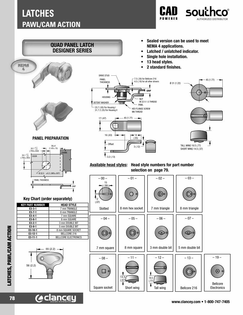
www.clancey.com • 1-800-747-740578
PAWL/CAM ACTIONLATCHES
LATC
HES,
PAW
L/CA
M A
CTIO
N
• Sealed version can be used to meet NEMA 4 applications.
• Latched / unlatched indicator.• Single hole installation.• 13 head styles.• 2 standard finishes.
23.7 (.93) For Housing I31.7 (1.25) For Housing II
7.5 (.30) for Bellcore 2164.5 (.18) for all other drivers
GRIP
PANELTHICKNESS
DRIVE STUD
HOUSING
DETENT WASHERPAWL
HEX FLANGE SCREWM6 THREAD
NUT M 22 X 1.5 THREAD
3.2 (.13)
Offset
00
3 (.12)
45 (1.77)17 (.67)
14(.55)
16 (.63)
45 (1.77)Ø 31 (1.22)
TALL WING 19.5 (.77) SHORT WING 14.5 (.57)
Available head styles: Head style numbers for part number selection on page 79.
19.5(.77)
– 11 –
Short wing
– 12 –
Tall wing
– 13 – – 19 –
Bellcore 216Bellcore
ElectronicsSquare socket
– 08 –
15(.58)
2(.07)
– 00 –
Slotted
– 01 –
8 mm hex socket
– 02 – – 03 –
7 mm triangle 8 mm triangle
– 04 –
7 mm square
– 05 –
8 mm square
– 06 – – 07 –
3 mm double bit 5 mm double bit
Key Chart (order separately)
PANEL PREPARATION
GRIP
PANEL THICKNESS
20.1 (.793±.002)
+0.1 -0.0
20.1 (.793±.002)
+0.1 -0.0
36±4(1.42±.15)
FRAME
Ø 22.5 ±0.2 (.885±.007)
DOOR
KEY PART NUMBER HEAD STYLEE3-3-1 7 mm TRIANGLEE3-7-1 8 mm TRIANGLEE3-4-1 7 mm SQUAREE3-8-1 8 mm SQUAREE3-2-1 3 mm DOUBLE BITE3-9-1 5 mm DOUBLE BIT
E3-10-1 8 mm SQUARE SOCKETE3-12-1 BELLCORE 216E3-11-1 BELLCORE ELECTRONICS
QUAD PANEL LATCH DESIGNER SERIES

www.clancey.com • 1-800-747-740579
LATCHES, PAWL/CAM
ACTION
PAWL/CAM ACTIONLATCHES
Accessories: (order separately)
Pull tab Padlock brackets
Adjustment 2.4 mm 2 mm 2 mm 0.4 mm Number (.093") (.08") (.08") (.02")
ADJUSTMENT FOR ACCESSORIES: Add the adjustment number to the formula above.
Seal: (included with sealed assemblies)
Ø 22.3 (.88)
Ø 28 (1.10) 0.8(.03)
Sealing washer
E3-77-102-31E3-77-101-31E5-18
Note: Non-standard pawls are available for larger grip ranges. Increased lead time and minimum orders will apply.
Note: If the difference between the door thickness and the grip is less than 4 mm (.16"), the latch pawl must be removed for installation.
HOUSING STYLE II (1-14 mm door thickness)
GRIP RANGEPART NUMBER
MINIMUM MAXIMUM Sealed, black finish
Sealed, chrome finish
Not sealed, black finish
Not sealed chrome finish
2 (.08") 4 (.16") E5-1-XX5-021 E5-1-XX1-021 E5-1-XX5-020 E5-1-XX1-0204 (.16") 6 (.24") E5-1-XX5-031 E5-1-XX1-031 E5-1-XX5-030 E5-1-XX1-0306 (.24") 8 (.31") E5-1-XX5-041 E5-1-XX1-041 E5-1-XX5-040 E5-1-XX1-0408 (.31") 10 (.39") E5-1-XX5-051 E5-1-XX1-051 E5-1-XX5-050 E5-1-XX1-050
10 (.39") 12 (.47") E5-1-XX5-061 E5-1-XX1-061 E5-1-XX5-060 E5-1-XX1-06012 (.47") 14 (.55") E5-1-XX5-071 E5-1-XX1-071 E5-1-XX5-070 E5-1-XX1-07014 (.55") 16 (.63") E5-1-XX5-081 E5-1-XX1-081 E5-1-XX5-080 E5-1-XX1-08016 (.63") 18 (.71") E5-1-XX5-091 E5-1-XX1-091 E5-1-XX5-090 E5-1-XX1-09018 (.71") 20 (.79") E5-1-XX5-101 E5-1-XX1-101 E5-1-XX5-100 E5-1-XX1-10020 (.79") 22 (.87") E5-1-XX5-111 E5-1-XX1-111 E5-1-XX5-110 E5-1-XX1-11022 (.87") 24 (.94") E5-1-XX5-121 E5-1-XX1-121 E5-1-XX5-120 E5-1-XX1-12024 (.94") 26 (1.02") E5-1-XX5-131 E5-1-XX1-031 E5-1-XX5-130 E5-1-XX1-130
HOUSING STYLE II (1-14 mm door thickness)
GRIP RANGEPART NUMBER
MINIMUM MAXIMUM Sealed, black finish
Sealed, chrome finish
Not sealed, black finish
Not sealed chrome finish
6 (.24") 8 (.31") E5-2-XX5-001 E5-2-XX1-001 E5-2-XX5-000 E5-2-XX1-0008 (.31") 10 (.39") E5-2-XX5-011 E5-2-XX1-011 E5-2-XX5-010 E5-2-XX1-010
10 (.39") 12 (.47") E5-2-XX5-021 E5-2-XX1-021 E5-2-XX5-020 E5-2-XX1-02012 (.47") 14 (.55") E5-2-XX5-031 E5-2-XX1-031 E5-2-XX5-030 E5-2-XX1-03014 (.55") 16 (.63") E5-2-XX5-041 E5-2-XX1-041 E5-2-XX5-040 E5-2-XX1-04016 (.63") 18 (.71") E5-2-XX5-051 E5-2-XX1-051 E5-2-XX5-050 E5-2-XX1-05018 (.71") 20 (.79") E5-2-XX5-061 E5-2-XX1-061 E5-2-XX5-060 E5-2-XX1-06020 (.79") 22 (.87") E5-2-XX5-071 E5-2-XX1-071 E5-2-XX5-070 E5-2-XX1-07022 (.87") 24 (.94") E5-2-XX5-081 E5-2-XX1-081 E5-2-XX5-080 E5-2-XX1-08024 (.94") 26 (1.02") E5-2-XX5-091 E5-2-XX1-091 E5-2-XX5-090 E5-2-XX1-090
26 (1.02") 28 (1.10") E5-2-XX5-101 E5-2-XX1-101 E5-2-XX5-100 E5-2-XX1-10028 (1.10") 30 (1.18") E5-2-XX5-111 E5-2-XX1-111 E5-2-XX5-110 E5-2-XX1-11030 (1.18") 32 (1.25") E5-2-XX5-121 E5-2-XX1-121 E5-2-XX5-120 E5-2-XX1-12032 (1.25") 34 (1.34") E5-2-XX5-131 E5-2-XX1-131 E5-2-XX5-130 E5-2-XX1-130
How to Order:1. Determine grip by adding: Door thickness __________ Accessories + __________ Sealing washer + __________ Frame thickness + __________ Grip =
2. Review door thickness. Enter part number chart based on door thickness. Place your grip in the grip range.
3. Determine your sealing option and select your finish.
4. Add the head style number from page 78 in place of -XX to compute your part number.
5. Order key from page 78 if head style requires.
For detailed material specifications
plus product installation instructions.
www.clancey.com
QUAD PANEL LATCH DESIGNER SERIES

www.clancey.com • 1-800-747-740580
PAWL/CAM ACTIONLATCHES
LATC
HES,
PAW
L/CA
M A
CTIO
N
• Accommodates misalignment between door and frame. • Latches in any frame thickness, and blind applications.
PANEL PREPARATION
For detailed material specifications
plus product installation instructions.
www.clancey.com
SWELL ACTION SERIES, HANDLE STYLE
Inner surface of panel MUST con-tact side mount.
MATERIAL AND FINISH 1010 Steel, zinc plated with
yellow chromate dip.
SIDE MOUNT BRACKET(order separately)

www.clancey.com • 1-800-747-740581
LATCHES, PAWL/CAM
ACTION
PAWL/CAM ACTIONLATCHES
• Flush design. • Dampens vibration.
PANEL PREPARATION1. Prepare rectangular hole in
door and round hole in frame.
2. Seat latch in rectangular hole.
3. Position bracket and retainer over stud. Place set tool over retainer and sharply strike tool. With handle in up (unlatched) position, adjust nut to provide satisfactory latching tension.
SET TOOL
MATERIAL AND FINISH1095 Steel, zinc plated.
PART NUMBER17-10019-11
SWELL ACTION SERIES, FLUSH STYLE
For detailed material specifications
plus product installation instructions.
www.clancey.com

www.clancey.com • 1-800-747-740582
PAWL/CAM ACTIONLATCHES
LATC
HES,
PAW
L/CA
M A
CTIO
N
PANEL PREPARATION
PANEL PREPARATION
• Accommodates misalignment between door and frame. • Latches in any frame thickness and blind applications. • Dampens vibration. • Latch and handle in one.
• Die-cast handle provides additional leverage for heavy duty applications.
PART NUMBER19-54-01
PART NUMBER19-14-10
SWELL ACTION SERIES, BULLET NOSE
SWELL ACTION SERIES, HEAVY DUTY
For detailed material specifications
plus product installation instructions.
www.clancey.com

www.clancey.com • 1-800-747-740583
LATCHES, PAWL/CAM
ACTION
PAWL/CAM ACTIONLATCHES
• Easy, intuitive action.• Supplied with surface and mortise keepers.• Mounting hardware is included.
• Knurled knob for easy grip
Material: BrassFinish: Satin nickel
PART NUMBERKR-50
PART NUMBER PRIMARY DIMENSIONSLENGTH “A” WIDTH “B” HEIGHT “L”
SBL-35 36 (1.42") 29 (1.14") 18 (.71")SBL-45 45 (1.77") 30 (1.18") 18.5 (.73")
PART NUMBERKR-65
PART NUMBERKR-75
SLIDE BOLTS
• Easy to activate
• No snag design
Material: 304 stainless steelFinish: Polished
• Wing drapes over latch channel
KNOB STYLE
TAB STYLE
ROUNDED TAB
WING TAB

www.clancey.com • 1-800-747-740584
PAWL/CAM ACTIONLATCHES
LATC
HES,
PAW
L/CA
M A
CTIO
N
• Spring action catch secures bar in place for secure closing.
• Push button release to disengage latch.• 6 sizes available.• NSF recognized component.
Material: 304 stainless steelFinish: PolishedNote: Supplied with stainless steel screws
PART NUMBER
PRIMARY DIMENSIONS MOUNTING DIMENSIONSL W A H1 H2 C C+/- C1 C2 C3
BLL-45 48 (1.89") 40 (1.57") 13 (.51") 17 (.67") 4.5 (.18") 23 (.91") 3 (.12") 32 (1.26") 6.5 (.26") ----BLL-60 63 (2.48") 46 (1.81") 16 (.63") 20 (.79") 6 (.24") 34 (1.34") 4 (.16") 37 (1.46") 8 (.31") ----BLL-80 85 (3.35") 65 (2.56") 20 (.79") 22.5 (.89") 7 (.28") 47 (1.85") 7 (.28") 53 (2.08") 10 (.39") ----
BLL-100 105 (4.13") 80 (3.15") 25 (.98") 26.5 (1.04") 8 (.31") 59 (2.32") 7 (.28") 66 (2.60") 12.5 (.49") ----BLL-120 127 (5.00") 100 (3.94") 28.5 (1.12") 28 (1.10") 8 (.31") 56 (2.20") 10 (.39") 80 (3.15") 6.8 (.27") 15 (.59")BLL-150 155 (6.10") 120 (4.72") 30.5 (1.20") 28 (1.10") 8 (.31") 74 (2.91") 14 (.55") 95 (3.74") 7.3 (.29") 16 (.63")
SPRING LOADED BAR LATCH

www.clancey.com • 1-800-747-740585
LATCHES, PAWL/CAM
ACTION
PAWL/CAM ACTIONLATCHES
• Spring action on latch pin forces the pin to the closed position and provides resistance when opening.
• 2 sizes available.• NSF recognized component.
Material: 304 stainless steelFinish: SatinNote: Supplied with stainless steel screws. Supplied with surface and mortise keepers.
PART NUMBER
PRIMARY DIMENSIONS MOUNTING DIMENSIONSL L1 B H1 H2 D C C1 C2 C3
BLS-60 60 (2.36")
25.4 (1.00")
33 (1.30")
20 (.79")
20.4 (.80")
17 (.67")
20 (.79")
12.7 (.50")
10 (.39")
40 (1.57")
BLS-90 90 (3.54")
25.4 (1.00")
33 (1.30")
20 (.79")
20.4 (.80")
24 (.97")
20 (.79")
12.7 (.50")
12.5 (.49")
65 (2.56")
SPRING LOADED BARREL BOLT
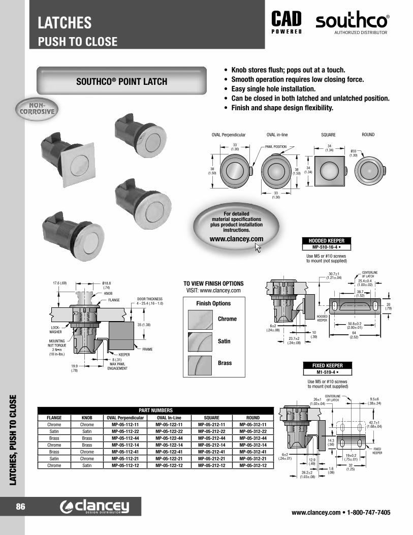
www.clancey.com • 1-800-747-740586
PUSH TO CLOSELATCHES
LATC
HES,
PUS
H TO
CLO
SE
SOUTHCO® POINT LATCH• Knob stores flush; pops out at a touch.• Smooth operation requires low closing force.• Easy single hole installation.• Can be closed in both latched and unlatched position.• Finish and shape design flexibility.
HOODED KEEPERMP-510-16-4 •
FIXED KEEPERM1-519-4 •
PART NUMBERSFLANGE KNOB OVAL Perpendicular OVAL In-Line SQUARE ROUNDChrome Chrome MP-05-112-11 MP-05-122-11 MP-05-212-11 MP-05-312-11
Satin Satin MP-05-112-22 MP-05-122-22 MP-05-212-22 MP-05-312-22Brass Brass MP-05-112-44 MP-05-122-44 MP-05-212-44 MP-05-312-44
Chrome Brass MP-05-112-14 MP-05-122-14 MP-05-212-14 MP-05-312-14Brass Chrome MP-05-112-41 MP-05-122-41 MP-05-212-41 MP-05-312-41Satin Chrome MP-05-112-21 MP-05-122-21 MP-05-212-21 MP-05-312-21
Chrome Satin MP-05-112-12 MP-05-122-12 MP-05-212-12 MP-05-312-12
For detailed material specifications
plus product installation instructions.
www.clancey.com
Use M5 or #10 screwsto mount (not supplied)
Use M5 or #10 screwsto mount (not supplied)
33(1.30)
38(1.50)
33(1.30)
38(1.50)
PAWL POSITION
OVAL Perpendicular OVAL in-line SQUARE
34(1.34)
34(1.34)
ROUND
Ø33(1.30)
HOODEDKEEPER
20(.79)
38.7(1.52)
50.8±0.2(2.00±.01)6±2
(.24±.08)64
(2.52)
25.4±0.4(1.00±.02)
30.7±1(1.21±.04)
10(.39)23.7±2
(.24±.08)
CENTERLINE0F LATCH
FIXEDKEEPER
CENTERLINEOF LATCH
19±0.2(.75±.01)
6±2(.24±.01)
9.5±6(.38±.24)
42.7±1(1.68±.04)
26±1(1.02±.04)
26.2±2 (1.03±.08)
32(1.25)
12.9(.49)
14.3(.56)
1.6(.06)
Ø18.8(.74)
17.6 (.69)
DOOR THICKNESS4 - 25.4 (.16 - 1.0)
35 (1.38)
8 (.31) MAX PAWL
ENGAGEMENT19.9(.78)
KNOB
FLANGE
MOUNTINGNUT TORQUE
2 N•m(18 in-lbs.)
LOCK-WASHER
FRAMEKEEPER
TO VIEW FINISH OPTIONSVISIT: www.clancey.com
Chrome
Satin
Brass
Finish Options

www.clancey.com • 1-800-747-740587
LATCHES, PUSH TO CLOSE
PUSH TO CLOSELATCHES
• Push button to “pop-out” the knob, then “twist” the knob to open the door.
• Serrated pawl accommodates panel misalignment.• Black, gold, or chrome finish.
• Push button to “pop-out” the knob, then “pull” the door to open.
• Corrosion and UV resistant.• Black, gold, or chrome finish.
Ø 38 (1.50) 22(.87)
6 (.24)
47 (1.85)
NUT
KNOB
HOUSING
38(1.50)
ALIGNMENT STEM
Ø 26(1.02)
12 (.47)
THREADM32x1.5
V PAWL
Ø 38 (1.50) 22 (.87)
6 (.24)
47 (1.85)
NUT
SERRATEDPAWL
KNOB
HOUSING
37.5(1.48)
ALIGNMENT STEM
Ø 26(1.02)
12 (.47)
THREADM32x1.5
25(.98)
26(1.02)
25(.98)
15 (.59)
5 (.20)
4.2 (.17)
5 (.20)
9 (.35)
4 (.16)
25(.98)
24(.95)
18 (.70)
4 (.16)
10 (.39)4 (.16)
Ø4.2 (.17)
15 (.59)
8 (.31)5 (.20)
NUT
STRAIGHT PAWL
HOUSING
38(1.50)
19.1(.75)
6.4(.25)
32(1.25)
7.6(.30)
5.3 (.21)
3.3(.13)
14.3(.56)
1.6(.O6)
12.5 (.49)
6 (.24)
5.2 (.2)
17.0 (.67)
2.5(.1)
7.5(.3)
28(1.1)
40(1.57)
16(.63)
2 (.08)
SELF-ADJUSTING GRIP LATCH
FIXED GRIP LATCH
SELF-ADJUSTING GRIP LATCH FIXED GRIP LATCH
Flush-mount keeperFor flush door/frame configuratons.
Surface-mount keeperFor overlapping doors.
Metal keeperCan be used for perpendicular door/frame configurations.
Pull to Open Latch
Pull to Open Keeper
Pull to Open Design
For detailed material specifications
plus product installation instructions.
www.clancey.com
POP-OUT KNOB, “TWIST” TO OPEN DESIGN
POP-OUT KNOB, “PULL” TO OPEN DESIGN

www.clancey.com • 1-800-747-740588
PUSH TO CLOSELATCHES
LATC
HES,
PUS
H TO
CLO
SE
• Push the button to unlatch. • Locking or non-locking.• Optional pull tabs and ejector spring.
PANEL PREPARATION
Latch only.
Pull tab in line with latching pawl.
Pull tab perpendicular to latching pawl.
PART NUMBERS93-303
93-313
93-307
93-304
93-314
93-308
Latch only12.7
(.500)
STYLE
Latch withpull tab
32 1.5(1.25 .06)
17 1.5(.66 .06)
40(1.57)
10.3(.407)
29.5 1.5(1.16 .06)
23 (.907 )
14.5 1.5(.57 .06)
37(1.47)+.000
-.032
A B C D REF.Max. doorthickness
Keylock* Non-keylock
25 0.4 (1.000 )+.000
-.032+0.1 -0.7
Ejector Spring (if required) 93-22-302-18
OPTIONAL PULL TAB
• Turn, open and pull in one motion. • Key locking.
PART NUMBER
93-403 *
* Latch supplied w/ 2 overmolded keys.
PANEL PREPARATION
22.2 (.875
25.5 (1.000 Ø
KEEPER
15±1.5 (.59±.06)
23 (.90)
FRAME
9.50±0.2 (.375±.01) hole centers for mounting keeper.
+0.2 -0.0
+0.2 -0.1
+.010 -.000
+.010 -.000 )
)
DOOR
9.5(.375)
19(.75)
KEEPER
LOCKWASHER
12.7 (.50)MAX. door thickness
MOUNTING NUT
CAM
27.7±1.5(1.09±06)
Ø 31.8(1.25)
15±1.5(.59±.06)
23±1.5(.90±.06)
22.4 (.88 )
KEEPER: (supplied)Mount keeper withtwo M3 or No. 6screws (not supplied).
+0-1
15.6 1.5(.61±.06)
37.5(1.48)
19.9(.78)
Alternate KEEPERPosition
+.00-.04
CORROSION-RESISTANT, PUSH-BUTTON STYLE
CORROSION-RESISTANT, “TWISTER”
* Keylocking version supplied w/2 standard keys.

www.clancey.com • 1-800-747-740589
LATCHES, PUSH TO CLOSE
PUSH TO CLOSELATCHES
OPTIONAL SEALING COVER(FLUSH STYLE ONLY)
PART NUMBERS
100 Series 200 Series
90-4 90-2
• Flush. • Optional sealing cover.
PANEL PREPARATION(KNOB AND FLUSH STYLES)
A
J K
B
CD
G
H
DOOR
O
R
9.5 ± 0.2 (.375 ± .010)hole centers for mounting keeper
Ø PS
FRAME
PART NUMBERS
93-10-102-10 93-10-102-50
93-10-103-10 93-10-103-50
BrightBlack
Knob styleLockplug
FinishWith keylock Without keylock
100 Series
93-10-202-10 93-10-202-50
93-10-203-10 93-10-203-50
BrightBlack
200 Series
Locks are keyed alike. Different key codes are available.2 standard keys supplied.
• Turn the knob to open. • Non-locking style available.
Locks are keyed alike. Different key codes are available.2 standard keys supplied.
INSTALLATION DIMENSIONSSERIES
O P R S
100
200
24 1.5(.94 .06) (1.000 )+.010
-.000
22.2 (.875 )
+0.3 -0.0
+.010 -.000
16 1.5(.63 .06)
20 1.5(.78 .06)
19 (.750 )
+0.3 -0.0+.010 -.000
16.3 (.640 )
+0.2 -0.0
+.010 -.000
12 1.5(.47 .06)
25.5 0.1
* Add 2.3 mm (.09") to your grip dimension “H”, if using sealing covers.
Ø A
29(1.13)
Ø B
24(.93)
Ø E
22(.88)
F
22(.88)
C
16 1.5(.63 .06)
D
24 1.5(.94 .06)
G
17 1.2(.66 .06)
J
4.8(.19)
K
37(1.44)
H
25 0.4(1.000 )+.000
-.032
100 Series
23(.88)
17(.68)
19(.75)
27(1.06)
12 1.5(.47 .06)
20 1.5(.78 .06)
12 1.2(.47 .06)
4.8(.19)
30(1.19)
(.812 )+.000
-.032
+0.6-0.2
200 Series
20
DIMENSIONAL CHART (FLUSH AND KNOB STYLES)
See flush drawing for dimensional references
For detailed material specifications
plus product installation instructions.
www.clancey.com
KEY-LOCKING, FLUSH STYLE
KEY-LOCKING, KNOB STYLE
PART NUMBERLow Profile, Key Actuated Style
100 Series 200 Series93-10-101-10 93-10-201-10

www.clancey.com • 1-800-747-740590
PUSH TO CLOSELATCHES
LATC
HES,
PUS
H TO
CLO
SE
• Slide to open. • Single-hole, “snap-in” installation. • Corrosion-resistant materials.
PANEL PREPARATION
PANELTHICKNESS
TOTALGRIP
A D
C
B
H
J
G
EF
SLIDE
PANEL
LATCH TRAVEL
FRAMESPRING
4 (.16) Series 204.3 (.17) Series 30
L
X
W
FRAME
PANEL
0.1(.005)
MAX R
SIZE PanelThickness
TotalGrip A B C D E F G
DIMENSIONSGRIP
Series 50
Series 90
(.070 )
(.090 .005)
(.090 .005)
6.6 0.1(.260 .005)
6.4 0.1(.250 .005)
6.4 0.1(.250 .005)
57(2.23)
15(.58)
28(1.11)
25(.99)
47(1.84)
13(.50)
2(.08)
57(2.23)
47(1.86)
44(1.74)
2(.08)
57(2.23)
21(.81)
50(1.95)
44(1.74)
19(.74)
2(.08)
15(.58)
47(1.84)
48(1.87)
13(.50)
+0.1-0.0+.005-.000
1.8
+0.2-0.02.2
+0.2-0.02.2
PARTNUMBER
A3-40-625-12
A3-50-925-12
A3-99-122-12
Series 40(.050 .005)
6.4 0.1(.250 .005)
57(2.23)
15(.58)
28(1.11)
25(.99)
47(1.84)
13(.50)
2(.08)
1.2 0.1 A3-40-525-12
D
Finger depression
C
GE
FB
SPRINGSLIDE
A
FRAME
PANEL
PANEL THICKNESS
TOTALGRIP LATCH TRAVEL
6.4 (.25)
SLIDE
D
Finger depression
C
E G
F B
SPRING
A
FRAME
PANEL
PANEL THICKNESS
TOTALGRIP LATCH TRAVEL
6.4 (.25)
SERIES 40 AND 50
• Three sizes. • Latch and handle in one.
• Flush. • Three sizes. • Latch and handle in one.
PARTNUMBER SIZEPANEL
THICKNESSTOTALGRIP A B C D E F G
DIMENSIONSGRIP
A3-10-310-12 Small
A3-20-412-12 Medium
.76 .08(.030 .003)
(.040 .005)
2.54 0.13(.100 .005)
3 0.1(.120 .005)
15.1(.59)
11.1(.44)
6.0(.23)
4.4(.17)
4.0(.16)
5.6(.22)
0.8(.03)
22.5(.87)
9.5(.37)
6.5(.26)
1.5(.06)
15.5(.61)
5.5(.22)
8.5(.33)
H J4.4
(.17)
7.5(.30)
11.9(.47)
18(.70)
.1 0.1
A3-30-519-12 Large(.050 .005)4.8 0.1
(.190 .005)36
(1.41)16.5(.64)
10.5(.41)
2(.08)
22.5(.88)
9(.34)
13(.50)
14(.55)
29(1.13)
+0.2-0.01.2
L W X
INSTALLATION
12.7 0.1(.500 .005)
7.8 0.05(.307 .002)
6.4 0.8(.25 .03)Medium
8.33 0.05(.328 .002)
4.57 0.05(.180 .002)
4.8 0.8(.19 .03)Small
22.2 0.1(.875 .005)
14.3 0.1(.562 .005)
9.5 0.7(.38 .03)Large
SERIES
40(1.500 .005)
+0.2-0.038
(1.00 .005)25.5 +0.0
-0.2(.50 .03)
+1.0-0.512.5
50(1.500 .005)
+0.2-0.038
(1.75 .005)44.5 0.1
(.50 .03)+1.0-0.512.5
90(1.500 .005)
+0.2-0.038
(1.75 .005)44.5 0.1
(.50 .03)+1.0-0.512.5
FLUSH
TAB
For detailed material specifications
plus product installation instructions.
www.clancey.com
Series 90
SLIDE LATCH, TAB STYLE
SLIDE LATCH, FLUSH STYLE

www.clancey.com • 1-800-747-740591
LATCHES, PUSH TO CLOSE
PUSH TO CLOSELATCHES
GRIP DIMENSIONS INSTALLATIONPART
NUMBERE DOOR THICKNESS
D TOTAL GRIP A B C F G H I J K L W X
1 ± 0.1(.04 ± .005)
3 ± 0.1(.12 ± .005)
19(.75)
22.2(.87)
4(.16)
5.1(.20)
1.5(.06)
8.3(.33)
15.5(.61)
9.5(.37)
7.6(.30)
12.7 ± 0.1(.500 ± .005)
7.8 ± 0.05(.307 ± .002)
6.4 ± 0.8(.25 ± .03) A3-70-412-25
1.2(.05 ± .005)
4.8 ± 0.1(.19 ± .005)
30.1(1.19)
36.3(1.43)
4.3(.17)
7.2(.28)
2.2(.09)
12.8(.50)
22.4(.88)
16.5(.65)
14(.55)
12.7 ± 0.1(.500 ± .005)
14.3 ± 0.1(.562 ± .005)
9.5 ± 0.8(.38 ± .03) A3-60-519-25
• New tab style offers easier slide & grip.• Single-hole “snap-in” installation.• Corrosion resistant materials.
• Integrated lock.• Flush design.• Corrosion resistant materials.
NOTE: Order keys separately.Key PART NUMBERS
Flat Keys (2 per ring) PK-10-01
Overmolded Keys (2 per ring) PK-10-01-05
E DOOR THICKNESS
D TOTAL GRIP K
J
I
H
G
SLIDE
DOOR
C LATCH TRAVEL FRAME
SPRING
A
F
B
L
X
W
FRAME
DOOR
0,1 MAX R
FRAME
DOOR
0.25 MAX R (.010)
49±0.1 (1.929±.004)
12.5±0.8 (.49±.03)
30.5±0.1 (1.201±.004)
34 (1.34)
SPRING
DOOR THICKNESS (see table)
61 (2.4)
65.9 (2.60)
TOTAL GRIP
6.7 (.26)
6.4 (.25) LATCH TRAVEL 30 (1.18)
24.6 (.97)
2 (.08)
PLUG for NON-LOCKING STYLE
LOCK PLUG LOCK RING
LATCH BODY
PANEL PREPARATION
PANEL PREPARATION
GRIP PART NUMBERSDOOR THICKNESS TOTAL
GRIP LOCKING NON-LOCKINGMIN. MAX
.8 (.031) 1.2 (.047) 6.4 ± 0.1 (.250 ± .005)
A3-85-525-12 A3-80-525-12
1.3 (.051) 1.6 (.062) A3-85-625-12 A3-80-625-12
+0.2-0
SLIDE LATCH, ERGO TAB STYLE
SLIDE LATCH, LOCKING

www.clancey.com • 1-800-747-740592
PUSH TO CLOSELATCHES
LATC
HES,
PUS
H TO
CLO
SE
• Plastic slide. • Flush mount. • Single hole installation.
• Accommodates many grip and panel thicknesses.• Available in stainless steel with black powder coat
finish. Change last digit in the part number to “5”. Example 64-10-111-55.
24.5
39 9.5±0.8(.38±.03)
R 1.5 (.06) MAX. +0.1-0.3
+0.1-0.3
(1.53 ± .01)
(.96 ± .01)
11(.42)
13(.53)
43 (1.69)
28(1.10)
0.9(.036)
8 (.32)
1.6 (.065) MAX.Panel Thickness
3.2±0.2(.125±.010)Total Grip
Style 2
Door thickness must not exceed “T” dimension (see table) in area through which slide will operate. It may be necessary to reduce thickness of door in the area indicated by grid.
47.5 ± 0.2(1.88 ± .01)
A
16 (.63) MIN.
10.3 ± 0.2(.41 ± .01)
36.5 ± 0.2(1.44 ± .01)
DOOR
FRAME
R 2 (.09) MAX.
56(2.20)
47(1.84)
42.5(1.67)
B
14(.56)
CUP
25(.97)
13(.50)
DOORTHICKNESSRANGE(see table)
MOUNTING NUT
STUD, M4 Thread
BRACKET
SLIDE
GRIPRANGE(see table)
1 (.04)
COVER
PADDLE
PANEL PREPARATION
• Larger sizes of Southco® paddle latches are available. Please call.
Style 1 Shown
PADDLE LATCH SERIES, MINIATURE SIZE
For detailed material specifications
plus product installation instructions.
www.clancey.com
PADDLE LATCH SERIES, SMALL SIZE
Style 3
Style 5

www.clancey.com • 1-800-747-740593
LATCHES, PUSH TO CLOSE
PUSH TO CLOSELATCHES
• Locking or non-locking. • Weld-on or rivet mounting. • Can be opened from back of the latch.• 3 steel finishes and stainless steel available.
• Locking or non-locking. • Weld-on or rivet mounting. • Heavy-duty Pivot Pawl action.• Steel or stainless steel.• Attractive black power coat.
NOTE: Locking latches supplied w/ 2 keys.
PANEL PREPARATION
PANEL PREPARATION
10.2 (.40)
108 (4.25)
139.7 (5.50)
22.6 (.89)
4XRIVET MOUNTING LATCHES ONLY
23.4 (.92)
1.2(.05)
45.1 (1.78)
16 ± 0.1 (.63 ± .04) 20.9 (.82)
22 (.87)
14 (.55)
FRAME
4X R5 (.20)
4.9 (.192")RIVET MOUNTING ONLYDOOR
96.8(3.81)
86(3.38)
118 (4.65)95.2 (3.75)
147.7
89
DOOR
4X R5
52 52 52
110
170
7
8X ØH RIVET MOUNTING LATCHES ONLY
5
100
FRAME KEEPER
37.9
17.2 DOOR THICKNESS
Installation
Stainless Steel Part Numbers
Stainless Steel, Black Finish Part Numbers
Locking Non-Locking Locking Non-Locking
Weld 64-60-500-20 64-60-510-20 64-60-500-52 64-60-510-52
3/16" Rivet 64-60-501-20 64-60-511-20 64-60-501-52 64-60-511-52
Installation
Steel, Zinc Plate Part Numbers
Steel, pre-plated (to paint)
Part NumbersSteel, Black Finish
Part Numbers
Locking Non-Locking Locking Non-Locking Locking Non-Locking
Weld 64-60-500-10 64-60-510-10 64-60-500-30 64-60-510-30 64-60-500-50 64-60-510-50
3/16" Rivet 64-60-501-10 64-60-511-10 64-60-501-30 64-60-511-30 64-60-501-50 64-60-511-50
InstallationStainless Steel Part Numbers
Steel, Zinc Plate Part Numbers
Steel, pre-plated (to paint)
Part NumbersSteel, Black Finish
Part Numbers
Non-Locking Locking Non-Locking Locking Non-Locking Locking Non-Locking Locking
Weld 64-50-400-20 64-50-410-20 64-50-400-10 64-50-410-10 64-50-400-30 64-50-410-30 64-50-400-50 64-50-410-50
3/16" Rivet 64-50-401-20 64-50-411-20 64-50-401-10 64-50-411-10 64-50-401-30 64-50-411-30 64-50-401-50 64-50-411-50
PADDLE LATCH SERIES, LARGE SIZE, SLIDE BOLT
PADDLE LATCH SERIES, LARGE SIZE, HEAVY DUTY PIVOT
NOTE: Locking latches supplied w/ 2 keys.

www.clancey.com • 1-800-747-740594
PUSH TO CLOSELATCHES
LATC
HES,
PUS
H TO
CLO
SE
Plastic version
Stainless version
• Stainless steel or non corrosive composite materials.
• 2 sizes in stainless steel.• 3 standard composite colors.• Inside actuation when locked or unlocked.• Easy single hole installation.• Latch and handle in one.
NOTE: Locking latches supplied w/ 2 keys.
Composite Materials (Plastic)
Panel Thickness “A”
2.00" Non-Locking
2.00" Standard Locking Pawl
Grip
Mounting Hole Size
“B”
“C” +/- 1.5
(+/- .06")
“D” +/- 1
(+/- .04")
Min. Max.Part Number Part Number
Black White Beige Black White Beige
2 (.075") 7 (.275") M1-61 M1-61-1 M1-61-7 M1-41 M1-41-1 M1-41-7
25.4 (1.00")
50 (2.00")
41 (1.62")
33 (1.30")
7 (.275") 12 (.475") M1-62 M1-62-1 M1-62-7 M1-42 M1-42-1 M1-42-712 (.475") 17 (.675") M1-63 M1-63-1 M1-63-7 M1-43 M1-43-1 M1-43-717 (.675") 22 (.875") M1-64 M1-64-1 M1-64-7 M1-44 M1-44-1 M1-44-7
Stainless Steel
Panel Thickness “A”
2.00" Non-
Locking
2.00" Std.
Locking
2.00" Three Wafer Key
Pawl Grip
Mounting Hole Size
“B”
“C” +/- 1.5
(+/- .06")
“D” +/- 1
(+/- .04")
Min. Max.Part Number Part Number Part Number
2 (.075") 7 (.275") M1-61-8 M1-41-8 M1-71-8
25.4 (1.00")
50 (2.00")
41 (1.62")
33 (1.30")
7 (.275") 12 (.475") M1-62-8 M1-42-8 M1-72-812 (.475") 17 (.675") M1-63-8 M1-43-8 M1-73-817 (.675") 22 (.875") M1-64-8 M1-44-8 M1-74-8
Stainless Steel
Panel Thickness “A”
2.50" Non-
Locking
2.50" Standard Locking
Pawl Grip
Mounting Hole Size
“B”
“C” +/- 1.5
(+/- .06")
“D” +/- 1
(+/- .04")
Min. Max.Part Number Part Number
2 (.075") 12 (.475")M1-25-61-18 M1-25-41-18 20 (.75")
63.5 (2.50")
52.5 (2.07")
27 (1.10")
M1-25-61-28 M1-25-41-28 32 (1.25") 39 (1.54")
12 (.475") 22 (.875")M1-25-62-18 M1-25-42-18 20 (.75") 27 (1.10')
M1-25-62-28 M1-25-42-28 32 (1.25") 39 (1.54")
2.50" Stainless“New Size”
FLUSH PULL LATCH
For detailed material specifications
plus product installation instructions.
www.clancey.com

www.clancey.com • 1-800-747-740595
LATCHES, PUSH TO CLOSE
PUSH TO CLOSELATCHES
PANEL PREPARATION/INSTALLATIONECONOMY VERSION
• Same mounting as 2.00" flush pull latch. • No inside actuation.
2.00" Medium size
2.50" Large size.
KEEPER
LATCH SUB-ASSEMBLY (NON-LOCKING shown)
19 ± 0.15(.750 .005)
M5 Phillips Recess PAN HEAD SCREWS (supplied)
Mounting bracket
Mounting screw
Ø5.50.1 (.22.004) Clearance hole for M5 (No. 10) size keeper mounting hardware (Hardware not supplied).
Ø B
A
C D
For detailed material specifications
plus product installation instructions.
www.clancey.com
FLUSH PULL LATCH
FLUSH SIMPLICITY™
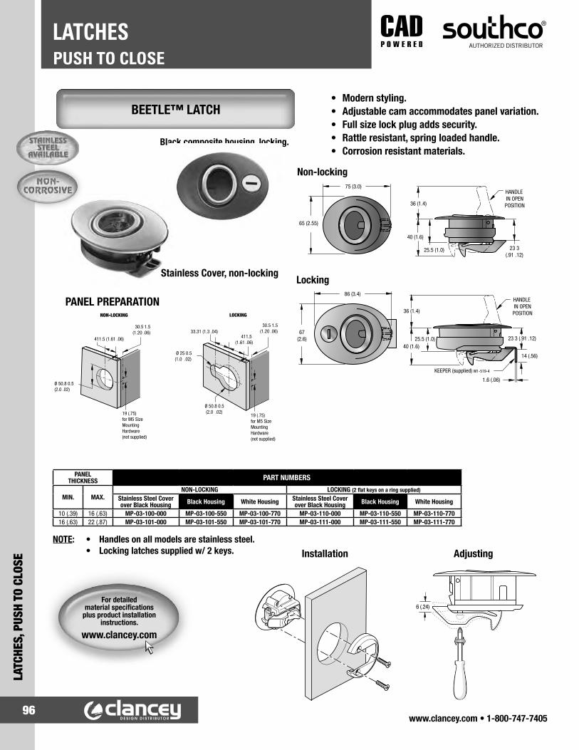
www.clancey.com • 1-800-747-740596
PUSH TO CLOSELATCHES
LATC
HES,
PUS
H TO
CLO
SE
• Modern styling.• Adjustable cam accommodates panel variation.• Full size lock plug adds security.• Rattle resistant, spring loaded handle.• Corrosion resistant materials.
NOTE: • Handles on all models are stainless steel. • Locking latches supplied w/ 2 keys.
PANEL PREPARATION
Black composite housing, locking.
PANEL THICKNESS PART NUMBERS
MIN. MAX.NON-LOCKING LOCKING (2 flat keys on a ring supplied)
Stainless Steel Cover over Black Housing Black Housing White Housing Stainless Steel Cover
over Black Housing Black Housing White Housing
10 (.39) 16 (.63) MP-03-100-000 MP-03-100-550 MP-03-100-770 MP-03-110-000 MP-03-110-550 MP-03-110-77016 (.63) 22 (.87) MP-03-101-000 MP-03-101-550 MP-03-101-770 MP-03-111-000 MP-03-111-550 MP-03-111-770
Installation Adjusting
Non-locking
LockingStainless Cover, non-locking
Ø 50.8 0.5 (2.0 .02)
411.5 (1.61 .06)
19 (.75)for M5 SizeMountingHardware(not supplied)
NON-LOCKING
30.5 1.5(1.20 .06)
Ø 50.8 0.5 (2.0 .02)
411.5 (1.61 .06)
19 (.75)for M5 SizeMountingHardware(not supplied)
LOCKING
33.31 (1.3 .04)
Ø 25 0.5(1.0 .02)
30.5 1.5(1.20 .06)
BEETLE™ LATCH
For detailed material specifications
plus product installation instructions.
www.clancey.com

www.clancey.com • 1-800-747-740597
LATCHES, PUSH TO CLOSE
PUSH TO CLOSELATCHES
• 4 way orientation of latch pawl.• Corrosion resistant materials.• Rotary action cam delivers easy
closing and opening.
NOTE: Locking latches are supplied w/ 2 standardkeys.
Ordering instructions:1. Determine panel thickness.2. Order latch, spacers (if necessary), and keeper.
PANEL PREPARATION
Chrome Face Locking (shown)
Panel Thickness Non-Locking LatchPart Numbers
Locking LatchPart Numbers Order 4mm
SpacersR4-64-13-1
Order 8mm Spacers
R4-64-13-2Min. Max. Black White Chrome Black White Chrome
1 (.040") 4.9 (.19")
R4-60-200-55 R4-60-200-75 R4-60-200-35 R4-60-210-55 R4-60-210-75 R4-60-210-35
- 2
5 (.20") 9.9 (.39") 1 1
10 (.39") 14.9 (.59") - 1
15 (.59") 19.9 (.78") 1 -
20 (.79") 23 (.94") - -
KEEPER PART NUMBERR4-64-11
Keeper (order separately)
COMPASS LATCH
S
EW
N
For detailed material specifications
plus product installation instructions.
www.clancey.com

www.clancey.com • 1-800-747-740598
PUSH TO CLOSELATCHES
LATC
HES,
PUS
H TO
CLO
SE
ROTARY LATCHES
PRODUCT FAMILY
LOAD RATING
SINGLE OR DOUBLE ROTOR
SINGLE OR TWO STAGE FEATURES APPLICATIONS INDUSTRIES PAGE
NON-
FM
VSS
COM
PLIA
NT
R4-10 Light-duty Single rotor Single stage Compact, flexible actuation styles,
light-duty, economical
Engine covers, baggage doors, access panels,
tool boxes
Off-highway, agricultural, truck, bus, recreational
vehicles, industrial equipment, enclosures
99-102
R4-20Medium-
dutySingle rotor
Single and two stage
Compact, flexible actuation styles,
medium-duty, economical
Engine covers, baggage doors, access panels,
tool boxes
Off-highway, agricultural, truck, bus, recreational
vehicles, industrial equipment, enclosures
105
FMVS
S CO
MPL
IANT R4-30 Heavy-duty Single rotor Two stage
Significant accommodation for misalignment between
the latch and keeper, heavy-duty
Entry doors, engine covers baggage doors,
large access panels
Off-highway, agricultural, truck, bus, recreational
vehicles, industrial equipment
103-104
R4-50 Heavy-duty Double rotor Two stage
Maximum accommodation for misalignment between
the latch and keeper, heavy-duty
Entry doors, engine covers, baggage doors,
large access panels
Off-highway, agricultural, truck, bus, recreational
vehicles, industrial equipment
106
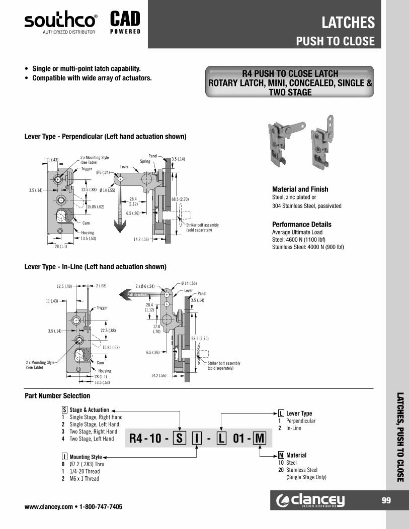
www.clancey.com • 1-800-747-740599
LATCHES, PUSH TO CLOSE
PUSH TO CLOSELATCHES
R4 - 10 - S I - L 01 - M
S Stage & Actuation1 Single Stage, Right Hand 2 Single Stage, Left Hand 3 Two Stage, Right Hand 4 Two Stage, Left Hand
I Mounting Style 0 Ø7.2 (.283) Thru 1 1/4-20 Thread 2 M6 x 1 Thread
L Lever Type1 Perpendicular 2 In-Line
M Material10 Steel 20 Stainless Steel (Single Stage Only)
Trigger
Pull direction3.5 (.14)
68.5 (2.70)
Striker bolt assembly(sold separately)
14.2 (.56)
6.5 (.26)
2 x Ø 6 (.24)Ø 14 (.55)
17.8(.70)
28.4(1.12)
Lever
2 x Mounting Style (See Table)
Housing
3.5 (.14)
11 (.43)
12.5 (.49) 2 (.08)
28 (1.1)13.5 (.53)
15.85 (.62)
22.5 (.88)
Cam
Panel
Pull
dire
ctio
n
3.5 (.14)
68.5 (2.70)
Striker bolt assembly(sold separately)
14.2 (.56)
6.5 (.26)
SpringLever
Ø 6 (.24)
Ø 14 (.55)
28.4(1.12)
2 x Mounting Style (See Table)
Housing
3.5 (.14)
11 (.43)
Trigger
28 (1.1)
15.85 (.62)
22.5 (.88)
Cam
13.5 (.53)
Panel
Lever Type - Perpendicular (Left hand actuation shown)
Lever Type - In-Line (Left hand actuation shown)
Material and FinishSteel, zinc plated or 304 Stainless Steel, passivated
Performance DetailsAverage Ultimate Load Steel: 4600 N (1100 lbf) Stainless Steel: 4000 N (900 lbf)
• Single or multi-point latch capability.• Compatible with wide array of actuators. R4 PUSH TO CLOSE LATCH
ROTARY LATCH, MINI, CONCEALED, SINGLE & TWO STAGE
Part Number Selection

www.clancey.com • 1-800-747-7405100
PUSH TO CLOSELATCHES
LATC
HES,
PUS
H TO
CLO
SE
Lever Type - Two Point (Left hand actuation shown)
Lever Type - Hand Actuation
Panel
Pull
dire
ction
Pull direction
Housing
3.5 (.14)
11 (.43)
12.5 (.49) 2 (.08)
Trigger
28 (1.1)
15.85 (.62)
22.5 (.88)
CamStriker bolt assembly (sold separately)
Spring
2 x Mounting Style (See Table)
3.5 (.14)
68.5 (2.70)
14.2 (.56)
6.5 (.26)
2 x Ø 14 (.55)
14 (.55)
17.5 (.69)
28(1.10)
Lever
3 x Ø 6 (.24)
Ø 5.4 (.21)
10.5 (.41)28
(1.10)
13.5 (.53)
Pull direction
Housing
3.5 (.14)11 (.43)
Trigger
13.5 (.53)28 (1.1)
Cam
15.85 (.62)
22.5 (.88)
16 (.63)
Striker bolt assembly(sold separately) 14.2 (.56)
3.5 (.14)
Spring
68.5 (2.70)
4 (.16)
Panel
2 x Mounting Style (See Table)
R4 PUSH TO CLOSE LATCH ROTARY LATCH, MINI, CONCEALED, SINGLE &
TWO STAGE
Material and FinishSteel, zinc plated or 304 Stainless Steel, passivated
Performance DetailsAverage Ultimate Load Steel: 4600 N (1100 lbf) Stainless Steel: 4000 N (900 lbf)
• Single or multi-point latch capability.• Compatible with wide array of actuators.
R4 - 10 - S I - L 01 - M
S Stage & Actuation1 Single Stage, Right Hand 2 Single Stage, Left Hand 3 Two Stage, Right Hand 4 Two Stage, Left Hand
I Mounting Style 0 Ø7.2 (.283) Thru 1 1/4-20 Thread 2 M6 x 1 Thread
L Lever Type3 Two Point 4 Hand Actuation
M Material10 Steel 20 Stainless Steel (Single Stage Only)
Part Number Selection

www.clancey.com • 1-800-747-7405101
LATCHES, PUSH TO CLOSE
PUSH TO CLOSELATCHES
Panel
Pull direction
Housing
3.5(.14)
11(.43) Trigger
13.5 (.53)28 (1.1)
Cam
15.85 (.62)
22.5 (.88)
38 (1.52)
Striker bolt assembly(sold separately)
14.2(.56)
Spring
68.5(2.70)
4 (.15)Ø 6.4±0.1
(.25±.004)
53.85(2.12)
80.2(3.16)
33.53 (1.32)
2 x Mounting Style(See Table)
Panel
Pull
dire
ctio
n
Housing
3.5(.14)
11 (.43)
Trigger
13.5 (.53)28 (1.1)
Cam
15.85 (.62)
22.5 (.88) Striker bolt assembly(sold separately)
14.2 (.56)
Spring
68.5(2.70)
4 (.15)
Ø 6.4±0.1 (.25±.009)
15.5±1(.61±.04)
39.2±.1(1.54±.04)
2 x Mounting Style(See Table)
Lever Type - Top (left hand actuation shown)
Lever Type Bottom (Left hand actuation shown)
• Single or multi-point latch capability.• Compatible with wide array of actuators. R4 PUSH TO CLOSE LATCH
ROTARY LATCH, MINI, CONCEALED, SINGLE & TWO STAGE
Material and FinishSteel, zinc plated or 304 Stainless Steel, passivated
Performance DetailsAverage Ultimate Load Steel: 4600 N (1100 lbf) Stainless Steel: 4000 N (900 lbf)
R4 - 10 - S I - L 01 - M
S Stage & Actuation1 Single Stage, Right Hand 2 Single Stage, Left Hand 3 Two Stage, Right Hand 4 Two Stage, Left Hand
I Mounting Style 0 Ø7.2 (.283) Thru 1 1/4-20 Thread 2 M6 x 1 Thread
L Lever Type5 Bottom 6 Top
M Material10 Steel 20 Stainless Steel (Single Stage Only)
Part Number Selection

www.clancey.com • 1-800-747-7405102
PUSH TO CLOSELATCHES
LATC
HES,
PUS
H TO
CLO
SE
STRIKER MOUNTING BRACKET PART NUMBER
R4-0-50114
STRIKER BOLT PART NUMBER
PART NUMBER MATERIAL
R4-90-121-10 Steel
R4-90-121-20 Stainless Steel
MOUNTING STYLE PANEL HOLE
Ø 7.2 (.283) Thru Ø 7.6 (.299)
1/4-20 Thread Ø 6.8 (.268)
M6 X 1 Thread Ø 6.4 (.252)
Latched position Unlatched position
12.7 (.50) Hex
Ø 25.4 (1.00)
Ø 9.5(.37) Washer
O-Ring
M8 x 1.25 thread
38.1 (1.50)27.7
(1.09)25.4
(1.00)
2.8 (.11)
Striker bolt
Striker Bolt Assembly (sold separately)
26 (1.02)
40 (1.57)10 (0.39)
14 (0.55)
14 (0.55)
8 (0.31)
Striker 90° Mounting Bracket
Operation
22.5±0.1(.89±.004)
26 (1.02) Min.
3.5±0.05 (.14±.002)
9 (.35) Max.
5 (.20) Min.
Panel Hole (See Table)
Panel Preparation
R4 PUSH TO CLOSE LATCH STRIKER BOLT, MINI, INSTALLATION,
ACCESSORIES
Material and FinishSteel, zinc plated or 304 Stainless Steel, passivated
• Striker bolt for R4-10 series rotary latch.

www.clancey.com • 1-800-747-7405103
LATCHES, PUSH TO CLOSE
PUSH TO CLOSELATCHES
MOUNTING STYLE
PART NUMBER
PERPENDICULAR BOTTOM
Left hand actuation Right hand actuation Left hand actuation Right hand actuation
Ø 6.7 (.265) Thru R4-30-40-101-10 R4-30-30-101-10 R4-30-40-501-10 R4-30-30-501-10
1/4-20 Thread R4-30-41-101-10 R4-30-31-101-10 R4-30-41-501-10 R4-30-31-501-10
M6 x 1 Thread R4-30-42-101-10 R4-30-32-101-10 R4-30-42-501-10 R4-30-32-501-10
Panel
Pull direction
Striker boltassembly(sold separately)
77(3.03)
Ø 6.4(.25)
11.4 (.45)
17.2 (.68)
19.4 (.76)
19 (.75)
Ø 7.2(.29)
2 x Mounting holes (see table)
19 (.75)
43°
17.8 (.70)35.7 (1.40)
3.5 (.14)
Panel
Pull directionStriker bolt assembly(sold separately)
77(3.03)
17.2 (.68)2 x Mounting holes
(see table)31.8 (1.25)
17.6(.69) 19.4 (.76)
19 (.75)
Ø 7.2(.29)
19 (.75)
43°
17.8 (.70)34.8 (1.37)
Ø 6.4(.25)
Two Stage - Perpendicular (left hand actuation shown)
Two Stage - Bottom (left hand actuation shown)
• Single or multi-point latch capability.• Compatible with wide array of actuators• FMVSS 206 compliant.
R4 PUSH TO CLOSE LATCH ROTARY LATCH, LARGE, CONCEALED,
TWO STAGE
Material and FinishSteel, zinc plated
Performance DetailsAverage ultimate load: 10675 N (2400) as shown 14230 N (3200 lbf) with support bracket. Contact Clancey for more information.

www.clancey.com • 1-800-747-7405104
PUSH TO CLOSELATCHES
LATC
HES,
PUS
H TO
CLO
SE
MOUNTING HOLE PART NUMBER LEFT HAND ACTUATION
PART NUMBER RIGHT HAND ACTUATION
Ø 6.7 (.265) Thru R4-30-40-301-10 R4-30-30-301-10
1/4-20 Thread R4-30-41-301-10 R4-30-31-301-10
M6 X 1 Thread R4-30-42-301-10 R4-30-32-301-10
STRIKER BOLT PART NUMBER
R4-90-321-10
38.1±0.3(1.50±.01)
19.05±0.2(.75±.01)
2 x Ø 7.8 (.307 )
+0.1-0.0
+.004-.0
2 x R7 (.28) R8 (.31)Min. 45˚
17 (.67)
Pull direction
Pull direction
Panel
Striker boltassembly(sold separately)
2 x Ø 6.4 (.25)
22 (.87)
11.4(.45)
5.5(.22)
11.7 (.46)16.9(.67)
7.4 (.29)
17.2(.68)
77(3.03)
19.4 (.76)
19 (.75)
Ø 7.2(.29)
2 x Mounting holes (see table)
19 (.75)
43°
17.8 (.70)35.7 (1.40)
16 (.63) Hex
Ø 28.7(1.13)
Ø 12.7(.50) Washer
O-ring
M10 x 1.5thread
52.3 (2.06)28.7
(1.13)
25.4(1.00)
2.8 (.11)
Striker bolt
2-Point Actuator (left hand actuation shown)
Striker Bolt Assembly (sold separately)
Latched position Unlatched position
• Striker bolt for R4-30 series rotary latch
Material and FinishSteel, zinc plated
Operation
R4 PUSH TO CLOSE LATCH ROTARY LATCH, LARGE, CONCEALED,
TWO STAGE
Material and FinishSteel, zinc plated
Performance DetailsAverage ultimate load: 10675 N (2400) as shown 14230 N (3200 lbf) with support bracket. Contact Clancey for more information.
• Single or multi-point latch capability.• Compatible with wide array of actuators.• FMVSS 206 compliant.

www.clancey.com • 1-800-747-7405105
LATCHES, PUSH TO CLOSE
PUSH TO CLOSELATCHES
POSITIONPART NUMBER
LEFT HAND ACTUATION RIGHT HAND ACTUATION STRIKER BOLT
Single stage R4-20-20-501-10 R4-20-10-501-10R4-91-231-10
Two stage R4-20-40-501-10 R4-20-30-501-10
Pull direction
Panel
Striker bolt (sold separately)
70(2.76)
1.4(.05)
1.4 (.05)
2 x 7.1 (.28)
70.5(2.77)
43(1.7)
18(.71)
2 x Ø 8.3(.32) Thru
Ø 6.5(.25)
28 (1.1)
59.4 (2.33)
17(.67)
Single Stage (left hand actuation shown)
Two Stage (left hand actuation shown)
Latched position Unlatched position
Striker Bolt (sold separately)
Pull direction
2 x 7.1 (.28)2 x Ø 8.3
(.33) Thru
43(1.69)
18 (.71)
70.3(2.77)
28 (1.10)
59.7 (2.35)
Ø 6.5(.26)
Panel
Striker bolt (sold separately)
70(2.76)
17(.67)
1.5 (.06)
1.5 (.06)
M10 x 1.5 thread
16 (.63)3.5
(.13) Ø 12(.47)
42.2 (1.66)
27.5(1.08)
Operation
• Single or multi-point latch capability.• Compatible with wide array of Actuators. R4 PUSH TO CLOSE LATCH
ROTARY LATCH, MEDIUM, CONCEALED, SINGLE & TWO STAGE
Material and FinishSteel, zinc plated
AccessoriesCables and retainer clips

www.clancey.com • 1-800-747-7405106
PUSH TO CLOSELATCHES
LATC
HES,
PUS
H TO
CLO
SE
R4 PUSH TO CLOSE LATCH ROTARY LATCH, HEAVY DUTY, TWO STAGE
Material and FinishSteel, zinc plated
• Single or multi-point latch capability.• Compatible with wide array of actuators.• FMVSS 206 compliant.
MOUNTING STYLEPART NUMBER
LEFT HAND ACTUATION RIGHT HAND ACTUATION STRIKER BOLT
Ø 7.2 (.283) Thru R4-50-40-101-10 R4-50-30-101-10
R4-90-441-101/4-20 Thread R4-50-41-101-10 R4-50-31-101-10
M6 X 1 Thread R4-50-42-101-10 R4-50-32-101-10
PanelPull direction
46(1.8)
6.5 (.255)
42.5(1.67)
55.3 (2.18)
2.16 (.085)
18.6 (.73)
46.6 (1.835)
Mounting holes (see table)
Ø 17.2 (.677)Max. striker
20.24(.797)
41.28(1.625)
82.55(3.25)
109(4.29)
3.6 (.142)3.2 (.125)
5.7 (.226)
20.7(.815)
Ø 6.73 (.265)
Latched position Unlatched position
Two Stage (left hand actuation shown)
19(.748)
Ø 17.1 (.675)34.5
(1.35)
22.2(.875)
Ø 27.9(1.1)
M12 x 1.75 thread
Striker Bolt Assembly (sold separately)Operation

www.clancey.com • 1-800-747-7405107
LATCHES, ACTUATORS
ACTUATORSLATCHES
AC - 30 - E L M - H B - KC
AC-30 MULTI POINT ACTUATOR PUSH-BUTTON
• Single or multi-point actuation capability.• Accommodates wide panel thickness.• Multiple key code options.• Single hole install.
Material and Finish Button: Nylon
Housing: Zinc or Stainless Steel Lock Plug: Zinc Cam, Washer, Rivet: Stainless Steel, Passivated
Ø 38.3 (1.51)
2 (0.08)
Ø4.1 (0.16)
28 (1.10)
64 (2.52)
Ø32 (1.26)Ø32.3 (1.27) Max
10 (0.39) Cam/Cable Travel2 X Ø5 ±0.1
(0.197 ±0.004)
No Spacer required if panel thickness > 10.3 (0.405)
Panel Thicknessfrom 1 to 22(0.04 to 0.87) Max
Ø 28.8 (1.13)29.1 (1.145) Max
51.4 (2.02)
With Cam Attachment Shown Without Cam Attachment Shown
Push Travel 12 (0.47)
28 (1.10)
Housing Seal
Spacer
E-Ring
Ø 32 .4 (1.27 )+ 0.2- 0
+ 0.2- 0
29.2 (1.15 )
Panel preparation thickness1 (0.04) to 22 (0.87)
+ 0.2- 0
+ 0.2- 0
Cable Holder
Metal Nut
Tab Washer
42 (1.65)
Push Down 12 (0.47)
L Locking Option1 Reversible key (No keys - R001)2 Reversible key (2 keys included - R001)3 Reversible key (Multiple key codes - 2 keys included)4 Standard key (No keys - CH751)5 Standard key (2 keys included - CH751)6 Standard key (Multiple key codes - 2 keys included)
M Mounting Method1 With spacer mounting (must have if glass panel)2 Without spacer mounting
E End Style1 With Cam attached 3 Without Cam attached B Button Material
1 Nylon with black molding
H Housing Material1 Zinc with black powder coat3 Stainless steel with black powder coat
KC Key Codes (Omit for locking options 1,2,4 and 5)KD10 Keyed differently (10 codes)MK10 Master keyed, keyed differently
Part Number Selection

www.clancey.com • 1-800-747-7405108
ACTUATORSLATCHES
LATC
HES,
ACT
UATO
RS
• Single or multi-point actuation capability.• Accommodates wide panel thickness.• Multiple key code options.• Easy Grip.
Material and Finish Button: Nylon
Housing: Zinc Die Cast or Stainless Steel Lock Plug: Zinc Die Cast Cam, Washer, Rivet: Stainless Steel, Passivated
AC-40 SINGLE OR MULTI POINT ACTUATOR
181.4 (7.14)
47 (1.85)
34 (1.34)
Cam/CableTravel 10 (0.39)
Ø 4.1 (0.16)
51.4 (2.02)
58 (2.28)
34 (1.34)
No Spacer if Panel Thickness > 4.6 (0.18)
Panel Thickness from 1 to 16.8 (0.04 to 0.66) Max.
2 X Ø5 ±0.1
Ø 32 (1.26)Ø 32.3 (1,27)
28.8 (1.13)
With Cam Attachment Shown
Without Cam Attachment Shown
AC - 40 - E L M - H B - KCL Locking Option
1 Reversible key (No keys - R001)2 Reversible key (2 keys included - R001)3 Reversible key (Multiple key codes - 2 keys included)4 Standard key (No keys - CH751)5 Standard key (2 keys included - CH751)6 Standard key (Multiple key codes - 2 keys included)
M Mounting Method1 Cable parallel (or no cable), with spacer mounting (must have if glass panel)2 Cable parallel (or no cable), without spacer mounting3 Cable cross with spacer mounting (must have if glass panel)4 Cable cross without spacer mounting
E End Style1 With Cam attached 3 Without Cam attached
B Button Material1 Nylon with black molding
H Handle Material1 Black GF nylon with zinc housing insert2 Black GF nylon with stainless steel housing insert
KC Key Codes (Omit for locking options 1,2,4 and 5)KD10 Keyed differently (10 codes)MK10 Master keyed, keyed differently
Part Number Selection
142 ±1 (5.59 ±0.02)
13 ±0.2 (0.51± 0.008)
8.4 ±0.1 (0.33 ±0.004)Ø 32.4 (1.27 ) 29.2 (1.15 ) for Cable Cross Mounting
+ 0.2-0+ 0.2
-0+ 0.2-0
+ 0.2-0
29.2 (1.15 ) for Cable Parallel Mounting+ 0.2-0
+ 0.2-0
142 ±1 (5.59 ±0.02)
Ø44 (1.73)
M8 X 1.25 thread18 depth Min
(Max mounting torque: 40 N·M)12 (0.47) Push Down
36 (1.42)
43

www.clancey.com • 1-800-747-7405109
LATCHES, ACTUATORS
ACTUATORSLATCHES
AC-75 SINGLE POINT ACTUATOR PADDLE
• Front mount installation.• Three cable mounting options.• Low Profile.• Robust Material.
Material and Finish Paddle and housing: Aluminum,
black powder coated
PART NUMBER
AC-75-101-11
CABLE ORIENTATION PANEL THICKNESS CABLE TRAVEL
Placement 1 12.5 (.49) max. 11.1 (.44)
Placement 2 16 (.63) max. 13.2 (.52)
Placement 3 16 (.63) max. 13.2 (.52)
49.2 (1.94)13 (0.51)
96.2 (3.78)
37.1(1.19)
Cable Placement 3
CablePlacement 2
CablePlacement 1
81 (3.2)
37.9(1.49)
18.9 (0.74)
4X R5 Max
Door
2X Ø 4.5 ±0.1(.177±.004)(For thru hole mounting)
4 ±0.1 (0.15 ±0.003)
35.2 (1.38)
37.1(1.46)
81 (3.2)
37.9(1.49)
18.9 (0.74)
4X R5 Max
2X Ø 4.5 ±0.1(.177±.004)(For thru hole mounting)
73 (2.87)
4 ±0.1 (0.15 ±0.003)

www.clancey.com • 1-800-747-7405110
ACTUATORSLATCHES
LATC
HES,
ACT
UATO
RS
AC SINGLE POINT ACTUATOR T-HANDLE
AC SINGLE POINT ACTUATOR PADDLE
PART NUMBER
AC-60-101-11
Pull direction
45 (1.77)Housing
T-handle
60 (2.36)
104.5 (4.11)117 Open (4.61)
25±0.2(.98±.008)
40±0.2 (1.57±.008)
4 x Ø 4.5±0.1 (.18±.004)
(For thru hole mounting)
56(2.20)
Cable clip 20.8 (.82)
21.7(.85)
23(.91)
• Surface mount installation• Generous grip area• Pull to activate
Material and FinishHousing: PC/ABS, blackT-handle and slide: 33% glass-filled nylon, blackClip: acetal, blackSpring: Stainless steel, passivated
CABLE ORIENTATION
PANEL THICKNESS CABLE TRAVEL
Placement 1 12.5 (.49) max. 11.1 (.44)
Placement 2 16 (.63) max. 13.2 (.52)
108.3 (4.26) Panel
Panel thickness
Cable placement 1
5.7 (.22)
38.3 (1.51)
53.7(2.11)
28.7(1.13)
80±0.3 (3.15±.012)
2 x Ø 4.5±0.1 (.177±.004)(For thru hole mounting)
91.6±0.3 (3.61±.012)5.8±0.1 (.23±.004)
42±0.5(1.65±.02)
21±0.2(.83±.008)
4 x R5 (.2) Maximum
Cable placement 2
• Front mount installation• Flush• Two cable mounting options
Material and FinishPaddle and housing: 33% glass-filled nylon, blackSpring: Stainless steel, passivated
PART NUMBER
AC-70-101-11

www.clancey.com • 1-800-747-7405111
LATCHES, ACTUATORS
ACTUATORSLATCHES
AC SINGLE POINT ACTUATOR PUSH-BUTTON
AC RETAINER CLIPS AND CABLES
PART NUMBER
AC-80-101-11
Knob Ø 26 (1.02) 6 (.24)
64.6 (2.54)
Door panel
Mounting nut
Housing
26 (1.02)Maximum panel thickness
Cam
Ø 32(1.26 )
+1-0
30±0.2 (1.18±.008)
Double-D hole preparation
+.04-0
13.7 (.54) Cable travel
Ø 38 (1.50)
• Flush• Mounting hardware included
Material and FinishPush button and housing: PC/ABS, blackCam: 33% glass-filled nylon, blackSpring: Stainless steel, passivated
LATCH SERIESPART NUMBER
RETAINER CLIP
R4-10R4-0-43922
R4-30
R4-20R4-0-43922-1
R4-50
Retainer clip
• For use with Ø 4 (.157) rod or Southco cable assembly
Material and FinishSee www.clancey.com

www.clancey.com • 1-800-747-7405112
PUSH TO CLOSELATCHES
LATC
HES,
PUS
H TO
CLO
SE
• Easy operation.• Stainless available.• Unassembled can be used in either hand.
• Rugged design• Optional cover for spring.
SPRING-ACTION LATCH BOLT STYLE
Primary DimensionsPART NUMBER Style P E R1 R2 L W B T H1 H2 H3 D
719-SL-Z Left hand.375" 1.25" 1.18" .687" 2.00" .656" 1.12" .120" .375" .437" 1.25" .265"719-SR-Z Right Hand
719-SU-Z Unassembled720-SL-Z Left hand
.500" 1.50" 1.22" 1.00" 3.00" .750" 1.25" .190" .500" .625" 1.75" .328"720-SR-Z Right Hand720-SU-Z Unassembled
Note: For Stainless Steel assemblies, add “-S” to the part number.
SPRING-ACTION LATCH HEAVY – DUTY
Primary DimensionsPART NUMBER Style P E R1 R2 L W T1 T2 H1 H2 H3 H4 D
707-SZ-COV covered.375" .562" .812" 1.00" 1.50" 1.25" .115" .090" .187" .375" .750" .875" .171"
707-SZ uncovered708-SZ-COV covered
.437" .750" 1.00" 1.25" 2.00" 1.63" .125" .120" .250" .375" 1.25" 1.13" .230"708-SZ uncovered
709-SZ-COV covered.500" .750" 1.25" 1.38" 2.88" 2.00" .150" .190" .312" .468" 1.93" 1.38" .265"
709-SZ uncoveredNote: For Stainless Steel assemblies, add “-S” to the part number.

www.clancey.com • 1-800-747-7405113
LATCHES, PUSH TO CLOSE
PUSH TO CLOSELATCHES
PANEL PREPARATION
PART NUMBERMC-28
10.3 ± 0.1(.406 ± .005)
FRAME THICKNESS D PART NUMBERMIN. MAX.1 (.04) 3 (.12) 0.9 (.035) E4-10-201-103 (.12) 5 (.20) 2.9 (.115) E4-10-202-105 (.20) 7 (.28) 4.9 (.195) E4-10-203-10
• Push the door to latch and unlatch.• “Snap-in” installation.• Self-adhesive keeper.
• 6.6 lbs retaining force.• Supplied w/ mounting screws.
• 8.8 lbs retaining force.• Supplied w/ mounting screws.
• Push the door to latch/unlatch.• Screw mounting is ideal for wood cabinets.• 2 sizes.
PART NUMBERBlack White Brown
MC-37-BLK MC-37-WHT MC-37-BRN
TOUCH LATCH, SNAP-IN DESIGN
SMALL SIZE
TOUCH LATCH, SCREW MOUNT
LARGE SIZE
Other sizes of snap-in touch latches are available.
www.clancey.com

www.clancey.com • 1-800-747-7405114
PUSH TO CLOSELATCHES
LATC
HES,
PUS
H TO
CLO
SE
• 2 colors.• 2.6 lbs.
holding force.• 8.5 mm stroke.
• 3 Styles of magnetic closure.• Touch action“pushes” door open
breaking the magnetic connection.• Mounting screws are supplied.
• 3 colors.• 3.5 lbs.
holding force.• 15 mm stroke.
Note: A 4.0 mm gap between the door and frame is required to activate the latch.
Note: A 3.5 mm gap between the door and frame is required to activate the latch.
f4.5, f6.5
12 15
23
f3.2, f6
3.2 × 8, 6 × 11
20 28 36(1
-27/
64")
3.5
79.
5
15
5
3
2
143.5(1-23/32")
38
155.5
136
1.4
0.5
PART NUMBER COLORML-30S-WHT WHITEML-30S-BRN BROWN
PART NUMBER COLORML-80-WHT WHITEML-80-BRN BROWNML-80-BLK BLACK
PART NUMBER COLORML-30W-WHT WHITEML-30W-BRN BROWN
• Used for dual doors meeting in the center.• Each half operates separately.• 2.6 lbs. holding force (each).• 8.5 mm stroke.
Note: A 4.0 mm gap between the door and frame is required to activate the latch.
Material: Body - ABS plastic.(All models) Magnet-steel. Strike - steel.
STANDARD SERIES
MAGNETIC TOUCH LATCHES
MINIMAL PROTRUSION
DOUBLE CATCH
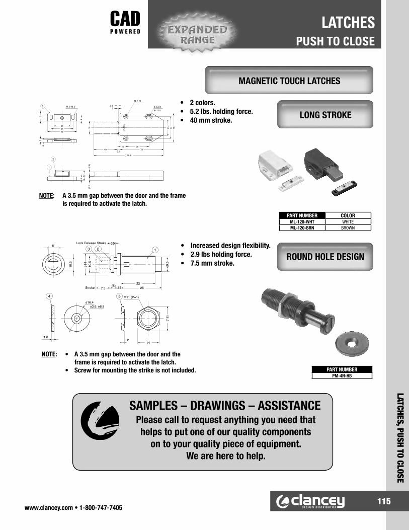
www.clancey.com • 1-800-747-7405115
LATCHES, PUSH TO CLOSE
PUSH TO CLOSELATCHES
• 2 colors.• 5.2 lbs. holding force.• 40 mm stroke.
PART NUMBER COLORML-120-WHT WHITEML-120-BRN BROWN
NOTE: A 3.5 mm gap between the door and the frame is required to activate the latch.
• Increased design flexibility.• 2.9 lbs holding force.• 7.5 mm stroke.
NOTE: • A 3.5 mm gap between the door and the frame is required to activate the latch. • Screw for mounting the strike is not included. PART NUMBER
PM-4N-HB
SAMPLES – DRAWINGS – ASSISTANCEPlease call to request anything you need that helps to put one of our quality components
on to your quality piece of equipment. We are here to help.
MAGNETIC TOUCH LATCHES
LONG STROKE
ROUND HOLE DESIGN

www.clancey.com • 1-800-747-7405116
PUSH TO CLOSELATCHES
LATC
HES,
PUS
H TO
CLO
SE
• Pull to open. • Optional mounting bracket available.
PANEL PREPARATION
Order Separately. For applications where frame is not suitable for punching.
A BE
F
C
D H
G0.8 (.03)REF.
LW
0.4(.015)
R MAX.
FRAME THICKNESS
B
TC
A
D (measured frominside surface ofdoor or strike)
Attach with two No. 4, No. 5 or M3 screws.
E
MOUNTING BRACKET
* High strength, large size, double magnet is available. Please call.
SIZEDIMENSIONS FRAME
THICKNESS PART NUMBERS
Black WhiteMIN. MAX.H
A B C D E F G
7.7(.30)
02-10-301-10 Small(300
Series)
Medium(100
Series)
Large(200
Series)
6.1(.24)
27.9(1.10) 23.6
(.93)0.8
(.031)13.3(.52)
22(.87)
0.5(.020)
2(.080)
2(.080)
3.5(.140)
0.9(.035)
2.4(.095) 02-10-302-10
02-10-301-20
02-10-302-20
9.2(.36)
7.7(.30)
47(1.85)
39.7(1.56)
0.8(.031)
25.4(1.00)
37.8(1.49)
0.5(.020)
2(.080)
2(.080)
3.5(.140)
3.5(.140)
5(.200)
0.5(.020)
2(.080)
2(.080)
3.5(.140)
3.5(.140)
5(.200)
11(.43)
9.4(.37)
65.3(2.57)
58.5(2.30)
1.2(.05)
20.6(.81)
57(2.24)
1(.040)
2.5(.100)
4(.160)
0.3(.010)
1.8(.070)
3.3(.130)
1.8 LBS.
10 LBS.
14 LBS.
02-10-101-10
02-10-102-10
02-10-101-20
02-10-102-20
02-10-103-10 02-10-103-20
02-10-201-10
02-10-202-10
02-10-201-20
02-10-202-20
02-10-203-10 02-10-203-20
26.7(1.05)
46.2(1.82)
45.5(1.79)
64.5(2.54)
63.3(2.49)
Break-awayForce
SIZEFor use with these catchesONLY: A B C D E T
BRACKETPART NUMBER
Small(300 series)
Medium(100 series)
Large(200 series)
02-10-301-10
02-10-101-10
02-10-201-10
02-10-301-20
02-10-101-20
02-10-201-20
41.3(1.63)
51(2.00)
76(3.00)
11.1(.44)
12.7(.50)
14.3(.56)
7.9 2.4(.31 .09)
0.1( .005)
24.6(.97)
18.7(.73)
35(1.38)
44.5(1.75)
70(2.75)
1(.042)
13.5(.53)
17.5 3.2(.69 .13)
12.7 3.2(.50 .13)
02-16-301-11
02-16-101-11
02-16-201-11
DIMENSIONS
L
22.2(.875)38.1
(1.500)57.1
(2.250)
6.4(.250)
8.1(.320)
9.6(.380)
SIZE 0.1(.005)
W 0.1(.005)
Small(300 Series)
Medium(100 Series)
Large(200 Series)
MAGNETIC CATCH, “SNAP-IN” STYLE
For detailed material specifications
plus product installation instructions.
www.clancey.com
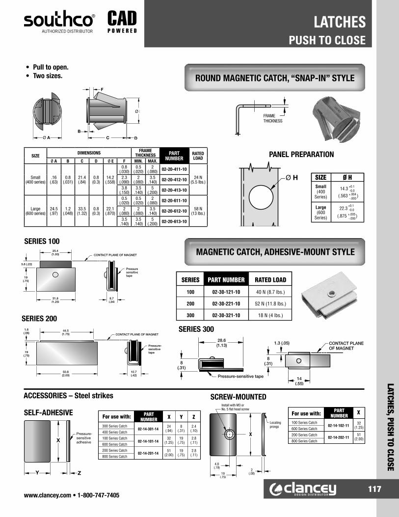
www.clancey.com • 1-800-747-7405117
LATCHES, PUSH TO CLOSE
PUSH TO CLOSELATCHES
• Pull to open. • Two sizes.
SERIES 100
F
Ø E
Ø A C D
B
19(.75)
CONTACT PLANE OF MAGNET
Pressure-sensitivetape
31.8(1.25)
5.6 (.22)
25.4(1.00)
8.7(.34)
44.5(1.75)
50.8(2.00)
19(.75)
1.6(.06)
10.7(.42)
CONTACT PLANE OF MAGNET
Pressure-sensitivetape
X
Y Z
Pressure-sensitiveadhesive
19(.75)
2(.08)
X
4.8(.19)
Locatingprongs
Install with M3 or No. 5 flat head screw
SERIES 200
SELF-ADHESIVE
SCREW-MOUNTEDACCESSORIES – Steel strikes
Ø H
FRAMETHICKNESS
PANEL PREPARATION
14(.55)
CONTACT PLANE OF MAGNET
8(.31)
1.3 (.05)28.6(1.13)
8(.31)
Pressure-sensitive tape
SERIES 300
ROUND MAGNETIC CATCH, “SNAP-IN” STYLE
MAGNETIC CATCH, ADHESIVE-MOUNT STYLE
SIZEDIMENSIONS FRAME
THICKNESS PART NUMBER
RATED LOAD
Ø A B C D Ø E F MIN. MAX.
Small(400 series)
.16 (.63)
0.8 (.031)
21.4 (.84)
0.8 (0.3)
14.2 (.558)
0.8 (.030)
0.5 (.020)
2 (.080) 02-20-411-10
24 N (5.5 lbs.)
2.3 (.090)
2 (.080)
3.5 .140) 02-20-412-10
3.8 (.150)
3.5 .140)
5 (.200) 02-20-413-10
Large (600 series)
24.5 (.97)
1.2 (.048)
33.5 (1.32)
0.8 (0.3)
22.1 (.870)
0.5 (.020)
0.5 (.020)
2 (.080) 02-20-611-10
58 N (13 lbs.)
2 (.080)
2 (.080)
3.5 .140) 02-20-612-10
3.5 .140)
3.5 .140)
5 (.200) 02-20-613-10

www.clancey.com • 1-800-747-7405118
PUSH TO CLOSELATCHES
LATC
HES,
PUS
H TO
CLO
SE
PART NUMBERZ4
PART NUMBERMC-159
PART NUMBER COLORIS-4/WHT WHITEIS-4/BLK BLACK
• “Push” into wood or metal panels.• 5.5 lbs holding force.
• Steel material for use with any magnet.• Easy to install.
PANEL PREPARATION
PART NUMBER T D d1 d2
W4 2.5 12 6 3W12 3 15 8 4
• 2.6 mm (.102") total thickness.• Very strong magnetic force (8.0 lbs).• Clean design.
• 2.2 mm (3/64") total thickness.• Strong magnetic force (5.9 lbs).
Notes: 1) Counterplate should avoid direct contact with magnetic surface.
2) Screw heads cannot protrude above base plate. 3) Suitable for temperatures below 100°C (212°F).
Material: magnet-neodymiom, base-steel, nickel finish
Notes: 1) Counterplate should avoid direct contact with magnetic surface.
2) Screw heads cannot protrude above base plate. 3) Suitable for temperatures below 100°C (212°F).
Material: magnet-neodymiom, base-steel, nickel finish
PART NUMBERYN-001
11 mm
STRIKES
MINIATURE ROUND
ULTRA-THIN MAGNETIC, HIGH STRENGTH
ULTRA-THIN MAGNETIC, STANDARD

www.clancey.com • 1-800-747-7405119
LATCHES, PUSH TO CLOSE
PUSH TO CLOSELATCHES
PART NUMBERJM-45
STRIKER PART NUMBERJM-49
• Strong neodymiun magnet molded in clean poly acetal body.
• Hermetically sealed.• 9.9 lbs holding force.• Stainless steel striker.• Thin design.
• Strong neodymiun magnet wrapped in clean poly acetal body is hermetically sealed.
• 6.6 lbs holding force.• Stainless steel striker. (see above)
• Magnet adjusts 5.5 mm to help with door alignment.
• 2 colors.• 6.6 lbs holding force.
PART NUMBER COLORMC-84-WHT WHITEMC-84-BLK BLACK
Note: Use M4 mounting screws (not supplied)
Striker
Note: Use M4 mounting screws (not supplied) • Stainless striker featured above.
SEALED MAGNETIC LATCH, THIN
SEALED MAGNETIC LATCH, STANDARD
ADJUSTABLE MAGNETIC CATCH
PART NUMBER COLORJM-50-WHT WHITEJM-50-BLK BLACK

www.clancey.com • 1-800-747-7405120
PUSH TO CLOSELATCHES
LATC
HES,
PUS
H TO
CLO
SE
STRIKER PART NUMBERSP0207
PART NUMBERS HOLDING FORCEBLACK WHITE GREY
MC0099BLK MC0099WHT — 2.4 lbs.MC0099SBLK MC0099SWHT — 8.3 lbs.
— — MC0099GR 11.4 lbs.
PART NUMBER COLORMC-110NF-WHT WHITEMC-110NF-GR GREY
• Ability to screw mount in 2 planes gives tremendous design flexibility.
• 3 holding forces.• Color options allow easy force identification.
• Minimum protrusion design with screw mounting in 2 planes.
• 17.6 lbs. holding force – highest force composite body magnet offered by Clancey.
• 2 colors.• Striker included.
Striker (order separately)
Clancey features a full line of standard and specialty drawer slides which can meet many application requirements. We specialize in stainless steel and extremely high capacity slides. Please give us a call for design assistance or samples.
Review our offerings on pages 252-263
DRAWER SLIDES
SCREW MOUNT MAGNETIC CATCHES
SCREW MOUNT MAGNETIC LATCHES HIGH FORCE

www.clancey.com • 1-800-747-7405121
LATCHES, PUSH TO CLOSE
PUSH TO CLOSELATCHES
• Robust zinc alloy housing construction.• Large range of holding forces (6.6 - 33 lbs.).• Striker is included.
• 2 holding forces.• Door open “ON” or door open “OFF” options.
Materials: (1) Housing - Polycarbonate, black. (2) Magnet - steel, nickel finish. (3) Striker plate - Steel, nickel finish.
See other electronic latching solutions on page 128 & 132.
PART NUMBER SWITCH ACTION
HOLDING FORCE
SMC-101B OPEN – OFF 2.2 lbs.SMC-103A OPEN – ON 6.6 lbs.SMC-103B OPEN – OFF 6.6 lbs.
PERFORMANCE SPECIFICATIONSWattage 10 WVoltage 100 VDCCurrent 0.5 A DC
Maximum Contact Resistance 0.15 Ω **Operating Temperature 0 ~ 60° C
Cable UL1007 AWG#26 BLACKCable Strength Maximum 1 kg
** Excluding cable conductor resistance.
PART NUMBERS L1 L2 L3 P1 P2 P2 A HOLDING FORCEMCH-40 20 40 22 30 30 12 3 6.6 lbs.MCH-50 27 50 29 40 40 18 4 15.4 lbs.MCH-61 41 61 43 50 50 27 6 24.2 lbs.MCH-80 55 80 60 70 70 40 8 30.8 lbs.
MCH-105 — — — — — — — 33.0 lbs.
4- 3.1
HEAVY DUTY MAGNETIC CATCH
ELECTRONIC MAGNETIC CATCH
MCH 40-80
MCH 105
MCH-105 MCH-61 MCH-40

www.clancey.com • 1-800-747-7405122
PUSH TO CLOSELATCHES
LATC
HES,
PUS
H TO
CLO
SE
• Non-corrosive materials• 6.0 lb. holding force• High cycle life
PART NUMBER HOLDING FORCE
55-106 6.0 lbs.
• Non-corrosive materials• Affordable• Exceeds 300,000 cycles• 2 sizes/forces
PART NUMBER COLOR HOLDING FORCE
6900 White 3.5 lbs.
6901-W White7.0 lbs.
6901-B Brown
Composite Roller Catch – DimensionsSERIES A B C D E F G H I J K L M N O
6900 29(1.14")
12(.472")
21.2(.835")
11.3(.445")
8(.315")
2(.079")
29(1.02")
13.5(.531")
7.5(.295")
1.7(.067")
21.5(.849")
6(.236")
20(.787")
3.1 x 7(.122 x .275")
3(.118")
6901 31.3(1.23")
14(.551")
27.2(1.07")
12.6(.496")
9(.354")
2.3(.091")
32(1.26")
16.5(.650")
9(.354")
2(.079")
24.4(.961")
7.5(.295")
23.6(.929")
3.1 x 7(.122 x .275")
3.1(.122")
• Non-corrosive materials• Aggressive holding force• Affordable
PART NUMBER HOLDING FORCE
K-115 15.4 lbs.
“Great Part – Call for samples”
STAINLESS ROLLER CATCH
COMPOSITE ROLLER CATCH
KNUCKLE CATCH

www.clancey.com • 1-800-747-7405123
LATCHES, PUSH TO CLOSE
PUSH TO CLOSELATCHES
• Non-corrosive materials.• Exceeds 50,000 cycles.• Adjustable closing pressure.• Easy keyhole mounting/installation.• 2 colors.
PART NUMBER COLORT9-10-102-70 WhiteT9-10-102-50 Black
• Over center latching for vibration resistance.• Cam self-adjusts for misalignment.
PART NUMBER COLOR
MT-01-10-7 WhiteMT-01-10-3 Brown
InstallationKeeper
Installation
Catch
Keeper
DETENT CATCH
SNAPPY CATCH
For detailed material specifications
plus product installation instructions.
www.clancey.com

www.clancey.com • 1-800-747-7405124
PUSH TO CLOSELATCHES
LATC
HES,
PUS
H TO
CLO
SE
• Non-corrosive, non-conductive.• Easy and intuitive push-to-close action.• Can be used without receptacle into a blind hole.
• Easy, “snap-in” installation.• Rugged design for high number of open/close cycles.
Blind hole mounting instructions:Reference #1 .312" hole at least .400" deep.Reference #2 .437" hole at least .500" deep.
Material: NylonColor: Black
Notes: Listed dimensions are nominal. Please call for drawings and samples.
How to order:Determine if you will use a receptacle.A) If yes, match receptacle reference number to the ball
you selected. (order both part numbers)B) If no, proceed to blind hole mounting instructions and
follow reference number. (order ball part number only)
BALL SLIDE PART NUMBER
DIMENSIONS BALL SIDE MOUNTING
RECEPTACLEREFERENCE
NUMBER(OPTIONAL)
PRONG LENGTH
BALL HEIGHT
PANEL THICKNESS
HOLE SIZE
MINITURE BALL
320-3222880-03 .225" .365" .040" - .180" .437" 1
STANDARD BALL
320-322880-06 .436" .472" .040" - .375" .250" 2
320-322880-00 .436" .472" .040" - .375" .437" 2
STANDARD BALL WITH 1/4" STAND-OFF
320-322880-01 .436" .722" .040" - .375" .437" 2
RECEPTACLE PART NUMBER
DIMENSIONS RECEPTACLE MOUNTING
RECEPTACLEREFERENCE
NUMBER(OPTIONAL)CUP DEPTH PANEL
THICKNESSHOLE SIZE
MINIATURE BALL
320-221401-01 .375" .040" - .250" .406" 1
STANDARD BALL
320-221401-01 .450" .040" - .250" .562" 2
LATCHPART NUMBER
MOUNTING
HOLE SIZE PANEL THICKNESS
7800-01 .515" X .656" RECTANGLE .035" - .060"
STRIKE PART NUMBER
MOUNTING
HOLE SIZE PANEL THICKNESS
263-000006-00 .286" X .291" SQUARE HOLE .032" - .052"
We are always happy to provide samples for you to test in your prototype and concept builds. Call us for your samples today.
SAMPLES
STRIKE AND LATCH
TREE-LOK FASTENER

www.clancey.com • 1-800-747-7405125
LATCHES, PUSH TO CLOSE
PUSH TO CLOSELATCHES
• Smooth action for panel doors.• Non-corrosive, non-conductive.• 3 sizes.
• Sanitary white color.• Latch & keeper
available separately.
• 2 color options.• Gradual ramp angle
yields smoothest action.
Keeper Dimensions
Catch Dimensions
Keeper DesignCatch Design
PART NUMBER COLORC882W WhiteC882BR Brown
SMALL SIZE PART NUMBERSCatch and Keeper T9-20-501-20
Catch Only T9-21-501-20Keeper Only T9-27-501-20
MEDIUM SIZE PART NUMBERSCatch and Keeper T9-20-801-20
Catch Only T9-21-801-20Keeper Only T9-27-801-20
SIZE A B C D E F G H J K L M NSMALL .81" .2" .63" .36" .37" 1.03" .55" .75" .15" .32" .13" .06" .42"
MEDIUM 1.19" .3" .87" .53" .53" 1.38" .72" 1.00" .22" .48" .15" .10" .60"
SIZE A B C D E F G H J K L M N P QSMALL 1.03" .75" .09" .75" .24" .25" .136" .34" — .115" — .055" .63" .45" .28"
MEDIUM 1.38" 1.0" .10" 1.0" .36" .19" .156" — .59" — .11" — .81" .55" .34"
ROLLER CATCHES
For detailed material specifications
plus product installation instructions.
www.clancey.com
MEDIUM & SMALL SIZES
LARGE SIZE

www.clancey.com • 1-800-747-7405126
PUSH TO CLOSELATCHES
LATC
HES,
PUS
H TO
CLO
SE
• Hidden, positive latching. • Choice of four pull-up forces. • Two keeper options.
PANEL PREPARATION - Standard Keeper
Standard Keeper Minimal Keeper
NOTES: Uses standard keeper illustrated above.
Not to be used as a safety interlock device.
Approximate Pull-up force
PART NUMBERS
13 N (3 lbs.) C3-180322 N (5 lbs.) C3-1805
44 N (10 Lbs.) C3-1810
Approximate Pull-up force
PART NUMBERSSTD. KEEPER MINIMAL KEEPER
13 N (3.0 lbs.) C3-803 C3-20322 N (5.0 lbs.) C3-805 C3-20544 N (10.0 lbs.) C3-810 C3-21066 N (15.0 lbs.) C3-99-152 —
GRABBER™ CATCH, SIDE MOUNT STYLE
GRABBER™ CATCH WITH INTEGRAL MICROSWITCH
For detailed material specifications
plus product installation instructions.
www.clancey.com
Note: These holes and dimensions are used only if adjustability through the use of slotted holes in catch is desired.
Call for minimal keeper Panel preparation

www.clancey.com • 1-800-747-7405127
LATCHES, PUSH TO CLOSE
PUSH TO CLOSELATCHES
• Catch snaps into frame. • Fits into frames from 1.1 mm (.043") to 7 mm (.276") thick. • Choice of three pull-up forces.
PANEL PREPARATION
MODIFICATIONSMost of the products in our catalog can be modified to meet the specific needs of your application. We can change materials, sizes, colors, and finishes to give your the part you need. Please call your Clancey Application Specialist to review your requirements.
CATCH KEEPER
LATCHED
Approx. Pull-up Force
PART NUMBERSPanel Thickness Range
1.1 (0.43) - 2.9 (.114)
2.9 (.114) - 5.3 (.209)
5.3 (.209) - 7 (.276)
13 N (3.0 lbs.) C3-303 C3-503 C3-70322 N (5.0 lbs.) C3-305 C3-505 C3-705
44 N (10.0 lbs.) C3-310 C3-510 C3-710
For detailed material specifications
plus product installation instructions.
www.clancey.com
GRABBER™ CATCH, SNAP-IN STYLE

www.clancey.com • 1-800-747-7405128
PUSH TO CLOSELATCHES
LATC
HES,
PUS
H TO
CLO
SE
• Push button to unlatch.• Designed for near edge applications.• Floating keeper assists alignment.• Can be used in remote or multi-point
latching applications.
FLOATING KEEPER FOR HINGED PANELS
FIXED KEEPER FOR LIFT-OFF PANELS
NOTE: Call for multi-point application assistance.
KEEPER STYLE ASSEMBLY PART NUMBERS
Fixed keeper E2-50-101-10
Floating keeper E2-50-101-20
HIDDEN PANEL LATCHING SYSTEM
For detailed material specifications
plus product installation instructions.
www.clancey.com

www.clancey.com • 1-800-747-7405129
LATCHES, PUSH TO CLOSE
PUSH TO CLOSELATCHES
• Allows for remote latch actuation from an in-line location.
1KEEPER PART NUMBERS
Fixed Keeper E2-55-101-10Floating Keeper E2-55-102-10
2STANDARD LEGNTH ROD P/ N’S500 mm E2-46-0500-161250 mm E2-46-1250-16
3 ACTUATOR P/ NAND
LATCH P/N
E2-91-101 E2-46-0500-16
HOW TO ORDER — 4 part numbers for a system.1) Select fixed or floating keeper.
NOTE: For less than 50 pieces order standard and cut to length. Greater than 50 call and we will make to specification.
2) Determine rod length required (see diagram).
3) Order actuator and latch – 2 parts.
REMOTE LATCHING OPTION
SOUTHCO SOLUTIONS ARE“CAD POWERED” AT WWW.CLANCEY.COM
Excellent 2D resources for sourcing prints and documentation, plus the latest in 3D solid models are just a few clicks away.

www.clancey.com • 1-800-747-7405130
PUSH TO CLOSELATCHES
LATC
HES,
PUS
H TO
CLO
SE
www.clancey.com • 1-800-747-7405
• Durable zinc alloy or non-corrosive 316 stainless steel.
• Tension can be adjusted easy to suit application requirements.
NOTE: Dimensions differ slightly between materials.
• Durable.• Economical.
• Non-corrosive.
Part Number A B C D E F G H I J K L M m
BCT-40 42.5 (1.67")
35 (1.38")
8 (.315")
26.9 (1.06")
7.5 (.295")
2.5 (.098")
25 (.984")
16 (.630")
7.5 (.295")
8.5 (.335")
2.5 (.098")
13.8 (.543")
3.2 (.126")
6.2 (.244")
BCT-50 50 (1.97")
40 (1.58")
10 (.394")
30 (1.18")
9.5 (.374")
3 (.118")
30 (1.18")
20 (.787")
9 (.354")
9.5 (.374")
3 (.118")
15.3 (.602")
4.2 (.165")
8.2 (.323")
BCT-70 70 (2.75")
60 (2.36")
13.5 (.531")
48.5 (1.91")
13 (.512")
4 (.157")
42 (1.65")
30 (1.18")
10.5 (.413")
13 (.512")
4 (.157")
21.2 (.835")
4.2 (.165")
8.2 (.323")
ZINC ALLOYPART NUMBERS
PUSH-INFORCE
PULL-OUTFORCE
BCT-40 7.9 lbs. 6.6 lbs.BCT-50 5.9 lbs. 3.5 lbs.BCT-70 10.1 lbs. 8.1 lbs.
316 STAINLESSPART NUMBERS
PUSH-INFORCE
PULL-OUTFORCE
BCTS-40 4.4 lbs. 2.9 lbs.BCTS-50 5.0 lbs. 3.9 lbs.BCTS-70 12.5 lbs. 8.5 lbs.
Part Number A B C D E F G H I J K L M m
BCTS-40 43 (1.69")
35 (1.38")
8 (.315")
28.4 (1.12")
10 (.394")
2.5 (.098")
25 (.984")
16 (.630")
7.5 (.295")
8.5 (.335")
2.5 (.098")
13.5 (.531")
3.2 (.126")
6.2 (.244")
BCTS-50 50 (1.97")
40 (1.58")
10 (.394")
31.5 (1.24")
12.2 (.480")
2.9 (.114")
30 (1.18")
20 (.787")
9 (.354")
10.3 (.405")
2.9 (.114")
15.9 (.626")
4.2 (.165")
8.2 (.323")
BCTS-70 70 (2.75")
60 (2.36")
13 (.512")
51 (2.01")
17 (.669")
4 (.157")
42 (1.65")
30 (1.18")
10.5 (.413")
15 (.590")
4 (.157")
23 (.905")
4.2 (.165")
8.2 (.323")
Zinc Alloy Dimensions
316 Stainless Steel Dimensions
DOUBLE BALL CATCH
ZINC ALLOY WITH CHROME FINISH
316 STAINLESS STEEL
70 SERIES
50 SERIES
40 SERIES

www.clancey.com • 1-800-747-7405131
LATCHES, DRAW LATCHES
DRAW LATCHESLATCHES
• Sleek, low-profile design.• Tamper resistant construction.• Three finishes with optional lock.• 2 sizes.
PANEL PREPARATION (both sizes)
Size A B
Standard 35.5 ± 0.1(1.398" ± .004")
16 ± .01(.630" ± .004")
Miniature 30 ± 0.1(1.181" ± .004")
12 ± .01(4.72" ± .004")
STYLEPART NUMBER
Bright Chrome Satin Chrome Black Powder Coated
Non-Locking V7-10-105-10 V7-10-105-20 V7-10-105-50Locking V7-10-115-10 V7-10-115-20 V7-10-115-50
NOTE: Locking latches supplied with 2 keys.
STYLEPART NUMBER
Bright Chrome Satin Chrome Black Powder Coated
Non-Locking V7-20-101-10 V7-20-101-20 V7-20-101-50Locking V7-20-111-10 V7-20-111-20 V7-20-111-50
NOTE: Locking latches supplied with 2 keys.
Black finish, locking
Satin chrome, non-locking
Bright chrome, locking
KEEPER
KEEPER
LATCH
LATCH
DESIGNER SERIES OVER CENTER LATCH
STANDARD SIZE
MINATURE SIZE• Friction drag feature for
one hand operation.
Now available in stainless steel,
please call.

www.clancey.com • 1-800-747-7405132
DRAW LATCHESLATCHES
LATC
HES,
DRA
W L
ATCH
ES
• Secondary catch prevents inadvertent release.• Compact size, clean design – no exposed hardware.• Spring assisted opening.
• Clean design – no exposed hardware.• Attractive chrome finish.
Material: Cold rolled steel, chrome finish.PART NUMBERLatch Keeper
V7-40-201-10 V7-47-201-10
PART NUMBERV7-30-302-50
Load: 45 lbs.
Material: Stainless steel. Load: 150 lbs.
For detailed material specifications
plus product installation instructions.
www.clancey.com
ENCLOSED OVER-CENTER LATCH, COMPACT
ENCLOSED OVER-CENTER LATCH, CHROME PLATED
Keeper

www.clancey.com • 1-800-747-7405133
LATCHES, DRAW LATCHES
DRAW LATCHESLATCHES
• Internal spring tensions the latch to resist vibration.• Clean design - no exposed hardware.
Material: 304 stainless steel
• Internal spring tensions the latch to resist vibration.• Clean design - no exposed hardware.
Load: 176 lbs.
Material: 304 stainless steel Load: 176 lbs.
PART NUMBERSTF-80
PART NUMBERSTF-100
ENCLOSED OVER-CENTER LATCH SPRING LOADED – STANDARD SIZE
ENCLOSED OVER-CENTER LATCH SPRING LOADED – LARGE SIZE

www.clancey.com • 1-800-747-7405134
DRAW LATCHESLATCHES
LATC
HES,
DRA
W L
ATCH
ES
• Mounting hardware is concealed.• Draws edge-mating panels together, holds in
three planes.• Secondary catch option available.
PANEL PREPARATION(both models)
Material: Polypropelene
Flammability rating:UL94-HB
Mount with .125" diameter countersunk head rivets, M3, or No. 4 flat head screws (not included).
NOTE: Custom colors are available.
SECONDARY CATCH MODEL
• Adjustable grip range/latching force.• Non-corrosive materials.• Mounting hardware is concealed.
To adjust latching force, thread adjustment nut up or down clevis (total 7.9 mm or .31" range).
PANEL PREPARATIONMount with M5 or No. 10 screws or 3/16" diameter rivets.
PART NUMBERWhite 07-10-201-11Black 07-10-201-12
Secondary Catch Color PART NUMBER
Red 07-10-501-70Black 07-10-501-72
PART NUMBERE8-10-502-20
LIVING HINGE SERIES
ADJUSTABLE STYLE
For detailed material specifications
plus product installation instructions.
www.clancey.com

www.clancey.com • 1-800-747-7405135
LATCHES, DRAW LATCHES
DRAW LATCHESLATCHES
PANEL PREPARATIONSExposed Base Latch –
Concealed KeeperExposed Base Latch –
Exposed KeeperConcealed Base Latch –
Concealed KeeperConcealed Base Latch –
Exposed Keeper
• Can securely latch out of plane applications.• Kickout feature moves unlatched hook from keeper.• Adjustable latch hook.• Black stainless available (plain handle only).
LATCH – SECONDARY CATCH OPTION(shown with exposed base + keepers)
LATCH – PADLOCK HASP OPTION(shown with concealed base
+ exposed keepers)
Note: Order latch and keeper separately.
UNDER-CENTER SERIES
padlock hasp(shown)
For detailed material specifications
plus product installation instructions.
www.clancey.com
KEEPERSCONCEALED EXPOSED
Finish KEEPER PART NUMBERS(Concealed) (Exposed)
steel, zinc palte 91-600-07 K4-2338-07stainless steel, bright 91-600-52 K4-2338-52stainless steel, black 91-600-63 K4-2338-63

www.clancey.com • 1-800-747-7405136
DRAW LATCHESLATCHES
LATC
HES,
DRA
W L
ATCH
ES
• Spring loaded design compensates for tolerance and vibration.
• Non-corrosive.
• 304 stainless steel, satin finish.
• 304 stainless.
PART NUMBERSCC-40
PART NUMBERSCC-60
HINGES See our full line of hinge offerings page 156 – 176
SPRING LOADED DRAW LATCHES
COMPACT
STANDARD

www.clancey.com • 1-800-747-7405137
LATCHES, DRAW LATCHES
DRAW LATCHESLATCHES
• Latching rod adjusts to fit grip range. • Steel or stainless steel available. • Optional hooked latching rod available.
PANEL PREPARATION
• Base dimensions are the same as ball-end latching rod above.
• Visit www.clancey.com for specific dimensional details on the hooked latching rod.
LATCH WITH HOOKED ROD
For detailed material specifications
plus product installation instructions.
www.clancey.com
ADJUSTABLE SERIES SMALL AND MEDIUM SIZES
ADJUSTABLE SERIES HOOKED LATCHING ROD

www.clancey.com • 1-800-747-7405138
DRAW LATCHESLATCHES
LATC
HES,
DRA
W L
ATCH
ES
• Torsion springs compensate up to 2.3 mm (.09") for misalignment.
• Padlockable and wire sealed versions for security.• Economical, solution.
PANEL PREPARATION
KEEPERS – ALL MODELS
DIMENSION DRAWING – TOP VIEW – ALL MODELS
SHORT BLADE
LONG BLADE
WIRE SEALING
PADLOCKABLE
MEDIUM SIZE LONG BLADE
MATERIAL PART NUMBER
Steel V2-0025-07Stainless Steel V2-0025-52
MINIMUM MAXIMUM55 (2.17") 57.3 (2.26")
MATERIAL PART NUMBER
Steel V2-0068-07
“S” DIMENSIONMINIMUM MAXIMUM
80.7 (3.17") 83 (3.26")
MATERIAL PART NUMBER
Steel V2-0034-07Stainless Steel V2-0034-52
“S” DIMENSIONMINIMUM MAXIMUM55 (2.17") 57.3 (2.26")
MATERIAL PART NUMBER
Steel V2-0026-07Stainless Steel V2-0026-52
MINIMUM MAXIMUM55 (2.17") 57.3 (2.26")
MATERIAL PART NUMBER
Steel V2-0072-07
“S” DIMENSIONMINIMUM MAXIMUM
96.7 (3.80") 99 (3.90")
For detailed material specifications
plus product installation instructions.
www.clancey.com
VERSA LATCH® SERIES
ø D STEEL STAINLESS STEEL
3.4 (.135) V2-0018-07 V2-0018-52
5.5 (.218) V2-0054-07 V2-0054-52

www.clancey.com • 1-800-747-7405139
LATCHES, DRAW LATCHES
DRAW LATCHESLATCHES
• Steel or stainless steel. • Variety of keeper styles.
PANEL PREPARATIONMount latches and keepers with M3 (No. 4) screws. For button type keeper, use a countersunk head screw.
Single Hole Keepers
Latch only
Two Hole Keepers
Note: Order latch and keeper separately.
For detailed material specifications
plus product installation instructions.
www.clancey.com
OVER-CENTER SERIES SMALL SIZE
Southco products are CAD powered at www.clancey.com. Download 2D drawings for your bill of materials prints or model parts in 3D in your CAD system. Visit www clancey.com for the resources you need.
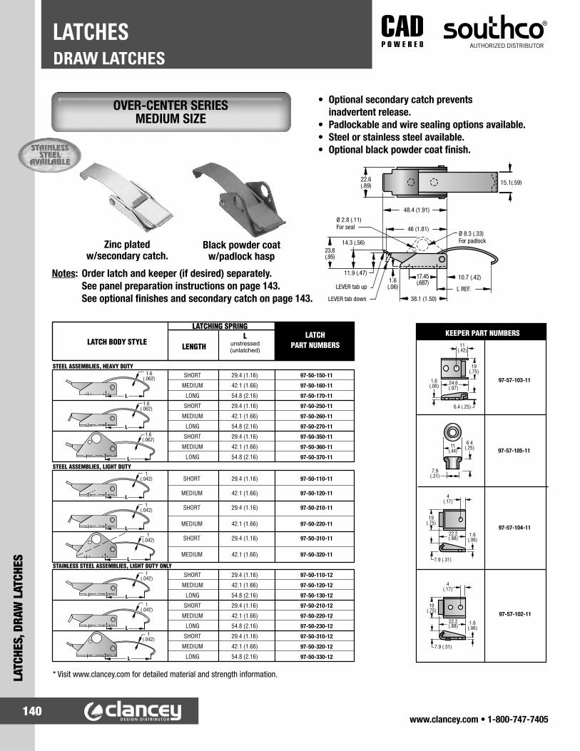
www.clancey.com • 1-800-747-7405140
DRAW LATCHESLATCHES
LATC
HES,
DRA
W L
ATCH
ES
• Optional secondary catch prevents inadvertent release.
• Padlockable and wire sealing options available.• Steel or stainless steel available.• Optional black powder coat finish.
* Visit www.clancey.com for detailed material and strength information.
Notes: Order latch and keeper (if desired) separately. See panel preparation instructions on page 143. See optional finishes and secondary catch on page 143.
OVER-CENTER SERIES MEDIUM SIZE
Zinc plated w/secondary catch.
Black powder coat w/padlock hasp
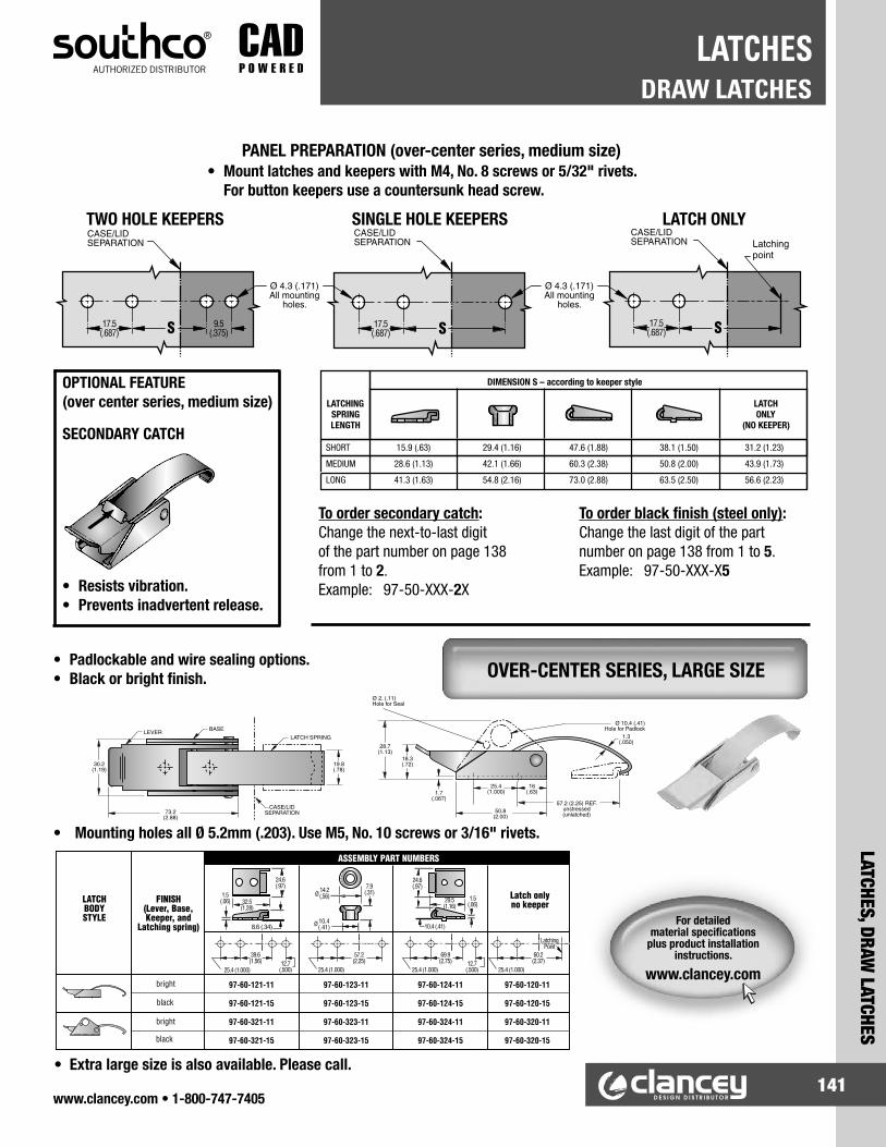
www.clancey.com • 1-800-747-7405141
LATCHES, DRAW LATCHES
DRAW LATCHESLATCHES
PANEL PREPARATION (over-center series, medium size)
• Padlockable and wire sealing options. • Black or bright finish.
TWO HOLE KEEPERS SINGLE HOLE KEEPERS LATCH ONLY
• Mount latches and keepers with M4, No. 8 screws or 5/32" rivets. For button keepers use a countersunk head screw.
• Extra large size is also available. Please call.
• Mounting holes all Ø 5.2mm (.203). Use M5, No. 10 screws or 3/16" rivets.
OPTIONAL FEATURE(over center series, medium size)
SECONDARY CATCH
• Resists vibration.• Prevents inadvertent release.
To order secondary catch:Change the next-to-last digit of the part number on page 138 from 1 to 2.Example: 97-50-XXX-2X
To order black finish (steel only):Change the last digit of the part number on page 138 from 1 to 5.Example: 97-50-XXX-X5
OVER-CENTER SERIES, LARGE SIZE
For detailed material specifications
plus product installation instructions.
www.clancey.com

www.clancey.com • 1-800-747-7405142
DRAW LATCHESLATCHES
LATC
HES,
DRA
W L
ATCH
ES
PANEL PREPARATION• Same great features in a larger size.• Ideal for outdoor applications subject
to vibration.• Additional options available.
PANEL PREPARATION
For Reversed Keeper
For Right Angle KeeperPANEL PREPARATION
PANEL PREPARATION
Use 5mm (3/16") rivets, M5 or No. 10 screws for mounting.
Use 4mm (5/32") rivets, M4 or No. 8 size screws for mounting.
• Elastomer body absorbs vibration, cushions impact and tolerates misalignment.
• 3 keeper configurations.• Stainless steel brackets and keepers.
SOFT LATCH® - SMALL SIZE
SOFT LATCH® - LARGE SIZE
For detailed material specifications
plus product installation instructions.
www.clancey.com
Keeper Style ASSEMBLY PART NUMBER
Concealed C7-10Reverse Keeper C7-11
Right Angle Keeper C7-12
ASSEMBLY PART NUMBERC7-20

www.clancey.com • 1-800-747-7405143
LATCHES, DRAW LATCHES
DRAW LATCHESLATCHES
• Non-corrosive UV resistant materials. • Compensates for misalignment in three planes.• Absorbs vibration.• 3 lengths, front or concealed mounting.
• Absorbs vibration. • Steel or stainless steel mounting hardware.
• Refer to above drawing and table for panel preparation.
Small size with stainless steel keeper and bracket.
Medium size with zinc plated steel keeper and bracket.
PART NUMBERStainless Steel37-10-051-20
PART NUMBERSteel Zinc Plated37-10-061-10
For detailed material specifications
plus product installation instructions.
www.clancey.com
TAB-HANDLE STYLE
FLEXIBLE T-HANDLE STYLE
PART NUMBERS Installationmethod
Dimensions
Latch Keeper Screws (3 per bag) E A B C D
F7-530 F7-537 — Front —
112 (4.81)
41 (1.6)
25.4 (1.00)
31 (1.23)F7-540 F7-547
F7-548-3 Concealed (thread forming)
up to 8.0 (.32)
F7-558-3 Concealed (thread forming)
8.1 (.32) to 17.5 (.69)
F7-630 F7-537 — Front —
167 (6.6)
72 (2.83)
32 (1.25)
298 (1.13)F7-640 F7-547
F7-548-3 Concealed (thread forming)
up to 8.0 (.32)
F7-558-3 Concealed (thread forming)
8.1 (.32) to 17.5 (.69)
F7-730 F7-537 — Front —
221 (8.7)
117 (4.6)
32 (1.25)
29 (1.13)F7-740 F7-547
F7-548-3 Concealed (thread forming)
up to 8.0 (.32)
F7-558-3 Concealed (thread forming)
8.1 (.32) to 17.5 (.69)
Notes: For concealed mounting order thread forming screw package based on panel thickness.
For front mounting, customer supplied #10, M5 or 3/16" rivets based on panel thickness.

www.clancey.com • 1-800-747-7405144
DRAW LATCHESLATCHES
LATC
HES,
DRA
W L
ATCH
ES
SMALL SIZE
• Absorbs vibration.• Steel or stainless steel base and keeper.• Available unassembled (steel only, select sizes)
for easy painting of base and keeper.• Available in stainless steel.
MEDIUM SIZE
LARGE SIZE
• This latch can be ordered unassembled. Change -086- to -087- (steel only).
• This latch can be ordered unassembled. Change -071- to -072- (steel only).
KEEPER STYLE R
KEEPER STYLE R
T-HANDLE SERIES
For detailed material specifications
plus product installation instructions.
www.clancey.com
KeeperStyle
PART NUMBERSSteel
Base and KeeperStainless Steel
Base and KeeperF 37-10-086-10 37-10-86-20R 37-20-086-10 37-20-86-20
PART NUMBERSSteel
Base and KeeperStainless Steel
Base and Keeper37-10-065-10 37-10-65-20
KeeperStyle
PART NUMBERSSteel
Base and KeeperStainless Steel
Base and KeeperF 37-10-071-10 37-10-071-20R 37-20-071-10 37-20-071-20

www.clancey.com • 1-800-747-7405145
LATCHES, DRAW LATCHES
DRAW LATCHESLATCHES
L X YKEEPERSTYLE Plated Steel,
Black RubberStainless Steel Metal Parts,
Black Rubber
37-10-101-10
37-20-101-10
37-10-131-10
37-20-131-10
37-10-101-20
37-20-101-20
37-10-131-20
37-20-131-20
F
R
F
R
50.8(2.00)130.2
(5.13)
247.7(9.75)
165.1(6.50)
204.8(8.06)
90.5(3.56)
SERIES
100
130
PART NUMBERS
KEEPER STYLE R
Regular (100 series) can be ordered unassembled. change -101- to -102 (steel only)
For detailed material specifications
plus product installation instructions.
www.clancey.com
FLEXIBLE DRAW LATCH T-HANDLE SERIES
EXTRA - LARGE SIZE
130 SERIES EXTENDED LENGTH
STANDARD LENGTH 100 SERIES (pictured)

www.clancey.com • 1-800-747-7405146
DRAW LATCHESLATCHES
LATC
HES,
DRA
W L
ATCH
ES
• Absorbs vibration.• 3 Sizes.• For heavy duty applications.• Optional pressure point button.
FLEXIBLE DRAW LATCH LEVER ASSISTED STYLE
DIMENSIONS PART NUMBERSA B C D Steel Stainless Steel
241.3(9.50)
152.4(6.00)
96.8(3.81) 25.4
(1.00)
37-10-274-10 • 37-10-274-20 •
366.7(14.44)
277.8(10.94)
222.3(8.75) 37-10-277-10 • 37-10-277-20 •
Heavy Duty245.3(9.66)
152.4(6.00)
93.7(3.69)
31.8( 1.25) 37-10-284-50 • 37-10-284-25 •
OPTIONAL PRESSURE BUTTON37-21-271-11
• For heavy duty applications.• Non-corrosive, UV-stable materials.• Absorbs vibration.
AEROLATCH™ LEVER ASSISTED STYLE
PANEL PREPARATIONDIMENSIONS PART
NUMBERSMOUNTING
HOLE SIZE
PAN or ROUND HEAD SCREW SIZEA B C
254 (10)
97 ± 3 (3.82 ± .12) 25.4
(1.00)
37-30-294-60 5.5 ± 0.1 (.217 ±.004)
M5 (No. 10)379
(15)222 ± 6
(8.74 ± .24) 37-30-297-60
HEAVY DUTY300 (12)
144 ± 4 (5.67 ± .16)
32 (1.25) 37-40-295-60 6.6 ± 0.1
(.260 ±.004)M6
(1/4-20)
Ø
± 0.2 (.008)
Ø

www.clancey.com • 1-800-747-7405147
LATCHES, DRAW LATCHES
DRAW LATCHESLATCHES
• Progressively draws two panels together.• Can compress gaskets to air or water
tight standards.• Multiple mounting options.
PANEL PREPARATION AND INSTALLATIONRECESSED POCKET SIDE MOUNT
• Strong closing pressure with minimal closing force.
• Vibration and impact resistant.
SHALLOW TAB DEEP TAB STANDARD FRONT MOUNT
TOOL (order separately) Please visit web site www.clancey.com to download complete dimensional drawings and mounting instructions.
For detailed material specifications
plus product installation instructions.
www.clancey.com
For detailed material specifications
plus product installation instructions.
www.clancey.com
ROTO LOCK® BUTT-JOINT PANEL FASTENER
DUAL LOCK® BUTT-JOINT PANEL FASTENER
8mm Hex Wrench29-0059-02
PART NUMBERSLatch Receptacle
R5-0074-08 R5-0079-08
PART NUMBERSStyle Shallow Tab Deep Tab Standard Front MountLatch R2-0259-02 R2-0169-02 R2-0055-02 R2-0267-02
Receptacle R2-0257-02 R2-0160-02 R2-0002-02 R2-0268-02

www.clancey.com • 1-800-747-7405148
DRAW LATCHESLATCHES
LATC
HES,
DRA
W L
ATCH
ES
• Sleek appearance. • Steel (with black finish) or stainless steel (bright).
PANEL PREPARATION
CONCEALED SPRING LOADED VERSIONIdeal for applications where shock and vibration occur. Compensates up to 1.7 mm (0.07 in.) for mounting hole irregularities, panel variations and gasket set. Also provides an additional allowance of 2.3 mm (0.09 in.) deflection when loaded.
FIXED VERSIONIdeal for applications where misalignment is not a concern.
Concealed Spring Loaded and Fixed Version dimensions are identical except for dimension "A", "B", and "C" (see table).
PANEL PREPARATION
• For applications where misalignment is not a concern.
ROTARY ACTION DRAW LATCH STYLIZED WING
LINK LOCK® ROTARY ACTION LATCH SMALL SIZE-RIVETED
For detailed material specifications
plus product installation instructions.
www.clancey.com
Many blade (slide) modifications are tooled
and available. Please call for assistance.
800-747-7405
RIVETED STYLE PART NUMBERSType Steel Stainless SteelLatch K3-1625-07 K3-1625-52
Keeper K3-0334-07 K3-0334-52
PART NUMBERS DIMENSIONS
LATCHVERSION Steel with
Black Powder Coat Stainless Steel A B C
Spring Loaded K2-3005-89 K2-3005-51 19 (.73) 48 (1.89) 32±0.(1.25±0)Fixed K2-3001-89 K2-3001-51 18 (.71) 47 (1.85) 32±0.2 (1.25±01)
KEEPER PLATE K4-2338-89 K4-2338-51
+1.7 -0.2
+1.7 -0.2

www.clancey.com • 1-800-747-7405149
LATCHES, DRAW LATCHES
DRAW LATCHESLATCHES
• Spring loaded anchor plate compensates up to 4 mm (.156") for misalignment.
PANEL PREPARATION
Right Angle Keeper Concealed Keeper
ADDITIONAL KEEPER PLATE OPTIONS (for small size link locks)Elongated Keeper
PANEL PREPARATION
• Security lock-out option.
MATERIAL PART NUMBERSteel K3-0100-07
Stainless Steel K3-0100-52
MATERIAL PART NUMBERSteel K3-0696-07
MATERIAL PART NUMBERSteel K3-1617-07
LINK LOCK® ROTARY ACTION LATCH SMALL SIZE-SPRING LOADED
LINK LOCK® ROTARY ACTION LATCH SMALL SIZE-PADLOCKABLE
SPRING LOADED STYLE PART NUMBERSType Steel Stainless SteelLatch K3-1735-07 K3-1735-52
Keeper K3-0334-07 K3-0334-52
PAD-LOCKABLE STYLE PART NUMBERSType Steel Stainless SteelLatch K3-2403-07 K3-2403-52
Keeper K3-0334-07 K3-0334-52

www.clancey.com • 1-800-747-7405150
DRAW LATCHESLATCHES
LATC
HES,
DRA
W L
ATCH
ES
PANEL PREPARATION
PANEL PREPARATION
PANEL PREPARATION
• Spring loaded anchor plate compensates up to 4mm for misalignment.
• Keyed alike, custom keycodes available. • Supplied with two keys.
• For applications where misalignment is not a concern.
Material: SteelFinish: Zinc plated, plus bright chromate dip.
Material: SteelFinish: Zinc plated, plus bright chromate dip.
Material: SteelFinish: Zinc plated, plus bright chromate dip.
* Flat cam dimensions vary slightly from hex cam which is shown.
HEX CAM PART NUMBER
Latch K4-2833-07
FLAT CAMPART NUMBER
Latch K4-3020-07
Keeper (both styles) K4-2338-07
LINK LOCK® ROTARY ACTION DRAW LATCH MEDIUM SIZE-RIVETED BASE
LINK LOCK® ROTARY ACTION DRAW LATCH MEDIUM SIZE-SPRING LOADED
LINK LOCK® ROTARY ACTION DRAW LATCH MEDIUM SIZE-KEY-LOCKING
PART NUMBERSLatch K4-2714-07
Keeper K4-2338-07
PART NUMBERSLatch K4-2359-07
Keeper K4-2338-07
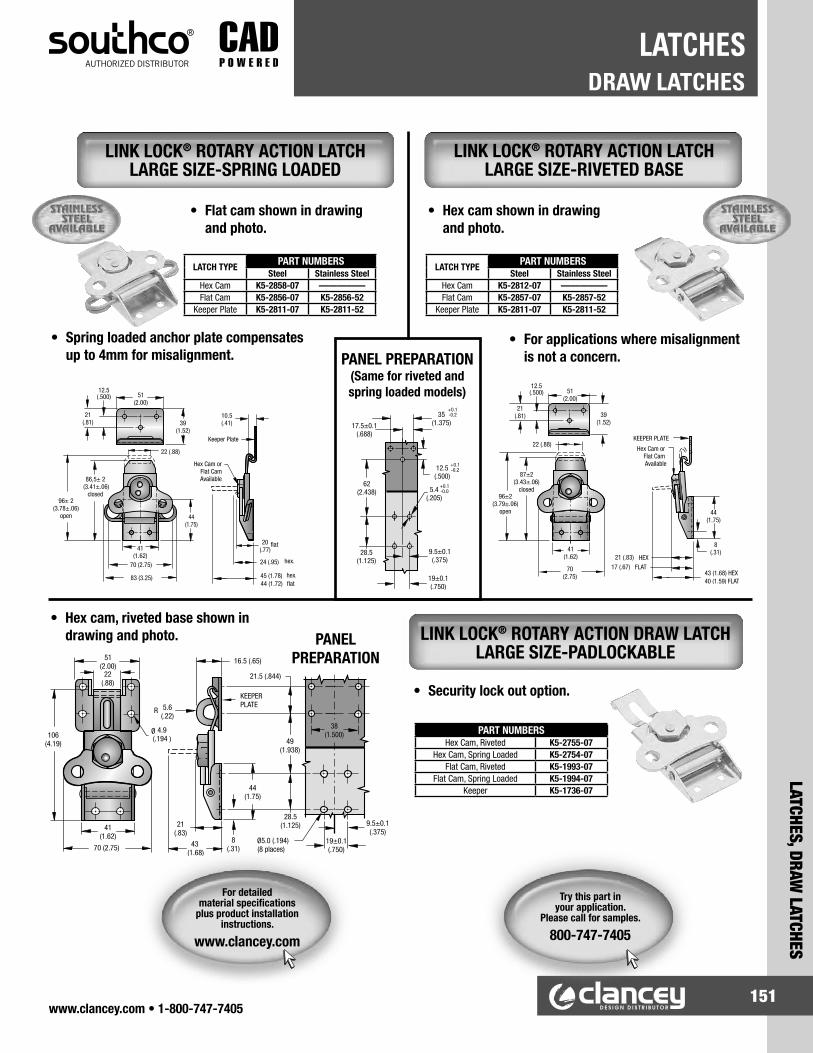
www.clancey.com • 1-800-747-7405151
LATCHES, DRAW LATCHES
DRAW LATCHESLATCHES
• Flat cam shown in drawing and photo.
PANEL PREPARATION (Same for riveted and spring loaded models)
• Hex cam shown in drawing and photo.
• Spring loaded anchor plate compensates up to 4mm for misalignment.
• Hex cam, riveted base shown in drawing and photo. PANEL
PREPARATION
• For applications where misalignment is not a concern.
• Security lock out option.
For detailed material specifications
plus product installation instructions.
www.clancey.com
LINK LOCK® ROTARY ACTION DRAW LATCH LARGE SIZE-PADLOCKABLE
LINK LOCK® ROTARY ACTION LATCH LARGE SIZE-RIVETED BASE
LINK LOCK® ROTARY ACTION LATCH LARGE SIZE-SPRING LOADED
Try this part in your application.
Please call for samples.
800-747-7405
LATCH TYPE PART NUMBERSSteel Stainless Steel
Hex Cam K5-2858-07 —————Flat Cam K5-2856-07 K5-2856-52
Keeper Plate K5-2811-07 K5-2811-52
LATCH TYPE PART NUMBERSSteel Stainless Steel
Hex Cam K5-2812-07 —————Flat Cam K5-2857-07 K5-2857-52
Keeper Plate K5-2811-07 K5-2811-52
PART NUMBERSHex Cam, Riveted K5-2755-07
Hex Cam, Spring Loaded K5-2754-07Flat Cam, Riveted K5-1993-07
Flat Cam, Spring Loaded K5-1994-07Keeper K5-1736-07

www.clancey.com • 1-800-747-7405152
LOCKSLO
CKS
www.clancey.com • 1-800-747-7405
HOW TO SELECT YOUR CAM LOCK
• Shuttered.
• Non-shuttered.
• Tool driven.
• Master keyed.• Removal keys.• Keyed alike.• Keyed differently.• Groups of 10, 50, or 125 codes.
LOCK PLUG OPTIONS
REMOVABLE CORE SYSTEMS • www.clancey.com or application specialist assisted only.
For the best results in selecting the proper lock and cam the first time, please use one of the following methods.
1) Visit the product configuration tool at www.clancey.com.
• You can get 3D models, request samples and pricing.
2) Call your application specialist.
• We are well trained to help you. 800-747-7405.
3) Work with the catalog to select your parts.
• Hardest method (sorry) please pay close attention to grips, cam offsets, cam lengths, sealing and finish options.
All items are ordered separately.
REMOVABLE CORE
- Multiple Key Codes
- Tool Actuation
- Change Key Codes in Future
- Configure to Order
Non-Sealed Sealed
CM-3CM-6
Online Configuration.
www.clancey.com

www.clancey.com • 1-800-747-7405153
LOCKS
LOCKS
www.clancey.com • 1-800-747-7405
LOCK CAMS
WING DRIVER CAM LOCKS
• Always ordered separately from locks.
• Three configurations.
• Standard
• Hook-type 1
• Hook-type 2
• Three standard lengths.
• .75" (19mm)
• 1.25" (31.8mm)
• 1.75" (44.5mm)
• Four standard cam offsets
• Allows for secure grip
• Can be forward or reverse
• See part number chart
• Order cams separately (Above)
Type 23/4" length
offset
Standard1-1/4" length
no offset
Type 11-3/4" lengthdeep offset
Fixed Core (Wing, Sealed)PART NUMBER
HOUSING & WING FINISH B = Black powder coated C = Chrome platedCAM ROTATION(see illustration), page 129 01 = Clockwise 09 = Counter-cockwise
HOUSING LENGTHSNumber Dimensions
1 16 (.625)2 22 (.875)3 35 (1.375)
CAM LENGTHSNumber Dimensions
06 19 (.75)10 31.8 (1.25)14 44.5 (1.75)
CAM TYPE C = No hook H = Hook, Type 1 L = Hook, Type 2
• Sealed to meet NEMA 4 water intrusion standards.• Smooth operation with superior feel.
CM-1
CAM OFFSET 0 = No Offset 2 = 3.2 (.125) 4 = 6.4 (.250) 6 = 9.5 (.375)
CM-3

www.clancey.com • 1-800-747-7405154
LOCKSLO
CKS
FIXED CORE, SEALED LOCKS• Sealed to meet NEMA 4 water intrusion standards.• Smooth operation with superior feel.• Black or chrome housings.• Shuttered lock core.
HOUSING FINISH B = Black powder coated C = Chrome plated
CAM ROTATION (see facing page) 01 = Clockwise 09 = Counter-clockwise
• Cams sold separately. (See page 153)
NOTE: After determining grip, add or subtract cam offset (see page 153) from housing length to assure a tight fit.
HOUSING LENGTHSNumber Dimensions
1 16 (.625)2 22 (.875)6 28.5 (1.125)3 35 (1.375)4 41 (1.625)5 48 (1.875)
LOCK PLUG BODY and MOUNTING NUT: Die-cast zinc, bright chromateHOUSING: Die-cast zinc, bright chromate and black power coated head or chrome plated headSCREW with LOCKWASHER and STOP WASHER: Steel, zinc plate, bright chromateO-RING: Nitrile, blackSEALING WASHER: Rubber, blackLOCKING SCALP: Stainless, steel, naturalSHUTTER: Brass, nickel plateWAFERS: Brass, natural.WAFER SPRINGS: Stainless steel, naturalSHUTTER SPRING: Steel alloyKEYS: Brass, nickel plated (2 included)LOCK: Key code CH751, keyed alike, key removal in locked and unlocked positions
CM-2
For detailed material specifications
plus product installation instructions.
www.clancey.com
www.clancey.com • 1-800-747-7405
Black Housing
Chrome Housing
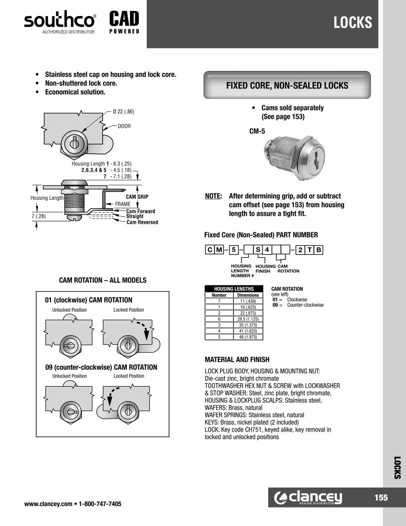
www.clancey.com • 1-800-747-7405155
LOCKS
LOCKS
FIXED CORE, NON-SEALED LOCKS
HOUSING LENGTHSNumber Dimensions
7 11 (.438)1 16 (.625)2 22 (.875)6 28.5 (1.125)3 35 (1.375)4 41 (1.625)5 48 (1.875)
CAM ROTATION (see left) 01 = Clockwise 09 = Counter-clockwise
MATERIAL AND FINISHLOCK PLUG BODY, HOUSING & MOUNTING NUT: Die-cast zinc, bright chromate TOOTHWASHER HEX NUT & SCREW with LOCKWASHER & STOP WASHER: Steel, zinc plate, bright chromate, HOUSING & LOCKPLUG SCALPS: Stainless steel, WAFERS: Brass, natural WAFER SPRINGS: Stainless steel, natural KEYS: Brass, nickel plated (2 included) LOCK: Key code CH751, keyed alike, key removal in locked and unlocked positions
• Stainless steel cap on housing and lock core.• Non-shuttered lock core.• Economical solution.
• Cams sold separately (See page 153)
NOTE: After determining grip, add or subtract cam offset (see page 153) from housing length to assure a tight fit.
Fixed Core (Non-Sealed) PART NUMBER
CM-5
01 (clockwise) CAM ROTATION
09 (counter-clockwise) CAM ROTATION
CAM ROTATION – ALL MODELS

www.clancey.com • 1-800-747-7405156
CONTINUOUS & BUTT HINGE DESIGN INFOHINGES
HING
ES, C
USTO
M D
ESIG
NS
PIN DIAMETER RANGE
.062" to .500"
LEAF THICKNESS RANGE
.025" to .250"
MATERIALSCold Rolled Steel
Sheet Steel Pre-Plated Steel
304 Stainless Steel 316 Stainless Steel
Aluminum Brass
CUSTOM CONFIGURATIONS
Let Us Help YouWe specialize in custom hinge designs.
We can offer virtually any combination ofoptions to meet your application requirements.Please call or e-mail our application specialists.
[email protected] 800-747-7405
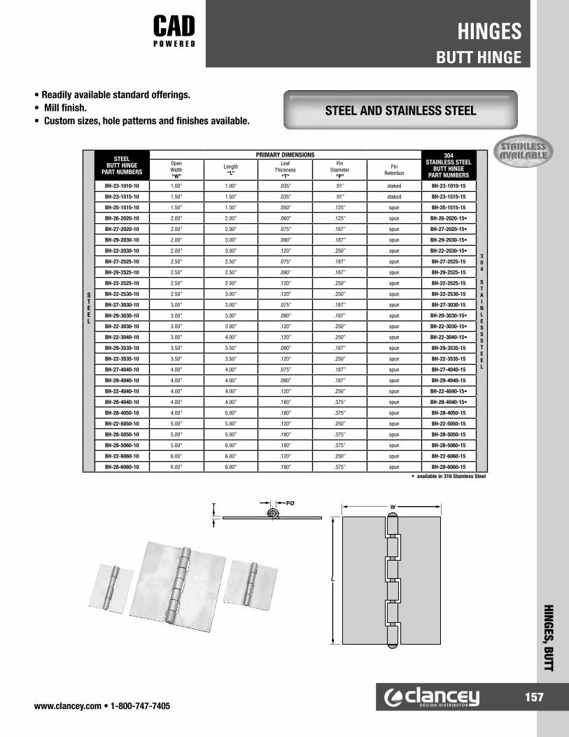
www.clancey.com • 1-800-747-7405157
HINGES, BUTT
BUTT HINGEHINGES
STEEL AND STAINLESS STEEL• Readily available standard offerings.• Mill finish.• Custom sizes, hole patterns and finishes available.
STEEL
STEELBUTT HINGE
PART NUMBERS
PRIMARY DIMENSIONS 304STAINLESS STEEL
BUTT HINGEPART NUMBERS
304 STAINLESSSTEEL
OpenWidth“W”
Length“L”
LeafThickness
“T”
PinDiameter
“P”
PinRetention
BH-23-1010-10 1.00” 1.00” .035” .91” staked BH-23-1010-15
BH-23-1515-10 1.50” 1.50” .035” .91” staked BH-23-1515-15
BH-25-1515-10 1.50” 1.50” .050” .125” spun BH-25-1515-15
BH-26-2020-10 2.00” 2.00” .060” .125” spun BH-26-2020-15•
BH-27-2020-10 2.00” 2.00” .075” .187” spun BH-27-2020-15•
BH-29-2030-10 2.00” 3.00” .090” .187” spun BH-29-2030-15•
BH-22-2030-10 2.00” 3.00” .120” .250” spun BH-22-2030-15•
BH-27-2525-10 2.50” 2.50” .075” .187” spun BH-27-2525-15
BH-29-2525-10 2.50” 2.50” .090” .187” spun BH-29-2525-15
BH-22-2525-10 2.50” 2.50” .120” .250” spun BH-22-2525-15
BH-22-2530-10 2.50” 3.00” .120” .250” spun BH-22-2530-15
BH-27-3030-10 3.00” 3.00” .075” .187” spun BH-27-3030-15
BH-29-3030-10 3.00” 3.00” .090” .187” spun BH-29-3030-15•
BH-22-3030-10 3.00” 3.00” .120” .250” spun BH-22-3030-15•
BH-22-3040-10 3.00” 4.00” .120” .250” spun BH-22-3040-15•
BH-29-3535-10 3.50” 3.50” .090” .187” spun BH-29-3535-15
BH-22-3535-10 3.50” 3.50” .120” .250” spun BH-22-3535-15
BH-27-4040-10 4.00” 4.00” .075” .187” spun BH-27-4040-15
BH-29-4040-10 4.00” 4.00” .090” .187” spun BH-29-4040-15
BH-22-4040-10 4.00” 4.00” .120” .250” spun BH-22-4040-15•
BH-28-4040-10 4.00” 4.00” .180” .375” spun BH-28-4040-15•
BH-28-4050-10 4.00” 5.00” .180” .375” spun BH-28-4050-15
BH-22-5050-10 5.00” 5.00” .120” .250” spun BH-22-5050-15
BH-28-5050-10 5.00” 5.00” .180” .375” spun BH-28-5050-15
BH-28-5060-10 5.00” 6.00” .180” .375” spun BH-28-5060-15
BH-22-6060-10 6.00” 6.00” .120” .250” spun BH-22-6060-15
BH-28-6060-10 6.00” 6.00” .180” .375” spun BH-28-6060-15
• available in 316 Stainless Steel
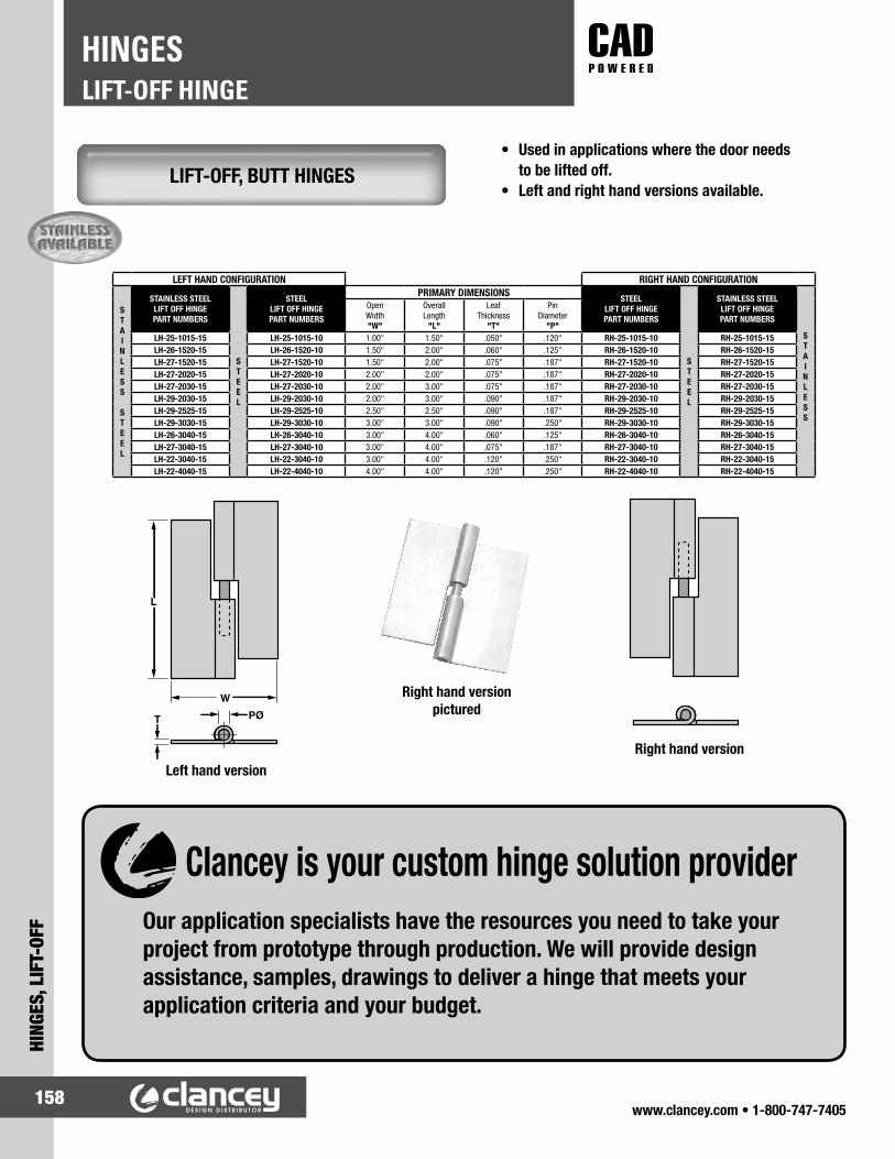
www.clancey.com • 1-800-747-7405158
LIFT-OFF HINGEHINGES
HING
ES, L
IFT-
OFF
LIFT-OFF, BUTT HINGES• Used in applications where the door needs
to be lifted off.• Left and right hand versions available.
Right hand versionpictured
Left hand version
LEFT HAND CONFIGURATION RIGHT HAND CONFIGURATION
STAINLESS
STEEL
STAINLESS STEELLIFT OFF HINGEPART NUMBERS
STEEL
STEELLIFT OFF HINGEPART NUMBERS
PRIMARY DIMENSIONSSTEEL
LIFT OFF HINGEPART NUMBERS
STEEL
STAINLESS STEELLIFT OFF HINGEPART NUMBERS
STAINLESS
OpenWidth"W"
OverallLength
"L"
LeafThickness
"T"
Pin Diameter
"P"LH-25-1015-15 LH-25-1015-10 1.00" 1.50" .050" .120" RH-25-1015-10 RH-25-1015-15LH-26-1520-15 LH-26-1520-10 1.50" 2.00" .060" .125" RH-26-1520-10 RH-26-1520-15LH-27-1520-15 LH-27-1520-10 1.50" 2.00" .075" .187" RH-27-1520-10 RH-27-1520-15LH-27-2020-15 LH-27-2020-10 2.00" 2.00" .075" .187" RH-27-2020-10 RH-27-2020-15LH-27-2030-15 LH-27-2030-10 2.00" 3.00" .075" .187" RH-27-2030-10 RH-27-2030-15LH-29-2030-15 LH-29-2030-10 2.00" 3.00" .090" .187" RH-29-2030-10 RH-29-2030-15LH-29-2525-15 LH-29-2525-10 2.50" 2.50" .090" .187" RH-29-2525-10 RH-29-2525-15LH-29-3030-15 LH-29-3030-10 3.00" 3.00" .090" .250" RH-29-3030-10 RH-29-3030-15LH-26-3040-15 LH-26-3040-10 3.00" 4.00" .060" .125" RH-26-3040-10 RH-26-3040-15LH-27-3040-15 LH-27-3040-10 3.00" 4.00" .075" .187" RH-27-3040-10 RH-27-3040-15LH-22-3040-15 LH-22-3040-10 3.00" 4.00" .120" .250" RH-22-3040-10 RH-22-3040-15LH-22-4040-15 LH-22-4040-10 4.00" 4.00" .120" .250" RH-22-4040-10 RH-22-4040-15
W
L
PØT
Right hand version
Our application specialists have the resources you need to take your project from prototype through production. We will provide design assistance, samples, drawings to deliver a hinge that meets your application criteria and your budget.
Clancey is your custom hinge solution provider

www.clancey.com • 1-800-747-7405159
HINGES, LIFT-OFF
LIFT-OFF HINGEHINGES
WELD-ON “BULLET” HINGE – STEEL BODY• Hinge can be mounted so the door can be lifted
off, or reversed for permanent installation.• Sleek design.
FIXED PIN CONFIGURATION
Try this part inyour application
Please call for samples.
800-747-7405
STEEL
BODY
WITH
STEEL
PIN
PART NUMBER
PRIMARY DIMENSIONS
LENGTH"L"
THICKNESS"T"
HINGEDIAMETER
"D"
PINDIAMETER
"P"FIXED STEEL PIN - BRASS WASHER
7010.PS.040 40mm 1.57" 9.5mm .37" 8mm .31" 5mm .20"7010.PS.060 60mm 2.36" 12mm .47" 10mm .39" 6mm .24"7010.PS.080 80mm 3.15" 15.5mm .61" 13mm .51" 8mm .31"7010.PS.100 100mm 3.94" 20mm .79" 16mm .63" 10mm .39"7010.PS.120 120mm 4.73" 20mm .79" 16mm .63" 11mm .43"7010.PS.135 135mm 5.32" 22mm .87" 18mm .71" 12mm .47"7010.PS.150 150mm 5.91" 25mm .98" 20mm .79" 13mm .51"7010.PS.180 180mm 7.09" 25mm .98" 20mm .79" 14mm .55"7010.PS.200 200mm 7.87" 28.5mm 1.12" 23mm .91" 16mm .63"
REMOVABLE STEEL PIN - BRASS WASHER7012.PS.080 80mm 3.15" 15.5mm .61" 13mm .51" 8mm .31"7012.PS.100 100mm 3.94" 20mm .79" 16mm .63" 10mm .39"
GREASE FITTING, FIXED STEEL PIN - BRASS WASHER7004.PS.080 80mm 3.15" 15.5mm .61" 13mm .51" 8mm .31"7004.PS.100 100mm 3.94" 20mm .79" 16mm .63" 10mm .39"7004.PS.120 120mm 4.73" 20mm .79" 16mm .63" 11mm .43"7004.PS.135 135mm 5.32" 22mm .87" 18mm .71" 12mm .47"7004.PS.150 150mm 5.91" 25mm .98" 20mm .79" 13mm .51"7004.PS.180 180mm 7.09" 25mm .98" 20mm .79" 14mm .55"7004.PS.200 200mm 7.87" 28.5mm 1.12" 23mm .91" 16mm .63"
STEEL
BODY
WITH
BRASS
PIN
PART NUMBER
PRIMARY DIMENSIONS
LENGTH"L"
THICKNESS"T"
HINGEDIAMETER
"D"
PINDIAMETER
"P"FIXED BRASS PIN - BRASS WASHER
7011.PS.040 40mm 1.57" 9.5mm .37" 8mm .31" 5mm .20"7011.PS.050 50mm 1.97" 9.5mm .37" 8mm .31" 5mm .20"7011.PS.060 60mm 2.36" 12mm .47" 10mm .39" 6mm .24"7011.PS.070 70mm 2.76" 13.5mm .53" 11.5mm .45" 7mm .28"7011.PS.080 80mm 3.15" 15.5mm .61" 13mm .51" 8mm .31"7011.PS.100 100mm 3.94" 20mm .79" 16mm .63" 10mm .39"7011.PS.120 120mm 4.73" 20mm .79" 16mm .63" 11mm .43"7011.PS.135 135mm 5.32" 22mm .87" 18mm .71" 12mm .47"7011.PS.150 150mm 5.91" 25mm .98" 20mm .79" 13mm .51"7011.PS.180 180mm 7.09" 25mm .98" 20mm .79" 14mm .55"7011.PS.200 200mm 7.87" 28.5mm 1.12" 23mm .91" 16mm .63"
REMOVABLE BRASS PIN - BRASS WASHER7013.PS.080 80mm 3.15" 15.5mm .61" 13mm .51" 8mm .31"7013.PS.100 100mm 3.94" 20mm .79" 16mm .63" 10mm .39"
GREASE FITTING, FIXED BRASS PIN - BRASS WASHER7005.PS.080 80mm 3.15" 15.5mm .61" 13mm .51" 8mm .31"7005.PS.100 100mm 3.94" 20mm .79" 16mm .63" 10mm .39"

www.clancey.com • 1-800-747-7405160
LIFT-OFF HINGEHINGES
HING
ES, L
IFT-
OFF REMOVABLE PIN
CONFIGURATIONGREASE FITTING CONFIGURATION
FLAT HEAD 316 STAINLESS CONFIGURATION
STAINLESS STEEL BODY
PART NUMBER
PRIMARY DIMENSIONS
LENGTH“L”
THICKNESS“T”
HINGEDIAMETER
“D”
PINDIAMETER
“P”304 STAINLESS STEEL BODY - ROUNDED HEAD.
FIXED STAINLESS STEEL PIN, STAINLESS STEEL WASHER7010.SS.060 60mm 2.36" 12mm .47" 10mm .39" 6mm .24"7010.SS.080 80mm 3.15" 15.5mm .61" 13mm .51" 8mm .31"7010.SS.100 100mm 3.94" 20mm .79" 16mm .63" 10mm .39"7010.SS.120 120mm 4.73" 20mm .79" 16mm .63" 11mm .43"7010.SS.150 150mm 5.91" 25mm .98" 20mm .79" 13mm .51"7010.SS.180 180mm 7.09" 25mm .98" 20mm .79" 14mm .55"
316 STAINLESS STEEL BODY - FLAT HEAD. FIXED STAINLESS STEEL PIN, STAINLESS STEEL WASHER
7015.SS.080 80mm 3.15" 15.5mm .61" 13mm .51" 8mm .31"7015.SS.100 100mm 3.94" 20mm .79" 16mm .63" 10mm .39"7015.SS.120 120mm 4.73" 20mm .79" 16mm .63" 11mm .43"
ALUMINI
M BODY
PART NUMBER
PRIMARY DIMENSIONS
LENGTH“L”
THICKNESS“T”
HINGEDIAMETER
“D”
PINDIAMETER
“P”ALUMINUM BODY
FIXED STAINLESS STEEL PIN, STAINLESS STEEL WASHER7010.AL.060 60mm 2.36" 12mm .47" 10mm .39" 6mm .24"7010.AL.080 80mm 3.15" 15.5mm .61" 13mm .51" 8mm .31"7010.AL.100 100mm 3.94" 20mm .79" 16mm .63" 10mm .39"7010.AL.120 120mm 4.73" 20mm .79" 16mm .63" 11mm .43"7010.AL.150 150mm 5.91" 25mm .98" 20mm .79" 13mm .51"7010.AL.180 180mm 7.09" 25mm .98" 20mm .79" 14mm .55"
ALUMINUM BODY - GREASE FITTINGFIXED STAINLESS STEEL PIN, STAINLESS STEEL WASHER
7004.AL.080 80mm 3.15" 15.5mm .61" 13mm .51" 8mm .31"7004.AL.100 100mm 3.94" 20mm .79" 16mm .63" 10mm .39"7004.AL.100 120mm 4.73" 20mm .79" 16mm .63" 11mm .43"7004.AL.150 150mm 5.91" 25mm .98" 20mm .79" 13mm .51"
Try this part inyour application
Please call for samples.
800-747-7405
Other sizesare available.
www.clancey.com
WELD-ON “BULLET” HINGE STAINLESS STEEL OR ALUMINUM BODY
• Optional grease fitting for lubrication.• Easy weld-on installation.

www.clancey.com • 1-800-747-7405161
HINGES, LIFT-OFF
LIFT-OFF HINGEHINGES
DIE CAST LIFT OFF HINGES MINIATURE SIZE
• Allows door to be removed at hinge side.• Hinges can be reversed for permanent
installation.• Mounting hardware is concealed.
INLINE HINGE
OFFSET HINGE
Use screw size PART NUMBER6-32 96-110
M4 x 0.7 96-140
Use screw size
PART NUMBERType“A”
Type“B”
6-32 96-111 96-112M4 x 0.7 96-141 96-142
Offset “B” pictured
• Offset hinges must be ordered as type “A” or type “B” assemblies.
For detailed material specifications
plus product installation instructions.
www.clancey.com
• In-line hinges can be used interchangeably on doors
hinged on either side.
IN-LINE VERSION
Offset “A” illustrated
OFFSET VERSION
Lift-off Installation Permanent Installation

www.clancey.com • 1-800-747-7405162
LIFT-OFF HINGEHINGES
HING
ES, L
IFT-
OFF
DIE-CAST LIFT-OFF HINGES LARGE SIZE
Offset “A” pictured
INLINE HINGE
OFFSET HINGE
• In-line hinges can be used interchangeably on doors
hinged on either side.• Also available in bright
chrome.
• Offset hinges must be ordered as type “A” or type “B” assemblies.
“(See diagram - page 167)”
For detailed material specifications
plus product installation instructions.
www.clancey.com
Use screw size PART NUMBERM5 96-50-500-50
No. 10-32 96-10-500-50
Use screw sizesPART NUMBERS
Type “A” Type “B”M5 96-50-510-50 96-50-520-50
No. 10-32 96-10-510-50 96-10-520-50
Offset Version
Offset “B” illustrated
Offset Version

www.clancey.com • 1-800-747-7405163
HINGES, LIFT-OFF
LIFT-OFF HINGEHINGES
• Allows door to be removed at hinge side.• Ergonomic design.• Non-conducting, corrosion resistant materials.
RECEIVER
LIFT-OFF INSTALLATION
PERMANENT INSTALLATION
PIN
For detailed material specifications
plus product installation instructions.
www.clancey.com
NYLON LIFT-OFF HINGES MEDIUM SIZE IN-LINE
Note: Order (1) pin, (1) receiver, and (4) screws from table below.
• Contact us for thicker panel requirements.
Hinge Element PART NUMBERReceiver 96-720
Pin 96-710
Mounting Screws“L”
Screw LegnthPanel
Thickness PART NUMBER
11.4 (.45) 1 - 4 (.04 - .16) 96-79-114.4 (.57) 4 - 7 (.16 - .28) 96-79-217.4 (6.9) 7 - 10 (.28 - .39) 96-79-320.4 (.80) 10 - 13 (.39 - .51) 96-79-4

www.clancey.com • 1-800-747-7405164
LIFT-OFF HINGEHINGES
HING
ES, L
IFT-
OFF
MOUNTING VARIATIONS
IN-LINE KNUCKLE STYLE OFFSET KNUCKLE STYLE
IN-LINE KNUCKLE STYLE OFFSET KNUCKLE STYLE
Offset “B” pictured
NYLON LIFT-OFF HINGES MEDIUM AND LARGE SIZE
Lift-off Installation
Permanent Installation
DIMENSIONS PART NUMBERSScrewthread
sizeA B C D E, F
& G H J K In-Line Knuckle StyleOffset Knuckle Style
Type “A” Type “B”
300 SeriesM5 31
(1.22)16.7(.66)
14.3(.56)
21.5(.84)
9.5(.38)
19(.75)
7(.28)
58(2.28) See page 169
96-50-310-11 96-50-320-1110-24 96-10-310-11 96-10-320-11
400 SeriesM6 41.3
(1.63)22.2(.88)
19(.75)
28.5(1.13)
12.7(.50)
25.5(1.00)
9.5(.38)
78(3.06)
96-50-400-11 96-50-410-11 96-50-420-111/4-20 96-10-400-11 96-10-410-11 96-10-420-11

www.clancey.com • 1-800-747-7405165
HINGES, CONCEALED
CONCEALEDHINGES
Door Leaf Type “A”F6-941-5
Door Leaf Type “B”F6-942-5
Formed Frame LeafF6-905-5
Flat Frame LeafF6-904-5
For detailed material specifications
plus product installation instructions.
www.clancey.com
SINGLE PIN CONCEALED, REMOVABLE HINGE
• High strength.• Durable.• Resists vibration.• Door and frame leaves can
be installed independently.
Material: 300 Series stainless steel, naturalNote: Order (1) door leaf and (1) frame leaf
to complete a hinge assembly.
• Mounts inside the frame of formed doors.
• Allows door to be removed from the hinge side.
• Three sizes to fit most standard door configurations.
Note: Part number denotes complete assembly polybagged. Bulk packaging is available.
Material:STEEL VERSION:Frame Leaf and Door Leaf:1010 steel, zinc plate plus yellow chromate dip.Hinge Pins:12L14 steel, zinc plate plus yellow chromate dipand clear organic coating.Release Pins:420 stainless steel, passivated.Internal Spring:302 stainless steel, passivated.
STAINLESS STEEL VERSIONFrame Leaf and Door Leaf:304 stainless steel, passivated.Hinge Pins:303 stainless steel, passivated plus clear organic coating.Release Pins:420 stainless steel, passivated.Internal Spring:302 stainless steel, passivated.
DOUBLE PIN CONCEALED, REMOVABLE HINGE
PART NUMBER FRAME LEAFDIMENSIONS
E* FF6-1 F6-1-1 17 (.67") 11.8 (.47")F6-2 F6-2-1 20 (.79") 14.8 (.58")F6-3 F6-3-1 23.4 (.92") 18.2 (.72")

www.clancey.com • 1-800-747-7405166
CONCEALEDHINGES
HING
ES, C
ONCE
ALED
• 180˚ opening angle.• 5.5 lbs. Per pair load rating.
Installation
Material: 304 Stainless Steel.Finish: Satin.Notes: Distance between door
edge and hinge must be less than 2 mm. Minimum door thickness 15 mm.
• 180˚ opening angle.• 66 lbs. Per pair load rating.
InstallationMaterial: Plate and Arm - 304 Stainless Steel.
Body - Polymide.Finish: Plate and arm - Satin. Body - white.Notes: Distance between door
edge and hinge must be less than 4 mm.
• 180˚ opening angle.• 88 lbs. Per pair load rating.
Material: Plate and Arm - 304 Stainless Steel. Body - Polymide.Finish: Plate and arm - Satin. Body - Brown.Notes: Distance between door edge and
hinge must be less than 3.5 mm.
LIGHT DUTY
MEDIUM DUTY
HEAVY DUTY
PART NUMBER W B C C1 H W1RK-50 50 (1.97") 11 (.43") 19 (.75") 38 (1.50") 14 (.55") 18.2 (.72")
PART NUMBERI-66
PART NUMBERI-90

www.clancey.com • 1-800-747-7405167
HINGES, CONCEALED
CONCEALEDHINGES
• 180˚ opening angle.• 5 sizes.
• 5˚ Inward bias for secure closure.• Economical.• For doors 3/4" thickness or less.
MULTI-LINK CONCEALED HINGE
90° CONCEALED HINGE
PARTNUMBER
PRIMARY DIMENSIONS MOUNTING DIMENSIONSL L1 B B1 H h t C C1 C2 D d
R-43 43(1.69")
22(.87")
29(1.14")
11(.43")
13(.51")
5(.20")
5(.20")
0.8(.03")
32(1.26")
18(.71")
6.2(.24")
3.5(.14")
R-45 45(1.77")
19(.75")
35.7(1.41")
13(.51")
18.5(.73")
6(.24")
5(.20")
0.8(.03")
32(1.26")
22.7(.89")
7(.28")
3.5(.14")
R-60 60(2.36")
33(1.30")
35.2(1.39")
13(.51")
18.5(.73")
6.5(.26")
6.5(.26")
1(.04")
47(1.85")
22.2(.87")
8.3(.33)
4.3(.17")
R-70 70(2.76")
35(1.38")
42.6(1.68")
16.1(.63")
23(.91")
9(.35")
7(.28")
1.2(.05")
53(2.09")
26.6(1.05")
9.1(.36")
4.6(.18")
R-100 100(3.94")
52(2.05")
53.2(2.09")
20(.79")
27.5(1.08")
9.5(.37")
9.5(.37")
1.8(.07")
80(3.15")
33.2(1.31")
10(.39")
5.3(.21")
RS-212 95.3(3.75")
52.4(2.13")
51.6(2.03")
19.1(.75")
27.4(1.08")
9.1(.36")
9.5(.37")
1(.04")
75.5(2.97")
32.5(1.28")
10(.39")
5.6(.22")
RS-216 117.5(4.63")
65.9(2.59")
69.1(2.72")
25.4(1.00")
37.2(1.46")
14.5(.57")
11.9(.47")
2(.08")
92(3.62")
43.7(1.72")
12.5(.49")
7(.28")
PARTNUMBER
MAXIMUMDOOR EDGEDISTANCE
"X"
MINIMUMDOOR
THICKNESS
MATERIALS / FINISH
BODY LINKS PINS
R-43 2.3 (.09") 13 (.51") Zinc Alloy / Satin Chrome
304 Stainless /Plain
303 Stainless /Plain
R-45 3 (.12") 19 (.75") Zinc Alloy /Satin Chrome
304 Stainless /Plain
303 Stainless /Plain
R-60 3 (.12") 19 (.75") Zinc Alloy / Satin Chrome
304 Stainless /Plain
303 Stainless /Plain
R-70 3.5 (.14") 25 (.98") Zinc Alloy /Satin Chrome
304 Stainless /Plain
303 Stainless /Plain
R-100 4.8 (.19") 29 (1.14") Zinc Alloy /Satin Chrome
304 Stainless /Plain
Steel / Plain
RS-212 5.5 (.22") 29 (1.14") Zinc Alloy / Yellow Zinc Dichromate
Steel /Yellow Zinc Dichromate
Steel / Yellow Zinc Dichromate
RS-216 6.5 (.26") 35 (1.38") Zinc Alloy / Yellow Zinc Dichromate
Steel / Yellow Zinc Dichromate
Steel / Yellow Zinc Dichromate
PART NUMBERES01/G
Try this part inyour application
Please call for samples.
800-747-7405

www.clancey.com • 1-800-747-7405168
POSITIONING HINGESHINGES
HING
ES, P
OSIT
IONI
NG
• Holds doors open without secondary mechanical support.
• 3 positioning torques hold doors at 80˚, 115˚ or 150˚.
• Free-swinging style available.
• Holds doors open without secondary mechanical support.
• Detent holds door closed, and open at 120˚ and 170˚.
• Free-swinging style available.
For detailed material specifications
plus product installation instructions.
www.clancey.com
POSITIONING-ADVANTAGE HINGE
DOOR-POSITIONING HINGE

www.clancey.com • 1-800-747-7405169
HINGES, POSITIONING
POSITIONING HINGESHINGES
• Holds in 90˚ position incriments.• Non-corrosive w/ stainless steel pin.• Caps hide mounting hardware.
• Polished stainless steel.• Eliminate heed for
door props.• Easy to use and install.
COMPOSITE DETENT HINGE
STAINLESS STEEL DETENT HINGE
PART NUMBERYC-105
PART NUMBER ColorYJ-50B BlackYJ-50W White
Holds in 4 positions - 90° each
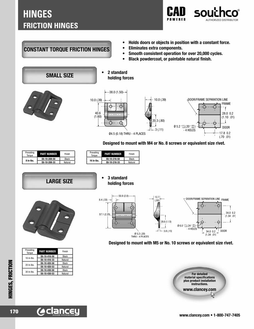
www.clancey.com • 1-800-747-7405170
FRICTION HINGESHINGES
HING
ES, F
RICT
ION
CONSTANT TORQUE FRICTION HINGES
SMALL SIZE
LARGE SIZE
• 2 standard holding forces
• Holds doors or objects in position with a constant force.• Eliminates extra components.• Smooth consistent operation for over 20,000 cycles.• Black powdercoat, or paintable natural finish.
• 3 standard holding forces
For detailed material specifications
plus product installation instructions.
www.clancey.com
Designed to mount with M4 or No. 8 screws or equivalent size rivet.
PrevailingTorque PART NUMBER Finish
8 in-lbs.E6-10-208-50 BlackE6-10-208-33 Natural
PrevailingTorque PART NUMBER Finish
16 in-lbs.E6-10-216-50 BlackE6-10-216-33 Natural
PrevailingTorque PART NUMBER Finish
16 in-lbs.E6-10-416-50 BlackE6-10-416-33 Natural
20 in-lbs.E6-10-420-50 BlackE6-10-420-53 Natural
30 in-lbs.E6-10-430-50 BlackE6-10-430-53 Natural
Designed to mount with M5 or No. 10 screws or equivalent size rivet.

www.clancey.com • 1-800-747-7405171
HINGES, FRICTION
FRICTION HINGESHINGES
For detailed material specifications
plus product installation instructions.
www.clancey.com
SMALL SIZE
MEDIUM AND LARGE SIZE
ADJUSTABLE FRICTION HINGES
COLOR PART NUMBERSBlack E6-10-101-20
Colonial White E6-10-101-30
DIMENSIONS COLOR PART NUMBERS SERIES(size)A B C D E F G H N
36.5(1.44)
43(1.69)
31.7(1.25)
25.5(1.00)
12.7(.50)
18.3(.72)
12.7(.50)
6(.23)
6.7(.27)
Colonial White E6-10-301-10300
Black E6-10-301-20
57.5(2.25)
63.5(2.50)
47.6(1.88)
38(1.50)
19(.75)
28.5(1.13)
19.4(.77)
5.2(.20)
10.3(.41)
Colonial White E6-10-501-10500
Black E6-10-501-20
• Hold doors open, partially open, closed.• Turn the screw to dampen or free-up
the door swing.

www.clancey.com • 1-800-747-7405172
FRICTION HINGESHINGES
HING
ES, F
RICT
ION
CEMA™ CONSTANT TORQUE HINGE MINATURE (.3 in. – lbf)
• Smooth consistant operation.• Extremely compact design.• Requires no adjustment.• Single torque rating.
CEMA™ CONSTANT TORQUE HINGE SMALL SIZE (3-5 in. – lbf)
• Smooth operation.• High torque in a small
package size.• Asymetric option allows
different amounts of torque in each direction.
PART NUMBER STATIC TORQUEST-4A-3S-33 0.35 kg-cm (.3 in - lbf)
APPLICATION EXAMPLE:
PANEL PREPARATION
PANEL PREPARATION
NOTE:• Installs with #4 socket
head screw (not included).• For proper function
assembly must include (1) Type A and (1) Type B hinge.
SYMMETRIC TORQUE VERSIONSPART NUMBERS STATIC TORQUE
(FORWARD and REVERSE)TYPE A TYPE BST-7A-30SA-33 ST-7A-30SB-33 3.5 kg-cm (3 in-lbf)ST-7A-40SA-33 ST-7A-30SB-33 4.6 kg-cm (4 in-lbf)
ST-7A-50SA-33 • ST-7A-30SB-33 • 5.8 kg-cm (5 in-lbf)
ASYMMETRIC TORQUE VERSIONSPART NUMBERS STATIC TORQUE
TYPE A TYPE B FORWARD REVERSEST-7A-40FA-33 ST-7A-40FB-33 4.6 kg-cm (4 in-lbf) 2.8 kg-cm (2.4 in-lbf)*ST-7A-50FA-33 ST-7A-50FB-33 5.8 kg-cm (5 in-lbf) 3.5 kg-cm (3 in-lbf)*
ST-7A-60FA-33 • ST-7A-60FB-33 • 6.9 kg-cm (6 in-lbf) 4.1 kg-cm (3.6 in-lbf)*ST-7A-40RA-33 ST-7A-40RB-33 2.8 kg-cm (2.4 in-lbf)* 4.6 kg-cm (4 in-lbf)ST-7A-40RA-33 ST-7A-50RB-33 3.5 kg-cm (3 in-lbf)* 5.8 kg-cm (5 in-lbf)
ST-7A-40RA-33 • ST-7A-60RB-33 • 4.1 kg-cm (3.6 in-lbf)* 6.9 kg-cm (6 in-lbf)NOTE: * Tolerance is low-torque direction ± 30%
Note: 1/2 degree MAX draft, 3.45 (.14) MAX depth. For use in materials otherthan polymerscontact Clancey.
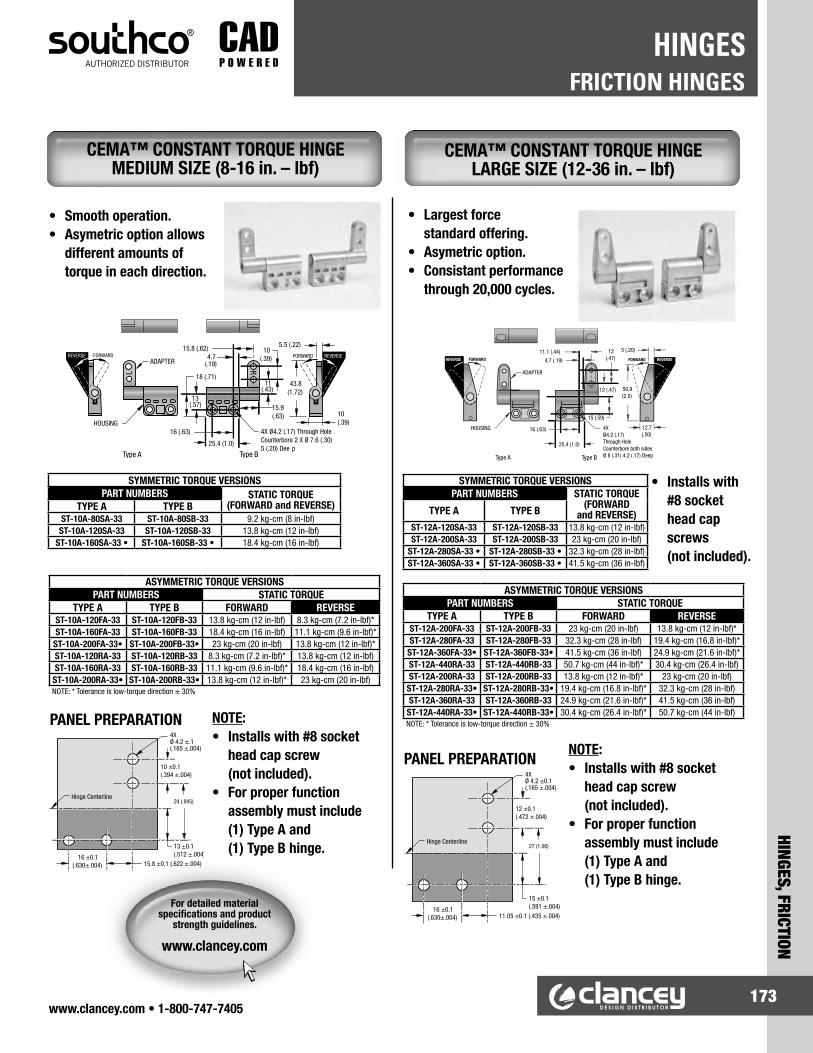
www.clancey.com • 1-800-747-7405173
HINGES, FRICTION
FRICTION HINGESHINGES
CEMA™ CONSTANT TORQUE HINGE MEDIUM SIZE (8-16 in. – lbf)
• Smooth operation.• Asymetric option allows
different amounts of torque in each direction.
CEMA™ CONSTANT TORQUE HINGE LARGE SIZE (12-36 in. – lbf)
• Largest force standard offering.
• Asymetric option.• Consistant performance
through 20,000 cycles.
PANEL PREPARATION NOTE:• Installs with #8 socket
head cap screw (not included).
• For proper function assembly must include
(1) Type A and (1) Type B hinge.
• Installs with #8 socket head cap screws (not included).
SYMMETRIC TORQUE VERSIONSPART NUMBERS STATIC TORQUE
(FORWARD and REVERSE)TYPE A TYPE BST-10A-80SA-33 ST-10A-80SB-33 9.2 kg-cm (8 in-lbf)ST-10A-120SA-33 ST-10A-120SB-33 13.8 kg-cm (12 in-lbf)
ST-10A-160SA-33 • ST-10A-160SB-33 • 18.4 kg-cm (16 in-lbf)
ASYMMETRIC TORQUE VERSIONSPART NUMBERS STATIC TORQUE
TYPE A TYPE B FORWARD REVERSEST-10A-120FA-33 ST-10A-120FB-33 13.8 kg-cm (12 in-lbf) 8.3 kg-cm (7.2 in-lbf)*ST-10A-160FA-33 ST-10A-160FB-33 18.4 kg-cm (16 in-lbf) 11.1 kg-cm (9.6 in-lbf)*
ST-10A-200FA-33• ST-10A-200FB-33• 23 kg-cm (20 in-lbf) 13.8 kg-cm (12 in-lbf)*ST-10A-120RA-33 ST-10A-120RB-33 8.3 kg-cm (7.2 in-lbf)* 13.8 kg-cm (12 in-lbf)ST-10A-160RA-33 ST-10A-160RB-33 11.1 kg-cm (9.6 in-lbf)* 18.4 kg-cm (16 in-lbf)
ST-10A-200RA-33• ST-10A-200RB-33• 13.8 kg-cm (12 in-lbf)* 23 kg-cm (20 in-lbf)NOTE: * Tolerance is low-torque direction ± 30%
SYMMETRIC TORQUE VERSIONSPART NUMBERS STATIC TORQUE
(FORWARD and REVERSE)TYPE A TYPE B
ST-12A-120SA-33 ST-12A-120SB-33 13.8 kg-cm (12 in-lbf)ST-12A-200SA-33 ST-12A-200SB-33 23 kg-cm (20 in-lbf)
ST-12A-280SA-33 • ST-12A-280SB-33 • 32.3 kg-cm (28 in-lbf)ST-12A-360SA-33 • ST-12A-360SB-33 • 41.5 kg-cm (36 in-lbf)
ASYMMETRIC TORQUE VERSIONSPART NUMBERS STATIC TORQUE
TYPE A TYPE B FORWARD REVERSEST-12A-200FA-33 ST-12A-200FB-33 23 kg-cm (20 in-lbf) 13.8 kg-cm (12 in-lbf)*ST-12A-280FA-33 ST-12A-280FB-33 32.3 kg-cm (28 in-lbf) 19.4 kg-cm (16.8 in-lbf)*
ST-12A-360FA-33• ST-12A-360FB-33• 41.5 kg-cm (36 in-lbf) 24.9 kg-cm (21.6 in-lbf)*ST-12A-440RA-33 ST-12A-440RB-33 50.7 kg-cm (44 in-lbf)* 30.4 kg-cm (26.4 in-lbf)ST-12A-200RA-33 ST-12A-200RB-33 13.8 kg-cm (12 in-lbf)* 23 kg-cm (20 in-lbf)
ST-12A-280RA-33• ST-12A-280RB-33• 19.4 kg-cm (16.8 in-lbf)* 32.3 kg-cm (28 in-lbf)ST-12A-360RA-33 ST-12A-360RB-33 24.9 kg-cm (21.6 in-lbf)* 41.5 kg-cm (36 in-lbf)
ST-12A-440RA-33• ST-12A-440RB-33• 30.4 kg-cm (26.4 in-lbf)* 50.7 kg-cm (44 in-lbf)NOTE: * Tolerance is low-torque direction ± 30%
NOTE:• Installs with #8 socket
head cap screw (not included).
• For proper function assembly must include
(1) Type A and (1) Type B hinge.
PANEL PREPARATION
For detailed materialspecifications and product
strength guidelines.
www.clancey.com
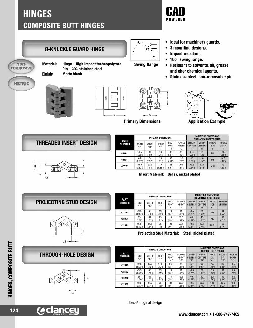
www.clancey.com • 1-800-747-7405174
COMPOSITE BUTT HINGESHINGES
HING
ES, C
OMPO
SITE
BUT
T
THREADED INSERT DESIGN
8-KNUCKLE GUARD HINGE
PROJECTING STUD DESIGN
THROUGH-HOLE DESIGN
Swing RangeMaterial: Hinge – High impact technopolymer Pin – 303 stainless steelFinish: Matte black
• Ideal for machinery guards.• 3 mounting designs.• Impact resistant.• 180° swing range.• Resistant to solvents, oil, grease
and oher chemical agents.• Stainless steel, non-removable pin.
Primary Dimensions Application Example
Insert Material: Brass, nickel plated
Projecting Stud Material: Steel, nickel plated
Elesa® original design
PARTNUMBER
PRIMARY DIMENSIONS MOUNTING DIMENSIONSTHREADED INSERT DESIGN
LENGTH“L”
WIDTH“B”
HEIGHT“H”
PIVOTPOINT“h1”
FLANGEHEIGHT
“h2”
LENGTHCENTERS
“f”
WIDTHCENTERS
“f1”
THREADSIZE“d”
THREADDEPTH
“h”
422111 49.5(1.95")
48(1.89")
19(.75")
13(.51")
11(.43")
30.5(1.20")
31(1.22") M5 8.5
(.33")
422211 65(2.56")
64(2.52")
23(.91")
15(.59")
13.5(.53")
40(1.57")
40(1.57") M6 10.5
(.41")
422311 96.5(3.80")
97.5(3.84")
35(1.38")
23(.91")
20.5(.81")
59.5(2.34")
62.5(2.46") M10 15
(.59")
PARTNUMBER
PRIMARY DIMENSIONS MOUNTING DIMENSIONSPROJECTING STUD DESIGN
LENGTH“L”
WIDTH“B”
HEIGHT“H”
PIVOTPOINT“h1”
FLANGEHEIGHT
“h2”
LENGTHCENTERS
“f”
WIDTHCENTERS
“f1”
THREADSIZE“d2”
THREADLENGTH
“I”
422121 49.5(1.95")
48(1.89")
19(.75")
13(.51")
11(.43")
30.5(1.20")
31(1.22") M5 14
(.55")
422221 65(2.56"
64(2.52")
23(.91")
15(.59")
13.5(.53")
40(1.57")
40(1.57") M6 18
(.71")
422321 96.5(3.80")
97.5(3.84")
35(1.38")
23(.91")
20.5(.81")
59.5(2.34")
62.5(2.46") M10 20
(.79")
PARTNUMBER
PRIMARY DIMENSIONS MOUNTING DIMENSIONSTHROUGH HOLE DESIGN
LENGTH“L”
WIDTH“B”
HEIGHT“H”
PIVOTPOINT“h1”
FLANGEHEIGHT
“h2”
LENGTHCENTERS
“f”
WIDTHCENTERS
“f1”
HOLEDIA.“d3”
RECESSDIA. “d5”
RECESSDEPTH“h3”
422412 39.5(1.56")
38.5(1.52")
14.5(.57")
9.5(.37")
9(.35")
25.1(.99")
25(.98")
4.5(.18")
8.5(.33")
4.5(.18")
422132 49.5(1.95")
48(1.89")
19(.75")
13(.51")
11(.43")
30.5(1.20")
31(1.22")
5.5(.22")
10(.39")
5.5(.22")
422232 65 (2.56"
64(2.52")
23(.91")
15(.59")
13.5(.53")
40(1.57")
40(1.57")
6.5(.26")
10(.39")
6.5(.26")
422332 96.5 (3.80")
97.5(3.84")
35(1.38")
23(.91")
20.5(.81")
59.5(2.34")
62.5(2.46")
10.5(.41")
16.5(.65")
10.5(.41")
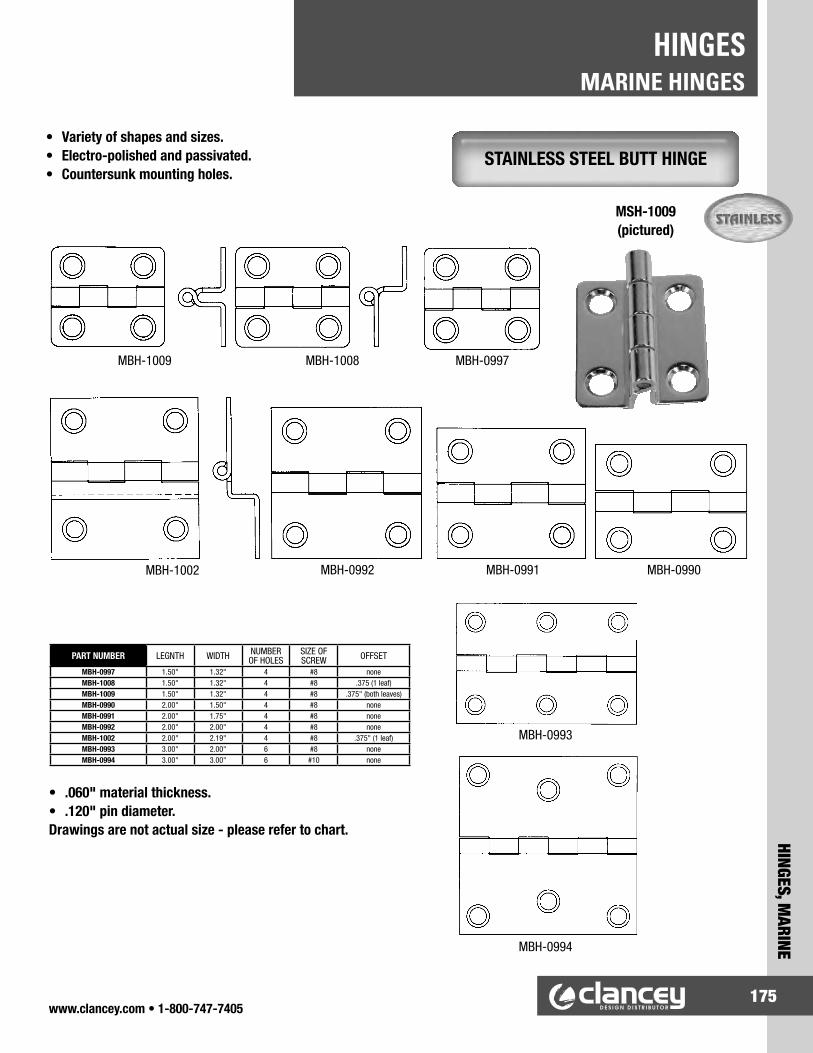
www.clancey.com • 1-800-747-7405175
HINGES, MARINE
MARINE HINGESHINGES
STAINLESS STEEL BUTT HINGE• Variety of shapes and sizes.• Electro-polished and passivated.• Countersunk mounting holes.
• .060" material thickness.• .120" pin diameter.Drawings are not actual size - please refer to chart.
PART NUMBER LEGNTH WIDTH NUMBER OF HOLES
SIZE OF SCREW OFFSET
MBH-0997 1.50" 1.32" 4 #8 noneMBH-1008 1.50" 1.32" 4 #8 .375 (1 leaf)MBH-1009 1.50" 1.32" 4 #8 .375" (both leaves)MBH-0990 2.00" 1.50" 4 #8 noneMBH-0991 2.00" 1.75" 4 #8 noneMBH-0992 2.00" 2.00" 4 #8 noneMBH-1002 2.00" 2.19" 4 #8 .375" (1 leaf)MBH-0993 3.00" 2.00" 6 #8 noneMBH-0994 3.00" 3.00" 6 #10 none
MBH-0997MBH-1008MBH-1009
MBH-0990MBH-0991MBH-0992MBH-1002
MBH-0993
MBH-0994
MSH-1009 (pictured)

www.clancey.com • 1-800-747-7405176
MARINE HINGESHINGES
HING
ES, M
ARIN
E
STAINLESS STEEL STRAP HINGES• Variety of shapes and sizes.• Electro-polished and passivated.• Countersunk mounting holes.
• .060" material thickness.• .120" pin diameter.Drawings are not actual size - please refer to chart.
PART NUMBER LEGNTH WIDTH NUMBER OF HOLES
SIZE OF SCREW OFFSET
MSH-1012 1.07" 4.00" 4 #8 noneMSH-0999 1.50" 2.00" 5 #8 noneMSH-1005 1.50" 2.00" 5 #8 .375 (1 leaf)MSH-0998 1.50" 2.75" 6 #8 noneMSH-1004 1.50" 2.63" 4 #8 noneMSH-1000 1.50" 4.00" 4 #8 noneMSH-1001 1.50" 6.00" 6 #8 noneMSH-1010 2.13" 4.25" 5 #8 none
MSH-1012
MSH-0999MSH-1005
MSH-1000
MSH-1001
MSH-1010
MSH-1004MSH-0998
MSH-1005 (pictured)

www.clancey.com • 1-800-747-7405177
QUICK ACCESS, 1/4 TURN FASTENERS
1/4-TURN ASSEMBLIESQUICK ACCESS FASTENERS
DZUS® 1/4 TURN FASTENERS
STANDARD LINE
PANEX® LINE
RAPIER® LINE
• High vibration solution.• Broadest 1/4 turn grip range.
• High tensile and shear strength.• Variety of actuation styles and sizes.
• Tool driven.• Economical choice for high volume applications.
This is the series that started it all. Excellent product that delivers predictable clamping force and is well suited for high vibration applications. High load strength, cycle life and a broad grip range make the standard line an excellent choice.
Excellent choice for applications in these industries.• Off-highway vehicles• HVAC• Lighting• Motorcycles
The rapier line is manufactured on automated equipment to exacting standards. The result is an economical fastener for volume applications. A wide variety of stud diameters and receptacles allows the rapier line to be easily engineered into a large range of application environments.
Online Configuration.
www.clancey.com

www.clancey.com • 1-800-747-7405178
1/4-TURN ASSEMBLIESQUICK ACCESS FASTENERS
QUIC
K AC
CESS
, 1/4
TUR
N FA
STEN
ERS
STANDARD ASSEMBLY STUD EJECTOR
PLEASE NOTE:Quarter-turn fastener assemblies have narrow tolerance ranges. If tolerance control is a problem, please consider a fast-lead screw assembly.
Small Medium Large
HOW TO SELECT A SOUTHCO® QUARTER-TURN FASTENER
1. Select a receptacle (note frame thickness limitations).
2. Select a stud.
a) Measure your outer panel- thickness or total material thickness. Note: Receptacle selection will determine which measurement you will use.
b) If there is an adjustment formula under receptacle, apply the adjustment formula to your measurement.
c) If you are using the wear washer or ejector spring option, apply the adjustment to your measurement.
d) Choose a head style and use your adjusted measurement to select a stud which will work in your application.
3. Select a retainer.
4. Order your components.
Required • Stud • Retainer • Receptacle
Optional • Wear washer • Ejector spring • Tools
• Interactive product configuration at www.clancey.com.
Small Medium Large
Online Configuration.
www.clancey.com

www.clancey.com • 1-800-747-7405179
QUICK ACCESS, 1/4 TURN FASTENERS
1/4-TURN ASSEMBLIESQUICK ACCESS FASTENERS
SHIELDED PRESS-IN FOR SHEET METAL
PRESS-IN FOR BLIND APPLICATIONS AND SOLID MATERIALS
• 5 receptacle styles.• Stainless steel options available.
• Provides RFI/EMI shielding
Material:Shell: SteelSpring: Stainless steel
Material:Shell: SteelSpring: Stainless steel
SMALL SERIES, RECEPTACLES
7.9(.309)
9.3(.366)overknurl
FOR ULTRASONIC INSTALLATION IN THERMOPLASTICS INSTALLATION
Material:Shell: SteelSpring: Stainless steel
STUD SELECTION• Use column II in stud selection table.• Use constant 1.3 mm (.050") for
frame thickness if frame thickness is less than 1.3 mm (.050").
STUD SELECTION• Determine outer panel thickness.• Use column I in stud selection table.
PART NUMBER81-35-311-55
PART NUMBER81-35-308-55
PART NUMBER81-35-310-55
TOOL PART NUMBER54-0-5466-11
STUD SELECTION• Determine total material thickness.• Use column I in stud selection table.

www.clancey.com • 1-800-747-7405180
1/4-TURN ASSEMBLIESQUICK ACCESS FASTENERS
QUIC
K AC
CESS
, 1/4
TUR
N FA
STEN
ERS
By hand
With screwdriver
With tool
Figure I P + F -1.07 (.042) (constant) when G is 0.45 (.018).
P + F + G -1.5 (.060) (constant) when G is 0.46 (.019) or greater.
CLIP-ON STYLEPANEL PREPARATION
INSTALLATION TOOL
TO INSTALL
SMALL SERIES, RECEPTACLES
INSTALLATION TOOL
SNAP-IN STYLE
Material:Housing and retainer: 301 stainless steelReceptacle: 1010 steel, zinc plateSpring: 302 stainless steel,
passivated
PART NUMBER81-35-309-56
PART NUMBER29-8125-309
PART NUMBER29-81-101-10
Figure II
Part Description PART NUMBER1064 STEEL,
DACROTIZED† 81-47-101-15
17-7 PH stainless steel 81-47-101-20
STUD SELECTION• Determine total material thickness.• Use column II in stud selection table.
STUD SELECTION• Add 1.5 mm (.060") to outer panel
thickness.• Use column II in stud selection table.

www.clancey.com • 1-800-747-7405181
QUICK ACCESS, 1/4 TURN FASTENERS
1/4-TURN ASSEMBLIESQUICK ACCESS FASTENERS
WING HEAD
OVAL SLOTTED
OVAL PHILLIPS RECESS
FLUSH PHILLIPS RECESS
• Interactive configuration at www.clancey.com• Quick access fastener assembly.• 4 head styles.• 5 receptacle styles.• For limited space applications.
WING HEADOVAL SLOTTEDOVAL
PHILLIPS RECESSFLUSH
PHILLIPS RECESS
SMALL SERIES, STUD SELECTION TABLE

www.clancey.com • 1-800-747-7405182
1/4-TURN ASSEMBLIESQUICK ACCESS FASTENERS
QUIC
K AC
CESS
, 1/4
TUR
N FA
STEN
ERS
Adjustment• Wear washer and ejector spring
add .8 mm (.032") to outer panel or total material thickness.
• Wear washer add .5 mm (.020") to outer panel or total material thickness.
INSTALLATION TOOL
SPLIT RING
PUSH-ON
FOR FLUSH-HEAD STYLE
EJECTOR SPRING
Stainless Steel
Nylon, Black
Stainless Steel
INSTALLATION TOOL
Drill or Punch
CountersinkDrill or Punch
FOR ABOVE-SURFACE STYLES
* Accessories cannot be used with flush phillips head style.
SMALL SERIES, RETAINERS
SMALL SERIES, ACCESSORIES
SMALL SERIES, PANEL PREPARATION
PART NUMBER81-32-101-20
PART NUMBER81-0-15129-11
PART NUMBER81-32-301-12
PART NUMBER81-0-18173-11
WEAR WASHER
Nylon
PART NUMBEREJECTOR SPRING
WEAR WASHERBlack Natural
81-41-102-24 81-46-101-41 81-46-101-39
RETAINER TOOL

www.clancey.com • 1-800-747-7405183
QUICK ACCESS, 1/4 TURN FASTENERS
1/4-TURN ASSEMBLIESQUICK ACCESS FASTENERS
FOR RIVETING - WITH BASE
FOR RIVETING - WITHOUT BASE
SIDE MOUNT
FOR WELDING
Material:Spring: 1064 steelBracket: 1010 steel
Material:Spring: 1064 steelBracket: 1010 steel
Material:Spring: 1064 steel or 17-7 stainlessEyelet: Steel or 302 stainless
Material:Spring: 1064 steelBase: 1010 steelWeld studs: Steel, copper plate
MEDIUM SERIES, RECEPTACLES LEAF SPRING RECEPTACLES
STUD SELECTION• Determine total material thickness.• Use column IV in stud selection
table.
STUD SELECTION• Calculate D + 1.5 mm (.060").• Use column IV in stud selection
table.
STUD SELECTION• Determine total material thickness.• Use column IV in stud selection
table.
STUD SELECTION• Determine total material thickness.• Use column IV in stud selection
table.
PART NUMBER82-35-302-15
PART NUMBERSteel Stainless Steel
82-35-295-15 82-35-295-20
PART NUMBER82-45-101-15
PART NUMBER82-35-303-15

www.clancey.com • 1-800-747-7405184
1/4-TURN ASSEMBLIESQUICK ACCESS FASTENERS
QUIC
K AC
CESS
, 1/4
TUR
N FA
STEN
ERS
1. Drill or punch hole in inner panel.
*Note: for inner panels less than 1.3 (.051) thick, the retainer will create a slight gap between the panels. For proper stud selection in these cases, assume the inner panel thickness as 1.3 (.051).
2. Press receptacle into hole until the shoulder on the receptacle bottoms out on the panel’s surface.
FOR ULTRASONIC INSTALLATION IN THERMOPLASTICS
SHIELDED PRESS-IN
PRESS-IN FOR BLIND APPLICATIONS AND SOLID MATERIALS
VIBRATION ISOLATING
STUD SELECTION• Determine outer panel thickness.• Use column II in stud selection table.
STUD SELECTION• Calculate D + 1.5 mm (.060").• Use column IV in stud selection table.
STUD SELECTION• Determine total material thickness.• Substitute 1.3 mm (.051") for frame thickness
if thickness is less than 1.3 mm (.051"). • Use column III in stud selection table.
STUD SELECTION• Determine outer panel thickness.• Use column I in stud selection
table.
PANEL PREPARATION
PANEL PREPARATIONBlind Hole Application
Through Hole Application
Material:Shell: SteelSpring: Stainless steel
Material:Shell: SteelSpring: Stainless steel
Material:Receptacle: SteelPlate: AluminumBoss: Neoprene
Material: Shell: Steel Spring: Stainless steel
MEDIUM SERIES, RECEPTACLES
PART NUMBER82-35-302-15
PART NUMBER82-35-315-55
PART NUMBER82-35-306-10
PART NUMBERwith 90
locking stops 82-35-308-55
without 90 locking stops 82-35-313-55

www.clancey.com • 1-800-747-7405185
QUICK ACCESS, 1/4 TURN FASTENERS
1/4-TURN ASSEMBLIESQUICK ACCESS FASTENERS
SNAP-IN STYLE
PANEL PREPARATION INSTALLATION TOOL
INSTALLATION TOOL
CLIP-ON STYLE
STUD SELECTION• Enter result in column IV of stud
selection table.
Figure I
P + F + 1.40 (.055) (constant) when G is 0.64 (.025) .
P + F + G + 0.76 (.030) (constant) when G is 0.65 (.026) or greater.
PANEL PREPARATION
Material:Housing and retainer: StainlessReceptacle: SteelSpring: Stainless
MEDIUM SERIES, RECEPTACLES
Figure II
Try this part inyour application
Please call for samples.
800-747-7405
STUD SELECTION• Calculate outer panel thickness
+ 5.08 mm (.200").• Use column IV in stud selection
table.
PART NUMBER29-8125-309
PART NUMBERSteel 82-47-113-15
Stainless Steel 82-47-113-20
PART NUMBER82-35-309-56

www.clancey.com • 1-800-747-7405186
1/4-TURN ASSEMBLIESQUICK ACCESS FASTENERS
QUIC
K AC
CESS
, 1/4
TUR
N FA
STEN
ERS
Adjustment• Add .5 mm (.020") to your outer panel
thickness or total material thickness.
INSTALLATION TOOLINSTALLATION TOOL
EJECTOR SPRINGNYLON WEAR WASHERSCUPPED FLAT
304 Stainless Steel, passivated.
302 Stainless Steel, passivated.
Nylon, black.
SEALING WASHERS
Nitrile fibre core rubber, black.
Adjustment• Add .5 mm (.020") to your outer panel
thickness or total material thickness.
302 Stainless steel, passivated.
MEDIUM SERIES, ACCESSORIES
MEDIUM SERIES, RETAINERS
Adjustment• When using an ejector spring and wear washer add
1 mm (.040") to your outer panel thickness or total material thickness.
PART NUMBER82-32-201-20
PART NUMBER82-32-301-12
PART NUMBER82-32-101-20
PART NUMBER82-0-22542-11
PART NUMBER82-0-7595-11
PART NUMBER43-13-1-24
PART NUMBER82-46-103-39
Natural
PART NUMBER82-43-201-38
PART NUMBER82-46-103-39
Black82-46-101-39
Natural

www.clancey.com • 1-800-747-7405187
QUICK ACCESS, 1/4 TURN FASTENERS
1/4-TURN ASSEMBLIESQUICK ACCESS FASTENERS
• Interactive configurator at www.clancey.com• 9 head styles.• Spring loaded fully retractable assemblies are available.• Stainless steel available in many styles.
OVAL SLOTTED
Drill or Punch
WING HEAD HEX SOCKET OVAL PHILLIPS FLUSH PHILLIPS
PANEL PREPARATION - ABOVE SURFACE STYLES
MEDIUM SERIES, STUD SELECTION TABLE
Low profile headstyles are available in
stainless steel: change suffix from -15 to -20.
www.clancey.com

www.clancey.com • 1-800-747-7405188
1/4-TURN ASSEMBLIESQUICK ACCESS FASTENERS
QUIC
K AC
CESS
, 1/4
TUR
N FA
STEN
ERS
KNURLED HEAD BAIL STYLE RB BAIL STYLE RA
PRESS-IN STUD ASSEMBLY
FLARE-IN STUD ASSEMBLY
PANEL PREPARATION - FLUSH HEAD STYLE - When outer panel is 1.3 mm (.050") or greater
TOOLHEAD RECESS
PART NUMBER29-90-214-10

www.clancey.com • 1-800-747-7405189
QUICK ACCESS, 1/4 TURN FASTENERS
1/4-TURN ASSEMBLIESQUICK ACCESS FASTENERS
STUD SELECTION• Calculate outer panel thickness.• Use column I in stud selection table.
PRESS-IN FOR BLIND APPLICATIONS AND SOLID MATERIALS
STUD SELECTION• Calculate total material thickness.• Use column II in stud selection table.• Substitute 1.4 mm (.055") if frame thickness is
less than 1.4 mm (.055").
SHIELDED PRESS-IN FOR SHEET METAL
STUD SELECTION• Calculate as follows.• Use column III in stud
selection table.
CLIP-ON STYLE
18.3(.72)
19.1(.75)
17.9(.71)
SNAP-IN STYLE
STUD SELECTION• Calculate outer panel thickness +
8.4 mm (.330").• Use column III in stud selection
table. PANEL PREPARATION
PANEL PREPARATIONINSTALLATION TOOL
INSTALLATION TOOL
• ProvIdes RFI-EMI shielding
P+ F+ 0.94 (.037) (constant) when G is 1.32 (.052).
P + F + G - 0.38 (.015) (constant) when G is 1.33 (.053) or greater.
Figure I
Figure IIPANEL PREPARATION
Material: See medium size.
Material: Shell: Steel Spring: Stainless steel.
Material:Shell: Steel Spring: Stainless steel
LARGE SERIES, RECEPTACLES
PART NUMBER29-8125-309
PART NUMBER85-35-311-55
PART NUMBER90-2825-11
PART NUMBER29-85-101-10
PART NUMBERSteel 85-47-101-15
Stainless Steel 85-47-101-20
PART NUMBERwith 90
locking stops 85-35-308-55
without 90 locking stops 85-35-313-55
PART NUMBER85-35-309-56

www.clancey.com • 1-800-747-7405190
1/4-TURN ASSEMBLIESQUICK ACCESS FASTENERS
QUIC
K AC
CESS
, 1/4
TUR
N FA
STEN
ERS
Material:Spring: 1064 steel Bracket: 1010 steel
FOR RIVETING
SIDE MOUNT
FOR WELDING
STUD SELECTION• Calculate total material thickness.• Use column III in stud selection
table.
STUD SELECTION• Calculate total material thickness.• Use column III in stud selection
table.
STUD SELECTION• Calculate D + 1.6 mm (.062").• Use column III in stud selection
table.
CLAMPING TOOL
PANEL PREPARATION
Material:Spring: 1064 Steel Base: 1010 steelRivet: Steel, copper plate
LARGE SERIES, LEAF SPRING RECEPTACLES
PART NUMBER85-90-3278-11
PART NUMBERSteel Stainless Steel
85-35-295-15 85-35-295-20
PART NUMBER85-35-296-15
PART NUMBER85-45-101-15

www.clancey.com • 1-800-747-7405191
QUICK ACCESS, 1/4 TURN FASTENERS
1/4-TURN ASSEMBLIESQUICK ACCESS FASTENERS
OVAL SLOTTED WING HEAD HEX SOCKET PHILLIPS RECESSTOOLHEAD RECESS
PANEL PREPARATION - ALL STUD STYLES
LARGE SERIES, STUD SELECTION TABLE
Low profile headstyles are available in
stainless steel: change suffix from-15 to -20.
www.clancey.com
PART NUMBER29-90-215-10

www.clancey.com • 1-800-747-7405192
1/4-TURN ASSEMBLIESQUICK ACCESS FASTENERS
QUIC
K AC
CESS
, 1/4
TUR
N FA
STEN
ERS
• Interactive configurator at www.clancey.com.
BAIL STYLE RB BAIL STYLE RAKNURLED HEAD
85-46-103-39
85-46-101-39
85-46-101-41
Flat Natural
Cupped Natural
Cupped Black
PART NUMBER
NYLON WEAR WASHERS
FLAT CUPPED
SEALING WASHER
Use installation tool Install by hand
PART NUMBER 85-34-201-20
PART NUMBER 85-34-301-12
PART NUMBER 85-33-101-27
PART NUMBER 85-0-22543-11
PART NUMBER 85-43-201-38
Stainless Nylon Neopreme
LARGE SERIES, ACCESSORIES
LARGE SERIES, RETAINERS
PART NUMBER 14-18-150-24 Adjustment
• When using an ejector spring and wear washer add 1.5 mm (.060") to your outer panel thickness or total material thickness.
Adjustment• When using a wear washer or sealing washer add
.51 mm (.020") to your outer panel thickness or total material thickness.EJECTOR SPRING

www.clancey.com • 1-800-747-7405193
QUICK ACCESS, 1/4 TURN FASTENERS
1/4-TURN ASSEMBLIESQUICK ACCESS FASTENERS
• Lightweight, high strength plastic system.• Economical cost and installation.• High cycle life.
DART® 1/4 FASTENERS
How to order DART® fasteners: Select receptacle on following page. Determine if you will use the retainer (recommended) or spring eject
accessories (optional). Choose your stud head style.
➃ Determine “-LLL.” Using formulas next to receptacles on following page. Account for retainer, spring and cup when calculating total material thickness (TMT) – see figure 1 below.
Input “LLL” into your stud part number for ordering.
Retainer and accessories.
TMT calculation
Use TMT to determine “LLL” for receptacle chosen
Select head style.
TMT EXAMPLEP Outer panel = .060"G Gap = .080"Q Support (frame) = .060" using cup spring = .130" .330"
Use TMT to determine “LLL” on following page.
Note: Retainer falls in gap.
PART NUMBERSplit Retainer
D1-004-000-010
Accessory PART NUMBERSSelf Ejecting Springs Self Ejecting Cup
D1-X1135-2S D1-X1137-2S D1-X1129
Stud Head Style PART NUMBERSStraight Slot Slotted Knob Wing Hex
D1-004-LLL-030 D1-444-LLL-030 D1-125-LLL-030 D1-166-LLL-030
ADJUSTMENT = .045" (1.1) ADJUSTMENT = .090" (2.3)WHEN “LLL” = .045-.070 WHEN “LLL” = .075-.100

www.clancey.com • 1-800-747-7405194
1/4-TURN ASSEMBLIESQUICK ACCESS FASTENERS
QUIC
K AC
CESS
, 1/4
TUR
N FA
STEN
ERS
Stud Length Selection TableTMT Stud Dim. “LLL”
4.13 - 5.39 (.169 - .220") -0455.40 - 6.66 (.220 - .272") -0506.67 - 7.93 (.272 - .324") -0557.94 - 9.20 (.324 - .376") -060
9.21 - 10.47 (.376 - .427") -06510.48 - 11.47 (.427 - .468") -07011.48 - 13.01 (.468 - .531") -07513.02 - 14.28 (.531 - .583") -08014.39 - 15.55 (.583 - .635") -08515.56 - 16.82 (.635 - .687") -09016.83 - 18.09 (.687 - .738") -09518.10 - 19.36 (.738 - .790") -100
Stud Length Selection TableTMT Stud Dim. “LLL”
4.15 - 5.41 (.169 - .221") -0455.42 - 6.68 (.221 - .273") -0506.69 - 7.95 (.273 - .324") -0557.96 - 9.22 (.324 - .376") -0609.23 - 10.49 (.376 - .428") -06510.50 - 11.76 (.428 - .480") -07011.77 - 13.03 (.480 - .532") -07513.04 - 14.30 (.532 - .587") -08014.31 - 15.57 (.587 - .636") -08515.58 - 16.84 (.636 - .761") -09016.85 - 18.11 (.761 - .739") -09518.12 - 19.38 (.739 - .791") -100
Support Thickness
Dim. Q
Mini Snap-In Front Load
PART NUMBERSX Dim.
0.9-1.25 (.035-.049) D1-004-911-010 1.7 (0.67)1.3-1.75 (.051-.069) D1-004-912-010 2.2 (0.87)1.8-2.25 (.035-.049) D1-004-913-010 2.7 (1.06)2.3-2.75 (.091-.109) D1-004-914-010 3.2 (1.26)2.8-3.25 (.111-.129) D1-004-915-010 3.7 (1.45)
Support Thickness Ranges Q
Mini Snap-In Back Load
PART NUMBERSX Dim.
0.81-1.27 (.032-.050) D1-004-012-010 3 (.118)1.29-2.54 (.051-.100) D1-004-013-010 4.3 (1.69)
Support Thickness
Dim QClip-On RecepticalPART NUMBERS
0.7 - 2.3 (.027 - .090) D1-004-921-0102.3 - 3.9 (.090 - .153) D1-004-922-0103.9 - 5.5 (1.53 - 2.16) D1-004-923-010
Rivet-InPART NUMBER D1-004-001-010
RIVET-ON RECEPTACLE
CLIP-ON RECEPTACLE
SNAP-IN BACK LOAD
SNAP-IN FRONT LOAD
Stud Length Selection TableTMT Stud Dim. “LLL”
2.54 - 3.80 (.100 - .149") -0453.81 - 5.07 (.150 - .199") -0505.08 - 6.34 (.200 - .249") -0556.35 - 7.61 (.250 - .299") -0607.62 - 8.88 (.300 - .349") -065
8.89 - 10.15 (.350 - .399") -07010.16 - 11.14 (.400 - .449") -07511.43 - 12.69 (.450 - .499") -08012.70 - 13.96 (.500 - .549") -08513.97 - 15.23 (.550 - .599") -09015.24 - 16.50 (.600 - .649") -09516.51 - 17.77 (.650 - .699") -100
Stud Length Selection TableTMT Stud Dim. “LLL”
4.32 - 5.58 (.170 - .219") -0455.59 - 6.85 (.220 - .269") -0506.86 - 8.12 (.270 - .319") -0558.13 - 9.39 (.320 - .369") -0609.40 - 10.66 (.370 - .419") -06510.67 - 11.93 (.420 - .469") -07011.94 - 13.20 (.470 - .519") -07513.21 - 14.47 (.520 - .569") -08014.48 - 15.74 (.570 - .619") -08515.75 - 17.01 (.620 - .669") -09017.02 - 18.28 (.670 - .719") -09518.29 - 19.55 (.720 - .769") -100
NOTES:
1. Gap thickness (G) is the stud retainer thickness. This part may be nested into recessed holes.
2. Add 1.1 (0.45) for a Split Retainer to your TMT calibration.
3. For use with Self-Ejecting Studs add 2.3 (.090) to your TMT calculation.
NOTES:
1. Gap thickness (G) is the thickness of receptacle top flange 2 (.079). This part may be nested into recessed holes.
2. For use with Self-Ejecting Studs add 2.3 (.090) to your TMT calculation.
NOTES:
1. Gap thickness (G) is the combined thickness of receptacle top flange 1.15 (.045) and stud retainer thickness. These parts may be nested into recessed holes.
2. Add 1.15 (0.45) for Split Retainer to your TMT calibration.
3. For use with Self-Ejecting Studs add 2.3 (.09) to your TMT calculation.
NOTES:
1. Gap thickness (G) is the combined thickness of receptacle top flange 1.1 (0.45) and stud retainer thickness. These parts may be nested into recessed holes.
2. Add 1.15 (0.45) for Split Retainer to your TMT calibration.
3. For use with Self-Ejecting Studs add 2.3 (.09) to your TMT calculation.
Receptacle Selection Table
Determine the thickness of the support material (Q). Find the Support Thickness Range in the table above to determine your Receptacle Part Number.
Stud Length Selection Stud Length Selection
Stud Length Selection Stud Length Selection

www.clancey.com • 1-800-747-7405195
QUICK ACCESS, 1/4 TURN FASTENERS
1/4-TURN ASSEMBLIESQUICK ACCESS FASTENERS
• Economical 1/4 turn fastener with highly desired “Push-to-Close” action.
• Available in black or bright.• Neoprene washer absorbs vibration.• Lateral tolerance receptacle helps with panel
deflection and tolerance stack-up.• Can be customized for volume applications.• No tools required for assembly.
HOW TO ORDER:
Receptacles
Studs
Standard Lateral Tolerance
Standard Self-Ejecting
Step 1 –Select ReceptacleBoth receptacles provide the same strength values. Use the Standard Receptacle in normal cases. The Lateral Tolerance Receptacle eases stud alignment. choose either to fit support panel thickness.
Step 2 –Select StudA choice of two stud styles is offered: standard studs and self ejecting. To complete the stud assembly a separate retainer and washer must be specified at time of order.
SAMPLESWe are happy to provide samples of this, or any part in our offering to assist in your application development. You may request online 24/7 at www.clancey.com, or call our customer service team at 800-747-7405. We are ready to help.
PILOT® 1/4 TURN FASTENER
HOW IT WORKS
Typical Assembly
Receptacle Installation
Panel Preparation
Figure 1:P = Panel ThicknessQ = Support Thickness
Standard Lateral Tolerance
Pilot Assembly
Pilot studs and receptacle require no tooling for installation. After panel preparation all components install by hand.

www.clancey.com • 1-800-747-7405196
1/4-TURN ASSEMBLIESQUICK ACCESS FASTENERS
QUIC
K AC
CESS
, 1/4
TUR
N FA
STEN
ERS
STANDARD RECEPTACLE
STANDARD STUD & WASHER
LATERAL TOLERANCE RECEPTACLE
SELF-EJECT STUD
Receptacle selection
Step
Pilot® Stud selection
Step
NOTE: Order both stud & washer (2) part numbers.
• Provides ± .200" of lateral tolerance.
Lateral Tolerance
Material & FinishMaterial: Spring steelFinish: Zinc phosphate
Standard
Material & FinishMaterial: Case hardened steel with zinc
plate with black or bright chromeCup: Black thermoplasticSpring: Stainless steelRetainer: Acetal copolymer
Material: Case hardened steelFinish: Zinc plate with black
or clear chromate
Standard Studs Washer
Material: Case hardened steelFinish: Zinc plate with black
or bright chromate
Material: Neoprene rubberFinish: Black
Stud Selection1. Select stud and washer
part numbers from the tables at right based on your panel thickness (P).
2. Typical washer compression .040" to .080"
Stud & Washer Selection
NOTE: Order both stud & retainer (2) part numbers.
Stud Retainer (Required)Self-Ejecting Studs
The ejecting assembly locks into the recep-tacle with a push on the stud. The eject spring provides locking tension that allows greater material thickness tolerance. A quarter turn releases the assembly. The ejecting stud assembly has a reduced gap between panel and support and can be used with either the square hole or lateral tolerance receptacles.
PanelThickness
PART NUMBERSBlack Bright
.020" - .120" D7-290-718-191 D7-290-718-190
.100" - .200" D7-290-720-191 D7-290-720-190
PART NUMBERD7-275-203-040
Support Thickness(Q)
Part NumberStandard
.025˝ to .049˝ D7-285-101-161
.050˝ to .069˝ D7-285-102-161
.070˝ to .089˝ D7-285-103-161
PPanel
Thickness
Stud
Dim
. L
Stud
Dim
. B
TW
ashe
r Thi
ckne
ss Part Numbers
Stud Washer
BlackChromate
BrightChromate
ForStd. Recep.
For Lat. Tol. Recep.
.050˝ to .069˝ .63˝ .28˝ .16˝ D7-265-716-191 D7-265-716-190 D7-275-040-400 D7-275-140-400
.070˝ to .089˝ .63˝ .28˝ .14˝ D7-265-716-191 D7-265-716-190 D7-275-035-400 D7-275-135-400
.090˝ to .109˝ .70˝ .35˝ .20˝ D7-265-718-191 D7-265-718-190 D7-275-050-400 D7-275-150-400
.110˝ to .129˝ .70˝ .35˝ .18˝ D7-265-718-191 D7-265-718-190 D7-275-045-400 D7-275-145-400
.130˝ to .149˝ .70˝ .35˝ .16˝ D7-265-718-191 D7-265-718-190 D7-275-040-400 D7-275-140-400
.150˝ to .169˝ .70˝ .35˝ .14˝ D7-265-718-191 D7-265-718-190 D7-275-035-400 D7-275-135-400
.170˝ to .189˝ .79˝ .43˝ .20˝ D7-265-720-191 D7-265-720-190 D7-275-050-400 D7-275-150-400
Support Thickness(Q)
Part NumberLateral Tolerance
.025˝ to .049˝ D7-285-201-161
.050˝ to .069˝ D7-285-202-161
.070˝ to .089˝ D7-285-203-161
.090˝ to .109˝ D7-285-204-161
.110˝ to .129˝ D7-285-205-161
Lateral Tolerance
Standard
P = Panel thicknessQ = Support thickness

www.clancey.com • 1-800-747-7405197
QUICK ACCESS FASTENERS, 1/4 TURN FASTENERS
1/4-TURN FASTENERSQUICK ACCESS FASTENERS
• 3 head styles.• Prongs expand 4 directions.• Non-corrosive, non-conductive.
NYLATCH® 1/4 TURN FASTENER ARROW 1/4 TURN FASTENER
• Economical choice - low in-stalled cost.
• Slotted or wing head option.• Non-corrosive, non-conductive.
Grip P Max. Length L Max..059˝ to .148˝ .042˝ -1 .50˝
.076˝ to .165˝ .057˝ -2 .51˝
.118˝ to .207˝ .098˝ -3 .55˝
.182˝ to .271˝ .162˝ -4 .62˝
Fastener Length Selection1. Calculate the Grip of your application.
Grip is comprised of the removable panel thickness (P), support panel thickness (F) and any gap (G) caused panel lip, washer or gasket used between panels; see Figure 1.
Nylatch Quarter-Turn Part Numbers:
NY-N6-XX-YYMaterial & Color
-20 = Black Polycarbonate -10 = White Polycarbonate -30 = Black Polysulfone -31 = Natural Polysulfone
Length (See chart above)Basic Part Number
Optional Wing Handle for N6 Fasteners:
NY-H6-YYColor - Use selection codes listed for NY-N6, above.
Basic Part Number
Panel PreparationFor the Nylatch Quarter-Turn Panel Fastener, panel prep involves the stamping of a square hole in both the removable and support panels. The hole in the removable panel (øR) is slightly smaller than the one in the support panel (øF) to allow for fastener captivation.
PanelThickness
P
PanelPlus Support
T
Receptacle Undercut
B
LengthUnder Head
HReceptacle
Part Number
.020˝ to .070˝ .080˝ to .200˝ .070˝ .48˝ D7-200-802-010
.071˝ to .125˝ .135˝ to .250˝ .125˝ .54˝ D7-201-802-010
For Use With Receptacle Series Head Style L Dimension Stud
Part Number
200
Hex .50˝ D7-200-701-010
Slotted .50˝ D7-200-711-010
Knob .50˝ D7-200-721-010
201
Hex .55˝ D7-201-701-010
Slotted .55˝ D7-201-711-010
Knob .55˝ D7-201-721-010
Studs
Fastener Selection1. Choose the receptacle that fits your panel thickness “P”.2. Verify that the combined thickness of your panel and support “T” is within listed
limits.3. Choose a stud head style. Then select the part number, tabulated at bottom right,
which corresponds to either the 200 or 201 series receptacle selected.
Receptacles
Panel PreparationTop Panel: .360˝ SQ. +.005˝.Bottom Panel: .375˝ SQ. +.005˝.
Installation ProcedureArrow studs and receptacles are packed separately. The receptacle is easily snapped into a square hole from the front panel and becomes self-retained. The stud is then pushed into the receptacle until it snaps in place.
Material & ColorMaterial: Acetal copolymer resinColor: Black
Material & ColorPolycarbonate or Polysulfane: Black, White or NaturalUL94-V2 rated
Grip = P + G + F
Latched Position Unlatched Position
Length Selection
Hex Recess Slotted Knob

www.clancey.com • 1-800-747-7405198
FAST-LEAD CAPTIVE SCREWSQUICK ACCESS FASTENERS
QUIC
K AC
CESS
FAS
TENE
RS, F
AST-
LEAD
CAP
TIVE
SCR
EWS
1. Choose a size: Small (09), Medium (12), or Large (17).
2. Determine panel configuration with dimensions.
FLAT TYPE• Small envelope• Available either
rivet type or weld type
• Anywhere in frame
3. Choose a receptacle. Note: availability of styles differs with size (See pages 200, 202, 204)
4. Choose a retainer. (See pages 200, 202, 204) 5. Determine constant.
CLIP-ON TYPE• Simple installation• Ideal for near edge
mounting
SADDLE TYPE• Permits multiple
screw assemblies on the same door while allowing one screw to fully retract from receptacle
• Rivet or weld type
SIDE-MOUNT TYPE• Permits mounting
to plane surface perpendicular to door surface
PRESS-IN TYPE• Simple
installation• Small envelope• For metal panels
only
DOOR THICKNESS
TOTAL MATERIAL THICKNESS
+ = ENTER IN COLUMN I
HOW TO SELECT FAST-LEAD CAPTIVE SCREWS – ALL SIZES
• Product configurator at www.clancey.com
6. Add constant to total material thickness from above.
7. Check your outer panel door thickness. (Must not exceed amount in column II)8. Choose your head style and finish.9. Order 3 parts: screw, retainer and receptacle.10. Order installation tools (recommended).

www.clancey.com • 1-800-747-7405199
QUICK ACCESS FASTENERS, FAST-LEAD CAPTIVE SCREWS
FAST-LEAD CAPTIVE SCREWSQUICK ACCESS FASTENERS
FAST-LEAD CAPTIVE SCREWS, SMALL SIZE
Try this part inyour application
Please call for samples.
800-747-7405
• Product configurator at www.clancey.com.• For limited space applications.• Four head styles.• Four receptacle styles.• Vibration resistant.

www.clancey.com • 1-800-747-7405200
FAST-LEAD CAPTIVE SCREWSQUICK ACCESS FASTENERS
QUIC
K AC
CESS
FAS
TENE
RS, F
AST-
LEAD
CAP
TIVE
SCR
EWS
FAST-LEAD CAPTIVE SCREWS, RECEPTACLES, SMALL SIZE
• 4 styles, 5 mounting options.• Stainless steel options.
FLAT TYPE CLIP-ON
PRESS-IN SADDLE TYPE
RETAINERS, SMALL SIZE

www.clancey.com • 1-800-747-7405201
QUICK ACCESS FASTENERS, FAST-LEAD CAPTIVE SCREWS
FAST-LEAD CAPTIVE SCREWSQUICK ACCESS FASTENERS
FAST-LEAD CAPTIVE SCREWS, MEDIUM SIZE
• Product configurator at www.clancey.com.• Widest range of configurations.• Five head styles.• Five receptacle styles.• Vibration resistant.
Try this part inyour application
Please call for samples.
800-747-7405

www.clancey.com • 1-800-747-7405202
FAST-LEAD CAPTIVE SCREWSQUICK ACCESS FASTENERS
QUIC
K AC
CESS
FAS
TENE
RS, F
AST-
LEAD
CAP
TIVE
SCR
EWS
FAST-LEAD CAPTIVE SCREWS, RECEPTACLES, MEDIUM SIZE
RETAINERS, MEDIUM SIZE
SIDE MOUNTFLAT TYPE
PRESS-IN SADDLE TYPE
CLIP-ONCLIP-ON
• 5 styles, 9 mounting options.• Stainless steel options.

www.clancey.com • 1-800-747-7405203
QUICK ACCESS FASTENERS, FAST-LEAD CAPTIVE SCREWS
FAST-LEAD CAPTIVE SCREWSQUICK ACCESS FASTENERS
FAST-LEAD CAPTIVE SCREWS, LARGE SIZE
• Product configurator at www.clancey.com.• Robust assembly.• Four head styles.• Three receptacle styles.• Vibration resistant.
For detailed material specifications and product
strength guidelines.
www.clancey.com
Try this part inyour application
Please call for samples.
800-747-7405

www.clancey.com • 1-800-747-7405204
FAST-LEAD CAPTIVE SCREWSQUICK ACCESS FASTENERS
QUIC
K AC
CESS
FAS
TENE
RS, F
AST-
LEAD
CAP
TIVE
SCR
EWS
SIDE MOUNT
CLIP-ON
FLAT TYPE
• 3 styles, 4 mounting options.• Stainless steel options.
FAST-LEAD CAPTIVE SCREWS, RECEPTACLES, LARGE SIZE
RETAINERS LARGE SIZE

www.clancey.com • 1-800-747-7405205
QUICK ACCESS FASTENERS, SPRING LOADED PLUNGERS
SPRING LOADED PLUNGERSQUICK ACCESS FASTENERS
PRESS-IN STYLE• Traditional bright or new overmolded “Prism”
series head styles.• Overmolded available in 5 standard colors with
custom colors available.• With or without hold open feature.• Presses into panels from .060" - .150" thick.
Panel Preparation
Installation
FLARE-IN STYLE
• For panels .060" - .185" thick.
Add color in place of “-000” (see below)
Panel Preparation and Installation
Bright Prism
PART NUMBER56-7-TOOL
To see these colors - visit www.clancey.com
Bright Prism
Outer Panel
Thickness P Knob Style
PART NUMBERSH1
Closed H2 Open B LHold Open Without
Hold OpenMin. Max.
1.52(.06)
3.17(.125)
7.9(.31)
Bright 56-71-1-15 56-70-1-15 13.7 (.54) 19.8 (.78)0.41
(.016)1.78 (.07")Color - Small 56-171-1-000 56-170-1-000 14.5 (.57) 20.5 (.81)
Color - Large 56-271-1-000 56-270-1-000 14.5 (.57) 20.5 (.81)
3.17(.125)
4.7(.185)
9.4(.37)
Bright 56-71-2-15 56-70-2-15 12.2 (.48) 18.2 (.72)1.52 (.06)
3.3 (.13)Color - Small 56-171-2-000 56-170-2-000 12.9 (.51) 19 (.75)
Color - Large 56-271-2-000 56-270-2-000 12.9 (.51) 19 (.75)
Panel Thickness P Knob
Style
PART NUMBERSH1
Closed H2 OpenHold Open Without
Hold OpenMin. Max.
1.52(.06)
3.81(0.15)
8.2(0.32)
Bright 56-61-15 56-60-15 12.2 (.48) 19.3 (.76)Color - Small 56-161-000 56-160-000 13 (.51) 20 (.79)Color - Large 56-261-000 56-260-000 13 (.51) 20 (.79)
Add color in place of “-000” (see above)
000 -008 -012 -013 -014
BLACK BLUE PURPLE RED GREEN

www.clancey.com • 1-800-747-7405206
SPRING LOADED PLUNGERSQUICK ACCESS FASTENERS
QUIC
K AC
CESS
FAS
TENE
RS, S
PRIN
G LO
ADED
PLU
NGER
S
THREAD-IN STYLE• Large knob with positive purchase.• Two sizes.• Easy installation – no press required.• For panels .025" - .125" thick.
Panel Preparation and Installation
For detailed materialspecifications and product
strength guidelines.
www.clancey.com
Bright
Retractable Hinge Positioning/Secondary Catch
Quick Installation
Installation Tool
Potential Applications:
Series
Dimensions PART NUMBERS
A B C D E F WWith
hold-open feature
Without hold-open
feature
300 13.5(.53)
4.7(.183)
6.5(.25)
20(.78)
6(.22)
9(.34)
7(.28) 56-10-301-20 56-99-196-20
400 17.5(.69)
6.3(.245)
8(.31)
26(1.03)
7(.28)
11.2(.44)
9.4(.37) 56-10-401-20 56-99-197-20
Series
Installation
Sleeve Thread
Size
TOOL PART
NUMBERX
(Tool)Panel
Thickness
MIN. MAX.
300 0.64 (.025)
1.52(0.60)
7.14(.281)
4.78(.250) M7 X 1 56-0-22041-03 7.1
(.28)
400 0.79(0.31)
3.18 (.125)
9.12(.359)
6.35(.250) M9 X 1 56-0-22041-04 9.5
(.38)
( )+0.08 -0.03+.003 -.001
Ø JØ H
±0.08 (±0.03)

www.clancey.com • 1-800-747-7405207
QUICK ACCESS FASTENERS, SPRING LOADED PLUNGERS
SPRING LOADED PLUNGERSQUICK ACCESS FASTENERS
• Knurled knob allows easy grip.• Locking or non-locking models.• Nylon patch option allows firm thread engagement.• Also available in brass or 316 stainless (please call).
KNOB STYLE
• Clean delrin knob with tapered undercut for easy pull.
• Locking or non-locking models.• Nylon patch option allows firm thread engagement.
NOTE: Add “– NP” to the end of the part number for optional nylon patch.
NOTE: Add “– NP” to the end of the part number for optional nylon patch. (not illustrated)
Locking (Positive Hold Open) Non-Locking (Automatic Return)
PART NUMBERS THREADSIZE“A”
THREADLENGTH
“B”
NOSELENGTH
“C”
NOSEDIAMETER
“D”
KNOBDIAMETER
“E”
KNOB HUBLENGTH
“F”
KNURLEDWIDTH
“G”STEEL, YELLOW ZINC 303 STAINLESS
LOCKING NON-LOCKING LOCKING NON-LOCKINGSLP-KL000 SLP-KNL00 SLP-KL005 SLP-KNL05 10 - 32 .400" .090" .104" .375" .250" .188"SLP-KL010 SLP-KNL10 SLP-KL015 SLP-KNL15 1/4 - 20 .500" .125" .123" .500" .312" .188"SLP-KL020 SLP-KNL20 SLP-KL025 SLP-KNL25 5/16 - 18 .630" .190" .154" .625" .375" .250"SLP-KL030 SLP-KNL30 SLP-KL035 SLP-KNL35 3/8 - 16 .750" .220" .185" .750" .500" ..312"SLP-KL040 SLP-KNL40 SLP-KL045 SLP-KNL45 1/2 - 13 .875" .250" .248" 1.00" .625" .375"SLP-KL050 SLP-KNL50 SLP-KL055 SLP-KNL55 5/8 - 11 1.00" .325" .312" 1.25" .750" .438"SLP-KL060 SLP-KNL60 SLP-KL065 SLP-KNL65 3/4 - 10 1.20" .450" .375" 1.50" .813" .500"
PART NUMBERS THREADSIZE“A”
BODYLENGTH
“B”
THREADLENGTH
“B”
NOSELENGTH
“C”
NOSEDIAMETER
“D”STEEL, BLACK OXIDE 303 STAINLESS
LOCKING NON-LOCKING LOCKING NON-LOCKINGSLP-DKL20 SLP-DKN20 SLP-DKL25 SLP-DKN25 1/4 - 20 .970" .625" .125" .160"SLP-DKL30 SLP-DKN30 SLP-DKL35 SLP-DKN35 3/8 - 16 1.40" .750" .180" .250"SLP-DKL50 SLP-DKN50 SLP-DKL55 SLP-DKN55 1/2 - 13 1.90" 1.00" .312" .312"
DELRIN KNOB STYLE
(Positive Hold Open)(Automatic Return)
LockingNon-Locking

www.clancey.com • 1-800-747-7405208
SPRING LOADED PLUNGERSQUICK ACCESS FASTENERS
QUIC
K AC
CESS
FAS
TENE
RS, S
PRIN
G LO
ADED
PLU
NGER
S
L-HANDLE STYLE• L-Handle can swing 360° in space restricted applications.• Locking or non-locking.• Also available in 316 stainless or with a nylon nose
(please call).
RING PULL STYLE• Economical and easy to use.• Non-locking “stubby” version has compact body.
Locking version (Positive hold open)
Non-locking version (Automatic return)
NOTE: Add “– NP” to the end of the part number for optional nylon patch.
PART NUMBERS THREADSIZE“A”
BODYLENGTH
“B”
NOSELENGTH
“C”
NOSEDIAMETER
“D”
HEXSIZE“E”
HANDLELENGTH
“F”
HANDLEDIAMETER
“G”
THREADLENGTH
“H”
THREADRELIEF
“I”STEEL, CLEAR ZINC 303 STAINLESS
LOCKING NON-LOCKING LOCKING NON-LOCKINGSLP-LHL00 SLP-LHN00 SLP-LHL05 SLP-LHN05 1/4 - 20 .750" .200" .160" .250" .400" .090" .500" -SLP-LHL10 SLP-LHN10 SLP-LHL15 SLP-LHN15 1/4 - 20 1.25" .375" .160" .250" .500" .090" .800" -SLP-LHL20 SLP-LHN20 SLP-LHL25 SLP-LHN25 3/8 - 16 1.13" .300" .250" .375" .563" .140" .750" .125"SLP-LHL30 SLP-LHN30 SLP-LHL35 SLP-LHN35 3/8 - 16 2.00" .563" .250" .375" .750" .140" 1.31" .125"SLP-LHL40 SLP-LHN40 SLP-LHL45 SLP-LHN45 1/2 - 13 1.50" .400" .312" .500" .750" .187" 1.00" .125"SLP-LHL50 SLP-LHN50 SLP-LHL55 SLP-LHN55 1/2 - 13 2.11" .750" .312" .500" 1.00" .187" 1.25" .125"SLP-LHL60 SLP-LHN60 SLP-LHL65 SLP-LHN65 5/8 - 11 1.88" .500" .375" .625" .875" .187" 1.25" .125"SLP-LHL70 SLP-LHN70 SLP-LHL75 SLP-LHN75 5/8 - 11 3.05" 1.00" .375" .625" 1.00" .187" 2.00" .125"
PART NUMBERS THREADSIZE“A”
BODYLENGTH
“B”
THREADLENGTH
“C”
NOSELENGTH
“D”
NOSEDIAMETER
“E”
RINGDIAMETER
“F”STEEL, NICKEL PLATE 303 STAINLESS
LOCKING LOCKINGSLP-RL250 SLP-RL255 1/4 - 20 1.14" .800" .250" .155" .875"SLP-RL380 SLP-RL385 3/8 - 16 1.68" 1.20" .375" .233" .875"SLP-RL500 SLP-RL505 1/2 - 13 2.00" 1.40" .500" .312" 1.00"SLP-RL580 SLP-RL585 5/8 - 11 3.35" 2.27" .550" .312" 1.25"SLP-RL750 SLP-RL755 3/4 - 10 4.06" 2.69" .650" .430" 1.38"SLP-RL100 SLP-RL105 1 - 8 4.63" 3.25" .900" .680" 1.38"
PART NUMBERS THREADSIZE“A”
BODYLENGTH
“B”
THREADLENGTH
“C”
NOSELENGTH
“D”
NOSEDIAMETER
“E”
RINGDIAMETER
“F”STEEL, NICKEL PLATE 303 STAINLESS
NON-LOCKING NON-LOCKINGSLP-RN250 SLP-RN255 1/4 - 20 .570" .312" .190" .160" .750"SLP-RN380 SLP-RN385 3/8 - 16 .820" .440" .280" .250" .750"SLP-RN500 SLP-RN505 1/2 - 13 1.06" .563" .375" .310" 1.00"SLP-RN580 SLP-RN585 5/8 - 11 1.31" .690" .440" .380" 1.00"SLP-RN750 SLP-RN755 3/4 - 10 1.50" .875" .500" .437" 1.13"SLP-RN100 SLP-RN105 1 - 8 1.75" 1.00" .630" .500" 1.13"
B
D
A
E
F
G
C
I
H
OPTIONALNYLON PATCH
B
D
A
E
F
G
C
I
H
OPTIONALNYLON PATCH
B
E
A
DC
FOPTIONAL
NYLON PATCH
B
E
A
D
C
FOPTIONAL
NYLON PATCH
Locking Version Non-Locking Version
Locking
Non-Locking
NOTE: Add “– NP” to the end of the part number for optional nylon patch.

www.clancey.com • 1-800-747-7405209
QUICK ACCESS FASTENERS, BALL DETENT PINS
BALL DETENT PINSQUICK ACCESS FASTENERS
LOCKWELL® SINGLE ACTING PINS
• Push center button to retract the balls and remove the pin.
• 2 or 4 ball configurations.• Military and aerospace grade available.• 2 pin materials, 4 handle styles.
Shank DIA. Dimensions
Size Code¹ A Min.
A Max.
B ±.005
C Max.
D Min.
E Min.
F Max.
G Max.
H Min.
J Max.
K Min.
L Min.
M Max.
N Min.
R Max.
S Min.
T Min.
U Min.
3/16 3 .1885 .1870 .220 .260 .250 .310 1.815 1.270 .800 1.800 .760 .730 1.450 1.060 .830 .720 .105 .380
1/4 4 .2485 .2470 .289 .290 .250 .310 1.815 1.270 .800 1.800 .760 .780 1.500 1.060 .890 .720 .105 .380
5/16 5 .3110 .3095 .375 .330 .250 .410 1.815 1.270 .800 1.800 .760 .830 1.650 1.060 .930 .810 .105 .380
3/8 6 .3735 .3720 .440 .365 .300 .450 2.065 1.450 .850 2.030 .850 .940 1.650 1.060 1.040 .875 .134 .510
7/16 7 .4360 .4345 .509 .380 .300 .550 2.065 1.470 .850 2.030 .850 .980 1.850 1.090 1.160 .940 .134 .510
1/2 8 .4985 .4970 .594 .460 .435 .600 2.345 1.600 .885 2.360 .850 1.140 1.850 1.160 1.190 1.300 .200 .630
9/16 9 .5610 .5595 .666 .510 .435 .680 2.345 1.600 .885 2.360 .850 1.140 2.030 1.160 1.410 1.340 .200 .630
5/8 10 .6235 .6220 .750 .580 .450 .750 3.100 1.700 .980 3.070 .905 1.400 2.250 1.240 1.500 1.530 .231 .810
3/4 12 .7485 .7470 .887 .670 .570 .865 3.100 1.720 1.030 3.070 .980 1.625 2.650 1.640 1.680 1.790 .231 .810
7/8 14 .8735 .8720 1.046 .760 .700 .980 3.520 2.170 1.310 3.700 1.200 1.875 3.000 1.640 1.985 2.120 .231 1.120
1 16 .9985 .9970 1.219 .890 .750 1.175 3.520 2.170 1.310 3.700 1.200 2.000 3.100 1.640 2.140 2.210 .231 1.180
Note:1. Use to complete part number.
Lockwell Single Acting Pins Part Numbers
LG - 3 C T 300 F M 750
Material – S = 4130 Alloy Steel C = CRES
Shank Diameter Code – See Dimension TableLockwell Single Acting Pins
Handle Style – See Style TableGrip Length (Thousandth inch increments)
Used when manufactured to MS or NASM
Ball Const. – F = 4-Ball Construction Omit for standard 2-Ball Construction
Longer Non-Standard “C” dim. (See Note 4) Omit for standard “C” dim.
Standard Part Number Special Order Instructions
Single Acting Notes:1. All pins can be ordered to the procurement
specifications NASM 23460, and/or NAS 1332 and are QPL listed on NASM 17984 thru 17987 and NAS 1333 through 1346. Commercial grade pins are also available.
2. Attaching links standard on all pins.3. Button “B” handle available in aluminum (A)
or CRES (“C”) on pins with CRES shank.4. If greater “C” dimension is necessary add
length in thousandth of an inch after “F” letter. Example: LG3CT300F750 (750 = .750 inch)
5. Pins are identified per AMS-STD-130 and applicable specification.
6. Single acting pins are available in metric sizes. Specify when ordering.
7. Custom lengths require a 25 piece minimum order quantity. Contact Southco customer service or your local Southco Representative for pricing and leadtimes.
__________________________________________All dimensions on this page are in inches.
Grip Length:This is the load bearing area on the Lockwell quick-release pin and is measured from shoulder to the tangent point where the ball intersects the shank diameter.
Grip length for Lockwell pins is always specified in thousandth-inch increments, e.g., 500 equals 1/2" grip length.
For detailed materialspecifications and product
strength guidelines.
www.clancey.com
Handle Style R Handle Style B Handle Style T Handle Style L
Material Note:“C” = CRES is stronger than “S” = 4130 alloy steel See www.clancey.com for specific tensile and shear strength information for all shank sizes.
Dimensions

www.clancey.com • 1-800-747-7405210
BALL DETENT PINSQUICK ACCESS FASTENERS
QUIC
K AC
CESS
FAS
TENE
RS, B
ALL
DETE
NT P
INS
LOCKWELL® DOUBLE ACTING PINS• “Push In”, or “Pull Out” to retract the balls and
remove the pin.• 2 or 4 ball configurations.• Military and aerospace grade available.• 2 pin materials, 3 handle styles.
Shank DIA. Dimensions
Size Code¹ A Min.
A Max.
B ±.005
C Max.
D Max.
E Min.
F Max.
G Max.
H Max.
J Min.
K Max.
L Max.
M Max.
N. Min.
P Min.
R Max.
3/16 3 .1885 .1870 .220 .410 .450 .935 .480 1.945 1.125 .780 1.300 .50 1.030 1.375 .105 .080
1/4 4 .2485 .2470 .289 .410 .450 .935 .480 1.945 1.125 .780 1.300 .50 1.030 1.375 .105 .080
5/16 5 .3110 .3095 .375 .440 .505 .935 .480 1.945 1.125 .780 1.300 .55 1.030 1.375 .105 .080
3/8 6 .3735 .3720 .440 .510 .630 1.000 .540 2.025 1.125 .830 1.500 .64 1.090 1.875 .134 .080
7/16 7 .4360 .4345 .509 .510 .630 1.000 .540 2.025 1.125 .830 1.500 .64 1.090 1.875 .134 .080
1/2 8 .4985 .4970 .594 .590 .755 1.070 .540 2.060 1.125 .880 1.655 .75 1.270 2.125 .200 .080
9/16 9 .5610 .5595 .666 .660 .755 1.070 .540 2.060 1.125 .880 1.655 .82 1.270 2.125 .200 .080
5/8 10 .6235 .6220 .750 .750 .870 1.250 .575 2.550 1.500 1.000 1.810 .93 1.465 2.375 .231 .120
3/4 12 .7485 .7470 .887 .790 .960 1.250 .595 2.550 1.500 1.000 1.810 .97 1.465 2.375 .231 .120
7/8 14 .8735 .8720 1.046 .950 1.150 1.500 .730 2.770 1.500 1.180 2.250 1.18 1.640 2.750 .231 .120
1 16 .9985 .9970 1.219 1.100 1.280 1.700 .865 2.950 1.500 1.320 2.250 1.35 1.830 2.750 .231 .120
Lockwell Double Acting Pins Part Numbers
LH - 3 C T 300 D F M 750
Material – = Alloy Steel = CRES
Shank Diameter Code – See Dimentions TableLockwell Double Acting Pins
Handle Style – See Style TableGrip Length (Thousandth inch increments)
Used when manufactured to MS or NASM
N = Non-Drive Out D = Drive Out ( See note 3.)
Longer Non-Standard “C” dim. (See Note 4.) Omit for standard “C” dim.
Ball Const. – F = 4-Ball Const. Omit for 2-Ball pin
Dimensions
Special Order Instructions
Double Acting Notes:1. All pins can be ordered to the procurement
specifications NASM 23460 and are QPL listed on NASM 17988 thru NASM 17990 and NAS 1353 thru 1366. Commercial grade pins are also available.
2. Attaching links standard on all pins.3. Double acting pins are available with a drive-out
feature. This feature is employed where removal of pin is necessary while in a shear loaded condition. To order drive-out, see part number example.
4. If greater “C” dimension is necessary add length in thousandth of an inch after “F” letter. Example: LG3CT300F750 (750 = .750 inch)
5. Pins are identified per AMS-STD-130 and applicable specification.
6. Double acting pins are available in metric sizes. Specify when ordering.
7. Custom lengths require a 25 piece minimum order quantity. Contact Clancey for pricing and leadtimes.
______________________________________All dimensions on this page are in inches.
Handle Style R Handle Style L Handle Style T
For detailed materialspecifications and product
strength guidelines.
www.clancey.com
Grip Length:This is the load bearing area on the Lockwell quick-release pin and is measured from shoulder to the tangent point where the ball intersects the shank diameter.
Grip length for Lockwell pins is always specified in thousandth-inch increments, e.g., 500 equals 1/2" grip length.
Material Note:“C” = CRES is stronger than “S” = 4130 alloy steel See www.clancey.com for specific tensile and shear strength information for all shank sizes.
Note:1. Use to complete part number.

www.clancey.com • 1-800-747-7405211
QUICK ACCESS FASTENERS, BALL DETENT PINS
BALL DETENT PINSQUICK ACCESS FASTENERS
Shank DIA. Dimensions
Size Code¹A
+.0000 - .003
B ±.010
C Max.
D +.020 -.030
E Max.
F DIA.
G H DIA.
J DIA.
K ±.060
3/16 3 .188 .200 .200 .750 .339 .096 1.25 .093 .062 .875
1/4 4 .250 .286 .312 .750 .401 .128 1.25 .125 .062 .875
5/16 5 .313 .358 .375 .750 .464 .159 1.25 .156 .062 .875
3/8 6 .375 .426 .500 .750 .589 .159 1.75 .156 .062 .875
7/16 7 .438 .496 .562 1.000 .652 .159 1.75 .156 .062 .875
1/2 8 .500 .570 .625 1.062 .714 .191 2.00 .188 .105 1.040
9/16 9 .563 .642 .687 1.062 .776 .191 2.00 .188 .105 1.040
5/8 10 .625 .710 .750 1.125 .870 .253 2.25 .250 .105 1.040
3/4 12 .750 .856 .937 1.375 .994 .253 2.25 .250 .105 1.290
7/8 14 .875 .996 1.000 1.500 1.009 .379 2.50 .375 .105 1.290
1 16 1.00 1.140 1.250 1.500 1.244 .379 2.50 .375 .105 1.290
Lockwell Industrial/Commercial Part Numbers
LR - * D T 1500Grip Length – in thousands (1.500" Grip)
Shank Diameter Code – See Dimensions Table
Pin Material – See material specifications and Shear Strength table at left D = 303 CRES E = 4130 Steel, Type 1 Cad. Plate F = 12L14/1215 Steel, Type 1 Cad. Plate
Handle Style – See Styles Table
Lockwell Detent Pin
LOCKWELL® DETENT PINS• Commercial grade single ball detent pins.• Ball retracts when pushed or pulled against
a hard surface.• 3 pin materials, five head styles.
For detailed materialspecifications and product
strength guidelines.
www.clancey.com
Grip Length: This is the load bearing area on the Lockwell quick-release pin and is measured from shoulder to the tangent point where the ball intersects the shank diameter.
Grip length for Lockwell pins is always specified in thousandth-inch increments, e.g., 500 equals 1/2" grip length.
Material Note:“D” 303 CRES and “F” 12L14 steel are similar in shear strength. “E” 4130 steel is stronger in sheer. All materials have equal tensile strength due to ball detent construction. For specific information visit www.clancey.com
Aerospace grade available(Please call)
Note:1. Use to complete part number.
Dimensions
Handle Style Codes
X L T R N

www.clancey.com • 1-800-747-7405212
PIN ACCESSORIESQUICK ACCESS FASTENERS
QUIC
K AC
CESS
FAS
TENE
RS, P
IN A
CCES
SORI
ES
LOCKWELL® PIN RECEPTACLES
• Spring loaded.• Dust / weather sealed.• Ideal for blind applications.• Variable skin thickness.• 2 mounting patterns.
Styles
Please call us for a quote on your design.
Material Options:Molded nylon steel cable stainless cable coated cables chain 100's of end-fitting combinations.
LANYARDS• Too many combinations to list them all.• Quick turn around and competitive pricing.
PinShank
Dia.ReceptacleSize Code1
Dimensions
A Dia.+.001–.000
B Dia.+.001–.004
D E Dia. G H
3/16 3 .190 .375 .625 1.281 1.000 1.25
1/4 4 .250 .375 .625 1.281 1.000 1.25
5/16 5 .312 .500 .625 1.281 1.000 1.25
3/8 6 .375 .625 .750 1.406 1.125 1.31
DimensionsChoose a receptacle size that matches your pin shank diameter. Use the same size code for your receptacle as your pin.
Lockwell Receptacle Part Numbers
LW-1981 - * C * ***Skin Thickness – in thousands of an inch (.032" to .500" standard, example: 048 = .048")
Mounting Plate Type 1 = 2 Holes 2 = 4 Holes
Material C = CRES
Receptacle Size Code – (Must match pin shank diameter code) 3 = 3/16˝ 4 = 1/4˝ 5 = 5/16˝ 6 = 3/8˝
Basic Lockwell Receptacle Part Number
Note:1. Use to complete part number.

www.clancey.com • 1-800-747-7405213
QUICK ACCESS FASTENERS, ASSEMBLY PINS
ASSEMBLY PINSQUICK ACCESS FASTENERS
SLIC PINS™• Patented ramped end allows easy insertion.
yet prevents back-out.• Eliminates other components.• Ideal for blind or restricted access applications.
Material:Low carbon steel
Finish:Zinc plated and yellow chromate dipped.
LYNCH PINS• Over-center “Flip” of the ring locks
the pin securely in place.• Several sizes including a thicker wire
diameter for heavy duty application.• Economical choice.• Excellent corrosion resistance.
• No tools required.• Call for samples,
and we’ll create your part number.
• Easy to customize.
SLIC PIN™ SPECS
Basic Shank Diameter
Effective Length
Shank Diameter
A
Head Diameter
B
Head Height
CChamfer
D
Approx. Wedge Height
E
3/16 as required .181 - .186 .31 .06 .040 x 22° .035
1/4 as required .243 - .248 .37 .09 .055 x 22° .049
5/16 as required .306 - .311 .43 .09 .065 x 22° .049
3/8 as required .368 - .373 .50 .12 .070 x 22° .075
7/16 as required .431 - 436 .56 .15 .080 x 22° .075
1/2 as required .491 - .496 .62 .15 .090 x 22° .083
5/8 as required .616 - .621 .81 .20 .120 x 22° .083
3/4 as required .741 - .746 .93 .25 .115 x 22° .083
Unless otherwise noted, all dimensions are for reference only.
Strong spring-loaded plunger features easy insertion ramp. Vertical face at rear prevents
backing out.
PART NUMBERPin
Diameter“A”
Shank Length
“B”
Head Width“C”
Head Width“D”
Capture Length
“E”
Wire Diameter
“F”77-100 .188" 1.25" .500" .348" 1.00" .118"77-200 .188" 1.56" .500" .348" 1.31" .138"77-400 .250" 1.75" .500" .348" 1.38" .138"77-600 .313" 1.75" .500" .406" 1.38" .138"77-810 .438" 1.75" .563" .438" 1.38" .138"77-820 .438" 1.94" .594" .500" 1.69" .138"77-300 .438" 1.94" .594" .500" 1.50" .197"
™Pivot-Point, Inc.

www.clancey.com • 1-800-747-7405214
ASSEMBLY PINSQUICK ACCESS FASTENERS
QUIC
K AC
CESS
FAS
TENE
RS, A
SSEM
BLY
PINS
WIRE LOCK PINS
TAB LOCK PINS
• Pin and cotter in one.• Flipping action secures the pin.• Round and square resigns.
• Extended tab on wire form allows easy operation.
Material: Finish:Low carbon steel -Pin Zinc platedMB spring wire - loop
PART NUMBERPin
Diameter “A”
Pin Length
“B”
Effective Length
“C”
Wire Diameter
“D”
Loop Clearance
“E”
Head Diameter
“F”
Head Height
“G”
Overall Height
“A”
Wire Loop
Shape77-TL-10R .243" 2.00" 1.75" .091" 1.63" .562" .312" 2.75" Round77-TL-80S .368" 2.75" 2.25" .091" 1.50" .625" .312" 2.75" Square
PART NUMBERPin
Diameter “A”
Pin Length
“B”
Effective Length
“C”
Wire Diameter
“D”
Loop Clearance
“E”
Head Diameter
“F”
Head Height
“G”
Wire Loop
Shape77-WL-10R .243" 2.00" 1.75" .091" 1.63" .562" .312" Round77-WL-30S .306" 2.75" 2.50" .091" 1.75" .625" .312" Square77-WL-30R .306" 2.75" 2.50" .091" 2.00" .625" .312" Round77-WL-70S .368" 2.50" 2.25" .091" 1.50" .625" .312" Square
Material: Finish:Low carbon steel -Pin Zinc platedMB spring wire - loop

www.clancey.com • 1-800-747-7405215
PANEL FASTENERS, CAPTIVE SCREWS
CAPTIVE SCREWSPANEL FASTENERS
SOUTHCO® “47” SERIES CAPTIVE SCREWS
SlottedCommon recess
PhillipsBetter tool retention. Meets certain limited-access restrictions.
Phillips/Slot CombinationCombine the better tool retention of Phillips with the convenience of a slotted recess
TORX® • Higher torque transfer.• Reduced camout & end load.• High-speed assembly.• Longer tool life.
TORX®/Slot CombinationCombine the benefits of TORX® with the convenience of a slotted recess.
Press-inSimple, one-step process commonly used in the sheet-metal industry.
Flare-inRequires less installation force. Especially good for near-edge installations or thin panels.
FloatingProvides additional radial float to accommodate a significant amount of misalignment.
P.C. BoardDesigned for use in P.C. Boards and other composites such as fiberglass.
Snap-inInstall by hand, no special tools required.
RESTRICTED ACCESS “47” CUSTOM CONFIGURATIONS
• Industry's broadest line of captive screw fastener options.
• Product configurator at www.clancey.com will help you select the screw best suited for your application.
• Hand turn close tool to open.• Meets UL restricted
access requirements.
• Southco’s specialty.• Jack-out• Tool only• Special recess• Screw length• Colors
Thread Size OptionsInch Metric4-40 M36-32 M3.58-32 M410-32 M51/4-20 M6
Type “47” into the search bar for direct
access to this complete product line.
www.clancey.com
HEAD STYLE OPTIONS: Bright, black powdercoat, overmolded in colors.
INSTALLATION OPTIONS:

www.clancey.com • 1-800-747-7405216
CAPTIVE SCREWSPANEL FASTENERS
PANE
L FA
STEN
ERS,
CAP
TIVE
SCR
EWS
• Highest quality, attractive finishes available — short lead times
SOUTHCO® CAPTIVE SCREWSVisit
www.clancey.comType the Clancey web search number into the search box on our homepage for direct
access to the full product line.
Polished (Spring Ejected) Clancey Web Search “53”
Thread Options Installation MethodInch Metric Flare-In4-40 M3 Head Style6-32 M4 Knurled8-32 M5 Recess Style10-32 M6 Slotted1/4-20 Finish Options
Polished BlackMaterial: Stainless
Polished (w/ stand-off) Clancey Web Search “51”
Thread Options Installation MethodInch Metric Flare-In4-40 M3 Head Style6-32 M4 Knurled8-32 M5 Recess Style10-32 M6 Slotted1/4-20 Finish
Polished BlackMaterial: Stainless
Flush Clancey Web Search “F5”
Thread Options Installation MethodInch Metric Press-In4-40 M3 Head Style6-32 M4 Flush8-32 M5 Recess Style
Phillips SlottedFinish
Stainless passivatedMaterial: Stainless
Polished Basic (no stand-off) Clancey Web Search “58”
Thread Options Installation MethodInch Metric Through Hole8-32 M4 Head Style
10-32 M5 Knurled1/4-20 M6 Recess Style
SlottedFinish
Polished BlackMaterial: Stainless
Minature (Spring Ejected) Clancey Web Search “52”
Thread Options Installation MethodInch Metric Press-In Flare-In4-40 M3 Head Style6-32 M4 Knurled Smooth
Recess StylesPhillips-Slot Torx Slot
FinishBright Zinc
Material: Hardened Steel
Mini-Polished (Spring Ejected) Clancey Web Search “52”
Thread Options Installation MethodInch Metric Press-In Flare-In4-40 M3 Head Style6-32 Smooth
Recess StyleSlottedFinish
Polished StainlessMaterial: Stainless
Heat Sink Clancey Web Search “5T”
Thread Options Installation MethodInch Metric Press-In Flare-In4-40 M3 Head Style6-32 M3.5 Knurled Smooth
Recess StylePhillips-Slot Torx Slot
FinishBright Zinc
Material: Hardened Steel
Captive Nut Clancey Web Search “N7”
Thread Options Installation MethodInch Metric Press-In4-40 M3 Head Style6-32 M4 Knurled8-32 M5 Recess Style10-32 M6 Blind Thru-Hole1/4-20 Finish
Knob - naturalMaterial: Knob - Stainless Ferrule - bright zinc
Ferrule - Steel
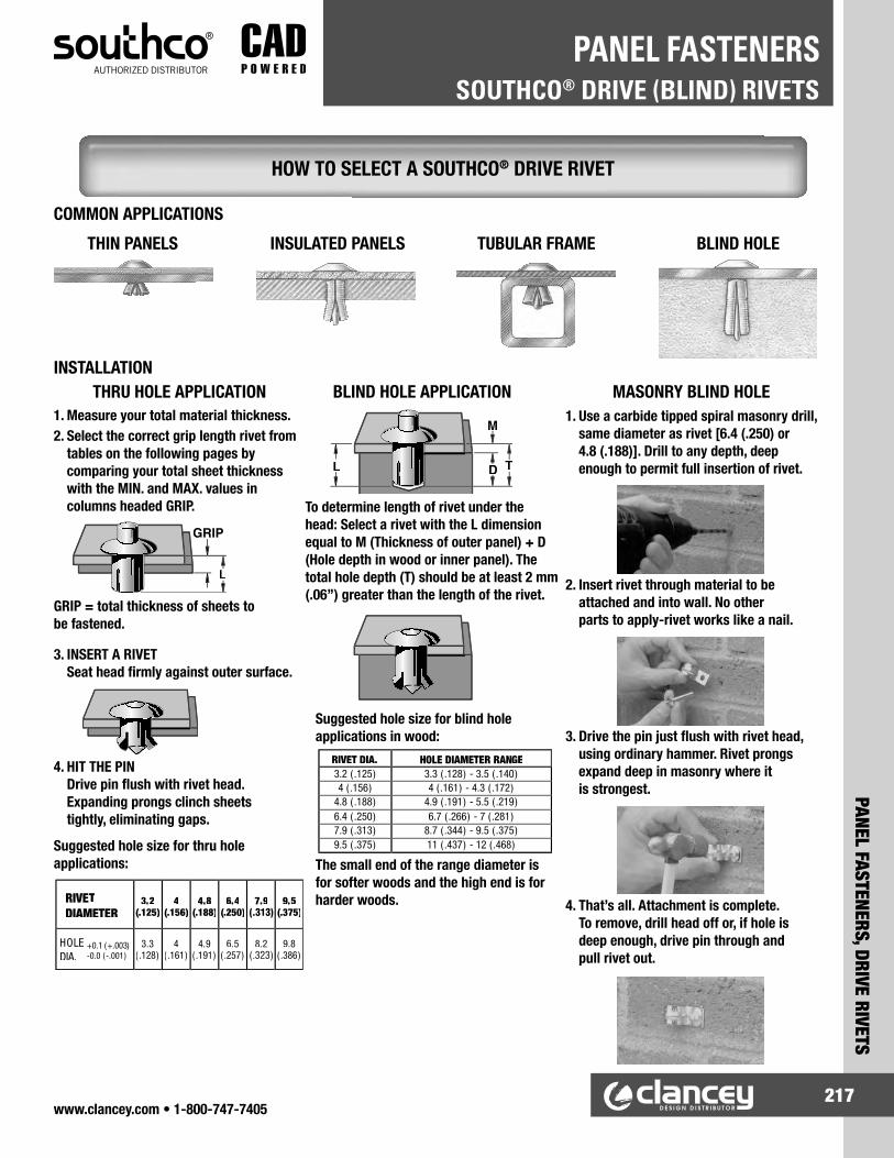
www.clancey.com • 1-800-747-7405217
PANEL FASTENERS, DRIVE RIVETS
SOUTHCO® DRIVE (BLIND) RIVETSPANEL FASTENERS
1. Measure your total material thickness.2. Select the correct grip length rivet from
tables on the following pages by comparing your total sheet thickness with the MIN. and MAX. values in columns headed GRIP.
Suggested hole size for thru hole applications:
RIVETDIAMETER
3.2(.125)
4(.156)
4.8(.188)
6.4(.250)
7.9 9.5(.375)
HOLEDIA.
3.3( .128)
4( .161)
4.9( .191)
6.5( .257)
8.2 9.8( .386)
+0.1 (+.003)-0.0 (-.001)
The small end of the range diameter is for softer woods and the high end is for harder woods.
Suggested hole size for blind hole applications in wood:
D
M
TL
To determine length of rivet under the head: Select a rivet with the L dimension equal to M (Thickness of outer panel) + D (Hole depth in wood or inner panel). The total hole depth (T) should be at least 2 mm (.06”) greater than the length of the rivet.
1. Use a carbide tipped spiral masonry drill, same diameter as rivet [6.4 (.250) or 4.8 (.188)]. Drill to any depth, deep enough to permit full insertion of rivet.
BLIND HOLE APPLICATIONTHRU HOLE APPLICATIONINSTALLATION
GRIP = total thickness of sheets to be fastened.
3. INSERT A RIVET Seat head firmly against outer surface.
4. HIT THE PIN Drive pin flush with rivet head. Expanding prongs clinch sheets tightly, eliminating gaps.
2. Insert rivet through material to be attached and into wall. No other parts to apply-rivet works like a nail.
3. Drive the pin just flush with rivet head, using ordinary hammer. Rivet prongs expand deep in masonry where it is strongest.
4. That’s all. Attachment is complete. To remove, drill head off or, if hole is deep enough, drive pin through and pull rivet out.
MASONRY BLIND HOLE
COMMON APPLICATIONS
THIN PANELS INSULATED PANELS TUBULAR FRAME BLIND HOLE
HOW TO SELECT A SOUTHCO® DRIVE RIVET

www.clancey.com • 1-800-747-7405218
SOUTHCO® DRIVE (BLIND) RIVETSPANEL FASTENERS
PANE
L FA
STEN
ERS,
DRI
VE R
IVET
S
L L
6.4(.250)
L
1.4(.054)
3.2(.125)
5.5(.216)
1.1(.042)
100˚
7.9(.312)
1.5 (.062)
3.2(.125)
3.2(.125)
Ø Ø
Ø Ø
Ø
Ø
L
7.9 (.312)1.7
(.067)
4 (.156)
Ø
Ø
Material and Finish:Rivet: Aluminum, naturalPin: 302 Stainless steel, natural
1/8" (3.2 mm) DIAMETER
5/32" (4 mm) DIAMETERMaterial and Finish:Rivet: Aluminum, naturalPin: 302 Stainless steel, natural
GENERAL PURPOSE RIVETS
These rivets can beused for masonry applications.See instructions on page 223.
www.clancey.com
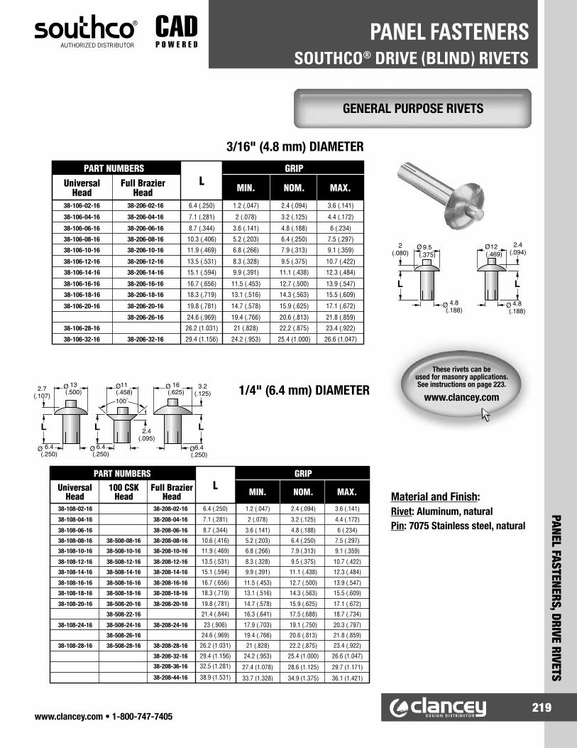
www.clancey.com • 1-800-747-7405219
PANEL FASTENERS, DRIVE RIVETS
SOUTHCO® DRIVE (BLIND) RIVETSPANEL FASTENERS
Material and Finish:Rivet: Aluminum, naturalPin: 7075 Stainless steel, natural
3/16" (4.8 mm) DIAMETER
1/4" (6.4 mm) DIAMETER
2(.080)
9.5(.375)
4.8(.188)
L
12(.469)
2.4(.094)
L
4.8(.188)
Ø
Ø Ø
Ø
11(.458)2.7
(.107)
L
6.4(.250)
L
100˚
2.4(.095)
16(.625)
L
13(.500)
6.4(.250)
6.4(.250)
3.2(.125)
Ø
Ø ØØ
ØØ
GENERAL PURPOSE RIVETS
These rivets can beused for masonry applications.See instructions on page 223.
www.clancey.com

www.clancey.com • 1-800-747-7405220
SOUTHCO® DRIVE (BLIND) RIVETSPANEL FASTENERS
PANE
L FA
STEN
ERS,
DRI
VE R
IVET
S
L 3.5(.138)
Ø 16(.625)
7.9(.313)
ØL
9.5(.375)
4.2(.166)
19(.750)
Ø
Ø
RIVETT LINER
POST
15.5Ø (.609)Ø2.2
(.085)
GRIP
L
4.8Ø (.188)Ø
Ø D2.8
(.110)
GRIP
L
4.8Ø (.188)Ø
Material and Finish:Rivet: Aluminum, naturalPin: 7075 Aluminum, natural
5/16" (7.9 mm) DIAMETER3/8" (9.5 mm) DIAMETER
TRAILER LINER RIVETS TAMPER-RESISTANT, TAMPER EVIDENT RIVETS
Material and Finish:Rivet: 2117 Aluminum, naturalPin: 7075 Aluminum, natural
Material and Finish:Rivet: 2117 Aluminum, naturalPin: 5056 Aluminum, natural
• Fast, efficient trailer lining• Low profile, non-snag head design• Six sizes
• Recessed pin resists being driven through or drilled out
• Removal is difficult and time consuming• Non-snag head design• 2 Diameters and 4 grip ranges
INSTALLATION EXAMPLE
LARGE DIAMETER ALUMINUM RIVETS

www.clancey.com • 1-800-747-7405221
PANEL FASTENERS, DRIVE RIVETS
DRIVE RIVETSPANEL FASTENERS
• Wide variety of hole sizes, grip ranges and head styles.
• Made from non-corrosive plastic materials.
• Prongs “Snap-in” to fastening hole and expand to secure panels when the pin is driven.
Notes: Hole size may vary with grip range. Dimensions listed are nominal.
Head Styles
Binder
Round
Barrel
Special Round
TrussMaterial: Nylon 66Colors: Natural, Black. Custom available
PLASTI-RIVETS®
Try this part inyour application
Please call for samples.
800-747-7405
PLASTI-RIVETSPART NUMBERS
DIMENSIONS MOUNTING STYLEPRONGLENGTH
"C"
HEADDIAMETER
"D"
HEADHEIGHT
"E"
NOMINALHOLE
DIAMETER
GRIPRANGE HEAD PIN
231-080551-00 .212" .187" .045" .125" .031" - .140" ROUND NON-DRIVEN231-080551-05 .240" .218" .060" .125" .031" - .140" ROUND PRE-DRIVEN231-090741-00 .296" .220" .050" .136" .040" - .218" BINDER PRE-DRIVEN201-100841-00 .323" .218" .050" .156" .187" - .250" BINDER NON-DRIVEN231-100841-01 .327" .230" .050" .156" .040" - .250" BINDER PRE-DRIVEN231-101041-01 .385" .375" .050" .156" .218" - .312" BINDER NON-DRIVEN201-120541-00 .228" .375" .125" .187" .062" - .156" BARREL NON-DRIVEN201-120741-00 .310" .438" .075" .187" .062" - .156" BINDER NON-DRIVEN231-120741-00 .310" .438" .075" .187" .062" - .156" BINDER PRE-DRIVEN201-120741-01 .310" .320" .075" .187" .062" - .156" TRUSS NON-DRIVEN201-120751-00 .310" .281" .075" .187" .062" - .156" ROUND NON-DRIVEN201-121041-00 .406" .437" .075" .187" .156" - .281" BINDER NON-DRIVEN231-121041-02 .416" .281" .062" .187" .040" - .375" SPECIAL ROUND PRE-DRIVEN226-120501-02 .212" .312" .031" .190" .031" - .125" BARREL NON-DRIVEN201-121541-00 .549" .281" .078" .190" .312" - .440" BINDER NON-DRIVEN231-121741-00 .613" .437" .075" .190" .375" - .500" BINDER NON-DRIVEN231-141141-01 .452" .344" .062" .218" .040" - .400" BINDER PRE-DRIVEN201-161241-00 .381" .437" .187" .250" .060" - .250" BINDER NON-DRIVEN231-161241-00 .381" .437" .187" .250" .060" - .250" BINDER PRE-DRIVEN231-161341-03 .510" .437" .080" .250" .040" - .462" BINDER PRE-DRIVEN201-161341-00 .499" .437" .080" .250" .125" - .375" BINDER NON-DRIVEN201-161751-00 .640" .375" .110" .250" .281" - .500" ROUND NON-DRIVEN201-180401-00 .205" .375" .312" .272" .031" - .109" BARREL NON-DRIVEN226-160501-01 .224" .406" .046" .272" .031" - .140" BARREL NON-DRIVEN201-181141-00 .483" .625" .109" .281" .134" - .320" BINDER NON-DRIVEN231-181141-00 .483" .625" .109" .281" .134" - .320" BINDER PRE-DRIVEN
® ITW Fastex

www.clancey.com • 1-800-747-7405222
DRIVE RIVETSPANEL FASTENERS
PANE
L FA
STEN
ERS,
DRI
VE R
IVET
S
• Securely holds panels in place.• Removable, re-usable by pulling up
on head.• Quick, easy hand installation.
• Holds securely in blind applications.• High impact nylon body.• Nylon or removable steel pin.
Material: Nylon Flammability rating: 94V-2Color: Black
Material & Finish: Body - Nylon, whitePin - Nylon. white - Steel, zinc plate
Try this part inyour application
Please call for samples.
800-747-7405
NYLON ANCHOR RIVETSNYLON PUSH RIVETS
PUSH RIVETSPART NUMBER
DIMENSIONS MOUNTINGPRONGLEGNTH
“A”
HEADHEIGHT
“B”
HEADDIAMETER
“C”
HOLEDIAMETER
GRIPRANGEBLACK WHITE
9020 9021 .126"
.055" .197" .106"
.039" - .079"9022 9023 .165" .082" - .118"9024 9025 .189" .106" - .141"9026 9027 .217" .134" - .169"
9028 9029 .138"
.063" .252" .122"
.039" - .079"9030 9031 .177" .079" - .118"9032 9033 .217" .118" - .157"9034 9035 .256" .157" - .197"9036 9039 .315" .217" - .256"
9046 9047 .177"
.063" .252" .142"
.086" - .122"9048 9049 .197" .106" - .142"9050 9051 .217" .126" - .161"9054 9055 .276" .185" - .220"
9058 9059 .197"
.071" .315" .161"
.098" - .138"9060 9061 .236" .138" - .177"9062 9063 .276" .177" - .217"9064 9065 .315" .217" - .256"9068 9069 .394" .295" - .335"
9070 9071 .177"
.087" .354" .201"
.059" - .098"9072 9073 .217" .098" - .138"9074 9075 .256" .138" - .177"9076 9077 .295" .177" - .217"9078 9079 .335" .217" - .256"9080 9081 .374" .256" - .295"9082 9083 .413" .295" - .335"
Head StyleHead
Diameter“A”
Head Height
“T”Mushroom .625" .110"
Round .438" .125"Truss .625" .110"Flat .438" .108"
PART NUMBER Hole Diameter
“D”Length
“L” Head StylePlastic Pin Steel Pin
61APM18075 61ASM18075 .187" .750"
Mushroom61APM25075 61ASM25075
.250".750"
61APM25175 61ASM25175 1.00"61APM25150 61ASM25150 1.50"61APR18075 61ASR18075 .187" .750"
Round61APR25075 61ASR25075
.250".750"
61APR25100 61ASR25100 1.00"61APR25150 61ASR25150 1.50"61APT18075 61AST18075 .187" .750"
Truss
61APT25075 61AST25075
.250"
.750"61APT25100 61AST25100 1.00"61APT25150 61AST25150 1.50"61APT25200 --- 2.00"61APT25300 --- 3.00"61APT25400 --- 4.00"61APT25500 --- 5.00"61APT25600 --- 6.00"61APF25056 ---
.250".563"
Flat61APF25075 --- .750"

www.clancey.com • 1-800-747-7405223
PANEL FASTENERS, DRIVE RIVETS - REMOVABLE
DRIVE RIVETS - REMOVABLEPANEL FASTENERS
Material: Nylon Colors: Black - custom availableNote: Listed dimensions are nominal
Material: NylonColors: Black - custom availableNote: Listed dimensions are nominal
• Quick, “push-action” installation.• Easy removal with phillips screwdriver.• Re-usable. • Vibration resistant.
• Ideal for fastening electronic components to printed circuit boards.
• Can withstand up to 500˚ F in wave solder process.
• Installed by hand, or with automatic equipment.• Removable.• Re-usable.• Vibration resistant.
* Open prong design, all other closed per screw type drawing.
** Square Head Style
Material: Heat stabilized impact modified nylonColor: BlackNote: Listed dimensions are nominal
* “Shoulder” style. Please call for additional dimensions.
STANDARD TUFLOK®
SCREW TYPE TUFLOK®
MICRO TUFLOK®
STANDARD TYPE TUFLOK
PART NUMBER
DIMENSIONS MOUNTING
A B C D HOLEDIAMETER
GRIPRANGE
31050001 .083" .283" .039" .445" .193" - .205" .059" - .181"
30060003 .049" .669" .098" .709" .236" - .244" .197" - .236"
30063001 .138" 1.00" .098" .898" .248" - .276" .098" - .350"
30063008* .098" .700" .098" .559" .244" - .262" .060" - .228"
30063014 .118" .590" .079" .897" .250" - .276" .098" - .315"
30080016 .091" .591" .106" .787" .315" - .325" .118" - .315"
® ITW Fastex

www.clancey.com • 1-800-747-7405224
SPECIAL PURPOSE RIVETSPANEL FASTENERS
PANE
L FA
STEN
ERS,
SPE
CIAL
PUR
POSE
• Mating parts securely connect flat panels.• Ideal for materials with variance, multiple layers,
and compressible materials.
Material: Nylon 66Colors: Natural, black - custom availableNote: Listed dimensions are nominal
• Mating parts securely connect flat panels.• Used extensively in the medical industry.• Ideal for compressible materials.
• Smooth oversized head and polished surface provide excellent external appearance.
• Inserts and installs easily by hand.• Removable with flat head screwdriver head (Pry open).• Streamlined size — Ideal for electronic applications.
Material: Nylon 66Colors: Clear, Natural, black - custom availableNote: Listed dimensions are nominal
Material: Nylon 66Color: Black Notes: UL94 V-2 Rating Listed dimensions are nominal
RACHET-RIVETS
SNAP-RIVETS
MINI PRO-LOK RIVET
RACHET RIVETSPART NUMBER
DIMENSIONS MOUNTING
HEADDIAMETER
HEADHEIGHT
HOLEDIAMETER
GRIPRANGE
236-170406-00 .750" .093" .281" .235" - .297"
236-170406-02 .750" .093" .281" .346" - 500"
236-170406-03 .750" .093" .281" .500" - .812"
236-170406-04 .750" .093" .281" .780" - 1.375"
236-170406-05 .406" .062" .281" .235" - .297"
236-170406-07 .406" .062" .281" .346" - 500"
236-170406-08 .406" .062" .281" .500" - .812"
236-170406-09 .406" .062" .281" .780" - 1.375"
SNAP RIVET ASSEMBLY DIMENSIONS MOUNTING
MALE PARTNUMBER
FEMALE PARTNUMBER
HEADDIA.
HEADHEIGHT
HOLEDIA.
GRIPRANGE
236-220603-00 236-220604-00 .625" .062" .320" .170" - .190"
236-220603-02 236-220604-00 .625" .062" .320" .220" - .240"
236-220603-05 236-220604-01 .460" .062" .320" .170" - .190"
236-220603-10 236-220604-00 .625" .062" .320" .320" - .340"
236-220603-10 2700-00 .625" .062" .320" .740" - .770"
MINIPRO-LOK RIVETPART NUMBER
DIMENSIONS MOUNTING
A B C D HOLEDIAMETER
GRIPRANGE
1116-17 .082" .315" .155" .278" .161" - .169" .177" - .217"
1116-21 .071" .315" .158" .315" .161" - .169" .217" - .256"
1116-29 .071" .315" .158" .394" .161" - .169" .295" - .335"

www.clancey.com • 1-800-747-7405225
PANEL FASTENERS, DRIVE RIVETS
DRIVE RIVETSPANEL FASTENERS
Material:Nylon, UL94 V2 Rated
Colors:Black or white
• High assembly speed.• Easy grip, or tamper-resistant head styles.• Fastener captivates in outer panel.• Non-corrosive, non-conductive.• High cycle life.
NYLATCH® 1-PIECE RIVET
Panel Preparation
Installation:
Please call for samples to try
in your application.800-747-7405
Panel Preparation
Head StyleHole Dia. Removable
Panel
Hole Dia. Fixed Panel
.238" - .242" .254" - .259" Tamper Proof
.294" - .299" .316 - .323" Easy Grip
Head StyleH Max. Load Data Weight per
100 PiecesLatched Unlatched Tension ShearTamper Proof .21" .37" 50 Lbs. 75 Lbs. .10 Lbs.
Easy Grip .48" .65" 60 Lbs. 150 Lbs. .32 Lbs.
Head Style G-Grip Range T Max. A Color Part Number
Tamper Proof .076" - .165" .057" .34"Black NY-N4-2-3-20White NY-N4-2-3-10
Easy Grip .182" - .271" .162" .42"Black NY-N5-4-1-20White NY-N5-4-1-10
The 1-piece Nylatch® grommet and plunger are molded into a single unit.
To install, insert the grommet end through previously drilled holes in the removable panel and fixed panel (see table above for hole diameters). Then drive the plunger into the grommet by striking the head with a mallet.
As the plunger penetrates the grommet, the grommet expands, locking the panel to the fixed panel.
To release the removable panel: simply pull the plunger up, allowing the grommet to contract. The panels can then be separated. The 1-piece Nylatch® is held captive and ready for reuse.
ØA
Ø.63˝ Ø.28˝
.10˝ .11˝
.38˝
H
G
TSPH. R
Easy GripHead Style
Tamper ProofHead Style
Fixed Panel
Removable Panel
Part Numbers

www.clancey.com • 1-800-747-7405226
DRIVE RIVETSPANEL FASTENERS
PANE
L FA
STEN
ERS,
DRI
VE R
IVET
S
1. Grip Add the thicknesses of the two panels in which the fastener is to be used (Figure 1). Include the thickness of any paint or coatings. This sum must fall within a range tabulated for each fastener size on the following page.
2. Outer Panel Thickness (P) For any Grip range there is a maximum outer panel thickness, P (Figure 1). Select the appropriate grommet by using P Max from the grommet and plunger tables.
3. Complete Part Number With each grip and outer panel size you will find a matching pair of Plunger and Grommet lengths tabulated. Use these two length numbers to form the part numbers that together will provide a fastener assembly that fits your application.
4. Finish Part Number Plunger head styles and material/color combinations are added last. The options are shown in the part number scheme layout.
Grommet Part NumbersNY-WG-XX-YY
Color & Material -20 = Black Polycarbonate (UL 94 V-2) -10 = White Polycarbonate (UL 94 V-2) -17 = Gray Polycarbonate (UL 94 V-2) -15 = Clear Polycarbonate (UL 94 V-2) -30 = Black Polysulfone (UL 94 V-0) -31 = Natural Polysulfone (UL 94 V-0) -40 = Black Acetal (UL 94 HB) -41 = White Acetal (UL 94 HB)
Series Size 3=.188" Dia. 4=.250" Dia. 5=.313" Dia
Grommet Length Number (See Grommet and Plunger Tables on previous page)
Plunger Part NumbersNY-WP-XX-Z-YY
Color & Material -50 = Black Nylon (UL 94 V-2) -51 = White Nylon (UL 94 V-2) -52 = Gray Nylon (UL 94 V-2) -60 = Black Polyester (UL 94 V-2) -62 = Natural Polyester (UL 94 V-0)
Head Style (See Drawings) -1 = Easy Grip1 -3 = Tamper Proof2 -4 = Mini Grip
Series Size 3=.188" Dia. 4=.250" Dia. 5=.313" Dia
Plunger Length Number3 (See Grommet and Plunger Tables on Previous Pages)
NYLATCH® 2-PIECE FASTENER• Economical choice.• 3 head styles.• Non-conductive, non-corrosive.• Order plunger & grommet separately.
PLUNGER
GROMMET
FIXEDSTRUCTURE
P L
WH
DIA. HOLE IN REMOVABLE PANEL
DIA. HOLE IN FIXED STRUCTURE
A
B
B
A B
.04
.04
Easy Grip (-1) Tamper Proof (-3)
Mini Grip (-4)
A
GRIP
P RemovablePanel
FixedPanel
Head StyleCode
Plunger Size3/16" 1/4" 5/16"
A B A B A B-1 - - - - .63" .38"-3 .26" .10" .28" .10" .30" .11"-4 .25" .26" .32" .28" .38" .30"
Panel Preparation(see sizes below)
Assembly Dimensions How to OrderGrip and Top Panel Thickness Figure 1
Note:See hold dimension information for each fastener size at right. Grommet shown without plunger.3/16" Diameter Plunger
1/4" Diameter Plunger
5/16" Diameter Plunger
Hole DiametersRemovable Panel: .180" to .183"Fixed Structure: .189" to .192"Operable Hole Misalignment: ±.007
Hole DiametersRemovable Panel: .238" to .242"Fixed Structure: .250" to .254"Operable Hole Misalignment: ±.019
Hole DiametersRemovable Panel: .294" to .299"Fixed Structure: .316" to .323"Operable Hole Misalignment: ±.020
Notes (for all 3 tables):1. Use to build part number. You must use the Plunger Number matching
the Grommet Number as shown in these tables when ordering.2. Available in Tamper proof head style.
Sheet Capacity Dimensions Length Number1
G Range P Max. H Max. L Max W Dia. Grommet Plunger.059" - .148" .042" .095" .371" .420" -51 -522
.084" - .173" .065" .080" .387" .420" -52 -522
.118" - .207" .098" .080" .429" .420" -53 -532
.182" - .217" .162" .080" .494" .420" -54 -542
.230" - .139" .210" .080" .542" .420" -55 -55
Sheet Capacity Dimensions Length Number1
G Range P Max. H Max. L Max W Dia. Grommet Plunger.059" - .148" .042" .079" .371" .336" -41 -422
.084" - .173" .065" .064" .386" .336" -42 -422
.118" - .207" .098" .064" .430" .336" -43 -432
.182" - .217" .162" .064" .494" .336" -44 -442
Sheet Capacity Dimensions Length Number1
G Range P Max. H Max. L Max W Dia. Grommet Plunger.056" - .153" .042" .065" .330" .255" -31 -322
.079" - .176" .065" .050" .346" .255" -32 -322
.112" - .209" .098" .050" .490" .255" -33 -332
.152" - .249" .138" .050" .430" .255" -34 -342

www.clancey.com • 1-800-747-7405227
PANEL FASTENERS, "PUSH" FASTENERS
"PUSH" FASTENERSPANEL FASTENERS
Note: Listed dimensions are nominal
Material: Nylon.Formulations to suit specific applicationsare available.
Color: Natural, black - custom available.
• Wide variety of head diameters, installation hole sizes, and grip ranges.
• Easy to install by hand.• Very secure.• Accommodates tolerances in panel thickness.
Head StylesRound Binder Crowned Flat
* Part is modified and different from the diagram. Please call for a complete drawing or samples of the part.
PointStyle
Conical Triangle Blunt Round
Prong Style
A
B
C
D
CHRISTMAS TREE™ CLIPS
CHRISTMAS TREEPART NUMBER
DIMENSIONS MOUNTING STYLE
HEADDIA.“A”
HEADHEIGHT
“B”
PRONG LENGTH
“C”
HOLEDIAMETER
GRIPRANGE
POINTSYTLE
HEADSTYLE
PRONGSTYLE
354-125300-00 .240" .080" .318" .120" - .130" .135" - .250" BLUNT* FLAT D354-156001-00 .375" .090" .551" .151" - .161" .035" - .312" BLUNT FLAT* A354-120240-00 .437" .070" .452" .182" - .192" .035" - .210" CONICAL FLAT A354-190001-00 .437" .070" .650" .182" - .192" .080" - .402" CONICAL FLAT A354-190001-01 .337" .050" .560" .182" - .192" .080" - .400" CONICAL ROUND A354-190300-00 .438" .080" 1.39" .182" - .192" .200" - 1.15" ROUND FLAT A354-200102-00 .470" .039" .700" .185 - .195" .100" - .600" CONICAL BINDER* A354-200101-00 .750" .070" .710" .190" - .200" .060" - .480" TRIANGLE FLAT* A354-220000-00 .500" .059" .955" .223" - .233" .140" - .750" CONICAL BINDER C354-250304-00 .618" .125" .404" .240" - .260" .075" - .185" ROUND FLAT C354-250103-00 .750" .040" .510" .245" - .255" .095" - .320" TRIANGLE* FLAT A354-070201-00 .750" square .055" 1.08" .245" - .255" .040" - .750" CONICAL FLAT A354-250303-00 .995" .060" 1.47" .245" - .255" .065" - 1.25" CONICAL FLAT A
2601-00 .700" .100" .561" .245" - .255" .070" - .400" TRIANGLE* ROUND C2607-00 .500" .060" .571" .245" - .255" .070" - .400" TRIANGLE* ROUND C2630-00 .700" .075" 1.04" .245" - .255" .110" - .800" CONICAL ROUND B2631-00 .700" .075" 1.35" .245" - .255" .410" - 1.13" CONICAL ROUND B
354-250302-00 1.25" .059" .451" .247" - .257" .110" - .370" TRIANGLE FLAT A354-280301-00 .937" .083" .730" .276" - .286" .050" - .440" TRIANGLE CROWNED A354-280302-00 1.22" .090" 1.14" .276" - .286" .350" - .800" CONICAL FLAT* A354-182740-00 .500" .060" .950" .276" - .286" .250" - .800" CONICAL ROUND C354-280308-01 .808" .053" .675" .281" - .286" .155" - .500" TRIANGLE* FLAT* A354-280307-00 .760" .110" 1.28" .276" - .286" .050" - .900" TRIANGLE CROWNED A354-280308-00 .620" .040" .770" .276" - .286" .093" - .470" TRIANGLE FLAT A354-280317-00 .600" .060" 1.32" .276" - .286" .100" - .870" CONICAL CROWNED A354-280318-00 .600" .060" 2.03" .276" - .286" .810" - 1.58" CONICAL CROWNED A354-280319-00 .600" .060" 2.73" .276" - .286" 1.52" - 2.29" TRIANGLE CROWNED A354-280305-00 1.25" .090" 1.23" .281" - .291" .530" - .920" CONICAL BINDER A354-310101-00 .380" x .500" .090" .540" .315" - .325" .093" - .400" BLUNT CROWNED* A354-310102-00 .500" .050" .660" .312" - .325" .130" - .500" BLUNT BINDER A
2622-00 .750" .120' 1.12" .374" - .414" .395" - .700" CONICAL BINDER B
™ ITW Fastex

www.clancey.com • 1-800-747-7405228
"PUSH" FASTENERSPANEL FASTENERS
PANE
L FA
STEN
ERS,
"PU
SH"
FAST
ENER
S
• Patented design assures that retaining fins will not be damaged or distort upon removal.
• Removable feature excellent for field use. • Easy to install by hand.
• Circular fin assures part cannot be pried out of the installation.
• Vandalism resistant.• Very secure.• Easy to install by hand.
Material: NylonColor: Black - custom availableNote: Listed dimensions are nominal
Head Styles
Round Flat Crowned
Non-removable, vandalism resistant drive rivets can be found on page 219.
* Parts feature a textured head
Material: NylonColor: Black - custom availableNote: Listed dimensions are nominal
PINE TREE CLIP®
REMOVABLE STYLE
PINE TREE CLIP®
NON-REMOVABLE STYLE
PINE-TREE CLIPREMOVABLE
PART NUMBER
DIMENSIONS MOUNTINGHEADDIA.“A”
PRONGLENGTH“B+C”
HEADHEIGHT
“D”
HOLEDIAMETER
GRIPRANGE
HEADSTYLE
36030001 .216" .386" .060" .118" .069" - .197" FLAT36030002 .216" .661" .060" .118" .160" - .472" FLAT
260500 .187" .220" .040" .125" .045" - .070" ROUND36050001 .433" .496" .040" .197" .067" - .315" FLAT36050003 .433" .700" .040" .197" .060" - .430" FLAT
261900 .472" .472" .098" .236" .079" - .236" ROUND36063007 .728" .749" .100" .250" .028" - .510" ROUND36063009 .625" .649" .060" .250" .173" - .394" ROUND
261701 .625" .791" .060" .250" .173" - .571" ROUND36063022 .728" .433" .090" .250" .030" - .291" ROUND36070015 .748" 1.31" .060" .276" .063" - 1.00" ROUND
36070005* 1.00" .787" .118" .276" .080" - .532" ROUND 36070007* 1.00" 1.46" .118" .276" .080" - 1.26" ROUND36070010 .748" 1.08" .060" .276" .138" - .710" ROUND36079005 1.00" .945" .118" .311" .040" - .472" ROUND36079004 .752" .895" .106" .311" .025" - .512" CROWNED
36079010* 1.00" .560" .118" .311" .040" - .433" ROUND
PINE-TREE CLIPNON-REMOVABLE
PART NUMBER
DIMENSIONS MOUNTINGHEADDIA.“A”
PRONGLENGTH“C-B”
HEADHEIGHT
“B”
HOLEDIAMETER
GRIPRANGE
HEADSTYLE
39050001 .394" .475" .040" .197" .063" - .252" BINDER39050006 .395" .580" .040" .197" .090" - .400" BINDER39063010 .700" .800" .100" .250" .098" - .472" BINDER39065005 .700" .510" .100" .250" .078" - .236" BINDER39088501 .630" .752" .098" .340" .055" - .395" BINDER39100001 .846" 1.12" .157" .394" .060" - 787" BINDER
® ITW Fastex

www.clancey.com • 1-800-747-7405229
PANEL FASTENERS, "PUSH" FASTENERS
"PUSH" FASTENERSPANEL FASTENERS
• Cost-effective, lightweight panel fastener.• Easy, hand installation in round hole.• Non-corrosive material.
• Twist-action secures top panel, then top panel assembly is pushed into second panel or frame.
• Completely blind.• Secure and non-corrosive.
• Secure fastening.• Non-removable from front, removable from rear.• Easy, hand installation in round hole.
Please Call for Additional Dimensions or Samples
Head Styles
Round
Truss
Binder
Pan
Material: Nylon Color: Natural, black - custom available
Material: Nylon Color: Natural
Material: NylonColor: Natural
CANOE® CLIPS
STALOK™ FASTENERS
DOUBLE-END CHRISTMAS TREE™
DOUBLE-HEAD CHRISTMAS TREE™
CANOE CLIPPART NUMBER
DIMENSIONS MOUNTINGHEAD
HEIGHT“B”
HEADDIAMETER
“C”
PRONGLENGTH
“D”
HOLEDIAMETER
GRIPRANGE
HEADSTYLE
254-080845-00 .040" .270" .330" .123" - .127" .080" - .100" BINDER254-090401-00 .150" .406" .275" .131" - .141" .060" - .090" ROUND254-090501-00 .100" .406" .365" .131" - .141" .080" - .125" ROUND254-090501-01 .100" .300" .365" .131" - .141" .080" - .125" ROUND254-090601-00 .100" .406" .437" .131" - .141" .115" - .160" ROUND254-090601-01 .100" .300" .437" .131" - .141" .115" - .160" ROUND254-090301-00 .060" .300" .330" .135" - .140" .060" - .070" ROUND254-120601-00 .060" .375" .437" .182" - .192" .100" - .160" TRUSS254-160801-00 .055" .500" .630" .240" - .260" .095" - .218" TRUSS254-160801-01 .090" .875" .630" .240" - .260" .095" - .218" TRUSS254-160801-03 .055" .750" .630" .240" - .260" .095" - .218" TRUSS254-160801-02 .060" .450" .460" .240" - .260" .095" - .218" PAN
STALOKPART NUMBER
DIMENSIONS MOUNTINGHEADDIA.“A”
HEADHEIGHT
“B”
PRONGLENGTH
“C”
PRONGDIA.“D”
HOLEDIAMETER
GRIPRANGE
215-120106-00 .325" .075" .586" .187" .182" - .192" .125" - .160"215-120106-02 .437" .148" .596" .187" .182" - .192" .125" - .160"215-120106-03 .375" .093" .607" .187" .182" - .192" .130" - .175"
DOUBLE ENDPART NUMBER
“A” SIDE MOUNTING HEADHEIGHT
“B”
“B” SIDE MOUNTINGHOLEDIA.
GRIPRANGE
HOLEDIA.
GRIPRANGE
354-201960-00 .320" .125" - .375" .040" .320" .140" - .750"354-162200-00 .156" .105" - .250" .067" .156" .105" - .250"
2610-00 .250" .020" - .270" .110" .250" .020" - .270"2627-00 .320" .095" - .300" .040" .320" .095" - .300"
DOUBLE HEADPART NUMBER
SPIN-IN HEADMOUNTING GAP
“C”
CHRISTMAS TREEMOUNTING
HOLEDIA.
PANELTHICKNESS
HOLEDIA.
GRIPRANGE
354-280113-00 .394" .050" - .080" .020" .281" .030" - .220"354-280103-00 .370" .080" - .110" .105" .281" .030" - .470"
® ITW Fastex

www.clancey.com • 1-800-747-7405230
SCREW GROMMETSPANEL FASTENERS
PANE
L FA
STEN
ERS,
SCR
EW G
ROM
MET
S
• Easy “snap-in” installation.• Self-retaining in the panel.• Works as a panel stand-off.• Spreads load over a large area to
achieve high load bearing capacity.• Insulates at fastening point against
electrolytic action.• Non-conductive, non-corrosive.
Material: Nylon
Color: Natural - custom available.
Note: Listed dimensions are nominal.
For detailed materialspecifications and product
strength guidelines.
www.clancey.com
PLASTI-GROMMETS™
PLATI-GROMMETSPART NUMBER
DIMENSIONS MOUNTINGHEADSIZE“A”
HEADHEIGHT
“B”
PRONGLENGTH
“C”HOLE SIZE PANEL
THICKNESSSCREW
SIZE
SQUARE HEAD STYLE212-110302-00 .218" SQUARE .050" .228" .175" SQUARE .031" - .078" 4212-160404-08 375" SQUARE .189" .291" .253" SQUARE .031" - .109" 6212-180402-91 375" SQUARE .305" .296" .273" SQUARE .031" - .109" 6242-160502-70 375" SQUARE .031" .296" .250" SQUARE .031" - .125" 6 or 8 242-170602-83 375" SQUARE .035" .335" .275" SQUARE .031" - .140" 6 or 8 242-170602-80 375" SQUARE .033" .340" .273" SQUARE .031" - .156" 8242-170602-84 375" SQUARE .035" .340" .283" SQUARE .031" - .156" 8212-180402-06 .406" SQUARE .030" .296" .273" SQUARE .031" - .109" 8 or 10 242-180602-90 .406" SQUARE .033" .340" .283" SQUARE .031" - .156" 8 or 10 242-180602-91 .406" SQUARE .062" .340" .283" SQUARE .031" - .156" 8 or 10 212-180602-10 375" SQUARE .045" .359" .284" SQUARE .031" - .156" 8 or 10 212-180402-55 .500" SQUARE .125" .296" .284" SQUARE .031" - .109" 8 or 10 212-240402-04 .625" SQUARE .078" .340" .383" SQUARE .031" - .156" 10 212-240602-04 .625" SQUARE .078" .359" .375" SQUARE .031" - .156" 1/4-20 212-240402-00 .625" SQUARE .078" .286" .378" SQUARE .031" - .109" 1/4-20 212-270402-01 .562" SQUARE .078" .327" .428" SQUARE .031" - .109" 5/16-18
CIRCULAR HEAD STYLE212-170602-37 .500" DIAMETER .500" .340" .283" SQUARE .031" - .156" 8212-170402-01 .375" DIAMETER .672" .296" .273" SQUARE .031" - .109" 8 or 10 212-180402-66 .500" DIAMETER .250" .296" .273" SQUARE .031" - .109" 8 or 10 212-180402-73 .500" DIAMETER .937" .296" .273" SQUARE .031" - .109" 8 or 10 212-170602-05 .500" DIAMETER 1.375" .296" .273" SQUARE .031" - .109" 8 or 10 212-180402-11 .562" DIAMETER .562" .296" .273" SQUARE .031" - .109" 8 or 10 212-180402-40 .493" DIAMETER .375" .296" .283" SQUARE .031" - .109" 8 or 10 212-180402-38 .493" DIAMETER .500" .296" .283" SQUARE .031" - .109" 8 or 10212-180402-37 .493" DIAMETER .625" .296" .283" SQUARE .031" - .093" 8 or 10 212-180402-51 .493" DIAMETER .687" .296" .283" SQUARE .031" - .109" 8 or 10 212-180402-53 .493" DIAMETER .750" .296" .283" SQUARE .031" - .109" 8 or 10 242-180602-92 .500" DIAMETER .098" .340" .283" SQUARE .031" - .156" 8 or 10 242-180602-93 .500" DIAMETER .130" .340" .283" SQUARE .031" - .156" 8 or 10 212-180402-15 .500" DIAMETER .250" .296" .283" SQUARE .031" - .109" 8 or 10 212-180402-69 .500" DIAMETER .312" .296" .283" SQUARE .031" - .109" 8 or 10 212-180602-13 .500" DIAMETER .375" .340" .283" SQUARE .031" - .156" 8 or 10 212-180402-83 .547" DIAMETER 1.062" .296" .283" SQUARE .031" - .109" 8 or 10 242-210602-10 .562" DIAMETER .062" .340" .337" SQUARE .031" - .156" 1/4-20 212-240402-07 .687" DIAMETER .375" .340" .383" SQUARE .031" - .156" 1/4-20 212-240602-00 .687" DIAMETER .469" .340" .383" SQUARE .031" - .156" 1/4-20
RECTANGULAR HEAD STYLE
212-170602-00 .500" x .750""RECTANGLE .040" .340" .273" SQUARE .031" - .156" 8 or 10
™ ITW Fastex

www.clancey.com • 1-800-747-7405231
PANEL FASTENERS, SCREW GROM
METS
SCREW GROMMETSPANEL FASTENERS
• Easy “snap-in” installation.• Encloz grommet captures the end of the
metal screw providing electrical insulation and protecting against temperature/moisture transfer and exposed screw points.
• Acts as a panel stand-off.• Non-conductive, non-corrosive.
• Ideal when components are fastened from the opposite side of the panel.
• Non-conductive, captures the screw.• Attractive decorative head.
• Insulated screw grommet for round hole mounting.• Special pin provides friction fit into the hole.
* panel hole size will vary with panel thicknessMaterial: NylonColor: NaturalNote: Listed dimensions are nominal
Material: Nylon Color: Natural Note: Listed dimensions are nominal
ENCLOZ® REVERSE SCREW GROMMETS
ROUND HOLE SCREW GROMMETS
ENCLOZ® SCREW GROMMETS
ENCLOZSCREW GROMMETS
PART NUMBER
DIMENSIONS MOUNTINGHEADSIZE“A”
HEADHEIGHT
“B”
PRONGLENGTH
“C”HOLE SIZE
PANELTHICKNESS
RANGESCREW SIZE
217-180502-22 .380" SQUARE .125" .490" .273" SQUARE .020" - .140" 8 or 10217-180502-24 .380" SQUARE .250" .480" .273" SQUARE .020" - .140" 8 or 10217-180502-26 .380" SQUARE .375" .490" .273" SQUARE .020" - .140" 8 or 10217-180502-35 .380" SQUARE .030" .490" .271" SQUARE .020" - .140" 8 or 10217-180502-04 .380" SQUARE .250" .490" .283" SQUARE .020" - .140" 8 or 10217-180502-05 .380" SQUARE .312" .490" .283" SQUARE .020" - .140" 8 or 10217-180502-06 .380" SQUARE .375" .490" .283" SQUARE .020" - .140" 8 or 10217-180502-08 .380" SQUARE .500" .490" .283" SQUARE .020" - .140" 8 or 10217-200502-06 .380" SQUARE .380" .480" .312" SQUARE .020" - .140" 8 or 10217-200502-08 .380" SQUARE .500" .480" .312" SQUARE .020" - .140" 8 or 10
ROUND HOLESCREW GROMMET
PART NUMBER
DIMENSIONS MOUNTINGHEADSIZE"A"
HEADHEIGHT
"B"
PRONGLENGTH
"C"HOLE SIZE
PANELTHICKNESS
RANGE*
SCREWSIZE
212-250301-00 .500" DIAMETER .060" .390" .248" - .265" DIA. .020" - .250" 8
ENCLOZ REVERSESCREW GROMMETS
PART NUMBER
DIMENSIONS MOUNTINGHEADSIZE“A”
HEADHEIGHT
“B”
PRONGLENGTH
“C”HOLE SIZE PANEL THICK-
NESS RANGE SCREW SIZE
212-320602-01 .500" DIAMETER .095" .397" .250" x .343" .040" - .060" 8212-320334-00 .500" DIAMETER .100" .525" .312" x .343" .062" - .092" 8
® ITW Fastex

www.clancey.com • 1-800-747-7405232
HOLE PLUGSPANEL FASTENERS
PANE
L FA
STEN
ERS,
HOL
E PL
UGS
• Convex head tapers to a thin edge.• Wide range of hole sizes and
panel thicknesses.• Custom colors are available.
• Same features as standard dome plugs in a halogen-free material.
Material: NylonCertifications: E-15331 LR-8919Flammability rating: 94V-2
* Single chassis design.
Material: NylonCertifications: E-15331 LR-8919Flammability rating: 94 V-O
Material: NylonCertifications: E-15331 LR-8919Flammability rating: 94V-2
DOMED PLUGSHALOGEN-FREE
94V-0 DOME PLUGS
DOME PLUGS
PART NUMBERDIMENSIONS MOUNTING
HEADDIAMETER
“A”
OVERALLHEIGHT
“B”
MAXIMUMPANEL
THICKNESS
HOLEDIAMETERBLACK WHITE
2590 2591 .250" .234" .062" .187"2603 2604 .312" .312" .062" .250"2613 2614 .375" .312" .062" .312"2617 2618 .468" .406" .125" .375"2633 2634 .531" .406" .125" .437"2643 2644 .578" .406" .125" .500"2653 2654 .656" .406" .125" .562"2663 2664 .718" .406" .125" .625"2673 2674 .781" .406" .125" .687"2683 2684 .921" .406" .125" .750"2693 2694 .890" .406" .125" .812"2703 2704 1.015" .453" .125" .875"2713 2714 1.203" .453" .125" 1.000"2723 2724 1.218" .453" .125" 1.125"2733 2734 1.312" .453" .125" 1.187"2740 2741 1.375" .453" .125" 1.250"2753 2754 1.500" .453" .125" 1.375"2763 2764 1.671" .453" .125" 1.500"2773 2774 1.906" .453" .125" 1.750"2783 2784 2.170" .469" .125" 2.000"2403 2404 2.343" .760" .250" 2.125"2411 2412 2.422" .750" .250" 2.250"2790 2791 2.718" .750" .250" 2.500"2455 2456 3.171" .750" .250" 3.000"2482 2483 3.656" .750" .250" 3.375"2464 2465 3.656" .750" .250" 3.500"2473 2474 4.156" .750" .250" 4.000"2451 2452 5.219" .781" .250" 5.000"2453 2454 6.219" .781" .250" 6.000"
PART NUMBERDIMENSIONS MOUNTING
HEADDIAMETER
“A”
OVERALLHEIGHT
“B”
MAXIMUMPANEL
THICKNESS
HOLEDIAMETERBLACK UL94V-0
2593* .265" .240" .062" .187"2606* .312" .312" .062" .250"2616* .375" .312" .062" .312"2623 .468" .406" .125" .375"2636 .531" .406" .125" .437"2646 .578" .406" .125" .500"2666 .718" .406" .125" .625"2686 .921" .406" .125" .750"2706 1.015" .453" .125" .875"2716 1.203" .453" .125" 1.000"2729 1.218" .453" .125" 1.125"
PART NUMBERDIMENSIONS MOUNTING
HEADDIAMETER
“A”
OVERALLHEIGHT
“B”
MAXIMUMPANEL
THICKNESS
HOLEDIAMETERBLACK WHITE
2128 2130 18.5 mm 10.3 mm 2.5 mm 16 mm
2131 2132 22.6 mm 10.3 mm 2.5 mm 20 mm
2133 2134 29.8 mm 11.5 mm 2.5 mm 25 mm
2135 2136 35.3 mm 11.5 mm 2.5 mm 32 mm

www.clancey.com • 1-800-747-7405233
PANEL FASTENERS, HOLE PLUGS
HOLE PLUGSPANEL FASTENERS
• Removable for access or re-use of the hole.• Can act as a bumper (head thickness .063").• Flat, matte finish.
• Limited internal protrusion.• Locks firmly in panel.• Quick, easy hand installation.
• Smooth glossy head has shiny finish.• Can also act as a glide.
(All Items) Material: Nylon Certifications: E-15331 LR-8919 Flammability rating: 94V-2
* Single chassis design.
PART NUMBERDIMENSIONS MOUNTING
HEADDIAMETER
“A”
OVERALLHEIGHT
“B”
MAXIMUMPANEL
THICKNESS
HOLEDIAMETERBLACK WHITE
3053 3054 .421" .328" .156" .250"3056 3057 .510" .406" .172" .312"3059 3060 .578" .312" .172" .375"3062 3063 .609" .406" .172" .437"3065 3066 .671" .406" .172" .500"3068 3069 .734" .406" .172" .562"3071 3072 .796" .406" .172" .625"3074 3075 .890" .406" .172" .687"3077 3078 .968" .406" .172" .750"3080 3081 1.031" .406" .172" .812"3083 3084 1.078" .406" .172" .875"3086 3087 1.218" .406" .172" 1.000"3089 3090 1.296" .406" .172" 1.093"3092 3093 1.406" .406" .172" 1.187"3095 3096 1.453" .406" .172" 1.250"3098 3099 1.578" .453" .172" 1.375"3124 3125 1.718" .453" .250" 1.500"
PART NUMBERDIMENSIONS MOUNTING
HEADDIAMETER
“A”
OVERALLHEIGHT
“B”
MAXIMUMPANEL
THICKNESS
HOLEDIAMETERBLACK WHITE
1654 1655 .281" .250" .062" .218"1660 1661 .343" .250" .062" .281"1678 1679 .375" .250" .062" .312"1663 1664 .406" .250" .062" .343"1681 1682 .468" .250" .062" .375"1666 1667 .468" .250" .062" .406"1684 1685 .531" .250" .062" .437"1669 1670 .531" .250" .062" .468"1687 1688 .563" .250" .062" .500"1672 1673 .593" .250" .062" .531"1675 1676 .687" .250" .062" .593"1690 1691 .718" .250" .062" .625"1693 1694 .843" .250" .062" .750"1696 1697 .890" .250" .062" .781"1699 1700 .968" .250" .062" .875"1702 1703 1.200" .250" .062" 1.000"
PART NUMBERDIMENSIONS MOUNTING
HEADDIAMETER
“A”
OVERALLHEIGHT
“B”
MAXIMUMPANEL
THICKNESS
HOLEDIAMETERBLACK WHITE
2600* 2601* .312" .312" .062" .250"2610* 2611* .375" .312" .062" .312"2620 2621 .468" .406" .125" .375"2630 2631 .531" .406" .125" .437"2640 2641 .563" .406" .125" .500"2650 2651 .656" .406" .125" .562"2660 2661 .734" .406" .125" .625"2680 2681 .859" .406" .125" .750"2700 2701 .953" .453" .125" .875"2710 2711 1.125" .453" .125" 1.000"2720 2721 1.218" .453" .125" 1.125"2730 2731 1.312" .453" .125" 1.187"
SHORTY PLUGSPRY-OUT PLUGS
GLOSSY PLUGS

www.clancey.com • 1-800-747-7405234
HOLE PLUGSPANEL FASTENERS
PANE
L FA
STEN
ERS,
HOL
E PL
UGS
Material: NylonCertifications: E-15331 LR-8919Flammability rating: 94V-2
Material: ABS-Clear Lexan-ClearFlammability rating: ABS – 94HB Lexan 94V-2
• Closes cavity-fill insulation holes in wood and other siding materials.
• Convex, matte finish blends with siding.
• Holds securely in hole.• Quick, easy hand installation .
• Allows air to flow and heat to escape.• Locks firmly into panel.• Quick, easy hand installation.
• Allows viewing inside of enclosure.• Locks firmly into panel.• Quick, easy hand installation.
* Single chassis design
AB
Material: NylonFlammability Rating: 94V-2
WINDOW PLUGSVENT PLUGS
INSULATION PLUGS
PART NUMBERDIMENSIONS MOUNTING
HEADDIAMETER
“A”
OVERALLHEIGHT
“B”
NUMBEROF
HOLES
MAXIMUMPANEL
THICKNESS
HOLEDIAMETERBLACK WHITE
2637 2638 .578" .406" 4 .156" .250"2657 2658 .734" .406" 5 .172" .312"2677 2678 .906" .406" 8 .172" .375"2697 2698 1.015" .453" 9 .172" .437"2707 2708 1.203" .453" 9 .172" .500"2726 2727 1.218" .453" 9 .172" .562"2743 2744 1.375" .453" 10 .172" .625"2797 ---- 1.375" .453" 4 .172" .687"2756 2757 1.500" .453" 11 .172" .750"2766 2767 1.671" .453" 13 .172" .812"2776 2777 1.906" .453" 13 .172" .875"2786 2787 2.140" .468" 19 .172" 1.000"2793 2794 2.718" .750" 19 .172" 1.093"2458 2459 3.171" .750" 26 .172" 1.187"2467 2468 3.656" .750" 38 .172" 1.250"2476 2477 4.156" .750" 48 .172" 1.375"
PART NUMBERDIMENSIONS MOUNTING
HEADDIAMETER
“A”
OVERALLHEIGHT
“B”
MAXIMUMPANEL
THICKNESS
HOLEDIAMETERBLACK WHITE
1300* 4300* .250" .234" .062" .187"1301* 4301* .312" .312" .062" .250"1302* 4302* .375" .312" .062" .312"1303 4303 .468" .406" .125" .375"1304 4304 .531" .406" .125" .437"1305 4305 .563" .406" .125" .500"1307 4307 .734" .406" .125" .625"1309 4309 .859" .406" .125" .750"1311 4311 .953" .453" .125" .875"1312 4312 1.125" .453" .125" 1.000"1313 4313 1.218" .453" .125" 1.125"1314 4314 1.468" .453" .125" 1.375"1316 4316 1.609" .453" .125" 1.500"1318 4318 1.875" .453" .125" 1.750"1319 4319 2.157" .453" .125" 2.000"
PART NUMBERDIMENSIONS MOUNTING
HEADDIAMETER
“A”
OVERALLHEIGHT
“B”
MAXIMUMPANEL
THICKNESS
HOLEDIAMETERBLACK WHITE
3149 3150 1.234" .687" NO MAX. 1.000"

www.clancey.com • 1-800-747-7405235
PANEL FASTENERS, HOLE PLUGS
HOLE PLUGSPANEL FASTENERS
• Plugs standard strain relief holes and other double “D” holes.
• Installs quickly, locks firmly.
Material: NylonFlammability Rating: 94V-2Certifications: E-15331 LR-8919
• Threads into standard “PG” conduit threads.
• Slotted head for easy installation/removal.
Material: Polymide 6.6Color: Gray
• Oil tight, rain tight, submersible.• Fits standard knock-out holes.• Quick, easy hand installation.
Material: Santoprene 251-80Certifications: E-28430 LR-81067Flammability rating: 94V-0
• Plugs electrical knock-outs.• Silver gray color to match galvanized steel.• Fits standard knock-out holes.
Material: Santoprene 251-80Certifications: E-15331 LR-8919Flammability rating: 94V-2
PART NUMBERDIMENSIONS MOUNTING
HEADDIAMETER
“A”
OVERALLHEIGHT
“B”
HEADHEIGHT
“C”
HOLEDIAMETER
MAXIMUMPANEL
THICKNESSBLACK
3833 1.28" .500" .359" .875" .125"3835 1.53" .546" .390" 1.093" .125"3837 1.80" .562" .421" 1.375" .125"
PART NUMBER DIMENSIONS MOUNTING
HEADDIAMETER
“A”
OVERALLHEIGHT
“B”
MAXIMUMPANEL
THICKNESS
HOLEDIAMETER
“E”
ANTI-ROTATION
“D”BLACK WHITE
2488 2489 .531" .406" .125" .437" .390"2491 2492 .578" .406" .125" .500" .445"2494 2495 .656" .406" .125" .562" .530"2497 2498 .718" .406" .125" .625 .550"2503 2504 .921" .453" .125" .750" .625"2509 2510 1.016" .453" .125" .875" .770"
TRADESIZE
PARTNUMBER DIMENSIONS MOUNTING
SILVERGRAY
HEADDIAMETER
“A”
OVERALLHEIGHT
“B”
MAXIMUMPANEL
THICKNESS
HOLEDIAMETER
1/2" 3997 1.015" .453" .125" .875"3/4" 3998 1.218" .453" .125" 1.093"1" 3999 1.500" .453" .125" 1.375"
1-1/4" 4000 1.906" .453" .125" 1.750"1-1/2" 4001 2.140" .453" .125" 2.000"
2" 4002 2.750" .750" .250" 2.500"
THREADTYPE/SIZE PART NUMBER
HEADDIAMETER
“A”
OVERALLHEIGHT
“B”
PG 7 3405 .551" (14 mm) .315" (8 mm)PG 9 3407 .787" (20 mm) .354" (9 mm)PG 11 3402 .866" (22 mm) .354" (9 mm)PG 13 3412 .984" (25 mm) .374" (9.5 mm)PG 16 3414 1.06" (27 mm) .374" (9.5 mm)PG 21 3416 1.30" (33 mm) .472" (12 mm)PG 29 3418 1.73" (44 mm) .472" (12 mm)
KNOCK-OUT SEALSLIQUID TIGHT KNOCK-OUT SEALS
PG THREADED PLUGSDOUBLE “D” PLUGS

www.clancey.com • 1-800-747-7405236
GAS SPRINGSDOOR ASSISTS
GAS
SPRI
NGS,
CAP
ABIL
ITIE
S
CLANCEY – THE LEADER IN DESIGNING GAS SPRING SOLUTIONS
Computer Validated Design AssistanceClancey's Application Specialists are trained in the use of computer simulation programs designed to reduce time and costs from prototypes through production.
By applying technology we can “dial in” the desired features for your application.• Opening force • Handle load• Closing force • Auto-rise• Control for temperature
Highest Quality ProductClancey partners with the best manufacturers in the business. We insist on automotive industry quality levels. When you are selecting a partner for your gas springs consider the two parts of the gas spring that have the greatest impact on its life:
Rod Quality:Our rods are treated with the "Ni-slide" salt bath nitrating process, resulting in a rod that is exceptionally smooth and corrosion resistant. When compared with industry standard chrome rods, the gas spring you select from Clancey will have a much longer life.
Seal Package:Clancey offers a seal package designed for the longest life. In addition to the highest quality orifice and piston stack, Clancey's gas springs offer a special seal guide system that promotes straight entry and exit resulting in longer life.
Largest Product Variety – Design FlexibilityFor custom gas springs based on application volume, Clancey offers customers the widest variety of configurations, hundreds more than other distributors. Here are but a few:
Inter-StopGas spring which locks in 2 distinct positions.
Bloc-o-LiftMulti-position, remote actuated locking gas spring.
Electro-LiftAllows electrical current to transmit through the gas spring acting as a switch.
Stainless Steel316 stainless steel construction for maximum corrosion resistance.
Heavy Duty20 mm x 40 mm Rod and tube configurations allows forces up to 1000 lbs.
End-FittingsWide variety to suit all applications.
A small sample of our offering.
Pressure tubeconnection
Piston system
Piston rod
Pressure tubewith filling medium
Oil
Specialseal-guide system
Piston rodconnection

www.clancey.com • 1-800-747-7405237
GAS SPRINGS, CAPABILITIES
GAS SPRINGSDOOR ASSISTS
Here is the information we will be looking for to assist you in selecting a gas spring that will work well in your application.
APPLICATION DEVELOPMENT
Section 1 - Customer and Project InformationCompany Name: Project Name/Number:
Engineering Contact: Application Description:
E-mail Address: Estimated Number of Units Annually:
Phone: Start of Production Date:
Section 2 - Application Type (Select One of Four Options)
VERTICAL DOOR OFFSET DOOR HORIZONTAL DOOR VERTICAL HINGE (E.G., CAB DOORS)
Section 3 - Dynamic RequirementsDesired Action:
Over-Center, e.g., vehicle rear hatch (most common)Auto Rise (door opens upon release of latch)
Desired Damping:Damped in Extension (most common)Custom Damping, e.g., damped in compression,
dynamic damping ______________________
Section 4 - Application DataTemperature: _____ °F or _____ °C_____ Minimum _____ Average _____ Maximum
Based on your selected application type, please give the following information (door in closed position):
Units: _____ mm or _____ inches
Center of Gravity: X1 = _____ Y1 = _____
Handle Location: HX = _____ HY = _____
Opening Angle: _____ degrees
Total Weight of Door: _____ lbs or _____ kg
Preferred Mounting Location (optional):
Fixed Point: X3 = _____ Y3 = _____
Moving Point: X4 = _____ Y4 = _____
Desired Handle Effort: To Open = _____ To Close = _____
Desired Number of Gas Springs Per Door: _____
HINGE POINT (0,0)
OPEN POSITION
OPENINGANGLE
CLOSED POSITION
HX
X3
Y1
X1
HY
Y3
X4
Y4
HING
E PO
INT
(0,0
) OPEN POSITION
OPENINGANGLE
CLOSED POSITION
X3
HX
X1X4
Y3 Y1 Y4
HY
HING
E PO
INT
(0,0
)
OPEN POSITION
OPENINGANGLE
CLOSED POSITION
X4HX
Y4Y3
X3
X1HY
HINGE POINT (0,0)
OPEN POSITION
OPENINGANGLE
CLOSED POSITION
HX
X3
Y1
X1
HY
Y3
X4
Y4

www.clancey.com • 1-800-747-7405238
COMPOSITE END GAS SPRINGSDOOR ASSISTS
DOOR
ASS
ISTS
, GAS
SPR
INGS
, COM
POSI
TE E
ND
6 mm ROD X 15 mm TUBE COMPOSITE END-FITTINGS
"R" "T" "L" "S" Force Part Number
6mm 15mm 7.5" 2"
20 lbs 4533BE40 lbs 4535BV60 lbs 4536BQ80 lbs 4537BL
6mm 15mm 7.7" 2.36"
11.2 lbs 6444BL22.5 lbs 6488IU33.7 lbs 6489IP45 lbs 6491IW
56.2 lbs 6492IR67.4 lbs 6493IM78.7 lbs 6494IH90 lbs 6495IC
6mm 15mm 9.27" 3.15"
11.2 lbs 6449IM22.5 lbs 6501IP33.7 lbs 6502IK45 lbs 6503IF
56.2 lbs 6504IA67.4 lbs 6505IW78.7 lbs 6505IR90 lbs 6507IM
6mm 15mm 10" 3"
20 lbs 4539BB40 lbs 4540BN60 lbs 4541BI80 lbs 4542BD100 lbs 5306BH
6mm 15mm 10.85" 3.94"
11.2 lbs 6458IL22.5 lbs 6508IH33.7 lbs 6509IC45 lbs 6511IJ
56.2 lbs 6514IV67.4 lbs 6515IQ78.7 lbs 6516IL90 lbs 6517IG
"R" "T" "L" "S" Force Part Number
6mm 15mm 12" 3.5"
20 lbs 5663BZ30 lbs 5664BU60 lbs 5665BP90 lbs 5666BK
6mm 15mm 12.42" 4.72"
11.2 lbs 6462II22.5 lbs 6519IX33.7 lbs 6521ID45 lbs 6522IZ
56.2 lbs 6523IU67.4 lbs 6524IP78.7 lbs 6525IK90 lbs 6526IF
6mm 15mm 14.78" 5.91"
11.2 lbs 6467IK22.5 lbs 6539IL33.7 lbs 6541IS45 lbs 6542IN
56.2 lbs 6543II67.4 lbs 6544ID78.7 lbs 6545IZ
6mm 15mm 15" 5.5"
20 lbs 5667BF40 lbs 5668BA60 lbs 5669BW80 lbs 5670BH
6mm 15mm 17" 6"
20 lbs 5671BC30 lbs 6147BR40 lbs 6146BW60 lbs 6148BM90 lbs 6149BH
6mm 15mm 20" 8"
20 lbs 6150BT30 lbs 6151BO40 lbs 6152BJ90 lbs 6153BE
• Ni-Slide corrosion resistant rod.• Corrosion resistant composite end-fitting.• Easy "snap-on" installation.• Many lengths, strokes, and forces are available.
10 mm COMPOSITE
Order 10 mm ball studs or brackets.
Custom configurations and forces are available for high
volume applications. [email protected] 800-747-7405

www.clancey.com • 1-800-747-7405239
DOOR ASSISTS, GAS SPRINGS, COMPOSITE END
COMPOSITE END GAS SPRINGSDOOR ASSISTS
8 mm ROD X 18 mm TUBE, COMPOSITE END-FITTINGS
10 mm COMPOSITE
Order 10 mm ball studs or brackets.
"R" "T" "L" "S" Force Part Number
8mm 18mm 9.65" 3.15"
22.5 lbs 75261435 lbs 75262245 lbs 1417EP56 lbs 75263068 lbs 1418EK78 lbs 1419EF90 lbs 752649
113 lbs 752657136 lbs 752665
8mm 18mm 11.20" 3.95"
22.5 lbs 75267335 lbs 75268145 lbs 1421EM56 lbs 75270368 lbs 1422EH78 lbs 1423EC90 lbs 752711
113 lbs 752738136 lbs 752746
8mm 18mm 11.89" 3.5"
20 lbs 4552BY30 lbs 4553BT60 lbs 455BO90 lbs 455BJ
120 lbs 4556BE150 lbs 4558BV
8mm 18mm 12" 3.6"
20 lbs 1573ET25 lbs 1574EO30 lbs 1575EJ35 lbs 1576EE40 lbs 1578EV45 lbs 1579EQ50 lbs 1581EX60 lbs 1582ES90 lbs 3071EV100 lbs 3072EQ140 lbs 1583EN
8mm 18mm 12.8" 4.7"
22.5 lbs 75275435 lbs 75276245 lbs 1424EY56 lbs 75277068 lbs 1425ET78 lbs 1426EO90 lbs 752789
113 lbs 752797136 lbs 752800
"R" "T" "L" "S" Force Part Number
8mm 18mm 14.5" 5"
20 lbs 4909EG25 lbs 3073EL30 lbs 1584EI35 lbs 1585ED40 lbs 1586EZ50 lbs 1587EU65 lbs 4634EH75 lbs 3075EB80 lbs 4908EL100 lbs 1588EP
8mm 18mm 15.25" 5"
20 lbs 0365BR30 lbs 03666BR60 lbs 0367BM90 lbs 0502BF120 lbs 0503BA150 lbs 0504BW
8mm 18mm 15.95" 6.3"
22.5 lbs 75281935 lbs 75282745 lbs 1427EJ56 lbs 75283568 lbs 1428EE78 lbs 1431EG90 lbs 752843
113 lbs 752851136 lbs 752878
8mm 18mm 17" 6"
20 lbs 4526BW30 lbs 4527BR60 lbs 4528BM90 lbs 4529BH120 lbs 4531BO150 lbs 4532BJ
8mm 18mm 17.2" 6.2"
20 lbs 1589EK25 lbs 1591ER30 lbs 3416EE35 lbs 1592EM40 lbs 3062EW45 lbs 1593EH50 lbs 1594EC55 lbs 1595EY60 lbs 1596ET80 lbs 3063ER85 lbs 1597EO90 lbs 1598EJ110 lbs 6334IX120 lbs 3065EH130 lbs 1599EE
"R" "T" "L" "S" Force Part Number
8mm 18mm 19.10" 7.9"
22.5 lbs 75288635 lbs 75289445 lbs 1432EB56 lbs 75290868 lbs 1433EX78 lbs 1434ES90 lbs 752916113 lbs 752924136 lbs 752932
8mm 18mm 19.7" 8"
30 lbs 3076EX35 lbs 1601EK45 lbs 1602EF55 lbs 1603EA60 lbs 1604EW70 lbs 3627EG80 lbs 3087EM85 lbs 1605ER90 lbs 3077ES100 lbs 3078EN120 lbs 1606EM130 lbs 1607EH
8mm 18mm 20" 8"
20 lbs 0628BK30 lbs 0629BF60 lbs 0630BR90 lbs 7290BH120 lbs 5358BA150 lbs 0631BM
8mm 18mm 23" 9.85"
22.5 lbs 75294035 lbs 75295945 lbs 1435EW56 lbs 85296768 lbs 1436EI78 lbs 1437ED90 lbs 752975
113 lbs 752983136 lbs 752991
Try this part in your application. Please call for samples.
[email protected] 800-747-7405
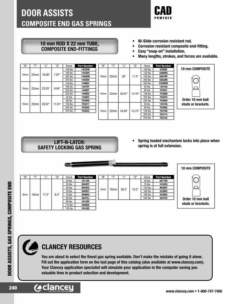
www.clancey.com • 1-800-747-7405240
COMPOSITE END GAS SPRINGSDOOR ASSISTS
DOOR
ASS
ISTS
, GAS
SPR
INGS
, COM
POSI
TE E
ND
10 mm ROD X 22 mm TUBE, COMPOSITE END-FITTINGS
LIFT-N-LATCH: SAFETY LOCKING GAS SPRING
CLANCEY RESOURCESYou are about to select the finest gas spring available. Don’t make the mistake of going it alone. Fill out the application form on the last page of this catalog (also available at www.clancey.com). Your Clancey application specialist will simulate your application in the computer saving you valuable time in product selection and development.
10 mm COMPOSITE
Order 10 mm ball studs or brackets.
10 mm COMPOSITE
Order 10 mm ball studs or brackets.
• NI-Slide corrosion resistant rod.• Corrosion resistant composite end-fitting.• Easy “snap-on” installation.• Many lengths, strokes, and forces are available.
• Spring loaded mechanism locks into place when spring is at full extension.
"R" "T" "L" "S" Force Part Number
10mm 22mm 19.09" 7.87"
158 lbs 1422EW180 lbs 1443ER202 lbs 1444EM225 lbs 1445EH
10mm 22mm 23.03" 9.84"
158 lbs 1446EC180 lbs 1447EY202 lbs 1448ET225 lbs 1449EO
10mm 22mm 26.97" 11.81"
56 lbs 1438EZ90 lbs 753009
158 lbs 753017202 lbs 753025225 lbs 753033
"R" "T" "L" "S" Force Part Number
10mm 22mm 28" 11.5"
100 lbs 0395BI120 lbs 0360BU150 lbs 0361BP200 lbs 0362BK250 lbs 5359BW
10mm 22mm 30.91" 13.78"
56 lbs 1441EA90 lbs 753041
158 lbs 753068202 lbs 753076225 lbs 753084
10mm 22mm 34.84" 15.75"
56 lbs 1441EA90 lbs 753092
158 lbs 753106202 lbs 753114225 lbs 753122
"R" "T" "L" "S" Force Part Number
8mm 18mm 17.2" 6.2"
20 lbs 1611EE30 lbs 3044EY40 lbs 5042ES50 lbs 3045ET70 lbs 3046EO80 lbs 3047EJ90 lbs 1613EV110 lbs 3048EE130 lbs 1614EQ
"R" "T" "L" "S" Force Part Number
8mm 18mm 26.3" 10.2"
30 lbs 2977ER70 lbs 1616EG120 lbs 4636EY160 lbs 3238EX190 lbs 3239EX240 lbs 3241EZ

www.clancey.com • 1-800-747-7405241
DOOR ASSISTS, GAS SPRINGS, STEEL END
STEEL END GAS SPRINGSDOOR ASSISTS
GAS SPRINGS WITH 10 mm STEEL END-FITTINGS
“S” Stroke
“L” Extended Length
“T” Tube Diameter
“R” Rod Diameter
10 mm Steel Be sure to order 2 safety clips
per gas spring.
PART NUMBER012378
Order 10 mm ballstuds or brackets
• NI-Slide corrosion resistant rod.• Use of safety clips is required.
"R" "T" "L" "S" Force Part Number
8mm 19mm 9.6" 3.2"
20 lbs 1617EB25 lbs 1618EX30 lbs 1619ES35 lbs 1621EZ40 lbs 1622EU45 lbs 3084EA50 lbs 3023EO60 lbs 1623EP70 lbs 3024EJ75 lbs 1624EK80 lbs 1625EF85 lbs 1626EA90 lbs 3025EE
100 lbs 1627EW110 lbs 3027EV120 lbs 1628ER150 lbs 1629EM170 lbs 3189EN
8mm 19mm 12.2" 4.3"
20 lbs 1631ET25 lbs 2978EM30 lbs 1632EO40 lbs 1633EJ45 lbs 2979EH55 lbs 1634EE85 lbs 1636EV90 lbs 2981EO110 lbs 1637EQ140 lbs 4609EA150 lbs 3079EI170 lbs 4917EK
"R" "T" "L" "S" Force Part Number
8mm 19mm 15.3" 5.8"
20 lbs 1638EL25 lbs 2993EZ30 lbs 1639EG35 lbs 2994EU40 lbs 1641EN45 lbs 2995EP50 lbs 1642EI60 lbs 1643ED70 lbs 3625EQ90 lbs 2996EK110 lbs 2997EF150 lbs 1644EZ160 lbs 3198EV
8mm 22mm 17.1" 6.7"
20 lbs 2998EA30 lbs 1651EH40 lbs 1652EC45 lbs 2999EW50 lbs 1653EY60 lbs 1654ET75 lbs 1655EO80 lbs 1656EJ85 lbs 3001EJ90 lbs 3002EE100 lbs 3004EV110 lbs 1657EE120 lbs 4734EA130 lbs 1659EV150 lbs 1661EB
"R" "T" "L" "S" Force Part Number
8mm 12mm 19.7" 7.9"
25 lbs 1662EX40 lbs 1633ES45 lbs 3009EX50 lbs 3092EE70 lbs 1664EN80 lbs 1665EI85 lbs 3012EZ90 lbs 1666ED100 lbs 4916EP110 lbs 5039EQ120 lbs 1667EZ150 lbs 1668EU
8mm 19mm 23" 8.9"
30 lbs 1645EU35 lbs 3017EA50 lbs 1646EP60 lbs 1647EK75 lbs 3018EW80 lbs 1648EF
120 lbs 1649EA140 lbs 3267EK
You're buying the best gas spring in the world.
Be sure to get the maximum life from it. Have our applications specialist run a computer simulation
of your design for maximum performance.

www.clancey.com • 1-800-747-7405242
STEEL END GAS SPRINGSDOOR ASSISTS
DOOR
ASS
ISTS
, GAS
SPR
INGS
, STE
EL E
ND
GAS SPRINGS WITH 13 mm STEEL END-FITTINGS
13 mm Steel Be sure to order 2 safety clips
per gas spring.
PART NUMBER012351
Order 13 mm ballstuds or brackets
• NI-Slide corrosion resistant rod.• Use of safety clips is required.• For heavy duty applications.
“S” Stroke
“L” Extended Length
“T” Tube Diameter
“R” Rod Diameter
"R" "T" "L" "S" Force Part Number
10mm 22mm 20.2" 7.9"
45 lbs 3242EO70 lbs 4893EQ100 lbs 1669EP110 lbs 3013EU120 lbs 3082EK125 lbs 4551ER130 lbs 1671EW140 lbs 3014EP150 lbs 1672ER180 lbs 1673EM190 lbs 1674EH200 lbs 3015EK220 lbs 1675EC240 lbs 1676CY
"R" "T" "L" "S" Force Part Number
10mm 22mm 26.3" 10.2"
30 lbs 1677ET35 lbs 2982EJ40 lbs 1678EO45 lbs 2983EE50 lbs 1679EJ70 lbs 1681EQ80 lbs 1682EL85 lbs 2985EV100 lbs 1683EG110 lbs 2986EQ120 lbs 1684EB130 lbs 2987EL150 lbs 1685EX190 lbs 2988EG220 lbs 1686ES240 lbs 2989EB260 lbs 1687EN
"R" "T" "L" "S" Force Part Number
10mm 22mm 36.3" 15.2"
30 lbs 1688EI35 lbs 3005EQ40 lbs 1689ED60 lbs 1691EK75 lbs 3006EL80 lbs 1692EF100 lbs 1693EA110 lbs 4608EF120 lbs 1694EW130 lbs 1695ER150 lbs 1696EM180 lbs 1697EH

www.clancey.com • 1-800-747-7405243
DOOR ASSISTS, GAS SPRINGS, STEEL END
STEEL END GAS SPRINGSDOOR ASSISTS
HEAVY-DUTY GAS SPRINGS
“R” “T” “L” “S” Force Part Number
14mm 28mm 13.8" 3.93"
1300 2029LS1500 2357LQ1700 2358LL1900 2359LG2100 2361LN
14mm 28mm 17.3 5.91"
1300 2033LP1500 2362LI1700 2363LS1900 2364LZ2100 2365LU
14mm 28mm 21.06" 7.87"
1300 2036LA1500 2366LP1700 2367LK1900 2368LF2100 2369LA
14mm 28mm 25.0" 9.84"
1300 2075LI1500 2371LH1700 2372LC1900 2373LY2100 2374LT
14mm 28mm 28.94 11.81"
1300 2078LU1500 2375LO1700 2376LJ1900 2377LE2100 2379LV
• Largest commercial available gas springs.• Wide range of strokes to suit nearly any application.• Ball studs and safety clips are included.
“L” “S” Force Part Number
32.87" 13.78"
1300 2082LR1500 2381LB1700 2382LX1900 2383LS2100 2384LN
36.81" 15.75"
1300 2085LC1500 2385LI1700 2386LD1900 2387LZ2100 2388LU
44.69" 19.64"
500 2088LO600 2389LP700 2391LW800 2392LR900 2393LM1000 2394LH1100 2395LC1300 2396LY1500 2397LT1700 2398LO
“S” Stroke
“L” Extended Length
“T” Tube Diameter
“R” Rod Diameter

www.clancey.com • 1-800-747-7405244
BALL STUDSDOOR ASSISTS
DOOR
ASS
ISTS
, BAL
L ST
UDS
• Used in the majority of applications.• Heat treated for additional strength.• Custom sizes and finishes are available.
• For applications where extra clearance is required.
PART NUMBER
THREAD SIZE “T”
THREAD LENGTH
“L”
STAND-OFF
HEIGHT “S”
HEX SIZE “H” MATERIAL, FINISH
BS-125-0750 5/16-18 .750" .880" 7/16 STEEL, ZINC PLATE
BS-160-0625 5/16-18 .625" .765" 1/2 STEEL, ZINC PLATE
BS-201-0375 1/4 - 28 .375" .820" 7/16 STEEL, ZINC PLATE
BS-203-0562 1/4 - 28 .562" .937" 7/16 STEEL, ZINC PLATE
PART NUMBER THREAD SIZE
THREAD LENGTH
“L”MATERIAL, FINISH
BS-100-0375 1/4-20 .375" STEEL, ZINC PLATEBS-100-0540 5/16-18 .540" STEEL, ZINC PLATEBS-105-0540 5/16-18 .540" STAINLESS STEEL, PLAINBS-100-0750 5/16-18 .750" STEEL, ZINC PLATEBS-100-1000 5/16-18 1.00" STEEL, ZINC PLATE
STANDARD BALL STUDS 10 MM
EXTENDED STANDOFF BALL STUDS 10 MM
All models feature 10 MM ball

www.clancey.com • 1-800-747-7405245
DOOR ASSISTS, BALL STUDS
BALL STUDSDOOR ASSISTS
• For riveting to your bracket or assembly.
• Used with larger gas springs.• Heat treated for additional strength.• Custom sizes and finishes are available.
PART NUMBERBSR - LB
PART NUMBERBSR - SB
PART NUMBERBSR - SP
PART NUMBER THREAD SIZE
THREAD LENGTH
“L”MATERIAL, FINISH
BS-130-0540 5/16-18 .540" STEEL, ZINC PLATEBS-135-0540 5/16-18 .540" STAINLESS STEEL, PLAINBS-130-0750 5/16-18 .750" STEEL, ZINC PLATEBS-130-1000 5/16-18 1.00" STEEL, ZINC PLATE
Material: Steel Finish: Zinc plate
RIVETABLE BALL STUDS 10 MM
STANDARD BALL STUDS 13 MM
PART NUMBERBSR - XLB
All models feature 10 MM ball

www.clancey.com • 1-800-747-7405246
BALL STUD BRACKETSDOOR ASSISTS
DOOR
ASS
ISTS
, BAL
L ST
UD B
RACK
ETS
90 DEGREE BRACKETS • Used for mounting gas springs.• Can be assembled forward or reversed.• Steel, stainless or aluminum available.• Available w/o holes or finish for welding
to your assembly.
PART NUMBERMATERIAL
THICKNESS “T”
MOUNTING HOLE SIZE
“H”47-52-169 14 GAUGE (.074") .203"
PART NUMBERMATERIAL
THICKNESS “T”
MOUNTING HOLE SIZE
“H”47-52-115 14 GAUGE (.074") .203"

www.clancey.com • 1-800-747-7405247
DOOR ASSISTS, BALL STUD BRACKETS
BALL STUD BRACKETSDOOR ASSISTS
PART NUMBERMATERIAL
THICKNESS “T”
MOUNTING HOLE SIZE
“H”47-52-155 14 GAUGE (.074”) .203"
PART NUMBERMATERIAL
THICKNESS “T”
MOUNTING HOLE SIZE
“H”47-52-255 14 GAUGE (.074") .203"
PART NUMBERMATERIAL
THICKNESS “T”
MOUNTING HOLE SIZE
“H”47-52-149 13 GAUGE (.090") .203"
PART NUMBERMATERIAL
THICKNESS “T”
MOUNTING HOLE SIZE
“H”47-72-195 13 GAUGE (.090") .203"
PART NUMBERMATERIAL
THICKNESS “T”
MOUNTING HOLE SIZE
“H”47-52-401 13 GAUGE (.090") .188"
PART NUMBERMATERIAL
THICKNESS “T”
MOUNTING HOLE SIZE
“H”47-52-405 13 GAUGE (.090”) .188"
90 DEGREE BRACKETS

www.clancey.com • 1-800-747-7405248
BALL STUD BRACKETSDOOR ASSISTS
DOOR
ASS
ISTS
, BAL
L ST
UD B
RACK
ETS
COMPUTER VALIDATED DESIGN ASSISTANCE
CLANCEY CAN HELP YOU SAVE TIME IN PRODUCT DEVELOPMENT AND ASSURE YOUR CUSTOMER GETS A FULL LIFE FROM THE GAS SPRING ON YOUR EQUIPMENT. GAS SPRINGS ARE OUR STRENGTH. CALL YOUR APPLICATION SPECIALIST TODAY.
90 DEGREE BRACKETS
PART NUMBERMATERIAL
THICKNESS “T”
MOUNTING HOLE SIZE
“H”47-52-132 13 GAUGE (.090") .203"
PART NUMBERMATERIAL
THICKNESS “T”
MOUNTING HOLE SIZE
“H”47-72-180 12 GAUGE (.105") .203"
PART NUMBERMATERIAL
THICKNESS “T”
MOUNTING HOLE SIZE
“H”47-52-185 12 GAUGE (.105") .203"
PART NUMBERMATERIAL
THICKNESS “T”
MOUNTING HOLE SIZE
“H”47-72-145 12 GAUGE (.105") .203"

www.clancey.com • 1-800-747-7405249
DOOR ASSISTS, BALL STUD BRACKETS
BALL STUD BRACKETSDOOR ASSISTS
NOTE: Ball studs cannot be reversed on flat brackets.
PART NUMBERMATERIAL
THICKNESS “T”
MOUNTING HOLE SIZE
“H”47-72-169 14 GAUGE (.074") .203"
PART NUMBERMATERIAL
THICKNESS “T”
MOUNTING HOLE SIZE
“H”47-52-190 14 GAUGE (.074") .203”
PART NUMBERMATERIAL
THICKNESS “T”
MOUNTING HOLE SIZE
“H”47-52-290 14 GAUGE (.074") .203”
PART NUMBERMATERIAL
THICKNESS “T”
MOUNTING HOLE SIZE
“H”47-52-180 12 GAUGE (.105") .203”
PART NUMBERMATERIAL
THICKNESS “T”
MOUNTING HOLE SIZE
“H”47-72-120 14 GAUGE (.074") .203"
PART NUMBERMATERIAL
THICKNESS “T”
MOUNTING HOLE SIZE
“H”47-52-173 12 GAUGE (.105") .203”
FLAT BRACKETS

www.clancey.com • 1-800-747-7405250
BALL STUD BRACKETSDOOR ASSISTS
DOOR
ASS
ISTS
, BAL
L ST
UD B
RACK
ETS
• Help improve mechanical advantage by re-position-ing the ball stud in vertical door applications.
Adjustable (Slotted)
MECHANICAL ADVANTAGE BRACKETS
PART NUMBERMATERIAL
THICKNESS “T”
MOUNTING HOLE SIZE
“H”47-52-157 10 GAUGE (.125") .203"
PART NUMBERMATERIAL
THICKNESS “T”
MOUNTING HOLE SIZE
“H”47-52-156 10 GAUGE (.125") .203"
Stationary (Holes)
PART NUMBERMATERIAL
THICKNESS “T”
MOUNTING HOLE SIZE
“H”47-52-1125 10 GAUGE (.125") .203"
PART NUMBERMATERIAL
THICKNESS “T”
MOUNTING HOLE SIZE
“H”47-52-1120 10 GAUGE (.125") .203"
Note: All products are illustrated with the ball stud in the forward position.

www.clancey.com • 1-800-747-7405251
DOOR ASSISTS, LID STAYS
LID STAYSDOOR ASSISTS
• Non-handed.• Positive stop keeps lid open.• Upward “Push” releases stay to close lid.• NSF recognized component.
POSITIVE STOP LID STAY
HEAVY DUTY VERSION• Non-handed.• 66 lb each load capacity.• Hole available for locking pin (not included).
MATERIAL: 304 stainless steel
FINISH: Satin
NOTE: Mounting screws not included
LOAD: 33 lbs each
PART NUMBER L1 L2 L3 A B C Door Height RangeL-195 148mm (5.83") 121mm (4.76") 129mm (5.08") 133mm (5.24") 62mm (2.44") 195mm (7.68") 250-350mm (9.8-13.8")L-270 185mm (7.28") 158mm (6.22") 166mm (6.54") 170mm (6.69") 100mm (3.98") 270mm (10.63") 320-500mm (12.6-19.7")
PART NUMBERLB-350

www.clancey.com • 1-800-747-7405252
ALUMINUM - LIGHTWEIGHTDRAWER SLIDES
DRAW
ER S
LIDE
S, A
LUM
INUM
- L
IGHT
WEI
GHT
PART NUMBERMRS-50C
PART NUMBER Rail Length “L” P NMRS30-100 100mm (3.93") 10mm (.39") 3mm (.12")MRS30-200 200mm (7.87") 20mm (.79") 5mm (.20")MRS30-400 400mm (15.75") 20mm (.79") 10mm (.39")MRS30-800 800mm (31.50") 20mm (.79") 20mm (.79")MRS30-2000 2000mm (78.74") 20mm (.79") 50mm (1.97")
• Drawer slide alternative.• Smooth movement (0.1 dynamic friction).• 5 standard rail sizes.
• Non-handed.• Positive stop.• Three-member.
• Non-handed.• Positive stop.• Two-member.
Call for mounting diagrams.
Call for mounting diagrams.
GUIDE BLOCK AND RAIL
ALUMINUM, FULL EXTENSION SLIDE 30 lbs/pair @ 16" LENGTH
PART NUMBER NOMINAL SIZE
PRIMARY DIMENSIONSOUTER
CHANNEL LENGTH
"A"
OUTERCHANNEL
WIDTH "B"
ASSEMBLYTHICKNESS
"C"TRAVEL
"T"
AR2-100 4 INCH 100 (3.94")
20(.79")
8(.31")
60 (2.36")AR2-200 8 INCH 200 (7.87") 120 (4.72")AR2-300 12 INCH 300 (11.81") 180 (7.09")AR2-400 16 INCH 400 (15.75") 240 (9.45")AR2-500 20 INCH 500 (19.69") 300 (11.81")
PARTNUMBER
NOMINAL SIZE
PRIMARY DIMENSIONSOUTER
CHANNELLENGTH
"A"
OUTERCHANNEL
WIDTH"B"
ASSEMBLYTHICKNESS
"C"
TRAVEL"T"
AR3-100 4 INCH 100 (3.94")
20(.79")
16(.53")
100 (3.94")AR3-200 8 INCH 200 (7.87") 200 (7.87")AR3-300 12 INCH 300 (11.81") 300 (11.81")AR3-400 16 INCH 400 (15.75") 400 (15.75")AR3-500 20 INCH 500 (19.69") 500 (19.69")
Note: Load rating will decrease with slide length
Ratings are for reference only.
For detailed material specifications
plus product installation instructions.
www.clancey.com
Material: Slides – Aluminum alloy Ball bearings – SteelFinish: Slides - White Alumite
Material: Block – Polyethlene w/ 304 stainless inserts Rail – AluminumFinish: Block – Black, Rail – White Alumite
Material: Slides – Aluminum alloy Ball bearings – SteelFinish: Slides - White Alumite
ALUMINUM, 3/4 EXTENSION SLIDE 55 lbs/pair @ 16" LENGTH

www.clancey.com • 1-800-747-7405253
DRAWER SLIDES, STAINLESS STEEL - LIGHTW
EIGHT
STAINLESS STEEL - LIGHTWEIGHTDRAWER SLIDES
Mounts with: M4 or #8 pan, round or binding head screws (not included)
• Front disconnect – easy assembly.• Hold-in detent.• Positive stop.• Non-handed.
STAINLESS, FULL EXTENSION SLIDE 75 lbs/pair @ 18" LENGTH
Note: Load rating will decrease with slide length.
Ratings are for reference only.
PARTNUMBER Slide Length Travel Length A B C D E F G H
ESR-3813-8 200mm (7.87") 200mm (7.87") - - - - 142mm (5.59") - - -ESR-3813-10 250mm (9.84") 243mm (9.57") - - - - 192mm (7.56") - - -ESR-3813-12 300mm (11.81") 304mm (12.00") - - - - 242mm (9.53") 224mm (8.82") - -ESR-3813-14 350mm (13.78") 355mm (14.00") - - - - 292mm (11.50") 224mm (8.82") - -ESR-3813-16 400mm (15.75") 406mm (16.00") - - - - 342mm (13.46") 224mm (8.82") 320mm (12.60") -ESR-3813-18 450mm (17.72") 457mm (18.00") - - 320mm (12.60") - 392mm (15.43") 224mm (8.82") 352mm (13.86") -ESR-3813-20 500mm (19.69") 508mm (20.00") - - 320mm (12.60") - 442mm (17.40") 224mm (8.82") 416mm (16.38") -ESR-3813-22 550mm (21.65") 559mm (22.00") - - 320mm (12.60") 416mm (16.38") 492mm (19.37") 224mm (8.82") 352mm (13.86") 448mm (17.64")ESR-3813-24 600mm (23.62") 610mm (24.00") 224mm (8.89") - 416mm (16.38") - 542mm (21.34") 224mm (8.82") 352mm (13.86") 480mm (18.90")
Ref. # Part Material1 Outer Rail
304 Stainless Steel2 Inner Rail3 Retainer4 Middle Rail5 Balls

www.clancey.com • 1-800-747-7405254
STAINLESS STEEL - STANDARD WEIGHTDRAWER SLIDES
DRAW
ER S
LIDE
S, S
TAIN
LESS
STE
EL -
STA
NDAR
D W
EIGH
T
• Front disconnect – easy assembly.• Hold-in detent.• Positive stop.• Non-handed.
STAINLESS, FULL EXTENSION SLIDE 100 lbs/pair @ 18" LENGTH
Mounts with: M4 or #8 pan, round or binding head screws (not included)
Ref. # Part Material1 Outer Rail
304 Stainless Steel2 Inner Rail3 Retainer4 Middle Rail5 Balls
PARTNUMBER Slide Length Travel Length A B C D E F G H
ESR-4513-10 250mm (9.84") 243mm (9.57") - - - - 192mm (7.56") - - -ESR-4513-12 300mm (11.81") 304mm (12.00") - - - - 242mm (9.53") 224mm (8.82") - -ESR-4513-14 350mm (13.78") 355mm (14.00") - - - - 292mm (11.50") 224mm (8.82") - -ESR-4513-16 400mm (15.75") 406mm (16.00") - - - - 342mm (13.46") 224mm (8.82") 320mm (12.60") -ESR-4513-18 450mm (17.72") 457mm (18.00") - - 320mm (12.60") - 392mm (15.43") 224mm (8.82") 352mm (13.86") -ESR-4513-20 500mm (19.69") 508mm (20.00") - - 320mm (12.60") - 442mm (17.40") 224mm (8.82") 416mm (16.38") -ESR-4513-22 550mm (21.65") 559mm (22.00") - - 320mm (12.60") 416mm (16.38") 492mm (19.37") 224mm (8.82") 352mm (13.86") 448mm (17.64")ESR-4513-24 600mm (23.62") 610mm (24.00") 224mm (8.89") - 416mm (16.38") - 542mm (21.34") 224mm (8.82") 352mm (13.86") 480mm (18.90")ESR-4513-26 650mm (25.59") 660mm (26.00") 224mm (8.89") - 416mm (16.38") 544mm (21.48") 592mm (23.31") 224mm (8.82") 352mm (13.86") 544mm (21.48")ESR-4513-28 700mm (27.56") 711mm (28.00") 224mm (8.89") 288mm (11.34") 416mm (16.38") 544mm (21.48") 642mm (25.28") 224mm (8.82") 352mm (13.86") 544mm (21.48")
Note: Load rating will decrease with slide length.
Ratings are for reference only.

www.clancey.com • 1-800-747-7405255
DRAWER SLIDES, STEEL - STANDARD W
EIGHT
STEEL - STANDARD WEIGHTDRAWER SLIDES
• Front disconnect - easy assembly.• Hold-in detent.• Breather tabs self-adjust to side clearance.• Non-handed.• Industry’s most popular model.• Options include self closing, touch release, and
easy close. Call for details.• Pocket and bayonet mounting available
STEEL, FULL EXTENSION SLIDE 100 lbs/pair @ 18" LENGTH
Note: Load rating will decrease with slide length.
Ratings are for reference only.
Material: Cold rolled steelFinish: Zinc plate
3832-C22Only
18.90 [480.0]Slide Length
1.26[32.0]
HG
F5.04
[128.0]
1.38[35]
.50[12.7]
.35[8.9]
.85 [21.6]
.50 [12.7]
.45[11.4] TYP.
.75[19.1]
.180 DIA.[4.6] (4x)
Dimension is 3.04[77.2] for C6
1.35[34.3]
.180 x .375[4.6 x 9.5]
TYP.
.250 DIA.[6.4] TYP.
.44[11.2]
Not Available on C6 and C8
Not Availble onC6, C8 and C10
Dimension is 3.78 [96.0]for 3832-C6, C10 and -C12
.172 x .38[4.4 x 9.5]
TYP..70 [17.8]
.35[8.9]TYP.
.187 x .310[4.7 x 7.9]
.172 DIA[4.4] TYP.
1.38[35]
2.38[60.5]
5.04[128.0]
.42 [10.6]
AB
CD
E
Slide Travel
Closed Position DrawerMember Flush or Under
*
*
+
.50[12.7]
1.80[45.7]
+
**
**
◊
◊
Not available on 6"-12"
PARTNUMBER Slide Length
Slide TravelA B C D E F G H
3832 3834C3832-C6P 5.84 (148) 5.50 (140)C3832-C8P 7.84 (199) 8.00 (203) 5.56 (141)
C3832-C10P 9.84 (250) 9.57 (243) 7.56 (192)C3832-C12P 11.81 (300) 12.00 (305) 13.00 (330) 9.52 (242) 8.82 (224)C3832-C14P 13.78 (350) 14.00 (356) 15.00 (381) 11.50 (292) 8.82 (224)C3832-C16P 15.75 (400) 16.00 (406) 17.00 (432) 13.47 (342) 8.82 (224) 12.60 (320)C3832-C18P 17.72 (450) 18.00 (457) 19.00 (483) 12.60 (320) 15.43 (392) 8.82 (224) 13.86 (352)C3832-C20P 19.69 (500) 20.00 (508) 21.00 (533) 12.60 (320) 17.40 (442) 8.82 (224) 16.38 (416)C3832-C22P 21.65 (550) 22.00 (559) 23.00 (584) 12.60 (320) 16.38 (416) 19.37 (492) 8.82 (224) 13.86 (352) 17.64 (448)C3832-C24P 23.62 (600) 24.00 (610) 25.00 (635) 8.82 (224) 16.38 (416) 21.34 (542) 8.82 (224) 13.86 (352) 18.90 (480)C3832-C26P 25.59 (650) 26.00 (660) 27.00 (686) 8.82 (224) 16.38 (416) 21.42 (544) 23.31 (592) 8.82 (224) 13.86 (352) 21.42 (544)C3832-C28P 27.56 (700) 28.00 (711) 29.00 (737) 8.82 (224) 11.34 (288) 16.38 (416) 21.42 (544) 25.28 (642) 8.82 (224) 13.86 (352) 21.42 (544)
‡ A lateral file drawer is wider than it is deepNot available on 3834-22
• Load rating based on 18" slides mounted in a 16" wide drawer cycled 50,000 times.��Clear and white finishes are RoHS compliant.

www.clancey.com • 1-800-747-7405256
STEEL - STANDARD WEIGHTDRAWER SLIDES
DRAW
ER S
LIDE
S, S
TEEL
- S
TAND
ARD
WEI
GHT
STEEL, FULL EXTENSION SLIDE 150 lbs/pair @ 18" LENGTH
Material: Cold rolled steelFinish: Zinc plate
• 1" over travel.• .50 side space.• Non-disconnect.• Lockout version available.• Lock-in and lockout version available.
Note: Load rating will decrease with slide length.
Ratings are for reference only.
PARTNUMBER Slide Length Slide Travel Load Rating
lbs (kg) per Pair A B C D E F
C3301-12P 12.00 (305) 13.00 (330) 150 (68.2) 6.38 (162.1) 8.75 (222.3) 9.25 (235.0) 10.25 (260.3) 8.25 (209.6)C3301-14P 14.00 (356) 15.00 (381) 148 (67.3) 8.38 (212.8) 10.75 (273.1) 11.25 (285.8) 12.25 (311.2) 10.25 (260.3)C3301-16P 16.00 (406) 17.00 (432) 147 (66.8) 10.35 (263.6) 12.75 (323.9) 13.25 (336.8) 14.26 (361.9) 12.25 (311.2)C3301-18P 18.00 (457) 19.00 (483) 146 (66.4) 8.38 (212.8) 12.38 (314.4) 14.75 (374.7) 15.25 (387.4) 16.25 (412.7) 14.26 (361.9)C3301-20P 20.00 (508) 21.00 (533) 145 (65.9) 9.38 (238.2) 14.38 (365.2) 16.75 (425.5) 17.25 (438.2) 18.25 (463.5) 16.25 (412.7)C3301-22P 22.00 (559) 23.00 (584) 140 (63.6) 10.38 (263.6) 16.38 (416.0) 18.75 (476.3) 19.25 (489.0) 20.25 (514.3) 18.25 (463.5)C3301-24P 24.00 (610) 25.00 (635) 135 (61.4) 11.38 (289.1) 18.38 (466.8) 20.75 (527.1) 21.25 (539.8) 22.25 (565.1) 20.25 (514.3)C3301-26P 26.00 (660) 27.00 (686) 127 (57.7) 12.38 (314.4) 20.38 (517.6) 22.75 (577.9) 23.25 (590.6) 24.25 (615.9) 22.25 (565.1)C3301-28P 28.00 (711) 29.00 (737) 120 (54.5) 13.38 (339.8) 22.38 (568.4) 24.75 (628.7) 25.25 (641.4) 26.25 (666.7) 24.25 (615.9)
*Load rating based on a 16" wide drawer cycled 10,000 times.
Slide Length
Slide Length Minus
Access Slot
TYP.
.63
[16.0]
REF.
Slide Travel
Closed Position
Beyond Flush
INCHES
[mm]
4.88
[123.8]
.39
[9.9]
.50
[12.7].180 X .210
[4.6 X 5.3]
TYP.
.63
[16.0]
4.88
[123.8]
2.00
[50.8]
1.10
[27.9]
.180 X .210
[4.6 X 5.3]
TYP.
A
B
F
D
E
A
B
C
D
E
.24
[6.1]
Drawer Member First Mounting Hole
.24
[6.1]
REF.
2.00
[50.8]
.50
[12.7]
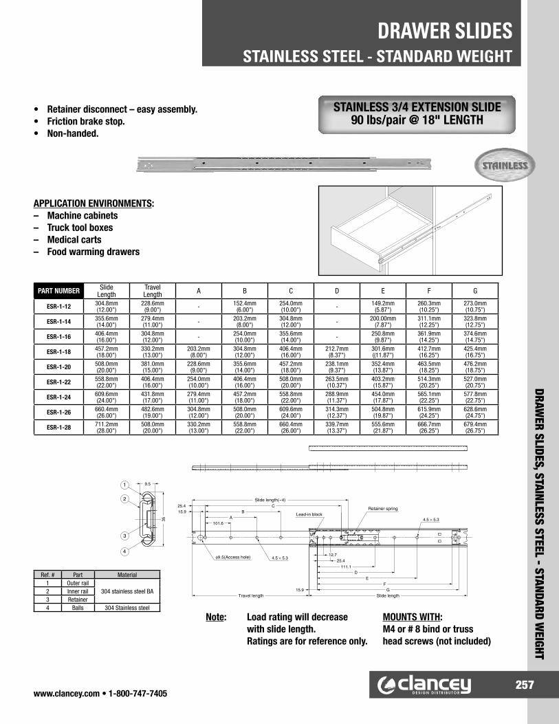
www.clancey.com • 1-800-747-7405257
DRAWER SLIDES, STAINLESS STEEL - STANDARD W
EIGHT
STAINLESS STEEL - STANDARD WEIGHTDRAWER SLIDES
STAINLESS 3/4 EXTENSION SLIDE 90 lbs/pair @ 18" LENGTH
MOUNTS WITH:M4 or # 8 bind or trusshead screws (not included)
Note: Load rating will decrease with slide length.
Ratings are for reference only.
PART NUMBER SlideLength
TravelLength A B C D E F G
ESR-1-12 304.8mm(12.00")
228.6mm (9.00") - 152.4mm
(6.00")254.0mm(10.00") - 149.2mm
(5.87")260.3mm(10.25")
273.0mm(10.75")
ESR-1-14 355.6mm(14.00")
279.4mm (11.00") - 203.2mm
(8.00")304.8mm(12.00") - 200.00mm
(7.87")311.1mm(12.25")
323.8mm(12.75")
ESR-1-16 406.4mm(16.00")
304.8mm(12.00") - 254.0mm
(10.00")355.6mm(14.00") - 250.8mm
(9.87")361.9mm(14.25")
374.6mm(14.75")
ESR-1-18 457.2mm(18.00")
330.2mm(13.00")
203.2mm(8.00")
304.8mm(12.00")
406.4mm(16.00")
212.7mm(8.37")
301.6mm((11.87")
412.7mm(16.25")
425.4mm(16.75")
ESR-1-20 508.0mm (20.00")
381.0mm(15.00")
228.6mm(9.00")
355.6mm(14.00")
457.2mm(18.00")
238.1mm(9.37")
352.4mm(13.87")
463.5mm(18.25")
476.2mm(18.75")
ESR-1-22 558.8mm (22.00")
406.4mm(16.00")
254.0mm(10.00")
406.4mm(16.00")
508.0mm(20.00")
263.5mm(10.37")
403.2mm(15.87")
514.3mm(20.25")
527.0mm(20.75")
ESR-1-24 609.6mm (24.00")
431.8mm(17.00")
279.4mm(11.00")
457.2mm(18.00")
558.8mm (22.00")
288.9mm(11.37")
454.0mm(17.87")
565.1mm(22.25")
577.8mm(22.75")
ESR-1-26 660.4mm (26.00")
482.6mm(19.00")
304.8mm(12.00")
508.0mm(20.00")
609.6mm (24.00")
314.3mm(12.37")
504.8mm(19.87")
615.9mm(24.25")
628.6mm(24.75")
ESR-1-28 711.2mm (28.00")
508.0mm(20.00")
330.2mm(13.00")
558.8mm (22.00")
660.4mm (26.00")
339.7mm(13.37")
555.6mm(21.87")
666.7mm(26.25")
679.4mm(26.75")
Ref. # Part Material1 Outer rail
304 stainless steel BA2 Inner rail3 Retainer4 Balls 304 Stainless steel
• Retainer disconnect – easy assembly.• Friction brake stop.• Non-handed.
APPLICATION ENVIRONMENTS:– Machine cabinets– Truck tool boxes– Medical carts– Food warming drawers

www.clancey.com • 1-800-747-7405258
STAINLESS STEEL - STANDARD WEIGHTDRAWER SLIDES
DRAW
ER S
LIDE
S, S
TAIN
LESS
STE
EL -
STA
NDAR
D W
EIGH
T
• Slight overtravel (9/16").• Positive stop.• Non-handed.• Does not disconnect.
STAINLESS, FULL EXTENSION SLIDE 150 lbs/pair @ 18" LENGTH
APPLICATION ENVIRONMENTS:– Electronic racks– Tool boxes– Battery trays– Equipment shelfs
Note: Load rating will decrease with slide length.
Ratings are for reference only.
PARTNUMBER
SlideLength
TravelLength A B C D
ESR-6-12 304.8mm (12.00") 319.00mm (12.56") - 149.2mm (5.87") 260.3mm (10.25") 273.0mm (10.75")ESR-6-14 355.6mm (14.00") 369.8mm (14.56") - 200.0mm (7.87") 311.1mm (12.25") 323.8mm (12.75")ESR-6-16 406.4mm (16.00") 420.6mm (16.56") - 250.8mm (9.87") 361.9mm (14.25") 374.6mm (14.75")ESR-6-18 457.2mm (18.00") 471.4mm (18.56") 212.7mm (8.37") 301.6mm (11.87") 412.7mm (16.25") 425.4mm (16.75")ESR-6-20 508.0mm (20.00") 522.2mm (20.56") 238.1mm (9.37") 352.4mm (13.87") 463.5mm (18.25") 476.2mm (18.75")ESR-6-22 558.8mm (22.00") 573.0mm (22.56") 263.5mm (10.37") 403.2mm (15.87") 514.3mm (20.25") 527.0mm (20.75")ESR-6-24 609.6mm (24.00") 623.8mm (24.56") 288.9mm (11.37") 454.0mm (17.87") 565.1mm (22.25") 577.8mm (22.75")ESR-6-26 660.4mm (26.00") 674.6mm (26.56") 314.3mm (12.37") 504.8mm (19.87") 615.9mm (24.25") 628.6mm (24.75")ESR-6-28 711.2mm (28.00") 725.4mm (28.56") 339.7mm (13.37") 555.6mm (21.87") 666.7mm (26.25") 679.4mm (26.75")
Ref. # Part Material1 outer rail
304 stainless steel BA2 inner rail3 middle rail4 retainer5 balls 304 Stainless steel
MOUNTS WITH:M4 or # 8 bind or truss head screws (not included)

www.clancey.com • 1-800-747-7405259
DRAWER SLIDES, STEEL - HEAVYW
EIGHT
STEEL - HEAVYWEIGHTDRAWER SLIDES
STEEL, FULL EXTENSION SLIDE 250 lbs/pair @ 18" LENGTH
• 1" overtravel.• Hold close feature prevents bounce back.• Non-handed.
Note: Load rating will decrease with slide length.
Ratings are for reference only.
Material: Cold rolled steelFinish: Zinc plate
INCHES[mm]
.375 [9.5]DIA.
.180 X .210[4.6 X 5.3]
(4X)
1.00[25.4]
.180 X .310[4.6 X 7.9]
4.00[101.6]
2.00[50.8]REF.
.180 X .210[4.6 X 5.3]
(5X)
Access Hole
Sequencing Bumper .180 X .374
[4.6 X 9.5](3X)
.25[6.4]
1.82[46.2]
2.38[60.5]
Slide Length
AB
CD
E
FG
H
.62[15.7]
Drawer Member
Intermediate Member
Cabinet Member
2.09[53.1]
.75[19.1]
Slide Travel
Drawer Member Is Flush or Under In Closed Position
PARTNUMBER Slide Length Slide Travel
Load Rating lbs (kg) per
PairA B C D E F G H
C3601-12P 12.00 (304.8) 13.00 (330.2) 255 (116) - 5.33 (135.4) 7.05 (179.1) 8.05 (204.5) 9.05 (229.9) 6.13 (155.6) 9.00 (228.6)C3601-14P 14.00 (355.6) 15.00 (381.0) 248 (112) - 7.33 (186.2) 9.05 (229.9) 10.05 (255.3) 11.05 (280.7) 8.13 (206.4) 11.00 (279.4)C3601-16P 16.00 (406.4) 17.00 (431.8) 241 (109) - 9.33 (237.0) 11.05 (280.7) 12.05 (306.1) 13.05 (331.5) 10.13 (257.2) 13.00 (330.2)C3601-18P 18.00 (457.2) 19.00 (482.6) 234 (106) 7.50 (190.5) 11.33 (287.8) 13.05 (331.5) 14.05 (356.9) 15.05 (382.3) 12.13 (308.0) 15.00 (381.0)C3601-20P 20.00 (508.0) 21.00 (533.4) 225 (102) 8.50 (215.9) 13.33 (338.6) 15.05 (382.3) 16.05 (407.7) 17.05 (433.1) 8.00 (203.2) 14.13 (358.8) 17.00 (431.8)C3601-22P 22.00 (558.8) 23.00 (584.2) 215 (98) 9.50 (241.3) 15.33 (389.4) 17.05 (433.1) 18.05 (458.5) 19.05 (483.9) 9.00 (228.6) 16.13 (409.6) 19.00 (482.6)C3601-24P 24.00 (619.6) 25.00 (635.0) 203 (92) 10.50 (266.7) 17.33 (440.2) 19.05 (483.9) 20.05 (509.3) 21.05 (534.7) 10.00 (254.0) 18.13 (460.4) 21.00 (533.4)C3601-26P 26.00 (660.4) 27.00 (685.8) 188 (85) 11.5 (292.1) 19.33 (491.0) 21.05 (534.7) 22.05 (560.1) 23.05 (585.5) 11.00 (279.4) 20.13 (511.2) 23.00 (584.2)C3601-28P 28.00 (711.2) 29.00 (736.6) 169 (77) 12.50 (317.5) 21.33 (541.8) 23.05 (585.5) 24.05 (610.9) 25.05 (636.6) 12.00 (304.8) 22.13 (562.0) 25.00 (653.0)

www.clancey.com • 1-800-747-7405260
STEEL - HEAVYWEIGHTDRAWER SLIDES
DRAW
ER S
LIDE
S, S
TEEL
- H
EAVY
WEI
GHT
STEEL, FULL EXTENSION SLIDE 500 lbs/pair @ 18" LENGTH
Material: Cold rolled steelFinish: Zinc plate
• Full extension.• .75" side space.• Silenced movement.• Lockout version available.• Lock-in and lockout version available.
Note: Load rating will de-crease with slide length. Ratings are for reference only.
PARTNUMBER
Slide Length
Slide Travel A B C D E F G H J K M N P Q R
C9301-10P 10.00(254.0)
10.00(254.0)
4.06(103.1)
5.06(128.5)
5.81(147.6)
6.56(166.6)
6.00(152.4)
8.25(209.6)
9.00(228.6)
C9301-12P 12.00(304.8)
12.00(304.8)
6.06(153.9)
7.06(179.3)
7.81(198.4)
8.56(217.4)
8.00(203.2
10.25(260.4)
11.00(279.4)
C9301-14P 14.00(355.6)
14.00(355.6)
8.06(204.7)
9.06(230.1)
9.81(249.2)
10.56(268.2)
10.00(254.0)
12.25(311.2)
13.00(330.2)
C9301-16P 16.00(406.4)
16.00(406.4)
5.00(127.0)
10.06(255.5)
11.06(280.9)
11.81(299.9)
12.56(319.0)
12.00(304.8)
14.25(361.9)
15.00(381.0)
C9301-18P 18.00(457.2)
18.00(457.2)
5.00(127.0)
9.69(246.1)
12.06(306.3)
13.06(331.7)
13.81(350.8)
14.56(369.8)
14.00(355.6)
16.25(412.8)
17.00(431.8)
C9301-20P 20.00(508.0)
20.00(508.0)
5.00(127.0)
7.50(190.5)
11.69(296.9)
14.06(357.1)
15.06(382.5)
15.81(401.6)
16.56(420.6)
16.00(406.4)
18.25(463.6)
19.00(482.6)
C9301-22P 22.00(558.8)
22.00(558.8)
5.00(127.0)
7.50(190.5)
13.69(347.7)
16.06(407.9)
17.06(433.3)
17.81(452.4)
18.56(471.4)
18.00(457.2)
20.25(514.4)
21.00(533.4)
C9301-24P 24.00(619.6)
24.00(619.6)
5.00(127.0)
7.50(190.5)
15.69(398.5)
18.06(458.7)
19.06(484.1)
19.81(503.2)
20.56(522.2)
20.00(508.0)
22.25(565.2)
23.00(584.2)
C9301-26P 26.00(660.4)
26.00(660.4)
5.00(127.0)
7.50(190.5)
17.69(449.3)
20.06(509.5)
21.06(534.9)
21.81(553.9)
22.56(573.0)
22.00(558.8)
24.25(615.9)
25.00(635.0)
C9301-28P 28.00(711.2)
28.00(711.2)
5.00(127.0)
7.50(190.5)
19.69(500.1
22.06(560.3)
23.06(585.7)
23.81(604.8)
24.56(623.8)
24.00(609.6)
26.25(666.8)
27.00(685.8)
C9301-30P 30.00(762.0)
30.00(762.0)
5.00(127.0)
7.50(190.5)
14.50(368.3)
21.69(550.9)
24.06(611.1)
25.06(636.5)
25.81(655.6)
26.56(674.6)
9.25(234.9)
19.75(501.6)
26.00(660.4)
28.25(717.6)
29.00(736.6)
C9301-32P 32.00(812.8)
32.00(812.8)
5.00(127.0)
7.50(190.5)
14.50(368.3)
23.69(601.7)
26.06(661.9)
27.06(687.3)
27.81(706.4)
28.56(725.4)
9.25(234.9)
15.50(393.7)
21.75(552.5)
28.00(711.2)
30.25(768.4)
31.00(787.4)
C9301-34P 34.00(863.6)
34.00(863.6)
5.00(127.0)
7.50(190.5)
14.50(368.3)
18.50(469.9)
25.69(652.5)
28.06(712.7)
29.06(738.1)
29.81(757.2)
30.56(776.2)
9.25(234.9)
16.50(419.1)
23.75(603.3)
30.00(762.0)
32.25(819.2)
33.00(838.2
C9301-36P 36.00(914.4)
36.00(914.4)
5.00(127.0)
7.50(190.5)
14.50(368.3)
20.50(520.7)
27.69(703.3)
30.06(763.5)
31.06(788.9)
31.81(807.9)
32.56(827.0)
9.25(234.9)
17.50(444.5)
25.75(654.1)
32.00(812.8)
34.25(870.0)
35.00(889.0)
C9301-40P 40.00(1016.0)
40.00(1016.0)
5.00(127.0)
7.50(190.5)
14.50(368.3)
20.50(520.7)
31.69(804.9)
34.06(865.1)
35.06(890.5)
35.81(909.6)
36.56(928.6)
9.25(234.9)
21.50(546.1)
29.75(755.7)
36.00(914.4)
38.25(971.6)
39.00(990.6)
C9301-42P 42.00(1066.8)
42.00(1066.8)
5.00(127.0)
7.50(190.5)
14.50(368.3)
20.50(520.7)
33.69(855.7)
36.06(915.9)
37.06(941.3)
37.81(960.4)
38.56(979.4)
9.25(234.9)
21.50(546.1)
31.75(806.5)
38.00(965.2)
40.25(1022.4)
41.00(1041.4)
C9301-44P 44.00(1117.6)
44.00(1117.6)
5.00(127.0)
7.50(190.5)
14.50(368.3)
20.50(520.7)
35.69(906.5)
38.06(966.7)
39.06(992.1)
39.81(1011.2)
40.56(1030.2)
9.25(234.9)
21.5(546.1)
33.75(857.3)
40.00(1016.0)
42.25(1073.2)
43.00(1092.2)
C9301-48P 48.00(1219.2)
48.00(1219.2)
5.00(127.0)
7.50(190.5)
14.50(368.3)
20.50(520.7)
39.69(1008.1)
42.06(1068.3)
43.06(1093.7)
43.81(1112.8)
44.56(1131.8)
9.25(234.9)
23.50(596.9)
37.75(958.9)
44.00(1117.6)
46.25(1174.8)
47.00(113.8)
C9301-60P 60.00(1524.0)
60.00(1524.0)
5.00(127.0)
7.50(190.5)
14.50(368.3)
20.50(520.7)
51.69(1312.9)
54.06(1373.1)
55.06(1398.5)
55.81(1417.6)
56.56(1436.6)
9.25(234.9)
23.50(596.9)
37.75(958.9)
56.00(1422.4)
58.25(1479.6)
59.00(1498.6)

www.clancey.com • 1-800-747-7405261
DRAWER SLIDES, STAINLESS - HEAVYW
EIGHT
STAINLESS - HEAVYWEIGHTDRAWER SLIDES
Note: Load rating will decrease with slide length.
Ratings are for reference only.
• Positive stop.• Non-handed.• Heavy duty.
• Positive stop.• Non-handed.• Heavy duty.
Ref. # Part Material1 Outer rail
304 stainless steel BA2 Inner rail3 Middle rail4 Retainer5 Balls 304 Stainless steel
PART NUMBER
SlideLength
Travel Length A B C D E F
ESR-5-12 304.8mm (12.00") 221.5mm (8.72") - 149.2mm (5.87") 273.0mm (10.75") - 152.4mm (6.00") 254.0mm (10.00")ESR-5-14 355.6mm (14.00") 259.6mm (10.22") - 200.0mm (7.87") 323.8mm (12.75") - 203.2mm (8.00") 304.8mm (12.00")ESR-5-16 406.4mm (16.00") 297.7mm (11.72") - 250.8mm (9.87") 374.6mm (14.75") - 254.0mm (10.00") 355.6mm (14.00")ESR-5-18 457.2mm (18.00") 348.5mm (13.72") 212.7mm (8.37") 301.6mm (11.87") 425.4mm (16.75") 203.2mm (8.00") 304.8mm (12.00") 406.4mm (16.00")ESR-5-20 508.0mm (20.00") 361.2mm (14.22") 238.1mm (9.37") 352.4mm (13.87") 476.2mm (18.75") 228.6mm (9.00") 355.6mm (14.00") 457.2mm (18.00")ESR-5-22 558.8mm (22.00") 424.7mm (16.72") 263.5mm (10.37") 403.2mm (15.87") 527.0mm (20.75") 254.0mm (10.00") 406.4mm (16.00") 508.0mm (20.00")ESR-5-24 609.6mm (24.00") 450.1mm (17.72") 288.9mm (11.37") 454.0mm (17.87") 577.8mm (22.75") 279.4mm (11.00") 457.2mm (18.00") 558.8mm (22.00")ESR-5-26 660.4mm (26.00") 462.8mm (18.22") 314.3mm (12.37") 504.8mm (19.87") 628.6mm (24.75") 304.8mm (12.00") 508.0mm (20.00") 609.6mm (24.00")ESR-5-28 711.2mm (28.00") 500.9mm (19.72") 339.7mm (13.37") 555.6mm (21.87") 679.4mm (26.75") 330.2mm (13.00") 558.8mm (22.00") 660.4mm (26.00")
PART NUMBER
Slide Length
Travel Length A B C
ESR-10-12 304.8mm (12.00") 319.0mm (12.56") - 149.2mm (5.87") 273.0mm (10.75")ESR-10-14 355.6mm (14.00") 369.8mm (14.56") - 200.0mm (7.87") 323.8mm (12.75")ESR-10-16 406.4mm (16.00") 420.6mm (16.56") - 250.8mm (9.87") 374.6mm (14.75")ESR-10-18 457.2mm (18.00") 471.4mm (18.56") 212.7mm (8.37") 301.6mm (11.87") 425.4mm (16.75")ESR-10-20 508.0mm (20.00") 522.2mm (20.56") 238.1mm (9.37") 352.4mm (13.87") 476.2mm (18.75")ESR-10-22 558.8mm (22.00") 573.0mm (22.56") 263.5mm (10.37") 403.2mm (15.87") 527.0mm (20.75")ESR-10-24 609.6mm (24.00") 623.8mm (24.56") 288.9mm (11.37") 454.0mm (17.87") 577.8mm (22.75")ESR-10-26 660.4mm (26.00") 674.6mm (26.56") 314.3mm (12.37") 504.8mm (19.87") 628.6mm (24.75")ESR-10-28 711.2mm (28.00") 725.4mm (28.56") 339.7mm (13.37") 555.6mm (21.87") 679.4mm (26.75")
Ref. # Part Material1 Outer rail
304 stainless steel BA2 Inner rail3 Retainer4 Balls 304 Stainless steel
STAINLESS STEEL, 3/4 EXTENSION DOUBLE RAIL SLIDE 225 lbs/pair @ 18" LENGTH
STAINLESS, FULL EXTENSION DOUBLE RAIL SLIDE 550 lbs/pair @ 18" LENGTH

www.clancey.com • 1-800-747-7405262
SPECIAL FEATURE SLIDES – LOCKS IN EXTENSIONDRAWER SLIDES
SPEC
IAL
FEAT
URE
SLID
ES –
LOC
KS IN
EXT
ENSI
ON
Note: Load rating will decrease with slide length.
Ratings are for reference only.
STAINLESS, 3/4 EXTENSION LOCKING SLIDE 90 lbs/pair @ 18" LENGTH
STAINLESS, FULL EXTENSION LOCKING SLIDE 115 lbs/pair @ 18" LENGTH
• Positive lock in extension.• Front disconnect – easy assembly.
• Positive lock in extension.• Front disconnect – easy assembly.
Ref. # Part Material1 Outer rail
304 stainless steel BA2 Inner rail3 Retainer4 Balls 304 Stainless steel
Ref. # Part Material1 Outer rail
304 stainless steel BA2 Inner rail3 Retainer4 Balls 304 Stainless steel
PART NUMBER
SlideLength
TravelLength A B C D E F G
ESR-8-12 304.8mm (12.00") 228.6mm (9.00") - 152.4mm (6.00") 254.0mm (10.00") - 149.2mm (5.87") 260.3mm (10.25") 273.0mm (10.75")ESR-8-14 355.6mm (14.00") 279.4mm (11.00") - 203.2mm (8.00") 304.8mm (12.00") - 200.0mm (7.87") 311.1mm (12.25") 323.8mm (12.75")ESR-8-16 406.4mm (16.00") 304.8mm (12.00") - 254.0mm (10.00") 355.6mm (14.00") - 250.8mm (9.87") 361.9mm (14.25") 374.6mm (14.75")ESR-8-18 457.2mm (18.00") 330.2mm (13.00") 203.2mm (8.00") 304.8mm (12.00") 406.4mm (16.00") 212.7mm (8.37") 301.6mm (11.87") 412.7mm (16.25") 425.4mm (16.75")ESR-8-20 508.0mm (20.00") 381.0mm (15.00") 228.6mm (9.00") 355.6mm (14.00") 457.2mm (18.00") 238.1mm (9.37") 352.4mm (13.87") 463.5mm (18.25") 476.2mm (18.75")ESR-8-22 558.8mm (22.00") 406.4mm (16.00") 254.0mm (10.00") 406.4mm (16.00") 508.0mm (20.00") 263.5mm (10.37") 403.2mm (15.87") 514.3mm (20.25") 527.0mm (20.75")ESR-8-24 609.6mm (24.00") 431.8mm (17.00") 279.4mm (11.00") 457.2mm (18.00") 558.8mm (22.00") 288.9mm (11.37") 454.0mm (17.87") 565.1mm (22.25") 577.8mm (22.75")ESR-8-26 660.4mm (26.00") 482.6mm (19.00") 304.8mm (12.00") 508.0mm (20.00") 609.6mm (24.00") 314.3mm (12.37") 504.8mm (19.87") 615.9mm (24.25") 628.6mm (24.75")ESR-8-28 711.2mm (28.00") 508.0mm (20.00") 330.2mm (13.00") 558.8mm (22.00") 660.4mm (26.00") 339.7mm (13.37") 555.6mm (21.87") 666.7mm (26.25") 679.4mm (26.75")
PART NUMBER
SlideLength
TravelLength A B C D E F G H
ESR-7-12 304.8mm (12.00") 336.0mm (13.23") - - - 260.3mm (10.25") 273.0mm (10.75") - 260.3mm (10.25") 273.0mm (10.75")ESR-7-14 355.6mm (14.00") 386.8mm (15.23") - - 298.4mm (11.75") 311.1mm (12.25") 323.8mm (12.75") - 311.1mm (12.25") 323.8mm (12.75")ESR-7-16 406.4mm (16.00") 437.6mm (17.23") - - 349.2mm (13.75") 361.9mm (14.25") 374.6mm (14.75") 250.8mm (9.87") 361.9mm (14.25") 374.6mm (14.75")ESR-7-18 457.2mm (18.00") 488.4mm (19.23") 212.7mm (8.37") - 400.0mm (15.75") 412.7mm (16.25") 425.4mm (16.75") 301.6mm (11.87") 412.7mm (16.25") 425.4mm (16.75")ESR-7-20 508.0mm (20.00") 539.2mm (21.23") 238.1mm (9.37") 365.1mm (14.37") 450.8mm (17.75") 463.5mm (18.25") 476.2mm (18.75") 352.4mm (13.87") 463.5mm (18.25") 476.2mm (18.75")ESR-7-22 558.8mm (22.00") 590.0mm (23.23") 263.5mm (10.37") 415.9mm (16.37") 501.6mm (19.75") 514.3mm (20.25") 527.0mm (20.75") 403.2mm (15.87") 514.3mm (20.25") 527.0mm (20.75")ESR-7-24 609.6mm (24.00") 640.8mm (25.23") 288.9mm (11.37") 466.7mm (18.37") 552.4mm (21.75") 565.1mm (22.25") 577.8mm (22.75") 454.0mm (17.87") 565.1mm (22.25") 577.8mm (22.75")ESR-7-26 660.4mm (26.00") 691.6mm (27.23") 314.3mm (12.37") 517.5mm (20.37") 603.2mm (23.75") 615.9mm (24.25") 628.6mm (24.75") 504.8mm (19.87") 615.9mm (24.25") 628.6mm (24.75")ESR-7-28 711.2mm (28.00") 742.4mm (29.23") 339.7mm (13.37") 568.3mm (22.37") 654.0mm (25.75") 666.7mm (26.25") 679.4mm (26.75") 555.6mm (21.87") 666.7mm (26.25") 679.4mm (26.75")

www.clancey.com • 1-800-747-7405263
SPECIAL FEATURE SLIDES – HEAVY DUTY “FLOOR” MOUNT
SPECIAL FEATURE SLIDES – HEAVY DUTY “FLOOR” MOUNT
DRAWER SLIDES
STAINLESS, FULL EXTENSION FLOOR MOUNT SLIDE 187 lbs/pair @ 500 mm LENGTH
• Carries loads from underneath.• 1" plus of over travel.• Positive stop.• Non-handed.• Heavy – duty.
PARTNUMBER Slide Legnth Travel Legnth # of mounting
holesLoad Rating
(per pair)TSS3-300 300 mm (11.81") 336 mm (13.23") 6 209 lbs.TSS3-400 400 mm (15.75") 436 mm (17.17") 8 198 lbs.TSS3-500 500 mm (19.69") 536 mm (21.10") 10 187 lbs.TSS3-600 600 mm (23.62") 636 mm (25.04") 12 176 lbs.TSS3-800 800 mm (31.50") 836 mm (32.91") 16 143 lbs.TSS3-1000 1000 mm (39.37") 1036 mm (40.78") 20 110 lbs.
Ref. # Part Material1 Outer rail
304 stainless steel BA2 Inner rail3 Retainer4 End stopper Polyamide5 Outer guide
Polyacetal6 Inner guide7 Plate 304 Stainless steel8 Large balls
Steel9 Small balls
Application Example
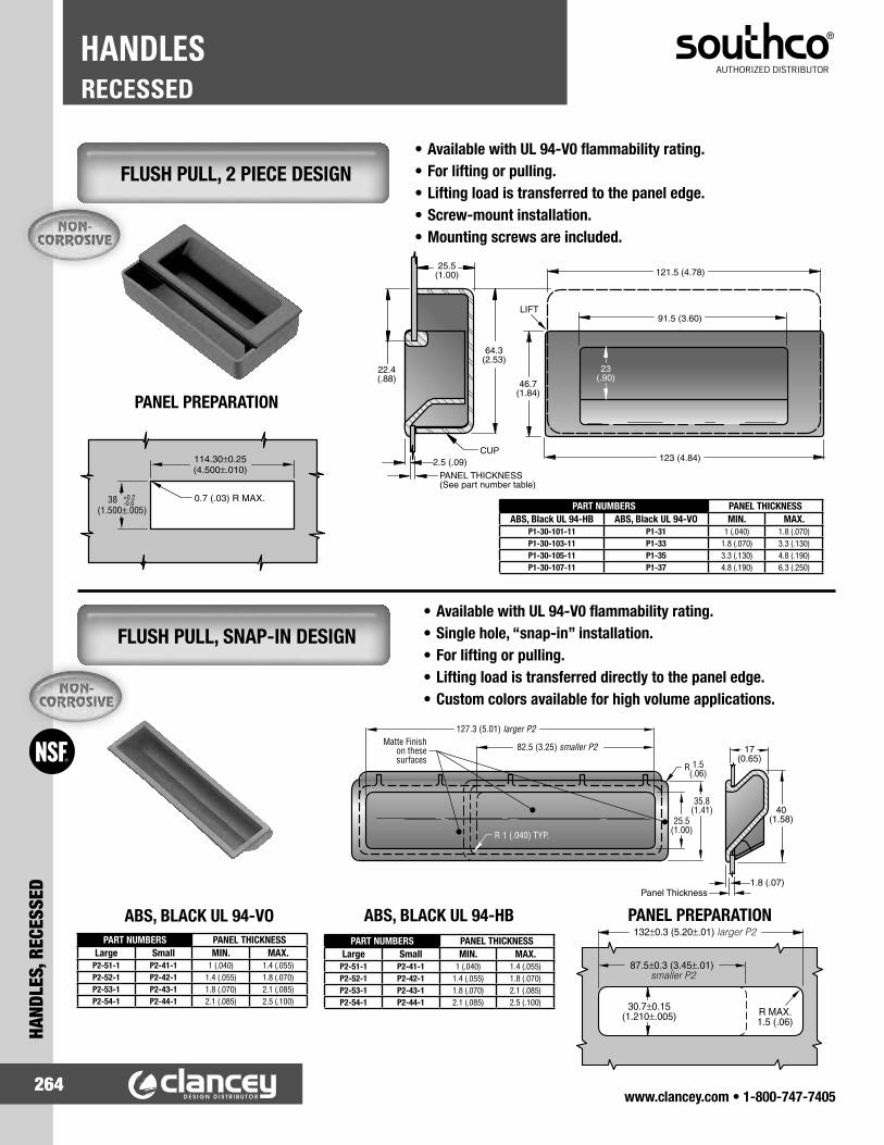
www.clancey.com • 1-800-747-7405264
RECESSEDHANDLES
HAND
LES,
REC
ESSE
D
• Available with UL 94-V0 flammability rating.• For lifting or pulling.• Lifting load is transferred to the panel edge.• Screw-mount installation.• Mounting screws are included.
• Available with UL 94-V0 flammability rating.• Single hole, “snap-in” installation.• For lifting or pulling.• Lifting load is transferred directly to the panel edge.• Custom colors available for high volume applications.
PANEL PREPARATION
PANEL PREPARATION
ABS, BLACK UL 94-HBABS, BLACK UL 94-VO
FLUSH PULL, 2 PIECE DESIGN
FLUSH PULL, SNAP-IN DESIGN
PART NUMBERS PANEL THICKNESSABS, Black UL 94-HB ABS, Black UL 94-VO MIN. MAX.
P1-30-101-11 P1-31 1 (.040) 1.8 (.070)P1-30-103-11 P1-33 1.8 (.070) 3.3 (.130)P1-30-105-11 P1-35 3.3 (.130) 4.8 (.190)P1-30-107-11 P1-37 4.8 (.190) 6.3 (.250)
PART NUMBERS PANEL THICKNESSLarge Small MIN. MAX.
P2-51-1 P2-41-1 1 (.040) 1.4 (.055)P2-52-1 P2-42-1 1.4 (.055) 1.8 (.070)P2-53-1 P2-43-1 1.8 (.070) 2.1 (.085)P2-54-1 P2-44-1 2.1 (.085) 2.5 (.100)
PART NUMBERS PANEL THICKNESSLarge Small MIN. MAX.
P2-51-1 P2-41-1 1 (.040) 1.4 (.055)P2-52-1 P2-42-1 1.4 (.055) 1.8 (.070)P2-53-1 P2-43-1 1.8 (.070) 2.1 (.085)P2-54-1 P2-44-1 2.1 (.085) 2.5 (.100)
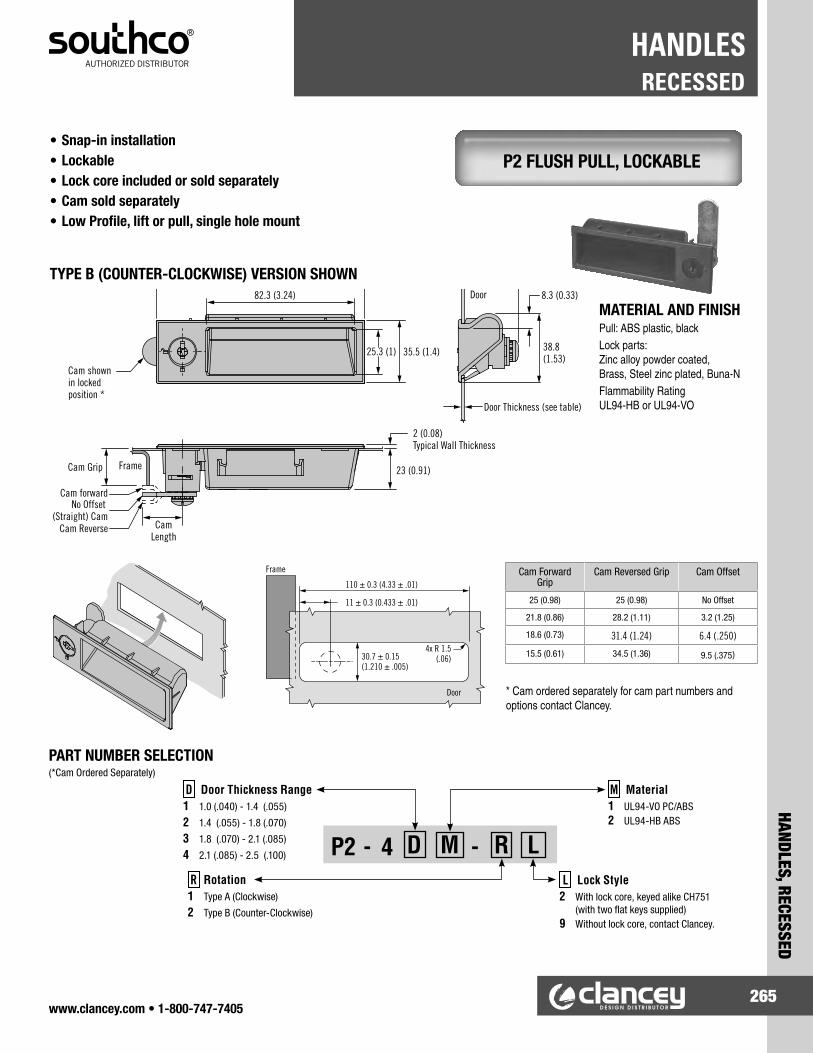
www.clancey.com • 1-800-747-7405265
HANDLES, RECESSED
RECESSEDHANDLES
Cam shownin lockedposition *
82.3 (3.24)
25.3 (1) 35.5 (1.4)
2 (0.08)Typical Wall Thickness
23 (0.91)Frame
Door
CamLength
Cam Grip
Cam forwardNo Offset
(Straight) CamCam Reverse
Door Thickness (see table)
8.3 (0.33)
38.8(1.53)
P2 FLUSH PULL, LOCKABLE• Snap-in installation• Lockable• Lock core included or sold separately• Cam sold separately• Low Profile, lift or pull, single hole mount
TYPE B (COUNTER-CLOCKWISE) VERSION SHOWN
110 ± 0.3 (4.33 ± .01)
Door
Frame
11 ± 0.3 (0.433 ± .01)
4x R 1.5(.06)30.7 ± 0.15
(1.210 ± .005)
Cam Forward Grip
Cam Reversed Grip Cam Offset
25 (0.98) 25 (0.98) No Offset
21.8 (0.86) 28.2 (1.11) 3.2 (1.25)
18.6 (0.73) 31.4 (1.24) 6.4 (.250)
15.5 (0.61) 34.5 (1.36) 9.5 (.375)
* Cam ordered separately for cam part numbers and options contact Clancey.
P2 - 4 D M - R L
M Material1 UL94-VO PC/ABS 2 UL94-HB ABS
L Lock Style2 With lock core, keyed alike CH751 (with two flat keys supplied) 9 Without lock core, contact Clancey.
D Door Thickness Range1 1.0 (.040) - 1.4 (.055)
2 1.4 (.055) - 1.8 (.070)
3 1.8 (.070) - 2.1 (.085)
4 2.1 (.085) - 2.5 (.100)
R Rotation1 Type A (Clockwise)
2 Type B (Counter-Clockwise)
MATERIAL AND FINISHPull: ABS plastic, blackLock parts: Zinc alloy powder coated, Brass, Steel zinc plated, Buna-NFlammability Rating UL94-HB or UL94-VO
PART NUMBER SELECTION(*Cam Ordered Separately)

www.clancey.com • 1-800-747-7405266
RECESSEDHANDLES
HAND
LES,
REC
ESSE
D
PART NUMBER
Primary DimensionsB L H h1 h2 b1 b2 I2
261131-C1 120mm (4.72”)
95mm (3.74”)
28.5mm (11.22”)
24mm (.94”)
26.5mm (1.04”)
94mm (3.70”)
103mm (4.05”)
11mm (.43”)
PART NUMBER
Primary DimensionsB L H h1 h2 b1 b2 I1 I2
261051-C1 90mm (3.54")
50mm (1.97")
19mm (.75")
17mm (.67")
17.5mm (.69")
76mm (2.99")
79mm (3.11")
28mm (1.10")
7mm (.28")
261111-C1 120mm (4.72")
95mm (3.74")
28.5mm (11.22")
24mm (.94")
26.5mm (1.04")
94mm (3.70")
103mm (4.05")
58mm (2.28")
11mm (.43")
Panel PreparationPanel
Thickness “s”
261051 261111
x y x y
.8mm (.032") 85mm (3.35")
34.9mm (1.37")
107.5mm (4.23")
70.6mm (2.78")
1mm (.040") 85mm (3.35")
35.1mm (1.38")
107.5mm (4.23")
70.9mm (2.79")
1.5mm (.060") 85mm (3.35")
36.1mm (1.42")
107.5mm (4.23")
71.1mm (2.80")
2mm (.078") 85mm (3.35")
36.1mm (1.42")
107.5mm (4.23")
71.3mm (2.81")
2.5mm (.098") 85mm (3.35")
36.1mm (1.42")
107.5mm (4.23")
71.6mm (2.82")
ERGOSTYLE® FLUSH PULL• Ergonomic design for secure grip.• 2 standard sizes.• Snap-in installation.
Material: Glass reinforced polyamide
• Cover provides a clean look.• Hinged cover folds inward for easy grip.ERGOSTYLE® FLUSH PULL W/COVER
Ergostyle® is a registered trade-mark of Elesa.Elesa Original design.
Color of screw cover can be changed by changing suffix of the part number.C1 = Black C4 = YellowC2 = Orange C5 = Light BlueC3 = Gray C6 = Red
Snap in mounting the same as 26111 above. Screw mounting available in thicker panels. Call for details.
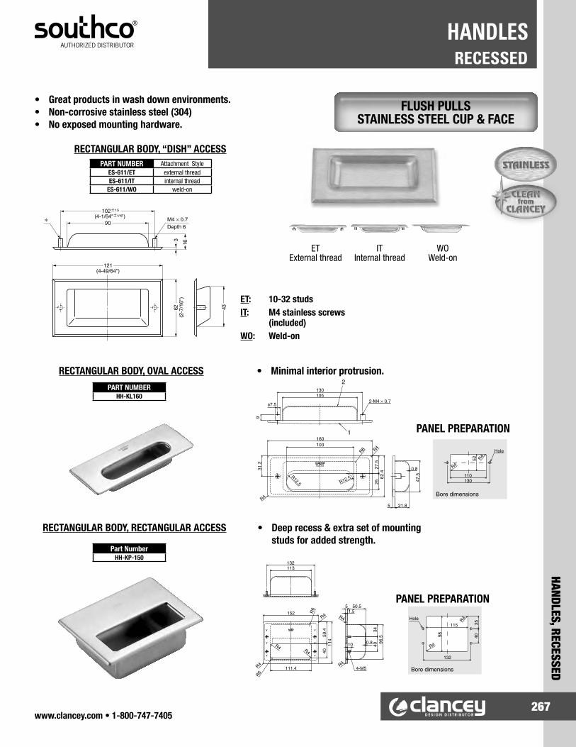
www.clancey.com • 1-800-747-7405267
HANDLES, RECESSED
RECESSEDHANDLES
• Great products in wash down environments.• Non-corrosive stainless steel (304)• No exposed mounting hardware.
• Minimal interior protrusion.
• Deep recess & extra set of mounting studs for added strength.
PANEL PREPARATION
PANEL PREPARATION
ET: 10-32 studsIT: M4 stainless screws (included)WO: Weld-on
Part NumberHH-KP-150
FLUSH PULLS STAINLESS STEEL CUP & FACE
RECTANGULAR BODY, “DISH” ACCESS
RECTANGULAR BODY, OVAL ACCESSPART NUMBER
HH-KL160
RECTANGULAR BODY, RECTANGULAR ACCESS
PART NUMBER Attachment StyleES-611/ET external threadES-611/IT internal thread
ES-611/WO weld-on
ET IT WO External thread Internal thread Weld-on

www.clancey.com • 1-800-747-7405268
PULLSHANDLES
HAND
LES,
PUL
LS
TEXTURED PULLS• Lightweight aluminum construction.• Available in clear or black.• Four sizes/styles to choose from.
Small size
Small size
Medium size
Large size
Extra Large size
Thread Size (screws not included)
PART NUMBERS
Black Anodized Clear Anodized
8-32 B4-10-103-15 B4-10-103-11
M4 x 0.7 B4-50-103-15 B4-50-103-11
Thread Size (screws not included)
PART NUMBERS
Black Anodized Clear Anodized
8-32 B4-10-203-15 B4-10-203-11
M4 x 0.7 B4-50-203-15 B4-50-203-11
Thread Size (screws not included)
PART NUMBERS
Black Anodized Clear Anodized
8-32 B4-10-303-15 B4-10-303-11
M4 x 0.7 B4-50-303-15 B4-50-303-11
Thread Size (screws not included)
PART NUMBERS
Black Anodized Clear Anodized
8-32 B4-10-403-15 B4-10-403-11
M4 x 0.7 B4-50-403-15 B4-50-403-11
Extra Large size
Small size (100 series)
Medium Size (200 series)
Large size (300 series) and Extra Large size (400 series)

www.clancey.com • 1-800-747-7405269
HANDLES, PULLS
PULLSHANDLES
• Two standard finish options.• Four standard sizes.
Material: AluminumFinish: See chart
ALUMINUM WIRE PULLS 8 mm DIAMETER
Clancey can provide almost any size or style of wire pull handle
Round-Internal Oval-Internal 90° free fall
Round-External 180° free fall
1-800-747-7405Please call for
samples or a quotation.
METRIC
INCH
INTERNAL
EXTERNAL
MATERIAL & FINISH
STEELSTAINLESSALUMINUM
BRASSBLACK
MIL-SPECCHROME
THREADING
Panel Preparation
PART NUMBERS METRIC THREAD Length “A”
Mounting Hardware
Thread SizeBlack Anodized Clear Anodized
P8-030-31-M4-15 P8-030-31-M4-11 30 (1.18")
M4P8-064-31-M4-15 P8-064-31-M4-11 64 (2.52")
P8-096-31-M4-15 P8-096-31-M4-11 96 (3.78")
P8-128-31-M4-15 P8-128-31-M4-11 128 (5.04")
PART NUMBERS INCH THREAD Length “A”
Mounting Hardware
Thread SizeBlack Anodized Clear Anodized
P8-030-31-08-15 P8-030-31-08-11 30 (1.18")
8-32P8-064-31-08-15 P8-064-31-08-11 64 (2.52")
P8-096-31-08-15 P8-096-31-08-11 96 (3.78")
P8-128-31-08-15 P8-128-31-08-11 128 (5.04")
Note: Mounting hardware not included.

www.clancey.com • 1-800-747-7405270
PULLSHANDLES
HAND
LES,
PUL
LS
• 90° folding to lower protrusion.• Built-in friction reduces rattle and yields a quality “feel”.• 2 standard finishes, four standard lengths.
Material: Handle, base - aluminum Pin - 300 series stainless steel
90° FOLDING PULLS
Material: Handle, base - aluminum Pin - 300 series stainless steel Nut, lockwasher - steel, zinc plate Bushings - nylon
Note: Mounting screws are not included within internal thread
Note: Mounting nuts are included with external thread model.
External thread
PART NUMBERS METRIC THREAD Length “A”
Mounting Hardware
Thread SizeBlack Anodized Clear Anodized
P9-040-40-M4N-15 P9-040-40-M4N-11 40 (1.57")
M4P9-064-40-M4N-15 P9-064-40-M4N-11 64 (2.52")P9-096-40-M4N-15 P9-096-40-M4N-11 96 (3.78")P9-128-40-M4N-15 P9-128-40-M4N-11 128 (5.04")
PART NUMBERS INCH THREAD Length “A”
Mounting Hardware
Thread SizeBlack Anodized Clear Anodized
P9-040-40-08N-15 P9-040-40-08N-11 40 (1.57")
8-32P9-064-40-08N-15 P9-064-40-08N-11 64 (2.52")P9-096-40-08N-15 P9-096-40-08N-11 96 (3.78")P9-128-40-08N-15 P9-128-40-08N-11 128 (5.04")
PART NUMBERS METRIC THREAD Length “A”
Mounting Hardware
Thread SizeBlack Anodized Clear Anodized
P9-040-40-M4X-15 P9-040-40-M4X-11 40 (1.57")
M4P9-064-40-M4X-15 P9-064-40-M4X-11 64 (2.52")P9-096-40-M4X-15 P9-096-40-M4X-11 96 (3.78")P9-128-40-M4X-15 P9-128-40-M4X-11 128 (5.04")
PART NUMBERS INCH THREAD Length “A”
MountingHardware
Thread SizeBlack Anodized Clear Anodized
P9-040-40-08X-15 P9-040-40-08X-11 40 (1.57")
8-32P9-064-40-08X-15 P9-064-40-08X-11 64 (2.52")P9-096-40-08X-15 P9-096-40-08X-11 96 (3.78")P9-128-40-08X-15 P9-128-40-08X-11 128 (5.04")
Internal thread
PANEL PREPARATION ALL VERSIONS

www.clancey.com • 1-800-747-7405271
GRAB-HANDLES, STAINLESS STEEL
GRAB-HANDLES, STAINLESS STEELHANDLES
• Mirror and satin finishes available.• Supplied with mounting hardware.
Material: 303 Stainless steel
Material: 303 Stainless steel
Material: 303 Stainless steel
Note: Profile change from line drawing.
OVAL HANDLE - STANDARD
OVAL HANDLE - ROBUST
OVAL HANDLE - LOW PROFILE
Supplied with (2) M3 x 28 mm mounting screws
Supplied with (2) M4 x 28 mm mounting screws
Supplied with (2) M5 x 28 mm mounting screws
PART NUMBER DIMENSIONS MOUNTINGMIRROR FINISH
SATIN FINISH L H B T C S THREAD
SIZE
DS-30M DS-30S 30 (1.18")
23 (.91")
10 (.39")
5 (.20")
25 (.98")
8 (.31") M3
DS-50M DS-50S 50 (1.97")
22 (.87")
10 (.39")
5 (.20")
45 (1.77")
10 (.39") M3
DS-70M DS-70S 70 (2.76")
22.5 (.89")
10 (.39")
5 (.20")
65 (2.56")
10 (.39") M3
DS-90M DS-90S 90 (3.54")
23 (.91")
10 (.39")
5 (.20")
85 (3.35")
10 (.39") M3
PART NUMBER DIMENSIONS MOUNTINGMIRROR FINISH
SATIN FINISH L H B T C S THREAD
SIZE
DL-70M DL-70S 70 (2.76")
23 (.91")
13 (.51")
6 (.24")
64 (2.52")
10 (.39") M4
DL-90M DL-90S 90 (3.54")
23.5 (.93")
13 (.51")
6 (.24")
84 (3.30")
10 (.39") M4
DL-110M DL-110M 110 (4.33")
24 (.94")
13 (.51")
6 (.24")
104 (4.09")
10 (.39") M4
DL-130M DL-130M 130 (5.12")
24.5 (.96")
13 (.51")
6 (.24")
124 (4.88")
10 (.39") M4
DL-150M DL-150M 150 (5.90")
25 (.98")
13 (.51")
6 (.24")
144 (5.67")
10 (.39") M4
PART NUMBER DIMENSIONS MOUNTINGMIRROR FINISH
SATIN FINISH L H B T C S THREAD
SIZE
EC-80M EC-80S 80 (3.15")
30 (1.18")
14 (.55")
8 (.31")
72 (2.83")
10 (.39") M5
EC-100M EC-100S 100 (3.94")
32 (1.26")
14 (.55")
8 (.31")
92 (3.62")
10 (.39") M5
EC-120M EC-120S 120 (4.72")
34 (1.34")
14 (.55")
8 (.31")
112 (4.41")
12 (.47") M5
EC-150M EC-150S 150 (5.91")
36 (1.42")
14 (.55")
8 (.31")
142 (5.59")
12 (.47") M5
EC-180M EC-180S 180 (7.09")
37 (1.46")
14 (.55")
8 (.31")
172 (6.77")
12 (.47") M5
EC-220M EC-220S 220 (8.66")
38 (1.50")
14 (.55")
8 (.31")
212 (8.35")
12 (.47") M5

www.clancey.com • 1-800-747-7405272
GRAB-HANDLES, STAINLESS STEELHANDLES
GRAB
-HAN
DLES
, STA
INLE
SS S
TEEL
• High grade 316 Stainless steel (select models).• Mirror and Satin finishes available.• Supplied with mounting hardware.
Material: 303 stainless steel
Note: Profile change from line drawing
Supplied with (2) M5 x 28 mm mounting screws.
OVAL HANDLE - TALL PROFILEPART NUMBER DIMENSIONS MOUNTING
MIRROR FINISH
SATIN FINISH L H B T C S THREAD
SIZE
ECH-50M ECH-50S 58 (2.28")
40 (1.57")
14 (.55")
8 (.31")
50 (1.97")
11 (.43") M5
ECH-75M ECH-75S 83 (3.27")
40 (1.57")
14 (.55")
8 (.31")
75 (2.92")
11 (.43") M5
ECH-100M ECH-100S 108 (4.25")
40 (1.57")
14 (.55")
8 (.31")
100 (3.94")
11 (.43") M5
ECH-125M ECH-125S 133 (5.24")
40 (1.57")
14 (.55")
8 (.31")
125 (4.92")
11 (.43") M5
ECH-150M ---- 158 (6.22")
50 (1.97")
14 (.55")
8 (.31")
150 (5.90")
11 (.43") M5
ECH-200M ---- 208 (8.19")
50 (1.97")
14 (.55")
8 (.31")
200 (7.87")
11 (.43") M5
ECH-250M ---- 258 (10.16")
50 (1.97")
14 (.55")
8 (.31")
250 (9.84")
11 (.43") M5
ECH-300M ---- 308 (12.13")
50 (1.97")
14 (.55")
8 (.31")
300 (11.81")
11 (.43") M5
Material: 316 stainless steel
Supplied with (2) 8-32 x 1" stainless steel mounting screws.
OVAL HANDLE - ROBUST
PART NUMBER DIMENSIONS MOUNTINGMIRROR FINISH
SATIN FINISH L H B T C S THREAD
SIZEEK-S635M EK-S635S 3.78" 1.26" .551" .276" 3.50" .375" 8-32EK-S640M EK-S640S 4.28" 1.26" .551" .276" 4.00" .375" 8-32EK-S650M EK-S650S 5.28" 1.26" .551" .276" 5.00" .375" 8-32EK-S660M EK-S660S 6.28" 1.26" .551" .276" 6.00" .375" 8-32
Material: 316 stainless steelSupplied with (2) 6-32 x 1" stainless steel mounting screws.
OVAL HANDLE - STANDARD
PART NUMBER DIMENSIONS MOUNTINGMIRROR FINISH
SATIN FINISH L H B T C S THREAD
SIZEKC-S635M KC-S635S 3.70" 1.18" .551" .197" 3.50" .375" 6-32KC-S640M KC-S640S 4.20" 1.18" .551" .197" 4.00" .375" 6-32KC-S650M KC-S650S 5.20" 1.18" .551" .197" 5.00" .375" 6-32KC-S660M KC-S660S 6.20" 1.18" .551" .197" 6.00" .375" 6-32

www.clancey.com • 1-800-747-7405273
GRAB HANDLE, COMPOSITE
GRAB HANDLE, COMPOSITEHANDLES
• Sleek ergonomic design.• Resistant to solvents, oils, grease and other
chemical agents.• Removable accent caps cover mounting hardware.
Available in 6 colors.
Accent Caps
To select cap color, add the following suffix to the part number in place of –XX.C1 = Black C4 = YellowC2 = Orange C5 = Light BlueC3 = Gray C6 = Red
• Brass inserts for rear mounting.• Accent caps available in 6 colors.
Elesa original design
Accent Caps
To select cap color, add the following suffix to the part number in place of –XX.C1 = Black C4 = YellowC2 = Orange C5 = Light BlueC3 = Gray C6 = Red
Material: (both models) Glass reinforced technopolymer
FRONT MOUNTING-BRIDGE STYLE
REAR MOUNTING-BRIDGE STYLE
FRONT MOUNTING
DIMENSIONS MOUNTING DIMENSIONS
L D h B I1 d1 h1 h2 f d
260111-XX 116 (4.57")
22 (.87")
35 (1.38")
7.5 (.30")
72 (2.83")
10.5 (.41")
6.5 (.25")
23.5 (.92")
93.5 (3.68")
6.5 (.25")
260211-XX 144 (5.67")
26 (1.02")
39 (1.54")
8.5 (.33")
92 (3.62")
13.5 (.53")
8.5 (.33")
26.5 (1.04")
117 (4.61")
8.5 (.33")
260311-XX 178 (7.01")
28 (1.10")
45 (1.77")
9.5 (.37")
122 (4.80")
13.5 (.53")
14 (.55")
32 (1.26")
150 (5.91")
8.5 (.33")
REAR MOUNTING
DIMENSIONS MOUNTING DIMENSIONSL D h B I1 d1 f INSERT p
90260121-XX 116 (4.57")
22 (.87")
35 (1.38")
7.5 (.30")
72 (2.83")
10.5 (.41")
93.5 (3.68") 1/4-20 12
(.47")
90260221-XX 144 (5.67")
26 (1.02")
39 (1.54")
8.5 (.33")
92 (3.62")
13.5 (.53")
117 (4.61") 5/16-18 13
(.51")
90260321-XX 178 (7.01")
28 (1.10")
45 (1.77")
9.5 (.37")
122 (4.80")
13.5 (.53")
150 (5.91") 5/16-18 13
(.51")

www.clancey.com • 1-800-747-7405274
GRAB HANDLE, COMPOSITEHANDLES
GRAB
HAN
DLE,
COM
POSI
TE
Material: ABS, plastic blackNote: Front mount - No hardware supplied Rear mount - Hardware is supplied
INSTALLATION
Customize with your logo - call
SMALL SIZE
LARGE SIZE
REAR MOUNT FRONT MOUNT
PART NUMBERS MAX. material thickness
(rear mount only)Rear Mount Front Mount
B8-45-3 B8-43-3 16.0 (.63")
• Ergonomic look and feel.
• Front or rear mounting options.• Snap-on cover conceals mounting hardware.• Can be customized with customer logo.
Material: ABS, plastic blackNote: Front mount - No hardware supplied Rear mount - Hardware is supplied
REAR MOUNT (illustrated)
REAR MOUNT1. Prepare clearance holes as shown.2. Mount handle using two thread forming
screws, supplied.
INSTALLATION
PART NUMBERS(Rear Mount Only)
Front Mount Rear Mount
B8-63-3 B8-66-3 19 (.75)
FRONT MOUNT1. Prepare holes as shown.2. Mount handle using M5 or No. 10
screws (not supplied), having maximum head size of Ø 10.5 (.41).
3. Snap cover onto handle.

www.clancey.com • 1-800-747-7405275
GRAB HANDLE, COMPOSITE
GRAB HANDLE, COMPOSITEHANDLES
Material: Glass reinforced technopolymer (various formulations)
FRONT MOUNTING GRAB HANDLE WITH HARDWARE POCKET
PART NUMBER DIMENSIONS MOUNTINGProduct Features
Black Orange Red Gray L h B I I1 d1 h1 h2 f d37031 ---- ---- ----
107 (4.21")
36 (1.42")
6 (.24")
21 (.83")
74 (2.91")
10.5 (.41")
7 (.28")
13 (.51")
93.5 (3.68")
6.5 (.25")
----
37001 37002 ---- 37004 high impact
150001 ---- ---- ---- UL 94 V-O
37131 ---- ---- ----134
(5.28")41
(1.61")7
(.28")26
(1.02")95
(3.74")13.5 (.53")
8.5 (.33")
15 (.59")
117 (4.61")
8.5 (.33")
----
37101 37102 37105 37104 high impact
150011 ---- ---- ---- UL 94 V-O
37181 ---- ---- ----150
(5.90")45
(1.77")7
(.28")27
(1.06")108
(4.25")13.5 (.53")
8.5 (.33")
16 (.63")
132 (5.20")
8.5 (.33")
----
37151 37152 ---- 37154 high impact
150021 ---- ---- ---- UL 94 V-O
37231 ---- ---- ----197
(7.76")50
(1.97")8
(.31")28
(1.10")153
(6.02")13.5 (.53")
8.5 (.33")
17 (.67")
179 (7.05")
8.5 (.33")
----
37201 37202 37205 37204 high impact
150031 ---- ---- ---- UL 94 V-O
37281 ---- ---- ---- 262 (10.31")
54 (2.13")
9 (.35")
31 (1.22")
202 (7.95")
16.5 (.65")
10.5 (.41")
20 (.79")
235 (9.25")
10.5 (.41")
----
37251 37252 ---- 37254 high impact
For detailed materialspecifications and product
strength guidelines.
www.clancey.com
Try this part inyour application
Please call for samples.
800-747-7405
• Standard safety and design colors available.• Wide variety of sizes.• UL 94 V-0 rating available.• Impact resistant formulation available.• Resistant to solvents, oils, grease and other
chemical agents.
Elesa original design

www.clancey.com • 1-800-747-7405276
CHEST STYLE HANDLESHANDLES
CHES
T ST
YLE
HAND
LES
• 90° stop feature.• Spring return of handle.• Neoprene rubber grips.
EXPOSED CHEST HANDLES
ROBUST SERIES
GUARDED HANDLE
STANDARD SERIES
• Rugged design.• Configurations to meet
Mil-Specs (Please call).
• Side guards prevent impact damage to handle.
• Configurations to meet Mil-Specs (Please call).
• Smaller mounting plate to reduce handle “foot print”.
• Economical choice.
PART NUMBERMounting Plate Bail Handle Grip
Dia.
Aluminum Sleeve Feature
Mounting HolesMaterial Finish Material Finish
H945-AL2-RG
Aluminum none
Aluminum none
.56" yes
yesH945-LS2-RGZE Steel zinc plate yesH945-SS2-RG Stainless none yes945-SS2-RG Stainless none no
H945-LS2-RG75ZE Steel zinc plate .75" no yesH945-SS2-RGSS Stainless none Stainless none .56" yes yes
H946-LS2-RG75ZE Steel Zinc plate Steel zinc plate .75" no yes
PART NUMBER Mounting Plate Bail Handle Grip Dia.
Mounting HolesMaterial Finish Material Finish
HA945-GLS2-RG75ZE Aluminum 3003 H14 none Steel zinc plate .75" yes
PART NUMBER Material Finish Grip Dia. Dim. “A” Dim. “B”
500-32-M15-ZBSteel Zinc Plate
.53" 2.97" 1.81"500-56-M15-ZB .75" 3.09" 1.70"500-32-M20-QQ
Steel Black Epoxy.53" 2.97" 1.81"
500-56-M20-QQ .75" 3.09" 1.70"500-32-M21-SP
Stainless Steel Passivated.53" 2.97" 1.81"
500-56-M21-SP .75" 3.09 " 1.70"
Special finishes and configurations
are available, please call.
800-747-7405
FEATURESA special aluminum sleeve located between the rubber grip and the ball assures the grip will not ride up on the ball during lifting. Adds comfort and durability.

www.clancey.com • 1-800-747-7405277
CHEST STYLE HANDLES
CHEST STYLE HANDLESHANDLES
RECESSED CHEST HANDLES• 90° stop spring return.• Standard of the case industry.• Variety of sizes and finishes.• Comfortable neoprene rubber grips.
STANDARD SERIES
• Compact, flush mount.• Available in deeper dish
model – please call.
MOUNTING OPENING3.10" x 5.20" rectangle.
PART NUMBERMounting Dish Bail Handle Dim.
“A”Grip Dia.Material Finish Material Finish
502-48-M15-ZBSteel Zinc
plate Steel Zinc plate
1.81" .53"
502-49-M15-ZB 1.69" .75"
502-48-M15-QQSteel Black
Epoxy Steel Black Epoxy
1.81" .53"
502-49-M15-QQ 1.69" .75"
LOW – PROFILE
• Excellent for lids and rack mounted case applications.
MOUNTING OPENING2.20" x 5.00" rectangle.
PART NUMBERMounting Dish Bail Handle
Material Finish Material Finish
502-200-M15-ZN Steel Zinc plate Steel Zinc
plate
LARGE SERIES
• More generous opening for easy grip.
MOUNTING OPENING3.90" x 5.75" rectangle.
PART NUMBERMounting Dish Bail Handle Dim.
“A”Grip Dia.Material Finish Material Finish
503-41-M15-ZBSteel Zinc
plate Steel Zinc plate
2.44" .53"
503-43-M15-ZB 2.31" .75"
503-41-M15-QQSteel Black
Epoxy Steel Black Epoxy
2.44" .53"
503-43-M15-QQ 2.31" .75"
Special finishes and configurations
are available, please call.
800-747-7405

www.clancey.com • 1-800-747-7405278
ORDERING INSTRUCTIONSKNOBS
KNOB
S, O
RDER
ING
INST
RUCT
IONS
Industrial Knobs are classified by function:
Clancey specializes in two of these four functional areas: clamping knobs and shaft terminations.
These function codes will be included in your part number, and are found at the top of each page.
Clamping Knobs
• Bar knobs = KCB
• Lobe Knobs = KCL
• Knurled knobs = KCK
• Adjustable Levers = KCA
Shaft End Knobs
• Ball style = KSB
• Tapered shaft handle = KST
To order knobs from Clancey use the following steps:
1) Select the series part number. Location: In the center of the photo chart
_ _ _ _ - Four digits or letters. Series selection determines the size of the part you are ordering.
2) Select your mounting configuration preference. Location: Available configurations are beneath the chart (right side)
Threaded Insert = I Materials: Brass (primary), steel zinc plate, or stainless steel
Molded Insert = M Materials: Same material as the knob - Machined inserts for metal knobs.
Projecting Stud = P Materials: Steel, zinc plate (primary), or stainless steel
Thru Hole - insert = T Materials: Brass (primary), steel nut with nylon locking patch, or stainless steel
Thru Shaft = S Materials: Same material as the knob. Shaft diameter thru knob center.
Drive Fit = D Materials: Same material as the knob
3) Select your thread size. Location: Available thread sizes are found in the photo chart (right side)
• M8 = M8
• M10 = M0
• M12 = M2
• M4 = M4
• M5 = M5
• M6 = M6
For Inch thread sizes: For Metric thread sizes:
4) Select the length of your projecting stud length. - For projecting stud models only. Not all lengths are available.
- Depth of insert or drive hole is a function of the size of the knob and the tooling.
- Please call for specific details on any dimension.
For Inch thread sizes: (in inches, three decimals) For Metric thread sizes: (in millimeters, no decimals)
- _ _ _ _ Examples: - _ _ _ _ Examples:3/8” = 0375
1 3/4” = 1750
60mm = 0060
125mm = 0125
5) Input your selections to complete your part number.
_ _ _ - _ _ _ _ - _ - _ _ - _ _ _ _
Function & Style
Code
Series
Part Number
Mounting
Configuration
Thread
Size
Projecting Stud
Length
KCB-3092-P-25-1000 (Example - Projecting Stud)
Clamping function - Bar Knob
1) 3092 series = 2.50” diameter standard bar knob
2) Projecting stud (Note: Will be steel zinc plate, unless otherwise specified.)
3) 1/4-20 thread size
4) 1.00” stud projection
KSB-0140-I-31 (Example - Threaded Insert)
Shaft end function - Ball Knob
1) 0140 series = 1.25” diameter deluxe ball knob
2) Threaded insert (Note: Will be brass, unless otherwise specified.)
3) 5/16-18 thread size
• 6-32 = 06
• 8-32 = 08
• 10-32 = 10
• 1/4-20 = 25
• 5/16-18 = 31
• 3/8-16 = 37
• 1/2-13 = 50
• 5/8-11 = 63
• Clamping • Shaft End • Control Knobs • Pulls ( see feature on the bottom of page 235) (see our “Handles” section)

www.clancey.com • 1-800-747-7405279
KNOBS, CLAMPING - BAR STYLE
CLAMPING - BAR STYLEKNOBS
Standard Bar Knob
Material: Thermoplastic Series Part Number
Primary Dimensions Available Thread Sizes (code #)
Finish: Textured, black A B C 10-32 (10)
1/4-20 (25)
5/16-18 (31)
3/8-16 (37)
1/2-13 (50)
M5 (M5)
M6 (M6)
M8 (M8)
M10 (M10)
3091 1.50" .75" .75" X X X X
3089 2.00" 1.13" .75" X X X X X X X
3088 2.50" 1.13" .75" X X X X X X
3094 3.50" 1.13" .94" X X X X X X X
• Thru hole style (pictured), projecting stud (illustrated) • Configured with threaded inserts (I), projecting stud (P), or thru-hole (T)• Phenolic version available in 3088 and 3089 series • Through hole parts available with nylon patch locking nut
Elliptical Bar Knob
Material: Thermoplastic Series Part Number
Primary Dimensions Available Thread Sizes (code #)
Finish: Textured, black A B C 10-32 (10)
1/4-20 (25)
5/16-18 (31)
M5 (M5)
M6 (M6)
M8 (M8)
M10 (M10)
E302 1.02" .51" .43" X X
E351 1.26" .59" .51" X X X
E452 1.57" .67" .61" X X X
• Projecting stud (pictured), threaded insert (illustrated) • Configured with threaded inserts (I), projecting stud (P), or thru-hole (T)• Ergonomic look and feel • Metric threads available • Elesa original design
Ergostyle®
Wing KnobMaterial: Thermoplastic Series
Part Number
Primary Dimensions Available Thread Sizes (code #)
Finish: Textured, black A B C 1/4-20 (25)
5/16-18 (31)
3/8-16 (37)
M6 (M6)
M8 (M8)
M10 (M10)
E211 1.85" .94" .53" X X
E236 2.17" 1.10" .63" X X X X
E241 2.76" 1.42" .79" X X
• Ergonomic look and feel • Configured with threaded inserts (I) or projecting stud (P)• Center cap available in colors: black (standard), orange, gray, yellow, light blue, red • ® Elesa. Elesa original design
HurricaneKnobs
Material: Thermoplastic Series Part Number
Primary Dimensions Available Thread Sizes (code #)
Finish: Textured, black A B C 8-32 (08)
10-32 (10)
1/4-20 (25)
5/16-18 (31)
3/8-16 (37)
1/2-13 (50)
3084 1.25" .83" .63" X X X
2020 1.38" 1.03" .59" X X X X X
2031 2.50" 1.00" .75" X X X X X X
• Projecting stud (pictured), threaded insert (illustrated) • Configured with threaded inserts (I), projecting stud (P), or thru-hole (T)• Ergonomic look and feel - compact design • Through hole parts available with nylon patch locking nut
• This series differs in appearance between sizes, please call for samples
All dimensions are for reference only.Please call for samples and/or a technical drawing.
A
C
B
Part Number = KCB - _ _ _ _ - _ - _ _ - _ _ _ _ Series
Part Number
Mounting
Configuration
Stud Projection Length
(projecting stud models only)
Thread
Size
See complete instructions on page 242

www.clancey.com • 1-800-747-7405280
CLAMPING - LOBE STYLEKNOBS
KNOB
S, C
LAM
PING
- LO
BE S
TYLE
Three Arm Heat Resistant
Material: Phenolic Series Part Number
Primary Dimensions Available Thread Sizes (code #)
Finish: Gloss Black A B C 8-32(08)
10-32(10)
1/4-20(25)
5/16-18(31)
3/8-16(37)
1/2-13(50)
3022 .88" .75" .50" X X X
3025 1.13" .75" .50" X X X
3035 1.50" .88" .63" X X X X
3040 2.00" 1.00" .75" X X X X
• Projecting stud (pictured), thru hole (illustrated) • Configured with threaded inserts (I), projecting stud (P), or thru hole (T)• Excellent in high temperatures • No undercuts - clean
Three ArmImpact Resistant
Material: Thermoplastic Series Part Number
Primary Dimensions Available Thread Sizes (code #)
Finish: Textured A B C 10-32 (10)
1/4-20 (25)
5/16-18 (31)
3/8-16 (37)
M5 (M5)
M6 (M6)
M8 (M8)
M10 (M10)
3036 1.50" .88" .63" X X X
3041 2.00" 1.00" .75" X X X X X X X X
3045 2.50" 1.25" .81" X X X X X X X X
• Threaded insert (pictured), projecting stud (illust.) • Configured with threaded inserts (I), projecting stud (P), or thru hole (T)• Economical solution • Excellent in application where knob may see impact
Four ArmHeat Resistant
Material: Phenolic Series Part Number
Primary Dimensions Available Thread Sizes (code #)
Finish: Gloss Black A B C 8-32 (08)
10-32 (10)
1/4-20 (25)
5/16-18 (31)
3/8-16 (37)
1/2-13 (50)
2800 1.00" .75" .44" X X X
2820 1.50" 1.00" .63" X X X X
2830 2.00" 1.00" .88" X X X X
2840 3.00" 1.13" .88" X X X X
• Projecting stud (pictured), thru hole (illustrated) • Configured with threaded inserts (I), projecting stud (P), or thru hole (T)• Excellent in high temperatures • No undercuts - clean
Four Arm Impact Resistant
Material: Thermoplastic Series Part Number
Primary Dimensions Available Thread Sizes (code #)
Finish: Textured A B C 10-32 (10)
1/4-20 (25)
5/16-18 (31)
3/8-16 (37)
1/2-13 (50)
M5 (M5)
M6 (M6)
M8 (M8)
M10 (M10)
2810 1.25" .88" .50" X X X
2825 1.75" 1.00" .75" X X X X X X X X
2837 2.25" 1.00" 1.00" X X X X
2500 2.50" 1.13" 1.00" X X X X X X X X
• Threaded insert (pictured), projecting stud (illust.) • Configured with threaded inserts (I), projecting stud (P), or thru hole (T)• Economical solution • Excellent in application where knob may see impact
Four ArmMetal
Material: Aluminum Series Part Number
Primary Dimensions Available Thread Sizes (code #)
Finish: Anodized A B C 1/4-20 (25)
5/16-18 (31)
3/8-16 (37)
1/2-13 (50)
5/8-11 (63)
M6 (M6)
M8 (M8)
M10 (M10)
M12 (M2)
MA10 1.00" .88" .63" X X
MA15 1.50" .88" .83" X X
MA20 2.00" 1.00" 1.00" X X X X
MA25 2.50" 1.13" 1.00" X X X X X
MA30 3.00" 1.25" 1.25" X X X X X
• Steel Stud pinned to knob head • Configured with threaded inserts (I), projecting stud (P), or thru hole (T)• Virtually any configuration is available • Excellent in application where knob may see heavy impact
All dimensions are for reference only.Please call for samples and/or a technical drawing.
Part Number = KCL - _ _ _ _ - _ - _ _ - _ _ _ _ Series
Part Number
Mounting
Configuration
Stud Projection Length
(projecting stud models only)
Thread
Size
See complete instructions on page 242
Projected stud (pictured) Threaded insert (illust.)

www.clancey.com • 1-800-747-7405281
KNOBS, CLAMPING - LOBE STYLE
CLAMPING - LOBE STYLEKNOBS
Soft SurfaceFour Lobe
Material: Elastomer overmold Series Part Number
Primary Dimensions Available Thread Sizes (code #)
Finish: Matte Black A B C 10-32 (10)
1/4-20 (25)
5/16-18 (31)
3/8-16 (37)
1/2-13 (50)
M5 (M5)
M6 (M6)
M8 (M8)
M10 (M0)
70J1 1.40” .68” .56” X X X X
70J2 1.75” .75” .68” X X X X X X X X
70J3 1.99” .86” .91” X X X X X X X X X
7001 2.50” 1.09” 1.25” X X X X
7003 3.00” 1.31” 1.50” X X X X X X X
• Projecting stud (pictured), threaded insert (illustrated) • Configured with threaded inserts (I), or projecting stud (P)• Ergonomic design and soft feel
Five Lobe“Star” knob
Material: Thermoplastic Series Part Number
Primary Dimensions Available Thread Sizes (code #)
Finish: Textured, black A B C 10-32 (10)
1/4-20 (25)
5/16-18 (31)
3/8-16 (37)
1/2-13 (50)
M5 (M5)
M6 (M6)
M8 (M8)
M10 (M0)
4052 1.33” 1.15” .85” X X X X X X X X X
4053 1.75” 1.25” .88” X X X X X X X X X
2980 2.25” .72” .84” X X X X X X X X
2990 3.50” 1.13” 1.38” X X X
• Thru hole (pictured), projecting stud (illustrated) • Configured with threaded inserts (I), projecting stud (P), or thru hole (T)• Economical solution • Available in overmolded elastomer soft surface for volume applications
Five Lobe“Husky” knob
Material: Phenolic Series Part Number
Primary Dimensions Available Thread Sizes (code #)
Finish: Gloss Black A B C 8-32 (08)
10-32 (10)
1/4-20 (25)
5/16-18 (31)
3/8-16 (37)
1/2-13 (50)
2855 .75” .63” .50” X X X
2850 1.00” .88” .75” X X X
2860 1.18” .82” .82” X X X
2870 1.63” .88” 1.16” X X X X
2890 2.50” 1.50” 1.25” X X X X
• Threaded insert (pictured and illustrated) • Configured with threaded inserts (I) or projecting stud (P)• Excellent in high temperatures • No undercuts - clean
Soft SurfaceFive Lobe
Material: Elastomer overmold Series Part Number
Primary Dimensions Available Thread Sizes (code #)
Finish: Matte Black A B C 10-32 (10)
1/4-20 (25)
5/16-18 (31)
3/8-16 (37)
1/2-13 (50)
M5 (M5)
M6 (M6)
M8 (M8)
M10 (M0)
7040 1.52” 1.09” .69” X X X X X X X X
7050 1.91” 1.09” .93” X X X X X X X X X
7060 2.26” 1.09” 1.25” X X X X X X X X
• Projecting stud (pictured), threaded insert (illustrated) • Configured with threaded inserts (I), projecting stud (P), or thru hole (T)• Ergonomic design and soft feel • Custom colors and pad printed labeling available for volume applications
Ergonomic Five Lobe
Material: Thermoplastic Series Part Number
Primary Dimensions Available Thread Sizes (code #)
Finish: Textured A B C 10-32 (10)
1/4-20 (25)
5/16-18 (31)
3/8-16 (37)
1/2-13 (50)
M5 (M5)
M6 (M6)
M8 (M8)
M10 (M10)
E803 .98” .75” .51” X X X
E844 1.26” .91” .59” X X X
E893 1.57” 1.06” .67” X X X
E953 1.97” 1.26” .75” X X X X
E013 2.48” 1.46” .87” X X X
• Threaded insert (pictured and illustrated) • Configured with threaded inserts (I), projecting stud (P), or thru hole (T) • ® Elesa original design• Center cap available in colors: black (standard), orange, gray, yellow, light blue, red
All dimensions are for reference only.Please call for samples and/or a technical drawing.
Part Number = KCL - _ _ _ _ - _ - _ _ - _ _ _ _ Series
Part Number
Mounting
Configuration
Stud Projection Length
(projecting stud models only)
Thread
Size
See complete instructions on page 242

www.clancey.com • 1-800-747-7405282
CLAMPING - LOBE STYLEKNOBS
KNOB
S, C
LAM
PING
- LO
BE S
TYLE
Five Lobew/ Recessed Top
Material: Thermoplastic Series Part Number
Primary Dimensions Available Thread Sizes (code #)
Finish: Matte Black A B C 10-32 (10)
1/4-20 (25)
5/16-18 (31)
3/8-16 (37)
1/2-13 (50)
M5 (M5)
M6 (M6)
M8 (M8)
M10 (M0)
E422 1.26" .89" .55" X X X X
E432 1.57" 1.02" .59" X X X X
E442 1.97" 1.22" .70" X X X X
E452 2.36" 1.45" .83" X X
• Projecting stud (pictured), threaded insert (illustrated) • Configured with threaded inserts (I), or projecting stud (P)• Ergonomic feel and attractive design • No undercuts - clean • ® Elesa original design
Five Lobew/ Domed Top
Material: Duroplast (Phenolic) Series
Part Number
Primary Dimensions Available Thread Sizes (code #)
Finish: Gloss Black A B C 1/4-20 (25)
5/16-18 (31)
3/8-16 (37)
1/2-13 (50)
5/8-11 (63)
M6 (M6)
M8 (M8)
M10 (M0)
M12 (M2)
E032 1.26" .91" .75" X X
E062 1.57" 1.06" .83" X X X X
E092 1.97" 1.30" .98" X X X X
E122 2.36" 1.45" 1.06" X X X X
E154 2.75" 1.73" 1.18" X
E182 3.34" 2.16" 1.37" X
• Projecting stud (pictured), threaded insert (illustrated) • Configured with threaded inserts (I), or projecting stud (P)• Clean domed top with standard stainless threads • No undercuts - clean • ® Elesa original design
FlutedMaterial: Thermoplastic Series
Part Number
Primary Dimensions Available Thread Sizes (code #)
Finish: Matte Black A B C 8-32 (08)
10-32 (10)
1/4-20 (25)
5/16-18 (31)
3/8-16 (37)
1/2-13 (50)
4322 1.25" .81" .50" X X X X
4312 1.75" 1.00" .69" X X X X X
4302 2.50" 1.16" .81" X X X X X X
• Threaded insert (pictured), thru hole (illustrated) • Configured with threaded inserts (I), projecting stud (P) or thru hole (T)• Economical choice
OctagonalMaterial: Thermoplastic Series
Part Number
Primary Dimensions Available Thread Sizes (code #)
Finish: Textured, black A B C 10-32 (10)
1/4-20 (25)
5/16-18 (31)
3/8-16 (37)
1/2-13 (50)
4200 1.38" .88" .69" X X X X
4210 1.75" 1.28" 1.06" X X X X
4230 2.38" 1.34" 1.25" X X X X
4340 3.25" 1.91" 2.00" X X X X
• Thru hole (pictured), threaded insert (illustrated) • Configured with threaded inserts (I), projecting stud (P) or thru hole (T)• Economical choice • Optional decorative inlay available for graphics or instructions for volume applications
Fluted GripMaterial: Thermoplastic Series
Part Number
Primary Dimensions Available Thread Sizes (code #)
Finish: Textured A B C 8-32 (08)
10-32 (10)
1/4-20 (25)
5/16-18 (31)
M4 (M4)
M5 (M5)
M6 (M6)
M8 (M8)
M10 (M0)
E321 .79" .63" .47" X X X X
E521 .79" .63" .47" X X X X
E623 .98" .75" .63" X X X X
E725 1.26" .87" .67" X X X X
• Threaded insert (pictured and illustrated) • Configured with threaded inserts (I), projecting stud (P), or thru hole (T)• Standard stainless steel threads available • No undercuts - clean • ® Elesa original design
All dimensions are for reference only.Please call for samples and/or a technical drawing.
Part Number = KCL - _ _ _ _ - _ - _ _ - _ _ _ _ Series
Part Number
Mounting
Configuration
Stud Projection Length
(projecting stud models only)
Thread
Size
See complete instructions on page 242

www.clancey.com • 1-800-747-7405283
KNOBS, CLAMPING - KNURLED
CLAMPING - KNURLEDKNOBS
Knurled GripMaterial: Phenolic
Series Part Number
Primary Dimensions Thread Sizes (code #)
Finish: Gloss Black A B C M5 (M5)
M6 (M6)
M8 (M8)
M10 (M0)
E001 .83" .98" .51" X X
E111 1.02" 1.10" .63" X X
E201 1.22" 1.26" .75" X X X
• Projecting stud (pictured), threaded insert (illustrated) • Configured with threaded inserts (I), or projecting stud (P)• Compact size with positive grip • No undercuts - clean • Elesa original design
Miniature Domed Knurled
Material: PhenolicSeries
Part Number
Primary Dimensions Thread Sizes (code #)
Finish: Gloss Black A B C 8-32(08)
10-32(10)
2720 .63" .56" .44" X X
2710 .75" .50" .50" X X
2730 .82" .53" .44" X
• Projecting stud (pictured), threaded insert (illustrated) • Configured with threaded inserts (I), or projecting stud (P)• Clean domed top • No undercuts - clean
Standard Domed Knurled
Material: ThermoplasticSeries
Part Number
Primary Dimensions Thread Sizes (code #)
Finish: Textured, Black A B C 1/4-20 (25)
5/16-18 (31)
3/8-16 (37)
2750 1.00" .81" .63" X X X
2770 1.38" .81" .75" X X X
2790 1.88" 1.00" 1.00" X X X
• Threaded insert (pictured), thru hole (illustrated) • Configured with threaded inserts (I), projecting stud (P) or thru hole (T)• Economical choice
Ergostyle® Knurled
Material: ThermoplasticSeries
Part Number
Primary Dimensions Available Thread Sizes (code #)
Finish: Matte Black A B C 8-32 (08)
10-32 (10)
1/4-20 (25)
5/16-18 (31)
M4 (M4)
M5 (M5)
M6 (M6)
M8 (M8)
E081 .63" .51" .33" X X
E091 .71" .61" .41" X X
E121 .83" .71" .49" X X
E212 .98" .89" .57" X X
E311 1.22" 1.06" .73" X X
• Projecting stud (pictured), threaded insert (illustrated) • Configured with threaded inserts (I), or projecting stud (P)• Ergonomic feel • No undercuts - clean • ® Elesa - Elesa original design
Diamond Knurled
Material: ThermoplasticSeries
Part Number
Primary Dimensions Available Thread Sizes (code #)
Finish: Textured, Black A B C 1/4-20 (25)
5/16-18 (31)
3/8-16 (37)
1/2-13 (50)
M6 (M6)
M8 (M8)
M10 (M0)
E206 1.22" .87" .59" X X
E322 1.57" .94" .67" X X X X
E421 1.97" 1.18" .79" X X X
E511 2.36" 1.38" .91" X X X
• Threaded insert (pictured and illustrated) • Configured with threaded inserts (I), or projecting stud (P)• Great looks, and tremendous “feel" • Soft Surface available - please call • Elesa original design
All dimensions are for reference only.Please call for samples and/or a technical drawing.
Part Number = KCK - _ _ _ _ - _ - _ _ - _ _ _ _ Series
Part Number
Mounting
Configuration
Stud Projection Length
(projecting stud models only)
Thread
Size
See complete instructions on page 234

www.clancey.com • 1-800-747-7405284
CLAMPING - ADJUSTABLE LEVERSKNOBS
KNOB
S, C
LAM
PING
- AD
JUST
ABLE
LEV
ERS
Ergostyle®
w/ steel fittingsHandle:
Glass Reinforced Technopolymer,
matte blackSeries
Part Number
Primary Dimensions Available Thread Sizes (code #)
A B C 10-32 (10)
1/4-20 (25)
5/16-18 (31)
3/8-16 (37)
1/2-13 (50)
M5 (M5)
M6 (M6)
M8 (M8)
M10 (M0)
EG44 1.73" 1.42" .47" X X X X
EG63 2.48" 1.85" .59" X X X X
EG78 3.07" 2.28" .75" X X X
EG95 3.74" 2.72" .85" X X X
• Projecting stud (pictured), threaded insert (illustrated) • Configured with threaded inserts (I), or projecting stud (P)• Center cap available in colors: black (standard), orange, gray, yellow, light blue, red • ® Elesa - Elesa original design
Ergostyle®
w/ stainless fittingsHandle:
Glass Reinforced Technopolymer,
matte blackSeries
Part Number
Primary Dimensions Available Thread Sizes (code #)
A B C 10-32 (10)
1/4-20 (25)
5/16-18 (31)
3/8-16 (37)
1/2-13 (50)
M5 (M5)
M6 (M6)
M8 (M8)
M10 (M0)
ES44 1.73" 1.42" .47" X X X X
ES63 2.48" 1.85" .59" X X X X
ES78 3.07" 2.28" .75" X X X
ES95 3.74" 2.72" .85" X X X
• Threaded insert (pictured), projecting stud (illustrated) • Configured with threaded inserts (I), or projecting stud (P)• Center cap available in colors: black (standard), orange, gray, yellow, light blue, red • ® Elesa - Elesa original design
Push Buttonw/ steel fittings
Handle:Glass Reinforced Technopolymer,
matte blackSeries
Part Number
Primary Dimensions Available Thread Sizes (code #)
A B C 10-32 (10)
1/4-20 (25)
5/16-18 (31)
3/8-16 (37)
1/2-13(50)
M6 (M6)
M8 (M8)
M10 (M0)
M12 (M2)
EP42 1.65" 1.40" .47" X X X
EP63 2.48" 1.83" .59" X X X
EP80 3.15" 2.30" .75" X X X X
EP10 3.94" 2.74" .98" X X X X
• Projecting stud (pictured), threaded insert (illustrated) • Configured with threaded inserts (I), or projecting stud (P)• Elesa original design
Push Buttonw/ stainless fittings
Handle:Glass Reinforced Technopolymer,
matte blackSeries
Part Number
Primary Dimensions Available Thread Sizes (code #)
A B C 10-32 (10)
1/4-20 (25)
5/16-18 (31)
3/8-16 (37)
1/2-13(50)
M6 (M6)
M8 (M8)
M10 (M0)
M12 (M2)
ES42 1.65" 1.40" .47" X X
ES63 2.48" 1.83" .59" X X
ES80 3.15" 2.30" .75" X X X
ES10 3.94" 2.74" .98" X X X X
• Threaded insert (pictured), projecting stud (illustrated) • Configured with threaded inserts (I), or projecting stud (P)• Elesa original design
Hex Adjustment w/ steel fittings
Handle:Glass Reinforced Technopolymer,
matte blackSeries
Part Number
Primary Dimensions Available Thread Sizes (code #)
A B C 1/4-20 (25)
5/16-18 (31)
3/8-16 (37)
1/2-13 (50)
5/8-11 (63)
EH42 1.65" 1.40" .47" X
EH63 2.48" 1.83" .59" X X
EH80 3.15" 2.30" .75" X X
EH10 3.94" 2.74" .98" X X
• Threaded insert (pictured and illustrated) • Configured with threaded inserts (I)• Fine adjustment with hex wrench • Elesa original design
All dimensions are for reference only.Please call for samples and/or a technical drawing.
Part Number = KCA - _ _ _ _ - _ - _ _ - _ _ _ _ Series
Part Number
Mounting
Configuration
Stud Projection Length
(projecting stud models only)
Thread
Size
See complete instructions on page 242

www.clancey.com • 1-800-747-7405285
KNOBS, CLAMPING - ADJUSTABLE LEVERS
CLAMPING - ADJUSTABLE LEVERSKNOBS
Die Cast Handlew/ steel fittings
Handle:Die Cast zinc,
shiny black powder coat
Series Part Number
Primary Dimensions Available Thread Sizes (code #)
A B C 10-32 (10)
1/4-20 (25)
5/16-18 (31)
3/8-16 (37)
1/2-13 (50) M5 (M5) M6
(M6)M8 (M8)
M10 (M0)
M12 (M2)
DC45 1.77" 1.52" .39" X X X X
DC63 2.48" 1.93" .53" X X X X
DC78 3.07" 2.33" .63" X X X X
DC92 3.62" 2.72" .75" X X X X
DC08 4.25" 3.19" .91" X X
• Threaded insert (pictured & illustrated) • Configured with threaded inserts (I), or projecting stud (P)• Special colors (safety colors) available • Blind Bores available, please call
Die Cast Handlew/ stainless fittings
Handle:Die Cast zinc,
shiny black powder coat
Series Part Number
Primary Dimensions Available Thread Sizes (code #)
A B C 10-32 (10)
1/4-20 (25)
5/16-18 (31)
3/8-16 (37)
1/2-13 (50)
M5 (M5)
M6 (M6)
M8 (M8)
M10 (M0)
M12 (M2)
DS45 1.77" 1.52" .39" X X X X
DS63 2.48" 1.93" .53" X X X X
DS78 3.07" 2.33" .63" X X X X
DS92 3.62" 2.72" .75" X X X X
• Threaded insert (pictured), projecting stud (illustrated) • Configured with threaded inserts (I), or projecting stud (P)• Special colors (safety colors) available • 303 stainless steel inserts and projecting studs
Stainless Handlew/ stainless fittings
Handle:304 Stainless Steel sand
blasted satin finishSeries
Part Number
Primary Dimensions Available Thread Sizes (code #)
A B C 10-32 (10)
1/4-20 (25)
5/16-18 (31)
3/8-16 (37)
1/2-13 (50)
M5 (M5)
M6 (M6)
M8 (M8)
M10 (M0)
SS45 1.77" 1.52" .39" X X X X
SS63 2.48" 1.93" .53" X X X X
SS78 3.07" 2.33" .63" X X X
• Projecting stud (pictured), threaded insert (illustrated) • Configured with threaded inserts (I), or projecting stud (P)• Excellent for food or chemical equipment use • 303 stainless steel inserts and projecting studs
Heavy Duty Handle steel
Handle: Steel, black oxide w/ phenolic ball
Series Part Number
Primary Dimensions Available Thread Sizes (code #)
A B C 1/4-20 (25)
5/16-18 (31)
3/8-16 (37)
1/2-13 (50)
5/8-11 (63)
M6 (M6)
M8 (M8)
M10 (M0)
M12 (M2)
HD70 2.76" 1.48" .53" X X X X
HD96 3.78" 1.75" .63" X X X X
HD10 4.33" 2.09" .75" X X X X
HD24 4.88" 2.39" .91" X X X
• Threaded insert (pictured), projecting stud (illustrated) • Configured with threaded inserts (I), or projecting stud (P)
Heavy Duty Handle stainless steel
Handle:304 Stainless
Steel sand blasted satin finish,
phenolic knob
Series Part Number
Primary Dimensions Available Thread Sizes (code #)
A B C 1/4-20 (25)
5/16-18 (31)
3/8-16 (37)
1/2-13 (50)
M6 (M6)
M8 (M8)
M10 (M0)
M12 (M2)
HS70 2.76" 1.48" .53" X X X X
HS96 3.78" 1.75" .63" X X X X
HS10 4.33" 2.09" .75" X X X X
• Threaded insert (pictured), projecting stud (illustrated) • Configured with threaded inserts (I), or projecting stud (P)• Excellent for food or chemical equipment use • 303 stainless steel inserts and projecting studs
All dimensions are for reference only.Please call for samples and/or a technical drawing.
Part Number = KCA - _ _ _ _ - _ - _ _ - _ _ _ _ Series
Part Number
Mounting
Configuration
Stud Projection Length
(projecting stud models only)
Thread
Size
See complete instructions on page 242

www.clancey.com • 1-800-747-7405286
SHAFT END - BALL KNOBSKNOBS
KNOB
S, S
HAFT
END
- BA
LL K
NOBS
All dimensions are for reference only.Please call for samples and/or a technical drawing.
Standard BallMaterial: Phenolic
Series Part Number
Primary Dimensions Available Thread Sizes (code #)
Finish: Gloss Black A B C 8-32 (08)
10-32 (10)
1/4-20 (25)
5/16-18 (31)
3/8-16 (37)
1/2-13 (50)
4901 .69" .59" .38" X X X
0030 1.00" .94" .50" X X X X
0025 1.25" 1.25" .53" X X
0033 1.38" 1.31" .53" X X X
0035 1.50" 1.50" .63" X X X
0055 1.94" 1.84" .81" X X X
• Excellent in high temperatures • Configured with threaded inserts (I), or molded threads (M)• Styled parting line • Projecting studs (P) available in some models
Deluxe BallMaterial: Phenolic
Series Part Number
Primary Dimensions Available Thread Sizes (code #)
Finish: Gloss Black A B C 10-32 (10)
1/4-20 (25)
5/16-18 (31)
3/8-16 (37)
1/2-13 (50)
M6 (M6)
M8 (M8)
M10 (M0)
M12 (M2)
0130 .78" .73" .38" X X
0135 1.00" .91" .58" X X X X X X
0140 1.25" 1.19" .58" X X X
0145 1.41" 1.34" .63" X X X X X X
0150 1.63" 1.50" .88" X X
0155 2.00" 1.84" 1.06" X X X
• Excellent in high temperatures • Configured with threaded inserts (I), or molded threads (M)• No seam line, highly polished
Economy BallMaterial: Thermoplastic
Series Part Number
Primary Dimensions Available Thread Sizes (code #)
Finish: Textured, black A B C 10-32 (10)
1/4-20 (25)
5/16-18 (31)
3/8-16 (37)
1/2-13 (50)
0014 1.25" 1.19" .63" X X X X X
0016 1.38" 1.25" .75" X X X X
0018 1.50" 1.44" .63" X X X X
0019 1.88" 1.75" .75" X X X
• Cost effective solution • Configured only with brass threaded inserts (I)• Textured finish hides finger prints • Call for similar knob with soft surface finish
Standard ball w/ stand-off
Material: PhenolicSeries
Part Number
Primary Dimensions Available Thread Sizes (code #)
Finish: Gloss Black A B C D 8-32 (08)
10-32 (10)
1/4-20 (25)
5/16-18 (31)
3/8-16 (37)
490S .69" .84" .38" .25" X X
025S 1.25" 1.50" .53" .31" X X X
035S 1.50" 1.81" .63" .50" X X X
• Stand-off allows easy pulling • Configured with threaded inserts (I), or molded threads (M)• Styled parting line • Projecting studs (P) available in some models
Metal Ball KnobsMaterial: Steel or Stainless
Series Part Number
Dimensions Available Thread Sizes (code #)
Finish: Polished A B 10-32 (10)
1/4-20 (25)
5/16-18 (31)
3/8-16 (37)
1/2-13 (50)
5/8-11 (62)
MB75 .75" .38" X
MB00 1.00" .50" X X X X
MB38 1.38" .63" X X X
MB88 1.88" .75" X X X
• Brass and Aluminum also available • Available in machined threads (M) version only• Precision machined knob - excellent quality • Threads are cut into the material - fine threads and metric threads are available
Part Number = KSB - _ _ _ _ - _ - _ _ - _ _ _ _ Series
Part Number
Mounting
Configuration
Stud Projection Length
(projecting stud models only)
Thread
Size
See complete instructions on page 234

www.clancey.com • 1-800-747-7405287
KNOBS, SHAFT END - HANDLES
SHAFT END - HANDLESKNOBS
All dimensions are for reference only.Please call for samples and/or a technical drawing.
Standard Teardrop
Material: PhenolicSeries
Part Number
Primary Dimensions Available Thread Sizes (code #)
Finish: Gloss Black A B C 1/4-20 (25)
5/16-18 (31)
3/8-16 (37)
1/2-13 (50)
.25" Drive (D1)
.31" Drive (D2)
.38" Drive (D3)
.50" Drive (D5)
E911 .59" .98" .47" X X
E921 .79" 1.22" .55" X X
0073 1.13" 1.47" .50" X X X
E931 1.02" 1.65" .67" X X
E941 1.30" 2.13" .79" X X
• Drive fit (pictured & illustrated) • Configured with threaded inserts (I), or drive fit (D)• Excellent in high temperatures • Styled parting line
Tall TeardropMaterial: Phenolic
Series Part Number
Primary Dimensions Available Thread Sizes (code #)
Finish: Gloss Black A B C D 1/4-20 (25)
5/16-18 (31)
3/8-16 (37)
1/2-13 (50)
.44" Drive (D4)
.25" thru (T1)
.31" thru (T2)
.38" thru (T3)
5041 1.00" 1.63" .50" .50" X X
0070 1.25" 1.70" .56" .50" X X
0071 1.19" 1.80" .56" .50" X X X X X X
0080 1.31" 1.88" .63" .50" X X X
0091 1.63" 2.50" .88" .75" X X X X X X
• Threaded insert (pictured and illustrated) • Configured with threaded inserts (I), drive fit (D) or thru-hole (T)• Excellent in high temperatures • Series 0080 available with projecting stud (P)
Small Tapered Handles
Material: PhenolicSeries
Part Number
Primary Dimensions Available Thread Sizes (code #)
Finish: Gloss Black A B C D 8-32 (08)
10-32 (10)
1/4-20 (25)
5/16-18 (31)
3/8-16 (37)
G024 .78" 1.00" .55" .38" X X X
S051 1.16" 2.00" .80" .50" X X X
• Threaded insert (pictured and illustrated) • Configured only with brass threaded inserts (I)• Highly polished finish, no parting line • Excellent in high temperatures
Smooth Tapered Handles
Material: PhenolicSeries
Part Number
Primary Dimensions Available Thread Sizes (code #)
Finish: Gloss Black A B C Head Shape
1/4-20 (25)
5/16-18 (31)
3/8-16 (37)
.25" Drive (D1)
.31" Drive (D2)
.38" Drive (D3)
.25" thru (T1)
0691 .75" 2.28" .56" flat X X X X X
0692 .88" 2.64" .66" flat X X X X X
0697 1.13" 3.00" .63" round X X X X
5582 1.00" 3.88" .66" round X X X X X X
• Flat (pictured) or round (illustrated) head shapes • Configured with threaded inserts (I), molded threads (M), projecting studs (P) • Excellent in high temperatures drive fit (D) and thru-hole (T)
Ribbed Tapered handles
Material: PhenolicSeries
Part Number
Primary Dimensions Available Thread Sizes (code #)
Finish: Gloss Black A B C Head Shape
1/4-20 (25)
5/16-18 (31)
3/8-16 (37)
1/2-13 (50)
.25" Drive (D1)
.31" Drive (D2)
.38" Drive (D3)
.50" Drive (D5)
0720 .88" 2.64" .66" flat X X X X X X X
0700 1.13" 3.00" .63" round X X X X
0710 1.13" 3.88" .66" round X X X X X X
0698 1.38" 4.38" 1.00" flat X X X X X X
0730 1.38" 5.06" 1.00" round X X X X
• Flat (pictured) or round (illustrated) head shapes • Configured with threaded inserts (I), molded threads (M),• Excellent in high temperatures projecting studs (P) or drive fit (D)
Part Number = KST - _ _ _ _ - _ - _ _ - _ _ _ _ Series
Part Number
Mounting
Configuration
Stud Projection Length
(projecting stud models only)
Thread
Size
See complete instructions on page 242
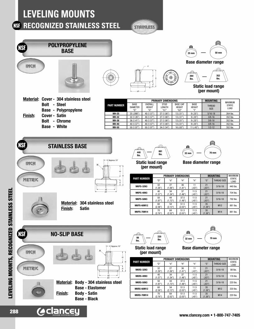
www.clancey.com • 1-800-747-7405288
RECOGNIZED STAINLESS STEELLEVELING MOUNTS
LEVE
LING
MOU
NTS,
REC
OGNI
ZED
STAI
NLES
S ST
EEL
Base diameter range
Static load range(per mount)
25 mm 50 mm
264lbs.
352lbs.
Base diameter range
32 mm 70 mm
Static load range(per mount)
88lbs.
220lbs.
Static load range(per mount)
440lbs.
881lbs.
Base diameter range
32 mm 70 mm
Material: Cover - 304 stainless steel Bolt - Steel Base - PolypropyleneFinish: Cover - Satin Bolt - Chrome Base - White
POLYPROPYLENE BASE
Material: 304 stainless steelFinish: Satin
STAINLESS BASE
Material: Body - 304 stainless steel Base - ElastomerFinish: Body - Satin Base - Black
NO-SLIP BASE
PART NUMBER
PRIMARY DIMENSIONS MOUNTINGMAXIMUM
STATICLOAD
BASEDIAMETER
“D”
OVERALLHEIGHT
“H”
STUDLENGTH
“h1”
BASE CAPHEIGHT
“h2”
BASEHEIGHT
“t”
THREADSIZE
MH-25 25 (.098") 40 (1.57") 27 (1.06") 13 (.51") 9 (.35") 5/16-18 264 lbs.MH-32 32 (1.26") 40 (1.57") 27 (1.06") 13 (.51") 9 (.35") 3/8-16 352 lbs.MH-36 36 (1.41") 40 (1.57") 27 (1.06") 13 (.51") 9 (.35") 3/8-16 352 lbs.MH-40 40 (1.57") 40 (1.57") 27 (1.06") 13 (.51") 9 (.35") 3/8-16 352 lbs.MH-50 50 (1.97") 50 (1.97") 34 (1.34") 16 (.63") 11 (.43") 1/2-12 352 lbs.
PART NUMBERPRIMARY DIMENSIONS MOUNTING MAXIMUM
STATICLOAD“D” “d” “H” “h” “S” THREAD SIZE
MKPS-32N3 32(1.26")
27(1.06")
36(1.41")
11(.43")
21(.83") 3/16-18 440 lbs.
MKPS-40N3 40(1.57")
34(1.34")
37(1.46")
11.5(.45")
21(.83") 3/16-18 704 lbs.
MKPS-50N3 50(1.97")
44(1.73")
37.5(1.48")
11.5(.45")
21(.83") 3/16-18 792 lbs.
MKPS-60M12 60(2.36")
54(2.13")
51.5(2.03")
11.5(.45")
35(1.38") M12 881 lbs.
MKPS-70M14 70(2.76")
64(2.52")
51.5(2.03")
11.5(.45")
35(1.38") M14 881 lbs.
PART NUMBERPRIMARY DIMENSIONS MOUNTING MAXIMUM
STATICLOAD“D” “d” “H” “h” “S” THREAD SIZE
MKRS-32N3 32(1.26")
27(1.06")
36(1.41")
11(.43")
21(.83") 3/16-18 88 lbs.
MKRS-40N3 40(1.57")
34(1.34")
37(1.46")
11.5(.45")
21(.83") 3/16-18 176 lbs.
MKRS-50N3 50(1.97")
44(1.73")
37.5(1.48")
11.5(.45")
21(.83") 3/16-18 220 lbs.
MKRS-60M12 60(2.36")
54(2.13")
51.5(2.03")
11.5(.45")
35(1.38") M12 220 lbs.
MKRS-70M14 70(2.76")
64(2.52")
51.5(2.03")
11.5(.45")
35(1.38") M14 220 lbs.
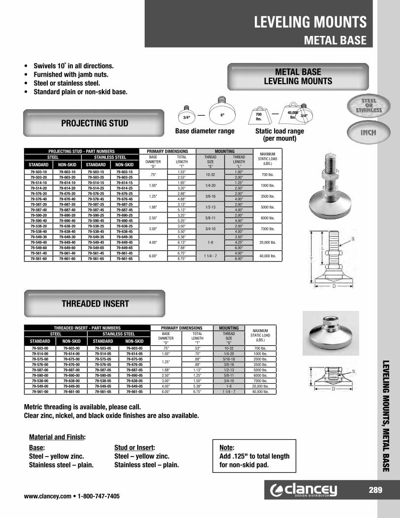
www.clancey.com • 1-800-747-7405289
LEVELING MOUNTS, M
ETAL BASE
METAL BASELEVELING MOUNTS
• Swivels 10˚ in all directions.• Furnished with jamb nuts.• Steel or stainless steel.• Standard plain or non-skid base.
METAL BASE LEVELING MOUNTS
PROJECTING STUD - PART NUMBERS PRIMARY DIMENSIONS MOUNTINGMAXIMUM
STATIC LOAD (LBS.)
STEEL STAINLESS STEEL BASEDIAMETER
"D"
TOTALLENGTH
"T"
THREADSIZE"S"
THREADLENGTH
"L"STANDARD NON-SKID STANDARD NON-SKID79-503-10 79-603-10 79-503-15 79-603-15
.75"1.53"
10-321.00"
700 lbs.79-503-20 79-603-20 79-503-25 79-603-25 2.53" 2.00"79-514-10 79-614-10 79-514-15 79-614-15
1.00"1.95"
1/4-201.25"
1000 lbs.79-514-20 79-614-20 79-514-25 79-614-25 3.20" 2.50"79-576-20 79-676-20 79-576-25 79-676-25
1.25"2.88"
3/8-162.00"
3500 lbs.79-576-40 79-676-40 79-576-45 79-676-45 4.88" 4.00"79-587-20 79-687-20 79-587-25 79-687-25
1.88"3.13"
1/2-132.00"
5000 lbs.79-587-40 79-687-40 79-587-45 79-687-45 5.13" 4.00"79-590-20 79-690-20 79-590-25 79-690-25
2.50"3.25"
5/8-112.00"
6000 lbs.79-590-40 79-690-40 79-590-45 79-690-45 5.25" 4.00"79-538-20 79-638-20 79-538-25 79-638-25
3.00"3.50"
3/4-102.00"
7000 lbs.79-538-40 79-638-40 79-538-45 79-638-45 5.50" 4.00"79-549-30 79-649-30 79-549-35 79-649-35
4.00"5.38"
1-83.50"
20,000 lbs.79-549-40 79-649-40 79-549-45 79-649-45 6.13" 4.25"79-549-60 79-649-60 79-549-65 79-649-65 7.88" 6.00"79-561-40 79-661-40 79-561-45 79-661-45
6.00"6.75"
1 1/4 - 74.00"
40,000 lbs.79-561-60 79-661-60 79-561-65 79-661-65 8.75" 6.00"
3/4"
Base diameter range Static load range(per mount)
6" 700lbs.
40,000lbs.
PROJECTING STUD
Metric threading is available, please call.Clear zinc, nickel, and black oxide finishes are also available.
Note:Add .125" to total length for non-skid pad.
THREADED INSERT
THREADED INSERT - PART NUMBERS PRIMARY DIMENSIONS MOUNTINGMAXIMUM
STATIC LOAD(LBS.)
STEEL STAINLESS STEEL BASEDIAMETER
"D"
TOTALLENGTH
"T"
THREADSIZE"S"STANDARD NON-SKID STANDARD NON-SKID
79-503-00 79-603-00 79-503-05 79-603-05 .75" .53" 10-32 700 lbs.79-514-00 79-614-00 79-514-05 79-614-05 1.00" .70" 1/4-20 1000 lbs.79-575-00 79-675-00 79-575-05 79-675-05
1.25".88" 5/16-18 2000 lbs.
79-576-00 79-676-00 79-576-05 79-676-05 .88" 3/8-16 3500 lbs.79-587-00 79-687-00 79-587-05 79-687-05 1.88" 1.13" 1/2-13 5000 lbs.79-590-00 79-690-00 79-590-05 79-690-05 2.50" 1.25" 5/8-11 6000 lbs.79-538-00 79-638-00 79-538-05 79-638-05 3.00" 1.50" 3/4-10 7000 lbs.79-549-00 79-649-00 79-549-05 79-649-05 4.00" 5.38" 1-8 20,000 lbs.79-561-00 79-661-00 79-561-05 79-661-05 6.00" 6.75" 1 1/4 - 7 40,000 lbs.
Material and Finish:Base:Steel – yellow zinc. Stainless steel – plain.
Stud or Insert:Steel – yellow zinc. Stainless steel – plain.
3/4"

www.clancey.com • 1-800-747-7405290
NYLON BASELEVELING MOUNTS
LEVE
LING
MOU
NTS,
NYL
ON B
ASE
• 15˚ swivel in all directions.• Non-corrosive high strength glass filled nylon base.• Available with or without lag holes.• Innovative “pop-out” lag holes allow for permanent mounting.• Available with or without non-skid pad.
Note:Add .06" to total length for non-skid base.
Metric threading is available, please call.
Base diameter range Static load range(per mount)
2" 4" 4,000lbs.
7,500lbs.
NYLON BASE LEVELING MOUNTS
PROJECTING STUD - PART NUMBER PRIMARY DIMENSIONS MOUNTINGMAXIMUM
STATIC LOAD(LBS.)
STEEL STAINLESS STEEL BASEDIAMETER
"D"
TOTALLENGTH
"T"
THREADSIZE"S"
THREADLENGTH
"L"STANDARD NON-SKID STANDARD NON-SKID79-126-40 79-226-40 79-126-45 79-226-45
2.00"5.12"
3/8-164.00"
4000 lbs.79-126-60 79-226-60 79-126-65 79-226-65 7.12" 6.00"79-126-80 79-226-80 79-126-85 79-226-85 9.12" 8.00"79-127-40 79-227-40 79-127-45 79-227-45
2.00"5.12"
1/2-134.00"
4000 lbs.79-127-60 79-227-60 79-127-65 79-227-65 7.12" 6.00"79-127-80 79-227-80 79-127-85 79-227-85 9.12" 8.00"79-136-40 79-236-40 79-136-45 79-236-45
3.00"5.12"
3/8-164.00"
5000 lbs.79-136-60 79-236-60 79-136-65 79-236-65 7.12" 6.00"79-136-80 79-236-80 79-136-85 79-236-85 9.12" 8.00"79-137-40 79-237-40 79-137-45 79-237-45
3.00"5.12"
1/2-134.00"
5000 lbs.79-137-60 79-237-60 79-137-65 79-237-65 7.12" 6.00"79-137-80 79-237-80 79-137-85 79-237-85 9.12" 8.00"79-138-40 79-238-40 79-138-45 79-238-45
3.00"5.12"
3/4-104.00"
5000 lbs.79-138-60 79-238-60 79-138-65 79-238-65 7.12" 6.00"79-138-80 79-238-80 79-138-85 79-238-85 9.12" 8.00"79-146-40 79-246-40 79-146-45 79-246-45
4.00"5.31"
3/8-164.00"
3500 lbs.79-146-60 79-246-60 79-146-65 79-246-65 7.31" 6.00"79-146-80 79-246-80 79-146-85 79-246-85 9.31" 8.00"79-147-40 79-247-40 79-147-45 79-247-45
4.00"5.31"
1/2-134.00"
5000 lbs.79-147-60 79-247-60 79-147-65 79-247-65 7.31" 6.00"79-147-80 79-247-80 79-147-85 79-247-85 9.31" 8.00"79-148-40 79-248-40 79-148-45 79-248-45
4.00"5.31"
3/4-104.00"
7500 lbs.79-148-60 79-248-60 79-148-65 79-248-65 7.31" 6.00"79-148-80 79-248-80 79-148-85 79-248-85 9.31" 8.00"79-149-40 79-249-40 79-149-45 79-249-45
4.00"5.31"
1-84.00"
7500 lbs.79-149-60 79-249-60 79-149-65 79-249-65 7.31" 6.00"79-149-80 79-249-80 79-149-85 79-249-85 9.31" 8.00"
THREADED INSERT - PART NUMBERS PRIMARY DIMENSIONS MOUNTINGMAXIMUM
STATIC LOAD(LBS.)
STEEL STAINLESS STEEL BASEDIAMETER
"D"
TOTALLENGTH
"T"
THREADSIZE"S"STANDARD NON-SKID STANDARD NON-SKID
79-126-00 79-226-00 79-126-05 79-226-052.00"
1.63" 5/16-18 4000 lbs.79-127-00 79-227-00 79-127-05 79-227-05 1.63" 1/2-13 4000 lbs.79-136-00 79-236-00 79-136-05 79-236-05
3.00"1.63" 5/16-18 5000 lbs.
79-137-00 79-237-00 79-137-05 79-237-05 1.63" 1/2-13 5000 lbs.79-138-00 79-238-00 79-138-05 79-238-05 1.63" 3/4-10 5000 lbs.79-146-00 79-246-00 79-146-05 79-246-05
4.00"
1.63" 5/16-18 3500 lbs.79-147-00 79-247-00 79-147-05 79-247-05 1.63" 1/2-13 5000 lbs79-148-00 79-248-00 79-148-05 79-248-05 1.63" 3/4-10 7500 lbs.79-149-00 79-249-00 79-149-05 79-249-05 1.63" 1-8 7500 lbs.
Material and Finish:Base: Nylon, BlackStud or Insert:Steel – clear zinc platedStainless steel – plain
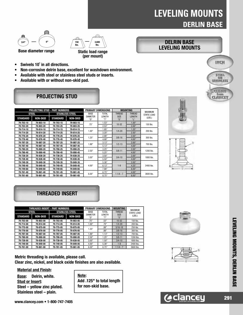
www.clancey.com • 1-800-747-7405291
LEVELING MOUNTS, DERLIN BASE
DERLIN BASELEVELING MOUNTS
• Swivels 10˚ in all directions.• Non-corrosive delrin base, excellent for washdown environment.• Available with steel or stainless steel studs or inserts.• Available with or without non-skid pad.
Base diameter range Static load range(per mount)
3/4" 6" 150lbs.
3,600lbs.
DELRIN BASE LEVELING MOUNTS
Metric threading is available, please call.Clear zinc, nickel, and black oxide finishes are also available.
Material and Finish:Base: Delrin, white.Stud or Insert:Steel – yellow zinc plated. Stainless steel – plain.
PROJECTING STUD
THREADED INSERT
PROJECTING STUD - PART NUMBERS PRIMARY DIMENSIONS MOUNTINGMAXIMUM
STATIC LOAD(LBS.)
STEEL STAINLESS STEEL BASEDIAMETER
"D"
TOTALLENGTH
"T"
THREADSIZE"S"
THREADLENGTH
"L"STANDARD NON-SKID STANDARD NON-SKID79-703-10 79-803-10 79-703-15 79-803-15
.75"1.53"
10-321.00"
150 lbs.79-703-20 79-803-20 79-703-25 79-803-25 2.53" 2.00"79-714-10 79-814-10 79-714-15 79-814-15
1.00"1.95"
1/4-201.25"
200 lbs.79-714-20 79-814-20 79-714-25 79-814-25 3.20" 2.50"79-776-20 79-876-20 79-776-25 79-876-25
1.25"2.88"
3/8-162.00"
300 lbs.79-776-40 79-876-40 79-776-45 79-876-45 4.88" 4.00"79-787-20 79-887-20 79-787-25 79-887-25
1.88"3.13"
1/2-132.00"
700 lbs.79-787-40 79-887-40 79-787-45 79-887-45 5.13" 4.00"79-790-20 79-890-20 79-790-25 79-890-25
2.50"3.25"
5/8-112.00"
1200 lbs.79-790-40 79-890-40 79-790-45 79-890-45 5.25" 4.00"79-738-20 79-838-20 79-738-25 79-838-25
3.00"3.50"
3/4-102.00"
1800 lbs.79-738-40 79-838-40 79-738-45 79-838-45 5.50" 4.00"79-749-30 79-849-30 79-749-35 79-849-35
4.00"5.38"
1-83.50"
2400 lbs.79-749-40 79-849-40 79-749-45 79-849-45 6.13" 4.25"79-749-60 79-849-60 79-749-65 79-849-65 7.88" 6.00"79-761-40 79-861-40 79-761-45 79-861-45
6.00"6.75"
1 1/4 - 74.00"
3600 lbs.79-761-60 79-861-60 79-761-65 79-861-65 8.75" 6.00"
THREADED INSERT - PART NUMBERS PRIMARY DIMENSIONS MOUNTINGMAXIMUM
STATIC LOAD(LBS.)
STEEL STAINLESS STEEL BASEDIAMETER
"D"
TOTALLENGTH
"T"
THREADSIZE"S"STANDARD NON-SKID STANDARD NON-SKID
79-703-00 79-803-00 79-703-05 79-803-05 .75" .53" 10-32 150 lbs.79-714-00 79-814-00 79-714-05 79-814-05 1.00" .70" 1/4-20 200 lbs.79-775-00 79-875-00 79-775-05 79-875-05
1.25".88" 5/16-18 250 lbs.
79-776-00 79-876-00 79-776-05 79-876-05 .88" 3/8-16 300 lbs.79-787-00 79-887-00 79-787-05 79-887-05 1.88" 1.13" 1/2-13 700 lbs.79-790-00 79-890-00 79-790-05 79-890-05 2.50" 1.25" 5/8-11 1200 lbs.79-738-00 79-838-00 79-738-05 79-838-05 3.00" 1.50" 3/4-10 1800 lbs.79-749-00 79-849-00 79-749-05 79-849-05 4.00" 5.38" 1-8 2400 lbs.79-761-00 79-861-00 79-761-05 79-861-05 6.00" 6.75" 1 1/4 - 7 3600 lbs.
Note:Add .125" to total length for non-skid base.

www.clancey.com • 1-800-747-7405292
ANTI-VIBRATIONLEVELING MOUNTS
LEVE
LING
MOU
NTS,
ANT
I-VIB
RATI
ON
ANTI-VIBE® MACHINE MOUNTS
PROJECTING STUD
THREADED INSERT
• Light, medium and heavy duty configurations.• Can isolate transmitted vibration up to 98%.• Protects your machinery.
Material:Low carbon steel, or 303 stainless steel
Metric sizes are available, please call.
™ S&W Mfg. Co., Inc.
Base diameter range Static load range(per mount)
1.25" 6" 200lbs.
27,100lbs.
PROJECTING STUD PART NUMBERS PRIMARY DIMENSIONS MOUNTING MAXIMUM STATIC LOAD
(LBS.)STEEL STAINLESS STEEL BASE DIA. “D”
LENGTH “T”
THREAD SIZE “S”
THREAD LENGTH “L”
L I G H T
D U T Y
79-AV1L-200 79-AV1L-205 1.25" 3.50" 3/8 - 16 2.00" 200 LBS.79-AV2L-200 79-AV2L-205 1.88" 3.75" 1/2 - 13 2.00" 500 LBS.79-AV3L-200 79-AV3L-205 2.50" 3.88" 5/8 - 11 2.00" 900 LBS.79-AV4L-200 79-AV4L-205 3.00" 4.13" 3/4 - 10 2.00" 1250 LBS.79-AV5L-350 79-AV5L-355 4.00" 6.00" 1 - 8 3.50" 2250 LBS.79-AV6L-400 79-AV6L-405 6.00" 6.88" 1 1/4 - 7 4.00" 5000 LBS.
M E D I U M
D U T Y
79-AV1M-200 79-AV1M-205 1.25" 3.50" 3/8 - 16 2.00" 400 LBS.79-AV2M-200 79-AV2M-205 1.88" 3.75" 1/2 - 13 2.00" 1000 LBS.79-AV3M-200 79-AV3M-205 2.50" 3.88" 5/8 - 11 2.00" 1800 LBS.79-AV4M-200 79-AV4M-205 3.00" 4.13" 3/4 - 10 2.00" 2500 LBS.79-AV5M-350 79-AV5M-355 4.00" 6.00" 1 - 8 3.50" 4500 LBS.79-AV6M-400 79-AV6M-405 6.00" 6.88" 1 1/4 - 7 4.00" 10,000 LBS.
H E A V Y
D U T Y
79-AV1H-200 79-AV1H-205 1.25" 3.50" 3/8 - 16 2.00" 995 LBS.79-AV2H-200 79-AV2H-205 1.88" 3.75" 1/2 - 13 2.00" 2400 LBS.79-AV3H-200 79-AV3H-205 2.50" 3.88" 5/8 - 11 2.00" 4400 LBS.79-AV4H-200 79-AV4H-205 3.00" 4.13" 3/4 - 10 2.00" 6500 LBS.79-AV5H-350 79-AV5H-355 4.00" 6.00" 1 - 8 3.50" 11,800 LBS.79-AV6H-400 79-AV6H-405 6.00" 6.88" 1 1/4 - 7 4.00" 27,100 LBS.
THREADED INSERT PART NUMBERS PRIMARY DIMENSIONS MOUNTING MAXIMUM STATIC LOAD
(LBS.)STEEL STAINLESS STEEL BASE DIA. “D”
LENGTH “T”
THREAD SIZE “S”
L I G H T
D U T Y
79-AV1L-00 79-AV1L-05 1.25" 1.50" 3/8 - 16 50 LBS.79-AV2L-00 79-AV2L-05 1.88" 1.75" 1/2 - 13 120 LBS.79-AV3L-00 79-AV3L-05 2.50" 1.88" 5/8 - 11 220 LBS.79-AV4L-00 79-AV4L-05 3.00" 2.13" 3/4 - 10 325 LBS.79-AV5L-00 79-AV5L-05 4.00" 2.50" 1 - 8 590 LBS.79-AV6L-00 79-AV6L-05 6.00" 2.88" 1 1/4 - 7 1350 LBS.
M E D I U M
D U T Y
79-AV1M-00 79-AV1M-05 1.25" 1.50" 3/8 - 16 100 LBS.79-AV2M-00 79-AV2M-05 1.88" 1.75" 1/2 - 13 240 LBS.79-AV3M-00 79-AV3M-05 2.50" 1.88" 5/8 - 11 440 LBS.79-AV4M-00 79-AV4M-05 3.00" 2.13" 3/4 - 10 650 LBS.79-AV5M-50 79-AV5M-05 4.00" 2.50" 1 - 8 1180 LBS.79-AV6M-00 79-AV6M-05 6.00" 2.88" 1 1/4 - 7 2710 LBS.
H E A V Y
D U T Y
79-AV1H-00 79-AV1H-05 1.25" 1.50" 3/8 - 16 250 LBS.79-AV2H-00 79-AV2H-05 1.88" 1.75" 1/2 - 13 600 LBS.79-AV3H-00 79-AV3H-05 2.50" 1.88" 5/8 - 11 1100 LBS.79-AV4H-00 79-AV4H-05 3.00" 2.13" 3/4 - 10 1625 LBS.79-AV5H-50 79-AV5H-05 4.00" 2.50" 1 - 8 2950 LBS.79-AV6H-00 79-AV6H-05 6.00" 2.88" 1 1/4 - 7 6775 LBS.

www.clancey.com • 1-800-747-7405293
LEVELING MOUNTS, ANTI-VIBRATION
ANTI-VIBRATIONLEVELING MOUNTS
MIGHTY MOUNT™
THREAD ENDS
• Meets OSHA anchoring standards.• Rugged steel housing.• High density non-skid base.
• Easy installation.• Durable construction.• Metric available (please call).
™ S&W Mfg. Co., Inc.
Material: Threaded stud – steel, zinc plate Base – steel, safety yellow powder coat
Base diameter range Static load range(per mount)
2" 9" 50lbs.
12,500lbs.
Material: Glass filled nylon with brass insert
PART NUMBERPRIMARY DIMENSIONS MOUNTING STATIC LOAD
BASE DIA. “D”
BASE HEIGHT “H”
THREAD SIZE “S”
THREAD LENGTH “L”
MINIMUM (LBS.)
MAXIMUM (LBS.)
79-5028A 2.00" 1.00" 1/4 - 28 1.75" 50 LBS. 300 LBS.79-5016A 2.00" 1.00" 3/8 - 16 3.00" 50 LBS. 300 LBS.79-5024B 2.00" 1.00" 3/8 - 24 3.00" 50 LBS. 300 LBS.79-80163 3.00" 1.50" 3/8 - 16 3.00" 300 LBS. 700 LBS.79-80243 3.00" 1.50" 3/8 - 24 3.00" 300 LBS. 700 LBS.79-80136 3.00" 1.50" 1/2 - 13 6.00" 300 LBS. 700 LBS.79-120135 5.00" 1.50" 1/2 - 13 5.00" 500 LBS. 2000 LBS.79-120118 5.00" 1.50" 5/8 - 11 8.00" 500 LBS. 2000 LBS.79-160135 6.00" 1.63" 1/2 - 13 5.00" 1000 LBS. 4500 LBS.79-160105 6.00" 1.63" 5/8 - 11 5.00" 1000 LBS. 4500 LBS.79-160108 6.00" 1.63" 3/4 - 10 8.00" 1000 LBS. 4500 LBS.79-230105 9.00" 2.50" 3/4 - 10 5.00" 4000 LBS. 12,500 LBS.79-230148 9.00" 2.50" 1 - 14 8.00" 4000 LBS. 12,500 LBS.
PART NUMBER
THREAD SIZE “S”
OUTSIDE DIAMETER
“D”
TUBE GAUGE / SHAPE
TUBE DIAMETER
TUBE WALL
THICKNESS
MAX. STATIC LOAD
79-TE1-2A 3/8 - 161.50"
Square16 gauge Square
1.50" Square .065" 1500 lbs.
79-TE1-2B 1/2 - 1379-TE1-2C 5/8 - 1179-TE1-2D 3/4 -10 79-TE1-3A 3/8 - 16
1.50" Square
11 gauge Square
1.50" Square .120" 1500 lbs.
79-TE1-3B 1/2 - 1379-TE1-3C 5/8 - 1179-TE1-3D 3/4 -10 79-TE2-1A 3/8 - 16
2.00" Square
16 gauge Square
2.00" Square .065" 2000 lbs.
79-TE2-1B 1/2 - 1379-TE2-1C 5/8 - 1179-TE2-1D 3/4 -10 79-TE2-3A 3/8 - 16
2.00" Square
11 - 12 gauge Square
2.00" Square
.109" / .120" 2000 lbs.
79-TE2-3B 1/2 - 1379-TE2-3C 5/8 - 1179-TE2-3D 3/4 -10
PART NUMBER
THREAD SIZE “S”
OUTSIDE DIAMETER
“D”
TUBE GAUGE / SHAPE
TUBE DIAMETER
TUBE WALL
THICKNESS
MAX. STATIC LOAD
79-TE1-1A 3/8 - 161.50" Round
16 gauge Round
1.50" Round .065" 1500 lbs.
79-TE1-1B 1/2 - 1379-TE1-1C 5/8 - 1179-TE1-1D 3/4 -10 79-TE2-2A 3/8 - 16
2.00" Round
11 gauge Round
2.00" Round .120" 2000 lbs.
79-TE2-2B 1/2 - 1379-TE2-2C 5/8 - 1179-TE2-2D 3/4 -10
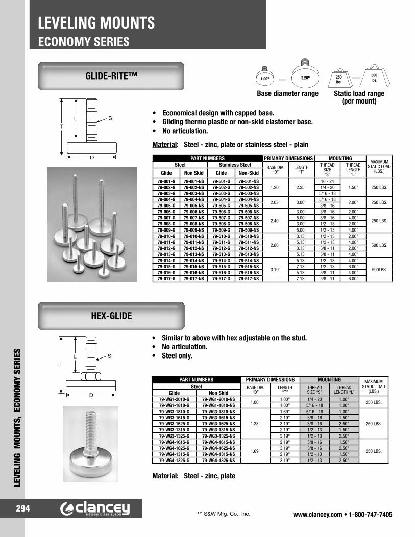
www.clancey.com • 1-800-747-7405294
ECONOMY SERIESLEVELING MOUNTS
LEVE
LING
MOU
NTS,
ECO
NOM
Y SE
RIES
GLIDE-RITE™
• Economical design with capped base.• Gliding thermo plastic or non-skid elastomer base.• No articulation.
Base diameter range Static load range(per mount)
1.00" 3.20" 250lbs.
500lbs.
Material: Steel - zinc, plate or stainless steel - plain
• Similar to above with hex adjustable on the stud.• No articulation.• Steel only.
Material: Steel - zinc, plate
PART NUMBERS PRIMARY DIMENSIONS MOUNTINGMAXIMUM
STATIC LOAD (LBS.)
Steel Stainless Steel BASE DIA. “D”
LENGTH “T”
THREAD SIZE “S"
THREAD LENGTH
“L"Glide Non Skid Glide Non-Skid79-001-G 79-001-NS 79-501-G 79-501-NS
1.20" 2.25"10 - 24
1.50" 250 LBS.79-002-G 79-002-NS 79-502-G 79-502-NS 1/4 - 2079-003-G 79-003-NS 79-503-G 79-503-NS 5/16 - 1879-004-G 79-004-NS 79-504-G 79-504-NS
2.03" 3.00"5/16 - 18
2.00" 250 LBS.79-005-G 79-005-NS 79-505-G 79-505-NS 3/8 - 1679-006-G 79-006-NS 79-506-G 79-506-NS
2.40"
3.00" 3/8 - 16 2.00"
250 LBS.79-007-G 79-007-NS 79-507-G 79-507-NS 5.00" 3/8 - 16 4.00"79-008-G 79-008-NS 79-508-G 79-508-NS 3.00" 1/2 - 13 2.00"79-009-G 79-009-NS 79-509-G 79-509-NS 5.00" 1/2 - 13 4.00"79-010-G 79-010-NS 79-510-G 79-510-NS
2.80"
3.13" 1/2 - 13 2.00"
500 LBS.79-011-G 79-011-NS 79-511-G 79-511-NS 5.13" 1/2 - 13 4.00"79-012-G 79-012-NS 79-512-G 79-512-NS 3.13" 5/8 - 11 2.00"79-013-G 79-013-NS 79-513-G 79-513-NS 5.13" 5/8 - 11 4.00"79-014-G 79-014-NS 79-514-G 79-514-NS
3.19"
5.13" 1/2 - 13 4.00"
500LBS.79-015-G 79-015-NS 79-515-G 79-515-NS 7.13" 1/2 - 13 6.00"79-016-G 79-016-NS 79-516-G 79-516-NS 5.13" 5/8 - 11 4.00"79-017-G 79-017-NS 79-517-G 79-517-NS 7.13" 5/8 - 11 6.00"
PART NUMBERS PRIMARY DIMENSIONS MOUNTING MAXIMUM STATIC LOAD
(LBS.)Steel BASE DIA.
“D”LENGTH
“T”THREAD SIZE “S”
THREAD LENGTH “L”Glide Non Skid
79-WG1-2010-G 79-WG1-2010-NS1.00"
1.00" 1/4 - 20 1.00"250 LBS.
79-WG1-1810-G 79-WG1-1810-NS 1.00" 5/16 - 18 1.00"79-WG3-1810-G 79-WG3-1810-NS
1.38"
1.69" 5/16 - 18 1.00"
250 LBS.79-WG3-1615-G 79-WG3-1615-NS 2.19" 3/8 - 16 1.50"79-WG3-1625-G 79-WG3-1625-NS 3.19" 3/8 - 16 2.50"79-WG3-1315-G 79-WG3-1315-NS 2.19" 1/2 - 13 1.50"79-WG3-1325-G 79-WG3-1325-NS 3.19" 1/2 - 13 2.50"79-WG4-1615-G 79-WG4-1615-NS
1.69"
2.19" 3/8 - 16 1.50"
250 LBS.79-WG4-1625-G 79-WG4-1625-NS 3.19" 3/8 - 16 2.50"79-WG4-1315-G 79-WG4-1315-NS 2.19" 1/2 - 13 1.50"79-WG4-1325-G 79-WG4-1325-NS 3.19" 1/2 - 13 2.50"
HEX-GLIDE
™ S&W Mfg. Co., Inc.

www.clancey.com • 1-800-747-7405295
LEVELING MOUNTS, ECONOM
Y SERIES
ECONOMY SERIESLEVELING MOUNTS
STAMPED BASE
HEX MOUNT
Material: Steel - zinc, plated
(black oxide available)
• For light-duty applications.• Economical design.• No articulation.
• Rugged, yet economical.• No articulation.
Material:Steel - zinc, plated
PART NUMBER
PRIMARY DIMENSIONS MOUNTINGBASE DIA. (FLATS)
“D”
TOTAL LENGTH
“T”
CAP HEIGHT
“C”
THREAD SIZE “S”
THREAD LENGTH
“L”79-S1-20-100
.94"1.25"
.19"1/4 - 20 1.00"
79-S1-20-125 1.50" 1/4 - 20 1.25"79-S1-18-100 1.25" 5/16 - 18 1.00"79-S2-20-150
1.07"
1.75"
.19"
1/4 - 20 1.50"79-S2-20-200 2.25" 1/4 - 20 2.00"79-S2-18-150 1.75" 5/16 - 18 1.50"79-S2-18-200 2.25" 5/16 - 18 2.00"79-S3-20-100
1.38"
1.25"
.15"
1/4 - 20 1.00"79-S3-18-100 1.25" 5/16 - 18 1.00"79-S3-16-150 1.75" 3/8 - 16 1.50"79-S3-16-200 2.25" 3/8 - 16 2.00"79-S3-16-250 2.75" 3/8 - 16 2.50"79-S3-13-150 1.75" 1/2 - 13 1.50"79-S3-13-200 2.25" 1/2 - 13 2.00"79-S3-13-250 2.75" 1/2 - 13 2.50"79-S3-13-300 3.25" 1/2 - 13 3.00"79-S4-20-150
1.38"
1.75"
.31"
1/4 - 20 1.50"79-S4-20-200 2.25" 1/4 - 20 2.00"79-S4-18-150 1.75" 5/16 - 18 1.50"79-S4-18-200 2.25" 5/16 - 18 2.00"79-S4-18-250 2.75" 5/16 - 18 2.50"79-S4-16-150 1.75" 3/8 - 16 1.50"79-S4-16-200 2.25" 3/8 - 16 2.00"79-S4-16-250 2.75" 3/8 - 16 2.50"79-S4-13-150 1.75" 1/2 - 13 1.50"79-S4-13-200 2.25" 1/2 - 13 2.00"79-S4-13-250 2.75" 1/2 - 13 2.50"79-S4-13-300 3.25" 1/2 - 13 3.00"
PART NUMBER
PRIMARY DIMENSIONS MOUNTING MAX. STATIC LOAD
BASE DIA. (FLATS)
“D”
TOTAL LENGTH
“T”
THREAD SIZE “S”
THREAD LENGTH
“L”79-H-1Z .56" 1.09" 1/4 - 20 1.00" 1000 LBS.79-H-2Z .75" 1.63" 5/16 - 18 1.50" 2300 LBS.79-H-3Z .88" 1.66" 3/8 - 16 1.50" 3750 LBS.79-H-4Z .88" 2.66" 3/8 - 16 2.50" 3750 LBS.79-H-5Z 1.07" 2.69" 1/2 - 13 2.50" 5000 LBS.
1000lbs.
5000lbs.
Static load range

www.clancey.com • 1-800-747-7405296
DERLIN BASELEVELING MOUNTS
LEVE
LING
MOU
NTS,
DER
LIN
BASE
www.clancey.com • 1-800-747-7405296
BUMPERS AND FEETLEVELING MOUNTS
LEVE
LING
MOU
NTS,
BUM
PERS
AND
FEE
T
• Excellent skid-resistance.• High coefficient of friction.• Non-marring, non-staining material.• High initial adhesion.• UL flammability recognition: UL 94HB.• 4 standard colors (see chart).• Application specific material formulation and
custom colors are available, please call.
Head Styles
Cylindrical
Square
Tapered Square
Hemisphere
• Quick and easy hand installation.• High shear force and holding strength.• Ideal for applications where conditions
will not allow a self-stick bumper: • Moisture • Uneven surfaces
URETHANE SELF-ADHESIVE BUMPERS
SNAP-IN BUMPER
Materials: Nylon base, Urethane bumper.Color: Black
Note: Listed dimensions are nominal.
UL file number E83785
URETHANEPART NUMBER
DIMENSIONS STANDARD COLORSSHAPE HEAD HEIGHT DIAMETER CLEAR BLACK WHITE GRAY
CYLINDRICAL
4041-00 .085" .312" X — — —4053* .125" .400" — X — —
4052-00 .140" .495" — X — —4031-00 .125" .500" — — X —4001-00 .140" .500" X X X —4006-00 .250" .500" — — X —4029-00 .325" .500" — X — —4023-00 .160" .750" — X — —4045-00 .197" .819" — — — X4047-00 .470" .685" — X — —
SQUARE4007-00 .100" .400" X .400"
SQUARE X — — —
4032-00 .120" .500" X .500"SQUARE — X — —
TAPEREDSQUARE
4009-00 .230" .500" X .500"SQUARE — X — —
4019-00 .300" .800" X .800"SQUARE — X — —
HEMISPHERE4042-00 .150" .375" X — — —4002-00 .200" .437" X X X —
SNAP-INBUMPER
PART NUMBER
BUMPERDIMENSIONS MOUNTING
HEIGHT DIAMETER HOLE DIAMETER
PANELTHICKNESS
8202-00-9909 .235" .370" .184"-.190" .030"-.090"

www.clancey.com • 1-800-747-7405297
LEVELING MOUNTS, BUM
PERS AND FEET
BUMPERS AND FEETLEVELING MOUNTS
• Acrylic based adhesive yields excellent long-term adhesion.
• Base is solvent and ultra-violet light resistant.• High shear strength.• 4 standard colors (see chart)• Application specific material formulations and
custom colors are available, please call.
PVCPART NUMBER
DIMENSIONS STANDARD COLORSSHAPE HEAD HEIGHT DIAMETER BLACK WHITE GRAY NATURAL
CYLINDRICAL
5005-01-00 .070" .500" X X — X5026-01-00 .090" .500" X — — —5031-01-00 .115" .500" X — — —5001-01-00 .140" .500" X — X X5006-01-00 .250" .500" X — — X5029-01-00 .325" .500" — — X —5034-01-00 .115" .645" X — — —5011-01-00 .400 .645" X X — —5025-01-00 .250" .830" X — — —
SQUARE
5033-01-00 .185" .375" X .375"SQUARE X — — —
5003-01-00 .200" .500" X .500"SQUARE X — — —
5010-01-00 .260" .510" X .510"SQUARE X — — —
5022-01-00 .130" .645" X .645"SQUARE X — — —
5004-01-00 .340" .760" X .760"SQUARE X — — —
TAPEREDSQUARE
5032-01-00 .120" .500" X .500"SQUARE X — — —
5019-01-00 .300" .810" X .810"SQUARE X — — —
HEMISPHERE5002-01-00 .200" .437" X — — —5015-01-00 .320" .645" X — — —
CIRCULARDEPRESSED
5017-01-00 .400" .875" X — — —5030-01-00 .560" 2.00" — X — —
CYLINDRICALCONCAVE 50918-01-00 .140" .500" — — X —
See our complete line of wire management products pages 299 to 321.
WIRE MANAGEMENT PRODUCTS
Head Shapes
Circular Depressed
Hemisphere
CylindricalConcave
Tapered Square
Cylindrical Square
For detailed materialspecifications and product
strength guidelines.
www.clancey.com
PVC SELF-ADHESIVE BUMPERS

www.clancey.com • 1-800-747-7405298
DERLIN BASELEVELING MOUNTS
LEVE
LING
MOU
NTS,
DER
LIN
BASE
www.clancey.com • 1-800-747-7405298
BUMPERS AND FEETLEVELING MOUNTS
LEVE
LING
MOU
NTS,
BUM
PERS
AND
FEE
T
• Quick, easy hand installation.• 17 sizes with various height combinations.• Can be released with access to the blind
side of the panel.
Material:Polypropylene/Elostomer blend
Material:Ethylene vinyl acetate
• Skid and vibration resistant.
Material: Ethylene vinyl acetateacetyl screw
• Push screw head to install. • Use slotted screwdriver to remove.
Other styles similar after
insertion.
PART NUMBER DIMENSIONS MOUNTING
OVERALLHEIGHT
"A"
TOPDIAMETER
"B"
BOTTOMDIAMETER
"C"
PANELTHICKNESS
RANGE
HOLEDIAMETERBLACK
2517 .217" .531" .559" .031" - .071" .122"2518 .217" .531" .559" .071" - .110" .122"2519 .157" .394" .425" .024" - .039" .142"2520 .157" .394" .425" .039" - .079" .142"2521 .157" .394" .425" .079" - .118" .142"2522 .165" .787" .827" .031" - .071" .161"2523 .165" .787" .827" .071" - .110" .161"2524 .165" .787" .827" .110" - .146" .161"2525 .165" .787" .827" .150" - .189" .161"2526 .236" .787" .827" .031" - .071" .161"2527 .236" .787" .827" .075" - .110" .161"2528 .236" .787" .827" .114" - .157" .161"2529 .315" .787" .827" .031" - .079 .161"2530 .315" .787" .827" .083" - .118" .161"2531 .354" .551" .591" .024" - .039" .161"2532 .354" .551" .591" .039" - .079" .161"2533 .354" .551" .591" .079" - .118" .161"
PART NUMBER DIMENSIONS MOUNTING
OVERALLHEIGHT
"A"
TOPDIAMETER
"B"
BOTTOMDIAMETER
"C"
PANELTHICKNESS
RANGE
HOLEDIAMETERBLACK
2543 .197" .906" .984" .031" - .059" .299"2544 .236" .787" .827" .197" - .315" .303"2545 .394" .709" .787" .031" - .059" .303"2547 .472" .709" .787" .031" - .047" .319"2549 .591" .709" .787" .031" - .047" .319"2551 .709" .709" .787" .031" - .047" .319"
PART NUMBER DIMENSIONS MOUNTING
OVERALLHEIGHT
"A"
TOPDIAMETER
"B"
BOTTOMDIAMETER
"C"
PANELTHICKNESS
RANGE
HOLEDIAMETERBLACK
2538 .551" .787" .945" .039" - .091" .197"
HEYCO® FEETS OF STRENGTH™
PUSH RIVET MOUNT
DRIVE PIN MOUNT
SCREW–RIVET MOUNT
™ HEYCO Products, Inc.

www.clancey.com • 1-800-747-7405299
WIRE M
ANAGEMENT, CORD CLIPS
CORD CLIPS – ADHESIVE BACKEDWIRE MANAGEMENT
• Easy hand installation.• Install on clean, dry and smooth surfaces.• Rounded corners and edges.• Easy release paper protects adhesive
until installation.
Material: Nylon, foamed backed adhesive tapeColors: Natural, black (some models)Note: Bundle diameter range reflects
a tight bundle
Try this part inyour application
Please call for samples.
800-747-7405
ADHESIVE BACKED CORD CLIPS
PART NUMBER PART NUMBER PART NUMBER PART NUMBER PART NUMBER PART NUMBER8511-28-00 8511-29-00 8511-30-00 8511-31-00 8511-34-00 8511-36-00
MAXIMUM BUNDLE DIAMETER
.156"
MAXIMUM BUNDLE DIAMETER
.375"
MAXIMUM BUNDLE DIAMETER
.375"
MAXIMUM BUNDLE DIAMETER
.625"
MAXIMUM BUNDLE DIAMETER
.450"
MAXIMUM BUNDLE DIAMETER
.375"AVAILABLE IN BLACK AVAILABLE IN BLACK AVAILABLE IN BLACK
PART NUMBER PART NUMBER PART NUMBER PART NUMBER PART NUMBER PART NUMBER PART NUMBER8511-37-00 8511-38-00 8511-54-00 8511-55-00 8511-55-01 8511-56-00 8511-46-00
MAXIMUM BUNDLE DIAMETER
.250"
MAXIMUM BUNDLE DIAMETER
.625"
MAXIMUM BUNDLE DIAMETER
.156"
MAXIMUM BUNDLE DIAMETER
.620"
MAXIMUM BUNDLE DIAMETER
1.00"
MAXIMUM BUNDLE DIAMETER
.156"
MAXIMUM BUNDLE DIAMETER
.156"SCREW HOLE #6 COUNTERSUNK

www.clancey.com • 1-800-747-7405300
CORD CLIPS – ADHESIVE BACKEDWIRE MANAGEMENT
WIR
E M
ANAG
EMEN
T, CO
RD C
LIPS
• Secure hold and quick release of bundle.• Mounts on virtually any flat, clean and dry surface.• 6 bundle sizes, 2 widths.
Material: Nylon with adhesive backed foam tape
Flammability Rating: 94V-2
• “Slide-in” bundle from the side.• Large adhesive base.
• “Drop-In” bundle from the top.• Compact design, for cable or tubing.
Material: PVC with adhesive backed foam tape.
HEYCLIP™ ADHESIVE BACKED WIRE CLIPS
HEYCLIP™ “C” STYLE–ADHESIVE BACKED
HEYCLIP™ “U” STYLE–ADHESIVE BACKED
PART NUMBER DIMENSIONS MAXIMUMBUNDLE
DIAMETERA B C D EGRAY3794 .38" .47" 1.00" .75" .05" .500"
• Low-profile design with large adhesive base for greater holding power.
• Clear Material.• 6 Bundle sizes.
Material: PVC with adhesive backed foam tape.
Try this part inyour application
Please call for samples.
800-747-7405
HEYCLIP™ “J” STYLE–ADHESIVE BACKED
PART NUMBER DIMENSIONS MAXIMUM BUNDLE
DIAMETERA B CBLACK NARROW STYLE
3888 .50" .75" .31" .187"3889 .50" 1.02" .41" .250"3893 .50" 1.00" .52" .375"3895 .50" 1.25" .67" .500"3896 .63" 1.25" .77" .625"3897 .75" 1.50" .94" .750"
WIDE STYLE3898 1.00" .75" .31" .187"3899 1.00" 1.02" .41" .250"3900 1.00" 1.00" .52" .375"3901 1.00" 1.25" .67" .500"3902 1.25" 1.25" .77" .625"3903 1.50" 1.50" .94" .750"
PART NUMBER DIMENSIONS MAXIMUM BUNDLE
DIAMETERA B CCLEAR3839 1.00" 1.00" .21" .125"3840 1.00" 1.25" .27" .187"3841 1.00" 1.50" .34" .250"3842 1.25" 1.75" .42" .312"3843 1.25" 2.00" .48" .375"3844 1.25" 2.25" .64" .500"
PART NUMBER DIMENSIONS MAXIMUM BUNDLE
DIAMETERA B C D EBLACK3792 .19" .15" .27" .42" .62" .250"
™ HEYCO Products, Inc.

www.clancey.com • 1-800-747-7405301
WIRE M
ANAGEMENT, CORD CLIPS
CORD CLIPS – SCREW MOUNTEDWIRE MANAGEMENT
Style 1
• Infinitely reusable.• “Twist” action interlocks ball ends.• Can accommodate large bundle diameters.• Won’t cut or abrade wires.
Material: NylonColor: NaturalNote: Bundle diameter range reflects
a tight bundle
• Can be fastened to a panel with a screw or a plasti-rivet.
• Hinged element allows part to lift bundle off of the panel surface based on tension. 90˚ range.
• Easy to open and close purse lock design.
STYLE 1PART NUMBER
BUNDLE DIAMETERRANGE "A"
232-353509-03 .300" - .350"232-353509-04 .400" - .480"232-353509-07 .700" - .799"
PART NUMBERDIMENSIONS MOUNTING
A B C D HOLE DIA. "E" STYLE
220-414100-01 .640" 1.18" 1.87" .250" .281" A220-242400-01 .375" .500" 1.32" .300" .157" B220-242400-02 .375" .500" 1.32" .300" .210" B
Style 2“ADDED STRENGTH DESIGN”
Style A“Positive Lock”
Style B
SCREW DOWN CLIPS
STANDOFF PURSE LOCK™
SCREW MOUNT – HINGED
PURSE LOCK™ WIRE TIES
STYLE 2PART NUMBER
BUNDLE DIAMETERRANGE "A"
232-353509-09 .900" - 1.00"232-353509-11 1.00" - 1.19"232-353509-23 2.25" - 2.35"
PART NUMBER232-454600-02
™ ITW Fastex

www.clancey.com • 1-800-747-7405302
CORD CLIPS – SCREW MOUNT, PUSH STYLEWIRE MANAGEMENT
WIR
E M
ANAG
EMEN
T, CO
RD C
LIPS
• For clamping cable or tubing securely into place.
• Resists corrosion, salt water, weak acids, gasoline, alcohol, oil, grease and common solvents.• Available in halogen free material in selected sizes.
Material: Nylon Certifications: #E-54523Flammability Rating: 94V-2
• Fast Installation.• Secure hold and quick release of bundle.
Material: Nylon Flammability Rating: 94V-2
Note: These clamps can be installed with many styles of non-corrosive panel fasteners found on pages 248 to 251.
NYLON CABLE CLAMPS
HEYCLIPTM SNAP-IN WIRE CLIPS
PART NUMBER DIMENSIONS MOUNTINGBUNDLE
DIAMETER"A"
THICKNESS"B"
WIDTH"C"
HOLE DIAMETER
SCREWSIZEBLACK NATURAL HALOGEN FREE
94V-0
LIGHT DUTY3362 3312 ---- .125"
.050" .375"
.170" 8
3363 3313 ---- .187"3364 3314 ---- .250"3365 3315 ---- .312"3366 3316 ---- .375"3367 3317 ---- .437"3368 3318 ---- .500"3352 3302 3873 .125"
.203" 10
3353 3303 3874 .187"3354 3304 3875 .250"3355 3305 3876 .312"3356 3306 3877 .375"3357 3307 3878 .437"3358 3308 3879 .500"
HEAVY DUTY3372 3322 ---- .125"
.060" .500" .203" 10
3373 3323 ---- .187"3374 3324 ---- .250"3375 3325 ---- .312"3376 3326 ---- .375"3377 3327 ---- .437"3378 3328 ---- .500"3379 3329 ---- .562"3380 3330 ---- .625"3381 3331 ---- .687"3382 3332 ---- .750"3383 3333 ---- .812"3384 3334 ---- .875"3390 3340 ---- 1.000"3392 3342 ---- 1.125"3393 3343 ---- 1.187"3394 3344 ---- 1.250"3396 3346 ---- 1.375"3398 3348 ---- 1.500"
PART NUMBER DIMENSIONS MAXIMUM BUNDLE
DIAMETER
MOUNTING
A B C D HOLEDIAMETER
PANELTHICKNESS
RANGEGRAY
3845 .55" 1.00" .39" .38" .187"
.250" .020" - .080"
3846 .58" 1.00" .44" .41" .250"3847 .65" 1.00" .53" .50" .375"3848 .77" 1.19" .72" .60" .500"3849 .88" 1.38" .97" .67" .750"3853 1.37" 1.88" 1.30" 1.00" 1.00"
3880 .55" 1.00" .39" .38" .187"
.250" .080" - .150"
3881 .58" 1.00" .44" .41" .250"3882 .65" 1.00" .53" .50" .375"3883 .77" 1.19" .72" .60" .500"3884 .88" 1.38" .97" .67" .750"3885 1.37" 1.88" 1.30" 1.00" 1.00"
™ HEYCO Products, Inc.

www.clancey.com • 1-800-747-7405303
WIRE M
ANAGEMENT, CORD CLIPS
CORD CLIPS – PUSH-INWIRE MANAGEMENT
Note: Listed dimensions are nominal
• Securely bundles wires and cords.• “Snap-in” design.• Insulates wires and holds them away from
panels or moving parts.
• Adjustable ratcheting clip “squeezes” the bundle.• Re-opens for adjustment/changes.• Positive locking. Excellent for high vibration.
• Fast installation into wide panel range.• Re-opens for adjustment/changes.• Positive locking. Excellent for high vibration.
* Modified ball ends.
• Greater panel range and panel material flexibility.• Securely bundles wires and cords.
Style 1 Style 2232-120211-00
(Only)
Style 2Flexible arm holds, single wires, small bundles, or large bundles
* Modified ball ends.
Material: (all items) Nylon, natural or black.
STANDOFF PURSE LOCK™
WITH CHRISTMAS TREE™ MOUNT
SNAP-IN CLIP ADJUSTABLE BUNDLE
SNAP-IN CLIP WITH CHRISTMAS TREE™ MOUNT
STANDOFF PURSE LOCK™
STANDOFFPURSE LOCK
PART NUMBER
DIMENSIONS MOUNTINGMAXIMUM
BUNDLE DIA."A"
STANDOFFDISTANCE
"B"
MAXIMUMINSTALLEDHEIGHT "C"
HOLEDIAMETER
PANELTHICKNESS
232-120207-00* .480" .187" 1.287" .187" .015" - .090"232-120207-10 .480" .500" 1.600" .187" .015" - .090"232-120207-20 .480" .750" 1.850" .187" .015" - .090"232-120209-00* .600" .187" 1.437" .187" .015" - .090"232-120209-15 .600" .625" 1.900" .187" .015" - .090"232-120211-00* .700" .187" 1.637" .187" .015" - .090"
STANDOFFPURSE LOCKCHRISTMASTREE STYLE
DIMENSIONS MOUNTINGMAXIMUM
BUNDLE DIA."A"
STANDOFFDISTANCE
"B"
MAXIMUMINSTALLEDHEIGHT "C"
HOLEDIAMETER
PANELTHICKNESS
232-160607-00 .480" .125" 1.226" .250" .055" - .250"232-160609-00 .600" .125" 1.403" .250" .055" - .250"232-160609-30 .600" .937" 2.215" .250" .055" - .250"
1918-00* 1.20" .250" 2.153" .318" .055" - .250"
SNAP-IN CLIPPART NUMBER
DIMENSIONS MOUNTINGMAXIMUMBUNDLE
DIAMETER A B C D HOLE
DIAMETERPANEL
THICKNESS
1925-00 .406" 1.00" .368" .400" .872" .187" .030" - .060"1927-00 .575" 1.02" .370" .400" .990" .250" .030" - .060"
SNAP-IN CLIPPART NUMBER
DIMENSIONS MOUNTINGMAXIMUMBUNDLE
DIAMETER
PRONGLENGTH
"A"
HOLEDIAMETER
PANELTHICKNESS
1908-00 .472" .410" .250" .020" - .197"1903-00 .350" .433" .256" .022" - .200"
™ ITW Fastex

www.clancey.com • 1-800-747-7405304
CORD CLIPS – PUSH-INWIRE MANAGEMENT
WIR
E M
ANAG
EMEN
T, CO
RD C
LIPS
Note: Illustrations are general representations of the parts shapes. Please call for samples or a drawing of the part you desire.
* Offset Prong
* High strength model
A
B
A
B
A B C D E F
• Allows maximum versatility for
installation and bundle changes.
• Captures the wire bundle (no escape).• Load wire bundle, then insert the clip into the panel.
SNAP-IN CLIPS
• Quick insertion in to the panel.• Wide variety of styles and
bundle diameters.
Try this part inyour application
Please call for samples.
800-747-7405
SNAP-IN CLIPS VARIOUS STYLES
TOP OPENING
BOTTOM OPENING
PART NUMBERMAXIMUMBUNDLE
DIAMETER "A"
MOUNTING
HOLE DIAMETER PANEL THICKNESS
220-404000-01 .620" .250" .030" - .060"220-646400-02 1.00" .250" .030" - .060"
220-646400-03* 1.38" .250" .075"220-646400-04 1.50" .250" .075"220-011005-00 1.00" .250" .030" - .125"220-011006-00 .620" .250" .030" - .060"220-011008-00 .500" .250" .030" - .125"
PART NUMBERMAXIMUM BUNDLE
DIAMETER "A"
MOUNTING
HOLE DIAMETER PANEL THICKNESS
220-242400-09 .250" .250" .030" - .125"220-242400-04 .375" .250" .030" - .125"220-242400-06 .500" .250" .030" - .125"
220-242400-11* .750" .250" .030" - .125"220-242400-07 .750" .250" .030" - .125"
PART NUMBERBUNDLE AREA MOUNTING REFERENCE
DRAWINGA B HOLE DIA. PANEL THICKNESS
220-041600-00 .255" .430" .187" .040" - .060"
A220-120212-00 .515" .432" .187" .015" - .094"220-031212-06 .515" .750" .187" .015" - .070"220-120216-00 .875" .385" .187" .015" - .094"220-031212-05 1.186" .478" .187" .015" - .070"
220-161213-00 .095" .390" .296" .068" - .114"B
220-031212-03 .515" .437" .187" .015" - .070"
354-156009-00* .110" .327" .156" .040" - .160"C
220-031212-02 .281" .287" .187" .015" - .070"
1916-00 1.072" .750" .190" .040" - .070" D
220-121200-00 .280" .400" .250" .125" - .180" E
220-424200-05 .480" 1.462" .250" .035" - .140" F

www.clancey.com • 1-800-747-7405305
WIRE M
ANAGEMENT, TUBING
LIQUID TIGHT CONDUIT & TUBINGWIRE MANAGEMENT
• Flexible construction, excellent for high vibration or flexing applications.
• Resists corrosion, oil and water.• Smooth inside diameter for easy wire pulling.• Submersible to 70 PSI.
• Crush, pull and tamper resistant.• Resists corrosion, abrasion, oil, water, acid, metal
shavings, and rough environments.• Smooth inside diameter for easy wire pulling.• Approved for direct burial, submersible to 70 PSI.
Material: PVCColor: GrayFlammability Rating: VW1Certifications: #E-121095 # LL-84578
Material: PVCColor: BlackFlammability Rating: VW1Certifications: #E-121095 # LL-84578
Heyco-Flex I & II can be used with Heyco Liquid Tight Connectors (pages 313 to 317), and Standard Mounting Brackets on page 312 as shown.
Cutting tool:Part Number 8340
HEYCO-FLEX™ I LIQUID TIGHT CONDUIT
HEYCO™ II LIQUID TIGHT TUBING
Try this part inyour application
Please call for samples.
800-747-7405
TRADESIZE
Heyco-Flex IPART NUMBER
OUTSIDEDIAMETER
"A"
INSIDEDIAMETER
"B"
3/8" 8430 .700" (17.8mm) .494" (12.5mm)1/2" 8431 .830" (21.2mm) .632" (16.1mm)3/4" 8432 1.04" (26.4mm) .830" (21.1mm)1" 8433 1.30" (33.1mm) 1.05" (26.8mm)
1 1/4" 8434 1.65" (41.8mm) 1.40" (35.4mm)1 1/2" 8435 1.88" (47.8mm) 1.59" (40.3mm)
2" 8436 2.36" (59.9mm) 2.03" (51.6mm)
TRADE SIZE
Heyco-Flex IIPART NUMBER
OUTSIDEDIAMETER
"A"
INSIDEDIAMETER
"B"
1/4" 8449 .568" (14.4mm) .395" (10.0mm)3/8" 8450 .700" (17.8mm) .494" (12.5mm)1/2" 8451 .830" (21.2mm) .632" (16.1mm)3/4" 8452 1.04" (26.4mm) .830" (21.1mm)1" 8453 1.30" (33.1mm) 1.05" (26.8mm)
1 1/4" 8454 1.65" (41.8mm) 1.40" (35.4mm)1 1/2" 8455 1.88" (47.8mm) 1.59" (40.3mm)
2" 8456 2.36" (59.9mm) 2.03" (51.6mm)
™ HEYCO Products, Inc.

www.clancey.com • 1-800-747-7405306
WATER/AIR HOSE & TUBINGWIRE MANAGEMENT
WIR
E M
ANAG
EMEN
T, TU
BING
• Suitable for light duty drainage, air, vacuum gravity feed and other equipment applications.
• Extremely flexible design.
• For use in industrial applications: factory air lines, automation machinery, pneumatic lines and water mains/feeds.
• Suitable for high working pressure under harsh conditions.
• For use with barb style hose connectors.
Material: NylonFlammability rating: 94V-2
• Used to position standard size conduit, tubing and hose.
Size Range: 3/8" through 2"Material: PVCColor: Clear with white helix
Size Range: 3/16" through 2"Material: Reinforced PVCColor: Clear with braiding
HEYCO-FLEX™ VI LIGHT DUTY EQUIPMENT HOSE
HEYCO-FLEX™ VII BRAIDED TUBING
STANDARD MOUNTING BRACKETS
Heyco-Flex VIPART NUMBER
INSIDEDIAMETER
"A"
OUTSIDEDIAMETER
"B"8399 .375" (9.5mm) .563" (14.3mm)8440 .500" (12.7mm) .688" (17.5mm)8441 .625" (15.9mm) .813" (20.7mm)8442 .750" (19.1mm) .969" (24.6mm)8443 1.00" (25.4mm) 1.25" (31.8mm")8444 1.25" (31.8mm) 1.50" (38.1mm)8445 1.50" (38.1mm) 1.81" (46.0mm)8446 2.00" (50.8mm) 2.38" (60.5mm)
Heyco-Flex VIIPART NUMBER
INSIDEDIAMETER
"A"
OUTSIDEDIAMETER
"B"8361 .180" (4.6mm) .410" (10.4mm)8362 .250" (6.4mm) .440" (11.2mm)8363 .310" (7.9mm) .490" (12.4mm)8364 .375" (9.5mm) .590" (15.0mm)8365 .500" (12.7mm) .750" (19.1mm)8366 .625" (15.9mm) .875" (22.2mm)8367 .750" (19.1mm) 1.02" (25.9mm)8368 1.00" (25.4mm) 1.30" (33.0mm)8369 1.25" (31.8mm) 1.63" (41.4mm)8370 1.50" (38.1mm) 1.93" (49.0mm)8371 2.00" (50.8mm) 2.50" (63.5mm)
FITS CONDUIT
TRADE SIZE
Heyco-Flex Mounting Brackets
DIMENSIONS
BLACK A B C D E
3/8" 1025 .71" .91" .69" .91" .75"1/2" 1027 .84" 1.07" .70" 1.05" .75"3/4" 1029 1.05" 1.26" .73" 1.26" .75"1" 1031 1.32" 1.51" .89" 1.52" .75"
™ HEYCO Products, Inc.

www.clancey.com • 1-800-747-7405307
WIRE M
ANAGEMENT, LIQUID TIGHT CONNECTORS
LIQUID TIGHT CONNECTORSWIRE MANAGEMENT
™ HEYCO Products, Inc.
For use with Heyco Brand and other non-metallic liquid tight conduit and tubing.• Resistant to salt water, weak acids, gasoline, oil,
alcohol, grease and common solvents. (nylon parts).• Use provided locknut or thread into NPT hole.• No disassembly required.• Use of sealing washer may be required for
wet applications.Size range 1/4" – 2"
Note: Black parts – Black Nylon LocknutGray parts – O-Ring and Metal Locknuts
Material: (1/4" – 1") Nylon (1 1/4" – 2") PVCFlammability Rating: 94V-2 (Nylon only)
Size range 1/4" – 1"
• Easy to assemble, simply “snap-in” to panel hole.• Resistant to salt water, weak acids, gasoline, oil,
alcohol, grease and common solvents.• No disassembly required.• Suitable for indoor or outdoor use.
Material: NylonFlammability Rating: 94V-2
Certifications: #E-28430 # LR-84579
and #LR-81067
* Not registered to listed certifications.
Certifications: #E-28430 # LR-84579
and #LR-81067
* only. file # E-121095.
HEYCO-FLEX™ STRAIGHT CONNECTORS - THREADED
HEYCO-FLEX™ STRAIGHT CONNECTORS - SNAP-IN
FITSCONDUITTRADESIZE
Heyco-FlexStraight Connector
PART NUMBER
DIMENSIONS MOUNTING SEALINGWASHER
PARTNUMBER
MAXIMUMLENGTH
"B"
THREADLENGTH
"C"
WRENCHING NUT
THICKNESS"D"
WRENCHINGFLATS
"E"
CLEARANCEHOLE"A"BLACK GRAY
1/4" 8398 ---- 1.13"(28.7mm)
.440"(11.2mm)
.218"(5.5mm)
.87"(22.1mm)
.492"(12.5mm) 3258
3/8" 8400 8401 1.33"(33.8mm)
.625"(15.9mm)
.250"(6.3mm)
1.30"(33mm)
.875"(22.2mm) 3260
1/2" 8402 8403 1.33"(33.8mm)
.625"(15.9mm)
.250"(6.3mm)
1.30"(33mm)
.875"(22.2mm) 3260
3/4" 8404 8405 1.41"(35.8mm)
.625"(15.9mm)
.250"(6.3mm)
1.52"(38.6mm)
1.109"(28.2mm) 3261
1" 8406 8407 1.47"(37.3mm)
.781"(19.8mm)
.250"(6.3mm)
1.875"(47.6mm)
1.375"(35mm) 3262
1 1/4" 8638* 8639* 2.12"(53.8mm)
.715"(18.2mm)
.250"(6.3mm) ---- 1.688"
(42.9mm) ----
1 1/2" 8640* 8641* 2.42"(61.5mm)
.680"(17.3mm)
.250"(6.3mm) ---- 1.938"
(49.2mm) ----
2" 8642* 8643* 2.49"(63.2mm)
.680"(17.3mm)
.250"(6.3mm) ---- 2.375"
(60.3mm) ----
FITSCONDUIT TRADESIZE
Heyco-Flex "Snap-In" Connector
PART NUMBER
DIMENSIONS MOUNTING
MAXIMUMLENGTH
"B"
BODYLENGTH
"C"
WRENCHINGNUT
THICKNESS"D"
WRENCHINGFLATS
"E"
MOUNTINGHOLE
DIAMETER"A"
PANEL THICKNESSBLACK
1/4" 8382* 1.50"(38.1mm)
.500"(12.7mm)
.218"(5.5mm)
.87"(22.1mm)
.500"(12.7mm)
.032" - .125"(.8mm - 3.2mm)
3/8" 8384 2.00"(50.8mm)
.625"(15.9mm)
.250"(6.3mm)
1.33"(33.7mm)
.875"(22.2mm)
.032" - .125"(.8mm - 3.2mm)
1/2" 8386 2.00"(50.8mm)
.625"(15.9mm)
.250"(6.3mm)
1.33"(33.7mm)
.875"(22.2mm)
.032" - .125"(.8mm - 3.2mm)
3/4" 8338 2.03"(51.6mm)
.625"(15.9mm)
.250"(6.3mm)
1.56"(39.7mm)
1.090(27.7mm)
.032" - .125"(.8mm - 3.2mm)
1" 8390 2.25"(57.1mm)
.781"(19.8mm)
.250"(6.3mm)
1.81"(46.0mm)
1.375"(35mm)
.032" - .125"(.8mm - 3.2mm)

www.clancey.com • 1-800-747-7405308
LIQUID TIGHT CONNECTORSWIRE MANAGEMENT
WIR
E M
ANAG
EMEN
T, LI
QUID
TIG
HT C
ONNE
CTOR
S
• Easy permanent assembly: push tubing over ferrule until tubing “clicks” in place.
• For use in wet or dry locations.• Low-profile, clean appearance.• Optional “O”-ring, yields a liquid tight system.
Material: NylonFlammability Rating: See chart above.Certifications: # E121095, # LR-84579 (halogen free only)
• Smooth internal surfaces for easier wire installation around corner angles.
• Use provided locknut, or thread into NPT hole.• No disassembly required.• Use of sealing washer may be required for
wet applications.Size range 3/8" – 2"
Material: (3/8" – 1 ") Nylon (1 1/4 – 2 ") PVCFlammability Rating: 94V-2
Size range 1/4" – 1"
B
CD
E
(Optional)"O" Ring
Certifications: #E-28430 # LR-84579
and #LR-81067
* Not registered to listed certifications.
HEYCO-FLEX™ III STRAIGHT CONNECTOR
HEYCO-FLEX™ SWEEP CONNECTOR - THREADED
FITSCONDUITTRADESIZE
Heyco-Flex III Straight Connector
PART NUMBER
PRIMARY DIMENSIONS MOUNTING
O-RING PART NUMBER
MAXIMUMLENGTH
"B"
BODYTHREAD LEN-
GTH "C"
WRENCHINGNUT
THICKNESS"D"
CLEARANCEHOLE "A"
THREADEDHOLEBLACK
94V-2HALOGEN
FREE BLACK94V-0
1/4" 9140 8469 1.54"(39.1mm)
.44"(11.3mm)
.20"(5.1mm)
.492"(12.5mm) PG-7 1983
3/8" 9146 8470 1.72"(43.7mm)
.62"(15.9mm)
.20"(5.1mm)
.875"(22.2mm) 1/2" NPT 1995
1/2" 9147 8471 1.72"(43.7mm)
.62"(15.9mm)
.20"(5.1mm)
.875"(22.2mm) 1/2" NPT 1995
3/4" 9148 8472 1.84"(46.7mm)
.62"(15.9mm)
.20"(5.1mm)
1.109"(28.2mm) 3/4" NPT 1996
1" 9149 8473 1.99"(50.5mm)
.78"19.8mm)
.20"(5.1mm)
1.375"(35mm) 1" NPT 1997
FITSCONDUIT TRADESIZE
Heyco-Flex Sweep Connector
PART NUMBER
DIMENSIONS MOUNTING SEALINGWASHER
PARTNUMBER
MAXIMUMHEIGHT
"B"
MAXIMUMLENGTH
"C"
THREADLENGTH
"D"
CLEARANCEHOLE"A"
THREADEDHOLEBLACK GRAY
3/8" 8423 8424 1.98"(50.3mm)
2.91"(73.9mm)
.52"(13.2mm)
.875"(22.2mm) 1/2" NPT 3260
1/2" 8425 8426 1.98"(50.3mm)
2.91"(73.9mm)
.52"(13.2mm)
.875"(22.2mm) 1/2" NPT 3260
3/4" 8427 8428 2.29"(58.2mm)
3.17"(80.5mm)
.52"(13.2mm)
1.109"(28.2mm) 3/4" NPT 3261
1" 8412 8413 2.83"(71.9mm)
3.96"(100.6mm)
.69"(17.5mm)
1.375"(35mm) 1" NPT 3262
1 1/4" 8652* 8653* 4.35"(110.5mm)
4.71"(119.6mm)
.64"(16.3mm)
1.688"(42.9mm) 1 1/4" NPT ----
1 1/2" 8654* 8655* 4.46"(113.3mm)
4.69"(119.1mm)
.66"(16.8mm)
1.938"(49.2mm) 1 1/2" NPT ----
2" 8656* 8657* 4.87"(123.7mm)
5.31"(134.9mm)
.67"(17.0mm)
2.375"(60.3mm) 2" NPT ----
™ HEYCO Products, Inc.

www.clancey.com • 1-800-747-7405309
WIRE M
ANAGEMENT, CONNECTORS
"QUICK TWIST" CONNECTORSWIRE MANAGEMENT
Size range 1/4" – 1"
• UL approved when used with Heyco-Flex™ II tubing.• Low piece part and installed cost.• One piece design with smooth internal surfaces for
easy wire routing.• No tools required.
Material: NylonFlammability Rating: 94V-2
Size range 3/8" – 3/4"
• UL approved when used with Heyco-Flex™ II tubing• Low piece part and installed cost.• One piece design with smooth internal surfaces for
easy wire routing around corners.• No tools required.
Material: NylonFlammability Rating: 94V-2
Accessories – Finishing Collars (Black or Gray) All Quick Twist Models
To Order: Add suffix “FC” to any “Quick Twist” series part number
B
DC
E
Certifications: #E121095
Note: Not available in 1/4" size
Certifications: #E121095
“QUICK TWIST” CONNECTOR STRAIGHT, SNAP-IN
“QUICK TWIST” CONNECTOR SWEEP, SNAP-IN
FITSCONDUIT TRADESIZE
"Quick Twist" ConnectorStraight - "Snap-In" Style
PART NUMBER
DIMENSIONS MOUNTING
OVERALLLENGTH
"B"
BODYLENGTH
"C"
WRENCHINGNUT"D"
WRENCHINGFLATS
"E"
MOUNTINGHOLE
DIAMETER "A"
PANELTHICKNESSBLACK GRAY
1/4" 8515 8516 1.33"(33.8mm)
.344"(8.7mm)
.090"(2.3mm)
.750"(19mm)
.540"(13.7mm)
.045" - .140"(1.1mm - 3.6mm)
3/8" 8485 8486 1.38"(35mm)
.391"(9.9mm)
.090"(2.3mm)
1.00"(25.4mm)
.875"(22.2mm)
.045" - .140"(1.1mm - 3.6mm)
1/2" 8490 8491 1.38"(35mm)
.391"(9.9mm)
.090"(2.3mm)
1.00"(25.4mm)
.875"(22.2mm)
.045" - .140"(1.1mm - 3.6mm)
3/4" 8495 8496 1.50"(38mm)
.390"(9.9mm)
.090"(2.3mm)
1.25"(31.8mm)
1.09"(27.8mm)
.045" - .140"(1.1mm - 3.6mm)
FITSCONDUIT TRADESIZE
"Quick Twist" ConnectorSweep - "Snap-In" Style
PART NUMBER
DIMENSIONS MOUNTINGMAXIMM HEIGHT
"B"
MAXIMUMLENGTH
"C"
BODYLENGTH
"D"
FLANGEDIAMETER
"E"
MOUNTINGHOLE
DIAMETER
PANELTHICKNESSBLACK GRAY
3/8" 8500 8501 1.75"(44.6mm)
2.75"(69.8mm)
.390"(9.9mm)
1.23"(31.2mm)
.875"(22.2mm)
.045" - .140"(1.1mm - 3.6mm)
1/2" 8505 8506 1.75"(44.6mm)
2.75"(69.8mm)
.390"(9.9mm)
1.23"(31.2mm)
.875"(22.2mm)
.045" - .140"(1.1mm - 3.6mm)
3/4" 8510 8511 1.97"(50mm)
3.08"(78.3mm)
.390"(9.9mm)
1.50"(38.1mm)
1.09"(27.8mm)
.045" - .140"(1.1mm - 3.6mm)
™ HEYCO Products, Inc.

www.clancey.com • 1-800-747-7405310
"QUICK TWIST" CONNECTORSWIRE MANAGEMENT
WIR
E M
ANAG
EMEN
T, CO
NNEC
TORS
• UL approved with Heyco-Flex™ I conduit.• Installs in NPT threaded hole or through clearance hole
with locknut (order separately) .• All nylon construction resists salt water, weak acids,
gasoline, oil grease and common solvents.• Easy permanent assembly by “twisting” tubing
on to the connector.
Size Range 1/4" – 3/4"
Material: NylonFlammability Rating: 94-V
• UL approved with Heyco-Flex™ I conduit.• Installs in NPT threaded hole or through clearance hole
with locknut (order separately) .• All nylon construction resists salt water, weak acids,
gasoline, oil grease and common solvents.• Easy permanent assembly by “twisting” tubing on to
the connector.
Size Range 3/8" – 3/4"
Material: NylonFlammability Rating: 94-V
Locknuts:Order separately for clearance hole applications.
B
DC
E
C
B
D
E
Certifications: #E28430
Certifications: #E28430
A
SUGGESTED CLEARANCE HOLEFOR NON-THREADED MOUNTING
“QUICK TWIST” CONNECTOR STRAIGHT, THREADED
“QUICK TWIST” CONNECTOR SWEEP, THREADED
FITSCONDUITTRADESIZE
"Quick Twist" Connector Straight - NPT Threaded
PART NUMBER
DIMENSIONS MOUNTINGMAXIMUMLENGTH
"B"
THREADLENGTH
"C"
WRENCHINGNUT"D"
WRENCHINGFLATS
"E"
CLEARANCEHOLE
DIAMETER
THREADEDHOLEBLACK GRAY
1/4" 8517 8518 1.56"(39.6mm)
.465"(11.8mm)
.200"(5.1mm)
.750"(19mm) ---- 1/4-NPT-90R
3/8" 8487 8488 1.72"(44.6mm)
.625"(15.9mm)
.200"(5.1mm)
1.18"(30mm)
.875"(22.2mm) 3/8-NPT-90R
1/2" 8493 8494 1.72"(44.6mm)
.625"(15.9mm)
.200"(5.1mm)
1.18"(30mm)
.875"(22.2mm) 1/2-NPT-90R
3/4" 8497 8498 1.84"(46.7mm)
.625"(15.9mm)
.200"(5.1mm)
1.37"(34.8mm)
1.109"(28.2mm) 3/4-NPT-90R
FITSCONDUITTRADESIZE
"Quick Twist" ConnectorSweep - NPT Threaded
PART NUMBER
DIMENSIONS MOUNTINGMAXIMUM
HEIGHT"B"
MAXIMUMLENGTH
"C"
THREADLENGTH
"D"
FLANGEDIAMETER
"E"
CLEARANCEHOLE
DIAMETER
THREADEDHOLEBLACK GRAY
3/8" 8502 8503 1.75" (44.6mm)
2.75" (69.8mm)
.521" (13.2mm)
1.23" (31.2mm)
.875" (22.2mm) 3/8-NPT-90R
1/2" 8507 8508 1.75" (44.6mm)
2.75" (69.8mm)
.521" (13.2mm)
1.23" (31.2mm)
.875" (22.2mm) 1/2-NPT-90R
3/4" 8512 8513 2.11" (53.5mm)
3.09" (78.3mm)
.530" (13.5mm)
1.50" (38.1mm)
1.109" (28.2mm) 3/4-NPT-90R
THREAD TYPEAND SIZE BLACK GRAY
3/8 NPT 8461 84621/2 NPT 8463 84643/4 NPT 8465 8466
™ HEYCO Products, Inc.

www.clancey.com • 1-800-747-7405311
WIRE M
ANAGEMENT, LIQUID TIGHT FITTINGS
LIQUID TIGHT FITTINGSWIRE MANAGEMENT
• For liquid tight passage of cable or tubing.• Suitable for NEMA 4 and NEMA 6 enclosures.
• Use fitting with the smallest maximum diameter for best results.
Locknuts:Order separately for NPT Hub parts, if a lockout is desired.
Material: Nylon with TPE GlandColor: Black, GrayCertifications: #E 51579 (shaded) #E 51579 (non-shaded) # LR-93876 (all)
CABLEDIAMETER
RANGE
Liquid TightStraight-Thru Fittings
PART NUMBER
DIMENSIONS MOUNTING
MAXIMUMLENGTH
"B"
THREADLENGTH
"C"
WRENCHINGNUT
THICKNESS"D"
WRENCHINGFLATS
"E"
CLEARANCEHOLE"A"
DIRECTTHREAD
SIZEBLACK GRAYPG HUB THREADING (LOCKNUT INCLUDED)
.064" - .210" 3444 3445 1.17" .33" .20" .59" .492"PG 7
.114" - .250" 3207 3208 1.17" .33" .20" .59" .492"
.069" - .187" 3446 3447 1.30" .34" .20" .75" .599"PG 9
.181" - .312" 3210 3211 1.30" .34" .20" .75" .599"
.069" - .250" 3448 3449 1.46" .39" .20" .86" .733"PG 11
.230" - .395" 3213 3214 1.46" .39" .20" .86" .733"
.170" - .470" 3216 3217 1.53" .41" .20" .95" .804" PG 13.5
.230" - .547" 3219 3220 1.66" .45" .23" 1.05" .886" PG 16
.250" - .490" 3454 3455 1.87" .52" .23" 1.30" 1.115"PG 21
.450" - .709" 3222 3223 1.87" .52" .23" 1.30" 1.115"
.590" - 1.00" 3225 3226 2.23" .59" .28" 1.66" 1.470" PG 29
.787" - 1.02" M3206 M3205 2.52" .51" .32" 2.09" 1.850"PG 36
.875" - 1.26" M3204 M3203 2.52" .51" .32" 2.09" 1.850"
.984" - 1.22" 3218 ---- 2.64" .51" .36" 2.36" 2.125"PG 42
1.26" - 1.50" 3212 ---- 2.64" .51" .36" 2.36" 2.125"1.14" - 1.38" 3283 ---- 2.72" .55" .36" 2.56" 2.335"
PG 481.48" - 1.73" 3281 ---- 2.72" .55" .36" 2.56" 2.335"
NPT HUB THREADING (ORDER LOCKNUT FOR PANEL MOUNTING - SEE BELOW).065" - .210" M4514 M4515 1.28" .45" .21" .63" .540"
1/4 NPT.115" - .250" M4516 M4517 1.28" .45" .21" .63" .540".069" - .187" 3458 3459 1.49" .53" .20" .75" .670"
3/8 NPT.181" - .312" 3228 3229 1.49" .53" .20" .75" .670".170" - .470" 3231 3232 1.72" .62" .20" .95" .875"
1/2 NPT.230" - .547" 3200 3201 1.83" .62" .23" 1.05" .875".250" - .485" 3460 3461 1.97" .63" .23" 1.30" 1.068"
3/4 NPT.450" - .709" 3234 3235 1.97" .63" .23" 1.30" 1.068".472" - 787" 8439 3227 2.42" .75" .28" 1.65" 1.375"
1 NPT.590" - 1.00" 8437 8438 2.42" .75" .28" 1.65" 1.375".787" - 1.02" M4522 M4523 2.69" .78" .30" 2.05" 1.680"
1 1/4 NPT.875" - 1.26" M4524 M4525 2.69" .78" .30" 2.05" 1.680"
METRIC HUB THREADING (LOCKNUT INCLUDED)1.7mm-5.6mm M4330 M4331 29.5mm 8.1mm 5.3mm 16mm 12mm
M122.9mm-6.4mm M4332 M4333 29.5mm 8.1mm 5.3mm 16mm 12mm1.7mm-4.7mm M4334 M4335 31.8mm 8.1mm 5.3mm 21mm 16mm
M162.7mm-7.9mm M4336 M4337 31.8mm 8.1mm 5.3mm 21mm 16mm2.4mm-6.6mm M4338 M4339 37.8mm 10.4mm 5.3mm 24.9mm 20mm
M204.3mm-11.9mm M4340 M4341 37.8mm 10.4mm 5.3mm 24.9mm 20mm6.4mm-12.3mm M4342 M4343 48mm 13.2mm 6.4mm 33mm 25mm
M2412.3mm-18mm M4344 M4345 48mm 13.2mm 6.4mm 33mm 25mm12.4mm-20mm M4346 M4347 56.6mm 14.7mm 7.6mm 43.9mm 32mm
M3215mm-25.4mm M4348 M4349 56.6mm 14.7mm 7.6mm 43.9mm 32mm20mm-25.9mm M4350 M4351 60.7mm 12.2mm 7.6mm 52.1mm 40mm
M4022mm-32mm M4352 M4353 60.7mm 12.2mm 7.6mm 52.1mm 40mm
THREAD TYPEAND SIZE BLACK GRAY
3/8 NPT 8461 84621/2 NPT 8463 84643/4 NPT 8465 84661 NPT 8467 8468
LIQUID TIGHT STRAIGHT-THRU FITTINGS

www.clancey.com • 1-800-747-7405312
LIQUID TIGHT FITTINGSWIRE MANAGEMENT
WIR
E M
ANAG
EMEN
T, LI
QUID
TIG
HT F
ITTI
NGS
• Flexible “Pigtail” extender prevents sharp bends; extends cable life.
• Suitable for NEMA 4 and NEMA 6 enclosures.
Locknuts (NPT Hub) – see chart on opposite page
• Molded open for easy installation.• Snap-shut to bend the cable without damage.• Suitable for NEMA 6P enclosures.
Mounting Hole
Material: Nylon with TPE or Buna-N-Gland
Certifications: #E-51579 (shaded) #E-51579 (non-shaded) #LR-93876 (all)
Specifications - (both styles)
LIQUID TIGHT PIGTAIL™ FITTINGS
LIQUID TIGHT RIGHT ANGLE FITTINGS
CABLEDIAMETER
RANGE
Liquid TightPigtail FittingsPART NUMBER
DIMENSIONS MOUNTING
MAXIMUMLENGTH
"B"
THREAD LENGTH
"C"
WRENCHINGNUT
THICKNESS"D"
WRENCHINGFLATS
"E"
CLEARANCEHOLE"A"
DIRECTTHREAD
SIZEBLACK GRAY
PG HUB THREADING (LOCKNUT INCLUDED).064" - .210" 3464 3465 2.44" .33" .20" .59" .492"
PG 7.114" - .250" 3237 3238 2.44" .33" .20" .59" .492".069" - .187" 3466 3467 2.77" .34" .20" .75" .599"
PG 9.181" - .312" 3240 3241 2.77" .34" .20" .75" .599".069" - .260" 3468 3469 3.44" .39" .20" .86" .733"
PG 11.230" - .395" 3243 3244 3.44" .39" .20" .86" .733".170" - .470" 3246 3247 3.88" .41" .20" .95" .804" PG 13.5.230" - .547" 3249 3250 4.36" .45" .23" 1.05" .886" PG 16.250" - .485" 3478 3479 5.03" .52" .23" 1.30" 1.115"
PG 21.450" - .709" 3245 3248 5.03" .52" .23" 1.30" 1.115"
NPT HUB THREADING (ORDER LOCKNUT FOR PANEL MOUNTING - SEE BELOW).069" - .187" 3474 3475 2.97" .53" .20" .75" .670"
3/8 NPT.181" - .312" 3254 3255 2.97" .53" .20" .75" .670".170" - .470" 3251 3252 4.09" .62" .20" .95" .875"
1/2 NPT.230" - .547" 3266 3267 4.54" .62" .23" 1.05" .875".250" - .485" 3462 3463 5.14" .63" .23" 1.30" 1.068"
3/4 NPT.450" - .709" 3239 3242 5.14" .63" .23" 1.30" 1.068"
METRIC HUB THREADING (LOCKNUT INCLUDED)1.7mm-5.6mm M4396 M4397 62mm 8.1mm 5.3mm 16mm 12mm
M122.9mm-6.4mm M4398 M4399 62mm 8.1mm 5.3mm 16mm 12mm1.7mm-4.7mm M4400 M4401 70.4mm 8.1mm 5.3mm 21.1mm 16mm
M162.7mm-7.9mm M4402 M4403 70.4mm 8.1mm 5.3mm 21.1mm 16mm2.4mm-6.6mm M4404 M4405 98.8mm 10.4mm 5.3mm 24.9mm 20mm
M204.3mm-11.9mm M4406 M4407 98.8mm 10.4mm 5.3mm 24.9mm 20mm6.4mm-12.3mm M4408 M4409 128mm 13.2mm 6.4mm 33mm 25mm
M2512.3mm-18mm M4410 M4411 128mm 13.2mm 6.4mm 33mm 25mm
CABLEDIAMETER
RANGE
Liquid TightRight Angle Fittings
PART NUMBER
DIMENSIONS MOUNTINGRIGHTANGLE HEIGHT
"B"
MAXIMUMLENGTH
(CLOSED)"C"
THREADLENGTH
"D"
SEALINGNUT
LENGTH"E"
WRENCHFLATS
"F"
CLEARANCEHOLE"A"
DIRECTTHREAD
SIZEBLACK GRAYPG HUB THREADING (LOCKNUT INCLUDED)
.064" - .210" M8530 M8531 .69" 1.53" .33" .86" .59" .492"PG 7
.114" - .250" M8532 M8533 .69" 1.53" .33" .86" .59" .492"
.069" - .187" M8534 M8535 .88" 1.77" .34" 1.07" .75" .599"PG 9
.181" - .312" M8536 M8537 .88" 1.77" .34" 1.07" .75" .599"
.078" - .260" M8538 M8539 .99" 1.99" .39" 1.23" .86" .733"PG 11
.230" - .395" M8540 M8541 .99" 1.99" .39" 1.23" .86" .733"
.170" - .470" M8542 M8543 1.06" 2.20" .41" 1.38" .95" .804" PG 13.5NPT HUB THREADING (ORDER LOCKNUT FOR PANEL MOUNTING - SEE BELOW)
.069" - .187" M8560 M8561 .88" 1.96" .53" 1.07" .75" .670"3/8 NPT
.181" - .312" M8562 M8563 .88" 1.96" .53" 1.07" .75" .670"
.170" - .470" M8564 M8565 1.06" 2.40" .62" 1.38" .95" .875" 1/2 NPTMETRIC HUB THREADING (LOCKNUT INCLUDED)
1.7mm-5.6mm M4448 M4449 17.5mm 38.8mm 8.1mm 21.8mm 16mm 12mmM12
2.9mm-6.4mm M4450 M4451 17.5mm 38.8mm 8.1mm 21.8mm 16mm 12mm1.7mm-4.7mm M4452 M4453 22.4mm 45mm 8.1mm 27.2mm 21mm 16mm
M162.7mm-7.9mm M4454 M4455 22.4mm 45mm 8.1mm 27.2mm 21mm 16mm2.4mm-6.6mm M4456 M4457 26.9mm 56.4mm 10.4mm 35.1mm 24.9mm 20mm
M204.3mm-11.9mm M4458 M4459 26.9mm 56.4mm 10.4mm 35.1mm 24.9mm 20mm
™ HEYCO Products, Inc.

www.clancey.com • 1-800-747-7405313
WIRE M
ANAGEMENT, STRAIN RELIEFS
STRAIN RELIEF BUSHINGSWIRE MANAGEMENT
For Round Cables
• Protects the cord by absorbing pull, push and twist forces.
• Securely anchors, insulates and protects the cable at the chassis entry point.
• Assembly tools are available, please call.
Material: Nylon Certifications: # E-15331 # LR-8919Flammability Rating: 94V-2
C
r=
A
B
A2
Try this part inyour application
Please call for samples.
800-747-7405
STRAIGHT-THRU STRAIN RELIEF BUSHINGS
WILL FIT THESE CABLES PART NUMBER MOUNTING
UL DESIGNATION AWGCONDUCTORS
APPROXIMATEDIAMETER
MAXIMUMPANEL
THICKNESS
HOLE SIZEBODY
LENGTH"C"BLACK WHITE DIAMETER
"A"
ANTI-ROTATION
"B"
AWM ---- .125" - .187" 1060 1061 .062" .375" .330" .406"
SV & SVT 18/2 .220" - .245" 1157 1158 .062".500" .450" .438"
SAME AS ABOVE, EXCEPT PANEL THICKNESS 1140 1141 .100"
SV & SVT18/2 .250"
1150 1151 .062"
.500"
.450".438"
18/3 .255" .500" - .515"
HPD18/2 .270" .500"16/2 .290" .500" - .515"
SAME AS ABOVE, EXCEPT PANEL THICKNESS1147 1148 .100"
SAME AS ABOVE1154 1155 .156"
SV & SVT 18/3 .255"1137 1138 .100" .500" .450" .438"
HPD 16/2 .290"
SJ, SJT & SJO 18/2 .300" 1184 1185 .090" .500" .465" .438"
SJ, SJT & SJO 18/2 .300" 1217 1218 .062" .625" .550".578"
SAME AS ABOVE, EXCEPT PANEL THICKNESS 1210 1211 .125" SAME AS ABOVE
SJ, SJT & SJO
16/2 .325"
1200 1201 .062" .625" .550".578"
18/3 .330"14/2 .350"16/3 .355"18/4 .360"
SAME AS ABOVE, EXCEPT PANEL THICKNESS 1207 1208 .125" SAME AS ABOVE
SJ, SJT & SJO
18/2 .300"
1214 1215 .156"
.625"
.550" .678"16/2 .325" .656"18/3 .330" .656"16/3 .355" .687"
SJT18/4 .360"
1244 1245 .062".750"
.660".750"
14/3 .370"
S & ST
18/2 .390"18/3 .405"16/2 .405"16/3 .430" .750" - .781"
SAME AS ABOVE, EXCEPT PANEL THICKNESS 1237 1238 .125" SAME AS ABOVE
SJ, SJT & SJO
16/2 .325"
1240 1241 .125" .875" .770" .750"18/3 .330"14/2 .350"16/3 .355"18/4 .360"
SJT14/3 .370"
1247 1248 .125" .875" .770".750"
12/3 .425"
S & ST
18/2 .390"18/3 .405"16/2 .405"16/3 .430"
SAME AS ABOVE, EXCEPT PANEL THICKNESS 1250 1251 .200" SAME AS ABOVE
SJT 12/3 .425" - .475" 1497 1498 .125" .875" .840" .812"
S & ST14/2 .530"
1254 1255 .062" .875" .840" .828"14/3 .560"12/2 .600"
SAME AS ABOVE, EXCEPT PANEL THICKNESS1260 1261 .125"
SAME AS ABOVE .812"1274 1275 .187"
S12/2 .600"
1287 1288 .281"
1.093"
1.00" 1.00"12/3 .635" 1.125"10/2 .640" 1.093"
S, ST & SO 10/3 .690" 1.187"

www.clancey.com • 1-800-747-7405314
STRAIN RELIEF BUSHINGSWIRE MANAGEMENT
WIR
E M
ANAG
EMEN
T, ST
RAIN
REL
IEFS
STRAIGHT-THRU STRAIN RELIEF BUSHINGS For Flat Cables
B
A
MOUNTING HOLES
A
B
Cr= 2A
r= 2A
WILL FIT THESE CABLES PART NUMBER MOUNTING
UL DESIGNATION AWGCONDUCTORS
APPROXIMATESIZE
MAXIMUMPANEL
THICKNESS
HOLE SIZEBODY
LENGTH"C"BLACK WHITE DIAMETER
"A"
ANTI-ROTATION
"B"
CLOCK SPT-120/2 .09" X .18"
1017 1018 .062".375" .345" .406"18/2 .11" X .21"
SAME AS ABOVE, EXCEPT PANEL THICKNESS 1034 1035 .125"
SPT-1 18/2 .12" X .22"
1074 1075 .040"
.437" .390" .406"1077 1078 .062"1104 1105 .100"1094 1095 .156"
SPT-1 HPN18/3 .12" X .30"
1120 1121 .062".500" .465" .406"
18/2 .15" X .28"
SAME AS ABOVE, EXCEPT PANEL THICKNESS1117 1118 .100"1127 1128 .156"
SPT-1 18/3 .12" X .30"
1114 1115 .095".500"
.460".500"
SPT-2 & HPN18/2 .15" X .28"16/2 .16" X .30"
.500" - .515"HPN 18/3 .15" X. 34"
SAME AS ABOVE, EXCEPT PANEL THICKNESS 1124 1125 .187" SAME AS ABOVE
SPT-218/3 .15" X .40"
1170 1171 .062".562" .530" .609"
16/3 .16" X .41"
SPT-318/2 .19" X .35"16/2 .20" X .37"
SAME AS ABOVE, EXCEPT PANEL THICKNESS 1167 1168 .125"
SPT-2 & HPN16/3 .16" X .37"
1174 1175 .125" .562" .530" .609"18/3 .15" X .40"16/3 .16" X .41"
SPT-218/3 .15" X .40"
1484 1485 .125" .560" .730" .672"
16/3 .16" x .41"
SPT-3
18/2 .19" X .35"18/3 .19" X .39"16/2 .20" X .37"16/3 .20 X .43"
SPT-3
16/2 .20" X .37"
1504 1505 .125" .750" .875" .781"16/3 .20 X .43"14/2 .24" X .42"14/3 .24" X .51"
SPT-3
14/2 .24" X .42"
1517 1518 .125" .875" .840" .813"14/3 .24" X .51"12/2 .29" X .51"12/3 .29" X .65"
SPT-312/3
.32" X .65" 1497 1498 .125" .875" .840" .813"10/3
300 OHM* .06" X .40"
1814 1815 .100"
.375"
.625"-.640".469"
SPT-1 18/3 .12" X .30" .375"-.390"
SPT-218/3 .15" X .40" .415"-.422"16/3 .16" X .41" .422"-.437"
SAME AS ABOVE, EXCEPT PANEL THICKNESS 1804 1805 .156" SAME AS ABOVE
• Protects the cord by absorbing pull, push and twist forces.
• Securely anchors, insulates and protects the cable at the chassis entry point.
• Assembly tools are available, please call.
Material: Nylon Certifications: # E-15331 # LR-8919Flammability Rating: 94V-2
Try this part inyour application
Please call for samples.
800-747-7405

www.clancey.com • 1-800-747-7405315
WIRE M
ANAGEMENT, STRAIN RELIEFS
STRAIN RELIEF BUSHINGSWIRE MANAGEMENT
Part Numbers 1829, 1830, 1832, 1833
Part Numbers 1834, 1835, 1836, 1837, 1848
Part Number 1847
.56(14,2mm)
.512(13,0mm)
.51 (13,0mm)
.55(14,0mm)
MOUNTING HOLE
.453 (11,5mm)
.72(18,3mm)
.76 (19,3mm)
.76(19,3mm)
.689(17,5mm)
.689 (17,5mm)
MOUNTING HOLEMOUNTING HOLE
.630(16,0mm)
.453 (11,5mm)
.55(14,0mm)
.61(15,5mm)
.51 (13,0mm)
• Strain reliefs self-lock onto the cable.
• May be assembled off-line and inserted into the chassis later.
• Protects the cord by absorbing push, pull and twisting forces.
• Assembly tools are available, please call.
Round Cable
Flat Cable
Material: Nylon Certifications: # E-15331 # LR-8919Flammability Rating: 94V-2
For Flat or Round Cables LOCKIT™ STRAIN RELIEF BUSHINGS
WILL FIT THESE CABLES PART NUMBER MOUNTING
ULDESIGNATION
AWGCONDUCTORS
APPROXIMATESIZE
HOLESIZE
PANELTHICKNESS
RANGEBLACK WHITE
FOR FLAT CABLES
SPT-118/2 .12" X .22"
1829 1830 .453" X .512"(11.5mm X 13mm)
.032" - .099"(.8mm-2.5mm)
18/3 .12" x .30"
SPT-2 & HPN18/2 .15" X .28"16/2 .16 X .30"
HPN 16/3 .16" X .37"
1834 1835 .689" X .689"(17.5mm X 17.5mm)
.032" - .157"(.8mm - .4mm)
SPT-218/3 .15" X .40"16/3 .16" X .41"
SPT-3
18/2 .19" X .35"18/3 .19" X .39"16/2 .20" X .37"16/3 .20" X .43"14/2 .24" X .42"
SPT-3 16/3 .032" X .099"1847 ---- .453" X . 630"
(11.5mm X 16mm).032" - .099"
(.8mm-2.5mm)HPN 18/3 .380" X .105"SPT-2 18/2 .135" X .270"
FOR ROUND CABLES
SV18/2 .220" DIA.
1832 1833 .453" X .512"(11.5mm X 13mm)
.032" - .099"(.8mm-2.5mm)
18/3 .250" DIA.
SVT18/2 .245" DIA.18/3 .255" DIA.
HPD18/2 .270" DIA.16/2 .290" DIA.
SJ18/2 .300" DIA.
1836 1837 .689" X .689"(17.5mm X 17.5mm)
.032" - .157"(.8mm - 4mm)
16/2 .315" DIA.18/3 .320" DIA.
SJO16/2 .325" DIA.18/3 .330" DIA.
SJT14/2 .350" DIA.16/3 .355" DIA.18/4 .360" DIA.
SJT 14/2 .355" DIA.1848 ---- .689" X . 689"
(17.5mm X 17.5mm).032" - .157"(.8mm-4mm)STO 16/3 .390" DIA.
SEOW-A 16/4 .420" DIA.
™ HEYCO Products, Inc.

www.clancey.com • 1-800-747-7405316
STRAIN RELIEF BUSHINGSWIRE MANAGEMENT
WIR
E M
ANAG
EMEN
T, ST
RAIN
REL
IEFS
For Flat or Round Cables
Flat Cable
• Saves space by allowing the cable to exit parallel to the chassis.
• Acts as a back bumper.• Protects the cord by
absorbing push, pull and twisting forces.
• Securely anchors, insulates and protects the cable at the chassis entry point.
• Assembly tools are available, please call.
Material: Nylon Certifications: # E-15331 # LR-8919Flammability Rating: 94V-2
Round Cable
RIGHT ANGLE STRAIN RELIEF BUSHINGS
WILL FIT THESE CABLES PARTNUMBER
MOUNTING
ULDESIGNATION
AWGCONDUCTORS
APPROXIMATESIZE
MAXIMUMPANEL
THICKNESS
HOLE SIZEHEAD
LENGTH"C"
BODYLENGTH
"D"BLACK DIAMETER"A"
ANTI-ROTATION
"B"
FOR FLAT CABLESSPT-1 18/2 .12" X .22" 1354 .062" .437" .390" .234" .500"
SPT-1 18/3 .12" X .30"1361 .040"
.500" .450" .390" .687"SPT-2 HPN18/2 .15" X .28"16/2 .16" X .30"
SAME AS ABOVE, EXCEPT PANEL THICKNESS 1364 .100"
SPT-2 18/3 .15" X .40"
1384 .125" .562" .525" .500" .859"SPT-318/2 .19" X .35"16/2 .20" X .37"
HPN 16/3 .16 X .37"
SPT-218/3 .15" X .40"
1424 .080" .560" .730".406" .812"
16/3 .16" X .41"
SPT-3
18/2 .19" X .35"18/3 .19" X .39"16/2 .20" X .37"16/3 .20" X .43"
SAME AS ABOVE, EXCEPT PANEL THICKNESS 1434 .125" SAME AS ABOVE
SPT-3
16/2 .20" X . 37"
1454 .125" .750" .875" .484" .937"16/3 .20" X .43"14/2 .24" X .42"14/3 .24" X . 51"
SPT-3
14/2 .24" X .42"
1464 .125" .875" .840" .500" .968"14/3 .24" X . 51"12/2 .29" X .51"12/3 .29" X .65"
SPT-3 10/3 .32" X .66" 1440 .125" 1.093" 1.00" .734" 1.437"FOR ROUND CABLES
SV & SVT18/2 .250" DIA.
1374 .100"
.500"
.450" .390" .687"18/3 .265" DIA. .500" - .515"
HPD18/2 .270" DIA. .500"16/2 .290" DIA. .500" - .515"
SJ, SJT & SJO
18/2 .300" DIA.
1320 .125" .625" .550" .562" .968"16/2 .325" DIA.18/3 .330" DIA.16/3 .355" DIA.
SJ, SJT & SJO16/2 .325" DIA.
1327 .125" .625" .550".562" .968"
18/3 .330" DIA.16/3 .355" DIA.
SAME AS ABOVE, EXCEPT PANEL THICKNESS 1330 .200" SAME AS ABOVE
SJT18/4 .360" DIA.
1397 .125".750"
.660" .640" 1.093"
14/3 .370" DIA.
S & ST
18/2 .390" DIA.18/3 .405" DIA.16/2 .405" DIA.16/3 .430" DIA. .750" - .781"

www.clancey.com • 1-800-747-7405317
WIRE M
ANAGEMENT, STRAIN RELIEFS
STRAIN RELIEF BUSHINGSWIRE MANAGEMENT
For Flat or Round Cables
* See Bell mouth for materials and certifications
• “Pigtail” end prevents sharp bending and assures long cable life
A2
r=
B
A
MOUNTING HOLE
C
D
For Flat or Round Cables
• Flared end prevents sharp bending and assures longer cable life.
Material: Nylon Certifications: #E-15331 # LR-8919Flammability Rating: 94V-2
BELL-MOUTH STRAIN RELIEF BUSHINGS
PIGTAIL™ STRAIN RELIEF BUSHINGS
WILL FIT THESE CABLES PARTNUMBER
MOUNTING
ULDESIGNATION
AWGCONDUCTORS
APPROXIMATESIZE
MAXIMUMPANEL
THICKNESS
HOLE SIZEHEAD
LENGTH"C"
BODYLENGTH
"D"BLACK WHITE DIAMETER "A"
ANTI-ROTATION
"B"FOR FLAT CABLES
CLOCK 18/3 .09" X .18"1020 1021 .062" .375" .330" .375" .625"
SPT-2 18/2 .11" X .21"
SPT-1 18/2 .12" X .22" 1080 1081 .062" .437" .390" .375" .625"
SPT-1 18/3 .12" X .30"1108 1109 .062"
.500".465" .406" .703"
SPT-2 & HPN18/2 .15" X .28"16/2 .16" X .30" .500"-.515"
HPN18/3 .15" X .34"
1229 1230 .125" .625" .550" .406" .813"16/3 .16" X .37"
SPT-216/2 .16" X .30"16/3 .16" X .41"
FOR ROUND CABLES
SV & SVT18/2 .250" DIA.
1143 1144 .062"
.500"
.450" .406" .688"18/3 .255" DIA. .500" - .515"
HPD18/2 .270" DIA. .500"16/2 .290" DIA. .500" - .515"
SJ, SJT & SJO 18/2 .300" DIA. 1226 1227 .125" .625" .550" .421" .813"
SJ, SJT & SJO16/2 .315" DIA.
1232 1233 .125" .625" .550" .421" .813"18/3 .320" DIA.
SJ, SJT & SJO
16/2 .325" DIA.
1223 1224 .062" .625" .550" .421" .813"18/3 .330" DIA.14/2 .350" DIA.16/3 .355" DIA.18/4 .360" DIA.
SAME AS ABOVE, EXCEPT PANEL THICKNESS 1220 1221 .125" SAME AS ABOVE .468" .813"
WILL FIT THESE CABLES PART NUMBER MOUNTING
ULDESIGNATION
AWGCONDUCTORS
APPROXIMATESIZE
MAXIMUMPANEL
THICKNESS
HOLE SIZEEXTENSION
LENGTH"C"
BODYLENGTH
"D"BLACK DIAMETER"A"
ANTI-ROTATION
"B"
FOR FLAT CABLESSPT-1 18/3 .12" X .30"
1541 .062" .500" .465" 1.72" 1.98"SPT-2 & HPN 18/2 .15" X .28"
FOR ROUND CABLES
SV & SVT18/2 .250" DIA.
1590 .062"
.500"
.450"1.70" 1.98"
18/3 .255" DIA. .500" - .515"
HPD18/2 .270" DIA. .500"16/2 .290" DIA. .500" - .515"
SAME AS ABOVE, EXCEPT PANEL THICKNESS 1593 .125" SAME AS ABOVE
SJ, SJT & SJO 18/2 .300" DIA. 1596 .062" .625" .550"1.72" 2.11"
SAME AS ABOVE, EXCEPT PANEL THICKNESS 1602 .125" SAME AS ABOVE
SJ, SJT & SJO
16/2 .315" DIA.
1599 .062" .625" .550"1.72" 2.11"
18/3 .320" DIA.14/2 .350" DIA.16/3 .355" DIA.18/4 .360" DIA.
SAME AS ABOVE, EXCEPT PANEL THICKNESS 1605 .125" SAME AS ABOVE
SJT18/4 .360" DIA.
1611 .125".750"
.660" 2.16" 2.60"
14/3 .370" DIA.
S & ST
18/2 .390" DIA.18/3 .405" DIA.16/2 .405" DIA.16/3 .430" DIA. .750"-.781"
™ HEYCO Products, Inc.

www.clancey.com • 1-800-747-7405318
BUSHINGSWIRE MANAGEMENT
WIR
E M
ANAG
EMEN
T, BU
SHIN
GS
• Converts raw holes to smooth, neat, insulated holes.• “Snaps” into the hole with fingertip pressure. • Wide range of hole sizes.• Locking fingers grip panel at thickness up to and
including listed maximum.• Brass colors for lamps available as standards in
select sizes.• Custom colors available for volume applications.
Material: Nylon Certifications: # E-15331 # LR-8919Flammability Rating: 94V-2
* Single chassis design, call for drawing
SNAP BUSHINGS
METRIC SIZES AVAILABLE, SEE PAGE 326.
PART NUMBER DIMENSIONS MOUNTINGINSIDE
DIAMETER"A"
HEADDIAMETER
"B"
OVERALLHEIGHT
"C"
MAXIMUMPANEL
THICKNESS
HOLEDIAMETERBLACK WHITE
2003* 2004* .125" .312" .312" .040" .250" 2000* 2001* .125" .312" .312" .062" .250"
2010* 2011* .187" .375" .312" .062" .312"
2020 2021 .187" .468" .406" .125" .375"2030 2031 .250" .468" .406" .125" .375"
2017* 2018* .281" .468" .406" .172" .375"
2038 2039 .270" .531" .406" .125" .437"2043 2044 .312" .531" .406" .125" .437"2042 2037 .243" .531" .406" .125" .437"
2058 2059 .250" .578" .406" .125" .500"2049 2050 .312" .578" .406" .125" .500"2053 2054 .391" .578" .406" .125" .500"
2060 2061 .312" .656" .406" .125" .562"2063 2064 .391" .656" .406" .125" .562"2066 2067 .437" .656" .406" .125" .562"
2075 2078 .250" .718" .406" .125" .625"2075 2078 .250" .718" .406" .125" .625"2075 2078 .250" .718" .406" .125" .625"2075 2078 .250" .718" .531" .125" .625"
2083 2084 .500" .781" .406" .125" .687"2086 2087 .562" .781" .406" .125" .687"
2090 2091 .391" .843" .406" .125" .750"2092 2099 .500" .843" .406" .125" .750"2093 2094 .562" .843" .406" .125" .750"2096 2097 .609" .843" .406" .125" .750"
2840* 2841* .625" .828" .531" .250" .750"
2100 2101 .562" .890" .406" .125" .812"2103 2104 .625" .890" .406" .125" .812"
PART NUMBER DIMENSIONS MOUNTINGINSIDE
DIAMETER"A"
HEADDIAMETER
"B"
OVERALLHEIGHT
"C"
MAXIMUMPANEL
THICKNESS
HOLEDIAMETERBLACK WHITE
2110 2111 .375" .953" .453" .125" .875"2113 2114 .437" .953" .453" .125" .875"2116 2117 .500" .953" .453" .125" .875"2120 2121 .562" .953" .453" .125" .875"2123 2124 .625" .953" .453" .125" .875"2126 2127 .687" .953" .453" .125" .875"
2140 2141 .766" 1.125" .453" .125" 1.000"
2160 2161 .812" 1.218" .453" .125" 1.125"2163 2164 .875" 1.218" .453" .125" 1.125"2166 2167 .937" 1.218" .453" .125" 1.125"
2182 2183 .937" 1.312" .453" .125" 1.187"
2198 2199 .937" 1.359" .453" .125" 1.250"2201 2202 1.000" 1.310" .453" .125" 1.250"
2207 2208 .875" 1.468" .453" .125" 1.375"2210 2211 1.000" 1.468" .453" .125" 1.375"
2233 2234 1.062" 1.609" .453" .125" 1.500"2236 2237 1.125" 1.609" .453" .125" 1.500"2240 2241 1.312" 1.609" .453" .125" 1.500"
2300 2301 1.375" 1.875" .453" .125" 1.750"
2400 2401 1.640" 2.125" .453" .125" 2.000"2406 ---- 1.750" 2.125" .453" .125" 2.000"
2415 2416 1.813" 2.350" .720" .250" 2.093"
2417 2418 1.860" 2.480" .720" .250" 2.250"
2420 2421 1.970" 2.660" .720" .250" 2.500"
2461 2462 2.470" 3.160" .720" .250" 3.000"
2407 2408 2.812" 3.660" .720" .250" 3.375"
2470 2471 2.940" .3660" .720" .250" 3.500"
2479 2480 3.460" 4.170" .720" .250" 4.000"
2409 2410 4.375" 5.219" .720" .250" 5.000"
2484 2485 5.375" 6.219" .720" .250" 6.000"

www.clancey.com • 1-800-747-7405319
WIRE M
ANAGEMENT, BUSHINGS
BUSHINGSWIRE MANAGEMENT
• Split design allows side entry and encirclement of pre-assembled harnesses and tubing.
• Can be used on holes already containing a cable assembly or tubing.
• Flexible shutters adjust to support any shape.• Absorbs vibration, cushions and insulates
cables, tubing, or shafts.
• Same as snap bushing, but with minimal internal protosion.
Specifications(All Models)
Flammability Rating: 94V-2
Certifications: # E-15331 # LR-8919
Material: Nylon
SHORTY BUSHINGS OPEN/CLOSE BUSHINGS
UNIVERSAL BUSHINGSHORTY UNIVERSAL BUSHING
PART NUMBER DIMENSIONS MOUNTINGINSIDE
DIAMETER"A"
HEADDIAMETER
"B"
OVERALLHEIGHT
"C"
MAXIMUMPANEL
THICKNESS
HOLEDIAMETERBLACK WHITE
2800 2801 .125" .250" .234" .062" .187"2859 2860 .125" .281" .234" .062" .218"2853 2854 .218" .343" .234" .062" .281"2810 2811 .250" .375" .234" .062" .312"2856 2857 .218" .406" .250" .062" .343"2803 2804 .250" .437" .250" .062" .375"2806 2807 .281" .468" .250" .062" .406"2813 2814 .312" .500" .250" .062" .437"2817 2818 .343" .530" .250" .062" .468"2820 2821 .375" .562" .250" .062" 500"2824 2825 .406" .593" .250" .062" .531"2833 2834 .468" .656" .250" .062" .593"2827 2828 .500" .703" .250" .062" .625"2836 2837 .625" .828" .250" .062" .750"2844 2845 .625" .859" .250" .062" .781"2850 2851 .750" .937" .250" .062" .875"2847 2848 .879" 1.060" .250" .062" 1.000"
PART NUMBER DIMENSIONS MOUNTINGINSIDE
DIAMETER"A"
HEADDIAMETER
"B"
OVERALLHEIGHT
"C"
MAXIMUMPANEL
THICKNESS
HOLEDIAMETERBLACK
2865 .265" .421" .390" .125" .375"2867 .312" .500" .406" .125" .437"2871 .312" .562" .406" .125" 500"2869 .390" .640" .406" .125" .562"2872 .453" .687" .406" .125" .625"2873 .546" .796" .406" .125" .750"2874 .671" .921" .406" .125" .875"2878 .812" 1.047" .406" .125" 1.000"2879 .875" 1.156" .406" .125" 1.093"2881 1.046" 1.343" .406" .125" 1.250"2882 1.171" 1.468" .406" .125" 1.375"2883 1.250" 1.578" .421" .125" 1.500"
PART NUMBER DIMENSIONS MOUNTINGMAXIMUM
INSIDEDIAMETER
HEADDIAMETER
"A"
OVERALLHEIGHT
"B"
MAXIMUMPANEL
THICKNESS
HOLEDIAMETERBLACK
2861 .437" .729" .250" .062" .625"2862 .500" .859" .250" .062" .750"2863 .560" .937" .250" .062" .875" PART NUMBER DIMENSIONS MOUNTING
MAXIMUMINSIDE
DIAMETER
HEADDIAMETER
"A"
OVERALLHEIGHT
"B"
MAXIMUMPANEL
THICKNESS
HOLEDIAMETERBLACK
2055 .312" .600" .385" .125" .500"2077 .437" .718" .406" .125" .625"2089 .500" .844" .390" .125" .750"2106 .500" .890" .390" .125" .812"2119 .562" .937" .453" .125" .875"2137 .750" 1.063" .453" .125" 1.000"2157 .812" 1.156" .453" .125" 1.093"2184 1.000" 1.490" .453" .125" 1.375"2213 1.062" 1.610" .450" .125" 1.500"

www.clancey.com • 1-800-747-7405320
BUSHINGSWIRE MANAGEMENT
WIR
E M
ANAG
EMEN
T, BU
SHIN
GS
• Extra internal sleeve covers entire inside diameter.• “No-snag” design.• Large radius exit hole.
• Standard metric hole sizes for the popular snap bushing line.
Material: Nylon Certifications: #E-15331 # LR-8919
Flammability Rating: 94V-2
• Provides insulation plus light strain relief.• Suitable for 1/8" – 1/4" diameter cable or tubing.
Material: Nylon Certifications: #E-15331 # LR-8919Flammability Rating: 94V-2
• Converts raw edge pipe ends with NPT threading to smooth insulated ends.
Material: Nylon (2282) Phenolic (2284, 2286)
DOUBLE INSULATED BUSHINGS METRIC SNAP BUSHINGS
SNUB BUSHINGS THREADED INSULATING BUSHINGS
PART NUMBER DIMENSIONS MOUNTINGINSIDE
DIAMETER"A"
HEADDIAMETER
"B"
OVERALLHEIGHT
"C"
MAXIMUMPANEL
THICKNESS
HOLEDIAMETERBLACK WHITE
2514 2515 .250" .562" .265" .062" .500"
PART NUMBER DIMENSIONS MOUNTINGINSIDE
DIAMETER"A"
HEADDIAMETER
"B"
OVERALLHEIGHT
"C"
MAXIMUMPANEL
THICKNESS
HOLEDIAMETERBLACK WHITE
2142 2143 12mm 18.5mm 10.3mm 2.5mm 16mm
2144 2145 15mm 22.6mm 10.3mm 2.5mm 20mm
2146 2147 19mm 27.8mm 11.5mm 2.5mm 25mm
2148 2149 26mm 34.9mm 11.5mm 2.5mm 32mm
APPROXIMATE CABLE DIAMETER ACCOMODATED
PART NUMBER
DIMENSIONS MOUNTINGHEAD
DIAMETER"A"
OVERALLHEIGHT
"B"
MAXIMUMPANEL
THICKNESS
HOLEDIAMETERBLACK
1/8" 2034 .460" .420" .125" .375"3/16" 2047 .470" .440" .125" .437"1/4" 2057 .560" .440" .125" .500"
PART NUMBER DIMENSIONS MOUNTINGINSIDE
DIAMETER"A"
HEADDIAMETER
"B"
OVERALLHEIGHT
"C"
NPTTRADE SIZEBLACK
2282 .268" .530" .296" 1/8"2284 .348" .715" .363" 1/4"2286 .468" .875" .466" 3/8"

www.clancey.com • 1-800-747-7405321
WIRE M
ANAGEMENT, BUSHINGS
BUSHINGSWIRE MANAGEMENT
Installation
• Protects and insulates wires from sharp panel edges.• Serrated design is ideal for irregular hole shapes.• Grommetting grips panel edge. Epoxy can be added
for additional grip strength.
Material: Nylon Flammability Rating: 94HB
Snap Into Panel
Cut
Cut as shown andInsert Cable
Pull Back Cable toForm Seal
• Provides light strain relief to the cable.• Simple to install; snap in panel, pierce
membrane, pull cable through.• Can also be used as liquid tight plug.
Material: Neoprene, GrayCertifications: Fire tested to FMVSS 302,
Vehicle Safety Norm 302 Protection Class IP 67 per EN 60529
LIQUID TIGHT BUSHINGS
FLEXIBLE GROMMETTING
CABLE DIAMETER
RANGE
"Snap-In" Liquid Tight Grommets
DIMENSIONS MOUNTINGHEAD
DIAMETER"D"
HEADTHICKNESS
"H"
OVERALLLENGTH
"L"
HOLEDIAMETER
PANELTHICKNESS
RANGEGRAY
.12" - .20" 4014 .79" .27" .50" .52" .040" - .160"
.20" - .28" 4015 .79" .23" .79" .63" .040" - .160"
.28" - .39" 4016 .94" .23" .83" .75" .040" - .160"
.39" - .55" 4017 1.02" .25" .93" .91" .040" - .160"
.55" - .79" 4018 1.34" .26" 1.02" 1.14" .040" - .160".79" - 1.02" 4019 1.81" .27" 1.18" 1.50" .040" - .160"1.02" - 1.38" 4020 2.26" .31" 1.42" 1.89" .040" - .160"
PART NUMBER DIMENSIONS MOUNTING
THICKNESS"A"
OUTSIDEDEPTH
"B"
INSIDEWIDTH
"C"
MAXIMUMPANEL
THICKNESSBLACK NATURAL
2220 2221 .032" .125" .031" .036"2222 2223 .032" .173" .109" .071"2224 2225 .032" .173" .109" .105"2226 2227 .047" .189" .156" .164"2228 2229 .047" .189" .187" .187"2230 2231 .047" .189" .250" .250"
Clancey offers a full line of grommets and bushings made from rubber compounds. Please call for samples or information.

TOGGLE CLAMPSWORK HOLDING SOLUTIONS
www.clancey.com • 1-800-747-7405322
WOR
K HO
LDIN
G SO
LUTI
ONS,
TOG
GLE
CLAM
PS
HOLD DOWN VERTICALThis popular style of clamp includes solid bar and U-Bar construction. Each clamp accepts all 5/16-18 diameter spindles. Each clamp is supplied with a 70947 neoprene tipped spindle assembly. The vertical handle type is supplied with a blue vinyl handle.
• Holding capacity: 500 lbs. max.• Weight: 11 oz.• Handle moves 60°, bar 100°• Solid Bar: 5/8” height, 1/4” wide• U-Bar: 5/8” height, 21/64” inside width • Horizontal spindle adjustment: 1 1/2”• Spindle Thread: 5/16-18
A*
FJ
B*
A
C
B
D
G
H
E
9/32 DIA.L
A A*
K
PART NUMBER A B C D E F G H J Handle Type Bar Type Base Type
70350 5 5/8 1 1/4 4 3/4 1.25 — 5/16 1/4 2.25 Vertical Solid Flange
70355 5 15/16 1 9/16 4 3/4 — 1/4 5/16 — 2.25 Vertical Solid Straight
70360 4 1/16 1 1/4 4 3/4 1.25 — 5/16 1/4 2.25 Tee Solid Flange
70365 5 5/8 1 1/4 5 1/4 3/4 1.25 — 5/16 1/4 3.4375 Vertical Solid Flange
71020 4 1/16 1 9/16 3 3/4 3/4 — 1/4 5/16 1/4 2 1/4 Tee Solid Straight
71021 5 5/8 1 9/16 4 1/8 3/4 — 1/4 5/16 1/4 3 7/16 Vertical Solid Straight
71022 4 1/16 1 9/16 4 1/8 3/4 — 1/4 5/16 1/4 3 7/16 Tee Solid Straight
71023 4 1/16 1 1/4 4 1/8 3/4 1.25 1/4 5/16 1/4 3 7/16 Tee Solid Flange
70380 5 5/8 1 1/4 4 3/4 1.25 — 5/16 1/4 2.25 Vertical U-Bar Flange
70385 6 5/16 1 9/16 4 3/4 — 1/4 5/16 — 2.25 Vertical U-Bar Straight
70390 4 1/16 1 1/4 4 3/4 1.25 — 5/16 1/4 2.25 Tee U-Bar Flange
70395 5 5/8 1 1/4 5 1/2 3/4 1.25 — 5/16 1/4 3.75 Vertical U-Bar Flange
71024 4 5/8 1 9/16 3 3/4 3/4 — 1/8 5/16 1/4 2 1/4 Tee U-Bar Straight
71025 6 5/16 1 9/16 4 7/16 3/4 — 1/8 5/16 1/4 3 3/4 Vertical U-Bar Straight
71026 4 5/8 1 9/16 4 7/16 3/4 — 1/8 5/16 1/4 3 3/4 Tee U-Bar Straight
71027 4 1/16 1 1/4 4 7/16 3/4 1.25 — 5/16 1/4 3 3/4 Tee U-Bar Flange
*Straight base type dimension. Note: Width of tee handle is 3 5/8”.• Solid arm models include a bolt retainer• U-Bar models include 2 flange washers
Clancey can provide crossover information for Carr Lane and De-Sta-Co.

TOGGLE CLAMPSWORK HOLDING SOLUTIONS
www.clancey.com • 1-800-747-7405323
WORK HOLDING SOLUTIONS, TOGGLE CLAM
PS
HOLD DOWN VERTICAL
BB*
A*
FJC
A
G
D H
E
13/64 DIA.
AA
L
BB*
A*
FJC
A
G
D H
E
13/64 DIA.
AA
L
This clamp has a narrow bar with a stationary spindle that accepts all 1/4-20 diameter spindles. Each clamp is supplied with a 70926 neoprene tipped spindle assembly. The vertical handle type is supplied with a blue vinyl handle.
• Holding capacity: 200 lbs. max.• Weight: 6 oz.• Handle moves 60°, bar 117°• Solid Bar: 3/8” height, 7/32” wide• Spindle Thread: 1/4-20
PART NUMBER A B C D E F G H J Handle Type Bar Type Base Type
70330 3 3/4 15/16 2 9/16 1/2 1 1/16 — 1/4 1/4 1 1/16 Vertical Solid Flange
70335 3 15/16 1 1/8 2 9/16 1/2 — 1/4 1/4 1/4 1 1/16 Vertical Solid Straight
70340 2 13/16 15/16 2 9/16 1/2 1 1/16 — 1/4 1/4 1 1/16 Tee Solid Flange
71016 2 13/16 1 1/8 2 9/16 1/2 — 1/4 1/4 1/4 1 1/16 Tee Solid Straight
*Straight base type dimension Note: Width of tee handle is 2 9/16”• Solid arm models include a bolt retainer • U-Bar models include 2 flange washers
This vertical clamp is equipped with a 1/4-20 spindle which has a tip, washers, and locknut for easy clamping. A blue vinyl handle is included. Each clamp is supplied with a 70926 vinyl coated spindle assembly with washer.
• Holding capacity: 250 lbs.• Weight: 6 oz.• Handle moves 64°, bar 104°• U-Bar: 3/8” height, 1/4” inside width• Horizontal spindle adjustment: 1 1/8”• Spindle Thread: 1/4-20• Spindle Number: 70926
PART NUMBER A B C D E F G H J Handle Type Bar Type Base Type
70342 4 15/16 3 1/2 1/16 — 1/4 1/4 1 3/4 Vertical U-Bar Flange
71017 4 1 1/8 3 1/2 — 9/32 1/4 1/4 1 3/4 Vertical U-Bar Straight
71018 2 13/16 1 1/8 3 1/2 — 9/32 1/4 1/4 1 3/4 Tee U-Bar Straight
71019 2 13/16 15/16 3 1/2 1/16 — 1/4 1/4 1 3/4 Tee U-Bar Flange
*Straight base type dimension Note: Width of tee handle is 2 9/16”• Solid arm models include a bolt retainer • U-Bar models include 2 flange washers

TOGGLE CLAMPSWORK HOLDING SOLUTIONS
www.clancey.com • 1-800-747-7405324
WOR
K HO
LDIN
G SO
LUTI
ONS,
TOG
GLE
CLAM
PS
HOLD DOWN VERTICALThis large capacity clamp is available in solid bar and U-Bar construction. It accepts all 3/8-16 diameter spindles. The solid bar clamp is supplied with a 70910 bolt retainer and 70915 neoprene tipped spindle assembly. The U-Bar style is supplied with 2 flanged washers and the 70915 spindle assembly. The vertical handle type is supplied with a blue vinyl handle.
• Holding capacity: 750 lbs. max.• Weight: 1 lb., 5 oz.• Handle moves 58°, bar 106°• Solid Bar: 3/4” height, 5/16” wide• U-Bar: 3/4” height, 7/16” inside width• Horizontal spindle adjustment: 2 9/16”• Spindle Thread: 3/8-16
PART NUMBER A B C D E F G H J Handle Type Bar Type Base Type
70420 7 3/4 1 11/16 5 1/2 1 1/4 1 25/32 — 21/64 3/8 3 19/32 Vertical Solid Flange
70425 8 1/4 2 3/16 5 1/2 1 1/4 — 3/8 21/64 — 3 19/32 Vertical Solid Straight
70430 5 1/4 1 11/16 5 1/2 1 1/4 1 25/32 — 21/64 3/8 3 19/32 Tee Solid Flange
71028 6 1/8 2 3/16 5 1/2 1 1/4 — 3/8 21/64 — 3 19/32 Tee Solid Straight
70440 7 3/4 1 11/16 5 1/2 1 1/4 1 25/32 — 21/64 3/8 3 17/32 Vertical U-Bar Flange
70445 8 1/4 2 3/16 5 1/2 1 1/4 — 3/8 21/64 — 3 17/32 Vertical U-Bar Straight
70450 5 1/4 1 11/16 5 1/2 1 1/4 1 25/32 — 21/64 3/8 3 17/32 Tee U-Bar Flange
71029 6 1/8 2 3/16 5 1/2 1 1/4 — 3/8 21/64 — 3 17/32 Tee U-Bar Straight
*Straight base type dimension Note: Width of tee handle is 5”
BB*
JC F
AA*
G
D
E
H21/64" DIA. HOLESFOR 5/16" SCREWS
Clancey can provide crossover information for Carr Lane and De-Sta-Co.
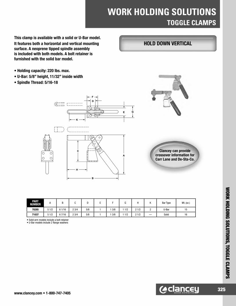
TOGGLE CLAMPSWORK HOLDING SOLUTIONS
www.clancey.com • 1-800-747-7405325
WORK HOLDING SOLUTIONS, TOGGLE CLAM
PS
A
B
H
C
K
FD
E G
HOLD DOWN VERTICALThis clamp is available with a solid or U-Bar model.It features both a horizontal and vertical mounting surface. A neoprene tipped spindle assembly is included with both models. A bolt retainer is furnished with the solid bar model.
• Holding capacity: 220 lbs. max.• U-Bar: 5/8” height, 11/32” inside width• Spindle Thread: 5/16-18
PART NUMBER A B C D E F G H K Bar Type Wt. (oz.)
70285 5 1/2 6 1/16 2 3/4 5/8 1 1 3/8 1 1/2 2 1/2 2 U-Bar 15
71037 5 1/2 6 7/16 2 3/4 5/8 1 1 3/8 1 1/2 2 1/2 — Solid 16
• Solid arm models include a bolt retainer• U-Bar models include 2 flange washers
Clancey can provide crossover information for Carr Lane and De-Sta-Co.
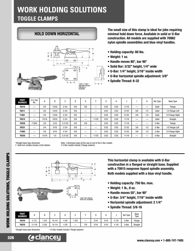
TOGGLE CLAMPSWORK HOLDING SOLUTIONS
www.clancey.com • 1-800-747-7405326
WOR
K HO
LDIN
G SO
LUTI
ONS,
TOG
GLE
CLAM
PS
BB*
JC F
A A*
G
D
E
H
21/64" DIA. HOLESFOR 5/16" SCREWS
y.
HOLD DOWN HORIZONTALThe small size of this clamp is ideal for jobs requiring minimal hold down force. Available in solid or U-Bar construction. All models are supplied with 70962 nylon spindle assemblies and blue vinyl handles.
• Holding capacity: 60 lbs.• Weight: 1 oz.• Handle moves 80°, bar 90°• Solid Bar: 3/32” height, 1/4” wide• U-Bar: 1/4” height, 3/16” inside width• U-Bar horizontal spindle adjustment: 3/8”• Spindle Thread: 8-32
PART NUMBER
S.S. Part No. A B C D E F G H J I K Bar Type Base Type
70210 — 3/4 13/32 2 3/4 5/8 5/8 — 5/32 5/32 11/16 — — Solid Flange
70211 — 3/4 13/32 2 3/4 5/8 — — 5/32 5/32 21/32 3/8 1/2 Solid 1/2 Flange-Left
71001 — 3/4 13/32 2 3/4 5/8 — — 5/32 5/32 21/32 3/8 1/2 Solid 1/2 Flange-Right
70215 — 15/16 19/32 2 3/4 5/8 — 11/32 5/32 5/32 11/16 — — Solid Straight
70230 71002 3/4 5/16 2 21/32 5/8 5/8 — 5/32 5/32 11/16 — — U-Bar Flange
70231 — 3/4 5/16 2 3/4 5/8 — — 5/32 5/32 21/32 3/8 1/2 U-Bar 1/2 Flange-Left
71003 — 3/4 5/16 2 3/4 5/8 — — 5/32 5/32 21/32 3/8 1/2 U-Bar 1/2 Flange-Right
70235 — 15/16 1/2 2 21/32 5/8 — 11/32 5/32 5/32 11/16 — — U-Bar Straight
*Straight base type dimension Note: J dimension goes all the way to end of the U-Bar models• Solid arm models include a bolt retainer • U-Bar models include 2 flange washers
BB*
JC
AA*
G
D
E
H F
K
I
11/64" x 17/64" OBLONG HOLESFOR NO. 8 SCREWS
This horizontal clamp is available with U-Bar construction in a flanged or straight base. Supplied with a 70915 neoprene tipped spindle assembly.Both models supplied with a blue vinyl handle.
• Holding capacity: 750 lbs. max.• Weight: 1 lb., 8 oz.• Handle moves 55°, bar 90°• U-Bar: 3/4” height, 7/16” inside width• Horizontal spindle adjustment: 2 1/4”• Spindle Thread: 3/8-16
PART NUMBER A B C D E F G H J Bar Type Base
Type
70270 2 1/2 1 3/4 10 1/4 1 5/8 1 5/8 — 5/16 5/16 4 1/8 U-Bar Flange
70275 3 1/16 2 3/8 10 1/4 1 5/8 — 7/8 5/16 5/16 4 1/8 U-Bar Straight
*Straight base type dimension • U-Bar models include 2 flange washers

TOGGLE CLAMPSWORK HOLDING SOLUTIONS
www.clancey.com • 1-800-747-7405327
WORK HOLDING SOLUTIONS, TOGGLE CLAM
PS
H
GKJ
D
A
EF
9/32" DIA. HOLESFOR 1/4" SCREWS
B
C
LM
PULL ACTIONThe adjustable hook is ideal for latching, locking or fastening doors, fixtures, pressure vessels, covers, and hatches on storage tanks. The hook bar has a 4” pull and is threaded for convenient adjustment. This clamp is furnished with a blue vinyl handle.
PART NUMBER A B C D E F Drawing
MovementHolding Capacity
(lbs)Wt. (oz.)
70570 1 7/16 3/4 8 5/16 3/4 1 3/8 5/16 4 375 10
70580 1 7/16 3/4 8 5/16 1 1/2 — 5/16 4 375 10
71039 2 5/8 1 13/16 13 1/4 1 1/8 2 3/8 1/2 6 1/8 990 16
AB
DF
E
C
1 1/2"
1/2"
NARROW BASE
13/64" DIA. HOLESFOR NO. 10SCREWS
9/32" DIA2 HOLES FOR 1/4" SCREWS
Note: Longer Hook Lengths Available Upon RequestNote: 70580 is a narrow base 1/2” wide
Ideal for locking and fastening on fixtures. Adjustable stop permits positioning of handle to limit travel once the clamp is installed. 4” drawing movement valuable for a wide range of applications.
PART NUMBER A B C D E F G H J K L M
Holding Capacity
(lbs)Wt. (oz.)
70550 1 3/8 5 11/16 8 5/16 3/4 1 1/4 1 3/4 1/4 5/16 1/8 3/8 1 7/8 1 5/8 375 12
70555 1 7/8 4 5/8 9 5/8 1 1/4 1 25/32 2 1/2 3/8 11/32 1/8 3/8 1 7/8 2 1/16 1,200 18
Clancey can provide crossover information for Carr Lane and De-Sta-Co.

TOGGLE CLAMPSWORK HOLDING SOLUTIONS
www.clancey.com • 1-800-747-7405328
WOR
K HO
LDIN
G SO
LUTI
ONS,
TOG
GLE
CLAM
PS
STRAIGHT LINEThis straight-line extra heavy duty clamp is constructed of malleable iron castings and cold rolled steel. The pivot joints are stainless steel. The mounting base is precision machined for flatness. A blue vinyl handle is included.
• Holding capacity: 500 lbs.• Weight: 14 oz.• Plunger travel: 1 3/16”• Plunger tapped: 5/16-18 X 1 1/8” deep
PART NUMBER B C D E G H J Mounting
Holes
70810 1 4 3/4 1 3/8 1 5/8 5/16 5/16 2 1/4 9/32
70815 1 4 3/4 1 7/16 1 5/16 5/16 5/16 2 1/4 7/32
MOUNTINGHOLES
B
J
C
G
D
E
H
This light duty clamp is equipped with an 8-32tapped plunger. A blue vinyl handle is included.
• Holding capacity: 90 lbs.• Weight: 1.5 oz.• Plunger travel: 5/8”• Plunger tapped: 8-32 X 15/32” deep
PART NUMBER A B C D F G H I J K L M N O
70818 1 7/32 2 21/32 1 1/16 1/2 15/32 1/4 7/32 5/16 5/8 3/32 1 11/32 13/16 1 9/32 7/16
B
3/16 DIA. HOLES FOR 10-32 SCREWS
L
G O
H
J I
D
AM
KNF
CJ
3/16" DIA. HOLES FOR 10-32 SCREWS
Clancey can provide crossover information for Carr Lane and De-Sta-Co.

SPRING LOADED PLUNGERSWORK HOLDING SOLUTIONS
www.clancey.com • 1-800-747-7405329
WORK HOLDING SOLUTIONS, SPRING LOADED PLUNGERS
Inch - Steel & Stainless Steel Tip With Locking Element Without Locking Element
SS PART NUMBER
STEEL PART
NUMBERThread Size A
Initial Force (lbs)
Final Force (lbs) B C D Hex Size E SS PART
NUMBERSTEEL PART
NUMBER
27336 27321 6-32 0.5 1.5 17/32 1/16 0.046 3/64 27031 27221
26936 26921 6-32 1.5 4.5 17/32 1/16 0.046 3/64 27011 26821
27337 27322 8-32 0.7 2.3 5/8 3/32 0.070 5/64 27032 27222
26937 26922 8-32 2.7 7.3 5/8 3/32 0.070 5/64 27012 26822
27338 27323 10-32 1.3 2.7 3/4 1/8 0.093 3/32 27033 27223
26938 26923 10-32 2.9 11.1 3/4 1/8 0.093 3/32 27013 26823
27339 27324 1/4-20 1.0 4.0 1 3/16 0.119 1/8 27034 27224
26939 26924 1/4-20 3.0 13.0 1 3/16 0.119 1/8 27014 26824
27340 27325 1/4-28 1.0 4.0 1 3/16 0.119 1/8 27035 27225
26940 26925 1/4-28 3.0 13.0 1 3/16 0.119 1/8 27015 26825
27341 27326 5/16-18 1.5 4.5 1 3/16 0.135 5/32 27036 27226
26941 26926 5/16-18 3.0 15.0 1 3/16 0.135 5/32 27016 26826
27342 27327 3/8-16 2.8 7.2 1 1/8 3/16 0.186 3/16 27037 27227
26942 26927 3/8-16 5.5 14.5 1 1/8 3/16 0.186 3/16 27017 26827
27343 27328 1/2-13 2.7 9.3 1 1/4 1/4 0.248 1/4 27038 27228
26943 26928 1/2-13 6.6 17.4 1 1/4 1/4 0.248 1/4 27018 26828
27344 27329 5/8-11 3.5 10.5 1 1/2 5/16 0.310 5/16 27039 27229
26944 26929 5/8-11 10.5 25.5 1 1/2 5/16 0.310 5/16 27019 26829
27345 27330 3/4-10 5.5 14.5 1 3/4 5/16 0.374 3/8 27040 27230
26945 26930 3/4-10 6.7 37.3 1 3/4 5/16 0.374 3/8 27020 26830
— 27311* 1-8 10.0 25.0 2 13/32 1/2 0.499 3/8 — 27211*
— 26911* 1-8 16.0 68.0 2 13/32 1/2 0.499 3/8 — 26811*
* Not available in DRIVE construction.NOTE: For easy insertion of Spring Plungers with locking elements, the tapped hole should becountersunk at least .030-.045” (0.76-1.14mm) larger than the major diameter of the plunger.
SPRING PLUNGERS INCHUnlike conventional spring plungers, the body of a Solid Drive Plunger is machined in one piece. The spring is assembled from the top so that there is no need for a set screw. Solid Drive Plungers do not have a set screw which can loosen or separate from the plunger body. The advantage is no lost springs, no need for “easy-out” tools. When adjusting Solid Drive, you can be sure the plunger body is turning and not a set screw.
• Single unit construction• No set screw to separate from plunger body• Better reliability• Steel tips are case hardened steel• Close tolerance between tip and body
• Material: Body – Low Carbon Steel, Black Oxide or 303-Stainless Steel Tip – Steel or Stainless Steel• Thread: 2A-UNC• 3D Solid Models are available in multiple formats• Conforms to TCMA dimensional standards
Plunger tips are color coded to indicate light or heavy force:Silver = Steel Tip, Light ForceBlack = Steel Tip, Heavy Force
Hex drive in rear for spring plunger insertion.

SPRING LOADED PLUNGERSWORK HOLDING SOLUTIONS
www.clancey.com • 1-800-747-7405330
WOR
K HO
LDIN
G SO
LUTI
ONS,
SPR
ING
LOAD
ED P
LUNG
ERS
Inch - Derlin Tip With Locking Element Without Locking Element
SS PART NUMBER
STEEL PART
NUMBERThread Size A
Initial Force (lbs)
Final Force (lbs) B C D Hex Size E SS PART
NUMBERSTEEL PART
NUMBER
30936 30921 6-32 0.5 1.5 17/32 1/16 0.046 3/64 30510 30821
30536 30521 6-32 1.5 4.5 17/32 1/16 0.046 3/64 30500 30421
30937 30922 8-32 0.7 2.3 5/8 3/32 0.070 5/64 30511 30822
30537 30522 8-32 2.7 7.3 5/8 3/32 0.070 5/64 30501 30422
30938 30923 10-32 1.3 2.7 3/4 1/8 0.093 3/32 30512 30823
30538 30523 10-32 2.9 11.1 3/4 1/8 0.093 3/32 30502 30423
30939 30924 1/4-20 1.0 4.0 1 3/16 0.119 1/8 30513 30824
30539 30524 1/4-20 3.0 13.0 1 3/16 0.119 1/8 30503 30424
30940 30925 1/4-28 1.0 4.0 1 3/16 0.119 1/8 30514 30825
30540 30525 1/4-28 3.0 13.0 1 3/16 0.119 1/8 30504 30425
30941 30926 5/16-18 1.5 4.5 1 3/16 0.135 5/32 30515 30826
30541 30526 5/16-18 3.0 15.0 1 3/16 0.135 5/32 30505 30426
30942 30927 3/8-16 2.8 7.2 1 1/8 3/16 0.186 3/16 30516 30827
30542 30527 3/8-16 5.5 14.5 1 1/8 3/16 0.186 3/16 30506 30427
30943 30928 1/2-13 2.7 9.3 1 1/4 1/4 0.248 1/4 30517 30828
30543 30528 1/2-13 6.6 17.4 1 1/4 1/4 0.248 1/4 30507 30428
30944 30929 5/8-11 3.5 10.5 1 1/2 5/16 0.310 5/16 30518 30829
30544 30529 5/8-11 10.5 25.5 1 1/2 5/16 0.310 5/16 30508 30429
30945 — 3/4-10 5.5 14.5 1 /34 5/16 0.374 3/8 30519 —
30545 — 3/4-10 6.7 37.3 1 3/4 5/16 0.374 3/8 30509 —
NOTE: For easy insertion of Spring Plungers with locking elements, the tapped hole should becountersunk at least .030-.045” (0.76-1.14mm) larger than the major diameter of the plunger.
Unlike conventional spring plungers, the body of a Solid Drive Plunger is machined in one piece. The spring is assembled from the top so that there is no need for a set screw. Solid Drive Plungers do not have a set screw which can loosen or separate from the plunger body. The advantage is no lost springs, no need for “easy-out” tools. When adjusting Solid Drive, you can be sure the plunger body is turning and not a set screw.
• Single unit construction• No set screw to separate from plunger body• No need for “easy-out” tools• Better reliability• Steel tips are case hardened steel• Close tolerance between tip and body
SPRING PLUNGERS INCH - DELRIN TIP
• Material: Body – Low Carbon Steel, Black Oxide or 303-Stainless Steel Tip – SDelrin• Thread: 2A-UNC• 3D Solid Models are available in multiple formats • Conforms to TCMA dimensional standards
Plunger tips are color coded to indicate light or heavy force:White = Delrin Tip, Light ForceBlue = Delrin Tip, Heavy Force
Hex drive in rear for spring plunger insertion.

SPRING LOADED PLUNGERSWORK HOLDING SOLUTIONS
www.clancey.com • 1-800-747-7405331
WORK HOLDING SOLUTIONS, SPRING LOADED PLUNGERS
SPRING PLUNGERS METRICUnlike conventional spring plungers, the body of a Solid Drive Plunger is machined in one piece. The spring is assembled from the top so that there is no need for a set screw. Solid Drive Plungers do not have a set screw which can loosen or separate from the plunger body. The advantage is no lost springs, no need for “easy-out” tools. When adjusting Solid Drive, you can be sure the plunger body is turning and not a set screw.
• Material: Body – Low Carbon Steel, Black Oxideor 303-Stainless Steel Tip – Steel or Stainless Steel• Thread: 2A-UNC• 3D Solid Models are available in multiple formats• Conforms to TCMA dimensional standards
The hex drive in the rear of the spring plunger is for plunger insertion.
Metric - Steel & Stainless Steel Tip With Locking Element Without Locking Element
SS PART NUMBER
STEEL PART
NUMBERThread Size A
Initial Force (kg)
Final Force (kg) B C D Hex Size E SS PART
NUMBERSTEEL PART
NUMBER
30890 27250 M4 x 0.7 0.32 1.04 16 2.5 1.78 2.0 30880 27270
30490 26850 M4 x 0.7 1.22 3.29 16 2.5 1.78 2.0 30480 26870
30891 27251 M5 x 0.8 0.59 1.22 19 3.0 2.36 2.5 30881 27271
30491 26851 M5 x 0.8 1.31 5.00 19 3.0 2.36 2.5 30481 26871
30892 27252 M6 x 1.0 0.45 1.80 25 5.0 3.02 3.0 30882 27272
30492 26852 M6 x 1.0 1.35 5.85 25 5.0 3.02 3.0 30482 26872
30893 27253 M8 x 1.25 0.68 2.03 25 5.0 3.43 4.0 30883 27273
30493 26853 M8 x 1.25 1.35 6.75 25 5.0 3.43 4.0 30483 26873
30894 27254 M10 x 1.5 1.26 3.26 29 5.0 4.72 5.0 30884 27274
30494 26854 M10 x 1.5 2.48 6.53 29 5.0 4.72 5.0 30484 26874
30895 27255 M12 x 1.75 1.22 4.21 32 6.0 6.30 6.0 30885 27275
30495 26855 M12 x 1.75 2.97 7.83 32 6.0 6.30 6.0 30485 26875
30897 27257 M16 x 2.0 1.58 4.76 38 8.0 7.87 8.0 30887 27277
30497 26857 M16 x 2.0 4.73 11.48 38 8.0 7.87 8.0 30487 26877
30898 27258 M20 x 2.5 2.50 6.58 44 8.0 9.50 10.0 30888 27278
30498 26858 M20 x 2.5 3.05 16.95 44 8.0 9.50 10.0 30488 26878
NOTE: For easy insertion of Spring Plungers with locking elements, the tapped hole should be countersunk at least .030-.045" (0.76-1.14mm) larger than the major diameter of the plunger.

SPRING LOADED PLUNGERSWORK HOLDING SOLUTIONS
www.clancey.com • 1-800-747-7405332
WOR
K HO
LDIN
G SO
LUTI
ONS,
SPR
ING
LOAD
ED P
LUNG
ERS
SPRING PLUNGERS METRIC - DELRIN TIPUnlike conventional spring plungers, the body of a Solid Drive Plunger is machined in one piece. The spring is assembled from the top so that there is no need for a set screw. Solid Drive Plungers do not have a set screw which can loosen or separate from the plunger body. The advantage is no lost springs, no need for “easy-out” tools. When adjusting Solid Drive, you can be sure the plunger body is turning and not a set screw.
The hex drive in the rear of the spring plunger is for plunger insertion.
• Material: Body – Low Carbon Steel, Black Oxideor 303-Stainless Steel Tip – Derlin• Thread: 2A-UNC• 3D Solid Models are available in multiple formats• Conforms to TCMA dimensional standards
Metric - Derlin Tip With Locking Element Without Locking Element
SS PART NUMBER
Thread Size A
Initial Force (kg)
Final Force (kg) B C D Hex Size E STEEL PART NUMBER
30850 M4 x 0.7 0.32 1.04 16 2.5 1.78 2.0 30870
30450 M4 x 0.7 1.22 3.29 16 2.5 1.78 2.0 30470
30851 M5 x 0.8 0.59 1.22 19 3.0 2.36 2.5 30871
30451 M5 x 0.8 1.31 5.00 19 3.0 2.36 2.5 30471
30852 M6 x 1.0 0.45 1.80 25 5.0 3.02 3.0 30872
30452 M6 x 1.0 1.35 5.85 25 5.0 3.02 3.0 30472
30853 M8 x 1.25 0.68 2.03 25 5.0 3.43 4.0 30873
30453 M8 x 1.25 1.35 6.75 25 5.0 3.43 4.0 30473
30854 M10 x 1.5 1.26 3.26 29 5.0 4.72 5.0 30874
30454 M10 x 1.5 2.48 6.53 29 5.0 4.72 5.0 30474
30855 M12 x 1.75 1.22 4.21 32 6.0 6.30 6.0 30875
30455 M12 x 1.75 2.97 7.83 32 6.0 6.30 6.0 30475
30857 M16 x 2.0 1.58 4.76 38 8.0 7.87 8.0 30877
30457 M16 x 2.0 4.73 11.48 38 8.0 7.87 8.0 30477
30858 M20 x 2.5 2.50 6.58 44 8.0 9.50 10.0 30878
30458 M20 x 2.5 3.05 16.95 44 8.0 9.50 10.0 30478
NOTE: For easy insertion of Spring Plungers with locking elements, the tapped hole should becountersunk at least .030-.045” (0.76-1.14mm) larger than the major diameter of the plunger.

SPRING LOADED PLUNGERSWORK HOLDING SOLUTIONS
www.clancey.com • 1-800-747-7405333
WORK HOLDING SOLUTIONS, SPRING LOADED PLUNGERS
SHORTIE SPRING PLUNGERS INCHShortie Spring Plungers are made to the same quality standards as the Solid Drive. Made with full standard spring plunger stroke in a short body. A screwdriver slot is substituted for the hex drive due to the smaller size.
• Material: Body – Low Carbon Steel, Black Oxide Tip – Delrin or Steel• Thread: 2A-UNC• 3D Solid Models are available in multiple formats • Conforms to TCMA dimensional standards• Thread: 2A-UNC• Available in metric sizes.
Inch - Shortie Spring Plunger With Locking ElementWithout Locking Element
STEEL TIP
DERLIN TIP
Thread Size A
Initial Force (lbs)
Final Force (lbs) B C D STEEL TIP DERLIN
TIP
27101 30701 6-32 0.5 1.5 3/8 1/16 0.046 27001 30601
26701 30301 6-32 0.5 3.5 3/8 1/16 0.046 26601 30201
27102 30702 8-32 0.5 2.0 1/2 3/32 0.070 27002 30602
26702 30302 8-32 0.5 4.0 1/2 3/32 0.070 26602 30202
27103* 30703* 10-32 0.3 3.0 9/16 1/8 0.093 27003* 30603*
26703* 30303* 10-32 0.5 5.0 9/16 1/8 0.093 26603* 30203*
27104 30704 1/4-20 0.3 3.5 5/8 3/16 0.119 27004 30604
26704 30304 1/4-20 0.5 6.0 5/8 3/16 0.119 26604 30204
27105 30705 5/16-18 0.5 4.5 5/8 3/16 0.135 27005 30605
26705 30305 5/16-18 0.5 10.0 5/8 3/16 0.135 26605 30205
27106 30706 3/8-16 1.5 7.5 11/16 3/16 0.186 27006 30606
26706 30306 3/8-16 1.0 12.0 11/16 3/16 0.186 26606 30206
27107 30707 1/2-13 1.7 8.5 13/16 1/4 0.248 27007 30607
26707 30307 1/2-13 2.5 15.0 13/16 1/4 0.248 26607 30207
27108 30708 5/8-11 2.0 10.5 1 1/8 5/16 0.310 27008 30608
26708 30308 5/8-11 3.5 26.0 1 1/8 5/16 0.310 26608 30208
*Thread: UNF
SHORTIE SPRING PLUNGERS STAINLESS STEEL (SHORT TRAVEL)
Inch - Stainless Steel With Locking ElementPART NUMBER
Thread Size A
Force (lbs)B C DSTEEL
TIPDERLIN
TIP Initial Final
27601 27621 8-32 .5 1.5 7/16 .052 .070
27602 27622 8-32 1.5 4.75 7/16 .052 .070
27603* 27623* 8-36 .5 1.5 7/16 .052 .070
27604* 27624* 8-36 1.5 4.75 7/16 .052 .070
27605 27625 10-32 .75 2.5 15/32 .065 .093
27606 27626 10-32 1.75 6.25 15/32 .065 .093
27607 27627 1/4-20 1.0 3.5 17/32 .078 .119
27608 27628 1/4-20 3.0 10.5 17/32 .078 .119
27609 27629 5/16-18 1.0 4.0 9/16 .084 .135
27610 27630 5/16-18 3.75 15.5 9/16 .084 .135
27611 27631 3/8-16 1.5 5.0 5/8 .110 .186
27612 27632 3/8-16 4.5 18.5 5/8 .110 .186
27613 27633 1/2-13 1.75 5.5 3/4 .151 .248
27614 27634 1/2-13 5.0 28.0 3/4 .151 .248
The slot in the rear of the Shortie SpringPlunger is for insertion.
• Material: Body, 303 Stainless Spring, 303 Stainless Nose, Stainless or Delrin• Thread: 2A-UNC
*Thread: UNF

SPRING LOADED PLUNGERSWORK HOLDING SOLUTIONS
www.clancey.com • 1-800-747-7405334
WOR
K HO
LDIN
G SO
LUTI
ONS,
SPR
ING
LOAD
ED P
LUNG
ERS
SHORTIE SPRING PLUNGERS METRICShortie Spring Plungers are made to the same quality standards as the Solid Drive. Made with full standard spring plunger stroke in a short body.A screwdriver slot is substituted for the hex drive due to the smaller size.
Metric - Shortie Spring Plunger With Locking ElementSTEEL
TIPDERLIN
TIP Thread Size A Initial Force (kg)
Final Force (kg) B C D
27170 30770 M4 x 0.7 0.23 0.91 13.0 2.5 1.78
26770 30370 M4 x 0.7 0.23 1.81 13.0 2.5 1.78
27171 30771 M5 x 0.8 0.14 1.36 14.5 3.0 2.36
26771 30371 M5 x 0.8 0.23 2.27 14.5 3.0 2.36
27172 30772 M6 x 1.0 0.14 1.59 16.0 4.7 3.02
26772 30372 M6 x 1.0 0.23 2.72 16.0 4.0 3.02
27173 30773 M8 x 1.25 0.23 2.04 16.0 5.0 3.43
26773 30373 M8 x 1.25 0.23 4.54 16.0 5.0 3.43
27174 30774 M10 x 1.5 0.68 3.4 17.5 4.7 4.72
26774 30374 M10 x 1.5 0.46 5.44 17.5 5.0 4.72
27175 30775 M12 x 1.75 0.77 3.86 20.5 6.5 6.30
26775 30375 M12 x 1.75 1.13 6.80 20.5 6.5 6.30
27177 30777 M16 x 2.0 0.91 4.76 28.5 8.0 7.87
26777 30377 M16 x 2.0 1.59 11.79 28.5 8.0 7.87
PLUNGER WRENCHESIMPORTANT: It is not recommended that a screwdriver be used to insert ball or spring plungers from the ball or plunger end. The tip of the screwdriver will force the ball or tip of the plunger below the surface of the end of the plunger. This may compress the spring to a solid, causing possible damage to the spring plunger. It is recommended that a Plunger Wrench be used or that a slot be ground in the end of a screwdriver to clear the height of the ball or tip for each size ball or plunger used.
PART NUMBERThread Size of Plungers
Inch Metric
27501 6-32 —
27502 8-32 M4
27503 10-32 M5
27504 1/4-20 M6
27505 5/16-18 M8
27506 3/8-16 M10
27507 1/2-13 M12
27508 5/8-11 M16
27509 3/4-10 M20
27510 1-8 M25
• Material: Body – Low Carbon Steel, Black Oxide Tip – Delrin or Steel• Thread: Class 6g• 3D Solid Models are available in multiple formats from • Plunger Tips are color coded to indicate light or heavy force. White = Light Force Blue = Heavy Force

SPRING LOADED PLUNGERSWORK HOLDING SOLUTIONS
www.clancey.com • 1-800-747-7405335
WORK HOLDING SOLUTIONS, SPRING LOADED PLUNGERS
BALL PLUNGERS INCH
Inch – Coarse Thread (UNC) With Locking Element Without Locking Element
SS PART NUMBER
STEEL PART NUMBER
Thread Size A
Initial Force (lbs)
Final Force (lbs) B C D SS PART
NUMBERSTEEL PART
NUMBER
11102 10927 5-40 0.25 0.75 1/4 0.020 0.062 11002 10827
11201 10701 10-24 0.50 1.50 33/64 0.025 0.093 11221 10721
11211 10711 10-24 1.50 3.00 33/64 0.025 0.093 11231 10731
11202 10702 10-24 2.00 5.00 33/64 0.025 0.093 11222 10722
11108 10904 1/4-20 2.00 4.00 17/32 0.035 0.125 11008 10804
11109 10905 1/4-20 3.00 7.00 17/32 0.035 0.125 11009 10805
11110 10906 1/4-20 4.00 12.00 17/32 0.035 0.125 11010 10806
11111 10907 5/16-18 2.00 4.50 37/64 0.040 0.156 11011 10807
11112 10908 5/16-18 4.00 9.00 37/64 0.040 0.156 11012 10808
11113 10909 5/16-18 6.00 17.00 37/64 0.040 0.156 11013 10809
11114 10910 3/8-16 2.50 5.00 5/8 0.048 0.187 11014 10810
11115 10911 3/8-16 5.00 10.00 5/8 0.048 0.187 11015 10811
11116 10912 3/8-16 6.00 21.00 5/8 0.048 0.187 11016 10812
11117 10913 1/2-13 3.00 6.00 3/4 0.072 0.281 11017 10813
11118 10914 1/2-13 6.00 12.00 3/4 0.072 0.281 11018 10814
11119 10915 1/2-13 6.00 30.00 3/4 0.072 0.281 11019 10815
11120 10916 5/8-11 4.50 9.00 1 0.096 0.375 11020 10816
11121 10917 5/8-11 9.00 18.00 1 0.096 0.375 11021 10817
11122 10918 5/8-11 7.00 50.00 1 0.096 0.375 11022 10818
Inch – Fine Thread (UNF) With Locking Element Without Locking Element
SS PART NUMBER
STEEL PART NUMBER
Thread Size A Initial Force (lbs) Final Force
(lbs) B C D SS PART NUMBER
STEEL PART NUMBER
11101 10926 4-48 0.12 0.50 3/16 0.020 0.062 11001 10826
11103 10928 6-40 0.50 1.00 5/16 0.023 0.078 11003 10828
11104 10929 8-36 0.50 1.25 11/32 0.025 0.093 11004 10829
11105 10901 10-32 0.50 1.50 33/64 0.025 0.093 11005 10801
11106 10902 10-32 1.50 3.00 33/64 0.025 0.093 11006 10802
11107 10903 10-32 2.00 5.00 33/64 0.025 0.093 11007 10803
11203 10703 1/4-28 2.0 4.0 17/32 0.035 0.125 11223 10723
11212 10712 1/4-28 3.0 7.0 17/32 0.035 0.125 11232 10732
11204 10704 1/4-28 4.0 12.0 17/32 0.035 0.125 11224 10724
11205 10705 5/16-24 2.0 4.5 37/64 0.040 0.156 11225 10725
11213 10713 5/16-24 4.0 9.0 37/64 0.040 0.156 11233 10733
11206 10706 5/16-24 6.0 17.0 37/64 0.040 0.156 11226 10726
11207 10707 3/8-24 2.5 5.0 5/8 0.048 0.187 11227 10727
11214 10714 3/8-24 5.0 10.0 5/8 0.048 0.187 11234 10734
11208 10708 3/8-24 6.0 21.0 5/8 0.048 0.187 11228 10728
11209 10709 1/2-20 3.0 6.0 3/4 0.072 0.281 11229 10729
11215 10715 1/2-20 6.0 12.0 3/4 0.072 0.281 11235 10735
11210 10710 1/2-20 6.0 30.0 3/4 0.072 0.281 11230 10730
• Body Material: Low Carbon Steel, or 303 Stainless Steel• Ball Material: Stainless, 440• Spring Material: Stainless, 17-7 PH• Finish: Black Oxide on Body• Thread: 2A• Dimensionally conforms to TCMA standards• 3D Solid Models are available in multiple formats
NOTE: For easy insertion of BallPlungers with locking elements, the tapped hole should be countersunk at least .030-.045 (0.76-1.14mm) larger than the major diameter of the plunger.

SPRING LOADED PLUNGERSWORK HOLDING SOLUTIONS
www.clancey.com • 1-800-747-7405336
WOR
K HO
LDIN
G SO
LUTI
ONS,
SPR
ING
LOAD
ED P
LUNG
ERS
Metric – Steel and Stainless Steel With Locking Element Without Locking Element
SS PART NUMBER
STEEL PART NUMBER Thread Size A Initial Force
(kg)Final Force
(kg) B C D SS PART NUMBER
STEEL PART NUMBER
11051 10971 M4 x 0.7 0.23 0.56 9.00 0.60 2.38 10951 10871
11052 10972 M5 x 0.8 0.23 0.68 13.00 0.60 2.38 10952 10872
11053 10973 M5 x 0.8 0.68 1.35 13.00 0.60 2.38 10953 10873
11054 10974 M5 x 0.8 0.90 2.25 13.00 0.60 2.38 10954 10874
11055 10975 M6 x 1.0 0.90 1.80 13.50 0.90 3.18 10955 10875
11056 10976 M6 x 1.0 1.35 3.15 13.50 0.90 3.18 10956 10876
11057 10977 M6 x 1.0 1.80 5.40 13.50 0.90 3.18 10957 10877
11058 10978 M8 x 1.25 0.90 2.03 15.00 1.00 3.97 10958 10878
11059 10979 M8 x 1.25 1.80 4.05 15.00 1.00 3.97 10959 10879
11060 10980 M8 x 1.25 2.70 7.65 15.00 1.00 3.97 10960 10880
11061 10981 M10 x 1.5 1.13 2.25 16.00 1.20 4.76 10961 10881
11062 10982 M10 x 1.5 2.25 4.50 16.00 1.20 4.76 10962 10882
11063 10983 M10 x 1.5 2.70 9.45 16.00 1.20 4.76 10963 10883
11064 10984 M12 x 1.75 1.35 2.70 19.00 2.00 7.14 10964 10884
11065 10985 M12 x 1.75 2.70 5.40 19.00 2.00 7.14 10965 10885
11066 10986 M12 x 1.75 2.70 13.50 19.00 2.00 7.14 10966 10886
11067 10987 M16 x 2.0 2.00 4.00 25.40 2.40 9.50 10967 10887
11068 10988 M16 x 2.0 4.00 8.10 25.40 2.40 9.50 10968 10888
11069 10989 M16 x 2.0 3.10 22.70 25.40 2.40 9.50 10969 10889
• Body Materials: Low Carbon Steel, Black Oxide or 303 Stainless Steel• Ball: Stainless, 440• Spring: Stainless, 17-7 PH• Thread: Class 6g• 3D Solid Models are available in multiple formats
BALL PLUNGERS METRIC
NOTE: For easy insertion ofBall Plungers with locking elements, the tapped hole should be countersunk at least .030-.045 (0.76-1.14mm) larger than the major diameter of the plunger.
PRESS FIT PLUNGERS
Heavy ForceForce (lbs)
A B C Ball Dia.D
E FPART NUMBER STAINLESS STEEL PART NUMBER Initial Final
10832 11032 2 5 .188 .405 .058 .156 .250 .035
10834 11034 3 7 .250 .481 .070 .187 .312 .044
10836 11036 5 14 .375 .785 .110 .312 .500 .078
10838 11038 8 18 .500 1.130 .161 .437 .688 .088
Light ForceForce (lbs)
A B C Ball Dia.D
E FPART NUMBER STAINLESS STEEL PART NUMBER Initial Final
10831 11031 1 2.5 .188 .405 .058 .156 .250 .035
10833 11033 1.5 3.5 .250 .481 .070 .187 .312 .044
10835 11035 2.5 7 .375 .785 .110 .312 .500 .078
10837 11037 4 9 .500 1.130 .161 .437 .688 .088
• Body Material: Low Carbon Steel• Ball Material: Stainless, 400• Spring Material: 17-7 PH• Finish: Black Oxide on Body

SPRING LOADED PLUNGERSWORK HOLDING SOLUTIONS
www.clancey.com • 1-800-747-7405337
WORK HOLDING SOLUTIONS, SPRING LOADED PLUNGERS
RETRACTABLE PLUNGERS HAND RETRACTABLE LOCKING STYLE
• Improved design allows plunger pin to be locked in fully retracted position
• Used in machining applications as positioners, loading pins or indexing devices
• Plunger pin has slight taper on end to assure easy alignment
• Zinc Plated Carbon Steel, 303 Stainless Steel• Phenolic Nose Prevents Marring of Soft Material• Supplied with locking element
Inch – Hand Retractable Locking Style Plungers
STEEL PART
NUMBER
STEEL PHENOLIC NOSE PART
NUMBER
STAINLESS STEEL PART
NUMBER
STAINLESS STEEL PHENO-LIC NOSE PART
NUMBERA
End Force (lbs)B C +.001
-.002D
E F Net Wt. (lbs) 10 pcs.Start Full
27426 27523 27826 27527 1/4-20 0.5 2.5 1/2 1/8 .124 1/4 1/2 .3
27421 27515 27821 27519 1/4-20 1.0 5.0 1/2 1/8 .124 1/4 1/2 .3
27427 27524 27827 27528 5/16-18 0.75 3.0 5/8 3/16 .155 9/32 5/8 .5
27422 27516 27822 27520 5/16-18 1.5 6.0 5/8 3/16 .155 9/32 5/8 .5
27428 27525 27828 27529 3/8-16 0.75 4.0 3/4 7/32 .186 5/16 3/4 .7
27423 27517 27823 27521 3/8-16 1.5 8.0 3/4 7/32 .186 5/16 3/4 .7
27429 27526 27829 27530 1/2-13 1.25 5.0 7/8 1/4 .249 3/8 1” 1.3
27424 27518 27824 27522 1/2-13 2.5 10.0 7/8 1/4 .249 3/8 1” 1.3
Metric – Hand Retractable Locking Style Plungers
STEEL PART
NUMBER
Class 6g ISOA
End Force (kg)B C +.025
-.050D
E F Net Wt. (lkg) 10 pcs.Start Full
27555 M6x1.0 0.225 1.135 12.50 3.17 3 6.3 12.7 .16
27551 M6x1.0 0.4 2.27 12.50 3.17 3 6.3 12.7 .16
27556 M8x1.25 0.34 1.36 16.00 4.75 4 7.0 15.8 .27
27552 M8x1.25 0.68 2.72 16.00 4.75 4 7.0 15.8 .27
27557 M10x1.5 0.34 1.815 19.00 5.50 5 7.9 19.0 .38
27553 M10x1.5 0.68 3.63 19.00 5.50 5 7.9 19.0 .38
27558 M12x1.75 0.565 2.27 22.00 6.35 6 9.4 25.4 .7
27554 M12x1.75 1.13 4.54 22.00 6.35 6 9.4 25.4 .7

SPRING LOADED PLUNGERSWORK HOLDING SOLUTIONS
www.clancey.com • 1-800-747-7405338
WOR
K HO
LDIN
G SO
LUTI
ONS,
SPR
ING
LOAD
ED P
LUNG
ERS
RETRACTABLE PLUNGERS PULL RING STYLE
• For use in application with limited space• Slight taper on end of plunger for easy alignment
Pull Ring – Short Locking Plungers
STEEL PART
NUMBER
STEEL PHENOLIC NOSE PART
NUMBER
STAINLESS STEEL PART
NUMBER
STAINLESS STEEL PHENO-LIC NOSE PART
NUMBERA
End Force (lbs)B C +.001
-.002D
E F G H O.DNet Wt.
(lbs) 10 pcs.Start Full
27441 27804 27800 27808 1/4-20 0.50 2.0 7/16 3/16 .156 1/4 1/32 5/32 9/32 3/4 .1
27442 27805 27801 27809 3/8-16 0.75 3.0 5/8 9/32 .250 3/8 1/8 3/16 7/16 3/4 .2
27443 27806 27802 27810 1/2-13 1.00 4.0 13/16 3/8 .312 1/2 5/32 1/4 9/16 1 .43
27444 27807 27803 27811 5/8-11 1.25 5.0 1 7/16 .375 5/8 5/32 5/16 11/16 1 .8
• For use in application with limited space• Slight taper on end of plunger for easy alignment• Turn ring to lock and extend plunger
Pull Ring – Short Locking Plungers
STEEL PART
NUMBER
STEEL PHENOLIC NOSE PART
NUMBER
STAINLESS STEEL PART
NUMBER
STAINLESS STEEL PHENO-LIC NOSE PART
NUMBERA
End Force (lbs)B C +.001
-.002D
E F GNet Wt.
(lbs) 10 pcs.Start Full
27446 27815 27812 27818 1/4-20 1.0 2.5 5/8 1/4 13/16 5/16 .156 1-1/8 .15
27447 27816 27813 27819 3/8-16 2.0 4.0 1 3/8 1-1/4 7/16 .233 1-11/16 .43
27448 27817 27814 27820 1/2-13 2.5 5.0 1-1/4 1/2 1-7/16 9/16 .312 2 .9

SPRING LOADED PLUNGERSWORK HOLDING SOLUTIONS
www.clancey.com • 1-800-747-7405339
WORK HOLDING SOLUTIONS, SPRING LOADED PLUNGERS
RETRACTABLE PLUNGERS L HANDLE HAND RETRACTABLE LOCKING STYLE
• Hand retractable for easy removal or insertion• Turn handle to unlock and extend plunger• Slight taper on end of plunger for easy alignment• Locking element standard on all sizes
Locking Plungers – Long Reach – Standard Length
STEEL PART
NUMBER
STEEL PHENOLIC NOSE PART
NUMBER
STAINLESS STEEL PART
NUMBER
STAINLESS STEEL PHENO-LIC NOSE PART
NUMBERA
End Force (lbs) +.001-.002
BC D E F G H J
Net Wt. (lbs)
10 pcs.Start Full
27436 27851 27836 27855 1/4-20 .50 2.5 .156 3/8 5/8 1-1/4 1/4 5/8 3/32 1/2 .15
27437 27852 27837 27856 3/8-16 .75 3.75 .250 9/16 1-1/16 2 3/8 15/16 9/64 11/16 .53
27438 27853 27838 27857 1/2-13 1.0 5.0 .312 3/4 1-1/8 2-1/8 1/2 1-1/4 3/16 3/4 1.03
27439 27854 27839 27858 5/8-11 1.0 5.0 .375 1 1-3/4 3 5/8 1-5/16 3/16 1-1/16 2.23
Locking Plungers – Long Reach – Short Length
STEEL PART
NUMBER
STEEL PHENOLIC NOSE PART
NUMBER
STAINLESS STEEL PART
NUMBER
STAINLESS STEEL PHENO-LIC NOSE PART
NUMBERA
End Force (lbs) +.001-.002
BC D E F G H J
Net Wt. (lbs)
10 pcs.Start Full
27416 27859 27867 27863 1/4-20 .125 .50 .156 3/16 7/16 3/4 1/4 9/16 3/32 1/4 .1
27417 27860 27868 27864 3/8-16 .25 1.25 .250 5/16 5/8 1-1/8 3/8 3/4 9/64 3/8 .3
27418 27861 27869 27865 1/2-13 .50 2.0 .312 13/32 7/8 1-1/2 1/2 1 3/16 1/2 .7
27419 27862 27870 27866 5/8-11 .75 2.5 .375 1/2 1-1/8 1-7/8 5/8 1-3/16 3/16 5/8 1.35
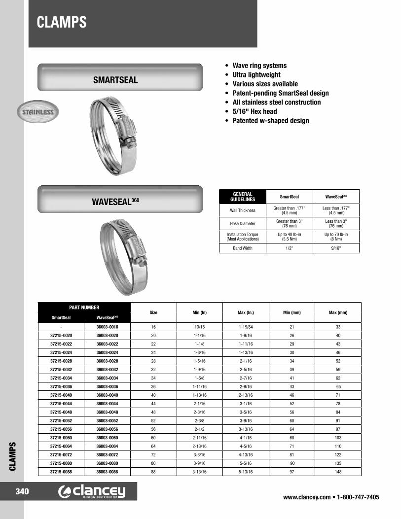
www.clancey.com • 1-800-747-7405340
CLAMPSCL
AMPS
SMARTSEAL
• Wave ring systems• Ultra lightweight• Various sizes available• Patent-pending SmartSeal design• All stainless steel construction• 5/16" Hex head• Patented w-shaped design
WAVESEAL360GENERAL
GUIDELINES SmartSeal WaveSeal360
Wall Thickness Greater than .177" (4.5 mm)
Less than .177" (4.5 mm)
Hose Diameter Greater than 3" (76 mm)
Less than 3" (76 mm)
Installation Torque (Most Applications)
Up to 48 lb-in (5.5 Nm)
Up to 70 lb-in (8 Nm)
Band Width 1/2" 9/16"
PART NUMBERSize Min (In) Max (In.) Min (mm) Max (mm)
SmartSeal WaveSeal360
- 36003-0016 16 13/16 1-19/64 21 33
37215-0020 36003-0020 20 1-1/16 1-9/16 26 40
37215-0022 36003-0022 22 1-1/8 1-11/16 29 43
37215-0024 36003-0024 24 1-3/16 1-13/16 30 46
37215-0028 36003-0028 28 1-5/16 2-1/16 34 52
37215-0032 36003-0032 32 1-9/16 2-5/16 39 59
37215-0034 36003-0034 34 1-5/8 2-7/16 41 62
37215-0036 36003-0036 36 1-11/16 2-9/16 43 65
37215-0040 36003-0040 40 1-13/16 2-13/16 46 71
37215-0044 36003-0044 44 2-1/16 3-1/16 52 78
37215-0048 36003-0048 48 2-3/16 3-5/16 56 84
37215-0052 36003-0052 52 2-3/8 3-9/16 60 91
37215-0056 36003-0056 56 2-1/2 3-13/16 64 97
37215-0060 36003-0060 60 2-11/16 4-1/16 68 103
37215-0064 36003-0064 64 2-13/16 4-5/16 71 110
37215-0072 36003-0072 72 3-3/16 4-13/16 81 122
37215-0080 36003-0080 80 3-9/16 5-5/16 90 135
37215-0088 36003-0088 88 3-13/16 5-13/16 97 148
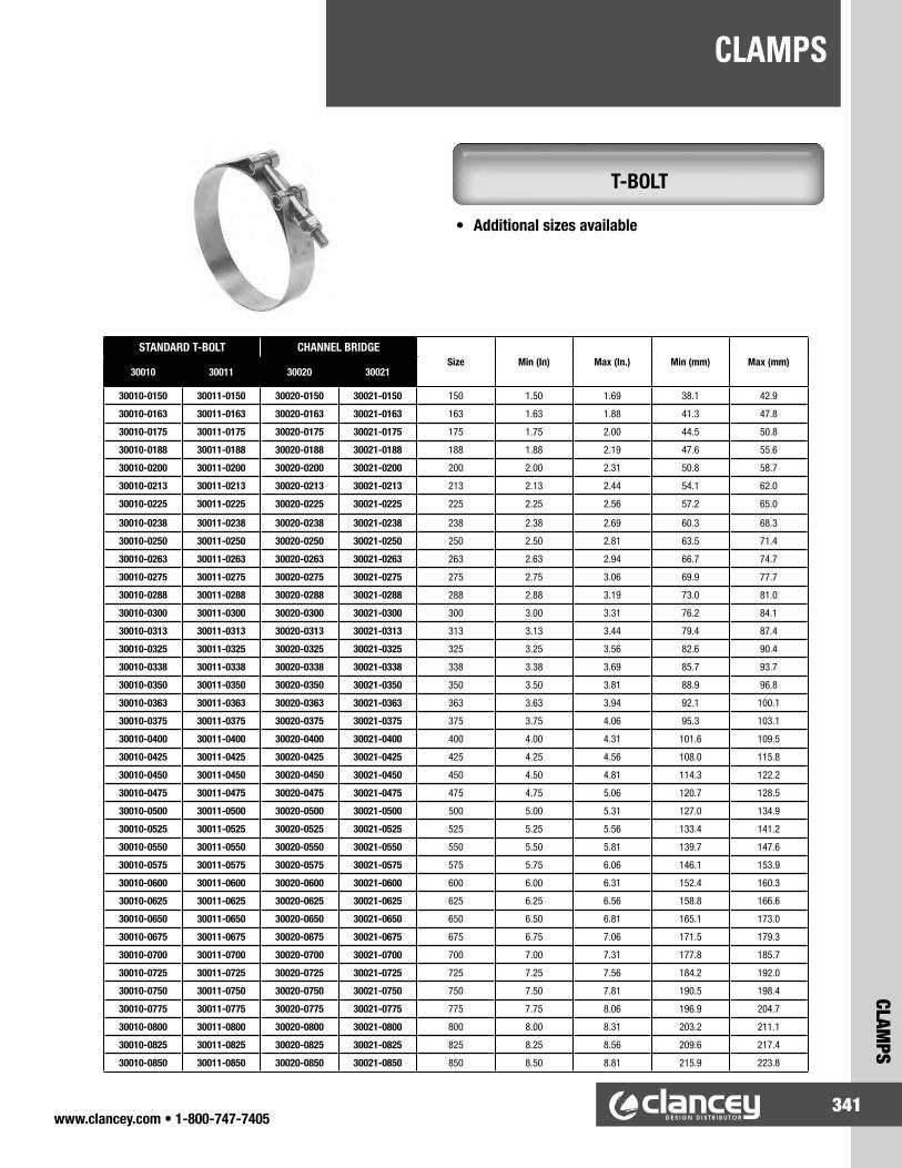
www.clancey.com • 1-800-747-7405341
CLAMPS
CLAMPS
T-BOLT
STANDARD T-BOLT CHANNEL BRIDGESize Min (In) Max (In.) Min (mm) Max (mm)
30010 30011 30020 30021
30010-0150 30011-0150 30020-0150 30021-0150 150 1.50 1.69 38.1 42.9
30010-0163 30011-0163 30020-0163 30021-0163 163 1.63 1.88 41.3 47.8
30010-0175 30011-0175 30020-0175 30021-0175 175 1.75 2.00 44.5 50.8
30010-0188 30011-0188 30020-0188 30021-0188 188 1.88 2.19 47.6 55.6
30010-0200 30011-0200 30020-0200 30021-0200 200 2.00 2.31 50.8 58.7
30010-0213 30011-0213 30020-0213 30021-0213 213 2.13 2.44 54.1 62.0
30010-0225 30011-0225 30020-0225 30021-0225 225 2.25 2.56 57.2 65.0
30010-0238 30011-0238 30020-0238 30021-0238 238 2.38 2.69 60.3 68.3
30010-0250 30011-0250 30020-0250 30021-0250 250 2.50 2.81 63.5 71.4
30010-0263 30011-0263 30020-0263 30021-0263 263 2.63 2.94 66.7 74.7
30010-0275 30011-0275 30020-0275 30021-0275 275 2.75 3.06 69.9 77.7
30010-0288 30011-0288 30020-0288 30021-0288 288 2.88 3.19 73.0 81.0
30010-0300 30011-0300 30020-0300 30021-0300 300 3.00 3.31 76.2 84.1
30010-0313 30011-0313 30020-0313 30021-0313 313 3.13 3.44 79.4 87.4
30010-0325 30011-0325 30020-0325 30021-0325 325 3.25 3.56 82.6 90.4
30010-0338 30011-0338 30020-0338 30021-0338 338 3.38 3.69 85.7 93.7
30010-0350 30011-0350 30020-0350 30021-0350 350 3.50 3.81 88.9 96.8
30010-0363 30011-0363 30020-0363 30021-0363 363 3.63 3.94 92.1 100.1
30010-0375 30011-0375 30020-0375 30021-0375 375 3.75 4.06 95.3 103.1
30010-0400 30011-0400 30020-0400 30021-0400 400 4.00 4.31 101.6 109.5
30010-0425 30011-0425 30020-0425 30021-0425 425 4.25 4.56 108.0 115.8
30010-0450 30011-0450 30020-0450 30021-0450 450 4.50 4.81 114.3 122.2
30010-0475 30011-0475 30020-0475 30021-0475 475 4.75 5.06 120.7 128.5
30010-0500 30011-0500 30020-0500 30021-0500 500 5.00 5.31 127.0 134.9
30010-0525 30011-0525 30020-0525 30021-0525 525 5.25 5.56 133.4 141.2
30010-0550 30011-0550 30020-0550 30021-0550 550 5.50 5.81 139.7 147.6
30010-0575 30011-0575 30020-0575 30021-0575 575 5.75 6.06 146.1 153.9
30010-0600 30011-0600 30020-0600 30021-0600 600 6.00 6.31 152.4 160.3
30010-0625 30011-0625 30020-0625 30021-0625 625 6.25 6.56 158.8 166.6
30010-0650 30011-0650 30020-0650 30021-0650 650 6.50 6.81 165.1 173.0
30010-0675 30011-0675 30020-0675 30021-0675 675 6.75 7.06 171.5 179.3
30010-0700 30011-0700 30020-0700 30021-0700 700 7.00 7.31 177.8 185.7
30010-0725 30011-0725 30020-0725 30021-0725 725 7.25 7.56 184.2 192.0
30010-0750 30011-0750 30020-0750 30021-0750 750 7.50 7.81 190.5 198.4
30010-0775 30011-0775 30020-0775 30021-0775 775 7.75 8.06 196.9 204.7
30010-0800 30011-0800 30020-0800 30021-0800 800 8.00 8.31 203.2 211.1
30010-0825 30011-0825 30020-0825 30021-0825 825 8.25 8.56 209.6 217.4
30010-0850 30011-0850 30020-0850 30021-0850 850 8.50 8.81 215.9 223.8
• Additional sizes available

www.clancey.com • 1-800-747-7405342
CLAMPSCL
AMPS
MICROGEAR
POW'R GEAR
62J 359 62M 345/MAH/MAS 62P 325/MH Size Min (In) Max
(In.)Min
(mm)Max (mm)
62J04 359-004 62604(1) 345-004 6204(3) 325-004 04 1/4 5/8 6 16
- - 62M05 345-005 62P05 325-005 05 7/16 11/16 11 17
62J06 359-006 62606(2) 345-006 6206(4) 325-006 06 5/16 7/8 8 22
62J08 - 62M08 345-008 62P08 325-008 08 7/16 1 11 25
62J10 - 62M10 345-010 62P10 325-010 10 1/2 1-1/16 13 27
- - 62M12 345-012 62P12 325-012 12 9/16 1-1/4 14 32
- - 62M16 345-016 62P16 325-016 16 11/16 1-1/2 18 38
- - 62M20 t345-020 62P20 325-020 20 3/4 1-3/4 19 44
- - 62M24 345-024 62P24 325-024 24 1 2 26 51
- - 62M28 345-028 62P28 325-028 28 1-1/4 2-1/4 32 57
- - 62M30 345-030 62P30 325-030 30 1-3/8 2-3/8 35 60
- - 62M32 345-032 62P32 325-032 32 1-1/2 2-1/2 38 63
- - 62M36 345-036 62P36 325-036 36 1-3/4 2-3/4 45 70
- - 62M44 345-044 62P44 325-044 44 2-1/4 3-1/4 57 82
- - 62M48 345-048 62P48 325-048 48 2-1/2 3-1/2 64 89
Micro-Gear clamps are tiny, tough and precision-engineered to use in small hose applications including emission control, fuel lines and vacuum hoses. Slim, 5/16" bands and low profile housings allow installation in confined areas.
60 M850 6P 6L M843 6M Size Min (In) Max (In.)
Min (mm)
Max (mm)
60175 850-175 6P175 6L175 843-175 6M175 175 1 1-3/4 25 45
60200 850-200 6P200 6L200 843-200 6M200 212 1-1/4 2-1/8 32 54
60250 850-250 6P250 6L250 843-250 6M250 262 1-3/4 2-5/8 45 66
60300 850-300 6P300 6L300 843-300 6M300 312 2-1/4 3-1/8 57 79
60350 850-350 6P350 6L350 843-350 6M350 362 2-3/4 3-5/8 70 92
60400 850-400 6P400 6L400 843-400 6M400 412 3-1/4 4-1/8 83 105
60450 850-450 6P450 6L450 843-450 6M450 462 3-3/4 4-5/8 95 117
60500 850-500 6P500 6L500 843-500 6M500 512 4-1/4 5-1/8 108 130
60550 850-550 6P550 6L550 843-550 6M550 562 4-3/4 5-5/8 121 143
60600 850-600 6P600 6L600 843-600 6M600 612 5-1/4 6-1/8 133 155
60650 850-650 6P650 6L650 843-650 6M650 662 5-3/4 6-5/8 146 168
60700 850-700 6P700 6L700 843-700 6M700 712 6-1/4 7-1/8 159 181
60750 850-750 6P750 6L750 843-750 6M750 762 6-3/4 7-5/8 172 193
60800 850-800 6P800 6L800 843-800 6M800 812 7-1/4 8-1/8 184 206
60850 850-850 6P850 6L850 843-850 6M850 862 7-3/4 8-5/8 197 219
60900 850-900 6P900 6L900 843-900 6M900 912 8-1/4 9-1/8 210 232
Pow’r-Gear high performance clamps are designed for high vibration and stubborn leakage applications such as industrial machinery, heavy truck, farm and off-road equipment engines. Pow’r-Gears feature an extra wide 5/8" heavy gauge band and a wide profile housing that provides maximum engagement of screw threads to band.

HYDRAULIC HOSE & ADAPTERS
www.clancey.com • 1-800-747-7405343
HYDRAULIC HOSE & ADAPTERS
• Hose• Custom hose assemblies• Pipe• Flare• SAE O-Ring• Flat face adapters• Metric adapters• Live working swivels
• Steel hose fittings• Brass barbs and adapters• Quick disconnect• Ball valve (high and low
pressure)• Flange adapters and anchor
flange pad fittings for any configuration in Code 61 and Code 62 applications.
Clancey Design Distributor has chosen to partner with a leader in the hydraulic industry to offer our customers a competitive source for hose, hose ends and, hydraulic adapters. This partnership allows us to provide our customers with cost competitive pricing and time saving solutions like kitting.
Items offered include:

www.clancey.com • 1-800-747-7405344
INDEXIN
DEX
Product Class Description Pages
01- Flush Cup Latch 62-6302- Magnetic Catch 116-117
03XXXX Gas Springs 239-24005XXXX Gas Springs 23906XXXX Gas Springs 239
07- Over Center Latch - Living Hinge 13409- Captive Screw, Fast Lead - Small 199-20010- Drive Rivet 220
10XX Mounting Bracket, Tubing 30610XX Bushing, Strain Relief 313-314, 317
10XXX Spring Loaded Plunger 335-3361116- Rivet, Miniature 22411XXX Spring Loaded Plunger 335-33611XX Bushing, Strain Relief 313-314, 31712- Installation Tool 20012- Captive Screw, Fast Lead - Medium 201-202
12XX Bushing, Strain Relief 313, 31713XX Hole Plug 23413XX Bushing, Strain Relief 31614- Ejector Spring 192
14XX Bushing, Strain Relief 314, 31614XXXX Gas Springs 239-24015XXXX Gas Springs 239150XXX Grab Handle, Composite 275
15XX Bushing, Strain Relief 314, 31716XX Hole Plug 23316XX Bushing, Strain Relief 317
16XXXX Gas Springs 239-24217- Captive Screw, Fast Lead - Large 203-204
17XX Hole Plug 23317XX- Rivet, Micro Tuflok 22318XX Bushing, Strain Relief 314-31519- Swell Latch 80-82
19XX Cord Clip, Various 303201- Plasti Rivet 22120XX Bushing, Snap 318-320
20XXXX Gas Springs 243212- Plasti Grommet 230-231215- Stalok Fastener 229217- Encloz Grommet 23121XX Hole Plug 23221XX Bushing, Snap 318-320220- Cord Clip, Various 301, 304226- Plasti Rivet 22122XX Bushing, Snap 319-321231- Plasti Rivet 221232- Cord Clip, Purse Lock 301, 303236- Rivet, Rachet or Snap 22423XX Bushing, Snap 318
23XXXX Gas Springs 24324- Flush T-Handle Latch 59, 68-69242- Plasti Grommet 23024XX Hole Plug 232, 234-23524XX Bushing, Snap 318254- Canoe Clip 22925XX Hole Plug 232, 23525XX Bushing, Snap 32025XX Bumper, Feets of Strength 298263- Strike and Latch 124
Product Class Description Pages
260XXX Grab Handle, Composite 273261XXX Flush Pull Ergostyle 266
26XX Hole Plug 232-23426XX- Christmas Tree Fastener 227, 22926XXX Spring Loaded Plunger 329, 331, 333-33426XXXX Pine Tree Clip 2282700- Rivet, Snap 22427XX Hole Plug 232-234
27XXX Spring Loaded Plunger 329, 331, 333-334274XX Spring Loaded Plunger, Retractable 337-339275XX Spring Loaded Plunger, Retractable 337275XX Plunger Wrenches 334278XX Spring Loaded Plunger, Retractable 33928XX Bushing, Snap 31929- Installation Tool 147, 18529- Key, Toolhead Recess 57
29XXXX Gas Springs 240-24230XX Hole Plug 233
30XXX Spring Loaded Plunger 330-33330010- Clamps, T-bolt 34130011- Clamps, T-bolt 34130020- Clamps, T-bolt 34130021- Clamps, T-bolt 34130XXXX Gas Springs 239-242
300XXXXX Rivet, Tuflok 223310XXXXX Rivet, Tuflok 223
31XX Hole Plug 233-23431XXXX Gas Springs 241
320- Tree-Lok Fastener 124325- Clamps, Microgear 34232XX Fitting, Liquid Tight 311-312
32XXXX Gas Springs 240-24233XX Cable Clamp 30234XX Hole Plug 23534XX Fitting, Liquid Tight 311-312345- Clamps, Microgear 342354- Christmas Tree Fastener 227, 229359- Clamps, Microgear 342
36003- Clamps, WaveSeal 34036XXXX Gas Springs 241
36XXXXXX Pine Tree Clip 22837- Flexible Draw Latch 143-146
37XX Cord Clip, Adhesive Backed 30037XXX Grab Handle, Composite 27537215- Clamps, SmartSeal 340
38- Drive Rivet 218-22038XX Hole Plug 23538XX Cord Clip, Adhesive Backed 30038XX Cord Clip, Snap-in 300, 30239XX Hole Plug 23539XX Cord Clip, Adhesive Backed 300
39XXXXXX Pine Tree Clip 22840XX Hole Plug 23540XX Liquid Tight Grommets 32140XX- Bumper, Self Adhesive - Urethane 296
422XXX Composite Butt Hinge 17443XX Hole Plug 234
45XXX Gas Springs 23945XXXX Gas Springs 238-239, 242

www.clancey.com • 1-800-747-7405345
INDEXINDEX
Product Class Description Pages
46XXXX Gas Springs 239-240, 24243- Ejector Spring 18647- Ball Stud Brackets 246-250
48XXXX Gas Springs 24249XXXX Gas Springs 239
500- Chest Handle 276502-, 503- Chest Handle 277
50XX- Bumper, Self Adhesive - PVC 29751- Captive Screw Design Guide 21652- Captive Screw Design Guide 21653- Captive Screw Design Guide 216
53XXXX Gas Springs 238-24054- Installation Tool 17955- Stainless Roller Catch 12256- Plunger, Spring Loaded 205-206
56XXXX Gas Springs 23857- Spring Latch 56-5858- Captive Screw Design Guide 2165T- Captive Screw Design Guide 216
6PXXX Clamps, Pow'r Gear 3426LXXX Clamps, Pow'r Gear 3426MXXX Clamps, Pow'r Gear 34260XXX Clamps, Pow'r Gear 342
600XXXXX Rivet, Screw Type Tuflok 223610XXXXX Rivet, Screw Type Tuflok 223
61XXXX Gas Springs 23861A Anchor Rivet 22262- Lift and Turn Compression Latch 50-52
62XXX Clamps, Microgear 34264- Paddle Latch 92-93
64XXXX Gas Springs 23865XXXX Gas Springs 238
68- "T" and Bail Handle Cam Latch 70-7269- Arrowhead Cam Latch 73
6900 Composite Roller Catch 1226901- Composite Roller Catch 1227004- Weld-on "Bullet" Hinge 159-1607005- Weld-on "Bullet" Hinge 1597010- Weld-on "Bullet" Hinge 159-1607011- Weld-on "Bullet" Hinge 1597012- Weld-on "Bullet" Hinge 1597013- Weld-on "Bullet" Hinge 1597015- Weld-on "Bullet" Hinge 160
707-, 708-, 709- Spring Action Latch Bolt Style 112
719-, 720- Spring Action Latch - Heavy Duty 112
70XXX Toggle Clamps 322-328
71XXX Toggle Clamps 322-327
72XXXX Gas Springs 239
75XXXX Gas Springs 239-24077- Lynch Pin, Locking Pins 213-214
7800- Strike and Latch 12479- Mighty Mount or Glide Rite 293-294
79-1XX Leveling Mount, Nylon Base 29079-2XX Leveling Mount, Nylon Base 29079-5XX Leveling Mount, Metal Base 28979-6XX Leveling Mount, Metal Base 28979-7XX Leveling Mount, Delrin Base 29179-8XX Leveling Mount, Delrin Base 291
Product Class Description Pages
79-AV Leveling Mount, Anti-Vibe 29279-H Leveling Mount, Hex 29579-S Leveling Mount, Stamped 29579-TE Thread End 29379-WG Glide, Hex 2947XX- Spring Action Latch 11281- 1/4 Turn Fastener, Small 179-18282- 1/4 Turn Fastener, Medium 183-188
8202- Bumper, Snap-in 29683XX Conduit Cutting Tool 30583XX Braided Tubing, Liquid Tight 30683XX Liquid Tight Connector 307843- Clamps, Pow'r Gear 34284XX Conduit and Tubing, Liquid Tight 305-30684XX Liquid Tight Connector 307-30884XX Connector, Quick Twist 309-31084XX Fitting, Liquid Tight 31184XX Locknut, Fittings 310-31185- 1/4 Turn Fastener, Large 189-192850- Clamps, Pow'r Gear 342
8511- Cord Clip, Adhesive Backed 29985XX Connector, Quick Twist 309-310
85XXXX Gas Springs 23986XX Liquid Tight Connector 307-30890- Vise Action Latch Accessories 38, 39, 43, 4790- Installation Tool 189
902XXX Grab Handle, Composite 27390XX Push Rivet, Nylon 22291- Under Center Latch 135
91XX Liquid Tight Connector 30892- "T" and "L" Handle Latches 64-6793- Push to Close Latch 88-8996- Lift-off Hinge 161-16497- Over Center Latch 139-141A1- Over Center Latch - Adjustable 137A2- Over Center Lever Latch 55A3- Slide Latch 90-91A7- Over Center Lever Latch 55AC- AC Cable Assembly 13
AC-30 Multi Point Actuator Push Button 107AC-40 Single or Multi Point Actuator 108AC-60 Single Point Actuator T-Handle 110AC-70 Single Point Actuator Paddle 110AC-75 Single Point Actuator Paddle 109AC-80 Single Point Actuator Push-Button 111AR2- Drawer Slide, 3/4 ext. 252AR3- Drawer Slide, Full ext. 252AV- Monitor Mounts 30-37B4- Textured Pull 268B8- Grab Handle, Composite 274
BCT-, BCTS- Double Ball Catch 130BH- Butt Hinge 157BLL- Spring Loaded Bar Latch 84BLS- Spring Loaded Barrel Bolt 85BS- Ball Stud 244-245
BSR- Ball Stud, Rivetable 245C2- Lever Latch 53C3- Grabber Catch 126-127

www.clancey.com • 1-800-747-7405346
INDEXIN
DEX
Product Class Description Pages
C3301- Drawer Slide, Full ext. 256C3601- Drawer Slide, Full ext. 259C3832- Drawer Slide, Full ext. 255
C5- Sealed Lever Latch 54C6- Door Positioning Hinge 168C7- Soft Latch 142
C882- Roller Catch 125C9301- Drawer Slide, Full ext. 260
CM- Cam Locks 152-155D1- 1/4 turn Fastener, Dart 193-194D7- 1/4 Turn Fastener, Pilot 195-196D7- 1/4 Turn Fastener, Arrow 197DL- Oval Handle, Robust 271DS- Oval Handle, Standard 271E2- Hidden Panel Latch 128-129E3- Vise Action Compression Latch 38-47
E3- Key, Latch Driver 38, 39, 41, 43, 46, 76, 78
E4- Touch Latch 113E5- 1/4 Turn "Quad" Cam Latch 60, 75-79E6- Friction Hinge 170-171E8- Over Center Latch - Adjustable 134
EA-A Electronic Access Controller 28-29EA-KC Electronic Access Keypad Membrane 22-23EA-P Electronic Access Proximity Reader 18-21EA-R Electronic Access Key Fob 24-27EC- Oval Handle, Low Profile 271
ECH- Oval Handle, Tall Profile 272EK- Oval Handle, Robust 272EM- E-Keeper Electronic Latch 16-17
ES01/G 90 degree Concealed Hinge 167ES- Flush Pull 267
ESR-1 Drawer Slide, 3/4 ext. 257
ESR-10 Drawer Slide, Full ext. 261ESR-3813 Drawer Slide, Full ext. 253ESR-4518 Drawer Slide, Full ext. 254
ESR-5 Drawer Slide, 3/4 ext. 261ESR-6 Drawer Slide, Full ext. 258ESR-7 Locking Drawer, Full ext. 262ESR-8 Locking Drawer Slide 262
F5- Captive Screw Design Guide 216F6- Door Removal Hinge 165F7- Flexible Draw Latch 143G6- Positioning Advantage Hinge 168H3- Swinghandle, Linear Actuator 60-61
H3-EM Electronic Locking Swinghandle 14-15H945-, H946- Chest Handle 276
HA945- Chest Handle 276HH- Flush Pull 267HP- Knob Style Cam Latch 74I- Concealed Hinge 166
IS- Round Magnetic Catch 118JM- Sealed Magnetic Catch 119K- Knuckle Catch 122K2- Rotary Action Latch 148K3- Rotary Action Latch 148-149K4- Latch Keeper 135, 148K4 - Rotary Action Latch 150K5- Rotary Action Latch 151KC- Oval Handle, Standard 272
Product Class Description Pages
KCA- Adjustable Lever 284-285KCB- Bar Knob 279KCK- Knurled Knob 283KCL- Lobe Knob 280-282KR- Slide Bolt 83
KSB- Ball Knob 286KST- Shaft End Handle Series 287
L- Positive Stop Lid Stay 251LB- Positive Stop Lid Stay - Heavy Duty 251LG- Detent Pin, Single Acting 209LH- Lift-off Butt Hinge 158LH- Detent Pin, Double Acting 210LP- Composite Cam Latch 74LR- Detent Pin 211LW- Detent Pin, Receptacle 212M1- Flush Pull Latch 94-95
M1-20 Round, Flush Lift and Turn Latch 49M1-25 Round, Flush Lift and Turn Latch 49M1-2A Pop-out Knob Latch 87M32XX Fitting, Liquid Tight 311M43XX Fitting, Liquid Tight 311-312M44XX Fitting, Liquid Tight 312M45XX Fitting, Liquid Tight 311M85XX Fitting, Liquid Tight 312MBH- Marine Butt Hinge 175MC- Touch Latch 113MC- Ultra-Thin Magnetic Catch 118MC- Adjustable Magnetic Catch 119MC- Magnetic Catch 120
MCH- Heavy Duty Magnetic Catch 121MH- Leveling Mount, Stainless 288
MKPS- Leveling Mount, Stainless 288MKRS- Leveling Mount, Stainless 288
ML- Magnetic Touch Latch 114-115MP- Point Latch 86MP- Beetle Latch 96
MRS- Guide Black and Rail 252MSH- Marine Strap Hinge 176MT- Snappy Catch 123N2- Lift and Turn Compression Latch 48N7- Captive Nut Design Guide 216NY- Rivet, Nylatch 225-226NY- 1/4 Fastener, Nylatch 197P1- Flush Pull 264P2- Flush Pull 264-265P8- Wire Pull, Aluminum 269P9- Folding Pull 270PK- Keys 91PM- Magnetic Touch Latch 115R- Multi-Link Concealed Hinge 167R2- Roto Lock® Butt-Joint Fastener 147R4- Compass Latch 97
R4-0- Retainer Clip 111R4-EM Electronic Access Rotary Latch 6 - 13R4-10 Light-duty Rotary Latch 99-102R4-20 Medium-duty Rotary Latch 105R4-30 Heavy-duty, Single Rotor Latch 103-104R4-50 Heavy-duty Double Rotor Latch 106

www.clancey.com • 1-800-747-7405347
INDEXINDEX
Product Class Description Pages
R4-9 Striker Bolt 8, 102, 104, 105, 106
R5- Dual Lock® Butt-Joint Panel Fastener 147RH- Lift-off Butt Hinge 158RK- Concealed Hinge 166RS- Multi-Link Concealed Hinge 167SBL- Slide Bolt 83SCC- Spring Loaded Draw Latch 136SLP- Plunger, Spring Loaded 207-208SMC- Electronic Magnetic Catch 121SP- Striker, Magnetic Catch 120ST- Constant Torque Friction Hinge 172-173
STF- Enclosed Over Center Latch 133T9- Detent Catch 123T9- Roller Catch 125
TSS3- Floor Mounted Slide 263V2- Over Center Latch 138V7- Over Center Latch 131-132
W12- Striker, Magnetic Catch 118W4- Striker, Magnetic Catch 118YC- Stainless Steel Detent Hinge 169YJ- Composite Detent Hinge 169YN- Ultra-Thin Magnetic Catch 118Z4- Striker, Magnetic Catch 118
Request Pricing or Samples
24/7/365www.clancey.com
Series Index for Knobs Section
Design Guide Index Pages
Cam Lock Design 152Custom Hinge Capabilities Guide 156
Gas Spring Design Guide 236-237Knob Design Guide 278
Lanyard Design Guide 212Slic Pin Design Guide 213
Drive Rivet Design Guide 217Quarter Turn Fastener Design Guide 177
Fast Lead Screw Design Guide 198
Series Number Description Pages
-00XX- Ball Knob 286-287-01XX- Ball Knob 286-06XX- Shaft End Handle 287-07XX- Shaft End Handle 287-20XX- Hurricane Bar Knob 279-27XX- Domed Knurled Knob 283-28XX- Four Arm, "Husky" Lobe Knob 280-281-29XX- Star Lobe Knob 281-30XX- Hurricane Bar & Three Arm Knob 279-280-40XX- Star Lobe Knob 281-42XX- Octagonal Lobe Knob 282-43XX- Fluted Lobe Knob 282-49XX- Ball Knob 286-50XX- Shaft End Handle 287-55XX- Shaft End Handle 287-70XX- Soft Surface Lobe Knob 281-DCXX- Adjustable Lever, Die Cast 285-DSXX- Adjustable Lever, Die Cast - SS 285-EGXX- Adjustable Lever, Ergostyle 284-EHXX- Adjustable Lever, Hex Head 284-EPXX- Adjustable Lever, Push Button 284-ESXX- Adjustable Lever, Push Button SS 284-EXXX- Knobs, various styles 279, 281-283, 287-G0XX- Shaft End Handle 287-HDXX- Adjustable Lever, Heavy Duty 285-HSXX- Adjustable Lever, Heavy Duty SS 285-MAXX- Metal Four Arm Lobe Knob 280-MBXX- Metal Ball Knob 286-SOXX- Shaft End Handle 287-SSXX- Adjustable Lever, Stainless Steel 285
Easy to Use Product Configurators
www.clancey.com

www.clancey.com • 1-800-747-7405348
CLANCEY APPLICATION WORKSHEETGAS SPRING ENGINEERING
GAS
SPRI
NG E
NGIN
EERI
NG, A
PPLI
CATI
ON W
ORKS
HEET
Here is the information we will be looking for to assist you in selecting a gas spring that will work well in your application.
APPLICATION DEVELOPMENT
Section 1 - Customer and Project InformationCompany Name: Project Name/Number:
Engineering Contact: Application Description:
E-mail Address: Estimated Number of Units Annually:
Phone: Start of Production Date:
Section 2 - Application Type (Select One of Four Options)
VERTICAL DOOR OFFSET DOOR HORIZONTAL DOOR VERTICAL HINGE (E.G., CAB DOORS)
Section 3 - Dynamic RequirementsDesired Action:
Over-Center, e.g., vehicle rear hatch (most common)Auto Rise (door opens upon release of latch)
Desired Damping:Damped in Extension (most common)Custom Damping, e.g., damped in compression,
dynamic damping ______________________
Section 4 - Application DataTemperature: _____ °F or _____ °C_____ Minimum _____ Average _____ Maximum
Based on your selected application type, please give the following information (door in closed position):
Units: _____ mm or _____ inches
Center of Gravity: X1 = _____ Y1 = _____
Handle Location: HX = _____ HY = _____
Opening Angle: _____ degrees
Total Weight of Door: _____ lbs or _____ kg
Preferred Mounting Location (optional):
Fixed Point: X3 = _____ Y3 = _____
Moving Point: X4 = _____ Y4 = _____
Desired Handle Effort: To Open = _____ To Close = _____
Desired Number of Gas Springs Per Door: _____
HINGE POINT (0,0)
OPEN POSITION
OPENINGANGLE
CLOSED POSITION
HX
X3
Y1
X1
HY
Y3
X4
Y4
HING
E PO
INT
(0,0
) OPEN POSITION
OPENINGANGLE
CLOSED POSITION
X3
HX
X1X4
Y3 Y1 Y4
HY
HING
E PO
INT
(0,0
)
OPEN POSITION
OPENINGANGLE
CLOSED POSITION
X4HX
Y4Y3
X3
X1HY
HINGE POINT (0,0)
OPEN POSITION
OPENINGANGLE
CLOSED POSITION
HX
X3
Y1
X1
HY
Y3
X4
Y4

Gauge ChartStandard sheet metal guage numbers, nominal decimal number, and tolerance ranges for cold rolled steel. These are the standard sizes for continuous hinge.
All t
ools
and
info
rmat
ion
are
for r
efer
ence
onl
y. Common Conversions
Length Measurements millimeters x 0.03937 = inches inches x 25.4 = millimeters
Weight Measurements grams x 0.03527 = ounces grams x 0.002205 = pounds ounces x 28.349527 = grams pounds x 453.5924 = grams pounds x 0.453592 = kilograms kilograms x 2.205 = pounds
Force Measurements pounds x 4.448 = Newtons Newtons x 0.2248 = pounds
Temperature Measurements Fahrenheit (F - 32) x .555 = Celsius Celsius (1.80 x C) + 32 = Fahrenheit
www.clancey.com800-747-7405
www.clancey.com800-747-7405