airplane flight manual m20v - n242kt
265
PILOT’S OPERATING HANDBOOK P/N: POH- 003920 MOONEY INTERNATIONAL CORPORATION 165 Al Mooney Road, Kerrville, Texas 78028 tel: 830-896-6000 www.mooney.com ORIGINAL ISSUE - 03-16-2017 Copyright 2017 - All Rights Reserved AND FAA APPROVED AIRPLANE FLIGHT MANUAL M20V Revision A - 08-18-2017
-
Upload
khangminh22 -
Category
Documents
-
view
3 -
download
0
Transcript of airplane flight manual m20v - n242kt

PILOT’S OPERATING HANDBOOK
P/N: POH-003920
MOONEY INTERNATIONAL CORPORATION 165 Al Mooney Road, Kerrville, Texas 78028 tel: 830-896-6000www.mooney.com
ORIGINAL ISSUE - 03-16-2017
Copyright 2017 - All Rights Reserved
AND FAA APPROVED
AIRPLANE FLIGHT MANUAL
M20VRevision A - 08-18-2017

THIS AIRCRAFT IS CERTIFIEDTO USE 100LL (BLUE) OR100/130 (GREEN) AVIATIONGASOLINE ONLY. IT IS THEPILOT’S RESPONSIBILITY TOINSURE THAT THE PROPERFUEL IS USED AT EACH
REFUELING.
CAUTION


ORIGINAL ISSUE - 03-16-2017 POH/AFM NUMBER: POH-003920
PILOT’S OPERATING HANDBOOKAND
FAA APPROVEDAIRPLANE FLIGHT MANUAL
MOONEYMODEL M20V ACCLAIM ULTRA
THIS HANDBOOK INCLUDES THE MATERIAL REQUIRED TO BE FURNISHED TO THE PILOT BYTHE FEDERAL AVIATION REGULATIONS, AND CONSTITUTES THE FAA APPROVED AIRPLANE
FLIGHT MANUAL.
THIS DOCUMENT MUST BE CARRIED IN THE AIRCRAFT AT ALL TIMES.MOONEY INTERNATIONAL CORPORATION
165 AL MOONEY ROADKERRVILLE, TEXAS 78028
SERIAL NUMBER:
REGISTRATION NUMBER:
FAAAPPROVED:
Jim GriggManager, Aircraft Certification OfficeFEDERAL AVIATION ADMINISTRATION10101 Hillwood ParkwayFort Worth, Texas 76177
DATE: 03-16-2017
FAA APPROVED in Normal Category based on CAR PART 3, applicable portions of FAR PART 23,and when applicable components are installed in accordance with Mooney Drawing 110101; applicable
to Model M20V S/N listed above only.
This handbook meets GAMA Specification No. 1, SPECIFICATION FOR PILOT’S OPERATING HAND-BOOK, issued February 15, 1975, revised October 18, 1996; Revision No. 2.
CopyrightE 2017 All Rights Reserved Mooney International Corporation - 165 Al Mooney Rd - Kerrville, Texas 78028
Revision A: 08-18-2017

MOONEYM20V
BLANK

MOONEYM20V ACCLAIM ULTRA
INTRODUCTION
ORIGINAL ISSUE - 03-16-2017
CONGRATULATIONS
WELCOME TO MOONEY’S NEWEST DIMENSION IN SPEED, QUALITY AND ECONOMY.YOURDECISION TOSELECT AMOONEYAIRCRAFTHASPLACEDYOU IN ANELITEANDDISTINCTIVE CLASS OF AIRCRAFT OWNERS. WE HOPE YOU FIND YOUR MOONEY AUNIQUE FLYING EXPERIENCE, WHETHER FOR BUSINESS OR PLEASURE, THE MOSTPROFITABLE EVER.
- NOTICE -
This manual is provided as an operating guide for the Mooney Model M20V. It is important thatyou, regardless of your previous experience, carefully read the handbook from cover to coverand review it frequently. THIS AFM MUST BE CARRIED IN THE AIRCRAFT AT ALL TIMES.
All information and illustrations in the manual are based on the latest product information avail-able at the time of publication approval and all sections including attached supplements aremandatory for proper operation of the aircraft. The right is reserved tomake changes at anytimewithout notice. Every effort has been made to present the material in a clear and convenientmanner to enable you to use themanual as a reference. Your cooperation in reporting presenta-tion and content recommendations is solicited.
REVISING THE MANUAL
The “i” pages of this manual contain a “List of Effective Pages” containing a complete currentlisting of all pages i.e., Original or Revised. Also, in the lower right corner of the outlined portion,is a box which denotes the manual number and issue or revision of the manual. It will be ad-vanced one letter, alphabetically, per revision. With each revision to the manual a new List ofEffective Pages showing all applicable revisions with dates of approval and a “Log of Revisions”page(s), with only the latest Revision shown, will be provided to replace the previous ones. It isthe operators responsibility to ensure that this manual is current through the latest published re-vision. This handbook will be kept current by Mooney International Corporation, paper copiescan be purchased through an authorized Mooney Service Center or through the Factory PartsDepartment. Electronic downloads, Log of Revisions and Supplements are available at MooneyInternationals website at www.mooney.com
Service Parts DepartmentMooney International Corporation
165 Al Mooney RoadKerrville, TX. 78028
Email: [email protected], [email protected] or [email protected]

MOONEYM20V ACCLAIM ULTRA
INTRODUCTION
BLANK

MOONEY INTRODUCTIONM20V ACCLAIM ULTRA
iPOH/AFM POH- 003920ORIGINAL ISSUE - 03-17-2017
This POH/AFM effective with S/N 33-0001 AND ON
LIST OF EFFECTIVE PAGESORIGINAL ISSUE 03-16-2017. . . . . . . . . . . . . . . . . . . . . . . . . . . . . . . . . . . . . . . . . . . . . . . . . . . . . .Revision A 08-18-2017. . . . . . . . . . . . . . . . . . . . . . . . . . . . . . . . . . . . . . . . . . . . . . . . . . . . . . . . . . . . .
Always destroy superseded pages when inserting revised pages.
TITLE PAGE 08-18-2017. . . . . . . . . . . . . . . . . . . . . . . . . . . . . . . . . . . . . . . . . . . . . . . . . . . . . . . . . . .CONGRATULATIONS ORIGINAL ISSUE. . . . . . . . . . . . . . . . . . . . . . . . . . . . . . . . . . . . . . . . . . . .i 08-18-2017. . . . . . . . . . . . . . . . . . . . . . . . . . . . . . . . . . . . . . . . . . . . . . . . . . . . . . . . . . . . . . . . . . . . . .ii 08-18-2017. . . . . . . . . . . . . . . . . . . . . . . . . . . . . . . . . . . . . . . . . . . . . . . . . . . . . . . . . . . . . . . . . . . . .iii 08-18-2017. . . . . . . . . . . . . . . . . . . . . . . . . . . . . . . . . . . . . . . . . . . . . . . . . . . . . . . . . . . . . . . . . . . . .iv ORIGINAL ISSUE. . . . . . . . . . . . . . . . . . . . . . . . . . . . . . . . . . . . . . . . . . . . . . . . . . . . . . . . . . . . . . .v ORIGINAL ISSUE. . . . . . . . . . . . . . . . . . . . . . . . . . . . . . . . . . . . . . . . . . . . . . . . . . . . . . . . . . . . . . .vi ORIGINAL ISSUE. . . . . . . . . . . . . . . . . . . . . . . . . . . . . . . . . . . . . . . . . . . . . . . . . . . . . . . . . . . . . . .vii 08-18-2017. . . . . . . . . . . . . . . . . . . . . . . . . . . . . . . . . . . . . . . . . . . . . . . . . . . . . . . . . . . . . . . . . . . .viii ORIGINAL ISSUE. . . . . . . . . . . . . . . . . . . . . . . . . . . . . . . . . . . . . . . . . . . . . . . . . . . . . . . . . . . . . .ix ORIGINAL ISSUE. . . . . . . . . . . . . . . . . . . . . . . . . . . . . . . . . . . . . . . . . . . . . . . . . . . . . . . . . . . . . . .x ORIGINAL ISSUE. . . . . . . . . . . . . . . . . . . . . . . . . . . . . . . . . . . . . . . . . . . . . . . . . . . . . . . . . . . . . . .1- 1 08-18-2017. . . . . . . . . . . . . . . . . . . . . . . . . . . . . . . . . . . . . . . . . . . . . . . . . . . . . . . . . . . . . . . . . . .1- 2 ORIGINAL ISSUE. . . . . . . . . . . . . . . . . . . . . . . . . . . . . . . . . . . . . . . . . . . . . . . . . . . . . . . . . . . . .1- 3 ORIGINAL ISSUE. . . . . . . . . . . . . . . . . . . . . . . . . . . . . . . . . . . . . . . . . . . . . . . . . . . . . . . . . . . . .1- 4 ORIGINAL ISSUE. . . . . . . . . . . . . . . . . . . . . . . . . . . . . . . . . . . . . . . . . . . . . . . . . . . . . . . . . . . . .1- 5 ORIGINAL ISSUE. . . . . . . . . . . . . . . . . . . . . . . . . . . . . . . . . . . . . . . . . . . . . . . . . . . . . . . . . . . . .1- 6 08-18-2017. . . . . . . . . . . . . . . . . . . . . . . . . . . . . . . . . . . . . . . . . . . . . . . . . . . . . . . . . . . . . . . . . . .1- 7 ORIGINAL ISSUE. . . . . . . . . . . . . . . . . . . . . . . . . . . . . . . . . . . . . . . . . . . . . . . . . . . . . . . . . . . . .1- 8 ORIGINAL ISSUE. . . . . . . . . . . . . . . . . . . . . . . . . . . . . . . . . . . . . . . . . . . . . . . . . . . . . . . . . . . . .1- 9 ORIGINAL ISSUE. . . . . . . . . . . . . . . . . . . . . . . . . . . . . . . . . . . . . . . . . . . . . . . . . . . . . . . . . . . . .1- 10 ORIGINAL ISSUE. . . . . . . . . . . . . . . . . . . . . . . . . . . . . . . . . . . . . . . . . . . . . . . . . . . . . . . . . . . .1- 11 ORIGINAL ISSUE. . . . . . . . . . . . . . . . . . . . . . . . . . . . . . . . . . . . . . . . . . . . . . . . . . . . . . . . . . . .1- 12 ORIGINAL ISSUE. . . . . . . . . . . . . . . . . . . . . . . . . . . . . . . . . . . . . . . . . . . . . . . . . . . . . . . . . . . .1- 13 ORIGINAL ISSUE. . . . . . . . . . . . . . . . . . . . . . . . . . . . . . . . . . . . . . . . . . . . . . . . . . . . . . . . . . . .1- 14 ORIGINAL ISSUE. . . . . . . . . . . . . . . . . . . . . . . . . . . . . . . . . . . . . . . . . . . . . . . . . . . . . . . . . . . .2- 1 08-18-2017. . . . . . . . . . . . . . . . . . . . . . . . . . . . . . . . . . . . . . . . . . . . . . . . . . . . . . . . . . . . . . . . . . .2- 2 ORIGINAL ISSUE. . . . . . . . . . . . . . . . . . . . . . . . . . . . . . . . . . . . . . . . . . . . . . . . . . . . . . . . . . . . .2- 3 ORIGINAL ISSUE. . . . . . . . . . . . . . . . . . . . . . . . . . . . . . . . . . . . . . . . . . . . . . . . . . . . . . . . . . . . .2- 4 ORIGINAL ISSUE. . . . . . . . . . . . . . . . . . . . . . . . . . . . . . . . . . . . . . . . . . . . . . . . . . . . . . . . . . . . .2- 5 ORIGINAL ISSUE. . . . . . . . . . . . . . . . . . . . . . . . . . . . . . . . . . . . . . . . . . . . . . . . . . . . . . . . . . . . .2- 6 ORIGINAL ISSUE. . . . . . . . . . . . . . . . . . . . . . . . . . . . . . . . . . . . . . . . . . . . . . . . . . . . . . . . . . . . .2- 7 ORIGINAL ISSUE. . . . . . . . . . . . . . . . . . . . . . . . . . . . . . . . . . . . . . . . . . . . . . . . . . . . . . . . . . . . .2- 8 ORIGINAL ISSUE. . . . . . . . . . . . . . . . . . . . . . . . . . . . . . . . . . . . . . . . . . . . . . . . . . . . . . . . . . . . .2- 9 ORIGINAL ISSUE. . . . . . . . . . . . . . . . . . . . . . . . . . . . . . . . . . . . . . . . . . . . . . . . . . . . . . . . . . . . .2- 10 ORIGINAL ISSUE. . . . . . . . . . . . . . . . . . . . . . . . . . . . . . . . . . . . . . . . . . . . . . . . . . . . . . . . . . . .2- 11 08-18-2017. . . . . . . . . . . . . . . . . . . . . . . . . . . . . . . . . . . . . . . . . . . . . . . . . . . . . . . . . . . . . . . . . .2- 12 ORIGINAL ISSUE. . . . . . . . . . . . . . . . . . . . . . . . . . . . . . . . . . . . . . . . . . . . . . . . . . . . . . . . . . . .2- 13 ORIGINAL ISSUE. . . . . . . . . . . . . . . . . . . . . . . . . . . . . . . . . . . . . . . . . . . . . . . . . . . . . . . . . . . .2- 14 ORIGINAL ISSUE. . . . . . . . . . . . . . . . . . . . . . . . . . . . . . . . . . . . . . . . . . . . . . . . . . . . . . . . . . . .2- 15 ORIGINAL ISSUE. . . . . . . . . . . . . . . . . . . . . . . . . . . . . . . . . . . . . . . . . . . . . . . . . . . . . . . . . . . .2- 16 ORIGINAL ISSUE. . . . . . . . . . . . . . . . . . . . . . . . . . . . . . . . . . . . . . . . . . . . . . . . . . . . . . . . . . . .2- 17 ORIGINAL ISSUE. . . . . . . . . . . . . . . . . . . . . . . . . . . . . . . . . . . . . . . . . . . . . . . . . . . . . . . . . . . .2- 18 ORIGINAL ISSUE. . . . . . . . . . . . . . . . . . . . . . . . . . . . . . . . . . . . . . . . . . . . . . . . . . . . . . . . . . . .2- 19 ORIGINAL ISSUE. . . . . . . . . . . . . . . . . . . . . . . . . . . . . . . . . . . . . . . . . . . . . . . . . . . . . . . . . . . .2- 20 ORIGINAL ISSUE. . . . . . . . . . . . . . . . . . . . . . . . . . . . . . . . . . . . . . . . . . . . . . . . . . . . . . . . . . . .2- 21 ORIGINAL ISSUE. . . . . . . . . . . . . . . . . . . . . . . . . . . . . . . . . . . . . . . . . . . . . . . . . . . . . . . . . . . .2- 22 ORIGINAL ISSUE. . . . . . . . . . . . . . . . . . . . . . . . . . . . . . . . . . . . . . . . . . . . . . . . . . . . . . . . . . . .3- 1 08-18-2017. . . . . . . . . . . . . . . . . . . . . . . . . . . . . . . . . . . . . . . . . . . . . . . . . . . . . . . . . . . . . . . . . . .3- 2 08-18-2017. . . . . . . . . . . . . . . . . . . . . . . . . . . . . . . . . . . . . . . . . . . . . . . . . . . . . . . . . . . . . . . . . . .
Revision A: 08-18-2017

MOONEYINTRODUCTIONM20V ACCLAIM ULTRA
iiPOH/AFM POH- 003920
This POH/AFM effective with S/N 33-0001 AND ON
ORIGINAL ISSUE - 03-16-2017
3- 3 ORIGINAL ISSUE. . . . . . . . . . . . . . . . . . . . . . . . . . . . . . . . . . . . . . . . . . . . . . . . . . . . . . . . . . . . .3- 4 08-18-2017. . . . . . . . . . . . . . . . . . . . . . . . . . . . . . . . . . . . . . . . . . . . . . . . . . . . . . . . . . . . . . . . . . .3- 5 08-18-2017. . . . . . . . . . . . . . . . . . . . . . . . . . . . . . . . . . . . . . . . . . . . . . . . . . . . . . . . . . . . . . . . . . .3- 6 08-18-2017. . . . . . . . . . . . . . . . . . . . . . . . . . . . . . . . . . . . . . . . . . . . . . . . . . . . . . . . . . . . . . . . . . .3- 7 08-18-2017. . . . . . . . . . . . . . . . . . . . . . . . . . . . . . . . . . . . . . . . . . . . . . . . . . . . . . . . . . . . . . . . . . .3- 8 08-18-2017. . . . . . . . . . . . . . . . . . . . . . . . . . . . . . . . . . . . . . . . . . . . . . . . . . . . . . . . . . . . . . . . . . .3- 9 08-18-2017. . . . . . . . . . . . . . . . . . . . . . . . . . . . . . . . . . . . . . . . . . . . . . . . . . . . . . . . . . . . . . . . . . .3- 10 08-18-2017. . . . . . . . . . . . . . . . . . . . . . . . . . . . . . . . . . . . . . . . . . . . . . . . . . . . . . . . . . . . . . . . . .3- 11 08-18-2017. . . . . . . . . . . . . . . . . . . . . . . . . . . . . . . . . . . . . . . . . . . . . . . . . . . . . . . . . . . . . . . . . .3- 12 08-18-2017. . . . . . . . . . . . . . . . . . . . . . . . . . . . . . . . . . . . . . . . . . . . . . . . . . . . . . . . . . . . . . . . . .3- 13 08-18-2017. . . . . . . . . . . . . . . . . . . . . . . . . . . . . . . . . . . . . . . . . . . . . . . . . . . . . . . . . . . . . . . . . .3- 14 08-18-2017. . . . . . . . . . . . . . . . . . . . . . . . . . . . . . . . . . . . . . . . . . . . . . . . . . . . . . . . . . . . . . . . . .3- 15 08-18-2017. . . . . . . . . . . . . . . . . . . . . . . . . . . . . . . . . . . . . . . . . . . . . . . . . . . . . . . . . . . . . . . . . .3- 16 08-18-2017. . . . . . . . . . . . . . . . . . . . . . . . . . . . . . . . . . . . . . . . . . . . . . . . . . . . . . . . . . . . . . . . . .3- 17 08-18-2017. . . . . . . . . . . . . . . . . . . . . . . . . . . . . . . . . . . . . . . . . . . . . . . . . . . . . . . . . . . . . . . . . .3- 18 08-18-2017. . . . . . . . . . . . . . . . . . . . . . . . . . . . . . . . . . . . . . . . . . . . . . . . . . . . . . . . . . . . . . . . . .3- 19 08-18-2017. . . . . . . . . . . . . . . . . . . . . . . . . . . . . . . . . . . . . . . . . . . . . . . . . . . . . . . . . . . . . . . . . .3- 20 08-18-2017. . . . . . . . . . . . . . . . . . . . . . . . . . . . . . . . . . . . . . . . . . . . . . . . . . . . . . . . . . . . . . . . . .3- 21 08-18-2017. . . . . . . . . . . . . . . . . . . . . . . . . . . . . . . . . . . . . . . . . . . . . . . . . . . . . . . . . . . . . . . . . .3- 22 08-18-2017. . . . . . . . . . . . . . . . . . . . . . . . . . . . . . . . . . . . . . . . . . . . . . . . . . . . . . . . . . . . . . . . . .3- 23 08-18-2017. . . . . . . . . . . . . . . . . . . . . . . . . . . . . . . . . . . . . . . . . . . . . . . . . . . . . . . . . . . . . . . . . .3- 24 08-18-2017. . . . . . . . . . . . . . . . . . . . . . . . . . . . . . . . . . . . . . . . . . . . . . . . . . . . . . . . . . . . . . . . . .3- 25 08-18-2017. . . . . . . . . . . . . . . . . . . . . . . . . . . . . . . . . . . . . . . . . . . . . . . . . . . . . . . . . . . . . . . . . .3- 26 08-18-2017. . . . . . . . . . . . . . . . . . . . . . . . . . . . . . . . . . . . . . . . . . . . . . . . . . . . . . . . . . . . . . . . . .3- 27 08-18-2017. . . . . . . . . . . . . . . . . . . . . . . . . . . . . . . . . . . . . . . . . . . . . . . . . . . . . . . . . . . . . . . . . .3- 28 08-18-2017. . . . . . . . . . . . . . . . . . . . . . . . . . . . . . . . . . . . . . . . . . . . . . . . . . . . . . . . . . . . . . . . . .3- 29 08-18-2017. . . . . . . . . . . . . . . . . . . . . . . . . . . . . . . . . . . . . . . . . . . . . . . . . . . . . . . . . . . . . . . . . .3- 30 08-18-2017. . . . . . . . . . . . . . . . . . . . . . . . . . . . . . . . . . . . . . . . . . . . . . . . . . . . . . . . . . . . . . . . . .4- 1 ORIGINAL ISSUE. . . . . . . . . . . . . . . . . . . . . . . . . . . . . . . . . . . . . . . . . . . . . . . . . . . . . . . . . . . . .4- 2 ORIGINAL ISSUE. . . . . . . . . . . . . . . . . . . . . . . . . . . . . . . . . . . . . . . . . . . . . . . . . . . . . . . . . . . . .4- 3 ORIGINAL ISSUE. . . . . . . . . . . . . . . . . . . . . . . . . . . . . . . . . . . . . . . . . . . . . . . . . . . . . . . . . . . . .4- 4 ORIGINAL ISSUE. . . . . . . . . . . . . . . . . . . . . . . . . . . . . . . . . . . . . . . . . . . . . . . . . . . . . . . . . . . . .4- 5 ORIGINAL ISSUE. . . . . . . . . . . . . . . . . . . . . . . . . . . . . . . . . . . . . . . . . . . . . . . . . . . . . . . . . . . . .4- 6 08-18-2017. . . . . . . . . . . . . . . . . . . . . . . . . . . . . . . . . . . . . . . . . . . . . . . . . . . . . . . . . . . . . . . . . . .4- 7 ORIGINAL ISSUE. . . . . . . . . . . . . . . . . . . . . . . . . . . . . . . . . . . . . . . . . . . . . . . . . . . . . . . . . . . . .4- 8 ORIGINAL ISSUE. . . . . . . . . . . . . . . . . . . . . . . . . . . . . . . . . . . . . . . . . . . . . . . . . . . . . . . . . . . . .4- 9 ORIGINAL ISSUE. . . . . . . . . . . . . . . . . . . . . . . . . . . . . . . . . . . . . . . . . . . . . . . . . . . . . . . . . . . . .4- 10 ORIGINAL ISSUE. . . . . . . . . . . . . . . . . . . . . . . . . . . . . . . . . . . . . . . . . . . . . . . . . . . . . . . . . . . .4- 11 ORIGINAL ISSUE. . . . . . . . . . . . . . . . . . . . . . . . . . . . . . . . . . . . . . . . . . . . . . . . . . . . . . . . . . . .4- 12 ORIGINAL ISSUE. . . . . . . . . . . . . . . . . . . . . . . . . . . . . . . . . . . . . . . . . . . . . . . . . . . . . . . . . . . .4- 13 ORIGINAL ISSUE. . . . . . . . . . . . . . . . . . . . . . . . . . . . . . . . . . . . . . . . . . . . . . . . . . . . . . . . . . . .4- 14 ORIGINAL ISSUE. . . . . . . . . . . . . . . . . . . . . . . . . . . . . . . . . . . . . . . . . . . . . . . . . . . . . . . . . . . .4- 15 ORIGINAL ISSUE. . . . . . . . . . . . . . . . . . . . . . . . . . . . . . . . . . . . . . . . . . . . . . . . . . . . . . . . . . . .4- 16 ORIGINAL ISSUE. . . . . . . . . . . . . . . . . . . . . . . . . . . . . . . . . . . . . . . . . . . . . . . . . . . . . . . . . . . .4- 17 ORIGINAL ISSUE. . . . . . . . . . . . . . . . . . . . . . . . . . . . . . . . . . . . . . . . . . . . . . . . . . . . . . . . . . . .4- 18 ORIGINAL ISSUE. . . . . . . . . . . . . . . . . . . . . . . . . . . . . . . . . . . . . . . . . . . . . . . . . . . . . . . . . . . .5- 1 ORIGINAL ISSUE. . . . . . . . . . . . . . . . . . . . . . . . . . . . . . . . . . . . . . . . . . . . . . . . . . . . . . . . . . . . .5- 2 ORIGINAL ISSUE. . . . . . . . . . . . . . . . . . . . . . . . . . . . . . . . . . . . . . . . . . . . . . . . . . . . . . . . . . . . .5- 3 ORIGINAL ISSUE. . . . . . . . . . . . . . . . . . . . . . . . . . . . . . . . . . . . . . . . . . . . . . . . . . . . . . . . . . . . .5- 4 ORIGINAL ISSUE. . . . . . . . . . . . . . . . . . . . . . . . . . . . . . . . . . . . . . . . . . . . . . . . . . . . . . . . . . . . .5- 5 ORIGINAL ISSUE. . . . . . . . . . . . . . . . . . . . . . . . . . . . . . . . . . . . . . . . . . . . . . . . . . . . . . . . . . . . .5- 6 ORIGINAL ISSUE. . . . . . . . . . . . . . . . . . . . . . . . . . . . . . . . . . . . . . . . . . . . . . . . . . . . . . . . . . . . .5- 7 ORIGINAL ISSUE. . . . . . . . . . . . . . . . . . . . . . . . . . . . . . . . . . . . . . . . . . . . . . . . . . . . . . . . . . . . .5- 8 ORIGINAL ISSUE. . . . . . . . . . . . . . . . . . . . . . . . . . . . . . . . . . . . . . . . . . . . . . . . . . . . . . . . . . . . .5- 9 ORIGINAL ISSUE. . . . . . . . . . . . . . . . . . . . . . . . . . . . . . . . . . . . . . . . . . . . . . . . . . . . . . . . . . . . .5- 10 ORIGINAL ISSUE. . . . . . . . . . . . . . . . . . . . . . . . . . . . . . . . . . . . . . . . . . . . . . . . . . . . . . . . . . . .
Revision A: 08-18-2017

MOONEY INTRODUCTIONM20V ACCLAIM ULTRA
iiiPOH/AFM POH- 003920
This POH/AFM effective with S/N 33-0001 AND ON
ORIGINAL ISSUE - 03-16-2017
5- 11 ORIGINAL ISSUE. . . . . . . . . . . . . . . . . . . . . . . . . . . . . . . . . . . . . . . . . . . . . . . . . . . . . . . . . . . .5- 12 ORIGINAL ISSUE. . . . . . . . . . . . . . . . . . . . . . . . . . . . . . . . . . . . . . . . . . . . . . . . . . . . . . . . . . . .5- 13 ORIGINAL ISSUE. . . . . . . . . . . . . . . . . . . . . . . . . . . . . . . . . . . . . . . . . . . . . . . . . . . . . . . . . . . .5- 14 ORIGINAL ISSUE. . . . . . . . . . . . . . . . . . . . . . . . . . . . . . . . . . . . . . . . . . . . . . . . . . . . . . . . . . . .5- 15 ORIGINAL ISSUE. . . . . . . . . . . . . . . . . . . . . . . . . . . . . . . . . . . . . . . . . . . . . . . . . . . . . . . . . . . .5- 16 ORIGINAL ISSUE. . . . . . . . . . . . . . . . . . . . . . . . . . . . . . . . . . . . . . . . . . . . . . . . . . . . . . . . . . . .5- 17 ORIGINAL ISSUE. . . . . . . . . . . . . . . . . . . . . . . . . . . . . . . . . . . . . . . . . . . . . . . . . . . . . . . . . . . .5- 18 ORIGINAL ISSUE. . . . . . . . . . . . . . . . . . . . . . . . . . . . . . . . . . . . . . . . . . . . . . . . . . . . . . . . . . . .5- 19 ORIGINAL ISSUE. . . . . . . . . . . . . . . . . . . . . . . . . . . . . . . . . . . . . . . . . . . . . . . . . . . . . . . . . . . .5- 20 ORIGINAL ISSUE. . . . . . . . . . . . . . . . . . . . . . . . . . . . . . . . . . . . . . . . . . . . . . . . . . . . . . . . . . . .5- 21 ORIGINAL ISSUE. . . . . . . . . . . . . . . . . . . . . . . . . . . . . . . . . . . . . . . . . . . . . . . . . . . . . . . . . . . .5- 22 ORIGINAL ISSUE. . . . . . . . . . . . . . . . . . . . . . . . . . . . . . . . . . . . . . . . . . . . . . . . . . . . . . . . . . . .5- 23 ORIGINAL ISSUE. . . . . . . . . . . . . . . . . . . . . . . . . . . . . . . . . . . . . . . . . . . . . . . . . . . . . . . . . . . .5- 24 ORIGINAL ISSUE. . . . . . . . . . . . . . . . . . . . . . . . . . . . . . . . . . . . . . . . . . . . . . . . . . . . . . . . . . . .5- 25 ORIGINAL ISSUE. . . . . . . . . . . . . . . . . . . . . . . . . . . . . . . . . . . . . . . . . . . . . . . . . . . . . . . . . . . .5- 26 ORIGINAL ISSUE. . . . . . . . . . . . . . . . . . . . . . . . . . . . . . . . . . . . . . . . . . . . . . . . . . . . . . . . . . . .5- 27 ORIGINAL ISSUE. . . . . . . . . . . . . . . . . . . . . . . . . . . . . . . . . . . . . . . . . . . . . . . . . . . . . . . . . . . .5- 28 ORIGINAL ISSUE. . . . . . . . . . . . . . . . . . . . . . . . . . . . . . . . . . . . . . . . . . . . . . . . . . . . . . . . . . . .5- 29 ORIGINAL ISSUE. . . . . . . . . . . . . . . . . . . . . . . . . . . . . . . . . . . . . . . . . . . . . . . . . . . . . . . . . . . .5- 30 ORIGINAL ISSUE. . . . . . . . . . . . . . . . . . . . . . . . . . . . . . . . . . . . . . . . . . . . . . . . . . . . . . . . . . . .5- 31 ORIGINAL ISSUE. . . . . . . . . . . . . . . . . . . . . . . . . . . . . . . . . . . . . . . . . . . . . . . . . . . . . . . . . . . .5- 32 ORIGINAL ISSUE. . . . . . . . . . . . . . . . . . . . . . . . . . . . . . . . . . . . . . . . . . . . . . . . . . . . . . . . . . . .5- 33 ORIGINAL ISSUE. . . . . . . . . . . . . . . . . . . . . . . . . . . . . . . . . . . . . . . . . . . . . . . . . . . . . . . . . . . .5- 34 ORIGINAL ISSUE. . . . . . . . . . . . . . . . . . . . . . . . . . . . . . . . . . . . . . . . . . . . . . . . . . . . . . . . . . . .5- 35 ORIGINAL ISSUE. . . . . . . . . . . . . . . . . . . . . . . . . . . . . . . . . . . . . . . . . . . . . . . . . . . . . . . . . . . .5- 36 ORIGINAL ISSUE. . . . . . . . . . . . . . . . . . . . . . . . . . . . . . . . . . . . . . . . . . . . . . . . . . . . . . . . . . . .5- 37 ORIGINAL ISSUE. . . . . . . . . . . . . . . . . . . . . . . . . . . . . . . . . . . . . . . . . . . . . . . . . . . . . . . . . . . .5- 38 ORIGINAL ISSUE. . . . . . . . . . . . . . . . . . . . . . . . . . . . . . . . . . . . . . . . . . . . . . . . . . . . . . . . . . . .5- 39 ORIGINAL ISSUE. . . . . . . . . . . . . . . . . . . . . . . . . . . . . . . . . . . . . . . . . . . . . . . . . . . . . . . . . . . .5- 40 ORIGINAL ISSUE. . . . . . . . . . . . . . . . . . . . . . . . . . . . . . . . . . . . . . . . . . . . . . . . . . . . . . . . . . . .5- 41 ORIGINAL ISSUE. . . . . . . . . . . . . . . . . . . . . . . . . . . . . . . . . . . . . . . . . . . . . . . . . . . . . . . . . . . .5- 42 ORIGINAL ISSUE. . . . . . . . . . . . . . . . . . . . . . . . . . . . . . . . . . . . . . . . . . . . . . . . . . . . . . . . . . . .5- 43 ORIGINAL ISSUE. . . . . . . . . . . . . . . . . . . . . . . . . . . . . . . . . . . . . . . . . . . . . . . . . . . . . . . . . . . .5- 44 ORIGINAL ISSUE. . . . . . . . . . . . . . . . . . . . . . . . . . . . . . . . . . . . . . . . . . . . . . . . . . . . . . . . . . . .5- 45 ORIGINAL ISSUE. . . . . . . . . . . . . . . . . . . . . . . . . . . . . . . . . . . . . . . . . . . . . . . . . . . . . . . . . . . .5- 46 ORIGINAL ISSUE. . . . . . . . . . . . . . . . . . . . . . . . . . . . . . . . . . . . . . . . . . . . . . . . . . . . . . . . . . . .5- 47 ORIGINAL ISSUE. . . . . . . . . . . . . . . . . . . . . . . . . . . . . . . . . . . . . . . . . . . . . . . . . . . . . . . . . . . .5- 48 ORIGINAL ISSUE. . . . . . . . . . . . . . . . . . . . . . . . . . . . . . . . . . . . . . . . . . . . . . . . . . . . . . . . . . . .5- 49 ORIGINAL ISSUE. . . . . . . . . . . . . . . . . . . . . . . . . . . . . . . . . . . . . . . . . . . . . . . . . . . . . . . . . . . .5- 50 ORIGINAL ISSUE. . . . . . . . . . . . . . . . . . . . . . . . . . . . . . . . . . . . . . . . . . . . . . . . . . . . . . . . . . . .5- 51 ORIGINAL ISSUE. . . . . . . . . . . . . . . . . . . . . . . . . . . . . . . . . . . . . . . . . . . . . . . . . . . . . . . . . . . .5- 52 ORIGINAL ISSUE. . . . . . . . . . . . . . . . . . . . . . . . . . . . . . . . . . . . . . . . . . . . . . . . . . . . . . . . . . . .5- 53 ORIGINAL ISSUE. . . . . . . . . . . . . . . . . . . . . . . . . . . . . . . . . . . . . . . . . . . . . . . . . . . . . . . . . . . .5- 54 ORIGINAL ISSUE. . . . . . . . . . . . . . . . . . . . . . . . . . . . . . . . . . . . . . . . . . . . . . . . . . . . . . . . . . . .5- 55 ORIGINAL ISSUE. . . . . . . . . . . . . . . . . . . . . . . . . . . . . . . . . . . . . . . . . . . . . . . . . . . . . . . . . . . .5- 56 ORIGINAL ISSUE. . . . . . . . . . . . . . . . . . . . . . . . . . . . . . . . . . . . . . . . . . . . . . . . . . . . . . . . . . . .5- 57 ORIGINAL ISSUE. . . . . . . . . . . . . . . . . . . . . . . . . . . . . . . . . . . . . . . . . . . . . . . . . . . . . . . . . . . .5- 58 ORIGINAL ISSUE. . . . . . . . . . . . . . . . . . . . . . . . . . . . . . . . . . . . . . . . . . . . . . . . . . . . . . . . . . . .5- 59 ORIGINAL ISSUE. . . . . . . . . . . . . . . . . . . . . . . . . . . . . . . . . . . . . . . . . . . . . . . . . . . . . . . . . . . .5- 60 ORIGINAL ISSUE. . . . . . . . . . . . . . . . . . . . . . . . . . . . . . . . . . . . . . . . . . . . . . . . . . . . . . . . . . . .5- 61 ORIGINAL ISSUE. . . . . . . . . . . . . . . . . . . . . . . . . . . . . . . . . . . . . . . . . . . . . . . . . . . . . . . . . . . .5- 62 ORIGINAL ISSUE. . . . . . . . . . . . . . . . . . . . . . . . . . . . . . . . . . . . . . . . . . . . . . . . . . . . . . . . . . . .5- 63 ORIGINAL ISSUE. . . . . . . . . . . . . . . . . . . . . . . . . . . . . . . . . . . . . . . . . . . . . . . . . . . . . . . . . . . .5- 64 ORIGINAL ISSUE. . . . . . . . . . . . . . . . . . . . . . . . . . . . . . . . . . . . . . . . . . . . . . . . . . . . . . . . . . . .5- 65 ORIGINAL ISSUE. . . . . . . . . . . . . . . . . . . . . . . . . . . . . . . . . . . . . . . . . . . . . . . . . . . . . . . . . . . .5- 66 ORIGINAL ISSUE. . . . . . . . . . . . . . . . . . . . . . . . . . . . . . . . . . . . . . . . . . . . . . . . . . . . . . . . . . . .

MOONEYINTRODUCTIONM20V ACCLAIM ULTRA
ivPOH/AFM POH- 003920
This POH/AFM effective with S/N 33-0001 AND ON
ORIGINAL ISSUE - 03-16-2017
5- 67 ORIGINAL ISSUE. . . . . . . . . . . . . . . . . . . . . . . . . . . . . . . . . . . . . . . . . . . . . . . . . . . . . . . . . . . .5- 68 ORIGINAL ISSUE. . . . . . . . . . . . . . . . . . . . . . . . . . . . . . . . . . . . . . . . . . . . . . . . . . . . . . . . . . . .5- 69 ORIGINAL ISSUE. . . . . . . . . . . . . . . . . . . . . . . . . . . . . . . . . . . . . . . . . . . . . . . . . . . . . . . . . . . .5- 70 ORIGINAL ISSUE. . . . . . . . . . . . . . . . . . . . . . . . . . . . . . . . . . . . . . . . . . . . . . . . . . . . . . . . . . . .5- 71 ORIGINAL ISSUE. . . . . . . . . . . . . . . . . . . . . . . . . . . . . . . . . . . . . . . . . . . . . . . . . . . . . . . . . . . .5- 72 ORIGINAL ISSUE. . . . . . . . . . . . . . . . . . . . . . . . . . . . . . . . . . . . . . . . . . . . . . . . . . . . . . . . . . . .6- 1 08-18-2017. . . . . . . . . . . . . . . . . . . . . . . . . . . . . . . . . . . . . . . . . . . . . . . . . . . . . . . . . . . . . . . . . . .6- 2 ORIGINAL ISSUE. . . . . . . . . . . . . . . . . . . . . . . . . . . . . . . . . . . . . . . . . . . . . . . . . . . . . . . . . . . . .6- 3 ORIGINAL ISSUE. . . . . . . . . . . . . . . . . . . . . . . . . . . . . . . . . . . . . . . . . . . . . . . . . . . . . . . . . . . . .6- 4 ORIGINAL ISSUE. . . . . . . . . . . . . . . . . . . . . . . . . . . . . . . . . . . . . . . . . . . . . . . . . . . . . . . . . . . . .6- 5 ORIGINAL ISSUE. . . . . . . . . . . . . . . . . . . . . . . . . . . . . . . . . . . . . . . . . . . . . . . . . . . . . . . . . . . . .6- 6 ORIGINAL ISSUE. . . . . . . . . . . . . . . . . . . . . . . . . . . . . . . . . . . . . . . . . . . . . . . . . . . . . . . . . . . . .6- 7 ORIGINAL ISSUE. . . . . . . . . . . . . . . . . . . . . . . . . . . . . . . . . . . . . . . . . . . . . . . . . . . . . . . . . . . . .6- 8 ORIGINAL ISSUE. . . . . . . . . . . . . . . . . . . . . . . . . . . . . . . . . . . . . . . . . . . . . . . . . . . . . . . . . . . . .6- 9 ORIGINAL ISSUE. . . . . . . . . . . . . . . . . . . . . . . . . . . . . . . . . . . . . . . . . . . . . . . . . . . . . . . . . . . . .6- 10 ORIGINAL ISSUE. . . . . . . . . . . . . . . . . . . . . . . . . . . . . . . . . . . . . . . . . . . . . . . . . . . . . . . . . . . .6- 11 ORIGINAL ISSUE. . . . . . . . . . . . . . . . . . . . . . . . . . . . . . . . . . . . . . . . . . . . . . . . . . . . . . . . . . . .6- 12 ORIGINAL ISSUE. . . . . . . . . . . . . . . . . . . . . . . . . . . . . . . . . . . . . . . . . . . . . . . . . . . . . . . . . . . .6- 13 ORIGINAL ISSUE. . . . . . . . . . . . . . . . . . . . . . . . . . . . . . . . . . . . . . . . . . . . . . . . . . . . . . . . . . . .6- 14 ORIGINAL ISSUE. . . . . . . . . . . . . . . . . . . . . . . . . . . . . . . . . . . . . . . . . . . . . . . . . . . . . . . . . . . .6- 15 ORIGINAL ISSUE. . . . . . . . . . . . . . . . . . . . . . . . . . . . . . . . . . . . . . . . . . . . . . . . . . . . . . . . . . . .6- 16 ORIGINAL ISSUE. . . . . . . . . . . . . . . . . . . . . . . . . . . . . . . . . . . . . . . . . . . . . . . . . . . . . . . . . . . .6- 17 ORIGINAL ISSUE. . . . . . . . . . . . . . . . . . . . . . . . . . . . . . . . . . . . . . . . . . . . . . . . . . . . . . . . . . . .6- 18 ORIGINAL ISSUE. . . . . . . . . . . . . . . . . . . . . . . . . . . . . . . . . . . . . . . . . . . . . . . . . . . . . . . . . . . .6- 19 ORIGINAL ISSUE. . . . . . . . . . . . . . . . . . . . . . . . . . . . . . . . . . . . . . . . . . . . . . . . . . . . . . . . . . . .6- 20 ORIGINAL ISSUE. . . . . . . . . . . . . . . . . . . . . . . . . . . . . . . . . . . . . . . . . . . . . . . . . . . . . . . . . . . .6- 21 ORIGINAL ISSUE. . . . . . . . . . . . . . . . . . . . . . . . . . . . . . . . . . . . . . . . . . . . . . . . . . . . . . . . . . . .6- 22 ORIGINAL ISSUE. . . . . . . . . . . . . . . . . . . . . . . . . . . . . . . . . . . . . . . . . . . . . . . . . . . . . . . . . . . .6- 23 ORIGINAL ISSUE. . . . . . . . . . . . . . . . . . . . . . . . . . . . . . . . . . . . . . . . . . . . . . . . . . . . . . . . . . . .6- 24 08-18-2017. . . . . . . . . . . . . . . . . . . . . . . . . . . . . . . . . . . . . . . . . . . . . . . . . . . . . . . . . . . . . . . . . .6- 25 ORIGINAL ISSUE. . . . . . . . . . . . . . . . . . . . . . . . . . . . . . . . . . . . . . . . . . . . . . . . . . . . . . . . . . . .6- 26 ORIGINAL ISSUE. . . . . . . . . . . . . . . . . . . . . . . . . . . . . . . . . . . . . . . . . . . . . . . . . . . . . . . . . . . .6- 27 ORIGINAL ISSUE. . . . . . . . . . . . . . . . . . . . . . . . . . . . . . . . . . . . . . . . . . . . . . . . . . . . . . . . . . . .6- 28 ORIGINAL ISSUE. . . . . . . . . . . . . . . . . . . . . . . . . . . . . . . . . . . . . . . . . . . . . . . . . . . . . . . . . . . .6- 29 08-18-2017. . . . . . . . . . . . . . . . . . . . . . . . . . . . . . . . . . . . . . . . . . . . . . . . . . . . . . . . . . . . . . . . . .6- 30 ORIGINAL ISSUE. . . . . . . . . . . . . . . . . . . . . . . . . . . . . . . . . . . . . . . . . . . . . . . . . . . . . . . . . . . .7- 1 08-18-2017. . . . . . . . . . . . . . . . . . . . . . . . . . . . . . . . . . . . . . . . . . . . . . . . . . . . . . . . . . . . . . . . . . .7- 2 08-18-2017. . . . . . . . . . . . . . . . . . . . . . . . . . . . . . . . . . . . . . . . . . . . . . . . . . . . . . . . . . . . . . . . . . .7- 3 ORIGINAL ISSUE. . . . . . . . . . . . . . . . . . . . . . . . . . . . . . . . . . . . . . . . . . . . . . . . . . . . . . . . . . . . .7- 4 ORIGINAL ISSUE. . . . . . . . . . . . . . . . . . . . . . . . . . . . . . . . . . . . . . . . . . . . . . . . . . . . . . . . . . . . .7- 5 ORIGINAL ISSUE. . . . . . . . . . . . . . . . . . . . . . . . . . . . . . . . . . . . . . . . . . . . . . . . . . . . . . . . . . . . .7- 6 08-18-2017. . . . . . . . . . . . . . . . . . . . . . . . . . . . . . . . . . . . . . . . . . . . . . . . . . . . . . . . . . . . . . . . . . .7- 7 ORIGINAL ISSUE. . . . . . . . . . . . . . . . . . . . . . . . . . . . . . . . . . . . . . . . . . . . . . . . . . . . . . . . . . . . .7- 8 ORIGINAL ISSUE. . . . . . . . . . . . . . . . . . . . . . . . . . . . . . . . . . . . . . . . . . . . . . . . . . . . . . . . . . . . .7- 9 ORIGINAL ISSUE. . . . . . . . . . . . . . . . . . . . . . . . . . . . . . . . . . . . . . . . . . . . . . . . . . . . . . . . . . . . .7- 10 ORIGINAL ISSUE. . . . . . . . . . . . . . . . . . . . . . . . . . . . . . . . . . . . . . . . . . . . . . . . . . . . . . . . . . . .7- 11 ORIGINAL ISSUE. . . . . . . . . . . . . . . . . . . . . . . . . . . . . . . . . . . . . . . . . . . . . . . . . . . . . . . . . . . .7- 12 ORIGINAL ISSUE. . . . . . . . . . . . . . . . . . . . . . . . . . . . . . . . . . . . . . . . . . . . . . . . . . . . . . . . . . . .7- 13 08-18-2017. . . . . . . . . . . . . . . . . . . . . . . . . . . . . . . . . . . . . . . . . . . . . . . . . . . . . . . . . . . . . . . . . .7- 14 08-18-2017. . . . . . . . . . . . . . . . . . . . . . . . . . . . . . . . . . . . . . . . . . . . . . . . . . . . . . . . . . . . . . . . . .7- 15 08-18-2017. . . . . . . . . . . . . . . . . . . . . . . . . . . . . . . . . . . . . . . . . . . . . . . . . . . . . . . . . . . . . . . . . .7- 16 ORIGINAL ISSUE. . . . . . . . . . . . . . . . . . . . . . . . . . . . . . . . . . . . . . . . . . . . . . . . . . . . . . . . . . . .7- 17 ORIGINAL ISSUE. . . . . . . . . . . . . . . . . . . . . . . . . . . . . . . . . . . . . . . . . . . . . . . . . . . . . . . . . . . .7- 18 ORIGINAL ISSUE. . . . . . . . . . . . . . . . . . . . . . . . . . . . . . . . . . . . . . . . . . . . . . . . . . . . . . . . . . . .7- 19 ORIGINAL ISSUE. . . . . . . . . . . . . . . . . . . . . . . . . . . . . . . . . . . . . . . . . . . . . . . . . . . . . . . . . . . .7- 20 ORIGINAL ISSUE. . . . . . . . . . . . . . . . . . . . . . . . . . . . . . . . . . . . . . . . . . . . . . . . . . . . . . . . . . . .
Revision A: 08-18-2017

MOONEY INTRODUCTIONM20V ACCLAIM ULTRA
vPOH/AFM POH- 003920
This POH/AFM effective with S/N 33-0001 AND ON
ORIGINAL ISSUE - 03-16-2017
7- 21 ORIGINAL ISSUE. . . . . . . . . . . . . . . . . . . . . . . . . . . . . . . . . . . . . . . . . . . . . . . . . . . . . . . . . . . .7- 22 ORIGINAL ISSUE. . . . . . . . . . . . . . . . . . . . . . . . . . . . . . . . . . . . . . . . . . . . . . . . . . . . . . . . . . . .7- 23 ORIGINAL ISSUE. . . . . . . . . . . . . . . . . . . . . . . . . . . . . . . . . . . . . . . . . . . . . . . . . . . . . . . . . . . .7- 24 ORIGINAL ISSUE. . . . . . . . . . . . . . . . . . . . . . . . . . . . . . . . . . . . . . . . . . . . . . . . . . . . . . . . . . . .7- 25 ORIGINAL ISSUE. . . . . . . . . . . . . . . . . . . . . . . . . . . . . . . . . . . . . . . . . . . . . . . . . . . . . . . . . . . .7- 26 ORIGINAL ISSUE. . . . . . . . . . . . . . . . . . . . . . . . . . . . . . . . . . . . . . . . . . . . . . . . . . . . . . . . . . . .7- 27 ORIGINAL ISSUE. . . . . . . . . . . . . . . . . . . . . . . . . . . . . . . . . . . . . . . . . . . . . . . . . . . . . . . . . . . .7- 28 ORIGINAL ISSUE. . . . . . . . . . . . . . . . . . . . . . . . . . . . . . . . . . . . . . . . . . . . . . . . . . . . . . . . . . . .7- 29 08-18-2017. . . . . . . . . . . . . . . . . . . . . . . . . . . . . . . . . . . . . . . . . . . . . . . . . . . . . . . . . . . . . . . . . .7- 30 ORIGINAL ISSUE. . . . . . . . . . . . . . . . . . . . . . . . . . . . . . . . . . . . . . . . . . . . . . . . . . . . . . . . . . . .7- 31 ORIGINAL ISSUE. . . . . . . . . . . . . . . . . . . . . . . . . . . . . . . . . . . . . . . . . . . . . . . . . . . . . . . . . . . .7- 32 ORIGINAL ISSUE. . . . . . . . . . . . . . . . . . . . . . . . . . . . . . . . . . . . . . . . . . . . . . . . . . . . . . . . . . . .7- 33 ORIGINAL ISSUE. . . . . . . . . . . . . . . . . . . . . . . . . . . . . . . . . . . . . . . . . . . . . . . . . . . . . . . . . . . .7- 34 ORIGINAL ISSUE. . . . . . . . . . . . . . . . . . . . . . . . . . . . . . . . . . . . . . . . . . . . . . . . . . . . . . . . . . . .7- 35 ORIGINAL ISSUE. . . . . . . . . . . . . . . . . . . . . . . . . . . . . . . . . . . . . . . . . . . . . . . . . . . . . . . . . . . .7- 36 ORIGINAL ISSUE. . . . . . . . . . . . . . . . . . . . . . . . . . . . . . . . . . . . . . . . . . . . . . . . . . . . . . . . . . . .8- 1 ORIGINAL ISSUE. . . . . . . . . . . . . . . . . . . . . . . . . . . . . . . . . . . . . . . . . . . . . . . . . . . . . . . . . . . . .8- 2 ORIGINAL ISSUE. . . . . . . . . . . . . . . . . . . . . . . . . . . . . . . . . . . . . . . . . . . . . . . . . . . . . . . . . . . . .8- 3 ORIGINAL ISSUE. . . . . . . . . . . . . . . . . . . . . . . . . . . . . . . . . . . . . . . . . . . . . . . . . . . . . . . . . . . . .8- 4 ORIGINAL ISSUE. . . . . . . . . . . . . . . . . . . . . . . . . . . . . . . . . . . . . . . . . . . . . . . . . . . . . . . . . . . . .8- 5 ORIGINAL ISSUE. . . . . . . . . . . . . . . . . . . . . . . . . . . . . . . . . . . . . . . . . . . . . . . . . . . . . . . . . . . . .8- 6 ORIGINAL ISSUE. . . . . . . . . . . . . . . . . . . . . . . . . . . . . . . . . . . . . . . . . . . . . . . . . . . . . . . . . . . . .8- 7 ORIGINAL ISSUE. . . . . . . . . . . . . . . . . . . . . . . . . . . . . . . . . . . . . . . . . . . . . . . . . . . . . . . . . . . . .8- 8 ORIGINAL ISSUE. . . . . . . . . . . . . . . . . . . . . . . . . . . . . . . . . . . . . . . . . . . . . . . . . . . . . . . . . . . . .8- 9 ORIGINAL ISSUE. . . . . . . . . . . . . . . . . . . . . . . . . . . . . . . . . . . . . . . . . . . . . . . . . . . . . . . . . . . . .8- 10 ORIGINAL ISSUE. . . . . . . . . . . . . . . . . . . . . . . . . . . . . . . . . . . . . . . . . . . . . . . . . . . . . . . . . . . .9- 1 ORIGINAL ISSUE. . . . . . . . . . . . . . . . . . . . . . . . . . . . . . . . . . . . . . . . . . . . . . . . . . . . . . . . . . . . .9- 2 ORIGINAL ISSUE. . . . . . . . . . . . . . . . . . . . . . . . . . . . . . . . . . . . . . . . . . . . . . . . . . . . . . . . . . . . .9- 3 ORIGINAL ISSUE. . . . . . . . . . . . . . . . . . . . . . . . . . . . . . . . . . . . . . . . . . . . . . . . . . . . . . . . . . . . .9- 4 ORIGINAL ISSUE. . . . . . . . . . . . . . . . . . . . . . . . . . . . . . . . . . . . . . . . . . . . . . . . . . . . . . . . . . . . .(Plus applicable supplements inserted)
10- 1 ORIGINAL ISSUE. . . . . . . . . . . . . . . . . . . . . . . . . . . . . . . . . . . . . . . . . . . . . . . . . . . . . . . . . . . .10- 2 ORIGINAL ISSUE. . . . . . . . . . . . . . . . . . . . . . . . . . . . . . . . . . . . . . . . . . . . . . . . . . . . . . . . . . . .10- 3 ORIGINAL ISSUE. . . . . . . . . . . . . . . . . . . . . . . . . . . . . . . . . . . . . . . . . . . . . . . . . . . . . . . . . . . .10- 4 ORIGINAL ISSUE. . . . . . . . . . . . . . . . . . . . . . . . . . . . . . . . . . . . . . . . . . . . . . . . . . . . . . . . . . . .10- 5 ORIGINAL ISSUE. . . . . . . . . . . . . . . . . . . . . . . . . . . . . . . . . . . . . . . . . . . . . . . . . . . . . . . . . . . .10- 6 ORIGINAL ISSUE. . . . . . . . . . . . . . . . . . . . . . . . . . . . . . . . . . . . . . . . . . . . . . . . . . . . . . . . . . . .10- 7 ORIGINAL ISSUE. . . . . . . . . . . . . . . . . . . . . . . . . . . . . . . . . . . . . . . . . . . . . . . . . . . . . . . . . . . .10- 8 ORIGINAL ISSUE. . . . . . . . . . . . . . . . . . . . . . . . . . . . . . . . . . . . . . . . . . . . . . . . . . . . . . . . . . . .10- 9 ORIGINAL ISSUE. . . . . . . . . . . . . . . . . . . . . . . . . . . . . . . . . . . . . . . . . . . . . . . . . . . . . . . . . . . .10- 10 ORIGINAL ISSUE. . . . . . . . . . . . . . . . . . . . . . . . . . . . . . . . . . . . . . . . . . . . . . . . . . . . . . . . . . .10- 11 ORIGINAL ISSUE. . . . . . . . . . . . . . . . . . . . . . . . . . . . . . . . . . . . . . . . . . . . . . . . . . . . . . . . . . .10- 12 ORIGINAL ISSUE. . . . . . . . . . . . . . . . . . . . . . . . . . . . . . . . . . . . . . . . . . . . . . . . . . . . . . . . . . .
Revision A: 08-18-2017

MOONEYINTRODUCTIONM20V ACCLAIM ULTRA
viPOH/AFM POH- 003920
This POH/AFM effective with S/N 33-0001 AND ON
ORIGINAL ISSUE - 03-16-2017
BLANK

MOONEYM20V ACCLAIM ULTRA
INTRODUCTION
POH/AFM POH- 003920ORIGINAL ISSUE - 03-16-2017
vii
LOG OF REVISIONS
REVISIONLETTER
REVISEDPAGES
FAAAPPROVED DATE
ORIGINALISSUE
ALL 3-16-2017
Revision ASee NarrativeDiscussion of
Revisions Page viii08-18-2017
Revision A: 08-18-2017

MOONEYM20V ACCLAIM ULTRA
INTRODUCTION
POH/AFM POH- 003920 ORIGINAL ISSUE - 03-16-2017viii
NARRATIVE DISCUSSION OF REVISIONS
RevLevel
PageNumber Comment
OI ALL Original Issue: Release of M20V Acclaim Ultra
A Title page Corrected spelling of “Registration”
A Title page,i, ii, iii, vii, viii
Revised page numbers of effected pages
A 1-6 Removed “Hartzell” from Governor line
A 1-1, 2-1, 3-1, 3-2,6-1, 7-1, 7-2
Revised Table of Contents
A 2- 11 Revised Garmin Cockpit Reference Guide part number
A 3- 4 Added “LOW MAN PRESS” Annunciation
A 3-5 Revised “ACTION WHEN ON” spelled out names
A 3-6 thru 3-11, 7- 13 Revised and Added Alert/ Annunciation Images
A 3-5 thru 3-30 Page numbering has changed due to new information
A 3-25, 7-6 Deleted: SKYWATCH - Added: New Optional equipment
A 4-6 Revised Oxygen Chart to: “See POH/AFM Supplement”
A 4-6 Revised word annunciator to annunciation
A 6-24, 6-29 Revised Weight and Balance Data to match Eng Drwg
A 7- 6 Revised Garmin Cockpit Reference Guide part number
A 7-14 Revised Alert/ Annunciation to match wording of NXi
A 7-15 Revised “60 5 KTS” to “70 5 KTS”
A 7-29 Revised diagram to show Generic components (NXi)
Revision A: 08-18-2017

MOONEYM20V ACCLAIM ULTRA
INTRODUCTION
ORIGINAL ISSUE - 03-16-2017ix
TABLE OF CONTENTS
TITLE SECTION. . . . . . . . . . . . . . . . . . . . . . . . . . . . . . . . . . . . . . . . . . . . . . . . . . . . . . . . . . . . . . . . . .
GENERAL . . . . . . . . . . . . . . . . . . . . . . . . . . . . . . . . . . . . . . . . . . . . . . . . . . . . . . . . . . . . . . . . . . I
LIMITATIONS . . . . . . . . . . . . . . . . . . . . . . . . . . . . . . . . . . . . . . . . . . . . . . . . . . . . . . . . . . . . . . . . II
EMERGENCY PROCEDURES . . . . . . . . . . . . . . . . . . . . . . . . . . . . . . . . . . . . . . . . . . . . . . . III
NORMAL PROCEDURES . . . . . . . . . . . . . . . . . . . . . . . . . . . . . . . . . . . . . . . . . . . . . . . . . . . . IV
PERFORMANCE . . . . . . . . . . . . . . . . . . . . . . . . . . . . . . . . . . . . . . . . . . . . . . . . . . . . . . . . . . . V
WEIGHT & BALANCE . . . . . . . . . . . . . . . . . . . . . . . . . . . . . . . . . . . . . . . . . . . . . . . . . . . . . . . VI
AIRPLANE & SYSTEM DESCRIPTIONS . . . . . . . . . . . . . . . . . . . . . . . . . . . . . . . . . . . . . . . VII
HANDLING, SERVICE & MAINTENANCE . . . . . . . . . . . . . . . . . . . . . . . . . . . . . . . . . . . . . . VIII
SUPPLEMENTAL DATA . . . . . . . . . . . . . . . . . . . . . . . . . . . . . . . . . . . . . . . . . . . . . . . . . . . . . . IX
SAFETY & OPERATIONAL TIPS . . . . . . . . . . . . . . . . . . . . . . . . . . . . . . . . . . . . . . . . . . . . . . X

MOONEYM20V ACCLAIM ULTRA
INTRODUCTION
ORIGINAL ISSUE - 03-16-2017x
BLANK

MOONEYM20V ACCLAIM ULTRA
SECTION IGENERAL
1 - 1ORIGINAL ISSUE - 03-16-2017 AIRPLANE FLIGHT MANUAL
TABLE OF CONTENTS
TITLE SECTION. . . . . . . . . . . . . . . . . . . . . . . . . . . . . . . . . . . . . . . . . . . . . . . . . . . . . . . . . . . . . . . . . .
THREE VIEW 1- 3. . . . . . . . . . . . . . . . . . . . . . . . . . . . . . . . . . . . . . . . . . . . . . . . . . . . . . . . . . . . . . . . .INTRODUCTION 1- 4. . . . . . . . . . . . . . . . . . . . . . . . . . . . . . . . . . . . . . . . . . . . . . . . . . . . . . . . . . . . . .DESCRIPTIVE DATA 1- 5. . . . . . . . . . . . . . . . . . . . . . . . . . . . . . . . . . . . . . . . . . . . . . . . . . . . . . . . . .
ENGINE 1- 5. . . . . . . . . . . . . . . . . . . . . . . . . . . . . . . . . . . . . . . . . . . . . . . . . . . . . . . . . . . . . . . . . . .PROPELLER 1- 6. . . . . . . . . . . . . . . . . . . . . . . . . . . . . . . . . . . . . . . . . . . . . . . . . . . . . . . . . . . . . .FUEL 1- 6. . . . . . . . . . . . . . . . . . . . . . . . . . . . . . . . . . . . . . . . . . . . . . . . . . . . . . . . . . . . . . . . . . . . .OIL 1- 6. . . . . . . . . . . . . . . . . . . . . . . . . . . . . . . . . . . . . . . . . . . . . . . . . . . . . . . . . . . . . . . . . . . . . . .LANDING GEAR 1- 7. . . . . . . . . . . . . . . . . . . . . . . . . . . . . . . . . . . . . . . . . . . . . . . . . . . . . . . . . . .MAXIMUM CERTIFICATED WEIGHTS 1- 7. . . . . . . . . . . . . . . . . . . . . . . . . . . . . . . . . . . . . . . .STANDARD AIRPLANE WEIGHTS 1- 7. . . . . . . . . . . . . . . . . . . . . . . . . . . . . . . . . . . . . . . . . . .CABIN & ENTRY DIMENSIONS 1- 7. . . . . . . . . . . . . . . . . . . . . . . . . . . . . . . . . . . . . . . . . . . . . .BAGGAGE SPACE & ENTRY DIMENSIONS 1- 7. . . . . . . . . . . . . . . . . . . . . . . . . . . . . . . . . . .SPECIFIC LOADINGS 1- 7. . . . . . . . . . . . . . . . . . . . . . . . . . . . . . . . . . . . . . . . . . . . . . . . . . . . . .IDENTIFICATION PLATE 1- 8. . . . . . . . . . . . . . . . . . . . . . . . . . . . . . . . . . . . . . . . . . . . . . . . . . . .OXYGEN SYSTEM 1- 8. . . . . . . . . . . . . . . . . . . . . . . . . . . . . . . . . . . . . . . . . . . . . . . . . . . . . . . . .GARMIN G1000 1- 8. . . . . . . . . . . . . . . . . . . . . . . . . . . . . . . . . . . . . . . . . . . . . . . . . . . . . . . . . . . .
SYMBOLS, ABBREVIATIONS & TERMINOLOGY 1- 9. . . . . . . . . . . . . . . . . . . . . . . . . . . . . . . . .GENERAL AIRSPEED TERMINOLOGY & SYMBOLS 1- 9. . . . . . . . . . . . . . . . . . . . . . . . . . .ENGINE POWER TERMINOLOGY 1- 9. . . . . . . . . . . . . . . . . . . . . . . . . . . . . . . . . . . . . . . . . . .AIRPLANE PERFORMANCE & FLIGHT PLANNING TERMINOLOGY 1- 10. . . . . . . . . . . .ENGINE CONTROLS & INSTRUMENTS TERMINOLOGY 1- 10. . . . . . . . . . . . . . . . . . . . . .METEOROLOGICAL TERMINOLOGY 1- 10. . . . . . . . . . . . . . . . . . . . . . . . . . . . . . . . . . . . . . .WEIGHT & BALANCE TERMINOLOGY 1- 11. . . . . . . . . . . . . . . . . . . . . . . . . . . . . . . . . . . . . .
MEASUREMENT CONVERSION TABLES 1- 12. . . . . . . . . . . . . . . . . . . . . . . . . . . . . . . . . . . . . .USE OF THE TERMSWARNING, CAUTION AND NOTE 1- 14. . . . . . . . . . . . . . . . . . . . . . . . .
Revision A: 08-18-2017

MOONEYM20V ACCLAIM ULTRA
SECTION IGENERAL
1 - 2ORIGINAL ISSUE - 03-16-2017AIRPLANE FLIGHT MANUAL
BLANK

MOONEYM20V ACCLAIM ULTRA
SECTION IGENERAL
1 - 3ORIGINAL ISSUE - 03-16-2017 AIRPLANE FLIGHT MANUAL
(1112.5 cm)
(279.4 cm)
76”(193.04 cm)
(201.9 cm)6’- 7 1/2”
9’- 2”
(358.1 cm)11’- 9”
(259.1 cm)8’- 6”
36’- 6”
(812.8 cm)26’- 8”
FIGURE 1- 1 THREE VIEW

MOONEYM20V ACCLAIM ULTRA
SECTION IGENERAL
1 - 4ORIGINAL ISSUE - 03-16-2017AIRPLANE FLIGHT MANUAL
INTRODUCTION
ThisOperatorsManual conforms toGAMASpecificationNo. 1 and includes bothManufacturer’smaterial and FAA APPROVED material required to be furnished to the pilot by the applicableFederal Aviation Regulations. Section IX contains supplemental data supplied byMooney Inter-national Corporation.
Section I contains information of general interest to the pilot. It also contains definitions of theterminology used in this Operators Manual.
This Pilot’s Operating Handbook is not designed as a substitute for adequate and competentflight instruction, knowledge of current airworthiness directives, applicable federal air regula-tions or advisory circulars. It is not intended to be a guide for basic flight instruction or a trainingmanual and should not be used for operational purposes unless kept in an up- to- date status.
All limitations, procedures, safety practices, servicing andmaintenance requirements publishedin this POH/AFM are consideredmandatory for the Continued Airworthiness of this airplane in acondition equal to that of its original manufacture.

MOONEYM20V ACCLAIM ULTRA
SECTION IGENERAL
1 - 5ORIGINAL ISSUE - 03-16-2017 AIRPLANE FLIGHT MANUAL
DESCRIPTIVE DATAENGINE
Number of Engines 1. . . . . . . . . . . . . . . . . . . . . . . . . . . . . . . . . . . . . . . . . . . . . . . . . . . . . . . . . . . . . . .Engine Manufacturer Continental Motors, Inc.. . . . . . . . . . . . . . . . . . . . . . . . . . . . . . . . . . . . . . . . .Engine Model Number (S/N 33- 0001 and ON) TSIO- 550- G (5). . . . . . . . . . . . . . . . . . . . . . . . .Recommended TBO 2200 Hours. . . . . . . . . . . . . . . . . . . . . . . . . . . . . . . . . . . . . . . . . . . . . . . . . . . .Type Reciprocating, air cooled, fuel injected, Turbo-Normalized. . . . . . . . . . . . . . . . . . . . . . . . . .Number of Cylinders 6, Horizontally opposed. . . . . . . . . . . . . . . . . . . . . . . . . . . . . . . . . . . . . . . . . .Firing Order 1- 6- 3- 2- 5- 4. . . . . . . . . . . . . . . . . . . . . . . . . . . . . . . . . . . . . . . . . . . . . . . . . . . . . . . . .Displacement 552 Cu. In. (9.05 Liters). . . . . . . . . . . . . . . . . . . . . . . . . . . . . . . . . . . . . . . . . . . . . . . .Bore 5.25 In. (13.3 cm). . . . . . . . . . . . . . . . . . . . . . . . . . . . . . . . . . . . . . . . . . . . . . . . . . . . . . . . . . . . .Stroke 4.25 In. (10.8 cm). . . . . . . . . . . . . . . . . . . . . . . . . . . . . . . . . . . . . . . . . . . . . . . . . . . . . . . . . . .Compression Ratio 7.5:1. . . . . . . . . . . . . . . . . . . . . . . . . . . . . . . . . . . . . . . . . . . . . . . . . . . . . . . . . . .
FUEL SYSTEM:
Type Fuel Injection. . . . . . . . . . . . . . . . . . . . . . . . . . . . . . . . . . . . . . . . . . . . . . . . . . . . . . . . . . . . . . . . .Make Continental Motors, Inc.. . . . . . . . . . . . . . . . . . . . . . . . . . . . . . . . . . . . . . . . . . . . . . . . . . . . . . .Fuel - Aviation Gasoline 100 octane - 100LL. . . . . . . . . . . . . . . . . . . . . . . . . . . . . . . . . . . . . . . . . .
ACCESSORIES:
Magnetos Bendix S6RSC- 25P (pressurized). . . . . . . . . . . . . . . . . . . . . . . . . . . . . . . . . . . . . . . . .Ignition Harness Shielded/Braided. . . . . . . . . . . . . . . . . . . . . . . . . . . . . . . . . . . . . . . . . . . . . . . . . . .Spark Plugs AC 273 (or equivalent) (18 m/m). . . . . . . . . . . . . . . . . . . . . . . . . . . . . . . . . . . . . . . . .Oil Cooler Continental Motors, Inc. Full Flow. . . . . . . . . . . . . . . . . . . . . . . . . . . . . . . . . . . . . . . . . .Alternator 28 Volt DC, 100 AMPS. . . . . . . . . . . . . . . . . . . . . . . . . . . . . . . . . . . . . . . . . . . . . . . . . . .Starter 24 volt DC. . . . . . . . . . . . . . . . . . . . . . . . . . . . . . . . . . . . . . . . . . . . . . . . . . . . . . . . . . . . . . . . .Intercooler Continental Motors, Inc.. . . . . . . . . . . . . . . . . . . . . . . . . . . . . . . . . . . . . . . . . . . . . . . . . . .Turbocharger ContinentalMotors, Inc./Kelly AerospaceModel TA36. . . . . . . . . . . . . . . . . . . . . . .Turbocharger Controller System Continental Motors, Inc.. . . . . . . . . . . . . . . . . . . . . . . . . . . . . . . .
RATINGS:
Maximum Continuous Power 280 BHP at 2500 RPM. . . . . . . . . . . . . . . . . . . . . . . . . . . . . . . . . .Recommended Cruise Power 262 BHP at 2500 RPM. . . . . . . . . . . . . . . . . . . . . . . . . . . . . . . . . .

MOONEYM20V ACCLAIM ULTRA
SECTION IGENERAL
1 - 6AIRPLANE FLIGHT MANUAL
PROPELLER
Hartzell
Number 1. . . . . . . . . . . . . . . . . . . . . . . . . . . . . . . . . . . . . . . . . . . . . . . . . . . . . . . . . . . . . . . . . . . . . . . . .Manufacturer Hartzell. . . . . . . . . . . . . . . . . . . . . . . . . . . . . . . . . . . . . . . . . . . . . . . . . . . . . . . . . . . . . .Model Number PHC- J3YF- 1RF/F7498. . . . . . . . . . . . . . . . . . . . . . . . . . . . . . . . . . . . . . . . . . . . . . .The (B) denotes a booted prop (for TKS) PHC- J3YF- 1RF/F7498(B). . . . . . . . . . . . . . . . . . .
Number of Blades 3. . . . . . . . . . . . . . . . . . . . . . . . . . . . . . . . . . . . . . . . . . . . . . . . . . . . . . . . . . . . . . . .Diameter (MAX.) 76 in. (193.0 cm). . . . . . . . . . . . . . . . . . . . . . . . . . . . . . . . . . . . . . . . . . . . . . . . . . .(MIN.) 74 in. (188.0 cm). . . . . . . . . . . . . . . . . . . . . . . . . . . . . . . . . . . . . . . . . . . . . . . . . . . . . . . . . . . .Type Constant Speed. . . . . . . . . . . . . . . . . . . . . . . . . . . . . . . . . . . . . . . . . . . . . . . . . . . . . . . . . . . . . .Governor Hydraulically controlled by engine oil. . . . . . . . . . . . . . . . . . . . . . . . . . . . . . . . . . . . . . . .
Blade Angles @ 30.0 in. Sta.:Low 17.0 degrees +/- 0.2 degrees. . . . . . . . . . . . . . . . . . . . . . . . . . . . . . . . . . . . . . . . . . . . . . . . . .High 38.0 degrees +/- 1.0 degrees. . . . . . . . . . . . . . . . . . . . . . . . . . . . . . . . . . . . . . . . . . . . . . . . . .
FUEL
Minimum Fuel Grade (Color) 100 LL (Blue) or 100 Octane (Green). . . . . . . . . . . . . . . . . . . . . . .Total Fuel - Useable 89 U.S. Gal. (336.9 liters). . . . . . . . . . . . . . . . . . . . . . . . . . . . . . . . . . . . . . . .Unusable Fuel 6 U.S. Gal. (22.7 liters). . . . . . . . . . . . . . . . . . . . . . . . . . . . . . . . . . . . . . . . . . . . . . .
OIL
Oil Specification or Oil Grade (First 25 EngineHours) - Non dispersantmineral oil conforming toSAE J1966 shall be used during the first 25 hours of flight operations. However, if the engine isflown less than once a week, a straight mineral oil with corrosion preventative MIL- C- 6529 forthe first 25 hours is recommended.
Oil Specification or Oil Grade (After 25 Engine Hours) - Continental Motors SpecificationMHS- 24. An ashless dispersant oil shall be used after 25 hours.
Oil Grades Recommended for Various Average Air Temperature RangesBelow 40 F (4 C) SAE 30, 10W30, 15W50 or 20W50. . . . . . . . . . . . . . . . . . . . . . . . . . . . . . . . . .Above 40 F (4 C) SAE 50, 15W50 or 20W50. . . . . . . . . . . . . . . . . . . . . . . . . . . . . . . . . . . . . . . .Total Oil Capacity 8 Qts. (7.57 liters). . . . . . . . . . . . . . . . . . . . . . . . . . . . . . . . . . . . . . . . . . . . . . . . .Oil Filter Full Flow. . . . . . . . . . . . . . . . . . . . . . . . . . . . . . . . . . . . . . . . . . . . . . . . . . . . . . . . . . . . . . . . . .Oil grades, specifications and changing recommendations are contained in SECTION VIII.
-NOTE-The first time the airplane is filled with oil, additional oil is required for the filter,
oil cooler and propeller dome. This oil is not drainable on subsequent oilchanges. Added oil is mixed with a few quarts of older oil in the system.
ORIGINAL ISSUE - 03-16-2017 Revision A: 08-18-2017

MOONEYM20V ACCLAIM ULTRA
SECTION IGENERAL
1 - 7ORIGINAL ISSUE - 03-16-2017 AIRPLANE FLIGHT MANUAL
LANDING GEAR
TYPE: Electrically operated, fully retractable tricycle gear with rubber shock discs. The mainwheels have hydraulically operated disc brakes. The nose wheel is fully steerable 11o left to 13oright of center.
Wheelbase 6’- 7 1/2” (201.9 cm). . . . . . . . . . . . . . . . . . . . . . . . . . . . . . . . . . . . . . . . . . . . . . . . . . . . .Wheel Track 9’- 2” (279.4 cm). . . . . . . . . . . . . . . . . . . . . . . . . . . . . . . . . . . . . . . . . . . . . . . . . . . . . . .
Tire Size:Nose 5.00 x 5 (6 ply). . . . . . . . . . . . . . . . . . . . . . . . . . . . . . . . . . . . . . . . . . . . . . . . . . . . . . . . . . . . . .Main 6.00 x 6 (6 ply). . . . . . . . . . . . . . . . . . . . . . . . . . . . . . . . . . . . . . . . . . . . . . . . . . . . . . . . . . . . . . .
Tire PressureNose 49 PSI. . . . . . . . . . . . . . . . . . . . . . . . . . . . . . . . . . . . . . . . . . . . . . . . . . . . . . . . . . . . . . . . . . . . . .Main 42 PSI. . . . . . . . . . . . . . . . . . . . . . . . . . . . . . . . . . . . . . . . . . . . . . . . . . . . . . . . . . . . . . . . . . . . . . .
Minimum Turning Radius (No brakes applied)Right 40 ft. (12.0 m). . . . . . . . . . . . . . . . . . . . . . . . . . . . . . . . . . . . . . . . . . . . . . . . . . . . . . . . . . . . . . .Left 48 ft. (14.4 m). . . . . . . . . . . . . . . . . . . . . . . . . . . . . . . . . . . . . . . . . . . . . . . . . . . . . . . . . . . . . . . . .
MAXIMUM CERTIFICATED WEIGHTS
Gross Weight 3368 Lbs. (1528 Kg). . . . . . . . . . . . . . . . . . . . . . . . . . . . . . . . . . . . . . . . . . . . . . . . . . .Maximum Landing Weight 3200 Lbs. (1452 Kg). . . . . . . . . . . . . . . . . . . . . . . . . . . . . . . . . . . . . . . .Useful Load (No Options) 1049 Lbs. (475.8 Kg). . . . . . . . . . . . . . . . . . . . . . . . . . . . . . . . . . . . . . .Baggage Area 120 Lbs. (54.4 Kg). . . . . . . . . . . . . . . . . . . . . . . . . . . . . . . . . . . . . . . . . . . . . . . . . . .Rear Storage Area 10 Lbs. (4.5 Kg). . . . . . . . . . . . . . . . . . . . . . . . . . . . . . . . . . . . . . . . . . . . . . . . .Cargo (Rear Seats Folded Down) 340 Lbs. (154.2 Kg). . . . . . . . . . . . . . . . . . . . . . . . . . . . . . . . .
STANDARD AIRPLANE WEIGHTS
Basic Empty Weight See Page 1- 11. . . . . . . . . . . . . . . . . . . . . . . . . . . . . . . . . . . . . . . . . . . . . . . . .Useful Load Varies with installed equipment. . . . . . . . . . . . . . . . . . . . . . . . . . . . . . . . . . . . . . . . . .See SECTION VI for specific airplane weight.
CABIN AND ENTRY DIMENSIONS
Cabin Width (Maximum) 43.5 In. (110.5 cm). . . . . . . . . . . . . . . . . . . . . . . . . . . . . . . . . . . . . . . . . . .Cabin Length (Maximum) 126 In. (315 cm). . . . . . . . . . . . . . . . . . . . . . . . . . . . . . . . . . . . . . . . . . . .Cabin Height (Maximum) 44.5 In. (113 cm). . . . . . . . . . . . . . . . . . . . . . . . . . . . . . . . . . . . . . . . . . . .Entry Width (Minimum) 34.0 In. (86.36 cm). . . . . . . . . . . . . . . . . . . . . . . . . . . . . . . . . . . . . . . . . . . .Entry Height (Minimum) 32.5 In. (82.55 cm). . . . . . . . . . . . . . . . . . . . . . . . . . . . . . . . . . . . . . . . . . .
BAGGAGE SPACE AND ENTRY DIMENSIONS
Compartment Width 24 In. (60.9 cm). . . . . . . . . . . . . . . . . . . . . . . . . . . . . . . . . . . . . . . . . . . . . . . . .Compartment Length 43 In. (109.2 cm). . . . . . . . . . . . . . . . . . . . . . . . . . . . . . . . . . . . . . . . . . . . . . .Compartment Height 35 In. (88.9 cm). . . . . . . . . . . . . . . . . . . . . . . . . . . . . . . . . . . . . . . . . . . . . . . . .Compartment Volume 22.6 cu. ft.. . . . . . . . . . . . . . . . . . . . . . . . . . . . . . . . . . . . . . . . . . . . . . . . . . . .
(0.63 cu. m). . . . . . . . . . . . . . . . . . . . . . . . . . . . . . . . . . . . . . . . . . . . . . . . . . . . . . . . . . . . . . . . . . . . . . .Cargo Area (with rear seat folded down) 38.6 cu. ft.. . . . . . . . . . . . . . . . . . . . . . . . . . . . . . . . . . .
(1.09 cu. m). . . . . . . . . . . . . . . . . . . . . . . . . . . . . . . . . . . . . . . . . . . . . . . . . . . . . . . . . . . . . . . . . . . . . . .Entry Height (Minimum) 20.5 In. (52.1 cm). . . . . . . . . . . . . . . . . . . . . . . . . . . . . . . . . . . . . . . . . . . .Entry Width 17.0 In. (43.2 cm). . . . . . . . . . . . . . . . . . . . . . . . . . . . . . . . . . . . . . . . . . . . . . . . . . . . . . .Ground to Bottom of Sill 46.0 In. (116.8 cm). . . . . . . . . . . . . . . . . . . . . . . . . . . . . . . . . . . . . . . . . . .
SPECIFIC LOADINGS
Wing Loading - @ Maximum Gross Weight 19.26 lbs./sq. ft.. . . . . . . . . . . . . . . . . . . . . . . . . . . .(94 kg/sq. m). . . . . . . . . . . . . . . . . . . . . . . . . . . . . . . . . . . . . . . . . . . . . . . . . . . . . . . . . . . . . . . . . . . . . .
Power Loading - @ Maximum Gross Weight 12.03 lbs./HP. . . . . . . . . . . . . . . . . . . . . . . . . . . . . .(5.46 kg/HP). . . . . . . . . . . . . . . . . . . . . . . . . . . . . . . . . . . . . . . . . . . . . . . . . . . . . . . . . . . . . . . . . . . . . .

MOONEYM20V ACCLAIM ULTRA
SECTION IGENERAL
1 - 8ORIGINAL ISSUE - 03-16-2017AIRPLANE FLIGHT MANUAL
IDENTIFICATION PLATE
All correspondence regarding your airplane should include theSerialNumber asdepicted on theidentification plate. The identification plate is located on the left hand side, aft end of the tailcone,below the horizontal stabilizer leading edge. The aircraft Serial Number and type certificate areshown.
OXYGEN SYSTEM: (Refer to Supplemental Information Section IX)GARMIN G1000 GENERALTheGARMING1000 Integrated Avionics System is a fully integrated flight, engine, communica-tion, navigation and surveillance instrumentation system. The system consists of a PrimaryFlight Display (PFD), Multi- Function Display (MFD), audio panel (GMA), Air Data Computer(ADC), Attitude and Heading Reference System (AHRS), engine/airframe processing unit(GEA), and integrated avionics (GIA) containing VHF communications, VHF navigation, andGPS navigation.
Do not load a new arrival or departure procedure in the flight plan if one currentlyexists without first removing the existing arrival or departure procedure. Failing toobserve this limitation can cause erroneous course deviation indications, loss of
GPS navigation information, and other display anomalies.
-WARNING-
-NOTE-If display anomalies are noted after editing the flight plan, perform either a directto or activate leg operation as appropriate on the flight plan to ensure correct
flight plan sequencing and guidance.The primary function of the PFD is to provide attitude, heading, air data, navigation, and alertinginformation to the pilot. ThePFDmay also be used for flight planning. The primary function of theMFD is to provide engine information, mapping terrain information and for flight planning. Theaudio panel is used for selection of radios for transmitting and listening, intercom functions, andmarker beacon functions.The primary function of the VHFCommunication portion of theG1000 is to enable external radiocommunication. The primary function of the VOR/ILS Receiver portion of the equipment is toreceive and demodulate VOR, localizer, and Glide Slope signals. The primary function of theGPS portion of the system is to acquire signals from the GPS satellites, recover orbital data,make range and Doppler measurements, and process this information in real time to obtain theuser’s position, velocity, and time.Provided the GARMIN G1000 GPS receivers are receiving adequate and usable GPS and/orVHF navigation signals, it has been demonstrated capable of andmeets the accuracy specifica-tions for the following types of flight operations:
VFR/IFRen- route, oceanic, and terminal operationsaswell as nonprecision instrumentapproach (GPS, Loran- C, VOR, VOR-DME, TACAN, NDB, NDB- DME, RNAV) opera-tion within the U.S. National Airspace System in accordance with AC20- 138A.Navigation in the North Atlantic Minimum Navigation Performance Specification(MNPS) Airspace in accordance with AC91- 49 and AC 120- 33.The GARMIN G1000 system meets RNP5 airspace (BRNAV) requirements of AC90- 96 and in accordance with AC 20- 138A, JAA AMJ 20X2 Leaflet 2 Revision 1, andFAAOrder 8110.60 for oceanic and remote airspace operations, provided it is receivingusable navigation information from the GPS receiver. (A separate software applicationfor prediction of GPSnavigation availabilitymay be required for oceanic and remote op-erations. Refer to appropriate limitations for the airspace you are operating in to deter-mine if this GPS prediction software is required).
Navigation is accomplished using theWGS- 84 (NAD- 83) coordinate reference datum.GPS navigation data is based upon use of only the Global Positioning System (GPS)operated by the United States of America.

MOONEYM20V ACCLAIM ULTRA
SECTION IGENERAL
1 - 9ORIGINAL ISSUE - 03-16-2017 AIRPLANE FLIGHT MANUAL
SYMBOLS, ABBREVIATIONS & TERMINOLOGY
GENERAL AIR SPEED TERMINOLOGY & SYMBOLS
GS GROUND SPEED - Speed of an airplane relative to the ground.
KCAS KNOTS CALIBRATED AIR SPEED - The indicated speed of an aircraft,corrected for position and instrument error. Calibrated airspeed is equal totrue airspeed in standard atmosphere at sea level.
KIAS KNOTS INDICATED AIRSPEED - The speed of an aircraft as shown onits airspeed indicator. IAS values published in this handbook assume zeroinstrument error.
KTAS KNOTS TRUE AIRSPEED - The airspeed of an airplane relative to undis-turbed air which is the KCAS corrected for altitude and temperature.
Va MANEUVERING SPEED - The maximum speed at which application offull available aerodynamic control will not overstress the airplane.
Vfe MAXIMUM FLAP EXTENDED SPEED - The highest speed permissiblewith wing flaps in a prescribed extended position.
Vle MAXIMUM LANDING GEAR EXTENDED SPEED - The maximum speedat which an aircraft can be safely flown with the landing gear extended.
Vlo MAXIMUM LANDING GEAR OPERATING SPEED - The maximum speedat which the landing gear can be safely extended or retracted.
Vne NEVER EXCEED SPEED - The speed limit that may not be exceeded atany time.
Vno MAXIMUM STRUCTURAL CRUISING SPEED - The speed that shouldnot be exceeded except in smooth air and then only with caution.
Vs STALLING SPEED - The minimum steady- flight speed at which the air-plane is controllable.
Vso STALLING SPEED - The minimum steady flight speed at which the air-plane is controllable in the landing configuration.
Vx BEST ANGLE-OF- CLIMB SPEED - The airspeed which delivers thegreatest gain of altitude in the shortest possible horizontal distance.
Vy BEST RATE-OF- CLIMB SPEED - The airspeed which delivers the great-est gain in altitude in the shortest possible time with gear and flaps up.
ENGINE POWER TERMINOLOGY
BHP BRAKE HORSEPOWER - Power developed by the engine.
CHT CYLINDER HEAD TEMPERATURE - Operating temperature of enginecylinder(s) being monitored by sensor unit. Expressed in oF.
TIT TURBINE INLET TEMPERATURE - Temperature at turbine inlet used toidentify the lean fuel flow mixtures for various power settings. Expressed inoF.
EGT EXHAUST GAS TEMPERATURE - The exhaust gas temperature mea-sured in the exhaust pipe manifold. Expressed in oF
MCP MAXIMUM CONTINUOUS POWER - The maximum power for take off,normal emergency operations.
MP MANIFOLD PRESSURE - Pressure measured in the engine’s inductionsystem and expressed in inches of mercury (Hg).
RPM REVOLUTIONS PER MINUTE - Engine speed.

MOONEYM20V ACCLAIM ULTRA
SECTION IGENERAL
1 - 10ORIGINAL ISSUE - 03-16-2017AIRPLANE FLIGHT MANUAL
AIRPLANE PERFORMANCE AND FLIGHT PLANNING TERMINOLOGY
DemonstratedCrosswindVelocity
The velocity of the crosswind component for which adequate control of theairplane during take off and landing test was actually demonstrated duringcertification. The value shown is not considered to be limiting.
g Acceleration due to gravity.
ServiceCeiling
The maximum altitude at which aircraft at gross weight has the capabilityof climbing at the rate of 100 ft/min.
ENGINE CONTROLS & INSTRUMENTS TERMINOLOGY
PropellerControl
The control used to select engine speed.
ThrottleControl
The control used to select engine power by controlling MP.
Mixturecontrol
Provides a mechanical linkage to the fuel injector mixture control to controlthe size of the fuel feed aperture, and therefore the air/fuel mixture. It isthe primary method to shut the engine down.
CHTGauge
Cylinder head temperature indicator used to determine that engine operat-ing temperature is within manufacturers specifications.
Tachometer An instrument that indicates rotational speed of the engine. The speed isshown as propeller revolutions per minute (RPM).
PropellerGovernor
The device that regulates RPM of the engine/propeller by increasing ordecreasing the propeller pitch, through a pitch change mechanism in thepropeller hub.
METEOROLOGICAL TERMINOLOGY
AGL Above ground level.
DensityAltitude
Altitude as determined by pressure altitude and existing ambient tempera-ture. In standard atmosphere (ISA) density and pressure altitude areequal. For a given pressure altitude, the higher the temperature, the higherthe density altitude.
IndicatedAltitude
The altitude actually read from an altimeter when, and only when baromet-ric subscale (Kollsman window) has been set to Station Pressure.
ISA INTERNATIONAL STANDARD ATMOSPHERE assumes that1. The air is a dry perfect gas;2. The temperature at sea level is 15 degrees Celsius (59oF);3. The pressure at sea level is 29.92 inches Hg (1013.2 MB);4. The temperature gradient from sea level to the altitude at which thetemperature is - 56.5oC (- 69.7oF) is - 0.00198oC (- 0.003564oF) per foot.
OAT OUTSIDE AIR TEMPERATURE - The free air static temperature, obtainedeither from in- flight temperature indications or ground meteorologicalsources. It is expressed in oC.
PressureAltitude
The indicated altitude when Kollsman window is set to 29.92 In. Hg. or1013.2 MB. In this handbook, altimeter instrument errors are assumed tobe zero.
StationPressure
Actual atmospheric pressure at field elevation.

MOONEYM20V ACCLAIM ULTRA
SECTION IGENERAL
1 - 11ORIGINAL ISSUE - 03-16-2017 AIRPLANE FLIGHT MANUAL
WEIGHT AND BALANCE TERMINOLOGY
Arm The horizontal distance from the reference datum to the center of gravity(C.G.) of an item.
BasicEmptyweight
The actual weight of the airplane and includes all operating equipment (in-cluding optional equipment) that has a fixed location and is actuallyinstalled in the aircraft.It includes the weight of unusable fuel and full oil.
Center ofGravity(C.G.)
The point at which an airplane would balance if suspended. Its distancefrom the reference datum is found by dividing the total moment by the totalweight of the airplane.
C.G. Arm The arm obtained by adding the airplane’s individual moments and divid-ing the sum by the total weight.
C.G. in% MAC
Center of Gravity expressed in percent of mean aerodynamic chord(MAC).
C.G.Limits
The extreme center of gravity locations within which the airplane must beoperated at a given weight.
MAC Mean Aerodynamic Chord.
MaximumWeight
The maximum authorized weight of the aircraft and its contents as listed inthe aircraft specifications.
MaximumLandingWeight
The maximum authorized weight of the aircraft and its contents when anormal landing is to be made.
Moment The product of the weight of an item multiplied by its arm. (Moment dividedby a constant is used to simplify balance calculations by reducing thenumber of digits).
ReferenceDatum
An imaginary vertical plane from which all horizontal distances are mea-sured for balance purposes.
Station A location along the airplane fuselage usually given in terms of distancefrom the reference datum.
Tare The weight of chocks, blocks, stands, etc. used when weighing an air-plane, and is included in the scale readings. Tare is deducted from thescale reading to obtain the actual (net) airplane weight.
UnusableFuel
Fuel remaining after a run- out test has been completed in accordancewith Federal regulations.
UsableFuel
Usable Fuel available for aircraft engine combustion.
UsefulLoad
The basic empty weight subtracted from the maximum weight of the air-craft. This load consists of the pilot, crew (if applicable), useable fuel, pas-sengers, and baggage.

MOONEYM20V ACCLAIM ULTRA
SECTION IGENERAL
1 - 12ORIGINAL ISSUE - 03-16-2017AIRPLANE FLIGHT MANUAL
MEASUREMENT CONVERSION TABLESOn the following pages are conversion tables and charts to and fromU.S.weights andmeasuresto metric and imperial equivalents. The conversion tables are included to help pilots who live incountries other than the United States or pilots from the United States who are traveling to orwithin other countries.
LENGTH
U. S. Customary Unit Metric Equivalents. . . . . . . . . . . . . . . . . . . . . . . . . . . . . . . . . . . . . . . . . . .
1 inch 2.54 centimeters. . . . . . . . . . . . . . . . . . . . . . . . . . . . . . . . . . . . . . . . . . . . . . . . . . . . . . . . . . . . .1 foot 0.3048 meter. . . . . . . . . . . . . . . . . . . . . . . . . . . . . . . . . . . . . . . . . . . . . . . . . . . . . . . . . . . . . . . .1 yard 0.9144 meter. . . . . . . . . . . . . . . . . . . . . . . . . . . . . . . . . . . . . . . . . . . . . . . . . . . . . . . . . . . . . . .1 mile (statute, land) 1,609 meters. . . . . . . . . . . . . . . . . . . . . . . . . . . . . . . . . . . . . . . . . . . . . . . . . . .1 mile (nautical, international) 1,852 meters. . . . . . . . . . . . . . . . . . . . . . . . . . . . . . . . . . . . . . . . . . .
AREA
U. S. Customary Unit Metric Equivalents. . . . . . . . . . . . . . . . . . . . . . . . . . . . . . . . . . . . . . . . . . .
1 square inch 6.4516 sq. centimeters. . . . . . . . . . . . . . . . . . . . . . . . . . . . . . . . . . . . . . . . . . . . . . . .1 square foot 929 sq. centimeters. . . . . . . . . . . . . . . . . . . . . . . . . . . . . . . . . . . . . . . . . . . . . . . . . . .1 square yard 0.836 sq. meter. . . . . . . . . . . . . . . . . . . . . . . . . . . . . . . . . . . . . . . . . . . . . . . . . . . . . . .
VOLUME OR CAPACITY
U. S. Customary Unit Metric Equivalents. . . . . . . . . . . . . . . . . . . . . . . . . . . . . . . . . . . . . . . . . . .
1 cubic inch 16.39 cubic centimeters. . . . . . . . . . . . . . . . . . . . . . . . . . . . . . . . . . . . . . . . . . . . . . . . .1 cubic foot 0.028 cubic meter. . . . . . . . . . . . . . . . . . . . . . . . . . . . . . . . . . . . . . . . . . . . . . . . . . . . . . .1 cubic yard 0.765 cubic meter. . . . . . . . . . . . . . . . . . . . . . . . . . . . . . . . . . . . . . . . . . . . . . . . . . . . . .
U.S. Customary Metric Equivalents. . . . . . . . . . . . . . . . . . . . . . . . . . . . . . . . . . . . . . . . . . . . . . . .Liquid Measure
1 fluid ounce 29.573 milliliters. . . . . . . . . . . . . . . . . . . . . . . . . . . . . . . . . . . . . . . . . . . . . . . . . . . . . . .1 pint 0.473 liter. . . . . . . . . . . . . . . . . . . . . . . . . . . . . . . . . . . . . . . . . . . . . . . . . . . . . . . . . . . . . . . . . . .1 quart 0.946 liter. . . . . . . . . . . . . . . . . . . . . . . . . . . . . . . . . . . . . . . . . . . . . . . . . . . . . . . . . . . . . . . . . .1 gallon 3.785 liters. . . . . . . . . . . . . . . . . . . . . . . . . . . . . . . . . . . . . . . . . . . . . . . . . . . . . . . . . . . . . . . .
U.S. Customary Metric Equivalents. . . . . . . . . . . . . . . . . . . . . . . . . . . . . . . . . . . . . . . . . . . . . . . .Dry Measure
1 pint 0.551 liter. . . . . . . . . . . . . . . . . . . . . . . . . . . . . . . . . . . . . . . . . . . . . . . . . . . . . . . . . . . . . . . . . . .1 quart 1.101 liters. . . . . . . . . . . . . . . . . . . . . . . . . . . . . . . . . . . . . . . . . . . . . . . . . . . . . . . . . . . . . . . . .
British Imperial U. S. MetricLiquid and Dry Measure Equivalents Equivalents. . . . . . . . . . . . . . . . . . . . . . . . . . . . . . . . . .
1 fluid ounce 0.961 U.S. 28.412 milliliters. . . . . . . . . . . . . . . . . . . . . . . . . . . . . . . . . . . . . . . . . . . .fluid ounce . . . . . . . . . . . . . . . . . . . . . . . . . . . . . . . . . . .1.734 cubic inches
1 pint 1.032 U.S. 568.26 milliliters. . . . . . . . . . . . . . . . . . . . . . . . . . . . . . . . . . . . . . . . . . . . . . . . . .dry pints1.201 U.S.liquid pts.34.678 cubic inches
1 quart 1.032 U.S. 1.136 liters. . . . . . . . . . . . . . . . . . . . . . . . . . . . . . . . . . . . . . . . . . . . . . . . . . . . . .dry quarts1.201 U.S.liquid qts.69.354 cubic inches
1 gallon 1.201 U.S. 4.546 liters. . . . . . . . . . . . . . . . . . . . . . . . . . . . . . . . . . . . . . . . . . . . . . . . . . . . .277.420 cubic inches

MOONEYM20V ACCLAIM ULTRA
SECTION IGENERAL
1 - 13ORIGINAL ISSUE - 03-16-2017 AIRPLANE FLIGHT MANUAL
WEIGHT
U. S. Customary Unit Metric Equivalents. . . . . . . . . . . . . . . . . . . . . . . . . . . . . . . . . . . . . . . . . . .(Avoir du pois)
1 grain 64.79891 milligrams. . . . . . . . . . . . . . . . . . . . . . . . . . . . . . . . . . . . . . . . . . . . . . . . . . . . . . . . .1 dram 1.772 grams. . . . . . . . . . . . . . . . . . . . . . . . . . . . . . . . . . . . . . . . . . . . . . . . . . . . . . . . . . . . . . . .1 ounce 28.350 grams. . . . . . . . . . . . . . . . . . . . . . . . . . . . . . . . . . . . . . . . . . . . . . . . . . . . . . . . . . . . .1 pound 453.6 grams. . . . . . . . . . . . . . . . . . . . . . . . . . . . . . . . . . . . . . . . . . . . . . . . . . . . . . . . . . . . . . .
PRESSURE
U.S. Customary Unit Metric Equivalents. . . . . . . . . . . . . . . . . . . . . . . . . . . . . . . . . . . . . . . . . . . .
1 PSIG 6.895 KPA. . . . . . . . . . . . . . . . . . . . . . . . . . . . . . . . . . . . . . . . . . . . . . . . . . . . . . . . . . . . . . . . .1 inch Hg 3.388 KPA. . . . . . . . . . . . . . . . . . . . . . . . . . . . . . . . . . . . . . . . . . . . . . . . . . . . . . . . . . . . . . .1 inch Hg 25.40 mm Hg. . . . . . . . . . . . . . . . . . . . . . . . . . . . . . . . . . . . . . . . . . . . . . . . . . . . . . . . . . . . .
COMMON CONVERSIONS
1 pound/square foot 0.488 kg/meter square. . . . . . . . . . . . . . . . . . . . . . . . . . . . . . . . . . . . . . . . . . .1 pound/square inch 2.036 inch Hg. . . . . . . . . . . . . . . . . . . . . . . . . . . . . . . . . . . . . . . . . . . . . . . . . .1 pound/HP 0.4538 kg/HP. . . . . . . . . . . . . . . . . . . . . . . . . . . . . . . . . . . . . . . . . . . . . . . . . . . . . . . . . .
ATMOSPHERIC PRESSURE RELATIONSHIPS (IN. HG AND HECTOPASCAL)
In. Hg hPa In. Hg hPa In. Hg hPa In. Hg hPa27.70 938 28.70 972 29.70 1006 30.65 103827.75 940 28.75 974 9.75 1007 30.70 104027.80 941 28.80 975 29.80 1009 30.75 104127.85 943 28.85 977 29.85 1011 30.80 104327.90 945 28.90 979 29.90 1013 30.85 104527.95 946 28.95 980 29.92 1013 30.90 104628.00 948 29.00 982 29.95 1014 30.95 104828.05 950 29.05 984 30.00 1016 31.00 105028.10 952 29.10 985 30.05 1018 31.05 105128.15 953 29.15 987 30.10 1019 31.10 105328.20 955 29.20 989 30.15 1021 31.15 105528.25 957 29.25 991 30.20 1023 31.20 105728.30 958 29.30 992 30.25 1024 31.25 105828.35 960 29.35 994 30.30 1026 31.30 106028.40 962 29.40 996 30.35 1028 31.35 106228.45 963 29.45 997 30.40 1029 31.40 106328.50 965 29.50 999 30.45 1031 31.45 106528.55 967 29.55 1001 30.50 1033 31.50 106728.60 969 29.60 1002 30.55 1035 31.55 106828.65 970 29.65 1004 30.60 1036 31.60 1070
PRESSURE

MOONEYM20V ACCLAIM ULTRA
SECTION IGENERAL
1 - 14ORIGINAL ISSUE - 03-16-2017AIRPLANE FLIGHT MANUAL
USE OF THE TERMSWARNING, CAUTION AND NOTE
The following conventions will be used for the terms Warning, Caution and Note:
The use of a Warning symbol means that information which follows is of critical impor-tance and concerns procedures and techniques which could cause or result in personal
injury or death if not carefully followed.
-WARNING-
The use of the Caution symbol means information which follows is of significantimportance and concerns procedures and techniques which could cause or result
in damage to the airplane and/or its equipment if not carefully followed.
-CAUTION-
-NOTE-The use of the term Note means the information that follows is essential to
emphasize.

MOONEYM20V ACCLAIM ULTRA
SECTION IILIMITATIONS
FAAAPPROVED
2 - 1AIRPLANE FLIGHT MANUALORIGINAL ISSUE - 03-16-2017
TABLE OF CONTENTS
TITLE SECTION. . . . . . . . . . . . . . . . . . . . . . . . . . . . . . . . . . . . . . . . . . . . . . . . . . . . . . . . . . . . . . . . . .
INTRODUCTION 2- 3. . . . . . . . . . . . . . . . . . . . . . . . . . . . . . . . . . . . . . . . . . . . . . . . . . . . . . . . . . . . . .NOISE LIMITS 2- 3. . . . . . . . . . . . . . . . . . . . . . . . . . . . . . . . . . . . . . . . . . . . . . . . . . . . . . . . . . . . . . . .AIRSPEED LIMITATIONS 2- 4. . . . . . . . . . . . . . . . . . . . . . . . . . . . . . . . . . . . . . . . . . . . . . . . . . . . . .AIRSPEED MARKINGS 2- 5. . . . . . . . . . . . . . . . . . . . . . . . . . . . . . . . . . . . . . . . . . . . . . . . . . . . . . . .POWER PLANT LIMITATIONS 2- 6. . . . . . . . . . . . . . . . . . . . . . . . . . . . . . . . . . . . . . . . . . . . . . . . . .POWER PLANT INSTRUMENT MARKINGS 2- 7. . . . . . . . . . . . . . . . . . . . . . . . . . . . . . . . . . . . . .FUEL LIMITATIONS 2- 8. . . . . . . . . . . . . . . . . . . . . . . . . . . . . . . . . . . . . . . . . . . . . . . . . . . . . . . . . . .WEIGHT LIMITS 2- 8. . . . . . . . . . . . . . . . . . . . . . . . . . . . . . . . . . . . . . . . . . . . . . . . . . . . . . . . . . . . . .CENTER OF GRAVITY LIMITS (GEAR DOWN) 2- 8. . . . . . . . . . . . . . . . . . . . . . . . . . . . . . . . . . .MANEUVER LIMITS 2- 9. . . . . . . . . . . . . . . . . . . . . . . . . . . . . . . . . . . . . . . . . . . . . . . . . . . . . . . . . . .FLIGHT LOAD FACTOR LIMITS 2- 9. . . . . . . . . . . . . . . . . . . . . . . . . . . . . . . . . . . . . . . . . . . . . . . .FLIGHT CREW 2- 9. . . . . . . . . . . . . . . . . . . . . . . . . . . . . . . . . . . . . . . . . . . . . . . . . . . . . . . . . . . . . . .OPERATING LIMITATIONS 2- 9. . . . . . . . . . . . . . . . . . . . . . . . . . . . . . . . . . . . . . . . . . . . . . . . . . . . .KINDS OF OPERATION LIMITS 2- 9. . . . . . . . . . . . . . . . . . . . . . . . . . . . . . . . . . . . . . . . . . . . . . . .KINDS OF OPERATION EQUIPMENT LIST 2- 10. . . . . . . . . . . . . . . . . . . . . . . . . . . . . . . . . . . . .TYPES OF OPERATION 2- 11. . . . . . . . . . . . . . . . . . . . . . . . . . . . . . . . . . . . . . . . . . . . . . . . . . . . . .GENERAL 2- 11. . . . . . . . . . . . . . . . . . . . . . . . . . . . . . . . . . . . . . . . . . . . . . . . . . . . . . . . . . . . . . . . . .
OXYGEN SYSTEM 2- 11. . . . . . . . . . . . . . . . . . . . . . . . . . . . . . . . . . . . . . . . . . . . . . . . . . . . . . . .G1000 SYSTEM 2- 11. . . . . . . . . . . . . . . . . . . . . . . . . . . . . . . . . . . . . . . . . . . . . . . . . . . . . . . . . . .
ADVISORY MESSAGES 2- 13. . . . . . . . . . . . . . . . . . . . . . . . . . . . . . . . . . . . . . . . . . . . . . . . . . . . . .DECALS, PLACARDS AND PANELS 2- 14. . . . . . . . . . . . . . . . . . . . . . . . . . . . . . . . . . . . . . . . . . .
CABIN INTERIOR - Decals & Placards 2- 14. . . . . . . . . . . . . . . . . . . . . . . . . . . . . . . . . . . . . . .CABIN INTERIOR - Panels 2- 17. . . . . . . . . . . . . . . . . . . . . . . . . . . . . . . . . . . . . . . . . . . . . . . . .CABIN INTERIOR - Panels 2- 18. . . . . . . . . . . . . . . . . . . . . . . . . . . . . . . . . . . . . . . . . . . . . . . . .FUSELAGE INTERIOR 2- 19. . . . . . . . . . . . . . . . . . . . . . . . . . . . . . . . . . . . . . . . . . . . . . . . . . . . .EXTERIOR 2- 20. . . . . . . . . . . . . . . . . . . . . . . . . . . . . . . . . . . . . . . . . . . . . . . . . . . . . . . . . . . . . . .EXTERIOR 2- 21. . . . . . . . . . . . . . . . . . . . . . . . . . . . . . . . . . . . . . . . . . . . . . . . . . . . . . . . . . . . . . .
Revision A: 08-18-2017

MOONEYM20V ACCLAIM ULTRA
SECTION IILIMITATIONS
2 - 2AIRPLANE FLIGHT MANUAL
ORIGINAL ISSUE - 03-16-2017
BLANK

MOONEYM20V ACCLAIM ULTRA
SECTION IILIMITATIONS
FAAAPPROVED2 - 3
AIRPLANE FLIGHT MANUALORIGINAL ISSUE - 03-16-2017
INTRODUCTION
SECTION II includes themandatory operating limitations, instrument markings, and basic plac-ards necessary for the safe operation of the airplane, its engine, standard systems and standardequipment.
The limitations included in this section have been approved by the Federal Aviation Administra-tion.
When applicable, limitations associated with optional systems or equipment such as autopilotsare included in SECTION IX.
-NOTE-The airspeeds listed in the Airspeed Limitations chart (Figure 2-1) and the Air-speed Indicator Markings chart (Figure 2-2) are based on Airspeed Calibration data shown in SECTION V with the normal static source. If the alternate static source is being used, ample margins should be observed to allow for the air-
speed calibration variations between the normal and alternate static sources as shown in SECTION V. When the alternate static system source is first opened,
there will be an immediate change to VS and ALT indications. The amount of indi-cated change will vary based on the current airspeed. The ALT indication will change to calibrated levels after the pressure stabilizes. (Refer to Section V for correction charts.) The autopilot will react to these changes if it is engaged in
ALT HOLD mode.
Your Mooney is certificated under FAA Type Certificate No. 2A3 as a Mooney M20V.
NOISE LIMITS
The certificated noise level per 14 CFR Part 36, Appendix G, Amendment 36-28 of the FederalAviation Regulations for the Mooney M20V, with the Hartzell 3 blade propeller installed at 3368lbs (1528 Kg.) maximumweight is 78.0 dB(A). No determination has been made by the FederalAviation Administration that the noise levels of this airplane are or should be acceptable or unac-ceptable for operation at, into, or out of, any airport.

MOONEYM20V ACCLAIM ULTRA
SECTION IILIMITATIONS
2 - 4AIRPLANE FLIGHT MANUAL FAAAPPROVED
ORIGINAL ISSUE - 03-16-2017
AIRSPEED LIMITATIONS
Airspeed limitations and their operational significance are shown in Figure 2-1. This calibrationassumes zero instrument error.
V/SPEED KCAS/KIAS REMARKS
VNE Never ExceedSpeed
196/195 Do not exceed thisspeed in any op-eration.
VNO Maximum StructuralCruising Speed
175/174 Do not exceed thisspeed except insmooth air, and thenonly with caution.
VA Maneuvering Speed at:lbs. /Kg.2232/1012 104/103. . . . . . . . .2430/1102 109/108. . . . . . . . .3300/1497 127/126. . . . . . . . .3368/1528 128/127. . . . . . . . .
Do not make full orabrupt control move-ment above thisspeed.
VFE Maximum Flap Ex-tended Speed
111/110 Do not exceed thisspeed with flaps inall extended posi-tions.
VLE Maximum LandingGear ExtendedSpeed
166/165 Maximum speed atwhich the aircraftcan be safely flownwith the landing gearextended.
VLO(EXT)
Max. Speed for GearExtension
141/140 Max. speed at whichthe landing gear canbe safely extended.
VLO(RET)
Max. Speed for GearRetraction
107/106 Maximum speed atwhich the landinggear can be safelyretracted.
Maximum Pilot Win-dow Open Speed
133/132 Do not exceed thisspeed with pilot win-dow open.
Figure 2-1AIRSPEED LIMITATIONS

MOONEYM20V ACCLAIM ULTRA
SECTION IILIMITATIONS
FAAAPPROVED2 - 5
AIRPLANE FLIGHT MANUALORIGINAL ISSUE - 03-16-2017
AIRSPEED MARKINGS
Airspeed indicator markings, their color code and operational significance are shown in Figure2- 2.
G-1000 AIRSPEED INDICATOR & STANDBY MARKINGS
MARKING IAS / STANDBY SIGNIFICANCE
Red band 20 KIAS – 59 KIAS Low speed awareness -stall is imminent
Yellow band 59 KIAS – 66 KIAS Lower limit of white band -approaching stall
White band 66 KIAS – 110 KIAS Operating range with flaps inall extended positions
Green band 66 KIAS – 174 KIAS Normal operating range
Yellow band 174 KIAS - 195 KIAS Caution range - smooth aironly
Red/White barber pole 195 KIAS and greater 195 KIAS is the maximumspeed for all operations
Figure 2-2AIRSPEED INDICATOR & STANDBY MARKINGS
The airspeed indicator is marked in IAS values.

MOONEYM20V ACCLAIM ULTRA
SECTION IILIMITATIONS
2 - 6AIRPLANE FLIGHT MANUAL FAAAPPROVED
ORIGINAL ISSUE - 03-16-2017
POWER PLANT LIMITATIONS
Number of Engines 1. . . . . . . . . . . . . . . . . . . . . . . . . . . . . . . . . . . . . . . . . . . . . . . . . . . . . . . . . . . . . . .Engine Manufacturer Continental Motors Incorporated (CMI). . . . . . . . . . . . . . . . . . . . . . . . . . . .Engine Model Number (S/N 33- 0001 and On) TSIO- 550- G (5). . . . . . . . . . . . . . . . . . . . . . . . .Recommended Time Between Overhaul 2200 Hours (Time in Service). . . . . . . . . . . . . . . . . . .Engine Operating Limits for Takeoff and Continuous Operations:Maximum Recommended Cruise (For Leaning) 262 HP. . . . . . . . . . . . . . . . . . . . . . . . . . . . . .Maximum Continuous Power
280 BHP. . . . . . . . . . . . . . . . . . . . . . . . . . . . . . . . . . . . . . . . . . . . . . . . . . . . . . . . . . . . . . . . . . . . . . . . . .Maximum Continuous RPM 2500 RPM. . . . . . . . . . . . . . . . . . . . . . . . . . . . . . . . . . . . . . . . . . . . . . .Maximum Recommended Continuous Cylinder Head Temperature . . . . . . . . . . . . . . . . . . .
420 F (215.6 C). . . . . . . . . . . . . . . . . . . . . . . . . . . . . . . . . . . . . . . . . . . . . . . . . . . . . . . . . . . . . . . . . .Maximum Cylinder Head Temperature 460 F (237.7 C). . . . . . . . . . . . . . . . . . . . . . . . . . . . .Maximum Turbine Inlet Temperature (TIT) 1750 F (954 C)/1850 F (1010 C) for 30 Sec.. .Maximum Oil Temperature 240 F (116 C). . . . . . . . . . . . . . . . . . . . . . . . . . . . . . . . . . . . . . . . . . . .Minimum Oil Temperature - Takeoff 100 F (38 C). . . . . . . . . . . . . . . . . . . . . . . . . . . . . . . . . . . .Recommended Cruising Oil Temperature 170 F- 220 F (76.7 C- 104.4 C). . . . . . . . . . . . . . .Maximum Manifold Pressure 33.5 Inches of Hg. . . . . . . . . . . . . . . . . . . . . . . . . . . . . . . . . . . . . . . .Oil PressureNormal Operating 30- 100 PSI. . . . . . . . . . . . . . . . . . . . . . . . . . . . . . . . . . . . . . . . . . . . . . . . . . . . . .Minimum (IDLE ONLY) 10 PSI. . . . . . . . . . . . . . . . . . . . . . . . . . . . . . . . . . . . . . . . . . . . . . . . . . . . . . .Maximum Allowable (Cold Oil) 100 PSI. . . . . . . . . . . . . . . . . . . . . . . . . . . . . . . . . . . . . . . . . . . . . . .Oil Grades Recommended for Various Average Air Temperature RangesBelow 40 F (4 C) SAE 30, 10W30, 15W50 or 20W50. . . . . . . . . . . . . . . . . . . . . . . . . . . . . . . . . .Above 40 F (4 C) SAE 50, 15W50 or 20W50. . . . . . . . . . . . . . . . . . . . . . . . . . . . . . . . . . . . . . . .Fuel Grade (Color) 100LL (Blue) or 100 octane (Green) 1. . . . . . . . . . . . . . . . . . . . . . . . . . . . . . .Fuel FlowNormal Operations 7 to 32 GPH (27 to 121 LPH). . . . . . . . . . . . . . . . . . . . . . . . . . . . . . . . . . . . . .
Number of Propellers 1. . . . . . . . . . . . . . . . . . . . . . . . . . . . . . . . . . . . . . . . . . . . . . . . . . . . . . . . . . . . .
Propeller Manufacturer Hartzell. . . . . . . . . . . . . . . . . . . . . . . . . . . . . . . . . . . . . . . . . . . . . . . . . . . . . .Propeller Hub/Blade Model Number PHC- J3YF- 1RF/F7498. . . . . . . . . . . . . . . . . . . . . . . . . . . .The (B) denotes a booted prop (for TKS) PHC- J3YF- 1RF/F7498(B). . . . . . . . . . . . . . . . . . .
Number of Blades 3. . . . . . . . . . . . . . . . . . . . . . . . . . . . . . . . . . . . . . . . . . . . . . . . . . . . . . . . . . . . . . . .Propeller Diameter:Min 74 In. (188.0 cm.). . . . . . . . . . . . . . . . . . . . . . . . . . . . . . . . . . . . . . . . . . . . . . . . . . . . . . . . . . . . . .Max 76 In. (193.0 cm.). . . . . . . . . . . . . . . . . . . . . . . . . . . . . . . . . . . . . . . . . . . . . . . . . . . . . . . . . . . . .Propeller Blade Angles @ 30.0 In. sta.:Low 17.0 Degrees +/- 0.2 Degrees. . . . . . . . . . . . . . . . . . . . . . . . . . . . . . . . . . . . . . . . . . . . . . . . . .High 38.0 Degrees +/- 1.0 Degrees. . . . . . . . . . . . . . . . . . . . . . . . . . . . . . . . . . . . . . . . . . . . . . . . . .Propeller Operating Limits 2500 RPM. . . . . . . . . . . . . . . . . . . . . . . . . . . . . . . . . . . . . . . . . . . . . . . .
1 100LL fuel is calibrated at 5.82 lb/gal (0.69 Kg/liter)100 octane fuel is calibrated at 6.0 lb./gal. (0.72 Kg/liter)

MOONEYM20V ACCLAIM ULTRA
SECTION IILIMITATIONS
FAAAPPROVED2 - 7
AIRPLANE FLIGHT MANUALORIGINAL ISSUE - 03-16-2017
POWER PLANT INSTRUMENT MARKINGS
Power plant instrument markings and their color code significance are shown in the table below.
-NOTE-When an indication lies in the caution range, the legend for that display will changeto the color of the caution range. When an indication lies in the upper or lower pro-hibited range, the legend for that display will change to the color of the prohibitedrange and will begin flashing as well.
INDICATION
Redarc / bar
=Lower
prohibitedrange
Yellowarc / bar
=Cautionrange
Greenarc / bar
=Normaloperatingrange
Yellowarc / bar
=Cautionrange
Redarc / bar
=Upper
prohibitedrange
Engine RPM - - 2200 – 2500 - 2500*
ManifoldPress. In. Hg - - 15 – 33.5** - 33.5
Oil Temp F - - 100 – 240 - 240
Oil Press PSI 10 (Idle) 10 – 30 30 – 100 - 100 (Cold)
Cyl. HeadTemp F - - 240 – 460 - 460
Turbine InletTemp. F - - 1000 - 1750 - 1750
*To prevent nuisance alerts during normal takeoffs: the “RPM” data will not turn red or flash untilthe RPM exceeds 2540.
** No color scale is depicted, and manifold pressure should be within this range.

MOONEYM20V ACCLAIM ULTRA
SECTION IILIMITATIONS
2 - 8AIRPLANE FLIGHT MANUAL FAAAPPROVED
ORIGINAL ISSUE - 03-16-2017
FUEL LIMITATIONS
Takeoff maneuvers when the selected fuel tank contains less than 12 gallons(45.4 liters) of fuel have not been demonstrated.
-WARNING-
-NOTE-Each fuel quantity gauge is calibrated to read zero only in coordinated level flight
when remaining quantity of fuel can no longer be safely used.
-NOTE-An optional visual fuel quantity gauge is installed on top of each tank and is to be
used as a reference for refueling tanks only.
Standard Tanks (2) 47.5 U.S. Gal. each (179.8 liters). . . . . . . . . . . . . . . . . . . . . . . . . . . . . . . . . . .Total Fuel Capacity - Standard (see Chapter XI for Optional) 95 U.S. Gal. (359.6 liters). . . .Usable Fuel 89 U.S. Gal. (336.9 liters). . . . . . . . . . . . . . . . . . . . . . . . . . . . . . . . . . . . . . . . . . . . . . .Unusable Fuel: 6 U.S. Gal. (22.7 liters). . . . . . . . . . . . . . . . . . . . . . . . . . . . . . . . . . . . . . . . . . . . . . .Fuel Grade (and color): 100LL (low lead) (blue) or 100 octane (green) is approved. . . . . . . .
Ethylene glycol monomethyl ether (EGME) or other additives are not recommendeddue to potential deteriorating effects within the fuel system. Under certain condi-tions of temperature and humidity, water can be present in fuel in sufficient quanti-ties to create ice formations within the fuel system. To prevent this, add AnhydrousISOPROPYL Alcohol to the fuel supply in quantities not to exceed 3% of total fuel
volume per tank.
-CAUTION-
WEIGHT LIMITSMaximum Weight - Takeoff 3368 lb. (1528 Kg.). . . . . . . . . . . . . . . . . . . . . . . . . . . . . . . . . . . . . . .Maximum Weight - Landing 3200 lb. (1452 Kg). . . . . . . . . . . . . . . . . . . . . . . . . . . . . . . . . . . . . . .Maximum Weight in Baggage Compartment 120 lb.. . . . . . . . . . . . . . . . . . . . . . . . . . . . . . . . . . . .
(54.4 Kg.) @ Fus. Sta. 101.5 (253.7 cm.). . . . . . . . . . . . . . . . . . . . . . . . . . . . . . . . . . . . . . . . . . . . .Maximum Weight in Rear Storage Area 10 lb.. . . . . . . . . . . . . . . . . . . . . . . . . . . . . . . . . . . . . . . . .
(4.54 Kg.) @ Fus. Sta. 131.0 (297.5 cm.). . . . . . . . . . . . . . . . . . . . . . . . . . . . . . . . . . . . . . . . . . . . .Maximum Weight in Cargo Area (Rear seats folded down) 340 lbs.. . . . . . . . . . . . . . . . . . . . . . .
(154.2 KG) @ Fus. Sta. 70.7 (176.8 cm.). . . . . . . . . . . . . . . . . . . . . . . . . . . . . . . . . . . . . . . . . . . . . .
CENTER OF GRAVITY LIMITS (GEAR DOWN)Most Forward Fus. Sta. 41.0 IN. (104.1 cm.) @ 2430 lb. (1102 Kg). . . . . . . . . . . . . . . . . . . . . . .
16.79% MAC. . . . . . . . . . . . . . . . . . . . . . . . . . . . . . . . . . . . . . . . . . . . . . . . . . . . . . . . . . . . . . . . . . . . . .Intermediate Forward Fus. Sta. 44 IN. (111.7 cm.) @ 3300 lb. (1497 Kg). . . . . . . . . . . . . . . . . .
21.7% MAC. . . . . . . . . . . . . . . . . . . . . . . . . . . . . . . . . . . . . . . . . . . . . . . . . . . . . . . . . . . . . . . . . . . . . . .Forward Gross Fus. Sta. 46.0 IN. (116.8 cm.) @ 3368 lb. (1528 Kg). . . . . . . . . . . . . . . . . . . . . .
24.98% MAC. . . . . . . . . . . . . . . . . . . . . . . . . . . . . . . . . . . . . . . . . . . . . . . . . . . . . . . . . . . . . . . . . . . . . .Aft Gross Fus. Sta. 51.0 IN. (129.5 cm.) @ 3368 lb. (1528 Kg). . . . . . . . . . . . . . . . . . . . . . . . . . .
33.18% MAC. . . . . . . . . . . . . . . . . . . . . . . . . . . . . . . . . . . . . . . . . . . . . . . . . . . . . . . . . . . . . . . . . . . . . .MAC (at Wing Sta. 94.85)(241 cm.) 61.00 In.. . . . . . . . . . . . . . . . . . . . . . . . . . . . . . . . . . . . . . . . . .Datum (station zero) is 13 inches (32.5 cm.) aft of the centerline of the nose gear trunnion attach/pivot bolts.
MANEUVER LIMITSThis airplanemust be operated as a Normal Category airplane. Aerobatic maneuvers, includingspins, are prohibited.

MOONEYM20V ACCLAIM ULTRA
SECTION IILIMITATIONS
FAAAPPROVED2 - 9
AIRPLANE FLIGHT MANUALORIGINAL ISSUE - 03-16-2017
-NOTE-Up to 500 foot altitude loss may occur during stalls at maximum weight.
FLIGHT LOAD FACTOR LIMITS
Maximum Positive Load FactorFlaps Up +3.8 g.. . . . . . . . . . . . . . . . . . . . . . . . . . . . . . . . . . . . . . . . . . . . . . . . . . . . . . . . . . . . . . . . . . .Flaps Down (33 Degrees) +2.0 g.. . . . . . . . . . . . . . . . . . . . . . . . . . . . . . . . . . . . . . . . . . . . . . . . . . . .
Maximum Negative Load FactorFlaps Up - 1.5 g.. . . . . . . . . . . . . . . . . . . . . . . . . . . . . . . . . . . . . . . . . . . . . . . . . . . . . . . . . . . . . . . . . . .Flaps Down 0.0 g.. . . . . . . . . . . . . . . . . . . . . . . . . . . . . . . . . . . . . . . . . . . . . . . . . . . . . . . . . . . . . . . . .
FLIGHT CREW
Pilot One. . . . . . . . . . . . . . . . . . . . . . . . . . . . . . . . . . . . . . . . . . . . . . . . . . . . . . . . . . . . . . . . . . . . . . . . .Maximum passenger seating configuration Three. . . . . . . . . . . . . . . . . . . . . . . . . . . . . . . . . . . . .
OPERATING LIMITATIONS
When aircraft is not equipped with an approved oxygen system and flight operations above12,000 ft. are desired, this airplane must be:
1. Equipped with supplemental oxygen in accordance with FAR 23.14412. Operate in accordance with FAR 91.211 and,3. Equipped with avionics in accordance with FAR 91 or FAR 135.ALTERNATOR OPERATING LIMITATIONS IS 94 AMPS.Above 30.5 inHg of manifold pressure only full rich mixture is permitted. At altitudes above22,000 feet, power settings above 2300 RPM must be operated at 1675o F TIT or richer.Above 12,000 ft. the minimum manifold pressure is 15 inHg and the minimum RPM is 2,000.
KINDS OF OPERATION LIMITSThis is a Normal Category airplane certified for VFR/IFR day or night operations when the re-quired equipment is installed and operational as specified in the KINDS OF OPERATIONEQUIPMENT LIST and the applicable operating rules.Optional equipment installations may not be required to be operational.The pilotmust determine that the applicable operating rules requirements for each kind of opera-tion are met.OPERATIONS IN KNOWN ICING CONDITIONS ARE PROHIBITED.
KINDS OF OPERATION EQUIPMENT LISTThe following equipment was approved during Type Certification and must be installed and op-erable for each kind of operation as specified.
-NOTE-The KINDS OF OPERATION EQUIPMENT list may not include all the equipment as
required by applicable operating rules.

MOONEYM20V ACCLAIM ULTRA
SECTION IILIMITATIONS
2 - 10AIRPLANE FLIGHT MANUAL FAAAPPROVED
ORIGINAL ISSUE - 03-16-2017
KINDS OF OPERATION EQUIPMENT LIST
SYSTEM or COMPONENT VFRDAY 1
VFRNIGHT
IFRDAY
IFRNIGHT
AIRSPEED INDICATOR 1 1 1 1
ALTIMETER, SENSITIVE 1 1 1 1
MAGNETIC DIRECTION INDICATOR 1 1 1 1
PRIMARY FLIGHT DISPLAY 2 1 1 1 1
MULTI- FUNCTION DISPLAY - - 1 1
AUDIO PANEL - - 1 1
AIR DATA COMPUTER 1 1 1 1
ATTITUDE AND HEADING REFERENCESYSTEM
- - 1 1
GPS - 1 2 2
LANDING GEAR POSITION INDICATOR 2 2 2 2
SEAT BELT & SHOULDER HARNESSFOR EACH OCCUPANT 3
1 1 1 1
OXYGEN MASK FOR EACH OCCUPANT4
1 2 1 2
POSITION LIGHTS - 3 - 3
STROBE LIGHTS (ANTI- COLLISION) - 3 - 3
GYRO-HORIZON - - 1 1
LANDING LIGHT 5 - 1 - 1
INSTRUMENT LIGHTS (INTERNAL orGLARESHIELD)
- 1 - 1
BATTERIES 2 2 2 2
FUEL BOOST PUMP 1 1 1 1
PILOT’S OPERATING HANDBOOK &AIRPLANE FLIGHT MANUAL
1 1 1 1
PITOT, HEATED 5 - - 1 1
ELT 1 1 1 1
ALTERNATE STATIC SOURCE 5 - - 1 11 Equipment must be installed and operable for all operations2 If the PFD is inoperative or removed for service, the MFD may be used as the PFD. TheMFD display must be operated in PFD (reversionary) mode by depressing the reversionarybutton on the Audio Panel. When operating in reversionary mode the system is limited toDAY VFR operations only.3 If inoperative for unoccupied seat(s), seat(s) must be placarded, “DO NOT OCCUPY”4 Only required when the operating rules require use of oxygen5 When required by the appropriate regulations
TYPES OF OPERATION
The airplane is approved for the following operationswhen equipped in accordancewith FAR91or FAR 135.
1. Day V.F.R.2. Night V.F.R3. Day I.F.R.4. Night I.F.R.5. Non-Icing

MOONEYM20V ACCLAIM ULTRA
SECTION IILIMITATIONS
FAAAPPROVED2 - 11
AIRPLANE FLIGHT MANUALORIGINAL ISSUE - 03-16-2017
GENERAL
OXYGEN SYSTEM: (Refer to Supplemental Information Section IX)
G1000 System:
1. The GARMIN G1000 Cockpit Reference Guide for the M20V Series aircraft, P/N190-02285-00, Revision A or later FAA approved revision must be immediately available tothe flight crew.
Do not load a new arrival or departure procedure in the flight plan if one currentlyexists without first removing the existing arrival or departure procedure. Failing toobserve this limitation can cause erroneous course deviation indications, loss of
GPS navigation information, and other display anomalies.
-WARNING-
-NOTE-If display anomalies are noted after editing the flight plan, perform either a directto or activate leg operation as appropriate on the flight plan to ensure correct
flight plan sequencing and guidance.
2. The GARMIN G1000 must utilize the following or later FAA approved software versions: Thedatabase version should be 0401.35 or later FAA approved version.
SYSTEM STATUS PAGENAME
SOFTWARE PARTNUMBER SOFTWARE VERSION
GDC1-GIA1 006- B0261- 03 2.05
GDC1 FPGA 006- C0055- 00 01.05
GDL69 006- B0317- 03 2.14.00
GEA1-GIA1 006- B0193- 02 2.04
GEA1-GIA2 006- B0193- 02 2.04
GIA1 006- B0190- 13 2.08
GIA2 006- B0190- 13 2.08
GMA1-GIA1 006- B0203- 10 2.11
GMA1-GIA2 006- B0203- 10 2.11
GMU1 006- B0224- 00 2.01
GMU1 FPGA 006- C0048- 00 2.00
GPS1 006- B0093- XX 3.01
GPS2 006- B0093- XX 3.01
GRS1-GIA1 006- B0223- 02 2.03
GRS1-GIA2 006- B0223- 02 2.03
GRS1 FPGA 006- B0049- 00 2.00
GTX-GIA1 006- B0172- XX 4.02
GTX-GIA2 006- B0172- XX 4.02
MFD1 006- B0319- 27 4.06
PFD1 006- B0319- 27 4.06
The database version is displayed on the MFD power- up page immediately after system pow-er- up and must be acknowledged. The remaining system software versions can be verified onthe AUX group sub- page 5, “AUX – SYSTEM STATUS.”
Revision A: 08-18-2017

MOONEYM20V ACCLAIM ULTRA
SECTION IILIMITATIONS
2 - 12AIRPLANE FLIGHT MANUAL FAAAPPROVED
ORIGINAL ISSUE - 03-16-2017
3. IFR enroute, oceanic and terminal navigation predicated upon the G1000 GPS Receiver isprohibited unless the pilot verifies the currency of the database or verifies each selectedway-point for accuracy by reference to current approved data.
4. Instrument approach navigation predicated upon the G1000 GPS Receiver must be accom-plished in accordance with approved instrument approach procedures that are retrievedfrom theGPSequipment database. TheGPSequipment databasemust incorporate the cur-rent update cycle.
a.) Instrument approaches utilizing theGPS receiver must be conducted in the approachmodeand Receiver Autonomous Integrity Monitoring (RAIM) must be available at the Final Ap-proach Fix.
b.) Accomplishment of ILS, LOC, LOC- BC, LDA, SDF, MLS or any other type of approach notapproved for GPS overlay with the G1000 GPS receiver is not authorized.
c.) Use of the G1000 VOR/ILS receiver to fly approaches not approved for GPS require VOR/ILS navigation data to be valid on the PFD display.
d.)When an alternate airport is required by the applicable operating rules, it must be served byan approach based on other than GPS navigation, the aircraft must have the operationalequipment capable of using that navigation aid, and the required navigation aid must be op-erational.
e.)VNAV informationmay be utilized for advisory information only. Use of VNAV information forInstrument Approach Procedures does not guarantee step- down fix altitude protection, orarrival at approach minimums in a normal position to land. VNAV also does not guaranteecompliance with intermediate altitude constraints between the top of descent and the way-point where the VNAV path terminates in terminal or enroute operations.
5. If not previously defined, the following default settingsmust bemade in the “SYSTEMSETUP”menu of the G1000 prior to operation (refer to Pilot’s Guide for procedure, if necessary).
a.) DIS, SPD..nmkt (sets navigation units to “nautical miles” and “knots”)
b.) ALT, VS..ft fpm (sets altitude units to “feet” and “feet per minute”)c.) MAP DATUM.WGS 84 (sets map datum to WGS- 84, [see note below])d.) POSITION..deg-min (sets navigation grid units to decimal minutes) example:
dd.mm.ss: 45_ 30’ 30” in decimal minutes are: 45_ 30.5’
-NOTE-In some areas outside the United States, datums other than WGS- 84 or NAD- 83may be used. If the G1000 is authorized for use by the appropriate Airworthinessauthority, the required geodetic datum must be set in the G1000 prior to its use
for navigation.
6. Operation is prohibited north of 70o N and south of 70o S latitudes. In addition, operation isprohibited in the following two regions:
a.) North of 65o N between 75o W and 120oW longitude andb.) South of 55o S between 120o E and 165o E longitude.
CDI mode sequencing (GPS-to-ILS) must be set to manual for instrumentapproaches conducted with the autopilot coupled.
-CAUTION-

MOONEYM20V ACCLAIM ULTRA
SECTION IILIMITATIONS
FAAAPPROVED2 - 13
AIRPLANE FLIGHT MANUALORIGINAL ISSUE - 03-16-2017
ADVISORY MESSAGES
TheG1000Cockpit ReferenceGuide and the G1000 Pilot’s Guide contain detailed descriptionsof the annunciator system and all advisory messages. These messages appear on the PFD forflight crew awareness.
The following warnings and cautionsmay appear in various locations on the PFD or MFD. Con-sult theG1000Cockpit ReferenceGuide and theG1000Pilot’sGuide for detailed descriptions ofeach annunciation as necessary.
ANNUNCIATION CAUSE
AHRS Aligning – Keep Wings LevelAttitude and Heading Reference System isaligning. Keep wings level using standby
attitude indicator.
ATTITUDE FAIL
Display system is not receiving attitude ref-erence information from the AHRS; accom-panied by the removal of sky/ground pre-
sentation and a red X over the attitude area.
AIRSPEED FAIL
Display system is not receiving airspeed in-put from the air data computer; accompa-nied by a red X through the airspeed dis-
play.
ALTITUDE FAIL
Display system is not receiving airspeed in-put from the air data computer; accompa-nied by a red X through the altimeter dis-
play.
VERT SPEED FAIL
Display system is not receiving verticalspeed input from the air data computer; ac-companied by a red X through the vertical
speed display.
HDGDisplay system is not receiving valid head-ing input from the AHRS; accompanied by ared X through the digital heading display.
Red X
A red X through any display field, such asCOM frequencies, NAV frequencies, or en-gine data, indicates that display field is not
receiving valid data.

MOONEYM20V ACCLAIM ULTRA
SECTION IILIMITATIONS
2 - 14AIRPLANE FLIGHT MANUAL FAAAPPROVED
ORIGINAL ISSUE - 03-16-2017
DECALS, PLACARDS AND PANELSCABIN INTERIORDecals&Placards - The following placards are relevant to proper operation of the airplane andmust be installed inside the cabin at the locations specified.When ordering replacement Decalsand Placards, refer to the Mooney International Corporation M20V IPC or call Mooney ServiceParts Dept.
150110-A1001WSPEEDBRAKE EQUIPPED: FOR OPERATING INSTRUCTIONAND LIMITATIONS SEE FAAAPPROVED AFM SUPPLEMENT
OR PILOT’S OPERATING HANDBOOK.
LIGHTNING DETECTIONEQUIPMENT NOT TO BE
USED FOR THUNDERSTORMAREA PENETRATION
(OPTIONAL)
ON INSTRUMENTPANEL
ON INSTRUMENTPANEL (ENGRAVED)
ON INSTRUMENTPANEL
CONTROL YOKE
(OPTIONAL)
WHEN ORDERING DECALS & PLACARDSCONTACT MOONEY SERVICE PARTS DEPT.
150110-P1004
150110-A3017W
DO NOT OPENABOVE 132 KIAS
BELOWPILOT’SSTORMWINDOW150110-A1031B
PUSH TO RELEASE
BETWEEN SEATS ONEMERGENCY GEAR RELEASE
EXTENSION HANDLE
150110-A1040WENGRAVED ON (CWS A/P DISC TRIM INTR)
150110-B1025B
ON LEFT SIDE PANEL IN PILOT’S VISION
150110-B1024B
REFER TO SUPPLEMENT IF INSTALLED
NXXXX(BLACK W/WHITE TEXT)
(CLEAR W/WHITE TEXT)
(CLEAR W/WHITE TEXT)
(CLEAR W/BLACK TEXT)
(CLEAR W/WHITE TEXT)
(BLACK W/WHITE TEXT)(BLACK W/WHITE TEXT)150110-Q1024 (BLACK W/SILVER TEXT) 150110-Q1025 (BLACK W/SILVER TEXT)
TKS NON- TKS
(BLACK W/WHITE TEXT)

MOONEYM20V ACCLAIM ULTRA
SECTION IILIMITATIONS
FAAAPPROVED2 - 15
AIRPLANE FLIGHT MANUALORIGINAL ISSUE - 03-16-2017
BELOW REAR SEAT
(OPTIONAL)150110-A3040W
UNDERSIDE OFFLOORBOARDABOVE FUELCHECK VALVE
150110-A2032R
ON MAGNETICCOMPASS
150110-F1016
WARNING
DO NOT EXCEED 10 LBS (4.5Kg) IN THIS COMPARTMENTUSE FOR STOWAGE OF LIGHT SOFT ARTICLES ONLYSEE AIRCRAFT LOADING SCHEDULE DATAFOR BAGGAGE COMPARTMENT ALLOWABLE
BAGGAGE COMPARTMENT ON HAT RACK SHELF
WARNING
DO NOT EXCEED 120 LBS
SEE AIRCRAFT LOADING SCHEDULE DATAFOR BAGGAGE COMPARTMENT ALLOWABLE
TOP OF BAGGAGE
(54.4 Kg) IN THIS COMPARTMENT
DOOR JAMB
150110-A1044B
150110-A1046B
FLOORBOARDBETWEENSEATS
150110-N1015
(CLEAR W/WHITE TEXT)
(CLEAR W/RED TEXT)
GREEN & CLEAR PLEXIGLASS
(CLEAR W/BLACK TEXT)
(CLEAR W/BLACK TEXT)

MOONEYM20V ACCLAIM ULTRA
SECTION IILIMITATIONS
2 - 16AIRPLANE FLIGHT MANUAL FAAAPPROVED
ORIGINAL ISSUE - 03-16-2017
WARNING:DO NOT EXCEED 170 LBS.
(77.1 Kg) ON THIS SEAT BACKFWD END OF
REAR SEAT BOTTOMSTRUCTURE
BETWEENFLOORBOARD
SEATS150085- 037
AUXILIARY EXITDO NOT OPEN IN FLIGHT
TO OPEN1. PULL OFF COVER2. PULL CABLE EXTRACTING LOCK PIN3. ACTUATE HANDLE
TO CLOSE1. STORE HANDLE2. INSERT LOCK PIN3. INSTALL COVER4. CLOSE AND LATCH DOOR USING
OUTSIDE HANDLE5. LOCK DOOR
ABOVEINSIDE
BAGGAGEDOORHANDLE
FUEL DRAIN
PULL OPEN
FLOORBOARD - FWD OFCO-PILOT SEAT
BETWEENFLOORBOARD
SEATS150085- 058
(OPTIONAL)
SEE AIRCRAFT LOADING SCHEDULE DATAFOR BAGGAGE COMPARTMENTALLOWABLE 150110-A1041W
150110-A1036B
150110-A1045B
ALT AIRPULL ON917033- 11
CONSOLE ON CONTROL KNOBENGRAVED BLACK W/WHITE TEXT
(CLEAR W/WHITE TEXT)
(CLEAR W/BLACK TEXT)
(CLEAR W/BLACK TEXT)

MOONEYM20V ACCLAIM ULTRA
SECTION IILIMITATIONS
FAAAPPROVED2 - 17
AIRPLANE FLIGHT MANUALORIGINAL ISSUE - 03-16-2017
Panels - The following “Electroluminescent Panels” with backlit reverse engraved nomen-clature, relevant to proper operation of the airplane. Replacement panels are available throughany Authorized Mooney Service Center, also refer to the M20V Illustrated Parts Catalog whenordering.
LOWERINSTRUMENT-ELECTROLUMINESCENTPA
NEL
LHDETA
ILSHOWN
150111-13(W
/TKSOPTIONSHOWN)
150111-15(W
/AIR
CONDITIONOPTION)
LHDETA
ILRHDETA
IL

MOONEYM20V ACCLAIM ULTRA
SECTION IILIMITATIONS
2 - 18AIRPLANE FLIGHT MANUAL FAAAPPROVED
ORIGINAL ISSUE - 03-16-2017
RHDETA
ILSHOWN
LOWERINSTRUMENT-ELECTROLUMINESCENTPA
NEL
150111-13(W
/TKSOPTIONSHOWN)
150111-15(W
/AIR
CONDITIONOPTION)
LHDETA
ILRHDETA
IL
150111-3
ONUPPER
CENTEROF
INSTRUMENT
PANEL
ELE
CTROLU
MINESCENT
PANEL

MOONEYM20V ACCLAIM ULTRA
SECTION IILIMITATIONS
FAAAPPROVED2 - 19
AIRPLANE FLIGHT MANUALORIGINAL ISSUE - 03-16-2017
FUSELAGE INTERIOR
The following placards are relevant to proper operation of the airplane and must be installed in-side the fuselage at the locations specified. When ordering replacement Decals and Placards,refer to the Mooney International Corporation M20V IPC or call Mooney Service Parts Dept.
MAINTAIN
LEVEL HERE
HYDRAULIC OILRESERVOIR
28 VOLTS
ONLY
BACKSIDE OFAUX. PWR.
RECEPTACLEDOOR
USE AVIATORSOXYGEN ONLY
SEE PILOT’S OPERATINGHANDBOOK FOR
FILLING PRESSURES
INSIDE OXYGENFILLER DOOR
- ENGINE OIL -OIL INSTALLED IN THIS ENGINE IS
NEXT OIL CHANGE DUE AT HRS(USE GREASE PENCIL) TACH TIME
INSIDE ENGINEOIL FILLERDOOR
BOTHBATTERIESMUST BEINSTALLEDFOR FLIGHT
ONBATTERYACCESSPANELSL/H & R/H
150110-A2015R
(CLEAR W/WHITE TEXT)150110-A2016W
150110-A2018B(CLEAR W/BLACK TEXT)
150110-A2023B(CLEAR W/BLACK TEXT)
(CLEAR W/RED TEXT)
150110-A2001B(CLEAR W/BLACK TEXT)

MOONEYM20V ACCLAIM ULTRA
SECTION IILIMITATIONS
2 - 20AIRPLANE FLIGHT MANUAL FAAAPPROVED
ORIGINAL ISSUE - 03-16-2017
EXTERIOR
The following placards are relevant to proper operation of the airplane and must be installed onthe exterior of the aircraft at the locations specified. When ordering replacement Decals andPlacards, refer to theMooney International CorporationM20V IPC or call Mooney Service PartsDept.
ON INBOARD END OF FLAPWING LEADING EDGES ANDWING AHEAD OF FLAPS
UNDERSIDE OF WINGS (2 PLCS)& AFT OF L/H COWL FLAP (1 PLC)
HORIZ. STAB. L/ERUDDER T/E (BOTH SIDES) UNDER TAILCONE
AFT OF WING T/E
UNDER LEFT WING L/ENEAR FUSELAGE
UNDER WING NEARSUMP DRAINS
UNDER FUSELAGE RT. SIDEAFT OF NOSE WHEEL WELL
TIRE PRESSURE 42 PSI (2.95 Kg/cm )2
ON MAIN LANDINGGEAR DOOR
TIRE PRESSURE 49 PSI (3.44 Kg/cm )2
ON NOSE LANDINGGEAR DOOR
TOWING LIMITS
ON NOSELANDING GEARLEG ASSEMBLY
WARNINGDO NOT EXCEEDTOWING LIMITS
ON NOSELANDING GEAR
SPINDLE ASSEMBLY
150110-B2012 (WHITE CUTOUT)
ON WINGEACH SPEEDBRAKE
LOCATION (OPTIONAL)
Electronically Acutated - DO NOT MANUALLY OPERATE
150110-A2010B (CLEAR W/BLACK TEXT)
150110-A3019B (CLEAR W/BLACK TEXT)
150110-A2006B150110- A2006W (CLEAR W/WHITE TEXT)150110- B2006W (CLEAR W/BLACK TEXT)150110- C2006 (BLACK CUTOUT)150110- B2006 (WHITE CUTOUT) 150110- C2012 (BLACK CUTOUT)
150110-B2019 (WHITE CUTOUT)150110-C2019 (BLACK CUTOUT)
150110-A2014B (CLEAR W/BLACK TEXT150110- A2014W (CLEAR W/WHITE TEXT)
150110-A2011B (CLEAR W/BLACK TEXT)150110-A2011W (CLEAR W/WHITE TEXT)
150110-A2013B (CLEAR W/BLACK TEXT)150110-A2013W (CLEAR W/WHITE TEXT)
150110-A2010W (CLEAR W/WHITE TEXT)
150110-A3019W (CLEAR W/WHITE TEXT)
150110-A2004B (CLEAR W/BLACK TEXT)150110-A2004W (CLEAR W/WHITE TEXT)
150110-A2005B (CLEAR W/BLACK TEXT)150110-A2005W (CLEAR W/WHITE TEXTTOWING LIMITS
150110-A2022B (CLEAR W/BLACK TEXT)150110-A2022W (CLEAR W/WHITE TEXT)150110-A2022R (CLEAR W/RED TEXT)
150110-A2003B (CLEAR W/BLACK TEXT)150110-A2003W (CLEAR W/WHITE TEXT)

MOONEYM20V ACCLAIM ULTRA
SECTION IILIMITATIONS
FAAAPPROVED2 - 21
AIRPLANE FLIGHT MANUALORIGINAL ISSUE - 03-16-2017
TOPLEFT/RIGHT WINGSAT FUEL FILLERS
TOPLEFT/RIGHT WINGSAT FUEL FILLERS
UNDER WING NEARSUMP DRAINS
150110-A2025B (CLEAR W/BLACK TEXT)
150110-B2007B
150110-B2008B (WHITE W/BLACK INK)
150110- A2025W (CLEAR W/WHITE TEXT)
(FULL COLOR PLACARD)

MOONEYM20V ACCLAIM ULTRA
SECTION IILIMITATIONS
2 - 22AIRPLANE FLIGHT MANUAL FAAAPPROVED
ORIGINAL ISSUE - 03-16-2017
BLANK

MOONEYM20V ACCLAIM ULTRA
SECTION IIIEMERGENCY PROCEDURES
3 - 1AIRPLANE FLIGHT MANUALORIGINAL ISSUE - 03-16-2017
TABLE OF CONTENTS
TITLE SECTION. . . . . . . . . . . . . . . . . . . . . . . . . . . . . . . . . . . . . . . . . . . . . . . . . . . . . . . . . . . . . . . . . .
INTRODUCTION 3- 3. . . . . . . . . . . . . . . . . . . . . . . . . . . . . . . . . . . . . . . . . . . . . . . . . . . . . . . . . . . . . .AIRSPEEDS FOR EMERGENCY OPERATIONS 3- 4. . . . . . . . . . . . . . . . . . . . . . . . . . . . . . . . . .GARMIN G1000 ANNUNCIATOR PANEL WARNING LIGHTS 3- 4. . . . . . . . . . . . . . . . . . . . . . .ENGINE 3- 13. . . . . . . . . . . . . . . . . . . . . . . . . . . . . . . . . . . . . . . . . . . . . . . . . . . . . . . . . . . . . . . . . . . .ENGINE POWER LOSS - DURING TAKEOFF ROLL 3- 13. . . . . . . . . . . . . . . . . . . . . . . . . . .ENGINE POWER LOSS - IMMEDIATELY AFTER LIFTOFF (Below 400 Ft AGL) 3- 13. . . .ENGINE POWER LOSS - DURING FLIGHT (ABOVE 400 FEET AGL) 3- 13. . . . . . . . . . . .ENGINE POWER LOSS, SUSTAINED NEGATIVE ”g” LOADING 3- 14. . . . . . . . . . . . . . . . .AFTER ENGINE RE- START 3- 15. . . . . . . . . . . . . . . . . . . . . . . . . . . . . . . . . . . . . . . . . . . . . . . . .EMERGENCY LANDING WITHOUT ENGINE POWER 3- 15. . . . . . . . . . . . . . . . . . . . . . . . . .EMERGENCY LANDING WITH THROTTLE STUCK AT IDLE POWER 3- 16. . . . . . . . . . . .PRECAUTIONARY LANDING WITH ENGINE POWER 3- 16. . . . . . . . . . . . . . . . . . . . . . . . . .POWER LOSS - PRIMARY ENGINE INDUCTION AIR SYSTEM BLOCKAGE 3- 16. . . . . .TURBOCHARGER FAILURE 3- 17. . . . . . . . . . . . . . . . . . . . . . . . . . . . . . . . . . . . . . . . . . . . . . . . .TURBOCHARGER OVERBOOST 3- 18. . . . . . . . . . . . . . . . . . . . . . . . . . . . . . . . . . . . . . . . . . . .ENGINE ROUGHNESS 3- 18. . . . . . . . . . . . . . . . . . . . . . . . . . . . . . . . . . . . . . . . . . . . . . . . . . . . .HIGH CYLINDER HEAD TEMPERATURE 3- 18. . . . . . . . . . . . . . . . . . . . . . . . . . . . . . . . . . . . .HIGH OIL TEMPERATURE 3- 18. . . . . . . . . . . . . . . . . . . . . . . . . . . . . . . . . . . . . . . . . . . . . . . . . .LOSS OF OIL PRESSURE 3- 19. . . . . . . . . . . . . . . . . . . . . . . . . . . . . . . . . . . . . . . . . . . . . . . . . . .ENGINE DRIVEN FUEL PUMP FAILURE 3- 19. . . . . . . . . . . . . . . . . . . . . . . . . . . . . . . . . . . . . .FUEL VAPOR SUPPRESSION (FLUCTUATING FUEL FLOW) 3- 19. . . . . . . . . . . . . . . . . . .
FIRES 3- 20. . . . . . . . . . . . . . . . . . . . . . . . . . . . . . . . . . . . . . . . . . . . . . . . . . . . . . . . . . . . . . . . . . . . . .ENGINE FIRE ON GROUND DURING STARTUP 3- 20. . . . . . . . . . . . . . . . . . . . . . . . . . . . . . .ENGINE FIRE IN- FLIGHT 3- 20. . . . . . . . . . . . . . . . . . . . . . . . . . . . . . . . . . . . . . . . . . . . . . . . . . .ELECTRICAL FIRE - IN FLIGHT (SMOKE IN CABIN) 3- 20. . . . . . . . . . . . . . . . . . . . . . . . . . .
EMERGENCY DESCENT PROCEDURE 3- 21. . . . . . . . . . . . . . . . . . . . . . . . . . . . . . . . . . . . . . . .GLIDE 3- 22. . . . . . . . . . . . . . . . . . . . . . . . . . . . . . . . . . . . . . . . . . . . . . . . . . . . . . . . . . . . . . . . . . . . . .FORCED LANDING EMERGENCY 3- 22. . . . . . . . . . . . . . . . . . . . . . . . . . . . . . . . . . . . . . . . . . . . .GEAR RETRACTED OR EXTENDED 3- 22. . . . . . . . . . . . . . . . . . . . . . . . . . . . . . . . . . . . . . . . .
OVERWEIGHT LANDING PROCEDURE 3- 23. . . . . . . . . . . . . . . . . . . . . . . . . . . . . . . . . . . . . . . .SYSTEMS EMERGENCIES 3- 23. . . . . . . . . . . . . . . . . . . . . . . . . . . . . . . . . . . . . . . . . . . . . . . . . . .PROPELLER OVERSPEED 3- 23. . . . . . . . . . . . . . . . . . . . . . . . . . . . . . . . . . . . . . . . . . . . . . . . . .ALTERNATOR OVERVOLTAGE 3- 23. . . . . . . . . . . . . . . . . . . . . . . . . . . . . . . . . . . . . . . . . . . . . .ALTERNATOR OUTPUT LOW 3- 23. . . . . . . . . . . . . . . . . . . . . . . . . . . . . . . . . . . . . . . . . . . . . . . .ALTERNATOR FAILURE 3- 24. . . . . . . . . . . . . . . . . . . . . . . . . . . . . . . . . . . . . . . . . . . . . . . . . . . . .
AVIONICS EMERGENCIES 3- 25. . . . . . . . . . . . . . . . . . . . . . . . . . . . . . . . . . . . . . . . . . . . . . . . . . .PFD OR MFD DISPLAY FAILURE 3- 25. . . . . . . . . . . . . . . . . . . . . . . . . . . . . . . . . . . . . . . . . . . .AHRS FAILURE 3- 25. . . . . . . . . . . . . . . . . . . . . . . . . . . . . . . . . . . . . . . . . . . . . . . . . . . . . . . . . . . .AIR DATA COMPUTER (ADC) FAILURE 3- 25. . . . . . . . . . . . . . . . . . . . . . . . . . . . . . . . . . . . . . .ERRONEOUS OR LOSS OF ENGINE AND FUEL DISPLAYS 3- 26. . . . . . . . . . . . . . . . . . . .
Revision A: 08-18-2017

MOONEYM20V ACCLAIM ULTRA
SECTION IIIEMERGENCY PROCEDURES
3 - 2
AIRPLANE FLIGHT MANUAL ORIGINAL ISSUE - 03-16-2017
TABLE OF CONTENTS (cont’d)ERRONEOUS OR LOSS OF WARNING/CAUTION ANNUNCIATORS 3- 26. . . . . . . . . . . . .
LANDING GEAR 3- 26. . . . . . . . . . . . . . . . . . . . . . . . . . . . . . . . . . . . . . . . . . . . . . . . . . . . . . . . . . . . .FAILURE OF LANDING GEAR TO EXTEND ELECTRICALLY 3- 26. . . . . . . . . . . . . . . . . . . .FAILURE OF LANDING GEAR TO RETRACT 3- 27. . . . . . . . . . . . . . . . . . . . . . . . . . . . . . . . . .GEAR FAILS TO RETRACT - GEAR WARNING VOICE ALERT SOUNDING 3- 27. . . . . . .WHEN READY TO EXTEND LANDING GEAR 3- 27. . . . . . . . . . . . . . . . . . . . . . . . . . . . . . . . .GEAR FAILS TO RETRACT - GEAR WARNING VOICE ALERT DOES NOT SOUND 3- 27WHEN READY TO EXTEND LANDING GEAR AT NEXT LANDING 3- 27. . . . . . . . . . . . . . .
OXYGEN 3- 27. . . . . . . . . . . . . . . . . . . . . . . . . . . . . . . . . . . . . . . . . . . . . . . . . . . . . . . . . . . . . . . . . . .ALTERNATE STATIC SOURCE 3- 27. . . . . . . . . . . . . . . . . . . . . . . . . . . . . . . . . . . . . . . . . . . . . . . .UNLATCHED DOORS IN FLIGHT 3- 28. . . . . . . . . . . . . . . . . . . . . . . . . . . . . . . . . . . . . . . . . . . . . .CABIN DOORS 3- 28. . . . . . . . . . . . . . . . . . . . . . . . . . . . . . . . . . . . . . . . . . . . . . . . . . . . . . . . . . . . .BAGGAGE DOOR 3- 28. . . . . . . . . . . . . . . . . . . . . . . . . . . . . . . . . . . . . . . . . . . . . . . . . . . . . . . . . .
ICING 3- 28. . . . . . . . . . . . . . . . . . . . . . . . . . . . . . . . . . . . . . . . . . . . . . . . . . . . . . . . . . . . . . . . . . . . . .INADVERTENT ICING ENCOUNTER 3- 28. . . . . . . . . . . . . . . . . . . . . . . . . . . . . . . . . . . . . . . . .
EMERGENCY EXIT OF AIRCRAFT 3- 30. . . . . . . . . . . . . . . . . . . . . . . . . . . . . . . . . . . . . . . . . . . .SPINS 3- 30. . . . . . . . . . . . . . . . . . . . . . . . . . . . . . . . . . . . . . . . . . . . . . . . . . . . . . . . . . . . . . . . . . . . . .OTHER EMERGENCIES 3- 30. . . . . . . . . . . . . . . . . . . . . . . . . . . . . . . . . . . . . . . . . . . . . . . . . . . . . .
Revision A: 08-18-2017

MOONEYM20V ACCLAIM ULTRA
SECTION IIIEMERGENCY PROCEDURES
3 - 3AIRPLANE FLIGHT MANUALORIGINAL ISSUE - 03-16-2017
INTRODUCTION
This section provides the recommended procedures to follow during adverse flight conditions.The information is presented to enable you to form, in advance, a definite plan of action forcoping with the most probable emergency situations which could occur in the operation of yourairplane.
As it is not possible to have a procedure for all types of emergencies that may occur, it is thepilot’s responsibility to use sound judgement based on experience and knowledge of the aircraftto determine the best course of action. Therefore, it is considered mandatory that the pilot readthe entire manual, especially this section before flight.
When applicable, emergency procedures associated with optional equipment such as Autopilots are included in SECTION IX.
-NOTE-All airspeeds in this section are indicated (IAS) and assume zero instrument error
unless stated otherwise.

MOONEYM20V ACCLAIM ULTRA
SECTION IIIEMERGENCY PROCEDURES
3 - 4
AIRPLANE FLIGHT MANUAL ORIGINAL ISSUE - 03-16-2017
AIRSPEEDS FOR EMERGENCY OPERATIONS
CONDITION RECOMMENDED SPEED
ENGINE FAILURE AFTER TAKEOFFWing Flaps UP 85 KIAS. . . . . . . . . . . . . . . . . . . . . . . . . . . . . . . .Wing Flaps DOWN 80 KIAS. . . . . . . . . . . . . . . . . . . . . . . . . . . . .
BEST GLIDE SPEED3368 lb./1528 kg 91.5 KIAS. . . . . . . . . . . . . . . . . . . . . . . . . . . . . . .3200 lb./1452 kg 89.0 KIAS. . . . . . . . . . . . . . . . . . . . . . . . . . . . . . .2900 lb./1315 kg 84.5 KIAS. . . . . . . . . . . . . . . . . . . . . . . . . . . . . . .2600 lb./1179 kg 80.0 KIAS. . . . . . . . . . . . . . . . . . . . . . . . . . . . . . .
MANEUVERING SPEED3368 lb./1528 kg 127 KIAS. . . . . . . . . . . . . . . . . . . . . . . . . . . . . . .3300 lb./1497 kg 126 KIAS. . . . . . . . . . . . . . . . . . . . . . . . . . . . . . .2430 lb./1102 kg 108 KIAS. . . . . . . . . . . . . . . . . . . . . . . . . . . . . . .2232 lb./1012 kg 103 KIAS. . . . . . . . . . . . . . . . . . . . . . . . . . . . . . .
PRECAUTIONARY LANDING WITH ENGINE POWERFlaps DOWN 75 KIAS. . . . . . . . . . . . . . . . . . . . . . . . . . . . . . . . . .
PRECAUTIONARY LANDING ABOVE 3200 LBSFlaps DOWN 80 KIAS. . . . . . . . . . . . . . . . . . . . . . . . . . . . . . . . . .
EMERGENCY DESCENT (GEAR UP)Smooth Air 194 KIAS. . . . . . . . . . . . . . . . . . . . . . . . . . . . . . . . . . . .Turbulent Air
3368 lb./1528 kg 127 KIAS. . . . . . . . . . . . . . . . . . . . . . . .3300 lb./1497 kg 126 KIAS. . . . . . . . . . . . . . . . . . . . . . . .2430 lb./1102 kg 108 KIAS. . . . . . . . . . . . . . . . . . . . . . . .2232 lb./1012 kg 103 KIAS. . . . . . . . . . . . . . . . . . . . . . . .
EMERGENCY DESCENT (GEAR DOWN)Smooth Air 165 KIAS. . . . . . . . . . . . . . . . . . . . . . . . . . . . . . . . . . . .
Turbulent Air3368 lb./1528 kg 127 KIAS. . . . . . . . . . . . . . . . . . . . . . . .3300 lb./1497 kg 126 KIAS. . . . . . . . . . . . . . . . . . . . . . . .2430 lb./1102 kg 108 KIAS. . . . . . . . . . . . . . . . . . . . . . . .2232 lb./1012 kg 103 KIAS. . . . . . . . . . . . . . . . . . . . . . . .
GARMIN G1000 ANNUNCIATIONS AND WARNING LIGHTSANNUNCIATION
FUNCTIONANNUNCIATION
COLORANNUNCIATION
TRIGGERACTIONWHEN ON
ACTIONWHEN OFF
GEAR DOWN GREEN GREEN GEAR DOWN DIS-PLAYED ON G1000
STEADYGREEN
“GEAR DOWN”
OFF WHENGEAR IS UP
GEAR UNSAFE RED RED GEAR UNSAFE DIS-PLAYED ON G1000. DISPLAYSALSO DURING GEAR TRANS-
ITION
STEADY RED“GEAR UN-SAFE”
OFF WHENGEAR IS UP OR
DOWN
LOW MANIFOLDPRESSURE
AMBER AMBER LOW MAN PRESS DIS-PLAYED, BELOW 15 IN. ABOVE
12,000 FEET ALTITUDE
STEADYAMBER
“LOW MANPRESS”
OFF WHENMANIFOLD
PRESSURE ISABOVE 15 IN.
Revision A: 08-18-2017

MOONEYM20V ACCLAIM ULTRA
SECTION IIIEMERGENCY PROCEDURES
3 - 5AIRPLANE FLIGHT MANUALORIGINAL ISSUE - 03-16-2017
GARMIN G1000 ANNUNCIATIONS AND WARNING LIGHTS - CONT’D
ANNUNCIATIONFUNCTION
ANNUNCIATIONCOLOR
ANNUNCIATIONTRIGGER
ACTIONWHEN ON
ACTIONWHEN OFF
SPEEDBRAKE WHITE WHITE SPEED BRAKE DIS-PLAYED ON G1000.
STEADY WHITE“SPEEDBRAKE”
OFF WHENSPEEDBRAKES
ARERETRACTED
ALTERNATE AIR AMBER AMBER ALTERNATE AIR whenALTERNATE AIR handle is manu-ally pulled out or when Automati-cally opened (Induction Air system
Blockage).
STEADYAMBER
“ALTERNATEAIR”
OFF WHEN AL-TERNATE AIRHANDLE ISPUSHED IN
PROP DEICE AMBER If system is operating properly, theGREEN PROP DEICE switchlamp is illuminated, and the
G1000 shows no annunciation.Amber PROP DEICE FAIL if thePROP DEICE switch is in ON po-
sition with Green PROPDEICE switch lamp illuminated,but PROP DEICE system hasfailed. NOTE: PROP DEICE isonly an option for aircraft without
TKS installed.
STEADYAMBER
“PROP DEICEFAIL”
OFF WHENPROP DEICESWITCH IS
SELECTED OFF
PITOT HEAT AMBER If system is operating properly, theGREEN Pitot Heat switch lamp isilluminated, and the G1000 showsno annunciation. AMBER PITOTHEAT FAIL if the PITOT HEATswitch is in ON position with
Green PITOT HEAT switch lampilluminated, but Pitot Heat system
has failed.
STEADYAMBER
“PITOT HEATFAIL”
OFF WHENPITOT HEATSWITCH IS
SELECTED OFF
ALTERNATORFAIL
RED RED ALTERNTR FAIL when Al-ternator output goes to zero, orwhen Field shorts. NOTE: Volt-meter on MFD Display flashes
YELLOW when bus voltage dropsbelow [email protected] whether al-
ternator has failed or not.
STEADY RED“ALTERNTR
FAIL”
OFF WHENALTERNATOROUTPUT ISNORMAL
START POWER RED RED START POWERdisplayed ON when starter is en-
gaged
STEADY RED“STARTPOWER”
OFF WHENSTARTER IS
NOT ENGAGED
EMERGENCYBUS
AMBER AMBER EMRGENCY BUS whenEMERGENCY BUS switch is se-lected ON. Green lamp on Emer-gency Bus switch when switch is
selected ON
STEADY RED“EMRGENCY
BUS”
OFF WHENEMERGENCYBUS NOTENERGIZED
DOOR OPEN RED RED DOOR OPEN Displayed onG1000 when either cabin door(s)or baggage door is not shut.
STEADY RED“DOOR OPEN”
OFF WHENALL DOORSARE SHUT
LOW BOOSTPUMP
WHITE LOW BOOST: GREEN lamp illu-minated on LOW BOOST Switch.WHITE low boost Illuminated on
Annunciation.
STEADY WHITE“LOW BOOST
PUMP”
OFF WHENLOW BOOST
PUMP SWITCH ISSELECTED OFF
LOW FUELRIGHT OR LEFT
AMBER AMBER when fuel quantityusable is ~10 U.S. Gallons
N/A N/A
LOW FUELRIGHT OR LEFT
RED RED when fuel quantity usable is> 6- 8 U.S. Gallons
N/A N/A
HI BOOST PUMP AMBER AMBER HI BOOST Displayed onG1000. NOTE: The HI BOOSTswitch has a thumb lock- out toprevent accidental operation in-
stead of a green lamp.
STEADYAMBER
“HI BOOSTPUMP”
OFF whenHI BOOST PUMP
switch isselected OFF
Revision A: 08-18-2017

MOONEYM20V ACCLAIM ULTRA
SECTION IIIEMERGENCY PROCEDURES
3 - 6
AIRPLANE FLIGHT MANUAL ORIGINAL ISSUE - 03-16-2017
GARMIN G1000 ANNUNCIATIONS AND WARNING LIGHTS - CONT’D
GEAR DOWN - ALERT & ANNUNCIATION GEAR UNSAFE - MASTER WARNING
GEAR UNSAFE - ALERT &ANNUNCIATION
GEAR UNSAFE - ALERT &ANNUNCIATION “IN TRANSITION”
GEAR UNSAFE GEAR DOWNALERT & ANNUNCIATION
SPEEDBRAKEALERT & ANNUNCIATION
Revision A: 08-18-2017

MOONEYM20V ACCLAIM ULTRA
SECTION IIIEMERGENCY PROCEDURES
3 - 7AIRPLANE FLIGHT MANUALORIGINAL ISSUE - 03-16-2017
GARMIN G1000 ANNUNCIATIONS AND WARNING LIGHTS - CONT’D
ALTERNATE AIR - ALERT& ANNUNCIATION
PROP DE-ICE FAILMASTER CAUTION
PROP DE-ICE FAILALERT & ANNUNCIATION
PITOT HEAT FAILMASTER CAUTION
PITOT HEAT FAILALERT & ANNUNCIATION
ALTERNATE AIRMASTER CAUTION
Revision A: 08-18-2017

MOONEYM20V ACCLAIM ULTRA
SECTION IIIEMERGENCY PROCEDURES
3 - 8
AIRPLANE FLIGHT MANUAL ORIGINAL ISSUE - 03-16-2017
GARMIN G1000 ANNUNCIATIONS AND WARNING LIGHTS - CONT’D
ALTERNATOR FAILMASTER WARNING
ALTERNATOR FAILALERT & ANNUNCIATION
DOOR OPENALERT & ANNUNCIATION DOOR OPEN - MASTER WARNING
EMERGENCY BUSALERT & ANNUNCIATION
EMERGENCY BUSMASTER CAUTION
Revision A: 08-18-2017

MOONEYM20V ACCLAIM ULTRA
SECTION IIIEMERGENCY PROCEDURES
3 - 9AIRPLANE FLIGHT MANUALORIGINAL ISSUE - 03-16-2017
GARMIN G1000 ANNUNCIATIONS AND WARNING LIGHTS - CONT’D
START POWER - ALERT& ANNUNCIATION
LOW BOOST PUMP - ALERT& ANNUNCIATION
HIGH BOOST PUMPALERT & ANNUNCIATION
HIGH BOOST PUMPMASTER CAUTION
LOW FUEL WARNING - LEFT & RIGHTMASTER WARNING
LOW FUEL WARNINGLEFT & RIGHT GAUGE
Revision A: 08-18-2017

MOONEYM20V ACCLAIM ULTRA
SECTION IIIEMERGENCY PROCEDURES
3 - 10
AIRPLANE FLIGHT MANUAL ORIGINAL ISSUE - 03-16-2017
GARMIN G1000 ANNUNCIATIONS AND WARNING LIGHTS - CONT’D
LOW FUEL CAUTIONLEFT GAUGE
LOW FUEL WARNING - LH & RHCAS & ALERT
LOW FUEL CAUTION - LEFTCAS & ALERT
LOW FUEL CAUTIONRIGHT GAUGE
LOW FUEL CAUTION - RIGHTCAS & ALERT GTX - NO GPS
Revision A: 08-18-2017

MOONEYM20V ACCLAIM ULTRA
SECTION IIIEMERGENCY PROCEDURES
3 - 11AIRPLANE FLIGHT MANUALORIGINAL ISSUE - 03-16-2017
GARMIN G1000 ANNUNCIATIONS AND WARNING LIGHTS - CONT’D
LRU REPLACEMENT MESSAGE SYSTEM CONFIG ERROR
TCAS FAIL / DATA PATH FAIL TRAFFIC FAIL
Revision A: 08-18-2017

MOONEYM20V ACCLAIM ULTRA
SECTION IIIEMERGENCY PROCEDURES
3 - 12
AIRPLANE FLIGHT MANUAL ORIGINAL ISSUE - 03-16-2017
If GARMIN G1000 GPS navigation information is not available or invalid, utilize remaining op-erational navigation equipment as required.
If the “POSNERROR” annunciation is displayed the systemwill flag and no longer provideGPSbased navigational guidance. The crew should revert to the G1000 VOR/ILS receivers or an al-ternate means of navigation other than the G1000 GPS receivers.
If the “POSN ERROR” annunciation is displayed in the enroute, oceanic, terminal, or initial ap-proach phase of flight, continue to navigate using the GPS equipment or revert to an alternatemeans of navigation other than the G1000 GPS receiver appropriate to the route and phase offlight. When continuing to useGPSnavigation, positionmust be verified every 15minutes usingthe G1000 VOR/ILS receiver or another IFR- approved primary navigation system.
If the “POSN ERROR” annunciation is displayed while on the final approach segment(between the Final Approach Fix and the Missed Approach Point), GPS based navi-gation will continue for up to 5 minutes with approach CDI sensitivity set at 0.3 nauti-cal mile. It is recommended that the pilot initiate the missed approach upon receiptof this message from the G1000. Navigation guidance will continue for 5 minutes al-lowing the pilot to initiate the missed approach while maintaining course guidanceon the final approach course. Then the system will flag and no longer provide courseguidance with approach sensitivity. Missed approach course guidance may still beavailable with 1 nautical mile CDI sensitivity by executing the missed approach. Thisis typically caused by the GPS sensor’s inability to provide adequate horizontal posi-tion accuracy for the final approach segment. It is possible, however unlikely, that
the GPS position may degrade to the point where terminal operations cannot be sup-ported for the missed approach segment. Navigate using other primary navigation
equipment (VOR receivers, etc.) if this occurs.
-CAUTION-
In an in- flight emergency, depressing and holding the Comm transfer button for 2 seconds willselect the emergency frequency of 121.500 MHz, and will show it in the “Active” frequency win-dow.
TheAttitude,Heading andReferenceSystem (AHRS) requires at least oneGPSor air data inputto function properly. In the unlikely event that both GPS position sources fail, and the air datacomputer fails, the AHRS will subsequently lose attitude and heading and the pilot will be re-quired to use the standby instrumentation. In this instance, the PFD will not provide altitude,airspeed, attitude, or navigation information
Revision A: 08-18-2017

MOONEYM20V ACCLAIM ULTRA
SECTION IIIEMERGENCY PROCEDURES
3 - 13AIRPLANE FLIGHT MANUALORIGINAL ISSUE - 03-16-2017
ENGINE
ENGINE POWER LOSS - DURING TAKE-OFF ROLL
Throttle SET TO IDLE. . . . . . . . . . . . . . . . . . . . . . . . . . . . . . . . . . . . . . . . . . . . . . . . . . . . . . . . . . . . . .Brakes AS REQUIRED TO STOP AIRCRAFT. . . . . . . . . . . . . . . . . . . . . . . . . . . . . . . . . . . . . . . . .Mixture SET TO IDLE CUTOFF. . . . . . . . . . . . . . . . . . . . . . . . . . . . . . . . . . . . . . . . . . . . . . . . . . . . .Fuel Selector OFF. . . . . . . . . . . . . . . . . . . . . . . . . . . . . . . . . . . . . . . . . . . . . . . . . . . . . . . . . . . . . . . . .Magneto Switch OFF. . . . . . . . . . . . . . . . . . . . . . . . . . . . . . . . . . . . . . . . . . . . . . . . . . . . . . . . . . . . . . .
ENGINE POWER LOSS - IMMEDIATELY AFTER LIFTOFF (Below 400 Feet AGL)
Airspeed 85 KIAS (Flaps UP) *. . . . . . . . . . . . . . . . . . . . . . . . . . . . . . . . . . . . . . . . . . . . . . . . . . . . . .80 KIAS (Flaps DOWN) *. . . . . . . . . . . . . . . . . . . . . . . . . . . . . . . . . . . . . . . . . . . . . . . . . . . . . . . . . . .
KEEP THE AIRCRAFT UNDER CONTROL - THEN:
Mixture SET TO IDLE CUTOFF. . . . . . . . . . . . . . . . . . . . . . . . . . . . . . . . . . . . . . . . . . . . . . . . . . . . .Fuel Selector OFF. . . . . . . . . . . . . . . . . . . . . . . . . . . . . . . . . . . . . . . . . . . . . . . . . . . . . . . . . . . . . . . . .Throttle CLOSED. . . . . . . . . . . . . . . . . . . . . . . . . . . . . . . . . . . . . . . . . . . . . . . . . . . . . . . . . . . . . . . . .Magneto Switch OFF. . . . . . . . . . . . . . . . . . . . . . . . . . . . . . . . . . . . . . . . . . . . . . . . . . . . . . . . . . . . . . .
Wing Flaps - IN THE LANDING POSITION (If airspeed and height above ground permit full ex-tensionof flaps.Otherwise, usemaximum flapextensionpracticable dependingonairspeedandheight above ground).
* Obtain this airspeed if altitude permits, otherwise lower the nose, maintain current airspeedand land straight ahead.
If the LOW or HIGH boost pump is in use during an emergency, proper leaning proce-dures are important. During the descent and approach to landing phases of the flight,DO NOT set the mixture too rich as prescribed in the normal landing procedures, andavoid closing the throttle completely. If a balked landing is necessary, coordinate the
simultaneous application of throttle and mixture.
-WARNING-
ENGINE POWER LOSS IN FLIGHT (Above 400 Feet AGL)Airspeed 85 KIAS (Flaps UP). . . . . . . . . . . . . . . . . . . . . . . . . . . . . . . . . . . . . . . . . . . . . . . . . . . . . . .
80 KIAS (Flaps DOWN). . . . . . . . . . . . . . . . . . . . . . . . . . . . . . . . . . . . . . . . . . . . . . . . . . . . . . . . . . . . .Fuel Selector SELECT FULLEST TANK. . . . . . . . . . . . . . . . . . . . . . . . . . . . . . . . . . . . . . . . . . . . . .Magneto Switch Verify on BOTH. . . . . . . . . . . . . . . . . . . . . . . . . . . . . . . . . . . . . . . . . . . . . . . . . . . . .LOW Boost Pump Switch ON. . . . . . . . . . . . . . . . . . . . . . . . . . . . . . . . . . . . . . . . . . . . . . . . . . . . . . . .Throttle SET TO HALF OPEN. . . . . . . . . . . . . . . . . . . . . . . . . . . . . . . . . . . . . . . . . . . . . . . . . . . . . . .Propeller FULL FORWARD. . . . . . . . . . . . . . . . . . . . . . . . . . . . . . . . . . . . . . . . . . . . . . . . . . . . . . . .Mixture PULL TO CUTOFF THEN GRADUALLY RICHEN UNTIL ENGINE STARTS. . . . . . .
If engine does not restart:Alternate Air Door PULL TO OPEN. . . . . . . . . . . . . . . . . . . . . . . . . . . . . . . . . . . . . . . . . . . . . . . . . .LOW Boost Pump OFF. . . . . . . . . . . . . . . . . . . . . . . . . . . . . . . . . . . . . . . . . . . . . . . . . . . . . . . . . . . . .HIGH Boost Pump ON. . . . . . . . . . . . . . . . . . . . . . . . . . . . . . . . . . . . . . . . . . . . . . . . . . . . . . . . . . . . . .Mixture PULL TO CUTOFF THEN GRADUALLY RICHEN UNTIL ENGINE STARTS. . . . . . .If engine does not re-start , establish best glide speed (Refer to Maximum Glide Distance Chart) and proceed to FORCED LANDING EMERGENCY.If engine starts:Engine Temperatures CHECK OIL and CHT within GREEN arc,. . . . . . . . . . . . . . . . . . . . . . . . .
warm engine at partial power if req’d. . . . . . . . . . . . . . . . . . . . . . . . . . . . . . . . . . . . . . . . . . . . . . . . .Altitude ATTAIN SAFE ALTITUDE. . . . . . . . . . . . . . . . . . . . . . . . . . . . . . . . . . . . . . . . . . . . . . . . . . .After engine re-start, refer to AFTER ENGINE RE- START procedure.
Revision A: 08-18-2017

MOONEYM20V ACCLAIM ULTRA
SECTION IIIEMERGENCY PROCEDURES
3 - 14
AIRPLANE FLIGHT MANUAL ORIGINAL ISSUE - 03-16-2017
At altitudes above 18,000 ft., an overrich mixture may result if the turbocharger fails andthe engine may stop firing.
-WARNING-
-NOTE-Excessive engine cooling may be experienced during long descents resulting inlow engine oil and cylinder head temperatures. This may result in the engine notaccelerating properly when power is reapplied. If oil or cylinder head tempera-
tures are excessively low then the engine should be operated at partial power un-til the temperatures are sufficient for full power operation.
ENGINE POWER LOSS, SUSTAINED NEGATIVE ”g” LOADING
DO NOT INTENTIONALLY OPERATE IN NEGATIVE ”g” LOADING.
-WARNING-
Per Continental Motors specifications the Model TSIO- 550 series engine is NOT APPROVEDfor continuous negative or zero “g” operation and operation in that environment is prohibited.Depending on the loading and amount of time encountered (more than normally encountered ingusts) the enginemay quit due to low oil pressure. Upon return to positive loading the enginewillnormally restart on its own but may require some leaning of the mixture at very high altitudes forrestart. If negative load conditions are unavoidably encountered, the following procedures arerecommended.Airspeed As required to RECOVER. . . . . . . . . . . . . . . . . . . . . . . . . . . . . . . . . . . . . . . . . . . . . . . . . .Attitude Wings LEVEL and UPRIGHT. . . . . . . . . . . . . . . . . . . . . . . . . . . . . . . . . . . . . . . . . . . . . . . .If engine restartsThrottle REDUCE POWER to prevent propeller over speed. . . . . . . . . . . . . . . . . . . . . . . . . . . . .Attitude Recover to LEVEL FLIGHT. . . . . . . . . . . . . . . . . . . . . . . . . . . . . . . . . . . . . . . . . . . . . . . . . .Power Resume NORMAL POWER setting. . . . . . . . . . . . . . . . . . . . . . . . . . . . . . . . . . . . . . . . . . . .If a propeller overspeed occurs follow PROPELLER OVERSPEED procedure.
If engine does not re- start within ten (10) seconds, follow ENGINE POWER LOSS IN
FLIGHT procedure.
Revision A: 08-18-2017

MOONEYM20V ACCLAIM ULTRA
SECTION IIIEMERGENCY PROCEDURES
3 - 15AIRPLANE FLIGHT MANUALORIGINAL ISSUE - 03-16-2017
AFTER ENGINE RESTART
HIGH Boost Pump If ON then turn OFF. . . . . . . . . . . . . . . . . . . . . . . . . . . . . . . . . . . . . . . . . . . . . . .Alternate Air Door CLOSED (If open). . . . . . . . . . . . . . . . . . . . . . . . . . . . . . . . . . . . . . . . . . . . . . . .
(see Power Loss - Primary Engine Induction Air System Blockage page 3- 12). . . . . . . . . . . . .Airspeed ADJUST as required. . . . . . . . . . . . . . . . . . . . . . . . . . . . . . . . . . . . . . . . . . . . . . . . . . . . . .Throttle MINIMUM FOR LEVEL FIGHT AT SAFE SPEED. . . . . . . . . . . . . . . . . . . . . . . . . . . . . . .Failure Analysis DETERMINE CAUSE. . . . . . . . . . . . . . . . . . . . . . . . . . . . . . . . . . . . . . . . . . . . . . . .
Improper Fuel Management - If the engine failure cause is determined to be improper fuelmanagement, set the HIGH boost pump to OFF and resume fight.
Engine Driven Fuel Pump Failure - If fuel management is correct, failure of the engine drivenfuel pump or a clogged fuel filter is probable. An engine driven fuel pump failure is probablewhen engine will only operate with HIGH BOOST pump ON. If practicable, reduce power to75% or less and land as soon as possible. Do not set the mixture too rich for descent or lan-ding.
Improper Mixture Setting - If fuel management is correct and the engine driven fuel pump isfunctioning properly, it is possible the mixture is either too lean or too rich.
Possible over rich conditions:S Very low power settings at high altitude and rich mixture.S Very low power settings with the fuel boost on and rich mixture.S Severe induction system blockage, leakage, or turbo failure and rich mixture.
Possible over lean conditions:S Advancing the throttle or prop from a lean condition before richening.S HIGH Fuel boost switched off from a lean condition before richening.S Vapor in fuel line (likely to happen in very hot ambient conditions at altitude).S High altitude descent in lean condition with no corresponding throttle or mixture
change.
EMERGENCY LANDING WITHOUT ENGINE POWER
GLIDE
Airspeed BEST GLIDE SPEED. . . . . . . . . . . . . . . . . . . . . . . . . . . . . . . . . . . . . . . . . . . . . . . . . . . . . .3368 lb./1528 kg 91.5 KIAS. . . . . . . . . . . . . . . . . . . . . . . . . . . . . . . . . . . . . . . . . . . . . . . . . . . . . . . . .3200 lb./1452 kg 89.0 KIAS. . . . . . . . . . . . . . . . . . . . . . . . . . . . . . . . . . . . . . . . . . . . . . . . . . . . . . . . .2900 lb./1315 kg 84.5 KIAS. . . . . . . . . . . . . . . . . . . . . . . . . . . . . . . . . . . . . . . . . . . . . . . . . . . . . . . . .2600 lb./1179 kg 80.0 KIAS. . . . . . . . . . . . . . . . . . . . . . . . . . . . . . . . . . . . . . . . . . . . . . . . . . . . . . . . .Propeller PULL FULL AFT. . . . . . . . . . . . . . . . . . . . . . . . . . . . . . . . . . . . . . . . . . . . . . . . . . . . . . . . . .Wing Flaps UP. . . . . . . . . . . . . . . . . . . . . . . . . . . . . . . . . . . . . . . . . . . . . . . . . . . . . . . . . . . . . . . . . . . .
(See Maximum Glide - Distance Chart for best speed). . . . . . . . . . . . . . . . . . . . . . . . . . . . . . . . . .Radio MAKE DISTRESS TRANSMISSION. . . . . . . . . . . . . . . . . . . . . . . . . . . . . . . . . . . . . . . . . . . .Seat Belts/Shoulder Harnesses FASTENED AND SECURE. . . . . . . . . . . . . . . . . . . . . . . . . . . . .Loose Objects SECURE. . . . . . . . . . . . . . . . . . . . . . . . . . . . . . . . . . . . . . . . . . . . . . . . . . . . . . . . . . .LOW Boost Pump OFF. . . . . . . . . . . . . . . . . . . . . . . . . . . . . . . . . . . . . . . . . . . . . . . . . . . . . . . . . . . . .
LANDING
Mixture SET TO IDLE CUTOFF. . . . . . . . . . . . . . . . . . . . . . . . . . . . . . . . . . . . . . . . . . . . . . . . . . . . .Fuel Selector OFF. . . . . . . . . . . . . . . . . . . . . . . . . . . . . . . . . . . . . . . . . . . . . . . . . . . . . . . . . . . . . . . . .Magneto Switch OFF. . . . . . . . . . . . . . . . . . . . . . . . . . . . . . . . . . . . . . . . . . . . . . . . . . . . . . . . . . . . . . .Wing Flaps AS REQUIRED (Full Flaps Recommended). . . . . . . . . . . . . . . . . . . . . . . . . . . . . . . .SPEEDBRAKE Switch SET TO OFF/DOWN POSITION. . . . . . . . . . . . . . . . . . . . . . . . . . . . . . . .Landing Flare INITIATE AT APPROPRIATE POINT TO ARREST DESCENT RATE AND. . . .
TOUCHDOWN AT NORMAL LANDING SPEEDS. . . . . . . . . . . . . . . . . . . . . . . . . . . . . . . . . . . . . .Braking AS REQUIRED TO STOP AIRCRAFT. . . . . . . . . . . . . . . . . . . . . . . . . . . . . . . . . . . . . . . .
Revision A: 08-18-2017

MOONEYM20V ACCLAIM ULTRA
SECTION IIIEMERGENCY PROCEDURES
3 - 16
AIRPLANE FLIGHT MANUAL ORIGINAL ISSUE - 03-16-2017
EMERGENCY LANDING WITH THROTTLE STUCK AT IDLE POWER
GLIDE
Airspeed BEST GLIDE SPEED (See MAXIMUM GLIDE DISTANCE Chart). . . . . . . . . . . . . . .3368 lb./1528 kg 91.5 KIAS. . . . . . . . . . . . . . . . . . . . . . . . . . . . . . . . . . . . . . . . . . . . . . . . . . . . . . . . .3200 lb./1452 kg 89.0 KIAS. . . . . . . . . . . . . . . . . . . . . . . . . . . . . . . . . . . . . . . . . . . . . . . . . . . . . . . . .2900 lb./1315 kg 84.5 KIAS. . . . . . . . . . . . . . . . . . . . . . . . . . . . . . . . . . . . . . . . . . . . . . . . . . . . . . . . .2600 lb./1179 kg 80.0 KIAS. . . . . . . . . . . . . . . . . . . . . . . . . . . . . . . . . . . . . . . . . . . . . . . . . . . . . . . . .Propeller PULL FULL AFT. . . . . . . . . . . . . . . . . . . . . . . . . . . . . . . . . . . . . . . . . . . . . . . . . . . . . . . . . .Wing Flaps UP. . . . . . . . . . . . . . . . . . . . . . . . . . . . . . . . . . . . . . . . . . . . . . . . . . . . . . . . . . . . . . . . . . . .Radio MAKE DISTRESS TRANSMISSION. . . . . . . . . . . . . . . . . . . . . . . . . . . . . . . . . . . . . . . . . . . .Seat Belts/Shoulder Harnesses FASTENED AND SECURE. . . . . . . . . . . . . . . . . . . . . . . . . . . . .Loose Objects SECURE. . . . . . . . . . . . . . . . . . . . . . . . . . . . . . . . . . . . . . . . . . . . . . . . . . . . . . . . . . .LOW Boost Pump OFF. . . . . . . . . . . . . . . . . . . . . . . . . . . . . . . . . . . . . . . . . . . . . . . . . . . . . . . . . . . . .
LANDING
Wing Flaps AS REQUIRED (Full Flaps Recommended). . . . . . . . . . . . . . . . . . . . . . . . . . . . . . . .Engine Shutdown DELAY AS LONG AS PRACTICABLE. . . . . . . . . . . . . . . . . . . . . . . . . . . . . . .Landing Flare INITIATE AT APPROPRIATE POINT TO ARREST DESCENT RATE AND. . . .
TOUCHDOWN AT NORMAL LANDING SPEEDS. . . . . . . . . . . . . . . . . . . . . . . . . . . . . . . . . . . . . .Braking AS REQUIRED TO STOP AIRCRAFT. . . . . . . . . . . . . . . . . . . . . . . . . . . . . . . . . . . . . . . .
PRECAUTIONARY LANDING WITH ENGINE POWER
Seat Belts/Shoulder Harnesses FASTENED AND SECURE. . . . . . . . . . . . . . . . . . . . . . . . . . . . .Loose Objects SECURE. . . . . . . . . . . . . . . . . . . . . . . . . . . . . . . . . . . . . . . . . . . . . . . . . . . . . . . . . . .Wing Flaps SET TO TAKEOFF POSITION. . . . . . . . . . . . . . . . . . . . . . . . . . . . . . . . . . . . . . . . . . . .Airspeed 75 KIAS. . . . . . . . . . . . . . . . . . . . . . . . . . . . . . . . . . . . . . . . . . . . . . . . . . . . . . . . . . . . . . . . .
80 KIAS (Above 3200 Lbs.). . . . . . . . . . . . . . . . . . . . . . . . . . . . . . . . . . . . . . . . . . . . . . . . . . . . . . . . .Select a Landing area . . . . . . . . . . . . . . . . . . . . . . . . . . . . . . . . . . . . . . . . . . . . . . . . . . . . . . . . . . . . . .Wing Flaps SET TO LANDING POSITION (On Final Approach). . . . . . . . . . . . . . . . . . . . . . . . .Airspeed 75 KIAS. . . . . . . . . . . . . . . . . . . . . . . . . . . . . . . . . . . . . . . . . . . . . . . . . . . . . . . . . . . . . . . . .
80 KIAS (Above 3200 Lbs.). . . . . . . . . . . . . . . . . . . . . . . . . . . . . . . . . . . . . . . . . . . . . . . . . . . . . . . . .Landing LAND AS SLOW AS PRACTICABLE - NOSE UP ATTITUDE. . . . . . . . . . . . . . . . . . . .Magneto Switch OFF. . . . . . . . . . . . . . . . . . . . . . . . . . . . . . . . . . . . . . . . . . . . . . . . . . . . . . . . . . . . . . .LOW Boost Pump Verify OFF. . . . . . . . . . . . . . . . . . . . . . . . . . . . . . . . . . . . . . . . . . . . . . . . . . . . . . .Braking AS REQUIRED TO STOP AIRCRAFT. . . . . . . . . . . . . . . . . . . . . . . . . . . . . . . . . . . . . . . .
If necessary, use fire extinguisher to keep fire out of cabin area.
POWER LOSS - PRIMARY ENGINE INDUCTION AIR SYSTEM BLOCKAGE
Blockage of the primary engine induction air system may be a result of flying in cloud or heavysnowwith cold outside air temperatures (0Cor below). At these temperatures, very small waterdroplets or solid ice crystals in the air may collect and freeze on the induction air filter causingpartial or total blockage of the primary engine induction system.
If primary induction air system blockage occurs, the alternate engine induction air system willautomatically open, supplying engine with an alternate air source drawn from inside the cowlingrather than through the air filter. The alternate air system can also be manually opened at anytime by pulling the control labeled ALTERNATEAIR. Automatic or manual activation of the alter-nate induction system is displayed in the cockpit by the illumination of the ALT AIR light in theG1000 annunciator panel. When operating on the alternate air system, available engine powerwill be less for a givenpropeller RPMcompared to the primary induction air system.This is due toloss of ram effect and induction of warmer inlet air.
Revision A: 08-18-2017

MOONEYM20V ACCLAIM ULTRA
SECTION IIIEMERGENCY PROCEDURES
3 - 17AIRPLANE FLIGHT MANUALORIGINAL ISSUE - 03-16-2017
The following check list should be used if a partial power loss due to primary induction air sys-tem blockage is experienced:
Alternate Air Verify OPEN (annunciator light ON). . . . . . . . . . . . . . . . . . . . . . . . . . . . . . . . . . . . . .Manifold Pressure 1 - 2 inches less than normal, due to warm induction air. . . . . . . . . . . . . . .
-NOTE-The alternate air door should open automatically when primary induction systemis restricted. If alternate air door has not opened (Annunciator light-OFF) it can
be opened manually by pulling alternate air control.
Throttle INCREASE as desired. . . . . . . . . . . . . . . . . . . . . . . . . . . . . . . . . . . . . . . . . . . . . . . . . . . . . .Propeller INCREASE as required. . . . . . . . . . . . . . . . . . . . . . . . . . . . . . . . . . . . . . . . . . . . . . . . . . . .
to maintain desired cruise power setting (Ref. SECTION V). . . . . . . . . . . . . . . . . . . . . . . . . . . . . .Mixture RELEAN to desired EGT. . . . . . . . . . . . . . . . . . . . . . . . . . . . . . . . . . . . . . . . . . . . . . . . . . . .Flight CONTINUE - request altitude with warmer air, if able. . . . . . . . . . . . . . . . . . . . . . . . . . . . .
In the unlikely event that a total power loss, due to primary engine induction air blockage, isexperienced, the following checklist should be used:
Airspeed BEST GLIDE SPEED. . . . . . . . . . . . . . . . . . . . . . . . . . . . . . . . . . . . . . . . . . . . . . . . . . . . . .3368 lb./1528 kg 91.5 KIAS. . . . . . . . . . . . . . . . . . . . . . . . . . . . . . . . . . . . . . . . . . . . . . . . . . . . . . . . .3200 lb./1452 kg 89.0 KIAS. . . . . . . . . . . . . . . . . . . . . . . . . . . . . . . . . . . . . . . . . . . . . . . . . . . . . . . . .2900 lb./1315 kg 84.5 KIAS. . . . . . . . . . . . . . . . . . . . . . . . . . . . . . . . . . . . . . . . . . . . . . . . . . . . . . . . .2600 lb./1179 kg 80.0 KIAS. . . . . . . . . . . . . . . . . . . . . . . . . . . . . . . . . . . . . . . . . . . . . . . . . . . . . . . . .Alternate Air Manually OPEN. . . . . . . . . . . . . . . . . . . . . . . . . . . . . . . . . . . . . . . . . . . . . . . . . . . . . . .LOW Boost Pump ON. . . . . . . . . . . . . . . . . . . . . . . . . . . . . . . . . . . . . . . . . . . . . . . . . . . . . . . . . . . . . .Throttle SET TO HALF OPEN. . . . . . . . . . . . . . . . . . . . . . . . . . . . . . . . . . . . . . . . . . . . . . . . . . . . . . .Propeller FULL FORWARD. . . . . . . . . . . . . . . . . . . . . . . . . . . . . . . . . . . . . . . . . . . . . . . . . . . . . . . . .Mixture PULL TO CUTOFF, THEN GRADUALLY RICHEN UNTIL ENGINE STARTS. . . . . . .Magneto/Starter Switch Verify on BOTH. . . . . . . . . . . . . . . . . . . . . . . . . . . . . . . . . . . . . . . . . . . . . .After engine re- start:Throttle ADJUST as required. . . . . . . . . . . . . . . . . . . . . . . . . . . . . . . . . . . . . . . . . . . . . . . . . . . . . . .Propeller ADJUST as required. . . . . . . . . . . . . . . . . . . . . . . . . . . . . . . . . . . . . . . . . . . . . . . . . . . . . .Mixture RELEAN as required for power setting. . . . . . . . . . . . . . . . . . . . . . . . . . . . . . . . . . . . . . . .
(Refer to power charts - SECTION V). . . . . . . . . . . . . . . . . . . . . . . . . . . . . . . . . . . . . . . . . . . . . . . .LOW Boost Pump OFF. . . . . . . . . . . . . . . . . . . . . . . . . . . . . . . . . . . . . . . . . . . . . . . . . . . . . . . . . . . . .
If engine does not re- start after several attempts, maintain best glide speed & proceed to
FORCED LANDING EMERGENCY.
TURBOCHARGER FAILURE
If turbocharger failure is a result of a loose, disconnected or burned through exhaust,than a serious fire hazard exists. If a failure in the exhaust system is suspected in flight,shut down the engine and LAND AS SOON AS POSSIBLE. If a suspected exhaust sys-
tem failure occurs before takeoff,DO NOT FLY THE AIRCRAFT.
-WARNING-
Turbocharger failure may be evidenced by the inability of the engine to develop manifold airpressure above the ambient pressure. The engine will revert to “normally aspirated” mode andcan be operated but will produce less than rated horsepower. If turbocharger failure occurs be-fore takeoff, do not fly the aircraft. If a failure occurs in flight, readjust mixture as necessary toobtain fuel flow appropriate to manifold air pressure and RPM.
Revision A: 08-18-2017

MOONEYM20V ACCLAIM ULTRA
SECTION IIIEMERGENCY PROCEDURES
3 - 18
AIRPLANE FLIGHT MANUAL ORIGINAL ISSUE - 03-16-2017
An interruption in fuel flow or manifold pressure to the engine will result in turbocharger “run-down”. At high altitude, merely restoring fuel flow may not cause the engine to restart, because without turbocharger boost, the mixture will be excessively rich. If the engine does not fire, there will be insufficient mass flow through the exhaust to turn the turbine. This condition may lead one to suspect a turbocharger failure. Follow the procedures described in ENGINE POWER LOSS IN FLIGHT (Above 400 Feel AGL) . Engine starting will be apparent by a surge of power. As the turbocharger begins to operate, manifold pressure will increase and mixture can be adjusted accordingly. If manifold pressure does not increase then the turbocharger has failed. If turbo-charger failure is a result of a loose, disconnected or burned through exhaust, then a serious fire hazard exists.
TURBOCHARGER OVERBOOST
If the turbocharger wastegate control fails in the CLOSED position, an engine power overboostcondition may occur. The following procedure is recommended for an overboost condition:
Throttle REDUCE as required to keep manifold pressure within limits. . . . . . . . . . . . . . . . . . . .
ENGINE ROUGHNESS
Engine instruments CHECK. . . . . . . . . . . . . . . . . . . . . . . . . . . . . . . . . . . . . . . . . . . . . . . . . . . . . . . . .Fuel Selector OTHER TANK. . . . . . . . . . . . . . . . . . . . . . . . . . . . . . . . . . . . . . . . . . . . . . . . . . . . . . . .Mixture READJUST for smooth operation. . . . . . . . . . . . . . . . . . . . . . . . . . . . . . . . . . . . . . . . . . . .Magneto/Starter Switch Select R or L or BOTH. . . . . . . . . . . . . . . . . . . . . . . . . . . . . . . . . . . . . . . .If roughness disappears on single magneto, monitor power and continue on selected magneto.
-WARNING-The engine may quit completely when one magneto is switched off if the other mag-neto is faulty. If this happens, close throttle to idle and mixture to idle cutoff before turning magnetos ON to prevent a severe backfire. When magnetos have been turned back ON, proceed to POWER LOSS - IN FLIGHT. Severe roughness may be sufficient to cause propeller separation. Do not continue to operate a rough engine unless
there is no other alternative.
Throttle REDUCE. . . . . . . . . . . . . . . . . . . . . . . . . . . . . . . . . . . . . . . . . . . . . . . . . . . . . . . . . . . . . . . . .check for a throttle setting that may cause roughness to decrease. . . . . . . . . . . . . . . . . . . . . . . .
If severe engine roughness cannot be eliminated, LAND AS SOON AS PRACTICABLE.
HIGH CYLINDER HEAD TEMPERATURE
Mixture ENRICH As Required. . . . . . . . . . . . . . . . . . . . . . . . . . . . . . . . . . . . . . . . . . . . . . . . . . . . . .Airspeed INCREASE As Required. . . . . . . . . . . . . . . . . . . . . . . . . . . . . . . . . . . . . . . . . . . . . . . . . . .Power REDUCE - if temperature cannot be maintained within limits. . . . . . . . . . . . . . . . . . . . .
HIGH OIL TEMPERATURE
-NOTE-Prolonged high oil temperature indications will usually be accompanied by a
drop in oil pressure. If oil pressure remains normal, then a high temperature indi-cation may be caused by a faulty instrument display or thermocouple.
Airspeed INCREASE. . . . . . . . . . . . . . . . . . . . . . . . . . . . . . . . . . . . . . . . . . . . . . . . . . . . . . . . . . . . . . .Power REDUCE. . . . . . . . . . . . . . . . . . . . . . . . . . . . . . . . . . . . . . . . . . . . . . . . . . . . . . . . . . . . . . . . . .
PREPARE FOR POSSIBLE ENGINE FAILURE IF TEMPERATURE CONTINUES HIGH.
Revision A: 08-18-2017

MOONEYM20V ACCLAIM ULTRA
SECTION IIIEMERGENCY PROCEDURES
3 - 19AIRPLANE FLIGHT MANUALORIGINAL ISSUE - 03-16-2017
LOSS OF OIL PRESSURE
Oil temperature 170 to 240 F (77 to 104 C). . . . . . . . . . . . . . . . . . . . . . . . . . . . . . . . . . . . . . . .If Oil Temperature Normal LAND AS SOON AS POSSIBLE. . . . . . . . . . . . . . . . . . . . . . . . . . . . .
If Oil Temperature Above NormalThrottle REDUCE to Minimum Power Required. . . . . . . . . . . . . . . . . . . . . . . . . . . . . . . . . . . . . . .
LAND AS SOON AS POSSIBLE. . . . . . . . . . . . . . . . . . . . . . . . . . . . . . . . . . . . . . . . . . . . . . . . . . . . .
BE PREPARED FOR LOSS OF ENGINE POWER AND PREPARE FOR AN EMERGENCYLANDING
ENGINE DRIVEN FUEL PUMP FAILURE
IF HIGH BOOST PUMP MUST BE LEFT ON TO ACHIEVE NORMAL FUEL FLOW, LANDAS SOON AS PRACTICABLE
-WARNING-
When operating engine at moderate power with “HIGH BOOST” ON and enginedriven fuel pump has failed, engine may quit or run rough when manifold
pressure is reduced, unless manually leaned.
-WARNING-
An engine driven fuel pump failure is probable when engine will only operate with HIGHBOOSTpump ON. Operation of engine with a failed engine driven fuel pump and auxiliary fuel pumpHIGH BOOST ON will require smooth operation of engine controls and corresponding mixturechange when throttle is repositioned or engine speed is changed. When retarding throttle orreducing engine speed, adjust mixture to prevent engine power loss from an overrich condition.Enrich mixture when opening throttle or increasing engine speed to prevent engine power lossfrom a lean condition. Always lean to obtain a smooth running engine.
The following procedure should be followedwhen a failed engine driven fuel pump is suspected:
HIGH BOOST Pump ON. . . . . . . . . . . . . . . . . . . . . . . . . . . . . . . . . . . . . . . . . . . . . . . . . . . . . . . . . . . .Throttle CRUISE Position or as required for engine operation. . . . . . . . . . . . . . . . . . . . . . . . . . .Mixture ADJUST for smooth engine operation. . . . . . . . . . . . . . . . . . . . . . . . . . . . . . . . . . . . . . . .
LAND AS SOON AS PRACTICABLE & CORRECT MALFUNCTION.
FUEL VAPOR SUPPRESSION (Fluctuating Fuel Flow)
LOW Boost Pump. . . . . . ON to clear vapors. . . . . . . . . . . . . . . . . . . . . . . . . . . . . . . . . . . . . . . . .Engine operation . . . . . . . . . MONITOR. . . . . . . . . . . . . . . . . . . . . . . . . . . . . . . . . . . . . . . . . . . . . .LOW Boost Pump OFF - (If condition still exists, REPEAT PROCEDURE, LEAVE PUMP ON)
Revision A: 08-18-2017

MOONEYM20V ACCLAIM ULTRA
SECTION IIIEMERGENCY PROCEDURES
3 - 20
AIRPLANE FLIGHT MANUAL ORIGINAL ISSUE - 03-16-2017
FIRES
-NOTE-If necessary, use fire extinguisher to keep fire out of cabin area.
ENGINE FIRE - DURING START ON GROUNDMagneto/Starter Switch CONTINUE cranking or until fire is extinguished.. . . . . . . . . . . . . . . . .
If engine starts:. . . . . . . . . . . . . . . . . . . . . . . . . . . . . . . . . . . . . . . . . . . . . . . . . . . . . . . . . . . . . . . . . . . .
If engine starts:
Power 1500 RPM for several minutes. . . . . . . . . . . . . . . . . . . . . . . . . . . . . . . . . . . . . . . . . . . . . . . .Engine SHUTDOWN; inspect for damage. . . . . . . . . . . . . . . . . . . . . . . . . . . . . . . . . . . . . . . . . . . . .
If engine does not start:
Magneto/Starter Switch CONTINUE CRANKING. . . . . . . . . . . . . . . . . . . . . . . . . . . . . . . . . . . . . .Mixture IDLE CUTOFF. . . . . . . . . . . . . . . . . . . . . . . . . . . . . . . . . . . . . . . . . . . . . . . . . . . . . . . . . . . . .Low Fuel Boost Pump Switch OFF. . . . . . . . . . . . . . . . . . . . . . . . . . . . . . . . . . . . . . . . . . . . . . . . . . .Throttle FULL FORWARD. . . . . . . . . . . . . . . . . . . . . . . . . . . . . . . . . . . . . . . . . . . . . . . . . . . . . . . . . .Fuel Selector Valve OFF. . . . . . . . . . . . . . . . . . . . . . . . . . . . . . . . . . . . . . . . . . . . . . . . . . . . . . . . . . . .Magneto/Starter Switch OFF. . . . . . . . . . . . . . . . . . . . . . . . . . . . . . . . . . . . . . . . . . . . . . . . . . . . . . . .Master Switch OFF. . . . . . . . . . . . . . . . . . . . . . . . . . . . . . . . . . . . . . . . . . . . . . . . . . . . . . . . . . . . . . . .FIRE EXTINGUISH with Fire Extinguisher. . . . . . . . . . . . . . . . . . . . . . . . . . . . . . . . . . . . . . . . . . . .
ENGINE FIRE - IN FLIGHTFuel Selector Valve OFF. . . . . . . . . . . . . . . . . . . . . . . . . . . . . . . . . . . . . . . . . . . . . . . . . . . . . . . . . . . .Throttle CLOSED. . . . . . . . . . . . . . . . . . . . . . . . . . . . . . . . . . . . . . . . . . . . . . . . . . . . . . . . . . . . . . . . .Mixture IDLE CUT OFF. . . . . . . . . . . . . . . . . . . . . . . . . . . . . . . . . . . . . . . . . . . . . . . . . . . . . . . . . . . .Magneto/Starter Switch OFF. . . . . . . . . . . . . . . . . . . . . . . . . . . . . . . . . . . . . . . . . . . . . . . . . . . . . . . .Cabin Ventilation & Heating Controls CLOSED. . . . . . . . . . . . . . . . . . . . . . . . . . . . . . . . . . . . . . . .
ELECTRICAL FIRE - IN FLIGHT (Smoke in Cabin)If electrical power is essential for the flight, attempt to isolate the faulty circuit.Cabin Ventilation OPEN. . . . . . . . . . . . . . . . . . . . . . . . . . . . . . . . . . . . . . . . . . . . . . . . . . . . . . . . . . . .Heating Controls CLOSED. . . . . . . . . . . . . . . . . . . . . . . . . . . . . . . . . . . . . . . . . . . . . . . . . . . . . . . . .Circuit Breakers CHECK to identify faulty circuit if possible. . . . . . . . . . . . . . . . . . . . . . . . . . . . . .
-NOTE-If fire is not extinguished, attempt to increase airflow over engine by increasing glide speed. Proceed with FORCED LANDING EMERGENCY. DO NOT attempt an
engine restart.
LAND AS SOON AS POSSIBLE.
If smoke in the cockpit continues, press the EMERGBUS switch and Pull BATT C/B to shed thenon- essential equipment.
-NOTE-If the autopilot is engaged, the EMERG BUS is activated and the BATT C/B is
pulled, it will disengage without annunciation.
-NOTE-The standby instrumentation will remain powered with the EMERG BUS switch
ON.
-NOTE-The standby instrumentation has an internal battery and will remain powered on
in the event of a complete loss of power.
Revision A: 08-18-2017

MOONEYM20V ACCLAIM ULTRA
SECTION IIIEMERGENCY PROCEDURES
3 - 21AIRPLANE FLIGHT MANUALORIGINAL ISSUE - 03-16-2017
If power must be re-established to navigation equipment to continue flight: If the faulty compo-nent canbedetermined, pull the associated circuit breaker if not trippedalready.Donot close theopen breaker to re- establish power to the failed circuit.
If the faulty component cannot be determined, pull all essential circuit breakers, switch theMas-ter switch ON and Alternator switch ON; then close circuit breakers one at a time. Permit a shorttime to elapse before closing the next circuit breaker.
EMERGENCY DESCENT PROCEDUREIn the event an emergency descent from high altitude is required, rates of descent of at least3,000 feet per minute can be obtained in two different configurations:
1.With landing gear and flaps retracted, an airspeed of 194 KIAS will be required for maximumrate of descent.
2. With the landing gear extended and flaps retracted an airspeed of 164 KIAS will also giveapproximately the same rate of descent. At 164 KIAS and the gear extended, the angle ofdescent will be greater, thus resulting in less horizontal distance traveled than a descent at194 KIAS. Additionally, descent at 164 KIAS will provide a smoother ride and less pilot workload.
THEREFORE; The following procedure is recommended for an emergency descent:
Power RETARD INITIALLY. . . . . . . . . . . . . . . . . . . . . . . . . . . . . . . . . . . . . . . . . . . . . . . . . . . . . . . . .Airspeed 140 KIAS. . . . . . . . . . . . . . . . . . . . . . . . . . . . . . . . . . . . . . . . . . . . . . . . . . . . . . . . . . . . . . . .Landing Gear EXTEND. . . . . . . . . . . . . . . . . . . . . . . . . . . . . . . . . . . . . . . . . . . . . . . . . . . . . . . . . . . . .Airspeed INCREASE TO 164 KIAS after landing gear is extended. . . . . . . . . . . . . . . . . . . . . . .Wing Flaps UP. . . . . . . . . . . . . . . . . . . . . . . . . . . . . . . . . . . . . . . . . . . . . . . . . . . . . . . . . . . . . . . . . . . .Airspeed MAINTAIN 164 KIAS during descent.. . . . . . . . . . . . . . . . . . . . . . . . . . . . . . . . . . . . . . . .Speedbrakes (If installed) EXTEND. . . . . . . . . . . . . . . . . . . . . . . . . . . . . . . . . . . . . . . . . . . . . . . . . .Altitude AS DESIRED. . . . . . . . . . . . . . . . . . . . . . . . . . . . . . . . . . . . . . . . . . . . . . . . . . . . . . . . . . . . . .Power During Descent AS REQUIRED. . . . . . . . . . . . . . . . . . . . . . . . . . . . . . . . . . . . . . . . . . . . . . .
to Maintain CHT 250oF (121 C) Minimum. . . . . . . . . . . . . . . . . . . . . . . . . . . . . . . . . . . . . . . . . . . . .Maximum Continuous 460 F (215.6 C). . . . . . . . . . . . . . . . . . . . . . . . . . . . . . . . . . . . . . . . . . . . . .
Revision A: 08-18-2017

MOONEYM20V ACCLAIM ULTRA
SECTION IIIEMERGENCY PROCEDURES
3 - 22
AIRPLANE FLIGHT MANUAL ORIGINAL ISSUE - 03-16-2017
MAXIMUM GLIDE DISTANCE MODEL M20V
0 5 10 15 20 3025 35 40 45 50 55 60
2000
4000
6000
8000
10000
12000
14000
16000
18000
20000
HEIGHTABOVETERRAIN
-FT.
GROUND DISTANCE - NAUTICAL MILES
ASSOCIATED CONDITIONSLanding GearWing FlapsPropellerWind
RetractedZero DegreesWindmillingZero Wind
BEST GLIDE SPEEDWeight
3368 (1528)3200 (1452)2900 (1315)2600 (1179)
IAS(Kts)91.589.084.580.0
LBS (Kg)
M-GLIDE
0 10 20 30 40 50 60 70 80 90 100 110GROUND DISTANCE - KILOMETERS
22000
24000
-NOTE-Greater glide distances can be attained by moving the propeller control FULL
AFT (LOW RPM).
FORCED LANDING EMERGENCYGEAR RETRACTED OR EXTENDED
Emergency Locator Transmitter ARMED. . . . . . . . . . . . . . . . . . . . . . . . . . . . . . . . . . . . . . . . . . . . .Seat Belts/Shoulder Harnesses SECURE. . . . . . . . . . . . . . . . . . . . . . . . . . . . . . . . . . . . . . . . . . . .Cabin Door(s) UNLATCHED. . . . . . . . . . . . . . . . . . . . . . . . . . . . . . . . . . . . . . . . . . . . . . . . . . . . . . . . .Fuel Selector OFF. . . . . . . . . . . . . . . . . . . . . . . . . . . . . . . . . . . . . . . . . . . . . . . . . . . . . . . . . . . . . . . . .Mixture IDLE CUTOFF. . . . . . . . . . . . . . . . . . . . . . . . . . . . . . . . . . . . . . . . . . . . . . . . . . . . . . . . . . . . .Magneto/Starter Switch OFF. . . . . . . . . . . . . . . . . . . . . . . . . . . . . . . . . . . . . . . . . . . . . . . . . . . . . . . .Wing Flaps Full DOWN. . . . . . . . . . . . . . . . . . . . . . . . . . . . . . . . . . . . . . . . . . . . . . . . . . . . . . . . . . . . .Landing Gear DOWN- If conditions permit. . . . . . . . . . . . . . . . . . . . . . . . . . . . . . . . . . . . . . . . . . . .Approach Speed 80 KIAS. . . . . . . . . . . . . . . . . . . . . . . . . . . . . . . . . . . . . . . . . . . . . . . . . . . . . . . . . .Master Switch OFF, prior to landing. . . . . . . . . . . . . . . . . . . . . . . . . . . . . . . . . . . . . . . . . . . . . . . . . .Wings LEVEL Attitude. . . . . . . . . . . . . . . . . . . . . . . . . . . . . . . . . . . . . . . . . . . . . . . . . . . . . . . . . . . . .
Revision A: 08-18-2017

MOONEYM20V ACCLAIM ULTRA
SECTION IIIEMERGENCY PROCEDURES
3 - 23AIRPLANE FLIGHT MANUALORIGINAL ISSUE - 03-16-2017
OVERWEIGHT LANDING PROCEDURESIn the event it is necessary to land with weight exceeding 3200 Lbs. (1452 Kg.) (max. landing weight) the following procedure is recommended in addition to normal APPROACH FOR LAND-ING procedures:
Approach Airspeed 80 KIAS. . . . . . . . . . . . . . . . . . . . . . . . . . . . . . . . . . . . . . . . . . . . . . . . . . . . . . . .
Use a flatter approach angle than normal, with power as necessary until a smooth touchdown isassured.
Expect landing distance over a 50 feet obstacle (Ref. SECTION V) to increase at least 600 ft. Conduct Gear and Tire Servicing inspection as required (Ref. SECTION VIII).
SYSTEMS EMERGENCIESPROPELLER OVERSPEED
Throttle RETARD. . . . . . . . . . . . . . . . . . . . . . . . . . . . . . . . . . . . . . . . . . . . . . . . . . . . . . . . . . . . . . . . . .Oil Pressure CHECK. . . . . . . . . . . . . . . . . . . . . . . . . . . . . . . . . . . . . . . . . . . . . . . . . . . . . . . . . . . . . . .Propeller DECREASE RPM, re- set if any control available. . . . . . . . . . . . . . . . . . . . . . . . . . . . . .Airspeed REDUCE. . . . . . . . . . . . . . . . . . . . . . . . . . . . . . . . . . . . . . . . . . . . . . . . . . . . . . . . . . . . . . . .Throttle AS REQUIRED to maintain RPM below 2500 RPM. . . . . . . . . . . . . . . . . . . . . . . . . . . . .Record POWER settings, MAX RPM, and duration TIME of overspeed event.. . . . . . . . . . . . . .
-NOTE-Refer to Engine and Propeller operating manuals to determine continued airwor-
thiness requirements post- flight.
ALTERNATOR OVERVOLTAGE
(Alternator warning light illuminated “Red” steady and Alternator Field circuit breaker tripped.)
Alternator Field Circuit Breaker RESET. . . . . . . . . . . . . . . . . . . . . . . . . . . . . . . . . . . . . . . . . . . . . . .If circuit breaker will not reset, the following procedures are required:
1. Reduce electrical load, as required, to maintain essential systems.
2. Continue flight and LAND, when PRACTICABLE, to correct malfunction.
-NOTE-The only source of electrical power is from the selected battery. Monitor battery
voltage (min. 18V) and switch to other battery when necessary.
ALTERNATOR OUTPUT LOW(Alternator annunciator warning light flashing)
Reduce electrical load.
If annunciator light still flashes:Alternator Field Switch OFF. . . . . . . . . . . . . . . . . . . . . . . . . . . . . . . . . . . . . . . . . . . . . . . . . . . . . . . . .
1. Reduce electrical load, as required, to maintain essential systems.
2. Continue flight and LAND, when PRACTICABLE, to correct malfunction.
-NOTE-The only source of electrical power is from the selected battery. Monitor battery
voltage (min. 18V) and switch to other battery when necessary.
Battery endurance will depend upon battery condition and electrical load on battery. If one bat-tery becomes depleted, switch to other battery.
Revision A: 08-18-2017

MOONEYM20V ACCLAIM ULTRA
SECTION IIIEMERGENCY PROCEDURES
3 - 24
AIRPLANE FLIGHT MANUAL ORIGINAL ISSUE - 03-16-2017
ALTERNATOR FAILURE
If the Main Alternator fails, indicated by the Master Warning “ALT VOLTS” flashing:Perform the Standby Alternator Emergency Checklist (repeated below)
1.Push the “StdbyAlt/EmergencyBus” switchON. (This activates theemergencybus circuitry&Standby Alternator system) Verify:
a.) The AMBER “EMERG BUS” annunciator illuminates, andb.) The RED “ALT VOLTS” flashing annunciator extinguishes.
-NOTE-The most efficient operating RPM is 2500 RPM when operating on the Standby
Alternator System.
2. All electrical systems will remain powered and functional.
3. If the RED “ALT VOLTS” annunciator remains flashing, then:
If the RED “ALT VOLTS” annunciation remains flashing, then the standby alternatorhas failed, and only main battery power remains.
-CAUTION-
4. Reduce the electrical load by pulling the “BAT” circuit breaker. This load sheds the non- es-sential bus. The following systems remain powered by the essential bus:
If the autopilot is engaged, when the BAT circuit breaker is pulled, the autopilot willdisconnect without annunciation.
-CAUTION-
S ALT SENSES EMER ALT BUSS ALT FIELDS EMER ALT FIELDS ALT OUTS STBY ALTS BATS AUX PANELS AUX OVHDS GLARESHIELD LIGHTS PFDS MFDS AHRSS ADCS ENGINE INSTS STBY GYROS ICE PROT SYS (If Installed)S STBY BUS BATS COM 1S NAV 1 / GPS 1S AUDIOS XPONDRS STALL WARNS ICE LITE (If Installed)S PITOT HEAT
Revision A: 08-18-2017

MOONEYM20V ACCLAIM ULTRA
SECTION IIIEMERGENCY PROCEDURES
3 - 25AIRPLANE FLIGHT MANUALORIGINAL ISSUE - 03-16-2017
The following systems on the non-essential bus will be unpowered:
S Com 2S Nav 2 / GPS 2S All lighting on the Overhead PanelS Fuel PumpsS AutopilotS Electric TrimS Landing Gear Motor and IndicatorsS Defrost BlowerS DATA LINKS WX Stormscope (OPTIONAL)S ADF (OPTIONAL)S DME (OPTIONAL)S TRAFFIC ALERT GTS 800 (OPTIONAL)
5. TERMINATE FLIGHT AS SOON AS PRACTICABLE.
6. On approach, the pilot may engage the “BAT” circuit breaker to reestablish power to all sys-tems if necessary.
7. If using battery power only and the primary battery has been depleted (minimum of 18 VDC),the pilot may select the alternate battery using the main battery selection switch. There willbe no change in available equipment when changing battery sources. All equipment pow-ered previously will remain powered
AVIONICS EMERGENCIESPFD OR MFD DISPLAY FAILURE
1. DISPLAY BACKUP button on audio panel PUSH. . . . . . . . . . . . . . . . . . . . . . . . . .
AHRS FAILURE
-NOTE-Failure of the Attitude and Heading Reference System (AHRS) is indicated by aremoval of the sky/ground presentation and a red X and a yellow “AHRS FAIL-
URE” shown on the PFD. The digital heading presentation will be replaced with ayellow “HDG” and the compass rose digits will be removed. The course pointer
will indicate straight up and course may be set using the digital window.
1. Use Standby Attitude Indicator and Magnetic compass.
2. Course Set using digital window
3. LAND AS SOON AS PRACTICABLE.
AIR DATA COMPUTER (ADC) FAILURE
-NOTE-Complete loss of the Air Data Computer is indicated by a red X and yellow textover the airspeed, altimeter, vertical speed, TAS and OAT displays. Some FMS
functions, such as true airspeed and wind calculations, will also be lost.
1. Use Standby Airspeed Indicator and Altimeter
2. LAND AS SOON AS PRACTICABLE at a suitable airport
Revision A: 08-18-2017

MOONEYM20V ACCLAIM ULTRA
SECTION IIIEMERGENCY PROCEDURES
3 - 26
AIRPLANE FLIGHT MANUAL ORIGINAL ISSUE - 03-16-2017
ERRONEOUS OR LOSS OF ENGINE AND FUEL DISPLAYS
-NOTE-Loss of an engine parameter is indicated by a red X through the data field. Erro-neous information may be identified by indications which do not agree with othersystem information. Erroneous indications may be determined by comparing a
display with other displays and other system information.1. Set power based on throttle lever position, engine noise and speed.2. Monitor other indications to determine the health of the engine.3. Use known power settings in the POH Chapter V for approximate fuel flow values.4.Useother system information, such as annunciatormessages, fuel quantity and flow, to safely
complete the flight.
ERRONEOUS OR LOSS OF WARNING/CAUTION ANNUNCIATORS
-NOTE-Loss of an annunciator may be indicated when engine or fuel displays show anemergency situation and the annunciator is not present. An erroneous annuncia-tor may be identified when an annunciator appears which does not agree with
other displays or system information.1. If an annunciator appears, treat it as if the condition exists. Refer to the POH/AFM Emergency
procedure or the procedures contained in this AFMS.2. If a display indicates an abnormal condition but no annunciator is present, use other system
information, such as engine displays, fuel quantity and flow, to determine if the condition ex-ists. If it cannot be determined that the condition does not exist, treat the situation as if the condition exists. Refer to the POH/AFM Emergency procedures or the procedures contained in this AFMS.
LANDING GEARFAILURE OF LANDING GEAR TO EXTEND ELECTRICALLY
Airspeed 140 KIAS or less. . . . . . . . . . . . . . . . . . . . . . . . . . . . . . . . . . . . . . . . . . . . . . . . . . . . . . . . . .Landing Gear Actuator Circuit Breaker PULL. . . . . . . . . . . . . . . . . . . . . . . . . . . . . . . . . . . . . . . . . .Landing Gear Switch DOWN. . . . . . . . . . . . . . . . . . . . . . . . . . . . . . . . . . . . . . . . . . . . . . . . . . . . . . .Gear Manual Emergency Extension Mechanism LATCH FORWARD/LEVER BACK. . . . . . . .
to engage manual extension mechanism. . . . . . . . . . . . . . . . . . . . . . . . . . . . . . . . . . . . . . . . . . . . . .
-NOTE-Slowly pull “T” handle 1 to 2 inches (2.5 to 5.1 cm.) to rotate clutch mechanism
and allow it to engage drive shaft.
T- Handle PULL (12 to 20 times). . . . . . . . . . . . . . . . . . . . . . . . . . . . . . . . . . . . . . . . . . . . . . . . . . . .and RETURN until gear is down and locked. . . . . . . . . . . . . . . . . . . . . . . . . . . . . . . . . . . . . . . . . . .
GEAR DOWN light ILLUMINATED; STOP when resistance is felt. . . . . . . . . . . . . . . . . . . . . . . . .Visual Gear Down Indicator CHECK ALIGNMENT. . . . . . . . . . . . . . . . . . . . . . . . . . . . . . . . . . . . .
by viewing from directly above indicator. . . . . . . . . . . . . . . . . . . . . . . . . . . . . . . . . . . . . . . . . . . . . . .
Continuing to pull on T-Handle, after GEAR DOWN light ILLUMINATES, may bindactuator; electrical retraction MAY NOT be possible until binding is eliminated byground maintenance. Return lever to normal position and secure with latch. Reset
landing gear actuator circuit breaker.
-CAUTION-
Do not operate landing gear electrically with manual extension system engaged. Donot fly aircraft until maintenance/inspection is done on landing gear system.
-WARNING-
Revision A: 08-18-2017

MOONEYM20V ACCLAIM ULTRA
SECTION IIIEMERGENCY PROCEDURES
3 - 27AIRPLANE FLIGHT MANUALORIGINAL ISSUE - 03-16-2017
FAILURE OF LANDING GEAR TO RETRACT
AIRSPEED Below 106 KIAS. . . . . . . . . . . . . . . . . . . . . . . . . . . . . . . . . . . . . . . . . . . . . . . . . . . . . . . .GEAR Switch UP Position. . . . . . . . . . . . . . . . . . . . . . . . . . . . . . . . . . . . . . . . . . . . . . . . . . . . . . . . . .
GEAR FAILS TO RETRACT - GEAR WARNING VOICE ALERT - SOUNDING;
GEAR ANNUNCIATOR LIGHT & GEAR SAFETY BY- PASS LIGHT - ILLUMINATED
GEAR SAFETY BY- PASS SWITCH DEPRESS. . . . . . . . . . . . . . . . . . . . . . . . . . . . . . . . . . . . . . .HOLD until landing gear is fully retracted“GEAR UNSAFE” and “GEAR DOWN” Lights EXTINGUISHED. . . . . . . . . . . . . . . . . . . . . . . . . .“GEAR RELAY” Circuit Breaker. PULL. . . . . . . . . . . . . . . . . . . . . . . . . . . . . . . . . . . . . . . . . . . . . . . .
(Gear Warning VOICE ALERT and Gear By Pass light will go OFF). . . . . . . . . . . . . . . . . . . . . . .
Check “Air speed Safety Switch” or other malfunction as soon as practicable.“GEAR RELAY” Circuit Breaker PUSH IN. . . . . . . . . . . . . . . . . . . . . . . . . . . . . . . . . . . . . . . . . . . . .
WHEN READY TO EXTEND LANDING GEAR
Airspeed BELOW 140 KIAS. . . . . . . . . . . . . . . . . . . . . . . . . . . . . . . . . . . . . . . . . . . . . . . . . . . . . . . .Gear Relay C/B RESET. . . . . . . . . . . . . . . . . . . . . . . . . . . . . . . . . . . . . . . . . . . . . . . . . . . . . . . . . . . .Landing Gear Switch DOWN. . . . . . . . . . . . . . . . . . . . . . . . . . . . . . . . . . . . . . . . . . . . . . . . . . . . . . .Gear Down Light ILLUMINATED. . . . . . . . . . . . . . . . . . . . . . . . . . . . . . . . . . . . . . . . . . . . . . . . . . . . .
-NOTE-If above procedures do not initiate retraction process, check gear emergency
manual extension lever (on floor) for proper position.
GEAR FAILS TO RETRACT - GEAR WARNING VOICE ALERT - DOES NOT SOUND
GEAR ANNUNCIATOR LIGHTS & GEAR BY- PASS LIGHT - NOT ILLUMINATED
GEAR EMERGENCY EXTENSION LEVER (on floor) Verify LATCHED in proper positionGEAR ACTUATOR C/B RESET. . . . . . . . . . . . . . . . . . . . . . . . . . . . . . . . . . . . . . . . . . . . . . . . . . . . .
Gear should retract if C/B was tripped. . . . . . . . . . . . . . . . . . . . . . . . . . . . . . . . . . . . . . . . . . . . . . . .FLIGHT CONTINUE (if desired). . . . . . . . . . . . . . . . . . . . . . . . . . . . . . . . . . . . . . . . . . . . . . . . . . . . .
WHEN READY TO EXTEND LANDING GEAR AT NEXT LANDINGAIRSPEED Below 140 KIAS. . . . . . . . . . . . . . . . . . . . . . . . . . . . . . . . . . . . . . . . . . . . . . . . . . . . . . . .GEAR SWITCH DOWN Position. . . . . . . . . . . . . . . . . . . . . . . . . . . . . . . . . . . . . . . . . . . . . . . . . . . . .
If gear will not extend electrically at this time, refer to FAILURE OF LANDING GEAR TO EXTEND ELECTRICALLY (previous page).
OXYGENIn the event of oxygen loss above 12,500 ft. return to 12,500 ft as soon as feasible, refer to Information in SECTION IX also refer to SECTION X for the physiological characteristics of high altitude flight.
ALTERNATE STATIC SOURCEThe alternate static air source should be usedwhenever it is suspected that the normal static airsources are blocked. Selecting the alternate static source changes the source of static air for thealtimeter, air speed indicator and rate-of-climb from outside of the aircraft to the cabin interior.
When alternate static source is in use, adjust indicated airspeed and altimeter readings accord-ing to the appropriate alternate static source airspeed and altimeter calibration tables in SEC-TION V. The alternate static air source valve is located on the LH side of instrument panel above ignition switch. When the alternate static system source is first opened, there will be an immedi-ate change to VS and ALT indications. The amount of indicated change will vary based on the current airspeed. The ALT indication will change to calibrated levels after the pressure stabilizes.(Refer to Section V for correction charts.) The autopilot will react to these changes if it is engaged in ALT HOLD mode.
Revision A: 08-18-2017

MOONEYM20V ACCLAIM ULTRA
SECTION IIIEMERGENCY PROCEDURES
3 - 28
AIRPLANE FLIGHT MANUAL ORIGINAL ISSUE - 03-16-2017
-NOTE-When using Alternate Static Source, pilot’s window and air vents
MUST BE KEPT CLOSED.
Alternate Static Source PULL ON. . . . . . . . . . . . . . . . . . . . . . . . . . . . . . . . . . . . . . . . . . . . . . . . . . . .Airspeed and Altimeter Readings CHECK Calibration Tables (Ref SECTION V). . . . . . . . . . . .
UNLATCHED DOORS IN FLIGHTCABIN DOORS
If cabin door(s) are not properly closed, they may come unlatched in flight and the “DOOROPEN” annunciation will display. The cabin door(s) will trail in a position approximately 3 inches(7.6 cm.) open, but the flight characteristics of the airplanewill not be affected. Therewill be con-siderablewind noise; loose objects, in the vicinity of the open cabin door(s), may exit the aircraft.If practicable, secure the door(s) in some manner to prevent it from swinging open during thelanding.
LAND AS SOON AS PRACTICABLE by the following procedures:
Air speed 110 TO 120 KIAS. . . . . . . . . . . . . . . . . . . . . . . . . . . . . . . . . . . . . . . . . . . . . . . . . . . . . . . . .Descent To Maintain Airspeed. . . . . . . . . . . . . . . . . . . . . . . . . . . . . . . . . . . . . . . . . . . . . . . . . . . . . . .Downwind 100 KIAS. . . . . . . . . . . . . . . . . . . . . . . . . . . . . . . . . . . . . . . . . . . . . . . . . . . . . . . . . . . . . . .Flaps Take Off. . . . . . . . . . . . . . . . . . . . . . . . . . . . . . . . . . . . . . . . . . . . . . . . . . . . . . . . . . . . . . . . . . . .Final 90- 95 KIAS until Touchdown. . . . . . . . . . . . . . . . . . . . . . . . . . . . . . . . . . . . . . . . . . . . . . . . . . .Door(s) PULL SHUT AND LATCH. . . . . . . . . . . . . . . . . . . . . . . . . . . . . . . . . . . . . . . . . . . . . . . . . . .
BAGGAGE DOOR
If baggage door is not properly closed, a “DOOR OPEN” annunciation will display, and it maycome unlatched in flight. This may occur during or after take off. The door may open to its fullopen position and then take an intermediate position depending upon speed of aircraft. Therewill be considerable wind noise; loose objects, in the vicinity of the open door, may exit the air-craft. There is no way to shut and latch door from the inside. Aircraft flight characteristics will notbe affected; fly aircraft in normalmanner; LANDASSOONASPOSSIBLE and secure baggagedoor.
Baggage Door latching mechanism VERIFY MECHANISM PROPERLY ENGAGED. . . . . . . .(inside latching mechanism) then shut from outside aircraft. . . . . . . . . . . . . . . . . . . . . . . . . . . . . .
ICING
DO NOT OPERATE IN KNOWN ICING CONDITIONS.
-WARNING-
TheModel M20V is NOT APPROVED for flight into known icing conditions and operation in thatenvironment is prohibited. However, if those conditions are inadvertently encountered or flightinto heavy snow is unavoidable, the following procedures are recommended until further icingconditions can be avoided:
INADVERTENT ICING ENCOUNTER
Pitot Heat ON. . . . . . . . . . . . . . . . . . . . . . . . . . . . . . . . . . . . . . . . . . . . . . . . . . . . . . . . . . . . . . . . . . . . .Propeller De- Ice ON (if installed). . . . . . . . . . . . . . . . . . . . . . . . . . . . . . . . . . . . . . . . . . . . . . . . . . . .Alternate Static Source ON (if required). . . . . . . . . . . . . . . . . . . . . . . . . . . . . . . . . . . . . . . . . . . . . . .Cabin Heat & Defroster ON. . . . . . . . . . . . . . . . . . . . . . . . . . . . . . . . . . . . . . . . . . . . . . . . . . . . . . . . .Engine Gauges MONITOR for any engine power reduction. . . . . . . . . . . . . . . . . . . . . . . . . . . . .
Turn back or change altitude to obtain an outside air temperature less conducive to icing.
Revision A: 08-18-2017

MOONEYM20V ACCLAIM ULTRA
SECTION IIIEMERGENCY PROCEDURES
3 - 29AIRPLANE FLIGHT MANUALORIGINAL ISSUE - 03-16-2017
Move propeller control to maximum RPM to minimize ice build- up on propeller blades. If icebuilds up or sheds unevenly on propeller, vibration will occur. If excessive vibration is noted, mo-mentarily reduce engine speed with propeller control to bottom of GREEN ARC (Lowest RPM),then rapidly move control FULL FORWARD.
-NOTE-Cycling RPM flexes propeller blades and high RPM increases centrifugal force
which improves propeller capability to shed ice.
As ice builds on the airframe, move elevator control fore and aft slightly to break any ice buildupthat may have bridged gap between elevator horn and horizontal stabilizer.
Watch for signs of induction air filter blockage due to ice build- up; increase throttle setting tomaintain engine power.
-NOTE-If ice blocks induction air filter, alternate air system will open automatically.
With ice accumulation of¼ inch ormore on the airframe, be prepared for a significant increase inaircraft weight and drag. This will result in significantly reduced cruise and climb performanceand higher stall speeds. Plan for higher approach speeds requiring higher power settings andlonger landing rolls.
Stall warning system may be inoperative.-CAUTION-
-NOTE-The defroster may not clear ice from windshield. If necessary open pilot’s storm
window for visibility in landing approach and touchdown.
With ice accumulations of 1 inch or less, use nomore than 10wing flaps for approach and land-ing. For ice accumulation of 1 inch or more, fly approaches and landing with flaps retracted tomaintain better pitch control. Fly approach speed at least 15 knots faster than normal, expect ahigher stall speed, resulting in higher touchdown speedwith longer landing roll. Use normal flareand touchdown technique.
Missed approaches SHOULD BE AVOIDED whenever possible because of severely reducedclimb performance. If a go-around is mandatory, apply full power, retract landing gear when ob-stacles are cleared; maintain 90 KIAS and retract wing flaps.
AVOID FURTHER ICING CONDITIONS
Revision A: 08-18-2017

MOONEYM20V ACCLAIM ULTRA
SECTION IIIEMERGENCY PROCEDURES
3 - 30
AIRPLANE FLIGHT MANUAL ORIGINAL ISSUE - 03-16-2017
EMERGENCY EXIT OF AIRCRAFTCABIN DOORS LH/RH
PULL latch handle UP.
PUSH OPEN door and exit aircraft.
BAGGAGE COMPARTMENT DOOR (Auxiliary Exit)
Release (Pull UP) rear seat back latches on spar.
Fold rear seat backs forward, CLIMB OVER.
PULL off plastic cover from over inside latch.
PULL lock pin.
Pull red handle.
OPEN door and exit aircraft.
To VERIFY RE-ENGAGEMENT of baggage door, outside, latch mechanism:
Open outside handle fully.
Close inside RED handle to engage pin into cam slide of latch mechanism.
Place lock pin in shaft hole to hold RED handle DOWN.
Replace cover.
CHECK & operate outside handle in normal manner.
SPINS
Up to 2,000 ft. altitude may be lost in a one turn spin and recovery;STALLS AT LOW ALTITUDE ARE EXTREMELY CRITICAL.
-WARNING-
-NOTE-The best spin avoidance technique is to avoid flight conditions conducive to spinentry. Low speed flight near stall should be approached with caution and exces-sive flight control movements in this flight regime should be avoided. Should anunintentional stall occur, the aircraft should not be allowed to progress into adeep stall. Fast, but smooth stall recovery will minimize the risk of progressinginto a spin. If an unusual post stall attitude develops and results in a spin, quick
application of anti-spin procedures should shorten the recovery.INTENTIONAL SPINS ARE PROHIBITED
In the event of an inadvertent spin, the following recovery procedure should be used:
Throttle RETARD to IDLE. . . . . . . . . . . . . . . . . . . . . . . . . . . . . . . . . . . . . . . . . . . . . . . . . . . . . . . . . .Ailerons NEUTRAL. . . . . . . . . . . . . . . . . . . . . . . . . . . . . . . . . . . . . . . . . . . . . . . . . . . . . . . . . . . . . . . .Rudder Apply FULL RUDDER opposite direction of spin. . . . . . . . . . . . . . . . . . . . . . . . . . . . . . .Control Wheel FORWARD of neutral in a brisk motion. . . . . . . . . . . . . . . . . . . . . . . . . . . . . . . . .
ADDITIONAL FORWARD elevator control may be required if rotation does not stop.
HOLD ANTI- SPIN CONTROLS UNTIL ROTATION STOPS
Wing Flaps (If extended) RETRACT as soon as possible. . . . . . . . . . . . . . . . . . . . . . . . . . . . . . .Rudder NEUTRALIZE when spin stops. . . . . . . . . . . . . . . . . . . . . . . . . . . . . . . . . . . . . . . . . . . . . .
Control Wheel SMOOTHLY MOVE AFT. . . . . . . . . . . . . . . . . . . . . . . . . . . . . . . . . . . . . . . . . . . . . .to bring the nose up to level flight attitude. . . . . . . . . . . . . . . . . . . . . . . . . . . . . . . . . . . . . . . . . . . . .
OTHER EMERGENCIESRefer to Section IX for Emergency Procedures of Optional Equipment.
Revision A: 08-18-2017

MOONEYM20V ACCLAIM ULTRA
SECTION IVNORMAL PROCEDURES
4 - 1AIRPLANE FLIGHT MANUALORIGINAL ISSUE - 03-16-2017
TABLE OF CONTENTS
TITLE SECTION. . . . . . . . . . . . . . . . . . . . . . . . . . . . . . . . . . . . . . . . . . . . . . . . . . . . . . . . . . . . . . . . . .
INTRODUCTION 4- 3. . . . . . . . . . . . . . . . . . . . . . . . . . . . . . . . . . . . . . . . . . . . . . . . . . . . . . . . . . . . . .SPEEDS FOR NORMAL OPERATION 4- 4. . . . . . . . . . . . . . . . . . . . . . . . . . . . . . . . . . . . . . . . . . .PRE-FLIGHT INSPECTION 4- 5. . . . . . . . . . . . . . . . . . . . . . . . . . . . . . . . . . . . . . . . . . . . . . . . . . . .BEFORE STARTING CHECK 4- 8. . . . . . . . . . . . . . . . . . . . . . . . . . . . . . . . . . . . . . . . . . . . . . . . . . .ENGINE START 4- 9. . . . . . . . . . . . . . . . . . . . . . . . . . . . . . . . . . . . . . . . . . . . . . . . . . . . . . . . . . . . . .
NORMAL ENGINE START 4- 9. . . . . . . . . . . . . . . . . . . . . . . . . . . . . . . . . . . . . . . . . . . . . . . . . . .HOT ENGINE START 4- 9. . . . . . . . . . . . . . . . . . . . . . . . . . . . . . . . . . . . . . . . . . . . . . . . . . . . . . .FLOODED ENGINE START 4- 9. . . . . . . . . . . . . . . . . . . . . . . . . . . . . . . . . . . . . . . . . . . . . . . . .EXTREME COLD WEATHER ENGINE START 4- 10. . . . . . . . . . . . . . . . . . . . . . . . . . . . . . . .AFTER ENGINE START 4- 10. . . . . . . . . . . . . . . . . . . . . . . . . . . . . . . . . . . . . . . . . . . . . . . . . . . .
BEFORE TAXI 4- 10. . . . . . . . . . . . . . . . . . . . . . . . . . . . . . . . . . . . . . . . . . . . . . . . . . . . . . . . . . . . . . .Standby Alternator Preflight Check 4- 10. . . . . . . . . . . . . . . . . . . . . . . . . . . . . . . . . . . . . . . . . . .Oxygen System 4- 10. . . . . . . . . . . . . . . . . . . . . . . . . . . . . . . . . . . . . . . . . . . . . . . . . . . . . . . . . . .Standby Alternator Checks Complete 4- 10. . . . . . . . . . . . . . . . . . . . . . . . . . . . . . . . . . . . . . . .
TAXI 4- 10. . . . . . . . . . . . . . . . . . . . . . . . . . . . . . . . . . . . . . . . . . . . . . . . . . . . . . . . . . . . . . . . . . . . . . . .MINOR SPARK PLUG FOULING 4- 11. . . . . . . . . . . . . . . . . . . . . . . . . . . . . . . . . . . . . . . . . . . . . . .BEFORE TAKEOFF 4- 12. . . . . . . . . . . . . . . . . . . . . . . . . . . . . . . . . . . . . . . . . . . . . . . . . . . . . . . . . .TAKEOFF 4- 13. . . . . . . . . . . . . . . . . . . . . . . . . . . . . . . . . . . . . . . . . . . . . . . . . . . . . . . . . . . . . . . . . . .
TAKEOFF (NORMAL) 4- 13. . . . . . . . . . . . . . . . . . . . . . . . . . . . . . . . . . . . . . . . . . . . . . . . . . . . . .TAKEOFF (SHORT FIELD) 4- 13. . . . . . . . . . . . . . . . . . . . . . . . . . . . . . . . . . . . . . . . . . . . . . . . .
CLIMB 4- 14. . . . . . . . . . . . . . . . . . . . . . . . . . . . . . . . . . . . . . . . . . . . . . . . . . . . . . . . . . . . . . . . . . . . . .CLIMB (CRUISE) 4- 14. . . . . . . . . . . . . . . . . . . . . . . . . . . . . . . . . . . . . . . . . . . . . . . . . . . . . . . . . .CLIMB (BEST RATE Vy) 4- 14. . . . . . . . . . . . . . . . . . . . . . . . . . . . . . . . . . . . . . . . . . . . . . . . . . . .CLIMB (BEST RATE Vx) 4- 14. . . . . . . . . . . . . . . . . . . . . . . . . . . . . . . . . . . . . . . . . . . . . . . . . . .
CRUISE 4- 14. . . . . . . . . . . . . . . . . . . . . . . . . . . . . . . . . . . . . . . . . . . . . . . . . . . . . . . . . . . . . . . . . . . .FUEL TANK SELECTION 4- 15. . . . . . . . . . . . . . . . . . . . . . . . . . . . . . . . . . . . . . . . . . . . . . . . . . . . .DESCENT 4- 15. . . . . . . . . . . . . . . . . . . . . . . . . . . . . . . . . . . . . . . . . . . . . . . . . . . . . . . . . . . . . . . . . .
NORMAL DESCENT - GEAR UP 4- 16. . . . . . . . . . . . . . . . . . . . . . . . . . . . . . . . . . . . . . . . . . . .NORMAL DESCENT - GEAR DOWN 4- 16. . . . . . . . . . . . . . . . . . . . . . . . . . . . . . . . . . . . . . . .
APPROACH FOR LANDING 4- 16. . . . . . . . . . . . . . . . . . . . . . . . . . . . . . . . . . . . . . . . . . . . . . . . . . .GO AROUND (BALKED LANDING) 4- 17. . . . . . . . . . . . . . . . . . . . . . . . . . . . . . . . . . . . . . . . . . . .LANDING 4- 17. . . . . . . . . . . . . . . . . . . . . . . . . . . . . . . . . . . . . . . . . . . . . . . . . . . . . . . . . . . . . . . . . . .TAXI AFTER LANDING 4- 17. . . . . . . . . . . . . . . . . . . . . . . . . . . . . . . . . . . . . . . . . . . . . . . . . . . . . . .SHUTDOWN 4- 17. . . . . . . . . . . . . . . . . . . . . . . . . . . . . . . . . . . . . . . . . . . . . . . . . . . . . . . . . . . . . . . .SECURING AIRCRAFT 4- 18. . . . . . . . . . . . . . . . . . . . . . . . . . . . . . . . . . . . . . . . . . . . . . . . . . . . . . .

MOONEYM20V ACCLAIM ULTRA
SECTION IVNORMAL PROCEDURES
4 - 2
AIRPLANE FLIGHT MANUAL ORIGINAL ISSUE - 03-16-2017
BLANK

MOONEYM20V ACCLAIM ULTRA
SECTION IVNORMAL PROCEDURES
4 - 3AIRPLANE FLIGHT MANUALORIGINAL ISSUE - 03-16-2017
INTRODUCTION
This section describes the recommended procedures for the conduct of normal operations forthe airplane. All of the required (FAA or ICAO regulations) procedures and those necessary foroperation of the airplane as determined by the operating and design features of the airplane arepresented.
These procedures are provided to present a source of reference and review and to supply infor-mation on procedures which are the same for all aircraft. Pilots should familiarize themselveswith the procedures given in this section in order to becomeproficient in the normal operations ofthe airplane.
Normal procedures associated with those optional systems and equipment which require handbook supplements are provided by SECTION IX (Supplemental Data).

MOONEYM20V ACCLAIM ULTRA
SECTION IVNORMAL PROCEDURES
4 - 4
AIRPLANE FLIGHT MANUAL ORIGINAL ISSUE - 03-16-2017
SPEEDS FOR NORMAL OPERATION
Unless otherwise noted, the following speeds are based on a weight of 3368 pounds and may be used for any lesser weight. However, to achieve the performance specified in SECTION V for take off distance and climb performance, the speed appropriate to the particular weight must be used.
TAKEOFF:Normal Climb Out 80-90 KIAS. . . . . . . . . . . . . . . . . . . . . . . . . . . . . . . . . . . . . . . . . . . . . . . . . . . . . .Short Field Takeoff, Speed At 50 Ft. 75 KIAS. . . . . . . . . . . . . . . . . . . . . . . . . . . . . . . . . . . . . . . . .
ENROUTE CLIMB, GEAR and FLAPS UP:Best Rate of Climb 104 KIAS. . . . . . . . . . . . . . . . . . . . . . . . . . . . . . . . . . . . . . . . . . . . . . . . . . . . . . .Best Angle of Climb 85 KIAS. . . . . . . . . . . . . . . . . . . . . . . . . . . . . . . . . . . . . . . . . . . . . . . . . . . . . . .
LANDING APPROACH (3200 lbs.):Normal Approach, Flaps 10 degrees 80 KIAS. . . . . . . . . . . . . . . . . . . . . . . . . . . . . . . . . . . . . . . . .Normal Approach, Flaps 33 degrees 75 KIAS. . . . . . . . . . . . . . . . . . . . . . . . . . . . . . . . . . . . . . . . .Short Field Approach, Flaps 33 degrees 70 KIAS. . . . . . . . . . . . . . . . . . . . . . . . . . . . . . . . . . . . . .
BALKED LANDING (3200 lbs.):Maximum Power, Flaps 10 degrees 85 KIAS. . . . . . . . . . . . . . . . . . . . . . . . . . . . . . . . . . . . . . . . . .
MAXIMUM RECOMMENDED TURBULENT AIR PENETRATION SPEED:3368 lbs./1528 Kg. 127 KIAS. . . . . . . . . . . . . . . . . . . . . . . . . . . . . . . . . . . . . . . . . . . . . . . . . . . . . . .3200 lbs./1452 Kg. 123 KIAS. . . . . . . . . . . . . . . . . . . . . . . . . . . . . . . . . . . . . . . . . . . . . . . . . . . . . . .2900 lbs./1315 Kg. 117 KIAS. . . . . . . . . . . . . . . . . . . . . . . . . . . . . . . . . . . . . . . . . . . . . . . . . . . . . . .2600 lbs./1179 Kg. 111 KIAS. . . . . . . . . . . . . . . . . . . . . . . . . . . . . . . . . . . . . . . . . . . . . . . . . . . . . . .2400 lbs./1089 Kg. 106 KIAS. . . . . . . . . . . . . . . . . . . . . . . . . . . . . . . . . . . . . . . . . . . . . . . . . . . . . . .
DEMONSTRATED CROSSWIND VELOCITY:Takeoff or Landing 18 Knots. . . . . . . . . . . . . . . . . . . . . . . . . . . . . . . . . . . . . . . . . . . . . . . . . . . . . . . . .
(This is NOT A LIMITATION, only a demonstrated number). . . . . . . . . . . . . . . . . . . . . . . . . . . . . .. . . . . . . . . . . . . . . . . . . . . . . . . . . . . . . (See CROSSWIND COMPONENT CHART, SECTION V)

MOONEYM20V ACCLAIM ULTRA
SECTION IVNORMAL PROCEDURES
4 - 5AIRPLANE FLIGHT MANUALORIGINAL ISSUE - 03-16-2017
2
10
3
4
56
8
9
7
1
11
PRE- FLIGHT INSPECTION
1. CockpitPOH/Documentation Available. . . . . . . . . . . . . . . . . . . . . . . . . . . . . . . . . . . . . . . . . . . . . . . . . . . . . . .Weight & Balance CHECK. . . . . . . . . . . . . . . . . . . . . . . . . . . . . . . . . . . . . . . . . . . . . . . . . . . . . . . . . .Gear Switch DOWN. . . . . . . . . . . . . . . . . . . . . . . . . . . . . . . . . . . . . . . . . . . . . . . . . . . . . . . . . . . . . . .Magneto/Starter Switch OFF. . . . . . . . . . . . . . . . . . . . . . . . . . . . . . . . . . . . . . . . . . . . . . . . . . . . . . . .All Rocker Switches OFF. . . . . . . . . . . . . . . . . . . . . . . . . . . . . . . . . . . . . . . . . . . . . . . . . . . . . . . . . . .Master Switch ON. . . . . . . . . . . . . . . . . . . . . . . . . . . . . . . . . . . . . . . . . . . . . . . . . . . . . . . . . . . . . . . . .All Circuit Breakers IN. . . . . . . . . . . . . . . . . . . . . . . . . . . . . . . . . . . . . . . . . . . . . . . . . . . . . . . . . . . . . .Battery Select Switch SELECT from: 1 to 2 - or- 2 to 1. . . . . . . . . . . . . . . . . . . . . . . . . . . . . . . . .
CHECK Voltmeter after each selection. Leave on Battery with highest voltage. . . . . . . . . . . . .Internal/External Lights CHECK operation. . . . . . . . . . . . . . . . . . . . . . . . . . . . . . . . . . . . . . . . . . . . .
Check for ammeter fluctuations as each light is checked. . . . . . . . . . . . . . . . . . . . . . . . . . . . . . . .Pitot Heat Switch ON. . . . . . . . . . . . . . . . . . . . . . . . . . . . . . . . . . . . . . . . . . . . . . . . . . . . . . . . . . . . . . .
Check Pitot Heat annunciator light illuminated Green on Switch *. . . . . . . . . . . . . . . . . . . . . . . . .Fuel Quantity Gauges CHECK QTY. . . . . . . . . . . . . . . . . . . . . . . . . . . . . . . . . . . . . . . . . . . . . . . . . .Master Switch OFF. . . . . . . . . . . . . . . . . . . . . . . . . . . . . . . . . . . . . . . . . . . . . . . . . . . . . . . . . . . . . . . .Pilot Window OPEN. . . . . . . . . . . . . . . . . . . . . . . . . . . . . . . . . . . . . . . . . . . . . . . . . . . . . . . . . . . . . . .Fuel Selector- It is recommended that wing tank sumps be drained prior to draining gascolator.
Rt. Tank: Pull Gascolator ring (5 seconds). . . . . . . . . . . . . . . . . . . . . . . . . . . . . . . . . . . . . . . . . . . . .Lt. Tank: Pull Gascolator ring (5 seconds). . . . . . . . . . . . . . . . . . . . . . . . . . . . . . . . . . . . . . . . . . . . .
Oxygen Supply Control Knob (if installed) OFF. . . . . . . . . . . . . . . . . . . . . . . . . . . . . . . . . . . . . . . .Oxygen Pressure Gauge CHECK. . . . . . . . . . . . . . . . . . . . . . . . . . . . . . . . . . . . . . . . . . . . . . . . . . . .Fire Extinguisher CHARGED. . . . . . . . . . . . . . . . . . . . . . . . . . . . . . . . . . . . . . . . . . . . . . . . . . . . . . . .

MOONEYM20V ACCLAIM ULTRA
SECTION IVNORMAL PROCEDURES
4 - 6
AIRPLANE FLIGHT MANUAL ORIGINAL ISSUE - 03-16-2017
Verify adequate oxygen supply for trip, (if use of oxygen is anticipated), refer to oxygenduration chart, found in the POH/AFM Supplement Section IX
Also check that face masks and hoses are accessible and in good condition
* If TKS system is installed, pitot heat annunciation will illuminate AMBER when Pitot Heat hasfailed.
2. Left WingGeneral Skin Condition INSPECT- Remove ice, snow, or frost. . . . . . . . . . . . . . . . . . . . . . . . . .Wing Flap & attach points INSPECT. . . . . . . . . . . . . . . . . . . . . . . . . . . . . . . . . . . . . . . . . . . . . . . . .Aileron & attach points INSPECT. . . . . . . . . . . . . . . . . . . . . . . . . . . . . . . . . . . . . . . . . . . . . . . . . . . .Control linkages INSPECT. . . . . . . . . . . . . . . . . . . . . . . . . . . . . . . . . . . . . . . . . . . . . . . . . . . . . . . . . .Wing Tip, Lights and Lens INSPECT. . . . . . . . . . . . . . . . . . . . . . . . . . . . . . . . . . . . . . . . . . . . . . . . .Fuel Tank Vent UNOBSTRUCTED. . . . . . . . . . . . . . . . . . . . . . . . . . . . . . . . . . . . . . . . . . . . . . . . . . .Master Switch ON (reach through pilots window). . . . . . . . . . . . . . . . . . . . . . . . . . . . . . . . . . . . . .Pitot Tube UNOBSTRUCTED/SECURED. . . . . . . . . . . . . . . . . . . . . . . . . . . . . . . . . . . . . . . . . . . . .
Heat element Operative. . . . . . . . . . . . . . . . . . . . . . . . . . . . . . . . . . . . . . . . . . . . . . . . . . . . . . . . . . . . .Landing/Taxi Lights INSPECT Lens & Bulbs. . . . . . . . . . . . . . . . . . . . . . . . . . . . . . . . . . . . . . . . . . .Stall Switch Vane CHECK operation. . . . . . . . . . . . . . . . . . . . . . . . . . . . . . . . . . . . . . . . . . . . . . . . . .Master Switch OFF (reach through pilots window). . . . . . . . . . . . . . . . . . . . . . . . . . . . . . . . . . . . .Fuel Tank CHECK QUANTITY/SECURE CAP. . . . . . . . . . . . . . . . . . . . . . . . . . . . . . . . . . . . . . . . .
-NOTE-The optional visual fuel quantity gauge is to be used for partial refueling purpos-
es only;DO NOT use for preflight quantity check.
Tiedown Rope/Chain REMOVE. . . . . . . . . . . . . . . . . . . . . . . . . . . . . . . . . . . . . . . . . . . . . . . . . . . . .Wheel Chock REMOVE. . . . . . . . . . . . . . . . . . . . . . . . . . . . . . . . . . . . . . . . . . . . . . . . . . . . . . . . . . . .Left Main Landing Gear, Shock Discs, Tire & Doors INSPECT. . . . . . . . . . . . . . . . . . . . . . . . . . .Fuel Tank Sump Drain DRAIN. . . . . . . . . . . . . . . . . . . . . . . . . . . . . . . . . . . . . . . . . . . . . . . . . . . . . .
Use sampler cup to VERIFY fuel is free of water, sediment & other contamination. . . . . . . . . .VERIFY proper fuel (BLUE/100LL) (GREEN/100 octane). . . . . . . . . . . . . . . . . . . . . . . . . . . . . . . .
Some diesel may be BLUE, Verify by smell and feel that 100LL is being used.
-CAUTION-
VERIFY drain closes and does not leak. . . . . . . . . . . . . . . . . . . . . . . . . . . . . . . . . . . . . . . . . . . . . . .Pitot System Drain PUSH plunger UP (Hold for 3- 5 seconds). . . . . . . . . . . . . . . . . . . . . . . . . . .
3. Left Cowl Area
Windshield CLEAN. . . . . . . . . . . . . . . . . . . . . . . . . . . . . . . . . . . . . . . . . . . . . . . . . . . . . . . . . . . . . . . .Cabin Air Inlet UNOBSTRUCTED. . . . . . . . . . . . . . . . . . . . . . . . . . . . . . . . . . . . . . . . . . . . . . . . . . .Left Side Engine Cowl Fasteners SECURED. . . . . . . . . . . . . . . . . . . . . . . . . . . . . . . . . . . . . . . . . .Exhaust Pipes INSPECT SECURED. . . . . . . . . . . . . . . . . . . . . . . . . . . . . . . . . . . . . . . . . . . . . . . . .Engine Oil Filler Door OPEN & INSPECT AREA. . . . . . . . . . . . . . . . . . . . . . . . . . . . . . . . . . . . . . .
-NOTE-The engine compartment must be free of foreign objects which could result in
possible overheating and serious damage to the engine.
Engine Oil CHECK QUANTITY. . . . . . . . . . . . . . . . . . . . . . . . . . . . . . . . . . . . . . . . . . . . . . . . . . . . . .8 Qts. (7.57 L.). . . . . . . . . . . . . . . . . . . . . . . . . . . . . . . . . . . . . . . . . . . . . . . . . . . . . . . . . . . . . . . . . . . .
Engine Oil Filler Door CLOSE & SECURE. . . . . . . . . . . . . . . . . . . . . . . . . . . . . . . . . . . . . . . . . . . .Cooling Air Inlet Verify UNOBSTRUCTED. . . . . . . . . . . . . . . . . . . . . . . . . . . . . . . . . . . . . . . . . . . .
4. Propeller/Spinner & Front Cowl AreaPropeller/Spinner INSPECT for nicks, cracks,. . . . . . . . . . . . . . . . . . . . . . . . . . . . . . . . . . . . . . . . . .
Revision A: 08-18-2017

MOONEYM20V ACCLAIM ULTRA
SECTION IVNORMAL PROCEDURES
4 - 7AIRPLANE FLIGHT MANUALORIGINAL ISSUE - 03-16-2017
oil leaks/rotational movement. . . . . . . . . . . . . . . . . . . . . . . . . . . . . . . . . . . . . . . . . . . . . . . . . . . . . . . .Prop De- Ice Boots (if installed) INSPECT condition. . . . . . . . . . . . . . . . . . . . . . . . . . . . . . . . . . .Induction Air Inlet/Filter UNOBSTRUCTED. . . . . . . . . . . . . . . . . . . . . . . . . . . . . . . . . . . . . . . . . . . .Nose Gear, Shock Discs, Tire & Doors INSPECT. . . . . . . . . . . . . . . . . . . . . . . . . . . . . . . . . . . . . .Wheel Chock REMOVE. . . . . . . . . . . . . . . . . . . . . . . . . . . . . . . . . . . . . . . . . . . . . . . . . . . . . . . . . . . .5. Right Cowl AreaRight Side Engine Cowl Fasteners SECURED. . . . . . . . . . . . . . . . . . . . . . . . . . . . . . . . . . . . . . . . .Cooling Air Inlet Verify UNOBSTRUCTED. . . . . . . . . . . . . . . . . . . . . . . . . . . . . . . . . . . . . . . . . . . .Windshield CLEAN. . . . . . . . . . . . . . . . . . . . . . . . . . . . . . . . . . . . . . . . . . . . . . . . . . . . . . . . . . . . . . . .Cabin Air Inlet UNOBSTRUCTED. . . . . . . . . . . . . . . . . . . . . . . . . . . . . . . . . . . . . . . . . . . . . . . . . . .
6. Right WingFuel Tank Sump Drain DRAIN. . . . . . . . . . . . . . . . . . . . . . . . . . . . . . . . . . . . . . . . . . . . . . . . . . . . . .
Use sampler cup to VERIFY fuel is free of water, sediment & other contamination. . . . . . . . . .VERIFY proper fuel (BLUE/100LL) (GREEN/100 octane). . . . . . . . . . . . . . . . . . . . . . . . . . . . . . . .
SEE CAUTION on diesel fuel on previous page. . . . . . . . . . . . . . . . . . . . . . . . . . . . . . . . . . . . . . . .VERIFY drain closes and does not leak. . . . . . . . . . . . . . . . . . . . . . . . . . . . . . . . . . . . . . . . . . . . . . .
Right Main Gear, Shock Discs, Tire & Doors INSPECT. . . . . . . . . . . . . . . . . . . . . . . . . . . . . . . . .Wheel Chock REMOVE. . . . . . . . . . . . . . . . . . . . . . . . . . . . . . . . . . . . . . . . . . . . . . . . . . . . . . . . . . . .General Skin Condition INSPECT Remove ice, snow and frost. . . . . . . . . . . . . . . . . . . . . . . . . .Fuel Tank CHECK QUANTITY/SECURE CAP. . . . . . . . . . . . . . . . . . . . . . . . . . . . . . . . . . . . . . . . .
-NOTE-The optional visual fuel quantity gauge is to be used for partial refueling purpos-
es only;DO NOT use for preflight quantity check.
Tiedown Rope/Chain REMOVE. . . . . . . . . . . . . . . . . . . . . . . . . . . . . . . . . . . . . . . . . . . . . . . . . . . . .Fuel Tank Vent UNOBSTRUCTED. . . . . . . . . . . . . . . . . . . . . . . . . . . . . . . . . . . . . . . . . . . . . . . . . . .Landing/Taxi Lights INSPECT Lens & Bulbs. . . . . . . . . . . . . . . . . . . . . . . . . . . . . . . . . . . . . . . . . . .Wing Tip, Lights and Lens INSPECT. . . . . . . . . . . . . . . . . . . . . . . . . . . . . . . . . . . . . . . . . . . . . . . . .Aileron and Attach Points INSPECT. . . . . . . . . . . . . . . . . . . . . . . . . . . . . . . . . . . . . . . . . . . . . . . . . .Wing Flap and Attach Points INSPECT. . . . . . . . . . . . . . . . . . . . . . . . . . . . . . . . . . . . . . . . . . . . . . .Control Linkages INSPECT. . . . . . . . . . . . . . . . . . . . . . . . . . . . . . . . . . . . . . . . . . . . . . . . . . . . . . . . .
7. Baggage Door AreaBaggage Door VERIFY SECURED. . . . . . . . . . . . . . . . . . . . . . . . . . . . . . . . . . . . . . . . . . . . . . . . . .
VERIFY inside handle is properly secured. . . . . . . . . . . . . . . . . . . . . . . . . . . . . . . . . . . . . . . . . . . . .CHECK outside handle operation. . . . . . . . . . . . . . . . . . . . . . . . . . . . . . . . . . . . . . . . . . . . . . . . . . . .
8. Right Fuselage/TailconeOxygen Filler Access Door and Filler Cap SECURED. . . . . . . . . . . . . . . . . . . . . . . . . . . . . . . . . .Battery #2 Access Panel SECURED. . . . . . . . . . . . . . . . . . . . . . . . . . . . . . . . . . . . . . . . . . . . . . . . .Instrument Static Pressure Port UNOBSTRUCTED. . . . . . . . . . . . . . . . . . . . . . . . . . . . . . . . . . . .General Skin Condition INSPECT. . . . . . . . . . . . . . . . . . . . . . . . . . . . . . . . . . . . . . . . . . . . . . . . . . .Tailcone/Empennage Access Panel SECURED. . . . . . . . . . . . . . . . . . . . . . . . . . . . . . . . . . . . . . . .Tail Tiedown Rope/Chain REMOVE. . . . . . . . . . . . . . . . . . . . . . . . . . . . . . . . . . . . . . . . . . . . . . . . . .9. EmpennageElevator and rudder attach points and control linkage attachments INSPECT. . . . . . . . . . . . . .Empennage Freeplay- Vertical/Horizontal INSPECT. . . . . . . . . . . . . . . . . . . . . . . . . . . . . . . . . . . .General Skin Condition INSPECT. . . . . . . . . . . . . . . . . . . . . . . . . . . . . . . . . . . . . . . . . . . . . . . . . . .
Remove ice, snow, or frost. . . . . . . . . . . . . . . . . . . . . . . . . . . . . . . . . . . . . . . . . . . . . . . . . . . . . . . . . .10. Left Fuselage/TailconeCabin Fresh Air Vent (Dorsal Fin) UNOBSTRUCTED. . . . . . . . . . . . . . . . . . . . . . . . . . . . . . . . . . .Tailcone/Empennage Access Panel SECURED. . . . . . . . . . . . . . . . . . . . . . . . . . . . . . . . . . . . . . . .Instrument Static Pressure Port UNOBSTRUCTED. . . . . . . . . . . . . . . . . . . . . . . . . . . . . . . . . . . .

MOONEYM20V ACCLAIM ULTRA
SECTION IVNORMAL PROCEDURES
4 - 8
AIRPLANE FLIGHT MANUAL ORIGINAL ISSUE - 03-16-2017
Avionics/Battery #1 Access Panel SECURED. . . . . . . . . . . . . . . . . . . . . . . . . . . . . . . . . . . . . . . . .Auxiliary Power Plug Access Door SECURED. . . . . . . . . . . . . . . . . . . . . . . . . . . . . . . . . . . . . . . . .Static System Drain PUSH Plunger UP, (Hold 3- 5 Seconds). . . . . . . . . . . . . . . . . . . . . . . . . . . .General Skin Condition INSPECT. . . . . . . . . . . . . . . . . . . . . . . . . . . . . . . . . . . . . . . . . . . . . . . . . . .
11. Return to CockpitMaster/Rocker Switches OFF. . . . . . . . . . . . . . . . . . . . . . . . . . . . . . . . . . . . . . . . . . . . . . . . . . . . . . .
BEFORE STARTING CHECKPreflight Inspection Complete. . . . . . . . . . . . . . . . . . . . . . . . . . . . . . . . . . . . . . . . . . . . . . . . . . . . . . .
Seats, Seat belts, Shoulder Harness (1 occupant per restraint) Adjust and Secured *. . . . . . .
Magneto/Starter Switch OFF. . . . . . . . . . . . . . . . . . . . . . . . . . . . . . . . . . . . . . . . . . . . . . . . . . . . . . . .
Master Switch ON. . . . . . . . . . . . . . . . . . . . . . . . . . . . . . . . . . . . . . . . . . . . . . . . . . . . . . . . . . . . . . . . .
Alternator Field Switch OFF. . . . . . . . . . . . . . . . . . . . . . . . . . . . . . . . . . . . . . . . . . . . . . . . . . . . . . . . .
Fuel Boost Pump Switches OFF. . . . . . . . . . . . . . . . . . . . . . . . . . . . . . . . . . . . . . . . . . . . . . . . . . . . .
Circuit Breakers Check- All In. . . . . . . . . . . . . . . . . . . . . . . . . . . . . . . . . . . . . . . . . . . . . . . . . . . . . . .
Rocker Switches OFF. . . . . . . . . . . . . . . . . . . . . . . . . . . . . . . . . . . . . . . . . . . . . . . . . . . . . . . . . . . . . .
Alternate Static Source Push OFF. . . . . . . . . . . . . . . . . . . . . . . . . . . . . . . . . . . . . . . . . . . . . . . . . . . .
Throttle Closed. . . . . . . . . . . . . . . . . . . . . . . . . . . . . . . . . . . . . . . . . . . . . . . . . . . . . . . . . . . . . . . . . . .
Propeller Full Forward (High RPM). . . . . . . . . . . . . . . . . . . . . . . . . . . . . . . . . . . . . . . . . . . . . . . . . . .
Mixture Idle Cut OFF. . . . . . . . . . . . . . . . . . . . . . . . . . . . . . . . . . . . . . . . . . . . . . . . . . . . . . . . . . . . . .
Brakes Set. . . . . . . . . . . . . . . . . . . . . . . . . . . . . . . . . . . . . . . . . . . . . . . . . . . . . . . . . . . . . . . . . . . . . . . .
Wing Flap Switch Flaps Up. . . . . . . . . . . . . . . . . . . . . . . . . . . . . . . . . . . . . . . . . . . . . . . . . . . . . . . . . .
Defrost Push OFF. . . . . . . . . . . . . . . . . . . . . . . . . . . . . . . . . . . . . . . . . . . . . . . . . . . . . . . . . . . . . . . . . .
Cabin Heat Push OFF. . . . . . . . . . . . . . . . . . . . . . . . . . . . . . . . . . . . . . . . . . . . . . . . . . . . . . . . . . . . . .
Cabin Vent As Desired. . . . . . . . . . . . . . . . . . . . . . . . . . . . . . . . . . . . . . . . . . . . . . . . . . . . . . . . . . . . .
Fuel Selector Fullest Tank. . . . . . . . . . . . . . . . . . . . . . . . . . . . . . . . . . . . . . . . . . . . . . . . . . . . . . . . . .
Landing Gear Switch Down Position. . . . . . . . . . . . . . . . . . . . . . . . . . . . . . . . . . . . . . . . . . . . . . . . .
Red Emergency Gear Extension Handle Down and Latched. . . . . . . . . . . . . . . . . . . . . . . . . . . .
Internal Lights OFF. . . . . . . . . . . . . . . . . . . . . . . . . . . . . . . . . . . . . . . . . . . . . . . . . . . . . . . . . . . . . . . .
Brief all pilots, and passengers on Warning’s, Caution’s, Note’s, andgeneral use and wearing of the Oxygen components DONE. . . . . . . . . . . . . . . . . . . . . . . . . . . . .
Oxygen System . . . . . . . . . . . . . . . . . . . . . . . . Refer to Section IX for Supplemental Information
Refer to SECTION IX - Supplemental Data for other Optional Equipment Procedures and Checks.

MOONEYM20V ACCLAIM ULTRA
SECTION IVNORMAL PROCEDURES
4 - 9AIRPLANE FLIGHT MANUALORIGINAL ISSUE - 03-16-2017
ENGINE START
When either battery voltage is low, inspection should be conducted to determinecondition of battery and/or reason for battery being low. Replacement or servicingof batteries is essential and charging for at least one hour should be done beforeengine is started. Batteries must be serviceable and IT IS RECOMMENDED THATBATTERIES BE FULLY CHARGED TO OPERATE AIRCRAFT. Electrical components
may also be damaged if aircraft is operated when batteries are low.
-CAUTION-
-NOTE-When starting engine using the approved external power source, no special start-
ing procedure is necessary. Use normal starting procedures below. DO NOTSTART ENGINE IF BOTH BATTERIES ARE INCAPABLE OF STARTING ENGINE.Recharge dead batteries for at least one hour (at 3 - 4 amps) before startingengine. Only No. 1 battery (left side of tailcone) is connected to the Auxiliary
Power plug.
NORMAL ENGINE START
Before Starting Check List COMPLETED. . . . . . . . . . . . . . . . . . . . . . . . . . . . . . . . . . . . . . . . . . . . .Mixture FULL RICH. . . . . . . . . . . . . . . . . . . . . . . . . . . . . . . . . . . . . . . . . . . . . . . . . . . . . . . . . . . . . . .Throttle FULL OPEN. . . . . . . . . . . . . . . . . . . . . . . . . . . . . . . . . . . . . . . . . . . . . . . . . . . . . . . . . . . . . . .Prime the Engine SWITCH HIGH BOOST ON 2 SECONDS. . . . . . . . . . . . . . . . . . . . . . . . . . . . .Throttle Control CLOSED THEN OPEN ⅛TO ¼ INCH. . . . . . . . . . . . . . . . . . . . . . . . . . . . . . . . .Check Propeller Area CLEAR. . . . . . . . . . . . . . . . . . . . . . . . . . . . . . . . . . . . . . . . . . . . . . . . . . . . . . .Ignition Switch TURN and PUSH TO START. . . . . . . . . . . . . . . . . . . . . . . . . . . . . . . . . . . . . . . . . .
If no oil pressure is noted within 30 seconds, shut down the engine and investigatethe cause. Operating the engine without oil pressure may result in engine damage
or malfunction.
-CAUTION-
HOT ENGINE START
Before Starting Check List COMPLETED. . . . . . . . . . . . . . . . . . . . . . . . . . . . . . . . . . . . . . . . . . . . .Mixture IDLE CUT OFF. . . . . . . . . . . . . . . . . . . . . . . . . . . . . . . . . . . . . . . . . . . . . . . . . . . . . . . . . . . .Propeller FULL FWD (High RPM). . . . . . . . . . . . . . . . . . . . . . . . . . . . . . . . . . . . . . . . . . . . . . . . . . . .Throttle Control SET TO CLOSED. . . . . . . . . . . . . . . . . . . . . . . . . . . . . . . . . . . . . . . . . . . . . . . . . . .Fuel Boost Pump HIGH for 5 SEC (or LOW for 25 SEC) THEN SET TO OFF. . . . . . . . . . . . . .Engine Start follow NORMAL procedures. . . . . . . . . . . . . . . . . . . . . . . . . . . . . . . . . . . . . . . . . . . . .
FLOODED ENGINE START
Before Starting Check List COMPLETED. . . . . . . . . . . . . . . . . . . . . . . . . . . . . . . . . . . . . . . . . . . . .Mixture IDLE CUTOFF. . . . . . . . . . . . . . . . . . . . . . . . . . . . . . . . . . . . . . . . . . . . . . . . . . . . . . . . . . . . .Throttle Control ½ OPEN. . . . . . . . . . . . . . . . . . . . . . . . . . . . . . . . . . . . . . . . . . . . . . . . . . . . . . . . . . .Ignition Switch TURN and PUSH TO START. . . . . . . . . . . . . . . . . . . . . . . . . . . . . . . . . . . . . . . . . .Mixture slowly advance toward RICH until engine starts. . . . . . . . . . . . . . . . . . . . . . . . . . . . . . . .

MOONEYM20V ACCLAIM ULTRA
SECTION IVNORMAL PROCEDURES
4 - 10
AIRPLANE FLIGHT MANUAL ORIGINAL ISSUE - 03-16-2017
EXTREME COLD WEATHER ENGINE START
Refer to Continental Motors Engine Operating Manual OI- 18 Section 7.5.1 for extreme coldweather starting procedures.
For engine operation at outside air temperatures below -25C (-13F), the engineand engine oil should be preheated to at least -25C (-13F) before the engine is
started.
-CAUTION-
-NOTE-“START POWER” warning light should illuminate when Magneto/Starter switch is
in “START” position.
-NOTE-Cranking should be limited to 30 seconds, and several minutes allowed betweencranking periods to permit the starter to cool. Never engage starter while the
propeller is still turning.
AFTER ENGINE STARTThrottle Control ADJUST IDLE (900 to 1000 RPM). . . . . . . . . . . . . . . . . . . . . . . . . . . . . . . . . . . .Oil Pressure CHECK for 30 TO 100 PSI. . . . . . . . . . . . . . . . . . . . . . . . . . . . . . . . . . . . . . . . . . . . . .Alternator field switch ON. . . . . . . . . . . . . . . . . . . . . . . . . . . . . . . . . . . . . . . . . . . . . . . . . . . . . . . . . . .Ammeter CHECK (Verify annunciator alternator light is OFF and the system is charging). . . .Position and Anti- collision Lights SET AS REQUIRED. . . . . . . . . . . . . . . . . . . . . . . . . . . . . . . . . .Radios and Required Avionics SET AS REQUIRED. . . . . . . . . . . . . . . . . . . . . . . . . . . . . . . . . . . .
BEFORE TAXIEngine Start Checklist Completed. . . . . . . . . . . . . . . . . . . . . . . . . . . . . . . . . . . . . . . . . . . . . . . . . . .Elevator Trim Switch ON. . . . . . . . . . . . . . . . . . . . . . . . . . . . . . . . . . . . . . . . . . . . . . . . . . . . . . . . . . . .Internal/External Lights As Desired. . . . . . . . . . . . . . . . . . . . . . . . . . . . . . . . . . . . . . . . . . . . . . . . . . .PFD/MFD Check Normal Operation. . . . . . . . . . . . . . . . . . . . . . . . . . . . . . . . . . . . . . . . . . . . . . . . . .Comm/Nav Radios Checked and Set. . . . . . . . . . . . . . . . . . . . . . . . . . . . . . . . . . . . . . . . . . . . . . . .Altimeter Set. . . . . . . . . . . . . . . . . . . . . . . . . . . . . . . . . . . . . . . . . . . . . . . . . . . . . . . . . . . . . . . . . . . . . .Fuel Selector Switch Tanks, verify engine runs on other tank. . . . . . . . . . . . . . . . . . . . . . . . . . . .Cabin Heat As Desired. . . . . . . . . . . . . . . . . . . . . . . . . . . . . . . . . . . . . . . . . . . . . . . . . . . . . . . . . . . . .Defroster As Desired. . . . . . . . . . . . . . . . . . . . . . . . . . . . . . . . . . . . . . . . . . . . . . . . . . . . . . . . . . . . . . .Cabin Vent As Desired. . . . . . . . . . . . . . . . . . . . . . . . . . . . . . . . . . . . . . . . . . . . . . . . . . . . . . . . . . . . .
Do not load a new arrival or departure procedure in the flight plan if one currentlyexists without first removing the existing arrival or departure procedure. Failing toobserve this limitation can cause erroneous course deviation indications, loss of
GPS navigation information, and other display anomalies.
-WARNING-
-NOTE-If display anomalies are noted after editing the flight plan, perform either a directto or activate leg operation as appropriate on the flight plan to ensure correct
flight plan sequencing and guidance.
Flight Plan As Desired. . . . . . . . . . . . . . . . . . . . . . . . . . . . . . . . . . . . . . . . . . . . . . . . . . . . . . . . . . . . . .Optional Equipment Checks Reference Section IX. . . . . . . . . . . . . . . . . . . . . . . . . . . . . . . . . . . . .
TAXI
Before Taxi Checklist Completed. . . . . . . . . . . . . . . . . . . . . . . . . . . . . . . . . . . . . . . . . . . . . . . . . . . .Rudder Trim As Desired. . . . . . . . . . . . . . . . . . . . . . . . . . . . . . . . . . . . . . . . . . . . . . . . . . . . . . . . . . . .

MOONEYM20V ACCLAIM ULTRA
SECTION IVNORMAL PROCEDURES
4 - 11AIRPLANE FLIGHT MANUALORIGINAL ISSUE - 03-16-2017
With Rudder Trim in the full right position the aircraft will tend to steer to the rightduring taxi.
-CAUTION-
Parking Brake Release. . . . . . . . . . . . . . . . . . . . . . . . . . . . . . . . . . . . . . . . . . . . . . . . . . . . . . . . . . . .Brakes Check during taxi. . . . . . . . . . . . . . . . . . . . . . . . . . . . . . . . . . . . . . . . . . . . . . . . . . . . . . . . . . .Heading Indicator Proper Indication During Turns. . . . . . . . . . . . . . . . . . . . . . . . . . . . . . . . . . . . . .PFD/MFD No Flags/Red X’s. . . . . . . . . . . . . . . . . . . . . . . . . . . . . . . . . . . . . . . . . . . . . . . . . . . . . . . .Throttle Minimum Power. . . . . . . . . . . . . . . . . . . . . . . . . . . . . . . . . . . . . . . . . . . . . . . . . . . . . . . . . . .Propeller Full Forward (High RPM). . . . . . . . . . . . . . . . . . . . . . . . . . . . . . . . . . . . . . . . . . . . . . . . . . .
To prevent battery depletion in prolonged taxi or holding position before takeoff, in-crease RPM until the “AMPS” indication on the G1000 indicates a positive number.
-CAUTION-
The absence of RPM drop when checking magneto function may be an indication ofa malfunction in the ignition circuit resulting in a hot magneto (not grounding prop-erly). Should the propeller be moved by hand, the engine may start and cause deathor injury. This type of malfunction must be corrected before operating the engine.
-WARNING-
Do not disregard the importance of pre- takeoff magneto checks. When operating on asingle ignition some RPM drop should always occur. Normal indications are 25 to 75
RPM and a slight engine roughness as each magneto is switched OFF. A drop in excessof 150 RPM may indicate a faulty magneto or fouled spark plugs.
-CAUTION-
Continuous overboost operation may damage the engine and require engineinspection.
-WARNING-
MINOR SPARK PLUG FOULINGMinor spark plug fouling may be cleared by:Brakes HOLD MANUALLY. . . . . . . . . . . . . . . . . . . . . . . . . . . . . . . . . . . . . . . . . . . . . . . . . . . . . . . . . .Throttle SET TO 2200 RPM. . . . . . . . . . . . . . . . . . . . . . . . . . . . . . . . . . . . . . . . . . . . . . . . . . . . . . . . .Mixture ADJUST FOR MAXIMUM PERFORMANCE. . . . . . . . . . . . . . . . . . . . . . . . . . . . . . . . . . .
Move Towards Idle Cutoff Until RPM Peaks. . . . . . . . . . . . . . . . . . . . . . . . . . . . . . . . . . . . . . . . . . .Hold For 10 Seconds. . . . . . . . . . . . . . . . . . . . . . . . . . . . . . . . . . . . . . . . . . . . . . . . . . . . . . . . . . . . . . .Return To Full Rich. . . . . . . . . . . . . . . . . . . . . . . . . . . . . . . . . . . . . . . . . . . . . . . . . . . . . . . . . . . . . . . . .
Throttle SET TO 1700 RPM. . . . . . . . . . . . . . . . . . . . . . . . . . . . . . . . . . . . . . . . . . . . . . . . . . . . . . . . .Magnetos RECHECK (50 RPM Difference With Max. Drop Of 150 RPM). . . . . . . . . . . . . . . . .Throttle SET TO IDLE (900 to 1000 RPM). . . . . . . . . . . . . . . . . . . . . . . . . . . . . . . . . . . . . . . . . . . .
Do not operate engine at a speed of more than 2000 RPM longer than necessary to testengine operations and observe engine instruments. Proper engine cooling depends onforward speed. Discontinue testing if temperature or pressure limits are approached.
-CAUTION-
Continuous overboost operation may damage the engine and require engineinspection.
-WARNING-

MOONEYM20V ACCLAIM ULTRA
SECTION IVNORMAL PROCEDURES
4 - 12
AIRPLANE FLIGHT MANUAL ORIGINAL ISSUE - 03-16-2017
BEFORE TAKEOFFTaxi Checklist Complete. . . . . . . . . . . . . . . . . . . . . . . . . . . . . . . . . . . . . . . . . . . . . . . . . . . . . . . . . . . .Parking Brake Set. . . . . . . . . . . . . . . . . . . . . . . . . . . . . . . . . . . . . . . . . . . . . . . . . . . . . . . . . . . . . . . . .Fuel Selector Fullest Tank. . . . . . . . . . . . . . . . . . . . . . . . . . . . . . . . . . . . . . . . . . . . . . . . . . . . . . . . . .Engine Runup OIL TEMPERATURE CHECK ABOVE 100_F. . . . . . . . . . . . . . . . . . . . . . . . . . . .Throttle 1700 RPM. . . . . . . . . . . . . . . . . . . . . . . . . . . . . . . . . . . . . . . . . . . . . . . . . . . . . . . . . . . . . . . .Magneto Switch L POSITION. . . . . . . . . . . . . . . . . . . . . . . . . . . . . . . . . . . . . . . . . . . . . . . . . . . . . . .
(25 RPM drop minimum, 150 RPM drop max., EGTs should rise). . . . . . . . . . . . . . . . . . . . . . . . .Magneto Switch R POSITION. . . . . . . . . . . . . . . . . . . . . . . . . . . . . . . . . . . . . . . . . . . . . . . . . . . . . . .
(25 RPM drop minimum, 150 RPM drop max.. . . . . . . . . . . . . . . . . . . . . . . . . . . . . . . . . . . . . . . . . .50 RPM difference between L and R, EGTs will rise). . . . . . . . . . . . . . . . . . . . . . . . . . . . . . . . . . . .
Magneto Switch BOTH (EGTs should drop). . . . . . . . . . . . . . . . . . . . . . . . . . . . . . . . . . . . . . . . . . .Propeller CHECK OPERATION (Cycle from high to low RPM two to three times). . . . . . . . . . .Engine Instruments CHECK. . . . . . . . . . . . . . . . . . . . . . . . . . . . . . . . . . . . . . . . . . . . . . . . . . . . . . . . .Annunciator TEST. . . . . . . . . . . . . . . . . . . . . . . . . . . . . . . . . . . . . . . . . . . . . . . . . . . . . . . . . . . . . . . . .Throttle SET TO IDLE. . . . . . . . . . . . . . . . . . . . . . . . . . . . . . . . . . . . . . . . . . . . . . . . . . . . . . . . . . . . . .Standby Alternator Preflight Check(Will Not Show A Charge Until Approximately 2000 rpm)Alt Field Switch OFF. . . . . . . . . . . . . . . . . . . . . . . . . . . . . . . . . . . . . . . . . . . . . . . . . . . . . . . . . . . . . . .
Verify red ALT VOLTS light illuminates. . . . . . . . . . . . . . . . . . . . . . . . . . . . . . . . . . . . . . . . . . . . .Stdby Alt/Emerg Bus switch ON. . . . . . . . . . . . . . . . . . . . . . . . . . . . . . . . . . . . . . . . . . . . . . . . . . . . .
Verify amber Emerg Bus light illuminates. . . . . . . . . . . . . . . . . . . . . . . . . . . . . . . . . . . . . . . . . . .Pull BATT Circuit Breaker. . . . . . . . . . . . . . . . . . . . . . . . . . . . . . . . . . . . . . . . . . . . . . . . . . . . . . . . .
Verify positive charge on battery ammeter. . . . . . . . . . . . . . . . . . . . . . . . . . . . . . . . . . . . . . . . . .Verify red ALT VOLTS light extinguishes. . . . . . . . . . . . . . . . . . . . . . . . . . . . . . . . . . . . . . . . . . .
Reset BATT Circuit Breaker. . . . . . . . . . . . . . . . . . . . . . . . . . . . . . . . . . . . . . . . . . . . . . . . . . . . . . .Stdby Alt/Emerg Bus switch OFF. . . . . . . . . . . . . . . . . . . . . . . . . . . . . . . . . . . . . . . . . . . . . . . . . . . .
Verify red ALT VOLTS light illuminates. . . . . . . . . . . . . . . . . . . . . . . . . . . . . . . . . . . . . . . . . . . . .Alt Field Switch ON. . . . . . . . . . . . . . . . . . . . . . . . . . . . . . . . . . . . . . . . . . . . . . . . . . . . . . . . . . . . . . . .
Verify red ALT VOLTS light extinguishes. . . . . . . . . . . . . . . . . . . . . . . . . . . . . . . . . . . . . . . . . . .If Oxygen is Required or Preferred, Refer to Supplemental Information in Section IXStandby Alternator Checks CompleteAmmeter CHECK positive charge indication. . . . . . . . . . . . . . . . . . . . . . . . . . . . . . . . . . . . . . . . . . .Main Battery Voltage Greater than 26.5VDC. . . . . . . . . . . . . . . . . . . . . . . . . . . . . . . . . . . . . . . . . . .
Select the other battery using the BAT 1/2 selector. . . . . . . . . . . . . . . . . . . . . . . . . . . . . . . . . . . . .Ammeter CHECK Positive Charge Indication. . . . . . . . . . . . . . . . . . . . . . . . . . . . . . . . . . . . . . . . . .Main Battery Voltage Greater than 26.5VDC. . . . . . . . . . . . . . . . . . . . . . . . . . . . . . . . . . . . . . . . . . .
Select desired Main Battery for use during flight using BAT 1/2 selector. . . . . . . . . . . . . . . . . . .Elevator Trim TAKEOFF SETTING. . . . . . . . . . . . . . . . . . . . . . . . . . . . . . . . . . . . . . . . . . . . . . . . . .Rudder Trim TAKEOFF SETTING. . . . . . . . . . . . . . . . . . . . . . . . . . . . . . . . . . . . . . . . . . . . . . . . . . .Wing Flaps CHECK operation. . . . . . . . . . . . . . . . . . . . . . . . . . . . . . . . . . . . . . . . . . . . . . . . . . . . . . .
SET AT TAKEOFF POSITION (10 degrees). . . . . . . . . . . . . . . . . . . . . . . . . . . . . . . . . . . . . . . . . . .Flight Controls CHECK free and correct movement. . . . . . . . . . . . . . . . . . . . . . . . . . . . . . . . . . . .Cabin Doors CHECK SECURED. . . . . . . . . . . . . . . . . . . . . . . . . . . . . . . . . . . . . . . . . . . . . . . . . . . .Seats, Seat Belts and Shoulder Harness SECURED. . . . . . . . . . . . . . . . . . . . . . . . . . . . . . . . . . .Avionics and Autopilot CHECK – (Refer to Section IX). . . . . . . . . . . . . . . . . . . . . . . . . . . . . . . . .G1000 Annunciation(s) CHECK. . . . . . . . . . . . . . . . . . . . . . . . . . . . . . . . . . . . . . . . . . . . . . . . . . . . . .Internal/External Lights AS DESIRED. . . . . . . . . . . . . . . . . . . . . . . . . . . . . . . . . . . . . . . . . . . . . . . . .Strobe Lights ON. . . . . . . . . . . . . . . . . . . . . . . . . . . . . . . . . . . . . . . . . . . . . . . . . . . . . . . . . . . . . . . . . .Pilots Window CLOSED. . . . . . . . . . . . . . . . . . . . . . . . . . . . . . . . . . . . . . . . . . . . . . . . . . . . . . . . . . .Emergency Gear Extension (RED) Handle DOWN and LATCHED. . . . . . . . . . . . . . . . . . . . . . . .Parking Brake RELEASE. . . . . . . . . . . . . . . . . . . . . . . . . . . . . . . . . . . . . . . . . . . . . . . . . . . . . . . . . . .

MOONEYM20V ACCLAIM ULTRA
SECTION IVNORMAL PROCEDURES
4 - 13AIRPLANE FLIGHT MANUALORIGINAL ISSUE - 03-16-2017
TAKEOFF
Proper engine operation should be checked early in the takeoff roll. Any significant indication ofrough or sluggish engine response is reason to discontinue takeoff. When takeoffmust bemadeover a gravel surface, it is important that the throttle be applied SLOWLY. This will allow the air-craft to start rolling before highRPM isdeveloped, andgravel or loosematerial will be blownbackfrom the propeller area instead of being pulled into it.
TAKEOFF (NORMAL)
Mixture FULL RICH. . . . . . . . . . . . . . . . . . . . . . . . . . . . . . . . . . . . . . . . . . . . . . . . . . . . . . . . . . . . . . .Power ADVANCE SLOWLY TO FULL RPM (2500 RPM). . . . . . . . . . . . . . . . . . . . . . . . . . . . . . .
(Watch manifold pressure, adjust throttle as required to avoid overboost). . . . . . . . . . . . . . . . . .Annunciator CHECK. . . . . . . . . . . . . . . . . . . . . . . . . . . . . . . . . . . . . . . . . . . . . . . . . . . . . . . . . . . . . . .Engine Instruments CHECK for proper indications. . . . . . . . . . . . . . . . . . . . . . . . . . . . . . . . . . . . .Lift Off/Climb Speed . . . . . . . . . . . . . . . . . . . . . . As specified in SECTION V (Takeoff Distance)Landing Gear RETRACT IN CLIMB after clearing obstacles. . . . . . . . . . . . . . . . . . . . . . . . . . . . .Wing Flaps UP. . . . . . . . . . . . . . . . . . . . . . . . . . . . . . . . . . . . . . . . . . . . . . . . . . . . . . . . . . . . . . . . . . . .
TAKEOFF (SHORT FIELD) - Complete BEFORE TAKEOFF Checklist First
Wing Flaps TAKEOFF POSITION. . . . . . . . . . . . . . . . . . . . . . . . . . . . . . . . . . . . . . . . . . . . . . . . . . . .Brakes APPLY. . . . . . . . . . . . . . . . . . . . . . . . . . . . . . . . . . . . . . . . . . . . . . . . . . . . . . . . . . . . . . . . . . . .Throttle FULL (2500 RPM). . . . . . . . . . . . . . . . . . . . . . . . . . . . . . . . . . . . . . . . . . . . . . . . . . . . . . . . .Mixture FULL RICH. . . . . . . . . . . . . . . . . . . . . . . . . . . . . . . . . . . . . . . . . . . . . . . . . . . . . . . . . . . . . . .LOW Boost Pump ON. . . . . . . . . . . . . . . . . . . . . . . . . . . . . . . . . . . . . . . . . . . . . . . . . . . . . . . . . . . . . .Brakes RELEASE. . . . . . . . . . . . . . . . . . . . . . . . . . . . . . . . . . . . . . . . . . . . . . . . . . . . . . . . . . . . . . . . . .Lift Off/Climb Speed . . . . . . . . . . . . . . . . . . . . . . As specified in SECTION V (Takeoff Distance)Landing Gear RETRACT IN CLIMB after clearing obstacles. . . . . . . . . . . . . . . . . . . . . . . . . . . . .Wing Flaps UP. . . . . . . . . . . . . . . . . . . . . . . . . . . . . . . . . . . . . . . . . . . . . . . . . . . . . . . . . . . . . . . . . . . .

MOONEYM20V ACCLAIM ULTRA
SECTION IVNORMAL PROCEDURES
4 - 14
AIRPLANE FLIGHT MANUAL ORIGINAL ISSUE - 03-16-2017
CLIMB
-NOTE-If applicable, use noise abatement procedures as required. See Section V, for
rate of climb graph.
CLIMB (CRUISE)
Airspeed 120 KIAS. . . . . . . . . . . . . . . . . . . . . . . . . . . . . . . . . . . . . . . . . . . . . . . . . . . . . . . . . . . . . . . .Throttle FULL. . . . . . . . . . . . . . . . . . . . . . . . . . . . . . . . . . . . . . . . . . . . . . . . . . . . . . . . . . . . . . . . . . . .Propeller 2500 RPM. . . . . . . . . . . . . . . . . . . . . . . . . . . . . . . . . . . . . . . . . . . . . . . . . . . . . . . . . . . . . . .Mixture FULL RICH (1350F to 1450TIT). . . . . . . . . . . . . . . . . . . . . . . . . . . . . . . . . . . . . . . . . . . .LOW Boost Pump ON for vapor suppression above 12,000 ft. or if TIT is. . . . . . . . . . . . . . . . . .
rising above 1450F. . . . . . . . . . . . . . . . . . . . . . . . . . . . . . . . . . . . . . . . . . . . . . . . . . . . . . . . . . . . . . . .CLIMB (BEST RATE, Vy)
Airspeed 104 KIAS. . . . . . . . . . . . . . . . . . . . . . . . . . . . . . . . . . . . . . . . . . . . . . . . . . . . . . . . . . . . . . . .Throttle FULL. . . . . . . . . . . . . . . . . . . . . . . . . . . . . . . . . . . . . . . . . . . . . . . . . . . . . . . . . . . . . . . . . . . .Propeller 2500 RPM. . . . . . . . . . . . . . . . . . . . . . . . . . . . . . . . . . . . . . . . . . . . . . . . . . . . . . . . . . . . . . .Mixture FULL RICH (1350F to 1450TIT). . . . . . . . . . . . . . . . . . . . . . . . . . . . . . . . . . . . . . . . . . . .LOW Boost Pump ON for vapor suppression above 12,000 ft. or if TIT is. . . . . . . . . . . . . . . . . .
rising above 1450F. . . . . . . . . . . . . . . . . . . . . . . . . . . . . . . . . . . . . . . . . . . . . . . . . . . . . . . . . . . . . . . .CLIMB (BEST ANGLE, Vx)
Airspeed 85 KIAS. . . . . . . . . . . . . . . . . . . . . . . . . . . . . . . . . . . . . . . . . . . . . . . . . . . . . . . . . . . . . . . . .Throttle FULL. . . . . . . . . . . . . . . . . . . . . . . . . . . . . . . . . . . . . . . . . . . . . . . . . . . . . . . . . . . . . . . . . . . . .Propeller 2500 RPM. . . . . . . . . . . . . . . . . . . . . . . . . . . . . . . . . . . . . . . . . . . . . . . . . . . . . . . . . . . . . . .Mixture FULL RICH (1350F to 1450TIT). . . . . . . . . . . . . . . . . . . . . . . . . . . . . . . . . . . . . . . . . . . .LOW Boost Pump ON for vapor suppression above 12,000 ft. or if TIT is. . . . . . . . . . . . . . . . . .
rising above 1450F. . . . . . . . . . . . . . . . . . . . . . . . . . . . . . . . . . . . . . . . . . . . . . . . . . . . . . . . . . . . . . . .
-NOTE-Leaning may be required during CLIMB depending on atmospheric conditions.
CRUISE
Airspeed ACCELERATE to cruise airspeed. . . . . . . . . . . . . . . . . . . . . . . . . . . . . . . . . . . . . . . . . . .Throttle SELECT setting. . . . . . . . . . . . . . . . . . . . . . . . . . . . . . . . . . . . . . . . . . . . . . . . . . . . . . . . . . .Propeller SELECT setting. . . . . . . . . . . . . . . . . . . . . . . . . . . . . . . . . . . . . . . . . . . . . . . . . . . . . . . . . .Mixture LEAN AS REQUIRED (observe limits, see CAUTION below). . . . . . . . . . . . . . . . . . . .
50F Rich of Peak for Best Power. . . . . . . . . . . . . . . . . . . . . . . . . . . . . . . . . . . . . . . . . . . . . . . . . . .50F Lean of Peak for Best Economy. . . . . . . . . . . . . . . . . . . . . . . . . . . . . . . . . . . . . . . . . . . . . . . . .
LOW Boost Pump OFF below 18,000 ft, leave ON above 18,000 ft. . . . . . . . . . . . . . . . . . . . . . .Temperatures CHECK within limits until stabilized. . . . . . . . . . . . . . . . . . . . . . . . . . . . . . . . . . . . . .Mixture RE- ADJUST if required. . . . . . . . . . . . . . . . . . . . . . . . . . . . . . . . . . . . . . . . . . . . . . . . . . . . .
-NOTE-Refer to cruise performance charts in Section V for power settings.
Above 12,000 ft the minimum manifold pressure is 15 in. Hg and the minimum RPM is2,000. Do not pull the throttle back to idle without leaning mixture appropriately above12,000 ft. The lack of manifold pressure at altitude without leaning will cause an over-rich condition. This condition may cause the engine to quit above 18,000 ft. This con-dition may also cause the engine to quit when the throttle is suddenly increased. If itdoes quit, it is possible to re-start the engine at any altitude by leaning the mixture.
-CAUTION-

MOONEYM20V ACCLAIM ULTRA
SECTION IVNORMAL PROCEDURES
4 - 15AIRPLANE FLIGHT MANUALORIGINAL ISSUE - 03-16-2017
Above 30.5 inHg of manifold pressure only full rich mixture is permitted. At altitudesabove 22,000 feet, power settings above 2300 rpm must be operated at 1675F TIT or
richer.
-CAUTION-
When changing power, the sequence control usage is important. Monitor the TIT dis-play to avoid exceeding 1750 F limit. To increase power, first increase the mixture (notnecessarily to FULL RICH), then increase RPM with the propeller control and then in-crease manifold pressure with the throttle control. To decrease power, decrease man-ifold pressure first with the throttle control and then decrease RPM with the propeller
control. When engine temperatures have stabilized, lean mixture to desired TIT.
-CAUTION-
FUEL TANK SELECTION
LOW Boost Pump ON. . . . . . . . . . . . . . . . . . . . . . . . . . . . . . . . . . . . . . . . . . . . . . . . . . . . . . . . . . . . . .Fuel Selector OPPOSITE TANK. . . . . . . . . . . . . . . . . . . . . . . . . . . . . . . . . . . . . . . . . . . . . . . . . . . . .LOW Boost Pump OFF. . . . . . . . . . . . . . . . . . . . . . . . . . . . . . . . . . . . . . . . . . . . . . . . . . . . . . . . . . . . .
DESCENT
Above 12,000 ft the minimum manifold pressure is 15 in. Hg and the minimum RPM is2,200. Do not pull the throttle back to idle without leaning mixture appropriately above12,000 ft. The lack of manifold pressure at altitude without leaning will cause an over-rich condition. This condition may cause the engine to quit above 18,000 ft. This con-dition may also cause the engine to quit when the throttle is suddenly increased. If itdoes quit, it is possible to re-start the engine at any altitude by leaning the mixture.
-CAUTION-
-NOTE-Avoid extended descents at low manifold pressure setting, as engine can coolexcessively and may not accelerate satisfactorily when power is re-applied.
NORMAL DESCENT - GEAR UP
Seats, Seat Belts/Shoulder Harness ADJUST AND SECURE. . . . . . . . . . . . . . . . . . . . . . . . . . .Wing Flaps UP. . . . . . . . . . . . . . . . . . . . . . . . . . . . . . . . . . . . . . . . . . . . . . . . . . . . . . . . . . . . . . . . . . . .Landing Gear UP. . . . . . . . . . . . . . . . . . . . . . . . . . . . . . . . . . . . . . . . . . . . . . . . . . . . . . . . . . . . . . . . . .Power Settings AS REQUIRED. . . . . . . . . . . . . . . . . . . . . . . . . . . . . . . . . . . . . . . . . . . . . . . . . . . . . .Mixture MOVE TO RICHER SETTING AS REQUIRED. . . . . . . . . . . . . . . . . . . . . . . . . . . . . . . . .LOW Boost Pump OFF Below 18,000 Ft.. . . . . . . . . . . . . . . . . . . . . . . . . . . . . . . . . . . . . . . . . . . . .Airspeed AS DESIRED (194 KIAS max.). . . . . . . . . . . . . . . . . . . . . . . . . . . . . . . . . . . . . . . . . . . . .Rudder Trim AS DESIRED. . . . . . . . . . . . . . . . . . . . . . . . . . . . . . . . . . . . . . . . . . . . . . . . . . . . . . . . . .
-NOTE-Refer to descent planning charts in Section V for recommended power settings.
DO NOT fly in YELLOW BAR speed range unless the air is smooth.
-CAUTION-

MOONEYM20V ACCLAIM ULTRA
SECTION IVNORMAL PROCEDURES
4 - 16
AIRPLANE FLIGHT MANUAL ORIGINAL ISSUE - 03-16-2017
NORMAL DESCENT - GEAR DOWN
Seats, Seat Belts/Shoulder Harness ADJUST AND SECURE. . . . . . . . . . . . . . . . . . . . . . . . . . .Wing Flaps UP. . . . . . . . . . . . . . . . . . . . . . . . . . . . . . . . . . . . . . . . . . . . . . . . . . . . . . . . . . . . . . . . . . . .Power Settings 2400 RPM and approximately 25 inches Hg. . . . . . . . . . . . . . . . . . . . . . . . . . . . .Airspeed 140 KIAS or less. . . . . . . . . . . . . . . . . . . . . . . . . . . . . . . . . . . . . . . . . . . . . . . . . . . . . . . . . .Landing Gear DOWN. . . . . . . . . . . . . . . . . . . . . . . . . . . . . . . . . . . . . . . . . . . . . . . . . . . . . . . . . . . . . .Airspeed 164 KIAS or less. . . . . . . . . . . . . . . . . . . . . . . . . . . . . . . . . . . . . . . . . . . . . . . . . . . . . . . . . .Power Settings AS REQUIRED. . . . . . . . . . . . . . . . . . . . . . . . . . . . . . . . . . . . . . . . . . . . . . . . . . . . . .Mixture AS REQUIRED. . . . . . . . . . . . . . . . . . . . . . . . . . . . . . . . . . . . . . . . . . . . . . . . . . . . . . . . . . . .LOW Boost Pump OFF Below 18,000 Ft.. . . . . . . . . . . . . . . . . . . . . . . . . . . . . . . . . . . . . . . . . . . . .Rudder Trim AS DESIRED. . . . . . . . . . . . . . . . . . . . . . . . . . . . . . . . . . . . . . . . . . . . . . . . . . . . . . . . . .
-NOTE-Using landing gear as a descent aid will result in a steeper descent rate for a giv-en power setting and airspeed. Alternatively, for a fixed descent rate more powerwill be required. This can be helpful for maintaining minimum oil and cylinder
head temperatures. Plan for additional fuel consumption accordingly.
APPROACH FOR LANDING
The airplane must be within allowable weight and balance envelope for landing (REF. SECTION VI). It will require a minimum of one hour of flight before a permissible land-ing weight is attained when takeoffs are made at maximum gross weight. If landing at a weight exceeding maximum landing weight (3200 Lbs.) (1452 Kgs.) is required, see
OVERWEIGHT LANDING PROCEDURE, SECTION III.
-CAUTION-
Seats, Seat Belts/Shoulder Harness ADJUST AND SECURE. . . . . . . . . . . . . . . . . . . . . . . . . . .Internal/External lights AS DESIRED. . . . . . . . . . . . . . . . . . . . . . . . . . . . . . . . . . . . . . . . . . . . . . . . .Landing Gear EXTEND below 140 KIAS. . . . . . . . . . . . . . . . . . . . . . . . . . . . . . . . . . . . . . . . . . . . . .
(Check Gear Down light ON- Check visual indicator). . . . . . . . . . . . . . . . . . . . . . . . . . . . . . . . . . . .Mixture FULL RICH (on final). . . . . . . . . . . . . . . . . . . . . . . . . . . . . . . . . . . . . . . . . . . . . . . . . . . . . . .Propeller HIGH RPM (on final). . . . . . . . . . . . . . . . . . . . . . . . . . . . . . . . . . . . . . . . . . . . . . . . . . . . . .Fuel Boost Pump Switches OFF. . . . . . . . . . . . . . . . . . . . . . . . . . . . . . . . . . . . . . . . . . . . . . . . . . . . .Fuel Selector FULLEST TANK. . . . . . . . . . . . . . . . . . . . . . . . . . . . . . . . . . . . . . . . . . . . . . . . . . . . . .Wing Flaps (below 110 KIAS in all extended positions) T/O POSITION. . . . . . . . . . . . . . . . . . .
(FULL DOWN). . . . . . . . . . . . . . . . . . . . . . . . . . . . . . . . . . . . . . . . . . . . . . . . . . . . . . . . . . . . . . . . . . . . .
To minimize control wheel forces when entering landing configuration, timely nose-uptrimming is recommended to counteract nose down pitching moment caused by re-
duction of power and/or extension of flaps.
-CAUTION-
Elevator Trim AS DESIRED. . . . . . . . . . . . . . . . . . . . . . . . . . . . . . . . . . . . . . . . . . . . . . . . . . . . . . . . .Rudder Trim AS DESIRED. . . . . . . . . . . . . . . . . . . . . . . . . . . . . . . . . . . . . . . . . . . . . . . . . . . . . . . . . .Parking Brake VERIFY OFF. . . . . . . . . . . . . . . . . . . . . . . . . . . . . . . . . . . . . . . . . . . . . . . . . . . . . . . .
-NOTE-The parking brake should be rechecked to preclude partially applied brakes dur-
ing touchdown.

MOONEYM20V ACCLAIM ULTRA
SECTION IVNORMAL PROCEDURES
4 - 17AIRPLANE FLIGHT MANUALORIGINAL ISSUE - 03-16-2017
GO AROUND (BALKED LANDING)
To minimize control wheel forces during GO-AROUND, timely nose-down trimming isrecommended to counteract nose up pitching moment as power is increased and/or
flaps are retracted.
-CAUTION-
Power FULL FORWARD/2500 RPM. . . . . . . . . . . . . . . . . . . . . . . . . . . . . . . . . . . . . . . . . . . . . . . . .Mixture Verify FULL RICH. . . . . . . . . . . . . . . . . . . . . . . . . . . . . . . . . . . . . . . . . . . . . . . . . . . . . . . . . .LOW Boost Pump OFF. . . . . . . . . . . . . . . . . . . . . . . . . . . . . . . . . . . . . . . . . . . . . . . . . . . . . . . . . . . . .Wing Flaps TAKEOFF POSITION (10). . . . . . . . . . . . . . . . . . . . . . . . . . . . . . . . . . . . . . . . . . . . . . .
After POSITIVE climb established:. . . . . . . . . . . . . . . . . . . . . . . . . . . . . . . . . . . . . . . . . . . . . . . . . . .Trim NOSE DOWN to reduce forces. . . . . . . . . . . . . . . . . . . . . . . . . . . . . . . . . . . . . . . . . . . . . . . . .Airspeed 85 KIAS. . . . . . . . . . . . . . . . . . . . . . . . . . . . . . . . . . . . . . . . . . . . . . . . . . . . . . . . . . . . . . . . .Landing Gear RETRACT. . . . . . . . . . . . . . . . . . . . . . . . . . . . . . . . . . . . . . . . . . . . . . . . . . . . . . . . . . .Wing Flaps RETRACT. . . . . . . . . . . . . . . . . . . . . . . . . . . . . . . . . . . . . . . . . . . . . . . . . . . . . . . . . . . . .Airspeed 105 KIAS. . . . . . . . . . . . . . . . . . . . . . . . . . . . . . . . . . . . . . . . . . . . . . . . . . . . . . . . . . . . . . . .
LANDING
LANDING (NORMAL)
Approach for Landing Check list COMPLETED. . . . . . . . . . . . . . . . . . . . . . . . . . . . . . . . . . . . . . . .Approach Airspeed As specified in SECTION V (Landing Distance). . . . . . . . . . . . . . . . . . . . . .Touchdown MAIN WHEELS FIRST (aligned w/runway). . . . . . . . . . . . . . . . . . . . . . . . . . . . . . . . .Landing Roll LOWER nose wheel gently. . . . . . . . . . . . . . . . . . . . . . . . . . . . . . . . . . . . . . . . . . . . . .Brakes MINIMUM required. . . . . . . . . . . . . . . . . . . . . . . . . . . . . . . . . . . . . . . . . . . . . . . . . . . . . . . . . .
TAXI AFTER LANDING
Throttle AS REQUIRED. . . . . . . . . . . . . . . . . . . . . . . . . . . . . . . . . . . . . . . . . . . . . . . . . . . . . . . . . . . .Fuel Boost Pump Switches OFF. . . . . . . . . . . . . . . . . . . . . . . . . . . . . . . . . . . . . . . . . . . . . . . . . . . . .Wing Flaps RETRACT. . . . . . . . . . . . . . . . . . . . . . . . . . . . . . . . . . . . . . . . . . . . . . . . . . . . . . . . . . . . .Elevator Trim TAKEOFF SETTING. . . . . . . . . . . . . . . . . . . . . . . . . . . . . . . . . . . . . . . . . . . . . . . . . .Avionics/Radios AS REQUIRED. . . . . . . . . . . . . . . . . . . . . . . . . . . . . . . . . . . . . . . . . . . . . . . . . . . . .Interior/Exterior Lights AS DESIRED. . . . . . . . . . . . . . . . . . . . . . . . . . . . . . . . . . . . . . . . . . . . . . . . .
SHUTDOWNParking Brake SET. . . . . . . . . . . . . . . . . . . . . . . . . . . . . . . . . . . . . . . . . . . . . . . . . . . . . . . . . . . . . . . .Throttle IDLE 900 RPM. . . . . . . . . . . . . . . . . . . . . . . . . . . . . . . . . . . . . . . . . . . . . . . . . . . . . . . . . . . .Interior/Exterior Lights OFF. . . . . . . . . . . . . . . . . . . . . . . . . . . . . . . . . . . . . . . . . . . . . . . . . . . . . . . . .Pitot Heat OFF. . . . . . . . . . . . . . . . . . . . . . . . . . . . . . . . . . . . . . . . . . . . . . . . . . . . . . . . . . . . . . . . . . . .Magneto/Starter Switch GROUNDING CHECK. . . . . . . . . . . . . . . . . . . . . . . . . . . . . . . . . . . . . . . .Mixture IDLE Cut- OFF. . . . . . . . . . . . . . . . . . . . . . . . . . . . . . . . . . . . . . . . . . . . . . . . . . . . . . . . . . . .Alternator Field Switch OFF. . . . . . . . . . . . . . . . . . . . . . . . . . . . . . . . . . . . . . . . . . . . . . . . . . . . . . . . .Master Switch OFF. . . . . . . . . . . . . . . . . . . . . . . . . . . . . . . . . . . . . . . . . . . . . . . . . . . . . . . . . . . . . . . .Magneto/Starter Switch OFF. . . . . . . . . . . . . . . . . . . . . . . . . . . . . . . . . . . . . . . . . . . . . . . . . . . . . . . .
Allow the engine to idle at 900 RPM for 5 minutes before shutdown in order to cool theturbochargers. Taxi time can be counted as cooling time.
-CAUTION-

MOONEYM20V ACCLAIM ULTRA
SECTION IVNORMAL PROCEDURES
4 - 18
AIRPLANE FLIGHT MANUAL ORIGINAL ISSUE - 03-16-2017
SECURING AIRCRAFT
Magneto/Starter Switch VERIFY OFF/key removed. . . . . . . . . . . . . . . . . . . . . . . . . . . . . . . . . . . .Master Switch VERIFY OFF. . . . . . . . . . . . . . . . . . . . . . . . . . . . . . . . . . . . . . . . . . . . . . . . . . . . . . . .Electrical Switches VERIFY OFF. . . . . . . . . . . . . . . . . . . . . . . . . . . . . . . . . . . . . . . . . . . . . . . . . . . .Interior Light Switches VERIFY OFF. . . . . . . . . . . . . . . . . . . . . . . . . . . . . . . . . . . . . . . . . . . . . . . . .Emergency Bus Switch VERIFY OFF. . . . . . . . . . . . . . . . . . . . . . . . . . . . . . . . . . . . . . . . . . . . . . . .Parking Brake RELEASE – Install wheel chocks. . . . . . . . . . . . . . . . . . . . . . . . . . . . . . . . . . . . . .Extended Parking Control Wheel Secured. . . . . . . . . . . . . . . . . . . . . . . . . . . . . . . . . . . . . . . . . . . .Cabin Windows and Doors Closed and Locked. . . . . . . . . . . . . . . . . . . . . . . . . . . . . . . . . . . . . . . .
TIE DOWN AIRCRAFTat wing and tail points
Refer to GROUND HANDLING - POH Section VIII for proper procedure

MOONEYM20V ACCLAIM ULTRA
SECTION VPERFORMANCE
5 - 1AIRPLANE FLIGHT MANUALORIGINAL ISSUE - 03-16-2017
TABLE OF CONTENTSTITLE SECTION. . . . . . . . . . . . . . . . . . . . . . . . . . . . . . . . . . . . . . . . . . . . . . . . . . . . . . . . . . . . . . . . . .
INTRODUCTION 5- 2. . . . . . . . . . . . . . . . . . . . . . . . . . . . . . . . . . . . . . . . . . . . . . . . . . . . . . . . . . . . . .VARIABLES 5- 2. . . . . . . . . . . . . . . . . . . . . . . . . . . . . . . . . . . . . . . . . . . . . . . . . . . . . . . . . . . . . . . . . .OPERATIONAL PROCEDURES FOR MAXIMUM FUEL EFFICIENCY
BEST POWER 5- 2. . . . . . . . . . . . . . . . . . . . . . . . . . . . . . . . . . . . . . . . . . . . . . . . . . . . . . . . . . . . .BEST ECONOMY 5- 3. . . . . . . . . . . . . . . . . . . . . . . . . . . . . . . . . . . . . . . . . . . . . . . . . . . . . . . . . .
PERFORMANCE CONSIDERATIONS 5- 3. . . . . . . . . . . . . . . . . . . . . . . . . . . . . . . . . . . . . . . . . . .GENERAL 5- 3. . . . . . . . . . . . . . . . . . . . . . . . . . . . . . . . . . . . . . . . . . . . . . . . . . . . . . . . . . . . . . . . .OXYGEN SYSTEM 5- 3. . . . . . . . . . . . . . . . . . . . . . . . . . . . . . . . . . . . . . . . . . . . . . . . . . . . . . . . .AIRSPEED INDICATION 5- 8. . . . . . . . . . . . . . . . . . . . . . . . . . . . . . . . . . . . . . . . . . . . . . . . . . . .REMOVABLE STEPS 5- 8. . . . . . . . . . . . . . . . . . . . . . . . . . . . . . . . . . . . . . . . . . . . . . . . . . . . . . .LANDING GEAR DOORS 5- 8. . . . . . . . . . . . . . . . . . . . . . . . . . . . . . . . . . . . . . . . . . . . . . . . . . .RANGE ADJUSTMENT 5- 8. . . . . . . . . . . . . . . . . . . . . . . . . . . . . . . . . . . . . . . . . . . . . . . . . . . . .
- TABLES AND CHARTS -
TEMPERATURE CONVERSION 5- 5. . . . . . . . . . . . . . . . . . . . . . . . . . . . . . . . . . . . . . . . . . . . . . . .CROSSWIND COMPONENT CHART 5- 6. . . . . . . . . . . . . . . . . . . . . . . . . . . . . . . . . . . . . . . . . . . .AIRSPEED CALIBRATION - PRIMARY STATIC SYS (POWER ON, CLEAN) 5- 7. . . . . . . . .AIRSPEED CALIBRATION - PRIMARY STATIC SYS (POWER OFF, CLEAN) 5- 8. . . . . . . .AIRSPEED CALIBRATION - PRIMARY STATIC SYS (POWER ON, 10 GR DWN) 5- 9. . . .AIRSPEED CALIBRATION - PRIMARY STATIC SYS (POWER OFF, 10 GR DWN) 5- 10. .AIRSPEED CALIBRATION - PRIMARY STATIC SYS (POWER ON, 33 GR DWN) 5- 11. . .AIRSPEED CALIBRATION - PRIMARY STATIC SYS (POWER OFF, 33 GR DWN) 5- 12. .AIRSPEED CALIBRATION - ALTERNATE STATIC SYSTEM 5- 13. . . . . . . . . . . . . . . . . . . . . .ALTIMETER CORRECTION - PRIMARY STATIC SYSTEM 5- 14. . . . . . . . . . . . . . . . . . . . . . .ALTIMETER CORRECTION - ALTERNATE STATIC SYSTEM 5- 15. . . . . . . . . . . . . . . . . . . . .STALL SPEED VS ANGLE OF BANK 5- 16. . . . . . . . . . . . . . . . . . . . . . . . . . . . . . . . . . . . . . . . . . .TAKEOFF:
GROUND ROLL 5- 17. . . . . . . . . . . . . . . . . . . . . . . . . . . . . . . . . . . . . . . . . . . . . . . . . . . . . . . . . . .OVER 50’ OBSTACLE 5- 18. . . . . . . . . . . . . . . . . . . . . . . . . . . . . . . . . . . . . . . . . . . . . . . . . . . . .
CLIMB RATE AT Vy 5- 19. . . . . . . . . . . . . . . . . . . . . . . . . . . . . . . . . . . . . . . . . . . . . . . . . . . . . . . . . .CLIMB RATE AT 120 KIAS (CRUISE CLIMB) 5- 20. . . . . . . . . . . . . . . . . . . . . . . . . . . . . . . . . . . .TIME - FUEL - DISTANCE (TO CLIMB - AT Vy) 5- 21. . . . . . . . . . . . . . . . . . . . . . . . . . . . . . . . .TIME - FUEL - DISTANCE (TO CLIMB - AT 120 KIAS) 5- 22. . . . . . . . . . . . . . . . . . . . . . . . . . .CRUISE POWER SETTINGS AND FUEL FLOWS
BEST POWER 5- 23. . . . . . . . . . . . . . . . . . . . . . . . . . . . . . . . . . . . . . . . . . . . . . . . . . . . . . . . . . . .BEST ECONOMY 5- 24. . . . . . . . . . . . . . . . . . . . . . . . . . . . . . . . . . . . . . . . . . . . . . . . . . . . . . . . .
SPEED POWER VS ALTITUDEBEST POWER 5- 25. . . . . . . . . . . . . . . . . . . . . . . . . . . . . . . . . . . . . . . . . . . . . . . . . . . . . . . . . . . .BEST ECONOMY 5- 32. . . . . . . . . . . . . . . . . . . . . . . . . . . . . . . . . . . . . . . . . . . . . . . . . . . . . . . . .
RANGE AND ENDURANCE - (89 GAL - Best Power and Best Economy) 5- 39. . . . . . . . . . .RANGE AND ENDURANCE - (100 GAL - Best Power and Best Economy) 5- 54. . . . . . . . . .TIME - FUEL - DISTANCE to DESCEND (Maintain 500 fpm Rate of Descent) 5- 69. . . . . . .TIME- FUEL- DISTANCE to DESCEND (Maintain 1000 fpm Rate of Descent) 5- 70. . . . . . . .LANDING:
GROUND ROLL 5- 71. . . . . . . . . . . . . . . . . . . . . . . . . . . . . . . . . . . . . . . . . . . . . . . . . . . . . . . . . . .OVER 50’ OBSTACLE 5- 72. . . . . . . . . . . . . . . . . . . . . . . . . . . . . . . . . . . . . . . . . . . . . . . . . . . . .

MOONEYM20V ACCLAIM ULTRA
SECTION VPERFORMANCE
5 − 2
AIRPLANE FLIGHT MANUAL ORIGINAL ISSUE − 03-16-2017
INTRODUCTION
The purpose of this section is to present the owner or operator with information needed to facili-tate planning of flights with reasonable accuracy.
The Performance Data and charts presented herein are calculated, based on actual flight testsin dry air, with the airplane and engine in good condition and the engine power control systemproperly adjusted.
The flight test data has been corrected to International Standard Atmosphere conditions andthen expanded analytically to cover various airplane gross weights, operating altitudes, and out-side air temperatures.
VARIABLES
It is not possible to make allowances in the charts for varying levels of pilot technique, proficiencyor environmental conditions. Mechanical or aerodynamic changes are not authorized becausethey can affect the performance or flight characteristics of the airplane. The effect of such thingsas soft runways, sloped runways, winds aloft or airplane configuration changes must be evaluat-ed by the pilot. However, the performance on the charts can be duplicated by following the statedprocedures in a properly maintained MOONEY M20V.
Examples are given to show how each chart is used. The only charts with no example are thosewhere such an example of use would be repetitive.
To obtain effect of altitude and OAT on aircraft performance:
1. Set altimeter to 29.92 and read “pressure altitude”.
2. Using the OAT grid for the applicable chart read the corresponding effect of OAT on perfor-mance.
Be sure to return to local altimeter setting in calculating aircraft elevation abovesea level.
-CAUTION-
OPERATIONAL PROCEDURES FOR MAXIMUM FUEL EFFICIENCY
Fuel efficiency (best defined as nmi/gal of fuel) is dependent on the proper use of the mixturecontrol. There are two recommended cruise settings for the TSIO−550−G ( ) engine describedin the following paragraphs. At all times engine limitations need to be observed.
Best Power − The Best Power setting will develop the maximum horsepower and speed for aparticular manifold pressure and RPM setting. Best Power mixture is desirable for minimizingflight time when fuel burn rate or range is not a primary concern. When TIT limitations preventattaining peak TIT then best power is obtained at 1650F TIT.
Best Power Procedure − Upon attaining level flight at cruise altitude set the manifold pressureand RPM as desired not exceeding 30.5 inHg. Slowly move the mixture control toward leanwhile observing TIT indicator and maintaining TIT limits. If manifold pressure changes whileleaning readjust throttle and continue leaning until peak TIT is attained. Note peak TIT and slow-ly richen mixture until TIT indication is 50F RICH OF PEAK. Re−adjust throttle or RPM as re-quired.

MOONEYM20V ACCLAIM ULTRA
SECTION VPERFORMANCE
5 − 3AIRPLANE FLIGHT MANUALORIGINAL ISSUE − 03-16-2017
Best Economy − Best Economy mixture is desirable for maximizing range and minimizing fuelcost. Best Economy is operated 50F lean of peak TIT. The engine may be leaned up to 100Flean of peak however the fuel economy generally doesn’t improve beyond 50F lean of peak.Lean of peak operation is dependent on all cylinders running at nearly equal EGT. The first cylin-der to reach an over lean condition will cause the engine to run rough. If at anytime during leanof peak operation the engine begins to run rough the pilot should immediately richen the mixture.If a smooth running engine cannot be attained at 50F lean of peak maintenance action will berequired to restore balanced fuel flow to the cylinders and the pilot should choose an alternatemixture setting and revise the flight plan accordingly. The pilot must follow the proper order forchanging the power settings (noted below and in SECTION IV) when transitioning back to richoperation or a higher power setting.
Best Economy Procedure − Upon attaining level flight at cruise altitude set the manifold pres-sure and RPM as desired not exceeding 30.5 inHg. Slowly move the mixture control toward leanwhile observing TIT indicator and maintaining TIT limits. If manifold pressure changes whileleaning readjust throttle and continue leaning until peak TIT is attained. Note peak TIT and slow-ly lean mixture until TIT indication is 50F LEAN OF PEAK. Re−adjust throttle or RPM as re-quired.
Above 30.5 inHg of manifold pressure only full rich mixture is permitted. At altitudesabove 22,000 feet, power settings above 2300 rpm must be operated at 1675F TIT or
richer.
-CAUTION-
When changing power, the sequence of control usage is important. Monitor the TITdisplay to avoid exceeding 1750F limit. To increase power, first increase the mix-ture (not necessarily to FULL RICH), then increase RPM with the propeller controland then increase manifold pressure with the throttle control. To decrease power,decrease manifold pressure first with the throttle control and then decrease RPM
with the propeller control. When engine temperatures have stabilized, lean mixtureto desired TIT.
-CAUTION-
PERFORMANCE CONSIDERATIONS
GENERAL
The cruise speed tables herein were established on a standard configuration M20V with an air-speed boom installed. The standard configuration includes the airframe, standard paint job,sanded walkway, Acclaim wingtips, flap seals, cowl exit vanes, standard antennae, standardlights, and low drag nose gear doors. The standard configuration does not include De−icing orAir−Conditioning provisions.
OXYGEN SYSTEM (Refer to Supplemental Information Section IX)

MOONEYM20V ACCLAIM ULTRA
SECTION VPERFORMANCE
5 − 4
AIRPLANE FLIGHT MANUAL ORIGINAL ISSUE − 03-16-2017
TRUE AIRSPEED INDICATION
True airspeed indication is included on the instrument panel as an aid to the pilot. This true air-speed indication is based on the conversion of indicated airspeed (KIAS) with zero instrumenterror not calibrated airspeed (KCAS). For this reason the true airspeed indication will normallybe a few knots low at typical cruise speeds. A true airspeed calibration for the Power On, CleanConfiguration based on the primary static system calibration of this manual is given below forconvenience. Actual calibration of both the airframe static system and airspeed indicators canvary slightly from aircraft to aircraft.
True airspeed indicator correction table; standard temperature day
Power on, clean configuration
Pressure Altitude, ft
KIAS 0 5,000 10,000 15,000 20,000 25,000
Increase KTAS by:
110 1.0 1.1 1.2 1.3 1.4 1.5
120 1.1 1.2 1.3 1.4 1.5 1.7
130 1.3 1.4 1.5 1.6 1.7 1.9
140 1.4 1.5 1.6 1.8 1.9 2.1
150 1.6 1.7 1.8 1.9 2.1 2.3
160 1.7 1.8 2.0 2.1 2.3 2.5
170 1.8 2.0 2.1 2.3 2.5 2.6
180 2.0 2.1 2.3 2.4 2.6 2.8
190 2.1 2.3 2.4 2.6 2.8 3.0
Add 2% of correction for each 10C above standard temperature
Subtract 2% of correction for each 10C below standard temperature
Example: 160 KIAS, ISA+20ºC, 25000’ correction = 2.5 + 0.04 * 2.5 = 2.6 KTAS
REMOVABLE STEPSThe cruise speed tables herein were established with the aircraft step removed. Aircraftequipped with a removable step may have it removed or installed by a mechanic. If the step isinstalled decrease the true airspeed at normal cruise power setting by approximately 1−2 KTAS.
LANDING GEAR DOORSWhen snow and ice are likely to be present on taxi and runway surfaces, inboard landing geardoors should be removed. Accumulation of ice and snow could prevent landing gear operation.If inboard landing gear doors are removed, a decrease in cruise speed and range can be ex-pected and should be considered in preflight planning. To be conservative the following figuresshould be used:Decrease of true airspeed at normal cruise power setting by approximately 5 KTAS.RANGE ADJUSTMENTAn approximate adjustment to range data shown in this manual can be made based on flight timeplanned with speed adjustment. For example, using the gear door cruise speed decrease for a 5hour flight will result in a decrease in range of approximately 25 N.M.:5 HR X 5 KTS = 25 N.M. reduction in range.. . . . . . . . . . . . . . . . . . . . . . . . . . . . . . . . . . . . . . . . . . .
Zero wind conditions seldom occur. In addition, varying atmospheric conditions,aircraft weight, mechanical condition of the aircraft and piloting techniques all affect
the actual flight time and fuel used during a flight.It is the pilot’s responsibility to determine the actual operating conditions and plan
the flight accordingly.
-CAUTION-

MOONEYM20V ACCLAIM ULTRA
SECTION VPERFORMANCE
5 − 5AIRPLANE FLIGHT MANUALORIGINAL ISSUE − 03-16-2017
TEMPERATURE CONVERSION
160
60
130
70
140
150
oo CELSIUSFAHRENHEIT
120
110
50
−40
−30
−20
−10
0
10
20
30
40
50
60
70
80
90
100
−40
−30
−20
−10
0
10
20
30
40

MOONEYM20V ACCLAIM ULTRA
SECTION VPERFORMANCE
5 − 6
AIRPLANE FLIGHT MANUAL ORIGINAL ISSUE − 03-16-2017
CROSSWIND COMPONENT CHARTDEMONSTRATED CROSS WIND IS 18 KNOTS (THIS IS NOT A LIMITATION)
60
55
50
45
40
35
30
25
20
15
10
5
0
−5
−10
−15
−200 5 10 15 20 25 30 35 40 45 50 55 60
1020
30
40
50
60
70
80
90
100
110120130140150
160
170
180
oo
o
o
o
o
o
o
o
o
ooooo
o
o
o
0o
EXAMPLE:WIND SPEED 18 KNOTS
ANGLE BETWEEN WINDDIRECTION AND FLIGHT PATH 35
HEADWIND COMPONENT 16.4 KNOTS
CROSSWIND COMPONENT 11.2 KNOTS
o
CROSSWIND COMPONENT IN KNOTS
CROSSWIND COMPONENT CHARTH
EA
DW
IND
CO
MP
ON
EN
T IN
KN
OT
S

MOONEYM20V ACCLAIM ULTRA
SECTION VPERFORMANCE
5 − 7AIRPLANE FLIGHT MANUALORIGINAL ISSUE − 03-16-2017
AIRSPEED CALIBRATION − PRIMARY STATIC SYSTEM POWER ON, CLEAN CONFIGURATION
60 70 80 90 100 110 120 130 140 150 160 170 180 19060
70
80
90
100
110
120
130
140
150
160
170
180
190
Primary Static System − Power On, Clean ConfigurationAir Speed Calibration
60657075
859095100105110115
KIAS KCAS
120125
60657076
869196101106111116121126
80 81
130135140145150155160165170175180
KIAS KCAS
185190
131136141146152157162167172177182187192
195 197
200
200
EXAMPLEGIVEN : IAS 129 KNOTSFIND: CAS 130 KNOTS
0.30.40.40.5
0.70.70.80.90.91.01.11.11.2
0.6
1.31.41.41.51.61.61.71.81.81.92.02.12.12.2
ERROR ERROR
KNOTS INDICATED AIRSPEED (KIAS)
KN
OT
S C
AL
IBR
AT
ED
AIR
SP
EE
D (
KC
AS
)

MOONEYM20V ACCLAIM ULTRA
SECTION VPERFORMANCE
5 − 8
AIRPLANE FLIGHT MANUAL ORIGINAL ISSUE − 03-16-2017
AIRSPEED CALIBRATION − PRIMARY STATIC SYSTEM POWER OFF, CLEAN CONFIGURATION
60 70 80 90 100 110 120 130 140 150 160 170 180 19060
70
80
90
100
110
120
130
140
150
160
170
180
190
Primary Static System − Power Off, Clean ConfigurationAir Speed Calibration
60657075
859095100105110115
KIAS KCAS
120125
60657075
859096101106111116121126
80 80
130135140145150155160165170175180
KIAS KCAS
185190
131136141146151156162167172177182187192
195 197
200
200
EXAMPLEGIVEN : IAS 129 KNOTSFIND: CAS 130 KNOTS
0.00.10.20.2
0.40.50.50.60.70.80.80.91.0
0.3
1.11.11.21.31.41.41.51.61.71.71.81.92.02.0
ERROR ERROR
KNOTS INDICATED AIRSPEED (KIAS)
KN
OT
S C
AL
IBR
AT
ED
AIR
SP
EE
D (
KC
AS
)

MOONEYM20V ACCLAIM ULTRA
SECTION VPERFORMANCE
5 − 9AIRPLANE FLIGHT MANUALORIGINAL ISSUE − 03-16-2017
AIRSPEED CALIBRATION − PRIMARY STATIC SYSTEM POWER ON, 10� FLAP, GEAR DOWN
60 70 80 90 100 110 120
60
70
80
90
100
110
120
Air Speed Calibration
60657075
859095100105110115
KIAS KCAS
120
60657075
859095100105111116121
80 80
−0.10.00.00.1
0.20.30.30.40.50.50.60.7
0.2
ERROR
Primary Static System - Power On, 10� Flap, Gear Down
50
50
55 55 −0.2
NOTE:
The minus sign indicates subtraction of thegiven numbers from KIAS to obtain thecorrected airspeed
EXAMPLEGIVEN : IAS 80 KNOTSFIND: CAS 80 KNOTS
SPEED FORSAFELY LOWERINGFLAPS
KNOTS INDICATED AIRSPEED (KIAS)
KN
OT
S C
AL
IBR
AT
ED
AIR
SP
EE
D (
KC
AS
)

MOONEYM20V ACCLAIM ULTRA
SECTION VPERFORMANCE
5 − 10
AIRPLANE FLIGHT MANUAL ORIGINAL ISSUE − 03-16-2017
AIRSPEED CALIBRATION − PRIMARY STATIC SYSTEM POWER OFF, 10� FLAP, GEAR DOWN
60 70 80 90 100 110 120
60
70
80
90
100
110
120
Air Speed Calibration
60657075
859095
100105110115
KIAS KCAS
120
61667175
859095
100105110115120
80 80
0.60.60.50.4
0.30.20.20.10.10.0−0.1−0.1
0.4
ERROR
Primary Static System - Power Off, 10� Flap, Gear Down
50
50
55 56 0.7
NOTE:
The minus sign indicates subtraction of thegiven numbers from KIAS to obtain thecorrected airspeed
EXAMPLEGIVEN : IAS 80 KNOTSFIND: CAS 80 KNOTS
SPEED FORSAFELY LOWERINGFLAPS
KNOTS INDICATED AIRSPEED (KIAS)
KN
OT
S C
AL
IBR
AT
ED
AIR
SP
EE
D (
KC
AS
)

MOONEYM20V ACCLAIM ULTRA
SECTION VPERFORMANCE
5 − 11AIRPLANE FLIGHT MANUALORIGINAL ISSUE − 03-16-2017
AIRSPEED CALIBRATION − PRIMARY STATIC SYSTEM POWER ON, 33� FLAP, GEAR DOWN
Air Speed Calibration − With Flap SealsPrimary Static System - Power On, 33� Flap, Gear Down
60 70 80 90 100 110 120
60
70
80
90
100
110
120
50
50
KNOTS INDICATED AIRSPEED (KIAS)
KN
OT
S C
AL
IBR
AT
ED
AIR
SP
EE
D (
KC
AS
)
60657075
859095
100105110115
KIAS KCAS
120
59646974
83889398
103108113118
80 78
−1.4−1.4−1.5−1.5
−1.6−1.6−1.6−1.6−1.7−1.7−1.7−1.8
−1.5
ERROR
55 54 −1.4
NOTE:
The minus sign indicates subtraction of thegiven numbers from KIAS to obtain thecorrected airspeed

MOONEYM20V ACCLAIM ULTRA
SECTION VPERFORMANCE
5 − 12
AIRPLANE FLIGHT MANUAL ORIGINAL ISSUE − 03-16-2017
AIRSPEED CALIBRATION WITH FLAP SEALS− PRIMARY STATIC SYSTEM POWER OFF, 33� FLAP, GEAR DOWN
60 70 80 90 100 110 120
60
70
80
90
100
110
120
50
50
KNOTS INDICATED AIRSPEED (KIAS)
KN
OT
S C
AL
IBR
AT
ED
AIR
SP
EE
D (
KC
AS
)
60657075
859095
100105110115
KIAS KCAS
120
60657075
85909599
104109114119
80 80
−0.2−0.3−0.3−0.4
−0.4−0.5−0.5−0.5−0.6−0.6−0.6−0.7
−0.4
ERROR
55 55 −0.2
NOTE:
The minus sign indicates subtraction of thegiven numbers from KIAS to obtain thecorrected airspeed
Air Speed Calibration − With Flap SealsPrimary Static System - Power Off, 33� Flap, Gear Down

MOONEYM20V ACCLAIM ULTRA
SECTION VPERFORMANCE
5 − 13AIRPLANE FLIGHT MANUALORIGINAL ISSUE − 03-16-2017
AIRSPEED CALIBRATION − ALTERNATE STATIC SYSTEM
KIASGEAR &
FLAPS UPKIAS
GEAR &FLAPS DN
(100)
KIAS
GEAR &FLAPS DN
(330)
KIAS
50 3.0 0.0 −1.0
60 1.5 −1.2 −2.0
70 0.0 −2.2 −3.2
80 −1.8 −3.2 −4.5
90 −2.8 −4.0 −6.0
100 −3.0 −4.7 −7.4
110 −3.0 −5.4 −8.8
120 −3.0 − −
130 −3.6 − −
140 −4.5 − −
150 −5.1 − −
160 −5.6 − −
170 −6.1 − −
180 −6.5 − −
190 −7.2 − −
200 −7.9 − −
NOTE:The minus sign indicates subtraction of the given numbers from KIAS
to obtain the corrected airspeed.
CONDITIONS: Power−ON, Storm Window & Vents − CLOSED,Heater & Defroster − ON or OFF

MOONEYM20V ACCLAIM ULTRA
SECTION VPERFORMANCE
5 − 14
AIRPLANE FLIGHT MANUAL ORIGINAL ISSUE − 03-16-2017
ALTIMETER CORRECTION − PRIMARY STATIC SYSTEM
−−− SEA LEVEL 12,500 FT. 25,000 FT.
KIASGear &Flaps
UP
GearDn/10o
Flaps
GearDN/33o
Flaps
Gear &Flaps
UP
GearDn/10o
Flaps
GearDN/33o
Flaps
Gear &Flaps
UP
GearDn/10o
Flaps
GearDN/33o
Flaps
50 1 −1 −6 1 −2 −9 2 −3 −15
60 2 0 −7 3 −1 −12 4 −1 −20
70 3 0 −9 4 0 −14 7 1 −24
80 4 1 −11 7 2 −17 11 3 −29
90 6 2 −13 9 4 −20 16 6 −34
100 8 4 −15 13 6 −23 21 10 −39
110 10 5 −17 16 8 −27 27 14 −45
120 12 − − 20 − − 34 − −
130 15 − − 24 − − 41 − −
140 18 − − 29 − − 49 − −
150 22 − − 35 − − 58 − −
160 25 − − 40 − − 68 − −
170 29 − − 47 − − 78 − −
180 33 − − 53 − − 90 − −
190 38 − − 60 − − 102 − −
200 42 − − 68 − − 115 − −
NOTE:
The minus sign indicates subtraction of the given numbers from the indicatedpressure altitude to obtain correct altitude, assuming zero instrument error.
EXAMPLE:KIAS = 110 ALTIMETER CORRECTION: 8 ft.. . . . . . . . . . . . . . . . . . . . . . . . . . . . . . . . . . . . . . . . .FLAPS = 10� INDICATED PRESSURE ALTITUDE:12,500 ft. . . . . . . . . . . . . . . . . . . . . . . . . . . . .
PRESSURE ALTITUDE; =12,508 ft.. . . . . . . . . . . . . . . . . . . . . . . . . . . . . . . . . . . . . . . . . . . . . . . . . .

MOONEYM20V ACCLAIM ULTRA
SECTION VPERFORMANCE
5 − 15AIRPLANE FLIGHT MANUALORIGINAL ISSUE − 03-16-2017
ALTIMETER CORRECTION − ALTERNATE STATIC SYSTEM
−−− SEA LEVEL 12,500 FT. 25,000 FT.
KIASGear &Flaps
UP
GearDn/10o
Flaps
GearDN/33o
Flaps
Gear &Flaps
UP
GearDn/10o
Flaps
GearDN/33o
Flaps
Gear &Flaps
UP
GearDn/10o
Flaps
GearDN/33o
Flaps
50 13 0 −4 20 0 −7 30 0 −10
60 8 −6 −11 12 −9 −16 18 −14 −24
70 0 −14 −20 0 −20 −29 0 −31 −45
80 −13 −23 −32 −19 −34 −47 −29 −51 −72
90 −23 −32 −48 −33 −47 −71 −50 −72 −108
100 −27 −42 −66 −39 −62 −97 −68 −94 −148
110 −30 −53 −87 −43 −78 −127 −66 −119 −194
120 −32 − − −48 − − −72 − −
130 −53 − − −77 − − −118 − −
140 −57 − − −84 − − −127 − −
150 −69 − − −102 − − −155 − −
160 −82 − − −128 − − −182 − −
170 −95 − − −139 − − −211 − −
180 −107 − − −158 − − −248 − −
190 −126 − − −185 − − −282 − −
200 −146 − − −215 − − −327 − −
NOTE:The minus sign indicates subtraction of the given numbers from the indicated
pressure altitude to obtain correct altitude, assuming zero instrument error. When the alternate static system source is first opened, there will be an immediate change to VS and ALT indications. The amount of indicated change will vary
based on the current airspeed. The ALT indication will change to calibrated levels after the pressure stabilizes. (Refer to Section V for correction charts.) The au-
topilot will react to these changes if it is engaged in ALT HOLD mode.
CONDITIONS: Power − ON, Vents & Storm Window − CLOSED,Heater & Defroster − ON or OFF.

MOONEYM20V ACCLAIM ULTRA
SECTION VPERFORMANCE
5 − 16
AIRPLANE FLIGHT MANUAL ORIGINAL ISSUE − 03-16-2017
STALL SPEED VS. ANGLE OF BANK
030
4560
KC
AS
KIA
SK
IAS
KC
AS
KC
AS
KIA
SK
CA
SK
IAS
AN
GLE
OF
BA
NK
GE
AR
AN
DF
LAP
PO
SIT
ION
GR
OS
SW
EIG
HT
GE
AR
UP,
FLA
PS
0
GE
AR
DO
WN
,
GE
AR
DO
WN
FLA
PS
33
FLA
PS
33
GE
AR
DO
WN
GE
AR
DO
WN
,
FLA
PS
0G
EA
R U
P,
GE
AR
UP,
FLA
PS
0
GE
AR
DO
WN
,
GE
AR
DO
WN
FLA
PS
33
AS
SO
CIA
TE
D C
ON
DIT
ION
S:
FO
RW
AR
D C
.G.
PO
WE
R ID
LE
EX
AM
PLE
:W
EIG
HT
LAN
DIN
G G
EA
RF
LAP
SA
NG
LE O
F B
AN
K
STA
LL S
PE
ED
OC
CU
R D
UR
ING
STA
LLS
AT
MA
XIM
UM
WE
IGH
TU
P T
O 5
00 F
EE
T A
LTIT
UD
E L
OS
S M
AY
NO
TE
:
DO
WN
10 45
FLA
PS
10
FLA
PS
10
FLA
PS
10
3368
LB
S(1
528
KG
S)
3000
LB
S(1
361
KG
S)
2700
LB
S
(122
5 K
GS
)
3000
LB
S (
1361
KG
S)
74.5
KC
AS
(74
.4 K
IAS
)
66.9
66.8
71.9
71.7
79.6
79.3
94.6
94.1
66.4
66.4
71.4
71.3
79.0
78.8
93.9
93.6
60.2
60.5
64.7
65.0
71.6
71.9
85.1
85.6
63.1
63.1
67.8
67.7
75.1
74.9
89.3
88.8
62.7
62.7
67.3
67.3
74.5
74.4
88.6
88.4
56.8
57.0
61.1
61.3
67.6
67.9
80.4
80.7
59.9
59.9
64.4
64.3
71.2
71.1
84.7
84.3
59.5
59.5
63.9
63.9
70.7
70.7
84.1
83.9
53.9
54.1
57.9
58.2
64.1
64.4
76.2
76.6

MOONEYM20V ACCLAIM ULTRA
SECTION VPERFORMANCE
5 − 17AIRPLANE FLIGHT MANUALORIGINAL ISSUE − 03-16-2017
TAKEOFF DISTANCE − GROUND ROLL

MOONEYM20V ACCLAIM ULTRA
SECTION VPERFORMANCE
5 − 18
AIRPLANE FLIGHT MANUAL ORIGINAL ISSUE − 03-16-2017
TAKEOFF DISTANCE − OVER 50’ (15m) OBSTACLE

MOONEYM20V ACCLAIM ULTRA
SECTION VPERFORMANCE
5 − 19AIRPLANE FLIGHT MANUALORIGINAL ISSUE − 03-16-2017
RATE OF CLIMB AT Vy

MOONEYM20V ACCLAIM ULTRA
SECTION VPERFORMANCE
5 − 20
AIRPLANE FLIGHT MANUAL ORIGINAL ISSUE − 03-16-2017
RATE OF CLIMB at 120 KIAS(CRUISE CLIMB)

MOONEYM20V ACCLAIM ULTRA
SECTION VPERFORMANCE
5 − 21AIRPLANE FLIGHT MANUALORIGINAL ISSUE − 03-16-2017
TIME - FUEL - DISTANCE(to CLIMB at Vy)

MOONEYM20V ACCLAIM ULTRA
SECTION VPERFORMANCE
5 − 22
AIRPLANE FLIGHT MANUAL ORIGINAL ISSUE − 03-16-2017
TIME - FUEL - DISTANCE(to CLIMB at 120 KIAS)

MOONEYM20V ACCLAIM ULTRA
SECTION VPERFORMANCE
5 − 23AIRPLANE FLIGHT MANUALORIGINAL ISSUE − 03-16-2017
2500
2400
2300
2200
RP
M:
Man
ifo
ld P
ressu
re (
inH
g):
30.5
29.0
26.0
22.0
30.5
27.0
24.0
21.0
28.0
25.0
22.0
19.0
21.0
STA
ND
AR
D D
AY
CR
UIS
E F
UE
L F
LO
W (
gal/
hr)
@ 6
.0 lb
/gal
Pr.
Alt
.S
TD
OA
T
21.4
20.6
18.7
16.1
20.4
18.0
15.8
13.4
17.8
15.5
13.1
10.5
11.0
21.4
20.5
18.7
16.0
20.4
18.1
16.0
13.7
17.9
15.9
13.9
11.7
12.5
21.3
20.4
18.6
15.9
20.3
18.1
16.1
14.0
17.9
16.0
14.0
11.9
12.5
21.3
20.4
18.5
15.8
20.3
18.2
16.2
14.2
17.8
16.0
14.0
12.0
12.5
21.2
20.3
18.4
15.8
20.2
18.2
16.3
14.4
17.8
16.0
14.1
12.1
12.5
21.1
20.2
18.3
15.7
20.2
18.2
16.4
14.5
17.8
16.0
14.1
12.1
12.4
21.1
20.1
18.2
15.7
20.2
18.2
16.4
14.5
17.8
16.0
14.1
12.2
12.4
21.0
20.1
18.2
15.6
20.2
18.1
16.3
14.5
17.8
15.9
14.1
12.2
12.4
21.0
20.0
18.1
15.6
20.2
18.1
16.3
14.5
17.8
15.9
14.1
12.2
12.4
21.0
20.0
18.1
15.6
20.2
18.0
16.2
14.5
17.8
15.9
14.1
12.3
12.5
20.9
19.9
18.0
15.6
20.2
18.0
16.2
14.4
17.7
15.9
14.1
12.3
12.6
20.9
19.9
18.0
15.6
20.2
17.9
16.2
14.5
17.7
15.9
14.1
12.4
12.7
0
2000
4000
6000
8000
10000
12000
14000
16000
18000
20000
22000
20.9
19.9
18.0
15.7
20.1
17.9
16.2
14.5
17.7
15.9
14.2
12.6
12.8
20.9
19.9
18.0
15.7
20.1
17.9
16.2
14.6
17.6
15.9
14.2
12.7
12.8
24000
25000
No
te 1
: A
t al
titu
des
ab
ove
22,
000
feet
, po
wer
set
tin
gs
abo
ve 2
300
rpm
mu
st b
e o
per
ated
at
1675
�F
TIT
or
rich
er.
No
te 2
: W
hen
op
erat
ing
ab
ove
30.
5 in
Hg
man
ifo
ld p
ress
ure
on
ly F
UL
L R
ICH
mix
ture
is p
erm
itte
d.
No
te 3
: D
ecre
ase
Fu
el F
low
0.5
gal
/hr
for
each
10�
C a
bo
ve s
tan
dar
d t
emp
erat
ure
.N
ote
4:
Incr
ease
Fu
el F
low
0.5
gal
/hr
for
each
10�
C b
elo
w s
tan
dar
d t
emp
erat
ure
.E
xam
ple
: fo
r 25
00 R
PM
, 250
00 f
t P
r. A
lt., −2
5�C
OA
T, 3
0.5
inH
g M
AP
th
e fu
el f
low
is:
21.3
− 0
.5 =
20.
8 g
al/h
r
15� C
59� F
11� C
52� F
45� F
3� C
‐1� C
30� F
‐5� C
23� F
‐9� C
16� F
‐13� C
9� F
‐17� C
2� F
‐21� C
‐5� F
‐25� C
‐12� F
‐29� C
‐19� F
‐33� C
‐27� F
‐35� C
‐30� F
7� C
38� F
BE
ST
PO
WE
R 5
0� R
ich
of
Pe
ak T
IT
So
me
(lo
w)
po
wer
set
tin
gs
may
no
t b
e at
tain
able
du
e to
low
cyl
ind
er o
r o
il te
mp
erat
ure
s d
epen
din
g o
n a
mb
ien
t co
nd
itio
ns
CRUISE POWER SETTINGS & FUEL FLOWS − BEST POWER

MOONEYM20V ACCLAIM ULTRA
SECTION VPERFORMANCE
5 − 24
AIRPLANE FLIGHT MANUAL ORIGINAL ISSUE − 03-16-2017
CRUISE POWER SETTINGS & FUEL FLOWS − BEST ECONOMY
2500
2400
2300
2200
RP
M:
Man
ifo
ld P
ressu
re (
inH
g):
30.5
29.0
26.0
22.0
30.5
27.0
24.0
21.0
28.0
25.0
22.0
19.0
21.0
STA
ND
AR
D D
AY
CR
UIS
E F
UE
L F
LO
W (
gal/
hr)
@ 6
.0 lb
/gal
Pr.
Alt
.S
TD
OA
T
18.5
17.8
16.2
13.8
17.7
15.6
13.7
11.5
15.5
13.5
11.3
9.7
10.8
18.4
17.7
16.1
13.8
17.6
15.7
13.8
11.8
15.6
13.9
12.0
10.0
10.9
18.4
17.6
16.1
13.7
17.6
15.7
14.0
12.1
15.5
13.9
12.1
10.2
10.9
18.3
17.5
16.0
13.6
17.5
15.7
14.1
12.3
15.5
13.9
12.2
10.3
10.9
18.2
17.5
15.9
13.6
17.5
15.7
14.1
12.4
15.5
13.9
12.2
10.4
10.8
18.1
17.4
15.8
13.5
17.4
15.7
14.2
12.5
15.5
13.9
12.2
10.4
10.8
18.1
17.3
15.7
13.5
17.4
15.7
14.2
12.5
15.5
13.9
12.2
10.5
10.8
18.1
17.3
15.7
13.5
17.4
15.7
14.1
12.5
15.5
13.9
12.2
10.5
10.8
18.1
17.3
15.6
13.5
17.4
15.6
14.1
12.5
15.5
13.9
12.2
10.5
10.8
18.0
17.2
15.6
13.5
17.4
15.6
14.1
12.5
15.5
13.9
12.2
10.6
10.9
18.1
17.2
15.6
13.5
17.5
15.6
14.0
12.5
15.5
13.8
12.3
10.6
11.0
18.1
17.2
15.6
13.5
17.5
15.6
14.0
12.5
15.4
13.8
12.3
10.7
11.1
0
2000
4000
6000
8000
10000
12000
14000
16000
18000
20000
22000
18.1
17.2
15.6
13.5
17.5
15.6
14.0
12.6
15.4
13.8
12.3
10.9
11.1
18.1
17.2
15.6
13.5
17.5
15.6
14.1
12.7
15.4
13.8
12.4
11.0
11.2
24000
25000
No
te 1
: A
t al
titu
des
ab
ove
22,
000
feet
, po
wer
set
tin
gs
abo
ve 2
300
rpm
mu
st b
e o
per
ated
at
1675
�F
TIT
or
rich
er.
No
te 2
: W
hen
op
erat
ing
ab
ove
30.
5 in
Hg
man
ifo
ld p
ress
ure
on
ly F
UL
L R
ICH
mix
ture
is p
erm
itte
d.
No
te 3
: D
ecre
ase
Fu
el F
low
0.5
gal
/hr
for
each
10�
C a
bo
ve s
tan
dar
d t
emp
erat
ure
.N
ote
4:
Incr
ease
Fu
el F
low
0.5
gal
/hr
for
each
10�
C b
elo
w s
tan
dar
d t
emp
erat
ure
.E
xam
ple
: fo
r 25
00 R
PM
, 200
00 f
t P
r. A
lt., −1
5�C
OA
T, 3
0.5
inH
g M
AP
th
e fu
el f
low
is:
18.4
− 0
.5 =
17.
9 g
al/h
r
15� C
59� F
11� C
52� F
45� F
3� C
‐1� C
30� F
‐5� C
23� F
‐9� C
16� F
‐13� C
9� F
‐17� C
2� F
‐21� C
‐5� F
‐25� C
‐12� F
‐29� C
‐19� F
‐33� C
‐27� F
‐35� C
‐30� F
7� C
38� F
BE
ST
EC
ON
OM
Y 5
0� L
ean
of
Pe
ak T
IT
Fill
ed S
pee
d &
Fu
el F
low
tab
le e
ntr
ies
ind
icat
eco
nd
itio
ns
that
may
no
t b
e at
tain
able
wit
ho
ut
ex-
ceed
ing
en
gin
e lim
itat
ion
No
te 1
on
Po
wer
Ch
art

MOONEYM20V ACCLAIM ULTRA
SECTION VPERFORMANCE
5 − 25AIRPLANE FLIGHT MANUALORIGINAL ISSUE − 03-16-2017
SPEED and POWER SETTINGS vs ALTITUDE − (BEST POWER)
(OAT) −54 (−81)�F 0 (−30)�F 54 (24)�F
RPM MAP KTAS GPH KTAS GPH KTAS GPH
2500 30.5 241 22.6 242 21.1 240 19.5
2500 29.0 237 21.5 238 20.1 236 18.5
2500 26.0 228 19.4 229 18.1 227 16.8
2500 22.0 215 16.9 216 15.8 213 14.6
2400 30.5 237 21.8 239 20.3 237 18.8
2400 27.0 228 19.4 229 18.1 227 16.7
2400 24.0 219 17.5 220 16.4 218 15.2
2400 21.0 210 15.8 209 14.8 207 13.7
2300 28.0 226 19.1 227 17.8 225 16.5
2300 25.0 218 17.2 218 16.0 215 14.8
2300 22.0 208 15.4 208 14.4 205 13.3
2300 19.0 197 13.7 196 12.8 192 11.9
2200 21.0 199 13.9 198 13.0 195 12.0
Conditions: Example:
Mixture: Pressure Altitude: 16000 ft
Best Power (50 F Rich of Peak TIT) Propeller Speed: 2400 RPM
Manifold Pressure: 30.5 in HG
Cruise Weight: 3100 LB Outside Air Temp: −16C
Altimeter: Set to 29.92 True Airspeed: 220 KTAS
Configuration: Clean Fuel Flow: 20.3 GPH
Some (low) power settings may not be attainable due to low cylinder or oil temperatures
depending on ambient conditions
�ISA: −30 (−65)�C 0 (−34)�C 30 (−4)�C
(OAT) −54 (−81)�F 0 (−27)�F 54 (27)�F
RPM MAP KTAS GPH KTAS GPH KTAS GPH
2500 30.5 239 22.6 240 21.1 238 19.5
2500 29.0 235 21.5 236 20.1 234 18.6
2500 26.0 226 19.4 227 18.2 225 16.8
2500 22.0 213 16.9 214 15.8 212 14.6
2400 30.5 235 21.8 237 20.3 235 18.8
2400 27.0 226 19.4 227 18.1 225 16.7
2400 24.0 217 17.5 218 16.4 215 15.1
2400 21.0 207 15.7 207 14.7 205 13.6
2300 28.0 225 19.1 226 17.8 224 16.5
2300 25.0 216 17.2 216 16.1 214 14.8
2300 22.0 206 15.4 206 14.4 203 13.3
2300 19.0 195 13.6 194 12.7 191 11.8
2200 21.0 197 13.8 197 12.9 193 12.0
�ISA: −30 (−63)�C 0 (−32)�C 30 (−2)�C
25000 Ft. Pressure Altitude
24000 Ft. Pressure Altitude

MOONEYM20V ACCLAIM ULTRA
SECTION VPERFORMANCE
5 − 26
AIRPLANE FLIGHT MANUAL ORIGINAL ISSUE − 03-16-2017
SPEED and POWER SETTINGS vs ALTITUDE − (BEST POWER)
Some (low) power settings may not be attainable due to low cylinder or oil temperatures
depending on ambient conditions
(OAT) −54 (−73)�F 0 (−19)�F 54 (35)�F
RPM MAP KTAS GPH KTAS GPH KTAS GPH
2500 30.5 235 22.6 236 21.1 235 19.5
2500 29.0 231 21.5 232 20.1 231 18.6
2500 26.0 222 19.5 223 18.2 221 16.8
2500 22.0 209 16.9 210 15.8 208 14.6
2400 30.5 232 21.8 233 20.4 231 18.8
2400 27.0 222 19.4 223 18.1 221 16.8
2400 24.0 213 17.5 214 16.3 211 15.1
2400 21.0 203 15.6 203 14.6 201 13.5
2300 28.0 221 19.2 222 17.9 220 16.6
2300 25.0 212 17.2 213 16.1 211 14.9
2300 22.0 202 15.3 202 14.3 199 13.2
2300 19.0 191 13.5 190 12.6 187 11.7
2200 21.0 193 13.8 193 12.9 190 11.9
�ISA: −30 (−59)�C 0 (−28)�C 30 (2)�C
22000 Ft. Pressure Altitude
(OAT) −54 (−66)�F 0 (−12)�F 54 (42)�F
RPM MAP KTAS GPH KTAS GPH KTAS GPH
2500 30.5 230 22.6 232 21.1 231 19.6
2500 29.0 226 21.6 228 20.1 226 18.6
2500 26.0 218 19.5 219 18.2 217 16.9
2500 22.0 205 16.9 206 15.8 204 14.6
2400 30.5 227 21.8 228 20.4 227 18.8
2400 27.0 218 19.4 219 18.2 217 16.8
2400 24.0 209 17.5 210 16.4 208 15.1
2400 21.0 199 15.6 200 14.6 197 13.5
2300 28.0 217 19.2 218 17.9 216 16.6
2300 25.0 208 17.2 209 16.1 207 14.9
2300 22.0 198 15.3 198 14.3 196 13.2
2300 19.0 187 13.4 186 12.5 183 11.6
2200 21.0 189 13.7 189 12.8 186 11.8
�ISA: −30 (−55)�C 0 (−24)�C 30 (6)�C
20000 Ft. Pressure Altitude

MOONEYM20V ACCLAIM ULTRA
SECTION VPERFORMANCE
5 − 27AIRPLANE FLIGHT MANUALORIGINAL ISSUE − 03-16-2017
SPEED and POWER SETTINGS vs ALTITUDE − (BEST POWER)
Some (low) power settings may not be attainable due to low cylinder or oil temperatures
depending on ambient conditions
(OAT) −54 (−59)�F 0 (−5)�F 54 (49)�F
RPM MAP KTAS GPH KTAS GPH KTAS GPH
2500 30.5 226 22.6 228 21.2 226 19.6
2500 29.0 222 21.6 224 20.2 222 18.7
2500 26.0 214 19.5 215 18.3 213 16.9
2500 22.0 202 16.9 202 15.8 200 14.6
2400 30.5 223 21.8 225 20.4 223 18.8
2400 27.0 214 19.5 215 18.2 213 16.8
2400 24.0 206 17.6 206 16.4 204 15.2
2400 21.0 196 15.7 196 14.6 193 13.5
2300 28.0 214 19.2 214 17.9 212 16.6
2300 25.0 204 17.2 205 16.1 203 14.9
2300 22.0 195 15.3 194 14.3 192 13.2
2300 19.0 183 13.3 183 12.5 180 11.5
2200 21.0 186 13.6 185 12.7 182 11.7
�ISA: −30 (−51)�C 0 (−20)�C 30 (10)�C
18000 Ft. Pressure Altitude
(OAT) −54 (−52)�F 0 (2)�F 54 (56)�F
RPM MAP KTAS GPH KTAS GPH KTAS GPH
2500 30.5 223 22.6 223 21.2 222 19.6
2500 29.0 219 21.6 219 20.2 218 18.7
2500 26.0 210 19.6 211 18.3 209 16.9
2500 22.0 198 16.9 198 15.8 196 14.6
2400 30.5 219 21.8 220 20.3 218 18.8
2400 27.0 210 19.5 211 18.2 209 16.9
2400 24.0 201 17.6 202 16.5 200 15.2
2400 21.0 192 15.7 192 14.7 190 13.6
2300 28.0 209 19.2 210 18.0 208 16.6
2300 25.0 200 17.2 200 16.1 198 14.9
2300 22.0 190 15.3 190 14.3 188 13.2
2300 19.0 179 13.3 179 12.4 176 11.5
2200 21.0 181 13.5 181 12.6 178 11.7
�ISA: −30 (−47)�C 0 (−16)�C 30 (14)�C
16000 Ft. Pressure Altitude

MOONEYM20V ACCLAIM ULTRA
SECTION VPERFORMANCE
5 − 28
AIRPLANE FLIGHT MANUAL ORIGINAL ISSUE − 03-16-2017
SPEED and POWER SETTINGS vs ALTITUDE − (BEST POWER)
Some (low) power settings may not be attainable due to low cylinder or oil temperatures
depending on ambient conditions
(OAT) −54 (−45)�F 0 (9)�F 54 (63)�F
RPM MAP KTAS GPH KTAS GPH KTAS GPH
2500 30.5 218 22.7 219 21.2 217 19.6
2500 29.0 214 21.7 215 20.3 213 18.8
2500 26.0 206 19.6 206 18.4 204 17.0
2500 22.0 193 16.9 193 15.8 191 14.6
2400 30.5 215 21.8 216 20.4 214 18.8
2400 27.0 206 19.6 206 18.3 205 16.9
2400 24.0 198 17.7 197 16.5 196 15.3
2400 21.0 188 15.7 188 14.7 186 13.6
2300 28.0 205 19.2 205 18.0 203 16.6
2300 25.0 196 17.2 196 16.1 194 14.9
2300 22.0 186 15.3 186 14.3 184 13.2
2300 19.0 175 13.2 175 12.4 172 11.5
2200 21.0 177 13.5 177 12.6 174 11.7
�ISA: −30 (−43)�C 0 (−12)�C 30 (18)�C
14000 Ft. Pressure Altitude
(OAT) −54 (−38)�F 0 (16)�F 54 (70)�F
RPM MAP KTAS GPH KTAS GPH KTAS GPH
2500 30.5 214 22.7 214 21.2 213 19.7
2500 29.0 210 21.7 210 20.3 209 18.8
2500 26.0 202 19.7 202 18.4 200 17.1
2500 22.0 189 17.0 189 15.9 187 14.7
2400 30.5 211 21.8 211 20.4 209 18.9
2400 27.0 202 19.6 202 18.3 200 17.0
2400 24.0 193 17.7 193 16.5 192 15.3
2400 21.0 184 15.7 183 14.7 181 13.6
2300 28.0 201 19.2 201 18.0 199 16.6
2300 25.0 192 17.3 192 16.1 190 14.9
2300 22.0 182 15.3 182 14.3 180 13.2
2300 19.0 171 13.2 171 12.4 168 11.4
2200 21.0 174 13.5 173 12.6 170 11.7
�ISA: −30 (−39)�C 0 (−8)�C 30 (22)�C
12000 Ft. Pressure Altitude

MOONEYM20V ACCLAIM ULTRA
SECTION VPERFORMANCE
5 − 29AIRPLANE FLIGHT MANUALORIGINAL ISSUE − 03-16-2017
SPEED and POWER SETTINGS vs ALTITUDE − (BEST POWER)
Some (low) power settings may not be attainable due to low cylinder or oil temperatures
depending on ambient conditions
(OAT) −54 (−31)�F 0 (23)�F 54 (77)�F
RPM MAP KTAS GPH KTAS GPH KTAS GPH
2500 30.5 209 22.8 210 21.3 208 19.7
2500 29.0 206 21.8 206 20.4 204 18.9
2500 26.0 197 19.8 198 18.5 196 17.1
2500 22.0 185 17.0 185 15.9 183 14.7
2400 30.5 206 21.8 207 20.4 205 18.9
2400 27.0 197 19.6 197 18.4 196 17.0
2400 24.0 189 17.7 189 16.5 187 15.3
2400 21.0 179 15.7 179 14.7 177 13.6
2300 28.0 196 19.2 196 18.0 195 16.6
2300 25.0 188 17.3 188 16.2 186 15.0
2300 22.0 178 15.3 178 14.3 175 13.2
2300 19.0 167 13.2 166 12.3 164 11.4
2200 21.0 169 13.5 169 12.6 166 11.7
�ISA: −30 (−35)�C 0 (−4)�C 30 (26)�C
10000 Ft. Pressure Altitude
(OAT) −54 (−24)�F 0 (30)�F 54 (84)�F
RPM MAP KTAS GPH KTAS GPH KTAS GPH
2500 30.5 205 22.8 205 21.4 204 19.8
2500 29.0 201 21.9 202 20.5 200 19.0
2500 26.0 193 19.9 193 18.6 191 17.2
2500 22.0 180 17.1 180 16.0 178 14.8
2400 30.5 202 21.8 202 20.4 200 18.9
2400 27.0 193 19.6 193 18.4 191 17.0
2400 24.0 184 17.6 184 16.5 182 15.3
2400 21.0 175 15.6 174 14.6 171 13.5
2300 28.0 192 19.2 192 18.0 190 16.7
2300 25.0 183 17.3 183 16.2 181 15.0
2300 22.0 174 15.2 173 14.3 171 13.2
2300 19.0 162 13.1 161 12.3 159 11.4
2200 21.0 166 13.5 165 12.7 163 11.7
�ISA: −30 (−31)�C 0 (0)�C 30 (30)�C
8000 Ft. Pressure Altitude

MOONEYM20V ACCLAIM ULTRA
SECTION VPERFORMANCE
5 − 30
AIRPLANE FLIGHT MANUAL ORIGINAL ISSUE − 03-16-2017
SPEED and POWER SETTINGS vs ALTITUDE − (BEST POWER)
Some (low) power settings may not be attainable due to low cylinder or oil temperatures
depending on ambient conditions
(OAT) −54 (−16)�F 0 (33)�F 54 (92)�F
RPM MAP KTAS GPH KTAS GPH KTAS GPH
2500 30.5 201 22.9 201 21.4 199 19.9
2500 29.0 197 22.0 197 20.6 195 19.0
2500 26.0 189 20.0 189 18.7 187 17.3
2500 22.0 175 17.1 175 16.0 173 14.8
2400 30.5 197 21.9 197 20.5 196 19.0
2400 27.0 188 19.6 188 18.4 186 17.0
2400 24.0 179 17.6 179 16.4 177 15.2
2400 21.0 169 15.4 168 14.4 166 13.4
2300 28.0 187 19.2 187 18.0 186 16.7
2300 25.0 179 17.3 178 16.2 177 15.0
2300 22.0 169 15.2 168 14.2 166 13.2
2300 19.0 157 13.0 156 12.2 154 11.3
2200 21.0 161 13.6 161 12.7 158 11.8
�ISA: −30 (−27)�C 0 (3)�C 30 (33)�C
6000 Ft. Pressure Altitude
(OAT) −54 (−9)�F 0 (45)�F 54 (99)�F
RPM MAP KTAS GPH KTAS GPH KTAS GPH
2500 30.5 196 23.0 196 21.5 194 19.9
2500 29.0 192 22.0 192 20.6 190 19.1
2500 26.0 184 20.1 184 18.8 182 17.4
2500 22.0 170 17.2 170 16.1 168 14.9
2400 30.5 193 21.9 193 20.5 191 19.0
2400 27.0 184 19.6 183 18.3 181 17.0
2400 24.0 174 17.5 173 16.3 171 15.1
2400 21.0 163 15.2 162 14.2 160 13.2
2300 28.0 183 19.3 183 18.0 181 16.7
2300 25.0 174 17.3 174 16.2 172 15.0
2300 22.0 164 15.1 163 14.2 161 13.1
2300 19.0 151 12.9 151 12.1 148 11.2
2200 21.0 157 13.6 156 12.7 154 11.8
�ISA: −30 (−23)�C 0 (7)�C 30 (37)�C
4000 Ft. Pressure Altitude

MOONEYM20V ACCLAIM ULTRA
SECTION VPERFORMANCE
5 − 31AIRPLANE FLIGHT MANUALORIGINAL ISSUE − 03-16-2017
SPEED and POWER SETTINGS vs ALTITUDE − (BEST POWER)
Some (low) power settings may not be attainable due to low cylinder or oil temperatures
depending on ambient conditions
(OAT) −54 (−2)�F 0 (52)�F 54 (106)�F
RPM MAP KTAS GPH KTAS GPH KTAS GPH
2500 30.5 191 23.0 191 21.6 190 20.0
2500 29.0 187 22.1 187 20.7 186 19.2
2500 26.0 179 20.1 179 18.9 177 17.5
2500 22.0 165 17.3 165 16.2 163 15.0
2400 30.5 188 22.0 188 20.6 186 19.0
2400 27.0 179 19.5 178 18.3 176 17.0
2400 24.0 169 17.3 167 16.2 165 15.0
2400 21.0 157 14.9 156 14.0 153 13.0
2300 28.0 178 19.3 178 18.1 176 16.7
2300 25.0 169 17.2 169 16.1 167 14.9
2300 22.0 158 15.0 157 14.1 155 13.0
2300 19.0 145 12.7 145 11.9 142 11.0
2200 21.0 152 13.6 151 12.7 149 11.8
�ISA: −30 (−19)�C 0 (11)�C 30 (41)�C
2000 Ft. Pressure Altitude
(OAT) −54 (5)�F 0 (59)�F 54 (113)�F
RPM MAP KTAS GPH KTAS GPH KTAS GPH
2500 30.5 186 23.1 186 21.6 184 20.0
2500 29.0 182 22.2 182 20.7 180 19.2
2500 26.0 173 20.2 173 18.9 171 17.5
2500 22.0 160 17.4 160 16.3 158 15.1
2400 30.5 184 22.0 183 20.6 182 19.1
2400 27.0 174 19.5 173 18.2 171 16.9
2400 24.0 163 17.1 161 16.0 160 14.9
2400 21.0 151 14.6 149 13.7 146 12.7
2300 28.0 174 19.3 173 18.1 172 16.7
2300 25.0 164 17.1 163 16.1 161 14.9
2300 22.0 152 14.9 152 13.9 150 12.9
2300 19.0 138 12.4 137 11.6 135 10.8
2200 21.0 147 13.5 146 12.6 144 11.7
�ISA: −30 (−15)�C 0 (15)�C 30 (45)�C
0 Ft. Pressure Altitude

MOONEYM20V ACCLAIM ULTRA
SECTION VPERFORMANCE
5 − 32
AIRPLANE FLIGHT MANUAL ORIGINAL ISSUE − 03-16-2017
Conditions: Example:
Mixture: Pressure Altitude: 12000 ft
Best Economy (50 F Lean of Peak TIT) Propeller Speed: 2300 RPM
Manifold Pressure: 28.0 in HG
Cruise Weight: 3100 LB Outside Air Temp: −8C
Altimeter: Set to 29.92 True Airspeed: 196 KTAS
Configuration: Clean Fuel Flow: 15.6 GPH
SPEED and POWER SETTINGS vs ALTITUDE − (BEST ECONOMY)
�ISA: −30 (−59)�C 0 (−28)�C 30 (2)�C
25000 Ft. Pressure Altitude
�ISA: −30 (−55)�C 0 (−24)�C 30 (6)�C
24000 Ft. Pressure Altitude
Some (low) power settings may not be attainabledue to low cylinder or oil temperatures depending
on ambient conditions
Filled Speed & Fuel Flow table entries indicateconditions that may not be attainable without ex-ceeding engine limitation Note 1 on Power Chart
(OAT) −54 (−84)�F 0 (−30)�F 54 (24)�F
RPM MAP KTAS GPH KTAS GPH KTAS GPH
2500 30.5 235 19.4 236 18.3 234 17.0
2500 29.0 231 18.4 232 17.4 229 16.2
2500 26.0 222 16.7 222 15.7 219 14.6
2500 22.0 208 14.6 208 13.7 204 12.7
2400 30.5 232 18.8 233 17.7 230 16.5
2400 27.0 222 16.7 223 15.7 220 14.7
2400 24.0 213 15.1 213 14.2 209 13.2
2400 21.0 203 13.6 202 12.8 197 11.9
2300 28.0 221 16.5 221 15.6 218 14.5
2300 25.0 212 14.9 212 14.0 208 13.0
2300 22.0 201 13.3 200 12.5 196 11.6
2300 19.0 189 11.8 188 11.1 182 10.3
2200 21.0 192 12.0 190 11.3 185 10.5
(OAT) −54 (−81)�F 0 (−27)�F 54 (27)�F
RPM MAP KTAS GPH KTAS GPH KTAS GPH
2500 30.5 234 19.4 234 18.3 232 17.0
2500 29.0 229 18.4 230 17.4 228 16.2
2500 26.0 220 16.7 221 15.7 217 14.6
2500 22.0 207 14.5 206 13.7 203 12.7
2400 30.5 231 18.8 231 17.7 228 16.5
2400 27.0 220 16.7 221 15.7 218 14.6
2400 24.0 211 15.1 211 14.2 207 13.2
2400 21.0 200 13.5 200 12.7 196 11.8
2300 28.0 220 16.6 219 15.6 216 14.5
2300 25.0 210 14.9 210 14.0 206 13.0
2300 22.0 200 13.3 198 12.5 194 11.6
2300 19.0 187 11.7 185 11.0 180 10.2
2200 21.0 191 12.0 189 11.3 184 10.5

MOONEYM20V ACCLAIM ULTRA
SECTION VPERFORMANCE
5 − 33AIRPLANE FLIGHT MANUALORIGINAL ISSUE − 03-16-2017
SPEED and POWER SETTINGS vs ALTITUDE − (BEST ECONOMY)
Some (low) power settings may not be attainable due to low cylinder or oil temperatures
depending on ambient conditions
(OAT) −54 (−73)�F 0 (−19)�F 54 (35)�F
RPM MAP KTAS GPH KTAS GPH KTAS GPH
2500 30.5 230 19.4 231 18.2 228 17.0
2500 29.0 225 18.4 226 17.4 224 16.2
2500 26.0 216 16.7 217 15.7 214 14.7
2500 22.0 203 14.5 203 13.6 199 12.7
2400 30.5 227 18.7 227 17.6 225 16.5
2400 27.0 217 16.7 217 15.7 214 14.7
2400 24.0 208 15.1 207 14.2 204 13.2
2400 21.0 197 13.5 196 12.6 192 11.8
2300 28.0 216 16.6 216 15.6 213 14.5
2300 25.0 207 14.9 206 14.0 203 13.0
2300 22.0 196 13.2 195 12.4 191 11.6
2300 19.0 184 11.6 182 10.9 177 10.1
2200 21.0 187 11.9 186 11.2 181 10.4
�ISA: −30 (−51)�C 0 (−20)�C 30 (10)�C
22000 Ft. Pressure Altitude
(OAT) −54 (−66)�F 0 (−12)�F 54 (42)�F
RPM MAP KTAS GPH KTAS GPH KTAS GPH
2500 30.5 226 19.3 227 18.2 224 17.0
2500 29.0 222 18.4 222 17.4 220 16.2
2500 26.0 213 16.7 213 15.8 210 14.7
2500 22.0 199 14.5 199 13.6 196 12.7
2400 30.5 223 18.7 224 17.6 221 16.4
2400 27.0 213 16.7 213 15.7 210 14.7
2400 24.0 204 15.1 203 14.2 200 13.2
2400 21.0 193 13.4 192 12.6 188 11.7
2300 28.0 213 16.6 213 15.6 210 14.6
2300 25.0 203 14.9 202 14.0 199 13.0
2300 22.0 192 13.2 192 12.4 188 11.5
2300 19.0 180 11.5 178 10.8 173 10.0
2200 21.0 184 11.9 182 11.1 178 10.3
�ISA: −30 (−47)�C 0 (−16)�C 30 (14)�C
20000 Ft. Pressure Altitude

MOONEYM20V ACCLAIM ULTRA
SECTION VPERFORMANCE
5 − 34
AIRPLANE FLIGHT MANUAL ORIGINAL ISSUE − 03-16-2017
SPEED and POWER SETTINGS vs ALTITUDE − (BEST ECONOMY)
Some (low) power settings may not be attainable due to low cylinder or oil temperatures
depending on ambient conditions
(OAT) −54 (−59)�F 0 (−5)�F 54 (49)�F
RPM MAP KTAS GPH KTAS GPH KTAS GPH
2500 30.5 222 19.3 222 18.2 220 17.0
2500 29.0 217 18.4 218 17.4 216 16.2
2500 26.0 209 16.7 209 15.8 206 14.7
2500 22.0 196 14.5 195 13.6 192 12.7
2400 30.5 219 18.7 219 17.6 217 16.4
2400 27.0 209 16.7 209 15.8 206 14.7
2400 24.0 200 15.1 200 14.2 196 13.2
2400 21.0 190 13.5 189 12.6 185 11.8
2300 28.0 209 16.6 209 15.6 206 14.6
2300 25.0 199 14.9 199 14.0 196 13.0
2300 22.0 188 13.2 187 12.4 184 11.5
2300 19.0 176 11.4 175 10.7 170 10.0
2200 21.0 179 11.8 178 11.1 174 10.3
�ISA: −30 (−51)�C 0 (−20)�C 30 (10)�C
18000 Ft. Pressure Altitude
(OAT) −54 (−52)�F 0 (2)�F 54 (56)�F
RPM MAP KTAS GPH KTAS GPH KTAS GPH
2500 30.5 218 19.3 218 18.2 216 17.0
2500 29.0 214 18.5 214 17.4 212 16.3
2500 26.0 205 16.8 205 15.8 202 14.7
2500 22.0 192 14.5 191 13.6 188 12.7
2400 30.5 215 18.6 215 17.6 213 16.4
2400 27.0 205 16.8 205 15.8 203 14.7
2400 24.0 196 15.1 196 14.3 193 13.3
2400 21.0 186 13.5 185 12.7 181 11.8
2300 28.0 205 16.6 204 15.6 202 14.6
2300 25.0 195 14.9 195 14.0 192 13.1
2300 22.0 185 13.2 184 12.4 180 11.5
2300 19.0 173 11.4 171 10.7 167 9.9
2200 21.0 176 11.7 174 11.0 170 10.2
�ISA: −30 (−47)�C 0 (−16)�C 30 (14)�C
16000 Ft. Pressure Altitude

MOONEYM20V ACCLAIM ULTRA
SECTION VPERFORMANCE
5 − 35AIRPLANE FLIGHT MANUALORIGINAL ISSUE − 03-16-2017
SPEED and POWER SETTINGS vs ALTITUDE − (BEST ECONOMY)
Some (low) power settings may not be attainable due to low cylinder or oil temperatures
depending on ambient conditions
(OAT) −54 (−45)�F 0 (9)�F 54 (63)�F
RPM MAP KTAS GPH KTAS GPH KTAS GPH
2500 30.5 214 19.3 214 18.2 212 17.0
2500 29.0 210 18.5 210 17.4 207 16.3
2500 26.0 201 16.8 201 15.9 198 14.8
2500 22.0 188 14.5 187 13.6 184 12.7
2400 30.5 211 18.6 211 17.6 208 16.4
2400 27.0 201 16.8 201 15.8 198 14.8
2400 24.0 192 15.2 192 14.3 189 13.3
2400 21.0 182 13.5 181 12.7 178 11.8
2300 28.0 200 16.6 200 15.6 198 14.6
2300 25.0 191 14.9 191 14.0 188 13.1
2300 22.0 181 13.2 180 12.4 176 11.5
2300 19.0 169 11.4 167 10.7 163 9.9
2200 21.0 172 11.7 170 11.0 166 10.2
�ISA: −30 (−43)�C 0 (−12)�C 30 (18)�C
14000 Ft. Pressure Altitude
(OAT) −54 (−38)�F 0 (16)�F 54 (70)�F
RPM MAP KTAS GPH KTAS GPH KTAS GPH
2500 30.5 210 19.3 210 18.2 207 17.1
2500 29.0 206 18.5 205 17.5 203 16.3
2500 26.0 197 16.9 196 15.9 194 14.8
2500 22.0 183 14.5 182 13.7 179 12.7
2400 30.5 207 18.6 206 17.6 204 16.4
2400 27.0 197 16.8 197 15.9 194 14.8
2400 24.0 188 15.2 187 14.3 185 13.3
2400 21.0 178 13.5 177 12.7 173 11.8
2300 28.0 196 16.6 196 15.6 194 14.6
2300 25.0 187 14.9 186 14.0 184 13.1
2300 22.0 177 13.2 176 12.4 172 11.5
2300 19.0 164 11.3 163 10.6 159 9.9
2200 21.0 168 11.6 166 10.9 163 10.2
�ISA: −30 (−39)�C 0 (−8)�C 30 (22)�C
12000 Ft. Pressure Altitude

MOONEYM20V ACCLAIM ULTRA
SECTION VPERFORMANCE
5 − 36
AIRPLANE FLIGHT MANUAL ORIGINAL ISSUE − 03-16-2017
SPEED and POWER SETTINGS vs ALTITUDE − (BEST ECONOMY)
Some (low) power settings may not be attainable due to low cylinder or oil temperatures
depending on ambient conditions
(OAT) −54 (−31)�F 0 (23)�F 54 (77)�F
RPM MAP KTAS GPH KTAS GPH KTAS GPH
2500 30.5 205 19.4 205 18.3 203 17.1
2500 29.0 201 18.6 201 17.5 199 16.4
2500 26.0 192 16.9 192 16.0 189 14.9
2500 22.0 179 14.6 178 13.7 175 12.8
2400 30.5 202 18.6 202 17.6 200 16.4
2400 27.0 193 16.8 193 15.9 190 14.8
2400 24.0 184 15.2 183 14.3 180 13.3
2400 21.0 174 13.5 172 12.7 169 11.8
2300 28.0 192 16.6 192 15.6 189 14.6
2300 25.0 183 14.9 182 14.1 179 13.1
2300 22.0 173 13.2 172 12.4 168 11.5
2300 19.0 160 11.3 158 10.6 154 9.9
2200 21.0 164 11.7 163 11.0 159 10.2
�ISA: −30 (−35)�C 0 (−4)�C 30 (26)�C
10000 Ft. Pressure Altitude
(OAT) −54 (−24)�F 0 (30)�F 54 (84)�F
RPM MAP KTAS GPH KTAS GPH KTAS GPH
2500 30.5 201 19.4 201 18.4 199 17.2
2500 29.0 197 18.7 197 17.6 194 16.5
2500 26.0 188 17.0 188 16.1 185 15.0
2500 22.0 174 14.6 173 13.8 170 12.8
2400 30.5 198 18.7 197 17.6 195 16.5
2400 27.0 188 16.9 188 15.9 185 14.8
2400 24.0 179 15.2 178 14.3 175 13.3
2400 21.0 169 13.4 166 12.6 163 11.7
2300 28.0 188 16.6 187 15.6 185 14.6
2300 25.0 178 14.9 178 14.1 175 13.1
2300 22.0 168 13.2 167 12.4 164 11.5
2300 19.0 155 11.2 153 10.6 150 9.8
2200 21.0 160 11.7 159 11.0 155 10.2
�ISA: −30 (−31)�C 0 (0)�C 30 (30)�C
8000 Ft. Pressure Altitude

MOONEYM20V ACCLAIM ULTRA
SECTION VPERFORMANCE
5 − 37AIRPLANE FLIGHT MANUALORIGINAL ISSUE − 03-16-2017
SPEED and POWER SETTINGS vs ALTITUDE − (BEST ECONOMY)
Some (low) power settings may not be attainable due to low cylinder or oil temperatures
depending on ambient conditions
(OAT) −54 (−16)�F 0 (38)�F 54 (92)�F
RPM MAP KTAS GPH KTAS GPH KTAS GPH
2500 30.5 196 19.5 196 18.4 194 17.2
2500 29.0 192 18.7 192 17.7 190 16.5
2500 26.0 183 17.1 183 16.1 180 15.1
2500 22.0 169 14.7 168 13.8 165 12.9
2400 30.5 193 18.7 193 17.7 191 16.5
2400 27.0 184 16.9 183 15.9 180 14.8
2400 24.0 174 15.1 173 14.2 170 13.3
2400 21.0 163 13.2 161 12.4 158 11.6
2300 28.0 183 16.6 183 15.7 180 14.6
2300 25.0 174 14.9 173 14.1 171 13.1
2300 22.0 163 13.1 162 12.3 159 11.5
2300 19.0 150 11.2 148 10.5 144 9.7
2200 21.0 156 11.7 154 11.0 151 10.3
�ISA: −30 (−27)�C 0 (3)�C 30 (33)�C
6000 Ft. Pressure Altitude
(OAT) −54 (−9)�F 0 (45)�F 54 (99)�F
RPM MAP KTAS GPH KTAS GPH KTAS GPH
2500 30.5 192 19.6 191 18.5 189 17.3
2500 29.0 188 18.8 187 17.8 185 16.6
2500 26.0 179 17.2 178 16.2 175 15.1
2500 22.0 164 14.8 163 13.9 160 12.9
2400 30.5 189 18.8 188 17.7 186 16.6
2400 27.0 179 16.9 178 15.9 175 14.8
2400 24.0 169 15.0 167 14.2 164 13.2
2400 21.0 157 13.0 155 12.3 151 11.4
2300 28.0 179 16.6 178 15.7 176 14.6
2300 25.0 169 14.9 168 14.1 165 13.1
2300 22.0 158 13.1 156 12.3 153 11.4
2300 19.0 144 11.0 143 10.4 138 9.6
2200 21.0 151 11.8 150 11.1 146 10.3
�ISA: −30 (−23)�C 0 (7)�C 30 (37)�C
4000 Ft. Pressure Altitude

MOONEYM20V ACCLAIM ULTRA
SECTION VPERFORMANCE
5 − 38
AIRPLANE FLIGHT MANUAL ORIGINAL ISSUE − 03-16-2017
SPEED and POWER SETTINGS vs ALTITUDE − (BEST ECONOMY)
Some (low) power settings may not be attainable due to low cylinder or oil temperatures
depending on ambient conditions
(OAT) −54 (−2)�F 0 (52)�F 54 (106)�F
RPM MAP KTAS GPH KTAS GPH KTAS GPH
2500 30.5 187 19.6 187 18.6 184 17.4
2500 29.0 183 18.9 182 17.9 180 16.7
2500 26.0 173 17.3 173 16.3 170 15.2
2500 22.0 159 14.8 158 14.0 155 13.0
2400 30.5 185 18.8 184 17.8 181 16.6
2400 27.0 174 16.8 173 15.9 170 14.8
2400 24.0 164 14.9 161 14.0 158 13.1
2400 21.0 151 12.8 148 12.0 144 11.2
2300 28.0 174 16.7 173 15.7 171 14.7
2300 25.0 164 14.9 163 14.0 160 13.1
2300 22.0 152 13.0 151 12.2 148 11.3
2300 19.0 138 10.8 136 10.2 131 9.5
2200 21.0 146 11.8 145 11.0 141 10.3
�ISA: −30 (−19)�C 0 (11)�C 30 (41)�C
2000 Ft. Pressure Altitude
(OAT) −54 (5)�F 0 (59)�F 54 (113)�F
RPM MAP KTAS GPH KTAS GPH KTAS GPH
2500 30.5 182 19.7 181 18.6 179 17.4
2500 29.0 178 19.0 177 17.9 174 16.7
2500 26.0 168 17.4 168 16.4 165 15.3
2500 22.0 154 14.9 153 14.0 149 13.1
2400 30.5 180 18.9 179 17.8 176 16.7
2400 27.0 169 16.8 167 15.8 164 14.8
2400 24.0 157 14.8 155 13.9 152 12.9
2400 21.0 144 12.5 140 11.8 137 10.9
2300 28.0 169 16.7 168 15.7 166 14.7
2300 25.0 158 14.8 157 14.0 155 13.0
2300 22.0 147 12.8 145 12.0 142 11.2
2300 19.0 130 10.5 128 9.9 123 9.2
2200 21.0 141 11.6 139 11.0 136 10.2
�ISA: −30 (−15)�C 0 (15)�C 30 (45)�C
0 Ft. Pressure Altitude

MOONEYM20V ACCLAIM ULTRA
SECTION VPERFORMANCE
5 - 39AIRPLANE FLIGHT MANUALORIGINAL ISSUE - 03-16-2017
Associated
ConditionsforRange&Endurance
Tables:
Warmup,Taxi,TakeoffFuel=
2gallons
ZeroWind
CruiseClim
bperSectionV
Clean
Configuration
500fpmDescentperSectionV
45minutereserveatCruisePow
erSetting
89gallons
ofUseableFuel
3368
lbRam
pWeight
Takeoff&
Land
atSea
Level
ExampleandDirections:
Lookup
rangeandtim
eaccordingtodesiredpowersetting
andam
bientconditions.
Whenam
bientconditions
fallbetweenthoseshow
nusemostconservativenumber(shorter
rangeandlongertim
e)For30.5MAP,2500
RPM,ISA+20,14000ftP.Alt,B
estPower
read:
704NMI
3.43
Hours
Ifuseablefuelisless
than
89gallons
lookup
fuelflowandspeedcorrespondingtopowersetting
inSectionVcruise
tables
Figurerangereductionandsubtractfrom
range;figuretim
ereductionandsubtractfrom
time:
For10
galless(79galuseable):
(217kts/
20.1gph)x
10gal=
108nm
iNew
zerowindrange=
704nm
i-108nm
i=596nm
iFinaltimeestimate=
3.43
hrs-
(108nm
i/217kts)=
2.93
hours
Conservativelyestim
atewindenroute(e.g.m
aximum
headwind,minmum
tailwind)
subtract[headw
indxtim
e]from
rangeoradd[tailwindxtim
e]torange
For20
knotsmaximum
headwindenroute:
20ktsx
2.9hours=
59nm
iFinalrangeestimate=
596nm
i-59
nmi=
537nm
i
Adjustpow
eroraltitudeas
requiredtomakesurerangeestim
ateexceedsrangerequirement
RANGEANDENDURANCE-(89GAL-B
estPower
andBestEconomy)
Some(low)power
settingsmay
notbeattainabledueto
lowcylinder
oroiltemperaturesdependingonam
bientconditions
Filled
Range&Endurance
tableentriesindicateconditionsthatmay
notbeattainablewithoutexceedingenginelim
itation
Note1onPower
Chart

MOONEYM20V ACCLAIM ULTRA
SECTION VPERFORMANCE
5 - 40
AIRPLANE FLIGHT MANUAL ORIGINAL ISSUE - 03-16-2017
RANGEANDENDURANCE-(89GAL-CruiseMAP=30.5inHG/C
ruiseRPM=2500)
Mixture
=BestPower
CruiseMAP=30.5inHG
CruiseRPM=2500
Press
Alt
Ft
STDOAT
CISA-30C
NMI
HRS
ISA-15C
NMI
HRS
ISA+0
CNMI
HRS
ISA+15C
NMI
HRS
ISA+30C
NMI
HRS
015
566
3.05
589
3.17
613
3.31
639
3.46
666
3.63
4000
7592
3.08
615
3.19
639
3.31
664
3.45
690
3.60
8000
-1617
3.11
639
3.21
662
3.32
686
3.44
711
3.58
12000
-9638
3.15
660
3.23
682
3.33
704
3.43
727
3.55
16000
-17
656
3.17
677
3.24
698
3.32
718
3.41
737
3.50
18000
-21
664
3.18
685
3.25
704
3.32
723
3.39
740
3.47
20000
-25
671
3.19
691
3.25
709
3.31
726
3.38
742
3.45
22000
-29
678
3.19
695
3.25
713
3.30
729
3.36
743
3.41
24000
-33
685
3.20
702
3.25
717
3.29
730
3.34
742
3.38
25000
-35
688
3.20
704
3.25
718
3.29
731
3.33
741
3.37
Mixture
=BestEconomy
CruiseMAP=30.5inHG
CruiseRPM=2500
Press
Alt
Ft
STDOAT
CISA-30C
NMI
HRS
ISA-15C
NMI
HRS
ISA+0
CNMI
HRS
ISA+15C
NMI
HRS
ISA+30C
NMI
HRS
015
669
3.70
691
3.82
714
3.96
738
4.11
763
4.29
4000
7700
3.71
722
3.82
744
3.94
767
4.08
791
4.23
8000
-1728
3.73
749
3.82
770
3.93
791
4.05
813
4.18
12000
-9749
3.73
769
3.81
788
3.90
807
4.00
826
4.11
16000
-17
765
3.72
783
3.79
801
3.86
818
3.94
834
4.02
18000
-21
771
3.71
789
3.77
805
3.83
820
3.90
834
3.97
20000
-25
776
3.70
793
3.75
808
3.80
821
3.86
833
3.92
22000
-29
779
3.68
795
3.73
809
3.77
821
3.82
830
3.86
24000
-33
783
3.67
797
3.70
810
3.74
819
3.78
826
3.81
25000
-35
784
3.66
798
3.69
809
3.72
818
3.75
823
3.78
Some(low)power
settingsmay
notbeattainabledueto
lowcylinder
oroiltemperaturesdependingonam
bientconditions

MOONEYM20V ACCLAIM ULTRA
SECTION VPERFORMANCE
5 - 41AIRPLANE FLIGHT MANUALORIGINAL ISSUE - 03-16-2017
RANGEANDENDURANCE-(89GAL-CruiseMAP=29
inHG/C
ruiseRPM=2500)
Mixture
=BestPower
CruiseMAP=29
inHG
CruiseRPM=2500
Press
Alt
Ft
STDOAT
CISA-30C
NMI
HRS
ISA-15C
NMI
HRS
ISA+0
CNMI
HRS
ISA+15C
NMI
HRS
ISA+30C
NMI
HRS
015
582
3.21
606
3.34
631
3.48
657
3.64
685
3.82
4000
7611
3.24
634
3.35
659
3.48
684
3.62
711
3.78
8000
-1637
3.27
660
3.37
684
3.49
708
3.61
733
3.75
12000
-9660
3.30
682
3.39
705
3.49
727
3.60
750
3.72
16000
-17
680
3.32
701
3.40
721
3.48
742
3.57
761
3.67
18000
-21
688
3.33
709
3.40
729
3.47
747
3.55
765
3.64
20000
-25
696
3.33
716
3.40
734
3.46
752
3.53
768
3.60
22000
-29
703
3.34
721
3.39
739
3.45
755
3.51
769
3.57
24000
-33
710
3.34
727
3.39
743
3.44
757
3.49
768
3.53
25000
-35
713
3.35
730
3.39
744
3.43
757
3.48
767
3.51
Mixture
=BestEconomy
CruiseMAP=29
inHG
CruiseRPM=2500
Press
Alt
Ft
STDOAT
CISA-30C
NMI
HRS
ISA-15C
NMI
HRS
ISA+0
CNMI
HRS
ISA+15C
NMI
HRS
ISA+30C
NMI
HRS
015
684
3.87
707
4.00
730
4.15
754
4.31
779
4.49
4000
7718
3.88
740
4.00
763
4.13
786
4.27
810
4.43
8000
-1747
3.90
768
4.00
790
4.11
812
4.23
834
4.37
12000
-9771
3.90
791
3.99
811
4.08
831
4.19
851
4.30
16000
-17
789
3.89
808
3.96
826
4.04
843
4.12
859
4.21
18000
-21
796
3.88
813
3.94
830
4.01
846
4.08
860
4.16
20000
-25
801
3.86
818
3.92
834
3.98
847
4.04
859
4.10
22000
-29
806
3.85
822
3.90
836
3.94
848
3.99
857
4.04
24000
-33
810
3.83
824
3.87
837
3.91
847
3.95
853
3.98
25000
-35
811
3.82
825
3.86
837
3.89
846
3.92
851
3.95
Some(low)power
settingsmay
notbeattainabledueto
lowcylinder
oroiltemperaturesdependingonam
bientconditions

MOONEYM20V ACCLAIM ULTRA
SECTION VPERFORMANCE
5 - 42
AIRPLANE FLIGHT MANUAL ORIGINAL ISSUE - 03-16-2017
RANGEANDENDURANCE-(89GAL-CruiseMAP=26
inHG/C
ruiseRPM=2500)
Mixture
=BestPower
CruiseMAP=26
inHG
CruiseRPM=2500
Press
Alt
Ft
STDOAT
CISA-30C
NMI
HRS
ISA-15C
NMI
HRS
ISA+0
CNMI
HRS
ISA+15C
NMI
HRS
ISA+30C
NMI
HRS
015
620
3.60
645
3.74
671
3.90
698
4.07
726
4.26
4000
7654
3.62
679
3.75
704
3.89
731
4.04
758
4.22
8000
-1684
3.64
708
3.76
733
3.88
758
4.02
784
4.17
12000
-9710
3.66
734
3.76
757
3.87
780
3.99
803
4.12
16000
-17
731
3.67
753
3.75
774
3.84
795
3.94
815
4.04
18000
-21
740
3.67
761
3.75
781
3.83
800
3.91
819
4.00
20000
-25
747
3.67
768
3.74
786
3.81
804
3.88
820
3.96
22000
-29
755
3.66
774
3.72
792
3.78
807
3.85
820
3.91
24000
-33
761
3.66
779
3.71
795
3.76
808
3.81
819
3.85
25000
-35
764
3.65
781
3.70
796
3.75
809
3.79
818
3.83
Mixture
=BestEconomy
CruiseMAP=26
inHG
CruiseRPM=2500
Press
Alt
Ft
STDOAT
CISA-30C
NMI
HRS
ISA-15C
NMI
HRS
ISA+0
CNMI
HRS
ISA+15C
NMI
HRS
ISA+30C
NMI
HRS
015
721
4.31
745
4.46
769
4.62
794
4.80
820
5.00
4000
7760
4.31
783
4.44
807
4.59
830
4.75
855
4.92
8000
-1794
4.32
817
4.43
839
4.56
862
4.69
884
4.85
12000
-9821
4.31
842
4.41
863
4.51
883
4.63
903
4.76
16000
-17
841
4.29
861
4.37
880
4.45
897
4.54
913
4.64
18000
-21
849
4.27
868
4.34
885
4.41
901
4.49
914
4.58
20000
-25
855
4.25
873
4.31
889
4.37
903
4.44
915
4.51
22000
-29
860
4.22
877
4.27
891
4.33
902
4.38
911
4.43
24000
-33
864
4.19
879
4.24
891
4.28
900
4.32
906
4.35
25000
-35
866
4.18
880
4.22
891
4.25
899
4.29
903
4.31
Some(low)power
settingsmay
notbeattainabledueto
lowcylinder
oroiltemperaturesdependingonam
bientconditions

MOONEYM20V ACCLAIM ULTRA
SECTION VPERFORMANCE
5 - 43AIRPLANE FLIGHT MANUALORIGINAL ISSUE - 03-16-2017
RANGEANDENDURANCE-(89GAL-CruiseMAP=22
inHG/C
ruiseRPM=2500)
Mixture
=BestPower
CruiseMAP=22
inHG
CruiseRPM=2500
Press
Alt
Ft
STDOAT
CISA-30C
NMI
HRS
ISA-15C
NMI
HRS
ISA+0
CNMI
HRS
ISA+15C
NMI
HRS
ISA+30C
NMI
HRS
015
688
4.32
715
4.49
742
4.67
770
4.87
799
5.10
4000
7727
4.33
753
4.47
780
4.64
808
4.82
836
5.02
8000
-1762
4.32
788
4.45
814
4.60
840
4.76
867
4.93
12000
-9790
4.30
815
4.42
839
4.54
864
4.68
888
4.82
16000
-17
810
4.26
834
4.36
856
4.46
877
4.57
897
4.69
18000
-21
817
4.24
841
4.33
861
4.42
881
4.51
899
4.61
20000
-25
823
4.21
845
4.29
864
4.37
881
4.45
896
4.53
22000
-29
829
4.18
849
4.24
866
4.31
882
4.38
895
4.45
24000
-33
832
4.14
851
4.20
866
4.26
879
4.31
889
4.36
25000
-35
834
4.13
851
4.18
865
4.22
877
4.27
885
4.31
Mixture
=BestEconomy
CruiseMAP=22
inHG
CruiseRPM=2500
Press
Alt
Ft
STDOAT
CISA-30C
NMI
HRS
ISA-15C
NMI
HRS
ISA+0
CNMI
HRS
ISA+15C
NMI
HRS
ISA+30C
NMI
HRS
015
788
5.17
813
5.34
838
5.53
863
5.75
888
6.00
4000
7835
5.14
860
5.30
885
5.47
910
5.66
935
5.88
8000
-1873
5.11
897
5.24
920
5.39
944
5.56
967
5.74
12000
-9905
5.06
927
5.17
949
5.30
970
5.44
990
5.59
16000
-17
926
4.98
946
5.07
965
5.18
983
5.29
998
5.40
18000
-21
932
4.93
952
5.02
969
5.11
985
5.20
997
5.30
20000
-25
936
4.88
956
4.95
971
5.03
984
5.11
994
5.19
22000
-29
940
4.83
956
4.89
969
4.95
980
5.01
988
5.07
24000
-33
941
4.77
955
4.82
967
4.86
975
4.91
978
4.95
25000
-35
940
4.74
954
4.78
965
4.82
971
4.85
973
4.88
Some(low)power
settingsmay
notbeattainabledueto
lowcylinder
oroiltemperaturesdependingonam
bientconditions

MOONEYM20V ACCLAIM ULTRA
SECTION VPERFORMANCE
5 - 44
AIRPLANE FLIGHT MANUAL ORIGINAL ISSUE - 03-16-2017
RANGEANDENDURANCE-(89GAL-CruiseMAP=30.5inHG/C
ruiseRPM=2400)
Mixture
=BestPower
CruiseMAP=30.5inHG
CruiseRPM=2400
Press
Alt
Ft
STDOAT
CISA-30C
NMI
HRS
ISA-15C
NMI
HRS
ISA+0
CNMI
HRS
ISA+15C
NMI
HRS
ISA+30C
NMI
HRS
015
592
3.24
616
3.37
641
3.51
668
3.67
696
3.85
4000
7617
3.26
641
3.38
666
3.50
692
3.65
719
3.80
8000
-1640
3.28
663
3.38
687
3.50
711
3.62
736
3.76
12000
-9660
3.29
682
3.38
704
3.48
727
3.59
750
3.70
16000
-17
677
3.30
698
3.38
718
3.46
739
3.55
759
3.64
18000
-21
684
3.30
705
3.37
725
3.44
743
3.52
761
3.61
20000
-25
690
3.30
710
3.36
728
3.43
745
3.50
761
3.57
22000
-29
696
3.30
714
3.36
731
3.41
747
3.47
761
3.53
24000
-33
703
3.30
719
3.35
735
3.40
749
3.45
760
3.49
25000
-35
705
3.31
721
3.35
736
3.39
749
3.43
759
3.47
Mixture
=BestEconomy
CruiseMAP=30.5inHG
CruiseRPM=2400
Press
Alt
Ft
STDOAT
CISA-30C
NMI
HRS
ISA-15C
NMI
HRS
ISA+0
CNMI
HRS
ISA+15C
NMI
HRS
ISA+30C
NMI
HRS
015
696
3.90
719
4.03
742
4.17
767
4.33
793
4.52
4000
7725
3.90
748
4.02
770
4.14
794
4.29
818
4.45
8000
-1751
3.90
772
4.00
793
4.11
815
4.23
838
4.37
12000
-9770
3.88
791
3.97
811
4.06
830
4.16
850
4.28
16000
-17
785
3.85
804
3.92
822
4.00
838
4.08
854
4.17
18000
-21
790
3.84
808
3.90
824
3.97
840
4.04
854
4.11
20000
-25
794
3.82
811
3.87
827
3.93
841
3.99
852
4.05
22000
-29
797
3.80
813
3.84
827
3.89
838
3.94
848
3.98
24000
-33
800
3.78
813
3.81
826
3.85
835
3.89
842
3.92
25000
-35
801
3.76
813
3.80
825
3.83
834
3.86
839
3.89
Some(low)power
settingsmay
notbeattainabledueto
lowcylinder
oroiltemperaturesdependingonam
bientconditions

MOONEYM20V ACCLAIM ULTRA
SECTION VPERFORMANCE
5 - 45AIRPLANE FLIGHT MANUALORIGINAL ISSUE - 03-16-2017
RANGEANDENDURANCE-(89GAL-CruiseMAP=27
inHG/C
ruiseRPM=2400)
Mixture
=BestPower
CruiseMAP=27
inHG
CruiseRPM=2400
Press
Alt
Ft
STDOAT
CISA-30C
NMI
HRS
ISA-15C
NMI
HRS
ISA+0
CNMI
HRS
ISA+15C
NMI
HRS
ISA+30C
NMI
HRS
015
647
3.77
673
3.92
699
4.08
727
4.26
756
4.46
4000
7671
3.72
696
3.85
722
3.99
749
4.15
777
4.33
8000
-1693
3.69
718
3.81
743
3.93
768
4.07
794
4.23
12000
-9714
3.68
737
3.78
761
3.89
784
4.01
807
4.14
16000
-17
733
3.68
755
3.77
776
3.86
797
3.95
818
4.06
18000
-21
743
3.68
764
3.76
784
3.84
803
3.93
821
4.02
20000
-25
751
3.68
771
3.75
790
3.82
807
3.90
823
3.97
22000
-29
757
3.68
777
3.74
795
3.80
810
3.86
824
3.92
24000
-33
762
3.67
781
3.72
796
3.77
810
3.82
820
3.87
25000
-35
766
3.66
782
3.71
796
3.75
809
3.79
818
3.83
Mixture
=BestEconomy
CruiseMAP=27
inHG
CruiseRPM=2400
Press
Alt
Ft
STDOAT
CISA-30C
NMI
HRS
ISA-15C
NMI
HRS
ISA+0
CNMI
HRS
ISA+15C
NMI
HRS
ISA+30C
NMI
HRS
015
748
4.49
773
4.64
797
4.81
823
5.00
850
5.21
4000
7778
4.41
802
4.55
826
4.69
850
4.86
875
5.04
8000
-1803
4.36
825
4.47
848
4.60
871
4.74
894
4.89
12000
-9825
4.32
846
4.42
867
4.52
887
4.64
908
4.77
16000
-17
843
4.29
863
4.37
881
4.45
899
4.54
916
4.64
18000
-21
850
4.27
869
4.34
886
4.42
902
4.49
916
4.58
20000
-25
857
4.25
874
4.31
890
4.37
904
4.44
915
4.51
22000
-29
862
4.22
878
4.28
892
4.33
904
4.38
912
4.43
24000
-33
864
4.19
880
4.23
892
4.28
901
4.32
907
4.35
25000
-35
865
4.17
880
4.21
891
4.25
899
4.28
903
4.30
Some(low)power
settingsmay
notbeattainabledueto
lowcylinder
oroiltemperaturesdependingonam
bientconditions

MOONEYM20V ACCLAIM ULTRA
SECTION VPERFORMANCE
5 - 46
AIRPLANE FLIGHT MANUAL ORIGINAL ISSUE - 03-16-2017
RANGEANDENDURANCE-(89GAL-CruiseMAP=24
inHG/C
ruiseRPM=2400)
Mixture
=BestPower
CruiseMAP=24
inHG
CruiseRPM=2400
Press
Alt
Ft
STDOAT
CISA-30C
NMI
HRS
ISA-15C
NMI
HRS
ISA+0
CNMI
HRS
ISA+15C
NMI
HRS
ISA+30C
NMI
HRS
015
707
4.40
734
4.57
762
4.75
791
4.96
822
5.19
4000
7729
4.25
755
4.40
782
4.56
810
4.74
839
4.94
8000
-1749
4.16
774
4.29
800
4.43
826
4.58
853
4.75
12000
-9770
4.11
794
4.22
818
4.34
842
4.47
866
4.61
16000
-17
789
4.09
812
4.18
834
4.28
855
4.38
876
4.50
18000
-21
799
4.08
820
4.16
841
4.25
860
4.34
879
4.44
20000
-25
806
4.07
827
4.14
846
4.22
863
4.30
879
4.38
22000
-29
813
4.05
832
4.11
850
4.18
865
4.25
878
4.31
24000
-33
817
4.02
835
4.08
850
4.13
863
4.18
873
4.23
25000
-35
817
4.00
835
4.05
849
4.10
861
4.14
869
4.18
Mixture
=BestEconomy
CruiseMAP=24
inHG
CruiseRPM=2400
Press
Alt
Ft
STDOAT
CISA-30C
NMI
HRS
ISA-15C
NMI
HRS
ISA+0
CNMI
HRS
ISA+15C
NMI
HRS
ISA+30C
NMI
HRS
015
812
5.23
838
5.41
864
5.61
890
5.83
917
6.07
4000
7835
5.03
860
5.18
885
5.35
910
5.54
936
5.75
8000
-1860
4.89
884
5.02
908
5.17
931
5.33
954
5.50
12000
-9881
4.81
904
4.92
925
5.04
946
5.17
967
5.31
16000
-17
901
4.75
921
4.84
940
4.94
958
5.04
975
5.15
18000
-21
909
4.73
928
4.81
946
4.89
962
4.98
975
5.07
20000
-25
916
4.70
934
4.76
950
4.84
964
4.91
975
4.99
22000
-29
920
4.66
936
4.71
950
4.77
961
4.83
969
4.89
24000
-33
921
4.60
936
4.65
948
4.70
956
4.74
961
4.77
25000
-35
921
4.57
934
4.61
945
4.65
952
4.68
954
4.71
Some(low)power
settingsmay
notbeattainabledueto
lowcylinder
oroiltemperaturesdependingonam
bientconditions

MOONEYM20V ACCLAIM ULTRA
SECTION VPERFORMANCE
5 - 47AIRPLANE FLIGHT MANUALORIGINAL ISSUE - 03-16-2017
RANGEANDENDURANCE-(89GAL-CruiseMAP=21
inHG/C
ruiseRPM=2400)
Mixture
=BestPower
CruiseMAP=21
inHG
CruiseRPM=2400
Press
Alt
Ft
STDOAT
CISA-30C
NMI
HRS
ISA-15C
NMI
HRS
ISA+0
CNMI
HRS
ISA+15C
NMI
HRS
ISA+30C
NMI
HRS
015
783
5.31
812
5.50
841
5.72
870
5.96
901
6.23
4000
7799
4.98
827
5.15
855
5.34
884
5.54
914
5.77
8000
-1816
4.77
843
4.92
870
5.08
897
5.25
924
5.44
12000
-9834
4.66
860
4.78
885
4.91
909
5.06
934
5.22
16000
-17
854
4.59
877
4.70
900
4.81
921
4.92
942
5.05
18000
-21
862
4.57
884
4.66
904
4.76
924
4.86
942
4.97
20000
-25
868
4.54
889
4.62
909
4.70
926
4.79
941
4.88
22000
-29
873
4.50
892
4.57
910
4.64
925
4.71
937
4.78
24000
-33
872
4.43
890
4.49
905
4.55
918
4.60
926
4.65
25000
-35
870
4.39
887
4.44
901
4.49
912
4.54
919
4.58
Mixture
=BestEconomy
CruiseMAP=21
inHG
CruiseRPM=2400
Press
Alt
Ft
STDOAT
CISA-30C
NMI
HRS
ISA-15C
NMI
HRS
ISA+0
CNMI
HRS
ISA+15C
NMI
HRS
ISA+30C
NMI
HRS
015
891
6.35
917
6.56
943
6.80
968
7.06
990
7.36
4000
7913
5.91
939
6.09
965
6.29
990
6.51
1015
6.76
8000
-1930
5.63
954
5.78
979
5.94
1002
6.13
1026
6.33
12000
-9951
5.46
975
5.58
997
5.72
1018
5.87
1037
6.03
16000
-17
969
5.35
990
5.45
1010
5.56
1027
5.68
1042
5.80
18000
-21
977
5.30
997
5.39
1015
5.49
1030
5.59
1042
5.70
20000
-25
983
5.25
1001
5.33
1016
5.41
1029
5.50
1038
5.58
22000
-29
984
5.18
999
5.25
1013
5.32
1023
5.38
1029
5.44
24000
-33
982
5.09
996
5.14
1008
5.19
1015
5.24
1017
5.28
25000
-35
978
5.03
991
5.08
1001
5.12
1007
5.15
1007
5.18
Some(low)power
settingsmay
notbeattainabledueto
lowcylinder
oroiltemperaturesdependingonam
bientconditions

MOONEYM20V ACCLAIM ULTRA
SECTION VPERFORMANCE
5 - 48
AIRPLANE FLIGHT MANUAL ORIGINAL ISSUE - 03-16-2017
RANGEANDENDURANCE-(89GAL-CruiseMAP=28
inHG/C
ruiseRPM=2300)
Mixture
=BestPower
CruiseMAP=28
inHG
CruiseRPM=2300
Press
Alt
Ft
STDOAT
CISA-30C
NMI
HRS
ISA-15C
NMI
HRS
ISA+0
CNMI
HRS
ISA+15C
NMI
HRS
ISA+30C
NMI
HRS
015
658
3.81
684
3.96
710
4.12
739
4.30
768
4.50
4000
7683
3.79
708
3.92
735
4.07
762
4.23
790
4.41
8000
-1706
3.78
730
3.90
756
4.02
781
4.17
807
4.32
12000
-9726
3.76
750
3.87
773
3.98
797
4.10
821
4.23
16000
-17
744
3.74
766
3.83
787
3.92
808
4.02
828
4.13
18000
-21
751
3.73
773
3.81
793
3.89
812
3.98
831
4.07
20000
-25
758
3.73
778
3.79
796
3.87
814
3.94
830
4.02
22000
-29
764
3.72
782
3.78
800
3.84
816
3.90
829
3.97
24000
-33
770
3.72
788
3.77
804
3.82
818
3.87
829
3.91
25000
-35
773
3.72
791
3.76
806
3.81
818
3.85
827
3.89
Mixture
=BestEconomy
CruiseMAP=28
inHG
CruiseRPM=2300
Press
Alt
Ft
STDOAT
CISA-30C
NMI
HRS
ISA-15C
NMI
HRS
ISA+0
CNMI
HRS
ISA+15C
NMI
HRS
ISA+30C
NMI
HRS
015
760
4.52
784
4.67
810
4.84
836
5.02
863
5.24
4000
7790
4.48
813
4.61
838
4.76
863
4.92
889
5.11
8000
-1816
4.44
839
4.56
862
4.68
885
4.83
909
4.98
12000
-9836
4.40
858
4.49
879
4.60
900
4.72
920
4.85
16000
-17
851
4.34
871
4.42
890
4.51
907
4.60
923
4.70
18000
-21
857
4.31
876
4.38
893
4.46
909
4.54
923
4.62
20000
-25
862
4.28
880
4.34
896
4.41
910
4.48
921
4.54
22000
-29
867
4.25
882
4.31
896
4.36
908
4.41
917
4.47
24000
-33
870
4.23
884
4.27
896
4.32
905
4.35
911
4.39
25000
-35
871
4.22
885
4.26
896
4.29
904
4.33
908
4.35
Some(low)power
settingsmay
notbeattainabledueto
lowcylinder
oroiltemperaturesdependingonam
bientconditions

MOONEYM20V ACCLAIM ULTRA
SECTION VPERFORMANCE
5 - 49AIRPLANE FLIGHT MANUALORIGINAL ISSUE - 03-16-2017
RANGEANDENDURANCE-(89GAL-CruiseMAP=25
inHG/C
ruiseRPM=2300)
Mixture
=BestPower
CruiseMAP=25
inHG
CruiseRPM=2300
Press
Alt
Ft
STDOAT
CISA-30C
NMI
HRS
ISA-15C
NMI
HRS
ISA+0
CNMI
HRS
ISA+15C
NMI
HRS
ISA+30C
NMI
HRS
015
714
4.39
741
4.56
769
4.74
799
4.95
829
5.18
4000
7740
4.30
767
4.45
794
4.61
822
4.79
852
5.00
8000
-1764
4.25
789
4.38
816
4.53
842
4.68
869
4.86
12000
-9784
4.22
809
4.33
834
4.45
858
4.58
882
4.73
16000
-17
803
4.18
825
4.27
848
4.37
869
4.48
890
4.60
18000
-21
810
4.16
832
4.24
853
4.33
873
4.43
891
4.53
20000
-25
818
4.14
838
4.21
857
4.29
875
4.37
891
4.45
22000
-29
823
4.11
843
4.18
861
4.25
876
4.31
889
4.38
24000
-33
828
4.09
846
4.15
861
4.20
874
4.25
884
4.30
25000
-35
830
4.08
846
4.13
861
4.18
872
4.22
880
4.26
Mixture
=BestEconomy
CruiseMAP=25
inHG
CruiseRPM=2300
Press
Alt
Ft
STDOAT
CISA-30C
NMI
HRS
ISA-15C
NMI
HRS
ISA+0
CNMI
HRS
ISA+15C
NMI
HRS
ISA+30C
NMI
HRS
015
816
5.19
842
5.36
869
5.56
896
5.77
924
6.02
4000
7847
5.06
872
5.22
898
5.39
924
5.57
950
5.78
8000
-1874
4.98
898
5.11
922
5.26
946
5.42
970
5.60
12000
-9897
4.91
919
5.02
941
5.14
963
5.28
983
5.42
16000
-17
914
4.84
935
4.93
954
5.03
972
5.13
988
5.24
18000
-21
920
4.80
939
4.88
957
4.96
973
5.05
987
5.15
20000
-25
924
4.75
942
4.82
958
4.90
972
4.97
983
5.05
22000
-29
929
4.71
945
4.77
959
4.83
970
4.89
978
4.94
24000
-33
931
4.66
946
4.71
958
4.76
966
4.80
971
4.84
25000
-35
932
4.64
946
4.68
957
4.72
964
4.75
966
4.78
Some(low)power
settingsmay
notbeattainabledueto
lowcylinder
oroiltemperaturesdependingonam
bientconditions

MOONEYM20V ACCLAIM ULTRA
SECTION VPERFORMANCE
5 - 50
AIRPLANE FLIGHT MANUAL ORIGINAL ISSUE - 03-16-2017
RANGEANDENDURANCE-(89GAL-CruiseMAP=22
inHG/C
ruiseRPM=2300)
Mixture
=BestPower
CruiseMAP=22
inHG
CruiseRPM=2300
Press
Alt
Ft
STDOAT
CISA-30C
NMI
HRS
ISA-15C
NMI
HRS
ISA+0
CNMI
HRS
ISA+15C
NMI
HRS
ISA+30C
NMI
HRS
015
787
5.20
815
5.40
845
5.61
875
5.85
907
6.11
4000
7809
5.00
838
5.17
866
5.36
895
5.56
925
5.79
8000
-1834
4.88
861
5.03
888
5.19
916
5.37
944
5.57
12000
-9855
4.80
881
4.93
906
5.07
931
5.21
956
5.38
16000
-17
872
4.73
895
4.83
918
4.94
940
5.06
960
5.19
18000
-21
879
4.68
902
4.78
923
4.88
943
4.98
961
5.09
20000
-25
884
4.64
905
4.72
924
4.81
941
4.90
956
4.99
22000
-29
886
4.59
906
4.66
923
4.73
938
4.80
950
4.87
24000
-33
888
4.53
906
4.59
921
4.65
933
4.70
941
4.75
25000
-35
887
4.50
904
4.55
919
4.60
929
4.65
936
4.69
Mixture
=BestEconomy
CruiseMAP=22
inHG
CruiseRPM=2300
Press
Alt
Ft
STDOAT
CISA-30C
NMI
HRS
ISA-15C
NMI
HRS
ISA+0
CNMI
HRS
ISA+15C
NMI
HRS
ISA+30C
NMI
HRS
015
895
6.17
922
6.37
948
6.60
975
6.86
1001
7.15
4000
7920
5.89
946
6.07
973
6.27
999
6.49
1026
6.73
8000
-1948
5.72
974
5.88
998
6.05
1023
6.23
1046
6.44
12000
-9971
5.60
995
5.73
1017
5.87
1038
6.02
1059
6.19
16000
-17
989
5.48
1010
5.58
1029
5.70
1047
5.82
1062
5.94
18000
-21
992
5.41
1012
5.51
1029
5.60
1045
5.71
1058
5.81
20000
-25
996
5.34
1015
5.42
1030
5.51
1043
5.59
1052
5.68
22000
-29
997
5.27
1013
5.33
1027
5.40
1037
5.47
1043
5.53
24000
-33
995
5.18
1009
5.23
1020
5.28
1027
5.33
1029
5.37
25000
-35
993
5.13
1006
5.18
1016
5.22
1021
5.26
1021
5.29
Some(low)power
settingsmay
notbeattainabledueto
lowcylinder
oroiltemperaturesdependingonam
bientconditions

MOONEYM20V ACCLAIM ULTRA
SECTION VPERFORMANCE
5 - 51AIRPLANE FLIGHT MANUALORIGINAL ISSUE - 03-16-2017
RANGEANDENDURANCE-(89GAL-CruiseMAP=19
inHG/C
ruiseRPM=2300)
Mixture
=BestPower
CruiseMAP=19
inHG
CruiseRPM=2300
Press
Alt
Ft
STDOAT
CISA-30C
NMI
HRS
ISA-15C
NMI
HRS
ISA+0
CNMI
HRS
ISA+15C
NMI
HRS
ISA+30C
NMI
HRS
015
876
6.41
906
6.64
936
6.90
966
7.18
997
7.50
4000
7898
6.00
928
6.19
957
6.41
988
6.65
1018
6.92
8000
-1920
5.76
948
5.93
977
6.11
1004
6.32
1032
6.55
12000
-9942
5.59
969
5.74
995
5.90
1020
6.07
1044
6.25
16000
-17
955
5.45
980
5.57
1003
5.70
1024
5.83
1043
5.98
18000
-21
960
5.37
983
5.48
1004
5.59
1023
5.71
1039
5.83
20000
-25
960
5.28
981
5.37
1000
5.47
1016
5.57
1030
5.67
22000
-29
958
5.18
978
5.26
995
5.34
1009
5.42
1018
5.49
24000
-33
953
5.06
970
5.13
984
5.19
995
5.25
1001
5.30
25000
-35
948
5.00
964
5.06
977
5.11
986
5.16
990
5.20
Mixture
=BestEconomy
CruiseMAP=19
inHG
CruiseRPM=2300
Press
Alt
Ft
STDOAT
CISA-30C
NMI
HRS
ISA-15C
NMI
HRS
ISA+0
CNMI
HRS
ISA+15C
NMI
HRS
ISA+30C
NMI
HRS
015
987
7.69
1012
7.95
1036
8.24
1058
8.56
1077
8.91
4000
71016
7.12
1043
7.34
1069
7.58
1093
7.84
1115
8.14
8000
-11042
6.79
1068
6.97
1093
7.18
1117
7.40
1139
7.64
12000
-91065
6.56
1089
6.71
1111
6.88
1131
7.06
1149
7.26
16000
-17
1079
6.36
1100
6.48
1119
6.61
1135
6.75
1148
6.90
18000
-21
1081
6.25
1100
6.35
1117
6.47
1130
6.59
1140
6.71
20000
-25
1080
6.12
1098
6.22
1112
6.31
1122
6.41
1127
6.51
22000
-29
1076
5.99
1091
6.06
1102
6.14
1109
6.21
1111
6.29
24000
-33
1065
5.83
1079
5.89
1088
5.95
1092
6.00
1089
6.04
25000
-35
1059
5.74
1072
5.80
1080
5.84
1082
5.88
1077
5.91
Some(low)power
settingsmay
notbeattainabledueto
lowcylinder
oroiltemperaturesdependingonam
bientconditions

MOONEYM20V ACCLAIM ULTRA
SECTION VPERFORMANCE
5 - 52
AIRPLANE FLIGHT MANUAL ORIGINAL ISSUE - 03-16-2017
RANGEANDENDURANCE-(89GAL-CruiseMAP=21
inHG/C
ruiseRPM=2200)
Mixture
=BestPower
CruiseMAP=21
inHG
CruiseRPM=2200
Press
Alt
Ft
STDOAT
CISA-30C
NMI
HRS
ISA-15C
NMI
HRS
ISA+0
CNMI
HRS
ISA+15C
NMI
HRS
ISA+30C
NMI
HRS
015
846
5.81
876
6.02
907
6.26
938
6.52
971
6.81
4000
7876
5.64
906
5.82
936
6.03
966
6.26
996
6.51
8000
-1910
5.57
938
5.73
966
5.91
995
6.11
1023
6.33
12000
-9935
5.48
962
5.63
988
5.78
1013
5.95
1038
6.13
16000
-17
948
5.35
972
5.47
996
5.60
1017
5.73
1037
5.87
18000
-21
952
5.27
975
5.37
996
5.48
1015
5.60
1033
5.72
20000
-25
951
5.17
972
5.26
992
5.36
1008
5.46
1022
5.55
22000
-29
949
5.08
969
5.16
986
5.24
1000
5.31
1010
5.39
24000
-33
948
4.99
966
5.06
981
5.12
992
5.18
998
5.23
25000
-35
947
4.95
964
5.01
978
5.07
987
5.11
991
5.15
Mixture
=BestEconomy
CruiseMAP=21
inHG
CruiseRPM=2200
Press
Alt
Ft
STDOAT
CISA-30C
NMI
HRS
ISA-15C
NMI
HRS
ISA+0
CNMI
HRS
ISA+15C
NMI
HRS
ISA+30C
NMI
HRS
015
957
6.85
985
7.08
1012
7.34
1040
7.63
1065
7.95
4000
7989
6.61
1016
6.81
1044
7.03
1071
7.28
1097
7.55
8000
-11027
6.50
1053
6.67
1079
6.86
1103
7.07
1126
7.31
12000
-91054
6.37
1078
6.52
1101
6.68
1123
6.86
1142
7.05
16000
-17
1068
6.19
1089
6.31
1108
6.43
1125
6.57
1138
6.71
18000
-21
1067
6.07
1086
6.17
1104
6.28
1118
6.40
1129
6.52
20000
-25
1066
5.94
1084
6.03
1099
6.12
1111
6.22
1118
6.31
22000
-29
1062
5.82
1078
5.89
1090
5.96
1099
6.04
1102
6.11
24000
-33
1056
5.70
1070
5.76
1080
5.81
1085
5.86
1084
5.91
25000
-35
1054
5.65
1066
5.70
1075
5.74
1078
5.78
1074
5.81
Some(low)power
settingsmay
notbeattainabledueto
lowcylinder
oroiltemperaturesdependingonam
bientconditions

MOONEYM20V ACCLAIM ULTRA
SECTION VPERFORMANCE
5 - 53AIRPLANE FLIGHT MANUALORIGINAL ISSUE - 03-16-2017
RANGEANDENDURANCE-(89GAL-CruiseMAP=21
inHG/C
ruiseRPM=2100)
Mixture
=BestPower
CruiseMAP=21
inHG
CruiseRPM=2100
Press
Alt
Ft
STDOAT
CISA-30C
NMI
HRS
ISA-15C
NMI
HRS
ISA+0
CNMI
HRS
ISA+15C
NMI
HRS
ISA+30C
NMI
HRS
015
877
6.10
908
6.32
939
6.56
972
6.84
1005
7.14
4000
7919
6.03
949
6.22
979
6.44
1010
6.69
1041
6.96
8000
-1963
6.06
992
6.24
1021
6.44
1050
6.65
1079
6.89
12000
-9995
6.02
1023
6.17
1049
6.34
1075
6.52
1099
6.72
16000
-17
1005
5.83
1031
5.96
1054
6.10
1076
6.24
1095
6.39
18000
-21
1003
5.70
1026
5.82
1048
5.93
1067
6.06
1083
6.19
20000
-25
999
5.57
1020
5.66
1039
5.76
1055
5.87
1068
5.97
22000
-29
994
5.44
1014
5.52
1030
5.60
1044
5.68
1053
5.76
24000
-33
992
5.34
1010
5.40
1023
5.47
1033
5.53
1038
5.58
25000
-35
992
5.30
1008
5.36
1020
5.42
1027
5.47
1029
5.51
Mixture
=BestEconomy
CruiseMAP=21
inHG
CruiseRPM=2100
Press
Alt
Ft
STDOAT
CISA-30C
NMI
HRS
ISA-15C
NMI
HRS
ISA+0
CNMI
HRS
ISA+15C
NMI
HRS
ISA+30C
NMI
HRS
015
987
7.12
1015
7.36
1044
7.62
1073
7.92
1101
8.25
4000
71031
7.01
1059
7.22
1087
7.45
1114
7.71
1140
8.00
8000
-11082
7.02
1109
7.21
1135
7.42
1159
7.65
1181
7.90
12000
-91114
6.95
1138
7.11
1161
7.28
1182
7.48
1201
7.68
16000
-17
1122
6.70
1144
6.83
1163
6.97
1179
7.12
1192
7.28
18000
-21
1119
6.54
1139
6.65
1156
6.77
1170
6.89
1179
7.02
20000
-25
1112
6.36
1130
6.45
1144
6.55
1155
6.65
1161
6.75
22000
-29
1104
6.19
1119
6.27
1131
6.35
1138
6.43
1139
6.50
24000
-33
1098
6.06
1111
6.12
1120
6.18
1123
6.23
1119
6.28
25000
-35
1097
6.01
1109
6.07
1116
6.12
1117
6.16
1110
6.19
Some(low)power
settingsmay
notbeattainabledueto
lowcylinder
oroiltemperaturesdependingonam
bientconditions

MOONEYM20V ACCLAIM ULTRA
SECTION VPERFORMANCE
5 - 54
AIRPLANE FLIGHT MANUAL ORIGINAL ISSUE - 03-16-2017
Associated
ConditionsforRange&Endurance
Tables:
Warmup,Taxi,TakeoffFuel=
2gallons
ZeroWind
CruiseClim
bperSectionV
Clean
Configuration
500fpmDescentperSectionV
45minutereserveatCruisePow
erSetting
100gallons
ofUseableFuel
3368
lbRam
pWeight
Takeoff&
Land
atSea
Level
ExampleandDirections:
Lookup
rangeandtim
eaccordingtodesiredpowersetting
andam
bientconditions.
Whenam
bientconditions
fallbetweenthoseshow
nusemostconservativenumber(shorter
rangeandlongertim
e)For30.5MAP,2500
RPM,ISA+20,14000ftP.Alt,B
estPower
read:
817NMI
4.09
Hours
Ifuseablefuelisless
than
89gallons
lookup
fuelflowandspeedcorrespondingtopowersetting
inSectionVcruise
tables
Figurerangereductionandsubtractfrom
range;figuretim
ereductionandsubtractfrom
time:
For10
galless(90galuseable):
(217kts/
20.1gph)x
10gal=
108nm
iNew
zerowindrange=
817nm
i-108nm
i=709nm
iFinaltimeestimate=
4.09
hrs-
(108nm
i/217kts)=
3.59
hours
Conservativelyestim
atewindenroute(e.g.m
aximum
headwind,minmum
tailwind)
subtract[headw
indxtim
e]from
rangeoradd[tailwindxtim
e]torange
For20
knotsmaximum
headwindenroute:
20ktsx
3.59
hours=
72nm
iFinalrangeestimate=
709nm
i-72
nmi=
637nm
i
Adjustpow
eroraltitudeas
requiredtomakesurerangeestim
ateexceedsrangerequirement
RANGEANDENDURANCE-(100
GAL-B
estPower
andBestEconomy)
Some(low)power
settingsmay
notbeattainabledueto
lowcylinder
oroiltemperaturesdependingonam
bientconditions
Filled
Range&Endurance
tableentriesindicateconditionsthatmay
notbeattainablewithoutexceedingenginelim
itation
Note1onPower
Chart

MOONEYM20V ACCLAIM ULTRA
SECTION VPERFORMANCE
5 - 55AIRPLANE FLIGHT MANUALORIGINAL ISSUE - 03-16-2017
RANGEANDENDURANCE-(100
GAL-CruiseMAP=30.5inHG/C
ruiseRPM=2500)
Mixture
=BestPower
CruiseMAP=30.5inHG
CruiseRPM=2500
Press
Alt
Ft
STDOAT
CISA-30C
NMI
HRS
ISA-15C
NMI
HRS
ISA+0
CNMI
HRS
ISA+15C
NMI
HRS
ISA+30C
NMI
HRS
015
655
3.53
681
3.67
708
3.82
737
3.99
768
4.19
4000
7685
3.56
711
3.68
738
3.82
767
3.98
797
4.15
8000
-1714
3.59
740
3.71
766
3.83
794
3.97
823
4.13
12000
-9739
3.62
765
3.72
790
3.84
817
3.96
843
4.09
16000
-17
761
3.64
786
3.73
810
3.83
834
3.93
857
4.05
18000
-21
770
3.65
795
3.73
818
3.82
841
3.92
863
4.02
20000
-25
779
3.65
802
3.73
825
3.81
846
3.90
866
3.99
22000
-29
787
3.66
809
3.73
831
3.80
850
3.88
869
3.95
24000
-33
796
3.66
817
3.73
835
3.79
853
3.85
869
3.92
25000
-35
799
3.67
820
3.73
838
3.79
855
3.84
869
3.90
Mixture
=BestEconomy
CruiseMAP=30.5inHG
CruiseRPM=2500
Press
Alt
Ft
STDOAT
CISA-30C
NMI
HRS
ISA-15C
NMI
HRS
ISA+0
CNMI
HRS
ISA+15C
NMI
HRS
ISA+30C
NMI
HRS
015
771
4.26
796
4.40
822
4.55
848
4.73
876
4.92
4000
7808
4.27
832
4.40
857
4.53
883
4.69
910
4.86
8000
-1840
4.29
864
4.40
888
4.52
913
4.66
938
4.81
12000
-9865
4.29
888
4.39
911
4.49
934
4.61
957
4.74
16000
-17
885
4.27
907
4.36
928
4.45
949
4.55
968
4.65
18000
-21
893
4.26
914
4.34
934
4.42
953
4.51
971
4.60
20000
-25
899
4.24
920
4.31
939
4.38
956
4.46
972
4.54
22000
-29
905
4.23
924
4.29
942
4.35
957
4.41
971
4.48
24000
-33
909
4.21
927
4.26
944
4.32
958
4.37
969
4.42
25000
-35
911
4.20
929
4.25
944
4.30
956
4.35
966
4.39
Some(low)power
settingsmay
notbeattainabledueto
lowcylinder
oroiltemperaturesdependingonam
bientconditions

MOONEYM20V ACCLAIM ULTRA
SECTION VPERFORMANCE
5 - 56
AIRPLANE FLIGHT MANUAL ORIGINAL ISSUE - 03-16-2017
RANGEANDENDURANCE-(100
GAL-CruiseMAP=29
inHG/C
ruiseRPM=2500)
Mixture
=BestPower
CruiseMAP=29
inHG
CruiseRPM=2500
Press
Alt
Ft
STDOAT
CISA-30C
NMI
HRS
ISA-15C
NMI
HRS
ISA+0
CNMI
HRS
ISA+15C
NMI
HRS
ISA+30C
NMI
HRS
015
673
3.71
700
3.86
728
4.02
757
4.19
788
4.39
4000
7706
3.74
733
3.87
760
4.01
789
4.17
820
4.35
8000
-1737
3.77
764
3.89
791
4.02
819
4.16
848
4.33
12000
-9764
3.80
790
3.90
816
4.02
842
4.15
869
4.29
16000
-17
787
3.82
812
3.91
837
4.01
861
4.12
885
4.24
18000
-21
797
3.82
822
3.91
846
4.00
869
4.10
891
4.20
20000
-25
807
3.83
831
3.91
854
3.99
875
4.08
895
4.17
22000
-29
816
3.83
838
3.90
860
3.98
880
4.05
899
4.13
24000
-33
825
3.83
846
3.90
866
3.96
884
4.03
900
4.10
25000
-35
829
3.84
850
3.90
868
3.96
885
4.02
899
4.08
Mixture
=BestEconomy
CruiseMAP=29
inHG
CruiseRPM=2500
Press
Alt
Ft
STDOAT
CISA-30C
NMI
HRS
ISA-15C
NMI
HRS
ISA+0
CNMI
HRS
ISA+15C
NMI
HRS
ISA+30C
NMI
HRS
015
788
4.46
813
4.60
839
4.76
866
4.95
893
5.15
4000
7827
4.47
852
4.60
878
4.74
904
4.91
932
5.09
8000
-1861
4.48
886
4.60
911
4.73
936
4.87
961
5.03
12000
-9890
4.48
914
4.59
937
4.70
961
4.82
984
4.96
16000
-17
913
4.47
935
4.56
957
4.65
978
4.76
997
4.87
18000
-21
921
4.46
942
4.54
963
4.62
982
4.71
1000
4.81
20000
-25
928
4.44
949
4.51
968
4.59
986
4.67
1001
4.75
22000
-29
935
4.42
955
4.48
973
4.55
988
4.62
1001
4.69
24000
-33
940
4.40
959
4.46
975
4.51
989
4.57
999
4.62
25000
-35
943
4.39
960
4.44
976
4.49
989
4.54
998
4.59
Some(low)power
settingsmay
notbeattainabledueto
lowcylinder
oroiltemperaturesdependingonam
bientconditions

MOONEYM20V ACCLAIM ULTRA
SECTION VPERFORMANCE
5 - 57AIRPLANE FLIGHT MANUALORIGINAL ISSUE - 03-16-2017
RANGEANDENDURANCE-(100
GAL-CruiseMAP=26
inHG/C
ruiseRPM=2500)
Mixture
=BestPower
CruiseMAP=26
inHG
CruiseRPM=2500
Press
Alt
Ft
STDOAT
CISA-30C
NMI
HRS
ISA-15C
NMI
HRS
ISA+0
CNMI
HRS
ISA+15C
NMI
HRS
ISA+30C
NMI
HRS
015
715
4.15
743
4.31
772
4.48
802
4.68
834
4.90
4000
7755
4.17
783
4.31
811
4.47
841
4.65
872
4.85
8000
-1789
4.19
817
4.32
845
4.47
874
4.63
904
4.80
12000
-9820
4.21
847
4.33
875
4.46
902
4.60
930
4.75
16000
-17
845
4.22
871
4.32
897
4.43
922
4.55
946
4.67
18000
-21
857
4.21
881
4.31
906
4.41
929
4.52
952
4.63
20000
-25
866
4.21
890
4.30
913
4.39
935
4.48
956
4.58
22000
-29
875
4.20
899
4.28
920
4.36
940
4.45
958
4.53
24000
-33
883
4.20
906
4.27
926
4.34
944
4.41
959
4.48
25000
-35
887
4.19
909
4.26
928
4.32
945
4.39
959
4.45
Mixture
=BestEconomy
CruiseMAP=26
inHG
CruiseRPM=2500
Press
Alt
Ft
STDOAT
CISA-30C
NMI
HRS
ISA-15C
NMI
HRS
ISA+0
CNMI
HRS
ISA+15C
NMI
HRS
ISA+30C
NMI
HRS
015
828
4.95
855
5.11
883
5.30
911
5.50
940
5.73
4000
7874
4.95
900
5.10
927
5.26
954
5.45
981
5.65
8000
-1914
4.96
940
5.09
966
5.24
992
5.40
1018
5.58
12000
-9946
4.95
971
5.07
996
5.19
1020
5.33
1043
5.48
16000
-17
971
4.92
995
5.02
1017
5.13
1039
5.24
1059
5.37
18000
-21
982
4.90
1004
4.99
1025
5.09
1045
5.19
1062
5.30
20000
-25
990
4.88
1012
4.96
1032
5.04
1050
5.13
1065
5.23
22000
-29
997
4.85
1017
4.92
1035
5.00
1051
5.07
1064
5.15
24000
-33
1003
4.82
1022
4.88
1038
4.95
1051
5.01
1061
5.07
25000
-35
1005
4.81
1024
4.86
1039
4.92
1050
4.97
1058
5.02
Some(low)power
settingsmay
notbeattainabledueto
lowcylinder
oroiltemperaturesdependingonam
bientconditions

MOONEYM20V ACCLAIM ULTRA
SECTION VPERFORMANCE
5 - 58
AIRPLANE FLIGHT MANUAL ORIGINAL ISSUE - 03-16-2017
RANGEANDENDURANCE-(100
GAL-CruiseMAP=22
inHG/C
ruiseRPM=2500)
Mixture
=BestPower
CruiseMAP=22
inHG
CruiseRPM=2500
Press
Alt
Ft
STDOAT
CISA-30C
NMI
HRS
ISA-15C
NMI
HRS
ISA+0
CNMI
HRS
ISA+15C
NMI
HRS
ISA+30C
NMI
HRS
015
790
4.96
821
5.15
851
5.35
883
5.58
915
5.84
4000
7835
4.97
865
5.14
896
5.32
927
5.53
960
5.76
8000
-1877
4.96
907
5.11
936
5.28
967
5.47
998
5.67
12000
-9911
4.94
939
5.07
968
5.22
996
5.38
1025
5.56
16000
-17
935
4.90
963
5.02
989
5.14
1015
5.28
1040
5.42
18000
-21
944
4.87
972
4.98
997
5.09
1021
5.21
1044
5.34
20000
-25
952
4.84
978
4.94
1001
5.04
1023
5.15
1043
5.26
22000
-29
959
4.80
984
4.89
1006
4.98
1026
5.07
1044
5.17
24000
-33
964
4.77
987
4.84
1007
4.92
1025
5.00
1039
5.07
25000
-35
966
4.75
988
4.82
1007
4.89
1023
4.96
1036
5.02
Mixture
=BestEconomy
CruiseMAP=22
inHG
CruiseRPM=2500
Press
Alt
Ft
STDOAT
CISA-30C
NMI
HRS
ISA-15C
NMI
HRS
ISA+0
CNMI
HRS
ISA+15C
NMI
HRS
ISA+30C
NMI
HRS
015
902
5.91
930
6.11
958
6.33
986
6.57
1014
6.85
4000
7956
5.89
985
6.07
1014
6.26
1042
6.48
1070
6.73
8000
-11002
5.86
1029
6.01
1056
6.19
1084
6.38
1110
6.60
12000
-91040
5.80
1067
5.94
1093
6.09
1117
6.26
1141
6.44
16000
-17
1067
5.72
1091
5.84
1114
5.96
1136
6.10
1156
6.24
18000
-21
1076
5.67
1099
5.78
1121
5.89
1140
6.01
1157
6.14
20000
-25
1081
5.62
1106
5.71
1126
5.81
1143
5.91
1157
6.02
22000
-29
1087
5.55
1108
5.64
1125
5.72
1140
5.81
1152
5.90
24000
-33
1090
5.49
1109
5.56
1124
5.63
1136
5.70
1144
5.77
25000
-35
1090
5.46
1109
5.52
1123
5.58
1134
5.65
1140
5.70
Some(low)power
settingsmay
notbeattainabledueto
lowcylinder
oroiltemperaturesdependingonam
bientconditions

MOONEYM20V ACCLAIM ULTRA
SECTION VPERFORMANCE
5 - 59AIRPLANE FLIGHT MANUALORIGINAL ISSUE - 03-16-2017
RANGEANDENDURANCE-(100
GAL-CruiseMAP=30.5inHG/C
ruiseRPM=2400)
Mixture
=BestPower
CruiseMAP=30.5inHG
CruiseRPM=2400
Press
Alt
Ft
STDOAT
CISA-30C
NMI
HRS
ISA-15C
NMI
HRS
ISA+0
CNMI
HRS
ISA+15C
NMI
HRS
ISA+30C
NMI
HRS
015
684
3.75
711
3.89
739
4.05
769
4.23
801
4.43
4000
7714
3.76
741
3.89
769
4.04
798
4.20
829
4.38
8000
-1740
3.78
767
3.90
794
4.03
822
4.17
851
4.33
12000
-9764
3.79
789
3.89
816
4.01
842
4.14
869
4.28
16000
-17
785
3.79
809
3.88
834
3.98
858
4.09
882
4.21
18000
-21
793
3.79
818
3.87
841
3.97
865
4.06
887
4.17
20000
-25
801
3.79
824
3.87
846
3.95
868
4.04
888
4.13
22000
-29
808
3.79
830
3.86
851
3.93
871
4.01
890
4.09
24000
-33
816
3.79
836
3.85
856
3.92
875
3.98
891
4.05
25000
-35
820
3.79
839
3.85
859
3.91
876
3.97
890
4.03
Mixture
=BestEconomy
CruiseMAP=30.5inHG
CruiseRPM=2400
Press
Alt
Ft
STDOAT
CISA-30C
NMI
HRS
ISA-15C
NMI
HRS
ISA+0
CNMI
HRS
ISA+15C
NMI
HRS
ISA+30C
NMI
HRS
015
801
4.49
826
4.63
853
4.80
880
4.98
909
5.18
4000
7835
4.49
861
4.62
887
4.76
913
4.93
941
5.11
8000
-1866
4.48
890
4.60
915
4.73
940
4.87
966
5.03
12000
-9890
4.46
913
4.56
937
4.68
960
4.80
984
4.93
16000
-17
908
4.43
930
4.51
952
4.61
972
4.71
992
4.82
18000
-21
915
4.41
936
4.48
956
4.57
976
4.66
994
4.76
20000
-25
920
4.38
941
4.45
961
4.53
978
4.61
994
4.69
22000
-29
924
4.36
944
4.42
962
4.49
977
4.55
991
4.62
24000
-33
929
4.34
946
4.39
962
4.44
976
4.50
986
4.55
25000
-35
931
4.32
947
4.37
962
4.42
975
4.47
984
4.52
Some(low)power
settingsmay
notbeattainabledueto
lowcylinder
oroiltemperaturesdependingonam
bientconditions
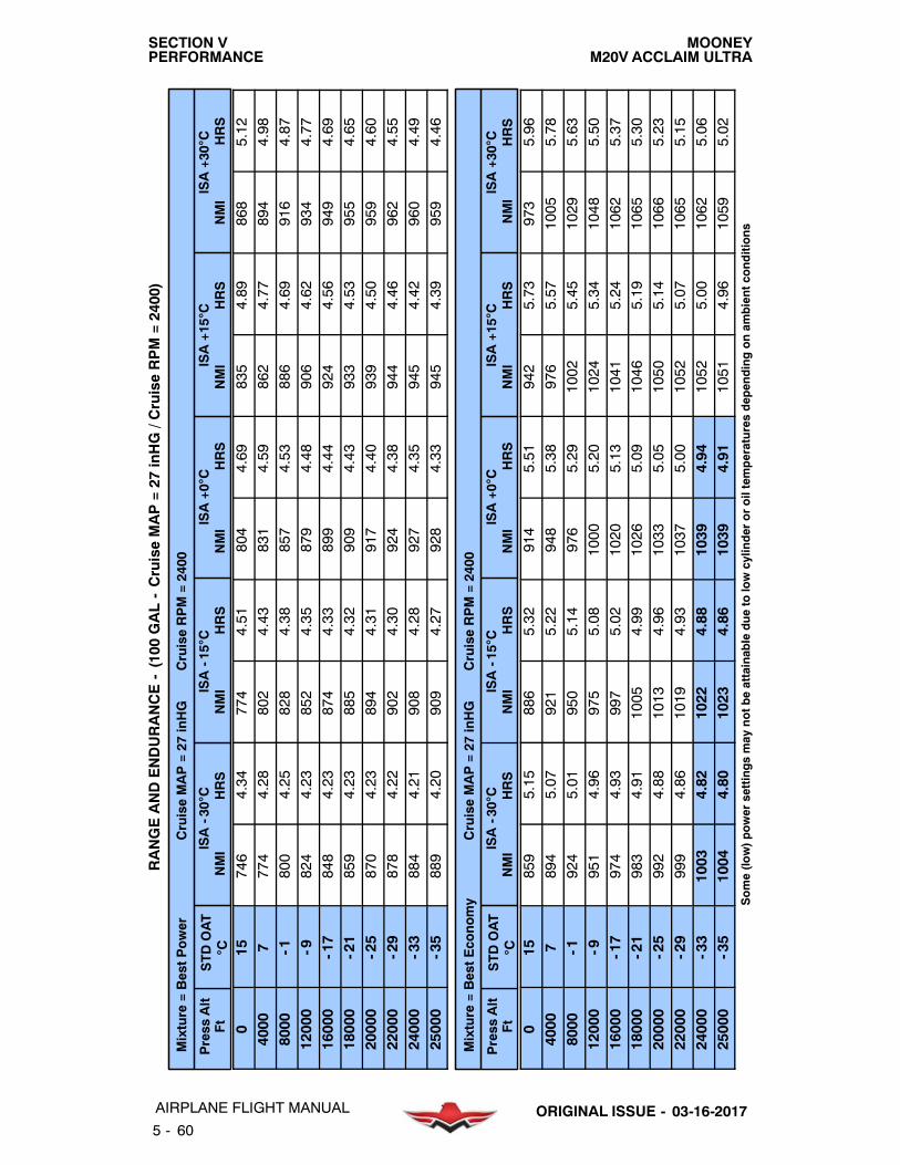
MOONEYM20V ACCLAIM ULTRA
SECTION VPERFORMANCE
5 - 60
AIRPLANE FLIGHT MANUAL ORIGINAL ISSUE - 03-16-2017
RANGEANDENDURANCE-(100
GAL-CruiseMAP=27
inHG/C
ruiseRPM=2400)
Mixture
=BestPower
CruiseMAP=27
inHG
CruiseRPM=2400
Press
Alt
Ft
STDOAT
CISA-30C
NMI
HRS
ISA-15C
NMI
HRS
ISA+0
CNMI
HRS
ISA+15C
NMI
HRS
ISA+30C
NMI
HRS
015
746
4.34
774
4.51
804
4.69
835
4.89
868
5.12
4000
7774
4.28
802
4.43
831
4.59
862
4.77
894
4.98
8000
-1800
4.25
828
4.38
857
4.53
886
4.69
916
4.87
12000
-9824
4.23
852
4.35
879
4.48
906
4.62
934
4.77
16000
-17
848
4.23
874
4.33
899
4.44
924
4.56
949
4.69
18000
-21
859
4.23
885
4.32
909
4.43
933
4.53
955
4.65
20000
-25
870
4.23
894
4.31
917
4.40
939
4.50
959
4.60
22000
-29
878
4.22
902
4.30
924
4.38
944
4.46
962
4.55
24000
-33
884
4.21
908
4.28
927
4.35
945
4.42
960
4.49
25000
-35
889
4.20
909
4.27
928
4.33
945
4.39
959
4.46
Mixture
=BestEconomy
CruiseMAP=27
inHG
CruiseRPM=2400
Press
Alt
Ft
STDOAT
CISA-30C
NMI
HRS
ISA-15C
NMI
HRS
ISA+0
CNMI
HRS
ISA+15C
NMI
HRS
ISA+30C
NMI
HRS
015
859
5.15
886
5.32
914
5.51
942
5.73
973
5.96
4000
7894
5.07
921
5.22
948
5.38
976
5.57
1005
5.78
8000
-1924
5.01
950
5.14
976
5.29
1002
5.45
1029
5.63
12000
-9951
4.96
975
5.08
1000
5.20
1024
5.34
1048
5.50
16000
-17
974
4.93
997
5.02
1020
5.13
1041
5.24
1062
5.37
18000
-21
983
4.91
1005
4.99
1026
5.09
1046
5.19
1065
5.30
20000
-25
992
4.88
1013
4.96
1033
5.05
1050
5.14
1066
5.23
22000
-29
999
4.86
1019
4.93
1037
5.00
1052
5.07
1065
5.15
24000
-33
1003
4.82
1022
4.88
1039
4.94
1052
5.00
1062
5.06
25000
-35
1004
4.80
1023
4.86
1039
4.91
1051
4.96
1059
5.02
Some(low)power
settingsmay
notbeattainabledueto
lowcylinder
oroiltemperaturesdependingonam
bientconditions

MOONEYM20V ACCLAIM ULTRA
SECTION VPERFORMANCE
5 - 61AIRPLANE FLIGHT MANUALORIGINAL ISSUE - 03-16-2017
RANGEANDENDURANCE-(100
GAL-CruiseMAP=24
inHG/C
ruiseRPM=2400)
Mixture
=BestPower
CruiseMAP=24
inHG
CruiseRPM=2400
Press
Alt
Ft
STDOAT
CISA-30C
NMI
HRS
ISA-15C
NMI
HRS
ISA+0
CNMI
HRS
ISA+15C
NMI
HRS
ISA+30C
NMI
HRS
015
812
5.05
842
5.24
874
5.45
906
5.68
940
5.94
4000
7838
4.88
868
5.05
898
5.23
930
5.44
963
5.66
8000
-1862
4.78
891
4.92
921
5.09
951
5.26
982
5.46
12000
-9887
4.72
916
4.85
944
4.99
972
5.15
1001
5.31
16000
-17
911
4.69
938
4.81
964
4.93
990
5.06
1015
5.20
18000
-21
923
4.69
949
4.79
974
4.90
998
5.02
1021
5.14
20000
-25
932
4.67
957
4.77
981
4.87
1003
4.97
1024
5.08
22000
-29
941
4.65
965
4.74
987
4.83
1007
4.92
1024
5.01
24000
-33
947
4.62
969
4.70
989
4.77
1007
4.85
1022
4.92
25000
-35
948
4.60
970
4.67
989
4.74
1006
4.80
1019
4.87
Mixture
=BestEconomy
CruiseMAP=24
inHG
CruiseRPM=2400
Press
Alt
Ft
STDOAT
CISA-30C
NMI
HRS
ISA-15C
NMI
HRS
ISA+0
CNMI
HRS
ISA+15C
NMI
HRS
ISA+30C
NMI
HRS
015
930
5.99
958
6.19
988
6.41
1017
6.66
1047
6.94
4000
7958
5.77
986
5.94
1014
6.13
1043
6.34
1072
6.58
8000
-1988
5.61
1016
5.76
1043
5.93
1070
6.12
1097
6.32
12000
-91014
5.52
1041
5.65
1066
5.79
1091
5.95
1115
6.12
16000
-17
1039
5.46
1063
5.57
1086
5.69
1108
5.82
1129
5.96
18000
-21
1049
5.43
1073
5.53
1095
5.64
1114
5.75
1132
5.87
20000
-25
1059
5.40
1081
5.49
1101
5.58
1119
5.68
1135
5.79
22000
-29
1065
5.36
1085
5.44
1103
5.52
1119
5.60
1131
5.69
24000
-33
1067
5.30
1087
5.37
1103
5.44
1115
5.50
1124
5.57
25000
-35
1068
5.26
1086
5.32
1101
5.38
1112
5.44
1118
5.50
Some(low)power
settingsmay
notbeattainabledueto
lowcylinder
oroiltemperaturesdependingonam
bientconditions

MOONEYM20V ACCLAIM ULTRA
SECTION VPERFORMANCE
5 - 62
AIRPLANE FLIGHT MANUAL ORIGINAL ISSUE - 03-16-2017
RANGEANDENDURANCE-(100
GAL-CruiseMAP=21
inHG/C
ruiseRPM=2400)
Mixture
=BestPower
CruiseMAP=21
inHG
CruiseRPM=2400
Press
Alt
Ft
STDOAT
CISA-30C
NMI
HRS
ISA-15C
NMI
HRS
ISA+0
CNMI
HRS
ISA+15C
NMI
HRS
ISA+30C
NMI
HRS
015
897
6.07
929
6.30
961
6.54
994
6.81
1028
7.12
4000
7916
5.71
948
5.90
980
6.11
1013
6.35
1047
6.61
8000
-1938
5.48
968
5.64
999
5.83
1031
6.03
1062
6.25
12000
-9960
5.34
990
5.49
1019
5.65
1048
5.82
1077
6.01
16000
-17
984
5.28
1012
5.40
1039
5.54
1065
5.68
1090
5.83
18000
-21
994
5.25
1021
5.36
1046
5.49
1070
5.62
1093
5.75
20000
-25
1003
5.22
1029
5.32
1053
5.43
1075
5.54
1094
5.66
22000
-29
1010
5.17
1034
5.26
1056
5.36
1075
5.46
1092
5.56
24000
-33
1010
5.10
1032
5.18
1052
5.26
1069
5.34
1083
5.42
25000
-35
1008
5.05
1029
5.13
1048
5.20
1064
5.27
1076
5.34
Mixture
=BestEconomy
CruiseMAP=21
inHG
CruiseRPM=2400
Press
Alt
Ft
STDOAT
CISA-30C
NMI
HRS
ISA-15C
NMI
HRS
ISA+0
CNMI
HRS
ISA+15C
NMI
HRS
ISA+30C
NMI
HRS
015
1017
7.24
1047
7.49
1076
7.75
1103
8.05
1128
8.39
4000
71044
6.76
1074
6.97
1103
7.19
1132
7.45
1160
7.73
8000
-11066
6.45
1094
6.62
1122
6.82
1150
7.03
1177
7.26
12000
-91093
6.26
1120
6.41
1147
6.57
1172
6.75
1195
6.95
16000
-17
1117
6.15
1142
6.27
1165
6.41
1186
6.55
1205
6.71
18000
-21
1127
6.10
1151
6.21
1173
6.33
1192
6.46
1208
6.60
20000
-25
1135
6.04
1157
6.14
1177
6.25
1194
6.36
1207
6.48
22000
-29
1137
5.97
1157
6.06
1175
6.15
1190
6.25
1200
6.34
24000
-33
1137
5.87
1156
5.94
1171
6.02
1183
6.09
1189
6.17
25000
-35
1133
5.80
1151
5.87
1165
5.94
1175
6.00
1179
6.06
Some(low)power
settingsmay
notbeattainabledueto
lowcylinder
oroiltemperaturesdependingonam
bientconditions

MOONEYM20V ACCLAIM ULTRA
SECTION VPERFORMANCE
5 - 63AIRPLANE FLIGHT MANUALORIGINAL ISSUE - 03-16-2017
RANGEANDENDURANCE-(100
GAL-CruiseMAP=28
inHG/C
ruiseRPM=2300)
Mixture
=BestPower
CruiseMAP=28
inHG
CruiseRPM=2300
Press
Alt
Ft
STDOAT
CISA-30C
NMI
HRS
ISA-15C
NMI
HRS
ISA+0
CNMI
HRS
ISA+15C
NMI
HRS
ISA+30C
NMI
HRS
015
757
4.39
786
4.55
817
4.74
848
4.94
882
5.17
4000
7787
4.36
816
4.51
846
4.68
876
4.86
909
5.07
8000
-1814
4.34
842
4.48
871
4.63
901
4.79
931
4.97
12000
-9839
4.33
866
4.45
893
4.58
921
4.72
949
4.88
16000
-17
860
4.30
886
4.41
912
4.52
937
4.64
961
4.77
18000
-21
869
4.29
895
4.39
919
4.49
943
4.60
966
4.71
20000
-25
878
4.28
902
4.37
925
4.46
946
4.55
967
4.66
22000
-29
885
4.27
908
4.35
930
4.43
950
4.51
968
4.60
24000
-33
893
4.27
916
4.34
936
4.41
955
4.48
970
4.55
25000
-35
897
4.27
919
4.33
939
4.40
956
4.46
970
4.52
Mixture
=BestEconomy
CruiseMAP=28
inHG
CruiseRPM=2300
Press
Alt
Ft
STDOAT
CISA-30C
NMI
HRS
ISA-15C
NMI
HRS
ISA+0
CNMI
HRS
ISA+15C
NMI
HRS
ISA+30C
NMI
HRS
015
872
5.18
899
5.35
928
5.54
957
5.75
988
5.99
4000
7907
5.14
934
5.29
962
5.46
990
5.65
1020
5.86
8000
-1939
5.10
965
5.23
991
5.38
1018
5.55
1046
5.73
12000
-9964
5.05
989
5.16
1014
5.29
1039
5.43
1063
5.59
16000
-17
983
4.99
1007
5.09
1029
5.19
1051
5.31
1071
5.43
18000
-21
991
4.95
1014
5.04
1035
5.14
1055
5.24
1073
5.35
20000
-25
998
4.92
1020
5.00
1040
5.09
1058
5.18
1073
5.27
22000
-29
1004
4.89
1024
4.96
1042
5.04
1058
5.11
1071
5.19
24000
-33
1009
4.87
1027
4.93
1043
4.99
1057
5.05
1066
5.11
25000
-35
1011
4.85
1029
4.91
1045
4.97
1057
5.02
1064
5.07
Some(low)power
settingsmay
notbeattainabledueto
lowcylinder
oroiltemperaturesdependingonam
bientconditions

MOONEYM20V ACCLAIM ULTRA
SECTION VPERFORMANCE
5 - 64
AIRPLANE FLIGHT MANUAL ORIGINAL ISSUE - 03-16-2017
RANGEANDENDURANCE-(100
GAL-CruiseMAP=25
inHG/C
ruiseRPM=2300)
Mixture
=BestPower
CruiseMAP=25
inHG
CruiseRPM=2300
Press
Alt
Ft
STDOAT
CISA-30C
NMI
HRS
ISA-15C
NMI
HRS
ISA+0
CNMI
HRS
ISA+15C
NMI
HRS
ISA+30C
NMI
HRS
015
820
5.04
851
5.23
882
5.43
915
5.67
949
5.92
4000
7851
4.94
881
5.11
912
5.30
944
5.50
978
5.73
8000
-1879
4.88
908
5.04
939
5.20
969
5.38
1001
5.58
12000
-9904
4.84
933
4.98
961
5.12
990
5.28
1018
5.45
16000
-17
927
4.80
954
4.91
980
5.04
1006
5.17
1031
5.31
18000
-21
937
4.78
963
4.88
988
4.99
1012
5.11
1035
5.24
20000
-25
946
4.75
970
4.85
994
4.95
1016
5.05
1037
5.17
22000
-29
953
4.73
977
4.81
1000
4.90
1020
4.99
1038
5.09
24000
-33
960
4.70
982
4.78
1002
4.85
1019
4.93
1034
5.01
25000
-35
962
4.69
983
4.76
1002
4.83
1018
4.90
1031
4.96
Mixture
=BestEconomy
CruiseMAP=25
inHG
CruiseRPM=2300
Press
Alt
Ft
STDOAT
CISA-30C
NMI
HRS
ISA-15C
NMI
HRS
ISA+0
CNMI
HRS
ISA+15C
NMI
HRS
ISA+30C
NMI
HRS
015
934
5.94
964
6.14
993
6.35
1024
6.60
1056
6.87
4000
7971
5.80
1000
5.98
1029
6.17
1058
6.38
1088
6.62
8000
-11004
5.71
1031
5.87
1059
6.04
1087
6.22
1114
6.43
12000
-91032
5.64
1058
5.77
1084
5.91
1109
6.07
1134
6.25
16000
-17
1054
5.56
1078
5.67
1102
5.79
1124
5.92
1144
6.06
18000
-21
1062
5.51
1085
5.61
1107
5.72
1127
5.84
1145
5.96
20000
-25
1068
5.47
1091
5.56
1111
5.65
1129
5.75
1144
5.86
22000
-29
1075
5.42
1095
5.50
1114
5.58
1129
5.67
1141
5.75
24000
-33
1079
5.37
1098
5.44
1115
5.51
1127
5.58
1136
5.64
25000
-35
1081
5.35
1100
5.41
1115
5.47
1126
5.53
1132
5.58
Some(low)power
settingsmay
notbeattainabledueto
lowcylinder
oroiltemperaturesdependingonam
bientconditions

MOONEYM20V ACCLAIM ULTRA
SECTION VPERFORMANCE
5 - 65AIRPLANE FLIGHT MANUALORIGINAL ISSUE - 03-16-2017
RANGEANDENDURANCE-(100
GAL-CruiseMAP=22
inHG/C
ruiseRPM=2300)
Mixture
=BestPower
CruiseMAP=22
inHG
CruiseRPM=2300
Press
Alt
Ft
STDOAT
CISA-30C
NMI
HRS
ISA-15C
NMI
HRS
ISA+0
CNMI
HRS
ISA+15C
NMI
HRS
ISA+30C
NMI
HRS
015
901
5.96
933
6.17
966
6.41
1000
6.68
1036
6.98
4000
7928
5.73
960
5.92
993
6.14
1026
6.37
1059
6.63
8000
-1958
5.60
989
5.77
1020
5.96
1052
6.16
1085
6.39
12000
-9984
5.51
1014
5.66
1044
5.82
1073
6.00
1102
6.20
16000
-17
1005
5.43
1033
5.56
1060
5.69
1087
5.84
1111
6.00
18000
-21
1015
5.38
1042
5.50
1068
5.63
1092
5.76
1115
5.90
20000
-25
1021
5.33
1046
5.44
1070
5.55
1092
5.67
1112
5.79
22000
-29
1025
5.28
1049
5.37
1071
5.47
1091
5.57
1108
5.67
24000
-33
1028
5.21
1051
5.30
1071
5.38
1088
5.46
1101
5.54
25000
-35
1028
5.18
1050
5.25
1069
5.33
1084
5.40
1096
5.47
Mixture
=BestEconomy
CruiseMAP=22
inHG
CruiseRPM=2300
Press
Alt
Ft
STDOAT
CISA-30C
NMI
HRS
ISA-15C
NMI
HRS
ISA+0
CNMI
HRS
ISA+15C
NMI
HRS
ISA+30C
NMI
HRS
015
1022
7.04
1052
7.28
1082
7.53
1112
7.82
1140
8.15
4000
71052
6.74
1082
6.94
1112
7.17
1143
7.42
1173
7.70
8000
-11087
6.56
1116
6.73
1145
6.93
1173
7.15
1200
7.39
12000
-91116
6.42
1143
6.58
1170
6.74
1195
6.93
1220
7.13
16000
-17
1139
6.29
1164
6.42
1187
6.56
1209
6.71
1228
6.87
18000
-21
1144
6.22
1168
6.34
1190
6.47
1210
6.60
1227
6.74
20000
-25
1150
6.15
1173
6.25
1193
6.36
1210
6.48
1223
6.59
22000
-29
1153
6.07
1173
6.15
1191
6.25
1206
6.34
1216
6.44
24000
-33
1152
5.97
1171
6.05
1186
6.13
1197
6.20
1203
6.27
25000
-35
1150
5.92
1168
5.99
1182
6.06
1192
6.12
1195
6.19
Some(low)power
settingsmay
notbeattainabledueto
lowcylinder
oroiltemperaturesdependingonam
bientconditions

MOONEYM20V ACCLAIM ULTRA
SECTION VPERFORMANCE
5 - 66
AIRPLANE FLIGHT MANUAL ORIGINAL ISSUE - 03-16-2017
RANGEANDENDURANCE-(100
GAL-CruiseMAP=19
inHG/C
ruiseRPM=2300)
Mixture
=BestPower
CruiseMAP=19
inHG
CruiseRPM=2300
Press
Alt
Ft
STDOAT
CISA-30C
NMI
HRS
ISA-15C
NMI
HRS
ISA+0
CNMI
HRS
ISA+15C
NMI
HRS
ISA+30C
NMI
HRS
015
1000
7.31
1034
7.58
1067
7.86
1101
8.19
1135
8.55
4000
71027
6.86
1061
7.08
1095
7.33
1129
7.61
1163
7.91
8000
-11054
6.59
1087
6.79
1119
7.01
1152
7.25
1184
7.51
12000
-91082
6.42
1113
6.59
1144
6.77
1173
6.98
1202
7.20
16000
-17
1100
6.26
1129
6.41
1156
6.56
1182
6.73
1206
6.91
18000
-21
1106
6.17
1134
6.31
1159
6.45
1183
6.60
1204
6.76
20000
-25
1108
6.08
1133
6.20
1157
6.32
1178
6.45
1196
6.59
22000
-29
1107
5.97
1131
6.07
1153
6.18
1172
6.29
1187
6.40
24000
-33
1102
5.84
1124
5.93
1143
6.02
1159
6.11
1170
6.19
25000
-35
1097
5.76
1119
5.85
1136
5.93
1150
6.01
1159
6.08
Mixture
=BestEconomy
CruiseMAP=19
inHG
CruiseRPM=2300
Press
Alt
Ft
STDOAT
CISA-30C
NMI
HRS
ISA-15C
NMI
HRS
ISA+0
CNMI
HRS
ISA+15C
NMI
HRS
ISA+30C
NMI
HRS
015
1124
8.76
1152
9.05
1179
9.37
1204
9.73
1225
10.14
4000
71160
8.13
1191
8.38
1220
8.65
1247
8.95
1272
9.29
8000
-11192
7.77
1222
7.98
1251
8.21
1279
8.47
1304
8.76
12000
-91221
7.52
1250
7.70
1276
7.90
1300
8.12
1322
8.35
16000
-17
1241
7.30
1267
7.45
1290
7.62
1310
7.79
1326
7.98
18000
-21
1245
7.18
1269
7.32
1289
7.46
1307
7.62
1321
7.78
20000
-25
1246
7.05
1268
7.17
1286
7.30
1300
7.43
1309
7.57
22000
-29
1242
6.90
1262
7.01
1278
7.11
1289
7.22
1294
7.33
24000
-33
1232
6.73
1250
6.82
1264
6.90
1272
6.99
1273
7.07
25000
-35
1227
6.63
1244
6.71
1256
6.79
1262
6.86
1260
6.93
Some(low)power
settingsmay
notbeattainabledueto
lowcylinder
oroiltemperaturesdependingonam
bientconditions

MOONEYM20V ACCLAIM ULTRA
SECTION VPERFORMANCE
5 - 67AIRPLANE FLIGHT MANUALORIGINAL ISSUE - 03-16-2017
RANGEANDENDURANCE-(100
GAL-CruiseMAP=21
inHG/C
ruiseRPM=2200)
Mixture
=BestPower
CruiseMAP=21
inHG
CruiseRPM=2200
Press
Alt
Ft
STDOAT
CISA-30C
NMI
HRS
ISA-15C
NMI
HRS
ISA+0
CNMI
HRS
ISA+15C
NMI
HRS
ISA+30C
NMI
HRS
015
967
6.64
1000
6.88
1035
7.15
1071
7.44
1107
7.77
4000
71003
6.45
1037
6.66
1070
6.90
1105
7.16
1139
7.45
8000
-11043
6.38
1076
6.57
1108
6.78
1141
7.01
1174
7.27
12000
-91074
6.29
1105
6.46
1136
6.64
1166
6.84
1195
7.06
16000
-17
1091
6.15
1120
6.29
1148
6.45
1175
6.61
1199
6.79
18000
-21
1097
6.05
1125
6.18
1151
6.32
1175
6.47
1197
6.63
20000
-25
1098
5.95
1124
6.07
1148
6.19
1169
6.32
1188
6.45
22000
-29
1097
5.85
1122
5.95
1143
6.06
1162
6.17
1178
6.28
24000
-33
1098
5.75
1120
5.84
1139
5.93
1155
6.02
1166
6.11
25000
-35
1097
5.71
1119
5.79
1137
5.87
1151
5.95
1160
6.03
Mixture
=BestEconomy
CruiseMAP=21
inHG
CruiseRPM=2200
Press
Alt
Ft
STDOAT
CISA-30C
NMI
HRS
ISA-15C
NMI
HRS
ISA+0
CNMI
HRS
ISA+15C
NMI
HRS
ISA+30C
NMI
HRS
015
1091
7.82
1122
8.08
1153
8.36
1184
8.68
1212
9.05
4000
71129
7.55
1161
7.78
1192
8.03
1223
8.31
1253
8.63
8000
-11176
7.43
1206
7.64
1235
7.86
1263
8.11
1290
8.38
12000
-91210
7.31
1238
7.48
1265
7.67
1291
7.88
1314
8.11
16000
-17
1228
7.11
1254
7.25
1277
7.41
1298
7.58
1316
7.76
18000
-21
1229
6.98
1253
7.11
1275
7.25
1293
7.40
1309
7.56
20000
-25
1230
6.84
1253
6.96
1272
7.08
1288
7.21
1299
7.34
22000
-29
1227
6.70
1247
6.80
1264
6.91
1277
7.01
1284
7.12
24000
-33
1223
6.58
1241
6.66
1255
6.75
1264
6.83
1267
6.91
25000
-35
1221
6.52
1238
6.60
1250
6.67
1257
6.74
1257
6.81
Some(low)power
settingsmay
notbeattainabledueto
lowcylinder
oroiltemperaturesdependingonam
bientconditions

MOONEYM20V ACCLAIM ULTRA
SECTION VPERFORMANCE
5 - 68
AIRPLANE FLIGHT MANUAL ORIGINAL ISSUE - 03-16-2017
RANGEANDENDURANCE-(100
GAL-CruiseMAP=21
inHG/C
ruiseRPM=2100)
Mixture
=BestPower
CruiseMAP=21
inHG
CruiseRPM=2100
Press
Alt
Ft
STDOAT
CISA-30C
NMI
HRS
ISA-15C
NMI
HRS
ISA+0
CNMI
HRS
ISA+15C
NMI
HRS
ISA+30C
NMI
HRS
015
1002
6.96
1036
7.21
1071
7.49
1108
7.80
1145
8.14
4000
71051
6.89
1085
7.12
1120
7.37
1155
7.64
1190
7.95
8000
-11103
6.94
1137
7.15
1170
7.37
1203
7.62
1237
7.90
12000
-91143
6.90
1174
7.08
1205
7.28
1235
7.50
1265
7.74
16000
-17
1157
6.70
1187
6.86
1215
7.02
1241
7.20
1265
7.39
18000
-21
1156
6.56
1184
6.70
1210
6.85
1234
7.01
1254
7.17
20000
-25
1152
6.41
1178
6.53
1202
6.66
1223
6.80
1241
6.94
22000
-29
1149
6.26
1173
6.37
1195
6.48
1213
6.60
1226
6.72
24000
-33
1148
6.15
1171
6.25
1189
6.34
1203
6.44
1212
6.53
25000
-35
1149
6.12
1169
6.20
1186
6.29
1198
6.37
1205
6.45
Mixture
=BestEconomy
CruiseMAP=21
inHG
CruiseRPM=2100
Press
Alt
Ft
STDOAT
CISA-30C
NMI
HRS
ISA-15C
NMI
HRS
ISA+0
CNMI
HRS
ISA+15C
NMI
HRS
ISA+30C
NMI
HRS
015
1124
8.12
1157
8.38
1189
8.68
1222
9.02
1253
9.39
4000
71177
8.00
1209
8.24
1241
8.51
1271
8.81
1302
9.14
8000
-11238
8.03
1269
8.25
1299
8.49
1327
8.76
1353
9.05
12000
-91277
7.96
1306
8.15
1333
8.36
1358
8.59
1381
8.84
16000
-17
1290
7.70
1316
7.86
1340
8.03
1360
8.22
1377
8.42
18000
-21
1289
7.52
1313
7.66
1335
7.81
1352
7.97
1365
8.14
20000
-25
1283
7.32
1305
7.45
1324
7.58
1338
7.71
1348
7.86
22000
-29
1275
7.14
1295
7.25
1311
7.36
1322
7.47
1327
7.58
24000
-33
1270
7.00
1288
7.09
1301
7.18
1308
7.27
1308
7.35
25000
-35
1270
6.95
1287
7.03
1298
7.11
1303
7.19
1299
7.25
Some(low)power
settingsmay
notbeattainabledueto
lowcylinder
oroiltemperaturesdependingonam
bientconditions

MOONEYM20V ACCLAIM ULTRA
SECTION VPERFORMANCE
5 - 69AIRPLANE FLIGHT MANUALORIGINAL ISSUE - 03-16-2017
TIME - FUEL - DISTANCE to DESCEND(Maintain 500 fpm Rate of Descent)

MOONEYM20V ACCLAIM ULTRA
SECTION VPERFORMANCE
5 - 70AIRPLANE FLIGHT MANUAL ORIGINAL ISSUE - 03-16-2017
TIME - FUEL - DISTANCE to DESCEND(Maintain 1000 fpm Rate of Descent)

MOONEYM20V ACCLAIM ULTRA
SECTION VPERFORMANCE
5 - 71AIRPLANE FLIGHT MANUALORIGINAL ISSUE - 03-16-2017
LANDING - GROUND ROLL

MOONEYM20V ACCLAIM ULTRA
SECTION VPERFORMANCE
5 - 72AIRPLANE FLIGHT MANUAL ORIGINAL ISSUE - 03-16-2017
LANDING - OVER 50’ (15m) OBSTACLE

MOONEYM20V ACCLAIM ULTRA
SECTION VIWEIGHT AND BALANCE
6 - 1AIRPLANE FLIGHT MANUALORIGINAL ISSUE - 03-16-2017
TABLE OF CONTENTS
TITLE SECTION. . . . . . . . . . . . . . . . . . . . . . . . . . . . . . . . . . . . . . . . . . . . . . . . . . . . . . . . . . . . . . . . . .
INTRODUCTION 6- 3. . . . . . . . . . . . . . . . . . . . . . . . . . . . . . . . . . . . . . . . . . . . . . . . . . . . . . . . . . . . . .AIRPLANE WEIGHING PROCEDURE 6- 4. . . . . . . . . . . . . . . . . . . . . . . . . . . . . . . . . . . . . . . . . . .WEIGHT & BALANCE CHART 6- 5. . . . . . . . . . . . . . . . . . . . . . . . . . . . . . . . . . . . . . . . . . . . . . . . . .OWNERS WEIGHT & BALANCE RECORD 6- 6. . . . . . . . . . . . . . . . . . . . . . . . . . . . . . . . . . . . . .PILOTS LOADING GUIDE 6- 7. . . . . . . . . . . . . . . . . . . . . . . . . . . . . . . . . . . . . . . . . . . . . . . . . . . . .PROBLEM FORM 6- 8. . . . . . . . . . . . . . . . . . . . . . . . . . . . . . . . . . . . . . . . . . . . . . . . . . . . . . . . . . . . .LOADING COMPUTATION GRAPH 6- 9. . . . . . . . . . . . . . . . . . . . . . . . . . . . . . . . . . . . . . . . . . . . .CENTER OF GRAVITY MOMENT ENVELOPE 6- 10. . . . . . . . . . . . . . . . . . . . . . . . . . . . . . . . . .CENTER OF GRAVITY LIMITS ENVELOPE 6- 11. . . . . . . . . . . . . . . . . . . . . . . . . . . . . . . . . . . . .FIXED BALLAST 6- 12. . . . . . . . . . . . . . . . . . . . . . . . . . . . . . . . . . . . . . . . . . . . . . . . . . . . . . . . . . . . .EQUIPMENT LIST 6- 12. . . . . . . . . . . . . . . . . . . . . . . . . . . . . . . . . . . . . . . . . . . . . . . . . . . . . . . . . . .
-NOTE-
The empty weight, center of gravity and equipment list for the airplane as delivered
section is valid for use with the airplane identified below when approved byMooney International Corporation.
MOONEY - MODEL M20V ACCLAIM ULTRA
AIRCRAFT SERIAL NO.
AIRCRAFT REGISTRATION NO.
from Mooney International Corporation is contained in this section. The use of this
Mooney International Corporation - Approved Signature and Date
Revision A: 08-18-2017

MOONEYM20V ACCLAIM ULTRA
SECTION VIWEIGHT AND BALANCE
6 - 2
AIRPLANE FLIGHT MANUAL ORIGINAL ISSUE - 03-16-2017
BLANK

MOONEYM20V ACCLAIM ULTRA
SECTION VIWEIGHT AND BALANCE
6 - 3AIRPLANE FLIGHT MANUALORIGINAL ISSUE - 03-16-2017
INTRODUCTION
This section describes the procedure for calculating loaded aircraft weight andmoment for vari-ous flight operations. In addition, procedures are provided for calculating the empty weight andmoment of the aircraft when the removal or addition of equipment results in changes to theempty weight and center of gravity. A comprehensive list of all Mooney equipment available forthis airplane is included in this section. Only those items checked (X) were installed at Mooneyand are included in the empty weight- and- balance data.
The aircraft owner and/or pilot, has the responsibility of properly loading the aircraft for safeflight. Data presented in this sectionwill enable you to carry out this responsibility and insure thatyour airplane is loaded to operatewithin the prescribedweight and center- of- gravity limitations.
At the time of delivery, Mooney International Corporation provides the empty weight and centerof gravity data for the computation of individual loadings. (The empty weight and C.G. (gearextended) as delivered from the factory is tabulated on page 6- 6 when this manual is suppliedwith the aircraft from the factory.)
FAA regulations also require that any change in the original equipment affecting the empty-weight and center of gravity be recorded in theAircraft LogBook.A convenient form formaintain-ing a permanent record of all such changes is provided on page 6- 6. This form, if properlymain-tained, will enable you to determine the current weight- and- balance status of the airplane forload scheduling. The weight- and- balance data entered as your aircraft left the factory, plus therecord you maintain on page 6- 6, is all of the data needed to compute loading schedules.
The maximum certificated gross weight for the CMI powered M20V is 3368 lbs (1528 Kg) forTakeoff and 3200 pounds (1452 Kgs) for Landing. Maximum useful load is determined by sub-tracting the corrected aircraft empty weight from itsmaximumgrossweight. The aircraft must beoperated strictly within the limits of the Center- of- Gravity Moment Envelope shown on page6- 10.

MOONEYM20V ACCLAIM ULTRA
SECTION VIWEIGHT AND BALANCE
6 - 4
AIRPLANE FLIGHT MANUAL ORIGINAL ISSUE - 03-16-2017
AIRPLANE WEIGHING PROCEDURE
LEVELING
Place a spirit level on the leveling screws above the tailcone left access door when leveling theaircraft longitudinally. Level the aircraft by increasing or decreasing air pressure in the nosewheel tire.
WEIGHING
To weigh the aircraft, select a level work area and:
1. Check for installation of all equipment as listed in the Weight & Balance Record EquipmentList.
2.Topoff bothwing tankswith full fuel. Subtract usable fuel, 100.0U.S. gals. (378.5 liters)@5.82lb/gal (100LL) (.69 Kg/l) = 582.0 lbs. (264.0 Kgs.), from total weight as weighed.
OPTIONAL METHOD - Ground aircraft and defuel tanks as follows:
a.)Disconnect fuel line at fuel systemunion located forward of the firewall on the lower left handside.
b.) Connect a flexible line to output fitting that will reach fuel receptacle.c.) Turn fuel selector valve to tank to be drained; remove filler cap from fuel filler port.d.) Turn on fuel boost pump until tank is empty.
REPEAT STEPS C. AND D. TO DRAIN OTHER TANK.e.) Replace 3.0 gallons (11.4 liters) fuel into each tank (unusable fuel). (Use 5.82lb/gal.
(.69 Kg/liter) for 100LL fuel).f.) Replace filler caps.
3. Fill oil tank to capacity (8 qts.).
4. Position front seats in full forward position.
5. Position flaps in full up position.
6. Position a 2000- pound (907.2 Kg.) capacity scale under each of the three wheels.
7. Level aircraft as previously described making certain nose wheel is centered.
8.Weigh the aircraft and deduct any tare from each reading.
9. Find reference point by dropping a plumb bob from center of nose gear trunnion (retractingpivot axis) to the floor. Mark the point of intersection.
10. Locate centerline of nose wheel axle and main wheel axles in the same manner.
11.Measure the horizontal distance from the reference point tomainwheel axle center line.Mea-sure horizontal distance fromcenterline of nosewheel axle to center line ofmainwheel axles.
12. Record weights and measurements, and compute basic weight and CG as follows on nextpage:
-NOTE-Wing Jack Points are located at Fus. Sta. 56.658 in. (143.91 cm). Nose Jack Point is located at Fus. Sta. - 5.51 in. (- 14.0 cm.). Refer to SECTION VIII, Jacking, for
procedures.

MOONEYM20V ACCLAIM ULTRA
SECTION VIWEIGHT AND BALANCE
6 - 5AIRPLANE FLIGHT MANUALORIGINAL ISSUE - 03-16-2017
M20V - WEIGHT & BALANCE CHART
REF.POINT(NOSE GEARTRUNNIONSTA. - 13)
Lm/nLm/rLc/g
Wn
Lm
WrWl
LM/N
M/RLMEASUREMENTS
DATUM(STA.0)REFERENCE
(LEVELING SCREWS)LEVEL REF.
INCHES/CM
INCHES/CM
SCALE POSITION AND SYMBOL SCALE READING TARE NET WEIGHT
NOSE WHEEL (W )
RIGHT MAIN WHEEL (W )
LEFT MAIN WHEEL (W )BASIC EMPTY WEIGHT (W )
AS WEIGHED (W )
of fuel has been drained
of fuel has not been drained
LBS/Kg
Weight @ Nose
(WN)
× In/cm/mm
Distance BetweenMain & Nose Wheel
Axle Centers
÷
(LM/N)
Total Weight ofAircraft
(WT)
=
CG Forward ofMain Wheels
(LM)
a. CG Forward of Main Wheels
b. CG Aft of Datum (Station 0)
13 In/33.0 cm/330 mm
Distance from CenterNose Gear Trunnion toCenter of Main WheelAxles (Horizontal)
(LM/R)
Distance fromNose Gear Trun-nion to Datum
Result ofComputationAbove (a.)
(LM)(CONSTANT)
CG (FUS STA)Distance Aft ofDatum (EmptyWeight CG)
(LC/G)
− =
LBS/Kg In/cm/mm
In/cm/mm In/cm/mmIn/cm/mm−
WEIGHT
As Weighed (W )Usable Fuel
Basic Empty Wt.
LBS. (Kg) C.G. In/cm/mm MOMENT Lb- In (Kg- cm)(Kg-mm)/1000
49.23 In/125 cm/1250 mmT
- -
N
R
L
T
T

MOONEYM20V ACCLAIM ULTRA
SECTION VIWEIGHT AND BALANCE
6 - 6
AIRPLANE FLIGHT MANUAL ORIGINAL ISSUE - 03-16-2017
OWNER’S
WEIGHTANDBALANCERECORD
(ENTERBELOWALLWEIGHTCHANGEDATA
FROMAIRCRAFTLOGBOOK)
AIRPLANEMODEL:
SERIALNO.:
FAAREG.N
O.:
DATE
DESCRIPTO
N
WEIGHTCHANGE
ADDED(+)
REMOVED(-)
RUNNINGEMPTY
WEIGHT
WT.
(LBS)
(Kg)
ARM
(INCHES)
(CM/MM)
MOMENT
/1000
USEFUL
LOAD
BASIC
EMPTYWEIGHTAS
(INCLUDES:)
(Mult.Inches
by25.4formm)
(Mult.Inches
by2.54
forcm
)(Mult.P
oundsby.4536forKg)
WT.
(LBS)
(Kg)
WT.
(LBS)
(Kg)
(INCHES)
(CM/MM)
ARM
ARM
(INCHES)
(CM/MM)
DELIVERED(W
T)
QTS-(
LITERS)
OF
MODIFICATION

MOONEYM20V ACCLAIM ULTRA
SECTION VIWEIGHT AND BALANCE
6 - 7AIRPLANE FLIGHT MANUALORIGINAL ISSUE - 03-16-2017
PILOT’S LOADING GUIDELOADING CALCULATION PROCEDURE
Proper loading of the aircraft is essential for maximum flight performance and safety. Thissectionwill assist you in determiningwhether the aircraft loading schedule iswithin the approvedweight and center- of- gravity limits.
To figure an actual loading problem for your aircraft, proceed as follows:
Step 1. Refer to the latest entry on page 6- 6 for the current empty weight and moment.
-NOTE-Since the engine oil is normally kept at the full level, the oil weight and moment isincluded in basic empty weight and is constant in calculating all loading prob-
lems.
Step 2. Note the pilot’s weight and the position his seat will occupy in flight. Find this weight on the left scale of the Loading Computation Form (page 6- 9) and cross the graph horizontally to the graph for #1 and #2 seats. When this point is located, drop down to the bottom scale to find the value of the moment/1000 due to the pilot’s weight and seat position.
Repeat procedure for co- pilot and enter these weights and moment/1000 values in the propersub- columns in the Problem Form on page 6- 8/9.
Step3.Proceedas inStep 2 to account for the passengers in seats 3 and4. Enter theweight andvalue of moment/1000 in the proper columns.
Step 4.Again proceed as in Step 2 to account for the amount of fuel carried, and enter theweightand moment/1000 values in the proper columns.
Step 5.Once more proceed as in Step 2 to account for the baggage to be carried and enter thefigures in the proper columns.
Step 6. Total the weight columns. This total must be 3368 Pounds (1528 Kg) or less. Total theMoment/1000 column.
DO NOT FORGET TO SUBTRACT NEGATIVE NUMBERS.
Step 7. Refer to the Center- of- Gravity Moment Envelope (page 6- 10). Locate the loaded weight of your airplane on the left scale of the graph and trace a line horizontally to the right. Locate the total moment/1000 value for your airplane on the bottom scale of the graph and trace a line vertically above this point until the horizontal line for weight is intersected. If the point of intersection is within the shaded area, your aircraft loading is acceptable. If the point of intersec-tion falls outside the shaded area, you must rearrange the load before take off.

MOONEYM20V ACCLAIM ULTRA
SECTION VIWEIGHT AND BALANCE
6 - 8
AIRPLANE FLIGHT MANUAL ORIGINAL ISSUE - 03-16-2017
PROBLEM FORM
A/C Basic Empty Wt. (W.) (from
STEP
ITEM
SAMPLEPROBLEM
YOURPROBLEM
WEIGHT(Kg)
Lbs
MOMENT(Kg- cm/1000)
lb- in/1000
WEIGHT(Kg)
Lbs
MOMENT(Kg- cm/1000)
lb- in/1000
1
2
3
4
5
Pilot Seat (#1) *
Co-Pilot Seat (#2) *
Left Rear Seat (#3) or Cargo Area
Right Rear Seat (#4) or Cargo
Baggage (Max. 120 Lbs (54.4 Kg)@ Sta. 101.5 (257.8 cm)
Hat Rack (Max. 10 Lbs (4.54 Kg)@ Sta. 126.0 (320 CM)
CONTINUE PROBLEM FORM ON NEXT PAGE
(1009)
2225
(164.7)
363
(77.1)
170
(77.1)
170
(77.1)
170
(114.6)
99.46
(8.52)
7.40
(7.25)
6.29
(14.3)
12.41
(20.59)
17.87
(aft pos)
(2nd. pos)
page 6- 5) (includes Full Oil)8 Qts (7.57 Li) @ 1.875 Lbs/Qt(.80 Kg/Li) (Sta. - 20.19) (- 51.3 cm)(Oil sump assumed FULL forall flights)
(Max. Usable -
(386.1 Li/266.4 Kg) @ Sta 49.23(125 cm)
* Obtain the moment/1000 value for each seat position (FWD, MID or AFT)from loading computation graph.
Area
(77.1)
170
(14.3)
12.41
(45.4)
100
(11.70)
10.15
102.0 Gal/593.6 Lbs.)
Fuel(Max. Usable -
(378.5 Li/264.0 Kg.) @ Sta 49.23(125 cm)
100.0 Gal/582.0 Lbs.)(164.7)
363
(20.59
17.87
Fuel

MOONEYM20V ACCLAIM ULTRA
SECTION VIWEIGHT AND BALANCE
6 - 9AIRPLANE FLIGHT MANUALORIGINAL ISSUE - 03-16-2017
PROBLEM FORM (CONT)
STEP
ITEM
SAMPLEPROBLEM
YOURPROBLEM
WEIGHT(Kg)
Lbs
MOMENT(Kg- cm/1000)
lb- in/1000
WEIGHT(Kg)
Lbs
MOMENT(Kg- cm/1000)
lb- in/1000
6
7
8
9
Loaded A/C Weight (Takeoff at
Required Fuel Burn-Off32 Gals (121Li) @ 5.82 Lbs/Gal
MAXIMUM LANDING WEIGHT
Refer to Center of Gravity Moment Envelope, to determine whether your A/C
(1528)
3368
(84.3)
186
(1452)
3200
(191.1)
165.8
(- 9.53)
- 8.27
(181.5)
157.53of A/C
Max. Weight) A/C will have toburn off 168 Lbs fuel beforenormal landing is accomplished
loading is acceptable.
CAUTION - DO NOT LAND A/C WHEN OVER 3200 LBS. EXCEPT IN ANEMERGENCY SITUATION.
Pilot is responsible for cargo loaded in rear seat area, with seat backs folded down.Cargo Center of Gravity location varies with total weight loaded.
Compute CG value when cargo is loaded.
-CAUTION-
LOADING COMPUTATION FORM
5 10 15 20 25 30 35
100
200
300
400
(50)
(100)
(150)
(200)
MOMENT/1000 (THOUSANDS OF INCH-POUNDS)
ITEMWEIGHT
(Kg) LBS0 5 10 15 20 25 30 35
MOMENT/1000 (THOUSANDS OF Kg- cm)

MOONEYM20V ACCLAIM ULTRA
SECTION VIWEIGHT AND BALANCE
6 - 10
AIRPLANE FLIGHT MANUAL ORIGINAL ISSUE - 03-16-2017
CENTER OF GRAVITY MOMENT ENVELOPE
800900
10001100
12001300
14001500
16001700
18001900
2000A/C WEIGHT(Kg) LBS.
LOAD AIRCRAFT MOMENT/1000-Kg-MM
(1528)
(1500)
(1452)
(1400)
(1300)
(1200)
(1100)
(1000)
(907)
3368
3300
3200
3100
3000
2900
2800
2700
2600
2500
2400
2300
2200
2100
2000
LOADEDAIRCRAFTWEIGHT
70 90 110 130 150 170 190
LOAD AIRCRAFT MOMENT/1000 - POUND- INCHES
2430
145.2
254.9171.7
A/C
LOADEDWITHIN
THIS
RANGE
AREAAREABOVENORMAL
APPROVEDLANDINGWEIGHT.
FUELMUSTBEBURNEDOFF
PRIORTO
NORMALLANDING.
99.6

MOONEYM20V ACCLAIM ULTRA
SECTION VIWEIGHT AND BALANCE
6 - 11AIRPLANE FLIGHT MANUALORIGINAL ISSUE - 03-16-2017
M20V - CENTER OF GRAVITY LIMITS ENVELOPE
(Kg) Lbs.
(907) 2000
2200
2400
2500
2600
2700
2100
2300
2800
2900
3000
3100
3200
3300
3368
(1000)
(1100)
(1200)
(1300)
(1400)
(1500)
(1452)
(1528)
41 42 43 44 45 46 47 48 49 50 51
A/C WEIGHT 1050 1100 1150 1200 1250 1300
AIRCRAFT CG LOCATION (L ) INCHES AFT OF DATUM (STA. 0.0)
FORWARD LIMIT
AFT LIMIT
2430
C/GMRCG-LIM
LOADEDAIRCRAFTWEIGHT
(3368 lbs.)
AIRCRAFT CG LOCATION (L ) MM AFT OF DATUM (STA. 0.0)C/G
3300

MOONEYM20V ACCLAIM ULTRA
SECTION VIWEIGHT AND BALANCE
6 - 12
AIRPLANE FLIGHT MANUAL ORIGINAL ISSUE - 03-16-2017
FIXED BALLAST
The M20V has provisions for a fixed ballast located in the tailcone at Fuselage Station 209.5.Some aircraft with TKS & other systems, may require all or a portion of the fixed ballast to beremoved in order to stay within the weight and balance center of gravity envelope.
EQUIPMENT LIST
The following equipment list is a listing of items approved at the time of publication of thismanualfor the Mooney M20V.
Only those items having an X in the “Mark If Installed” column and dated were installed atMooney International Corporation at the time of manufacture.
If additional equipment is to be installed it must be done in accordance with the reference draw-ing or a separate FAA approval.
-NOTE-Positive arms are distances aft of the airplane datum. Negative arms are dis-
tances forward of the airplane datum.
Asterisks (*) after the itemweight andarm indicate complete assembly installations. Somemajorcomponents of the assembly are listed and indented on the lines following. The summation ofthe major components will not necessarily equal the complete assembly installation.

MOONEYM20V ACCLAIM ULTRA
SECTION VIWEIGHT AND BALANCE
6 - 13AIRPLANE FLIGHT MANUALORIGINAL ISSUE - 03-16-2017
EQUIPMENTLIST
MO.
ITEM
ITEM
MARKIF
INSTA
LLED
WT.(LBS)
(Kg)
ARM (INCHES)
(cm)
A.FIXEDBALLAST
WEIGHT(-501INSTL)DESCRIPTION
REF.
DRAWING
NO.
DAY
YEAR
WEIGHT(-503INSTL)
WEIGHT(-505INSTL)
1A 2A 3A
350203
350203
350203
(2.81)
(6.08)
(8.94)
6.2
13.4
19.7
(532.1)
209.50
(532.1)
209.50
(532.1)
209.50

MOONEYM20V ACCLAIM ULTRA
SECTION VIWEIGHT AND BALANCE
6 - 14
AIRPLANE FLIGHT MANUAL ORIGINAL ISSUE - 03-16-2017
EQUIPMENTLIST
MO.
ITEM
ITEM
MARKIF
INSTA
LLED
WT.(LBS)
(Kg)
ARM (INCHES)
(cm)
B.P
OWERPLANT&ACCESSORIES
ENGINE-CMITSIO-550-G
()*,INCLUDES;
DESCRIPTION
REF.
DRAWING
NO.
DAY
YEAR
1B 3B
600292
(249.3)
549.5
(159.16)
-23.29
STA
RTER,A
LTERNATO
R,E
XHAUST,
INDUCT.SYST.,A
LT.A
IR,E
NG.M
T.,
FULLOIL,P
ROP.GOV
X
*Refer
toSectionI&
IIforengine/propellerconfiguration
PROPELLER*-CONSTA
NTSPEED:
HARTZELL-PHC-J3Y
F-1RF/F7498
W/SPINNER
680038
(34.02)
75.0
(-125.7)
-49.5
2B
PROPELLER*-CONSTA
NTSPEED:
HARTZELL-PHC-J3Y
F-1RF/F7498(B)(W
/TKSBoots)
W/SPINNER
680038
(34.02)
75.0
(-125.7)
-49.5
4B

MOONEYM20V ACCLAIM ULTRA
SECTION VIWEIGHT AND BALANCE
6 - 15AIRPLANE FLIGHT MANUALORIGINAL ISSUE - 03-16-2017
EQUIPMENTLIST
MO.
ITEM
ITEM
MARKIF
INSTA
LLED
WT.(LBS)
(Kg)
ARM (INCHES)
(cm)
B.P
OWERPLANT&ACCESSORIES(CONT.)
DESCRIPTION
REF.
DRAWING
NO.
DAY
YEAR
(0.60)
1.31
(-67.51)
-26.58
REIFFENGINEHEATER
950303
5B 6B 7B 8B 9B 10B
11B
12B
13B
14B
15B

MOONEYM20V ACCLAIM ULTRA
SECTION VIWEIGHT AND BALANCE
6 - 16
AIRPLANE FLIGHT MANUAL ORIGINAL ISSUE - 03-16-2017
EQUIPMENTLIST
MO.
ITEM
ITEM
MARKIF
INSTA
LLED
WT.(LBS)
(Kg)
ARM (INCHES)
(cm)
C.E
LECTRICALSYSTEM
DESCRIPTION
REF.
DRAWING
NO.
DAY
YEAR
BATTERIES,24VOLTS(2)
REGULATO
R,V
OLTAGE(2)
PITOT,HEATED
POWERSUPPLY,A
UX.E
QUIP.(12v)
FUELPUMP,ELECTRIC
BOOST
STA
LLWARNINGINDICATO
R
GEARWARNINGINDICATO
R
WINGTIP
STROBELIGHTINSTL.
TAILSTROBELIGHTINSTL.
LANDING/TAXILIGHTS(2SETS)
ACTUATO
R,FLAPS
1C 2C 3C 4C 5C 6C 7C 8C 9C 10C
11C
**REFERTO
APPLICABLEA/C
ELECTRICALSCHEMATIC
FORCOMPONENTINFORMATION
** ** ** ** ** ** **** ** ** **
(13.4)
29.55
(370.8)
146.0
(.27)
.6EA
(41.28)
16.25
(.52)
1.15
(106.3)
41.85
(.08)
.17
(49.53)
19.5
(.86)
1.9
(38.1)
15.0
(.45)
1.0
(127.0)
50.0
(.45)
1.0
(49.53)
19.5
(2.27)
5.0
(134.62)
53.0
(.68)
1.5
(578.7)
227.82
(2.7)
5.88
(105.6)
41.6
(2.3)
5.1
(277.1)
109.1
X X X X X X X X X X

MOONEYM20V ACCLAIM ULTRA
SECTION VIWEIGHT AND BALANCE
6 - 17AIRPLANE FLIGHT MANUALORIGINAL ISSUE - 03-16-2017
EQUIPMENTLIST
MO.
ITEM
ITEM
MARKIF
INSTA
LLED
WT.(LBS)
(Kg)
ARM (INCHES)
(cm)
C.E
LECTRICALSYSTEM(CONT.)
DESCRIPTION
REF.
DRAWING
NO.
DAY
YEAR
E.L.T.(AMERI-KING)(AK-450)
V.REG.(VOLT
REG)
12C
13C
14C
15C
16C
17C
18C
19C
20C
810436
**
(1.41)
3.1
(429.0)
168.9
(1.36)
3.0
(40)
15.75
X
ACTUATO
R,LANDINGGEAR
**(5.08)
11.2
(99.06)
39.0
X
**REFERTO
APPLICABLEA/C
ELECTRICALSCHEMATIC
FORCOMPONENTINFORMATION
E.L.T.(ARTEXME406)
(1.85)
4.07
(378.84)
149.15
810509

MOONEYM20V ACCLAIM ULTRA
SECTION VIWEIGHT AND BALANCE
6 - 18
AIRPLANE FLIGHT MANUAL ORIGINAL ISSUE - 03-16-2017
EQUIPMENTLIST
MO.
ITEM
ITEM
MARKIF
INSTA
LLED
WT.(LBS)
(Kg)
ARM (INCHES)
(cm)
D.W
HEELS,TIRES&BRAKES
DESCRIPTION
REF.
DRAWING
NO.
DAY
YEAR
BRAKEDISCASSEMBLY
(2)
TIRE,M
AIN
(6PLY
RATING)6.00
X6TYPEIII(2)
NOSEWHEELASSEMBLY
(1)
1D 2D 3D 4D 5D 6D 7D
520029
520029
540000
540000
(1.92)
4.24
(153.74)
60.53
(8.2)
18.0
(162.51)
63.98
(1.36)
3.0
(-33.8)
-13.3
(2.4)
5.3
(-33.8)
-13.3
X X X
8D
TIRE,N
OSE(6PLY
RATING)5.00
X5TYPEIII(1)
MAIN
WHEEL&BRAKEDISCASSYS(2)
WHEELASSEMBLY
(2)
(1.81)
4.0
(21.08)
8.3
MASTERCYLINDER,B
RAKE(2)
(.27)
.6(-3.68)
-1.45
VALV
E,PARKINGBRAKE
2.67
5.88
(168.48)
66.53
DUALPUCKBRAKECYL.A
SSY(2)
9D
850109
850109
520029
520029
520029
(6.46)*
14.24*
(163.57)
64.4
(4.53)
10.0
(162.51)
63.98
X X X X X

MOONEYM20V ACCLAIM ULTRA
SECTION VIWEIGHT AND BALANCE
6 - 19AIRPLANE FLIGHT MANUALORIGINAL ISSUE - 03-16-2017
EQUIPMENTLIST
MO.
ITEM
ITEM
MARKIF
INSTA
LLED
WT.(LBS)
(Kg)
ARM (INCHES)
(cm)
D.W
HEELS,TIRES&BRAKES(CONT)
DESCRIPTION
REF.
DRAWING
NO.
DAY
YEAR
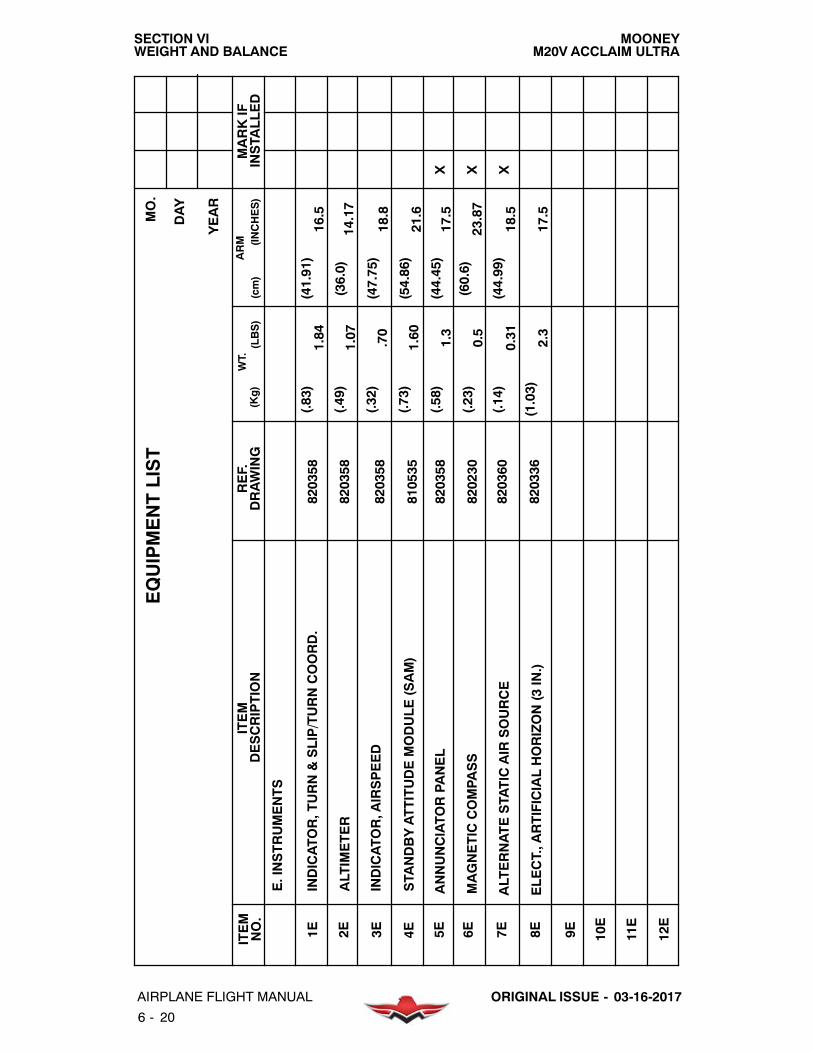
MOONEYM20V ACCLAIM ULTRA
SECTION VIWEIGHT AND BALANCE
6 - 20
AIRPLANE FLIGHT MANUAL ORIGINAL ISSUE - 03-16-2017
ANNUNCIATO
RPA
NEL
MAGNETIC
COMPA
SS
820358
(.58)
1.3
(44.45)
17.5
(.23)
0.5
(60.6)
23.87
X X820230
EQUIPMENTLIST
MO.
ITEM
ITEM
MARKIF
INSTA
LLED
WT.(LBS)
(Kg)
ARM (INCHES)
(cm)
E.INSTRUMENTS
DESCRIPTION
REF.
DRAWING
NO.
DAY
YEAR
1E 4E 5E 6E 7E 8E 9E
(.83)
1.84
(41.91)
16.5
10E
INDICATO
R,TURN&SLIP/TURNCOORD.
(.49)
1.07
(36.0)
14.17
ALTIMETER
(.32)
.70
(47.75)
18.8
INDICATO
R,A
IRSPEED
11E
2E 3E 12E
820358
820358
820358
(.73)
1.60
(54.86)
21.6
STA
NDBYATTITUDEMODULE(SAM)
810535
ALTERNATESTATIC
AIR
SOURCE
(.14)
0.31
(44.99)
18.5
X820360
(1.03)
2.3
17.5
ELECT.,A
RTIFICIALHORIZON(3IN.)
820336

MOONEYM20V ACCLAIM ULTRA
SECTION VIWEIGHT AND BALANCE
6 - 21AIRPLANE FLIGHT MANUALORIGINAL ISSUE - 03-16-2017
EQUIPMENTLIST
MO.
ITEM
ITEM
MARKIF
INSTA
LLED
WT.(LBS)
(Kg)
ARM (INCHES)
(cm)
E.INSTRUMENTS(CONT)
DESCRIPTION
REF.
DRAWING
NO.
DAY
YEAR
13E
16E
17E
18E
19E
20E
21E
22E
23E
14E
15E
24E

MOONEYM20V ACCLAIM ULTRA
SECTION VIWEIGHT AND BALANCE
6 - 22
AIRPLANE FLIGHT MANUAL ORIGINAL ISSUE - 03-16-2017
EQUIPMENTLIST
MO.
ITEM
ITEM
MARKIF
INSTA
LLED
WT.(LBS)
(Kg)
ARM (INCHES)
(cm)
F.MISCELLANEOUSSYSTEMS
DESCRIPTION
REF.
DRAWING
NO.
DAY
YEAR
1F 4F 5F 6F 7F 8F 9F 10F
11F
2F 3F 12F
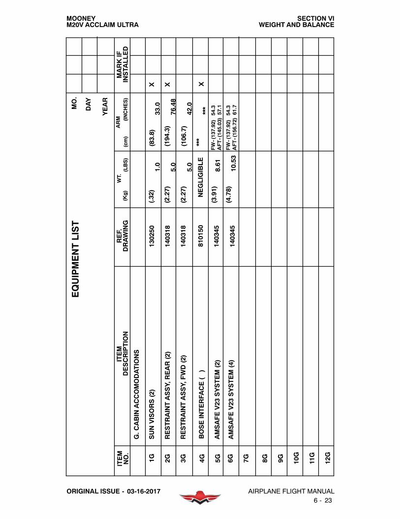
MOONEYM20V ACCLAIM ULTRA
SECTION VIWEIGHT AND BALANCE
6 - 23AIRPLANE FLIGHT MANUALORIGINAL ISSUE - 03-16-2017
BOSEINTERFA
CE()
***
***
X810150
NEGLIGIBLE
EQUIPMENTLIST
MO.
ITEM
ITEM
MARKIF
INSTA
LLED
WT.(LBS)
(Kg)
ARM (INCHES)
(cm)
G.C
ABIN
ACCOMODATIONS
DESCRIPTION
REF.
DRAWING
NO.
DAY
YEAR
RESTRAINTASSY,FWD(2)
AMSAFEV23
SYSTEM(2)
1G 4G 5G 6G 7G 8G 9G
(2.27)
5.0
(106.7)
42.0
(3.91)
8.61
FW-(137.92)54.3
(4.78)
10.53
10G
SUNVISORS(2)
RESTRAINTASSY,REAR(2)
130250
(.32)
1.0
(83.8)
33.0
(2.27)
5.0
(194.3)
76.48
X X2G 3G
140345
140345
140318
140318
11G
12G
AMSAFEV23
SYSTEM(4)
AFT-(145.03)57.1
FW-(137.92)54.3
AFT-(156.72)61.7

MOONEYM20V ACCLAIM ULTRA
SECTION VIWEIGHT AND BALANCE
6 - 24
AIRPLANE FLIGHT MANUAL ORIGINAL ISSUE - 03-16-2017
EQUIPMENTLIST
MO.
ITEM
ITEM
MARKIF
INSTA
LLED
WT.(LBS)
(Kg)
ARM (INCHES)
(cm)
H.AVIONICS&AUTO
PILOTS
DESCRIPTION
REF.
DRAWING
NO.
DAY
YEAR
GARMIN
ADF
KN63
DME
GARMIN
GFC700AUTO
PILOT
1H 4H 5H 6H 7H 8H 9H
(3.44)
7.59
(332.41)
130.87
(1.36)
3.00
(321.82)
126.70
(7.82)
17.23
(288.04)
113.40
X
10H
GARMIN
G1000
GARMIN
GDL69/69A
11H
950300
(38.08)
83.95
(208.28)
82.00
(1.28)
2.93
(350.01)
137.80
X X2H 3H 12H
950300
950300
950300
830153
SYNTHETIC
VISIONSYSTEM
810535
Revision A: 08-18-2017

MOONEYM20V ACCLAIM ULTRA
SECTION VIWEIGHT AND BALANCE
6 - 25AIRPLANE FLIGHT MANUALORIGINAL ISSUE - 03-16-2017
EQUIPMENTLIST
MO.
ITEM
ITEM
MARKIF
INSTA
LLED
WT.(LBS)
(Kg)
ARM (INCHES)
(cm)
H.AVIONICS&AUTO
PILOTS
(CONT.)
DESCRIPTION
REF.
DRAWING
NO.
DAY
YEAR
13H
17H
18H
19H
20H
21H
14H
15H
22H
16H

MOONEYM20V ACCLAIM ULTRA
SECTION VIWEIGHT AND BALANCE
6 - 26
AIRPLANE FLIGHT MANUAL ORIGINAL ISSUE - 03-16-2017
EQUIPMENTLIST
MO.
ITEM
ITEM
MARKIF
INSTA
LLED
WT.(LBS)
(Kg)
ARM (INCHES)
(cm)
I.AUXILIARYEQUIPMENT(FLY
AWAY)
DESCRIPTION
REF.
DRAWING
NO.
DAY
YEAR
EYEBOLT,W
INGTIE
DOWN(2)(STO
WED)
FUELSAMPLERCUP(STO
WED)
BAGGAGETIE
DOWNS(2)(STO
WED)
1I 4I 5I 6I 7I 8I 9I
(.09)
.1(332.7)
131.0
(.04)
.05
(332.7)
131.0
(.04)
.16
(332.7)
131.0
(.27)
1.0
(332.7)
131.0
X X X X
10I
CARGORESTRAINTBELTS(2)(STO
WED)
TOW
BAR,FOLDING(STO
WED)
JACKPOINTS(2)(STO
WED)
(.03)
.3(332.7)
131.0
PITOTCOVER(STO
WED)
(.84)
1.5
(332.7)
131.0
POH/AFMNO.
(.35)
.5(332.7)
131.0
ENGINEOPERATO
R’S
MANUAL-(CMI)
11I
010037
(1.03)
2.6
(273.1)
107.5
(.07)
.1(332.7)
131.0
X X X X X
2I 3I 12I
ENGINELOGBOOK
(.07)
.2(332.7)
131.0
X
AIRFRAMELOGBOOK
010037
010037
010037
010037
010037
010037
010037
010037
010037
010037
(.063)
.2(332.7)
131.0
X
MOONEY

MOONEYM20V ACCLAIM ULTRA
SECTION VIWEIGHT AND BALANCE
6 - 27AIRPLANE FLIGHT MANUALORIGINAL ISSUE - 03-16-2017
EQUIPMENTLIST
MO.
ITEM
ITEM
MARKIF
INSTA
LLED
WT.(LBS)
(Kg)
ARM (INCHES)
(cm)
J.OPTIONALEQUIPMENT
DESCRIPTION
REF.
DRAWING
NO.
DAY
YEAR
ACCESSPA
NEL,FUELGAUGE(2)
RUDDERPEDALEXTENSIONINSTL.(
)
1J 4J 5J 6J 7J 8J 9J
NEGLIGIBLEDIFFERENCE
(.059)
.13
(38.1)
15.0
(1.48)
3.27
(332.7)
131.0
X
10J
AUX.P
OWERRECEPTA
CLEINSTL.
ARMRESTINSTL,P
ILOT’S
SEAT
LUMBARSUPPORTINSTL.(2)
(3.43)
7.57
****
AUX.P
OWERCABLEADAPTER
(1.38)
3.05
(38.1)
15.0
DUALBRAKEPEDALINSTL.
STATIC
DISCHARGEINSTL.(STATIC
WICKS)
11J
140295
(.95)
2.1
(87.6)
34.5
(.99)
2.18
(88.9)
35.0
X
2J 3J ****NORMALLY
STO
WEDIN
BAGGAGECOMPA
RTMENTBETWEENST.110&130
STEPSASSEMBLY/IN
STA
L.
880042
950270
950253
950256
(2.49)
5.50
(274.3)
108.0
140300
210099
720115
800166
STA
ND-B
YALTERNATO
R800379
(3.1)
6.8
(-11.89)
-4.68
FIREEXTINGUISHERINSTL.
130328
(1.20)
2.65
(153.7)
60.5
NEGLIGIBLEDIFFERENCE

MOONEYM20V ACCLAIM ULTRA
SECTION VIWEIGHT AND BALANCE
6 - 28
AIRPLANE FLIGHT MANUAL ORIGINAL ISSUE - 03-16-2017
EQUIPMENTLIST
MO.
ITEM
ITEM
MARKIF
INSTA
LLED
WT.(LBS)
(Kg)
ARM (INCHES)
(cm)
J.OPTIONALEQUIPMENT(CONT.)
DESCRIPTION
REF.
DRAWING
NO.
DAY
YEAR
HEADRESTINSTL.,REAR
HEADRESTINSTL.,FRONT
12J
15J
16J
17J
18J
19J
20J
(1.57)
3.47
(203.20)
80.0
(1.57)
3.47
(114.3)
45.0
21J
ANTI-COLLISIONBEACON,FLASHING(RED)
(.39)
.87
(24.1)
9.5
DEFROSTERBLOWER
NOCHANGE
NOCHANGE
3PA
SSENGER,R
EAR,B
ENCHSEAT
(16.8)
36.5
(202.3)
79.6
TKSAIRFRAME,W
INGSONLY
(NOFLUID)
22J
950272
(.48)
1.06
(215.9)
85.0
274.3
108.0
13J
14J
23J
TKS-A/F/W
INGS/PROP-KNOWNICE(NOFLUID)
640315
140305
690007
690007
(18.1)
39.8
(203.5)
80.1
950301
140313/140323
140313/140323
TKS-FLUID
(TANKSFULL-6.0GAL.)
690007
(25.0)
55.2
(179.6)
70.7
REMOVEABLESTEPSASSEMBLY
RECOGNITIONLIGHTINSTL.(2)
(.60)
1.32
(134.6)
53.0
210413
50GALLONCAPA
CITYUSABLEFUELTA
NKS(2)
210217
(125.04)
49.23

MOONEYM20V ACCLAIM ULTRA
SECTION VIWEIGHT AND BALANCE
6 - 29AIRPLANE FLIGHT MANUALORIGINAL ISSUE - 03-16-2017
EQUIPMENTLIST
MO.
ITEM
ITEM
MARKIF
INSTA
LLED
WT.(LBS)
(Kg)
ARM (INCHES)
(cm)
J.OPTIONALEQUIPMENT(CONT.)
DESCRIPTION
REF.
DRAWING
NO.
DAY
YEAR
24J
27J
28J
29J
30J
31J
32J
147.42
33J
(30.0)
66.1
(151.5)
59.7
AIR
CONDITIONER(MINUSWTS.)
(4.1)
9.0
(180.3)
71.0
SPEEDBRAKE2000
34J
25J
26J
770000
950286
810447
WX500STO
RMSCOPE
(374.45)
3.34
(1.52)
870032
(9.75)
21.5
OXYGEN(77.1Cu.Ft.)Precise
Flight(Empty)
(347.98)
137.0
870032
(12.66)
27.9
(347.98)
137.0
OXYGEN(77.1Cu.Ft.)Precise
Flight(Full)
Revision A: 08-18-2017

MOONEYM20V ACCLAIM ULTRA
SECTION VIWEIGHT AND BALANCE
6 - 30
AIRPLANE FLIGHT MANUAL ORIGINAL ISSUE - 03-16-2017
EQUIPMENTLIST
MO.
ITEM
ITEM
MARKIF
INSTA
LLED
WT.(LBS)
(Kg)
ARM (INCHES)
(cm)
J.OPTIONALEQUIPMENT(CONT.)
DESCRIPTION
REF.
DRAWING
NO.
DAY
YEAR
36J
39J
40J
41J
42J
43J
44J
45J
46J
37J
38J
35J

MOONEYM20V ACCLAIM ULTRA
SECTION VIIAIRPLANE AND SYSTEM DESCRIPTION
7 - 1AIRPLANE FLIGHT MANUALORIGINAL ISSUE - 03-16-2017
TABLE OF CONTENTSTITLE SECTION. . . . . . . . . . . . . . . . . . . . . . . . . . . . . . . . . . . . . . . . . . . . . . . . . . . . . . . . . . . . . . . . . .
INTRODUCTION 7- 3. . . . . . . . . . . . . . . . . . . . . . . . . . . . . . . . . . . . . . . . . . . . . . . . . . . . . . . . . . . . . .AIRFRAME 7- 3. . . . . . . . . . . . . . . . . . . . . . . . . . . . . . . . . . . . . . . . . . . . . . . . . . . . . . . . . . . . . . . . . . .FLIGHT CONTROLS DESCRIPTION 7- 3. . . . . . . . . . . . . . . . . . . . . . . . . . . . . . . . . . . . . . . . . . . .
AILERON SYSTEM 7- 3. . . . . . . . . . . . . . . . . . . . . . . . . . . . . . . . . . . . . . . . . . . . . . . . . . . . . . . . .RUDDER SYSTEM 7- 4. . . . . . . . . . . . . . . . . . . . . . . . . . . . . . . . . . . . . . . . . . . . . . . . . . . . . . . . .RUDDER TRIM SYSTEM 7- 4. . . . . . . . . . . . . . . . . . . . . . . . . . . . . . . . . . . . . . . . . . . . . . . . . . . .ELEVATOR SYSTEM 7- 4. . . . . . . . . . . . . . . . . . . . . . . . . . . . . . . . . . . . . . . . . . . . . . . . . . . . . . .PITCH TRIM SYSTEM 7- 4. . . . . . . . . . . . . . . . . . . . . . . . . . . . . . . . . . . . . . . . . . . . . . . . . . . . . .WING FLAPS 7- 4. . . . . . . . . . . . . . . . . . . . . . . . . . . . . . . . . . . . . . . . . . . . . . . . . . . . . . . . . . . . . .
INSTRUMENT PANEL 7- 5. . . . . . . . . . . . . . . . . . . . . . . . . . . . . . . . . . . . . . . . . . . . . . . . . . . . . . . . .GARMIN G1000 7- 5. . . . . . . . . . . . . . . . . . . . . . . . . . . . . . . . . . . . . . . . . . . . . . . . . . . . . . . . . . . .
FLIGHT PANEL & INSTRUMENTS 7- 8. . . . . . . . . . . . . . . . . . . . . . . . . . . . . . . . . . . . . . . . . . . . . .SWITCHES & CONTROLS 7- 8. . . . . . . . . . . . . . . . . . . . . . . . . . . . . . . . . . . . . . . . . . . . . . . . . .
ANNUNCIATIONS OR ALERTS 7- 13. . . . . . . . . . . . . . . . . . . . . . . . . . . . . . . . . . . . . . . . . . . . . . . .GROUND CONTROL 7- 15. . . . . . . . . . . . . . . . . . . . . . . . . . . . . . . . . . . . . . . . . . . . . . . . . . . . . . . . .
NOSE GEAR STEERING 7- 15. . . . . . . . . . . . . . . . . . . . . . . . . . . . . . . . . . . . . . . . . . . . . . . . . . .TAXIING AND GROUND HANDLING 7- 15. . . . . . . . . . . . . . . . . . . . . . . . . . . . . . . . . . . . . . . .
LANDING GEAR 7- 15. . . . . . . . . . . . . . . . . . . . . . . . . . . . . . . . . . . . . . . . . . . . . . . . . . . . . . . . . . . . .CONSTRUCTION 7- 15. . . . . . . . . . . . . . . . . . . . . . . . . . . . . . . . . . . . . . . . . . . . . . . . . . . . . . . . .RETRACTION SYSTEM 7- 15. . . . . . . . . . . . . . . . . . . . . . . . . . . . . . . . . . . . . . . . . . . . . . . . . . . .WHEEL BRAKES 7- 15. . . . . . . . . . . . . . . . . . . . . . . . . . . . . . . . . . . . . . . . . . . . . . . . . . . . . . . . . .EMERGENCY EXTENSION SYSTEM 7- 16. . . . . . . . . . . . . . . . . . . . . . . . . . . . . . . . . . . . . . . .WARNING SYSTEM 7- 16. . . . . . . . . . . . . . . . . . . . . . . . . . . . . . . . . . . . . . . . . . . . . . . . . . . . . . .
CABIN 7- 16. . . . . . . . . . . . . . . . . . . . . . . . . . . . . . . . . . . . . . . . . . . . . . . . . . . . . . . . . . . . . . . . . . . . . .BAGGAGE COMPARTMENT 7- 16. . . . . . . . . . . . . . . . . . . . . . . . . . . . . . . . . . . . . . . . . . . . . . .CARGO RESTRAINT 7- 17. . . . . . . . . . . . . . . . . . . . . . . . . . . . . . . . . . . . . . . . . . . . . . . . . . . . . .SEATS 7- 18. . . . . . . . . . . . . . . . . . . . . . . . . . . . . . . . . . . . . . . . . . . . . . . . . . . . . . . . . . . . . . . . . . .SEAT BELTS/SAFETY HARNESS 7- 18. . . . . . . . . . . . . . . . . . . . . . . . . . . . . . . . . . . . . . . . . . .
DOORS, WINDOWS & EXITS 7- 18. . . . . . . . . . . . . . . . . . . . . . . . . . . . . . . . . . . . . . . . . . . . . . . . .CABIN DOORS 7- 18. . . . . . . . . . . . . . . . . . . . . . . . . . . . . . . . . . . . . . . . . . . . . . . . . . . . . . . . . . .PILOT’S WINDOW 7- 18. . . . . . . . . . . . . . . . . . . . . . . . . . . . . . . . . . . . . . . . . . . . . . . . . . . . . . . .EMERGENCY EXITS 7- 18. . . . . . . . . . . . . . . . . . . . . . . . . . . . . . . . . . . . . . . . . . . . . . . . . . . . . .
ENGINE 7- 19. . . . . . . . . . . . . . . . . . . . . . . . . . . . . . . . . . . . . . . . . . . . . . . . . . . . . . . . . . . . . . . . . . . .GENERAL 7- 19. . . . . . . . . . . . . . . . . . . . . . . . . . . . . . . . . . . . . . . . . . . . . . . . . . . . . . . . . . . . . . . .ENGINE CONTROLS 7- 19. . . . . . . . . . . . . . . . . . . . . . . . . . . . . . . . . . . . . . . . . . . . . . . . . . . . . .ENGINE INSTRUMENTS 7- 19. . . . . . . . . . . . . . . . . . . . . . . . . . . . . . . . . . . . . . . . . . . . . . . . . . .ENGINE OPERATION AND CARE 7- 20. . . . . . . . . . . . . . . . . . . . . . . . . . . . . . . . . . . . . . . . . . .OIL SYSTEM 7- 20. . . . . . . . . . . . . . . . . . . . . . . . . . . . . . . . . . . . . . . . . . . . . . . . . . . . . . . . . . . . .LUBRICATION SYSTEM 7- 21. . . . . . . . . . . . . . . . . . . . . . . . . . . . . . . . . . . . . . . . . . . . . . . . . . .BREATHER FOR CRANKCASE 7- 21. . . . . . . . . . . . . . . . . . . . . . . . . . . . . . . . . . . . . . . . . . . . .IGNITION SYSTEM 7- 21. . . . . . . . . . . . . . . . . . . . . . . . . . . . . . . . . . . . . . . . . . . . . . . . . . . . . . . .AIR INDUCTION SYSTEM 7- 23. . . . . . . . . . . . . . . . . . . . . . . . . . . . . . . . . . . . . . . . . . . . . . . . . .ICING PROTECTION 7- 24. . . . . . . . . . . . . . . . . . . . . . . . . . . . . . . . . . . . . . . . . . . . . . . . . . . . . .
Revision A: 08-18-2017

MOONEYM20V ACCLAIM ULTRA
SECTION VIIAIRPLANE AND SYSTEM DESCRIPTION
7 - 2
AIRPLANE FLIGHT MANUAL ORIGINAL ISSUE - 03-16-2017
EXHAUST SYSTEM 7- 24. . . . . . . . . . . . . . . . . . . . . . . . . . . . . . . . . . . . . . . . . . . . . . . . . . . . . . .FUEL INJECTION 7- 24. . . . . . . . . . . . . . . . . . . . . . . . . . . . . . . . . . . . . . . . . . . . . . . . . . . . . . . . .ENGINE COOLING AIR 7- 24. . . . . . . . . . . . . . . . . . . . . . . . . . . . . . . . . . . . . . . . . . . . . . . . . . . .ENGINE STARTING SYSTEM 7- 25. . . . . . . . . . . . . . . . . . . . . . . . . . . . . . . . . . . . . . . . . . . . . .
ACCESSORIES 7- 25. . . . . . . . . . . . . . . . . . . . . . . . . . . . . . . . . . . . . . . . . . . . . . . . . . . . . . . . . . . . . .EXHAUST GAS TEMPERATURE PROBE 7- 25. . . . . . . . . . . . . . . . . . . . . . . . . . . . . . . . . . . .TURBINE INLET TEMPERATURE (TIT) 7- 25. . . . . . . . . . . . . . . . . . . . . . . . . . . . . . . . . . . . . .
PROPELLER 7- 25. . . . . . . . . . . . . . . . . . . . . . . . . . . . . . . . . . . . . . . . . . . . . . . . . . . . . . . . . . . . . . . .HARTZELL THREE BLADE 7- 25. . . . . . . . . . . . . . . . . . . . . . . . . . . . . . . . . . . . . . . . . . . . . . . . .
FUEL SYSTEM SCHEMATIC 7- 26. . . . . . . . . . . . . . . . . . . . . . . . . . . . . . . . . . . . . . . . . . . . . . . . . .FUEL SYSTEM 7- 27. . . . . . . . . . . . . . . . . . . . . . . . . . . . . . . . . . . . . . . . . . . . . . . . . . . . . . . . . . . . . .ELECTRICAL SYSTEM 7- 27. . . . . . . . . . . . . . . . . . . . . . . . . . . . . . . . . . . . . . . . . . . . . . . . . . . . . . .
ALTERNATOR & BATTERY 7- 27. . . . . . . . . . . . . . . . . . . . . . . . . . . . . . . . . . . . . . . . . . . . . . . . .ESSENTIAL BUS 7- 28. . . . . . . . . . . . . . . . . . . . . . . . . . . . . . . . . . . . . . . . . . . . . . . . . . . . . . . . . .NON- ESSENTIAL BUS 7- 28. . . . . . . . . . . . . . . . . . . . . . . . . . . . . . . . . . . . . . . . . . . . . . . . . . . .EQUIPMENT LOCATION 7- 28. . . . . . . . . . . . . . . . . . . . . . . . . . . . . . . . . . . . . . . . . . . . . . . . . . .SCHEMATIC 7- 29. . . . . . . . . . . . . . . . . . . . . . . . . . . . . . . . . . . . . . . . . . . . . . . . . . . . . . . . . . . . . .CIRCUIT BREAKER PANEL 7- 30. . . . . . . . . . . . . . . . . . . . . . . . . . . . . . . . . . . . . . . . . . . . . . . .ACCESSORIES 7- 31. . . . . . . . . . . . . . . . . . . . . . . . . . . . . . . . . . . . . . . . . . . . . . . . . . . . . . . . . . .ANNUNCIATIONS AND ALERTS 7- 31. . . . . . . . . . . . . . . . . . . . . . . . . . . . . . . . . . . . . . . . . . . .
LIGHTING SYSTEM 7- 31. . . . . . . . . . . . . . . . . . . . . . . . . . . . . . . . . . . . . . . . . . . . . . . . . . . . . . . . . .INSTRUMENT & PLACARD LIGHTS 7- 31. . . . . . . . . . . . . . . . . . . . . . . . . . . . . . . . . . . . . . . . .MAP LIGHT 7- 32. . . . . . . . . . . . . . . . . . . . . . . . . . . . . . . . . . . . . . . . . . . . . . . . . . . . . . . . . . . . . . .CABIN LIGHTING 7- 32. . . . . . . . . . . . . . . . . . . . . . . . . . . . . . . . . . . . . . . . . . . . . . . . . . . . . . . . .EXTERIOR LIGHTING 7- 32. . . . . . . . . . . . . . . . . . . . . . . . . . . . . . . . . . . . . . . . . . . . . . . . . . . . .
CABIN ENVIRONMENT 7- 33. . . . . . . . . . . . . . . . . . . . . . . . . . . . . . . . . . . . . . . . . . . . . . . . . . . . . . .HEATING & VENTILATION SYSTEMS 7- 33. . . . . . . . . . . . . . . . . . . . . . . . . . . . . . . . . . . . . . .
PITOT PRESSURE & STATIC SYSTEM 7- 34. . . . . . . . . . . . . . . . . . . . . . . . . . . . . . . . . . . . . . . . .STALL WARNING SYSTEM 7- 34. . . . . . . . . . . . . . . . . . . . . . . . . . . . . . . . . . . . . . . . . . . . . . . . . . .OXYGEN SYSTEM 7- 35. . . . . . . . . . . . . . . . . . . . . . . . . . . . . . . . . . . . . . . . . . . . . . . . . . . . . . . . . . .VACUUM SYSTEM 7- 35. . . . . . . . . . . . . . . . . . . . . . . . . . . . . . . . . . . . . . . . . . . . . . . . . . . . . . . . . . .EMERGENCY LOCATOR TRANSMITTER 7- 35. . . . . . . . . . . . . . . . . . . . . . . . . . . . . . . . . . . . . .
ELT REMOTE SWITCH OPERATION 7- 35. . . . . . . . . . . . . . . . . . . . . . . . . . . . . . . . . . . . . . . .
Revision A: 08-18-2018

MOONEYM20V ACCLAIM ULTRA
SECTION VIIAIRPLANE AND SYSTEM DESCRIPTION
7 - 3AIRPLANE FLIGHT MANUALORIGINAL ISSUE - 03-16-2017
INTRODUCTION
Acquiring a working knowledge of the aircraft’s controls and equipment is one of your importantfirst steps in developing a fully efficient operating technique. This Airplane and Systems Sectiondescribes location, function, and operation of systems’ controls and equipment. It is recom-mended that you, the pilot, familiarize yourself with all controls and systems while sitting in thepilot’s seat and rehearsing the systems operations and flight procedures portions of thismanual.
AIRFRAME
The M20V is a metal/composite, low wing, high performance airplane. The fuselage has awelded, tubular- steel cabin frame covered with non- structural composite and aluminum skin.Access to the cabin is provided by pilot and co-pilot side doors located on each side of the fuse-lage. A door is provided aft of the rear seat for access to the baggage compartment. The aft fuse-lage, tailcone, is of semi- monocoque construction.
Seating in the cabin is provided for the pilot and three passengers.
The M20V has a tapered, full- cantilever, aluminum construction, laminar- flow type wing. Theairfoil varies from aNACA 632- 215 at the wing root to a NACA 641- 412 at the wing tip, modifiedbyan inboard leadingedge cuff.Wrap- around stretched formedskins cover thewing; flush rivet-ing is used on the forward, top and bottom two thirds of the wing chord to provide benefit of lami-nar flow aerodynamics.
The empennage consists of the vertical and horizontal stabilizer assembly and the rudder andelevator surfaces. The entire empennage pivots around attaching points on the aft fuselage toprovide pitch attitude trim.
The tricycle landing gear allows maximum vision and ground maneuvering. Hydraulic discbrakes and a steerable nose wheel aid in directional control during taxiing and ground opera-tions. The landing gear is electrically retracted and extended. A gear warning VOICE ALERT, agear position indicator on the floorboard and a green “GEAR DOWN” annunciation helps pre-vent in advertent gear-up landings. A manual emergency gear extension system is provided inthe event of electrical failure.
FLIGHT CONTROLS DESCRIPTION
The aircraft has dual flight controls and can be flown from either the pilot or co- pilot seat. Dualpairs of foot pedals control rudder and nose wheel steering mechanisms. Push- pull tubes actu-ate all- metal flight control surfaces. Rod- end bearings are used through out the flight controlsystems. These bearings are simple and require little maintenance other than occasional lu-brication. Longitudinal pitch trim is achieved through a trim control system that pivots the entireempennage around tailcone attachment points.
AILERON SYSTEM
The ailerons are of all- metal construction with beveled trailing edges. Three hinges ofmachined, extruded aluminum attach each aileron to aft wing spar outboard of wing flaps. Theailerons link to the control wheel through push- pull tubes and bellcranks. Counterweights bal-ance theailerons. A spring- loaded interconnect device indirectly joins aileronand rudder controlsystems to balance in lateral stability during flight maneuvers.

MOONEYM20V ACCLAIM ULTRA
SECTION VIIAIRPLANE AND SYSTEM DESCRIPTION
7 - 4
AIRPLANE FLIGHT MANUAL ORIGINAL ISSUE - 03-16-2017
RUDDER SYSTEM
The rudder attaches to the aft, vertical fin spar at four hinge points. Push- pull tubes andbellcranks link the rudder to the rudder pedals.
RUDDER TRIM SYSTEM
TheM20V is equipped with an electric rudder trim systemwhich allows the pilot to trim out muchof the rudder force required for take off, climb, cruise anddescent. The system is a “bungee” typespring assembly, attached to the rudder control system and driven by an electric motor. The trimsystem is operatedbya spring loadedmomentary switch, locatedabove the throttle on thepilot’spanel. The momentary switch is a safety measure that greatly reduces the possibility of a run-away trim situation. Rudder force varies from negligible (with trim to the far right ) to mild (withtrim set to the third segment from the right). Cruise setting will result in the trim indicator beingslightly left of neutral. A high speeddescentwill result in anevenmore left of neutral position. TheRudder Trim indicator is located on the Garmin GDU 10(XX) Mutli-Function Flight Display(MFD). The indicator depicts the position (right/left) of the rudder trim setting. Actual trimpositionis shown using a blue inverted triangle. The “takeoff” rudder trim position is shown in white.
ELEVATOR SYSTEM
Elevator construction is essentially the same as that of the rudder. Both elevators attach to thehorizontal stabilizer at four hinge points. Push- pull tubes and bellcranks link the elevators to thecontrol wheel. A down- spring located in the tailcone anda bobweight located forward of the con-trol column help create desirable stability characteristics. A factory set, fixed trim tab spans thelength of the elevator. Counterweights balance the elevators.
PITCH TRIM SYSTEM
Pitch trim is electrically actuated with a split toggle switch on the control wheel for autopilotequipped aircraft. The pitch trim may be manually actuated by a wheel located on the floor be-tween the pilot and co- pilot seat. Trim actuation turns a ball screw that increases or decreasesthe pitch angle of the entire empennage. The elevator trim position indicator (located on theMFD) depicts the position (up/down) of the pitch trim setting. Trim position is shown by a bluetriangle. A white block indicates “take- off” pitch trim position.
WING FLAPS
The wing flaps are electrically operated and interconnected through a torque tube andbellcranks. Total flap area is 17.98 square feet.
Nominal travel is 0 to 33. Limit switches prevent travel beyond these limits. Wing flap position iscontrolled by a pre- select switch located on the lower instrument panel. The flap position indica-tor (located on theMFD) shows the current position of the flaps. The three possible positions, up,take-off and down are depicted in cyan as “UP,” “T/O” and “DN,” respectively. During flaps posi-tion transition, “///” is displayed in the window. Generally, aircraft trim requirements will changewith use of the flaps. Lowering of the flaps will cause a nose down pitching condition which canbe easily corrected by application of nose up trim. Conversely, retraction of the flaps, from atrimmed flight condition, will cause a nose up pitching condition. Use of flaps should always bewithin the operational limits established in SECTION II. The flaps are very effective in loweringlanding speed and can be used to slow the aircraft to approach speeds.

MOONEYM20V ACCLAIM ULTRA
SECTION VIIAIRPLANE AND SYSTEM DESCRIPTION
7 - 5AIRPLANE FLIGHT MANUALORIGINAL ISSUE - 03-16-2017
INSTRUMENT PANELThe instrument panel has been designed to incorporate theG1000 Integrated Cockpit. All Com-munications, Navigation, Engine Instruments, and System annunciations have been integratedinto a custom design package specifically for the M20V series aircraft.
Engine andelectrical switches are locatedon the left side of the switch panel. Nav, strobe, recog-nition/landing and taxi light switches are located on the overhead switch panel.
Instrument panel lighting is provided by electroluminescent panels and post lights, overheadpanel lights and the internally lightedG1000 Integrated Cockpit System.Optimum cockpit panellighting for night flying is achieved by using a combination of panel lights and overhead maplights.
-NOTE-The illustrations depict a standard panel configuration. The location of
instruments, switches, and avionics may be relocated in each aircraft, dependantupon the optional equipment selected by the customer and available panel space.
GARMIN G1000
The GARMIN G1000 Integrated Avionics System consists of a Primary Flight Display (PFD), aMulti- Function Display (MFD), an Audio Panel, and Attitude and Heading Reference System(AHRS), an Air Data Computer (ADC), and the sensors and computers to process flight and en-gine information for display to the pilot. The system contains dual GPS receivers, dual VOR/ILSreceivers, dual VHF communications transceivers, a transponder, and an integrated annunci-ation system to alert the pilot of certain abnormal conditions. The G1000 also has an integratedGarmin Flight Management System (FMS) controller known as “GCU476KEYPADUNIT” - thisprovides alphanumeric, softkey, and flight planning function keys used to interfacewith aGarminIntegrated Flight Deck. The GCU 476 also provides heading, course, and altitude controls.
The Primary Flight Display (PFD) typically displays airspeed, attitude, altitude, and heading in-formation in a traditional format. Slip information is shownas a trapezoid under the bank pointer.One width of the trapezoid is equal to a one ball width slip. Rate of turn information is shown onthe scale above the compass rose; full scale deflection is equal to a standard rate turn. The fol-lowing controls are available on the PFD (clockwise from top right):S Communications frequency volume and squelch knobS Communications frequency set knobsS Communications frequency transfer buttonS Altimeter setting knob (baro/QNH set)S Course knobS Map range knob and cursor controlS FMS control buttons and knobS PFD softkey buttons, including master warning/caution acknowledgementS Altitude reference set knobS Heading bug controlS Navigation frequency transfer buttonS Navigation frequency set knobsS Navigation frequency volume and Identifier knobS Autopilot controls located on the MFD/PFD Bottom LH side
The PFD displays the crew alerting system (G1000 Annunciations). When an alert message isreceived, an aural tone will be heard. Selecting the Alert button will allow the flight crew to seeadditional information regarding the alert message.
Trend vectors are shown on the airspeed and altimeter displays as a magenta line predicting 6secondsat the current rate. The turn rate indicator also functions as a trend indicator on the com-pass scale.
The PFD can be displayed in a composite format for emergency use by pressing the DISPLAYBACKUP button on the audio panel. In the composite mode, the crew alerting function remainsoperative, but no map functions are available.

MOONEYM20V ACCLAIM ULTRA
SECTION VIIAIRPLANE AND SYSTEM DESCRIPTION
7 - 6
AIRPLANE FLIGHT MANUAL ORIGINAL ISSUE - 03-16-2017
The Multi- Function Display (MFD) typically displays engine data, maps, terrain, traffic and to-pography displays, and flight planning and progress information. The display unit is identical tothe PFD and contains the same controls as previously listed.
The audio panel contains traditional transmitter and receiver selectors, as well as an integralintercom andmarker beacon system. Themarker beacon lights appear on the PFD. In addition,a clearance recorder records the last 2½minutes of received audio. Lights above the selectionsindicate what selections are active. Pressing the red DISPLAY BACKUP button on the audiopanel causes both the PFD and MFD to display a composite mode.
The Attitude and Heading Reference System (AHRS) uses GPS, rate sensors, air data, andmagnetic variation to determine pitch and roll attitude, sideslip and heading. Operation is pos-sible in a degraded mode if the system loses any of these inputs, but the AHRS must have atleast theADCorGPS input to function. Statusmessagesalert the crewof the lossof anyof theseinputs. The AHRS will align while the aircraft is in motion, but will align quicker if the wings arekept level during the alignment process.
TheAir DataComputer (ADC) provides airspeed, altitude, vertical speed, and air temperature tothe display system. In addition to the primary displays, this information is used by the FMS andTIS systems.
Engine instruments are displayed on theMFD.Discrete engine sensor information (oil pressure,manifold pressure, etc.) is processed by the GARMIN Engine Airframe (GEA) sub- system.When an engine sensor indicates a value outside the normal operating range, the legend willturn yellow for caution range, and turn red and flash for warning range.
The G1000 also interfaces to the GFC700 autopilot and repeats the autopilot mode annuncia-tors on the G1000 PFD. This provides easy viewing of the autopilot operating mode and status,but remains a supplemental display of autopilot operating modes.
The GDL 69 Series are SiriusXM Satellite Radio data link receivers. The SiriusXM Satellite Ra-dio antenna receives the SiriusXM satellite signal and passes it to the GDL 69 Series. The GDL69/69H are weather data receivers only, and theGDL 69A/69AH are weather receivers, with theaddition of SiriusXM Satellite Radio audio entertainment. For detailed operating instructions,see Garmin G1000 Cockpit Reference Guide for the Mooney M20V.
The TSO’d KN 63, if installed, is a complete 100 watt, 200- channel remote DME system. Dis-tances up to 389 nm (at line- of- sight altitude), groundspeeds up to 999 knots and time- to- sta-tion up to 99 minutes are computed digitally and displayed on the G1000 PFD and controlled bythe G1000 interface controls. Distance lock- on is virtually instantaneous (usually within onesecond) with accurate groundspeed and time- to- station readouts following in less than a min-ute. For detailed operating instructions, see Garmin G1000 Cockpit Reference Guide for theMooney M20V.
TheTSO’dBecker ADF3502- (2) AutomaticDirection Finder system, if installed, provides accu-rate bearing- to- station in the 200 kHz to 1799 kHz frequency range, complete with ADF, ANTand BFO tuning modes, plus audio output for station identification and monitoring AM broad-casts. It is displayed on the G1000 PFD and controlled by the PFD interface controls. For de-tailed operating instructions, see Garmin G- 1000 Cockpit Reference Guide for the MooneyM20V.
The “Optional” GTS 800 is a microprocessor- based Line Replaceable Unit (LRU) that uses ac-tive interrogations of Mode S and Mode C transponders to provide traffic advisories to the pilot.Theadvisory providedbyGTS800 is independent of the air traffic control systemwhich improvespilot situational awareness. The traffic information is displayed on the PFD andMFD via HSDB,refer to the Pilot’s Guide and theGarminG1000Cockpit ReferenceGuide for theMooneyM20V.
Refer to the GARMIN G1000 Cockpit Reference Guide for the M20VMODEL aircraft, GARMINP/N 190-02285-00, Rev. A or later FAA approved, for complete descriptions of the G1000 sys-tem and operating procedures.
Revision A: 08-18-2017

MOONEYM20V ACCLAIM ULTRA
SECTION VIIAIRPLANE AND SYSTEM DESCRIPTION
7 - 7AIRPLANE FLIGHT MANUALORIGINAL ISSUE - 03-16-2017
FIGURE 7- 1 FLIGHT PANEL (33-0001 THRU 33- TBD)

MOONEYM20V ACCLAIM ULTRA
SECTION VIIAIRPLANE AND SYSTEM DESCRIPTION
7 - 8
AIRPLANE FLIGHT MANUAL ORIGINAL ISSUE - 03-16-2017
FLIGHT PANEL & INSTRUMENTS
SWITCHES & CONTROLS
-NOTE-The illustration depicts a standard panel configuration. The location of instru-
ments, switches, and avionics may be relocated in each aircraft, dependant uponthe optional equipment selected by the customer and available panel space.
1. MAGNETIC COMPASSMagnetic compass dial is graduated in five- degree increments and is encased in liquid-filled glass andmetal case. It is equipped with compensating magnets, adjustable from frontof case. Access to compass light and compensating magnets is provided by pivoted covers.No maintenance is required on magnetic compass except an occasional check on a com-pass rose, adjustment of the compensation screws (if necessary) and replacement of thelamp.
2. HOUR METER (NOT SHOWN)Hour meter - located on baggage compartment bulkhead indicates actual flight time and istriggered by theG1000airspeed indication setting. Locationmay vary depending on installedsystems.
3. STANDBY ATTITUDE MODULE (SAM)Digital standby instrument to provide attitude, altitude, airspeed and slip information in anadvanced 2- inch format. The self- contained, rechargeable, emergency battery offers pilotsan increased level of security. In Pre- flightmode, the introduction screenwill be displayed forapproximately five seconds andwill transition to Flight Modewhen complete. In Flight Mode,the unit operates normally by displaying all four major functions: Attitude, Altitude, Airspeedand Slip Information.
ATTITUDE Indicator portion of the displaywill always appear on the top display. TheAtti-tude Indicator consists of seven parts: Horizon Line, Sky (blue), Ground (brown), SymbolicAirplane, Roll Scale, Pitch Scale and Slip Indicator.
SLIP Indicator portion of the display will always appear at the bottom of the Attitude Dis-play. The Slip Indicator is represented by a shaded translucent background with two whitelines around center and a white ball. When the ball is maintained between the vertical linesduring banking maneuvers, the turn is considered “coordinated” without slip.
ALTIMETER Indicator portion of the display will always appear on the bottom display.The Altimeter consists of four parts; AltitudeWindow, Altitude Tape, Barometric SettingWin-dow and optional Altitude Trend Bar.
AIRSPEED Indicator portion of the display will always appear on the bottom display. TheAirspeed Indicator Display consists of three parts; AirspeedWindow, Airspeed Tape and Air-speed Limitations or Range Markings.
4. GARMIN GDU 10(XX) PRIMARY FLIGHT DISPLAY (PFD)See description in “Garmin G1000” earlier in this section.
5. GARMIN GDU 10(XX) MULTI- FUNCTION FLIGHT DISPLAY (MFD)See description in “Garmin G1000” earlier in this section.
6. GARMIN GMA 1347 AUDIO PANELSee description in “Garmin G1000” earlier in this section.
7. MAGNETO/STARTER SWITCHMagneto/Starter switch combines both ignition and starting functions. Turning ignition keyclockwise through R, L, and BOTH to START position and then pushing forward on key andreceptacle, engages starter. Releasing key when engine starts allows switch to return, byspring action, to BOTH position.
8. ALTERNATOR FIELD SWITCHThis switch cuts alternator field power from main buss to alternator.

MOONEYM20V ACCLAIM ULTRA
SECTION VIIAIRPLANE AND SYSTEM DESCRIPTION
7 - 9AIRPLANE FLIGHT MANUALORIGINAL ISSUE - 03-16-2017
9. MASTER POWER SWITCHMaster switch operates battery relay which controls battery power (selected battery) to mainbuss. This switch cuts ALL ship powerOFF, except cabin overhead lights and baggage com-partment light.
10. BATTERY SELECT SWITCH - BAT 1/BAT 2This switch allows pilot to select either battery as primary for any flight. Battery #1 is normallyused for operations. The battery not being used is recharged througha trickle charge system.It is recommended to switch batteries occasionally.
11. EMERGENCY BUS SWITCH (Optional when Stand- by Alternator is installed)When Low Voltage annunciation illuminates, steady or flashing, pull 90A BAT circuit breakerand PUSH EMERG BUS switch ON to bring Stand- by Alternator online.
12. STROBE LIGHT SWITCHStrobe light switch turns wing tip and tail strobe lights ON.
13. NAVIGATION LIGHT (NAV LITE) SWITCHNavigation light switch turns wing tip and tail navigation lights ON.
14. TAXI LIGHT (TAXI LITE) SWITCHES (L & R)
15. LANDING LIGHT (LDG LITE) SWITCHES (L & R)Select and push split switches to turn desired set of lights ON. Push switches OFF to turndesired set of lights off. Lights should be operated only for short timeperiodswhile not in flightto preclude overheating of lamps. Overload protection is achieved by circuit breakers in pan-el.
16. GEAR SAFETY BY PASS SWITCH (Gear Retraction Override)Gear safety override switch is amanualmeansof electrically by-passing theAir speedSafetySwitch. In the event the landinggear switch is placed in gear-up position, a properly operatingAirspeed Safety Switch prevents gear from being retracted before take off speed of approxi-mately 60 5 KTS is reached. To retract landing gear at a lower air speed, the GR SAFETYBY PASS switch may be held de-pressed until landing gear is completely retracted.
Activation of landing gear safety override switch overrides the safety features ofairspeed safety switch and CAN cause landing gear to start retracting while aircraft
is on ground.
-CAUTION-
17. LANDING GEAR SWITCHElectric gear switch, identified by its wheel shaped knob, is a two-position switch. Pulling aftand lowering knob lowers landing gear while pulling aft and raising knob raises landing gear.
-NOTE-Failure to “Pull” knob out prior to movement may result in a broken switch.
18. GEAR DOWN POSITION INDICATORThe gear- down position indicator, located on floorboard near back of fuel selector valve pan,aft of center console, has two marks that align when landing gear is down and illuminateswhen GREEN GEAR DOWN annunciation is ON. A red-white striped decal shows whenlanding gear is NOT in the down position.
19. RUDDER TRIM SWITCHSpring loaded momentary switch to position rudder into trimmed condition to reduce rudderpedal forces during take off, climbs or descents. Right - take off and climbs; Left - descents.Turning left side of spring loaded switch trims rudder left, turning right side of switch trimsrudder right.
20. PITOT HEAT SWITCHPitot heat SWITCH turns on heating elements within pitot tube. “PITOT HEAT” annunciationwill illuminate “AMBER” only when failure occurs.

MOONEYM20V ACCLAIM ULTRA
SECTION VIIAIRPLANE AND SYSTEM DESCRIPTION
7 - 10
AIRPLANE FLIGHT MANUAL ORIGINAL ISSUE - 03-16-2017
21. ICE LIGHT SWITCH (if Equipped)Lighting to alert the pilot of ice formation on surfaces of an aircraft.
22. READING LIGHTS SWITCHMomentary switch operates 4 overhead lamps in 3 modes. Reading Light Switch UP posi-tion, only the Pilot reading light is activated.With Reading Light Switch in Down position, ALLreading lights are activated. Passenger switches are located in the overhead panel.
23. DOME LIGHTS SWITCHON or OFF switch operates 1 main dome light in the center of overhead console.
24. “HIGH BOOST” FUEL BOOST PUMP SWITCHThe High Fuel boost pump switch operates the fuel boost pump on high power. The highboost setting is capable of operating engine at reduced power in case of engine driven fuelpump failure or severe fuel filter blockage. Selecting High Boost while Low Boost is poweredon causes LowBoost to turn off. Continuous operation should be avoided except in an emer-gency. Never run the boost pump without fuel in the system.
Pushing HIGH BOOST pump switch ON when engine driven pump is operatingproperly will cause engine to quit due to excessive rich fuel mixture.
-CAUTION-
25. BOOST PUMP SWITCH (LOW BOOST)The Low Fuel boost pump switch operates the fuel boost pump on low power to provide ameans of suppressing fuel vapor from fuel system during hot day and high altitude condi-tions. Lowboostmay also be used as an engine starting aid. Continuous operation of the lowboost is permitted. Never run the boost pump without fuel in the system.
Pushing LOW BOOST pump switch ON when engine is operating properly at idleconditions will cause engine to run rough or quit due to excessive rich fuel mix-
ture. For this reason LOW BOOST should be turned off except where prescribed inthe normal operating procedures.
-CAUTION-
26. AUTOPILOT POWER SWITCHA manually operated rocker switch located on the instrument panel. This switch will providepower to the autopilot system and the Manual Electric Trim (MET). There is another discon-nect using the MET and AP disconnect on the Pilot LH side control yoke. If the AP masterswitch is OFF, there will be an alert “FAILED PATH - A data path has failed”.
27. WING FLAP SWITCHFlap switch, on lower instrument panel, operates the electrically-actuated wing flaps. Theflap switch incorporates a pre-select feature for TAKEOFFandFULLDOWNpositions.Moveswitch down to first détente position to obtain TAKEOFF flaps (10). Move switch to full downposition to select FULLDOWN flaps (33).When flap switch ismovedUP to either TAKEOFFposition or FULL UP position the flaps will retract to the selected position.
Positioning Flap Switch to the UP position retracts the flaps completely.
-CAUTION-
28. PANEL LIGHT AND GLARESHIELD SWITCHMomentary light switch UP position will illuminate full strength or DOWN increases/decreas-es light intensity for the instrument panel area.
29. THROTTLE CONTROLPush throttle control forward to increase engine power. Pull throttle aft to decrease enginepower. Vernier control is optional.

MOONEYM20V ACCLAIM ULTRA
SECTION VIIAIRPLANE AND SYSTEM DESCRIPTION
7 - 11AIRPLANE FLIGHT MANUALORIGINAL ISSUE - 03-16-2017
30. PROPELLER CONTROLPush propeller control forward to increase engine RPM; pull control aft to decrease engineRPM. Control is a vernier type and fine adjustments of RPM can be obtained by turning knobclockwise to increase RPM and counter clockwise to decrease RPM. Knob should not beturned IN any closer than .030” to .060” to panel nut face.
31. MIXTURE CONTROLMixture control allows pilot to adjust the fuel- air ratio (mixture) of the engine. Push controlforward to enrich mixture. Pull control full aft to close idle cut off, shutting down engine. Con-trol is a vernier type and fine adjustments of mixture can be obtained by turning knob clock-wise to enrichmixture and counterclockwise to lean. Knob should not be turned IN any closerthan .030” to .060” to panel nut face.
32. EMERGENCY LOCATOR TRANSMITTER (ELT) SWITCHELT is activated when the ON button is pushed. ELT returns to ’armed’ condition when theRESET button is pushed. Refer to ELT description elsewhere in this section on proper andlawful usage.ARTEX ELT (optional): If the ELT switch is labeled ’ARTEX ELT’ then operation is differentfromabove. ELT is activatedwhen the switch is in theONposition. ELT returns to ’armed’ theswitch is in the ARMED position.
33. GO AROUND SWITCHGO AROUND switch is activated when the GA button is pushed. Reference G1000 Pilot’sGuide for more detailed information on system functionality.
34. ALTERNATE STATIC SOURCE VALVEPull alternate static source valve full aft to change source of static air for the altimeter, air-speed and vertical speed indicator from outside of aircraft to cabin interior. Air speed and al-timeter readings are affected slightly when alternate static source is used (See Charts inSECTION V).
35. PARKING BRAKE CONTROLDepress brake pedals and pull parking brake control to set parking brake. Push parkingbrake control in to release parking brake.
36. ALTERNATE AIR (ALT AIR)The alternate air valve automatically opens when the primary induction air system becomesblocked for any reason. The valve may be opened manually by pulling the ALT AIR knob aft.An AMBER annunciation will illuminate when alternate air door is open.
37. CABIN HEAT CONTROLPull cabin heat control to turn cabin heat on. To lower cabin temperature, cabin heat control ispushed forward toward the OFF position. Optimum use of cabin heat control is described inthe Cabin Environment Section.
38. DEFROST CONTROLPull defrost control to decrease air flow to lower cabin area and increase air flow towindshieldducts in the front of glareshield area. Optimum use of the defrost control is described in theCabin Environment Section.
39. CABIN VENT CONTROL (Fresh Air)Pull cabin vent control aft to open valve inmixing box connected to cabin air inlet vent locatedon the right side of the airplane. Optimum use of cabin vent control is described in the CabinEnvironment Section.
40. ACCESSORY USB PORTUniversal Serial Bus: an external serial bus interface standard for charging peripheral per-sonal devices; USB cable.
41. AIR CONDITIONING CONTROL (OPTIONAL)See description in “Supplemental Section” in this POH/AFM.
42. TKS (OPTIONAL)See description in “Supplemental Section” in this POH/AFM.

MOONEYM20V ACCLAIM ULTRA
SECTION VIIAIRPLANE AND SYSTEM DESCRIPTION
7 - 12
AIRPLANE FLIGHT MANUAL ORIGINAL ISSUE - 03-16-2017
43. 476 KEYPAD UNITThe GCU 476 refers to the Garmin Flight Management System (FMS) Controller used in aGarmin Integrated Flight Deck.The GCU 476 Line Replaceable Unit (LRU) provides alphanumeric, softkey, and flight plan-ning function keys used to interface with a Garmin Integrated Flight Deck. In addition to al-phanumeric, softkey, and flight planning function keys the GCU 476 provides COM/NAV tun-ing capabilities. The GCU 476 mounts flush to the aircraft instrument panel using ajackscrew.
44. CIRCUIT BREAKER PANELSee details elsewhere in this Section.
45. OXYGEN SELECTOR SWITCH - Precise Flight Oxygen System (Optional)See description in “Supplemental Section” in this POH/AFM.
46. FUEL SELECTOR VALVE (NOT SHOWN)Fuel selector valve, located on floorboard, is a three position valvewhich allows pilot to selecteither left or right fuel tank. Turning valve OFF, shuts off ALL fuel to engine. At full throttleengine will stop from fuel starvation in 2 to 3 seconds.
47. TRIM CONTROL WHEEL (NOT SHOWN)Rotating trim control wheel forward lowers nose during flight; rearward rotation raises noseofaircraft during flight. If optional electric trim system is installed, pushing both sides of split trimswitch, located on left hand portion of pilots control wheel, will electrically trim aircraft.
48. PILOT, CO-PILOT’SHEADSET JACKS,MIC JACK (HandHeldMicrophone) andUSBPORT (If installed) (NOT SHOWN)Plug hand held microphone jack into this plug and place microphone in holder located onfront of lower center console both LH and RH side.
49. OPTIONAL EQUIPMENT SWITCHES (If installed) (NOT SHOWN)MAP LIGHT SWITCH/RHEOSTAT, MIKE SWITCH, ELECTRIC TRIMSWITCH (if installed),WX Clear (if installed) are located in the pilot’s control wheel.

MOONEYM20V ACCLAIM ULTRA
SECTION VIIAIRPLANE AND SYSTEM DESCRIPTION
7 - 13AIRPLANE FLIGHT MANUALORIGINAL ISSUE - 03-16-2017
FIGURE 7- 2 ANNUNCIATIONS
ANNUNCIATIONS AND ALERTS
ANNUNCIATIONS or ALERTS
GEAR SAFETY INDICATOR (GEAR DOWN - GEAR UNSAFE)AGEARDOWN annunciation “GREEN”, a GEARUNSAFE annunciation “RED”, and a gearwarning VOICE ALERT provide visual and audible gear position signals. The “GREEN”(GEAR DOWN) annunciation shows continuously when gear is fully extended. All gear an-nunciations are OUT when landing gear is fully retracted. Red “GEAR UNSAFE” annuncia-tion displays during gear transition. Additional verification is accomplished by checking floorboard indicator window.
SPEEDBRAKESThe Annunciation will illuminate “WHITE” after the SpeedBrake switch is depressed ON andboth units are in the fully extended position. If the annunciation fails to illuminate and bothSpeedBrakes do not extend after the switch is depressed ON, it indicates a failure of one ofthe SpeedBrake cartridges. The SpeedBrake switch should be depressed OFF. The systemmay be checked a second time for proper operation, but after the second attempt the Speed-Brake switch should be leftOFF.When theSpeedBrakeSwitch is depressed to theOFFposi-tion, the annunciation will extinguish when both SpeedBrakes are fully retracted in the wing.The central - logic unit will disconnect theSpeedBrake clutch power to bothSpeedBrake car-tridges if one cartridge does not reach full extension. However, the drivemotors will continueto operate until the SpeedBrake Switch is depressed OFF. The central - logic unit also dis-connects clutch power if SpeedBrakes retract to within 10 degrees of the fully stowed posi-tion.
-NOTE-
A SpeedBrake cartridge that operates but does not fully retract flush with thewing surface is an indication of a failed cartridge clutch. Place the Speedbrake
circuit breaker in the pulled position and have maintenance personnel inspect thesystem per Precise Flight SpeedBrake 2000 Maintenance procedures before any
subsequent Speedbrake System Operation.
Revision A: 08-18-2017

MOONEYM20V ACCLAIM ULTRA
SECTION VIIAIRPLANE AND SYSTEM DESCRIPTION
7 - 14
AIRPLANE FLIGHT MANUAL ORIGINAL ISSUE - 03-16-2017
ALTERNATE AIRIlluminates AMBER when the alternate air door is opened, either manually or automatically.In this situation, induction air for the engine is drawn from inside cowling rather than throughthe induction air intake. Thenormal induction air systemMUSTbechecked, for proper opera-tion, prior to next flight.
-NOTE-Induction of alternate air (warm air) will result in loss of power.
PROP DEICE - (PROP DEICE is only an option for aircraft without TKS installed.)Illuminates AMBER when PROPDEICE has been selected ON. If system is operating prop-erly, theGREENPROPDEICE switch lamp is illuminated, and theG1000 shows no annunci-ation. Amber PROP DEICE if the PROP DEICE switch is in ON position with Green PROPDE-ICE switch lamp illuminated, but PROP DEICE system has failed.
PITOT HEATIf system is operating properly, the GREEN Pitot Heat switch lamp is illuminated, and theG1000 shows no annunciation. AMBERPITOT HEAT if the PITOT HEAT switch is in ON po-sition with GREEN PITOT HEAT switch lamp illuminated, but Pitot Heat system has failed.PITOTHEATwill illuminateAMBERonlywhen there is any type of electrical failure in the pitotheat system. It will not illuminatewhen switch isOFFandwill not illuminatewhen switch isONand current is flowing through pitot heater.
ALTERNATOR VOLTSA RED annunciation indicates improper voltage supply. RED ALTERNTR FAIL on G1000Display whenAlternator output goes to zero, or when Field shorts. NOTE: Voltmeter onMFDDisplay flashes YELLOW when bus voltage drops below [email protected] whether alternatorhas failed or not.
START POWERIlluminates RED when the starter switch is engaged or relay has malfunctioned and thestarter is engaged while the engine is running. Shut the engine off as soon as practicable.
EMERGENCY BUSAMBER EMERGENCY BUS Displayed on G1000 when EMERGENCY BUS switch isselected ON. GREEN lamp on Emergency Bus switch when switch is selected ON
DOOR OPENRED DOOR OPEN Displayed on G1000 when either cabin door(s) or baggage door is notshut.
LOW BOOST PUMPGREEN lamp illuminated on LOW BOOST Switch. WHITE low boost Illuminated on G1000Annunciation.
HIGH BOOST PUMPAMBERHIGH BOOST Displayed onG1000. NOTE: The HIGHBOOST switch has a thumblock- out to prevent accidental operation instead of a green lamp.
SWITCH PANELS & ANNUNCIATOR PANELS MAY VARY WITH AIRCRAFT
Revision A: 08-18-2017

MOONEYM20V ACCLAIM ULTRA
SECTION VIIAIRPLANE AND SYSTEM DESCRIPTION
7 - 15AIRPLANE FLIGHT MANUALORIGINAL ISSUE - 03-16-2017
GROUND CONTROLNOSE GEAR STEERING
Nose gear steering system consists of a steering horn on the nose gear leg linked to the rudderpedals by push- pull tubes. Rudder pedal action steers the nose wheel. Gear retraction relievesthe rudder control system of its nose wheel steering and centers wheel to permit retraction intothe nose wheel well. Minimum turning radius on the ground is 40 feet (12.0m) to the right and 48feet (14.4 m) to the left. Adjustable steering stops have been incorporated on nose gear leg as-sembly.
The nose wheel must not be swivelled beyond 11 left or 13 right of center. Toexceed these limits may cause structural damage.
-CAUTION-
TAXIING AND GROUND HANDLING
The aircraft can be easily taxied with minimum use of brakes. Minimum turning radius is 40 ft.(12.0 m) right & 48 ft. (14.4 m) left, without use of brakes. A MANUAL towbar is provided toground handle aircraft. Care must be used to not swivel nose wheel beyond 13 right or 11 leftfrom center. Adjustable steering stops are incorporated on nose gear leg assembly.
Exceeding steering swivel angle limits may cause structural damage.
-CAUTION-
LANDING GEARCONSTRUCTION
Landing gear legs are constructed of chrome-molybdenum tubular steel, heat- treated forgreater strength andwear resistance.Main gear leg attaching points pivot in bearing surfaces onforward and stub spars. The nose gear mounts on cabin tubular steel frame. Rubber discs in allgear leg assemblies absorb shock of taxiing and landing.
RETRACTION SYSTEM
Landing gear is electrically retracted and extended. The landing gear switch operates a landinggear actuator relay. Pull wheel- shaped knob out and move it to upper détente to raise landinggear. An Airspeed Safety Relay, connected to the airspeed indicator, is incorporated into theGarminG1000 system and alerts the pilot to prevent landing gear retraction while on the groundand until a safe takeoff speed (approximately 70 5 KTS) is reached. A properly rigged up- limitswitch will stop landing gear in its retracted position. Move control knob to its lower détente tolower landing gear. A properly rigged down- limit switch will stop landing gear actuating motorwhen proper force has been exerted to hold landing gear in the down- and- locked position.Bungee springs pre- load the retractionmechanism in an over center position to assist in holdinglanding gear down. A landing gear safety by- pass switch override is provided, next to the gearswitch, to allow the landing gear to retract for maintenance purposes. Depress and hold thisswitch tomanually by- pass airspeed safety relay and allow landinggear to retract. Theelectricalextension or retraction systemwill not operate if themanual extension lever is not properly posi-tioned down (refer to Emergency Extension System section).
Never rely on airspeed safety relay to keep landing gear down during taxi, takeoffor landing. Always make certain that landing gear switch is in down position during
these operations.
-CAUTION-
WHEEL BRAKES
Main gear wheels incorporate self-adjusting, disc-type, dual puck, hydraulic brakes. The pilot’srudder pedals have individual toe-actuatedbrake cylinders linked to the rudder pedals.Depress-
Revision A: 08-18-2017

MOONEYM20V ACCLAIM ULTRA
SECTION VIIAIRPLANE AND SYSTEM DESCRIPTION
7 - 16
AIRPLANE FLIGHT MANUAL ORIGINAL ISSUE - 03-16-2017
ing both toe pedals and pulling parking brake control, on console, sets the brakes. Push parkingbrake control forward to release brakes. It is not advisable to set parking brake when brakes areoverheated, after heavy braking or when outside temperatures are unusually high. Trapped hy-draulic fluidmay expandwith heat and damage the system.Wheel chocks and tie downs shouldbe used for long-term parking.
EMERGENCY EXTENSION SYSTEM
A manual, emergency gear extension mechanism is provided to allow emergency lowering oflanding gear. The control mechanism is located between and aft of pilot and co- pilot seats. TheRED lever must be released and pulled up (rotated aft) to engage themanual emergency exten-sion mechanism. The mechanism has a spring retracted pull cable which manually drives thegear actuator to extend landing gear. 12- 20 pulls are required to fully extend and lock landinggear down. The electrical extension or retraction systemwill not operate if themanual extensionlever is not properly positioned down.
WARNING SYSTEMThe landing gear warning system consists of:
1) landing gear condition annunciations, GREEN for “GEAR DOWN” and RED for “GEAR UN-SAFE”, and
2) VOICE ALERT, activated when landing gear is not down-and-locked and throttle is approxi-mately 1/4 inch from idle position. The green annunciation shows continuously when landinggear is fully extended. The red annunciation shows when ever landing gear is in transit or notlocked down but is OFF when landing gear is fully retracted. A visual gear-position indicator, lo-cated on floorboard, aft of the fuel selector, shows that landing gear is down when indicatormarks align. The gear down annunciation is dimmed when navigation lights are turned on.
CABINBAGGAGE COMPARTMENT
The baggage compartment is located aft of rear passenger seats. The standard compartmenthas 20.9 cubic feet (0.59 cu.m.) of baggage or cargo space. A maximum of 120 pounds (54 Kg)may be loaded in this area. There are floor tie down straps provided. Passengers should not beallowed to occupy this space.
Additional cargo space is available by folding rear seats down. To fold seats down remove rearseat bottom cushion. Pull seat back release handle and fold seat back forward, pull Velcro at-tachment loose, and slide seat cover UP andOFF frame. Fold the seat backs the rest of the waydown. Store the cushions as desired. Reverse the procedure to re-install.
Seat back frames may also be removed for additional space. To remove frame fold rear seatback forward, pull Velcro attachment loose, and slide seat coverUPandOFF frame. Pull the lockpin on the left side of each frame then pull seat frame from pivot rods. Pull seat back releasehandle UP and push pivot rods forward & down into seat cushion cavity. Reverse the procedureto re-install.
Both rear seats can be folded down and/or removed together or independent of each other.
The storage area located aft of the top of the aft baggage compartment bulkhead (hat rack) isrestricted to 10 pounds (4.5 Kg).

MOONEYM20V ACCLAIM ULTRA
SECTION VIIAIRPLANE AND SYSTEM DESCRIPTION
7 - 17AIRPLANE FLIGHT MANUALORIGINAL ISSUE - 03-16-2017
FIGURE 7- 3 CARGO RETENTION (TYPICAL)
CARGO RESTRAINT
Cargo tie down rings/clevis pins are to be inserted into holes provided in web of front seat rails.The cargo belts attach to these rings and to standard seat belt harness to retain cargo. Refer toFigure 7- 3 for typical restraint.
-CAUTION-Proper loading and retention of cargo is mandatory. See Loading Computation
Graph, SECTION VI.
SEAT BELT - STD SEAT BELT - REEL
SINGLE POINT ADJUSTMENT
FIGURE 7- 4 INERTIAL REEL/HARNESS RETENTION

MOONEYM20V ACCLAIM ULTRA
SECTION VIIAIRPLANE AND SYSTEM DESCRIPTION
7 - 18
AIRPLANE FLIGHT MANUAL ORIGINAL ISSUE - 03-16-2017
SEATS
The front seats are individuallymounted andmaybe adjusted fore and aft to fit individual comfortpreferences. The front seat back may be adjusted by turning left side hand crank (knob) untilseat back is in desired position. Both optional front seat configurations allow vertical seat heightadjustment by turning right side hand crank to raise or lower the entire seat assembly. The rearseat backs have four (4) adjustment positions. Each seat can be adjusted independent of theother by pulling up on respective release handle located on left or right of aircraft centerline onforward spar. This allows adjustments from approximately 10 to 40 recline position.
SEAT BELTS/SAFETY HARNESS
Safety restraints, if worn properly, (1 occupant per restraint) keep occupants firmly in their seatsduring T/O, landing, turbulent air and during maneuvers. The belts/harnesses aremechanicallysimple and comfortable to wear. The front seat inertia belts/harnesses are attached to hardpoints on side structure and seats. The rear seat belts are attached to brackets firmlymounted tostructural hard points. Shoulder harnesses are provided for rear seat occupants. Safety belts/harnesses MUST be fastened for take- off and landing operations. It is recommended that allinfants and small children below 40 lbs. weight and/or under 40 in. height be restrained in anapproved child restraint system appropriate to their height and weight. The single diagonal typesafety harness is designed so the chest strap crosses diagonally from the outboard shoulder toan attachment point as lowon the inboard hip as possible. Rear seat occupants should take careto conform with this procedure in adjusting chest strap and inboard belt length. This diagonalconfiguration places body center-of-gravity inside the triangle formedby chest strap and lapbelt.The lap belt should be adjusted comfortably tight. As a result, the body is restricted from rollingout toward the unrestricted shoulder or “open” side of the harness, upon forward impact. Refer toFigure 7- 4 for proper seat belt/harness adjustment.
TheAAIRV23 is a self-contained,modular, three-point restraint system that improves protectionfrom serious head impact injury during a survivable aircraft crash by inclusion of an inflatableairbag to the lap belt portion of the three point restraint.
The AAIR V23 system is activated when the buckle’s are joined [buckled] together at each seatlocation.
DOORS, WINDOWS & EXITSCABIN DOORS
Access into cabin is provided by a door located on left and right side of fuselage. These doorshave inside and outside operating handles. The outside door handle can be locked with a keyspecifically provided for it. Each door has two latching pinmechanisms, one located at the top ofdoor and one at the aft, center of door.
Should any of the doors come open in flight, flying qualities of the aircraft will not be affected. Procedures for closing door in flight are contained in SECTION III.
PILOT’S WINDOW
A pilot’s stormwindow is located in the left main cabin window. This window is generally used forfresh air for prolonged ground operations or as required during adverseweather conditions. Thewindow should not be opened in flight above 132 KIAS.
EMERGENCY EXITS
Both CABINDOORSare the primary emergency exit from the cabin. If a situation exists where aprobable off airport landing will occur, the door should be unlatched to prevent jamming duringlanding.
The BAGGAGE compartment access DOOR can be used as an auxiliary exit. The door can beopened from the inside even though locked. To open, pull off small ABS cover, pull out latch pinand pull Red Handle.

MOONEYM20V ACCLAIM ULTRA
SECTION VIIAIRPLANE AND SYSTEM DESCRIPTION
7 - 19AIRPLANE FLIGHT MANUALORIGINAL ISSUE - 03-16-2017
To verify re-engagement of latching mechanism; open outside handle fully, close inside handleto engage pin into cam slide of latchmechanism; insert latch pin into shaft hole to hold RedHan-dle down. Replace ABS cover. Operate outside handle in normal method.
ENGINEGENERAL
The engine installed is a Continental Motors Inc. TSIO 550- G( * ), turbocharged, fuel injectedengine. The following designation describes engine:
TS Denotes “TURBO- SUPERCHARGED”. . . . . . . . . . . . . . . . . . . . . . . . . . . . . . . . . . . . . . . . . . .I Denotes “FUEL INJECTED”. . . . . . . . . . . . . . . . . . . . . . . . . . . . . . . . . . . . . . . . . . . . . . . . . . . . . . .O Denotes “OPPOSED” (refers to the horizontally opposed cylinders). . . . . . . . . . . . . . . . . . .550 Denotes piston displacement in “CUBIC INCHES”. . . . . . . . . . . . . . . . . . . . . . . . . . . . . . . . .G ( * ) Denotes a specific equipment configuration. . . . . . . . . . . . . . . . . . . . . . . . . . . . . . . . . . . . .
* Refer to TCDS for engine configuration required.
The TSIO-550-G has twin turbochargers which use exhaust gas flow to boost induction air pres-sure for increased power. There is one turbocharger on each side of the engine. The turbocharg-ers compress and raise the temperature of the incoming air before going to the intercoolers. Thecompressed air runs through the intercoolerswhere it is cooled down before entering the throttlebody and cylinders. The dual turbochargers are lubricated from external oil supply lines from asource at the bottom of the oil cooler. There is one oil pressure actuated wastegate on the leftside of the engine controlling the amount of exhaust gas used by the turbochargers. Control isaccomplished by a diaphragm actuated valve sensing differential pressure across the throttleplate and controlling the oil return flow rate from the wastegate. An overboost valve in the induc-tion system provides protection from too much pressure by actuating at 35 in Hg of manifoldpressure.
The engine operates with three, standard engine controls. The propeller turns clockwise asviewed from the cockpit.
ENGINE CONTROLS
The engine controls are centrally located between the pilot and co- pilot on the lower middle in-strument panel. TheBLACK throttle knob regulatesmanifold pressure; push the knob forward toincrease the setting; pull the knob aft to decrease the setting.
The propeller control, with its crowned BLUE knob, controls engine RPM through the propellergovernor. Push the knob forward to increase engine RPM; pull the knob aft to decrease RPM.
The mixture control, with its RED fluted knob, establishes the fuel- air ratio (mixture). Push theknob full forward to set themixture to full- rich, pull the knob gradually aft to lean themixture. Pullthe knob to itsmaximum aft travel position to close the idle cut- off valve to completely shutdownthe engine. Precisemixture settings can beestablished by observing theTIT gaugeon the pilot’sinstrument panel while adjusting the mixture control.
The throttle, propeller andmixture controls are vernier type and fine adjustment can bemade byturning knobs clockwise or counter- clockwise. The vernier controls should be riggedwithin .030to .060 in. from panel nut face. Rapid movement or large adjustments can be made by pushingbutton on end of control and positioning control where desired. The non- vernier throttle has anintegral friction device.
ENGINE INSTRUMENTS
Engine instruments operate electrically, except manifold pressure, through variations in resis-tance caused by pressure or temperature changes or by variations in current output caused byvarying engine RPM or alternator output. The tachometer receives its signal from the Hall effectsensor in magneto.

MOONEYM20V ACCLAIM ULTRA
SECTION VIIAIRPLANE AND SYSTEM DESCRIPTION
7 - 20
AIRPLANE FLIGHT MANUAL ORIGINAL ISSUE - 03-16-2017
Engine operating instruments are displayed in the Garmin GDU 10(XX) Multi- Function Display. Colored bars on instrument faces mark operating ranges. Proper interpretation of engine instru-ment readings is essential for selecting optimum control settings and for maintaining maximum cruise fuel economy. (Refer to SECTION II for Limitations).
ENGINE OPERATION AND CARE
Life of an engine is determined by the care it receives. Maximum efficiency and engine servicelife can be expected when a good maintenance program is followed. Poor maintenance resultsin faulty engine performance and reduced service life. Efficient engine operation demands care-ful attention to cleanliness of air, fuel, oil andmaintaining operating temperatureswithin requiredlimits. Servicing of the engine should be accomplished only by qualified personnel. The mini-mum grade of fuel for this engine is 100LL or 100 octane aviation gasoline. Operational proce-dures for adverse environmental conditions can be found in enginemaintenance and operator’smanual.
OIL SYSTEM
The engine has a full- pressure, wet sump oil systemwith an 8 quart (7.57 liters) capacity. A con-ventional dipstick is provided for determining oil quantity. The oil system is depicted in Figure7- 5. The propeller governor boosts engine oil pressure for operation of the propeller. It controlsoil pressure going to the propeller hub to maintain or change propeller blade angles. This oilflows through propeller shaft to reach the propeller.

MOONEYM20V ACCLAIM ULTRA
SECTION VIIAIRPLANE AND SYSTEM DESCRIPTION
7 - 21AIRPLANE FLIGHT MANUALORIGINAL ISSUE - 03-16-2017
TOCRANKSHAFTBEARNGSTO
PROPGOVERNOR
VALVEASSY
OILTEMPCNTRLVALVE
TURBOCHARGER
WASTEGATE
OILCOOLER
OILPUMP
CHECKVALVE
CAMSHAFT
TAPPET
OILSUCTIONTUBE
STARTERIDLERGEAR
PISTON &CONNECTING
ROD
CRANKSHAFT
TOPROPELLER
SHAFTGEAR
TURBOCHARGER
CONTROLLER
FIGURE 7- 5 OIL SYSTEM SCHEMATIC
LUBRICATION SYSTEMOil Filter - Full flow oil filter is a throw away filter element with a bypass valve incorporated.BREATHER FOR CRANKCASEThe crankcase is vented overboard through an air- oil separator to a “C“ shaped standpipemounted in the left wheel-well area. The air oil separator condenses some of the oil vapor andreturns the oil back to the crankcase. Proper maintenance of this system is required tominimizeoil consumption.
IGNITION SYSTEM
The TSIO- 550- G engine is equipped with pressurized magnetos with impulse couplings oneach magneto.
Power from the engine crankshaft is transmitted through camshaft gear to the magneto drivegears, which in turn drives the magneto drive couplings. The left magneto incorporates an im-pulse coupling. As the rubber bushings in the drive gear turns the coupling drive lugs, counter-weighted latch pawls inside the coupling cover, engage pins on themagneto case and hold backthe latch plate until forced inward by the coupling cover. When the latch plate is released, the

MOONEYM20V ACCLAIM ULTRA
SECTION VIIAIRPLANE AND SYSTEM DESCRIPTION
7 - 22
AIRPLANE FLIGHT MANUAL ORIGINAL ISSUE - 03-16-2017
coupling spring spins the magneto shaft through its neutral position and the breaker opens toproduce a high voltage surge in the secondary coil. The spring action permits the latch plate,magnet and breaker to be delayed througha lag angle of 30 degrees of drive gear rotation duringthe engine cranking period. Two lobes on the breaker cam produce two sparks per revolution ofthe drive shaft. After engine is running, counter- weights hold the latch pawls away from the stoppins and the magneto shaft is driven at full advance.
The engine firing order is 1- 6- 3- 2- 5- 4. Ignition harnesses are connected to the magnetos sorightmagneto fires the upper plugs on the right side and lower plugs on the left. The left magnetofires the upper plugs on the left and lower plugs on the right. The magneto cases, spark plugs,harnesses and connections are shielded to prevent radio interference.

MOONEYM20V ACCLAIM ULTRA
SECTION VIIAIRPLANE AND SYSTEM DESCRIPTION
7 - 23AIRPLANE FLIGHT MANUALORIGINAL ISSUE - 03-16-2017
AIR INDUCTION SYSTEM
The primary engine air induction system draws air from the upper cowling plenum through theengine cooling inlets. The air passes through a filter and is split to provide air to the left and rightturbo. The standard air filter is cleanable and must be serviced at 100 hour intervals. Refer theservice and maintenance manual for instructions.
AIR INLET
FILTER
FUELCONTROL
UNIT
ALT.AIRBOX
ENGINE INDUCTIONAIR SYSTEM
FILTER CAN
ENGINE
INTERCOOLER
LH
INTERCOOLER
RH
FRONTOF
AIRCRAFT
LH TURBO RH TURBO
AIR INLET
LOWER COWLPLENUM
UPPER COWLPLENUM
FIGURE 7- 6 AIR INDUCTION SYSTEM SCHEMATIC
A secondary or alternate air source for combustion air is provided. It has a door which normallyremains closed and is held by a magnetic catch. If the air filter or induction air inlet is restrictedbeyond a minimum allowable inlet pressure, the alternate air door will automatically open.Warmer air will then be drawn from the engine compartment. There will be a reduction of enginepower when the alternate air door is open due to lower inlet air pressure and higher air tempera-ture. Whenever the alternate air door is open, a switch will activate the ”ALT AIR” annunciationon the panel to alert the pilot.

MOONEYM20V ACCLAIM ULTRA
SECTION VIIAIRPLANE AND SYSTEM DESCRIPTION
7 - 24
AIRPLANE FLIGHT MANUAL ORIGINAL ISSUE - 03-16-2017
ICING PROTECTION
Continued operation of the induction system in the event of intake air being obstructed is provid-ed by activation of the alternate air system. The alternate air is automatically or manually con-trolled. When the door is opened, unfiltered, relatively warm air, from engine compartment, isadmitted into the induction system.
EXHAUST SYSTEM
Engine exhaust is collected by a system of headers. The left side cylinder exhaust is routedthrough the left turbocharger. The right side cylinder exhaust is routed through the right tur-bocharger. Both the left and right side headers are connected to a single wastegate on the leftside that exhausts into the left tailpipe. The left and right turbochargers exhaust out of the cowlingthrough independent tailpipes. The left tailpipe also provides a vent for the crankcase oilbreather system.
Inspections for cracking, burn through, etc. is required during each maintenance activity and in-spection of the tailpipes is recommended before each flight. Particular attention should be paidto any crack, burn through, or loose tailpipe clamps that may allow exhaust to impinge on thefirewall. Do not attempt flight if the exhaust system is compromised.
FUEL INJECTION
The fuel injection system is of the multi- nozzle, continuous flow type which controls fuel flow tomatch engine requirements. Any change in air throttle position, engine speed or a combinationof these causes changes in fuel pressure in direct relation to engine requirements. A manualmixture control is provided for precise leaning at any altitude and power setting. A fuel flow sys-tem is installed for digital read out of fuel flow in gallons per hour. However, fuel flow is NOT to beused as reference for manual leaning. Use the TIT gauge for this purpose.
The continuous- flow system permits the use of a typical rotary vane pump with integral reliefvalve.With this system there is no need for an intricatemechanism for timing fuel injection to theengine. The fuel injector pump is equipped with a separator where vapor is separated by aswirling augmenter system from the liquid fuel and returned to the tank selected. The fuel injectorpump forces liquid fuel into the metering unit assembly.
The fuel metering unit/air throttle controls the amount of intake air admitted into the intakemani-fold and meters the proportionate amount of fuel to the fuel manifold valve. The assembly hasthree control units, one for air, in the air throttle assembly, and two for the fuel control unit.
The manifold valve receives fuel from the metering unit. When fuel pressure reaches approxi-mately 3.5 PSI, a check valve opens and admits fuel to six ports in the manifold valve (one portfor each fuel nozzle line). The manifold valve also serves to provide a clean cut off of fuel to thecylinder when engine is shut down.
The injector nozzle lines connect the manifold valve to the six fuel injector nozzles.
The injector nozzles (one per cylinder) are “air bleed” type fuel nozzles which spray fuel directlyinto the intake port of the cylinder.When engine is running, flow through the nozzle is continuousand will enter the cylinder combustion chamber when the intake valve opens.
Since the size of the fuel nozzles are fixed, the amount of fuel flowing through them is determinedby the pressure applied. For this reason, fuel flow may be accurately determined by measuringfuel pressure at the manifold valve.
ENGINE COOLING AIR
Ram air enters the forward part of upper cowl and flows through the cylinders, intercoolers, oilcooler, and alternators using several baffles to control air direction. Hot air, off the engine, exitsthe cowl thru lower cowl openings, located on either side of engine lower cowl, immediately for-ward of the firewall.

MOONEYM20V ACCLAIM ULTRA
SECTION VIIAIRPLANE AND SYSTEM DESCRIPTION
7 - 25AIRPLANE FLIGHT MANUALORIGINAL ISSUE - 03-16-2017
ENGINE STARTING SYSTEM
Engine starting is provided by a 24 volt starter. The starter engages the drive shaft with a springclutch. Avoid manually turning the propeller backwards as it may damage the clutch. A starterengaged warning annunciation (START POWER) is incorporated in the annunciator panel.
Ignition is provided by an impulse coupled magneto. The engine firing order is 1- 6- 3- 2- 5- 4.The ignition harnesses are connected to themagnetos so the rightmagneto fires theupper plugson the right side and lower plugs on the left. The leftmagneto fires the upper plugs on the left andthe lower plugs on the right.
ACCESSORIESEXHAUST GAS TEMPERATURE PROBE
The exhaust gas temperature (EGT) probe measures exhaust gas temperature as it exits theexhaust valves into the exhaust manifold. The EGT probe varies electrical current (milliamps),based on exhaust gas temperature, and displays this data on the Garmin GDU 10(XX) Multi-Function Display.
TURBINE INLET TEMPERATURE (TIT)
The TIT (Turbine Inlet Temperature) indicator displays the temperature at the turbine inlet in de-grees Fahrenheit. A green bar indicates “Normal” operating range of 1000 to 1750 degreesFahrenheit. A red “Warning” bar indicates 1750 degrees Fahrenheit. The TIT gauge is used asthe primary source to lean fuel mixture.
PROPELLERHARTZELL THREE BLADE PHC- J3YF- 1RF/F7498 or PHC- J3YF- 1RF/F7498(B)The (B) denotes a booted prop (for TKS)
The propeller is a three- blade, 76 inch (193 cm.) diameter, constant speed unit that featuresaluminum blades in an aluminum hub. The spinner is fabricated from aluminum alloy. A moredetailed description is found in Hartzell Manual 115N (Propeller Owner’s Manual).
Centrifugal twisting moment acting on the blades moves the blades to a low blade angle (lowpitch) to increaseRPM. Since the centrifugal twistingmoment is only present when the propelleris rotating, a mechanical spring is installed within the propeller to assist movement of the bladesto a lower pitch position as RPM decays, and to reduce the propeller pitch to the low pitch stopwhen the propeller is static.With the blades at low pitch, the load on the starter when starting theengine is reduced significantly.
Oil pressure opposes the spring and centrifugal twisting moment to move the blades to a highblade angle (high pitch), reducing engineRPM. If oil pressure is lost at any time, the propeller willmove to low pitch. This occurs because the spring and blade centrifugal twistingmoment are nolonger opposed by hydraulic oil pressure. The propeller will then reduce blade pitch to the lowpitch stop.
In cruise, always use the power setting charts provided in SECTION V.

MOONEYM20V ACCLAIM ULTRA
SECTION VIIAIRPLANE AND SYSTEM DESCRIPTION
7 - 26
AIRPLANE FLIGHT MANUAL ORIGINAL ISSUE - 03-16-2017
FUELDISTRIBUTION
SYSTEM
FUELCHECK
FUELSYSTEMSCHEMATIC
(FORREFERENCEONLY)
VENT
OUTBOARD
OUTLETSCREEN
DRAIN
LEFTFUELTA
NK
SELECTO
RVA
LVE
FIREWALL
INDICATO
RFUELFLOW
FUELFLOW
TRANSDUCER
FUELMETERING
UNIT
FUELPUMP
ENGINEDRIVEN
GASCOLATO
R
DRAIN
ELECTRIC
FUELPUMP
FILLERCAP VENT
RIGHTFUELQUANTITY
LEFTFUELQUANTITY
INBOARD
OUTLET
RIGHTFUELTA
NK
DRAIN
VALV
E
FILLERCAP
SCREEN
ASSY
INDICATO
R
INDICATO
R
ASSY
TRANSMITTER
TRANSMITTER
OUTBOARD
TRANSMITTER
VALV
EVA
LVE
VALV
E
INBOARD
TRANSMITTER
FIGURE 7- 7 FUEL SYSTEM SCHEMATIC
MOONEYM20V ACCLAIM ULTRA
SECTION VIIAIRPLANE AND SYSTEM DESCRIPTION
7 - 27AIRPLANE FLIGHT MANUALORIGINAL ISSUE - 03-16-2017
FUEL SYSTEM
Fuel is carried in two integrally sealed sections of the forward, inboard area of wing. Total usablefuel capacity is 89 U.S. gallons (336.9 liters). There are sump drains at the lowest point in eachtank for taking fuel samples to check for sediment contamination or condensedwater accumula-tion.
The recessed three position handle aft of the console, on the floor, allows pilot to set selectorvalve to LEFT tank, RIGHT tank or OFF position.
The gascolator, located at right of selector valve, in the floorboard, is for draining condensedwater and sediment from lowest point in fuel system before first flight of the day and after eachrefueling. The gascolator sump can be used to drain the selected fuel tank.
Fuel is delivered, by the engine driven pump, to a throttle body fuel injector where pressure isregulated and the correct volumeof fuel ismetered to each cylinder of the engine. Fuel not need-ed by the engine is returned to the tank from which it is drawn.
The HIGH BOOST pump switch operates the fuel boost pump on high power. The high boostsetting is capable of operating theengine in caseof enginedriven fuel pump failure or severe fuelfilter blockage. High Boost may be used on the ground as an engine starting aid. Continuousoperation should be avoided except in an emergency. Never run the boost pump without fuel inthe system. Refer to SECTIONS III and IV for proper use of the HIGH BOOST setting.
Pushing HIGH BOOST pump switch ON when engine driven pump is operatingproperly will cause engine to quit due to excessive rich fuel mixture.
-CAUTION-
The BOOST PUMP (Low Boost) switch operates the fuel boost pump on low power to provide a means of suppressing fuel vapor from fuel system during hot day and high altitude conditions. Low boost may also be used as an engine starting aid. Continuous operation of the low boost is permitted. Never run the boost pump without fuel in the system. Refer to SECTIONS III and IV for proper use of the BOOST PUMP setting
Pushing LOW BOOST pump switch ON when engine is operating properly at idleconditions will cause engine to run rough or quit due to excessive rich fuel mixture.For this reason LOW BOOST should normally be turned off except where prescribed
in the normal operating procedures.
-CAUTION-
Twoelectric fuel- level transmitters, working in series, in eachwing tank operate the appropriate,left or right, fuel quantity gauges. The master switch actuates the fuel quantity indicator systemto depict an indication of fuel remaining in each tank. Vents in each fuel tank allow for overflowand pressure equalization.
The optional, visual fuel quantity indicators, in the top of each wing, are to be used for PARTIALFUELLOADINGonly andNOT for preflight inspection purpose. TheFuel Flow indicating systemindicates the volume of fuel being used, total fuel used or fuel remaining or time remaining (referto GARMIN User Manual).
ELECTRICAL SYSTEMALTERNATOR & BATTERYTheM20Vhas a 28Volt DCelectrical system, powered by a 100- amp alternator which ismount-ed on the front of the engine. It is driven by the engine crankshaft through a shear mechanismand charges themain batteries. The alternator is the primary source of aircraft power and is con-nected to the aircraft electrical system at the main bus. In the event of an alternator failure, a 20

MOONEYM20V ACCLAIM ULTRA
SECTION VIIAIRPLANE AND SYSTEM DESCRIPTION
7 - 28
AIRPLANE FLIGHT MANUAL ORIGINAL ISSUE - 03-16-2017
Ampstandby alternator, actuated by the pilot using amanual switch in the cockpit labeledEMERBUS, powers Essential systems as presented on the fascia of the Circuit Breaker Panel. If thePrimary and Standby charging systems fail, the ship’s battery(s) provide the systemwith electri-cal power.
The M20V has 2 separate 11 ampere/hour batteries, which are mounted in the tail cone. Eitherbattery can be selected to power the electrical bus using the BATT 1/BATT 2 select rocker switchmounted on the LH side of the Pilot’s Flight Panel. Only one batterywill power the bus at any onetime. The unselected battery will be trickle charged by the ship’s alternator when the engine isrunning and the ammeter shows a positive charge condition. The selected battery is connectedto the aircraft bus by the BATTMASTER rocker switch located on the LH side of the Pilot’s FlightPanel. The aircraft has anExternal Power receptacle located on the left side of the tailcone, aft ofthe tailcone access panel. When external power is connected to this receptacle, either or bothbatteries may be charged. The External Power receptacle can also be used for maintenanceactivities, or to start the engine.
In the event of an alternator failure, selecting EMER BUS will:S Power the standby alternator.SShed unessential loads and power Essential systems consisting of:SG1000 system, which is comprised of the PFD/MFD, AHRS, ADC, Com1, Nav1, GPS1,transponder, audio panel, and Engine Instruments;SAn independent, standby attitude indicator (artificial horizon);SAux. Overhead Equipment, Aux Panel Equipment, and Ice Protection
Activating the EMERBUS switch bypasses themaster switch and electrically feeds the standbyattitude indicator and all standby lighting using both main batteries in the event that the StandbyAlternator also fails.
-NOTE-In flight, NEVER deselect the BATT MASTER switch unless the EMER BUS switch
is energized.
ESSENTIAL BUS
TheEssential bus is tied directly to themain aircraft battery via the non- essential bus. When themaster switch is turned on, power is immediately supplied to the Essential and non- Essentialbusses. The Essential bus provides power to the G1000 equipment and to the backup instru-ments. When the Emergency Bus switch is activated by the pilot, the standby alternator isbrought online and two relays close to power the essential bus via a secondary path. The select-ed main battery (two main batteries are available) remains online.
NON - ESSENTIAL BUS
The non- essential bus powers the autopilot, the Stormscope, andGIA #2. This bus is load shedmanually by the pilot by pulling the BATT circuit breaker when the standby alternator and emer-gency bus switch are activated.
EQUIPMENT LOCATION
TheG1000 ADC andGEA LRU’s are located behind the PFD andMFD, whichmay be removedusing a hexagonal tool. The magnetometer is located in the right wing outboard of the landinglight. The AHRS, and remaining LRU’s are located in the forward section of the tailcone near themain batteries.

MOONEYM20V ACCLAIM ULTRA
SECTION VIIAIRPLANE AND SYSTEM DESCRIPTION
7 - 29AIRPLANE FLIGHT MANUALORIGINAL ISSUE - 03-16-2017
SCHEMATIC (See FIGURE 7- 8)
The voltage regulator adjusts alternator output to current load while maintaining a constant volt-age level. It also prevents Overvoltage and Field Short conditions from damaging the electricalsystem. A voltage warning annunciation illuminates steadily when voltage limits are exceeded(i.e. voltage spikes) and flashes when the voltage is low.
ON
OFF
MASTER
SWITCH
BAT
TSELE
CT
12
BAT
T1
BAT
T2
5A5A5A5A5A 7.5A
A/PPOWER
PANELLIGHT
wx
COM2
NAV
2GPS2
STA
NDBYAT
TITUDE
NO.2
GIA63
INTEGRAT
ED
AVIONICS
GOODRICH
WX-500
STO
RMSCOPE
DIMMER
CONTROL
GARMIN
GFC700
AFCS
DIM
SW
BACKUP
AIRSPEED
ALTITUDE
STA
NDBY
GYRO
INSTRUMENTLIGHTING
BACKUP
HEADING
WET
COMPA
SSLIGHT
2A
STBY
7.5A
GLR
SHLD
5A
ADC
5A
AHRS5A
ENGINE
5A
MFD
5A
PFD
NO.1
GDU10(XX)
PFD
NO.2
GDU10(XX)
MFD
GEA71
ENGINE
AIRFRAME
GRS79
AHRS
GDC72
AIR
DATA
GLA
RESHIELD
NO.1
GIA63
INTEGRAT
ED
AVIONICS
5A5A5A5A
AUDIO
XPDR
COM1
NAV
1GPS1
GMA1347
AUDIO
PANEL
GTX345R
MODES
TRANSPONDER
ESSENTIALBUS
ESSENTIALBUS
EMERGENCY
POWER
RELAY
EMERGBUS
ANNUNCIATO
RN.O.
N.O.
EMERGBUS
SWITCH
OFF
ON
EMERGALT
FIELD
5A
STBY
ALT
30A
STBYALT
CONTROLLER
STBYBUSBAT
20A
STA
NDBY
ALTERNATOR
ALTERNATOR
ALT
OUT
90A
BAT
70A
CURRENTSHUNT
NON-ESSENTIALBUS
LIGHT
COMPA
SS
INST
LIGHT
GYRO
MODULE
STA
NDBYAT
TITUDE
MODULE
REFER TO THE AIRCRAFTSERVICE AND MAINTENANCE MANUAL
FOR SPECIFIC WIRING DIAGRAM
FOR REFERENCE ONLY
Figure 7- 8 M20V POWER SUMMARY - GENERIC SYSTEM SHOWN
Revision A: 08-18-2017

MOONEYM20V ACCLAIM ULTRA
SECTION VIIAIRPLANE AND SYSTEM DESCRIPTION
7 - 30
AIRPLANE FLIGHT MANUAL ORIGINAL ISSUE - 03-16-2017
FIGURE 7- 9 CIRCUIT BREAKER PANEL (TYPICAL)
CIRCUIT BREAKER PANEL (See FIGURES 7- 9)(Illustration depicts typical C/B panel; may vary from your aircraft)
The circuit breaker panel is located on the right side of the instrument panel. Each breaker isclearly marked to show which circuit it protects. Also, circuit provisions are made to handle theaddition of (optional) communications and navigation equipment.

MOONEYM20V ACCLAIM ULTRA
SECTION VIIAIRPLANE AND SYSTEM DESCRIPTION
7 - 31AIRPLANE FLIGHT MANUALORIGINAL ISSUE - 03-16-2017
Push- pull circuit breakers automatically break the electrical current flow if the system or unit re-ceives current overload to prevent damage to electrical wiring. Figure 7- 9 illustrates a typicalmain circuit breaker panel with its push- pull circuit breakers.
The alternator’s push- pull circuit breaker, on the main breaker panel, furnish an emergencyoverload break between the alternators and the power bus. Since the alternator is incapable ofoutput in excess of circuit breaker capacity, a tripped breaker normally indicates a fault within thealternator.
NEVER fly the aircraft with a severely discharged battery, even if you do not plan to useit. Selection of a severely discharged battery in flight can cause a current ”in-rush” from
the alternator, and may damage on-board systems.
-WARNING-
The alternator field has a push- pull circuit breaker to furnish an emergency break in the alterna-tor field excitation circuit in the event of alternator or voltage regulator malfunction. If regulatoroutput voltage exceeds limits, the warning annunciation illuminates steadily and the alternatorfield circuit breaker trips.Resetting the alternator field circuit breaker should reset the alternator. If the circuit breaker willnot reset, continue flight withminimumelectrical load. The flight will be continued using only bat-tery power, caution is advised to not drain both batteries if electrical powerwill be required beforeyou are able to land. Land when practical to correct the malfunction.
-NOTE-The circuit breakers installed in the panel may vary depending on installed equip-
ment.
ACCESSORIES
Standard electrical accessories include the starter, the electric fuel pump, and the stall warninghorn. Electrical accessories include the navigation lights, anti- collision strobe lights, instrumentpanel lighting, and cabin courtesy lights. Make sure the lighting and Emergency Bus switch, aswell as the SAM circuit breaker are de-energized when leaving the aircraft. Leaving these sys-tems energized for an extended period of time could cause depletion of the battery.
1 dome and 4 reading lights, mounted in the overhead panel and glareshield lights, mountedbelow edge of glareshield provide instrument and cockpit lighting for night flying. Awing tip posi-tion light system consists of 2 lights on each wingtip and is operated by a rocker type switchmounted in the overhead switch panel. Landing and taxi lights are mounted on the wing leadingedges on both wings.
Wing tip and tail mounted Strobe lights are controlled by a rocker type switch mounted in theoverhead switch panel.
TheM20V electrical system is divided into two power buses. A simplified schematic of the elec-trical system is shown in the diagram which follows.
ANNUNCIATIONS AND ALERTS
The landing gear, speed brakes, alternate air, prop de- ice, pitot heat, alternator fail, start power,emergency buss, door open, Low/High boost pump annunciations are grouped in theGDU10(XX) PFD panel.
LIGHTING SYSTEMINSTRUMENT & PLACARD LIGHTS
All placards are floodlighted by lights from the glareshield. There are two momentary switcheson the right hand radio panel, below theMFD. The right switch regulates intensity of the placardlighting. The left switch provides avionics and instrument lighting. Selecting the switches up ordown increases or decreases light intensity.

MOONEYM20V ACCLAIM ULTRA
SECTION VIIAIRPLANE AND SYSTEM DESCRIPTION
7 - 32
AIRPLANE FLIGHT MANUAL ORIGINAL ISSUE - 03-16-2017
MAP LIGHT
Map lights are installed on the bottom of the pilot and co- pilot’s wheel. The intensity of the maplight may be adjusted with the MAP LITE knob located (while facing the wheel) on the right aftside of the pilot’s and co- pilot’s control wheel.
CABIN LIGHTING
Overhead lights illuminate the cabin, 1 dome and 4 reading lights. All passenger reading lightsare controlled by a main switch located on the instrument panel below the PFD. With ReadingLight Switch UP position, only the Pilot reading light is activated. With Reading Light Switch inDown position, ALL reading lights are activated. Passenger switches are located on the over-head panel.
Amomentary light switch has been installed on both cabin and baggage doors.When one of thecabin or baggage doors are opened, the baggage light will illuminate for approximately 1.5 min-utes and then distinguish until door has been shut and reopened again.
The Dome Light rocker switch is connected directly to the battery. Leaving theswitch on indefinitely when the engine is shutdown will run down the batteries.
-CAUTION-
EXTERIOR LIGHTINGConventional navigation and high intensity strobe lights are installed on the wing tips and on therudder trailing edge (strobe light only). Landing and Taxi lights are installed in the right and leftwing leading edge. A switch is used to control both the left and right taxi and landing lights. Allexterior light switches are located on overhead panel just behind top of windshield.The high intensity wing tip and tail strobe lights are required for night operation but should beturned OFF when taxiing near other aircraft or flying in fog or clouds. The conventional positionlights must be used for all night operations.

MOONEYM20V ACCLAIM ULTRA
SECTION VIIAIRPLANE AND SYSTEM DESCRIPTION
7 - 33AIRPLANE FLIGHT MANUALORIGINAL ISSUE - 03-16-2017
CABIN ENVIRONMENT
FIGURE 7- 10 CABIN AIR FLOW CABIN ENVIRONMENT
HEATING & VENTILATION SYSTEMS
Multiple controls are available to provide fresh air and/or heated fresh air according to individualpreferences.
PILOT/CO- PILOT AIR VALVE - One adjustable swivel head valve is provided for each cockpitseat on the cabin walls at knee height just forward of the front seats. These valves are supplieddirectly by outside ram air. Twist vent to adjust flow. Tilt vent to direct flow.
CABIN VENT - TheCABINVENT handle on the center console opens a valve that will mix freshoutside air with the cabin heat or defrost system. Pull CABIN VENT knob to open. When cabinheat is on intermediate settings between full open and full closed provide continuously variablemixing ratios. Cold and hot air mixing may be used to control the total cabin heat output.

MOONEYM20V ACCLAIM ULTRA
SECTION VIIAIRPLANE AND SYSTEM DESCRIPTION
7 - 34
AIRPLANE FLIGHT MANUAL ORIGINAL ISSUE - 03-16-2017
CABIN HEAT - Sonic nozzles extract high temperature bleed air immediately downstream fromthe turbo compressor. A silencer quiets the bleed air flow. The nozzles aremost effective at highaltitude and higher power settings because they rely on the compressor pressure ratio & speedto create hot air flow.A second source of hot air comes from a fresh (ram) air port on the aft engine baffle. This air isrouted through a heat exchanger located on the exhaust system. This source ismost effective atlower altitudes (warmer ambient temperature), higher speeds, and awide range of cruise powersettings. Heat from this source is proportional to the turbo inlet temperature (TIT).Both the hot bleed air and hot ram air are mixed together at the cabin heat valve. With the heatvalve closed unusedhot air is exhausted into the cowling. Pulling theCABINHEAThandle on thecenter console AFT opens the cabin heat valve and closes the overboard outflow vent to provideheated air to the cabin. Intermediate settings will provide intermediate amounts of cabin heatflow and overboard outflow. If exhaust or oil fumes are detected in the cockpit immediately shutthe CABIN HEAT valve. Oil fumes may be a sign of impending turbo bearing failure or other oilleakage into the induction system and should be investigated post flight.
OVERHEADVENTILATION - Cabin overhead ventilating systemworks independently of cabinheating and ventilating system. Fresh air enters a duct on dorsal fin and is controlled by individu-al outlets above and between each seat. Amaster air vent control is located between the pilots &co- pilots seat on the overhead panel. Rotating this control left or right will regulate the total airflow available to all four overhead vents.
DEFROST - The windshield defrost system takes air from the cabin air distribution system anddistributes this over the windshield interior surface any time the CABIN HEAT and/or CABINVENT valves are opened. Pulling the DEFROST control full AFT decreases flow to the cabin,turns the defroster blower ON and forces maximum air to flow through the defrost ducts.
PITOT PRESSURE & STATIC SYSTEMA pitot tube, mounted on lower surface of the left wing, picks up ram air for air speed indication.Two static ports, one on each side of the tailcone, supply static air pressure for the altimeter, theairspeed indicator, and vertical speed indicator.
A pitot heater prevents pitot tube icing when flying in moisture- laden air. A pitot system drainvalve is located on the forward bottom skin of the left wing to fuselage fillet. A static system drainvalve is located on fuselage bottom skin below the left side, tailcone access door and is used todrain moisture that might collect in static system lines. Excessive moisture in the system canaffect instrument readings.
An alternate static pressure source valve handle is installed in the instrument panel below the pilot’s control wheel shaft. Alternate static air pressure is sensed from within the cabin and will affect flight instrument readings. Correction charts in SECTION V depict the difference between indicated and calibrated instrument readings for both primary and alternate static systems as-suming zero instrument error. These corrections are required to determine true airspeed. The true airspeed indicated on the MFD and the backup airspeed indicator doesn’t include static er-ror corrections.
STALL WARNING SYSTEMThe electrical stall warning system uses a vane- actuated switch, installed in left wing leadingedge, to energize stall warning horn located in the cabin. The stall warning switch is adjusted toprovide aural warning (VOICE ALERT) at 5 to 10 KIAS before actual stall is reached and willremain on until aircraft flight attitude is changed toward a non- stalled condition.
-NOTE-Do not attempt to adjust prestall warning speed by bending the vane. This parthas been heat treated and cannot be bent without damaging or breaking the
vane.

MOONEYM20V ACCLAIM ULTRA
SECTION VIIAIRPLANE AND SYSTEM DESCRIPTION
7 - 35AIRPLANE FLIGHT MANUALORIGINAL ISSUE - 03-16-2017
OXYGEN SYSTEMIf Oxygen is Required or Preferred, Refer to Supplemental Information in Section IX
VACUUM SYSTEM
The M20V aircraft is all electric. There is no Vacuum System in the standard aircraft.
EMERGENCY LOCATOR TRANSMITTER
The ARTEX ME-406 Emergency Locator Transmitter (ELT) is located in the tailcone and is ac-cessible from the battery access door on the right side of the tailcone. The emergency locatortransmittermeets the requirements of FAR91.52 and is automatically activated by a longitudinalforce of 4.5 feet/second 0.5 feet/second (2.3g). The ELT transmits a distress signal on both121.5MHzand406.0MHz. The121.5MHzsignalwill operate for 24hours and thenautomatical-ly shut down. The 406.0 MHz signal will continue to operate until the batteries are exhausted,which is at least 50 hours. The unit operates on a self- contained battery. The battery should bechecked at each annual inspection. The battery has a useful life of six years. However, to complywith FAA regulations it must be replaced after two years of shelf life. The battery should also bereplaced if the transmitter has been used in an emergency situation or if accumulated test timeexceeds one hour. The battery replacement date is marked on the transmitter label.
On theunit itself is a two-position selector switchplacarded “ARM”and “ON”.The “ARM”positionis provided to set the unit to the automatic position so that it will transmit only after impact andwillcontinue to transmit until battery is drained to depletion or until the switch is manually reset.“ARM” position is selected when the transmitter is installed at the factory and switch should re-main in that position whenever unit is installed in the airplane. The “ON” position is provided sounit can be used as a portable transmitter or in the event the automatic feature was not triggeredby impact or to periodically test the function of the transmitter. Reset the unit by selecting the“ON” position for approximately one second and returning the switch to the “ARM” position.
ELT REMOTE SWITCH OPERATION
Apilot’s remoteELT switch is located just below the bottom right corner of the co- pilotMFD. Theremote ELT switch allows the transmitter to be controlled from inside the cabin. ELT is activatedwhen theONbutton is pushed. The unit can be reset by selecting “ON” position for approximate-ly one second and returning the switch to the “ARM” position. Both the remote switch on the con-trol panel and the local switch on the unit must be in “ARM” position for the unit to be armed.
-NOTE-If for any reason a test transmission is necessary, the operator must first obtainpermission from a local FAA or FCC representative (or other applicable Authority)or in accordance with current regulations. Test transmission should be kept to aminimal duration. Testing of ELT should be conducted only during the first five
(5) minutes after any hour and no longer than three (3) audible sweeps.
The ELT should be checked during the ground check tomake certain the unit has not been acci-dentally activated. Check by tuning a radio receiver to 121.5 MHz. If there is an oscillating/war-bling sound, the locatormay have been activated and should be turned off immediately. Reset to“ARM” position and check again to insure against outside interference.

MOONEYM20V ACCLAIM ULTRA
SECTION VIIAIRPLANE AND SYSTEM DESCRIPTION
7 - 36
AIRPLANE FLIGHT MANUAL ORIGINAL ISSUE - 03-16-2017
BLANK

MOONEYM20V ACCLAIM ULTRA
SECTION VIIIHANDLING, SERVICE AND MAINTENANCE
8 - 1
AIRPLANE FLIGHT MANUALORIGINAL ISSUE - 03-16-2017
TABLE OF CONTENTS
TITLE SECTION. . . . . . . . . . . . . . . . . . . . . . . . . . . . . . . . . . . . . . . . . . . . . . . . . . . . . . . . . . . . . . . . . .
INTRODUCTION 8- 3. . . . . . . . . . . . . . . . . . . . . . . . . . . . . . . . . . . . . . . . . . . . . . . . . . . . . . . . . . . . . .GROUND HANDLING 8- 4. . . . . . . . . . . . . . . . . . . . . . . . . . . . . . . . . . . . . . . . . . . . . . . . . . . . . . . . .
TOWING 8- 4. . . . . . . . . . . . . . . . . . . . . . . . . . . . . . . . . . . . . . . . . . . . . . . . . . . . . . . . . . . . . . . . . .TIEDOWN 8- 4. . . . . . . . . . . . . . . . . . . . . . . . . . . . . . . . . . . . . . . . . . . . . . . . . . . . . . . . . . . . . . . . .JACKING 8- 4. . . . . . . . . . . . . . . . . . . . . . . . . . . . . . . . . . . . . . . . . . . . . . . . . . . . . . . . . . . . . . . . . .
SERVICING 8- 5. . . . . . . . . . . . . . . . . . . . . . . . . . . . . . . . . . . . . . . . . . . . . . . . . . . . . . . . . . . . . . . . . .REFUELING 8- 5. . . . . . . . . . . . . . . . . . . . . . . . . . . . . . . . . . . . . . . . . . . . . . . . . . . . . . . . . . . . . . .FUEL ADDITIVES 8- 5. . . . . . . . . . . . . . . . . . . . . . . . . . . . . . . . . . . . . . . . . . . . . . . . . . . . . . . . . .ENGINE LUBRICATION 8- 6. . . . . . . . . . . . . . . . . . . . . . . . . . . . . . . . . . . . . . . . . . . . . . . . . . . . .INDUCTION AIR FILTER 8- 6. . . . . . . . . . . . . . . . . . . . . . . . . . . . . . . . . . . . . . . . . . . . . . . . . . . .GEAR AND TIRES 8- 8. . . . . . . . . . . . . . . . . . . . . . . . . . . . . . . . . . . . . . . . . . . . . . . . . . . . . . . . .BATTERIES 8- 8. . . . . . . . . . . . . . . . . . . . . . . . . . . . . . . . . . . . . . . . . . . . . . . . . . . . . . . . . . . . . . .HYDRAULIC BRAKE RESERVOIR SYSTEM 8- 9. . . . . . . . . . . . . . . . . . . . . . . . . . . . . . . . . .OXYGEN SYSTEM 8- 9. . . . . . . . . . . . . . . . . . . . . . . . . . . . . . . . . . . . . . . . . . . . . . . . . . . . . . . . .
MAINTENANCE 8- 9. . . . . . . . . . . . . . . . . . . . . . . . . . . . . . . . . . . . . . . . . . . . . . . . . . . . . . . . . . . . . .ENGINE PERFORMANCE CHECKS 8- 9. . . . . . . . . . . . . . . . . . . . . . . . . . . . . . . . . . . . . . . . . .PROPELLER CARE 8- 9. . . . . . . . . . . . . . . . . . . . . . . . . . . . . . . . . . . . . . . . . . . . . . . . . . . . . . . .EXTERIOR CARE 8- 9. . . . . . . . . . . . . . . . . . . . . . . . . . . . . . . . . . . . . . . . . . . . . . . . . . . . . . . . . .INTERIOR CARE 8- 10. . . . . . . . . . . . . . . . . . . . . . . . . . . . . . . . . . . . . . . . . . . . . . . . . . . . . . . . . .
AIRPLANE FILE 8- 10. . . . . . . . . . . . . . . . . . . . . . . . . . . . . . . . . . . . . . . . . . . . . . . . . . . . . . . . . . . . .

MOONEYM20V ACCLAIM ULTRA
SECTION VIIIHANDLING, SERVICE AND MAINTENANCE
8 - 2
AIRPLANE FLIGHT MANUAL ORIGINAL ISSUE - 03-16-2017
BLANK

MOONEYM20V ACCLAIM ULTRA
SECTION VIIIHANDLING, SERVICE AND MAINTENANCE
8 - 3
AIRPLANE FLIGHT MANUALORIGINAL ISSUE - 03-16-2017
INTRODUCTION
This section contains factory recommended procedures for proper ground handling, routinecare and servicing of your Mooney.
It is required that all aircraft undergo a complete inspection (ANNUAL) each twelve calendarmonths. In addition to the required ANNUAL inspection, aircraft operated commercially (for hire)should have a complete inspection every 100 hours of operation. All inspections must be per-formed by a designated representative of the FAA or the Aviation Authority of the country inwhich the aircraft is licensed.
TheFAAmay require other inspections by the issuance of AirworthinessDirectives applicable tothe airplane, engine, propeller and other components. It is the responsibility of the owner/opera-tor to ensure compliance with all applicable Airworthiness Directives and recommended “MAN-DATORY” Mooney Service Bulletins/Instructions. When inspections are repetitive the owner/operator should take appropriate steps to prevent inadvertent non- compliance.
Scheduling of ALL maintenance is the responsibility of the aircraft operator. A general knowl-edge of the aircraft is necessary to perform day-to-day service procedures and to determinewhen non-routine or unusual service or shop maintenance is needed.
Service information in this section of themanual is limited to service procedures which the oper-ator will normally perform or supervise. Reference should be made to CFR Part 43 and 91 forinformation regarding preventivemaintenancewhichmay be performed by aU.S. licensed pilot.
It iswise to followaplanned schedule of lubrication andpreventivemaintenancebasedon clima-tic and flying conditions encountered in your locality.
Keep in touch with your Authorized Mooney Service Center and take advantage of his knowl-edge and experience. He knows your airplane and how tomaintain it. Should an extraordinary ordifficult problem arise concerning the repair or upkeep of your Mooney, consult the:
Product Support DepartmentMooney International Corporation
165 Al Mooney Road, Kerrville, TX. 78028Telephone: (830) 896-6000 or (800) 331-3880
Email: [email protected] or [email protected]
All correspondence regarding your airplane should include the aircraft MODEL and SERIALNUMBER. These numbers can be found on an identification plate located on the lower aft por-tion of the left side of the tailcone. The aircraft Model andSerial Numbermust also be usedwhenconsulting either the Mooney Service & Maintenance Manual or Illustrated Parts Catalog.
Service & Maintenance Manuals and Illustrated Parts Catalogs for your airframe and sys-tems (excluding Avionics & Navigation) may be obtained from your Mooney Service Center. Ser-vice Bulletins and Service Instructions are available for download and printing from the Mooney International Corporation website, www.mooney.com.
Avionics and Navigation Systems information should be obtained from the applicable manufac-turers.
Engine information should be obtained from:Continental Motors, Inc.
2039 Broad StreetMobile, AL 36615, USA
Telephone, (800) 718- 3411.

MOONEYM20V ACCLAIM ULTRA
SECTION VIIIHANDLING, SERVICE AND MAINTENANCE
8 - 4
AIRPLANE FLIGHT MANUAL ORIGINAL ISSUE - 03-16-2017
GROUND HANDLING
TOWING
Formaneuvering the aircraft in close quarters, in the hangar, or on the ramp, use themanual towbar furnished with the aircraft loose equipment. The tow bar attaches to the nose gear crossbar.Onemancanmove theaircraft providing theground surface is relatively smooth and the tires areproperly inflated.
When no tow bar is available, or when assistance in moving the aircraft is required, push byhand:
1. On wing leading edges
and
2. On inboard portion of propeller blades adjacent to propeller hub.
Towing by tractor or other powered equipment is NOT RECOMMENDED.
Exercise care not to turn the nose wheel past its normal swivel angle of 11 Left or13Right of center. Exceeding the turn limits shown on the turn indicator may
cause structural damage.
-CAUTION-
TIE DOWN
As a precaution against wind damage, always tie down the aircraft when parked outside. Re-movable wing tie down eye-bolts, supplied with the loose equipment, screw into wing recep-tacles marked HOIST POINT just outboard of each main gear.
Replace these eye bolts with jack point fixtures when it is necessary to lift the aircraft with jacks.The tail tie down point is part of the tail skid.
To Tie Down Aircraft:
1. Park the airplane facing the wind.
2. Fasten the co-pilot seat belt through the flight control wheel. Pull seat belt snug so flight con-trols are immobilized.
3.Fasten strongground-anchored chain or rope to the installedwing tie downeyebolt, andplacewheel chocks fore and aft of each wheel.
4. Fasten a strong ground-anchored chain or rope through the tail skid.
JACKING
When it is necessary to raise the aircraft off the ground:
1. Install jack points in tie down mounting holes outboard of each main gear.
2. Use standard aircraft jacks at both wing hoist points (wing tie down eyebolt receptacles) out-board of the main gears. While holding jack point in place, raise jack to firmly contact jackpoint.
3. Place a jack under front jack point (Sta. - 5.51) to lift nose wheel.
4. Raise aircraft, keeping wings as nearly level as possible.
5. Secure safety locks on each jack.

MOONEYM20V ACCLAIM ULTRA
SECTION VIIIHANDLING, SERVICE AND MAINTENANCE
8 - 5
AIRPLANE FLIGHT MANUALORIGINAL ISSUE - 03-16-2017
Do not raise the aircraft on jacks out of doors when wind velocity is over 8 KTS.When lowering aircraft on jacks, bleed off pressure on all jacks simultaneously and
evenly to keep aircraft level as it is lowered.
-CAUTION-
-NOTE-Individual wheels may be raised without raising entire aircraft. Wheels not being
raised should be chocked fore and aft.
SERVICINGREFUELINGIntegrally sealed tanks, in forward, inboard sections of wing (LH & RH), carry the standard fuelquantity. With aircraft positioned on level ground, service each fuel tank after flight with 100 oc-tane or 100LL aviation grade gasoline. The fuel tank is considered full when fuel completely cov-ers bottom of standpipe.The optional, fuel quantity sight indicators on top of each wing tank should be used as a refer-ence for partial refueling only. These gauges will not indicate the tank’s total capacity above 30gallons of fuel.Before filling fuel tanks, when planning a maximum weight flight configuration, consult the Weight & Balance Record (SECTION VI) for loading data.
Never use aviation fuel of a lower grade than 100 octane or 100LL avgas.
-CAUTION-
Fuel samples from the sump drain of each tank should always be taken before the first flight ofthe day to check forwater, sediment or other contamination. It is recommended that fuel samplesbe taken prior to each flight. Fuel samples taken immediately after refuelingmay not showwateror sediment due to mixing action of refueling process.
Allow five minutes after refueling for water and sediment to settle in tank and fueldrain valve before taking fuel samples or draining gascolator.
-WARNING-
Tank sump drains are near each wing root, forward of thewheel wells. A small plastic cup is sup-plied as loose equipment for obtaining fuel samples. To collect a fuel sample, insert cup actuatorprong into sump drain receptacle; push upward to open valve momentarily and drain fuel intocup. If water is in fuel, a distinct line separatingwater fromgasolinewill be seen through transpar-ent cup wall. Water, being heavier, will settle to bottom of cup, while colored fuel will remain ontop.Continue taking fuel samples until all water is purged from tank.Aircraft should be in alevel position to prevent the possibility of any contamination not being at sump drain area.
The fuel system gascolator is on the cabin floor, forward of co-pilot’s seat. To flush system andlines leading from wing tanks to selector valve, turn selector handle to the left tank position andpull fuel drain valve for about five seconds. Repeat procedure for right tank. Be sure fuel drainvalve is returned to closed position and drain valve is not leaking.
-NOTE-Use recommended engine break-in procedures as published by engine
manufacturer.
FUEL ADDITIVES
Ethylene glycol monomethyl ether (EGME) or other additives are not recommendeddue to potential deteriorating effects within the fuel system.
-CAUTION-

MOONEYM20V ACCLAIM ULTRA
SECTION VIIIHANDLING, SERVICE AND MAINTENANCE
8 - 6
AIRPLANE FLIGHT MANUAL ORIGINAL ISSUE - 03-16-2017
Under certain conditions of temperature and humidity, water can be present in fuel in sufficientquantities to create ice formations within the fuel system. To prevent this, add Anhydrous ISO-PROPYL Alcohol to the fuel supply in quantities not to exceed 3 of total fuel volume per tank.
ENGINE LUBRICATION
Operate and service new engine within limitations given in SECTION II and per Continental Mo-tors, Inc. Maintenance and Operators Manual.
Before every flight, check engine oil level and replenish as necessary.
The oil filler cap access door is located in top cowling. Any lubricating oil must conformwith Con-tinental Motors, Inc. Specification MHS24 to be acceptable for use in engine. See ContinentalMotors, Inc. Maintenance and Operators Manual for specifically approved products.
During the engine break- in period, Nondispersantmineral oil conforming toSAE51 966 shall beused. However, if the engine is flown less than once a week, a straight mineral oil with corrosionpreventative MIL-C-6529 for the first 25 hours is recommended. After the first 25 hours of theairplane’s time in service, the oil and oil filter must be changed and a new supply of ContinentalMotors, Inc. specification MHS-24 (latest revision) ashless dispersant oil must be used. At 50hours of time in service, the oil and oil filter shall be changed. Discard the old filter and replacewith new.Check discarded oil for evidence ofmetal particles. Thereafter, the oil and oil filtermustbe changed at every 50 hours of time in service.
At the first oil change, the engine and related accessories including themagnetos, starter, alter-nator, engine driven fuel and oil pumps, oil cooler, and propeller governor, should be inspectedfor oil leaks and security.
Your AuthorizedMooneyService Center will change engine oil in addition to performing all otherservice and inspection procedures needed when you bring your airplane in for its 50-hour;100-hour, or annual inspections.
Excessive oil sludge buildup indicates that the oil system needs servicing at lessthan 50-hour intervals.
-CAUTION-
When changing or adding oil, the following grades of oil are recommended:
Oil Grades Recommended for Various Average Air Temperature RangesBelow 40 F (4 C) SAE 30, 10W30, 15W50 or 20W50 *. . . . . . . . . . . . . . . . . . . . . . . . . . . . . . . .Above 40 F (4 C) SAE 50, 15W50 or 20W50 *. . . . . . . . . . . . . . . . . . . . . . . . . . . . . . . . . . . . . . .Total Oil Capacity 8 Qts. (7.57 liters). . . . . . . . . . . . . . . . . . . . . . . . . . . . . . . . . . . . . . . . . . . . . . . . .Oil Filter Full Flow. . . . . . . . . . . . . . . . . . . . . . . . . . . . . . . . . . . . . . . . . . . . . . . . . . . . . . . . . . . . . . . . . .
-NOTE-The first time the airplane is filled with oil, additional oil is required for the filter,
oil cooler and propeller dome. This oil is not drainable on subsequent oilchanges. Added oil is mixed with a few quarts of older oil in the system.
* Refer to the latest edition of Continental Motors, Inc. Maintenance and Operators Manual forapproved brands of oil.
All AuthorizedMooneyServiceCenter’s stock approvedbrandsof lubricating oil and all consum-able materials necessary to service your airplane. For a listing of Authorized Mooney ServiceCenters, visit www.mooney.com
INDUCTION AIR FILTER
The importance of keeping the induction air filter clean cannot be over- emphasized. A cleanfilter promotes fuel economy and longer engine life.

MOONEYM20V ACCLAIM ULTRA
SECTION VIIIHANDLING, SERVICE AND MAINTENANCE
8 - 7
AIRPLANE FLIGHT MANUALORIGINAL ISSUE - 03-16-2017
Challenger Aviation Products
Re- charging instructions must be followed carefully for maximum air filter life. Air filter must berecharged every 100 hours or 12 months or sooner if operated in extreme dusty conditions. Airfilter assembly must be replaced after 25 cleanings or sooner if any deterioration or damage isfound during pre- flight, post flight or any other aircraft inspections.
To clean the Challenger Aviation Products filter:
1. Remove engine cowling.
2.Remove the air filter assembly from the aircraft air box. DONOTREMOVE filter element frominside its frame. Remove the old sealing gasket from filter assembly with frame.
3.Begin re- charging air filter by “gently” tapping the filter assembly on a hard surface to removeany loose dust that will easily fall off the filter. Visually inspect the filter for any damage,cracks, broken wires or missing fibers. If any of those conditions are visible, the filter assem-bly must be scrapped and replaced with a new filter assembly.
4. Begin cleaning with Challenger Re- charger Kit P/N CP-99-5050, the only FAA approved re-charge kit. Inside are two squeeze bottles, one for cleaning and one red in color for re- oilingthe filter element. Remove the bottle containing cleaning fluid and thoroughly saturate thefilter. Allow the filter to soak for approximately 15 minutes. DO NOT USE ANY OTHERCLEANING FLUID.
5.Flush the filter with low non- pressurizedwarmwater starting from inside out. After flush, gent-ly shake the water out of the filter and allow to air dry only. DO NOT USEANYOTHERDRY-ING METHOD.
6.Remove the bottle from the Re- charger Kit P/N CP-99-5050 containing oil red in color. Beginre- oiling the dry filter by applying a beador line of red oil along the top only of each pleat of thefilter. The oil will soak into the length of each pleat. It may be necessary to apply oil on filtermaterial that has not received oil from the wicking action. The entire filter medium must becoveredwith redoil. DONOTOVEROIL. If oil drips from the filter, it hasbeenover oiled.Allowthe filter to drain the excess oil onto a clean rag or paper towel until the red oil stops dripping.Replace gasket with a new on the frame surface to be mounted to the air box assembly.
7.Re-install air filter.Make sure theair filter assembly is properly seatedand ismounted securelyto the filter air box assembly.
8. Re-install engine cowling.
-NOTE-Do not use gasoline, jet fuel, or caustic cleaning solutions or shop solvents. Useonly FAA approved Challenger cleaning solution in Challenger Re-charger Kit P/N
CP-99-5050.Do not use steam cleaning equipment or any other cleaning devices. When dry-ing the filter after cleaning, let the filter dry naturally. Pressurized equipment will
strip the cotton of critical microfilaments.Do not use compressed air, open flames or heating devices of any kind. When
recharging the filter with oil, use only FAA approved Challenger Re-charger Oil inRe-charger Kit P/N CP-99-5050. The oil is the same oil applied at the factory dur-
ing the manufacturing process.Do not use transmission fluid, motor oil, or any other lightweight oil of any kind
or any products containing petroleum products.
Dry- Type Air Filters
The dry-type filter can usually be washed six to eight times before replacement is necessary.Replace the paper induction air filter every 500 HOURS or at ONE YEAR intervals, whicheveroccurs first.

MOONEYM20V ACCLAIM ULTRA
SECTION VIIIHANDLING, SERVICE AND MAINTENANCE
8 - 8
AIRPLANE FLIGHT MANUAL ORIGINAL ISSUE - 03-16-2017
To clean the dry-type induction air filter:
1. Remove engine cowling.
2. Remove filter element.
3. Direct a jet of air from inside of filter out (opposite normal airflow). Cover entire filterarea with air jet.
Do not use a compressor unit with a nozzle pressure greater than 100 PSI.-CAUTION-
4. After cleaning, inspect filter for damage. Discard if filter or gasket is damaged.
-NOTE-If filter shows an accumulation of carbon, soot, or oil, continue with cleaning
steps “5” through “8.”
5. Soak filter in non- sudsing detergent for 15 minutes; then agitate filter back and forthfor two to five minutes to free filter element of deposits.
-NOTE-A Donaldson D-1400 Filter Cleaner is also recommended. Do not use solvents.
6. Rinse filter element with a stream of clear water until rinse water is clear.
7. Dry filter thoroughly. Do not use a light bulb or air heated above 180 F. for filter drying.
8. Inspect for damageand rupturesbyholding light bulb inside filter. If damage is evident, replacefilter with a new one.
GEAR & TIRES
Theaircraft is equippedwith 6-ply, Type III, standard- brand tires and tubes. Keepmain gear tiresinflated at 42 PSI and the nose tire at 49 PSI for maximum service life. Proper inflation will mini-mize tire wear and impact damage. Visually inspect tires during pre-flight for cracks, rupturesand worn spots. Avoid taxi speeds that require heavy braking or fast turns. Keep the gear andexposed gear retraction system components free of mud and ice to prevent retraction interfer-ence and binding. It is recommended that retraction/extension cycles (5 minimum) be done anytime any tire is replaced to assure that no interference exists during the cycle.
After any landing, other than a smooth touchdown and rollout, when aircraft isabove 3200 Lbs (1,452 Kg), the aircraft should undergo the Gear System Operational
Inspection as outlined in M20V Service and Maintenance Manual,Chapter 32.
-CAUTION-
The gear warning VOICE ALERTmay be checked in flight by retarding throttle with the gear up.The gear warning VOICE ALERT should sound when throttle is positioned 1/4 to 3/8 inch fromidle (while gear is up).
BATTERIESThe two 24-volt, 10 ampere-hour electrical sealed storage batteries are located in the tailcone,aft of baggage compartment bulkhead, accessible through left and right side tailcone accesspanels.To service batteries, remove tailcone access cover(s) to gain access to battery(ies). Check ter-minals and connectors for corrosion.
Keep battery at full charge to prevent freezing in cold weather and to prolong service life.

MOONEYM20V ACCLAIM ULTRA
SECTION VIIIHANDLING, SERVICE AND MAINTENANCE
8 - 9
AIRPLANE FLIGHT MANUALORIGINAL ISSUE - 03-16-2017
Alternator and voltage regulator operate only as a one-polarity system. Be sure thepolarity is correct when connecting a charger or booster battery.
-CAUTION-
If corrosion is present, flush battery, shelf and mounting area with a solution of baking soda andwater. Keep cable connections clean and tightly fastened.
HYDRAULIC BRAKE RESERVOIR SYSTEMThe brake systemhydraulic reservoir is located on the tailcone bulkhead, forward of the avionicscomponents. To service, remove the left side tailcone access panel and check fluid level every50 HOURS of operation. Fluid level should be no higher than two (2) inches (5 cm) below fillercap.Use only hydraulic fluid (Red) conforming to specificationMIL-H-5606. DONOTFILL reser-voir while parking brake is set.OXYGEN SYSTEM: (see Supplemental Information in Section IX)
MAINTENANCEENGINE PERFORMANCE CHECKSWhen the aircraft leaves the factory the TSIO-550-G( ) engine has been properly tuned and willperform at optimum efficiency. To insure that the engine is continuing to perform properly certainmaintenance action should be performed during the 100HOURor ANNUAL inspection orwhen-ever it is suspected that engine performance is not correct.Refer to M20V SERVICE AND MAINTENANCE MANUAL or Continental Motors, Inc. mainte-nance manuals for specific maintenance actions to adjust engine, if necessary.PROPELLER CAREThe high stresses to which propeller blades are subjected makes their careful inspection andmaintenance vitally important. Check blades for nicks, cracks or indications of other damagebefore each flight. Nicks tend to cause high stress concentrations in the bladeswhich, if ignored,may result in cracks. It is very important that all nicks and scratches be repaired prior to flight. It isnot unusual for propeller blades to have some end play or fore and aft movement as a result ofmanufacturing tolerances in the parts. This has no adverse effect on propeller performance oroperation. With the first turn, centrifugal force firmly seats the blades, rigidly and positivelyagainst the retention bearing in the propeller hub. Routine propeller servicing is described in thelatest revision of Hartzell Manual 115N (Propeller Owner’s Manual).Pre-flight inspection of the propeller blades should include, in addition to the foregoing, an occa-sional wipingwith an cloth soaked in kerosene. NEVERUSEANALKALINECLEANERONTHEBLADES.Your Mooney Service Center will answer any questions you may have concerning blade repairand inspection.EXTERIOR CAREAs with any paint applied to a metal surface, an initial curing period is necessary for developingthe desired qualities of durability and appearance. Therefore, DO NOT APPLY WAX TO THENEWAIRCRAFTEXTERIORUNTIL TWOORTHREEMONTHSAFTERDELIVERY.Wax sub-stances will seal paint from the air and prevent curing. Wash the exterior to prevent dirt fromworking into the curing paint. Hold buffing to a minimum until curing is complete and there is nodanger of disturbing the undercoat.
Before washing the exterior, be certain the brake discs are covered, a pitot cover isin place, and all static-air buttons are masked off.
-CAUTION-
Remove grease or oil from the exterior bywipingwith a cotton cloth saturated in kerosene. Flushaway loose dirt and mud deposits before washing the exterior with an aircraft- type washingcompound mixed in warm water. Use soft cleaning cloths or a chamois, and USE ONLY MILDLIQUIDTYPEDETERGENTS, avoid harsh or abrasive detergents that might scratch or corrodethe surface. It is essential that ALL CLEANING COMPOUNDS AND APPLICATION CLOTHS

MOONEYM20V ACCLAIM ULTRA
SECTION VIIIHANDLING, SERVICE AND MAINTENANCE
8 - 10
AIRPLANE FLIGHT MANUAL ORIGINAL ISSUE - 03-16-2017
BE FREE OF ABRASIVES, GRIT, OR OTHER FOREIGN MATTER. Use a pre-wax cleaner toremove a heavy oxidation film. For non-oxidized or pre-cleaned surfaces, apply a good exteriorfinish wax recommended for protection of urethane enamel finishes. Carefully follow themanufacturer’s instructions. A heavier coating of wax on the leading edge of the wings, empen-nage, and nose section will help reduce drag and abrasion in these areas.
If fuel, hydraulic fluid or any other dye-containing substance is found on the exterior paint, washthe area at once to prevent staining.Before wiping windows or windshield, flush exterior with clear water to remove particles of dirt.Household window cleaning compounds should NOT be used; some contain abrasives or sol-vents which could harm Plexiglass. Any commercial anti-static Plexiglass cleaner is recom-mended for cleaning and polishing the windshield and windows.
INTERIOR CARE
Normal household cleaning practices are recommended for routine interior care. Frequentlyvacuum clean seats, carpets, fabric, side panels and headliner to remove asmuch surface dustand dirt as possible. Spot clean Neather Leather with mild soap and water. For stubborn stains,usemild solvent such as Fantastik or 409. Other type cleaners are not recommended at thistime.
Never use benzene, carbon tetrachloride, acetone, or gasoline for cleaning Plexi-glass or interior panels. Carefully follow the manufacturer’s instructions when using
commercial cleaning and finishing compounds.
-CAUTION-
Foam type shampoos may be used for routine cleaning of carpets. To minimize carpet wetting,keep foam type cleaners as dry as possible and gently rub in circles. Use vacuum cleaner toremove foam and dry the materials. Grease spots, on carpet, should be removed with jelly-typespot lifter. Do not saturate carpet with a solution which could damage backing materials.
Use a damp cloth to clean metal surfaces.
AIRPLANE FILECertainmiscellaneous data, information and licenses are a part of the airplane file. The followingis a checklist of documents that must either be carried in the airplane or available on request ofthe proper authority.1. To be displayed in the airplane at all times:a.) Aircraft Airworthiness Certificate (FAA Form 8100- 2).b.) Aircraft Registration Certificate (FAA Form 8050- 3).2. To be carried in the airplane during all flight operations:a.) Pilot’s Operating Handbook (including FAA Approved Flight Manual).b.)Weight and Balance, and associated papers (latest copy of the Repair and Alteration Form,
FAA Form 337, if applicable).c.) Equipment List.
-NOTE-The original weight and balance data and Equipment List are contained in
SECTION VI of this manual. This manual is supplied with each new airplane pur-chased from Mooney International Corporation. It is recommended that copies of
SECTION VI be made and stored in a safe place.3. To be made available upon request:a.) Airplane Log Book.b.) Engine Log Book.Since the regulations of other nations may require other documents and data, owners of air-planes not registered in the United States should check with their own aviation officials to deter-mine their individual requirements.

MOONEYM20V ACCLAIM ULTRA
SECTION IXSUPPLEMENTAL DATA
9 - 1AIRPLANE FLIGHT MANUALORIGINAL ISSUE - 03-16-2017
TABLE OF CONTENTS
TITLE SECTION. . . . . . . . . . . . . . . . . . . . . . . . . . . . . . . . . . . . . . . . . . . . . . . . . . . . . . . . . . . . . . . . . .
INTRODUCTION 9- 3. . . . . . . . . . . . . . . . . . . . . . . . . . . . . . . . . . . . . . . . . . . . . . . . . . . . . . . . . . . . . .
THE SUPPLEMENTS INSERTED INTO THIS SECTION ARE FAA APPROVED
SUPPLEMENT INSERTED DATE

MOONEYM20V ACCLAIM ULTRA
SECTION IXSUPPLEMENTAL DATA
9 - 2AIRPLANE FLIGHT MANUAL ORIGINAL ISSUE - 03-16-2017
SUPPLEMENT INSERTED DATE

MOONEYM20V ACCLAIM ULTRA
SECTION IXSUPPLEMENTAL DATA
9 - 3AIRPLANE FLIGHT MANUALORIGINAL ISSUE - 03-16-2017
INTRODUCTION
FAA approved data pertaining to Limitations, Normal Procedures, Emergency Procedures and effects on performance for certain optional equipment installed in the airplane are con-tained in this section. Commonly installed items of optional equipment whose function and operation do not require detailed instructions are described by Section VII.
The supplements are Approved by the FAA prior to incorporation into the Airplane FlightManual.

MOONEYM20V ACCLAIM ULTRA
SECTION IXSUPPLEMENTAL DATA
9 - 4AIRPLANE FLIGHT MANUAL ORIGINAL ISSUE - 03-16-2017
BLANK

MOONEYM20V ACCLAIM ULTRA
SECTION XSAFETY INFORMATION
10 - 1AIRPLANE FLIGHT MANUALORIGINAL ISSUE - 03-16-2017
TABLE OF CONTENTS
TITLE SECTION. . . . . . . . . . . . . . . . . . . . . . . . . . . . . . . . . . . . . . . . . . . . . . . . . . . . . . . . . . . . . . . . . .
INTRODUCTION 10- 3. . . . . . . . . . . . . . . . . . . . . . . . . . . . . . . . . . . . . . . . . . . . . . . . . . . . . . . . . . . . .
GENERAL 10- 4. . . . . . . . . . . . . . . . . . . . . . . . . . . . . . . . . . . . . . . . . . . . . . . . . . . . . . . . . . . . . . . . . .
GENERAL SOURCES OF INFORMATION 10- 5. . . . . . . . . . . . . . . . . . . . . . . . . . . . . . . . . . . . . .
RULES AND REGULATIONS 10- 5. . . . . . . . . . . . . . . . . . . . . . . . . . . . . . . . . . . . . . . . . . . . . . . . . .
FAR, PART 39, AIRWORTHINESS DIRECTIVES 10- 5. . . . . . . . . . . . . . . . . . . . . . . . . . . . . .
AIRMAN INFORMATION, ADVISORIES, AND NOTICES,FAA AERONAUTICAL INFORMATION MANUAL 10- 5. . . . . . . . . . . . . . . . . . . . . . . . . . . . . .ADVISORY INFORMATION 10- 6. . . . . . . . . . . . . . . . . . . . . . . . . . . . . . . . . . . . . . . . . . . . . . . . .
GENERAL INFORMATION ON SPECIFIC TOPICS 10- 6. . . . . . . . . . . . . . . . . . . . . . . . . . . . . . .
FLIGHT PLANNING 10- 6. . . . . . . . . . . . . . . . . . . . . . . . . . . . . . . . . . . . . . . . . . . . . . . . . . . . . . .
INSPECTIONS-MAINTENANCE 10- 6. . . . . . . . . . . . . . . . . . . . . . . . . . . . . . . . . . . . . . . . . . . . .
SPECIAL CONDITIONS CAUTIONARY NOTICE 10- 6. . . . . . . . . . . . . . . . . . . . . . . . .
WALK AROUND INSPECTIONS 10- 7. . . . . . . . . . . . . . . . . . . . . . . . . . . . . . . . . . . . . . .
COCKPIT CHECKS 10- 7. . . . . . . . . . . . . . . . . . . . . . . . . . . . . . . . . . . . . . . . . . . . . . . . . .
FLIGHT OPERATIONS 10- 7. . . . . . . . . . . . . . . . . . . . . . . . . . . . . . . . . . . . . . . . . . . . . . . . . . . . . . .
GENERAL 10- 7. . . . . . . . . . . . . . . . . . . . . . . . . . . . . . . . . . . . . . . . . . . . . . . . . . . . . . . . . . . . . . . .
TURBULENT WEATHER 10- 7. . . . . . . . . . . . . . . . . . . . . . . . . . . . . . . . . . . . . . . . . . . . . . . . . . .
FLIGHT IN TURBULENT AIR 10- 8. . . . . . . . . . . . . . . . . . . . . . . . . . . . . . . . . . . . . . . . . . . . . . .
MOUNTAIN FLYING 10- 8. . . . . . . . . . . . . . . . . . . . . . . . . . . . . . . . . . . . . . . . . . . . . . . . . . . . . . .
VFR-LOW CEILINGS 10- 8. . . . . . . . . . . . . . . . . . . . . . . . . . . . . . . . . . . . . . . . . . . . . . . . . . . . . .
VFR AT NIGHT 10- 8. . . . . . . . . . . . . . . . . . . . . . . . . . . . . . . . . . . . . . . . . . . . . . . . . . . . . . . . . . . .
VERTIGO-DISORIENTATION 10- 9. . . . . . . . . . . . . . . . . . . . . . . . . . . . . . . . . . . . . . . . . . . . . . .
STALLS, SPINS AND SLOW FLIGHT 10- 9. . . . . . . . . . . . . . . . . . . . . . . . . . . . . . . . . . . . . . . .
STANDARD PROCEDURE - SPIN RECOVERY 10- 10. . . . . . . . . . . . . . . . . . . . . . . . . . . . . .
VORTICES-WAKE TURBULENCE 10- 10. . . . . . . . . . . . . . . . . . . . . . . . . . . . . . . . . . . . . . . . . .
TAKE-OFF AND LANDING CONDITIONS 10- 10. . . . . . . . . . . . . . . . . . . . . . . . . . . . . . . . . . .
MEDICAL FACTS FOR PILOTS 10- 11. . . . . . . . . . . . . . . . . . . . . . . . . . . . . . . . . . . . . . . . . . . . . . .
GENERAL 10- 11. . . . . . . . . . . . . . . . . . . . . . . . . . . . . . . . . . . . . . . . . . . . . . . . . . . . . . . . . . . . . . .
FATIGUE 10- 11. . . . . . . . . . . . . . . . . . . . . . . . . . . . . . . . . . . . . . . . . . . . . . . . . . . . . . . . . . . . . . . .
HYPOXIA 10- 11. . . . . . . . . . . . . . . . . . . . . . . . . . . . . . . . . . . . . . . . . . . . . . . . . . . . . . . . . . . . . . .
HYPERVENTILATION 10- 11. . . . . . . . . . . . . . . . . . . . . . . . . . . . . . . . . . . . . . . . . . . . . . . . . . . . .
ALCOHOL 10- 11. . . . . . . . . . . . . . . . . . . . . . . . . . . . . . . . . . . . . . . . . . . . . . . . . . . . . . . . . . . . . . .
DRUGS 10- 12. . . . . . . . . . . . . . . . . . . . . . . . . . . . . . . . . . . . . . . . . . . . . . . . . . . . . . . . . . . . . . . . .
SCUBA DIVING 10- 12. . . . . . . . . . . . . . . . . . . . . . . . . . . . . . . . . . . . . . . . . . . . . . . . . . . . . . . . . .
ADDITIONAL INFORMATION 10- 12. . . . . . . . . . . . . . . . . . . . . . . . . . . . . . . . . . . . . . . . . . . . . . . . .
MANUFACTURER’S INFORMATION 10- 12. . . . . . . . . . . . . . . . . . . . . . . . . . . . . . . . . . . . . . .

MOONEYM20V ACCLAIM ULTRA
SECTION XSAFETY INFORMATION
10 - 2AIRPLANE FLIGHT MANUAL ORIGINAL ISSUE - 03-16-2017
BLANK

MOONEYM20V ACCLAIM ULTRA
SECTION XSAFETY INFORMATION
10 - 3AIRPLANE FLIGHT MANUALORIGINAL ISSUE - 03-16-2017
INTRODUCTION
The best of engineering know-how andmanufacturing craftsmanship have gone into the designand building of your Mooney aircraft. Like any high performance airplane, it operates most effi-ciently and safely in the hands of a skilled pilot.
Weurge you to be thoroughly familiar with the contents of your operatingmanuals, placards, andcheck list to insuremaximumutilization of your airplane.When the airplane has changed owner-ship, some of these may have been misplaced. If any are missing, replacements should be ob-tained from any Authorized Mooney Service Center as soon as possible.
For your added protection and safety, we have added this special section to the Pilot’sOperatingHandbook to refresh your knowledge of a number of safety subjects. You should review thesesubjects periodically.
Topics in this section are mostly excerpts from FAA Documents and other articles pertaining tothe subject of safe flying. Theyare not limited to any particularmakeormodel airplaneanddonotreplace instructions for particular types of airplanes.
YourMooney aircraft was designed and built to provide youwithmany years of safe and efficienttransportation. By maintaining it properly and flying it prudently, you should realize its full poten-tial.

MOONEYM20V ACCLAIM ULTRA
SECTION XSAFETY INFORMATION
10 - 4AIRPLANE FLIGHT MANUAL ORIGINAL ISSUE - 03-16-2017
GENERAL
Flying is one of the safest modes of travel. Remarkable safety records are being establishedeach year. As a pilot you are responsible to yourself, your relatives, to those who travel with you,to other pilots and to ground personnel to fly wisely and safely.
The following materials in this Safety section covers several subjects in limited detail. Here aresome condensed DO’s and Don’t.
DO’S
1. Be thoroughly familiar with your airplane and be current in it, or get a check ride.
2. Pre-plan all aspects of your flight - including weather.
- FLY YOUR PLAN -
3. Use services available - FSS, Weather Bureau, etc.
4. Pre-flight you airplane thoroughly.
5. Use your checklists.
6. Have more than enough fuel for take off, the planned trip, and adequate reserve.
7. Be sure your weight loading and C.G. are within limits.
8. Be sure articles and baggage are secured.
9. Check freedom of all controls.
10. Maintain appropriate airspeed in take off, climb, descent and landing.
11. Avoid other aircraft wake turbulence.
12. Switch fuel tanks before engine starvation occurs.
13. Practice engine out, emergency landing gear extension and other emergency procedures atsafe altitude; preferably with a check pilot.
14. Use caution in mountainous terrain.
15. Keep your airplane in good mechanical condition.
16. Stay informed and alert, fly in a sensible manner.
DON’TS
1. Don’t take off with frost, ice or snow on the aircraft surfaces.
2. Don’t take off with less than minimum recommended fuel, plus reserves.
3. Don’t fly in a reckless, show off, careless manner.
4. Don’t fly in thunderstorms or severe weather.
5.Don’t fly in possible icing conditions. If you encounter icing conditions, alter altitude or courseto minimize exposure.
6.Don’t apply controls abruptly orwith high forces that could exceeddesign loadsof theairplane.
7. Don’t fly when physically or mentally exhausted.
8. DON’T TRUST LUCK.

MOONEYM20V ACCLAIM ULTRA
SECTION XSAFETY INFORMATION
10 - 5AIRPLANE FLIGHT MANUALORIGINAL ISSUE - 03-16-2017
GENERAL SOURCES OF INFORMATION
There is a wealth of information available to the pilot created for the sole purpose ofmaking yourflying easier, faster, and safer. Take advantage of this knowledge and be prepared for an emer-gency in the remote event that one should occur. You as a pilot also have certain responsibilitiesunder government regulations. These are designed for your own protection. Compliance is notonly beneficial but mandatory.
RULES AND REGULATIONS
Federal AviationRegulations, Part 91, General Operating and Flight Rules, is a document of lawgoverning operation of aircraft and the owner’s and pilot’s responsibilities.
This document covers such subjects as:
Responsibilities and authority of the pilot in commandCertificates requiredLiquor and drugsFlight plansPre-flight actionFuel requirementsFlight rulesMaintenance, preventative maintenance, alterations, inspections andmaintenance records
These are only some of the topics covered. It is the owner’s and pilot’s responsibility to be thor-oughly familiar with all items in FAR Part 91 and to follow them.
FEDERAL AVIATION REGULATIONS, PART 39 - AIRWORTHINESS DIRECTIVES
This document specifies that no person may operate a product to which an airworthiness direc-tive issued by the FAA applies, except in accordance with the requirements of that airworthinessdirective.
AIRMAN INFORMATION, ADVISORIES, AND NOTICES, FAA AERONAUTICALINFORMATION MANUAL
This document contains a wealth of pilot information for nearly all realms of flight, navigation,ground procedures and medical information. Among the subjects are:
Controlled Air SpaceServices Available to PilotsRadio Phraseology and TechniqueAirport OperationsClearances and SeparationsPre- flightDepartures - IFREnroute - IFRArrival - IFREmergency ProceduresWeatherWake TurbulenceMedical Facts for PilotsBird HazardsGood Operating PracticesAirport Location Directory

MOONEYM20V ACCLAIM ULTRA
SECTION XSAFETY INFORMATION
10 - 6AIRPLANE FLIGHT MANUAL ORIGINAL ISSUE - 03-16-2017
We urge all pilots to be thoroughly familiar with and use the information in this manual.
ADVISORY INFORMATION
Airmen can subscribe to services to obtain FAANOTAMSandAirman Advisories, and these arealso available at FAAFlight Service Stations. NOTAMSare documents that have infomation of atime-critical nature that would affect a pilot’s decision to make a flight; for example, an airportclosed, terminal radar out of service, enroute navigational aids out of service, etc.
GENERAL INFORMATION ON SPECIFIC TOPICSFLIGHT PLANNING
FAR Part 91 requires that each pilot in command, before beginning a flight, familiarize himselfwith all available information concerning that flight.
All pilots are urged to obtain a complete preflight briefing. This would consist of weather; local,enroute and destination, plus alternates, enroute navaid information. Also airport runways ac-tive, length of runways, takeoff and landing distances for the airplane for conditions expectedshould be known.
The prudent pilot will review his planned enroute track and stations andmake a list for quick ref-erence. It is strongly recommended a flight plan be filed with Flight Service Stations even thoughthe flight may be VFR. Also, advise Flight Service Stations of changes or delays of one hour ormore and remember to close the flight plan at destination.
The pilot must be completely familiar with the performance of the airplane and performance datain the airplane manuals and placards. The resultant effect of temperature and pressure altitudemust be taken into account in determining performance if not accounted for on the charts. Appli-cable FAA manuals must be aboard the airplane at all times including the weight and balanceforms and equipment lists.
The airplanemust be loaded so as not to exceed the weight and the weight and balance loadingcenter of gravity (c.g.) limitations. Also, that at least minimum fuel for takeoff is aboard and suffi-cient for the trip, plus reserves. Oil in the engines should be checked and filled as required.
INSPECTIONS - MAINTENANCE
In addition tomaintenance inspections andpreflight information required byCFRPart 43and91,a complete pre-flight inspection is imperative. It is the responsibility of the owner and operator toassure that the airplane ismaintained in an airworthy condition and propermaintenance recordsare kept.
While the following items can not substitute for the pre-flight specified for each type of airplane,they will serve as reminders of general items that should be checked.
SPECIAL CONDITIONS CAUTIONARY NOTICE
Airplanes operated for Air Taxi or other than normal operation and airplanes operated in humidtropics or cold and damp climates, etc., may needmore frequent inspections for wear, corrosionand or lack of lubrication. In these areas periodic inspections should be performed until the oper-ator can set his own inspection periods based on experience.
-NOTE-The required periods do not constitute a guarantee that the item will reach theperiod without malfunction, as the aforementioned factors cannot be controlled
by the manufacturer.
Corrosion, and its effects, must be treated at the earliest possible opportunity. A clean dry sur-face is virtually immune to corrosion.Make sure that all drain holes remain unobstructed.Protec-

MOONEYM20V ACCLAIM ULTRA
SECTION XSAFETY INFORMATION
10 - 7AIRPLANE FLIGHT MANUALORIGINAL ISSUE - 03-16-2017
tive films and sealants help to keep corrosive agents from contacting metallic surfaces. Corro-sion inspections should be made most frequently under high-corrosion-risk operatingconditions, such as in regions of heavy airborne salt concentrations (e.g., near the sea) andhigh-humidity areas (e.g., tropical regions).
WALK AROUND INSPECTIONS
All airplane surfaces free of ice, frost or snow.Tires properly inflated.All external locks, covers and tie downs removed.Fuel sumps drained.Fuel quantity, adequate for trip, plus reserve, (visually checked) and access doors secured.Oil quantity checked and access doors secured.Check general condition of airplane, engine, propeller, exhaust stacks, etc.All external doors secured.
COCKPIT CHECKS
Flashlight available.Required documents on board.Use the check list.All internal control locks removed (If installed).Check freedom of controls.Cabin and baggage doors properly closed.Seat belts and shoulder harnesses fastened.Passengers briefed.Engine and propeller operating satisfactorily.All engine gauges checked for proper readings.Fuel selector in proper position.Fuel quantity checked by gauges.Altimeter setting checked.
FLIGHT OPERATIONSGENERAL
The pilot should be thoroughly familiar with all information published by the manufacturer con-cerning the airplane. The pilot is required by FAA to operate in accordance with the FAR’s andthe FAA Approved Airplane Flight Manual and/or placards installed.
TURBULENT WEATHER
A complete weather briefing prior to beginning a flight is the start of assurance of a safe trip. Up-dating of weather information enroute is another assurance. However, the wise pilot also knowsweather conditions change quickly at times and treats weather forecasting as professional ad-vice rather than as absolute fact. He obtains all the advice he can, but still stays alert throughknowledge of weather changes, observations, and conditions.
Plan the flight to avoid areas of severe turbulence and thunderstorms. It is not always possible todetect individual storm areas or find the in between clear areas.
Thunderstorms, squall lines and violent turbulence should be regarded as extremely dangerousand MUST be avoided. Hail and tornadic wind velocities can be encountered in thunderstormsthat can destroy any airplane, just as tornados destroy nearly everything in their path on theground.
A roll cloud ahead of a squall line or thunderstorm is visible evidence of violent turbulence, how-ever, the absence of a roll cloud should not be interpreted as denoting the lack of turbulence.

MOONEYM20V ACCLAIM ULTRA
SECTION XSAFETY INFORMATION
10 - 8AIRPLANE FLIGHT MANUAL ORIGINAL ISSUE - 03-16-2017
FLIGHT IN TURBULENT AIR
Even though flight in severe turbulence is to be avoided, flight in turbulent air may be encoun-tered under certain conditions. Flying through turbulent air presents two basic problems, to bothof which the answer is PROPER AIRSPEED. On the one hand, if you maintain an excessiveairspeed, you run the risk of structural damageor failure; on theother hand, if your airspeed is toolow, youmay stall. If turbulence encountered in cruise or descent becomes uncomfortable to thepilot or passengers, the best procedure is to reduce speed to the maneuvering speed, which islisted in theLimitationsSection of theFAAApprovedAirplaneFlightManual andPilotsOperatingHandbook. This speed gives the best assurance of avoiding excessive stress loads, and at thesame time providing margin against inadvertent stalls due to gusts.
Beware of overcontrolling in attempting to correct for changes in altitude; applying control pres-sure abruptly will build up G-forces rapidly and could cause damaging structural stress loads.You should watch particularly your angle of bank, making turns aswide and shallow as possible,and be equally cautious in applying forward or back pressure to keep the nose level. Maintainstraight and level attitude in either up or down drafts. Use trim sparingly to avoid being grosslymistrimmed as the vertical air columns change velocity and direction.
MOUNTAIN FLYING
Avoid flight at low altitudes over mountainous terrain, particularly near the lee slopes.
- OBSERVE PUBLISHED MINIMUM ENROUTE ALTITUDES (MEA) -
If the wind velocity near the level of the ridge is in excess of 25 knots and approximately perpen-dicular to the ridge, mountain wave conditions are likely over and near the lee slopes. If the windvelocity at the level of the ridge exceeds 50 knots, a strong mountain wave is probable withstrong up and down drafts and severe or extreme turbulence. The worst turbulence will be en-countered in and below the rotor zone which is usually 8 to 10 miles down wind from the ridge.This zone is characterized by the presence of “roll clouds” if sufficient moisture is present; alto-cumulus standing lenticular clouds are also visible signs that a mountain wave exists, but theirpresence is likewise dependent onmoisture. Mountain wave turbulence can, of course, occur indry air and the absence of such clouds should not be taken as any assurance that mountainwave turbulence will not be encountered. A mountain wave down draft may exceed the climbcapability of your airplane.
- AVOID MOUNTAIN WAVE DOWN DRAFTS -
VFR - LOW CEILINGS
If you are not instrument rated, avoid “VFR On Top” and “Special VFR”. Being caught above anundercast when an emergency descent is required (or at destination) is an extremely hazardousposition for the VFR pilot.
Accepting a clearance out of certain airport control zones with nominimum ceiling and one-milevisibility as permitted with “Special VFR” is not a recommended practice for VFR pilots.
Avoid areas of low ceilings and restricted visibility unless you are instrument proficient and havean instrument equipped airplane. Then proceed with caution and have planned alternates.
VFR - AT NIGHT
When flying VFR at night, in addition to the altitude appropriate for the direction of flight, pilotsshould maintain a safe minimum altitude as dictated by terrain, obstacles such as TV towers, orcommunities in the area flown. This is especially true inmountainous terrain, where there is usu-ally very little ground reference and absolute minimum clearance is 2,000 feet. Don’t depend onyour being able to see obstacles in time to miss them. Flight on dark nights over sparsely popu-lated country can be almost the same as IFR and should be avoided by untrained pilots.

MOONEYM20V ACCLAIM ULTRA
SECTION XSAFETY INFORMATION
10 - 9AIRPLANE FLIGHT MANUALORIGINAL ISSUE - 03-16-2017
VERTIGO - DISORIENTATION
Disorientation can occur in a variety of ways. During flight, inner ear balancing mechanisms aresubjected to varied forces not normally experienced on the ground. This combined with loss ofoutside visual reference can cause vertigo. False interpretations (illusions) result and may con-fuse the pilot’s conception of the attitude and position of his airplane.
Under VFR conditions the visual sense, using the horizon as a reference, can override the illu-sions. Under low visibility conditions (night, fog, clouds, haze, etc.) the illusions predominate.Only through awareness of these illusions, and proficiency in instrument flight procedures, canan airplane be operated safely in a low visibility environment.
Flying in fog, dense haze or dust, cloud banks, or very low visibility, with strobe lights, and partic-ularly rotating beacons turned on frequently causes vertigo. They should be turned off in theseconditions, particularly at night.
All pilots should check the weather and use good judgment in planning flights. The VFR pilotshould use extra caution in avoiding low visibility conditions.
Motion sickness often precedes or accompanies disorientation and may further jeopardize theflight.
STALLS, SPINS AND SLOW FLIGHT
Stalls, and slow flight should be practiced at safe altitudes to allow for recovery. Any of thesemaneuvers should be performed at an altitude in excess of 6,000 feet above ground level. Spinsmay be dangerous and should be avoided. In fact, most airplanes are placarded against inten-tional spins. Spins are preceded by stalls. A prompt and decisive stall recovery protects againstinadvertent spins. All airplanes are required to have flight characteristics that give adequate ad-vance warning of an impending stall or they must be equipped with an artificial stall warning de-vice. Keep the artificial system in goodworking order. Do not operate the airplanewith the devicemade inoperative by the use of circuit breakers or other means.
Stalls should be practiced at safe altitudes for ample recovery. Should a spin be encounteredinadvertently, spin recovery should be initiated immediately.
As stall attitude is approached, be alert. Take prompt corrective action to avoid the stall or if youare practicing stalls, react the moment the stall occurs. The following is suggested:
1. Do not carry passengers. Be certain that the airplane’s center of gravity is as far forwardas possible. Forward CG aids spin recovery.
2. Be certain that both student pilot and instructor pilot have a full set of operable controls.
3. Conduct such practice at altitudes in excess of 6,000 ft. above ground level.
Remember that an airplane at or near traffic pattern altitude probably will not recover from a spinbefore impact with the ground. When descending to traffic pattern altitude and during operationin the traffic pattern and approach, maintain a safe margin above stall speed. During takeoff orgo-around, be especially careful to avoid departure stalls associated with turns at low speed.Maintain speeds recommended in this handbook (Section II & V).

MOONEYM20V ACCLAIM ULTRA
SECTION XSAFETY INFORMATION
10 - 10AIRPLANE FLIGHT MANUAL ORIGINAL ISSUE - 03-16-2017
STANDARD PROCEDURE FOR SPIN RECOVERY
In the event of an inadvertent spin, the following recovery procedure should be used:
Throttle RETARD to IDLE. . . . . . . . . . . . . . . . . . . . . . . . . . . . . . . . . . . . . . . . . . . . . . . . . . . . . . . . . .Ailerons NEUTRAL. . . . . . . . . . . . . . . . . . . . . . . . . . . . . . . . . . . . . . . . . . . . . . . . . . . . . . . . . . . . . . . .Rudder Apply FULL RUDDER opposite the direction of spin.. . . . . . . . . . . . . . . . . . . . . . . . . . . .Control Wheel FORWARD of neutral in a brisk motion to break stall.. . . . . . . . . . . . . . . . . . . . .
Additional FORWARD elevator control may be required if rotation does not stop.. . . . . . . . . . .Flaps (If extended) RETRACT as soon as possible. . . . . . . . . . . . . . . . . . . . . . . . . . . . . . . . . . . .Rudder NEUTRALIZE when spin stops.. . . . . . . . . . . . . . . . . . . . . . . . . . . . . . . . . . . . . . . . . . . . . .Control Wheel Smoothly MOVE AFT to bring the nose up. . . . . . . . . . . . . . . . . . . . . . . . . . . . . .
to a level flight attitude after spin has stopped.. . . . . . . . . . . . . . . . . . . . . . . . . . . . . . . . . . . . . . . . .
VORTICES - WAKE TURBULENCE
Every airplane generates wakes of turbulence while in flight. Part of this is from the propeller orjet engine and part from the wing tip vortices. The larger and heavier the airplane the morepronounced wake turbulence will be. Wing tip vortices from large heavy airplanes are very se-vere at close range, degenerating with time, wind and space. These are rolling in nature fromeachwing tip. In test, vortex velocities of 133 knots have been recorded. Exhaust velocities fromlarge airplanes at takeoff have been measured at 25 MPH, 2100 feet behind medium, large air-planes.
Encountering the rolling effect of wing tip vortices within two minutes or less after passage oflarge airplanes is hazardous to light airplanes. This roll effect can exceed themaximum counterroll obtainable in an airplane.
The turbulent areasmay remain for as long as threeminutes or more, depending onwind condi-tions, and may extend several miles behind the airplane. Plan to fly slightly above or to the upwind side of the other airplane’s flight path.
Because of thewide variety of conditions that can be encountered, there is no set rule to follow toavoid wake turbulence in all situations. However, the Aeronautical InformationManual goes intoconsiderable detail for a number of wake turbulence avoidance procedures. Use prudent judg-ment and allow ample clearance time and space following or crossing the wake turbulence ofother airplanes in all takeoff, climb out, approach and landing operations. Be observant of waketurbulence from all aircraft, regardless of size.
The Aeronautical Information Manual contains a section on wake turbulence. FAA Advisory Cir-cular AC 90-23F is also recommended reading.
TAKE-OFF AND LANDING CONDITIONS
When takingoff on runways coveredwithwater or freezing slush, the landinggear should remainextended for approximately ten seconds longer than normal, allowing the wheels to spin anddissipate the freezing moisture. The landing gear should then be cycled up, then down, waitapproximately five seconds and then retract again. Cautionmust be exercised to assure that theentire operation is performed below Maximum Landing Gear Operating Air speed.
Use caution when landing on runways that are covered by water or slush which cause hydro-planing (aquaplaning), a phenomenon that renders braking and steering ineffective because ofthe lack of sufficient surface friction. Snow and ice covered runways are also hazardous. Thepilot should be alert to the possibility of the brakes freezing.
Use caution when taking off or landing in gusty winds. Be aware of special wind conditionscaused by buildings or other obstructions located near runway in a crosswind pattern.

MOONEYM20V ACCLAIM ULTRA
SECTION XSAFETY INFORMATION
10 - 11AIRPLANE FLIGHT MANUALORIGINAL ISSUE - 03-16-2017
MEDICAL FACTS FOR PILOTSGENERAL
Modern industry’s record in providing reliable equipment is very good.When the pilot enters theairplane, he becomes an integral part of the man-machine system. He is just as essential to asuccessful flight as the control surfaces. To ignore the pilot in pre-flight planning would be assenseless as failing to inspect the integrity of the control surfaces or any other vital part of themachine. The pilot himself has the responsibility for determining his reliability prior to enteringthe airplane for flight. While piloting an airplane, an individual should be free of conditions whichare harmful to alertness, ability to make correct decisions, and rapid reaction time.
FATIGUE
Fatigue generally slows reaction times and causes foolish errors due to inattention. In addition tothe most common cause of fatigue, insufficient rest and loss of sleep, the pressure of business,financial worries and family problems, can be contributing factors. If your fatigue is a factor priorto a given flight, don’t fly. To prevent fatigue effects during long flights, keep mentally active bymaking ground checks and radio-navigation position plots.
HYPOXIA
Hypoxia in simple terms is a lack of sufficient oxygen to keep the brain and other body tissuesfunctioning properly. There is wide individual variation in susceptibility to hypoxia. In addition toprogressively insufficient oxygen at higher altitudes, anything interfering with the blood’s abilityto carry oxygen can contribute to hypoxia (anemias, carbonmonoxide, and certain drugs). Also,alcohol and various drugs decrease the brain’s tolerance to hypoxia. Your body has no built inalarm system to let you knowwhen you are not getting enough oxygen. It is impossible to predictwhen or where hypoxia will occur during a flight, or how it will manifest itself. Amajor early symp-tom of hypoxia is an increased sense of well-being (referred to as euphoria). This progresses toslow reactions, impaired thinking ability, unusual fatigue, and dull headache feeling.
Symptomsare slowbut progressive, insidious in onset, andaremostmarkedat altitudes startingabove 10,000 feet. Night vision, however, can be impaired starting at altitudes lower than 10,000feet. Heavy smokers may experience early symptoms of hypoxia at altitudes lower than non-smokers. Use oxygen on flights above 10,000 feet and at anytime when symptoms appear.
HYPERVENTILATION
Hyperventilation or over-breathing, is a disturbance of respiration that may occur in individualsas a result of emotional tension or anxiety. Under conditions of emotional stress, fright, or pain,breathing rate may increase, causing increased lung ventilation, although the carbon dioxideoutput of the body cells does not increase. As a result, carbon dioxide is “washed out” of theblood. Themost common symptoms of hyperventilation are: dizziness; hot and cold sensations;tingling of the hands, legs and feet; tetany; nausea; sleepiness; and finally unconsciousness.
Should symptomsoccur that cannot definitely be identified as either hypoxia or hyperventilation,try three or four deepbreaths of oxygen. The symptoms should improvemarkedly if the conditionwas hypoxia (recovery from hypoxia is rapid). If the symptoms persist, discontinue use of oxy-gen; consciously slow your breathing rate until symptoms clear; then resume normal breathingrate. Normal breathing can be aided by talking aloud.
ALCOHOL
Commonsense and scientific evidence dictate that you not fly as a crewmemberwhile under theinfluence of alcohol. Even small amounts of alcohol in the human system can adversely affectjudgment and decision making abilities. FAR 91.11 states “(a) No person may act as a crewmember - (1) within 8 hours after the consumption of any alcoholic beverage.”
Tests indicate that as a general rule, 2 ounces (.06 liters) of alcohol at 15,000 feet produce thesame adverse effects as 6 ounces (.18 liters) at sea level. In other words, the higher you get, “thehigher you get.”

MOONEYM20V ACCLAIM ULTRA
SECTION XSAFETY INFORMATION
10 - 12AIRPLANE FLIGHT MANUAL ORIGINAL ISSUE - 03-16-2017
DRUGS
Self-medication or takingmedicine in any formwhen you are flying can be extremely hazardous.Even simple homeor over-the-counter remediesdrugs suchasaspirin, antihistamines, cold tab-lets, coughmixtures, laxatives, tranquilizers, andappetite suppressors,mayseriously impair thejudgment and coordination neededwhile flying. The safest rule is to TAKENOMEDICINEbeforeor while flying, except on the advice of your Aviation Medical Examiner.
SCUBA DIVING
Flying shortly after any prolonged scuba diving could be dangerous. Under the increased pres-sure of thewater, excess nitrogen is absorbed into your system. If sufficient time has not elapsedprior to take off for your system to rid itself of this excess gas, you may experience the bends ataltitudes even under 10,000 feet, where most light planes fly.
ADDITIONAL INFORMATION
In addition to the coverage of subjects in this section, the National Transportation Safety Boardand the FAA periodically issue general aviation pamphlets concerning aviation safety, and ingreater detail. These can be obtained at FAAOffices,Weather Stations, Flight Service Stations,or Airport Facilities. These are very good sources of information and are highly recommendedfor study. Some of these are titled:
Aeronautical Information Manual12 Golden Rules for Pilots
Weather or NotDisorientationPlane Sense
Weather Info Guide for PilotsWake Turbulence
Don’t Trust Luck, Trust SafetyThunderstorm - TRW
IFR- VFR , Either Way Disorientation Can be Fatal
MANUFACTURER’S INFORMATION
See following applicable pages of information that may have been inserted.