
AirGate 4G - NOVUS Automation
124
NOVUS AUTOMATION 1/124 AirGate 4G INSTRUCTION MANUAL V1.0x B
-
Upload
khangminh22 -
Category
Documents
-
view
1 -
download
0
Transcript of AirGate 4G - NOVUS Automation

NOVUS AUTOMATION 1/124
AirGate 4G INSTRUCTION MANUAL V1.0x B

NOVUS AUTOMATION 2/124
1 SAFETY ALERTS ...................................................................................................................................................................... 5
1.1 INTERFERENCE ISSUES ........................................................................................................................................... 5 2 INTRODUCTION ....................................................................................................................................................................... 6
2.1 FEATURES AND BENEFITS ...................................................................................................................................... 6 2.2 MECHANICAL SPECIFICATIONS .............................................................................................................................. 7 2.3 PACKAGE CHECKLIST .............................................................................................................................................. 7
3 INSTALLATION ......................................................................................................................................................................... 9 3.1 DEVICE OVERVIEW ................................................................................................................................................... 9
3.1.1 FRONT PANEL .............................................................................................................................................. 9 3.1.2 LEFT SIDE PANEL ........................................................................................................................................ 9
3.2 LED INDICATOR ....................................................................................................................................................... 10 3.3 ETHERNET PORT INDICATOR................................................................................................................................ 10 3.4 CONNECTOR PIN DEFINITION ............................................................................................................................... 11
3.4.1 SERIAL PORTS & DIDO ............................................................................................................................. 11 3.4.2 POWER INPUT............................................................................................................................................ 12
3.5 RESET BUTTON ....................................................................................................................................................... 12 3.6 SIM CARD ................................................................................................................................................................. 12 3.7 ANTENNAS ............................................................................................................................................................... 13
3.7.1 AIRGATE 4G ............................................................................................................................................... 13 3.7.2 AIRGATE 4G WI-FI ..................................................................................................................................... 13
3.8 DIN RAIL .................................................................................................................................................................... 13 3.9 PROTECTIVE GROUNDING INSTALLATION .......................................................................................................... 14 3.10 POWER SUPPLY INSTALLATION ........................................................................................................................... 14 3.11 TURN ON THE DEVICE ............................................................................................................................................ 14
4 ACCESS TO WEB PAGE ........................................................................................................................................................ 15 4.1 PC CONFIGURATION ............................................................................................................................................... 15
4.1.1 SET AN IP ADDRESS AUTOMATICALLY .................................................................................................. 15 4.1.2 SET AN STATIC IP ADDRESS ................................................................................................................... 15
4.2 FACTORY DEFAULT SETTINGS ............................................................................................................................. 16 4.3 LOGIN TO WEB PAGE ............................................................................................................................................. 16
5 WEB INTERFACE ................................................................................................................................................................... 17 5.1 WEB INTERFACE ..................................................................................................................................................... 17
5.1.1 WEB PAGE BUTTONS ............................................................................................................................... 17 5.2 OVERVIEW................................................................................................................................................................ 18
5.2.1 STATUS ....................................................................................................................................................... 18 5.2.2 SYSLOG ...................................................................................................................................................... 19
5.3 LINK MANAGEMENT ................................................................................................................................................ 20 5.3.1 CONNECTION MANAGER ......................................................................................................................... 20 5.3.2 CELLULAR .................................................................................................................................................. 22 5.3.3 ETHERNET .................................................................................................................................................. 24 5.3.4 WI-FI ............................................................................................................................................................ 29
5.4 INDUSTRIAL INTERFACE ........................................................................................................................................ 32 5.4.1 SERIAL ........................................................................................................................................................ 32 5.4.2 DIGITAL I/O ................................................................................................................................................. 34
5.5 NETWORK................................................................................................................................................................. 36 5.5.1 FIREWALL ................................................................................................................................................... 36 5.5.2 ROUTE ........................................................................................................................................................ 38 5.5.3 VRRP ........................................................................................................................................................... 39 5.5.4 IP PASSTHROUGH ..................................................................................................................................... 40
5.6 APPLICATIONS ......................................................................................................................................................... 41 5.6.1 DDNS ........................................................................................................................................................... 41 5.6.2 SMS ............................................................................................................................................................. 42 5.6.3 SCHEDULE REBOOT ................................................................................................................................. 44
5.7 VPN ............................................................................................................................................................................ 45 5.7.1 OpenVPN ..................................................................................................................................................... 45

NOVUS AUTOMATION 3/124
5.7.2 IPSec ........................................................................................................................................................... 47 5.7.3 GRE ............................................................................................................................................................. 50
5.8 MAINTENANCE ......................................................................................................................................................... 52 5.8.1 UPGRADE ................................................................................................................................................... 52 5.8.2 SOFTWARE................................................................................................................................................. 52 5.8.3 SYSTEM ...................................................................................................................................................... 53 5.8.4 CONFIGURATION ....................................................................................................................................... 56 5.8.5 DEBUG TOOLS ........................................................................................................................................... 56
6 TUTORIALS ............................................................................................................................................................................. 57 6.1 RS232: TRANSPARENT MODE WITH TCP CLIENT ............................................................................................... 57
6.1.1 TOPOLOGY ................................................................................................................................................. 57 6.1.2 RS232 CABLE ............................................................................................................................................. 57 6.1.3 CONFIGURATION ....................................................................................................................................... 58 6.1.4 TEST ............................................................................................................................................................ 59
6.2 RS485: TRANSPARENT MODE WITH TCP CLIENT ............................................................................................... 60 6.2.1 TOPOLOGY ................................................................................................................................................. 60 6.2.2 RS485 CABLE ............................................................................................................................................. 60 6.2.3 CONFIGURATION ....................................................................................................................................... 60 6.2.4 TEST ............................................................................................................................................................ 62
6.3 OpenVPN CERTIFICATES GENERATED ................................................................................................................ 63 6.3.1 OpenVPN SOFTWARE INSTALLED........................................................................................................... 63 6.3.2 CERTIFICATES GENERATED ................................................................................................................... 63
6.4 OpenVPN WITH X.509 CERTIFICATE ..................................................................................................................... 67 6.4.1 TOPOLOGY ................................................................................................................................................. 67 6.4.2 CONFIGURATION ....................................................................................................................................... 67 6.4.3 ROUTE TABLE ............................................................................................................................................ 69 6.4.4 TEST ............................................................................................................................................................ 70
6.5 OpenVPN CLIENT WITH PRE-SHARED KEY .......................................................................................................... 71 6.5.1 TOPOLOGY ................................................................................................................................................. 71 6.5.2 CONFIGURATION ....................................................................................................................................... 71 6.5.3 ROUTE TABLE ............................................................................................................................................ 73 6.5.4 TEST ............................................................................................................................................................ 73
6.6 OpenVPN CLIENT WITH USERNAME & PASSWORD ............................................................................................ 74 6.6.1 TOPOLOGY ................................................................................................................................................. 74 6.6.2 CONFIGURATION ....................................................................................................................................... 74 6.6.3 ROUTE TABLE ............................................................................................................................................ 78 6.6.4 TEST ............................................................................................................................................................ 78
6.7 OpenVPN WITH TAP AND PRE-SHARED KEY UNDER P2P MODE ..................................................................... 80 6.7.1 TOPOLOGY ................................................................................................................................................. 80 6.7.2 CONFIGURATION ....................................................................................................................................... 80 6.7.3 ROUTE TABLE ............................................................................................................................................ 82 6.7.4 TEST ............................................................................................................................................................ 82
6.8 OpenVPN WITH TAP UNDER P2P MODE ............................................................................................................... 83 6.8.1 TOPOLOGY ................................................................................................................................................. 83 6.8.2 CONFIGURATION ....................................................................................................................................... 83 6.8.3 ROUTE TABLE ............................................................................................................................................ 85 6.8.4 TEST ............................................................................................................................................................ 85
6.9 OpenVPN WITH TUN CERTIFICATE UNDER P2P MODE ...................................................................................... 86 6.9.1 TOPOLOGY ................................................................................................................................................. 86 6.9.2 CONFIGURATION ....................................................................................................................................... 86 6.9.3 ROUTE TABLE ............................................................................................................................................ 88
6.9.4 TEST .......................................................................................................................................................................... 88 6.10 IPsec: PRE-SHARED KEY WITH CISCO ROUTER ................................................................................................. 89
6.10.1 TOPOLOGY ................................................................................................................................................. 89 6.10.2 CONFIGURATION ....................................................................................................................................... 89 6.10.3 TEST ............................................................................................................................................................ 91
6.11 IPsec: FQDN WITH CISCO ROUTER ....................................................................................................................... 93

NOVUS AUTOMATION 4/124
6.11.1 TOPOLOGY ................................................................................................................................................. 93 6.11.2 CONFIGURATION ....................................................................................................................................... 93 6.11.3 TEST ............................................................................................................................................................ 95
6.12 IPsec: PRE-SHARED KEY AND XAUTH WITH CISCO ROUTER ........................................................................... 97 6.12.1 TOPOLOGY ................................................................................................................................................. 97 6.12.2 CONFIGURATION ....................................................................................................................................... 97 6.12.3 TEST ............................................................................................................................................................ 99
6.13 IPsec: FQDN, PRE-SHARED KEY AND XAUTH WITH CISCO ROUTER ............................................................. 101 6.13.1 TOPOLOGY ............................................................................................................................................... 101 6.13.2 CONFIGURATION ..................................................................................................................................... 101 6.13.3 TEST .......................................................................................................................................................... 103
6.14 CELLULAR SETTING .............................................................................................................................................. 105 6.14.1 TOPOLOGY ............................................................................................................................................... 105 6.14.2 CELLULAR CONFIGURATION ................................................................................................................. 105 6.14.3 TEST .......................................................................................................................................................... 106
6.15 ETHERNET SETTING ............................................................................................................................................. 107 6.15.1 TOPOLOGY ............................................................................................................................................... 107 6.15.2 CONFIGURATION ..................................................................................................................................... 107 6.15.3 TEST .......................................................................................................................................................... 108
6.16 DIGITAL INPUT SETTING ...................................................................................................................................... 110 6.16.1 TYPICAL APPLICATION DIAGRAM ......................................................................................................... 110 6.16.2 DIGITAL INPUT CONFIGURATION .......................................................................................................... 110 6.16.3 TEST .......................................................................................................................................................... 110
6.17 DIGITAL OUTPUT SETTING .................................................................................................................................. 112 6.17.1 TYPICAL APPLICATION DIAGRAM ......................................................................................................... 112 6.17.2 DIGITAL OUTPUT CONFIGURATION ...................................................................................................... 112 6.17.3 TEST .......................................................................................................................................................... 113
6.18 SMS CONTROL ...................................................................................................................................................... 114 6.18.1 TOPOLOGY ............................................................................................................................................... 114 6.18.2 CONFIGURATION ..................................................................................................................................... 114 6.18.3 CLI COMMAND ......................................................................................................................................... 115 6.18.4 TEST .......................................................................................................................................................... 115
6.19 SMS EVENT (DIDO) ................................................................................................................................................ 116 6.19.1 TOPOLOGY ............................................................................................................................................... 116 6.19.2 CONFIGURATION ..................................................................................................................................... 116 6.19.3 TEST .......................................................................................................................................................... 117 6.19.4 DO STATUS TO MOBILE PHONE ............................................................................................................ 118
7 TROUBLESHOOTING .......................................................................................................................................................... 119 8 COMMAND LINE INTERFACE ............................................................................................................................................. 120
8.1 AIRGATE 4G CLI ACCESS ..................................................................................................................................... 120 8.2 CLI REFERENCE COMMANDS.............................................................................................................................. 120 8.3 HOW TO CONFIGURE THE CLI............................................................................................................................. 121
9 TECHNICAL SPECIFICATIONS ........................................................................................................................................... 122 10 WARRANTY .......................................................................................................................................................................... 124

NOVUS AUTOMATION 5/124
1 SAFETY ALERTS The symbols below are used throughout this manual to draw the user’s attention to important information regarding safety and use of the device.
CAUTION
Read the manual fully before installing and operating the device.
CAUTION OR HAZARD Risk of electric shock.
ATTENTION Material sensitive to static charge. Check
precautions before handling.
Safety recommendations must be followed to ensure user safety and to prevent damage to the device or system. If the device is used in a manner other than that specified in this manual, the safety protections may not be effective.
1.1 INTERFERENCE ISSUES Avoid possible radio frequency (RF) interference by following these guidelines: • The use of cellular telephones or devices in aircraft is illegal. Use in aircraft may endanger operation and disrupt the cellular network. Failure
to observe this restriction may result in suspension or denial of cellular services to the offender, legal action, or both. • Do not operate in the vicinity of gasoline or diesel fuel pumps unless use has been approved or authorized. • Do not operate in locations where medical equipment that the device could interfere with may be in use. • Do not operate in fuel depots, chemical plants, or blasting areas unless use has been approved and authorized. • Use care if operating in the vicinity of protected personal medical devices, i.e., hearing aids and pacemakers. • Operation in the presence of other electronic equipment may cause interference if equipment is incorrectly protected. Follow
recommendations for installation from equipment manufacturers.

NOVUS AUTOMATION 6/124
2 INTRODUCTION AirGate 4G has a unique and flexible platform that allows remote access to industrial automation networks. This device enables wireless data connectivity over public and private cellular networks with 2G/3G/4G technology and access to legacy network with Modbus RTU over RS485 networks and several protocols over TCP/IP and RS232. AirGate 4G has two SIM cards inputs, allowing the use of up to two cellular network operators (one of them acting as failover), two LAN ports (one port that can be used as both LAN and WAN - for fixed Internet with mobile failover) and two digital inputs and two digital outputs for alarm applications. AirGate 4G Wi-Fi model has a Wi-Fi 802.11 b/g/n interface for access point with equipment that has Wi-Fi connectivity. The device supports 9 to 48 VDC supply voltage and has a reverse polarity protection mechanism for added reliability. It is an advanced choice for M2M wireless applications with reliable data transmission capabilities.
2.1 FEATURES AND BENEFITS INDUSTRIAL INTERNET ACCESS • Wireless mobile broadband 2G / 3G / 4G connection • Remote access to SCADA system for industrial automation • Reduce high costs for on-site maintenance
DESIGNED FOR INDUSTRIAL USAGE • Power input range 9 to 48 VDC • Industrial designed for harsh environment • Compact metal casing for easy mounting
SECURE AND RELIABLE REMOTE CONNECTION • Connection manager ensure seamless communication • Support multiple VPN tunnels for data encryption • Firewall prevents unsafe and unauthorized access
EASY TO USE AND EASY TO MAINTAIN • User-friendly web interface for human interaction • Easy configuration for deployment • Support 3rd party remote management cloud
NOVUS AUTOMATION 7/124
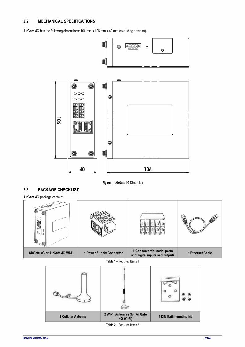
2.2 MECHANICAL SPECIFICATIONS
AirGate 4G has the following dimensions: 106 mm x 106 mm x 40 mm (excluding antenna).
Figure 1 - AirGate 4G Dimension
2.3 PACKAGE CHECKLIST AirGate 4G package contains:
AirGate 4G or AirGate 4G Wi-Fi 1 Power Supply Connector 1 Connector for serial ports and digital inputs and outputs 1 Ethernet Cable
Table 1 – Required Items 1
1 Cellular Antenna 2 Wi-Fi Antennas (for AirGate 4G Wi-Fi) 1 DIN Rail mounting kit
Table 2 – Required Items 2

NOVUS AUTOMATION 8/124
AirGate 4G contains the following optional accessory items:
Power Supply Cellular Antenna
Table 3 – Optional items

NOVUS AUTOMATION 9/124
3 INSTALLATION 3.1 DEVICE OVERVIEW 3.1.1 FRONT PANEL
Figure 2 – Front panel
In the front panel, AirGate 4G has the following items: 1. Wi-Fi antenna connector (AirGate 4G Wi-Fi model); 2. MAIN cellular antenna connector; 3. LED indicator; 4. Serial ports and digital inputs and digital outputs (DIDO) connector; 5. Ethernet port; 6. Wi-Fi antenna connector (AirGate 4G Wi-Fi model); 7. AUX cellular antenna connector.
3.1.2 LEFT SIDE PANEL
Figure 3 – Left site
In the left side panel, AirGate 4G has the following items: 1. SIM card slot; 2. Reset button; 3. Power connector; 4. Grounding stud.

NOVUS AUTOMATION 10/124
3.2 LED INDICATOR
NAME COLOR STATUS DESCRIPTION
SYS Green Slow blinking (500 ms duration) System booting. Fast blinking Operating normally. Off Power is off.
NET Green
On Register to highest priority network service (depend on Radio, e.g. Radio support LTE as Highest priority network).
Fast blinking (500 ms duration) Register to non-highest priority network service (depend on Radio, e.g. Radio support LTE as Highest priority network, then WCDMA and GPRS is non-highest priority network).
Off Register failed.
USR: SIM Green On Router is trying cellular connection with SIM1.
Fast blinking (250 ms duration) Router is trying cellular connection with SIM2. Off No SIM detected.
USR: Wi-Fi Green On Wi-Fi is enable but without data transmission. Blinking Wi-Fi is enabled and transmitting data. Off Wi-Fi is disabled or failed to boot.
Signal Strength Indicator
Green
On / 3 LED light up Signal strength (21-31) is high. On / 2 LED light up Signal strength (11-20) is medium. On / 1 LED light up Signal strength (1-10) is low.
Off No signal.
Table 4 – LED indicator
3.3 ETHERNET PORT INDICATOR
NAME COLOR STATUS DESCRIPTION
Link indicator Green
On Connection is established.
Blinking Data is being transmitted. Off Connection is not established.
Yellow Not used for this device model. Table 5 – Ethernet port indicator

NOVUS AUTOMATION 11/124
3.4 CONNECTOR PIN DEFINITION 3.4.1 SERIAL PORTS & DIDO Figure 4 shows the RS232, the RS485, and the DIDO connections:
Digital input and RS232 connection Digital output and RS485 connection
Figure 4 - AirGate 4G connections
Table 6 shows the connector pins numbering:
PIN RS232 RS485 DI DO DIRECTION
1 -- -- -- DO1 Router → Device
2 -- -- -- DO2 Router → Device 3 -- -- -- COM --
4 -- D1 -- -- Router ↔ Device
5 -- D0 -- -- Router ↔ Device
6 -- -- DI1 -- Router ← Device
7 -- -- DI2 -- Router ← Device
8 GND -- -- -- --
9 TX -- -- -- Router → Device
10 RX -- -- -- Router ← Device
Table 6 – Serial ports & DIDO
Table 7 shows the RS485 signals:
Bidirectional line of data. Terminal 4
Inverted bidirectional line of data. Terminal 5
Optional link that improves communication performance. Terminal 8
Table 7 - RS485 signals

NOVUS AUTOMATION 12/124
3.4.2 POWER INPUT Figure 5 shows the power input connections:
Figure 5 – Power input
PIN DESCRIPTION V+ Positive V- Negative
PGND GND Table 8 – Power input
3.5 RESET BUTTON
FUNCTION ACTION
Reboot Press the RST button for up to 3 seconds while device is operating.
Factory reset Press the RST button until all LEDs flash. After that, you must manually restart the device.
Table 9 – Reset button
3.6 SIM CARD To insert or remove a SIM card in AirGate 4G, you must do the following: 1. Ensure that the device is not being electrically powered; 2. Use a Phillips screwdriver to remove the protective cover from the device; 3. Insert the SIM card into the SIM socket; 4. Replace the protective cover.
Figure 6 - Inserting SIM card

NOVUS AUTOMATION 13/124
3.7 ANTENNAS 3.7.1 AIRGATE 4G AirGate 4G supports two antennas: one on the MAIN connector and one on the AUX connector. The MAIN connector is used to receive and transmit data via cellular antenna. The AUX connector is used to improve signal strength and depends on using an antenna on the MAIN connector to work. How to connect the cellular antenna to the MAIN and AUX connectors of the device:
Figure 7 – Cellular antenna
3.7.2 AIRGATE 4G WI-FI AirGate 4G Wi-Fi supports four antennas: two on Wi-Fi connectors for Wi-Fi functionality, one on MAIN connector and one on AUX connector, both for cellular connection. Wi-Fi connectors are used to receive and transmit data wirelessly and their antennas should always be used together. The MAIN connector is used to receive and transmit data via cellular antenna. The AUX connector, in turn, is used to improve signal strength and depends on using an antenna on the MAIN connector to work. How to connect the Wi-Fi antenna to the Wi-Fi connector of the device:
Figure 8 – Wi-Fi antenna
3.8 DIN RAIL To mount the DIN rail kit, you must do the following: 1. Use four M3x6 flat head Phillips screws to fix the DIN rail kit to the device; 2. Insert the handle of the DIN rail bracket; 3. Press the device into the DIN rail until the bracket snaps into place.
Figure 9 – DIN rail mounting
NOVUS AUTOMATION 14/124
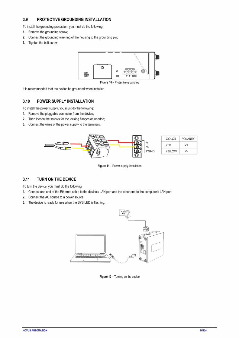
3.9 PROTECTIVE GROUNDING INSTALLATION To install the grounding protection, you must do the following: 1. Remove the grounding screw; 2. Connect the grounding wire ring of the housing to the grounding pin; 3. Tighten the bolt screw.
Figure 10 – Protective grounding
It is recommended that the device be grounded when installed.
3.10 POWER SUPPLY INSTALLATION To install the power supply, you must do the following: 1. Remove the pluggable connector from the device; 2. Then loosen the screws for the locking flanges as needed; 3. Connect the wires of the power supply to the terminals.
Figure 11 – Power supply installation
3.11 TURN ON THE DEVICE To turn the device, you must do the following: 1. Connect one end of the Ethernet cable to the device's LAN port and the other end to the computer's LAN port; 2. Connect the AC source to a power source; 3. The device is ready for use when the SYS LED is flashing.
Figure 12 – Turning on the device

NOVUS AUTOMATION 15/124
4 ACCESS TO WEB PAGE 4.1 PC CONFIGURATION AirGate 4G has a DHCP server that will automatically assign an IP address to the user's computer. In some cases, it will be necessary to change the computer's network settings to accept the router's IP address. You can also manually configure the IP address. The sections below provide information on setting up an IP for AirGate 4G and how to make the first access to the device's web interface.
4.1.1 SET AN IP ADDRESS AUTOMATICALLY You can set the device to automatically obtain an IP by following these steps:
Figure 13 – Set an IP address automatically
Select Start » Control Panel » Network Connections. Right click Local Area Connection and select Properties to open the configuration dialog box for Local Area Connection. Select Internet Protocol (TCP/IP) and click Properties to open the TCP/IP configuration window. On the General tab, select Obtain an IP address automatically and Obtain DNS server address automatically. Click OK to complete TCP/IP configuration.
4.1.2 SET AN STATIC IP ADDRESS You can set your device to manually obtain an IP by following these steps:
Figure 14 – Set a static IP address
Click Use the following IP address to assign a static IP manually within the same subnet of the router. Default Gateway and DNS Server are not necessary if PC not routing all traffic go through router.

NOVUS AUTOMATION 16/124
4.2 FACTORY DEFAULT SETTINGS AirGate 4G can be set up via a web page. The Graphical User Interface (GUI), presented in the LOGIN TO WEB PAGE section, allows you to manage and configure the device. During the first router configuration, the following default settings should be used: • Username: admin • Password: admin • LAN IP Address: 192.168.5.1 (Eth0 ~ Eth1 as LAN mode) • DHCP Server: Enabled
4.3 LOGIN TO WEB PAGE To access AirGate 4G setup page, you must open a web browser on your computer (Google Chrome or Internet Explorer are recommended) and enter IP 192.168.5.1 in the address bar. After that, just use the same username and password (admin / admin) to access device settings.
Figure 15 - Login to Web page
NOVUS AUTOMATION 17/124
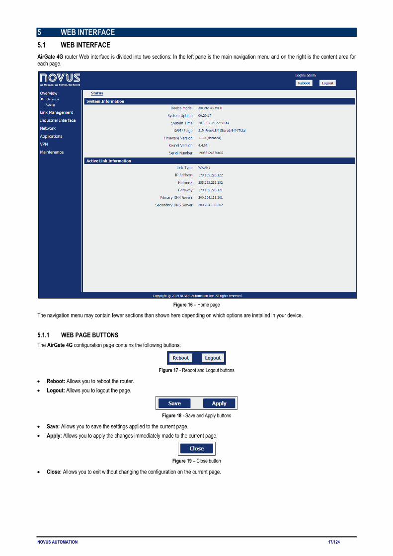
5 WEB INTERFACE 5.1 WEB INTERFACE AirGate 4G router Web interface is divided into two sections: In the left pane is the main navigation menu and on the right is the content area for each page.
Figure 16 – Home page
The navigation menu may contain fewer sections than shown here depending on which options are installed in your device.
5.1.1 WEB PAGE BUTTONS The AirGate 4G configuration page contains the following buttons:
Figure 17 - Reboot and Logout buttons
• Reboot: Allows you to reboot the router. • Logout: Allows you to logout the page.
Figure 18 - Save and Apply buttons
• Save: Allows you to save the settings applied to the current page. • Apply: Allows you to apply the changes immediately made to the current page.
Figure 19 – Close button
• Close: Allows you to exit without changing the configuration on the current page.
NOVUS AUTOMATION 18/124
5.2 OVERVIEW This section displays general information about the device and the system log files obtained by it.
5.2.1 STATUS This tab allows displays information about the system and the current AirGate 4G connection.
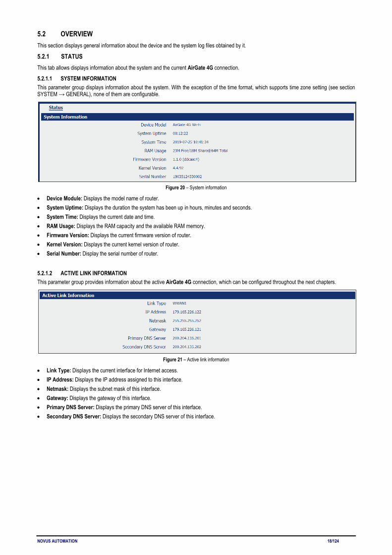
5.2.1.1 SYSTEM INFORMATION This parameter group displays information about the system. With the exception of the time format, which supports time zone setting (see section SYSTEM → GENERAL), none of them are configurable.
Figure 20 – System information
• Device Module: Displays the model name of router. • System Uptime: Displays the duration the system has been up in hours, minutes and seconds. • System Time: Displays the current date and time. • RAM Usage: Displays the RAM capacity and the available RAM memory. • Firmware Version: Displays the current firmware version of router. • Kernel Version: Displays the current kernel version of router. • Serial Number: Display the serial number of router.
5.2.1.2 ACTIVE LINK INFORMATION This parameter group provides information about the active AirGate 4G connection, which can be configured throughout the next chapters.
Figure 21 – Active link information
• Link Type: Displays the current interface for Internet access. • IP Address: Displays the IP address assigned to this interface. • Netmask: Displays the subnet mask of this interface. • Gateway: Displays the gateway of this interface. • Primary DNS Server: Displays the primary DNS server of this interface. • Secondary DNS Server: Displays the secondary DNS server of this interface.

NOVUS AUTOMATION 19/124
5.2.2 SYSLOG This feature allows you to view device system log data.
Figure 22 - Syslog
• Download Diagnosis: Allows you to download the diagnosis file for analysis. This function will create a compressed file with extension .en. The information, however, is confidential and, if necessary, must be sent to NOVUS Technical Support.
• Download Syslog: Allows you to download the complete syslog since last reboot. • Clear: Allows you to clear the current page syslog. • Refresh: Allows you to reload the current page.

NOVUS AUTOMATION 20/124
5.3 LINK MANAGEMENT This section allows you to view information about device connection setup and management.
5.3.1 CONNECTION MANAGER This tab allows you to view and manage the information of each connection configured for the device.
5.3.1.1 CONNECTION MANAGER → STATUS This parameter group allows you to view information about the connections configured for the device. Each connection can be individually created, configured, or removed in the CONNECTION MANAGER → CONNECTION tab.
Figure 23 – Connection information
• Type: Displays the connection interface. • Status: Displays the connection status of this interface. • IP Address: Displays the IP address of this interface. • Netmask: Displays the netmask of this interface. • Gateway: Displays the gateway of this interface. This is used for routing packets to remote networks.
5.3.1.2 CONNECTION MANAGER → CONNECTION This parameter group allows you to add or delete connections, as well as edit parameters for connections previously created for the device.
Figure 24 – Connection: General settings
This parameter group has the following buttons:
Button: Allows you to add a new priority interface.
Button: Allows you to edit current interface settings.
Button: Allows you to delete current interface settings.
This group displays the following parameters: • Priority: Displays the priority list of default routing selection. The order of priorities will be defined by the order of creation of each connection,
respecting the limit of three connections. • Enable: Displays the connection enable status. Enabled connections will be displayed as "True" and disabled connections will be displayed as
"False". • Connection Type: Displays the name of this interface. • Description: Displays the description of this connection.

NOVUS AUTOMATION 21/124
As you can see in Figure 25 – , you can create a new connection by clicking the button.
Figure 25 – Connection settings
GENERAL SETTINGS This parameter group allows you to define the general connection settings. • Priority: Displays current index on priority list. The order of priority will be defined by the connections creation order and cannot be manually
changed. • Enable: Allows you to enable or disable the connection. • Connection Type: Allows you to define the connection type: "WWAN1", "WWAN2" or "WAN". It is recommended to specify the SIM1 operator
link as "WWAN1" and the SIM2 operator link as "WWAN2". • Description: Allows you to define a description for the connection. ICMP DETECTION SETTINGS This parameter group allows you to define the ICMP (Internet Control Message Protocol) protocol operation. The ICMP protocol is used to manage information about errors founded when a message is send. • Enable: Allows you to enable detection of link connection status based on pings to a specified IP address. • Primary Server: Allows you to enter the primary IP address that pings will be sent to, to detect the link state. Recommend entering the IP
address of known external reachable server or network (e.g. 8.8.8.8). • Secondary Server: Allows you to enter the secondary IP address that pings will be sent to, when the primary server is ping failed, router would
try to ping the secondary server. • Interval: Allows you to enter the duration of each ICMP detection (in seconds). 1 to 1800 second interval is allowed • Retry Interval: Allows you to enter the interval in seconds between each ping if no packets have been received. 1 to 300 second retry interval
is allowed. • Timeout: Allows you to enter a timeout period, in seconds, for the response of received pings to determine ICMP detection failures. 1 to 10
seconds timeout is allowed. • Retry Times: Allows you to specify the retry times for ICMP detection. 1 to 10 seconds retry times is allowed.
NOVUS AUTOMATION 22/124
5.3.2 CELLULAR This tab allows you to view and manage the SIM card information for the device.
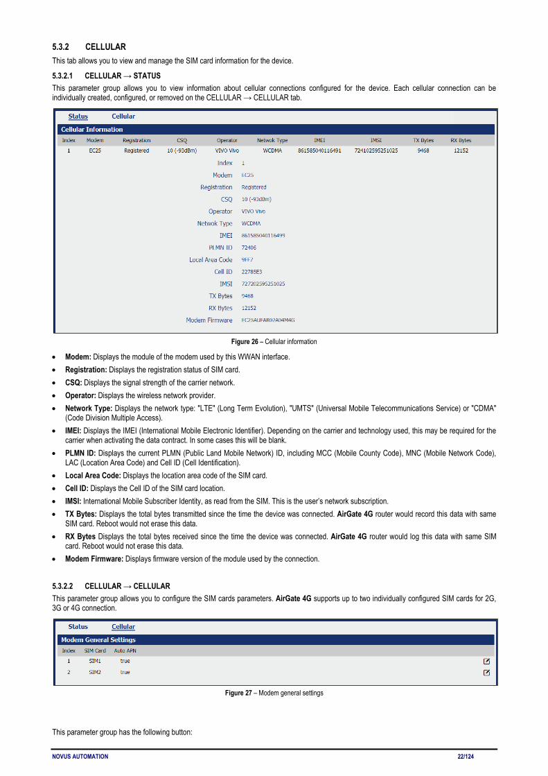
5.3.2.1 CELLULAR → STATUS This parameter group allows you to view information about cellular connections configured for the device. Each cellular connection can be individually created, configured, or removed on the CELLULAR → CELLULAR tab.
Figure 26 – Cellular information
• Modem: Displays the module of the modem used by this WWAN interface. • Registration: Displays the registration status of SIM card. • CSQ: Displays the signal strength of the carrier network. • Operator: Displays the wireless network provider. • Network Type: Displays the network type: "LTE" (Long Term Evolution), "UMTS" (Universal Mobile Telecommunications Service) or "CDMA"
(Code Division Multiple Access). • IMEI: Displays the IMEI (International Mobile Electronic Identifier). Depending on the carrier and technology used, this may be required for the
carrier when activating the data contract. In some cases this will be blank. • PLMN ID: Displays the current PLMN (Public Land Mobile Network) ID, including MCC (Mobile County Code), MNC (Mobile Network Code),
LAC (Location Area Code) and Cell ID (Cell Identification). • Local Area Code: Displays the location area code of the SIM card. • Cell ID: Displays the Cell ID of the SIM card location. • IMSI: International Mobile Subscriber Identity, as read from the SIM. This is the user’s network subscription. • TX Bytes: Displays the total bytes transmitted since the time the device was connected. AirGate 4G router would record this data with same
SIM card. Reboot would not erase this data. • RX Bytes Displays the total bytes received since the time the device was connected. AirGate 4G router would log this data with same SIM
card. Reboot would not erase this data. • Modem Firmware: Displays firmware version of the module used by the connection.
5.3.2.2 CELLULAR → CELLULAR This parameter group allows you to configure the SIM cards parameters. AirGate 4G supports up to two individually configured SIM cards for 2G, 3G or 4G connection.
Figure 27 – Modem general settings
This parameter group has the following button:
NOVUS AUTOMATION 23/124
Button: Allows you to edit the settings of the selected SIM card.
This group displays the following parameters: • SIM Card: Displays the SIM card support on this device. • Auto APN: Displays the status of auto APN function.
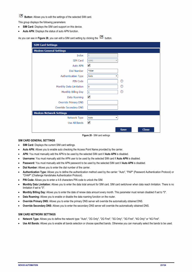
As you can see in Figure 28, you can edit a SIM card setting by clicking the button.
Figure 28 - SIM card settings
SIM CARD GENERAL SETTINGS • SIM Card: Displays the current SIM card settings. • Auto APN: Allows you to enable auto checking the Access Point Name provided by the carrier. • APN: You must manually add the APN to be used by the selected SIM card if Auto APN is disabled. • Username: You must manually add the APN user to be used by the selected SIM card if Auto APN is disabled. • Password: You must manually add the APN password to be used by the selected SIM card if Auto APN is disabled. • Dial Number: Allows you to enter the dial number of the carrier. • Authentication Type: Allows you to define the authentication method used by the carrier: "Auto", "PAP" (Password Authentication Protocol) or
"CHAP" (Challenge Handshake Authentication Protocol). • PIN Code: Allows you to enter a 4-8 characters PIN code to unlock the SIM. • Monthly Data Limitation: Allows you to enter the data total amount for SIM card. SIM card switchover when data reach limitation. There is no
limitation if set to "0". • Monthly Billing Day: Allows you to enter the date of renew data amount every month. This parameter must remain disabled if set to "0". • Data Roaming: Allows you to enable or disable the data roaming function on the router. • Override Primary DNS: Allows you to enter the primary DNS server will override the automatically obtained DNS. • Override Secondary DNS: Allows you to enter the secondary DNS server will override the automatically obtained DNS. SIM CARD NETWORK SETTINGS • Network Type: Allows you to define the network type: "Auto", "2G Only", "2G First", "3G Only", "3G First", "4G Only" or "4G First". • Use All Bands: Allows you to enable all bands selection or choose specified bands. Otherwise you can manually select the bands to be used.
NOVUS AUTOMATION 24/124
5.3.3 ETHERNET This tab allows you to view and manage the information of Ethernet connection for the device.
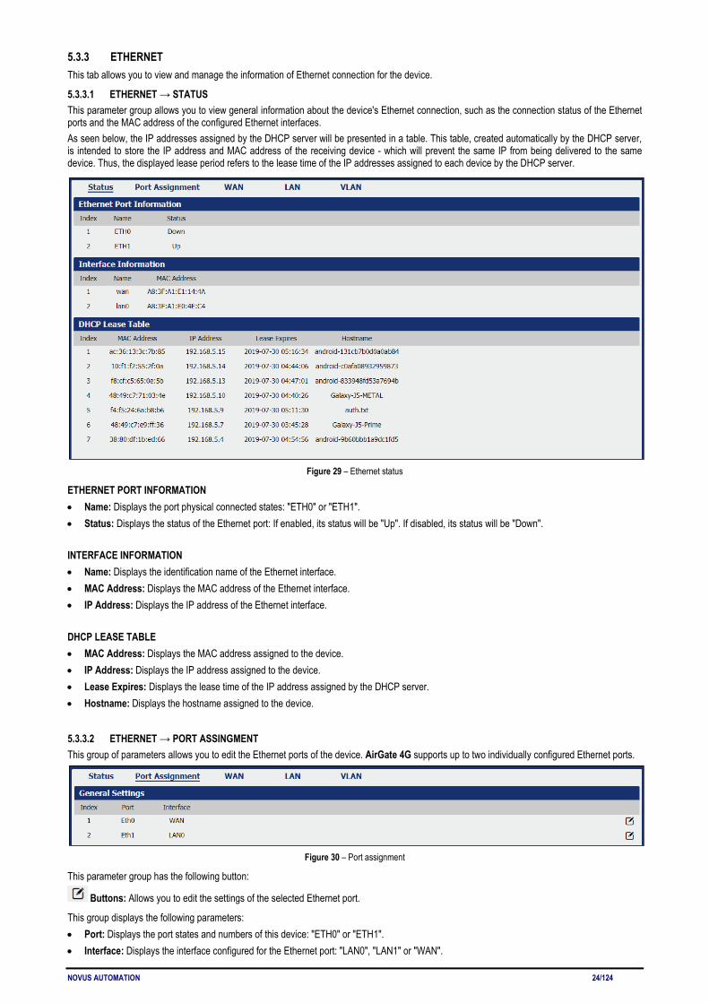
5.3.3.1 ETHERNET → STATUS This parameter group allows you to view general information about the device's Ethernet connection, such as the connection status of the Ethernet ports and the MAC address of the configured Ethernet interfaces. As seen below, the IP addresses assigned by the DHCP server will be presented in a table. This table, created automatically by the DHCP server, is intended to store the IP address and MAC address of the receiving device - which will prevent the same IP from being delivered to the same device. Thus, the displayed lease period refers to the lease time of the IP addresses assigned to each device by the DHCP server.
Figure 29 – Ethernet status
ETHERNET PORT INFORMATION • Name: Displays the port physical connected states: "ETH0" or "ETH1". • Status: Displays the status of the Ethernet port: If enabled, its status will be "Up". If disabled, its status will be "Down". INTERFACE INFORMATION • Name: Displays the identification name of the Ethernet interface. • MAC Address: Displays the MAC address of the Ethernet interface. • IP Address: Displays the IP address of the Ethernet interface. DHCP LEASE TABLE • MAC Address: Displays the MAC address assigned to the device. • IP Address: Displays the IP address assigned to the device. • Lease Expires: Displays the lease time of the IP address assigned by the DHCP server. • Hostname: Displays the hostname assigned to the device.
5.3.3.2 ETHERNET → PORT ASSINGMENT This group of parameters allows you to edit the Ethernet ports of the device. AirGate 4G supports up to two individually configured Ethernet ports.
Figure 30 – Port assignment
This parameter group has the following button:
Buttons: Allows you to edit the settings of the selected Ethernet port.
This group displays the following parameters: • Port: Displays the port states and numbers of this device: "ETH0" or "ETH1". • Interface: Displays the interface configured for the Ethernet port: "LAN0", "LAN1" or "WAN".
NOVUS AUTOMATION 25/124
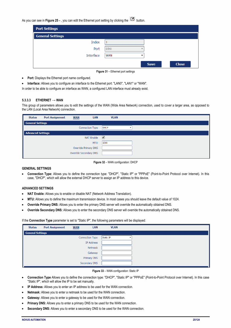
As you can see in Figure 25 – , you can edit the Ethernet port setting by clicking the button.
Figure 31 – Ethernet port settings
• Port: Displays the Ethernet port name configured. • Interface: Allows you to configure an interface to the Ethernet port: "LAN0", "LAN1" or "WAN". In order to be able to configure an interface as WAN, a configured LAN interface must already exist.
5.3.3.3 ETHERNET → WAN This group of parameters allows you to edit the settings of the WAN (Wide Area Network) connection, used to cover a larger area, as opposed to the LAN (Local Area Network) connection.
Figure 32 – WAN configuration: DHCP
GENERAL SETTINGS • Connection Type: Allows you to define the connection type: "DHCP", "Static IP" or "PPPoE" (Point-to-Point Protocol over Internet). In this
case, "DHCP", which will allow the external DHCP server to assign an IP address to this device. ADVANCED SETTINGS • NAT Enable: Allows you to enable or disable NAT (Network Address Translation). • MTU: Allows you to define the maximum transmission device. In most cases you should leave the default value of 1024. • Override Primary DNS: Allows you to enter the primary DNS server will override the automatically obtained DNS. • Override Secondary DNS: Allows you to enter the secondary DNS server will override the automatically obtained DNS. If the Connection Type parameter is set to "Static IP", the following parameters will be displayed:
Figure 33 – WAN configuration: Static IP
• Connection Type Allows you to define the connection type: "DHCP", "Static IP" or "PPPoE" (Point-to-Point Protocol over Internet). In this case "Static IP", which will allow the IP to be set manually.
• IP Address: Allows you to enter an IP address to be used for the WAN connection. • Netmask: Allows you to enter a netmask to be used for the WAN connection. • Gateway: Allows you to enter a gateway to be used for the WAN connection. • Primary DNS: Allows you to enter a primary DNS to be used for the WAN connection. • Secondary DNS: Allows you to enter a secondary DNS to be used for the WAN connection.

NOVUS AUTOMATION 26/124
The Advanced Settings section parameters are the same as above and must be filled in the same way. If the Connection Type parameter is set to "PPPoE" (Point-to-Point Protocol over Internet), the following parameters will be displayed:
Figure 34 – WAN configuration: PPPoE
• Connection Type: Allows you to define the connection type: "DHCP", "Static IP" or "PPPoE" (Point-to-Point Protocol over Internet). In this case, "PPPoE".
• Authentication Type: Allows you to define the type of authentication to be used by the WAN connection: "Auto", "PAP" (Password Authentication Protocol) or "CHAP" (Challenge Handshake Authentication Protocol).
• Username: Allows you to enter a username to be used by the WAN connection. • Password: Allows you to enter a password to be used by the WAN connection. The Advanced Settings section parameters are the same as above and must be filled in the same way.
5.3.3.4 ETHERNET → LAN This group of parameters allows you to define the settings of the LAN (Local Area Network) connection, a local area network designed for smaller areas, as opposed to the WAN (Wide Area Network) connection.
Figure 35 – LAN settings
This parameter group has the following buttons:
Button: Allows you to add a new LAN connection.
Button: Allows you to edit the current LAN connection settings.
Button: Allows you to delete the current LAN connection settings.
NOVUS AUTOMATION 27/124
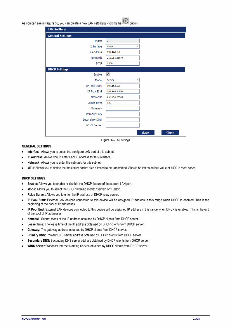
As you can see in Figure 36, you can create a new LAN setting by clicking the button.
Figure 36 – LAN settings
GENERAL SETTINGS • Interface: Allows you to select the configure LAN port of this subnet. • IP Address: Allows you to enter LAN IP address for this interface. • Netmask: Allows you to enter the netmask for this subnet. • MTU: Allows you to define the maximum packet size allowed to be transmitted. Should be left as default value of 1500 in most cases. DHCP SETTINGS • Enable: Allows you to enable or disable the DHCP feature of the current LAN port. • Mode: Allows you to select the DHCP working mode: "Server" or "Relay". • Relay Server: Allows you to enter the IP address of DHCP relay server. • IP Pool Start: External LAN devices connected to this device will be assigned IP address in this range when DHCP is enabled. This is the
beginning of the pool of IP addresses. • IP Pool End: External LAN devices connected to this device will be assigned IP address in this range when DHCP is enabled. This is the end
of the pool of IP addresses. • Netmask: Subnet mask of the IP address obtained by DHCP clients from DHCP server. • Lease Time: The lease time of the IP address obtained by DHCP clients from DHCP server. • Gateway: The gateway address obtained by DHCP clients from DHCP server. • Primary DNS: Primary DNS server address obtained by DHCP clients from DHCP server. • Secondary DNS: Secondary DNS server address obtained by DHCP clients from DHCP server. • WINS Server: Windows Internet Naming Service obtained by DHCP clients from DHCP server.
NOVUS AUTOMATION 28/124
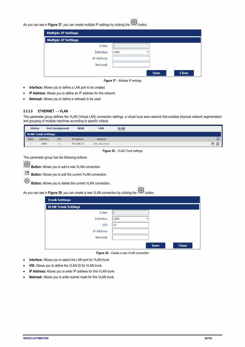
As you can see in Figure 37, you can create multiple IP settings by clicking the button.
Figure 37 – Multiple IP settings
• Interface: Allows you to define a LAN port to be created. • IP Address: Allows you to define an IP address for this network. • Netmask: Allows you to define a netmask to be used.
5.3.3.5 ETHERNET → VLAN This parameter group defines the VLAN (Virtual LAN) connection settings, a virtual local area network that enables physical network segmentation and grouping of multiple machines according to specific criteria.
Figure 38 – VLAN Trunk settings
This parameter group has the following buttons:
Button: Allows you to add a new VLAN connection.
Button: Allows you to edit the current VLAN connection.
Button: Allows you to delete the current VLAN connection.
As you can see in Figure 39, you can create a new VLAN connection by clicking the button.
Figure 39 – Create a new VLAN connection
• Interface: Allows you to select the LAN port for VLAN trunk. • VID: Allows you to define the VLAN ID for VLAN trunk. • IP Address: Allows you to enter IP address for this VLAN trunk. • Netmask: Allows you to enter subnet mask for this VLAN trunk.
NOVUS AUTOMATION 29/124
5.3.4 WI-FI This section allows you to view and manage information about the Wi-Fi connection and how the Wi-Fi interface works.
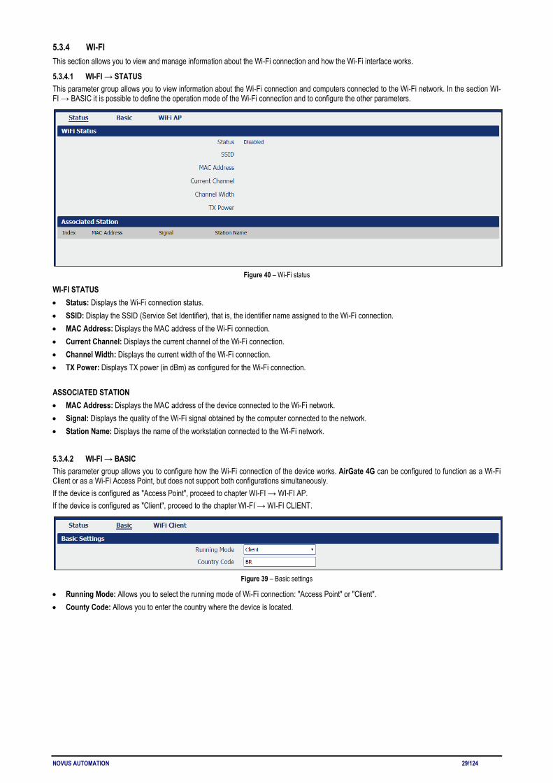
5.3.4.1 WI-FI → STATUS This parameter group allows you to view information about the Wi-Fi connection and computers connected to the Wi-Fi network. In the section WI-FI → BASIC it is possible to define the operation mode of the Wi-Fi connection and to configure the other parameters.
Figure 40 – Wi-Fi status
WI-FI STATUS • Status: Displays the Wi-Fi connection status. • SSID: Display the SSID (Service Set Identifier), that is, the identifier name assigned to the Wi-Fi connection. • MAC Address: Displays the MAC address of the Wi-Fi connection. • Current Channel: Displays the current channel of the Wi-Fi connection. • Channel Width: Displays the current width of the Wi-Fi connection. • TX Power: Displays TX power (in dBm) as configured for the Wi-Fi connection. ASSOCIATED STATION • MAC Address: Displays the MAC address of the device connected to the Wi-Fi network. • Signal: Displays the quality of the Wi-Fi signal obtained by the computer connected to the network. • Station Name: Displays the name of the workstation connected to the Wi-Fi network.
5.3.4.2 WI-FI → BASIC This parameter group allows you to configure how the Wi-Fi connection of the device works. AirGate 4G can be configured to function as a Wi-Fi Client or as a Wi-Fi Access Point, but does not support both configurations simultaneously. If the device is configured as "Access Point", proceed to chapter WI-FI → WI-FI AP. If the device is configured as "Client", proceed to the chapter WI-FI → WI-FI CLIENT.
Figure 39 – Basic settings
• Running Mode: Allows you to select the running mode of Wi-Fi connection: "Access Point" or "Client". • County Code: Allows you to enter the country where the device is located.
NOVUS AUTOMATION 30/124
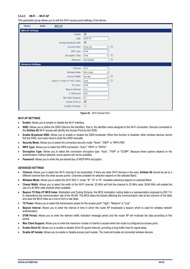
5.3.4.3 WI-FI → WI-FI AP This parameter group allows you to edit the Wi-Fi access point settings of the device.
Figure 42 – Wi-Fi Access Point
WI-FI AP SETTINGS • Enable: Allows you to enable or disable the Wi-Fi interface. • SSID: Allows you to define the SSID (Service Set Identifier), that is, the identifier name assigned to the Wi-Fi connection. Devices connected to
the AirGate 4G Wi-Fi access will identify the Access Point by this SSID. • Enable Broadcast SSID: Allows you to enable or disable the SSID broadcast. When this function is disabled, other wireless devices cannot
find the SSID, and users have to enter the SSID manually. • Security Mode: Allows you to select the connection security mode: "None", "WEP" or "WPA PSK". • WPA Type: Allows you to select the WPA connection: "Auto", "WPA" or "WPA2". • Encryption Type: Allows you to select the connection encryption type: "Auto", "TKIP" or "CCMP". Because these options depend on the
authentication method selected, some options will not be available. • Password: Allows you to enter the pre-shared key of WEP/WPA encryption. ADVANCED SETTINGS • Channel: Allows you to select the Wi-Fi channel to be transmitted. If there are other Wi-Fi devices in the area, AirGate 4G should be set to a
different channel than the other access points. Channels available for selection depend on the selected Band. • Wireless Mode: Allows you to select the Wi-Fi 802.11 mode: "B", "G" or "N". Available selections depend on selected Band. • Chanel Width: Allows you to select the width of the Wi-Fi channel. 20 MHz will limit the channel to 20 MHz wide; 20/40 MHz will enable the
use of a 40 MHz wide channel when available. • Beacon TX Rate HT MCS Index: Modulation and Coding Scheme, the MCS modulation coding table is a representation proposed by 802.11n
to characterize the communication rate of the WLAN. The MCS takes the factors affecting the communication rate as the columns of the table and uses the MCS index as a row to form a rate table.
• TX Power: Allows you to select the transmission power for the access point: "High", "Medium" or "Low". • Beacon Interval: Allows you to enter the interval of time in which the router AP broadcasts a beacon which is used for wireless network
authentication. • DTIM Period: Allows you to enter the delivery traffic indication message period and the router AP will multicast the data according to this
period. • Max Client Support: Allows you to enter the maximum number of clients to access when the router is configured as access point. • Enable Short GI: Allows you to enable or disable Short GI (guard interval), providing a long buffer time for signal delay. • Enable AP Isolate: Allows you to enable or disable access point isolate. The route will isolate all connected wireless devices.
NOVUS AUTOMATION 31/124
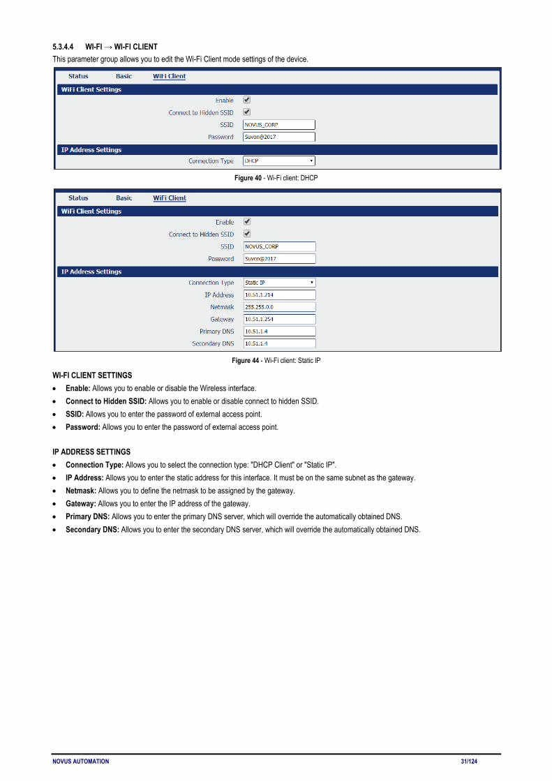
5.3.4.4 WI-FI → WI-FI CLIENT This parameter group allows you to edit the Wi-Fi Client mode settings of the device.
Figure 40 - Wi-Fi client: DHCP
Figure 44 - Wi-Fi client: Static IP
WI-FI CLIENT SETTINGS • Enable: Allows you to enable or disable the Wireless interface. • Connect to Hidden SSID: Allows you to enable or disable connect to hidden SSID. • SSID: Allows you to enter the password of external access point. • Password: Allows you to enter the password of external access point. IP ADDRESS SETTINGS • Connection Type: Allows you to select the connection type: "DHCP Client" or "Static IP". • IP Address: Allows you to enter the static address for this interface. It must be on the same subnet as the gateway. • Netmask: Allows you to define the netmask to be assigned by the gateway. • Gateway: Allows you to enter the IP address of the gateway. • Primary DNS: Allows you to enter the primary DNS server, which will override the automatically obtained DNS. • Secondary DNS: Allows you to enter the secondary DNS server, which will override the automatically obtained DNS.
NOVUS AUTOMATION 32/124
5.4 INDUSTRIAL INTERFACE This section shows information about configuring RS232 and RS485 interfaces and device digital input and output.
5.4.1 SERIAL This section allows you to view and manage information about device serial connections.
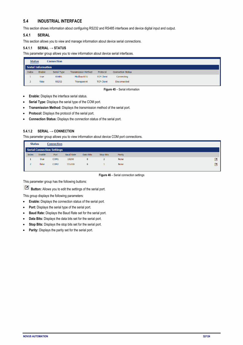
5.4.1.1 SERIAL → STATUS This parameter group allows you to view information about device serial interfaces.
Figure 45 – Serial information
• Enable: Displays the interface serial status. • Serial Type: Displays the serial type of the COM port. • Transmission Method: Displays the transmission method of the serial port. • Protocol: Displays the protocol of the serial port. • Connection Status: Displays the connection status of the serial port.
5.4.1.2 SERIAL → CONNECTION This parameter group allows you to view information about device COM port connections.
Figure 46 – Serial connection settings
This parameter group has the following buttons:
Button: Allows you to edit the settings of the serial port.
This group displays the following parameters: • Enable: Displays the connection status of the serial port. • Port: Displays the serial type of the serial port. • Baud Rate: Displays the Baud Rate set for the serial port. • Data Bits: Displays the data bits set for the serial port. • Stop Bits: Displays the stop bits set for the serial port. • Parity: Displays the parity set for the serial port.

NOVUS AUTOMATION 33/124
As you can see in Figure 25 – 47, you can edit the settings of the selected serial port by clicking the button.
Figure 47 – Serial port connection settings
SERIAL CONNECTION SETTINGS • Enable: Allows you to enable or disable the serial port. • Port: Displays the serial type of the serial port. • Baud Rate: Allows you to define the Baud Rate for the serial port: 300, 600, 1200, 2400, 4800, 9600, 19200, 38400, 57600 or 115200. • Data Bits: Allows you to define the data bits set for the serial port. Select the values from 7 or 8. • Stop Bits: Allows you to define the stop bits for the serial port. Select the values from 1 or 2. • Parity: Allows you to define the parity for the serial port: "None", "Even" or "Odd". TRANSMISSION SETTINGS This section allows you to set the transmission settings of the selected serial port if the Protocol parameter is set to "TCP Client". • Transmission Method: Allows you to define the transmission method of serial port: "Transparent", "Modbus RTU Gateway" or "Modbus ASCII
Gateway". • MTU: Allows you to define the maximum packet size allowed to be transmitted. Should be left as default value of 1024 in most cases. • Protocol: Allows you to define the mode for serial IP communication: "UDP", "TCP Server" or "TCP Client". In this case, "TCP Client". • Remote IP Address: Allows you to enter the IP address of the remote server. • Remote Port: Allows you to enter the port number of the remote server. TRANSMISSION SETTINGS This section allows you to set the transmission settings of the selected serial port if the Protocol parameter is set to "TCP Server".
Figure 48 - TCP Server protocol
• Transmission Method: Allows you to define the transmission method of serial port: "Transparent", "Modbus RTU Gateway" or "Modbus ASCII Gateway".
• MTU: Allows you to define the maximum packet size allowed to be transmitted. Should be left as default value of 1024 in most cases. • Protocol: Allows you to define the mode for serial IP communication: "UDP", "TCP Server" or "TCP Client". In this case, "TCP Server". • Local IP Address: Allows you to enter the IP address of the local endpoint. • Local Port: Displays the port number assigned to the serial IP port on which communications will take place. TRANSMISSION SETTINGS

NOVUS AUTOMATION 34/124
This section allows you to set the transmission settings of the selected serial port if the Protocol parameter is set to "UDP".
Figure 49 – UDP Protocol
• Transmission Method: Allows you to define the transmission method of serial port: "Transparent", "Modbus RTU Gateway" or "Modbus ASCII Gateway".
• MTU: Allows you to define the maximum packet size allowed to be transmitted. Should be left as default value of 1024 in most cases. • Protocol: Allows you to define the mode for serial IP communication: "UDP", "TCP Server" or "TCP Client". In this case, "TCP Server". • Local IP Address: Allows you to enter the IP address of the local endpoint. • Local Port: Displays the port number assigned to the serial IP port on which communications will take place. • Remote IP Address: Allows you to enter the IP address of the remote server. • Remote Port: Allows you to enter the port number of the remote server.
5.4.2 DIGITAL I/O This section allows you to configure digital input and output parameters. The digital input can be used to trigger alarms. The digital output, in turn, can be used to control the slave device by means of the digital signal.
5.4.2.1 DIGITAL I/O → STATUS This parameter group allows you to view digital input and output information.
Figure 50 – Digital input and output status
• Enable: Displays the status of current digital IO function. • Logic Level: Displays the electrical level of digital IO port. • Status: Displays the alarm status of digital IO port.
5.4.2.2 DIGITAL I/O → DIGITAL I/O This parameter group allows you to configure the digital input and output.
Figure 51 – Digital IP settings
This parameter group has the following buttons:
Button: Allows you to edit the settings of the digital input or output selected.

NOVUS AUTOMATION 35/124
As you can see in Figure 52, you can edit the settings of the selected digital input by clicking the button.
Figure 52 – Digital input settings
• Enable: Allows you to enable or disable the digital input function. • Alarm ON Mode: Allows you to select the electrical level to trigger alarm: "Low" or "High". • Alarm ON Content: Allows you to specify the alarm on content to be sent out via SMS message. • Alarm OFF Content: Allows you to specify the alarm off content to be sent out via SMS message.
As you can see in Figure 53, you can edit the settings of the selected digital output by clicking the button.
Figure 53 – Digital output settings
• Enable: Allows you to enable or disable the digital output function. • Alarm Source: Allows you to select the alarm source: "Digital Input 1", "Digital Input 2" or "SMS". Digital output triggers the related action when
there is alarm comes from Digital Input or SMS. • Alarm ON Action: Allows you to select the alarm action when ON: "High", "Low" or "Pulse". "High" means high electrical level output. "Low"
means low electrical level output. "Pulse" will generate a square wave as specified in the pulse mode parameters when triggered. • Alarm OFF Action: Allows you to select the alarm action when OFF: "High", "Low" or "Pulse". "High" means high electrical level output. "Low"
means low electrical level output. "Pulse" will generate a square wave as specified in the pulse mode parameters when triggered. • Pulse Width: This parameter is available when select "Pulse" option in the Alarm ON Action or Alarm OFF Action parameters. The selected
digital output channel will generate a square wave as specified in the pulse mode parameters.

NOVUS AUTOMATION 36/124
5.5 NETWORK This section shows information about Firewall, Router, VRRP (Virtual Routing Redundancy Protocol), and IP Passthrough settings.
5.5.1 FIREWALL This section allows you to view and manage device firewall information. Firewall rules are security rule-sets to implement control over users, applications or network objects in an organization. Using the firewall rule, you can create blanket or specialized traffic transit rules based on the requirement.
5.5.1.1 FIREWALL → ACL This parameter group allows you to view information about firewall access control policies. An access control list (ACL), with respect to a computer file system, is a list of permissions attached to an object. An ACL specifies which users or system processes are granted access to objects, as well as what operations are allowed on given objects.
Figure 54 - Firewall: ACL
This parameter group hast the following buttons:
Button: Allows you to create a new access control list (ACL).
Button: Allows you to edit the selected access control list.
Button: Allows you to delete the selected access control list.
This group displays the following parameter:
• Default Policy: Allows you to select the firewall default policy: "Accept" or "Drop". The packets which are not included in the access control list will be processed by the default filter policy.
As you can see in Figure 55, you can create a new access control list by clicking the button.
Figure 55 – ACL rule settings
• Description: Allows you to enter a description for the rule to be created. • Protocol: Allows you to select the protocol to be used: "All" (Any protocol number), "TCP", "UDP", "TCP & UDP" or "ICMP". • Source Address: Allows you to enter a specific host IP address or a range of IP addresses via bitmask. • Destination Address: Allows you to enter a specific IP address or a range of IP addresses via bitmask.
NOVUS AUTOMATION 37/124
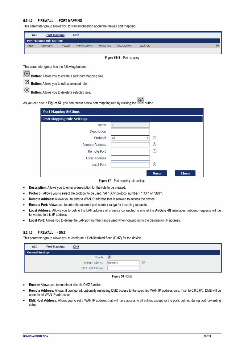
5.5.1.2 FIREWALL → PORT MAPPING This parameter group allows you to view information about the firewall port mapping.
Figure 5641 – Port mapping
This parameter group has the following buttons:
Button: Allows you to create a new port mapping rule.
Button: Allows you to edit a selected rule.
Button: Allows you to delete a selected rule.
As you can see in Figure 57, you can create a new port mapping rule by clicking the button.
Figure 57 – Port mapping rule settings
• Description: Allows you to enter a description for the rule to be created. • Protocol: Allows you to select the protocol to be used: "All" (Any protocol number), "TCP" or "UDP". • Remote Address: Allows you to enter a WAN IP address that is allowed to access the device. • Remote Port: Allows you to enter the external port number range for incoming requests. • Local Address: Allows you to define the LAN address of a device connected to one of the AirGate 4G interfaces. Inbound requests will be
forwarded to this IP address. • Local Port: Allows you to define the LAN port number range used when forwarding to the destination IP address.
5.5.1.3 FIREWALL → DMZ This parameter group allows you to configure a DeMilitarized Zone (DMZ) for the device.
Figure 58 - DMZ
• Enable: Allows you to enable or disable DMZ function. • Remote Address: Allows, if configured, optionally restricting DMZ access to the specified WAN IP address only. If set to 0.0.0.0/0, DMZ will be
open for all WAN IP addresses. • DMZ Host Address: Allows you to set a WAN IP address that will have access to all entries except for the ports defined during port forwarding
setup.
NOVUS AUTOMATION 38/124
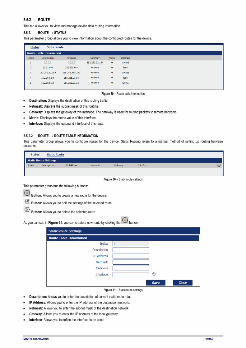
5.5.2 ROUTE This tab allows you to view and manage device data routing information.
5.5.2.1 ROUTE → STATUS This parameter group allows you to view information about the configured routes for the device.
Figure 59 – Route table information
• Destination: Displays the destination of this routing traffic. • Netmask: Displays the subnet mask of this routing. • Gateway: Displays the gateway of this interface. The gateway is used for routing packets to remote networks. • Metric: Displays the metric value of this interface. • Interface: Displays the outbound interface of this route.
5.5.2.2 ROUTE → ROUTE TABLE INFORMATION This parameter group allows you to configure routes for the device. Static Routing refers to a manual method of setting up routing between networks.
Figure 60 – Static route settings
This parameter group has the following buttons:
Button: Allows you to create a new route for the device.
Button: Allows you to edit the settings of the selected route.
Button: Allows you to delete the selected route.
As you can see in Figure 61, you can create a new route by clicking the button.
Figure 61 – Static route settings
• Description: Allows you to enter the description of current static route rule. • IP Address: Allows you to enter the IP address of the destination network. • Netmask: Allows you to enter the subnet mask of the destination network. • Gateway: Allows you to enter the IP address of the local gateway. • Interface: Allows you to define the interface to be used.

NOVUS AUTOMATION 39/124
5.5.3 VRRP This tab allows you to view and manage information about the virtual router redundancy protocol. The VRRP (Virtual Router Redundancy Protocol) is a computer networking protocol that provides automatic assignment of available Internet Protocol (IP) routers for participating hosts. The VRRP router who has the highest number will become the virtual master router. The VRRP router number ranges from 1 to 255 and usually we use 255 for the highest priority and 100 for backup. If the current virtual master router receives an announcement from a group member (Router ID) with a higher priority, then the latter will pre-empt and become the virtual master router.
Figure 62 - VRRP
This parameter group has the following buttons:
Button: Allows you to create a new VRRP.
Button: Allows you to edit the settings of the selected VRRP.
Button: Allows you to delete the selected VRRP.
As you can see in Figure 63, you can create a new VRRP by clicking the button.
Figure 63 – VRRP network settings
• Enable: Allows you to enable or disable the VRRP. • Interface: Allows you to select the virtual router interface. • Virtual Router ID: Allows you to define the user-defined virtual router ID. Range: 1-255. • Authentication Type: Allows you to select the authentication type for VRRP: "None" or "PASS". • Password: If "PASS" option is selected in the Authentication Type parameter, allows you to set a password for the VRRP network. • Priority: Allows you to define a VRRP priority range. Range: 1-254 (a bigger number indicates a higher priority). • Interval: Allows you to define the heartbeat package transmission time interval between routers in the virtual IP group. Range: 1-255. • Virtual IP Address: Allows you to enter the virtual IPP address of virtual gateway.

NOVUS AUTOMATION 40/124
5.5.4 IP PASSTHROUGH This parameter group allows you to manage information about IP Passthrough mode. P Passthrough mode disables NAT (Network Address Translation) and routing and passes the WAN IP address from the WAN interface to the device connected on the local Interface. It is used instead of NAT in order to make the router "transparent" in the communication process.
Figure 64 - IP Passthrough
• Enable: Allows you to enable or disable IP passthrough. • Passthrough Host MAC: Allows you to enter the MAC of passthrough host to receive the WAN IP address. • Remote HTTPS Access Reserved: Allows you to enable or disable remote HTTPS access. • Remote Telnet Access Reserved: Allows you to enable or disable remote Telnet access. • Remote SSH Access Reserved: Allows you to enable or disable remote SSH access.
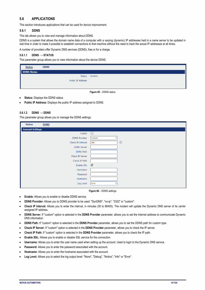
NOVUS AUTOMATION 41/124
5.6 APPLICATIONS This section introduces applications that can be used for device improvement.
5.6.1 DDNS This tab allows you to view and manage information about DDNS. DDNS is a system that allows the domain name data of a computer with a varying (dynamic) IP addresses held in a name server to be updated in real time in order to make it possible to establish connections to that machine without the need to track the actual IP addresses at all times.
A number of providers offer Dynamic DNS services (DDNS), free or for a charge.
5.6.1.1 DDNS → STATUS This parameter group allows you to view information about the device DDNS.
Figure 65 – DDNS status
• Status: Displays the DDNS status. • Public IP Address: Displays the public IP address assigned to DDNS.
5.6.1.2 DDNS → DDNS This parameter group allows you to manage the DDNS settings.
Figure 66 – DDNS settings
• Enable: Allows you to enable or disable DDNS service. • DDNS Provider: Allows you to DDNS provider to be used: "DynDNS", "no-ip", "3322" or "custom". • Check IP Interval: Allows you to enter the interval, in minutes (30 to 86400). The modem will update the Dynamic DNS server of its carrier
assigned IP address. • DDNS Server: If "custom" option is selected in the DDNS Provider parameter, allows you to set the Internet address to communicate Dynamic
DNS information. • DDNS Path: If "custom" option is selected in the DDNS Provider parameter, allows you to set the DDNS path for custom type. • Check IP Server: If "custom" option is selected in the DDNS Provider parameter, allows you to check the IP server. • Check IP Path: If "custom" option is selected in the DDNS Provider parameter, allows you to check the IP path. • Enable SSL: Allows you to enable or disable SSL service for the connection. • Username: Allows you to enter the user name used when setting up the account. Used to login to the Dynamic DNS service. • Password: Allows you to enter the password associated with the account. • Hostname: Allows you to enter the hostname associated with the account. • Log Level: Allows you to select the log output level: "None", "Debug", "Notice", "Info" or "Error".
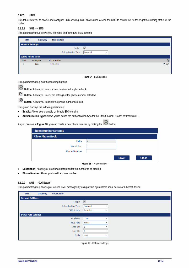
NOVUS AUTOMATION 42/124
5.6.2 SMS This tab allows you to enable and configure SMS sending. SMS allows user to send the SMS to control the router or get the running status of the router.
5.6.2.1 SMS → SMS This parameter group allows you to enable and configure SMS sending.
Figure 67 – SMS sending
This parameter group has the following buttons:
Button: Allows you to add a new number to the phone book.
Button: Allows you to edit the settings of the phone number selected.
Button: Allows you to delete the phone number selected.
This group displays the following parameters: • Enable: Allows you to enable or disable SMS sending. • Authentication Type: Allows you to define the authentication type for the SMS function: "None" or "Password".
As you can see in Figure 68, you can create a new phone number by clicking the button.
Figure 68 – Phone number
• Description: Allows you to enter a description for the number to be created. • Phone Number: Allows you to add a phone number.
5.6.2.2 SMS → GATEWAY This parameter group allows you to send SMS messages by using a valid syntax from serial device or Ethernet device.
Figure 69 – Gateway settings

NOVUS AUTOMATION 43/124
GENERAL SETTINGS • Enable: Allows you to enable or disable SMS gateway. • Authentication Type: Allows you to define an authentication type for SMS gateway: "None" or "Password". • SMS Source: Allows you to define a valid syntax: "Serial Port" or "HTTP(S) GET/POST". SERIAL PORT SETTINGS • Serial Port: Allows you to select the serial port: COM1 or COM2. • Baud Rate: Allows you to select the serial port Baud Rate: 300, 600, 1200, 2400, 4800, 9600, 19200, 38400, 57600 or 115200. • Data Bits: Allows you to select the data bits values: 7 to 8. • Stop Bits: Allows you to select the serial port stop bits: 1 or 2. • Parity: Allows you to select the serial port parity: "None", "Even" or "Odd".
5.6.2.3 SMS → NOTIFICATION This parameter group allows sending SMS notification to the pre-setting phone number when some of router status changed.
Figure 70 – Notification channel settings
• Description: Allows you to add the description for notification channel. • Phone Number: Allows you to add a pre-setting phone number to receive the notification. • Startup Notify: Allows you to send SMS notification to the pre-setting phone number when system startup. • Reboot Notify: Allows you to send SMS notification to the pre-setting phone number when system reboot. • NTP Update Notify: Allows you to send SMS notification to the pre-setting phone number when system startup. • LAN Port Status Notify: Allows you to send SMS notification to the pre-setting phone number when LAN port status changed. • WAN Port Status Notify: Allows you to send SMS notification to the pre-setting phone number when WAN port status changed. • WWAN Port Status Notify: Allows you to send SMS notification to the pre-setting phone number when WWAN port status changed. • Active Link Status Notify: Allows you to send SMS notification to the pre-setting phone number when active link status changed. • Digital Input Status Notify: Allows you to send SMS notification to the pre-setting phone number when DI status changed • Digital Output Status Notify: Allows you to send SMS notification to the pre-setting phone number when DO status changed. • IPSec Connection Status Notify: Allows you to send SMS notification to the pre-setting phone number when IPSec connection status
changed. • OpenVPN Connection Status Notify: Allows you to send SMS notification to the pre-setting phone number when OpenVPN Connection
Status changed.
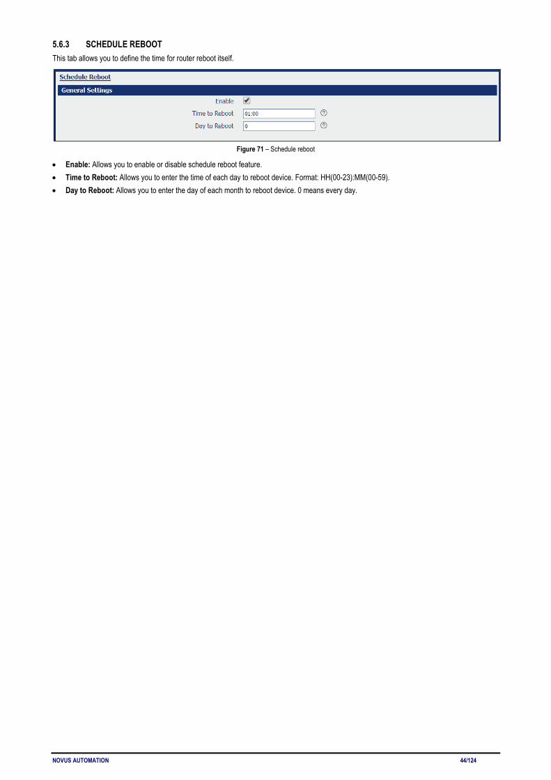
NOVUS AUTOMATION 44/124
5.6.3 SCHEDULE REBOOT This tab allows you to define the time for router reboot itself.
Figure 71 – Schedule reboot
• Enable: Allows you to enable or disable schedule reboot feature. • Time to Reboot: Allows you to enter the time of each day to reboot device. Format: HH(00-23):MM(00-59). • Day to Reboot: Allows you to enter the day of each month to reboot device. 0 means every day.

NOVUS AUTOMATION 45/124
5.7 VPN This section allows you to define VPN settings.
5.7.1 OpenVPN OpenVPN is an open source virtual private network (VPN) product that offers a simplified security framework, modular network design, and cross-platform portability.
5.7.1.1 OpenVPN → STATUS This parameter group allows you to view the OpenVPN status. Each OpenVPN can be individually created, configured or removed in the OpenVPN → OpenVPN tab.
Figure 72 - OpenVPN
• Enable: Displays current OpenVPN settings is enable or disable. • Status: Displays the current VPN connection status. • Uptime: Displays the connection time since VPN is established. • Virtual IP: Displays the virtual IP address obtain from remote side.
5.7.1.2 OpenVPN → OpenVPN This parameter group allows you to configure the OpenVPN.
Figure 73 – OpenVPN settings
This parameter group has the following buttons:
Button: Allows you to add a new OpenVPN.
Button: Allows you to edit the settings of the selected OpenVPN.
Button: Allows you to delete the selected OpenVPN.

NOVUS AUTOMATION 46/124
As you can see in Figure 74, you can create a new OpenVPN by clicking the button.
Figure 74 – OpenVPN settings
• Enable: Allows you to enable or disable OpenVPN tunnel. • Description: Allows you to Enter a description for this OpenVPN tunnel. • Mode: Allows you to define a mode for the OpenVPN tunnel: "Client" or "P2P". • Protocol: Allows you to define a protocol for the OpenVPN tunnel: "UDP" or "TCP Client". • Connection Type: Allows you to define a connection type for the OpenVPN tunnel: "TUN" or "TAP". The difference between TUN and TAP
device is that a TUN device is a point-to-point virtual device on network while a TAP device is a virtual device on Ethernet. • Server Address: Allows you to Enter the IP address or domain of remote server • Server Port: Allows you to Enter the negotiate port on OpenVPN server • Authentication Method: Allows you to define an authentication method for the OpenVPN tunnel: "X.509", "Pre-shared", "Password" or "X.509
and Password". • Encryption Type: Allows you to define a encryption type for the OpenVPN tunnel: "BF-CBC", "DES-CBC", "DES-EDE-CBC", "DES-EDE3-
CBC", "AES-128-CBC", "AES-192-CBC" or "AES-256 -CBC". • Username: Allows you to enter the username for authentication when selection from "Password" or "X.509 And Password". • Password: Allows you to enter the password for authentication when selection from "Password" or "X.509 And Password". • Local IP Address: Allows you to enter the local virtual IP address when select "P2P" mode. • Remote IP Address: Allows you to enter the remote virtual IP address when select "P2P" mode. • Local Netmask: Allows you to enter the local netmask when select "TAP" connection type. • TAP Bridge: Allows you to select the specified LAN that bridge with OpenVPN tunnel when select "TAP" connection type. • Renegotiate Interval: Allows you to enter the renegotiate interval if connection is failed. • Keep Alive Interval: Allows you to enter the keep alive interval to check the tunnel is active or not.

NOVUS AUTOMATION 47/124
• Keep Alive Timeout: Allows you to enter the keep alive timeout, once connection is failed it will trigger the OpenVPN reconnect. • Fragment: Allows you to enter the fragment size. 0 means disable • Private Key Password: Allows you to enter the private key password for authentication when selection from "X.509" or "X.509 And Password". • Output Verbosity Level: Allows you to enter the level of the output log and values. AVANCED SETTINGS • Enable NAT: Allows you to enable or disable NAT. • Enable PKCS#12: Allows you to enable or disable PKCS#12. It is an exchange of digital certificate encryption standard, used to describe
personal identity information. • Enable X.509 Attribute nsCertType: Require that peer certificate was signed with an explicit nsCertType designation of "server". • Enable HMAC Firewall: Add additional layer of HMAC authentication on the top of the TLS control channel to protect against DoS attacks. • Enable Compression LZO: Allows you to enable or disable compress the data. • Additional Configurations: Allows you to enter some other options of OpenVPN in this field. Each expression can be separated by a ";".
5.7.1.3 OpenVPN → X.509 CERTIFICATE This parameter group allows you to add certificates to the device.
Figure 75 – Certificate files
• Connection Index: Displays the current connection index for OpenVPN channel. • CA Certificate: Allows you to import CA certificate file. • Local Certificate File: Allows you to import local certificate file. • Local Private Key: Allows you to import local private key file. • HMAC Firewall Key: Allows you to import HMAC firewall key file. • Pre-shared Key: Allows you to import the pre-shared key file. • PKCS#12 Certificate: Allows you to import PKCS#12 certificate.
5.7.2 IPSec IPSec facilitates configuration of secured communication tunnels. The various tunnel configurations will be displayed in the Tunnel Table at the bottom of the page. All tunnels are create using the ESP (Encapsulating Security Payload) protocol.
5.7.2.1 IPSec → STATUS This section allows you to view IPSec status.
Figure 76 – IPSec status
• Enable: Displays current IPSec settings is enable or disable. • Description: Displays the description of current VPN channel. • Status: Displays the current VPN connection status.
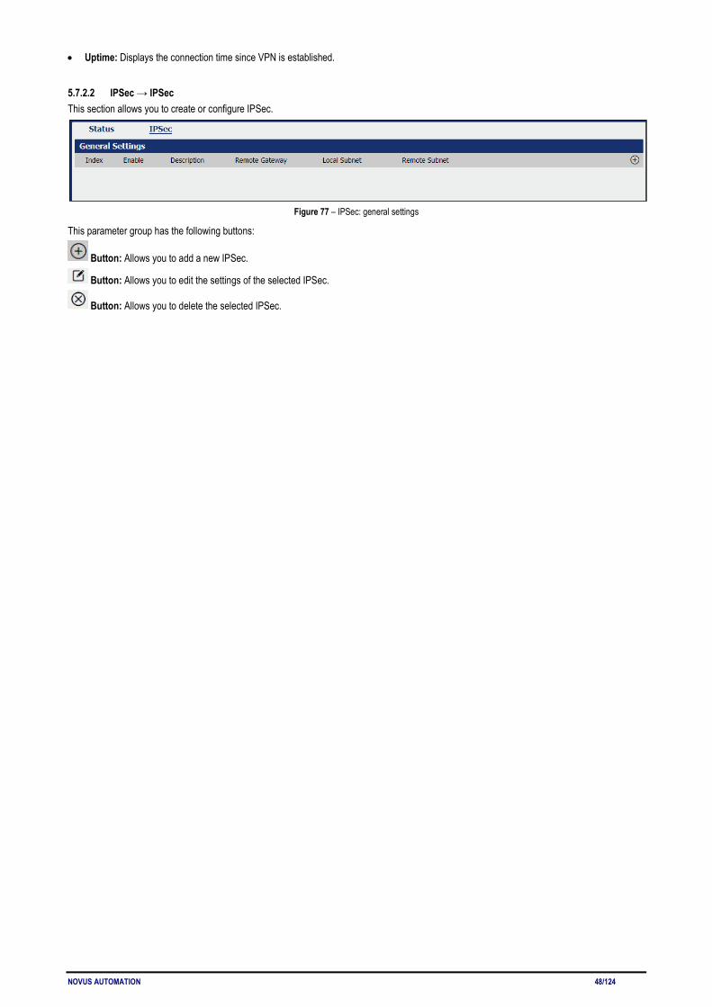
NOVUS AUTOMATION 48/124
• Uptime: Displays the connection time since VPN is established.
5.7.2.2 IPSec → IPSec This section allows you to create or configure IPSec.
Figure 77 – IPSec: general settings
This parameter group has the following buttons:
Button: Allows you to add a new IPSec.
Button: Allows you to edit the settings of the selected IPSec.
Button: Allows you to delete the selected IPSec.
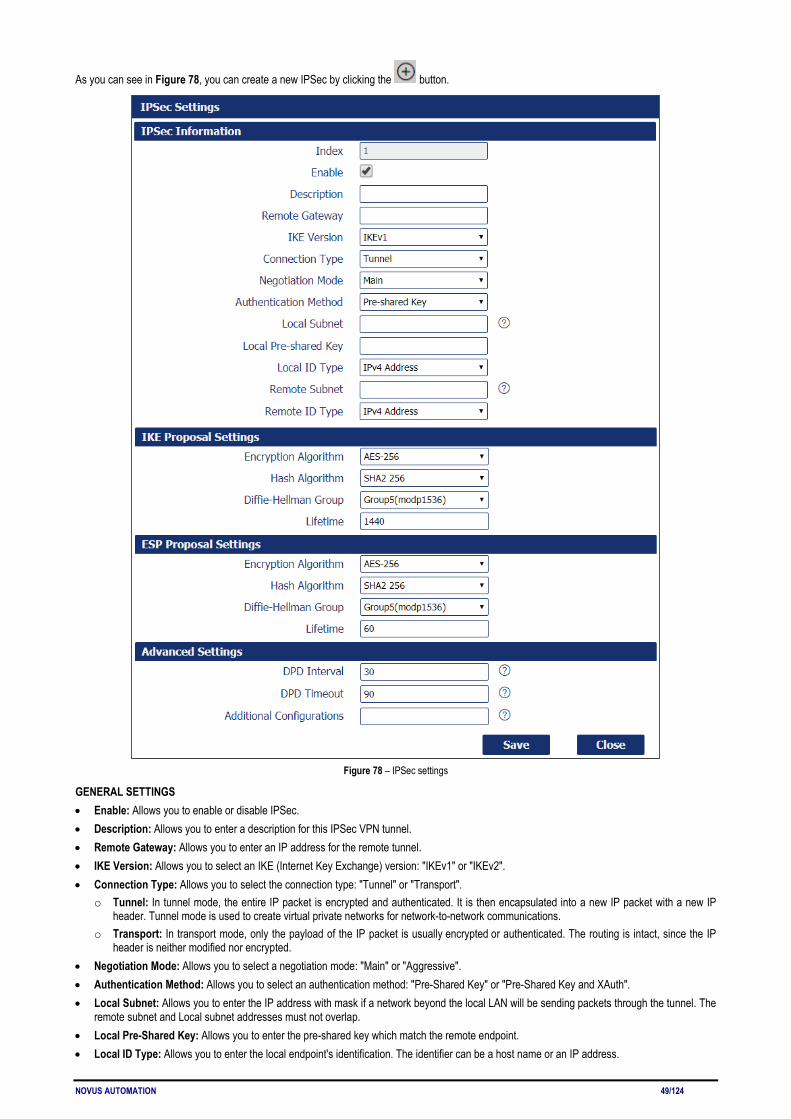
NOVUS AUTOMATION 49/124
As you can see in Figure 78, you can create a new IPSec by clicking the button.
Figure 78 – IPSec settings
GENERAL SETTINGS • Enable: Allows you to enable or disable IPSec. • Description: Allows you to enter a description for this IPSec VPN tunnel. • Remote Gateway: Allows you to enter an IP address for the remote tunnel. • IKE Version: Allows you to select an IKE (Internet Key Exchange) version: "IKEv1" or "IKEv2". • Connection Type: Allows you to select the connection type: "Tunnel" or "Transport".
o Tunnel: In tunnel mode, the entire IP packet is encrypted and authenticated. It is then encapsulated into a new IP packet with a new IP header. Tunnel mode is used to create virtual private networks for network-to-network communications.
o Transport: In transport mode, only the payload of the IP packet is usually encrypted or authenticated. The routing is intact, since the IP header is neither modified nor encrypted.
• Negotiation Mode: Allows you to select a negotiation mode: "Main" or "Aggressive". • Authentication Method: Allows you to select an authentication method: "Pre-Shared Key" or "Pre-Shared Key and XAuth". • Local Subnet: Allows you to enter the IP address with mask if a network beyond the local LAN will be sending packets through the tunnel. The
remote subnet and Local subnet addresses must not overlap. • Local Pre-Shared Key: Allows you to enter the pre-shared key which match the remote endpoint. • Local ID Type: Allows you to enter the local endpoint's identification. The identifier can be a host name or an IP address.

NOVUS AUTOMATION 50/124
• Identity XAuth: Allows you to enter Xauth identity after "Pre-shared Key and Xauth" on authentication Method is enabled. • Password XAuth: Allows you to enter Xauth password "Pre-shared Key and Xauth" on authentication Method is enabled. • Remote Subnet: Allows you to enter an IP address with mask if encrypted packets are also destined for the specified network that is beyond
the Remote IP Address. The remote subnet and local subnet addresses must not overlap. • Remote ID Type: Allows you to enter the authentication address of the remote endpoint. IKE PROPOSAL SETTINGS • Encryption Algorithm (IKE): Allows you to select the encryption algorithm: "3DES AES-128", "AES-192" or "AES-256". • Hash Algorithm (IKE): Allows you to select the hash algorithm: "MD5", "SHA1", "SHA2 256", "SHA2 384" or "SHA2 512". • Diffie-Hellman Group (IKE): Allows you to select the Diffie-Hellman method: "Negotiate (None)", "768 (Group 1)", "1024 (Group 2)", "1536
(Group 5)" or "2048 (Group 14)". • Lifetime (IKE): How long a particular instance of a connection should last, from successful negotiation to expiry. ESP PROPOSAL SETTINGS • Encryption Algorithm (ESP): Allows you to select the encryption algorithm: "3DES AES-128", "AES-192" or "AES-256". • Hash Algorithm (ESP): Allows you to select the hash algorithm: "MD5", "SHA1", "SHA2 256", "SHA2 384" or "SHA2 512". • Diffie-Hellman Group (ESP): Allows you to select the Diffie-Hellman method: "Negotiate (None)", "768 (Group 1)", "1024 (Group 2)", "1536
(Group 5)" or "2048 (Group 14)". • Lifetime (ESP): How long a particular instance of a connection should last, from successful negotiation to expiry. ADVANCED SETTINGS • DPD Interval: Allows you to enter the interval after which DPD is triggered if no IPsec protected packets is received from the peer. • DPD Timeout: Allows you to enter the remote peer probe response timer. • Additional Configurations: Allows you to enter some other options of IPSec in this field. Each expression can be separated by a ";".
5.7.3 GRE Generic Routing Encapsulation (GRE) is a protocol that encapsulates packets in order to route other protocols over IP networks. It’s a tunneling technology that provides a channel through which encapsulated data message could be transmitted and encapsulation and decapsulation could be realized at both ends.
5.7.3.1 GRE → STATUS This parameter group allows you to view the GRE protocol status.
Figure 79 – GRE status
• Enable: Displays current GRE settings is enable or disable. • Description: Displays the description of current VPN channel. • Mode: Displays the current VPN mode. • Status: Displays the current VPN connection status.
5.7.3.2 GRE → GRE This parameter group allows you to create or configure the GRE protocol.
Figure 80 – GRE settings
This parameter group has the following buttons:
Button: Allows you to add a new GRE.
Button: Allows you to edit the settings of the selected GRE.

NOVUS AUTOMATION 51/124
Button: Allows you to delete the selected GRE.
As you can see in Figure 81 – GRE, you can create a GRE by clicking the button.
Figure 81 – GRE information
• Enable: Allows you to enable or disable GRE. • Description: Allows you to enter the description of current VPN channel. • Mode: Allows you to specify the running mode of GRE: "Layer 2" or "Layer 3". • Remote Gateway: Allows you to enter the remote IP address of peer GRE tunnel. • Local Virtual IP: Allows you to enter the local virtual netmask of GRE tunnel. • Local Virtual Netmask: Allows you to enter the local virtual netmask of GRE tunnel. • Tunnel Key: Allows you to enter the authentication key of GRE tunnel. • Enable NAT: Allows you to enable or disable NAT. • Bridge Interface: Allows you to specify the bridge interface work with Layer 2 mode.
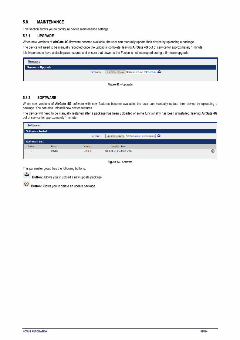
NOVUS AUTOMATION 52/124
5.8 MAINTENANCE This section allows you to configure device maintenance settings.
5.8.1 UPGRADE When new versions of AirGate 4G firmware become available, the user can manually update their device by uploading a package. The device will need to be manually rebooted once the upload is complete, leaving AirGate 4G out of service for approximately 1 minute. It is important to have a stable power source and ensure that power to the Fusion is not interrupted during a firmware upgrade.
Figure 82 – Upgrade
5.8.2 SOFTWARE When new versions of AirGate 4G software with new features become available, the user can manually update their device by uploading a package. You can also uninstall new device features. The device will need to be manually restarted after a package has been uploaded or some functionality has been uninstalled, leaving AirGate 4G out of service for approximately 1 minute.
Figure 83 - Software
This parameter group has the following buttons:
Button: Allows you to upload a new update package.
Button: Allows you to delete an update package.

NOVUS AUTOMATION 53/124
5.8.3 SYSTEM This tab allows you to configure the device.
5.8.3.1 SYSTEM → GENERAL This parameter group allows you to define the general settings.
Figure 84 – System
GENERAL SETTINGS • Hostname: Allows you to define the router name, which might be used for IPSec local ID identify. • User LET Type: Allows you to define the LED behavior: "None", "SIM" or "WiFi". TIME ZONE SETTINGS • Time Zone: Allows you to define the time zone where the device is in use. • Customized Time Zone: Allows you to define a customized zone where the device is in use. TIME SYNCHRONISATION • Enable (NTP Client): If enabled, allows the NTP client to synchronize the device clock over the network when using a time server (NTP
Server). • Primary NTP Server: Allows you to enter the IP address (or host name) of the primary time server. • Secondary NTP Server: Allows you to Enter the IP address (or host name) of the secondary time server.
5.8.3.2 SYSTEM → ACCOUNTS This parameter group allows you to define user settings linked to the device.
Figure 85 – Account settings
ACCOUNT SETTINGS • Administrator: Displays the name of current administrator, default as "admin". • Old Password: Allows you to enter the old password of administrator. • New Password: Allows you to enter the new password of administrator. • Confirm Password: Allows you to confirm the new password of administrator. VISITOR SETTINGS This parameter group hast the following buttons:
Button: Allows you to add a new visitor.
Button: Allows you to edit the settings of the selected visitor.
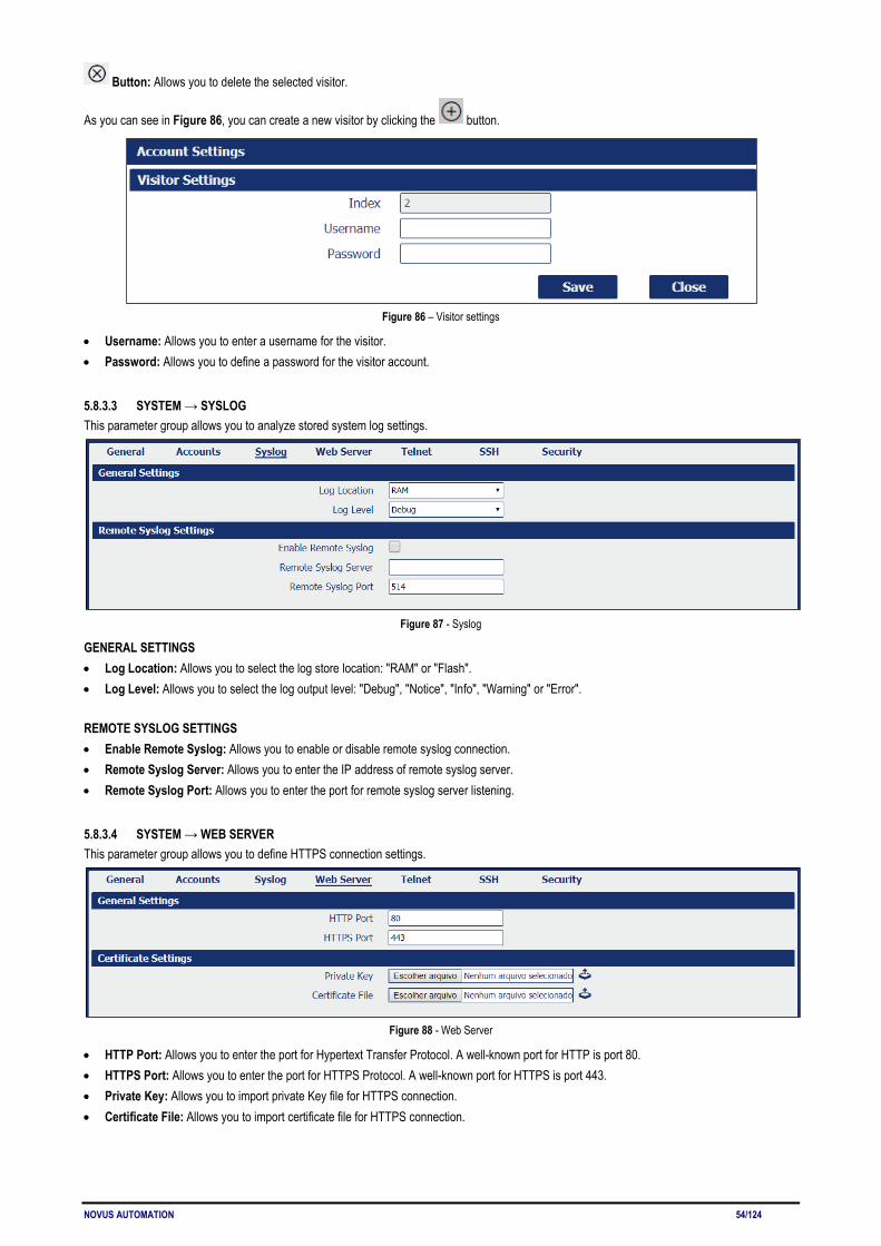
NOVUS AUTOMATION 54/124
Button: Allows you to delete the selected visitor.
As you can see in Figure 86, you can create a new visitor by clicking the button.
Figure 86 – Visitor settings
• Username: Allows you to enter a username for the visitor. • Password: Allows you to define a password for the visitor account.
5.8.3.3 SYSTEM → SYSLOG This parameter group allows you to analyze stored system log settings.
Figure 87 - Syslog
GENERAL SETTINGS • Log Location: Allows you to select the log store location: "RAM" or "Flash". • Log Level: Allows you to select the log output level: "Debug", "Notice", "Info", "Warning" or "Error". REMOTE SYSLOG SETTINGS • Enable Remote Syslog: Allows you to enable or disable remote syslog connection. • Remote Syslog Server: Allows you to enter the IP address of remote syslog server. • Remote Syslog Port: Allows you to enter the port for remote syslog server listening.
5.8.3.4 SYSTEM → WEB SERVER This parameter group allows you to define HTTPS connection settings.
Figure 88 - Web Server
• HTTP Port: Allows you to enter the port for Hypertext Transfer Protocol. A well-known port for HTTP is port 80. • HTTPS Port: Allows you to enter the port for HTTPS Protocol. A well-known port for HTTPS is port 443. • Private Key: Allows you to import private Key file for HTTPS connection. • Certificate File: Allows you to import certificate file for HTTPS connection.
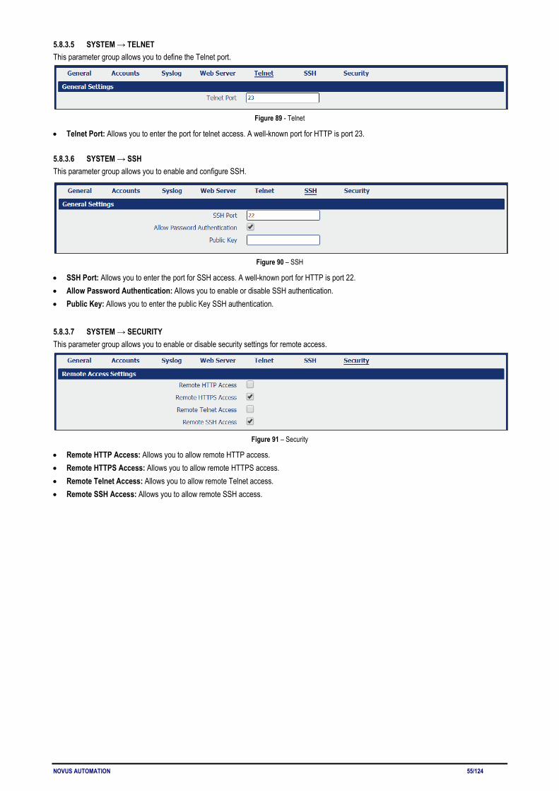
NOVUS AUTOMATION 55/124
5.8.3.5 SYSTEM → TELNET This parameter group allows you to define the Telnet port.
Figure 89 - Telnet
• Telnet Port: Allows you to enter the port for telnet access. A well-known port for HTTP is port 23.
5.8.3.6 SYSTEM → SSH This parameter group allows you to enable and configure SSH.
Figure 90 – SSH
• SSH Port: Allows you to enter the port for SSH access. A well-known port for HTTP is port 22. • Allow Password Authentication: Allows you to enable or disable SSH authentication. • Public Key: Allows you to enter the public Key SSH authentication.
5.8.3.7 SYSTEM → SECURITY This parameter group allows you to enable or disable security settings for remote access.
Figure 91 – Security
• Remote HTTP Access: Allows you to allow remote HTTP access. • Remote HTTPS Access: Allows you to allow remote HTTPS access. • Remote Telnet Access: Allows you to allow remote Telnet access. • Remote SSH Access: Allows you to allow remote SSH access.
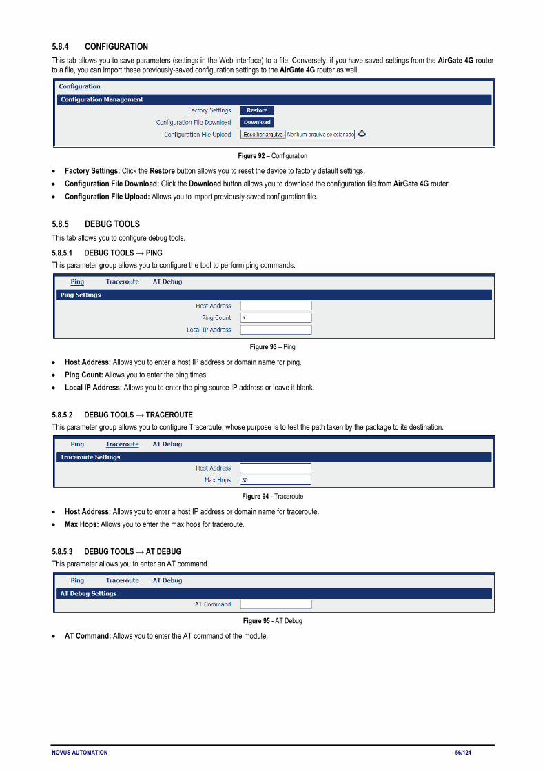
NOVUS AUTOMATION 56/124
5.8.4 CONFIGURATION This tab allows you to save parameters (settings in the Web interface) to a file. Conversely, if you have saved settings from the AirGate 4G router to a file, you can Import these previously-saved configuration settings to the AirGate 4G router as well.
Figure 92 – Configuration
• Factory Settings: Click the Restore button allows you to reset the device to factory default settings. • Configuration File Download: Click the Download button allows you to download the configuration file from AirGate 4G router. • Configuration File Upload: Allows you to import previously-saved configuration file.
5.8.5 DEBUG TOOLS This tab allows you to configure debug tools.
5.8.5.1 DEBUG TOOLS → PING This parameter group allows you to configure the tool to perform ping commands.
Figure 93 – Ping
• Host Address: Allows you to enter a host IP address or domain name for ping. • Ping Count: Allows you to enter the ping times. • Local IP Address: Allows you to enter the ping source IP address or leave it blank.
5.8.5.2 DEBUG TOOLS → TRACEROUTE This parameter group allows you to configure Traceroute, whose purpose is to test the path taken by the package to its destination.
Figure 94 - Traceroute
• Host Address: Allows you to enter a host IP address or domain name for traceroute. • Max Hops: Allows you to enter the max hops for traceroute.
5.8.5.3 DEBUG TOOLS → AT DEBUG This parameter allows you to enter an AT command.
Figure 95 - AT Debug
• AT Command: Allows you to enter the AT command of the module.

NOVUS AUTOMATION 57/124
6 TUTORIALS This chapter presents tutorials that show how to configure different features of the AirGate 4G.
6.1 RS232: TRANSPARENT MODE WITH TCP CLIENT This tutorial shows how to configure and use the Transparent mode of the RS232 interface with AirGate 4G configured as TCP Client.
6.1.1 TOPOLOGY You can use the following topology:
Figure 95 – RS232: Transparent mode
1. AirGate 4G runs as TCP Client and connect to Internet with SIM card. 2. PC1 simulate as serial device and runs serial software, such as Hercules. Hercules will send the data to the TCP server side through AirGate
4G with TCP transparent mode. 3. PC2 runs as TCP server and assume it can get the Public Static IP address. PC2 enable TCP software, such as TCPUDPDbg. TCPUDPDbg
can receive the data from TCP Client side.
6.1.2 RS232 CABLE Follow Figure 96 bellow to make the RS232 cable:
Figure 96 – RS232 Cable
Table 10 shows the connector pins:
PIN RS232 RS485 DI DO DIRECTION 6 -- -- DI1 -- Router ← Device 7 -- -- DI2 -- Router ← Device 8 GND -- -- -- -- 9 TX -- -- -- Router → Device 10 RX -- -- -- Router ← Device
Table 10 – RS232 connector pins

NOVUS AUTOMATION 58/124
6.1.3 CONFIGURATION 6.1.3.1 RS232 CONFIGURATION To configure RS232 interface, you must open the Web Interface of AirGate 4G and go to Industrial Interface > Serial > Connection > Index 2. To perform the interface configuration, just click on the COM2 edit button.
Figure 97 – RS232 configuration
To enable RS232 configuration, you must select the protocol as "TCP Client" and enter the server IP address and server port. Then click Save.
Figure 98 – Transmission configurations
6.1.3.2 TCP SERVER CONFIGURATION To configure TCP server, you must run the TCP Software "TCPUDPDbg" on server PC2. AirGate 4G will connect to the TCP Server automatically.
Figure 99 – TCPUDPDDbg Software
In the AirGate 4G Web Interface, go to Industrial Interface > Serial > Status > Serial Information > Index2. It will show the connection status.
Figure 100 – RS232 status connection
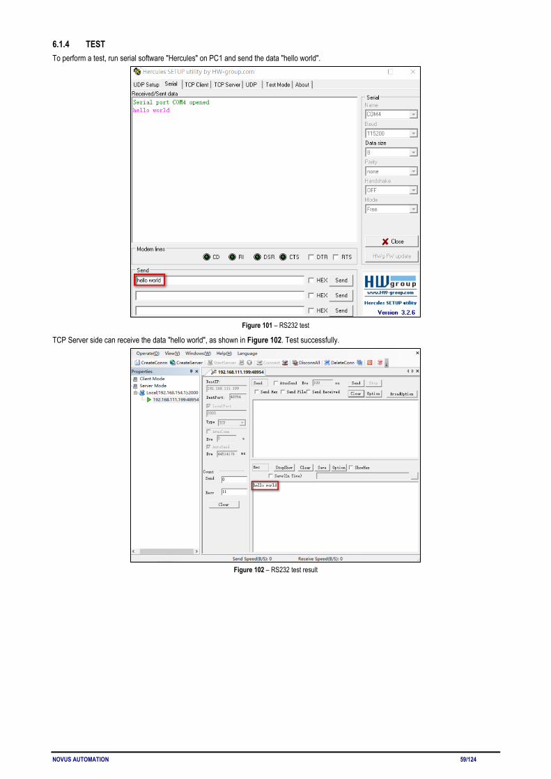
NOVUS AUTOMATION 59/124
6.1.4 TEST To perform a test, run serial software "Hercules" on PC1 and send the data "hello world".
Figure 101 – RS232 test
TCP Server side can receive the data "hello world", as shown in Figure 102. Test successfully.
Figure 102 – RS232 test result
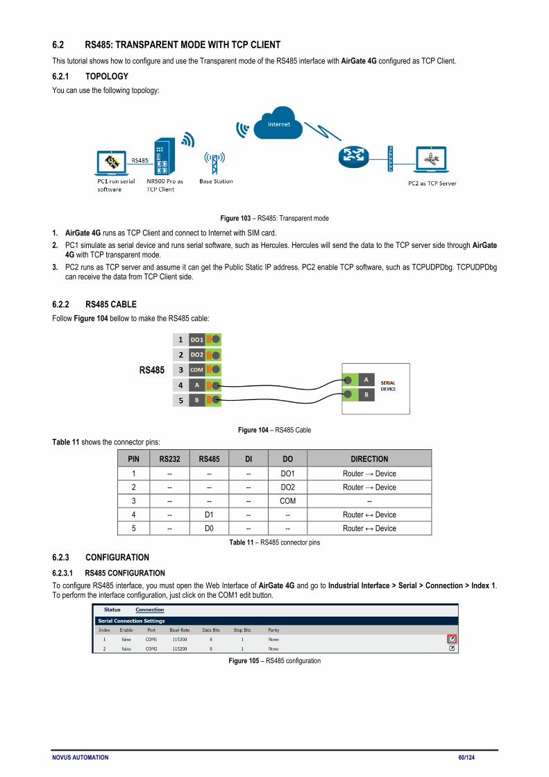
NOVUS AUTOMATION 60/124
6.2 RS485: TRANSPARENT MODE WITH TCP CLIENT This tutorial shows how to configure and use the Transparent mode of the RS485 interface with AirGate 4G configured as TCP Client.
6.2.1 TOPOLOGY You can use the following topology:
Figure 103 – RS485: Transparent mode
1. AirGate 4G runs as TCP Client and connect to Internet with SIM card. 2. PC1 simulate as serial device and runs serial software, such as Hercules. Hercules will send the data to the TCP server side through AirGate
4G with TCP transparent mode. 3. PC2 runs as TCP server and assume it can get the Public Static IP address. PC2 enable TCP software, such as TCPUDPDbg. TCPUDPDbg
can receive the data from TCP Client side.
6.2.2 RS485 CABLE Follow Figure 104 bellow to make the RS485 cable:
Figure 104 – RS485 Cable
Table 11 shows the connector pins:
PIN RS232 RS485 DI DO DIRECTION 1 -- -- -- DO1 Router → Device 2 -- -- -- DO2 Router → Device 3 -- -- -- COM -- 4 -- D1 -- -- Router ↔ Device 5 -- D0 -- -- Router ↔ Device
Table 11 – RS485 connector pins
6.2.3 CONFIGURATION 6.2.3.1 RS485 CONFIGURATION To configure RS485 interface, you must open the Web Interface of AirGate 4G and go to Industrial Interface > Serial > Connection > Index 1. To perform the interface configuration, just click on the COM1 edit button.
Figure 105 – RS485 configuration

NOVUS AUTOMATION 61/124
To enable RS485 configuration, you must select the protocol as "TCP Client" and enter the server IP address and server port. Then click Save.
Figure 106 – Transmission configurations
6.2.3.2 TCP SERVER CONFIGURATION To configure TCP server, you must run the TCP Software "TCPUDPDbg" on server PC2. AirGate 4G will connect to the TCP Server automatically.
Figure 107 – TCPUDPDDbg Software
In the AirGate 4G Web Interface, go to Industrial Interface > Serial > Status > Serial Information > Index1. It will show the connection status.
Figure 108 – RS485 status connection

NOVUS AUTOMATION 62/124
6.2.4 TEST To perform a test, run serial software "Hercules" on PC1 and send the data "study".
Figure 109 – RS485 test
TCP Server side can receive the data "study", as shown in Figure 110. Test successfully.
Figure 110 – RS485 test result

NOVUS AUTOMATION 63/124
6.3 OpenVPN CERTIFICATES GENERATED This tutorial shows how to generate certificates needed to use OpenVPN.
6.3.1 OpenVPN SOFTWARE INSTALLED You must download the OpenVPN software, located at http://openvpn.net/index.php, and install it on a Windows computer.
6.3.2 CERTIFICATES GENERATED To generate a certificate, you must run as an administrator the Windows command prompt and type the following cd command to "C:\Program Files\OpenVPN\easy-rsa", as shown in the figure below:
Figure 111 – cd “C:\Program Files\OpenVPN\easy-rsa” command
Then run the init-config.bat command to copy the configuration files to vars.bat (this command will overwrite both the previous vars.bat file and the openssl.cnf files).
Figure 112 – init-config.bat command
Edit the vars.bat file and set the KEY_COUNTRY, KEY_PROVINCE, KEY_CITY, KEY_ORG, KEY_EMAIL, KEY_CN, KEY_NAME, KEY_OU, PKCS11_MODULE_PATH and PKCS11_PIN parameters (parameters must be entered without space):
Figure 113 – Editing the parameters
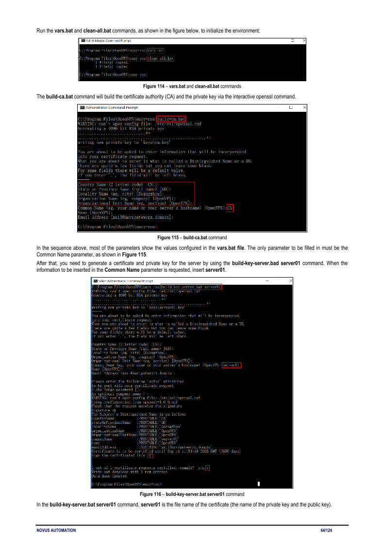
NOVUS AUTOMATION 64/124
Run the vars.bat and clean-all.bat commands, as shown in the figure below, to initialize the environment:
Figure 114 – vars.bat and clean-all.bat commands
The build-ca.bat command will build the certificate authority (CA) and the private key via the interactive openssl command.
Figure 115 – build-ca.bat command
In the sequence above, most of the parameters show the values configured in the vars.bat file. The only parameter to be filled in must be the Common Name parameter, as shown in Figure 115. After that, you need to generate a certificate and private key for the server by using the build-key-server.bad server01 command. When the information to be inserted in the Common Name parameter is requested, insert server01.
Figure 116 – build-key-server.bat server01 command
In the build-key-server.bat server01 command, server01 is the file name of the certificate (the name of the private key and the public key).

NOVUS AUTOMATION 65/124
The next step involves generating the client's certificate and private key when using the build-key-pass.bat client01 command. You will need to use the key authentication in the OpenVPN client configuration. When the information to be inserted in the Common Name parameter is requested, insert client01.
Figure 117 – build-key-pass.bat client01 command
In the build-key-pass.bat client01 command, client01 is the file name of the certificate (the name of the private key and the public key). You must use a unique name for each client. After that, generate Diffie Hellman parameters.
Figure 118 – Diffie Hellman parameters

NOVUS AUTOMATION 66/124
Once the certificates had been generated, you can check them out on path C:\Program Files\OpenVPN\easy-rsa\keys.
Figure 119 – List of certificates

NOVUS AUTOMATION 67/124
6.4 OpenVPN WITH X.509 CERTIFICATE This tutorial shows how to configure OpenVPN with a X.509 certificate.
6.4.1 TOPOLOGY You can use the following topology:
Figure 120 – OpenVPN with X.509 certificate
1. AirGate 4G runs as OpenVPN Client with any kind of IP, which can ping OpenVPN server IP successfully. 2. A PC runs as OpenVPN Server with a static public IP and open a specified a listening port for OpenVPN. 3. OpenVPN tunnel is established between Server and Client, the subnet can Ping each other successfully.
6.4.2 CONFIGURATION 6.4.2.1 SERVER CONFIGURATION To configure a computer as a server, you must download the OpenVPN software, available at https://openvpn.net/, and run and install it with administrator authority. Once the software has been installed, you should copy the related certificates and the specific configuration to your computer, as shown in the figure below:
Figure 121 – OpenVPN configuration
After that, you must create a "ccd" folder, rename it ("client01" is the common name), rename it without suffix and configure it according to Figure 122:
Figure 122 – Client01 file
After that, just run the file server.ovpn and configure it as shown below:
local 59.41.92.241 mode server port 1194 proto udp dev tun tun-mtu 1500 fragment 1500 ca ca.crt cert server01.crt key server01.key # This file should be kept secret dh dh2048.pem

NOVUS AUTOMATION 68/124
server 10.8.0.0 255.255.255.0 ifconfig-pool-persist ipp.txt push "route 192.168.10.0 255.255.255.0" client-config-dir ccd route 192.168.5.0 255.255.255.0 keepalive 10 120 cipher BF-CBC comp-lzo max-clients 100 persist-key persist-tun status openvpn-status.log verb 3
6.4.2.2 CLIENT CONFIGURATION To configure a computer as a client, you must open the Web Interface of AirGate 4G and go to VPN > OpenVPN > OpenVPN > General Settings. Click the edit button and configure OpenVPN as below:
Figure 123 – OpenVPN configuration
Click Save > Apply.

NOVUS AUTOMATION 69/124
Once you have set up OpenVPN, go to VPN > OpenVPN > X.509 Certificate to import the related certification. Click Apply.
Figure 124 – Certificate import
Route had connected to OpenVPN server. Go to VPN > OpenVPN > Status to check the connection status.
Figure 125 – OpenVPN connection status
6.4.3 ROUTE TABLE Figure 117 shows a route table of the OpenVPN server for reference:
Figure 126 – Route table of OpenVPN server
Figure 118 shows a route table of the OpenVPN client for reference:
Figure 127 – Route table of OpenVPN client
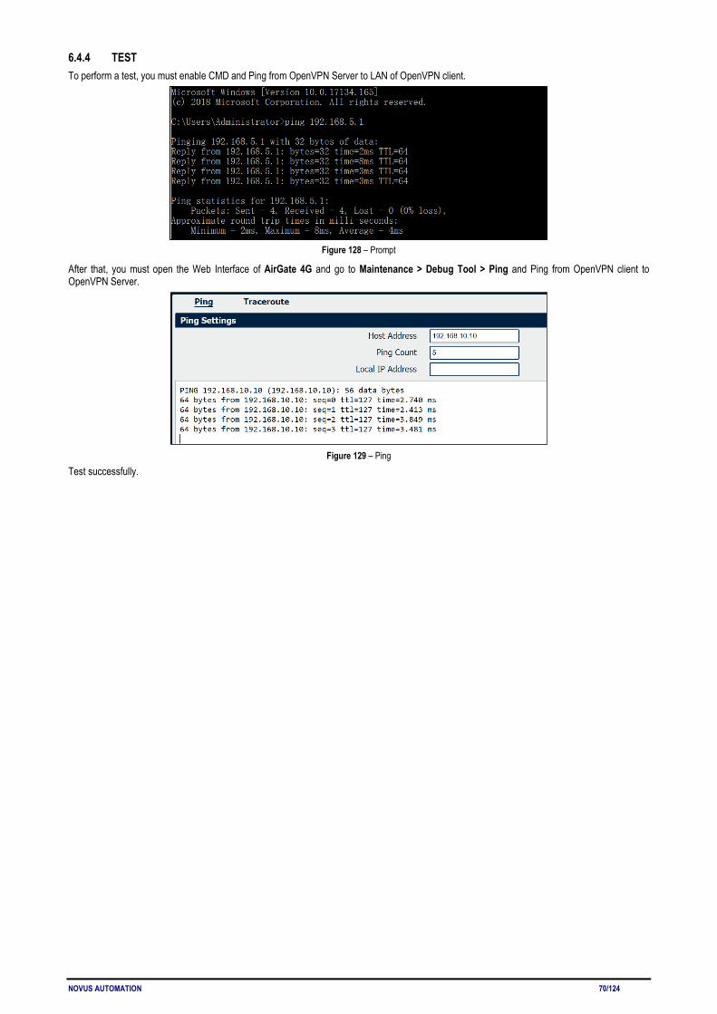
NOVUS AUTOMATION 70/124
6.4.4 TEST To perform a test, you must enable CMD and Ping from OpenVPN Server to LAN of OpenVPN client.
Figure 128 – Prompt
After that, you must open the Web Interface of AirGate 4G and go to Maintenance > Debug Tool > Ping and Ping from OpenVPN client to OpenVPN Server.
Figure 129 – Ping
Test successfully.
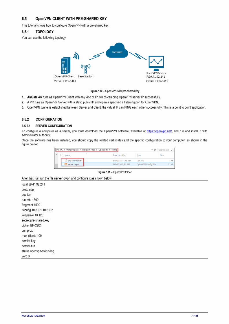
NOVUS AUTOMATION 71/124
6.5 OpenVPN CLIENT WITH PRE-SHARED KEY This tutorial shows how to configure OpenVPN with a pre-shared key.
6.5.1 TOPOLOGY You can use the following topology:
Figure 130 – OpenVPN with pre-shared key
1. AirGate 4G runs as OpenVPN Client with any kind of IP, which can ping OpenVPN server IP successfully. 2. A PC runs as OpenVPN Server with a static public IP and open a specified a listening port for OpenVPN. 3. OpenVPN tunnel is established between Server and Client, the virtual IP can PING each other successfully. This is a point to point application.
6.5.2 CONFIGURATION 6.5.2.1 SERVER CONFIGURATION To configure a computer as a server, you must download the OpenVPN software, available at https://openvpn.net/, and run and install it with administrator authority. Once the software has been installed, you should copy the related certificates and the specific configuration to your computer, as shown in the figure below:
Figure 131 – OpenVPN folder
After that, just run the file server.ovpn and configure it as shown below:
local 59.41.92.241 proto udp dev tun tun-mtu 1500 fragment 1500 ifconfig 10.8.0.1 10.8.0.2 keepalive 10 120 secret pre-shared.key cipher BF-CBC comp-lzo max-clients 100 persist-key persist-tun status openvpn-status.log verb 3

NOVUS AUTOMATION 72/124
6.5.2.2 CLIENT CONFIGURATION To configure a PC as a client, you must open the Web Interface of AirGate 4G and go to VPN > OpenVPN > OpenVPN > General Settings. Click the edit button and configure OpenVPN as below:
Figure 132 – OpenVPN settings
Click Save > Apply. After that, go to VPN > OpenVPN > X.509 Certificate to import the related certification. Click Apply.
Figure 133 – Pre-shared key
Route had connected to OpenVPN server. Go to VPN > OpenVPN > Status to check the connection status.
Figure 134 – OpenVPN status connection

NOVUS AUTOMATION 73/124
6.5.3 ROUTE TABLE Figure 135 shows a route table of the OpenVPN server for reference:
Figure 135 – Server route table information
Figure 136 shows a route table of the OpenVPN client for reference:
Figure 136 – Client route table information
6.5.4 TEST To perform a test, you must enable CMD and Ping from OpenVPN Server to LAN of OpenVPN client.
Figure 137 – CMD
After that, you must open the Web Interface of AirGate 4G and go to Maintenance > Debug Tool > Ping and Ping from OpenVPN client to OpenVPN Server.
Figure 138 – Ping
Test successfully.

NOVUS AUTOMATION 74/124
6.6 OpenVPN CLIENT WITH USERNAME & PASSWORD This tutorial shows how to configure OpenVPN with a username and password.
6.6.1 TOPOLOGY You can use the following topology:
Figure 139 – OpenVPN with username and password
1. Two AirGate 4G run as OpenVPN Client01 and Client02 with any kind of IP, which can ping OpenVPN server IP successfully. 2. A PC runs as OpenVPN Server with a static public IP and open a specified a listening port for OpenVPN. 3. OpenVPN tunnel is established between Server and Client. Client01 can ping Client02 successfully and vice versa.
6.6.2 CONFIGURATION 6.6.2.1 SERVER CONFIGURATION To configure a computer as a server, you must download the OpenVPN software, available at https://openvpn.net/, and run and install it with administrator authority. Once the software has been installed, you should copy the related certificates and the specific configuration to your computer, as shown in the figure below:
Figure 140 – OpenVPN folders
After that, two new notepads must be created inside the "ccd" folder, renamed it without suffix (using the default names "client01" and "client02") and configured according to Figure 141:
Figure 141 – Client01 and client02 configuration files
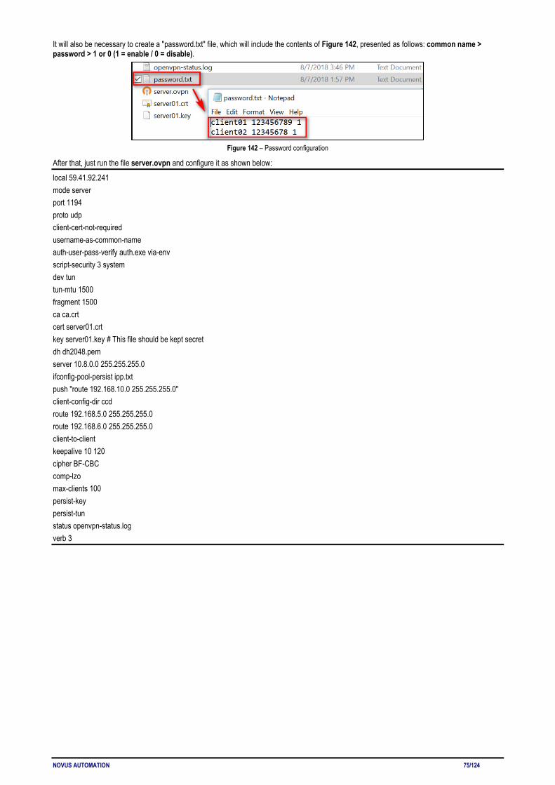
NOVUS AUTOMATION 75/124
It will also be necessary to create a "password.txt" file, which will include the contents of Figure 142, presented as follows: common name > password > 1 or 0 (1 = enable / 0 = disable).
Figure 142 – Password configuration
After that, just run the file server.ovpn and configure it as shown below:
local 59.41.92.241 mode server port 1194 proto udp client-cert-not-required username-as-common-name auth-user-pass-verify auth.exe via-env script-security 3 system dev tun tun-mtu 1500 fragment 1500 ca ca.crt cert server01.crt key server01.key # This file should be kept secret dh dh2048.pem server 10.8.0.0 255.255.255.0 ifconfig-pool-persist ipp.txt push "route 192.168.10.0 255.255.255.0" client-config-dir ccd route 192.168.5.0 255.255.255.0 route 192.168.6.0 255.255.255.0 client-to-client keepalive 10 120 cipher BF-CBC comp-lzo max-clients 100 persist-key persist-tun status openvpn-status.log verb 3
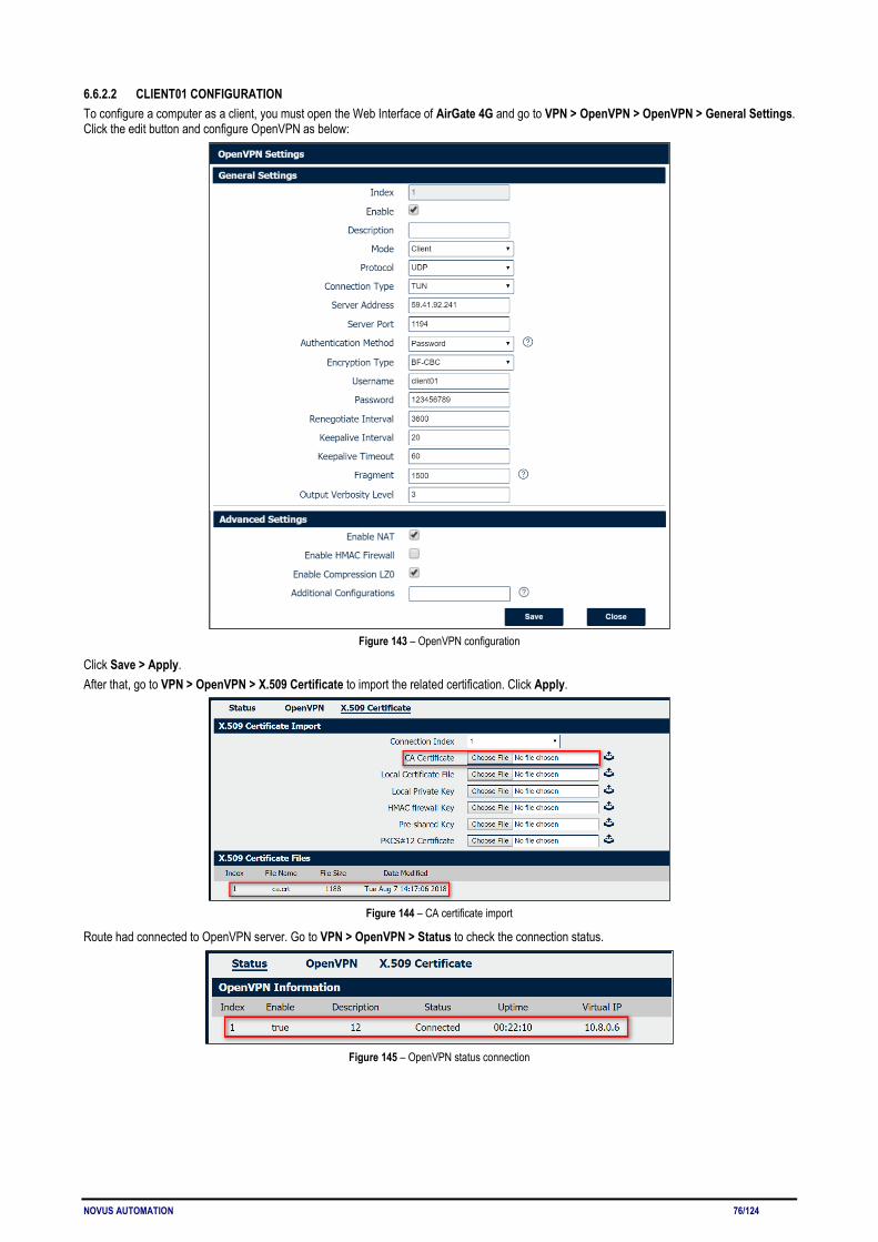
NOVUS AUTOMATION 76/124
6.6.2.2 CLIENT01 CONFIGURATION To configure a computer as a client, you must open the Web Interface of AirGate 4G and go to VPN > OpenVPN > OpenVPN > General Settings. Click the edit button and configure OpenVPN as below:
Figure 143 – OpenVPN configuration
Click Save > Apply. After that, go to VPN > OpenVPN > X.509 Certificate to import the related certification. Click Apply.
Figure 144 – CA certificate import
Route had connected to OpenVPN server. Go to VPN > OpenVPN > Status to check the connection status.
Figure 145 – OpenVPN status connection
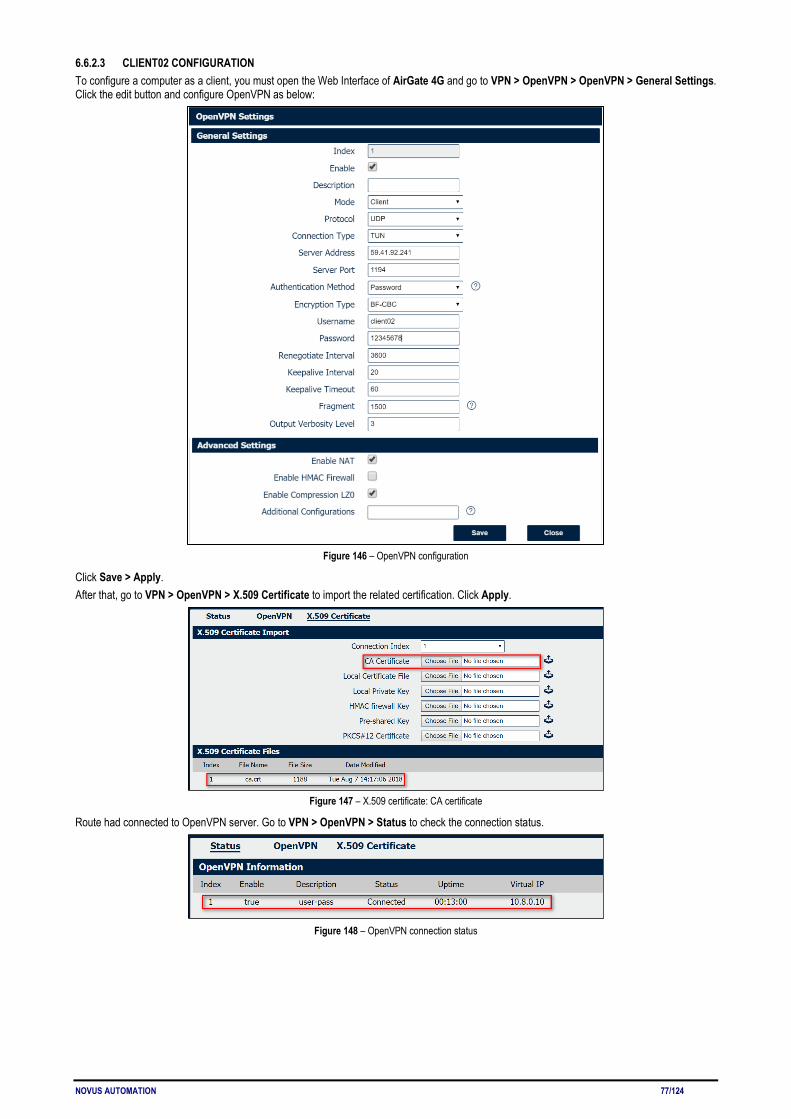
NOVUS AUTOMATION 77/124
6.6.2.3 CLIENT02 CONFIGURATION To configure a computer as a client, you must open the Web Interface of AirGate 4G and go to VPN > OpenVPN > OpenVPN > General Settings. Click the edit button and configure OpenVPN as below:
Figure 146 – OpenVPN configuration
Click Save > Apply. After that, go to VPN > OpenVPN > X.509 Certificate to import the related certification. Click Apply.
Figure 147 – X.509 certificate: CA certificate
Route had connected to OpenVPN server. Go to VPN > OpenVPN > Status to check the connection status.
Figure 148 – OpenVPN connection status

NOVUS AUTOMATION 78/124
6.6.3 ROUTE TABLE Figure 149 shows a route table of the OpenVPN server for reference:
Figure 149 – OpenVPN server route table
Figure 150 shows a route table of the Client01 for reference:
Figure 150 – Client01 route table
Figure 151 shows a route table of the Client02 for reference:
Figure 151 – Client02 route table
6.6.4 TEST You must open the Web Interface of AirGate 4G and go to Maintenance > Debug Tool > Ping and ping from Client01 to Cliente02:
Figure 152 – Ping from Client01 to Client02

NOVUS AUTOMATION 79/124
After that, Ping from Client02 to Cliente01 as below:
Figure 153 – Ping from Client02 to Client01
Test successfully.

NOVUS AUTOMATION 80/124
6.7 OpenVPN WITH TAP AND PRE-SHARED KEY UNDER P2P MODE This tutorial shows how to configure OpenVPN with TAP and pre-shared key under P2P mode.
6.7.1 TOPOLOGY You can use the following topology:
Figure 154 – OpenVPN with TAP and pre-shared key
1. AirGate 4G runs as OpenVPN Client with any kind of IP, which can ping OpenVPN server IP successfully. 2. A PC runs as OpenVPN Server with a static public IP and open a specified a listening port for OpenVPN. 3. OpenVPN tunnel is established between Server and Client, the virtual IP can PING each other successfully. Also server can Ping LAN PC
device and vice versa.
6.7.2 CONFIGURATION 6.7.2.1 SERVER CONFIGURATION To configure a computer as a server, you must download the OpenVPN software, available at https://openvpn.net/, and run and install it with administrator authority. Once the software has been installed, you should copy the related certificates and the specific configuration to your computer, as shown in the figure below:
Figure 155 – OpenVPN folder
After that, just run the file p2p-server-tap-pre-shared.ovpn and configure it as shown below:
mode p2p port 1194 proto udp dev tap # tap ifconfig 10.1.0.1 255.255.255.0 keepalive 20 120 persist-key persist-tun secret pre-shared.key # None TLS Mode cipher BF-CBC comp-lzo status openvpn-status.log verb 3 tun-mtu 1500 fragment 1500

NOVUS AUTOMATION 81/124
6.7.2.2 CLIENT CONFIGURATION To configure a computer as a client, you must open the Web Interface of AirGate 4G and go to VPN > OpenVPN > OpenVPN > General Settings. Click the edit button and configure OpenVPN as below:
Figure 156 – OpenVPN settings
Click Save > Apply. After that, go to VPN > OpenVPN > X.509 Certificate to import the related certification. Click Apply.
Figure 157 – Pre-shared key
Route had connected to OpenVPN server. Go to VPN > OpenVPN > Status to check the connection status.
Figure 158 – OpenVPN connection status
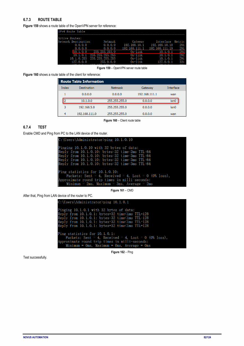
NOVUS AUTOMATION 82/124
6.7.3 ROUTE TABLE Figure 159 shows a route table of the OpenVPN server for reference:
Figure 159 – OpenVPN server route table
Figure 160 shows a route table of the client for reference:
Figure 160 – Client route table
6.7.4 TEST Enable CMD and Ping from PC to the LAN device of the router.
Figure 161 – CMD
After that, Ping from LAN device of the router to PC.
Figure 162 – Ping
Test successfully.

NOVUS AUTOMATION 83/124
6.8 OpenVPN WITH TAP UNDER P2P MODE This tutorial shows how to configure OpenVPN with TAP and under P2P mode.
6.8.1 TOPOLOGY You can use the following topology:
Figure 163 – OpenVPN with TAP under P2P
1. AirGate 4G runs as OpenVPN Client with any kind of IP, which can ping OpenVPN server IP successfully. 2. A PC runs as OpenVPN Server with a static public IP and open a specified a listening port for OpenVPN. 3. OpenVPN tunnel is established between Server and Client, the virtual IP can PING each other successfully. Also Server can ping LAN PC
device and vice versa.
6.8.2 CONFIGURATION 6.8.2.1 PC CONFIGURATION To configure the computer, you must download the OpenVPN software, available at https://openvpn.net/, and run and install it with administrator authority. Once the software has been installed, you should copy the related certificates and the specific configuration to your computer, as shown in the figure below:
Figure 164 – OpenVPN configuration
After that, just run the file p2p-server-tap-x.509.ovpn and configure it as shown below:
mode p2p port 1194 proto udp dev tap # tap ifconfig 10.1.0.1 255.255.255.0 keepalive 20 120 persist-key persist-tun tls-server ca ca.crt cert server01.crt key server01.key dh dh2048.pem #tls-auth ta.key 0 cipher BF-CBC comp-lzo status openvpn-status.log verb 3 tun-mtu 1500
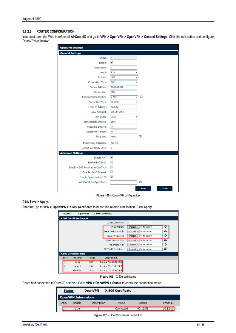
NOVUS AUTOMATION 84/124
fragment 1500
6.8.2.2 ROUTER CONFIGURATION You must open the Web Interface of AirGate 4G and go to VPN > OpenVPN > OpenVPN > General Settings. Click the edit button and configure OpenVPN as below:
Figure 165 – OpenVPN configuration
Click Save > Apply. After that, go to VPN > OpenVPN > X.509 Certificate to import the related certification. Click Apply.
Figure 166 – X.509 certificates
Route had connected to OpenVPN server. Go to VPN > OpenVPN > Status to check the connection status.
Figure 167 – OpenVPN status connection
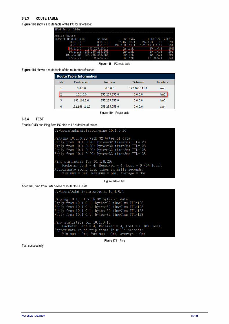
NOVUS AUTOMATION 85/124
6.8.3 ROUTE TABLE Figure 168 shows a route table of the PC for reference:
Figure 168 – PC route table
Figure 169 shows a route table of the router for reference:
Figure 169 – Router table
6.8.4 TEST Enable CMD and Ping from PC side to LAN device of router.
Figure 170 – CMD
After that, ping from LAN device of router to PC side.
Figure 171 – Ping
Test successfully.

NOVUS AUTOMATION 86/124
6.9 OpenVPN WITH TUN CERTIFICATE UNDER P2P MODE This tutorial shows how to configure OpenVPN with TUN and under P2P mode.
6.9.1 TOPOLOGY You can use the following topology:
Figure 172 – OpenVPN with TUN under P2P mode
1. AirGate 4G runs as OpenVPN Client with any kind of IP, which can ping OpenVPN server IP successfully. 2. A PC runs as OpenVPN Server with a static public IP and open a specified a listening port for OpenVPN. 3. OpenVPN tunnel is established between Server and Client, the virtual IP can Ping each other successfully.
6.9.2 CONFIGURATION 6.9.2.1 PC CONFIGURATION To configure the computer, you must download the OpenVPN software, available at https://openvpn.net/, and run and install it with administrator authority. Once the software has been installed, you should copy the related certificates and the specific configuration to your computer, as shown in the figure below:
Figure 173 – OpenVPN configuration
After that, just run the file p2p-server-tun-x.509 and configure it as shown below:
mode p2p port 1194 proto udp dev tun # tun ifconfig 10.8.0.1 10.8.0.2 keepalive 20 120 persist-key persist-tun tls-server ca ca.crt cert server01.crt key server01.key dh dh2048.pem #tls-auth ta.key 0 cipher BF-CBC comp-lzo status openvpn-status.log verb 3 tun-mtu 1500 fragment 1500

NOVUS AUTOMATION 87/124
6.9.2.2 ROUTER CONFIGURATION You must open the Web Interface of AirGate 4G and go to VPN > OpenVPN > OpenVPN > General Settings. Click the edit button and configure OpenVPN as below:
Figure 174 – OpenVPN settings
Click Save > Apply. After that, go to VPN > OpenVPN > X.509 Certificate to import the related certification. Click Apply.
Figure 175 – Certificate import
Route had connected to OpenVPN server. Go to VPN > OpenVPN > Status to check the connection status.
Figure 176 – OpenVPN status connection
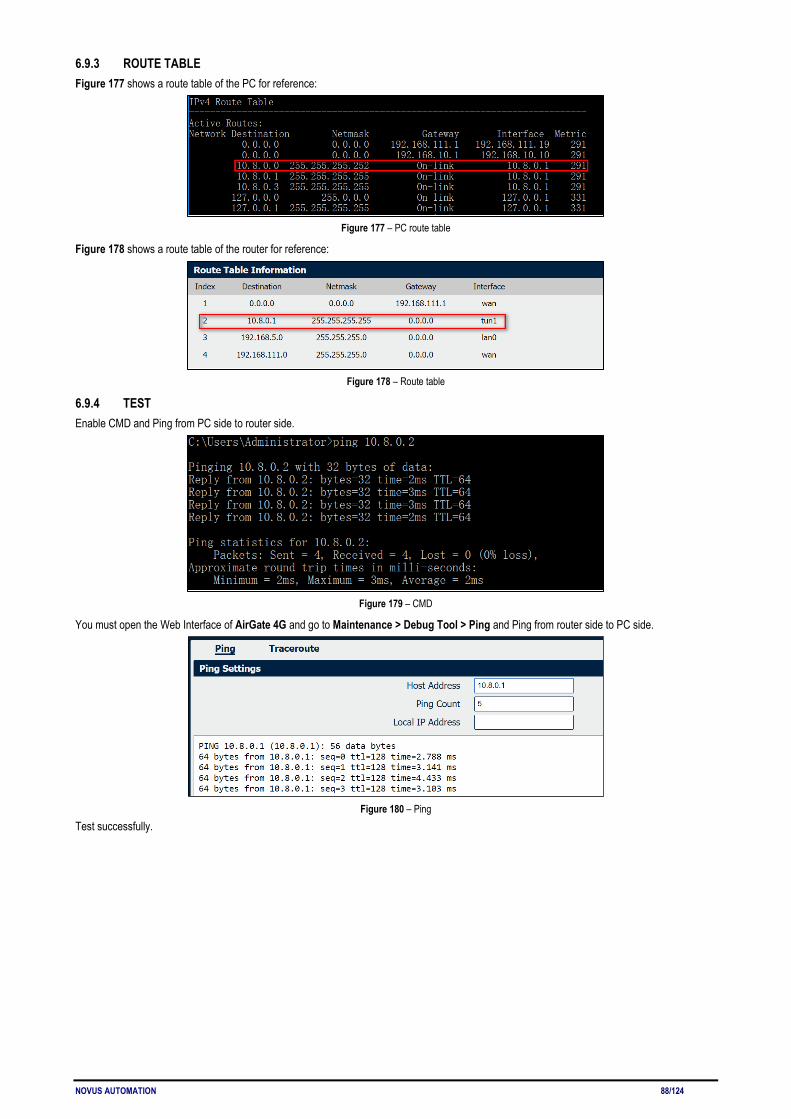
NOVUS AUTOMATION 88/124
6.9.3 ROUTE TABLE Figure 177 shows a route table of the PC for reference:
Figure 177 – PC route table
Figure 178 shows a route table of the router for reference:
Figure 178 – Route table
6.9.4 TEST Enable CMD and Ping from PC side to router side.
Figure 179 – CMD
You must open the Web Interface of AirGate 4G and go to Maintenance > Debug Tool > Ping and Ping from router side to PC side.
Figure 180 – Ping
Test successfully.

NOVUS AUTOMATION 89/124
6.10 IPsec: PRE-SHARED KEY WITH CISCO ROUTER This tutorial shows how to configure IPsec with pre-shared key with Cisco router.
6.10.1 TOPOLOGY You can use the following topology:
Figure 181 – IPsec topology
1. AirGate 4G runs as IPSec Client with any kind of IP, which can ping IPSec server IP successfully. 2. Cisco router runs as IPSec Server with a static public IP. 3. IPSec tunnel is established between AirGate 4G and Cisco router.
6.10.2 CONFIGURATION 6.10.2.1 SERVER CONFIGURATION Login to Cisco router and setting like below:
cisco2811#show running-config Building configuration... Current configuration : 3071 bytes ! version 12.4 hostname cisco2811 logging message-counter syslog enable secret 5 $1$tw/d$UQQ3Xh06n.2HHFeAVIgXJ. ! no aaa new-model ! ip domain name cisco.com ip name-server 192.168.111.1 ip address-pool local no ipv6 cef ! multilink bundle-name authenticated ! username cisco password 0 cisco archive log config hidekeys ! crypto isakmp policy 10 encr aes 256 hash md5 authentication pre-share group 5 crypto isakmp key 6 cisco address 0.0.0.0 0.0.0.0 ! crypto ipsec transform-set NR500 esp-3des esp-md5-hmac ! crypto dynamic-map DYN 10 set transform-set NR500 set pfs group5

NOVUS AUTOMATION 90/124
match address 101 reverse-route ! crypto map SMAP 10 ipsec-isakmp dynamic DYN ! track 1 interface FastEthernet0/0 line-protocol ! interface Loopback0 ip address 192.168.50.1 255.255.255.0 ! interface FastEthernet0/0 ip address 192.168.111.254 255.255.255.0 ip nat outside ip nat enable ip virtual-reassembly duplex full speed auto no mop enabled crypto map SMAP ! interface FastEthernet0/1 ip address 192.168.5.1 255.255.255.0 ip nat inside ip nat enable ip virtual-reassembly duplex auto speed auto ! ip forward-protocol nd ip route 0.0.0.0 0.0.0.0 192.168.111.1 no ip http server no ip http secure-server ! ip nat inside source list 10 interface FastEthernet0/0 overload ! ip access-list extended VPN permit ip 192.168.50.0 0.0.0.255 192.168.6.0 0.0.0.255 ! access-list 10 permit 192.168.5.0 0.0.0.255 access-list 101 permit ip 192.168.50.0 0.0.0.255 192.168.6.0 0.0.0.255 snmp-server community public RO end cisco2811#
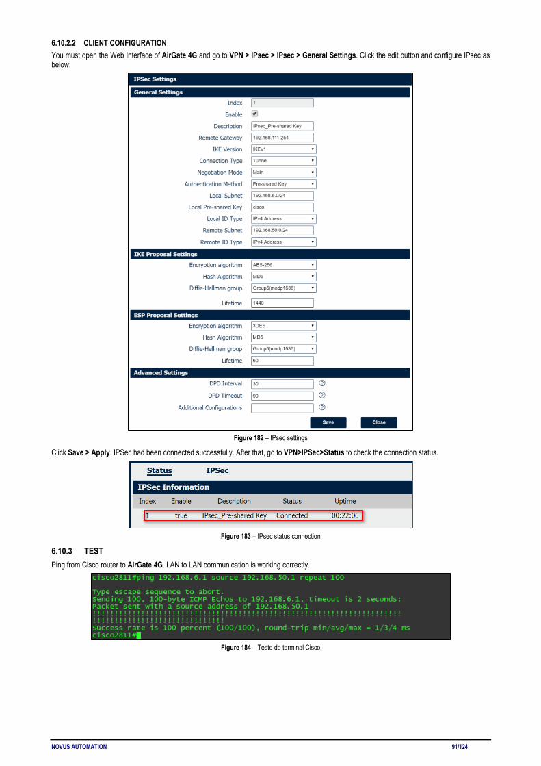
NOVUS AUTOMATION 91/124
6.10.2.2 CLIENT CONFIGURATION You must open the Web Interface of AirGate 4G and go to VPN > IPsec > IPsec > General Settings. Click the edit button and configure IPsec as below:
Figure 182 – IPsec settings
Click Save > Apply. IPSec had been connected successfully. After that, go to VPN>IPSec>Status to check the connection status.
Figure 183 – IPsec status connection
6.10.3 TEST Ping from Cisco router to AirGate 4G. LAN to LAN communication is working correctly.
Figure 184 – Teste do terminal Cisco
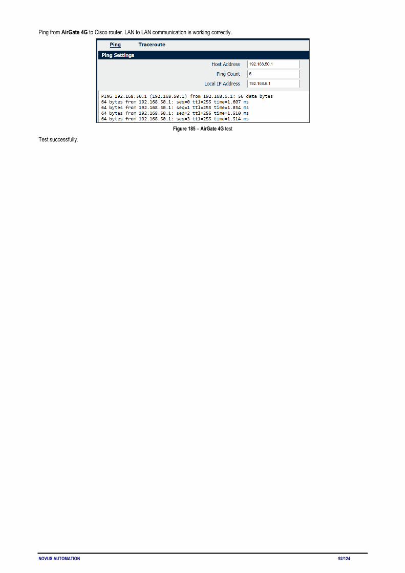
NOVUS AUTOMATION 92/124
Ping from AirGate 4G to Cisco router. LAN to LAN communication is working correctly.
Figure 185 – AirGate 4G test
Test successfully.

NOVUS AUTOMATION 93/124
6.11 IPsec: FQDN WITH CISCO ROUTER This tutorial shows how to configure IPsec_FQDN with Cisco router.
6.11.1 TOPOLOGY You can use the following topology:
Figure 186 – IPsec topology
1. AirGate 4G runs as IPSec Client with any kind of IP, which can ping IPSec server IP successfully. 2. Cisco router runs as IPSec Server with a static public IP. 3. IPSec tunnel is established between AirGate 4G and Cisco router.
6.11.2 CONFIGURATION 6.11.2.1 SERVER CONFIGURATION Login to Cisco router and setting like below:
cisco2811#show running-config Building configuration... version 12.4 hostname cisco2811 ! logging message-counter syslog enable secret 5 $1$tw/d$UQQ3Xh06n.2HHFeAVIgXJ. ! no aaa new-model ip cef ! ip name-server 192.168.111.1 ip address-pool local multilink bundle-name authenticated ! username cisco password 0 cisco archive log config hidekeys ! crypto isakmp policy 10 encr aes 256 hash md5 authentication pre-share group 5 crypto isakmp key 6 cisco hostname NR500 crypto isakmp identity hostname ! crypto isakmp peer address 0.0.0.0 set aggressive-mode password cisco set aggressive-mode client-endpoint fqdn NR500 ! crypto ipsec transform-set NR500 esp-3des esp-md5-hmac ! crypto dynamic-map DYN 10

NOVUS AUTOMATION 94/124
set transform-set NR500 set pfs group5 match address 101 reverse-route ! crypto map SMAP 10 ipsec-isakmp dynamic DYN ! track 1 interface FastEthernet0/0 line-protocol ! interface Loopback0 ip address 192.168.50.1 255.255.255.0 ! interface FastEthernet0/0 ip address 192.168.111.254 255.255.255.0 ip nat outside ip nat enable ip virtual-reassembly duplex full speed auto no mop enabled crypto map SMAP ! interface FastEthernet0/1 ip address 192.168.5.1 255.255.255.0 ip nat inside ip nat enable ip virtual-reassembly duplex auto speed auto ip forward-protocol nd ip route 0.0.0.0 0.0.0.0 192.168.111.1 ip nat inside source list 10 interface FastEthernet0/0 overload ! ip access-list extended VPN permit ip 192.168.50.0 0.0.0.255 192.168.6.0 0.0.0.255 ! access-list 10 permit 192.168.5.0 0.0.0.255 access-list 101 permit ip 192.168.50.0 0.0.0.255 192.168.6.0 0.0.0.255 snmp-server community public RO ! end cisco2811#
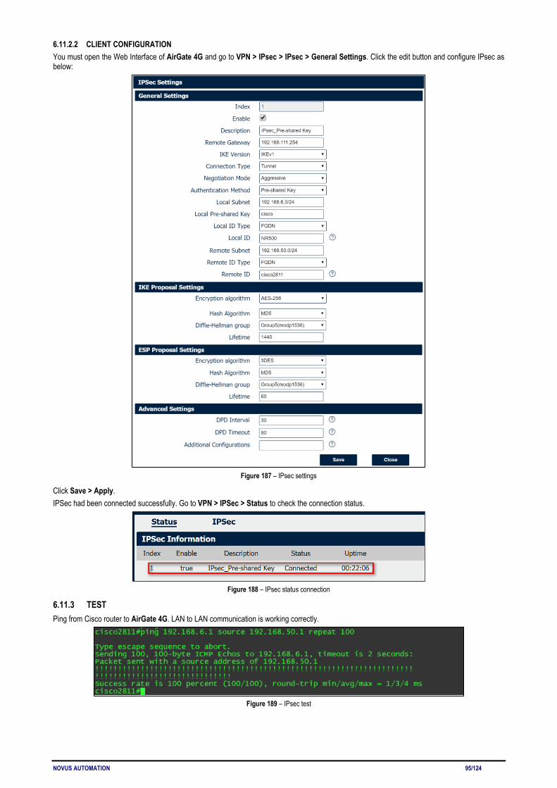
NOVUS AUTOMATION 95/124
6.11.2.2 CLIENT CONFIGURATION You must open the Web Interface of AirGate 4G and go to VPN > IPsec > IPsec > General Settings. Click the edit button and configure IPsec as below:
Figure 187 – IPsec settings
Click Save > Apply. IPSec had been connected successfully. Go to VPN > IPSec > Status to check the connection status.
Figure 188 – IPsec status connection
6.11.3 TEST Ping from Cisco router to AirGate 4G. LAN to LAN communication is working correctly.
Figure 189 – IPsec test
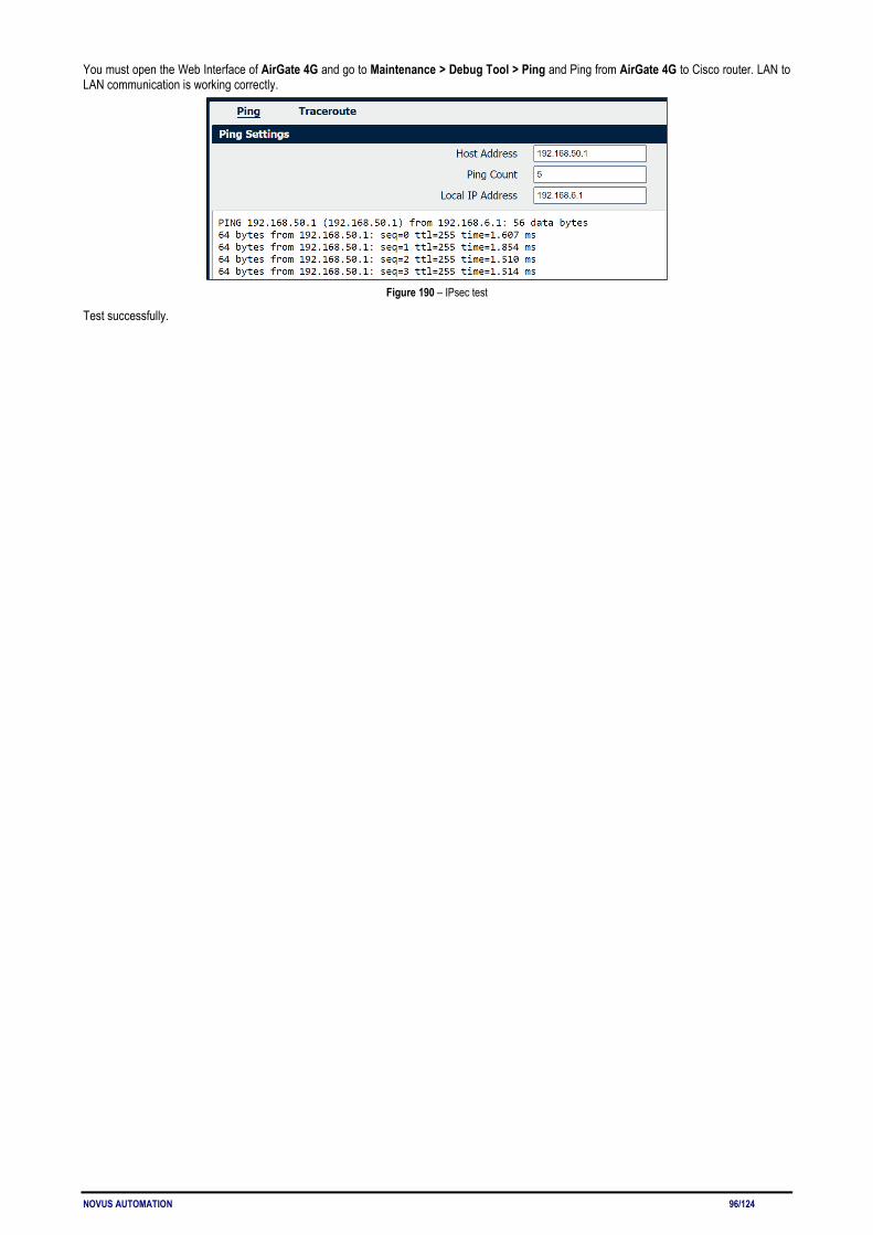
NOVUS AUTOMATION 96/124
You must open the Web Interface of AirGate 4G and go to Maintenance > Debug Tool > Ping and Ping from AirGate 4G to Cisco router. LAN to LAN communication is working correctly.
Figure 190 – IPsec test
Test successfully.
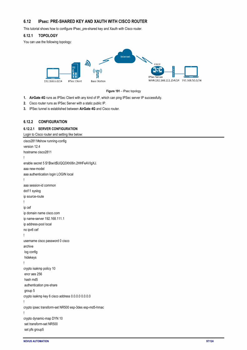
NOVUS AUTOMATION 97/124
6.12 IPsec: PRE-SHARED KEY AND XAUTH WITH CISCO ROUTER This tutorial shows how to configure IPsec_pre-shared key and Xauth with Cisco router.
6.12.1 TOPOLOGY You can use the following topology:
Figure 191 – IPsec topology
1. AirGate 4G runs as IPSec Client with any kind of IP, which can ping IPSec server IP successfully. 2. Cisco router runs as IPSec Server with a static public IP. 3. IPSec tunnel is established between AirGate 4G and Cisco router.
6.12.2 CONFIGURATION 6.12.2.1 SERVER CONFIGURATION Login to Cisco router and setting like below:
cisco2811#show running-config version 12.4 hostname cisco2811 ! enable secret 5 $1$tw/d$UQQ3Xh06n.2HHFeAVIgXJ. aaa new-model aaa authentication login LOGIN local ! aaa session-id common dot11 syslog ip source-route ! ip cef ip domain name cisco.com ip name-server 192.168.111.1 ip address-pool local no ipv6 cef ! username cisco password 0 cisco archive log config hidekeys ! crypto isakmp policy 10 encr aes 256 hash md5 authentication pre-share group 5 crypto isakmp key 6 cisco address 0.0.0.0 0.0.0.0 ! crypto ipsec transform-set NR500 esp-3des esp-md5-hmac ! crypto dynamic-map DYN 10 set transform-set NR500 set pfs group5

NOVUS AUTOMATION 98/124
match address 101 reverse-route ! crypto map MAP client authentication list LOGIN crypto map MAP 10 ipsec-isakmp dynamic DYN ! track 1 interface FastEthernet0/0 line-protocol interface Loopback0 ip address 192.168.50.1 255.255.255.0 ! interface FastEthernet0/0 ip address 192.168.111.254 255.255.255.0 ip nat outside ip nat enable ip virtual-reassembly duplex full speed auto no mop enabled crypto map MAP ! interface FastEthernet0/1 ip address 192.168.5.1 255.255.255.0 ip nat inside ip nat enable ip virtual-reassembly duplex auto speed auto ! ip forward-protocol nd ip route 0.0.0.0 0.0.0.0 192.168.111.1 ip nat inside source list 10 interface FastEthernet0/0 overload ! ip access-list extended VPN permit ip 192.168.50.0 0.0.0.255 192.168.6.0 0.0.0.255 ! access-list 10 permit 192.168.5.0 0.0.0.255 access-list 101 permit ip 192.168.50.0 0.0.0.255 192.168.6.0 0.0.0.255 !! line con 0 line vty 5 15 exec-timeout 5 2 end

NOVUS AUTOMATION 99/124
6.12.2.2 CLIENT CONFIGURATION You must open the Web Interface of AirGate 4G and go to VPN > IPsec > IPsec > General Settings. Click the edit button and configure IPsec as below:
Figure 192 – IPsec settings
Click Save > Apply. IPSec had been connected successfully. Go to VPN > IPSec > Status to check the connection status.
Figure 193 – IPsec status connection
6.12.3 TEST Ping from Cisco router to AirGate 4G. LAN to LAN communication is working correctly.
Figure 194 – Cisco test

NOVUS AUTOMATION 100/124
You must open the Web Interface of AirGate 4G and go to Maintenance > Debug Tool > Ping and Ping from AirGate 4G to Cisco router. LAN to LAN communication is working correctly.
Figure 195 – AirGate 4G test
Test successfully.

NOVUS AUTOMATION 101/124
6.13 IPsec: FQDN, PRE-SHARED KEY AND XAUTH WITH CISCO ROUTER This tutorial shows how to configure IPSec_FQDN_Pre shared key and Xauth with Cisco router.
6.13.1 TOPOLOGY You can use the following topology:
Figure 196 – IPsec toplogy
1. AirGate 4G runs as IPSec Client with any kind of IP, which can ping IPSec server IP successfully. 2. Cisco router runs as IPSec Server with a static public IP. 3. IPSec tunnel is established between AirGate 4G and Cisco router.
6.13.2 CONFIGURATION 6.13.2.1 SERVER CONFIGURATION Login to Cisco router and setting like below:
cisco2811#show running-config version 12.4 hostname cisco2811 ! logging message-counter syslog enable secret 5 $1$tw/d$UQQ3Xh06n.2HHFeAVIgXJ.! aaa new-model ! aaa authentication login LOGIN local ! aaa session-id common ! ip name-server 192.168.111.1 ip address-pool local ! multilink bundle-name authenticated ! username cisco password 0 cisco archive log config hidekeys ! crypto isakmp policy 10 encr aes 256 hash md5 authentication pre-share group 5 crypto isakmp key cisco hostname NR500 crypto isakmp identity hostname ! crypto isakmp peer address 0.0.0.0 set aggressive-mode password ken set aggressive-mode client-endpoint fqdn cisco2811 ! crypto ipsec transform-set NR500 esp-3des esp-md5-hmac

NOVUS AUTOMATION 102/124
! crypto dynamic-map DYN 10 set transform-set NR500 set pfs group5 match address 101 reverse-route ! crypto map MAP client authentication list LOGIN crypto map MAP 10 ipsec-isakmp dynamic DYN ! track 1 interface FastEthernet0/0 line-protocol ! interface Loopback0 ip address 192.168.50.1 255.255.255.0 ! interface FastEthernet0/0 ip address 192.168.111.254 255.255.255.0 ip nat outside ip nat enable ip virtual-reassembly duplex full no mop enabled crypto map MAP ! interface FastEthernet0/1 ip address 192.168.5.1 255.255.255.0 ip nat inside ip nat enable ip virtual-reassembly duplex auto ip forward-protocol nd ip route 0.0.0.0 0.0.0.0 192.168.111.1 ip nat inside source list 10 interface FastEthernet0/0 overload ! ip access-list extended VPN permit ip 192.168.50.0 0.0.0.255 192.168.6.0 0.0.0.255 ! access-list 10 permit 192.168.5.0 0.0.0.255 access-list 101 permit ip 192.168.50.0 0.0.0.255 192.168.6.0 0.0.0.255 line con 0 line vty 5 15 end

NOVUS AUTOMATION 103/124
6.13.2.2 CLIENT CONFIGURATION You must open the Web Interface of AirGate 4G and go to VPN > IPsec > IPsec > General Settings. Click the edit button and configure IPsec as below:
Figure 197 – IPsec settings
Click Save > Apply. IPSec had been connected successfully. Go to VPN > IPSec > Status to check the connection status.
Figure 198 – IPsec status connection
6.13.3 TEST Ping from Cisco router to AirGate 4G, LAN to LAN communication is working correctly.
Figure 199 – Cisco terminal

NOVUS AUTOMATION 104/124
You must open the Web Interface of AirGate 4G and go to Maintenance > Debug Tool > Ping and Ping from AirGate 4G to Cisco router. LAN to LAN communication is working correctly.
Figure 200 – AirGate 4G test
Test successfully.
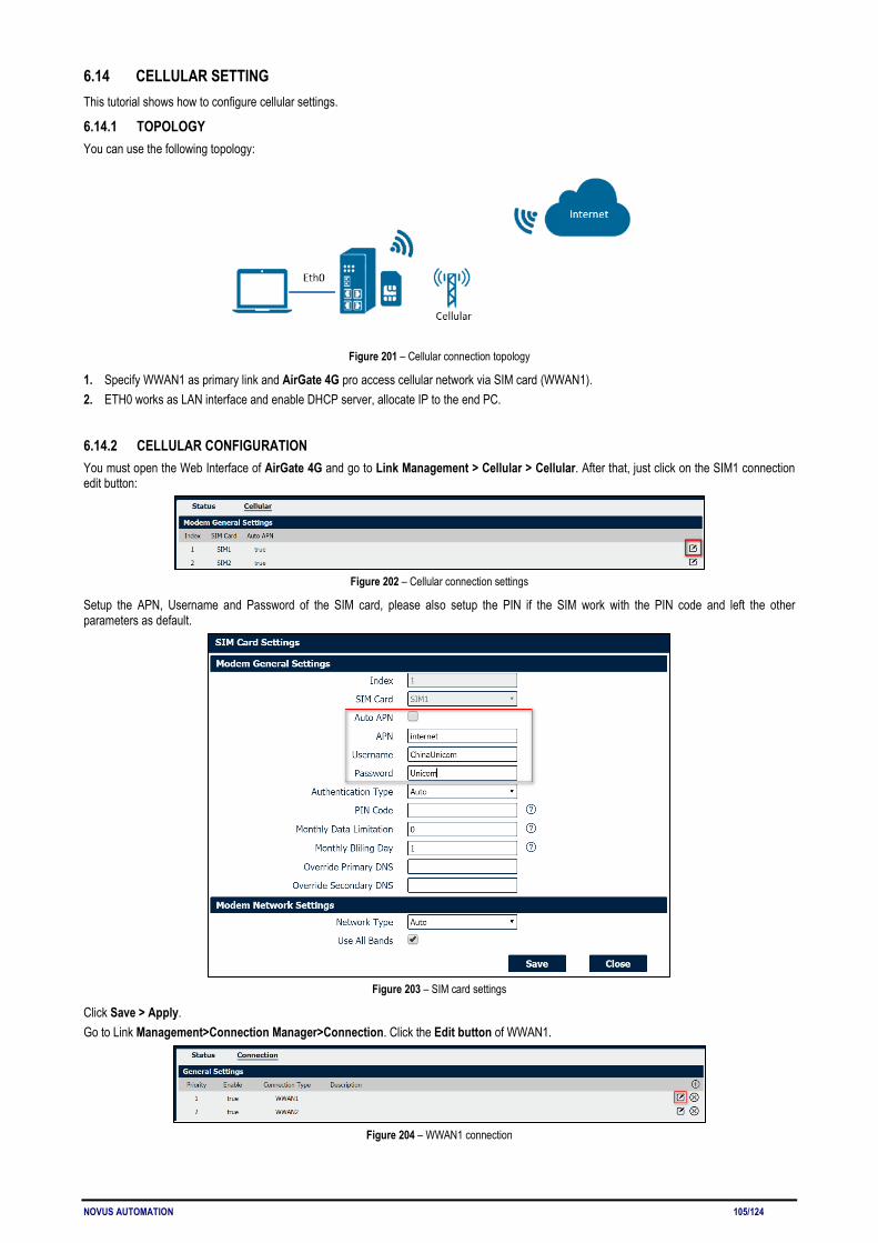
NOVUS AUTOMATION 105/124
6.14 CELLULAR SETTING This tutorial shows how to configure cellular settings.
6.14.1 TOPOLOGY You can use the following topology:
Figure 201 – Cellular connection topology
1. Specify WWAN1 as primary link and AirGate 4G pro access cellular network via SIM card (WWAN1). 2. ETH0 works as LAN interface and enable DHCP server, allocate IP to the end PC.
6.14.2 CELLULAR CONFIGURATION You must open the Web Interface of AirGate 4G and go to Link Management > Cellular > Cellular. After that, just click on the SIM1 connection edit button:
Figure 202 – Cellular connection settings
Setup the APN, Username and Password of the SIM card, please also setup the PIN if the SIM work with the PIN code and left the other parameters as default.
Figure 203 – SIM card settings
Click Save > Apply. Go to Link Management>Connection Manager>Connection. Click the Edit button of WWAN1.
Figure 204 – WWAN1 connection

NOVUS AUTOMATION 106/124
Setup the parameters of WWAN1 as below:
Figure 205 – IPsec status connection
Click Save > Apply.
6.14.3 TEST Go to Overview > Overview > Active Link Information. The router had been got the IP information for ISP.
Figure 206 – IPsec status connection
Go to Link Management > Cellular > Status to check the registration information.
Figure 207 – Cellular status

NOVUS AUTOMATION 107/124
6.15 ETHERNET SETTING This tutorial shows how to configure Ethernet settings.
6.15.1 TOPOLOGY You can use the following topology:
Figure 208 – Ethernet connection topology
1. Specify ETH0 port as WAN port and AirGate 4G communicate with Internet via WAN link. 2. ETH1 works as LAN interface and enable DHCP server, allocate IP to the end PC.
6.15.2 CONFIGURATION 6.15.2.1 ETHERNET CONFIGURATION You must open the Web Interface of AirGate 4G and go to Link Management>Ethernet>Port Assignment. After that, just click the Edit button of Eth0.
Figure 209 – Eth0 port configuration
Assigned the port ETH0 as WAN, like below:
Figure 210 – Eth0 interface
Click Save > Apply. Go to Industrial Interface > Ethernet > Status > WAN, specify the Connection Type as "Static IP" and configure the IP information accordingly, setting like below:
Figure 211 – WWAN1 connection
AirGate 4G also supports DHCP and PPPoE connection types. In this example, however, the static IP configuration is used. Click Save > Apply.

NOVUS AUTOMATION 108/124
Figure 212 – Ethernet settings
Click Save > Apply.
6.15.2.2 PRIMARY LINK CONFIGURATION You must open the Web Interface of AirGate 4G and go to Link Management > Connection Manager > Connection, delete the WWAN1 and WWAN2, then click Save > Apply. After that, add the "WAN" link as below picture:
Figure 213 – Primary link settings
Configure the WAN parameters as below:
Figure 214 – WAN parameters
6.15.3 TEST You must open the Web Interface of AirGate 4G and go to Overview > Status > Active Link Information.
Figure 215 – WAN status connection

NOVUS AUTOMATION 109/124
After that, you must go to Maintenance > Debug Tool > Ping. Router can ping "8.8.8.8" successfully.
Figure 216 – Ethernet configuration test
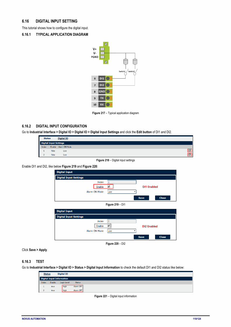
NOVUS AUTOMATION 110/124
6.16 DIGITAL INPUT SETTING This tutorial shows how to configure the digital input.
6.16.1 TYPICAL APPLICATION DIAGRAM
Figure 217 – Typical application diagram
6.16.2 DIGITAL INPUT CONFIGURATION Go to Industrial Interface > Digital IO > Digital IO > Digital Input Settings and click the Edit button of DI1 and DI2.
Figure 218 – Digital input settings
Enable DI1 and DI2, like below Figure 219 and Figure 220:
Figure 219 – DI1
Figure 220 – DI2
Click Save > Apply.
6.16.3 TEST Go to Industrial Interface > Digital IO > Status > Digital Input Information to check the default DI1 and DI2 status like below:
Figure 221 – Digital input information
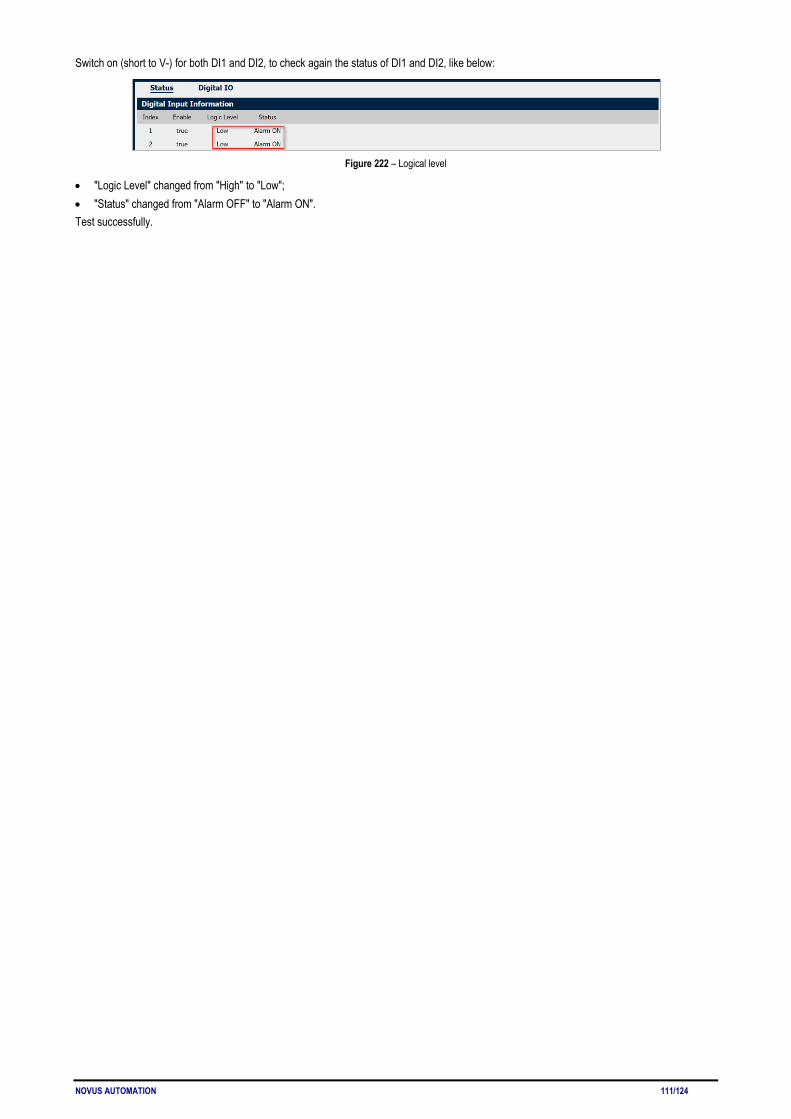
NOVUS AUTOMATION 111/124
Switch on (short to V-) for both DI1 and DI2, to check again the status of DI1 and DI2, like below:
Figure 222 – Logical level
• "Logic Level" changed from "High" to "Low"; • "Status" changed from "Alarm OFF" to "Alarm ON". Test successfully.
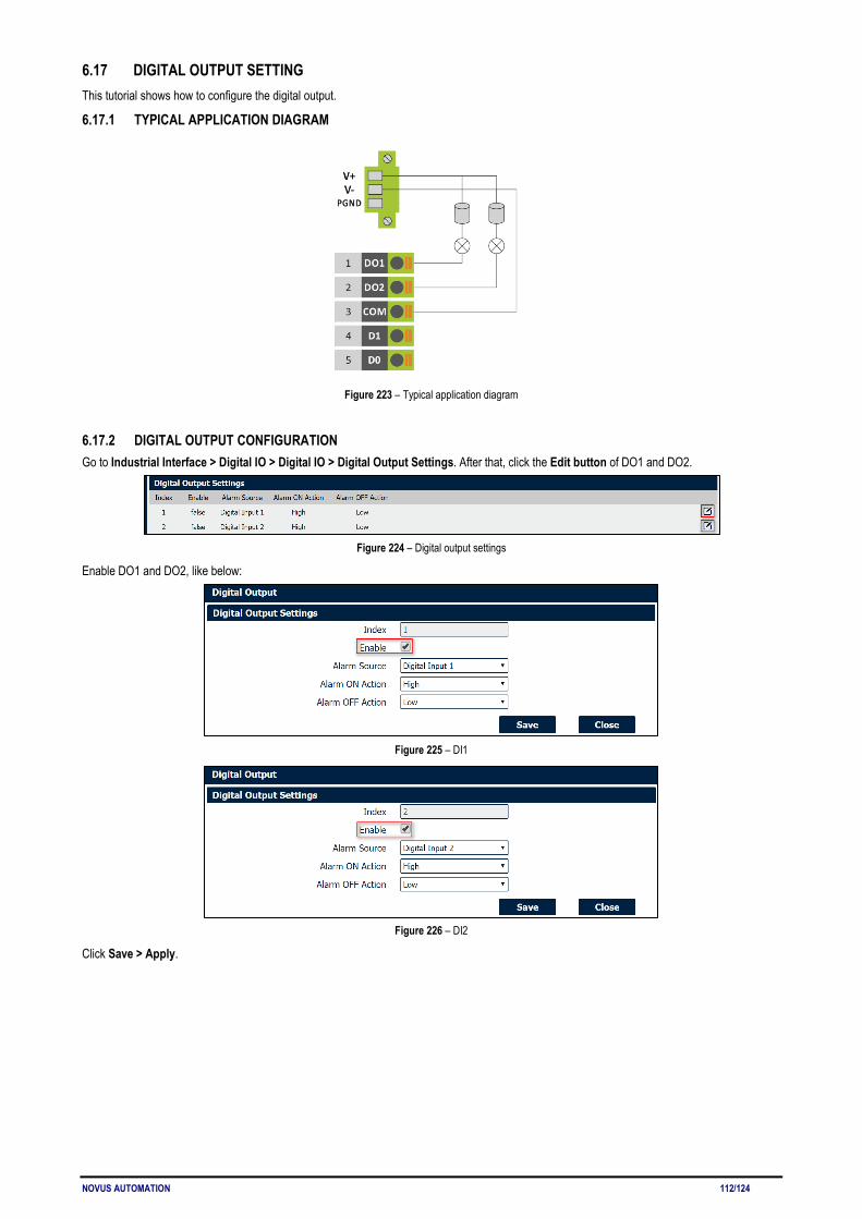
NOVUS AUTOMATION 112/124
6.17 DIGITAL OUTPUT SETTING This tutorial shows how to configure the digital output.
6.17.1 TYPICAL APPLICATION DIAGRAM
Figure 223 – Typical application diagram
6.17.2 DIGITAL OUTPUT CONFIGURATION Go to Industrial Interface > Digital IO > Digital IO > Digital Output Settings. After that, click the Edit button of DO1 and DO2.
Figure 224 – Digital output settings
Enable DO1 and DO2, like below:
Figure 225 – DI1
Figure 226 – DI2
Click Save > Apply.

NOVUS AUTOMATION 113/124
6.17.3 TEST Go to Industrial Interface > Digital IO > Status, to check the default DI1, DI2, DO1 and DO2 status like below:
Figure 227 – Digital and output status
Switch on (short to V-) for both DI1 and DI2, DO1 and DO2 will receive the trigger signal from D11 and DI2, the LED will become ON and the DO status like below:
Figure 228 – Digital output test
• "Logic Level" changed from "High" to "Low"; • "Status" changed from "Alarm OFF" to "Alarm ON". Test successfully.
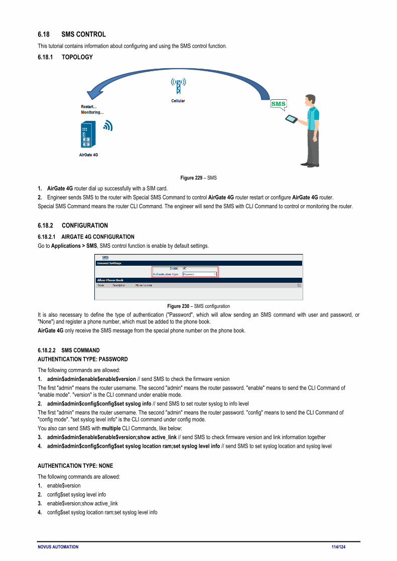
NOVUS AUTOMATION 114/124
6.18 SMS CONTROL This tutorial contains information about configuring and using the SMS control function.
6.18.1 TOPOLOGY
Figure 229 – SMS
1. AirGate 4G router dial up successfully with a SIM card. 2. Engineer sends SMS to the router with Special SMS Command to control AirGate 4G router restart or configure AirGate 4G router. Special SMS Command means the router CLI Command. The engineer will send the SMS with CLI Command to control or monitoring the router.
6.18.2 CONFIGURATION 6.18.2.1 AIRGATE 4G CONFIGURATION Go to Applications > SMS, SMS control function is enable by default settings.
Figure 230 – SMS configuration
It is also necessary to define the type of authentication ("Password", which will allow sending an SMS command with user and password, or "None") and register a phone number, which must be added to the phone book. AirGate 4G only receive the SMS message from the special phone number on the phone book.
6.18.2.2 SMS COMMAND AUTHENTICATION TYPE: PASSWORD
The following commands are allowed: 1. admin$admin$enable$enable$version // send SMS to check the firmware version The first "admin" means the router username. The second "admin" means the router password. "enable" means to send the CLI Command of "enable mode". "version" is the CLI command under enable mode. 2. admin$admin$config$config$set syslog info // send SMS to set router syslog to info level The first "admin" means the router username. The second "admin" means the router password. "config" means to send the CLI Command of "config mode". "set syslog level info" is the CLI command under config mode. You also can send SMS with multiple CLI Commands, like below: 3. admin$admin$enable$enable$version;show active_link // send SMS to check firmware version and link information together 4. admin$admin$config$config$set syslog location ram;set syslog level info // send SMS to set syslog location and syslog level
AUTHENTICATION TYPE: NONE
The following commands are allowed: 1. enable$version 2. config$set syslog level info
3. enable$version;show active_link
4. config$set syslog location ram;set syslog level info
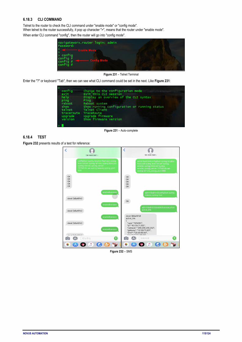
NOVUS AUTOMATION 115/124
6.18.3 CLI COMMAND Telnet to the router to check the CLI command under "enable mode" or "config mode". When telnet to the router successfully, it pop up character ">", means that the router under "enable mode". When enter CLI command "config", then the router will go into "config mode".
Figure 231 – Telnet Terminal
Enter the "?" or keyboard "Tab", then we can see what CLI command could be set in the next. Like Figure 231:
Figure 231 – Auto-complete
6.18.4 TEST Figure 232 presents results of a test for reference:
Figure 232 – SMS
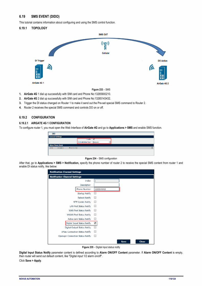
NOVUS AUTOMATION 116/124
6.19 SMS EVENT (DIDO) This tutorial contains information about configuring and using the SMS control function.
6.19.1 TOPOLOGY
Figure 233 – SMS
1. AirGate 4G 1 dial up successfully with SIM card and Phone No:13265900210. 2. AirGate 4G 2 dial up successfully with SIM card and Phone No:13265143432. 3. Trigger the DI status changed on Router 1 to make it send out the Pre-set special SMS command to Router 2. 4. Router 2 receives the special SMS command and controls DO on or off.
6.19.2 CONFIGURATION 6.19.2.1 AIRGATE 4G 1 CONFIGURATION To configure router 1, you must open the Web Interface of AirGate 4G and go to Applications > SMS and enable SMS function.
Figure 234 – SMS configuration
After that, go to Applications > SMS > Notification, specify the phone number of router 2 to receive the special SMS content from router 1 and enable DI status notify, like below:
Figure 235 – Digital input status notify
Digital Input Status Notify parameter content is defined according to Alarm ON/OFF Content parameter. If Alarm ON/OFF Content is empty, then router will send out default content, like "Digital input 1/2 alarm on/off". Click Save > Apply.

NOVUS AUTOMATION 117/124
Go to Industrial Interface > Digital IO > Digital Input Settings, to specify the special content of Alarm ON and OFF, like below:
Figure 236 – Alarms content
The special SMS content to control DO on and off like below: • DO ON: admin$admin$doctl$DO 1/2 ON • DO OFF: admin$admin$doctl$DO 1/2 OFF • Format: <username>$<password>$<control command>$<DO> <DO_index> <ON/OFF>
6.19.2.2 AIRGATE 4G 2 CONFIGURATION To configure router 1, you must open the Web Interface of AirGate 4G and go to Applications > SMS. SMS control function is already enabled.
Figure 237 – Router 2: SMS sending
After that, go to Industrial Interface > Digital IO > Digital Output Settings, to specify the Alarm Source from SMS, like below:
Figure 238 – Digital output settings
Click Save > Apply.
6.19.3 TEST DI activated, send the special SMS to router 2. DO of Router 2 will be ON or OFF after received the special SMS from router 1.
6.19.3.1 TRIGGER ON STATUS
Figure 239 – On status

NOVUS AUTOMATION 118/124
6.19.3.2 TRIGGER OFF STATUS
Figure 240 – Off status
Test successfully.
6.19.4 DO STATUS TO MOBILE PHONE DO status on router 2 could be send to the special phone number, configuration like below. Go to Applications > SMS > Notification, specify the phone number to receive the DO status and enable DO status notify.
Figure 241 – Digital output configuration
Click Save > Apply. DO status was sent to the mobile phone.
Figure 242 – SMS
NOVUS AUTOMATION 119/124
7 TROUBLESHOOTING NO SIGNAL Phenomenon: AirGate 4G modem status shows no signal. Possible Reason: • Antenna installation is wrong. • Modem failure. Solution: • Check the operation of the LTE antenna or replace it with a new one. • In the LINK MANAGEMENT section, confirm that modem has been detected correctly. CANNOT DETECT SIM CARD Phenomenon: AirGate 4G cannot detect SIM card even though the cellular connection has no connection problems. Possible Reason: • SIM card damage. • SIM card with poor contact. Solution: • Replace SIM card. • Reinstall SIM card. SINAL FRACO Phenomenon: No signal or weak signal device. Possible Reason: • Antenna installation is wrong. • Area signal weak. Solution: • Check and reconnect the antenna. • Contact the telecommunications company to confirm the existence of signal problems. • Replace the actual antenna with a more powerful antenna. IPSec VPN ESTABLISHED, BUT LAN TO LAN CANNOT COMMUNICATE Phenomenon: IPSec VPN established, but LAN to LAN cannot communicate. Possible Reason: • Both networks do not match the selected traffic. • IPSec second phase (ESP) settings do not match. Solution: • Check both networks settings. • Check IPSec second phase (ESP) setting. FORGET ROUTER PASSWORD Phenomenon: User forgot device login password. Possible Reason: User has changed the password. Solution: After initializing the router, press the RESET button for 3 to 10 seconds. The router will need to be rebooted manually and will return to factory default settings (username/password: admin/admin).

NOVUS AUTOMATION 120/124
8 COMMAND LINE INTERFACE Command-line interface (CLI) is a software interface that provides another configurable way to set parameters on the router. You can use Telnet or SSH connect the router for CLI input.
8.1 AIRGATE 4G CLI ACCESS login novusautomation.router: admin Password: admin >
8.2 CLI REFERENCE COMMANDS >?
config Change to the configuration mode exit Exit this CLI session help Display an overview of the CLI syntax ping Ping reboot Reboot system show Show running configuration or running status telnet Telnet Client traceroute Traceroute upgrade Upgrade firmware version Show firmware version
Example: > version 1.0.0 (1017.4) > show wifi wifi { "status":"Ready", "mac":"a8: 3f: a1: e0: ab: 81", "ssid":"NR500-WAN", "channel":"6", "width":"40 MHz", "txpower":"20,00 dBm" } > ping www.baidu.com PING www.baidu.com (14.215.177.38): 56 data bytes 64 bytes from 14.215.177.38: seq=0 ttl=54 time=10.826 ms 64 bytes from 14.215.177.38: seq=1 ttl=54 time=10.284 ms 64 bytes from 14.215.177.38: seq=2 ttl=54 time=10.073 ms 64 bytes from 14.215.177.38: seq=3 ttl=54 time=10.031 ms 64 bytes from 14.215.177.38: seq=4 ttl=54 time=10.347 ms --- www.baidu.com ping statistics --- 5 packets transmitted, 5 packets received, 0% packet loss round-trip min/avg/max = 10.031/10.312/10.826 ms >

NOVUS AUTOMATION 121/124
8.3 HOW TO CONFIGURE THE CLI CONTEXT SENSITIVE HELP [?] - Display context sensitive help. This is either a list of possible command completions with summaries, or the full syntax of the current command. A subsequent repeat of this key, when a command has been resolved, will display a detailed reference. AUTO-COMPLETION The following keys both perform auto-completion for the current command line. If the command prefix is not unique then the bell will ring and a subsequent repeat of the key will display possible completions.
[enter] Auto-completes, syntax-checks then executes a command. If there is a syntax error then offending part of the command line will be
highlighted and explained.
[space] Auto-completes, or if the command is already resolved inserts a space. MOVEMENT KEYS [CTRL-A] Move to the start of the line [CTRL-E] Move to the end of the line. [up] Move to the previous command line held in history. [down] Move to the next command line held in history. [left] Move the insertion point left one character. [right] Move the insertion point right one character. DELETION KEYS [CTRL-C] Delete and abort the current line [CTRL-D] Delete the character to the right on the insertion point. [CTRL-K] Delete all the characters to the right of the insertion point. [CTRL-U] Delete the whole line. [backspace] Delete the character to the left of the insertion point. ESCAPE SEQUENCES !! Substitute the last command line. !N Substitute the Nth command line (absolute as per 'history' command). !-N Substitute the command line entered N lines before (relative).

NOVUS AUTOMATION 122/124
9 TECHNICAL SPECIFICATIONS CHARACTERISTICS AIRGATE 4G
Cellular Interface
Frequency bands: • 4G LTE:
LTE FDD: 2100 (B1) / 1900 (B2) / 1800 (B3) / 1700 (B4) / 850 (B5) / 2600 (B7) / 900 (B8) / 700 (B28) MHz LTE TDD: 2300 (B40) MHz
• 3G UMTS: 2100 (B1) / 1900 (B2) / 850 (B5) / 900 (B8) MHz • 2G GSM: 1900 (B2) / 1800 (B3) / 850 (B5) / 900 (B8) MHz Data transfer rate: • 4G LTE:
LTE FDD: Max 150 Mbps (DL) / Max 50 Mbps (UL) LTE TDD: Max 130 Mbps (DL) / Max 30 Mbps (UL)
• 3G UMTS: DC-HSDPA: Max 42 Mbps (DL) HSUPA: Max 5.76 Mbps (UL) WCDMA: Max 384 Kbps (DL) / Max 384 Kbps (UL)
• 2G GSM: EDGE: Max 296 Kbps (DL) / Max 236.8 Kbps (UL) GPRS: Max 107 Kbps (DL) / Max 85.6 Kbps (UL)
2 x SMA female antenna connectors. 2 x SIM (3.0 V and 1.8 V).
Wi-Fi Interface (Optional)
• Standards: 802.11 b/g/n, 300 Mbps; • 2 x RP-SMA male antenna connector; • Support Wi-Fi Access Point and Client modes; • Security: WEP, WPA and WPA2 encryption; • Encryption: TKIP and CCMP.
Ethernet Interface
• Standards: IEEE 802.3, IEEE 802.3u; • 2 x ports 10/100 Mbps, RJ45 connector; • 1 x WAN interface (conFigureble on Web GUI interface); • 1.5KV magnetic isolation protection.
Serial Interface
• 1 x RS232 (3 pin): TX, RX, GND; • 1 x RS485 (2 pin): D1, D0; • Baud Rate: 300 bps to 115.200 bps; • 15 KV ESD protection.
Digital Input and Digital Output
• 2 x Digital Inputs; • 2 x Digital Outputs; • Isolation: 3 KVDC or 2 KVrms; • Absolute maximum VDC: 36 VCC; • Absolute maximum ADC: 100 mA.
Wi-Fi Antenna Wi-Fi Magnet Antenna, 3 Meters Long, 2.412-2.483 GHz, 7 dBi, Φ 29×220 mm.
Cellular Antenna 4G / 3G / 2G Magnet Antenna, 3 Meters Long, 698-960 / 1710-2700 MHz, 2.5 dBi, Φ 29×112 mm.
LED
• 1 x SYS; • 1 x NET; • 1 x USR; • 3 x RSSI.
Software
• Network protocols: TCP, UDP, DHCP, ICMP, PPPoE, HTTP, HTTPS, DNS, VRRP, NTP; • VPN: IPSec, GRE, OpenVPN, DMVPN; • Policy: RIPv1 / RIPv2 / OSPF / BGP (optional); • Firewall & Filter: Port forwarding, DMZ, anti-DoS, ACL; • Serial Port: TCP, UDP; • Management: Web Interface.
Power Supply
• Connector: 3-pin 3.5 mm female socket with lock; • Input voltage range: 9 to 48 VDC; • Power consumption:
o Idle: 100 mA @ 12 V;

NOVUS AUTOMATION 123/124
o Data Link: 400 mA (peak) @ 12 V. Dimension 106 mm x 106 mm x 40 mm (excluding antenna). Mounting DIN rail mounting.
Environmental • Operation temperature: -40 to 60 °C (-40 to 140 °F); • Storage temperature: -40 a 85 °C (-40 to 185 °F); • Operation humidity: 5 to 95 % non-condensing.
Housing Metal. 300 g. Protection IP30
Electromagnetic Compatibility
• EMI: EN 55032:2012 Class B • EMS: o IEC 61000-4-2 ESD: Level 4 o IEC 61000-4-3 RS: Level 3 o IEC 61000-4-4 EFT: Level 3 o IEC 61000-4-5 Surge: Level 3 o IEC 61000-4-6 CS: Level 3
Certifications CE, Anatel (07661-19-12560), RoHS. Table 10 – Technical Specifications
RoHS NOVUS Automation declares and certifies that all of their products are designed and fabricated in compliance with the requirements of Directive 2011/65/EU (EU RoHS 2) of The European Parliament and of the Council of the 8th of June 2011 on the restriction of the use of certain hazardous substances in electrical and electronic equipment (EEE) and the amendment (EU) 2015/863/EU.
CE Mark This is a Class A product. In a domestic environment, this product may cause radio interference in which case the user may be required to take adequate measures. ANATEL This device is homologated by ANATEL, in accordance with the procedures regulated by Resolution 242/2000, and meets the technical requirements applied. This equipment is not subject to the protection from harmful interference and may not cause interference with duly authorized systems. For more information, see the ANATEL website www.anatel.gov.br.
NORMA CISPR 22 In a domestic environment, this product may cause interference, which may require that the user take appropriate measures to minimize the interference.

NOVUS AUTOMATION 124/124
10 WARRANTY Warranty conditions are available on our website www.novusautomation.com/warranty.