AIR EPC MANUAL
26
1-28, Geumjeong-dong, Gunpo-si, Kyeonggi-do, 435-824, KOREA 1. PARTS OF THE SYSTEM. 2P 2. INSTALLATION, PIPING AND WIRING. 4P 3. OPERATING METHOD. 10P 4. REPAIR AND INSPECTION. 16P 5. INSTALLATION CONDITION AND ROLL ARRANGEMENT. 18P 6. COMPOSITION AND OPERATION PRINCIPLE. 22P 7. EXTERNAL DIMENSION. 25P Pora Electric Machinery Co., Ltd. Phone : 82-31-455-8183(k.n) E-MAIL : http://www.pora.com AIR EPC MANUAL CONTENTS
-
Upload
khangminh22 -
Category
Documents
-
view
4 -
download
0
Transcript of AIR EPC MANUAL

1-28, Geumjeong-dong, Gunpo-si, Kyeonggi-do, 435-824, KOREA
1. PARTS OF THE SYSTEM. 2P2. INSTALLATION, PIPING AND WIRING. 4P3. OPERATING METHOD. 10P4. REPAIR AND INSPECTION. 16P5. INSTALLATION CONDITION AND ROLL ARRANGEMENT. 18P6. COMPOSITION AND OPERATION PRINCIPLE. 22P7. EXTERNAL DIMENSION. 25P
Pora Electric Machinery Co., Ltd.
Phone : 82-31-455-8183(k.n)E-MAIL : http://www.pora.com
AIR EPC MANUAL
CONTENTS

Confirm whether supplied parts are agree with your company's requirement
as referring subsequent picture. Contents of system parts are same as below.
1.PARTS OF THE SYSTEM.
Model :S 750W-A.C-E
Parts without model number.
Cylinder / Flexible hose / Hydraulic oil
MODEL : PR-106A(S400W-A.M-E) MODEL : PR-106A(S400W-A.C-E)
Remote S/WRemote S/W
Centering NozzleHose(Strip included)
Remote S/W (UP, DOWN)
Model :S 750W-A.C-LIFTModel :S 750W-A.M-E
1
Each component is registered by model number.Model :S 400W-A.M-E Model :S 400W-A.C-E
Sensor holder & sensor / Operating manual / Binding band / PVC hose covered by teflon

2
MODEL : PR-106A(S750W-A.M-E)
MODEL : PR-106A(750W-A.C-E)
MODEL : PR-106A(750W-A.C-.LIFT)

2. INSTALLATION, PIPING AND WIRING
3
2.2 Hydraulic Unit
Install sensing nozzle on four corners rod of diameter 25mm or round rod diameter 30Φ.
Fix installation rod parallel with strip.
Fix sensing nozzle safely without vibration.
Install air E.P.C. nearby working cylinder and sensing nozzle.
Figure 2.1 (e.g. Installation, piping and wiring)
2.1 Sensing nozzle ( Screw guide included )
Check over description of each part before plan and start installation, piping work and wiring.
Install hydraulic unit in place where can check and control easily and has enough space to
supplement oil.
Please install on flat place.
Only under special place where as no shock from other machine
it can be Installed without framework bolts.

over 5meter.
easily without damaging as reel separation. But if it is inevitable to install them as like
2.6 Piping
Use attached air hose(3m).
sensing nozzle. For piping work, refer drawings on 6 and 7 page.
Connect sensing nozzle upside down if position of sensing nozzle differs with drawing.
Use attached flexible hose(2m).
figure 2.1, please protect them using rod or cover which removable or able to open and close
as controls nozzle.
To connect selective switch, refer page9.
Piping side of cylinder differs according to control system or position between cylinder and
2.3 Working Cylinder.
Install air vent of cylinder facing up.
Use coupling device for connecting to reduce vibration.
Take care immoderate force may not inflict cylinder rod in installation.
2.4 Centering nozzle
Put wire set bolts on parts that moving like reel stand.
And put centering nozzle on parts that is fixed in the substructure
2.5 Selective switch
Although centering nozzle and wire set bolts are installed in front of reel on figure 2.1
for instance, it is recommended to Install them on place where can control centering nozzle
Caution :
Centering nozzle is excluded on such model; S 400W-A.M-E, S 750W-A.M-E or S-750W-A.M-LIFT
4
If length of attached flexible hose is not enough, use couplings (fittings) or
with diesel oil.
Minimum flexure (bending) radius of flexible hose is 100mm. Take care not to bent more.
Use flexible hose on side of cylinder.
Flexible hose and couplings should be cleaned. If it is dirty, clean them before using
a 1/4B carbon steel pipe. But length of extra hose should not be extended
Use steel pipe on side of servo unit.
Don’t step it on and avoid any substance be touched with hose.
If you want to extend piping for the shortage of length, It is recommended not over 5meter.
Don’t step it on and avoid any substance be touched with hose.
2.7 Air piping work to sensing nozzle
Minimum flexure (bending) radius of hose is 100mm. Take care not to bent more.
5
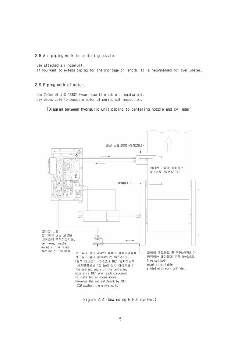
Figure 2.2 (Unwinding E.P.C system.)
2.8 Air piping work to centering nozzle
2.9 Piping work of motor.
Use attached air hose(3m).
Use 2.0mm of JIS C3302 2-core cap tire cable or equivalent.
Lay pipes able to separate motor at periodical inspection.
[Diagram between hydraulic unit piping to centering nozzle and cylinder]
If you want to extend piping for the shortage of length, It is recommended not over 5meter.
MA
DE
IN K
OR
EA
PO
RA
ROTATE
OIL
to sensor
to center
9valve
press.bias
press.bias prim pres
s.
8
zero adj.
press.
secondB
pres s.second
7
6prim press.
A
센싱 노즐(SENSING NOZZLE)
UNWINDER
최대한 가깝게 설치할것.AS CLOSE AS POSSIBLE
센터링 노즐.움직이지 않는 고정된
베이스에 부착하십시요.Centreing nozzle.Mount it the fixed section of the base.
위그림과 같이 각각의 제품이 설치되었을때센터링 노즐의 설치각도는 180 입니다.
(흰색 마크선이 적색점과 180 일치하도록
시계방향으로 1회 돌려 설치 하십시요.)The setting angle of the centeringnozzle is 180 when each componentis installed as shown above.
(Reverse the red matchmark by 180
CCW against the white mark.)
와이어 셑트볼트 를 작동실린더 가 움직이는 테이블에 부착 하십시요.Wire set boltMount it on tableslided with work cylinder.

6
Figure 2.4 (Rewinding E.P.C. system.)
Figure 2.3 (Mid-guide roll E.P.C system.)
MA
DE
IN K
OR
EA
PO
RA
ROTATE
OIL
to sensor
to cen
ter9valve
press.
bias
pres
s.bi
as prim
press
.
8
zero
adj.
pres
s.seco
ndB
press
.sec
ond
7
6pri
m pres
s.
A
센싱 노즐(SENSING NOZZLE)
센터링 노즐.움직이지 않는 고정된 베이스에 부착하십시요.Centreing nozzle.Mount it the fixed section of the base.
위그림과 같이 각각의 제품이 설치되었을때센터링 노즐의 설치각도는 180 입니다.
(흰색 마크선이 적색점과 180 일치하도록
시계방향으로 1회 돌려 설치 하십시요.)The setting angle of the centeringnozzle is 180 when each componentis installed as shown above.
(Reverse the red matchmark by 180
CCW against the white mark.)
와이어 셑트볼트 를 작동실린더 가 움직이는 테이블에 부착 하십시요.Wire set boltMount it on tableslided with work cylinder.
와이어 설치시 실린더의 센터라인과평행하게 당겨 저야만 한다.The wire must always bepulled in parallel to thecenter line of the cylinder.
MA
DE
IN K
OR
EA
PO
RA
ROTATE
OIL
to sensor
to cente
r9valve
press.bi
as
press.
bias prim
press.
8
zero adj.
press.
second
B
press.secon
d
7
6prim
press.
A
센싱 노즐(SENSING NOZZLE)
UNWINDER
센터링 노즐.움직이지 않는 고정된 베이스에 부착하십시요.Centreing nozzle.Mount it the fixed section of the base.
위그림과 같이 각각의 제품이 설치되었을때센터링 노즐의 설치각도는 0 입니다.
(흰색 마크선이 적색점이 일치한 상태로 설치 하십시요.)The setting angle of the centeringnozzle is 0 when each componentis installed as shown above.
(match the white mark and the red mark.)
와이어 셑트볼트 를 작동실린더 가 움직이는 테이블에 부착 하십시요.Wire set boltMount it on tableslided with work cylinder.

7
Mee-Chang.
Cosmo Oil.
Lando ISO VG 46
Dahooni ISO VG 46
Mecroove ISO VG 46
Diamond hydro flood EP 46
Cosmo hydro RO 46
LG Caltex.
Ssang yong.
Mistubishi Oil.
Ziq superbuiz no. 46 SK Corporation.
Oiling to hydraulic unit
Figure 2.5
Supply oil to storage tank through oil service port,
Prepare enough oil which unites all capacity of storage tank(12 liter), cylinder and piping.
Fill oil to tank up to standard level on gauge using funnel as Figure 2.5
After finishing installation and piping.
Kinds of recommended hydraulic gasoline
Brand Manufacturing company

Figure 2.7 (PR-106A-A/M)
Wiring diagram
Figure 2.6 (PR-106A-A/C)
8
Figure 2.8 (PR-106A-A/C)
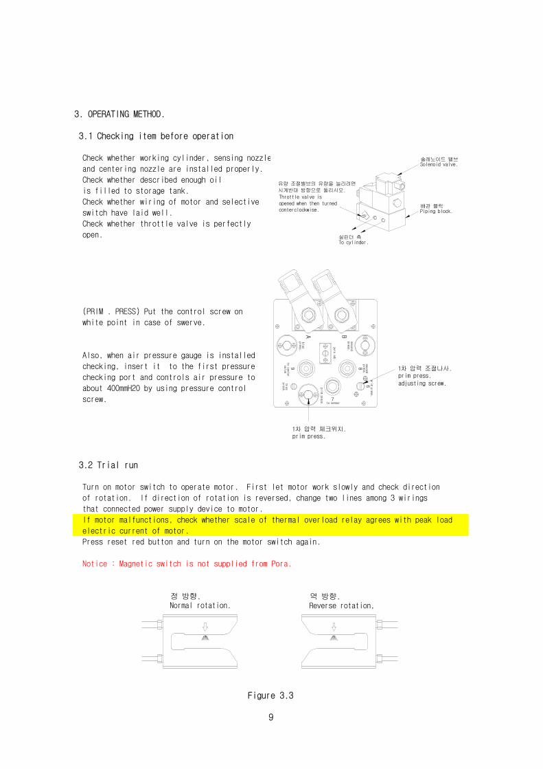
Press reset red button and turn on the motor switch again.
is filled to storage tank.
3. OPERATING METHOD.
3.1 Checking item before operation
Check whether wiring of motor and selective
Check whether working cylinder, sensing nozzle
Notice : Magnetic switch is not supplied from Pora.
switch have laid well.
Check whether throttle valve is perfectly
that connected power supply device to motor.
open.
Also, when air pressure gauge is installed
electric current of motor.
and centering nozzle are installed properly.
Check whether described enough oil
(PRIM . PRESS) Put the control screw on
3.2 Trial run
Turn on motor switch to operate motor. First let motor work slowly and check direction
white point in case of swerve.
of rotation. If direction of rotation is reversed, change two lines among 3 wirings
Figure 3.3
9
If motor malfunctions, check whether scale of thermal overload relay agrees with peak load
checking, insert it to the first pressure
checking port and controls air pressure to
about 400mmH2O by using pressure control
screw.
실린더 측To cylinder.
유량 조절밸브의 유량을 늘리려면시계반대 방향으로 돌리시오.Throttle valve isopened when then turnedconterclockwise.
배관 블럭
솔레노이드 밸브
Piping block.
Solenoid valve.
1차 압력 조절나사.prim press.adjusting screw.
press.
second
8
to c
enter
9valve
1차 압력 체크위치.
to sensor7
prim press.
bias
pres s.
prim
press.
prim p
ress.
6
press
.bia
sA
seco
ndpr
ess.
zero
adj.
B
역 방향.Reverse rotation,Normal rotation.
정 방향.

deflate air in A,
Check motion of cylinder piston.
Using paper such as business card, intercept air
When cylinder piston moves to left,
Figure 3.5
Put selective switch on "Automatic".
Figure 3.4
and when cylinder moves to right side,
loosen air vent screw in B.
that flows from sensing nozzle and check
motion of cylinder.
But, bubble stops while cylinder piston is
If air vent screw becomes loose, bubble and mixed oil bleed.
moving. As no more bubbles, block air vent and
tight air vent screw.
Air vent from working cylinder and piping.
Move cylinder piston by same method that is explained in above.
At first a lot of bubbles bleed.
Figure 3.6
10

Move cylinder piston by same method that is explained above.
Since piston rod is only one section of cylinder,
Control and check of centering nozzle. (model S400W- A.C - E, S750W - A.C-E)
Figure 3.7
there are differences on space between right
and left section and speed also be differed
about 15%. If difference of speed is bigger
than difference of area,
follow instruction on page 14.
When direction of piston rod is same with direction that wire of centering nozzle is pulled
Loosen six angles socket set screw of centering nozzle
And control set spring screw on controller
that pressure gauge is attached.
sensing nozzle, and decide match mark with hose couplings of centering nozzle.
Check speed of cylinder piston.
Refer page 12 for centering nozzle; PR-C 12.
again, and let piston of working cylinder stay on
center by turning hose couplings.
Fix selective switch to CENT on remote control.
stop piston in place of minimum stroke.
If the direction is reversed, stop piston in place of maximum stroke.(Refer table 1)
Pull wire of centering nozzle about 25cm. And fix it on wire set bolt.
Find proper angle according to operation condition of centering nozzle, cylinder and
Figure 3.8
Figure 3.9
Figure 3.10 (Centering Nozzle CN-12)
11
피스톤 로드(Piston rod)
빠른속도(High speed) 느린속도(Low speed)
빨강마크 점
(Red matchmark dot)
하얀마크 점
(White matchmark dot)250mm
느슨하게 된 육각멈춤 볼트를호스피팅 을 돌려 셑팅후꽉조여 주십시요.Loosen the hexogonal socketset screw slightly and turnthe hose fitting. lock itafter setting.
쎈터위치가 유지되기 위해서는그림과같이 공기배출구 가반정도 막혀 있어야한다.The center position is obtainedwhen the air outlet is closed half.
빨강마크 점
(Red matchmark dot)
하얀마크 점
(White matchmark dot)
와이어 셑팅 볼트
(wier set bolt)

[Caution]
Figure 3.11
12
180°---- Turn red match mark to 180°to anticlockwise from white match mark.
Method setting angle of centering nozzle.
Setting angle differs according to installation direction of centering nozzle, working cylinde
sensing nozzle and control system.
Decide right angle by referring below table.
0°------ Homologize white match mark with red match mark.
하얀마크 점
(White matchmark dot)
시계반대방향으로 180 돌릴것.
(Turn 180 CCW)
Centering nozzle.
센터 노즐.
Cylinder.
실린더.
Sensing nozzle.
센싱 노즐.
Unwinding guide roller.
Centering nozzle setting angle.센터링 노즐 셑팅 각도
언와인딩 가이드롤러.
Rewinder.
리와인더.
1.
2.
3.
4.
5.
6.
7.
8.
180° 0°
180°0°
180° 0°
0° 180°
0°180°
0° 180°
0°
180°
180°
0°

13
Manual operation. (model S400W- A.M, S750W-A.M)
Fix selective switch to MAN.
Press JOG button, and check whether working cylinder piston
moves to left or right according to LEFT/RIGHT switch.
Operation checking is completed in trail run.
Set reel or guide roll in center position by
And let a strip thru.
Apply screw guide so that edge of strip may be
situated in center of orifice of sensing nozzle.
Operate system automatically so that can check the movement of strips.
Satisfactory results can be gained by following above instructions.
If is not so, refer figure 3.3 page on 9.
(Mark ⇓).
Figure 3.13
Figure 3.14
centering or manual operation as explained above.
Figure 3.12

Figure 4.1 (Sensing nozzle cleaning)
14
Figure 4.2 (Dipstick)
such as wire. (Refer figure 4.1)
Gasoline leakage checking -
Inspect whether gasoline leaks from working cylinder, servo guide controller and couplings.
Never mix with gasoline of other brand.
If so, take action.
Gasoline level checking -
Supplement gasoline when gasoline level is low.(Refer figure 4.2).
Sensing nozzle -
Check whether controller and air vent blocked by dust.
If so, remove dust by stiff paper as business cards.
Since they are produced very finely, it is not recommendable to clean by liquid or hard meta
4. REPAIR AND INSPECTION.
4.1 Daily checking.
let sensing nozzle approach toward idler role.
Deflate air perfectly since from cylinder it is perhaps imperfect.
It might be done wrongly that installation of cylinder and sensing nozzle, please fix them wel
and to 250mmH2O for PR-106A-(S400W)
(Because speed differs between left direction with right in this case,
reset set spring control screw again.)
Because hunting is caused by wrinkles of strip edge, put in tension on strip and
If speed of cylinder seems too fast, lower it by turning throttle valve to clockwise.
Then lower the first pressure.
Maximum speed is unchanged even the pressure is lowered to 320mmH2O for model of PR-106A-(S750
3.3 Problem solution If hunting occurs on test, follow below instruction.
(Reel or guide roll is clattering in short cycle.)
On auto operation -

Figure 4.3 (Cleaning of suction filter)
Figure 4.4 (Replacement and cleaning of hydraulic filter)
4.3 Replacement of solenoid coil.
Solenoid coil used when change switch auto to manual
or reverse.
Replace solenoid if burn-up.
(Refer figure 4.6)
15
4.2 Regular repair and inspection.
Suction filter cleaning of ventilator -
If filter is blocked, air pressure does not rise.
Replace hydraulic oil after using about 3000 hours.
Replacement of hydraulic oil -
Replacement of hydraulic filter -
(Refer figure 4.5)
Never mix with gasoline of other brand.
Figure 4.6
Hydraulic pump inhalation filter cleaning -
After remove drain plug, then drain used oil.
Move cover of tank and clean the tank by oil for
washing then wipe with pure sponge.
First, disjoint pump inhalation filter from pump and
clean inhalation filter by gasoline,
then blow compressed air outside from filter inside.
Fill hydraulic oil again after reassemble.
but wash filter after using 60 ~ 200 hours.
Figure 4.5 (Cleaning of Storage tank inside.)
Replace filter after using 3000 hours.
It is differ according to use,
And after using 300 ~ 1000 hours, exchange filter.
Remove filter and clean filter by blowing air or
using gasoline for washing.(Refer figure 4.3)
When wash by gasoline or water,
Loosen patch bolt of filter cover and remove filter
install filter after dry perfectly.
필터 엘리먼트Filter element

- Air pressure gauge for checking : Handheld Digital Manometer (type 477-2, 0-10 KPa)
- Oil pressure gauge for checking : 0—50 kgf/ ㎠
Pressure gauge
The gauges mentioned below are convenient to use for repair.
Recommended to prepare below gauges for convenience regardless of quantity of equipment.
4.4 Air pressure gauge for inspection use.
speed of cylinder is same the left direction with right.
For example, the second pressure must be more than 120mmH2O in case of the first one is 400mm
Next, close sensing nozzle with card to catch balance of cylinder.
This pressure gauge is used to check the first and the second pressure of air circuit and is
convenient device as repair.
This gauge takes precautions when handle because it is gauge for measuring subtle pressure.
Remove lid of checking port as figure 4.7,
then push air pressure gauge for inspection to inside of port and measures air pressure.
In case of sensing nozzle is perfectly unclosed, the second pressure
(pressure of entry sensing nozzle) must become more than 30% of the first one (exit pressure)
When balance pressure is high, turn the screw to clockwise.
When balance pressure is low, turn the screw to anticlockwise.
After control, remove pressure gauge then close the lid.
Figure 4.7
When pressure is more than half from when sensing nozzle perfectly opened,
If balance pressure is unequal, control set spring control screw.
16
prim press.
prim press.
press.bias
7to sensor
6
valve
9to cent
er
biaspress.
A
8zero adj.
B
second
p ress.
secondpress.
바이어스압 체크 위치Bias pressure check.
바이어스압 조절나사Bias pressure screw.
1차 압력체크 위치Prim pressure.
1차 압력 조절나사Prim pressure screw.
영점조절 나사.Zero screw.
2차 압력체크 위치.Second pressure check.
BA

5. INSTALLATION CONDITION AND ROLL ARRANGEMENT.
Idler roll works with unwinding roll.
Figure 5.1 (Reel control system for unwinding)
5.1 Reel control system for unwinding.
Install sensing nozzle nearby idler role.
Strip roles as rotating axis and supplied by deflector roll or pinch roll.
If sensing nozzle irrelevantly installed in EPC system and roll is unarranged,
It is not controlled well and strip furrows.
Consider item is as following when planning and design.
This reel is used to supply strip that is wound irregularly as telescope pattern by adjusting
rightly the edge of strip with following print at cutting process.
In such occasion, whole reel be operated by working cylinder that fixed sensing nozzle is insta
Distance between exit idler roll and pivot roll should be wider than maximum wideness of strip.
17

5 degrees to maximum.
guide roll, install sensing nozzle near guide roll as possible. Space distance among guide roll and
entry roll so that they may be a time or double of the maximum wideness of strip.
If these distance is so short, strip furrows or it would be difficult to control because tension
difference of right and left edge of strip.
18
5.2 Control system of middle guide roll
It is installed when need to set strip edge rightly at middle of process, or large scale
correction needed on existing machine so that unwinding and rewinding roll may move.
There are two kinds of control method of guide role.
One is center pivot method and another is end pivot method.
○ Center pivot method
Pivot has been in extension of strip that enters in entry guide roll and laid in row with cen
This method is applied to product that is apt to tear because of inelasticity material edge
Install sensing nozzle from idler roll to prop of entering side position safely.
tension's difference such as paper, news print-cloth, coating paper, metal foil, cellulose,
acetate, plastic etc. or be wrenched permanently.
Strip is hardly slide because it is covered 180 degrees in guide role.
If slide, can prevent slither by using rubber coated roll instead.
As long as strip does not contact sensor by change of strip passage caused because of motion
Strip usually moves along guide roll.
The rotation angle of guide roll can be gained by multiplying tangent. It must not exceed
Figure 5.2 (Control system of center pivot)

Strip is moved to crosswise or at the same time, flow direction of strip changes to direction that
strip is moved for correction of deflection.
Expected spin axis of guide roll and distance of guide rolls are arranged long.
If previous size is same with shorter distance, angle of rotation of guide role and tension's change
may be more decrescent. So, will reduce distortion of strip, and give better EPC effect.
Rolls of light weight (light-duty) for strip position control have to be made from aluminum to reduc
○ End pivot method
inertia, and rubber of exit roll must coated. This method is used in small tensile force.
End pivot role method should be used when can do and secure enough long distance between entry idler
roll and exit idler roll, and it is used for strips that absorb tension change between right and lef
edge of material.
Contrary to center pivot method, this method does not need 2 idler rolls and need lesser space
and arrangement is simpler. Because of this advantage, this method is applied much to product such
paper, vinyl latex, texture, polypropylene, polyethylene, Mylar, polystyrene, tire cord etc.
soft material things.
Install sensing nozzle near exit guide roll according to flow if is possible.
19
Figure 5.3 (Control system of end pivot)

Please follow below instructions so that strip may not slide over the rolls.
At least it needs to have 30 degrees of winding angle.
Maximize the diameter of control roll in order to have wide rapping area.
Cover the rubber on control roll to get higher frictional force.
Have enough tension force to get higher frictional force.
It is desirable to minimize retardation of control system in any case when apply for strip
20
5.3 Control system of winding reel
This is used to arrange the edge of end( wound up )coil of strip changelessly.
Sensing nozzle works with winding reel.
Install control roll to prop rigidly.
Figure 5.4 (Control system of winding reel)
Spin axis of strip on control roll
Not allowed any movement on axis of control roll.
Space a time or double of distance to centers between winding roll and control roll than the
maximum wideness of strip from. If distance is so short, wrinkles tend to get pleated in
Install sensing nozzle to winding reel rigidly so that they may move together.
Install sensing nozzle to entry of control roll and near deflector roll.
gossamer material.
guide system.
Do the best arrangement to minimize retardation.
And consider all constraints that like strip furrow caused by reel motion, special quality
of strips or factory condition etc.
Caution

21
6. COMPOSITION AND OPERATION PRINCIPLE.
spring force. Cylinder port 1 and port 2 are connected individually to hydraulic oil port 4
6.1 AUTO/CENT switch
AUTO - It is directly connected hydraulic pump PV and air ventilator BL motor(M).
The first air pressure is supplied from ventilator to sensing nozzle and airflow is changed t
Regulator is consisted of diaphragm and spring. Diaphragm is connected on spool of servo valv
Therefore, spool moves up and down by difference between force that is given to diaphragm and
Position of strip(W) is corrected by operating last controller (CY) that is connected servo
valve (P) with strip guide G.
Guides of each strip are used to guide roll mechanism, unwinding roll and winding reel.
the second air pressure signal in proportion to transfer of strip edge. And, this signal is
passed by regulator. The second air pressure from sensing nozzle is converted to force that
move spools with diaphragm. When edge of strip blocks opening of sensing nozzle half,
diaphragm force and spring force are in balance and spool is moved to middle position.
and return oil port 5.
Figure 6.1 (Model PR-106A-A.C-E current drawing)
(Refer figure 6.1 . and 6.2.)
CENT -
When selective switch is set in position "CENT", solenoid valve B is closed and solenoid valv
is unclosed. And air flows to centering nozzle. Centering nozzle senses strip guide G positio

22
RIGHT, LEFT -
MANU - Solenoid valve C is closed (de-energized) and solenoid valve B is closed too (de-energized).
It is occurred differential motion pressure on both sides of diaphragm by opening and closing
of solenoid valve A. Then spools move.
JOG - Even if hydraulic circuit is closed state in above(1)
Figure 6.2 (Principle of controller assembled parts)
Solenoid valve C open when press JOG button (energized).
Cylinder moves by direction that is selected by RIGHT/LEFT switch.
Guides of each strip are used to guide roll mechanism, unwinding roll and winding reel.
(Refer figure 6.1 . and 6.2.)
STOP - Cylinder stops on that position.
diaphragm force and spring force are in balance and spool is moved to middle position.
Position of strip(W) is corrected by operating last controller (CY) that is connected servo
valve (P) with strip guide G.
6.2 AUTO/MAN switch
AUTO - It is directly connected hydraulic pump PV and air ventilator BL motor(M).
Regulator is consisted of diaphragm and spring. Diaphragm is connected on spool of servo valv
Therefore, spool moves up and down by difference between force that is given to diaphragm and
spring force. Cylinder port 1 and port 2 are connected individually to hydraulic oil port 4
and return oil port 5.
The first air pressure is supplied from ventilator to sensing nozzle and airflow is changed t
the second air pressure signal in proportion to transfer of strip edge. And, this signal is
passed by regulator. The second air pressure from sensing nozzle is converted to force that
move spools with diaphragm. When edge of strip blocks opening of sensing nozzle half,
다이아프램Diaphagm.
2차 에어 압력Second air pressure.
입력 센싱노즐From sensing nozzle.
실린더 포트Cylinder port.
2
1써버 밸브(슬리브)
Sorvo valve (sleeve)
써버 밸브(수풀)
Sorvo valve (spool)
Sorvoguide PR-A-1 controller

Figure 6.3 (Model PR-106A-A.M-E current drawing)
23

SPECIFICATION
Model-S400W-A.C-E
Air capacity.
Action. Integral
Max.pressure.
Pump capacity.
Air pressure.
temperature.
Oil required
Hydraulic fluid
AUTO-CENT TYPE
AUTO-MANU TYPE
A.C 220/380V-50.60Hz (1/2HP)
1.5MPa (15Kg/㎠)
2.0L/min.
400mm H2o
50L/min
-10℃ ~ +40℃
12L
Regulator Oil 46 or equivalent
32Kg(excluding oil)
HorizontalInstallation.
24
AIR EPCMODEL: PR106A-S400W SINGLE-TYPE CONTROLLER
Model-S400W-A.M-E
Motor.
Mass.
MA
DE
IN K
OR
EA
PO
RA
ROTATE
OIL
to sensor
to cent
er9valve
press.
bias
press
.bi
as prim
press.
8
zero a
dj.
press .
se co
nd
B
press.
second
7
6prim
press.
1/2" 주유구Air breather
유량조절 밸브Throttle valve
A port
압력조절 밸브Relief valve
쎈터링 노즐 포트
센싱노즐 토출 포트From sensing nozzle
단자함
모터Motor
유압 솔레노이드 밸브Hyd. solenoid valve
에어 솔레노이드 밸브Air solenoid valve
A
센싱노즐 입력 포트To sensing nozzle
B port
Drain port
M
PV BL
BP
AVR
SP
2 1DF
SOLA
SOLB
PP
4 5
F
L
7
8
SOLC
P
그림. 1 (모델: PR-106A-S400W) 그림. 2 (배관도)Fig. 1 (Modle: PR-106A-S400W) Fig. 2 (Piping Diagram)
PF 1/4"
PF 1/4"
Sentering nozzle port

Mass. (Head, hose) 0.5kg / 0.4kg
Model PR-106A-A/M, A/C
Ambient A.C 220V-50/60Hz
PR-106A- A/M PR-106A- A/C
SENSING NOZZLE(SPECIFICATION)
REMOTE CONTROL(SPECIFICATIONS)
2 vinyl hoses 3m(with 6 bands)
45L/min(400mm H2o)
CENTERING NOZZLE(SPECIFICATIONS)
Air consumption.(supply pressure)
Accessory.
Model PR-C12
-10℃ ~ +40℃
PR-S30W
30mm
10mm
30ms
0.1mm
25
MODEL PR106A-S400W SENSING NOZZLE & CENTERING NOZZLE REMOTE CONTROL
Model
Sensor gap.
Detecting length.
Response speed.
Resolution.
0.45kg / 0.5kgMass. (Head, hose)
temperature.
Mass.(Head,hose)
Mass.(Screw guide)
Ambient
1 vinyl hoses 3m
(with 2 bindingAccessory.
-10℃ ~ +40℃
0.55kg / 1kg
0.65kg
PORA
PORA