
HOT AIR BALLOON FLIGHT MANUAL
104
FLIGHT MANUAL ISSUE 10 Amendment 5 Page i-i 31 July 2008 Approval CAMERON BALLOONS Limited St. Johns Street, Bedminster, Bristol BS3 4NH UNITED KINGDOM Tel: +44(0)1179637216 email: [email protected] website:www.cameronballoons.co.uk Manufacturer: HOT AIR BALLOON FLIGHT MANUAL Approved by EASA under Approval Number EASA.BA.A.01000 on 10 April 2006. This manual forms part of EASA Type Certificates EASA.BA.012 and EASA.BA.013. Following initial certification as shown above, any subsequent revisions to this manual shall either be directly approved by EASA or be approved under the authority of Cameron Balloons Limited, DOA No. EASA 21J.140. Any revisions/supplements made by other Approved Organisations must be separately approved Signed Name Date Authority This Manual is specific to the following balloon: This balloon is to be operated in compliance with the information and limitations contained herein. Model Registration Applicable MTOM Constructor’s Number Year Of Construction kg Applicable MTOM Date Of Change Signature Record Of MTOM Amendments
-
Upload
khangminh22 -
Category
Documents
-
view
4 -
download
0
Transcript of HOT AIR BALLOON FLIGHT MANUAL

FLIGHT MANUAL ISS
UE 10
Amendment 5 Page i-i31 July 2008
Approval
CAMERON BALLOONS LimitedSt. Johns Street, Bedminster, Bristol BS3 4NH
UNITED KINGDOMTel: +44(0)1179637216
email: [email protected] website:www.cameronballoons.co.uk
Manufacturer:
HOT AIR BALLOON FLIGHT MANUAL
Approved by EASA under Approval Number EASA.BA.A.01000 on 10 April 2006.
This manual forms part of EASA Type Certificates EASA.BA.012 and EASA.BA.013. Following initial certification as shown above, any subsequent revisions to this manual shall either be directly approved by EASA or be approved under the authority of Cameron Balloons Limited, DOA No. EASA 21J.140.
Any revisions/supplements made by other Approved Organisations must be separately approved
Signed Name Date
Authority
This Manual is specific to the following balloon:
This balloon is to be operated in compliance with the information and limitations contained herein.
Model
Registration
Applicable MTOM
Constructor’s Number
Year Of Construction
kg
ApplicableMTOM Date Of Change Signature
Record Of MTOM Amendments

Intentionally Blank Page
FLIGHT MANUALISS
UE 10
Page i-ii 10 April 2006
Approval
FLIGHT MANUAL ISS
UE 10
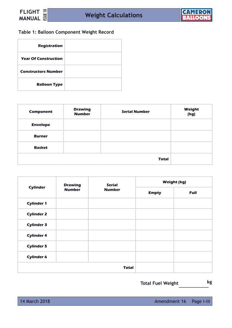
Page i-iii14 March 2018 Amendment 16
Weight Calculations
Table 1: Balloon Component Weight Record
ComponentDrawing Number
Serial NumberWeight
(kg)
Envelope
Burner
Basket
Total
Registration
Year Of Construction
Constructors Number
Balloon Type
Total Fuel Weight kg
CylinderDrawing Number
Serial Number
Weight (kg)
Empty Full
Cylinder 1
Cylinder 2
Cylinder 3
Cylinder 4
Cylinder 5
Cylinder 6
Total

Intentionally Blank Page
FLIGHT MANUALISS
UE 10
Amendment 16Page i-iv 14 March 2018
Weight Calculations
FLIGHT MANUAL ISS
UE 10
Amendment 16 Page i-v14 March 2018
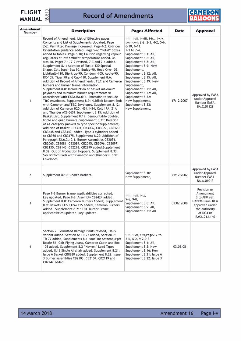
Record of Amendments
Amendment Number Description Pages Affected Date Approval
1
Record of Amendment, List of Effective pages, Contents and List of Supplements Updated. Page 2-2: Permitted Damage increased. Page 4-2: Cylinder Orientation guidance added. Page 5-6: “Total” boxes added to tables. Page 6-10; Caution regarding vapour regulators at low ambient temperature added. 45 was 60. Pages 7-1, 7-2 revised, 7-3 and 7-4 added. Supplement 8.1: Addition of Turtle-120 Special Shape, Colt Sugar Box 90, Buddy-90, Head One-105, Lightbulb-110, Bierkrug-90, Condom -105, Apple-90, RX-105, Tiger 90 and Cup-110. Supplement 8.6: Addition of Record of Amendments, T&C and Cameron burners and burner frame information. Supplement 8.8: Introduction of basket maximum payloads and minimum burner requirements in accordance with EASA.BA.016. Extension to include T&C envelopes. Supplement 8.9: Kubíček Bottom Ends with Cameron and T&C Envelopes. Supplement 8.12: Addition of Cameron H20, H24, H34, Colt 17A, 21A and Thunder AX6-56S1.Supplement 8.15: Addition of Basket List. Supplement 8.19: Demountable double, triple and quad burners. Supplement 8.21: Deletion of A1 category (moved to type specific supplements), Addition of Basket CB3394, CB3006, CB3027, CB3120, CB3448 and CB3449, added. Type 3 cylinders added to CB950 and CB3175. Supplement 8.22: Addition of Paragraph 22.6.3.10.1. Burner Assemblies CB2051, CB2065, CB2081, CB2089, CB2095, CB2096, CB2097, CB2130, CB2145, CB2298, CB2299 added.Supplement 8.32: Out of Production Hoppers. Supplement 8.33: Sky Bottom Ends with Cameron and Thunder & Colt Envelopes.
i-iii, i-vii, i-viii, i-ix, i-xiv, ixv, i-xvi, 2-2, 2-3, 4-2, 5-6, 6-10, 6-11, 7-1 to 7-4,Supplement 8.1: All, Supplement 8.6: All,Supplement 8.8: All,Supplement 8.9: New Supplement, Supplement 8.12: All, Supplement 8.15: All,Supplement 8.19: New Supplement,Supplement 8.21: All, Supplement 8.22: All,Supplement 8.32: New Supplement,Supplement 8.33: New Supplement,
17:12:2007
Approved by EASA under Approval Number EASA.
BA.C.01128
2 Supplement 8.10: Chaize Baskets. Supplement 8.10: New Supplement, 21:12:2007
Approved by EASA under Approval Number EASA.
BA.A.01013
3
Page 9-6 Burner frame applicabilities corrected, key updated, Page 9-8: Assembly CB2424 added, Supplement 8.8: Cameron Burners Added; Supplement 8.9: Baskets K12/K12A/K15 added, Cameron Burners Added. Supplement 8.21: T&C Burner Frame applicabilities updated, key updated.
i-iii, i-vii, i-ix, 9-6, 9-8, Supplement 8.8: All,Supplement 8.9: All, Supplement 8.21: All
01:02:2008
Revision nr Amendment 3 to AFM ref.
HABFM-Issue 10 is approved under the authority
of DOA nr EASA.21J.140
4
Section 2: Permitted Damage limits revised, TR-77 Variant added. Section 6: TR-77 added, Section 9: TR-77 added, Supplements 8.1 Issue 10: Satzenburger Bottle 56, Colt Flying Jeans, Cameron Cabin and Box 105 added. Supplement 8.2 “Kevron” Load Tapes added, 8.16 Single Airchair added, Supplement 8.21: Issue 6 Basket CB8280 added. Supplement 8.22: Issue 3 Burner assemblies CB2103, CB2104, CB2119 and CB2242 added.
i-iii, i-vii, i-ix,Page2-2 to 2-6, 6-2, 9-2,9-3.Supplement 8.1: All, Supplement 8.2: NewSupplement 8.16: New Supplement 8.21: Issue 6Supplement 8.22: Issue 3
03.03.08

FLIGHT MANUALISS
UE 10
Page i-vi 14 March 2018Amendment 16
Record of Amendments
Amendment Number Description Pages Affected Date Approval
5
Approval statement revised, Record of Amendments updated, List of effective pages updated, List of supplements removed (now on website). Section 1: Clarification of amendment procedure, Type certificate references now in title only “envelopes” added to Section 1.5. Section 2: Limitations Format revised, 2.17 Z-425LW added , Table 1 now only lists volumes (not variant prefixes). Section 8: Supplement Section revised to allow the use of approved data from old manuals. Section 9: Table 8-CB2941 added. Appendix 2 Load Calculation revised. Supplement 1: Egg-120 (new), House-60, Can-60, Newspaper 90, Flying Lager Bottle 2, Tub-80, Club-90 (all approved data) added.Supplement 9: Ignis double and triple burner added. Supplement 21: CB310-5A, CB994, CB3380 and CB3482 added, Type 2 Cylinders added to CB3018
i-i, i-iv, i-vii, i-ix, i-x, 1-1, 1-2, 2-1, 2-2, 2.5, 2.6, 2-7, 8-1, A2-1
Supp 8.1: All, Supp 8.9 : All, Supp 8.21: All
31:07:2008
Approved by EASA under Approval Number EASA.
BA.C.01161
6
Record of Amendments updated. Section 2, Section 5 “35” and “50” Variants added. Section 6 Envelope descriptions tabulated. Section 9 A-225, C-50 and TR-84 added. Supplements incorporated: 8-1 Issues 12 and 13 (Furness -56 Building, Colt Flying Head, Elephant-77, S-Can-100, Inverted Balloon-105, Orange-120, Ball-70, Fire Truck-100, N-120MW, Beer Crate-120), 8-7 Iss 2 (MK21, BMK008, BMK-050 burners added, C-12 basket added) 8-9 Iss 4 (K-16 and K-18 baskets added), 8-21 Issues 8 and 9 (CB3490, CB3497 added)
i-iv, i-vii, i-xiv, 2-6, 5-4, 5-5, 6-1,6-2, 9-1to 9-3,
Supp 8.1: All, Supp 8.7 : All, Supp 8.9 : All, Supp 8.21: All
25:06:2009
Approved by EASA under Approval Number EASA.
BA.C.01197
7
Record of Amendments updated. LEP updated. Contents updated. Section 2: Windspeed limitation reworded for clarity. Minimum equipment list amended, Pilot qualification deleted, Rates of climb and descent amended (relative wind limit restored from issue 7), 2.13 Deleted (now in Supplement 8.3), 2.14 Tethering limits revised for large balloons, 2.17 A450LW added.Section 3: Approval statement added. Fire in the air amendedSection 4: Completely revised Section 5: Cross reference updated, Table 2 and 3 A-450LW addedSection 6: Parachute edge tempilabel deleted.Section 9: A-450 LW added, basket applicability for large balloons amended, Burner frame CB2665 added Table 5A added. 4 tonne karabiner note deleted (already in limitations)Appendix 5 added.Supplements 8.3 and 8.4 IntroducedSupplement 8.9 raised to issue 5 (burner frame CB855 added).Supplement 8.21 raised to issue 10 (burner frame CB2475 and basket CB3502 added.
i-iv, i-v, i-vii, i-viii, i-xi to i-xvi, 2-1, 2-3, 2-4, 2-5, 2-7, 3-1, 3-2, 4-1 to 4-20 (4-21 to 4-28 deleted), 5-1, 5-4, 5-5, 6-4, 6-5, 9-1, 9-3 to 9-5, A5-1, A5-2. Supp 8.3 all, Supp 8.4 all, Supp 8.9 all, Supp 8.21 all
29:04:2010Approved by EASA
under Approval Number 10029886

FLIGHT MANUAL ISS
UE 10
Amendment 16 Page i-vii14 March 2018
Record of Amendments
Amendment Number Description Pages Affected Date Approval
8
Record of Amendments updated, List of effective pages updated,Section 2: 2.10 Ambiguity for 340 000 correctedSection 9: Burner Frame CB2371 added to basket CB754.Supplement 8.1: Colt Beer Glass, Colt Flying Kiwi and Super FMG-100 Special Shape added.Supplement 8.21: CB3157 Description corrected, CB947 and CB3505 added, burner frame CB2269 added to basket CB3394
i-v, i-vii, 2-4, 9-6, Supp 8.1: All, Supp 8.21: All,
14:07:2010
Approved by EASA under Approval Number
10030936
9
Record of Amendments updated, List of effective pages updated,Section 9, Table 6: Page 9-5, table completely revised, no new equipment introduced.Page 9-6, Burner Frame CB2192 (older non gimbal style) added to basket CB3360Appendix 3, A3-1, Conversion factor standardised, reference to tables corrected. Supp. 8-13 Duo Airchair: Addition of Duo Skychariot and Duo Airchair. Supp. 8-14 Cloudhopper Millennium: Addition of part number of chair assembly and applicable cylinders. Supp. 8-15 Wheelchair Baskets: Limitations on occupancy moved from Section 6 to Section 2. Descriptions, cylinder and burner frame applicability updated. Supp. 8-21 Special Baskets: Cylinder and burner frame applicability updated. Baskets CB3520, CB3525 and CB3528 added.
i-v, i-vii, i-viii, 9-5, 9-6, A3-1.Supp 8.13: All, Supp 8.14: All, Supp 8.15: All, Supp 8.21: All.
02:03:2011
Approved by EASA under Approval Number
10034058
10
Record of Amendments updated, List of effective pages updated. Section 6: Description of out of production cylinders moved to new supplement. Section 9: Table 5: Envelopes, Type R baskets added to Z-425, Z-450, Z-600. Table 6: Burner Frames CB750, CB2860 and CB2863 added, burner frame applicability to CB8000 series updated Table 7: out of production cylinders deleted, Table 8: Solenoid and removable burners moved to supplements. Appendix III: Out of production cylinders moved to new supplement, Supplements 8.2-8.4, 8.6-8.8, 8.12-8.16, 8.19-8.20, 8.23-8.26, 8.30, 8.32, 8.35 and 8.36: Maintenance Sections removed (published with Maintenance Manual i10-Amdt 3), editorial updates, previously approved equipment added to 8.13 and 8.16. Supplement 8.21: LBL Burner frame (BA-152-A-002) added to CB994, Baskets CB3196, CB3537, CB3541, CB3543 and CB3545 added. Supplement 8.39: New Supplement, “Out of production cylinders” (approved data)
i-v, i-vii, i-viii, i-xv, 6-10, 6-11, 9-3, 9-5-9-8 A3-1. Supp 8.2-8.4, 8.6-8.8, 8.10, 8.13-8.16, 8.19-8.21, 8.23-8.26, 8.30, 8.32, 8.35, 8.36 and 8.39 All,
25:01:2012
Approved by EASA under Approval Number
10038169
11
Section 2 : Z-750 Added, Z-600 classification corrected (AX14). Section 9 : Table 5: Z-750 added, Z-600 now R type baskets only. Table 6: Baskets CB3060, CB3081 deleted (in Supp 8.15), burner frame applicabilities updated. Basket CB3550 added, Supp. 8.6 Basket Nos. 244 and 265 added, Supp. 8.21 CB301 Series baskets added.
i-v, i-vii, 2-2, 2-4, 2-7, 5-4-5-5, 9-3, 9-6, Supp 8.6: All, Supp 8.21: All
13:07:2012
Approved by EASA under Approval Number
10040615
FLIGHT MANUALISS
UE 10
Amendment 16Page i-viii 14 March 2018
Record of Amendments
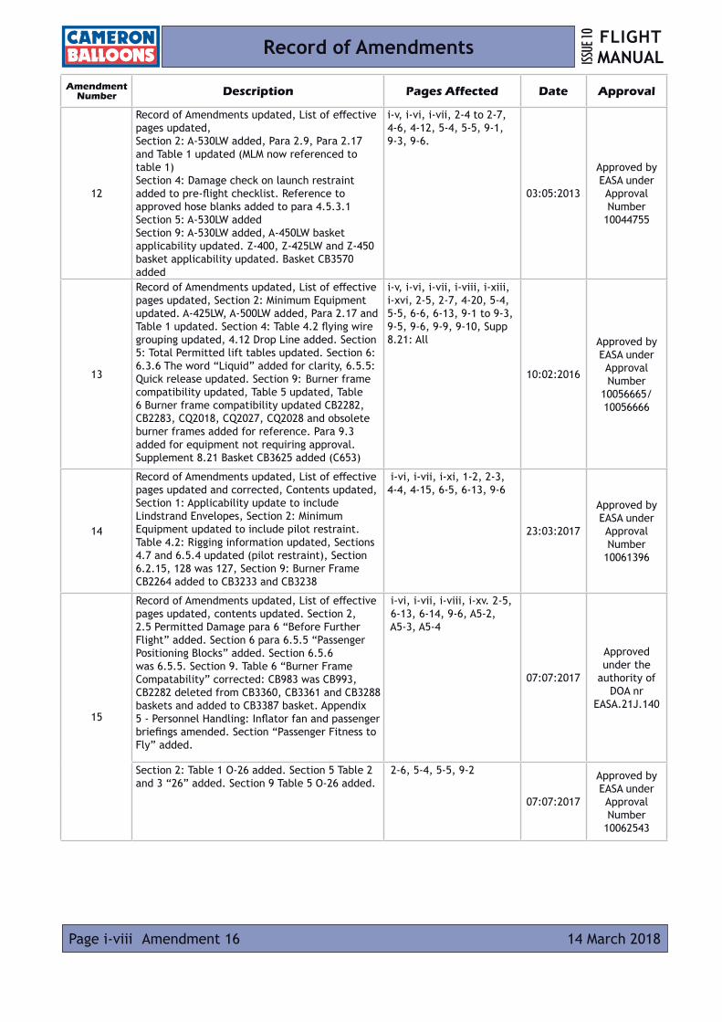
Amendment Number Description Pages Affected Date Approval
12
Record of Amendments updated, List of effective pages updated,Section 2: A-530LW added, Para 2.9, Para 2.17 and Table 1 updated (MLM now referenced to table 1) Section 4: Damage check on launch restraint added to pre-flight checklist. Reference to approved hose blanks added to para 4.5.3.1Section 5: A-530LW addedSection 9: A-530LW added, A-450LW basket applicability updated. Z-400, Z-425LW and Z-450 basket applicability updated. Basket CB3570 added
i-v, i-vi, i-vii, 2-4 to 2-7, 4-6, 4-12, 5-4, 5-5, 9-1, 9-3, 9-6.
03:05:2013
Approved by EASA under Approval Number
10044755
13
Record of Amendments updated, List of effective pages updated, Section 2: Minimum Equipment updated. A-425LW, A-500LW added, Para 2.17 and Table 1 updated. Section 4: Table 4.2 flying wire grouping updated, 4.12 Drop Line added. Section 5: Total Permitted lift tables updated. Section 6: 6.3.6 The word “Liquid” added for clarity, 6.5.5: Quick release updated. Section 9: Burner frame compatibility updated, Table 5 updated, Table 6 Burner frame compatibility updated CB2282, CB2283, CQ2018, CQ2027, CQ2028 and obsolete burner frames added for reference. Para 9.3 added for equipment not requiring approval. Supplement 8.21 Basket CB3625 added (C653)
i-v, i-vi, i-vii, i-viii, i-xiii, i-xvi, 2-5, 2-7, 4-20, 5-4, 5-5, 6-6, 6-13, 9-1 to 9-3, 9-5, 9-6, 9-9, 9-10, Supp 8.21: All
10:02:2016
Approved by EASA under Approval Number
10056665/10056666
14
Record of Amendments updated, List of effective pages updated and corrected, Contents updated, Section 1: Applicability update to include Lindstrand Envelopes, Section 2: Minimum Equipment updated to include pilot restraint. Table 4.2: Rigging information updated, Sections 4.7 and 6.5.4 updated (pilot restraint), Section 6.2.15, 128 was 127, Section 9: Burner Frame CB2264 added to CB3233 and CB3238
i-vi, i-vii, i-xi, 1-2, 2-3, 4-4, 4-15, 6-5, 6-13, 9-6
23:03:2017
Approved by EASA under Approval Number
10061396
15
Record of Amendments updated, List of effective pages updated, contents updated. Section 2, 2.5 Permitted Damage para 6 “Before Further Flight” added. Section 6 para 6.5.5 “Passenger Positioning Blocks” added. Section 6.5.6 was 6.5.5. Section 9. Table 6 “Burner Frame Compatability” corrected: CB983 was CB993, CB2282 deleted from CB3360, CB3361 and CB3288 baskets and added to CB3387 basket. Appendix 5 - Personnel Handling: Inflator fan and passenger briefings amended. Section “Passenger Fitness to Fly” added.
i-vi, i-vii, i-viii, i-xv. 2-5, 6-13, 6-14, 9-6, A5-2, A5-3, A5-4
07:07:2017
Approved under the
authority of DOA nr
EASA.21J.140
Section 2: Table 1 O-26 added. Section 5 Table 2 and 3 “26” added. Section 9 Table 5 O-26 added.
2-6, 5-4, 5-5, 9-2
07:07:2017
Approved by EASA under Approval Number
10062543
FLIGHT MANUAL ISS
UE 10
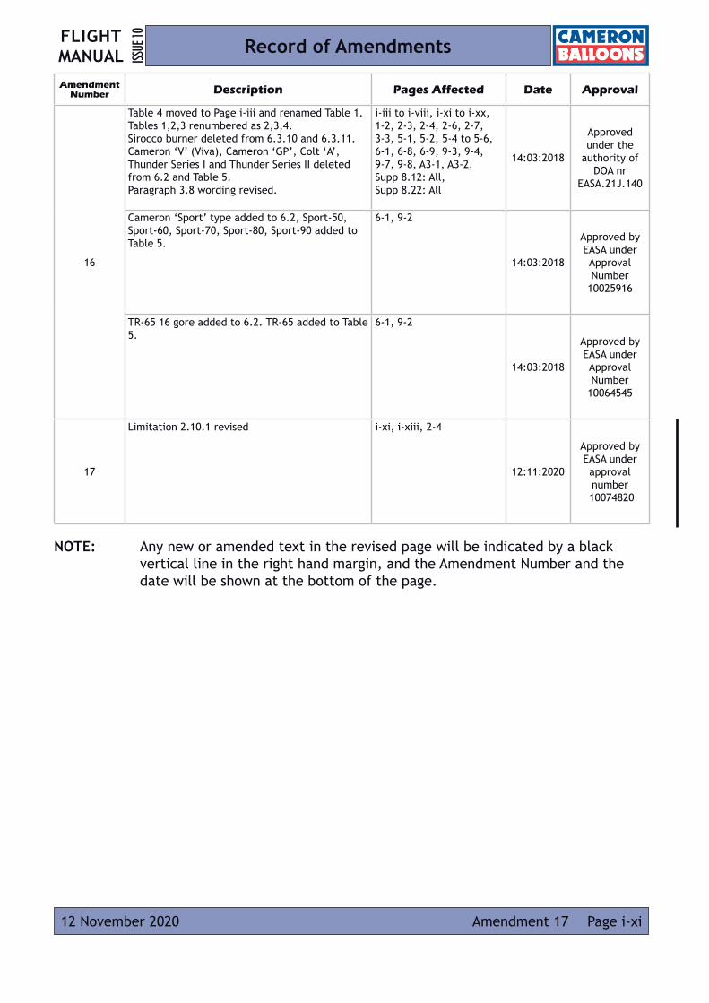
Page i-xi12 November 2020 Amendment 17
NOTE: Any new or amended text in the revised page will be indicated by a black vertical line in the right hand margin, and the Amendment Number and the date will be shown at the bottom of the page.
Record of Amendments
Amendment Number Description Pages Affected Date Approval
16
Table 4 moved to Page i-iii and renamed Table 1. Tables 1,2,3 renumbered as 2,3,4.Sirocco burner deleted from 6.3.10 and 6.3.11.Cameron ‘V’ (Viva), Cameron ‘GP’, Colt ‘A’, Thunder Series I and Thunder Series II deleted from 6.2 and Table 5. Paragraph 3.8 wording revised.
i-iii to i-viii, i-xi to i-xx, 1-2, 2-3, 2-4, 2-6, 2-7, 3-3, 5-1, 5-2, 5-4 to 5-6, 6-1, 6-8, 6-9, 9-3, 9-4, 9-7, 9-8, A3-1, A3-2, Supp 8.12: All, Supp 8.22: All
14:03:2018
Approved under the
authority of DOA nr
EASA.21J.140
Cameron ‘Sport’ type added to 6.2, Sport-50, Sport-60, Sport-70, Sport-80, Sport-90 added to Table 5.
6-1, 9-2
14:03:2018
Approved by EASA under Approval Number
10025916
TR-65 16 gore added to 6.2. TR-65 added to Table 5.
6-1, 9-2
14:03:2018
Approved by EASA under Approval Number
10064545
17
Limitation 2.10.1 revised i-xi, i-xiii, 2-4
12:11:2020
Approved by EASA under approval number
10074820
Intentionally Blank Page
FLIGHT MANUALISS
UE 10
Amendment 16Page i-xii 14 March 2018
Record of Amendments

FLIGHT MANUAL ISS
UE 10
Amendment 17 Page i-xiii12 November 2020
List of Effective Pages
Section Page Date Section Page Datei i-i 31 July 2008 4 4-11 29 April 2010
i-ii 10 April 2006 (cont) 4-12 03 May 2013
i-iii 14 March 2018 4-13 29 April 2010
i-iv 14 March 2018 4-14 29 April 2010
i-v 14 March 2018 4-15 23 March 2017
i-vi 14 March 2018 4-16 29 April 2010
i-vii 14 March 2018 4-17 29 April 2010
i-viii 14 March 2018 4-18 29 April 2010
i-ix Deleted 4-19 29 April 2010
i-x Deleted 4-20 10 February 2016
i-xi 12 November 2020 4-21 Deleted
i-xii 14 March 2018 4-22 Deleted
i-xiii 12 November 2020 4-23 Deleted
i-xiv 14 March 2018 4-24 Deleted
i-xv 14 March 2018 4-25 Deleted
i-xvi 14 March 2018 4-26 Deleted
i-xvii 14 March 2018 4-27 Deleted
i-xviii 14 March 2018 4-28 Deleted
i-xix 14 March 2018
i-xx 14 March 2018 5 5-1 14 March 2018
5-2 14 March 2018
1 1-1 31 July 2008 5-3 10 April 2006
1-2 14 March 2018 5-4 14 March 2018
1-3 10 April 2006 5-5 14 March 2018
1-4 10 April 2006 5-6 14 March 2018
2 2-1 13 July 2012 6 6-1 14 March 2018
2-2 07 July 2017 6-2 25 June 2009
2-3 14 March 2018 6-3 10 April 2006
2-4 12 November 2020 6-4 29 April 2010
2-5 10 February 2016 6-5 23 March 2017
2-6 14 March 2018 6-6 10 February 2016
2-7 14 March 2018 6-7 10 April 2006
2-8 10 April 2006 6-8 14 March 2018
6-9 14 March 2018
3 3-1 29 April 2010 6-10 25 January 2012
3-2 29 April 2010 6-11 25 January 2012
3-3 14 March 2018 6-12 10 April 2006
3-4 10 April 2006 6-13 07 July 2017
3-5 10 April 2006 6-14 07 July 2017
3-6 10 April 2006
7 7-1 17 December 2007
4 4-1 29 April 2010 7-2 17 December 2007
4-2 07 July 2017 7-3 17 December 2007
4-3 29 April 2010 7-4 17 December 2007
4-4 23 March 2017
4-5 10 February 2016 8 8-1 31 July 2008
4-6 03 May 2013 8-2 31 July 2008
4-7 29 April 2010
4-8 29 April 2010 9 9-1 10 February 2016
4-9 29 April 2010 9-2 14 March 2018
4-10 29 April 2010 9-3 14 March 2018

FLIGHT MANUALISS
UE 10
Amendment 16Page i-xiv 14 March 2018
List of Effective Pages
Section Page Date Section Page Date9 9-4 14 March 2018
(cont) 9-5 10 February 2016
9-6 07 July 2017
9-7 14 March 2018
9-8 14 March 2018
9-9 10 February 2016
9-10 10 February 2016
Appendices A1-1 / A1-2 10 April 2006
A2-1 / A2-2 31 July 2008
A3-1 / A3-2 14 March 2018
A4-1 / A4-2 10 April 2006
A5-1 / A5-4 07 July 2017
FLIGHT MANUAL ISS
UE 10
Page i-xv14 March 2018 Amendment 16
Contents
APPROVAL
BALLOON COMPONENT WEIGHT RECORD
RECORD OF AMENDMENTS
LIST OF EFFECTIVE PAGES
CONTENTS
SECTION 1: GENERAL INFORMATION
1.1 INTRODUCTION
1.2 CERTIFICATION BASIS
1.3 DEFINITIONS
1.4 DESCRIPTION
1.5 USE OF OLDER TYPES OF EQUIPMENT
1.6 APPLICABILITY
SECTION 2: LIMITATIONS
2.1 INTRODUCTION
2.2 WEATHER
2.3 FUEL
2.3.1 Fuel Pressures
2.4 MINIMUM BURNER REQUIREMENTS
2.5 PERMITTED DAMAGE
2.6 SAFETY EQUIPMENT (Minimum Equipment)
2.7 CREW
2.8 ENVELOPE TEMPERATURE AND LOADING
2.9 WEIGHT RANGE
2.10 RATES OF CLIMB AND DESCENT
2.10.1 Conventionally Shaped Balloons (excluding TR Types)
2.10.2 TR Type Balloons
2.11 PARACHUTE VALVE
2.12 RAPID DEFLATION SYSTEMS
2.13 DELETED
2.14 TETHERED FLIGHT
2.15 BASKETS
2.16 CYLINDERS
2.17 ENVELOPE RIGGING
TABLE 2: ENVELOPE WEIGHT LIMITS AND VOLUMES

FLIGHT MANUALISS
UE 10
Amendment 16Page i-xvi 14 March 2018
Contents
SECTION 3: EMERGENCY PROCEDURES
3.1 INTRODUCTION
3.2 AVOIDANCE OF DANGEROUS OBSTACLES AT LOW LEVEL
3.2.1 Emergency Climb
3.2.2 Emergency Landing
3.3 CONTACT WITH ELECTRIC POWER LINES
3.4 FIRE - IN THE AIR
3.5 FIRE - ON THE GROUND
3.6 DAMAGE TO ENVELOPE IN FLIGHT
3.7 ACCIDENTAL OPERATION OF THE RAPID DEFLATION SYSTEM
3.8 PREPARATION FOR A HARD LANDING
3.9 ENVELOPE OVER TEMPERATURE
3.10 BURNER FAILURE
3.11 PILOT LIGHT FAILURE
SECTION 4: NORMAL PROCEDURES
4.1 INTRODUCTION
4.2 PREPARATION AND RIGGING
4.2.1 Site Selection
4.2.2 Basket rigging
4.2.3 Burner Rigging
4.2.3.1 Flexible Corner Socket Burner Frames
4.2.3.2 Fixed Corner Socket Burner Frames
4.2.3.3 Adjustable Height Burner Frames
4.2.3.4 Rigging of Basket Wires to Burner Frame (All Burner Frames)
4.2.3.5 Mini Vapour Cylinder
4.2.4 Envelope Rigging
4.2.4.1 Parachute/Lock Top Deflation System
4.2.4.2 RDS Deflation System
4.2.4.3 Launch Restraint (Quick Release)
4.3 INFLATION
4.3.1 Cold Inflation
4.3.1.1 Lock Top Deflation System
4.3.1.2 RDS Deflation System
4.3.2 Hot Inflation

FLIGHT MANUAL ISS
UE 10
Page i-xvii14 March 2018 Amendment 16
Contents
4.4 TAKE-OFF
4.4.1 Pre Take-Off Checks
4.4.1.1 Parachute
4.4.1.2 Lock Top
4.4.1.3 RDS
4.4.1.4 Mini Vapour Cylinder
4.4.2 Take-Off- Calm Conditions
4.4.3 Take-Off- Windy Conditions, Sheltered Site
4.4.4 Quick Release
4.5 CONTROL IN FLIGHT
4.5.1 Burner Control
4.5.2 Venting in Flight
4.5.2.1 Parachute Valve/RDS
4.5.2.2 Lock Top
4.5.2.3 Turning Vents
4.5.3 Fuel Management
4.5.3.1 Use Of cylinder manifolds
4.5.4 Climbing
4.5.5 Descending
4.5.6 Flight At Higher Altitudes
4.6 LANDING
4.6.1 Approach to Land
4.6.1.1 Turning Vents
4.6.2 Touchdown
4.6.2.1 Parachute
4.6.2.2 Lock Top
4.6.2.3 RDS
4.6.3 Action after Landing
4.7 PILOT RESTRAINT HARNESS
4.8 TETHER OPERATION
4.8.1 Site
4.8.2 Rigging
4.8.3 During Tethered Flight
4.8.4 Tethering Weak Link (Optional)

FLIGHT MANUALISS
UE 10
Amendment 16Page i-xviii 14 March 2018
Contents
4.9 REFUELLING
4.9.1 Use Of Fuel Safe
4.9.2 Emptying Fuel Cylinders
4.10 FUEL PRESSURISATION
4.11 USE OF A MINI VAPOUR CYLINDER
4.11.1 Refuelling a Mini Vapour Cylinder
4.12 Drop Line
SECTION 5: WEIGHT CALCULATIONS
5.1 INTRODUCTION
5.2 LOADING CHART
5.2.1 Instruction For Use Of The Chart
5.3 INVERSION CONDITIONS
5.4 SAMPLE CALCULATIONS
Table 3: Total Permitted Lift (kg)
Table 4: Total Permitted Lift (lb)
SECTION 6: BALLOON AND SYSTEMS DESCRIPTION
6.1 INTRODUCTION
6.2 ENVELOPE
6.2.1-6.2.8 Paragraphs Deleted
6.2.9 Parachute Valve
6.2.10 Lock-Top
6.2.11 Rapid Deflation System (RDS)
6.2.12 Paragraph Deleted
6.2.13 Paragraph Deleted
6.2.14 Turning Vent
6.2.15 Temperature Streamer
6.2.16 Tempilabel
6.3 BURNER
6.3.1 General
6.3.2 Main Burner
6.3.3 Whisper Burner
6.3.4 Pilot Light
6.3.5 Pressure Gauge
6.3.6 Fuel Supplies
FLIGHT MANUAL ISS
UE 10
Page i-xix14 March 2018 Amendment 16
Contents 6.3.7 Simultaneous Multiple Burner Operation
6.3.8 Shadow and Stealth Burners
6.3.8.1 Shadow Single Burner
6.3.8.2 Shadow And Shadow / Stealth Combination Burners
6.3.9 Stratus Burner
6.3.9.1 Stratus Single Burner
6.3.9.2 Stratus Double, Triple And Quad Burners
6.3.10 Deleted
6.3.11 Deleted
6.3.12 Fixed Height Burner Frame
6.3.13 Adjustable Height Burner Frame
6.4 FUEL CYLINDERS
6.4.1 Deleted
6.4.2 Cameron Duplex Stainless Steel Fuel Cylinders
6.4.3 Deleted
6.4.4 Mini Vapour Cylinder
6.4.5 Fuel Manifolds
6.5 BASKET
6.5.1 Concept Basket
6.5.2 Aristocrat And Classic Baskets
6.5.3 Partitioned Baskets
6.5.4 Pilot Restraint Harness
6.5.5 Passenger Positioning Blocks
6.5.6 Quick Release
6.6 FLIGHT INSTRUMENTS
SECTION 7: BALLOON MAINTENANCE, HANDLING AND CARE
7.1 INTRODUCTION
7.2 INSPECTION PERIODS
7.3 ALTERATIONS OR REPAIRS
7.4 TRANSPORTATION
7.4.1 Envelope
7.4.2 Burners
7.4.3 Cylinders
7.4.4 Baskets

FLIGHT MANUALISS
UE 10
Page i-xx 14 March 2018Amendment 16
Contents
7.5 STORAGE
SECTION 8: SUPPLEMENTS
8.1 INTRODUCTION
8.2 List of Supplements Inserted
8.3 Additional Data
SECTION 9: EQUIPMENT LIST
9.1 INTRODUCTION
9.2 EQUIPMENT LIST
Table 5: Envelopes
Table 6: Baskets
Table 7: Fuel Cylinders
Table 8: Burners
9.3 Additional Equipment
9.3.1 Hand Fire Extinguisher
9.3.2 Fire Blanket
9.3.3 Knife
9.3.4 First Aid Kit
9.3.5 Drop Line
9.3.6 Accurate Time Piece
APPENDIX 2: LIFT CALCULATIONS FOR BALLOONS
APPENDIX 3: STANDARD COMPONENT WEIGHTS
APPENDIX 4: BASKET OCCUPANCY
APPENDIX 5: PERSONNEL HANDLING
A5.1 INTRODUCTION
A5.2 CREW BRIEFINGS
A5.2.1. General
A5.3 PASSENGER BRIEFINGS

FLIGHT MANUAL ISS
UE 10
Amendment 5 Page 1-131 July 2008
Section 1: General Information
1.1 INTRODUCTION
This balloon flight manual has been prepared to provide pilots and instructors with information for the safe operation of all Cameron manned free hot air balloons.
Revisions to this Manual are published on the Cameron Balloons Limited website at www.cameronballoons.co.uk. Mandatory revisions to this manual will be introduced by Service Bulletin.
Email notification of revisions can be received by subscribing to the Technical Update Service on this website.
1.2 CERTIFICATION BASIS
The types of balloon for which this manual is applicable have been approved by EASA, under the following Type Certificates:
EASA.BA.013: Conventionally shaped envelopes
EASA.BA.012: Cameron ‘Special’ shaped envelopes
1.3 DEFINITIONS
Checklists are given in blue text, while important information is given in bold text.
The following definitions apply to warnings, cautions and notes used in this flight manual.
WARNING: Means the non-observation of the corresponding procedure leads to an immediate or important degradation of flight safety.
CAUTION: Means the non-observation of the corresponding procedure leads to a minor long-term degradation of flight safety.
NOTE: Draws attention to any special item not directly related to safety, but which is important or unusual.
The Maximum take-off Mass (MTOM) is the maximum permissible total weight of the balloon and all its equipment at take-off, including fuel, instruments, passengers and crew.
The Minimum Landing Mass (MLM) is the minimum permissible total weight of the balloon and all its equipment at landing, including fuel, instruments, passengers and crew.
Throughout this manual, the terms ‘mass’ and ‘weight’ are interchangeable and have an identical meaning.

FLIGHT MANUALISS
UE 10
Page 1-2 14 March 2018Amendment 16
Section 1: General Information
1.4 DESCRIPTION
Envelopes are of sewn construction. Envelopes are made from high tenacity nylon fabric and polyester load-bearing tapes.
The main heat source for balloon flight is a high-output burner fuelled by liquid propane (LPG).
The fuel is carried in liquid form under pressure in metal cylinders.
Occupants are carried in a basket of traditional wickerwork construction.
A full description of the balloons and their systems is given in Section 6.
1.5 USE OF OLDER TYPES OF EQUIPMENT
Older types of envelopes, baskets and burners not listed in Issue 10 of Flight Manual may be used provided the appropriate approved Cameron Balloons Flight Manual supplement is used.
The weights of the envelope basket and burner must be recorded in the Component Weight Record of this manual (Table 1, Page i-iii) and the appropriate Section of the aircraft logbook.
These weights are listed in the log book of the balloon the items were originally supplied with, or determined by weighing.
The limitations and procedures given in Sections 2 to 5 of this Flight Manual and supplements apply to all Cameron burner and basket types. The inspection schedule given in Section 6 of the Cameron Balloons Maintenance Manual Issue 10 applies to all Cameron envelope, burner, cylinder and basket types.
1.6 APPLICABILITY
This is the recommended Flight Manual for all serially produced Hot Air Balloons for which Cameron Balloons Limited is the Type Certificate Holder (i.e. Cameron, Colt, Lindstrand Hot Balloons, Sky Balloons, Thunder, Thunder & Colt).
Where the envelope model is not listed or where national regulations require, the Flight Manual supplied with the balloon should be used (unless changed by Airworthiness Directive or Service Bulletin).
NOTE: Throughout this document the term “Lindstrand” refers to Lindstrand Hot Air Balloons Limited.
FLIGHT MANUAL ISS
UE 10
Page 1-310 April 2006
Section 1: General Information
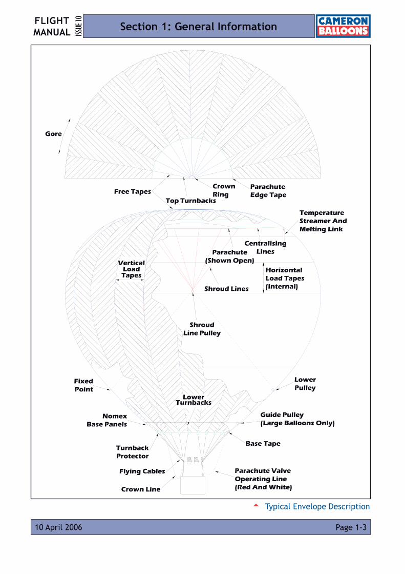
Centralising Lines
Top Turnbacks
Horizontal Load Tapes (Internal)Shroud Lines
Vertical Load Tapes
Shroud Line Pulley
Fixed Point
Nomex Base Panels
Flying Cables
Turnback Protector
Lower Pulley
Parachute Valve Operating Line (Red And White)
Parachute Edge Tape
Guide Pulley (Large Balloons Only)
Crown Ring
Temperature Streamer And Melting Link
Lower Turnbacks
Free Tapes
Crown Line
Parachute (Shown Open)
Gore
Base Tape
5 Typical Envelope Description
FLIGHT MANUALISS
UE 10
Page 1-4 10 April 2006
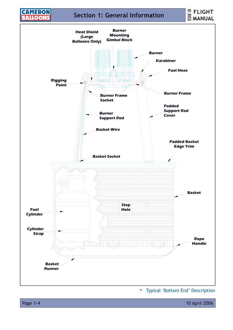
Section 1: General Information
Burner
Karabiner
Fuel Hose
Padded Support Rod Cover
Padded Basket Edge Trim
Basket
Rope Handle
Burner Frame Socket
Burner Support Rod
Basket Wire
Basket Socket
Basket Runner
Cylinder Strap
Fuel Cylinder
Rigging Point
Burner Mounting
Gimbal Block
Heat Shield (Large
Balloons Only)
Burner Frame
Step Hole
5 Typical ‘Bottom End’ Description
FLIGHT MANUAL ISS
UE 10
Page 2-113 July 2012 Amendment 11
Section 2: Limitations
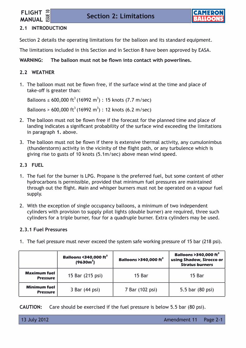
2.1 INTRODUCTION
Section 2 details the operating limitations for the balloon and its standard equipment.
The limitations included in this Section and in Section 8 have been approved by EASA.
WARNING: The balloon must not be flown into contact with powerlines.
2.2 WEATHER
1. The balloon must not be flown free, if the surface wind at the time and place of take-off is greater than:
2. The balloon must not be flown free if the forecast for the planned time and place of landing indicates a significant probability of the surface wind exceeding the limitations in paragraph 1. above.
3. The balloon must not be flown if there is extensive thermal activity, any cumulonimbus (thunderstorm) activity in the vicinity of the flight path, or any turbulence which is giving rise to gusts of 10 knots (5.1m/sec) above mean wind speed.
2.3 FUEL
1. The fuel for the burner is LPG. Propane is the preferred fuel, but some content of other hydrocarbons is permissible, provided that minimum fuel pressures are maintained through out the flight. Main and whisper burners must not be operated on a vapour fuel supply.
2. With the exception of single occupancy balloons, a minimum of two independent cylinders with provision to supply pilot lights (double burner) are required, three such cylinders for a triple burner, four for a quadruple burner. Extra cylinders may be used.
2.3.1 Fuel Pressures
1. The fuel pressure must never exceed the system safe working pressure of 15 bar (218 psi).
CAUTION: Care should be exercised if the fuel pressure is below 5.5 bar (80 psi).
Balloons <340,000 ft3
(9630m3)Balloons >340,000 ft3
Balloons >340,000 ft3
using Shadow, Sirocco or Stratus burners
Maximum fuel Pressure 15 Bar (215 psi) 15 Bar 15 Bar
Minimum fuel Pressure 3 Bar (44 psi) 7 Bar (102 psi) 5.5 bar (80 psi)
Balloons ≤ 600,000 ft3 (16992 m3) : 15 knots (7.7 m/sec)
Balloons > 600,000 ft3 (16992 m3) : 12 knots (6.2 m/sec)

FLIGHT MANUALISS
UE 10
Page 2-2 07 July 2017Amendment 15
Section 2: Limitations
2.4 MINIMUM BURNER REQUIREMENTS
2.5 PERMITTED DAMAGE
1. No damage is permitted to load tapes or any load bearing part of the suspension system.
2. No damage is permitted to the burner or fuel system.
3. Damage to the fabric below the first horizontal load tape above the Nomex (Cameron) or within 4 m of the Nomex (Thunder & Colt) is limited to holes or tears smaller than 1.5 m (60”) in any direction.
4. Damage to fabric in areas above that defined in 3, but below the upper part of the envelope (defined as the area above the widest horizontal seam between two vertical load tapes) is limited to holes or tears smaller than 50 mm (2”) in any direction. The distance between two adjacent holes must not less than four times the maximum dimension of the larger hole. There must be not more than 15 holes in this section of the envelope and no more than 5 in any one panel.
5. Damage to the fabric in the upper part of the envelope is limited to holes or tears smaller than 12 mm (½”) in any direction. The distance between two adjacent holes must not be less than 50 mm (2”). There must be not more than 15 holes in this section of the envelope and there must not be more than 5 holes in any one panel.
6. Any damage outside these limitations must be repaired before further flight in accordance with the instructions contained in the Maintenance Manual. Permitted damage, other than that specified in 3, must be repaired prior to an annual or 100 hour inspection.
NOTE: If any two or more small holes lie within a circle of the same diameter as a permitted hole, they may be considered as one hole for the purposes of paragraphs 4 and 5.
Burner Configuration Permitted Envelope Volume
Single 17,000 ft3 (481 m3) - 105,000 ft3 (2975 m3)
Double 56,000 ft3 (1585m3) - 210,000 ft3 (5950 m3)
Triple 140,000 ft3 (3970 m3) - 315,000 ft3 (8920 m3)
Quad 180,000 ft3 (5100 m3) - 750,000 ft3 (21238 m3)
FLIGHT MANUAL ISS
UE 10
Page 2-314 March 2018 Amendment 16
Section 2: Limitations
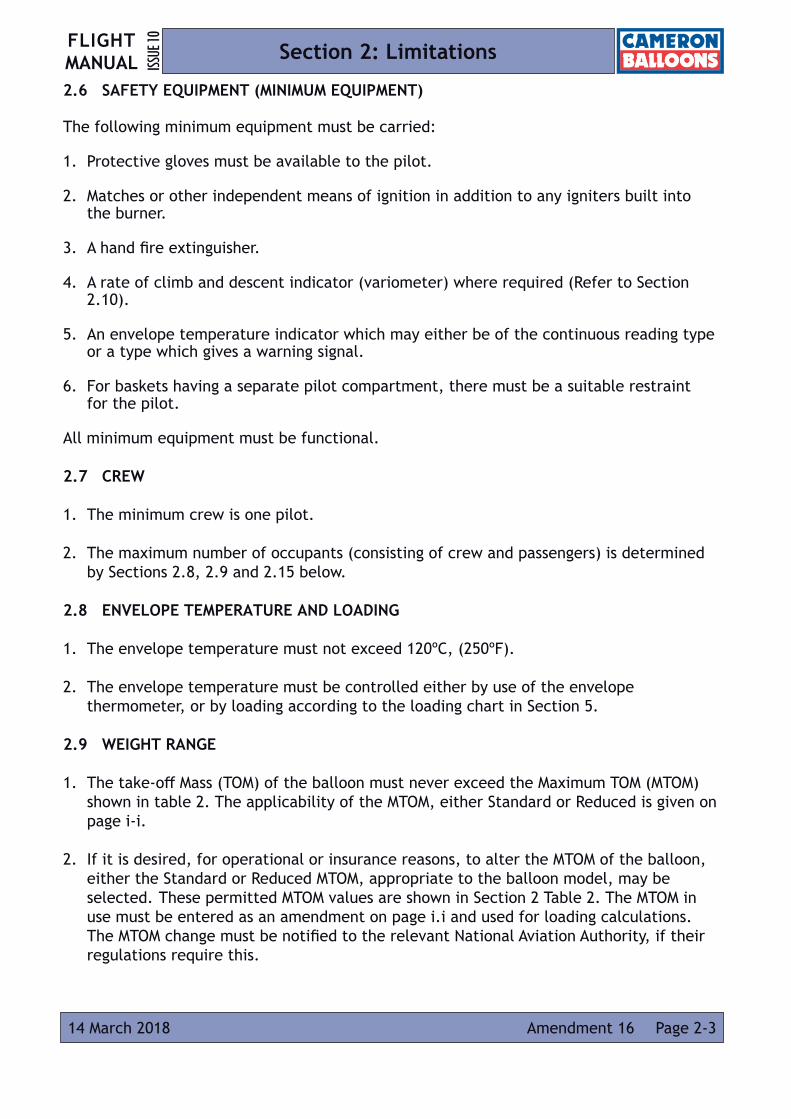
2.6 SAFETY EQUIPMENT (MINIMUM EQUIPMENT)
The following minimum equipment must be carried:
1. Protective gloves must be available to the pilot.
2. Matches or other independent means of ignition in addition to any igniters built into the burner.
3. A hand fire extinguisher.
4. A rate of climb and descent indicator (variometer) where required (Refer to Section 2.10).
5. An envelope temperature indicator which may either be of the continuous reading type or a type which gives a warning signal.
6. For baskets having a separate pilot compartment, there must be a suitable restraint for the pilot.
All minimum equipment must be functional.
2.7 CREW
1. The minimum crew is one pilot.
2. The maximum number of occupants (consisting of crew and passengers) is determined by Sections 2.8, 2.9 and 2.15 below.
2.8 ENVELOPE TEMPERATURE AND LOADING
1. The envelope temperature must not exceed 120ºC, (250ºF).
2. The envelope temperature must be controlled either by use of the envelope thermometer, or by loading according to the loading chart in Section 5.
2.9 WEIGHT RANGE
1. The take-off Mass (TOM) of the balloon must never exceed the Maximum TOM (MTOM) shown in table 2. The applicability of the MTOM, either Standard or Reduced is given on page i-i.
2. If it is desired, for operational or insurance reasons, to alter the MTOM of the balloon, either the Standard or Reduced MTOM, appropriate to the balloon model, may be selected. These permitted MTOM values are shown in Section 2 Table 2. The MTOM in use must be entered as an amendment on page i.i and used for loading calculations. The MTOM change must be notified to the relevant National Aviation Authority, if their regulations require this.

FLIGHT MANUALISS
UE 10
Amendment 17Page 2-4 12 November 2020
Section 2: Limitations
3. The Minimum Landing Mass (MLM) for normal operation is given in Table 2.
4. For special flights, record attempts etc., with only necessary crew on board, lower masses may be used at the pilot’s discretion.
2.10 RATES OF CLIMB AND DESCENT
2.10.1 Conventionally Shaped Balloons (excluding TR Types)
1. For balloons with a volume of 140,000 cu.ft. or less. If a rate of climb instrument is not fitted, rates of climb sufficient to cause a relative wind at basket level, must be avoided. If a rate-of-climb indicator (variometer) is fitted the maximum rate of climb is 1000 ft/min (5 m/sec). Cold descents are permitted.
2. The maximum rate of climb and descent for balloons with a volume of greater than 140,000 cu.ft and less than 340,000 cu.ft is 1000 ft/min (5 m/sec).
3. The maximum rate of climb and descent for balloons with a volume of between 340,000 and 750,000 cu.ft is 800 ft/min (4 m/sec).
2.10.2 TR Type Balloons
1. The maximum rate of climb and descent for ‘TR’ Type balloons is 1700 ft/min (8.5 m/sec), except where the RDS is fitted, when the maximum rates of climb and descent are limited to 1000 ft/min (5 m/sec).
2.11 PARACHUTE VALVE
1. The parachute valve must not be held open for periods longer than 3 seconds during flight. The envelope must be allowed to re-inflate fully and the envelope mouth must be seen to be fully open before subsequent operations of the vent.
2. ‘TR’ Type balloons must not have the parachute valve opened at rates of descent greater than 500 ft/min (2.5 m/sec).
2.12 RAPID DEFLATION SYSTEMS
1. The parachute valve of the rapid deflation system, when used for the controlled release of hot air during flight, must not be held open for periods longer than 3 seconds. The envelope must be allowed to re-inflate fully between operations of the vent.
2. Use of the rip line is not permitted at heights greater than 2 m (6 ft) above ground level, except in an emergency.
2.13 DELETED

FLIGHT MANUAL ISS
UE 10
Page 2-510 February 2016 Amendment 13
Section 2: Limitations
2.14 TETHERED FLIGHT
2.15 BASKETS
1. Each compartment must not contain more than six persons.
2. Reasonable space must be provided for each occupant, with regard to both comfort during the flight and to safety during the landing (Refer to Appendix 4).
3. There must be at least one restraint, e.g. hand hold, for each basket occupant.
4. Woven floor baskets must be fitted with load spreading boards when fitted with cylinders with a useable volume greater than 45 litres.
5. Where the ratio of length to width of the basket is greater than 1.4:1 the balloon must be equipped with envelope turning vents to allow the basket to be correctly orientated for landing.
2.16 CYLINDERS
1. All stainless steel, duplex stainless steel and titanium cylinders shall be equipped with an outer, water resistant protective layer at least 25mm thick made from structural cellular foam or similar material.
2. Each cylinder must be secured by a minimum of two cylinder straps. The straps must be of an approved design. Leather straps should not be used to secure cylinders with a useable volume greater than 60 litres.
2.17 ENVELOPE RIGGING 1. The following envelope types must be rigged using 4 tonne karabiners; Z-375, Z-400,
A-425LW, Z-425LW, A-450LW, Z-450, A-500LW and A-530LW.
LimitationsBalloons
<180,000 ft3
(5098 m3)
Balloons >180,000 ft3
<275,000 ft3
(7788 m3)
Balloons >275,000 ft3
Max. Surface wind speed15 knots
(7.7 m/sec)5 knots
(2.5 m/sec) Calm
Max. Surface wind speed with passengers10 knots
(5.1 m/sec)5 knots
(2.5 m/sec) Calm
Max. Height above ground (measured from underside of basket) 30 m (100 ft) 30 m (100 ft) 30m (100 ft)
Maximum Take-Off Mass limited to 75% of the standard MTOM
FLIGHT MANUALISS
UE 10
Page 2-6 14 March 2018Amendment 16
Section 2: Limitations
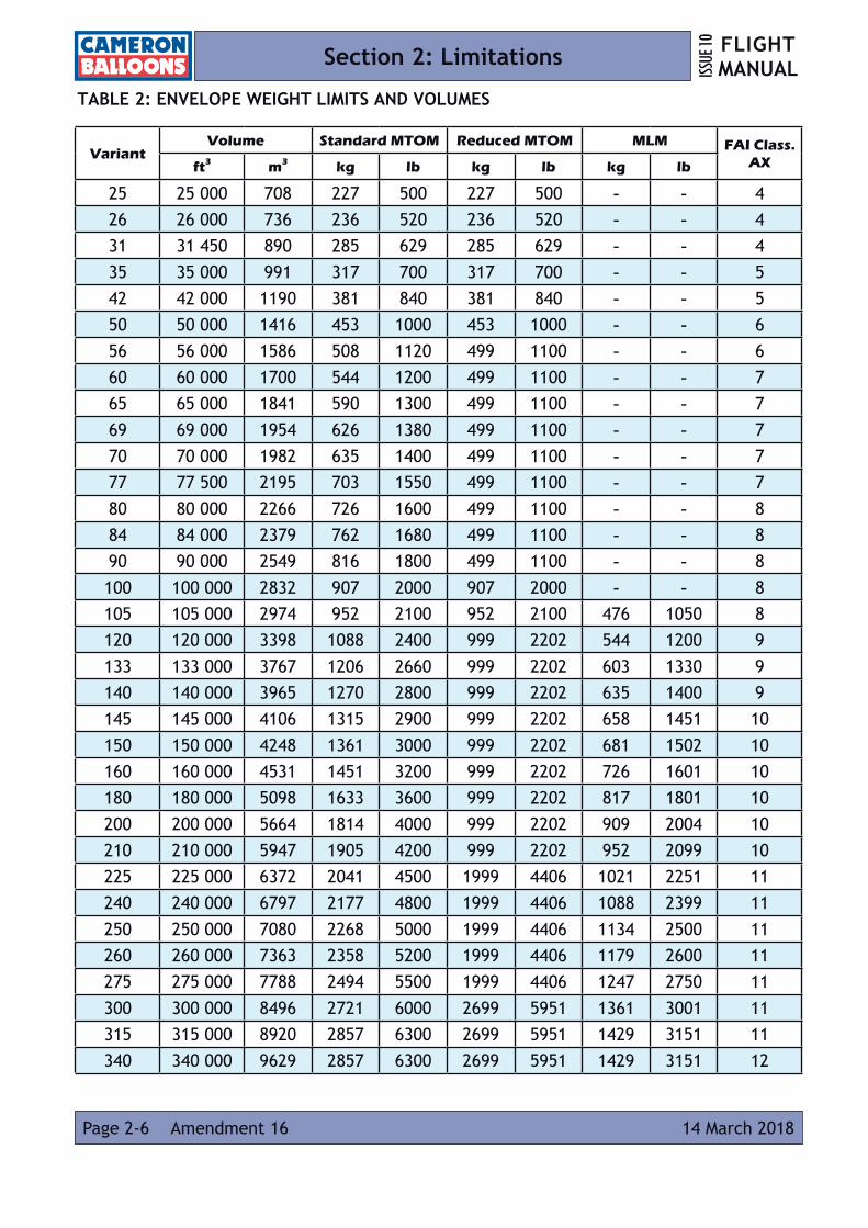
TABLE 2: ENVELOPE WEIGHT LIMITS AND VOLUMES
VariantVolume Standard MTOM Reduced MTOM MLM FAI Class.
AXft3 m3 kg lb kg lb kg lb
25 25 000 708 227 500 227 500 - - 426 26 000 736 236 520 236 520 - - 431 31 450 890 285 629 285 629 - - 435 35 000 991 317 700 317 700 - - 542 42 000 1190 381 840 381 840 - - 550 50 000 1416 453 1000 453 1000 - - 656 56 000 1586 508 1120 499 1100 - - 660 60 000 1700 544 1200 499 1100 - - 765 65 000 1841 590 1300 499 1100 - - 769 69 000 1954 626 1380 499 1100 - - 770 70 000 1982 635 1400 499 1100 - - 777 77 500 2195 703 1550 499 1100 - - 780 80 000 2266 726 1600 499 1100 - - 884 84 000 2379 762 1680 499 1100 - - 890 90 000 2549 816 1800 499 1100 - - 8100 100 000 2832 907 2000 907 2000 - - 8105 105 000 2974 952 2100 952 2100 476 1050 8120 120 000 3398 1088 2400 999 2202 544 1200 9133 133 000 3767 1206 2660 999 2202 603 1330 9140 140 000 3965 1270 2800 999 2202 635 1400 9145 145 000 4106 1315 2900 999 2202 658 1451 10150 150 000 4248 1361 3000 999 2202 681 1502 10160 160 000 4531 1451 3200 999 2202 726 1601 10180 180 000 5098 1633 3600 999 2202 817 1801 10200 200 000 5664 1814 4000 999 2202 909 2004 10210 210 000 5947 1905 4200 999 2202 952 2099 10225 225 000 6372 2041 4500 1999 4406 1021 2251 11240 240 000 6797 2177 4800 1999 4406 1088 2399 11250 250 000 7080 2268 5000 1999 4406 1134 2500 11260 260 000 7363 2358 5200 1999 4406 1179 2600 11275 275 000 7788 2494 5500 1999 4406 1247 2750 11300 300 000 8496 2721 6000 2699 5951 1361 3001 11315 315 000 8920 2857 6300 2699 5951 1429 3151 11340 340 000 9629 2857 6300 2699 5951 1429 3151 12
FLIGHT MANUAL ISS
UE 10
Amendment 16 Page 2-714 March 2018
Section 2: Limitations
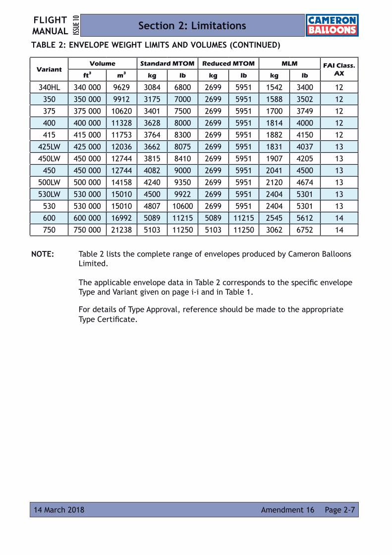
TABLE 2: ENVELOPE WEIGHT LIMITS AND VOLUMES (CONTINUED)
NOTE: Table 2 lists the complete range of envelopes produced by Cameron Balloons Limited. The applicable envelope data in Table 2 corresponds to the specific envelope Type and Variant given on page i-i and in Table 1. For details of Type Approval, reference should be made to the appropriate Type Certificate.
VariantVolume Standard MTOM Reduced MTOM MLM FAI Class.
AXft3 m3 kg lb kg lb kg lb
340HL 340 000 9629 3084 6800 2699 5951 1542 3400 12350 350 000 9912 3175 7000 2699 5951 1588 3502 12375 375 000 10620 3401 7500 2699 5951 1700 3749 12400 400 000 11328 3628 8000 2699 5951 1814 4000 12415 415 000 11753 3764 8300 2699 5951 1882 4150 12
425LW 425 000 12036 3662 8075 2699 5951 1831 4037 13450LW 450 000 12744 3815 8410 2699 5951 1907 4205 13
450 450 000 12744 4082 9000 2699 5951 2041 4500 13500LW 500 000 14158 4240 9350 2699 5951 2120 4674 13530LW 530 000 15010 4500 9922 2699 5951 2404 5301 13
530 530 000 15010 4807 10600 2699 5951 2404 5301 13600 600 000 16992 5089 11215 5089 11215 2545 5612 14750 750 000 21238 5103 11250 5103 11250 3062 6752 14
Intentionally Blank Page
FLIGHT MANUALISS
UE 10
Page 2-8 10 April 2006
Section 2: Limitations

Page 3-129 April 2010
FLIGHT MANUAL ISS
UE 10
Amendment 7
Section 3: Emergency Procedures
3.1 INTRODUCTION
Section 3 provides checklists and amplified procedures for coping with emergencies that may occur. This Section is approved by EASA.
3.2 AVOIDANCE OF DANGEROUS OBSTACLES AT LOW LEVEL
The pilot must decide whether to climb or to make an emergency landing.
3.2.1 Emergency Climb
Single Burners:
Emergency climbs should be made by operating one main burner valve and one whisper burner valve. The main burner valve and whisper burner valve used must be fed from independent fuel supplies.
Double, Triple and Quad Burners:
Emergency climbs should be made by operating the main burner valve on each burner unit simultaneously.
NOTE: The operation of two burners from a single fuel supply using the crossflow valve will not give maximum burner power.
3.2.2 Emergency Landing
Emergency landings can be made by partially opening the parachute valve, Rapid Deflation System or Velcro rip panel at heights of 15 m (50 ft) or less.
3.3 CONTACT WITH ELECTRIC POWER LINES
Contact with electric power wires is extremely dangerous and can result in serious or fatal injuries. It should be avoided at all costs.
If contact with power wires cannot be avoided, initiate a rapid descent so that contact with the wires will be made by the envelope instead of the basket assembly.
Shut off all the fuel supplies at the cylinder valves and vent the fuel hoses before contact.
If the balloon is caught in the power wires, do not touch any metallic parts.
Page 3-2 29 April 2010
FLIGHT MANUALISS
UE 10
Amendment 7
Section 3: Emergency Procedures
If the basket is not in contact with the ground remain in it, if possible, until the electrical power is shut off.
If it is necessary to leave the basket, do not place the body in contact with the ground and any part of the balloon at the same time.
Do not attempt to recover the balloon until the electricity authority has been contacted, and has indicated that it is safe to do so.
3.4 FIRE - IN THE AIR
Shut off the fuel supply at the cylinder valve and vent the hoses through the burner.
Put out fire with extinguisher.
Identify the cause of the fire and decide if it is possible to relight the burner. If not, the procedure for a hard landing (Section 3.8) must be followed.
3.5 FIRE - ON THE GROUND
Shut off the fuel supply at the cylinder valve and send all persons not directly fighting the fire to a safe distance.
Put out fire with extinguisher.
WARNING: If the fire is not extinguished immediately, ensure that all remaining persons retreat to a safe distance, as an explosion will occur if the fire continues and causes the cylinders to rupture.
If the balloon is inflated the pilot must pull the parachute operating / rip line to prevent the balloon becoming airborne while the passengers exit. The pilot should exit the balloon last with the parachute operating / rip line in hand to ensure that the balloon does not become airborne.
NOTE: If a dry powder fire extinguisher has been used, it is very important that all traces of the powder residue are removed from the balloon and associated equipment. The powder becomes extremely corrosive once it has been used on a fire or exposed to the atmosphere, and can cause damage.
3.6 DAMAGE TO ENVELOPE IN FLIGHT
Heat to replace lost lift while maintaining a steady rate of descent.
Remain at very low altitude and land as soon as possible.

FLIGHT MANUAL ISS
UE 10
Page 3-314 March 2018 Amendment 16
Section 3: Emergency Procedures
Do not burn if the air loss from the balloon is sufficient to cause the mouth to close, as damage to suspension tapes could cause a catastrophic failure.
If the rate of descent cannot be controlled, consider jettisoning all disposable ballast, including fuel cylinders which are not in use, if it is possible to do so without endangering people or property on the ground.
3.7 ACCIDENTAL OPERATION OF THE RAPID DEFLATION SYSTEM
If the rip line is accidentally pulled in flight the vent will start to operate. The pilot will be warned by the difference in feel as the panel starts to open.
The rip line should immediately be released, and the panel closed by pulling on the venting line.The burner must be operated to replace lost heat.
WARNING: The panel will not automatically re-close on release of the rip line.
3.8 PREPARATION FOR A HARD LANDING
There are two possible hard landing situations. A burner or envelope failure results in a ‘heavy’ landing where the speed is mostly vertical, whereas a weather emergency may cause a ‘fast’ landing where the speed is mostly horizontal.
In a heavy landing the occupants should brace against vertical compression, with their knees only slightly bent. The rope handles or cylinder rims should be firmly held.
In a fast landing the basket may tip forward violently on impact, tending to throw the occupants out. The occupants should adopt a low down position (knees well bent) with their back or shoulder pressed against the leading edge of the basket, head level with the basket edge and rope handles or cylinder rims firmly held.
Remind passengers not to leave the basket until told to do so.
Extinguish the pilot light(s) and shut the fuel off at all cylinders in use. Empty the hoses if time permits.
The parachute operating / rip line should be firmly gripped before touchdown.
3.9 ENVELOPE OVER TEMPERATURE
Descend to the minimum practical altitude and keep to low rates of climb and descent. If the temperature remains too high, land as soon as possible.
NOTE: If the balloon is not overloaded for the altitude and ambient temperature it is extremely unlikely that the envelope temperature limits will be exceeded in
normal flight.
FLIGHT MANUALISS
UE 10
Page 3-4 10 April 2006
Section 3: Emergency Procedures
3.10 BURNER FAILURE
Burner Unit Malfunction:
Transfer control to another burner unit or to the other fuel supply (single burner).
Shut off the fuel supply to the defective burner unit at the cylinder valve.
Vent fuel from the defective burner unit and supply hose.
Land as soon as possible.
NOTE: If the blast valve fails in the open position, its flow can be controlled by opening and closing the cylinder valve (liquid offtake).
Crossflow Valve Leak (Stealth, Shadow and Stratus burners only)-
Close the two blast valves connected by the crossflow valve.
Transfer control to the whisper burners or burners not connected by the crossflow valve. Land as soon as possible.
NOTE: Crossflow valve leaks are only evident with the main burner operating.
If a fuel leak cannot be controlled, shut off all fuel including the pilot light and brief passengers for a hard landing (Section 3.8).
NOTE: If the main fuel hoses are removed from the support rod covers they are long enough to reach fuel cylinders at the opposite end of the basket.
CAUTION: Care should be taken when operating with the fuel hoses outside of the support rod covers, as the liquid fuel pressure can cause the hose to deflect when the blast or whisper valve is operated. This may change the direction of the burner and flame.
3.11 PILOT LIGHT FAILURE
If a pilot light is extinguished for any reason, it should be relit.
Each burner unit is fitted with a pilot light, single burners having two independent pilot lights. All burners will operate with one failed pilot light. The failed pilot light should be turned off and a landing made as soon as possible.
On double burners or pairs of burners the crossflow valve, if fitted, should be opened to ensure reliable ignition of both burners from the remaining pilot light. If the pilot light fails on the single unit of a triple burner then control should be maintained on another burner.

FLIGHT MANUAL ISS
UE 10
Page 3-510 April 2006
Section 3: Emergency Procedures
If all pilot lights fail the following procedure should be adopted:
1. Shut off all fuel supplies at the cylinder valve.
2. Lock one whisper burner valve (Shadow, Stealth and Sirocco burners) fully open or lock one main burner valve open using the blast valve latch (Stratus Burner).
3. Partially open the fuel supply to this burner at the cylinder valve, to permit a small amount of fuel to enter the burner.
4. Light the burner with a match or other igniter. WARNING: Do not use the igniter built into the burner, as it will not ignite
the fuel.
5. Fully open the fuel supply to the burner, using the cylinder liquid valve to control the flight of the balloon.
6. Partially close the cylinder liquid valve to a fractional setting, regulating the burner to maintain a pilot setting.
7. Land as soon as possible.
NOTE: Do not leave one cylinder providing the pilot setting, with main fuel taken from another, because prolonged restricted flow of liquid will cause freezing of the valves.

Intentionally Blank Page
FLIGHT MANUALISS
UE 10
Page 3-6 10 April 2006
Section 3: Emergency Procedures

Page 4-129 April 2010
FLIGHT MANUAL ISS
UE 10
Amendment 7
Section 4: Normal Procedures
4.1 INTRODUCTION
Section 4 provides checklists and amplified procedures for the conduct of normal operation. Normal procedures associated with optional systems can be found in Section 8. The procedures included in this Section and in Section 8 have been approved by EASA.
4.2 PREPARATION AND RIGGING
4.2.1 Site Selection
The site should be chosen so that the downwind path that the balloon will take is clear of powerlines or obstructions. The clear area should be large enough that the balloon cannot be damaged should it move during inflation.
The area for laying out the balloon should ideally be a smooth grass surface. Surfaces covered with rocks, sticks or other objects likely to cause fabric damage should be avoided.
4.2.2 Basket rigging
Non-partitioned (open) baskets should be positioned with the step hole on the upwind side.
T-partition baskets should be positioned with the pilot compartment on the right, looking from the basket towards the envelope.
Double T-partition baskets should be positioned with either long side facing towards the envelope.
Strap the cylinders as required into the basket. Check the contents and ensure that the master cylinders (if used) are on the downwind (envelope) side of the basket.
The orientation of the cylinders should ensure that:
1. Cylinders that are required to supply liquid during inflation are positioned so that the liquid valve is in the lower half of the cylinder when the basket is on its side.
2. Cylinders that are required to supply vapour during inflation are positioned so that the vapour valve is uppermost when the cylinder is on its side.
3. All cylinders should be positioned so that the liquid off-takes and hoses cannot be struck by the pilot or passengers during landing.
WARNING: Incorrect positioning of cylinders used for vapour offtake can result in pilot light failure.
5 Correct Positioning Of Master Cylinders
Vapour Offtake
MasterCylinder Envelope
Step Hole
MasterCylinder
Wind Direction
2 1
4 3

FLIGHT MANUALISS
UE 10
Amendment 15Page 4-2 07 July 2017
Section 4: Normal Procedures
4.2.3 Burner Rigging
The burner frame should be orientated so that the burner pressure gauges are legible when the basket is laid down for inflation. The burner frame is rigged to the basket using karabiners of which there are three standards detailed below. The 2.5 and 3 tonne karabiners may be regarded as direct alternatives, although the 2.5 tonne is the preferred standard as it causes less flattening of the wires due to its symmetric oval shape.
Karabiner Specifications
The 2.5 Tonne karabiners are used in all basket-envelope rigging, not including tethering, except in the following applications where 4 tonne karabiners are recommended;
– where the burner frame has only 4 attachment points and the envelope volume is of 210,000 cu.ft (5947 m3) and greater;
and,
– where the burner frame has 8 attachment points and the envelope volume is of 340,000 cu.ft (9629 m3) or larger.
If a launch restraint is to be attached to these karabiners, it is essential that they are orientated so that restraint karabiners must load the solid, not the screwgate side of the envelope karabiners.
4.2.3.1 Flexible Corner Socket Burner Frames
Insert the support rods into the basket sockets, then lift the burner up and locate the burner frame corner sockets onto the top of the support rods.
4.2.3.2 Fixed Corner Socket Burner Frames
Insert the support rods into the burner frame corner sockets, lift up the burner and rods and locate the lower end of the rods into the basket sockets.
4.2.3.3 Adjustable Height Burner Frames
Where an adjustable height burner frame is used, the gas strut must be below the burner during inflation and the burner must be in the upper half of its height range. On larger baskets the gas strut is positioned to the side of the burner, and care must be taken not to overheat the strut.
4.2.3.4 Rigging of Basket Wires to Burner Frame (All Burner Frames)
The correct attachment of the basket wires depends on the number of wires and the burner frame type. The four configurations ( A, B, C, D) are shown in the following figures.
Part No. Rating Identification Markings
CU-9820-0003 2.5 Tonne STUBAI SYMOVAL2500 UIAACU-9820-0001 3 Tonne STUBAI SYMOVAL3000 UIAACU-9825-0001 4 Tonne STUBAI SYMOVAL4000 UIAA

Page 4-329 April 2010
FLIGHT MANUAL ISS
UE 10
Amendment 7
Section 4: Normal Procedures
Fit the padded support rod covers, enclosing the hoses within them. Start the zips at the top and close downwards. It is important that there is sufficient slack hose at the top to allow the burner to gimbal, but not so much that the hose is affected by radiant heat from the burner.
In open baskets the liquid hoses are enclosed in the upwind support rod covers. Vapour hoses (if used) are enclosed in the downwind support rod covers.
In T-partitioned baskets all the hoses fit into the two covers at the pilot’s compartment end of the basket.
When double burners are fitted to a double T-partition basket the hoses are arranged identically to the hoses in an open basket. If a triple or quad burner is fitted the hose(s) of each burner follow the adjacent rod. Double T baskets can use two additional padded covers containing only the fuel hoses, suspended from the burner frame and connected inside the pilot compartment.
Check that all burner and cylinder valves are closed and connect the fuel hoses to the cylinders. If cylinder manifolds are used they must be connected as described in Section 4.6.3.1. Fuel hoses should be filled with fuel to check that there are no leaks. The burner test may be performed now or when the balloon is inflated (see Pre-Take-off checklist). Close the cylinder valves and burn the fuel from the hoses.
Manoeuvre the basket onto its side with the burner facing the envelope.
4.2.3.5 Mini Vapour Cylinder
The mini vapour cylinder should be strapped into a suitable location in the basket. It should be oriented so that it is vertical at all times that vapour is being withdrawn.
If only one vapour hose is to be connected the other vapour outlet may be left bare. If two vapour hoses are to be connected then an extension hose may be required.
Care must be taken to ensure that two independent pilot light fuel supplies remain to keep the redundancy of the fuel and burner system.
NOTE: Some mini vapour cylinders incorporate a dip tube which allows vapour to be drawn off with the cylinder in the horizontal position when the outlet is oriented downwards.
5 Rigging Of Frame Type ‘C’
5 Rigging Of Frame Type ‘D’
5 Rigging Of Frame Type ‘B’
5 Rigging Of Frame Type ‘A’
FLIGHT MANUALISS
UE 10
Amendment 14Page 4-4 23 March 2017
Section 4: Normal Procedures
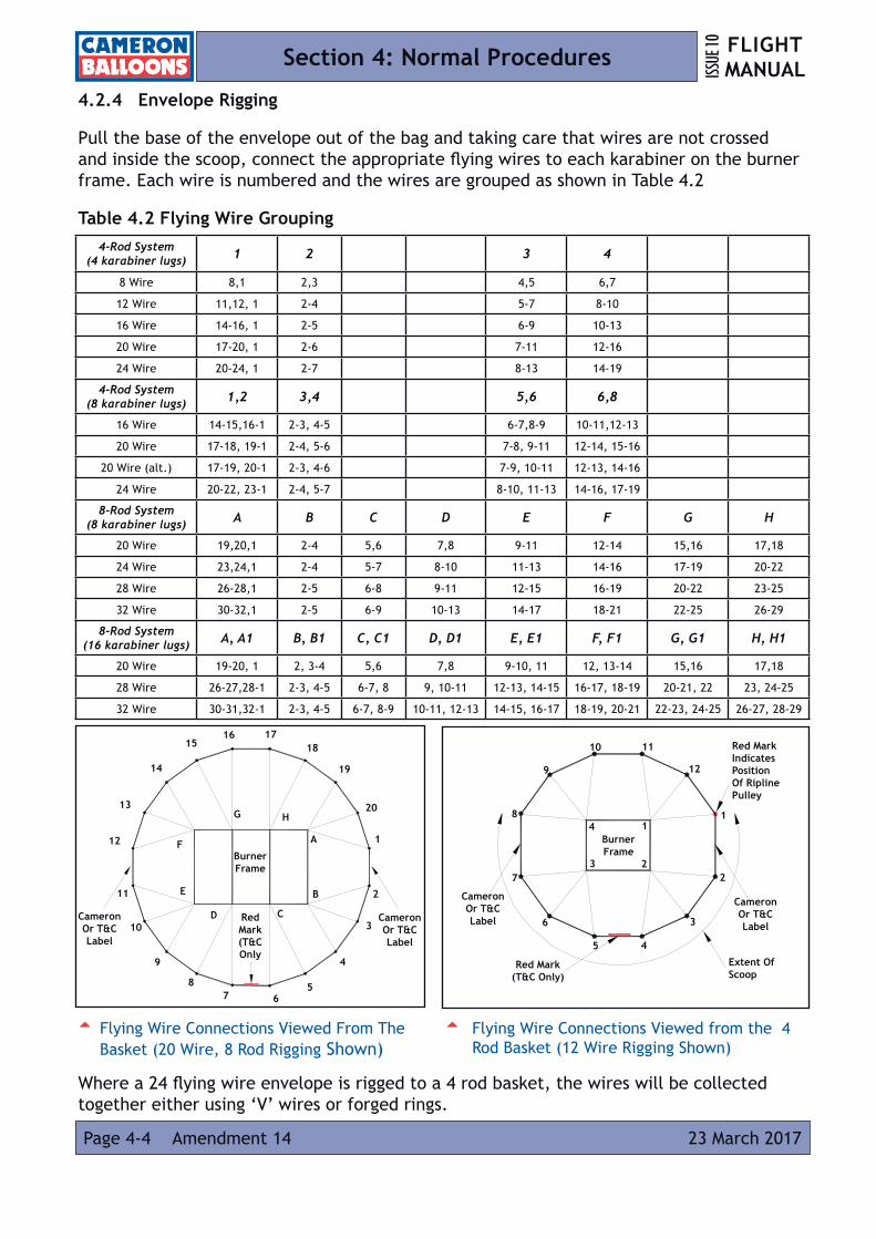
4.2.4 Envelope Rigging
Pull the base of the envelope out of the bag and taking care that wires are not crossed and inside the scoop, connect the appropriate flying wires to each karabiner on the burner frame. Each wire is numbered and the wires are grouped as shown in Table 4.2
Table 4.2 Flying Wire Grouping
Where a 24 flying wire envelope is rigged to a 4 rod basket, the wires will be collected together either using ‘V’ wires or forged rings.
5 Flying Wire Connections Viewed from the 4 Rod Basket (12 Wire Rigging Shown)
5 Flying Wire Connections Viewed From The Basket (20 Wire, 8 Rod Rigging Shown)
Cameron Or T&C Label
Cameron Or T&C Label
Burner Frame
15
14
13
12
11
10
16 1718
19
20
1
2
3
4
567
8
9
Red Mark Indicates Position Of Ripline Pulley
Cameron Or T&C Label
Extent Of Scoop
Burner Frame
Cameron Or T&C Label
9
1
2
3
45
6
12
1110
7
8
Red Mark (T&C Only)
Red Mark (T&C Only
A
B
CD
E
F
G H4 1
23
4-Rod System(4 karabiner lugs) 1 2 3 4
8 Wire 8,1 2,3 4,5 6,7
12 Wire 11,12, 1 2-4 5-7 8-10
16 Wire 14-16, 1 2-5 6-9 10-13
20 Wire 17-20, 1 2-6 7-11 12-16
24 Wire 20-24, 1 2-7 8-13 14-19
4-Rod System(8 karabiner lugs) 1,2 3,4 5,6 6,8
16 Wire 14-15,16-1 2-3, 4-5 6-7,8-9 10-11,12-13
20 Wire 17-18, 19-1 2-4, 5-6 7-8, 9-11 12-14, 15-16
20 Wire (alt.) 17-19, 20-1 2-3, 4-6 7-9, 10-11 12-13, 14-16
24 Wire 20-22, 23-1 2-4, 5-7 8-10, 11-13 14-16, 17-19
8-Rod System(8 karabiner lugs) A B C D E F G H
20 Wire 19,20,1 2-4 5,6 7,8 9-11 12-14 15,16 17,18
24 Wire 23,24,1 2-4 5-7 8-10 11-13 14-16 17-19 20-22
28 Wire 26-28,1 2-5 6-8 9-11 12-15 16-19 20-22 23-25
32 Wire 30-32,1 2-5 6-9 10-13 14-17 18-21 22-25 26-29
8-Rod System(16 karabiner lugs) A, A1 B, B1 C, C1 D, D1 E, E1 F, F1 G, G1 H, H1
20 Wire 19-20, 1 2, 3-4 5,6 7,8 9-10, 11 12, 13-14 15,16 17,18
28 Wire 26-27,28-1 2-3, 4-5 6-7, 8 9, 10-11 12-13, 14-15 16-17, 18-19 20-21, 22 23, 24-25
32 Wire 30-31,32-1 2-3, 4-5 6-7, 8-9 10-11, 12-13 14-15, 16-17 18-19, 20-21 22-23, 24-25 26-27, 28-29

FLIGHT MANUAL ISS
UE 10
Amendment 13 Page 4-510 February 2016
Section 4: Normal Procedures
Envelope cables may be left permanently attached to a second set of karabiners, which are connected to the burner frame karabiners during rigging. This arrangement causes a 900 twist, which can be avoided by connecting a forged tether ring between the karabiners.
Close all karabiner screwgates and connect the control lines to the appropriate points on the burner frame or basket.
Connect the launch restraint.
Pull the envelope from the carrying bag by taking hold of the bag handles and walking away downwind. Stow the envelope bag in the basket or attach it to a support rod taking care not to trap any of the fuel hoses.
4.2.4.1 Parachute/Lock Top Deflation System
The parachute operating line should be attached to either of the karabiners on the pilot’s right or inside the pilot compartment of partitioned baskets.
4.2.4.2 RDS Deflation System
Attach the rip line (red rope) to the burner frame and the venting line (red and white rope) to the ring on the Rapid Deflation System bag installed in the basket.
4.2.4.3 Launch Restraint (Quick Release)
The ends of the webbing yoke should be connected to the restraint lugs on the upwind side of the burner frame. If restraint lugs are not fitted, the yoke should be connected to the two uppermost karabiners during inflation. A short tether line is best for maximum control, and is looped through the jaws of the latch.
If the basket is fitted with strong points (Modification C438), the balloon may be restrained from these points using the quick release in the ‘Y’ configuration.
WARNING: To prevent unintentional entanglement, If the basket is fitted with strong points on both sides it is important that no rigging is left attached to the strong points on the upwind side of the basket when they are not in use.
‘Y’ Type - 4 Pole Baskets 120 Size And Above
Standard Type - Up To 120 Size Baskets
‘W’ Type - 8 Pole Baskets
5 Quick Release Systems
RopeWebbing
FLIGHT MANUALISS
UE 10
Amendment 12Page 4-6 03 May 2013
Section 4: Normal Procedures
4.3 INFLATION
4.3.1 Cold Inflation
The crew members should be briefed before the inflation procedure is started. Passengers may be briefed either before inflation begins, or once they are in the basket after inflation. Passengers should be shown how to correctly get into the basket before inflation starts. For Personnel handling information refer to Appendix 5
CAUTION: The most important instruction for all crew members is to let go immediately if they are lifted off the ground.
Partially inflate the envelope to introduce enough air into the envelope to free the parachute and parachute operating line.
Untangle the control lines and feed any slack into the mouth of the balloon. Additional control lines should be attached to any suitable karabiner or to the attachment points provided in the pilot compartment of partitioned baskets.
If the parachute has become tangled, follow two adjacent shroud lines from the envelope to the parachute, then work around the edge of the parachute untangling the lines.
Tab the parachute valve into position, matching the numbers or colours near the Velcro tabs on the parachute and envelope. Make sure that there are no folds of fabric lying on the parachute operating line which could open the parachute during the inflation.
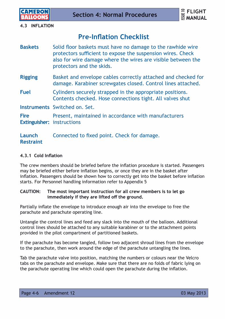
Pre-Inflation ChecklistBaskets Solid floor baskets must have no damage to the rawhide wire
protectors sufficient to expose the suspension wires. Check also for wire damage where the wires are visible between the protectors and the skids.
Rigging Basket and envelope cables correctly attached and checked for damage. Karabiner screwgates closed. Control lines attached.
Fuel Cylinders securely strapped in the appropriate positions. Contents checked. Hose connections tight. All valves shut
Instruments Switched on. Set.
Fire Extinguisher:
Present, maintained in accordance with manufacturers instructions
Launch Restraint
Connected to fixed point. Check for damage.
Page 4-729 April 2010
FLIGHT MANUAL ISS
UE 10
Amendment 7
Section 4: Normal Procedures
4.3.1.1 Lock Top Deflation System
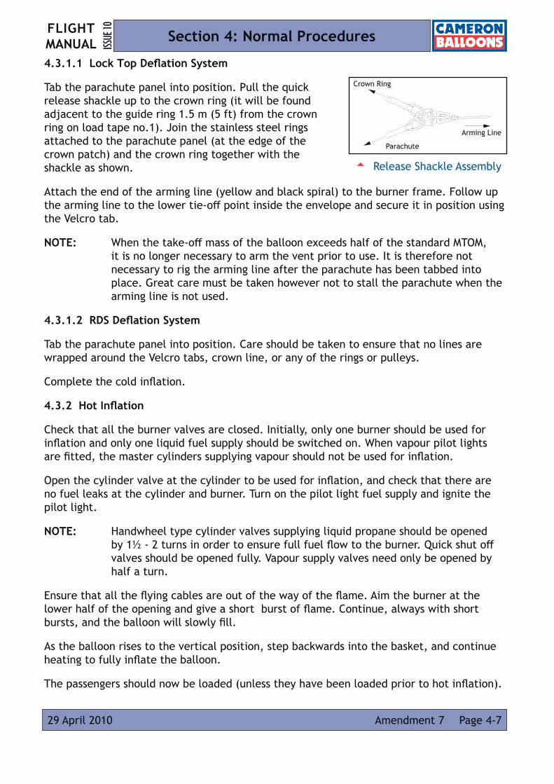
Tab the parachute panel into position. Pull the quick release shackle up to the crown ring (it will be found adjacent to the guide ring 1.5 m (5 ft) from the crown ring on load tape no.1). Join the stainless steel rings attached to the parachute panel (at the edge of the crown patch) and the crown ring together with the shackle as shown.
Attach the end of the arming line (yellow and black spiral) to the burner frame. Follow up the arming line to the lower tie-off point inside the envelope and secure it in position using the Velcro tab.
NOTE: When the take-off mass of the balloon exceeds half of the standard MTOM, it is no longer necessary to arm the vent prior to use. It is therefore not necessary to rig the arming line after the parachute has been tabbed into place. Great care must be taken however not to stall the parachute when the arming line is not used.
4.3.1.2 RDS Deflation System
Tab the parachute panel into position. Care should be taken to ensure that no lines are wrapped around the Velcro tabs, crown line, or any of the rings or pulleys.
Complete the cold inflation.
4.3.2 Hot Inflation
Check that all the burner valves are closed. Initially, only one burner should be used for inflation and only one liquid fuel supply should be switched on. When vapour pilot lights are fitted, the master cylinders supplying vapour should not be used for inflation.
Open the cylinder valve at the cylinder to be used for inflation, and check that there are no fuel leaks at the cylinder and burner. Turn on the pilot light fuel supply and ignite the pilot light.
NOTE: Handwheel type cylinder valves supplying liquid propane should be opened by 1½ - 2 turns in order to ensure full fuel flow to the burner. Quick shut off valves should be opened fully. Vapour supply valves need only be opened by half a turn.
Ensure that all the flying cables are out of the way of the flame. Aim the burner at the lower half of the opening and give a short burst of flame. Continue, always with short bursts, and the balloon will slowly fill.
As the balloon rises to the vertical position, step backwards into the basket, and continue heating to fully inflate the balloon.
The passengers should now be loaded (unless they have been loaded prior to hot inflation).
5 Release Shackle Assembly
Crown Ring
Arming Line
Parachute

Page 4-8 29 April 2010
FLIGHT MANUALISS
UE 10
Amendment 7
Section 4: Normal Procedures4.4 TAKE-OFF
4.4.1 Pre Take-Off Checks
Pre-Take-Off ChecklistEnvelope
General condition: Damage within Limitations
Temperature Flag: Visible
Deflation System: Visual Check, Test operation, Operating lines attached (refer 4.4.1.1 to 4.4.1.3)
Load tapes: Free of damage without sign of undue strain
Flying Cables: Correctly connected
Karabiners: Screwgates closed and karabiners loaded lengthwise
Scoop: Attached
Crown Line(s): Attached
BurnerPilot Lights: Burning satisfactorily, normal appearance and sound. No
freezing at cylinder vapour offtake and vapour valve open (vapour pilot light only).
Test: Test all systems. Check all valves for leaks (including crossflow valves where fitted).
CylindersFuel Pressure: Within limitations
Additional Cylinders:
All fuel cylinders should be connected and tested, to ensure adequate fuel pressure and uncontaminated fuel delivery.
Mini Vapour Cylinder:
Valve open (refer to 4.4.1.4)
EquipmentInstruments: Switched on, set
Alternative source of ignition:
Present, tested.
Pilot Restraint Belt Worn and strap connected (if used)
Page 4-929 April 2010
FLIGHT MANUAL ISS
UE 10
Amendment 7
Section 4: Normal Procedures
4.4.1.1 Parachute
Check the parachute function by pulling on the parachute operating line until the Velcro unbans. Release the line and check the appearance of the panel after it has closed.
4.4.1.2 Lock Top
Check the operation of the parachute valve. Check that the arming line is attached to the load frame, that the tie-off is not broken and that the lock-top indicator flag is not hanging inside the envelope (it can normally be seen sitting on top of the parachute panel).
4.4.1.3 RDS
Test the venting action of the system and ensure that all the Velcro tabs are detached.
Ensure that the balloon is hot and then test the deflation action of the system. Pull on the rip line to collapse the parachute into the centre of the balloon. As soon as a complete ring of sky can be seen around the edge of the parachute, pull on the venting line to fully close the panel. A second operation of the venting line may be needed to obtain a good seal.
The excess venting line should be placed loosely into the top of the Rapid Deflation System bag to prevent any possibility of entanglement.
4.4.1.4 Mini Vapour Cylinder
WARNING: It is important to check that the mini vapour cylinder valve is open before flight as residual vapour in the hose from the burner test may give the impression, for a period of time, that the system is fully functional even when the valve is closed.
4.4.2 Take-Off- Calm Conditions
Take-off by building up lift with intermittent burning, all crew standing clear of the basket. The balloon will lift off and burning can stop a short distance above the ground.
Be ready to burn again at the top of the climb to prevent a descent.
4.4.3 Take-Off- Windy Conditions, Sheltered Site
An apparent loss of lift can occur as the balloon first encounters faster moving air just above the surface during windy conditions. When the balloon is static on the ground, the faster moving air above it creates an area of low pressure which creates lift in the same way as an aeroplane wing.
As the balloon takes-off, this effect diminishes causing the balloon to descend unless more heat is added. The burner flame will also be deflected which may prevent heating to replace the lost lift.
Page 4-10 29 April 2010
FLIGHT MANUALISS
UE 10
Amendment 7
Section 4: Normal Procedures
In windy conditions build up excess lift before leaving the ground either by using crew in a ‘hands on’ and ‘hands off’ drill, or a restraining device. Burn while ascending and use the angle control on the burner to counteract the deflection of the flame by the wind. The balloon should be launched with the open side of the scoop (if fitted) facing upwind.
4.4.4 Quick Release
When take-off is imminent, the securing pin is withdrawn ready for the final release. The final release should be performed by the pilot. The latch should be held firmly by the handle, and the pilot should be ready to prevent the latch from recoiling or falling towards the occupants of the basket. For this reason, the final release should be made when the quick release is as lightly loaded as possible.
Page 4-1129 April 2010
FLIGHT MANUAL ISS
UE 10
Amendment 7
Section 4: Normal Procedures
4.5 CONTROL IN FLIGHT
4.5.1 Burner Control
The flight path of the balloon is controlled by the use of the burner, which is either full on or full off. Burner Control layouts are given in Section 6.
4.5.2 Venting in Flight
When venting frequently in flight, always watch the envelope to observe the amount of deflation occurring. Venting should not exceed the limitations in Section 2.
Under very lightly loaded conditions it is possible that the parachute will not reclose automatically, but it will do so if the burner is operated - this requires a visual check.
4.5.2.1 Parachute Valve/RDS
To release hot air during flight the venting line should be pulled.
4.5.2.2 Lock Top
To release hot air during flight the venting line should be pulled. Great care must be taken not to stall the parachute when the arming line is not used.
WARNING: In the unlocked state an extended pull on the parachute operating line beyond the limits in Section 2 may cause the parachute to ‘stall’. The parachute will then not re-close.
4.5.2.3 Turning Vents
Where turning vents are fitted it is possible to vent hot air by simultaneous operation of both the turning vents.
4.5.3 Fuel Management
In flight one fuel cylinder is connected to each burner fuel supply. Two cylinders will be connected for a single or a double burner, three cylinders for a triple burner and four cylinders for a quad. These cylinders should be tested immediately before take-off and remain turned on during flight.
NOTE: Tema 3810 connectors have a latching locking ring below the main release ring. When the locking ring is ‘up’ (towards the connection), the main release ring cannot be operated to release or make the connection.
One fuel supply should be used preferentially during flight to ensure that two fuel systems are never exhausted simultaneously.

FLIGHT MANUALISS
UE 10
Amendment 12Page 4-12 03 May 2013
Section 4: Normal Procedures
Master cylinders (if a vapour pilot light is fitted) should normally be used last. Occasionally, in very cold conditions, or where a long flight is planned the master cylinders should be used first, as the withdrawal of vapour to fuel the pilot lights reduces cylinder pressure over time. Sufficient fuel should be left in the cylinder to fuel the pilot lights- 3% of cylinder contents per hour of flight is sufficient to fuel a vapour pilot light.
The last cylinder available to each fuel supply must not be used to below 25% full. This ensures that multiple fuel supplies remain at all times and that full burner power is available in an emergency.
CAUTION: The main burners are designed to operate on liquid propane. If they are operated on propane vapour the burner will overheat and may be permanently damaged.
If it is desired to burn as much fuel as possible from a cylinder, then the last 5% of the contents should be burned with the whisper burner, where the liquid fuel can be clearly seen emerging from the whisper jet. Once liquid fuel stops emerging, discontinue the use of that cylinder as the vapour flame will not provide sufficient heat to maintain height.
Cylinder Change Procedure
1. Check function of an alternative burner or fuel supply.
2. Check safe flight path.
3. Shut off the empty cylinder at the cylinder valve.
4. Operate the burner valve to empty the fuel hose.
5. Disconnect the fuel hose from the empty cylinder and reconnect to a full cylinder.
6. Check secure connection.
7. Open the full cylinder, relight the pilot light if necessary.
8. Check function of burner.
4.5.3.1 Use Of cylinder manifolds
WARNING: Only manifolds supplied by Cameron Balloons Ltd. may be used.
The manifold must not be used to connect two or more burner fuel supplies together to reduce the number of independent fuel supplies
A manifold must not be used in such a way as to leave a bare cylinder connector (e.g. only two cylinders on a three-cylinder manifold) unless an approved hose blank is fitted.
Only one cylinder at a time should be open to each burner.

Page 4-1329 April 2010
FLIGHT MANUAL ISS
UE 10
Amendment 7
Section 4: Normal Procedures
4.5.4 Climbing
A climb is initiated by burning more than is required for level flight. Care should be taken to not overheat the envelope.
4.5.5 Descending
A descent is initiated by burning less than is required for level flight.
Rapid descents from high altitude may be made without burning (a cold descent). If the mouth of the envelope shows any tendency to close a short burn should be made, sufficient to reopen it. The limitations in Section 2.10 must be respected.
Recovery from cold descents should be initiated at least 2000 ft, (600 m) above the ground and should be achieved with a number of short burns rather than a single long burn, which could overheat the balloon.
4.5.6 Flight At Higher Altitudes
When flights are being made to a considerable altitude (greater than 3000 ft 900 m] above take-off level) the weight calculations should be rechecked in the light of the actual temperature encountered at altitude. It is therefore necessary to have a loading chart, an altimeter and a thermometer in the basket.
Alternatively, if an envelope temperature gauge is fitted, it may be used to monitor envelope temperature during the climb.
4.6 LANDING
Pre-Landing Checks
Powerlines Clear of approach path and overshoot.
Passenger Briefing Silence during landing. Repeat landing part of passenger briefing.
Pilot Restraint Belt worn and strap connected (if used).
Fuel Enough fuel in cylinder(s) in use for landing and overshoot.
Loose Items Instruments, cameras, radios, etc., securely stowed.
Rip line Parachute operating line or rip line in hand during approach.
Arming Line Pulled and indicator flag visible (Lock Top only).
Venting Line Available and free to pull out of bag (Rapid Deflation System only).
Liquid Fuel Check contents of cylinders in use.
Pilot Lights Should be turned off when the pilot is satisfied that no further burneroperation will be required.

Page 4-14 29 April 2010
FLIGHT MANUALISS
UE 10
Amendment 7
Section 4: Normal Procedures
4.6.1 Approach to Land
For landing, a field must be chosen in the line of flight, containing a sufficiently large clear area in which to land the balloon with no high obstacles in the approach or overshoot. A larger landing area will be needed in stronger winds.
4.6.1.1 Turning Vents
Where the basket requires turning vents to fitted to the envelope (Section 2.15)
the basket should be orientated so that the long side is upwind for landing.
4.6.2 Touchdown
CAUTION: If the wind speed is high, or the landing field poses a fire risk, the pilot lights should be turned off immediately prior to touchdown and the main fuel supply turned off, if time allows.
4.6.2.1 Parachute
The parachute should be opened immediately prior to touchdown. If winds are light and it is intended to keep the balloon upright then the parachute operating line may be released once the balloon is stationary. In stronger winds the parachute operating line should be pulled and held in order to deflate the balloon completely.
4.6.2.2 Lock Top
Landing a balloon with a Lock-top is similar to landing a balloon fitted with a conventional parachute valve, but the system must be armed prior to touchdown. The arming line, which unlocks the parachute from the crown ring, should only be pulled when a final landing is imminent.
The indicator flag becomes visible inside the envelope when the system is armed.
WARNING: In the unlocked state an extended pull on the parachute operating line beyond the limits in Section 2.11 may cause the parachute to ‘stall’. The parachute will then not re-close.
4.6.2.3 RDS
The rip line may be pulled immediately before touchdown. For final deflation the panel should be pulled fully open. If the balloon is to be kept inflated, the panel may be opened and then closed by pulling on the venting line once sufficient air has been released.
In light winds it is possible to deflate the balloon by using the venting action, however deflation will be slower than with a conventional parachute.

FLIGHT MANUAL ISS
UE 10
Page 4-1523 March 2017 Amendment 14
Section 4: Normal Procedures
4.6.3 Action after Landing
Shut off and empty any fuel hoses not already shut down and switch off instruments.
Empty the envelope of air by folding it into a long line and expelling the air towards the crown.
Pack the envelope into the bag starting at the crown. Do not detach the envelope from the burner frame until at least half of it is in the bag.
4.7 PILOT RESTRAINT HARNESS
For baskets having a separate pilot compartment, a pilot restraint harness conforming to CS-31HB.63 must be used.
The pilot restraint harness may be worn at any time, but must be worn during low level flight. Before the landing approach, the pilot should tighten the strap by pulling the sewn handle.
WARNING: The pilot restraint harness must always be attached to the anchor point at floor level; it must never be attached to fixing points near the top of the basket wall.

Page 4-16 29 April 2010
FLIGHT MANUALISS
UE 10
Amendment 7
Section 4: Normal Procedures
4.8 TETHER OPERATION
WARNING: Only approved equipment supplied by the manufacturer may be used
4.8.1 Site
Tethering requires an open site free from obstruction (including overhead wires or cables). It must be sufficiently large to allow the safe inflation of the balloon and the installation of the tether lines. The area downwind of the site should also be free from obstacles should any of the tether equipment fail.
While tethering it is important to keep spectators away from basket, tether lines and vehicles used as anchors for tether ropes.
4.8.2 Rigging
The most suitable arrangement of tether lines is a low tripod (less than 450) arrangement with the balloon at its apex. If higher tethers are required then the dimensions of the tripod base should be increased in order to keep the angle of the ropes to the ground the same as with a low tether. As the wind speed increases the tripod should be made flatter either by increasing the distances between the tether points or by decreasing the rope length.
Ropes used for tethering should have a minimum strength of 4000 kg (8800 lb), and should be inspected before each flight. Where karabiners are required in the tether system (not the balloon rigging), 5000 kg (11000 lb) karabiners must be used.
Anchors for tether points should be capable of withstanding a 4000 kg (8800 lb) loading.
Two tether ropes should be deployed upwind to provide the main resistance to movement. The angle between them should be between 60º and 120º.
5 Correct Tethering Site Layout
Crowd Line
Maximum Height: Refer to Section 2
Prevailing Wind Direction
5 V-Bridle Rigging
V-Bridle End With Forged Ring
Burner Frame

Page 4-1729 April 2010
FLIGHT MANUAL ISS
UE 10
Amendment 7
Section 4: Normal Procedures
Forged tether rings must be used to attach the V-bridles to the balloon. Burner frame restraint lugs must not be used.
The ropes should be attached to a V-bridle connected to two forged tether rings on the side of the load frame opposite the scoop. A third rope should be attached to a V-bridle connected to the two tether rings on the downwind side of the burner frame. This rope should be attached to a third, downwind, anchor point.
While rigging it must be ensured that karabiners are loaded only in their long axis. Transverse loads, especially across the screwgate, can cause the karabiner to fail far below its rated strength.
WARNING: WEBBING V-BRIDLES USED FOR INFLATION RESTRAINTS MUST NOT BE USED FOR TETHERING.
4.8.3 During Tethered Flight
The pilot should monitor the surface wind speed (using a hand held anemometer, windsock etc.) and other weather during the tethered flight. If the speed of the wind exceeds the permitted maximum or the prevailing conditions cause the balloon to become unstable, the balloon must be deflated as soon as possible.
In windy conditions the amount of jerking of the balloon on the tether ropes must be minimised. This is usually achieved by adjusting the length of the tether ropes so that all three ropes are taut when the balloon is just above ground level. If a vehicle is used as an anchor point for the downwind tether line it may be moved backwards and forwards in order to vary the maximum height of the balloon.
4.8.4 Tethering Weak Link (Optional)
The weak link is a calibrated ‘fuse piece’, which, if fitted, provides an early warning of excessive loads in the tether system. The link is fitted between two tether rings and bypassed by a steel rope. The weak link is fitted to the apex of the upwind V-bridle. If tether loads exceed 500kg (1100lb) the fuse piece will break, transferring loads into the steel wire. If the link fails the balloon should be deflated immediately.

Page 4-18 29 April 2010
FLIGHT MANUALISS
UE 10
Amendment 7
Section 4: Normal Procedures
4.9 REFUELLING
Flight cylinders are refuelled by volume or weight in accordance with standard practices for handling propane.
The fixed liquid level gauge is set to approximately 80% of the water capacity.
Filling by weight should not exceed 0.42 kg/l of the water capacity.
NOTE: It is important that the refilling and emptying of propane cylinders is carried out with reference to the safety, handling and storage regulations in place for these cylinders.
WARNING: IF A CYLINDER IS TO BE REFUELLED FROM A HIGH PRESSURE PUMP (E.G., AT AN AUTOMOTIVE OR COMMERCIAL FILLING STATION), SUITABLE PRECAUTIONS MUST BE TAKEN TO ENSURE THAT CYLINDER PRESSURE DOES NOT EXCEED THE SAFE WORKING PRESSURE OF 15 BAR (218 PSI).
Pilots regularly refuelling from commercial LPG cylinders should ensure that a suitable fuel filter (e.g., Bonanno fuel filter) is included in their refuelling hose, especially if a Stealth or Sirocco burner is used.
4.9.1 Use Of Fuel Safe
The Fuel Safe system is an extension fitted to the fixed liquid level gauge to vent propane vapour via a hose away from the vicinity of the cylinder. This enables the safe refuelling of cylinders in a basket or trailer.
The system operates in the same way as a conventional bleed valve. When the cylinder is full, liquid appears in the hose adjacent to the fixed liquid level gauge.
CAUTION: The precautions detailed in this section must still be observed when using the Fuelsafe System.
4.9.2 Emptying Fuel Cylinders
If it is necessary to completely empty a cylinder for transport or maintenance, the remaining fuel should be burnt off by intermittent use of the whisper burner.
4.10 FUEL PRESSURISATION
WARNING: Pressurisation must never be carried out with air or oxygen, as an explosive mix would occur within the cylinder
In order to provide increased fuel pressure during cold conditions fuel cylinders may be pressurised with nitrogen.
Page 4-1929 April 2010
FLIGHT MANUAL ISS
UE 10
Amendment 7
Section 4: Normal Procedures
The nitrogen used must be from a regulated supply, providing a pressure of between 0 and 10 bar (0 - 145 psi) to the fuel cylinder, and this nitrogen supply must be operated in accordance with the suppliers instructions.
Nitrogen is added to the cylinder through its liquid feed valve until the desired pressure level is reached.
CAUTION: The maximum cylinder pressure must not exceed 10 bar (145 psi).
CAUTION: The maximum cylinder pressure must not exceed 7 bar (100 psi) if the cylinder is to be stored in a pressurised state.
If vapour pilot lights are used, sufficient master cylinders must remain nitrogen-free and be easily identifiable for operation.
CAUTION: A cylinder that has been pressurised with nitrogen becomes unusable for vapour withdrawal, as the nitrogen occupies the vapour space at the top of the fuel cylinder.
When fuel cylinders which have been pressurised with nitrogen are warmed, the fuel pressure will rise much more rapidly than that of an unpressurised cylinder. Care must be taken to ensure that the cylinder maximum safe working pressure is never exceeded. This may be achieved either by pressurising cylinders to a maximum of 7 bar(100 psi) if they are to be stored, or by pressurising cylinders to 10 bar(145psi) immediately before a flight and venting the nitrogen from any unused or partially used cylinders as soon as is practical after landing.
It is highly recommended that any cylinder which has been pressurised with nitrogen is labelled as such, and extra care is taken with the use and storage of the cylinder.
Nitrogen is vented from a fuel cylinder by opening the fixed liquid level gauge and allowing vapour to vent for a minimum of 10 minutes. This will allow a considerable amount of nitrogen and propane vapour to escape, markedly reducing the internal pressure of the cylinder.
When using this procedure, the same precautions must be taken as when filling the cylinders.
If a master cylinder is to be returned to use supplying a vapour pilot light after having being nitrogen pressurised, empty the cylinder then refill normally. Extra care should be taken during the first pre flight burner test to ensure the pilot light operates correctly and provides a stable flame.
It is important that the use of high pressure nitrogen cylinders is carried out with reference to the safety, handling and storage guidelines in place for these cylinders. Local and national regulations concerning the use of these cylinders must also be complied with. The supplier of the cylinders will be able to provide the necessary information.

FLIGHT MANUALISS
UE 10
Amendment 13Page 4-20 10 February 2016
Section 4: Normal Procedures
4.11 USE OF A MINI VAPOUR CYLINDER
The mini vapour cylinder contains sufficient fuel to supply one pilot light for approximately ten hours or two pilot lights for approximately five hours.
4.11.1 Refuelling a Mini Vapour Cylinder
The vapour regulator and connecting hose should be removed from the cylinder by unscrewing the ‘Rego’ connector. Once the vapour regulator is removed, the refuelling procedure is identical to a flight cylinder.
If the cylinder is fitted with a fixed liquid level gauge (rather than a fill stop valve), the level gauge is incorporated in the cylinder valve. Care is required not to overfill the mini cylinder if a pump is being used for refuelling, but care must also be taken to ensure the cylinder is full.
The fixed liquid level gauge is in the flow of liquid during refuelling causing a small amount of leakage from the fixed liquid level gauge during filling. The cylinder is not full until there is a constant liquid flow from the fixed liquid level gauge.
4.12 DROP LINE
A drop line or handling line can be used to manoeuvre the balloon in light wind conditions. The drop line is attached to the envelope karabiners, forged rings or basket strong points (if fitted) using an additional karabiner. The drop line should not be attached adjacent to the karabiner screwgate.
The free end can be deployed to the retrieve crew when it is safe to do so.
If the landing is aborted, the drop line should either be detached or retracted to ensure no contact is made with ground based obstacles during flight (e.g. power lines).
WARNING: When attaching the drop line, ensure that it is free from all fuel hoses, control lines and rigging.
FLIGHT MANUAL ISS
UE 10
Page 5-114 March 2018 Amendment 16
Section 5: Weight Calculations
5.1 INTRODUCTION
This Section gives the procedure to calculate the weight range within which the balloon may safely be operated.
5.2 LOADING CHART
Before each flight the take-off mass must be calculated, and a check made to ensure that this does not exceed the available lift, otherwise the envelope can easily be overheated.
The load which can be carried safely depends on-
1. The temperature of the surrounding air (ambient temperature).
2. The expected flight altitude.
The available lift may also be calculated using the information given in Appendix 2
5.2.1 Instruction For Use Of The Chart
1. Find the ‘Lift (lb) per 1000 cu ft’ for the expected flight altitude and temperature, using the chart.
2. Use Section 5, Table 3 or 4 to find total permitted lift for the size of balloon, interpolating if necessary.
3. Disposable lift is the total permitted lift minus the balloon empty weight.
4. Ensure that the combined weight of passengers and fuel cylinders does not exceed the disposable lift.
Notes
1. The dotted lines show typical temperature variations with height (I.S.A. is the International Standard Atmosphere). These are an approximation, and can be used to estimate the ambient temperature (and therefore the lift) at another altitude when the ambient temperature at one altitude is known. For flights to altitudes high above take-off altitude see Section 4.5.6.
2. The loading chart is based on static lift with an 100ºC internal temperature, thus allowing for moderate rates of climb within the temperature limitation.
3. The applicable Maximum take-off Mass of the balloon must not be exceeded. (See Section 2, Table 2).

FLIGHT MANUALISS
UE 10
Amendment 16Page 5-2 14 March 2018
Section 5: Weight Calculations
4. Empty weight includes the envelope, carrying bag, burner, karabiners and basket including poles, pole covers and fire extinguisher. (Not included are cylinders, accessories or occupants). The main component weights are listed on Page i-iii, Table 1 and the balloon’s log book.
5. Fuel cylinder weights are given on Page i-iii, Table 1 and Table 9 in Appendix 3.
5.3 INVERSION CONDITIONS
When the temperature of the atmosphere increases with height, loading according to the temperature of the cool ground layer can lead to overheating after the initial climb.
On cool early morning flights, either use the expected midday temperatures for the calculations, or leave a good margin below the calculated maximum permitted weight.
5.4 SAMPLE CALCULATIONS
Dotted lines showing the sample calculations are marked on the chart.
Example 1: Ambient temperature at maximum altitude known.
The balloon is to be flown to a maximum altitude of 3000 ft and the forecast temperature at that altitude is 11ºC.
Start with the ambient temperature at the maximum altitude on the horizontal scale. Follow up vertically to intersect the 3000 ft curve. This point will show the lift at 3000 ft on the vertical scale (16.7 lb per 1000 cu ft).
Example 2: Ambient temperature at maximum altitude not known
The balloon is to be flown to a maximum altitude of 10,000 ft from a take-off altitude of 3000 ft The ambient temperature at take-off is 8ºC.
Start with the ambient temperature at take-off on the horizontal scale. Follow up vertically to intersect the 3000 ft curve. This point will show the lift at 3000 ft on the vertical scale (17.4 lb per 1000 cu ft).
To allow for the effect of altitude follow parallel to the ISA curves until the 10000 ft curve is reached. This point shows the theoretical ambient temperature at 10,000 ft (-7ºC) on the horizontal scale and the lift at 10,000 ft (16.3 lb per 1000 cu ft) on the vertical scale.

FLIGHT MANUAL ISS
UE 10
Page 5-310 April 2006
Section 5: Weight Calculations
20 1619 18 17 15 1011121314
20 1619 18 17 15 1011121314
-50º
-40º
-30º
-20º
-10º
0º10
º20
º40
º30
º
100º
90º
80º
70º
60º
50º
40º
30º
20º
10º
0º-1
0º-2
0º-3
0º-4
0º-5
0º
Sea Level
3000 ft
6000 ft
10,000 ft
15,000 ft
20,0
00 ft
25,0
00 ft
30,0
00 ft
ISA -2
0ºC
ISA -1
0ºC
ISA
ISA
+10º
C
ISA
+20º
C
Lif
t (l
b)
Pe
r 1
00
0 C
u F
t
Lif
t (l
b)
Pe
r 1
00
0 C
u F
t
Ce
lsiu
s
Fa
hre
nh
eit
Am
bie
nt
Te
mp
era
ture
LO
AD
ING
CH
AR
T
Ex
am
ple
1
Ex
am
ple
2

FLIGHT MANUALISS
UE 10
Page 5-4 14 March 2018Amendment 16
Section 5: Weight Calculations
Table 3: Total Permitted Lift (kg)
Balloon Size
Lift (lb) Per 1000 cu.ft.
10 11 12 13 14 15 16 17 18 19 2025 113 125 136 147 159 170 181 193 204 215 22726 118 130 142 153 165 177 189 200 212 224 23631 143 157 171 185 200 214 228 243 257 271 28535 158 174 190 206 222 238 254 269 285 301 31742 191 210 229 248 267 286 305 324 343 362 38150 226 249 272 294 317 340 362 385 408 430 45356 254 279 305 330 356 381 406 432 457 483 50860 272 299 327 354 381 408 435 463 490 517 54465 295 324 354 383 413 442 472 501 531 560 59069 313 344 376 407 438 469 501 532 563 595 62670 317 349 381 413 444 476 508 540 571 603 63577 352 387 422 457 492 527 562 597 633 668 70380 363 399 435 472 508 544 580 617 653 689 72684 381 419 457 495 533 572 610 648 686 724 76290 408 449 490 531 571 612 653 694 735 776 816100 454 499 544 590 635 680 726 771 816 862 907105 476 524 572 619 667 714 762 810 857 905 952120 544 599 653 707 762 816 871 925 980 1034 1088133 603 663 724 784 844 905 965 1025 1086 1146 1206140 635 699 762 826 889 953 1016 1080 1143 1207 1270145 658 723 789 855 921 987 1052 1118 1184 1250 1315150 680 748 816 884 952 1020 1088 1156 1224 1293 1361160 726 798 871 943 1016 1088 1161 1234 1306 1379 1451180 816 898 980 1061 1143 1225 1306 1388 1470 1551 1633200 907 998 1088 1179 1270 1361 1451 1542 1633 1723 1814210 952 1047 1143 1238 1334 1429 1524 1619 1715 1810 1905225 1020 1122 1224 1327 1429 1531 1633 1735 1837 1939 2041240 1089 1197 1306 1415 1524 1633 1742 1851 1960 2068 2177250 1134 1247 1361 1474 1588 1701 1814 1928 2041 2155 2268260 1179 1297 1415 1533 1651 1769 1887 2005 2123 2241 2359275 1247 1372 1497 1621 1746 1871 1995 2120 2245 2370 2494300 1361 1497 1633 1679 1905 2041 2177 2313 2449 2585 2721315 1429 1571 1714 1857 2000 2143 2286 2429 2571 2714 2857340 1542 1696 1850 2005 2159 2313 2467 2621 2776 2857 2857
340HL 1542 1696 1850 2005 2159 2313 2467 2621 2776 2930 3084350 1587 1746 1905 2063 2222 2381 2540 2698 2857 3016 3175375 1701 1871 2041 2211 2381 2551 2722 2892 3062 3232 3401400 1814 1995 2177 2358 2540 2721 2902 3084 3265 3447 3628415 1882 2070 2259 2447 2635 2823 3011 3200 3388 3576 3764
425LW 1927 2120 2313 2506 2698 2891 3084 3277 3469 3662 3662450LW 2041 2245 2449 2653 2857 3061 3265 3469 3673 3815 3815
450 2041 2245 2449 2653 2857 3061 3265 3469 3673 3878 4082500LW 2268 2494 2721 2948 3175 3401 3628 3855 4082 4240 4240530LW 2404 2644 2884 3125 3365 3605 3846 4086 4327 4500 4500
530 2404 2644 2884 3125 3365 3605 3846 4086 4327 4567 4807600 2721 2993 3265 3537 3810 4082 4354 4626 4898 5089 5089750 3402 3742 4082 4423 4763 5103 5103 5103 5103 5103 5103

FLIGHT MANUAL ISS
UE 10
Page 5-514 March 2018 Amendment 16
Section 5: Weight Calculations
Table 4: Total Permitted Lift (lb)
Balloon Size
Lift (lb) Per 1000 cu.ft.
10 11 12 13 14 15 16 17 18 19 2025 250 275 300 325 350 375 400 425 450 475 50026 260 286 312 338 364 390 416 442 468 494 52031 315 346 378 409 441 472 504 535 567 598 62035 350 385 420 455 490 525 560 595 630 665 70042 420 462 504 546 588 630 672 714 756 798 84050 500 550 600 650 700 750 800 850 900 950 100056 560 616 672 728 784 840 896 952 1008 1064 112060 600 660 720 780 840 900 960 1020 1080 1140 120065 650 715 780 845 910 975 1040 1105 1170 1235 130069 690 759 828 897 966 1035 1104 1173 1242 1311 138070 700 770 840 910 980 1050 1120 1190 1260 1330 140077 775 852 930 1007 1085 1162 1240 1317 1395 1472 154080 800 880 960 1040 1120 1200 1280 1360 1440 1520 160084 840 924 1008 1092 1176 1260 1344 1428 1512 1596 164090 900 990 1080 1170 1260 1350 1440 1530 1620 1710 1800100 1000 1100 1200 1300 1400 1500 1600 1700 1800 1900 2000105 1050 1155 1260 1365 1470 1575 1680 1785 1890 1995 2100120 1200 1320 1440 1560 1680 1800 1920 2040 2160 2280 2400133 1330 1463 1596 1729 1862 1995 2128 2261 2394 2527 2660140 1400 1540 1680 1820 1960 2100 2240 2380 2520 2660 2800145 1450 1595 1740 1885 2030 2175 2320 2465 2610 2755 2900150 1500 1650 1800 1950 2100 2250 2400 2550 2700 2850 3000160 1600 1760 1920 2080 2240 2400 2560 2720 2880 3040 3200180 1800 1980 2160 2340 2520 2700 2880 3060 3240 3420 3600200 2000 2200 2400 2600 2800 3000 3200 3400 3600 3800 4000210 2100 2310 2520 2730 2940 3150 3360 3570 3780 3990 4200225 2250 2475 2700 2925 3150 3375 3600 3825 4050 4275 4500240 2400 2640 2880 3120 3360 3600 3840 4080 4320 4560 4800250 2500 2750 3000 3250 3500 3750 4000 4250 4500 4750 5000260 2600 2860 3120 3380 3640 3900 4160 4420 4680 4940 5200275 2750 3025 3300 3575 3850 4125 4400 4675 4950 5225 5500300 3000 3300 3600 3900 4200 4500 4800 5100 5400 5700 6000315 3150 3465 3780 4095 4410 4725 5040 5355 5670 5985 6300340 3400 3740 4080 4420 4760 5100 5440 5780 6120 6300 6300
340HL 3400 3740 4080 4420 4760 5100 5440 5780 6120 6460 6800350 3500 3850 4200 4550 4900 5250 5600 5950 6300 6650 7000375 3750 4125 4500 4875 5250 5625 6000 6375 6750 7125 7500400 4000 4400 4800 5200 5600 6000 6400 6800 7200 7600 8000415 4150 4565 4980 5395 5810 6225 6640 7055 7470 7885 8300
425LW 4250 4675 5100 5525 5950 6375 6800 7225 7650 8075 8075450LW 4500 4950 5400 5850 6300 6750 7200 7650 8100 8410 8410
450 4500 4950 5400 5850 6300 6750 7200 7650 8100 8550 9000500LW 5000 5500 6000 6500 7000 7500 8000 8500 9000 9350 9350530LW 5300 5830 6360 6890 7420 7950 8480 9010 9540 9920 9920
530 5300 5830 6360 6890 7420 7950 8480 9010 9540 10070 10600600 6000 6600 7200 7800 8400 9000 9600 10200 10800 11215 11215750 7500 8250 9000 9750 10500 11250 11250 11250 11250 11250 11250

Intentionally Blank Page
FLIGHT MANUALISS
UE 10
Amendment 16Page 5-6 14 March 2018
Section 5: Weight Calculations

FLIGHT MANUAL ISS
UE 10
Page 6-114 March 2018 Amendment 16
Section 6: Balloon & Systems Description
6.1 INTRODUCTION
Section 6 provides a description of the standard component parts and assemblies that make up the balloon system.
Optional equipment is described in Section 8.
6.2 ENVELOPE
Envelopes are of sewn construction, and are made of high tenacity nylon fabric. The fabric is coated to make it airtight and to protect it from the effects of sunlight. All the main loads on the envelopes are carried by nylon or polyester load tapes and the designs use high factors of safety.
Horizontal tapes act as rip stoppers so that any damage to the envelope will be limited in extent.
The base panels of the balloon are made from Nomex heat resistant fabric so that the nylon is kept at a sufficient distance from the flame to prevent heat damage. The lower ends of the load tapes are formed into rigging loops to which stainless steel or Kevlar cables, called flying cables, are attached.
Envelopes are fitted as standard with a ‘Parachute’ deflation system in sizes of up to 150,000 cu.ft (4250 m3) and a ‘Lock-Top’ deflation system in larger sizes. The Rapid Deflation System is available as an option on most models.
The base of the balloon may be fitted with a Scoop. This improves the performance of the balloon when taking off or tethering in wind, and during flight in turbulent conditions.
There are seven standard types of envelope, all of which are of the conventional ‘inverted teardrop’ shape. Approved volumes and variants are listed in the Type Certificate Data Sheet EASA.BA.013.
Type No. of GoresSuspension
CablesProfile
Cameron ‘C’ Type (Concept) 12-16 12-16 Smooth
Cameron ‘O’ Type 12 12 Semi-Bulbous
Cameron ‘A’ Type 20 20 Semi-Bulbous
Cameron ‘N’ Type 24-32 12-16 Smooth
Cameron ‘Z’ Type 16-32 12-32 Smooth
Cameron ‘TR’ Type 16-24 12-16 Smooth
Cameron ‘Sport’ Type 16 16 Semi-Bulbous
FLIGHT MANUALISS
UE 10
Amendment 6Page 6-2 25 June 2009
Section 6: Balloon & Systems Description
6.2.1-6.2.8 Paragraphs Deleted

FLIGHT MANUAL ISS
UE 10
Page 6-310 April 2006
Section 6: Balloon & Systems Description
6.2.9 Parachute Valve
The parachute valve allows the controlled release of hot air (venting) and the complete deflation of the envelope. It takes the form of a circular parachute-style panel sealing a circular opening in the top of the envelope.
The parachute is held in position by the internal pressure of the hot air and by centralising lines which join its edge to the inside surface of the balloon.
The parachute valve is opened by pulling the red and white operating line attached, via a pulley, to the shroud lines of the parachute. The operating line passes through a second pulley to give a greater mechanical advantage. Larger envelopes may be fitted with a third or fourth pulley to increase the mechanical advantage.
For in-flight venting the parachute panel is opened for a few seconds, whereas for deflation it is held open until the envelope deflates.
6.2.10 Lock-Top
The Lock-Top is a modified form of the parachute valve fitted as standard equipment to larger envelopes. The parachute panel is fitted with longer centralising lines, allowing it to be pulled clear of the circular opening in the top of the envelope. This results in a faster final deflation.
The centre of the parachute is attached to the crown ring by a snap shackle which ensures that the parachute cannot be ‘stalled’ as a result of over-venting. On the final approach to landing the shackle is opened by pulling the yellow and black arming line. A flag appears inside the envelope once the system has been armed.
6.2.11 Rapid Deflation System (RDS)
The Rapid Deflation System is similar in appearance to a parachute valve. However, the centralising and shroud lines are replaced by a single length of line running through pulleys.
Pulling the red line gathers the parachute panel into a column in the centre of the circular opening for final deflation.
5 Parachute Internal Arrangement
Centralising Lines
Parachute Valve
Shroud Lines
Shroud Line
Pulley
Parachute Operating
Line
Fixed Attachment
Point
Pulley
Parachute Operating Line Attached To Burner Frame
5 Rapid Deflation System Internal Arrangement
Crown RingSliding Rings
Restraint Lines
Parachute Pulleys
Vent Line
Shroud / Centralising Lines
Rip Line
Fixed Attachment
Point
Lower Pulleys
Rip Line Attached To Burner Frame
Vent Line Attached To Bag
Shroud Line Pulley
Envelope Pulleys

Page 6-4 29 April 2010
FLIGHT MANUALISS
UE 10
Amendment 7
Section 6: Balloon & Systems Description
The action of the red line can be reversed by pulling the red and white venting line.
Pulling the red and white venting line opens the parachute in a similar way to a parachute valve for in-flight venting of hot air.
6.2.12 Paragraph Deleted
6.2.13 Paragraph Deleted
6.2.14 Turning Vent
Turning vents may be fitted, which allow the balloon to be rotated about its vertical axis while airborne. These can be used to align the basket into the safest position for landing and can assist the effective display of advertising. The black line will rotate the balloon to the pilot’s left, the green line to the pilot’s right.
5 Turning Vent Internal Arrangement
Rotation
Turning Vent
Pulley
Turning Vent Lines
PulleyRotation
Turning Vent (Shown Open)
Vent Panel Balloon Edge Panel
Pulleys
Turning Vent Lines
Turning Vent Lines Attached To Burner Frame
Guide Pulleys

FLIGHT MANUAL ISS
UE 10
Page 6-523 March 2017 Amendment 14
Section 6: Balloon & Systems Description
6.2.15 Temperature Streamer
A melting link attached to a streamer is fitted to all envelopes, usually near the top of load tape no. 2. If the envelope is overheated the streamer will fall through the mouth of the envelope warning the pilot. The streamer will fall out at 128ºC (262ºF) and may be of any colour contrasting with the envelope.
6.2.16 Tempilabel
A tempilabel is sewn into all envelopes near the top of load tape 3. This label has temperature sensitive areas which permanently change colour at different temperatures between 90º to 150ºC (200º to 300ºF). This provides a permanent record of the maximum temperature the fabric has reached.
6.3 BURNER
6.3.1 General
The main heat source for balloon flight is a high-output burner fuelled with liquid propane.
Burners are available in single, double, triple and quad configurations.
The burner valve controls are colour coded to aid recognition.
6.3.2 Main Burner
The fuel passes through a vaporising coil (burner coil) and jet system prior to combustion.
Fuel flow is controlled by an on/off valve referred to as the blast valve. The blast valve control is coloured red.
6.3.3 Whisper Burner
The Whisper burner (‘Liquid Fire’ or ‘Cow Burner’) feeds liquid fuel directly to a multi-hole jet producing a quieter and less powerful flame. Fuel flow is controlled by a rotary valve or toggle valve which can vary the output of the burner. The whisper burner control is coloured blue.
The Whisper burner is designed for occasional use. Excessive use may cause discolouration of the envelope.
The Whisper burner should not be operated continuously with the valve partially open as this may lead to droplets of propane being produced at the nozzle. Liquid fuel may then collect in the base of the burner and present a fire risk.

FLIGHT MANUALISS
UE 10
Page 6-6 10 February 2016Amendment 13
Section 6: Balloon & Systems Description
6.3.4 Pilot Light
Burner ignition is provided by a pilot light. Pilot lights may be fuelled by liquid propane taken from the main fuel supply or from a separate regulated vapour supply. The pilot light is controlled by a rotary action shut off valve. Each pilot light has its own piezo igniter (except the Shadow Single burner which shares one igniter between two pilot lights). The pilot light control obscures the igniter push button when in the closed position. The pilot light control is coloured gold.
NOTE: During initial use, some ‘bedding down’ of the pilot light and whisper burner valves may occur necessitating a simple adjustment to ensure the valves shut off correctly (Maintenance Manual Sections 4.5.1 and 4.6.1).
6.3.5 Pressure Gauge
A pressure gauge is fitted to each liquid fuel supply. The pressure gauge displays the fuel pressure at the burner.
6.3.6 Fuel Supplies
A minimum of two separate fuel supplies is always fitted. In a single burner these both feed, via independent valves, to the same burner coil. In double, triple or quad burners, each burner unit has its own independent fuel supply.
The liquid fuel hoses on triple and quad burners are marked with a coloured band at each end so that the hose couplings can be matched with their burner unit.
6.3.7 Simultaneous Multiple Burner Operation
In multiple burners, pairs of burners are linked by either ‘dual action handles’ or by a crossflow valve. The dual action handle allows the operation of two main blast valves, via separate fuel supplies, with one hand. The crossflow valve allows the routing of single fuel supply from one blast valve to two burner coils. Maximum power will not be achieved using the crossflow as both the burners are being fed from one fuel hose.
6.3.8 Shadow and Stealth Burners
The Shadow burner uses a jet ring incorporating multi-hole jets producing a powerful slim high speed flame.
5 Shadow / Stealth Control Layout
Whisper Valve
Blast Valve
Pilot Light Igniter Button Pilot Light Valve
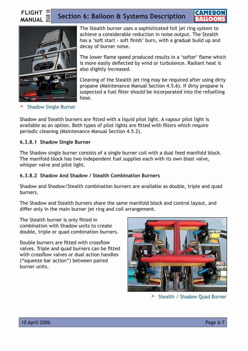
FLIGHT MANUAL ISS
UE 10
Page 6-710 April 2006
Section 6: Balloon & Systems Description
The Stealth burner uses a sophisticated foil jet ring system to achieve a considerable reduction in noise output. The Stealth has a ‘soft start - soft finish’ burn, with a gradual build up and decay of burner noise.
The lower flame speed produced results in a ‘softer’ flame which is more easily deflected by wind or turbulence. Radiant heat is also slightly increased.
Cleaning of the Stealth jet ring may be required after using dirty propane (Maintenance Manual Section 4.5.6). If dirty propane is suspected a fuel filter should be incorporated into the refuelling hose.
Shadow and Stealth burners are fitted with a liquid pilot light. A vapour pilot light is available as an option. Both types of pilot lights are fitted with filters which require periodic cleaning (Maintenance Manual Section 4.5.2).
6.3.8.1 Shadow Single Burner
The Shadow single burner consists of a single burner coil with a dual feed manifold block. The manifold block has two independent fuel supplies each with its own blast valve, whisper valve and pilot light.
6.3.8.2 Shadow And Shadow / Stealth Combination Burners
Shadow and Shadow/Stealth combination burners are available as double, triple and quad burners.
The Shadow and Stealth burners share the same manifold block and control layout, and differ only in the main burner jet ring and coil arrangement.
The Stealth burner is only fitted in combination with Shadow units to create double, triple or quad combination burners.
Double burners are fitted with crossflow valves. Triple and quad burners can be fitted with crossflow valves or dual action handles (“squeeze bar action”) between paired burner units.
5 Shadow Single Burner
5 Stealth / Shadow Quad Burner

FLIGHT MANUALISS
UE 10
Amendment 16Page 6-8 14 March 2018
Section 6: Balloon & Systems Description
6.3.9 Stratus Burner
The Stratus Burner is available as a single, double, triple or quad burner.
The main burners are fitted with squeeze action blast valves which are operated by squeezing the control lever towards the hand grip. Each handle has a latch fitted on its underside to allow the valve to be locked on in an emergency (Section 3.11). The blast valve handles are arranged so that pairs of burners be operated simultaneously with one hand.
The Whisper burner is operated by a toggle valve, which may be rotated to give a convenient operating position.
The Stratus burner is fitted with a liquid pilot light. A vapour pilot light is available as an option. Both types of pilot lights are fitted with filters which require periodic cleaning (Maintenance Manual Section 4.7.2).
6.3.9.1 Stratus Single Burner
The Stratus single burner has two independent fuel supplies. Each fuel supply feeds a pilot and whisper burners. One main blast valve is fitted and its fuel supply is denoted by a red arrow on the block. The Stratus single burner has two igniters.
6.3.9.2 Stratus Double, Triple And Quad Burners
Triple and quad burners can be fitted with crossflow valves between adjacent burners. When a crossflow valve is open, two burners can be operated from one burner valve. This enables all the burners to be operated with one hand.
6.3.10 Paragraph Deleted
5 Stratus Control Layout
Pilot Light Igniter Button
Pilot Light Valve
Whisper Valve
PressureGauge
Blast Valve Latch
Blast Valve
(Under)
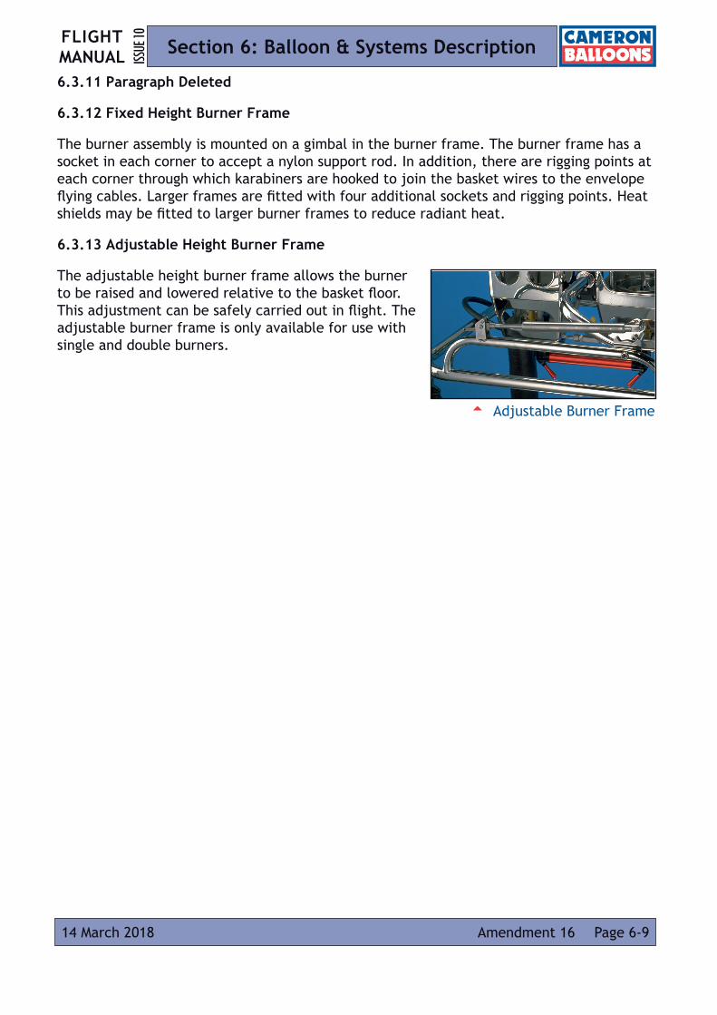
FLIGHT MANUAL ISS
UE 10
Page 6-914 March 2018 Amendment 16
Section 6: Balloon & Systems Description
6.3.11 Paragraph Deleted
6.3.12 Fixed Height Burner Frame
The burner assembly is mounted on a gimbal in the burner frame. The burner frame has a socket in each corner to accept a nylon support rod. In addition, there are rigging points at each corner through which karabiners are hooked to join the basket wires to the envelope flying cables. Larger frames are fitted with four additional sockets and rigging points. Heat shields may be fitted to larger burner frames to reduce radiant heat.
6.3.13 Adjustable Height Burner Frame
The adjustable height burner frame allows the burner to be raised and lowered relative to the basket floor. This adjustment can be safely carried out in flight. The adjustable burner frame is only available for use with single and double burners.
5 Adjustable Burner Frame
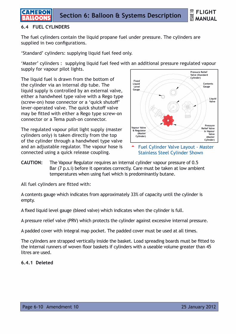
FLIGHT MANUALISS
UE 10
Amendment 10Page 6-10 25 January 2012
Section 6: Balloon & Systems Description
6.4 FUEL CYLINDERS
The fuel cylinders contain the liquid propane fuel under pressure. The cylinders are supplied in two configurations.
‘Standard’ cylinders: supplying liquid fuel feed only.
‘Master’ cylinders : supplying liquid fuel feed with an additional pressure regulated vapour supply for vapour pilot lights.
The liquid fuel is drawn from the bottom of the cylinder via an internal dip tube. The liquid supply is controlled by an external valve, either a handwheel type valve with a Rego type (screw-on) hose connector or a ‘quick shutoff’ lever-operated valve. The quick shutoff valve may be fitted with either a Rego type screw-on connector or a Tema push-on connector.
The regulated vapour pilot light supply (master cylinders only) is taken directly from the top of the cylinder through a handwheel type valve and an adjustable regulator. The vapour hose is connected using a quick release coupling.
CAUTION: The Vapour Regulator requires an internal cylinder vapour pressure of 0.5 Bar (7 p.s.i) before it operates correctly. Care must be taken at low ambient temperatures when using fuel which is predominantly butane.
All fuel cylinders are fitted with:
A contents gauge which indicates from approximately 33% of capacity until the cylinder is empty.
A fixed liquid level gauge (bleed valve) which indicates when the cylinder is full.
A pressure relief valve (PRV) which protects the cylinder against excessive internal pressure.
A padded cover with integral map pocket. The padded cover must be used at all times.
The cylinders are strapped vertically inside the basket. Load spreading boards must be fitted to the internal runners of woven floor baskets if cylinders with a useable volume greater than 45 litres are used.
6.4.1 Deleted
5 Fuel Cylinder Valve Layout - Master Stainless Steel Cylinder Shown
Pressure Relief Valve (Standard Cylinder)
Fixed Liquid Level
Gauge
Contents Gauge
Liquid Valve
Vapour Valve & Regulator
(Master Cylinder)
Pressure Relief Valve
In Vapour Valve
(Master Cylinder)

FLIGHT MANUAL ISS
UE 10
Amendment 10 Page 6-1125 January 2012
Section 6: Balloon & Systems Description
6.4.2 Cameron Duplex Stainless Steel Fuel Cylinders
A range of duplex stainless steel cylinders is available. These have usable volumes of between 45 and 72 litres. Cameron duplex stainless steel fuel cylinders have curved dip tubes.
6.4.3 Deleted
6.4.4 Mini Vapour Cylinder
The Mini Vapour Cylinder is a 5 litre Worthington aluminium fuel cylinder, fitted with a vapour outlet, pressure regulator and connections for two pilot light hoses.
Use of a Mini Vapour Cylinder allows the main master cylinders to be pressurised with nitrogen (N2) or carbon dioxide (CO2) to increase burner power in cold conditions, or in cases of low gas pressure (e.g. when using butane).
6.4.5 Fuel Manifolds
Approved fuel manifolds may be used to join the outlets of several fuel cylinders to one burner fuel hose.
WARNING: Accidents have been caused by the use of non-approved fuel manifolds In particular it is important that rigid refuelling adapters are not used to allow the combination of Rego outlet cylinders with Tema connectors or vice-versa.

FLIGHT MANUALISS
UE 10
Page 6-12 10 April 2006
Section 6: Balloon & Systems Description
6.5 BASKET
Baskets are of traditional wickerwork construction. The basket floors are either woven or solid plywood. The structural load is taken by stainless steel wires forming a continuous sling from the burner frame underneath the basket floor.
The baskets are strengthened by aluminium ‘U’-tubes or a stainless steel frame.
The top of the basket is padded with foam, which is then trimmed with leather or suede. The bottom edge is covered with rawhide which protects the basket from damage during landings and transit. Openings are woven into the basket for cylinders straps and step holes.
The basket cables, burner support rods and fuel hoses are contained within zip-up padded covers.
Side or end wall cushions and cushion floors may be added inside the basket to increase the levels of passenger comfort.
A fire extinguisher must be fitted inside the basket.
6.5.1 Concept Basket
The Concept basket is available in two sizes to match the Concept 60 - 70 and 80 - 100 envelopes. The baskets are of lightweight construction and have a flat top.
6.5.2 Aristocrat And Classic Baskets
The Aristocrat and Classic ranges of baskets carry between one and six occupants. The baskets are usually made with the top of the basket upswept at each end but flat top baskets can be specified.
6.5.3 Partitioned Baskets
Larger baskets have internal partitions woven into the walls and floor of the basket. These partitions provide greater structural integrity and separation between groups of passengers The pilot and fuel cylinders occupy a separate compartment from the passengers.
Larger partitioned baskets use two rigging points on each corner of the load frame for increased strength. The largest partitioned baskets have provision for eight burner support rods, each with its own rigging points.
5 Aristocrat Basket

FLIGHT MANUAL ISS
UE 10
Amendment 15 Page 6-1307 July 2017
Section 6: Balloon & Systems Description
Padded hose covers can be used to bring fuel hoses from the centre of the burner frame to the centre of the pilot compartment.
Turning vents should be fitted to envelopes used with partitioned baskets. This allows the basket to be rotated so that the long side faces the direction of travel during landing.
6.5.4 Pilot Restraint Harness
The pilot restraint harness prevents the pilot being thrown from the basket during landing.
The harness is a waist belt fitted with a buckle which will allow rapid release in an emergency. A strap of adjustable length is clipped to a metal D-ring on the belt and an anchor point on or near the floor of the basket.
A pouch is fitted to the wall of the basket to store the belt and strap when not in use.
6.5.5 Passenger Positioning Blocks
Passenger positioning blocks assist passengers to achieve and maintain the proper landing position by preventing the passengers from over-bending their knees or squatting down on their heels.
The blocks are made from foam with a fabric outer cover and are laced or attached with Velcro to the leading edge of the passenger compartments of partioned blocks.
6.5.6 Quick Release
The quick release is designed to restrain the balloon during inflation and heating up for take-off, but must not be used for tethered flight. A locking pin or collar is fitted to prevent accidental release.
Use of the quick release is recommended to ensure that the balloon does not drag during inflation or leave the ground prematurely.
NOTE: Care should be taken to protect all webbing and rope items from the effects of sunlight. Ultraviolet radiation causes degradation of the rope or webbing, considerably reducing its strength. This applies especially to the launch restraint and equipment for tethered flight. Regular checks should be made to the launch restraint and equipment for tethered flight for wear and loss of strength.
5 Double ‘T’ Partition Basket

FLIGHT MANUALISS
UE 10
Page 6-14 07 July 2017Amendment 15
Section 6: Balloon & Systems Description
6.6 FLIGHT INSTRUMENTS
Flight instruments used in ballooning are an altimeter (for altitude measurement), a variometer (to display climb and descent rate), a time piece (to record flight times, sunset times etc.) and an envelope temperature gauge (to indicate envelope internal temperature).

FLIGHT MANUAL ISS
UE 10
Page 7-117 December 2007 Amendment 1
Section 7: Balloon Maintenance, Handling & Care
7.1 INTRODUCTION
This Section contains the recommended procedures for proper ground handling and servicing of the balloon.
7.2 INSPECTION PERIODS
Details of the required inspection periods are given in Cameron Balloons Maintenance Manual Issue 10, Section 6.
7.3 ALTERATIONS OR REPAIRS
It is essential that the responsible airworthiness authority is contacted prior to any alterations being made to the balloon to ensure that the airworthiness of the balloon is not compromised. For repair procedures, reference should be made to Cameron Balloons Maintenance Manual Issue 10.
7.4 TRANSPORTATION
The following Sections apply to road transportation. If the balloon is to be transported by rail, sea or air, the operator of the service should be contacted prior to travel to find out what requirements they have in respect of fans, propane cylinders etc. Extra protection may be required when shipping by these methods.
7.4.1 Envelope
When the balloon is to be transported, the envelope must be carried in its storage bag, and should be protected from weather.
7.4.2 Burners
The burners must be vented of propane, and the fuel hoses disconnected from the cylinders before transport.
The burners should not be rigged to the basket. Transporting a basket and burner in this manner leads to greatly increased wear to the structure, and there is a chance of the burner striking low bridges.
Burners fitted with a crossflow valve should be transported with the crossflow valve in the open position.

FLIGHT MANUALISS
UE 10
Page 7-2 17 December 2007Amendment 1
Section 7: Balloon Maintenance, Handling & Care
Sirocco, Shadow and Stealth burners are fitted with ‘squeeze action’ valve controls mounted below the hand grip. The burner should be transported and stored with the control lever moved through approximately 150º so that it is parallel with the hand grip.
Burners with liquid pilot lights should be transported and stored with the burner vertical and coils uppermost, to prevent any ‘heavy ends’ in the fuel interfering with the liquid pilot light regulator.
7.4.3 Cylinders
Fuel cylinders must only be transported or stored vertically with the valves uppermost, as the pressure relief valves are designed to vent only vapour.
The cylinders must be firmly secured inside the basket or other form of protection within the transportation unit.
Cylinders which have been pressurised with nitrogen must be checked to ensure the internal vapour pressure is not greater than 7 bar (100 psi) prior to transportation.
If the cylinder pressure exceeds 7 bar, the cylinder must be vented (Section 4.14) until the cylinder pressure is below 7 bar.
7.4.4 Baskets
WARNING: Great care must be taken when transporting solid floor baskets to ensure that damage is not caused to the wires on the underside of the basket floor. If damage is evident or suspected, the wires must be inspected as per Cameron Balloons Maintenance Manual Issue 10 Section 6.17.4 before flight.
Baskets should be protected from the elements during transportation by use of a suitable cover.
When using ratchet straps to secure baskets to trailers, care must be taken not to over tighten these straps as permanent distortion to the basket can occur (especially when the basket is new or wet).
Baskets can be loaded longitudinally or transversely. Solid floor baskets must not be loaded or unloaded over the side of a vehicle or trailer unless wire protectors (CB 3351) are fitted. This is due to the high risk of wire damage from the edge of the vehicle or trailer. Before loading, check that all these protectors are in place and secure. Woven floor baskets must be protected from areas of the trailer that could cause damage to the wires or wicker. If the basket is to be winched lengthways onto a vehicle or trailer, only approved basket towing plates and bridles should be used. The winch cable must not be attached to the rope handles, or any other part of the basket, or serious damage could be caused to the basket structure.

FLIGHT MANUAL ISS
UE 10
Amendment 1 Page 7-317 December 2007
Section 7: Balloon Maintenance, Handling & Care
When unloading baskets from trailers, great care must be taken not to drop the basket onto the ground without cushioning the impact (especially larger baskets with full fuel cylinders) as damage to the structure can occur.
7.5 STORAGE
The balloon should be stored in a clean dry place.
The envelope should not be stored damp or wet for more than a few days, as residual moisture can result in fabric deterioration due to mould or mildew. A wet envelope should be gently dried by keeping it cold inflated with a fan, rolling the envelope over if necessary. Hot inflating a wet envelope may cause damage to the fabric.
The basket should not be stored wet or with a covering of mud, as this will trap moisture next to the hide and wicker, leading to deterioration of the basket. The basket should be cleaned using fresh water and allowed to dry. If the basket is secured to a trailer using ratchet straps during storage, the straps should be loosened to prevent any permanent distortion.
Salt contamination of any part of the balloon and its equipment must be avoided. If any of the balloon’s components become contaminated with sea water they should be washed with plenty of fresh water. Salt will cause corrosion in metal components (including stainless steel), accelerate decay in wickerwork, and adversely affect the envelope fabric and tapes.
For full cleaning instructions, reference should be made to Cameron Balloons Maintenance Manual Issue 10.
Cylinders must be stored in a well-ventilated area with no sources of ignition or excessive heat. Cylinders must not be stored near drains or cellars, where any leaked propane could collect.
Intentionally Blank Page
FLIGHT MANUALISS
UE 10
Page 7-4 17 December 2007Amendment 1
Section 7: Balloon Maintenance, Handling & Care

FLIGHT MANUAL ISS
UE 10
Amendment 5 Page 8-131 July 2008
Section 8: Supplements
8.1 INTRODUCTION
This Section contains the appropriate supplements and additional approved data necessary to safely and efficiently operate the balloon when equipped with various optional systems and equipment not included in the main manual.
The balloon shall be operated in accordance with the applicable supplement and/or additional approved data when appropriate, but the content of the base Flight Manual will also apply.
Where a conflict arises between the information given in a Supplement and/or additional approved data and the information given in the base Flight Manual, the information given in a supplement takes precedence.
A complete list of Supplements is available on the Cameron Balloons Limited website.
NOTE: Supplements are updated independently of the base flight manual. It is not necessary to update supplements issued with a specific balloon unless notified by Service Bulletin.
8.2 LIST OF SUPPLEMENTS INSERTED
Date ofInsertion
Doc. Ref Description
Signed Name Date
Authority
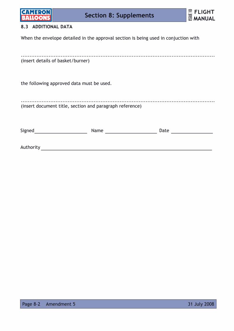
FLIGHT MANUALISS
UE 10
Amendment 5Page 8-2 31 July 2008
Section 8: Supplements
8.3 ADDITIONAL DATA
When the envelope detailed in the approval section is being used in conjuction with
................................................................................................................(insert details of basket/burner)
the following approved data must be used.
................................................................................................................(insert document title, section and paragraph reference)
Signed Name Date
Authority

FLIGHT MANUAL ISS
UE 10
Amendment 13 Page 9-110 February 2016
Section 9: Equipment List
9.1 INTRODUCTION
This Section lists the major components which may be combined with each envelope to make a complete balloon. Additional equipment, not requiring approval, is listed in Section 9.3.
9.1.1 Burner Frame Compatability
Table 6 lists the compatible burner load frames for each basket type. The burner load frames are divided into two categories:
Applicable Burner Frames (specific): These are frames design specifically to fit a given basket type.
Applicable Burner Frames (with Assembly check):
These are structurally and dimensionally similar frames which have been designed for similar baskets that incorporate minor design changes (e.g. additional restraint lugs, offset crossbar, changed rod socket angles etc.). These frames may only be combined with the listed basket after an assembly check by a competent person (normally an inspector).
9.2 EQUIPMENT LIST
Tables 5, 6, 7 and 8 list the envelopes, baskets, fuel cylinders, burners and burner frames which are compatible.
Table 5: EnvelopesEnvelope
TypeDrawing Number
ApplicableBurners
ApplicableBaskets
A-105 CB115 B B, C, D, E, F, G, H, I, J, KA-120 CB617 B C, D, E, F, G, H, I, J, K, LA-140 CB105 B D, E, F, G, H, I, J, K, L, MA-160 CB653 B, C D, E, F, G, H, I, J, K, L, M, NA-180 CB692 B, C, D E, F, G, H, I, J, K, L, M, N, OA-200 CB1199 B, C, D G, H, I, J, K, L, M, N, O, P, QA-210 CB199 B, C, D G, H, I, J, K, L, M, N, O, P, QA-225 CB1618 B, C, D G, H, I, J, K, L, M, N, O, P, QA-250 CB463 C, D H, I, J, K, L, M, N, O, P, QA-275 CB1147 C, D I, J, K, L, M, N, O, P, QA-300 CB603 C, D K, L, M, N, O, P, QA-315 CB1028 C, D K, L, M, N, O, P, QA-340 CB1166 D L, M, N, O, P, Q
A-340HL CB1148 D L, M, N, O, P, QA-375 CB761 D M, N, O, P, QA-400 CB1248 D N, O, P, QA-415 CB1311 D N, O, P, Q
A-425LW CB1716 D N, O, P, QA-450LW CB1626 D P, Q, RA-500LW CB1725 D P, Q, RA-530LW CB1672 D P, Q, R
A-530 CB197 D O, P, Q

FLIGHT MANUALISS
UE 10
Page 9-2 14 March 2018Amendment 16
Section 9: Equipment List
Table 5: Envelopes (continued)
EnvelopeType
Drawing Number
ApplicableBurners
ApplicableBaskets
C-50 CB1611 A, B A, B, C, DC-60 CB996 A, B A, B, C, D, E, F, GC-70 CB1256 A, B A, B, C, D, E, F, G, HC-80 CB1025 A, B A, B, C, D, E, F, G, H, IC-90 CB1460 A, B A, B, C, D, E, F, G, H, I, JC-100 CB1048 A, B B, C, D, E, F, G, H, I, J, K
N-31 CB476 A A, B, C, DN-42 CB476 A A, B, C, D, EN-56 CB476 A, B A, B, C, D, E, F, GN-65 CB476 A, B A, B, C, D, E, F, G, HN-70 CB476 A, B A, B, C, D, E, F, G, HN-77 CB476 A, B A, B, C, D, E, F, G, H, IN-90 CB476 A, B A, B, C, D, E, F, G, H, I, JN-100 CB476 A, B B, C, D, E, F, G, H, I, J, KN-105 CB476 B B, C, D, E, F, G, H, I, J, KN-120 CB476 B C, D, E, F, G, H, I, J, K, LN-133 CB476 B C, D, E, F, G, H, I, J, K, LN-145 CB476 B, C D, E, F, G, H, I, J, K, L, MN-160 CB476 B, C E, F, G, H, I, J, K, L, M, NN-180 CB476 B, C, D E, F, G, H, I, J, K, L, M, N, ON-210 CB476 B, C, D G, H, I, J, K, L, M, N, O, P, Q
O-26 CB1752 A A,B,CO-31 CB110 A A, B, C, DO-42 CB101 A A, B, C, D, EO-56 CB45 A, B A, B, C, D, E, F, GO-65 CB54 A, B A, B, C, D, E, F, G, HO-77 CB112 A, B A, B, C, D, E, F, G, H, IO-84 CB49 A, B A, B, C, D, E, F, G, H, IO-90 CB658 A, B A, B, C, D, E, F, G, H, I, JO-105 CB167 B B, C, D, E, F, G, H, I, J, KO-120 CB505 B C, D, E, F, G, H, I, J, K, LO-140 CB772 B, C D, E, F, G, H, I, J, K, L, MO-160 CB368 B, C D, E, F, G, H, I, J, K, L, M, N
Sport-50 CB1759 A, B A, B, C, DSport-60 CB1755 A, B A, B, C, D, ESport-70 CB1756 A, B B, C, D, E, FSport-80 CB1757 A, B B, C, D, E, FSport-90 CB1758 A, B B, C, D, E, F
TR-60 CB1520 A, B A, B, C, D, E, FTR-65 CB1749 A, B A, B, C, D, E, FTR-70 CB1519 A, B A, B, C, D, E, FTR-77 CB1591 A, B A, B, C, D, E, FTR-84 CB1612 A, B A, B, C, D, E, F

FLIGHT MANUAL ISS
UE 10
Amendment 16 Page 9-314 March 2018
Section 9: Equipment List
Table 5: Envelopes (continued)
EnvelopeType
Drawing Number
ApplicableBurners
ApplicableBaskets
Z-25 CB1461 A A, B, CZ-31 CB1462 A A, B, C, DZ-35 CB-1619 A A, B, C, DZ-42 CB1463 A A, B, C, D, EZ-56 CB1464 A, B A, B, C, D, E, F, GZ-65 CB1346 A, B A, B, C, D, E, F, G, HZ-69 CB1465 A, B A, B, C, D, E, F, G, HZ-77 CB1342 A, B A, B, C, D, E, F, G, H, IZ-90 CB1340 A, B A, B, C, D, E, F, G, H, I, JZ-105 CB1345 B B, C, D, E, F, G, H, I, J, KZ-120 CB1348 B C, D, E, F, G, H, I, J, K, LZ-133 CB1349 B C, D, E, F, G, H, I, J, K, LZ-140 CB1477 B, C D, E, F, G, H, I, J, K, L, MZ-145 CB1350 B, C D, E, F, G, H, I, J, K, L, MZ-150 CB1473 B, C D, E, F, G, H, I, J, K, L, MZ-160 CB1351 B, C D, E, F, G, H, I, J, K, L, M, NZ-180 CB1352 B, C, D E, F, G, H, I, J, K, L, M, N, OZ-210 CB1353 B, C, D G, H, I, J, K, L, M, N, O, P, QZ-225 CB1466 C, D G, H, I, J, K, L, M, N, O, P, QZ-250 CB1459 C, D H, I, J, K, L, M, N, O, P, QZ-275 CB1467 C, D I, J, K, L, M, N, O, P, QZ-315 CB1468 C, D K, L, M, N, O, P, QZ-350 CB1469 D L, M, N, O, P, QZ-375 CB1470 D M, N, O, P, QZ-400 CB1471 D N, O, P, Q
Z-425LW CB1502 D N, O, P, QZ-450 CB1472 D N, O, P, QZ-600 CB1565 D RZ-750 CB1663 D R
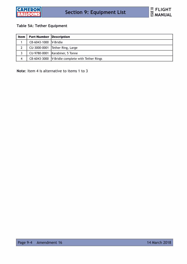
FLIGHT MANUALISS
UE 10
Page 9-4 14 March 2018Amendment 16
Section 9: Equipment List
Table 5A: Tether Equipment
Note: Item 4 is alternative to items 1 to 3
Item Part Number Description
1 CB-6043-1000 V-Bridle
2 CU-3000-0001 Tether Ring, Large
3 CU-9780-0001 Karabiner, 5 Tonne
4 CB-6043-3000 V-Bridle complete with Tether Rings

FLIGHT MANUAL ISS
UE 10
Amendment 13 Page 9-510 February 2016
Section 9: Equipment List
Table 6: Baskets
* For key see page 9-6
Basket Cat.
Drawing Number
Basket Description*
Applicable Cylinders
Applicable Burner Frames(specific)
Applicable Burner Frames(with Assembly check)
B CB3037 LITE 1a, 1, 2 CB2118, CB2355, CB2356
B CB310-1A 31-42 O 1a, 1, 2 CB855, CB871, CB925, CB2203(Fl), CB2224(Fl), CB2231(Fl), CB2598, CB2874
C CB300-2A
56-65 O
1a, 1, 2, 3CB855, CB871, CB925, CB2203(Fl),
CB2224(Fl), CB2231(Fl), CB2598 (Fl), CB2643, CB2665, CB2857(Fl), CB2874
CB2203, CB2224, CB2231, CB2598, CB2650, CB2652, CB2857, CB2995, CB8810,CB8810, CB8811, CB8820, CB8821, CB8864,CB8894, CB8902,
CB8903, CB8905, Concept (CB994,CB2000),
BA-152-A-002 (LBL)**
C CB310-2A
C CB3050-2
C CB3115-2
C CB3011-2A
56-65 OHC CB3023-2
C CB3011-2B
C CB3051 C60/70 O 1a, 1, 2, 3
CB855, CB871, CB925, CB2203, CB2224, CB2231, CB2598, CB2665, CB2860,
CB2863, CB2874, CQ2018***, CQ2028
CB2643, CB2650, CB2652, CB2665, CB2857, CB2874, CB8810, CB8811, CB8820, CB8821, CB8864,CB8894,
CB8902, CB8903, CB8905
D CB300-3A
77-84 O 1a, 1, 2, 3D CB310-3A
D CB3050-3
D CB3115-3
D CB3011-3A
77-84 OH 1a, 1, 2, 3D CB3023-3
D CB3011-3B
D CB3052 C80/90 O 1a, 1, 2, 3
D CB800165-77 O 1a, 1, 2, 3
CB855, CB871, CB925, CB8810, CB8811, CB8820, CB8821, CB8894, CB8902,
CB8903, CB8905, CB8912
CB2203, CB2224, CB2231, CB2598,CB2650, CB2652, CB2857, CB2995, Concept (CB994,CB2000),
BA-152-A-002 (LBL)**
D CB8012
D CB800665-77 OH 1a, 1, 2, 3
D CB8017
D CB800277-90 O 1a, 1, 2, 3
D CB8013
D CB800777-90 OH 1a, 1, 2, 3
D CB8018
E CB300-4A
90-105 O 1a, 1, 2, 3CB855, CB871, CB925, CB2203, CB2224,
CB2231, CB2598, CB2665, CB2874, CQ2027
CB2203, CB2224, CB2231, CB2598,CB2650, CB2652, CB2857, CB2995, Concept (CB994,CB2000),
BA-152-A-002 (LBL)**
E CB310-4A
E CB3050-4
E CB3115-4
E CB3011-4A
90-105 OH 1a, 1, 2, 3E CB3023-4
E CB3011-4B
E CB800390-105 O 1a, 1, 2, 3 CB8810, CB8811, CB8820, CB8821,
CB8894, CB8902, CB8903, CB8905, CB8912
CB2203, CB2224, CB2231, CB2598,CB2650, CB2652, CB2857, CB2995, Concept (CB994,CB2000),
BA-152-A-002 (LBL)**
E CB8014
E CB800890-105 OH 1a, 1, 2, 3
E CB8019
F CB8004105-120 O 1a, 1, 2, 3
CB8822, CB8823, CB8824, CB8825, CB8830, CB8831, CB8846
F CB8013
F CB8009105-120 OH 1a, 1, 2, 3
F CB8020
F CB8200 105-120 T 1a, 1, 2, 3
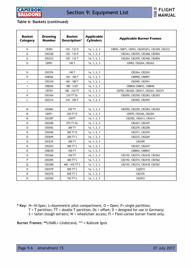
FLIGHT MANUALISS
UE 10
Page 9-6 07 July 2017Amendment 15
Section 9: Equipment List
Table 6: Baskets (continued)
* Key: H= Hi-Spec; L=Asymmetric pilot compartment; O = Open; P= single partition; T = T partition; TT = double T partition; Os = offset; D = designed for use in Germany; S = Safari (tough terrain); W = wheelchair access; Fl = Flexi-corner burner frame only.
Burner Frames: **LHABL= Lindstrand, *** = Kubicek Ignis
Basket Category
DrawingNumber
Basket Description*
Applicable Cylinders
Applicable Burner Frames
G CB303 120 - 133 O 1a, 1, 2, 3 CB855, CB871, CB925, CB2203(Fl), CB2309, CB2312
G CB3238 120 - 133 P 1a, 1, 2, 3 CB2264, CB2470, CB2468, CB2856
G CB3233 120 - 133 T 1a, 1, 2, 3 CB2264, CB2470, CB2468, CB2856
H CB991 140 T 1a, 1, 2, 3 CB983, CB2264, CB2263
H CB3376 140 T 1a, 1, 2, 3 CB2264, CB2263
H CB8266 120 - 160 T 1a, 1, 2, 3 CB8900, CB8901
I CB3310 160 - 180 T 1a, 1, 2, 3 CB2590, CB2591
I CB8206 180 - 210T 1a, 1, 2, 3 CB8826 CB8832, CB8840
J CB754 180 - 210 TT 1a, 1, 2, 3 CB750, CB2420, CB2411, CB2261, CB2371
K CB3164 210 TT Os 1a, 1, 2, 3 CB2050, CB2250, CB2283, CB2303
L CB3314 210 - 250 T 1a, 1, 2, 3 CB2505, CB2592
M CB3004 250 TT 1a, 1, 2, 3 CB2050, CB2250, CB2283, CB2303
M CB971 250 TT D 1a, 1, 2, 3 CB970, CB2260, CB2304
M CB3387 250TT 1a, 1, 2, 3 CB2282, CB2613, CB2614
N CB3200 275 TT Os 1a, 1, 2, 3 CB2427, CB2447
O CB3042 300 TT 1a, 1, 2, 3 CB2270, CB2258
O CB3040 300 TT D 1a, 1, 2, 3 CB2271, CB2259
O CB3049 300 TT S 1a, 1, 2, 3 CB2272, CB2269
O CB3235 300 TT 1a, 1, 2, 3 CB2390
O CB3223 300 TT S 1a, 1, 2, 3 CB2427, CB2447
O CB8250 350 TT 1a, 1, 2, 3 CB8842, CB8843
O CB3360 350 TT 1a, 1, 2, 3 CB2192, CB2274, CB2418, CB2562
P CB3205 400 TT S 1a, 1, 2, 3 CB2192, CB2274, CB2418, CB2562
Q CB3288 400 - 410 TT S 1a, 1, 2, 3 CB2192, CB2274, CB2418, CB2562
R CB3570 500 TT S 1a, 1, 2, 3 CQ2015
R CB3370 600 TT S 1a, 1, 2, 3 CB2376
R CB3550 750 TT S 1a, 1, 2, 3 CB2953

FLIGHT MANUAL ISS
UE 10
Amendment 16 Page 9-714 March 2018
Section 9: Equipment List
Table 7: Fuel Cylinders
Table 8: Burners
Shadow and Stealth burners have their pilot light configuration denoted, with the following drawing numbers being appended with -1 for vapour, -2 for liquid or -3 for mixed vapour and liquid.
CylinderCategory
Drawing Number
Cylinder Material Cylinder Description
1a CB901 ALUMINIUM MINI WORTHINGTON2 CB2900 DUPLEX STAINLESS STEEL 452 CB2901 DUPLEX STAINLESS STEEL 603 CB2902 DUPLEX STAINLESS STEEL 543 CB2903 DUPLEX STAINLESS STEEL 72

FLIGHT MANUALISS
UE 10
Page 9-8 14 March 2018Amendment 16
Section 9: Equipment List
Table 8: Burners (continued)Burner
CategoryDrawingNumber
BurnerDescription
A CB2245 Single Shadow, Fixed FrameA CB2246 Single Shadow, Adjustable Height Frame
A CB2233 Single Shadow Mini, Fixed Frame
A CB8710 Single Stratus, Liquid Pilot LightA CB8712 Single Stratus, Vapour Pilot LightB CB2222 Double Shadow, Fixed Frame
B CB2215 Double Shadow, Adjustable Height FrameB CB2243 Double Shadow / Stealth, Fixed Frame
B CB2244 Double Shadow / Stealth, Adjustable Height Frame
B CB8720 Double Stratus, Liquid Pilot LightB CB8721 Double Stratus, Vapour Pilot LightC CB2255 Triple ShadowC CB2424 Triple Shadow, Crossflow to Single BurnerC CB2520 Triple Shadow, Squeeze Bar Action, with Crossflow C CB2301 Triple Stealth (double) / Shadow (single)C CB2289 Triple Shadow (double) / Stealth (single)C CB2446 Triple Shadow / Stealth (double) ‘ Shadow (single)C CB2459 Triple Stealth (double) / Shadow (single), Squeeze bar ActionC CB2467 Triple Shadow (double) / Stealth (single), Squeeze bar ActionC CB2469 Triple Shadow / Stealth (double) / Shadow (single), Squeeze bar Action
C CB2941 Triple Shadow (double) / Stealth (single), Squeeze bar Action
C CB8730 Triple Stratus, Liquid Pilot Light. C CB8731 Triple Stratus, Liquid Pilot Light, ‘T’ BasketsC CB8732 Triple Stratus, Liquid Pilot Light, ‘TT’ BasketsC CB8733 Triple Stratus, Vapour Pilot LightC CB8734 Triple Stratus, Vapour Pilot Light, ‘T’ BasketsC CB8735 Triple Stratus, Vapour Pilot Light, ‘TT’ BasketsD CB2256 Quad ShadowD CB2351 Quad Shadow, Dual Squeeze BarD CB2305 Quad Shadow (double) / Stealth (double)D CB2342 Quad Shadow (double) / Stealth (double), Dual Squeeze BarD CB2395 Quad Shadow / Stealth (double) / Shadow / Stealth (double)
D CB8740 Quad Stratus, Liquid Pilot LightD CB8741 Quad Stratus, Liquid Pilot Light, CrossflowD CB8742 Quad Stratus, Vapour Pilot LightD CB8743 Quad Stratus, Vapour Pilot Light, Crossflow
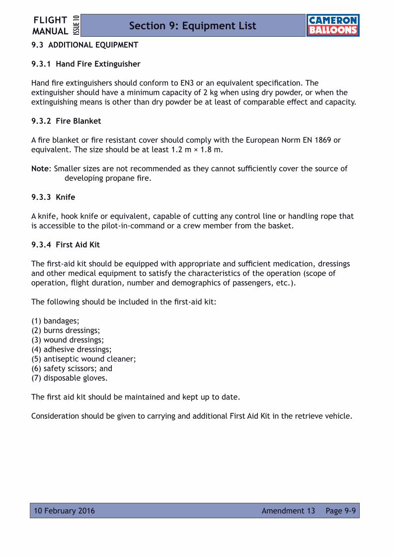
FLIGHT MANUAL ISS
UE 10
Page 9-910 February 2016 Amendment 13
Section 9: Equipment List
9.3 ADDITIONAL EQUIPMENT
9.3.1 Hand Fire Extinguisher
Hand fire extinguishers should conform to EN3 or an equivalent specification. The extinguisher should have a minimum capacity of 2 kg when using dry powder, or when the extinguishing means is other than dry powder be at least of comparable effect and capacity.
9.3.2 Fire Blanket
A fire blanket or fire resistant cover should comply with the European Norm EN 1869 or equivalent. The size should be at least 1.2 m × 1.8 m. Note: Smaller sizes are not recommended as they cannot sufficiently cover the source of developing propane fire.
9.3.3 Knife
A knife, hook knife or equivalent, capable of cutting any control line or handling rope that is accessible to the pilot-in-command or a crew member from the basket.
9.3.4 First Aid Kit
The first-aid kit should be equipped with appropriate and sufficient medication, dressings and other medical equipment to satisfy the characteristics of the operation (scope of operation, flight duration, number and demographics of passengers, etc.). The following should be included in the first-aid kit:
(1) bandages; (2) burns dressings; (3) wound dressings; (4) adhesive dressings; (5) antiseptic wound cleaner; (6) safety scissors; and (7) disposable gloves.
The first aid kit should be maintained and kept up to date.
Consideration should be given to carrying and additional First Aid Kit in the retrieve vehicle.

FLIGHT MANUALISS
UE 10
Amendment 13Page 9-10 10 February 2010
Section 9: Equipment List
9.3.5 Drop Line
The drop line or handling line may be used, by ground crew, to manoeuvre the balloon in light wind conditions. A minimum length of 25 m is recommended. When not in use thedrop line is coiled up in a fabric bag and secured inside the basket.
9.3.6 Accurate Time Piece
A means of measuring and displaying the time in hours, minutes and seconds (e.g. wrist watch).

FLIGHT MANUAL ISS
UE 10
Page A1-110 April 2006
Appendix 1: Notes on Propane Fuel
Propane is a petroleum hydrocarbon, chemical formula C3H8. At normal temperatures and pressures it is a vapour, but it is stored as a liquid under pressure.
Propane is in its pure state colourless and odourless, and is heavier than air (1.5 times as dense). To reduce the risk of a propane leak going undetected a sulphur compound is added to give it a noticeable smell.
The requirements for commercial propane vary from country to country. Propane may contain ‘heavy ends’ which are long-chain hydrocarbons (oils and greases) or water. Special care is required when using commercial cylinders for the supply of propane as these are generally used for vapour supply, allowing heavy ends and water to collect in the bottom of the cylinder. Heavy ends may contaminate the fuel system (especially the vapour side) necessitating stripping and cleaning. Water may freeze in the cylinders and obstruct the liquid fuel flow.
Commercial propane will also contain some amount of butane (C4H10). Butane is also deliberately added to propane, particularly in hot countries, in order to reduce the vapour pressure. Butane has similar properties to propane, differing mainly in its vapour pressure which is substantially lower.
0
20
19
18
17
16
15
14
13
12
11
10
-40° -30° -20° 0° 10° 20° 30° 40°-50° -10° 50°
2
0
1
5
3
4
6
7
8
9
25
50
75
100
125
150
175
200
225
250
275
Bar
Temperature (ºC)
PSI
Propane Vapour Pressure

FLIGHT MANUALISS
UE 10
Page A1-2 10 April 2006
Appendix 1: Notes on Propane Fuel
A small proportion of butane in the fuel is acceptable, provided that the fuel pressure does not drop below the minimum required for flight.
The storage of the fuel under pressure is an advantage as it allows the operation of a very high output burner without a pump, but since burner power is directly related to the fuel pressure, lower burner power is obtained in winter.
Liquid propane expands rapidly with increasing temperature, making it essential to never completely fill a storage cylinder. The fixed liquid level gauge (bleed valve) is set to release liquid when the cylinder is approximately 80% full leaving sufficient vapour space to allow for normal levels of fuel expansion.
Further protection from high temperatures and overfilling is provided by a pressure relief valve in the cylinder. This valve is set to open at approximately 26 bar (375psi).
Large amounts of heat are required to change propane from a liquid to a gas. This is the reason the burner uses liquid fuel, drawn from the bottom of a cylinder via a dip tube. If vapour were drawn off at the high rates required then the cylinder would rapidly cool and lose pressure.
A vapour pilot light draws propane vapour from the top of the cylinder via a pressure regulator. Occasionally when the cylinder is on its side during inflation liquid propane will enter the regulator. The evaporation of propane inside the regulator will cause frost to form on the outside and the regulator may perform erratically or leak slightly.

FLIGHT MANUAL ISS
UE 10
Page A2-131 July 2008 Amendment 5
Appendix 2: Lift Calculations for Balloons
The lift of a hot air balloon at a given flight altitude may be calculated as follows:
where A = maximum planned flight altitude in m Eg = elevation of take-off site above sea level in m L = total lift of the balloon in kg P = air pressure at maximum planned flight altitude in hPa / mB Ta = ambient temperature at flight altitude in °C Tg = ambient temperature at take-off site elevation in °C Ti = average internal envelope temperature in °C (Maximum of 100 °C) V = envelope volume in m3
ISA environmental lapse rate is assumed.

Intentionally Blank Page
FLIGHT MANUALISS
UE 10
Page A2-2 31 July 2008Amendment 5
Appendix 2: Lift Calculations for Balloons
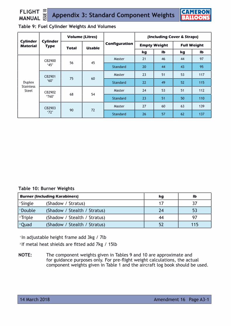
FLIGHT MANUAL ISS
UE 10
Page A3-114 March 2018 Amendment 16
Appendix 3: Standard Component Weights
Table 9: Fuel Cylinder Weights And Volumes
Table 10: Burner Weights
1 In adjustable height frame add 3kg / 7lb 2 If metal heat shields are fitted add 7kg / 15lb
NOTE: The component weights given in Tables 9 and 10 are approximate and for guidance purposes only. For pre-flight weight calculations, the actual component weights given in Table 1 and the aircraft log book should be used.
Burner (Including Karabiners) kg lb
1 Single (Shadow / Stratus) 17 37 1 Double (Shadow / Stealth / Stratus) 24 53 2 Triple (Shadow / Stealth / Stratus) 44 97 2 Quad (Shadow / Stealth / Stratus) 52 115
CylinderMaterial
Cylinder Type
Volume (Litres)
Configuration
(Including Cover & Straps)
Total UsableEmpty Weight Full Weight
kg lb kg lb
DuplexStainless
Steel
CB2900 ‘45’ 56 45
Master 21 46 44 97
Standard 20 44 43 95
CB2901 ‘60’ 75 60
Master 23 51 53 117
Standard 22 49 52 115
CB2902 ‘T60’ 68 54
Master 24 53 51 112
Standard 23 51 50 110
CB2903 ‘72’ 90 72
Master 27 60 63 139
Standard 26 57 62 137

Intentionally Blank Page
FLIGHT MANUALISS
UE 10
Page A3-2 14 March 2018Amendment 16
Appendix 3: Standard Component Weights

FLIGHT MANUAL ISS
UE 10
Page A4-110 April 2006
Appendix 4: Basket Occupancy
Introduction
In addition to the limitations in Section 2 and Section 5, the following factors should be considered when determining how many occupants a particular basket can carry for a particular flight. The guidance below assumes that a standard occupant is an adult of 77kg mass.
The pilot should also take into account the relative masses and sizes of the passengers when loading partitioned baskets to evenly distribute the payload.
Maximum Occupancy
For all baskets, a minimum 0.25m2, floor area should be allowed for each standard occupant.
When calculating the number of occupants, the area used by items of other equipment (e.g. fuel cylinders) must be subtracted from the total area.
For the purposes of these calculations the floor area taken up by single fuel cylinders can be taken as 0.1m2 for “large” diameter cylinders (e.g. CB2901) and 0.09 m2 small diameter cylinders (e.g. CB2900).
Example
If we consider the following example;
Envelope; Z-140,
Basket; CB303,
Double Burner; CB2694,
Fuel for 1 hour flight with reserve; CB2901x2 and CB2900 x1
Limitation on occupancy by floor area;
Floor area of basket (to frame tube centre-lines) = 1.1x1.78 = 1.96 m2
Floor area of equipment = [0.1x2] +0.09 = 0.29 m2
Available floor area for occupants = 1.96 – 0.29 m2 = 1.67 m2
Total maximum number of occupants = 1.67 / 0.25 = 6.68 = 6 standard occupants

Intentionally Blank Page
FLIGHT MANUALISS
UE 10
Page A4-2 10 April 2006
Appendix 4: Basket Occupancy
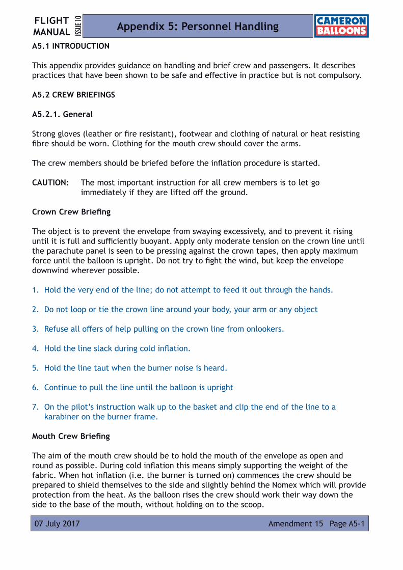
FLIGHT MANUAL ISS
UE 10
Amendment 15 Page A5-107 July 2017
Appendix 5: Personnel Handling
A5.1 INTRODUCTION
This appendix provides guidance on handling and brief crew and passengers. It describes practices that have been shown to be safe and effective in practice but is not compulsory.
A5.2 CREW BRIEFINGS
A5.2.1. General
Strong gloves (leather or fire resistant), footwear and clothing of natural or heat resisting fibre should be worn. Clothing for the mouth crew should cover the arms. The crew members should be briefed before the inflation procedure is started.
CAUTION: The most important instruction for all crew members is to let go immediately if they are lifted off the ground.
Crown Crew Briefing
The object is to prevent the envelope from swaying excessively, and to prevent it rising until it is full and sufficiently buoyant. Apply only moderate tension on the crown line until the parachute panel is seen to be pressing against the crown tapes, then apply maximum force until the balloon is upright. Do not try to fight the wind, but keep the envelope downwind wherever possible.
1. Hold the very end of the line; do not attempt to feed it out through the hands.
2. Do not loop or tie the crown line around your body, your arm or any object
3. Refuse all offers of help pulling on the crown line from onlookers.
4. Hold the line slack during cold inflation.
5. Hold the line taut when the burner noise is heard.
6. Continue to pull the line until the balloon is upright
7. On the pilot’s instruction walk up to the basket and clip the end of the line to a karabiner on the burner frame.
Mouth Crew Briefing
The aim of the mouth crew should be to hold the mouth of the envelope as open and round as possible. During cold inflation this means simply supporting the weight of the fabric. When hot inflation (i.e. the burner is turned on) commences the crew should be prepared to shield themselves to the side and slightly behind the Nomex which will provide protection from the heat. As the balloon rises the crew should work their way down the side to the base of the mouth, without holding on to the scoop.
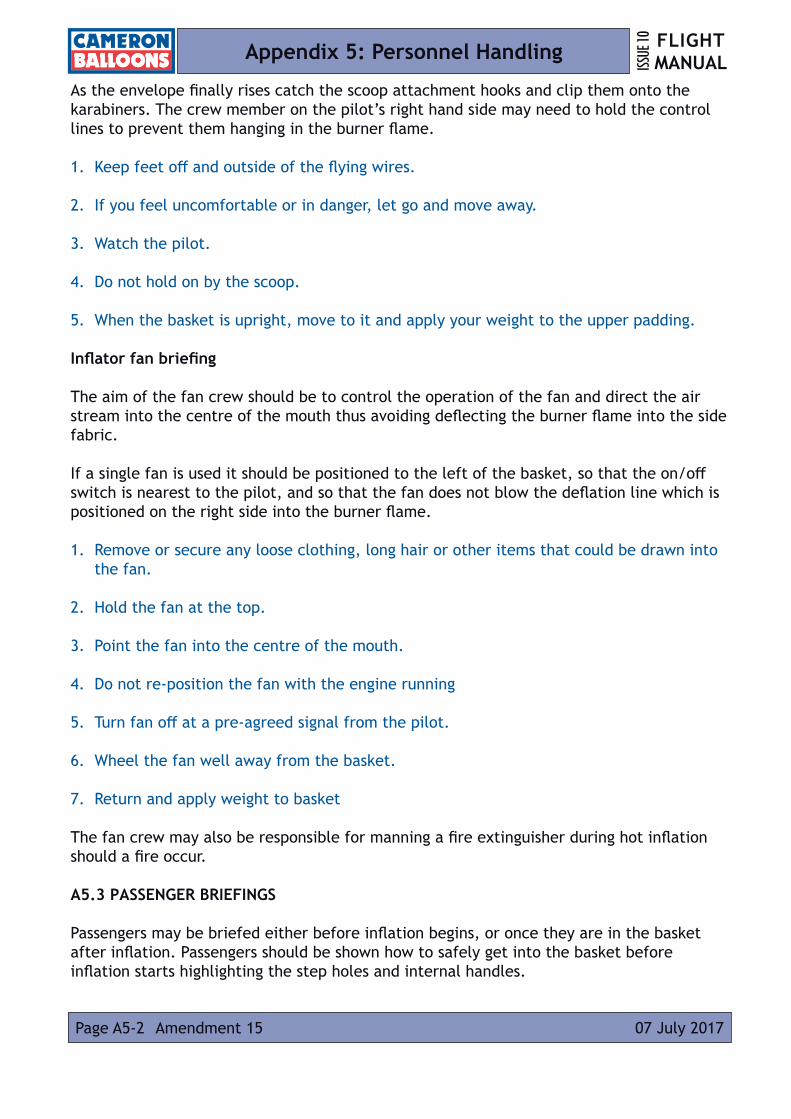
FLIGHT MANUALISS
UE 10
Page A5-2 07 July 2017Amendment 15
Appendix 5: Personnel Handling
As the envelope finally rises catch the scoop attachment hooks and clip them onto the karabiners. The crew member on the pilot’s right hand side may need to hold the control lines to prevent them hanging in the burner flame.
1. Keep feet off and outside of the flying wires.
2. If you feel uncomfortable or in danger, let go and move away.
3. Watch the pilot.
4. Do not hold on by the scoop.
5. When the basket is upright, move to it and apply your weight to the upper padding.
Inflator fan briefing
The aim of the fan crew should be to control the operation of the fan and direct the air stream into the centre of the mouth thus avoiding deflecting the burner flame into the side fabric.
If a single fan is used it should be positioned to the left of the basket, so that the on/off switch is nearest to the pilot, and so that the fan does not blow the deflation line which is positioned on the right side into the burner flame.
1. Remove or secure any loose clothing, long hair or other items that could be drawn into the fan.
2. Hold the fan at the top.
3. Point the fan into the centre of the mouth.
4. Do not re-position the fan with the engine running
5. Turn fan off at a pre-agreed signal from the pilot.
6. Wheel the fan well away from the basket.
7. Return and apply weight to basket
The fan crew may also be responsible for manning a fire extinguisher during hot inflation should a fire occur. A5.3 PASSENGER BRIEFINGS
Passengers may be briefed either before inflation begins, or once they are in the basket after inflation. Passengers should be shown how to safely get into the basket before inflation starts highlighting the step holes and internal handles.
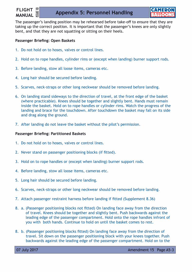
FLIGHT MANUAL ISS
UE 10
Amendment 15 Page A5-307 July 2017
Appendix 5: Personnel Handling
The passenger’s landing position may be rehearsed before take-off to ensure that they are taking up the correct position. It is important that the passenger’s knees are only slightly bent, and that they are not squatting or sitting on their heels. Passenger Briefing: Open Baskets
1. Do not hold on to hoses, valves or control lines.
2. Hold on to rope handles, cylinder rims or (except when landing) burner support rods.
3. Before landing, stow all loose items, cameras etc.
4. Long hair should be secured before landing.
5. Scarves, neck-straps or other long neckwear should be removed before landing.
6. On landing stand sideways to the direction of travel, at the front edge of the basket (where practicable). Knees should be together and slightly bent. Hands must remain inside the basket. Hold on to rope handles or cylinder rims. Watch the progress of the landing and brace for the touchdown. After touchdown the basket may fall on its side and drag along the ground.
7. After landing do not leave the basket without the pilot’s permission.
Passenger Briefing: Partitioned Baskets
1. Do not hold on to hoses, valves or control lines.
2. Never stand on passenger positioning blocks (if fitted).
3. Hold on to rope handles or (except when landing) burner support rods.
4. Before landing, stow all loose items, cameras etc.
5. Long hair should be secured before landing.
6. Scarves, neck-straps or other long neckwear should be removed before landing.
7. Attach passenger restraint harness before landing if fitted (Supplement 8.36)
8. a. (Passenger positioning blocks not fitted) On landing face away from the direction of travel. Knees should be together and slightly bent. Push backwards against the leading edge of the passenger compartment. Hold onto the rope handles infront of you with both hands. Continue to hold on until the basket comes to rest.
8. b. (Passenger positioning blocks fitted) On landing face away from the direction of travel. Sit down on the passenger positioning block with your knees together. Push backwards against the leading edge of the passenger compartment. Hold on to the

FLIGHT MANUALISS
UE 10
Page A5-4 07 July 2017Amendment 15
Appendix 5: Personnel Handling
rope handles in front of you with both hands. Continue to hold on until the basket comes to rest.
9. After landing do not leave the basket without the pilot’s permission.
Passenger Fitness to Fly
The pilot is responsible for the safety of the passengers and deciding whether they are suitable to undertake the flight.
Children and people with infirmities or disabilities should only be flown if they are able to understand and respond to the briefing and other instructions from the pilot, are able to adopt the correct landing position, and to firmly hold onto the internal handles. A useful guide for flying children in a balloon is that they should only be flown if they are tall enough to see over the edge of the basket while standing on its floor and are able to reach the internal handles while in the normal position.
Pilots may be able to achieve an equivalent level of safety for less able passengers by the use of passenger restrains and passenger positioning blocks in partitioned baskets, or by flying in good weather conditions.