Air Conditioning System Installation Manual for 350-00-031 ...
357
Air Conditioning System Installation Manual for 350-00-031-HP ECL Tour 1 Version (Revised: Mar 24, 2016, Rev: K)
-
Upload
khangminh22 -
Category
Documents
-
view
0 -
download
0
Transcript of Air Conditioning System Installation Manual for 350-00-031 ...

Air Conditioning System
Installation Manual
for
350-00-031-HP ECL Tour 1 Version
(Revised: Mar 24, 2016, Rev: K)


RECORD OF REVISIONS
Revision Description Date Revised By
IR Initial Release 8 August 2007 IFS
A Added Basic Configuration 29 June 2008 IFS
A Added New Doublers 29 June 2008 IFS
B Removed Basic Configuration 2 January 2009 IFS
C Updated continued airworthiness 21 August 2009 IFS
D Added AEC Improvements 4 November 2009 IFS
E Revised Compressor Install 5 February 2010 IFS
F Updated Kit List to Rev H 7 February 2013 RSG
G Updated Kit List to Rev L 19 March 2014 RSG
H Formatted to RSG Products. Updated Kit List to Rev M 29 May 2015 RSG
J Updated Section 1, 6, 7, and RFMS’s 2 November 2015 RSG
K Updated Section 1 24 March 2016 RSG

LIST OF EFFECTIVE PAGES
Rev Section Pgs Description Date
C 1 Insert Revised Parts Listing 11/04/09
H 1 Insert Revised Parts List and added MSDS docs. 05/29/15
J 1 Insert Revised Kit Inventory List 11/06/15
K 1 Insert Revised Kit Inventory List 03/24/16
F 2 Insert Revised Kit Inventory List 02/07/13
G 2 Insert Revised Kit Inventory List 03/19/14
IR 2 1-4 Initial Release 08/08/06
IR 3 1-3 Initial Release 08/08/06
IR 4 1-2 Initial Release 08/08/06
A 5 1-5 Added Resistor Mnt Assy Stp. 5.17 09/13/09
H 5 Insert Updated drawings 05/29/15
IR 6 1-5 Initial Release 08/08/06
H 6 Insert Updated drawings 05/29/15
J 6 Insert Update drawing 11/06/15
C 7 1-12 Revised to Tour 1 Only 11/04/09
H 7 Insert Updated drawings 05/29/15
J 7 Insert Updated drawing 11/06/15
A 8 1-5 Revised Instructions 02/05/10
H 8 4 Step 8.9 05/29/15
H 8 Insert Updated drawings 05/29/15
IR 9 1-2 Initial Release 08/08/06
H 9 Insert Updated drawings 05/29/15
IR 10 1-3 Initial Release 08/08/06
H 10 Insert Updated drawings 05/29/15

IR 11 1-2 Initial Release 08/08/06
H 11 2 Updated to RSG 05/29/15
H 11 Insert Updated STC Cover Sheet 05/29/15
H 11 Insert Updated RFMS’s 05/29/15
J 11 Insert Updated RFMS’s 11/06/15
C 12 1-12 Refrigerant charge changed 09/21/09
H 12 Insert Updated ICA 05/29/15
A 13 1-5 Revised Parts List 11/04/09
H 13 1-5 Updated to RSG 05/29/15
C 14 1-6 Warranty Revised 11/04/09
A 15 Insert Troubleshooting Revised 01/29/09

Getting Started The air conditioning system installation instructions are laid out step-by-step starting with one (1) thru nine (9) for installation and ten (10) thru fifteen (15) for care and airworthiness, the instructions are designed to be easy – to – use. The example below is designed to give you a basic overview of how the steps work. Example: A. In the step below there is a number 5.1 The “5” stands for step 5 and the “1” stands for direction 1.
Installation of Aircraft Systems Example: B. When the parts are called out in a step: 5.1, locate the part and parts that go with this step (5.1). It is best to organize your parts by step numbers so they can be drawn from as needed.
Should you have any questions, problems or need technical support, do not hesitate to call, fax, E-mail, or write us: Phone: 1-888-545-8371 E-Mail: [email protected] Fax: 1-800-624-6603
Step Procedure Mech Insp
5.1 Position the aft evaporator doubler, P/N 261370, on the upper transmission deck per the dimensions shown on drawing number 4-1EC130. Mark and remove all existing rivets, bolts, and nut plates to allow the doubler to sit flat on deck. (Ref photo 501)

RSG Products Inc. REQUIRED TOOLS – AS350 Air-Conditioning
Required Tools
1. Drill ¼ or 3/8 Capacity / Straight and 90 degrees
2. Rivet Gun - #4 & #5 Rivet Set
3. Blind Rivet Puller
4. Assorted Drill Bits - 40, 30, 10, ¼, & 21
5. Standard Wrenches - ¼, 1-¼
6. Metric Wrenches - 5mm to 19mm
7. Standard Sockets - ¼ to ¾ cap Ratchet & Extensions
8. Metric Sockets - 5mm to 19mm
9. Torque Wrench (For Coupling) 200inch lbs
10. Rotary File (Die Grinder)
11. Drum Sander
12. Hole Finder - #30 & #10
13. Cleco - #30, #21 & #40
14. C-Clamps – Vise Grip Clamps
15. Wire Cutters
16. Phillips Screw Driver
17. Torque-Bite (For Belly Pan) Pan American Tool 170-10 & 170-8 Power Torque
18. Common Screw Drivers
19. Cape Chisel
20. Center Punch
21. 6oz Ballpeen Hammer for Removing Rivets
22. Assorted Bucking Bars
23. Safety Wire .032
24. Wire Twisters
25. Steel Ruler
26. Spring scale

RSG Products Inc. REQUIRED TOOLS – AS350 Air-Conditioning
27. Adjust Wrench Cap 1-1/2
28. Vacuum Pump
29. Gauge Manifold
30. Nitrogen
31. R-134A
32. Blocks for Supporting Forward Engine
33. Vacuum Cleaner
34. Rivnut Puller
.X: ±.1 .XX: ±.03.XXX: ±.010 X.X°: ±.5°BREAK ALL SHARPEDGES .01ALL DIMENSIONS ININCHES UNLESSOTHERWISE STATED
TOLERANCES
APPROVED BY:
NEXT ASSY.
DATE:
EXCEPT AS SHOWN
DRAWN BY:
APPLICATION:
DATE:
TITLE:
REV.: SCALE:
DWG. NO.:
SHEET:
PROPRIETARY NOTICET O A L L P E R S O N S R E C E I V IN G T H I S D O C U M E N TTHIS DOCUMENT AND INFORMATION OR TECHNICALD A T A A N D D E S I G N S C O N T A I N E D H E R E I N A R EPROPRIETARY DATA AND EXCLUSIVE PROPERTY OF RSGPRODUCTS INC. AND IS DELIVERED ON THE EXPRESSCONDITION THAT NEITHER THIS DOCUMENT NOR THEINFORMATION CONTAINED HEREIN SHALL BE DISCLOSEDTO OTHERS, REPRODUCED IN WHOLE OR IN PART, ORUSED FOR THE MANUFACTURE OR FABRICATION OFPARTS FOR ANYONE OTHER THAN RSG PRODUCTS INC.WITHOUT WRITTEN CONSENT AND AUTHORIZATION, ANDTHAT NO RIGHT IS GRANTED TO DISCLOSE OR SO USEANY INFORMATION CONTAINED IN SAID DOCUMENT. THISRESTRICTION DOES NOT LIMIT THE RIGHT TO USEINFORMATION OBTAINED FROM ANOTHER SOURCE.
PRODUCTS INC.A ROTORCRAFT SERVICES GROUP COMPANY
8 7 6 5 4 3 2 1
A
B
C
D
A
B
C
D
8 7 6 5 4 3 2 1
DATE:REV DESCRIPTION OF CHANGE
REVISION RECORDAPPVD.
BYREV.BY
AS350 1-4-AS350
1 OF 1N/AD11/10/96MAH
AIR CONDITIONING OVERVIEW
A 08/16/00 DWG. NUMBER WAS 1-AS 350. SHEET 1 OF 1.IS NOW 1-4-AS350
B 04/27/02 REDRAW IN AUTOCAD. RECONFIGURED AIR OUTLETS.ADJUSTED NOTES ACCORDINGLY.
C 09/09/09 REVISED TITLE BLOCK.
D 09/01/14 CHANGED TITLE BLOCK AND REVISION BLOCK. AJC
CONDENSER BLOWERS 2X
CONDENSER ASSY
MASTER AIR CONDITIONINGELECTRICAL CONTROL BOX
AFT EVAPORATOR
ELECTRICAL CONTROL BOXMASTER AIR CONDITIONING
ALTERNATE LOCATION
FORWARD AIR OUTLETS
ECL TOUR-1
UTILIZED WITH:
FOWARD EVAPORATION
AFT EVAPORATOR FAN
COMPRESSOR

Air Conditioning System Kit Part Number: 350‐00‐031‐HP Tour 1 Version
Form IFS 33.41 24 March 2016 Rev Q 1 of 16
Step 1
Kit Inventory
P/N 350-00-031-HP
Tour 1 Version (Rev. Q)
March 24, 2016

Air Conditioning System Kit Part Number: 350‐00‐031‐HP Tour 1 Version
Form IFS 33.41 24 March 2016 Rev Q 2 of 16
RECORD OF REVISIONS
Revision Description Date Revised By
IR Initial Release 22 December 2008 IFS
A Rev. Per 8110 Approval 23 March 2009 IFS
B Separated Pulley and Comp. Config. 25 August 2009 IFS
C Incorporated AEC Improvements 04 November 2009 IFS
D Removed Grooved Belt/Compressor 02 February 2010 IFS
E Corrected Screw Callout Step
5.10/5.17 03 May 2010 IFS
F Corrected Angle P/N 260322-2 22 August 2010 IFS
G Corrected Screw Callout Step 6.10 04 May 2011 IFS
H Added compressor Bracket Kit
Upgrades 02 February 2013 RSG
K Corrected P/Ns in Step 9.4 & 9.5 25 February 2014 RSG
L Corrected P/Ns of Hardware 17 April 2014 RSG
M Formatted to RSG Products. Updated
and added P/N’s. 28 May 2015 RSG
N Removed items and corrected P/N’s 18 August 2015 RSG
P Added hardware to Section 9.2 2 November 2015 RSG
Q Added Alt. P/N Section 9.4 24 March 2016 RSG
LIST OF EFFECTIVE PAGES
Rev Pgs Description Date
A 6 Added RH Air Exit Doubler PN: 261100-1 04/23/09
A 6 Added LH Air Exit Doubler PN: 261101-1 04/23/09
A 6 LH Strap PN: 261511 04/23/09
A 6 Added RH Strap PN: 261512 04/23/09
A 6 Added Filler PN: 261512 04/23/09
Air Conditioning System Kit Part Number: 350‐00‐031‐HP Tour 1 Version
Form IFS 33.41 24 March 2016 Rev Q 3 of 16
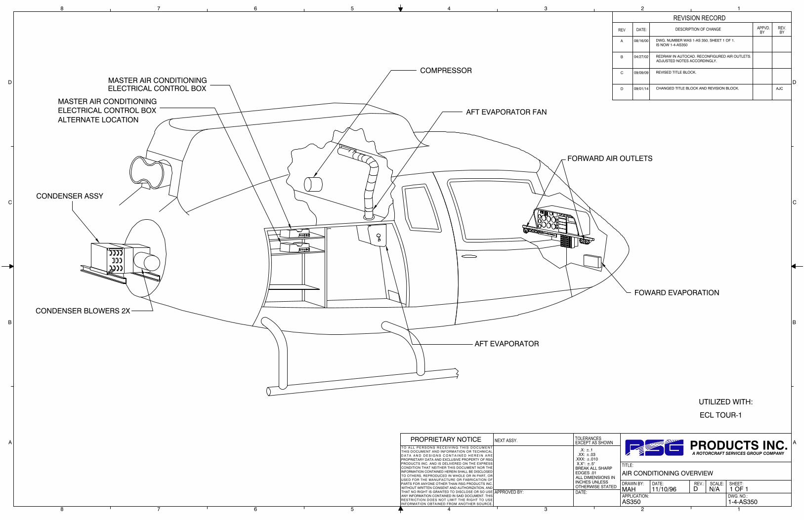
A 6 Added Rivets PN: MS20470E5-6 04/23/09
A 6 Added Rivets PN: MS20470E5-7 04/23/09
A 8 Removed (Ester Oil), added PN: (Alt: 590008-1) to SD-507
Comp. Assy. 04/23/09
A 8 Changed Part Name “Belt” to “Flat Belt”, added PN: (Alt:
060005, Groove Belt) 04/23/09
B 8 Separated Alternate configuration Parts and Numbers to
different rows, ship per customer choice 08/25/09
C 5 Resistor Mount Assy. added 510463 11/04/09
C 6 Air Inlet Doubler R.H. added 261013-2 11/04/09
D 8 Removed P/N’s 060005 and 590008-1 02/02/10
E 5 MS35206-244 is now MS35206-230 03/05/10
E 4 AN525-10R6 is now AN525-10R7 03/05/10
F 4 Angle P/N 260322-1 is now 260322-2 09/22/10
G 6 Was: AN525-832R8, Is: AN525-832R10 05/04/11
H 14 Changed Kit List for: Compressor Bracket Installation Kit
(Was: IFS-350/130-507, Is: 350-11-031-02) 02/07/13
H 10 Added Hose Disconnect Bracket to Step 10.3
(P/N:04-130-21-107-01) 02/07/13
H 9 Changed P/N for Step 8.9
(Was: IFS-350/130-507, Is: 350-11-031-02) 02/07/13
K 10 Changed P/N for Step 9.4
(Was: 22CR4HM, Is: ZZCR4HM) 02/25/14
K 10 Changed P/N for Step 9.4
(Was: 16-14, Is: AP320562) 02/25/14
K 10 Changed P/N for Step 9.4
(Was: 16-14x1/4”, Is: AP320563) 02/25/14
K 10 Changed P/N for Step 9.4
(Was: 22-18, Is: 050020-6) 02/25/14
K 10 Changed P/N for Step 9.4
(Was: 16-14x#10, Is: 050020-8) 02/25/14
K 10 Changed P/N for Step 9.4
(Was: 16x14, Is: 050020-2) 02/25/14
K 10 Changed P/N for Step 9.5
(Was: 8x#10, Is: 050020-9) 02/25/14
L 5 Changed P/N in Step 5.4 and 5.8 (Was: CR3243-4-3 / CR3243-4-4, Is: CR3243-4-03 / CR3243-4-04) 04/17/14
L 6 Changed P/N in Step 5.17
(Was: CR3243-4-2, Is: CR3243-4-02) 04/17/14
L 9 Changed P/Ns in Step 7.5 and 7.11 (Was: CR3243-4-3 / CR3243-4-4, Is: CR3243-4-03 / CR3243-4-04) 04/17/14
L 10 Changed P/N in Step 9.4
(Was: CR3243-4-4, Is: CR3243-4-04) 04/17/14

Air Conditioning System Kit Part Number: 350‐00‐031‐HP Tour 1 Version
Form IFS 33.41 24 March 2016 Rev Q 4 of 16
L 12 Added additional hardware 04/17/14
L 15 Updated Compressor Bracket Kit to include Shim 04/17/14
M All Formatted to RSG Products. 05/28/15
M 6 Updated P/N in Step 5.17 (Was: 490017-1, Is: 490017-1-02 05/28/15
M 9 Added optional P/N in Step 8.5: 060005. 05/28/15
M 9 Added optional P/N in Step 8.10: 590008 05/28/15
M 10 Added missing P/N in Step 10.4: 570072-“O”-A 05/28/15
M 13 Changed drawing # (Was: 5-12-AS350, Is: 5-25-AS350) 05/28/15
N 7 Removed P/N 490017-1-01 and Resistor with components
in step 5.17 08/18/15
N 10 Replaced P/N 350-11-031-02 with note “SEE PAGE 16” 08/18/15
N 12 Removed P/N 070003 in step 10.9 08/18/15
N 16 Removed Kit P/N. 08/18/15
P 10 Added hardware to section 9.2 for optional location for
electrical control box. 11/02/15
Q 11 Added alternate P/N CR4HM in Step 9.4 3/24/16

Air Conditioning System Kit Part Number: 350‐00‐031‐HP Tour 1 Version
Form IFS 33.41 24 March 2016 Rev Q 5 of 16
Kit Configuration Inventory List: 350‐00‐031‐HP Tour 1 Version
Customer Information
Sales Order Number:
Shipping Date:
Customer:
Customer P.O. Number:
Notes:
Kit Specifics
Kit S/N:
Condenser Blower S/N:
Condenser Blower S/N:
Aft Evaporator Blower S/N:
Compressor S/N:

Air Conditioning System Kit Part Number: 350‐00‐031‐HP Tour 1 Version
Form IFS 33.41 24 March 2016 Rev Q 6 of 16
Kit Configuration Inventory List
STEP PART NAME PART
NUMBER QTY
CHK’D BY
VERF’DBY
5.1 Aft Evaporator Fan Doubler 260328-1 1
5.4 Rivets MS20470AD4-4 100
5.4 Rivets MS20470AD4-5 25
5.4 Rivets MS20426AD4-4 15
5.4 Rivets CR3243-4-03 2
5.4 Caterpillar Grommet GM1 18” in
5.5 Aft Evaporator Assembly 560010-O-5 1
5.5 Bolt AN3-5A 4
5.5 Washer AN960-10 4
5.6 Doubler, Return Air 260322-1 1
5.8 Angle 260322-2 1
5.8 Rivets MS20470AD4-3 25
5.8 Rivets CR3243-4-03 25
5.8 Rivets CR3243-4-04 25
5.8 Rivets MS20470AD4-4 10
5.8 Rivets MS20426AD4-4 10
5.9 Return Air Screen 080022-1 1
5.9 Chrome Screw #8 X 1/2 050020-4 4
5.9 Chrome Washer #8 050020-5 4
5.10 Angle Return Air Connector Assembly 510261 1
5.10 Rivets AD44ABS 15
5.10 Screw AN525-10R7 2
5.10 Return Air Cover Connector 250166 1
5.11 Return Air Duct 250149 1

Air Conditioning System Kit Part Number: 350‐00‐031‐HP Tour 1 Version
Form IFS 33.41 24 March 2016 Rev Q 7 of 16
Kit Configuration Inventory List
STEP PART NAME PART
NUMBER QTY
CHK’D BY
VERF’DBY
5.15 Rivnut A10K80 3
5.15 Screws AN525-10R6 3
5.15 Screws AN525-10R10 4
5.15 Clip Nut (Alt P/N: 13100000-5) RM52LHA4972-10-02 4
5.16 Aluminum Foil Tape 070076 30’ ft.
5.16 Cork Insulation Tape 070078-0 6’ ft.
5.17 Aft Evaporator Fan Assembly* (Brushless) 490017-1-02 1
5.17 Bolt AN3-5A 5
5.17 Washer AN960-10 5
5.18 Aft Transition Elbow Assembly 520036-3 1
5.20 Bolt AN3-6A 6
5.20 Nut MS21044N3 6
5.20 Washer AN960-10 12
5.20 Transition Elbow Strap 261299 1
5.21 6” Band clamp 060035 2
5.21 Ø5.0” Duct 25” Long 060004 25” in
5.21 Insulation Foam Tape 070078 20’ ft.
5.22 Air Duct Closure Assembly 510092 1
5.23 Hose Doubler, Baggage Comp. 260369 1
5.23 Rivets MS20470AD4-4 10
6.2 Air Inlet Doubler L.H. 261013 1
6.2 Air Inlet Doubler R.H. 261013-2 1
6.7 Stringer 261012 4
Air Conditioning System Kit Part Number: 350‐00‐031‐HP Tour 1 Version
Form IFS 33.41 24 March 2016 Rev Q 8 of 16
Kit Configuration Inventory List
STEP PART NAME PART
NUMBER QTY
CHK’D BY
VERF’DBY
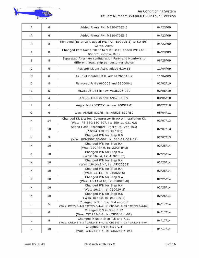
6.8 Rivets MS20470AD4-3 160
6.8 Rivets MS20470AD4-4 160
6.8 Rivets MS20470AD4-5 160
6.10 Strap 261014 2
6.10 Screen 080040 2
6.10 Screw AN525-832R8 12
6.10 Washer AN960-8 18
6.10 Nuts MS21044N08 6
6.10 Rivnut MS27130-A13K 6
6.11 R.H. Air Exit Doubler (Alt: 261100) 261100-1 1
6.11 L.H. Air Exit Doubler (Alt: 261101) 261101-1 1
6.11 L.H. Strap 261511 1
6.11 R.H. Strap 261512 1
6.11 Filler 261513 4
6.11 UPPER FILLER STRIP 261094 2
6.11 LOWER FILLER STRIP 261095 2
6.11 ANGLE, UPPER, R.H. 261096 1
6.11 ANGLE, UPPER, L.H. 261097 1
6.11 ANGLE, LOWER, R.H. 261098 1
6.11 ANGLE, LOWER, L.H. 261099 1
6.11 Rivets MS20470AD5-3 25
6.11 Rivets MS20470AD5-4 40
6.11 Rivets MS20470AD5-5 40
6.11 Rivets MS20470AD5-6 20
6.11 Rivets MS20470AD4-3 40
6.11 Rivets MS20470AD4-4 60
6.11 Rivets MS20470AD4-5 60
6.11 Rivets MS20470E5-6 70
6.11 Rivets MS20470E5-7 70
6.12 Channel Fwd. 261080 1
6.13 Channel Aft. 261081 1

Air Conditioning System Kit Part Number: 350‐00‐031‐HP Tour 1 Version
Form IFS 33.41 24 March 2016 Rev Q 9 of 16
Kit Configuration Inventory List
STEP PART NAME PART
NUMBER QTY
CHK’D BY
VERF’DBY
6.14 Bolts AN4-5A 8
6.14 Washer AN960-416 16
6.14 Nuts MS21044N4 8
6.15 Condenser Assembly 550022 1
6.16 Bolt AN3-5A 4
6.16 Washer AN960-10 8
6.16 Nut MS21044N3 4
6.17 Air Exit Collar 250324 2
6.17 Screw AN525-832R12 8
6.17 Washer AN960-8 16
6.17 Nut MS21044N08 8
6.17 Screen 080039 2
6.19 .25” Heat Shrink 070077 24”
6.20 Ø5.0” Duct 8” Long 060004 2
6.20 Band Clamp 6” 060035 4
6.21 Close out Panel 250301 1
7.3 Forward Evaporator Assembly 560025-“O” 1
(Configuration -01 LOW HAT Configuration -02 HIGH HAT)
7.4 Nut Plate MS21059L3 1
7.4 Rivet CCR264SS3-03 3
7.5 Doubler 260373-1 1
7.5 Rivets CR3243-4-03 18
Air Conditioning System Kit Part Number: 350‐00‐031‐HP Tour 1 Version
Form IFS 33.41 24 March 2016 Rev Q 10 of 16
Kit Configuration Inventory List
STEP PART NAME PART
NUMBER QTY
CHK’D BY
VERF’D BY
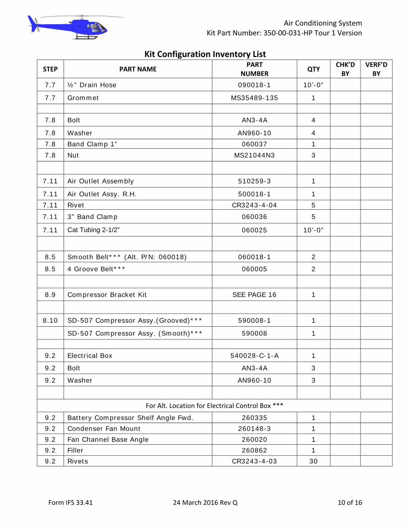
7.7 ½” Drain Hose 090018-1 10’-0”
7.7 Grommet MS35489-135 1
7.8 Bolt AN3-4A 4
7.8 Washer AN960-10 4
7.8 Band Clamp 1” 060037 1
7.8 Nut MS21044N3 3
7.11 Air Outlet Assembly 510259-3 1
7.11 Air Outlet Assy. R.H. 500018-1 1
7.11 Rivet CR3243-4-04 5
7.11 3” Band Clamp 060036 5
7.11 Cat Tubing 2-1/2” 060025 10’-0”
8.5 Smooth Belt*** (Alt. P/N: 060018) 060018-1 2
8.5 4 Groove Belt*** 060005 2
8.9 Compressor Bracket Kit SEE PAGE 16 1
8.10 SD-507 Compressor Assy.(Grooved)*** 590008-1 1
SD-507 Compressor Assy. (Smooth)*** 590008 1
9.2 Electrical Box 540028-C-1-A 1
9.2 Bolt AN3-4A 3
9.2 Washer AN960-10 3
For Alt. Location for Electrical Control Box ***
9.2 Battery Compressor Shelf Angle Fwd. 260335 1
9.2 Condenser Fan Mount 260148-3 1
9.2 Fan Channel Base Angle 260020 1
9.2 Filler 260862 1
9.2 Rivets CR3243-4-03 30

Air Conditioning System Kit Part Number: 350‐00‐031‐HP Tour 1 Version
Form IFS 33.41 24 March 2016 Rev Q 11 of 16
Kit Configuration Inventory List
STEP PART NAME PART
NUMBER QTY
CHK’D BY
VERF’D BY
9.2 Screw AN507-1032R10 6
9.2 Washer AN960-10 9
9.2 Nut MS21044N3 6
9.2 Rivet MS20470AD4-10 40
9.2 Bolt AN3-4A 3
9.3 Washer AN960-10 8
9.3 Nuts MS21044N3 4
9.3 Screws AN525-10R8 4
9.4 Tie Wrap (10” Length Min.) 63128 200
9.4 Tie Block (Alt. P/N: CR4HM) ZZCR4HM 25
9.4 Butt Splice 16-14 050020-1 2
9.4 Ring Terminal 16-14 X 1/4” MS25036-154 2
9.4 Knife Splice 22-18 050020-6 2
9.4 Ring Terminal 16-14 X #10 050020-8 2
9.4 Knife Splice 16-14 050020-2 6
9.4 Electrical Harness Assembly 540044-6 1
9.5 Harness Assembly 540045-1 1
9.5 Ring Terminal 8 X #10 050020-9 1
9.7 Rivet CR3243-4-04 6
10.3 Hose Assy Fwd Evap to Aft. Evap To Comp 570087-“O”-A 1
10.3 #10 “O” Ring 090094 3
10.3 Adel Clamp MS21919WDG12 6
10.3 Nut MS21044N3 6
10.3 Screw AN525-10R10 6
10.3 Washer AN960-10 12
10.3 Hose Disconnect Bracket 04-130-21-107-01 2

Air Conditioning System Kit Part Number: 350‐00‐031‐HP Tour 1 Version
Form IFS 33.41 24 March 2016 Rev Q 12 of 16
Kit Configuration Inventory List
STEP PART NAME PART
NUMBER QTY
CHK’D BY
VERF’D BY
10.4 Hose Assy. #6 Fwd. Evap. To Drier 570072-“O”-A 1
10.4 #6 “O” Ring 090092 2
10.4 Adel Clamp MS21919WDG10 6
10.4 Nut MS21044N3 6
10.4 Screw AN525-10R10 6
10.4 Washer AN960-10 12
10.6 Hose Assembly #8 Comp. Discharge 570070-“O”-A 1
10.6 #8 “O” Ring 090093 3
10.6 Adel Clamp MS21919WDG11 4
10.6 Nut MS21044N3 4
10.6 Screw AN525-10R10 4
10.6 Washer AN960-10 8
10.6 Hose Assembly #6 Condenser to Drier 570067-“O”-A 1
10.6 #6 “O” Ring 090092 3
10.6 Adel Clamp MS21919WDG10 4
10.6 Nut MS21044N3 4
10.6 Screw AN525-10R10 4
10.6 Washer AN960-10 8
10.7 Receiver/Drier Bottle “O” Type 090016-5 1
10.7 Band Clamp 3” 060036 1
10.7 Rec/Drier Mount Bracket 260123-2 1
10.7 Bolt AN3-5A 2
10.7 Nut MS21044N3 2
10.7 Washer AN960-10 4
10.9 Low Pressure Switch 050107 1
10.9 High Pressure Switch 090004 1
Spiral Wrap Ø3/4” SW12BKV 12’ ft.
Screw AN525-10R8 4
Screw AN525-10R10 2

Air Conditioning System Kit Part Number: 350‐00‐031‐HP Tour 1 Version
Form IFS 33.41 24 March 2016 Rev Q 13 of 16
Kit Configuration Inventory List
STEP PART NAME PART
NUMBER QTY
CHK’D BY
VERF’D BY
Washers AN970-3 6
Cherry Max Rivet CR3243-4-02 44
Cherry Max Rivet CR3243-4-03 5
Cherry Max Rivet CR3243-4-04 25
Nutplate Rivet CCR264SS3-02 10
Nutplate Rivet CCR264SS3-03 7
Nutplate Rivet CCR264SS3-04 10
Nutplate Rivet CCR264SS3-06 10
Rivet (Solid) MS20426AD4-5 50
Rivet (Solid) MS20426AD4-3 50
Rivet (Solid) MS20426AD4-4 35
Rivet (Solid) MS20470AD5-3 25
Rivet (Solid) MS20470AD5-4 40
Rivet (Solid) MS20470AD5-5 40
Rivet (Solid) MS20470AD5-6 20
** Indicates is utilized for new style only. *** Indicates it has alternate or optional configuration.

Air Conditioning System Kit Part Number: 350‐00‐031‐HP Tour 1 Version
Form IFS 33.41 24 March 2016 Rev Q 14 of 16
DRAWING LIST
DRAWING NAME DRAWING # QTY CHK’D BY
VERF’D BY
AIR CONDITIONING OVERVIEW 1-4-AS350 1
ELECTRICAL ROUTING 2-4-AS350 1
ELECTRICAL DIAGRAM 2-14-AS350 1
ELECTRICAL DIAGRAM 2-24-AS350 1
PLUMBING DIAGRAM 3-5-AS350 1
PLUMBING DIAGRAM 3-15-AS350 1
AFT EVAPORATOR INSTALL, SHEET 1 of 2 4-3-AS350 1
AFT EVAPORATOR INSTALL, SHEET 2 of 2 4-3-AS350 1
AFT EVAPORATOR INSTALL 4-13-AS350 1
FORWARD EVAPORATOR INSTALL 4-21-AS350 1
AIR DISTRIBUTION 5-4-AS350 1
AIR DISTRIBUTION 5-21-AS350 1
AIR DISTRIBUTION 5-25-AS350 1
COMPRESSOR INSTALLATION 6-2-AS350 1
COMPRESSOR INSTALLATION 6-12-AS350 1
COMPRESSOR INSTALLATION 6-21-AS350 1
COMPRESSOR INSTALLATION* 6-3-AS350* 1*
COMPRESSOR INSTALLATION* 6-13-AS350* 1*
COMPRESSOR INSTALLATION* 6-22-AS350* 1*
CONDENSER INSTALL 7-22-AS350 1
L.H. AIR EXIT DOUBLER INSTALL 7-23-AS350 1
R.H. AIR EXIT DOUBLER INSTALL 7-24-AS350 1
INSTALLATION, AIR INLET DBLR L.H. 7-25-AS350 1
INSTALLATION, AIR INLET DBLR R.H. 7-26-AS350 1
R.H. AIR EXIT DOUBLER INSTALL 7-28-AS350 1
L.H. AIR EXIT DOUBLER INSTALL 7-29-AS350 1 * Indicates drawings required for newer Gimbal Housing design
Air Conditioning System Kit Part Number: 350‐00‐031‐HP Tour 1 Version
Form IFS 33.41 24 March 2016 Rev Q 15 of 16
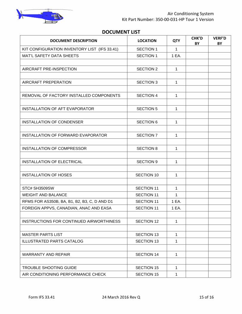
DOCUMENT LIST
DOCUMENT DESCRIPTION LOCATION QTY CHK’D BY
VERF’D BY
KIT CONFIGURATION INVENTORY LIST (IFS 33.41) SECTION 1 1
MAT’L SAFETY DATA SHEETS SECTION 1 1 EA.
AIRCRAFT PRE-INSPECTION SECTION 2 1
AIRCRAFT PREPERATION SECTION 3 1
REMOVAL OF FACTORY INSTALLED COMPONENTS SECTION 4 1
INSTALLATION OF AFT EVAPORATOR SECTION 5 1
INSTALLATION OF CONDENSER SECTION 6 1
INSTALLATION OF FORWARD EVAPORATOR SECTION 7 1
INSTALLATION OF COMPRESSOR SECTION 8 1
INSTALLATION OF ELECTRICAL SECTION 9 1
INSTALLATION OF HOSES SECTION 10 1
STC# SH3509SW SECTION 11 1
WEIGHT AND BALANCE SECTION 11 1
RFMS FOR AS350B, BA, B1, B2, B3, C, D AND D1 SECTION 11 1 EA.
FOREIGN APPVS, CANADIAN, ANAC AND EASA SECTION 11 1 EA.
INSTRUCTIONS FOR CONTINUED AIRWORTHINESS SECTION 12 1
MASTER PARTS LIST SECTION 13 1
ILLUSTRATED PARTS CATALOG SECTION 13 1
WARRANTY AND REPAIR SECTION 14 1
TROUBLE SHOOTING GUIDE SECTION 15 1
AIR CONDITIONING PERFORMANCE CHECK SECTION 15 1

Air Conditioning System Kit Part Number: 350‐00‐031‐HP Tour 1 Version
Form IFS 33.41 24 March 2016 Rev Q 16 of 16
COMPRESSOR BRACKET INSTALLATION KIT
ITEM DESCRIPTION Part Number QTY Comment CHK’D BY
VERF’D BY
COMPRESSOR MOUNT BRACKET 04-130-21-101-01 1
COMPRESSOR MOUNT TENSION BOLT 04-130-21-102-01 1
JAM NUT DRILLED 04-130-21-104-01 2
COMPRESSOR CLAMP 04-130-21-105-01 2
BUSHING, SD 507 261007 2
COMPRESSOR STAND OFF 300067-1 1
SHIM 300363-2 2 Alternate (261155)
THREADED ROD END 2434K39 1
PIN 300095 1
STRAP HOUSING 530100-1 1
WASHER NAS1149D0416H 1 Or NAS Hardware equivalent
WASHER NAS1149D0632H 6 Or NAS Hardware equivalent
WASHER NAS1149D0532H 2 Or NAS Hardware equivalent
WASHER AN960-416 4 Alternate (AN960-416L)
WASHER AN960-516L 1 Alternate (AN960-516)
WASHER AN960-616L 2 Alternate (AN960-616)
NUT MS21042-L5 2 Alternate (MS20364-524C)
NUT MS21042-L4 2 Alternate (AN365-424)
NUT MS21042L6 4 Or NAS Hardware equivalent
BOLT AN4-5A 1 Or NAS Hardware equivalent
BOLT AN4-14A 2 Or NAS Hardware equivalent
BOLT AN5-34A 1 Or NAS Hardware equivalent
BOLT AN6-13A 2 Or NAS Hardware equivalent
BOLT HEX DRIVE AN6-12 1 Or NAS Hardware equivalent
BOLT AN6-33A 1 Or NAS Hardware equivalent


MATERIAL SAFETY DATA SHEET Trade Name: Johnsen's Ester 100MSDS NO. 6711Revision Date: 03/26/2007Date Printed 12/30/2008
1. CHEMICAL PRODUCT AND COMPANY IDENTIFICATION Trade Name: Johnsen's Ester 100Chemical Family: Refrigeration OilSynonyms: NoneEmergency Telephone (24 hr.): CHEMTREC 1-800-424-9300 Supplier: Technical Chemical Company, P.O. Box 139, Cleburne, Texas 76033
2. COMPOSITION/INFORMATION ON INGREDIENTS
Component Weight % OSHA TWA OSHA STEL OSHA SKIN
Ester Propietary Inhibitor Package Mixture
0-20 Not Listed Not Listed Not Listed
Ester Propietary Base Stock Mixture
20-80 Not Listed Not Listed Not Listed
Component Weight % OSHA Z PEL OSHA Z TWA OSHA Z Ceiling
Ester Propietary Inhibitor Package Mixture
0-20 Not Listed Not Listed Not Listed
Ester Propietary Base Stock Mixture
20-80 Not Listed Not Listed Not Listed
Component ACGIH TLV TWA ACGIH TLV STEL ACGIH TLV Ceiling
Ester Propietary Inhibitor Package Mixture
Not Listed Not Listed Not Listed
Ester Propietary Base Stock Mixture
Not Listed Not Listed Not Listed
Other: Contains no ingredients in concentrations greater than 0.1% that are now known to be hazardous as defined by OSHA.
3. HAZARDS IDENTIFICATION Emergency Overview: Ingestion of this product may cause gastrointestinal distress with symptoms of nausea, vomiting, diarrhea
and abdominal pain. May cause irritation to skin and eyes. HMIS Classification: Health: 1 Flammability: 1 Physical Hazard: 0NFPA Rating: Health: 1 Flammability: 1 Reactivity: 0
4. FIRST AID MEASURES Eye Contact: In case of contact, immediately flush eyes with plenty of water for at least 15 minutes, occasionally lifting
the upper and lower lids. Seek medical attention if irritation persists.Ingestion: DO NOT INDUCE VOMITING. Give nothing by mouth. Get medical attention! If vomiting occurs, keep
head lower than hips to prevent aspiration.Inhalation: If inhaled, remove to fresh air. If not breathing give artificial respiration, preferably mouth-to-mouth. If
breathing is difficult give oxygen. Get medical attention.Skin Contact: Remove contaminated clothing and shoes, and launder before reuse. Get medical attention if irritation
persists. Wash with soap and water. Use skin cream for defatted areas. Page 1 of 4

MATERIAL SAFETY DATA SHEET Trade Name: Johnsen's Ester 100MSDS NO. 6711Revision Date: 03/26/2007Date Printed 12/30/2008
5. FIRE FIGHTING MEASURES Flammable Properties
Flash Point °F(°C): >482 (<250)Flash Point Method: COCFlammable Limits in Air - Lower (%): Not DeterminedFlammable Limits in Air - Upper (%): Not DeterminedAutoignition Temperature °F(°C): Not DeterminedExtinguishing Media: Carbon dioxide. Dry chemical. Foam.Protection Of Fire-Fighters:
Special Fire-Fighting Procedures: Wear approved positive-pressure self-contained breathing apparatus and protective clothing. Do not direct a solid stream of water or foam into hot, burning pools; this may cause frothing and increase fire intensity.
Hazardous Combustion Products: Oxides of carbon, nitrogen and phosphorus. Aerosol Comments: Not Applicable
6. ACCIDENTAL RELEASE MEASURES Personal Precautions: Wear appropriate protective clothing and equipment to prevent skin and eye contact.Spill Procedures: Wear protective equipment specified. Contain any liquid from leaking containers.Action to be taken if material is released or spilled:
Absorb spills on inert material such as perlite, vermiculite, sand or dirt. Place in double polyethylene bags. Isolate from other waste materials. Wash walking surfaces with detergent and water to reduce slipping hazard.
Environmental Precautions: Do not allow to enter sanitary drains, sewer or surface and subsurface waters.
7. HANDLING AND STORAGE Handling and Storage: Avoid contact with eyes. Keep containers tightly closed when not in use. Use only in a well ventilated area.
Good hygienic practices should be observed. Work clothes should be washed separately at the end of each work day. Contaminated disposable clothing should be discarded in accordance with local, state and federal rules. Wash thoroughly after handling. Do Not Swallow. Store at room temperature. Avoid prolonged/repeated breathing of vapors, mists or fumes.
8. EXPOSURE CONTROLS/PERSONAL PROTECTION
Engineering Controls: Eyewash stations. Showers. Use local exhaust.Eyes: Chemical goggles; also wear a face shield if splashing hazard exists.Skin Protection: Neoprene coated apron or clothing. Respiratory Protection: Appropriate respiratory protection shall be worn when applied engineering controls are not adequate to
protect against inhalation exposure.
9. PHYSICAL AND CHEMICAL PROPERTIES Appearance: Clear to light yellow liquidOdor: MILD ETHERpH Value: Not DeterminedVapor Pressure: Not DeterminedVapor Density (Air=1): Not DeterminedBoiling Point (°F): >300 C.Melting/Freezing Point: Not DeterminedSolubility in Water: INSOLUBLEBulk Density at 20°C: Not DeterminedMolecular Weight: MixtureSpecific Gravity (H20=1): 1.04 @ 60FViscosity: 100 cSt @ 40CEvaporation Rate: Not DeterminedVOC Content(%): Not determined.Decomposition Temperature: Not Known
Page 2 of 4
MATERIAL SAFETY DATA SHEET Trade Name: Johnsen's Ester 100MSDS NO. 6711Revision Date: 03/26/2007Date Printed 12/30/2008
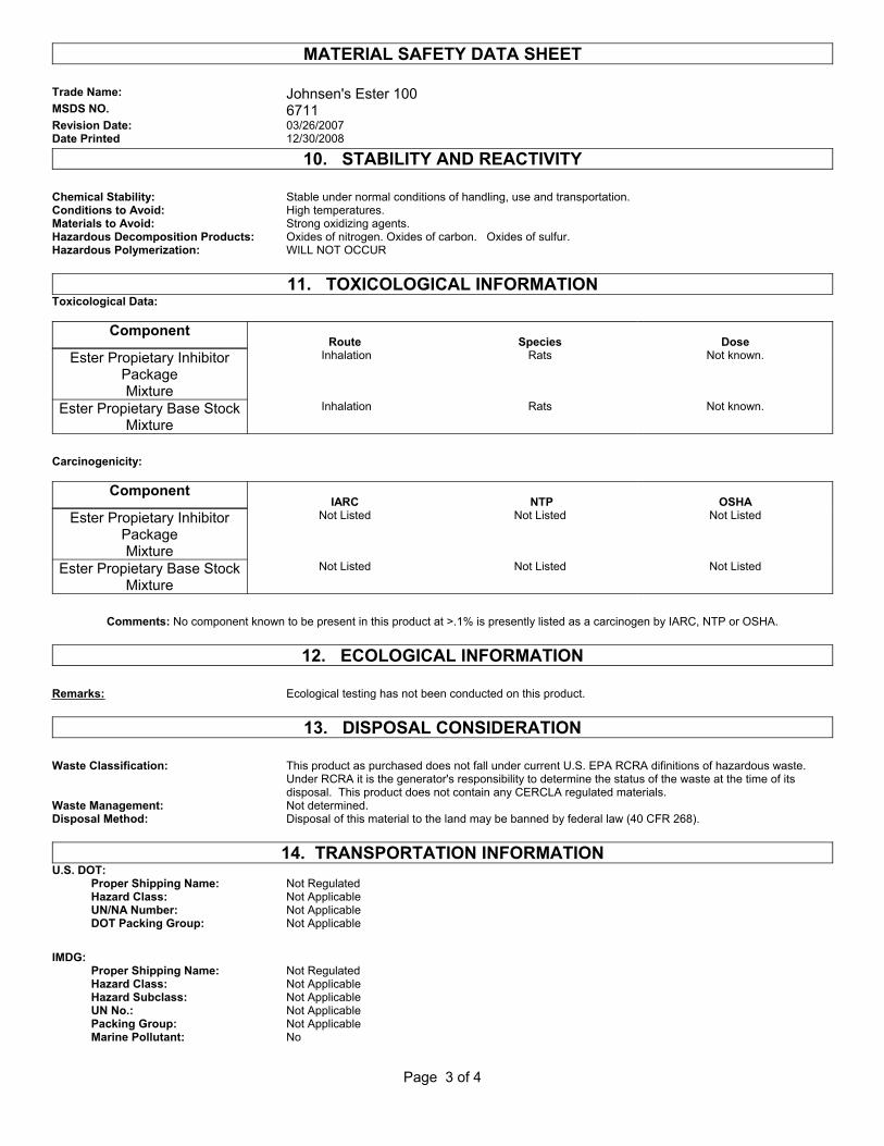
10. STABILITY AND REACTIVITY Chemical Stability: Stable under normal conditions of handling, use and transportation.Conditions to Avoid: High temperatures.Materials to Avoid: Strong oxidizing agents.Hazardous Decomposition Products: Oxides of nitrogen. Oxides of carbon. Oxides of sulfur.Hazardous Polymerization: WILL NOT OCCUR
11. TOXICOLOGICAL INFORMATIONToxicological Data:
Component Route Species Dose
Ester Propietary Inhibitor Package Mixture
Inhalation Rats Not known.
Ester Propietary Base Stock Mixture
Inhalation Rats Not known.
Carcinogenicity:
Component IARC NTP OSHA
Ester Propietary Inhibitor Package Mixture
Not Listed Not Listed Not Listed
Ester Propietary Base Stock Mixture
Not Listed Not Listed Not Listed
Comments: No component known to be present in this product at >.1% is presently listed as a carcinogen by IARC, NTP or OSHA.
12. ECOLOGICAL INFORMATION
Remarks: Ecological testing has not been conducted on this product.
13. DISPOSAL CONSIDERATION Waste Classification: This product as purchased does not fall under current U.S. EPA RCRA difinitions of hazardous waste.
Under RCRA it is the generator's responsibility to determine the status of the waste at the time of its disposal. This product does not contain any CERCLA regulated materials.
Waste Management: Not determined.Disposal Method: Disposal of this material to the land may be banned by federal law (40 CFR 268).
14. TRANSPORTATION INFORMATIONU.S. DOT: Proper Shipping Name: Not Regulated Hazard Class: Not Applicable UN/NA Number: Not Applicable DOT Packing Group: Not Applicable IMDG: Proper Shipping Name: Not Regulated Hazard Class: Not Applicable Hazard Subclass: Not Applicable UN No.: Not Applicable Packing Group: Not Applicable Marine Pollutant: No
Page 3 of 4
MATERIAL SAFETY DATA SHEET Trade Name: Johnsen's Ester 100MSDS NO. 6711Revision Date: 03/26/2007Date Printed 12/30/2008
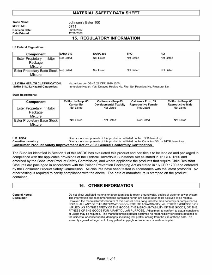
15. REGULATORY INFORMATION US Federal Regulations:
Component SARA 313 SARA 302 TPQ RQ
Ester Propietary Inhibitor Package Mixture
Not Listed Not Listed Not Listed Not Listed
Ester Propietary Base Stock Mixture
Not Listed Not Listed Not Listed Not Listed
US OSHA HEALTH CLASSIFICATION: Hazardous per OSHA 29 CFR 1910.1200 SARA 311/312 Hazard Catagories: Immediate Health: Yes, Delayed Health: No, Fire: No, Reactive: No, Pressure: No. State Regulations:
Component California Prop. 65 Cancer list
California - Prop 65 Developmental Toxicity
California Prop. 65 Reproductive Female
California Prop. 65 Reproductive Male
Ester Propietary Inhibitor Package Mixture
Not Listed Not Listed Not Listed Not Listed
Ester Propietary Base Stock Mixture
Not Listed Not Listed Not Listed Not Listed
U.S. TSCA: One or more components of this product is not listed on the TSCA Inventory.Canadian Inventory: One or more components of this product is not listed on the Canadian DSL or NDSL Inventory.Consumer Product Safety Improvement Act of 2008 General Conformity Certification
The Supplier identified in Section 1 of this MSDS has evaluated this product and certifies it to be labeled and packaged in compliance with the applicable provisions of the Federal Hazardous Substance Act as stated in 16 CFR 1500 and enforced by the Consumer Product Safety Commission, and where applicable the products that require Child Resistant Closures are packaged in accordance with the Poison Prevention Packaging Act as stated in 16 CFR 1700 and enforced by the Consumer Product Safety Commission. All closures have been tested in accordance with the latest protocols. No other testing is required to certify compliance with the above. The date of manufacture is stamped on the product container.
16. OTHER INFORMATION General Notes: Do not allow undiluted material or large quantities to reach groundwater, bodies of water or sewer system.Disclaimer: The information and recommendations contained herein are based upon tests believed to be reliable.
However, the manufacturer/distributor of this product does not guarantee their accuracy or completeness NOR SHALL ANY OF THIS INFORMATION CONSTITUTE A WARRANTY, WHETHER EXPRESSED OR IMPLIED, AS TO THE SAFETY OF THE GOODS, THE MERCHANTABILITY OF THE GOODS, OR THE FITNESS OF THE GOODS FOR A PARTICULAR PURPOSE. Adjustment to conform to actual conditions of usage may be required. The manufacturer/distributor assumes no responsibility for results obtained or for incidental or consequential damages, including lost profits, arising from the use of these data. No warranty against infringement of any patent, copyright or trademark is made or implied.
Page 4 of 4

RSG Products Inc. AIRCRAFT PRE-INSPECTION – AS350 Air Conditioning
Date: 05/29/15 Section 2: Aircraft Pre-Inspection Page 1 of 4
Step 2
Aircraft Pre-Inspection

RSG Products Inc. AIRCRAFT PRE-INSPECTION – AS350 Air Conditioning
Date: 05/29/15 Section 2: Aircraft Pre-Inspection Page 2 of 4
Aircraft Pre-Inspection
STEP PROCEDURE MECH INSP
2.1 Inspect the aircraft for other kits and Modifications that may effect the installation of The air conditioning kit.
2.2 Inspect the airframe structure for any obvious Structural damage or corrosion.
2.3 Repair discrepancies that are found prior to Installation of kit.
2.4 Inspect aircraft paperwork for damage history that may effect the installation of this kit.
RSG Products Inc. AIRCRAFT PRE-INSPECTION – AS350 Air Conditioning
Date: 05/29/15 Section 2: Aircraft Pre-Inspection Page 3 of 4
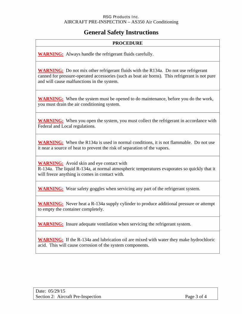
General Safety Instructions
PROCEDURE
WARNING: Always handle the refrigerant fluids carefully.
WARNING: Do not mix other refrigerant fluids with the R134a. Do not use refrigerant canned for pressure-operated accessories (such as boat air horns). This refrigerant is not pure and will cause malfunctions in the system.
WARNING: When the system must be opened to do maintenance, before you do the work, you must drain the air conditioning system.
WARNING: When you open the system, you must collect the refrigerant in accordance with Federal and Local regulations.
WARNING: When the R134a is used in normal conditions, it is not flammable. Do not use it near a source of heat to prevent the risk of separation of the vapors.
WARNING: Avoid skin and eye contact with R-134a. The liquid R-134a, at normal atmospheric temperatures evaporates so quickly that it will freeze anything is comes in contact with.
WARNING: Wear safety goggles when servicing any part of the refrigerant system.
WARNING: Never heat a R-134a supply cylinder to produce additional pressure or attempt to empty the container completely.
WARNING: Insure adequate ventilation when servicing the refrigerant system.
WARNING: If the R-134a and lubrication oil are mixed with water they make hydrochloric acid. This will cause corrosion of the system components.

RSG Products Inc. AIRCRAFT PRE-INSPECTION – AS350 Air Conditioning
Date: 05/29/15 Section 2: Aircraft Pre-Inspection Page 4 of 4
General Safety Instructions
PROCEDURE
WARNING: You must replace the filter drier each time you open the system.
WARNING: Comply with the regulations in force in the country where the aircraft is operated when working on the air conditioning system.
WARNING: Only use nitrogen or Alcohol to clean the system components.
WARNING: Always keep the R-134a supply cylinder in an upright position when admitting refrigerant into the system. If a cylinder is on its side or upside down, liquid will enter the R-134a system and cause damage to the compressor.
RSG Products Inc. AIRCRAFT PREPARATION – AS350 Air Conditioning
Date: 05/29/15 Section 3: Aircraft Preparation Page 1 of 3
Step 3
Aircraft Preparation
RSG Products Inc. AIRCRAFT PREPARATION – AS350 Air Conditioning
Date: 05/29/15 Section 3: Aircraft Preparation Page 2 of 3
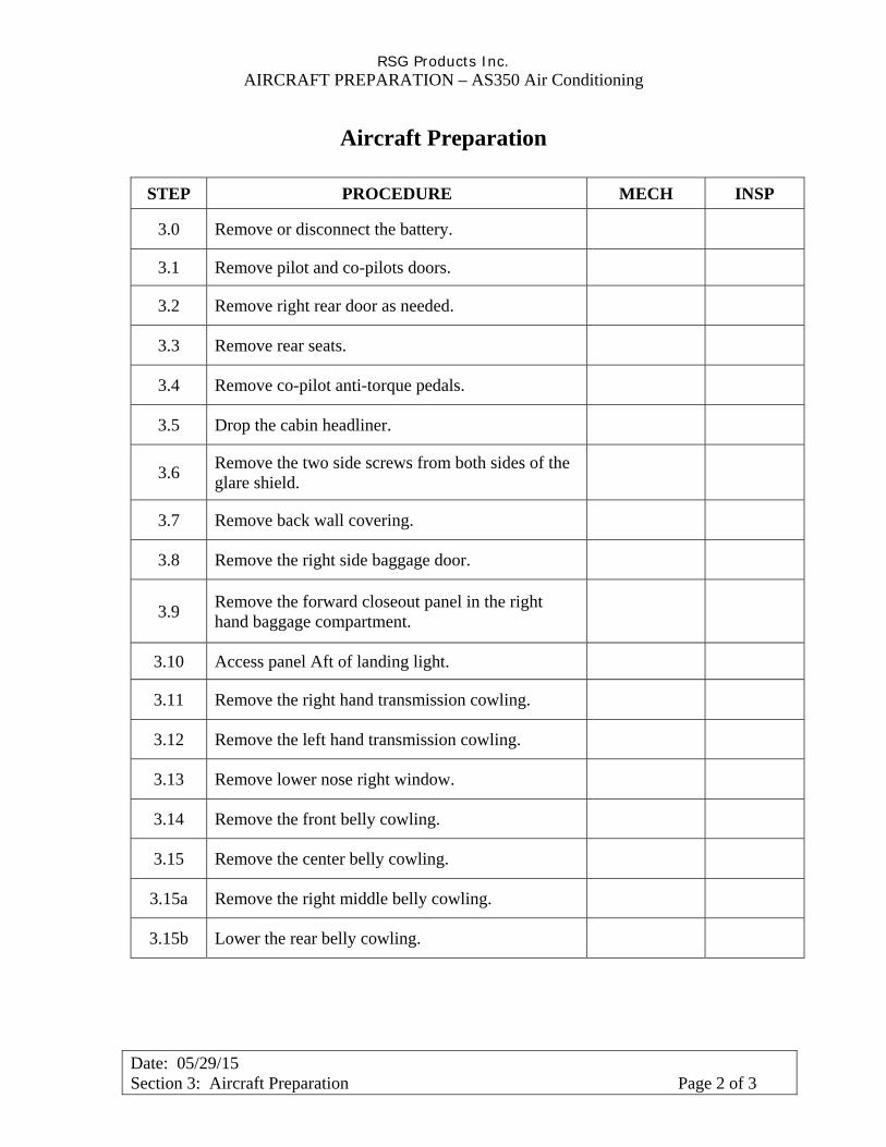
Aircraft Preparation
STEP PROCEDURE MECH INSP
3.0 Remove or disconnect the battery.
3.1 Remove pilot and co-pilots doors.
3.2 Remove right rear door as needed.
3.3 Remove rear seats.
3.4 Remove co-pilot anti-torque pedals.
3.5 Drop the cabin headliner.
3.6 Remove the two side screws from both sides of the glare shield.
3.7 Remove back wall covering.
3.8 Remove the right side baggage door.
3.9 Remove the forward closeout panel in the right hand baggage compartment.
3.10 Access panel Aft of landing light.
3.11 Remove the right hand transmission cowling.
3.12 Remove the left hand transmission cowling.
3.13 Remove lower nose right window.
3.14 Remove the front belly cowling.
3.15 Remove the center belly cowling.
3.15a Remove the right middle belly cowling.
3.15b Lower the rear belly cowling.
RSG Products Inc. AIRCRAFT PREPARATION – AS350 Air Conditioning
Date: 05/29/15 Section 3: Aircraft Preparation Page 3 of 3
Aircraft Preparation
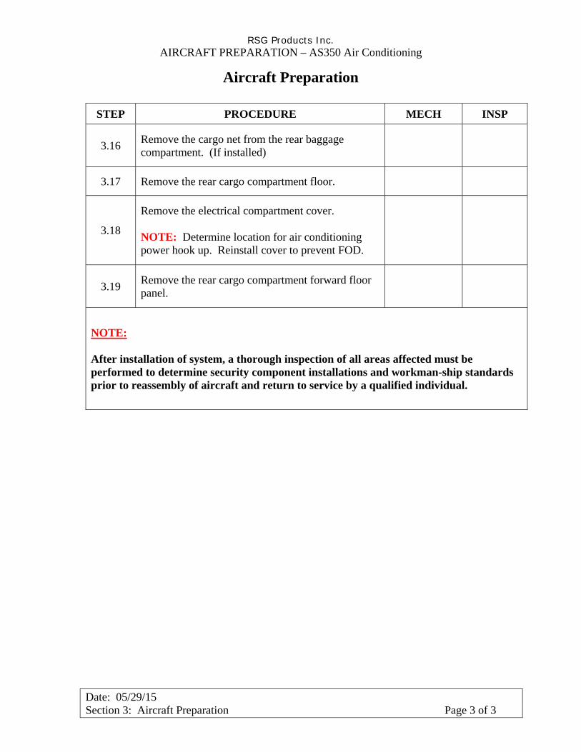
STEP PROCEDURE MECH INSP
3.16 Remove the cargo net from the rear baggage compartment. (If installed)
3.17 Remove the rear cargo compartment floor.
3.18
Remove the electrical compartment cover. NOTE: Determine location for air conditioning power hook up. Reinstall cover to prevent FOD.
3.19 Remove the rear cargo compartment forward floor panel.
NOTE: After installation of system, a thorough inspection of all areas affected must be performed to determine security component installations and workman-ship standards prior to reassembly of aircraft and return to service by a qualified individual.

RSG Products Inc. REMOVAL OF FACTORY INSTALLED COMPONENTS – AS350 Air Conditioning
Date: 05/29/15 Section 4: Removal of Factory Installed Components Page 1 of 2
Step 4
Removal of Factory Installed Components
RSG Products Inc. REMOVAL OF FACTORY INSTALLED COMPONENTS – AS350 Air Conditioning
Date: 05/29/15 Section 4: Removal of Factory Installed Components Page 2 of 2
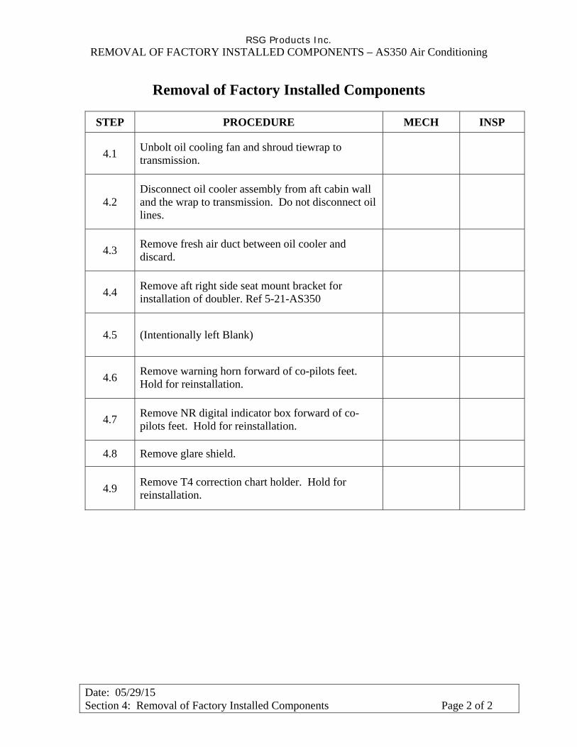
Removal of Factory Installed Components
STEP PROCEDURE MECH INSP
4.1 Unbolt oil cooling fan and shroud tiewrap to transmission.
4.2 Disconnect oil cooler assembly from aft cabin wall and the wrap to transmission. Do not disconnect oil lines.
4.3 Remove fresh air duct between oil cooler and discard.
4.4 Remove aft right side seat mount bracket for installation of doubler. Ref 5-21-AS350
4.5 (Intentionally left Blank)
4.6 Remove warning horn forward of co-pilots feet. Hold for reinstallation.
4.7 Remove NR digital indicator box forward of co-pilots feet. Hold for reinstallation.
4.8 Remove glare shield.
4.9 Remove T4 correction chart holder. Hold for reinstallation.

RSG Products Inc. INSTALLATION OF AFT EVAPORATOR – AS350 Air Conditioning
Date: 05/29/15 Section 5: Installation of Aft Evaporator Page 1 of 5
Step 5
Installation of Aft Evaporator

RSG Products Inc. INSTALLATION OF AFT EVAPORATOR – AS350 Air Conditioning
Date: 05/29/15 Section 5: Installation of Aft Evaporator Page 2 of 5
Installation of Aft Evaporator
STEP PROCEDURE MECH INSP
5.1
Remove Right Hand Transmission Cowling Forward latch. (See photo 1). Hold for reinstallation. Position the aft evaporator doubler P/N 260328-1 on the upper transmission deck per drawing 4-3-AS350 sheet 1 of 2. Mark around doubler and remove all existing rivets, bolts, and nut plates to allow the doubler to sit flat on deck.
5.2 Drill through deck using pilot holes in doubler. Back drill the doubler from existing holes in the deck.
5.3 Mark and cut openings in the transmission deck using doubler P/N 260328-1 as a template.
5.4
Install aft evaporator doubler P/N 260328-1 on right hand upper transmission deck in accordance with drawing 4-3-AS350 sheet 1 of 2 using rivets as shown. Re-install Right Hand Transmission Cowling Forward latch as shown in drawing 4-3-AS350 sheet 1 of 2.
5.5 Next temporarily install Aft evaporator assembly P/N 560010-“O”-5 with 4 ea. AN3-5A bolts and 4 ea. AN960-10 washers per drawing 4-13-AS350.
5.6
Position return air doubler P/N 260322-1 against aft cabin bulk head as shown in drawing 5-21-AS350 trace outline on bulkhead. Remove doubler and drill out rivets inside trace.
5.7 Reposition doubler P/N 260322-1. Back drill all holes and Clelo in place. Using doubler as guide pen route out return air hole.
5.8
Remove doubler, clean holes. Install doubler P/N 260322-1 and angle P/N 260322-2 rivet in place per drawing 5-21-AS350.
NOTE: Two different situations, requiring different doublers are utilized depending on the type and location of the aft seat harness reel (if installed). See drawing for specifics.

RSG Products Inc. INSTALLATION OF AFT EVAPORATOR – AS350 Air Conditioning
Date: 05/29/15 Section 5: Installation of Aft Evaporator Page 3 of 5
PHOTO 1

RSG Products Inc. INSTALLATION OF AFT EVAPORATOR – AS350 Air Conditioning
Date: 05/29/15 Section 5: Installation of Aft Evaporator Page 4 of 5
Installation of Aft Evaporator
STEP PROCEDURE MECH INSP
5.9 Install return air screen P/N 080022-1 as per drawing 5-21-AS350.
NOTE: Before final install of evaporator. Install condenser channels P/N 510007 and P/N 510008. (See condenser install: Step 6)
5.10
Locate “Return Air Connector” P/N 250166. Trial fit to the aft side of the cabin wall, immediately in front of the aft evaporator. The open side of the connector must face aft. Slide the connector upward until it contacts the forward side of the evaporator. Mark with a pencil, the inside of the connector position on to the evaporator. Remove the connector and evaporator. Reference drawing 4-13-AS350.
Draw a line one (1) inch above the lower/forward face of the evaporator case. Trial fit “Return Air Connector” to the evaporator, ensuring that the flanges of the connector DO NOT go past the inboard/outboard sides of the evaporator.
Confirm the pencil lines. Remove the connector. Cut out the area within the pencil lines, leaving the one (1) inch lower lip on the evaporator case as a drain seal.
NOTE: ENSURE DURING DRILLING THAT THE COIL INSIDE THE CASE IS NOT DAMAGED.
Seal and secure the Return Air Duct Connector PN: 250166 with rivets to the Evaporator PN: 560010-O-5 case per drawing 4-13-AS350. Next install the connector angle assembly P/N 510261, per drawing 4-3-AS350 Sheet 1 of 2 and 4-13-AS350. This holds the upper part of the return air duct.
5.11
Position the aft evaporator return air duct P/N 250149 in the right side baggage compartment as shown on drawing 4-13-AS350. Use the return air opening to locate the return air duct. Trim the return air duct as required to fit.
5.12 Remove the access panel from the outboard side of the aft evaporator P/N 560010-O-5.
5.13 Temporarily install the aft evaporator, P/N 560010-O-5 using 4 each, AN3-5A, bolts and AN960-10, washers.

RSG Products Inc. INSTALLATION OF AFT EVAPORATOR – AS350 Air Conditioning
Date: 05/29/15 Section 5: Installation of Aft Evaporator Page 5 of 5
Installation of Aft Evaporator
STEP PROCEDURE MECH INSP
5.14 Locate and drill the holes for mounting the aft evaporator return air duct connector P/N 250166.
5.15 Attach Return Air Duct P/N 250149 per drawings 4-3- AS350 sheet 1 of 2 and 4-13-AS350.
5.16
SEAL THE EVAPORATOR TO THE RETURN AIR DUCT WITH ALUMINUM FOIL TAPE IFS PN: 070076 as required by reaching through the outboard opening in the evaporator. Re-install the aft evaporator access panel.
5.17
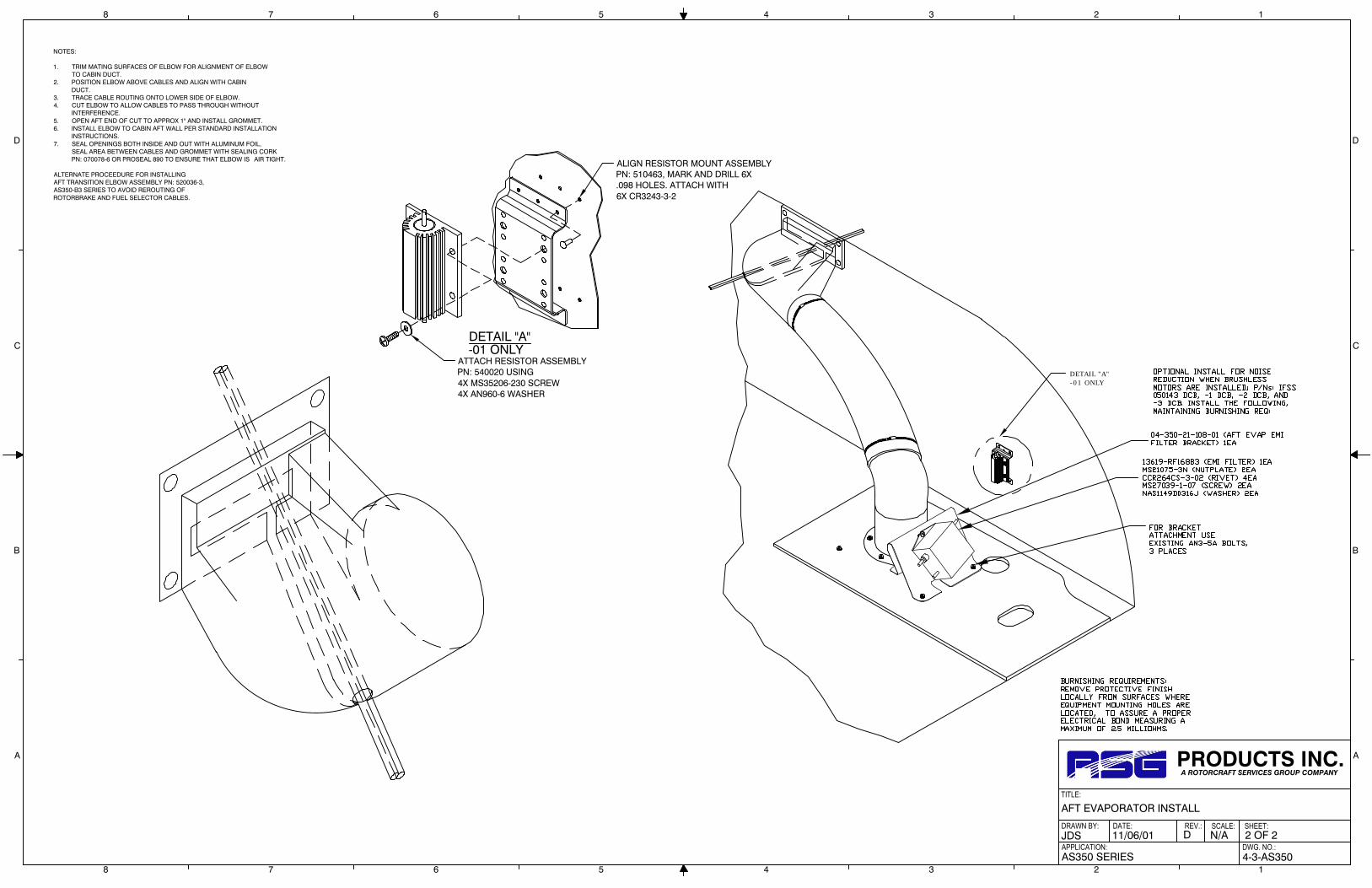
Install the Aft Evaporator Fan Assembly, P/N 490017-1, using five each AN3-5A bolts, and 5 ea. AN960-10 washers. Attach Resistor Mount Assembly P/N 510463 and Resistor Assembly P/N 540020 per drawing 4-3-AS350 Sheet 2 of 2.
5.18
Locate Transition Elbow P/N 520036-3. This will be mounted on upper Aft Cabin Wall on transmission side. See drawing 4-3-AS350 Sheets 1 and 2. Remove oil coolers from upper deck dog house. (Do Not Disconnect oil Lines) Position as to be able to modify Aft cabin wall. Do Not Re-install until step 5.22.
5.19
Mark hole to be cut out in aft cabin wall per drawing 4-3-AS350 Sheet 1 of 2. Be careful not to but the cabin air duct bonded to aft cabin wall. Drill a couple of # 40 holes to see if you clear duct.
5.20 Cut out hole and mount elbow as shown in drawing No. 4-3-AS350 Sheet 1 and 2 of 2.
5.21
Install a 5-inch flex duct (25”in) long from the aft evaporator fan assembly to the aft air distribution elbow end with two each 6” band clamps P/N 060035. Insulate the duct with foam tape P/N 070078 and wrap with aluminum tape P/N 070076.
5.22
Modify over head wemac’s as shown in drawing 5-25-AS350 if S/N 1302 or lower. Remove existing spacer air duct between oil coolers. Install new Air Duct Closure Assembly PN: 510092 using existing hardware. Re-install oil cooler assembly.
5.23 Install hose doubler P/N 260369 per drawing 3-5-AS350.

.X: ±.1 .XX: ±.03.XXX: ±.010 X.X°: ±.5°BREAK ALL SHARPEDGES .01ALL DIMENSIONS ININCHES UNLESSOTHERWISE STATED
TOLERANCES
APPROVED BY:
NEXT ASSY.
DATE:
EXCEPT AS SHOWN
DRAWN BY:
APPLICATION:
DATE:
TITLE:
REV.: SCALE:
DWG. NO.:
SHEET:
PROPRIETARY NOTICET O A L L P E R S O N S R E C E I V IN G T H I S D O C U M E N TTHIS DOCUMENT AND INFORMATION OR TECHNICALD A T A A N D D E S I G N S C O N T A I N E D H E R E I N A R EPROPRIETARY DATA AND EXCLUSIVE PROPERTY OF RSGPRODUCTS INC. AND IS DELIVERED ON THE EXPRESSCONDITION THAT NEITHER THIS DOCUMENT NOR THEINFORMATION CONTAINED HEREIN SHALL BE DISCLOSEDTO OTHERS, REPRODUCED IN WHOLE OR IN PART, ORUSED FOR THE MANUFACTURE OR FABRICATION OFPARTS FOR ANYONE OTHER THAN RSG PRODUCTS INC.WITHOUT WRITTEN CONSENT AND AUTHORIZATION, ANDTHAT NO RIGHT IS GRANTED TO DISCLOSE OR SO USEANY INFORMATION CONTAINED IN SAD DOCUMENT. THISRESTRICTION DOES NOT LIMIT THE RIGHT TO USEINFORMATION OBTAINED FROM ANOTHER SOURCE.
PRODUCTS INC.A ROTORCRAFT SERVICES GROUP COMPANY
8 7 6 5 4 3 2 1
A
B
C
D
A
B
C
D
8 7 6 5 4 3 2 1
DATE:REV DESCRIPTION OF CHANGE
REVISION RECORDAPPVD.
BYREV.BY
AS350 SERIES 4-3-AS350
1 OF 2N/AD11/06/01JDS
AFT EVAPORATOR INSTALL
A 11/06/01 CONVERTED TO AUTOCAD
B 01/03/07 ADDED SHEET 2 OF 2 TO INCLUDE SLOTTINGINFORMATION FOR B3
JTYE
C 02/23/09 REVISED TITLE BLOCK. SHEET 1 AND 2 NOW ON FILE.ADDED RESISTOR MOUNT ASSEMBLY, P/N: 510463.
DWE
D 9/1/14 CHANGED TITLE BLOCK AND REVISION BLOCK.INCORPORATED ECO 0204, 0324, 0538, 0554, & 0654.
AJC
VIEW LOOKING DOWN AT TRANSMISSION DECK
TRANSMISSION
FOR (-011) K
IT SEE 3-4-AS350
VIEW D-D FOR LOCATION
BAGGAGE COMPARTMENT
FLOOR
CUT DUCT TO MATCHDOOR SUPPORT RODNOTCH
SCREW AN525-10R6 3 @ O.B. SIDE
SCREW AN525-10R10 4 @ I.B. SIDE
EXISTINGOPENING
7.2
1.6
OPEN TO INSIDEEDGE OF EXISTINGDUCT ALL AROUND
AN3-6A (BOLTS) 6 EA.MS21044-N3 (NUT) 6 EA.AN960-10 (WASHERS) 12 EA.
TRIM BOTTOM LIP ON DOGHOUSECOWLING, AS REQUIRED, TOCLEAR TRANSITION ELBOW
6" BAND CLAMPTYP. 2
6.5 (REF) N.T.S
7.5 (REF)
ROUTE DRAIN TUBEFROM EVAP. DOWNTHRU DOUBLER, ANDTIE WRAP TO LANDINGGEAR TUBE
DRILL (3PL)AND INSTALLA10K80RIVNUT
BACK DRILL FROM INSIDECABIN (4 PL), INSTALL
CLIP NUT P/N RM52LHA4972-10-02
LINE HOLE W/CATERPILLAR GROMMET
BOND TO METAL
RIVET CR3243-4-2
BACK DRILL HOLES THRUTHE DECK TO .228 #1 DRILL (TYP. 9)
FORWARD
OUTBOARD
MS20470AD-4-X (FIELD)
MS20470AD-4-X (REPLACES EXIST. RIVETS)
MS20426AD-4-X (CSK. AT TOP SURFACES)
.228 DIA HOLE #1 DRILL (FOR AN 3-5A BOLT)
EXISTING
C
C
AFT SIDE CABIN WALL
OUTBOARDRIGHT
VIEW "C-C"
AFT EVAP. ASSY.P/N: 560010-"0"-5
TRIM LIP OF FUEL TANKACCESS COVER TO CLEAR
R.A. DUCT.
CONNECT DUCT TO EVAP. USINGCONNECTOR ANGLE ASSY. P/N 510261
TO INSIDE RETURN AIR DUCTP/N 250149 ATTACH ANGLE ASSY. TO
EVAP. W/ ABA4-4 RIVETS AND RETURNAIR DUCT W/ AN525-10R7 SCREWS.
EXISTING DOOR LATCH. REMOVEBEFORE INSTALLING DOUBLER.INSTALL NEW CR3243-4-3CHERRYMAX RIVETS THRUOUT BOARD SIDE OF LATCH.
AFT. TRANSITION ELBOW ASSY.520036-3. ON FINAL INSTALLATION, SEAL FLANGE TO AFT
CABIN WALL WITH P.R.C. OR EQUIVALENT.
DECK
AFT EVAP. FAN ASSY.-01 ONLY: P/N: 490017-1-01-02 ONLY: P/N: 490017-1-02
CUT-OUT
NOTE: RIVET LENGTH MAYBE DETERMINED UPON INSTALLATION. INTERCHANGEABILITY BETWEEN MS20470AD-4-X RIVETS AND CR3242-4-X RIVETS IS APPROVED.
DOUBLERP/N 260328-1
REINSTALL (2)EXISTING BOLTS
BOLT AN3-5A (TYP. 9)WASHER AN960-10 (TYP. 9)
AFTER B3, S/N: 3322, REMOVE GROMMET IN P/N 520036-3.CUT OUT OPENING TO 1.6 X 7.2 OR TO MATCH DUCT OPENING AS IN VIEW C-C. ROUTEPUSH/PULL CABLES AND ELECTRICAL HARNESS TO LEFT AND TIE WRAP TOGETHER.
SLOT THE TRANSITION ELBOW AS REQUIRED, TYP. B3 MODELS (SEE PAGE 2 OF 2 FORALTERNATE INSTALL.) SLIDE TRANSITION ELBOW OVER CABLES AND PLACE ELBOW INPOSITION AGAINST AFT CABIN WALL. BACK DRILL 6 EACH MOUNTING HOLES. REMOVE ANDSEAL FLANGE TO AFT CABIN WALL WITH P.R.C. OR EQUIVALENT. REINSTALL DUCT TO AFTCABIN WALL USING HARDWARE CALLED OUT.
USING STRAP, P/N 261299 SANDWITCH DUCT TO AFT CABIN WALL BY USING TOP ANDTOP/LEFT HAND MOUNTING HOLES AS SHOWN.
REINSTALL GROMMET AND COVER ENTIRE AERA WITH FOIL TAPE.
TRANSITION ELBOW STRAP P/N 261299FOR USE IF ELBOW IS SLOTTED.SEE PAGE 2 OF 2 FOR ALTERNATE INSTALL.
PUSH PULL CABLESELECTRICAL HARNESS(NEW LOCATION)
CUT OUT
CUT OUT
CUT
OUT
INSULATE DUCT WITH:PN: 070078 FOAM INSULATION TAPEPN: 070076 ALUMINUM FOIL TAPE
RESISTOR ASSEMBLY PN: 540020RESISTOR MOUNT ASSEMBLYP/N: 510463INSTALL PER DETAIL "A"SHEET 2 OF 2
RESISTOR ASSYP/N 540020
RESISTOR MOUNT ASSY.P/N: 510463 SCREW MS35206-230 (4)
WASHER AN960-6 (4)
FOR (-031) K
IT SEE 3-5-AS350
VIEW D-D FOR LOCATION
-01 AFT EVAPORATOR INSTALL WITH FAN ASSEMBLY 490017-1-01 (BRUSHMOTOR)-02 AFT EVAPORATOR INSTALL WITH FAN ASSEMBLY 490017-1-02 (BRUSHLESSMOTOR) (AS NOTED)
-01 ONLY
DRAWN BY:
APPLICATION:
DATE:
TITLE:
REV.: SCALE:
DWG. NO.:
SHEET:
PRODUCTS INC.A ROTORCRAFT SERVICES GROUP COMPANY
8 7 6 5 4 3 2 1
A
B
C
D
A
B
C
D
8 7 6 5 4 3 2 1
AFT EVAPORATOR INSTALL
JDS
AS350 SERIES
11/06/01 D N/A 2 OF 2
4-3-AS350
NOTES:
1. TRIM MATING SURFACES OF ELBOW FOR ALIGNMENT OF ELBOW TO CABIN DUCT.2. POSITION ELBOW ABOVE CABLES AND ALIGN WITH CABIN DUCT.3. TRACE CABLE ROUTING ONTO LOWER SIDE OF ELBOW.4. CUT ELBOW TO ALLOW CABLES TO PASS THROUGH WITHOUT INTERFERENCE.5. OPEN AFT END OF CUT TO APPROX 1" AND INSTALL GROMMET.6. INSTALL ELBOW TO CABIN AFT WALL PER STANDARD INSTALLATION INSTRUCTIONS.7. SEAL OPENINGS BOTH INSIDE AND OUT WITH ALUMINUM FOIL, SEAL AREA BETWEEN CABLES AND GROMMET WITH SEALING CORK PN: 070078-6 OR PROSEAL 890 TO ENSURE THAT ELBOW IS AIR TIGHT.
ALTERNATE PROCEEDURE FOR INSTALLINGAFT TRANSITION ELBOW ASSEMBLY PN: 520036-3,AS350-B3 SERIES TO AVOID REROUTING OFROTORBRAKE AND FUEL SELECTOR CABLES.
ATTACH RESISTOR ASSEMBLYPN: 540020 USING4X MS35206-230 SCREW4X AN960-6 WASHER
ALIGN RESISTOR MOUNT ASSEMBLYPN: 510463, MARK AND DRILL 6X.098 HOLES. ATTACH WITH6X CR3243-3-2
DETAIL "A"-01 ONLY
DETAIL "A"
-01 ONLY

.X: ±.1 .XX: ±.03.XXX: ±.010 X.X°: ±.5°BREAK ALL SHARPEDGES .01ALL DIMENSIONS ININCHES UNLESSOTHERWISE STATED
TOLERANCES
APPROVED BY:
NEXT ASSY.
DATE:
EXCEPT AS SHOWN
DRAWN BY:
APPLICATION:
DATE:
TITLE:
REV.: SCALE:
DWG. NO.:
SHEET:
PROPRIETARY NOTICET O A L L P E R S O N S R E C E I V IN G T H I S D O C U M E N TTHIS DOCUMENT AND INFORMATION OR TECHNICALD A T A A N D D E S I G N S C O N T A I N E D H E R E I N A R EPROPRIETARY DATA AND EXCLUSIVE PROPERTY OF RSGPRODUCTS INC. AND IS DELIVERED ON THE EXPRESSCONDITION THAT NEITHER THIS DOCUMENT NOR THEINFORMATION CONTAINED HEREIN SHALL BE DISCLOSEDTO OTHERS, REPRODUCED IN WHOLE OR IN PART, ORUSED FOR THE MANUFACTURE OR FABRICATION OFPARTS FOR ANYONE OTHER THAN RSG PRODUCTS INC.WITHOUT WRITTEN CONSENT AND AUTHORIZATION, ANDTHAT NO RIGHT IS GRANTED TO DISCLOSE OR SO USEANY INFORMATION CONTAINED IN SAD DOCUMENT. THISRESTRICTION DOES NOT LIMIT THE RIGHT TO USEINFORMATION OBTAINED FROM ANOTHER SOURCE.
PRODUCTS INC.A ROTORCRAFT SERVICES GROUP COMPANY
8 7 6 5 4 3 2 1
A
B
C
D
A
B
C
D
8 7 6 5 4 3 2 1
DATE:REV DESCRIPTION OF CHANGE
REVISION RECORDAPPVD.
BYREV.BY
AS350 4-13-AS350
1 OF 1N/AC11/07/01TMUZZY
AFT EVAPORATOR INSTALL
A 11/07/01 CONVERTED TO AUTOCAD
B 01/03/07 CORRECTED SENSING BULB POSITION TO MATCHMFG DWGS. REMOVED NOTES CONCERNING SENSINGBULB ATTACHMENT, IT IS NOW INSTALLED AT THEASSEMBLY STAGE, ADDED ALT. CLIPNUTPN's SL215-3-1 OR 130062, CHANGED FONT, ADDEDDETAILS TO VIEWS TO SHOW INSTALLED. REVISEDTITLE BLOCK.
JTYE
C 9/1/14 CHANGED TITLE BLOCK AND REVISION BLOCK. AJC
VIEW LOOKING AFT
NOTE: ENSURE THAT DRILLING DOES NOT HIT COIL
1.0 MIN
FOR USE WITH AFT EVAPORATOR
ALTERNATE CLIPNUTINSTALLATION:SLOT DUCT FLANGEIF REQUIRED, TURNCLIPNUT 90° ASSHOWN & ALIGNSCREW HOLEVERTICALLY.
ASSEMBLY IFS P/N 560010-"O"-5
EXPANSION VALVEIFS PN: 090002-"O"
4X AN3-5A BOLT4X AN960-10 WASHER
RETURN AIR DUCTCONNECTORIFS PN: 250166
SEAL AIR TIGHT
NUTPLATE
SEAL BETWEENANGLE AND HOUSING
RIVET ABA4-45 PLC'S
ANGLE, RETURN AIRCONNECTOR ASSEMBLY
IFS PN: 510261
TRIM IFS PN: 250166AS REQUIRED
AN525-10R7 SCREW2 PLC'S
VIEW OUTBOARDLOOKING INBOARD
RETURN AIR DUCTIFS PN: 250149
AFT EVAPORATOR ASSEMBLYIFS PN: 560010-O-5
RIVET ABA4-47 PLC'S
REMOVE FIBERGLASSFROM AFT EVAP ASSYINSIDE DOTTED LINESPER INSTRUCTIONNOTE 5.
TYPICALCLIPNUTINSTALLATION
INSTALLATION INSTRUCTIONS:
1. AFT EVAPORATOR AND RETURN AIR DUCT INSTALLATION:
2. TEMPORARILY INSTALL EVAPORATOR ASSEMBLY, P/N 560010-"0"-5 UNDER NEWLYINSTALLED DOUBLER WITH 4X AN3-5A BOLTS AND 4X AN960-10 WASHERS ASSHOWN.
3. LOCATE "RETURN AIR CONNECTOR" P/N 250166. TRIAL FIT TO THE AFT SIDE OF THECABIN WALL, IMMEDIATELY IN FRONT OF THE AFT EVAPORATOR. THE OPEN SIDE OFTHE CONNECTOR MUST FACE AFT. SLIDE THE CONNECTOR UPWARD UNTIL ITCONTACTS THE FORWARD SIDE OF THE EVAPORATOR. MARK WITH A PENCIL, THEINSIDE OF THE CONNECTORS POSITION ON TO THE EVAPORATOR. REMOVE THECONNECTOR AND EVAPORATOR. NOTE: THIS HOLE MAY ALREADY EXIST IF IFS HASTEST RUN SYSTEM AT IT'S LOCATION.
4. LOCATE A LINE ONE (1) INCH ABOVE THE LOWER/FORWARD FACE OF THEEVAPORATOR. TRIAL FIT CONNECTOR TO THE EVAPORATOR, ENSURING THAT THEFLANGES OF THE CONNECTOR DO NOT GO PAST THE INBOARD/OUTBOARD SIDESOF THE EVAPORATOR.
5. CONFIRM THE PENCIL LINES. REMOVE THE CONNECTOR. CUT OUT THE AREA WITHINTHE PENCIL LINES, LEAVING THE ONE (1) INCH LOWER LIP ON THE EVAPORATOR ASA DRAIN SEAL. SEAL AND SECURE WITH RIVETS, THE CONNECTOR TO THEEVAPORATOR PER THE DRAWING.
6. TRIAL FIT RETURN AIR DUCT P/N 250149. BACK DRILL FROM INSIDE THE CABIN ATFOUR PLACES, EQUALLY SPACED, AT INBOARD EDGE OF RETURN AIR DUCT FLANGE.DRILL THREE PLACES, EQUALLY SPACED, ON OUTBOARD EDGE OF RETURN AIRDUCT FLANGE, THROUGH FLANGE INTO AIRCRAFT BOX SECTION.
7. REMOVE DUCT AND INSTALL THREE EACH A10K80 RIVNUTS UNDER OUTBOARDFLANGE LOCATION, INTO AIRCRAFT BOX SECTION. INSTALL FOUR EACH CLIPNUTS,P/N RM52LHA4972-10-02, (ALT. PN: SL215-3-1 OR 130062), ONTO INBOARD FLANGE OFRETURN AIR DUCT. INSTALL RETURN AIR DUCT WITH SEVEN EACH AN525-10R10SCREWS (FOUR FROM INSIDE CABIN FOR CLIPNUTS), USING K501 TAPE UNDER BOTHDUCT FLANGES AS SEALANT.
8. CONNECT RETURN AIR DUCT TO AFT EVAPORATOR USING ANGLE, RETURN AIRCONNECTOR ASSEMBLY, P/N 510261. USE POP RIVETS, NUTPLATES AND SCREWS.SEAL ANGLE TO RETURN AIR DUCT AND AFT EVAPORATOR HOUSING.
9. INSTALL DRAIN LINE AND ROUTE AS SHOWN IN DRAWING 4-3-AS350 SHEET 1 OF 2.SECURE DRAIN LINE WITH ADEL CLAMPS OR TIE WRAPS AND ROUTE TO A LOCATIONOUTBOARD OF THE BELLY PANEL. TIE WRAP TO LANDING GEAR CROSS MEMBER ONAFT SIDE.
NOTES:
ENSURE THAT DRAIN LINE IS NOT CRIMPED WHEN BELLY PANEL IS RE-INSTALLED.
CAUTION:
BE SURE THAT THE DRAIN LINE IS PROPERLY SECURED AND LONG ENOUGH SOTHAT CONDENSATION DOES NOT FLOW FROM THE LINE, AFT INTO THE BAGGAGECOMPARTMENT.
106.29STA

.X: ±.1 .XX: ±.03.XXX: ±.010 X.X°: ±.5°BREAK ALL SHARPEDGES .01ALL DIMENSIONS ININCHES UNLESSOTHERWISE STATED
TOLERANCES
APPROVED BY:
NEXT ASSY.
DATE:
EXCEPT AS SHOWN
DRAWN BY:
APPLICATION:
DATE:
TITLE:
REV.: SCALE:
DWG. NO.:
SHEET:
PROPRIETARY NOTICET O A LL PE R S ON S R E C EI V IN G T H I S DO C UM E NTTHIS DOCUMENT AND INFORMATION OR TECHNICALD A T A A N D D E S I G N S C O N T A I N E D H E R E I N A R EPROPRIETARY DATA AND EXCLUSIVE PROPERTY OF RSGPRODUCTS INC. AND IS DELIVERED ON THE EXPRESSCONDITION THAT NEITHER THIS DOCUMENT NOR THEINFORMATION CONTAINED HEREIN SHALL BE DISCLOSEDTO OTHERS, REPRODUCED IN WHOLE OR IN PART, ORUSED FOR THE MANUFACTURE OR FABRICATION OFPARTS FOR ANYONE OTHER THAN RSG PRODUCTS INC.WITHOUT WRITTEN CONSENT AND AUTHORIZATION, ANDTHAT NO RIGHT IS GRANTED TO DISCLOSE OR SO USEANY INFORMATION CONTAINED IN SAD DOCUMENT. THISRESTRICTION DOES NOT LIMIT THE RIGHT TO USEINFORMATION OBTAINED FROM ANOTHER SOURCE.
PRODUCTS INC.A ROTORCRAFT SERVICES GROUP COMPANY
8 7 6 5 4 3 2 1
A
B
C
D
A
B
C
D
8 7 6 5 4 3 2 1
DATE:REV DESCRIPTION OF CHANGE
REVISION RECORDAPPVD.
BYREV.BY
AS350 5-25-AS350
1 OF 1N/AB07/08/02JTYE
AIR DISTRIBUTION
A 09/09/09 REVISED TITLE BLOCK. ADDED CORRECTED DETAIL C.
B 9/1/14 CHANGED TITLE BLOCK AND REVISION BLOCK. AJC
UTILIZED WITH:
VIEW B-B
TAP EXISTING AIR OUTLET MOUNTSTO 8-32 UNFINSTALL WEMAC USING SCREWSMS 24693-S55 (4)SNAP ON DECOR RING NO 7194-1
TRIM HEADLINER AND CABINSTRUCTURE TO FIT WEMAC
ROTATE NEW WEMAC 90°MATCH DRILL NEW HOLES (COUNTERSINK)IN WEMAC TO MATCH AIR FRAME
WEMAC NO 2368-503 (CLEAR)NOTE: APPLIES TO AIRCRAFTW/SMALL ADH AIR OUTLETS
DETAIL C
VIEW A-A
REPLACE EXISTING AIROUTLETS WITH WEMACNO 2368-503 (4)
NOTE: APPLIES TO SN 1302 & DOWN ONLY
NOT REQUIRED IF LATEMODEL ADH AIR OUTLETSARE IN PLACE
HEADLINER
AIR DUCT CLOSURE ASSYPN 510092REMOVE & DISCARD EXISTINGFRESH AIR INLET INSTALLCLOSURE ASSY USINGEXISTING HARDWARE
A
BA
B
ECL TOUR -1
2 12" FLEX DUCT
DETAIL C
NOTES:
1. CUT 3" HOLE AS REQUIREDTO ALLOW FLEX DUCT TO CONNECTTO LH AIR OUTLET
2. INSTALL BLACK EDGETRIM AROUND HOLE

.X: ±.1 .XX: ±.03.XXX: ±.010 X.X°: ±.5°BREAK ALL SHARPEDGES .01ALL DIMENSIONS ININCHES UNLESSOTHERWISE STATED
TOLERANCES
APPROVED BY:
NEXT ASSY.
DATE:
EXCEPT AS SHOWN
DRAWN BY:
APPLICATION:
DATE:
TITLE:
REV.: SCALE:
DWG. NO.:
SHEET:
PROPRIETARY NOTICET O A LL PE R S ON S R E C EI V IN G T H I S DO C UM E NTTHIS DOCUMENT AND INFORMATION OR TECHNICALD A T A A N D D E S I G N S C O N T A I N E D H E R E I N A R EPROPRIETARY DATA AND EXCLUSIVE PROPERTY OF RSGPRODUCTS INC. AND IS DELIVERED ON THE EXPRESSCONDITION THAT NEITHER THIS DOCUMENT NOR THEINFORMATION CONTAINED HEREIN SHALL BE DISCLOSEDTO OTHERS, REPRODUCED IN WHOLE OR IN PART, ORUSED FOR THE MANUFACTURE OR FABRICATION OFPARTS FOR ANYONE OTHER THAN RSG PRODUCTS INC.WITHOUT WRITTEN CONSENT AND AUTHORIZATION, ANDTHAT NO RIGHT IS GRANTED TO DISCLOSE OR SO USEANY INFORMATION CONTAINED IN SAD DOCUMENT. THISRESTRICTION DOES NOT LIMIT THE RIGHT TO USEINFORMATION OBTAINED FROM ANOTHER SOURCE.
PRODUCTS INC.A ROTORCRAFT SERVICES GROUP COMPANY
8 7 6 5 4 3 2 1
A
B
C
D
A
B
C
D
8 7 6 5 4 3 2 1
DATE:REV DESCRIPTION OF CHANGE
REVISION RECORDAPPVD.
BYREV.BY
AS350 5-21-AS350
1 OF 1N/AG04/12/85BP
AIR DISTRIBUTION
A 03/27/91 TITLE BLOCK WAS CAS, IS NOW IFS.
B 11/15/95 ADD REEL HARNESS.
C 08/16/00 REVISED DWG No. WAS 5-AS350 SHEET 3 OF 3.
D 04/12/02 COMPUTERIZED.
E 04/16/02 ADDED 260322, OPTIONAL.
F 01/03/07 CORRECTED PN'S, ADDED PHOTO AND TRIMMINGNOTATION. REVISED TITLE BLOCK.
JTYE
G 9/1/14 CHANGED TITLE BLOCK AND REVISION BLOCK. AJC
RETURN AIR OPENING
EXPANDED ALUMINUMSCREEN PN 080022
5.25
6.0
CHROME SHEET METAL SCREW(4)CHROME DECOR WASHER(4)
STEP 2
MATCH DRILL DOUBLERTO AIRFRAME & AIRFRAMETO DOUBLERRIVET IN PLACE
STEP 3
NOTE: ADD SCREEN SCREWS & SEAL EDGES
STEP 1
NOTE: CUT OPENING IN INTERIOR AFT BULKHEAD PANEL TO MATCH RETURN AIR DOUBLER
NOTES:
1. REMOVE REEL
2. TRIAL FIT DOUBLER ASSY
3. FIT REEL TO DOUBLER ASSY
IN SAME LOCATION AS
PREVIOUSLY MOUNTED
4. INSTALL DOUBLER ASSY
& SCREEN
5. INSTALL REEL, TRIMMING
AFT TURNED LIP OF DOUBLER
UNDER HARNESS, AS NECESSARY,
FOR CLEARANCE
6. IF NUTPLATES(TYP 4)ARE NOT
INSTALLED, ADD PN MS21059-L3
ON AFT SIDE OF WALL
CUTOUT
RETURN AIROPENING
CHROME SHEET METAL SCREW(4)
CHROME DECOR WASHER(4)
AIRCRAFT
RIVET LEGEND
-MS20470 AD4(IN NEW HOLE)
-CR 3243-4(IN NEW HOLE)
-CR 3243-4(IN EXISTING HOLE)
-MS20426AD4-X(FLUSH RIVET)
NOTE:
STEPS #1 & #2 PERTAIN TOBOTH DOUBLER INSTALLATIONS
INTERCHANGEABILITY BETWEEN MS20470 AD RIVETS
& CR 3243 RIVETS ALLOWABLE, DIA AND LENGTH
MAY BE DETERMINED BY THE INSTALLER
INSTALL HARDWAREPER AEC KIT
CABIN FLOOR
VIEW LOOKING AFT AT STA 106.29AFT CABIN BULKHEAD
260322 (OPTIONAL) IF INERTIAWHEEL IS NOT IN THE WAY
DOUBLER, RETURN AIR PN: 260322-1
ANGLE PN: 260322-2
AFT BULKHEAD, MATCH DRILL NEW RIVETHOLES TO DOUBLER AND ANGLE.
CL
EXPANDED ALUMINUMSCREEN PN: 080022-1
OUTBOARD, RIGHT
RETURN AIR OPENING
TRIM OR ADJUST AS REQUIREDTO ACHIEVE BEST FIT.

.X: ±.1 .XX: ±.03.XXX: ±.010 X.X°: ±.5°BREAK ALL SHARPEDGES .01ALL DIMENSIONS ININCHES UNLESSOTHERWISE STATED
TOLERANCES
APPROVED BY:
NEXT ASSY.
DATE:
EXCEPT AS SHOWN
DRAWN BY:
APPLICATION:
DATE:
TITLE:
REV.: SCALE:
DWG. NO.:
SHEET:
PROPRIETARY NOTICET O A L L P E R S O N S R E C E I V IN G T H I S D O C U M E N TTHIS DOCUMENT AND INFORMATION OR TECHNICALD A T A A N D D E S I G N S C O N T A I N E D H E R E I N A R EPROPRIETARY DATA AND EXCLUSIVE PROPERTY OF RSGPRODUCTS INC. AND IS DELIVERED ON THE EXPRESSCONDITION THAT NEITHER THIS DOCUMENT NOR THEINFORMATION CONTAINED HEREIN SHALL BE DISCLOSEDTO OTHERS, REPRODUCED IN WHOLE OR IN PART, ORUSED FOR THE MANUFACTURE OR FABRICATION OFPARTS FOR ANYONE OTHER THAN RSG PRODUCTS INC.WITHOUT WRITTEN CONSENT AND AUTHORIZATION, ANDTHAT NO RIGHT IS GRANTED TO DISCLOSE OR SO USEANY INFORMATION CONTAINED IN SAD DOCUMENT. THISRESTRICTION DOES NOT LIMIT THE RIGHT TO USEINFORMATION OBTAINED FROM ANOTHER SOURCE.
PRODUCTS INC.A ROTORCRAFT SERVICES GROUP COMPANY
8 7 6 5 4 3 2 1
A
B
C
D
A
B
C
D
8 7 6 5 4 3 2 1
DATE:REV DESCRIPTION OF CHANGE
REVISION RECORDAPPVD.
BYREV.BY
AS350 3-5-AS350
1 OF 1N/AC11/01/99N.DEAN
PLUMBING DIAGRAM
A 05/01/02 CONVERTED TO AUTOCAD.
B 06/30/08 REVISED TITLE BLOCK. MLD JTYE
C 9/1/14 CHANGED TITLE BLOCK AND REVISION BLOCK.INCORPORATED ECO # 0279 AND 0509.
AJC
QTY ITEM PART NUMBER DESCRIPTION
1 2 570067-O-A HOSE ASSY. COND. TO REC./DRIER
1 3 570072-O-A HOSE ASSY. AFT EVAP TO FWD. EVAP TO REC/DRIER
1 4 570087-O-A HOSE ASSY FWD EVAPORATOR TO AFT EVAPORATOR
1 5 570070-O-A HOSE ASSY COMPRESSOR TO CONDENSER
1 6 560025-O FORWARD EVAPORATOR1 7 090004 HIGH PRESSURE SWITCH
1 8 050107 LOW PRESSURE SWITCH
1 9 090016-5 RECEIVER DRIER BOTTLE
1 10 5500022 CONDENSER
1 11 590008 COMPRESSOR 24 VDC R-134a O-RING (590008-1)
1 12 560010-O-5 AFT EVAPORATOR
2 13 AN3-5A BOLT4 14 AN960-10 WASHER
2 15 MS21044-N3 NUT
1 16 260123-2 RECEIVER DRIER MOUNT
2 17 090002-O EXPANSION VALVE
1 18 060036 3 INCH BAND CLAMP
#10 HOSE
#6 HOSE
#8 HOSE
NOTES:
1. LOCATION OF PRESSURESWITCHES WHEN R-12COMPRESSOR IS INSTALLED.
2. LOCATION OF PRESSURESWITCHES WHEN R-134aCOMPRESSOR IS INSTALLED.
3. 590001R-12 FLARE
590001-"0"R-12 "0" RING
590001-1-"0"R-134a W/ESTER OIL
590001-2-"0"R134a W/SP-20 OIL
590008 ALT. 590008-1R-134a W/ESTER OIL
TRANS. DECK
COMPRESSOR
DRILL THRU TRANSMISSIONDECK FOR HOSES, MATCH TO DOUBLER P/N 260238-1 LINEW/CATERPILLAR AND SEALW/PRC OR PT-1
VIEW LOOKING FWD. AT STA. 115.01C-CVIEW
SECURE HOSES TO AFT CABIN WALL AS REQ'D. USE VIEW B-B ONDWG. 3-AS350 SHEET 2 OF 2 FOR HOSE CLAMP DETAIL.
FROM CONDENSER
SIGHT GLASS ON TOP
4.7" (REF)
TO FWD EVAP.
IN
3
13 14 15
9
TO AFTEVAPORATOR
VIEW B-B
HIGH PRESSURESERVICE PORT
R-134a11.5" 18
2
4
16
FLOOR
5
A A
B
B
9
10
4
8
7
12
199.7STA
11
6
4
DISCHARGE
SUCTION
3.6"
NO. 6 HOSENO. 10 HOSE
DOUBLERP/N 260369
CUT HOLE THRU FLOOR.MATCH DRILL TO DOUBLER. INSTALL DOUBLER. LINE W/CATERPILLERAND SEAL W/PRCOR PT-1
3
D
106.29STA
STA115.01
VIEW LOOKING DOWNVIEW D-D
17
17.0STA
LOW PRESSURE SERVICE PORT
8
71
1
2
2
C
C
17
HIGH PRESSURE SERVICE PORT
CL
ROUTE HOSE AROUNDDYNAMIC DAMPER
VIEW A-AVIEW LOOKING UP
ALT: ROUTINGLOCATION
P/N 090083
#8 P/N 090082
#6 P/N 090081
FERRULES FOR ABOVE
P/N 090080
#8 P/N 090079
#10
#10
#6 P/N 090078
& ATCO CRIMPER P/N 3700
MUST USE ATCO REDUCED BARRIER TYPE FITTINGS
IFS P/N
PRODUCT
BASIC
IFS P/N
PRODUCT #8 P/N 090090
P/N 090091#10
BASIC #6 P/N 090089
OR MASTERCOOL P/N 71500
NOTES:
ALTERNATE HOSE: 1995-ON NEOPRENE1991-ON NEOPRE BARRIER TYPE REDUCED BARRIER TYPE
5 19 090092 #6 O-RING
3 20 090093 #8 O-RING
3 21 090094 #10 0-RING
VIEW UPDATE

RSG Products Inc. INSTALLATION OF CONDENSER – AS350 Air Conditioning
Date: 11/06/15 Section 6: Installation of Condenser Page 1 of 5
Step 6
Installation of Condenser

RSG Products Inc. INSTALLATION OF CONDENSER – AS350 Air Conditioning
Date: 11/06/15 Section 6: Installation of Condenser Page 2 of 5
Installation of Condenser
STEP PROCEDURE MECH INSP
6.1 Remove “tail boom closeout panel” and discard.
6.2
Prepare to install Air Inlet Doubler L.H. P/N 261013 on the lower right side of the tail boom and Air inlet Doubler R.H. P/N 261013-2 on the lower right side of the tail boom. Secure doublers and Drawings 7-25 and 26-AS350. NOTE: ALWAYS INSTALL R.H. doubler prior to installing the L.H.
6.3
Locate station lines 5683 and 5932 on the tail boom. Align the TOP of the inside of the R.H. doubler cut out with the skin lap on the tail boom. Note that the doubler has a taper to it, being wider at the front than at the rear. Tape doubler in place and draw the outline of the inner and outer shape onto the tail boom.
6.4
Ensure that the doubler will cover all the rivets shown on the install Drawing, both existing and the new rivets that will be added. Adjust as required to maintain 2D edge distance (twice the diameter of hole, from center of hole to edge).
6.5
Remove stringers on the inside of the tail boom (Drawing 7-22-AS350 within the area of the doubler by drilling out the supporting rivets. These stringers WILL NOT be reused. Drill out all rivets within the area of the doubler.
6.6
Locate doubler on tail boom as in 6.3. Tape in place. Back drill existing rivet holes to doubler. Cleco doubler in place after first few holes have been drilled. Start a center line and work towards outer edge of doubler.
6.7
Lay out staggered rows of new rivets around the outer edge of the doubler. Ensure 2D edge distance. Drill through doubler and airframe skin. Remove doubler and deburr all holes. Fit stringers, P/N 261012 and back drill to match skin (see Drawing 7-22-AS350).
6.8 Rivet doubler in place. Remove airframe skin to the inside edge of the doubler. Deburr, remove any shavings or debris.
6.9 Install L.H. doubler of the same part number in the same manner as above, ensuring that the widest part of the doubler faces forward.

RSG Products Inc. INSTALLATION OF CONDENSER – AS350 Air Conditioning
Date: 11/06/15 Section 6: Installation of Condenser Page 3 of 5
Installation of Condenser STEP PROCEDURE MECH INSP
6.10
Install air inlet screens. Note that R.H. screen is mounted with a strap containing rivnuts, using screws to make that screen removable. This allows accessibility to the tail boom. NOTE: SOME LATE MODEL HELICOPTERS HAVE EUROCOPTER CORPORATION INSTALLED ACCESS DOORS (with screens) ON THE L.H. SIDE, JUST ABOVE WHERE THE IFS DOUBLERS AND SCREENS ARE USUALLY FITTED. THIS AREA MAY BE USED IN LIEU OF THE IFS DOUBLER/SCREEN, FOR AN AIR INTAKE.
6.11 Lay out and install L.H. and R.H. Air Exit doublers, screens and Air Exit Collars in the same manner as the Air Inlets per Drawings 7-23-AS350 and 7-24-AS350.
6.12
Position condenser support, channel, forward P/N 261080 five (5) inches above the aft baggage floor (as measured from the floor to the top of the channel) per 7-22-AS350. Level channel and re-check measurements. Clamp in place.
6.13 Position condenser support, channel, aft P/N 261081 aft of the next frame in tail boom. Level to support, channel, forward and clamp in place.
6.14
Ensure that both channels are equally spaced off the center line of the airframe and that the pre-drilled mounting holes in the channels allow a minimum of 2D edge distance in the frames they are to be mounted to. Scribe through the holes in both channels to the airframe. Remove channels and drill all right (8) mounting holes, Deburr.
6.15
Mount the aft and forward channels using the specified hardware. Remove 5” Blowers and temporarily install condenser assembly P/N 550022 in place and note any areas of interference.
6.16
Mark two (2) hole locations in condenser, at each lower outboard corner. Centering on top flange of mounting channel. Drill holes (Drawing 7-22-AS350). Place AN3-5A bolt in hole until trial fitting is complete.
6.17
Temporarily mount both condenser blowers and ensure alignment with each air exit collar, P/N 250324. Remove blowers and condenser until refrigerant hoses have been connected and leak tested.

RSG Products Inc. INSTALLATION OF CONDENSER – AS350 Air Conditioning
Date: 11/06/15 Section 6: Installation of Condenser Page 4 of 5
Installation of Condenser
STEP PROCEDURE MECH INSP
6.18 Reinstall the condenser after all hoses have been connected and leak tested.
6.19 Install dual condenser blowers P/N 050143. Use one mounting screw as ground for each blower.
6.20 Fit condenser air exit flex duct over blower and onto air exit collar. Install band clamps to secure flex duct.
6.21 Install Baggage Compartment Close Out Panel P/N 250301 per drawing 7-22-AS350.

RSG Products Inc. INSTALLATION OF CONDENSER – AS350 Air Conditioning
Date: 11/06/15 Section 6: Installation of Condenser Page 5 of 5
NOTES:
________________________________________________________________________
________________________________________________________________________
________________________________________________________________________
________________________________________________________________________
________________________________________________________________________
________________________________________________________________________
________________________________________________________________________
________________________________________________________________________
________________________________________________________________________
________________________________________________________________________
________________________________________________________________________
________________________________________________________________________
________________________________________________________________________
________________________________________________________________________
________________________________________________________________________
________________________________________________________________________
________________________________________________________________________
________________________________________________________________________
________________________________________________________________________
________________________________________________________________________
________________________________________________________________________

.X: ±.1 .XX: ±.03.XXX: ±.010 X.X°: ±.5°BREAK ALL SHARPEDGES .01ALL DIMENSIONS ININCHES UNLESSOTHERWISE STATED
TOLERANCES
APPROVED BY:
NEXT ASSY.
DATE:
EXCEPT AS SHOWN
DRAWN BY:
APPLICATION:
DATE:
TITLE:
REV.: SCALE:
DWG. NO.:
SHEET:
PROPRIETARY NOTICET O A LL PE R S ON S R E C EI V IN G T H I S DO C UM E NTTHIS DOCUMENT AND INFORMATION OR TECHNICALD A T A A N D D E S I G N S C O N T A I N E D H E R E I N A R EPROPRIETARY DATA AND EXCLUSIVE PROPERTY OF RSGPRODUCTS INC. AND IS DELIVERED ON THE EXPRESSCONDITION THAT NEITHER THIS DOCUMENT NOR THEINFORMATION CONTAINED HEREIN SHALL BE DISCLOSEDTO OTHERS, REPRODUCED IN WHOLE OR IN PART, ORUSED FOR THE MANUFACTURE OR FABRICATION OFPARTS FOR ANYONE OTHER THAN RSG PRODUCTS INC.WITHOUT WRITTEN CONSENT AND AUTHORIZATION, ANDTHAT NO RIGHT IS GRANTED TO DISCLOSE OR SO USEANY INFORMATION CONTAINED IN SAD DOCUMENT. THISRESTRICTION DOES NOT LIMIT THE RIGHT TO USEINFORMATION OBTAINED FROM ANOTHER SOURCE.
PRODUCTS INC.A ROTORCRAFT SERVICES GROUP COMPANY
8 7 6 5 4 3 2 1
A
B
C
D
A
B
C
D
8 7 6 5 4 3 2 1
DATE:REV DESCRIPTION OF CHANGE
REVISION RECORDAPPVD.
BYREV.BY
AS350 7-22-AS350
1 OF 1N/AD11/10/96KML
INSTALLATION CONDENSER
A 08/16/00 CONVERTED INTO AUTOCAD, REVISED DRAWING NO.WAS 7-AS355, SHEET 1 OF 5.
B 06/27/02 REDRAWN INTO AUTOCAD, REVISED TITLE BLOCK.
D 9/1/14 CHANGED TITLE BLOCK AND REVISION BLOCK.CORRECTED SCREW CALLOUT PER ECO # 0280.ADDED BURNISHING REQ'T PER ECO # 0412.
AJC
C 02/14/09 CORRECTED DIMENSION CALLOUTS FOR 5"X8" LONGFLEX DUCT. SPECIFIED BOLT SIZE, WAS AN5-A, ISNOW AN4-5A. ADDED MODIFIED DOUBLERS. REVISEDTITLE BLOCK. ADDED P/N: 261013-2; R/H AIR INLETDOUBLER. ADDED NUTPLATE FOR COND. INSTALL.SHOWED RIVETS FOR DOUBLER INSTALL.
MLD DWEANGLE UPPER, R.H. P/N 261096(OPPOSITE SIDE-ANGLE UPPER L.H.P/N 261097)
AIR OUTLET SCREENP/N 080039
AIR EXIT COLLARP/N 250324
DOUBLER, R.H.P/N 261100
OR PN: 261100-1
FILLER STRIP, LOWERP/N 261095
ANGLE LOWER, R.H. P/N 261098 SHOWN(OPPOSITE SIDE-ANGLE LOWER, L.H.
P/N 261099)5" BAND CLAMP (2 PLC'S)
Ø5" X 8" LONG FLEX DUCT
SECURE PANEL TO FRAMEW/ VELCRO TAPE PROVIDED
AFT BAGGAGE CLOSEOUT PANELP/N 250301, TRIM AS REQUIRED
CONDENSER MOUNTING HOLE(#10)
SUPPORT CHANNEL FORWARD P/N 261080TRIM TO RADIUS OF TAILBOOM
IF NECESSARY.
LOCATE TOP OFCHANNEL 5" ABOVE
BAGGAGE FLOOR
AN3-5A BOLT BOTH SIDES
CONDENSER COILASSEMBLYP/N 550022
SECTION A-A
SECTION B-B
ENSURE THAT WHEN FITTINGCONDENSER ASSEMBLY THATANGLE LOCKS INTO CHANNEL
AIRCRAFT FRAME SECTIONDELETED FOR CLARITY
CHANNEL, SUPPORT, AFTP/N 261081
A - A
BB
AN4-5A BOLT (8 PLC'S)FORWARD & AFT SUPPORTS
AN960-416 WASHER(16 PLC'S)
MS21044-N4(8 PLC'S)
DOUBLER, L.H.P/N 261101OR PN: 261101-1
AIR OUTLET SCREENP/N 080039 AN525-832R10 SCREW
(6 PLC'S/DOUBLER)
MS20470AD4-XRIVET (TYP.)
SUPPORT CHANNELAFT P/N 261081TRIM TO RADIUSOF TAILBOOMIF NECESSARY.
AIR INLET SCREENP/N 080040
MS21044N08 NUT(6 PLC'S/DOUBLER)
AN970-3 WASHER(6 PLC'S/DOUBLER)
REMOVE EXISTING STRINGERS IN AREAWHERE DOUBLERS ARE TO BE INSTALLED.INSTALL NEW IFS STRINGERS P/N 261012, ASSHOWN.
MS27130-A13K RIVNUT(6 PLC'S)
STRAP (2 PLC'S) RIGHT SIDE ONLY
P/N 261014
SCREEN
CUT OUT IN
A/C SKIN
DOUBLER
P/N 261013 & 261013-2
SCREW AN525-832R12(6 PLC'S R.H. ONLY)
FILLER STRIP, UPPERP/N 261094
OPTIONAL:1 EACH SIDE, NUT PLATEP/N MS21059-L3SEE DETAIL "A"
DETAIL A
Ø.2502X #40CSK FOR RIVET USED
NOT TO SCALETYPICAL NUTPLATE INSTALLATION
MS21059L3NUTPLATE
(ALT: MS21060-3)
2X CCR264SS3-X RIVET(ALT RIVET:MS20426AD3-X)
Ø.250
Ø.06.344
.344
MS21059L3
SCALE: 1:1TYPICAL HOLE PATTERN
L/H AIR INLETDOUBLERP/N 261013
STRINGERNOT SHOWNFOR CLARITY.
R/H AIR INLETDOUBLERP/N 261013-2
MS21044-N3 NUT
AN960-10 WASHER
BURNISHING REQUIREMENTS:REMOVE PROTECTIVE FINISH LOCALLY FROMSURFACES WHERE EQUIPMENT MOUNTING HOLESARE LOCATED, TO ASSURE A PROPER ELECTRICALBOND MEASURING A MAXIMUM OF 2.5 MILLIOHMS.
OPTIONAL INSTALL FOR NOISE REDUCTION WHEN BRUSHLESSMOTORS ARE INSTALLED; P/Ns: IFSS 050143 DCB, -1 DCB,-2 DCB, AND -3 DCB.INSTALL THE FOLLOWING, MAINTAINING BURNISHING REQ:13619-RF16883 (EMI FILTER) 2EAMS27039-0807 (SCREW) 4EANAS620-8L (WASHER) 4EA
SEE ECO 0797

WAS:
IS:

.X: ±.1 .XX: ±.03.XXX: ±.010 X.X°: ±.5°BREAK ALL SHARPEDGES .01ALL DIMENSIONS ININCHES UNLESSOTHERWISE STATED
TOLERANCES
APPROVED BY:
NEXT ASSY.
DATE:
EXCEPT AS SHOWN
DRAWN BY:
APPLICATION:
DATE:
TITLE:
REV.: SCALE:
DWG. NO.:
SHEET:
PROPRIETARY NOTICET O A LL PE R S ON S R E C EI V IN G T H I S DO C UM E NTTHIS DOCUMENT AND INFORMATION OR TECHNICALD A T A A N D D E S I G N S C O N T A I N E D H E R E I N A R EPROPRIETARY DATA AND EXCLUSIVE PROPERTY OF RSGPRODUCTS INC. AND IS DELIVERED ON THE EXPRESSCONDITION THAT NEITHER THIS DOCUMENT NOR THEINFORMATION CONTAINED HEREIN SHALL BE DISCLOSEDTO OTHERS, REPRODUCED IN WHOLE OR IN PART, ORUSED FOR THE MANUFACTURE OR FABRICATION OFPARTS FOR ANYONE OTHER THAN RSG PRODUCTS INC.WITHOUT WRITTEN CONSENT AND AUTHORIZATION, ANDTHAT NO RIGHT IS GRANTED TO DISCLOSE OR SO USEANY INFORMATION CONTAINED IN SAD DOCUMENT. THISRESTRICTION DOES NOT LIMIT THE RIGHT TO USEINFORMATION OBTAINED FROM ANOTHER SOURCE.
PRODUCTS INC.A ROTORCRAFT SERVICES GROUP COMPANY
8 7 6 5 4 3 2 1
A
B
C
D
A
B
C
D
8 7 6 5 4 3 2 1
DATE:REV DESCRIPTION OF CHANGE
REVISION RECORDAPPVD.
BYREV.BY
AS350 7-23-AS350
1 OF 1N/AE11/10/96KML
L.H.AIR EXIT DOUBLER INSTALL
A 08/16/00 CONVERTED INTO AUTOCAD, REVISED DRAWING NO.WAS 7-AS355, SHEET 3 OF 5.
C 01/03/07 CHANGED RIVET COUNT. ADDED REFERENCEDIMENSIONS FOR PLATE ALIGNMENT. ADDEDNOTES 3 - 12.
JTYE
D 06/30/08 ADDED NEW NOTE 1., RENUMBERED FOLLOWINGNOTES. ADDED ALT. DOUBLER PN: 261101-1. REVISEDTITLE BLOCK.
JTYE
E 9/1/14 CHANGED TITLE BLOCK AND REVISION BLOCK. AJC
B 04/03/02 REMOVED AS355 NOTES. REMOVED LINEARDIMENSIONS FOR PLATE ALIGNMENT. ADDED RIVETCOUNT FOR PLATE ALIGNMENT. REVISEDTITLE BLOCK.
NOTES:
1. IF A STRAP TYPE DOUBLER HAS BEEN INSTALLED BYTHE MANUFACTURER AT THE SPLICE POINTBETWEEN THE FUSELAGE AND TAILBOOM, SEE IFSDRAWING 7-29-AS350 FOR INSTALLATION OF THISDOUBLER
2. IF STROBE POWERPACK IS IN THE 3 O'CLOCKPOSITION, RELOCATE TO THE 2 O'CLOCK POSITION.
3. RIVET LENGTHS MAYBE DETERMINED UPONINSTALLATION, INTERCHANEABILITY BETWEENMS20470AD RIVET AND CR3234 OR CR3243 RIVETS ISAPPROVED
4. LOCATE EXISTING RIVET PATTERN AS SHOWN ANDPOSITION DOUBLER.
5. MARK AROUND DOUBLER, REMOVE DOUBLER ANDREMOVE ANY RIVETS INSIDE MARKING.
6. RE-POSITION DOUBLER, BACK DRILL DOUBLER ANDCLECO IN PLACE.
7. CUT OUT CENTER HOLE.
8. MARK OUT 8 RIVET LOCATIONS EQUALLY SPACED INLINE WITH TOP FWD AND AFT EXISTING RIVETS.
9. NOTE: IF ANY EXISTING HOLE PATTERNS EXISTUNDER THE DOUBLER, USE THESE AS PATTERN FORADDED ROWS IN THE FOLLOWING STEPS.
10. ADD A 2nd ROW OF 8 RIVETS EQUALLY SPACEDAPPROX. 1" DOWN IN LINE WITH FWD AND AFTEXISTING RIVETS. (IF THERE IS AN EXISTING ROW,USE THIS ROW AND EXTRA RIVETS). ALSO DRILLUPPER ANGLE PN: 261096 AND FILLER PN: 261094.
11. MARK OUT 7 RIVET LOCATIONS EQUALLY SPACED ONBOTTOM ROW IN LINE WITH BOTTOM FWD AND AFTEXISTING RIVETS.
12. ADD 2nd ROW OF 8 EQUALLY SPACED RIVETSAPPROX. 1" UP. ALSO DRILL IN LOWER ANGLE PN:261098 AND FILLER PN: 261095.
13. ADD 3rd ROW OF 7 EQUALLY SPACED RIVETS .8" UP.
AFT
FWD
BAGGAGE DOOR
RIVET LINE.
BAGGAGE DOOR OPENING
6.1(REF)
7.1(REF)
EXISTING RIVETS
1
2
3
4
5
6
7
8
8 RIVETS DOWN
9 RIVETS DOWN
1
2
3
4
5
6
7
8
9
AN525-832R12
SCREW (4 PLC's)
STA. 4923
L.H. AIR EXIT
DOUBLER
PN: 261101
(ALT: 261101-1)
UPPER ANGLE PN: 261097
UPPER FILLER PN: 261094
REMOVE EXISTING ROW OF RIVETS
UNDER DOUBLER VERTICALLY.
FIT DOUBLER THEN BACK DRILL.
DRILL AND INSTALL FIELD RIVETS.
REMOVE EXISTING
ROW OF RIVETS
UNDER DOUBLER
VERTICALLY.
FIT DOUBLER
THEN BACK DRILL.
DRILL AND
INSTALL FIELD
RIVETS.
LOWER ANGLE PN: 261098
LOWER FILLER PN: 261095
RIVET LEGEND:
MS20470AD5-X RIVET EXISTING
MS20470AD5-X RIVET
MS20470AD4-X RIVET
MS20470AD4-X RIVET

.X: ±.1 .XX: ±.03.XXX: ±.010 X.X°: ±.5°BREAK ALL SHARPEDGES .01ALL DIMENSIONS ININCHES UNLESSOTHERWISE STATED
TOLERANCES
APPROVED BY:
NEXT ASSY.
DATE:
EXCEPT AS SHOWN
DRAWN BY:
APPLICATION:
DATE:
TITLE:
REV.: SCALE:
DWG. NO.:
SHEET:
PROPRIETARY NOTICET O A LL PE R S ON S R E C EI V IN G T H I S DO C UM E NTTHIS DOCUMENT AND INFORMATION OR TECHNICALD A T A A N D D E S I G N S C O N T A I N E D H E R E I N A R EPROPRIETARY DATA AND EXCLUSIVE PROPERTY OF RSGPRODUCTS INC. AND IS DELIVERED ON THE EXPRESSCONDITION THAT NEITHER THIS DOCUMENT NOR THEINFORMATION CONTAINED HEREIN SHALL BE DISCLOSEDTO OTHERS, REPRODUCED IN WHOLE OR IN PART, ORUSED FOR THE MANUFACTURE OR FABRICATION OFPARTS FOR ANYONE OTHER THAN RSG PRODUCTS INC.WITHOUT WRITTEN CONSENT AND AUTHORIZATION, ANDTHAT NO RIGHT IS GRANTED TO DISCLOSE OR SO USEANY INFORMATION CONTAINED IN SAD DOCUMENT. THISRESTRICTION DOES NOT LIMIT THE RIGHT TO USEINFORMATION OBTAINED FROM ANOTHER SOURCE.
PRODUCTS INC.A ROTORCRAFT SERVICES GROUP COMPANY
8 7 6 5 4 3 2 1
A
B
C
D
A
B
C
D
8 7 6 5 4 3 2 1
DATE:REV DESCRIPTION OF CHANGE
REVISION RECORDAPPVD.
BYREV.BY
AS350 7-24-AS350
1 OF 1N/AE11/10/95CS
R.H.AIR EXIT DOUBLER INSTALL
A 08/16/00 CONVERTED INTO AUTOCAD, REVISED DRAWING NO.WAS 7-AS355, SHEET 3 OF 5.
C 01/03/07 REMOVED RIVET COUNT. ADDED REFERENCE PHOTOFOR PLATE ALIGNMENT.
JTYE
D 06/30/08 ADDED NEW NOTE 1., RENUMBERED FOLLOWINGNOTES. ADDED ALT. DOUBLER PN: 261100-1. REVISEDTITLE BLOCK.
JTYE
E 9/1/14 CHANGED TITLE BLOCK AND REVISION BLOCK. AJC
B 04/03/02 REMOVED AS355 NOTES. REMOVED LINEARDIMENSIONS FOR PLATE ALIGNMENT. ADDED RIVETCOUNT FOR PLATE ALIGNMENT. REVISEDTITLE BLOCK.
EXISTING RIVETS
REMOVE EXISTINGROW OF RIVETSUNDER DOUBLERVERTICALLY.
FIT DOUBLER THEN BACKDRILL.
DRILL AND INSTALLFIELD RIVETS.
R.H. AIR EXITDOUBLER
PN: 261100(ALT: 261100-1)
EXISTING RIVETS
EXISTING RIVETS
EXISTING RIVETS
REMOVE EXISTING BRACKETFILL HOLES WITH
RIVETS AS SHOWN
REMOVE EXISTING ROW OFRIVETS UNDER DOUBLER
VERTICALLY.
FIT DOUBLER THEN BACKDRILL.
DRILL AND INSTALLFIELD RIVETS.
UPPER ANGLE PN: 261096UPPER FILLER PN: 261094
AN525-832R12
SCREW
(4 PLC's)
LOWER ANGLE PN: 261098LOWER FILLER PN: 261095
NOTES:
1. IF A STRAP TYPE DOUBLER HAS BEEN INSTALLED BYTHE MANUFACTURER AT THE SPLICE POINTBETWEEN THE FUSELAGE AND TAILBOOM, SEE IFSDRAWING 7-28-AS350 FOR INSTALLATION OF THISDOUBLER
2. RIVET LENGTHS MAYBE DETERMINED UPONINSTALLATION, INTERCHANEABILITY BETWEENMS20470AD RIVET AND CR3234 OR CR3243 RIVETS ISAPPROVED.
RIVET LEGEND:
MS20470AD5-X RIVET EXISTING
MS20470AD5-X RIVET
MS20470AD4-X RIVET
MS20470AD4-X RIVET
AFT
FWD
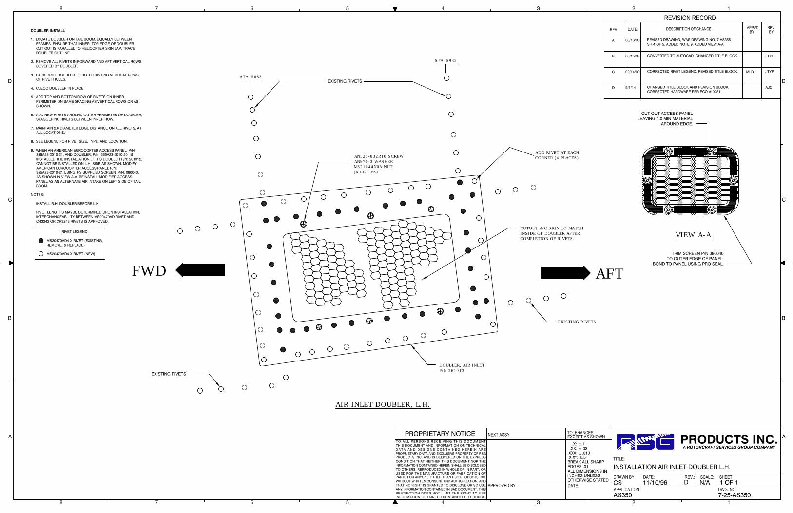
.X: ±.1 .XX: ±.03.XXX: ±.010 X.X°: ±.5°BREAK ALL SHARPEDGES .01ALL DIMENSIONS ININCHES UNLESSOTHERWISE STATED
TOLERANCES
APPROVED BY:
NEXT ASSY.
DATE:
EXCEPT AS SHOWN
DRAWN BY:
APPLICATION:
DATE:
TITLE:
REV.: SCALE:
DWG. NO.:
SHEET:
PROPRIETARY NOTICET O A LL PE R S ON S R E C EI V IN G T H I S DO C UM E NTTHIS DOCUMENT AND INFORMATION OR TECHNICALD A T A A N D D E S I G N S C O N T A I N E D H E R E I N A R EPROPRIETARY DATA AND EXCLUSIVE PROPERTY OF RSGPRODUCTS INC. AND IS DELIVERED ON THE EXPRESSCONDITION THAT NEITHER THIS DOCUMENT NOR THEINFORMATION CONTAINED HEREIN SHALL BE DISCLOSEDTO OTHERS, REPRODUCED IN WHOLE OR IN PART, ORUSED FOR THE MANUFACTURE OR FABRICATION OFPARTS FOR ANYONE OTHER THAN RSG PRODUCTS INC.WITHOUT WRITTEN CONSENT AND AUTHORIZATION, ANDTHAT NO RIGHT IS GRANTED TO DISCLOSE OR SO USEANY INFORMATION CONTAINED IN SAD DOCUMENT. THISRESTRICTION DOES NOT LIMIT THE RIGHT TO USEINFORMATION OBTAINED FROM ANOTHER SOURCE.
PRODUCTS INC.A ROTORCRAFT SERVICES GROUP COMPANY
8 7 6 5 4 3 2 1
A
B
C
D
A
B
C
D
8 7 6 5 4 3 2 1
DATE:REV DESCRIPTION OF CHANGE
REVISION RECORDAPPVD.
BYREV.BY
AS350 7-25-AS350
1 OF 1N/AD11/10/96CS
INSTALLATION AIR INLET DOUBLER L.H.
A 08/16/00 REVISED DRAWING, WAS DRAWING NO. 7-AS355SH 4 OF 5. ADDED NOTE 9. ADDED VIEW A-A.
B 06/15/03 CONVERTED TO AUTOCAD, CHANGED TITLE BLOCK. JTYE
C 02/14/09 CORRECTED RIVET LEGEND. REVISED TITLE BLOCK. MLD JTYE
D 9/1/14 CHANGED TITLE BLOCK AND REVISION BLOCK.CORRECTED HARDWARE PER ECO # 0281.
AJC
CUTOUT A/C SKIN TO MATCH
INSIDE OF DOUBLER AFTER
COMPLETION OF RIVETS.
EXISTING RIVETS
DOUBLER, AIR INLET
P/N 261013
DOUBLER INSTALL
1. LOCATE DOUBLER ON TAIL BOOM, EQUALLY BETWEENFRAMES. ENSURE THAT INNER, TOP EDGE OF DOUBLER
CUT OUT IS PARALLEL TO HELICOPTER SKIN LAP. TRACEDOUBLER OUTLINE.
2. REMOVE ALL RIVETS IN FORWARD AND AFT VERTICAL ROWSCOVERED BY DOUBLER.
3. BACK DRILL DOUBLER TO BOTH EXISTING VERTICAL ROWSOF RIVET HOLES.
4. CLECO DOUBLER IN PLACE.
5. ADD TOP AND BOTTOM ROW OF RIVETS ON INNERPERIMETER ON SAME SPACING AS VERTICAL ROWS OR ASSHOWN.
6. ADD NEW RIVETS AROUND OUTER PERIMETER OF DOUBLER,STAGGERING RIVETS BETWEEN INNER ROW.
7. MAINTAIN 2.0 DIAMETER EDGE DISTANCE ON ALL RIVETS, ATALL LOCATIONS.
8. SEE LEGEND FOR RIVET SIZE, TYPE, AND LOCATION.
9. WHEN AN AMERICAN EUROCOPTER ACCESS PANEL, P/N:355A23-2010-21, AND DOUBLER, P/N: 355A23-2010-20, ISINSTALLED THE INSTALLATION OF IFS DOUBLER P/N: 261012,CANNOT BE INSTALLED ON L.H. SIDE AS SHOWN. MODIFYAMERICAN EUROCOPTER ACCESS PANEL P/N:355A23-2010-21 USING IFS SUPPLIED SCREEN, P/N: 080040,AS SHOWN IN VIEW A-A. REINSTALL MODIFIED ACCESSPANEL AS AN ALTERNATE AIR INTAKE ON LEFT SIDE OF TAILBOOM.
NOTES:
INSTALL R.H. DOUBLER BEFORE L.H.
RIVET LENGTHS MAYBE DETERMINED UPON INSTALLATION,INTERCHANGEABILITY BETWEEN MS20470AD RIVET ANDCR3242 OR CR3243 RIVETS IS APPROVED.
AN525-832R10 SCREW
AN970-3 WASHER
MS21044N08 NUT
(6 PLACES)
STA. 5683
EXISTING RIVETS
EXISTING RIVETS
CUT OUT ACCESS PANELLEAVING 1.0 MIN MATERIAL
AROUND EDGE.
TRIM SCREEN P/N 080040TO OUTER EDGE OF PANEL.
BOND TO PANEL USING PRO SEAL.
VIEW A-A
ADD RIVET AT EACH
CORNER (4 PLACES)
AIR INLET DOUBLER, L.H.
STA. 5932
RIVET LEGEND:
MS20470AD4-X RIVET (EXISTING,REMOVE, & REPLACE)
MS20470AD4-X RIVET (NEW)
AFT
FWD

.X: ±.1 .XX: ±.03.XXX: ±.010 X.X°: ±.5°BREAK ALL SHARPEDGES .01ALL DIMENSIONS ININCHES UNLESSOTHERWISE STATED
TOLERANCES
APPROVED BY:
NEXT ASSY.
DATE:
EXCEPT AS SHOWN
DRAWN BY:
APPLICATION:
DATE:
TITLE:
REV.: SCALE:
DWG. NO.:
SHEET:
PROPRIETARY NOTICET O A LL PE R S ON S R E C EI V IN G T H I S DO C UM E NTTHIS DOCUMENT AND INFORMATION OR TECHNICALD A T A A N D D E S I G N S C O N T A I N E D H E R E I N A R EPROPRIETARY DATA AND EXCLUSIVE PROPERTY OF RSGPRODUCTS INC. AND IS DELIVERED ON THE EXPRESSCONDITION THAT NEITHER THIS DOCUMENT NOR THEINFORMATION CONTAINED HEREIN SHALL BE DISCLOSEDTO OTHERS, REPRODUCED IN WHOLE OR IN PART, ORUSED FOR THE MANUFACTURE OR FABRICATION OFPARTS FOR ANYONE OTHER THAN RSG PRODUCTS INC.WITHOUT WRITTEN CONSENT AND AUTHORIZATION, ANDTHAT NO RIGHT IS GRANTED TO DISCLOSE OR SO USEANY INFORMATION CONTAINED IN SAD DOCUMENT. THISRESTRICTION DOES NOT LIMIT THE RIGHT TO USEINFORMATION OBTAINED FROM ANOTHER SOURCE.
PRODUCTS INC.A ROTORCRAFT SERVICES GROUP COMPANY
8 7 6 5 4 3 2 1
A
B
C
D
A
B
C
D
8 7 6 5 4 3 2 1
DATE:REV DESCRIPTION OF CHANGE
REVISION RECORDAPPVD.
BYREV.BY
AS350/355 7-26-AS350
1 OF 1N/AD11/10/96KML
INSTALLATION AIR INLET DOUBLER R.H.
A 08/16/00 REVISED DRAWING NO., WAS 7-AS 355 SHEET 5 OF 5.
DOUBLER INSTALL
1. LOCATE DOUBLER ON TAIL BOOM, EQUALLY BETWEENFRAMES. ENSURE THAT INNER, TOP EDGE OF DOUBLER
CUT OUT IS PARALLEL TO HELICOPTER SKIN LAP. TRACEDOUBLER OUTLINE.
2. REMOVE ALL RIVETS IN FORWARD AND AFT VERTICAL ROWSCOVERED BY DOUBLER.
3. BACK DRILL DOUBLER TO BOTH EXISTING VERTICAL ROWSOF RIVET HOLES.
4. CLECO DOUBLER IN PLACE.
5. ADD TOP AND BOTTOM ROW OF RIVETS ON INNERPERIMETER ON SAME SPACING AS VERTICAL ROWS OR ASSHOWN.
6. ADD NEW RIVETS AROUND OUTER PERIMETER OF DOUBLER,STAGGERING RIVETS BETWEEN INNER ROW.
7. MAINTAIN 2.0 DIAMETER EDGE DISTANCE ON ALL RIVETS, ATALL LOCATIONS.
8. SEE LEGEND FOR RIVET SIZE, TYPE, AND LOCATION.
NOTES:
INSTALL R.H. DOUBLER BEFORE L.H.
RIVET LENGTHS MAYBE DETERMINED UPON INSTALLATION,INTERCHANGEABILITY BETWEEN MS20470AD RIVET ANDCR3242 OR CR3243 RIVETS IS APPROVED.
RIVET LEGEND:
MS20470AD4-X RIVET (EXISTING,REMOVE, & REPLACE)
MS20470AD4-X RIVET (NEW)
AFT
FWD
EXISTING RIVETS
CUTOUT A/C SKIN TO MATCH
INSIDE OF DOUBLER AFTER
COMPLETION OF RIVETS.
AN525-832R10 SCREW
TYP. 6 PLACES
EXISTING RIVETS
EXISTING RIVETS
STA. 5932
R/H AIR INLET DOUBLER
P/N 261013-2
ADD RIVET AT EACH
CORNER (4 PLACES)
SKIN LAP (REF.)
STA. 5683
STRINGERP/N 2610122 PLACES
RIVET DESIGNATIONSTYP. 36 PLACES
AIR INLET DOUBLER, L.H.
B 08/16/00 CONVERTED TO AUTOCAD, CHANGED TITLE BLOCK.
D 9/1/14 CHANGED TITLE BLOCK AND REVISION BLOCK.CORRECTED HARDWARE CALLOUT PER ECO # 0282
AJC
C 02/14/09 CHANGED P/N: 261013 TO 261013-2. UPDATED TITLEBLOCK. CORRECTED RIVET LEGEND. CHANGED RIVETDESIGNATIONS ON DOUBLER INSTALL. REVISEDTITLE BLOCK.
DWE

.X: ±.1 .XX: ±.03.XXX: ±.010 X.X°: ±.5°BREAK ALL SHARPEDGES .01ALL DIMENSIONS ININCHES UNLESSOTHERWISE STATED
TOLERANCES
APPROVED BY:
NEXT ASSY.
DATE:
EXCEPT AS SHOWN
DRAWN BY:
APPLICATION:
DATE:
TITLE:
REV.: SCALE:
DWG. NO.:
SHEET:
PROPRIETARY NOTICET O A LL PE R S ON S R E C EI V IN G T H I S DO C UM E NTTHIS DOCUMENT AND INFORMATION OR TECHNICALD A T A A N D D E S I G N S C O N T A I N E D H E R E I N A R EPROPRIETARY DATA AND EXCLUSIVE PROPERTY OF RSGPRODUCTS INC. AND IS DELIVERED ON THE EXPRESSCONDITION THAT NEITHER THIS DOCUMENT NOR THEINFORMATION CONTAINED HEREIN SHALL BE DISCLOSEDTO OTHERS, REPRODUCED IN WHOLE OR IN PART, ORUSED FOR THE MANUFACTURE OR FABRICATION OFPARTS FOR ANYONE OTHER THAN RSG PRODUCTS INC.WITHOUT WRITTEN CONSENT AND AUTHORIZATION, ANDTHAT NO RIGHT IS GRANTED TO DISCLOSE OR SO USEANY INFORMATION CONTAINED IN SAD DOCUMENT. THISRESTRICTION DOES NOT LIMIT THE RIGHT TO USEINFORMATION OBTAINED FROM ANOTHER SOURCE.
PRODUCTS INC.A ROTORCRAFT SERVICES GROUP COMPANY
8 7 6 5 4 3 2 1
A
B
C
D
A
B
C
D
8 7 6 5 4 3 2 1
DATE:REV DESCRIPTION OF CHANGE
REVISION RECORDAPPVD.
BYREV.BY
AS350 7-28-AS350
1 OF 1N/AA10/18/07MGV
R.H. AIR EXIT DOUBLER INSTALL
A 9/1/14 CHANGED TITLE BLOCK AND REVISION BLOCK. AJC
NOTES:
1. THIS INSTALLATION IS APPLICABLE TOAIRCRAFT WITH STRAP TYPE DOUBLERSAT THE SPLICE POINT BETWEEN THEFUSELAGE AND TAILBOOM.
2. REMOVE EXISTING STRAP. DISCARD.
3. REMOVE EXISTING BRACKET INSIDE ANDDISCARD.
4. LOCATE EXISTING RIVET PATTERN ASSHOWN AND POSITION DOUBLER.
5. MARK AROUND DOUBLER, REMOVEDOUBLER AND REMOVE ANY RIVETSINSIDE MARKING.
6. RE-POSITION DOUBLER, BACK DRILLDOUBLER AND CLECO IN PLACE.
7. CUT OUT CENTER HOLE. TRIM DOUBLERAS NECESSARY TO FIT.
8. ALSO DRILL UPPER ANGLE P/N: 261096AND DRILL IN LOWER ANGLE P/N: 261098
9. INSTALL NEW STRAP P/N 261512 IN SAMELOCATION OVER NEW DOUBLER.
10. TRIM LENGTHS AS NECESSARY.
11. SEAL AROUND DOUBLERS WITH PRC.
12. RIVET LENGTHS MAYBE DETERMINEDUPON INSTALLATION, INTERCHANEABILITYBETWEEN MS20470AD RIVET AND CR3234OR CR3243 RIVETS IS APPROVED.
UPPER ANGLE P/N: 261096
FIT DOUBLER, THEN BACK DRILL.
DRILL AND INSTALL FIELD RIVETS.
R.H. AIR EXIT DOUBLERP/N: 261100-1
LOWER ANGLEP/N: 261098
AN525-832R12SCREW (4 PLACES)DRILL AS SHOWN
SCREENP/N: 080039
PICK UP EXISTING HOLESADD RIVETSTHIS LOCATION
COUNTERSINK DOUBLERP/N: 261100-1 FORFLUSH RIVETS (3 PLC'S)
PICK UP EXISTING HOLES
ADD RIVETTHIS LOCATION
STRAPP/N 261512
FILLERP/N 261513
FILLERP/N 261513
RIVET LEGEND:
MS20470E-X RIVETALT: MS20470D-X RIVET
MS20470AD5-X RIVET EXISTING
MS20470AD5-X RIVET
MS20470AD4-X RIVET
MS20470AD4-X RIVET

.X: ±.1 .XX: ±.03.XXX: ±.010 X.X°: ±.5°BREAK ALL SHARPEDGES .01ALL DIMENSIONS ININCHES UNLESSOTHERWISE STATED
TOLERANCES
APPROVED BY:
NEXT ASSY.
DATE:
EXCEPT AS SHOWN
DRAWN BY:
APPLICATION:
DATE:
TITLE:
REV.: SCALE:
DWG. NO.:
SHEET:
PROPRIETARY NOTICET O A LL PE R S ON S R E C EI V IN G T H I S DO C UM E NTTHIS DOCUMENT AND INFORMATION OR TECHNICALD A T A A N D D E S I G N S C O N T A I N E D H E R E I N A R EPROPRIETARY DATA AND EXCLUSIVE PROPERTY OF RSGPRODUCTS INC. AND IS DELIVERED ON THE EXPRESSCONDITION THAT NEITHER THIS DOCUMENT NOR THEINFORMATION CONTAINED HEREIN SHALL BE DISCLOSEDTO OTHERS, REPRODUCED IN WHOLE OR IN PART, ORUSED FOR THE MANUFACTURE OR FABRICATION OFPARTS FOR ANYONE OTHER THAN RSG PRODUCTS INC.WITHOUT WRITTEN CONSENT AND AUTHORIZATION, ANDTHAT NO RIGHT IS GRANTED TO DISCLOSE OR SO USEANY INFORMATION CONTAINED IN SAD DOCUMENT. THISRESTRICTION DOES NOT LIMIT THE RIGHT TO USEINFORMATION OBTAINED FROM ANOTHER SOURCE.
PRODUCTS INC.A ROTORCRAFT SERVICES GROUP COMPANY
8 7 6 5 4 3 2 1
A
B
C
D
A
B
C
D
8 7 6 5 4 3 2 1
DATE:REV DESCRIPTION OF CHANGE
REVISION RECORDAPPVD.
BYREV.BY
AS350 7-29-AS350
1 OF 1N/AA10/18/07MGV
L.H. AIR EXIT DOUBLER INSTALL
A 9/1/14 CHANGED TITLE BLOCK AND REVISION BLOCK. AJC
STA 4923
8 RIVETS DOWN 9 RIVETS DOWN
BAGGAGE DOOR OPENING
UPPER ANGLE P/N: 261097
REMOVE EXISTING ROW OF RIVETSUNDER DOUBLER VERTICALLY.
FIT DOUBLER, THEN BACK DRILL.
DRILL AND INSTALL FIELD RIVETS.
AN525-832R12SCREW (4 PLACES)DRILL AS SHOWN
L.H. AIR EXIT DOUBLERP/N: 261101-1
LOWER ANGLEP/N: 261098
1
2
3
4
5
6
7
8
1
2
3
4
5
6
7
8
9
SCREENP/N: 080039
6.1
(REF)7.1
(REF)
STRAPP/N: 261511
FILLERP/N: 261513
FILLERP/N: 261513
RIVET LEGEND:
MS20470E-X RIVETALT: MS20470D-X RIVET
MS20470AD5-X RIVET
MS20470AD4-X RIVET
MS20470AD4-X RIVET
MS20426AD4-X RIVET
NOTES:
1. THIS INSTALLATION IS APPLICABLE TOAIRCRAFT WITH STRAP TYPE DOUBLERSAT THE SPLICE POINT BETWEEN THEFUSELAGE AND TAILBOOM.
2. REMOVE EXISTING STRAP. DISCARD.
3. IF STROBE POWERPACK IS IN THE THREEO'CLOCK POSITION, RE-LOCATE TO THE 2O'CLOCK POSITION.
4. LOCATE EXISTING RIVET PATTERN ASSHOWN AND POSITION DOUBLER.
5. MARK AROUND DOUBLER, REMOVEDOUBLER AND REMOVE ANY RIVETSINSIDE MARKING.
6. RE-POSITION DOUBLER, BACK DRILLDOUBLER AND CLECO IN PLACE.
7. CUT OUT CENTER HOLE. TRIM DOUBLERAS NECESSARY TO FIT.
8. ALSO DRILL UPPER ANGLE P/N: 261097AND DRILL IN LOWER ANGLE P/N: 261098
9. INSTALL NEW STRAP P/N 261511 IN SAMELOCATION OVER NEW DOUBLER.
10. TRIM LENGTHS AS NECESSARY.
11. SEAL AROUND DOUBLERS WITH PRC.
12. RIVET LENGTHS MAYBE DETERMINEDUPON INSTALLATION, INTERCHANEABILITYBETWEEN MS20470AD RIVET AND CR3234OR CR3243 RIVETS IS APPROVED.

RSG Products Inc. INSTALLATION OF FORWARD EVAPORATOR – AS350 Air Conditioning
Date: 11/06/15 Section 7: Installation of Forward Evaporator Page 1 of 3
Step 7
Installation of Forward Evaporator

RSG Products Inc. INSTALLATION OF FORWARD EVAPORATOR – AS350 Air Conditioning
Date: 11/06/15 Section 7: Installation of Forward Evaporator Page 2 of 3
Installation of Forward Evaporator
STEP PROCEDURE MECH INSP
7.1 On B3 models, relocate NR digital indicator. Higher 12” min., and aft of pitot static lines, using assisting hardware. See note on drawing 4-21-AS350.
7.2 Relocate warning horn up and forward as required.
7.3
Position forward evaporator assembly, P/N 560025-O, as shown in drawing 4-21-AS350. Mark rivets to be drilled out and existing bolts that will be used to mount evaporator. Also mark location on inboard forward mount hole on floor as shown in note on drawing 4-21-AS350.
7.4 Remove and drill out rivets and marked hole. Install nut plate on evaporator.
7.5
Position doubler P/N 260373-1 as shown in drawing 4-21-AS350, drill and install as shown. Cut out center. Line hole with Caterpillar Grommet. Bond grommet to edge of metal.
7.6 Do not install evaporator until Freon lines are connected.
7.7
Install drain line from the evaporator out through the cabin floor. The existing hole normally found in the aircraft skin (right forward side) can be utilized. Cutting of the aircraft skin will not usually be required. “IF” no vacant hole is found, locate and drill a hole according to the detail “A” on drawing 4-21-AS350. Secure drain line and cut off at a negative angle.
7.8
When connecting Freon lines, make sure you install sensing bulb on #10 line. Wrap cork tape around fittings. See drawing 4-21 AS350 “Expansion Valve Detail”. After all lines are attached install Fwd Evaporator with hardware per drawing 4-21-AS350.
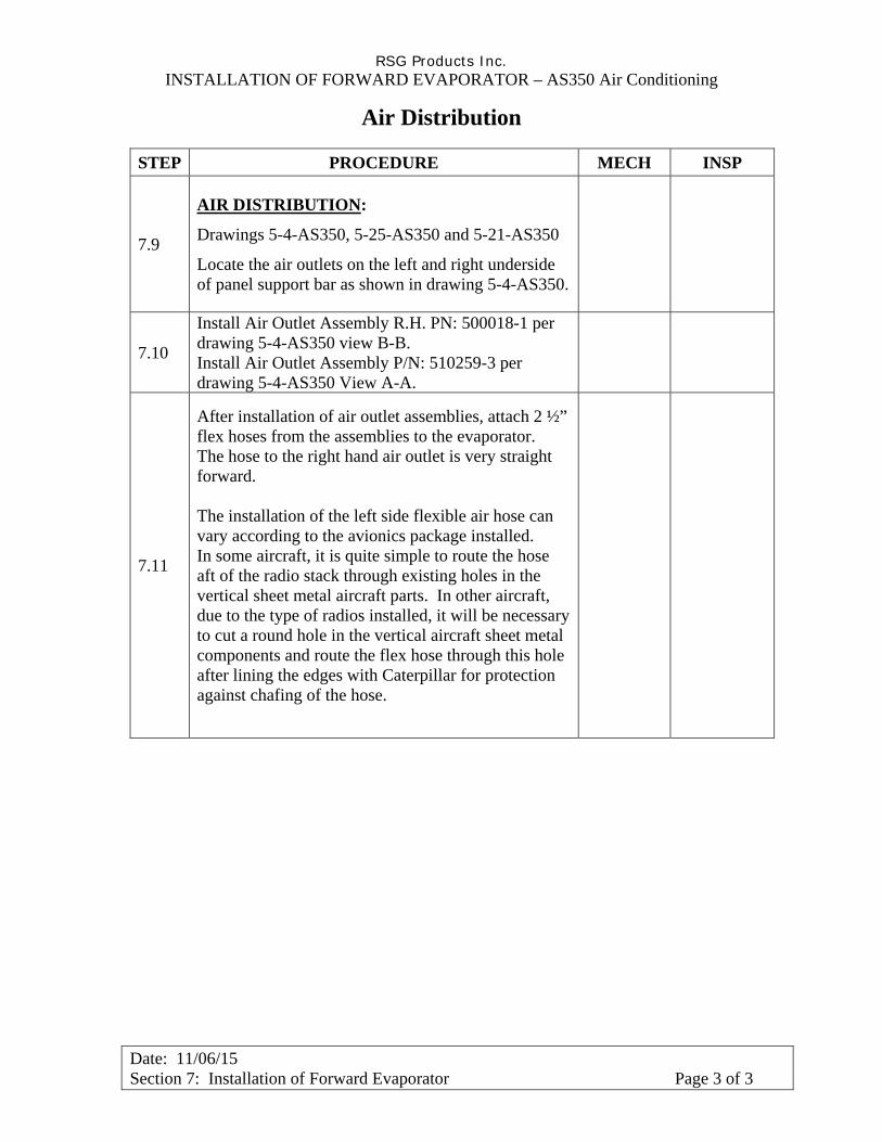
RSG Products Inc. INSTALLATION OF FORWARD EVAPORATOR – AS350 Air Conditioning
Date: 11/06/15 Section 7: Installation of Forward Evaporator Page 3 of 3
Air Distribution
STEP PROCEDURE MECH INSP
7.9
AIR DISTRIBUTION:
Drawings 5-4-AS350, 5-25-AS350 and 5-21-AS350
Locate the air outlets on the left and right underside of panel support bar as shown in drawing 5-4-AS350.
7.10
Install Air Outlet Assembly R.H. PN: 500018-1 per drawing 5-4-AS350 view B-B. Install Air Outlet Assembly P/N: 510259-3 per drawing 5-4-AS350 View A-A.
7.11
After installation of air outlet assemblies, attach 2 ½” flex hoses from the assemblies to the evaporator. The hose to the right hand air outlet is very straight forward. The installation of the left side flexible air hose can vary according to the avionics package installed. In some aircraft, it is quite simple to route the hose aft of the radio stack through existing holes in the vertical sheet metal aircraft parts. In other aircraft, due to the type of radios installed, it will be necessary to cut a round hole in the vertical aircraft sheet metal components and route the flex hose through this hole after lining the edges with Caterpillar for protection against chafing of the hose.

.X: ±.1 .XX: ±.03.XXX: ±.010 X.X°: ±.5°BREAK ALL SHARPEDGES .01ALL DIMENSIONS ININCHES UNLESSOTHERWISE STATED
TOLERANCES
APPROVED BY:
NEXT ASSY.
DATE:
EXCEPT AS SHOWN
DRAWN BY:
APPLICATION:
DATE:
TITLE:
REV.: SCALE:
DWG. NO.:
SHEET:
PROPRIETARY NOTICET O A L L P E R S O N S R E C E I V IN G T H I S D O C U M E N TTHIS DOCUMENT AND INFORMATION OR TECHNICALD A T A A N D D E S I G N S C O N T A I N E D H E R E I N A R EPROPRIETARY DATA AND EXCLUSIVE PROPERTY OF RSGPRODUCTS INC. AND IS DELIVERED ON THE EXPRESSCONDITION THAT NEITHER THIS DOCUMENT NOR THEINFORMATION CONTAINED HEREIN SHALL BE DISCLOSEDTO OTHERS, REPRODUCED IN WHOLE OR IN PART, ORUSED FOR THE MANUFACTURE OR FABRICATION OFPARTS FOR ANYONE OTHER THAN RSG PRODUCTS INC.WITHOUT WRITTEN CONSENT AND AUTHORIZATION, ANDTHAT NO RIGHT IS GRANTED TO DISCLOSE OR SO USEANY INFORMATION CONTAINED IN SAD DOCUMENT. THISRESTRICTION DOES NOT LIMIT THE RIGHT TO USEINFORMATION OBTAINED FROM ANOTHER SOURCE.
PRODUCTS INC.A ROTORCRAFT SERVICES GROUP COMPANY
8 7 6 5 4 3 2 1
A
B
C
D
A
B
C
D
8 7 6 5 4 3 2 1
DATE:REV DESCRIPTION OF CHANGE
REVISION RECORDAPPVD.
BYREV.BY
AS350 4-21-AS350
1 OF 1N/AG06/20/85JEL
FORWARD EVAPORATOR INSTALL
A 05/27/91 REPOSITIONED EVAPORATOR AND LINES. ADDEDDETAIL "A" AND NOTES. TITLE BLOCK WAS "CAS" ISNOW "IFS" WAS 2 OF 2, IS NOW 3 OF 3.
MD
B 11/15/99 ADDED NUTPLATE AND NOTE. JHK
C 01/25/99 SEE NR NOTE. JHK
D 08/16/00 REVISED DRAWING NUMBER,WAS 4-AS350 SHEET3 OF 3. IS NOW 4-21-AS350
JHK
E 04/12/02 COMPUTERIZED, CHANGED TITLE BLOCK JDB
F 01/03/07 CORRECTED FWD EVAP PN: 560025-1-O TO 560025-O.REVISED TITLE BLOCK.
IFS JTYE
G 9/1/14 CHANGED TITLE BLOCK AND REVISION BLOCK. AJC
STAINLESSSTEEL CLAMP
INSULATIONDELETEDFOR CLARITY
SENSING BULB
EXPANSION VALVEEVAP
EXPANSION VALVE DETAILSCALE: NONE
INSULATE SENSION BULB BEFORE CHARGINGWITH REFRIGERENT.
FORWARD EVAPORATORASS'Y. P/N 560025-"O"DELETED FOR CLARITY
DRAIN TUBE SEE DETAIL "A"
CP 104
DOUBLER P/N 260373-1
LINE W/"CATERPILLAR",BOND TO METAL
RIVET CR 3243-4-3 (TYP. 16)
FWD
FWD
OUTBDVIEW LOOKING DOWN AT COCKPITFLOOR FORWARD OF PILOT'S SEAT
INSTALL W/EXISTING AIRCRAFT FASTENER
USE 5THBOLT FROMCORNER 12"
NOTE:IF EXISITING GROMMETIS NOT AVAILABLE, INSTALLNEW GROMMET MS35489-1352" AFT OF EXISTING FOR A/C DRAIN.
DETAIL AFORWARD
1.0045°
FWD. EVAPORATOR
DRAIN TUBE
CUT DRAIN TUBE AS SHOWN
DRILL OUT EXISTING ACH RIVETS &ENLARGE HOLE TO #10INSTALL W/AN3-4A BOLTS(3)AN960-10 WASHERS(6)MS21044-N3 NUTS(3)
INSTALL EVAP TEMPORALLY AND LOCATE FWD INBOARD NUTPLATE LOCATION. REMOVE EVAP AND INSTALL NUTPLATE MS21059L3 W/2 EA. RIVET CCR264SS3-3
NOTES:
RELOCATE WARNING HORN UP& FORWARD, AS REQUIRED.
NOTE B3 ONLY:
RELOCATE NR DIGITAL INDICATOR MOUNTEDNEAR FLOOR, ON RIGHT SIDE OF CONSOLEPANEL UP 12.0" MIN. FROM FLOOR AND AFT OFPITOT STATIC LINES USING EXISTING HARDWARE.REROUTE NR WIRE TO ACCOMMODATE NEW NRLOCATION.
EXTREMELY IMPORTANT:
FAILURE TO SECURE EXPANSION VALVESENSING BULB, TIGHTLY, TO THE RETURNLINE HOSE FITTING (#10) WITH A STAINLESSSTEEL CLAMP (AND INSULATE SENSING BULB &LINE) WILL DRAMATICALLY DECREASE THEPERFORMANCE OF THE AFT EVAPORATOR(NOT FORWARD).

.X: ±.1 .XX: ±.03.XXX: ±.010 X.X°: ±.5°BREAK ALL SHARPEDGES .01ALL DIMENSIONS ININCHES UNLESSOTHERWISE STATED
TOLERANCES
APPROVED BY:
NEXT ASSY.
DATE:
EXCEPT AS SHOWN
DRAWN BY:
APPLICATION:
DATE:
TITLE:
REV.: SCALE:
DWG. NO.:
SHEET:
PROPRIETARY NOTICET O A L L P E R S O N S R E C E I V IN G T H I S D O C U M E N TTHIS DOCUMENT AND INFORMATION OR TECHNICALD A T A A N D D E S I G N S C O N T A I N E D H E R E I N A R EPROPRIETARY DATA AND EXCLUSIVE PROPERTY OF RSGPRODUCTS INC. AND IS DELIVERED ON THE EXPRESSCONDITION THAT NEITHER THIS DOCUMENT NOR THEINFORMATION CONTAINED HEREIN SHALL BE DISCLOSEDTO OTHERS, REPRODUCED IN WHOLE OR IN PART, ORUSED FOR THE MANUFACTURE OR FABRICATION OFPARTS FOR ANYONE OTHER THAN RSG PRODUCTS INC.WITHOUT WRITTEN CONSENT AND AUTHORIZATION, ANDTHAT NO RIGHT IS GRANTED TO DISCLOSE OR SO USEANY INFORMATION CONTAINED IN SAD DOCUMENT. THISRESTRICTION DOES NOT LIMIT THE RIGHT TO USEINFORMATION OBTAINED FROM ANOTHER SOURCE.
PRODUCTS INC.A ROTORCRAFT SERVICES GROUP COMPANY
8 7 6 5 4 3 2 1
A
B
C
D
A
B
C
D
8 7 6 5 4 3 2 1
DATE:REV DESCRIPTION OF CHANGE
REVISION RECORDAPPVD.
BYREV.BY
AS350 5-4-AS350
1 OF 11/2E08/29/01TMUZZY
AIR DISTRIBUTION
A 05/10/99 ADDED ALTERNATE AIR OUTLET ASSY, P/N 500018-1.
D 12/29/08 ADDED CONFIGURATION NOTATION FOR CLARITY.ADDED VIEW A-A, REMOVED REFERENCE NOTE TODWG # 5-14-AS350 SH 1 OF 1. REMOVED NOTE 4.ADDED VIEW C-C. VIEW DETAILS REDRAWN FORCLARITY. REVISED TITLE BLOCK.
B 08/16/00 REVISED DRAWING NUMBER, WAS 5-AS 350; SHEETNUMBER WAS 1B OF 3.
C 08/29/01 CONVERTED TO AUTOCAD, REVISED TITLE BLOCK.
E 09/01/14 CHANGED TITLE BLOCK AND REVISION BLOCK. AJC
AIR OUTLET INSTALLATIONVIEW LOOKING FORWARD AT INSTRUMENT PANEL
IFS P/N 500018 OR 500018-1 RH AIR OUTLET ASSEMBLY
(EXISTING)PANEL SUPPORT BAR
TOUR OPERATOR VERSIONEUROCOPTER CANADA LTD
COMPATIBLE WITH CLAIRION OR SIMILAR TAPE PLAYER.
A
A
B
B
LH AIR OUTLET ASSEMBLYIFS PN 510259-2
UTILIZE WITH: TOUR 1 VERSION
VIEW A-A2 1/2" BAND CLAMP
LH AIR OUTLET ASSY
EXISTING PANEL
FROM FWD
2 1/2" FLEX HOSE
MIN 2X CCR3243-4-X RIVETS
SUPPORT BAR
IFS PN 5120259-2
VIEW B-B
EXISTING PANEL
RH AIR OUTLET ASSY
GLARE SHIELDMOUNTING SCREW
GLARE SHIELD
2 1/2" FLEX HOSE
2 1/2" BAND CLAMPIFS PN 500018-1
SUPPORT BAR
MIN 3X CCR3243-4-XRIVETS
EVAPORATOR
FROM FWD EVAPORATOR
HI LOWLOW MEDHIFANOFFA/C
INTEGRATED FLIGHT
FWD FANMASTER AFT FAN
AIR CONDITIONING
MASTER
5
VIEW C-C
MIN 5X CCR3243-4-XRIVETS
C
C
EXISTING PANELSUPPORT BAR
PLACARD P/N 120105
SWITCH PLATEP/N 261086
1. LOCATE IFS P/N 500018 OR 500018-1 AS SHOWN, FLUSHWITH AFT SURFACE OF SUPPORT BAR.
2. REMOVE EXISTING RIVETS IN BACK SIDE OF SUPPORTBAR AS REQUIRED.
3. MATCH DRILL AIR OUTLET ASSEMBLY'S VERTICALALUMINUM SUPPORT TO BACK SIDE OF SUPPORT BARAND ATTACH USING CR3243-4-X CHERRY RIVETS, 3X MIN.
4. REMOVED.5. ATTACH AIR OUTLET AT FORWARD END WITH ANGLES,
(IFS P/N 261087) TO EUROCOPTER CANADA CLOSE OUTPANEL, ABOVE. CLIPS NO LONGER USED NOTE REMOVED.
1. REMOVE EXISTING RIVETS IN BOTTOM OF PANEL SUPPORTBAR. MATCH DRILL SWITCH PLATE, (IFS P/N 261086) TOEXISTING HOLES.
2. FIT SWITCH PLATE. SHIM DOWNWARD AS REQUIRED TOALLOW PLACARD TO CLEAR PANEL SUPPORT BAR AT TOP.ATTACH SWITCH PLATE USING CR3243-4-X CHERRY MAXRIVETS, 5X MIN.
3. INSTALL SWITCHES AND CIRCUIT BREAKER FROM BACKSIDE OF SWITCH PANEL.
4. INSTALL SWITCH PLACARD (IFS P/N 120105) AND SWITCHESUSING 6X MS35214-29 SCREWS. .
5. SECURE CIRCUIT BREAKER.
SEE ECO 0576


.X: ±.1 .XX: ±.03.XXX: ±.010 X.X°: ±.5°BREAK ALL SHARPEDGES .01ALL DIMENSIONS ININCHES UNLESSOTHERWISE STATED
TOLERANCES
APPROVED BY:
NEXT ASSY.
DATE:
EXCEPT AS SHOWN
DRAWN BY:
APPLICATION:
DATE:
TITLE:
REV.: SCALE:
DWG. NO.:
SHEET:
PROPRIETARY NOTICET O A LL PE R S ON S R E C EI V IN G T H I S DO C UM E NTTHIS DOCUMENT AND INFORMATION OR TECHNICALD A T A A N D D E S I G N S C O N T A I N E D H E R E I N A R EPROPRIETARY DATA AND EXCLUSIVE PROPERTY OF RSGPRODUCTS INC. AND IS DELIVERED ON THE EXPRESSCONDITION THAT NEITHER THIS DOCUMENT NOR THEINFORMATION CONTAINED HEREIN SHALL BE DISCLOSEDTO OTHERS, REPRODUCED IN WHOLE OR IN PART, ORUSED FOR THE MANUFACTURE OR FABRICATION OFPARTS FOR ANYONE OTHER THAN RSG PRODUCTS INC.WITHOUT WRITTEN CONSENT AND AUTHORIZATION, ANDTHAT NO RIGHT IS GRANTED TO DISCLOSE OR SO USEANY INFORMATION CONTAINED IN SAD DOCUMENT. THISRESTRICTION DOES NOT LIMIT THE RIGHT TO USEINFORMATION OBTAINED FROM ANOTHER SOURCE.
PRODUCTS INC.A ROTORCRAFT SERVICES GROUP COMPANY
8 7 6 5 4 3 2 1
A
B
C
D
A
B
C
D
8 7 6 5 4 3 2 1
DATE:REV DESCRIPTION OF CHANGE
REVISION RECORDAPPVD.
BYREV.BY
AS350 5-25-AS350
1 OF 1N/AB07/08/02JTYE
AIR DISTRIBUTION
A 09/09/09 REVISED TITLE BLOCK. ADDED CORRECTED DETAIL C.
B 9/1/14 CHANGED TITLE BLOCK AND REVISION BLOCK. AJC
UTILIZED WITH:
VIEW B-B
TAP EXISTING AIR OUTLET MOUNTSTO 8-32 UNFINSTALL WEMAC USING SCREWSMS 24693-S55 (4)SNAP ON DECOR RING NO 7194-1
TRIM HEADLINER AND CABINSTRUCTURE TO FIT WEMAC
ROTATE NEW WEMAC 90°MATCH DRILL NEW HOLES (COUNTERSINK)IN WEMAC TO MATCH AIR FRAME
WEMAC NO 2368-503 (CLEAR)NOTE: APPLIES TO AIRCRAFTW/SMALL ADH AIR OUTLETS
DETAIL C
VIEW A-A
REPLACE EXISTING AIROUTLETS WITH WEMACNO 2368-503 (4)
NOTE: APPLIES TO SN 1302 & DOWN ONLY
NOT REQUIRED IF LATEMODEL ADH AIR OUTLETSARE IN PLACE
HEADLINER
AIR DUCT CLOSURE ASSYPN 510092REMOVE & DISCARD EXISTINGFRESH AIR INLET INSTALLCLOSURE ASSY USINGEXISTING HARDWARE
A
BA
B
ECL TOUR -1
2 12" FLEX DUCT
DETAIL C
NOTES:
1. CUT 3" HOLE AS REQUIREDTO ALLOW FLEX DUCT TO CONNECTTO LH AIR OUTLET
2. INSTALL BLACK EDGETRIM AROUND HOLE

RSG Products Inc. INSTALLATION OF COMPRESSOR – AS350 Air Conditioning
Date: 05/29/15 Section 8: Installation of Compressor Page 1 of 5
Step 8
Installation of Compressor

RSG Products Inc. INSTALLATION OF COMPRESSOR – AS350 Air Conditioning
Date: 05/29/15 Section 8: Installation of Compressor Page 2 of 5
Installation of Compressor
STEP PROCEDURE MECH INSP
8.0 NOTE: MUST BE PERFORMED IN ACCORDANCE WITH CURRENT EUROCOPTER TECHNICAL DATA.
8.1 Place a support on the transmission deck to support the engine drive while the shaft is disconnected for belt installation.
8.2 Remove the cotter pins from the four pins holding the “Gimble Ring” at the Thomas coupling.
8.3 Slide the “Gimble Ring” aft to gain access to the Thomas coupling.
8.4 Remove the 6 bolts and Thomas coupling connecting the drive shaft and shift slightly aft.
8.5 Install two (2) Compressor Drive belts
8.6 Reassemble the Thomas coupling per AEC Specifications. Torque and Safety Coupling!! Torque Mark all bolts.
8.7
Secure 1 belt to the outside of the drive shaft cover for a spare and slip one through the housing and over the drive pulley. NOTE: THE CURRENT BELT P/N 060018-1 HAS A SPECIFIC DIRECTION OF ROTATION. (See figure 1, page 3) NOTE: THE CURRENT BELT P/N 060005 HAS NO SPECIFIC DIRECTION OF ROTATION.

RSG Products Inc. INSTALLATION OF COMPRESSOR – AS350 Air Conditioning
Date: 05/29/15 Section 8: Installation of Compressor Page 3 of 5

RSG Products Inc. INSTALLATION OF COMPRESSOR – AS350 Air Conditioning
Date: 05/29/15 Section 8: Installation of Compressor Page 4 of 5
Installation of Compressor
STEP PROCEDURE MECH INSP
8.8 Install the “Gimble Ring” pins and cotter pins. Remove supports.
8.9
Installation of Bracket Kit P/N 350-11-031-02 in accordance with: 6-2-AS350, 6-12-AS350 and 6-21-AS350 or 6-3-AS350, 6-13-AS350 and 6-22-AS350.
8.10
Install the Forward Compressor Bracket, Compressor Standoffs and Compressor per Drawings: 6-2-AS350, 6-12-AS350 and 6-21-AS350 or 6-3-AS350, 6-13-AS350 and 6-22-AS350
8.11
Install the compressor drive belt on the drive pulley and the compressor clutch pulley. Tighten bolts at the adjustment arm assuring the belt proper amount of tension. Tighten the lower forward mounting bolt.
8.12 This tension may be performed by either pull scale. (See Belt Tension Recommendation)
8.13 50/30 lbs pull tension at tension adjustment bolt should provide adequate belt tension. (See figure 2, page 5)
BELT TENSION RECOMMENDATION:
FLAT BELT IFS P/N 060018-1 TENSION TO 50lbs
GROOVED BELT IFS P/N 060005 TENSION TO 30lbs
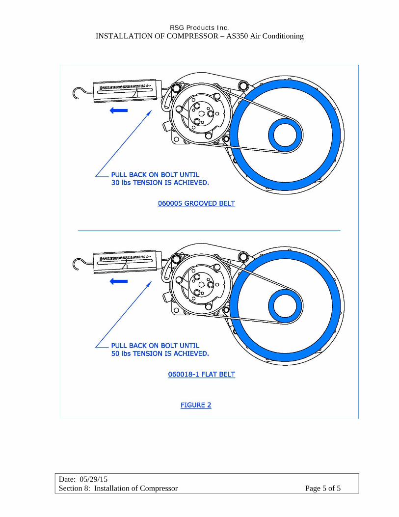
RSG Products Inc. INSTALLATION OF COMPRESSOR – AS350 Air Conditioning
Date: 05/29/15 Section 8: Installation of Compressor Page 5 of 5
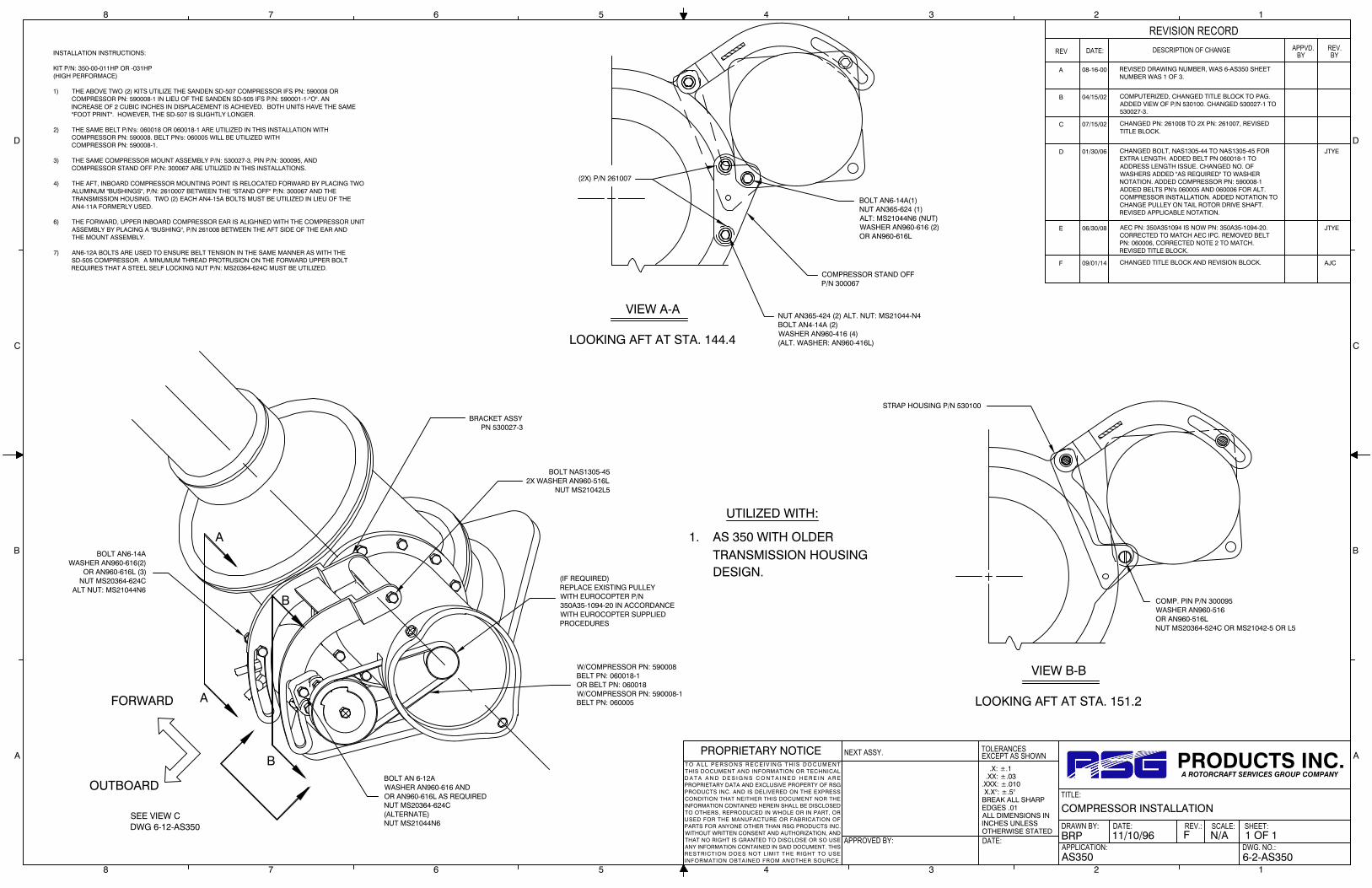
.X: ±.1 .XX: ±.03.XXX: ±.010 X.X°: ±.5°BREAK ALL SHARPEDGES .01ALL DIMENSIONS ININCHES UNLESSOTHERWISE STATED
TOLERANCES
APPROVED BY:
NEXT ASSY.
DATE:
EXCEPT AS SHOWN
DRAWN BY:
APPLICATION:
DATE:
TITLE:
REV.: SCALE:
DWG. NO.:
SHEET:
PROPRIETARY NOTICET O A L L P E R S O N S R E C E I V IN G T H I S D O C U M E N TTHIS DOCUMENT AND INFORMATION OR TECHNICALD A T A A N D D E S I G N S C O N T A I N E D H E R E I N A R EPROPRIETARY DATA AND EXCLUSIVE PROPERTY OF RSGPRODUCTS INC. AND IS DELIVERED ON THE EXPRESSCONDITION THAT NEITHER THIS DOCUMENT NOR THEINFORMATION CONTAINED HEREIN SHALL BE DISCLOSEDTO OTHERS, REPRODUCED IN WHOLE OR IN PART, ORUSED FOR THE MANUFACTURE OR FABRICATION OFPARTS FOR ANYONE OTHER THAN RSG PRODUCTS INC.WITHOUT WRITTEN CONSENT AND AUTHORIZATION, ANDTHAT NO RIGHT IS GRANTED TO DISCLOSE OR SO USEANY INFORMATION CONTAINED IN SAID DOCUMENT. THISRESTRICTION DOES NOT LIMIT THE RIGHT TO USEINFORMATION OBTAINED FROM ANOTHER SOURCE.
PRODUCTS INC.A ROTORCRAFT SERVICES GROUP COMPANY
8 7 6 5 4 3 2 1
A
B
C
D
A
B
C
D
8 7 6 5 4 3 2 1
DATE:REV DESCRIPTION OF CHANGE
REVISION RECORDAPPVD.
BYREV.BY
AS350 6-2-AS350
1 OF 1N/AF11/10/96BRP
COMPRESSOR INSTALLATION
A 08-16-00 REVISED DRAWING NUMBER, WAS 6-AS350 SHEETNUMBER WAS 1 OF 3.
STRAP HOUSING P/N 530100
A
A
B
B
FORWARD
OUTBOARD
SEE VIEW CDWG 6-12-AS350
W/COMPRESSOR PN: 590008BELT PN: 060018-1OR BELT PN: 060018W/COMPRESSOR PN: 590008-1BELT PN: 060005
BOLT AN 6-12AWASHER AN960-616 ANDOR AN960-616L AS REQUIREDNUT MS20364-624C(ALTERNATE)NUT MS21044N6
BOLT AN6-14AWASHER AN960-616(2)
OR AN960-616L (3)NUT MS20364-624C
ALT NUT: MS21044N6
BOLT NAS1305-452X WASHER AN960-516L
NUT MS21042L5
BRACKET ASSYPN 530027-3
VIEW A-A
LOOKING AFT AT STA. 144.4
(2X) P/N 261007
NUT AN365-424 (2) ALT. NUT: MS21044-N4BOLT AN4-14A (2)WASHER AN960-416 (4)(ALT. WASHER: AN960-416L)
COMPRESSOR STAND OFFP/N 300067
BOLT AN6-14A(1)NUT AN365-624 (1)ALT: MS21044N6 (NUT)WASHER AN960-616 (2)OR AN960-616L
VIEW B-B
LOOKING AFT AT STA. 151.2
COMP. PIN P/N 300095WASHER AN960-516OR AN960-516LNUT MS20364-524C OR MS21042-5 OR L5
INSTALLATION INSTRUCTIONS:
KIT P/N: 350-00-011HP OR -031HP(HIGH PERFORMACE)
1) THE ABOVE TWO (2) KITS UTILIZE THE SANDEN SD-507 COMPRESSOR IFS PN: 590008 OR COMPRESSOR PN: 590008-1 IN LIEU OF THE SANDEN SD-505 IFS P/N: 590001-1-"O". AN INCREASE OF 2 CUBIC INCHES IN DISPLACEMENT IS ACHIEVED. BOTH UNITS HAVE THE SAME "FOOT PRINT". HOWEVER, THE SD-507 IS SLIGHTLY LONGER.
2) THE SAME BELT P/N's: 060018 OR 060018-1 ARE UTILIZED IN THIS INSTALLATION WITH COMPRESSOR PN: 590008. BELT PN's: 060005 WILL BE UTILIZED WITH COMPRESSOR PN: 590008-1.
3) THE SAME COMPRESSOR MOUNT ASSEMBLY P/N: 530027-3, PIN P/N: 300095, AND COMPRESSOR STAND OFF P/N: 300067 ARE UTILIZED IN THIS INSTALLATIONS.
4) THE AFT, INBOARD COMPRESSOR MOUNTING POINT IS RELOCATED FORWARD BY PLACING TWO ALUMINUM "BUSHINGS", P/N: 2610007 BETWEEN THE "STAND OFF" P/N: 300067 AND THE TRANSMISSION HOUSING. TWO (2) EACH AN4-15A BOLTS MUST BE UTILIZED IN LIEU OF THE AN4-11A FORMERLY USED.
6) THE FORWARD, UPPER INBOARD COMPRESSOR EAR IS ALIGHNED WITH THE COMPRESSOR UNIT ASSEMBLY BY PLACING A "BUSHING", P/N 261008 BETWEEN THE AFT SIDE OF THE EAR AND THE MOUNT ASSEMBLY.
7) AN6-12A BOLTS ARE USED TO ENSURE BELT TENSION IN THE SAME MANNER AS WITH THE SD-505 COMPRESSOR. A MINUMUM THREAD PROTRUSION ON THE FORWARD UPPER BOLT
REQUIRES THAT A STEEL SELF LOCKING NUT P/N: MS20364-624C MUST BE UTILIZED.
UTILIZED WITH:
1. AS 350 WITH OLDERTRANSMISSION HOUSING DESIGN.
D 01/30/06 CHANGED BOLT, NAS1305-44 TO NAS1305-45 FOREXTRA LENGTH. ADDED BELT PN 060018-1 TOADDRESS LENGTH ISSUE. CHANGED NO. OFWASHERS ADDED "AS REQUIRED" TO WASHERNOTATION. ADDED COMPRESSOR PN: 590008-1ADDED BELTS PN's 060005 AND 060006 FOR ALT.COMPRESSOR INSTALLATION. ADDED NOTATION TOCHANGE PULLEY ON TAIL ROTOR DRIVE SHAFT.REVISED APPLICABLE NOTATION.
JTYE
E 06/30/08 AEC PN: 350A351094 IS NOW PN: 350A35-1094-20.CORRECTED TO MATCH AEC IPC. REMOVED BELTPN: 060006, CORRECTED NOTE 2 TO MATCH.REVISED TITLE BLOCK.
JTYE
B 04/15/02 COMPUTERIZED, CHANGED TITLE BLOCK TO PAG.ADDED VIEW OF P/N 530100. CHANGED 530027-1 TO530027-3.
C 07/15/02 CHANGED PN: 261008 TO 2X PN: 261007, REVISEDTITLE BLOCK.
F 09/01/14 CHANGED TITLE BLOCK AND REVISION BLOCK. AJC
(IF REQUIRED)REPLACE EXISTING PULLEYWITH EUROCOPTER P/N350A35-1094-20 IN ACCORDANCEWITH EUROCOPTER SUPPLIEDPROCEDURES

A
AFT
DETAIL A(SOME A/C STRUCTURES REMOVED FOR CLARITY) OR
B
.X: ±.1 .XX: ±.03.XXX: ±.010 X.X°: ±.5°BREAK ALL SHARPEDGES .01ALL DIMENSIONS ININCHES UNLESSOTHERWISE STATED
TOLERANCES
APPROVED BY:
NEXT ASSY.
DATE:
EXCEPT AS SHOWN
DRAWN BY:
APPLICATION:
DATE:
TITLE:
REV.: SCALE:
DWG. NO.:
SHEET:
PROPRIETARY NOTICET O A L L P E R S O N S R E C E I V IN G T H I S D O C U M E N TTHIS DOCUMENT AND INFORMATION OR TECHNICALD A T A A N D D E S I G N S C O N T A I N E D H E R E I N A R EPROPRIETARY DATA AND EXCLUSIVE PROPERTY OF RSGPRODUCTS INC. AND IS DELIVERED ON THE EXPRESSCONDITION THAT NEITHER THIS DOCUMENT NOR THEINFORMATION CONTAINED HEREIN SHALL BE DISCLOSEDTO OTHERS, REPRODUCED IN WHOLE OR IN PART, ORUSED FOR THE MANUFACTURE OR FABRICATION OFPARTS FOR ANYONE OTHER THAN RSG PRODUCTS INC.WITHOUT WRITTEN CONSENT AND AUTHORIZATION, ANDTHAT NO RIGHT IS GRANTED TO DISCLOSE OR SO USEANY INFORMATION CONTAINED IN SAID DOCUMENT. THISRESTRICTION DOES NOT LIMIT THE RIGHT TO USEINFORMATION OBTAINED FROM ANOTHER SOURCE.
PRODUCTS INC.A ROTORCRAFT SERVICES GROUP COMPANY
8 7 6 5 4 3 2 1
A
B
C
D
A
B
C
D
8 7 6 5 4 3 2 1
DATE:REV DESCRIPTION OF CHANGE
REVISION RECORDAPPVD.
BYREV.BY
AS350 6-3-AS350
1 OF 4N/AD10/03/2012S.THORNTON
COMPRESSOR INSTALLATION
B 06/30/08 CHANGED AEC PN: 350A351094 TO PN: 350A35-1094-20TO MATCH AEC IPC. REVISED TITLE BLOCK.
JTYE
A 01/30/06 CHANGED BOLT, NAS1305-44 TO NAS1305-45 FOREXTRA LENGTH. CHANGED BELT TO 060018-1TOADDRESS LENGTH ISSUE.ADDED COMPRESSOR SHIMPN: 300363-2 AND SHIM PN: 261155 TO ISOMETRICVIEW. CHANGED WASHER NOTES. REMOVED BEVELEDEDGE NOTE.ADDED COMPRESSOR PN 590008-1.ADDED BELT PN: 060005. REVISED NOTES TO MATCH.
JTYE
C 10/03/12 INCORPORATED ECO 0508. WST
D 09/01/14 CHANGED TITLE BLOCK AND REVISION BLOCK. ADDEDAND CHANGED PART NUMBERS, DESCRIPTION ANDQUANTITIES TO BOM PER ECO # 0568.
AJC
NOTES:
1. UTILIZED ON AS350 WITH LATEST TRANSMISSION HOUSING DESIGN
2. ALTERNATE FOR ITEM 16 COMPRESSOR IS P/N 590008 WHICH CAN ONLY BE USED WITH ITEM 7 ALTERNATE BELT P/N 060018-1.
3. ENSURE PLANAR TOLERANCE BETWEEN THE TAIL ROTOR & COMPRESSOR PULLEY CENTERLINE IS ±.100 IN. ALIGNMENT CAN BE ADJUSTED BY CHANGING THE WASHER STACKUP BETWEEN ITEM 11 & GEAR BOX COUPLING CASE.
4. REAM ITEM 10 BUSHING FOR PROPER FIT OF ITEM 12 PIN WITH RANGE .302 TO .359 IN.
5. TENSION BELT TO F= 30 LBS. DEFLECTION AT CENTER OF THE BELT TO BE .10 IN. UNDER 5 LB LOAD.
6 NAS1149D0632H WASHER2 NAS1149D0532H WASHER
2
33
MS21042L5 NUT (ALT. MS20364-524C)
A/R
32
MS20995C32 SAFETY WIRE
29
1
28
AN960-516L WASHER (ALT. AN960-516)4
27
AN960-416 WASHER (ALT. AN960-416L)1
26
AN6-33A BOLT
2
25
AN6-13A BOLT1
24
AN6-12 BOLT
1
23
AN5-34A BOLT2
22
AN4-14A BOLT
2
21
MS21042L4 NUT (ALT. AN365-424)
20
1817
1 16 590008-1 COMPRESSOR 12.85 LB1 15 530100-1 STRAP HOUSING
1 12 300095 PIN1 11 300067-1 COMPRESSOR STAND OFF
2 9 261007 BUSHING1 8 2434K39 THREADED ROD END McMASTER CARR1 7 060005 BELT2 6 04-130-21-105-01 COMPRESSOR CLAMP2 5 04-130-21-104-01 JAM NUT, DRILLED1 4 04-130-21-102-01 COMP MOUNT TENSION BOLT1 3 04-130-21-101-01 COMPRESSOR MOUNT BRACKET 0.52 LB
2 -02 COMPRESSOR INSTALLATION
QTY ITEM PART NUMBER DESCRIPTION VENDOR WEIGHT
2 AN960-616L WASHER (ALT. AN960-616)
4 MS21042L6 NUT
-- 1 -01 COMPRESSOR INSTALLATION
2
34
2
2
2
11
11
2
1
--
QTY
A/R
10 261008 BUSHING1
13 300363-2 SHIM (ALT: 261155)214 530027-3 BRACKET ASSEMBLY1
AN6-12A BOLT191
301 AN365-624 NUT (ALT. MS21044N6)MS20364-624C NUT (ALT. MS21044N6)312
34 NAS1305-45 BOLT135 AN4-5A BOLT136 MS21042L4 NUT137 NAS1149DO416H WASHER1
111
2
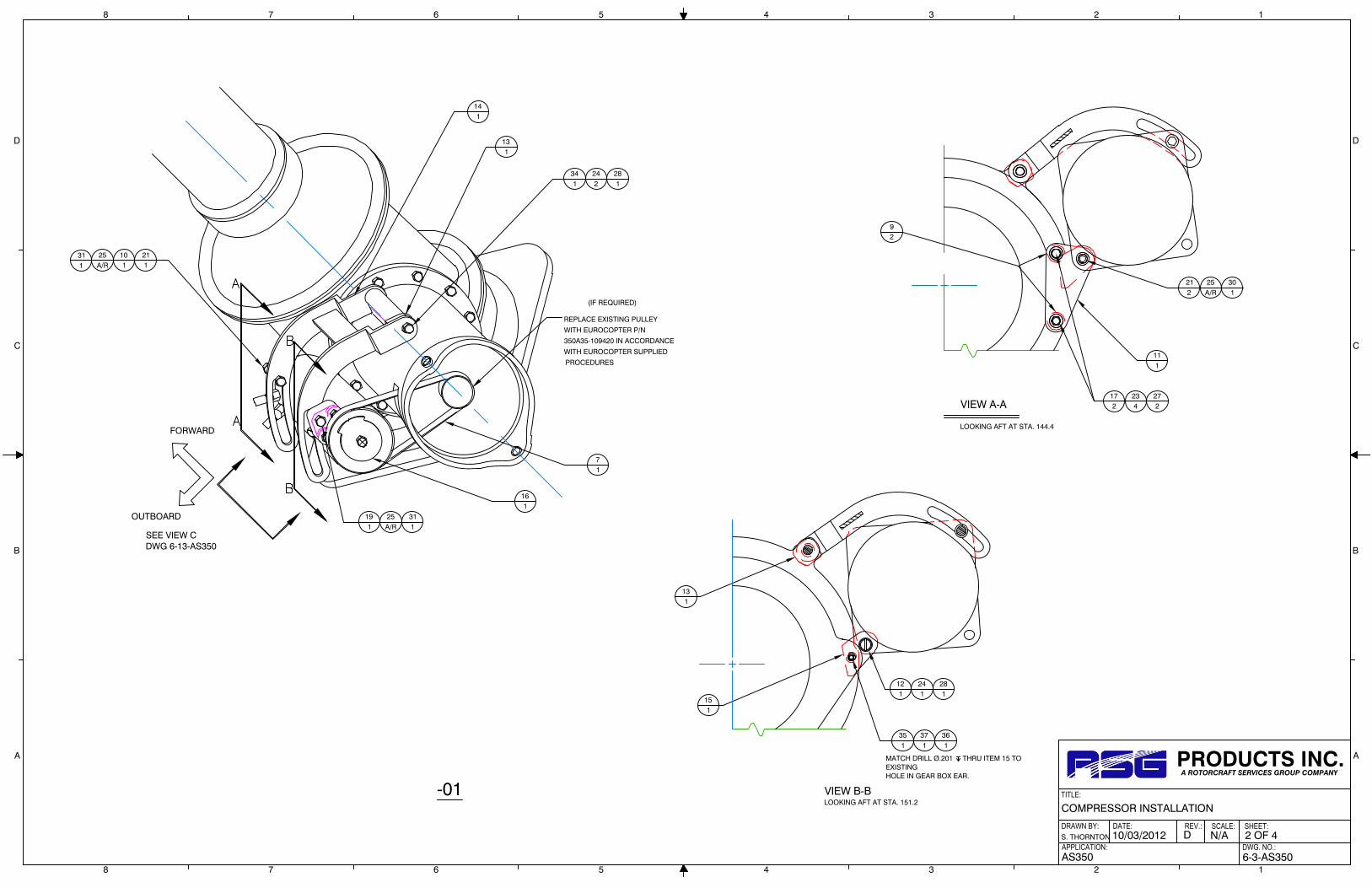
FORWARD
OUTBOARD
SEE VIEW CDWG 6-13-AS350
VIEW B-BLOOKING AFT AT STA. 151.2
141
131
341
242
281
211
25A/R
311
191
25A/R
311
71
(IF REQUIRED)
PROCEDURES
WITH EUROCOPTER SUPPLIED
350A35-109420 IN ACCORDANCE
WITH EUROCOPTER P/N
REPLACE EXISTING PULLEY
161
151
121
241
281
131
101
-01
MATCH DRILL Ø.201 THRU ITEM 15 TOEXISTINGHOLE IN GEAR BOX EAR.
351
371
361
VIEW A-A
LOOKING AFT AT STA. 144.4
92
212
25A/R
301
111
172
234
272
DRAWN BY:
APPLICATION:
DATE:
TITLE:
REV.: SCALE:
DWG. NO.:
SHEET:
PRODUCTS INC.A ROTORCRAFT SERVICES GROUP COMPANY
8 7 6 5 4 3 2 1
A
B
C
D
A
B
C
D
8 7 6 5 4 3 2 1
COMPRESSOR INSTALLATION
S. THORNTON
AS350
10/03/2012 D N/A 2 OF 4
6-3-AS350

2
DETAIL B
17REF
71
23REF
27REF
C
C
SECTION C-C
111
18REF
32REF
PULLEY
BELT TENSIONING
(VIEW LOOKING AFT)
7REF
28REF
234
272
172
92
E
E
D
D
F F
G
G
SECTION E-E
181
281
3REF
32132
1
SECTION D-D
8REF
26A/R
(VIEW LOOKING DOWN)
SECTION F-F
121
241
281
211
2925
(VIEW LOOKING UP.)
151
1
(SHOWN WITH COTTER PIN TYPE HARDWARE)
(SHOWN WITH COTTER PIN TYPE HARDWARE)
(SHOWN WITH COTTER PIN TYPE HARDWARE)
1
(SHOWN WITH COTTER PIN TYPE HARDWARE)
(SHOWN WITH COTTER PIN TYPE HARDWARE)1
-02
351
371
361
MATCH DRILL Ø.201 x THRUITEM 15 TO EXISTING
HOLE IN GEAR BOX EAR.
211
252
291
3(300067)
OLDER STYLE
3(300067)
OLDER STYLE
DRAWN BY:
APPLICATION:
DATE:
TITLE:
REV.: SCALE:
DWG. NO.:
SHEET:
PRODUCTS INC.A ROTORCRAFT SERVICES GROUP COMPANY
8 7 6 5 4 3 2 1
A
B
C
D
A
B
C
D
8 7 6 5 4 3 2 1
COMPRESSOR INSTALLATION
S. THORNTON
AS350
10/03/2012 D N/A 3 OF 4
6-3-AS350
TIGHTEN BOTH NUTS AGAINST THE COMP MOUNT TENSION2.BOLT. SAFETY WIRE NUTS USING ITEM 26 IAW MS33540.
PERMISSIBLE TO USE ALTERNATE COTTER PIN TYPE HARDWARE:1.BOLT ANX-XX, NUT AN310-X, COTTER PIN MS24665-XXX.
NOTES:(APPLICABLE TO -02 CONFIGURATION ONLY)
3. OLD AND NEW COMPRESSOR MOUNT BRACKET
04-130-21-101-01 TO REPLACE 530027-3.
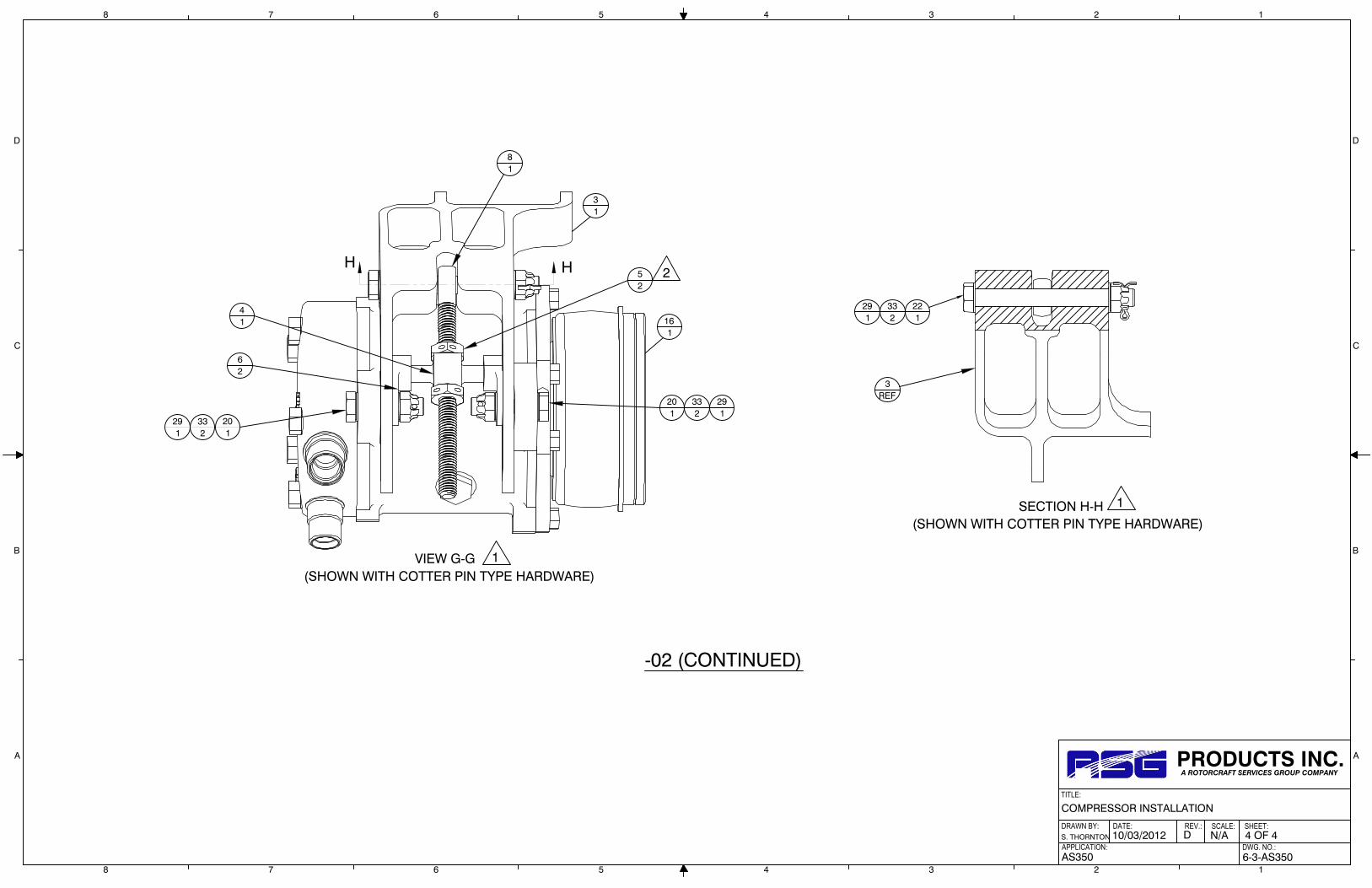
62
31
41
201
332
H H
81
52
201
332
291
291
VIEW G-G
161
(SHOWN WITH COTTER PIN TYPE HARDWARE)1
2
SECTION H-H
221
332
291
3REF
(SHOWN WITH COTTER PIN TYPE HARDWARE)
1
-02 (CONTINUED)
DRAWN BY:
APPLICATION:
DATE:
TITLE:
REV.: SCALE:
DWG. NO.:
SHEET:
PRODUCTS INC.A ROTORCRAFT SERVICES GROUP COMPANY
8 7 6 5 4 3 2 1
A
B
C
D
A
B
C
D
8 7 6 5 4 3 2 1
COMPRESSOR INSTALLATION
S. THORNTON
AS350
10/03/2012 D N/A 4 OF 4
6-3-AS350

.X: ±.1 .XX: ±.03.XXX: ±.010 X.X°: ±.5°BREAK ALL SHARPEDGES .01ALL DIMENSIONS ININCHES UNLESSOTHERWISE STATED
TOLERANCES
APPROVED BY:
NEXT ASSY.
DATE:
EXCEPT AS SHOWN
DRAWN BY:
APPLICATION:
DATE:
TITLE:
REV.: SCALE:
DWG. NO.:
SHEET:
PROPRIETARY NOTICET O A LL PE R S ON S R E C EI V IN G T H I S DO C UM E NTTHIS DOCUMENT AND INFORMATION OR TECHNICALD A T A A N D D E S I G N S C O N T A I N E D H E R E I N A R EPROPRIETARY DATA AND EXCLUSIVE PROPERTY OF RSGPRODUCTS INC. AND IS DELIVERED ON THE EXPRESSCONDITION THAT NEITHER THIS DOCUMENT NOR THEINFORMATION CONTAINED HEREIN SHALL BE DISCLOSEDTO OTHERS, REPRODUCED IN WHOLE OR IN PART, ORUSED FOR THE MANUFACTURE OR FABRICATION OFPARTS FOR ANYONE OTHER THAN RSG PRODUCTS INC.WITHOUT WRITTEN CONSENT AND AUTHORIZATION, ANDTHAT NO RIGHT IS GRANTED TO DISCLOSE OR SO USEANY INFORMATION CONTAINED IN SAD DOCUMENT. THISRESTRICTION DOES NOT LIMIT THE RIGHT TO USEINFORMATION OBTAINED FROM ANOTHER SOURCE.
PRODUCTS INC.A ROTORCRAFT SERVICES GROUP COMPANY
8 7 6 5 4 3 2 1
A
B
C
D
A
B
C
D
8 7 6 5 4 3 2 1
DATE:REV DESCRIPTION OF CHANGE
REVISION RECORDAPPVD.
BYREV.BY
AS350 6-12-AS350
1 OF 1N/AE11/10/96BT
COMPRESS INSTALLATION
A 08/16/00 REVISED DRAWING NUMBER, WAS 6-AS350, SHEETNo. WAS 2 OF 3.
B 04/16/02 COMPUTERIZED, CLARIFIED NOTE, REVISED TITLEBLOCK.
c 01/30/06 CHANGED NOTES, ADDED PRELOAD NOTE. ADDEDSHIMMING NOTES.
JTYE
D 06/30/08 REVISED TITLE BLOCK. JTYE
E 9/1/14 CHANGED TITLE BLOCK AND REVISION BLOCK.CORRECTED HARDWARE CALLOUT PER ECO # 0261.
AJC
SECTION B-B
VIEW LOOKING INBOARD
SECTION A-A
COMPRESSOR STAND OFFPN 300067
A
A B
B
PULLEY HOUSING
TRANSMISSIONHOUSING
VIEW CREF 6-2-AS350
BOLT AN6-14A(1)WASHER AN960-616 AND
OR AN960-616L, SHIMAS REQUIRED
NUT MS20364-624C(1)ALT NUT: MS21044N6(1)
ALT NUT: MS21042-6/L6(1)
SHIM P/N 261007(2 PLC'S)
COMPRESSORSTAND-OFF PN 300067
2X BOLT AN4-14ANUT MS21042-4 OR MS2104L4WASHER AN960-616 AND ORAN960-616L AS REQUIRED
COMP PIN PN 300095WASHER AN960-516 ORAN960-516LNUT MS20364-524C ORMS21042-5
NOTE:DO NOT CUT TRANSMISSIONFLANGE-NOT REQUIRED
MOUNTING BOLTSDELETED FOR CLARITY
FORWARD
ENLARGE TO .325 DIA, TOMATCH P/N 530100 STRAP
SHIM WITH PN 261008AND/OR AN960-616
AND/OR AN960-616LAS REQUIRED.
NOTE:SHIM IF REQUIRED TO AVOIDPRE-LOADING OF BRACKETFORKS.
SHIM WITH AN960-616 ANDOR AN960-616L IF REQUIRED/AS REQUIRED.
FORWARD
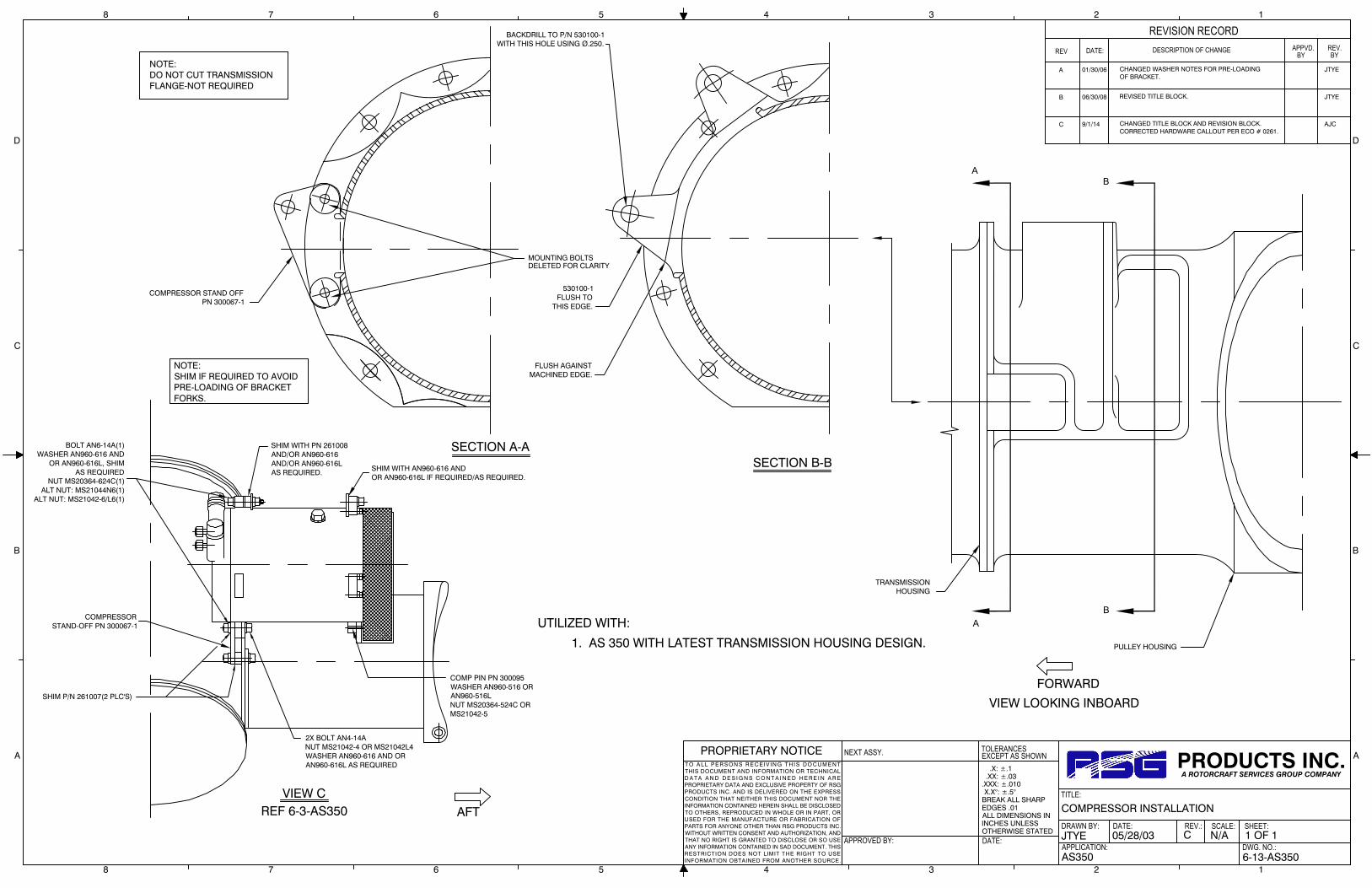
.X: ±.1 .XX: ±.03.XXX: ±.010 X.X°: ±.5°BREAK ALL SHARPEDGES .01ALL DIMENSIONS ININCHES UNLESSOTHERWISE STATED
TOLERANCES
APPROVED BY:
NEXT ASSY.
DATE:
EXCEPT AS SHOWN
DRAWN BY:
APPLICATION:
DATE:
TITLE:
REV.: SCALE:
DWG. NO.:
SHEET:
PROPRIETARY NOTICET O A LL PE R S ON S R E C EI V IN G T H I S DO C UM E NTTHIS DOCUMENT AND INFORMATION OR TECHNICALD A T A A N D D E S I G N S C O N T A I N E D H E R E I N A R EPROPRIETARY DATA AND EXCLUSIVE PROPERTY OF RSGPRODUCTS INC. AND IS DELIVERED ON THE EXPRESSCONDITION THAT NEITHER THIS DOCUMENT NOR THEINFORMATION CONTAINED HEREIN SHALL BE DISCLOSEDTO OTHERS, REPRODUCED IN WHOLE OR IN PART, ORUSED FOR THE MANUFACTURE OR FABRICATION OFPARTS FOR ANYONE OTHER THAN RSG PRODUCTS INC.WITHOUT WRITTEN CONSENT AND AUTHORIZATION, ANDTHAT NO RIGHT IS GRANTED TO DISCLOSE OR SO USEANY INFORMATION CONTAINED IN SAD DOCUMENT. THISRESTRICTION DOES NOT LIMIT THE RIGHT TO USEINFORMATION OBTAINED FROM ANOTHER SOURCE.
PRODUCTS INC.A ROTORCRAFT SERVICES GROUP COMPANY
8 7 6 5 4 3 2 1
A
B
C
D
A
B
C
D
8 7 6 5 4 3 2 1
DATE:REV DESCRIPTION OF CHANGE
REVISION RECORDAPPVD.
BYREV.BY
AS350 6-13-AS350
1 OF 1N/AC05/28/03JTYE
COMPRESSOR INSTALLATION
A 01/30/06 CHANGED WASHER NOTES FOR PRE-LOADINGOF BRACKET.
JTYE
B 06/30/08 REVISED TITLE BLOCK. JTYE
C 9/1/14 CHANGED TITLE BLOCK AND REVISION BLOCK.CORRECTED HARDWARE CALLOUT PER ECO # 0261.
AJC
1. AS 350 WITH LATEST TRANSMISSION HOUSING DESIGN.
UTILIZED WITH:
SECTION B-B
VIEW LOOKING INBOARD
SECTION A-A
COMPRESSOR STAND OFFPN 300067-1
A
AB
B
PULLEY HOUSING
TRANSMISSIONHOUSING
VIEW CREF 6-3-AS350
BOLT AN6-14A(1)WASHER AN960-616 AND
OR AN960-616L, SHIMAS REQUIRED
NUT MS20364-624C(1)ALT NUT: MS21044N6(1)
ALT NUT: MS21042-6/L6(1)
SHIM P/N 261007(2 PLC'S)
COMPRESSORSTAND-OFF PN 300067-1
2X BOLT AN4-14ANUT MS21042-4 OR MS21042L4WASHER AN960-616 AND ORAN960-616L AS REQUIRED
COMP PIN PN 300095WASHER AN960-516 ORAN960-516LNUT MS20364-524C ORMS21042-5
MOUNTING BOLTSDELETED FOR CLARITY
BACKDRILL TO P/N 530100-1WITH THIS HOLE USING Ø.250.
530100-1FLUSH TO
THIS EDGE.
FLUSH AGAINSTMACHINED EDGE.
SHIM WITH PN 261008AND/OR AN960-616AND/OR AN960-616LAS REQUIRED. SHIM WITH AN960-616 AND
OR AN960-616L IF REQUIRED/AS REQUIRED.
FORWARD
AFT
NOTE:DO NOT CUT TRANSMISSIONFLANGE-NOT REQUIRED
NOTE:SHIM IF REQUIRED TO AVOIDPRE-LOADING OF BRACKETFORKS.

.X: ±.1 .XX: ±.03.XXX: ±.010 X.X°: ±.5°BREAK ALL SHARPEDGES .01ALL DIMENSIONS ININCHES UNLESSOTHERWISE STATED
TOLERANCES
APPROVED BY:
NEXT ASSY.
DATE:
EXCEPT AS SHOWN
DRAWN BY:
APPLICATION:
DATE:
TITLE:
REV.: SCALE:
DWG. NO.:
SHEET:
PROPRIETARY NOTICET O A LL PE R S ON S R E C EI V IN G T H I S DO C UM E NTTHIS DOCUMENT AND INFORMATION OR TECHNICALD A T A A N D D E S I G N S C O N T A I N E D H E R E I N A R EPROPRIETARY DATA AND EXCLUSIVE PROPERTY OF RSGPRODUCTS INC. AND IS DELIVERED ON THE EXPRESSCONDITION THAT NEITHER THIS DOCUMENT NOR THEINFORMATION CONTAINED HEREIN SHALL BE DISCLOSEDTO OTHERS, REPRODUCED IN WHOLE OR IN PART, ORUSED FOR THE MANUFACTURE OR FABRICATION OFPARTS FOR ANYONE OTHER THAN RSG PRODUCTS INC.WITHOUT WRITTEN CONSENT AND AUTHORIZATION, ANDTHAT NO RIGHT IS GRANTED TO DISCLOSE OR SO USEANY INFORMATION CONTAINED IN SAD DOCUMENT. THISRESTRICTION DOES NOT LIMIT THE RIGHT TO USEINFORMATION OBTAINED FROM ANOTHER SOURCE.
PRODUCTS INC.A ROTORCRAFT SERVICES GROUP COMPANY
8 7 6 5 4 3 2 1
A
B
C
D
A
B
C
D
8 7 6 5 4 3 2 1
DATE:REV DESCRIPTION OF CHANGE
REVISION RECORDAPPVD.
BYREV.BY
AS350 6-21-AS350
1 OF 1N/AE11/10/96KLM
COMPRESSOR INSTALLATION
B 05/08/02 REVISED TITLE BLOCK. CHANGED 530027-2 TO530027-3. CONVERTED TO AUTOCAD.
A 08/16/00 REDRAWN INTO AUTOCAD, REVISED DRAWING No.WAS 6-AS350; SHEET No. WAS 3 OF 3. ADDED ITEMS6 TO "INSTRUCTIONS". CHANGED "CASING" TO"HOUSING". ADDED VIEW A, B AND C.
C 01/30/06 CHANGED NAS1305-44 BOLT TO NAS1305-45 FORLENGTH.
JTYE
D 06/30/08 REVISED TITLE BLOCK. JTYE
E 9/1/14 CHANGED TITLE BLOCK AND REVISION BLOCK. AJC
TRANSMISSIONHOUSING
(1) NAS1305-45 BOLT
P/N 530027-3
P/N 530100 ISLOCATED BETWEENGIMBLE HOUSING& P/N 530027-3
REMOVE TOP OF EAR,AS NECESSARY, TO ENSUREP/N 530100 SEATS FLUSHAGAINST RECESS IN THEGIMBLE HOUSING
A-ASECTION
VIEW A, B, C
AFTER P/N 530100 ISLOCATED, BACKDRILL #10HOLE INTO HOUSING,INSTALL HARDWARE:AN3-5A BOLT (1)AN960-10L WASHER (2)MS21042-L3 NUT (1)
NOTE:
COMPRESSOR REMOVEDFOR CLARITY.
(1) MS20364-524C NUT
(2) AN960-516L WASHERALT: MS21042L5
PULLEY HOUSING
A
FORWARD
VIEW LOOKING INBOARD
VIEW C
VIEW B
VIEW A
A
37mm
25mm
25mmOR LESS
INSTALLATION INSTRUCTIONS:
KIT P/N: 350-00-01, -011, -031, -011HP, AND -031HP
1) THE ABOVE KITS UTILIZE THE SANDEN SD-505 OR SD-507 COMPRESSOR (SEEDRAWING 350-00-011HP OR -031HP FOR DETAILS OF SD-507 INSTALLATION)..
2) IN EARLY 1997 IT WAS NOTICED BY AMERICAN EUROCOPTER AND LATEREUROCOPTER CANADA, LTD. THAT A FEW AS350 MODELS WERE ARRIVING WITHA DIFFERENT "ENGINE TO MAIN GEAR BOX COUPLING CASING", COMMONLYCALLED A "HOUSING", INSTALLED. THE PART NUMBER SHOWN IN THEEUROCOPTER IPC WAS: 350A35-1104-03. THIS COMPONENT HAS "EARS"EXTENDING OFF THE "HOUSING", ON BOTH SIDES, 37 mm IN LENGTH (SEEVIEW "A").
THE NEW "HOUSING " PART NUMBER IS 350A08-1635-21. IT HAS ONE EAR ONTHE LEFT SIDE THAT IS ONLY 25 mm LONG.(SEE VIEW "B")
THE 25 mm LONG EAR WILL NOT ALLOW AN INTEGRATED FLIGHT SYSTEMS,INC. SD-505 OR SD-507 COMPRESSOR TO BE INSTALLED IN IT'S USUALLOCATION.
3) THE "LOGICAL ANSWER" WAS TO LOCATE THE "MOUNTING POINT" OF THECOMPRESSOR(S) SO THAT A DIFFERENT LENGTH BELT, ETC. WOULD NOTBE REQUIRED..
4) ONLY TWO (2) PART CHANGES WERE REQUIRED TO ALLOW ITEM 3 TO OCCUR.a. COMPRESSOR MOUNT ASSEMBLY 530027-1 WAS CHANGED TO -2 (.125
WIDER AT THE TOP MOUNTING POINT).b. A NEW COMPONENT, NOT PREVIOUSLY USED, "STRAP, HOUSING MOD.
ASSEMBLY", P/N: 530100 IS UTILIZED TO LOCATE THE COMPRESSORMOUNTING POINT BACK TO IT'S ORIGINAL LOCATION.
c. A AN3-5A BOLT AND ASSOCIATED HARDWARE SECURES THE "STRAP" TOTHE "HOUSING".
5) IN SOME CASES IT MAY BE NECESSARY TO REMOVE A SMALL AMOUNT OFMATERIAL FROM THE OUTER EDGE OF THE 25 mm EAR TO ALLOW THE "NEW"IFS COMPONENT TO LAY IN IT'S PROPER LOCATION. THIS IS DUE TO THE "SHIM"WELDED ON THE FORWARD SIDE OF THE COMPONENT WHICH ALLOWSALIGNMENT TO THE COMPRESSOR EAR. ANY PAINT REMOVED FROM THE"HOUSING" EAR MUST BE TOUCHED UP BEFORE INSTALLING THE IFS PARTS.
6) IF AERO AIRE OR OTHER SIMILAR TYPE A/C COMPRESSOR HAS BEENPREVIOUSLY INSTALLED PER VIEW "B" or "C", IT MAY BE NECESSARY TOFOLLOW THE STEPS IN ITEM 5 FOR CORRECT CLEARANCE.

.X: ±.1 .XX: ±.03.XXX: ±.010 X.X°: ±.5°BREAK ALL SHARPEDGES .01ALL DIMENSIONS ININCHES UNLESSOTHERWISE STATED
TOLERANCES
APPROVED BY:
NEXT ASSY.
DATE:
EXCEPT AS SHOWN
DRAWN BY:
APPLICATION:
DATE:
TITLE:
REV.: SCALE:
DWG. NO.:
SHEET:
PROPRIETARY NOTICET O A LL PE R S ON S R E C EI V IN G T H I S DO C UM E NTTHIS DOCUMENT AND INFORMATION OR TECHNICALD A T A A N D D E S I G N S C O N T A I N E D H E R E I N A R EPROPRIETARY DATA AND EXCLUSIVE PROPERTY OF RSGPRODUCTS INC. AND IS DELIVERED ON THE EXPRESSCONDITION THAT NEITHER THIS DOCUMENT NOR THEINFORMATION CONTAINED HEREIN SHALL BE DISCLOSEDTO OTHERS, REPRODUCED IN WHOLE OR IN PART, ORUSED FOR THE MANUFACTURE OR FABRICATION OFPARTS FOR ANYONE OTHER THAN RSG PRODUCTS INC.WITHOUT WRITTEN CONSENT AND AUTHORIZATION, ANDTHAT NO RIGHT IS GRANTED TO DISCLOSE OR SO USEANY INFORMATION CONTAINED IN SAD DOCUMENT. THISRESTRICTION DOES NOT LIMIT THE RIGHT TO USEINFORMATION OBTAINED FROM ANOTHER SOURCE.
PRODUCTS INC.A ROTORCRAFT SERVICES GROUP COMPANY
8 7 6 5 4 3 2 1
A
B
C
D
A
B
C
D
8 7 6 5 4 3 2 1
DATE:REV DESCRIPTION OF CHANGE
REVISION RECORDAPPVD.
BYREV.BY
AS350 6-22-AS350
1 OF 1N/AC05/28/03JTYE
COMPRESSOR INTALLATION
C 9/1/14 CHANGED TITLE BLOCK AND REVISION BLOCK. AJC
A 01/30/06 CHANGED NAS1305-44 BOLT TO NAS1305-45 FORLENGTH. ADDED ALT. COMPRESSOR SHIMS.REMOVED BEVELED EDGE NOTATION FORALIGNMENT.
JTYE
B 06/30/08 REVISED TITLE BLOCK. JTYE
TRANSMISSIONHOUSING
(1) NAS1305-45 BOLT
P/N 530027-3
P/N 300363-2 ISLOCATED BETWEENGIMBLE HOUSING& P/N 530027-3(ALT. 261155)
ALIGN 530100-1 ON AFTSIDE OF GIMBLE HOUSING,FLUSH EDGE TO EAR CONTOUR.
SECTION A-A
BACKDRILL Ø.250HOLE INTO 530100-1ONCE LOCATED ANDINSTALL HARDWARE:AN4-5A BOLT (1)AN960-416L WASHER (2)MS21042-L4 NUT (1)
(1) MS20364-524C NUTALT: MS21042L5
(2) AN960-516L WASHER
PULLEY HOUSING
A
FORWARDVIEW LOOKING INBOARD
A
DETAIL A
DETAIL ANOT TO SCALE
FLUSH THISEDGE TO EAR.
BACKDRILL Ø.250HOLE.
1. AS 350 WITH LATEST TRANSMISSION HOUSING DESIGN.
UTILIZED WITH:
P/N 300363-2UPPER COMPRESSORSHIM(ALT. 261155)
P/N 530100-1STRAP, HOUSINGMOD ASSY.
NOTE:
COMPRESSOR REMOVEDFOR CLARITY.

RSG Products Inc. INSTALLATION OF ELECTRICAL – AS350 Air Conditioning
Date: 05/29/15 Section 9: Installation of Electrical Page 1 of 2
Step 9
Installation of Electrical
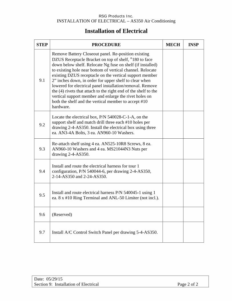
RSG Products Inc. INSTALLATION OF ELECTRICAL – AS350 Air Conditioning
Date: 05/29/15 Section 9: Installation of Electrical Page 2 of 2
Installation of Electrical
STEP PROCEDURE MECH INSP
9.1
Remove Battery Closeout panel. Re-position existing DZUS Receptacle Bracket on top of shelf, °180 to face down below shelf. Relocate Ng fuse on shelf (if installed) to existing hole near bottom of vertical channel. Relocate existing DZUS receptacle on the vertical support member 2” inches down, in order for upper shelf to clear when lowered for electrical panel installation/removal. Remove the (4) rivets that attach to the right end of the shelf to the vertical support member and enlarge the rivet holes on both the shelf and the vertical member to accept #10 hardware.
9.2
Locate the electrical box, P/N 540028-C-1-A, on the support shelf and match drill three each #10 holes per drawing 2-4-AS350. Install the electrical box using three ea. AN3-4A Bolts, 3 ea. AN960-10 Washers.
9.3 Re-attach shelf using 4 ea. AN525-10R8 Screws, 8 ea. AN960-10 Washers and 4 ea. MS21044N3 Nuts per drawing 2-4-AS350.
9.4 Install and route the electrical harness for tour 1 configuration, P/N 540044-6, per drawing 2-4-AS350, 2-14-AS350 and 2-24-AS350.
9.5 Install and route electrical harness P/N 540045-1 using 1 ea. 8 x #10 Ring Terminal and ANL-50 Limiter (not incl.).
9.6 (Reserved)
9.7 Install A/C Control Switch Panel per drawing 5-4-AS350.

.X: ±.1 .XX: ±.03.XXX: ±.010 X.X°: ±.5°BREAK ALL SHARPEDGES .01ALL DIMENSIONS ININCHES UNLESSOTHERWISE STATED
TOLERANCES
APPROVED BY:
NEXT ASSY.
DATE:
EXCEPT AS SHOWN
DRAWN BY:
APPLICATION:
DATE:
TITLE:
REV.: SCALE:
DWG. NO.:
SHEET:
PROPRIETARY NOTICET O A L L P E R S O N S R E C E I V IN G T H I S D O C U M E N TTHIS DOCUMENT AND INFORMATION OR TECHNICALD A T A A N D D E S I G N S C O N T A I N E D H E R E I N A R EPROPRIETARY DATA AND EXCLUSIVE PROPERTY OF RSGPRODUCTS INC. AND IS DELIVERED ON THE EXPRESSCONDITION THAT NEITHER THIS DOCUMENT NOR THEINFORMATION CONTAINED HEREIN SHALL BE DISCLOSEDTO OTHERS, REPRODUCED IN WHOLE OR IN PART, ORUSED FOR THE MANUFACTURE OR FABRICATION OFPARTS FOR ANYONE OTHER THAN RSG PRODUCTS INC.WITHOUT WRITTEN CONSENT AND AUTHORIZATION, ANDTHAT NO RIGHT IS GRANTED TO DISCLOSE OR SO USEANY INFORMATION CONTAINED IN SAID DOCUMENT. THISRESTRICTION DOES NOT LIMIT THE RIGHT TO USEINFORMATION OBTAINED FROM ANOTHER SOURCE.
PRODUCTS INC.A ROTORCRAFT SERVICES GROUP COMPANY
8 7 6 5 4 3 2 1
A
B
C
D
A
B
C
D
8 7 6 5 4 3 2 1
DATE:REV DESCRIPTION OF CHANGE
REVISION RECORDAPPVD.
BYREV.BY
AS350 2-4-AS350
1 OF 1N/AD11/10/96MAH
ELECTRICAL ROUTING
B 06/15/03 REVISED TITLE BLOCK.
A-AVIEW
COMPRESSOR
HARNESS P/N 540044-6AIR CONDITIONER WIRE BUNDLE
LOW PRESSURE SWITCHP/N 050107
HIGH PRESSURE SWITCHP/N 090004
AFT TRANSITION ELBOWASSY P/N 520036-3
RESISTOR P/N 050024-2
INSTALL "BOOT" P/N MS25171-2STOP AND BOTTOM OF RESISTOR
AFT EVAPORATOR FAN ASSYP/N 490017 OR 490017-1
EXISTING MASTER AIRCRAFTELECTRICAL PANEL
USE 50 AMP CIRCUIT BREAKER
AFT EVAPORATOR DELETEDFOR CLARITY
DUAL CONDENSER BLOWER
AIR CONDITIONINGELECTRICAL PANELP/N 540028-"C"-1-A(SEE INSTALLATIONINSTRUCTIONS BELOW)
CP101CP100
CONDENSER BLOWERS 2X
CONDENSER ASSY
WIRE SERVICE LOOP 2X
AA
AFT MOUNTED
TOUR-1 CONFIGURATIONEUROCOPTER CANADA LTD
FORWARD AIR OUTLETS
CP104
LOCATED JUST FWD OF FWDTHRU FWD DOUBLER, P/N 260373-1ROUTE ELECTRICAL HARNESS
EVAPORATOR
OR FUSE AT PP-12 BUSS
EXISTING SHELF
EXISTING VERTICALSUPPORT
ROUTE IFS WIRES ALONGDEFROSTER DUCT OR EXISTINGWIRE BUNDLES TO LH AIR OUTLET(5 AMP CIRCUIT BREAKER)
ALT. P/N 520036-2
ALT. RESISTOR ASSY. P/N 540020
A/C CONTROL SWITCHES
WHEN RESISTOR 050024-2 IS USED
A 08/16/00 REVISED DRAWINGS NUMBER, WAS 2-AS 350; SHEETNUMBER WAS 1 OF 3; ADDED INSTALLATIONINSTRUCTIONS FOR ELECTRICAL PANEL ASSEMBLY.ADDED NEW NOTE 2. OLD NOTE 2 IS NOTE 3. OLDNOTE 3 IS NOTE 4.
C 04/09/09 CHANGED AFT TRANSITION ELBOW PN:520036-2 TOALTERNATE, 520036-3 IS NOW PRIMARY. ADDED ALT.RESISTOR ASSEMBLY PN: 540020. CORRECTED AIROUTLET VIEWS. CORRECTED WIRE ROUTING VIEW.REVISED TITLE BLOCK.
NOTES:
USE EXISTING LIGHTENING HOLES ONLY FOR ALL ROUTING ORSECURE WIRES TO EXISTING BUNDLES OR REFRIGERATION HOSEUSING TY-WRAPS, STAND-OFFS, AND SPACERS BLOCKS AS REQUIRED.
1. LOCATION OF PRESSURE SWITCHES WHEN R-134a IS UTILIZED.
2. ON B3 MODELS IFS WIRE ROUTING MUST BE ACCORDANCE WITH THIS DRAWING.
3. INSTALL IFS104C14 TO LOW PRESSURE SWITCH. (BLUE LEADS)
4. INSTALL IFS108B20 AND IFS108D20 TO HIGH PRESSURE SWITCH. (BLACK LEADS)
5. REMOVE BATTERY CLOSEOUT PANEL. REPOSITION EXISTING DZUS RECEPTACLE BRACKET ONTOP OF SHELF, 180 DEGREES TO FACE DOWN BELOW SHELF.
6. RELOCATE Ng FUSE ON SHELF (IF INSTALLED) TO EXISTING HOLE NEAR BOTTOM OF VERTICALCHANNEL. RELOCATE EXISTING DZUS RECEPTACLE ON THE VERTICAL SUPPORT MEMBER 2INCHES DOWN, IN ORDER FOR UPPER SHELF TO CLEAR WHEN LOWERED FOR ELECTRICAL BOXINSTALLATION\REMOVAL.
7. REMOVE THE (4) RIVETS THAT ATTATCH TO THE RIGHT END OF SHELF TO VERTICAL SUPPORTMEMBER. ENLARGE RIVET HOLES ON FRONT END OF SHELF AND VERTICAL SUPPORT TOACCOMMODATE #10 FASTENERS. LOCATE ELECTRICAL PANEL ON SHELF AND BACK DRILLTHREE (3) EACH #10 HOLES TO MATCH NUT PLATE ON BOTTOM OF ELECTRICAL PANELASSEMBLY.
8. ATTACH ELECTRICAL PANEL ASSEMBLY TO SHELF USING AN3-4A BOLT AND AN960-10 WASHER,IN THREE (3) PLACES.
9. REATTACH END OF SHELF TO VERTICAL SUPPORT USING AN525-10R8 SCREW, AN960-10WASHER, AND MS21044-N3 NUT IN FOUR (4) PLACES.
10. CUT CLOSEOUT PANEL LEVEL WITH THE TOP OF THE UPPER SHELF. RELOCATE DZUSFASTENERS TO MATCH NEW LOCATION OF DZUS RECEPTICALS. REINSTALL CLOSEOUT PANEL.
D 09/01/14 CHANGED TITLE BLOCK AND REVISION BLOCK. AJC
SEE ECO 0771

ADDED NOTES 5 - 11.


.X: ±.1 .XX: ±.03.XXX: ±.010 X.X°: ±.5°BREAK ALL SHARPEDGES .01ALL DIMENSIONS ININCHES UNLESSOTHERWISE STATED
TOLERANCES
APPROVED BY:
NEXT ASSY.
DATE:
EXCEPT AS SHOWN
DRAWN BY:
APPLICATION:
DATE:
TITLE:
REV.: SCALE:
DWG. NO.:
SHEET:
PROPRIETARY NOTICET O A L L P E R S O N S R E C E I V IN G T H I S D O C U M E N TTHIS DOCUMENT AND INFORMATION OR TECHNICALD A T A A N D D E S I G N S C O N T A I N E D H E R E I N A R EPROPRIETARY DATA AND EXCLUSIVE PROPERTY OF RSGPRODUCTS INC. AND IS DELIVERED ON THE EXPRESSCONDITION THAT NEITHER THIS DOCUMENT NOR THEINFORMATION CONTAINED HEREIN SHALL BE DISCLOSEDTO OTHERS, REPRODUCED IN WHOLE OR IN PART, ORUSED FOR THE MANUFACTURE OR FABRICATION OFPARTS FOR ANYONE OTHER THAN RSG PRODUCTS INC.WITHOUT WRITTEN CONSENT AND AUTHORIZATION, ANDTHAT NO RIGHT IS GRANTED TO DISCLOSE OR SO USEANY INFORMATION CONTAINED IN SAID DOCUMENT. THISRESTRICTION DOES NOT LIMIT THE RIGHT TO USEINFORMATION OBTAINED FROM ANOTHER SOURCE.
PRODUCTS INC.A ROTORCRAFT SERVICES GROUP COMPANY
8 7 6 5 4 3 2 1
A
B
C
D
A
B
C
D
8 7 6 5 4 3 2 1
DATE:REV DESCRIPTION OF CHANGE
REVISION RECORDAPPVD.
BYREV.BY
AS350 2-14-AS350
1 OF 1N/AD11/10/96MAH
ELECTRICAL DIAGRAM
NOTES:
1. ALL WIRE MIL-W-22759/16 & MIL-W-22759/16.ALL WIRE 14ga UNLESS OTHERWISE SPECIFIED.
2. FUSES MAY BE USED, P/N 100FU01-050 (50AMP).
3. LOCATE #8 WIRE AT T4, T5, T6, OR T7 (INSTALL 50 AMP FUSE IF NOT PRESENT, SEE NOTE 2)
4. WHEN ALL EUROCOPTER FUSES OR C/B LOCATIONS ARE UTILIZED, A "AUX" CURRENT LIMITERBASE P/N FU1541-501, BRACKET/SUPPLY BAR AND CURRENT LIMITER MAY BE INSTALLED AT F9OR F10 PER EUROCOPTERS COMPONENT MAINTENANCE MANUAL. IFS P/N FOR LIMITER BASEIS 050023. IFS P/N FOR LIMITER, 50 A,P IS 050015-2.
B 08/16/00 REVISED DRAWING NUMBER, WAS 2-AS 350; SHEETNUMBER WAS 2 OF 3. ADDED NOTE 1 THRU 4. ADDEDALTERNATE BLOWER P/N 050180.
INTERCHANGEABLE 5" BLOWERS
050143
050085-1
IFSS 050143 DCB
IFSS 050143-3 DCB
ELECTRICAL WIRING DIAGRAM
FOR DUAL CONDENSER BLOWER AFT MOUNTED
AS350
TOUR-1 CONFIGURATION
ELEC. PANEL ASSY.540028-"C"-1-A
HI LO MED
3214
CP104
FORWARD EVAPORATORMOTOR
GROUND TO AIRFRAME#14-16X10 RING TERMINAL
12
3
4
6
51
3
2
#20
FWD EVAPORATORSPEED CONTROL
SWITCH P/N 050001
3 62 51 4
COMPRESSOR
#14-16 WIRE SPLICE
AFT EVAPORATOR SPEEDCONTROL SWITCH P/N 050006-2
A/C-OFF-FAN SWITCHP/N 050001
+-
RESISTOR 2 OHM, 100WP/N 050024-2
N0. 14-16X5/16 KNIFE SPLICE(3 REQ'D)
IFS101E14
IFS101C14
NO. 14-16X10 RINGTERMINAL (1 REQ'D).
OR P/N 050006
LOW
HI
AFT EVAPORATORMOTOR
GROUND TO AIRFRAME.
#20
#20
TOUR OPERATOR VERSIONEUROCOPTER CANADA LTD
#20
#14-16X10 RINGTERMINAL
#20
#8 WIRE X #10 RING TERMINAL(1 REQUIRED)
(2 REQUIRED)#14-16 WIRE SPLICE
P/N 050085-1 2XCONDENSER BLOWER
RELAYEVAP.
M
M 50
PP-12
P/N 540045-18 GA WIRE
CP101
1
CP100
CIRCUIT BREAKERS
2020 20 115
BCA I F G H E D
TIMER
RELAYCOND.
COM
ALT P/N 050143. BUSS
2 3 4
ALT. P/N 540020 RESISTOR ASSEMBLY
A 05/10/99 ADDED ALTERNATE BLOWER, IFS P/N 050143. EVAPBREAKER WAS 15 AMP, IS NOW 20 AMP. ADDED NOTES4, 5, & 6. CHANGED LOCATION OF "LOW" SWITCH.WAS PP-2, IS PP-12
C 03/31/09 REMOVED ALTERNATE BLOWER P/N 050180. ADDEDLISTING OF INTERCHANGEABLE 5" BLOWERS. ADDEDALTERNATE RESISTOR ASSEMBLY P/N 540020.REVISED TITLE BLOCK.
D 09/01/14 CHANGED TITLE BLOCK AND REVISION BLOCK. AJC
SEE ECO 0774


.X: ±.1 .XX: ±.03.XXX: ±.010 X.X°: ±.5°BREAK ALL SHARPEDGES .01ALL DIMENSIONS ININCHES UNLESSOTHERWISE STATED
TOLERANCES
APPROVED BY:
NEXT ASSY.
DATE:
EXCEPT AS SHOWN
DRAWN BY:
APPLICATION:
DATE:
TITLE:
REV.: SCALE:
DWG. NO.:
SHEET:
PROPRIETARY NOTICET O A L L P E R S O N S R E C E I V IN G T H I S D O C U M E N TTHIS DOCUMENT AND INFORMATION OR TECHNICALD A T A A N D D E S I G N S C O N T A I N E D H E R E I N A R EPROPRIETARY DATA AND EXCLUSIVE PROPERTY OF RSGPRODUCTS INC. AND IS DELIVERED ON THE EXPRESSCONDITION THAT NEITHER THIS DOCUMENT NOR THEINFORMATION CONTAINED HEREIN SHALL BE DISCLOSEDTO OTHERS, REPRODUCED IN WHOLE OR IN PART, ORUSED FOR THE MANUFACTURE OR FABRICATION OFPARTS FOR ANYONE OTHER THAN RSG PRODUCTS INC.WITHOUT WRITTEN CONSENT AND AUTHORIZATION, ANDTHAT NO RIGHT IS GRANTED TO DISCLOSE OR SO USEANY INFORMATION CONTAINED IN SAD DOCUMENT. THISRESTRICTION DOES NOT LIMIT THE RIGHT TO USEINFORMATION OBTAINED FROM ANOTHER SOURCE.
PRODUCTS INC.A ROTORCRAFT SERVICES GROUP COMPANY
8 7 6 5 4 3 2 1
A
B
C
D
A
B
C
D
8 7 6 5 4 3 2 1
DATE:REV DESCRIPTION OF CHANGE
REVISION RECORDAPPVD.
BYREV.BY
AS350 2-24-AS350
1 OF 1N/AD11/10/96MAH
ELECTRICAL DIAGRAM
A 05/10/99 WAS PP-2 BUSS, IS PP-12BUSS, EVAP BREAKER WAS15 AMP, IS 20 AMP CHANGED LOCATION FOR LOWPRESSURE SWITCH.
B 06/16/00 REVISED DRAWING NUMBER WAS 2-AS350 SHEETNUMBER WAS 3 OF 3.
D 09/01/14 CHANGED TITLE BLOCK AND REVISION BLOCK. ADDED"INTERCHANGEABLE 5 BLOWERS" TABLE FROMDRAWING No. 2-14-AS350.
AJC
C 06/30/08 REDRAWN FOR CLARITY. 12 WIRE IS NOW 14.REMOVED CP103 INFO. LOW PRESSURE SWITCHESNOW SHOWING IN CLOSED POSITION. REVISED TITLEBLOCK.
MLD JTYE
NOTES:
1. ALL WIRE MIL-W-22759/16.ALL WIRE 14ga UNLESS OTHERWISE SPECIFIED.
2. FUSES MAY BE USED, P/N 100FU01-050 (50AMP).
3. LOCATE #8 WIRE AT T4, T5, T6, OR T7 (INSTALL 50AMP FUSE IF NOT REPRESENT, SEE NOTE 2).
4. WHEN ALL EUROCOPTER FUSES OR C/B LOCATIONS ARE UTILIZED, A "AUX" CURRENT LIMITERBASE FU1541-501, BRACKET/SUPPLY BAR AND CURRENT LIMITER MAY BE INSTALLED AT F9 ORF10 PER EUROCOPTERS COMPONENT MAINTENANCE MANUAL. IFS P/N FOR LIMITER BASE IS050023. IFS P/N FOR LIMITER, 50 AMP IS 050015-2.
6C
3B
5F
A1
H2
4G
HI
LOW
MED
3
2
1RED
YEL
ORN
IFS102D14
IFS102C14
IFS102E14
IFS102B14
3
2
1
IFS101B14
IFS103C14
IFS104B14 IFS104C14
IFS105B205
IFS105N20
IFS105C20
IFS106B20
CP101
CP 104
AFT EVAP. FAN MOTOR
IFS101C14
IFS101E14
52
3 6
1 4
A/C-OFF-FAN SWITCH
HI PRESSURE SWITCH
LOW PRESSURE SWITCH
E
D
COMPRESSOR CLUTCH
IFS101C14
FWD EVAP. SPEED CONTROL SWITCH
FWD EVAP. FAN MOTOR
TIMER
#20
#20
#20
PP-12 BUSS
50
P/N 540045-1
CP 100
CONDENSER
#20
#20
#20
1
#8
1
RELAYEVAP.
#8
#10
#10
RELAY
#10
#14
#14
#14
15#14
AFT EVAP. SPEED CONTROL SWITCH
IFS108B20
IFS108D20
20
B1
A2 X1
A3
B3
A1X2 B2
3X 14 X 16 KNIFE SPLICE
ELECT. PANEL ASSY.PN: 540028-C-1-A
CONDENSER BLOWER
CONDENSER BLOWER
COMPRESSOR/
IFS107C14I
#14
RESETRELAY
BLK
#20
ELECTRICAL WIRING DIAGRAM
TOUR 1 VERSION
AS350
DUAL CONDENSER BLOWER
1. SEE 2-4-AS350 SH 1 0F 1 FOR WIRE SPLICE LOC.2. WIRE SPEC: MIL-W-22759/16
WIRE NO. IFS XXX X XX
GROUP
SEQUENCE (N INDICATES GROUND)
GAUGE
INTERCHANGEABLE 5" BLOWERS
050143
050085-1
IFSS 050143 DCB
IFSS 050143-3 DCB
SEE ECO 0772
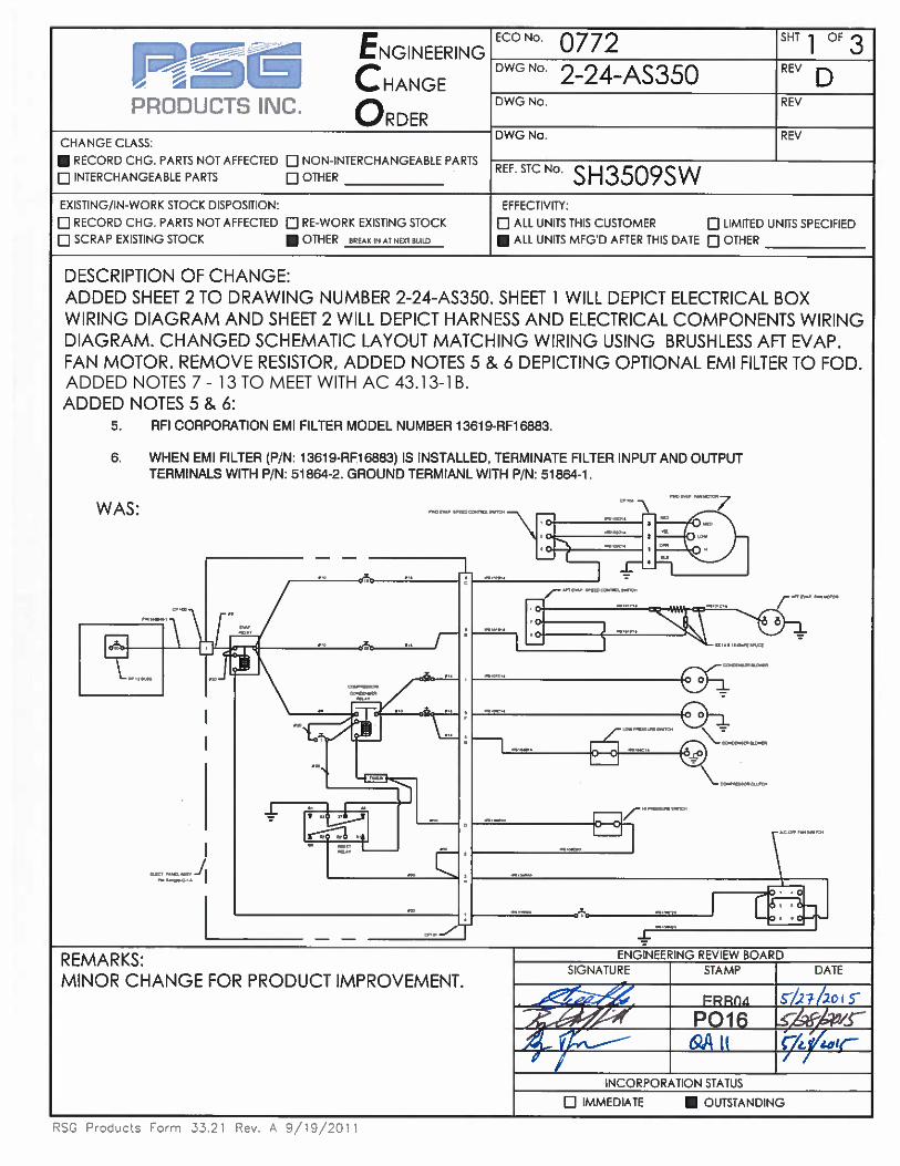
ADDED NOTES 7 - 13 TO MEET WITH AC 43.13-1B.
acuellar
Rectangle

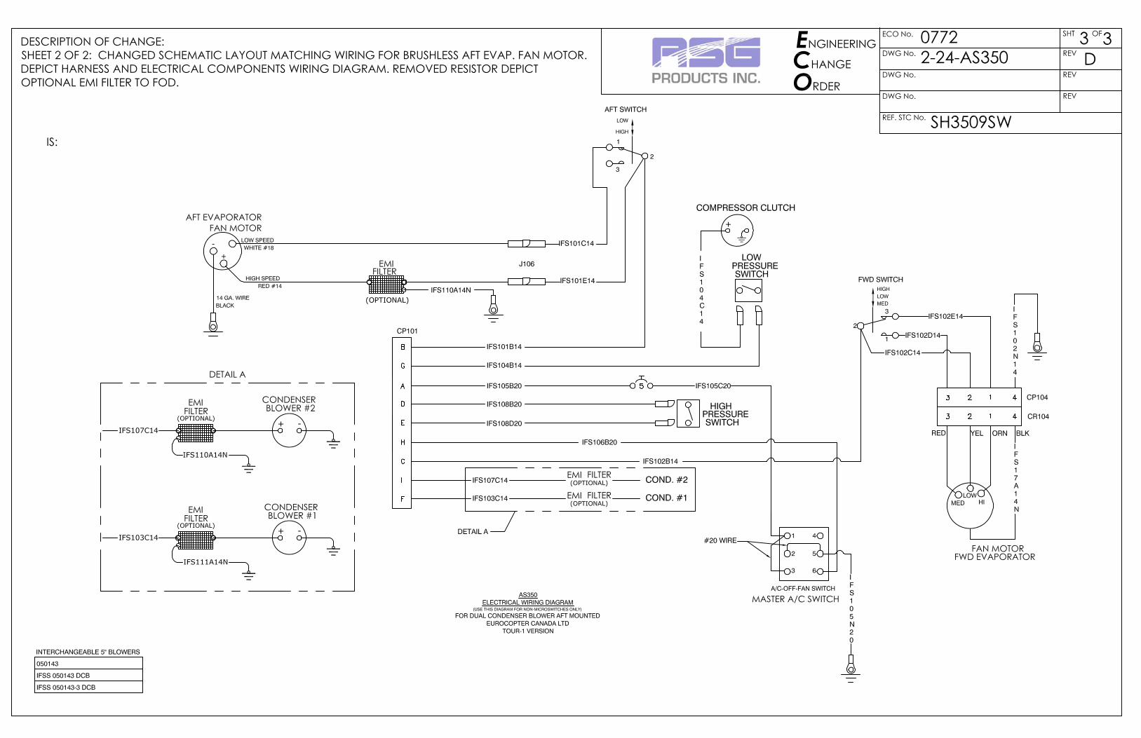

RSG Products Inc. INSTALLATION OF HOSES – AS350 Air Conditioning
Date: 05/29/15 Section 10: Installation of Hoses Page 1 of 3
Step 10
Installation of Hoses

RSG Products Inc. INSTALLATION OF HOSES – AS350 Air Conditioning
Date: 05/29/15 Section 10: Installation of Hoses Page 2 of 3
Installation of hoses
STEP PROCEDURE MECH INSP
10.1 Review Install Drawings 3-5-AS350 and 3-15-AS350.
10.2 WARNING: Before connecting hoses, be sure all fittings have R134 approved “O” Rings installed.
10.3
Route evaporator return line hose assembly #10 suction hose (tee fitting above deck), P/N 570087-O-A from the upper transmission deck down through the right side baggage compartment, through the existing opening in the baggage compartment floor, under the floor forward to the forward evaporator. The short length of hose connects to the Aft evaporator return fitting above the transmission deck. The longer length above the transmission deck is routed against the cabin back wall to the compressor suction fitting located on the left side of the transmission.
10.4
Route the evaporator expansion valve supply line high pressure hose assembly #6, P/N 570072-O-A from the baggage department down through the existing opening in the baggage compartment floor, under the floor forward to the forward evaporator. The tee fitting connects to the “out” or supply fitting on the dryer bottle. The short length to the evaporator.
10.5
Clamp the coil on the end of the expansion valve to the return hose fitting (#10 large line) with a 1-inch band clamp. Assure the fitting is clean where the coil is clamped. Insulate the coil completely with cork tape, P/N 070078-0, PER DRAWING NO. 3-5-A350
10.6
Route THE CONDENSER SUPPLY LINE HOSE ASSEMBLY #8, P/N 570070-O-A from the compressor discharge fitting against the cabin back wall to the right side of the transmission deck. Route down the same opening in the transmission deck as the return hose was routed. Connect to cone condenser. Route hose assembly #6, P/N 570067-O-A, along beside #8 line as shown in Drawing No. 3-5-AS350.

RSG Products Inc. INSTALLATION OF HOSES – AS350 Air Conditioning
Date: 05/29/15 Section 10: Installation of Hoses Page 3 of 3
Installation of Hoses
STEP PROCEDURE MECH INSP
10.7 Install drier mount bracket, P/N 260123-2 per Drawing No. 3-5-AS350 and drier bottle, P/N 090016-5.
10.8 Do not connect drier bottle up until all lines are connected and you are ready to vacuum down system.
10.9 Connect high and low pressure switches. Be sure to connect the correct wire to each switch. Low pressure switch P/N 050107, High pressure switch, P/N 90004.
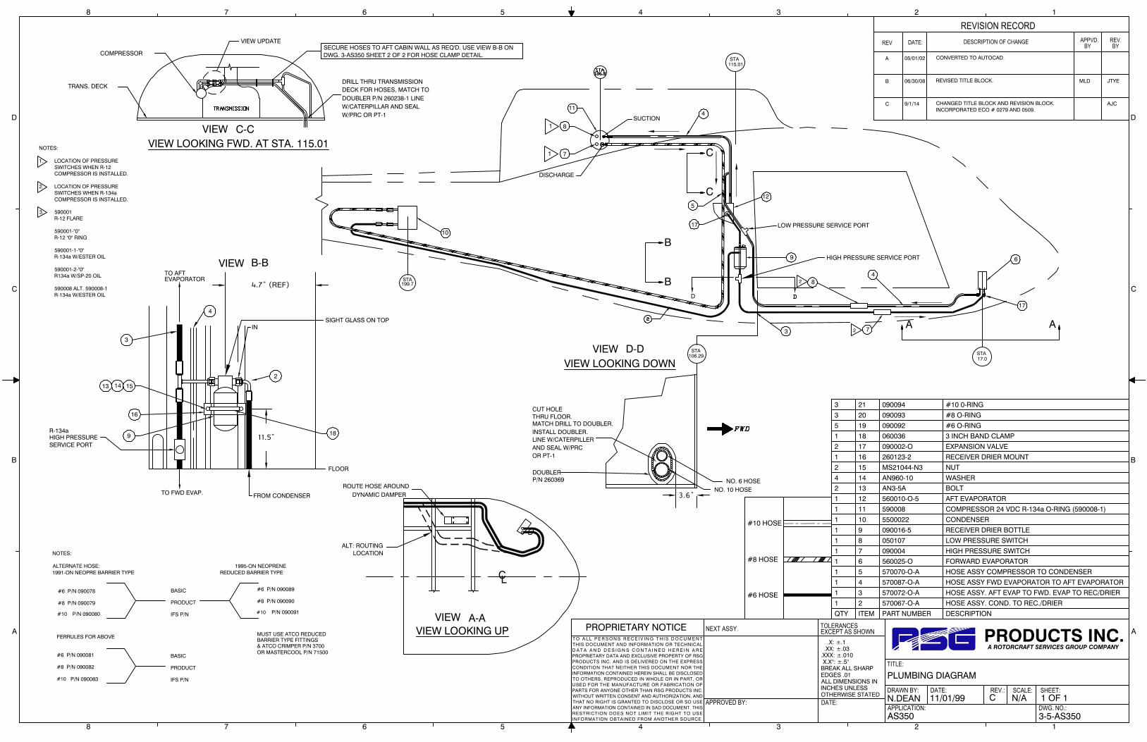
.X: ±.1 .XX: ±.03.XXX: ±.010 X.X°: ±.5°BREAK ALL SHARPEDGES .01ALL DIMENSIONS ININCHES UNLESSOTHERWISE STATED
TOLERANCES
APPROVED BY:
NEXT ASSY.
DATE:
EXCEPT AS SHOWN
DRAWN BY:
APPLICATION:
DATE:
TITLE:
REV.: SCALE:
DWG. NO.:
SHEET:
PROPRIETARY NOTICET O A L L P E R S O N S R E C E I V IN G T H I S D O C U M E N TTHIS DOCUMENT AND INFORMATION OR TECHNICALD A T A A N D D E S I G N S C O N T A I N E D H E R E I N A R EPROPRIETARY DATA AND EXCLUSIVE PROPERTY OF RSGPRODUCTS INC. AND IS DELIVERED ON THE EXPRESSCONDITION THAT NEITHER THIS DOCUMENT NOR THEINFORMATION CONTAINED HEREIN SHALL BE DISCLOSEDTO OTHERS, REPRODUCED IN WHOLE OR IN PART, ORUSED FOR THE MANUFACTURE OR FABRICATION OFPARTS FOR ANYONE OTHER THAN RSG PRODUCTS INC.WITHOUT WRITTEN CONSENT AND AUTHORIZATION, ANDTHAT NO RIGHT IS GRANTED TO DISCLOSE OR SO USEANY INFORMATION CONTAINED IN SAD DOCUMENT. THISRESTRICTION DOES NOT LIMIT THE RIGHT TO USEINFORMATION OBTAINED FROM ANOTHER SOURCE.
PRODUCTS INC.A ROTORCRAFT SERVICES GROUP COMPANY
8 7 6 5 4 3 2 1
A
B
C
D
A
B
C
D
8 7 6 5 4 3 2 1
DATE:REV DESCRIPTION OF CHANGE
REVISION RECORDAPPVD.
BYREV.BY
AS350 3-5-AS350
1 OF 1N/AC11/01/99N.DEAN
PLUMBING DIAGRAM
A 05/01/02 CONVERTED TO AUTOCAD.
B 06/30/08 REVISED TITLE BLOCK. MLD JTYE
C 9/1/14 CHANGED TITLE BLOCK AND REVISION BLOCK.INCORPORATED ECO # 0279 AND 0509.
AJC
QTY ITEM PART NUMBER DESCRIPTION
1 2 570067-O-A HOSE ASSY. COND. TO REC./DRIER
1 3 570072-O-A HOSE ASSY. AFT EVAP TO FWD. EVAP TO REC/DRIER
1 4 570087-O-A HOSE ASSY FWD EVAPORATOR TO AFT EVAPORATOR
1 5 570070-O-A HOSE ASSY COMPRESSOR TO CONDENSER
1 6 560025-O FORWARD EVAPORATOR1 7 090004 HIGH PRESSURE SWITCH
1 8 050107 LOW PRESSURE SWITCH
1 9 090016-5 RECEIVER DRIER BOTTLE
1 10 5500022 CONDENSER
1 11 590008 COMPRESSOR 24 VDC R-134a O-RING (590008-1)
1 12 560010-O-5 AFT EVAPORATOR
2 13 AN3-5A BOLT4 14 AN960-10 WASHER
2 15 MS21044-N3 NUT
1 16 260123-2 RECEIVER DRIER MOUNT
2 17 090002-O EXPANSION VALVE
1 18 060036 3 INCH BAND CLAMP
#10 HOSE
#6 HOSE
#8 HOSE
NOTES:
1. LOCATION OF PRESSURESWITCHES WHEN R-12COMPRESSOR IS INSTALLED.
2. LOCATION OF PRESSURESWITCHES WHEN R-134aCOMPRESSOR IS INSTALLED.
3. 590001R-12 FLARE
590001-"0"R-12 "0" RING
590001-1-"0"R-134a W/ESTER OIL
590001-2-"0"R134a W/SP-20 OIL
590008 ALT. 590008-1R-134a W/ESTER OIL
TRANS. DECK
COMPRESSOR
DRILL THRU TRANSMISSIONDECK FOR HOSES, MATCH TO DOUBLER P/N 260238-1 LINEW/CATERPILLAR AND SEALW/PRC OR PT-1
VIEW LOOKING FWD. AT STA. 115.01C-CVIEW
SECURE HOSES TO AFT CABIN WALL AS REQ'D. USE VIEW B-B ONDWG. 3-AS350 SHEET 2 OF 2 FOR HOSE CLAMP DETAIL.
FROM CONDENSER
SIGHT GLASS ON TOP
4.7" (REF)
TO FWD EVAP.
IN
3
13 14 15
9
TO AFTEVAPORATOR
VIEW B-B
HIGH PRESSURESERVICE PORT
R-134a11.5" 18
2
4
16
FLOOR
5
A A
B
B
9
10
4
8
7
12
199.7STA
11
6
4
DISCHARGE
SUCTION
3.6"
NO. 6 HOSENO. 10 HOSE
DOUBLERP/N 260369
CUT HOLE THRU FLOOR.MATCH DRILL TO DOUBLER. INSTALL DOUBLER. LINE W/CATERPILLERAND SEAL W/PRCOR PT-1
3
D
106.29STA
STA115.01
VIEW LOOKING DOWNVIEW D-D
17
17.0STA
LOW PRESSURE SERVICE PORT
8
71
1
2
2
C
C
17
HIGH PRESSURE SERVICE PORT
CL
ROUTE HOSE AROUNDDYNAMIC DAMPER
VIEW A-AVIEW LOOKING UP
ALT: ROUTINGLOCATION
P/N 090083
#8 P/N 090082
#6 P/N 090081
FERRULES FOR ABOVE
P/N 090080
#8 P/N 090079
#10
#10
#6 P/N 090078
& ATCO CRIMPER P/N 3700
MUST USE ATCO REDUCED BARRIER TYPE FITTINGS
IFS P/N
PRODUCT
BASIC
IFS P/N
PRODUCT #8 P/N 090090
P/N 090091#10
BASIC #6 P/N 090089
OR MASTERCOOL P/N 71500
NOTES:
ALTERNATE HOSE: 1995-ON NEOPRENE1991-ON NEOPRE BARRIER TYPE REDUCED BARRIER TYPE
5 19 090092 #6 O-RING
3 20 090093 #8 O-RING
3 21 090094 #10 0-RING
VIEW UPDATE

.X: ±.1 .XX: ±.03.XXX: ±.010 X.X°: ±.5°BREAK ALL SHARPEDGES .01ALL DIMENSIONS ININCHES UNLESSOTHERWISE STATED
TOLERANCES
APPROVED BY:
NEXT ASSY.
DATE:
EXCEPT AS SHOWN
DRAWN BY:
APPLICATION:
DATE:
TITLE:
REV.: SCALE:
DWG. NO.:
SHEET:
PROPRIETARY NOTICET O A L L P E R S O N S R E C E I V IN G T H I S D O C U M E N TTHIS DOCUMENT AND INFORMATION OR TECHNICALD A T A A N D D E S I G N S C O N T A I N E D H E R E I N A R EPROPRIETARY DATA AND EXCLUSIVE PROPERTY OF RSGPRODUCTS INC. AND IS DELIVERED ON THE EXPRESSCONDITION THAT NEITHER THIS DOCUMENT NOR THEINFORMATION CONTAINED HEREIN SHALL BE DISCLOSEDTO OTHERS, REPRODUCED IN WHOLE OR IN PART, ORUSED FOR THE MANUFACTURE OR FABRICATION OFPARTS FOR ANYONE OTHER THAN RSG PRODUCTS INC.WITHOUT WRITTEN CONSENT AND AUTHORIZATION, ANDTHAT NO RIGHT IS GRANTED TO DISCLOSE OR SO USEANY INFORMATION CONTAINED IN SAD DOCUMENT. THISRESTRICTION DOES NOT LIMIT THE RIGHT TO USEINFORMATION OBTAINED FROM ANOTHER SOURCE.
PRODUCTS INC.A ROTORCRAFT SERVICES GROUP COMPANY
8 7 6 5 4 3 2 1
A
B
C
D
A
B
C
D
8 7 6 5 4 3 2 1
DATE:REV DESCRIPTION OF CHANGE
REVISION RECORDAPPVD.
BYREV.BY
AS350 3-15-AS350
1 OF 1N/AC11/01/99MAH
PLUMBING ROUTING
A 05/06/02 CONVERTED TO AUTOCAD.
B 09/09/09 REVISED TITLE BLOCK.
C 9/1/14 CHANGED TITLE BLOCK AND REVISION BLOCK. AJC
VIEW A
B
B
C
C
S
D
LOW PRESSURE SERVICE PORT
AFT EVAPORATOR
CUT HOLE IN TRANSMISSION DECKSEE DWG 4-2-AS350 (SH 1 OF 1).
COMPRESSOR
SEE DWG 3-5-AS350(SH 1 OF 1),
VIEW D-D
SECURE HOSES TO FIREWALLSEE DWG 3-5-AS350 (SH 1 OF 1)
VIEW C-C
RECEIVER/DRIER
EXPANSION VALVED D
CONDENSER
LOW PRESSURE SWITCHP/N 050107
P/N 090004HIGH PRESSURE SWITCH
A
EVAPORATORLOCATED JUST FWD OF FWDFWD DOUBLER, P/N 260373-1,ROUTE BOTH HOSES THRU
FWD EVAPORATOR
HIGH PRESSURE SERVICE PORT
OUTLET AND BREAKER CONFIGURATIONSWILL CHANGE ACCORDING TO MODEL.
NOTE:
USE EXISTING LIGHTENING HOLES ONLY FORALL ROUTING (PREFERRED).
INSTALL PER VIEW B-B ORALTERNATE VIEW B-B ORVIEW C-C
EXTREMELY IMPORTANT
FAILURE TO SECURE EXPANSION VALVESENSING BULB, TIGHTLY, TO THE RETURNLINE HOSE FITTING (#10) WITH A STAINLESSSTEEL CLAMP (AND INSULATE SENSING BULB &LINE) WILL DRAMATICALLY DECREASE THEPERFORMANCE OF THE AFT EVAPORATOR(NOT FORWARD).
TYPICAL HOSE INSTALLATION:
FOR #6 HOSE ATTACH WITH ADEL CLAMPMS21919DG10 & HARDWARE AS SHOWN
FOR #8 HOSE ATTACH WITH ADEL CLAMPMS21919DG11 & HARDWARE AS SHOWN
FOR #10 HOSE ATTACH WITH ADEL CLAMPMS21919DG12 & HARDWARE AS SHOWN
NOTE, INWARD PLACEMENT OF CLAMPS TOFACILITATE INSTALLATION USING ONLYONE SCREW, WASHER, & NUT SET-UP.
NO 10 SCREW
MOUNT LHMS-S10D
TIE WRAP 2X
TIE BLOCK ZZCR4HM
HOSE 2X
B-BVIEW"ALTERNATE"
C-CVIEW
TIE BLOCK ZZCR4HM
TIE WRAPS TY524M 2X
B-BVIEWALTERNATE: P/N LHMS-S10D MOUNTUSE #10 SCREW OR AN3 BOLTWITH TIE WRAP & ZZCR4HMBLOCK IF DESIRED (SEE VIEW B-B"ALTERNATE")
AN3-4A BOLT ORAN525-10R10 SCREW
AN960-10 WASHERMS21044-N3 NUT
RSG Products Inc. PAPERWORK – AS350 Air Conditioning
Date: 05/22/15 Section 11: Paperwork Page 1 of 2
Step 11
Paperwork

RSG Products Inc. PAPERWORK – AS350 Air Conditioning
Date: 05/22/15 Section 11: Paperwork Page 2 of 2
DETAILED WEIGHT AND BALANCE DATA
FOR
RSG PRODUCTS INC.
FREON AIR CONDITIONING
UNIT INSTALLED IN A
TYPICAL HELICOPTER, MODEL AS350 B, BA, B1, B2, B3, C, D OR D1
PERTAINS TO KIT #350-00-031
ITEM WEIGHT ARM MOMENT
Forward Evaporator Assembly 10.00 19.00 190.00
Forward Air Outlets 4.00 31.32 125.28
Aft Evaporator and Return Air 9.00 120.00 1080.90
Aft Evaporator Blower 6.00 120.85 725.10
Condenser Assy. & Mount w/ Dual condenser blowers 28.20 201.80 5690.76
Compressor and Mount 15.00 147.80 2217.00
Electrical Relay Panes 4.0 153.70 614.80
Refrigerant, Hoses and Fittings 9.00 76.90 692.10
Sub Total: (Air Conditioner) 85.20 133.05 11,335.94


FLIGHT MANUAL
SUPPLEMENT
FOR
AS350B, C, D AND D1

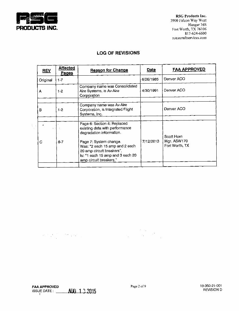


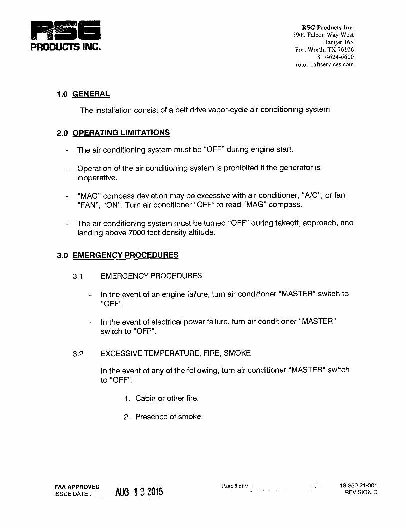


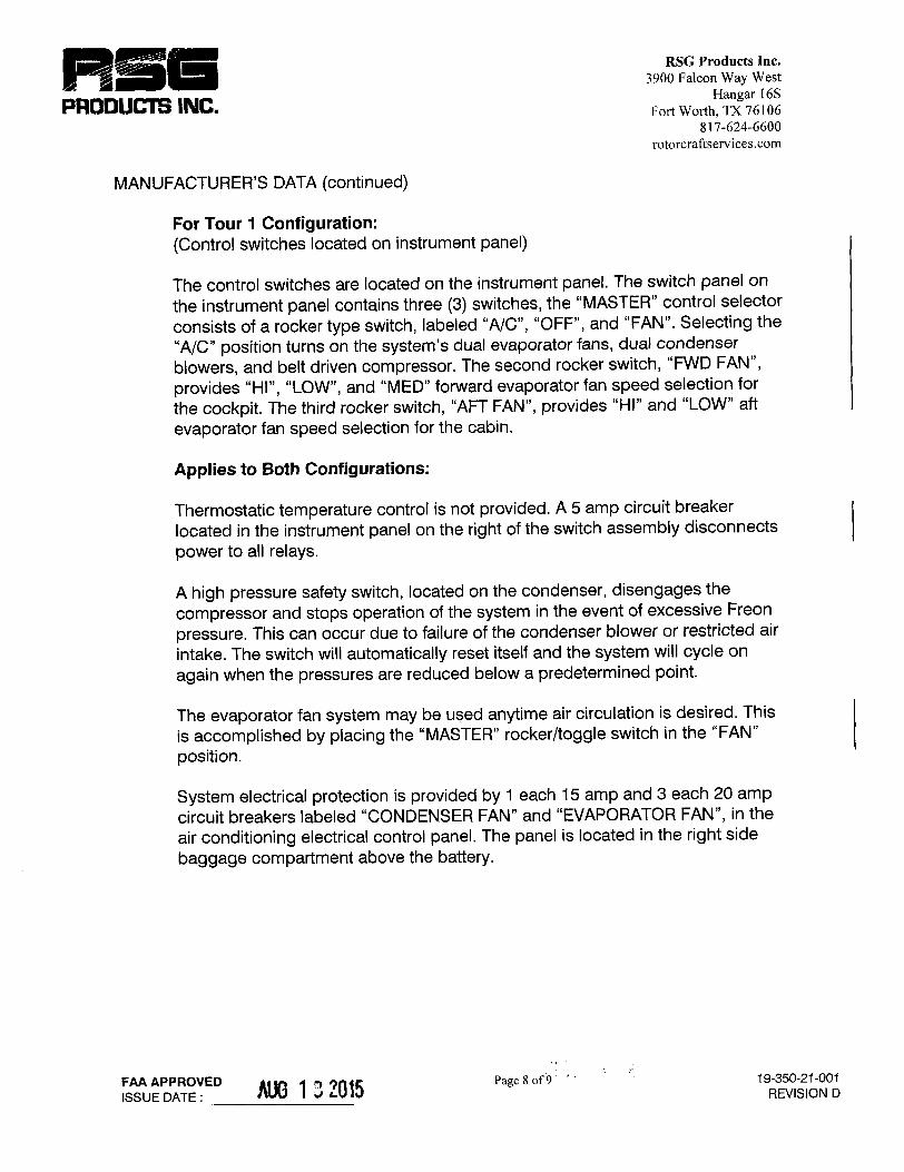


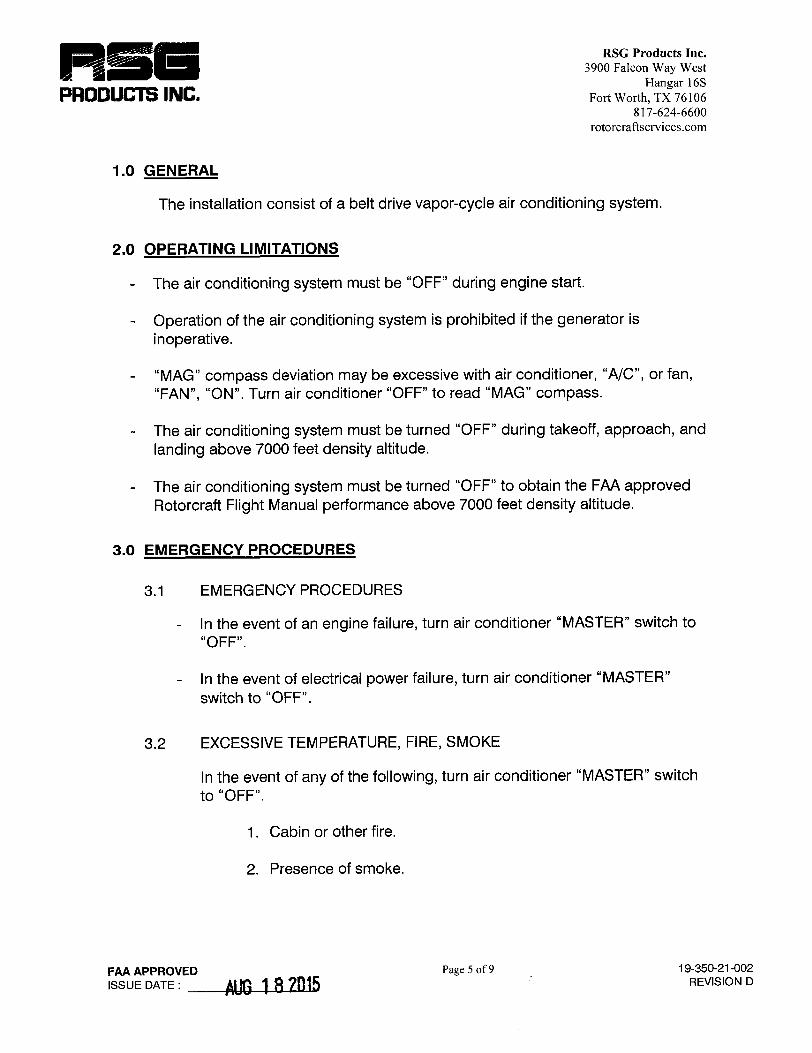

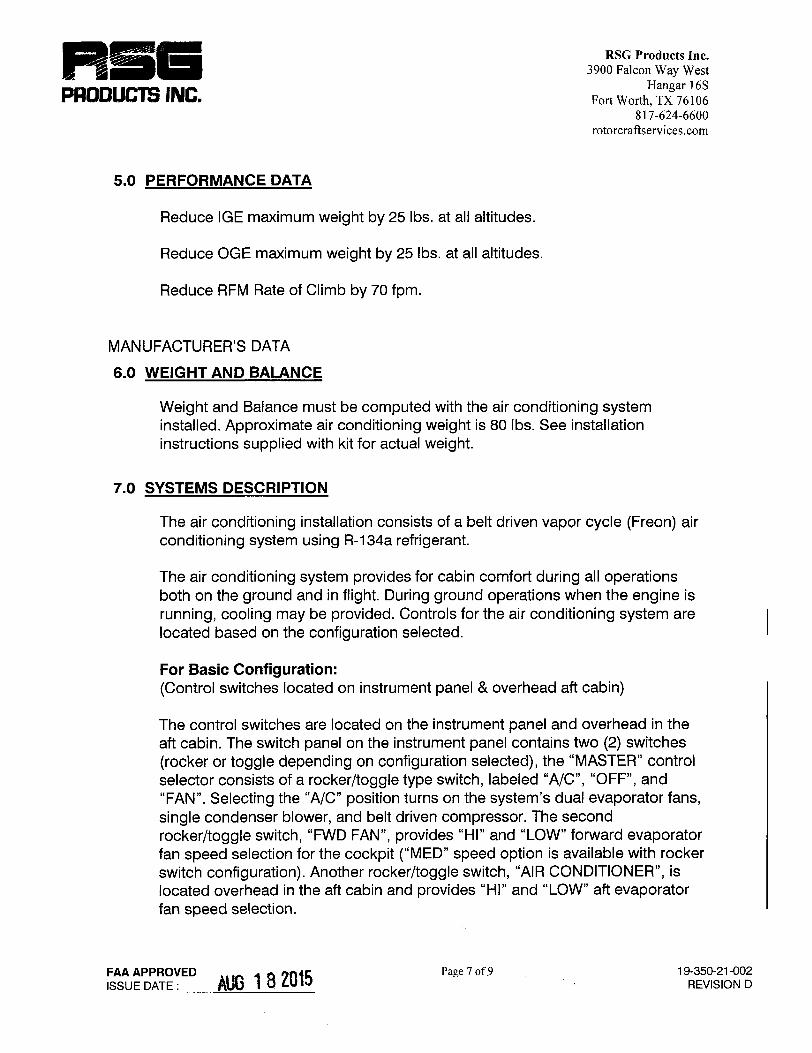


FLIGHT MANUAL
SUPPLEMENT
FOR
AS350BA
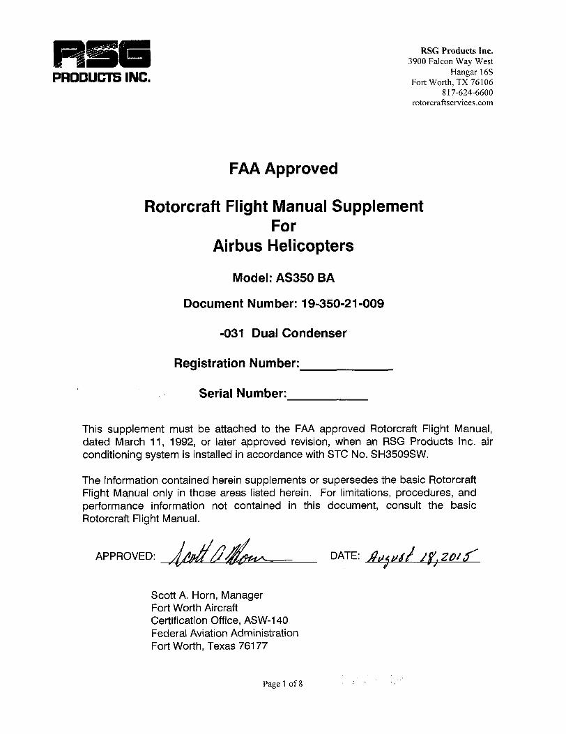
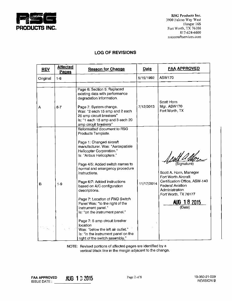

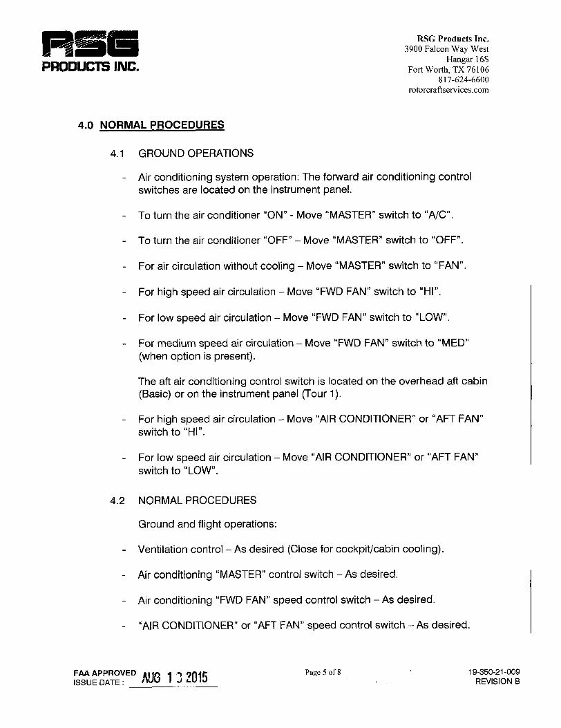


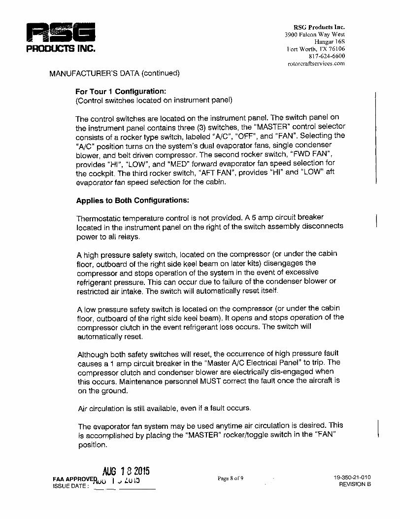


FLIGHT MANUAL
SUPPLEMENT
FOR
AS350B1


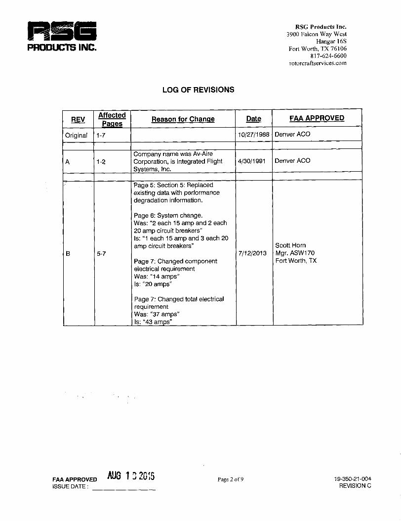


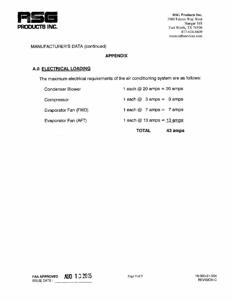

FLIGHT MANUAL
SUPPLEMENT
FOR
AS350B2


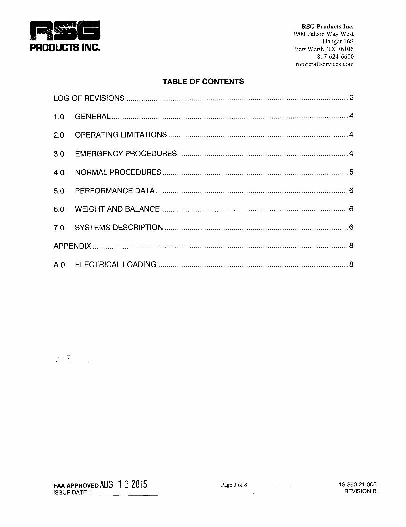


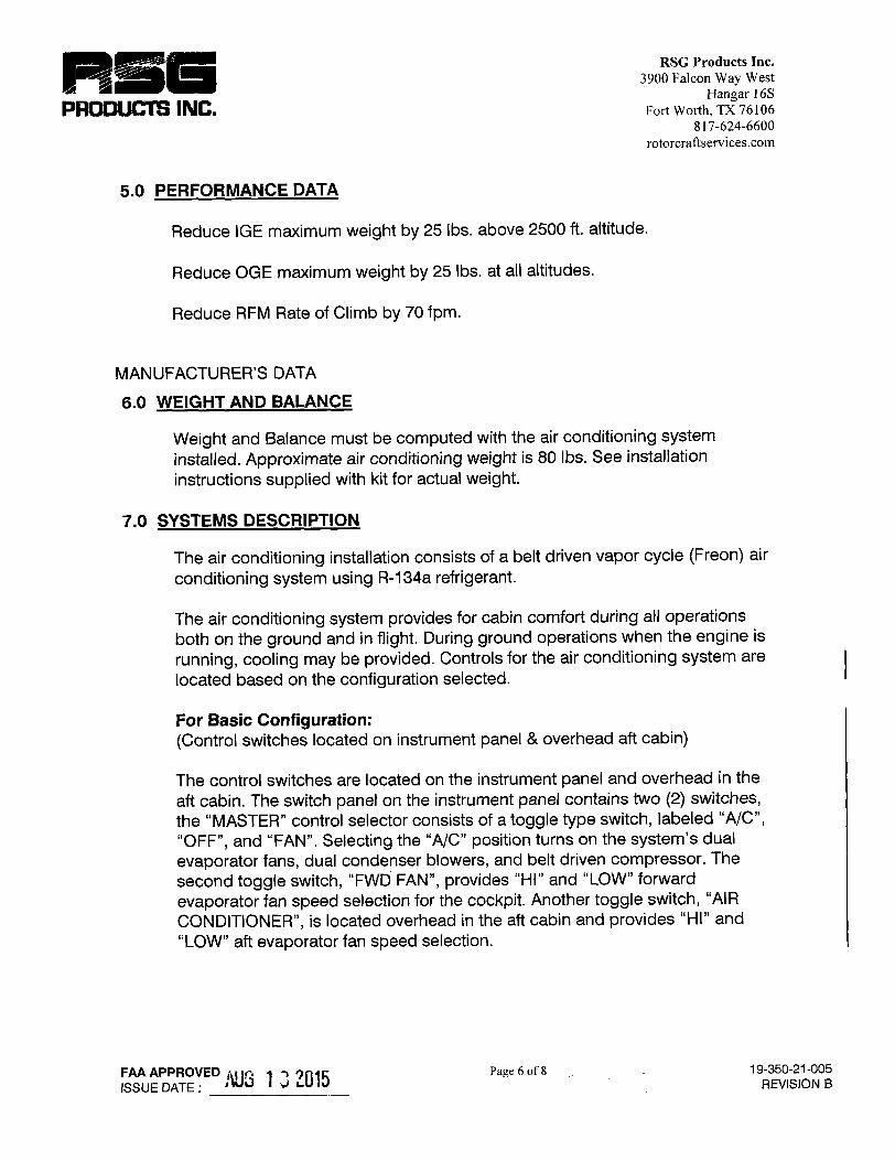
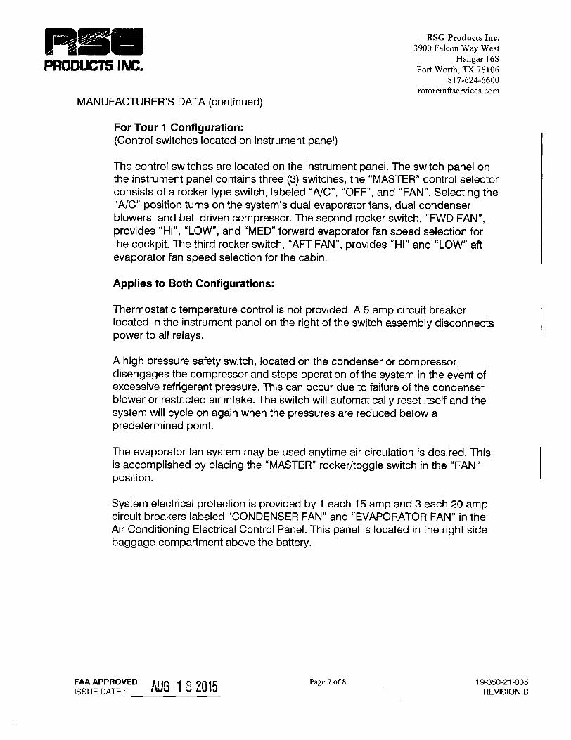


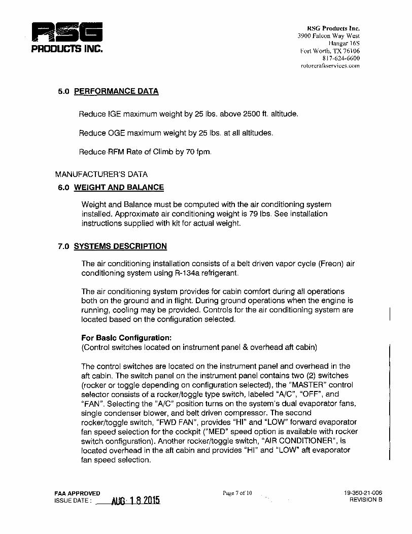

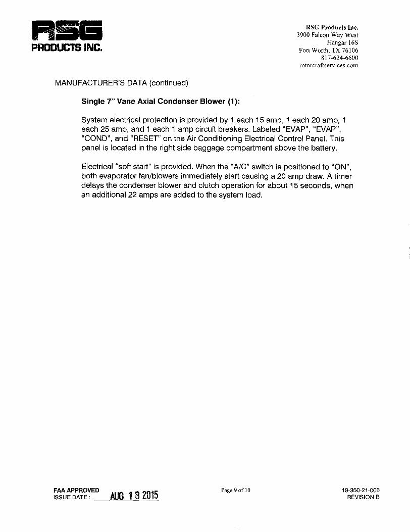


FLIGHT MANUAL
SUPPLEMENT
FOR
AS350B3


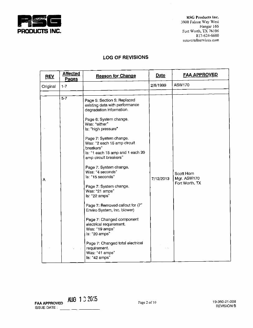


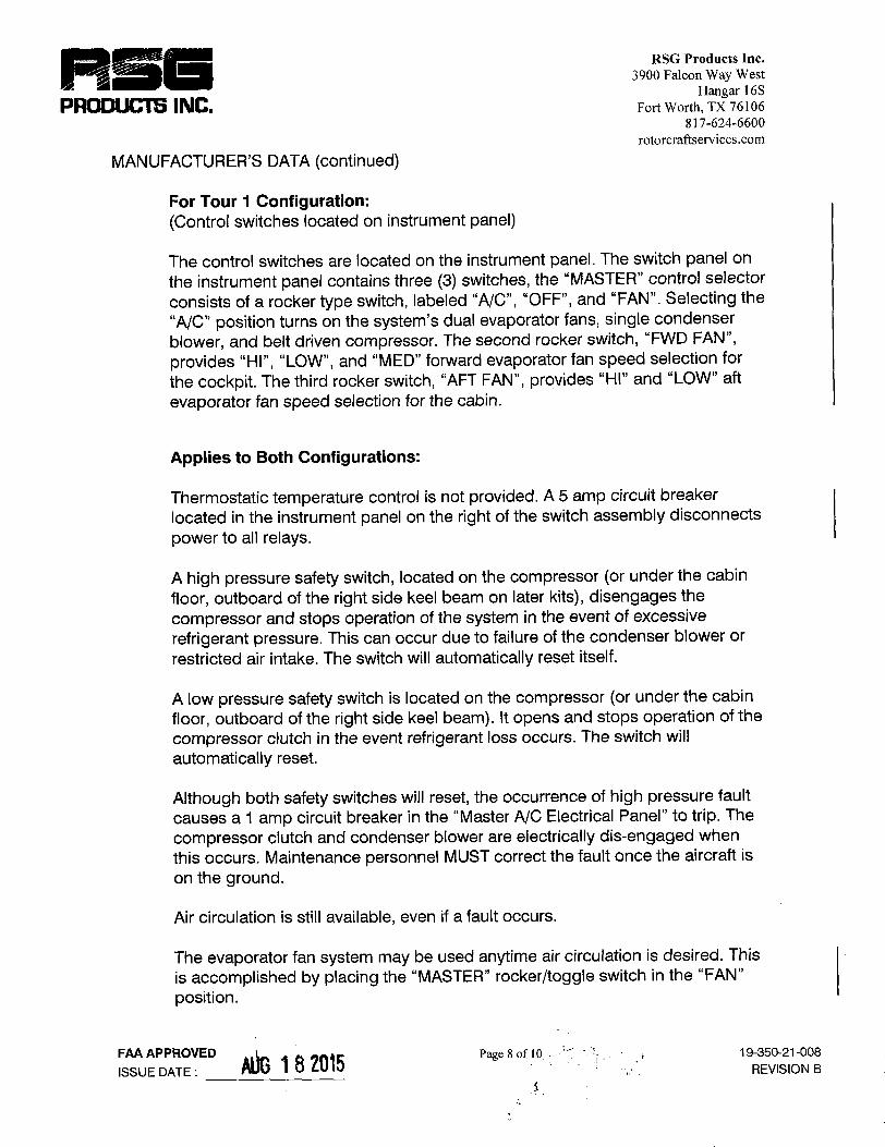


RSG Products Inc. CONTINUED AIRWORTHINESS – AS350 Air Conditioning
Date: 11/19/14 Section 12: Continued Airworthiness Page 1 of 112
Step 12
Continued Airworthiness
Air Conditioning System Installation
Instructions for Continued Airworthiness for
Airbus Helicopters AS-350 B, C, D, D1, B1, B2, B3, BA & EC-130 B4
FAA Project Number: SA3109RC-R STC Number: SH3509SW

DATE: DOC No.: REV: PAGE:
11/19/2014 IFSE-007 D ii of vii TITLE:
Air Conditioning System Installation Instructions For Continued Airworthiness for Airbus Helicopters AS-350 B, C, D, D1, B1, B2, B3, BA & EC-130 B4
LOG OF REVISIONS Instructions for Continued Airworthiness for the Airbus Helicopters AS-350 B, C, D, D1, B, B1, B2, B3, BA and EC-130 B4 Air Conditioning System Installation have been reviewed and found to be acceptable to the Administrator. For the purpose of these Instructions for Continued Airworthiness (ICA), acceptable to the Administrator means the ICA contains the applicable requirements specified in Appendix A to Federal Aviation Regulations Part 27, as appropriate, do not contain any incorrect terminology or incorrect references, and contain a Cover Page, Log of Accepted Revisions, Revision Control Procedure and Record of Temporary Revisions, a list of Effective Pages, and a Table of Contents. Changes to this document will be distributed to owners of the kits within 10 days after the revision is approved. Changes to this document will be indicated by a revision letter in the header, in the Record of Revisions, and on the List of Effective Pages. Contact RSG Products by mail at 3900 Falcon Way West Hangar 16S, Fort Worth, TX, 76106. Or by phone at 817-624-6600.
REV Date Description Written ByChecked
By FAA
ApprovalApproval
Date - 05/03/10 Original Issue E. Sherrill P. Ban A 06/11/10 Incorporated FAA redlines E. Sherrill K. Sheridan B 08/08/10 Revised to add Brushless Motor
part information, page 87 E. Sherrill P. Ban
C 08/12/10 Incorporated FAA redlines E. Sherrill P. Ban
C-1 12/11/13 Revised Chapter 5, 100 hour inspection to change belt on condition. Changed Name.
A. Weidler S. Weidler
C-2 09/17/14 Revised Chapter 12 and 21. Removed paragraphs 7 - 9 of Section 12-10-02.d. Removed sight glass troubleshooting information Section 21-00-06 under symptoms.
A. Cuellar S. Weidler
C-3 09/30/14 Revised chapter 5 to increase inspection interval to 150 Hours +/- 15
S. Weidler S. Weidler
D 11/19/14 Changed Template. Changed Mfr. Name. Was: Eurocopter, Is: Airbus Helicopters. Updated parts list with newer configurations. Parts list is now under Chapter 31. Updated
S. Johnson S. Thornton

DATE: DOC No.: REV: PAGE:
11/19/2014 IFSE-007 D iii of vii TITLE:
Air Conditioning System Installation Instructions For Continued Airworthiness for Airbus Helicopters AS-350 B, C, D, D1, B1, B2, B3, BA & EC-130 B4
electrical and plumbing diagrams and install drawings. Updated annual/150-hour inspection program in sections 05-00-00 and 05-10-00.
Typed signatures indicate approval. Handwritten signature approvals of this document are on file at RSG Products Inc.

DATE: DOC No.: REV: PAGE:
11/19/2014 IFSE-007 D iv of vii TITLE:
Air Conditioning System Installation Instructions For Continued Airworthiness for Airbus Helicopters AS-350 B, C, D, D1, B1, B2, B3, BA & EC-130 B4
RECORD OF TEMPORARY REVISIONS Rev. No.
Issue Date Date Inserted
By Rev. No.
Issue Date Date Inserted
By

DATE: DOC No.: REV: PAGE:
11/19/2014 IFSE-007 D v of vii TITLE:
Air Conditioning System Installation Instructions For Continued Airworthiness for Airbus Helicopters AS-350 B, C, D, D1, B1, B2, B3, BA & EC-130 B4
LIST OF EFFECTIVE PAGES
LIST OF REVISIONS Revision A December 06, 2012 Revision B February 27, 2013 Revision C May 14, 2013 Revision D November 19, 2014 LIST OF EFFECTIVE PAGES TITLE PAGES REV.No Cover i D Log of Revisions ii D Record of Temporary Revisions iv D List of Effective Pages v D Table of Contents vi - vii D Chapter 1 Introduction 1 D Chapter 4 Airworthiness Limitation 2 D Chapter 5 Continued Airworthiness Inspections 3 - 9 D Chapter 6 Dimensions and Access 10 - 12 D Chapter 11 Markings and Placards 13 D Chapter 12 Servicing Maintenance Practices 14 - 30 D Chapter 20 Standard Practices 31 - 41 D Chapter 21 Air Conditioning 42 – 56 D Chapter 31 Illustrated Parts List 57 - 88 D Chapter 98 Wiring Diagrams and Plumbing Schematics 89 - 101 D Appendix A Weight and Balance 102 - 104 D _______________________________________________________________________________________

DATE: DOC No.: REV: PAGE:
11/19/2014 IFSE-007 D vi of vii TITLE:
Air Conditioning System Installation Instructions For Continued Airworthiness for Airbus Helicopters AS-350 B, C, D, D1, B1, B2, B3, BA & EC-130 B4
Table of Contents LOG OF REVISIONS .......................................................................................................................... ii
RECORD OF TEMPORARY REVISIONS ..........................................................................................iv
LIST OF EFFECTIVE PAGES ............................................................................................................ v
Chapter 1 ............................................................................................................................................ 1
Section 01-00-00 Introduction ....................................................................................................... 1
Chapter 4 ............................................................................................................................................ 2
Section 04-00-00 Airworthiness Limitations ................................................................................. 2
Chapter 5 ............................................................................................................................................ 3
Section 05-00-00 Continued Airworthiness Inspections .............................................................. 3
Section 05-10-00 Continued Airworthiness Scheduled Inspections ........................................... 6
Chapter 6 .......................................................................................................................................... 10
Section 06-00-00 Dimensions and Access ................................................................................. 10
Chapter 11 ....................................................................................................................................... 13
Section 11-00-00 Placards and Markings ................................................................................... 13
Chapter 12 ....................................................................................................................................... 14
Section 12-00-00 Servicing Maintenance Practices ................................................................... 14
Section 12-10-00 Charging Practices ......................................................................................... 15
Section 12-20-00 Clutch Servicing Practices ............................................................................. 20
Section 12-30-00 System Leak Check ........................................................................................ 26
Section 12-40-00 Fitting Torque Procedures ............................................................................. 27
Section 12-50-00 Normal Operation Functional Test................................................................. 28
Section 12-60-00 Belt Tension Procedure .................................................................................. 29
Section 12-70-00 Drive Belt Change Procedure ........................................................................ 30
Chapter 20 ....................................................................................................................................... 31
Section 20-00-00 Standard Practices ......................................................................................... 31
Section 20-10-00 Torques Maintenance Practices .................................................................... 32
Section 20-30-00 Painting Maintenance Practices .................................................................... 36
Section 20-40-00 Corrosion Control Maintenance Practices .................................................... 37
DATE: DOC No.: REV: PAGE:
11/19/2014 IFSE-007 D vii of vii TITLE:
Air Conditioning System Installation Instructions For Continued Airworthiness for Airbus Helicopters AS-350 B, C, D, D1, B1, B2, B3, BA & EC-130 B4
Section 20-50-00 Mechanical Fastener Sealing Methods ......................................................... 41
Section 20-90-00 Dye-Penetrant Inspection Methods ............................................................... 42
Chapter 21 ........................................................................................................................................ 43
Section 21-00-00 Air Conditioning ................................................................................................ 43
Section 21-10-00 Illustrated Parts List ........................................................................................ 58
Chapter 98 ....................................................................................................................................... 89
Section 98-00-00 Wiring Diagrams and Plumbing Schematics ................................................ 89
APPENDIX A Weight and Balance ............................................................................................ 102

DATE: DOC No.: REV: PAGE:
11/19/2014 IFSE-007 D 1 of 104 TITLE:
Air Conditioning System Installation Instructions For Continued Airworthiness for Airbus Helicopters AS-350 B, C, D, D1, B1, B2, B3, BA & EC-130 B4
01-00-00
Chapter 1
Section 01-00-00 Introduction
These are accepted Instructions for Continued Airworthiness for modifications performed in accordance with the Airbus Helicopters AS-350 B, C, D, D1, B, B1, B3, BA and EC-130 B4 Belt-Driven Vapor Cycle Air Conditioning System Installation. All references to the Air Conditioning System in this document will refer to the Belt-Driven Air Conditioning System Installation and other related components specified in STC – SH3509SW. Whether modified by Rotorcraft Services Group. or by another Agency with expressed permission from RSG these Instructions for Continued Airworthiness (ICA) should be supplied to the owner/operator of the STC at the time of completion. Subsequent accepted changes to the ICA will be submitted by Rotorcraft Services Group for distribution to owners and operators of the STC. This, Instructions for Continued Airworthiness, is intended to supplement the AS-350 B, C, D, D1, B, B1, B2, B3, BA, and EC-130 B4 rotorcraft maintenance manuals provided by Airbus Helicopters. The information, procedures, requirements, and limitations contained in this, Instructions for Continued Airworthiness, for this type design change supersede the information, procedures, requirements, and limitations contained in the rotorcraft’s maintenance manual when the type design change is installed on the Type Certificate Holder’s rotorcraft.

DATE: DOC No.: REV: PAGE:
11/19/2014 IFSE-007 D 2 of 104 TITLE:
Air Conditioning System Installation Instructions For Continued Airworthiness for Airbus Helicopters AS-350 B, C, D, D1, B1, B2, B3, BA & EC-130 B4
04-00-00
Chapter 4
Section 04-00-00 Airworthiness Limitations
“The Airworthiness Limitations section is FAA approved and specifies inspections and other maintenance required under §§43.16 and 91.403 of the Federal Aviation Regulation unless an alternative program has been FAA approved.” There are no additional airworthiness limitations associated with the Air Conditioning System Installation. There are no life limited components associated with the Air Conditioning System Installation.

DATE: DOC No.: REV: PAGE:
11/19/2014 IFSE-007 D 3 of 104 TITLE:
Air Conditioning System Installation Instructions For Continued Airworthiness for Airbus Helicopters AS-350 B, C, D, D1, B1, B2, B3, BA & EC-130 B4
05-00-00
Chapter 5
Section 05-00-00 Continued Airworthiness Inspections
1. General This chapter contains time limit intervals for the Component Overhaul Schedule and Scheduled Inspections for the Air Conditioning System. This chapter is to be added to the approved scheduled inspection for the rotorcraft.
2. Component Overhaul Schedule & Scheduled Maintenance Practices This chapter describes the inspections that must be accomplished on the Air Conditioning System Installation at Scheduled Inspection intervals. Scheduled Inspection requirements must be complied with at the hourly and/or calendar time intervals specified. Refer to Tables 5-01 and 5-02, in Section 05-20-00 for hourly and/or calendar inspection schedules.
3. Conditional Inspection After any operational incident involving hard landings, sudden stoppage of the drive train or water immersions the system must not be operated and an Annual or 150 flight hour inspection is required.
4. Documentation Aircraft mechanics, owners, or operators are required to keep records of the aircraft systems inspections and repairs. This includes, but is not limited to, airworthiness directives, service notices, scheduled inspections, records and life limited components.
5. Definitions The following is short descriptions of words and terms used in the procedures for the required scheduled inspections.
Ambient air temperature: The temperature of the air surrounding a person. Charging station: An air conditioning system service. Cold: The absence of heat. Condensation: The process of changing a vapor into a liquid. Condition: The state of an item or component compared to a known
standard.

DATE: DOC No.: REV: PAGE:
11/19/2014 IFSE-007 D 4 of 104 TITLE:
Air Conditioning System Installation Instructions For Continued Airworthiness for Airbus Helicopters AS-350 B, C, D, D1, B1, B2, B3, BA & EC-130 B4
05-00-00
Damage: Physical deterioration of a component. Desiccant: A material used in the receiver/dryer bottle, to absorb moisture
from the refrigerant. Evaporate: To change from a liquid into a vapor. Examine: Look carefully to find the condition of the component. Find how
that condition is related to a specific standard. Heat load: The amount of heat which the air conditioner is required to
remove from the aircraft cabin. Inches of Mercury: A measurement of pressure normally used for
pressures below atmospheric, one i-h of mercury is equal to approximately one half pound per square i-h.
Inspection: A procedure that includes checking, inspecting and examining a system or component.
Maintenance: The servicing and/or repair of a rotorcraft, a system or a component that keeps it serviceable.
Pressure, ambient: The pressure of the air surrounding a body, normally measured in Pounds per Square i-h, or PSIG.
Refrigerant: A fluid which is used in an air conditioning system to absorb heat from the cabin and carry it outside the helicopter where it can be transferred to the outside air.
Relative Humidity: The ratio of the amount of water vapor in the air to the amount of water vapor required to saturate the air at the existing temperature.
Scheduled Inspection: An inspection procedure that must occur at a specified calendar interval or at specific operational time intervals. Scheduled Inspections are required to help ensure the rotorcraft stays airworthy.
Security: Term used for inspection of hardware and components to make sure they are properly attached and tightened.
Temperature Differential: Difference in temperature. Thermostat: An air condition control which senses the temperature of the
evaporator coil and causes the system to cycle or by-pass to maintain the proper temperature of cooling air.
Vacuum: A negative pressure, or pressure below atmospheric; it is usually expressed in inches of mercury.
Vapor: The gaseous state of a material.

DATE: DOC No.: REV: PAGE:
11/19/2014 IFSE-007 D 5 of 104 TITLE:
Air Conditioning System Installation Instructions For Continued Airworthiness for Airbus Helicopters AS-350 B, C, D, D1, B1, B2, B3, BA & EC-130 B4
05-00-00
6. Abbreviations:
ICA: Instructions for Continued Airworthiness TD: Temperature differential In: Inches InHg: Inches of Mercury lbs: Pounds oz: Ounces Psig: Pounds per Square I-h (gauge) gr: Grams kg: Kilograms kgcm: Kilograms Per Centimeter ml: Milliliters mm: Millimeters N-m: Newton-meters

DATE: DOC No.: REV: PAGE:
11/19/2014 IFSE-007 D 6 of 104 TITLE:
Air Conditioning System Installation Instructions For Continued Airworthiness for Airbus Helicopters AS-350 B, C, D, D1, B1, B2, B3, BA & EC-130 B4
05-10-00
Section 05-10-00 Continued Airworthiness Scheduled Inspections
1. General This section contains requirements for scheduled inspections.
2. Scheduled Inspection Program The Air Conditioning System Installation requires scheduled inspections in order to maintain continued airworthiness. Every effort should be made to perform the inspections with the aircraft placed in a clean well lit environment. There are two different scheduled inspections required for the Air Conditioning System Installation.
a) 50-Hour Inspection
The 50-hour inspection is required to be performed every 50 hours of rotorcraft time-in- service. Inspection Table 5-01 specifies the requirements of the 50-hour inspection. The 50 hour inspection does not require any component removal unless a discrepancy is encountered.
b) Annual or 150-Hour Inspection The inspection is required to be performed annually or every 150 hours of rotorcraft time-in-service, whichever comes first, +/- 15 hours. If inspection is overflown then overflown time must be deducted from the next inspection due. Inspection Table 5-02 specifies the requirements of the annual inspection.
3. Tools and Special Tools for Scheduled Inspection Although not necessarily considered special tools, the adjustable ball swivel mirror and bright flashlight and / or drop light are standard requirements for doing inspections. These items should be used freely and frequently to enhance inspection quality and help ensure discrepancies are not missed. It is important to have adequate lighting for all phases of the inspection. The special tools necessary for the Air Conditioning System Installation inspection are listed as follows: a) Vacuum Pump b) Gauge Manifold c) Vacuum Cleaner d) Pull Scale

DATE: DOC No.: REV: PAGE:
11/19/2014 IFSE-007 D 7 of 104 TITLE:
Air Conditioning System Installation Instructions For Continued Airworthiness for Airbus Helicopters AS-350 B, C, D, D1, B1, B2, B3, BA & EC-130 B4
05-10-00
Table 5-01 50 – Hour Inspection
Registration No. Serial No. Helicopter Total Hours The 50-hour inspection shall be accomplished each 50 hours, time-in-
service. Initial each item after accomplishing the inspection. Record all findings and attach a copy of findings to this inspection form. After correction of all findings, make maintenance record entry.
PRE-INSPECTION Initial 1. Review Airworthiness Directives. 2. Review records for the Air Conditioning System. 3. Review log books for discrepancies. INSPECTION Initial 1. Access the condenser (Ref. Section 6-00-00 Dimensions and Access). Check
the entire condenser assembly for security, including support brackets and attachment fittings. Visually inspect the condenser blower mount.
2. Access the compressor (Ref. Section 6-00-00 Dimensions and Access). Visually inspect the security of the compressor and mount.
3. Inspect the condition of the belt for cracks, deterioration, separation and worn or flat spots. Change belt if necessary. Check belt for proper tension (Ref. 12-60-00 Belt Tension).
4. Access the evaporators (Ref. 6-00-00 Dimensions and Access). Visually inspect for security.
5. Inspect air outlets for condition. 6. Test normal operation functions. (Ref. Section 12-50-00 Normal Operation
Function Test)

DATE: DOC No.: REV: PAGE:
11/19/2014 IFSE-007 D 8 of 104 TITLE:
Air Conditioning System Installation Instructions For Continued Airworthiness for Airbus Helicopters AS-350 B, C, D, D1, B1, B2, B3, BA & EC-130 B4
05-10-00
Table 5-02 Annual or 150 – Hour Inspection
Registration No. Serial No. Helicopter Total Hours The inspection shall be accomplished annually or every 150 hours of
rotorcraft time-in-service, whichever comes first, +/- 15 hours. If inspection is overflown then overflown time must be deducted from the
next inspection due. Initial each item after accomplishing the inspection. Record all findings and attach a copy of findings to this inspection form. After correction of all findings, make maintenance record entry.
PRE-INSPECTION Initial 1. Review Airworthiness Directives. 2. Review records for the Air Conditioning System. 3. Review log books for discrepancies. INSPECTION Initial 1. Perform an operational test of the system in accordance with Section 12-50-00 2. Complete the 50 Flight Hour Scheduled Inspection found in Table 5-01 3. Inspect the condition of the belt for cracks, deterioration, separation and worn
or flat spots. Change belt if necessary. Check belt for proper tension (Ref. 12-60-00 Belt Tension).
4. Inspect the compressor for a true turning and free clutch. One mechanic should turn the main rotor blade while another observes the belt and clutch faceplate. Turn system to "A/C" and check magnetic operation of clutch faceplate. An independent #14 wire may be necessary from the compressor to an airframe ground in order to endure that the clutch engages in a positive manner. If clutch plate and pulley show signs of excessive heat, replace clutch pulley assembly, bearing and coil (Ref. Section 12-20-00 Clutch Servicing Procedures)
5. Inspect the compressor clutch bearing. It is not mandatory to grease the bearing. If the bearing is greased use a hypodermic needle, without removing the bearing using 3 to 5cc of Mobil 25 grease. This has proven to be satisfactory when performed at regularly scheduled inspections of 500 hours. Some operators flying as much as 200 hours per month have found that re-greasing can occur at more than 500 hour intervals, provided they DO NOT OVER PACK THE BEARING.
100% capacity packing of the bearing can cause a failure to occur in 1 to
1 ½ hours.
5. Inspect hoses for general condition, cuts or swelling. Replace as required. 6. Check for security of all plumbing fittings (Ref. Section 12-40-00 Fitting Torque
Procedures). Replace fittings as needed. Check security of clamps and anti-chaff material. Perform system leak check (Ref. 12-30-00 System leak check).
7. For brushed motors only, access the Aft Evaporator (Ref. Section 6-00-00

DATE: DOC No.: REV: PAGE:
11/19/2014 IFSE-007 D 9 of 104 TITLE:
Air Conditioning System Installation Instructions For Continued Airworthiness for Airbus Helicopters AS-350 B, C, D, D1, B1, B2, B3, BA & EC-130 B4
05-10-00
Dimensions and Access). Aft evaporator motor has two (2) removable brushes. Detach elbow from top of blower assembly. Remove brushes one (1) at a time. Note position relative to curvature of armature. Inspect brush for wear. Replace if brush is 5/16” or less. Install new brushes and run at 12 VDC (utilizing an independent power source).
Until seating occurs on 70% of the surface (this should be accomplished with
motor assembly removed from aircraft). This action will greatly enhance brush life. Reconnect wires to aircraft system and reinstall insulated duct. Run both of the blower/fans in the “FAN” position and perform visual inspection of the assemblies to see that foreign materials have not been ingested into the blower/fan, which might cause blade damage. The blower/fan should also be run at the various speeds available to check the motor operation.
8. Access the condenser (Ref. Section 6-00-00 Dimensions and Access). Check the fins of the condenser coil for cleanliness and ensure that they are straight. If damage has occurred to the fins, a fin comb should be utilized to put them in like new condition.
9. If the kit installed has a condenser motor with brushes: Two (2) brushes are located under caps on each side of the motor. Inspect brushes every 300 hours. Replace brushes with 5/16” or less.
NOTE: TAKE CARE WHEN INSTALLING BRUSHES THAT BRAIDED
POSITIVE LEAD DOES NOT CONTACT HOUSING, CAUSING A SHORT
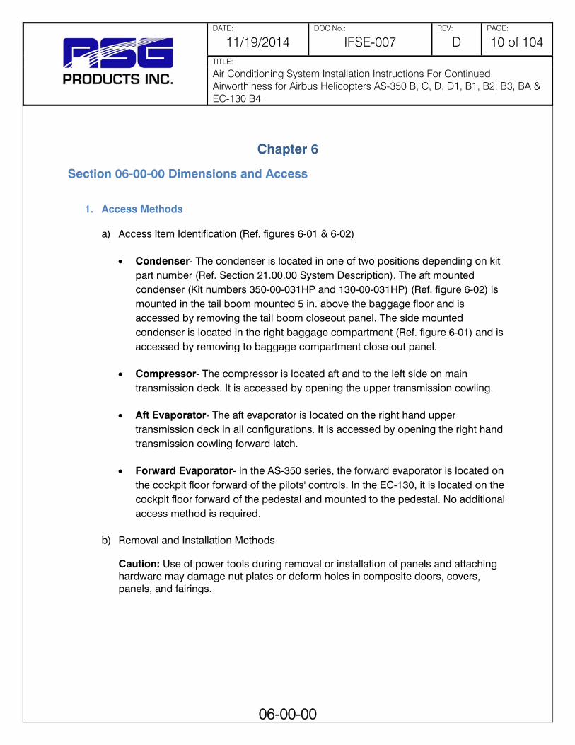
DATE: DOC No.: REV: PAGE:
11/19/2014 IFSE-007 D 10 of 104 TITLE:
Air Conditioning System Installation Instructions For Continued Airworthiness for Airbus Helicopters AS-350 B, C, D, D1, B1, B2, B3, BA & EC-130 B4
06-00-00
Chapter 6
Section 06-00-00 Dimensions and Access
1. Access Methods
a) Access Item Identification (Ref. figures 6-01 & 6-02) Condenser- The condenser is located in one of two positions depending on kit
part number (Ref. Section 21.00.00 System Description). The aft mounted condenser (Kit numbers 350-00-031HP and 130-00-031HP) (Ref. figure 6-02) is mounted in the tail boom mounted 5 in. above the baggage floor and is accessed by removing the tail boom closeout panel. The side mounted condenser is located in the right baggage compartment (Ref. figure 6-01) and is accessed by removing to baggage compartment close out panel.
Compressor- The compressor is located aft and to the left side on main transmission deck. It is accessed by opening the upper transmission cowling.
Aft Evaporator- The aft evaporator is located on the right hand upper transmission deck in all configurations. It is accessed by opening the right hand transmission cowling forward latch.
Forward Evaporator- In the AS-350 series, the forward evaporator is located on the cockpit floor forward of the pilots' controls. In the EC-130, it is located on the cockpit floor forward of the pedestal and mounted to the pedestal. No additional access method is required.
b) Removal and Installation Methods
Caution: Use of power tools during removal or installation of panels and attaching hardware may damage nut plates or deform holes in composite doors, covers, panels, and fairings.
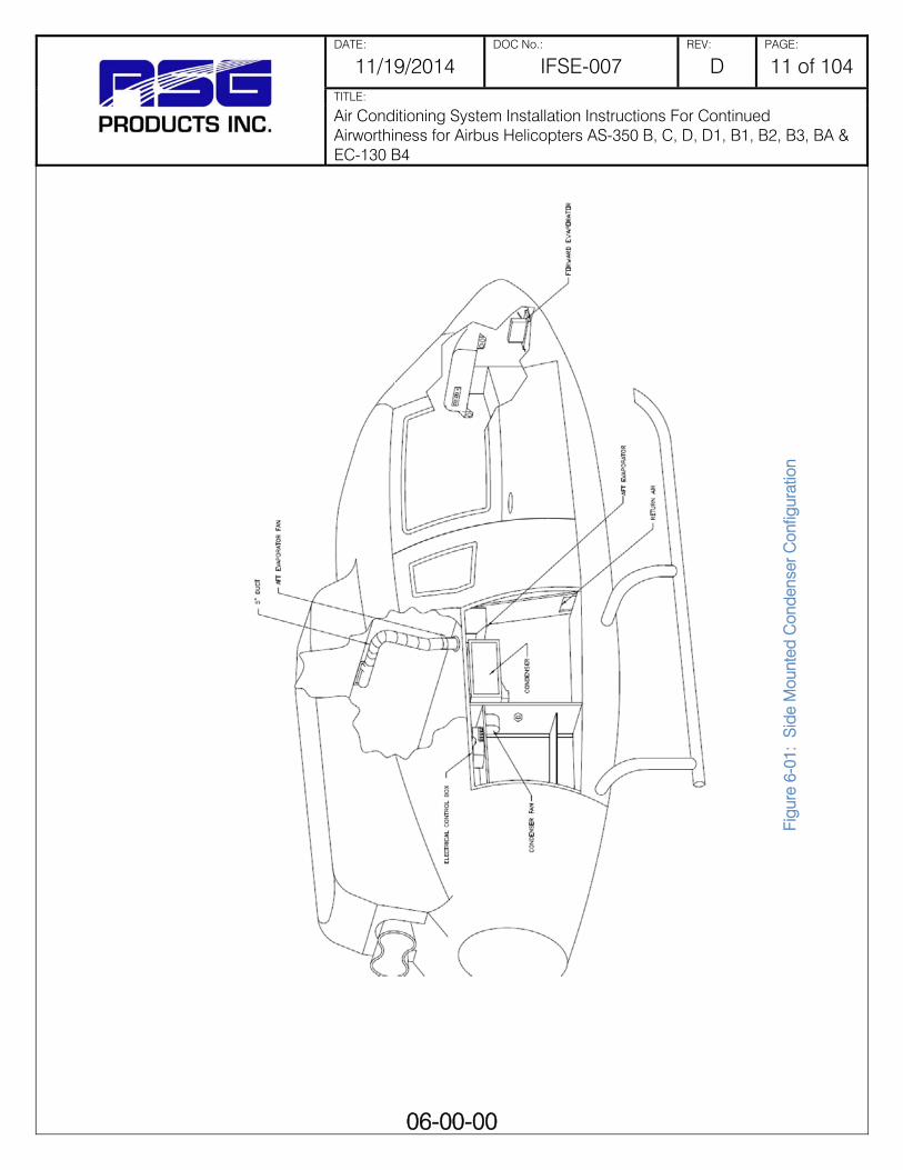
DATE: DOC No.: REV: PAGE:
11/19/2014 IFSE-007 D 11 of 104 TITLE:
Air Conditioning System Installation Instructions For Continued Airworthiness for Airbus Helicopters AS-350 B, C, D, D1, B1, B2, B3, BA & EC-130 B4
06-00-00
Figu
re 6
-01:
Sid
e M
ount
ed C
onde
nser
Con
figur
atio
n
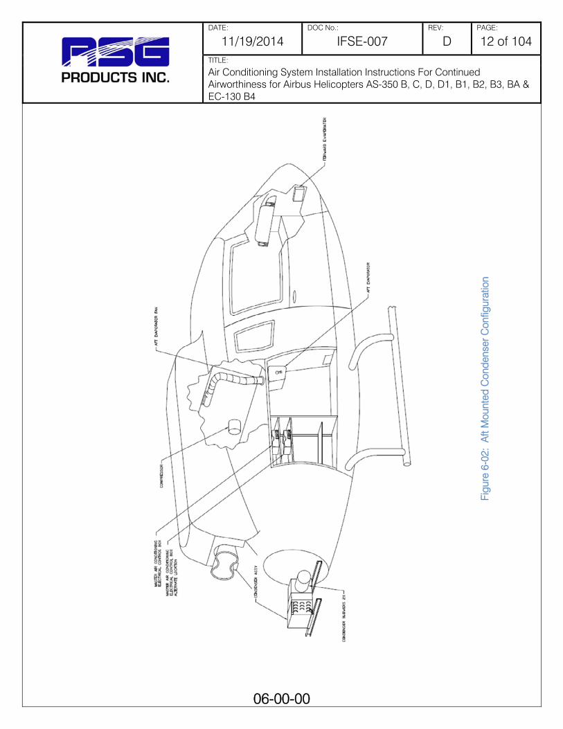
DATE: DOC No.: REV: PAGE:
11/19/2014 IFSE-007 D 12 of 104 TITLE:
Air Conditioning System Installation Instructions For Continued Airworthiness for Airbus Helicopters AS-350 B, C, D, D1, B1, B2, B3, BA & EC-130 B4
06-00-00
Figu
re 6
-02:
Aft
Mou
nted
Con
dens
er C
onfig
urat
ion
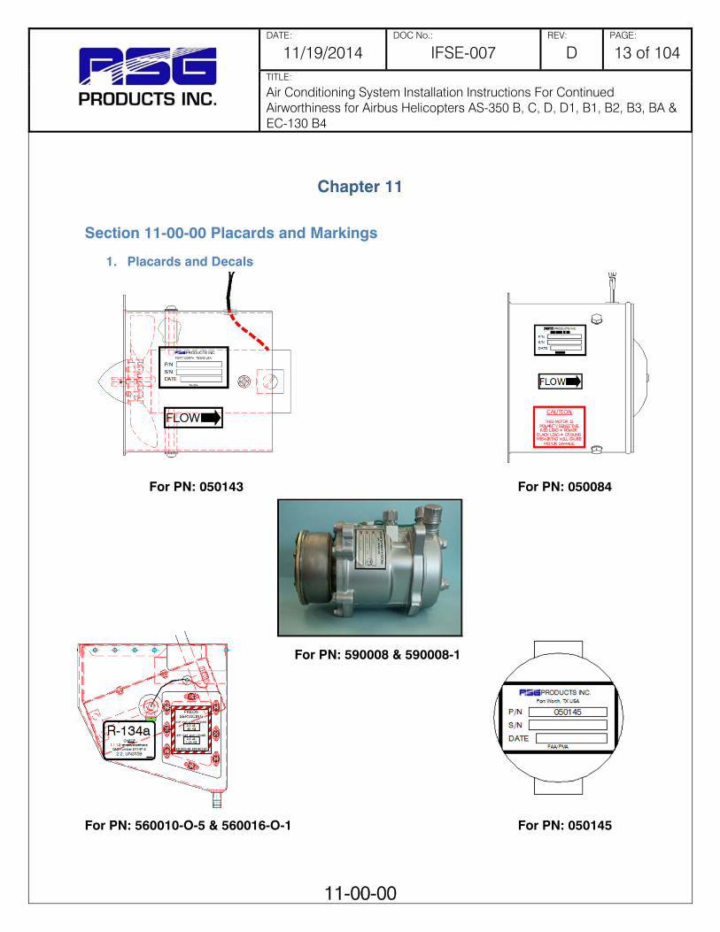
DATE: DOC No.: REV: PAGE:
11/19/2014 IFSE-007 D 13 of 104 TITLE:
Air Conditioning System Installation Instructions For Continued Airworthiness for Airbus Helicopters AS-350 B, C, D, D1, B1, B2, B3, BA & EC-130 B4
11-00-00
Chapter 11
Section 11-00-00 Placards and Markings
1. Placards and Decals
For PN: 050143 For PN: 050084
For PN: 590008 & 590008-1 For PN: 560010-O-5 & 560016-O-1 For PN: 050145

DATE: DOC No.: REV: PAGE:
11/19/2014 IFSE-007 D 14 of 104 TITLE:
Air Conditioning System Installation Instructions For Continued Airworthiness for Airbus Helicopters AS-350 B, C, D, D1, B1, B2, B3, BA & EC-130 B4
12-00-00
Chapter 12
Section 12-00-00 Servicing Maintenance Practices
1. General It is assumed in the following practices that the personnel engaged in Charging, Servicing, or Maintenance of the system will be either an experienced air conditioning mechanic under the supervision of a qualified A & P mechanic or an A & P mechanic possessing good air conditioning skills.

DATE: DOC No.: REV: PAGE:
11/19/2014 IFSE-007 D 15 of 104 TITLE:
Air Conditioning System Installation Instructions For Continued Airworthiness for Airbus Helicopters AS-350 B, C, D, D1, B1, B2, B3, BA & EC-130 B4
12-10-00
Section 12-10-00 Charging Practices
1. Reclaiming a) Connect the EPA approved recovery unit services hoses, which shall have shut-off
valves to the aircraft air conditioning system service ports.
b) Operate the recovery equipment as covered by the equipment manufacturers recommended procedure.
c) Start the recovery process and remove the refrigerant from the aircraft air conditioning system. Operate the recovery unit until the aircraft system has been reduced from a pressure to a vacuum. With the recovery unit shut off for at least 5 minutes, determine that there is not refrigerant remaining in the aircraft air conditioning system. If the aircraft system has pressure, additional recover operation is required to remove the remaining refrigerant. Repeat the operation until the aircraft air conditioning system vacuum level remains stable for two minutes.
d) Close the valves in the service lines and then remove the service lines from the aircraft system. Proceed with the repair/service. If the recovery equipment has automatic closing valves, be sure they are properly operating.
2. Charging a) Prior to Charging the System
Prior to charging the system with R-134a, the evaporator fan/blower and condenser blower should be checked for operation and direction of airflow. This is most easily done by utilizing a GPU unit for electrical power. Since the compressor is belt driven only those maintenance and operational functions that are electrically powered may be checked either in the hanger or on the ramp without running the engine. After the GPU is connected to the aircraft and the Aircraft Master Switch is “On”, the air conditioning system may be turned “On”. Place the rocker switch on the Master Air Conditioning Control Panel to “A/C”. It does not cause the compressor to run or refrigerant to be pumped. All evaporator blowers and the forward evaporator fan should start immediately. The 7” condenser blower and clutch will not engage until after approximately 4 seconds after evaporator fan start. NOTE: SYSTEM MUST HAVE MINIMUM 30 PSI CHARGE Check airflow of each evaporator fan/blower. Determine that air is coming out of the cockpit and the cabin air outlets.

DATE: DOC No.: REV: PAGE:
11/19/2014 IFSE-007 D 16 of 104 TITLE:
Air Conditioning System Installation Instructions For Continued Airworthiness for Airbus Helicopters AS-350 B, C, D, D1, B1, B2, B3, BA & EC-130 B4
12-10-00
Check airflow into and out of condenser air openings.
b) Charging the System *NOTE: All evaporators’ fan/blower, condenser blowers, and controls are 28 volt DC. DANGER: R-134a, particularly liquid R-134a, should never be allowed to come in contact with the eyes or skin. Under normal conditions, R-134a as a gas or vapor is an inert substance and non-poisonous. A flame-type leak detector should never be used because of the danger of fire or explosion around an aircraft. Several electronic leak detectors are available on the market. Never heat a cylinder of R-134a to produce additional pressure or to squeeze that last bit of refrigerant from the cylinder. If the cylinder has become cooled to the point where additional refrigerant cannot be obtained from it, the only approved method is to place the entire cylinder in a container of warm water. Do Not Exceed 120 Degrees Fahrenheit. Never attempt to repair a leak requiring brazing or soldering within the aircraft structure as fire or explosion can result. Remove the entire assembly from the aircraft to a safe location before attempting such a procedure.
CAUTION: Should R-134a come in contact with the eyes or skin, Do Not attempt first aid beyond the immediate washing of the eye or skin with clear water. A doctor should be contacted immediately for diagnosis and treatment even though the injury may be considered slight.
The refrigerant used in this system R-134a, and no other refrigerant is to be considered. Normal safety practices, such as wearing of gloves and the use of goggles, should be utilized as R-134a could freeze the eyeball instantly were it to come in contact with the eye. Also, frostbite could occur to areas of the skin if R-134a were allowed to come in contact.
Charging of the system is a simple procedure whether on initial or recharging after leakage repair. A set of refrigerant gauges with a minimum of three hoses should be connected to the high side and low side service ports provided. Prior to charging each newly installed system with R-134a, you will not need to charge compressor with oil since 7.5 ounces of ESTER oil has already been added. Do not add additional oil if replacing a compressor in an existing system.

DATE: DOC No.: REV: PAGE:
11/19/2014 IFSE-007 D 17 of 104 TITLE:
Air Conditioning System Installation Instructions For Continued Airworthiness for Airbus Helicopters AS-350 B, C, D, D1, B1, B2, B3, BA & EC-130 B4
12-10-00
c) Initial Charging
Tighten any leaking connections or make repairs as necessary to eliminate leaks. Shut off and disconnect hose from the refrigerant cylinder. Connect the hose to a regulator mounted on a cylinder of dry nitrogen. Purge the regulator to center manifold hose. Close low side valve (left) at manifold. Failure to do so can cause pressure to flow to the low side (left) gauge. Failure of gauge can result. Pressurize system to 250-PSI minimum, 300-PSI maximum. After the system has been rechecked with the leak detector and it is determined that no leaks exist, disconnect the charging hose from the manifold set to the cylinder of nitrogen. Open the valves allowing the R-134a and nitrogen within the system to be collected into an EPA approved recycling until (expelling of refrigerant is not allowed). Connect a vacuum pump to the center manifold hose. Open both valves and evacuate the system for a minimum of twenty minutes. (NOTE: For each 1,000 foot rise in altitude above sea level, a decrease below 30” of vacuum of 1” per one thousand feet rise in altitude will occur).
d) Adding R134-a Refrigerant Close both the manifold valves and connect the center charging hoses to a cylinder of R-134a. Open the valves of the cylinder. Purge the charging hose by loosening it at the charging manifold’s center hose. ONLY THE HIGH SIDE VALVE OF THE CHARGING MANIFOLD MAY NOW BE OPENED The combination of the vacuum still existing and the pressure in the R-134a cylinder transfers the R-134a from the cylinder into the system, on the high side only, without the compressor running. If a scale is available, the cylinder may be
Figure 12 - 01: Adding Oil to the Compressor
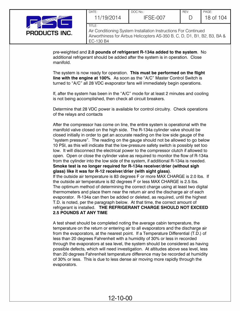
DATE: DOC No.: REV: PAGE:
11/19/2014 IFSE-007 D 18 of 104 TITLE:
Air Conditioning System Installation Instructions For Continued Airworthiness for Airbus Helicopters AS-350 B, C, D, D1, B1, B2, B3, BA & EC-130 B4
12-10-00
pre-weighted and 2.0 pounds of refrigerant R-134a added to the system. No additional refrigerant should be added after the system is in operation. Close manifold. The system is now ready for operation. This must be performed on the flight line with the engine at 100%. As soon as the “A/C” Master Control Switch is turned to “A/C” all 28 VDC evaporator fans will immediately begin operations. If, after the system has been in the “A/C” mode for at least 2 minutes and cooling is not being accomplished, then check all circuit breakers. Determine that 28 VDC power is available for control circuitry. Check operations of the relays and contacts After the compressor has come on line, the entire system is operational with the manifold valve closed on the high side. The R-134a cylinder valve should be closed initially in order to get an accurate reading on the low side gauge of the “system pressure”. The reading on the gauge should not be allowed to go below 10 PSI, as this will indicate that the low-pressure safety switch is possibly set too low. It will disconnect the electrical power to the compressor clutch if allowed to open. Open or close the cylinder valve as required to monitor the flow of R-134a from the cylinder into the low side of the system, if additional R-134a is needed. Smoke test is no longer required for R-134a receiver/drier (without sigh glass) like it was for R-12 receiver/drier (with sight glass). If the outside air temperature is 83 degrees F or more MAX CHARGE is 2.0 lbs. If the outside air temperature is 82 degrees F or less MAX CHARGE is 2.5 lbs. The optimum method of determining the correct charge using at least two digital thermometers and place them near the return air and the discharge air of each evaporator. R-134a can then be added or deleted, as required, until the highest T.D. is noted, per the paragraph below. At that time, the correct amount of refrigerant is installed. THE REFRIGERANT CHARGE SHOULD NOT EXCEED 2.5 POUNDS AT ANY TIME A test sheet should be completed noting the average cabin temperature, the temperature on the return or entering air to all evaporators and the discharge air from the evaporators, at the nearest point. If a Temperature Differential (T.D.) of less than 20 degrees Fahrenheit with a humidity of 30% or less in recorded through the evaporators at sea level, the system should be considered as having possible defects, which will need investigation. At altitudes above sea level, less than 20 degrees Fahrenheit temperature difference may be recorded at humidity of 30% or less. This is due to less dense air moving more rapidly through the evaporators.

DATE: DOC No.: REV: PAGE:
11/19/2014 IFSE-007 D 19 of 104 TITLE:
Air Conditioning System Installation Instructions For Continued Airworthiness for Airbus Helicopters AS-350 B, C, D, D1, B1, B2, B3, BA & EC-130 B4
12-10-00
e) Effect of Humidity on TD It should be noted that in measurements taken and entered on a test sheet that similar measurements made at a later date, when the humidity is considerably higher, would dramatically change the T.D. The higher the humidity, as compared to a previous T.D. reading taken with a low humidity, will result in a lower T.D. The reason for this lower T.D. measurement is that when a test is performed at lower humidity, only “SENSIBLE HEAT” is being removed. With higher humidity, a different condition exists. It requires that “LATENT HEAT” containing moisture borne heat must first be removed prior to the removal of the sensible heat If the system is found to be completely empty of R-134a, a set of charging gauges should be connected to both high and low side service ports and to a cylinder of R-134a. Purge the charging hoses from the cylinder to the service ports with R-134a vapor. Open both the low and high side charging valves and allow pressure from the cylinder to equalize through the system until at least 50 PSI is noted. Utilizing an electronic leak detector, check all fittings on the system to determine the point of leakage. Any fitting indicating an oily or dirty condition is a prime suspect.
f) Recharging the System After the leaks have been found and corrected, pressurize the system with dry nitrogen. Re-check for leaks. Connect a vacuum pump to the system and evacuate the system for a minimum of 20 minutes from both the high and low sides. If the system has been allowed to become contaminated, then the receiver/drier is to be replaced. It is always good air conditioning practice to replace the receiver/drier whenever it is suspected that moisture has contaminated the system. The balance of the recharging procedure is exactly the same as pointed out previously under the Charging Operation. A judgment must be made as to the amount of oil, if any, lost at the point of leakage. Additional oil may be required to be added to the system. If the refrigerant has been expelled rapidly by the rupture of a line or similar situation then two (2) ounces of refrigerant oil of the type previously specified should be applied to the system at this time and immediately prior to charging of the system with R-134a.

DATE: DOC No.: REV: PAGE:
11/19/2014 IFSE-007 D 20 of 104 TITLE:
Air Conditioning System Installation Instructions For Continued Airworthiness for Airbus Helicopters AS-350 B, C, D, D1, B1, B2, B3, BA & EC-130 B4
12-20-00
Section 12-20-00 Clutch Servicing Practices
1. General These clutch servicing practices are applicable to all compressors that can be installed with the Air Conditioning System Installation.
a) Clutch Armature Assembly Removal (1) If armature dust cover is present, remove the 3 or 6 bolts holding it in place
and remove cover. If auxiliary sheet metal pulley is present, remove the screws holding it in place. Then remove pulley.
(2) Insert pins of armature plate spanner into threaded holes of armature assembly.
(3) Hold armature assembly stationary while removing retaining nut with 3/4 in, 19 mm or 14 mm socket wrench as appropriate. (Ref. Figure 12-02)
(4) Remove armature assembly using puller. Thread 3 puller bolts into the threaded holes in the armature assembly. Turn center screw clockwise until armature assembly comes loose. (Ref. Figure 12-03)
Figure 12 - 02
Figure 12 - 03

DATE: DOC No.: REV: PAGE:
11/19/2014 IFSE-007 D 21 of 104 TITLE:
Air Conditioning System Installation Instructions For Continued Airworthiness for Airbus Helicopters AS-350 B, C, D, D1, B1, B2, B3, BA & EC-130 B4
12-20-00
(5) If shims are above shaft key, the key and bearing dust cover (if present) must be removed before the shims can be removed.
(6) Remove bearing dust cover (if present). Use caution to prevent distorting cover when removing it.
(7) Remove shaft key by tapping loose with a flat blade screwdriver and hammer.
(8) Remove shims. Use a pointed tool and a small screwdriver to prevent the shims from binding on the shaft.
b) Rotor Assembly Removal
(1) If bearing dust cover has not been removed, remove it now. (2) If internal snap ring for bearing is visible above the bearing, remove it with
internal snap ring pliers. (3) Remove rotor snap ring. (4) Remove shaft key. (5) Remove rotor assembly: insert the lip of the jaws into the snap ring groove,
place rotor puller shaft protector (puller set) over the exposed shaft, align thumb screws to puller jaws and finger tighten and turn puller center bolt clockwise using a socket wrench until rotor pulley is free. (Ref. Figure 12-05)
Figure 12 - 04

DATE: DOC No.: REV: PAGE:
11/19/2014 IFSE-007 D 22 of 104 TITLE:
Air Conditioning System Installation Instructions For Continued Airworthiness for Airbus Helicopters AS-350 B, C, D, D1, B1, B2, B3, BA & EC-130 B4
12-20-00
c) Field Coil Assembly Removal (1) Loosen lead wire clamp screw with #2 Phillips screwdriver until wire(s) can
be slipped out from under clamp. (2) Undo any wire connections on the compressor which would prevent
removal of the field coil assembly. (3) Remove snap ring. (4) Remove the field coil assembly. (Ref. Figure 12-06)
d) Field Coil Assembly Installation (1) Reverse the steps of the field coil assembly removal. Protrusion on
underside of coil ring must match hole in front housing to prevent movement and correctly locate lead wire(s).
e) Rotor Assembly Installation (1) Place compressor on support stand, supported at rear end of compressor.
If the compressor must be clamped in a vice, clamp only on the mounting ears, never on the body of the compressor.
Figure 12 - 05
Figure 12 - 06

DATE: DOC No.: REV: PAGE:
11/19/2014 IFSE-007 D 23 of 104 TITLE:
Air Conditioning System Installation Instructions For Continued Airworthiness for Airbus Helicopters AS-350 B, C, D, D1, B1, B2, B3, BA & EC-130 B4
12-20-00
(2) Set rotor squarely over the front housing boss. (3) Place the rotor installer ring into the bearing bore. Ensure that the edge
rests only on the inner race of the bearing, not on the seal, pulley, or outer race of the bearing.
(4) Place the driver into the ring and drive the rotor down onto the front housing with a hammer or arbor press. Drive the rotor against the front housing step. A distinct change of sound can be heard when using a hammer to install the rotor. (Ref. figure 12-07).
(5) Reinstall rotor bearing snap ring, if it has been removed, with internal snap ring pliers. (Ref. figure 12-08)
(6) Reinstall rotor retaining snap ring with external snap ring pliers. If a bevel is present in the snap ring, it should be face up (away from the body of the compressor).
(7) Reinstall rotor bearing dust cover (if present) by gently tapping it into place.
Figure 12 - 07
Figure 12 - 08

DATE: DOC No.: REV: PAGE:
11/19/2014 IFSE-007 D 24 of 104 TITLE:
Air Conditioning System Installation Instructions For Continued Airworthiness for Airbus Helicopters AS-350 B, C, D, D1, B1, B2, B3, BA & EC-130 B4
12-20-00
f) Armature Assembly Installation (1) Install shaft key with pliers. (Ref. figure 12-09)
(2) Install clutch shims. NOTE: Clutch air gap is determined by shim thickness.
When installing a clutch on a used compressor, try the original shims first. When installing a clutch on a compressor that has not had a clutch installed before, first try 0.04 in, 0.02 in and 0.004 in (1.0, 0.5, 0.1 mm) shims.
(3) Align keyway in armature assembly to shaft key. Using driver and a hammer or arbor press, drive the armature assembly down over the shaft until it bottoms on the shims. A distinct sound change will be noted if driving with a hammer. (Ref. figure 12-10)
(4) Replace retaining nut and torque to specification
1/2-20: 20-25 ft*lb (27-34 N*m) M8: 11-15 ft*lb (15-21 N*m)
Figure 12 - 09
Figure 12 - 10
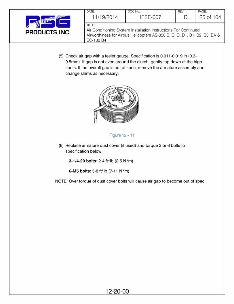
DATE: DOC No.: REV: PAGE:
11/19/2014 IFSE-007 D 25 of 104 TITLE:
Air Conditioning System Installation Instructions For Continued Airworthiness for Airbus Helicopters AS-350 B, C, D, D1, B1, B2, B3, BA & EC-130 B4
12-20-00
(5) Check air gap with a feeler gauge. Specification is 0.011-0.019 in (0.3-
0.5mm). If gap is not even around the clutch, gently tap down at the high spots. If the overall gap is out of spec, remove the armature assembly and change shims as necessary.
(6) Replace armature dust cover (if used) and torque 3 or 6 bolts to
specification below.
3-1/4-20 bolts: 2-4 ft*lb (2-5 N*m) 6-M5 bolts: 5-8 ft*lb (7-11 N*m) NOTE: Over torque of dust cover bolts will cause air gap to become out of spec.
Figure 12 - 11

DATE: DOC No.: REV: PAGE:
11/19/2014 IFSE-007 D 26 of 104 TITLE:
Air Conditioning System Installation Instructions For Continued Airworthiness for Airbus Helicopters AS-350 B, C, D, D1, B1, B2, B3, BA & EC-130 B4
12-30-00
Section 12-30-00 System Leak Check
1. General Identification and elimination of system fitting leaks is extremely important to the operation of this air conditioning system installation. A system which contains a partial charge of refrigerant can be leak tested with the aid of an electronic leak detector and be recharged without evacuating the system. A new or empty system can be pressurized with nitrogen 70-80 psi (5.1-5.6 kgcm) or R134a 50 psi to conduct a leak survey. Do not use compressed air, for it can introduce moisture into the system causing degradation to the operation of the system. The preferred method is to use an electronic leak detector in conjunction with a small charge of R134a refrigerant. All checks done in this manner should be conducted with the air conditioner off. Since the refrigerant is heavier than air, leaks are most likely to be detected on the underside of the hoses and fittings. Refrigerants will collect in low areas and provide erroneous leak detection. A stream of compressed air from a nozzle may be useful in clearing the area just prior to conducting a leak test. If the nitrogen method is used, it will be necessary to mix together a water and mild soap solution. Each fitting or suspected leak area should be brushed with this soap solution and watched for evidence of bubbles formed by the escaping nitrogen. If a leak is detected at an O-ring fitting, check to insure proper torque has been applied to the fitting. If the system continues to leak, evacuate the system of refrigerant and install a new O-ring. NOTE: be sure that the O-ring is lubricated with refrigerant oil prior to its installation. A small amount of leakage (approximately one ounce per year) past the compressor shaft seal is normal. Most leak detectors are sensitive enough to show a leak a magnitude.
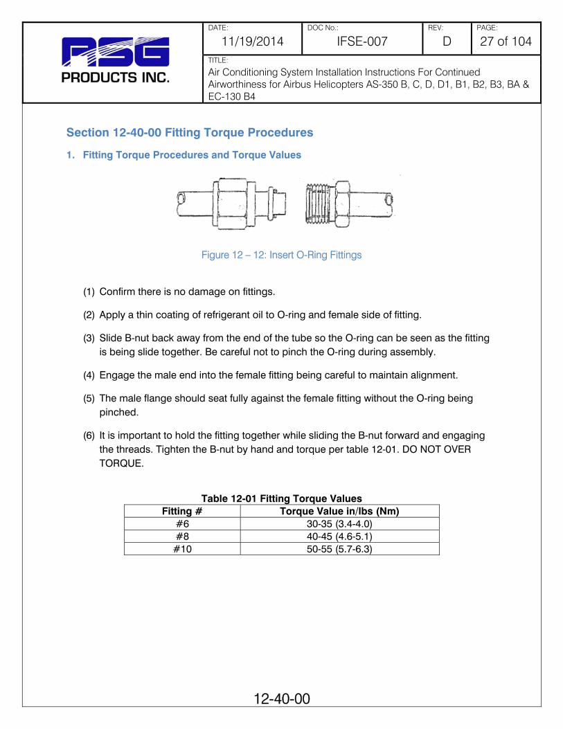
DATE: DOC No.: REV: PAGE:
11/19/2014 IFSE-007 D 27 of 104 TITLE:
Air Conditioning System Installation Instructions For Continued Airworthiness for Airbus Helicopters AS-350 B, C, D, D1, B1, B2, B3, BA & EC-130 B4
12-40-00
Section 12-40-00 Fitting Torque Procedures
1. Fitting Torque Procedures and Torque Values
(1) Confirm there is no damage on fittings.
(2) Apply a thin coating of refrigerant oil to O-ring and female side of fitting.
(3) Slide B-nut back away from the end of the tube so the O-ring can be seen as the fitting is being slide together. Be careful not to pinch the O-ring during assembly.
(4) Engage the male end into the female fitting being careful to maintain alignment.
(5) The male flange should seat fully against the female fitting without the O-ring being pinched.
(6) It is important to hold the fitting together while sliding the B-nut forward and engaging the threads. Tighten the B-nut by hand and torque per table 12-01. DO NOT OVER TORQUE.
Table 12-01 Fitting Torque Values
Fitting # Torque Value in/lbs (Nm) #6 30-35 (3.4-4.0) #8 40-45 (4.6-5.1) #10 50-55 (5.7-6.3)
Figure 12 – 12: Insert O-Ring Fittings

DATE: DOC No.: REV: PAGE:
11/19/2014 IFSE-007 D 28 of 104 TITLE:
Air Conditioning System Installation Instructions For Continued Airworthiness for Airbus Helicopters AS-350 B, C, D, D1, B1, B2, B3, BA & EC-130 B4
12-50-00
Section 12-50-00 Normal Operation Functional Test
a. With the aircraft engine operating, electrical system on and functioning normally, move the air conditioner control switch to the "FAN" position.
b. Move the cockpit fan switch from "LOW" to "HIGH" speed and ensure that air output is present in all the forward air outlets. Repeat the test using the aft cabin fan speed selector switch for the aft cabin air outlets.
c. Reposition the air conditioner control switch to the "A/C" position and repeat Step 2 above. Cool air should be supplied to the cockpit and cabin vents after a time delay of 4 to 8 seconds.
d. Turn air conditioner switch to "OFF" or the center position. Entire system should shut down.
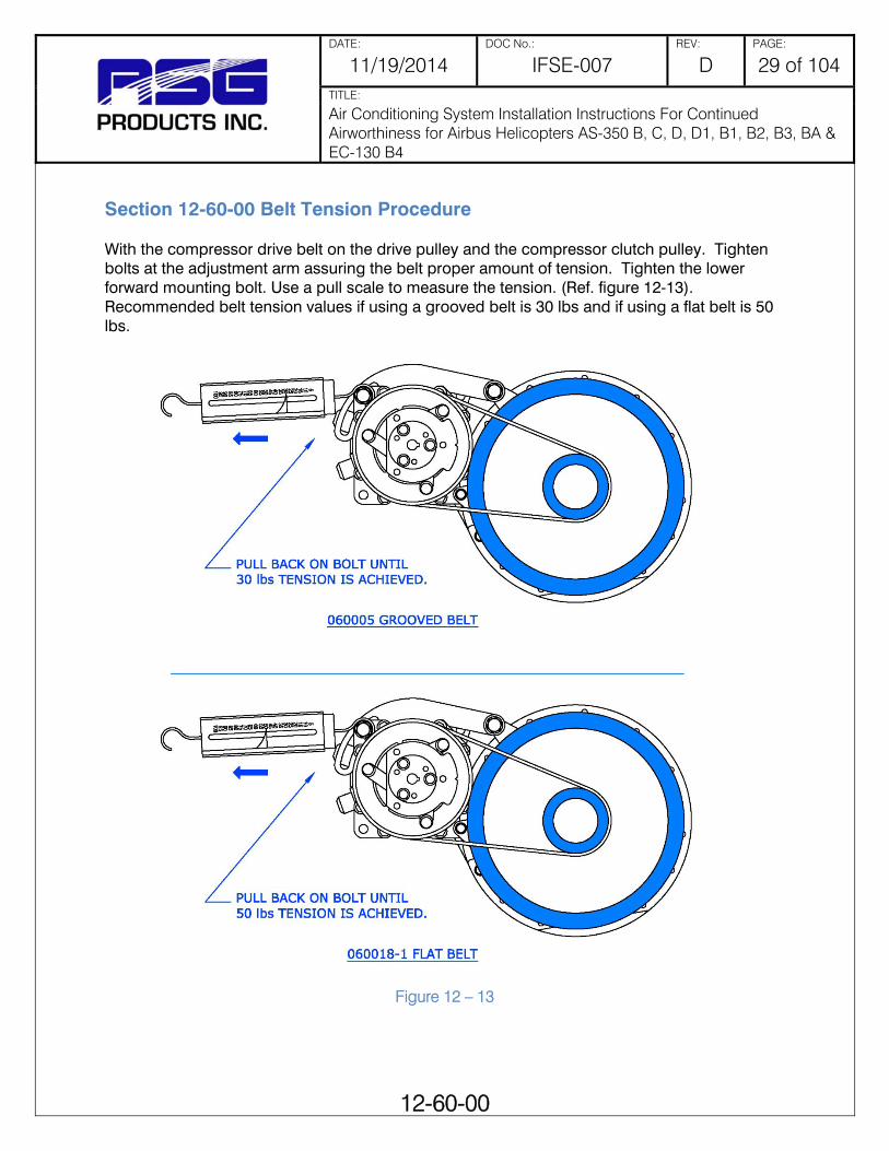
DATE: DOC No.: REV: PAGE:
11/19/2014 IFSE-007 D 29 of 104 TITLE:
Air Conditioning System Installation Instructions For Continued Airworthiness for Airbus Helicopters AS-350 B, C, D, D1, B1, B2, B3, BA & EC-130 B4
12-60-00
Section 12-60-00 Belt Tension Procedure
With the compressor drive belt on the drive pulley and the compressor clutch pulley. Tighten bolts at the adjustment arm assuring the belt proper amount of tension. Tighten the lower forward mounting bolt. Use a pull scale to measure the tension. (Ref. figure 12-13). Recommended belt tension values if using a grooved belt is 30 lbs and if using a flat belt is 50 lbs.
Figure 12 – 13

DATE: DOC No.: REV: PAGE:
11/19/2014 IFSE-007 D 30 of 104 TITLE:
Air Conditioning System Installation Instructions For Continued Airworthiness for Airbus Helicopters AS-350 B, C, D, D1, B1, B2, B3, BA & EC-130 B4
12-70-00
Section 12-70-00 Drive Belt Change Procedure
a. Access the compressor installation (ref. Section 6-00-00 Dimensions and Access). For compressor information reference Section 21-00-00 Air Conditioning.
b. Place a support on the transmission deck to support the engine drive while the shaft is
disconnected for belt installation.
c. Remove the cotter pins from the four pins holding the “Gimble Ring” at the Thomas coupling.
d. Slide the “Gimble Ring” aft to gain access to the Thomas coupling.
e. Remove the 6 bolts and Thomas coupling connecting the drive shaft and shift slightly aft.
f. Install two (2) Compressor Drive belts.
g. Reassemble the Thomas coupling.
h. Secure 1 belt to the outside of the drive shaft cover for a spare and slip one through the housing and over the drive pulley.
i. Install the “Gimble Ring” pins and cotter pins. Remove supports.
j. Install the compressor drive belt on the drive pulley and the compressor clutch pulley. Tighten bolts at the adjustment arm assuring the belt proper amount of tension. (Ref. Section 12-60-00 Belt Tension Procedure). Tighten the lower forward mounting bolt.

DATE: DOC No.: REV: PAGE:
11/19/2014 IFSE-007 D 31 of 104 TITLE:
Air Conditioning System Installation Instructions For Continued Airworthiness for Airbus Helicopters AS-350 B, C, D, D1, B1, B2, B3, BA & EC-130 B4
20-00-00
Chapter 20
Section 20-00-00 Standard Practices This chapter contains maintenance information and procedures that are common standard practices. Information contained in this chapter is standard torque charts and application procedures, corrosion prevention, painting, mechanical fastener sealing, and dye penetrant inspection techniques.

DATE: DOC No.: REV: PAGE:
11/19/2014 IFSE-007 D 32 of 104 TITLE:
Air Conditioning System Installation Instructions For Continued Airworthiness for Airbus Helicopters AS-350 B, C, D, D1, B1, B2, B3, BA & EC-130 B4
20-10-00
Section 20-10-00 Torques Maintenance Practices
1. Torque Wrenches a) Torque Wrench Accuracy
Torque wrenches must be of good quality and calibrated at least once a year. Any torque wrench that has been dropped or abused should be calibrated to ensure continued accuracy.
b) Application of Torque Wrench Loads
(1) Be sure the bolt and nut and the surface they bear on are clean and dry, unless otherwise specified by the manufacturer.
(2) Run the nut down to near contact with the washer or bearing surface and check the
friction drag torque required to turn the nut. Add the friction drag torque to the desired torque to arrive at the “final torque” to be registered on the torque wrench indicator.
(3) Whenever possible, apply the torque to the nut instead of the bolt. This will reduce
rotation of the bolt in the hole and reduce wear.
(4) Apply a smooth even pull when applying torque pressure.
(5) If special adapters are used which will change the effective length of the torque wrench, the final torque indication or wrench setting must be adjusted accordingly. To determine the torque wrench setting or indication with adapter installed reference Figure 20-01.

DATE: DOC No.: REV: PAGE:
11/19/2014 IFSE-007 D 33 of 104 TITLE:
Air Conditioning System Installation Instructions For Continued Airworthiness for Airbus Helicopters AS-350 B, C, D, D1, B1, B2, B3, BA & EC-130 B4
20-10-00
Figure 20 - 1: Torque Wrenches and Adapters

DATE: DOC No.: REV: PAGE:
11/19/2014 IFSE-007 D 34 of 104 TITLE:
Air Conditioning System Installation Instructions For Continued Airworthiness for Airbus Helicopters AS-350 B, C, D, D1, B1, B2, B3, BA & EC-130 B4
20-10-00
2. Torque Values Warning: Do not exceed maximum allowable torque value. Overstressing of fastener may result.
Standard hardware torque values are given in the following Table 20 - 1 through Table 20 - 3. Table 20 - 1 gives recommended torque values for fine thread fasteners, shear and tension applications. Table 20 - 2 gives recommended torque values for coarse thread fasteners, shear and tension applications. Table 20 - 3 gives recommended torque values for Phillips-head screws.
Table 20 - 1: Recommended Torque Values for Fine-Thread Fasteners Thread Size
Fractional (decimal) Shear Tension
Recommended in-lb (N-m)
Maximum in-lb (N-m)
Recommended in-lb (N-m)
Maximum in-lb (N-m)
8-36 (0.1640-36)
7-9 (0.79-1.02)
12(1.36)
12-15 (1.36-1.69)
20 (2.26)
10-32 (0.1900-32)
12-15 (1.36-1.69)
25 (2.82)
20-25 (2.25-2.82)
40 (4.51)
¼-28 (0.2500-28)
30-40 (3.38-4.51)
60(6.77)
50-70 (5.64-7.90)
100(11.29)
5/16-24 (0.3125-24)
60-85 (6.77-9.60)
140 (15.81)
100-140 (11.29-15.81)
225(25.41)
3/8-24 (0.3750-24)
95-110(10.73-12.42)
240(27.11)
160-190 (18.07-21.46)
390(44.05)
7/16-20 (0.4375-20)
270-300(30.49-33.88)
500(56.48)
450-500 (50.83-56.48)
840(94.88)
½-20 (0.5000-20)
290-410(32.75-46.31)
660(74.55)
480-690 (54.22-77.94)
1,100(124.25)
9/16-18 (0.5625-18)
480-600(54.22-67.77)
960(108.44)
800-1,000 (90.36-112.96)
1,600(180.73)
5/8-18 (0.6250-18)
660-780(74.55-88.10)
1,400(158.14)
1,100-1,300 (124.25-146.84)
2,400(271.10)
¾-16 (0.7500-16)
1,300-1,500(146.84-169.44)
3,000(338.88)
2,300-2,500 (259.80-282.40)
5,000(564.80)
7/8-14 (0.8750-14)
1,500-1,800(169.44-203.32)
4,200(474.43)
2,500-3,000 (282.40-338-88)
7,000(790.72)
1-12 (1.0000-12)
2,200-3,300(248.51-372.76)
6,000(677.76)
3,700-5,500 (417.95-621.28)
10,000(1129.6)
1-1/8-12 (1.1250-12)
3,000-4,200(338.88-474.43)
9,000(1016.6)
5,000-7,000 (564.80-790.72)
15,000(1694.4)
1-1/4-12 (1.2500-12)
5,400-6,600(609.98-745.53)
15,000(1694.4)
9,000-11,000 (1016.6-1242.6)
25,000(2824.0)
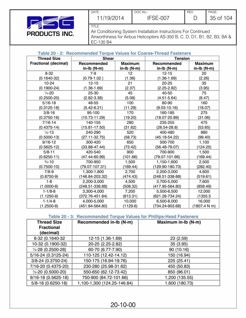
DATE: DOC No.: REV: PAGE:
11/19/2014 IFSE-007 D 35 of 104 TITLE:
Air Conditioning System Installation Instructions For Continued Airworthiness for Airbus Helicopters AS-350 B, C, D, D1, B1, B2, B3, BA & EC-130 B4
20-10-00
Table 20 - 2: Recommended Torque Values for Coarse-Thread Fasteners Thread Size
Fractional (decimal) Shear Tension
Recommended in-lb (N-m)
Maximum in-lb (N-m)
Recommended in-lb (N-m)
Maximum in-lb (N-m)
8-32 (0.1640-32)
7-9 (0.79-1.02 )
12(1.36)
12-15 (1.36-1.69)
20 (2.26)
10-24 (0.1900-24)
12-15 (1.36-1.69)
21 (2.37)
20-25 (2.25-2.82)
35 (3.95)
¼-20 (0.2500-20)
25-30 (2.82-3.38)
45(5.08)
40-50(4.51-5.64)
75(8.47)
5/16-18 (0.3125-18)
48-55 (5.42-6.21)
100 (11.29)
80-90(9.03-10.16)
160(18.07)
3/8-16 (0.3750-16)
95-100(10.73-11.29)
170(19.20)
160-185 (18.07-20.89)
275(31.06)
7/16-14 (0.4375-14)
140-155(15.81-17.50)
280(31.62)
235-255 (26.54-28.8)
475(53.65)
½-13 (0.5000-13)
240-290(27.11-32.75)
520(58.73)
400-480 (45.18-54.22)
880(99.40)
9/16-12 (0.5625-12)
300-420(33.88-47.44)
650(73.42)
500-700 (56.48-79.07)
1,100(124.25)
5/8-11 (0.6250-11)
420-540(47.44-60.99)
900(101.66)
700-900 (79.07-101.66)
1,500(169.44)
¾-10 (0.7500-10)
700-950(79.07-107.31)
1,500(169.44)
1,150-1,600 (129.90-180.73)
2,500(282.40)
7/8-9 (0.8750-9)
1,300-1,800(146.84-203.32)
2,700(474.43)
2,200-3,000 (248.51-338-88)
4,600(519.61)
1-8 (1.0000-8)
2,200-3,000(248.51-338.88)
4,500(508.32)
3,700-5,000 (417.95-564.80)
7,600(858.49)
1-1/8-8 (1.1250-8)
3,300-4,000(372.76-451.84)
7,200(813.31)
5,500-6,500 (621.28-734.24)
12,000(1355.5
1-1/4-8 (1.2500-8)
4,000-5,000(451.84-564.80)
10,000(1129.6)
6,500-8,000 (734.24-903.68)
16,000(1807.4 N m)
Table 20 - 3: Recommended Torque Values for Phillips-Head Fasteners
Thread Size Fractional (decimal)
Recommended in-lb (N-m) Maximum in-lb (N-m)
8-32 (0.1640-32 12-15 (1.36-1.69) 23 (2.59) 10-32 (0.1900-32) 20-25 (2.25-2.82) 35 (3.95) ¼-28 (0.2500-28) 60-70 (6.77-7.90) 90 (10.16)
5/16-24 (0.3125-24) 110-125 (12.42-14.12) 150 (16.94) 3/8-24 (0.3750-24) 150-175 (16.94-19.76) 225 (25.41) 7/16-20 (0.4375-20) 230-280 (25.98-31.62) 450 (50.83) ½-20 (0.5000-20) 550-650 (62.12-73.42) 850 (96.01)
9/16-18 (0.5625-18) 750-900 (84.72-101.66) 1,200 (135.55) 5/8-18 (0.6250-18) 1,100-1,300 (124.25-146.84) 1,600 (180.73)

DATE: DOC No.: REV: PAGE:
11/19/2014 IFSE-007 D 36 of 104 TITLE:
Air Conditioning System Installation Instructions For Continued Airworthiness for Airbus Helicopters AS-350 B, C, D, D1, B1, B2, B3, BA & EC-130 B4
20-30-00
Section 20-30-00 Painting Maintenance Practices
The following procedures should be used to touch-up paint flaking, scratches, nicks, and gouges in system components.
Warning: Cleaning solvents and epoxy primer are flammable. Cleaning solvents, epoxy primer, and alodine can cause burns and irritation when skin is contacted. Vapors are harmful and caustic to eyes; goggles must be worn for eye protection. Cleaning solvents and alodine are poisonous. Vapors are harmful to life or health; work should be performed with proper ventilation and / or respirators should be worn while working with cleaning solvents, epoxy primer and alodine.
1. Paint Touch-Up of Small Areas Use the following procedures to touch-up paint of small sanded areas and nicks, scratches, gouges, etc., that do not go through paint and primer to bare metal.
a. Wipe surface clean with trichloroethane, MIL-T-81533, or equivalent cleaning solvent, and wipe dry immediately.
b. Apply coat of epoxy polymide primer, MIL-P-23377F or equivalent, to match original.
Feather primer coating onto surrounding color coat. Allow primer to air dry for 30 minutes.
c. Apply topcoat to match original finish.

DATE: DOC No.: REV: PAGE:
11/19/2014 IFSE-007 D 37 of 104 TITLE:
Air Conditioning System Installation Instructions For Continued Airworthiness for Airbus Helicopters AS-350 B, C, D, D1, B1, B2, B3, BA & EC-130 B4
20-40-00
Section 20-40-00 Corrosion Control Maintenance Practices
1. Corrosion Control The system components are fabricated primarily of steel and aluminum, and should be inspected regularly for any signs of corrosion. The following procedures should be used for removing corrosion and treating affected areas.
2. Corrosion Removal Remove corrosion by either chemical or mechanical means.
a) Paint Removal, Chemical
Caution: Do not use chemical paint stripper on composite materials. Chemical paint strippers can cause composite components to de-bond and / or lose adhesion of the epoxy matrix.
(1) Mask all non-metallic surfaces in area to be stripped as well as areas where solution may get entrapped.
Warning: Paint stripper can cause burns and irritation when it contacts skin; proper gloves should be worn. Vapors are harmful and caustic to eyes; goggles must be worn for eye protection. Paint stripper is poisonous. Vapors are harmful to life or health; work should be performed with proper ventilation and / or respirators should be worn while working with paint stripper.
(2) Using a fiber brush, apply sufficient paint stripper (Turco 5873) to cover area
of removal.
Note: If paint stripper evaporates quickly or works slowly, cover area with plastic sheet.
(3) Allow paint remover to remain on surface for a time sufficient to cause
wrinkling and lifting of paint (about 10-30 minutes).
(4) Using non-metallic scraper or abrasive pads (3M Scotchbrite 63) scrub area to further loosen paint.
(5) Reapply paint stripper (Turco 5873) as necessary in areas where paint
remains tightly adherent.
(6) Wash and scrub surface with demineralized water and alkaline cleaner to neutralize paint stripper.
DATE: DOC No.: REV: PAGE:
11/19/2014 IFSE-007 D 38 of 104 TITLE:
Air Conditioning System Installation Instructions For Continued Airworthiness for Airbus Helicopters AS-350 B, C, D, D1, B1, B2, B3, BA & EC-130 B4
20-40-00
(7) Remove masking materials and any residual paint or stripper
(8) Rinse with demineralized water.
b) Paint Removal, Mechanical
Caution: Do not sand into or expose composite fibers. Do not remove more material than necessary. Do not use aluminum oxide abrasive materials on epoxy/graphite materials.
Use abrasive flap wheel, abrasive disk, abrasive paper, or plastic media blast to remove paint.
c) Corrosion Removal
Note: Aircraft shall be electrically grounded during corrosion removal operations. When removing exterior corrosion from electronic boxes, the unit case shall be electrically grounded during the complete operation.
(1) Corrosion shall be removed by the mildest method possible.
(a) Hand scrub with dry non-metallic brush/pad (3M pad).
(b) Use abrasive cloth (Aluminum oxide 240 grit). Caution: Do not use on epoxy/graphite materials.
(c) Use 320-grit sandpaper.
(d) Glass bead blast.
(e) Use 240-grit abrasive wheel.
Note: On high-strength steel, do not use power tools other than a flap brush or mandrel with abrasive material; overheating and notching may occur.
(2) Ensure all active corrosion and corrosion products have been
removed.
(3) Using 320-grit sandpaper, blend edges of paint (if applicable) surrounding repair area to create a smooth transition. Vacuum the area thoroughly to remove all contaminants.
(4) Apply aluminum surface treatment if applicable. (Ref. Section 4 of
20-40-00, Aluminum Alloy Surface Touch-Up Treatment).

DATE: DOC No.: REV: PAGE:
11/19/2014 IFSE-007 D 39 of 104 TITLE:
Air Conditioning System Installation Instructions For Continued Airworthiness for Airbus Helicopters AS-350 B, C, D, D1, B1, B2, B3, BA & EC-130 B4
20-40-00
(5) Touch-up primer and paint to match original.
3. Mechanical Defects (Nicks, Scratches, Gouges, Etc.) a) Section 20-30-00 Painting Maintenance Practices).
b) If damage is through the paint surface, prepare area for paint touch-up using the
following methods.
Note: On high-strength steel, do not use power tools other than a flap brush or mandrel with abrasive material; overheating and notching may occur.
(1) Remove defect using flap wheel, abrasive disk, abrasive paper, or plastic
media blast.
(2) Using 320-grit sandpaper, blend edges of paint surrounding repair area to create a smooth transition.
(3) Apply aluminum surface treatment if applicable. (Ref. Section 4 of 20-40-00,
Aluminum Alloy Surface Touch-Up Treatment).
(4) Touch-up primer and paint to match original.
4. Aluminum Alloy Surface Touch-Up Treatment Note: If there is any question as to whether or not the protective coating is removed, surface treatment shall be applied. Warning: Alodine and solvents can cause burns and irritation when it contacts skin; proper gloves should be worn. Vapors are harmful and caustic to eyes; goggles must be worn for eye protection. Alodine is poisonous. Vapors are harmful to life or health; work should be performed with proper ventilation and / or respirators should be worn while working with solvents and alodine. Solvent cleaners are flammable.
a) Scuff surface using 3M Scotchbrite 63 cellulose/nylon scouring pad.
b) Wipe exposed surface with isopropyl alcohol or aliphatic naphtha. Allow area to air dry for 10 minutes. Do not touch or otherwise contaminate surface after solvent wipe.

DATE: DOC No.: REV: PAGE:
11/19/2014 IFSE-007 D 40 of 104 TITLE:
Air Conditioning System Installation Instructions For Continued Airworthiness for Airbus Helicopters AS-350 B, C, D, D1, B1, B2, B3, BA & EC-130 B4
20-40-00
c) Apply Alodine 1200 or equivalent with cotton swab, non-metallic brush, or by dipping. Maintain moist surface for 1-3 minutes with repeated application. Surface will become amber or brown in color.
d) Irrigate surface with demineralized or distilled water to remove surface treatment chemical. Allow to air dry for approximately 1 hour.
e) If there is any surface without color change, repeat procedure.
f) Apply paint touch-up as required (Ref Section 20-30-00 Painting Maintenance Practices).
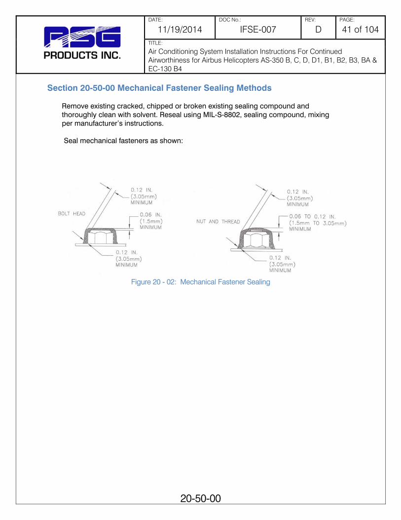
DATE: DOC No.: REV: PAGE:
11/19/2014 IFSE-007 D 41 of 104 TITLE:
Air Conditioning System Installation Instructions For Continued Airworthiness for Airbus Helicopters AS-350 B, C, D, D1, B1, B2, B3, BA & EC-130 B4
20-50-00
Section 20-50-00 Mechanical Fastener Sealing Methods
Remove existing cracked, chipped or broken existing sealing compound and thoroughly clean with solvent. Reseal using MIL-S-8802, sealing compound, mixing per manufacturer’s instructions. Seal mechanical fasteners as shown:
Figure 20 - 02: Mechanical Fastener Sealing

DATE: DOC No.: REV: PAGE:
11/19/2014 IFSE-007 D 42 of 104 TITLE:
Air Conditioning System Installation Instructions For Continued Airworthiness for Airbus Helicopters AS-350 B, C, D, D1, B1, B2, B3, BA & EC-130 B4
20-90-00
Section 20-90-00 Dye-Penetrant Inspection Methods
Warning: solvents can cause burns and irritation when it contacts skin; proper gloves should be worn. Vapors are harmful and caustic to eyes; goggles must be worn for eye protection. Vapors are harmful to life or health; work should be performed with proper ventilation and / or respirators should be worn while working with solvents. Solvent cleaners are flammable.
Use the following steps to perform dye-penetrant inspection:
1. Using cleaning solvent trichloroethane, MIL-T-81533, clean area to be inspected.
Note: Parts to be inspected must be dry and heated to at least 70° F (21.1° C), but not over 130° F (54.4° C). Note: Manufacturer’s instructions on Dye-Penetrant Kit take precedence over the following instructions.
2. Apply penetrant from dye-penetrant kit (MIL-I-25135) by brushing, spraying, or by dipping. Allow to stand for a minimum of 2 minutes.
3. Remove excess penetrant with remover (available with dye-penetrant kit), or by cleaning with plain water. Allow part to dry.
4. Apply a light, even layer of developer from dye-penetrant kit by brushing, spraying, or by dipping. When dipping, avoid excess quantity.
5. Penetrant which has penetrated into cracks (or other openings) in the surface of the part will be drawn out by the developer, resulting in a bright red indication.
6. If part is serviceable or repairable, clean part free of penetrant and developer with trichloroethane (MIL-T-81533) cleaning solvent.

DATE: DOC No.: REV: PAGE:
11/19/2014 IFSE-007 D 43 of 104 TITLE:
Air Conditioning System Installation Instructions For Continued Airworthiness for Airbus Helicopters AS-350 B, C, D, D1, B1, B2, B3, BA & EC-130 B4
21-00-00
Chapter 21
Section 21-00-00 Air Conditioning
1. Description and Operation The Air Conditioning System Installation consists of a belt driven vapor cycle air-conditioning system using R-134a as the refrigerant. The air conditioning system provides for cabin comfort during all operations, both in the ground and in flight. During ground operations when the engines are running, cooling may be provided. This system consists of 4 major components:
Condenser- The condenser is located in one of two positions depending on kit part number (Ref. table 21.1). The aft mounted condenser (Ref. figure 21-01) is mounted in the tail boom mounted 5 in. above the baggage floor. The side mounted condenser is located in the right baggage compartment (Ref. figure 21-02). The EC-130 condenser is only located in the aft mounted configuration. The aft mounted condenser assembly has two blower motors, whereas the side mounted condenser assembly only has one blower motor.
Compressor- The compressor is located aft and to the left side on main transmission deck. The belt is secured to the outside of the drive shaft, in all configurations. If designated by the kit part number (Ref. tables 21-01 & 21-02), either a smooth pulley compressor or a grooved double V-belt pulley compressor is installed.
Aft Evaporator- The aft evaporator is located on the right hand upper transmission deck in all configurations.
Forward Evaporator- In the AS-350 series, the forward evaporator is located on the cockpit floor forward of the pilots' controls. In the EC-130 kits, it is located forward of the pedestal and mounted to the pedestal.
Controls for the air conditioning system are located around or in the instrument panel, the specific location depending on the Kit number part as described in tables 21-01 and 21-02. All kits contain a Master Control Selector, which consists of a rocker type switch labeled, "A/C", "OFF" and "FAN." Selecting the "A/C" turns on the system's dual evaporator fans, compressor and condenser blower. The second rocker switch, also included with every kit, is for "HIGH," "MED" and "LOW" evaporator fan speed selection for the forward cockpit. An additional 2 position switch for the aft evaporator fan speed "HI/LOW" is present depending on the kit part numbers and the switch is located per that kit.

DATE: DOC No.: REV: PAGE:
11/19/2014 IFSE-007 D 44 of 104 TITLE:
Air Conditioning System Installation Instructions For Continued Airworthiness for Airbus Helicopters AS-350 B, C, D, D1, B1, B2, B3, BA & EC-130 B4
21-00-00
Table 21-1 Air Condition System Installation Kit Part Number Description AS-350 Series AS-350 Series
BASE KIT NUMBERS: 350-00-011-HP Side Mounted Condenser (Ref Figure 21-01) 350-00-031-HP Aft Mounted Condenser (Ref Figure 21-02)
CUSTOM CONFIGURATIONS: 350-00-011-HP-01* 350-00-031-HP-01*
AEC Basic Configuration (Ref Figure 21-03)
350-00-011-HP-11* 350-00-031-HP-11*
Corporate Configuration (Ref Figure 21-04)
350-00-011-HP-21* 350-00-031-HP-21*
EMS 1 Configuration (Ref Figure 21-05)
350-00-011-HP-22* 350-00-031-HP-22*
EMS 2 Configuration (Ref Figure 21-06)
350-00-011-HP-31* 350-00-031-HP-31*
ECL Tour 1 Configuration (Ref Figure 21-07)
350-00-011-HP-32* 350-00-031-HP-32*
ECL Tour 2 Configuration (Ref Figure 21-08)
350-00-011-HP-41* 350-00-031-HP-41*
Law Enforcement Configuration (Ref Figure 21-09)
* the addition of s to the end of the part number denotes a smooth pulley compressor
Table 21-2 Air Condition System Installation Kit Part Number Description AS-350 Series EC-130B4
BASE KIT NUMBER: 130-00-031-HP* Aft Mounted Condenser (Ref Figure 21-02)
CUSTOM CONFIGURATIONS: Corporate 1 Configuration (Ref Figure 21-10) Corporate 2 Configuration (Ref Figure 21-11) * the addition of s to the end of the part number denotes a smooth pulley compressor

DATE: DOC No.: REV: PAGE:
11/19/2014 IFSE-007 D 45 of 104 TITLE:
Air Conditioning System Installation Instructions For Continued Airworthiness for Airbus Helicopters AS-350 B, C, D, D1, B1, B2, B3, BA & EC-130 B4
21-00-00
Figu
re 2
1-01
: E
quip
men
t Loc
atio
ns fo
r Air
Con
ditio
ning
S
yste
m w
ith th
e -0
11 C
onfig
urat
ion
(Sid
e M
ount
ed
Con
dens
er)
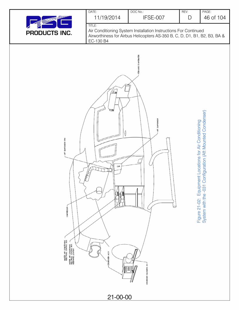
DATE: DOC No.: REV: PAGE:
11/19/2014 IFSE-007 D 46 of 104 TITLE:
Air Conditioning System Installation Instructions For Continued Airworthiness for Airbus Helicopters AS-350 B, C, D, D1, B1, B2, B3, BA & EC-130 B4
21-00-00
Figu
re 2
1-02
: E
quip
men
t Loc
atio
ns fo
r Air
Con
ditio
ning
S
yste
m w
ith th
e -0
31 C
onfig
urat
ion
(Aft
Mou
nted
Con
dens
er)

DATE: DOC No.: REV: PAGE:
11/19/2014 IFSE-007 D 47 of 104 TITLE:
Air Conditioning System Installation Instructions For Continued Airworthiness for Airbus Helicopters AS-350 B, C, D, D1, B1, B2, B3, BA & EC-130 B4
21-00-00
Figure 21 - 03: -01 AEC Basic Configuration
Figure 21 - 04: -31 ECL Tour 1 Configuration

DATE: DOC No.: REV: PAGE:
11/19/2014 IFSE-007 D 48 of 104 TITLE:
Air Conditioning System Installation Instructions For Continued Airworthiness for Airbus Helicopters AS-350 B, C, D, D1, B1, B2, B3, BA & EC-130 B4
21-00-00
2. Removal/ Installation Forward Evaporator (Ref. figures 21-12 and 21-13)
a) Removal 1) Access forward evaporator per Section 6-00-00 Dimensions and Access.
2) Connect refrigerant reclaimer to system in accordance with Section 21-00-00 and remove coolant from system. Comply with all Federal, State, and Local rules governing refrigerant handling.
3) Remove bolts securing evaporator.
4) Remove evaporator assembly.
5) Support evaporator while removing lines and other duct work.
6) Remove evaporator from aircraft.
7) Cap all open lines on unit and aircraft.
8) Disconnect electrical connections and remove evaporator fan.
b) Installation
1) Reinstall fan in aircraft and connect electrical connections.
2) Position evaporator against fan assembly and loosely install with securing hardware. Secure mounting hardware.
3) Reinstall drain line.
4) Connect duct work.
5) Ensure refrigerant o-rings are installed and in good condition. Replace as necessary. Oil all o-rings and fittings with refrigerant oil of the same type listed on the compressor. Torque refrigerant lines: #6 11-13 ft/lbs.; #8 15-20 ft/lbs.; #10 21-27 ft/lbs.
6) After completing other system functions and maintenance, charge system in accordance with Section 12-10-00.
7) Check for leaks per section 12-30-00
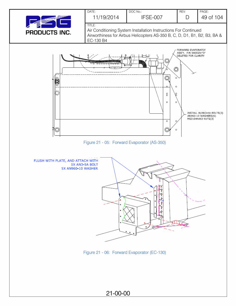
DATE: DOC No.: REV: PAGE:
11/19/2014 IFSE-007 D 49 of 104 TITLE:
Air Conditioning System Installation Instructions For Continued Airworthiness for Airbus Helicopters AS-350 B, C, D, D1, B1, B2, B3, BA & EC-130 B4
21-00-00
Figure 21 - 05: Forward Evaporator (AS-350)
Figure 21 - 06: Forward Evaporator (EC-130)

DATE: DOC No.: REV: PAGE:
11/19/2014 IFSE-007 D 50 of 104 TITLE:
Air Conditioning System Installation Instructions For Continued Airworthiness for Airbus Helicopters AS-350 B, C, D, D1, B1, B2, B3, BA & EC-130 B4
21-00-00
3. Removal/ Installation Aft Evaporator (Ref Figure 21-14)
a) Removal 1) Access aft evaporator (Ref. Section 6-00-00 Dimensions and access) and remove
electrical connections.
2) Reclaim refrigerant in system in accordance with Section 12-10-00, to remove coolant from system.
3) Support evaporator while removing lines and duct work.
4) Cap all open lines on unit and aircraft.
b) Installation 1) Reinstall fan/evaporator and connect electrical connections.
2) Position evaporator and loosely install with securing hardware. Secure mounting hardware.
3) Reinstall drain line.
4) Connect duct work.
5) Ensure refrigerant o-rings are installed and in good condition. Replace as necessary. Oil all o-rings and fittings with refrigerant oil of the same type listed on the compressor. Torque refrigerant lines: #6 11-13 ft/lbs.; #8 15-20 ft/lbs.; #10 21-27 ft/lbs.
6) After completing other system functions and maintenance, charge system in accordance with Section 12-10-00.
7) Check for leaks per section 12-30-00.

DATE: DOC No.: REV: PAGE:
11/19/2014 IFSE-007 D 51 of 104 TITLE:
Air Conditioning System Installation Instructions For Continued Airworthiness for Airbus Helicopters AS-350 B, C, D, D1, B1, B2, B3, BA & EC-130 B4
21-00-00
4. Removal / Installation - Condenser (Ref figures 21-08 and 21-09)
a) Removal 1) Access the condenser (Ref Section 6-00-00 Dimensions and Access)
2) Reclaim refrigerant in system in accordance with Section 12-10-00, to remove coolant from system.
3) Remove hardware securing condenser assembly. Disconnect blower wires and refrigerant hoses.
4) Remove condenser and cap all open lines on condenser and airframe.
b) Installation 1) Place condenser back in location.
Figure 21 - 07: Aft Evaporator

DATE: DOC No.: REV: PAGE:
11/19/2014 IFSE-007 D 52 of 104 TITLE:
Air Conditioning System Installation Instructions For Continued Airworthiness for Airbus Helicopters AS-350 B, C, D, D1, B1, B2, B3, BA & EC-130 B4
21-00-00
2) Loosely install all hardware securing condenser assembly. Tighten mounting hardware only after all other hardware is installed.
3) Remove protective caps from refrigerant lines. Inspect that o-rings are installed and in good condition. Oil all o-rings and fittings with refrigerant oil of the same type listed on the compressor.
4) Install refrigerant lines. Torque refrigerant lines as follows: #6 11-13 ft/lbs.; #8 15-20 ft/lbs.; #10 21-27 ft/lbs. Do not over tighten.
5) Charge system in accordance with Section 12-10-00

DATE: DOC No.: REV: PAGE:
11/19/2014 IFSE-007 D 53 of 104 TITLE:
Air Conditioning System Installation Instructions For Continued Airworthiness for Airbus Helicopters AS-350 B, C, D, D1, B1, B2, B3, BA & EC-130 B4
21-00-00
Figure 21 - 08: Aft Mounted Condenser (AS-350, EC-130)

DATE: DOC No.: REV: PAGE:
11/19/2014 IFSE-007 D 54 of 104 TITLE:
Air Conditioning System Installation Instructions For Continued Airworthiness for Airbus Helicopters AS-350 B, C, D, D1, B1, B2, B3, BA & EC-130 B4
21-00-00
5. Removal / Installation - Compressor (Ref figure 21-10)
a) Removal 1) Access the compressor (Ref Section 6-00-00 Dimensions and Access)
2) Reclaim refrigerant in system in accordance with Section 12-10-00, to remove coolant from system.
Figure 21 - 09: Side Mounted Condenser (AS-350)

DATE: DOC No.: REV: PAGE:
11/19/2014 IFSE-007 D 55 of 104 TITLE:
Air Conditioning System Installation Instructions For Continued Airworthiness for Airbus Helicopters AS-350 B, C, D, D1, B1, B2, B3, BA & EC-130 B4
21-00-00
3) Remove refrigerant lines from compressor and install protective caps to protect from foreign material entering system and compressor.
4) Disconnect drive belt to compressor.
5) Remove bolts securing compressor to mount and remove compressor.
b) Installation
1) Install compressor loosely on support frame with attaching hardware.
2) Install drive belt.
3) Tighten compressor bolts allowing compressor to "Seek" its own natural position on the frame. Tighten compressor belt tensioning bolt to 50 lbs. belt tension for PN 060018-1 Flat Belt, or 30 lbs tension for PN 060005 Grooved Belt.
4) Tighten and safety all compressor mounting bolts.
5) Remove protective caps from refrigerant lines and compressor. Inspect the o-rings from installation and condition. Replace as necessary.
6) Oil all fittings and o-rings.
7) Install refrigerant lines.
8) Torque refrigerant lines: #6 11-13 ft/lbs.; #8 15-20 ft/lbs.; #10 21-27 ft/lbs. Do not over tighten.
9) Charge system in accordance with Section 12-00-00.
10) Install previously removed cowlings.

DATE: DOC No.: REV: PAGE:
11/19/2014 IFSE-007 D 56 of 104 TITLE:
Air Conditioning System Installation Instructions For Continued Airworthiness for Airbus Helicopters AS-350 B, C, D, D1, B1, B2, B3, BA & EC-130 B4
21-00-00
Figure 21 - 10: Compressor

DATE: DOC No.: REV: PAGE:
11/19/2014 IFSE-007 D 57 of 104 TITLE:
Air Conditioning System Installation Instructions For Continued Airworthiness for Airbus Helicopters AS-350 B, C, D, D1, B1, B2, B3, BA & EC-130 B4
21-00-00
6. Troubleshooting guide Symptoms Trouble Cause Correction -Insufficient cooling -Low-side pressure too low -High -side pressure too low -Air in ducts only slightly cool
Low or partial refrigerant charge
Leak Find and fix the leak. If there was a loss of oil, be sure to check to compressor oil level. Evacuate and recharge per section 12.10.00
- Insufficient cooling during hottest part of the day or during extended flying. - Low-side pressure normal, though it may be too low or even a vacuum - High-side pressure normal, though it may be low-at the same time low side is low - Air in the ducts is usually cold, but becomes warm when pressure reading drop
Excessive moisture in the system
The desiccant in the drier/receiver is saturated
Replace or rebuild the receiver/drier. Evacuate and recharge per section 12.10.00
- Insufficient cooling - Low-side pressure normal, but does not drop when the clutch cycles - High-side pressure high - Air in ducts only slight cool
Air in the System
Refrigerant contains non-condensable in the form of air moisture
Leak test, watch for bad compressor seals. Drain the system. Repair leaks as needed. Replace or rebuild the receiver-drier. Check the compressor oil. Evacuate and recharge per section 12.10.00.
- No cooling - Low-side pressure too high - High-side pressure too high - Liquid line very hot - Air in ducts is warm
Condenser malfunction or system overcharge
Condenser malfunction or system overcharge
Evacuate and recharge per section 12.10.00 or replace condenser.

DATE: DOC No.: REV: PAGE:
11/19/2014 IFSE-007 D 58 of 104 TITLE:
Air Conditioning System Installation Instructions For Continued Airworthiness for Airbus Helicopters AS-350 B, C, D, D1, B1, B2, B3, BA & EC-130 B4
21-10-00
Section 21-10-00 Illustrated Parts List
1. General
This section contains information on parts for the Air Conditioning System Installation, for use in ordering replacements if necessary.
Air Outlets
Air Outlets
RSG PN: 520071 Condenser Air Intake
Assembly (Hi Profile)
RSG PN: 520071-1 Condenser Air Intake Assembly Low Profile
(Sliding Door)

DATE: DOC No.: REV: PAGE:
11/19/2014 IFSE-007 D 59 of 104 TITLE:
Air Conditioning System Installation Instructions For Continued Airworthiness for Airbus Helicopters AS-350 B, C, D, D1, B1, B2, B3, BA & EC-130 B4
21-10-00
Air Outlets
RSG PN: 500008-1 Louver Assembly
Right Side
RSG PN: 500010-1 Louver Assembly
Right Side
RSG PN: 500002 Right Side Air Outlet
RSG PN: 500001 Left Side Air Outlet

DATE: DOC No.: REV: PAGE:
11/19/2014 IFSE-007 D 60 of 104 TITLE:
Air Conditioning System Installation Instructions For Continued Airworthiness for Airbus Helicopters AS-350 B, C, D, D1, B1, B2, B3, BA & EC-130 B4
21-10-00
Air Outlets
RSG PN: 500008-1 Louver Assembly
Right Side
RSG PN: 500010-1 Louver Assembly
Right Side
RSG PN: 500002 Right Side Air Outlet
RSG PN: 500011-1 Louver Assembly Left
Side
RSG PN: 500018 Air Outlet Assembly
Right Side
RSG PN: 500018-2 Air Outlet Assembly
Right Side
RSG PN: 510259 Air Outlet Assembly

DATE: DOC No.: REV: PAGE:
11/19/2014 IFSE-007 D 61 of 104 TITLE:
Air Conditioning System Installation Instructions For Continued Airworthiness for Airbus Helicopters AS-350 B, C, D, D1, B1, B2, B3, BA & EC-130 B4
21-10-00
Air Outlets
RSG PN: 520156HP-01 Air Outlet L.H.
RSG PN: 520157HP-01 Air Outlet R.H.
RSG PN: 510259-1 Louver Assembly Right Side, Lower
RSG PN: 510259-2 Air Outlet Assembly

DATE: DOC No.: REV: PAGE:
11/19/2014 IFSE-007 D 62 of 104 TITLE:
Air Conditioning System Installation Instructions For Continued Airworthiness for Airbus Helicopters AS-350 B, C, D, D1, B1, B2, B3, BA & EC-130 B4
21-10-00
Blower Motors
RSG PN: 050143 5” Vane Axial Blower
Assembly
RSG PN: 050084 Fan, Vane Axial 7”, 24
VDC (Dynamic)
RSG PN: 050084-6 7” Vane Axial Blower Assembly (Enviro)
RSG PN: 610000
7” Blower Assembly DC Brushless

DATE: DOC No.: REV: PAGE:
11/19/2014 IFSE-007 D 63 of 104 TITLE:
Air Conditioning System Installation Instructions For Continued Airworthiness for Airbus Helicopters AS-350 B, C, D, D1, B1, B2, B3, BA & EC-130 B4
21-10-00
Blower Motors
RSG PN: 630000 7” Blower Assembly
(Ampflow)
RSG PN: 640000 7” Blower Assembly
(Ampflow)
RSG PN: 050052-1 Blower Motor,
Modified Right Half
RSG PN: 490017-1 Aft Evaporator Fan
Assembly

DATE: DOC No.: REV: PAGE:
11/19/2014 IFSE-007 D 64 of 104 TITLE:
Air Conditioning System Installation Instructions For Continued Airworthiness for Airbus Helicopters AS-350 B, C, D, D1, B1, B2, B3, BA & EC-130 B4
21-10-00
Blower Motor Parts
RSG PN: 580000 5” Hub & Propeller
Assembly
RSG PN: 250371 5” Propeller
RSG PN: 261176 Fan Blade Hub
RSG PN: 040004-8 Fan Wheel CW

DATE: DOC No.: REV: PAGE:
11/19/2014 IFSE-007 D 65 of 104 TITLE:
Air Conditioning System Installation Instructions For Continued Airworthiness for Airbus Helicopters AS-350 B, C, D, D1, B1, B2, B3, BA & EC-130 B4
21-10-00
Blower Motor Parts
RSG PN: 050031 5” Motor Brushes
RSG PN: 610000-8 7” Motor Brushes
(Ampflow)
RSG PN: 050038
7” Motor Brushes (Enviro)
RSG PN: A20420 7” Motor Brushes
(Dynamic)
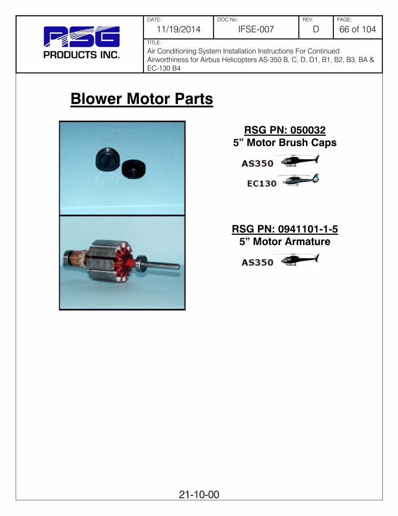
DATE: DOC No.: REV: PAGE:
11/19/2014 IFSE-007 D 66 of 104 TITLE:
Air Conditioning System Installation Instructions For Continued Airworthiness for Airbus Helicopters AS-350 B, C, D, D1, B1, B2, B3, BA & EC-130 B4
21-10-00
Blower Motor Parts
RSG PN: 050032 5” Motor Brush Caps
RSG PN: 0941101-1-5 5” Motor Armature

DATE: DOC No.: REV: PAGE:
11/19/2014 IFSE-007 D 67 of 104 TITLE:
Air Conditioning System Installation Instructions For Continued Airworthiness for Airbus Helicopters AS-350 B, C, D, D1, B1, B2, B3, BA & EC-130 B4
21-10-00
Compressor and Parts
RSG PN: 590008 Compressor
Assembly
RSG PN: 590008-1 Compressor
Assembly
RSG PN: 010015 Face Plate
(A3G/A2Y/1BQ/005 prefix stamped on face of rim) ∅.501 shaft
RSG PN: 010013 Face Plate
(A6H prefix stamped on face of rim keyed- ∅.430 shaft)

DATE: DOC No.: REV: PAGE:
11/19/2014 IFSE-007 D 68 of 104 TITLE:
Air Conditioning System Installation Instructions For Continued Airworthiness for Airbus Helicopters AS-350 B, C, D, D1, B1, B2, B3, BA & EC-130 B4
21-10-00
Compressor and Parts
RSG PN: 300355-2 Pulley
RSG PN: 300396 Pulley
RSG PN: 010011 Bearing
RSG PN: 050033 Coil, 24 VDC

DATE: DOC No.: REV: PAGE:
11/19/2014 IFSE-007 D 69 of 104 TITLE:
Air Conditioning System Installation Instructions For Continued Airworthiness for Airbus Helicopters AS-350 B, C, D, D1, B1, B2, B3, BA & EC-130 B4
21-10-00
Compressor and Parts
Shim and Nut Kit (keyed- ∅.430 shaft)
Nut Fits All Shaft Sizes
RSG PN: 060005 24.3” 4 Groove Serpentine Belt
RSG PN: 060006 25.3” 5 Groove Serpentine Belt
RSG PN: 060018 25-1/4” RSG PN: 060018-1 25”
Flat Belt

DATE: DOC No.: REV: PAGE:
11/19/2014 IFSE-007 D 70 of 104 TITLE:
Air Conditioning System Installation Instructions For Continued Airworthiness for Airbus Helicopters AS-350 B, C, D, D1, B1, B2, B3, BA & EC-130 B4
21-10-00
Compressor Bracket/Parts
RSG PN: 350-11-031-02 Compressor Bracket Kit
RSG PN: 04-130-21-101-01 Compressor Mount
Bracket
RSG PN: 530100 Strap, Housing Mod
Assembly
RSG PN: 530100-1 Strap, Housing Mod
Assembly

DATE: DOC No.: REV: PAGE:
11/19/2014 IFSE-007 D 71 of 104 TITLE:
Air Conditioning System Installation Instructions For Continued Airworthiness for Airbus Helicopters AS-350 B, C, D, D1, B1, B2, B3, BA & EC-130 B4
21-10-00
Compressor Bracket/Parts
RSG PN: 300363-2 Compressor Shim, Upper (Alt: 261155 not shown)
RSG PN: 300067-1 Compressor Standoff
RSG PN: 300067 Compressor Standoff
RSG PN: 261007 Bushings, SD507

DATE: DOC No.: REV: PAGE:
11/19/2014 IFSE-007 D 72 of 104 TITLE:
Air Conditioning System Installation Instructions For Continued Airworthiness for Airbus Helicopters AS-350 B, C, D, D1, B1, B2, B3, BA & EC-130 B4
21-10-00
Compressor Bracket/Parts
RSG PN: 261008 Bushings, SD507
RSG PN: 300095 Compressor Pin

DATE: DOC No.: REV: PAGE:
11/19/2014 IFSE-007 D 73 of 104 TITLE:
Air Conditioning System Installation Instructions For Continued Airworthiness for Airbus Helicopters AS-350 B, C, D, D1, B1, B2, B3, BA & EC-130 B4
21-10-00
Condenser/Evaporator
RSG PN: 090002-O Expansion Valve
RSG PN: 090016-5 Receiver/Drier
RSG PN: 550003-O Aft Condenser
Assembly
RSG PN: 550007-1 Side Condenser
Assembly

DATE: DOC No.: REV: PAGE:
11/19/2014 IFSE-007 D 74 of 104 TITLE:
Air Conditioning System Installation Instructions For Continued Airworthiness for Airbus Helicopters AS-350 B, C, D, D1, B1, B2, B3, BA & EC-130 B4
21-10-00
Condenser/Evaporator
RSG PN: 550022 Aft Condenser
Assembly
RSG PN: 560004 Fwd Evaporator
Assembly
RSG PN: 560010-O-5 Aft Evaporator
Assembly
RSG PN: 560016-O-1 Aft Evaporator
Assembly
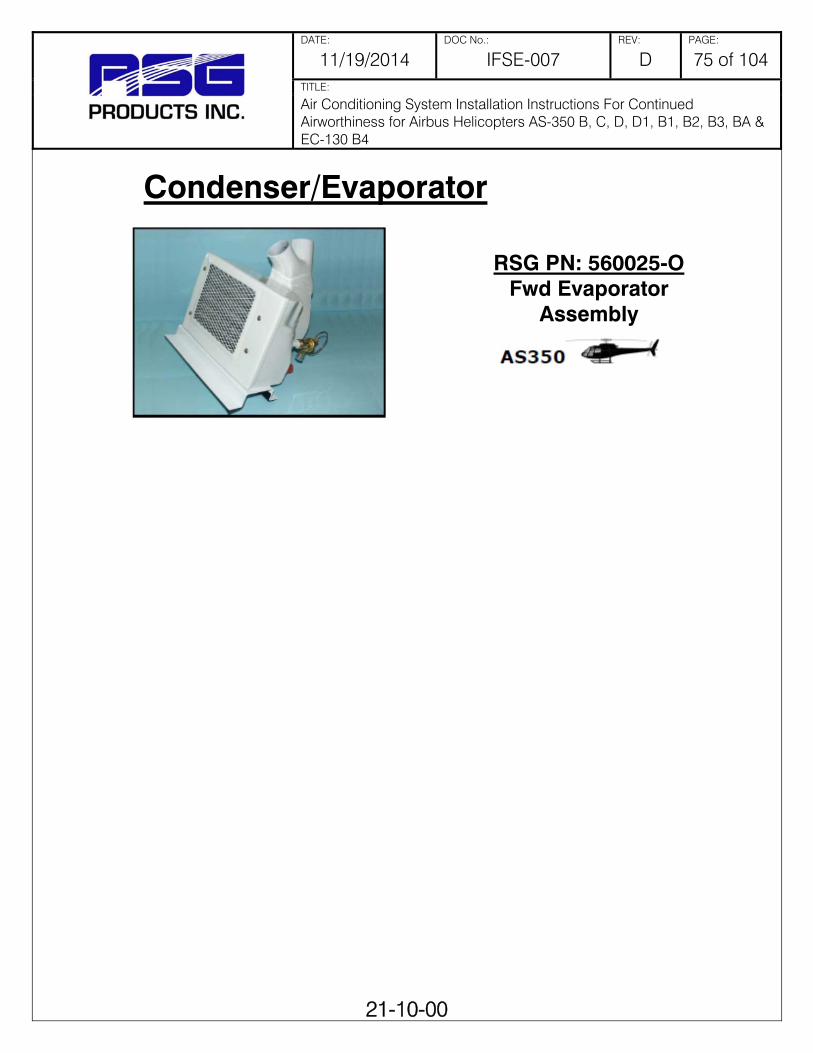
DATE: DOC No.: REV: PAGE:
11/19/2014 IFSE-007 D 75 of 104 TITLE:
Air Conditioning System Installation Instructions For Continued Airworthiness for Airbus Helicopters AS-350 B, C, D, D1, B1, B2, B3, BA & EC-130 B4
21-10-00
Condenser/Evaporator
RSG PN: 560025-O Fwd Evaporator
Assembly

DATE: DOC No.: REV: PAGE:
11/19/2014 IFSE-007 D 76 of 104 TITLE:
Air Conditioning System Installation Instructions For Continued Airworthiness for Airbus Helicopters AS-350 B, C, D, D1, B1, B2, B3, BA & EC-130 B4
21-10-00
Electrical Parts RSG PN: 540009
Electrical Box Assembly
RSG PN: 540028-C-1-A RSG PN: 540028-C-2-A
Electrical Box Assembly
RSG PN: 540011 Instrument Panel
Switch
RSG PN: 540020 Resistor Assembly

DATE: DOC No.: REV: PAGE:
11/19/2014 IFSE-007 D 77 of 104 TITLE:
Air Conditioning System Installation Instructions For Continued Airworthiness for Airbus Helicopters AS-350 B, C, D, D1, B1, B2, B3, BA & EC-130 B4
21-10-00
Electrical Parts
RSG PN: 540044-5 Instrument Panel
Switch
RSG PN: 540044-8 Instrument Panel
Switch
RSG PN: 540044-9 5 amp Breaker
Assembly
RSG PN: 540089 Aft Evaporator Switch
Assembly

DATE: DOC No.: REV: PAGE:
11/19/2014 IFSE-007 D 78 of 104 TITLE:
Air Conditioning System Installation Instructions For Continued Airworthiness for Airbus Helicopters AS-350 B, C, D, D1, B1, B2, B3, BA & EC-130 B4
21-10-00
Electrical Parts
RSG PN: 050000 Switch with Button
RSG PN: 050001 Switch without Button
RSG PN: 050006 Switch without Button
RSG PN: 050006-1 Switch with Button

DATE: DOC No.: REV: PAGE:
11/19/2014 IFSE-007 D 79 of 104 TITLE:
Air Conditioning System Installation Instructions For Continued Airworthiness for Airbus Helicopters AS-350 B, C, D, D1, B1, B2, B3, BA & EC-130 B4
21-10-00
Electrical Parts
RSG PN: 050006-2 Switch with Button
RSG PN: 050006-3 Switch without Button
RSG PN: 050007-1 Button
RSG PN: 050007-3 Button

DATE: DOC No.: REV: PAGE:
11/19/2014 IFSE-007 D 80 of 104 TITLE:
Air Conditioning System Installation Instructions For Continued Airworthiness for Airbus Helicopters AS-350 B, C, D, D1, B1, B2, B3, BA & EC-130 B4
21-10-00
Electrical Parts
RSG PN: 050007-4 Button
RSG PN: 050008 Relay
RSG PN: 050015-2 50 Amp Limiter
RSG PN: 050024 Resistor

DATE: DOC No.: REV: PAGE:
11/19/2014 IFSE-007 D 81 of 104 TITLE:
Air Conditioning System Installation Instructions For Continued Airworthiness for Airbus Helicopters AS-350 B, C, D, D1, B1, B2, B3, BA & EC-130 B4
21-10-00
Electrical Parts RSG PN: 050026
Timer
RSG PN: 050107 Low Pressure Switch
RSG PN: 090004 High Pressure Switch

DATE: DOC No.: REV: PAGE:
11/19/2014 IFSE-007 D 82 of 104 TITLE:
Air Conditioning System Installation Instructions For Continued Airworthiness for Airbus Helicopters AS-350 B, C, D, D1, B1, B2, B3, BA & EC-130 B4
21-10-00
Electrical Parts
RSG PN: 540044-8-02 Instrument Panel
Switch Assy.
RSG PN: 540089-02 Aft Switch Assy.
RSG PN: 7303J21ZQI22 Switch, 3PDT, 3 POS.
RSG PN: 7301J21ZGE22 Switch, 3PDT, 3 POS.

DATE: DOC No.: REV: PAGE:
11/19/2014 IFSE-007 D 83 of 104 TITLE:
Air Conditioning System Installation Instructions For Continued Airworthiness for Airbus Helicopters AS-350 B, C, D, D1, B1, B2, B3, BA & EC-130 B4
21-10-00
Electrical Parts
RSG PN: 7301J11ZQE22 Switch, SPST, 2 POS.
RSG PN: 7101J51ZQE22 Switch, SPST, 2 POS.
RSG PN: 7203J51ZQE22 Switch, DPDT, 2 POS.
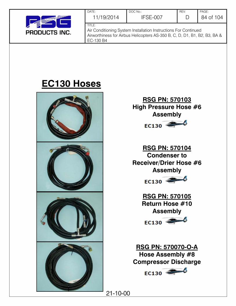
DATE: DOC No.: REV: PAGE:
11/19/2014 IFSE-007 D 84 of 104 TITLE:
Air Conditioning System Installation Instructions For Continued Airworthiness for Airbus Helicopters AS-350 B, C, D, D1, B1, B2, B3, BA & EC-130 B4
21-10-00
EC130 Hoses
RSG PN: 570103 High Pressure Hose #6
Assembly
RSG PN: 570104 Condenser to
Receiver/Drier Hose #6 Assembly
RSG PN: 570105 Return Hose #10
Assembly
RSG PN: 570070-O-A Hose Assembly #8
Compressor Discharge

DATE: DOC No.: REV: PAGE:
11/19/2014 IFSE-007 D 85 of 104 TITLE:
Air Conditioning System Installation Instructions For Continued Airworthiness for Airbus Helicopters AS-350 B, C, D, D1, B1, B2, B3, BA & EC-130 B4
21-10-00
AS350 Hoses Aft Mount Condenser
RSG PN: 570067-O-A Hose Assembly #6 Condenser to Drier
RSG PN: 570070-O-A Hose Assembly #8
Compressor Discharge
RSG PN: 570072-O-A Hose Assembly #6 Fwd
Evaporator to Receiver/Drier
RSG PN: 570087-O-A Hose Assy. Fwd Evaporator
to Aft Evaporator to Condenser

DATE: DOC No.: REV: PAGE:
11/19/2014 IFSE-007 D 86 of 104 TITLE:
Air Conditioning System Installation Instructions For Continued Airworthiness for Airbus Helicopters AS-350 B, C, D, D1, B1, B2, B3, BA & EC-130 B4
21-10-00
AS350 Hoses Side Mount Condenser
RSG PN: 570020-O-A Hose Assembly #6 Condenser to Drier
RSG PN: 570024-O-A Hose Assembly #8
Compressor Discharge
RSG PN: 570072-O-A Hose Assembly #6 Fwd
Evaporator to Receiver/Drier
RSG PN: 570087-O-A Hose Assembly Fwd
Evaporator to Aft Evaporator to Compressor

DATE: DOC No.: REV: PAGE:
11/19/2014 IFSE-007 D 87 of 104 TITLE:
Air Conditioning System Installation Instructions For Continued Airworthiness for Airbus Helicopters AS-350 B, C, D, D1, B1, B2, B3, BA & EC-130 B4
21-10-00
BRUSHLESS BLOWER MOTORS AND PARTS
RSG PN 540126-1 CONTROLLER ASSY
RSG PN 040019 7" PROPELLER RSG PN 050176-1 7" PROPELLER HUB ASSY RSG PN 050193 7" DC BRUSHLESS MOTOR
RSG PN 040020 7" BLOWER
RSG PN 540126-1 CONTROLLER ASSY
RSG PN 040019 7" PROPELLER RSG PN 050176-1 7" PROPELLER HUB ASSY RSG PN 050193 7" DC BRUSHLESS MOTOR
RSG PN 040021 7" BLOWER
RSG PN: 050084-7-2 7” DC Brushless Blower
Assembly Short
RSG PN: 050084-7-3 7” DC Brushless Blower
Assembly Long

DATE: DOC No.: REV: PAGE:
11/19/2014 IFSE-007 D 88 of 104 TITLE:
Air Conditioning System Installation Instructions For Continued Airworthiness for Airbus Helicopters AS-350 B, C, D, D1, B1, B2, B3, BA & EC-130 B4
21-10-00
LIST OF CONSUMABLE MATERIALS DESCRIPTION P/N VENDOR/SPECIFICATION
THREAD LOCK 242 LOCTITE ADHESIVE 1300L 3M Cleaning cloth, Low-Lint -- Commercial
Mineral Spirits, Cleaning Solvent -- MIL-PRF-680, TYP II
OR ASTM-D235 Alodine Alodine 1200 -- Alodine Iridite 14-2 -- Paint Stripper Turco 5873 -- Polyamide Paint Primer -- -- Dye Penetrant Kit -- -- Acetone -- ASTM-D329 Isopropyl Alcohol -- TT-I-735 Trichloroethane -- MIL-T-81533 Nylon Scouring Pad (3M) Scotchbrite 63 3M 240 Grit Sandpaper -- Commercial 320 Grit Sandpaper -- Commercial 240 Grit Aluminum Oxide Abrasive
-- Commercial
Cloth -- Commercial Sealant -- MIL-S-8802 Adhesive transfer tape 950 (2") 70-0060-3057-4 3M Refrigerant R134a --

DATE: DOC No.: REV: PAGE:
11/19/2014 IFSE-007 D 89 of 104 TITLE:
Air Conditioning System Installation Instructions For Continued Airworthiness for Airbus Helicopters AS-350 B, C, D, D1, B1, B2, B3, BA & EC-130 B4
98-00-00
Chapter 98
Section 98-00-00 Wiring Diagrams and Plumbing Schematics This section contains all applicable wiring diagrams and plumbing schematics.

DATE: DOC No.: REV: PAGE:
11/19/2014 IFSE-007 D 90 of 104 TITLE:
Air Conditioning System Installation Instructions For Continued Airworthiness for Airbus Helicopters AS-350 B, C, D, D1, B1, B2, B3, BA & EC-130 B4
98-00-00

DATE: DOC No.: REV: PAGE:
11/19/2014 IFSE-007 D 91 of 104 TITLE:
Air Conditioning System Installation Instructions For Continued Airworthiness for Airbus Helicopters AS-350 B, C, D, D1, B1, B2, B3, BA & EC-130 B4
98-00-00
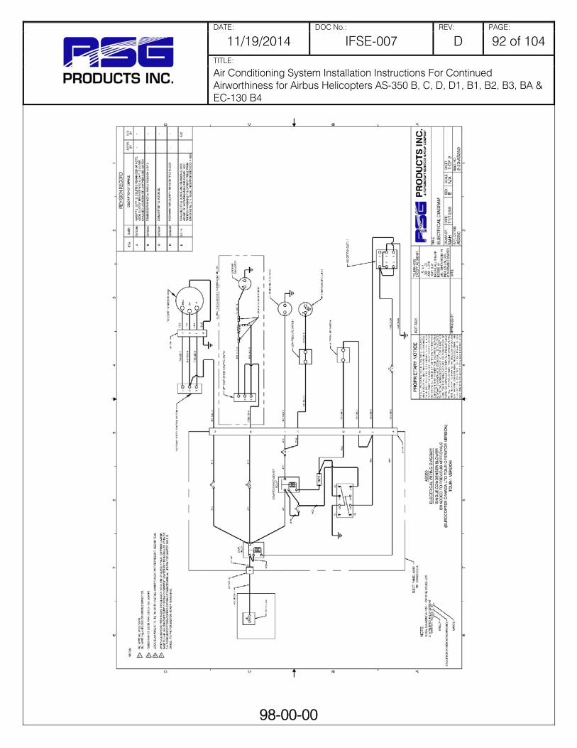
DATE: DOC No.: REV: PAGE:
11/19/2014 IFSE-007 D 92 of 104 TITLE:
Air Conditioning System Installation Instructions For Continued Airworthiness for Airbus Helicopters AS-350 B, C, D, D1, B1, B2, B3, BA & EC-130 B4
98-00-00
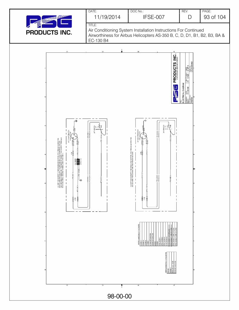
DATE: DOC No.: REV: PAGE:
11/19/2014 IFSE-007 D 93 of 104 TITLE:
Air Conditioning System Installation Instructions For Continued Airworthiness for Airbus Helicopters AS-350 B, C, D, D1, B1, B2, B3, BA & EC-130 B4
98-00-00

DATE: DOC No.: REV: PAGE:
11/19/2014 IFSE-007 D 94 of 104 TITLE:
Air Conditioning System Installation Instructions For Continued Airworthiness for Airbus Helicopters AS-350 B, C, D, D1, B1, B2, B3, BA & EC-130 B4
98-00-00

DATE: DOC No.: REV: PAGE:
11/19/2014 IFSE-007 D 95 of 104 TITLE:
Air Conditioning System Installation Instructions For Continued Airworthiness for Airbus Helicopters AS-350 B, C, D, D1, B1, B2, B3, BA & EC-130 B4
98-00-00
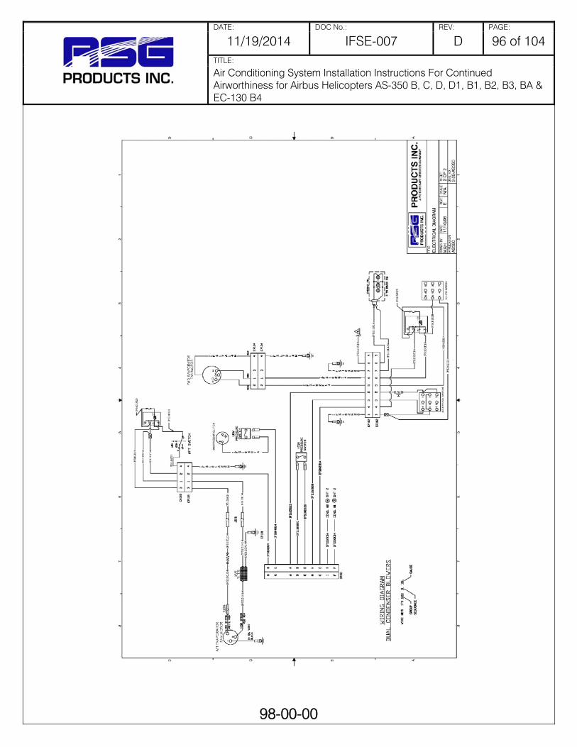
DATE: DOC No.: REV: PAGE:
11/19/2014 IFSE-007 D 96 of 104 TITLE:
Air Conditioning System Installation Instructions For Continued Airworthiness for Airbus Helicopters AS-350 B, C, D, D1, B1, B2, B3, BA & EC-130 B4
98-00-00

DATE: DOC No.: REV: PAGE:
11/19/2014 IFSE-007 D 97 of 104 TITLE:
Air Conditioning System Installation Instructions For Continued Airworthiness for Airbus Helicopters AS-350 B, C, D, D1, B1, B2, B3, BA & EC-130 B4
98-00-00

DATE: DOC No.: REV: PAGE:
11/19/2014 IFSE-007 D 98 of 104 TITLE:
Air Conditioning System Installation Instructions For Continued Airworthiness for Airbus Helicopters AS-350 B, C, D, D1, B1, B2, B3, BA & EC-130 B4
98-00-00
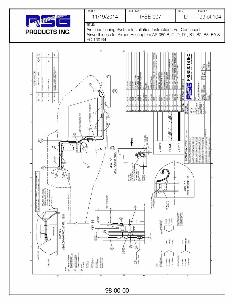
DATE: DOC No.: REV: PAGE:
11/19/2014 IFSE-007 D 99 of 104 TITLE:
Air Conditioning System Installation Instructions For Continued Airworthiness for Airbus Helicopters AS-350 B, C, D, D1, B1, B2, B3, BA & EC-130 B4
98-00-00

DATE: DOC No.: REV: PAGE:
11/19/2014 IFSE-007 D 100 of 104 TITLE:
Air Conditioning System Installation Instructions For Continued Airworthiness for Airbus Helicopters AS-350 B, C, D, D1, B1, B2, B3, BA & EC-130 B4
98-00-00

DATE: DOC No.: REV: PAGE:
11/19/2014 IFSE-007 D 101 of 104 TITLE:
Air Conditioning System Installation Instructions For Continued Airworthiness for Airbus Helicopters AS-350 B, C, D, D1, B1, B2, B3, BA & EC-130 B4
98-00-00

DATE: DOC No.: REV: PAGE:
11/19/2014 IFSE-007 D 102 of 104 TITLE:
Air Conditioning System Installation Instructions For Continued Airworthiness for Airbus Helicopters AS-350 B, C, D, D1, B1, B2, B3, BA & EC-130 B4
A-1
APPENDIX A Weight and Balance
PERTAINS TO KIT #350-00-011
ITEM WEIGHT ARM MOMENT
Forward Evaporator Assembly 10.0 19.00 190.00
Forward Air Outlets 4.0 31.32 125.28
Aft Evaporator and Return Air 9.0 120.00 1080.90
Aft Evaporator Blower 6.0 120.85 725.10
Condenser Coil and Mount 20.0 133.80 2676.00
Condenser Blower and Mount 8.0 148.60 1188.80
Compressor and Mount 12.0 147.80 1773.60
Electrical Relay Panes 4.0 153.70 614.80
Refrigerant, Hoses and Fittings 6.0 76.90 461.40
Sub Total: (Air Conditioner)
79.0 111.85 8835.88
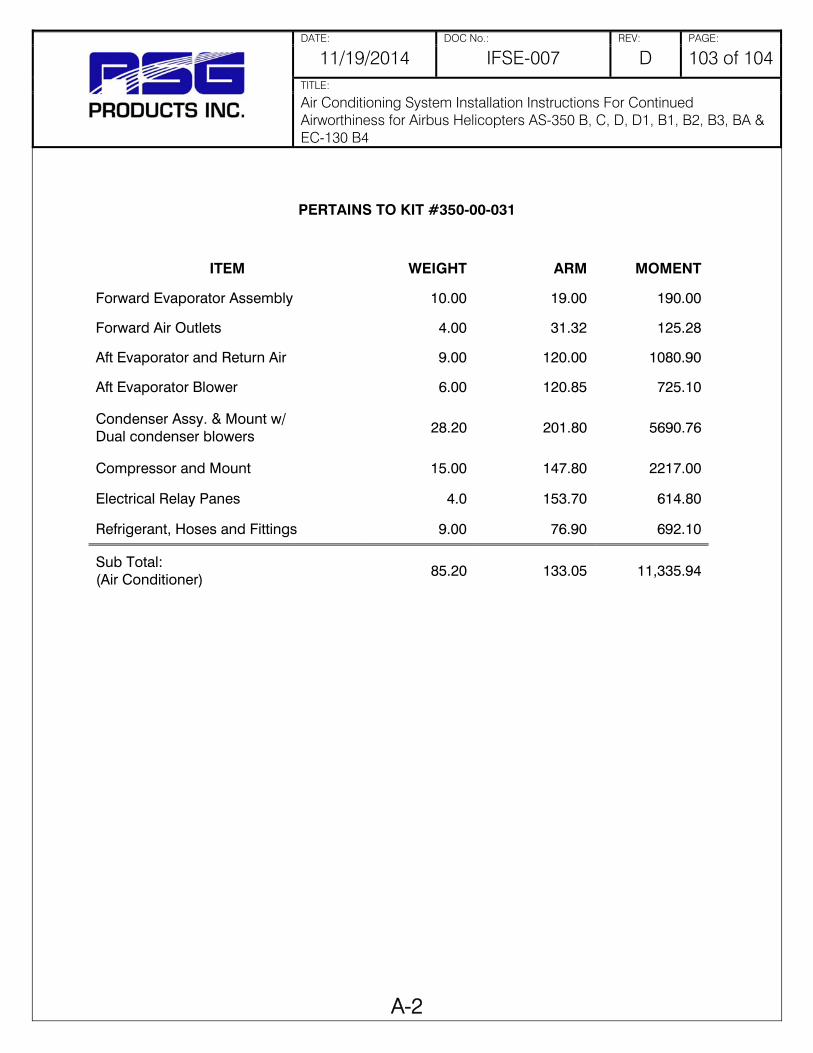
DATE: DOC No.: REV: PAGE:
11/19/2014 IFSE-007 D 103 of 104 TITLE:
Air Conditioning System Installation Instructions For Continued Airworthiness for Airbus Helicopters AS-350 B, C, D, D1, B1, B2, B3, BA & EC-130 B4
A-2
PERTAINS TO KIT #350-00-031
ITEM WEIGHT ARM MOMENT
Forward Evaporator Assembly 10.00 19.00 190.00
Forward Air Outlets 4.00 31.32 125.28
Aft Evaporator and Return Air 9.00 120.00 1080.90
Aft Evaporator Blower 6.00 120.85 725.10
Condenser Assy. & Mount w/ Dual condenser blowers
28.20 201.80 5690.76
Compressor and Mount 15.00 147.80 2217.00
Electrical Relay Panes 4.0 153.70 614.80
Refrigerant, Hoses and Fittings 9.00 76.90 692.10
Sub Total: (Air Conditioner)
85.20 133.05 11,335.94

DATE: DOC No.: REV: PAGE:
11/19/2014 IFSE-007 D 104 of 104 TITLE:
Air Conditioning System Installation Instructions For Continued Airworthiness for Airbus Helicopters AS-350 B, C, D, D1, B1, B2, B3, BA & EC-130 B4
A-3
PERTAINS TO KIT # 130-00-031
ITEM WEIGHT ARM MOMENT
FWD. EVAP ASSY W/ MOTOR 12.0 24.0 288
FWD AIR OUTLETS (x2) W/ DUCTING 3.0 33.29 99.87
AFT EVAP W/ MOTOR & DUCTS 16.0 120.5 1928
CONDENSER ASSY W/ MOTOR & AIR DISCHARGE
33.0 223.3 7368.9
COMPRESSOR W/ MOUNTING KIT 14.0 147.8 2069.2
ELECTRICAL CONTROL BOX 4.0 153.7 614.8
REFRIGERANT HOSES 5.0 76.9 384.5
ELECTRICAL HARNESS 3.5 70.0 245
INSTALLATION TOTALS 90.5 143.62 12998.27

RSG Products Inc. Parts Break Down – 350-00-031 Air Conditioning
Date: 05/22/15 Section 13: Parts Break Down Page 1 of 5
Step 13
Parts Break Down

RSG Products Inc. Parts Break Down – 350-00-031 Air Conditioning
Date: 05/22/15 Section 13: Parts Break Down Page 1 of 5
MASTER PARTS LIST
IN
ALL AS350 SERIES
FOR
KIT # 350-00-031-HP
with
AFT MOUNTED CONDENSER (DUAL CONDENSER BLOWERS)
"ESTER OIL EQUIPPED COMPRESSOR" Model: SD-507
Revised: May 22,2015
November 4, 2009 August 28, 2006
February 1, 2002 March 1, 2001
August 6, 2001

RSG Products Inc. Parts Break Down – 350-00-031 Air Conditioning
Date: 05/22/15 Section 13: Parts Break Down Page 2 of 5
MASTER PARTS LIST
AS350 SERIES 05/22/15
KIT #350-00-031HP
SINGLE CONDENSER BLOWER ITEM DESCRIPTION PART # 1. BELT - FLAT 060018-1 060018 (Alt) BELT - GROOVED 060005 2. SD-507 COMPRESSOR ASSEMBLY 590008
COMPLETE W/ FLAT PULLEY, 24 VDC COIL (FOR USE WITH R-134a ONLY, "ESTER oil equipped)
SD-507 COMPRESSOR ASSEMBLY 590008-1 COMPLETE W/ GROOVED PULLEY, 24 VDC COIL (FOR USE WITH R-134a ONLY, "ESTER oil equipped)
COMPRESSOR PARTS
FOR: SD-507 W/ 5.0" CLUTCH 3. BEARING (ONLY): SD-507 010011
COMPRESSOR W/ 5.0" CLUTCH 4. 24 VDC COIL (GREEN WIRE) 050033

RSG Products Inc. Parts Break Down – 350-00-031 Air Conditioning
Date: 05/22/15 Section 13: Parts Break Down Page 3 of 5
COMPRESSOR PARTS ITEM DESCRIPTION PART # 5. PULLEY (FLAT) 300355 (Alt) 300355-2 PULLEY (GROOVED) 300396 6. PULLEY FACE PLATE 5.0" (A6H) 010013 7. PULLEY FACE PLATE 5.0" (A3G/A2Y) 010015
EVAPORATOR BLOWER PARTS
8. 5" VANE AXIAL BLOWER ASSY. 050143 (SINGLE FLANGE W/NYLON BLADE) For: AFT EVAPORATOR BLOWER ASSY.
P/N 490017-1 9. MOTOR: 5" VANE AXIAL BLOWER 050145
10. NYLON BLADE AND HUB ASSY. 580000
FITS 5" VANE AXIAL BLOWER, 11. BRUSHES (2 EACH)/MOTOR 050031
12. MOTOR, FORWARD EVAPORATOR 050052-1 24VDC, single shaft, right hand 13. WHEEL, FORWARD EVAPORATOR, fan, 040004-8
metal, CC rotation, 5/16" bore
DUAL CONDENSER BLOWER PARTS
14. 5" VANE AXIAL BLOWER ASSY. 050143 (SINGLE FLANGE W/NYLON BLADE) For: AFT EVAPORATOR BLOWER ASSY.
P/N 490017-1

RSG Products Inc. Parts Break Down – 350-00-031 Air Conditioning
Date: 05/22/15 Section 13: Parts Break Down Page 4 of 5
ITEM DESCRIPTION PART #
15. MOTOR: 5" VANE AXIAL BLOWER 050145 16. NYLON BLADE AND HUB ASSY. 580000
FITS 5" VANE AXIAL BLOWER,
17. BRUSHES (2 Brush motor) 050031 18. (INTENTIONALLY BLANK) 19. (INTENTIONALLY BLANK)
MISC. PARTS 20. RECEIVER/DRIER 090016-5
1991 & ON - "O" RING TYPE 21. EXPANSION VALVE
1992 & ON - FWD. AND AFT EVAP. 090002-"O" "O" RING TYPE
22. HIGH PRESSURE SAFETY SWITCH 090004
(ALL YEARS) 23. LOW PRESSURE SAFETY SWITCH 050107
1991 & ON - NON-ADJUSTABLE (7 OUT/22 IN)

RSG Products Inc. Parts Break Down – 350-00-031 Air Conditioning
Date: 05/22/15 Section 13: Parts Break Down Page 5 of 5
RSG Products Inc. Pressure Switch Identification for all
vapor cycle air conditioning kits using R-134a
Low Pressure Switch: P/N 050107
Leads are: BLUE in color
Mfg. P/N on switch: 20PS003MA022C007C
Opens: 7PSI Closes: 22 PSI
High Pressure Switch: P/N 090004
Leads are: BLACK in color
Mfg. P/N on switch: 20PS002MB375K265K Opens: 375 PSI Closes: 265 PSI
ALT. Mfg. P/N on switch: 20PS104MB350K250K
Opens: 350 PSI Closes: 250 PSI
P/N 090004 (Both Types)

RSG Products Inc. Warranty/Repair – AS350 Air Conditioning
Date: 09/19/11 Section 14: WARRANTY/REPAIR (EFFECTIVE DATE 09/19/11) Page 1 of 6
Step 14
Warranty/Repair

RSG Products Form 33.40 Rev 09/19/2011
Standard Terms and Conditions of Sale 1. Terms of Payment: Unless prior arrangements are made to establish credit terms RSG Products Inc., all sales are prepaid in full prior to shipment. Payment may be made via cash, check or electronic transfer to RSG Products Inc. prior to delivery. 2. Buyer’s Deposit: A 50% deposit is required to process an order for an air conditioning kit. The deposit is non-refundable and will be applied to the final price of the kit. 3. Taxes / Other Charges: Prices of the specified products are exclusive of all city, state, federal and international taxes, duties, levies or charges of any kind, including, without limitation, taxes on manufacture, sales, receipts, gross income, occupation, use and similar taxes or other charges. Whenever applicable, any taxes or other charges shall be added to the invoice as a separate charge to be paid by Buyer. 4. Shipment and Packaging: All products will be suitably packed, marked and shipped F.O.B. RSG Products Inc. Fort Worth Texas, in accordance with standard packaging procedures. 5. Delays: RSG Products Inc. will not be liable for any delay in the performance of orders or contracts, or in the delivery or shipment of goods, or for any damages suffered by Buyer by reason of such delays. 6. Technical Advice: RSG Products Inc. technical support staff is available for telephone consultation concerning the products it manufactures; however, RSG Products does not warrant or guarantee such advice. 7. Aircraft Variation: Due to aircraft manufacturing variations, alterations and other factors, there are differences between aircraft of a certain make and model. Because of these variations, RSG Products Inc. does not guarantee that Buyer has purchased the correct product or that a specified product will fit the intended aircraft. Further, RSG Products does not guarantee the number of labor hours required to install its products. 8. Returns: All sales are final unless a return is approved at the sole discretion of RSG Products Inc. If RSG Products Inc. does agree to accept a return, a twenty percent (20%) restocking fee will be charged. All items returned to RSG Products Inc. must be sent freight prepaid and must have a return material authorization (RMA) number clearly marked on the shipping container. 9. No Fault Found: If items are sent to RSG Products Inc. for evaluation and no problem is found, or if Buyer elects not to make the required repairs, then Buyer shall be responsible for the payment of $250 evaluation fee. 10. Certificate of Conformity: RSG Products Inc. will provide a Certificate of Conformity with each product assuring that the product has been manufactured according to its approved design drawings. Any additional assurances or certifications shall be at the expense of Buyer and shall be added to the invoice as a separate charge to be paid by Buyer. 11. Failed Products: Should any product prove defective, RSG Products Inc. will either replace the item or adjust the matter fairly and promptly, but under no circumstances shall RSG Products be liable for consequential or other damages, losses, or expenses in connections with or by reason of the use or liability to use products purchased for any purpose. 12. Patents: Buyer shall hold RSG Products Inc. harmless from, and release and not make claim or suit against RSG Products because of any suits, claims, losses, or other liability made against, or suffered by, Buyer arising from any claim of, or infringement of, patent, copyright, trademark, or other proprietary right, at common law, or claim of unfair trade or of unfair competition, resulting from, or occasioned by Buyer’s use, possession, sale, or delivery of the products sold to Buyer by RSG Products Inc. 13. Warranty Registration and Claims: The terms RSG Products Inc. Limited Warranty is written on the Warranty Registration Card and published on the RSG Products Inc., website www.integratedflightsys.com. The registration form must be completed and returned to RSG Products Inc. upon receipt of a product. The completed form may be faxed to +1 817 624 6601. Failure to complete the Warranty Registration Card may result in denial of a claim. In order to process a warranty claim, call RSG Products Inc. at +1 817-624 6600 or fax +1 817 624 6601. A Warranty Claim without a Return Material Authorization (RMA) Number will cause delays and a possible denial of the claim.

RSG Products Form 33.40 Rev 09/19/2011
WEBSITE Terms of Use. When you access, browse or use this Site, you accept, without limitation or qualification, the terms and conditions set forth below. If you do not agree to them, do not use the Site or download any materials from integratedflightsys.com. The information herein contained may include technical inaccuracies or typographical errors. Changes may periodically be made to the information and will be incorporated in new editions of this document without notice. In no event will RSG Products Inc. be liable to any party for any direct, indirect, special or other consequential damages for any use of this web site or any other hyper linked site; including without limitation any lost profits, business interruption, loss of programs or other data on your information handling system. Site Information. Site information regarding RSG Products Inc., services, technical parts and components, including their availability, appearance, price and specifications are subject to change without notice. In no event shall RSG Products be held liable for indirect or consequential damages or any damages resulting from the use of information from this Site. The information on this Site is at the recipient’s own risk. Links. This site contains links to other Sites on the World Wide Web. RSG Products Inc. provides such links for your convenience only, and is not responsible for the content of any Site linked to or from this Site. Links from this Site to any other Site does not mean that RSG Products Inc. approves of, endorses or recommends that Site. Rights of Use. Any person is hereby authorized to view, copy, print, and distribute any document published by Integrated Flight Systems Corp provided that it is: for personal use, for information purposes and reference must be made to RSG Products Inc. when the document is used. Information Collected. When you visit this site, RSG Products Inc. may collect information in two ways – through information automatically gathered from your computer or through information you voluntarily provide. As to automatically gathered information, RSG Products collects navigational information about where visitors go on our Site, how many visits are made to the Site, when the Site is visited and other non-personally identifiable information (for example, this can include domain type, browser version, service provider, IP address). The navigational information that is automatically gathered when you visit integratedflightsys.com is used on an aggregate basis to evaluate and effectiveness of our Site, to analyze trends and to administer the Site. This navigational information allows us to determine such things as which areas are most visited and difficulties our visitors may experience in accessing out Site. Voluntarily provided information is collected online if you elect to e-mail RSG Products Inc. Whenever this act is made the information you voluntarily provide, name, e-mail address, phone number, specific information comments or questions, is not distributed and is confidential. All information collected from our site and/or information voluntarily provided is kept confidential and is not distributed for any reason without your approval. 14. Acceptance: This is not a firm offer and may be changed or revoked at any time. Acceptance of this offer is expressly limited to the exact terms contained herein, or as may be changed by a prior written contract between the Buyer and RSG Products Inc., and any attempt to alter or omit any of such terms shall be deemed a rejection and a counteroffer.

RSG Products Form 33.39 Rev 09/19/2011
Warranty Terms RSG Products Inc., warrants that each of its Air Conditioning Systems (the “Equipment”) shall be free from defects in material and workmanship under normal use and service until one year after its date of sale if, and only if, installation, maintenance and operation of the Equipment is in accordance with the specifications and instructions provided by RSG Products Inc. and no substitute parts are installed in accordance with the specifications and instructions provided by RSG Products Inc. and no substitute parts are installed in the equipment without the prior written authorization from RSG Products Inc.. For the Equipment, the warranty period is 12 months or 1,000 hours, whichever comes first, from the date of sale. In the case of new spare parts, this warranty is further limited to a period of six (6) months from the date of sale. In the case of overhauled products, this warranty is further limited to a period of three (3) months from the date of sale. In the case of repaired products, this warranty is further limited to a period of thirty (30) days from the date of sale and applies only to the parts used for the repair. Any claims under this warranty shall be made to RSG Products Inc., 3900 Falcon Way West Hanger 16S, Fort Worth, Texas 76106, USA. Warranty is not valid unless the enclosed Registration Card is completed and returned to RSG Products Inc. prior to any claim. The Warranty Claim Form must be completed and returned with the Equipment. All claims shall be handled according to standard warranty repair procedures. Limitations & Exclusions. This warranty shall not apply to any Equipment repaired or altered outside the Rotorcraft Services Inc. Service Department unless express prior written authorization is granted: nor shall this warranty apply to any Equipment that has been subjected to misuse or accident, as determined solely by Rotorcraft Services Inc. The sole responsibility and liability of RSG Products Inc. and your exclusive remedy under any claim arising out of, connected with, or resulting from this sale or the performance or breach or any condition of warranty there under, or from the manufacture, delivery, or use of the Equipment shall be the repair or replacement of defective equipment upon return of the defective equipment to RSG Products Inc. with transportation, customs and any applicable import duties prepaid and provided that an inspection by RSG Products Inc. discloses that the equipment is defective and covered by this warranty. RSG Products Inc. shall not be liable for any labor or other charges necessary to remove or reinstall the Equipment. In no event, whether as a result of a breach of contract, warranty, tort (including negligence) or otherwise, shall RSG Products Inc. be liable for any special, consequential, incidental or penal damages or expenses including but not limited to loss of profit, goodwill or revenues, loss of use of the Equipment or any associated equipment, damage to associated equipment, cost of capital, cost of substitute products, facilities or services, down time, or costs or claims of third parties for such damages or expenses. THE FOREGOING WARRANTY IS EXCLUSIVE AND IN LIEU OF ALL OTHER WARRANTIES OR REMEDIES WHETHER WRITTEN, ORAL, IMPLIED OR STATUTORY, ANY AND ALL IMPLIED WARRANTIES OF MERCHANTABILITY, FITNESS FOR A PARTICULAR PURPOSE, COURSE OF DEALING OR USAGE OF TRADE ARE HEREBY EXPRESSLY DISCLAIMED AND EXCLUDED. Acceptance of the Equipment by you shall constitute your acknowledgement and acceptance of the terms, provisions, limitations and exclusions set forth herein. Such term, provisions, limitations and exclusions shall not be modified, deleted or supplemented. In a case where the purchaser has negotiated warranty terms by express written agreement with RSG Products Inc. as to certain equipment, the terms of that agreement shall supersede the warranty.

RSG Products Form 33.41 Rev 09/19/2011
WARRANTY REGISTRATION FORM
DATE: _______________ CUSTOMER NAME:_______________________________________________ ADDRESS:______________________________________________________ CITY:_______________________ STATE:____________ ZIP:____________ PHONE NUMBER: (____) _____________FAX NUMBER:(____)___________ COMPONENT NAME: _____________________________________________ PART NUMBER:________________SERIAL NUMBER:__________________ TYPE AIRCRAFT:_______________ N#:______________S/N:_____________ AIR CONDITIONING INSTALLATION DATE:____________________________ AIR CON. INSTALLATION COMPANY:_________________________________ DATE INSTALLED:________________ T.T AT INSTALLATION:____________ COPY OF T.T. LOG BOOK ENTRY OF A/C INSTALL SIGN OFF.
This Form Must be received from the Owner of the Aircraft for the warranty to be active. Warranty period extends from Date of Purchase for a period of one year or 1000 hours Subject to the limitations identified in the attached Warranty Terms; effective 22 February 2007
PLEASE REVIEW THE ATTACHED WARRANTY POLICY
PRIOR TO SUBMITTING THIS REGISTRATION FORM.

RSG Products Form 33.41 Rev 09/19/2011
WARRANTY CLAIM FORM
DATE: _______________ __ RMA#____________________ CUSTOMER NAME: _______________________________________________ ADDRESS: ______________________________________________________ CITY: _______________________ STATE:____________ ZIP:_____________ PHONE NUMBER:(____)______________FAX NUMBER:(____)____________ COMPONENT NAME:_____________________________________________ PART NUMBER: _________________SERIAL NUMBER: _________________ TYPE AIRCRAFT: _______________ N#:______________S/N: ____________ AIR CONDITIONING INSTALLATION DATE: ___________________________ AIR CON. INSTALLATION COMPANY: ________________________________ DATE INSTALLED: ______________ T.T AT INSTALLATION: _____________ DATE REMOVED: ________________ T.T AT REMOVAL: ________________ REASON FOR RETURNING COMPONENT: ____________________________
For Company use only Date Received: ____________________ Warranty Accepted: ____YES ____NO Disposition of component: _______________________ Comments: ___________________________________ _____________________________________________

Integrated Flight Systems Trouble Shooting Guide – AS350 Air Conditioning
Date: 11/04/09 Section 15: TROUBLE SHOOTING GUIDE
Step 15
Trouble Shooting
Guide

Servicing and Trouble Shooting Guide
AS350 (Series) and EC130 B4
Air Conditioning System
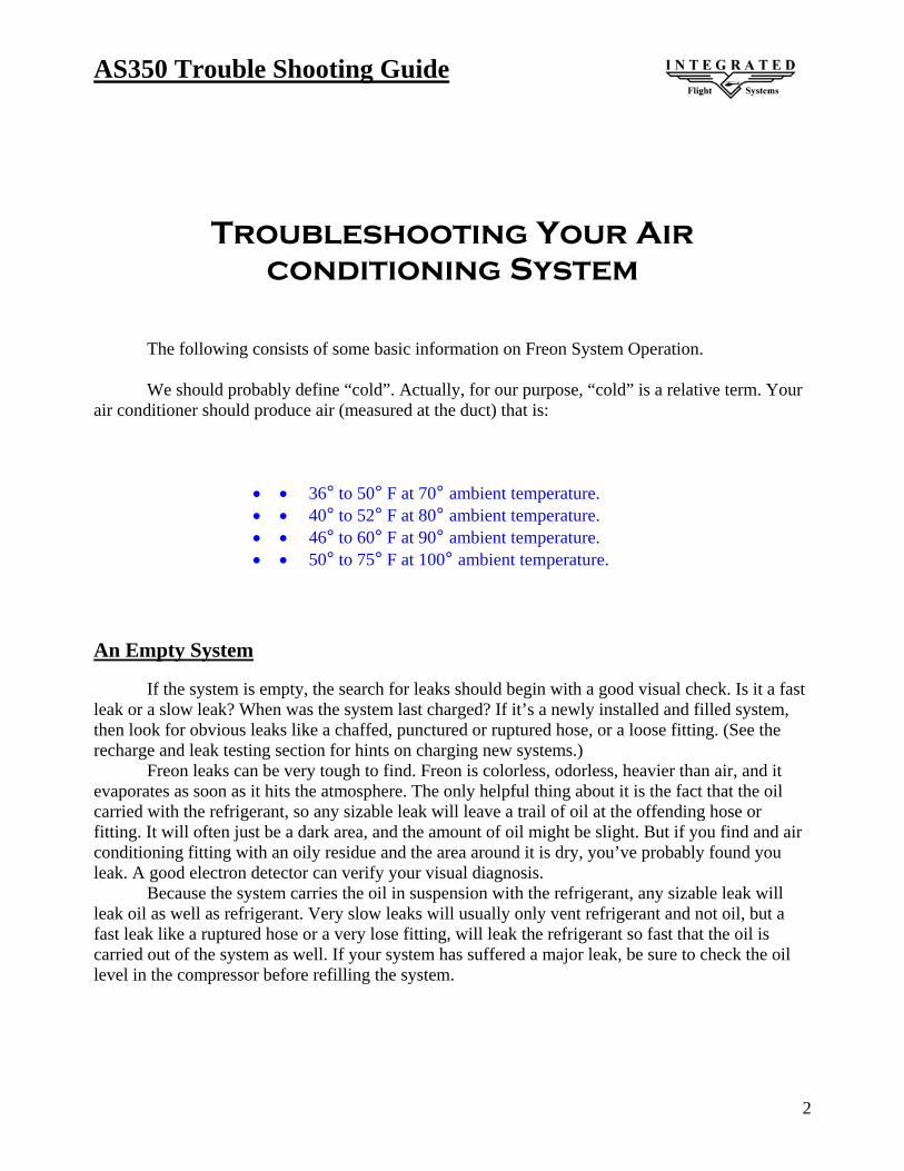
AS350 Trouble Shooting Guide
2
Troubleshooting Your Air conditioning System
The following consists of some basic information on Freon System Operation. We should probably define “cold”. Actually, for our purpose, “cold” is a relative term. Your air conditioner should produce air (measured at the duct) that is:
• • 36° to 50° F at 70° ambient temperature. • • 40° to 52° F at 80° ambient temperature. • • 46° to 60° F at 90° ambient temperature. • • 50° to 75° F at 100° ambient temperature.
An Empty System If the system is empty, the search for leaks should begin with a good visual check. Is it a fast leak or a slow leak? When was the system last charged? If it’s a newly installed and filled system, then look for obvious leaks like a chaffed, punctured or ruptured hose, or a loose fitting. (See the recharge and leak testing section for hints on charging new systems.) Freon leaks can be very tough to find. Freon is colorless, odorless, heavier than air, and it evaporates as soon as it hits the atmosphere. The only helpful thing about it is the fact that the oil carried with the refrigerant, so any sizable leak will leave a trail of oil at the offending hose or fitting. It will often just be a dark area, and the amount of oil might be slight. But if you find and air conditioning fitting with an oily residue and the area around it is dry, you’ve probably found you leak. A good electron detector can verify your visual diagnosis. Because the system carries the oil in suspension with the refrigerant, any sizable leak will leak oil as well as refrigerant. Very slow leaks will usually only vent refrigerant and not oil, but a fast leak like a ruptured hose or a very lose fitting, will leak the refrigerant so fast that the oil is carried out of the system as well. If your system has suffered a major leak, be sure to check the oil level in the compressor before refilling the system.

AS350 Trouble Shooting Guide
3
Troubleshooting
Trouble: Low or partial refrigerant charge Symptoms: - Insufficient cooling - Low-side pressure too low - High-side pressure too low
- Receiver/drier sight glass shows a stream of bubbles - Air in ducts only slightly cool
Cause: The system is low on refrigerant, probably cause by a leak.
Correction: Find and fix the leak. If there was a loss of oil, be sure to check the compressor oil level. Evacuate and recharge.
A System Full of Refrigerant First, you should double-check all the obvious things (i.e. the compressor clutch, the belt tension, and the operation of the evaporator blower). Next, establish some baseline conditions for your testing: run aircraft, high blower and coldest thermostat setting, doors and windows closed, ambient temperature of 70° F or above. Situations do occur where the system is full of refrigerant, yet the sight glass remains cloudy. The first thing to consider is whether the receiver/drier is install backwards. Be sure the line from the condenser goes to the port marked “in” on the receiver/drier. The other condition that might give you a cloudy glass (on a full system) is a restriction in the liquid line from the condenser to the receiver/drier. On some new receiver/driers the filter screen could be pushed up so the bottom of the screen is blocking the liquid pickup tube. You will have to cut open the receiver-drier to confirm your diagnosis. You should test next for a system that is overcharged. If the sight glass is clear, but the high- and low pressure gauge readings are high (300 or more on the high side, 50 or more on the low side), disconnect the compressor clutch. (Note that on HFC-134A systems, milky is the normal look for a correctly charge system.) The refrigerant should foam and then settle away from the glass in less than forty-five seconds. If the sight glass remains clear foe more that forty-five seconds you have an overcharged condition and will have to remove Freon.

AS350 Trouble Shooting Guide
4
Trouble: Excessive moisture in the system Symptoms: - Insufficient cooling during hottest part of the day or during extended flying.
- Low-side pressure normal, though it may be too low or even a vacuum - High-side pressure normal, though it may be low-at the same time low side is low - Receiver-drier sight glass may show tiny bubbles (Note: This could be a tough call with HFC-134A since the sight glass is always milky).
- Air in the ducts is usually cold, but becomes warm when pressure reading drop Cause: Excessive moisture in the system. The drying agent in the receiver-drier is saturated with moisture, which is released to the system when outside temperature increased. Moisture in the system collects and freezes on the expansion valve, stopping the flow or refrigerant. Correction: Suck all the CFC-12 from the system. Replace of rebuild the receiver-drier. Evacuate and recharge. Trouble: Air in the system Symptoms: - Insufficient cooling
- Low-side pressure normal, but does not drop when the clutch cycles - High-side pressure high - Receiver/drier sight glass shows occasional bubbles (Note again that with HFC-134A the sight glass should be milky when the system is fully charged.)
- Air in ducts only slight cool Cause: Refrigerant contains non-condensable in the form of air and moisture. Correction: Leak test, watch for bad compressor seals. Drain the system. Repair leaks as needed. Replace or rebuild the receiver-drier. Check the compressor oil. Evacuate and recharge.

AS350 Trouble Shooting Guide
5
Trouble: Condenser malfunction or system overcharge Symptoms:
- No cooling - Low-side pressure too high - High-side pressure too high - Receiver/drier sight glass may show occasional bubbles - Liquid line very hot - Air in ducts is warm
Cause: The condenser is not function properly because of high head pressure. System may be overcharged.
(Note: Technicians will have to be especially careful to avoid overcharging HFC-134A systems. Because the sight glass is hard to read and the volume given is slightly lower with HFC-134A).
NOTE:
Cloudy Sight Glass
A cloudy sight glass indicates a system that is only partially full of refrigerant (with a few
exceptions). A perfectly clear sight glass (use a light to get a good look) meaans the system is either
full or empty. Note, with HFC-134A the glass appears milky when properly charged, and may show
occasional bubbles.

AS350 Trouble Shooting Guide
6
1. System has no electrical power to air conditioner master control box:
A) Check 50 amp circuit breaker or fuse in aircraft electrical bus.
2. System has power but will not turn on: A) Check 5 amp circuit breaker on switch assembly. B) Check ground lead on cannon plug 102 wire IFS105N20. C) Check evaporator fan relay in air conditioner master control box.
3. Forward evaporator fan will not turn on, but aft fan runs:
A) Check 20 amp circuit breaker in master electrical box. B) Check ground wire from evaporator motor. C) AS350 disconnect CP104 and check for power on pin 2. On AS350 or EC130 B4 by
checking ground lead from master switch. 1) If you have power, your motor is bad. 2) If no power, disconnect CP101 cannon plug and check continuity from pin
6/c on CP101 to cannon plug CP104 pin 2. If no power, check cannon plugs and switch.
D) EC130 B4 check for power on wire IFS 101C14 at resistor assembly P/N 540020 if no power, trace through the fan switch for power.
4. Aft evaporator fan will not run, but forward evaporator runs:
A) Check 20 amp circuit breaker on master electrical box. B) Check ground wire from fan. C) Check Brushes. D) AS350 check for power on wire IFS 101C14 at resistor assembly P/N 540020 or
resistor P/N 050024-2 (parts are two way interchangeable). 1) If you have power, your motor is bad. 2) If no power trace through fan switch for power. 3) If no power disconnect cannon plug CP101 and check continuity from pin
3/B of CP101 to wire IFS101C14 on resistor with fan switch on “Low”.
E) EC130 B4 check for power on wire IFS 101C14 at resistor assembly P/N 540020. 1) If you have power your motor is bad. 2) If no power trace through fan switch for power. 3) If no power disconnect cannon plug CP101 and check continuity from pin
3/B of CP101 to pin 4 of cannon plug 102.

AS350 Trouble Shooting Guide
7
5. Condenser fan/fans do not operate:
A) Check 20 amp circuit breaker. B) Check 1 amp circuit breaker.
1) If popped, reset. a) Check brushes. b) Check power. c) Check ground. d) Check fins for blockage in air condenser assembly.
2) Run air conditioning system. a) Check pressures, If pressure is running higher than normal, then continue with b), ect… b) System may be over-
serviced. c) System may be contaminated by improper Freon or a mix of Freon’s.
1) NOTE: This has happened more than once. The service carts are great for servicing systems, but there is a danger in its misuse. Untrained operators or an individual who wants to service his car, truck, motor home or even his room A/C can pump down their system into your tank. It can have any number of different Freon’s. It could also be contaminated by a failed compressor, dryer bottle, wrong oil or any number of things. This has happened to a company with brand new equipment just 3 weeks old. There were large warning signs on this service cart, designated HELICOPTER SERVICE ONLY. They had one for ground equipment. All of the mechanics were well trained except for the management, janitors and their family members of the company. It can happen to any operator.
6. Compressor clutch does not engage, but air conditioner fans work.
A) Check clutch for power. 1) If power, clutch coil may be bad or air gap in clutch face may be
too excessive. 2) If NO power check system for
total Freon loss. 3) If system is serviced and still no
Power and you have an optional temperature controller, you can bypass by jumping pins 3 and 4
on CP102 to check if faulty.

AS350 Trouble Shooting Guide
8
7. System not cooling: A) Check that air condenser fan/fans are blowing. B) Check clutch engagement. Is clutch staying engaged or cycling? Check belt tension. C) Check to see if air condenser coil is free from debris and fins are clean and not rolled
over blocking air flow. D) Check evaporator return air inlets, that they are not blocked and fins are clean and not
rolled over blocking airflow. E) Put gauges on system. Run system and check pressures also measure Delta
temperature from both evaporators. (Measure inlet temperature and outlet temperature to get Delta. This is a must, do not rely on just using your hand and guessing).
F) Check sight glass. (NOTE: There are several ways to service Freon systems:
1) Service system to a clear sight glass R12. Note: On 134a systems the sight glass appears milky when properly charged, though there may be occasional bubbles in the sight glass.
2) Service system by weight. If you have a service station or scale, you can add the proper amount by weight.
3) The optimum method for best performance is to use at least two mechanical thermometers and place them near the return air and the discharge air of each evaporator. R-134a can then be added or deleted as required, until the highest T.D. is noted per the paragraph below. At that time, the correct amount of refrigerant is installed. At any time the high pressure gauge reaches 280 psi, stop servicing. Do not exceed 3.0 lbs of refrigerant..
4) Service according to a standard pressure temperature chart.)
8. One evaporator is cooling, one is not. A) One expansion valve may be blocked form contamination.
B) One expansion valve may be locked full open. (NOTE: The one valve that is full open is causing the problem. It may make it seem like the other valve is bad and not working.)
C) One of the sensing bulbs on expansion valves may become loose from suction side of coil. Also check to see if sensing bulb is mounted to the correct evaporator tube. The bulb should be mounted at 9 or 3 o’clock position.
D) Hose may be crimped, kinked or have a fitting bent over blocking flow.
82° F or higher service with 2.0 lbs max Freon.
Below 82° F service with 2.5 lbs max Freon.

AS350 Trouble Shooting Guide
9
E) (NOTE: The recommended fix is to pump down system. Change BOTH expansion valves and dryer bottle. Make sure to mount sensing bulb on suction side of coil and when possible at 9 or 3 o’clock position on tube. Re-service system.)
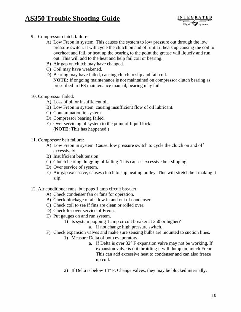
AS350 Trouble Shooting Guide
10
9. Compressor clutch failure:
A) Low Freon in system. This causes the system to low pressure out through the low pressure switch. It will cycle the clutch on and off until it heats up causing the coil to overheat and fail, or heat up the bearing to the point the grease will liquefy and run out. This will add to the heat and help fail coil or bearing.
B) Air gap on clutch may have changed. C) Coil may have weakened. D) Bearing may have failed, causing clutch to slip and fail coil.
NOTE: If ongoing maintenance is not maintained on compressor clutch bearing as prescribed in IFS maintenance manual, bearing may fail.
10. Compressor failed:
A) Loss of oil or insufficient oil. B) Low Freon in system, causing insufficient flow of oil lubricant. C) Contamination in system. D) Compressor bearing failed. E) Over servicing of system to the point of liquid lock.
(NOTE: This has happened.)
11. Compressor belt failure: A) Low Freon in system. Cause: low pressure switch to cycle the clutch on and off
excessively. B) Insufficient belt tension. C) Clutch bearing dragging of failing. This causes excessive belt slipping. D) Over service of system. E) Air gap excessive, causes clutch to slip heating pulley. This will stretch belt making it
slip.
12. Air conditioner runs, but pops 1 amp circuit breaker: A) Check condenser fan or fans for operation. B) Check blockage of air flow in and out of condenser. C) Check coil to see if fins are clean or rolled over. D) Check for over service of Freon. E) Put gauges on and run system.
1) Is system popping 1 amp circuit breaker at 350 or higher? a. If not change high pressure switch.
F) Check expansion valves and make sure sensing bulbs are mounted to suction lines. 1) Measure Delta of both evaporators.
a. If Delta is over 32° F expansion valve may not be working. If expansion valve is not throttling it will dump too much Freon. This can add excessive heat to condenser and can also freeze up coil.
2) If Delta is below 14° F. Change valves, they may be blocked internally.

AS350 Trouble Shooting Guide
11
13. Fresh air supply valve inoperable. EC130 B4 only A) If valve fails to open.
1) Check 2 ½ amp CB 2) Check for power at wire IFS 104V20
a. If power, check for power on wire IFS 104E20 1. If no power motor/controller is bad 2. If power trace back to source
b. If no power check continuity to Pin 1 on cannon plug CP101. c. If no continuity check low pressure switch for ON.
B) If valve fails to close 1) Check for power on wires at valve IFS 104V20 and IFS 104E20
a. If power, both motor /controller is bad. b. If no power on wire IFS 104V20.
a. Check 2 ½ amp CB. b. Check to see if low pressure switch is open. c. Check continuity from valve wire IFS 104V20 to Pin 1 on
cannon plug CP101.
NOTE: When running in “A/C” mode and you switch straight to “OFF” the Fresh Air Valve will stay in the closed position. You will need to switch to the “Fan” position to reset the Fresh Air valve to the open position.
14. Blower Motor Brush Inspection
A) Ø 5.0” Blower motors have brushes 13/16” long. Brushes should be inspected every 200 hours. When brushes wear down to 5/16”, replace them.
B) Ø 7.0” 2 Brush Blower motors have brushes 3/4” long. They should be inspected
every 300 hours. These brushes should be replaced at 1/2” or less.
C) Ø 7.0” 4 Brush Blower motors have brushes 9/16” long. They should be inspected
every 300 hours. These brushes should be replaced at 5/16” or less.

AS350 Trouble Shooting Guide
12
MANUFACTURERS NOTICE
THE BRUSHES IN THESE FAN MODELS ARE DESIGNED AND MANUFACTURED TO PROVIDE 500 HOURS OF SERVICE LIFE.
BRUSHES ARE A WEAR ITEM AND REQUIRE REGULAR INSPECTION AND MAINTENANCE! SINCE BRUSH LIFE VARIES GREATLY FOR EACH APPLICATION OR INSTALLATION, WE RECOMMEND INSPECTION AT REGULAR INTERVALS, SPECIFICALLY:
IN ORDER TO KEEP YOUR WARRANTY IN EFFECT FOR THE FULL TERM OF THE WARRANTY
A.) IFS PN: 050143 5” BLOWER MOTORS HAVE BRUSHES .75” LONG. BRUSHES MUST BE INSPECTED EVERY 200 HOURS AND REPLACED WHEN WEAR IS DOWN TO .30” OR LESS.
a. SEE CHART “C”. BRUSH PN: 050031
B.) IFS PN: 050084-6 7” - 2 BRUSH BLOWER MOTORS HAVE BRUSHES .90” LONG. BRUSHES MUST BE INSPECTED EVERY 300 HOURS AND REPLACED WHEN WEAR IS DOWN TO .40” OR LESS.
a. SEE CHART “D”. BRUSH PN: 050038
C.) IFS PN: 050084 7”- 4 BRUSH BLOWER MOTORS HAVE BRUSHES .60” LONG. BRUSHES MUST BE INSPECTED EVERY 300 HOURS AND REPLACED WHEN WEAR IS DOWN TO .25” OR LESS.
a. SEE CHART “A”. BRUSH PN: 420A-20
D.) IFS PN: 630000 7”- 4 BRUSH BLOWER MOTORS HAVE BRUSHES .53” LONG. BRUSHES MUST BE INSPECTED EVERY 300 HOURS AND REPLACED WHEN WEAR IS DOWN TO .25” OR LESS.
a. SEE CHART “B”. BRUSH PN: 610000-8
E.) IFS PN: 640000 7”- 4 BRUSH BLOWER MOTORS HAVE BRUSHES .53” LONG. BRUSHES MUST BE INSPECTED EVERY 300 HOURS AND REPLACED WHEN WEAR IS DOWN TO .25” OR LESS.
a. SEE CHART “B”. BRUSH PN: 610000-8
NOTICE
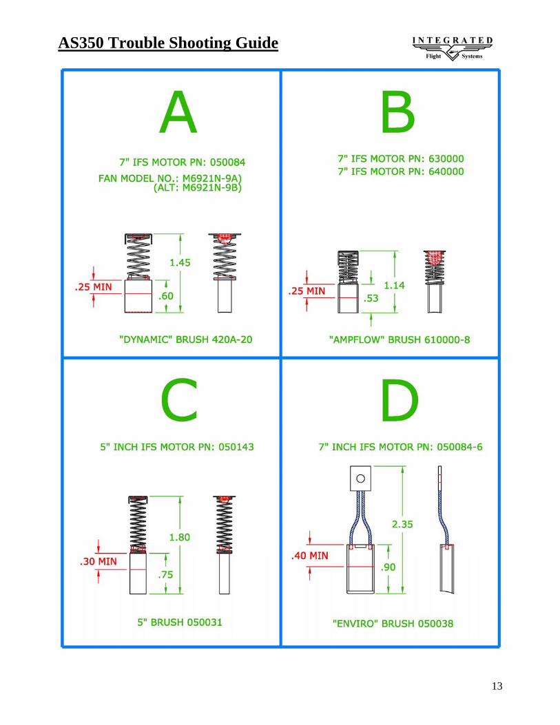
AS350 Trouble Shooting Guide
13

AS350 Trouble Shooting Guide
14

AS350 Trouble Shooting Guide
15
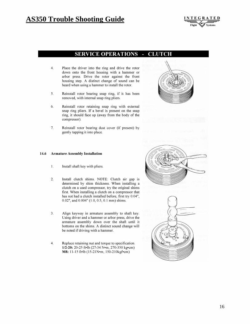
AS350 Trouble Shooting Guide
16

AS350 Trouble Shooting Guide
17