
Agilent G1888 Headspace Sampler Service Manual
302
Agilent Technologies Agilent G1888 Headspace Sampler Service Manual
-
Upload
khangminh22 -
Category
Documents
-
view
12 -
download
0
Transcript of Agilent G1888 Headspace Sampler Service Manual

Agilent G1888 Headspace Sampler
Service Manual
Agilent Technologies

Notices© Agilent Technologies, Inc. 2010
No part of this manual may be reproduced in any form or by any means (including electronic storage and retrieval or transla-tion into a foreign language) without prior agreement and written consent from Agi-lent Technologies, Inc. as governed by United States and international copyright laws.
Manual Part Number
G1888-90020
Edition
Second edition, August 2010
Printed in USA
Agilent Technologies, Inc. 2850 Centerville Road Wilmington, Delaware 19809
Warranty
The material contained in this document is provided “as is,” and is subject to being changed, without notice, in future edi-tions. Further, to the maximum extent per-mitted by applicable law, Agilent disclaims all warranties, either express or implied, with regard to this manual and any information contained herein, includ-ing but not limited to the implied warran-ties of merchantability and fitness for a particular purpose. Agilent shall not be liable for errors or for incidental or conse-quential damages in connection with the furnishing, use, or performance of this document or of any information contained herein. Should Agilent and the user have a separate written agreement with war-ranty terms covering the material in this document that conflict with these terms, the warranty terms in the separate agree-ment shall control.
Safety Notices
CAUTION
A CAUTION notice denotes a haz-ard. It calls attention to an operat-ing procedure, practice, or the like that, if not correctly performed or adhered to, could result in damage to the product or loss of important data. Do not proceed beyond a CAUTION notice until the indicated conditions are fully understood and met.
WARNING
A WARNING notice denotes a hazard. It calls attention to an operating procedure, practice, or the like that, if not correctly per-formed or adhered to, could result in personal injury or death. Do not proceed beyond a WARNING notice until the indicated condi-tions are fully understood and met.

Contents
1 Notices
G1888 Service Manual
Before Servicing the Headspace Sampler 18
Important safety warnings 18Safety and regulatory certifications 20Symbols 21Electromagnetic compatibility 22Sound emission certification for Federal Republic of Germany 22Tools required for service 23Fuses 23
2 Instrument Configuration
Overview 26
Cable Connections 27
Power cord 28Communication cables 28
Headspace Sampler to Gas Chromatograph Connection 31
EPC and MPC 31Common carrier gas connections 32Vial pressurization gas connection 32Headspace Sampler vent connection 33MPC connections 33EPC using 6850 and 6890 GCs 34EPC using 7890 GC 36Advantages and disadvantages of EPC vs. MPC 37
3 Vial Tray Components
Overview 40
Replacement Parts 41
Illustrated Parts Breakdown 47
Replacement Procedures 50
Tray/shutter drive assembly and tray chain 50Replace the tray chain and tray/shutter drive assembly 54
Alignment Procedures 56
3

4
Tray/shutter drive assembly 56Tray chain alignment 60First adjust the X axis–Tray/shutter drive assembly 67Adjust the Y axis–Tray position one sensor 68Optical vial sensor (Vial present sensor) 72
Advanced Functions 76
Chain homing 76Shutter opening 76Shutter closing 76Advancing the tray 76
4 Oven
Overview 78
Replacement Parts 79
Illustrated Parts Breakdown 90
Replacement Procedures 94
Accessing the components from the bottom panel 94Accessing carousel components 95Carousel sensor 96Oven fan motor 98Carousel stepper motor 100Lifter assemblies 104Carousel sensor disk 108Oven fan and carousel 110Oven band heater/oven thermoswitch 113
5 Pneumatics
Overview 118
Carrier and pressurization gas supplies 119Headspace Sampler states 120
Replacement Parts 123
Illustrated Parts Breakdown 137
Pneumatic compartment IPB 137Pneumatic compartment IPB 140Pneumatic tubing IPB 143
Replacement Procedures 146
Access pneumatics components 146Pneumatic tubing 149Sample loop 151Sample probe 152
G1888 Service Manual

G1888 Service Manual
Transfer line 1546-port valve 156Heaters 1576-port valve motor assembly 159
6 Electrical
Overview 162
Replacement Parts 165
Replacement Procedures 172
Tools 172General comments 172Measurements 172Accessing the components 173Transformer 178Temperature controllers 1 and 2 181Motor controllers 1 and 2 183Pressure sensor 186Processor 187Communications board 189
Operating Descriptions 191
Solenoid valve 191Tray 192Shutter 193Tray lifter 194Vial sensor 195Carousel 196Sampler probe lifter 197Solenoid valves 198Oven heated zone 199Loop heated zone 201Transfer line heated zone 202Pressure sensor 203
Cabling 204
PCA boards 204Power distribution 208Electrical schematic 210Electrical schematic 211
7 Firmware and Updating Firmware
Firmware Overview 214
Updating Firmware 215
5

6
Methods of updating main processor firmware 215Advanced function 5 215Agilent GC firmware update utility 217HyperTerminal 217Instrument Utilities 217
Recovering from Corrupt Installations 220
Recovering from the blue screen using Instrument Utilities 220Recovering from the blue screen using Hyperterminal 223
8 Error Messages
Overview 228
Errors With A Diagnostic Message 229
110 Oven Sensor Error 229111 Oven Sensor Error 229112 Oven Temp Error 229113 Oven Temp Error 229120 Loop Sensor Error 229121 Loop Sensor Error 229122 Loop Temp Error 229123 Loop Temp Error 229130 Transfer Line Sensor Error 230131 Transfer Line Sensor Error 230132 Transfer Line Temp Error 230133 Transfer Line Temp Error 230210 Tray Too Slow Error 230211 Tray Motor Encoder Error 230212 Tray Position 1 Error 230219 Tray Lock 231220 Shutter Error 231229 Shutter Lock 231230 Lifter 1 Error 231239 Lifter 1 Lock 231240 Lifter 2 Error 231249 Lifter 2 Lock 232250 Carousel Error 232259 Carousel Lock 232260 6-port Valve Error 232300 Pressure Error 232400 Power Error 232
Internal Communication Serial I/O Errors 233
510 Serial I/O Error 233520 Serial I/O Error 233
G1888 Service Manual

G1888 Service Manual
530 Serial I/O Error 233540 Serial I/O Error 233550 Serial I/O Error 233560 Serial I/O Error 233600 - 605 Serial I/O Error 233
Errors Without A Diagnostic Message 234
GC is not ready 234RAM error 234Vial not dropped 234Remove all vials 235Vial not found in oven 235Tray full! 235Temperature actual reads “open” or “short” 235Zone at or near ambient 235Zone does not stabilize 236Analysis aborted Oven Temp. Error 236Analysis aborted Loop Temp. Error 236Analysis aborted Tr.line Temp. Error 236
9 Troubleshooting
Tests Overview 238
Strife test 239Chain method test 240Checking the Headspace Sampler for leaks 240Headspace Sampler leak test 242Troubleshooting vent restrictions 253Troubleshooting leaks at fittings in standby mode 254Troubleshooting leaks at fittings in inject mode 255
Chromatographic Results 258
No peaks or reduced sensitivity 258Poor retention time reproducibility 259Poor area count repeatability 259Carryover in air or solvent blanks 260Unwanted background noise or peaks 260
Pressure Readings 261
GC goes not ready during a run 261GC pressure reading does not match Headspace Sampler pressure
reading 261
Synchronization with GC start 262
GC does not start 262Run is aborted 262
7

8
Communication with PC 263
To correct an invalid serial number 263Lantronix Cobox micro LED patterns 264Improving LAN communications 266
Memory and Processor Errors 269
Blank Display 269
Power ON, No Response / Instrument Dead 269
Vial Handling 269
Vial present sensor 269Tray position 1 sensor 270Optical alignment 270Carousel and lifter alignment 270Chain tensioning 270
MeOH Test 271
Troubleshooting Electronics 277
10 Parts
List of Consumable Parts 280
Ship Kit 283
Enhanced PM Kit 284
EPC Plumbing Kit 285
PM Kit with 1 -mL Loop 285
PM Kit with 3-mL Loop 286
Headspace Leak Test Kit 286
Power Cords 287
Fuses 287
Parts List 288
Index
G1888 Service Manual

List of FiguresFigure 1. Wrenches 7/8mm 23Figure 2. Connections on the back of the Headspace Sampler 26Figure 3. Common cabling configurations 27Figure 4. Cable connections 29Figure 5. Cable connection details 30Figure 6. EPC/MPC toggle switches 31Figure 7. MPC and EPC connections 31Figure 8. Carrier and vial pressure connections 33Figure 9. Plumbing MPC 34Figure 10. The auxiliary EPC module gas outlet block 35Figure 11. Connecting the Headspace Sampler to the auxiliary module 36Figure 12. Plumbing EPC to GC 36Figure 13. Headspace Sampler vial tray and keypad 40Figure 14. 0410105006 Vial present sensor assembly, discontinued replaced
with part shown in Figure 15 41Figure 15. 0410105106 Vial present sensor assembly (with spring) 41Figure 16. 0410105021 Shutter motor-sensor assembly 41Figure 17. 0410105019 Tray drive motor 42Figure 18. 6310103107 Tray/shutter drive assembly cover, old color
6310103126 Tray/shutter drive assembly cover, new color 42Figure 19. 2283000015 Belt, shutter drive 42Figure 20. 2283000016 Belt, tray drive 43Figure 21. 2181212004 Clip ring, tray chain pulley 43Figure 22. 0410205001 Tray chain link repair kit 43Figure 23. 2283500020 Pulley, tray chain 44Figure 24. 2285000001 Tray chain assembly 44Figure 25. 0410105022 Tray/shutter drive assembly,discontinued replaced
with part shown in Figure 26 44Figure 26. 0410105022 Tray/shutter drive assembly 45Figure 27. 0410105005 Insulation disk and retainer 45Figure 28. 6410216136 Pulley standoff 5.7 cm 45Figure 29. 6410216137 Tray pulley standoff 6.9 cm 45Figure 30. 0410105020 Tray position 1 sensor 46Figure 31. 0410205005 Tray cover, 3 pieces 46Figure 32. Tray motor group IPB 47Figure 33. 1400900029 Tray chain tensioning tool 50Figure 34. Tray/shutter drive assembly cover 51Figure 35. Tray covers 51Figure 36. Tray/shutter drive assembly ribbon cables 52Figure 37. Tensioning pulley 52Figure 38. Tray/shutter drive assembly removal 53Figure 39. Tray chain assembly 54
G1888 Service Manual 9

Figure 40. Tensioning tool 54Figure 41. Tray/shutter drive assembly 55Figure 42. The slotted disk and optical sensors 56Figure 43. Incorrect position of shutter belt 57Figure 44. Correct shutter belt tension 58Figure 45. Shutter motor-sensor assembly screws 58Figure 46. Bracket alignment hole 58Figure 47. Sensor disk 59Figure 48. Optical sensor open position 59Figure 49. G1888-80000 Optical alignment tools 60Figure 50. The orientation of the rulon optical tool 61Figure 51. The thermocouple cover secures the tool 62Figure 52. Plate to hold extended length rulon bushing 62Figure 53. Light source tool in the carousel 63Figure 54. Chain optical tool in the chain 63Figure 55. Location of chain notch and tool hole 63Figure 56. Marked sprocket position 64Figure 57. The cross hairs do not line up (parallax) 65Figure 58. The parallax is good, indicating your head position is correct 66Figure 59. X and Y directions for alignment corrections 66Figure 60. The location of the three tray/shutter drive assembly
screws 67Figure 61. The four base plate screws. 67Figure 62. X and Y directions for alignment corrections 68Figure 63. Screws that secure the tray position one sensor 69Figure 64. Vial sensor 72Figure 65. The center cover 73Figure 66. Old and new revisions of the optical vial sensor 74Figure 67. Slots in the tray chain links 75Figure 68. Vial sensor with spring and tray chain link 75Figure 69. Vial sensor screw and pivot point 75Figure 70. 0410105032 Top, oven enclosure 79Figure 71. 6310103026 Screen, oven fan 79Figure 72. 0410105029 Heater sensor assembly, oven 79Figure 73. 3700500902 Oven fan blades with setscrew 80Figure 74. 6310090035 Carousel, 12 position 80Figure 75. 6410216138 Shaft, carousel 80Figure 76. 6410302066 Bushing, carousel shaft top 81Figure 77. 6410204041 Collar, carousel 81Figure 78. 0410105013 Base, carousel compartment 81Figure 79. 0410105025 Base, carousel compartment with switch 82Figure 80. 3070000010 Thermoswitch, oven max temperature 82Figure 81. 0410205003 Standoff, oven fan 82Figure 82. 2195140001 Sleeve, carousel 82
10 G1888 Service Manual

Figure 83. 6410202002 Sleeve, ceramic lifter rod 83Figure 84. 2195140002 Spacer, oven heater block base 83Figure 85. 0410105027 Enclosure, oven 83Figure 86. 0410105033 Oven enclosure with carousel enclosure 84Figure 87. 6410216084 Base, oven enclosure 84Figure 88. 2180036007 Washer, carousel shaft bottom teflon 84Figure 89. 2180037001 Washer, carousel shaft top rulon 85Figure 90. 2283000006 Belt, carousel drive 85Figure 91. 0410105008 Disk, carousel sensor 85Figure 92. 3411500107 Carousel sensor 85Figure 94. 0410105028 Oven fan motor assembly 86Figure 93. 0221670000 Carousel stepper motor assembly 86Figure 95. 0410105002 Lifter assembly, sample probe 87Figure 96. 0410105003 Lifter assembly, tray 87Figure 97. 0410105030 Fan, vial cooling 88Figure 98. 3641500008 Relay, oven heater 88Figure 99. 0410105024 Lid assembly with oven enclosure top, old color
0410105124 Lid assembly with oven enclosure top, new color 88Figure 100. 0410105031 Frame, old color
0410105131 Frame, new color 89Figure 101. 0410205002 Latch, lid closure 89Figure 102. 301-019-HSP Lid lever lock 89Figure 103. IPB Oven and carousel 90Figure 104. The bottom cover 94Figure 105. The locking tabs for the lid 95Figure 106. Removing the carousel sensor 96Figure 107. Disk centered between carousal sensor 97Figure 108. Oven fan motor screws and cables 98Figure 109. Threaded posts for oven fan motor 99Figure 110. Motor shaft centered in the carousel shaft 99Figure 111. Parts included with the stepper motor 100Figure 112. Removing the stepper motor 101Figure 113. Toothed gear on carousel sensor disk (underside) 101Figure 114. Assembled spring 102Figure 115. Connector screws placed in the motor assembly 102Figure 116. Spring attached to the stepper motor arm 103Figure 117. The two lifter assemblies shown from the bottom of the
Headspace Sampler. 104Figure 118. The tray lifter assembly in the Headspace Sampler 106Figure 119. Orientation of the tray lifter assembly 106Figure 120. Screws securing the carousel sensor disk 108Figure 121. Pencil mark position 1 111Figure 122. Oven fan screen 111Figure 123. Fan blade setscrew 111
G1888 Service Manual 11

Figure 124. Carousel screws 112Figure 125. Three screws attaching carousel compartment and oven
enclosure base 113Figure 126. Oven thermoswitch and carousel compartment base 114Figure 127. Tighten the carousel screws 115Figure 128. Carrier and pressurization gas control in the HS 119Figure 129. State 1–Standby 120Figure 130. State 2–Pressurize the vial 121Figure 131. State 3–Fill the sample loop 121Figure 132. State 4–Loop equilibration 122Figure 133. State 5–Inject the sample 122Figure 134. 0410105016 Pneumatics compartment cover, old color
0410105116 Pneumatics comopartment cover, new color 123Figure 135. 1300502506 Tube, probe to 6-port valve deactivated 123Figure 136. 1300530005 Tube, switch to brass tee 123Figure 137. 1300530006 Tube, switch to flow controller 124Figure 138. 1300530007 Tube, switch to pressure regulator 124Figure 139. 1300530008 Tube, flow controller to bulkhead 124Figure 140. 1300530009 Tube, pressure regulator to bulkhead 125Figure 141. 1300530010 Tube, tee to pressure PCA 125Figure 142. 1300530011 Tube, tee to 6-port valve carrier 125Figure 143. 2321390008 Flow restrictor 126Figure 144. 1300530001 Tube, vent deactivated 126Figure 145. 1300530002 Tube, vial pressure valve to union 126Figure 146. 1300530004 Tube, switch to bulkhead 127Figure 147. 0410105017 Tubing, solenoids to 6-port, deactivated 127Figure 148. 0410105007 Pressure regulator with knob 127Figure 149. 0410105010 Flow controller with knob 128Figure 150. 0410105018 Switch, pneumatic mode 128Figure 151. 3600500001 Valve, solenoid vent kalrez 128Figure 152. 3600500002 Valve, solenoid vial pressurization 129Figure 153. 6550119125 Bracket, solenoid valves 129Figure 154. 2020403035, 2020402010, 2020403016 Pneumatic screws 129Figure 155. 9040700026 Valve, 6-port sampling 130Figure 156. 5104319115 Cable assembly, solenoid valves 130Figure 157. 6410090050 Strain relief septum nut 130Figure 158. 0410103101 Transferline deactivated 0.8 SILTEK 131Figure 159. 0410105014 Holder, transfer line 131Figure 160. 2322590004 Needle, transfer line deactivated OD 0.5 131Figure 161. 6410202015 Needle guide 132Figure 162. 6550209030 Sample probe holder 132Figure 163. 2322700011 Sample probe deactivated 132Figure 164. 9110509015 Heater block, loop 133Figure 165. 0410105009 Mandrel, loop holder with screw 133
12 G1888 Service Manual

Figure 166. 2321700003 Sample loop, 1 mL deactivated 133Figure 167. 2321700004 Sample loop, 3 mL deactivated 134Figure 168. 0410105036 Heater sensor assembly, loop 134Figure 169. 0410205004 Heater block, tube from probe 134Figure 170. 2302533140 M6 union, brass 135Figure 171. 2304533140 Tee, brass 135Figure 172. 2307230001 Union, zero dead volume, deactivated 135Figure 173. 2307833900 Bulkhead fitting 135Figure 174. 0410105004 Motor-sensor assembly, 6-port valve 136Figure 175. 0410105015 Cover, loop heated zone 136Figure 176. Pneumatics covering IPB 137Figure 177. Pneumatics compartment IPB 140Figure 178. Pneumatic tubing IPB 143Figure 179. Screws under lip of pneumatics cover 146Figure 180. Screws on left side of pneumatics cover 146Figure 181. Screws on right side of pneumatics cover 147Figure 182. Access to pressure transducers, tubing, and manual
regulators 147Figure 183. Screws to insulated cover of loop and valve heated zone 148Figure 184. Access to loop and valve heated zone 148Figure 185. Swagelok nuts and ferrules 149Figure 186. Assembling the fitting for a swagelok connection 149Figure 187. Insert the tubing for a swagelok connection 150Figure 188. Mark the fitting for a swagelok connection 150Figure 189. Final tightening for a swagelok connection 150Figure 190. Completed fitting for a swagelok connection 150Figure 191. Ports 1 and 4 on the 6-port sampling valve 151Figure 192. Location of the heater block and screw 152Figure 193. Location of the zero dead volume union and hexagonal
nut 153Figure 194. Removing the sampling probe 153Figure 195. Transfer line wires - sensor and heater 155Figure 196. Transfer line - side panel view 155Figure 197. Two bolts on 6-port valve 156Figure 198. Removing the loop heater sensor assembly 157Figure 199. Heater plug J1A and sensor wire plug J2A 158Figure 200. Terminal block 159Figure 201. 0410105012 Fan, power supply 165Figure 202. 0410105026 Transformer 165Figure 203. 0410105030 Fan, vial cooling 165Figure 204. 0410105034 Display keypad assembly, old color
0410105134 Display keypad assembly, new color 166Figure 205. 0410105035 Panel, power supply, old color
0410105135 Panel, power supply, new color 166
G1888 Service Manual 13

Figure 206. 0410105040 Communications board 166Figure 207. 3411500110 Power distribution plus 5 VDC 167Figure 208. 3411500111 Motor controller 1 167Figure 209. 3411500112 Motor controller 2 167Figure 210. 3411500113 Temperature controllers 1 and 2 168Figure 211. 3411500114 Processor board 168Figure 212. 3411500115 Pressure sensor board 168Figure 213. 3641500008 Relay, oven heater 169Figure 214. 3821019002 Switch, voltage selector 169Figure 215. 3840300011 Line filter 169Figure 216. 3856000004 Power supply, 24 VDC 170Figure 217. 5404020001 Line module 170Figure 218. 6550106033 Front panel old color / 6550106036 New
color 170Figure 219. 5104319115 Cable assembly, solenoid valves 170Figure 220. 5104319108 PCA power supply harness 171Figure 221. 5104309004 Control harness, ribbon cable 171Figure 222. 5104309005 Communications harness, ribbon cable 171Figure 223. The locking tabs for the lid 173Figure 224. The captive screws securing the front panel 173Figure 225. The lid raised and the front panel open 174Figure 226. Inside the front panel 174Figure 227. Accessing the PCAs inside the rear panel 175Figure 228. Inside the rear panel 175Figure 229. Screws under lip of pneumatics cover 176Figure 230. Screws on left side of pneumatics cover 176Figure 231. Screws on right side of pneumatics cover 176Figure 232. Inside the pneumatics compartment 177Figure 233. The transformer screws 178Figure 234. Two transformer screw holes accessible 179Figure 235. Removing the transformer board 179Figure 236. Placing the transformer in the Headspace Sampler 180Figure 237. Temperature controllers 1 and 2 182Figure 238. Motor controllers 1 and 2 184Figure 239. Motor controller 1 184Figure 240. Motor controller 2 185Figure 241. Pressure sensor board 186Figure 242. Processor board 188Figure 243. Screws attaching the communications board 189Figure 244. Communications board 190Figure 245. Solenoid valve wiring 191Figure 246. Tray function 192Figure 247. Shutter function 193Figure 248. Tray lifter function 194
14 G1888 Service Manual

Figure 249. Vial sensor function 195Figure 250. Carousel function 196Figure 251. Sampling probe lifter function 197Figure 252. Solenoid valves function 198Figure 253. Oven heated zone 199Figure 254. Loop heated zone 201Figure 255. Transfer line heated zone 202Figure 256. Pressure sensor function 203Figure 257. Cabling in front panel 204Figure 258. Ribbon cable connections inside front panel 205Figure 259. PCA Power wiring harness 206Figure 260. PCA Voltage and serial bus addresses 207Figure 261. 5 VDC supply and power distribution board fuses and
LEDs 208Figure 262. Power distribution 209Figure 263. Electrical schematic - part A 210Figure 264. Electrical schematic - part B 211Figure 265. Firmware display screens 214Figure 266. The advanced functions menu 215Figure 267. Update firmware with Advanced Function 5 216Figure 268. Carrier gas flow for leak test 241Figure 269. Tubing for restriction test 245Figure 270. Manual pressure control shutoff valves 245Figure 271. Electronic pneumatic control shutoff valves 246Figure 272. Change the pressure units to PSI 246Figure 273. Set source pressures to 30 PSI 247Figure 274. Disconnect the transfer line 247Figure 275. Leak test vial placement 247Figure 276. Start leak test 248Figure 277. Troubleshooting vent restrictions 253Figure 278. Troubleshooting leaks at fittings in standby mode 254Figure 279. Troubleshooting leaks at fittings in inject mode 255Figure 280. Flow path - standby 256Figure 281. Flow path - inject 257Figure 282. Lantronix cobox micro LED indicator 264Figure 283. The LAN card screws 267Figure 284. LAN card bracket screws 267Figure 285. Insulating the LAN card 268
G1888 Service Manual 15

16 G1888 Service Manual

Agilent G1888 HeadSpace SamplerService Manual
1Notices
Before Servicing the Headspace Sampler 18
Important safety warnings 18
Safety and regulatory certifications 20
Symbols 21
Electromagnetic compatibility 22
Sound emission certification for Federal Republic of Germany 22
Tools required for service 23
Fuses 23
17Agilent Technologies

1 Notices
Before Servicing the Headspace Sampler
Important safety warnings
18
There are several important safety notices that you should always keep in mind when using the Headspace Sampler (HS).
Dangerous Voltages
Many internal parts of the Headspace Sampler carry dangerous voltages.
If the HS is connected to a power source potentially dangerous voltages exist on:
• The wiring between the HS power cord, main switch, and the 24 volt power supply
• The power supply itself
• The wiring from the power supply to the voltage selector
• The wiring from the voltage selector to the transformer
• All electronics boards in the HS
• The internal wires and cables connected to these boards
• The wires for any heater (such as the oven)
To avoid a potential shock hazard when using liquid solution to locate leaks, turn the main power switch off and disconnect the main power cord. Be careful not to spill leak solution on electrical leads.
WARNING All these parts are shielded by covers. With the covers in place, it should be difficult to accidentally make contact with dangerous voltages. Unless specifically instructed to, never remove a cover unless the heated zones are turned off.
WARNING If the power cord insulation is frayed or worn, replace the cord.
G1888 Service Manual

Notices 1
G1888 Service Manual
Harmful Electrostatic Discharge
Electrostatic discharge is a threat to Headspace Sampler electronics.
The printed circuit (PCA) boards in the HS can be damaged by electrostatic discharge. If you must handle a board wear a grounded wrist strap and take other antistatic precautions. Wear a grounded wrist strap any time you must remove the electronics cover.
Hot Surfaces
Many parts of the HS operate at temperatures high enough to cause serious burns. These parts include but are not limited to:
• The carousel and its contents
• The sample probe/loop assembly
Always cool these areas of the HS to room temperature before working on them. They will cool faster if you first set the temperature of the heated zone to room temperature. Turn the zone off after it has reached the setpoint.
If you must perform maintenance on hot parts wear gloves.
Gases
• Do not use flammable carrier gases.
• Do not use hydrogen as a carrier gas in the Headspace Sampler. Hydrogen creates a potential explosion hazard due to the venting of gases during operation and “standby”.
• Wear eye protection when using compressed gas to avoid eye injury.
• Fasten all compressed gas cylinders securely to an immovable structure or permanent wall.
• Do not put gas cylinders in the path of a hot air vent (including a GC oven exhaust).
19

1 Notices
Safety and regulatory certifications
20
The Headspace Sampler conforms to the following safety standards:
• Canadian Standards Association (CSA): C22.2 No. 1010.1
• CSA/Nationally Recognized Test Laboratory (NRTL): UL 61010A–1
• International Electrotechnical Commission (IEC): 61010–1
• EuroNorm (EN): 61010–1
The Headspace Sampler conforms to the following regulations on Electromagnetic Compatibility (EMC) and Radio Frequency Interference (RFI):
• CISPR 11/EN 55011: Group 1, Class A
• IEC/EN 61326
• AUS/NZ
This ISM device complies with Canadian ICES-001. Cet appareil ISM est conforme a la norme NMB—001 du Canada.
The Headspace Sampler is designed and manufactured under a quality system registered to ISO 9001.
The Agilent Technologies Headspace Sampler meets the following IEC (International Electro-Technical Commission) classifications: Safety Class I, Transient Overvoltage Category II, Pollution Degree 2.
This unit has been designed and tested in accordance with recognized safety standards and is designed for use indoors. If the HS is used in a manner not specified by the manufacturer, the protection provided by the HS may be impaired. Whenever the safety protection of the Agilent Headspace Sampler has been compromised, disconnect the unit from all power sources and secure the unit against unintended operation. Refer servicing to qualified service personnel. Substituting parts or performing any unauthorized modification to the HS may result in a safety hazard.
G1888 Service Manual

Notices 1
Symbols
G1888 Service Manual
Warnings in the manual or on the Headspace Sampler must be observed during all phases of operation, service, and repair of this instrument. Failure to comply with these precautions violates safety standards of design and the intended use of the instrument. Agilent Technologies assumes no liability for the customer’s failure to comply with these requirements.
See accompanying instructions for more information
Indicates a hot surface.
Indicates hazardous voltages.
Indicates earth (ground) terminal.
Indicates potential explosion hazard.
Indicates radioactivity hazard.
Indicates electrostatic discharge hazard.
Indicates that you must not discard this electrical/electronic product in domestic household waste.
or
21

1 Notices
Electromagnetic compatibility
22
This device complies with the requirements of CISPR 11. Operation is subject to the following two conditions:
1 This device may not cause harmful interference.
2 This device must accept any interference received, including interference that may cause undesired operation.
If this equipment causes harmful interference to radio or television reception, which can be determined by turning the equipment off and on, the user is encouraged to try one or more of the following measures:
1 Relocate the radio or antenna.
2 Move the device away from the radio or television.
3 Plug the device into a different electrical outlet, so that the device and the radio or television are on separate electrical circuits.
4 Make sure that all peripheral devices are also certified.
5 Make sure that appropriate cables are used to connect the device to peripheral equipment.
6 Consult your equipment dealer, Agilent Technologies, or an experienced technician for assistance.
7 Changes or modifications not expressly approved by Agilent Technologies could void the user’s authority to operate the equipment.
Sound emission certification for Federal Republic of Germany
Sound pressure
Sound pressure Lp < 68 dB(A) according to DIN-EN 27779 (Type test).
Schalldruckpegel
Schalldruckpegel LP < 68 dB(A) nach DIN-EN 27779 (Typprufung).
G1888 Service Manual

Notices 1
Tools required for service
G1888 Service Manual
Small Phillips head screwdriver
Large Phillips head screwdriver
7x8 mm wrench 2 pieces 1340407010
6x7 mm wrench 2 pieces 1340407011
8x10 mm wrench 2 pieces 1340407012
Hex L wrench 2.5 mm 1341002500
Hex L wrench 3 mm 134120300
Alignment tools G1888-80000
Chain tensioning tool 1400900029
Figure 1 Wrenches 7/8mm
Fuses
See also Table 36, “Avaliable fuses for older models”,” on page 287.
Table 1 Fuses
Location Description Part number
F1 Power distribution PCA
Interchangeable bussmann 5 x 20 mm,Type: GMD D1A (T 1A 250 V), CSA
384-1595011-HSP
F3 and F4 Power distribution PCA
Interchangeable bussmann 5 x 20 mm,Type: GMD (F 6A 125 V), CSA
384-1295001-HSP
Main fuses on power switch
10 amp, fast acting, 250 V, 5x20 mm 5188-1157
Transformer fuse 8 amp, fast acting, 250 V, 5x20 mm 5188-1158
23

24
1 Notices
G1888 Service Manual

Agilent G1888 HeadSpace SamplerService Manual
2Instrument Configuration
Overview 26
Cable Connections 27
Power cord 28
Communication cables 28
Headspace Sampler to Gas Chromatograph Connection 31
EPC and MPC 31
Common carrier gas connections 32
Vial pressurization gas connection 32
Headspace Sampler vent connection 33
MPC connections 33
EPC using 6850 and 6890 GCs 34
EPC using 7890 GC 36
Advantages and disadvantages of EPC vs. MPC 37
25Agilent Technologies

2 Instrument Configuration
Overview
26
The transfer line from the Headspace Sampler (HS) can be connected to the GC inlet in two ways:
Using the needle For manual pressure control (MPC), a needle is connected to the end of the transfer line and inserted through the GC inlet septum. This allows rapid changeover between headspace sampling and manual or automatic liquid sampler (ALS) injections.
Direct connection For electronic pressure control (EPC), the HS transfer line is inserted into the carrier gas line by cutting the line from the GC gas control and the inlet. Fittings and additional tubing route the carrier gas to the sampler and then back, via the transfer line, to the inlet gas supply. This requires some cutting and connecting and complicates changeover, but allows the GC to control carrier gas flow through the sampler. It is best for dedicated use of a GC with a HS.
Transfer line
Power voltageselect
Vial pressurization in
Carrier gas in
Vent
LAN port
Power cord
Remote port
RS232 port
Pressure regulatormanual adjust
Flow controllermanual adjust
Power ON/OFFswitch
Figure 2 Connections on the back of the Headspace Sampler
G1888 Service Manual

Instrument Configuration 2
Cable Connections
G1888 Service Manual
The Headspace Sampler is used with a Gas Chromatograph, and often with a Chemstation, a printer, and other accessories. These instruments must be synchronized to function properly. Common cabling configurations are shown in Figure 3.
Workstation
Printer
Hub or switch
G1888A 6890/7890N
21
1 1
Workstation
Printer
Hub or switch
G1888A 6850
21
1 1
Local Talk
Local Talk
BNC
BNC
Workstation
Printer
0286A8881G
23
5 3
Workstation
Printer
Hub or switch
421
1 11
Cables
8121-0940, Cable, 7.5-m 100-BaseT LAN
G1530-60930, 2-m APG remote cable, 9-pin male to 9-pin male
1.
2.
G1530-60600, 2-m RS-232 cable, 9-pin female to 9-pin female
G1530-61200, 2-m APG Y-cable, two 9-pin male, one 9-pin female
8121-1013, USB-DB9 RS-232 adapter cable
3.
4.
5.
G1888A 6890/7890MSD
Figure 3 Common cabling configurations
27

2 Instrument Configuration
Power cord
28
The power cord is country dependant.
Power setting
The power selector switch is set to 230 VAC at the factory. Change it if necessary.
Failure to change the power cord / fuse pair could result in blown fuses or damage to the instrument.
Table 2 Power cords - country specific
Country Description Part number
Argentina 8120-6869
Australia/NZ C13, 10 amp 8120-1369
Chile C13, 10 amp 8120-6978
China C13, 10 amp 8121-0723
DK/Greenland C13, 10 amp 8120-3997
Europe C13, 10 amp 8120-1689
GB/HK/SG/MY C13, 10 amp 8120-8705
India/South Africa C13, 10 amp 8120-4211
Israel C13, 10 amp 8120-5182
Japan C15, 15 amp 8120-5342
Korea C13, 10 amp 8121-1226
Switzerland C13, 10 amp 8120-2104
US/CA/TW/TH C13, 13 amp 8120-1992
Communication cables
RS-232 and remote start/stop
Part numbers:
• G1530-60600, 2-m RS-232 (Included in ship kit page 283)
• G1530-60930 Remote start/stop cable (Included in ship kit page 283)
• G1530-61200 2-m APG Y-cable available for GC-MSD system A remote start/stop is required to start a GC or GC-MSD system.
G1888 Service Manual

Instrument Configuration 2
G1888 Service Manual
For 4890, 5890, 6820 systems RS-232 is required to use control software or the diagnostic utility.
LAN
Part number:
• 8121-0940 7.5-m 100-BaseT LAN cable
For 6850, 6890 and 7890 systems LAN is recommended to use control software or the diagnostic utility.
Figure 4 Cable connections
Remote
RS-232
LAN
Power
Power selectorswitch
Fuse door
connector
29

2 Instrument Configuration
Figure 5 Cable connection details
Port Settings
# Description
1 External ground
Remote Pin-out
2 Not used
3 Start. Low true
4 Not used
5 Not used
6 Not used
7 Ready. High true
8 Not used
9 Not used
1
5
3
6
7
9
# Description
1 DCD-1, Data carrier detect
2 RX-1, Receive data
3 TX-1, Transmit data
4 DRT-1, Data terminal ready
5 Signal ground
6 DSR-1, Data set ready
7 RTS-1, Request to send
8 CTS-1, Clear to send
9 RI-1, Ring Indicator
6
9
1
5
LED 1 GreenSerial communication channel 1ON indicates good connection to COBOX-LAN connector on the main processorPCA.Blinking indicates software communication.
LED 4 GreenNetwork statusON indicates connection to network device,such as, HUB, switch, or PC. Also ON ifRS-232 enabledOFF indicates not connected to networkdevice.
LED 2 RedDiagnostic LED which would indicate a
malfunction during operation.Normally OFF except during Power-On
self-test.
LED 3 YellowSerial communications channel 2
If RS-232 enabled, OFF.If LAN enabled, ON
High true,stable signalof +5 VDC
RS-232 Serial Pin-out
2
48
2
3
4
7
8
30 G1888 Service Manual

Instrument Configuration 2
Headspace Sampler to Gas Chromatograph Connection
EPC and MPC
G1888 Service Manual
The Headspace Sampler uses two gas flows, Carrier gas flow and Vial pressurization flow. These may be set independently for either Manual Pressure Control (MPC) or Electronic Pressure Control (EPC).
When a flow path is set for manual pressure control, it uses the manual flow or pressure controller built into the HS.
When a flow path is set for electronic pressure control, the GC electronically controls flow and pressure.
Toggle the flow mode between EPC and MPC using the switches under the lid (Figure 6). Carrier gas and vial pressurization gas do not have to be set to the same flow mode.
MPC
EPC
Carrier gas
Vial pressurization gas
Figure 6 EPC/MPC toggle switches
Four 1/8–inch Swagelok® bulkhead fittings are provided at the rear of the pneumatic compartment for connecting vial pressure and carrier gas lines. Two fittings are for MPC, and two fittings are for EPC.
Figure 7 MPC and EPC connections
31

32
2 Instrument Configuration
Common carrier gas connections
GC inlet with MPC from Headspace Sampler
If the Headspace Sampler uses MPC for the carrier gas, the transfer line connects to the GC inlet by a needle passing through the inlet septum. Attach a regulated source gas line to the connector marked Carrier MPC line, the upper left gas connector on the back of the G1888. See the “MPC connections” section in the G1888 Site Prep and Installation Guide.
Split/splitless inlet with EPC control or MMI
The GC inlet control channel supplies carrier gas to the Headspace Sampler. See the section titled “Direct connection from the transfer line to a split/splitless inlet” in the G1888 Site Prep and Installation Guide.
VI inlet with EPC control
The carrier gas from the GC EPC module is routed to the connector marked Carrier EPC line, the upper right gas connector on the back of the G1888. See the “VI inlet” section in the GC Maintenance Manual for more information.
Vial pressurization gas connection
The vial pressurization gas can be configured in 2 different ways.
Manual Pressure Control (MPC) from Headspace Sampler
Attach a regulated source gas line to the connector marked Vial Press MPC line, the lower left gas connector on the back of the G1888. See the “MPC connections” section in the G1888 Site Prep and Installation Guide.
Electronic pressure Control (EPC) from GC
Attach a gas line from one channel of the GC EPC module through a bleed weldment into the connector marked Vial Press EPC line, the lower middle gas connector on the back of the G1888. See the “EPC connections” section in the G1888 Site Prep and Installation Guide.
G1888 Service Manual

Instrument Configuration 2
Headspace Sampler vent connection
G1888 Service Manual
The vent connection can be configured in 2 different ways.
Direct to atmosphere
If the components of this gas are expected to be toxic or noxious, place the HS within a fume hood or attach a vent system, at atmospheric pressure, to the port on the HS. Use a 1/8-inch Swagelok fitting for the connection. See the “Venting Requirements” section in the G1888 Site Prep and Installation Guide.
Pneumatics Control Module (PCM) from GC 7890
The 7890 PCM provides constant pressure at the G1888 Headspace Sampler sample vial vent. Constant pressure at the vent improves run-to-run reproducibility in vapor phase component concentrations passed to the GC for quantitative analysis. See G3476-90011 for installation details.
MPC connections
If both the carrier gas and vial pressurization gas are MPC, install a T-fitting to the on/off valves. Run a line from a pressure-regulated gas source to the T-fitting as shown in Figure 8.
Figure 8 Carrier and vial pressure connections
Carrier gas in
Vial pressure
To pressureregulatedgas source
On/off valves
T-fitting
33

34
2 Instrument Configuration
If only one gas input fitting uses MPC, run a line from a pressure-regulated gas source directly to the on/off valve connected to the MPC gas input fitting.
Figure 9 Plumbing MPC
EPC using 6850 and 6890 GCs
See the “Installation” chapter in the Site Prep and Installation manual.
An Auxiliary gas channel in the GC supplies vial pressurization gas. The following steps describe installation for a 6890 GC with EPC control of headspace. The installation procedure is similar for a 6850 GC.
1 If the GC does not have an Auxiliary EPC module, install the G1940A Headspace Interface Kit. Follow the instructions provided with that kit.
2 Install the external HS interface kit (Part number G1888-60705) into the GC. Follow the procedure for installing onto a back-pressure regulated system.
3 Locate the block on the Auxiliary EPC module that connects the three gas outlet tubes for the auxiliary channels to the pneumatics module.
4 Remove the screw that holds the block to the pneumatics module. Pull the block free of the module and rotate it so that the frits are on top. See Figure 10.
G1888 Service Manual

Instrument Configuration 2
Aux 5
Aux 4
Aux 3
Aux 3
Aux 4
Aux 5
Frits
Outputs
G1888 Service Manual
Figure 10 The auxiliary EPC module gas outlet block
5 Choose a channel for the vial pressurization control. Remove that channel’s frit from the block. Remove the O-ring that seals the channel.
6 Place an O-ring on a zero-resistance brass tube frit (part number G1570-20540). Place the O-ring/frit combination in the block.
7 Reconnect the block to the pneumatics module. Tighten the screw.
8 Use tubing and Swagelok fittings to connect the appropriate Auxiliary module output, the bleed weldment, and the vial pressure fitting to the on/off valve on the back of the Headspace Sampler as shown in Figure 11. Do not disturb the brass end on the bleed weldment.
35

2 Instrument Configuration
Conn
Figure 11 Connecting the Headspace Sampler to the auxiliary module
Headspace Sampler
Vial pressure fitting
Bleed weldment
Brass end
To auxiliary module output
GC
36
Figure 12 Plumbing EPC to GC
EPC using 7890 GC
For detailed instructions see the 7890A GC to the G1888A Headspace Sampler manual part number G3476-90011.
The installation is similar to the 6850/6890 procedure except that the frits are in a different location.
1 Remove the pneumatics cover from the top of the GC.
2 Locate the EPC module for the HS.
3 Remove the tube to the selected channel (1 screw). This exposes the frit location.
G1888 Service Manual

Instrument Configuration 2
G1888 Service Manual
4 Inspect the frit location. It should have no frit at all or, if a frit is present, it must be an open tube.
5 Replace the frit if necessary or simply remove it and store it in a clean place.
6 The O-ring must be present. Reinstall the tube and secure with the screw.
Advantages and disadvantages of EPC vs. MPC
Table 3 Advantages and disadvantages of EPC vs. MPC
Inlet type
Carrier Vial pressurization
MPC EPC MPC EPC
All • User must measure flows and calculate split ratio.
• Setpoint not stored with GC method.
• Accurate EPC pressures and split ratios.
• Setpoints stored with GC method
• Less stable• Requires
adjustments• Easier to move
HSS to another GC without an Aux EPC module
• More stable• Easier to
transfer application to another system
• Setpoint saved with GC method
• Better for regulated customer
Volatiles • Best sensitivity• Smallest volume• Most inert
Split/splitless capillary
• More inert• Better sensitivity than
splice• Easy to remove and
replace with ALS
Cool on-column • Closest to a splitless injection mode
PTV • Potential for using concentration mode
37

38
2 Instrument Configuration
G1888 Service Manual
Agilent G1888 HeadSpace SamplerService Manual
3Vial Tray Components
Overview 40
Replacement Parts 41
Illustrated Parts Breakdown 47
Replacement Procedures 50
Tray/shutter drive assembly and tray chain 50
Replace the tray chain and tray/shutter drive assembly 54
Alignment Procedures 56
Tray/shutter drive assembly 56
Tray chain alignment 60
Optical vial sensor (Vial present sensor) 72
Advanced Functions 76
Chain homing 76
Shutter opening 76
Shutter closing 76
Advancing the tray 76
39Agilent Technologies

3 Vial Tray Components
Overview
40
The vial tray is located on top of the Headspace Sampler (HS) to the left of the oven. The tray contains a flexible tray chain composed of 70 links. Each link is a ring capable of holding a sample vial. The tray chain can more forward and backward along its path to deliver any sample vial to the carousel lifter. See Figure 13.
Figure 13 Headspace Sampler vial tray and keypad
The keypad on the front of the HS controls the tray chain position. Some service procedures require tray chain movement.
Dust, broken glass, and spills can cause enough resistance to reduce the life of the components and cause vial handling problems.
Over time, the following may occur:
• Tray chain may loosen causing vial not dropped errors.
• Tray motor and shutter motor drive belts may wear causing tray and shutter errors.
• Tray chain hinges may break causing tray errors.
There are 3 key adjustments to the tray compartment that should always be performed in this order:
1 Adjust tray chain tension.
2 Align the tray/shutter drive assembly.
3 Align the tray position 1 sensor.
Tray chain
Vial tray lifter(hidden beneath chain)
with vials
Sample vial tray
Keypad
G1888 Service Manual

Vial Tray Components 3
Replacement Parts
G1888 Service Manual
Headspace Samplers with serial numbers less than IT00604011 have grey external skins. Current HS models are white in color.
Figure 14 0410105006 Vial present sensor assembly, discontinued replaced with part shown in Figure 15
Figure 15 0410105106 Vial present sensor assembly (with spring)
Figure 16 0410105021 Shutter motor-sensor assembly
41

42
3 Vial Tray Components
Figure 17 0410105019 Tray drive motor
Figure 18 6310103107 Tray/shutter drive assembly cover, old color 6310103126 Tray/shutter drive assembly cover, new color
l
Figure 19 2283000015 Belt, shutter drive
Tray/shutter driveassembly cover
G1888 Service Manual

Vial Tray Components 3
G1888 Service Manual
Figure 20 2283000016 Belt, tray drive
Figure 21 2181212004 Clip ring, tray chain pulley
Figure 22 0410205001 Tray chain link repair kit
43

44
3 Vial Tray Components
Figure 23 2283500020 Pulley, tray chain
Figure 24 2285000001 Tray chain assembly
Figure 25 0410105022 Tray/shutter drive assembly,discontinued replaced with part shown in Figure 26
G1888 Service Manual

Vial Tray Components 3
G1888 Service Manual
Figure 26 0410105022 Tray/shutter drive assembly
Figure 27 0410105005 Insulation disk and retainer
Figure 28 6410216136 Pulley standoff 5.7 cm
Figure 29 6410216137 Tray pulley standoff 6.9 cm
45

46
3 Vial Tray Components
Figure 30 0410105020 Tray position 1 sensor
Figure 31 0410205005 Tray cover, 3 pieces
G1888 Service Manual

Vial Tray Components 3
Illustrated Parts Breakdown
Figure 32 Tray motor group IPB
18
40C
F
39
4546
10
44
43E
3335
383736
31F
9
14
30
2915
28
27
E
A
13
D23
24
17
22
21
20
2625
8C76
AB
5
4
3CBA
122
F
CB
F
D
41
CB
32
16
B
19
3442
1
11
47
G1888 Service Manual 47

48
3 Vial Tray Components
Table 4 Tray motor group
Description Part Number Qty
1 Motor-sensor assembly, shutterconsists of parts 2 through 10
0410105021 1
2 Stepper motor 1
3 Screw 3
4 8 cm x 10 cm aluminum bracket 1
5 Printed circuit assembly 1
6 Spacer 3
7 Flat washer 3
8 Nut 3
9 Disk 1
10 Pulley 1
11 Tray vial chain motor assemblyconsists of parts12 through 15
00410105019 1
12 Tray motor 1
13 Bracket 1
14 Pulley 1
15 Screw 2
16 PCA, tray position 1 sensor assemblyconsists of parts 17 through 18
0410105020 1
17 Optical sensor 1
18 Bracket 1
19 Tray shutter drive assemblyconsists of parts 20 through 41
0410105022 1
20 Screw 1
21 Axel 1
22 Spring clip 1
23 Spring clip 1
24 Top bracket 1
25 Screw 3
26 Toothed washer 3
27 Sprocket 2
G1888 Service Manual

Vial Tray Components 3
G1888 Service Manual
28 Pulley 1
29 Tray drive belt 2283000016 1
30 Screw 4
31 Screw 1
32 Shutter
33 Shutter drive belt 2283000015 1
34 Shutter insulation disk assemblyconsists of parts 35 through 38
0410105005 1
35 Insulation disk 1
36 Spring clamp 1
37 Flat washer 1
38 Nut 1
39 Nut 1
40 Bottom bracket 1
41 Spacer 4
42 PCA, vial present sensor assemblyconsists of parts 43 through 47
0410105106 1
43 Flat washer 2
44 Vial present sensor 1
45 Bracket 2
46 Nut 1
47 Spring 1
Table 5 Tray motor group associated screws and washers
Description Part Number Qty
A Screw 6
B Flat washer 7
C Toothed washer 10
D Screw 6
E Screw 4
F Screw 3
Table 4 Tray motor group (continued)
49
3 Vial Tray Components
Replacement Procedures
Tray/shutter drive assembly and tray chain
50
Required tools
6 mm open end wrench
Phillips screwdriver
Flat-blade screwdriver
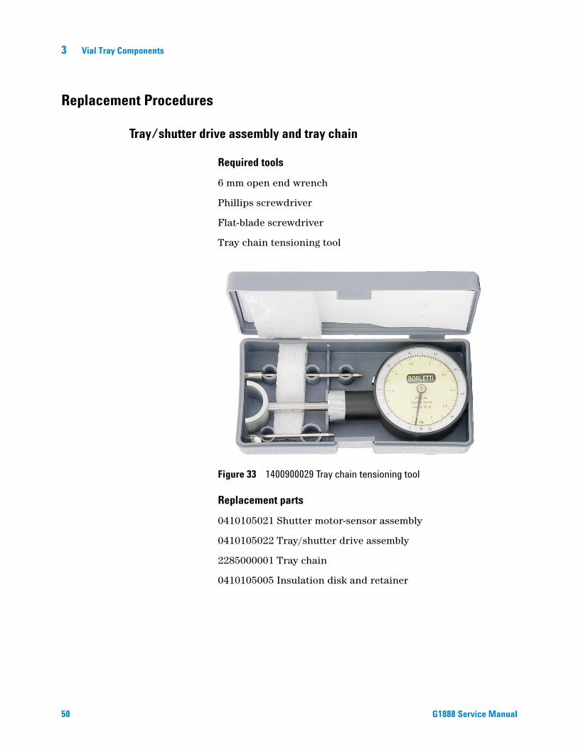
Tray chain tensioning tool
Figure 33 1400900029 Tray chain tensioning tool
Replacement parts
0410105021 Shutter motor-sensor assembly
0410105022 Tray/shutter drive assembly
2285000001 Tray chain
0410105005 Insulation disk and retainer
G1888 Service Manual

Vial Tray Components 3
G1888 Service Manual
Remove the tray/shutter drive assembly and tray chain
1 Pry the tray/shutter drive assembly cover off with a flat-blade screwdriver.
Figure 34 Tray/shutter drive assembly cover
2 Remove all screws (circled in Figure 35) fastening the three tray covers.
Figure 35 Tray covers
Tray/shutterdrive assemblycover
51

52
3 Vial Tray Components
3 Remove the ribbon cables from the tray/shutter drive assembly.
Figure 36 Tray/shutter drive assembly ribbon cables
Remove cables
4 Use a 6 mm wrench to loosen the tensioning pulley shown in Figure 37.
Figure 37 Tensioning pulley
Tensioning pulley
G1888 Service Manual

Vial Tray Components 3
G1888 Service Manual
5 Remove the 3 screws* (circled in Figure 38) and lock washers. Remove the tray/shutter drive assembly. * There are 4 screws on the new tray/shutter drive assembly.
Figure 38 Tray/shutter drive assembly removal
6 Do not disassemble this component. Clean off any dust or dirt from the assembly, especially the four optical sensors: position 1 sensor, vial sensor, and two shutter sensors.
7 Carefully remove the tray chain assembly using both hands.
53
3 Vial Tray Components
Replace the tray chain and tray/shutter drive assembly
54
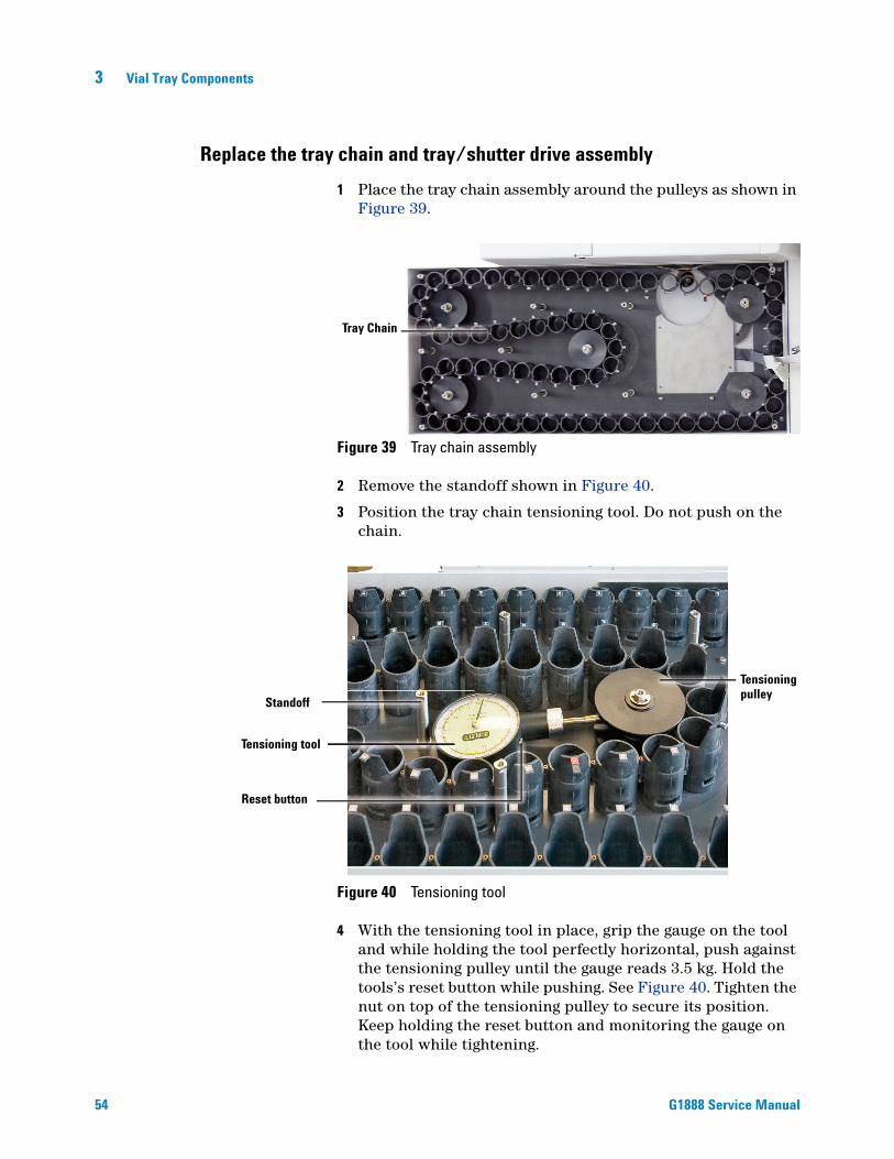
1 Place the tray chain assembly around the pulleys as shown in Figure 39.
Figure 39 Tray chain assembly
2 Remove the standoff shown in Figure 40.
3 Position the tray chain tensioning tool. Do not push on the chain.
Tray Chain
Reset button
Tensioningpulley
Tensioning tool
Standoff
Figure 40 Tensioning tool
4 With the tensioning tool in place, grip the gauge on the tool
and while holding the tool perfectly horizontal, push against the tensioning pulley until the gauge reads 3.5 kg. Hold the tools’s reset button while pushing. See Figure 40. Tighten the nut on top of the tensioning pulley to secure its position. Keep holding the reset button and monitoring the gauge on the tool while tightening.G1888 Service Manual

Vial Tray Components 3
G1888 Service Manual
5 Replace the standoff that was removed in step 2.
6 Replace the insulation disk. If the retaining spring appears bent or does not hold the disk on the pin, replace the spring.
7 If the belts for the tray and shutter drives are worn, ask the customer to consider replacing the tray/shutter drive assembly.
8 Align the “Tray/shutter drive assembly”, see page 56.
9 Place the tray/shutter drive assembly in position on the tray as shown in Figure 41.
10 Secure the tray/shutter drive assembly using screws and lock washers. See Figure 38.
Tray/shutterdrive assembly
Figure 41 Tray/shutter drive assembly
11 Replace the ribbon cables. See Figure 36.
12 Align the assembly with the optical alignment tools. See “Tray chain alignment” on page 60.
13 Place the tray covers back on the HS. Install and tighten all screws on the cover.
14 Run the strife test with vials to make sure the vials can be delivered to and from the HS oven. See “Strife test” on page 239.
15 Select Clear to end the test.
55
3 Vial Tray Components
Alignment Procedures
Tray/shutter drive assembly
56
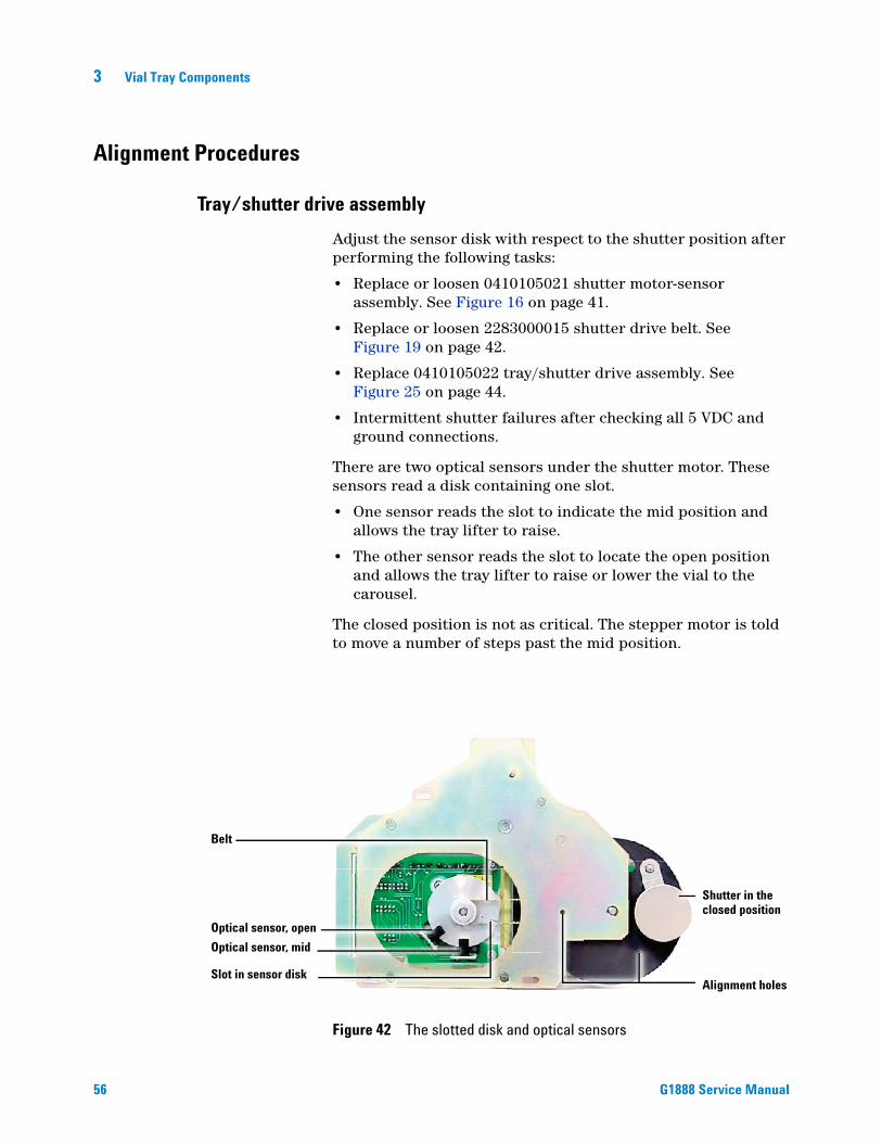
Adjust the sensor disk with respect to the shutter position after performing the following tasks:
• Replace or loosen 0410105021 shutter motor-sensor assembly. See Figure 16 on page 41.
• Replace or loosen 2283000015 shutter drive belt. See Figure 19 on page 42.
• Replace 0410105022 tray/shutter drive assembly. See Figure 25 on page 44.
• Intermittent shutter failures after checking all 5 VDC and ground connections.
There are two optical sensors under the shutter motor. These sensors read a disk containing one slot.
• One sensor reads the slot to indicate the mid position and allows the tray lifter to raise.
• The other sensor reads the slot to locate the open position and allows the tray lifter to raise or lower the vial to the carousel.
The closed position is not as critical. The stepper motor is told to move a number of steps past the mid position.
Optical sensor, open
Optical sensor, mid
Belt
Slot in sensor diskAlignment holes
Shutter in theclosed position
Figure 42 The slotted disk and optical sensors
G1888 Service Manual

Vial Tray Components 3
G1888 Service Manual
Required tools
No. 1 Phillips screwdriver with narrow handle
2.5 mm allen wrench
Replacement parts
0410105021 Shutter motor-sensor assembly
2283000015 Shutter drive belt
0410105022 Tray/shutter drive assembly
Align the tray/shutter drive assembly
This procedure assumes that you have removed the tray/shutter drive assembly from the Headspace Sampler. See “Remove the tray/shutter drive assembly and tray chain” on page 51 if needed. When installing this assembly check the belt tension, align the tray/shutter drive assembly, and align the position 1 sensor, as described here.
1 Inspect the shutter belt. Make sure it is properly fitted on both pulleys.
Figure 43 Incorrect position of shutter belt
2 Press on the belt to check the tension. It should be tight enough to hold the belt to the gear teeth without putting strain on motor axle. If the tension needs adjustment, loosen the three screws shown in Figure 45 and slide the shutter motor-sensor assembly as needed. Tighten the screws when finished.
Improper fit on pulley
57

58
3 Vial Tray Components
Figure 44 Correct shutter belt tension
Figure 45 Shutter motor-sensor assembly screws
3 Align the holes in the shutter and bracket. Place a 2.5-mm allen wrench or piece of 1/16-inch tubing through both the hole shown here and the hole in the disk shown in Figure 42.
Figure 46 Bracket alignment hole
Alignment hole
G1888 Service Manual

Vial Tray Components 3
G1888 Service Manual
4 Find the screw that holds the sensor disk to the pulley axle. Loosen the screw. Keep the screwdriver in this location.
Figure 47 Sensor disk
5 Align the sensor disk slot under the optical sensor for the open position. Note that there is a hole in the disk at the same radius. Tighten the pulley axle screw.
6 To verify the alignment, reassemble the tray components, make any other adjustments and run the strife test. See “Strife test” on page 239.
Figure 48 Optical sensor open position
59

3 Vial Tray Components
Tray chain alignment
60
Before performing this procedure, the Headspace Sampler with carousel/oven group must already be aligned.
Required tools
Phillips screwdriver
Replacement batteries for the light source tool
G1888-80000 Optical alignment tools
Light source
Rulon optical tool
Chain optical tool
Rulon optical tool
Magnifying lens
holder plate
Figure 49 G1888-80000 Optical alignment tools
Replacement parts
Not required.
Align the tray chain
There are four procedures required to align the tray chain:
1 Prepare the HS and position the optical alignment tools.
2 Align the chain with the optical tool.
3 Make alignment corrections.
4 Verify the alignment using the optical tool.
G1888 Service Manual

Vial Tray Components 3
G1888 Service Manual
Procedure 1: Prepare the Headspace Sampler and position the optical alignment tools
1 The HS must have the carousel and oven group already aligned. Check that the lifters are aligned with the carousel and that the carousel is aligned with the rulon bushing.
2 Remove the tray/shutter drive assembly cover. See Figure 34 on page 51.
3 Remove the screws and the center cover. See Figure 65 on page 73.
4 Make sure the tray/shutter drive assembly screws are tight. See Figure 38 on page 53 for the screw locations.
5 Turn the HS on. Turn off the heated zones by going into active method > heated zones. Scroll to each zone and Press 0 then Enter. Wait until the HS completes homing.
6 Wait until the temperature of the oven and sample port is less than 50°C.
7 Install the rulon optical tool in the rulon bushing. The rulon optical tool contains a dot on one surface. The dot faces upwards into the rulon bushing as shown in Figure 50.
Figure 50 The orientation of the rulon optical tool
Dot
61

62
3 Vial Tray Components
8 Secure the rulon optical tool with the thermocouple cover as shown in Figure 51. If the rulon bushing is longer than the plate see step 9. If the rulon bushing is secure, go to step 10.
9 If an extended length rulon bushing is installed, use the plate that is included in the alignment kit to hold the rulon optical tool. See Figure 52. Place a piece of paper over the carousel so that the screw does not fall into the oven.
Figure 52 Plate to hold extended length rulon bushing
Figure 51 The thermocouple cover secures the tool
Extended-length
rulon bushing
Rulon optical toolholder plate
G1888 Service Manual
Vial Tray Components 3
G1888 Service Manual
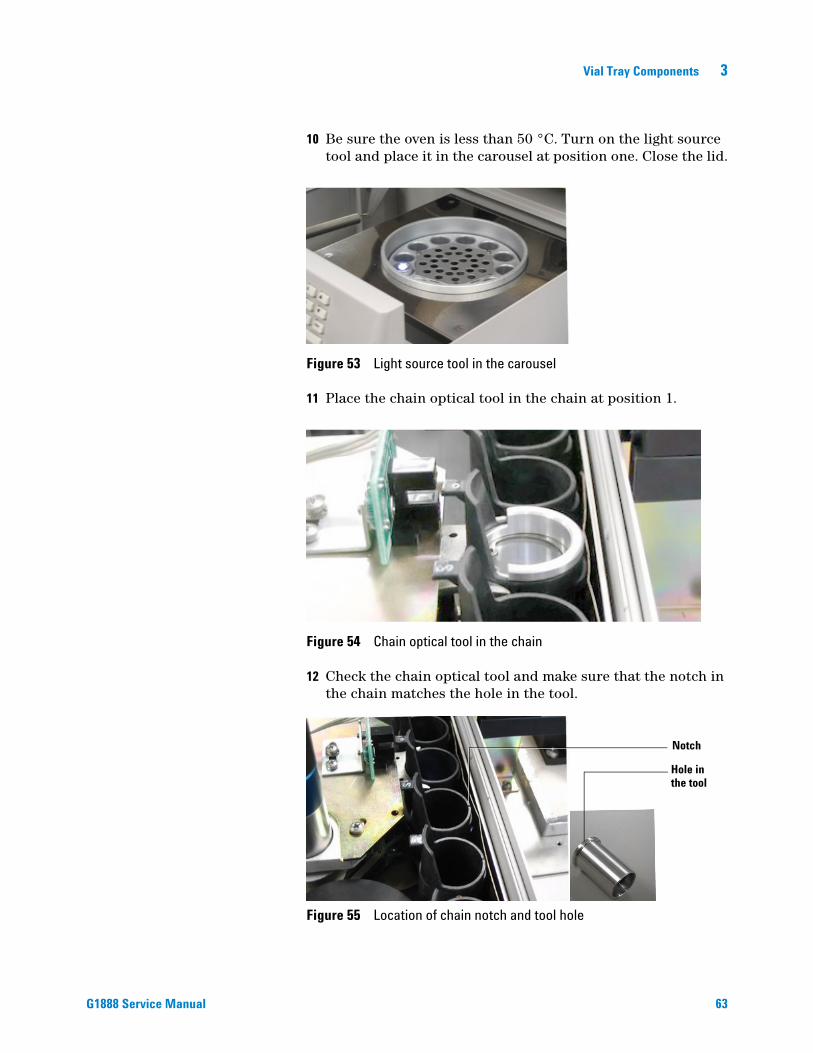
10 Be sure the oven is less than 50 °C. Turn on the light source tool and place it in the carousel at position one. Close the lid.
Figure 53 Light source tool in the carousel
11 Place the chain optical tool in the chain at position 1.
Figure 54 Chain optical tool in the chain
12 Check the chain optical tool and make sure that the notch in the chain matches the hole in the tool.
Figure 55 Location of chain notch and tool hole
Notch
Hole inthe tool
63

64
3 Vial Tray Components
13 Use a reference sprocket position. Mark a sprocket position with a marker. Perform the Y and X alignment with the tray link in this sprocket. After aligning, check the alignment in each sprocket position.
Figure 56 Marked sprocket position
14 Make sure that the shutter is closed. See page 76.
15 Home the chain. See page 76.
16 Open the shutter to mid position. See page 76.
Marked sprocketposition
G1888 Service Manual

Vial Tray Components 3
G1888 Service Manual
Procedure 2: Align the chain with the optical tool
The optical tool is directly above the rulon tool. If the chain alignment is correct, the dot on the surface of the rulon tool appears in the center of the concentric circles on the lens of the optical tool.
The optical tool contains two sets of cross hairs, one on the top lens and one on the bottom lens. These cross hairs are used to align your vision directly down the center of the tool.
1 Look through the optical tool. Move your head until the cross hairs line up in the center. Note the position of the dot.
Figure 57 shows cross hairs out of alignment indicating that even though the dot is in the middle circle your vision is not directed down the center of the optic tool.
Figure 57 The cross hairs do not line up (parallax)
65

66
3 Vial Tray Components
Figure 58 shows correct cross hair alignment. The dot shows alignment is out in both the X and Y axis.
2 If the dot is within the center circle go to “Procedure 4: Verify the alignment through the optical tool” on page 70. If the dot is not inside the center circle continue to “Procedure 3: Make alignment corrections” on page 66.
Procedure 3: Make alignment corrections
1 If the dot needs to be moved left or right to be in the middle circle, adjust the X (Tray/shutter drive assembly).
Figure 59 X and Y directions for alignment corrections
Figure 58 The parallax is good, indicating your head position is correct
Y direction
X direction
G1888 Service Manual

Vial Tray Components 3
G1888 Service Manual
2 If the dot needs to be moved front or back to be in the middle circle, adjust the Y (position 1 sensor).
3 In many cases both X and Y need to be aligned. Adjust the X axis first. If the chain is not out of alignment in the X direction go to “Adjust the Y axis–Tray position one sensor” on page 68.
First adjust the X axis–Tray/shutter drive assembly
If the chain is out of alignment in the X direction:1 Loosen the three screws that secure the tray/shutter drive assembly as shown in Figure 60. New hardware revisions have four screws. Adjust the left to right position of the tray/shutter drive assembly to minimize the error in the X direction.
2 If the tray base plate is interfering with the shutter, perform steps 3 and 4.
3 Loosen the four screws attaching the black tray base plate. See Figure 61. The figure shows the tray with the tray/shutter drive assembly removed for a better view of the screws, but you do not remove the tray/shutter drive assembly for this procedure.
Figure 61 The four base plate screws.
Figure 60 The location of the three tray/shutter drive assembly screws
67

68
3 Vial Tray Components
4 Move the base plate in the direction of the sample port. Tighten the base plate screws.
5 Adjust the tray/shutter drive assembly in the X direction and tighten the screws.
6 Check for interference between the base plate and the shutter. If the interference still exists repeat steps 1 through step 6.
CAUTION It is important that the shutter has clearance on all sides. Check that you can see light on all edges of the shutter.
7 To recheck the alignment go to “Procedure 4: Verify the alignment through the optical tool” on page 70.
Adjust the Y axis–Tray position one sensor
If the chain is out of alignment in the Y direction:
Figure 62 X and Y directions for alignment corrections
1 Open the shutter. See page 76.
2 Loosen the two screws on the “tray position-one” sensor and move the sensor in the “Y” direction.
3 Advance the tray one position forward and then one position back.
4 Check if the Y axis is aligned using the optical alignment tool.
5 If the Y axis is not aligned, repeat steps 2 through 4.
Y direction
X direction
G1888 Service Manual

Vial Tray Components 3
G1888 Service Manual
Figure 63 Screws that secure the tray position one sensor
6 When the dot is aligned on the X axis (Y=0) tighten the screws on the “tray position one” sensor.
7 Do a final alignment check. Go to “Procedure 4: Verify the alignment through the optical tool” on page 70.
69

70
3 Vial Tray Components
Procedure 4: Verify the alignment through the optical tool
1 Close the shutter. See page 76.
2 Home the chain. See page 76.
3 Open the shutter at least half way. See page 76.
4 Observe the dot in the optical tool with the cross hairs aligned.
X and Y both need adjustment. See “Procedure 3: Make alignment corrections” on page 66.
The HS is aligned in the Y direction. X needs adjustment. See “First adjust the X axis–Tray/shutter drive assembly” on page 67.
The HS is aligned in the Y direction. X needs adjustment. See “First adjust the X axis–Tray/shutter drive assembly” on page 67.
The HS is aligned in the X direction. Y needs adjustment. See “Adjust the Y axis–Tray position one sensor” on page 68.
G1888 Service Manual

Vial Tray Components 3
G1888 Service Manual
5 Close the shutter. See page 76.
6 Check to make sure the tray/shutter drive assembly, position 1 sensor, and base plate screws are tight.
7 Rotate the chain three full revolutions. This will put the chain back at home with the mark at position 1.
8 Check the alignment with the optical tool one final time.
9 Check that the tray lifter does not hit the shutter. To do this, open the shutter to mid position, raise the tray lifter.
10 Make sure that the tray chain link sits correctly in the tray motor group sprocket.
11 Check the alignment in each HS sprocket position. Check this by viewing the alignment of vial position 1, rotate the tray chain, check the alignment. Repeat this step three times. If the alignment changes in different sprocket positions, the tray motor group assembly needs to be replaced.
12 Remove all of the alignment tools.
13 Replace the tray cover and the tray/shutter drive assembly cover.
This completes the chain alignment procedure.
71

3 Vial Tray Components
Optical vial sensor (Vial present sensor)
72
There is an optical sensor at the base of the tray drive sprocket that senses the presence of a vial. The sensor senses the reflective surface of the vial through a slot in the tray chain links. The sensor looks for a vial just before and after a vial is delivered to or returned from the carousel.
Adjust the optical vial sensor after replacing this sensor.
Required tools
No. 1 Phillips screwdriver
Headspace vial
Volt meter with small probes
Replacement part
0410105106 Vial present sensor assembly
Figure 64 Vial sensor
G1888 Service Manual
Vial Tray Components 3
G1888 Service Manual
Align the optical vial sensor
1 Power ON the HS. Place a vial in tray position 1.
2 Remove the tray/shutter drive assembly cover. See Figure 34 on page 51.
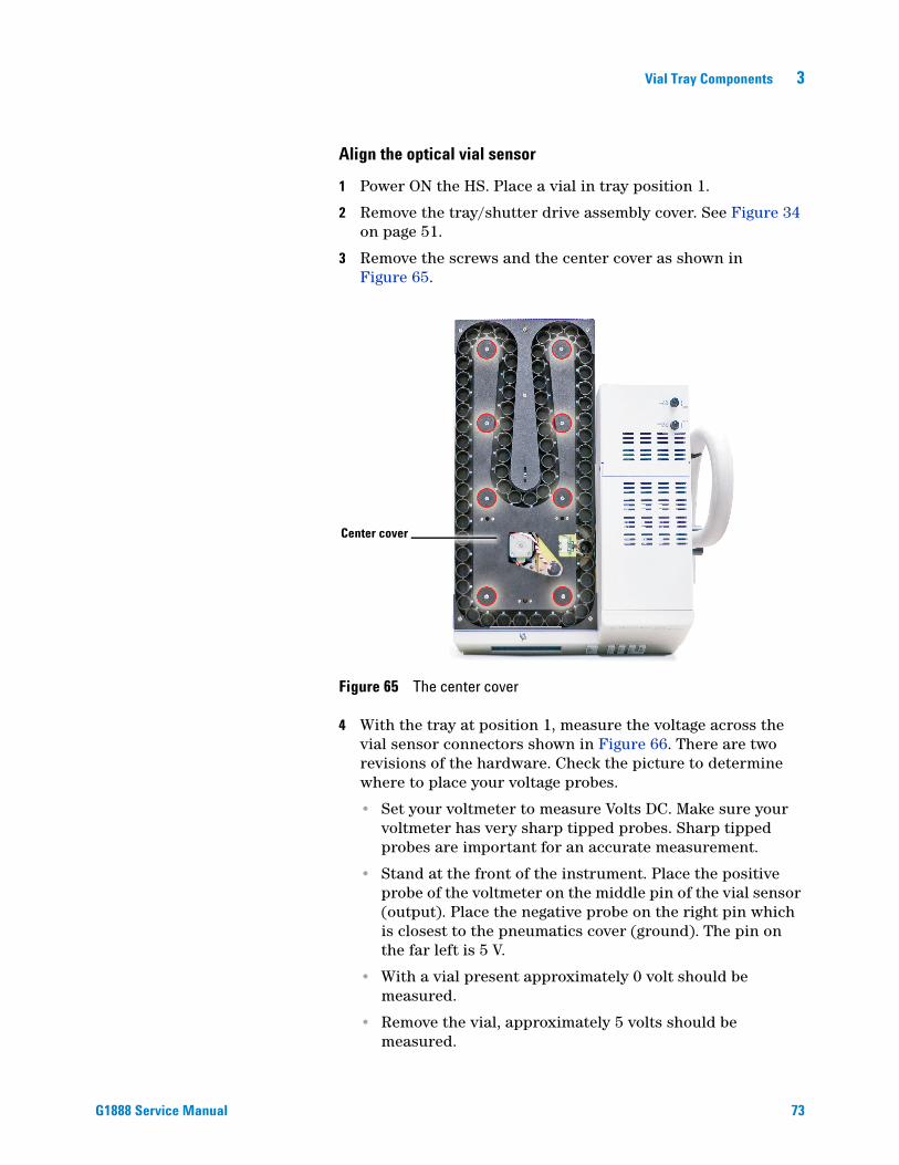
3 Remove the screws and the center cover as shown in Figure 65.
Figure 65 The center cover
4 With the tray at position 1, measure the voltage across the vial sensor connectors shown in Figure 66. There are two revisions of the hardware. Check the picture to determine where to place your voltage probes.
• Set your voltmeter to measure Volts DC. Make sure your voltmeter has very sharp tipped probes. Sharp tipped probes are important for an accurate measurement.
• Stand at the front of the instrument. Place the positive probe of the voltmeter on the middle pin of the vial sensor (output). Place the negative probe on the right pin which is closest to the pneumatics cover (ground). The pin on the far left is 5 V.
• With a vial present approximately 0 volt should be measured.
• Remove the vial, approximately 5 volts should be measured.
Center cover
73

3 Vial Tray Components
Figure 66 Old and new revisions of the optical vial sensor
Tray position 1Tray position 1
Vial sensor
Vial sensor
Old revision sensorNew revision sensor
Center pin is OutputRight pin is Ground
74
5 Check that the optical vial sensor is aligned with the slot in the tray chain link. See Figure 67 and Figure 68. If the slot is too high or low, adjust the bracket height. If the slot needs to be closer or farther away, adjust the piviot point.
• To adjust the bracket height, tighten the nut at the pivot point until the bottom of the bracket touches the top of the spring. See Figure 68.
• To adjust the pivot point, loosen the screw shown and pivot the vial sensor. When the vial sensor detects the vial, tighten the screw to secure the position of the sensor. See Figure 69.
G1888 Service Manual

Vial Tray Components 3
G1888 Service Manual
Figure 67 Slots in the tray chain links
Figure 68 Vial sensor with spring and tray chain link
Figure 69 Vial sensor screw and pivot point
Slot in link
Tray chain link
Vial present sensor
Spring
Slot in link
LoosenPivot point/nut
75

3 Vial Tray Components
Advanced Functions
Chain homing
76
1 From the main screen press Menu then ↑ repeatedly until the screen highlights advanced functions.
2 Press Enter > 5, then ↓ repeatedly until the screen highlights Tray.
3 Press 1 and then 5.
Shutter opening
1 From the main screen press Menu then ↑ repeatedly until the screen highlights advanced functions.
2 Press Enter > 5, then ↓ repeatedly until the screen highlights Shutter.
3 Press 1 to open to mid position. Press 1 again to open to full position.
Shutter closing
1 From the main screen press Menu then ↑ repeatedly until the screen highlights advanced functions.
2 Press Enter > 5, then ↓ repeatedly until the screen highlights Shutter.
3 Press 0 to close to mid position. Press 0 again to close completely.
Advancing the tray
1 From the main screen press Menu then ↑ repeatedly until the screen highlights advanced functions.
2 Press Enter > 5, then ↓ repeatedly until the screen highlights Tray.
3 Press 1 to advance forward, 0 to go backward.
4 To rotate the tray press 1 and then 5.
G1888 Service Manual

Agilent G1888 HeadSpace SamplerService Manual
4Oven
Overview 78
Replacement Parts 79
Illustrated Parts Breakdown 90
Replacement Procedures 94
Accessing the components from the bottom panel 94
Accessing carousel components 95
Carousel sensor 96
Oven fan motor 98
Carousel stepper motor 100
Lifter assemblies 104
Carousel sensor disk 108
Oven fan and carousel 110
Oven band heater/oven thermoswitch 113
77Agilent Technologies
4 Oven
Overview
78
The vial oven is where the vials heat during thermal and chemical stabilization. The setpoint temperature range is 40 °C to 230 °C.
The oven contains a circular aluminum sample carousel that holds twelve 10-mL or 20-mL sample vials. Sample vials are transferred from the chain on top of the Headspace Sampler (HS) to the heated carousel inside the oven to equilibrate before sampling.
A resistance band heater heats the oven. A fan in the center of the carousel circulates the air to maintain uniform temperature. The carousel can shake at two speeds to help components achieve an equilibrium between volatiles in the sample and volatiles in the empty space above it quicker. Mechanical rods move vials down into the oven and up to the sample probe needle for extraction.
G1888 Service Manual

Oven 4
Replacement Parts
G1888 Service Manual
Headspace Samplers with serial numbers less than IT00604011 have grey external skins. Current HS models are white in color.
Figure 70 0410105032 Top, oven enclosure
Figure 71 6310103026 Screen, oven fan
Figure 72 0410105029 Heater sensor assembly, oven
79
80
4 Oven
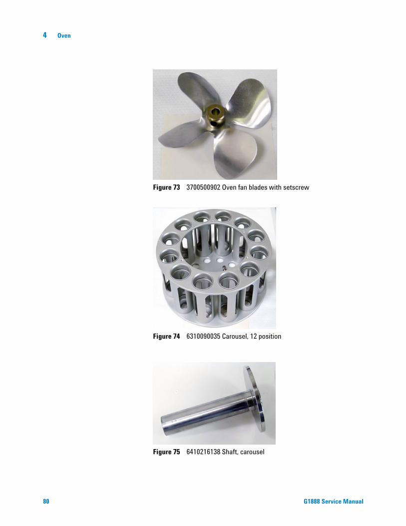
Figure 73 3700500902 Oven fan blades with setscrew
Figure 74 6310090035 Carousel, 12 position
Figure 75 6410216138 Shaft, carousel
G1888 Service Manual

Oven 4
G1888 Service Manual
Figure 76 6410302066 Bushing, carousel shaft top
Figure 77 6410204041 Collar, carousel
Figure 78 0410105013 Base, carousel compartment
81

82
4 Oven
l
Figure 79 0410105025 Base, carousel compartment with switch
Figure 80 3070000010 Thermoswitch, oven max temperature
Figure 81 0410205003 Standoff, oven fan
Figure 82 2195140001 Sleeve, carousel
G1888 Service Manual

Oven 4
G1888 Service Manual
Figure 83 6410202002 Sleeve, ceramic lifter rod
Figure 84 2195140002 Spacer, oven heater block base
Figure 85 0410105027 Enclosure, oven
83

84
4 Oven
Figure 86 0410105033 Oven enclosure with carousel enclosure
Figure 87 6410216084 Base, oven enclosure
Figure 88 2180036007 Washer, carousel shaft bottom teflon
G1888 Service Manual
Oven 4
G1888 Service Manual
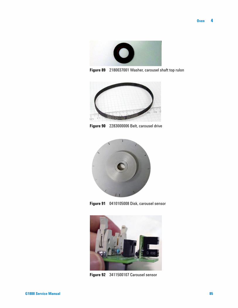
Figure 89 2180037001 Washer, carousel shaft top rulon
Figure 90 2283000006 Belt, carousel drive
Figure 91 0410105008 Disk, carousel sensor
Figure 92 3411500107 Carousel sensor
85
86
4 Oven
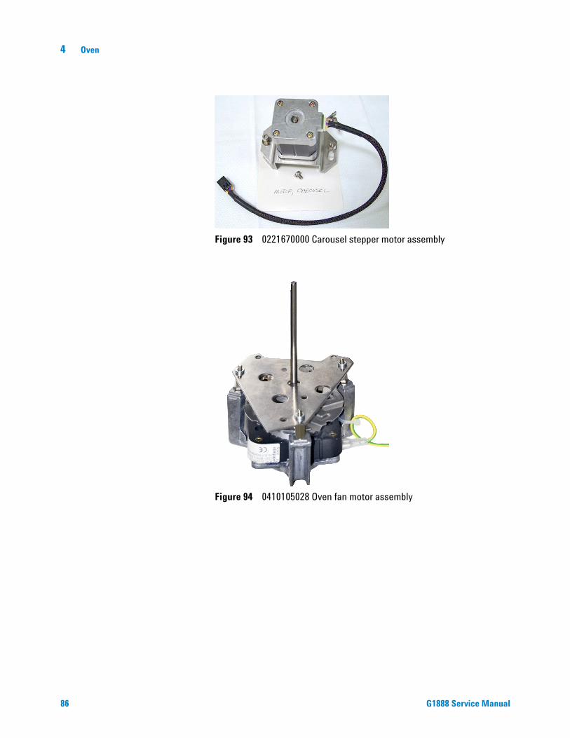
Figure 93 0221670000 Carousel stepper motor assembly
Figure 94 0410105028 Oven fan motor assembly
G1888 Service Manual

Oven 4
Hole
G1888 Service Manual
Figure 95 0410105002 Lifter assembly, sample probe
Figure 96 0410105003 Lifter assembly, tray
87

88
4 Oven
Figure 97 0410105030 Fan, vial cooling
Figure 98 3641500008 Relay, oven heater
Figure 99 0410105024 Lid assembly with oven enclosure top, old color 0410105124 Lid assembly with oven enclosure top, new color
G1888 Service Manual
Oven 4
G1888 Service Manual
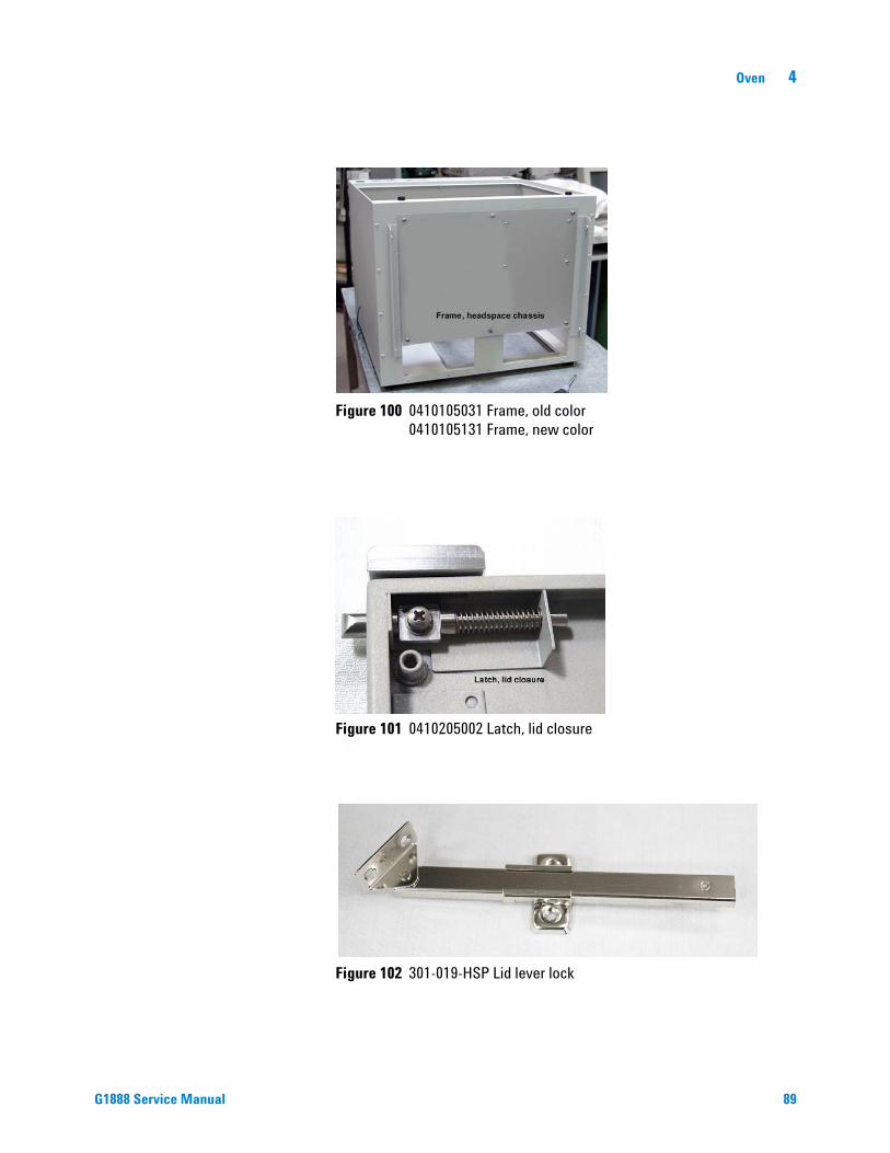
Figure 100 0410105031 Frame, old color 0410105131 Frame, new color
Figure 101 0410205002 Latch, lid closure
Figure 102 301-019-HSP Lid lever lock
89

4 Oven
Illustrated Parts Breakdown
Figure 103 IPB Oven and carousel
29
56
40
23
21
4
5
8
9
10
19
2022
24
35
39
36
41
4445
6062
53
656667686970
63
54
464748495051
55
72
575859
73
7475
76
52
7778
79
80
13
12
14
6
31
272826
123
7
11
15
42
4364
71
37
38
81
18
25
1716
15
61
323334
30
90 G1888 Service Manual

Oven 4
G1888 Service Manual
Table 6 Oven and carousel IPB
Description Part Number Qty
1 Screw M3x6 2020403006 3
2 Toothed washer 2171304030 3
3 Oven fan screen 631010326 1
4 Fan blades 3700500902 1
5 Screw M3x10 2020403010 3
6 Toothed washer 2171304030 3
7 Carousel, 12 position 6310090035 1
8 Carousel shaft 6410216138 1
9 Bushing, carousel shaft 6410302066 1
10 Carousel collar 6410204041 1
11 Top of oven enclosure assemblyconsists of parts 12 through 14
0410105032 1
12 Screw M3x16 2060403016 4
13 Oven enclosure top 6310103025 1
14 Insulation 1171210008 2
15 Oven enclosure with carousel enclosureconsists of parts 16 through 36
0410105033 1
16 Oven heater sensor assemblyconsists of parts 17 through 18
0410105029 1
17 Heater 9101030001 1
18 Carousel enclosure 9011090003 1
19 Screw M4x20 2060404020 3
20 Oven enclosure assemblyconsists of parts 21 through 23
0410105027 1
21 Oven insulation 1171210003 1
22 Oven base 1171210007 1
23 Oven external covering 1211109032 1
24 Screw M4x6 2020404006 2
25 Toothed washer 2171304040 2
26 Base and switch assemblyconsists of parts 27 through 34
0410105025 1
91

92
4 Oven
27 Switch, oven max temperature 3070000010 1
28 Toothed washer 2171304030 2
29 Screw M3x6 2020403006 2
30 Carousel compartment base assemblyconsists of parts 31 through 34
0410105013 1
31 Carousel compartment base 6410106046 1
32 Screw M3x10 2020403010 3
33 Toothed washer 2171304030 3
34 Clip 6310206011 3
35 Spacer, oven heater block base 2195140002 3
36 Sleeve, ceramic lifter rod 6410202002 2
37 Sleeve, carousel 2195140001 1
38 Base, oven enclosure 6410216084 1
39 Bushing, carousel shaft bottom 6410302067 1
40 Toothed washer 2171304030 3
41 Screw M3x8 2020403008 3
42 Washer, carousel shaft bottom, teflon 2180036007 1
43 Carousel motor assemblyconsists of parts 44 through 59
0221670000 1
44 Small pulley 2283500008 1
45 Screw M3x6 2020403006 2
46 Set piece 2195310012 1
47 Tensioning bracket 6410110100 1
48 Flat washer 2170204040 1
49 Nut post 2190164010 1
50 Spring 2351500030 1
51 Screw M4x10 2020404010 1
52 Flat washer 2170204030 4
53 Spacer 2195040010 4
54 Chock 5282003502 4
55 Stepping motor 6410090081 1
56 Allen Screw M4x30 2030404030 1
57 Washer 2181212003 1
58 Screw M3x10 2020403010 4
Table 6 Oven and carousel IPB (continued)
G1888 Service Manual
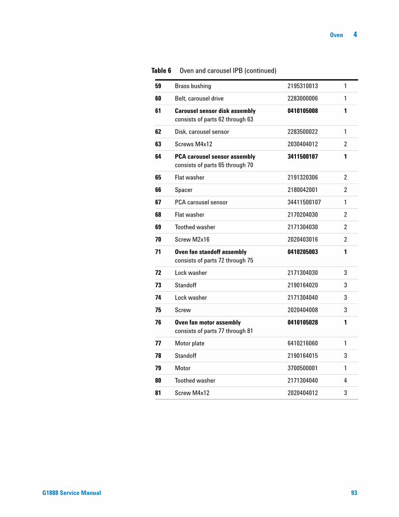
Oven 4
G1888 Service Manual
59 Brass bushing 2195310013 1
60 Belt, carousel drive 2283000006 1
61 Carousel sensor disk assemblyconsists of parts 62 through 63
0410105008 1
62 Disk, carousel sensor 2283500022 1
63 Screws M4x12 2030404012 2
64 PCA carousel sensor assembly consists of parts 65 through 70
3411500107 1
65 Flat washer 2191320306 2
66 Spacer 2180042001 2
67 PCA carousel sensor 34411500107 1
68 Flat washer 2170204030 2
69 Toothed washer 2171304030 2
70 Screw M2x16 2020403016 2
71 Oven fan standoff assemblyconsists of parts 72 through 75
0410205003 1
72 Lock washer 2171304030 3
73 Standoff 2190164020 3
74 Lock washer 2171304040 3
75 Screw 2020404008 3
76 Oven fan motor assemblyconsists of parts 77 through 81
0410105028 1
77 Motor plate 6410216060 1
78 Standoff 2190164015 3
79 Motor 3700500001 1
80 Toothed washer 2171304040 4
81 Screw M4x12 2020404012 3
Table 6 Oven and carousel IPB (continued)
93

4 Oven
Replacement Procedures
Accessing the components from the bottom panel
94
The following components are accessed from the bottom of the HS:
• Carousel sensor
• Oven fan motor assembly
• Carousel stepper motor assembly
• Lifter assembly, sample probe
• Lifter assembly, tray
• Disk, carousel sensor
To remove the bottom cover of the HS:
1 Disconnect the power cord and LAN or RS232 cables from the back of the HS.
2 Disconnect the gases.
3 Carefully lean the HS back. Rest the back of the vial tray on the table.
4 Use a No.1 Phillips screwdriver to remove the four screws that hold the bottom cover in place. Remove the cover and set it to the side.
Remove screws
Figure 104 The bottom cover
G1888 Service Manual
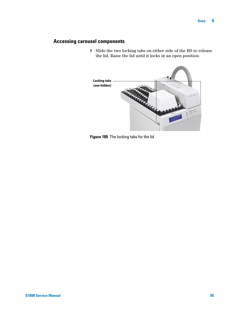
Oven 4
Accessing carousel components
G1888 Service Manual
1 Slide the two locking tabs on either side of the HS to release the lid. Raise the lid until it locks in an open position.
Figure 105 The locking tabs for the lid
Locking tabs(one hidden)
95

4 Oven
Carousel sensor
96
Required tools
Phillips screwdriver
Mirror
Replacement part
3411500107 Carousel sensor
Remove the carousel sensor
1 Remove the bottom cover. See “Accessing the components from the bottom panel”on page 94.
2 Place a piece of paper over the power supply to block small screws and washers that might fall.
3 Remove the ribbon cable and stepper motor cable. See Figure 106.
Ribbon cable
Stepper motor cable
Carousel sensor top screw
Carousel sensorbottom screw
Paper to catch falling screws
Figure 106 Removing the carousel sensor
The carousel stepper motor cable wires are fragile. Be careful not to
CAUTIONdamage the cables.G1888 Service Manual

Oven 4
G1888 Service Manual
4 Remove the bottom Phillips screw from the carousel sensor. Let the sensor slide down clear of the carousel disk.
5 Remove the top Phillips screw from the carousel sensor. Remove the sensor from the HS.
Replace the carousel sensor
1 Place a piece of paper over the power supply to block small screws and washers that might fall.
2 Place the sensor in the HS chassis and loosely fasten the top screw.
Do not allow the disk to damage the sensor.
CAUTION3 Rotate the sensor into position as shown in Figure 107.
4 Use a mirror to make sure that the disk is centered between the sensor.
5 Insert and tighten the bottom screw. Tighten the top screw.
6 Plug the stepper motor cable into the 4-prong female jack in the sensor motor chassis. Plug in the ribbon cable. See Figure 106.
7 Replace the HS bottom cover. Set the HS upright.
8 Align the carousel. See “Align the carousel”on page 115.
Figure 107 Disk centered between carousal sensor
Carousal sensor
Disk
97

4 Oven
Oven fan motor
98
Required tools
Phillips screwdriver
Needle nose pliers
Replacement parts
0410105028 Oven fan motor
3700500902 Oven fan blades
Remove the oven fan motor
1 Remove the fan blades. See “Remove the oven fan and carousel”on page 111.
2 Remove the bottom cover. See “Accessing the components from the bottom panel”on page 94.
3 Place a piece of paper over the power supply to block small screws and washers that might fall.
4 Remove the three large Phillips screws securing the fan motor to the chassis. See Figure 108.
Figure 108 Oven fan motor screws and cables
5 Pull the oven fan motor assembly out of the chassis.
G1888 Service Manual

Oven 4
G1888 Service Manual
Cable wire connections are fragile.
CAUTION6 Remove the white and blue cables using needle nose pliers.
7 Remove the green and yellow cable using needle nose pliers.
Replace the oven fan motor
1 Place a piece of paper over the power supply to block small screws and washers that might fall.
2 Place the motor in the HS chassis and line up the motor screw holes with the threaded posts in the HS chassis. See Figure 109.
Figure 109 Threaded posts for oven fan motor
3 Check that the motor shaft is centered in the carousel shaft in the oven. If it is not centered, the fan shaft will scrape against the carousel shaft. To adjust the fan shaft adjust the three standoffs under the motor.
Figure 110 Motor shaft centered in the carousel shaft
Shaft
Even space
Fan motor
around this opening
99
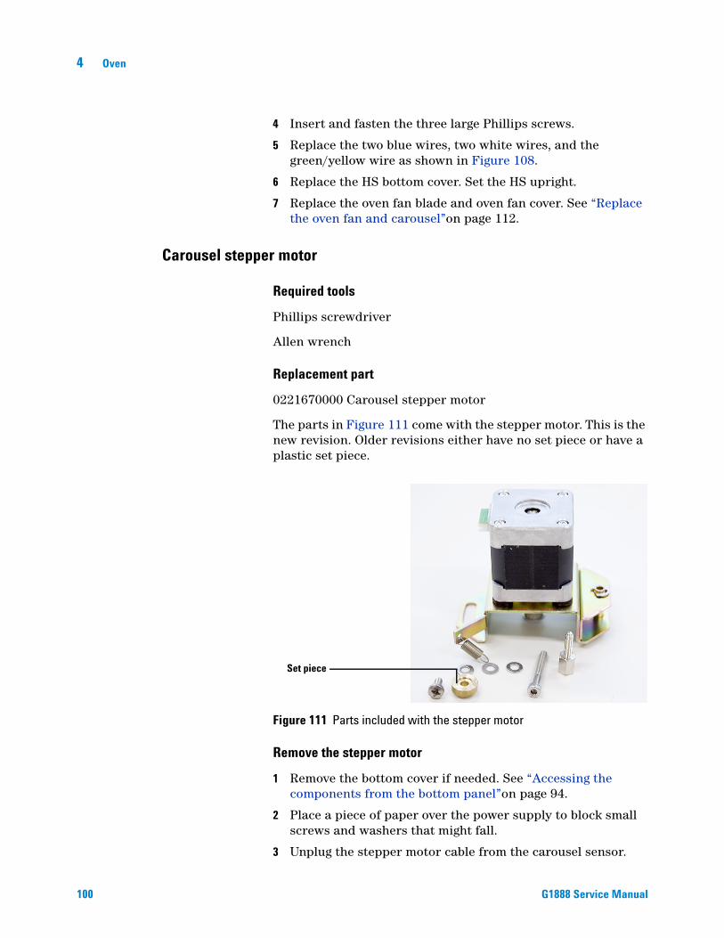
100
4 Oven
4 Insert and fasten the three large Phillips screws.
5 Replace the two blue wires, two white wires, and the green/yellow wire as shown in Figure 108.
6 Replace the HS bottom cover. Set the HS upright.
7 Replace the oven fan blade and oven fan cover. See “Replace the oven fan and carousel”on page 112.
Carousel stepper motor
Required tools
Phillips screwdriver
Allen wrench
Replacement part
0221670000 Carousel stepper motor
The parts in Figure 111 come with the stepper motor. This is the new revision. Older revisions either have no set piece or have a plastic set piece.
Figure 111 Parts included with the stepper motor
Remove the stepper motor
1 Remove the bottom cover if needed. See “Accessing the components from the bottom panel”on page 94.
2 Place a piece of paper over the power supply to block small screws and washers that might fall.
3 Unplug the stepper motor cable from the carousel sensor.
Set piece
G1888 Service Manual

Oven 4
G1888 Service Manual
Figure 112 Removing the stepper motor
Allen screw
Stepper motorcable
Screw
4 Undo the screws that connect the motor to the HS chassis. See Figure 112.
5 Lift the stepper motor out of the HS.
Replace the stepper motor
1 Place a piece of paper over the power supply to block small screws and washers that might fall.
2 Make sure the belt is set on the carousel disk. Pull the belt a few inches in each direction. See Figure 113.
Figure 113 Toothed gear on carousel sensor disk (underside)
Sensor disk
Gear teeth
Se
Ge
nsor disk
ar teeth
101

102
4 Oven
3 Assemble the nut post, washer, spring, and Phillips screw as shown in Figure 114. Loosely screw the spring to the nut fitting. The screw should be loose enough to allow the spring to freely rotate. Place the assembled screw in the stepper motor assembly as shown in Figure 115.
Figure 114 Assembled spring
Nut post
Washer
Spring
Screw
4 Place the washers and brass bushing on with the allen screw. Place the allen screw in the stepper motor assembly as shown in Figure 115.
Assembled spring
and screw
Allen screw
Toothed gear
Brass bushing
Brass set piece
Figure 115 Connector screws placed in the motor assembly
5 Hook the belt to the toothed gear on the motor assembly. Use an allen wrench to help set the belt on the gear.
6 Line up the screw holes and place the assembly on the HS chassis. Finger-tighten both the nut post and the allen screw to the HS chassis.
G1888 Service Manual

Oven 4
G1888 Service Manual
7 Test the belt to make sure it is securely set on both gears. Move the belt along its path and watch for both the motor cylinder and carousel wheel to rotate with the belt.
8 Hook the spring onto the stepper motor arm. See Figure 116.
Allen screw
Screw
Phillips screw
Spring on stepper motor arm
Figure 116 Spring attached to the stepper motor arm
9 Tighten the Phillips screw securing the spring.
10 Move the belt again. Tension should be applied to the belt by the spring.
11 Attach the cable between the carousel sensor and the stepper motor. See Figure 112 on page 101.
12 Replace the bottom cover.
13 Align the carousel. See “Align the carousel”on page 115.
103

4 Oven
Lifter assemblies
104
There are two lifter assemblies in the Headspace Sampler:
• The sample probe lifter assembly
• The tray lifter assembly
See Figure 117 for the location of each assembly.
Tray lifterassembly
Sample probelifter assembly
Figure 117 The two lifter assemblies shown from the bottom of the Headspace Sampler.
The lifters are attached to the base of the oven compartment with 3 sets of screws and washers. The brass gear on the motor raises and lowers a toothed rod.
The tray lifter is under carousel position 1. It lowers vials from the vial chain to the carousel and vice-versa.
The sampling lifter is under carousel position 9. It raises vials from the carousel up to the sampling needle and lowers them back to the carousel.
An optical sensor reads a hole in the rod at the bottom of each lifter’s travel.
The motor’s encoder counts motor turns to the correct height.
G1888 Service Manual
Oven 4
G1888 Service Manual
The lifters are almost identical. The rod on the tray lifter is longer and has a tapered tip to fit through shutter in the "mid" position.
The removal and installation procedures for each assembly are identical aside from the location of the assemblies. This manual gives instructions for the removal and installation of the sample probe lifter assembly. Use these same instructions for the tray lifter assembly.
Failure may occur if lifter rod hole is dirty. Make sure it is clean.
CAUTIONNever put oil or grease on rods. The rods have self-lubricating
CAUTIONbushings.Required tool
No. 1 Phillips screwdriver
Replacement parts
0410105003 Lifter assembly, tray
0410105002 Lifter assembly, sample probe
Remove the lifter assembly
1 Remove the bottom cover. See “Accessing the components from the bottom panel”on page 94.
2 Place a piece of paper over the power supply to block small screws and washers that might fall.
3 Detach the ribbon cable shown in Figure 118.
4 Remove the 3 Phillips screws shown in Figure 118 that hold the lifter motor to the HS chassis.
5 Pull the lifter motor assembly out of the chassis.
105

4 Oven
Ribbon cablefor lifter assembly
Screws
106
Figure 118 The tray lifter assembly in the Headspace Sampler
Replace the lifter assembly
1 Place a piece of paper over the power supply to block small screws and washers that might fall.
2 The hole in the lifter rod must be above the optical sensor. See Figure 119 for orientation.
3 Slide the brass ring on the end of the lifter arm all of the way towards the bottom of the arm. See Figure 119 for orientation.
Hole
Bottom
Top
Optic sensor
Brass ring
Figure 119 Orientation of the tray lifter assembly
4 Insert the lifter rod into the chassis.
G1888 Service Manual

Oven 4
G1888 Service Manual
5 Line the screw holes up with the chassis holes. Secure the assembly to the chassis with 3 Phillips screws. See Figure 118.
6 Attach the ribbon cable. Be careful to attach the proper ribbon to the lifter motor.
7 Replace the bottom cover and set the HS upright.
8 Connect all cables and gas lines.
9 Power on the HS. The self-test for the lifter assembly should pass.
10 Use manual operation, advanced function 5 to move the lifter up and down.
107

4 Oven
Carousel sensor disk
108
Required tools
Allen wrench
Mirror
Replacement parts
3700500902 Carousel shaft
0410105008 Carousel sensor disk
Remove the carousel sensor disk
1 Remove the bottom cover. See “Accessing the components from the bottom panel”on page 94.
2 Place a piece of paper over the power supply to block small screws and washers that might fall.
3 Remove the fan motor. See “Remove the oven fan motor”on page 98.
4 Remove the carousel sensor. See “Remove the carousel sensor”on page 96.
5 Remove the stepper motor. See “Remove the stepper motor”on page 100.
6 The sensor disk is secured by two allen screws set in the large toothed gear on the back of the disk. The gear is completely obscured by the sensor disk, so use a mirror to see the screws. Loosen the screws and remove the disk.
Figure 120 Screws securing the carousel sensor disk
Sensor disk
Carousel shaft
Allen screws
G1888 Service Manual
Oven 4
G1888 Service Manual
Replace the carousel sensor disk
1 Place a piece of paper over the power supply to block small screws and washers that might fall.
2 If the carousel drive belt is worn, ask the customer to consider replacing it.
3 Place the carousel drive belt over the carousel sensor disk and slide the sensor disk over the carousel shaft.
4 Tighten the 2 allen screws holding the disk to the shaft. See Figure 120 on page 108.
5 Install the stepper motor. See “Replace the stepper motor”on page 101.
6 Install the carousel sensor. See “Replace the carousel sensor”on page 97.
7 Install the fan motor. See “Replace the oven fan motor”on page 99.
8 Install the bottom cover.
9 Align the carousel. See “Align the carousel”on page 115.
109

4 Oven
Oven fan and carousel
110
Required tools
Pencil
No. 1 Phillips screwdriver
2.5-mm hex wrench
Replacement parts
0410105029 Oven heater sensor assembly
3070000010 Oven thermoswitch
3641500008 Oven heater relay
6310090035 12-position carousel
6310103026 Oven fan screen
Power OFF the HS unless you are verifying the repair. Use caution
WARNINGaround the oven fan blades and hot surfaces. Also be careful with screws and washers. If you drop any screws or washers, find them before verifying your repair.Access the components
1 Power OFF the HS.
When the HS is on, if the shaft is bumped the carousel stepper motor is activated. Before starting this process, make sure the HS is off.
2 Raise the lid of the HS until the support bracket snaps into place.
3 Lower both lifters so they are clear of the carousel.
G1888 Service Manual
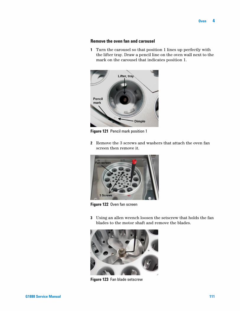
Oven 4
G1888 Service Manual
Remove the oven fan and carousel
1 Turn the carousel so that position 1 lines up perfectly with the lifter tray. Draw a pencil line on the oven wall next to the mark on the carousel that indicates position 1.
2 Remove the 3 screws and washers that attach the oven fan screen then remove it.
3 Using an allen wrench loosen the setscrew that holds the fan blades to the motor shaft and remove the blades.
Figure 121 Pencil mark position 1
Figure 122 Oven fan screen
Figure 123 Fan blade setscrew
111

112
4 Oven
4 Remove the 3 setscrews and locking washers that attach the carousel to the collar with Phillips screwdriver.
5 Carefully lift the carousel out of the HS chassis.
Replace the oven fan and carousel
1 Place the carousel onto the collar.
2 Align 3 holes to the collar.
3 Start the screws into the 3 holes on the collar. Do not tighten. The carousel should turn freely without rotating the carousel shaft.
4 Proceed to step 3 of “Align the carousel”on page 115.
Figure 124 Carousel screws
G1888 Service Manual
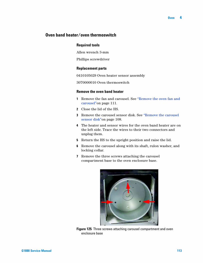
Oven 4
Oven band heater/oven thermoswitch
G1888 Service Manual
Required tools
Allen wrench 3-mm
Phillips screwdriver
Replacement parts
0410105029 Oven heater sensor assembly
3070000010 Oven thermoswitch
Remove the oven band heater
1 Remove the fan and carousel. See “Remove the oven fan and carousel”on page 111.
2 Close the lid of the HS.
3 Remove the carousel sensor disk. See “Remove the carousel sensor disk”on page 108.
4 The heater and sensor wires for the oven band heater are on the left side. Trace the wires to their two connectors and unplug them.
5 Return the HS to the upright position and raise the lid.
6 Remove the carousel along with its shaft, rulon washer, and locking collar.
7 Remove the three screws attaching the carousel compartment base to the oven enclosure base.
Figure 125 Three screws attaching carousel compartment and oven enclosure base
113

114
4 Oven
8 Remove the three front screws that hold the top trim around the oven cover.
9 Remove the four screws holding the oven enclosure top.
10 The top trim piece should lift a sufficient amount to allow removal of the oven enclosure top from beneath.
11 Remove the insulation from under the oven enclosure top.
12 Remove the carousel oven base, sides, and oven band heater.
13 If replacing the band heater, remove the heater sensor assembly from the carousel compartment base by loosening the three retaining clips with a 3-mm allen wrench.
14 If replacing the oven max temperature thermoswitch, remove it from the underside of the carousel compartment base.
Figure 126 Oven thermoswitch and carousel compartment base
G1888 Service Manual
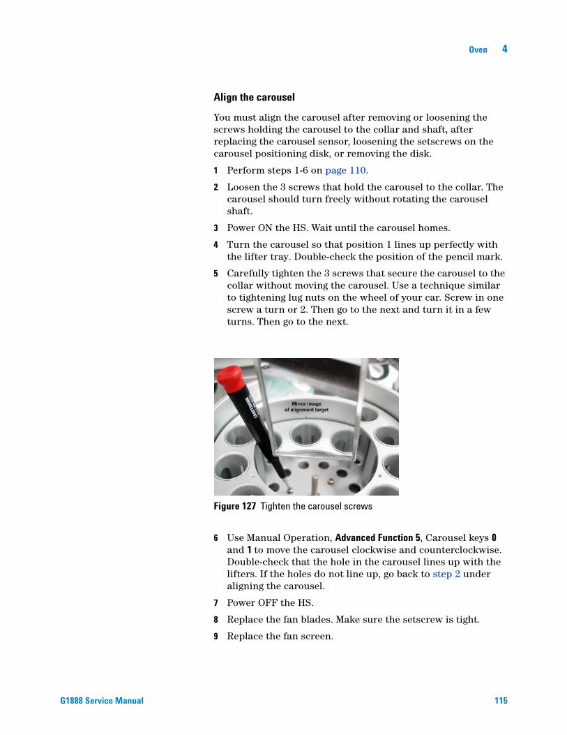
Oven 4
G1888 Service Manual
Align the carousel
You must align the carousel after removing or loosening the screws holding the carousel to the collar and shaft, after replacing the carousel sensor, loosening the setscrews on the carousel positioning disk, or removing the disk.
1 Perform steps 1-6 on page 110.
2 Loosen the 3 screws that hold the carousel to the collar. The carousel should turn freely without rotating the carousel shaft.
3 Power ON the HS. Wait until the carousel homes.
4 Turn the carousel so that position 1 lines up perfectly with the lifter tray. Double-check the position of the pencil mark.
5 Carefully tighten the 3 screws that secure the carousel to the collar without moving the carousel. Use a technique similar to tightening lug nuts on the wheel of your car. Screw in one screw a turn or 2. Then go to the next and turn it in a few turns. Then go to the next.
6 Use Manual Operation, Advanced Function 5, Carousel keys 0 and 1 to move the carousel clockwise and counterclockwise. Double-check that the hole in the carousel lines up with the lifters. If the holes do not line up, go back to step 2 under aligning the carousel.
7 Power OFF the HS.
8 Replace the fan blades. Make sure the setscrew is tight.
9 Replace the fan screen.
Figure 127 Tighten the carousel screws
115

116
4 Oven
Verify the alignment
1 Set up the vials.
2 Run the strife test. See “Strife test”on page 239.
3 Allow all vials to load and unload.
Vial Not Dropped and Lifter errors
If the carousel is not properly aligned, the hole in the lid will not line up with the cylindrical vial holder (or rulon bushing) in the carousel. The result is a “Vial Not Dropped” error. Also if the alignment is off by more that a few millimeters, the holes in the carousel for the lifters will not line up. The result is “Lifter” errors.
The carousel is secured to the shaft and drive mechanism by a collar and 3 screws. By loosening these screws, you can turn the carousel so that position 1 lines up over the tray lifter and position 9 lines up over the sampling probe lifter.
G1888 Service Manual

Agilent G1888 HeadSpace SamplerService Manual
5Pneumatics
Overview 118
Carrier and pressurization gas supplies 119
Headspace Sampler states 120
Replacement Parts 123
Illustrated Parts Breakdown 137
Pneumatic compartment IPB 137
Pneumatic compartment IPB 140
Pneumatic tubing IPB 143
Replacement Procedures 146
Access pneumatics components 146
Pneumatic tubing 149
Sample loop 151
Sample probe 152
Transfer line 154
6-port valve 156
Heaters 157
6-port valve motor assembly 159
117Agilent Technologies

5 Pneumatics
Overview
118
The G1888 Headspace Sampler (HS) heats and, if desired, agitates a partially-filled sample vial to achieve an equilibrium between volatiles in the sample and volatiles in the empty space above it. It then samples this headspace and transfers the volatiles to a gas chromatograph for analysis.
The following is the normal sequence for a single run.
1 The HS is in standby condition between samples. Setpoints are those left by the previous method. Carrier gas flows through the sample loop, transfer line, and GC column.
2 Load the desired method. The setpoints change accordingly and the Waiting for Ready period begins.
3 This is a good time to prepare the samples if this has not already been done. Load them into the sample tray (chain).
4 When the oven temperature has equilibrated, the HS becomes Ready.
5 Start the method. The link chain moves the first vial into position, the shutter opens, and the vial lifter lowers the vial into the oven carousel. The shutter closes.
6 If the method calls for agitation (shaking), the carousel shakes for the specified time.
7 The sample vial remains in the carousel for a specified time to allow the volatiles in the sample to equilibrate with the empty space above it.
8 When the GC is ready, sampling begins.a The carousel moves the sample vial under the injection
probe.b The probe lifter raises the vial to the stationary probe,
which pierces the vial septum.c Pressurization gas flows into the vial.d The sampling valve rotates to the Load position. The
pressurization gas in the vial forces the volatiles into the sampling loop.
e The sampling valve rotates to the Inject position. Carrier gas flushes the volatiles in the loop through the transfer line to the GC. The GC run begins.
9 The probe lifter moves the sample vial back to the carousel.
10 The carousel moves the vial to the shutter position, the shutter opens, the vial lifter returns the vial to the link chain, and the shutter closes. Depending on the timing there may be multiple vials in the oven heating at the same time.
11 The system waits for the next sample.
G1888 Service Manual
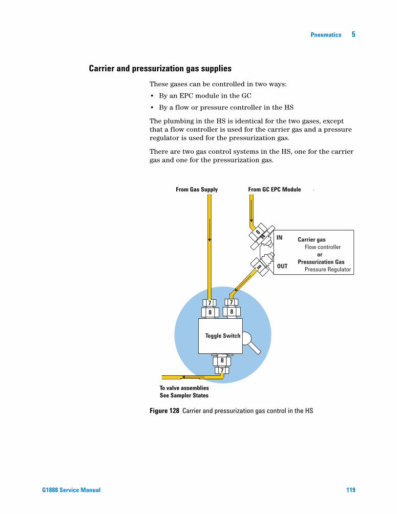
Pneumatics 5
Carrier and pressurization gas supplies
G1888 Service Manual
These gases can be controlled in two ways:
• By an EPC module in the GC
• By a flow or pressure controller in the HS
The plumbing in the HS is identical for the two gases, except that a flow controller is used for the carrier gas and a pressure regulator is used for the pressurization gas.
There are two gas control systems in the HS, one for the carrier gas and one for the pressurization gas.
Figure 128 Carrier and pressurization gas control in the HS
8
Carrier gas Flow controller orPressurization Gas Pressure Regulator
IN
OUT
814
7
8
7
8
7
8
Toggle Switch
From Gas Supply From GC EPC Module
To valve assembliesSee Sampler States
119

5 Pneumatics
Headspace Sampler states
120
Standby
This is the resting position between samples. The flow paths are flushed to get ready for samples and carrier gas flows to the GC to protect the column and detector.
Carrier gas to GC
Pressurize gas flushes loop and probe
Valve conditionsPressurize valve OFF (closed)Vent valve OFF (closed)Sample valve OFF
Timed eventsGC CYCLE TIMEVIAL EQ TIME
2
4
1
6
5 3
EE
E
E
EE
CarrierPressurizationSample
To GC
Vent valve
Pressurize valveLoop
Probe
Pressurize gas in Carrier gas in
Pressuretransducers
Figure 129 State 1–Standby
G1888 Service Manual

Pneumatics 5
G1888 Service Manual
Vial pressurization
To prepare for vial pressurization the pressurization valve is turned off. When it begins the pressurization valve opens. A sample vial is raised to the sampling probe. This pierces the vial septum and compresses a spring that will later free the vial from the probe. Pressurizing gas flows through the 6-port valve and sample loop, and into the vial.
Carrier gas to GC
Vial raised onto probe
Valve conditionsPressurize valve closed, then openafter vial is raisedVent valve OFF (closed)Sample valve OFF
Timed eventsPRESSURIZE TM
2
4
1
6
5 3
EE
EEE
CarrierPressurizationSample
Figure 130 State 2–Pressurize the vial
Filling the sample loop
The pressurized gas in the vial forces sample into and through the sample loop.
2
4
1
6
5 3
EE
EE
CarrierPressurizationSample
Carrier gas to GC
Probe in vial
Valve conditionsPressurize valve ON (closed)Vent valve ON (open)Sample valve OFF
Timed eventsLOOP FILL TIME
Figure 131 State 3–Fill the sample loop
121

122
5 Pneumatics
Loop equilibration
This is a pressure and temperature equilibration period.
2
4
1
6
5 3
EE
EE
CarrierPressurizationSample
Carrier gas to GC
Probe in vial
Valve conditionsPressurize valve ON (closed)Vent valve OFF (closed)Sample valve OFF
Timed eventsLOOP EQ TIME
Figure 132 State 4–Loop equilibration
Sample injection
The sampling valve operates, inserting the sample loop into the carrier gas flow path. The carrier pushes the loop contents through the transfer line to the GC inlet. After INJECT TIME expires, the HS returns to the standby state to get ready for the next sample.
2
4
1
6
5 3
EE
EE
CarrierPressurizationSample
Carrier gas flushes loop to GC
Probe in vial
Valve conditionsPressurize valve ON (closed)Vent valve OFF (closed)Sample valve ON
Timed eventsINJECT TIME
Figure 133 State 5–Inject the sample
G1888 Service Manual

Pneumatics 5
Replacement Parts
G1888 Service Manual
Headspace Samplers with serial numbers less than IT00604011 have grey external skins. Current HS models are white in color.
Figure 134 0410105016 Pneumatics compartment cover, old color 0410105116 Pneumatics comopartment cover, new color
Figure 135 1300502506 Tube, probe to 6-port valve deactivated
Figure 136 1300530005 Tube, switch to brass tee
123

124
5 Pneumatics
Figure 137 1300530006 Tube, switch to flow controller
Figure 138 1300530007 Tube, switch to pressure regulator
Figure 139 1300530008 Tube, flow controller to bulkhead
G1888 Service Manual

Pneumatics 5
G1888 Service Manual
Figure 140 1300530009 Tube, pressure regulator to bulkhead
Figure 141 1300530010 Tube, tee to pressure PCA
Figure 142 1300530011 Tube, tee to 6-port valve carrier
125

126
5 Pneumatics
Figure 143 2321390008 Flow restrictor
Figure 144 1300530001 Tube, vent deactivated
Figure 145 1300530002 Tube, vial pressure valve to union
G1888 Service Manual

Pneumatics 5
G1888 Service Manual
Figure 146 1300530004 Tube, switch to bulkhead
Figure 147 0410105017 Tubing, solenoids to 6-port, deactivated
Figure 148 0410105007 Pressure regulator with knob
127

128
5 Pneumatics
Figure 149 0410105010 Flow controller with knob
Figure 150 0410105018 Switch, pneumatic mode
Figure 151 3600500001 Valve, solenoid vent kalrez
G1888 Service Manual

Pneumatics 5
G1888 Service Manual
Figure 152 3600500002 Valve, solenoid vial pressurization
Figure 153 6550119125 Bracket, solenoid valves
Figure 154 2020403035, 2020402010, 2020403016 Pneumatic screws
2020403035
2020402010
2020403016
129
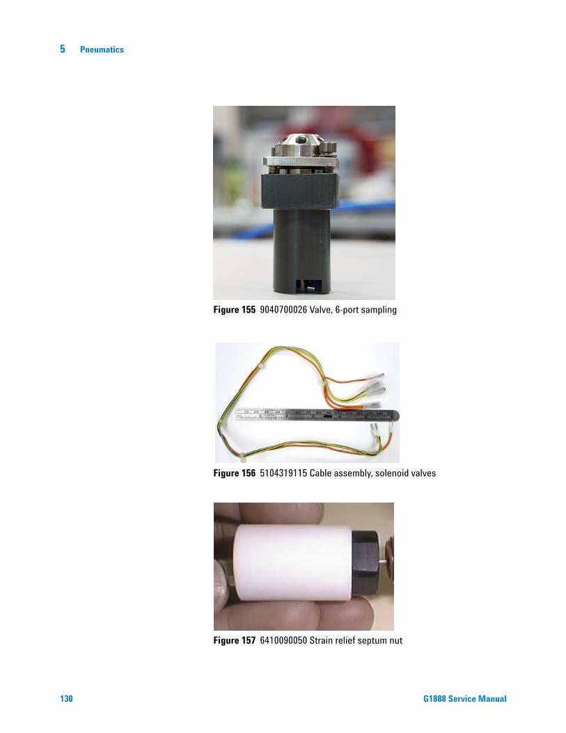
130
5 Pneumatics
Figure 155 9040700026 Valve, 6-port sampling
Figure 156 5104319115 Cable assembly, solenoid valves
Figure 157 6410090050 Strain relief septum nut
G1888 Service Manual
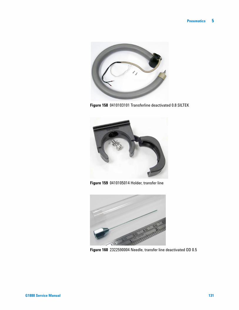
Pneumatics 5
G1888 Service Manual
Figure 158 0410103101 Transferline deactivated 0.8 SILTEK
Figure 159 0410105014 Holder, transfer line
Figure 160 2322590004 Needle, transfer line deactivated OD 0.5
131

132
5 Pneumatics
Figure 161 6410202015 Needle guide
Figure 162 6550209030 Sample probe holder
Figure 163 2322700011 Sample probe deactivated
G1888 Service Manual

Pneumatics 5
G1888 Service Manual
Figure 164 9110509015 Heater block, loop
Figure 165 0410105009 Mandrel, loop holder with screw
Figure 166 2321700003 Sample loop, 1 mL deactivated
133

134
5 Pneumatics
Figure 167 2321700004 Sample loop, 3 mL deactivated
Figure 168 0410105036 Heater sensor assembly, loop
Figure 169 0410205004 Heater block, tube from probe
G1888 Service Manual

Pneumatics 5
G1888 Service Manual
Figure 170 2302533140 M6 union, brass
Figure 171 2304533140 Tee, brass
Figure 172 2307230001 Union, zero dead volume, deactivated
Figure 173 2307833900 Bulkhead fitting
135

136
5 Pneumatics
Figure 174 0410105004 Motor-sensor assembly, 6-port valve
Figure 175 0410105015 Cover, loop heated zone
G1888 Service Manual

Pneumatics 5
Illustrated Parts Breakdown
Pneumatic compartment IPB
Figure 176 Pneumatics covering IPB
11
10
9
1213
6
8
2
75
3
41
AB
DF
CBA
A C
CBA
26
2524
23
1817
16
15
14
2021
22
DE
19
G1888 Service Manual 137
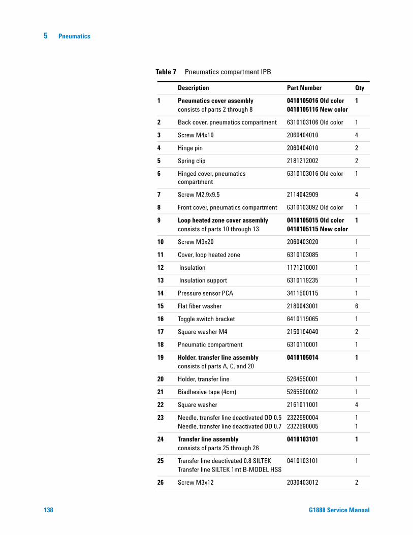
138
5 Pneumatics
Table 7 Pneumatics compartment IPB
Description Part Number Qty
1 Pneumatics cover assemblyconsists of parts 2 through 8
0410105016 Old color0410105116 New color
1
2 Back cover, pneumatics compartment 6310103106 Old color 1
3 Screw M4x10 2060404010 4
4 Hinge pin 2060404010 2
5 Spring clip 2181212002 2
6 Hinged cover, pneumatics compartment
6310103016 Old color 1
7 Screw M2.9x9.5 2114042909 4
8 Front cover, pneumatics compartment 6310103092 Old color 1
9 Loop heated zone cover assemblyconsists of parts 10 through 13
0410105015 Old color0410105115 New color
1
10 Screw M3x20 2060403020 1
11 Cover, loop heated zone 6310103085 1
12 Insulation 1171210001 1
13 Insulation support 6310119235 1
14 Pressure sensor PCA 3411500115 1
15 Flat fiber washer 2180043001 6
16 Toggle switch bracket 6410119065 1
17 Square washer M4 2150104040 2
18 Pneumatic compartment 6310110001 1
19 Holder, transfer line assemblyconsists of parts A, C, and 20
0410105014 1
20 Holder, transfer line 5264550001 1
21 Biadhesive tape (4cm) 5265500002 1
22 Square washer 2161011001 4
23 Needle, transfer line deactivated OD 0.5Needle, transfer line deactivated OD 0.7
23225900042322590005
11
24 Transfer line assemblyconsists of parts 25 through 26
0410103101 1
25 Transfer line deactivated 0.8 SILTEKTransfer line SILTEK 1mt B-MODEL HSS
0410103101 1
26 Screw M3x12 2030403012 2
G1888 Service Manual

Pneumatics 5
G1888 Service Manual
Table 8 Pneumatic covering associated screws and washers
Description Part Number Qty
A Flat washer 2170204040 15
B Toothed washer 2171304040 18
C Screw M4x10 2020404010 12
D Toothed washer 2171304030 24
E Screw M3x6 2020403006 10
F Screw M3x8 2020403008 14
139

5 Pneumatics
Pneumatic compartment IPB
140
Figure 177 Pneumatics compartment IPB
16
AB
D
AB
28
13
11
F
27
15BA
14
12
26
30
18
31
32
F
BC
D
25
20
21
BC
A
FD
35
3433
36
19
3DE
4
5
9
10
1
2
7
D E 6
8
1
17
22
23D24
29
G1888 Service Manual

Pneumatics 5
G1888 Service Manual
Table 9 Pneumatic compartment IPB
Description Part Number Qty
1 Motor, sensor assemblyconsists of parts 2 through 10
0410105004 1
2 Valve motor - 24 VDC 3701509002 1
3 Flat fiber washer 2180043001 6
4 Terminal block, 6-port valve 3411500116 1
5 Sensor, 6-port valve 3411500102 1
6 Screw M4x6 2020404006 2
7 Bracket, motor support 6550119055 1
8 Screw M3x8 2060403008 3
9 Motor-sensor disk 6410204035 1
10 Coupling 2311500003 1
11 Union, zero dead volume deactivated 2307230001 1
12 Sample probe holder 6550209030 1
13 7-mm bolt 2040404016 1
14 Screw M4x12 2030404012 1
15 Screw M4x25 2020404025 2
16 Heater block, loop and sampling probe 9110509015 1
17 Spring, vial push 2351500035 1
18 Needle guide 6410202015 1
19 Insulation block 6410106045 1
20 Valve, solenoid vial pressurization 3600500002 1
21 Valve, solenoid vent kalrez 3600500001 1
22 Bracket, solenoid valves 6550119125 1
23 Screw M3x10 2020403010 2
24 Flat washer 2170204030 2
25 Pneumatics base 6410216081 1
26 Heater, sensor assemblyconsists of parts 27 through 28
0410105036 1
27 Heater 9100005005 2
28 Sensor 3831019003 1
141
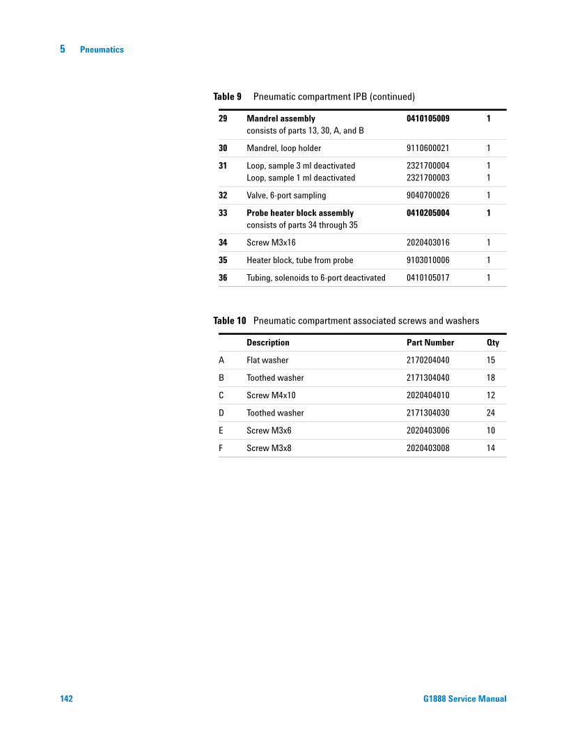
142
5 Pneumatics
29 Mandrel assemblyconsists of parts 13, 30, A, and B
0410105009 1
30 Mandrel, loop holder 9110600021 1
31 Loop, sample 3 ml deactivatedLoop, sample 1 ml deactivated
23217000042321700003
11
32 Valve, 6-port sampling 9040700026 1
33 Probe heater block assemblyconsists of parts 34 through 35
0410205004 1
34 Screw M3x16 2020403016 1
35 Heater block, tube from probe 9103010006 1
36 Tubing, solenoids to 6-port deactivated 0410105017 1
Table 10 Pneumatic compartment associated screws and washers
Description Part Number Qty
A Flat washer 2170204040 15
B Toothed washer 2171304040 18
C Screw M4x10 2020404010 12
D Toothed washer 2171304030 24
E Screw M3x6 2020403006 10
F Screw M3x8 2020403008 14
Table 9 Pneumatic compartment IPB (continued)
G1888 Service Manual

Pneumatics 5
Pneumatic tubing IPB
Figure 178 Pneumatic tubing IPB
VIAL PRESS.
VENT
VENT
PRESS25
3
1
1
8
2223
20
17
18
67
27
9
19
31
1015
11
MPC
EPC
CARRIER 14
16
3
1
8
4
67
910
15
11
13
2
*
29
2
*
*
5
21
5*
*
Vial pressurization gas pneumatic system for the Headspace Sampler
Carrier gas pneumatic system for the Headspace Sampler
3028
29 12
24
26
G1888 Service Manual 143

144
5 Pneumatics
Table 11 Pneumatic tubing IPB
Description Part Number Qty
1 M6 union brass 2302533140 3
2 Pressure sensor board 3411500115 1
3 Tube, tee to pressure PCA 1300530010 2
4 Tube, flow controller to bulkhead 1300530008 1
5 Bulkhead fitting assemblyconsists of parts 6 through 8
2307833900 5
6 Washer 2180014004 5
7 Nut 2160014003 5
8 Connector 2305533141 5
9 Tube, switch to bulkhead 1300530004 2
10 Tube, switch to brass tee 1300530005 2
11 Switch, pneumatic mode 0410105018 2
12 Flow controller assemblyconsists of parts 13 and 29
0410105010 1
13 Flow controller 9050790001 1
14 Tube, switch to flow controller 1300530006 1
15 Brass tee 2304533140 2
16 Tube, tee to 6-port valve carrier 1300530011 1
17 Tube, switch to pressure regulator 1300530007 1
18 Tube, vent deactivated 1300530001 1
19 Tube, vial pressure valve to union 1300530002 1
20 Union 2303002051 4
21 Tubing assembly, solenoids to 6-port deactivatedconsists of parts 22 through 24
0410105017 1
22 Base of solenoid tubing assembly 1
23 Union 2307601001 1
24 Screw M2x10 2020402010 1
25 Tube, probe to 6-port deactivated 1300502506 1
26 Ferrule, pneumatics tubing to 6-port valveNut, pneumatics tubing to 6-port valve
19258208701925820830
27 Flow restrictor 2321390008 1
G1888 Service Manual

Pneumatics 5
G1888 Service Manual
* See Figure 177, “Pneumatics compartment IPB”,” on page 140
28 Pressure regulator assemblyconsists of parts 28 and 29
0410105007 1
29 Pressure regulator 9050590004 1
30 Knob 2272000001 2
31 Tube, pressure regulator to bulkhead 1300530009 1
Table 11 Pneumatic tubing IPB (continued)
145

5 Pneumatics
Replacement Procedures
Access pneumatics components
146
Required tool
Phillips screwdriver
Replacement parts
Does not apply
Remove the pneumatic covers
1 Raise the lid of the HS.
2 Use a Phillips screwdriver to loosen the two screws at the front of the sample cover shown below.
3 Lower the lid of the HS.
4 Raise the pneumatics cover.
5 Remove the two Phillips screws from the left side.
Figure 179 Screws under lip of pneumatics cover
Figure 180 Screws on left side of pneumatics cover
Remove screws
G1888 Service Manual

Pneumatics 5
G1888 Service Manual
6 Use short or ratchet driver to remove 2 Phillips screws from right side.
7 Carefully lift cover to remove.
Figure 181 Screws on right side of pneumatics cover
Figure 182 Access to pressure transducers, tubing, and manual regulators
Remove screws
147

148
5 Pneumatics
8 Loosen the two screws on the loop cover.
9 Carefully lift off cover.
Figure 183 Screws to insulated cover of loop and valve heated zone
Figure 184 Access to loop and valve heated zone
G1888 Service Manual

Pneumatics 5
Pneumatic tubing
G1888 Service Manual
Most tubing uses a swagelock connection.
Required tools
7/16 inch wrench
9/16 inch wrench
Replacement parts
See “Replacement Parts”on page 123 and
See “Pneumatic tubing IPB”on page 143.
Making a Swagelok connection
1 Place a Swagelok nut, back ferrule, and front ferrule to the tubing as shown in Figure 185.
Figure 185 Swagelok nuts and ferrules
2 Clamp a stainless steel plug or similar fitting in a bench vise.
3 Push the tubing into the stainless steel plug. Make sure that the front ferrule is touching the plug. Slide the Swagelok nut over the ferrule and thread it onto the plug. See Figure 186.
Figure 186 Assembling the fitting for a swagelok connection
4 Push the tube fully into the plug, then withdraw it approximately 1 to 2 mm. Finger-tighten the nut.
Front ferrule
Back ferrule
Nut
Tubing
IMPORTANT!The narrow end of the backferrule fits into the rear ofthe front ferrule.
Plug or fitting
Nut and ferrules
Tubingheld in a vise
149
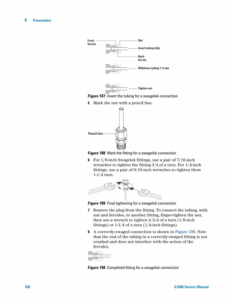
150
5 Pneumatics
Figure 187 Insert the tubing for a swagelok connection
5 Mark the nut with a pencil line.
Figure 188 Mark the fitting for a swagelok connection
6 For 1/8-inch Swagelok fittings, use a pair of 7/16-inch wrenches to tighten the fitting 3/4 of a turn. For 1/4-inch fittings, use a pair of 9/16-inch wrenches to tighten them 1-1/4 turn.
Figure 189 Final tightening for a swagelok connection
7 Remove the plug from the fitting. To connect the tubing, with nut and ferrules, to another fitting, finger-tighten the nut, then use a wrench to tighten it 3/4 of a turn (1/8-inch fittings) or 1-1/4 of a turn (1/4-inch fittings).
8 A correctly-swaged connection is shown in Figure 190. Note that the end of the tubing in a correctly-swaged fitting is not crushed and does not interfere with the action of the ferrules.
Figure 190 Completed fitting for a swagelok connection
Frontferrule
Backferrule
Nut
Insert tubing fully
Withdraw tubing 1-2 mm
Tighten nut
Pencil line
G1888 Service Manual

Pneumatics 5
Sample loop
G1888 Service Manual
The loop zone controls the temperature of the valve, and the sample loop. The setpoint range of the loop is 45 to 250 °C. Keep the loop temperature 10 to 15 °C higher than the vial temperature for most operations.
Required tool
7-mm wrench
Replacement parts
2321700003 Sample loop, 1 mL deactivated
2321700004 Sample loop, 3 mL deactivated
Remove the sample loop
1 Remove the plumbing from the 6-port valve by using a 7-mm wrench to loosen the two nuts connecting the sample loop to ports 1 and 4 of the 6-port valve.
2 Slide the sample loop off the mandrel.
Replace the sample loop
1 Slide the new sample loop onto the mandrel.
Figure 191 Ports 1 and 4 on the 6-port sampling valve
Sample loop
Port 1
Port 4
CAUTION Do not bend the deactivated sample loop or the coating will break and compromise inertness.
2 Reverse the steps given above to reassemble the HS.
3 Perform a leak test on fittings before replacing the insulation and manifold cover.
151

5 Pneumatics
Sample probe
152
Required tools
Two 7-mm wrenches
Tweezers
Replacement part
2322700011 Sample probe, deactivated
Remove the sample probe
1 Loosen the Phillips screw shown below.
2 Lift out the heater block covering the sampling probe.
3 To disconnect the plumbing from the sampling probe support the zero dead volume union with a 7-mm wrench and remove the nut with another 7-mm wrench.
Figure 192 Location of the heater block and screw
Heater block
Screw
CAUTION Do not bend any tubing or the coating will break and compromise inertness.
4 Loosen the connection to port 5 on the 6-port valve. Lift the tube off of the sample probe and swivel out of the way.
G1888 Service Manual

Pneumatics 5
G1888 Service Manual
5 Loosen and remove the zero dead volume union.
6 Pick up the sampling probe with tweezers and remove it from the HS.
Replace the sample probe
1 Insert a new sampling probe.
2 Reverse the previous steps to reassemble the HS.
3 Tighten each fitting and perform a leak test before replacing the insulation and cover.
Figure 193 Location of the zero dead volume union and hexagonal nut
Figure 194 Removing the sampling probe
Hexagonal nut
Zero dead volumeunion
Tweezers
Sampling probe
153

5 Pneumatics
Transfer line
154
This line connects the Headspace Sampler to the GC. The transfer line is 85 cm long and made of deactivated stainless steel. The temperature range of the transfer line is 50 to 250 °C.
Required tools
Phillips screwdriver
Flat-blade screwdriver
7-mm wrench
Replacement parts
0410103101 Transfer line deactivated 0.8 SILTEK
0410105014 Holder, transfer line
2322590005 Needle, transfer line deactivated OD 0.7
2322590004 Needle, transfer line deactivated OD 0.5Use for on-column injection and other inlets
Remove the transfer line
1 Access the pneumatic components. See “Access pneumatics components”on page 146.
2 Remove the transfer line from connection 3 of the 6-port valve.
3 Trace the transfer line heater and sensor wires back to the terminal block. Unplug the heater line and the sensor lines.
4 Use a flat-blade screwdriver to remove the sensor wires from the plug.
G1888 Service Manual

Pneumatics 5
G1888 Service Manual
Figure 195 Transfer line wires - sensor and heater
Transfer line Sensor wires
Transfer line Heater wires
5 Use a flat-blade screwdriver to remove the heater wires from the plug.
6 Remove the two screws holding the transfer line to the side panel then remove the transfer line.
Replace the transfer line
1 Reverse the steps given above to install the transfer line.
2 Perform a leak test on fittings before replacing the insulation and manifold cover.
Figure 196 Transfer line - side panel view
155

5 Pneumatics
6-port valve
156
Required tools
Phillips screwdriver
Allen wrench
Two 7-mm wrenches
Replacement part
9040700026 Valve, 6-port sampling
1925820830 Nut, pneumatics tubing to 6-port valve
1925820870 Ferrule, pneumatics tubing to 6-port valve
Removing the 6-port valve
1 Access the pneumatic components. See “Access pneumatics components”on page 146.
2 Remove the six tubing lines from the 6-port valve.
3 Use an allen wrench to remove the two bolts holding the 6-port valve to the heater block.
4 Pull the 6-port valve forward to remove it from the heater block. The valve uncouples from the motor-sensor assembly.
Installing the 6-port valve
1 Reverse the steps given above to install the 6-port valve.
2 Perform a leak test on fittings before replacing the insulation and manifold cover.
Figure 197 Two bolts on 6-port valve
G1888 Service Manual
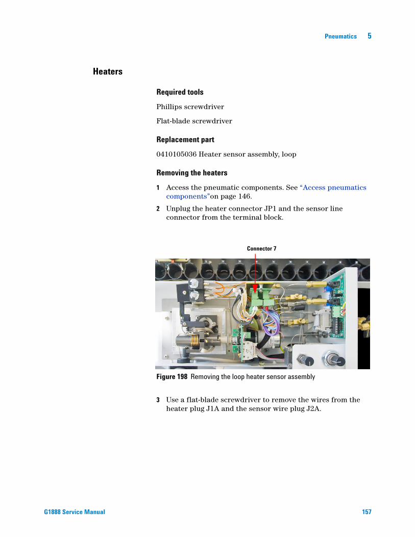
Pneumatics 5
Heaters
G1888 Service Manual
Required tools
Phillips screwdriver
Flat-blade screwdriver
Replacement part
0410105036 Heater sensor assembly, loop
Removing the heaters
1 Access the pneumatic components. See “Access pneumatics components”on page 146.
2 Unplug the heater connector JP1 and the sensor line connector from the terminal block.
3 Use a flat-blade screwdriver to remove the wires from the heater plug J1A and the sensor wire plug J2A.
Figure 198 Removing the loop heater sensor assembly
Connector 7
157

158
5 Pneumatics
4 Remove the heaters and sensors from the heater block.
Install the loop heater
Reverse the steps given above to install the loop heaters and sensors.
Figure 199 Heater plug J1A and sensor wire plug J2A
J1A
J2A
G1888 Service Manual

Pneumatics 5
6-port valve motor assembly
G1888 Service Manual
Required tool
Phillips screwdriver
Replacement part
0410105004 6-port valve motor assembly
Removing the motor assembly
1 Access the pneumatic components. See “Access pneumatics components”on page 146.
2 Unplug the four plugs from the terminal block.
Figure 200 Terminal block
Terminal block
Ribbon cable
3 Unplug the ribbon cable from the MV-valve terminal block.
4 Use a Phillips screwdriver to remove the screws holding the base of the motor assembly.
5 Remove the motor assembly.
Install the motor assembly
Reverse the steps given above to install the 6-port valve motor assembly.
159

160
5 Pneumatics
G1888 Service Manual

Agilent G1888 HeadSpace SamplerService Manual
6Electrical
Overview 162
Replacement Parts 165
Replacement Procedures 172
Accessing the components 173
Transformer 178
Temperature controllers 1 and 2 181
Motor controllers 1 and 2 183
Pressure sensor 186
Processor 187
Communications board 189
Operating Descriptions 191
Solenoid valve 191
Tray 192
Shutter 193
Tray lifter 194
Vial sensor 195
Carousel 196
Sampler probe lifter 197
Solenoid valves 198
Oven heated zone 199
Loop heated zone 201
Transfer line heated zone 202
Pressure sensor 203
Cabling 204
PCA boards 204
Power distribution 208
Electrical schematic 211
161Agilent Technologies
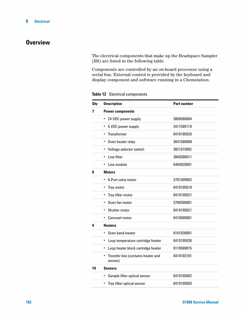
6 Electrical
Overview
162
The electrical components that make up the Headspace Sampler (HS) are listed in the following table.
Components are controlled by an on-board processor using a serial bus. External control is provided by the keyboard and display component and software running in a Chemstation.
Table 12 Electrical components
Qty Description Part number
7 Power components
• 24 VDC power supply 3856000004
• 5 VDC power supply 3411500110
• Transformer 0410105026
• Oven heater relay 3641500008
• Voltage selector switch 3821019002
• Line filter 3840300011
• Line module 5404020001
6 Motors
• 6-Port valve motor 3701509002
• Tray motor 0410105019
• Tray lifter motor 0410105021
• Oven fan motor 3700500001
• Shutter motor 0410105021
• Carousel motor 6410090081
4 Heaters
• Oven band heater 9101030001
• Loop temperature cartridge heater 0410105036
• Loop heater block cartridge heater 9110509015
• Transfer line (contains heater and sensor)
0410103101
14 Sensors
• Sample lifter optical sensor 0410105002
• Tray lifter optical sensor 0410105003
G1888 Service Manual

Electrical 6
G1888 Service Manual
• 6-port valve optical sensor 0410105004
• Vial present sensor optical sensor 0410105106
• Carousel sensor optical sensor 0410105008
• Tray position 1 sensor optical sensor 0410105020
• Shutter sensor(2) optical sensor 0410105021
• Optical sensor
• Oven temperature sensor 0410105029
• Loop temperature sensor 3831019003
• Transferline (contains heater and sensor)
0410103101
• Carrier gas pressure sensor 3411500115
• Vial pressure sensor 3411500115
4 Fans
• Power supply cooling 0410105012
• Vial cooling fan (2) 0410105030
• Oven fan 3700500902
2 Solenoid valves
• Vial pressurization 3600500002
• Solenoid vent 3600500001
6 Printed Circuit Assembly
• Motor controller 1 3411500111
• Motor controller 2 3411500112
• Temperature controllers 1 & 2 3411500113
• Pressure sensors 3411500115
• Main processor 3411500114
1 Interfaces
• Keypad and display 0410105134 - new color0410105034 - old color
2 Ribbon cables
• Control harness, ribbon cable 5104309004
• Communications harness, ribbon cable 5104309005
Table 12 Electrical components (continued)
163

164
6 Electrical
See also Table 36, “Avaliable fuses for older models”,” on page 287.
1 Cable Assembly
• Solenoid valves, cable assembly 5104319115
1 Wiring harness
• PCA power supply, harness 5104319108
Table 13 Power cords - country specific
Country Description Part number
Argentina 8120-6869
Australia/NZ C13, 10 amp 8120-1369
Chile C13, 10 amp 8120-6978
China C13, 10 amp 8121-0723
DK/Greenland C13, 10 amp 8120-3997
Europe C13, 10 amp 8120-1689
GB/HK/SG/MY C13, 10 amp 8120-8705
India/South Africa C13, 10 amp 8120-4211
Israel C13, 10 amp 8120-5182
Japan C15, 15 amp 8120-5342
Korea C13, 10 amp 8121-1226
Switzerland C13, 10 amp 8120-2104
US/CA/TW/TH C13, 13 amp 8120-1992
Table 14 Fuses
Location Description Part number
F1 Power distribution PCA
Interchangeable Bussmann 5 x 20 mm,Type: GMD D1A (T 1A 250 V), CSA
384-1595011-HSP
F3 and F4 Power distribution PCA
Interchangeable Bussmann 5 x 20 mm,Type: GMD (F 6A 125 V), CSA
384-1295001-HSP
Main fuses on power switch
10 amp, fast acting, 250 V, 5x20 mm 5188-1157
Transformer fuse 8 amp, fast acting, 250 V, 5x20 mm 5188-1158
Table 12 Electrical components (continued)
G1888 Service Manual

Electrical 6
Replacement Parts
G1888 Service Manual
Headspace Samplers with serial numbers less than IT00604011 have grey external skins. Current HS models are white in color.
Figure 201 0410105012 Fan, power supply
Figure 202 0410105026 Transformer
Figure 203 0410105030 Fan, vial cooling
165

166
6 Electrical
Figure 204 0410105034 Display keypad assembly, old color 0410105134 Display keypad assembly, new color
Figure 205 0410105035 Panel, power supply, old color 0410105135 Panel, power supply, new color
Figure 206 0410105040 Communications board
G1888 Service Manual

Electrical 6
G1888 Service Manual
Figure 207 3411500110 Power distribution plus 5 VDC
Figure 208 3411500111 Motor controller 1
Figure 209 3411500112 Motor controller 2
167

168
6 Electrical
Figure 210 3411500113 Temperature controllers 1 and 2
Figure 211 3411500114 Processor board
Figure 212 3411500115 Pressure sensor board
G1888 Service Manual

Electrical 6
G1888 Service Manual
Figure 213 3641500008 Relay, oven heater
Figure 214 3821019002 Switch, voltage selector
Figure 215 3840300011 Line filter
169

170
6 Electrical
Figure 216 3856000004 Power supply, 24 VDC
Figure 217 5404020001 Line module
Figure 218 6550106033 Front panel old color / 6550106036 New color
Figure 219 5104319115 Cable assembly, solenoid valves
Fuses and fuse holder
G1888 Service Manual

Electrical 6
G1888 Service Manual
Figure 220 5104319108 PCA power supply harness
Figure 221 5104309004 Control harness, ribbon cable
Figure 222 5104309005 Communications harness, ribbon cable
171

6 Electrical
Replacement Procedures
Tools
172
• A well-equipped toolkit (screwdrivers, wrenches, etc.)
• Digital meter (VDC and Ohms)
• Pointed set of probes for the meter
• 10-pin and 16-pin test jumpers
• Metal paper clips
• Reference materials (manuals)
General comments
When measuring resistance, the power is off. When measuring voltage, the power is on.
Be careful with all wires. They snap off easily.
• Yellow wires are ground
• Red wires are 5 volts
• Orange wires are 24 volts
Measurements
• Power OFF - resistance (ohms)
• Power ON - voltages (VDC)
G1888 Service Manual
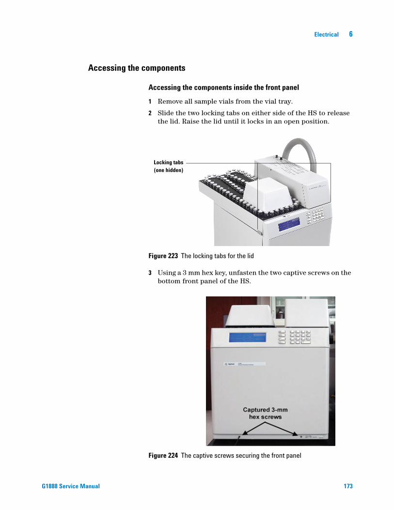
Electrical 6
Accessing the components
G1888 Service Manual
Accessing the components inside the front panel
1 Remove all sample vials from the vial tray.
2 Slide the two locking tabs on either side of the HS to release the lid. Raise the lid until it locks in an open position.
Figure 223 The locking tabs for the lid
3 Using a 3 mm hex key, unfasten the two captive screws on the bottom front panel of the HS.
Figure 224 The captive screws securing the front panel
Locking tabs(one hidden)
173

174
6 Electrical
4 Lift the front panel out of its slot. Gently place the panel on the workbench face-down hanging from two nylon lines.
Figure 225 The lid raised and the front panel open
Figure 226 Inside the front panel
Temp controller 2
Temp controller 1
Motor controller 2
Motor controller 1
Processor
G1888 Service Manual

Electrical 6
G1888 Service Manual
Accessing the components inside the rear panel
1 Power OFF and disconnect the power cord.
2 Remove the six Phillips screws.
3 Carefully lower the back panel.
Figure 227 Accessing the PCAs inside the rear panel
24 VDC power supply 3856000004
24 VDC cooling fan 0410105012
Oven relay3641500008
Fuses on Power Distribution board384-1595011-HSP384-1295001-HSP
Line filter 3840300011
weer supplplyyyy y y yy yyyyyy y yyy4
er 11e
00
coolinng faannnnnnnnnnnnnn 012
4
Oven relayyy36415000080888
Fuses on
LLine filt338403000
Main fuses onPower Switch
5188-1157
Figure 228 Inside the rear panel
175

176
6 Electrical
Accessing the components inside the pneumatics compartment
1 Raise the lid of the HS.
2 Use a Phillips screwdriver to loosen the two screws at the front of the sample cover shown below.
3 Lower the lid of the HS.
4 Raise the pneumatics cover.
5 Remove the two Phillips screws from left side.
6 Use short or ratchet driver to remove the two Phillips screws from right side.
Figure 229 Screws under lip of pneumatics cover
Figure 230 Screws on left side of pneumatics cover
Figure 231 Screws on right side of pneumatics cover
Remove screws
Remove screws
G1888 Service Manual

Electrical 6
G1888 Service Manual
7 Carefully lift cover.
Figure 232 Inside the pneumatics compartment
Pressure sensor PCA
Solenoid valves
Terminal block
6-port sensor
Ribbon cable
177
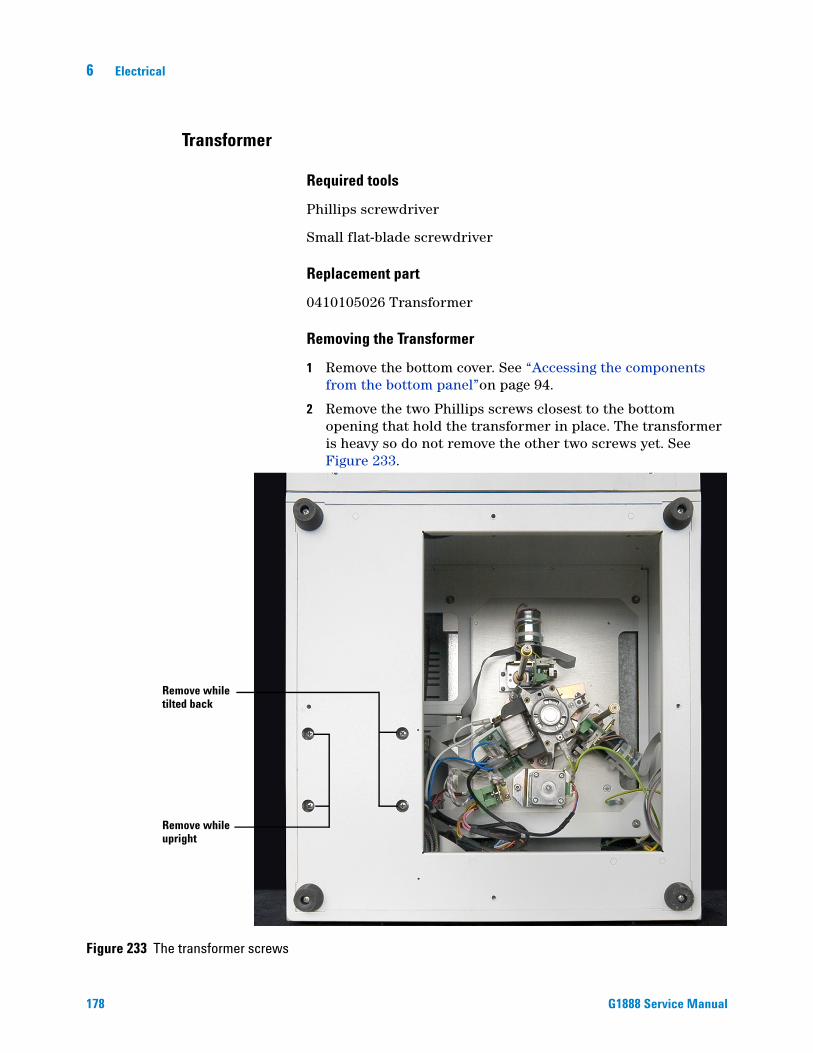
6 Electrical
Transformer
178
Required tools
Phillips screwdriver
Small flat-blade screwdriver
Replacement part
0410105026 Transformer
Removing the Transformer
1 Remove the bottom cover. See “Accessing the components from the bottom panel”on page 94.
2 Remove the two Phillips screws closest to the bottom opening that hold the transformer in place. The transformer is heavy so do not remove the other two screws yet. See Figure 233.
Figure 233 The transformer screws
Remove while
Remove while
tilted back
upright
G1888 Service Manual

Electrical 6
G1888 Service Manual
3 Set the HS upright. Position it so two of the transformer screw holes hang over the edge of the work bench and are accessible from below. Remove the remaining two screws.
Figure 234 Two transformer screw holes accessible
4 Slide the HS completely on to the work bench. Remove the back panel (with electronics attached). See “Accessing the components inside the rear panel”on page 175.
Screw holes
Figure 235 Removing the transformer board
Remove plugs
Remove screws
5 Unplug the connectors from the transformer board located in front of the transformer.
6 Use a small flat-blade screwdriver to remove the transformer wires from the transformer board connectors.
179

180
6 Electrical
7 Remove the two Phillips screws from the transformer board. See Figure 235. Remove the transformer board.
8 Cut twist ties attached to the transformer wire harness where needed.
9 Remove the transformer from the HS chassis. Take care since the transformer is heavy.
Installing the Transformer
1 Due to the weight of the transformer, it is difficult to secure the four bottom screws while the HS is on its side. Position the HS so two of the screw holes hang over the edge of the work bench and are accessible from below. See Figure 234.
2 Align the four threaded clips over each screw hole before positioning the transformer in the HS chassis. The clips are easily reached through the open back panel.
3 Place the transformer in position through the open back panel and line up the screw holes.
Transformer
Figure 236 Placing the transformer in the Headspace Sampler
4 From below, insert the first two Phillips screws into the transformer and tighten.
5 Slide the HS completely onto the table.
6 Flip the HS to expose the bottom panel.
7 Insert the two remaining screws and tighten until snug.
8 Replace the bottom panel and set the HS upright.
9 Replace the transformer board and reconnect the cables leading to the transformer and oven fan. See Figure 235.
G1888 Service Manual
Electrical 6
Temperature controllers 1 and 2
G1888 Service Manual
This procedure is valid for both temperature controllers. The difference between the temperature controllers is the location of the jumper pin on JP1.
• Temperature Controller 1 JP1 jumper location = 3
• Temperature Controller 2 JP1 jumper location = 4
Firmware on this board can not be upgraded in the field.
Temperature controller 1 performs the following functions:
• Controls loop and transfer line temperature
• Reads loop and transfer line sensors and compares with setpoints.
• Uses set of resistors as a reference to measure temperature.
• Tells the 5 VDC power supply PCA to close a relay to send 24 VDC to power the loop or transfer line heater.
• Turns solenoid valves ON and OFF.
Temperature controller 2 performs the following functions:
• Controls oven temperature.
• Reads oven sensor and compares with setpoint.
• Uses set of resistors as a reference to measure temperature.
• Tells 5 VDC power supply PCA to turn on 48 VAC relay to heat oven.
Replacement part
3411500113 Temperature Controller 1 and 2
Remove the temperature controllers
1 Power OFF and disconnect the power cord.
2 Remove the HS front cover. See “Accessing the components inside the front panel”on page 173.
3 Unplug the ribbon cables. See Figure 237.
4 Use a screwdriver to remove the 5-volt power cables.
5 Remove the screws in the corners of the board and then remove the temperature controller PCA.
181

182
6 Electrical
Replace the temperature controllers
1 Set the jumper pin on JP1 to the same location as the board which is being replaced.
2 Installation is the reverse of the above steps.
Figure 237 Temperature controllers 1 and 2
Red wire+5 VDC for logic circuits
Yellow wire, GND
1 Loop sensor 2 Transfer line sensor
3 AGND 4 AGND
5 Loop FET 6 Transfer line FET
7 I/O, Pres. Valve 8 I/O, Vent Valve
9 I/O 10 Ground
Reference voltage
Reference resistance
Temp controller 1jumper =3
J4 cable pin-outs for Temp controller 1 J4 cable pin-outs for Temp controller 2
1 Oven sensor 2 not used
3 AGND 4 not used
5 Relay 6 not used
7 I/O 8 I/O
9 I/O 10 Ground
J22 SP1 Serial bus
Temp controller 2jumper =4
J4
Pin 1
G1888 Service Manual
Electrical 6
Motor controllers 1 and 2
G1888 Service Manual
The procedure to remove either motor controller 1 or 2 is identical. However MC1 and MC2 are not interchangeable.Firmware on this board can not be upgraded in the field.
Motor controller 1 controls the following motors and receives input from the following sensors:
• Drives tray motor and reads position 1 and vial present optical sensors.
• Drives lifter tray motor and reads its hole.
• Drives shutter motor and reads its 2 optical sensors.
• SPI address = 1
Motor controller 2 controls the following motors and receives input from the following sensors:
• Drives sampling valve motor and reads its 2 optical senors.
• Drives lifter sampling motor and reads its hole.
• Drives carousel motor and reads its optical sensor.
• SPI address = 2
Replacement parts
3411500111 Motor Controller 1
3411500112 Motor Controller 2
Remove the motor controllers
1 Power OFF and disconnect the power cord.
2 Remove the HS front cover. See “Accessing the components inside the front panel”on page 173.
3 Unplug the ribbon cables. See Figure 238.
4 Unplug the power cables.
5 Remove the screws in the corners of the board and then remove the motor controller PCA.
Replace the motor controllers
Installation is the reverse of the above steps.
183

6 Electrical
Figure 238 Motor controllers 1 and 2
Figure 239 Motor controller 1
ribbon cablesMotor controller 1
Motor controller 1power cables
Motor controller 2power cables
ribbon cablesMotor controller 2
Red wire+5 VDC for logic circuits
Yellow wire GND
Orange wire+24 VDC for driving motors
J4 - tray motor, position 1sensor and vial sensor
J5 - tray lifter motor andsensor for hole in shaft
J6 - shutter motor andsensors for MIS and OPEN slots
J7 - SPI serial bus
184 G1888 Service Manual

Electrical 6
Figure 240 Motor controller 2
Red wire+5 VDC for logic circuits
Yellow wire GND
Orange wire+24 VDC for driving motors
J4 - 6-port sampling valvemotor and sensors, 1 slot
J5 - sampling probe liftermotor and sensor for hole inshaft
J6 - carousel motor andsensor for 13 slots in disk
J7 - SPI serial bus
G1888 Service Manual 185

6 Electrical
Pressure sensor
186
The pressure sensors reads carrier gas pressure or vial pressure using pressure transducers and provides this information to the processor board. Both channels are calibrated at the factory. Do not touch gain or offset in the field. The pressure sensor uses SPI address = 5.
Firmware on this board can not be upgraded in the field.
Replacement part
3411500115 Pressure sensor board
Remove the pressure sensor board
1 Power OFF and disconnect the power cord.
2 Open the pneumatics cover. See “Accessing the components inside the pneumatics compartment”on page 176.
3 Unplug the ribbon cable. See Figure 241.
4 Use a screwdriver to remove the power cables.
Use a wrench to hold the fitting on the transducer and another
CAUTIONwrench to hold the gas line nut. The transducer is fragile. Do not damage it while loosening the connection.5 Disconnect the two gas lines using two wrenches.
6 Remove the screws in the corners of the board and remove the pressure controller PCA.
Replace the pressure sensor board
1 Set the jumper on pin 5 of JP1.
2 Installation is the reverse of the above steps.
Figure 241 Pressure sensor board
Yellow wire GND
Carriertransducer
Carrier gain
Carrier offset
Vial pressure gain
Vial pressuretransducer
Orange wire+24 VDC for driving motors
Red wire+5 VDC for logic circuits
Address jumper
Ribbon cable
Vial pressure offset
G1888 Service Manual

Electrical 6
Processor
G1888 Service Manual
The processor is the main controller and on-board computer. The firmware on this board is flashable.
The main processor performs the following functions:
• Receives instructions from keypad and external software applications
• Sends instructions to peripheral PCAs
• Continually monitors their status
• Sends status to display and external software applications
Replacement part
3411500114 Processor board
Remove the processor board
1 Power OFF and disconnect the power cord.
2 Remove the HS front cover. See “Accessing the components inside the front panel”on page 173.
3 Unplug the ribbon cables from the board. Label the cables as you disconnect them. See Figure 242.
4 Use a screwdriver to remove the power cables.
5 Remove the screws in the corners of the board and remove the processor board.
Adjust the contrast of the display screen
1 Connect the processor board.
1 Turn the HS power ON.
2 Locate the potentiometer. See Figure 242.
3 Turn the red screw with a flat blade screwdriver while looking at the display screen.
187

188
6 Electrical
Replace the processor board
Installation is the reverse of the above steps.
Figure 242 Processor board
Red wire+5 VDC for logic circuits
Yellow wiresGND
Remote start/stop
SPI Serial Interface Bus
To LED display
To keypad
RS-232
LAN
Use to recover dead main processor PCA when firmware is corrupted
Potentiometer
G1888 Service Manual

Electrical 6
Communications board
G1888 Service Manual
The communications board contains connectors and converters for external communications:• LAN to RS-232 and vice-versa.• Generates remote start/stop signal.• Passes RS-232.• Connects directly to main processor PCA.
Replacement part
0410105040 Communications board
Remove the communications board
To replace the communications board:
1 Power OFF and disconnect the power cord.
2 Remove the HS rear panel. See “Accessing the components inside the rear panel”on page 175.
3 Unplug the ribbon cables. See Figure 244.
4 Remove the two attachment screws located on the back panel. See Figure 243.
5 Remove the communications board.
Figure 243 Screws attaching the communications board
Screw
Rear panel
Screw
189

190
6 Electrical
Replace the communications board
Installation is the reverse of the above steps.
Figure 244 Communications board
Remote connector
LAN connector
RS-232 connector
G1888 Service Manual

Electrical 6
Operating Descriptions
Solenoid valve
G1888 Service Manual
The orange wire is always a24 VDC when measured against ground (HS chassis). Please pay attention, orange wire is not common ground it is common 24V.
Red/yellow and blue/yellow wires will change voltage (when measured against ground) depending on valve states.
Vo = orange wire voltageVry = red/yellow voltageVby = blue /yellow voltage
Pressurization valve is normally open (ON). A de-energized solenoid valve coil maintains gas flow through valve.• Vry = 24V (measurement of red/yellow wire against ground)• Vo – Vry = 0V (measure across orange wire and red/yellow
wire)
When pressurization valve is closed (OFF) energizing solenoid valve stops gas flow through valve.• Vry = 0V (measurement of red/yellow wire against ground)• Vo – Vry = 24V (measure across orange wire and red/yellow
wire)
Vent valve is normally closed (OFF).• Vby = 24V (measurement of blue/yellow wire against ground)• Vo – Vby = 0V (measure across orange wire and blue/yellow
wire)
When vent valve is open (ON).• Vby = 0V (measurement of blue/yellow wire against ground) • Vo – Vby = 24V (measure across orange wire and blue/yellow
wire)
Figure 245 Solenoid valve wiring
Front of Headspace Sampler
24 VDC
191

6 Electrical
Tray
192
The main processor PCA sends commands over the serial bus to address 1, the motor controller 1 PCA board, to run the tray motor a fixed number of revolutions at a specified rotational speed. To locate the number 1 vial position, the motor is sent a signal to run until the position 1 optical sensor detects the position 1 tab on the tray chain. When the position 1 optical sensor I/O pin's measured voltage reads 0.2 VDC or less, the tray has vial 1 in the home position. When the position 1 optical sensor I/O pin's measured voltage is closer to 4.8 VDC the vial is not in position 1. From the vial 1 position, the main processor PCA keeps track of the number of revolutions it travels from the oven entry (home) location. It knows how many revolutions from the home location that every other vial's position on the chain is located, and can therefore send any vial location on the tray to the oven entry (home) location.
24 VDC
5 VDC & distribution
BrushMotor
GearBox
BrushMotor
2 Encoders:Revolutions
Speed
GearBox
Belt
ChainLink
Position 1sensorMotor Controller 1 PCA
5 VDC and 24 VDC
Main processor PCA
5 VDC5 VDC
24 VDC24 VDC24 VDC24 VDC
inte
rcon
nect
5 VDC
Sprocket
Serial busAddress 1
GND5 24GND5 24
Position 1 - ~0.2 VDCNot position 1 - ~4.8 VDC
Shutter motorsensor terminal block
Figure 246 Tray function
The 24 VDC power supply provides 24 VDC power to the 5 VDC & distribution board where part of it is converted to 5 VDC and sent to the motor controller 1 PCA board along with 24 VDC power. The 24 VDC power is used by the motor controller 1 PCA board to power three motors including the tray motor. The ribbon cable attached to J4 on the motor controller 1 PCA board runs to connector J1 on the shutter motor-sensor terminal block and carries the 24 VDC motor drive, the 5 VDC and ground to the position 1 optical sensor and the I/O return signal from the position 1 optical sensor. The optical sensor attaches to connector J4 and the tray motor connector J3 on the shutter motor-sensor terminal block.
G1888 Service Manual

Electrical 6
Shutter
G1888 Service Manual
The main processor PCA sends commands over the serial bus to address 1, the motor controller 1 PCA board, to run the shutter stepper motor in a clockwise or counterclockwise rotation until stopped by an optical sensor or rotation count. To locate the OPEN shutter position, the motor is sent a signal to run until the OPEN position optical sensor detects the disk slot. To locate the MID shutter position, the motor is sent a signal to run until the MID position optical sensor detects the disk slot. To close the shutter, the shutter motor is run a fixed number of revolutions past the MID position.
StepperMotor
Belt
Open
Motor Controller 1 PCA5 VDC and 24 VDC
Main processor PCA
5 VDC5 VDC
24 VDC24 VDC
24 VDC24 VDCin
terc
onne
ct
5 VDC
Shutter
Serial busAddress 1
Mid
2 shutter sensorsread slot in disk
24 VDC
5 VDC & distribution
GND 5 24GND 5 24
~6 ohms
Figure 247 Shutter function
The 24 VDC power supply provides 24 VDC power to the 5 VDC & distribution board where part of it is converted to 5 VDC and sent to the motor controller 1 PCA board along with 24 VDC power. The 24 VDC power is used by the motor controller 1 PCA board to power three motors including the shutter motor. The ribbon cable attached to J6 on the motor controller 1 PCA board runs to connector J2 on the shutter motor-sensor terminal block and carries the 24 VDC motor drive, the 5 VDC and ground to the MID and OPEN position optical sensor and the I/O return signals from the MID and OPEN position optical sensors which are mounted to the bottom of the shutter motor-sensor terminal block. The shutter motor attaches to connection J5 of the shutter motor-sensor terminal block.
193

6 Electrical
Tray lifter
194
The main processor PCA sends commands over the serial bus to address 1, the motor controller 1 PCA board, to run the tray lifter motor in a clockwise or counterclockwise rotation until stopped by an optical sensor or rotation count. To locate the home (lowered) position, the motor is sent a signal to run until the home optical sensor detects a hole in the threaded drive. To lift the vial to the tray, the tray lifter motor is run a fixed number of revolutions past the home position. To lower the tray lifter to the home position, the motor is sent a signal to run in the opposite direction (from lifting) until the optical sensor detects the hole in the shaft at which point the motor stops. With the vial lifter in the home position the carousel can rotate if the sampler probe lifter is also in the home (lowered) position.
Rod
Brush motorEncoder counts
revolutionsMotor Controller 1 PCA5 VDC and 24 VDC
Main processor PCA
24 VDC24 VDC
5 VDC
Gear
Serial busAddress 1
Optical sensorreads hole in rodas down or homeposition
24 VDC
5 VDC & distribution
GND 5 24GND 5 24
Figure 248 Tray lifter function
The 24 VDC power supply provides 24 VDC power to the 5 VDC & distribution board where part of it is converted to 5 VDC and sent to the motor controller 1 PCA board along with 24 VDC power. The 24 VDC power is used by the motor controller 1 PCA board to power three motors including the tray lifter motor. The ribbon cable attached to J5 on the motor controller 1 PCA board runs to connector J1 on the tray lifter terminal block and carries the 24 VDC motor drive, the 5 VDC and ground to the sensors and the sensor I/O return signals from the home position optical sensors which is mounted to the bottom of the tray lifter motor terminal block and the motor revolution counter. The tray lifter motor attaches to connection J2 of the tray lifter motor terminal block and the motor revolution counter attaches to J3.
G1888 Service Manual

Electrical 6
Vial sensor
G1888 Service Manual
The main processor PCA sends commands over the serial bus to address 1, the motor controller 1 PCA board, to determine if a vial is present in the vial location over the oven opening. When the vial present optical sensor I/O pin's measured voltage reads 0.2 VDC or less, the tray has a vial in the location over the oven opening. When the vial present optical sensor I/O pin's measured voltage is closer to 4.8 VDC the vial is not in position over the oven opening.
Motor Controller 1 PCA5 VDC and 24 VDC
Main processor PCA
24 VDC
5 VDC
Serial busAddress 1
24 VDC
5 VDC & distribution
GND5 24GND5 24
Vial - ~0.2 VDC
No vial - ~4.8 VDC
5 Volt
GroundNegativeProbe
OutputPositiveProbe
Test Lead
Test Lead
Measure output to ground View from the front of the Headspace
Figure 249 Vial sensor function
The 24 VDC power supply provides 24 VDC power to the 5 VDC & distribution board where part of it is converted to 5 VDC and sent to the motor controller 1 PCA board. The ribbon cable attached to J4 on the motor controller 1 PCA board runs to connector J1 on the shutter motor-sensor terminal block and carries the 5 VDC and ground to the vial present optical sensor and the I/O return signal from the vial present optical sensor. The vial present optical sensor attaches to connector J4 on the shutter motor-sensor terminal block.
195

6 Electrical
Carousel
196
The main processor PCA sends commands over the serial bus to address 2, the motor controller 2 PCA board, to run the Carousel stepper motor until stopped by an optical sensor or rotation count. To locate the carousel's home position, the motor is sent a signal to run until the optical sensor detects a disk slot spaced fewer motor revolutions apart than the other 12 slots (13 slots total). From the home position, each slot in the disk represents a known carousel vial location. With both vial lifters in their home position the carousel can rotate.
StepperMotor
Belt
Motor Controller 2 PCA5 VDC and 24 VDC
Main processor PCA
24 VDC24 VDC
5 VDC
Serial busAddress 2
1 optical sensorreads 13 slots in disk
Carousel
24 VDC
5 VDC & distribution
GND5 24GND5 24
Figure 250 Carousel function
The 24 VDC power supply provides 24 VDC power to the 5 VDC & distribution board where part of it is converted to 5 VDC and sent to the motor controller 2 PCA board along with 24 VDC power. The 24 VDC power is used by the motor controller 2 PCA board to power three motors including the Carousel motor. The ribbon cable attached to J6 on the motor controller 2 PCA board runs to connector J1 located on the carousel terminal block and it carries the 24 VDC for motor drive, the 5 VDC and ground to the optical sensor and the sensor I/O return signal. The optical sensor is mounted on the carousel terminal block. The carousel motor attaches to connection J2 of the Carousel terminal block.
G1888 Service Manual
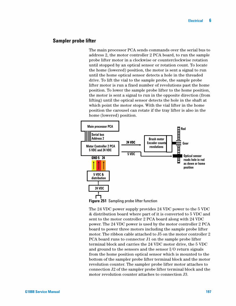
Electrical 6
Sampler probe lifter
G1888 Service Manual
The main processor PCA sends commands over the serial bus to address 2, the motor controller 2 PCA board, to run the sample probe lifter motor in a clockwise or counterclockwise rotation until stopped by an optical sensor or rotation count. To locate the home (lowered) position, the motor is sent a signal to run until the home optical sensor detects a hole in the threaded drive. To lift the vial to the sample probe, the sample probe lifter motor is run a fixed number of revolutions past the home position. To lower the sample probe lifter to the home position, the motor is sent a signal to run in the opposite direction (from lifting) until the optical sensor detects the hole in the shaft at which point the motor stops. With the vial lifter in the home position the carousel can rotate if the tray lifter is also in the home (lowered) position.
Rod
Brush motorEncoder counts
revolutionsMotor Controller 2 PCA5 VDC and 24 VDC
Main processor PCA
24 VDC24 VDC
5 VDC
Gear
Serial busAddress 2
Optical sensorreads hole in rodas down or homeposition
24 VDC
5 VDC & distribution
GND 5 24GND 5 24
Figure 251 Sampling probe lifter function
The 24 VDC power supply provides 24 VDC power to the 5 VDC & distribution board where part of it is converted to 5 VDC and sent to the motor controller 2 PCA board along with 24 VDC power. The 24 VDC power is used by the motor controller 2 PCA board to power three motors including the sample probe lifter motor. The ribbon cable attached to J5 on the motor controller 2 PCA board runs to connector J1 on the sample probe lifter terminal block and carries the 24 VDC motor drive, the 5 VDC and ground to the sensors and the sensor I/O return signals from the home position optical sensor which is mounted to the bottom of the sampler probe lifter terminal block and the motor revolution counter. The sampler probe lifter motor attaches to connection J2 of the sampler probe lifter terminal block and the motor revolution counter attaches to connection J3.
197

6 Electrical
Solenoid valves
198
The solenoid valves receive 24 volt power to one side of their solenoid coil whenever the HS is powered. The other side of the coil is either grounded (energized) or isolated from ground (de-energized) by control circuits on temperature controller 1 PCA.
The main processor PCA communicates with the temperature controller 1 PCA over the serial bus using address 3. It can send a command to the temperature controller 1 PCA to energize or de-energize the vial pressurization and vent solenoid valves.
Temperature Controller 1 PCA 5 VDC
Main processor PCA
Serial busAddress 3
24 VDC
5 VDC & distribution
GND5GND5
inte
rcon
nect
24 VDC
Vent VialPressurization
J2A
J4B4
55
667
Pin 8 on J4 = Vent valvePin 7 on J4 = Vial pressure valve
Figure 252 Solenoid valves function
Pin 7 on ribbon connector JP4 of the temperature controller 1 PCA is grounded to close the normally open vial pressurization valve or isolated from ground to open the valve. Likewise, pin 8 on ribbon connector JP4 of the temperature controller 1 PCA is grounded to open the normally closed vent valve or isolated from ground to close the valve.
The 5 VDC & Distribution board supplies 24 VDC to both solenoid valves. Additionally, the red/yellow vial pressurization and the green/yellow vent valve wires are passed through this board using the ribbon cable connecting to the temperature controller 1 PCA.
G1888 Service Manual

Electrical 6
Oven heated zone
G1888 Service Manual
The transformer converts filtered line voltage to 48 V for the oven heater. The 48 V fused supply from the transformer to the oven heater is controlled by energizing the oven relay when heating is required. When the relay is energized, LED 1 is lit. The fuse for the heater is located in the transformer terminal block. The heater is attached to pins 1 and 2 on connector J1a of the oven terminal block and the 48 V supply from the relay is attached to pins 1 and 2 of connector J1B.
24 VDC
5 VDC & distribution
Transformer
Temperature Controller 2PCA 5 VDC
Main processor PCA
Line voltage
Oven relay
OvenHeater48 V
Gnd
High LimitOven
sensorOvenRelay
Serial Bus Address 4
TS
TTOven
sensor
Figure 253 Oven heated zone
The main processor PCA sends the oven temperature setpoint over the serial bus to address 4, the temperature controller 2 PCA board which stores the setpoint. This setpoint is compared to the actual oven temperature which is measured by a pt 100 temperature sensor located in the oven. If the setpoint temperature is greater than the oven temperature, temperature controller 2 PCA board sends a signal to close the oven heater
199

200
6 Electrical
relay and provide 48 V power to the oven heater. The signal to power the oven relay is located on pin 5 of J4 on the temperature controller 2 PCA board. This signal wire is connected to pin 5 of the power supply board. The control power to energize the oven heater relay is supplied on pins 1 and 2 of connector J4A on the power supply board. An oven high temperature switch opens the oven heater relay shutting down the oven heater if a safe oven temperature is exceeded. When this happens, LED 4 on the power supply is lit. This temperature limit switch is wired to pins 5 and 6 of the oven terminal block at connector J2A and exits the terminal block on pins 5 and 6 of connector J2B. These wires are then attached to pins 7 and 8 of connector J4A on the power supply board.
A pt 100 temperature sensor transmits an oven temperature signal to temperature controller 2 PCA. The pt 100 temperature sensor changes resistance as the temperature changes. This change in resistance is used to control the temperature of the oven. The temperature sensor is attached to the oven terminal block at connector J2A located in the bottom of the HS. From here the temperature sensor wires exit the oven terminal block at connector J2B pins 8 and 9 which run to the power supply board connector J4B pins 9 and 10. The temperature signal exits the power supply board at connector J5 pins 1 (oven sensor) and 3 (AGND) and enter the temperature controller 2 PCA at connector J4 pins 1 (oven sensor) and 3 (AGND).
G1888 Service Manual
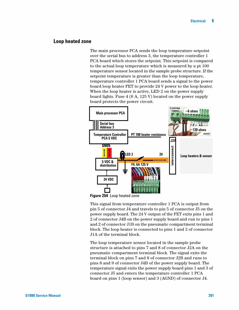
Electrical 6
Loop heated zone
G1888 Service Manual
The main processor PCA sends the loop temperature setpoint over the serial bus to address 3, the temperature controller 1 PCA board which stores the setpoint. This setpoint is compared to the actual loop temperature which is measured by a pt 100 temperature sensor located in the sample probe structure. If the setpoint temperature is greater than the loop temperature, temperature controller 1 PCA board sends a signal to the power board loop heater FET to provide 24 V power to the loop heater. When the loop heater is active, LED 2 on the power supply board lights. Fuse 4 (6 A, 125 V) located on the power supply board protects the power circuit.
Temperature Controller 1 PCA 5 VDC
Main processor PCA
Serial busAddress 3
24 VDC
5 VDC & distribution
GND5GND5
24
F4, 6A 125 V
PT 100 heater resistance
LED 2
inte
rcon
nect
J2A
~6 ohms
~120 ohms
Loop heaters & sensor
Figure 254 Loop heated zone
This signal from temperature controller 1 PCA is output from pin 5 of connector J4 and travels to pin 5 of connector J5 on the power supply board. The 24 V output of the FET exits pins 1 and 2 of connector J4B on the power supply board and run to pins 1 and 2 of connector J1B on the pneumatic compartment terminal block. The loop heater is connected to pins 1 and 2 of connector J1A of the terminal block.
The loop temperature sensor located in the sample probe structure is attached to pins 7 and 8 of connector J2A on the pneumatic compartment terminal block. The signal exits the terminal block on pins 7 and 8 of connector J2B and runs to pins 8 and 9 of connector J4B of the power supply board. The temperature signal exits the power supply board pins 1 and 3 of connector J5 and enters the temperature controller 1 PCA board on pins 1 (loop sensor) and 3 (AGND) of connector J4.
201

6 Electrical
Transfer line heated zone
202
The main processor PCA sends the transfer line temperature setpoint over the serial bus to address 3, the temperature controller 1 PCA board which stores the setpoint. This setpoint is compared to the actual transfer line temperature which is measured by a pt 100 temperature sensor located in the transfer line. If the setpoint temperature is greater than the transfer line temperature, temperature controller 1 PCA board sends a signal to the power board transfer line heater FET to provide 24 V power to the transfer line heater. When the transfer line heater is active, LED 3 on the power supply board lights. Fuse 3 (6 A, 125 V) located on the power supply board protects the power circuit.
Temperature Controller 1 PCA 5 VDC
Main processor PCA
Serial busAddress 3
24 VDC
5 VDC & distribution
GND5GND5
24
F3, 6A 125 V
PT 100 heater resistance
LED 3
inte
rcon
nect
J2A~6 ohms~120 ohms
Figure 255 Transfer line heated zone
This signal from temperature controller 1 PCA is output from pin 6 of connector J4 and travels to pin 6 of connector J5 on the power supply board. The 24 V output of the FET exits pins 3 and 4 of connector J4B on the power supply board and run to pins 1 and 2 of connector J2B on the pneumatic compartment terminal block. The transfer line heater is connected to pins 1 and 2 of connector J2A of the terminal block.
The transfer line temperature sensor located in the transfer line is attached to pins 9 and 10 of connector J2A on the pneumatic compartment terminal block. The signal exits the terminal block on pins 9 and 10 of connector J2B and runs to pins 9 and 10 of connector J4B of the power supply board. The temperature signal exits the power supply board pins 2 and 3 of connector J5 and enters the temperature controller 1 PCA board on pins 2 (loop sensor) and 3 (AGND) of connector J4.
G1888 Service Manual

Electrical 6
Pressure sensor
G1888 Service Manual
The pressure sensor located on the pneumatics compartment's rear panel has two pressure transducers. One transducer measures vial pressurization and the other transducer measures carrier gas pressure. These pressures are converted to digital values and read by the main processor PCA using serial bus address 5.
Figure 256 Pressure sensor function
24 VDC
5 VDC & distribution
Pressure PCA5 VDC and 24 VDC
Main processor PCA
Serial busAddress 5
GND 5 24GND 5 24
PT
PT
Vial pressure transducer
Carrier gas pressure transducer
203
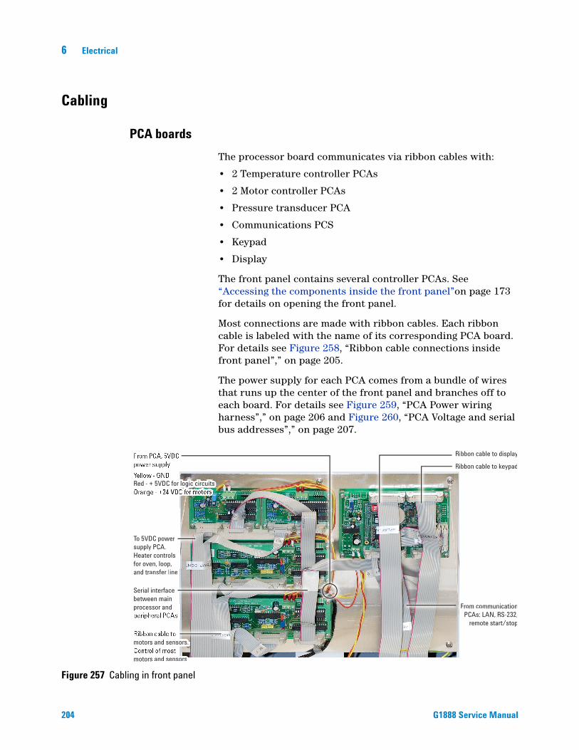
6 Electrical
Cabling
PCA boards
204
The processor board communicates via ribbon cables with:
• 2 Temperature controller PCAs
• 2 Motor controller PCAs
• Pressure transducer PCA
• Communications PCS
• Keypad
• Display
The front panel contains several controller PCAs. See “Accessing the components inside the front panel”on page 173 for details on opening the front panel.
Most connections are made with ribbon cables. Each ribbon cable is labeled with the name of its corresponding PCA board. For details see Figure 258, “Ribbon cable connections inside front panel”,” on page 205.
The power supply for each PCA comes from a bundle of wires that runs up the center of the front panel and branches off to each board. For details see Figure 259, “PCA Power wiring harness”,” on page 206 and Figure 260, “PCA Voltage and serial bus addresses”,” on page 207.
Figure 257 Cabling in front panel
Red - + 5VDC for logic circuits
Serial interface between mainprocessor and
Ribbon cable to display
Ribbon cable to keypad
From communicationPCAs: LAN, RS-232,
remote start/stop
To 5VDC power supply PCA.Heater controls for oven, loop, and transfer line
motors and sensors.
motors and sensors
Red - + 5VDC for logic circuits
motors and sensors.
motors and sensors
Dy r
s. dds and sensors.
ds and sensors
inees
aen
ss
RiR bbon ca
RiR bbon ca
From comPCAs: L
remot
5VDC f ogic circuits 5VDC for logic circuits
C powerr PCA.controls
nterfaceeen main
nsfer linen, loop,
sor and
G1888 Service Manual

Electrical 6
G1888 Service Manual
Figure 258 Ribbon cable connections inside front panel
+
+
+ +
C1L1
R8
U4
U3 U2
CX2
R7 R6
TEMP CONTROLLER HSSX2R CS 2090-1002
R5 R4 R3 R2 R1
C2
C3
C5
CX3
CX1
C4
J3 J1
11
JP1C7 C6
U1 +
+
+ +
C1L1
R8
U4
U3 U2
CX2
R7 R6
TEMP CONTROLLER HSSX2R CS 2090-1002
R5 R4 R3 R2 R1
C2
C3
C5
CX3
CX1
C4
J3 J1
11
JP1C7
U1
+
MOTOR CONTROLLER HSSX2R
RXE 1R16
U4
R14
R13R15
R11R10R12
R17
C12 C11
C3
C1
U1
JP1
1
J1
21
1615
CS2085/0602 REV-1R19R18R21R20
R31R30R33R32
U6
CX3
R26R27R25
R23R22R24
U5
R29 R28
C14 C13
RXE 2
+
C5
R1D1
D2C6C4
R8R9R4
R6R7R5
C9 C10
C7
C8
J3
C2
U3
CX1
R2 R3
1
CX2
U8 U2
P1CX4
+
RXE 1R16
U4
R14
R13R15
R11R10R12
R17
C12 C11
C3
C1
U1
JP1
1
J1
21
1615
R31R30R33R32
R26R27R25
R23R22R24
U5
R29 R28
C14 C13
RXE 2
+
C5
R1D1
D2C6C4
R8R9R4
R6R7R5
C9 C10
C7
C8
J3
C2
U3
CX1
R2 R3
1
CX2
U8 U2
P1CX4
U10
SERIAL I/0 - I2C
J2POWERSUPPLY
P2
R1
JP2C15
C3
C1
C16
C18
U11C19
C12CX9
JP8
DIGITAL & ANALOG I/O
A1
Motor Contr112Motor Contr112Motor Controller 2
Motor Controller 1Motor Controller 134115001113411500111Motor Controller 1
Processor
J4A2J5
A3J6
A2 J10
A3J6
A2J5
A1J4
A2J4
A1J4
Control harnessribbon cable5104309004
A1
J2
A3
A4
A5
J2
J2
J2
J4
Communications harnessribbon cable 5104309005
A2
A3J3
A1J9
TemperatureController 1
TemperatureController 2
1
DisplayJ1 A1
J6
J5
To pneumaticcontrol module
1J1Keypad
Display kepad assemblyOld color 0410105034New color 0410105134
205

206
6 Electrical
Figure 259 PCA Power wiring harness
+
+
+ +
C1
R8
U4
U3 U2
CX2
R7 R6
TEMP CONTROLLER HSSX2R CS 2090-1002
R5 R4 R3 R2 R1
C2
C3
C5
CX3
CX1
C4
J3J1
11
JP1C7 C6
J2J4
U1 +
+
+ +
C1
R8
U4
U3 U2
CX2
R7 R6
TEMP CONTROLLER HSSX2R CS 2090-1002
R5 R4 R3 R2 R1
C2
C3
C5
CX3
CX1
C4
J3J1
1
JP1C7 C6
J2J4
U1
+
MOTOR CONTROLLER HSSX2R
RXE 1R16
U4
R14
R13R15
R11R10R12
R17J4 J2J6J5
C12 C11
C3
C1
U1
JP1
1
J1
21
1615
CS2085/0602 REV-1R19R18R21R20
R31R30R33R32
U6
CX3
R26R27R25
R23R22R24
U5
R29 R28
C14 C13
RXE 2
+
C5
R1D1
D2C6C4
R8R9R4
R6R7R5
C9 C10
C7
C8
J3C2
U3
CX1
R2 R3
1
CX2
U8 U2
P1CX4
+
RXE 1R16
U4
R14
R13R15
R11R10R12
R17J4 J2J6J5
C12 C11
C3
C1
U1
JP1
1
J1
21
1615
R31R30R33R32
R26R27R25
R23R22R24
U5
R29 R28
C14 C13
RXE 2
+
C5
R1D1
D2C6C4
R8R9R4
R6R7R5
C9 C10
C7
C8
J3C2
U3
CX1
R2 R3
1
CX2
U8 U2
P1CX4
U10
DRAOBYEKYALPSID
J4SERIAL I/0 - I2C
J2POWERSUPPLY
P2
R1
JP2C15
C3
C1
C16
C18
U11C19
CX1
C12CX9
JP8
5J6J
J3DIGITAL & ANALOG I/O
J10
C5
To pneumaticcontrol module
TemperatureController 2
TemperatureController 1
Motor Controller 2
Motor Controller 1
Processor
A1
A2 ---> Pin 2 of J2A3 ---> Pin 1 of J2
A4 ---> Pin 3 of J3 A5 ---> Pin 2 of J3
B6 ---> Pin 3 of J3B7 ---> Pin 2 of J3
B4 ---> Pin 3 of J3B5 ---> Pin 2 of J3 A1 ---> Pin 1 of J3
A4 A5 B6 B7
B4 B5
A2A3
B1 ---> Pin 3 of J3B2 ---> Pin 2 of J3 B3 ---> Pin 1 of J3
B3B1 B2
1
Display
5 VDC Power Supply and Distribution
J11 2 3 4 5
G1888 Service Manual

Electrical 6
Figure 260 PCA Voltage and serial bus addresses
6-port valve, Lifter sampling, Carousel
J4 J2
Motor Controller 2
J5 J6
GN
D
5 V
DC
24 V
DC
2
J4 J2
Motor Controller 1
J5 J6
Tray, Lifter tray, and Shutter
GN
D
5 V
DC
24 V
DC
1G
ND
5 V
DC
24 V
DC
J2
Pressure
5
J4
cobo
x-LA
N
Processor
J3
Seria
l 1-R
S232
not u
sed
J6 J5
GN
D
5 V
DC
GND
5 VDC
24 VDC
5
= Ground
= 5 Volts DC
= 24 Volts DC
= PCA's serial bus address
J4 J2
Temp Controller 2
Oven
GN
D
5 V
DC
4
J4 J2
Temp Controller 1
Loop & Transfer LineG
ND
5 V
DC
3
G1888 Service Manual
207
6 Electrical
Power distribution
208
5 VDC Power distribution
The 5 VDC supply and power distribution board is located on the inside face of the HS back panel. See “Accessing the components inside the rear panel”on page 175 for details.
This board contains three fuses. See Figure 261 for locations and Table 35 on page 287 for part numbers.
• Fuse 1 – 1A, 250 V, Protects the motor controller circuits
• Fuse 3 – 6A, 125 V, Protects the transfer line heater circuit
• Fuse 4 – 6A, 125 V, Protects the loop heater circuit
This board also contains four LED indicators. See Figure 261:
• LED 1 – Oven heater ON when 5 VDC sent to close oven relay and provide 48VAC to the oven heater
• LED 2 – Loop cartridge heater ON when 5 VDC sent to close on-board relay and provide 24VDC to the loop cartridge heater
• LED 3 – Transfer line heater ON when 5 VDC sent to close on-board relay and provide 24VDC to transfer line heater
• LED 4 – Oven max temperature indicator ON when the oven max temperature switch opens
Fuse 3
Fuse 4
Fuse 1
Fuse 444
Fuse 11
Fuse 33333
LED 1
LED 2
LED 4
LED 3
LLED 1
LLED 2
LLEL D 3
LEL D 1
LLLED 4
J4 J5
J2 J1 J3
Figure 261 5 VDC supply and power distribution board fuses and LEDs
G1888 Service Manual

Electrical 6
G1888 Service Manual
Power distribution for heated zones
Figure 262 shows power distribution associated with the heated zones including fuses, LEDs, and test points.
Figure 262 Power distribution
Power distribution PCA
Oven Relay
Power Selector SwitchManual Switch and Main Fuses
Line Filter
Neutral
Chassis Ground
Line115 VAC
230 VAC
115 VAC
115 VAC
Main fuse
Main fuse
F3
F4
safety relayK2
LED 2
LED 3
Loop heater, 5.75 ohms
Transfer line heater, 6.6 ohms
LED 1
LED 1 - ON when heating OvenLED 2 - ON when heating LoopLED 3 - ON when heating TlineLED 4 - ON when oven is above max temperature limit
1
24
3
F1
Power Distribution PCA fusesF1, 1A 250 V, Motor controllers PN - 384-1595011-HSPF3, 6A 125 V, Transfer line PN - 384-1295001-HSPF4, 6A 125 V, Loop heater PN - 384-1295001-HSP
48 VAC
Oven fan motor 1.11 amps100 watts
Transformer 500 VAC
+
++
Transformerfuse
AC-DC Converter
Input: 85-264 VAC 47-63 HzOutput: 24 VDC 12.5 Amps
Oven heaterOven heater1.75 ohms1.75 ohmsOven heater1.75 ohms
LED 4
To motor control circuits
Main fuses10 amp, fast acting250 V, 5x20 mmPN - 5188-1157
Transformer fuse8 amp, fast acting250 V, 5x20 mmPN - 5188-1158
209

6 Electrical
Electrical schematic
Figure 263 Electrical schematic - part A
J1
J2
J3
J4
J5
J6
J1
J2
J2
J4J6
J5
J3J9
J5
J1
J2
J3
J2
J3
J4
J3
J2
J2
J4J6
J5
J3J9
ProcessorD10_601_9 S.opj
SPI SDINSPI SDOUT
SPI SCLKSPI CSSPI A0SPI A1SPI A2SPI A3
I2C-1 SDAI2C-1 SCL
EXP A0EXP R/WEXP LCD E
EXP D0EXP D1EXP D2EXP D3EXP D4EXP D5EXP D6EXP D7
RESET
VCCGND
-VEEV-CONTR
VC
CG
ND
DIG
9 I/
OD
IG 1
0 IN
GND
VCCV
CC
GND
DCD-1DSR-2
RX-1RTS-1
TX-1CTS-1DTR-1
RI-1
GN
DTX
D-1
RX
CB
CTS
CB
DS
RC
BH
SO
-1/R
TS-1
DIG
3 I/
O /
DTR
-1R
STC
B
KEYB COL1KEYB COL2KEYB COL3KEYB COL4KEYB COL5KEYB COL6KEYB COL7KEYB COL8KEYB ROW1KEYB ROW2KEYB ROW3KEYB ROW4KEYB ROW5KEYB ROW6KEYB ROW7KEYB ROW8
GNDVCC
APG Remote
D10_601_10_1 S.opj
EXT.GNDREADYSTART
DIG 9 I/ODIG 10 IN
GNDVCC
Cobox-Lan
RSTCBDIS3 / DTR-1
HSO+1/RTS-1DSRCBCTSCB
RXCBTXD-1
GNDVCC
J3
J2
Pressure
D10_607_15 S.opjj
SPI SDOUTSPI SCLK
SPI CSSPI A0SPI A1SPI A2SPI A3
SPI SDIN
GN
D
VC
C
I2C-1 SCLI2C-1 SDA
Display
VCC-VEE
GND
EXP A0EXP R/W
EXP LCD E
EXP D0EXP D1EXP D2EXP D3EXP D4EXP D5EXP D6EXP D7
RESET
A
K
Tb Transformer
D10_601_14 S.opj
1
2
2
1
2
1
12
12
12
J2
J3
J4
Temp. Controller 1
D10_601_13 S.opj
TEM
P1
TEM
P2
AG
ND
TEM
P1.
HE
AT
TEM
P1.
HE
AT
I/O 3
I/O 4
I/O 5
SPI SDOUTSPI SCLK
SPI CSSPI A0SPI A1SPI A2SPI A3
SPI SDIN
VC
C
GN
D
I2C-1 SCLI2C-1 SDA
KeyboardP10_675 S.opj
VCCGND
KEYB COL1KEYB COL2KEYB COL3KEYB COL4KEYB COL5KEYB COL6KEYB COL7KEYB COL8
KEYB ROW1KEYB ROW2KEYB ROW3KEYB ROW4KEYB ROW5KEYB ROW6KEYB ROW7KEYB ROW8
D10_604_1 S.opj
I/O 3
I/O 4
I/O 5
TEM
P1.
HE
AT
TEM
P1.
HE
AT
TEM
P1
TEM
P2
AG
ND
GNDVCC+24V
24V+PGND
GND+24V
12
34
24 Volt Power Supply
SP300-24
+24V+24V
GND
L
N
G
+24V
GNDGND
N
L
G
VCC
VCC+24V
VCC
Ext Gnd
VCC
F1 10A
T1
Transformer
P1
RS232-1594837261
M8
Oven fan
P2
Remote
594837261
F2 10A
Line Filter
230V
115V
SW1 SEL 115/230V
Continued on next page
PowerSupply
Main Switch
Voltage Selector
A
B
C
D
E
210 G1888 Service Manual

Electrical 6
Electrical schematic
Figure 264 Electrical schematic - part B
J1
J1B
J2AJ2BJ4A
J1B J1A
J2B J2A
J1A
J1
J4B
J5
J3
J2 J4
J3
J2
J4
J6
J5
J3
J2
J6
J5
J4
J5J2
J6J3J1
J4
J2
J7
J3J1
J2
J3
J3
J2
J1
J2J1
Tb ValveD10_607_6 S.opj
VCC
GND
M2+
M2-
I/O 2
M1+M1-
I/O 1I/O 2
GNDVCC
I/O 3
Tb CarouselD10_640 S.opj
MS1-
MS2+
MS2-
MS1+MS1+MS1-
I/O 1GND
VCCMS2+MS2-
Tb Pneumatics
D10_607_6_1 S.opj
12
123456789
10
12345678910
12
Position 1Optical Sensor
D10_628 S.opj
VCC
GN
DI/O
1
J3
J2
J4
J6
J5
Motor Controller 1
D10_601_12 S.opj
I/O 1I/O 2I/O 3I/O 4
I/O 5I/O 6
I/O 9I/O 10I/O 11
MS1+MS1-
MS2+MS2-
M2+M2-
M1+M1+
GND
GND
GND
VCC
VCC
VCC
SPI SDOUTSPI SCLK
SPI A0SPI A1SPI A2SPI A3
SPI CS
SPI SDIN
+24V
VCC
GND
I2C-1 SCLI2C-1 SDA
J3
J2
J6
J5
J4
Motor Controller 2
D10_601_15 S.opj
I/O 1I/O 2I/O 3I/O 4
I/O 5I/O 6
I/O 9I/O 10I/O 11
MS1+MS1-
MS2+MS2-
M2+M2-
M1+M1+
GND
GND
GND
VCC
VCC
VCC
SPI SDOUTSPI SCLK
SPI A0SPI A1SPI A2SPI A3
SPI CS
SPI SDIN
+24V
VCC
GND
I2C-1 SCLI2C-1 SDA
Tb TrayD10_627 S.opj
VCCGND
I/O 2I/O 3
M1+M1-VC
C
GN
DI/O
1
VCC
GN
DI/O
3
MS1+MS1-MS2+MS2-
VCCGND
M1+M1+I/O 1I/O 2I/O 3
I/O 1I/O 2I/O 3
GND
VCC
MS1+MS1-
MS2+MS2-
I/O 4
Tb Lifter Tray D10_635 S.opj
VCC
GND
M2+
M2-
I/O 2
M2+M2-
I/O 1I/O 2
GNDVCC
Tb Oven Heater
D10_607_6_1 S.opj
12
123456789
10
12345678910
12
Tb Sampling LifterD10_635 S.opj
VCC
GND
M2+
M2-
I/O 2
M2+M2-
I/O 1I/O 2
GNDVCC
123456789
10
123456789
10
TEM
P1TE
MP2
AGN
D
TEM
P1.H
EAT
TEM
P1.H
EAT
I/O 3
I/O 4
I/O 5
Vial PresentOptical Sensor
D10_671 S.opj
VCC
C GN
D
J3
J2 J4
Temp. Controller 2
D10_601_13 S.opj
TEM
P1TE
MP2
AGN
D
TEM
P1.H
EAT
TEM
P1.H
EAT
I/O 3
I/O 4
I/O 5
SPI SDOUTSPI SCLKSPI CSSPI A0SPI A1SPI A2SPI A3
SPI SDIN
GN
D
VCC
I2C-1 SCLI2C-1 SDA
VCC
VCC
VCC
+24V
+24V
Loop Heater
MS1Shutter Motor
- +
M6
tTransfer Line PT100
MS2Carousel Motor
M1
Tray Motor
123456
M2
Lifter Tray Motor
123
4
5
tOven PT100
M3
6-Port Valve Motor
123
4
5
Vent
-
+ M7
- +
M5
t Loop PT100
SSR1
1 2
3 4
LOAD LOAD
IN+
IN-
Transfer Line Heater
M4
Sampling Lifter
123
4
5
V2V1
Relay
Pressure
Continued from previous page
PowerSupply
Oven Heater
Vial TrayCooling
SW2Thermostat
A
B
C
D
E
G1888 Service Manual 211

212
6 Electrical
G1888 Service Manual
Agilent G1888 HeadSpace SamplerService Manual
7Firmware and Updating Firmware
Firmware Overview 214
Updating Firmware 215
Methods of updating main processor firmware 215
Advanced function 5 215
Agilent GC firmware update utility 217
HyperTerminal 217
Instrument Utilities 217
Recovering from Corrupt Installations 220
Recovering from the blue screen using Instrument Utilities 220
Recovering from the blue screen using Hyperterminal 223
213Agilent Technologies

7 Firmware and Updating Firmware
Firmware Overview
214
At the time of this publication there are eight firmware revisions. You can view the firmware revision installed on your HS from Advanced Function 19 or from the Power ON self-test.
The main processor has the only updatable firmware. All other firmware is non-flashable.
Figure 265 Firmware display screens
G1888 Service Manual

Firmware and Updating Firmware 7
Updating Firmware
Methods of updating main processor firmware
G1888 Service Manual
• Advanced Function 5 diagnostic utility
• Agilent GC firmware update utility
• Through a HyperTerminal
• Through Instrument Utilities
Advanced function 5
1 Launch the diagnostic utility and connect to the HS.
2 Backup any customer methods and temperature zone calibration data. Select Advanced Tests > Advanced Functions > Backup > Restore Headspace Data.
3 Select Advanced Tests > Advanced Functions > Update Firmware.
Figure 266 The advanced functions menu
215

216
7 Firmware and Updating Firmware
Figure 267 Update firmware with Advanced Function 5
4 When prompted browse and select the <firmware>.txt file.
Progress can be monitored by the progress bar. It will display the current record, total number of records and percentage of completion.
When Update Firmware is pressed, a file open box dialog is opened. When the proper firmware update file is selected, (.txt extension), the file is checked to insure that all lines conform to the proper construct for firmware update. If the file is ok, the firmware update will then proceed.
Filename of firmware update is displayed.
Response from the HS is displayed.
G1888 Service Manual

Firmware and Updating Firmware 7
Agilent GC firmware update utility
G1888 Service Manual
1 Launch Agilent GC firmware update utility.
2 Select update G1888 HS.
3 Connect to HS.
4 When prompted select the <firmware>.txt file.
5 Power cycle the HS.
HyperTerminal
1 Select Start > Accessories > Communications, > HyperTerminal.
2 Configure the connection for LAN or RS-232.
3 Send commands to HS.
4 When prompted select Transfer > Send text file.
5 Browse and select the <firmware>.txt file.
Instrument Utilities
To update the firmware using Instrument Utilities you must first configure the instrument and then update the firmware.
Configure the Instrument
1 Start Instrument Utilities.
2 In the explorer pane, select Configuration > Instruments.
3 In the Add to My Instruments panel, select Agilent G1888 as the Instrument Type.
4 Enter the Instrument Address. If you are connected via RS232, you must type in the COM port (for example COM1). If you are connected VIA LAN, type in the IP address. Then select Add Instrument.
217
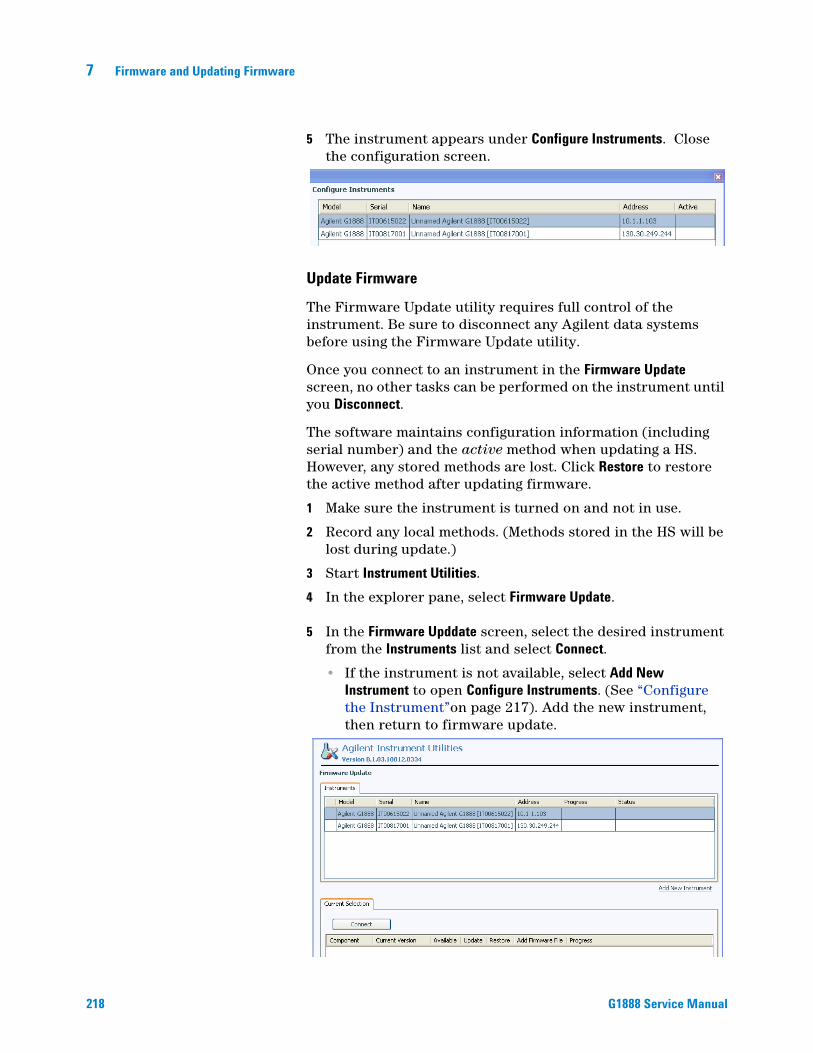
218
7 Firmware and Updating Firmware
5 The instrument appears under Configure Instruments. Close the configuration screen.
Update Firmware
The Firmware Update utility requires full control of the instrument. Be sure to disconnect any Agilent data systems before using the Firmware Update utility.
Once you connect to an instrument in the Firmware Update screen, no other tasks can be performed on the instrument until you Disconnect.
The software maintains configuration information (including serial number) and the active method when updating a HS. However, any stored methods are lost. Click Restore to restore the active method after updating firmware.
1 Make sure the instrument is turned on and not in use.
2 Record any local methods. (Methods stored in the HS will be lost during update.)
3 Start Instrument Utilities.
4 In the explorer pane, select Firmware Update.
5 In the Firmware Upddate screen, select the desired instrument from the Instruments list and select Connect.
• If the instrument is not available, select Add New Instrument to open Configure Instruments. (See “Configure the Instrument”on page 217). Add the new instrument, then return to firmware update.
G1888 Service Manual

Firmware and Updating Firmware 7
G1888 Service Manual
6 Under Current Selection, select the desired firmware version from the Available drop-down list. If the desired firmware version is not available, add it as follows:
a Go to the Agilent web site at http://www.chem.agilent.com/en-US/Support/Downloads/firmware/Pages/default.aspx.
b Download the updated firmware for your instrument type.
c Unzip the firmware file(s).
d In the Firmware Update utility, click Add. Browse to and select the files unzipped in the previous step. The new firmware version will now appear in the Available drop-down list
7 Select Update.
8 When prompted, save the active method and configuration data. You will restore the data from this file in a later step.
Do not turn off power to the device during firmware update.
WARNING9 When the process completes, the instrument reboots. Reconnect to the instrument, then select Restore. Select the previously-saved data file to restore the active method.
10 To disconnect the firmware update utility from the instrument, select Disconnect.
G1888 HS only: If the HS firmware update fails, you will not be able to reconnect to the instrument. The HS front display will be blue, with no text. The software will prompt if you would like to connect to the instrument in recovery mode. Follow the steps described in “Recovering from the blue screen using Instrument Utilities”on page 220.
219

7 Firmware and Updating Firmware
Recovering from Corrupt Installations
220
• Instrument Utilities can be used to recover from corrupt installations.
• Hyperterminal or Advanced 5 can be used to recover from corrupt installations.
• LAN can not be used when recovering from corrupt installations.
Recovering from the blue screen using Instrument Utilities
Only perform this procedure after a failed firmware update. Turn on the headspace sampler (HS). The display will be blue, with no text. You will not be able to connect to the HS using a LAN connection.
NOTE You may receive a prompt to recover the headspace sampler for other reasons, for example, if the G1888 is turned off, or if the IP address is changed, or if the instrument is in use by another computer. Only recover the HS after a firmware update fails and the HS display is blue, with no visible text.
The recovery process requires the following:
• An RS-232 cable (part number G1530-60600)
• A properly-configured COM port on the Instrument Utilities computer
• A properly-configured COM port on the Lab Advisor computer
• A 3-mm hex wrench
• ESD wrist strap (to prevent damage to the HS electronics)
Recover the HS as described below.
1 If you have been prompted by the software to attempt recovery of the HS, click No. You need to perform a few hardware steps before attempting recovery. Leave the Firmware Update interface open.
2 Set up the computer COM port. On most computers, the COM (serial port) needed will be COM1. (Computers can have port extenders installed, and also certain devices create additional COM ports. However, the one you need to modify is the one for the serial connection on the PC.) These changes require administrative privileges.
G1888 Service Manual

Firmware and Updating Firmware 7
G1888 Service Manual
• On Windows Vista or 7, open the Control Panel, then open Device Manager > Ports.
• On Windows XP, open the Start menu, then right-click My Computer. Select Manage, then open Device Manager > Ports.
If you need help making the settings for the COM ports, open the operating system help and search for “COM port.”
Set up the COM port to use the following settings:
• Bits per second - 9600
• Data bits - 8
• Parity - None
• Stop bits - 1
• Flow control - Hardware
3 Connect the RS 232 cable between the HS and the PC.
4 Turn on the HS.
Hazardous voltages are present when the front cover is open.
WARNINGTo prevent damage to the HS electronics, wear an ESD wrist
CAUTIONstrap when accessing the HS components.5 Access the electronics boards. See “Accessing the components”on page 173.
6 If not open, start the Instrument Utility. If not open, start Lab Advisor.
7 From the explorer pane, select Firmware Update.
8 Select the desired instrument from the Instrument list and select Connect.
9 When the software fails to connect to the HS, the software will prompt you to attempt recovery. Click Yes. The software opens serial communications using the COM port. If the connection fails, recheck the port settings and verify that the cable is properly connected between the HS and the PC.
10 When prompted to toggle the main processor PCS switch to PROGRAM mode, locate the DIP switch and toggle it to ON / PRG as shown below. Click Continue.
221

222
7 Firmware and Updating Firmware
11 When prompted to return the switch to RUN mode, set the switch as shown below. Click Continue.
12 The software will re-download the firmware.
13 When complete, power cycle the HS. After reboot, the display should appear normal.
14 Reconnect to the instrument and click Restore. Select the previously-saved data file to restore the active method.
G1888 Service Manual
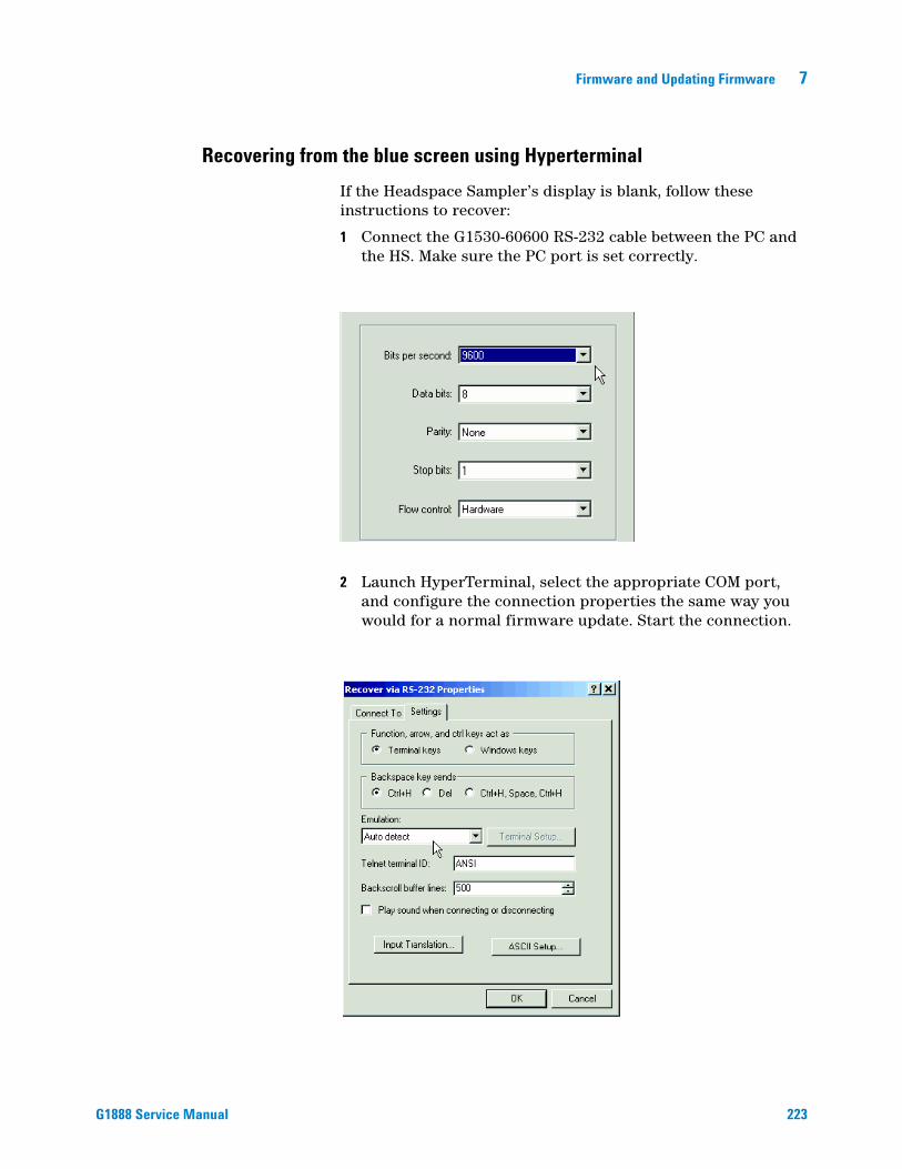
Firmware and Updating Firmware 7
Recovering from the blue screen using Hyperterminal
G1888 Service Manual
If the Headspace Sampler’s display is blank, follow these instructions to recover:
1 Connect the G1530-60600 RS-232 cable between the PC and the HS. Make sure the PC port is set correctly.
2 Launch HyperTerminal, select the appropriate COM port, and configure the connection properties the same way you would for a normal firmware update. Start the connection.
223

224
7 Firmware and Updating Firmware
3 Access the main processor PCA and move switch 1 to PRG or program mode.
4 The Sampler replies with this message. Enter S.VM-1 Control Computer running Venom-SCVersion 2003 01 15Copyright 2000-2003 Micro-Robotics Ltd.Clear memory: Y/N/S ?
5 Type: -->stop all > Enter .
6 Type -->protect(0) > Enter.
7 Move switch 1 to Run mode. Erasing app. area...Done.
8 Second prompt appears when you toggle switch back to Run mode. -->
9 Type -->-->protect(128).Send S-Records now50000 50010 50020
10 Select Transfer > Send Text File.
G1888 Service Manual

Firmware and Updating Firmware 7
G1888 Service Manual
11 Browse and select the text file that contains the firmware.
12 If the recovery is successful, you should get this message at the end of the download:
13 Disconnect HyperTerminal from the HS and power cycle the HS.
6E460 6E470 6E480 6E4906E500 6E510 6E520 6E5306E5A0 6E5B0 6E5C0 6E5D06E640 6E650 6E660 6E6706E6E0 6E6F0 6E700 6E7106E780 6E790 6E7A0 6E7B0Download doneCopied to trash -->
225

226
7 Firmware and Updating Firmware
G1888 Service Manual

Agilent G1888 HeadSpace SamplerService Manual
8Error Messages
Overview 228
Errors With A Diagnostic Message 229
Internal Communication Serial I/O Errors 233
Errors Without A Diagnostic Message 234
227Agilent Technologies

8 Error Messages
Overview
228
This chapter will help you recover from most of the problems that occur while operating the Headspace Sampler (HS). It is separated into three main types of error messages:
• Errors with a diagnostic message
• Internal communication
• Errors without a diagnostic message
G1888 Service Manual

Error Messages 8
Errors With A Diagnostic Message
110 Oven Sensor Error
G1888 Service Manual
Oven sensor open or disconnected.
111 Oven Sensor Error
Oven sensor short or damaged.
112 Oven Temp Error
Oven temp higher than expected.
Is oven set 10 below loop?
SVC: Left temp controller 1 PCA, calibration
113 Oven Temp Error
Oven temp lower than expected.
Is oven lid closed?
SVC: Left temp controller 1 PCA, calibration, power config, TPCA F3
120 Loop Sensor Error
Loop sensor open or disconnected.
121 Loop Sensor Error
Loop sensor short or damaged.
122 Loop Temp Error
Loop temperature higher than expected.
Is Loop temp set 10 above oven?
SVC: Right temp controller 2 PCA, calibration
123 Loop Temp Error
Loop temp lower than expected.
Is Loop cover on?
229

230
8 Error Messages
SVC: Right temp controller 2 PCA, calibration, Power PCA F3
130 Transfer Line Sensor Error
Transfer line sensor open or disconnected.
131 Transfer Line Sensor Error
Transfer line sensor short or damaged.
132 Transfer Line Temp Error
Transfer line temp higher than expected.
SVC: Right temp controller 1 PCA
133 Transfer Line Temp Error
Transfer line temp lower than expected.
SVC: Right temp controller 2 PCA, Power PCA F3
210 Tray Too Slow Error
This error results when the tray motor encoder senses an obstruction.
Please check and clear any obstruction to the tray chain.
SVC: Tray friction, adjustment, motor, bottom motor controller 1 PCA
211 Tray Motor Encoder Error
This error results when the tray motor encoder is not responding.
SVC: tray motor, bottom motor controller 1 PCA
212 Tray Position 1 Error
This error results when the tray position 1 sensor is not found after several attempts.
Check the tray chain tension and tray position 1 alignment.
Check for tray interference.
SVC: tray motor, sensor, bottom motor controller 1 PCA
G1888 Service Manual

Error Messages 8
219 Tray Lock
G1888 Service Manual
This component did not FAIL. It is disabled to protect the HS. View information for FAIL items only.
220 Shutter Error
This error results when the shutter stepper motor senses an obstruction or cannot find its home position.
SVC: shutter motor-sensor assembly and bottom motor controller 1 PCA
229 Shutter Lock
This component did not FAIL. It is disabled to protect the HS. View information for FAIL items only
230 Lifter 1 Error
This error results when the tray lifter motor encoder senses an obstruction or cannot find its home position.
Please check and clear any obstruction to the lifter. Also check the shutter and carousel alignment.
SVC: Lifter 1, carousel alignment, bottom motor controller 1 PCA
239 Lifter 1 Lock
This component did not FAIL. It is disabled to protect the HS. View information for FAIL items only.
240 Lifter 2 Error
This error results when the tray lifter motor encoder senses an obstruction or cannot find its home position.
Please check and clear any obstruction to the lifter. Make sure you have the correct vial size setting; Advanced Function 12. Also check the carousel alignment.
SVC: Lifter 2, carousel alignment, top motor controller 2 PCA
231

8 Error Messages
249 Lifter 2 Lock
232
This component did not FAIL. It is disabled to protect the HS. View information for FAIL items only.
250 Carousel Error
This error results when the carousel motor encoder senses an obstruction or cannot find its position.
Please check and clear any obstruction to the carousel. Also check the carousel alignment.
SVC: carousel motor, sensor, alignment, top motor controller 2 PCA
259 Carousel Lock
This component did not FAIL. It is disabled to protect the HS. View information for FAIL items only.
260 6-port Valve Error
This error results when the 6-port valve motor encoder senses an obstruction or cannot find its home position.
Please check and clear any obstruction to the valve motor linkage. Also check the for any rubbing on the back side of the insulated cover to the loop heated zone.
SVC: 6-port valve motor-sensor assembly, top motor controller 2 PCA
300 Pressure Error
Number series for pressure errors. Not implemented.
400 Power Error
Number series for power errors. Not implemented.
G1888 Service Manual

Error Messages 8
Internal Communication Serial I/O Errors
G1888 Service Manual
These errors indicate a bad connection between the main processor PCA and peripheral PCAs.
510 Serial I/O Error
SVC: connections and PCAs: main PCA J4 and bottom motor controller 1 PCA J2
520 Serial I/O Error
SVC: connections between main PCA J4 and top motor controller 2 PCA J2
530 Serial I/O Error
SVC: connections between main PCA J4 and left temp controller 2 PCA J2
540 Serial I/O Error
SVC: connections between main PCA J4 and right temp controller 2 PCA J2
550 Serial I/O Error
SVC: connections between main PCA J4 and top motor controller 2 PCA J2
560 Serial I/O Error
SVC: connections between main PCA J4 and Pressure PCA J2
600 - 605 Serial I/O Error
SVC: update firmware for main PCA
233

8 Error Messages
Errors Without A Diagnostic Message
234
These errors appear in the lower right-hand corner of the display. They do not have diagnostic information for them at this time.
GC is not ready
GC is not ready when the HS is ready to inject the sample vial. Advanced Function 9, Check GC Ready must be set to WAIT.
GC not properly connected. GC cycle time setpoint too short.
Press START/STOP button to stop analysis and recover all vials from oven to tray. Check GC_READY signal connection.
RAM error
Checksum on HS data stored in non-volatile memory is wrong.
A debug information on which part of non-volatile memory has caused the problem is present in diagnostic menu.
This can happen only at HS start-up.
Press CLEAR to clear all non volatile HS memory and restart the HS.
The HS will restore all default values for methods and configuration parameters.
Vial not dropped
This error results when a vial is not successfully lowered from the tray to the carousel. This information is provided by the TB-vials sensor to electronics. A sensor checks for a vial after the tray lifter lowers the vial. Check the following:
• Tray belt tension
• Tray position 1 alignment (see “Align the carousel”on page 115).
• Carousel alignment
• Obstructions or dirt
If this error is reported and the vial did drop or is still in the tray, check the vial sensor (see step 4 on page 73).
G1888 Service Manual

Error Messages 8
Remove all vials
G1888 Service Manual
This error is caused by incoherence between vial positions in the oven carousel and information about vial positions stored in HS memory.
This error may appear while the HS is trying to recover vials after a vial handling error or after you press the Stop button. The message indicates that the HS found vials in an unexpected carousel location. Carefully remove all vials from the heated carousel and reset the HS with Advanced Function 10. You can also restart the HS.
Vial not found in oven
This error may appear while the HS is trying to recover vials after a vial handling error or after you press the stop button. The message indicates that the HS did not find a vial in the carousel where it expected to find the vial. Carefully remove all vials from the heated carousel and reset the HS with Advanced Function 10. You can also restart the HS.
If this error, Vial not found, is reported and the vial is still in the tray, check the vial sensor (see step 4 on page 73).
Tray full!
This error may appear while the HS is trying to recover vials after n vial handling error or after you press the stop button. The message indicates that the HS tray is full and it cannot check for vials in the carousel. It is not possible to check if there are vials in the oven because there isn't an empty vial location on the tray.
Carefully remove one vial from the tray and reset the HS with Advanced Function 10. You can also restart the HS.
Temperature actual reads “open” or “short”
If the actual temperature reads "open" or "short", the temperature sensor for that zone is disconnected or damaged.
Zone at or near ambient
If the actual temperature is near ambient, please check the following:
• Zone setpoint is "0" or OFF.
• The fuse for the heated zone is blown.
235

8 Error Messages
Zone does not stabilize
236
If the actual oven temperature is slow to respond or does not reach the setpoint, please check the following:
• The oven lid is closed and the latches locked.
• The loop heated zone cover sits flush with the base of the pneumatic compartment.
• If the voltage at the electrical outlet is from 90 to 132 VAC, the line voltage selector switch is set to 115 VAC.
Analysis aborted Oven Temp. Error
Oven temperature was out of range for more than 6 seconds during a run. Run interrupted.
Check the following:
• The oven lid is closed and the latches locked.
• The loop heated zone cover sits flush with the base of the pneumatic compartment.
Press START/STOP button to stop analysis and recover all vials from oven to tray
Analysis aborted Loop Temp. Error
Loop temperature was out of range for more than 6 seconds during a run. Run interrupted.
Check the following:• The oven lid is closed and the latches locked.• The loop heated zone cover sits flush with the base of the
pneumatic compartment.
Press START/STOP button to stop analysis and recover all vials from oven to tray
Analysis aborted Tr.line Temp. Error
Transfer line temperature was out of range for more than 6 seconds during a run. Run interrupted.Check the following:• The oven lid is closed and the latches locked.• The loop heated zone cover sits flush with the base of the
pneumatic compartment.Press START/STOP button to stop analysis and recover all vials from oven to tray
G1888 Service Manual

Agilent G1888 HeadSpace SamplerService Manual
9Troubleshooting
Tests Overview 238
Strife test 239
Chain method test 240
Checking the Headspace Sampler for leaks 240
Headspace Sampler leak test 242
Troubleshooting vent restrictions 253
Troubleshooting leaks at fittings in standby mode 254
Troubleshooting leaks at fittings in inject mode 255
Chromatographic Results 258
No peaks or reduced sensitivity 258
Poor retention time reproducibility 259
Poor area count repeatability 259
Carryover in air or solvent blanks 260
Unwanted background noise or peaks 260
Pressure Readings 261
GC goes not ready during a run 261
GC pressure reading does not match Headspace Sampler pressure reading 261
Synchronization with GC start 262
GC does not start 262
Run is aborted 262
Communication with PC 263
Lantronix Cobox micro LED patterns 264
Improving LAN communications 266
Memory and Processor Errors 269
Blank Display 269
Power ON, No Response / Instrument Dead 269
Vial Handling 269
MeOH Test 271
Troubleshooting Electronics 277
237Agilent Technologies

9 Troubleshooting
Tests Overview
238
This section should help you recover from most of the problems that you might see while operating the Headspace Sampler (HS).
Diagnostic error messages can have values of OK, LOCK, or FAIL.
FAIL errors point to the component that requires troubleshooting.
G1888 Service Manual

Troubleshooting 9
Strife test
G1888 Service Manual
A strife test can be used to test mechanical parts and vial handling.
Running the strife test is recommended after the alignment, replacement, or adjustment of a mechanical part.
Two different strife routines are now available. One expects to have all seventy vials loaded in the tray, the other expects to have no vials in the tray. In previous revisions of firmware, only one strife routine (that accepts an undefined number of vials [from 0 to 70] in the tray) was available.
The strife routines execute the same mechanical movements , but they handle information received from the Vial Present Sensor differently.
If the strife routine expecting all vials in the tray doesn’t “see” a vial at any tray position, it stops immediately showing an error on the local display
If the strife routine expecting no vials in the tray does “see” a vial at any tray position, it stops immediately showing an error on the local display.
Procedure for HS revision A.01.09 or less with or without vials.
1 Put from 0 to 70 vials in the HS vial tray of the selected vial size.
2 Start the strife test by going to the main menu and typing Clear > dot > 9 > ↓ > N > Enter on the HS keypad. N equals the number of times to run the test. If N = 0, the test runs continously.
3 Observe that vials are successfully loaded and unloaded from the carousel.
4 Stop the test by pressing Clear on the HS keypad.
Procedure for HS revision A.01.10 with vials
1 Put 70 vials in the HS vial tray of the selected vial size.
2 Start the strife test by by going to the main menu and typing Clear > dot > 9 > ↓ > N > Enter on the HS keypad. N equals the number of times to run the test. If N = 0, the test runs continously.
3 Observe that the 70 vials are successfully loaded and unloaded from the carousel.
4 Stop the test by pressing Clear on the HS keypad.
239

240
9 Troubleshooting
Procedure for HS revision A.01.10 without vials.
1 Empty the HS vial tray.
2 Start the strife test by by going to the main menu and typing Clear > dot > 8 > ↓ > N > Enter on the HS keypad. N equals the number of times to run the test. If N = 0, the test runs continously.
3 Stop the test by pressing Clear on the HS keypad.
Chain method test
A chain method test can be used for repair centers. It will run the strife test and 3 different methods a defined number of times.
1 Start the chain method test by by going to the main menu and typing Clear > dot > 1 > ↓ > N on the HS keypad. N equals the number of times to run the chain method test.
2 Stop the test by pressing Clear on the HS keypad.
Checking the Headspace Sampler for leaks
This procedure checks the GC/HS system to find out if a leak is in the HS/carrier gas supply or GC capillary inlet/septum purge/split vent system. Half-Splitting the carrier system:
• Isolates the G1888 carrier pneumatics from the GC Capillary Inlet.
• Tests the carrier flow path in the HS and proportional control valve 1 and the flow sensor in the GC inlet EPC module.
G1888 Service Manual

Troubleshooting 9
G1888 Service Manual
The integrity of the test is dependant on the accuracy and stability of the GC EPC flow sensor.
EPC ModuleEPC Module
GCGCHeadspace SamplerHeadspace Sampler
Figure 268 Carrier gas flow for leak test
1 Disconnect the G1888 transfer line from the GC inlet.
2 Seal the open end of the transfer line.
3 Make sure the inlet is in Split Mode.
4 Set inlet total flow to 60 mL/min.
5 If the HS/carrier gas system is leak free, the total flow will drop to 0 mL/min. The time for the flow to drop will be dependent on the volume of the tubing connecting the GC EPC module to the carrier fitting of the HS and the volume of the loop in the HS.
6 If the total flow is greater than zero, the HS carrier system is leaking at this rate. Perform the leak test in the next section to isolate and fix the leak.
This test should be repeated in both positions of the 6-port valve in the HS using Advance Function 5. This will check for leaks while carrier flow is configured to pass through or bypass the sample loop.
241

9 Troubleshooting
Headspace Sampler leak test
242
Before performing this test, perform “Checking the Headspace Sampler for leaks”on page 240 to rule out a leaking GC capillary inlet system.
This procedure describes how to:
• Check for leaks in the toggle valves
• Check for restrictions in the flow path associated with filling the sample loop
• Check for leaks in the carrier flow path
• Check for leaks in the vial pressurization flow path
• Check for leaks across the ports of the 6-port sampling valve
Symptoms associated with restrictions include no peaks or loss of sensitivity. This is often caused by the swelling of the solenoid vent valve seals or the build up of residues in the vent tube.
Symptoms associated with leaks include high detector backgrounds and loss of sensitivity. The most common leaks are at the connections of the transfer line, external plumbing, and sample probe union.
The leak test is partially automated either by using Advanced Function 18, Leak Test or by using the leak test feature of the Advanced Function 5 diagnostic utility. The complete procedure takes about 1 hour.
If you are using Advanced Function 18, pressing Clear stops the test, returns the vials, and resets the valves to standby mode.
Required tools
Beaker of water20-mL capped vialLeak Test Kit, G1888-607017 × 8-mm wrenches, 1340407010Small flat screwdriver
G1888 Service Manual

Troubleshooting 9
G1888 Service Manual
Leak test the toggle valves
1 Connect a gasline to the EPC pressurization gas fitting on the back of the instrument (see Figure 7 on page 31).
2 Attach a tube to the MPC pressurization gas fitting.
3 Place the end of the tube into a beaker of water.
If bubbles come out of the tube connected to the MPC fitting while the EPC pressurization is being used, the toggle valve is leaking.
The same procedure can be used to test the toggle valve on the carrier side (see Figure 280 on page 256).
243

244
9 Troubleshooting
General flow of procedure
This table summarizes the steps that make up the leak test procedure.
Leak Location
Computer Display Action
18. Leak Test Check the plumbing and set up the tools and tubing.Select the test. Menu > Advanced Function > 18 Leak Test > Enter
Loop fillrestrictions
Vent restriction test WITH loopPressurizing 0.2Loop fill 0.3
• Listen for the click of the vent valve.• Watch for the stream of bubbles in the beaker of water after the vent
valve switches on.• Normal duration: 4 to 5 seconds
Vent restriction test WITHOUT loopPressurizing 0.2Loop fill 0.3
Same as before, except you’re checking forflow without the sampling loop.Normal duration: 3 to 4 seconds
Decide if you should continue.
Fittingleaks
Pressure decay test, Loop in VialCarrier (PSI) 25.6Vial (PSI) 25.4
Carrier ports: 2, 3Vial pressurization ports: 1, 4, 5, 6
6-portvalve leaks
Pressure decay test, Loop in VialCarrier (PSI) 0.1Vial (PSI) 25.4
Remove plug from transfer line
Pressure decay test, Loop in VialCarrier (PSI) 25.6Vial (PSI) 0.2
Carefully lift lid to remove sample probefrom leak test vial.
Decide if you should continue.
Fittingleaks
Pressure decay test, Loop in CarrierCarrier (PSI) 26.1Vial (PSI) 26.0
Carrier ports: 1, 2, 3, 4Vial pressurization ports: 5, 6
6-portvalve leaks
Pressure decay test, Loop in CarrierCarrier (PSI) 0.1Vial (PSI) 26.0
Remove plug from transfer line.
Pressure decay test, Loop in CarrierCarrier (PSI) 26.1Vial (PSI) 0.2
Carefully lift lid to remove sample probe from leak test vial
Decide if you should continue.
G1888 Service Manual
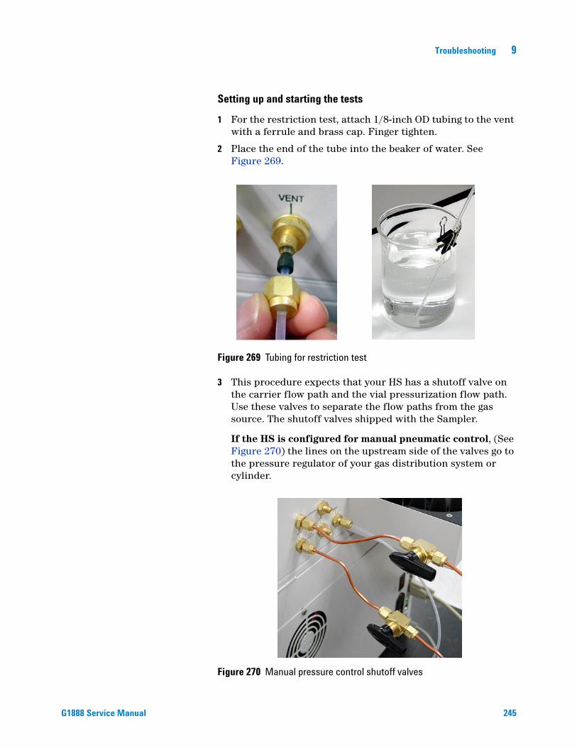
Troubleshooting 9
G1888 Service Manual
Setting up and starting the tests
1 For the restriction test, attach 1/8-inch OD tubing to the vent with a ferrule and brass cap. Finger tighten.
2 Place the end of the tube into the beaker of water. See Figure 269.
Figure 269 Tubing for restriction test
3 This procedure expects that your HS has a shutoff valve on the carrier flow path and the vial pressurization flow path. Use these valves to separate the flow paths from the gas source. The shutoff valves shipped with the Sampler.
If the HS is configured for manual pneumatic control, (See Figure 270) the lines on the upstream side of the valves go to the pressure regulator of your gas distribution system or cylinder.
Figure 270 Manual pressure control shutoff valves
245
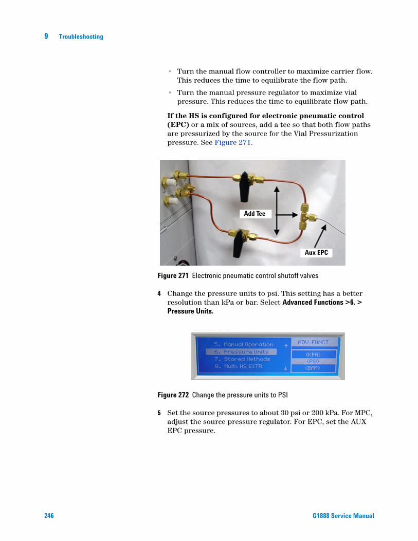
246
9 Troubleshooting
• Turn the manual flow controller to maximize carrier flow. This reduces the time to equilibrate the flow path.
• Turn the manual pressure regulator to maximize vial pressure. This reduces the time to equilibrate flow path.
If the HS is configured for electronic pneumatic control (EPC) or a mix of sources, add a tee so that both flow paths are pressurized by the source for the Vial Pressurization pressure. See Figure 271.
Figure 271 Electronic pneumatic control shutoff valves
4 Change the pressure units to psi. This setting has a better resolution than kPa or bar. Select Advanced Functions >6. > Pressure Units.
Figure 272 Change the pressure units to PSI
5 Set the source pressures to about 30 psi or 200 kPa. For MPC, adjust the source pressure regulator. For EPC, set the AUX EPC pressure.
Add Tee
Aux EPC
G1888 Service Manual

Troubleshooting 9
G1888 Service Manual
Figure 273 Set source pressures to 30 PSI
6 Disconnect the transfer line from the inlet. If you are using a transfer line needle, plug off the end with a septa. If there is no needle, cap off the end with a union and plug. See Figure 274.
Figure 274 Disconnect the transfer line
7 Place unused, capped vial in tray position 1. The vial size must match the vial size that you specify under the Vial Size parameter: 10-mL or 20-mL. (The first part of the leak test method uses the vial size parameter to determine how far to lift the vial.)
8 Place the aluminum leak test vial in tray position 2. If you do not have this tool place a 20-mL capped vial. It is very important that the vial cap is sealed tightly.
Figure 275 Leak test vial placement
247

248
9 Troubleshooting
9 Select Menu > Advanced Function > 18. Leak Test > Enter. The shortcut is Advanced Function > .8. Press Enter again to begin the test.
Figure 276 Start leak test
Restriction test
1 At the start of the restriction test the HS loads the vial from tray position 1 into the oven carousel and positions it under the sample probe and lifts the vial onto the sample probe. The valve is positioned so that the pressurization gas flows through the sample loop into the vial.
2 The pressurization valve opens and pressurizes the vial for 0.2 minutes. After 0.2 minutes, the pressurization valve closes.Vent restriction test WITH loop Pressurizing 0.2
3 The vent valve opens for 0.3 minutes. Watch the beaker of water. After the click of the vent valve, you should observe bubbles from the tip of the tube. Normal behavior is a burst of bubbles that slows and stops after about 4 to 5 seconds.__________ seconds.Vent restriction test WITH loop Loop Fill 0.3
4 The HS switches the 6-port valve to the inject position. Here the pressure gas flows directly to the vial, bypassing the sample loop.
5 The pressurization valve opens and pressurizes the vial for 0.2 minutes. After 0.2 minutes, the pressurization valve closes.
6 The vent valve opens for 0.3 minutesVent restriction testWITHOUT loop Pressurizing 0.2
7 Watch the beaker of water. After the click of the vent valve, you should observe bubbles from the tip of the tube. Normal
G1888 Service Manual

Troubleshooting 9
G1888 Service Manual
behavior is a burst of bubbles that slows and stops after about 3 to 4 seconds.__________ seconds.Vent restriction test WITHOUT loopLoop Fill 0.3
8 Before you continue, make a decision based on your observations. If there are restrictions, turn to “Troubleshooting vent restrictions”on page 253. If there are no restrictions, continue with the pressure decay tests.
Pressure decay tests overview
If you have completed a restriction test (see page 248) and there are no restrictions, continue with the pressure decay test. At the end of the restriction tests, the HS returns the vial to tray position 1 and loads the leak test vial or 20-mL vial in tray position 2 to plug the sample probe.
Using the shutoff valves at the back of the HS, you will pressurize the flow paths and watch for a pressure decay.
Each pressure decay test is made up of four steps. During each test you will:
1 Pressurize the flow path long enough for the pressure to be equalized across the manual pneumatic controls and the flow restrictor.
2 Seal the flow path.
3 Monitor the pressure for 5 minutes.
4 Record the results. The pressure should decay less than 2 psi over 5 minutes.
If you are checking for leaks in tube fittings, you will do this two times:
• Once with the sampling loop in the vial pressurization flow path (standby mode).
• Once with the sampling loop in the carrier flow path (inject mode).
To fix a leak from a tube fitting, carefully tighten the connection. Where the tubing nut, tubing ferrule, or sealing surface is damaged, replace the part.
If you are checking for leaks across the 6-port sampling valve, you will do this four times: two times in standby mode and two times in inject mode.
To fix a leak from the 6-port valve, replace the valve.
249

250
9 Troubleshooting
Pressure decay test part 1: Fittings check with Loop in vial pressurization flow path
Pressure decay test,Loop in VialCarrier (PSI) 25.6Vial (PSI) 25.4
1 Wait a full 5 minutes for the flow paths to pressurize.
2 Turn off the shutoff valves at the back of the HS.
3 Record the time and initial pressure values in the table.
4 After 5 minutes, record the time and final pressure values in Table 15 on page 250.
Before you continue, make a decision based on your observations. If there are leaks, turn to “Troubleshooting leaks at fittings in standby mode”on page 254. If there are no leaks, continue with the next pressure decay test.
Table 15 Record pressure decay test data here
Test T final T initial P initial P final
Vial pressurization Part 1
Vial pressurizationPart 2
Carrier Part 3
Carrier Part 4
Pressure decay test part 2: 6-port Valve Check with Loop in vial pressurization flow path
Pressure decay testLoop in VialCarrier (PSI) 0.1Vial (PSI) 25.4
1 Open the nut or septum on the transfer line to depressurize the carrier flow path. Monitor the vial pressurization flow path. The carrier (PSI) should drop within a minute to almost 0 psi.
2 Record the time and initial vial pressure value in the table.
G1888 Service Manual

Troubleshooting 9
G1888 Service Manual
3 After 5 minutes, record the time and final pressure value in Table 15 on page 250.
4 Reconnect the plug on the transfer line. Open the shutoff valve to pressurize the carrier flow path. The carrier (PSI) should recharge within a minute.
5 Open the lid to depressurize the vial pressurization flow path. The vial (PSI) should drop within a minute to almost 0 psi.
6 Turn off the carrier shutoff valve at the back of the HS.
7 Record the time and initial carrier pressure value in the table.
8 After 5 minutes, record the time and final pressure value in Table 15 on page 250.
Before you continue, make a decision based on your observations. If there are no leaks across the ports of the 6-port valve, continue with the next pressure decay test. If there is a leak, replace the 6- port valve.
Pressure decay test part 3: Fittings check with Loop in carrier flow path
Pressure decay test,Loop in CarrierCarrier (PSI) 26.1Vial (PSI) 26.0
1 If there is no leak, press the Enter button and open the shutoff valves. The 6-port valve will rotate so the loop is in the carrier flow path. This is the inject mode.
2 Wait a full 5 minutes for the flow paths to pressurize and equilibrate.
3 Turn off the shutoff valves at the back of the HS.
4 Record the time and initial pressure values in the table.
5 After 5 minutes, record the time and final pressure values in Table 15 on page 250.
Before you continue, make a decision based on your observations. If there are leaks, turn to “Troubleshooting leaks at fittings in inject mode”on page 255. If there are no leaks, continue with the next pressure decay test.
Pressure decay test part 4: 6-port Valve with Loop in carrier flow path
Pressure decay test,
251

252
9 Troubleshooting
Loop in CarrierCarrier (PSI) 0.1Vial (PSI) 26.0
1 Open the nut or septum on the transfer line to depressurize the carrier flow path. Monitor the vial pressurization flow path. The carrier (PSI) should drop within a minute to almost 0 psi.
2 Record the time and initial vial pressure value in the table.
3 After 5 minutes, record the time and final pressure value in Table 15 on page 250.
4 Reconnect the plug on the transfer line. Open the shutoff valve to pressurize the carrier flow path. The carrier (PSI) should recharge within a minute.
5 Open the lid to depressurize the vial pressurization flow path. The vial (PSI) should drop within a minute to almost 0 psi.Pressure decay test,Loop in CarrierCarrier (PSI) 26.1Vial (PSI) 0.2
6 Turn off the carrier shutoff valve at the back of the HS.
7 Record the time and initial vial pressure value in the table.
8 After 5 minutes, record the time and final pressure value in Table 15 on page 250.
Before you continue, make a decision based on your observations. If there are no leaks across the ports of the 6-port valve, press Clear. The HS will reset the valves and return the vial to tray position 2.
If there is a leak, replace the 6-port valve.3. After 5 minutes, record the time and final pressure value in the table.
G1888 Service Manual

Troubleshooting 9
Troubleshooting vent restrictions
G1888 Service Manual
ossible cause
Observation PWITH loop – no bubbles, no burst,long slow release of bubblesWITHOUT loop – normal
• Restricted or clogged sample loop.• Restricted or clogged 6-port valve at ports 1 and 4.• Disconnected sampling loop.
For both WITH and WITHOUT loop:No burst, but long slowrelease of bubbles.
• Restriction in flow path from sample probe to vent bulkhead fitting.• Vent valve seals swollen.
No bubbles with or without loop • Large leak or disconnected tubing at 6-port sampling valve.• No sample probe.• Defective pressurization valve (won’t open).• Defective vent valve (won’t energize or open).• Plugged vent tube.
No bubbles and no valve clicks • Disconnected or faulty wiring to solenoid valves.• Solenoid valve not getting 24 VDC to energize.• Disconnected at PCA, 5 VDC, and power distribution.• Defective temperature controller PCA 2, top right-hand position.
Figure 277 Troubleshooting vent restrictions
253

9 Troubleshooting
Troubleshooting leaks at fittings in standby mode
254
Possible cause
ObservationPressure decay for carrier ≥ 2 psi • 6-port valve fittings at ports 2 and 3. • Fittings from 6-port valve to bulkhead fitting.
Pressure decay for vial pressurization ≥ 2 psi • 6-port valve fittings at ports 1, 4, 5, and 6.• Fittings from sample probe to bulkhead fitting.
0 psi < Pressure decay < 2 psi • If the pressure decay for a flow path passes the criteria but is greater that 0 psi, there is a leak in that flow path.
• For some applications where sensitivity is very important, you should troubleshoot and attempt to find the fitting(s) that are causing the leak.
Figure 278 Troubleshooting leaks at fittings in standby mode
G1888 Service Manual

Troubleshooting 9
Troubleshooting leaks at fittings in inject mode
G1888 Service Manual
Possible cause
ObservationPressure decay for carrier ? 2 psi • 6-port valve fittings at ports 1, 4, 5, and 6. • Fittings from 6-port valve to bulkhead fitting.
Pressure decay for vial pressurization ? 2 psi • 6-port valve fittings at ports 2 and 3. • Fittings from sample probe to bulkhead fitting.
0 psi < Pressure decay < 2 psi • If the pressure decay for a flow path passes the criteria but is greater that 0 psi, there is a leak in that flow path.
• For some applications where sensitivity is very important, you should troubleshoot and attempt to find the fitting(s) that are causing the leak.
Figure 279 Troubleshooting leaks at fittings in inject mode
255

256
9 Troubleshooting
Figure 280 Flow path - standby
8
1 4
326 5
7 7
8 8
8
8 8
Bra
ss T
ee
8
PCA,
pre
ssur
e tra
nsdu
cers
Pres
sure
Reg
ulat
or
88
88
8
8
10
10
Flow
Con
trolle
r
8
PC
A, p
ress
ure
trans
duce
rs8
Vent
7 7
Clo
sed
Sta
ndby
Clo
ckw
ise
77
Tran
sfer
line
7IN O
UT
IN
OU
T
Vial
Pre
ssur
izat
ion
Car
rier
EPC
MPC
EPC
MPC
CW
Incr
ease
Pre
ssur
eC
CW
Incr
ease
Flow
1313
1313
13
814
7878
7 8
7 8
7 8
7 8
Togg
le S
witc
h
Togg
le S
witc
h
8
8
8
Bra
ss T
ee
Sample Loop
Flowres
trictor
Val
ve, 6
-por
t sam
plin
g
Ven
t val
veno
rmal
ly c
lose
ddu
ring
stan
dby
mod
e.
77 8 8P
78
Solenoid valve, vent
Solenoid valve, vial pressurization
Sam
ple
prob
e
7
7 8 V
G1888 Service Manual

Troubleshooting 9
G1888 Service Manual
Figure 281 Flow path - inject
8
1 4
326 5
7 7
8 8
8
8 8
Bra
ss T
ee
8
PCA,
pre
ssur
e tra
nsdu
cers
Pres
sure
Reg
ulat
or
88
88
8
8
10
10
Flow
Con
trolle
r
8
PC
A, p
ress
ure
trans
duce
rs8
Vent
7 7
Ope
nIn
ject
ing
77
Tran
sfer
line
7
IN OU
T
IN
OU
T
Vial
Pre
ssur
izat
ion
Car
rier
EPC
MPC
EPC
MPC
CW
Incr
ease
Pre
ssur
eC
CW
Incr
ease
Flow
1313
1313
13
814
7878
7 8
7 8
7 8
7 8
Togg
le S
witc
h
Togg
le S
witc
h
8
8
8
Bra
ss T
ee
Sample Loop
Flowres
trictor
Val
ve, 6
-por
t sam
plin
g
Ven
t val
veno
rmal
ly c
lose
ddu
ring
inje
ctm
ode.
Sam
ple
prob
e
7
77 8 8P
78
Solenoid valve, vent
Solenoid valve, vial pressurization
7 8 V
257

9 Troubleshooting
Chromatographic Results
No peaks or reduced sensitivity
258
No peaks result from the sample not reaching the GC detector. To see why, check these general areas:
• GC
• Source of gas to the HS
• Sample vial
• Flow paths that load the sample loop and carry the sample to the inlet
1 Verify that your GC system is working properly. In most cases, you can inject a small quantity of internal or calibration standard directly into the inlet.
2 Check the sample vial for cracks or defective seal.
3 For the HS, check for the following:
• The source gas for vial pressurization is connected to the correct bulkhead fittings for your configuration. MPC: 60-80psi. EPC: A pressure above the pressure inside the sample vial after equilibration. Usually 10 to 20 psi.
• The source gas for the carrier is connected to the correct bulkhead fittings for your configuration. MPC: 60-80psi. EPC: the inlet pressure setting. In GCs with electronic pneumatic controls, a lack of flow from the headspace to inlet usually causes an inlet shutdown error.
• The pneumatic toggle switch for vial pressurization is set correctly for your configuration. The pneumatic toggle switch for carrier is set correctly for your configuration. In GCs with electronic pneumatic controls, a lack of flow from the headspace to the inlet usually causes an inlet shutdown error.
• There is a flow of carrier gas from the HS to the GC inlet. For MPC, the carrier pressure is set so that the HS provides most of the flow to the inlet.
• Check for restrictions that block the flow path for filling the sample loop. The flow path starts at the sample probe and runs to the bulkhead fitting. See “Headspace Sampler leak test”on page 242.
• Check for leaks in the carrier flow path. The flow path starts at the sample probe and ends at the GC inlet. See “Headspace Sampler leak test”on page 242.
G1888 Service Manual

Troubleshooting 9
Poor retention time reproducibility
G1888 Service Manual
Poor retention time repeatability results from changes in the time the sample reaches the GC detector.
Check these general areas: the GC and HS flow paths.
• Check for leaks and restrictions in the carrier flow path. The flow path starts at the sample probe and ends at the GC inlet. See “Headspace Sampler leak test”on page 242.
Poor area count repeatability
Poor area count reproducibility results from changes in the amount of sample reaching the GC detector. Check these general areas:
• GC
• Sample preparation
• Sample vial
• Equilibration of the sample vial
1 Check the sample vials that show low area counts for cracks, defective seals, and poor crimps.
2 Verify that your GC system is working properly. If you can mount an automatic liquid sampler over the inlet, you can inject a sequence of internal or calibration standard directly into the inlet and check the area count repeatability.
3 For the HS, check for the following:
• If you have the Check GC Ready setting set to WAIT, the vial equilibration times may vary. Increase the GC Cycle Time or select a different Check GC Ready setting.
• Poor choice of equilibration temperature or time. For the best repeatability, the analytes in the sample and in the headspace of the vial must reach static equilibrium. Increase the equilibration time and increase the oven heated zone temperature.
• If it is a liquid sample, try shaking to speed up equilibration.
• Check for inconsistent sample preparation technique and vial cap crimping.
259

9 Troubleshooting
Carryover in air or solvent blanks
260
In theory, if you run a blank after a sample, you would expect no peaks in your chromatogram except for the analytes from the lab air or solvent that is trapped in the sample vial. Carryover results when sample condenses on the flow path or is trapped in unswept areas from a sample injection. When you run a blank you see small quantities of these analytes.
Carryover decreases for each run If you run a series of solvent blanks and the amount of carryover decreases by a factor of 5 to 10 for each run, the carryover is probably due to an unswept area. Please check the following:
• Transfer line connection to the GC inlet
Caryover does not decrease for each runIf you run a series of solvent blanks and the amount of carryover does not decay for each run, the carryover is probably due to analytes absorbed or condensed on the flow path or in the inlet. Please check the following:
• Poor choice of heated zone temperature settings
• Unswept areas in flow path
• Poor choice of vial pressurization pressure or time
• Flow path contamination
• Poor choice of inlet
Unwanted background noise or peaks
In theory, if you run a sample, you would expect no unrecognized peaks in your chromatogram. Unwanted peaks or ghost peaks result when some unknown is present in your sample vial or flow path.
1 Verify that your GC system is working properly. In most cases, you can inject a small quantity of internal or calibration standard directly into the inlet.
2 For the HS, please check for the following:
• Possible contamination in sample preparation materials and techniques.
• Leaks and restrictions in the carrier flow path. The flow path starts at the sample probe and ends at the GC inlet. See “Headspace Sampler leak test”on page 242.
• Possible contamination in lab air. Run a standard after purging the vial headspace with nitrogen or argon.
G1888 Service Manual

Troubleshooting 9
Pressure Readings
GC goes not ready during a run
G1888 Service Manual
When using the AUX EPC to pressurize the vial, it is normal for the GC to go “not ready” for 10 to 20 seconds during the sample extraction.
The tubing from the AUX EPC module to the shutoff valve is 1/16-inch OD tubing. The tubing from the shutoff valve is about 6 inches of 1/8-inch OD copper tubing. If the 1/8-inch tubing is longer, it can cause a problem.
GC pressure reading does not match Headspace Sampler pressure reading
The instruments use a different type of sensor and the two sensors are calibrated using different processes.
If there are severe differences in the pressure check for leaks and restrictions. See “Headspace Sampler leak test”on page 242.
If pressures are below normal operating pressures, check the following:
• Check the pressure of the gas source (tank, generator, or manifold). For example, the tank may be low on pressure.
• Make sure the shutoff valves on the back of the HS are on.
• Check for leaks between the source and the bulkhead fittings of the GC (EPC) or HS (MPC).
• Check for large restrictions or leaks in the HS. See“Headspace Sampler leak test”on page 242.
261

9 Troubleshooting
Synchronization with GC start
GC does not start
262
If the HS is not starting the GC, please check the following:
• The Remote Start/Stop cable connection
• The Check for Ready setting, Advanced Function 9
Run is aborted
If the run is aborted, please check for ready settings: Advanced Function 9.
G1888 Service Manual

Troubleshooting 9
Communication with PC
G1888 Service Manual
This type of problem results from a break in the communication between the computer and the HS. Please check the cable connections between the computer and the HS.
To correct an invalid serial number
For some instruments (including the 78xx series GCs and the G1888 HS), the software detects whether or not the instrument serial number is valid. If the software discovers an invalid serial number, do the following:
1 Go to the instrument and record its serial number, including all letters and numbers. A GC’s serial number tag is located on the bottom right front of the GC, below the keypad.
2 Click Set Serial Number.
3 When prompted, enter the serial number exactly as it appears on the serial number tag.
• Use the drop-down list to select the initial letters of the serial number.
4 Click Set Serial Number. The instrument reboots once or twice, depending on the model. Look for a success message in the Serial Number dialog box. When the serial number has been successfully applied, close the Serial Number dialog.
263

9 Troubleshooting
Lantronix Cobox micro LED patterns
Figure 282 Lantronix cobox micro LED indicator
1
2
3
4
Back panel LANConnector
264
LED 1
• Indicates the status of channel 1
• GREEN channel 1 LED
• Solid - channel 1 is idle.
• Blinking - channel is connected over the network
• This LED is also used for diagnostic and error detection when combined with LED 3 (Red). See below.
LED 2
• Indicates network connectivity
• GREEN Network Link LED
LED 3
• Indicates a series of diagnostic patterns when combined with LED 1
• RED Error and diagnostic LED
• If the Red LED is on or blinking, the Green LED will give a diagnostic code.
RED LED SOLID ON, GREEN LED BLINKING
• 1x: EPROM checksum error
• 2x: RAM error
• 3x: Network controller error
G1888 Service Manual

Troubleshooting 9
G1888 Service Manual
• 4x: EEPROM checksum error
• 5x: Duplicate IP address on the network
RED LED BLINKING, GREEN LED BLINKING
• 4x: The network connection is faulty. This should only appear after power up. Even though the Micro is going into operation mode, the problem will potentially persist.
• 5x: No DHCP response was received
LED 4
• Indicates the status of channel 2.
• YELLOW Channel 2 LED
• Solid - channel 2 is idle.
• Blinking - channel is connected over the network.
265

9 Troubleshooting
Improving LAN communications
266
Before starting the procedure to improve LAN communications:
1 Measure the resistance between the LAN Cobox and ground. If there is a reasonable resistance <0.5 ohms, then the LAN communication intermittence has some other cause.
2 Check the following for a LAN connection:
• The HS and computer have compatible network addresses. For example, the IP address are compatible on the same network.
• The Enable RS-232 setting is OFF - Advanced Function 16.
• The LAN address is correct - Advanced Function 14. Must reset or power cycle for IP address to take effect.
Required tools
Flat-blade screwdriver
Mirror
#1 Phillips screwdriver
2.5 mm Hex Driver
Multimeter
Scissors
Replacement parts
2190-0638 Metal washer
2020403008 Screw
1400-0249 Small cable tie
1400-0308 Large cable tie
ESD Wrist strap
Procedure for improving LAN communications
1 Ground the LAN card.
2 Disconnect the power cord from the HS.
3 Remove the back cover of the HS.
G1888 Service Manual

Troubleshooting 9
G1888 Service Manual
4 Remove the two screws that hold the bracket for the LAN card.
Figure 283 The LAN card screws
5 Use a mirror to view the inside of the back panel. Using a flat-blade screwdriver, scrape the paint on the inside of the chassis surrounding the two slots for the LAN board bracket.
6 Remove the three screws that hold the LAN card to the bracket.
Figure 284 LAN card bracket screws
7 Place the metal washer between the screw and the LAN card. Place the insulating washer on the backside of the LAN card.
267

268
9 Troubleshooting
Figure 285 Insulating the LAN card
8 Use a multimeter to measure the resistance of the LAN card. Have one pin on the grounding screw of the LAN card as shown and put the other pin on chassis ground. If the measured resistance is above 0.5 ohms, repeat steps 1-3.
9 Using the ping command, test the connection using the command window of your PC.
Cable Routing
1 Check the routing of the signal cable and ground cable to the power supply. Reroute if necessary with cable ties.
2 Fasten the back panel.
Check the following for an RS-232 connection:
• The com port settings are: Bits per second: 9600; Data bits: 8; Parity: None; Stop bits: 1; Flow control: Hardware.
• The Enable RS-232 setting is ON - Advanced Function 16. No reset required.
G1888 Service Manual

Troubleshooting 9
Memory and Processor Errors
G1888 Service Manual
These errors result from defects in firmware or defective main processor PCA.
Blank Display
A blank display results from an interrupted or incomplete firmware update. The HS fans are running, there is no self-test, and the display is lighted but blank. See “Recovering from Corrupt Installations”on page 220.
Power ON, No Response / Instrument Dead
This symptom results when the line voltage from the wall outlet is not reaching the internal power supplies of the HS. Please check the following:
• HS line module fuses open or blown. Also check the power selector switch setting. Fuses will blow if switch is set to 115 VAC and the line voltage is 220-260 VAC.
• Power cord not connected.
• Power ON switch, set to OFF.
• Line voltage not available at electrical outlet.
Vial Handling
Most problems with vial handling are due to the vials themselves or to misalignment, not to part failures.
• Check that vial labels are properly applied: flat without bumps, no loose label ends, etc.
• Look for old labels stuck in chain links.
• Check chain links for cleanliness. If necessary, remove and clean chain. While chain is removed, clean tray surface.
Vial present sensor
This sensor checks that a vial is in position before and after it is moved between the chain and the oven. For details, see “Optical vial sensor (Vial present sensor)”on page 72.
269
9 Troubleshooting
Tray position 1 sensor
270
This sensor is located near the Vial Present sensor. See “Optical vial sensor (Vial present sensor)”on page 72.
Optical alignment
These procedures ensure that the chain, tray lifter, carousel, and related parts are aligned.
See “Align the tray chain”on page 60.
Carousel and lifter alignment
The lifter cannot deliver vials to the carousel if the two parts are not aligned.
See “Align the carousel”on page 115 and “Lifter assemblies”on page 104.
Chain tensioning
If the chain is too loose, the links may not align properly with the carousel and the tray lifter. If it is too tight, the chain may bind and overload the drive motor.
Chain tension should be checked periodically. See “Replace the tray chain and tray/shutter drive assembly”on page 54.
G1888 Service Manual

Troubleshooting 9
MeOH Test
G1888 Service Manual
The methanol (MeOH) test makes 20 injections from one vial, using a sample of approximately 10 µL of methanol in 10 mL of water (1000 ppm) in a 20-mL vial. The normal extended equilibration time is not used. A GC cycle time is selected that is appropriate for the column.
Using this short cycle time, the true equilibrium of the headspace is never reached. However since all timing, temperatures and pressures are constant, the resulting intermediate equilibrium soon becomes constant after several injections, and the final stability of this equilibrium is measured. Of the 20 injections made from one vial, the first 10 are rejected as these injections are required to establish the stability. The final 10 injections of the 20 injection sequence are observed, and the relative standard deviation of the areas obtained are considered to be within specification when they are less than 1%.
Since the possible causes of failure are all hardware related (the exception is a leaking vial), the test proves excellent in determining whether a hardware fault exists with the system. For each of the 20 injections, the HS has pressurized, vented and injected identically.
The methanol test is done using one vial, eliminating variation from sample preparation.
This mix should be easy to find in almost any lab. Using a 10-mL disposable pipette, pipette 10 mL of deionized water into a 20-mL vial. Using a 10-µL syringe, inject 10-µL of reagent grade methanol onto the wall of the vial. Wipe the tip of the needle on the vial wall. After capping the vial, invert it several times to wash the methanol off of the wall.
Vials and caps: 20-mL Headspace sample vials (144 vials per box), part number 5182-0837 and vial caps (100/pkg), part number 5183-4477.
271

9 Troubleshooting
Headspace conditions
272
Table 16 Headspace conditions
Parameter Value
Heated zones Oven 60, Loop 110, Transfer line 120
Timed events GC cycle time 2.0, equilibration time 5.0, vial pressurization 0.20, vent time 0.20, loop equilibration 0.05, injection time 0.5 minutes
Vial parameters 1, 1, 0 (no shake)
Pressurization Vial 15 psi, Carrier ~16 psi
Standard nickel flow-path 1mL loop, passed leak test
Advanced function 8 8, 20 injections per vial, multiple puncture mode
Advanced function 9 GC READY NO
Chain method 1+2+3+4
Method parameters
If the HS software is used, the method parameters must be set as follows. Apply the method to Locations 1-4.
Table 17 Method parameters
Parameter Value
Oven temperature 60
Sample valve temperature
110
Transfer line temperature 120
GC cycle time 2
Vial equilibration time 5
Vial pressurization time 0.2
Sample loop fill time 0.2
Loop equilibration time 0.05
Sample injection time 0.5
Sample matrix Water
Sample matrix boiling point
100
G1888 Service Manual

Troubleshooting 9
G1888 Service Manual
The progress of the analysis can be easily identified on the HS display. These are the monitored values.
After setting the HS conditions, you should end the program so that it doesn't interfere with the HS timing.
Vial range Start vial 1, end vial 1
Shaking None
Parameter increment, non-chain use only
None
Extractions per vial 20
Multiple puncture On
Table 17 Method parameters (continued)
Parameter Value
Column conditions
The column conditions are as follows. After setting the conditions, we allowed the FID to stabilize overnight.
Table 18 Column conditions
Parameter Value
Column 1
Mode Const Pressure
Inlet Front/Back
Detector Front/Back
Outlet psi Ambient
Helium pressure 16.27 psi
Helium Flow 3.8 mL/min
Average velocity 55 cm/sec
Column HP 19091J-413, HP-5 5% Phenyl methyl siloxane
Initial pressure 16.27 psi
Run Time 40
273

9 Troubleshooting
Oven conditions
274
The oven conditions are as follows. The GC cycle time on the HS was set to 2.0 minutes.
Table 19 Oven conditions
Parameter Value
Oven On
Initial temperature 60
Hold 1 40
Post run 50
Maximum temperature 325
Equilibration min. 0
Split/splitless inlet conditions
The inlet conditions for the split/splitless inlet are as follows. Adjust the measured split vent flow to 100 mL/min manually, using the HS flow controller. This means 50 mL/min comes from the HS and 50 mL/min from the GC.
Table 20 Inlet conditions
Parameter Value
Mode Split
Gas Helium
Heater On, 200 °C
Pressure On, 16.27 psi
Total flow On, 56 mL/min
Split ratio 13.2
Split flow 50 mL/min
Gas saver 20 min, 2 min
G1888 Service Manual

Troubleshooting 9
Flame ionization detector conditions
G1888 Service Manual
The flame ionization detector (FID) conditions are as follows.
Table 21 Detector conditions
Parameter Value
Heater 300 °C
H2 flow 30 mL/min
Air flow 400 mL/min
Makeup flow N2, 21.2 mL/min
Makeup mode Const. Col + Makeup
Flame On
Lit offset 2
Signal parameters
The signal parameters are as follows.
Table 22 Signal parameters
Parameter Value
Signal 1 Det, Front detector/Back detector
Data rate 20 Hz
Minimum peak width 0.01 min
Save data All
Start 0
Stop 40
Interpreting results
The criteria currently in use:
The last 10 peaks area RSD lower than 1% and the mean area higher than 140 pA*s. Typical values are 0.3% area RSD and 160 pA*s for area mean.
The test may fail for the following reasons:
275

276
9 Troubleshooting
Table 23 Problems and symptoms
Problem Symptom
Leaking vial RSD% > 1 and one or more peak areas are high or lowRSD% > 1 and peak areas change randomly
Leaks within HS RSD% > 1 and one or more peak areas are high or lowRSD% > 1 and peak areas change randomly
Defective valves (also intermittent) RSD% > 1 and one or more peak areas are high or lowRSD% > 1 and peak areas change randomlyMissing peaks
Blocked flow paths (also intermittent)
RSD% > 1 and one or more peak areas are high or lowRSD% > 1 and peak areas change randomly
Irreproducible timing RSD% > 1 and one or more peak areas are high or lowRetention times change
Vial pressure instability RSD% > 1 and one or more peak areas are high or lowRSD% > 1 and peak areas change randomly
Temperature instability RSD% > 1 and peak areas change randomly
Contamination Ghost peak(s)
Peak areas are < 140 pA
RSD% > 1 and peak areas increase or decrease
G1888 Service Manual
Troubleshooting 9
Troubleshooting Electronics
G1888 Service Manual
What makes the control circuit work?
• Appropriate voltages applied to heaters, motors, solenoid valves, sensors, and PCAs.
• Resistances read from PT100 sensors at each heated zone.
• Commands sent between PCAs through a serial bus.
General approach to troubleshooting
• Check the working component.
• Trace the voltage from the working component back to the source.
• Check the 5 VDC and ground to the controller PCAs.
Checking the working components
• Will it respond to Advanced Function 5 commands?
• Will it run in TEST MODE?
• Does it have a pulse?
• Motors: resistance
• Heaters: resistance
• PT100 sensors: resistance
• Optical sensors: 0 and 5 VDC
Tracing the 24 VDC back to the source
• At the working component
• At the peripheral PCA or distribution PCA
• At the 24 VDC power supply
Checking the ground and 5 VDC
• At each peripheral PCA
• At the main processor PCA
• At the 5 VDC power supply
277

278
9 Troubleshooting
G1888 Service Manual

Agilent G1888 HeadSpace SamplerService Manual
10Parts
List of Consumable Parts 280
Ship Kit 283
Enhanced PM Kit 284
EPC Plumbing Kit 285
PM Kit with 1 -mL Loop 285
PM Kit with 3-mL Loop 286
Headspace Leak Test Kit 286
Power Cords 287
Fuses 287
Parts List 288
279Agilent Technologies

10 Parts
List of Consumable Parts
280
Table 24 G1888A Network Headspace Sampler supplies
Description Part number
Needles
Needle, transfer line, deactivated, 0.5 mm od 2322590004
Needle, transfer line, deactivated, 0.7 mm od 2322590005
Fittings
Union, zero dead volume, deactivated 2307230001
Bulkhead fitting, stainless steel 2307833901
Union, M6, brass 2302533140
Union, M5, brass 2302532140
Tee, brass 2304533140
Valves
Valve, solenoid, vent kalrez 3600500001
Valve, solenoid, vial pressurization 3600500002
Tubing and Transfer Lines
Strain relief septum nut 31-205-HSP
Sample probe, deactivated 2322700011
Sample loop, 3 mL, deactivated 2321700004
Tube, probe to 6-port valve, deactivated 1300502506
Tube, solenoids to 6-port valve, deactivated 0410105017
Tube, vent, deactivated 1300530001
Tube, tee to pressure PCA 1300530010
Transfer line, deactivated 0410103101
Repair, Leak Test, and OQ/PV Supplies
Tray chain link repair kit 0410205001
Headspace leak test kit G1888-60701
OQ/PV Headspace Sample 5182-9733
G1888 Service Manual

Parts 10
G1888 Service Manual
Table 25 Headspace Sampler vials
Description Unit Part number
Certified Flat Bottom Headspace Crimp Top Glass Vials
20 mL, clear, 23 × 75 mm 100/pkg 5182-0837
10 mL, clear, 23 × 46 mm 100/pkg 5182-0838
20 mL, amber, 23 × 75 mm 100/pkg 5067-0226
10 mL, amber, 23 × 46 mm 100/pkg 5067-0227
Certified Rounded Bottom Headspace Crimp Top Vials
20 mL, clear, 23 × 75 mm 100/pkg 5183-4474
10 mL, clear, 23 × 46 mm 100/pkg 5183-4475
Certified Headspace Screw Top Vials for G1888A Sampler and CTC CombiPAL
20 mL, clear, 23 × 75 mm 100/pkg 5188-2753
10 mL, clear, 23 × 46 mm 100/pkg 5188-5392
20 mL, amber, 23 × 75 mm 100/pkg 5188-6537
10 mL, amber, 23 × 46 mm 100/pkg 5188-6638
Table 26 Headspace Sampler caps and septaDescription Specification Unit Part number
Certified 20 mm Headspace Crimp Caps with Septa
Silver aluminum, PTFE/silicone septa -60 °C to 180 °C 100/pkg 5183-4477
Silver aluminum, safety feature, PTFE/silicone septa
-60 °C to 180 °C 100/pkg 5183-4478
Silver aluminum, molded PTFE/butyl septa -40 °C to 125 °C 100/pkg 5183-4479
Certified Ultra Clean 18 mm Screw Top Caps with Septa
Silver, 1.5 mm PTFE/silicone septa (top white, bottom blue)
to 100 °C 100/pkg 5188-2759
20 mm Headspace Crimp Caps with Septa
Silver aluminum, safety feature, molded PTFE/butyl septa
-40 °C to 125 °C 100/pkg 5173-4480
20 mm Crimp Caps (no septa)
Silver aluminum, one-piece 100/pkg 9301-0721
Silver aluminum, one-piece, safety feature 100/pkg 9301-0778
281
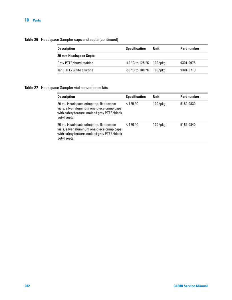
10 Parts
20 mm Headspace Septa
Gray PTFE/butyl molded -40 °C to 125 °C 100/pkg 9301-0976
Tan PTFE/white silicone -60 °C to 180 °C 100/pkg 9301-0719
Table 26 Headspace Sampler caps and septa (continued)
Description Specification Unit Part number
282
nvenience kits
Table 27 Headspace Sampler vial coDescription Specification Unit Part number
20 mL Headspace crimp top, flat bottom vials, silver aluminum one-piece crimp caps with safety feature, molded gray PTFE/black butyl septa
< 125 °C 100/pkg 5182-0839
20 mL Headspace crimp top, flat bottom vials, silver aluminum one-piece crimp caps with safety feature, molded gray PTFE/black butyl septa
< 180 °C 100/pkg 5182-0840
G1888 Service Manual

Parts 10
Ship Kit
G1888 Service Manual
Table 28 Headspace Sampler ship kit
Description Base unit Quantity Part number
Needle, Headspace Transfer Line 0.7mm OD EA 1 2322590005
Liner, direct, 2mm ID, deactivated EA 1 5181-8818
Flat bottom Headspace vials, 20ml, 100PK PK 1 5182-0837
11mm lowbld septa 5 pk PK 1 5182-3413
HS Al crimp cap, PTFE/Si sep, 20mm, 100PK PK 1 5183-4477
Agilent G1888 Network HS Supp EA 1 5989-0490EN
Cable, w/conn, 80-1000 V, telecom EA 1 8121-0940
Crimper, 20mm Seals EA 1 9301-0720
MPC Plumbing Kit EA 1 G1290-60515
Cable, RS232, 9F/9F EA 1 G1530-60600
Cable, Remote, 6890, 9M/9M EA 1 G1530-60930
Headspace Leak Test Kit EA 1 G1888-60701
G1888A EPC Plumbing Kit EA 1 G1888-60705
Headspace User Information CD-ROM EA 1 G1888-90010
Certificate of Similarity EA 1 G1888-90200
Strain Relief Septum Nut EA 1 6410090050
Wrenches, 7x8-mm Set of 2 EA 1 1340407010
MPC Plumbing Kit 0 G1290-60515
1/8 Union Tee Brass Swagelok EA 1 0100-0090
1/8 Nut & Ferrule Set Brass Swagelok EA 2 5181-7481
1/8" Ball Valve EA 2 0100-2144
Copper tubing, 1/8" 12 ft. length EA 1 5021-7107
Headspace Leak Test Kit 0 G1888-60701
Plug, 1/8’ tube Fitting, Nylon EA 3 0100-2414
M5 Plug, Brass EA 2 2301102140
M6 Plug, Brass EA 2 2301103140
M5 Union, Brass EA 2 2302532140
M6 Union, Brass EA 2 2302533140
283

10 Parts
Enhanced PM Kit
Ferrule Pk, Vespel, for G1888-60701 kit EA 1 5188-2755
11mm lowbld septa 5 pk PK 1 5182-3413
Headspace Leak Test Vial EA 1 G1290-20600
Tubing, 1/16" ID x 1/8" OD x 4', Teflon EA 1 G1290-80050
Headspace Leak Test Quick Reference EA 1 G1888-90011
Nut 1/8" Tubing Brass EA 1 0100-0058
G1888A EPC Plumbing Kit G1888-60705
Tube, 520MM EA 1 1530-2167
Pressure bleed weldmt EA 1 19258-60530
Union, for use with the G1888A Headspace EA 2 2307232901
1/8 Nut & Ferrule Set Brass Swagelok EA 2 5181-7481
Knife file EA 1 8755-0099
Tube Zero Restrictor EA 3 G1570-20540
O-Ring, 2-010, Fluoroelastomer, 5PK EA 1 5188-6405
Table 28 Headspace Sampler ship kit (continued)
Description Base unit Quantity Part number
284
Table 29 G1888-60704 G1888A enhanced PM kit
Description Base Unit Quantity Part number
Transferline, Deactivated EA 1 0410103101
Tube, vent deactivated EA 1 1300530001
GEN Accessory Carton EA 1 19256-80075
Valve, Solenoid Vent Kalrez EA 1 3600500001
Valve, Solenoid for Vial Pressurization EA 1 3600500002
Valve, 6-Port Sampling EA 1 9040700026
Cable Tie .062-.625-DIA .091-WD NYL EA 5 1400-0249
G1888 Service Manual
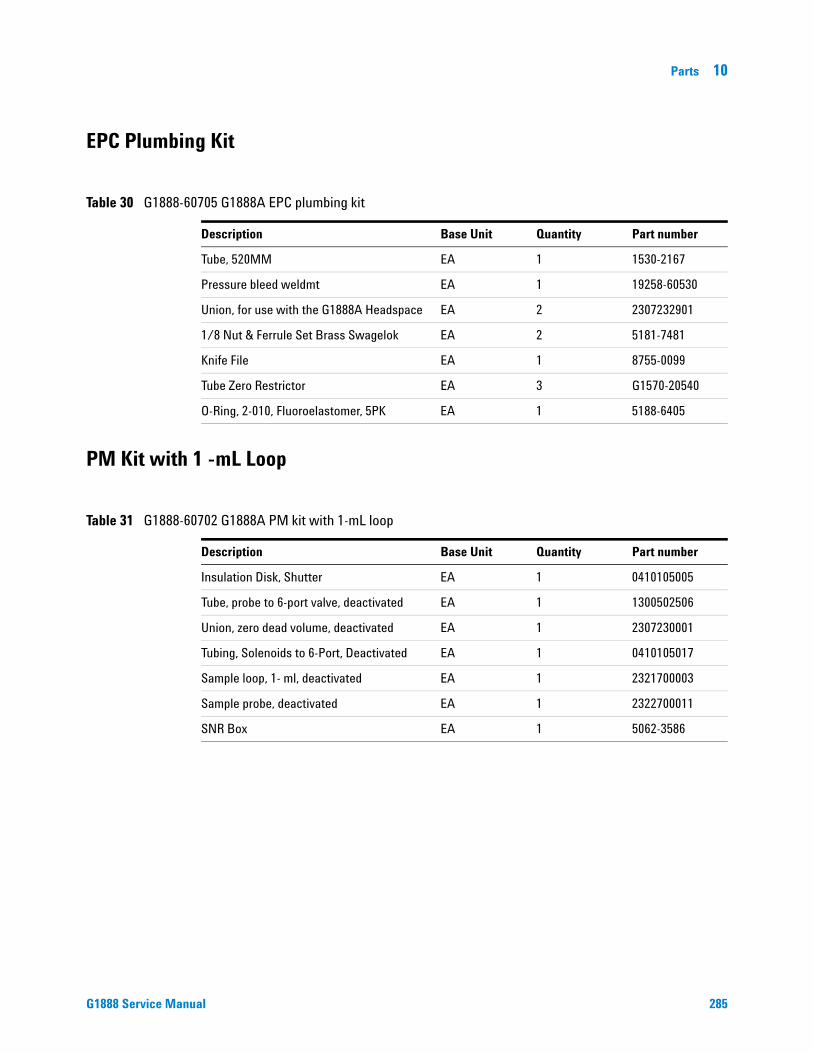
Parts 10
EPC Plumbing Kit
G1888 Service Manual
PM Kit with 1 -mL Loop
Table 30 G1888-60705 G1888A EPC plumbing kit
Description Base Unit Quantity Part number
Tube, 520MM EA 1 1530-2167
Pressure bleed weldmt EA 1 19258-60530
Union, for use with the G1888A Headspace EA 2 2307232901
1/8 Nut & Ferrule Set Brass Swagelok EA 2 5181-7481
Knife File EA 1 8755-0099
Tube Zero Restrictor EA 3 G1570-20540
O-Ring, 2-010, Fluoroelastomer, 5PK EA 1 5188-6405
Table 31 G1888-60702 G1888A PM kit with 1-mL loop
Description Base Unit Quantity Part number
Insulation Disk, Shutter EA 1 0410105005
Tube, probe to 6-port valve, deactivated EA 1 1300502506
Union, zero dead volume, deactivated EA 1 2307230001
Tubing, Solenoids to 6-Port, Deactivated EA 1 0410105017
Sample loop, 1- ml, deactivated EA 1 2321700003
Sample probe, deactivated EA 1 2322700011
SNR Box EA 1 5062-3586
285
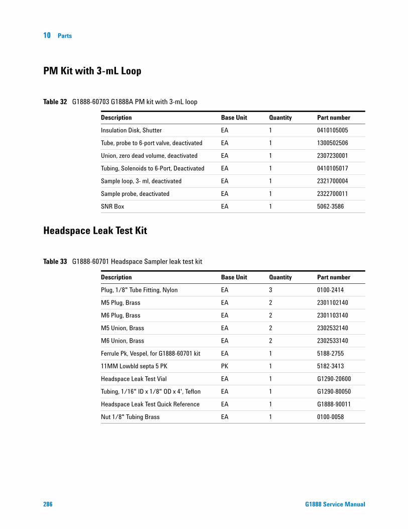
10 Parts
PM Kit with 3-mL Loop
286
Headspace Leak Test Kit
Table 32 G1888-60703 G1888A PM kit with 3-mL loop
Description Base Unit Quantity Part number
Insulation Disk, Shutter EA 1 0410105005
Tube, probe to 6-port valve, deactivated EA 1 1300502506
Union, zero dead volume, deactivated EA 1 2307230001
Tubing, Solenoids to 6-Port, Deactivated EA 1 0410105017
Sample loop, 3- ml, deactivated EA 1 2321700004
Sample probe, deactivated EA 1 2322700011
SNR Box EA 1 5062-3586
Table 33 G1888-60701 Headspace Sampler leak test kit
Description Base Unit Quantity Part number
Plug, 1/8" Tube Fitting, Nylon EA 3 0100-2414
M5 Plug, Brass EA 2 2301102140
M6 Plug, Brass EA 2 2301103140
M5 Union, Brass EA 2 2302532140
M6 Union, Brass EA 2 2302533140
Ferrule Pk, Vespel, for G1888-60701 kit EA 1 5188-2755
11MM Lowbld septa 5 PK PK 1 5182-3413
Headspace Leak Test Vial EA 1 G1290-20600
Tubing, 1/16" ID x 1/8" OD x 4', Teflon EA 1 G1290-80050
Headspace Leak Test Quick Reference EA 1 G1888-90011
Nut 1/8" Tubing Brass EA 1 0100-0058
G1888 Service Manual

Parts 10
Power Cords
G1888 Service Manual
Table 34 Power cords - country specific
Country Description Part number
Argentina 8120-6869
Australia/NZ C13, 10 amp 8120-1369
Chile C13, 10 amp 8120-6978
China C13, 10 amp 8121-0723
DK/Greenland C13, 10 amp 8120-3997
Europe C13, 10 amp 8120-1689
GB/HK/SG/MY C13, 10 amp 8120-8705
India/SouthAfrica C13, 10 amp 8120-4211
Israel C13, 10 amp 8120-5182
Japan C15, 15 amp 8120-5342
Korea C13, 10 amp 8121-1226
Switzerland C13, 10 amp 8120-2104
US/CA/TW/TH C13, 13 amp 8120-1992
Fuses Table 35 Fuses
Location Description Part number
F1 Power distribution PCA
Interchangeable Bussmann 5 x 20 mm,Type: GMD D1A (T 1A 250 V), CSA
384-1595011-HSP
F3 and F4 Power distribution PCA
Interchangeable Bussmann 5 x 20 mm,Type: GMD (F 6A 125 V), CSA
384-1295001-HSP
Main fuses on power switch
10 amp, fast acting, 250 V, 5x20 mm 5188-1157
Transformer fuse 8 amp, fast acting, 250 V, 5x20 mm 5188-1158
Table 36 Avaliable fuses for older models
Description Part number
Fuse 5 x 20 1A T 384-1595001-HSP
Fuse 5 x 20 2A T 384-1695001-HSP
Fuse 5x20 3A T 384-1695003-HSP
Fuse 5 x 20 500MA 384-1695004-HSP
287

10 Parts
Parts List
288
Table 37 Replacement parts
Description Part number
Carousel motor & tensioning bracket 0221670000
Transferline deactivated 0.8 SILTEK 0410103101
Lifter assembly, sample probe 0410105002
Lifter assembly, tray 0410105003
Motor-sensor assembly, 6-port valve 0410105004
Insulation disk, shutter 0410105005
PCA, vial present sensor 0410105106
Pressure regulator with knob 0410105007
Disk, carousel sensor 0410105008
Mandrel, loop holder with screw 0410105009
Flow controller valve with knob 0410105010
Fan, power supply 0410105012
Base, carousel compartment 0410105013
Holder, transfer line 0410105014
Cover, loop heated zone*old color* for units before SN IT00604011
0410105015
Cover, pneumatics compartment *old color* for units before SN IT00604011
0410105016
Tubing, solenoids to 6-port, deactivated 0410105017
Switch, pneumatic mode 0410105018
Motor, tray vial chain 0410105019
PCA, tray position 1 sensor 0410105020
Motor-sensor assembly, shutter 0410105021
Tray-shutter drive assembly 0410105022
Lid assembly with oven enclosure top *old color* for units before SN IT00604011
0410105024
Base, carousel compartment with switch 0410105025
Transformer 0410105026
Enclosure, oven 0410105027
G1888 Service Manual

Parts 10
G1888 Service Manual
Motor, oven fan 0410105028
Heater sensor assembly, oven 0410105029
Fan, vial cooling 0410105030
Frame, Headspace chassis 0410105031
Top, oven enclosure 0410105032
Oven enclosure with carousel enclosure 0410105033
Display keypad assembly 0410105034
Panel, power supply 0410105035
Heater sensor assembly, loop 0410105036
CO-BOX RS232 (PCA Communications) 0410105040
Cover, loop heated zone * New Color* for units after SN IT00604011
0410105115
Cover pneumatics compartment * New Color* for units after SN IT00604011
0410105116
Lid assembly with oven enclosed top *New Color* for units after SN IT00604011
0410105124
Frame, Headspace chassis *New Color* for units after SN IT00604011
0410105131
Display, keypad assembly *New Color* for units after SN IT00604011
0410105134
Panel, power supply *New Color* for units after SN IT00604011
0410105135
Tray chain link repair kit 0410205001
Latch, lid closure 0410205002
Standoff, oven fan 0410205003
Heater block, tube from probe, includes screw 0410205004
Cover, tray 3 pieces 0410205005
Heater block, solenoid valves 0410205007
Line module with fuse holder and fuses 0410205009
Insulation 1171210001
Oven base insulation 1171210003
Oven base 1171210007
Table 37 Replacement parts (continued)
Description Part number
289

290
10 Parts
Oven top insulation 1171210008
Oven external covering 1211109032
Dani red septa 100/pk D20SIL/PTFE 1260995003
Tube, sample probe to 6-port valve deactivated 1300502506
Tube, vent deactivated 1300530001
Tube, vial pressure valve to union 1300530002
Tube, switch to bulkhead 1300530004
Tube, switch to brass tee 1300530005
Tube, switch to flow controller 1300530006
Tube, switch to pressure regulator 1300530007
Tube, flow controller to bulkhead 1300530008
Tube, pressure regulator to bulkhead 1300530009
Tube, tee to pressure PCA 1300530010
Tube, tee to 6-port valve carrier 1300530011
Wrenches, 7x8-mm set of 2 1340407010
Wrenches, 6x7-mm set of 2 1340407011
Wrenches, 8x10-mm set of 2 1340407012
Hex, L-wrench, 2.5-mm 1341002500
Hex L-wrench, 3-mm 1341203000
Nut, pneumatics tubing to 6-port valve 1925820830
Ferrule, pneumatics tubing to 6-port valve 1925820870
Screw M2x10 2020402010
Screw M3x6 2020403006
Screw M3x8 2020403008
Screw M3x10 2020403010
Screw M2x16 2020403016
Pneumatic screw 2020403035
Screw M4x6 2020404006
Screw, phillips pan head M4 x 8 SS 2020404008
Screw M4x10 2020404010
Screw M4x12 2020404012
Table 37 Replacement parts (continued)
Description Part number
G1888 Service Manual

Parts 10
G1888 Service Manual
Screw M4x25 2020404025
Screw M4x12 2030404012
Allen Screw M4x30 2030404030
7 mm bolt 2040404016
Screw M3x8 2060403008
Screw M3x16 2060403016
Screw M3x20 2060403020
Screw M4x10 2060404010
Hinge pin 6410316040
Screw M4x20 2060404020
Screw M2.9x9.5 2114042909
Square washer M4 2150104040
Nut 2160014003
Square washer 2161011001
Flat washer 2170204030
Flat washer 2170204040
Toothed washer 2171304030
Washer, tooth locking, 4.0 SS 2171304040
Washer 2180014004
Washer, teflon, carousel shaft bottom 2180036007
Washer, rulon, carousel shaft top 2180037001
Spacer 2180042001
Flat fiber washer 2180043001
Spring clip 2181212002
Washer 2181212003
Clip ring, tray chain pulley 2181212004
Nut post 2190164010
Standoff 2190164015
Standoff 2190164020
Flat washer 2191320306
Spacer 2195040010
Table 37 Replacement parts (continued)
Description Part number
291

292
10 Parts
Sleeve, carousel 2195140001
Spacer, oven heater block base 2195140002
Nylon spacer 2195310012
Brass bushing 2195310013
Knob 2272000001
Carousel belt 2283000006
Shutter belt 2283000015
Tray belt 2283000016
Small pulley 2283500008
Pulley, tray chain 2283500020
Disk, carousel sensor 2283500022
Vial chain assembly 2285000001
M5 plug, brass 2301102140
M6 plug, brass 2301103140
M5 union, brass 2302532140
M6 union, brass 2302533140
Union 2303002051
Tee, brass 2304533140
Connector 2305533141
Union, zero dead volume, deactivated 2307230001
Union 5M SS 2307232901
Union 2307601001
Tubing, 6-port valve to solenoid valves SILTEK 2307601004
Bulkhead fitting 2307833900
Bulkhead fitting, SS 2307833901
Coupling 2311500003
Sample loop 100 ul SILTEK 2320346020
Flow restrictor 2321390008
Sample loop, 1-mL deactivated 2321700003
Sample loop, 3-mL deactivated 2321700004
Needle, transfer line deactivated OD 0.5 2322590004
Table 37 Replacement parts (continued)
Description Part number
G1888 Service Manual

Parts 10
G1888 Service Manual
Needle, transfer line deactivated OD 0.7 2322590005
Sample probe, for G1888A, deactivated 2322700011
Spring 2351500030
Spring, vial push 2351500035
Thermoswitch, oven 3070000010
Sensor, 6-port 3411500102
PCA, carousel sensor 3411500107
PCA, power distribution plus 5 VDC 3411500110
PCA, motor controller 1 3411500111
PCA, motor controller 2 3411500112
PCA, temperature controller 3411500113
PCA main Processor 3411500114
Pressure sensor PCA 3411500115
Terminal block, 6-port 3411500116
Valve, solenoid vent kalrez 3600500001
Valve, solenoid vial pressurization 3600500002
Relay, oven heater 3641500008
Motor 3700500001
Fan blades, oven with setscrew 3700500902
Valve motor-24 VDC 3701509002
Switch, voltage selector 3821019002
Sensor 3831019003
Line filter 3840300011
Power supply, 24 VDC 3856000004
Ribbon cable, control harness 5104309004
Ribbon cable, communication harness 5104309005
Harness, PCA power supply 5104319108
Cable assembly, solenoid valves 5104319115
Holder, transfer line 5264550001
Biadhesive tape 4 cm 5265500002
Chock 5282003502
Table 37 Replacement parts (continued)
Description Part number
293

294
10 Parts
Line module 5404020001
Valve, solenoid vial pressurization 3600500002
Carousel, 12 position 6310090035
Hinged Cover, pneumatics compartment *ld color* 6310103016
Oven enclosure top 6310103025
Screen, oven fan 6310103026
Cover, loop heated zone 6310103085
Front cover, pneumatics compartment *old color* 6310103092
Trim center 6310103095
Back Cover, pneumatics compartment *old color* 6310103106
Tray motor group cover *old color* 6310103107
Tray motor group cover *new color* 6310103126
Pneumatic compartment 6310110001
Insulation support 6310119235
Clip on carousel base assembly 6310206011
Strain relief septum nut 6410090050
Stepping motor 6410090081
Insulation block 6410106045
Carousel compartment base 6410106046
Tensioning bracket 6410110100
Toggle switch bracket 6410119065
Sleeve, ceramic lifter rod 6410202002
Sleeve, rulon J oven cover (rulon bushing) 6410202011
Needle guide 6410202015
Motor-sensor disk 6410204035
Collar, carousel 6410204041
Motor plate 6410216060
Pneumatics base 6410216081
Base, oven enclosure 6410216084
Standoff, tray pulley 5.7 cm 6410216136
Standoff, tray cover 6.9 cm 6410216137
Table 37 Replacement parts (continued)
Description Part number
G1888 Service Manual

Parts 10
G1888 Service Manual
Shaft, carousel 6410216138
Standoff, center tray pulley 6410216141
Bushing, carousel shaft top 6410302066
Bushing, carousel shaft bottom 6410302067
Front panel *old color* - before SN IT00604011 6550106033
Front panel *new color* - after SN IT00604011 6550106036
Bracket, motor support 6550119055
Bracket, solenoid valves 6550119125
Sample probe holder 6550209030
Carousel enclosure 9011090003
Valve, 6-port sampling 9040700026
Flow controller 9050790001
Heater 9100005005
Oven band heater 9101030001
Heater block, tube from probe 9103010006
Heater block, loop 9110509015
Mandrel, loop holder 9110600021
PCA carousel sensor 34411500107
MPC plumbing kit G1290-60515
Headspace leak test kit G1888-60701
G1888A PM Kit with 1-mL Loop G1888-60702
G1888A PM Kit with 3-mL Loop G1888-60703
G1888A enhanced PM kit G1888-60704
G1888A EPC plumbing kit G1888-60705
Pressure regulator 9050590004
Table 37 Replacement parts (continued)
Description Part number
295

296
10 Parts
G1888 Service Manual

Index
Index
G1888 Service Manual 297

Index
Numerics
00410105019, 480100-0058, 284, 2860100-0090, 2830100-2144, 2830100-2414, 283, 2860221670000, 86, 100, 2880410103101, 131, 138, 154, 162, 163, 280,
284, 2880410105002, 87, 105, 162, 2880410105003, 87, 105, 162, 2880410105004, 136, 141, 159, 163, 2880410105005, 45, 49, 50, 285, 286, 2880410105006, 410410105007, 127, 145, 2880410105008, 85, 108, 163, 2880410105009, 133, 142, 2880410105010, 128, 144, 2880410105012, 163, 2880410105013, 81, 2880410105014, 131, 138, 154, 2880410105015, 136, 138, 2880410105016, 123, 138, 2880410105017, 127, 142, 144, 280, 285, 286,
2880410105018, 128, 144, 2880410105019, 42, 162, 2880410105020, 46, 48, 163, 2880410105021, 41, 48, 50, 56, 57, 162, 163,
2880410105022, 44, 48, 50, 56, 57, 2880410105024, 88, 2880410105025, 82, 2880410105026, 162, 165, 178, 2880410105027, 83, 2880410105028, 86, 98, 2890410105029, 79, 110, 113, 163, 2890410105030, 88, 163, 165, 2890410105031, 89, 2890410105032, 79, 2890410105033, 84, 2890410105034, 163, 166, 2890410105035, 166, 2890410105036, 134, 141, 157, 162, 2890410105040, 166, 189, 2890410105106, 41, 49, 72, 163, 2880410105115, 138, 2890410105116, 123, 138, 2890410105124, 88, 2890410105131, 89, 2890410105134, 163, 166, 2890410105135, 166, 2890410205001, 43, 280, 2890410205002, 89, 2890410205003, 82, 2890410205004, 134, 142, 2890410205005, 46, 2890410205007, 2890410205009, 2891171210001, 138, 2891260995003, 290
298
1300502506, 123, 144, 280, 285, 286, 2901300530001, 126, 144, 280, 284, 2901300530002, 126, 144, 2901300530004, 127, 144, 2901300530005, 123, 144, 2901300530006, 124, 144, 2901300530007, 124, 144, 2901300530008, 124, 144, 2901300530009, 125, 145, 2901300530010, 125, 144, 280, 2901300530011, 125, 144, 2901340407010, 23, 283, 2901340407011, 23, 2901340407012, 23, 2901341002500, 23, 290134120300, 231341203000, 2901400-0249, 266, 2841400-0308, 2661400900029, 23, 501530-2167, 284, 28519256-80075, 2841925820830, 144, 156, 2901925820870, 144, 156, 29019258-60530, 284, 2852020402010, 129, 144, 2902020403006, 139, 142, 2902020403008, 139, 142, 266, 2902020403010, 141, 2902020403016, 129, 142, 2902020403035, 129, 2902020404006, 141, 2902020404008, 2902020404010, 139, 142, 2902020404012, 2902020404025, 141, 2912030403012, 1382030404012, 141, 2912030404030, 2912040404016, 141, 2912060403008, 141, 2912060403016, 2912060403020, 138, 2912060404010, 138, 2912060404020, 2912114042909, 138, 2912150104040, 138, 2912160014003, 144, 2912161011001, 138, 2912170204030, 141, 2912170204040, 139, 142, 2912171304030, 139, 142, 2912171304040, 139, 142, 2912180014004, 144, 2912180036007, 84, 2912180037001, 85, 2912180043001, 138, 141, 2912181212002, 138, 2912181212003, 2912181212004, 43, 2912190-0638, 2662190164010, 291
2190164015, 2912190164020, 2912191320306, 2912195040010, 2912195140001, 82, 2922195140002, 83, 2922195310012, 2922195310013, 2922272000001, 145, 2922283000006, 85, 2922283000015, 42, 49, 56, 57, 2922283000016, 43, 49, 2922283500008, 2922283500020, 44, 2922283500022, 2922285000001, 44, 50, 2922301102140, 283, 286, 2922301103140, 283, 286, 2922302532140, 280, 283, 286, 2922302533140, 144, 280, 283, 286, 2922303002051, 144, 2922304533140, 144, 280, 2922305533141, 144, 2922307230001, 141, 280, 285, 286, 2922307232901, 284, 285, 2922307601001, 144, 2922307601004, 2922307833900, 135, 144, 2922307833901, 280, 2922311500003, 141, 2922320346020, 2922321390008, 126, 144, 2922321700003, 133, 142, 151, 285, 2922321700004, 134, 142, 151, 280, 286, 2922322590004, 131, 138, 154, 280, 2922322590005, 138, 154, 280, 283, 2932322700011, 132, 152, 280, 285, 286, 2932351500030, 2932351500035, 141, 293301-019-HSP, 893070000010, 82, 110, 113, 29331-205-HSP, 2803411500102, 141, 2933411500107, 85, 96, 2933411500110, 162, 167, 2933411500111, 163, 167, 183, 2933411500112, 163, 167, 183, 2933411500113, 163, 168, 181, 2933411500114, 163, 168, 187, 2933411500115, 138, 144, 163, 168, 186, 2933411500116, 141, 29334411500107, 2953600500001, 128, 141, 163, 280, 284, 2933600500002, 129, 141, 163, 280, 284, 293,
2943641500008, 88, 110, 162, 169, 2933700500001, 162, 2933700500902, 80, 98, 108, 163, 2933701509002, 141, 162, 2933821019002, 162, 169, 2933831019003, 141, 163, 2933840300011, 162, 169, 293
G1888 Service Manual
Index
384-1295001-HSP, 23, 164, 287384-1595001-HSP, 287384-1595011-HSP, 23, 164, 287384-1695001-HSP, 287384-1695003-HSP, 287384-1695004-HSP, 2873856000004, 162, 170, 2935021-7107, 2835062-3586, 285, 2865067-0226, 2815067-0227, 2815104309004, 163, 171, 2935104309005, 163, 171, 2935104319108, 164, 171, 2935104319115, 130, 164, 170, 2935173-4480, 2815181-7481, 283, 284, 2855181-8818, 2835182-0837, 271, 281, 2835182-0838, 2815182-0839, 2825182-0840, 2825182-3413, 283, 284, 2865182-9733, 2805183-4474, 2815183-4475, 2815183-4477, 271, 281, 2835183-4478, 2815183-4479, 2815188-1157, 23, 164, 2875188-1158, 23, 164, 2875188-2753, 2815188-2755, 284, 2865188-2759, 2815188-5392, 2815188-6405, 284, 2855188-6537, 2815188-6638, 2815264550001, 138, 2935265500002, 138, 2935282003502, 2935404020001, 162, 170, 2945989-0490EN, 2836310090035, 80, 110, 2946310103016, 138, 2946310103025, 2946310103026, 79, 110, 2946310103085, 138, 2946310103092, 138, 2946310103095, 2946310103106, 138, 2946310103107, 42, 2946310103126, 42, 2946310110001, 138, 2946310119235, 138, 2946310206011, 2946410090050, 130, 283, 2946410090081, 162, 2946410106045, 141, 2946410106046, 2946410110100, 2946410119065, 138, 294
G1888 Service Manual
6410202002, 83, 2946410202011, 2946410202015, 132, 141, 2946410204035, 141, 2946410204041, 81, 2946410216060, 2946410216081, 141, 2946410216084, 84, 2946410216136, 45, 2946410216137, 45, 2946410216138, 80, 2956410216141, 2956410302066, 81, 2956410302067, 2956410316040, 2916550106033, 170, 2956550106036, 170, 2956550119055, 141, 2956550119125, 129, 141, 2956550209030, 132, 141, 2958120-0723, 28, 164, 2878120-1369, 28, 164, 2878120-1689, 28, 164, 2878120-1992, 28, 164, 2878120-2104, 28, 164, 2878120-3997, 28, 164, 2878120-4211, 28, 164, 2878120-5182, 28, 164, 2878120-5342, 28, 164, 2878120-6869, 28, 164, 2878120-6978, 28, 164, 2878120-8705, 28, 164, 2878121-0940, 29, 2838121-1226, 28, 164, 2878755-0099, 284, 2859011090003, 2959040700026, 130, 142, 156, 284, 2959050590004, 145, 2959050790001, 144, 2959100005005, 141, 2959101030001, 162, 2959103010006, 142, 2959110509015, 133, 141, 162, 2959110600021, 142, 2959301-0719, 2829301-0720, 2839301-0721, 2819301-0778, 2819301-0976, 282
G
G1290-20600, 284, 286G1290-60515, 283, 295G1290-80050, 284, 286G1530-60600, 28, 283G1530-60930, 28, 283G1530-61200, 28G1570-20540, 35, 284, 285G1888-60701, 280, 283, 295G1888-60702, 295G1888-60703, 295
G1888-60704, 295G1888-60705, 34, 283, 284, 295G1888-80000, 23, 60G1888-90010, 283G1888-90011, 284, 286G1888-90200, 283G3476-90011, 33, 36
299

Index
300
G1888 Service Manual

Agilent Technologies
Agilent Technologies, Inc.Printed in USA, August 2010G1888-90020