AGENDA - City of San Bruno
262
Rico Medina, Mayor Marty Medina, Vice Mayor Tom Hamilton, Councilmember Linda Mason, Councilmember Michael Salazar, Councilmember “The City with a Heart” GOVERNOR’S EXECUTIVE ORDER N-25-20**** CORONAVIRUS COVID-19 AND SAN MATEO COUNTY HEALTH DIRECTIVE FROM MARCH 14, 2020 On March 17, 2020, the Governor of California issued Executive Order N-29-20 suspending certain provisions of the Ralph M. Brown Act in order to allow for local legislative bodies to conduct their meetings telephonically or by other electronic means. Pursuant to the current Shelter-In-Place Order issued by the San Mateo County Health Officer which became effective on March 17, 2020, and which was updated and extended on March 31, 2020; the statewide Shelter-In-Place Order issued by the Governor in Executive Order N-33-20 on March 19, 2020; and the CDC’s social distancing guidelines which discourage large public gatherings, the San Bruno City Council Chambers at the Senior Center is no longer open to the public for meetings of the City Council. If you would like to make a Public Comment on an item not on the agenda, or comment on a particular agenda item, you may address the Council orally during the meeting, or you may email us at [email protected]. The length of all emailed comments should be commensurate with the three minutes customarily allowed per speaker, which is approximately 300 words total. Emails received before the special or regular meeting start time will be forwarded to the City Council, posted on the City’s website, and will become part of the public record for that meeting. If emailed comments are received after the meeting start time, or after the meeting ends, they will be forwarded to the City Council and filed with the agenda packet becoming part of the public record for that meeting. Individuals who require special assistance of a disability-related modification or accommodation to participate in this meeting, or who have a disability and wish to request an alternative format for the agenda, agenda packet or other writings that may be distributed at the meeting, should contact Melissa Thurman, City Clerk 48 hours prior to the meeting at (650) 619-7070 or by email at [email protected]. Notification in advance of the meeting will enable the City of San Bruno to make reasonable arrangements to ensure accessibility to this meeting, the materials related to it, and your ability to comment. AGENDA SAN BRUNO CITY COUNCIL SPECIAL MEETING January 26, 2021 6:00 p.m. In compliance with the Americans with Disabilities Act, individuals requiring reasonable accommodations or appropriate alternative formats for notices, agendas and records for this meeting should notify us 48 hours prior to meeting. Please call the City Clerk’s Office (650) 616-7061, or email your request to Melissa Thurman, City Clerk at [email protected]. 1. CALL TO ORDER 2. ROLL CALL 3. PUBLIC COMMENTS FOR ITEMS NOT ON THE AGENDA 4. CLOSED SESSION a. Public Employee Performance Evaluation Pursuant to Government Code § 54957 Title: City Manager. 5. ADJOURNMENT: The next Regular City Council Meeting will be held January 26, 2021 at 7:00 p.m. Posted Pursuant to Law 01/22/2021
-
Upload
khangminh22 -
Category
Documents
-
view
1 -
download
0
Transcript of AGENDA - City of San Bruno

Rico Medina, Mayor Marty Medina, Vice Mayor Tom Hamilton, Councilmember Linda Mason, Councilmember Michael Salazar, Councilmember
“The City with a Heart”
GOVERNOR’S EXECUTIVE ORDER N-25-20**** CORONAVIRUS COVID-19
AND SAN MATEO COUNTY HEALTH DIRECTIVE FROM MARCH 14, 2020
On March 17, 2020, the Governor of California issued Executive Order N-29-20 suspending certain provisions of the Ralph M. Brown Act in order to allow for local legislative bodies to conduct their meetings telephonically or by other electronic means. Pursuant to the current Shelter-In-Place Order issued by the San Mateo County Health Officer which became effective on March 17, 2020, and which was updated and extended on March 31, 2020; the statewide Shelter-In-Place Order issued by the Governor in
Executive Order N-33-20 on March 19, 2020; and the CDC’s social distancing guidelines which discourage large public gatherings, the San Bruno City Council Chambers at the Senior Center is no longer open to the public for meetings of the City Council.
If you would like to make a Public Comment on an item not on the agenda, or comment on a particular agenda item, you may address the Council orally during the meeting, or you may email us at [email protected]. The length of all emailed comments should be commensurate with the three minutes customarily allowed per speaker, which is approximately 300 words
total. Emails received before the special or regular meeting start time will be forwarded to the City Council, posted on the City’s
website, and will become part of the public record for that meeting. If emailed comments are received after the meeting start time, or after the meeting ends, they will be forwarded to the City Council and filed with the agenda packet becoming part of the public record for that meeting.
Individuals who require special assistance of a disability-related modification or accommodation to participate in this meeting, or who have a disability and wish to request an alternative format for the agenda, agenda packet or other writings that may be distributed at the meeting, should contact Melissa Thurman, City Clerk 48 hours prior to the meeting at (650) 619-7070 or by email at [email protected]. Notification in advance of the meeting will enable the City of San Bruno to make reasonable arrangements to ensure accessibility to this meeting, the materials related to it, and your ability to comment.
AGENDA
SAN BRUNO CITY COUNCIL SPECIAL MEETING
January 26, 2021
6:00 p.m.
In compliance with the Americans with Disabilities Act, individuals requiring reasonable accommodations or appropriate alternative formats for notices, agendas and records for this meeting should notify us 48 hours prior to meeting. Please
call the City Clerk’s Office (650) 616-7061, or email your request to Melissa Thurman, City Clerk at [email protected].
1. CALL TO ORDER
2. ROLL CALL
3. PUBLIC COMMENTS FOR ITEMS NOT ON THE AGENDA
4. CLOSED SESSION
a. Public Employee Performance Evaluation Pursuant to Government Code § 54957 Title: City Manager.
5. ADJOURNMENT: The next Regular City Council Meeting will be held January 26, 2021 at 7:00 p.m.
Posted Pursuant to Law 01/22/2021

THIS PAGE INTENTIONALLY LEFT BLANK

Rico Medina, Mayor Marty Medina, Vice Mayor Tom Hamilton, Councilmember Linda Mason, Councilmember Michael Salazar, Councilmember
“The City with a Heart”
GOVERNOR’S EXECUTIVE ORDER N-25-20**** CORONAVIRUS COVID-19
AND SAN MATEO COUNTY HEALTH DIRECTIVE FROM MARCH 14, 2020
On March 17, 2020, the Governor of California issued Executive Order N-29-20 suspending certain provisions of the Ralph M. Brown Act in order to allow for local legislative bodies to conduct their meetings telephonically or by other electronic means. Pursuant to the statewide Shelter-In-Place Order issued by the Governor in Executive Order N-33-20 on March 19, 2020; and the CDC’s social distancing guidelines which discourage large public gatherings, the San Bruno City Council meetings are being conducted electronically. The meeting is not available for in-person attendance. Members of the public may attend the meeting by video or phone linked in this agenda or watch by livestream at www.youtube.com/user/cityofsanbruno. CityNet Services Channel 1 will air the meeting live and the recorded meeting will be made available for viewing on the City’s YouTube channel after the meeting has concluded.
If you would like to make a Public Comment on an item not on the agenda, or comment on a particular agenda item, please email [email protected]. Emails received before the special or regular meeting start time will be forwarded to the City Council, posted on the City’s website and will become part of the public record for that meeting. If emailed comments are received after the meeting start time, or after the meeting ends, they will be forwarded to the City Council and filed with the agenda packet becoming part of the public record for that meeting. Emails received will not be read aloud during the meeting.
Individuals who require special assistance of a disability-related modification or accommodation to participate in this meeting, or who have a disability and wish to request an alternative format for the agenda, agenda packet or other writings that may be distributed at the meeting, should contact Melissa Thurman, City Clerk 48 hours prior to the meeting at (650) 619-7070 or by email at [email protected]. Notification in advance of the meeting will enable the City of San Bruno to make reasonable arrangements to ensure accessibility to this meeting, the materials related to it, and your ability to comment.
AGENDA
SAN BRUNO CITY COUNCIL
January 26, 2021
7:00 p.m.
Zoom Meeting Details:
https://sanbruno-ca-gov.zoom.us/j/94524416016?pwd=QThvUFVNSk1rWTQwMnZWMXBPcWdhZz09
Webinar or Meeting ID: 945 2441 6016 (audio only) Participant ID: #
Webinar or Meeting Password: 138041 Zoom Phone Line: 1-669-900-9128 (same webinar ID and password as above)
City Council meetings are conducted in accordance with Roberts Rules of Order. All regular Council meetings are recorded and televised on CityNet Services Channel 1 and replayed the following Thursday, at 2:00 pm.

City Council – Agenda January 26, 2021 Page 2 of 3
Posted Pursuant to Law 01/22/2021
1. CALL TO ORDER
2. ROLL CALL/PLEDGE OF ALLEGIANCE
3. PUBLIC COMMENTS FOR ITEMS NOT ON THE AGENDA Individuals allowed three minutes. It is the Council's policy to refer matters raised in this forum to staff for investigation and/or action where appropriate. The Brown Act prohibits the Council from discussing or acting upon any matter not agendized pursuant to State Law.
4. ANNOUNCEMENTS/PRESENTATIONS
a. Receive Update on COVID-19 Response Efforts.
b. Receive Presentation on a Standardized Evacuation Planning Project.
c. Receive Community Grant from the San Bruno Community Foundation.
5. CONSENT CALENDAR All items are considered routine or implement an earlier Council action and may be enacted by one motion; there will be no separate discussion, unless requested.
a. Accept Accounts Payable of January 11 and January 19, 2021.
b. Accept Payroll of December 20, 2020.
c. Approve the Regular Meeting Minutes for the Special and Regular Meetings of January 12 and 14, 2021.
d. Adopt Resolution Accepting the 2019-20 Slurry Seal Project as Complete, Authorizing the Filing of Notice of Completion with the San Mateo County Recorder’s Office, and Authorizing the Release of the Construction Contract Retention in the Amount of $17,871.
e. Receive Report and Confirm Appointment of City Councilmembers:
• To City Council Subcommittees;
• As Liaisons to the City’s Citizen Advisory Commissions, Boards and
Committees; and
• As Representatives and Alternates to San Mateo County and other
Regional Agencies.
f. Adopt Resolution Acknowledging Receipt of a Report Made by the Fire Chief Regarding the Inspection of Certain Occupancies Required to Perform Annual Inspection in Such Occupancies Pursuant to Section 13146.2 and 13146.3 of the California Health and Safety Code.
g. Receive Report and Adopt Resolution Accepting Annual Report on Receipt and Use of Development Impact Fees for the Fiscal Year Ending June 30, 2020.
6. CONDUCT OF BUSINESS
a. Adopt Resolution Authorizing the City Manager to Execute a Contract with West Yost Associates to Update the Urban Water Management Plan in an Amount Not to Exceed $84,370.
b. Adopt a resolution authorizing the City Manager to: Execute a contract with Golden State Fire Apparatus for the Purchase of two (2) Type I 1500 GPM Pumpers including equipment Installation and customization in an amount not

City Council – Agenda January 26, 2021 Page 3 of 3
Posted Pursuant to Law 01/22/2021
to exceed $1,583,776.32; Execute the Necessary Documents to Enter into a Lease/Purchase Arrangement for the Pumpers with the California Communities Statewide Development Authority (CSCDA); and Add Funds to the 2021-22 Fiscal Year Budget to Complete the Lease Purchase.
7. STUDY SESSION
a. Report on Regional Housing Needs Allocation (RHNA) for the 2023-2031 Housing Element Update.
8. COMMENTS FROM COUNCIL MEMBERS
a. Linda Mason:
• Request for deferment of 2021 increases for all City run enterprise accounts due to the COVID 19 pandemic and its financial impact on San Bruno families.
• Request that the City Manager or City Attorney make a written request to Recology to forego the 2021 garbage rate increase due to the COVID 19 pandemic and its financial impact on San Bruno families.
b. Marty Medina:
• Request for the Formation of Two Ad-hoc Subcommittees: Beautification and Communication.
9. ADJOURNMENT - The next Regular City Council Meeting will be held on February 9, 2021 at 7:00 p.m.

THIS PAGE INTENTIONALLY LEFT BLANK

MThurman
Typewritten text
ITEM 5.a.


THIS PAGE INTENTIONALLY LEFT BLANK

City Council Agenda Item
Staff Report
CITY OF SAN BRUNO
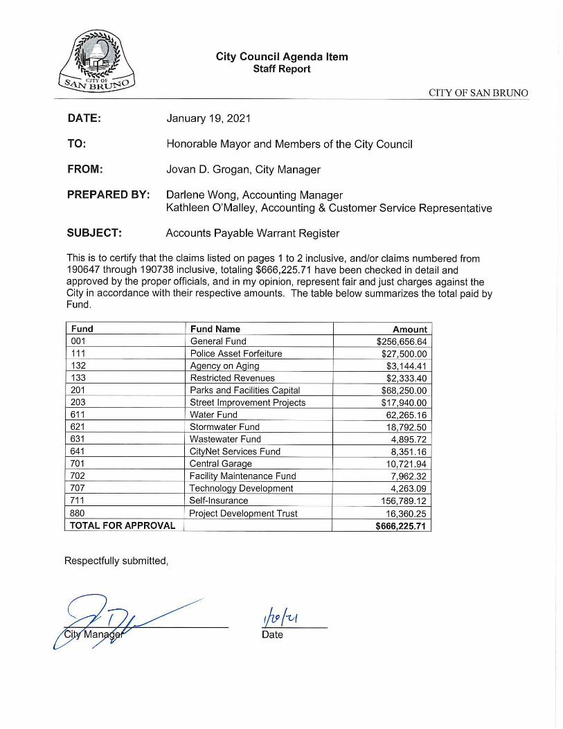
DATE: January 26, 2021
TO: Honorable Mayor and Members of the City Council
FROM: Jovan D. Grogan, City Manager
PREPARED BY: Benjie Lin, Payroll Specialist
SUBJECT: Payroll Acceptance
City Council acceptance of the City payroll distributed December 25, 2020 is
recommended. The Labor Summary report reflecting the total payroll amount of
$1,548,725.17 for bi-weekly pay period ending December 20, 2020 by fund is shownbelow:
Fund Amount
Fund: 001 - GENERAL FtJND
Fund: 121 - FEDERAL/STATE GRANTS
Fund: 122 - SOLID WAIST/RECYCL.
Fund: 201 - PARKS AND FACILITIES CAPITAL
Fund: 203 - STREET IMPROVE. PROJECTS
Fund: 611 - WATER FUND
Fund: 621- STORMWATER FUND
Fund: 631 - WASTEWATER FUND
Fund: 641 - CITYNET SERVICES FUND
Fund: 701 - CENTRAL GARAGE
Fund: 702 - FACILITY MAINT.FUND
Fund: 707 - TECHNOLOGY DEVELOPMENT
Fund: 711 - SELF INSURANCE
$1 ,160,909.43
1,128.03
2,273.74
3,806.77
1 ,891 .56
101,445.29
26,059.00
81 ,021 .35
101,015.58
13,715.05
35,436.18
'i1 ,365.92
8,657.27
Total: $1,548,725.17
Jova . rog5n, City Manager
MThurman
Typewritten text
iTEM 5.b.

THIS PAGE INTENTIONALLY LEFT BLANK

Rico Medina, Mayor Marty Medina, Vice Mayor Tom Hamilton, Councilmember Linda Mason, Councilmember Michael Salazar, Councilmember
“The City with a Heart”
MINUTES
SAN BRUNO CITY COUNCIL
January 12, 2021
7:00 p.m.
1. CALL TO ORDER
2. ROLL CALL/PLEDGE OF ALLEGIANCE – All Council Members were present.
3. PUBLIC COMMENTS FOR ITEMS NOT ON THE AGENDA
The following members of the public spoke during Public Comment:
• Bo Smith – Spoke regarding cleaning up San Bruno and requested city supplies to assist in the effort.
• Riley Gibbons – Spoke regarding a recently successful ballot measure regarding cannabis and about cleaning up San Bruno.
• Stephen Seymour – Spoke regarding cleaning up San Bruno and the recently successful ballot measure regarding cannabis.
• Alexander Melendrez – Spoke regarding two pieces of state legislature regarding housing, AB15 and AB 16, and requested support for both.
• Reyna Burgos – Spoke to thank an employee of Walgreens in San Bruno for cleaning the street surrounding the business.
4. ANNOUNCEMENTS/PRESENTATIONS
a. Receive presentation from HIP Housing.
Kahla Espinoza, HIP Housing Representative, spoke to thank the City Council for their support of HIP Housing and to introduce the 2021 HIP Housing calendar.
b. Receive Update on COVID-19 Response Efforts.
Jennifer Dianos, Executive Assistant to the City Manager, provided the update.
c. Recognition of Tim Wallace for 25 Years of Service to the City of San Bruno.
Ann Mottola, Community Services Director, recognized Tim Wallace, Community Services Superintendent, for his 25 years of service to the City of San Bruno. The City Council thanked Tim for his years of service.
5. CONSENT CALENDAR
Linda Mason, Council Member, pulled item 5.f. for a separate vote.
Motion by Mason to approved item 5.f., with an amendment to remove the appropriation of $40,000 from the General Fund. Motion failed due to lack of a second.
MThurman
Typewritten text
ITEM 5.c.

City Council – Minutes January 12, 2021 Page 2 of 4
M/S Salazar/M. Medina to approve item 5.f. Motion carried unanimously by roll call vote.
M/S Salazar/M. Medina to approve the Consent Calendar, excluding item 5.f. Motion carried unanimously by roll call vote.
a. Accept Accounts Payable of December 1, December 7, December 14, December 21 and December 29, 2020.
b. Accept Payroll of November 27 and December 8, 2020.
c. Accept Reconciliation of General Ledger to Bank Reports and Investment Reports Dated September and November 2020.
d. Approve the Regular Meeting Minutes for the Special and Regular Meetings of December 4, December 8, December 9, and December 17, 2020.
e. Approve the 2021 City Council Meeting Calendar and Direct Staff to Cancel the Regular City Council Meeting of August 10, 2021.
f. Adopt Resolution Authorizing the City Manager to Execute a Five-Year Contract with Odyssey Power for Generator Maintenance Services in an Amount not to exceed $100,000 for FY2020-21 and Appropriating $40,000 from the General Fund.
g. Adopt Resolution Authorizing the City Manager to Execute a Contract with Andy’s Roofing Company, Inc. for Roof Repair and Emergency Repair Response Services in an Amount not to Exceed $60,000 for FY 2020-21 and Appropriating $40,000 from the General Fund Capital Improvement Reserve Fund.
h. Adopt Resolution Amending the City Classification Plan by Adopting the Position Description and Salary Range for Information Technology Associate.
i. Accept Resignation from Personnel Board Member Effective December 7, 2020, and Planning Commissioner Effective December 8, 2020 and Direct the City Clerk to Post a Notice of Vacancies in Accordance with State Law.
j. Approve City of San Bruno Response Letter to the San Mateo County Civil Grand Jury Report titled “Second Units: Adding New Housing in The Neighborhoods”.
6. CONDUCT OF BUSINESS
a. Adopt a Resolution Initiating Proceedings to Establish a Revised Storm Drainage and Flood Protection Fee.
Jovan Grogan, City Manager, presented the item with Jimmy Tan, Public Works Director, and Jim Steele, Management Partners Consultant.
The following members of the public spoke regarding this item:
• Paul Wapensky – Spoke regarding concerns about the history of storm drain management in the city.
• Bo Smith – Asked about any bonds available to this project.
• John Lampros – Asked about impermeable areas throughout the city in relation to this project.
• Robert Riechel – Spoke in opposition of the project.
Motion by Salazar to adopt a resolution, as amended. Motion failed due to lack of a second.

City Council – Minutes January 12, 2021 Page 3 of 4
The Council asked clarifying questions to staff regarding the recommended action.
M/S Salazar/Hamilton to adopt a resolution, as amended, and direct staff to come back with an item to delay or defer the fifth-year rate increase for water and sewer. Motion carried unanimously by roll call vote.
7. COMMENTS FROM COUNCIL MEMBERS
a. Linda Mason:
• Joint Committee Meeting with School Board
The majority of the City Council directed staff to reach out to the San Bruno Parks
Superintendent to discuss the possibility of a future joint meeting between the two
bodies. The City Council requested that two members of the City Council attend
the meeting between the City Manager and Superintendent to review a possible
meeting agenda.
• Expand the Citizens Revenue Oversight Committee (Measure G
Committee) to 7 seats
The City Council unanimously directed staff to receive applications for two more
members of the Citizens Revenue Oversight Committee, bringing the total number
of members to 7.
• Request City Manager to: (1) Scheduled a Closed Session of the City Council to discuss the possibility of acquiring the El Crystal property from the San Bruno Park Unified School District, and (2) Assess the potential opportunity for lease of site for Park and Rec sub-station during the RAC construction.
The majority of the City Council directed the City Manager to schedule a Closed Session to discuss the possibility of acquiring the El Crystal property from the San Bruno Park Unified School District.
b. Michael Salazar:
• Update on the San Bruno’s Heart Committee and Discuss Future Activities.
Michael Salazar, Council Member, presented the update and explained future activities of the San Bruno Heart Committee.
• Marty Medina – Announced a special San Bruno Parks School District Board meeting on Saturday January 16, 2021.
• Tom Hamilton – Thanked the City Manager and staff for his on-boarding process and thanked the community for welcoming him to the City Council.
• Rico Medina – Announced the passing of Former Mayor George Corey and San Bruno resident and business owner Harry Costa.
8. ADJOURNMENT – The meeting adjourned at 11:55 p.m. in memory of Former Mayor George Corey and San Bruno resident Harry Costa. The next Regular City Council Meeting will be held on January 26, 2021 at 7:00 p.m.

City Council – Minutes January 12, 2021 Page 4 of 4
The meeting minutes were prepared by Melissa Thurman, City Clerk, for approval at the regular meeting of January 26, 2021.
_________________________________________________
Melissa Thurman, CMC City Clerk
_________________________________ Rico E. Medina Mayor

Rico Medina, Mayor Marty Medina, Vice Mayor Tom Hamilton, Councilmember Linda Mason, Councilmember Michael Salazar, Councilmember
“The City with a Heart”
MINUTES
SAN BRUNO CITY COUNCIL SPECIAL MEETING
January 14, 2021
4:00 p.m.
1. CALL TO ORDER
2. ROLL CALL – All Council Members were present.
3. PUBLIC COMMENTS FOR ITEMS NOT ON THE AGENDA
There were no speakers during public comment.
4. STUDY SESSION
a. Discuss and Review Draft City Council Policies & Procedures.
The City Council discussed various sections of the Draft City Council Policies & Procedures and made edits throughout the document, based on majority consensus for each recommended edit. The City Council will meet in a second special meeting, with a date to be determined, to continue the discussion and editing of the City Council Policies & Procedures document.
Discussion item only. No motion taken.
5. ADJOURNMENT – The meeting adjourned at 6:29 p.m. The next Regular City Council Meeting will be held January 26, 2021 at 7:00 p.m.
The meeting minutes were prepared by Melissa Thurman, City Clerk, for approval at the regular meeting of January 26, 2021.
_________________________________________________ Melissa Thurman, CMC City Clerk
_________________________________ Rico E. Medina
Mayor

THIS PAGE INTENTIONALLY LEFT BLANK

City Council Agenda Item
Staff Report
CITY OF SAN BRUNO
DATE: January 26, 2021 TO: Honorable Mayor and Members of the City Council FROM: Jovan D. Grogan, City Manager PREPARED BY: Jimmy Tan, Public Works Director SUBJECT: Adopt Resolution Accepting the 2019-20 Slurry Seal Project as
Complete, Authorizing the Filing of Notice of Completion with the San Mateo County Recorder’s Office, and Authorizing the Release of the Construction Contract Retention in the Amount of $17,871
BACKGROUND: The City’s Capital Improvement Program (CIP) includes the 2019-20 Slurry Seal Project to repair and apply preventative maintenance treatment to local, collector, and arterial streets. The City utilizes the Metropolitan Transportation Commission's Streetsaver Program, also known as the Pavement Management Program (PMP), to analyze pavement data in selecting street treatments in order to optimize use of funds for maintenance and rehabilitation work. The streets selected for this project are those that required preventative maintenance to prevent roadway failure. A total of 22 street segments totaling approximately 3.25 centerline miles received preventative maintenance slurry seal treatment. The project scope of work consisted of slurry seal application, concrete curb and gutter replacement, base repair of failed street areas and restriping of pavement markings. The completion of this project extended the life of the pavement and reduced life cycle costs by deferring the need for more expensive rehabilitative repairs. Street segments that received preventative maintenance treatment were as follows:
STREET NAME FROM TO
ALDEN COURT MERIMONT CIRCLE END
CEDARWOOD COURT N/A N/A FLEETWOOD COURT FLEETWOOD DRIVE END
GOODWIN DRIVE ALLEN DRIVE LONGVIEW DRIVE GREENWOOD WAY FLEETWOOD DRIVE ROLLINGWOOD DRIVE MARBELLA LANE MERIMONT CIRCLE MERIMONT CIRCLE
MERIMONT CIRCLE EVERGREEN DRIVE END
PACIFIC AVENUE HUNTINGTON AVENUE EAST HERMAN STREET PACIFIC HEIGHTS BOULEVARD HIGHLAND DRIVE SKYLINE COLLEGE
PROPERTY LINE ROSEWOOD DRIVE COURTLAND DRIVE MADISON AVENUE
SANTA CLARA AVENUE SAN ANTONIO AVENUE EL CAMINO REAL
SANTA DOMINGA AVENUE SAN ANTONIO AVENUE EL CAMINO REAL
STANISLAUS COURT SNEATH LANE END
TRINITY COURT SNEATH LANE END
WALNUT STREET CALTRAIN PROPERTY SAN MATEO AVENUE
MThurman
Typewritten text
ITEM 5.d.

Honorable Mayor and Members of the City Council January 26, 2021 Page 2 of 3
STREET NAME FROM TO
YORKSHIRE COURT CRESTMOOR DRIVE END
YOLO COURT RIVERSIDE DRIVE END
BERING DRIVE COLLEGE ROAD MARISOL DRIVE
CYPRESS AVENUE KAINS AVENUE SOUTH SYCAMORE AVENUE
MARISOL DRIVE ADRIATIC WAY COLLEGE DRIVE
PARK AVENUE CYPRESS AVENUE GRUNDY PARK
SAN MATEO AVENUE 400’ NORTH OF KAINS AVENUE WALNUT STREET
DISCUSSION: On April 28, 2020, the City Council approved a construction contract with American Asphalt Repair and Resurfacing Company Inc. in the amount of $379,878 with a construction contingency of $60,000. Two change orders were issued to American Asphalt Repair and Resurfacing Company Inc. during construction for additional striping work and quantity adjustment. Due to the actual quantities completed being less than the initial estimate, a change order for credit in the amount of $22,447 was issued which decreased the final contract amount to $357,431. The project was completed under budget and without any major issues. All construction work as part of this contract has been completed to the satisfaction of the City’s project management team. There are no unresolved stop notices or outstanding construction claims for this project. The construction contract required a 5% retention, which totals $17,781.55, be withheld by the City. Staff recommends that the City Council accept the project as complete, authorize filing a Notice of Completion with the San Mateo County Recorder’s Office, and approve release of the contract retention. FISCAL IMPACT:
The total approved project budget which included design contract, the construction contract, project contingency, and staff management and design was $554,878. As detailed below, the total expenditure for the project was approximately $454,800. Of the remaining budget of approximately $100,000, $55,000 will be returned to the Measure A fund and approximately $45,000 of Gas Tax fund will be returned to the Pavement Management Program.
Expenditure Staff Project Management and In-House design $ 34,820 Construction Contract $ 357,431 Staff Construction Management and Inspection $ 51,500 Materials Testing (Pavement Engineering Incorporated) $ 9,735 Reproduction & Advertisement $ 1,263
Project Total $ 454,749 ALTERNATIVES: 1. Do not accept the construction contract as complete and do not authorize filing of a

Honorable Mayor and Members of the City Council January 26, 2021 Page 3 of 3
Notice of Completion. RECOMMENDATION:
Adopt Resolution accepting the 2019-20 Slurry Seal Project as complete, authorizing the filing of Notice of Completion with the San Mateo County Recorder’s Office, and authorizing the release of the construction contract retention in the amount of $17,871. DISTRIBUTION: None ATTACHMENTS:
1. Resolution 2. Project Acceptance Information Form
DATE PREPARED: December 17, 2020

THIS PAGE INTENTIONALLY LEFT BLANK

RESOLUTION NO. 2021 - ___
RESOLUTION ACCEPTING THE 2019-20 SLURRY SEAL PROJECT AS COMPLETE, AUTHORIZING THE FILING OF NOTICE OF COMPLETION WITH THE SAN MATEO
COUNTY RECORDER’S OFFICE, AND AUTHORIZING THE RELEASE OF THE CONSTRUCTION CONTRACT RETENTION IN THE AMOUNT OF $17,871
WHEREAS, the City’s Capital Improvement Program (CIP) included the 2019-20
Slurry Seal Project to apply preventative maintenance treatments including making asphalt base repairs, repairing concrete curb and gutter, applying slurry seal, replacing existing striping at various streets within the City of San Bruno; and WHEREAS, on April 28, 2020, the City Council approved a construction contract with American Asphalt Repair and Resurfacing Company Inc. for the 2019-20 Slurry Seal Project in the amount of $379,878; and
WHEREAS, Chrisp Company began construction in July 2020 and completed construction work in September 2020; and
WHEREAS, two contract change orders were issued for additional striping work and
quantity adjustment which decreased the contract amount to $357,431; and WHEREAS, all construction work as part of this contract has been completed to the
satisfaction of the City’s project management team; and WHEREAS, the construction contract requires the filing of a Notice of Completion of
this project with the San Mateo County Recorder’s Office and release of the construction contract retention in the amount of $17,871 upon the acceptance of the project as complete.
NOW, THEREFORE, BE IT RESOLVED that the City Council accepts the 2019-20
Slurry Seal Project as complete, authorizes the filing of Notice of Completion with the San Mateo County Recorder’s Office, and authorizes the release of the construction contract retention in the amount of $17,871.
Dated: ATTEST: Melissa Thurman, CMC City Clerk
MThurman
Typewritten text
ATTACHMENT 1

-o0o-
I, Melissa Thurman, City Clerk, do hereby certify that the foregoing Resolution was duly and regularly passed and adopted by the City Council of the City of San Bruno this 26th day of January 2021 by the following vote:
AYES: Councilmembers:
NOES: Councilmembers
ABSENT: Councilmembers:

PUBLIC WORKS DEPARTMENT
Capital Improvement Program
Project Acceptance Information Form
As of December 18, 2020
Project Information:
Contract Name: 2019-20 Slurry Seal project Contract No.: 60015
Construction Contractor: American Asphalt Repair and Resurfacing Company Inc.
Construction Management and
Inspection Services City Staff and PEI
Project Description:
Performing base repair at identified locations, placing crack seal, slurry sealing existing streets, replacing concrete curb and gutters, and restriping existing striping markings. Work is at various streets within the City of San Bruno.
Construction Contract Award:
April 28, 2020
Start of Construction:
July 22, 2020
Contract Change Orders (CCO):
Two change orders were issued to install new delineators, replaced damaged curb bumpers, and balance quantities. Substantial
Completion: September 4, 2020
Final Completion: September 17, 2020
Notice of Completion:
Scheduled for filing on January 27, 2021
MThurman
Typewritten text
ATTACHMENT 2

Project Costs:
Budget Actual
TOTAL PROJECT $554,878 $ 454,749
Design (In-House) $ 40,000 $ 34,820
Construction Contract (American Asphalt)
$379,878 $ 379,878
Construction Contingency $ 60,000 -
Change Order #1 - $ 4,037
Change Order #2 - ($ 26,484)
Construction Management Staff Time
$ 60,000 $ 51,500
Construction Materials Testing
$ 15,000 $ 9,735
Reproduction & Advertisement
- $ 1,263

City Council Agenda Item
Staff Report
CITY OF SAN BRUNO
DATE: January 26, 2021 TO: Honorable Mayor and Members of the City Council FROM: Jovan D. Grogan, City Manager PREPARED BY: Melissa Thurman, City Clerk SUBJECT: Receive Report and Confirm Appointment of City Councilmembers:
• To City Council Subcommittees;
• As Liaisons to the City’s Citizen Advisory Commissions, Boards and Committees; and
• As Representatives and Alternates to San Mateo County and other Regional Agencies
BACKGROUND:
Each calendar year the City Council confirms assignment of each City Councilmember to serve on City Council Subcommittees, as liaisons to Citizen Advisory Commissions, Boards and Committees (CBC), and as representatives to San Mateo County and other regional agencies. Under State Law (Brown Act), the City Council may establish subcommittees consisting of less than a quorum of the full City Council to review and discuss City business in two ways:
(1) A temporary advisory subcommittee, or “ad hoc” subcommittee may be established to serve a limited, or single purpose. A temporary advisory subcommittee may meet more than one time but is expected to be dissolved once the specific task is completed. Such a subcommittee is not subject to the Brown Act’s requirements for public notice, and the opportunity for public participation.
(2) A subcommittee which is assigned a continuing subject matter jurisdiction is considered by the Brown Act to be a “standing committee”. The Brown Act’s requirements for public notice of meetings and the opportunity for public participation apply to standing subcommittees, even if the subcommittee is comprised of less than a quorum of the full City Council.
The City Council has previously established subcommittees consisting of two Councilmembers each to support a variety of City Council policy issues, and to provide review and recommendations on issues that will be presented to the City Council for action. These ad hoc City Council subcommittees meet on an as-needed, and in most cases, infrequent basis. As discussed below in this report, the City Council has also previously established four standing subcommittees that meet on an as-needed basis on recurring topics of City Council business. City Council liaison assignments were previously established to support coordination between the citizen advisory bodies and the City Council in the establishment and implementation of City Council policy. The schedule of City Council liaison assignments rotates annually, as originally established by the City Council in 2006.
MThurman
Typewritten text
ITEM 5.e.

Honorable Mayor and Members of the City Council January 26, 2021 Page 2 of 2
______________________________________________________________________ As City Council representatives serve on San Mateo County and other regional Agency Boards, City Councilmembers actively participate in the formation of local policy and implementation of projects that have a region/county wide impact. The San Bruno Municipal Code section 2.04.120(A) calls for the Mayor to make all appointments to and removals from Commissions, Boards and Committees, subject to the approval of the City Council. DISCUSSION:
A list of the City Councilmember liaison assignments is included as an attachment to this report. The attached list also shows all of the regional agencies to which the City has an assigned representative. Some of the regional agency assignments are not made directly at the City’s discretion. These non-San Bruno appointed positions are listed separately in the attachment. Staff is recommending that the City Council review and confirm the rotational liaison assignments, City Council Subcommittee assignments and the San Mateo County and regional Agency Board assignments. In order to assist with the continuing need for periodic involvement of a City Council subcommittee on various topics, staff recommends that the City Council also continue the City’s long-standing practice of the Mayor’s appointment of two Councilmembers to ad-hoc subcommittees as needed throughout the year.
FISCAL IMPACT:
There is no direct or anticipated fiscal impact of the proposed action to confirm City Councilmember liaison, subcommittee, county and regional assignments.
ALTERNATIVES:
1. Do not make changes to the standing subcommittees or the City Councilmember Liaison assignments.
RECOMMENDATION:
Receive report and confirm appointment of City Councilmembers:
• To City Council Subcommittees;
• As liaisons to the City’s Citizen Advisory Commissions, Boards and Committees; and
• As representatives and alternates to San Mateo County and other regional agencies ATTACHMENTS:
1. Regional Bodies 2. Council Ad-Hoc Committees 3. Liaison Assignments
DATE PREPARED:
December 7, 2020

2021 COUNTY & REGIONAL AGENCIES
Board Description Meeting Frequency2020 Representative(s)
Primary/Alternative
2021 PROPOSED
Representative(s)
Primary/Alternative
Body Requires an
Alternative?
Yes/No
Did the prior year representative
hold a leadership position or other
responsibility on the board or a
related subcommittee/taskforce?
Typical Meeting Location
Association of Bay Area Governments
(ABAG)
Determine policy matters for the Association, including adopting the annual
general budget and review recommendations of the Executive Board.
Meets once or twice yearly 9 AM -
2:30 PM
M. Medina M. Medina No alt. required n/a Bay Area Metro Center
375 Beale Street,
SF, CA 94105
Advanced Life Support – Joint Powers
Board (ALS)
San Mateo County Pre-Hospital Emergency Medical Services Group. JPA for
emergency ambulance services in San Mateo County. Meets the 3
rd Wed. of
Jan/May/Sept. at 6:30 PM
R. Medina R. Medina No alt. required n/a Belmont City Hall 1 Twin Pines Ln,
Belmont, CA 94002
Airport Community Roundtable A voluntary public forum established in 1981 for the discussion and
implementation of noise mitigation strategies at San Francisco International
Airport (SFO).
Meets 1st Wed. of
Feb/April/June/Aug/Oct/Dec) At 7
PM
L. Davis T. Hamilton No alt. required n/a David Chetcuti Community Room
– Millbrae City Hall 450 Poplar Ave
Millbrae CA
Airport Land-Use Committee (ALUC) To advise and recommend actions to C/CAG regarding the updating of the
ALUCPs and other land use compatibility issues effecting San Mateo County.
Meets Jan through Oct normally 4 to
5 meetings a year at 4 PM
L. Davis / R. Medina T. Hamilton / TBD Yes, alt. required Vice-Chair Burlingame City Hall 501 Primrose
Rd. Burlingame Council Chambers
Bay Area Water Supply and Conservation
Agency (BAWSCA)
Represent the needs of the cities, water districts and private utilities that
depend on the regional water system.
Meets Jan, March, May, July, Sept,
Nov at 6:30 PM 3rd Thursday of the
month
L. Davis T. Hamilton n/a n/a San Mateo Library 55 West 3rd
Ave SM 1st floor Oakroom
City/County Association of Governments
(C/CAG)
Association of cities and County discussing the issues affecting San Mateo
County. Meets 2
nd Thurs. of the month M . Salazar / R. Medina M . Salazar / R. Medina Yes, alt. required n/a San Mateo County Transit 1250
San Carlos Ave San Carlos 2nd
Floor AuditoriumColma Creek Flood Control District Discuss matters relating to zone policies and acts in an advisory capacity to the
Board of Supervisors.
2nd Tuesday of the Month
(Quarterly) 3:00 PM - 5:00 PM
J. Grogan J. Grogan No alt. required n/a City of SSF Corporation Yard
Conference Room 550 N Canal St.
SSF
Grand Boulevard Initiative Task Force
(SamTrans)
Regional collaboration dedicated to the revitalization of the El Camino Real
corridor.
Annual plus Corridor tours may also
be held in lieu of regular meetings
M. Salazar M. Salazar No alt. required n/a Various Locations
Home for All Public, private and nonprofit agencies collaborate to address the job/housing
gap throughout San Mateo County.
Meets as needed M. Salazar L. Mason No alt. required n/a
Housing Endowment and Regional Trust of
San Mateo County (HEART)
10 elected officials and 10 members of the private sector work together to
create more affordable housing throughout San Mateo County.
Meets 4th Wed. of every month L. Mason L. Mason No alt. required n/a
League of California Cities/Peninsula
Division (Regional)
The Peninsula Division runs from San Francisco to Gilroy and meets at various
locations throughout the Peninsula. One annual breakfast is held to elect
officers of the division during the League of California Cities Annual
Conference.
Meets quarterly. Jan, March, June at
11:30 AM August at 5:00 PM
L. Mason L. Mason No alt. required, others may
attend
n/a Different Locations in August
Woodside
Local Policy Maker Group (Caltrain) Advisory group comprised of officials from the cities and counties along the
Caltrain corridor.
Meets 4th Thurs. of the month M. Salazar / R. Medina M. Salazar / R. Medina Yes, alt. required n/a San Mateo County Transit 1250
San Carlos Ave San Carlos 2nd
Floor Auditorium
Peninsula Clean Energy Advisory
Committee
Acts as a liaison to the community and to provide feedback on PCE policy and
operational objectives.
Meet 2nd Thurs. of the month M. Medina / M. Salazar M. Medina Yes, alt. required n/a 2075 Woodside Road, Redwood
City, CA 94061
Peninsula Traffic Congestion Relief Alliance
(commute.org)
Discuss ways to reduce the number of single occupancy vehicles traveling in,
to, or through San Mateo County.
Meets 3rd Thurs. in
Feb/April/June/Sept/Nov
R. Medina / L. Davis R. Medina / M. Medina No alt. required n/a Meets in San Mateo, Foster City
San Mateo County Mosquito Abatement
District (Citizen Appointment)
San Mateo County district that monitors and reduces mosquitos and other
vectors.
Meets as scheduled R. Reichel
(Appointment through 12/24)
R. Reichel
(Appointment through 12/24)
n/a n/a 1351 Rollins Rd Burlingame CA
94010
San Mateo County Council of Cities Mayor and Councilmembers from San Mateo County’s 20 cities meet to discuss
issues and receive presentations on issues of mutual concern.
Meets 4th Fri. monthly (Dec Mtg
earlier in the month)
R. Medina - voting representative R. Medina - voting representative Yes, alt. required
(Vice-Mayor or Delegate)
n/a Each month cities rotate - Dec in
Colma
San Mateo County Operational Area
Emergency Services Council
Provide coordinated plans for the protection of persons and property based on
the five phases of emergency management: prevention, protection, response,
recovery and mitigation.
Meets Quarterly Jan, April, June,
Sept at 5:30 PM
R. Medina / M. Salazar R. Medina / M. Salazar Yes, alt. required Vice-Chair, JPA Review Ad-Hoc San Mateo County Board of
Supervisors Chambers in RWC
Sea Level Rise Vulnerability Assessment
Policy Advisory Committee
Identify public infrastructure within Sea Level Rise Vulnerability Zone and
assesses the infrastructure’s vulnerability to flooding.
Meets as scheduled R. Medina / TBD M. Medina / TBD Yes, alt. required n/a
Other Bodies Not Appointed by the City
Board Description Meeting Frequency2020 Representative(s)
Primary/Alternative
2021 PROPOSED
Representative(s)
Primary/Alternative
Body Requires and
Alternative?
Yes/No
Did the prior year representative hold a
leadership position or other
responsibility on the board or a related
subcommittee/taskforce?
Typical Meeting Location
MThurman
Typewritten text
ATTACHMENT 1

San Mateo County Transportation Authority Administer the proceeds from Measure A (1988) to fund a broad spectrum of
transportation-related projects and programs.
Meets 1st Thurs. of the month R. Medina R. Medina n/a Vice-Chair, JPA Managed Lanes,
Strategic planning Ad-hoc
San Mateo County Transit 1250
San Carlos Ave, San Carlos, 2nd
Floor Auditorium
Bicycle and Pedestrian Advisory
Committee (BPAC)
Provides advice and recommendations to the full C/CAG Board of Directors on
matters relating to planning and funding for countywide bicycle and pedestrian
improvements. The BPAC advises the C/CAG Board on priority projects for
funding such as the Transportation Development Act Article 3 (TDA 3) grant
program and the One Bay Area Grant program.
Approximately six
meetings are held per year on the
fourth Thursday of the month at 7:00
p.m.
none none n/a Prior to the COVID-19 Crisis, the
meetings were held in the San
Mateo City Hall.
Congestion Management & Environmental
Quality (CMEQ) Committee
Provides advice and recommendations to the full C/CAG Board on all matters
relating to transportation planning, congestion management, travel demand
management, coordination of land use and transportation planning, mobile
source air quality programs, energy resources and conservation, and other
environmental issues facing the local jurisdictions in San Mateo County. The
role of the CMEQ Committee also includes making recommendations to the
C/CAG Board on the allocation of funding for specific projects and activities
addressing these programmatic areas.
Meets on the last Monday of each
month from 3:00 p.m. to 5:00 p.m.
none none n/a Prior to the COVID-19 Crisis, the
meetings were held in the San
Mateo City Hall.
Legislative Committee Provides advice and recommendations to the full C/CAG Board on all matters
relating to State legislation and ballot measures of potential interest to C/CAG.
The Committee monitors bills of potential interest to C/CAG and selects those to
be tracked. The Committee then recommends positions on bills for
consideration by the full C/CAG Board and acts as the liaison with C/CAG’s
legislative advocating firm. The Committee receives reports and
recommendations from the C/CAG legislative advocating firm. The Committee
also represents C/CAG through an annual visit with San Mateo County
representatives on the State Legislature and other key members at the State
agencies.
Meets on the 2nd Thursday of the
month from 5:30 p.m. to 6:30 p.m.
none M. Salazar n/a Prior to the COVID-19 Crisis, the
meetings were held in the San
Mateo City Hall.
Resource Management and Climate
Protection (RMCP) Committee
Provides advice and recommendations to the full C/CAG Board and provides
updates to the Congestion Management and Environmental Quality (CMEQ)
Committee on matters related to energy, water, and climate action efforts in San
Mateo County, and develops and promotes actions, programs and resources
on the same. The RMCP committee also receives reports on the San Mateo
County Energy Watch (SMCEW) and Regionally Integrated Climate Action
Planning (RICAPS) program. The Committee supports the goals, strategies,
and actions outlined in the San Mateo County Energy and Water Strategy,
which include: conserving and transitioning our energy supply and grid, water
supply conservation and technologies, collaboration, leadership, and economic
development opportunities.
Meets on the third Wednesday of
the month from 3:00 p.m. to 5:00
p.m.
none none n/a Prior to the COVID-19 Crisis, the
meetings were held at in the
conference room at 155 Bovet Rd.
in the City of San Mateo or the
County Center in Redwood City as
a secondary location.
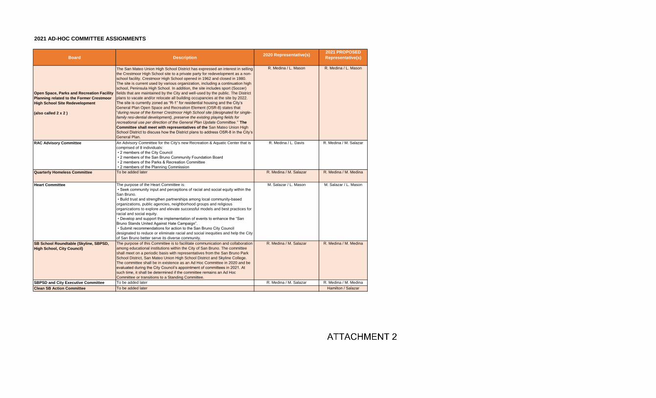
2021 AD-HOC COMMITTEE ASSIGNMENTS
Board Description2020 Representative(s)
2021 PROPOSED
Representative(s)
Open Space, Parks and Recreation Facility
Planning related to the Former Crestmoor
High School Site Redevelopment
(also called 2 x 2 )
The San Mateo Union High School District has expressed an interest in selling
the Crestmoor High School site to a private party for redevelopment as a non-
school facility. Crestmoor High School opened in 1962 and closed in 1980.
The site is current used by various organization, including a continuation high
school, Peninsula High School. In addition, the site includes sport (Soccer)
fields that are maintained by the City and well-used by the public. The District
plans to vacate and/or relocate all building occupancies at the site by 2022.
The site is currently zoned as “R-1” for residential housing and the City’s
General Plan Open Space and Recreation Element (OSR-8) states that
“during reuse of the former Crestmoor High School site (designated for single-
family residential development), preserve the existing playing fields for
recreational use per direction of the General Plan Update Committee.” The
Committee shall meet with representatives of the San Mateo Union High
School District to discuss how the District plans to address OSR-8 in the City’s
General Plan.
R. Medina / L. Mason R. Medina / L. Mason
RAC Advisory Committee An Advisory Committee for the City's new Recreation & Aquatic Center that is
comprised of 8 individuals:
• 2 members of the City Council
• 2 members of the San Bruno Community Foundation Board
• 2 members of the Parks & Recreation Committee
• 2 members of the Planning Commission
R. Medina / L. Davis R. Medina / M. Salazar
Quarterly Homeless Committee To be added later R. Medina / M. Salazar R. Medina / M. Medina
Heart Committee The purpose of the Heart Committee is:
• Seek community input and perceptions of racial and social equity within the
San Bruno.
• Build trust and strengthen partnerships among local community-based
organizations, public agencies, neighborhood groups and religious
organizations to explore and elevate successful models and best practices for
racial and social equity.
• Develop and support the implementation of events to enhance the “San
Bruno Stands United Against Hate Campaign”.
• Submit recommendations for action to the San Bruno City Council
designated to reduce or eliminate racial and social inequities and help the City
of San Bruno better serve its diverse community.
M. Salazar / L. Mason M. Salazar / L. Mason
SB School Roundtable (Skyline, SBPSD,
High School, City Council)
The purpose of this Committee is to facilitate communication and collaboration
among educational institutions within the City of San Bruno. The committee
shall meet on a periodic basis with representatives from the San Bruno Park
School District, San Mateo Union High School District and Skyline College.
The committee shall be in existence as an Ad Hoc Committee in 2020 and be
evaluated during the City Council’s appointment of committees in 2021. At
such time, it shall be determined if the committee remains an Ad Hoc
Committee or transitions to a Standing Committee.
R. Medina / M. Salazar R. Medina / M. Medina
SBPSD and City Executive Committee To be added later R. Medina / M. Salazar R. Medina / M. Medina
Clean SB Action Committee To be added later Hamilton / Salazar
MThurman
Typewritten text
ATTACHMENT 2

2021 COMMISSION, BOARD AND COMMITTEE LIAISON ASSIGNMENTS
Commission, Board or Committee 2021 2022 2023 2024 2025
Planning Commission T. Hamilton M. Salazar L. Mason R. Medina M. Medina
Parks and Recreation Commission M. Medina T. Hamilton M. Salazar L. Mason R. Medina
Senior Citizens Advisory Board M. Medina T. Hamilton M. Salazar L. Mason R. Medina
Culture and Arts Commission R. Medina M. Medina T. Hamilton M. Salazar L. Mason
Personnel Board R. Medina M. Medina T. Hamilton M. Salazar L. Mason
Citizens Crime Prevention Committee L. Mason R. Medina M. Medina T. Hamilton M. Salazar
Community Preparedness Committee L. Mason R. Medina M. Medina T. Hamilton M. Salazar
Traffic, Safety & Parking Committee M. Salazar L. Mason R. Medina M. Medina T. Hamilton
Bicycle & Pedestrian Advisory Committee M. Salazar L. Mason R. Medina M. Medina T. Hamilton
MThurman
Typewritten text
ATTACHMENT 3

City Council Agenda Item Staff Report
CITY OF SAN BRUNO
DATE: January 26, 2021 TO: Honorable Mayor and Members of the City Council FROM: Jovan D. Grogan, City Manager PREPARED BY: Ari Delay, Fire Chief
Gage Schlice, Fire Marshal SUBJECT: Adopt a resolution acknowledging receipt of a report made by the Fire
Chief regarding the inspection of certain occupancies required to perform annual inspection in such occupancies pursuant to section 13146.2 and 13146.3 of the California Health and Safety Code.
BACKGROUND: The California State Fire Marshal’s Office requires that certain occupancies be inspected annually by local fire departments pursuant to California Health and Safety Code Sections 13146 et seq. These occupancies include hotels/motels, multi-family residences with 3 or more units, and K-12 public and private schools to enforce current building and fire safety standards. After several multi-family apartment fatality fires in 2016 and 2017 in other cities, including the December 2, 2016, “Ghost Ship Warehouse” fire that killed 36 people, a bay area news group collected eight years of data from twelve bay area fire departments and found that many schools and apartments were not being inspected annually as required by law. On September 27, 2018, the Legislature adopted SB1205 introduced by Senator Jerry Hill, now codified as Health and Safety Code Section 13146.4.The new law requires fire departments to perform the state mandated inspections, report inspection results annually to the City Council and require that a resolution be adopted acknowledging receipt of the report. DISCUSSION: San Bruno Fire Department conducts a fire and life safety inspection program, which includes inspecting all state mandated occupancies annually. The fire inspection cycle runs from January 1st thru December 31st annually. EDUCATIONAL GROUP E OCCUPANCIES
Educational Group E occupancies are generally those public and private schools, used by more than six persons at any one time for educational purposes through the 12th grade. Within the City of San Bruno, there lie 16 Group E occupancies, buildings, structures and/or facilities.
MThurman
Typewritten text
ITEM 5.f.

Honorable Mayor and Members of the City Council January 26, 2021 Page 2 of 2
During calendar year 2020, the San Bruno Fire Department completed the annual inspection of 16 Group E occupancies, buildings, structures and/or facilities. This is a compliance rate of 100% for this reporting period. RESIDENTIAL GROUP R OCCUPANCIES
Residential Group R occupancies, for the purposes of this resolution, are generally those occupancies containing sleeping units, and include hotels, motels, apartments (three units or more), etc. as well as other residential occupancies (including several residential care facilities). These residential care facilities have several different sub-classifications, and they may contain residents or clients that have a range of needs, including those related to custodial care, mobility impairments, cognitive disabilities, etc. The residents may also be non-ambulatory or bedridden. Within the City of San Bruno, there lie 368 Group R (and their associated sub-categories) occupancies of this nature.
During calendar year 2020, the San Bruno Fire Department completed the annual inspection of 368 Group R occupancies, buildings, structures and/or facilities. This is a compliance rate of 100 % for this reporting period. The San Bruno Fire Department has completed 100% of the required inspections. FISCAL IMPACT: None RECOMMENDATION: Adopt a resolution acknowledging receipt of a report made by the Fire Chief regarding the inspection of certain occupancies required to perform annual inspection in such occupancies pursuant to section 13146.2 and 13146.3 of the California Health and Safety Code. ALTERNATIVES: 1. Request additional information before adopting the resolution. ATTACHMENTS:
1. Resolution 2. Bill Text – Senate Bill No. 1205
DISTRIBUTION: None.

RESOLUTION NO.___
RESOLUTION ACKNOWLEDGING RECEIPT OF A REPORT MADE BY THE FIRE CHIEF REGARDING THE INSPECTION OF CERTAIN OCCUPANCIES REQUIRED TO PERFORM
ANNUAL INSPECTIONS IN SUCH OCCUPANCIES PURSUANT TO SECTIONS 13146.2 AND 13146.3 OF THE CALIFORNIA HEALTH AND SAFETY CODE
WHEREAS, California Health & Safety Code Section 13146.4 was added in 2018, and became effective on September 27, 2018; and
WHEREAS, California Health & Safety Code Sections 13146.2 and 13146.3 requires all fire departments, including the San Bruno Fire Department, that provide fire protection services to perform annual inspections in every building used as a public or private school, hotel, motel, lodging house, apartment house, and certain residential care facilities for compliance with building standards, as provided; and
WHEREAS, California Health & Safety Code Section 13146.2 requires all fire departments, including the San Bruno Fire Department, that provide fire protection services to report annually to its administering authority on its compliance with Sections 13146.2 and 13146.3; and
WHEREAS, the City Council intends this Resolution to fulfill the requirements of the California Health & Safety Code regarding acknowledgment of receipt of the San Bruno Fire Department’s compliance with California Health and Sections 13146.2 and 13146.3.
NOW, THEREFORE, BE IT RESOLVED by the San Bruno City Council acknowledges receipt of the Fire Marshal’s report regarding compliance with California Health and Safety Code Sections 13146.2 and 13146.3.
A. EDUCATIONAL GROUP E OCCUPANCIES:
Educational Group E occupancies are generally those public and private schools, used by more than six persons at any one time for educational purposes through the 12th grade. Within the City of San Bruno, there lie 16 Group E occupancies, buildings, structures and/or facilities.
During calendar year 2020, the San Bruno Fire Department completed the annual inspection of 16 Group E occupancies, buildings, structures and/or facilities. This is a compliance rate of 100 % for this reporting period.
Additional items of note regarding this compliance rate can be found in the accompanying staff report for this resolution.
B. RESIDENTIAL GROUP R OCCUPANCIES:
Residential Group R occupancies, for the purposes of this resolution, are generally those occupancies containing sleeping units, and include hotels, motels, apartments (three units or more), etc. as well as other residential occupancies (including several residential care facilities). These residential care facilities have several different sub-classifications, and they may contain residents or clients that have a range of needs, including those related to custodial care, mobility impairments, cognitive disabilities, etc. The residents may also be non-ambulatory or bedridden. Within the City of San Bruno, there lie 368 Group R (and their associated sub-categories) occupancies of this nature.
During calendar year 2020, the San Bruno Fire Department completed the annual inspection of 368 Group R occupancies, buildings, structures and/or facilities. This is a compliance rate of 100 % for this reporting period. Additional items of note regarding this compliance rate can be found in the accompanying staff report for this resolution.
MThurman
Typewritten text
ATTACHMENT 1

Dated:
-o0o-
I, Melissa Thurman, City Clerk, do hereby certify that the foregoing Resolution was duly and regularly passed and adopted by the City Council of the City of San Bruno this 26th day of January 2021 by the following vote:
AYES: Councilmembers:
NOES: Councilmembers
ABSENT: Councilmembers:
ATTEST: Melissa Thurman, CMC
City Clerk

City Council Agenda Item
Staff Report
CITY OF SAN BRUNO
DATE: January 26, 2021 TO: Honorable Mayor and Members of the City Council FROM: Jovan D. Grogan, City Manager PREPARED BY: Esther Garibay-Fernandes, Financial Services Manager SUBJECT: Receive Report and Adopt Resolution Accepting Annual Report on
Receipt and Use of Development Impact Fees for the Fiscal Year Ending June 30, 2020
BACKGROUND: The City levies six fees under the terms specified in AB 1600. These fees are codified in California Government Code §§ 66000-66025 (Mitigation Fee Act). The Act contains legal requirements for enacting development impact fees, which the City has complied with during the adoption process for these impact fees. Impact fees are different from user fees, in that user fees are charged to customers for services received, for example a Recreation class or a building permit. Impact fees are levied to mitigate cost impacts that development projects have on existing City facilities and infrastructure. By levying an impact fee, the City intends to collect sufficient such fees over time so that the infrastructure impacted may be expanded or enhanced to accommodate the development. AB 1600 requires that an Annual Report be reviewed by the City Council at a regularly scheduled public meeting. Notice of the time and place of the meeting shall be mailed at least 15 days prior to the meeting to any interested party who files a written request with the local agency and must be made available to the public 15 days prior to the meeting. No such requests were made at the time of this report by interested parties. As of the date this report was finalized, City staff did not receive any such request. The report has been posted for the public, however, on the City’s website in accordance with the reporting requirements. The Annual Report attached to the City Council resolution presents the revenues, expenditures, and fund balances for the impact fees. Development Fees subject to AB 1600 requirements are: Water and Sewer Capacity charges, and development fees for Community Facilities, Public Safety, General Government, Utilities, and Transportation.
MThurman
Typewritten text
ITEM 5.g.

Honorable Mayor and Members of the City Council January 26, 2021 Page 2 of 4
Developer fees are segregated from the General Fund and from other all other City funds or accounts containing fees collected for other purposes in accordance with accounting standards. Interest earned on each fee is deposited into the fund or account and used only for the purposes for which the fees were collected. DISCUSSION: AB 1600 Annual Reporting Requirements AB 1600 requires that local agencies provide an accounting of impact fees imposed on development projects. Each local agency is required, within 180 days after the last day of each fiscal year, to make available to the public the following information regarding each fund or account (Government Code §§ 66006). 1 The development impact fees covered by the AB 1600 requirements and documented in Attachment 1 to the resolution include the following fees:
- The City levies Water Capacity charges on new or expanded connections to the water system. These charges are levied as a condition of development or change in use and are designed to recover the cost of capacity in infrastructure and assets benefitting new development. Approximately $32,000 of water capacity fees were collected in FY2019-20 from various projects.
- The City levies Sewer Capacity charges on new or expanded connections to the sewer systems. Approximately $53,000 of sewer capacity fees were collected in FY2019-20. These charges are levied as a condition of development or change in use and are designed to recover the cost of capacity in infrastructure and assets benefitting new development. The FY2020-21 adopted capital in process (CIP) budget includes water and sewer capital projects that will use water and sewer capacity fees collected as a critical funding source to complete the projects.
Both capacity charges are outlined in the City’s master fee schedule updated annually during the budget process. A supplementary Five-Year Project Cost and Funding Summary for all impact fees is included as Attachment B to provide further information on each fee.
- On May 1, 2019, the City’s adopted five new Development Impact Fees (Municipal Code Ch. 12.260) to fund:
o community facilities,
o public safety,
1 Due to COVID work limitations and staffing shortages in the Finance Department, this December 31 deadline was
missed. Staff will correct this reporting deficiency for 2021. Staff does not believe the lateness in reporting will have
any consequences for the City.

Honorable Mayor and Members of the City Council January 26, 2021 Page 3 of 4
o general government,
o transportation, and
o utility projects to serve demand created by new development.
Approximately $76,400 of these five development impact fees were collected in FY2019-20, with details showing in the Attachments to this report. Additional fees are expected to be collected in FY2020-21. During the FY2020-21 budget process, staff developed a projection for additional development impact fee revenue as well as recommending capital projects that can use development impact fees as a funding source.
AB 1600 requires the following items to be reported on annually:
Required Reporting Item In Report Attachment
Not Applicable to San Bruno this reporting year
1. Description of the type of fee in the fund;
X
2. Amount of the fee; X
3. Beginning and ending balance for the fiscal year;
X
4. Amount of fees collected, and interest earned;
X
5. Identification of each public improvement on which fees were expended and the amount of the expenditure on each improvement;
X
6. Identification of an approximate date by which the construction of a public improvement will commence, if the local agency determines that sufficient funds have been collected to complete financing on an incomplete public improvement;
NA
7. Description of each interfund transfer or loan made from the account or fund, including the public improvement on which the loaned funds will be expended, and in the case of an interfund loan, the date on which the loan will be repaid and the rate of interest that the account or fund will receive on the loan; and
NA
8. Amount of any refunds made due to inability to expend fees within the required time frame.
NA
Non-AB1600 Development Related Fees:

Honorable Mayor and Members of the City Council January 26, 2021 Page 4 of 4
Residential developers also paid the fees listed below in fulfilling City requirements that do not fit within the definition of development impact fees subject to AB 1600 reporting requirements. However, staff has included them in this report for informational purposes to the Council and the public.
• Park Dedication or In-Lieu fees (Municipal Code Ch. 12.44.140) are imposed on new residential subdivisions of five or more lots. The subdivisions are required to either dedicate land or pay an in-lieu fee for the City to purchase or improve land for parks and recreational purposes. This fee is exempt from the AB 1600 requirement. This fee has not been collected since FY2014-15; however, the City collected approximately $3.1 Million in fees in November of 2019 related to the 111 San Bruno Avenue development project.
• Affordable Housing Fees and Commercial Linkage Fees (Municipal Code Ch. 12.230) are collected on all residential ownership or rental developments of 5 units or more throughout the City. Additionally, an affordable housing commercial linkage fee is assessed on all non-residential development. Residential ownership units may provide below market rate units onsite, off-site, or pay a residential impact fee. This fee is exempt from the AB 1600 requirement.
FISCAL IMPACT: The annual AB 1600 report is a mandated reporting requirement provided to the City Council for informational purposes only. There is no direct fiscal impact by receiving the report and adopting the resolution. RECOMMENDATION: Receive report and adopt resolution accepting the Annual Report on the Receipt and Use of Development Impact Fees for the Year Ended June 30, 2020. ALTERNATIVES:
1. The Annual AB 1600 report is a mandated reporting requirement for informational purposes only.
ATTACHMENTS:
1. Resolution 2. Annual Development Impact Fee Revenue and Expenditure Report FY2019-20
DATE PREPARED: December 3, 2020

RESOLUTION NO. 2021-_____
RESOLUTION ACCEPTING ANNUAL REPORT FOR DEVELOPMENT IMPACT FEES
FOR FISCAL YEAR ENDING JUNE 30, 2020
WHEREAS, pursuant to Section 66000 et seq. of the Government Code, the City is required to prepare and present an annual development impact fees report for all impact fees and charges as defined by the Government Code; and WHEREAS, the City collects water and wastewater/sewer capacity charges to defray costs from increased capacity demands on water and sewer infrastructure; and
WHEREAS, the City collects five additional development impact fees to fund: community facilities, public safety, general government, transportation, and utility projects to fully or partially offset the costs of public facilities that are needed to serve demand created by that development; and
NOW THEREFORE, BE IT RESOLVED that the City Council of the City of San Bruno:
- receives and accepts the Annual Report on Development Impact Fees for the Year Ending June 30, 2020; and
- certifies that the City intends to use the fees described above to fund projects that are still planned and needed by the community.
—oOo—
I hereby certify that foregoing Resolution No. 2021-_____
was introduced and adopted by the San Bruno City Council at a regular meeting on January 26, 2021 by the following vote:
AYES: NOES: ABSENT: ___________________________ Melissa Thurman, CMC City Clerk
MThurman
Typewritten text
ATTACHMENT 1

THIS PAGE INTENTIONALLY LEFT BLANK

City of San Bruno
AB 1600 Development Impact Fees
Annual Report for Fiscal Year 2019-20
The attachments following reflect the required reporting for the City of San Bruno’s Development
Impact Fees for the fiscal year 2019-20 in compliance with California Government Code Sections
66000 – 66006.
MThurman
Typewritten text
ATTACHMENT 2

City of San Bruno Attachment 1
Development Impact Fees
Revenue and Expenditures Summary
For the period ending June 30, 2020
Revenue
Development Fees 31,999$
Interest 61
Total revenue 32,060
Expenditure
Pressure Regulator Station Impr & Replacement 379
Pump Station Projects -
Water Tank Improvement Projects -
Water Mains Improvement Projects 16,335
Well Improvement Projects 200
Total expenditure 16,914
Excess of revenues over expenditures 15,146
Fund balance, beginning 833,404
Fund balance, ending 848,550$
Revenue
Development fees 53,187$
Interest 160
Total revenue 53,347
Expenditure
Wastewater Pump Station Improvement Projects -
Wastewater Main Improvement Projects 55,533
Water Quality Control Plant Improvement Projects -
Total expenditure 55,533
Excess of revenues over expenditures (2,186)
Fund balance, beginning 8,140
Fund balance, ending 5,953$
WATER CAPACITY FEE
SEWER CAPACITY FEE

Revenue
Development fees 50,673$
Interest 1,162
Total revenue 51,835
Expenditure
None -
Total expenditure -
Excess of expenditures over revenues 51,835
Fund balance, beginning 21,893
Fund balance, ending 73,728$
Revenue
Development fees 4,004$
Interest 92
Total revenue 4,096
Expenditure
None -
Total expenditure -
Excess of expenditures over revenues 4,096
Fund balance, beginning 1,729
Fund balance, ending 5,825$
Revenue
Development fees 5,327$
Interest 122
Total revenue 5,449
Expenditure
None -
Total expenditure -
Excess of expenditures over revenues 5,449
Fund balance, beginning 2,301
Fund balance, ending 7,750$
Development Impact Fees - Community Facilities
Development Impact Fees - Public Safety
Development Impact Fees - General Government

Revenue
Development fees 9,135$
Interest 209
Total revenue 9,344
Expenditure
None -
Total expenditure -
Excess of expenditures over revenues 9,344
Fund balance, beginning 3,947
Fund balance, ending 13,291$
Revenue
Development fees 7,294$
Interest 167
Total revenue 7,461
Expenditure
None -
Total expenditure -
Excess of expenditures over revenues 7,461
Fund balance, beginning 3,151
Fund balance, ending 10,612$
Development Impact Fees - Transportation
Development Impact Fees - Utilities

City of San Bruno Attachment 1
Development Impact Fees
Revenue and Expenditures Summary
For the period ending June 30, 2020
Revenue
Development fees 3,173,625$
Interest 49,602
Total revenue 3,223,227
Expenditure
None -
Total expenditure -
Excess of expenditures over revenues 3,223,227
Fund balance, beginning 9,207
Fund balance, ending 3,232,434$
Revenue
Development fees -$
Interest 65,473
Total revenue 65,473
Expenditure
21 Elements 2,350
HIP Housing Program 30,000
Shelter Network Home Sharing Program 7,500
Total expenditure 39,850
Excess of revenues over expenditures 25,623
Fund balance, beginning 3,872,132
Fund balance, ending 3,897,755$
PARK IN-LIEU FEE
BELOW MARKET HOUSING IN-LIEU FEE

City of San Bruno Attachment 1
Five-Year Project Cost and Funding Summary
Water Capacity Charges
Description
Revenue and Expenditures: For Each Fiscal Year Ending June 30
Fiscal Year
Project
Expenditures
Projected
Increased
Capacity 2014-15 2015-16 2016-17 2017-18 2018-19 2019-20
Capacity Charges Received $7,525 $25,593 $99,354 $23,543 $804,958 $31,999
Interest Allocation 61 147 106 95 38,075 61
Total Revenue Received $7,586 $25,740 $99,460 $23,638 $843,033 $32,060
Project Expenditures
Advanced Water Meter (84132)
2015-16 Expenditures 3,693,000 306,519
2016-17 Expenditures 3,134 313 313
2017-18 Expenditures 86,474 8,647 0
2018-19 Expenditures 156 16 0
2019-20 Expenditures 0 - 0
Well No. 15 Replacement (84709)
2013-14 Expenditures 177,713 14,750
2014-15 Expenditures 274,398 22,775
2015-16 Expenditures 35,329 2,932 2,022
2016-17 Expenditures 8,634 863 863
2017-18 Expenditures 55 6 0
2018-19 Expenditures 4,093 409 409
2019-20 Expenditures 0 - 0
Pump Station No. 4 College Replacement (84140)
2013-14 Expenditures 1,629,510 135,249
2014-15 Expenditures 1,412,158 117,209
2015-16 Expenditures 30,845 2,560 $1,540
2016-17 Expenditures 67 7 7
2017-18 Expenditures 0 - 0
2018-19 Expenditures 0 - 0
2019-20 Expenditures 0 - 0
Tank No. 1 Improvement and Replacement (85100)
2013-14 Expenditures 100,046 8,304
2014-15 Expenditures 32,816 2,724 $540
2015-16 Expenditures 85,160 7,068 2,168
2016-17 Expenditures 3,689 369 369
2017-18 Expenditures 19,228 1,923 0
2018-19 Expenditures 6,837 684 0
2019-20 Expenditures 58,144 5,814 0
Sweeney Ridge Tank Replacement (11022)
2018-19 Expenditures 21,039 2,104 0
2019-20 Expenditures 246,749 24,675 0
Princeton Tank Replacement (11023)
2018-19 Expenditures 0 - 0
2019-20 Expenditures 0 - 0
Water Mains Improvement and Replacement (84129)
2013-14 Expenditures 150,312 15,031.20
2014-15 Expenditures 448,653 44,865.30
2015-16 Expenditures 863 86
2016-17 Expenditures 0 - 0
2017-18 Expenditures 0 - 0
2018-19 Expenditures 0 - 0
2019-20 Expenditures 0 - 0
Charges collected on new connections or water meter size upgrades contribute to the prior investments by ratepayers in the existing facilities that provide available capacity.

City of San Bruno Attachment 1
Five-Year Project Cost and Funding Summary
Water Capacity Charges
Description
Revenue and Expenditures: For Each Fiscal Year Ending June 30
Fiscal Year
Project
Expenditures
Projected
Increased
Capacity 2014-15 2015-16 2016-17 2017-18 2018-19 2019-20
Charges collected on new connections or water meter size upgrades contribute to the prior investments by ratepayers in the existing facilities that provide available capacity.
Tank No.3 Glenview Replacement (84142)
2013-14 Expenditures 136,656 11,342
2014-15 Expenditures 2,139,772 177,601
2015-16 Expenditures 2,809,009 233,148 55,944
2016-17 Expenditures 53,421 5,342 5,342
2017-18 Expenditures 0 - 0
2018-19 Expenditures 0 - 0
2019-20 Expenditures 0 - 0
Water Main Improvement -Jenevein Ave (84150)
2014-15 Expenditures 30,307 2,515 2,515
2015-16 Expenditures 83,915 6,965 3,065
2016-17 Expenditures 7,124 712 712
2017-18 Expenditures 1,436 144 144
2018-19 Expenditures 0 - 0
2019-20 Expenditures 0 - 0
Water Main Improvement -San Mateo Ave (84151)
2014-15 Expenditures 25,736 2,136 2,136
2015-16 Expenditures 98,951 8,213 2,013
2016-17 Expenditures 52,773 5,277 5,277
2017-18 Expenditures 2,234,338 223,434 0
2018-19 Expenditures 17,820 1,782 0
2019-20 Expenditures 0 - 0
Water Main Improvement -Crystal Springs (84152)
2014-15 Expenditures 28,860 2,395 2,395
2015-16 Expenditures 55,565 4,612 1,212
2016-17 Expenditures 7,518 752 752
2017-18 Expenditures 16,443 1,645 1,645
2018-19 Expenditures 0 - 0
2019-20 Expenditures - 0
Water Main Improvement - Ave No. 1-1 (84153)
2015-16 Expenditures 30,738 2,551 2,551
2016-17 Expenditures 47,915 4,792 4,792
2017-18 Expenditures 54,054 5,405 0
2018-19 Expenditures 12,491 1,249 0
2019-20 Expenditures 1,777,405 177,741 0
Water Main Improvement - Ave No. 1-2 (11002)
2015-16 Expenditures 30,854 2,561 1,912
2016-17 Expenditures 46,706 4,671 1,912 4,671
2017-18 Expenditures 44,352 4,436 4,436
2018-19 Expenditures 15,974 1,597 0
2019-20 Expenditures 1,788,289 178,829 0
Lake Drive Pump Station Impr (11003)
2016-17 Expenditures 1,364 136 136
2017-18 Expenditures 0 - 0
2018-19 Expenditures 4,982 498 0
2019-20 Expenditures 134,866 13,487 0
Sneath Lane Pump Station (11004)
2018-19 Expenditures 2,553 255 0
2019-20 Expenditures 106,767 10,677 0

City of San Bruno Attachment 1
Five-Year Project Cost and Funding Summary
Water Capacity Charges
Description
Revenue and Expenditures: For Each Fiscal Year Ending June 30
Fiscal Year
Project
Expenditures
Projected
Increased
Capacity 2014-15 2015-16 2016-17 2017-18 2018-19 2019-20
Charges collected on new connections or water meter size upgrades contribute to the prior investments by ratepayers in the existing facilities that provide available capacity.
Whitman Pump Station Generator (11012)
2018-19 Expenditures 28,439 2,844 0
2019-20 Expenditures 28,681 2,868 0
Princeton Pump Station (11021)
2018-19 Expenditures 9,059 906 0
2019-20 Expenditures 15,826 1,583 0
Arbor Court Pressure Regulator Relacemt (11005)
2016-17 Expenditures 23,730 2,373 2,373
2017-18 Expenditures 35,591 3,560 3,560
2018-19 Expenditures 452,978 45,298 0
2019-20 Expenditures - 0
Rollingwood Pressure Regulator Rehab (11016)
2018-19 Expenditures 814 81 0
2019-20 Expenditures 11,016 1,102 0
Oakmont Pressure Regulator Rehab (11017)
2018-19 Expenditures 425 43 0
2019-20 Expenditures 4,037 404 0
Cunningham Pressure Regulator Replacemt (11018)
2018-19 Expenditures 22 2 2
2019-20 Expenditures 0 - 0
Glenview Pressure Regulator Replacemt (11019)
2018-19 Expenditures 0 - 0
2019-20 Expenditures 3,790 379 379
Piedmont Ave Pressure Regulator Improv (11020)
2018-19 Expenditures 0 - 0
2019-20 Expenditures 0 - 0
Water Main Improvement - San Antonio Ave (11006)
2016-17 Expenditures 1,416 142 142
2017-18 Expenditures 20,267 2,027 0
2018-19 Expenditures 942,252 94,225 0
2019-20 Expenditures 90,133 9,013 9,013
Corp Yard Well (17) Rehab (84707)
2018-19 Expenditures 0 - 0
2019-20 Expenditures - 0
Lions Field Well (20) Rehabilitation (11013)
2016-17 Expenditures 1,015 102 102
2017-18 Expenditures 150,589 15,059 15,059
2018-19 Expenditures 2,107 211 211
2019-20 Expenditures 112 11 11
City Park Well (18) Rehab (11014)
2018-19 Expenditures 75,872 7,587 7,587
2019-20 Expenditures 0 - 0
Forest Lane Well Rehab (16) (11015)
2017-18 Expenditures 74,991 7,499 7,499
2018-19 Expenditures 14,319 1,432 1,432
2019-20 Expenditures 1,888 189 189

City of San Bruno Attachment 1
Five-Year Project Cost and Funding Summary
Water Capacity Charges
Description
Revenue and Expenditures: For Each Fiscal Year Ending June 30
Fiscal Year
Project
Expenditures
Projected
Increased
Capacity 2014-15 2015-16 2016-17 2017-18 2018-19 2019-20
Charges collected on new connections or water meter size upgrades contribute to the prior investments by ratepayers in the existing facilities that provide available capacity.
SCADA Radio Transmitter Instal (84102)
2015-16 Expenditures 307,000 25,481 3,481
2016-17 Expenditures 1,127 113 113
2017-18 Expenditures 0 - 0
2018-19 Expenditures 0 - 0
2019-20 Expenditures 0 - 0
Shallow Groundwater Study (84712)
2015-16 Expenditures 94,241 7,822 3,861
2016-17 Expenditures 23,665 2,367 2,367
2017-18 Expenditures 0 - 0
2018-19 Expenditures 0 - 0
2019-20 Expenditures 0 - 0
S. Westside Basin Groudwater Mgmt Study (84715)
2015-16 Expenditures 42 3 3
2016-17 Expenditures 1,843 184 184
2017-18 Expenditures 2,414 241 241
2018-19 Expenditures 665 67 67
2019-20 Expenditures 0 - 0
Ave No. 1-3 Water Main Improvement (11007)
2017-18 Expenditures 59,595 5,960 5,960
2018-19 Expenditures 105,592 10,559 0
2019-20 Expenditures 278,161 27,816 0
Ave No. 2-1 Water Main Improvement (11008)
2018-19 Expenditures 152 15 15
2019-20 Expenditures 73,216 7,322 7,322
Ave No. 3-1 Water Main Improvement (11009)
2018-19 Expenditures 46,335 4,634 0
2019-20 Expenditures 209,924 20,992 0
Ave No. 3-2 Water Main Improvement (11010)
2018-19 Expenditures 0 - 0
2019-20 Expenditures 0 - 0
Ave No. 3-3 Water Main Improvement (11011)
2018-19 Expenditures 0 - 0
2019-20 Expenditures 0 - 0
Total Expenditures 7,586 25,740 84,460 38,544 9,723 16,914
Unused Funds $0 $0 $15,000 ($14,906) $833,310 $15,146
Total Available Funds $94 $833,404 $848,550

City of San Bruno Attachment 1
Five-Year Project Cost and Funding Summary
Water Capacity Charges
Description
Revenue and Expenditures: For Each Fiscal Year Ending June 30
Fiscal Year
Project
Expenditures
Projected
Increased
Capacity 2014-15 2015-16 2016-17 2017-18 2018-19 2019-20
Charges collected on new connections or water meter size upgrades contribute to the prior investments by ratepayers in the existing facilities that provide available capacity.
Funding committed for FY2020-21 Capital Program
Total
Budgeted
FY2020-21
Project
Cost
Projected
Increased
Capacity
Advanced Water Meter $1,172,737 117,274
Acappella Well Project $1,812,751 181,275
Water Mains Improvement and Replacement 10,276,193 1,027,619
Pressure Regulator Station Improvements & Replacement $1,592,278 159,228
Pump Stations Improvement and Replacement $3,095,862 309,586
Water Tanks Improvement and Replacement 4,037,799 403,780
Well Replacement and Rehabilitation 200,000 20,000
Total Capacity Charges Commited for Capital Improvement Program $22,187,620 2,218,762
Total Uncommitted Capacity Charges $0
Five-Year Disclosure:
Fees collected and interest earned are in compliance with California Code Section 66013.
Note: Capacity increase calculation from 8.3% to 10% for FY2016-17 which is consistent to the Water Capacity Study completed
in September 28, 2017

City of San Bruno Attachment 1
Five-Year Project Cost and Funding Summary
Sewer Capacity Charges
Description
Revenue and Expenditures: For Each Fiscal Year Ending June 30
Fiscal Year
Project
Expenditures
Projected
Increased
Capacity 2014-15 2015-16 2016-17 2017-18 2018-19 2019-20
Capacity Charges Received $17,475 $36,116 $76,893 $118,323 $19,251 $53,187
Interest Allocation 81 225 105 182 22 160
Total Revenue Received $17,556 $36,341 $50,105 $118,505 $19,273 $53,347
Project Expenditures
Olympic Pump Station (84336)
2013-14 Expenditures 255,075 21,171
2014-15 Expenditures 542,192 45,002
2015-16 Expenditures 2,262,537 187,791 $5,880
2016-17 Expenditures 1,883 188 0
2017-18 Expenditures 0 - 0
2018-19 Expenditures 0 - 0
2019-20 Expenditures 0 - 0
Trenton Drive Wastewater Main Replacement (85704)
2013-14 Expenditures 69,685 5,784
2014-15 Expenditures 97,091 8,059
2015-16 Expenditures 68,921 5,720 5,720
2016-17 Expenditures 1,167,853 116,785 23,278
2017-18 Expenditures 317,334 31,733 31,733
2018-19 Expenditures 5,701 570 570
2019-20 Expenditures 0 - 0
Wastewater Pipeline Repair Program (84322)
2013-14 Expenditures 48,010 3,985
2014-15 Expenditures 43,181 3,584
2015-16 Expenditures 26,541 2,203 2,203
2016-17 Expenditures 6,747 675 675
2017-18 Expenditures 0 - 0
2018-19 Expenditures 0 - 0
2019-20 Expenditures 0 - 0
Wastewater Main Improvement-Jenevein Ave (84340)
2014-15 Expenditures 32,651 2,710
2015-16 Expenditures 73,351 6,088 3,753 $2,335
2016-17 Expenditures 1,478,713 147,871
2017-18 Expenditures 2,524 252 252
2018-19 Expenditures 0 - 0
2019-20 Expenditures 0 - 0
Wastewater Main Improvement-San Mateo Ave (84341)
2014-15 Expenditures 29,819 2,475
2015-16 Expenditures 92,233 7,655 7,655
2016-17 Expenditures 42,598 4,260
2017-18 Expenditures 2,931,618 293,162 0
2018-19 Expenditures 24,513 2,451 0
2019-20 Expenditures 0 - 0
Charges collected on new connections or sewer meter size upgrades contribute to the prior investments by ratepayers in the existing facilities that provide available capacity.

City of San Bruno Attachment 1
Five-Year Project Cost and Funding Summary
Sewer Capacity Charges
Description
Revenue and Expenditures: For Each Fiscal Year Ending June 30
Fiscal Year
Project
Expenditures
Projected
Increased
Capacity 2014-15 2015-16 2016-17 2017-18 2018-19 2019-20
Charges collected on new connections or sewer meter size upgrades contribute to the prior investments by ratepayers in the existing facilities that provide available capacity.
Wastewater Main Improvement-Crystal Springs Ave (84342)
2014-15 Expenditures 30,063 2,495
2015-16 Expenditures 52,889 4,390 4,390
2016-17 Expenditures 19,055 1,906 1,906
2017-18 Expenditures 48,303 4,830 0
2018-19 Expenditures 3,313,583 331,358 0
2019-20 Expenditures 0 - 0
Wastewater Main Improvement-Ave No. 1-1 (84343)
2015-16 Expenditures 30,597 2,540 2,540
2016-17 Expenditures 36,710 3,671 1,607
2017-18 Expenditures 44,014 4,401 0
2018-19 Expenditures 12,846 1,285 0
2019-20 Expenditures 1,669,810 166,981 0
Wastewater Main Improvement-Ave No. 1-2 (31001)
2015-16 Expenditures 31,085 2,580 2,580
2016-17 Expenditures 36,763 3,676
2017-18 Expenditures 44,246 4,425 0
2018-19 Expenditures 18,847 1,885 0
2019-20 Expenditures 1,575,948 157,595 0
Wastewater Main Improvement-Crestmoor Canyon (31002)
2015-16 Expenditures 12,910 1,072 1,072
2016-17 Expenditures 15,817 1,582 1,582
2017-18 Expenditures 304,761 30,476 30,476
2018-19 Expenditures 0 - 0
2019-20 Expenditures 0 - 0
Crestmoor Pump Station (31003)
2016-17 Expenditures 171,480 17,148 1,700 3,148
2017-18 Expenditures 73,520 7,352 0
2018-19 Expenditures 628,368 62,837 0
2019-20 Expenditures 1,495,346 149,535 0
Crestwood Pump Station (31004)
2016-17 Expenditures 2,248 225 225
2017-18 Expenditures 86,403 8,640 0
2018-19 Expenditures 18,712 1,871 0
2019-20 Expenditures 56,494 5,649 0
Lomita Pump Station (31005)
2016-17 Expenditures 177,234 17,723 7,724
2017-18 Expenditures 79,175 7,918 0
2018-19 Expenditures 608,253 60,825 0
2019-20 Expenditures 1,651,354 165,135 0
Wastewater Main Improvement-Crestwood Dr. (31006)
2016-17 Expenditures 1,103 110 110
2017-18 Expenditures 56,119 5,612 0
2018-19 Expenditures 10,799 1,080 0
2019-20 Expenditures 48,351 4,835 0
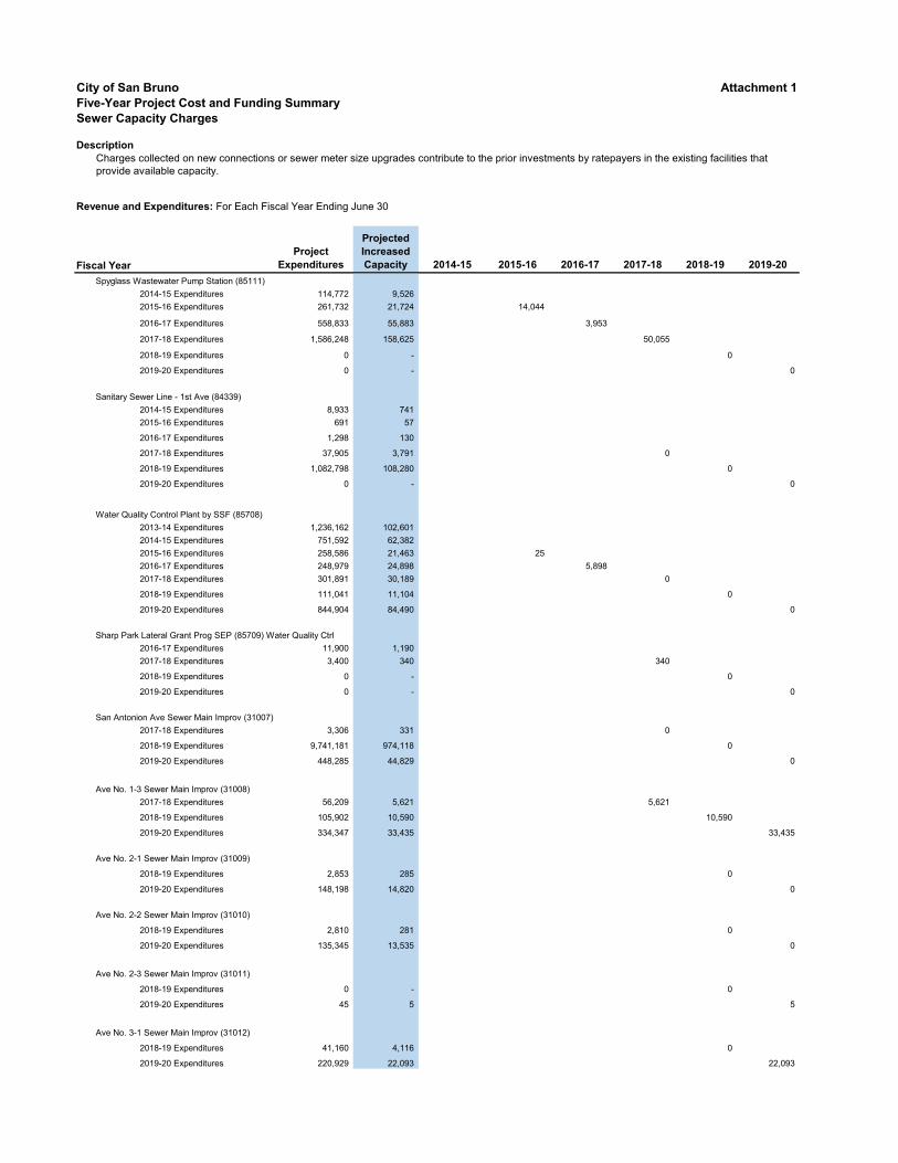
City of San Bruno Attachment 1
Five-Year Project Cost and Funding Summary
Sewer Capacity Charges
Description
Revenue and Expenditures: For Each Fiscal Year Ending June 30
Fiscal Year
Project
Expenditures
Projected
Increased
Capacity 2014-15 2015-16 2016-17 2017-18 2018-19 2019-20
Charges collected on new connections or sewer meter size upgrades contribute to the prior investments by ratepayers in the existing facilities that provide available capacity.
Spyglass Wastewater Pump Station (85111)
2014-15 Expenditures 114,772 9,526
2015-16 Expenditures 261,732 21,724 14,044
2016-17 Expenditures 558,833 55,883 3,953
2017-18 Expenditures 1,586,248 158,625 50,055
2018-19 Expenditures 0 - 0
2019-20 Expenditures 0 - 0
Sanitary Sewer Line - 1st Ave (84339)
2014-15 Expenditures 8,933 741
2015-16 Expenditures 691 57
2016-17 Expenditures 1,298 130
2017-18 Expenditures 37,905 3,791 0
2018-19 Expenditures 1,082,798 108,280 0
2019-20 Expenditures 0 - 0
Water Quality Control Plant by SSF (85708)
2013-14 Expenditures 1,236,162 102,601
2014-15 Expenditures 751,592 62,382
2015-16 Expenditures 258,586 21,463 25
2016-17 Expenditures 248,979 24,898 5,898
2017-18 Expenditures 301,891 30,189 0
2018-19 Expenditures 111,041 11,104 0
2019-20 Expenditures 844,904 84,490 0
Sharp Park Lateral Grant Prog SEP (85709) Water Quality Ctrl
2016-17 Expenditures 11,900 1,190
2017-18 Expenditures 3,400 340 340
2018-19 Expenditures 0 - 0
2019-20 Expenditures 0 - 0
San Antonion Ave Sewer Main Improv (31007)
2017-18 Expenditures 3,306 331 0
2018-19 Expenditures 9,741,181 974,118 0
2019-20 Expenditures 448,285 44,829 0
Ave No. 1-3 Sewer Main Improv (31008)
2017-18 Expenditures 56,209 5,621 5,621
2018-19 Expenditures 105,902 10,590 10,590
2019-20 Expenditures 334,347 33,435 33,435
Ave No. 2-1 Sewer Main Improv (31009)
2018-19 Expenditures 2,853 285 0
2019-20 Expenditures 148,198 14,820 0
Ave No. 2-2 Sewer Main Improv (31010)
2018-19 Expenditures 2,810 281 0
2019-20 Expenditures 135,345 13,535 0
Ave No. 2-3 Sewer Main Improv (31011)
2018-19 Expenditures 0 - 0
2019-20 Expenditures 45 5 5
Ave No. 3-1 Sewer Main Improv (31012)
2018-19 Expenditures 41,160 4,116 0
2019-20 Expenditures 220,929 22,093 22,093

City of San Bruno Attachment 1
Five-Year Project Cost and Funding Summary
Sewer Capacity Charges
Description
Revenue and Expenditures: For Each Fiscal Year Ending June 30
Fiscal Year
Project
Expenditures
Projected
Increased
Capacity 2014-15 2015-16 2016-17 2017-18 2018-19 2019-20
Charges collected on new connections or sewer meter size upgrades contribute to the prior investments by ratepayers in the existing facilities that provide available capacity.
Total Expenditures 17,556 36,341 50,105 118,478 11,160 55,533
Unused Funds $0 $0 ($0) $27 $8,113 ($2,186)
Total Available Funds $27 $8,140 $5,953
Funding committed for FY2020-21 Capital Program
Total
Budgeted
FY2020-21
Project
Cost
Projected
Increased
Capacity
Wastewater Pump Stations Improvement and Replacement 5,612,327 561,233
Wastewater Mains Improvement and Replacement 11,705,519 1,170,552
Water Quality Control Plant by SSF 5,482,184 548,218
Total Capacity Charges Commited for Capital Improvement Program $22,800,030 $2,280,003
Total Uncommitted Capacity Charges $0
Five-Year Disclosure:
Fees collected and interest earned are in compliance with California Code Section 66013.
Note: Capacity increase calculation from 8.3% to 10% for FY2016-17 which is consistent to the Water Capacity Study completed
in September 28, 2017

City of San Bruno Attachment 1
Five-Year Project Cost and Funding Summary
Development Impact Fees - Community Facilities
Description
Revenue and Expenditures: For Each Fiscal Year Ending June 30
Fiscal Year
Total
Project
Cost 2018-19 2019-20
Revenues
Fees Received
4250 Community Facilities Impact Fee 21,717$ 50,673$
Interest Allocation 176 1,162
Total Revenue Received 21,893$ 51,835$
Project Expenditures
4250 Community Facilities Impact Fee - -
Total Expenditures -$ -$
Total Change in Revenues (Expenditures) 21,893$ 51,835$
Beginning Fund Balance at July 1, 2019 21,893$
Total Change in Revenues (Expenditures) 51,835
Ending Fund Balance at June 30, 2020 73,728$
Five-Year Disclosure:
The Development Impact Fees collected upon development and redevelopment
projects to fully or partially offset the costs of public facilities that are needed to serve
demand created by that development project.
Ordinance added Chapter 12.260 to Title 12 (Zoning) of the San Bruno Municipal
Code established for Development Impact Fees effective May 1, 2019.
For the fifth fiscal year following the first deposit into the accounts or funds
established pursuant to Section 12.260.080 of the ordinance, and every five years
thereafter, the City Council shall, in connection with its review conducted, make each
of the findings required by Section 66001(d) of the California Government Code
including purpose of the fee, reasonable relationship between the fee and purpose,
sources and amounts of funds, and approximate dates when funding is expected to
be deposited into appropriate accounts or funds.

City of San Bruno Attachment 1
Five-Year Project Cost and Funding Summary
Development Impact Fees - Public Safety
Description
Revenue and Expenditures: For Each Fiscal Year Ending June 30
Fiscal Year
Total
Project
Cost 2018-19 2019-20
Revenues
Fees Received
4251 Public Safety Impact Fee 1,716$ 4,004$
Interest Allocation 13 92
Total Revenue Received 1,729$ 4,096$
Project Expenditures
4251 Public Safety Impact Fee - -
Total Expenditures -$ -$
Total Change in Revenues (Expenditures) 1,729$ 4,096$
Beginning Fund Balance at July 1, 2019 1,729$
Total Change in Revenues (Expenditures) 4,096
Ending Fund Balance at June 30, 2020 5,825$
Five-Year Disclosure:
The Development Impact Fees collected upon development and redevelopment
projects to fully or partially offset the costs of public facilities that are needed to serve
demand created by that development project.
Ordinance added Chapter 12.260 to Title 12 (Zoning) of the San Bruno Municipal
Code established for Development Impact Fees effective May 1, 2019.
For the fifth fiscal year following the first deposit into the accounts or funds
established pursuant to Section 12.260.080 of the ordinance, and every five years
thereafter, the City Council shall, in connection with its review conducted, make each
of the findings required by Section 66001(d) of the California Government Code
including purpose of the fee, reasonable relationship between the fee and purpose,
sources and amounts of funds, and approximate dates when funding is expected to
be deposited into appropriate accounts or funds.

City of San Bruno Attachment 1
Five-Year Project Cost and Funding Summary
Development Impact Fees - General Government
Description
Revenue and Expenditures: For Each Fiscal Year Ending June 30
Fiscal Year
Total
Project
Cost 2018-19 2019-20
Revenues
Fees Received
4252 General Government Impact Fee 2,283$ 5,327$
Interest Allocation 18 122
Total Revenue Received 2,301$ 5,449$
Project Expenditures
4252 General Government Impact Fee - -
Total Expenditures -$ -$
Total Change in Revenues (Expenditures) 2,301$ 5,449$
Beginning Fund Balance at July 1, 2019 2,301$
Total Change in Revenues (Expenditures) 5,449
Ending Fund Balance at June 30, 2020 7,750$
Five-Year Disclosure:
The Development Impact Fees collected upon development and redevelopment
projects to fully or partially offset the costs of public facilities that are needed to serve
demand created by that development project.
Ordinance added Chapter 12.260 to Title 12 (Zoning) of the San Bruno Municipal
Code established for Development Impact Fees effective May 1, 2019.
For the fifth fiscal year following the first deposit into the accounts or funds
established pursuant to Section 12.260.080 of the ordinance, and every five years
thereafter, the City Council shall, in connection with its review conducted, make each
of the findings required by Section 66001(d) of the California Government Code
including purpose of the fee, reasonable relationship between the fee and purpose,
sources and amounts of funds, and approximate dates when funding is expected to
be deposited into appropriate accounts or funds.

City of San Bruno Attachment 1
Five-Year Project Cost and Funding Summary
Development Impact Fees - Transportation
Description
Revenue and Expenditures: For Each Fiscal Year Ending June 30
Fiscal Year
Total
Project
Cost 2018-19 2019-20
Revenues
Fees Received
4253 Transportation Impact Fee 3,915$ 9,135$
Interest Allocation 32 209
Total Revenue Received 3,947$ 9,344$
Project Expenditures
4253 Transportation Impact Fee - -
Total Expenditures -$ -$
Total Change in Revenues (Expenditures) 3,947$ 9,344$
Beginning Fund Balance at July 1, 2019 3,947$
Total Change in Revenues (Expenditures) 9,344
Ending Fund Balance at June 30, 2020 13,291$
Five-Year Disclosure:
The Development Impact Fees collected upon development and redevelopment
projects to fully or partially offset the costs of public facilities that are needed to serve
demand created by that development project.
Ordinance added Chapter 12.260 to Title 12 (Zoning) of the San Bruno Municipal
Code established for Development Impact Fees effective May 1, 2019.
For the fifth fiscal year following the first deposit into the accounts or funds
established pursuant to Section 12.260.080 of the ordinance, and every five years
thereafter, the City Council shall, in connection with its review conducted, make each
of the findings required by Section 66001(d) of the California Government Code
including purpose of the fee, reasonable relationship between the fee and purpose,
sources and amounts of funds, and approximate dates when funding is expected to
be deposited into appropriate accounts or funds.
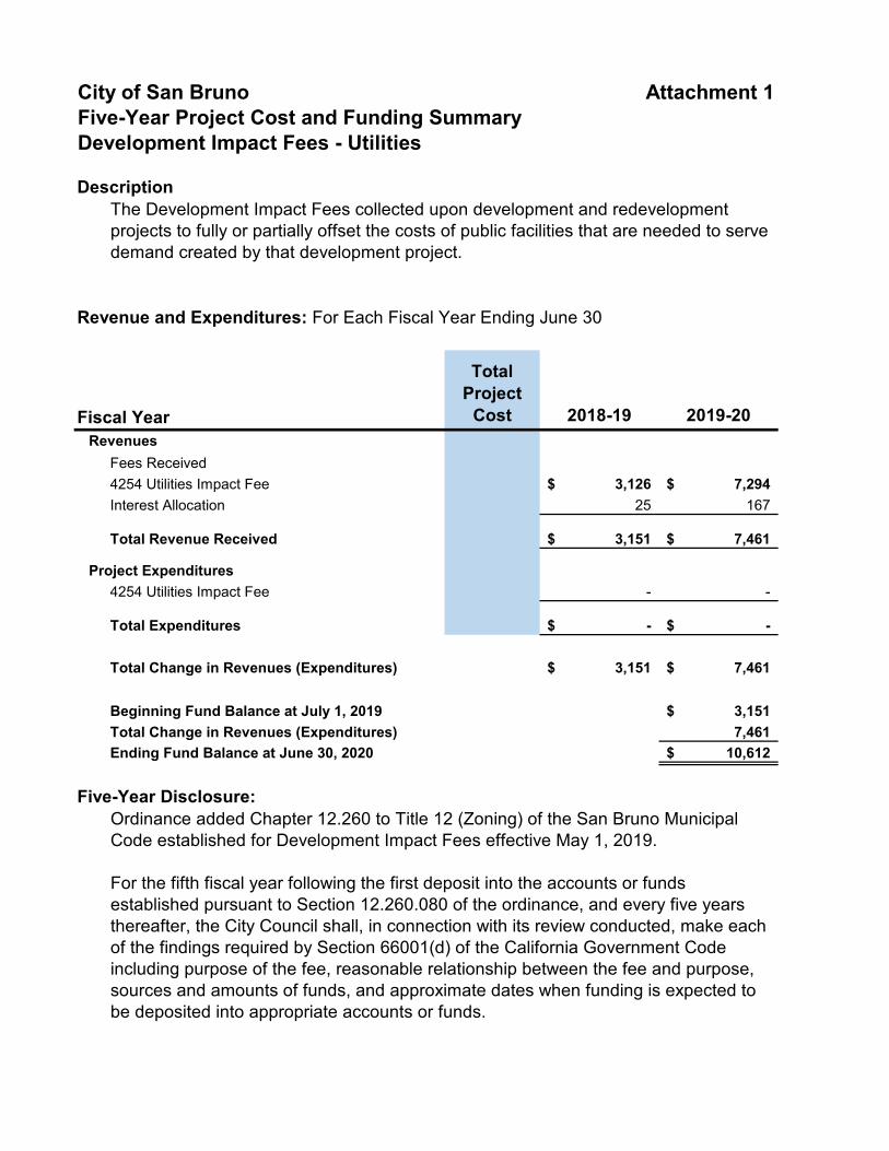
City of San Bruno Attachment 1
Five-Year Project Cost and Funding Summary
Development Impact Fees - Utilities
Description
Revenue and Expenditures: For Each Fiscal Year Ending June 30
Fiscal Year
Total
Project
Cost 2018-19 2019-20
Revenues
Fees Received
4254 Utilities Impact Fee 3,126$ 7,294$
Interest Allocation 25 167
Total Revenue Received 3,151$ 7,461$
Project Expenditures
4254 Utilities Impact Fee - -
Total Expenditures -$ -$
Total Change in Revenues (Expenditures) 3,151$ 7,461$
Beginning Fund Balance at July 1, 2019 3,151$
Total Change in Revenues (Expenditures) 7,461
Ending Fund Balance at June 30, 2020 10,612$
Five-Year Disclosure:
The Development Impact Fees collected upon development and redevelopment
projects to fully or partially offset the costs of public facilities that are needed to serve
demand created by that development project.
Ordinance added Chapter 12.260 to Title 12 (Zoning) of the San Bruno Municipal
Code established for Development Impact Fees effective May 1, 2019.
For the fifth fiscal year following the first deposit into the accounts or funds
established pursuant to Section 12.260.080 of the ordinance, and every five years
thereafter, the City Council shall, in connection with its review conducted, make each
of the findings required by Section 66001(d) of the California Government Code
including purpose of the fee, reasonable relationship between the fee and purpose,
sources and amounts of funds, and approximate dates when funding is expected to
be deposited into appropriate accounts or funds.

City of San Bruno Attachment 1
Five-Year Project Cost and Funding Summary
Park in-Lieu Fees
Description
Revenue and Expenditures: For Each Fiscal Year Ending June 30
Fiscal Year
Total
Project
Cost 2014-15 2015-16 2016-17 2017-18 2018-19 2019-20
Revenues
Fees Received 2,000$ -$ -$ -$ -$ 3,173,625$
Interest Allocation 1,434 65 73 105 167 49,602
Total Revenue Received 3,434$ 65$ 73$ 105$ 167$ 3,223,227$
Project Expenditures
2013-14 Expenditures - 324 Florida Ave 0 - - - - -
2014-15 Expenditures - 324 Florida Ave 603,015 603,015 - - - - -
Total Expenditures 603,015$ -$ -$ -$ -$ -$
Total Change in Revenues (Expenditures) (599,581)$ 65$ 73$ 105$ 167$ 3,223,227$
Beginning Fund Balance at July 1, 2019 608,378$ 9,207$
Total Change in Revenues (Expenditures) 65 3,223,227
Ending Fund Balance at June 30, 2020 608,443 3,232,434$
Five-Year Disclosure:
Exempt per Quimby Act
The Park In-Lieu Fees collected are dedicated to land for parks and recreational purpose. With the adoption of the Development Impact
Fee Ordinance that took effect on May 1, 2019, the Park in-Lieu fee was repealed and replaced with the new Facilities Impact Fee.

City of San Bruno Attachment 1
Five-Year Project Cost and Funding Summary
Below Market Rate Housing in-Lieu Fees
Description
Revenue and Expenditures: For Each Fiscal Year Ending June 30
Fiscal Year
Total
Eligible
Cost 2014-15 2015-16 2016-17 2017-18 2018-19 2019-20
Revenues
Fees Received -$ -$ -$ 320,000$ -$
Interest Allocation 24,268$ 25,907$ 29,046$ 41,417$ 66,990$ 65,473$
Total Revenue Received 24,268$ 25,907$ 29,046$ 41,417$ 386,990$ 65,473$
Operating Expenditures
21 Elements 6,000$ 2,000 2,000 2,000 1,800 2,350
HIP Housing Program 150,000$ 30,000$ 30,000$ 30,000$ 30,000$ 30,000$ 30,000$
Urban Housing Communities 4,000$
City of Foster City - Housing Nexus Study -$
Shelter Network Homesharing Program (LifeMoves) 30,000$ 7,500 7,500 7,500 7,500 7,500 7,500
North Peninsula Neighborhood Center 6,000$
Total Expenditures 37,500$ 39,500$ 39,500$ 39,500$ 39,300$ 39,850$
Total Change in Revenues (Expenditures) (13,232)$ (13,593)$ (10,454)$ 1,917$ 347,690$ 25,623$
Beginning Fund Balance at July 1, 2019 3,541,904$ 3,872,132$
Total Change in Revenues (Expenditures) (13,232) 25,623
Ending Fund Balance at June 30, 2020 3,528,672$ 3,897,755$
Five-Year Disclosure:
Not required. Development fees collected in conjunction with contractual agreement, or development agreements, are not constrained by AB 1600 requirement.
The Below Market Rate Housing in-Lieu fees are charged on all residential ownership or rental developments of 10 units or more throughout the City.

THIS PAGE INTENTIONALLY LEFT BLANK

City Council Agenda Item Staff Report
CITY OF SAN BRUNO
DATE: January 26, 2021 TO: Honorable Mayor and Members of the City Council FROM: Jovan D. Grogan, City Manager PREPARED BY: Jimmy Tan, Public Works Director
Dennis Bosch, Public Works Deputy Director SUBJECT: Adopt Resolution Authorizing the City Manager to Execute a Contract
with West Yost Associates to Update the Urban Water Management Plan in an Amount Not to Exceed $84,370
BACKGROUND: The Urban Water Management Planning Act (Act) of the California Water Code requires urban water suppliers to make every effort to ensure that appropriate levels of water service are reliably maintained to meet the needs of its customers during normal, dry, and multiple dry years. This is accomplished through the preparation and implementation of an Urban Water Management Plan (UWMP) by water suppliers to support long-term resource planning and to ensure adequate water supplies are available to meeting existing and future demands. Every water supplier that either provides 3,000 acre-feet of water annually or serves 3,000 or more connections is required to assess the reliability of its water sources over a 20-year planning horizon. The UWMP is to be prepared every five (5) years and submitted to the Department of Water Resources (DWR) for review and the last review was in 2016. The DWR reviews the submitted plan to make sure the water supplier completed the requirements identified in the Act. An UWMP is required in order for a water supplier to be eligible for DWR administered state grants, loans, and drought assistance. Moreover, the UWMP serves as a long-range water supply planning document that will also provide a source of information to other governments for the understanding, development and integration of regional water management plans. The UWMP also serves as a foundational document that will incorporate information from the General Plan. The connection between the UWMP and the General Plan is part of the Water Supply Assessment process required by SB610 and SB221 that integrate land use and water supply planning. The City is planning to update the UWMP to meet DWR requirements. Specifically, UWMP must include the following:
• Assess the reliability of water sources over a 20-year planning time frame
• Describe demand management measures and water shortage contingency plans
MThurman
Typewritten text
iTEM 6.a.
MThurman
Typewritten text
I

Honorable Mayor and Members of the City Council January 26, 2021 Page 2 of 3
• Report progress toward meeting a targeted 20-percent reduction in per-capita (per-person) urban water consumption by the year 2020
• Discuss the use and planned use of recycled water Upon completion, staff will request City Council to adopt the UWMP following a public notification and public hearing process. Then, the adopted UWMP will be forwarded to the State Department of Water Resources for review as to its completeness pursuant to the Act by July 1, 2021. DISCUSSION: In October 2020, the City issued a Request for Proposals (RFP) to develop and update the City’s UWMP. The RFP was directly distributed to at least three qualified engineering firms in the Bay Area and posted on the City’s website. The City received two proposals, ranging in cost from $45,000 to $85,000, from the following firms:
1. West & Associates Engineering, Inc. of Foothill Ranch, California (Long Beach area) 2. West Yost Associates of Davis, California
Staff conducted an evaluation of the proposals based on the following criteria:
• Project understanding and approach
• Qualifications and experience of the project manager and team
• Qualifications related to the development of similar urban water management plans
After evaluating the proposals, staff is recommending West Yost Associates to update the City’s UWMP. Their proposal demonstrated a professional, well-qualified level of specific experience and expertise in water system demand analysis and supply shortage contingency planning. Further, the West Yost project team has intimate knowledge of statewide and regional water issues, and a demonstrated track record developing quality Urban Water Management Plans, water supply assessments, and hydraulic analyses for Bay Area and Northern California cities including Fresno, Modesto, Sacramento, Santa Rosa, Stockton, and Woodland, and the water districts of the Coastside County Water District, the Dublin-San Ramon Services District, and the San Gabriel Water Valley Company. One team member alone dedicated to this project has personally managed or participated in over 30 UWMPs for various agencies within the Bay Area. The other firm did not have the same amount of qualifications and experience. The firm also completed San Bruno’s 2015 Urban Water Management Plan.
Staff anticipates a draft UWMP to be completed within six (6) months after contract execution. FISCAL IMPACT: The contract amount with West Yost Associates is for $84,370 and is within the $100,000 amount approved in the FY20-21 Water Operating budget for this project. Therefore no additional appropriation is being requested.

Honorable Mayor and Members of the City Council January 26, 2021 Page 3 of 3
ALTERNATIVES: 1. Direct further review of submitted proposals for selection of a different firm from the current
proposals. 2. Request staff to issue a new request for proposals. RECOMMENDATION: Adopt resolution authorizing the City Manager to execute a contract with West Yost Associates to update the Urban Water Management Plan in an amount not to exceed $84,370. DISTRIBUTION: None. ATTACHMENTS: 1. Resolution DATE PREPARED: December 31, 2020

THIS PAGE INTENTIONALLY LEFT BLANK

RESOLUTION NO. 2021- ___
RESOLUTION AUTHORIZING THE CITY MANAGER TO EXECUTE A CONTRACT WITH WEST YOST ASSOCIATES TO
UPDATE THE URBAN WATER MANAGEMENT PLAN IN AN AMOUNT NOT TO EXCEED $84,370
WHEREAS, an Urban Water Management Plan (UWMP) is required by the State of
California (State) to ensure urban water suppliers anticipate future water demand and provide adequate supply to all of its customers; and
WHEREAS, the State requires a UWMP update every five years, with the City’s last
UWMP completed in 2015 and approved at the June 28, 2016 City Council Meeting, and submitted to the California Department of Water Resources (DWR) by the July 1, 2016 due date; and
WHEREAS, Urban Water Management Plans must assess the reliability of water
sources over a 20-year planning time frame; describe demand management measures and water shortage contingency plans; report progress toward meeting a targeted 20-percent reduction in per-capita (per-person) urban water consumption by the year 2020; and discuss the use and planned use of recycled water; and
WHEREAS, the 2020 updated UWMP is due to the DWR by July 1, 2021; and WHEREAS, the City issued a Request for Proposal (RFP) for professional
engineering services in October 2020 and received proposals from two engineering firms; and
WHEREAS, after a review of the proposals, staff is recommending West Yost Associates and determined them to be a well-qualified firm based on their technical expertise and experience developing similar Urban Water Management Plans, and related engineering, water system demand analysis, and supply shortage contingency planning for other California and west coast cities and water districts; one team member alone dedicated to this project has personally managed or participated in over thirty (30) UWMPs for various agencies within the Bay Area; the other firm did not have the same amount of qualifications and experience; and
WHEREAS, the City has negotiated a scope of services with West Yost in an
amount not to exceed $84,370 to update the City’s Urban Water Management Plan; and WHEREAS, the FY 2020-21 Water Operating Budget included $100,000 to complete
this project; and.
NOW, THEREFORE, BE IT RESOLVED that the San Bruno City Council authorizes the City Manager to execute a contract with West Yost Associates to update the Urban Water Management Plan in an amount not to exceed $84,370. Dated: January 26, 2021
MThurman
Typewritten text
ATTACHMENT 1

ATTEST: Melissa Thurman, CMC City Clerk
-o0o-
I, Melissa Thurman, City Clerk, do hereby certify that the foregoing Resolution was duly and regularly passed and adopted by the City Council of the City of San Bruno this 26th day of January, 2021 by the following vote:
AYES: Councilmembers:
NOES: Councilmembers
ABSENT: Councilmembers:

City Council Agenda Item Staff Report
CITY OF SAN BRUNO
DATE: January 26, 2021 TO: Honorable Mayor and Members of the City Council FROM: Jovan D. Grogan, City Manager PREPARED BY: Ari Delay, Fire Chief
SUBJECT: Adopt a resolution authorizing the City Manager to: Execute a contract with Golden State Fire Apparatus for the Purchase of two (2) Type I 1500 GPM Pumpers including equipment Installation and customization in an amount not to exceed $1,583,776.32; Execute the Necessary Documents to Enter into a Lease/Purchase Arrangement for the Pumpers with the California Communities Statewide Development Authority (CSCDA); and Add Funds to the 2021-22 Fiscal Year Budget to Complete the Lease Purchase
BACKGROUND:
The City of San Bruno maintains various vehicles including large pieces of equipment such as Fire Department Engines. Each year department staff reviews the entire fleet along with specific department requests to identify vehicles that have exceeded their useful life, have developed other maintenance or operational problems, and should be considered for replacement. Criteria used to evaluate a vehicle are age, mileage, operating hours, physical condition, maintenance history, and opportunities to improve fleet efficiency and effectiveness. Emergency vehicles are at the core of our mission and play a vital component in the service delivery for the San Bruno Fire Department. The Fire Department responds to over 4,500 service calls annually. Fire engines are staffed with life safety personnel and equipment to provide advanced life support and fire protection to the individuals and property in our community. Fire apparatus are emergency vehicles that must be relied on to transport firefighters safely to and from an incident and to operate reliably and properly to support the mission of the fire department. A piece of fire apparatus that breaks down at any time during an emergency operation not only compromises the success of the operation but may have life or death consequences for patient(s) and jeopardize the safety of the firefighters relying on that apparatus to support their role in an emergency incident.
MThurman
Typewritten text
ITEM 6.b.

Honorable Mayor and Members of the City Council January 26, 2021 Page 2 of 5
DISCUSSION: The San Bruno Fire Department currently operates a fleet of 11 vehicle including the following:
• 2 - Type I 1500 GPM Front Line Pumpers (Active Fire Engines) o Engine 51 o Engine 52
• 2 - Type I 1500 GPM Reserve Pumpers (Reserve Fire Engines) o Engine 151 o Engine 152
• 1 - Type I Front Line Aerial Ladder Truck (Active Ladder Truck) o Truck 51
• 1 - Type I Reserve Aerial Ladder Truck (Reserve Ladder Truck) o Truck 151
• 5 - Staff Command / Vehicles (SUVs and Pickup Trucks) Both Reserve Type I 1500 GPM Pumpers are 20 + years old and have approximately 113,000
(E-151) and 141,000 (E-152) miles respectively and have reached the end of their useful life as reserve fire engines based on age, mileage, operating hours, physical condition, maintenance history, and opportunities to improve fleet efficiency and effectiveness. Fire Department staff have evaluated the current fleet and have considered the following options to replace the current reserve pumpers based on a 10-year front line and 10-year reserve plan. Option 1: Refurbish the Department’s 2 Type I 1500 GPM Pumpers. After a thorough evaluation and in consultation with vendors that perform fire apparatus refurbishment staff has determined that due to the age of the reserve apparatus, critical enhancements in current designs, safety, and technology the refurbishment of the current reserve pumpers would be cost-prohibitive. Option 2: Purchase 2 used Type I 1500 GPM Pumpers. Used fire apparatus purchases are problematic as sales are typically these vehicles are sold “as is and where is”. The history of the apparatus is unknown, and the risk of a catastrophic failure is high. Warranties to cover major repairs are expensive. Option 3: Purchase 2 new Type I 1500 GPM Pumpers. New Type I Pumpers purchased would provide new and unused apparatus to be placed in front line service. These pumpers would be procured with a 5 years bumper to bumper
warranty and allow the two current front-line engines to be moved to reserve status and in turn, the two current reserve engines will be deemed surplus and removed from the fleet and disposed of in compliance with City policy.

Honorable Mayor and Members of the City Council January 26, 2021 Page 3 of 5
APPARATUS COMMITTEE:
The Fire Department has established an apparatus committee comprised of five personnel representing all ranks of the Department. This apparatus committee worked closely together over the past 6 months to review manufacturers, engines available, methods being used to purchase, and other factors to make a final manufacturer selection. Our apparatus committee has recommended Pierce Manufacturing as the preferred supplier. Golden State Fire Apparatus located in Sacramento; CA is their local dealer.
The Fire Department proposes placing our current two front-line engines at stations 51 and 52 respectively into reserve status and place the two new pumpers into front line service. These actions would decrease the Fire Department’s overall average fleet age and provide efficient and dependable fire coverage in our City. Retirement of Current Lease Purchase Obligations The current fire department fleet includes lease-purchase arrangements for 1 Type I 1500 GPM Pumper and 1 Type I Aerial Ladder. This lease-purchase obligation is due to be retired in October of 2021. It continues to be cost effective to take advantage of the current low interest rate environment to enter into new tax-exempt lease purchases for the two pumpers. The execution of the new lease-purchase obligations would be timed to commence in approximately the January - March 2022 timeframe to coincide with the date of final delivery of
the pumpers, when payment is owed to Golden State. (The build time for these Engines would require approximately 12 to 14 months for final delivery).
Procurement Method The Fire Department proposes to purchase the two (2) Type I 1500 GPM Pumpers through HGACBuy a nationwide, government procurement service. All contracts available to Units of local government participating members of HGACBuy have been awarded by virtue of a public competitive procurement process compliant with state statutes and the City’s local purchasing regulations. Financing Method The City of San Bruno Finance Department proposes to establish a lease-purchase agreement for the two (2) Type I 1500 GPM Pumpers through California Statewide Communities Development Authority’s (CSCDA’s) CaLease program. CSCDA was created in 1988, under California’s Joint Exercise of Powers Act, to provide California’s local governments with an effective tool for the timely financing of community-based public benefit projects. Although cities, counties and special districts are able to issue their own debt obligations or serve as a conduit issuer of private activity bonds that promote economic development and provide critical community services, many local agencies find stand-alone financings too costly or lack the necessary resources or experience to facilitate the bond issuance and perform post-issuance activities for the term of the bonds. In response, CSCDA was

Honorable Mayor and Members of the City Council January 26, 2021 Page 4 of 5
created by and for local governments in California and is sponsored by the California State Association of Counties and the League of California Cities. CalLease offers tax-exempt lease financing to public agencies for capital projects and equipment, by soliciting proposals for competitive financing for local governments. At the end of the financing term, typically 10 years, ownership would reside with the City of San Bruno. Here is a summary of CalLease information from their website at: https://cscda.org/Public-Agency-Programs/CaLEASE.html:
“CalLease provides local agencies with access to multiple funding institutions who competitively bid on their project. This comprehensive lease management program allows local government the ability to bid and manage leases without dedicating significant staff time to the process. More than 40 local agencies in California have participated in the CalLease program, including the cities of Elk Grove and Pinole and the counties of Santa Clara, Santa Barbara and Solano. Minimum project sizes start at $500,000 for equipment and $1 million for real property. To maximize efficiencies and control costs, CSCDA has designated a team of financial and legal experts to partner with on the CaLease Program. This design reduces issuance cost via negotiated fees based upon program volume while maintaining consistency in the program documents. Since inception, CSCDA has issued over $125.9 million for more than 161 projects throughout California.”
Budget Funding will need to be added to fiscal year 2021-22 General Fund Equipment Replacement Fund budget to pay for the purchase, with offsetting revenue from lease revenue proceeds. The annual lease payments will be made subsequently from the General Fund. The attached Resolution authorizes the City Manager to add funds to the 2021-22 budget to complete this transaction. The first debt service payment is not expected to occur until 6 months after the leasing is complete, that is, in fiscal year 2022-23, and re-payments will occur over approximately 10 years. FISCAL IMPACT: The cost for the two (2) Type I 1500 GPM Pumpers is $1,583,776.32 including sales tax and California tire fees. This pricing includes a $73,160.00 discount for procurement through HGACBuy and a $10,900.00 discount for a multiple unit order. Funding will take place through a lease purchase transaction to be paid off over approximately 10 years.

Honorable Mayor and Members of the City Council January 26, 2021 Page 5 of 5
RECOMMENDATION:
Adopt Resolution Authorizing the City Manager to: execute a contract with Golden State Fire Apparatus for the Purchase of two (2) Type I 1500 GPM Pumpers with Equipment Installation and Customization in an Amount Not to Exceed $1,583,776.32 contract; execute the necessary lease financing documents through the CSCDA to complete a lease purchase arrangement; add funding to the 2021-22 budget for the purchase, offset by lease revenue proceeds. ALTERNATIVES: 1.) Purchase the apparatus from the General Fund Equipment Reserve Fund, which would
deplete fund balance from approximately $3.4 million to $1.8 million.
2.) Do not purchase these vehicles, and direct staff to schedule any necessary repairs and continue on-going maintenance.
3.) Delay the acquisition of one or more of these vehicles to a future year. ATTACHMENTS:
1. Resolution
2. Summary chart with information about each vehicle proposed for replacement 3. San Bruno Pumper Proposal Package – 18 Jan 21
DISTRIBUTION: 1. None

THIS PAGE INTENTIONALLY LEFT BLANK

RESOLUTION NO. 2021 -
ADOPT A RESOLUTION AUTHORIZING THE CITY MANAGER TO: EXECUTE A CONTRACT WITH GOLDEN STATE FOR THE PURCHASE OF TWO FIRE ENGINES IN AN
AMOUNT NOT TO EXCEED $1,600,000; EXECUTE LEASE PURCHASE DOCUMENTS WITH CalLEASE TO FINANCE THOSE FIRE ENGINES; AND BUDGET SUFFICIENT FUNDS IN THE
FISCAL YEAR 2021-22 BUDGET TO PAY FOR THOSE TRANSACTIONS
WHEREAS, fire apparatus are emergency vehicles that must be relied on to transport firefighters safely to and from an incident and to operate reliably and properly to support the mission of the fire department; and
WHEREAS, the San Bruno Fire Department currently operates a fleet of 11 vehicles; and
WHEREAS, two 1500 GPM Pumpers are over 20 years old and have over 100,000 miles of
service on them, have reached the end of their useful life as reserve fire engines based on age, mileage, operating hours, physical condition, maintenance history, and opportunities to improve fleet efficiency and effectiveness; and
WHEREAS, the Fire Department proposes to purchase the two (2) Type I 1500 GPM Pumpers through HGACBuy, a nationwide, government procurement service; and WHEREAS, HGACBuy has quoted the City $1,583,776.32 for the purchase of two pumpers; and
WHEREAS, the California Statewide Development Authority (CSCDA) has created a cost- effective, tax-exempt financing program for local governments (CalLease); and
WHEREAS, lease financing is cost effective in today’s low interest rate environment, and
will spread the cost of payments for the pumpers to taxpayers over the useful life of those pumpers; and
WHEREAS, funds will be needed to be added to the fiscal year 2021-22 budget to
execute the lease purchase transaction.
NOW, THEREFORE, BE IT RESOLVED that the San Bruno City Council authorizes the City Manager to:
- execute purchase documents with Golden State for two pumpers for not to exceed the amount of $1,600,000;
- execute lease purchase documents with CalLease to pay for the purchase; and - add funds to the fiscal year 2021-22 budget to pay for the lease purchase transaction.
---oOo---
MThurman
Typewritten text
ATTACHMENT 1

I hereby certify that foregoing Resolution No. 2021 - was introduced and adopted by the San Bruno City Council at a regular meeting on
January 26, 2021, by the following vote:
AYES: Councilmembers: NOES: Councilmembers: ABSENT: Councilmembers:
_________________________________ Melissa Thurman, CMC City Clerk

MThurman
Typewritten text
ATTACHMENT 2

THIS PAGE INTENTIONALLY LEFT BLANK

goldenstatefire.com 7400 Reese Road Sacramento, CA 95828 Office 916.330.1638 Fax 916.330.1649
January 18, 2021
Michael Ku, Battalion Chief San Bruno Fire Department 555 El Camino Real San Bruno, CA 94066
Dear Chief Ku:
I am enclosing our proposal for two (2) new 1500 GPM Pumpers with this cover letter. Based on your department’s input, we have selected the Pierce Enforcer chassis on which to base this proposal. Some of the significant features you’ll find include:
500 horsepower Cummins X12 motor with an Allison EVS 4000 transmission 1,500 GPM Waterous two stage pump with 500-gallon water tank Pierce Husky 12 single agent foam system with refill and draft features All emergency lighting is LED
The cost of the unit described in this proposal is dependent on how the City may choose to purchase it. As noted in the various options, Pierce deducts certain prepayment credits from the final invoice, depending on the selected purchasing option. Please take a look at the information and figures attached.
The total prices shown above include California Sales Tax at the rate of 9.75%. They also include two (2) factory inspection trips for three (3) San Bruno personnel (pre-construction and final inspection). Price is based on delivery F.O.B. to the San Bruno Fire Department Headquarters.
If the City elects to purchase the proposed apparatus and would like to submit a purchase order, please address it to the following.
Golden State Fire Apparatus Inc. 7400 Reese Road Sacramento, CA 95828
This quote will be valid until January 31, 2021.
We appreciate the opportunity to submit this information and look forward to going over any questions you might have. Let me know if there’s anything else I can do and feel free to give me a call anytime. My cell number is (831) 251-8931 and thank you again.
Sincerely,
Rich Myers Sales Consultant
MThurman
Typewritten text
ATTACHMENT 3

OPTION A 100% Pre-Payment or Lease Purchase
This will be the price of the project contingent upon the Department (or leasing institution) paying 100% of the contract amount within 15 days of Contract Signing (or issuance of Purchase Order) OR if you
Lease Purchase the Vehicle

PROPOSAL PREPARED FOR San Bruno Fire Department Pierce Manufacturing, Inc. Two (2) Enforcer 1500 GPM Pumpers HGAC FS12-19, Code FS19VC07 January 18, 2021 OPTION A
SALES CONSULTANT Rich Myers Golden State Fire Apparatus, Inc. 7400 Reese Road Sacramento, CA 95828 831.251.8931 Cell [email protected]
PARTS, SERVICE & SUPPORT Golden State Emergency Vehicle Service, Inc. 7400 Reese Road Sacramento, CA 95828 916.330.1638 Office [email protected]

Page 2 of 3
www.goldenstatefire.com 7400 Reese Road Sacramento, CA 95828 Office 916.330.1638 Fax 916.330.1649
PROPOSAL PREPARED FOR:
San Bruno Fire Department 555 El Camino Real San Bruno, CA 94066
We hereby propose and agree to furnish, after your acceptance of this proposal and the proper execution by the SAN BRUNO FIRE DEPARTMENT, hereinafter called “Customer” and an officer of Golden State Fire Apparatus, Inc., hereinafter called “GSFA”, the following fire apparatus and equipment, hereinafter called “Product”:
PROPOSAL SUMMARY
This proposal includes the following items in accordance with the specifications hereto attached:
Fire apparatus and equipment described herein Delivery to GSFA service center in Sacramento Pre-delivery inspection/services by GSFA
Final delivery from service center to Customer Demonstration and familiarization of the Product
PRODUCT COMPLETION
Product shall be built in accordance with the specifications hereto attached, delays due to acts of God, strikes, war, or intentional conflict, failures to obtain chassis, materials, unusual weather conditions or other causes beyond GSFA’s control not preventing, within approximately 365 to 425 CALENDAR DAYS after receipt of this order and the acceptance thereof at our Sacramento, California office. Within thirty (30) calendar days after receipt of this order and acceptance thereof, GSFA shall submit to Customer a production schedule including tentative pre-construction conference, final inspection and final delivery dates.
DELIVERY LOCATION
Product shall be shipped in accordance with the specifications hereto attached and be delivered to you at SAN BRUNO, CALIFORNIA. Proof of insurance must be demonstrated by the Customer to GSFA prior to transferring of the Product(s).
Submitted Date: January 18, 2021
Proposal Number: 40118-21A
Expiration Date: January 31, 2021
Sales Consultant: Rich Myers
# Description Price A Two (2) Pierce Manufacturing, Inc. Enforcer 1500 GPM Pumpers 1,527,117.24
B Discount for HGAC FS12-19, Product Code FS19VC07 (2 Enforcer Pumpers) (73,160.00)
C Pierce Multiple Unit Discount (2 Enforcer Pumpers ) (10,900.00) D Discount For 100% Pre-Payment at Time of Order (2 Enforcer Pumpers ) (55,395.32)
SUBTOTAL 1,387,661.92 State Sales Tax @ 9.75% 135,297.04
California Tire Fee 21.00
GRAND TOTAL 1,522,979.96

7400 Reese Road, Sacramento, CA 95828 | Office 916.330.1638 | Fax 916.330.1649 Page 3 of 3
ACCEPTING THIS PROPOSAL
In the event Customer wishes to purchase the Product described in this Proposal and the attached specifications, then, prior to the expiration date listed on page 2 of this Proposal, Customer shall sign and return this Proposal. Thereafter, GSFA and Customer will endeavor to enter into a purchase agreement incorporating this Proposal and including additional terms (a “Purchase Agreement”). If Customer returns a signed copy of this Proposal alone, GSFA will send Customer its form of Purchase Agreement for Customer’s review and signature. If Customer desires to use its standard form of purchase order as the Purchase Agreement, then Customer should return a signed copy of this Proposal along with a copy of such purchase order. All purchase orders shall be made out to GSFA. GSFA will review such purchase order and contact the Customer regarding any required revisions. Only upon a full execution of a Purchase Agreement shall GSFA and Customer be obligated to purchase and sell the Product set forth in this Proposal.
TERMS AND CONDITIONS
The following Terms and Conditions are hereby made part of this Proposal:
1. Payment Terms (100% Pre-Payment at Time of Order) – Customer shall pay the amount listed on page one of this Proposal, which includes: (i) the total price for the Product (the “Purchase Price”), (ii) the estimated state sales tax on the Product, and (iii) the California tire fee (together with the Purchase Price and estimated state sales tax, the “Grand Total”) within fifteen (15) calendar days from the date on which the Purchase Agreement is fully executed. The proposed delivery timeframe forthe Product, which is outlined on page one of this Proposal, shall not begin until full payment of the Grand Total is received. In the event Customer does not pay GSFA the Grand Total in the timeframe set forth in this Section 1, GSFA may, in its sole discretion, cancel the Purchase Agreement entered into between the parties.
2. Multiple Unit Purchase – If the Purchase Price includes pricing for multiple units, the price stated on this Proposal shall only be valid if the quantity of Products being proposed are purchased at the same time, pursuant to the same Purchase Agreement.
3. Stock / Demo Units – If applicable, any stock/demo units, including those identified by this Proposal, are available for sale on an as-is, first-come and first served-basis. Regardless of this Proposal, the first Customer to enter into a Purchase Agreement identifying any such stock/demo unites shall obtain said units.
4. Order Changes – The Customer may request that GSFA incorporate a change to the Product or the Specifications for the Product by delivering a written change order to GSFA, which shall include a description of the proposed change sufficient to permit GSFA to evaluate the feasibility of such change (a “Change Order”). GSFA will provide Customer a written response (a “Response”) stating (i) whether GSFA will accommodate such Change Order (which GSFA may decide in its sole and absolute discretion) and (ii) the terms of the modification to the order, including any increase or decrease in the Purchase Price resulting from such Change Order, and any effect on production scheduling or Delivery resulting from such Change Order. Customer shall have seven (7) days after receipt of the Response to notify GSFA as to whether Customer desires to make the changes GSFA has approved in the Response. In the event Customer counter-signs GSFA’s Response, Customer shall pay the increase (or be refunded the decrease) in the Purchase Price prior to final delivery to Customer location.
5. Force Majeure – GSFA shall not be responsible nor deemed to be in default on account of delays in performance due to causes which are beyond GSFA’s and manufacturer’s control and which make GSFA’s performance impracticable, including but not limited to wars, insurrections, strikes, riots, fires, storms, floods, other acts of nature, explosions, earthquakes, accidents, any act of government, delays in transportation, inability to obtain necessary labor supplies or manufacturing facilities, allocation regulations or orders affecting materials, equipment, facilities or completed products, failure to obtain any required license or certificates, acts of God or the public enemy or terrorism, failure of transportation, epidemics, quarantine restrictions, failure of vendors (due to causes similar to those within the scope of this clause) to perform their contracts or labor troubles causing cessation, slowdown, or interruption of work.
6. Cancellation/Termination – In the event Customer and GSFA enter into a Purchase Agreement and Customer thereafter cancels or terminates the Purchase Agreement, GSFA will charge a cancellation fee as follows: (a) 10% of the Purchase Price after order is accepted and entered by GSFA; (b) 20% of the Purchase Price after completion of the pre-construction phase of the order process; and (c) 50% of the Purchase Price after the requisition ofany materials or commencement of any manufacturing or assembly of the Product by either GSFA or the manufacturer of the Product. The tier of cancellation fee applicable to any cancellation shall be in the sole and absolute discretion of GSFA.
7. State Sales Tax – Customer shall be responsible for the cost of state sales tax associated with, or attributable to the Product. The taxes owed by Customer for the Product is subject to adjustment for the applicable state sales tax rate in effect when the Product is delivered to the Customer. Therefore, the sales tax will be increased or decreased at the time of delivery if a change in the sales tax rate has occurred, in which case Customer shall pay GSFA (or be refunded by GSFA) the applicable change in sales tax.
8. Proposal Expiration – After the Expiration Date shown on page one of this Proposal, Customer shall require GSFA’s written consent to accept this Proposal.
9. Governing Law – This Proposal is to be governed by and underthe laws of the state of California.
Thank you for providing Golden State Fire Apparatus, Inc. with the opportunity to provide this proposal. If you have any questions regarding the options presented or need additional options, please contact me.
Sincerely, I, _______________________________________________________________authorized representative of SAN BRUNO FIRE DEPARTMENT agrees to purchase the proposed Product(s) and agree to the terms and conditions of this proposal and the specifications hereto attached.
Rich Myers SIGNATURE: _________________________________________________________________________________ Golden State Fire Apparatus, Inc.
TITLE: _________________________________________________ DATE: ______________________________

OPTION B Payment at Time of Delivery
This will be the price of the project if the Department pays 100% of the contract at Time of Delivery

PROPOSAL PREPARED FOR San Bruno Fire Department Pierce Manufacturing, Inc. Two (2) Enforcer 1500 GPM Pumpers HGAC FS12-19, Code FS19VC07 January 18, 2021 OPTION B
SALES CONSULTANT Rich Myers Golden State Fire Apparatus, Inc. 7400 Reese Road Sacramento, CA 95828 831.251.8931 Cell [email protected]
PARTS, SERVICE & SUPPORT Golden State Emergency Vehicle Service, Inc. 7400 Reese Road Sacramento, CA 95828 916.330.1638 Office [email protected]

Page 2 of 3
www.goldenstatefire.com 7400 Reese Road Sacramento, CA 95828 Office 916.330.1638 Fax 916.330.1649
PROPOSAL PREPARED FOR:
San Bruno Fire Department 555 El Camino Real San Bruno, CA 94066
We hereby propose and agree to furnish, after your acceptance of this proposal and the proper execution by the SAN BRUNO FIRE DEPARTMENT, hereinafter called “Customer” and an officer of Golden State Fire Apparatus, Inc., hereinafter called “GSFA”, the following fire apparatus and equipment, hereinafter called “Product”:
PROPOSAL SUMMARY
This proposal includes the following items in accordance with the specifications hereto attached:
Fire apparatus and equipment described herein Delivery to GSFA service center in Sacramento Pre-delivery inspection/services by GSFA
Final delivery from service center to Customer Demonstration and familiarization of the Product
PRODUCT COMPLETION
Product shall be built in accordance with the specifications hereto attached, delays due to acts of God, strikes, war, or intentional conflict, failures to obtain chassis, materials, unusual weather conditions or other causes beyond GSFA’s control not preventing, within approximately 365 to 425 CALENDAR DAYS after receipt of this order and the acceptance thereof at our Sacramento, California office. Within thirty (30) calendar days after receipt of this order and acceptance thereof, GSFA shall submit to Customer a production schedule including tentative pre-construction conference, final inspection and final delivery dates.
DELIVERY LOCATION
Product shall be shipped in accordance with the specifications hereto attached and be delivered to you at SAN BRUNO, CALIFORNIA. Proof of insurance must be demonstrated by the Customer to GSFA prior to transferring of the Product(s).
Submitted Date: January 18, 2021
Proposal Number: 40118-21B
Expiration Date: January 31, 2021
Sales Consultant: Rich Myers
# Description Price A Two (2) Pierce Manufacturing, Inc. Enforcer 1500 GPM Pumpers 1,527,117.24
B Discount for HGAC FS12-19, Product Code FS19VC07 (2 Enforcer Pumpers) (73,160.00)
C Pierce Multiple Unit Discount (2 Enforcer Pumpers ) (10,900.00) SUBTOTAL 1,443,057.24
State Sales Tax @ 9.75% 140,698.08 California Tire Fee 21.00
GRAND TOTAL 1,583,776.32

7400 Reese Road, Sacramento, CA 95828 | Office 916.330.1638 | Fax 916.330.1649 Page 3 of 3
ACCEPTING THIS PROPOSAL
In the event Customer wishes to purchase the Product described in this Proposal and the attached specifications, then, prior to the expiration date listed on page 2 of this Proposal, Customer shall sign and return this Proposal. Thereafter, GSFA and Customer will endeavor to enter into a purchase agreement incorporating this Proposal and including additional terms (a “Purchase Agreement”). If Customer returns a signed copy of this Proposal alone, GSFA will send Customer its form of Purchase Agreement for Customer’s review and signature. If Customer desires to use its standard form of purchase order as the Purchase Agreement, then Customer should return a signed copy of this Proposal along with a copy of such purchase order. All purchase orders shall be made out to GSFA. GSFA will review such purchase order and contact the Customer regarding any required revisions. Only upon a full execution of a Purchase Agreement shall GSFA and Customer be obligated to purchase and sell the Product set forth in this Proposal.
TERMS AND CONDITIONS
The following Terms and Conditions are hereby made part of this Proposal:
1. Payment Terms (Payment at Time of Delivery) – Customer shall pay the Grand Total at time of delivery or pick up of the Product to GSFA. It is the responsibility of the Customer to have full payment ready when the Product is complete and ready to deliver or pick up. If payment is late or delivery is delayed pending payment, a daily finance charge of $150.00 and a daily storage fee of $50.00 may apply until such payment is received. Due to insurance liability, the Product(s) will not be left at the Customer’s location without full acceptance and payment or prior written agreement between the Customer and GSFA.
2. Multiple Unit Purchase – If the Purchase Price includes pricing for multiple units, the price stated on this Proposal shall only be valid if the quantity of Products being proposed are purchased at the same time, pursuant to the same Purchase Agreement.
3. Stock / Demo Units – If applicable, any stock/demo units, including those identified by this Proposal, are available for sale on an as-is, first-come and first served-basis. Regardless of this Proposal, the first Customer to enter into a Purchase Agreement identifying any such stock/demo unites shall obtain said units.
4. Order Changes – The Customer may request that GSFA incorporate a change to the Product or the Specifications for the Product by delivering a written change order to GSFA, which shall include a description of the proposed change sufficient to permit GSFA to evaluate the feasibility of such change (a “Change Order”). GSFA will provide Customer a written response (a “Response”) stating (i) whether GSFA will accommodate such Change Order (which GSFA may decide in its sole and absolute discretion) and (ii) the terms of the modification to the order, including any increase or decrease in the Purchase Price resulting from such Change Order, and any effect on production scheduling or Delivery resulting from such Change Order. Customer shall have seven (7) days after receipt of the Response to notify GSFA as to whether Customer desires to make the changes GSFA has approved in the Response. In the event Customer counter-signs GSFA’s Response, Customer shall pay the increase (or be refunded the decrease) in the Purchase Price prior to final delivery to Customer location.
5. Force Majeure – GSFA shall not be responsible nor deemed to be in default on account of delays in performance due to causes which are beyond GSFA’s and manufacturer’s control and which make GSFA’s performance impracticable, including but not limited to wars, insurrections, strikes, riots, fires, storms, floods, other acts of nature, explosions, earthquakes, accidents, any act of government, delays in transportation, inability to obtain necessary labor supplies or manufacturing facilities, allocation regulations or orders affecting materials, equipment, facilities or completed products, failure to obtain any required license or certificates, acts of God or the public enemy or terrorism, failure of transportation, epidemics, quarantine restrictions, failure of vendors (due to causes similar to those within the scope of this clause) to perform their contracts or labor troubles causing cessation, slowdown, or interruption of work.
6. Cancellation/Termination – In the event Customer and GSFA enter into a Purchase Agreement and Customer thereafter cancels or terminates the Purchase Agreement, GSFA will charge a cancellation fee as follows: (a) 10% of the Purchase Price after order is accepted and entered by GSFA; (b) 20% of the Purchase Price after completion of the pre-construction phase of the order process; and (c) 50% of the Purchase Price after the requisition ofany materials or commencement of any manufacturing or assembly of the Product by either GSFA or the manufacturer of the Product. The tier of cancellation fee applicable to any cancellation shall be in the sole and absolute discretion of GSFA.
7. State Sales Tax – Customer shall be responsible for the cost of state sales tax associated with, or attributable to the Product. The taxes owed by Customer for the Product is subject to adjustment for the applicable state sales tax rate in effect when the Product is delivered to the Customer. Therefore, the sales tax will be increased or decreased at the time of delivery if a change in the sales tax rate has occurred, in which case Customer shall pay GSFA (or be refunded by GSFA) the applicable change in sales tax.
8. Proposal Expiration – After the Expiration Date shown on page one of this Proposal, Customer shall require GSFA’s written consent to accept this Proposal.
9. Governing Law – This Proposal is to be governed by and underthe laws of the state of California.
Thank you for providing Golden State Fire Apparatus, Inc. with the opportunity to provide this proposal. If you have any questions regarding the options presented or need additional options, please contact me.
Sincerely, I, _______________________________________________________________authorized representative of SAN BRUNO FIRE DEPARTMENT agrees to purchase the proposed Product(s) and agree to the terms and conditions of this proposal and the specifications hereto attached.
Rich Myers SIGNATURE: _________________________________________________________________________________ Golden State Fire Apparatus, Inc.
TITLE: _________________________________________________ DATE: ______________________________
Proposal Details Report
OptionCode Type Option ProposalText0766611 Boiler Plates, Pumper
GSFA is pleased to submit a proposal to the San Bruno Fire Department for a Pierce® triple combination pumper per your request for quotation. The following paragraphs will describe in detail the apparatus, construction methods, and equipment proposed. This proposal will indicate size, type, model and make of components parts and equipment, providing proof of compliance with each and every item (except where noted) in the departments advertised specifications. PIERCE MANUFACTURING was founded in 1913. Since then we have been building bodies with one philosophy, "BUILD THE FINEST". Our skilled craftsmen take pride in their work, which is reflected, in the final product. We have been building fire apparatus since the early "forties" giving Pierce Manufacturing over 75 years of experience in the fire apparatus market. Pierce Manufacturing has built and put into service more than 62,500 apparatus, including more than 33,900 on Pierce custom chassis designed and built specifically for fire and emergency applications. Our Appleton, Wisconsin facility has over 870,000 total square feet of floor space situated on approximately 105 acres of land. Our Bradenton, Florida facility has 300,000 square feet of floor space situated on approximately 38 acres of land. Our beliefs in high ethical standards are carried through in all of our commitments and to everyone with whom we do business. Honesty, Integrity, Accountability and Citizenship are global tenets by which we all live and work. Consequently, we neither engage in, nor have we ever been convicted of price fixing, bid rigging, or collusion in any domestic or international fire apparatus market.Pierce has only one brand of fire apparatus "Pierce", ensuring you are receiving top of the line product that meets your specification.In accordance with the current edition of NFPA 1901 standards, this proposal will specify whether the fire department, manufacturer, or apparatus dealership will provide required loose equipment.Images and illustrative material in this proposal are as accurate as known at the time of publication, but are subject to change without notice. Images and illustrative material is for reference only, and may include optional equipment and accessories and may not include all standard equipment.GENERAL DESIGN AND CONSTRUCTIONTo control quality, ensure compatibility, and provide a single source for service and warranty, the custom cab, chassis, pump module and body will be entirely designed, assembled/welded and painted in Pierce owned manufacturing facilities. This includes, but not limited to the cab weldment, the pumphouse module assembly, the chassis assembly, the body and the electrical system.QUALITY AND WORKMANSHIPPierce has set the pace for quality and workmanship in the fire apparatus field. Our tradition of building the highest quality units with craftsmen second to none has been the rule right from the beginning and we demonstrate that ongoing commitment by: Ensuring all steel welding follows American Welding Society D1.1-2004 recommendations for structural steel welding. All aluminum welding follows American Welding society and ANSI D1.2-2003 requirements for structural welding of aluminum. All sheet metal welding follows American welding Society B2.1-2000 requirements for structural welding of sheet metal. Our flux core arc welding uses alloy rods, type 7000 and is performed to American Welding Society standards A5.20-E70T1. Furthermore, all employees classified as welders are tested and certified to meet the American welding Society codes upon hire and every three (3) years thereafter. Pierce also employs and American Welding Society certified welding inspector in plant during working hours to monitor weld quality. Pierce Manufacturing operates a Quality Management System under the requirements of ISO 9001. These standards sponsored by the International Organization for Standardization (ISO) specify the quality systems that are established by the manufacturer for design, manufacture, installation and service. A copy of the certificate of compliance is included with this proposal. In addition to the Quality Management system, we also employ a Quality Achievement Supplier program to insure the vendors and suppliers that we utilize meet the high standards we demand. That is just part of our overall "Quality at the Source" program at Pierce. To demonstrate the quality of our products and services, a list of at least twenty (20) fire departments/municipalities that have purchased vehicles for a second time is provided.DELIVERYThe apparatus will be delivered under its own power to insure proper break-in of all components while the apparatus is still under warranty. A qualified delivery representative shall deliver the apparatus and remain for a sufficient length of time to instruct personnel in proper operation, care and maintenance of the equipment delivered.MANUAL AND SERVICE INFORMATIONAt time of delivery, complete operation and maintenance manuals covering the apparatus will be provided. A permanent plate will be mounted in the driver's compartment specifying the quantity and type of fluids required including engine oil, engine coolant, transmission, pump transmission lubrication, pump primer and drive axle.SAFETY VIDEOAt the time of delivery Pierce will also provide one (1) 39-minute, professionally produced apparatus safety video, in DVD format. This video will address key safety considerations for personnel to follow when they are driving, operating, and maintaining the apparatus, including the following: vehicle pre-trip inspection, chassis operation, pump operation, aerial operation, and safety during maintenance.PERFORMANCE TESTSA road test will be conducted with the apparatus fully loaded and a continuous run of no less than ten (10) miles. During that time the apparatus will show no loss of power nor will it overheat. The transmission drive shaft or shafts and the axles will run quietly and be free of abnormal vibration
1/18/2021
Customer: San Bruno Fire Department Bid Number: 686Representative Myers, Rich Job Number: Requirements Manager: Organization: Golden State Fire Apparatus, IncDescription: San Bruno FD Enforcer PumperChassis: Enforcer ChassisBody: Pumper, Medium, Aluminum, 2nd Gen
1686Bid #:

or noise. The apparatus when fully loaded will not have less than 25 percent nor more than 50 percent on the front axle, and not less than 50 percent nor more than 75 percent on the rear axle. The apparatus will meet NFPA 1901 acceleration and braking requirements.SERVICE AND WARRANTY SUPPORTPierce dealership support will be provided by GSEVS by operating a Pierce authorized service center. The service center will have factory-trained mechanics on staff versed in Pierce fire apparatus. The service facility will be located within one hundred (100) miles of the fire department. In addition to the dealership, Pierce has service facilities located in both, Weyauwega, Wisconsin and Bradenton, Florida. Pierce also maintains a dedicated parts facility of over 100,000 square feet in Appleton, Wisconsin. The parts facility stocks in excess of $5,000,000 in parts dedicated to service and replacement parts. The parts facility employs a staff dedicated solely for the distribution and shipment of service and replacement parts.Service parts for the apparatus being proposed can be found via Pierceparts.com which, is an interactive online tool that delivers information regarding your specific apparatus as well as the opportunity to register for training classes.As a Pierce customer you have the ability to view the complete bill of materials for your specific apparatus, including assembly drawings, piece part drawings, and beneficial parts notations. You will also have the ability to search the complete Pierce item master through a parts search function which offers all Pierce SKU's and descriptions offered on all Pierce apparatus. Published component catalogs, which include proprietary systems along with an extensive operators manual library is available for easy reference. Pierce Manufacturing maintains a dedicated service and warranty staff of over 35 personnel, dedicated to customer support, which also maintains a 24 hour 7 day a week toll free hot line, four (4) on staff EVTs, and offers hands-on repair and maintenance training classes multiple times a year. LIABILITYThe successful bidder will defend any and all suits and assume all liability for the use of any patented process including any device or article forming a part of the apparatus or any appliance furnished under the contract.INSURANCE PROVIDED BY BIDDERCOMMERCIAL GENERAL LIABILITY INSURANCEThe successful bidder will, during the performance of the contract and for three (3) years following acceptance of the product, keep in force at least the following minimum limits of commercial general liability insurance:Each Occurrence $1,000,000Products/Completed Operations Aggregate $1,000,000Personal and Advertising Injury $1,000,000General Aggregate $2,000,000Coverage will be written on a Commercial General Liability form. The policy will be written on an occurrence form and will include Contractual Liability coverage for bodily injury and property damage subject to the terms and conditions of the policy. The policy will include Owner as an additional insured when required by written contract.COMMERCIAL AUTOMOBILE LIABILITY INSURANCEThe successful bidder will, during the performance of the contract, keep in force at least the following minimum limits of commercial automobile liability insurance and coverage will be written on a Commercial Automobile liability form:Each Accident Combined Single Limit: $1,000,000UMBRELLA/EXCESS LIABILITY INSURANCEThe successful bidder will, during the performance of the contract and for three (3) years following acceptance of the product, keep in force at least the following minimum limits of umbrella liability insurance:Aggregate: $3,000,000Each Occurrence: $3,000,000The umbrella policy will be written on an occurrence basis and at a minimum provide excess to the bidder's General Liability and Automobile Liability policies.The required limits can be provided by one (1) or more policies provided all other insurance requirements are met.Coverage will be provided by a carrier(s) rated A- or better by A.M. Best.All policies will provide a 30-day notice of cancellation to the named insured. The Certificate of Insurance will provide the following cancellation clause: Should any of the above described polices be cancelled before the expiration date thereof, notice will be delivered in accordance with the policy provisions. Bidder agrees to furnish owner with a current Certificate of Insurance with the coverages listed above along with the bid. The certificate will show the purchaser as certificate holder.INSURANCE PROVIDED BY MANUFACTURERPRODUCT LIABILITY INSURANCEThe manufacturer will, during the performance of the contract and for three (3) years following acceptance of the product, keep in force at least the following minimum limits of Product Liability insurance:Each Occurrence $1,000,000Products/Completed Operations Aggregate $1,000,000Coverage will be written on a Commercial General Liability form. The policy will be written on an occurrence form. The manufacturer's policy will include the owner as additional insured when required by written contract between the Owner and a Pierce authorized dealer.UMBRELLA/EXCESS LIABILITY INSURANCEThe manufacturer will, during the performance of the contract and for three (3) years following acceptance of the product, keep in force at least the following minimum limits of umbrella liability insurance:Each Occurrence: $25,000,000
2686Bid #:

Aggregate: $25,000,000The umbrella policy will be written on an occurrence basis and provide excess to the manufacturer's General Liability/Products policies.The required limits can be provided by one (1) or more policies provided all other insurance requirements are met.Coverage will be provided by a carrier(s) rated A- or better by A.M. Best.All policies will provide a 30-day notice of cancellation to the named insured. The Certificate of Insurance will provide the following cancellation clause: Should any of the above described polices be cancelled before the expiration date thereof, notice will be delivered in accordance with the policy provisions. Manufacturer agrees to furnish owner with a current Certificate of Insurance with the coverages listed above along with the bid. The certificate will show the purchaser as the certificate holder.
0661794 Single Source Compliance
SINGLE SOURCE MANUFACTURERPierce Manufacturing, Inc. provides an integrated approach to the design and manufacture of our products that delivers superior apparatus and a dedicated support team. From our facilities, the chassis, cab weldment, cab, pumphouse (including the sheet metal enclosure, valve controls, piping and operators panel) and body will be entirely designed, tested, and hand assembled to the customer's exact specifications. The electrical system either hardwired or multiplexed, will be both designed and integrated by Pierce Manufacturing. The warranties relative to these major components (excluding component warranties such as engine, transmission, axles, pump, etc.) will be provided by Pierce as a single source manufacturer. Pierce's single source solution adds value by providing a fully engineered product that offers durability, reliability, maintainability, performance, and a high level of quality.
0584456 Manufacture Location, Appleton, Wisconsin
Your apparatus will be manufactured in Appleton, Wisconsin.
0584452 RFP Location: Appleton, Wisconsin
0588609 Vehicle Destination, US
0610784 Comply NFPA 1901 Changes Effective Jan 1, 2016, With Exceptions
NFPA 2016 STANDARDSThis unit will comply with the NFPA standards effective January 1, 2016, except for fire department directed exceptions. These exceptions will be set forth in the Statement of Exceptions.Certification of slip resistance of all stepping, standing and walking surfaces will be supplied with delivery of the apparatus.All horizontal surfaces designated as a standing or walking surface that are greater than 48.00" above the ground must be defined by a 1.00" wide line along its outside perimeter. Perimeter markings and designated access paths to destination points will be identified on the customer approval print and are shown as approximate. Actual location(s) will be determined based on materials used and actual conditions at final build. Access paths may pass through hose storage areas and opening or removal of covers or restraints may be required. Access paths may require the operation of devices and equipment such as the aerial device or ladder rack.A plate that is highly visible to the driver while seated will be provided. This plate will show the overall height, length, and gross vehicle weight rating.The manufacturer will have programs in place for training, proficiency testing and performance for any staff involved with certifications.An official of the company will designate, in writing, who is qualified to witness and certify test results.
0533347 Pumper/Pumper with Aerial Device Fire Apparatus
0588611 Vehicle Certification, Pumper
3686Bid #:

0661778 Agency, Apparatus Certification, Pumper/Tanker, U.L.
NFPA COMPLIANCYApparatus proposed by the bidder will meet the applicable requirements of the National Fire Protection Association (NFPA) as stated in current edition at time of contract execution. Fire department's specifications that differ from NFPA specifications will be indicated in the proposal as "non-NFPA".VEHICLE INSPECTION PROGRAM CERTIFICATIONTo assure the vehicle is built to current NFPA standards, the apparatus, in its entirety, will be third-party, audit-certified through Underwriters Laboratory (UL) that it is built and complies to all applicable standards in the current edition of NFPA 1901. The certification will include: all design, production, operational, and performance testing of not only the apparatus, but those components that are installed on the apparatus. A placard will be affixed in the driver's side area stating the third party agency, the date, the standard and the certificate number of the whole vehicle audit.PUMP TESTUnderwriters Laboratory (UL) will test, approved, and certify the pump. The test results and the pump manufacturer's certification of hydrostatic test; the engine manufacturer's certified brake horsepower curve; and the pump manufacturer's record of pump construction details will be forwarded to the Fire Department.GENERATOR TESTIf the unit has a generator, Underwriters Laboratory (UL) will test, approved, and certify the generator. The test results will be provided to the Fire Department at the time of delivery.BREATHING AIR TESTIf the unit has breathing air, Pierce Manufacturing will draw an air sample from the air system and have the sample certified that the air quality meets the requirements of NFPA 1989, Standard on Breathing Air Quality for Fire and Emergency Services Respiratory Protection.
0000000 STF GSFA, Final Insp, ATW Factory, Major Airport, 4 Days and 3 nights
FINAL INSPECTION FACTORY TRIPA final inspection trip to the manufacturing facility will be provided for three (3) Customer representative(s). The intent of this trip is to ensure that the apparatus is built to specification and to detect any deficiencies that require correction. The final inspection trip will have a duration of four (4) days and three (3) nights and be scheduled at times mutually agreed upon between Golden State Fire Apparatus (GSFA). and the Customer. Costs for airfare, lodging, meals and ground transportation while at the manufacturers location will be the responsibility of GSFA. Air travel will be from one of the following airports: Sacramento, San Francisco or San Jose.Costs such as Customer ground transportation in California, Customer airport parking, Customer luggage fees and Customer incidentals while traveling to the factory will be the responsibility of the Customer. Flight reservations are non-refundable and in the event of a cancellation after booking, the Customer will be responsible for all costs associated with this cancellation, which may include not only the original ticket cost but also any change or cancellation fees imposed by the airline and/ or travel agency. Flight reservations are also non-transferable.
0000000 STF GSFA, Pre-Construction, ATW Factory, Major Airport, 4 Days and 3 nights
PRE-CONSTRUCTION, FACTORY TRIPA pre-construction trip to the manufacturing facility will be provided for three (3) Customer representative(s). The intent of this trip is to review and finalize, in detail, the specifications prior to the start of production. The pre-construction trip will have a duration of four (4) days and three (3) nights and be scheduled at times mutually agreed upon between Golden State Fire Apparatus (GSFA). and the Customer. Costs for airfare, lodging, meals and ground transportation while at the manufacturers location will be the responsibility of GSFA. Air travel will be from one of the following airports: Sacramento, San Francisco or San Jose.Costs such as Customer ground transportation in California, Customer airport parking, Customer luggage fees and Customer incidentals while traveling to the factory will be the responsibility of the Customer. Flight reservations are non-refundable and in the event of a cancellation after booking, the Customer will be responsible for all costs associated with this cancellation, which may include not only the original ticket cost but also any change or cancellation fees imposed by the airline and/ or travel agency. Flight reservations are also non-transferable.
0092138 Highly Customized Product (HCP) PRODUCT CHANGES AND IMPROVEMENTSOur components and processes, as described in this proposal document, are as accurate as known at the time of bid submission, but are subject to change for the purpose of product or process improvements, or changes in industry standards providing the change does not affect the meaning or definition of the bid specifications.
4686Bid #:

0000000 STF Pre-Delivery Service, GSFA PRE-DELIVERY SERVICEAfter transportation from the factory and prior to delivery, the apparatus will receive a pre-delivery service to confirm proper operation and correction of any issues found as a result of said inspection. The Golden State Fire Apparatus, Inc. pre-delivery service consists of the following:Engine Compartment and Undercarriage – Check for hoses, electrical and air lines that are unprotected and provide chaffing protection as required. Check for any broken mounting brackets and inspect for correct capacities of the following (if applicable): engine oil, coolant, power steering fluid, washer reservoir fluid, transmission fluid, rear end fluid, pump transmission oil, and primer oil. Lift the apparatus with the with the ARI-HETRA lift system to inspect electrical and air line runs so that they are routed in such a manner as to prevent chaffing, rubbing, etc. The DPF and SCR components will also be inspected along with the U-joints. Interior – Operate all doors, windows and locks for proper adjustment. Check upholstery. Exterior – Repair reasonable paint scratches or chips. Tighten any loose hardware and inspect tires and wheels for proper pressure and lug torqueing. Road Test – With the water tank (if applicable) full, the apparatus will be driven approximately 20 miles which allows the drive train components to get up to operating temperature. Road test will be on both city and highway roads. A DOT compliant brake test will be conducted to ensure the system is holding air. The brake condition and wheel seals will also be inspected. Electrical - Operate all lights, sirens, and other electrical accessories to verify operation. Pump - If applicable, vacuum test the pump to hold for 15 minutes. After vacuum test, operate the relief valve, transfer valve and check pump shift. Check water tank for leaks and inspect water level gauge for calibration. With discharge caps loose, rapid test all individual gauges and main gauges for calibration. Lubricate valve rods. Foam System – If applicable, tighten caps and connect foam lines. Test selector, valves, metering valve and operation of foam system (including flush). Aerial – If applicable, operate the aerial device to ensure functionality and visually inspect for any damage during delivery to dealership. Rear Suspension Adjustment – The rear axle suspension will be re-torqued per OEM recommendations at the dealership location prior to final delivery. Fuel Tank - Fuel tank will be filled at the dealership location prior to final delivery. DEF Tank - DEF tank will be filled at the dealership location prior to final delivery. Wash - The apparatus will be thoroughly washed at the dealership location prior to final delivery.
0000000 STF Weekly Progress Reports, Pumper, GSFA
WEEKLY PROGRESS REPORTSGolden State Fire Apparatus, Inc. will provide weekly progress reports including photographs of the apparatus or the major components as they are being constructed. The reports will commence at the start of the manufacturing process and will continue through production by the manufacturer. The reports will show the progress of the apparatus through the course of each week. Special attention will be given to show the unique features and aspects of the apparatus as construction progresses.
0000000 STF DMV Compliance, Licensing & Registration
LICENSED MANUFACTURERThe State of California Vehicle Code, section 11701 requires “every manufacturer of a vehicle subject to registration shall make application to the Department of Motor Vehicles (DMV) for a license containing a general distinguishing number”. The manufacturer has a current license at time of proposal and shall provide a copy upon request. Temporary licenses are not acceptable. LICENSED DEALERSHIPThe State of California Vehicle Code, section 11701 requires a “dealer in vehicles of a type subject to registration, shall make application to the Department of Motor Vehicles (DMV) for a license containing a general distinguishing number”. Golden State Fire Apparatus, Inc. has a current license at time of bid as outlined above and is available upon request. Temporary licenses are not acceptable. LICENSED SALES REPRESENTATIVEThe State of California Vehicle Code, section 11800 requires that it shall be “unlawful for any person to act as a vehicle salesperson without having first procured a license issued by the Department of Motor Vehicles (DMV)”. The representative has a current vehicle salespersons license at time of proposal and shall provide a copy upon request. Temporary licenses are not acceptable. VEHICLE REGISTRATIONThe State of California Vehicle Code section 11739 requires that the “dealer of a new motor vehicle sale is responsible for applying for the title, securing vehicle registration, and obtaining license plates for the Customer” through the Department of Motor Vehicles (DMV). Golden State Fire Apparatus, Inc. is a factory-authorized dealer of the vehicle being sold and is authorized to register with the State of California as a new vehicle manufacturer. The dealer will make all necessary applications and complete all transfer papers, including applying for California Exempt “E” license plates.
5686Bid #:

0620362 Consortium, HGAC
0537375 Unit of Measure, US Gallons
0030006 Bid Bond Not Requested
BID BOND NOT REQUESTEDA bid bond will not be included. If requested, the following will apply:All bidders will provide a bid bond as security for the bid in the form of a 5% bid bond to accompany their bid. This bid bond will be issued by a Surety Company who is listed on the U.S. Treasury Departments list of acceptable sureties as published in Department Circular 570. The bid bond will be issued by an authorized representative of the Surety Company and will be accompanied by a certified power of attorney dated on or before the date of bid. The bid bond will include language, which assures that the bidder/principal will give a bond or bonds as may be specified in the bidding or contract documents, with good and sufficient surety for the faithful performance of the contract, including the Basic One (1) Year Limited Warranty, and for the prompt payment of labor and material furnished in the prosecution of the contract.Notwithstanding any document or assertion to the contrary, any surety bond related to the sale of a vehicle will apply only to the Basic One (1) Year Limited Warranty for such vehicle. Any surety bond related to the sale of a vehicle will not apply to any other warranties that are included within this bid (OEM or otherwise) or to the warranties (if any) of any third party of any part, component, attachment or accessory that is incorporated into or attached to the vehicle. In the event of any contradiction or inconsistency between this provision and any other document or assertion, this provision will prevail.
0050066 Performance Bond, 100% Req'd (Statement by Rep)
PERFORMANCE BONDNotwithstanding any document or assertion to the contrary, any surety bond related to the sale of a vehicle will apply only to the Basic One (1) Year Limited Warranty for such vehicle. Any surety bond related to the sale of a vehicle will not apply to any other warranties that are included within this bid (OEM or otherwise) or to the warranties (if any) of any third party of any part, component, attachment or accessory that is incorporated into or attached to the vehicle. In the event of any contradiction or inconsistency between this provision and any other document or assertion, this provision will prevail.
0000007 Approval Drawing APPROVAL DRAWINGA drawing of the proposed apparatus will be prepared and provided to the purchaser for approval before construction begins. The Pierce sales representative will also be provided with a copy of the same drawing. The finalized and approved drawing will become part of the contract documents. This drawing will indicate the chassis make and model, location of the lights, siren, horns, compartments, major components, etc.A "revised" approval drawing of the apparatus will be prepared and submitted by Pierce to the purchaser showing any changes made to the approval drawing.
0739732 Electrical Diagrams, 12V As-Built on USB, Custom Chassis Pumper, Multiple Unit
ELECTRICAL WIRING DIAGRAMSThere will be three (3) USB flash drives containing "As-Built" electrical wiring diagrams specifically prepared for the apparatus provided. The diagrams will consist of information pertaining to the 12 volt DC systems only.Due to the complexity of each custom unit built and possible changes that may occur, the design of the "As Built" electrical wiring diagrams will begin after the apparatus is shipped from the manufacturer's facility. The USB flash drives will be shipped to the customer no more that 75 days after the apparatus is shipped from the manufacturer's facility. There will be two (2) flash drives shipped to the customer and one (1) flash drive stored at the apparatus manufacturer's facility for future reference.Each USB flash drive will include the following capabilities:The capability of viewing each separate diagram.The capability of zooming in on any section of each separate diagram.The capability of printing each separate diagram.The capability of printing each zoomed in area of each separate diagram.Each CD will include the following items:Title page, identifying the job number and chassis model.Table of contents.Truck specific electrical compartment and instrument layouts for the chassis.Truck specific electrical compartment layouts for the body.Applicable drawings from the appropriate standard wiring diagrams.All truck specific wiring diagrams (special drawings).Harness drawings for all wiring harnesses used on the chassis.Harness drawings for all wiring harnesses used on the body.All truck input and output programming sheets (multiplexed trucks only).There will be no hard copies of these diagrams required for this unit.The spiral bound, clear plastic covered hard copies will included everything from the USB printed on 11" x 17" white paper.Two (2) truck order (includes verification and CD costs) in this order for multiple order credit.
6686Bid #:

0649754 Enforcer Chassis
ENFORCER CHASSISThe Pierce Enforcer™ is the custom chassis developed exclusively for the fire service. Chassis provided will be a new, tilt-type custom fire apparatus. The chassis will be manufactured in the apparatus body builder's facility eliminating any split responsibility. The chassis will be designed and manufactured for heavy-duty service, with adequate strength, capacity for the intended load to be sustained, and the type of service required. The chassis will be the manufacturer's first line tilt cab.
0021007 Maximum Overall Height
MAXIMUM OVERALL HEIGHTThe maximum overall height of the apparatus will be 114".
0523786 Angle of Approach
ANGLE OF APPROACHThe angle of approach will be 13.5 degrees. This will be effective with the truck in a unloaded state.
0523787 Angle of Departure ANGLE OF DEPARTUREThe angle of departure will be 13.5 degrees. This will be effective with the truck in a unloaded state.
0000110 Wheelbase WHEELBASEThe wheelbase of the vehicle will be 181.50".
0000070 GVW Rating GVW RATINGThe gross vehicle weight rating will be 43,500.
0729280 Frame Rails, 13.38 x 3.50 x .375, Enforcer
FRAMEThe chassis frame will be built with two (2) steel channels bolted to five (5) cross members or more, depending on other options of the apparatus. The side rails will have a 13.38" tall web over the front and mid sections of the chassis, with a continuous smooth taper to 10.75" over the rear axle. Each rail will have a section modulus of 25.992 cubic inches and a resisting bending moment (rbm) of 3,119,040 in-lb over the critical regions of the frame assembly, with a section modulus of 18.96 cubic inches with an rbm of 2,275,200 in-lb over the rear axle. The frame rails will be constructed of 120,000 psi yield strength heat-treated 0.38" thick steel with 3.50" wide flanges.
0020018 Frame Liner Not Req'd
0637911 Axle, Front, Dana, D-2000F, 20,000 lb Saber FR/Enforcer
FRONT AXLEThe front axle will be a reverse "I" beam type with inclined king pins. It will be a Dana axle, Model D-2000F, with a rated capacity of 20,000 lb.
0637913 Suspension, Front, Standens, Taper Leaf, 20,000 lb, Saber FR/Enforcer
FRONT SUSPENSIONThe front springs will be a Standens, three (3)-leaf, taper leaf design, 54.00" long x 4.00" wide, with a ground rating of 20,000 lb.The two (2) top leaves will wrap the forward spring hanger pin. The top leaf will also wrap the rear spring hanger pin. Both the front and rear eyes will be Berlin style wraps that will place the eyes in the horizontal plane within the main leaf. This will reduce bending stress from acceleration and braking.A steel encased rubber bushing will be used in the spring eye. The steel encased rubber bushing will be maintenance free and require no lubrication.
0000321 Shock Absorbers on Front Axle, Monroe Magnum 65, Saber/Enforcer
SHOCK ABSORBERSTo provide a smoother ride, the front axle will be furnished with heavy-duty telescoping shock absorbers.
0000322 Oil Seals, Front Axle FRONT OIL SEALSOil seals with viewing window will be provided on the front axle.
0677584 Tires, Front, Goodyear, G296 MSA, 385/65R22.50, 18 ply, Fire Service Load Rating
FRONT TIRESFront tires will be Goodyear 385/65R22.5 radials, 18 ply G296 MSA tread, rated for 20,050 lb maximum axle load and 68 mph maximum speed.
0660547 Wheels, Front, Accuride, 22.50" x 12.25", Aluminum, Hub Pilot
The tires will be mounted on Accuride® 22.50" x 12.25" polished aluminum disc type wheels with a ten (10) stud, 11.25" bolt circle.
7686Bid #:

0641555 Axle, Rear, Dana S23-190, 24,000 lb, Saber/Enforcer
REAR AXLEThe rear axle will be a Dana Model S23-190, single axle assembly with a capacity of 24,000 lb.
0544253 Top Speed of Vehicle, 68 MPH
TOP SPEED OF VEHICLEA rear axle ratio will be furnished to allow the vehicle to reach a top speed of 68 mph.
0565379 Suspen, Rear, Single Slipper Spring, 24,000 lb, Saber/Enforcer
REAR SUSPENSIONThe rear suspension will be Standens, semi-elliptical, 3.00" wide x 53.00" long, 12-leaf pack with a ground rating of 24,000 lb. The spring hangers will be castings.The two (2) top leaves will wrap the forward spring hanger pin, and the rear of the spring will be a slipper style end that will ride in a rear slipper hanger. To reduce bending stress due to acceleration and braking, the front eye will be a berlin eye that will place the front spring pin in the horizontal plane within the main leaf.A steel encased rubber bushing will be used in the spring eye. The steel encased rubber bushing will be maintenance free and require no lubrication.
0000485 Oil Seals, Rear Axle
REAR OIL SEALSOil seals will be provided on the rear axle(s).
0587216 Tires, Rear, Goodyear, G622 RSD, 12R22.50, 16 ply, Single
REAR TIRESRear tires will be four (4) Goodyear® 12R22.50 radials, 16 ply all season G622 RSD tread, rated for 27,120 lb maximum axle load and 75 mph maximum speed.
0039925 Wheels, Rear, Alcoa, 22.50" x 9.00", Aluminum, Hub Pilot, Single, 12R Tire
The tires will be mounted on 22.50" x 9.00" polished aluminum disc wheels with a ten (10) stud,11.25" bolt circle. The wheels will be Alcoa© part number 894652, hub piloted.
0568081 Tire Balancing, Counteract Beads
TIRE BALANCEAll tires will be balanced with Counteract balancing beads. The beads will be inserted into the tire and eliminate the need for wheel weights.
0620570 Tire Pressure Monitoring, RealWheels, AirSecure, Valve Cap, Single Axle
TIRE PRESSURE MANAGEMENTThere will be a RealWheels LED AirSecure™ tire alert pressure management system provided, that will monitor each tire's pressure. A sensor will be provided on the valve stem of each tire for a total of six (6) tires.The sensor will calibrate to the tire pressure when installed on the valve stem for pressures between 10 and 200 psi. The sensor will activate an integral battery operated LED when the pressure of that tire drops 5 to 8 psi.Removing the cap from the sensor will indicate the functionality of the sensor and battery. If the sensor and battery are in working condition, the LED will immediately start to flash.
0003245 Axle Hub Covers w/center hole, S/S, Front Axle
FRONT HUB COVERSStainless steel hub covers will be provided on the front axle. An oil level viewing window will be provided.
0001960 Axle Hub Covers, Rear, S/S, High Hat (Pair)
REAR HUB COVERSA pair of stainless steel high hat hub covers will be provided on rear axle hubs.
0057936 Covers, Lug Nut, Chrome
CHROME LUG NUT COVERSChrome lug nut covers will be supplied on front and rear wheels.
0002045 Mud Flap, Front and Rear, Pierce Logo
MUD FLAPSMud flaps with a Pierce logo will be installed behind the front and rear wheels.
0617577 Chocks, Wheel, Worden HWG- SB, Super Gripper
WHEEL CHOCKSThere will be one (1) pair of Worden Safety Products, Model HWG-SB, wheel chocks provided.Heavy Duty, large molded aluminum wheel chock with solid bottom, natural cast aluminum finish.
0646364 Mounting Brackets, Chocks, Worden Safety, Model U815T
WHEEL CHOCK BRACKETSThere shall be one (1) pair of Worden Safety model U815T mounting wheel chock brackets provided . The brackets shall be mounted under LS3.
8686Bid #:

0010670 ABS Wabco Brake System, Single rear axle
ANTI-LOCK BRAKE SYSTEMThe vehicle will be equipped with a Meritor WABCO 4S4M, anti-lock braking system. The ABS will provide a 4-channel anti-lock braking control on both the front and rear wheels. A digitally controlled system that utilizes microprocessor technology will control the anti-lock braking system. Each wheel will be monitored by the system. When any particular wheel begins to lockup, a signal will be sent to the control unit. This control unit then will reduce the braking of that wheel for a fraction of a second and then reapply the brake. This anti-lock brake system will eliminate the lockup of any wheel thus helping to prevent the apparatus from skidding out of control.
0690932 Brakes, Bendix, ADB22X, 17" Disc, Front
BRAKESThe service brake system will be full air type by Bendix®.Front brakes will be Model ADB22X™, disc type with automatic pad wear adjustment and 17.00" rotors for improved stopping distance.
0581433 Brakes, Bendix, Cam, Rear, 16.50 x 7.00"
The rear brakes will be Bendix®, Model ES1657D, 16.50" x 7.00" cam operated with automatic slack adjusters.
0731553 Air Compressor, Brake, Cummins/Wabco 25.9 CFM
BRAKE SYSTEM AIR COMPRESSORThe air compressor will be a Cummins/WABCO with 25.9 cubic feet per minute output.
0644232 Brake Reservoirs, 4,272 Cubic Inch Minimum Capacity, Saber FR/Enforcer
BRAKE SYSTEMThe brake system will include:Brake treadle valve Heated automatic moisture ejector on air dryer Total air system minimum capacity of 4,272 cubic inches Two (2) air pressure gauges with a red warning light and an audible alarm, that activates when air pressure falls below 60 psi Spring set parking brake system Parking brake operated by a push-pull style control valve A parking "brake on" indicator light on instrument panel Park brake relay/inversion and anti-compounding valve, in conjunction with a double check valve system, with an automatic spring brake application at 40 psi A pressure protection valve to prevent all air operated accessories from drawing air from the air system when the system pressure drops below 80 psi (550 kPa) 1/4 turn drain valves on each air tankThe air tank will be primed and painted to meet a minimum 750 hour salt spray test.To reduce the effects of corrosion, the air tank will be mounted with stainless steel brackets.
0644228 Air Dryer, Wabco System Saver 1200 IWT, Heated, Saber FR/Enforcer
BRAKE SYSTEM AIR DRYERThe air dryer will be a WABCO System Saver 1200 IWT, with internal wet tank, spin-on coalescing filter cartridge and 100 watt heater.
0000790 Brake Lines, Nylon BRAKE LINESColor-coded nylon brake lines will be provided. The lines will be wrapped in a heat protective loom in the chassis areas that are subject to excessive heat.
0000858 Inlet/Outlet, Air, w/Disconnect Fitting
AIR INLET/OUTLETOne (1) air inlet/outlet will be installed with the female coupling located in the driver side lower step well of cab. This system will tie into the "wet" tank of the brake system and include a check valve in the inlet line and an 85 psi pressure protection valve in the outlet line. The air outlet will be controlled by a needle valve.A mating male fitting will be provided with the loose equipment.The air inlet will allow a shoreline air hose to be connected to the vehicle. This will allow station air to be supplied to the brake system of the vehicle to insure constant air pressure.
0563105 SP Brake Chambers, Rr Axle 30-36 TR
BRAKE CHAMBERS 30-36The rear axle brakes chambers will be type TR 30/36.
0675244 All Wheel Lock-up, Single Prk Brk Control
ALL WHEEL LOCK-UPAn all wheel lock-up system will be installed which will apply air to the front brakes and use the spring brake at the rear.Front brakes will apply when standard rear parking brake control valve is activated.
9686Bid #:

0736410 Engine, Cummins X12, 500 hp, 1695 lb-ft, W/OBD, EPA 2021, Enforcer
ENGINEThe chassis will be powered by an electronically controlled engine as described below:Make:CumminsModel:X12Power:500 hp at 1900 rpmTorque:1695 lb-ft at 1000 rpmGoverned Speed:2000 rpmEmissions Level:EPA 2021Fuel:DieselCylinders:Six (6)Displacement:729 cubic inches (11.9L)Starter:Delco 39MT™Fuel Filters:Spin-on style primary filter with water separator and water-in-fuel sensor. Secondary spin-on style filter.The engine will include On-board diagnostics (OBD), which provides self diagnostic and reporting. The system will give the owner or repair technician access to state of health information for various vehicle sub systems. The system will monitor vehicle systems, engine and after treatment. The system will illuminate a malfunction indicator light on the dash console if a problem is detected.
0730807 Remote Mounted Filters Not Required, X12
0001244 High Idle w/Electronic Engine, Custom
HIGH IDLEA high idle switch will be provided, inside the cab, on the instrument panel, that will automatically maintain a preset engine rpm. A switch will be installed, at the cab instrument panel, for activation/deactivation.The high idle will be operational only when the parking brake is on and the truck transmission is in neutral. A green indicator light will be provided, adjacent to the switch. The light will illuminate when the above conditions are met. The light will be labeled "OK to Engage High Idle."
0687994 Engine Brake, Jacobs Compression Brake, Cummins Engine
ENGINE BRAKEA Jacobs® engine brake is to be installed with the controls located on the instrument panel within easy reach of the driver.The driver will be able to turn the engine brake system on/off and have a high, medium and low setting.The engine brake will activate when the system is on and the throttle is released.The high setting of the brake application will activate and work simultaneously with the variable geometry turbo (VGT) provided on the engine.The engine brake will be installed in such a manner that when the engine brake is slowing the vehicle the brake lights are activated.The ABS system will automatically disengage the auxiliary braking device, when required.
0644227 Clutch, Fan, Air Actuated, Saber FR/Enforcer
CLUTCH FANA fan clutch will be provided. The fan clutch will be automatic when the pump transmission is in "Road" position, and constantly engaged when in "Pump" position.
0640477 Air Intake, Metal Screen, Saber FR/Enforcer
ENGINE AIR INTAKEThe engine air intake will be located above the engine cooling package. It will draw fresh air from the front of the apparatus through the radiator grille. A stainless steel metal screen will be installed at the inlet of the air intake system that will meet NFPA 1901 requirements.The air cleaner and stainless steel screen will be easily accessible by tilting the cab.
0794743 Exhaust System, 5", X12/X15, MX13, Engine, Horizontal, Right Side
EXHAUST SYSTEMThe exhaust system will include a Single Module™ aftertreatment device to meet current EPA standards. The exhaust system will be stainless steel from the turbo to the inlet of the aftertreatment device, and will be 5.00" in diameter. An insulation wrap will be provided on all exhaust pipes between the turbo and aftertreatment device to minimize the heat loss to the aftertreatment device. The exhaust will terminate horizontally ahead of the right side rear wheels. A tailpipe diffuser will be provided to reduce the temperature of the exhaust as it exits. Heat deflector shields will be provided to isolate chassis and body components from the heat of the tailpipe diffuser.
10686Bid #:

0683310 Diffuser, Exhaust, Modified For Extraction, 5"x7"x5", Flush With Rub Rail, CARE
EXHAUST MODIFICATIONThe exhaust pipe will be 90 degrees to the body.The diffuser will be reduced to 5.00" in the center to accommodate the fire department's air recovery system. The 5.00" extension pipe coming out of the end of the diffuser will be flush with the body rub rail. There will be a minimum of 4.00" clearance between the top of the 5.00" extension and the bottom of the body. There will be a minimum of 2.50" from the exhaust pipe to the under side of the body heat shield. The last 7.00" of the exhaust will be free of hangers and/or clamps.
0788765 Radiator, Saber FR/Enforcer
RADIATORThe radiator and the complete cooling system will meet or exceed NFPA and engine manufacturer cooling system standards.For maximum corrosion resistance and cooling performance, the entire radiator core will be constructed using long life aluminum alloy. The radiator core will consist of aluminum fins, having a serpentine design, brazed to aluminum tubes. The radiator core will have a minimum front area of 1060 square inches. Supply tank will be made of heavy duty glass-reinforced nylon and the return tank will be mode of aluminum. Both tanks will be crimped onto the core assembly using header tabs and a compression gasket to complete the radiator core assembly. There will be a full steel frame around the inserts to enhance cooling system durability and reliability. The radiator will be compatible with commercial antifreeze solutions.The radiator assembly will be isolated from the chassis frame rails with rubber isolators to prevent the development of leaks caused by twisting or straining when the apparatus operates over uneven terrain. The radiator will include a de-aeration/expansion tank. For visual coolant level inspection, the radiator will have a built-in sight glass. The radiator will be equipped with a 15 psi pressure relief cap.A drain port will be located at the lowest point of the cooling system and/or the bottom of the radiator to permit complete flushing of the coolant from the system.Shields or baffles will be provided to prevent recirculation of hot air to the inlet side of the radiator.
0001090 Cooling Hoses, Rubber
COOLANT LINESGates, or Goodyear, rubber hose will be used for all engine coolant lines installed by Pierce Manufacturing.Hose clamps will be stainless steel constant torque type to prevent coolant leakage. They will expand and contract according to coolant system temperature thereby keeping a constant clamping pressure on the hose.
0041125 Fuel Tank, 65 Gallon, Dual Fills
FUEL TANKA 65 gallon fuel tank will be provided and mounted at rear of chassis. The tank will be constructed of 12-gauge, hot rolled steel. It will be equipped with swash partitions and a vent. To eliminate the effects of corrosion, the fuel tank will be mounted with stainless steel straps. A .75" drain plug will be provided in a low point of the tank for drainage.A fill inlet will be located on the left hand and right hand sides of the body and be covered with a hinged, spring loaded, stainless steel door that is marked "Ultra Low Sulfur - Diesel Fuel Only."A .50" diameter vent will be provided running from top of tank to just below fuel fill inlets.The tank will meet all FHWA 393.67 requirements including a fill capacity of 95 percent of tank volume.Servicing the fuel tank pick-up tubes and fuel gauge sending unit will be capable of being accomplished by draining fuel and dropping tank.
0001129 Lines, Fuel All fuel lines will be provided as recommended by the engine manufacturer.
0662965 DEF Tank, 4.5 Gallon, DS Fill, Rear of Axle, Common Air Bottle Door
DIESEL EXHAUST FLUID TANKA 4.5 gallon diesel exhaust fluid (DEF) tank will be provided and mounted in the driver's side body rearward of the rear axle.A 0.50" drain plug will be provided in a low point of the tank for drainage.A fill inlet will be provided and marked "Diesel Exhaust Fluid Only". The fill inlet will be located adjacent to the air bottle storage behind a common door on the driver side of the vehicle.The tank will meet the engine manufacturers requirement for 10 percent expansion space in the event of tank freezing.The tank will include an integrated heater unit that utilizes engine coolant to thaw the DEF in the event of freezing.
0552793 Not Required, Fuel Priming Pump
0552712 Not Required, Shutoff Valve, Fuel Line
0553019 Cooler, Engine Fuel, Imp/Vel, AXT/Qtm/Sab/DCF/SFR/Enf
FUEL COOLERAn air to fuel cooler will be installed in the engine fuel return line.
11686Bid #:

0578959 Fuel/Water Separator, Racor Inline
FUEL SEPARATORThe engine will be equipped with a Racor in-line spin-on fuel and water separator in addition to the engine fuel filters.
0642582 Trans, Allison 5th Gen, 4000 EVS P, w/Prognostics, Imp/Vel/DCF/SFR/Enf
TRANSMISSIONAn Allison 5th generation, Model EVS 4000P, electronic, torque converting, automatic transmission will be provided.The transmission will be equipped with prognostics to monitor oil life, filter life, and transmission health. A wrench icon on the shift selector's digital display will indicate when service is due.Two (2) PTO openings will be located on left side and top of converter housing (positions 8 o'clock and 1 o'clock).A transmission temperature gauge with red light and buzzer will be installed on the cab instrument panel.
0510877 Transmission, Shifter, 6-Spd, Push Button w/4+2 mode
TRANSMISSION SHIFTERA six (6)-speed push button shift module with the 4 + 2 "Mode" button will be mounted to right of driver on console. Shift position indicator will be indirectly lit for after dark operation.The Allison shifter will be a "double-digit" display model.The transmission ratio will be 1st - 3.51 to 1.00, 2nd - 1.91 to 1.00, 3rd - 1.43 to 1.00, 4th - 1.00 to 1.00, 5th - 0.75 to 1.00, 6th - 0.64 to 1.00, R - 4.80 to 1.00.
0684459 Transmission Oil Cooler, Modine, External
TRANSMISSION COOLERA Modine plate and fin transmission oil cooler will be provided using engine coolant to control the transmission oil temperature.
0550313 Label @ Transmission Fill Point, "Synthetic Fluid Only"
SYNTHETIC FLUID ONLY TAGA tag will be located at the transmission fill point labeled "Synthetic Fluid Only".
0027844 Fluid, 4000 Series Trans, Allison Approved TES-295 Synthetic, IPOS, Custom
TRANSMISSION FLUIDThe transmission will be provided with TranSynd, or other Allison approved TES-295 heavy duty synthetic transmission fluid.
0001375 Driveline, Spicer 1810 DRIVELINEDrivelines will be a heavy-duty metal tube and be equipped with Spicer® 1810 universal joints.The shafts will be dynamically balanced before installation.A splined slip joint will be provided in each driveshaft where the driveline design requires it. The slip joint will be coated with Glidecoat® or equivalent.
0637248 Steering, Dual Gear, TRW TAS-65, w/tilt, Pump w/ Cooler, Saber FR/Enforcer
STEERINGDual steering gear, with integral heavy-duty power steering, will be provided. For reduced system temperatures, the power steering will incorporate an air to oil cooler and Vickers® V20NF hydraulic pump with integral pressure and flow control. All power steering lines will have wire braded lines with crimped fittings.A tilt and telescopic steering column will be provided to improve fit for a broader range of driver configurations.
0605356 Steering Wheel, 4 Spoke without Controls, Saber FR/Enforcer
STEERING WHEELThe steering wheel will be 18.00" in diameter, have tilting and telescoping capabilities, and a 4-spoke design.
0690274 Logo/Emblem, on Dash
LOGO AND CUSTOMER DESIGNATION ON DASHThe dash panel will have an emblem containing the Pierce logo and customer name. The emblem will have three (3) rows of text for the customer's department name. There will be a maximum of eight (8) characters in the first row, 11 characters in the second row and 11 characters in the third row.The first row of text will be: San BrunoThe second row of text will be: FireThe third row of text will be: Dept
12686Bid #:

0606505 Bumper, 16" Extended, Steel Painted, Reinforced, Saber FR/Enforcer
BUMPERA one (1) piece bumper manufactured from 0.25" formed steel with a 0.38" bend radius will be provided. The bumper will be a minimum of 10.00" high with a 1.50" top and bottom flange, and will extend 16.00" from the face of the cab. The bumper will be 95.28" wide with 45 degree corners and side plates. The bumper will be metal finished and painted job color.To provide adequate support strength, the bumper will be mounted directly to the front of the C channel frame. The frame will be a bolted modular extension frame constructed of 50,000 psi tensile steel. The frame will include a 6.00" x 2.00" x 0.25" wall steel tube with 0.38" gusset plates for increased support of the bumper assembly.Gravel PanA gravel pan, constructed of bright aluminum treadplate, will be furnished between the bumper and the cab face. The pan will be properly supported from the underside to prevent flexing and vibration.
0640199 Tray, Hose, Center, 16" Bumper, Outside Air Horns
CENTER HOSE TRAYA hose tray, constructed of aluminum, will be placed in the center of the bumper extension.The tray will have a capacity of 100' of 1.75" double jacket cotton-polyester hose.Black rubber grating will be provided at the bottom of the tray. Drain holes are also provided.
0624826 Hose Restraint, Bumper Tray, 2.00" Straps, Fasteners, Pair
Center Hose Tray RestraintThere will be one (1) pair of hose tray restraint straps located over the center mounted tray.The restraints will be 2.00" wide black nylon straps with seat belt buckle fasteners provided. The straps will be used to secure the hose in the tray.
0614646 No Lift & Tow Package, Imp/Vel, AXT, SFR/Enf
0049963 Tow Eyes, Painted Black, Below Deck
TOW EYESTwo (2) painted steel tow eyes will be installed under the bumper and attached to the front frame members. The tow eyes will be designed and positioned to allow up to a 6,000 lb straight horizontal pull in line with the centerline of the vehicle. The tow eyes will not be used for lifting of the apparatus.The inner and outer edges of the tow eyes will have a .25" radius.The tow eyes will be painted black.
13686Bid #:
0649716 Cab, Enforcer, 6010
CABThe Enforcer cab will be designed specifically for the fire service and manufactured by the chassis builder.The cab will be built by the apparatus manufacturer in a facility located on the manufacturer's premises.For reasons of structural integrity and enhanced occupant protection, the cab will be a heavy duty design, constructed to the following minimal standards.The cab will have 12 main vertical structural members located in the A-pillar (front cab corner posts), B-pillar (side center posts), C-pillar (rear corner posts), and rear wall areas. The A-pillar will be constructed of solid A356-T5 aluminum castings. The B-pillar and C-pillar will be constructed from 0.13" wall extrusions. The rear wall will be constructed of two (2) 2.00" x 2.00" outer aluminum extrusions and two (2) 2.00" x 1.00" inner aluminum extrusions. All main vertical structural members will run from the floor to 4.625" x 3.864" x 0.090" thick roof extrusions to provide a cage-like structure with the A-pillar and roof extrusions being welded into a 0.25" thick corner casting at each of the front corners of the roof assembly.The front of the cab will be constructed of a 0.13" firewall plate, covered with a 0.090" front skin (for a total thickness of 0.22"), and reinforced with a full width x 0.50" thick cross-cab support located just below the windshield and fully welded to the engine tunnel. The cross-cab support will run the full width of the cab and weld to each A-pillar, the 0.13" firewall plate, and the front skin.The cab floors will be constructed of 0.125" thick aluminum plate and reinforced at the firewall with an additional 0.25" thick cross-floor support providing a total thickness of 0.375" of structural material at the front floor area. The front floor area will also be supported with two (2) triangular 0.30" wall extrusions that also provides the mounting point for the cab lift. This tubing will run from the floor wireway of the cab to the engine tunnel side plates, creating the structure to support the forces created when lifting the cab.The cab will be 96.00" wide (outside door skin to outside door skin) to maintain maximum maneuverability.The forward cab section will have an overall height (from the cab roof to the ground) of approximately 99.00". The crew cab section will have a 10.00" raised roof, with an overall cab height of approximately 109.00". The overall height listed will be calculated based on a truck configuration with the lowest suspension weight rating, the smallest diameter tires for the suspension, no water weight, no loose equipment weight, and no personnel weight. Larger tires, wheels, and suspension will increase the overall height listed.The floor to ceiling height inside the crew cab will be 64.50" in the center and outboard positions.The crew cab floor will measure 36.00" from the rear wall to the back side of the rear facing seat risers.The medium block engine tunnel, at the rearward highest point (knee level), will measure 51.50" to the rear wall. The big block engine tunnel will measure 41.50" to the rear wall.The crew cab will be a totally enclosed design with the interior area completely open to improve visibility and verbal communication between the occupants.The cab will be a full tilt cab style.A 3-point cab mount system with rubber isolators will improve ride quality by isolating chassis vibrations from the cab.CAB ROOF DRIP RAILFor enhanced protection from inclement weather, a drip rail will be furnished on the sides of the cab. The drip rail will be painted to match the cab roof, and bonded to the sides of the cab. The drip rail will extend the full length of the cab roof.INTERIOR CAB INSULATIONThe cab will include 1.00" insulation in the ceiling, 1.50" insulation in the side walls, and 2.00" insulation in the rear wall to maximize acoustic absorption and thermal insulation.FENDER LINERSFull circular inner fender liners in the wheel wells will be provided.PANORAMIC WINDSHIELDA one (1)-piece safety glass windshield will be provided with over 2,775 square inches of clear viewing area. The windshield will be full width and will provide the occupants with a panoramic view. The windshield will consist of three (3) layers: outer light, middle safety laminate, and inner light. The outer light layer will provide superior chip resistance. The middle safety laminate layer will prevent the windshield glass pieces from detaching in the event of breakage. The inner light will provide yet another chip resistant layer. The cab windshield will be bonded to the aluminum windshield frame using a urethane adhesive. A custom frit pattern will be applied on the outside perimeter of the windshield for a finished automotive appearance.WINDSHIELD WIPERSThree (3) electric windshield wipers with washer will be provided that meet FMVSS and SAE requirements.The washer reservoir will be able to be filled without raising the cab.
0747442 Engine Tunnel, X12, MX13, Enforcer
ENGINE TUNNELEngine hood side walls will be constructed of 0.375" aluminum. The top will be constructed of 0.125" aluminum and will be tapered at the top to allow for more driver and passenger elbow room.The engine hood will be insulated for protection from heat and sound. The noise insulation keeps the dBA level within the limits stated in the current NFPA 1901 standards.The engine tunnel will be no higher than 17.00" off the crew cab floor.
0633594 Rear Wall, Interior, Adjustable Seating
INTERIOR CREW CAB REAR WALL ADJUSTABLE SEATING (PATENT PENDING)The interior rear wall of the crew cab will have mounting holes every 2.75" to allow for adjustability of the forward facing crew cab seating along the rear wall. Seats will be adjustable with use of simple hand tools allowing departments flexibility of their seating arrangement should their department needs change.
14686Bid #:

0632103 Rear Wall, Exterior, Cab, Saber FR/Enforcer
CAB REAR WALL EXTERIOR COVERINGThe exterior surface of the rear wall of the cab will be painted job color.
0639727 Cab Lift, Elec/Hyd, Manual Override, Saber FR/Enforcer
CAB LIFTA hydraulic cab lift system will be provided consisting of an electric powered hydraulic pump, dual lift cylinders, and necessary hoses and valves.Hydraulic pump will have a manual override for backup in the event of electrical failure.Lift controls will be located on the right side pump panel or front area of the body in a convenient location.The cab will be capable of tilting 43 degrees to accommodate engine maintenance and removal.The cab will be locked down by a 2-point normally closed spring loaded hook type latch that fully engages after the cab has been lowered. The system will be hydraulically actuated to release the normally closed locks when the cab lift control is in the raised position and cab lift system is under pressure. When the cab is completely lowered and system pressure has been relieved, the spring loaded latch mechanisms will return to the normally closed and locked position.The hydraulic cylinders will be equipped with a velocity fuse that protects the cab from accidentally descending when the control is located in the tilt position.For increased safety, a redundant mechanical stay arm will be provided that must be manually put in place on the left side between the chassis and cab frame when the cab is in the raised position. This device will be manually stowed to its original position before the cab can be lowered.Cab Lift InterlockThe cab lift system will be interlocked to the parking brake. The cab tilt mechanism will be active only when the parking brake is set and the ignition switch is in the on position. If the parking brake is released, the cab tilt mechanism will be disabled.
0550344 Stay Arm, Cab Tilt, Reduced Tilt Height, Additional
ADDITIONAL STAY ARMAn additional stay arm will be supplied to allow the cab to be tilted and held at an overall height of 165". The standard stay arm will also be provided so the cab can be fully tilted.
0695930 Grille, Bright Finished, Front of Cab, Dash CF/Enforcer
GRILLEA bright finished aluminum mesh grille screen, inserted behind a bright finished grille surround, will be provided on the front center of the cab.
0647932 Not Required, Trim, S/S Band, Across Cab Face, AXT/Dash CF/Saber/Enforcer
0015440 No Chrome Molding, On side of cab
0521669 Mirrors, Retrac, West Coast Style, Htd/Rmt, w/Htd/Rmt Convex
MIRRORSA Retrac, Model 613423, dual vision, motorized, west coast style mirror, with chrome finish, will be mounted on each side of the front cab door with spring loaded retractable arms. The flat glass and convex glass will be heated and adjustable with remote control within reach of the driver.
0561587 Mirror, Blind Spot Convex (Grote Brand) @ PS Cab Roof Corner
FRONT CROSS VIEW MIRRORA Grote 8.00" diameter convex mirror will be provided. The mirror will provide the driver with a view of the right front bumper corner and the area several feet in front of the truck.The mirror housing, tubing, clamps and hardware will be constructed of corrosion resistant stainless steel.
15686Bid #:

0648170 Door, Half-Height, Saber FR/Enforcer 4-Door Cab, Raised Roof
DOORSTo enhance entry and egress to the cab, the forward cab door openings will be a minimum of 37.50" wide x 63.37" high. The crew cab doors will be located on the sides of the cab and will be constructed in the same manner as the forward cab doors. The crew cab door openings will be a minimum of 34.30" wide x 73.25" high.The forward cab and crew cab doors will be constructed of extruded aluminum with a nominal material thickness of 0.093". The exterior door skins will be constructed from 0.090" aluminum.A customized, vertical, pull-down type door handle will be provided on the exterior of each cab door. The exterior handle will be designed specifically for the fire service to prevent accidental activation, and will provide 4.00" wide x 2.00" deep hand clearance for ease of use with heavy gloved hands.Each door will also be provided with an interior flush, open style paddle handle that will be readily operable from fore and aft positions, and be designed to prevent accidental activation. The interior handles will provide 4.00" wide x 1.25" deep hand clearance for ease of use with heavy gloved hands.The cab doors will be provided with both interior (rotary knob) and exterior (keyed) locks exceeding FMVSS standards. The keys will be Model 751. The locks will be capable of activating when the doors are open or closed. The doors will remain locked if locks are activated when the doors are opened, then closed.A full length, heavy duty, stainless steel, piano-type hinge with a 0.38" pin and 11 gauge leaf will be provided on all cab doors. There will be double automotive-type rubber seals around the perimeter of the door framing and door edges to ensure a weather-tight fit.A chrome grab handle will be provided on the inside of each cab door for ease of entry.A red webbed grab handle will be installed on the crew cab door stop strap. The grab handles will be securely mounted.The bottom cab step at each cab door location will be located below the cab doors and will be exposed to the exterior of the cab.
0655543 Door Panel, Brushed Stainless Steel, Saber/Enforcer 4-Door Cab
Door PanelsThe inner cab door panels will be constructed out of brushed stainless steel.
0630636 Controls, Electric Roll-Up Windows, 4dr, 4 Driver Controls, Saber FR/Enforcer
ELECTRIC OPERATED CAB DOOR WINDOWSAll four (4) cab doors will be equipped with electric operated windows with one (1) flush mounted automotive style switch on each door. The driver's door will have four (4) switches, one (1) to control each door window.Each switch will allow intermittent or auto down operation for ease of use. Auto down operation will be actuated by holding the window down switch for approximately 1 second.
0633615 Steps, 4-Door Cab, Reduced Bottom Step, Saber FR/Enforcer
CAB STEPSThe forward cab and crew cab access steps will be a full size two (2) step design to provide largest possible stepping surfaces for safe ingress and egress. The bottom steps will be designed with a grip pattern punched into bright aluminum treadplate material to provide support, slip resistance, and drainage. The bottom steps will be a bolt-in design to minimize repair costs should they need to be replaced. The forward cab steps will be a minimum 25.00" wide, and the crew cab steps will be 21.65" wide with an 8.00" minimum depth. The inside cab steps will not exceed 16.50" in height.The vertical surfaces of the step well will be aluminum treadplate.
0770194 Handrail, Exterior, Knurled, Alum, 4-Door Cab
CAB EXTERIOR HANDRAILSA 1.25" diameter slip-resistant, knurled aluminum handrail will be provided adjacent to each cab and crew cab door opening to assist during cab ingress and egress.
0634786 Lights, Cab & Crw Cab Acs Stps, P25, LED w/Bezel, 1Lt Per Step 6lts
STEP LIGHTSThere will be six (6) white LED step lights installed for cab and crew cab access steps.One (1) light for the driver's access steps. Two (2) lights for the driver's side crew cab access steps. Two (2) lights for the passenger's side crew cab access steps. One (1) light for the passenger's side access step.In order to ensure exceptional illumination, each light will provide a minimum of 25 foot-candles (fc) covering an entire 15" x 15" square placed ten (10) inches below the light and a minimum of 1.5 fc covering an entire 30" x 30" square at the same ten (10) inch distance below the light. The lights will be activated when the battery switch is on and the adjacent door is opened.
0002141 Fenders, s/s on cab - Saber/Enforcer
FENDER CROWNSStainless steel fender crowns will be installed at the cab wheel openings.
0042105 No Windows, Side of Crew Cab
0012090 Not Required, Windows, Front/Side of raised roof
0779033 Not Required, Windows Rear of Crew Cab, Saber FR/Enforcer
16686Bid #:

0786279 Window Tint, Crew Cab Door, Right Side, Privacy Dark Gray
RIGHT SIDE ROLLUP CREW CAB DOOR WINDOW TINTThe rollup window in the right side crew cab door will be tinted privacy dark gray.
0786286 Window Tint, Upper Crew Cab Door, Right Side, Privacy Dark Gray
RIGHT SIDE UPPER CREW CAB DOOR WINDOW TINTThe upper window in the right side crew cab door will be tinted privacy dark gray.
0786290 Window Tint, Crew Cab Door, Left Side, Privacy Dark Gray
LEFT SIDE ROLLUP CREW CAB DOOR WINDOW TINTThe rollup window in the left side crew cab door will be tinted privacy dark gray.
0786294 Window Tint, Upper Crew Cab Door, Left Side, Privacy Dark Gray
LEFT SIDE UPPER CREW CAB DOOR WINDOW TINTThe upper window in the left side crew cab door will be tinted privacy dark gray.
0663689 Liner, Brushed Stainless Steel, Removable, Wheelwell, Cab
REMOVABLE WHEELWELL LINERA full depth brushed stainless steel liner, as large as structurally possible, will be provided on both cab wheel wells. The liner will be removable.The liner will be bolted to the wheelwell with stainless steel screws.
0618193 Storage Pockets, Elastic Cover, Recessed, Overhead Switch Panel, Saber FR/Enf
RECESSED POCKET WITH ELASTIC COVERTo provide organized storage (clutter control) in the cab for miscellaneous equipment, the cab interior will be provided with recessed storage pockets. The pockets will be approximately 6.00" wide x 2.12" high x 6.00" deep and will be constructed of aluminum. The pockets will be provided with a perforated elastic material cover to secure the equipment in the pocket. There will be one (1) pockets installed open overhead switch panel #6. Pockets will only be installed in overhead locations where there is available depth behind the panel.
0522268 Add Cables To Crew Cab Compartment Doors
DOOR STOP CABLESCables will be supplied to keep the crew cab compartment doors from hitting things when the doors are opened. There will be two (2) located both EMS doors.
0607217 Mounting Provisions, 3/16" Alum, Full Engine Tunnel, Saber FR/Enforcer
MOUNTING PLATE ON ENGINE TUNNELEquipment installation provisions will be installed on the engine tunnel.A 0.188" smooth aluminum plate will be bolted to the top surface of the engine tunnel. The plate will follow the contour of the engine tunnel and will run the entire length of the engine tunnel. The plate will be spaced off the engine tunnel .50" to allow for wire routing below the plate. The mounting surface will be painted to match the cab interior.
0750824 Cab Interior, Vinyl Headliner, Saber FR/Enforcer, CARE
CAB INTERIORThe cab interior will be constructed of primarily metal (painted aluminum) to withstand the severe duty cycles of the fire service.The officer side dash will be a flat faced design to provide easy maintenance and will be constructed out of painted aluminum.The instrument cluster will be surrounded with a high impact ABS plastic contoured to the same shape of the instrument cluster.The engine tunnel will be padded and covered, on the top and sides, with dark silver gray 36 ounce leather grain vinyl resistant to oil, grease, and mildew.For durability and ease of maintenance, the cab interior side walls will be painted aluminum. The rear wall will be painted aluminum.The headliner will be installed in both forward and rear cab sections. Headliner material will be vinyl. A sound barrier will be part of its composition. Material will be installed on an aluminum sheet and securely fastened to interior cab ceiling.The forward portion of the cab headliner will permit easy access for service of electrical wiring or other maintenance needs.All wiring will be placed in metal raceways.CAB INTERIOR UPHOLSTERYThe cab interior upholstery will be 36 oz dark silver gray vinyl.
0753903 Cab Interior, Paint Color, Saber FR/Enforcer
CAB INTERIOR PAINTThe cab interior metal surfaces, excluding the rear heater panels, will be painted fire smoke gray, vinyl texture paint.The rear heater panels will be painted black, vinyl textured paint.
0052100 Floor, Rubber Padded, Cab & Crew Cab, Saber/Enforcer
CAB FLOORThe cab and crew cab floor areas will be covered with Polydamp™ acoustical floor mat consisting of a black pyramid rubber facing and closed cell foam decoupler.The top surface of the material has a series of raised pyramid shapes evenly spaced, which offer a superior grip surface. Additionally, the material has a 0.25" thick closed cell foam (no water absorption) which offers a sound dampening material for reducing sound levels.
17686Bid #:

0741237 HVAC, Saber/Enforcer, CARE
DEFROST/AIR CONDITIONING SYSTEMA ceiling mounted combination heater, defroster and air conditioning system will be installed in the cab above the engine tunnel area.Cab DefrosterA 54,000 BTU heater-defroster unit with 690 SCFM of air flow will be provided inside the cab. The heater-defrost will be installed in the forward portion of the cab ceiling. Air outlets will be strategically located in the cab header extrusion per the following:One (1) adjustable will be directed towards the left side cab window One (1) adjustable will be directed towards the right side cab window Six (6) fixed outlets will be directed at the windshieldThe defroster will be capable of clearing 98 percent of the windshield and side glass when tested under conditions where the cab has been cold soaked at 0 degrees Fahrenheit for 10 hours, and a 2 ounce per square inch layer of frost/ice has been able to build up on the exterior windshield. The defroster system will meet or exceed SAE J382 requirements.Cab/Crew Auxiliary HeaterThere will be one (1) 31,000 BTU auxiliary heater with 560 SCFM of air flow provided in each outboard rear facing seat risers with a dual scroll blower. An aluminum plenum incorporated into the cab structure used to transfer heat to the forward positions.Air ConditioningA condenser will be a 59,644 BTU output that meets and exceeds the performance specification will be mounted on the radiator. The air conditioning system will be capable of cooling the average cab temperature from 100 degrees Fahrenheit to 75 degrees Fahrenheit at 50 percent relative humidity within 30 minutes. The cooling performance test will be run only after the cab has been heat soaked at 100 degrees Fahrenheit for a minimum of 4 hours.The evaporator unit will be installed in the rear portion of the cab ceiling over the engine tunnel. The evaporator will include one (1) high performance heating core, one (1) high performance cooling core with (1) plenum directed to the front and one (1) plenum directed to the rear of the cab.The evaporator unit will have a 52,000 BTU at 690 SCFM rating that meets and exceeds the performance specifications.Adjustable air outlets will be strategically located on the forward plenum cover per the following:Four (4) will be directed towards the seating position on the left side of the cab Four (4) will be directed towards the seating position on the right side of the cabAdjustable air outlets will be strategically located on the evaporator cover per the following:Five (5) will be directed towards crew cab areaA high efficiency particulate air (HEPA) filter will be included for the system. Access to the filter cover will be secured with four (4) screws.The air conditioner refrigerant will be R-134A and will be installed by a certified technician.Climate ControlAn automotive style controller will be provided to control the heat and air conditioning system within the cab. The controller will have three (3) functional knobs for fan speed, temperature, and air flow distribution (front to rear) control.The system will control the temperature of the cab and crew cab automatically by pushing the center of the fan speed control knob. Rotate the center temperature control knob to set the cab and crew cab temperature.The AC system will be manually activated by pushing the center of the temperature control knob. Pushing the center of the air flow distribution knob will engage the AC for max defrost, setting the fan speeds to 100 percent and directing all air flow to the overhead forward position.The system controller will be located within panel position #12.Gravity Drain TubesTwo (2) condensate drain tubes will be provided for the air conditioning evaporator. The drip pan will have two (2) drain tubes plumbed separately to allow for the condensate to exit the drip pan. No pumps will be provided.
0639675 Sun Visor, Smoked Lexan, AXT, Dash CF, Imp/Vel, Saber FR/Enforcer
SUN VISORSTwo (2) smoked Lexan™ sun visors provided. The sun visors will be located above the windshield with one (1) mounted on each side of the cab.There will be a polished stainless steel bracket provided to help secure each sun visor in the stowed position.
0634328 Grab Handles, Driver and Officer Door Posts, Saber FR/Enforcer
GRAB HANDLESA black rubber covered grab handle will be mounted on the door post of the driver and officer's side cab door to assist in entering the cab. The grab handles will be securely mounted to the post area between the door and windshield.
0583938 Lights, Engine Compt, Custom, Auto Sw, Wln 3SC0CDCR, 3" LED, Trim
ENGINE COMPARTMENT LIGHTSThere will be one (1) Whelen, Model 3SC0CDCR, 12 volt DC, 3.00" white LED light(s) with Whelen, Model 3FLANGEC, chrome flange kit(s) installed under the cab to be used as engine compartment illumination.These light(s) will be activated automatically when the cab is raised.
0631830 Fluid Check Access, Saber FR/Enforcer, Arrow XT
ACCESS TO ENGINE DIPSTICKSFor access to the engine oil and transmission fluid dipsticks, there will be a door on the engine tunnel, inside the crew cab. The door will be on the rear wall of the engine tunnel, on the vertical surface.The engine oil dipstick will allow for checking only. The transmission dipstick will allow for both checking and filling.The door will have a rubber seal for thermal and acoustic insulation. One (1) flush latch will be provided on the access door.
18686Bid #:

0583042 Side Roll and Frontal Impact Protection
CAB SAFETY SYSTEMThe cab will be provided with a safety system designed to protect occupants in the event of a side roll or frontal impact, and will include the following:A supplemental restraint system (SRS) sensor will be installed on a structural cab member behind the instrument panel. The SRS sensor will perform real time diagnostics of all critical subsystems and will record sensory inputs immediately before and during a side roll or frontal impact event.A slave SRS sensor will be installed in the cab to provide capacity for eight (8) crew cab seating positions.A fault-indicating light will be provided on the vehicle's instrument panel allowing the driver to monitor the operational status of the SRS system.A driver side front air bag will be mounted in the steering wheel and will be designed to protect the head and upper torso of the occupant, when used in combination with the 3-point seat belt.A passenger side knee bolster air bag will be mounted in the modesty panel below the dash panel and will be designed to protect the legs of the occupant, when used in combination with the 3-point seat belt.Air curtains will be provided in the outboard bolster of outboard seat backs to provide a cushion between occupant and the cab wall.Suspension seats will be provided with devices to retract them to the lowest travel position during a side roll or frontal impact event.Seat belts will be provided with pre-tensioners to remove slack from the seat belt during a side roll or frontal impact event.FRONTAL IMPACT PROTECTIONThe SRS system will provide protection during a frontal or oblique impact event. The system will activate when the vehicle decelerates at a predetermined G force known to cause injury to the occupants. The cab and chassis will have been subjected, via third party test facility, to a crash impact during frontal and oblique impact testing. Testing included all major chassis and cab components such as mounting straps for fuel and air tanks, suspension mounts, front suspension components, rear suspensions components, frame rail cross members, engine and transmission and their mounts, pump house and mounts, frame extensions and body mounts. The testing provided configuration specific information used to optimize the timing for firing the safety restraint system. The sensor will activate the pyrotechnic devices when the correct crash algorithm, wave form, is detected.The SRS system will deploy the following components in the event of a frontal or oblique impact event:Driver side front air bagPassenger side knee bolster air bagAir curtains mounted in the outboard bolster of outboard seat backsSuspension seats will be retracted to the lowest travel positionSeat belts will be pre-tensioned to firmly hold the occupant in placeSIDE ROLL PROTECTIONThe SRS system will provide protection during a fast or slow 90 degree roll to the side, in which the vehicle comes to rest on its side. The system will analyze the vehicle's angle and rate of roll to determine the optimal activation of the advanced occupant restraints.The SRS system will deploy the following components in the event of a side roll:Air curtains mounted in the outboard bolster of outboard seat backsSuspension seats will be retracted to the lowest travel positionSeat belts will be pre-tensioned to firmly hold the occupant in place
0622619 Seating Capacity, 4 Seats
SEATING CAPACITYThe seating capacity in the cab will be four (4).
0636955 Seat, Driver, Pierce PSV, Air Ride, High Back, Safety, Saber FR/Enforcer
DRIVER SEATA seat will be provided in the cab for the driver. The seat design will be a cam action type, with air suspension. For increased convenience, the seat will include a manual control to adjust the horizontal position (6.00" travel). The manual horizontal control will be a towel-bar style located below the forward part of the seat cushion. To provide flexibility for multiple driver configurations, the seat will have an adjustable reclining back. The seat back will be a high back style with side bolster pads for maximum support. For optimal comfort, the seat will be provided with 17.00" deep foam cushions designed with EVC (elastomeric vibration control).The seat will include the following features incorporated into the side roll protection system:Side air curtain will be mounted integral to the outboard bolster of the seat back. The air curtain will be covered by a decorative panel when in the stowed position. A suspension seat safety system will be included. When activated in the event of a side roll, this system will pretension the seat belt and retract the seat to its lowest travel position.The seat will be furnished with a 3-point, shoulder type seat belt.
19686Bid #:

0621633 Seat, Officer, Pierce PSV, Air Ride, SCBA, Safety, Slides, Saber FR/Enforcer
OFFICER SEATA seat will be provided in the cab for the passenger. The seat will be a cam action type, with air suspension. For increased convenience, the seat will be provided with 6.00" double locking fore/aft slide adjustment. For optimal comfort, the seat will be provided with 17.00" deep foam cushions designed with EVC (elastomeric vibration control).The seat back will be an SCBA back style with 5 degree fixed recline angle. The SCBA cavity will be adjustable from front to rear in 1.00" increments, to accommodate different sized SCBA cylinders. Moving the SCBA cavity will be accomplished by unbolting, relocating, and re-bolting it in the desired location.The seat will include the following features incorporated into the side roll protection system:Side air curtain will be mounted integral to the outboard bolster of the seat back. The air curtain will be covered by a decorative panel when in the stowed position. A suspension seat safety system will be included. When activated, this system will pretension the seat belt and then retract the seat to its lowest travel position.The seat will be furnished with a 3-point, shoulder type seat belt.
0002517 Not Required, Radio Compartment
0770618 Cabinet, Rear Facing, LS, 23 W x 39 H x 26.75 D, Web, Ext Acc, SFR/Enf
REAR FACING LEFT SIDE CABINETA rear facing cabinet will be provided in the crew cab at the left side outboard position.The cabinet will be 23.00" wide x 39.00" high x 26.75" deep. The interior door will be web netting. The netting is to be made with 1.00" wide nylon material with 2.00" openings. The nylon webbing will be permanently fastened at the top side of the cabinet and have 1.00" side release fasteners on the opposite side to secure it. The clear door opening will be 16.00" wide x 36.00" high.The cabinet will also provide access from outside the cab with one (1) reverse hinged double pan door painted to match the cab exterior with a locking D-ring latch with #751 key. A pneumatic stay arm will be provided as a door stop. The door will be located on the side of the cab over the wheelwell. The clear door opening will be 17.25" wide x 34.00" high.The cabinet will include one (1) infinitely adjustable shelf with a 0.75" up-turned lippainted to match the cab interior. The cabinet will include no louvers.The exterior access will be provided with a polished stainless steel scuffplate on the lower door frame.The cabinet will be constructed of smooth aluminum and painted to match the cab interior.Cabinet LightThere will be one (1) white LED strip light installed horizontally above the interior cabinet door opening. The lights will be controlled by an automatic door switch and a rocker switch on the cabinet exterior.
0102783 Not Required, Seat, Rr Facing C/C, Center
0767446 Cabinet, Rear Facing, RS, 22 W x 39 H x 26.75 D, Web, Ext Acc, SFR/Enf
REAR FACING RIGHT SIDE CABINETA rear facing cabinet will be provided in the crew cab at the right side outboard position.The cabinet will be 22.00" wide x 39.00" high x 26.75" deep. The interior door will be web netting. The netting is to be made with 1.00" wide nylon material with 2.00" openings. The nylon webbing will be permanently fastened at the top side of the cabinet and have 1.00" side release fasteners on the opposite side to secure it. The interior clear door opening will be 15.00" wide x 36.00" high.The cabinet will include one (1) infinitely adjustable shelf with a 0.75" up-turned lippainted to match the cab interior.The cabinet will include no louvers.The cabinet will also provide access from outside the cab with one (1) reverse hinged double pan door painted to match the cab exterior with a locking D-ring latch with #751 key. The door will be located on the side of the cab over the wheelwell. A pneumatic stay arm will be provided as a door stop. The exterior clear door opening shall be 17.00" wide x 34.00" high.The exterior access will be provided with a polished stainless steel scuffplate on the lower door frame.The cabinet will be constructed of smooth aluminum and painted to match the cab interior.Cabinet LightThere will be one (1) white LED strip light installed horizontally above the interior cabinet door opening. The lighting will be controlled by an automatic door switch and a rocker switch on the front of the cabinet.
0108189 Not Required, Seat, Forward Facing C/C, DS Outboard
0635957 Seat, Forward Facing C/C, Center, (2) Pierce PSV, SCBA, Safety, Saber FR/Enf
FORWARD FACING CENTER SEATSThere will be two (2) forward facing seats provided at the center position in the crew cab. For optimal comfort, the seats will be provided with 15.00" deep foam cushions designed with EVC (elastomeric vibration control).The seat backs will be an SCBA style with 90 degree back. The SCBA cavity will be adjustable from front to rear in 1.00" increments to accommodate different sized SCBA cylinders. Moving the SCBA cavity will be accomplished by unbolting, relocating, and re-bolting it in the desired location.The seat will include the following features incorporated into the side roll protection system:A seat safety system will be included. When activated, this system will pretension the seat belt.The seats will be furnished with a 3-point, shoulder type seat belt.
20686Bid #:

0108190 Not Required, Seat, Forward Facing C/C, PS Outboard
0761275 SP Cabinet, Rear Facing, Top Eng Tnl, 39 W x 17 H x 17 D, Locking Liftup, SFR/Enf
REAR FACING CENTER CABINETA rear facing cabinet will be provided on the top rear of the engine tunnel. The rear of the cabinet will be aligned to match the engine tunnel.The cabinet will be 39.00" wide x 17.00" high x 17.00" deep with a liftup door and two (2) locking flush lift and turn latches. The door will include two (2) stay arms to hold the door in the open position. The door opening will be on the rear of the cabinet. The clear door opening of the cabinet will be 36.50" wide x 14.50" high.The cabinet will include one (1) infinitely adjustable shelf with a 0.75" flanged down lippainted to match the cab interior. The cabinet will include louvers provided on the back side of the cabinet for ventilation.The cabinet will be constructed of smooth aluminum, and painted to match the cab interior.Cabinet LightThere will be one (1) white LED strip light installed horizontally above the interior cabinet door opening. The lighting will be controlled by an automatic door switch.
0766467 Upholstery, Seats In Cab, All Vinyl, Seats Inc, CARE
SEAT UPHOLSTERYAll seat upholstery will be leather grain 36 oz dark silver gray vinyl resistant to oil, grease and mildew. The cab will have four (4) seating positions.
0543991 Bracket, Air Bottle, Hands-Free II, Cab Seats
AIR BOTTLE HOLDERSAll SCBA type seats in the cab will have a "Hands-Free" auto clamp style bracket in its backrest. For efficiency and convenience, the bracket will include an automatic spring clamp that allows the occupant to store the SCBA bottle by simply pushing it into the seat back. For protection of all occupants in the cab, in the event of an accident, the inertial components within the clamp will constrain the SCBA bottle in the seat and will exceed the NFPA standard of 9G.There will be a quantity of three (3) SCBA brackets.
0025527 Inserts, Back Rest for PS6, PSV, 911 SCBA Seats, (New Style)
Provided with the SCBA seats, will be backrest inserts which cover the SCBA cavity. The insert cover will be padded and covered with the same material as the seat. A total of three (3) inserts will be provided officer seat and in the crew cab. The seat back insert is designed to support the firefighters back, with or without the SCBA bottle in place. The insert is held in place with two (2) elastic cords.
0603866 Seat Belt, Dual Retractor, ReadyReach, Saber FR/Enforcer
SEAT BELTSAll cab and tiller cab (if applicable) seating positions will have red seat belts. To provide quick, easy use for occupants wearing bunker gear, the female buckle and seat belt webbing length will meet or exceed the current edition of NFPA 1901 and CAN/ULC - S515 standards.The 3-point shoulder type seat belts will include height adjustment. This adjustment will optimize the belts effectiveness and comfort for the seated firefighter. The 3-point shoulder type seat belts will be furnished with dual automatic retractors that will provide ease of operation in the normal seating position.The 3-point shoulder type belts will also include the ReadyReach D-loop assembly to the shoulder belt system. The ReadyReach feature adds an extender arm to the D-loop location placing the D-loop in a closer, easier to reach location.Any flip up seats will include a 3-point shoulder type belts only.To ensure safe operation, the seats will be equipped with seat belt sensors in the seat cushion and belt receptacle that will activate an alarm indicating a seat is occupied but not buckled.
0602464 Helmet Storage, Provided by Fire Department, NFPA 2016
HELMET STORAGE PROVIDED BY FIRE DEPARTMENTNFPA 1901, 2016 edition, section 14.1.7.4.1 requires a location for helmet storage be provided.There is no helmet storage on the apparatus as manufactured. The fire department will provide a location for storage of helmets.
0647647 Lights, Dome, FRP Dual LED 4 Lts
CAB DOME LIGHTSThere will be four (4) dual LED dome lights with grey bezels provided. Two (2) lights will be mounted above the inside shoulder of the driver and officer and two (2) lights will be installed and located, one (1) on each side of the crew cab.The color of the LED's will be red and white.The white LED's will be controlled by the door switches and the lens switch. The color LED's will be controlled by the lens switch.In order to ensure exceptional illumination, each white LED dome light will provide a minimum of 10.1 foot-candles (fc) covering an entire 20.00" x 20.00" square seating position when mounted 40.00" above the seat.
0602637 Portable Hand Light, Provided by Fire Dept, Pumper NFPA 2016 Classification
PORTABLE HAND LIGHTS, PROVIDED BY FIRE DEPARTMENTNFPA 1901, 2016 edition, section 5.9.4 requires two portable hand lights mounted in brackets fastened to the apparatus.The hand lights are not on the apparatus as manufactured. The fire department will provide and mount these hand lights.
0622803 Cab Instruments, Black Gauges, CAB INSTRUMENTATION
21686Bid #:

Black Bezels, Enforcer MUX
The cab instrument panel will be a molded ABS panel and include gauges, an LCD display, telltale indicator lamps, control switches, alarms, and a diagnostic panel. The function of the instrument panel controls and switches will be identified by a label adjacent to each item. Actuation of the headlight switch will illuminate the labels in low light conditions. Telltale indicator lamps will not be illuminated unless necessary. The cab instruments and controls will be conveniently located within the forward cab section, forward of the driver. The gauge assembly and switch panels are designed to be removable for ease of service and low cost of ownership.GaugesThe gauge panel will include the following ten (10) black faced gauges with black bezels to monitor vehicle performance:Voltmeter gauge (volts): Low volts (11.8 VDC) Amber caution indicator on the information center with intermittent alarm Amber caution light on gauge assemblyHigh volts (15.5 VDC) Amber caution indicator on the information center with intermittent alarm Amber caution light on gauge assemblyVery low volts (11.3 VDC) Red warning indicator on the information center with a steady alarm Amber caution light on gauge assemblyVery high volts (16.0 VDC) Red warning indicator on the information center with a steady alarm Amber caution light on gauge assemblyEngine Tachometer (RPM) Speedometer MPH (Major Scale), KM/H (Minor Scale) Fuel level gauge (Empty - Full in fractions): Low fuel (1/8 full) Amber caution indicator on the information center with intermittent alarm Amber caution light on gauge assemblyVery low fuel (1/32 full) Red caution indicator on the information center with steady alarm Amber caution light on gauge assemblyEngine Oil pressure Gauge (PSI): Low oil pressure to activate engine warning lights and alarms Red caution indicator on the information center with steady alarm Amber caution light on gauge assemblyFront Air Pressure Gauges (PSI): Low air pressure to activate warning lights and alarm Red warning indicator on the information center with a steady alarm Amber caution light on gauge assemblyRear Air Pressure Gauges (PSI): Low air pressure to activate warning lights and alarm Red warning indicator on the information center with a steady alarm Amber caution light on gauge assemblyTransmission Oil Temperature Gauge (Fahrenheit): High transmission oil temperature activates warning lights and alarm Amber caution indicator on the information center with intermittent alarm Amber caution light on gauge assemblyEngine Coolant Temperature Gauge (Fahrenheit): High engine temperature activates an engine warning light and alarms Amber caution indicator on the information center with intermittent alarm Amber caution light on gauge assemblyDiesel Exhaust Fluid Level Gauge (Empty - Full in fractions): Low fluid (1/8 full) Amber indicator light in gauge dialAll gauges will perform prove out at initial power-up to ensure proper performance.Indicator LampsTo promote safety, the following telltale indicator lamps will be located on the instrument panel in clear view of the driver. The indicator lamps will be "dead-front" design that is only visible when active. The colored indicator lights will have descriptive text or symbols.The following amber telltale lamps will be present:Low coolant Trac cntl (traction control) (where applicable) Check engine Check trans (check transmission Aux brake overheat (Auxiliary brake overheat Air rest (air restriction) Caution (triangle symbol) Water in fuel DPF (engine diesel particulate filter regeneration) Trailer ABS (where applicable) Wait to start (where applicable) HET (engine high exhaust temperature) (where applicable) ABS (antilock brake system) MIL (engine emissions system malfunction indicator lamp) (where applicable) Side roll fault (where applicable) Front air bag fault (where applicable)The following red telltale lamps will be present: Warning (stop sign symbol) Seat belt Parking brake Stop engine Rack downThe following green telltale lamps will be provided:Left turn Right turn Battery onThe following blue telltale lamp will be provided:
22686Bid #:

High beamAlarmsAudible steady tone warning alarm: A steady audible tone alarm will be provided whenever a warning message is present.Audible pulsing tone caution alarm: A pulsing audible tone alarm (chime/chirp) will be provided whenever a caution message is present without a warning message being present.Alarm silence: Any active audible alarm will be able to be silenced by holding the ignition switch at the top position for three (3) to five (5) seconds. For improved safety, silenced audible alarms will intermittently chirp every 30 seconds until the alarm condition no longer exists. The intermittent chirp will act as a reminder to the operator that a caution or warning condition still exists. Any new warning or caution condition will enable the steady or pulsing tones respectively.Indicator Lamp and Alarm Prove-OutA system will be provided which automatically tests telltale indicator lights and alarms located on the cab instrument panel. Telltale indicators and alarms will perform prove-out at initial power-up to ensure proper performance.Control SwitchesFor ease of use, the following controls will be provided immediately adjacent to the cab instrument panel within easy reach of the driver. All switches will have backlit labels for low light applications. Headlight/Parking light switch: A three (3)-position maintained rocker switch will be provided. The first switch position will deactivate all parking and headlights. The second switch position will activate the parking lights. The third switch will activate the headlights.Panel back lighting intensity control switch: A three (3)-position momentary rocker switch will be provided. Pressing the top half of the switch, "Panel Up" increases the panel back lighting intensity and pressing the bottom half of the switch, "Panel Down" decreases the panel back lighting intensity. Pressing the half or bottom half of the switch several times will allow back lighting intensity to be gradually varied from minimum to maximum intensity level for ease of use.Ignition switch: A three (3)-position maintained/momentary rocker switch will be provided. The first switch position will turn off and deactivate vehicle ignition. The second switch position will activate vehicle ignition and will perform prove-out on the telltale indicators and alarms for 3 to 5 seconds after the switch is turned on. A green indicator lamp is activated with vehicle ignition. The third momentary position will temporarily silence all active cab alarms. An alarm "chirp" may continue as long as alarm condition exists. Switching ignition to off position will terminate the alarm silence feature and reset function of cab alarm system.Engine start switch: A two (2)-position momentary rocker switch will be provided. The first switch position is the default switch position. The second switch position will activate the vehicle's engine. The switch actuator is designed to prevent accidental activation.Hazard switch will be provided on the instrument panel or on the steering column.Heater, defroster, and optional air conditioning control panel: A control panel with membrane switches will be provided to control heater/defroster temperature and heater, defroster, and air conditioning fan speeds. A green LED status bar will indicate the relative temperature and fan speed settings.Turn signal arm: A self-canceling turn signal with high beam headlight controls will be provided. Parking brake control: An air actuated push/pull park brake control valve will be provided.Chassis horn control: Activation of the chassis horn control will be provided through the center of the steering wheel.High idle engagement switch: A momentary rocker switch with integral indicator lamp will be provided. The switch will activate and deactivate the high idle function. The "OK To Engage High Idle" indicator lamp must be active for the high idle function to engage. A green indicator lamp integral to the high idle engagement switch will indicate when the high idle function is engaged."OK To Engage High Idle" indicator lamp: A green indicator light will be provided next to the high idle activation switch to indicate that the interlocks have been met to allow high idle engagement.Emergency switching will be controlled by multiple individual warning light switches for various groups or areas of emergency warning lights. An Emergency Master switch provided on the instrument panel that enables or disables all individual warning light switches is included.An additional "Emergency Master" button will be provided on the lower left hand corner of the gauge panel to allow convenient control of the "Emergency Master" system from inside the driver's door when standing on the ground.Custom Switch PanelsThe design of cab instrumentation will allow for emergency lighting and other switches to be placed within easy reach of the operator thus improving safety. There will be positions for up to four (4) switch panels in the lower instrument console and up to six (6) switch panels in the overhead visor console. All switches have backlit labels for low light conditions.Diagnostic PanelA diagnostic panel will be accessible while standing on the ground and located inside the driver's side door left of the steering column. The diagnostic panel will allow diagnostic tools such as computers to connect to various vehicle systems for improved troubleshooting providing a lower cost of ownership. Diagnostic switches will allow ABS systems to provide blink codes should a problem exist. The diagnostic panel will include the following:Engine diagnostic port Transmission diagnostic port ABS diagnostic port Roll sensor diagnostic port Command Zone USB diagnostic port ABS diagnostic switch (blink codes flashed on ABS telltale indicator) Diesel particulate filter regeneration switch (where applicable) Diesel particulate filter regeneration inhibit switch (where applicable)Cab LCD Display
23686Bid #:

A digital four (4)-row by 20-character dot matrix display will be integral to the gauge panel. The display will be capable of showing simple graphical images as well as text. The display will be split into three (3) sections. Each section will have a dedicated function. The upper left section will display the outside ambient temperature. The upper right section will display the following, along with other configuration specific information:Odometer Trip mileage PTO hours Fuel consumption Engine hoursThe bottom section will display INFO, CAUTION, and WARNING messages. Text messages will automatically activate to describe the cause of an audible caution or warning alarm. The LCD will be capable of displaying multiple text messages should more than one caution or warning condition exist.
0509511 Air Restriction Indicator, Imp/Vel, AXT, Dash CF, Enf MUX
AIR RESTRICTION INDICATORA high air restriction warning indicator light LCD message with amber warning indicator and audible alarm will be provided.
0668061 Light, Do Not Move Apparatus, Wln VTX609R Red LED
"DO NOT MOVE APPARATUS" INDICATORThere will be a Whelen, Model VTX609R, red LED indicator light with chrome trim located in the driving compartment. This light will be illuminated automatically per the current NFPA requirements. The light will be labeled "Do Not Move Apparatus If Light Is On."The same circuit that activates the Do Not Move Apparatus indicator will activate a steady tone alarm when the parking brake is released.
0509042 Messages, Open Dr/DNMT, Color Dsply,
DO NOT MOVE TRUCK MESSAGESMessages will be displayed on the Command Zone™, color display located within sight of the driver whenever the Do Not Move Truck light is active. The messages will designate the item or items not in the stowed for vehicle travel position (parking brake disengaged).The following messages will be displayed (where applicable):Do Not Move Truck DS Cab Door Open (Driver Side Cab Door Open) PS Cab Door Open (Passenger's Side Cab Door Open) DS Crew Cab Door Open (Driver Side Crew Cab Door Open) PS Crew Cab Door Open (Passenger's Side Crew Cab Door Open) DS Body Door Open (Driver Side Body Door Open) PS Body Door Open (Passenger's Side Body Door Open) Rear Body Door Open DS Ladder Rack Down (Driver Side Ladder Rack Down) PS Ladder Rack Down (Passenger Side Ladder Rack Down) Deck Gun Not Stowed Lt Tower Not Stowed (Light Tower Not Stowed) Fold Tank Not Stowed (Fold-A-Tank Not Stowed) Aerial Not Stowed (Aerial Device Not Stowed) Stabilizer Not Stowed Steps Not Stowed Handrail Not StowedAny other device that is opened, extended, or deployed that creates a hazard or is likely to cause major damage to the apparatus if the apparatus is moved will be displayed as a caution message after the parking brake is disengaged.
0622798 Switching, Cab Instrument Lower Console & Overhead, Rocker MUX, Enforcer
SWITCH PANELSThe built-in switch panels will be located in the lower console or overhead console of the cab.The switches will be rocker-type and include an integral indicator light. For quick, visual indication the switch will be illuminated whenever the switch is active. A 2-ply, scratch resistant laser engraved Gravoply label indicating the use of each switch will be placed below the switches. The label will allow light to pass through the letters for improved visibility in low light conditions. Switches and light source are integral to the switch panel assembly.
0644179 Wiper Control, 2-Speed with Intermittent, Saber FR/Enforcer
WIPER CONTROLWiper control will consist of a two (2)-speed windshield wiper control with intermittent feature and windshield washer controls.
0699928 Wiring, Spare, 40 A 12V DC, 6 Circuit Fuse Block, Blue Sea 5025 1st
SPARE CIRCUITThere will be one (1) pair of wires, including a positive and a negative, installed on the apparatus.The above wires will have the following features:The positive wire will be connected directly to the battery power.The negative wire will be connected to ground.Wires will be protected to 40 amps at 12 volts DC.Power and ground will terminate behind officer seat, loose with a 6' coil.Termination will be to a Blue Sea System, Model 5025, 6 circuit with negative bus bar. The terminal block will include a cover with circuit labels.Wires will be sized to 125% of the protection.This circuit(s) may be load managed when the parking brake is set.
24686Bid #:

0548004 Wiring, Spare, 15 A 12V DC 1st
SPARE CIRCUITThere will be four (4) pair of wires, including a positive and a negative, installed on the apparatus.The above wires will have the following features:The positive wire will be connected directly to the battery powerThe negative wire will be connected to groundWires will be protected to 15 amps at 12 volts DCPower and ground will terminate on the officer's side of the engine tunnel, on the rear wall of the crew cab, driver's side, on the rear wall of the crew cab, passenger's side and on the driver's side of the engine tunnelTermination will be with 15 amp, power point plug with rubber coverWires will be sized to 125 percent of the protectionThe circuit(s) may be load managed when the parking brake is set.
0548009 Wiring, Spare, 20 A 12V DC 1st
SPARE CIRCUITThere will be two (2) pair of wires, including a positive and a negative, installed on the apparatus.The above wires will have the following features:The positive wire will be connected directly to the battery powerThe negative wire will be connected to groundWires will be protected to 20 amps at 12 volts DCPower and ground will terminate LS2, loose with a 8' coil, RS1 loose with a 6' coilTermination will be with heat shrinkable butt splicingWires will be sized to 125% of the protectionThis circuit(s) may be load managed when the parking brake is set.
0585913 Wiring, Spare, 20 A 12V DC, 6 Circuit Fuse Block, Blue Sea 5025 2nd
SPARE CIRCUITThere will be one (1) pair of wires, including a positive and a negative, installed on the apparatus.The above wires will have the following features:The positive wire will be connected directly to the battery power.The negative wire will be connected to ground.Wires will be protected to 20 amps at 12 volts DC.Power and ground will terminate RS3 loose with a 6' coil.Termination will be to a Blue Sea System, Model 5025, 6 circuit with negative bus bar. The terminal block will include a cover with circuit labels.Wires will be sized to 125% of the protection.This circuit(s) may be load managed when the parking brake is set.
0585914 Wiring, Spare, 20 A 12V DC, 6 Circuit Fuse Block, Blue Sea 5025 1st
SPARE CIRCUITThere will be one (1) pair of wires, including a positive and a negative, installed on the apparatus.The above wires will have the following features:The positive wire will be connected directly to the battery switched power.The negative wire will be connected to ground.Wires will be protected to 20 amps at 12 volts DC.Power and ground will terminate behind the officer seat.Termination will be to a Blue Sea System, Model 5025, 6 circuit with negative bus bar. The terminal block will include a cover with circuit labels.Wires will be sized to 125% of the protection.This circuit(s) may be load managed when the parking brake is set.
0643196 Radio, AM/FM/CD/WB, Jensen, Front Aux In / USB / Bluetooth
STEREO RADIOA Jensen, heavy duty AM/FM/CD/Weatherband stereo radio, with front auxiliary input will be installed per switch panel layout . There will be 5.25" speakers installed one (1) pair of 5.25" speakers in the cab and one (1) pair of 5.25" speakers in the crew cab. The antenna will be a roof-mounted rubber antenna located in an open space, on the cab roof .The following features will be included:CD Player with Electronic Skip Protection (ESP) Full 7-Channel NOAA Weatherband Tuner with SAME technology Built-in Clock Audio CD, CD-R, R/W, MP3 CD compatible Radio Broadcast Data System Text Display Front panel USB input Front and Rear Auxiliary Audio Input Receives audio (A2DP/AVRCP) from Bluetooth enabled device Supports Bluetooth HFP to receive phone calls from BT-enabled phones Low battery alert (<10.8Vdc) Heavy Duty design with Conformal Coated Circuit Boards for maximum durability under all conditions
0679284 Switch, 12V (Inst Pnl), AM/FM Radio, Off Switch, Auto On
SWITCH, MASTER, AM/FM RADIOThere will be a remote switch provided inside the cab to control the AM/FM radio. The switch will be installed per switch panel layout. The radio will automatically turn on with when the battery switch is turned on.
0615386 Vehicle Information Center, 7" Color Display, Touchscreen, MUX
INFORMATION CENTERAn information center employing a 7.00" diagonal touch screen color LCD display will be encased in an ABS plastic housing. The information center will have the following specifications:Operate in temperatures from -40 to 185 degrees Fahrenheit An Optical Gel will be placed between the LCD and protective lens
25686Bid #:

Five weather resistant user interface switches Grey with black accents Sunlight Readable Linux operating system Minimum of 1000nits rated display Display can be changed to an available foreign languageA LCD display integral to the cab gauge panel will be included as outlined in the cab instrumentation area. Programmed to read US CustomaryGeneral Screen DesignWhere possible, background colors will be used to provide "At a Glance" vehicle information. If information provided on a screen is within acceptable limits, a green background will be used. If a caution or warning situation arises the following will occur:An amber background/text color will indicate a caution condition A red background/text color will indicate a warning condition The information center will utilize an "Alert Center" to display text messages for audible alarm tones. The text messages will be written to identify the item(s) causing the audible alarm to sound. If more than one (1) text message occurs, the messages will cycle every second until the problem(s) have been resolved. The background color for the "Alert Center" will change to indicate the severity of the "warning" message. If a warning and a caution condition occur simultaneously, the red background color will be shown for all alert center messages. A label for each button will exist. The label will indicate the function for each active button for each screen. Buttons that are not utilized on specific screens will have a button label with no text or symbol.Home/Transit ScreenThis screen will display the following:Vehicle Mitigation (if equipped) Water Level (if the water level system includes compatible communications to the information center) Foam Level (if the foam level system includes compatible communications to the information center) Seat Belt Monitoring Screen Seat Belt Monitoring Screen Tire Pressure Monitoring (if equipped) Digital Speedometer Active AlarmsOn Scene ScreenThis screen will display the following and will be auto activated with pump engaged (if equipped):Battery Voltage Fuel Oil Pressure Coolant Temperature RPM Water Level (if equipped) Foam Level (if equipped) Foam Concentration (if equipped) Water Flow Rate (if equipped) Water Used (if equipped) Active AlarmsVirtual ButtonsThere will be four (4) virtual switch panel screens that match the overhead and lower lighting and HVAC switch panels.Page ScreenThe page screen will display the following and allow the user to progress into other screens for further functionality:Diagnostics Faults Listed by order of occurrence Allows to sort by systemInterlock Throttle Interlocks Pump Interlocks (if equipped) Aerial Interlocks (if equipped) PTO Interlocks (if equipped)Load Manager A list of items to be load managed will be provided. The list will provide a description of the load. The lower the priority numbers the earlier the device will be shed should a low voltage condition occur. The screen will indicate if a load has been shed (disabled) or not shed. "At a glance" color features are utilized on this screen.Systems Command Zone Module type and ID number Module Version Input or output number Circuit number connected to that input or output Status of the input or output Power and Constant Current module diagnostic informationFoam (if equipped) Pressure Controller (if equipped) Generator Frequency (if equipped)Live Data General Truck DataMaintenance Engine oil and filter Transmission oil and filter Pump oil (if equipped) Foam (if equipped) Aerial (if equipped)
26686Bid #:

Setup Clock Setup Date & Time 12 or 24 hour format Set time and dateBacklight Daytime Night time SensitivityUnit Selection Home Screen Virtual Button Setup On Scene Screen Setup Configure Video Mode Set Video Contrast Set Video Color Set Video TintDo Not Move The screen will indicate the approximate location and type of item that is open or is not stowed for travel. The actual status of the following devices will be indicated Driver Side Cab Door Passenger's Side Cab Door Driver Side Crew Cab Door Passenger's Side Crew Cab Door Driver Side Body Doors Passenger's Side Body Doors Rear Body Door(s) Ladder Rack (if applicable) Deck Gun (if applicable) Light Tower (if applicable) Hatch Door (if applicable) Stabilizers (if applicable) Steps (if applicable)Notifications View Active Alarms Shows a list of all active alarms including date and time of the occurrence is shown with each alarm Silence Alarms - All alarms are silencedTimer Screen HVAC (if equipped) Tire Information (if equipped)Ascendant Set Up Confirmation (if equipped)Button functions and button labels may change with each screen.
0615121 Vehicle Information Center, 7" Color Display, MUX, Additional, Touchscreen
ADDITIONAL INFORMATION CENTERThere will be one (1) information center(s) each employing a 7.00" diagonal touch screen color LCD display located on the right side engine tunne. The information center(s) will have the following specifications:Operate in temperatures from -40 to 185 degrees Fahrenheit An Optical Gel will be placed between the LCD and protective lens Five weather resistant user interface switches Grey with black accents Sunlight Readable Linux operating system Minimum of 1000nits rated display Display can be changed to an available foreign languageA LCD display integral to the cab gauge panel will be included as outlined in the cab instrumentation area. Programmed to read US CustomaryGeneral Screen DesignWhere possible, background colors will be used to provide "At a Glance" vehicle information. If information provided on a screen is within acceptable limits, a green background will be used. If a caution or warning situation arises the following will occur:An amber background/text color will indicate a caution condition A red background/text color will indicate a warning condition The information center will utilize an "Alert Center" to display text messages for audible alarm tones. The text messages will be written to identify the item(s) causing the audible alarm to sound. If more than one (1) text message occurs, the messages will cycle every second until the problem(s) have been resolved. The background color for the "Alert Center" will change to indicate the severity of the "warning" message. If a warning and a caution condition occur simultaneously, the red background color will be shown for all alert center messages. A label for each button will exist. The label will indicate the function for each active button for each screen. Buttons that are not utilized on specific screens will have a button label with no text or symbol.Home/Transit ScreenThis screen will display the following:Vehicle Mitigation (if equipped) Water Level (if equipped) Foam Level (if equipped) Seat Belt Monitoring Screen Tire Pressure Monitoring (if equipped) Digital Speedometer Active AlarmsOn Scene ScreenThis screen will display the following and will be auto activated with pump engaged (if equipped):Battery Voltage
27686Bid #:
Fuel Oil Pressure Coolant Temperature RPM Water Level (if equipped) Foam Level (if equipped) Foam Concentration (if equipped) Water Flow Rate (if equipped) Water Used (if equipped) Active AlarmsVirtual ButtonsThere will be four (4) virtual switch panel screens that match the overhead and lower lighting and HVAC switch panels.Page ScreenThe page screen will display the following and allow the user to progress into other screens for further functionality:Diagnostics Faults Listed by order of occurrence Allows to sort by systemInterlock Throttle Interlocks Pump Interlocks (if equipped) Aerial Interlocks (if equipped) PTO Interlocks (if equipped)Load Manager A list of items to be load managed will be provided. The list will provide a description of the load. The lower the priority numbers the earlier the device will be shed should a low voltage condition occur. The screen will indicate if a load has been shed (disabled) or not shed. "At a glance" color features are utilized on this screen.Systems Command Zone Module type and ID number Module Version Input or output number Circuit number connected to that input or output Status of the input or output Power and Constant Current module diagnostic informationFoam (if equipped) Pressure Controller (if equipped) Generator Frequency (if equipped)Live Data General Truck DataMaintenance Engine oil and filter Transmission oil and filter Pump oil (if equipped) Foam (if equipped) Aerial (if equipped)Setup Clock Setup Date & Time 12 or 24 hour format Set time and dateBacklight Daytime Night time SensitivityUnit Selection Home Screen Virtual Button Setup On Scene Screen Setup Configure Video Mode Set Video Contrast Set Video Color Set Video TintDo Not Move The screen will indicate the approximate location and type of item that is open or is not stowed for travel. The actual status of the following devices will be indicate Driver Side Cab Door Passenger's Side Cab Door Driver Side Crew Cab Door Passenger's Side Crew Cab Door Driver Side Body Doors Passenger's Side Body Doors Rear Body Door(s) Ladder Rack (if applicable) Deck Gun (if applicable) Light Tower (if applicable) Hatch Door (if applicable) Stabilizers (if applicable) Steps (if applicable)Notifications View Active Alarms Shows a list of all active alarms including date and time of the occurrence is shown with each alarm Silence Alarms - All alarms are silenced
28686Bid #:

Timer Screen HVAC (if equipped) Tire Information (if equipped) Button functions and button labels may change with each screen.
0734857 Collision Mitigation, HAAS Alert (R2V), HA5
COLLISION MITIGATIONThere will be a HAAS Alert®, Model HA 5 Responder-to-Vehicle (R2V) collision avoidance system provided on the apparatus. The HA5 cellular transponder module will be installed behind the cab windshield, as high and near to the center as practical, to allow clear visibility to the sky. The module dimensions are 5.40" long x 2.70" wide x 1.30" high, and operating temperature range is -40 degree C to 85 degree C.The transponder will be connected to the vehicle's emergency master circuit and battery direct power and ground. While responding with emergency lights on, the HA5 transponder sends alert messages via cellular network to motorists in the vicinity of the responding truck that are equipped with the WAZE app. While on scene with emergency lights on, the HA5 transponder sends road hazard alerts to motorists in the vicinity of the truck that are equipped with the WAZE app.The HA5 Responder-to-Vehicle (R2V) collision avoidance system will include the transponder and a 5 year cellular plan subscription.Activation of the HAAS Alert system requires a representative of the customer to accept the End User License Agreement (EULA) via an on-line portal.
0606249 Vehicle Data Recorder w/CZ and Overhead Display Seat Belt Monitor
VEHICLE DATA RECORDERThere will be a vehicle data recorder (VDR) capable of reading and storing vehicle information provided. The information stored on the VDR can be downloaded through a USB port mounted in a convenient location determined by cab model. A USB cable can be used to connect the VDR to a laptop to retrieve required information. The program to download the information from the VDR will be available to download on-line.The vehicle data recorder will be capable of recording the following data via hardwired and/or CAN inputs:Vehicle Speed - MPH Acceleration - MPH/sec Deceleration - MPH/sec Engine Speed - RPM Engine Throttle Position - % of Full Throttle ABS Event - On/Off Seat Occupied Status - Yes/No by Position Seat Belt Buckled Status - Yes/No by Position Master Optical Warning Device Switch - On/Off Time - 24 Hour Time Date - Year/Month/DaySeat Belt Monitoring SystemA seat belt monitoring system (SBMS) will be provided on the Command Zone™ color display and in the center overhead of the cab instrument panel. The SBMS will be capable of monitoring up to 10 seating positions indicating the status of each seat position per the following: Seat Occupied & Buckled = Green LED indicator illuminated Seat Occupied & Unbuckled = Red LED indicator with audible alarm No Occupant & Buckled = Red LED indicator with audible alarm No Occupant & Unbuckled = No indicator and no alarmThe seat belt monitoring screen will become active on the Command Zone color display when:The home screen is active: and there is any occupant seated but not buckled or any belt buckled with an occupant. and there are no other Do Not Move Apparatus conditions present. As soon as all Do Not Move Apparatus conditions are cleared, the SBMS will be activated.The SBMS will include an audible alarm that will warn that an unbuckled occupant condition exists and the parking brake is released, or the transmission is not in park.
0615007 SP Intercom, David Clark, 5-Pos, 3-Dual Radio, (D,O,RPTT),2ibC,P
INTERCOM SYSTEMA five (5) position intercom system with dual radio interface capability at the driver, officer, and pump operator positions will be provided. The driver and officer will have dual remote transmit buttons located per the switch panel layout . Two (2) forward facing inboard crew cab positions will have radio listen / intercom only.The following David Clark components will be supplied with this system:Two (2) U3805 Radio Cord Junction Modules Three (3) U3816 Dual Radio Interface Modules Four (4) Remote Transmit Button Kits (2 Driver, 2 Officer) One (1) U3800 Intercom Unit One (1) C3820 Power Cable All necessary cables and connectors
0637058 David Clark Universal Radio Interfaces Included with Single/Dual System
RADIO / INTERCOM INTERFACE INCLUDEDAll radio interfaced stations will have universal radio interfaces installed. The interface wiring will be routed within the cab to to be provided .
29686Bid #:

0589947 Headset, David Clark, H3432 Over The Head, Flex Mic, Push On Push Off
OVER THE HEAD HEADSETThere will be four (4) over the head, headset(s) provided D, O, 2 Crew.Each David Clark, Model H3432, headset will feature:5' Coiled cordNoise cancelling electric microphoneFlexible microphone boom rotates 200 degrees for left or right dressMicrophone on/off buttonComfort Gel Earseals23 dB noise reduction
0681408 Hangers For Headsets, NFPA, Each
HEADSET HANGERSThere will be four (4) headset hanger(s) installed driver's seat, officer's seat, driver's side inboard forward facing seat and passenger's side inboard forward facing seat. The hanger(s) will meet NFPA 1901, Section 14.1.11, requirement for equipment mounting.
0755389 SP Antenna, Cradlepoint, 9 in 1, Low Profile Dome Antenna
COMBO ANTENNAThere will be one (1), Cradlepoint bolt on, low profile 9 in 1 dome antenna(s). The antenna kit contains a complete set of 9 extension cables; four (4) 5m low loss double shieldedcables terminating in SMA plugs for 2G/3G/4G LTE,four (4) 5m ultra-low loss double shielded cablesterminating in reverse polarity SMA plugs for Wi-Fi and a 5m RG58 cable terminating in an SMAplug for GPS/GNSS.The antenna will be black.The cables will be routed within the cab to to be provided.
0687904 Antenna Mount, Custom Chassis, Cable Routed to Behind Officer Seat
RADIO ANTENNA MOUNTThere will be four (4) standard 1.125", 18 thread antenna-mounting base(s) installed best location on the cab roof with high efficiency, low loss, coaxial cable(s) routed to behind the officer seat. A weatherproof cap will be installed on the mount.
0653519 Camera, Pierce, Driver Mux, R, RS, LS Cameras
VEHICLE CAMERA SYSTEMThere will be a color vehicle camera system provided with the following:One (1) camera located at the rear of the apparatus, pointing rearward, displayed automatically with the vehicle in reverse. One (1) camera located on the right side of the apparatus, pointing rearward, displayed automatically with the right side turn signal. One (1) camera located on the left side of the apparatus, pointing rearward, displayed automatically with the left side turn signal.The camera images will be displayed on the driver's vehicle information center display. Audio from the microphone on the rear camera will be emitted by an amplified speaker with volume control located behind the driver seat.The following components will be included:One (1) SV-CW134639CAI Camera Two (2) CS134404CI Side cameras One (1) Amplified speaker (if applicable) All necessary cables
0747005 Video, Drivers Display to Passenger Display, Isolator, Mux
VEHICLE CAMERA VIDEO SPLITVideo from one (1) camera camera(s) located at officer side engine tunnel , will be split to both the driver's vehicle information center display and the officers vehicle information center display. A video isolator will be installed at each display video connection. The control triggers for each camera will be the same on both displays.
0523921 Recess, Rear Vision Camera
RECESS REAR CAMERAA rear camera recess will be provided in the center at the rear .
0762208 Key Storage, Knox-Box, KeySecure 6, KS-6K2-B, WiFi, Cab Surface Mt
KNOX-BOXThere will be a Knox-Box® KeySecure® 6, Model KS-6K2-B, with key pad access provided. The system will allow all administration functions to be performed via WiFi or Ethernet cable utilizing KnoxConnect™, a cloud-based management system. The box will secure both an eKey™ and a mechanical key. It will include one (1) eKey and mounting bracket. The box will be installed per direction at pre con.
0726864 SP Battery Backup, Knox-Box Power Pack, P/N 9101
KNOX-BOX® POWER PACKA Knox-Box® power pack battery back up will be installed to be determined.
0796434 Pierce Command Zone, Advanced Electronics & Control System, LEDs, Enf, Blk WiFi
ELECTRICAL POWER CONTROL SYSTEMThe primary power distribution will be located forward of the officer's seating position and be easily accessible while standing on the ground for simplified maintenance and troubleshooting. Additional electrical distribution centers will be provided throughout the vehicle to house the vehicle's electrical power, circuit protection, and control components. The electrical distribution centers will be located strategically throughout the vehicle to minimize wire length. For ease of maintenance, all electrical distribution centers will be easily accessible. All distribution centers
30686Bid #:

containing fuses, circuit breakers and/or relays will be easily accessible.Distribution centers located throughout the vehicle will contain battery powered studs for supplying customer installed equipment thus providing a lower cost of ownership.Circuit protection devices, which conform to SAE standards, will be utilized to protect electrical circuits. All circuit protection devices will be rated per NFPA requirements to prevent wire and component damage when subjected to extreme current overload. General protection circuit breakers will be Type-I automatic reset (continuously resetting). When required, automotive type fuses will be utilized to protect electronic equipment. Control relays and solenoid will have a direct current rating of 125 percent of the maximum current for which the circuit is protected per NFPA.Solid-State Control SystemA solid-state electronics based control system will be utilized to achieve advanced operation and control of the vehicle components. A fully computerized vehicle network will consist of electronic modules located near their point of use to reduce harness lengths and improve reliability. The control system will comply with SAE J1939-11 recommended practices.The control system will operate as a master-slave system whereas the main control module instructs all other system components. The system will contain patented Mission Critical software that maintains critical vehicle operations in the unlikely event of a main controller error. The system will utilize a Real Time Operating System (RTOS) fully compliant with OSEK/VDX™ specifications providing a lower cost of ownership.For increased reliability and simplified use the control system modules will include the following attributes:Green LED indicator light for module power Red LED indicator light for network communication stability status Control system self test at activation and continually throughout vehicle operation No moving parts due to transistor logic Software logic control for NFPA mandated safety interlocks and indicators Integrated electrical system load management without additional components Integrated electrical load sequencing system without additional components Customized control software to the vehicle's configuration Factory and field re programmable to accommodate changes to the vehicle's operating parameters Complete operating and troubleshooting manuals USB connection to the main control module for advanced troubleshootingTo assure long life and operation in a broad range of environmental conditions, the solid-state control system modules will meet the following specifications:Module circuit board will meet SAE J771 specifications Operating temperature from -40C to +70C Storage temperature from -40C to +70C Vibration to 50g IP67 rated enclosure (Totally protected against dust and also protected against the effect of temporary immersion between 15 centimeters and one (1) meter) Operating voltage from eight (8) volts to 16 volts DCThe main controller will activate status indicators and audible alarms designed to provide warning of problems before they become critical.Circuit Protection and Control DiagramCopies of all job-specific, computer network input and output (I/O) connections will be provided with each chassis. The sheets will indicate the function of each module connection point, circuit protection information (where applicable), wire numbers, wire colors and load management information.On-Board Advanced/Visual Electrical System DiagnosticsThe on-board information center will include the following diagnostic information:Text description of active warning or caution alarms Simplified warning indicators Amber caution indication with intermittent alarm Red warning indication with steady tone alarmAll control system modules, with the exception of the main control module, will contain on-board visual diagnostic LEDs that assist in troubleshooting. The LEDs will be enclosed within the sealed, transparent module housing near the face of the module. One LED for each input or output will be provided and will illuminate whenever the respective input or output is active. Color-coded labels within the modules will encompass the LEDs for ease of identification. The LED indicator lights will provide point of use information for reduced troubleshooting time without the need for an additional computer.Tech Module with WiFiAn in cab module will provide WiFi wireless interface and data logging capability. The WiFi interface will comply with IEEE 802.11 b/g/n capabilities while communicating at 2.4 Gigahertz. The module will provide a black external antenna connection allowing a line of site communication range of up to 300 feet with a roof mounted antenna.The module will transmit a password protected web page to a WiFi enabled device (i.e. most smart phones, tablets or laptops) allowing two levels of user interaction. The firefighter level will allow vehicle monitoring of the vehicle and firefighting systems on the apparatus. The technician level will allow diagnostic access to inputs and outputs installed on the Command Zone, control and information system.The data logging capability will record faults from the engine, transmission, ABS and Command Zone, control and information systems as they occur. No other data will be recorded at the time the fault occurs. The data logger will provide up to 2 Gigabytes of data storage.A USB connection will be provided on the Tech Module. It will provide a means to download data logger information and update software in the device.PrognosticsA software based vehicle tool will be provided to predict remaining life of the vehicles critical fluid and events.The system will send automatic indications to the Command Zone, color display and/or wireless enabled device to proactively alert of upcoming service intervals.Prognostics will include:Engine oil and filter Transmission oil and filter Pump oil (if equipped) Foam oil (if equipped) Aerial oil and filter (if equipped)
31686Bid #:
Advanced DiagnosticsAn advanced, Windows-based, diagnostic software program will be provided for this control system. The software will provide troubleshooting tools to service technicians equipped with a Windows-based computer or wireless enabled device.The service and maintenance software will be easy to understand and use and have the ability to view system input/output (I/O) information.Indicator Light and Alarm Prove-Out SystemA system will be provided which automatically tests basic indicator lights and alarms located on the cab instrument panel.Voltage Monitor SystemA voltage monitoring system will be provided to indicate the status of the battery system connected to the vehicle's electrical load. The system will provide visual and audible warning when the system voltage is below or above optimum levels.The alarm will activate if the system falls below 11.8 volts DC for more than two (2) minutes.Power and Ground StudsSpare circuits will be provided in the primary distribution center for two-way radio equipment.The spare circuits will consist of the following:One (1) 12-volt DC, 30 amp battery direct spare One (1) 12-volt DC ground and un-fused switched battery stud located in or adjacent to the power distribution centerEnhanced SoftwareThe solid-state control system will include the following software enhancements:All perimeter lights and scene lights (where applicable) will be deactivated when the parking brake is released.Cab and crew cab dome lights will remain on for ten (10) seconds for improved visibility after the doors close. The dome lights will dim after ten (10) seconds or immediately if the vehicle is put into gear.Cab and crew cab perimeter lights will remain on for ten (10) seconds for improved visibility after the doors close. The dome lights will dim after ten (10) seconds or immediately if the vehicle is put into gear.EMI/RFI ProtectionTo prevent erroneous signals from crosstalk contamination and interference, the electrical system will meet, at a minimum, SAE J551/2, thus reducing undesired electromagnetic and radio frequency emissions. An advanced electrical system will be used to ensure radiated and conducted electromagnetic interference (EMI) or radio frequency interference (RFI) emissions are suppressed at their source.The apparatus will have the ability to operate in the electromagnetic environment typically found in fire ground operations to ensure clean operations. The electrical system will meet, without exceptions, electromagnetic susceptibility conforming to SAE J1113/25 Region 1, Class C EMR for 10KHz-1GHz to 100 Volts/Meter. The vehicle OEM, upon request, will provide EMC testing reports from testing conducted on an entire apparatus and will certify that the vehicle meets SAE J551/2 and SAE J1113/25 Region 1, Class C EMR for 10KHz-1GHz to 100 Volts/Meter requirements. Component and partial (incomplete) vehicle testing is not adequate as overall vehicle design can impact test results and thus is not acceptable by itself.EMI/RFI susceptibility will be controlled by applying appropriate circuit designs and shielding. The electrical system will be designed for full compatibility with low-level control signals and high-powered two-way radio communication systems. Harness and cable routing will be given careful attention to minimize the potential for conducting and radiated EMI/RFI susceptibility.
0624253 Electrical System, Enforcer MUX
ELECTRICALAll 12-volt electrical equipment installed by the apparatus manufacturer will conform to modern automotive practices. All wiring will be high temperature crosslink type. Wiring will be run, in loom or conduit, where exposed and have grommets where wire passes through sheet metal. Automatic reset circuit breakers will be provided which conform to SAE Standards. Wiring will be color, function and number coded. Function and number codes will be continuously imprinted on all wiring harness conductors at 2.00" intervals. Exterior exposed wire connectors will be positive locking, and environmentally sealed to withstand elements such as temperature extremes, moisture and automotive fluids.Electrical wiring and equipment will be installed utilizing the following guidelines:All holes made in the roof will be caulked with silicon. Large fender washers, liberally caulked, will be used when fastening equipment to the underside of the cab roof. Any electrical component that is installed in an exposed area will be mounted in a manner that will not allow moisture to accumulate in it. Exposed area will be defined as any location outside of the cab or body. Electrical components designed to be removed for maintenance will not be fastened with nuts and bolts. Metal screws will be used in mounting these devices. Also a coil of wire will be provided behind the appliance to allow them to be pulled away from mounting area for inspection and service work. Corrosion preventative compound will be applied to all terminal plugs located outside of the cab or body. All non-waterproof connections will require this compound in the plug to prevent corrosion and for easy separation (of the plug). All lights that have their sockets in a weather exposed area will have corrosion preventative compound added to the socket terminal area. All electrical terminals in exposed areas will have silicon (1890) applied completely over the metal portion of the terminal.All lights and reflectors, required to comply with Federal Motor Vehicle Safety Standard #108, will be furnished. Rear identification lights will be recessed mounted for protection. Lights and wiring mounted in the rear bulkheads will be protected from damage by installing a false bulkhead inside the rear compartments.An operational test will be conducted to ensure that any equipment that is permanently attached to the electrical system is properly connected and in working order.The results of the tests will be recorded and provided to the purchaser at time of delivery.
32686Bid #:

0644383 Batteries, (6) Exide Grp 31, 31XPD 1000 CCA each, Threaded Stud
BATTERY SYSTEMThere will be six (6) 12 volt Exide, Model 31XPD, batteries that include the following features provided:1000 CCA, cold cranking amps200 amp reserve capacityHigh cycleGroup 31Threaded stainless steel studs
0008621 Battery System, Single Start, All Custom Chassis
BATTERY SYSTEMThere will be a single starting system with an ignition switch and starter button provided and located on the cab instrument panel.MASTER BATTERY SWITCHThere will be a master battery switch provided within the cab within easy reach of the driver to activate the battery system.An indicator light will be provided on the instrument panel to notify the driver of the status of the battery system.
0002698 Battery Compartment, Saber/Enforcer
BATTERY COMPARTMENTSBatteries will be placed on non-corrosive mats and stored in well ventilated compartments located under the cab.Heavy-duty, 2/0 gauge, color coded battery cables will be provided. Battery terminal connections will be coated with anti-corrosion compound.Battery solenoid terminal connections will be encapsulated with semi-permanent rubberized compound.JUMPER STUDSOne (1) set of battery jumper studs with plastic color-coded covers will be included on the battery compartments.
0637577 Charger, Sngl Sys, Kussmaul, Pump Plus 1200, 091-9-12V-1200-194-WT-**
BATTERY CHARGER/ AIR COMPRESSORThere will be a Kussmaul Pump Plus 1200, Model 091-9-12V-1200194-WT-XX, 40 amp single output battery charger/air compressor with Model 091-194-IND-WT-XX watertight digital display provided. The color of the charge indicator will be red.The 12-volt air compressor will be installed to maintain the air system pressure when the vehicle is not in use.There will be an auto pump timer installed between the pressure switch and the pump that will allow the pump to run for one hour than shut down for one hour.The battery charger will be wired to the AC shoreline inlet.
0012781 Location, Charger/Compr, Front left body compt
Battery charger/compressor will be located in the front left body compartment.
0530949 Location, Bat Chrg Ind, Driver's Seat Riser
The battery charger indicator will be located on the driver's seat riser.
0016857 Shoreline, 20A 120V, Kussmaul Auto Eject, 091-55-20-120, Super
AUTO EJECT FOR SHORELINEThere will be one (1) Kussmaul™, Model 091-55-20-120, 20 amp 120 volt AC shoreline inlet(s) provided to operate the dedicated 120 volt AC circuits on the apparatus.The shoreline inlet(s) will include red weatherproof flip up cover(s).There will be a release solenoid wired to the vehicle's starter to eject the AC connector when the engine is starting.The shoreline(s) will be connected to battery charger and block heater.There will be a mating connector body supplied with the loose equipment.There will be a label installed near the inlet(s) that state the following:Line Voltage Current Ratting (amps) Phase Frequency
0026800 Shoreline Location
The shoreline receptacle will be located in the driver side lower step well of cab.
0754105 Alternator, 430 amp, Niehoff C681
ALTERNATORThere will be a C.E. Niehoff, Model C681, alternator with integrated voltage regulator provided. It will have a rated output current of 430 amp as measured by SAE method J56. The alternator will be connected to the power and ground distribution system with heavy-duty cables sized to carry the full rated alternator output.
33686Bid #:

0092582 Load Manager/Sequencer, MUX
ELECTRONIC LOAD MANAGERAn electronic load management (ELM) system will be provided that monitors the vehicles 12-volt electrical system, automatically reducing the electrical load in the event of a low voltage condition, and automatically restoring the shed electrical loads when a low voltage condition expires. This ensures the integrity of the electrical system.For improved reliability and ease of use, the load manager system will be an integral part of the vehicle's solid state control system requiring no additional components to perform load management tasks. Load management systems which require additional components will not be allowed.The system will include the following features:System voltage monitoring.A shed load will remain inactive for a minimum of five minutes to prevent the load from cycling on and off.Sixteen available electronic load shedding levels.Priority levels can be set for individual outputs.High Idle to activate before any electric loads are shed and deactivate with the service brake. If enabled: "Load Man Hi-Idle On" will display on the information center.Hi-Idle will not activate until 30 seconds after engine start up.Individual switch "on" indicator to flash when the particular load has been shed.The information center indicates system voltage.The information center, where applicable, includes a "Load Manager" screen indicating the following:Load managed items list, with priority levels and item condition.Individual load managed item condition: ON = not shedSHED = shedSEQUENCERA sequencer will be provided that automatically activates and deactivates vehicle loads in a preset sequence thereby protecting the alternator from power surges. This sequencer operation will allow a gradual increase or decrease in alternator output, rather than loading or dumping the entire 12 volt load to prolong the life of the alternator.For improved reliability and ease of use, the load sequencing system will be an integral part of the vehicle's solid state control system requiring no additional components to perform load sequencing tasks. Load sequencing systems which require additional components will not be allowed.Emergency light sequencing will operate in conjunction with the emergency master light switch. When the emergency master switch is activated, the emergency lights will be activated one by one at half-second intervals. Sequenced emergency light switch indicators will flash while waiting for activation.When the emergency master switch is deactivated, the sequencer will deactivate the warning light loads in the reverse order.Sequencing of the following items will also occur, in conjunction with the ignition switch, at half-second intervals:Cab Heater and Air ConditioningCrew Cab Heater (if applicable)Crew Cab Air Conditioning (if applicable)Exhaust Fans (if applicable)Third Evaporator (if applicable)
0783153 Headlights, Rect LED, JW Spkr Evo 2, AXT/DCF/Enf/Imp/Sab/Vel
HEADLIGHTSThere will be four (4) JW Speaker®, Model 8800, 4" x 6" rectangular LED lights mounted in the front quad style, chrome housing on each side of the cab grille:the outside light on each side will contain a part number 055***1 low beam module the inside light on each side will contain a part number 055***1 high beam module the headlight to include chrome bezelsThe low beam lights will be activated when the headlight switch is on.The high beam and low beam lights will be activated when the headlight switch and the high beam switch is activated.
0648426 Light, Directional, Wln 60A00TAR Arrow, Common Bzl, Above Headlts,Sab/Enf
DIRECTIONAL LIGHTSThere will be two (2) Whelen, Model 60A00T*R, amber LED populated arrow directional lights provided on the front of the cab, above the headlights. Each light will be housed in the same quad common bezel as the front warning light. The lens color(s) to be clear.
0620054 Light, Directional/Marker, Intermediate, Weldon 9186-8580-29 LED 2lts
INTERMEDIATE LIGHTThere will be two (2) Weldon, Model 9186-8580-29, amber LED turn signal marker lights furnished, one (1) each side, in the rear fender panel. The light will double as a turn signal and marker light.
0735474 Lights, Clearance/Marker/ID, Front, P25 LED 7 Lts, Saber FR/Enforcer
CAB CLEARANCE/MARKER/ID LIGHTSThere will be seven (7) amber LED lights provided per the following:Three (3) amber LED identification lights will be installed in the center of the cab above the windshield. Two (2) amber LED clearance lights will be installed, one (1) on each outboard side of the cab above the windshield as close to the outside of the apparatus as practical. Two (2) amber LED clearance lights will be installed, one (1) on each side of the cab as high and far forward as practical.
34686Bid #:

0647899 Lights, Directional/Marker, Cab Front Side, Weldon 9186-8580-29 LED, Sab/Enf
FRONT CAB SIDE DIRECTIONAL/MARKER LIGHTSThere will be two (2) Weldon, Model 9186-8580-29, amber LED lights installed front of the cab door, one (1) on each side of the cab.The lights will activate as marker lights with the headlight switch and directional lights with the corresponding directional circuit.
0563675 Lights, Clearance/Marker/ID, Rear, Truck-Lite 33050R LED 7Lts
REAR CLEARANCE/MARKER/ID LIGHTINGThere will be three (3) Truck-Lite®, Model 33050R, LED lights used as identification lights recessed and located at the rear of the apparatus per the following:As close as practical to the vertical centerline Centers spaced not less than 6.00" or more than 12.00" apart Red in color All at the same heightThere will be two (2) Truck-Lite, Model 33050R, LED lights recessed at the rear of the apparatus used as clearance lights located at the rear of the apparatus per the following:To indicate the overall width of the vehicle One (1) each side of the vertical centerline As near the top as practical Red in color To be visible from the rear All at the same heightThere will be two (2) Truck-Lite, Model 33050R, LED lights recessed on the side of the apparatus as marker lights as close to the rear as practical per the following:To indicate the overall length of the vehicle One (1) each side of the vertical centerline As near the top as practical Red in color To be visible from the side All at the same heightThere will be two (2) red reflectors located on the rear of the truck facing to the rear. One (1) each side, as far to the outside as practical, at a minimum of 15.00", but no more than 60.00", above the ground.There will be two (2) red reflectors located on the side of the truck facing to the side. One (1) each side, as far to the rear as practical, at a minimum of 15.00", but no more than 60.00", above the ground.
Per FMVSS 108 and CMVSS 108 requirements.
0551870 Lights, Tail, Wln M6BTT* Red LED Stop/Tail & M6T* Amber LED Dir w/Flange
REAR FMVSS LIGHTINGThe rear stop/tail and directional LED lighting will consist of the following:Two (2) Whelen®, Model M6BTT, red LED stop/tail lights Two (2) Whelen, Model M6T, amber LED arrow turn lightsThe lights will be provided with color lenses.Each light will be installed separately at the rear with Whelen, Model M6FC, chrome flanges.
0551758 Lights, Backup, Wln M6BUW, LED, Flange Feature
Two (2) Whelen Model M6BUW, LED backup lights, will be provided with a flange.
0664481 Bracket, License Plate & Light, P25 LED
LICENSE PLATE BRACKETThere will be one (1) license plate bracket mounted on the rear of the body.A white LED light will illuminate the license plate. A stainless steel light shield will be provided over the light that will direct illumination downward, preventing white light to the rear.
0589905 Alarm, Back-up Warning, PRECO 1040
BACK-UP ALARMA PRECO, Model 1040, solid-state electronic audible back-up alarm that actuates when the truck is shifted into reverse will be provided. The device will sound at 60 pulses per minute and automatically adjust its volume to maintain a minimum ten (10) dBA above surrounding environmental noise levels.
0059581 Buzzer, Warning - Button, Qty, Location
REAR STEP BUZZERThere will be one (1) buzzer button(s) located left rear of body above tail lights that will be labeled 1-Stop, 2-Go and 3-Back.The button(s) will activate the alarm in the cab.The switches will be located within 62.00" to the ground.
0626588 Lights, Perimeter Cab, TecNiq T10-LC00-1 15" LED 4Dr
CAB PERIMETER SCENE LIGHTSThere will be four (4) TecNiq, Model T10-LC00-1, 15.00" lights with white LEDs and 45 degree stainless steel brackets provided per the following:one (1) under the driver's side cab access step one (1) under the passenger's side cab access step one (1) under the passenger's side crew cab access step one (1) under the driver's side crew cab access stepThe lights will be activated when the battery switch is on, when the respective door is open and by the same control selected for the body perimeter lights.
35686Bid #:

0617901 Lights, Perimeter Pump House, TecNiq T10-LC00-1 15" LED 2lts
PUMP HOUSE PERIMETER LIGHTSThere will be two (2) TecNiq, Model T10-LC00-1, 15.00" white 12 volt DC LED weatherproof strip lights provided under the pump panel running boards, one (1) each side.The lights will be controlled by the same means as the body perimeter lights.
0626579 Lights, Perimeter Body, TecNiq T10-LC00-1 15" LED 2lts, Rear Step
BODY PERIMETER SCENE LIGHTSThere will be two (2) TecNiq, Model T10-LC00-1, 15.00" 12 volt DC LED strip lights provided at the rear step area of the body, one (1) each side shining to the rear.The perimeter scene lights will be activated when a switch within reach of the driver is activated and the parking brake is applied.
0556360 Lights, Step, P25 LED 4lts, Pump Pnl Sw
STEP LIGHTSFour (4) white LED step lights will be provided. One (1) step light will be provided on each side, on the front compartment face and two (2) step lights at the rear to illuminate the tailboard.In order to ensure exceptional illumination, each light will provide a minimum of 25 foot-candles (fc) covering an entire 15.00" x 15.00" square placed 10.00" below the light and a minimum of 1.5 fc covering an entire 30.00" x 30.00" square at the same 10.00" distance below the light. These step lights will be actuated with the pump panel light switch.All other steps on the apparatus will be illuminated per the current edition of NFPA 1901.
0532358 Not Required, Deck Lights, Other Hose Bed & Rear Lighting
0645879 Lights, Hose Bed, Cover, Dual Amdor AY-9750-20 LED Light Strips 2lts, Low
HOSE BED LIGHTSThere will be Amdor LumaBar H2O, Model AY-9750-20, 20.00" white 12 volt DC LED light strips provided to illuminate the hose bed area.One (1) LED light strip will be installed on the driver's side hose bed cover 30.00" from the front of the hose bed, as close to the hinge as practical. One (1) LED light strip will be installed on the passenger's side hose bed cover 30.00" from the rear of the hose bed, as close to the hinge as practical.The lights will be activated when the hosebed cover is raised.
0760447 Light, Roof Mt, HiViz, FT-B-72-*-*, Cnt Feature, Mux
12 VOLT LIGHTINGThere will be a HiViz Model FT-B-72-*-*, 2.56" high x 72.69" long x 3.31" deep 21,067 effective lumens 12 volt DC light with white LEDs configured with a combination of flood and spot optics mounted, as far forward on the cab roof as practical.The painted parts of the light housing and brackets to be black.The light will be activated by a switch at the driver's side switch panel and by a switch at the passenger's side switch panel.The light may be load managed when the parking brake is applied.
0774308 Lights, Wln, P*H2* Pioneer, 12 VDC, 2nd
12 VOLT DC SCENE LIGHTSThere will be one (1) Whelen® Model P*H2*, 17,750 lumens 12 volt DC powered lights with white LEDs and a combination of flood and spot optics installed on the apparatus located, rear of cab, RS.The light(s) to be installed on push up 2" low profile side mounts, outside pole length to be 20.00" long with a handle holder and sensor connecting the pole to the Do Not Move Truck Indicator circuit.The painted parts of this light assembly to be black.The lights will be activated by a switch at the driver's side switch panel, by a switch at the driver's side pump panel, by a switch at the passenger's side switch panel and by a switch at the passenger's side pump panel.The light(s) may be load managed when the parking brake is applied.
0774309 Lights, Wln, P*H2* Pioneer, 12 VDC, 1st
12 VOLT DC SCENE LIGHTSThere will be one (1) Whelen® Model P*H2*, 17,750 lumens 12 volt DC powered lights with white LEDs and a combination of flood and spot optics installed on the apparatus located, rear of cab, LS.The light(s) to be installed on push up 2" low profile side mounts, outside pole length to be 20.00" long with a handle holder and sensor connecting the pole to the Do Not Move Truck Indicator circuit.The painted parts of this light assembly to be black.The lights will be activated by a switch at the driver's side switch panel, by a switch at the driver's side pump panel and by a switch at the passenger's side switch panel.The light(s) may be load managed when the parking brake is applied.
0746931 Lights, Rear Scene, Wln, M9LZC LED, 30" - 102" High
REAR SCENE LIGHTSThere will be two (2) Whelen® Model M9LZC, LED scene lights with chrome trim installed at the rear of the apparatus. These lights will be installed between 30.00" and 102.00" above the ground.The lights will be controlled by a switch at the driver's side switch panel and by a switch in a stainless steel cup located at the rear of the apparatus no more than 72.00" from the ground.
36686Bid #:

0794961 Lights, Walk Surf, 8-P25 LED, Hose Bed Cover, Overall Height Restrictions
WALKING SURFACE LIGHTThere will be eight (8) 12 volt DC LED lights provided on the hose bed cover to illuminate the walking surface. The lights will be located near the hose bed cover hinges evenly spaced four (4) on each side. The lights will be activated when the body step lights are on.
0060115 Pumper, Medium, Aluminum, 2nd Gen
0554271 Body Skirt Height, 20"
0028244 Tank, Water, 500 Gallon, Poly, Med
WATER TANKBooster tank will have a capacity of 500 gallons and be constructed of polypropylene plastic by United Plastic Fabricating, Incorporated.Tank joints and seams will be nitrogen welded inside and out.Tank will be baffled in accordance with NFPA Bulletin 1901 requirements.Baffles will have vent openings at both the top and bottom to permit movement of air and water between compartments.Longitudinal partitions will be constructed of .38" polypropylene plastic and will extend from the bottom of the tank through the top cover to allow for positive welding.Transverse partitions will extend from 4.00" off the bottom of the tank to the underside of the top cover.All partitions will interlock and will be welded to the tank bottom and sides.Tank top will be constructed of .50" polypropylene. It will be recessed .38" and will be welded to the tank sides and the longitudinal partitions.Tank top will be sufficiently supported to keep it rigid during fast filling conditions.Construction will include 2.00" polypropylene dowels spaced no more than 30.00" apart and welded to the transverse partitions. Two (2) of the dowels will be drilled and tapped (.50" diameter, 13.00" deep) to accommodate lifting eyes.A sump that will be sized dependent on the tank to pump plumbing will be provided at the bottom of the water tank.Sump will include a drain plug and the tank outlet.Tank will be installed in a fabricated cradle assembly constructed of structural steel.Sufficient crossmembers will be provided to properly support bottom of tank. Crossmembers will be constructed of steel bar channel or rectangular tubing.Tank will "float" in cradle to avoid torsional stress caused by chassis frame flexing. Rubber cushions, .50" thick x 3.00" wide, will be placed on all horizontal surfaces that the tank rests on.Stops or other provision will be provided to prevent an empty tank from bouncing excessively while moving vehicle.Mounting system will be approved by the tank manufacturer.
0003405 Overflow, 4.00" Water Tank, Poly
Fill tower will be constructed of .50" polypropylene and will be a minimum of 8.00" wide x 14.00" long.Fill tower will be furnished with a .25" thick polypropylene screen and a hinged cover.An overflow pipe, constructed of 4.00" schedule 40 polypropylene, will be installed approximately halfway down the fill tower and extend through the water tank and exit to the rear of the rear axle.
0028104 Foam Cell Required
0740473 SP Drain, Tank - 1.50", Tee Handle Below Body
TANK DRAINA 1.50" tank drain will be installed with a 1.50" ball valve and tee handle control. The tee handle control will be located underneath the forward section of the left front compartments and will be properly labeled. The valve and control handle will be installed in a manner that neither one could be hit during normal operation.
0633066 Sleeve, Through Tank
SLEEVE, PLUMBING, THROUGH TANKTwo (2) sleeves will be provided in the water tank for a 3.00" pipe to the rear.
0553729 Not Required, Restraint, Water Tank, Heavy Duty
0003429 Not Required, Direct Tank Fill
0003424 Not Required, Dump Valve
0048710 Not Required, Jet Assist
0030007 Not Required, Dump Valve Chute
37686Bid #:

0514778 Not Required, Switch, Tank Dump Master
0126633 Hose Bed, Aluminum, Pumper
HOSE BEDThe hose bed will be fabricated of .125"-5052 aluminum with a nominal 38,000 psi tensile strength.Upper and rear edges of side panels will have a double break for rigidity.The upper inside area of the beavertails will be covered with brushed stainless steel to prevent damage to painted surface when hose is removed.Flooring of the hose bed will be removable aluminum grating with the top surface corrugated to aid in hose aeration. The grating slats will be a minimum of 0.50" x 4.50" with spacing between slats for hose ventilation.
0003481 Hose Bed Capacity, Special
Hose bed will accommodate Left to Right 300' 1.75" DJ Hose 200' 2.5" DJ Hose 300' 2.5" DJ Hose 300' 2.5" DJ Hose 800' 5" LDH.
0689089 Divider, Hose Bed, Unpainted, w/Handhold
HOSE BED DIVIDERFour (4) adjustable hosebed dividers will be furnished for separating hose.Each divider will be constructed of a .125" brushed aluminum sheet fitted and fastened into a slotted, 1.50" diameter radiused extrusion along the top, bottom, and rear edge. An oval opening will be provided near the rear of the divider to be used as a hand hold and aid in accessing the hose bed.Divider will be fully adjustable by sliding in tracks, located at the front and rear of the hose bed.Divider will be held in place by tightening bolts, at each end.Acorn nuts will be installed on all bolts in the hose bed which have exposed threads.
0010133 Cross-Divider, Hose Bed
A cross-divider will be provided just behind the fill tower. The divider will be bolted to the side sheet.
0729033 Cover, Hose Bed, Alum Treadplate, Bolted T-Bar, w/Positive Stay Arm
HOSE BED COVERA two (2) section hose bed cover, constructed of .125" bright aluminum treadplate will be furnished. The cover will be hinged with full length stainless steel piano hinge. The sides will be slanted down with the center of the cover supported by a stationary modular bridgework support.The cover will be reinforced so that it can support the weight of a man walking on the cover.The cover is designed with the left cover opening first.If access to water tank fill tower is blocked by the hose bed cover, then a hinged door will be provided in it so that tank may be filled without raising cover doors.Chrome grab handles and gas filled cylinders will be provided to assist in opening and closing the cover. Two (2) gas cylinders will be provided on each section of the cover for a total quantity of four (4).A positive stay arm will be provided at the front of the cover. A handrail is to be provided at the rear, in the center of the support, to assist in opening the cover.
0697328 Flap, Rear of Alum Hose Bed Cover, Two Piece, Vinyl, w/Seat Belt Buckles
HOSEBED END FLAPA pair of black vinyl flaps will be installed on the rear, one for each of the aluminum treadplate hose bed covers. The vinyl flap will be secured to the hose bed cover with quarter turn fasteners.Each vinyl flap will have (2) nylon tie down straps with seat belt buckles to secure the flaps at their base.
0013512 Running Boards, 12.75" Deep
RUNNING BOARDSRunning boards will be fabricated of .125" bright aluminum treadplate.Each running board will be supported by a welded 2.00" square tubing and channel assembly, which will be bolted to the pump compartment substructure.Running boards will be 12.75" deep and spaced .50" away from the pump panel.A splash guard will be provided above the running board treadplate.
0689621 Tailboard, 16" Deep
TAILBOARDThe tailboard will also be constructed of .125" bright aluminum treadplate and spaced .50" from the body, as well as supported by a structural steel assembly.The tailboard area will be 16.00" deep.The exterior side will be flanged down and in for increased rigidity of tailboard structure.
0690037 Wall, Rear, Smooth Aluminum/Body Material
REAR WALL, SMOOTH ALUMINUM/BODY MATERIALThe rear facing surfaces of the center rear wall will be smooth aluminum.The bulkheads, the surface to the rear of the side body compartments, will be smooth and the same material as the body.Any inboard facing surfaces below the height of the hosebed will be aluminum diamondplate.
38686Bid #:

0078558 Tow Bars, (2) w/Hitch Receiver, Rear/Sides, Under Body, No Wiring
TOW BARSTwo (2) tow bars will be installed under the tailboard.Tow bars will be fabricated of 1.00" CRS bar rolled into a 3.00" radius.Tow bar assemblies will be constructed of .38" structural angle. When force is applied to the bar, it will be transmitted to the frame rail.Tow bar assemblies will be designed and positioned to allow up to a 30 degree upward angled pull of 17,000 lb, or a 20,000 lb straight horizontal pull in line with the centerline of the vehicle.Tow bar design will have been fully tested and evaluated using strain gauge testing and finite element analysis techniques.HITCH RECEIVERA hitch receiver will be installed at the rear and the sides of the apparatus. The side receivers will be located to the rear of the wheels, under the rear platform.The hitch receivers will be constructed of heavy steel tubing and reinforced to the truck framework, for the receiving portion. This will be a Class III/IV trailer hitch. A class IV rating will be obtained only when a weight distributing hitch is used.Slide-in portion will be held in place by one (1) safety pin with clip.
0590926 Hose Restraint, Running Board, Velcro Straps
RUNNING BOARD HOSE RESTRAINTA pair of 2.00" wide black nylon straps with Velcro fasteners will be provided for each hose tray to secure the hose during travel. There will be Two (2) hose trays located one (1) in each side running board.
0695615 Tray, Hose, Running Board, Free Floating, 20' of 5.00" Soft Suction, Tapered
HOSE TRAYTwo (2) hose trays will be made free floating one (1) in each side running board.The tray(s) will be flanged and drop in from the top. The ends will be tapered at the front and rear towards the center. No fasteners will be used to secure the tray(s).Capacity of the tray will be 20.00' of 5.00" soft suction hose.Rubber matting will be installed on the floor of the tray to provide proper ventilation.
39686Bid #:

0003561 Construction, Compt, Alum, Pumper COMPARTMENTATIONBody and compartments will be fabricated of .125", 5052-H32 aluminum.Side compartments will be an integral assembly with the rear fenders.Circular fender liners will be provided for prevention of rust pockets and ease of maintenance.Side compartment flooring will be of the sweep out design with the floor higher than the compartment door lip.The side compartment door opening will be framed by flanging the edges in 1.75" and bending out again .75" to form an angle.Drip protection will be provided above the doors by means of bright aluminum extrusion, formed bright aluminum treadplate or polished stainless steel.The top of the compartment will be covered with bright aluminum treadplate rolled over the edges on the front, rear and outward side. These covers will have the corners welded.Side compartment covers will be separate from the compartment tops.Front facing compartment walls will be covered with bright aluminum treadplate.All screws and bolts which protrude into a compartment will have acorn nuts on the ends to prevent injury.UNDERBODY SUPPORT SYSTEMDue to the severe loading requirements of this pumper a method of body and compartment support suitable for the intended load will be provided.The backbone of the support system will be the chassis frame rails which is the strongest component of the chassis and is designed for sustaining maximum loads.The support system will include .375" thick steel vertical angle supports bolted to the chassis frame rails with .625" diameter bolts.Attached to the bottom of the steel vertical angles will be horizontal angles, with gussets welded to the vertical members, which extend to the outside edge of the body.A steel frame will be mounted on the top of these supports to create a floating substructure which will result in a 500 lb equipment support rating per lower compartment.The floating substructure will be separated from the horizontal members with neoprene elastomer isolators. These isolators will reduce the natural flex stress of the chassis from being transmitted to the body.Isolators will have a broad load range, proven viability in vehicular applications, be of a fail safe design and allow for all necessary movement in three (3) transitional and rotational modes.The neoprene isolators will be installed in a modified V three (3)-point mounting pattern to reduce the natural flex of the chassis being transmitted to the body.AGGRESSIVE WALKING SURFACEAll exterior surfaces designated as stepping, standing, and walking areas will comply with the required average slip resistance of the current NFPA standards.LOUVERSLouvers will be stamped into compartment walls to provide the proper airflow inside the body compartments and to prevent water from dripping into the compartment. Where these louvers are provided, they will be formed into the metal and not added to the compartment as a separate plate.TESTING OF BODY DESIGN Body structural analysis has been fully tested. Proven engineering and test techniques such as finite element analysis, stress coating and strain gauging have been performed with special attention given to fatigue, life and structural integrity of the cab, body and substructure.Body will be tested while loaded to its greatest in-service weight.The criteria used during the testing procedure will include:Raising opposite corners of the vehicle tires 9.00" to simulate the twisting a truck may experience when driving over a curb.Making a 90 degree turn, while driving at 20 mph to simulate aggressive driving conditions.Driving the vehicle at 35 mph on a washboard road.Driving the vehicle at 55 mph on a smooth road.Accelerating the vehicle fully, until reaching the approximate speed of 45 mph on rough pavement.Evidence of actual testing techniques will be made available upon request.
0771668 LS 152" Lap, Full Height Front & Rear, FDLER, Raised Rear 3"
LEFT SIDE COMPARTMENTATIONThe left side compartmentation will consist of three lap door compartments.A full height, vertically hinged, single door compartment ahead of the rear wheels will be provided. The interior dimensions of this compartment will be 34.50" wide x 66.63" high x 25.88" deep in the lower 25.00" of the compartment and 12.00" deep in the remaining upper portion. The clear door opening will be a minimum of 28.63" wide x 61.88" high.A horizontally hinged, single lift-up door compartment over the rear wheels will be provided. The interior dimensions of this compartment will be 66.50" wide x 32.88" high x 12.00" deep. The clear door opening will be a minimum of 59.25" wide x 27.00" high.A full height, vertically hinged, double door compartment behind the rear wheels will be provided.The interior dimensions of this compartment will be 47.75" wide x 64.63" high x 25.88" deep in the lower 23.00" of the compartment and 12.00" deep in the remaining upper portion. The clear door opening will be a minimum of 43.50" wide x 59.88" high.The interior height of the compartments will be measured from the compartment floor to the ceiling. The depth of the compartments will be measured from the back wall to the inside of the door frame.Closing of the door will not require releasing, unlocking, or unlatching any mechanism and will easily be accomplished with one hand. The vertically hinged doors will be furnished with a positive door holder.The lift-up door will be furnished with two gas-charged cylinders to assist in the opening of the door and to maintain the door in an open position. There will be a field adjustable, three-position bracket mounted on the vertical side door opening that will allow the door to be held open at 87°, 90°, or 93°.
40686Bid #:

0771667 RS 152" Lap, Full Height Front & Rear, FDLER, Raised Rear 3"
RIGHT SIDE COMPARTMENTATIONThe right side compartmentation will consist of three lap door compartments.A full height, vertically hinged, single door compartment ahead of the rear wheels will be provided. The interior dimensions of this compartment will be 34.50" wide x 66.63" high x 25.88" deep in the lower 25.00" of the compartment and 12.00" deep in the remaining upper portion. The clear door opening will be a minimum of 28.63" wide x 61.88" high.A horizontally hinged, single lift-up door compartment over the rear wheels will be provided. The interior dimensions of this compartment will be 66.50" wide x 32.88" high x 12.00" deep. The clear door opening will be a minimum of 59.25" wide x 27.00" high.A full height, vertically hinged, double door compartment behind the rear wheels will be provided.The interior dimensions of this compartment will be 47.75" wide x 64.63" high x 25.88" deep in the lower 23.00" of the compartment and 12.00" deep in the remaining upper portion. The clear door opening will be a minimum of 43.50" wide x 59.88" high.The interior height of the compartments will be measured from the compartment floor to the ceiling. The depth of the compartments will be measured from the back wall to the inside of the door frame.Closing of the doors will not require releasing, unlocking, or unlatching any mechanism and will easily be accomplished with one hand. The vertically hinged doors will be furnished with a positive door holder.The lift-up door will be furnished with two gas-charged cylinders to assist in the opening of the door and to maintain the door in an open position. There will be a field adjustable, three-position bracket mounted on the vertical side door opening that will allow the door to be held open at 87°, 90°, or 93°.
0063911 Doors, Lap w/ "D" Handles - Side Compartments
SIDE COMPARTMENT DOORSAll hinged compartment doors will be lap style with double panel construction and will be a minimum of 1.50" thick. To provide additional door strength a "C" section reinforcement will be installed between the outer and interior panels.Doors will be provided with a closed cell rubber gasket around the surface that laps onto the body. A second heavy-duty automotive rubber molding with a hollow core will be installed on the door framing that seals onto the interior panel, to ensure a weather resisting compartment.All compartment doors will have polished stainless steel continuous hinge with a pin diameter of .25" that is bolted or screwed on with stainless steel fasteners.All door locking mechanisms will be fully enclosed within the door panels to prevent fouling of the lock in the event equipment inside shifts into the lock area.Doors will be latched with recessed, polished stainless steel "D" ring handles and FMVSS approved door locking mechanisms.To prevent corrosion caused by dissimilar metals, compartment door handles will not be attached to outer door panel with screws. A rubber gasket will be provided between the "D" ring handle and the door.
0013671 Compt, Rear, Rollup, 30.75" FF, 25.88" D
REAR COMPARTMENTATIONA roll-up door compartment above the rear tailboard will be provided.The interior dimensions of this compartment will be 40.00" wide x 33.63" high x 25.88" deep. The spool of the rollup door at the top of the compartment takes up some usable space. The depth of the compartment will be calculated with the compartment door closed.A louvered, removable access panel will be furnished on the back wall of the compartment.The rear compartment will be open into the rear side compartments.The clear door opening of this compartment will be a minimum of 33.25" wide x 23.88" high.Closing of the door will not require releasing, unlocking, or unlatching any mechanism and will easily be accomplished with one hand.
0594003 Door, Amdor, Rollup, Rear Compartment
ROLLUP REAR COMPARTMENT DOORThe rear compartment will have a rollup door.The door will be double faced, aluminum construction, satin aluminum and manufactured by AMDOR™ brand rollup doors.The door will be constructed using 1.00" extruded double wall aluminum slats which will feature a flat smooth interior surface to provide maximum protection against equipment hang-up. The slats will be connected with a structural driven ball and socket hinge designed to provide maximum curtain diaphragm strength. Mounting and adjusting the curtain will be done with a clip system that connects the curtain to the balancer drum allowing for easy tension adjustment without tools. The slats will be mounted in reusable slat shoes with positive snap-lock securement. Each slat will incorporate weather tight recessed dual durometer seals. One (1) fin will be designed to locate the seal within the extrusion. The second will serve as a wiping seal which will also allow for compression to prevent water ingression. The door will be mounted in a one (1)-piece aluminum side frame with recessed side seals to minimize seal damage during equipment deployment. All seals including side frames, top gutters and bottom panel are to be manufactured utilizing non-marring materials. Bottom panel flange of rollup door will be equipped with two (2) cut-outs to allow for easier access with gloved hands.A polished stainless steel lift bar with locking key latches to be provided for each roll-up door. The keys to be Model 751 to match all compartment and cab doors. The lift bar will be located at the bottom of door with striker latches installed at the base of the side frames. Side frame mounted door strikers will include support beneath the stainless steel lift bar to prevent door curtain bounce, improve bottom seal life expectancy and to avoid false door ajar signals.All injection molded rollup door wear components will be constructed of Type 6 Nylon. The door will have a 3.00 inch diameter balancer/tensioner drum to assist in lifting the door.The header for the rollup door assembly will not exceed 4.00".A heavy-duty magnetic switch will be used for control of open compartment door warning lights.
41686Bid #:

0554995 No Body Modification Required
0003915 Keyed Locks for Latches, Lap Doors (#751 Lock to Match Cab)
KEYED LOCK(S)A keyed lock will be furnished for seven (7) compartment doors. The compartmentation, to have a keyed lock, will be all body compartments.
0003919 Reverse Hinge Compartment Door REVERSE HINGED DOORThe one (1) compartment door, located LS3, will have the hinge at the rear of the door.
0659353 Lights, Compt, Amdor AY-9220 LED, Dual Lt Strip
COMPARTMENT LIGHTINGThere will be seven (7) compartments with Amdor, Model AY-9220, white 12 volt DC LED compartment light strips. The lights will be mounted with mechanical fasteners.There will be two (2) strip lights installed vertically in each compartment opening per the latest NFPA requirements.The lights will be activated when the battery switch is on and the respective compartment door is opened.
0687135 Shelf Tracks, Unpainted
MOUNTING TRACKSThere will be five (5) sets of tracks for mounting shelf(s) in LS1, LS2, RS1, RS2 and RS3. These tracks will be installed vertically to support the adjustable shelf(s), and will be full height of the compartment. The tracks will be unpainted with a natural finish.
0600350 Shelves, Adj, 500 lb Capacity, Full Width/Depth, Predefined Locations
ADJUSTABLE SHELVESThere will be nine (9) shelves with a capacity of 500 lb provided.The shelf construction will consist of .188" aluminum with a dual action finish with 2.00" sides.Each shelf will be infinitely adjustable by means of a threaded fastener, which slides in a track.The shelves will be held in place by .12" thick stamped plated brackets and bolts.The location(s) will be in RS4 in the lower third, in RS3 in the upper third, in RS3 in the upper third, in RS1 in the upper third, in RS1 in the upper third, in LS3 in the upper third, in LS1 in the upper third, in LS1 in the upper third and in LS2 in the lower third to the right of the partition.
0709689 Tray, 500 lb Slide-out, 2" Sides - Adj. Height, Predefined Locations
SLIDE-OUT ADJUSTABLE HEIGHT TRAYThere will be one (1) slide-out tray provided.Each tray will have 2.00" high sides and a minimum capacity rating of 500 lb in the extended position.Each tray will be constructed of aluminum with a dual action finish.Each tray will be mounted on a pair of side mounted slides. The slide mechanisms will have ball bearings for ease of operation and years of dependable service. The slides will be mounted to shelf tracks to allow the tray to be adjustable up and down within the designated mounting location. An automatic lock will be provided for both the in and out tray positions. The lock trip mechanism will be located at the front of the tray and will be easily operated with a gloved hand.The location(s) will be in LS1 in the lower third
0647091 Tray, Floor Mounted, Slide-Out, 500lb, 2.00" Sides
SLIDE-OUT FLOOR MOUNTED TRAYThere will be two (2) floor mounted slide-out tray(s) provided.Each tray will have 2.00" high sides and a minimum capacity rating of 500 lb in the extended position.Each tray will be constructed of aluminum with a dual action finishThere will be two undermount-roller bearing type slides rated at 250lb each provided. The pair of slides will have a safety factor rating of 2.To ensure years of dependable service, the slides will be coated with a finish that is tested to withstand a minimum of 1,000 hours of salt spray per ASTM B117.To ensure years of easy operation, the slides will require no more than a 50lb force for push-in or pull-out movement when fully loaded after having been subjected to a 40 hour vibration (shaker) test under full load. The vibration drive file will have been generated from accelerometer data collected from a heavy truck chassis driven over rough gravel roads in an unloaded condition. Proof of compliance will be provided upon request.Automatic locks will be provided for both the "in" and "out" positions. The trip mechanism for the locks will be located at the front of the tray for ease of use with a gloved hand.The location(s) will be RS1 and LS1.
0540317 Toolboard, Swing-out, Alum, .188", Peg Board
SWING OUT TOOLBOARDA swing out aluminum toolboard will be provided.It will be a minimum of .188" thick with .281" diameter holes in a pegboard pattern with 1.00" centers between holes.A 1.00" x 1.00" aluminum tube frame will be welded to the edge of the pegboard.The board will be mounted on a pivoting device at the back of the compartment on the top and bottom to allow easy movement in and out of the compartment. The maximum tool load will be 400 pounds.The board will have positive lock in the stowed and extended position.The board will be mounted on adjustable tracks from front to back within the compartment.There will be One (1) toolboard(s) provided. The toolboard(s) will be with a dual action finish and installed LS2.
42686Bid #:

0764973 SP Drug Locker, Knox, MedVault® 2, WiFi Enabled, Surface Mounted
KNOX MEDVAULT 2There will be a Knox MedVault® 2, Model 5520, installed RS3, exact location will be provided. within the body. The box will be surface mounted and WiFi enabled.
0558499 Drawer Assembly, CTECH, Three Drawers, Up To 36" Wide
DRAWER ASSEMBLYA slideout drawer assembly will be installed LS3.The clear dimensions of the first drawer starting at the top will be 3.00" with a face plate that is 4.00" high x 21.00" deep. The clear dimensions of the second drawer will be 5.75" with a face plate that is 6.00" high x 21.00" deep. The clear dimensions of the third drawer will be 7.75" with a face plate that is 8.00" high x 21.00" deep. Each drawer will be the same width and not exceed 36.00".The drawers will have a capacity of 250 pounds.The drawers will be mounted in a cabinet housing constructed of light gray powder coated aluminum with anodized aluminum frames. The housing will be 24.00" deep, and completely enclose the drawer.A full-length aluminum extruded rail will be provided at the top edge of each drawer. This rail will act as the latching mechanism as well as the handle for each drawer.There will be a total of one (1) provided.
0076795 Bracket, SCBA, Zico, ULLH, Load & Lock, Mounted
SCBA HOLDERA total of one (1) Ziamatic model ULLH SCBA holder bracket. This bracket will include a backplate, two seats, a footplate and the model LLS ("Load & Lock") strap to hold the bottle in the bracket. The bracket seats will be a "one size fits all" style seat and will accommodate SCBA cylinders from the high pressure 30-minute to the high pressure 60-minute.The brackets will be mounted Left interior rear wall of crew cab, exact location at pre con.
0656031 Compt, Backboard Storage, Over Pump
BACKBOARD STORAGEA transverse area over the pump and forward of the crosslays will hold two (2) storage troughs.A blister will be supplied at each side to enclose the backboards due to their length.The backboards will be accessible from either side of the vehicle through the aluminum treadplate door(s) with a pair of lift and turn latches. The door(s) will be hinged along the forward edge.The size of the backboard(s) to be stored will be 73"x18" x 2.50".
0755527 Pegboard, Back Wall Mounted, 3/16" Alum, Standard Depth Upper
PEGBOARDThere will be 3/16" thick aluminum pegboard with a dual action finish will be installed on the back wall of two (2) compartments. It will be mounted using two (2) horizontal tracks. Retainers will be used to mount the pegboard to the tracks. The pegboard(s) installed will be the full height of the upper standard depth section of the compartment. The holes will be .281" diameter, punched 1.00" on center. Pegboard will be provided in the following compartments: LS2 and LS3.
0698739 Rub Rail, Aluminum Extruded at Side & Treadplate at Rear of Body
RUB RAILBottom edge of the side body compartments will be trimmed with a bright aluminum extruded rub rail. The rear lower edge of the rear compartments will have an aluminum treadplate rub rail.Trim extrusion will be 2.12" high with 1.38" flanges turned outward for rigidity.The rub rails will not be an integral part of the body construction, which allows replacement in the event of damage.
0784811 Fender Crowns, Rear, Stainless, w/Removable Liner
BODY FENDER CROWNSPolished stainless steel fender crowns will be provided around the rear wheel openings with a dielectric barrier will be provided between the fender crown and the fender sheet metal to prevent corrosion.The fender crowns will be held in place with stainless steel screws that thread directly into a composite nut and not directly into the parent body sheet metal to eliminate dissimilar metals contact and greatly reduce the chance for corrosion. Rubber welting will be provided between the body and crown.BODY FENDER LINERA painted fender liner will be provided. The liners will be removable to aid in the maintenance of rear suspension components.
0602222 Hose, Hard Suction, 6.0", 10.0', Clear Corrugated, Kochek
HARD SUCTION HOSEof 6.00" Kochek Fire Grade clear corrugated hard suction hose, reinforced with a black spiral helix, 10' in length, will be provided. The hose will be equipped with a long handle female coupling on one (1) end and a rocker lug male coupling on the other end. Couplings will be black anodized hard coated aluminum.
0004095 Troughs, H.S.H., (1) Each Side, Steel
HOSE TROUGHSHard suction hose will be carried in two (2) V-shaped troughs, one (1) each side, and held in place by chrome plated, quarter turn, spring loaded clamps.Troughs will be constructed of steel and painted job color.
43686Bid #:

0626229 Handrails, Side Pump Panels, Per Print
HANDRAILSThe handrails will be 1.25" diameter anodized aluminum extrusion, with a ribbed design, to provide a positive gripping surface.Chrome plated end stanchions will support the handrail. Plastic gaskets will be used between end stanchions and any painted surfaces.Drain holes will be provided in the bottom of all vertically mounted handrails.Handrails will be provided to meet NFPA 1901 section 15.8 requirements. The handrails will be installed as noted on the sales drawing.
0004126 Handrails, Beavertail, Standard
HANDRAILSOne (1) vertical handrail will be located on each rear beavertail.
0004146 Handrail, Rear, Below Hose Bed, Full Width
HANDRAILOne (1) full width horizontal handrail will be provided below the hose bed at the rear of the apparatus.
0004154 Handrail, Extra - 10" Long
ADDITIONAL HANDRAILTwo (2) handrails, 10.00" long, will be mounted both sides rear upper hose bed flange.
0636301 Compt, Extinguisher (2) in Fender Panel, Triangular Door
EXTINGUISHER/AIR BOTTLE/ STORAGE (Triangular)A total of one (1) extinguisher/air bottle/storage compartments will be provided RS forward of the rear axle. The triangular shaped compartment will be sized to fit a 8.00" diameter extinguisher in the lower area and a 8.00" diameter extinguisher in the upper area. The compartment will be approximately 25.50" deep. A partition will be provided to separate the compartment. Also inside the compartment, black rubber matting will be provided. The compartment will be furnished with a drain hole. A painted stainless steel, triangular shaped door with a chrome plated flush lift & turn latch will be provided to contain the air bottles. A dielectric barrier will be provided between the door hinge, hinge fasteners and the body sheet metal.AIR BOTTLE COMPARTMENT STRAPA strap will be provided in the air bottle compartment(s) to help contain the bottles when the vehicle is parked on an incline. The strap will wrap around the neck and attach to the wall of the compartment.
0657522 Compt, Air Bottle, Triple, Fender Panel
AIR BOTTLE STORAGE (Triple)A quantity of one (1) air bottle compartment designed to hold (3) air bottles up to 7.25" in diameter x 26.00" deep will be provided on the left side forward of the rear wheels. A painted stainless steel door with a chrome plated flush lift & turn latch will be provided to contain the air bottle. A dielectric barrier will be provided between the door hinge, hinge fasteners and the body sheet metal.Inside the compartment, black rubber matting will be provided. AIR BOTTLE COMPARTMENT STRAPA strap will be provided in the air bottle compartment(s) to help contain the air bottles when the vehicle is parked on an incline. The strap will wrap around the neck and attach to the wall of the compartment.
0654143 Compt, Air Bottle, Single, Common Triple Door (DEF/Fuel), Fender Panel
AIR BOTTLE STORAGE (Single)A quantity of one air bottle compartment, approximately 7.50" wide x 7.50" tall x 26.00" deep, will be provided on the driver side rearward of the rear wheels. The triangular door will cover the air bottle opening, the DEF tank access, and fuel fill. The compartment will be square with angled corners. A painted stainless steel door with a chrome plated flush lift & turn latch will be provided to contain the air bottle. A dielectric barrier will be provided between the door hinge, hinge fasteners and the body sheet metal.Inside the compartment, black rubber matting will be provided.AIR BOTTLE COMPARTMENT STRAPA strap will be provided in the air bottle compartment to help contain the air bottle when the vehicle is parked on an incline. The strap will wrap around the neck and attach to the wall of the compartment.
0637785 Compt, Extinguisher in Fender Panel, 9.00" Square
EXTINGUISHER STORAGEA quantity of one (1) extinguisher compartments will be provided on the right side rearward of the rear wheels. The extinguisher compartment will be in the form of a 9.00" square tube and of adequate depth to accommodate different size extinguishers. A painted stainless steel door with a chrome plated flush lift & turn latch will be provided to contain the extinguisher. A dielectric barrier will be provided between the door hinge, hinge fasteners, and the body sheet metal. Inside the compartment, black rubber matting will be provided. There will also be a drain hole for each compartment.
0004225 Ladder, 24' Duo-Safety 900A 2-Section
EXTENSION LADDERThere will be a 24' two-section aluminum Duo-Safety Series 900-A extension ladder provided.
0004230 Ladder, 14' Duo-Safety 775A Roof ROOF LADDERThere will be a 14' aluminum Duo-Safety Series 775-A roof ladder provided.
44686Bid #:

0787027 Ladders Btwn Tank & S.Sht, RS, Ext'd Rr, Encl'd Complete, RPH, Special Mounting
LADDER STORAGEThe ladders will be stored between the water tank and the right side compartments.The ladders will extend into the pump compartment just to the rear of the water pump discharges.The ladder storage area will be enclosed as practical by means of sheet metal to protect the ladders from road dirt. The ladders that extend into the pump house will also be enclosed. A black rubber boot will be provided to enclosed the ladders in the gap between the pump house and the body.Each ladder will be stored vertically in a separate stainless steel storage trough. Each stainless steel trough will be lined with Dura-Surf nylon slides.A bright aluminum treadplate enclosure will be provided at the rear of the body to properly contain the ladders. This enclosure will extend to the rear of the side body compartments.The ladders will be stored with the 24' ladder fly in towards the center of the truck.The enclosure will also include a vertically hinged smooth aluminum door with a D-handle latch to access the ladders.
0522837 SP Not Required, Folding Ladder, Alternate Ladder Provided
0004235 Ladder, 10' Duo-Safety 701 Fresno
ATTIC LADDEROne (1) 10' aluminum Series 701 Fresno ladder will be installed in a U-shaped trough inside the ladder storage compartment.
0727272 SP Pole, Pike 7.5' Fire Hooks Unlimited, San Francisco Hook, FH
PIKE POLE, 7.5'One (1) pike pole, Fire Hooks Unlimited, Model FH, 7.5' long roof hook, will be provided and located ladder compartment.
0547754 Not Required, Pike, Pole, 8'
0552649 Pike Pole, 6' Fire Hooks Unlimited, New York Roof Hook, Steel, Pry End, RH-6
6 FT PIKE POLEThere will be one (1) Fire Hooks Unlimited NY roof hook RH-6, 6 foot pike pole(s) with steel handles and pry end provided ladder compartment.
0004361 Tubes, Alum, Pike Pole Storage
PIKE POLE STORAGEAluminum tubing will be used for the storage of two (2) pike poles and will be located in ladder storage compartment. If the head of a pike pole can come in contact with a painted surface, a stainless steel scuffplate will be provided.
0004379 Bell, 12" Chrome w/Eagle, Mounted on Cab Corner
BELLA chrome plated, 12.00" bronze cast bell, complete with an eagle, will be mounted on the passenger side radiused corner of cab face. The cab will be properly reinforced to support the weight of the bell. A rope pull, for the bell, will be installed inside the cab.
0593072 Steps, Folding, Front of Body, One Each Side, w/LED, Trident
STEPSA folding step will be provided on the front of each fender compartment. The step will be bright finished, non-skid with a luminescent coating that is rechargeable from any light source and can hold a charge for up to 24 hours. Each step will incorporate an LED light to illuminate the stepping surface. The step can be used as a hand hold with two openings wide enough for a gloved hand.
0592994 Steps, Folding, Rear of Body, w/LED, Trident
REAR FOLDING STEPSBright finished, non-skid folding steps with a luminescent coating that is rechargeable from any light source and can hold a charge for up to 24 hours will be provided at the rear. Each step will incorporate an LED light to illuminate the stepping surface. The steps can be used as a hand hold with two openings wide enough for a gloved hand.
0020500 Step, Camper Style, 8.00" Deep, Pull-out & Drop Down, 26" Wide
STEP, PULL-OUT/DROP DOWNOne (1) pull-out step will be provided. Each step will be 26" wide x 8.00" deep and will pull out and drop down to provide easy access.A pullout and down (camper style) step will be installed below the body. The step surface, when pulled out from its nested position, will be 9.00" below the body. The stepping surface will be bright aluminum treadplate. Slotted side support pieces of the pullout portion of step to be made out of .25" aluminum.The step will be located on the below tailboard driver side.
0650261 I Zone Bracket, Pair, Folding Style
I-ZONE BRACKETSTwo (2) flip-out I-Zone brackets will be provided and mounted at the rear of the apparatus, exact location at the pre con. The brackets will be designed with adequate reinforcement to eliminate flexing of the body (oil canning).
45686Bid #:

0004460 Pump, Waterous, CMU, 1500 GPM, Two Stage
PUMPPump will be a Waterous CMU 1500 gpm two (2) stage midship mounted centrifugal type.Pump will be the class "A" type.Pump will deliver the percentage of rated discharge at pressures indicated below:- 100% of rated capacity at 150 psi net pump pressure.- 70% of rated capacity at 200 psi net pump pressure.- 50% of rated capacity at 250 psi net pump pressure.Pump body will be close-grained gray iron, bronze fitted, and horizontally split in two (2) sections for easy removal of the entire impeller shaft assembly (including wear rings).Pump will be designed for complete servicing from the bottom of the truck, without disturbing the pump setting or apparatus piping.Pump case halves will be bolted together on a single horizontal face to minimize a chance of leakage and facilitate ease of reassembly. No end flanges will be used.Discharge manifold of the pump will be cast as an integral part of the pump body assembly and will provide a minimum of three (3) 3.50" openings for flexibility in providing various discharge outlets for maximum efficiency.The three (3) 3.50" openings will be located as follows: one (1) outlet to the right of the pump, one (1) outlet to the left of the pump, and one (1) outlet directly on top of the discharge manifold.Impeller shaft will be stainless steel, accurately ground to size. It will be supported at each end by sealed, anti-friction ball bearings for rigid precise support. Impeller will have flame plated hubs assuring maximum pump life and efficiency despite any presence of abrasive matter in the water supply.Bearings will be protected from water and sediment by suitable stuffing boxes, flinger rings, and oil seals. No special or sleeve type bearings will be used.
0004482 Seal, Mechanical, Waterous Pump will be equipped with a self-adjusting, maintenance-free, mechanical shaft seal.The mechanical seal will consist of a flat, highly polished, spring fed carbon ring that rotates with the impeller shaft. The carbon ring will press against a highly polished stainless steel stationary ring that is sealed within the pump body.In addition, a throttling ring will be pressed into the steel chamber cover, providing a very small clearance around the rotating shaft in the event of a mechanical seal failure. The pump performance will not deteriorate, nor will the pump lose prime, while drafting if the seal fails during pump operation.Wear rings will be bronze and easily replaceable to restore original pump efficiency and eliminate the need to replace the entire pump casing due to wear.
0559769 Trans, Pump, Waterous C20 Series
PUMP TRANSMISSIONThe pump transmission will be made of a three (3) piece, aluminum, horizontally split casing. Power transfer to pump will be through a high strength Morse HY-VO silent drive chain. By the use of a chain rather than gears, 50% of the sprocket will be accepting or transmitting torque, compared to two (2) or three (3) teeth doing all the work.Drive shafts will be 2.35" diameter hardened and ground alloy steel and supported by ball bearings. The case will be designed to eliminate the need for water cooling.
0635600 Pumping Mode, Stationary Only
PUMPING MODEAn interlock system will be provided to ensure that the pump drive system components are properly engaged so that the apparatus can be safely operated. The interlock system will be designed to allow stationary pumping only.
0605126 Pump Shift, Air Mnl Override, Split Shaft, Interlocked, Waterous
AIR PUMP SHIFTPump shift engagement will be made by a two (2) position sliding collar, actuated pneumatically (by air pressure), with a three (3) position air control switch located in the cab. A manual back-up shift control will also be located on the left side pump panel.Two (2) indicator lights will be provided adjacent to the pump shift inside the cab. One (1) green light will indicate the pump shift has been completed and be labeled "pump engaged". The second green light will indicate when the pump has been engaged, and that the chassis transmission is in pump gear. This indicator light will be labeled "OK to pump".The pump shift will be interlocked to prevent the pump from being shifted out of gear when the chassis transmission is in gear to meet NFPA requirements.The pump shift control in the cab will be illuminated to meet NFPA requirements.
0003148 Transmission Lock-up, EVS TRANSMISSION LOCK-UPThe direct gear transmission lock-up for the fire pump operation will engage automatically when the pump shift control in the cab is activated.
0004547 Auxiliary Cooling System AUXILIARY COOLING SYSTEMA supplementary heat exchange cooling system will be provided to allow the use of water from the discharge side of the pump for cooling the engine water. The heat exchanger will be a separate unit. The heat exchanger will be installed in the pump or engine compartment with the control located on the pump operator's control panel. Exchanger will be plumbed to the master drain valve.
46686Bid #:

0004485 Transfer Valve, Electric, Waterous
TRANSFER VALVETransfer valve design will be of the latest ball type, of all bronze construction and incorporate a hydraulically balanced seal assembly, minimizing leakage around the ball and assuring maximum pump efficiency.Transfer valve will operate smoothly and without sticking, even when exposed to sandy or dirty water.Transfer valve will be operated electrically with a control switch mounted on the pump operator's control panel, with two (2) indicator lights which will indicate "pressure" or "volume".Transfer valve will have the ability to change from series (pressure) operation to parallel (volume) operation without reducing the operating speed of the engine regardless of the operating pressure of the pump, thus maintaining an effective fire stream at the nozzle at all times.A manual override will be provided in the event of electrical malfunction. The manual override system operates with the use of a removable hand crank located at the left side pump panel.
0746508 Valve(s), Relief Intake, Trident Air Max, Control Location
INTAKE RELIEF VALVEOne (1) Trident Air Max intake relief valve(s) will be installed on the suction side of the pump preset at 125 psig.The relief valve will have a working range of 50 PSI to 350 PSI.The outlet will terminate below the frame rails with a 2.50" National Standard hose thread adapter and will have a "do not cap" warning tag.One (1) adjustable air regulator and pressure indicating gauge will be located on a common bezel on the left side pump panel to control the intake valve(s).
0527225 Controller, Pressure, FRC, INCONTROL, TGA400, Control Knob
PRESSURE CONTROLLERA Fire Research, INCONTROL Model TGA400 pressure governor will be provided.A pressure transducer will be installed in the water discharge and intake manifold on the pump.The display panel will be located at the pump operator's panel.
0072153 Primer, Trident, Air Prime, Air Operated
PRIMING PUMPThe priming pump will be a Trident Emergency Products compressed air powered, high efficiency, multistage venturi based AirPrime System, conforming to standards outlined in the current edition of NFPA 1901.All wetted metallic parts of the priming system are to be of brass and stainless steel construction.One (1) priming control will open the priming valve and start the pump primer.
0044552 Line, 0.50" Recirculating w/Check Valve
RECIRCULATING LINE WITH CHECK VALVEA 0.50" diameter recirculating line, from the pump to the water tank, will be furnished with a control installed at the pump operator's control panel. A check valve will be provided in this line to prevent the back flow of water from the tank to the pump if the valve is left in the open position.
0758115 SP Outlet, 0.75" Garden Hose, Fed From Water Pump w/Pressure Protection Valve, CARE
GARDEN HOSE OUTLETThere will be one (1) outlet at the left side pump panel.The outlet will be plumbed from the water pump using A 0.75" diameter plumbing with a swing handle quarter turn valve located on the pump panel near the outlet. A pressure protection valve will be set not to exceed 60 psi to prevent over pressurization.
0658368 Thermal Relief Valve, OPM, w/Red Warning Light, Waterous Pump
THERMAL RELIEF VALVEA Waterous Overheat Protection Manager (OPM) will be included on the pump that monitors pump water temperature and opens to relieve water to cool the pump when the temperature of the pump water exceeds 140 Degrees F (60 C) and a red warning light that is triggered when the water in the pump reaches 180 F (82 C).The warning light will act as an additional protection device if the temperature in the pump keeps rising after the valve opens. The warning light with a test switch will be mounted on the pump operator panel.The discharge line will be plumbed to ground.
0780364 Manuals, Pump, (2) Total, Electronic Copies
PUMP MANUALSThere will be a total of two (2) pump manuals provided by the pump manufacturer and furnished with the apparatus. The manuals will be provided by the pump manufacturer in the form of two (2) electronic copies. Each manual will cover pump operation, maintenance, and parts.
0602509 Plumbing, Stainless Steel and Hose, Two Stage Pump, Control Zone
PLUMBING, STAINLESS STEEL AND HOSEAll inlet and outlet lines will be plumbed with either stainless steel pipe, hydraulic type hose or synthetic rubber hose reinforced with hi-tensile polyester braid. All hose's will be equipped with brass or stainless steel couplings. All stainless steel hard plumbing will be a minimum of a schedule 10 wall thickness.Where vibration or chassis flexing may damage or loosen piping or where a coupling is required for servicing, the piping will be equipped with victaulic or rubber couplings.Plumbing manifold bodies will be ductile cast iron or stainless steel.All piping lines are to be drained through a master drain valve or will be equipped with individual drain valves. All drain lines will be extended with a hose to drain below the chassis frame.All water carrying gauge lines will be hydraulic or reinforced poly hose.All piping, hose and fittings will have a minimum of a 700 PSI hydrodynamic pressure rating.
47686Bid #:

0795135 Plumbing, Stainless Steel, w/Foam System
FOAM SYSTEM PLUMBINGAll piping that is in contact with the foam concentrate or foam/water solution will be stainless steel. The fittings will be stainless steel or brass. Cast iron pump manifolds will be allowed.
0004645 Inlets, 6.00" - 1250 GPM or Larger Pump
MAIN PUMP INLETSA 6.00" pump manifold inlet will be provided on each side of the vehicle. The suction inlets will include removable die cast zinc screens that are designed to provide cathodic protection for the pump, thus reducing corrosion in the pump.
0004646 Cap, Main Pump Inlet, Long Handle, NST, VLH
MAIN PUMP INLET CAPThe main pump inlets will have National Standard Threads with a long handle chrome cap.The cap will be the Pierce VLH, which incorporates an exclusive thread design to automatically relieve stored pressure in the line when disconnected.
0730359 Valve, Ball Intake, TFT, ABD Series
INLET VALVES WITH INTAKE RELIEF VALVEThere will be Two (2) Task Force Tips (TFT) ABD Series manually operated aluminum ball intake valve(s) provided at each main inlet . The inlet connection will be 3ST (5.0" Swivel Storz) with a cap and the outlet connection will be NX (6.0" Threaded Swivel) . The ball intake valve will be controlled with a NFPA compliant slow-close hand wheel. A position indicator will be provided to allow for a quick visualization of the status of the valve in the open, closed or transition position.The ball intake valve will be equipped with standard adjustable pressure relief valve. The relief valve will have a working range of 90 PSI to 300 PSI.A 3/4" TFT bleeder/drain valve will be provided on the ball intake valve to exhaust excess air or water from the valve. For corrosion protection the aluminum casting will have a hard coat anodized finish, with a powder coated internal and external finish. All the components facing the wet side of the valve will be constructed from stainless steel.
0084610 Valves, Akron 8000 series- All VALVESAll ball valves will be Akron® Brass. The Akron valves will be the 8000 series heavy-duty style with a stainless steel ball and a simple two-seat design. No lubrication or regular maintenance is required on the valve.Valves will have a ten (10) year warranty.
0004660 Inlet, Left Side, 2.50"
LEFT SIDE INLET There will be one (1) auxiliary inlet with a 2.50" valve at the left side pump panel, terminating with a 2.50" (F) National Standard hose thread adapter. The auxiliary inlet will be provided with a strainer, chrome swivel and plug.
0004680 Inlet, Right Side, 2.50"
RIGHT SIDE INLETThere will be one (1) auxiliary inlet with a 2.50" valve at the right side pump panel, terminating with a 2.50" (F) National Standard hose thread adapter. The auxiliary inlet will be provided with a strainer, chrome swivel and plug.
0016158 Valve, Inlet(s) Recessed, Side Cntrl, "Control Zone"
The location of the valve for the one (1) inlet will be recessed behind the pump panel.
0004700 Control, Inlet, at Valve
INLET CONTROLThe side auxiliary inlet(s) will incorporate a quarter-turn ball valve with the control located at the inlet valve. The valve operating mechanism will indicate the position of the valve.
0092569 No Rear Inlet (Large Dia) Requested
0092696 Not Required, Cap, Rear Inlet
0064116 No Rear Inlet Actuation Required
0009648 No Rear Intake Relief Valve Required on Rear Inlet
0092568 No Rear Auxiliary Inlet Requested
48686Bid #:
0563738 Valve, .75" Bleeder, Aux. Side Inlet, Swing Handle
INLET BLEEDER VALVEA 0.75" bleeder valve will be provided for each side gated inlet. The valves will be located behind the panel with a swing style handle control extended to the outside of the panel. The handles will be chrome plated and provide a visual indication of valve position. The swing handle will provide an ergonomic position for operating the valve without twisting the wrist and provides excellent leverage. The water discharged by the bleeders will be routed below the chassis frame rails.
0014751 Tank to Pump, (1) 3.00" Valve, 3.00" Plumbing, Reverse Linkage
TANK TO PUMPThe booster tank will be connected to the intake side of the pump with heavy duty piping and a quarter turn 3.00" full flow line valve with the control remotely located at the operator's panel. The tank to pump line will run straight (no elbows) from the pump into the front face of the water tank and down into the tank sump. A rubber coupling will be included in this line to prevent damage from vibration or chassis flexing.The control on the pump panel will be "in" when the valve is open and "out" when the valve is closed.A check valve will be provided in the tank to pump supply line to prevent the possibility of "back filling" the water tank.
0004905 Outlet, Tank Fill, 1.50"
TANK REFILLA 1.50" combination tank refill and pump re-circulation line will be provided, using a quarter-turn full flow ball valve controlled from the pump operator's panel.
0004940 Outlet, Left Side, 2.50"
LEFT SIDE DISCHARGE OUTLETSThere will be Two (2) discharge outlets with a 2.50" valve on the left side of the apparatus, terminating with a 2.50" (M) National Standard hose thread adapter.
0092570 Not Required, Outlets, Left Side Additional
0004945 Outlet, Right Side, 2.50"
RIGHT SIDE DISCHARGE OUTLETSThere will be One (1) discharge outlet with a 2.50" valve on the right side of the apparatus, terminating with a 2.50" (M) National Standard hose thread adapter.
0092571 Not Required, Outlets, Right Side Additional
0005047 Outlet, 4" w/4" Right, Handwheel
LARGE DIAMETER DISCHARGE OUTLETThere will be a 4.00" discharge outlet with a 4.00" Akron valve installed on the right side of the apparatus, terminating with a 4.00" (M) National Standard hose thread adapter. This discharge outlet will be actuated with a handwheel control at the pump operator's control panel.An indicator will be provided to show when the valve is in the closed position.
0649939 Outlet, Front, 1.50" w/2" Plumbing
FRONT DISCHARGE OUTLETThere will be one (1) 1.50" discharge outlet piped to the front of the apparatus and located on the top of the right side of the front bumper.Plumbing will consist of 2.00" piping and flexible hose with a 2.00" ball valve with control at the pump operator's panel. A fabricated weldment made of stainless steel pipe will be used in the plumbing where appropriate. The piping will terminate with a 1.50" NST with 90 degree stainless steel swivel.There will be automatic drains provided at all low points of the piping.
0004995 Outlet, Rear, 2.50"
REAR DISCHARGE OUTLETThere will be Two (2) discharge outlets piped to the rear of the hose bed, one (1) each side, installed so proper clearance is provided for spanner wrenches or adapters. Plumbing will consist of 2.50" piping along with a 2.50" full flow ball valve with the control from the pump operator's panel.
0092574 Not Required, Outlet, Rear, Additional
0004990 Outlet, Front HB, 2.50" w/2.50" Plumbing
FRONT OF HOSE BED DISCHARGE OUTLETThere will be Two (2) discharge outlets discharge(s) piped to the front of the hose bed and located LS exact location to be provided. Plumbing will consist of 2.50" piping with a 2.50" full-flow ball valve controlled at the pump operator's panel. The discharge(s) will terminate with a 2.50" (M) National Standard hose thread adapter.
49686Bid #:

0752097 Caps/Plugs for 1.00" to 3.00" Discharges/Inlets, Chain
DISCHARGE CAPS/ INLET PLUGSChrome plated, rocker lug, caps with chain will be furnished for all discharge outlets 1.00" thru 3.00" in size, besides the pre-connected hose outlets.Chrome plated, rocker lug, plugs with chain will be furnished for all auxiliary inlets 1.00" thru 3.00" in size.The caps and plugs will incorporate a thread design to automatically relieve stored pressure in the line when disconnected.
0563739 Valve, 0.75" Bleeder, Discharges, Swing Handle
OUTLET BLEEDER VALVEA 0.75" bleeder valve will be provided for each outlet 1.50" or larger. Automatic drain valves are acceptable with some outlets if deemed appropriate with the application.The valves will be located behind the panel with a swing style handle control extended to the outside of the side pump panel. The handles will be chrome plated and provide a visual indication of valve position. The swing handle will provide an ergonomic position for operating the valve without twisting the wrist and provides excellent leverage. Bleeders will be located at the bottom of the pump panel. They will be properly labeled identifying the discharge they are plumbed in to. The water discharged by the bleeders will be routed below the chassis frame rails.
0005091 Elbow, Left Side Outlets, 45 Degree, 2.50" FNST x 2.50" MNST, VLH
LEFT SIDE OUTLET ELBOWSThe 2.50" discharge outlets located on the left side pump panel will be furnished with a 2.50" (F) National Standard hose thread x 2.50" (M) National Standard hose thread, chrome plated, 45 degree elbow.The elbow will be Pierce VLH, which incorporates an exclusive thread design to automatically relieve stored pressure in the line when disconnected.
0035094 Not Required, Elbow, Left Side Outlets, Additional
0025091 Elbow, Right Side Outlets, 45 Degree, 2.50" FNST x 2.50" MNST, VLH
RIGHT SIDE OUTLET ELBOWSThe 2.50" discharge outlets located on the right side pump panel will be furnished with a 2.50" (F) National Standard hose thread x 2.50" (M) National Standard hose thread, chrome plated, 45 degree elbow.The elbow will be Pierce VLH, which incorporates an exclusive thread design to automatically relieve stored pressure in the line when disconnected.
0089584 Not Required, Elbow, Right Side Outlets, Additional
0045091 Elbow, Rear Outlets, 45 Degree, 2.50" FNST x 2.50" MNST, VLH
REAR OUTLET ELBOWSThe 2.50" discharge outlets located at the rear of the apparatus will be furnished with a 2.50" (F) National Standard hose thread x 2.50" (M) National Standard hose thread, chrome plated, 45 degree elbow.The elbow will be Pierce VLH, which incorporates an exclusive thread design to automatically relieve stored pressure in the line when disconnected.
0085695 Not Required, Elbow, Rear Outlets, Large, Additional
0005097 Elbow, Large Dia Outlet, 30 Deg, 4.00" FNST x 5.00" Storz
LARGE DIAMETER OUTLET ELBOWSThe 4.00" outlet(s) will be furnished with one (1) 4.00" (F) National Standard hose thread x 5.00" Storz elbow adapter with Storz cap.
0092504 Reducer, 2.50" FNST x 1.50" MNST, No Cap
ADAPTERSThere will be seven (7) adapters with 2.50" FNST x 1.50" MNST threads installed on all 2.50" outlets.
0062133 Control, Outlets, Manual, Pierce HW if applicable
DISCHARGE OUTLET CONTROLSThe discharge outlets will incorporate a quarter-turn ball valve with the control located at the pump operator's panel. The valve operating mechanism will indicate the position of the valve.If a handwheel control valve is used, the control will be a minimum of a 3.9" diameter stainless steel handwheel with a dial position indicator built in to the center of the handwheel.Any 3.00 inch or larger discharge valve will be a slow-operating valve in accordance with NFPA 16.7.5.3.
50686Bid #:

0531625 Outlet, 3.00" Deluge w/TFT Extend-a-Gun XG18 riser, w/foam bypass
DELUGE RISERA 3.00" deluge riser will be installed above the pump best location in such a manner that a monitor can be mounted and used effectively. Piping will be rigidly braced and installed securely so no movement develops when the line is charged. The riser will be gated and controlled at the pump operator's panel. This outlet will have two (2) supply lines teed together to allow proper water flow in the water only operation and the water/foam operation. The water only piping will consist of a 3.00" ball valve. The water/foam piping will include a 2.50" ball valve and it will be plumbed into the foam system.Any 3.00 inch or larger discharge valve will be a slow-operating valve in accordance with NFPA 16.7.5.3.TELESCOPIC PIPINGThe deluge riser piping will include a 18.00" Task Force Model XG18 Extend-A-Gun extension.This extension will be telescopic to allow the deluge gun to be raised 18.00" increasing the range of operation.A position sensor will be provided on the telescopic piping that will activate the "do not move vehicle" light inside the cab when the monitor is in the raised position.
0092044 Monitor, TFT Crossfire XFC-52, (2) 2.5" Inlets, Package
MONITORA Task Force Crossfire XFC-52 monitor package will be furnished and properly installed on the deluge riser. The monitor will include a M-R nozzle, 10" stream straightener and quad stacked tips. The portable base unit with folding legs and a safety valve will have (2) 2.50" female NST inlets. The monitor will be painted to match the body.
0047175 No Additional Nozzle Req'd
0046857 Deluge Mount, For TFT Crossfire Monitor, TFT Manual Extend-A-Gun Only
The deluge riser Extend-a-Gun will have provisions for direct mounting a Task Force Tips CrossFire monitor.
0029167 Crosslays Sngl Sheet Unpainted, (2+) 1.50", Std. Cap
CROSSLAY HOSE BEDSTwo (2) crosslays with 1.50" outlets will be provided. Each bed to be capable of carrying 200' of 1.75" double jacketed hose and will be plumbed with 2.00" i.d. pipe and gated with a 2.00" quarter turn ball valve.Outlets to be equipped with a 1.50" National Standard hose thread 90 degree swivel located in the hose bed so that hose may be removed from either side of apparatus.The crosslay controls will be at the pump operator's panel.The center crosslay dividers will be fabricated of 0.25" aluminum and will provide adjustment from side to side. The divider will be unpainted with a brushed finish. Vertical scuffplates constructed of stainless steel will be provided at the front and rear ends of the bed on each side of vehicle.Crosslay bed flooring will consist of removable perforated brushed aluminum.
0029196 Not Required, 2.50" Crosslay
0684866 Hose Restraint, X-lay/Speedlay/Deadlay, Vinyl, Velcro, Seat Belt Buckle
HOSE RESTRAINT SIDESOne (1) vinyl end skirt will be provided on each side of the crosslay/speedlay/deadlay hose beds to secure the hose during travel. Each end skirt will be a single piece with seat belt buckle style latches at the top and Velcro strap pull releases at the bottom. The Velcro straps will be approximately 9.00" in length. Color will be black
0029260 Not Required, Speedlays
0750536 Hose Restr, Spdly, Not Required, No Spdly
0580925 Hose Restraint, Crosslay/Deadlay, 3/16" Alum Treadplate, Top Only
CROSSLAY/DEADLAY HOSE RESTRAINTA hinged .19" aluminum treadplate cover, hinged at the front will be installed over the crosslay/deadlay(s). It will include a latch at each end of the cover to hold it securely in place, a chrome grab handle at each end for opening and closing the cover and a foam rubber gasket where the cover comes into contact to a painted surface. The cover will be provided with rubber latch hold open device.
0019853 Crosslays, 8.00" Lower Than Standard - Control Zone w/9.00" Raised PH
CROSSLAY 8.00" LOWER THAN STANDARDThe crosslays will be lowered 8.00" from standard.
51686Bid #:

0092844 Deadlay(s), Special Cap.
DEADLAY HOSE BEDOne (1) deadlay bed without plumbing, will be provided above the pump compartment capable of carrying 150' DJ Hose x 2 packs.Stainless steel vertical scuffplates will be provided at hose bed ends (each side of vehicle). The bottom of hose bed ends (each side) will also be equipped with a stainless steel scuffplate.in front of both crosslaysDeadlay bed flooring will consist of removable perforated brushed aluminum.
0015216 Reel, Booster, Aluminum - Over Pump, Right Side
BOOSTER HOSE REELA Hannay electric rewind booster hose reel will be installed over the pump in a recessed open compartment on the right side of the apparatus. The reel will be fabricated of aluminum and have highly polished end discs.A polished stainless steel roller and guide assembly will be mounted on the reel side of the apparatus.Discharge control will be provided at the pump operator's panel. Plumbing to the reel will consist of 1.50" Aeroquip hose and a 1.50" valve.
0011060 Switch, Reel Rewind - One at Pump Panel
Reel motor will be protected from overload with a circuit breaker rated to match the motor.An electric rewind control switch will be installed on the reel side pump panel.
0005300 Hose, Booster - 150' of 1.00"/800 PSI Booster hose, 1.00" diameter and 150 feet, with chrome plated Barway, or equal couplings will be provided.Working pressure of the booster hose will be a minimum of 800 psi.
0005244 Capacity, Hose Reel 200' of 1" Capacity of the hose reel will be 200 feet of 1.00" booster hose.
0666715 Nozzle (1), TFT, Ultimatic, B-BGH 10-125 gpm
HOSE REEL NOZZLEA Task Force Tips model B-BGH 10-125 gpm nozzle with shut-off valve and pistol grip will be provided.
0622237 Roller Assembly, Additional There will be one (1) additional polished stainless steel roller and guide assembly mounted LS pump house.
0624936 Foam Sys, Husky 12, Single Agent, Multi Select Feature
FOAM PROPORTIONERA Pierce Husky™ 12 foam proportioning system will be provided that is an on demand, automatic proportioning, single point, direct injection system suitable for all types of Class A and B foam concentrates, including the high viscosity (6000 cps), alcohol resistant Class B foams. Operation will be based on direct measurement of water flow, and remain consistent within the specified flows and pressures. The system will automatically balance and proportion foam solution at rates from .1 percent to 9.9 percent regardless of variations in water pressure and flow, up to the maximum rated capacity of the foam concentrate pump.The design of the system will allow operation from draft, hydrant, or relay operation. This will provide a versatile system to meet the demands at a fire scene.System CapacityThe system will have the ability to deliver the following minimum foam solution flow rates that meet or exceed NFPA requirements at a pump rating of 250 psi.200 gpm @ 6 percent400 gpm @ 3 percent1200 gpm @ 1 percentThe foam concentrate setting may be adjusted in .1 percent increments from .1 percent to 9.9 percent. Typical settings are .3 percent, .5 percent and 1.0 percent (The maximum capacity will be limited to the plumbing and water pump capacity).Control SystemThe system will be equipped with a digital electronic control display located on the pump operators panel. Push button controls will be integrated into the panel to turn the system on/off, control the foam percentage, direct which foam to use on a multi-tank system, and to set the operation modes (automatic, manual, draft, calibration, or flush).The percent of injection will have presets for Class A or Class B foam. These presets can be changed at the fire department as desired. The percent of injection will be able to be easily changed at the scene to adjust to changing demands.In order to minimize the use of abbreviations and interpretations, system information will be displayed on the panel by way of .50 tall LEDs that total 14 characters (two (2) lines of seven (7) each). System on and foam pump on indicator lights will also be included. Information displayed will include mode of operation (automatic, manual, draft, calibration, or flush), foam supply selected (Class A or Class B), water total, foam total, foam percentage, remaining gallons, and time remaining.The control display will direct a microprocessor, which receives input from the systems water flow meter while also monitoring the position of the foam concentrate pump. The microprocessor will compare the values of the water flow versus the position/rate of the foam pump, to ensure the proportion rate is accurate. One (1) check valve will be installed in the plumbing to prevent foam from contaminating the water pump.Low Level Foam TankThe control head will display a warning message when the foam tank in use is below a quarter tank.Hydraulic Drive SystemThe foam concentrate pump will be powered by a hydraulic drive system, which is automatically activated, whenever the vehicle water pump is engaged. A large parasitic electric load used to
52686Bid #:

power the foam pump can cause an overload of the chassis electrical system.Hydraulic oil cooler will be provided to automatically prevent overheating of the hydraulic oil, which is detrimental to system components. The oil/water cooler will be designed to allow continuous system operation without allowing hydraulic oil temperature to exceed the oil specifications.The hydraulic oil reservoir will be of four (4) gallons minimum capacity and will also be of sufficient size to minimize foaming and be located to facilitate checking oil level or adding oil without spillage or the need to remove access panels.Foam Concentrate PumpThe foam concentrate pump will be of positive displacement, self-priming; linear actuated design, driven by the hydraulic motor. The pump will be constructed of brass body; chrome plated stainless steel shaft, with a stainless steel piston. In order to increase longevity of the pump, no aluminum will be present in its construction.A relief system will be provided which is designed to protect the drive system components and prevent over pressuring the foam concentrate pumpThe foam concentrate pump will have minimum capacity for 12 gpm with all types of foam concentrates with a viscosity at or below 6000 cps including protein, fluoroprotein, AFFF, FFFP, or AR-AFFF. The system will deliver only the amount of foam concentrate flow required, without recirculating foam back to the storage tank. Recirculating foam concentrate back to the storage tank can cause agitation and premature foaming of the concentrate, which can result in system failure. The foam concentrate pump will be self-priming and have the ability to draw foam concentrate from external supplies such as drums or pails.External Foam Concentrate ConnectionAn external foam pick-up will be provided to enable use of a foam agent that is not stored on the vehicle. The external foam pick-up will be designed to allow continued operation after the on-board foam tank is empty. The external foam pick-up will be designed to allow use with training foam or colored water for training purposes.Panel Mounted Strainer / External Pick-Up ConnectionA bronze body strainer / connector unit will be provided. The unit will be mounted to the pump panel. The external foam pick-up will be one (1) 1.00" male connection with chrome-plated cap integrated to a 2.00" strainer cleanout cap. A check valve will be installed in the pick-up portion of the cleanout cap. A basket style stainless steel screen will be installed in the body of the strainer / connector unit. Removal of the 2.00" cleanout cap will be all that is required to gain access to and remove the stainless steel basket screen. The strainer / connector unit will be ahead of the foam concentrate pump inlet port to insure that all agents reaching the foam pump has been strained.Pick-Up HoseA 1.00" flexible hose with an end for insertion into foam containers will be provided. The hose will be supplied with a 1.00" female swivel NST thread swivel connector. The hose will be shipped loose.DischargesThe foam system will be plumbed to the right side of front bumper, deluge foam bypass, front of hose bed left side, hose reel in right side of dunnage area, right rear outlet and rear crosslay.System Electrical LoadThe foam proportioning will not impose an electrical load on the vehicle electrical system any greater than five (5) amps at 12VDC.Foam Supply ValveAn electric valve will be used for the foam supply valve. The foam supply valve will be controlled at the foam system control head for ease of operation. The supply valve will be electric, remote controlled, to eliminate air pockets in the foam tank supply hose.Maintenance MessageA message will be displayed on the control head to advise when system maintenance needs to be performed. The message will display interval for cleaning the foam strainer, cleaning for the water strainers, and changing the hydraulic oil.Flush SystemThe system will be designed such that a flush mode will be provided to allow the system to flush all foam concentrate with clear water. The flush circuit control logic will ensure the foam tank supply valve is closed prior to opening the flush valve. The flush valve will be operated at the foam system control head for ease of operation. The valve will be electrically controlled and located as close to the foam tank supply valve as possible. A manual flush drain valve will be labeled and located under the left side running board.
0012126 Not Required, CAF Compressor
0552481 Refill, Foam Tank, Single Tank, Husky 12, Class A Foam
SINGLE FOAM TANK REFILLThe foam system's proportioning pump will be used to fill the Class A foam tank. This will allow use of the auxiliary foam pick-up to pump the foam from pails or a drum on the ground into the foam tank. A foam shut-off switch will be installed in the fill dome of the tank to shut the system down when the tank is full. The fill operation will be controlled by a mode in the foam system controller stating TANK FILL. While the proportioner pump is filling the tank, the controller will display FILL TANK. When the tank is full, as determined by the float switch in the tank dome, the pump will stop and the controller will display TANK FULL.
0031896 Demonstration, Foam System, Dealer Provided
0005449 Foam Cell, 50 Gallon, Not Reduce Water
FOAM TANKThe foam tank will be an integral portion of the polypropylene water tank. The cell will have a capacity of 50 gallons of foam with the intended use of Class A foam. The brand of foam stored in this tank will be 3M. The foam cell will not reduce the capacity of the water tank. The foam cell will have a screen in the fill dome and a breather in the lid.
53686Bid #:

0505016 Drain, 1.00", Foam Tank #1, Husky 12 Foam System
FOAM TANK DRAINA system of 1.00" foam tank drains will be provided, integrated into the foam systems strainer and tank to foam pump valve management system. The tank to pump hoses running from the tank(s) to the panel mounted strainer will 1.00" diameter. The foam system controller will have a mode that allows for a given foam valve to be opened at will. Flow of foam from the tank valve to the strainer will be usable as a tank drain mode.An adaptor will be supplied, that allows the 1.00" foam intake screen to assembly to be used as a drain outlet. The standard supplied 1.00" foam pick up hose will be attached to the screen assembly by way of the adapter. The drain mode will allow the operator to open and close the tank valve as required from the control head, to drain foam and re-fill foam containers through the connected hose, without foam spillage beneath the vehicle.
0091079 Not Required, Foam Tank #2
0091112 Not Required, Foam Tank #2 Drain
0007590 Pump House, Side Control, 52", Control Zone
PUMP COMPARTMENTThe pump compartment will be separate from the hose body and compartments so that each may flex independently of the other. It will be a fabricated assembly of steel tubing, angles and channels which supports both the fire pump and the side running boards.The pump compartment will be mounted on the chassis frame rails with rubber biscuits in a four point pattern to allow for chassis frame twist.Pump compartment, pump, plumbing and gauge panels will be removable from the chassis in a single assembly.PUMP MOUNTINGPump will be mounted to a substructure which will be mounted to the chassis frame rail using rubber isolators. The mounting will allow chassis frame rails to flex independently without damage to the fire pump.LEFT SIDE PUMP CONTROL PANELSAll pump controls and gauges will be located at the left side of the apparatus and properly identified.Layout of the pump control panel will be ergonomically efficient and systematically organized.The pump operator's control panel will be removable in two (2) main sections for ease of maintenance:The upper section will contain sub panels for the mounting of the pump pressure control device, engine monitoring gauges, electrical switches, and foam controls (if applicable). Sub panels will be removable from the face of the pump panel for ease of maintenance. Below the sub panels will be located all valve controls and line pressure gauges.The lower section of the panel will contain all inlets, outlets, and drains.All push/pull valve controls will have 1/4 turn locking control rods with polished chrome plated zinc tee handles. Guides for the push/pull control rods will be chrome plated zinc castings securely mounted to the pump panel. Push/pull valve controls will be capable of locking in any position. The control rods will pull straight out of the panel and will be equipped with universal joints to eliminate binding.IDENTIFICATION TAGSThe identification tag for each valve control will be recessed in the face of the tee handle.All discharge outlets will have color coded identification tags, with each discharge having its own unique color. Color coding will include the labeling of the outlet and the drain for each corresponding discharge.All line pressure gauges will be mounted directly above the corresponding discharge control tee handles and recessed within the same chrome plated casting as the rod guide for quick identification. The gauge and rod guide casting will be removable from the face of the pump panel for ease of maintenance. The casting will be color coded to correspond with the discharge identification tag.All remaining identification tags will be mounted on the pump panel in chrome plated bezels.The pump panel on the right side will be removable with lift and turn type fasteners.Trim rings will be installed around all inlets and outlets.The trim rings for the side discharge outlets will be color coded and labeled to correspond with the discharge identification tag.
54686Bid #:

0746445 Approval Dwg, Pump Operator's Panel, Includes Color And Label Tags
The following drawing(s) will be provided for approval by the customer. The drawing(s) will be made for up One (01) Truck apparatus and/or similar Pierce job number.PUMP OPERATOR'S PANEL DRAWINGA detailed drawing to scale of the pump operator's panel will be provided for the customer to review. The drawing will include all of the gauges, controls, switching, etc.., located on the pump operator's panel. The customer will be allowed to make changes and/or mark-ups to this approval drawing. The fire apparatus manufacturer will make revisions (If needed) to the drawing per the customer changes and/or mark-ups as long as the changes are physically possible within a specific product line. The finalized and signed customer approved pump operator's panel drawing will become part of the contract documents. Due to the way drain(s), bleeder(s), operational/maintenance tag(s) and NFPA required warning tag(s) are placed on pump panel(s), these items will NOT be shown on any pump panel approval drawing(s). These item(s) will be placed on pump panel(s) at the fire apparatus manufacturer discretion.COLOR CODED TAGSA detailed drawing/chart of the colors used on all of the inlet(s) and outlet(s) will be provided for the customer to review. The customer will be allowed to make changes and/or mark-ups to this approval drawing/chart. The fire apparatus manufacturer will make revisions (If needed) to the drawing per the customer changes and/or mark-ups as long as the changes are physically possible within a specific product line. The finalized and signed customer approved drawing/chart of the colors will become part of the contract documents.SPECIAL TEXT/VERBIAGE TAGSA detailed drawing/chart of the text/verbiage used on all of the inlet(s) and outlet(s) will be provided for the customer to review. The customer will be allowed to make changes and/or mark-ups to this approval drawing/chart. The fire apparatus manufacturer will make revisions (If needed) to the drawing per the customer changes and/or mark-ups as long as the changes are physically possible within a specific product line. The finalized and signed customer approved drawing/chart of the text/verbiage will become part of the contract documents.
0032479 Pump Panel Configuration, Control Zone
PUMP PANEL CONFIGURATIONThe pump panel configuration will be arranged and installed in an organized manner that will provide user-friendly operation.
0635355 Material, Pump Panels, Side Control Painted FormCoat Black
PUMP AND GAUGE PANELThe pump and gauge panels will be constructed of aluminum with a painted FormCoat black finish. A polished aluminum trim molding will be provided around each panel.
0786758 Panel, Pump Access - RightSide Lift-up, Top Horz Hinged, Trigger Latches, Shocks
PUMP PANEL ACCESSLEFT SIDE PANELThe left panel will be secured using screws.RIGHT SIDE PANELThe right side upper pump panel will have a top mounted horizontally hinged access panel. Gas shocks will be provided to hold the panel in the open position. The panel will be made as large as possible without removing any elbows or fittings off inlets or discharges while meeting NFPA 1901 chapter 15.6 standards. The panel will include push button/trigger type latches.The lower portion/balance of the right panel(s) will be secured using screws and/or lift and turn latches.FRONT OF PUMPHOUSEOn the front of the pump house structure, provisions will be provided for access to the pump.
0037731 Pump House Structure, Raised, Included with Ladder Storage
0005945 Light, Pump Compt
PUMP COMPARTMENT LIGHTA pump compartment light will be provided inside the right side pump enclosure and accessible through a door on the pump panel.A .125" weep hole will be provided in each light lens, preventing moisture retention.
0586382 Gauges, Engine, Included With Pressure Controller
Engine monitoring graduated LED indicators will be incorporated with the pressure controller.Also provided at the pump panel will be the following:- Master Pump Drain Control
0005601 Throttle, Engine, Incl'd w/Press Controller
0739224 Indicator Light @ Pump Panel, Throttle Ready, Incl w/Pressure Gov/Throttle,Green
THROTTLE READY GREEN INDICATOR LIGHTThere will be a green indicator light integrated with the pressure governor and/or engine throttle installed on the pump operators panel that is activated when the pump is in throttle ready mode.
55686Bid #:

0549333 Indicators, Engine, Included with Pressure Controller
0745568 Indicator Light, Pump Panel, Ok To Pump, Green
OK TO PUMP INDICATOR LIGHTThere will be a green indicator light installed on the pump operators panel that is activated when the pump is in Ok To Pump mode.
0553643 Control, Air Horn at Pmp Pnl, Red Switch
AIR HORN SWITCHAn air horn control switch will be provided at the pump operator's control panel. This switch will be red and properly labeled. The switch will be located within easy reach of the operator in the electrical switch panel.
0787948 SP Cover, Plexiglass, Over Pressure Controller, Hinged
COVERThere shall be a vertically hinged plexiglass cover installed over the pressure controller to minimize risk of damage.
0511098 Gauges, Master, Class 1, Special
VACUUM AND PRESSURE GAUGESThe pump vacuum and pressure gauges will be liquid filled and manufactured by Class 1 Incorporated ©.The gauges will be a minimum of 4.00" in diameter and will have white faces with black markings, with a pressure range of 30.00" 0-400 psi.Gauge construction will include a Zytel nylon case with adhesive mounting gasket and threaded retaining nut.The pump pressure and vacuum gauges will be installed adjacent to each other at the pump operator's control panel.Test port connections will be provided at the pump operator's panel. One (1) will be connected to the intake side of the pump, and the other to the discharge manifold of the pump. They will have 0.25 in. standard pipe thread connections and non-corrosive polished stainless steel or brass plugs. They will be marked with a label.This gauge will include a 10 year warranty against leakage, pointer defect, and defective bourdon tube.
0008637 Gauge, 2.50" Pressure, Class 1, Special
PRESSURE GAUGESThe individual "line" pressure gauges for the discharges will be interlube filled and manufactured by Class 1©.They will be a minimum of 2.50" in diameter and the dial will have white faces with black markings.Gauges will have a pressure rating of 0-300 psi.The individual pressure gauge will be installed as close to the outlet control as practical.
0037928 Gauge, Flowmeter / Pressure, FRC Insight Ultimate, FPA400
FLOWMETERSThere will be two (2) Fire Research Insight, Model FPA400, combination digital flowmeter and pressure indicator kit installed for main pressure and vacuum gauges .The module will have a digital LED display for flow with super bright digits more than 3/8" high. Flow rate will be displayed in GPM. The module will have an analog display for pressure with an expanded scale in the normal operating range for more accurate readings. The pressure indicator input and movement will be electronic. Pressure will be displayed in PSI.An FRC X-FLC flow conditioner will be installed in the plumbing for better flow readings.
0604123 Gauge, Water Level, FRC, WLA 300-A00, TankVision Pro, w/Remote Light Driver
WATER LEVEL GAUGEA Fire Research TankVision Pro model WLA300-A00 water tank indicator gauge shall be installed on the pump operators panel. The gauge kit shall include an electronic indicator module, a pressure sensor, and a 10' sensor cable. The gauge shall show the volume of water in the tank on nine (9) easy to see super bright RGB LEDs. A wide view lens over the LEDs shall provide for a viewing angle of 180 degrees. The gauge case shall be waterproof, manufactured of Polycarbonate/Nylon material, and have a distinctive blue label.The program features shall be accessed from the front of the indicator module. The program shall support self-diagnostics capabilities, self-calibration, six (6) programmable colored light patterns to display tank volume, adjustable brightness control levels and a data link to connect remote indicators. Low water warnings shall include flashing LEDs at 1/4 tank and down chasing LEDs when the tank is almost empty.The gauge shall receive an input signal from an electronic pressure sensor. The sensor shall be mounted from the outside of the water tank near the bottom. No probe shall be placed on the interior of the tank. Wiring shall be weather resistant and have automotive type plug-in connectors.REMOTE LIGHT DRIVERA Fire Research TankVision model WLA290-A00 remote light driver shall be installed. The driver shall provide four (4) separate outputs to control additional water level lights around the apparatus. The lights shall show 1/4, 1/2, 3/4, and full tank. When power is applied the driver shall run a test and cycle each remote light on and off. When the tank is less than 1/4 full the 1/4 tank light shall blink.
56686Bid #:

0750438 Water Level Gauge, Wln PSTANK2, LED 1-Light, 4-Level
WATER LEVEL GAUGEThere will be two (2) additional water level indicator(s), Whelen®, Model PSTANK2, LED module with black trim, installed one (1) single light high and aft of the left side crew cab door and one (1) single light high and aft of the right side crew cab door.This light module(s) will include four (4) colored levels, and function similar to the water level indicator located at the operators panel:First green module indicates a full water level Second blue module indicates a water level above 3/4 full Third amber module indicates a water level above 1/2 full Last red module indicates a water level above 1/4 full and empty Above 1/4 this light will be steady burning At empty this light will be flashingThe flash rate will be determined by the main water level tank sensor.This module will be activated when the when either the pump is in gear, or the parking brake is applied.
0604354 Gauge, Foam Level, FRC, Tank Vision Pro, WLA 360-A00, Class "A"
CLASS "A" FOAM LEVEL GAUGEA Fire Research TankVision Pro model WLA360-A00 cell/tank level indicator kit shall be installed on the pump operators panel. The kit will include an electronic indicator module, a pressure sensor, a 10' sensor cable and a tank vent. The indicator will show the volume of Class "A" foam concentrate in the cell/tank on nine (9) easy to see super bright RGB LEDs. A wide view lens over the LEDs will provide for a viewing angle of 180 degrees. The indicator case will be waterproof, manufactured of Polycarbonate/Nylon material and have a distinctive green label.The program features will be accessed from the front of the indicator module. The program will support self-diagnostics capabilities, self-calibration, six (6) programmable colored light patterns to display cell/tank volume, adjustable brightness control levels and a data link to connect remote indicators. Low foam level warnings will include flashing LEDs at 1/4 cell/tank and down chasing LEDs when the cell/tank is almost empty.The indicator will receive an input signal from an electronic pressure sensor. The sensor will be mounted from the outside of the foam cell/tank near the bottom. No probe will be placed on the interior of the cell/tank. Wiring will be weather resistant and have automotive type plug-in connectors.
0593161 Light Shield, S/S LED
LIGHT SHIELDThere will be a polished, 16 gauge stainless steel light shield installed over the pump operator's panel.There will be 12 volt DC white LED lights installed under the stainless steel light shield to illuminate the controls, switches, essential instructions, gauges, and instruments necessary for the operation of the apparatus. These lights will be activated by the pump panel light switch. Additional lights will be included every 18.00" depending on the size of the pump house. One (1) pump panel light will come on when the pump is in ok to pump mode.There will be a light activated above the pump panel light switch when the parking brake is set. This is to afford the operator some illumination when first approaching the control panel.
0606695 Air Horns, (2) Grover, Stutter Tone, 24" Long, in Bumper
AIR HORN SYSTEMTwo (2) Grover, Stutter Tone air horns, 24.00" long, will be recessed in the front bumper. The horn system will be piped to the air brake system wet tank utilizing 0.38" tubing. A pressure protection valve will be installed in-line to prevent loss of air in the air brake system.
0606834 Location, Air Horns, Bumper, Each Side, Outside Frame, Inboard (Pos #2 & #6)
Air Horn LocationThe air horns will be located on each side of the bumper, just outside of the frame rails.
0046064 Control, Air Horn, Horn Ring Only
AIR HORN CONTROLThe air horns will be actuated by the horn button in the steering wheel. The driver will have the option to control the air horns or the chassis horns from the horn button by means of a selector switch located on the instrument panel.
0525667 Siren, Wln 295SLSA1, 100 or 200 Watt
ELECTRONIC SIRENA Whelen®, Model 295SLSA1, electronic siren with noise canceling microphone will be provided.This siren to be active when the battery switch is on and that emergency master switch is on.
0510206 Location, Elect Siren, Recessed Overhead In Console
Electronic siren head will be recessed in the driver side center switch panel.
0076156 Control, Elec Siren, Head Only The electronic siren will be controlled on the siren head only. No horn button or foot switches will be provided.
0601306 Speaker, (1) Wln, SA315P, w/Pierce Polished Stainless Steel Grille, 100 watt
SPEAKERThere will be one (1) Whelen®, Model SA315P, black nylon composite, 100-watt, speaker with through bumper mounting brackets and polished stainless steel grille provided. The speaker will be connected to the siren amplifier.
57686Bid #:

0601565 Location, Speaker, Frt Bumper, Recessed, Center (Pos 4)
The speaker(s) will be recessed in the center of the front bumper.
0016080 Siren, Federal Q2B
AUXILIARY MECHANICAL SIRENA Federal Q2B® siren will be furnished.The control solenoid will be powered up after the emergency master switch is activated.
0665593 Siren, Mechanical, Recessed In Bumper, Special Recessing Depth, EF Grille
The mechanical siren will be recessed behind the front bumper on the left side. The siren will be supported by the bumper framework. The Federal, Model MSFMT-EF, grille will be used on the front bumper in place of the standard Q2B mechanical siren grille.
0026170 Control, Mech Siren, DS Foot Sw, PS Push Button
MECHANICAL SIREN CONTROLThe mechanical siren WIll be actuated by a push button located on the officer's side instrument panel and by a foot switch on the driver's side.
0736164 Sw, Siren Brake, Momentary, LS Overhead Sw Pnl
A momentary switch will be included in the left side overhead switch panel to activate the siren brake.
0736165 Sw, Siren Brake, Momentary, RS Overhead Sw Pnl
A momentary switch will be included in the right side overhead switch panel to activate the siren brake.
0604784 Lightbar, Wln, Freedom IV-Q, 81", RRRRWRsrROptRsrRWRRRR
FRONT ZONE UPPER WARNING LIGHTSThere will be one (1) 81.00" Whelen® Freedom IV™ lightbar mounted on the cab roof.The lightbar will include the following:One (1) red flashing LED module in the driver's side end position. One (1) red flashing LED module in the driver's side front corner position. One (1) red flashing LED module in the driver's side first front position. One (1) red flashing LED module in the driver's side second front position. One (1) white flashing LED module in the driver's side third front position. One (1) red flashing LED module in the driver's side fourth front position. One (1) red steady burning LED module in the driver's side fifth front position. One (1) red flashing LED module in the driver's side sixth front position. One (1) 795 LED traffic light controller set to national standard high priority in the center positions.
One (1) red flashing LED module in the passenger's side sixth front position. One (1) red steady burning LED module in the passenger's side fifth front position. One (1) red flashing LED module in the passenger's side fourth front position. One (1) white flashing LED module in the passenger's side third front position. One (1) red flashing LED module in the passenger's side second front position. One (1) red flashing LED module in the passenger's side first front position. One (1) red flashing LED module in the passenger's side front corner position. One (1) red flashing LED module in the passenger's side end position.There will be clear lenses included on the lightbar.The following switches may be a installed in the cab on the switch panel to control the lightbar:a switch to control the flashing LED modules. the traffic light controller by a cab switch with emergency master control. a driver's side momentary cab switch with no emergency master control to activate the traffic light controller.The white flashing LED modules and the traffic light controller will be disabled when the parking brake is applied.The eight (8) red flashing LED modules in the front positions may be load managed when the parking brake is applied.
0016380 No Additional Lights Req'd, Side Zone Upper
0540383 Lights, Front Zone, Wln M6* LED, Colored Lens, In Common Bezel
FRONT ZONE LOWER LIGHTSThere will be two (2) Whelen, Model M6*, LED flashing warning lights installed on the cab face above the headlights, in a common bezel with the directional lights.The driver's side front warning light to be red.The passenger's side front warning light to be red.Both lights will include a lens that is the same color as the LED's.There will be a switch located in the cab on the switch panel to control the lights.
0558676 Daytime Running Lights, Headlights, Qtm, Vel/Imp, Enf/AXT-MUX, DCF (Low Beam)
DAYTIME RUNNING LIGHTS (HEADLIGHTS)The low-beam headlights used as daytime running lights will be activated with the following measures:Ignition switch is turned onParking brake is releasedThese lights will be deactivated with any one of the following measures:Headlight switch is turned onHigh-beam flash is turned onParking brake is set
58686Bid #:
0757440 Light, Front, Roto Ray 4000W, PAR46 LED, 2-R, 1-W, Hidden Mt Top Section Grl
ROTO RAY LIGHTThere will be one (1) Roto Ray, Model 4000W rotating warning light provided on the front of the cab mounted through the top section of the front grille.This warning light will include the following:Two (2) PAR46 lights with red LEDs and clear lenses One (1) PAR46 light with white LEDs and a clear lensThere will be a switch in the cab on the switch panel to control this light. The rotation motor and the warning lights will be deactivated when the parking brake is applied.
0653937 Flasher, Headlight Alternating
HEADLIGHT FLASHERThe high beam headlights will flash alternately between the left and right side.There will be a switch installed in the cab on the switch panel to control the high beam flash. This switch will be live when the battery switch and the emergency master switches are on.The flashing will automatically cancel when the hi-beam headlight switch is activated or when the parking brake is set.
0746667 Lights, Side Zone Lower, Wln M6**, M6**, 4Lts
SIDE ZONE LOWER LIGHTINGThere will be four (4) Whelen®, Model M6**, 4.31" high x 6.75" long x 1.37" deep flashing LED warning lights with chrome trim installed per the following:Two (2) lights located, one (1) each side on the bumper extension. The driver's side, side front light to include red warning LEDs and the passenger's side, side front light to include red warning LEDs. Two (2) lights located, one (1) each side above rear wheels. The driver's side, side rear light to include red warning LEDs and the passenger's side, side rear light to include red warning LEDs. The lens color(s) to be the same as the LEDs.There will be a switch in the cab on the switch panel to control the lights.
0672937 Lights, Side, Wln WIONSMC* LED, Chrome Flange, Mounted In Rub Rail, 1st
SIDE WARNING LIGHTSThere will be four (4) Whelen, Model WIONSMC* LED light(s) provided and located in the body rub rails Under LS1, LS3, RS1, RS3. The lights will NOT be mounted with the rubber gasket behind the light which will allow the light(s) to fit in the rub rails.The color of each light will be red LED with a clear lens.Each light will be provided with a chrome plated ABS flange.The light(s) will be activated with the side warning switch.
0564654 Lights, Rear Zone Lower, Wln M6* LED, Colored Lens, For Tail Light Housing
REAR ZONE LOWER LIGHTINGThere will be two (2) Whelen®, Model M6*, LED flashing warning lights will be located at the rear of the apparatus.The driver's side rear light to be redThe passenger's side rear light to be redBoth lights will include a lens that is the same color as the LED's.There will be a switch located in the cab on the switch panel to control the lights.
0088745 Light, Rear Zone Upper, Wln L31HRFN LED Beacon, Red LED
REAR/SIDE ZONE UPPER WARNING LIGHTSThere will be two (2) Whelen®, Model L31H*FN, LED warning beacons provided at the rear of the truck, located one (1) each side. There will be a switch located in the cab on the switch panel to control the beacons.The color of the lights will be red LEDs with both domes red.
0006551 Not Required, Lights, Rear Upper Zone Blocking
0006615 Mtg, Rear Warn Lts, On Top of Compt
The rear warning lights will be mounted on top of the compartmentation with all wiring totally enclosed. The rear deck lights will be mounted on the beavertails as high as possible.
0518696 Inverter, Vanner Bravo QBC10-12/120-60G,1050W Rated @ 787.50 watts
INVERTERThere will be a Vanner Model Bravo 1050 Model QBC10-12/120-60G inverter provided. The inverter will be rated at 787 watts to meet NFPA requirements. The inverter will be connected to the batteries through proper fusing and also to shoreline AC power.An auto transfer switch will be included allowing AC loads connected to the inverter to be powered from the battery whenever shoreline AC power is not available. If shoreline AC power is available, the AC loads connected to the inverter will be powered through the shoreline connection.The inverter will be mounted in the right side forward compartment and have adequate ventilation. A master on/off switch will be provided in the compartment near the inverter.
59686Bid #:

0780267 Receptacle, 15/20A 120V 3-Pr 3-Wr SB Dup, GFI, Interior Cab
120 VOLT RECEPTACLEThere will be one (1), 15/20 amp 120 volt AC three (3) wire straight blade duplex GFCI receptacle(s) with interior stainless steel wall plate(s), installed officer side engine tunnel, exact location will be provided. The NEMA configuration for the receptacle(s) will be 5-20R.The receptacle(s) will be powered from the on board 12 volt DC to 120 volt AC power inverter.There will be a label installed near the receptacle(s) that state the following:Line Voltage Current Ratting (amps) Phase Frequency
0036622 Receptacle, 20A 120V 3-Pr 3-Wr SB Dup, GFCI, Wtrprf
120 VOLT RECEPTACLEThere will be two (2), 20 amp 120 volt AC three (3) wire straight blade duplex GFCI receptacle(s) with waterproof flip up cover(s) installed lower portion of the rear bulkhead, mounted below the tail light cluster, one each side. The NEMA configuration for the receptacles will be 5-20R.The receptacle(s) will be powered from the on board 12 volt DC to 120 volt AC power inverter.There will be a label installed near the receptacle(s) that state the following:Line Voltage Current Ratting (amps) Phase Frequency
0519934 Not Required, Brand, Hydraulic Tool System
0649753 Not Required, PTO Driven Hydraulic Tool System
0007150 Bag of Nuts and Bolts
LOOSE EQUIPMENTThe following equipment will be furnished with the completed unit:One (1) bag of chrome, stainless steel, or cadmium plated screws, nuts, bolts and washers, as used in the construction of the unit.
0602516 NFPA Required Loose Equipment, Pumper, NFPA 2016, Provided by Fire Department
NFPA REQUIRED LOOSE EQUIPMENT PROVIDED BY FIRE DEPARTMENTThe following loose equipment as outlined in NFPA 1901, 2016 edition, section 5.9.3 and 5.9.4 will be provided by the fire department. 800 ft (60 m) of 2.50" (65 mm) or larger fire hose. 400 ft (120 m) of 1.50" (38 mm), 1.75" (45 mm), or 2.00" (52 mm) fire hose. One (1) handline nozzle, 200 gpm (750 L/min) minimum. Two (2) handline nozzles, 95 gpm (360 L/min) minimum. One (1) smoothbore of combination nozzle with 2.50" shutoff that flows a minimum of 250 gpm. One (1) SCBA complying with NFPA 1981 for each assigned seating position, but not fewer than four (4), mounted in brackets fastened to the apparatus or stored in containers supplied by the SCBA manufacturer. One (1) spare SCBA cylinder for each SCBA carried, each mounted in a bracket fastened to the apparatus or stored in a specially designed storage space(s). One (1) first aid kit. Four (4) combination spanner wrenches. Two (2) hydrant wrenches. One (1) double female 2.50" (65 mm) adapter with National Hose threads. One (1) double male 2.50" (65 mm) adapter with National Hose threads. One (1) rubber mallet, for use on suction hose connections. Two (2) salvage covers each a minimum size of 12 ft x 14 ft (3.7 m x 4.3 m). One (1) traffic vest for each seating position, each vest to comply with ANSI/ISEA 207, Standard for High Visibility Public Safety Vests, and have a five-point breakaway feature that includes two (2) at the shoulders, two (2) at the sides, and one (1) at the front. Five (5) fluorescent orange traffic cones not less than 28.00" (711 mm) in height, each equipped with a 6.00" (152 mm) retro-reflective white band no more than 4.00" (152 mm) from the top of the cone, and an additional 4.00" (102 mm) retro-reflective white band 2.00" (51 mm) below the 6.00" (152 mm) band. Five (5) illuminated warning devices such as highway flares, unless the five (5) fluorescent orange traffic cones have illuminating capabilities. One (1) automatic external defibrillator (AED). Four (4) ladder belts meeting the requirements of NFPA 1983, Standard on Fire Service Life Safety Rope and System Components (if equipped with an aerial device).If the supply hose carried does not use sexless couplings, an additional double female adapter and double male adapter, sized to fit the supply hose carried, will be carried mounted in brackets fastened to the apparatus. If none of the pump intakes are valved, a hose appliance that is equipped with one or more gated intakes with female swivel connection(s) compatible with the supply hose used on one side and a swivel connection with pump intake threads on the other side will be carried. Any intake connection larger than 3.00" (75 mm) will include a pressure relief device that meets the requirements of 16.6.6. If the apparatus does not have a 2.50" National Hose (NH) intake, an adapter from 2.50" NH female to a pump intake will be carried, mounted in a bracket fastened to the apparatus if not already mounted directly to the intake. If the supply hose carried has other than 2.50" National Hose (NH) threads, adapters will be carried to allow feeding the supply hose from a 2.50" NH thread male discharge and to allow the hose to connect to a 2.50" NH female intake, mounted in brackets fastened to the apparatus if not already mounted directly to the discharge or intake.
60686Bid #:

0602407 Soft Suction Hose, Provided by Fire Department, Pumper NFPA 2016 Classification
SOFT SUCTION HOSE PROVIDED BY FIRE DEPARTMENTNFPA 1901, 2016 edition, section 5.8.2.1 requires a minimum of 20' of suction hose or 15' of supply hose will be carried.Hose is not on the apparatus as manufactured. The fire department will provide suction or supply hose.
0007028 Strainer, 6.00"
- One (1)-6.00" National Standard hose thread barrel strainer, chrome plated
0602538 Extinguisher, Dry Chemical, Pumper NFPA 2016 Class, Provided by Fire Department
DRY CHEMICAL EXTINGUISHER PROVIDED BY FIRE DEPARTMENTNFPA 1901, 2016 edition, section 5.9.4 requires one (1) approved dry chemical portable fire extinguisher with a minimum 80-B:C rating mounted in a bracket fastened to the apparatus.The extinguisher is not on the apparatus as manufactured. The fire department will provide and mount the extinguisher.
0602360 Extinguisher, 2.5 Gal. Pressurized Water, Pumper NFPA 2016,Provided by Fire Dept
WATER EXTINGUISHER PROVIDED BY FIRE DEPARTMENTNFPA 1901, 2016 edition, section 5.9.4 requires one (1) 2.5 gallon or larger water extinguisher mounted in a bracket fastened to the apparatus.The extinguisher is not on the apparatus as manufactured. The fire department will provide and mount the extinguisher.
0602679 Axe, Flathead, Pumper NFPA 2016 Classification, Provided by Fire Department
FLATHEAD AXE PROVIDED BY FIRE DEPARTMENTNFPA 1901, 2016 edition, Section 5.9.4 requires one (1) flathead axe mounted in a bracket fastened to the apparatus.The axe is not on the apparatus as manufactured. The fire department will provide and mount the axe.
0602667 Axe, Pickhead, Pumper NFPA 2016 Classification, Provided by Fire Department
PICKHEAD AXE PROVIDED BY FIRE DEPARTMENTNFPA 1901, 2016 edition, Section 5.9.4 requires one (1) pickhead axe mounted in a bracket fastened to the apparatus.The axe is not on the apparatus as manufactured. The fire department will provide and mount the axe.
61686Bid #:

0741569 Paint Process / Environmental Requirements, Appleton
PAINTThe exterior custom cab and body painting procedure will consist of a seven (7) step finishing process as follows: Manual Surface Preparation - All exposed metal surfaces on the custom cab and body will be thoroughly cleaned and prepared for painting. Imperfections on the exterior surfaces will be removed and sanded to a smooth finish. Exterior seams will be sealed before painting. Exterior surfaces that will not be painted include; chrome plating, polished stainless steel, anodized aluminum and bright aluminum treadplate. Chemical Cleaning and Pretreatment - All surfaces will be chemically cleaned to remove dirt, oil, grease, and metal oxides to ensure the subsequent coatings bond well. The aluminum surfaces will be properly cleaned and treated using a high pressure, high temperature 4 step Acid Etch process. The steel and stainless surfaces will be properly cleaned and treated using a high temperature 3 step process specifically designed for steel or stainless. The chemical treatment converts the metal surface to a passive condition to help prevent corrosion. Surfacer Primer - The Surfacer Primer will be applied to a chemically treated metal surface to provide a strong corrosion protective basecoat. A minimum thickness of 2 mils of Surfacer Primer is applied to surfaces that require a Critical aesthetic finish. The Surfacer Primer is a two-component high solids urethane that has excellent sanding properties and an extra smooth finish when sanded. Finish Sanding - The Surfacer Primer will be sanded with a fine grit abrasive to achieve an ultra-smooth finish. This sanding process is critical to produce the smooth mirror like finish in the topcoat. Sealer Primer - The Sealer Primer is applied prior to the Basecoat in all areas that have not been previously primed with the Surfacer Primer. The Sealer Primer is a two-component high solids urethane that goes on smooth and provides excellent gloss hold out when topcoated. Basecoat Paint - Two coats of a high performance, two component high solids polyurethane basecoat will be applied. The Basecoat will be applied to a thickness that will achieve the proper color match. The Basecoat will be used in conjunction with a urethane clear coat to provide protection from the environment. Clear Coat - Two (2) coats of Clear Coat will be applied over the Basecoat color. The Clear Coat is a two-component high solids urethane that provides superior gloss and durability to the exterior surfaces. Lap style and roll-up doors will be Clear Coated to match the body. Paint warranty for the roll-up doors will be provided by the roll-up door manufacturer.After the cab and body are painted, the color will be verified to make sure that it matches the color standard. Electronic color measuring equipment will be used to compare the color sample to the color standard entered into the computer. Color specifications will be used to determine the color match. A Delta E reading will be used to determine a good color match within each family color.All removable items such as brackets, compartment doors, door hinges, and trim will be removed and painted separately if required, to ensure paint behind all mounted items. Body assemblies that cannot be finish painted after assembly will be finish painted before assembly.The paint finish quality levels for critical areas of the apparatus (cab front and sides, body sides and doors, and boom lettering panels) are to meet or exceed Cadillac/General Motors GMW15777 global paint requirements. Orange peel levels are to meet or exceed the #6 A.C.T.standard in critical areas. These requirements must be met in order for the exterior paint finish to be considered acceptable. The manufacture's written paint standards will be available upon request. PAINT - ENVIRONMENTAL IMPACTContractor will meet or exceed all current state regulations concerning paint operations. Pollution control will include measures to protect the atmosphere, water and soil. Controls will include the following conditions:Topcoats and primers will be chrome and lead free. Metal treatment chemicals will be chrome free. The wastewater generated in the metal treatment process will be treated on-site to remove any other heavy metals. Particulate emission collection from sanding operations will have a 99.99% efficiency factor. Particulate emissions from painting operations will be collected by a dry filter or water wash process. If the dry filter is used, it will have an efficiency rating of 98.00%. Water wash systems will be 99.97% efficient Water from water wash booths will be reused. Solids will be removed on a continual basis to keep the water clean. Paint wastes are disposed of in an environmentally safe manner. Empty metal paint containers will be recycled to recover the metal. Solvents used in clean-up operations will be recycled on-site or sent off-site for distillation and returned for reuse.Additionally, the finished apparatus will not be manufactured with or contain products that have ozone depleting substances. Contractor will, upon demand, present evidence that the manufacturing facility meets the above conditions and that it is in compliance with his state EPA rules and regulations.
0709566 Paint, Two-Tone Color, Enforcer
CAB TWO-TONE PAINTThe cab will be painted two-tone with the upper section painted Black Sikkens BT-650 and the lower section painted FLNA 95668 RED. There will be a standard two-tone cab paint break provided.There will be a standard cab shield provided.
0709845 Paint, Single Color, Body
BODY PAINTThe body will be painted to match the lower section of the cab.
62686Bid #:

0646897 Paint Chassis Frame Assy, E-Coat, Standard
PAINT CHASSIS FRAME ASSEMBLYThe chassis frame assembly will be finished with a single system black top coat before the installation of the cab and body, and before installation of the engine and transmission assembly, air brake lines, electrical wire harnesses, etc.Components treated with epoxy E-coat protection prior to paint:Two (2) C-channel frame rails Components that are included with the chassis frame assembly that will be painted not e-coated are:Cross members Axles Suspensions Steering gear Battery boxes Bumper extension weldment Frame extensions Body mounting angles Rear Body support substructure (front and rear) Pump house substructure Air tanks Steel fuel tank Castings Individual piece parts used in chassis and body assemblyThe E-coat process will meet the technical properties shown.
0693797 No Paint Required, Aluminum Front Wheels
0693792 No Paint Required, Aluminum Rear Wheels
0733739 Paint, Axle Hubs
AXLE HUB PAINTAll axle hubs will be painted black #101.
0007234 Compartment, Unpainted, D/A Finished
COMPARTMENT INTERIOR FINISHThe interior of the compartments will be dual action finished and not painted.
0544129 Reflective Band, 1"-6"-1"
REFLECTIVE STRIPESThree (3) reflective stripes will be provided across the front of the vehicle and along the sides of the body. The reflective band will consist of a 1.00" gold stripe at the top with a 1.00" gap then a 6.00" black stripe with a 1.00" gap and a 1.00" gold stripe on the bottom.
0007356 Reflective across Cab Face
The reflective band provided on the cab face will be at the headlight level.
0536954 Stripe, Chevron, Rear, Diamond Grade, Pumper
REAR CHEVRON STRIPINGThere will be alternating chevron striping located on the rear-facing vertical surface of the apparatus. The rear surface, excluding the rear compartment door, will be covered.The colors will be red and yellow diamond grade.Each stripe will be 6.00" in width.This will meet the requirements of the current edition of NFPA 1901, which states that 50% of the rear surface will be covered with chevron striping.
0669643 Stripe, Reflective, Inside Aluminum Rub Rail
REFLECTIVE STRIPE INSIDE RUBRAILSA reflective stripe will be provided inside the extruded aluminum rubrails. The reflective material will be black. There will be a quantity of five (5) rubrails striped.
0065687 Stripe, Reflective, Cab Doors Interior
CAB DOOR REFLECTIVE STRIPEA 6.00" x 16.00" black reflective stripe will be provided across the interior of each cab door. The stripe will be located approximately 1.00" up from the bottom, on the door panel.This stripe will meet the NFPA 1901 requirement.
0680371 Stripe, Gold Leaf, Two-Tone Paint Break with Shield, IPO Chrome Molding
CAB STRIPEThere will be a genuine gold leaf stripe provided on both sides of the cab in place of the chrome molding and on the cab face with shield.
0027372 Lettering Specifications, (GOLD STAR Process)
LETTERINGThe lettering will be totally encapsulated between two (2) layers of clear vinyl.
63686Bid #:

0686428 Lettering, Gold Leaf, 3.00", (41-60)
LETTERINGForty-one (41) to sixty (60) genuine gold leaf lettering, 3.00" high, with outline and shade will be provided.
0683997 Lettering, Vinyl, 18.00", Each
LETTERINGThere will be non-reflective vinyl lettering, 18.00" high, with no outline or shade provided. There will be five (5) letters provided.
0685750 Lettering, Sign Gold, 9.00", Each
LETTERINGThere will be sign gold lettering, 9.00" high, with outline and shade provided. There will be two (2) letters provided.
0685800 Lettering, Sign Gold, 6.00", Each
LETTERINGThere will be sign gold lettering, 6.00" high, with outline and shade provided. There will be six (6) letters provided.
0685806 Lettering, Sign Gold, 5.00", Each
LETTERINGThere will be sign gold lettering, 5.00" high, with outline and shade provided. There will be six (6) letters provided.
0655896 Sign Kit, Painted, Holder and Insert, Each
SIGN KIT FOR LETTERING/NUMERALSfour (4) painted stainless steel plate(s) and holder(s) will be provided for department lettering. They will be mounted per the LSP and to be provided on the LSP in size.
0772003 Manual, Fire Apparatus Parts, USB Flash Drive, Custom
FIRE APPARATUS PARTS MANUALThere will be one (1) custom parts manual(s) in USB flash drive format for the complete fire apparatus provided.The manual(s) will contain the following:Job number Part numbers with full descriptions Table of contents Parts section sorted in functional groups reflecting a major system, component, or assembly Parts section sorted in alphabetical order Instructions on how to locate partsEach manual will be specifically written for the chassis and body model being purchased. It will not be a generic manual for a multitude of different chassis and bodies.Service Parts Internet SiteThe service parts information included in these manuals are also available on the Pierce website. The website offers additional functions and features not contained in this manual, such as digital photographs and line drawings of select items. The website also features electronic search tools to assist in locating parts quickly.
0772037 Manual, Chassis Service, USB Flash Drive, Custom
CHASSIS SERVICE MANUALSThere will be one (1) chassis service manuals on USB flash drives containing parts and service information on major components provided with the completed unit.The manual will contain the following sections:Job number Table of contents Troubleshooting Front Axle/Suspension Brakes EngineTires Wheels Cab Electrical, DC Air Systems Plumbing AppendixThe manual will be specifically written for the chassis model being purchased. It will not be a generic manual for a multitude of different chassis and bodies.
0773381 Manual, Chassis Operation, (1) USB Flash Drive, Custom
CHASSIS OPERATION MANUALThe chassis operation manual will be provided on one (1) USB flash drive.
0030008 Warranty, Basic, 1 Year, Apparatus, WA0008
ONE (1) YEAR MATERIAL AND WORKMANSHIPA Pierce basic apparatus limited warranty certificate, WA0008, is included with this proposal.
0696698 Warranty, Engine, Cummins, 5 Year, WA0181
ENGINE WARRANTYA Cummins five (5) year limited engine warranty will be provided. A limited warranty certificate, WA0181, is included with this proposal.
64686Bid #:

0684952 Warranty, Steering Gear, TRW Ross TAS, 1 Year WA0202
STEERING GEAR WARRANTYA TRW one (1) year limited steering gear warranty will be provided. A copy of the warranty certificate will be submitted with the bid package.
0596017 Warranty, Frame, 50 Year, Custom Chassis, WA0013
FIFTY (50) YEAR STRUCTURAL INTEGRITYThe Pierce custom chassis frame limited warranty certificate, WA0013, is included with this proposal.
0610471 Warranty, Axle, Eaton/Dana, 5 Year/100,000 Mile, Parts and Labor
FRONT AXLE WARRANTYA Eaton five (5)-year/100,000 mile parts and labor warranty will be provided.
0610485 Warranty, Axle, Eaton/Dana, 5 Year/100,000 Mile, Parts and Labor
REAR AXLE WARRANTYA Eaton five (5)-year/100,000 mile parts and labor warranty will be provided.
0652758 Warranty, ABS Brake System, 3 Year, Meritor Wabco, WA0232
ABS BRAKE SYSTEM THREE (3) YEAR MATERIAL AND WORKMANSHIP WARRANTYA Meritor Wabco™ ABS brake system limited warranty certificate, WA0232, is included with this proposal.
0019914 Warranty, Structure, 10 Year, Custom Cab, WA0012
TEN (10) YEAR STRUCTURAL INTEGRITYThe Pierce custom cab limited warranty certificate, WA0012, is included with this proposal.
0744240 Warranty, Paint, 10 Year, Cab, Pro-Rate, WA055
TEN (10) YEAR PRO-RATED PAINT AND CORROSIONA Pierce cab limited pro-rated paint warranty certificate, WA0055, is included with this proposal.
0524627 Warranty, Electronics, 5 Year, MUX, WA0014
FIVE (5) YEAR MATERIAL AND WORKMANSHIPThe Pierce Command Zone electronics limited warranty certificate, WA0014, is included with this proposal.
0695416 Warranty, Pierce Camera System, WA0188
CAMERA SYSTEM WARRANTYA Pierce fifty four (54) monthwarranty will be provided for the camera system.
0708760 Warranty, Not Applicable, LED Strip Lights
COMPARTMENT LIGHT WARRANTYThe compartment lights will not offer an extended warranty.
0046369 Warranty, 5-year EVS Transmission, Standard Custom, WA0187
TRANSMISSION WARRANTYThe transmission will have a five (5) year/unlimited mileage warranty covering 100 percent parts and labor. The warranty will be provided by Allison Transmission.Note: The transmission cooler is not covered under any extended warranty you may be getting on your Allison Transmission. Please review your Allison Transmission warranty for coverage limitations.
0685945 Warranty, Transmission Cooler, WA0216
TRANSMISSION COOLER WARRANTYThe transmission cooler will carry a five (5) year parts and labor warranty (exclusive to the transmission cooler). In addition, a collateral damage warranty will also be in effect for the first three (3) years of the warranty coverage and will not exceed $10,000 per occurrence. A copy of the warranty certificate will be submitted with the bid package.
0688798 Warranty, Water Tank, Lifetime, UPF, Poly Tank, WA0195
WATER TANK WARRANTYA UPF poly water tank limited warranty certificate, WA0195, is included with this proposal.
0596025 Warranty, Structure, 10 Year, Body, WA0009
TEN (10) YEAR STRUCTURAL INTEGRITYThe Pierce apparatus body limited warranty certificate, WA0009, is included with this proposal.
0693126 Warranty, AMDOR, Roll-up Door, 10 Year/5 Year Painted, WA0185
ROLL UP DOOR MATERIAL AND WORKMANSHIP WARRANTYAn AMDOR roll-up door limited warranty will be provided. The roll-up door will be warranted against manufacturing defects for a period of ten (10) years. A five (5) year limited warranty will be provided on painted roll up doors. The limited warranty certificate, WA0185, is included with this proposal.
65686Bid #:

0734463 Warranty, Pump, Waterous, 7 Year Parts, WA0382
PUMP WARRANTYThe Waterous pump will be provided with a Seven (7) yearmaterial and workmanship limited warranty. A copy of the warranty certificate will be submitted with the bid package (no exception).
0648675 Warranty, 10 Year S/S Pumbing, WA0035
TEN (10) YEAR PUMP PLUMBING WARRANTYThe Pierce apparatus plumbing limited warranty certificate, WA0035, is included with this proposal.
0657846 Warranty, Foam System, Husky 12, WA0231
FOAM SYSTEM WARRANTYThe Husky 12 foam system limited warranty certificate, WA0231, is included with this proposal.
0595820 Warranty, Paint, 10 Year, Body, Pro-Rate, WA0057
TEN (10) YEAR PRO-RATED PAINT AND CORROSIONA Pierce body limited pro-rated paint warranty certificate, WA0057, is included with this proposal.
0595421 Warranty, Goldstar, 3 Year, Apparatus, WA0018
THREE (3) YEAR MATERIAL AND WORKMANSHIPThe Pierce Goldstar gold leaf lamination limited warranty limited warranty certificate, WA0018, is included with this proposal.
0596304 Warranty, Extended, 5 Year, Pierce Body, Class H, WA0099
FIVE (5) YEAR EXTENDEDThe Pierce body limited warranty certificate, WA0099, is included with this proposal.
0596340 Warranty, Extended, 5 Year, Custom Chassis, Class M, WA0063
FIVE (5) YEAR EXTENDEDThe Pierce custom chassis warranty certificate, WA0063, is included with this proposal.
0683627 Certification, Vehicle Stability, CD0156
VEHICLE STABILITY CERTIFICATIONThe fire apparatus manufacturer will provide a certification stating the apparatus complies with NFPA 1901, current edition, section 4.13, Vehicle Stability. The certification will be provided at the time of bid.
0736243 Certification, Engine Installation, Enforcer, Cummins X12, 2021
ENGINE INSTALLATION CERTIFICATIONThe fire apparatus manufacturer will provide a certification, along with a letter from the engine manufacturer stating they approve of the engine installation in the bidder's chassis. The certification will be provided at the time of delivery.
0686786 Certification, Power Steering, CD0098
POWER STEERING CERTIFICATIONThe fire apparatus manufacturer will provide a certification stating the power steering system as installed meets the requirements of the component supplier. The certification will be provided at the time of bid.
0631980 Certification, Cab Integrity, Saber FR/Enforcer, CD0130
CAB INTEGRITY CERTIFICATIONThe fire apparatus manufacturer will provide a cab crash test certification with this proposal. The certification will state that a specimen representing the substantial structural configuration of the cab has been tested and certified by an independent third party test facility. Testing events will be documented with photographs, real-time and high-speed video, vehicle accelerometers, cart accelerometers, and a laser speed trap. The fire apparatus manufacturer will provide a state licensed professional engineer to witness and certify all testing events. Testing will meet or exceed the requirements below:European Occupant Protection Standard ECE Regulation No.29.SAE J2422 Cab Roof Strength Evaluation - Quasi-Static Loading Heavy Trucks.SAE J2420 COE Frontal Strength Evaluation - Dynamic Loading Heavy Trucks.Roof CrushThe cab will be subjected to a roof crush force of 22,500 lb. This value meets the ECE 29 criteria, and is equivalent to the front axle rating up to a maximum of ten (10) metric tons.Side ImpactThe same cab will be subjected to dynamic preload where a 13,275-lb moving barrier is slammed into the side of the cab at 5.50 mph, striking with an impact of 13,000 ft-lb of force. This test is part of the SAE J2422 test procedure and more closely represents the forces a cab will see in a rollover incident.Frontal ImpactThe same cab will withstand a frontal impact of 32,600 ft-lb of force using a moving barrier in accordance with SAE J2420.Additional Frontal ImpactThe same cab will withstand a frontal impact of 65,200 ft-lb of force using a moving barrier. (Twice the force required by SAE J2420)The same cab will withstand all tests without any measurable intrusion into the survival space of the occupant area.
66686Bid #:

0631973 Certification, Cab Door Durability, Saber FR/Enforcer, CD0137
CAB DOOR DURABILITY CERTIFICATIONRobust cab doors help protect occupants. Cab doors will survive a 200,000 cycle door slam test where the slamming force exceeds 20 G's of deceleration. The bidder will certify that the sample doors similar to those provided on the apparatus have been tested and have met these criteria without structural damage, latch malfunction, or significant component wear.
0631978 Certification, Windshield Wiper Durability, Saber FR/Enforcer, CD0132
WINDSHIELD WIPER DURABILITY CERTIFICATIONVisibility during inclement weather is essential to safe apparatus performance. Windshield wipers will survive a 3 million cycle durability test in accordance with section 6.2 of SAE J198 Windshield Wiper Systems - Trucks, Buses and Multipurpose Vehicles. The bidder will certify that the wiper system design has been tested and that the wiper system has met these criteria.
0631974 Certification, Electric Window Durability, Saber FR/Enforcer, CD0133
ELECTRIC WINDOW DURABILITY CERTIFICATIONCab window roll-up systems can cause maintenance problems if not designed for long service life. The window regulator design will complete 30,000 complete up-down cycles and still function normally when finished. The bidder will certify that sample doors and windows similar to those provided on the apparatus have been tested and have met these criteria without malfunction or significant component wear.
0631977 Certification, Seat Belt Anchors and Mounting, Saber FR/Enforcer, CD0134
SEAT BELT ANCHOR STRENGTHSeat belt attachment strength is regulated by Federal Motor Vehicle Safety Standards and should be validated through testing. Each seat belt anchor design will withstand 3000 lb of pull on both the lap and shoulder belt in accordance with FMVSS 571.210 Seat Belt Assembly Anchorages. The bidder will certify that each anchor design was pull tested to the required force and met the appropriate criteria.SEAT MOUNTING STRENGTHSeat attachment strength is regulated by Federal Motor Vehicle Safety Standards and should be validated through testing. Each seat mounting design will be tested to withstand 20 G's of force in accordance with FMVSS 571.207 Seating Systems. The bidder will certify, at time of delivery, that each seat mount and cab structure design was pull tested to the required force and met the appropriate criteria.
0735949 Certification, Cab HVAC System Performance, SFR/Enf, CD0165/CD0167/CD0174/CD0175
PERFORMANCE CERTIFICATIONSCab Air ConditioningGood cab air conditioning temperature and air flow performance keeps occupants comfortable, reduces humidity, and provides a climate for recuperation while at the scene. The cab air conditioning system will cool the cab from a heat-soaked condition at 100 degrees Fahrenheit to an average of 78 degrees Fahrenheit in 30 minutes. The bidder will certify that a substantially similar cab has been tested and has met these criteria.Cab DefrosterVisibility during inclement weather is essential to safe apparatus performance. The defroster system will clear the required windshield zones in accordance with SAE J381 Windshield Defrosting Systems Test Procedure And Performance Requirements - Trucks, Buses, And Multipurpose Vehicles.The bidder will certify that the defrost system design has been tested in a cold chamber and passes the SAE J381 criteria.Cab Auxiliary HeaterGood cab heat performance and regulation provides a more effective working environment for personnel, whether in-transit, or at a scene. An auxiliary cab heater will warm the cab 77 degrees Fahrenheit from a cold-soak, within 30 minutes when tested using the coolant supply methods found in SAE J381. The bidder will certify, at time of delivery, that a substantially similar cab has been tested and has met these criteria.
0545073 Amp Draw Report, NFPA Current Edition
AMP DRAW REPORTThe bidder will provide, at the time of bid and delivery, an itemized print out of the expected amp draw of the entire vehicle's electrical system.The manufacturer of the apparatus will provide the following:Documentation of the electrical system performance tests.A written load analysis, which will include the following: The nameplate rating of the alternator.The alternator rating under the conditions specified per: Applicable NFPA 1901 or 1906 (Current Edition).The minimum continuous load of each component that is specified per: Applicable NFPA 1901 or 1906 (Current Edition).Additional loads that, when added to the minimum continuous load, determine the total connected load.Each individual intermittent load.All of the above listed items will be provided by the bidder per the applicable NFPA 1901 or 1906 (Current Edition).
0002758 Amp Draw, NFPA/ULC Radio Allowance
0799248 Appleton/Florida BTO
67686Bid #:

0000018 PUMPER, 2ND GEN
0000012 PIERCE CHASSIS
0004713 ENGINE, OTHER
0046396 EVS 4000 Series TRANSMISSION
0020011 WATEROUS PUMP
0020009 POLY TANK
0028048 FOAM SYSTEM
0020006 SIDE CONTROL
0020007 AKRON VALVES
0020015 ABS SYSTEM
0658751 PUMPER BASE
68686Bid #:

Turning Performance Analysis
Bid Number: 686 Chassis: Enforcer Chassis
Department: San Bruno Fire Department Body: Pumper, Medium, Aluminum, 2nd Gen
Parameters:
*Inside Cramp Angle: 50°Axle Track: 85.86 in.Wheel Offset: 4.68 in.Tread Width: 15.9 in.Chassis Overhang: 65.95 in.Additional Bumper Depth: 16 in.Front Overhang: 81.95 in.Wheelbase: 181.5 in.
Calculated Turning Radii:Inside Turn: 11 ft. 8 in.Curb to curb: 26 ft. 0 in.Wall to wall: 30 ft. 4 in.
Notes:
*Actual Inside cramp angle may be less than shown.
Curb to Curb turning radius calculated for 9.00 inch curb.
01/18/2021
Category Option DescriptionAxle, Front, Custom 0637911 Axle, Front, Dana, D-2000F, 20,000 lb Saber FR/EnforcerWheels, Front 0660547 Wheels, Front, Accuride, 22.50" x 12.25", Aluminum, Hub PilotTires, Front 0677584 Tires, Front, Goodyear, G296 MSA, 385/65R22.50, 18 ply, Fire Service Load
RatingBumpers 0606505 Bumper, 16" Extended, Steel Painted, Reinforced, Saber FR/Enforcer

Definitions:
Inside CrampAngle Maximum turning angle of the front inside fire.
Axle Track King-pin to King-pin distance of front axle.
Wheel Offset Offset from the center line of the wheel to the King-pin.
Tread Width Width of the tire tread.
Chassis Overhang Distance of the center line of the front axle to the front edge of the cab. This does not include the bumper depth.
Additional Bumper Wheel Depth that the bumper assembly adds to the front overhang.
Wheelbase Distance between the center lines of the vehicles front and rear axles.
Inside Turning Radius Radius of the smallest circle around which the vehicle can turn.
Curb to Curb Turning Radius Radius of the smallest circle around which the vehicle's tires can turn. This measures assumes a curb height of 9 inches.
Wall to Wall Turning Radius Radius of the smallest circle around which the vehicle's tires can turn. This measures takes into account any front overhang due to chassis , bumper extensions and or aerial devices.

Option Description Type* Minimum Load
Intermittent Load
Total Connected
0001244 High Idle w/Electronic Engine, Custom 0.00 1.20 0.000004485 Transfer Valve, Electric, Waterous 0.00 0.00 0.200005945 Light, Pump Compt 0.00 1.80 0.000010670 ABS Wabco Brake System, Single rear axle 0.00 6.00 0.000015216 Reel, Booster, Aluminum - Over Pump, Right Side 0.00 36.00 0.000016080 Siren, Federal Q2B 0.00 100.00 0.000046064 Control, Air Horn, Horn Ring Only 0.00 0.83 0.000059581 Buzzer, Warning - Button, Qty, Location 0.00 0.01 0.000072153 Primer, Trident, Air Prime, Air Operated 0.00 0.01 0.000548004 Wiring, Spare, 15 A 12V DC 1st 0.00 0.00 60.000549333 Indicators, Engine, Included with Pressure Controller 0.00 0.35 0.000551758 Lights, Backup, Wln M6BUW, LED, Flange Feature 0.00 3.20 0.000553643 Control, Air Horn at Pmp Pnl, Red Switch 0.00 0.16 0.000583938 Lights, Engine Compt, Custom, Auto Sw, Wln 3SC0CDCR, 3" LED,
Trim0.00 0.30 0.00
0585913 Wiring, Spare, 20 A 12V DC, 6 Circuit Fuse Block, Blue Sea 5025 2nd 0.00 0.00 20.000589905 Alarm, Back-up Warning, PRECO 1040 0.00 0.50 0.000602637 Portable Hand Light, Provided by Fire Dept, Pumper NFPA 2016
Classification0.00 0.50 0.00
0604354 Gauge, Foam Level, FRC, Tank Vision Pro, WLA 360-A00, Class "A" 0.00 0.00 1.230615007 Intercom, David Clark, 5-Pos, 3-Dual Radio, (D,O,RPTT),2ibC,P 0.00 0.00 0.500615121 Vehicle Information Center, 7" Color Display, MUX, Additional,
Touchscreen0.00 0.00 1.20
0624936 Foam Sys, Husky 12, Single Agent, Multi Select Feature 0.00 5.00 0.000630636 Controls, Electric Roll-Up Windows, 4dr, 4 Driver Controls, Saber
FR/Enforcer0.00 26.00 0.00
0639727 Cab Lift, Elec/Hyd, Manual Override, Saber FR/Enforcer 0.00 180.00 0.000643196 Radio, AM/FM/CD/WB, Jensen, Front Aux In / USB / Bluetooth 0.00 0.00 2.000644383 Batteries, (6) Exide Grp 31, 31XPD 1000 CCA each, Threaded Stud 0.00 3.00 0.000653519 Camera, Pierce, Driver Mux, R, RS, LS Cameras 0.00 1.20 0.000653937 Flasher, Headlight Alternating 0.00 0.00 0.080672937 Lights, Side, Wln WIONSMC* LED, Chrome Flange, Mounted In Rub
Rail, 1st0.00 0.00 4.00
0679284 Switch, 12V (Inst Pnl), AM/FM Radio, Off Switch, Auto On 0.00 0.00 1.000687994 Engine Brake, Jacobs Compression Brake, Cummins Engine 0.00 0.42 0.000699928 Wiring, Spare, 40 A 12V DC, 6 Circuit Fuse Block, Blue Sea 5025 1st 0.00 0.00 40.000757440 Light, Front, Roto Ray 4000W, PAR46 LED, 2-R, 1-W, Hidden Mt Top
Section Grl0.00 4.00 0.00
0762208 Key Storage, Knox-Box, KeySecure 6, KS-6K2-B, WiFi, Cab Surface Mt
0.00 0.00 0.000774308 Lights, Wln, P*H2* Pioneer, 12 VDC, 2nd 0.00 0.00 13.000774309 Lights, Wln, P*H2* Pioneer, 12 VDC, 1st 0.00 0.00 13.000548009 Wiring, Spare, 20 A 12V DC 1st LM 0.00 0.00 40.000585914 Wiring, Spare, 20 A 12V DC, 6 Circuit Fuse Block, Blue Sea 5025 1st LM 0.00 0.00 20.000741237 HVAC, Saber/Enforcer, CARE LM 0.00 0.00 100.000760447 Light, Roof Mt, HiViz, FT-B-72-*-*, Cnt Feature, Mux LM 0.00 0.00 22.500002758 Amp Draw, NFPA/ULC Radio Allowance NFPA 5.00 0.00 0.000013671 Compt, Rear, Rollup, 30.75" FF, 25.88" D NFPA 0.90 0.00 0.900088745 Light, Rear Zone Upper, Wln L31HRFN LED Beacon, Red LED NFPA 3.20 4.80 0.000092582 Load Manager/Sequencer, MUX NFPA 0.56 0.56 0.000518696 Inverter, Vanner Bravo QBC10-12/120-60G,1050W Rated @ 787.50
wattsNFPA 102.55 0.00 0.00
0525667 Siren, Wln 295SLSA1, 100 or 200 Watt NFPA 1.56 14.06 0.000527225 Controller, Pressure, FRC, INCONTROL, TGA400, Control Knob NFPA 1.80 0.00 0.000540383 Lights, Front Zone, Wln M6* LED, Colored Lens, In Common Bezel NFPA 1.80 2.70 0.000551870 Lights, Tail, Wln M6BTT* Red LED Stop/Tail & M6T* Amber LED Dir
w/FlangeNFPA 0.83 2.49 0.00
0556360 Lights, Step, P25 LED 4lts, Pump Pnl Sw NFPA 1.00 0.00 0.000563675 Lights, Clearance/Marker/ID, Rear, Truck-Lite 33050R LED 7Lts NFPA 0.35 0.00 0.00
* UDMC = User Defined Mission Critical, LM = User Defined Load Managed, S = Electrical Amperage Supply
1
Electrical Analysis 1/18/2021
Bid #: 686
San Bruno FD Enforcer Pumper Sales Rep:
Organization:
Myers, Rich
Golden State Fire Apparatus, Inc
Desc:
Job #:
Customer: San Bruno Fire Department

Option Description Type* Minimum Load
Intermittent Load
Total Connected
0564654 Lights, Rear Zone Lower, Wln M6* LED, Colored Lens, For Tail Light Housing
NFPA 1.80 2.70 0.000586382 Gauges, Engine, Included With Pressure Controller NFPA 0.30 0.00 0.000593161 Light Shield, S/S LED NFPA 3.00 0.00 0.000604123 Gauge, Water Level, FRC, WLA 300-A00, TankVision Pro, w/Remote
Light DriverNFPA 1.23 0.00 0.00
0604784 Lightbar, Wln, Freedom IV-Q, 81", RRRRWRsrROptRsrRWRRRR NFPA 8.96 2.68 9.920605126 Pump Shift, Air Mnl Override, Split Shaft, Interlocked, Waterous NFPA 1.00 0.00 0.000615386 Vehicle Information Center, 7" Color Display, Touchscreen, MUX NFPA 1.20 0.00 0.000617901 Lights, Perimeter Pump House, TecNiq T10-LC00-1 15" LED 2lts NFPA 0.80 0.00 0.000620054 Light, Directional/Marker, Intermediate, Weldon 9186-8580-29 LED 2lts NFPA 0.10 0.90 0.000622803 Cab Instruments, Black Gauges, Black Bezels, Enforcer MUX NFPA 1.26 0.00 0.000626579 Lights, Perimeter Body, TecNiq T10-LC00-1 15" LED 2lts, Rear Step NFPA 0.80 0.00 0.000626588 Lights, Perimeter Cab, TecNiq T10-LC00-1 15" LED 4Dr NFPA 1.60 0.00 0.000634786 Lights, Cab & Crw Cab Acs Stps, P25, LED w/Bezel, 1Lt Per Step 6lts NFPA 1.00 0.00 0.000642582 Trans, Allison 5th Gen, 4000 EVS P, w/Prognostics,
Imp/Vel/DCF/SFR/EnfNFPA 2.00 2.00 0.00
0644179 Wiper Control, 2-Speed with Intermittent, Saber FR/Enforcer NFPA 1.20 4.80 0.000644228 Air Dryer, Wabco System Saver 1200 IWT, Heated, Saber FR/Enforcer NFPA 7.81 0.00 0.000645879 Lights, Hose Bed, Cover, Dual Amdor AY-9750-20 LED Light Strips
2lts, LowNFPA 1.70 0.00 0.00
0647647 Lights, Dome, FRP Dual LED 4 Lts NFPA 0.80 0.80 0.000647899 Lights, Directional/Marker, Cab Front Side, Weldon 9186-8580-29
LED, Sab/EnfNFPA 0.80 0.00 0.00
0648426 Light, Directional, Wln 60A00TAR Arrow, Common Bzl, Above Headlts,Sab/Enf
NFPA 0.70 0.70 0.000649716 Cab, Enforcer, 6010 NFPA 6.80 10.20 0.000662965 DEF Tank, 4.5 Gallon, DS Fill, Rear of Axle, Common Air Bottle Door NFPA 0.60 11.40 0.000664481 Bracket, License Plate & Light, P25 LED NFPA 0.07 0.00 0.000668061 Light, Do Not Move Apparatus, Wln VTX609R Red LED NFPA 0.30 0.45 0.000735474 Lights, Clearance/Marker/ID, Front, P25 LED 7 Lts, Saber FR/Enforcer NFPA 0.35 0.00 0.000736410 Engine, Cummins X12, 500 hp, 1695 lb-ft, W/OBD, EPA 2021,
EnforcerNFPA 10.00 0.00 0.00
0739224 Indicator Light @ Pump Panel, Throttle Ready, Incl w/Pressure Gov/Throttle,Green
NFPA 0.10 0.00 0.000745568 Indicator Light, Pump Panel, Ok To Pump, Green NFPA 0.10 0.00 0.000746667 Lights, Side Zone Lower, Wln M6**, M6**, 4Lts NFPA 3.60 5.40 0.000746931 Lights, Rear Scene, Wln, M9LZC LED, 30" - 102" High NFPA 12.00 0.00 0.000750438 Water Level Gauge, Wln PSTANK2, LED 1-Light, 4-Level NFPA 1.60 0.00 0.000761275 Cabinet, Rear Facing, Top Eng Tnl, 39 W x 17 H x 17 D, Locking
Liftup, SFR/EnfNFPA 0.17 0.17 0.00
0764973 Drug Locker, Knox, MedVault® 2, WiFi Enabled, Surface Mounted NFPA 2.50 0.00 0.000767446 Cabinet, Rear Facing, RS, 22 W x 39 H x 26.75 D, Web, Ext Acc,
SFR/EnfNFPA 0.86 0.86 0.00
0770618 Cabinet, Rear Facing, LS, 23 W x 39 H x 26.75 D, Web, Ext Acc, SFR/Enf
NFPA 0.78 0.78 0.000771667 RS 152" Lap, Full Height Front & Rear, FDLER, Raised Rear 3" NFPA 4.50 0.00 4.500771668 LS 152" Lap, Full Height Front & Rear, FDLER, Raised Rear 3" NFPA 4.50 0.00 4.500783153 Headlights, Rect LED, JW Spkr Evo 2, AXT/DCF/Enf/Imp/Sab/Vel NFPA 4.20 4.20 0.000794961 Lights, Walk Surf, 8-P25 LED, Hose Bed Cover, Overall Height
RestrictionsNFPA 0.56 0.00 0.00
0754105 Alternator, 430 amp, Niehoff C681 S 0.00 0.00 0.00Load Totals: 211.20 443.13 358.53
Note: Minimum Continous Load is in "Blocking Right of Way" mode.(Reference current edition of NFPA 1901)Note: Intermittent Load items are not factored in on any alternator load comparisons. These items are included on the report for reference only and should be looked at as amp draw exclusion items. (Reference current edition of NFPA 1901)Note: Total Connected Load "Demand" represents Total Connected Load minus any Load Managed items
290.00 388.00Alternator Output at Idle: Alternator Output at Governed Speed:
* UDMC = User Defined Mission Critical, LM = User Defined Load Managed, S = Electrical Amperage Supply
2
Electrical Analysis 1/18/2021
Bid #: 686
San Bruno FD Enforcer Pumper Sales Rep:
Organization:
Myers, Rich
Golden State Fire Apparatus, Inc
Desc:
Job #:
Customer: San Bruno Fire Department

Minimum Continuous Load
Supply: 290.00
Demand: 211.20
Variance: 78.80
Total Connected Load
Supply: 388.00
Demand: 387.23
Variance: 0.77
* UDMC = User Defined Mission Critical, LM = User Defined Load Managed, S = Electrical Amperage Supply
3
Electrical Analysis 1/18/2021
Bid #: 686
San Bruno FD Enforcer Pumper Sales Rep:
Organization:
Myers, Rich
Golden State Fire Apparatus, Inc
Desc:
Job #:
Customer: San Bruno Fire Department

CERTIFICATIONS
What is a Certification? A “Certification” is a document from an authority attesting that a claim is accurate or true. The certifications included in this section are statements by Pierce Mfg. Inc. that the products perform to the level Pierce Mfg. Inc. claims that it will. These claims may be supported by testing, calculation, or validation, depending on the topic. These certifications should help provide confidence that Pierce is standing behind the performance of our products.

Oshkosh Corporation Classification: Unrestricted
CD0137 Door Durability - Saber FR - Enforcer 141118.doc 1 11/18/2014
PIERCE MANUFACTURING INC.®
AN OSHKOSH CORPORATION® COMPANY
Certification Document CD0137
Saber®FR – EnforcerTM Cab Doors
Pierce Manufacturing certifies the integrity of the Saber®FR – EnforcerTM cab doors. Specimens representing the substantial structural configuration of the Saber®FR – EnforcerTM cab front and crew doors have been successfully tested to meet the following objectives: OBJECTIVES:
Survive a 200,000-cycle door slam test with a slam acceleration up to 20 g’s on one representative
Validate the assembly concept of the main structure of the door by evaluating the durability of the bonding technique.
Evaluate components, structure, and mounting of the door during and the end of the test for fatigue and failure to ensure durability.
Verify that the door seals function properly at the end of the test. Evaluate the new extrusions and castings of the cab doorframe during and at the end of
the test for fatigue, failure, and deformation of seal flanges. Evaluate various mounting options for the electronic control module for durability during
portions of the slam test. CONCLUSIONS:
The door structure and doorframe successfully completed a 200,000-cycle door slam test with a door slam acceleration of 20 g’s.
VALIDATION TEST: RD2425 Pierce Manufacturing, Inc. David Archer November 18, 2014

CD0133 Window Regulators - Saber FR - Enforcer .doc 1 11/17/2014
PIERCE MANUFACTURING INC.®
AN OSHKOSH CORPORATION® COMPANY
Certification Document CD0133
Saber® FR – EnforcerTM Window Regulators
Pierce Manufacturing certifies the integrity of the Saber ®FR – EnforcerTM window regulators. Specimens representing the substantial structural configuration of the Saber®FR – EnforcerTM
window regulators have been successfully tested to meet the following objectives: OBJECTIVES:
Electric window regulators withstand 30,000 up-down cycles. CONCLUSIONS:
The electric window regulators withstood 30,000 cycles without failure. VALIDATION TEST: RD2425 Pierce Manufacturing, Inc.
David Archer Vice President of Engineering

CD0134 Seats and Belts - Saber FR - Enforcer .doc 1 11/17/2014
PIERCE MANUFACTURING INC.®
AN OSHKOSH CORPORATION® COMPANY
Certification Document CD0134
Saber® FR – EnforcerTM
Seats and Seat Belts Pierce Manufacturing certifies the conformance of the Saber® FR – EnforcerTM cab seats and seat belts to Federal Motor Vehicle Safety Standards. Representative Saber® FR – EnforcerTM
Seat and Seat Belt designs have been tested successfully in accordance with FMVSS 207. Physical testing was performed to qualify passenger seats to meet Federal Motor Vehicle Safety Standards (FMVSS) 207 and 210. This requires that a minimum of 3,000 lbf be applied to both the lap and shoulder belts via appropriate body blocks. A third force of twenty times the mass of the seat must be applied at the center-of-gravity (CG) of the seat. All three forces are applied at the same time, reached within thirty seconds of the start of the test, and be held for a minimum of ten seconds. A force equal to twenty times the mass of the seat was applied to each seat in the direction opposite to the combination pull. A moment of 275 lb-ft was applied to the seat with reference to the H-point. This testing ensures that the seat mounting and seat belt anchors are adequate to retain the seats and occupants in a crash. The Federal requirements are based on the high deceleration rates of passenger vehicles, so the design requirements are significantly more conservative considering the slower crash speeds of heavy trucks. VALIDATION TESTS: RD2397 Pierce Manufacturing, Inc.
David Archer Vice President of Engineering

CD0132 Windshield Wipers - Enforcer-Saber FR 141117.doc 1 11/18/2014
PIERCE MANUFACTURING INC.®
AN OSHKOSH CORPORATION® COMPANY
Certification Document CD0132
Saber®FR – EnforcerTM Windshield Wiper System
Pierce Manufacturing certifies the integrity of the Saber® FR –EnforcerTM Windshield Wiper System. Specimens representing the configuration of the Saber® FR –EnforcerTM windshield wipers have been successfully tested to meet the following objectives: OBJECTIVES:
Complete 3,000,000 cycles of windshield wiper operation per SAE J198 § 6.2 Inspect wiper motor, pivots, linkages, and mounts frequently to validate cumulative
wiper system integrity. CONCLUSIONS:
The wiper linkage, pivots, and mounts successfully completed the 3,000,000 cycles. VALIDATION TEST: RD2462 Pierce Manufacturing, Inc.
David Archer Vice President of Engineering

CD0130 Cab Integrity Certification - Saber FR - Enforcer .doc 1 11/17/2014
PIERCE MANUFACTURING INC.®
AN OSHKOSH TRUCK CORPORATION® COMPANY
Certification Document CD0130
Saber® FR - EnforcerTM Cab Integrity Certification
Pierce Manufacturing certifies the integrity of the Saber® FR – EnforcerTM cab relative to occupant protection. A specimen representing the substantial structural configuration of the Saber® FR – EnforcerTM
cab models has been successfully tested in accordance with the following standards. SAE J2422 Cab Roof Strength Evaluation – Quasi-Static Loading Heavy Trucks. European Occupant Protection Standard ECE Regulation No. 29. SAE J2420 COE Frontal Strength Evaluation – Dynamic Loading Heavy Trucks.
Side Impact: The test cab was subjected to dynamic preload where a 14,253 lb moving barrier was slammed into the side of the cab at 5.25 mph, striking with an impact of 13,000 ft-lbs of energy. This test is not required to meet the ECE 29 standard, but is part of the SAE J2422 test procedure and more closely represents the forces a cab will see in a roll-over incident. Frontal Impact: The test cab was struck by the 14,253 lb moving barrier at a speed sufficient to impart the required 32,549 ft-lbs of energy.

CD0130 Cab Integrity Certification - Saber FR - Enforcer .doc 2 11/17/2014
Roof Crush: This same test cab was then subjected to a roof crush force of 24,453 lbs. This value meets the ECE 29 criteria, which must be equivalent to the front axle rating up to a maximum of 10 metric tons. Pass-Fail criteria of the SAE tests and the ECE 29 test is a measure of whether the “survival space” inside the cab is compromised, all doors remain shut, and the cab remained attached to the chassis frame in at least one location. The Pierce cab met all of the Performance Criteria requirements on all 3 integrity tests. Witnessed and Certified by: Pierce Manufacturing, Inc.
David Archer Vice President of Engineering

CD0156 Vehicle Stability 170601.doc 1 6/26/2017
PIERCE MANUFACTURING INC.®
AN OSHKOSH CORPORATION® COMPANY
Certification Document CD0156
Statement of Compliance to NFPA 1901-2016 Vehicle Stability
Pierce fire apparatus comply with NFPA 1901 Section 4.13 Vehicle Stability using the tilt table method. As prescribed by the standard, each apparatus is compared to a substantially similar apparatus that has been loaded as required and tested on a tilt table per the SAE J2180 test procedure. If the apparatus configuration was not expected to meet the minimum tilt table criteria, then it will be equipped with the Electronic Stability Control option. A listing of all tested apparatus is maintained by the Research and Development lab and is available for inspection at the Appleton factory.
VALIDATION TEST: Multiple Tests Pierce Manufacturing, Inc.
David W. Archer Vice President of Engineering June 1, 2017

CD0098 Power Steering System 110623.doc 1 10/14/2014
PIERCE MANUFACTURING INC.®
AN OSHKOSH CORPORATION
® COMPANY
Certification Document CD0098
Power Steering System Pierce Manufacturing, Inc. certifies that the power steering system as installed in our custom chassis meets the requirements of the component supplier, the NFPA 1901 and NFPA 1906 guidelines as applicable, and Pierce internal design standards.
VALIDATION TEST: RD1987, RD2055 RD2056, RD2057, RD2058, RD2059 Pierce Manufacturing, Inc.
David W. Archer Director of Engineering June 03, 2011

CD0165 Heat - Saber FR-Enforcer MCC 290420.doc 1 4/28/2020
Oshkosh Corporation Classification - Restricted
PIERCE MANUFACTURING INC.®
AN OSHKOSH CORPORATION® COMPANY
Certification Document CD0165
Saber® FR – EnforcerTM Cab Heater
Pierce Manufacturing certifies the performance of the Saber® FR – EnforcerTM cab heat systems. The Saber®FR - EnforcerTM Heater System was tested successfully in an environmental chamber. Heater testing was performed using the coolant supply procedures from SAE J381. The average cab temperature increased 82.3º F from -10º F to 72.3º F within the prescribed 30 minutes utilizing the right side under seat auxiliary heater. The cab was contained in a cold chamber at -10º F during the duration of the test.
VALIDATION TEST: TR#19-0047 R00

CD0165 Heat - Saber FR-Enforcer MCC 290420.doc 2 4/28/2020
Oshkosh Corporation Classification - Restricted
Pierce Manufacturing, Inc.
David Archer Vice President of Engineering

CD0167 Saber FR - Enforcer Air Conditioning_Defrost 290420.doc 1 4/28/2020
Oshkosh Corporation Classification - Restricted
PIERCE MANUFACTURING INC.®
AN OSHKOSH CORPORATION® COMPANY
Certification Document CD0167
Saber® FR - EnforcerTM
Air Conditioning & Defrost Pierce Manufacturing certifies the performance of the Saber®FR - EnforcerTM cab air conditioning and defrost system. The air conditioning and defrost system was tested successfully in an environmental chamber. Air Conditioning: Air conditioning performance testing was conducted at an ambient of 100°F and 50 percent relative humidity. The engine speed was maintained at 1000 RPM with the QP21 compressor The vehicle was heat soaked in the environmental chamber. All temperature probes were monitored to confirm temperature stabilization. The transient test began when all the vehicle doors were closed, and the air conditioning turned on. The average cab temperature dropped to a maximum of 72.1°F within 30 minutes.

CD0167 Saber FR - Enforcer Air Conditioning_Defrost 290420.doc 2 4/28/2020
Oshkosh Corporation Classification - Restricted
Defrosting Defroster testing was performed in accordance with SAE J381 Windshield Defrosting Systems Test Procedure and Performance Requirements-Trucks, Buses, and Multipurpose Vehicles. This SAE Recommended Practice establishes uniform test procedures and performance requirements for the defrosting system of enclosed cab trucks, buses, and multipurpose vehicles. Current engineering practice prescribes that for laboratory evaluation of defroster systems, an ice coating of known thickness be applied to the windshield and left- and right-hand side windows to provide more uniform and repeatable test results, even though under actual conditions such a coating would necessarily be scraped off before driving. The test condition, therefore, represents a more severe condition than the actual condition, where the defroster system must merely be capable of maintaining a cleared viewing area. During the test, the vehicle is cold soaked to 0º F in a cold chamber. A prescribed layer of ice is applied to the windshield. The defroster is then run, and the advancing melt boundary marked as the test proceeds. The SAE prescribed area of the windshield was 100% cleared and the side windows were 75% cleared within the specified 30-minute period.
Defrost Results
Start of Test 15 Minutes 30 Minutes
Right Viewed From Outside Left

CD0167 Saber FR - Enforcer Air Conditioning_Defrost 290420.doc 3 4/28/2020
Oshkosh Corporation Classification - Restricted
VALIDATION TEST: MCC Test Report TR#19-0047 R00
Pierce Manufacturing, Inc.
David W. Archer Vice President of Engineering

CD0174 Saber FR-Enforcer cab Heater - MCC Certified.doc 1 11/18/2020
Oshkosh Corporation Classification - Restricted
PIERCE MANUFACTURING INC.®
AN OSHKOSH CORPORATION® COMPANY
Certification Document CD0174
Saber® FR – EnforcerTM Cab Heater
Pierce Manufacturing, in conjunction with Mobile Climate Control, Inc., certifies the performance of the Saber® FR – EnforcerTM cab heat systems. The Saber®FR - EnforcerTM Heater System was tested successfully in an environmental chamber. Heater testing was performed using the coolant supply procedures from SAE J381. The average cab temperature increased 82.3º F from -10º F to 72.3º F within the prescribed 30 minutes utilizing the right side under seat auxiliary heater. The cab was contained in a cold chamber at -10º F during the duration of the test.
VALIDATION TEST: TR#19-0047 R00

CD0174 Saber FR-Enforcer cab Heater - MCC Certified.doc 2 11/18/2020
Oshkosh Corporation Classification - Restricted
Pierce Manufacturing, Inc.
David Archer Vice President of Engineering Mobile Climate Control, Inc.
Brent Griffith Lead Test Engineer & Large Application Specialist

CD0175 Saber FR - Enforcer Air Conditioning_Defrost - MCC Certified.doc 1 11/18/2020
Oshkosh Corporation Classification - Restricted
PIERCE MANUFACTURING INC.®
AN OSHKOSH CORPORATION® COMPANY
Certification Document CD0175
Saber® FR - EnforcerTM
Air Conditioning & Defrost Pierce Manufacturing, in conjunction with Mobile Climate Control, Inc., certifies the performance of the Saber®FR - EnforcerTM cab air conditioning and defrost system. The air conditioning and defrost system was tested successfully in an environmental chamber. Air Conditioning: Air conditioning performance testing was conducted at an ambient of 100°F and 50 percent relative humidity. The engine speed was maintained at 1000 RPM with the QP21 compressor The vehicle was heat soaked in the environmental chamber. All temperature probes were monitored to confirm temperature stabilization. The transient test began when all the vehicle doors were closed, and the air conditioning turned on. The average cab temperature dropped to a maximum of 72.1°F within 30 minutes.

CD0175 Saber FR - Enforcer Air Conditioning_Defrost - MCC Certified.doc 2 11/18/2020
Oshkosh Corporation Classification - Restricted
Defrosting Defroster testing was performed in accordance with SAE J381 Windshield Defrosting Systems Test Procedure and Performance Requirements-Trucks, Buses, and Multipurpose Vehicles. This SAE Recommended Practice establishes uniform test procedures and performance requirements for the defrosting system of enclosed cab trucks, buses, and multipurpose vehicles. Current engineering practice prescribes that for laboratory evaluation of defroster systems, an ice coating of known thickness be applied to the windshield and left- and right-hand side windows to provide more uniform and repeatable test results, even though under actual conditions such a coating would necessarily be scraped off before driving. The test condition, therefore, represents a more severe condition than the actual condition, where the defroster system must merely be capable of maintaining a cleared viewing area. During the test, the vehicle is cold soaked to 0º F in a cold chamber. A prescribed layer of ice is applied to the windshield. The defroster is then run, and the advancing melt boundary marked as the test proceeds. The SAE prescribed area of the windshield was 100% cleared and the side windows were 75% cleared within the specified 30-minute period.
Defrost Results
Start of Test 15 Minutes 30 Minutes
Right Viewed From Outside Left

CD0175 Saber FR - Enforcer Air Conditioning_Defrost - MCC Certified.doc 3 11/18/2020
Oshkosh Corporation Classification - Restricted
VALIDATION TEST: MCC Test Report TR#19-0047 R00
Pierce Manufacturing, Inc.
David W. Archer Vice President of Engineering Mobile Climate Control, Inc.
Brent Griffith Lead Test Engineer & Large Application Specialist

WARRANTIES

Note: Any Surety Bond, if a part of the sale of the vehicle as to which this limited warranty is provided, applies only to this Pierce Basic One Year Limited Warranty for such vehicle, and not to other warranties made by Pierce in a separate document (if any) or to the warranties (if any) made by any manufacturer (other than Pierce) of any part, component, attachment or accessory that is incorporated into or attached to the vehicle.
2/8/2010 WA0012
1. LIMITED WARRANTY
THE WARRANTY SET FORTH IN PARAGRAPH 1 IS THE SOLE AND EXCLUSIVE WARRANTY GIVEN BY PIERCE. PIERCE HEREBY DISCLAIMS AND EXCLUDES ALL OTHER WARRANTIES, WHETHER EXPRESS, IMPLIED OR STATUTORY, INCLUDING WITHOUT LIMITATION ANY WARRANTY OF MERCHANTABILITY, ANY WARRANTY OF FITNESS FOR A PARTICULAR PURPOSE, AND ANY WARRANTIES ARISING FROM COURSE OF DEALING OR USAGE OF TRADE.
2. DISCLAIMERS OF WARRANTIES
The original purchaser may void this warranty in part or in its entirety if the product is repaired or replaced (a) without prior written approval of the Pierce Customer Service Department; or (b) at a facility which has not been approved by Pierce as to technical capability. Any repairs, modifications, alterations or aftermarket parts added after manufacture without the authorization of Pierce may void this warranty.
This limited warranty shall apply only if the product is properly maintained in accordance with Pierce's maintenance instructions and manuals and is used in service which is normal to the particular model. Normal service means service which does not subject the product to stresses or impacts greater than normally result from careful use. If the Buyer discovers a defect or nonconformity, it must notify Pierce in writing within thirty (30) days after the date of discovery, but in any event prior to the expiration of the warranty period. THIS LIMITED WARRANTY MAY NOT BE ASSIGNED OR OTHERWISE TRANSFERRED BY THE BUYER TO ANY SUBSEQUENT USER OR PURCHASER OR TO ANY OTHER PERSON OR ENTITY.
This warranty applies only to the cab tubular support and mounting structures and other structural components of the cab of the vehicle model, as identified in the Pierce specifications for the Fire and Rescue Apparatus.
This warranty does not apply to damage caused by corrosion.
Conditions and Exclusions:
See AlsoParagraphs2 thru 4
Limited WarrantySubject to the limitations and exclusions set forth below, Pierce Manufacturing provides the following warranty to the Buyer:
(c) any vehicle, chassis or component, part, attachment or accessory that has been repaired, altered or assembled in any way by any person or entity other than Pierce which, in the sole judgment of Pierce, adversely affects the performance, stability or purpose for which it was manufactured; or
(a) any integral parts, components, attachments or trade accessories of or to the product that are not manufactured by Pierce, including but not limited to engines, transmissions, drivelines, axles, water pumps and generators; with respect to all such parts, components, attachments and accessories, Pierce shall assign to Buyer the applicable warranties, if any, made by the respective manufacturers thereof;
Notwithstanding anything to the contrary herein, Pierce makes no warranty whatsoever as to:
Fire and Rescue Apparatus
Coverage:
Ten (10) Year Structural IntegrityCustom Cab
Ten (10) Years- or -100,000 Miles
Warranty Period Ends After:
The date of the original purchase invoice (issued when the product ships from the factory).Warranty Begins:
The Pierce Custom Cab shall be free from structural failures caused by defects in material and workmanship
(d) products or parts which may in the ordinary course wear out and have to be replaced during the warranty period, including, but not limited to, tires, fluids, gaskets and light bulbs. Pierce assumes no responsibility for the assembly of its parts or subassemblies into finishing products or vehicles unless the assembly is performed by Pierce.
(b) any vehicle, chassis, or component, part, attachment or accessory damaged by misuse, neglect, fire, exposure to severe environmental or chemical conditions, acidic environment, improper maintenance, accident, crash, or force majeure such as natural disaster, lightning, earthquake, windstorm, hail, flood, war or riot;
4. EXCLUSION OF CONSEQUENTIAL AND INCIDENTAL DAMAGES.Notwithstanding anything to the contrary herein or in any agreement between Pierce and Buyer, IN NO EVENT SHALL PIERCE BE LIABLE FOR ANY CONSEQUENTIAL, INCIDENTAL, SPECIAL, INDIRECT, OR PUNITIVE DAMAGES WHATSOEVER, WHETHER ARISING OUT OF BREACH OF CONTRACT, WARRANTY, TORT (INCLUDING NEGLIGENCE AND STRICT LIABILITY) OR OTHER THEORY OF LAW OR EQUITY, WITH RESPECT TO VEHICLES OR OTHER PRODUCTS SOLD BY PIERCE, OR THEIR OPERATION OR FAILURE TO OPERATE, OR ANY DEFECTS THEREIN, OR ANY UNDERTAKINGS, ACTS OR OMISSIONS RELATED THERETO, REGARDLESS OF WHETHER PIERCE HAS BEEN INFORMED OF THE POSSIBILITY OF ANY SUCH DAMAGES. Without limiting the generality of the foregoing, Pierce specifically disclaims any liability for property or personal injury damages, penalties, damages for lost profits or revenues, loss of vehicles or products or any associated equipment, cost of substitute vehicles or products, down-time, delay damages, any other types of economic loss, or for any claims by any third party for any such damages.
If the product fails to conform to the warranty set forth in paragraph 1 during the warranty period, and such nonconformity is not due to misuse, neglect, accident or improper maintenance, Buyer must notify Pierce within the time period specified in paragraph 1, and shall make the product available for inspection by Pierce or its designated agent. At the request of Pierce, any allegedly defective product shall be returned to Pierce by Buyer for examination and/or repair. Buyer shall be responsible for the cost of such transportation, and for risk of loss of or damage to the product during transportation. Within a reasonable time, Pierce shall repair or replace (at Pierce's option and expense) any nonconforming or defective parts. Repair or replacement shall be made only by a facility approved in advance in writing by Pierce. THIS REMEDY SHALL BE THE EXCLUSIVE AND SOLE REMEDY FOR ANY BREACH OF WARRANTY.
3. BUYER'S EXCLUSIVE REMEDY.

Note: Any Surety Bond, if a part of the sale of the vehicle as to which this limited warranty is provided, applies only to this Pierce Basic One Year Limited Warranty for such vehicle, and not to other warranties made by Pierce in a separate document (if any) or to the warranties (if any) made by any manufacturer (other than Pierce) of any part, component, attachment or accessory that is incorporated into or attached to the vehicle.
2/8/2010 WA0008
1. LIMITED WARRANTY
THE WARRANTY SET FORTH IN PARAGRAPH 1 IS THE SOLE AND EXCLUSIVE WARRANTY GIVEN BY PIERCE. PIERCE HEREBY DISCLAIMS AND EXCLUDES ALL OTHER WARRANTIES, WHETHER EXPRESS, IMPLIED OR STATUTORY, INCLUDING WITHOUT LIMITATION ANY WARRANTY OF MERCHANTABILITY, ANY WARRANTY OF FITNESS FOR A PARTICULAR PURPOSE, AND ANY WARRANTIES ARISING FROM COURSE OF DEALING OR USAGE OF TRADE.
2. DISCLAIMERS OF WARRANTIES
The original purchaser may void this warranty in part or in its entirety if the product is repaired or replaced (a) without prior written approval of the Pierce Customer Service Department; or (b) at a facility which has not been approved by Pierce as to technical capability. Any repairs, modifications, alterations or aftermarket parts added after manufacture without the authorization of Pierce may void this warranty.
This limited warranty shall apply only if the product is properly maintained in accordance with Pierce's maintenance instructions and manuals and is used in service which is normal to the particular model. Normal service means service which does not subject the product to stresses or impacts greater than normally result from careful use. If the Buyer discovers a defect or nonconformity, it must notify Pierce in writing within thirty (30) days after the date of discovery, but in any event prior to the expiration of the warranty period. THIS LIMITED WARRANTY MAY NOT BE ASSIGNED OR OTHERWISE TRANSFERRED BY THE BUYER TO ANY SUBSEQUENT USER OR PURCHASER OR TO ANY OTHER PERSON OR ENTITY.
No specific exclusions apply
Conditions and Exclusions:
See AlsoParagraphs2 thru 4
Limited WarrantySubject to the limitations and exclusions set forth below, Pierce Manufacturing provides the following warranty to the Buyer:
(c) any vehicle, chassis or component, part, attachment or accessory that has been repaired, altered or assembled in any way by any person or entity other than Pierce which, in the sole judgment of Pierce, adversely affects the performance, stability or purpose for which it was manufactured; or
(a) any integral parts, components, attachments or trade accessories of or to the product that are not manufactured by Pierce, including but not limited to engines, transmissions, drivelines, axles, water pumps and generators; with respect to all such parts, components, attachments and accessories, Pierce shall assign to Buyer the applicable warranties, if any, made by the respective manufacturers thereof;
Notwithstanding anything to the contrary herein, Pierce makes no warranty whatsoever as to:
Fire and Rescue Apparatus
Coverage:
One (1) Year Material and WorkmanshipBasic Apparatus
Twelve (12) months.Warranty Period Ends After:
The date the apparatus is placed in service, or 60 days from the original buyer invoice date, whichever comes first.Warranty Begins:
Portions of the apparatus manufactured by Pierce shall be free from defects in material and workmanship
(d) products or parts which may in the ordinary course wear out and have to be replaced during the warranty period, including, but not limited to, tires, fluids, gaskets and light bulbs. Pierce assumes no responsibility for the assembly of its parts or subassemblies into finishing products or vehicles unless the assembly is performed by Pierce.
(b) any vehicle, chassis, or component, part, attachment or accessory damaged by misuse, neglect, fire, exposure to severe environmental or chemical conditions, acidic environment, improper maintenance, accident, crash, or force majeure such as natural disaster, lightning, earthquake, windstorm, hail, flood, war or riot;
4. EXCLUSION OF CONSEQUENTIAL AND INCIDENTAL DAMAGES.Notwithstanding anything to the contrary herein or in any agreement between Pierce and Buyer, IN NO EVENT SHALL PIERCE BE LIABLE FOR ANY CONSEQUENTIAL, INCIDENTAL, SPECIAL, INDIRECT, OR PUNITIVE DAMAGES WHATSOEVER, WHETHER ARISING OUT OF BREACH OF CONTRACT, WARRANTY, TORT (INCLUDING NEGLIGENCE AND STRICT LIABILITY) OR OTHER THEORY OF LAW OR EQUITY, WITH RESPECT TO VEHICLES OR OTHER PRODUCTS SOLD BY PIERCE, OR THEIR OPERATION OR FAILURE TO OPERATE, OR ANY DEFECTS THEREIN, OR ANY UNDERTAKINGS, ACTS OR OMISSIONS RELATED THERETO, REGARDLESS OF WHETHER PIERCE HAS BEEN INFORMED OF THE POSSIBILITY OF ANY SUCH DAMAGES. Without limiting the generality of the foregoing, Pierce specifically disclaims any liability for property or personal injury damages, penalties, damages for lost profits or revenues, loss of vehicles or products or any associated equipment, cost of substitute vehicles or products, down-time, delay damages, any other types of economic loss, or for any claims by any third party for any such damages.
If the product fails to conform to the warranty set forth in paragraph 1 during the warranty period, and such nonconformity is not due to misuse, neglect, accident or improper maintenance, Buyer must notify Pierce within the time period specified in paragraph 1, and shall make the product available for inspection by Pierce or its designated agent. At the request of Pierce, any allegedly defective product shall be returned to Pierce by Buyer for examination and/or repair. Buyer shall be responsible for the cost of such transportation, and for risk of loss of or damage to the product during transportation. Within a reasonable time, Pierce shall repair or replace (at Pierce's option and expense) any nonconforming or defective parts. Repair or replacement shall be made only by a facility approved in advance in writing by Pierce. THIS REMEDY SHALL BE THE EXCLUSIVE AND SOLE REMEDY FOR ANY BREACH OF WARRANTY.
3. BUYER'S EXCLUSIVE REMEDY.

NEW PRODUCT WARRANTY
PARTICIPATING OEM SALES DISTRIBUTOR SALES
LIMITED WARRANTY ON NEW ALLISON AUTOMATIC TRANSMISSIONS USED IN EMERGENCY VEHICLE APPLICATIONS
Allison Transmission will provide for repairs or replacement, at its option, during the warranty period of each new Allison transmission listed below that is installed in an Emergency Vehicle in accordance with the following terms, conditions, and limitations.
WHAT IS COVERED
WARRANTY APPLIES — This warranty is for new Allison transmission models listed below installed in an Emergency Vehicle and is provided to the original and any subsequent owner(s) of the vehicle during the warranty period.
REPAIRS COVERED — The warranty covers repairs or replacement, at Allison Transmission’s option, to correct any transmission malfunction resulting from defects in material or workmanship occurring during the warranty period. Needed repairs or replacements will be performed using the method Allison Transmission determines most appropriate under the circumstances.
TOWING — Towing is covered to the nearest Allison Transmission Distributor or authorized Dealer only when necessary to prevent further damage to your transmission.
PAYMENT TERMS — Warranty repairs, including parts and labor, will be covered per the schedule shown in the chart contained in section “APPLICABLE MODELS, WARRANTY LIMITATIONS, AND ADJUSTMENT SCHEDULE.”
OBTAINING REPAIRS — To obtain warranty repairs, take the vehicle to any Allison Transmission Distributor or authorized Dealer within a reasonable amount of time and request the needed repairs. A reasonable amount of time must be allowed for the Distributor or Dealer to perform necessary repairs.
TRANSMISSION REMOVAL AND REINSTALLATION — Labor costs for the removal and re-installation of the transmission, when necessary to make a warranty repair, are covered by this warranty.
WARRANTY PERIOD — The warranty period for all coverages shall begin on the date the transmission is delivered to the first retail purchaser, with the following exception:
Demonstration Service - A transmission in a new truck or bus may be demonstrated to a total of 5000 miles (8000 kilometers). If the vehicle is within this limit when sold to a retail purchaser, the warranty start date is the date of purchase. Normal warranty services are applicable to the demonstrating Dealer. Should the truck or bus be sold to a retail purchaser after these limits are reached, the warranty period will begin on the date the vehicle was first placed in demonstration service and the purchaser will be entitled to the remaining warranty.
APPLICABLE MODELS, WARRANTY LIMITATIONS, AND ADJUSTMENT SCHEDULE
WARRANTY LIMITATIONS (Whichever occurs first)
ADJUSTMENT CHARGE TO BEPAID BY THE CUSTOMER APPLICABLE
MODELS Months
Transmission Miles Or Kilometers Parts Labor
MT, MD 3000, 3200, 3500, 3700 0–24 No Limit No Charge No Charge
HT with Hydraulic Controls 0–24 No Limit No Charge No Charge
AT, 1000 Series, 2000 Series, 2400 Series 0–36 No Limit No Charge No Charge
HT with Electronic Controls 0–60 No Limit No Charge No Charge
HD 1000 EVS, 2100 EVS, 2200 EVS 2350 EVS, 2500 EVS, 2550 EVS,
3000 EVS, 3500 EVS, 4000, 4000 EVS, 4500, 4500 EVS, 4700,
4700 EVS, 4800, 4800 EVS
0–60 No Limit No Charge No Charge
Page 1 of 2

WHAT IS NOT COVERED DAMAGE DUE TO ACCIDENT, MISUSE, or ALTERATION — Defects and damage caused as the result of any of the following
are not covered: — Flood, collision, fire, theft, freezing, vandalism, riot, explosion, or objects striking the vehicle; — Misuse of the vehicle; — Installation into unapproved applications and installations; — Alterations or modification of the transmission or the vehicle, and — Damage resulting from improper storage (refer to long-term storage procedure outlined in the applicable Allison Service Manual) — Anything other than defects in Allison Transmission material or workmanship
NOTE: This warranty is void on transmissions used in vehicles currently or previously titled as salvaged, scrapped, junked, or totaled.
CHASSIS, BODY, and COMPONENTS — The chassis and body company (assemblers) and other component and equipment manufacturers are solely responsible for warranties on the chassis, body, component(s), and equipment they provide. Any transmission repair caused by an alteration(s) made to the Allison transmission or the vehicle which allows the transmission to be installed or operated outside of the limits defined in the appropriate Allison Installation Guideline is solely the responsibility of the entity making the alteration(s).
DAMAGE CAUSED by LACK of MAINTENANCE or by the USE of TRANSMISSION FLUIDS NOT RECOMMENDED in the OPERATOR’S MANUAL — Defects and damage caused by any of the following are not covered:
— Failure to follow the recommendations of the maintenance schedule intervals applicable to the transmission;
— Failure to use transmission fluids or maintain transmission fluid levels recommended in the Operator’s Manual.
MAINTENANCE — Normal maintenance (such as replacement of filters, screens, and transmission fluid) is not covered and is the owner’s responsibility.
REPAIRS by UNAUTHORIZED DEALERS — Defects and damage caused by a service outlet that is not an authorized Allison Transmission Distributor or Dealer are not covered.
USE of OTHER THAN GENUINE ALLISON TRANSMISSION PARTS — Defects and damage caused by the use of parts that are not genuine Allison Transmission parts are not covered.
EXTRA EXPENSES — Economic loss and extra expenses are not covered. Examples include but are not limited to: loss of vehicle use; inconvenience; storage; payment for loss of time or pay; vehicle rental expense; lodging; meals; or other travel costs.
“DENIED PARTY” OWNERSHIP — Warranty repair parts and labor costs are not reimbursed to any participating or non-participating OEMs, dealers or distributors who perform warranty work for, or on behalf of, end users identified by the United States as being a “denied party” or who are citizens of sanctioned or embargoed countries as defined by the U.S. Department of Treasury Office of Foreign Assets Control. Furthermore, warranty reimbursements are not guaranteed if the reimbursement would be contrary to any United States export control laws or regulations as defined by the U.S. Department of Commerce, the U.S. Department of State, or the U.S. Department of Treasury.
OTHER TERMS APPLICABLE TO CONSUMERS AS DEFINED by the MAGNUSON-MOSS WARRANTY ACT
This warranty gives you specific legal rights and you may also have other rights which vary from state to state.
Allison Transmission does not authorize any person to create for it any other obligation or liability in connection with these transmissions. ANY IMPLIED WARRANTY OF MERCHANTABILITY OR FITNESS FOR A PARTICULAR PURPOSE APPLICABLE TO THESE TRANSMISSIONS IS LIMITED IN DURATION TO THE DURATION OF THIS WRITTEN WARRANTY. PERFORMANCE OF REPAIRS AND NEEDED ADJUSTMENTS IS THE EXCLUSIVE REMEDY UNDER THIS WRITTEN WARRANTY OR ANY IMPLIED WARRANTY. ALLISON TRANSMISSION SHALL NOT BE LIABLE FOR INCIDENTAL OR CONSEQUENTIAL DAMAGES (SUCH AS, BUT NOT LIMITED TO, LOST WAGES OR VEHICLE RENTAL EXPENSES) RESULTING FROM BREACH OF THIS WRITTEN WARRANTY OR ANY IMPLIED WARRANTY.** ** Some states do not allow limitations on how long an implied warranty will last or the exclusion or limitation of incidental or consequential damages, so the above limitations or exclusions may not apply to you.
OTHER TERMS APPLICABLE TO OTHER END-USERS THIS WARRANTY IS THE ONLY WARRANTY APPLICABLE TO THE ALLISON TRANSMISSION MODELS LISTED ABOVE AND IS EXPRESSLY IN LIEU OF ANY OTHER WARRANTIES, EXPRESS OR IMPLIED, INCLUDING ANY IMPLIED WARRANTY OF MERCHANTABILITY OR FITNESS FOR A PARTICULAR PURPOSE. ALLISON TRANSMISSION DOES NOT AUTHORIZE ANY PERSON TO CREATE FOR IT ANY OTHER OBLIGATION OR LIABILITY IN CONNECTION WITH SUCH TRANSMISSIONS. ALLISON TRANSMISSION SHALL NOT BE LIABLE FOR INCIDENTAL OR CONSEQUENTIAL DAMAGES RESULTING FROM BREACH OF THIS WARRANTY OR ANY IMPLIED WARRANTY.
QUESTIONS If you have any questions regarding this warranty or the performance of warranty obligations, you may contact any Allison Transmission Distributor or Dealer or write to: Allison Transmission, Inc. P.O. Box 894 Indianapolis, IN 46206-0894 Attention: Warranty Administration PF-9
Form SE0616EN (201009)
Page 2 of 2

Note: Any Surety Bond, if a part of the sale of the vehicle as to which this limited warranty is provided, applies only to this Pierce Basic One Year Limited Warranty for such vehicle, and not to other warranties made by Pierce in a separate document (if any) or to the warranties (if any) made by any manufacturer (other than Pierce) of any part, component, attachment or accessory that is incorporated into or attached to the vehicle.
2/8/2010 WA0014
1. LIMITED WARRANTY
THE WARRANTY SET FORTH IN PARAGRAPH 1 IS THE SOLE AND EXCLUSIVE WARRANTY GIVEN BY PIERCE. PIERCE HEREBY DISCLAIMS AND EXCLUDES ALL OTHER WARRANTIES, WHETHER EXPRESS, IMPLIED OR STATUTORY, INCLUDING WITHOUT LIMITATION ANY WARRANTY OF MERCHANTABILITY, ANY WARRANTY OF FITNESS FOR A PARTICULAR PURPOSE, AND ANY WARRANTIES ARISING FROM COURSE OF DEALING OR USAGE OF TRADE.
2. DISCLAIMERS OF WARRANTIES
The original purchaser may void this warranty in part or in its entirety if the product is repaired or replaced (a) without prior written approval of the Pierce Customer Service Department; or (b) at a facility which has not been approved by Pierce as to technical capability. Any repairs, modifications, alterations or aftermarket parts added after manufacture without the authorization of Pierce may void this warranty.
This limited warranty shall apply only if the product is properly maintained in accordance with Pierce's maintenance instructions and manuals and is used in service which is normal to the particular model. Normal service means service which does not subject the product to stresses or impacts greater than normally result from careful use. If the Buyer discovers a defect or nonconformity, it must notify Pierce in writing within thirty (30) days after the date of discovery, but in any event prior to the expiration of the warranty period. THIS LIMITED WARRANTY MAY NOT BE ASSIGNED OR OTHERWISE TRANSFERRED BY THE BUYER TO ANY SUBSEQUENT USER OR PURCHASER OR TO ANY OTHER PERSON OR ENTITY.
This limited warranty applies to all of the control modules for the Command Zone system, including the full color graphic displays. Related wire harnesses, cables and connectors are not covered under this limited warranty and are instead covered under the Pierce One Year Basic Apparatus Limited Warranty.
Conditions and Exclusions:
See AlsoParagraphs2 thru 4
Limited WarrantySubject to the limitations and exclusions set forth below, Pierce Manufacturing provides the following warranty to the Buyer:
(c) any vehicle, chassis or component, part, attachment or accessory that has been repaired, altered or assembled in any way by any person or entity other than Pierce which, in the sole judgment of Pierce, adversely affects the performance, stability or purpose for which it was manufactured; or
(a) any integral parts, components, attachments or trade accessories of or to the product that are not manufactured by Pierce, including but not limited to engines, transmissions, drivelines, axles, water pumps and generators; with respect to all such parts, components, attachments and accessories, Pierce shall assign to Buyer the applicable warranties, if any, made by the respective manufacturers thereof;
Notwithstanding anything to the contrary herein, Pierce makes no warranty whatsoever as to:
Fire and Rescue Apparatus
Coverage:
Five (5) Year Material and WorkmanshipCommand Zone Electronics
Five (5) YearsWarranty Period Ends After:
The date of the original purchase invoice (issued when the product ships from the factory).Warranty Begins:
Command Zone control modules shall be free from failures caused by defects in material and workmanship
(d) products or parts which may in the ordinary course wear out and have to be replaced during the warranty period, including, but not limited to, tires, fluids, gaskets and light bulbs. Pierce assumes no responsibility for the assembly of its parts or subassemblies into finishing products or vehicles unless the assembly is performed by Pierce.
(b) any vehicle, chassis, or component, part, attachment or accessory damaged by misuse, neglect, fire, exposure to severe environmental or chemical conditions, acidic environment, improper maintenance, accident, crash, or force majeure such as natural disaster, lightning, earthquake, windstorm, hail, flood, war or riot;
4. EXCLUSION OF CONSEQUENTIAL AND INCIDENTAL DAMAGES.Notwithstanding anything to the contrary herein or in any agreement between Pierce and Buyer, IN NO EVENT SHALL PIERCE BE LIABLE FOR ANY CONSEQUENTIAL, INCIDENTAL, SPECIAL, INDIRECT, OR PUNITIVE DAMAGES WHATSOEVER, WHETHER ARISING OUT OF BREACH OF CONTRACT, WARRANTY, TORT (INCLUDING NEGLIGENCE AND STRICT LIABILITY) OR OTHER THEORY OF LAW OR EQUITY, WITH RESPECT TO VEHICLES OR OTHER PRODUCTS SOLD BY PIERCE, OR THEIR OPERATION OR FAILURE TO OPERATE, OR ANY DEFECTS THEREIN, OR ANY UNDERTAKINGS, ACTS OR OMISSIONS RELATED THERETO, REGARDLESS OF WHETHER PIERCE HAS BEEN INFORMED OF THE POSSIBILITY OF ANY SUCH DAMAGES. Without limiting the generality of the foregoing, Pierce specifically disclaims any liability for property or personal injury damages, penalties, damages for lost profits or revenues, loss of vehicles or products or any associated equipment, cost of substitute vehicles or products, down-time, delay damages, any other types of economic loss, or for any claims by any third party for any such damages.
If the product fails to conform to the warranty set forth in paragraph 1 during the warranty period, and such nonconformity is not due to misuse, neglect, accident or improper maintenance, Buyer must notify Pierce within the time period specified in paragraph 1, and shall make the product available for inspection by Pierce or its designated agent. At the request of Pierce, any allegedly defective product shall be returned to Pierce by Buyer for examination and/or repair. Buyer shall be responsible for the cost of such transportation, and for risk of loss of or damage to the product during transportation. Within a reasonable time, Pierce shall repair or replace (at Pierce's option and expense) any nonconforming or defective parts. Repair or replacement shall be made only by a facility approved in advance in writing by Pierce. THIS REMEDY SHALL BE THE EXCLUSIVE AND SOLE REMEDY FOR ANY BREACH OF WARRANTY.
3. BUYER'S EXCLUSIVE REMEDY.

Note: Any Surety Bond, if a part of the sale of the vehicle as to which this limited warranty is provided, applies only to this Pierce Basic One Year Limited Warranty for such vehicle, and not to other warranties made by Pierce in a separate document (if any) or to the warranties (if any) made by any manufacturer (other than Pierce) of any part, component, attachment or accessory that is incorporated into or attached to the vehicle.
2/22/2010 WA0018
1. LIMITED WARRANTY
THE WARRANTY SET FORTH IN PARAGRAPH 1 IS THE SOLE AND EXCLUSIVE WARRANTY GIVEN BY PIERCE. PIERCE HEREBY DISCLAIMS AND EXCLUDES ALL OTHER WARRANTIES, WHETHER EXPRESS, IMPLIED OR STATUTORY, INCLUDING WITHOUT LIMITATION ANY WARRANTY OF MERCHANTABILITY, ANY WARRANTY OF FITNESS FOR A PARTICULAR PURPOSE, AND ANY WARRANTIES ARISING FROM COURSE OF DEALING OR USAGE OF TRADE.
2. DISCLAIMERS OF WARRANTIES
The original purchaser may void this warranty in part or in its entirety if the product is repaired or replaced (a) without prior written approval of the Pierce Customer Service Department; or (b) at a facility which has not been approved by Pierce as to technical capability. Any repairs, modifications, alterations or aftermarket parts added after manufacture without the authorization of Pierce may void this warranty.
This limited warranty shall apply only if the product is properly maintained in accordance with Pierce's maintenance instructions and manuals and is used in service which is normal to the particular model. Normal service means service which does not subject the product to stresses or impacts greater than normally result from careful use. If the Buyer discovers a defect or nonconformity, it must notify Pierce in writing within thirty (30) days after the date of discovery, but in any event prior to the expiration of the warranty period. THIS LIMITED WARRANTY MAY NOT BE ASSIGNED OR OTHERWISE TRANSFERRED BY THE BUYER TO ANY SUBSEQUENT USER OR PURCHASER OR TO ANY OTHER PERSON OR ENTITY.
This warranty does not cover damage from lack of maintenance and cleaning (proper cleaning and maintenance procedures are detailed in the Pierce operation and maintenance manual).
Conditions and Exclusions:
See AlsoParagraphs2 thru 4
Limited Warranty
Subject to the limitations and exclusions set forth below, Pierce Manufacturing provides the following warranty to the Buyer:
(c) any vehicle, chassis or component, part, attachment or accessory that has been repaired, altered or assembled in any way by any person or entity other than Pierce which, in the sole judgment of Pierce, adversely affects the performance, stability or purpose for which it was manufactured; or
(a) any integral parts, components, attachments or trade accessories of or to the product that are not manufactured by Pierce, including but not limited to engines, transmissions, drivelines, axles, water pumps and generators; with respect to all such parts, components, attachments and accessories, Pierce shall assign to Buyer the applicable warranties, if any, made by the respective manufacturers thereof;
Notwithstanding anything to the contrary herein, Pierce makes no warranty whatsoever as to:
Fire and Rescue Apparatus
Coverage:
Three (3) Year Material and WorkmanshipGoldstar® Gold Leaf Lamination
Three (3) YearsWarranty Period Ends After:
The date of the original purchase invoice (issued when the product ships from the factory).Warranty Begins:
Each Goldstar® gold leaf lamination shall be free from defects in material and workmanship.
(d) products or parts which may in the ordinary course wear out and have to be replaced during the warranty period, including, but not limited to, tires, fluids, gaskets and light bulbs. Pierce assumes no responsibility for the assembly of its parts or subassemblies into finishing products or vehicles unless the assembly is performed by Pierce.
(b) any vehicle, chassis, or component, part, attachment or accessory damaged by misuse, neglect, fire, exposure to severe environmental or chemical conditions, acidic environment, improper maintenance, accident, crash, or force majeure such as natural disaster, lightning, earthquake, windstorm, hail, flood, war or riot;
4. EXCLUSION OF CONSEQUENTIAL AND INCIDENTAL DAMAGES.Notwithstanding anything to the contrary herein or in any agreement between Pierce and Buyer, IN NO EVENT SHALL PIERCE BE LIABLE FOR ANY CONSEQUENTIAL, INCIDENTAL, SPECIAL, INDIRECT, OR PUNITIVE DAMAGES WHATSOEVER, WHETHER ARISING OUT OF BREACH OF CONTRACT, WARRANTY, TORT (INCLUDING NEGLIGENCE AND STRICT LIABILITY) OR OTHER THEORY OF LAW OR EQUITY, WITH RESPECT TO VEHICLES OR OTHER PRODUCTS SOLD BY PIERCE, OR THEIR OPERATION OR FAILURE TO OPERATE, OR ANY DEFECTS THEREIN, OR ANY UNDERTAKINGS, ACTS OR OMISSIONS RELATED THERETO, REGARDLESS OF WHETHER PIERCE HAS BEEN INFORMED OF THE POSSIBILITY OF ANY SUCH DAMAGES. Without limiting the generality of the foregoing, Pierce specifically disclaims any liability for property or personal injury damages, penalties, damages for lost profits or revenues, loss of vehicles or products or any associated equipment, cost of substitute vehicles or products, down-time, delay damages, any other types of economic loss, or for any claims by any third party for any such damages.
If the product fails to conform to the warranty set forth in paragraph 1 during the warranty period, and such nonconformity is not due to misuse, neglect, accident or improper maintenance, Buyer must notify Pierce within the time period specified in paragraph 1, and shall make the product available for inspection by Pierce or its designated agent. At the request of Pierce, any allegedly defective product shall be returned to Pierce by Buyer for examination and/or repair. Buyer shall be responsible for the cost of such transportation, and for risk of loss of or damage to the product during transportation. Within a reasonable time, Pierce shall repair or replace (at Pierce's option and expense) any nonconforming or defective parts. Repair or replacement shall be made only by a facility approved in advance in writing by Pierce. THIS REMEDY SHALL BE THE EXCLUSIVE AND SOLE REMEDY FOR ANY BREACH OF WARRANTY.
3. BUYER'S EXCLUSIVE REMEDY.

Note: Any Surety Bond, if a part of the sale of the vehicle as to which this limited warranty is provided, applies only to this Pierce Basic One Year Limited Warranty for such vehicle, and not to other warranties made by Pierce in a separate document (if any) or to the warranties (if any) made by any manufacturer (other than Pierce) of any part, component, attachment or accessory that is incorporated into or attached to the vehicle.
2/8/2010 WA0057
1. LIMITED WARRANTY
THE WARRANTY SET FORTH IN PARAGRAPH 1 IS THE SOLE AND EXCLUSIVE WARRANTY GIVEN BY PIERCE. PIERCE HEREBY DISCLAIMS AND EXCLUDES ALL OTHER WARRANTIES, WHETHER EXPRESS, IMPLIED OR STATUTORY, INCLUDING WITHOUT LIMITATION ANY WARRANTY OF MERCHANTABILITY, ANY WARRANTY OF FITNESS FOR A PARTICULAR PURPOSE, AND ANY WARRANTIES ARISING FROM COURSE OF DEALING OR USAGE OF TRADE.
2. DISCLAIMERS OF WARRANTIES
The original purchaser may void this warranty in part or in its entirety if the product is repaired or replaced (a) without prior written approval of the Pierce Customer Service Department; or (b) at a facility which has not been approved by Pierce as to technical capability. Any repairs, modifications, alterations or aftermarket parts added after manufacture without the authorization of Pierce may void this warranty.
This limited warranty shall apply only if the product is properly maintained in accordance with Pierce's maintenance instructions and manuals and is used in service which is normal to the particular model. Normal service means service which does not subject the product to stresses or impacts greater than normally result from careful use. If the Buyer discovers a defect or nonconformity, it must notify Pierce in writing within thirty (30) days after the date of discovery, but in any event prior to the expiration of the warranty period. THIS LIMITED WARRANTY MAY NOT BE ASSIGNED OR OTHERWISE TRANSFERRED BY THE BUYER TO ANY SUBSEQUENT USER OR PURCHASER OR TO ANY OTHER PERSON OR ENTITY.
This limited warranty is applicable to the vehicle in the following percentage costs of warranty repair, if any:
Topcoat Durability & Appearance: Gloss, Color Retention & Cracking0-72 months 100%73-96 months 50%97-120 months 25%
Integrity of Coating System: Adhesion, Blistering/Bubbling0-36 months 100%37-84 months 50%85-120 months 25%
Corrosion: Dissimilar Metal and Crevice0-36 months 100%37-48 months 50%49-72 months 25%73-120 months 10%
Corrosion Perforation0-120 months 100%
This limited warranty applies only to exterior paint. Paint on the vehicle's interior is warranted only under the Pierce Basic One Year Limited Warranty.
Items not covered by this warranty include:(a) Damage from lack of maintenance and cleaning (proper cleaning and maintenance procedures are detailed in the Pierce operation and maintenance manual).(b) UV paint fade.(c) Any cab not manufactured by Pierce.
Conditions and Exclusions:
See AlsoParagraphs2 thru 4
Limited WarrantySubject to the limitations and exclusions set forth below, Pierce Manufacturing provides the following warranty to the Buyer:
(c) any vehicle, chassis or component, part, attachment or accessory that has been repaired, altered or assembled in any way by any person or entity other than Pierce which, in the sole judgment of Pierce, adversely affects the performance, stability or purpose for which it was manufactured; or
(a) any integral parts, components, attachments or trade accessories of or to the product that are not manufactured by Pierce, including but not limited to engines, transmissions, drivelines, axles, water pumps and generators; with respect to all such parts, components, attachments and accessories, Pierce shall assign to Buyer the applicable warranties, if any, made by the respective manufacturers thereof;
Notwithstanding anything to the contrary herein, Pierce makes no warranty whatsoever as to:
Fire and Rescue Apparatus
Coverage:
Ten (10) Year Pro-Rated Paint and CorrosionCustom Body
Ten (10) YearsWarranty Period Ends After:
The date of the original purchase invoice (issued when the product ships from the factory).Warranty Begins:
Exterior surfaces of the body shall be free from blistering, peeling, corrosion or any other adhesion defect caused by defective manufacturing methods or paint material selection.
(d) products or parts which may in the ordinary course wear out and have to be replaced during the warranty period, including, but not limited to, tires, fluids, gaskets and light bulbs. Pierce assumes no responsibility for the assembly of its parts or subassemblies into finishing products or vehicles unless the assembly is performed by Pierce.
(b) any vehicle, chassis, or component, part, attachment or accessory damaged by misuse, neglect, fire, exposure to severe environmental or chemical conditions, acidic environment, improper maintenance, accident, crash, or force majeure such as natural disaster, lightning, earthquake, windstorm, hail, flood, war or riot;
4. EXCLUSION OF CONSEQUENTIAL AND INCIDENTAL DAMAGES.Notwithstanding anything to the contrary herein or in any agreement between Pierce and Buyer, IN NO EVENT SHALL PIERCE BE LIABLE FOR ANY CONSEQUENTIAL, INCIDENTAL, SPECIAL, INDIRECT, OR PUNITIVE DAMAGES WHATSOEVER, WHETHER ARISING OUT OF BREACH OF CONTRACT, WARRANTY, TORT (INCLUDING NEGLIGENCE AND STRICT LIABILITY) OR OTHER THEORY OF LAW OR EQUITY, WITH RESPECT TO VEHICLES OR OTHER PRODUCTS SOLD BY PIERCE, OR THEIR OPERATION OR FAILURE TO OPERATE, OR ANY DEFECTS THEREIN, OR ANY UNDERTAKINGS, ACTS OR OMISSIONS RELATED THERETO, REGARDLESS OF WHETHER PIERCE HAS BEEN INFORMED OF THE POSSIBILITY OF ANY SUCH DAMAGES. Without limiting the generality of the foregoing, Pierce specifically disclaims any liability for property or personal injury damages, penalties, damages for lost profits or revenues, loss of vehicles or products or any associated equipment, cost of substitute vehicles or products, down-time, delay damages, any other types of economic loss, or for any claims by any third party for any such damages.
If the product fails to conform to the warranty set forth in paragraph 1 during the warranty period, and such nonconformity is not due to misuse, neglect, accident or improper maintenance, Buyer must notify Pierce within the time period specified in paragraph 1, and shall make the product available for inspection by Pierce or its designated agent. At the request of Pierce, any allegedly defective product shall be returned to Pierce by Buyer for examination and/or repair. Buyer shall be responsible for the cost of such transportation, and for risk of loss of or damage to the product during transportation. Within a reasonable time, Pierce shall repair or replace (at Pierce's option and expense) any nonconforming or defective parts. Repair or replacement shall be made only by a facility approved in advance in writing by Pierce. THIS REMEDY SHALL BE THE EXCLUSIVE AND SOLE REMEDY FOR ANY BREACH OF WARRANTY.
3. BUYER'S EXCLUSIVE REMEDY.

Note: Any Surety Bond, if a part of the sale of the vehicle as to which this limited warranty is provided, applies only to this Pierce Basic One Year Limited Warranty for such vehicle, and not to other warranties made by Pierce in a separate document (if any) or to the warranties (if any) made by any manufacturer (other than Pierce) of any part, component, attachment or accessory that is incorporated into or attached to the vehicle.
2/8/2010 WA0013
1. LIMITED WARRANTY
THE WARRANTY SET FORTH IN PARAGRAPH 1 IS THE SOLE AND EXCLUSIVE WARRANTY GIVEN BY PIERCE. PIERCE HEREBY DISCLAIMS AND EXCLUDES ALL OTHER WARRANTIES, WHETHER EXPRESS, IMPLIED OR STATUTORY, INCLUDING WITHOUT LIMITATION ANY WARRANTY OF MERCHANTABILITY, ANY WARRANTY OF FITNESS FOR A PARTICULAR PURPOSE, AND ANY WARRANTIES ARISING FROM COURSE OF DEALING OR USAGE OF TRADE.
2. DISCLAIMERS OF WARRANTIES
The original purchaser may void this warranty in part or in its entirety if the product is repaired or replaced (a) without prior written approval of the Pierce Customer Service Department; or (b) at a facility which has not been approved by Pierce as to technical capability. Any repairs, modifications, alterations or aftermarket parts added after manufacture without the authorization of Pierce may void this warranty.
This limited warranty shall apply only if the product is properly maintained in accordance with Pierce's maintenance instructions and manuals and is used in service which is normal to the particular model. Normal service means service which does not subject the product to stresses or impacts greater than normally result from careful use. If the Buyer discovers a defect or nonconformity, it must notify Pierce in writing within thirty (30) days after the date of discovery, but in any event prior to the expiration of the warranty period. THIS LIMITED WARRANTY MAY NOT BE ASSIGNED OR OTHERWISE TRANSFERRED BY THE BUYER TO ANY SUBSEQUENT USER OR PURCHASER OR TO ANY OTHER PERSON OR ENTITY.
This warranty does not apply to damage caused by corrosion.
Conditions and Exclusions:
See AlsoParagraphs2 thru 4
Limited WarrantySubject to the limitations and exclusions set forth below, Pierce Manufacturing provides the following warranty to the Buyer:
(c) any vehicle, chassis or component, part, attachment or accessory that has been repaired, altered or assembled in any way by any person or entity other than Pierce which, in the sole judgment of Pierce, adversely affects the performance, stability or purpose for which it was manufactured; or
(a) any integral parts, components, attachments or trade accessories of or to the product that are not manufactured by Pierce, including but not limited to engines, transmissions, drivelines, axles, water pumps and generators; with respect to all such parts, components, attachments and accessories, Pierce shall assign to Buyer the applicable warranties, if any, made by the respective manufacturers thereof;
Notwithstanding anything to the contrary herein, Pierce makes no warranty whatsoever as to:
Fire and Rescue Apparatus
Coverage:
Lifetime Fifty (50) Year Structural IntegrityCustom Chassis Frame
Fifty (50) Years(Expected Life of Apparatus)
Warranty Period Ends After:
The date of the original purchase invoice (issued when the product ships from the factory).Warranty Begins:
Custom chassis frame rail manufactured by Pierce shall be free from defects in material and workmanship
(d) products or parts which may in the ordinary course wear out and have to be replaced during the warranty period, including, but not limited to, tires, fluids, gaskets and light bulbs. Pierce assumes no responsibility for the assembly of its parts or subassemblies into finishing products or vehicles unless the assembly is performed by Pierce.
(b) any vehicle, chassis, or component, part, attachment or accessory damaged by misuse, neglect, fire, exposure to severe environmental or chemical conditions, acidic environment, improper maintenance, accident, crash, or force majeure such as natural disaster, lightning, earthquake, windstorm, hail, flood, war or riot;
4. EXCLUSION OF CONSEQUENTIAL AND INCIDENTAL DAMAGES.Notwithstanding anything to the contrary herein or in any agreement between Pierce and Buyer, IN NO EVENT SHALL PIERCE BE LIABLE FOR ANY CONSEQUENTIAL, INCIDENTAL, SPECIAL, INDIRECT, OR PUNITIVE DAMAGES WHATSOEVER, WHETHER ARISING OUT OF BREACH OF CONTRACT, WARRANTY, TORT (INCLUDING NEGLIGENCE AND STRICT LIABILITY) OR OTHER THEORY OF LAW OR EQUITY, WITH RESPECT TO VEHICLES OR OTHER PRODUCTS SOLD BY PIERCE, OR THEIR OPERATION OR FAILURE TO OPERATE, OR ANY DEFECTS THEREIN, OR ANY UNDERTAKINGS, ACTS OR OMISSIONS RELATED THERETO, REGARDLESS OF WHETHER PIERCE HAS BEEN INFORMED OF THE POSSIBILITY OF ANY SUCH DAMAGES. Without limiting the generality of the foregoing, Pierce specifically disclaims any liability for property or personal injury damages, penalties, damages for lost profits or revenues, loss of vehicles or products or any associated equipment, cost of substitute vehicles or products, down-time, delay damages, any other types of economic loss, or for any claims by any third party for any such damages.
If the product fails to conform to the warranty set forth in paragraph 1 during the warranty period, and such nonconformity is not due to misuse, neglect, accident or improper maintenance, Buyer must notify Pierce within the time period specified in paragraph 1, and shall make the product available for inspection by Pierce or its designated agent. At the request of Pierce, any allegedly defective product shall be returned to Pierce by Buyer for examination and/or repair. Buyer shall be responsible for the cost of such transportation, and for risk of loss of or damage to the product during transportation. Within a reasonable time, Pierce shall repair or replace (at Pierce's option and expense) any nonconforming or defective parts. Repair or replacement shall be made only by a facility approved in advance in writing by Pierce. THIS REMEDY SHALL BE THE EXCLUSIVE AND SOLE REMEDY FOR ANY BREACH OF WARRANTY.
3. BUYER'S EXCLUSIVE REMEDY.

Note: Any Surety Bond, if a part of the sale of the vehicle as to which this limited warranty is provided, applies only to this Pierce Basic One Year Limited Warranty for such vehicle, and not to other warranties made by Pierce in a separate document (if any) or to the warranties (if any) made by any manufacturer (other than Pierce) of any part, component, attachment or accessory that is incorporated into or attached to the vehicle.
2/8/2010 WA0009
1. LIMITED WARRANTY
THE WARRANTY SET FORTH IN PARAGRAPH 1 IS THE SOLE AND EXCLUSIVE WARRANTY GIVEN BY PIERCE. PIERCE HEREBY DISCLAIMS AND EXCLUDES ALL OTHER WARRANTIES, WHETHER EXPRESS, IMPLIED OR STATUTORY, INCLUDING WITHOUT LIMITATION ANY WARRANTY OF MERCHANTABILITY, ANY WARRANTY OF FITNESS FOR A PARTICULAR PURPOSE, AND ANY WARRANTIES ARISING FROM COURSE OF DEALING OR USAGE OF TRADE.
2. DISCLAIMERS OF WARRANTIES
The original purchaser may void this warranty in part or in its entirety if the product is repaired or replaced (a) without prior written approval of the Pierce Customer Service Department; or (b) at a facility which has not been approved by Pierce as to technical capability. Any repairs, modifications, alterations or aftermarket parts added after manufacture without the authorization of Pierce may void this warranty.
This limited warranty shall apply only if the product is properly maintained in accordance with Pierce's maintenance instructions and manuals and is used in service which is normal to the particular model. Normal service means service which does not subject the product to stresses or impacts greater than normally result from careful use. If the Buyer discovers a defect or nonconformity, it must notify Pierce in writing within thirty (30) days after the date of discovery, but in any event prior to the expiration of the warranty period. THIS LIMITED WARRANTY MAY NOT BE ASSIGNED OR OTHERWISE TRANSFERRED BY THE BUYER TO ANY SUBSEQUENT USER OR PURCHASER OR TO ANY OTHER PERSON OR ENTITY.
This warranty applies only to the body tubular support and mounting structures and other structural components of the body of the vehicle model, as identified in the Pierce specifications for the Fire and Rescue Apparatus.
This warranty does not apply to damage caused by corrosion.
Conditions and Exclusions:
See AlsoParagraphs2 thru 4
Limited WarrantySubject to the limitations and exclusions set forth below, Pierce Manufacturing provides the following warranty to the Buyer:
(c) any vehicle, chassis or component, part, attachment or accessory that has been repaired, altered or assembled in any way by any person or entity other than Pierce which, in the sole judgment of Pierce, adversely affects the performance, stability or purpose for which it was manufactured; or
(a) any integral parts, components, attachments or trade accessories of or to the product that are not manufactured by Pierce, including but not limited to engines, transmissions, drivelines, axles, water pumps and generators; with respect to all such parts, components, attachments and accessories, Pierce shall assign to Buyer the applicable warranties, if any, made by the respective manufacturers thereof;
Notwithstanding anything to the contrary herein, Pierce makes no warranty whatsoever as to:
Fire and Rescue Apparatus
Coverage:
Ten (10) Year Structural IntegrityApparatus Body
Ten (10) Years- or -100,000 Miles
Warranty Period Ends After:
The date of the original purchase invoice (issued when the product ships from the factory).Warranty Begins:
The apparatus body shall be free from structural failures caused by defects in material and workmanship
(d) products or parts which may in the ordinary course wear out and have to be replaced during the warranty period, including, but not limited to, tires, fluids, gaskets and light bulbs. Pierce assumes no responsibility for the assembly of its parts or subassemblies into finishing products or vehicles unless the assembly is performed by Pierce.
(b) any vehicle, chassis, or component, part, attachment or accessory damaged by misuse, neglect, fire, exposure to severe environmental or chemical conditions, acidic environment, improper maintenance, accident, crash, or force majeure such as natural disaster, lightning, earthquake, windstorm, hail, flood, war or riot;
4. EXCLUSION OF CONSEQUENTIAL AND INCIDENTAL DAMAGES.Notwithstanding anything to the contrary herein or in any agreement between Pierce and Buyer, IN NO EVENT SHALL PIERCE BE LIABLE FOR ANY CONSEQUENTIAL, INCIDENTAL, SPECIAL, INDIRECT, OR PUNITIVE DAMAGES WHATSOEVER, WHETHER ARISING OUT OF BREACH OF CONTRACT, WARRANTY, TORT (INCLUDING NEGLIGENCE AND STRICT LIABILITY) OR OTHER THEORY OF LAW OR EQUITY, WITH RESPECT TO VEHICLES OR OTHER PRODUCTS SOLD BY PIERCE, OR THEIR OPERATION OR FAILURE TO OPERATE, OR ANY DEFECTS THEREIN, OR ANY UNDERTAKINGS, ACTS OR OMISSIONS RELATED THERETO, REGARDLESS OF WHETHER PIERCE HAS BEEN INFORMED OF THE POSSIBILITY OF ANY SUCH DAMAGES. Without limiting the generality of the foregoing, Pierce specifically disclaims any liability for property or personal injury damages, penalties, damages for lost profits or revenues, loss of vehicles or products or any associated equipment, cost of substitute vehicles or products, down-time, delay damages, any other types of economic loss, or for any claims by any third party for any such damages.
If the product fails to conform to the warranty set forth in paragraph 1 during the warranty period, and such nonconformity is not due to misuse, neglect, accident or improper maintenance, Buyer must notify Pierce within the time period specified in paragraph 1, and shall make the product available for inspection by Pierce or its designated agent. At the request of Pierce, any allegedly defective product shall be returned to Pierce by Buyer for examination and/or repair. Buyer shall be responsible for the cost of such transportation, and for risk of loss of or damage to the product during transportation. Within a reasonable time, Pierce shall repair or replace (at Pierce's option and expense) any nonconforming or defective parts. Repair or replacement shall be made only by a facility approved in advance in writing by Pierce. THIS REMEDY SHALL BE THE EXCLUSIVE AND SOLE REMEDY FOR ANY BREACH OF WARRANTY.
3. BUYER'S EXCLUSIVE REMEDY.

Note: Any Surety Bond, if a part of the sale of the vehicle as to which this limited warranty is provided, applies only to this Pierce Basic One Year Limited Warranty for such vehicle, and not to other warranties made by Pierce in a separate document (if any) or to the warranties (if any) made by any manufacturer (other than Pierce) of any part, component, attachment or accessory that is incorporated into or attached to the vehicle.
2/8/2010 WA0099
1. LIMITED WARRANTY
THE WARRANTY SET FORTH IN PARAGRAPH 1 IS THE SOLE AND EXCLUSIVE WARRANTY GIVEN BY PIERCE. PIERCE HEREBY DISCLAIMS AND EXCLUDES ALL OTHER WARRANTIES, WHETHER EXPRESS, IMPLIED OR STATUTORY, INCLUDING WITHOUT LIMITATION ANY WARRANTY OF MERCHANTABILITY, ANY WARRANTY OF FITNESS FOR A PARTICULAR PURPOSE, AND ANY WARRANTIES ARISING FROM COURSE OF DEALING OR USAGE OF TRADE.
2. DISCLAIMERS OF WARRANTIES
The original purchaser may void this warranty in part or in its entirety if the product is repaired or replaced (a) without prior written approval of the Pierce Customer Service Department; or (b) at a facility which has not been approved by Pierce as to technical capability. Any repairs, modifications, alterations or aftermarket parts added after manufacture without the authorization of Pierce may void this warranty.
This limited warranty shall apply only if the product is properly maintained in accordance with Pierce's maintenance instructions and manuals and is used in service which is normal to the particular model. Normal service means service which does not subject the product to stresses or impacts greater than normally result from careful use. If the Buyer discovers a defect or nonconformity, it must notify Pierce in writing within thirty (30) days after the date of discovery, but in any event prior to the expiration of the warranty period. THIS LIMITED WARRANTY MAY NOT BE ASSIGNED OR OTHERWISE TRANSFERRED BY THE BUYER TO ANY SUBSEQUENT USER OR PURCHASER OR TO ANY OTHER PERSON OR ENTITY.
This limited warranty does not apply to aspects of the product that are covered by other Pierce or Supplier warranties. See the applicable specific warranty for details of coverage and exclusions. Such warranties may include, but not be limited to, paint, corrosion, , frame, structure, electronics, pumps, piping, and Goldstar laminates. Where conflicts exist, the coverage and exclusions of the specific warranty shall apply.
This warranty does not cover normal wear to any parts or components including but not limited to: filters, lubricants, and light bulbs.
Conditions and Exclusions:
See AlsoParagraphs2 thru 4
Limited WarrantySubject to the limitations and exclusions set forth below, Pierce Manufacturing provides the following warranty to the Buyer:
(c) any vehicle, chassis or component, part, attachment or accessory that has been repaired, altered or assembled in any way by any person or entity other than Pierce which, in the sole judgment of Pierce, adversely affects the performance, stability or purpose for which it was manufactured; or
(a) any integral parts, components, attachments or trade accessories of or to the product that are not manufactured by Pierce, including but not limited to engines, transmissions, drivelines, axles, water pumps and generators; with respect to all such parts, components, attachments and accessories, Pierce shall assign to Buyer the applicable warranties, if any, made by the respective manufacturers thereof;
Notwithstanding anything to the contrary herein, Pierce makes no warranty whatsoever as to:
Fire and Rescue Apparatus
Coverage:
Five (5) Year Bumper to BumperPierce Body - Class H
Five (5) Years, or50,000 Miles, or7,500 Engine Hours
Warranty Period Ends After:
The date of the original purchase invoice (issued when the product ships from the factory).Warranty Begins:
This limited warranty covers repairs to correct any defect related to materials or workmanship occuring during the warranty period.
(d) products or parts which may in the ordinary course wear out and have to be replaced during the warranty period, including, but not limited to, tires, fluids, gaskets and light bulbs. Pierce assumes no responsibility for the assembly of its parts or subassemblies into finishing products or vehicles unless the assembly is performed by Pierce.
(b) any vehicle, chassis, or component, part, attachment or accessory damaged by misuse, neglect, fire, exposure to severe environmental or chemical conditions, acidic environment, improper maintenance, accident, crash, or force majeure such as natural disaster, lightning, earthquake, windstorm, hail, flood, war or riot;
4. EXCLUSION OF CONSEQUENTIAL AND INCIDENTAL DAMAGES.Notwithstanding anything to the contrary herein or in any agreement between Pierce and Buyer, IN NO EVENT SHALL PIERCE BE LIABLE FOR ANY CONSEQUENTIAL, INCIDENTAL, SPECIAL, INDIRECT, OR PUNITIVE DAMAGES WHATSOEVER, WHETHER ARISING OUT OF BREACH OF CONTRACT, WARRANTY, TORT (INCLUDING NEGLIGENCE AND STRICT LIABILITY) OR OTHER THEORY OF LAW OR EQUITY, WITH RESPECT TO VEHICLES OR OTHER PRODUCTS SOLD BY PIERCE, OR THEIR OPERATION OR FAILURE TO OPERATE, OR ANY DEFECTS THEREIN, OR ANY UNDERTAKINGS, ACTS OR OMISSIONS RELATED THERETO, REGARDLESS OF WHETHER PIERCE HAS BEEN INFORMED OF THE POSSIBILITY OF ANY SUCH DAMAGES. Without limiting the generality of the foregoing, Pierce specifically disclaims any liability for property or personal injury damages, penalties, damages for lost profits or revenues, loss of vehicles or products or any associated equipment, cost of substitute vehicles or products, down-time, delay damages, any other types of economic loss, or for any claims by any third party for any such damages.
If the product fails to conform to the warranty set forth in paragraph 1 during the warranty period, and such nonconformity is not due to misuse, neglect, accident or improper maintenance, Buyer must notify Pierce within the time period specified in paragraph 1, and shall make the product available for inspection by Pierce or its designated agent. At the request of Pierce, any allegedly defective product shall be returned to Pierce by Buyer for examination and/or repair. Buyer shall be responsible for the cost of such transportation, and for risk of loss of or damage to the product during transportation. Within a reasonable time, Pierce shall repair or replace (at Pierce's option and expense) any nonconforming or defective parts. Repair or replacement shall be made only by a facility approved in advance in writing by Pierce. THIS REMEDY SHALL BE THE EXCLUSIVE AND SOLE REMEDY FOR ANY BREACH OF WARRANTY.
3. BUYER'S EXCLUSIVE REMEDY.

Note: Any Surety Bond, if a part of the sale of the vehicle as to which this limited warranty is provided, applies only to this Pierce Basic One Year Limited Warranty for such vehicle, and not to other warranties made by Pierce in a separate document (if any) or to the warranties (if any) made by any manufacturer (other than Pierce) of any part, component, attachment or accessory that is incorporated into or attached to the vehicle.
2/8/2010 WA0063
1. LIMITED WARRANTY
THE WARRANTY SET FORTH IN PARAGRAPH 1 IS THE SOLE AND EXCLUSIVE WARRANTY GIVEN BY PIERCE. PIERCE HEREBY DISCLAIMS AND EXCLUDES ALL OTHER WARRANTIES, WHETHER EXPRESS, IMPLIED OR STATUTORY, INCLUDING WITHOUT LIMITATION ANY WARRANTY OF MERCHANTABILITY, ANY WARRANTY OF FITNESS FOR A PARTICULAR PURPOSE, AND ANY WARRANTIES ARISING FROM COURSE OF DEALING OR USAGE OF TRADE.
2. DISCLAIMERS OF WARRANTIES
The original purchaser may void this warranty in part or in its entirety if the product is repaired or replaced (a) without prior written approval of the Pierce Customer Service Department; or (b) at a facility which has not been approved by Pierce as to technical capability. Any repairs, modifications, alterations or aftermarket parts added after manufacture without the authorization of Pierce may void this warranty.
This limited warranty shall apply only if the product is properly maintained in accordance with Pierce's maintenance instructions and manuals and is used in service which is normal to the particular model. Normal service means service which does not subject the product to stresses or impacts greater than normally result from careful use. If the Buyer discovers a defect or nonconformity, it must notify Pierce in writing within thirty (30) days after the date of discovery, but in any event prior to the expiration of the warranty period. THIS LIMITED WARRANTY MAY NOT BE ASSIGNED OR OTHERWISE TRANSFERRED BY THE BUYER TO ANY SUBSEQUENT USER OR PURCHASER OR TO ANY OTHER PERSON OR ENTITY.
This general limited warranty does not apply to aspects of theproduct that are covered by specific Pierce or Supplier warranties. See the applicable specific warranty for details of coverage and exclusions. Specific warranties may include, but not be limited to, paint, corrosion, frame, structure, electronics, pumps, piping, and Goldstar laminates. Where conflicts exist, the coverage and exclusions of the specific warranty shall apply.
This warranty does not cover normal wear to any parts or components including but not limited to: tires, brake pads or shoes, belts, filters, lubricants, light bulbs, fuses, and batteries.
Conditions and Exclusions:
See AlsoParagraphs2 thru 4
Limited WarrantySubject to the limitations and exclusions set forth below, Pierce Manufacturing provides the following warranty to the Buyer:
(c) any vehicle, chassis or component, part, attachment or accessory that has been repaired, altered or assembled in any way by any person or entity other than Pierce which, in the sole judgment of Pierce, adversely affects the performance, stability or purpose for which it was manufactured; or
(a) any integral parts, components, attachments or trade accessories of or to the product that are not manufactured by Pierce, including but not limited to engines, transmissions, drivelines, axles, water pumps and generators; with respect to all such parts, components, attachments and accessories, Pierce shall assign to Buyer the applicable warranties, if any, made by the respective manufacturers thereof;
Notwithstanding anything to the contrary herein, Pierce makes no warranty whatsoever as to:
Fire and Rescue Apparatus
Coverage:
Five (5) Year Bumper to BumperPierce Custom Chassis - Class M
Five (5) Years, or50,000 Miles, or7,500 Engine Hours
Warranty Period Ends After:
The date of the original purchase invoice (issued when the product ships from the factory).Warranty Begins:
This limited warranty covers repairs to correct any defect related to materials or workmanship occuring during the warranty period.
(d) products or parts which may in the ordinary course wear out and have to be replaced during the warranty period, including, but not limited to, tires, fluids, gaskets and light bulbs. Pierce assumes no responsibility for the assembly of its parts or subassemblies into finishing products or vehicles unless the assembly is performed by Pierce.
(b) any vehicle, chassis, or component, part, attachment or accessory damaged by misuse, neglect, fire, exposure to severe environmental or chemical conditions, acidic environment, improper maintenance, accident, crash, or force majeure such as natural disaster, lightning, earthquake, windstorm, hail, flood, war or riot;
4. EXCLUSION OF CONSEQUENTIAL AND INCIDENTAL DAMAGES.Notwithstanding anything to the contrary herein or in any agreement between Pierce and Buyer, IN NO EVENT SHALL PIERCE BE LIABLE FOR ANY CONSEQUENTIAL, INCIDENTAL, SPECIAL, INDIRECT, OR PUNITIVE DAMAGES WHATSOEVER, WHETHER ARISING OUT OF BREACH OF CONTRACT, WARRANTY, TORT (INCLUDING NEGLIGENCE AND STRICT LIABILITY) OR OTHER THEORY OF LAW OR EQUITY, WITH RESPECT TO VEHICLES OR OTHER PRODUCTS SOLD BY PIERCE, OR THEIR OPERATION OR FAILURE TO OPERATE, OR ANY DEFECTS THEREIN, OR ANY UNDERTAKINGS, ACTS OR OMISSIONS RELATED THERETO, REGARDLESS OF WHETHER PIERCE HAS BEEN INFORMED OF THE POSSIBILITY OF ANY SUCH DAMAGES. Without limiting the generality of the foregoing, Pierce specifically disclaims any liability for property or personal injury damages, penalties, damages for lost profits or revenues, loss of vehicles or products or any associated equipment, cost of substitute vehicles or products, down-time, delay damages, any other types of economic loss, or for any claims by any third party for any such damages.
If the product fails to conform to the warranty set forth in paragraph 1 during the warranty period, and such nonconformity is not due to misuse, neglect, accident or improper maintenance, Buyer must notify Pierce within the time period specified in paragraph 1, and shall make the product available for inspection by Pierce or its designated agent. At the request of Pierce, any allegedly defective product shall be returned to Pierce by Buyer for examination and/or repair. Buyer shall be responsible for the cost of such transportation, and for risk of loss of or damage to the product during transportation. Within a reasonable time, Pierce shall repair or replace (at Pierce's option and expense) any nonconforming or defective parts. Repair or replacement shall be made only by a facility approved in advance in writing by Pierce. THIS REMEDY SHALL BE THE EXCLUSIVE AND SOLE REMEDY FOR ANY BREACH OF WARRANTY.
3. BUYER'S EXCLUSIVE REMEDY.

New for 2011!
Dana Holding Corporation is pleased to announce a change in our standard
warranty for fire/rescue vehicles. All steer and drive axles will now come
with a 5 year / 100,000 mile warranty. For further information, please go to
www.roadranger.com.
Dana Holding Corporation is working with chassis manufactures to supply a 24K
front steer beam with a 5 ¼’ drop. We have listened to your requests for a
slightly higher GAWR for single axle aerials. Not all fire stations can
accommodate a long wheel base application. This allows manufactures to meet
the limited length requirements for smaller fire houses. Please submit your
requests through our website. Please indicate on the application your need
for 24K GAWR.
Finally, our drive axles will accommodate simultaneous auxiliary braking.
Dana axles are built tough and were design with Telma retarders in mind.
Submit your application for single or tandem designation.
Dana Holding Corporation will work with you to provide the best drive train
solution with the best warranty in the fire/rescue industry. For additional
information please contact:
Alan Manzon
Account Manager – Specialty Markets
Dana Holding Corporation
One Village Center Dr.
Van Buren Twp., MI 48111-5711
Phone: (734)629-1141
Cell: (269)312-3220
Grace Lake Corporate Center 1 Village Center Drive Van Buren Township, Michigan 48111 www.dana.com

Warranty Begins:
Stainless steel piping shall be free from structural failures caused by defects in material and workmanship, or perforation caused by corrosion.
(b) any vehicle, chassis, or component, part, attachment or accessory damaged by misuse, neglect, fire, exposure to severe environmental or chemical conditions, acidic environment, improper maintenance, accident, crash, or force majeure such as natural disaster, lightning, earthquake, windstorm, hail, flood, war or riot;
(d) products or parts which may in the ordinary course wear out and have to be replaced during the warranty period, including, but not limited to, tires, fluids, gaskets and light bulbs. Pierce assumes no responsibility for the assembly of its parts or subassemblies into finishing products or vehicles unless the assembly is performed by Pierce.
Ten (10) Years- or -100,000 Miles
Warranty Period Ends After:
Fire and Rescue Apparatus
Coverage:
Ten (10) Year Material and WorkmanshipStainless Steel Piping
1. LIMITED WARRANTY
The original purchaser may void this warranty in part or in its entirety if the product is repaired or replaced (a) without prior written approval of the Pierce Customer Service Department; or (b) at a facility which has not been approved by Pierce as to technical
Limited WarrantySubject to the limitations and exclusions set forth below, Pierce Manufacturing provides the following warranty to the Buyer:
(c) any vehicle, chassis or component, part, attachment or accessory that has been repaired, altered or assembled in any way by any person or entity other than Pierce which, in the sole judgment of Pierce, adversely affects the performance, stability or purpose for which it was manufactured; or
(a) any integral parts, components, attachments or trade accessories of or to the product that are not manufactured by Pierce, including but not limited to engines, transmissions, drivelines, axles, water pumps and generators; with respect to all such parts, components, attachments and accessories, Pierce shall assign to Buyer the applicable warranties, if any, made by the respective manufacturers thereof;
Notwithstanding anything to the contrary herein, Pierce makes no warranty whatsoever as to:
The date of the original purchase invoice (issued when the product ships from the factory).
This limited warranty shall apply only if the product is properly maintained in accordance with Pierce's maintenance instructions and manuals and is used in service which is normal to the particular model. Normal service means service which does not subject the product to stresses or impacts greater than normally result from careful use. If the Buyer discovers a defect or nonconformity, it must notify Pierce in writing within thirty (30) days after the date of discovery, but in any event prior to the expiration of the warranty period. THIS LIMITED WARRANTY MAY NOT BE ASSIGNED OR OTHERWISE TRANSFERRED BY THE BUYER TO ANY SUBSEQUENT USER OR PURCHASER OR TO ANY OTHER PERSON OR ENTITY.
Pierce’s obligation under this warranty is limited to repairing or replacing without charge, as Pierce may elect, the stainless steel piping or components which Pierce determines to have failed due to defective material and workmanship, or perforation caused by corrosion.
This warranty does not cover the use of fluoroprotein (FP) type foam. The sodium chloride within FP foam can cause long-term damage to system components if not thoroughly flushed immediately after use.
Conditions and Exclusions:
See AlsoParagraphs2 thru 4
4. EXCLUSION OF CONSEQUENTIAL AND INCIDENTAL DAMAGES.Notwithstanding anything to the contrary herein or in any agreement between Pierce and Buyer, IN NO EVENT SHALL PIERCE BE LIABLE FOR ANY CONSEQUENTIAL, INCIDENTAL, SPECIAL, INDIRECT, OR PUNITIVE DAMAGES WHATSOEVER, WHETHER ARISING OUT OF BREACH OF CONTRACT, WARRANTY, TORT (INCLUDING NEGLIGENCE AND STRICT LIABILITY) OR OTHER THEORY OF LAW OR EQUITY, WITH RESPECT TO VEHICLES OR OTHER PRODUCTS SOLD BY PIERCE, OR THEIR OPERATION OR FAILURE TO OPERATE, OR ANY DEFECTS THEREIN, OR ANY UNDERTAKINGS, ACTS OR OMISSIONS RELATED THERETO, REGARDLESS OF WHETHER PIERCE HAS BEEN INFORMED OF THE POSSIBILITY OF ANY SUCH DAMAGES. Without limiting the generality of the foregoing, Pierce specifically disclaims any liability for property or personal injury damages, penalties, damages for lost profits or revenues, loss of vehicles or products or any associated equipment, cost of substitute vehicles or products, down-time, delay damages, any other types of economic loss, or for any claims by any third party for any such damages.
If the product fails to conform to the warranty set forth in paragraph 1 during the warranty period, and such nonconformity is not due to misuse, neglect, accident or improper maintenance, Buyer must notify Pierce within the time period specified in paragraph 1, and shall make the product available for inspection by Pierce or its designated agent. At the request of Pierce, any allegedly defective product shall be returned to Pierce by Buyer for examination and/or repair. Buyer shall be responsible for the cost of such transportation, and for risk of loss of or damage to the product during transportation. Within a reasonable time, Pierce shall repair or replace (at Pierce's option and expense) any nonconforming or defective parts. Repair or replacement shall be made only by a facility approved in advance in writing by Pierce. THIS REMEDY SHALL BE THE EXCLUSIVE AND SOLE REMEDY FOR ANY BREACH OF WARRANTY.
3. BUYER'S EXCLUSIVE REMEDY.
Note: Any Surety Bond, if a part of the sale of the vehicle as to which this limited warranty is provided, applies only to this Pierce Basic One Year Limited Warranty for such vehicle, and not to other warranties made by Pierce in a separate document (if any) or to the warranties (if any) made by any manufacturer (other than Pierce) of any part, component, attachment or accessory that is incorporated into or attached to the vehicle.3/22/2012 WA0035
THE WARRANTY SET FORTH IN PARAGRAPH 1 IS THE SOLE AND EXCLUSIVE WARRANTY GIVEN BY PIERCE. PIERCE HEREBY DISCLAIMS AND EXCLUDES ALL OTHER WARRANTIES, WHETHER EXPRESS, IMPLIED OR STATUTORY, INCLUDING WITHOUT LIMITATION ANY WARRANTY OF MERCHANTABILITY, ANY WARRANTY OF FITNESS FOR A PARTICULAR PURPOSE, AND ANY WARRANTIES ARISING FROM COURSE OF DEALING OR USAGE OF TRADE.
2. DISCLAIMERS OF WARRANTIES
capability. Any repairs, modifications, alterations or aftermarket parts added after manufacture without the authorization of Pierce may void this warranty.

Coverage:
Limited WarrantyNotwithstanding anything to the contrary herein, Pierce makes no warranty whatsoever as to:
The Meritor Wabco ABS brake system shall be covered by Meritor Wabco as indicated in the attached Meritor Wabco warranty coverage description
(b) any vehicle, chassis, or component, part, attachment or accessory damaged by misuse, neglect, fire, exposure to severe environmental or chemical conditions, acidic environment, improper maintenance, accident, crash, or force majeure such as natural disaster, lightning, earthquake, windstorm, hail, flood, war or riot;
Subject to the limitations and exclusions set forth below, Pierce Manufacturing provides the following warranty to the Buyer:
(c) any vehicle, chassis or component, part, attachment or accessory that has been repaired, altered or assembled in any way by any person or entity other than Pierce which, in the sole judgment of Pierce, adversely affects the performance, stability or purpose for which it was manufactured; or
(a) any integral parts, components, attachments or trade accessories of or to the product that are not manufactured by Pierce, including but not limited to engines, transmissions, drivelines, axles, water pumps and generators; with respect to all such parts, components, attachments and accessories, Pierce shall assign to Buyer the applicable warranties, if any, made by the respective manufacturers thereof;
The date of the original purchase invoice (issued when the product ships from the factory).Warranty Begins:
(d) products or parts which may in the ordinary course wear out and have to be replaced during the warranty period, including, but not limited to, tires, fluids, gaskets and light bulbs. Pierce assumes no responsibility for the assembly of its parts or subassemblies into finishing products or vehicles unless the assembly is performed by Pierce.
Three (3) YearWarranty Period Ends After:
The original purchaser may void this warranty in part or in its entirety if the product is repaired or replaced (a) without prior written approval of the Pierce Customer Service Department; or (b) at a facility which has not been approved by Pierce as to technical
This limited warranty shall apply only if the product is properly maintained in accordance with Pierce's maintenance instructions and manuals and is used in service which is normal to the particular model. Normal service means service which does not subject the product to stresses or impacts greater than normally result from careful use. If the Buyer discovers a defect or nonconformity, it must notify Pierce in writing within thirty (30) days after the date of discovery, but in any event prior to the expiration of the warranty period. THIS LIMITED WARRANTY MAY NOT BE ASSIGNED OR OTHERWISE TRANSFERRED BY THE BUYER TO ANY SUBSEQUENT USER OR PURCHASER OR TO ANY OTHER PERSON OR ENTITY.
The exclusions listed in the attached Meritor Wabco warranty description shall apply.
Conditions and Exclusions:
See AlsoParagraphs2 thru 4
Notwithstanding anything to the contrary herein or in any agreement between Pierce and Buyer, IN NO EVENT SHALL PIERCE BE LIABLE FOR ANY CONSEQUENTIAL, INCIDENTAL, SPECIAL, INDIRECT, OR PUNITIVE DAMAGES WHATSOEVER, WHETHER ARISING OUT OF BREACH OF CONTRACT, WARRANTY, TORT (INCLUDING NEGLIGENCE AND STRICT LIABILITY) OR OTHER THEORY OF LAW OR EQUITY, WITH RESPECT TO VEHICLES OR OTHER PRODUCTS SOLD BY PIERCE, OR THEIR OPERATION OR FAILURE TO OPERATE, OR ANY DEFECTS THEREIN, OR ANY UNDERTAKINGS, ACTS OR OMISSIONS RELATED THERETO, REGARDLESS OF WHETHER PIERCE HAS BEEN INFORMED OF THE POSSIBILITY OF ANY SUCH DAMAGES. Without limiting the generality of the foregoing, Pierce specifically disclaims any liability for property or personal injury damages, penalties, damages for lost profits or revenues, loss of vehicles or products or any associated equipment, cost of substitute vehicles or products, down-time, delay damages, any other types of economic loss, or for any claims by any third party for any such damages.
If the product fails to conform to the warranty set forth in paragraph 1 during the warranty period, and such nonconformity is not due to misuse, neglect, accident or improper maintenance, Buyer must notify Pierce within the time period specified in paragraph 1, and shall make the product available for inspection by Pierce or its designated agent. At the request of Pierce, any allegedly defective product shall be returned to Pierce by Buyer for examination and/or repair. Buyer shall be responsible for the cost of such transportation, and for risk of loss of or damage to the product during transportation. Within a reasonable time, Pierce shall repair or replace (at Pierce's option and expense) any nonconforming or defective parts. Repair or replacement shall be made only by a facility approved in advance in writing by Pierce. THIS REMEDY SHALL BE THE EXCLUSIVE AND SOLE REMEDY FOR ANY BREACH OF WARRANTY.
Note: Any Surety Bond, if a part of the sale of the vehicle as to which this limited warranty is provided, applies only to this Pierce Basic One Year Limited Warranty for such vehicle, and not to other warranties made by Pierce in a separate document (if any) or to the warranties (if any) made by any manufacturer (other than Pierce) of any part, component, attachment or accessory that is incorporated into or attached to the vehicle.2/25/2013 WA0232
THE WARRANTY SET FORTH IN PARAGRAPH 1 IS THE SOLE AND EXCLUSIVE WARRANTY GIVEN BY PIERCE. PIERCE HEREBY DISCLAIMS AND EXCLUDES ALL OTHER WARRANTIES, WHETHER EXPRESS, IMPLIED OR STATUTORY, INCLUDING WITHOUT LIMITATION ANY WARRANTY OF MERCHANTABILITY, ANY WARRANTY OF FITNESS FOR A PARTICULAR PURPOSE, AND ANY WARRANTIES ARISING FROM COURSE OF DEALING OR USAGE OF TRADE.
capability. Any repairs, modifications, alterations or aftermarket parts added after manufacture without the authorization of Pierce may void this warranty.

WarrantyModel Year 2018 Vehicles

SIMPLER IS BETTER
Warranty coverage is essential to protecting your investment. But understanding the full details of your coverage can be challenging. This straightforward approach allows you, our valued customer, to better understand how your specific vehicle applications will be covered in your region. Our component warranty coverage is provided according to vocation/usage categories listed below.
• Linehaul covers high mileage operation (over 60,000 miles/year) on well maintained major highways of concrete or asphalt construction.
• General Service covers moderate mileage operations (less than 60,000 miles/year) on well maintained public roads (less than 10 percent off-road) typically with less than three (3) stops per mile.
• Heavy Service (Vocational) covers vehicles with more than 10 percent off-road OR moderate to frequent starts/stops typically with more than three (3) stops per mile.
• Off-Highway Service covers lower mileage operations. Vehicles are not typically licensed for highway use.
2

3
Linehaul Service ............................................................................................... 4General Service ................................................................................................ 4Heavy Service .................................................................................................. 5Industrial/Off-Highway Service ........................................................................ 6Terms and Conditions ...................................................................................... 7
How to Read Warranty Coverage (Example)
Number of Years Mileage (in thousands) Unl=Unlimited
P=Parts Only P&L=Parts & Labor
3 300 P
CONTENTS

Effective Model Year 2018 Vehicles 5
Heavy Service Vehicles
Meritor WABCO Components1
ABS (Anti-Lock Braking System) Air 3/300/P&LABS (Anti-Lock Braking System) Hydraulic 2/200/P&LElectronic Braking System (EBS) 3/300/P&L Electronic Stability Control (ESC) 3/300/P&LRoll Stability Control (RSC) 3/300/P&LAir Dryers (ALL) 1/100/P&LLeveling Valves 1/100/P&LAir Brake Valves 1/100/P&LEmission Valves (SCR) 2/200/P&LClutch Controls 2/200/P&LAir Compressors (ALL)2 1/100/P&LOnGuard™ 3/300/P&LOnGuardACTIVE™ 3/300/P&LOnLane™ Lane Departure Warning 3/300/P&LBlind Spot Detection 3/300/P&LOptiRide™ 2/200/P<railer Roll Stability Support (RSS) 3/300/P<railer Control Line Filter3 1/100/P<railer ABS Valve3 3/300/P&L
1 WABCO and Meritor WABCO branded components.2 WABCO compressors installed on Cummins, Mercedes, and DDC engines
are not warranted or serviced by Meritor WABCO. Please contact your respective dealer/distributor of those engines for warranty and servicing.
3 An extended warranty of 4/400/P will be applied when a Meritor WABCO Trailer Control Line Filter is used in combination with a Meritor WABCO Trailer ABS valve.
• Airport Rescue Fire (ARF)• Airport Shuttle• Asphalt Truck• Block Truck• Bottom Dump Trailer
Combination• Cementing Vehicle• City Bus• Commercial Pick-Up• Concrete Pumper• Construction Material Hauler• Crash Fire Rescue (CFR)• Mixer• Demolition• Drill Rig• Dump• Emergency Service
• Equipment Hauling• Flatbed Trailer Hauler• Flatbed Truck• Fracturing Truck• Front Loader• Geophysical Exploration• Hopper Trailer Combinations• Landscaping Truck• Liquid Waste Hauler• Log Hauling• Lowboy• Michigan Special Gravel
Trains• Michigan Special Log Hauler• Michigan Special Steel Hauler• Michigan Special Waste
Vehicle
• Municipal Dump• Newspaper Delivery• Package Delivery• Pick-up and Delivery• Rapid Intervention Vehicle
(RIV)• Rear Loader• Recycling Truck• Residential Pick-Up/Waste• Rigging Truck• Roll-Off• Scrap Truck• Semi-End Dump• Sewer/Septic Vacuum• Shuttle Bus• Side Loader• Snowplow/Snowblower
• Steel Hauling• Tanker• Tank Truck• Tractors with Pole Trailers• Tractor/Trailer with Jeeps• Transfer Dump• Transfer Vehicle• Transit Bus• Trolley• Utility Truck• Winch Truck
Heavy Service Typically Is• On/Off road vocations (10% or more off-road) OR• Moderate to frequent starts/stops typically more than
three (3) stops per mile
HEAVY SERVICE (VOCATIONAL) WARRANTY INFORMATION

7
Coverage ExclusionsProduct Description
All The cost of any repairs, replacements or adjustments to a covered product due to the following: (1) damage to the product or its component parts caused by incorrect use, installation, maintenance or repair, including without limitation (a) improper fit of mating components or brackets, (b) damaged threads, (c) cut, broken, chafed, pinched or otherwise damaged wiring (sensors, harnesses and connectors), (d) damaged sensors from removal when seized in block, or associated with sensor adjustments/alignments, and (e) damage resulting from the use or installation of non-genuine Meritor WABCO components or materials; (2) damage to the product, its component parts, or diminished product or component part performance due to incorrect operation, deviation from approved conditions or misapplication; (3) any unauthorized disassembly of the product or its component parts including without limitation (a) obliterated, defaced or missing WABCO or Meritor WABCO name plate, serial numbers or label identifying the device as a Meritor WABCO product or WABCO component, (b) changes to sealed adjusting screws, and (c) opening or attempted repair of non-serviceable components; (4) malfunction of the component due to internal contamination out of the vehicle system including without limitation (a) water and other contamination damage that is due to the use of a non-genuine air dryer cartridge or (b) valve failures due to contamination in air system, (5) complaints associated with noise, (6) damage resulting from corrosion (including oxidation of electrical devices and connections).
Air Dryers
Mounting brackets (see vehicle OEM). Desiccant cartridge housing only.
Air System Components
Normal wear items; Gladhand seals, dash valve knobs, valve actuation handles, treadles, pedals.
ABS, Electronic Stability Control (ESC), Roll Stability Control (RSC), OptiRide™, OnGuard™ and OnLane™, collectively “Electronics”
Failure of electronic components due to overvoltage condition, improper grounding, electrostatic discharge (ESD), improper shielding, electromagnetic interference (EMI), or other wiring or installation issues.
Malfunctions and failure codes caused by other electronic subsystem failures (data bus, engine, transmission, dashboard, etc.)
Hydraulic Components
For certain components, brake fluid DOT3 or DOT4 is used as the operating medium. Use of any other fluid will void all warranties associated with that component. For hydraulic braking applications the brake fluid is considered a maintenance item. Maintenance intervals are listed in TB-1367.
Coverage LimitationsProduct Description
All Any claim beyond 60 days from date of repair will not be accepted or honored under this warranty program.
Products purchased on an incomplete vehicle (glider) are limited to one year, 1/Unl/P.
For vehicles that operate full- or part-time outside of the United States and Canada, a 1-Year/Unlimited Miles parts only (1/Unl/P) will apply.
TOOLBOX™ Software
Proper diagnostics of Meritor WABCO Electronics may require the latest version of TOOLBOX™. Additional labor due to use of an outdated version of TOOLBOX™. TOOLBOX™ software, and/or the time to purchase or install latest version of TOOLBOX™ are not covered under product warranty.
TERMS AND CONDITIONS

8
TERMS AND CONDITIONS
(1) What is Covered by this Commercial Warranty? Meritor WABCO Vehicle Control Systems warrants to the owner (“Owner”) that the components listed in this publication, which have been installed by an Original Equipment Manufacturer (“OEM”) as original equipment will be free from defects in material and workmanship. This warranty coverage begins from the original in-service date to the limits provided and runs concurrently with any warranties provided by OEMs and/or any service contracts that cover the components listed in this publication, if any. If the components listed in this publication are covered by an OEM warranty and/or service contract, then the OEM’s warranty and/or service contract shall supersede Meritor WABCO’s warranty and Owner shall comply with all OEM’s warranty and/or service contract requirements for claims under such OEM’s warranty and/or service contract until those agreements expire. Once those agreements expire and provided the Meritor WABCO warranty has not expired under the terms stated above, the Meritor WABCO warranty would be in effect until its expiration date. Warranty coverage ends at the expiration of the applicable time period from the date of vehicle purchase by the first Owner, or, the applicable mileage limitation, whichever occurs first. Duration of coverage varies by component and vocation as detailed previously in this publication. Some components are warranted for parts only and the Owner must pay any labor costs associated with the repair or replacement of the component. Other components are warranted for both parts and reasonable labor to repair or replace the subject component. Additional diagnostic time due to use of an outdated version of TOOLBOX™, time to purchase or install latest version of TOOLBOX™ are the responsibility of the authorized Meritor WABCO service location and are not covered under product warranty. Components installed as replacements under this warranty are warranted only for the remainder of the original period of time or mileage under the original warranty.
(2) Designation of Vocational Use Required. To obtain warranty coverage, each Owner must notify Meritor WABCO through the OEM new truck and/or trailer dealer of the intended vocational use of the vehicle into which the Meritor WABCO components have been incorporated prior to the vehicle in-service date. This notification may be accomplished by registering the vehicle through your OEM new truck and/or trailer dealer or with Meritor WABCO directly. Failure to notify Meritor WABCO of (I) the intended vocational use of the vehicle or (II) a change in vocational use from that which was originally designated, will result in the application of a one year, unlimited mileage, parts only warranty (1/Unl/P) from the initial in-service date.
A second Owner and each subsequent Owner must also notify Meritor WABCO as to the intended vocational use of the vehicle. This notification can be sent directly to Meritor WABCO or through the OEM new truck and/or trailer dealer. The duration and mileage coverage of this warranty cannot exceed the coverage extended to the first Owner after his or her initial designation of vocational use.
Coverage under Meritor WABCO’s warranty requires that the application of products be properly approved pursuant to OEM and Meritor WABCO, approvals.
(3) What is the Cost of this Warranty? There is no charge to the Owner for this warranty.
(4) What is not Covered by this Warranty? In addition to the items listed on page 7, this warranty does not cover normal wear and tear, or service items; nor does it cover a component that fails, malfunctions or is damaged as a result of
(a) improper handling, storage, installation, adjustment, repair or modification including the use of unauthorized attachments or changes or modification in the vehicle’s configuration, usage, or vocation from that which was originally approved by Meritor WABCO, (b) accident, fire or other casualty, natural disaster, road debris, negligence, misuse, abuse, or improper use (including loading beyond the specified maximum vehicle weight or altering engine power settings to exceed the brake system capacity), or (c) improper or insufficient maintenance (including deviation from maintenance intervals, approved lubricants, or lube levels). This warranty does not cover any component or part that is not sold by Meritor WABCO.
(5) Remedy. The exclusive remedy under this warranty shall be the repair or replacement of the defective component at Meritor WABCO’s option. Meritor WABCO reserves the right to require that all applicable covered components are available and/or returned to Meritor WABCO for review and evaluation.
(6) DISCLAIMER OF WARRANTY. THIS WARRANTY IS EXPRESSLY IN LIEU OF ALL OTHER WARRANTIES
OR CONDITIONS, EXPRESS, IMPLIED OR STATUTORY INCLUDING ANY IMPLIED WARRANTY OF MERCHANTABILITY OR FITNESS FOR PARTICULAR PURPOSE. SOME STATES LIMIT OR DO NOT ALLOW THE DISCLAIMER OF IMPLIED OR OTHER WARRANTIES, SO THE ABOVE LIMITATION OR EXCLUSION MAY NOT APPLY TO THE EXTENT SUCH STATE’S LAW IS APPLICABLE TO THESE TERMS.
(7) LIMITATION OF REMEDIES. IN NO EVENT SHALL MERITOR WABCO BE LIABLE FOR SPECIAL, INCI-DENTAL, INDIRECT, OR CONSEQUENTIAL DAMAGES OF ANY KIND OR UNDER ANY LEGAL THEORY, INCLUDING, BUT NOT LIMITED TO, TOW-ING, DOWNTIME, LOST PRODUCTIVITY, CARGO DAMAGE, TAXES, LOST PROFITS, COSTS OF PROCUREMENT OF A SUBSTITUTE COMPONENT OR ANY OTHER LOSSES OR COSTS RESULTING FROM A COVERED COMPONENT. SOME STATES DO NOT ALLOW THE EXCLUSION OR LIMITATION OF SPECIAL, INCIDENTAL, INDIRECT OR CONSEQUENTIAL DAMAGES, SO THE ABOVE LIMITATION OR EXCLUSION MAY NOT APPLY TO THE EXTENT SUCH STATE’S LAW IS APPLICABLE TO THESE TERMS.
(8) TIME LIMIT ON COMMENCING LEGAL ACTION. ANY LEGAL ACTION OR CLAIM ARISING FROM OR RELATED TO THIS WARRANTY, IN CONTRACT OR OTHERWISE, MUST BE COMMENCED WITHIN ONE YEAR FROM THE ACCRUAL OF THAT CAUSE OF ACTION, OR BE BARRED FOREVER.
(9) To Obtain Service. If the Owner discovers within the applicable coverage period a defect in material or workmanship, the Owner must promptly give notice to either Meritor WABCO or the dealer from which the vehicle was purchased. To obtain service, the vehicle must be taken to any participating OEM new truck and/or trailer dealer or authorized Meritor WABCO service location. The dealer will inspect the vehicle and contact Meritor WABCO for an evaluation of the claim. When authorized by Meritor WABCO, the dealer will repair or replace during the term of this warranty any defective Meritor WABCO component covered by this warranty.
(10) Entire Agreement. This is the entire agreement between Meritor WABCO and the Owner about warranty and no Meritor, Meritor WABCO employee, or dealer is authorized to make any additional warranty on behalf of Meritor WABCO unless in writing and signed by an authorized representative of Meritor WABCO.

meritorwabco.com ©2017 Meritor WABCO Vehicle Control SystemsMeritor WABCO Vehicle Control Systems is ajoint venture of Meritor™ and WABCO
For more information on Meritor WABCO Warranty, call our OnTrac Customer Service team at 866-OnTrac1 (866-668-7221) or visit meritorwabco.com.
Litho in USA. Revised 06/17.SP-1375 (47865/11900)Meritor WABCO Vehicle Control Systems2135 West Maple Road, Troy, Michigan 48084, USAPhone: 866-ONTRAC1 (866-668-7221) Fax: 248-435-8002

This limited warranty shall apply only if the product is properly maintained in accordance with Pierce's maintenance instructions and manuals and is used in service which is normal to the particular model. Normal service means service which does not subject the product to stresses or impacts greater than normally result from careful use. If the Buyer discovers a defect or nonconformity, it must notify Pierce in writing within thirty (30) days after the date of discovery, but in any event prior to the expiration of the warranty period. THIS LIMITED WARRANTY MAY NOT BE ASSIGNED OR OTHERWISE TRANSFERRED BY THE BUYER TO ANY SUBSEQUENT USER OR PURCHASER OR TO ANY OTHER PERSON OR ENTITY.
This warranty does not cover repair due to accidents, misuse, and excessive vibration, flying debris, storage damage (freezing), negligence or modification. This warranty is void if any modification or repairs are performed without authorization. This also voids any future warranty.
This warranty does not cover cost of maintenance or repairs due to lack of required maintenance services as recommended. Performance of the required maintenance and use of proper fluids are the responsibility of the owner.
Conditions and Exclusions:
See AlsoParagraphs2 thru 4
4. EXCLUSION OF CONSEQUENTIAL AND INCIDENTAL DAMAGES.Notwithstanding anything to the contrary herein or in any agreement between Pierce and Buyer, IN NO EVENT SHALL PIERCE BE LIABLE FOR ANY CONSEQUENTIAL, INCIDENTAL, SPECIAL, INDIRECT, OR PUNITIVE DAMAGES WHATSOEVER, WHETHER ARISING OUT OF BREACH OF CONTRACT, WARRANTY, TORT (INCLUDING NEGLIGENCE AND STRICT LIABILITY) OR OTHER THEORY OF LAW OR EQUITY, WITH RESPECT TO VEHICLES OR OTHER PRODUCTS SOLD BY PIERCE, OR THEIR OPERATION OR FAILURE TO OPERATE, OR ANY DEFECTS THEREIN, OR ANY UNDERTAKINGS, ACTS OR OMISSIONS RELATED THERETO, REGARDLESS OF WHETHER PIERCE HAS BEEN INFORMED OF THE POSSIBILITY OF ANY SUCH DAMAGES. Without limiting the generality of the foregoing, Pierce specifically disclaims any liability for property or personal injury damages, penalties, damages for lost profits or revenues, loss of vehicles or products or any associated equipment, cost of substitute vehicles or products, down-time, delay damages, any other types of economic loss, or for any claims by any third party for any such damages.
If the product fails to conform to the warranty set forth in paragraph 1 during the warranty period, and such nonconformity is not due to misuse, neglect, accident or improper maintenance, Buyer must notify Pierce within the time period specified in paragraph 1, and shall make the product available for inspection by Pierce or its designated agent. At the request of Pierce, any allegedly defective product shall be returned to Pierce by Buyer for examination and/or repair. Buyer shall be responsible for the cost of such transportation, and for risk of loss of or damage to the product during transportation. Within a reasonable time, Pierce shall repair or replace (at Pierce's option and expense) any nonconforming or defective parts. Repair or replacement shall be made only by a facility approved in advance in writing by Pierce. THIS REMEDY SHALL BE THE EXCLUSIVE AND SOLE REMEDY FOR ANY BREACH OF WARRANTY.
3. BUYER'S EXCLUSIVE REMEDY.
(d) products or parts which may in the ordinary course wear out and have to be replaced during the warranty period, including, but not limited to, tires, fluids, gaskets and light bulbs. Pierce assumes no responsibility for the assembly of its parts or subassemblies into finishing products or vehicles unless the assembly is performed by Pierce.
One (1) Year & Five (5) YearWarranty Period Ends After:
Note: Any Surety Bond, if a part of the sale of the vehicle as to which this limited warranty is provided, applies only to this Pierce Basic One Year Limited Warranty for such vehicle, and not to other warranties made by Pierce in a separate document (if any) or to the warranties (if any) made by any manufacturer (other than Pierce) of any part, component, attachment or accessory that is incorporated into or attached to the vehicle.1/30/2013 WA0231
THE WARRANTY SET FORTH IN PARAGRAPH 1 IS THE SOLE AND EXCLUSIVE WARRANTY GIVEN BY PIERCE. PIERCE HEREBY DISCLAIMS AND EXCLUDES ALL OTHER WARRANTIES, WHETHER EXPRESS, IMPLIED OR STATUTORY, INCLUDING WITHOUT LIMITATION ANY WARRANTY OF MERCHANTABILITY, ANY WARRANTY OF FITNESS FOR A PARTICULAR PURPOSE, AND ANY WARRANTIES ARISING FROM COURSE OF DEALING OR USAGE OF TRADE.
2. DISCLAIMERS OF WARRANTIES
The original purchaser may void this warranty in part or in its entirety if the product is repaired or replaced (a) without prior written approval of the Pierce Customer Service Department; or (b) at a facility which has not been approved by Pierce as to technical capability. Any repairs, modifications, alterations or aftermarket parts added after manufacture without the authorization of Pierce may void this warranty.
Fire and Rescue Apparatus
Coverage:
One (1) Year Material and Workmanship Foam System & Five (5) Year Material and Workmanship Control Head
Limited WarrantyNotwithstanding anything to the contrary herein, Pierce makes no warranty whatsoever as to:
Limited warranty 1 year parts and labor for for the foam system and 5 years parts and labor for the control head.
1. LIMITED WARRANTY
(b) any vehicle, chassis, or component, part, attachment or accessory damaged by misuse, neglect, fire, exposure to severe environmental or chemical conditions, acidic environment, improper maintenance, accident, crash, or force majeure such as natural disaster, lightning, earthquake, windstorm, hail, flood, war or riot;
Subject to the limitations and exclusions set forth below, Pierce Manufacturing provides the following warranty to the Buyer:
(c) any vehicle, chassis or component, part, attachment or accessory that has been repaired, altered or assembled in any way by any person or entity other than Pierce which, in the sole judgment of Pierce, adversely affects the performance, stability or purpose for which it was manufactured; or
(a) any integral parts, components, attachments or trade accessories of or to the product that are not manufactured by Pierce, including but not limited to engines, transmissions, drivelines, axles, water pumps and generators; with respect to all such parts, components, attachments and accessories, Pierce shall assign to Buyer the applicable warranties, if any, made by the respective manufacturers thereof;
The date of the original purchase invoice (issued when the product ships from the factory).Warranty Begins:

TRW COMMERCIAL STEERING SYSTEMS800 HEATH STREETLAFAYETTE, INDIANA 47904
PRODUCT WPRODUCT WPRODUCT WPRODUCT WPRODUCT WARRANTYARRANTYARRANTYARRANTYARRANTY
I. WARRANTY: The Commercial Steering Systems group of TRW, Inc., hereinafter referred to as “CSS”, warrants that each newproduct supplied by CSS to its customer, when properly installed, used and maintained, shall be free from defect in material andworkmanship for the period specified below:
(A) CSS Product installed in New On-highway Motor Vehicle:
Within twelve (12) months after date of delivery of such vehicle to the original retail purchaser, or before such vehicle has beendriven one hundred thousand (100,000) miles, whichever event shall first occur.
(B) CSS Product installed in New Agricultural, Turf, Industrial, or Construction Vehicles and Related Equipment:
Within twelve (12) months after date of delivery of such vehicle/equipment to the original retail purchaser or before suchvehicle/equipment has been operated for two thousand (2000) hours or fifty thousand (50,000) miles, whichever occurs first.
(C) CSS Product installed in New End Product, Not Specifically Mentioned in Classifications (A) or (B) Above and AllOther Off-Highway/Severe Applications:Within six (6) months after date of delivery of the original equipment manufacturer’s end product to the original retail purchaser.
II. REMEDY: Customer’s sole remedy under the foregoing warranty is limited to correction by means of repair, replacement or issuanceof credit, at the option of CSS, of any product which is:
(A) Returned to CSS within the specified warranty time period, with prior notice to, and the written consent of, CSS, withtransportation and handling charges prepaid, together with a statement describing the alleged defect, the part number, modelnumber and application, and mileage or hours of use of such product; and
(B) Upon examination, determined by CSS not to conform to the warranty.
III. Any product which is repaired or replaced under this warranty will be returned to customer prepaid. Disposition of any productdetermined not to be covered by this warranty will be at the customer’s expense.
IV. CSS will not be liable for any repairs, replacements, or adjustments to any product or any cost of labor performed by or at the requestof customer without the express prior written consent of CSS.
V. EXCEPTIONS: The provision of this warranty shall not apply to any CSS product which is used for a purpose for which it is notdesigned, or which shall have been repaired or altered in any way, or which has been subject to misuse, negligence or accident,neglect of normal maintenance services, so as, in the judgement of CSS to adversely affect its performance and reliability. In no casewill the CSS warranty exceed the standard published warranty of its customer in terms of time and/or distance. In all events, the CSSwarranty will expire thirty (30) months after the date of manufacture as stamped on the Product. In the case of hydraulic equipment,operation with unapproved fluid or temperatures voids this warranty.
VI. EXCLUSION OF ALL OTHER REMEDIES AND LIMITATION OF LIABILITY: Customer’s sole and exclusive remedy under theforegoing warranty shall be for the repair, replacement or issuance of credit with respect to a defective product, as set forth anddescribed above. Other provisions hereof notwithstanding, CSS shall not be liable to Customer, or any successor in interest,beneficiary or assignee of Customer, based upon any claim against CSS, whether in contract, warranty, negligence, strict liability,indemnity or otherwise, for any special, consequential, incidental or other damages relating in any way to the design, manufacture,sale, installation or other use of any product purchased from CSS.
VII. EXCLUSION OF ALL OTHER WARRANTIES: THE FOREGOING WARRANTY IS THE EXCLUSIVE WARRANTY BY CSS AND ISIN LIEU OF AND EXCLUDES ALL OTHER WARRANTIES AND REPRESENTATIONS, WHETHER ORAL, WRITTEN, EX-PRESSED, IMPLIED OR STATUTORY, INCLUDING BUT NOT LIMITED TO ANY WARRANTY OF MERCHANTIBILITY ORFITNESS FOR A PARTICULAR PURPOSE.
TRW COMMERCIAL STEERING SYSTEMS Revised November 2001

Warranty Begins:
The transmission cooler shall be free from component or
structural failures caused by defects in material and/or
workmanship. Collateral damage up to $10,000 per
occurrence is available for the first three (3) years.
(b) any vehicle, chassis, or component, part, attachment or accessory damaged by
misuse, neglect, fire, exposure to severe environmental or chemical conditions, acidic
environment, improper maintenance, accident, crash, or force majeure such as natural
disaster, lightning, earthquake, windstorm, hail, flood, war or riot;
(d) products or parts which may in the ordinary course wear out and have to be replaced
during the warranty period, including, but not limited to, tires, fluids, gaskets and light
bulbs. Pierce assumes no responsibility for the assembly of its parts or subassemblies
into finishing products or vehicles unless the assembly is performed by Pierce.
Five (5) Years on Oil Cooler and three (3) years on collateral
damage coverage
Warranty Period
Ends After:
Fire and Rescue Apparatus
Coverage:
Five (5) Year Material and Workmanship - Transmission Oil CoolerThree (3) Year Collateral Damage Coverage
1. LIMITED WARRANTY
The original purchaser may void this warranty in part or in its entirety if the product is
repaired or replaced (a) without prior written approval of the Pierce Customer Service
Department; or (b) at a facility which has not been approved by Pierce as to technical
Limited Warranty
Subject to the limitations and exclusions set forth below, Pierce Manufacturing provides
the following warranty to the Buyer:
(c) any vehicle, chassis or component, part, attachment or accessory that has been
repaired, altered or assembled in any way by any person or entity other than Pierce
which, in the sole judgment of Pierce, adversely affects the performance, stability or
purpose for which it was manufactured; or
(a) any integral parts, components, attachments or trade accessories of or to the product
that are not manufactured by Pierce, including but not limited to engines, transmissions,
drivelines, axles, water pumps and generators; with respect to all such parts,
components, attachments and accessories, Pierce shall assign to Buyer the applicable
warranties, if any, made by the respective manufacturers thereof;
Notwithstanding anything to the contrary herein, Pierce makes no warranty whatsoever
as to:
The date of delivery to the first retail purchaser.
This limited warranty shall apply only if the product is properly maintained in accordance
with Pierce's maintenance instructions and manuals and is used in service which is
normal to the particular model. Normal service means service which does not subject the
product to stresses or impacts greater than normally result from careful use. If the Buyer
discovers a defect or nonconformity, it must notify Pierce in writing within thirty (30) days
after the date of discovery, but in any event prior to the expiration of the warranty period.
THIS LIMITED WARRANTY MAY NOT BE ASSIGNED OR OTHERWISE
TRANSFERRED BY THE BUYER TO ANY SUBSEQUENT USER OR PURCHASER
OR TO ANY OTHER PERSON OR ENTITY.
This warranty does not cover repair due to accidents,
misuse, and excessive vibration, flying debris, storage
damage (freezing), negligence or modification. This warranty
is void if any modification or repairs are performed without
authorization. This also voids any future warranty.
This warranty does not cover cost of maintenance or repairs
due to lack of required maintenance services as
recommended. Performance of the required maintenance
and use of proper fluids are the responsibility of the owner.
Towing is covered to the nearest distributor or authorized
dealer only when necessary to prevent further damage to
your transmission.
Labor costs for the removal and reinstallation of goods may
be covered when necessary to make repairs. Please contact
your OEM for authorization.
Replacement of cooler during the warranty period is limited
to 100% of reasonable labor costs up to a maximum of $700
to remove, replace, or repair the oil cooler.
Conditions and
Exclusions:
See Also
Paragraphs
2 thru 4
4. EXCLUSION OF CONSEQUENTIAL AND INCIDENTAL DAMAGES.Notwithstanding anything to the contrary herein or in any agreement between Pierce and
Buyer, IN NO EVENT SHALL PIERCE BE LIABLE FOR ANY CONSEQUENTIAL,
INCIDENTAL, SPECIAL, INDIRECT, OR PUNITIVE DAMAGES WHATSOEVER,
WHETHER ARISING OUT OF BREACH OF CONTRACT, WARRANTY, TORT
(INCLUDING NEGLIGENCE AND STRICT LIABILITY) OR OTHER THEORY OF LAW
OR EQUITY, WITH RESPECT TO VEHICLES OR OTHER PRODUCTS SOLD BY
PIERCE, OR THEIR OPERATION OR FAILURE TO OPERATE, OR ANY DEFECTS
THEREIN, OR ANY UNDERTAKINGS, ACTS OR OMISSIONS RELATED THERETO,
REGARDLESS OF WHETHER PIERCE HAS BEEN INFORMED OF THE
POSSIBILITY OF ANY SUCH DAMAGES. Without limiting the generality of the
foregoing, Pierce specifically disclaims any liability for property or personal injury
damages, penalties, damages for lost profits or revenues, loss of vehicles or products or
any associated equipment, cost of substitute vehicles or products, down-time, delay
damages, any other types of economic loss, or for any claims by any third party for any
such damages.
If the product fails to conform to the warranty set forth in paragraph 1 during the warranty
period, and such nonconformity is not due to misuse, neglect, accident or improper
maintenance, Buyer must notify Pierce within the time period specified in paragraph 1,
and shall make the product available for inspection by Pierce or its designated agent. At
the request of Pierce, any allegedly defective product shall be returned to Pierce by
Buyer for examination and/or repair. Buyer shall be responsible for the cost of such
transportation, and for risk of loss of or damage to the product during transportation.
Within a reasonable time, Pierce shall repair or replace (at Pierce's option and expense)
any nonconforming or defective parts. Repair or replacement shall be made only by a
facility approved in advance in writing by Pierce. THIS REMEDY SHALL BE THE
EXCLUSIVE AND SOLE REMEDY FOR ANY BREACH OF WARRANTY.
3. BUYER'S EXCLUSIVE REMEDY.
Note: Any Surety Bond, if a part of the sale of the vehicle as to which this limited warranty is provided, applies only to this Pierce Basic One Year Limited Warranty for such vehicle, and not to other warranties made by Pierce in a separate document (if any) or to the warranties (if any) made by any manufacturer (other than Pierce) of any part, component, attachment or accessory that is incorporated into or attached to the vehicle.
2/22/2012 WA0216
THE WARRANTY SET FORTH IN PARAGRAPH 1 IS THE SOLE AND EXCLUSIVE
WARRANTY GIVEN BY PIERCE. PIERCE HEREBY DISCLAIMS AND EXCLUDES
ALL OTHER WARRANTIES, WHETHER EXPRESS, IMPLIED OR STATUTORY,
INCLUDING WITHOUT LIMITATION ANY WARRANTY OF MERCHANTABILITY, ANY
WARRANTY OF FITNESS FOR A PARTICULAR PURPOSE, AND ANY WARRANTIES
ARISING FROM COURSE OF DEALING OR USAGE OF TRADE.
2. DISCLAIMERS OF WARRANTIES
capability. Any repairs, modifications, alterations or aftermarket parts added after
manufacture without the authorization of Pierce may void this warranty.

United Plastic Fabricating, Inc. (hereinafter called “UPF”) warrants each POLY-TANK®, Booster/Foam Tank POLYSIDE® Wetside Tank, Integrator Tank/Body, ELLIPSE™ Elliptical Tank, Ellip-T-Tank Tank and DEFENDER™ Skid Tank to be free from defects in material and workmanship for the service life of the original vehicle (vehicle must be actively used in an emergency re-sponse for fire suppression). All UPF Tanks must be installed and operated in accordance with the UPF Installation and Operating Guidelines. Failure to do so can void the warranty.
Every UPF Tank is inspected and tested before leaving our facility. Should your UPF Tank require service, please notify UPF via email, fax, in writing or by calling UPF at 1-978-975-4520. Please provide the serial number, a de-scription of the service request, the location along with the phone number and name of the contact person. Our goal is to have scheduled work completed within a reasonable time period.
Under a valid warranty claim, UPF will cover the cost to repair the UPF Tank including the customary and reasonable costs to make the tank accessible such as the removal and reinstallation of the tank if authorized in advance (pre-approved) by UPF. The warranty will not cover tanks that have been im-properly installed, operated, misused, abused, or modified from its intended or designed use. Serial number must not have been altered, defaced or re-moved. Tanks that are not stored or installed properly which results in the tank suffering UV damage will not be covered by this agreement.
Should UPF determine that the service claim is valid under this warranty for a tank located outside of the United States and Canada, UPF will assume the costs for labor and material for the warranty repair as described above plus all travel costs to the U.S. port of embarkation. Costs for airline travel outside of the U.S. and Canada will not be the responsibility of UPF.
In the event the tank shall become stationed in an area of the world that is considered to be a war zone or where unsafe conditions exist for the safe passage of United States Nationals, as reported by the United States Depart-ment of State, (http://www.state.gov), and a request to perform service or warranty repairs, UPF reserves the right to refuse to honor such requests. It is the purchaser’s responsibility to relocate the tank to an area where such repairs can be performed without undue risk to UPF employees or their des-ignee. UPF will make every reasonable effort to support our products though alternative means.
For Ellipse™ elliptical tanks, a separate five year warranty provided by the subcontractor is applied to the sub-frames, chute linings (rubber isolation strips) and metal components. The stainless steel wrap provided by UPF shall be warranted by the subcontractor performing the wrap installation in accordance with their warranty in place at the time of the installation. UPF will not be liable for any warranty costs associated with the wrap, sub-frames, chute linings (rubber isolation strips) and metal components but will assist with all claims on behalf of its customer.
For PolySide® wetsided tanks and Integrator™ Tank/Body units, all polypro-pylene components related to the tank shall carry the standard UPF lifetime FO
R: P
OLY
-TA
NK
®, P
OLY
SID
E®
, IN
TE
GR
ATO
R™
, ELL
IPS
E™
, ELL
IP-T
-TA
NK
™ &
DE
FEN
DE
R™
WA
RR
AN
TY
UN
ITED
PLA
STIC
FA
BRIC
ATIN
G, I
NC.
LIFETIME SERVICE WARRANTY
Continued on back
E f f e c t i v e 1 A u g u s t , 2 0 0 9

service warranty. Other polypropylene components, including but not limited to compartments, wheel wells, fenders and other body related components shall be warranted by UPF for a period of ten years. The warranty for the PolySide® and Integrator™ units excludes paint or hardware, which shall be covered by the manufacturer of the paint/hardware.
All UPF tanks 50 gallons or less utilized for non-fire applications and installed on specialty vehicles such as ATVs, trailers, boats, etc. are covered under a separate warranty policy available from UPF. Further, UPF Protector™ foam and water trailers are warranted under a separate warranty policy available from UPF.
This UPF warranty is transferable within the United States only with prior writ-ten approval by UPF (except an original apparatus manufacturer may assign this warranty to the first titled owner/lessee of the apparatus).
UPF will NOT reimburse any unnecessary work and/or work that has not been pre-approved. Any and all third party charges must be pre-authorized and approved in writing by UPF prior to commencing the work. Any unauthorized third party repairs, alterations, actions or modi-fications will not be covered and can void the warranty. UPF will be the sole determining authority as to whether a service claim will be valid and covered under this warranty.
In no event will UPF be liable for an amount in excess of the purchase price of the booster/foam tank at the time of manufacture or for any loss or dam-age, whether direct, indirect, incidental, consequential, or otherwise arising out of failure of its product. Loss of contents (water, foam, etc.) shall not be the responsibility of UPF. Further, UPF is not responsible for costs associated with service repairs to chassis, sub-frames, bodies, valves, dumps, hoses, pressure vacuum vents, and other components (i.e. liquid level transducers, etc.). Further, UPF will not cover the cost for travel of the vehicle to and from a repair facility.
This warranty contains the entire warranty. It is the sole warranty and price agreements or representation, whether oral or written, are either merged herein or expressly cancelled. UPF neither assumes, nor authorizes any per-son supposing to act on its behalf to change, nor assume for it, any warranty or liability concerning its product.
This warranty gives you specific legal rights, and you may also have other rights which vary from state to state. Some states do not allow exclusion or limitation or incidental or consequential damage, so the above limitation or exclusion may not apply to you. Since some states do not allow limitations on the length of an implied warranty, the above limitation may not apply to you.
THERE ARE NO WARRANTIES, EXPRESSED OR IMPLIED, WHICH EX-TEND BEYOND THE DESCRIPTION OF THE FACE HEREOF. THERE IS NO EXPRESS OR IMPLIED WARRANTY OF MERCHANTABILITY OR A WARRANTY OF FITNESS FOR A PARTICULAR PURPOSE. ADDITION-ALLY, THIS WARRANTY IS IN LIEU OF ALL OTHER OBLIGATION OR LIABILITIES ON THE PART OF UPF.
FOR
: PO
LY-T
AN
K®
, PO
LYS
IDE
®, I
NT
EG
RA
TOR
™, E
LLIP
SE
™, E
LLIP
-T-T
AN
K™
& D
EFE
ND
ER
™W
AR
RA
NT
YU
NIT
ED P
LAST
IC F
ABR
ICAT
ING
, IN
C.
POLY-TANK®,& POLYSIDE® are registered trademarks of UPF, Inc. INTEGRATOR™, ELLIPSE™, ELLIP-T-TANK™ & DEFENDER™ are trademarks of UPF, Inc. © 08/01/09 UPF, Inc. Printed in the USA

2 6 0 0 A M E R I C A N D R I V E • A P P L E T O N , W I 5 4 9 1 2 - 2 0 1 7 • 9 2 0 - 8 3 2 - 3 0 0 0
P I E R C E M A N U F A C T U R I N G I N C .
B U L L E T I N
TO: All Dealer Service Representatives From: Kevin Hanegraaf DATE: January 4, 2010
RE: UPF Tank Warranty Policy – Truck in Accident Service Topic #292 To keep the UPF tank warranty valid on trucks that have been involved in a vehicular accident, it is UPF’s policy that the customer must remove the tank from the truck and send it back to one of UPF’s facilities for inspection. In the event that this does not take place, the warranty will be considered null and void. The customer must remove and send the tank back to UPF for inspection in order to maintain the original warranty coverage, at which time it will be: - Filled with water - Visually inspected - Ultraviolet spark tested on articulating test stand in the dark - Recommendation for repairs if necessary provided by UPF - Fully evaluated and repaired by UPF If your customer chooses to leave the tank on the truck and wants a technician to inspect and/or repair the tank in the field, then the warranty is no longer in effect. This direction is upheld by UPF because the technician cannot inspect the entire tank when it is still installed on the truck. Note: This memo is intended to relay the information Pierce has received
on UPF’s tank warranty for trucks that are in a vehicular accident. In the event of an actual claim, we direct you to consult with UPF’s service Manager Maura Watts (800-638-8265 x253)

Effective March 15, 2010
AMDOR Inc. TERMS OF BUSINESS AND GENERAL INFORMATION
Warranty: All AMDOR Inc. roll-up door products are warranted for a period of 10 years from the date of delivery (with the exception of wet paint adhesion - please see below). AMDOR Inc. liability covers the replacement or repair of any component that fails due to defects in material and / or workmanship during the coverage period. We accept no liability for claims made for damages to any part (or parts) of a vehicle and / or machine (of any type) or injury claims by a person or persons assumed or alleged to have been brought about by the use or misuse of any product supplied by AMDOR Inc. Warranty coverage does not extend to door attachments including (but not limited to) decals, emblems, stripes and adhesives. In order to initiate the claims process please contact your authorized representative of AMDOR Inc. Warranty claims must be accompanied by a written description providing full and reasonable details as to the nature of the defect. Upon receipt of your claim arrangements will be made to inspect the defective product (if necessary). Justified warranty claims will be repaired, exchanged, or credited to the customer's account at AMDOR Inc.'s discretion. All warranty claims must be approved in writing by the Customer Service Manager for AMDOR Inc. There are no exceptions to this clause. Limited warranty coverage includes the labor associated with the disassembly and assembly of products deemed to be defective by AMDOR Inc. Labor allowances are based on a set time schedule as determined by AMDOR Inc. The maximum allowable hourly labor rate is $ 50. All warranty labor claims must be approved in writing by an authorized representative of AMDOR Inc. prior to commencement of work. Allowances for removal and installation:
Curtain replacement: 3/4 hour Balancer replacement: 1 hour Door ajar switch 3/4 hour Bottom Panel Assembly: 1/2 hour Slat replacement: 3/4 hour Door removal and replacement 1 1/2 hours Items authorized for return must be accompanied by a Return Goods Authorization (RGA) number. We will accept collect shipments of items deemed to be defective provided that they are returned via the most economical carrier. Should items be

returned by means other than the most economical carrier the difference will be charged back to the sender. AMDOR Inc. reserves the right to reject any claim when a product has been opened, interfered with or modified. Claims may also be rejected when damage to the product (or any sub-assembly) has been brought about by accident, misuse, abuse, vandalism, incorrect installation, temperature extremes, chemical exposure or any factor other than regular operating conditions. Limited Wet Paint Match Adhesion Warranty AMDOR Inc. warrants wet paint finishes applied by AMDOR utilizing our approved factory paint specification. All wet paint match colors must be approved in writing by an authorized OEM representative. AMDOR Inc. will provide a color spray out for this purpose. The time required for shipping and consideration of initial color spray outs will be considered over and above stated lead times. Warranty coverage will extend for a period of not less than 5 years from the date of delivery as determined by AMDOR Inc.'s Packing Slip. AMDOR reserves the right to determine whether individual units will be replaced and / or repaired by an AMDOR approved vendor. An allowance will be made for labor associated with the disassembly and assembly of individual units at the prescribed hourly rate of $ 50 per hour. Compensation for labor will not exceed the maximum time allowance permitted for door removal and replacement. Written approval including specified allowance for time must be obtained from AMDOR prior to initiating work. Warranty coverage will extend to the following visible paint system defects:
1./ Loss of mechanical adhesion as evidenced by peeling, cracking or blistering which exposes the substrate material.
2./ Corrosion of the substrate due to paint system failure. 3./ Fading which results in a substantial departure from the primary AMDOR approved body color. Wet paint adhesion limited warranty coverage will be excluded when damages to the system are determined by AMDOR Inc. to be a result of the following:
1./ Damage caused through the use of attachments including (but not limited to) decals, labels, adhesives, non factory approved coatings.
2./ Loss of gloss, discoloration or damage due to improper maintenance (including but not limited to) mechanical wash systems, pressure washers, steam cleaners, non approved wash or polishing agents. 3./ Abuse, acts of nature, excessive heat / cold, chemical exposure, vandalism and / or accidents. 4./ Scratches, chips, abrasions, or dents from any source.
This document supercedes all previous written and / or verbal warranties provided by AMDOR Inc. and / or it's affiliates.

Note: Any Surety Bond, if a part of the sale of the vehicle as to which this limited warranty is provided, applies only to this Pierce Basic One Year Limited Warranty for such vehicle, and not to other warranties made by Pierce in a separate document (if any) or to the warranties (if any) made by any manufacturer (other than Pierce) of any part, component, attachment or accessory that is incorporated into or attached to the vehicle.
1/11/2011 WA0188
1. LIMITED WARRANTY
THE WARRANTY SET FORTH IN PARAGRAPH 1 IS THE SOLE AND EXCLUSIVE
WARRANTY GIVEN BY PIERCE. PIERCE HEREBY DISCLAIMS AND EXCLUDES ALL
OTHER WARRANTIES, WHETHER EXPRESS, IMPLIED OR STATUTORY,
INCLUDING WITHOUT LIMITATION ANY WARRANTY OF MERCHANTABILITY, ANY
WARRANTY OF FITNESS FOR A PARTICULAR PURPOSE, AND ANY WARRANTIES
ARISING FROM COURSE OF DEALING OR USAGE OF TRADE.
2. DISCLAIMERS OF WARRANTIES
The original purchaser may void this warranty in part or in its entirety if the product is
repaired or replaced (a) without prior written approval of the Pierce Customer Service
Department; or (b) at a facility which has not been approved by Pierce as to technical
capability. Any repairs, modifications, alterations or aftermarket parts added after
manufacture without the authorization of Pierce may void this warranty.
This limited warranty shall apply only if the product is properly maintained in accordance
with Pierce's maintenance instructions and manuals and is used in service which is
normal to the particular model. Normal service means service which does not subject the
product to stresses or impacts greater than normally result from careful use. If the Buyer
discovers a defect or nonconformity, it must notify Pierce in writing within thirty (30) days
after the date of discovery, but in any event prior to the expiration of the warranty period.
THIS LIMITED WARRANTY MAY NOT BE ASSIGNED OR OTHERWISE
TRANSFERRED BY THE BUYER TO ANY SUBSEQUENT USER OR PURCHASER
OR TO ANY OTHER PERSON OR ENTITY.
This limited warranty does not apply to related wire
harnesses, cables, and connectors, which are covered by the
Pierce one (1) year basic apparatus limited warranty.
Conditions and
Exclusions:
See Also
Paragraphs
2 thru 4
Limited Warranty
Subject to the limitations and exclusions set forth below, Pierce Manufacturing provides
the following warranty to the Buyer:
(c) any vehicle, chassis or component, part, attachment or accessory that has been
repaired, altered or assembled in any way by any person or entity other than Pierce
which, in the sole judgment of Pierce, adversely affects the performance, stability or
purpose for which it was manufactured; or
(a) any integral parts, components, attachments or trade accessories of or to the product
that are not manufactured by Pierce, including but not limited to engines, transmissions,
drivelines, axles, water pumps and generators; with respect to all such parts,
components, attachments and accessories, Pierce shall assign to Buyer the applicable
warranties, if any, made by the respective manufacturers thereof;
Notwithstanding anything to the contrary herein, Pierce makes no warranty whatsoever
as to:
Fire and Rescue Apparatus
Coverage:
54 Months Material and WorkmanshipCamera System
Fifty - Four (54) monthsWarranty Period
Ends After:
The date of delivery.Warranty Begins:
This limited warranty covers repairs to correct any defect
related to materials or workmanship of the Sharpvision
camera system installed on the apparatus occuring during the
warranty period.
(d) products or parts which may in the ordinary course wear out and have to be replaced
during the warranty period, including, but not limited to, tires, fluids, gaskets and light
bulbs. Pierce assumes no responsibility for the assembly of its parts or subassemblies
into finishing products or vehicles unless the assembly is performed by Pierce.
(b) any vehicle, chassis, or component, part, attachment or accessory damaged by
misuse, neglect, fire, exposure to severe environmental or chemical conditions, acidic
environment, improper maintenance, accident, crash, or force majeure such as natural
disaster, lightning, earthquake, windstorm, hail, flood, war or riot;
4. EXCLUSION OF CONSEQUENTIAL AND INCIDENTAL DAMAGES.Notwithstanding anything to the contrary herein or in any agreement between Pierce and
Buyer, IN NO EVENT SHALL PIERCE BE LIABLE FOR ANY CONSEQUENTIAL,
INCIDENTAL, SPECIAL, INDIRECT, OR PUNITIVE DAMAGES WHATSOEVER,
WHETHER ARISING OUT OF BREACH OF CONTRACT, WARRANTY, TORT
(INCLUDING NEGLIGENCE AND STRICT LIABILITY) OR OTHER THEORY OF LAW
OR EQUITY, WITH RESPECT TO VEHICLES OR OTHER PRODUCTS SOLD BY
PIERCE, OR THEIR OPERATION OR FAILURE TO OPERATE, OR ANY DEFECTS
THEREIN, OR ANY UNDERTAKINGS, ACTS OR OMISSIONS RELATED THERETO,
REGARDLESS OF WHETHER PIERCE HAS BEEN INFORMED OF THE POSSIBILITY
OF ANY SUCH DAMAGES. Without limiting the generality of the foregoing, Pierce
specifically disclaims any liability for property or personal injury damages, penalties,
damages for lost profits or revenues, loss of vehicles or products or any associated
equipment, cost of substitute vehicles or products, down-time, delay damages, any other
types of economic loss, or for any claims by any third party for any such damages.
If the product fails to conform to the warranty set forth in paragraph 1 during the warranty
period, and such nonconformity is not due to misuse, neglect, accident or improper
maintenance, Buyer must notify Pierce within the time period specified in paragraph 1,
and shall make the product available for inspection by Pierce or its designated agent. At
the request of Pierce, any allegedly defective product shall be returned to Pierce by
Buyer for examination and/or repair. Buyer shall be responsible for the cost of such
transportation, and for risk of loss of or damage to the product during transportation.
Within a reasonable time, Pierce shall repair or replace (at Pierce's option and expense)
any nonconforming or defective parts. Repair or replacement shall be made only by a
facility approved in advance in writing by Pierce. THIS REMEDY SHALL BE THE
EXCLUSIVE AND SOLE REMEDY FOR ANY BREACH OF WARRANTY.
3. BUYER'S EXCLUSIVE REMEDY.

Cummins Warranty WorldwideFire Apparatus/Crash Trucks

CoverageProducts WarrantedThis Warranty applies to new diesel Engines sold byCummins and delivered to the first user on or afterApril 1, 2007, that are used in fire apparatus truck andcrash truck* applications Worldwide.
Base Engine WarrantyThe Base Engine Warranty covers any failures of theEngine which result, under normal use and service,from a defect in material or factory workmanship(Warrantable Failure). This Coverage begins with thesale of the Engine by Cummins and ends five years or100,000 miles (160,935 kilometers), whichever occursfirst, after the date of delivery of the Engine to the firstuser.Engine aftertreatment components included in theCummins Critical Parts List (CPL) and marked with aCummins part number are covered under Base EngineWarranty.Additional Coverage is outlined in the EmissionWarranty section.These Warranties are made to all Owners in thechain of distribution and Coverage continues to allsubsequent Owners until the end of the periods ofCoverage.
CumminsResponsibilitiesCummins will pay for all parts and labor needed torepair the damage to the Engine resulting from aWarrantable Failure.Cummins will pay for the lubricating oil, antifreeze,filter elements, belts, hoses and other maintenanceitems that are not reusable due to the WarrantableFailure.Cummins will pay for reasonable labor costs forEngine removal and reinstallation when necessary torepair a Warrantable Failure.Cummins will pay reasonable costs for towing avehicle disabled by a Warrantable Failure to thenearest authorized repair location. In lieu of the towingexpense, Cummins will pay reasonable costs formechanics to travel to and from the location of thevehicle, including meals, mileage and lodging whenthe repair is performed at the site of the failure.
OwnerResponsibilitiesOwner is responsible for the operation andmaintenance of the Engine as specified in CumminsOperation and Maintenance Manuals. Owner is alsoresponsible for providing proof that all recommendedmaintenance has been performed.Before the expiration of the applicable Warranty,Owner must notify a Cummins distributor, authorizeddealer or other repair location approved by Cumminsof any Warrantable Failure and make the Engineavailable for repair by such facility. Except for Enginesdisabled by a Warrantable Failure, Owner must alsodeliver the Engine to the repair facility.Service locations are listed on the Cummins WorldwideService Locator at cummins.com.Owner is responsible for the cost of lubricating oil,antifreeze, filter elements and other maintenance itemsprovided during Warranty repairs unless such itemsare not reusable due to the Warrantable Failure.Owner is responsible for communication expenses,meals, lodging and similar costs incurred as a result ofa Warrantable Failure.Owner is responsible for non-Engine repairs and for‘‘downtime’’ expenses, cargo damage, fines, allapplicable taxes, all business costs and other lossesresulting from a Warrantable Failure.Owner is responsible for a $100 (U.S. Dollars)deductible per each service visit under this plan in the3rd, 4th and 5th years of Base Engine Warranty. Thedeductible will not be charged during the first 2 yearsof the Base Engine Warranty.
LimitationsCummins is not responsible for failures or damageresulting from what Cummins determines to be abuseor neglect, including, but not limited to: operationwithout adequate coolants or lubricants; overfueling;overspeeding; lack of maintenance of lubricating,cooling or intake systems; improper storage, starting,warm-up, run-in or shutdown practices; unauthorizedmodifications of the Engine.Any unauthorized modifications to the aftertreatmentcould negatively effect emissions certification and voidWarranty.Cummins is also not responsible for failures caused byincorrect oil, fuel or diesel exhaust fluid or by water,dirt or other contaminants in the fuel, oil or diesel

exhaust fluid.This Warranty does not apply to accessories suppliedby Cummins which bear the name of anothercompany. Such non-warranted accessories include, butare not limited to: alternators, starters, fans, airconditioning compressors, clutches, filters,transmissions, torque converters, vacuum pumps,power steering pumps, fan drives and air compressors.Cummins branded alternators and starters are coveredfor the first two years from the date of delivery of theEngine to the first user, or the expiration of the BaseEngine Warranty, whichever occurs first.Failures resulting in excessive oil consumption are notcovered beyond the duration of the Coverage or100,000 miles (160,935 kilometers) or 7,000 hours fromthe date of delivery of the Engine to the first user,whichever of the three occurs first. Before a claim forexcessive oil consumption will be considered, Ownermust submit adequate documentation to show thatconsumption exceeds Cummins published standards.Failures of belts and hoses supplied by Cummins arenot covered beyond the first year from the date ofdelivery of the Engine to the first user or the durationof the Warranty, whichever occurs first.Parts used to repair a Warrantable Failure may be newCummins parts, Cummins approved rebuilt parts orrepaired parts. Cummins is not responsible for failuresresulting from the use of parts not approved byCummins.A new Cummins or Cummins approved rebuilt partused to repair a Warrantable Failure assumes theidentity of the part it replaced and is entitled to theremaining Coverage hereunder.Cummins Inc. reserves the right to interrogateElectronic Control Module (ECM) data for purposes offailure analysis.CUMMINS DOES NOT COVER WEAR OR WEAROUTOF COVERED PARTS.CUMMINS IS NOT RESPONSIBLE FOR INCIDENTALOR CONSEQUENTIAL DAMAGES.THIS WARRANTY AND THE EMISSION WARRANTYSET FORTH HEREINAFTER ARE THE SOLEWARRANTIES MADE BY CUMMINS IN REGARD TOTHESE ENGINES. CUMMINS MAKES NO OTHERWARRANTIES, EXPRESS OR IMPLIED, OR OFMERCHANTABILITY OR FITNESS FOR APARTICULAR PURPOSE.This Warranty gives you specific legal rights, and youmay also have other rights which vary from state tostate.
EmissionWarrantyProducts WarrantedThis Emission Warranty applies to new Enginesmarketed by Cummins that are used in the UnitedStates** in vehicles designed for transporting personsor property on a street or highway. This Warrantyapplies to Engines delivered to the first user on or afterSeptember 1, 1992.
CoverageCummins warrants to the first user and eachsubsequent purchaser that the Engine is designed,built and equipped so as to conform at the time of saleby Cummins with all U.S. federal emission regulationsapplicable at the time of manufacture and that it is freefrom defects in material or factory workmanship whichwould cause it not to meet these regulations within thelonger of the following periods: (A) Five years or100,000 miles (160,935 kilometers) of operation,whichever occurs first, as measured from the date ofdelivery of the Engine to the first user or (B) The BaseEngine Warranty.If the vehicle in which the Engine is installed isregistered in the state of California, a separateCalifornia Emission Warranty also applies.
LimitationsFailures, other than those resulting from defects inmaterial or factory workmanship, are not covered bythis Warranty.Cummins is not responsible for failures or damageresulting from what Cummins determines to be abuseor neglect, including, but not limited to: operationwithout adequate coolants or lubricants; overfueling;overspeeding; lack of maintenance of lubricating,cooling or intake systems; improper storage, starting,warm-up, run-in or shutdown practices; unauthorizedmodifications of the Engine.Any unauthorized modifications to the aftertreatmentcould negatively effect emissions certification and voidWarranty.Cummins is also not responsible for failures caused byincorrect oil, fuel or diesel exhaust fluid or by water,dirt or other contaminants in the fuel, oil or dieselexhaust fluid.Cummins is not responsible for non-Engine repairs,‘‘downtime’’ expenses, cargo damage, fines, allapplicable taxes, all business costs or other lossesresulting from a Warrantable Failure.

Cummins Inc. Box 3005 Columbus, IN 47202-3005 U.S.A.
Bulletin 3381161 Printed in U.S.A. Rev. 08/09 ©2001 Cummins Inc.
CUMMINS IS NOT RESPONSIBLE FOR INCIDENTALOR CONSEQUENTIAL DAMAGES.* Airport operated crash trucks and fire departmentoperated trucks employed to respond to fires,hazardous material releases, rescue and otheremergency-type situations.** United States includes American Samoa, theCommonwealth of Northern Mariana Islands, Guam,Puerto Rico and the U.S. Virgin Islands.
Cummins Inc.Box 3005Columbus, IN 47202-3005U.S.A.
Bulletin 3381161Printed in U.S.A. Rev. 08/09�2001 Cummins Inc.

Waterous Company125 Hardman Avenue SouthSouth St. Paul, MN 55075 USAwww.waterousco.com
F-2891 (04/15/20)
Waterous Seven-Year Limited WarrantyWATEROUS warrants, to the original Buyer only, that products manufactured by WATEROUS will be free from defects in material and workmanship under normal use and service for a period of seven (7) years from the date the product is first placed in service, or seven and one-half (7-1/2) years from the date of shipment by WATEROUS, whichever period shall be the first to expire; provided the Buyer notifies WATEROUS, in writing, of the defect in said product within the warranty period, and said product is found by WATEROUS to be nonconforming with the aforesaid warranty. When required in writing by WATEROUS, defective products must be promptly returned by Buyer to WATEROUS at WATEROUS’ plant at South St. Paul, Minnesota, or at such other place as may be specified by WATEROUS, with transportation and other charges prepaid. A Returned Material Authorization (RMA) is required for all products and parts and may be requested by phone, fax, email, or mail. The aforesaid warranty excludes any responsibility or liability of WATEROUS for:
(a) damages or defects due to accident, abuse, misuse, abnormal operating conditions, negligence, accidental causes, use in non-firefighting applications, or improper maintenance, or attributable to written specifications or instructions furnished by Buyer;
(b) defects in products manufactured by others and furnished by WATEROUS hereunder, it being understood and agreed by the parties that the only warranty provided for such products shall be the warranty provided by the manufacturer thereof which, if assignable, WATEROUS will assign to Buyer, if requested by Buyer;
(c) any product or part, altered, modified, serviced or repaired other than by WATEROUS, without its prior written consent;(d) the cost of dismantling, removing, transporting, storing, or insuring the defective product or part and the cost of reinstallation; and(e) normal wear items (packing, strainers, filters, light bulbs, anodes, intake screens, mechanical seals, etc.).
ALL OTHER WARRANTIES ARE EXCLUDED, WHETHER EXPRESS OR IMPLIED BY OPERATION OF LAW OR OTHERWISE, INCLUDING ALL IMPLIED WARRANTIES OF MERCHANTABILITY OR FITNESS FOR A PARTICULAR PURPOSE. IN NO EVENT, WHETHER AS A RESULT OF BREACH OF CONTRACT, WARRANTY, TORT (INCLUDING NEGLIGENCE), STRICT LIABILITY, OR ANY OTHER CAUSE OF ACTION, SHALL WATEROUS BE LIABLE FOR ANY PUNITIVE, SPECIAL, INCIDENTAL OR CONSEQUENTIAL DAMAGES, OR FOR PERSONAL INJURY OR PROPERTY DAMAGES.The exclusive remedy of Buyer and the sole liability of WATEROUS, whether based on contract, warranty, tort or any other basis of recovery whatsoever, is expressly limited at the election of WATEROUS to:
(a) the replacement at the agreed point of delivery of any product or part, which upon inspection by WATEROUS or its duly authorized representative, is found not to conform to the limited warranty set forth above, or
(b) the repair of such product or part, or(c) the refund or crediting to Buyer of the net sales price of the defective product or part.
BUYER’S REMEDIES CONTAINED HEREIN ARE EXCLUSIVE OF ANY OTHER REMEDY OTHERWISE AVAILABLE TO BUYER.

4. EXCLUSION OF CONSEQUENTIAL AND INCIDENTAL DAMAGES.Notwithstanding anything to the contrary herein or in any agreement between Pierce and Buyer, IN NO EVENT SHALL PIERCE BE LIABLE FOR ANY CONSEQUENTIAL, INCIDENTAL, SPECIAL, INDIRECT, OR PUNITIVE DAMAGES WHATSOEVER, WHETHER ARISING OUT OF BREACH OF CONTRACT, WARRANTY, TORT (INCLUDING NEGLIGENCE AND STRICT LIABILITY) OR OTHER THEORY OF LAW OR EQUITY, WITH RESPECT TO VEHICLES OR OTHER PRODUCTS SOLD BY PIERCE, OR THEIR OPERATION OR FAILURE TO OPERATE, OR ANY DEFECTS THEREIN, OR ANY UNDERTAKINGS, ACTS OR OMISSIONS RELATED THERETO, REGARDLESS OF WHETHER PIERCE HAS BEEN INFORMED OF THE POSSIBILITY OF ANY SUCH DAMAGES. Without limiting the generality of the foregoing, Pierce specifically disclaims any liability for property or personal injury damages, penalties, damages for lost profits or revenues, loss of vehicles or products or any associated equipment, cost of substitute vehicles or products, down-time, delay damages, any other types of economic loss, or for any claims by any third party for any such damages.
If the product fails to conform to the warranty set forth in paragraph 1 during the warranty period, and such nonconformity is not due to misuse, neglect, accident or improper maintenance, Buyer must notify Pierce within the time period specified in paragraph 1, and shall make the product available for inspection by Pierce or its designated agent. At the request of Pierce, any allegedly defective product shall be returned to Pierce by Buyer for examination and/or repair. Buyer shall be responsible for the cost of such transportation, and for risk of loss of or damage to the product during transportation. Within a reasonable time, Pierce shall repair or replace (at Pierce's option and expense) any nonconforming or defective parts. Repair or replacement shall be made only by a facility approved in advance in writing by Pierce. THIS REMEDY SHALL BE THE EXCLUSIVE AND SOLE REMEDY FOR ANY BREACH OF WARRANTY.
3. BUYER'S EXCLUSIVE REMEDY.
Fire and Rescue Apparatus
Coverage:
Ten (10) Year Pro-Rated Paint and CorrosionCab
Ten (10) YearsWarranty Period Ends After:
The date of the original purchase invoice (issued when the product ships from the factory).Warranty Begins:
Exterior surfaces of the cab painted by Pierce shall be free from blistering, peeling, corrosion or any other adhesion defect caused by defective manufacturing methods or paint material selection.
(d) products or parts which may in the ordinary course wear out and have to be replaced during the warranty period, including, but not limited to, tires, fluids, gaskets and light bulbs. Pierce assumes no responsibility for the assembly of its parts or subassemblies into finishing products or vehicles unless the assembly is performed by Pierce.
(b) any vehicle, chassis, or component, part, attachment or accessory damaged by misuse, neglect, fire, exposure to severe environmental or chemical conditions, acidic environment, improper maintenance, accident, crash, or force majeure such as natural disaster, lightning, earthquake, windstorm, hail, flood, war or riot;
Limited Warranty
Subject to the limitations and exclusions set forth below, Pierce Manufacturing provides the following warranty to the Buyer:
(c) any vehicle, chassis or component, part, attachment or accessory that has been repaired, altered or assembled in any way by any person or entity other than Pierce which, in the sole judgment of Pierce, adversely affects the performance, stability or purpose for which it was manufactured; or
(a) any integral parts, components, attachments or trade accessories of or to the product that are not manufactured by Pierce, including but not limited to engines, transmissions, drivelines, axles, water pumps and generators; with respect to all such parts, components, attachments and accessories, Pierce shall assign to Buyer the applicable warranties, if any, made by the respective manufacturers thereof;
Notwithstanding anything to the contrary herein, Pierce makes no warranty whatsoever as to:
Note: Any Surety Bond, if a part of the sale of the vehicle as to which this limited warranty is provided, applies only to this Pierce Basic One Year Limited Warranty for such vehicle, and not to other warranties made by Pierce in a separate document (if any) or to the warranties (if any) made by any manufacturer (other than Pierce) of any part, component, attachment or accessory that is incorporated into or attached to the vehicle.
2/8/2010 WA0055
1. LIMITED WARRANTY
THE WARRANTY SET FORTH IN PARAGRAPH 1 IS THE SOLE AND EXCLUSIVE WARRANTY GIVEN BY PIERCE. PIERCE HEREBY DISCLAIMS AND EXCLUDES ALL OTHER WARRANTIES, WHETHER EXPRESS, IMPLIED OR STATUTORY, INCLUDING WITHOUT LIMITATION ANY WARRANTY OF MERCHANTABILITY, ANY WARRANTY OF FITNESS FOR A PARTICULAR PURPOSE, AND ANY WARRANTIES ARISING FROM COURSE OF DEALING OR USAGE OF TRADE.
2. DISCLAIMERS OF WARRANTIES
The original purchaser may void this warranty in part or in its entirety if the product is repaired or replaced (a) without prior written approval of the Pierce Customer Service Department; or (b) at a facility which has not been approved by Pierce as to technical capability. Any repairs, modifications, alterations or aftermarket parts added after manufacture without the authorization of Pierce may void this warranty.
This limited warranty shall apply only if the product is properly maintained in accordance with Pierce's maintenance instructions and manuals and is used in service which is normal to the particular model. Normal service means service which does not subject the product to stresses or impacts greater than normally result from careful use. If the Buyer discovers a defect or nonconformity, it must notify Pierce in writing within thirty (30) days after the date of discovery, but in any event prior to the expiration of the warranty period. THIS LIMITED WARRANTY MAY NOT BE ASSIGNED OR OTHERWISE TRANSFERRED BY THE BUYER TO ANY SUBSEQUENT USER OR PURCHASER OR TO ANY OTHER PERSON OR ENTITY.
This limited warranty is applicable to the vehicle in the following percentage costs of warranty repair, if any:
Topcoat Durability & Appearance: Gloss, Color Retention & Cracking0-72 months 100%73-96 months 50%97-120 months 25%
Integrity of Coating System: Adhesion, Blistering/Bubbling0-36 months 100%37-84 months 50%85-120 months 25%
Corrosion: Dissimilar Metal and Crevice0-36 months 100%37-48 months 50%49-72 months 25%73-120 months 10%
Corrosion Perforation0-120 months 100%
This limited warranty applies only to exterior paint. Paint on the vehicle's interior is warranted only under the Pierce Basic One Year Limited Warranty.
Items not covered by this warranty include:(a) Damage from lack of maintenance and cleaning (proper cleaning and maintenance procedures are detailed in the Pierce operation and maintenance manual).(b) UV paint fade.(c) Any cab not manufactured by Pierce.
Conditions and Exclusions:
See AlsoParagraphs2 thru 4

THIS PAGE INTENTIONALLY LEFT BLANK

City Council Agenda Item Staff Report
CITY OF SAN BRUNO
DATE: January 26, 2021 TO: Honorable Mayor and Members of the City Council FROM: Jovan D. Grogan, City Manager PREPARED BY: Pamela Wu, Acting Community and Economic Development Director SUBJECT: Report on Regional Housing Needs Allocation (RHNA) for the 2023-2031
Housing Element Update BACKGROUND: Since 1929, cities and counties in the State of California are required to fulfill their fair share of regional housing need and to incorporate the opportunity in developing new housing units through the Housing Elements update process. The fair share housing assignment is determined through the Regional Housing Needs Allocation (RHNA) process. The California State Department of Housing and Community Development (HCD) determines the overall share of the State’s housing need for each region and in turn, Association of Bay Area Governments (ABAG) allocates the regional housing need for the Bay Area region to each county. The RHNA assignment for each jurisdiction is comprised of four income categories: very-low; low; moderate; and above moderate. The recommended allocation factor for very low and low-income units is weighted as follows: 70% to access to high opportunity area; 15% based on job proximity (auto) and 15% based on job proximity (transit). The allocation factors for moderate and above moderate-income units are weighted as 40% access to high opportunity areas and 60% to job proximity (auto). San Bruno is currently in its fifth RHNA cycle with its Housing Element certified by HCD on July 30, 2015. The current Housing Element covers the period 2015 through 2023 and requires a total of 1,155 housing units to be completed. The next Housing Element cycle, the sixth RHNA cycle, will cover the period 2023 through 2031 and is required to be certified by HCD on or before January 1, 2023. The sixth RHNA cycle will also incorporate policy changes mandated through the 2017 and 2018 Housing Element State legislation updates. These State legislation updates further define each jurisdiction’s Housing Element certification criteria and anticipate a significant increase in each city’s total RHNA allocation. It is important for a jurisdiction to be compliant with its Housing Element so that the City would remain eligible for relevant State and regional funding opportunities for housing, transportation, and parks initiatives. San Bruno remains compliant with its current Housing Element but is behind on meeting the required overall housing production. For the upcoming sixth RHNA cycle to complete the next Housing Element update, San Bruno has been collaborating with 21 Elements, which comprises all 20 cities and the county in San Mateo County. Through 21 Elements, various levels of technical assistance are offered to the City at reduced cost and with funding support from the County.
MThurman
Typewritten text
ITEM 7.a.

Honorable Mayor and Members of the City Council January 26, 2021 Page 2 of 6
DISCUSSION:
Methodology and Final Draft Allocation In June 2020, HCD released the sixth RHNA cycle allocation with a total of 441,176 new housing units for the Bay Area region. While this is a 135% increase over the region’s fifth RHNA cycle, a much higher increase was anticipated before the final release. In comparison, the Bay Area region received a less substantial increase than the Southern California Association of Governments (i.e. the Los Angeles Metro area) region. The SCAG received a 225% that for its sixth RHNA allocation. In order to distribute the overall Bay Area regional share, ABAG formed a Housing Methodology Committee (HMC) to provide recommendations on the methodology to assign the final housing allocations to jurisdictions. Using the criteria selected by HMC, ABAG then assigned the overall regional housing allocations at a local level. In October 2020, ABAG released its proposed RHNA methodology which assigned San Bruno a total allocation of 2,130 housing units. Although this represented an 84% increase over the fifth RHNA cycle allocation, it was not an unreasonable increase from a planning perspective, as it reflected San Bruno’s fair share of the region’s allocation. On December 18, 2020, ABAG released the final draft sixth RHNA cycle allocation which assigned San Bruno an additional 1,062 housing units, representing a 50% RHNA allocation increase, bringing San Bruno’s total RHNA allocation up to 3,192 housing units. The percentage increase is the second highest within the Bay Area, behind only Rio Vista, and the largest increase within San Mateo County. Anticipating that the ABAG Executive Board would approve the final shares at its January 21, 2021 meeting, staff met with ABAG Plan Bay Area staff to better understand the justification for San Bruno’s dramatic RHNA allocation increase between the proposed methodology that was released in October and the draft methodology that was released in December. In the conversation, ABAG staff noted that the increase was due to final adjustments to the Plan Bay Area Blueprint 2050 that shifted new housing growth to areas with projected job growth and transit-rich communities. Staff commented to ABAG that while the priority shift is understandable, it does not adequately explain the 50% increase in housing allocation for San Bruno since other similar transit-rich communities resulted a decrease in RHNA allocation. ABAG staff also noted the increased allocation was due in part to public lands strategy, aging shopping malls, office parks and pipeline projects. Mayor Medina and City Manager forwarded a written letter requesting the ABAG Executive Board to reconsider San Bruno’s final allocation at the January 21, 2021 meeting (Attachment 2). The letter noted that many of the properties near San Bruno’s two transit stations (BART and Caltrain) cannot be developed as housing due to their close proximity to San Francisco International Airport and the land use restrictions imposed through the Airport Land Use Compatibility Plan. For these reasons, San Bruno requested that ABAG to reconsider the December increase in RHNA allocation. On January 21, 2021 the ABAG Executive Board approved the draft RHNA 6 allocations, which included the higher allocation of housing units to the City of San Bruno, which staff intends to an appeal. The ABAG draft RHNA allocations that were approved on January 21 will not be finalized until Spring 2021 and there is an appeals period following its final approval estimated to commence in Summer 2021 with final RHNA allocation approval in December 2021. Any

Honorable Mayor and Members of the City Council January 26, 2021 Page 3 of 6
jurisdiction in the ABAG region as well as HCD can appeal on any of the following bases: 1) local planning factors and information on affirmatively furthering fair housing; 2) application of final methodology; and 3) a significant and unforeseen change in circumstances. ABAG will then approve a final allocation in fall 2021. San Bruno’s RHNA Allocations San Mateo County’s draft housing allocation for the sixth RHNA cycle is 47,321 units. Of this amount, San Bruno’s housing allocation of 3,192 units represents approximately 6.7% of the overall County housing allocation. However, San Bruno’s sixth RHNA allocation of 3,192 units represents a 176% housing allocation increase from the current fifth RHNA cycle (3,192 units – sixth RHNA cycle / 1,155 units – fifth RHNA cycle). The table below compares the fifth RHNA allocation to the sixth RHNA for City of San Bruno.
San Bruno RHNA Allocation Comparison
Very low income
Low income
Moderate income
Above Moderate income
Total
Fifth RHNA Final Allocation
358
161
205
431
1,155
Sixth RHNA Final Draft Allocation
721
415
573
1,483
3,192
As reported in the City’s 2019 Annual Progress Report to HCD, San Bruno has approved a total of 168 new housing units since 2015, leaving 987 units to complete before 2022. Although a large residential development (Mills Park Center development with 427 units) was approved in August 2019 and will be counted towards the current cycle, it is uncertain if all of the remaining units can be completed before the end the current RHNA allocation cycle. In addition, HCD has yet to confirm if the remaining unmet housing allocation would be added onto the next Housing Element cycle. If so, the total allocation for sixth RHNA cycle is estimated at a total of 3,700 units (~3,192 + 500 = 3,700 units). The table below shows the current housing production as shown in the 2019 Annual Progress Report.
2019 San Bruno Annual Progress Report
Income Level
RHNA
2015
2016
2017
2018
2019
Total Units to
Date
Remaining
RHNA
Very Low 358 0 0 0 0 0 0 358
Low 161 1 4 14 6 42 67 94
Moderate 205 1 41 0 0 5 47 158
Above Moderate
431
9
42
1
0
2
54
377
Total Units 1,155 11 87 15 6 49 168 987

Honorable Mayor and Members of the City Council January 26, 2021 Page 4 of 6
Through the Housing Element update process, State law requires local governments to adequately plan and facilitate the ability of the community to meet their existing and projected housing needs, including their share of the regional housing needs, as established in the RHNA. The proposed RHNA allocation of 3,192 new units would result in a 20% growth rate from 2019 households for San Bruno. It is anticipated that the RHNA allocations will be finalized in Spring 2021.
Staff is currently working with the 21 Elements and Good City Company consultant team to analyze site needs, discuss options, assess the current Housing Element and develop work plans. The next phase of work includes identifying preferred site strategies, prepare needs, a constraints assessment, and to conduct community engagement. The final phase will be to initiate any rezoning efforts, refine the site inventory to prepare goals, policies and programs. There will be other upcoming opportunities for City Council to provide direction and/or for the community to provide comments and feedback throughout the process before its final certification by HCD by January 2023.
2023-2031 RHNA / Housing Element Update Overall Timeline

Honorable Mayor and Members of the City Council January 26, 2021 Page 5 of 6
FISCAL IMPACT: A portion of the awarded LEAP grant ($80,000) in addition to a budget enhancement ($100,000) through the FY2020-21 budget has been allocated to completion of the Housing Element update effort. Staff will be pursuing the Regional Early Action Program (REAP) grant that is offered through ABAG in February 2021 to further support Housing Elements and other housing-supportive initiatives. The REAP grant is non-competitive and can provide an additional $140,000 funds towards completion of the next Housing Element update. ALTERNATIVES: None, report is informational only.

Honorable Mayor and Members of the City Council January 26, 2021 Page 6 of 6
RECOMMENDATION: Receive the report on Regional Housing Needs Allocation (RHNA) for the 2023-2031 Housing Element update DISTRIBUTION:
None ATTACHMENTS:
1. December 18, 2020 ABAG Draft RHNA Methodology and Final Subregional Shares 2. January 20, 2021 letter to ABAG Executive Board requesting reconsideration of San
Bruno’s RHNA 6 Allocation
DATE PREPARED: January 15, 2021

ABAG Draft RHNA Methodology Release | December 18, 2020 | Page 1
RELEASE OF ABAG DRAFT RHNA METHODOLOGY AND FINAL SUBREGIONAL SHARES December 18, 2020 What is RHNA? The Regional Housing Needs Allocation (RHNA) is the state-mandated1 process to identify the share of the statewide housing need for which each community must plan. As the Council of Governments (COG) for the Bay Area, the Association of Bay Area Governments (ABAG) is responsible for developing a methodology for allocating a share of the Regional Housing Need Determination (RHND) the Bay Area received from the California Department of Housing and Community Development (HCD)2 to every local government in the Bay Area. The RHNA methodology is a formula that quantifies the number of housing units, separated into four income categories,3 that will be assigned to each city, town, and county in the region. The allocation must meet the statutory objectives identified in Housing Element Law4 and be consistent with the forecasted development pattern from Plan Bay Area 2050.5 Each local government must then update the Housing Element of its General Plan and its zoning to show how it can accommodate its RHNA allocation. How was the Draft RHNA Methodology for the 2023-2031 RHNA Cycle Developed? ABAG convened an ad hoc Housing Methodology Committee (HMC) from October 2019 to September 2020 to advise staff on the methodology for allocating a share of the region’s total housing need to every local government in the Bay Area. The HMC included local elected officials and staff as well as regional stakeholders to facilitate sharing of diverse viewpoints across multiple sectors.6 At its final meeting on September 18, the HMC voted to recommend Option 8A: High Opportunity Areas Emphasis & Job Proximity with the 2050 Households baseline allocation as the Proposed RHNA Methodology. On October 1, the ABAG Regional Planning Committee voted to recommend this methodology for approval by the Executive
1 See California Government Code Section 65584. 2 In a letter dated June 9, 2020, HCD provided ABAG with a total RHND of 441,176 units for the 2023-2031 RHNA. 3 State law defines the following RHNA income categories:
• Very Low Income: households earning less than 50 percent of Area Median Income (AMI) • Low Income: households earning 50 - 80 percent of AMI • Moderate Income: households earning 80 - 120 percent of AMI • Above Moderate Income: households earning 120 percent or more of AMI
4 See California Government Code Section 65584(d). 5 See Government Code Section 65584.04(m)(1). 6 The HMC roster is available at https://abag.ca.gov/sites/default/files/hmc_roster_06_16_2020_0.pdf.
MThurman
Typewritten text
ATTACHMENT 1

ABAG Draft RHNA Methodology Release | December 18, 2020 | Page 2
Board, and the Board approved its release as the Proposed RHNA Methodology for public comment on October 15, 2020. Materials related to the Proposed RHNA Methodology have been posted on ABAG’s website since October 24 (https://abag.ca.gov/our-work/housing/rhna-regional-housing-needs-allocation). As required by law, ABAG held a public comment period from October 25 to November 27 and conducted a public hearing at the November 12 meeting of the ABAG Regional Planning Committee. ABAG heard 29 oral comments and received 106 written comments on the Proposed Methodology during the public comment period. These comments provided perspectives from over 200 local government staff and elected officials, advocacy organizations, and members of the public, as some letters represented multiple signatories. Appendix 1 summarizes the public comments received and initial staff responses. What is the Draft RHNA Methodology for the 2023-2031 RHNA Cycle? ABAG-MTC staff considered the comments received during the public comment period and is not proposing to make any adjustments to the baseline allocation or factors and weights in the Draft RHNA Methodology. The components of the Draft RHNA Methodology are the same as the Proposed RHNA Methodology (Figure 1). However, the Draft RHNA Methodology incorporates future year 2050 households data generated from the Plan Bay Area 2050 Final Blueprint, which is being released concurrently with the Draft RHNA Methodology. As noted in the Proposed Methodology, the illustrative allocations reflected baseline data on 2050 households from the Plan Bay Area 2050 Draft Blueprint, with updates slated throughout fall 2020 to reflect the revised Strategies and Growth Geographies approved by the ABAG Executive Board and Commission in September 2020 for the Final Blueprint. Integrating the updated data about future year 2050 households from the Final Blueprint into the Draft RHNA Methodology results in changes to the illustrative allocations to local jurisdictions.

ABAG Draft RHNA Methodology Release | December 18, 2020 | Page 3
Figure 1: Proposed RHNA Methodology Overview7
There are two primary components to the Draft RHNA Methodology:
1. Baseline allocation: 2050 Households (Blueprint) The baseline allocation is used to assign each jurisdiction a beginning share of the RHND. The baseline allocation is based on each jurisdiction’s share of the region’s total households in the year 2050 from the Plan Bay Area 2050 Blueprint.8 Using the 2050 Households baseline takes into consideration the number of households that are currently living in a jurisdiction as well as the number of households expected to be added over the next several decades.
2. Factors and weights for allocating units by income category:
Table 1 shows the factors and weights in the Draft RHNA Methodology. Each factor represents data related to the methodology’s policy priorities: access to high opportunity areas and proximity to jobs. The factors and weights adjust a jurisdiction’s baseline allocation
7 The RHNA Proposed Methodology Report provides more details about the methodology. 8 Plan Bay Area 2050 is the Regional Transportation Plan/Sustainable Communities Strategy for the Bay Area.
Table 1: Factors and Weights for Proposed RHNA Methodology
Very Low and Low Units Moderate and Above Moderate Units
70% Access to High Opportunity Areas 15% Job Proximity – Auto 15% Job Proximity – Transit
40% Access to High Opportunity Areas 60% Job Proximity – Auto
ABAG Draft RHNA Methodology Release | December 18, 2020 | Page 4
up or down, depending on how a jurisdiction scores on a factor compared to other jurisdictions in the region. The weight assigned to each factor (i.e., the percentages shown in Table 1) determines the share of the region’s housing need that will be assigned by a factor.
How do the Results from the Draft RHNA Methodology Compare to those from the Proposed RHNA Methodology? As noted above, the Draft RHNA Methodology uses data from the Plan Bay Area 2050 Final Blueprint. Whereas the Plan Bay Area 2050 Draft Blueprint featured 25 strategies that influenced the location of future growth, the Final Blueprint features 35 revised strategies adopted by the ABAG Executive Board and Commission in fall 2020. These strategies shift the regional growth pattern, with generally small to moderate impacts on RHNA allocations. Additionally, the Final Blueprint features updated baseline data based on consultation with local jurisdictions in summer and fall 2020. Therefore, incorporating the Final Blueprint into the Draft RHNA Methodology results in changes to the illustrative allocations to local jurisdictions. ABAG-MTC staff has developed several resources to help local jurisdictions, stakeholders, and members of the public better understand how the illustrative allocations from the Draft RHNA Methodology (which uses the Final Blueprint as the baseline allocation) compare to those from the Proposed RHNA Methodology (which used the Draft Blueprint as the baseline allocation). The maps in Appendix 2 show each jurisdiction’s growth rate and total allocation and Appendix 3 shows illustrative allocations for each jurisdiction. Note: the allocation results for jurisdictions are only illustrative. Local governments will receive their final allocations in late 2021. As noted previously, Housing Element Law requires that the RHNA methodology meet the five statutory objectives of RHNA and that it be consistent with the forecasted development pattern from Plan Bay Area 2050. ABAG-MTC staff developed a set of performance metrics to evaluate how well a methodology does in meeting the RHNA objectives. Evaluation of the Draft RHNA Methodology shows that it furthers all of the RHNA objectives. Appendix 4 compares the results for the Draft RHNA Methodology and Proposed RHNA Methodology. ABAG-MTC staff also developed a framework for evaluating consistency between RHNA and Plan Bay Area 2050. RHNA and Plan Bay Area 2050 are determined to be consistent if the 8-year growth level from RHNA does not exceed the 35-year growth level at the county and sub-county geographies used in the Plan. Staff evaluated the Draft RHNA Methodology using this approach and determined that RHNA and Plan Bay Area 2050 remain consistent.9
9 The Draft RHNA Methodology and Plan Bay Area 2050 are consistent for all nine counties and in 33 of 34 superdistricts (i.e., sub-county areas) using the methodology developed during the HMC process. In the one superdistrict flagged during the consistency check, the Final Blueprint reflects the loss of more than 1,000 homes in

ABAG Draft RHNA Methodology Release | December 18, 2020 | Page 5
Final Subregional Shares Housing Element Law allows two or more neighboring jurisdictions to form a “subregion” to conduct a parallel RHNA process to allocate the subregion’s housing need among its members.10 ABAG must assign each subregion a share of the Bay Area’s RHND, which represents the total number of units, by income category, the subregion must allocate to its member jurisdictions. The ABAG Executive Board approved the release of Draft Subregional Shares for public comment on October 15, 2020. ABAG received no comments on the Draft Subregional Shares during the public comment period. The Final Subregional Shares have been updated based on the integration of the Final Blueprint into the Draft RHNA Methodology. Appendix 5 provides more details about the Final Subregional Shares. Winter Office Hours Local jurisdiction staff and partner organizations are invited to book office hours with MTC-ABAG planners to discuss the Final Blueprint outcomes and the Draft RHNA Methodology updates in more detail. Winter Office Hour appointments are available for booking from December 21, 2020 to January 15, 2021. Visit bit.ly/2VpczrC to book your appointment.
Please note Winter Office Hour appointments are limited to local jurisdiction staff and partner organizations. Individual members of the public are encouraged to submit questions or comments via email to [email protected].
RHNA Next Steps The ABAG Regional Planning Committee will consider the Draft RHNA Methodology and make a recommendation to the ABAG Executive Board at its meeting on January 14, 2021. The ABAG Executive Board is slated to take action on the Draft RHNA Methodology at the January 21, 2021 meeting. After a Draft RHNA Methodology is adopted by the Executive Board, ABAG will submit the methodology to HCD for review and then use the state agency’s feedback to develop a final methodology and draft RHNA allocation in spring 2021. Release of the draft allocation will be followed by an appeals period in the summer of 2021, with the final RHNA allocation assigned to each of the Bay Area’s local governments in late 2021.
wildfires since 2015. Anticipated reconstruction of these units during the RHNA period does not yield significant net growth in housing units, making these allocations consistent with the Final Blueprint long-range projections. 10 Government Code Section 65584.03.

ABAG Draft RHNA Methodology Release | Appendix 1 | December 18, 2020 | Page 1
Appendix 1: Summary of Public Comments Received and Preliminary Responses from ABAG-MTC Staff Public Comment Period for the Proposed RHNA Methodology Housing Element Law requires ABAG to hold a public comment period and conduct at least one public hearing to receive oral and written comments on the Proposed RHNA Methodology1 and Draft Subregional Shares2 prior to adoption of the Draft RHNA Methodology and Final Subregional Shares. The written public comment period began on October 25 and ended on November 27 per the Notice of Public Hearing published in newspapers and an ABAG press release. Additionally, ABAG held a public hearing at the November 12 meeting of the Regional Planning Committee, where 29 local government representatives, advocacy organizations, and members of the public provided oral comments on the proposed methodology. Geographic Representation and Respondent Types for Comments Received During the public comment period, ABAG received 106 written comments on the Proposed RHNA Methodology. These letters provided perspectives from over 200 local government staff and elected officials, advocacy organizations, and members of the public, as some letters represented multiple signatories. In total, 42 of ABAG’s 109 jurisdictions were signatories on letters received during the public comment period. Table 1 shows the number of written and oral comments received from advocacy organizations, members of the public, and various public agencies across the nine-county Bay Area.3 ABAG received no comments on the Draft Subregional Shares.
1 California Government Code 65584.04 (d) 2 California Government Code 65584.03 (c) 3 The sum of the number of letters received in Table 1 exceeds 106, as two letters had signatories from public agencies across multiple counties. Similarly, the sum of the number of oral comments in Table 1 exceeds 29 because one of comments came from a special district that represents both San Mateo and Santa Clara Counties.

ABAG Draft RHNA Methodology Release | Appendix 1 | December 18, 2020 | Page 2
Table 1. Share of public comments received from different types of respondents
Type of Respondent Number of Letters Received
Number of Oral Comments from Public Hearing
Public Agency – Alameda 5 0 Public Agency – Contra Costa 3 0 Public Agency – Marin 11 1 Public Agency – Napa 2 0 Public Agency – San Francisco 0 0 Public Agency – San Mateo 11 2 Public Agency – Santa Clara 8 2 Public Agency – Solano 1 0 Public Agency – Sonoma 1 0 Advocacy Organizations 9 8 Members of the Public 57 17
Most Common Themes from Comments Received Table 2 below summarizes the key themes that are most prevalent across the comments received about the Proposed RHNA Methodology. The themes are ordered roughly in terms of how many letters and oral comments mentioned them, though it is worth noting that some letters represented comments from multiple jurisdictions, advocacy organizations, and/or individual members of the public. The table also includes a brief, preliminary response about the Draft RHNA Methodology (which incorporates data from the Plan Bay Area 2050 Final Blueprint) from ABAG staff responding to the different topics in the comment letters. Comment letters on the Proposed RHNA Methodology will receive a more specific response in the coming weeks, with responses to local jurisdictions slated prior to the January ABAG Executive Board meeting. Table 2. Most common themes from written comments received
1. Jurisdiction is built out and/or lacks infrastructure to accommodate its allocation: Comments noted a lack of developable land and the inability to provide the services and infrastructure that would be needed as a result of growth from RHNA. Some residents objected to any new housing growth.
Preliminary ABAG Response: Housing Element Law requires RHNA to increase the housing supply and mix of housing types for all jurisdictions. ABAG-MTC staff worked with local governments to gather information about local plans, zoning, physical characteristics and potential development opportunities and constraints. This information was used as an input into the Plan Bay Area 2050 Blueprint, which is used as the baseline allocation in the Draft RHNA Methodology. The Final Blueprint that was integrated into the Draft RHNA Methodology includes a number of updates based on corrections to local data provided by jurisdiction staff. The Blueprint allows additional feasible growth within the urban footprint by increasing allowable residential densities and expanding housing into select areas currently

ABAG Draft RHNA Methodology Release | Appendix 1 | December 18, 2020 | Page 3
zoned for commercial and industrial uses. Ultimately, by law, ABAG cannot limit RHNA based on existing zoning or land use restrictions. The statute also requires ABAG to consider the potential for increased residential development under alternative zoning ordinances and land use restrictions.
2. The methodology should focus more on transit and jobs to better align with Plan Bay Area 2050 and the statutory RHNA objective to promote infill development and achieve greenhouse gas emissions reduction targets: Comments suggested that proposed methodology directs too much RHNA to jurisdictions without adequate transit and/or with few jobs. These comments also argued that changing the RHNA methodology’s baseline allocation to household growth from the Blueprint would better align the methodology with Plan Bay Area 2050 and statutory goals related to greenhouse gas emission reductions and sustainability.
Preliminary ABAG Response: The Draft RHNA Methodology directly incorporates the forecasted development pattern from the Plan Bay Area 2050 Blueprint as the baseline allocation. The Blueprint emphasizes growth near job centers and in locations near transit, as well as in high-resource areas, with the intent of reducing greenhouse gas emissions. The strategies incorporated into the Blueprint help improve the region’s jobs-housing balance, leading to shorter commutes—especially for low-income workers.
The inclusion of job proximity by both automobile and transit as factors in the Draft RHNA Methodology also furthers the RHNA objective related to efficient development patterns and greenhouse gas emission reductions by encouraging shorter commutes for all modes of travel. The job proximity factors allocate nearly half of the total number of housing units assigned to the Bay Area by the State. This includes allocating 15% of the region’s lower-income units based on a jurisdiction’s proximity to jobs that can be accessed by public transit.
Accordingly, the performance evaluation metrics indicate that the Draft RHNA Methodology performs well in meeting all five of the RHNA statutory objectives. This analysis shows that the draft methodology results in jurisdictions with the most access to jobs and transit as well as jurisdictions with the lowest vehicle miles traveled per resident experiencing higher growth rates from their RHNA allocations than other jurisdictions in the region. In contrast, the performance evaluation metrics also show that, while using Plan Bay Area 2050 household growth as the RHNA methodology’s baseline performs marginally better on the RHNA objective related to reducing greenhouse gas emissions, it may fall short in achieving statutory requirements related to affirmatively furthering fair housing. Staff evaluated the 8-year allocations from the Draft RHNA Methodology and the 35-year housing growth from Plan Bay Area 2050 at the county and subcounty levels and determined that RHNA and the Plan are consistent.4
4 The Draft RHNA Methodology and Plan Bay Area 2050 are consistent for all nine counties and in 33 of 34 superdistricts (i.e., sub-county areas), using the methodology approved during the HMC process. Relatively unique circumstances exist in the one superdistrict flagged during the consistency check (superdistrict 28). In this superdistrict, net housing growth between 2015 and 2050 is less than the eight-year RHNA for the associated jurisdictions. However, wildfires prior to the 2023 to 2031 RHNA cycle destroyed more than 1,000 homes. Because of the loss in housing units early in the 35-year analysis period, the eight-year allocations remain consistent with the
ABAG Draft RHNA Methodology Release | Appendix 1 | December 18, 2020 | Page 4
3. Methodology needs to directly incorporate hazard risk: Comments suggested the methodology allocated too much growth near areas with high wildfire risk and exposure to other natural hazards such as sea-level rise. Others felt the Blueprint needs to better incorporate hazard data, particularly related to wildland-urban interface (WUI) maps and FEMA floodways.
Preliminary ABAG Response: Including the Blueprint in the RHNA methodology addresses concerns about natural hazards, as the Blueprint excludes areas with unmitigated high hazard risk from Growth Geographies. The Blueprint Growth Geographies exclude CAL FIRE designated “Very High” fire severity areas as well as county-designated WUIs where applicable. The Blueprint strategies focus future growth away from the highest fire risk zones, support increased wildland management programs, and support residential building upgrades that reduce the likelihood for damage when fires occur in the wildland urban interface.
The Blueprint incorporates strategies to mitigate the impacts of sea level rise, protecting nearly all communities at risk from two feet of permanent inundation. Riverine flooding is not yet integrated into the Blueprint because existing research does not provide guidance on how to model impacts of temporary riverine flooding to buildings and land value. Communities can choose to take these risks into consideration with where and how they site future development, either limiting growth in areas of higher hazard or by increasing building standards to cope with the hazard.
4. Support for proposed methodology: Comments from residents, local jurisdictions, and a diverse range of advocacy organizations supporting the methodology emphasized its importance for furthering regional equity.
Preliminary ABAG Response: Staff’s analysis aligns with these comments and indicates the Draft RHNA Methodology successfully furthers all five of the statutory objectives of RHNA, including requirements related to affirmatively furthering fair housing.
5. Need to account for impacts from COVID-19: Comments generally focused on the effects of the pandemic and suggest either delaying RHNA or reconsidering the focus on proximity to jobs.
Preliminary ABAG Response: Staff appreciates concerns about the significant economic and societal changes resulting from COVID-19, and these concerns were relayed to the State in early summer. However, the Regional Housing Need Determination (RHND) from HCD has been finalized at this point in time. ABAG is obligated by state law to move forward with the RHNA process so jurisdictions can complete updates to their Housing Elements on time.
Additionally, the eight-year RHNA cycle (which starts in 2023) represents a longer-term outlook than the current impacts of the pandemic in 2020 and 2021. The potential impacts of the trend toward telecommuting in the longer term are incorporated into the RHNA methodology through the integration of the Plan Bay Area 2050 Blueprint, which includes
long-range projections for this portion of the Bay Area, as the reconstruction of units during the RHNA period does not lead to significant net growth from 2015 levels.

ABAG Draft RHNA Methodology Release | Appendix 1 | December 18, 2020 | Page 5
strategies to expand commute trip reduction programs through telecommuting and other sustainable modes of travel.
6. Concerns about allocation to unincorporated areas: Comments argued that the methodology allocates too much growth to unincorporated areas that are rural and lack infrastructure to support development.
Preliminary ABAG Response: The Plan Bay Area 2050 Blueprint forecasts very little growth in unincorporated county areas, and that growth is focused inside urban growth boundaries. The RHNA allocations to these areas are driven, largely, by the number of existing households in unincorporated county areas, since the 2050 Households baseline in the Draft RHNA Methodology is the sum of existing households and forecasted household growth. Use of the Final Blueprint as the baseline allocation in the RHNA methodology resulted in smaller allocations for most of the counties in the region compared to the Proposed RHNA Methodology, which relied on the Draft Blueprint. ABAG-MTC will continue discussions with local jurisdictions about opportunities to direct additional RHNA units to incorporated areas, including the use of the provisions in Housing Element Law that allow a county to transfer a portion of its RHNA allocation to a city or town after it receives its RHNA allocation from ABAG.5
7. Support for adding the “equity adjustment” proposed by some HMC members to the methodology: Comments were generally supportive of the methodology but noted the HMC-proposed equity adjustment should be included to advance the statutory requirement to affirmatively further fair housing.
Preliminary ABAG Response: Staff notes the importance of meeting all statutory requirements, including the mandate to affirmatively further fair housing. However, staff’s analysis indicates the Draft RHNA Methodology does successfully achieve all five statutory objectives of RHNA. At the final HMC meeting, staff recommended that the HMC not move forward with the proposed equity adjustment as this change would increase the complexity of the methodology for minimal impact on RHNA allocations. The proposed equity adjustment would shift less than 2 percent of the region’s lower-income RHNA to the jurisdictions identified by an HMC-proposed composite score as exhibiting above-average racial and socioeconomic exclusion. However, the underlying methodology for the composite score and adjustment approach would make it more difficult for local policy makers and members of the public to understand the RHNA methodology. Ultimately, the HMC chose not to move forward with the proposed equity adjustment in its recommended RHNA methodology.
8. Concern that HCD’s Regional RHND calculation was inaccurate and too high: Comments from several members of the public and one local jurisdiction expressed the belief that HCD’s RHND calculations may have been flawed and resulted in ABAG receiving an allocation from the state that was too large.
Preliminary ABAG Response: The determination provided by HCD is based on a population forecast from the California Department of Finance (DOF), which is then modified by staff at DOF and HCD to tackle overcrowding and make other adjustments as specified in law. The
5 Government Code Section 65584.07.

ABAG Draft RHNA Methodology Release | Appendix 1 | December 18, 2020 | Page 6
procedures for calculating the RHND are clearly specified in state law and the grounds for an appeal were narrowly designed by the Legislature. ABAG staff have reviewed HCD’s calculation methodology and believe it adheres to applicable legal requirements. The ABAG Board ultimately decided not to appeal the RHND in June 2020. At this time, the window of appeal of the RHND is now closed. Further feedback on this element of the process is most appropriately provided to HCD, rather than ABAG.
9. Jurisdiction-specific issues with Plan Bay Area 2050 Blueprint: Some jurisdictions had concerns about the accuracy of the Blueprint’s underlying data. Others felt the Blueprint needs to better incorporate hazard data, particularly related to wildland-urban interface (WUI) maps and FEMA floodways.
Preliminary ABAG Response: Local jurisdiction staff were provided with several months to comment on the BASIS data used as the input for the Blueprint, as well as the additional public comment period on the Draft Blueprint during Summer 2020. ABAG-MTC staff appreciates jurisdictions’ feedback on Blueprint data and has worked directly with local jurisdiction staff to address these concerns.
Next Steps Staff will consider comments and will recommend any necessary adjustments for integration into the Draft RHNA Methodology, which is scheduled for release in the next week. The ABAG Regional Planning Committee will consider the Draft RHNA Methodology and make a recommendation to the ABAG Executive Board the Draft RHNA Methodology at its meeting on January 14, 2021 and the ABAG Executive Board is slated to take action on the Draft RHNA Methodology at the January 21, 2021 meeting. After a Draft RHNA Methodology is adopted by the Executive Board, ABAG will submit the methodology to HCD for review and then use the state agency’s feedback to develop a final methodology and draft RHNA allocation in spring 2021. Release of the draft allocation will be followed by an appeals period in the summer of 2021, with the final RHNA allocation assigned to each of the Bay Area’s local governments in late 2021.

Frfx16%
Unc Snm10%
Mll Vlly13%
Lrkspr17%
Sn Anslm14%
Unc Mrn14%
Sbstpl12%
Hldsbrg8%
Hlf MnBy8%
Pcfc14%
Clm37%
SnFrncsc
19%
Sslt18%
Crt Mdr17%
Rss14%
Nvt10%
Ctt9%
Snt Rs10%
Clvrdl9%
Wdsd16%
Mllbr29%
Sth SnFrncsc
19%
Dly Cty15%
Blvdr17%
Tbrn16%
Sn Rfl12%
Ptlm9%
RhnrtPrk8%
Wndsr8%
Unc SnMt14%
PrtlVlly14%
Sn Mt17%
Hllsbrgh16%
Sn Brn14%
Brsbn149%
Snm7%
St. Hln7%
Ls AltsHlls19%
Athrtn13%
Rdwd Cty17%
Brlngm28%
Fstr Cty16%
Albny18%
Rchmnd11%
AmrcnCnyn8%
Yntvll7%
Clstg10%
Srtg19%
Ls Alts20%
Mnl Prk24%
Sn Crls20%
Blmnt17%
Almd15%
Emryvll22%
El Crrt11%
Sn Pbl9%
Vllj8%
Np7%
Unc Np9%
Mnt Srn15%
Cprtn31%
Pl Alt36%
Est PlAlt12%
Oklnd17%
Brkly16%
Lfytt17%
Pnl8%
Hrcls8%
Bnc8%
Frfld9%
Unc Sln15%
Ls Gts15%
Cmpbll24%
Snnyvl22%
Mntn Vw33%
Unn Cty11%
Sn Lndr10%
Pdmnt15%
Mrg19%
Ornd17%
Mrtnz9%
Ssn Cty7%
Vcvll6%
Mrgn Hll8%
Sn Js20%
Snt Clr26%
Nwrk13%
Frmnt19%
Hywrd9%
Dnvll14%
PlsntHll14%
Cncrd9%
Pttsbrg7%
R Vst5%
Dxn6%
Unc SntClr16%
Glry9%
Mlpts30%
Plsntn18%
Dbln16%
Sn Rmn17%
Wlnt Crk18%
Clytn15%
Antch7%
Unc Almd9%
Lvrmr13%
Unc CntrCst10%
Brntwd7%
Okly8%
Frfx15%
Unc Snm7%
Mll Vlly13%
Lrkspr16%
Sn Anslm16%
Unc Mrn13%
Sbstpl6%
Hldsbrg7%
Hlf MnBy8%
Pcfc14%
Clm41%
SnFrncsc
22%
Sslt17%
Crt Mdr18%
Rss13%
Nvt10%
Ctt8%
Snt Rs7%
Clvrdl8%
Wdsd16%
Mllbr27%
Sth SnFrncsc
19%
Dly Cty14%
Blvdr17%
Tbrn16%
Sn Rfl14%
Ptlm8%
RhnrtPrk10%
Wndsr7%
Unc SnMt13%
PrtlVlly14%
Sn Mt18%
Hllsbrgh15%
Sn Brn20%
Brsbn85%
Snm6%
St. Hln6%
Ls AltsHlls17%
Athrtn14%
Rdwd Cty15%
Brlngm27%
Fstr Cty15%
Albny17%
Rchmnd10%
AmrcnCnyn8%
Yntvll7%
Clstg6%
Srtg16%
Ls Alts18%
Mnl Prk23%
Sn Crls23%
Blmnt17%
Almd17%
Emryvll27%
El Crrt14%
Sn Pbl8%
Vllj7%
Np7%
Unc Np9%
Mnt Srn15%
Cprtn23%
Pl Alt22%
Est PlAlt11%
Oklnd16%
Brkly19%
Lfytt22%
Pnl7%
Hrcls9%
Bnc8%
Frfld8%
Unc Sln13%
Ls Gts16%
Cmpbll18%
Snnyvl21%
Mntn Vw33%
Unn Cty11%
Sn Lndr13%
Pdmnt15%
Mrg20%
Ornd20%
Mrtnz9%
Ssn Cty7%
Vcvll6%
Mrgn Hll7%
Sn Js19%
Snt Clr25%
Nwrk13%
Frmnt17%
Hywrd10%
Dnvll14%
PlsntHll12%
Cncrd11%
Pttsbrg9%
R Vst10%
Dxn5%
Unc SntClr12%
Glry8%
Mlpts31%
Plsntn22%
Dbln17%
Sn Rmn18%
Wlnt Crk18%
Clytn14%
Antch9%
Unc Almd10%
Lvrmr14%
Unc CntrCst13%
Brntwd8%
Okly9%
5.0% 10.0% 15.0% 20.0% 25.0% 30.0% 150.0%
Jurisdiction Growth Rate (Compared to 2020 Households)
ABAG Draft RHNA Methodology Release | Appendix 2 | December 18, 2020
Proposed RHNA Methodology (Baseline: 2050 Households (Draft Blueprint))
Draft RHNA Methodology(Baseline: 2050 Households (Final Blueprint))
Appendix 2: Illustrative Results of Proposed RHNA Methodology (Draft Blueprint) and Draft RHNA Methodology (Final Blueprint)
Note: the jurisdiction-specific allocations shown are for illustrative purposes only. ABAG will issue Final Allocations by the end of 2021.

Almd4.9k
Albny1.2k
AmrcnCnyn0.5k
Antch2.5k
Athrtn0.3k
Blmnt1.8k
Blvdr0.2k
Bnc0.9k
Brkly7.7k
Brntwd1.5k
Brsbn2.8k
Brlngm3.4k
Clstg0.2k
Cmpbll4.0k
Clytn0.6k
Clvrdl0.3k
Clm0.2k
Cncrd3.9kCrt Mdr
0.7k
Ctt0.3k
Cprtn6.2k
Dly Cty4.8k
Dnvll2.2k
Dxn0.4k
Dbln3.6k
Est PlAlt
0.9k
El Crrt1.2k
Emryvll1.5k
Frfx0.5k
Frfld3.6k
Fstr Cty2.0k
Frmnt14.3k
Glry1.5k
Hlf MnBy
0.3k
Hywrd4.2k
Hldsbrg0.4k
Hrcls0.7k
Hllsbrgh0.6k
Lfytt1.7k
Lrkspr1.0k
Lvrmr4.0k
Ls Alts2.3kLs Alts
Hlls0.5k
Ls Gts1.9k
Mrtnz1.4k
Mnl Prk3.1k
Mll Vlly0.8k
Mllbr2.4k
Mlpts6.6k
Mnt Srn0.2k
Mrg1.1k
Mrgn Hll1.1k
Mntn Vw11.4k
Np2.1k
Nwrk1.8k
Nvt2.1k
Oklnd27.3k
Okly0.9k
Ornd1.1k
Pcfc1.9k
Pl Alt10.1k
Ptlm2.1k
Pdmnt0.6k
Pnl0.6k
Pttsbrg1.6k
PlsntHll
1.9k
Plsntn4.8k
PrtlVlly0.3k
Rdwd Cty5.2k
Rchmnd4.2k
R Vst0.2k
RhnrtPrk1.3k
Rss0.1k
Sn Anslm0.7k
Sn Brn2.1k
Sn Crls2.4k
SnFrncsc72.1k
Sn Js66.5k
Sn Lndr3.1k
Sn Mt6.7k
Sn Pbl0.8k
Sn Rfl2.8k
Sn Rmn4.7k
Snt Clr12.0k
Snt Rs6.5k
Srtg2.1k
Sslt0.7k
Sbstpl0.4k
Snm0.3k
Sth SnFrncsc4.0k
St. Hln0.2k
Ssn Cty0.6k
Snnyvl13.0k
Tbrn0.6k
Unc Almd4.5k
Unc CntrCst5.8k
Unc Mrn3.8k
Unc Np0.8k
Unc SnMt
2.9k
Unc SntClr
4.1k
Unc Sln1.0k
Unc Snm5.3k
Unn Cty2.2k
Vcvll2.0k
Vllj3.2k
Wlnt Crk5.7k
Wndsr0.7k
Wdsd0.3k
Yntvll0.1k
Almd5.4k
Albny1.1k
AmrcnCnyn0.5k
Antch3.0k
Athrtn0.3k
Blmnt1.8k
Blvdr0.2k
Bnc0.8k
Brkly9.0k
Brntwd1.5k
Brsbn1.6k
Brlngm3.3k
Clstg0.1k
Cmpbll3.0k
Clytn0.6k
Clvrdl0.3k
Clm0.2k
Cncrd5.1kCrt Mdr
0.7k
Ctt0.2k
Cprtn4.6k
Dly Cty4.4k
Dnvll2.2k
Dxn0.4k
Dbln3.7k
Est PlAlt
0.8k
El Crrt1.4k
Emryvll1.8k
Frfx0.5k
Frfld3.1k
Fstr Cty1.9k
Frmnt12.9k
Glry1.3k
Hlf MnBy
0.3k
Hywrd4.7k
Hldsbrg0.3k
Hrcls0.7k
Hllsbrgh0.6k
Lfytt2.1k
Lrkspr1.0k
Lvrmr4.4k
Ls Alts2.0kLs Alts
Hlls0.5k
Ls Gts2.0k
Mrtnz1.4k
Mnl Prk2.9k
Mll Vlly0.8k
Mllbr2.2k
Mlpts6.7k
Mnt Srn0.2k
Mrg1.1k
Mrgn Hll1.0k
Mntn Vw11.2k
Np2.0k
Nwrk1.9k
Nvt2.1k
Oklnd26.5k
Okly1.1k
Ornd1.4k
Pcfc1.9k
Pl Alt6.1k
Ptlm1.9k
Pdmnt0.6k
Pnl0.5k
Pttsbrg2.0k
PlsntHll
1.6k
Plsntn6.0k
PrtlVlly0.2k
Rdwd Cty4.6k
Rchmnd3.6k
R Vst0.5k
RhnrtPrk1.6k
Rss0.1k
Sn Anslm0.8k
Sn Brn3.2k
Sn Crls2.7k
SnFrncsc82.8k
Sn Js62.8k
Sn Lndr3.9k
Sn Mt7.1k
Sn Pbl0.8k
Sn Rfl3.3k
Sn Rmn5.1k
Snt Clr11.7k
Snt Rs4.7k
Srtg1.7k
Sslt0.7k
Sbstpl0.2k
Snm0.3k
Sth SnFrncsc4.0k
St. Hln0.2k
Ssn Cty0.6k
Snnyvl12.0k
Tbrn0.6k
Unc Almd4.8k
Unc CntrCst7.7k
Unc Mrn3.5k
Unc Np0.8k
Unc SnMt
2.9k
Unc SntClr
3.2k
Unc Sln0.9k
Unc Snm3.9k
Unn Cty2.3k
Vcvll1.9k
Vllj3.0k
Wlnt Crk5.9k
Wndsr0.7k
Wdsd0.3k
Yntvll0.1k
0 2,500 5,000 7,500 10,000 15,000 20,000 100,000
Jurisdiction Growth (Units)
Proposed RHNA Methodology (Baseline: 2050 Households (Draft Blueprint))
Draft RHNA Methodology(Baseline: 2050 Households (Final Blueprint))
ABAG Draft RHNA Methodology Release | Appendix 2 | December 18, 2020
Appendix 2: Illustrative Results of Proposed RHNA Methodology (Draft Blueprint) and Draft RHNA Methodology (Final Blueprint)
Note: the jurisdiction-specific allocations shown are for illustrative purposes only. ABAG will issue Final Allocations by the end of 2021.

Appendix 3: Jurisdiction Illustrative Allocations
Draft RHNA Methodology
(Final Blueprint)
2015-2023 RHNA
(Cycle 5)
Proposed RHNA Methodology
(Draft Blueprint)
Draft RHNA Methodology
(Final Blueprint)
Bay Area Households
(2019)Bay Area Jobs
(2017)
Alameda 88,985 23% 19% 20% 21% 20%
Contra Costa 48,932 11% 10% 11% 14% 10%
Marin 14,380 1% 3% 3% 4% 3%
Napa 3,523 1% 1% 1% 2% 2%
San Francisco 82,840 15% 16% 19% 13% 19%
San Mateo 47,321 9% 11% 11% 10% 10%
Santa Clara 129,927 31% 33% 29% 24% 27%
Solano 11,097 4% 3% 3% 5% 4%
Sonoma 14,171 4% 4% 3% 7% 5%
BAY AREA 441,176 100% 100% 100% 100% 100%
ABAG Draft RHNA Methodology Release | Appendix 3 | December 18, 2020
Illustrative Allocations by County

Jurisdiction Illustrative Allocations by Income CategoryNote: the jurisdiction-specific allocations shown are for illustrative purposes only. ABAG will issue Final Allocations by the end of 2021.
Draft Blueprint
Final Blueprint
Very Low Income
Low Income
Moderate Income
Above Moderate
Income TotalVery Low Income
Low Income
Moderate Income
Above Moderate
Income Total
Unit Change from Proposed
to Draft
Percent Change from Proposed
to DraftAlameda 0.994% 1.100% 1,318 759 786 2,033 4,896 1,455 837 868 2,246 5,406 510 10%Albany 0.211% 0.206% 324 187 180 464 1,155 315 182 175 453 1,125 (30) -3%Berkeley 1.452% 1.701% 2,148 1,237 1,211 3,134 7,730 2,504 1,441 1,416 3,664 9,025 1,295 17%Dublin 0.687% 0.705% 1,060 611 547 1,413 3,631 1,085 625 560 1,449 3,719 88 2%Emeryville 0.399% 0.493% 377 217 249 646 1,489 462 265 308 797 1,832 343 23%Fremont 2.694% 2.434% 4,040 2,326 2,214 5,728 14,308 3,640 2,096 1,996 5,165 12,897 (1,411) -10%Hayward 1.393% 1.571% 980 564 726 1,880 4,150 1,100 632 817 2,115 4,664 514 12%Livermore 1.130% 1.269% 1,109 639 620 1,606 3,974 1,240 714 696 1,799 4,449 475 12%Newark 0.578% 0.609% 453 260 303 784 1,800 475 274 318 824 1,891 91 5%Oakland 6.503% 6.338% 6,880 3,962 4,584 11,860 27,286 6,665 3,838 4,457 11,533 26,493 (793) -3%Piedmont 0.099% 0.098% 166 96 94 243 599 163 94 92 238 587 (12) -2%Pleasanton 0.909% 1.135% 1,405 810 717 1,855 4,787 1,750 1,008 894 2,313 5,965 1,178 25%San Leandro 0.913% 1.137% 713 411 561 1,451 3,136 882 507 696 1,802 3,887 751 24%Unincorporated Alameda 1.347% 1.419% 1,221 704 726 1,879 4,530 1,281 738 763 1,976 4,758 228 5%Union City 0.702% 0.727% 565 326 370 957 2,218 582 335 382 988 2,287 69 3%Alameda County 20.011% 20.942% 22,759 13,109 13,888 35,933 85,689 23,599 13,586 14,438 37,362 88,985 3,296 4%Antioch 1.032% 1.270% 661 380 402 1,038 2,481 811 467 493 1,275 3,046 565 23%Brentwood 0.618% 0.647% 395 228 237 614 1,474 411 237 247 641 1,536 62 4%Clayton 0.115% 0.111% 176 102 87 227 592 170 97 84 219 570 (22) -4%Concord 1.306% 1.725% 1,006 579 643 1,662 3,890 1,322 762 847 2,190 5,121 1,231 32%Danville 0.410% 0.424% 632 365 328 848 2,173 652 376 338 875 2,241 68 3%El Cerrito 0.339% 0.405% 289 166 203 524 1,182 342 197 241 624 1,404 222 19%Hercules 0.240% 0.264% 164 95 115 297 671 179 104 126 327 736 65 10%Lafayette 0.297% 0.382% 468 269 255 659 1,651 599 344 326 845 2,114 463 28%Martinez 0.381% 0.383% 357 205 220 569 1,351 358 206 221 573 1,358 7 1%Moraga 0.193% 0.204% 302 174 163 422 1,061 318 183 172 445 1,118 57 5%Oakley 0.395% 0.450% 251 145 152 393 941 286 165 172 446 1,069 128 14%Orinda 0.197% 0.235% 313 180 181 468 1,142 372 215 215 557 1,359 217 19%Pinole 0.209% 0.183% 142 82 99 256 579 124 71 87 223 505 (74) -13%Pittsburg 0.630% 0.787% 419 242 273 707 1,641 518 298 340 880 2,036 395 24%Pleasant Hill 0.423% 0.368% 522 300 293 758 1,873 451 261 254 657 1,623 (250) -13%Richmond 1.403% 1.227% 988 569 731 1,891 4,179 860 496 638 1,651 3,645 (534) -13%San Pablo 0.261% 0.248% 187 108 139 359 793 177 102 132 341 752 (41) -5%San Ramon 0.898% 0.975% 1,382 796 708 1,830 4,716 1,497 862 767 1,985 5,111 395 8%Unincorporated Contra Costa 1.658% 2.203% 1,609 928 917 2,373 5,827 2,131 1,227 1,217 3,147 7,722 1,895 33%Walnut Creek 1.118% 1.148% 1,655 954 869 2,247 5,725 1,696 976 890 2,304 5,866 141 2%Contra Costa County 12.124% 13.638% 11,918 6,867 7,015 18,142 43,942 13,274 7,646 7,807 20,205 48,932 4,990 11%
Proposed RHNA Methodology (Baseline: 2050 Households - Draft Blueprint)
Draft RHNA Methodology (Baseline: 2050 Households - Final Blueprint) Comparison of Total RHNA
Jurisdiction Share of 2050 Households*
Jurisdiction
ABAG Draft RHNA Methodology Release | Appendix 3 | December 18, 2020

Jurisdiction Illustrative Allocations by Income CategoryNote: the jurisdiction-specific allocations shown are for illustrative purposes only. ABAG will issue Final Allocations by the end of 2021.
Draft Blueprint
Final Blueprint
Very Low Income
Low Income
Moderate Income
Above Moderate
Income TotalVery Low Income
Low Income
Moderate Income
Above Moderate
Income Total
Unit Change from Proposed
to Draft
Percent Change from Proposed
to Draft
Proposed RHNA Methodology (Baseline: 2050 Households - Draft Blueprint)
Draft RHNA Methodology (Baseline: 2050 Households - Final Blueprint) Comparison of Total RHNA
Jurisdiction Share of 2050 Households*
JurisdictionBelvedere 0.033% 0.032% 49 28 23 61 161 49 28 23 60 160 (1) -1%Corte Madera 0.135% 0.138% 209 121 106 274 710 213 123 108 281 725 15 2%Fairfax 0.104% 0.098% 158 91 75 195 519 149 86 71 184 490 (29) -6%Larkspur 0.197% 0.189% 303 175 150 390 1,018 291 168 145 375 979 (39) -4%Mill Valley 0.161% 0.164% 248 142 124 320 834 252 144 126 326 848 14 2%Novato 0.669% 0.672% 582 335 332 858 2,107 583 336 332 860 2,111 4 0%Ross 0.023% 0.022% 35 20 17 44 116 33 19 16 41 109 (7) -6%San Anselmo 0.149% 0.167% 226 130 108 280 744 253 145 121 314 833 89 12%San Rafael 0.895% 1.048% 752 433 446 1,154 2,785 877 504 521 1,350 3,252 467 17%Sausalito 0.125% 0.125% 200 115 115 296 726 200 115 114 295 724 (2) 0%Tiburon 0.123% 0.126% 186 107 91 236 620 193 110 93 243 639 19 3%Unincorporated Marin 0.893% 0.822% 1,157 666 557 1,440 3,820 1,063 611 512 1,324 3,510 (310) -8%Marin County 3.507% 3.605% 4,105 2,363 2,144 5,548 14,160 4,156 2,389 2,182 5,653 14,380 220 2%American Canyon 0.190% 0.176% 124 72 81 209 486 115 67 75 194 451 (35) -7%Calistoga 0.090% 0.052% 58 32 33 86 209 32 19 19 50 120 (89) -43%Napa 0.815% 0.769% 550 317 339 876 2,082 516 298 319 825 1,958 (124) -6%St. Helena 0.073% 0.068% 46 27 27 71 171 43 24 26 66 159 (12) -7%Unincorporated Napa 0.288% 0.279% 218 126 125 323 792 210 121 120 312 763 (29) -4%Yountville 0.031% 0.029% 20 12 12 32 76 19 11 12 30 72 (4) -5%Napa County 1.487% 1.373% 1,016 586 617 1,597 3,816 935 540 571 1,477 3,523 (293) -8%San Francisco 12.394% 14.304% 18,637 10,717 11,910 30,816 72,080 21,359 12,294 13,717 35,470 82,840 10,760 15%Atherton 0.065% 0.072% 74 43 51 130 298 81 47 56 144 328 30 10%Belmont 0.302% 0.305% 485 280 282 728 1,775 488 281 283 733 1,785 10 1%Brisbane 0.742% 0.423% 573 330 534 1,382 2,819 324 187 303 785 1,599 (1,220) -43%Burlingame 0.572% 0.546% 926 534 555 1,434 3,449 883 509 529 1,368 3,289 (160) -5%Colma 0.047% 0.052% 40 24 33 86 183 45 26 37 96 204 21 11%Daly City 1.040% 0.945% 1,150 661 841 2,175 4,827 1,039 598 762 1,971 4,370 (457) -9%East Palo Alto 0.219% 0.206% 179 104 169 437 889 169 97 159 410 835 (54) -6%Foster City 0.349% 0.327% 556 320 321 831 2,028 520 299 300 777 1,896 (132) -7%Half Moon Bay 0.147% 0.149% 93 54 54 141 342 93 54 54 141 342 - 0%Hillsborough 0.107% 0.097% 169 97 95 245 606 153 88 87 223 551 (55) -9%Menlo Park 0.500% 0.481% 773 445 517 1,340 3,075 740 426 496 1,284 2,946 (129) -4%Millbrae 0.375% 0.350% 618 356 386 999 2,359 575 331 361 932 2,199 (160) -7%Pacifica 0.359% 0.356% 557 321 294 761 1,933 551 317 291 753 1,912 (21) -1%Portola Valley 0.045% 0.045% 70 41 39 101 251 70 40 39 99 248 (3) -1%Redwood City 1.102% 0.984% 1,284 739 885 2,291 5,199 1,141 658 789 2,041 4,629 (570) -11%San Bruno 0.486% 0.730% 481 278 382 989 2,130 721 415 573 1,483 3,192 1,062 50%San Carlos 0.398% 0.455% 647 372 383 991 2,393 739 425 438 1,133 2,735 342 14%San Mateo 1.338% 1.419% 1,722 991 1,111 2,873 6,697 1,819 1,047 1,175 3,040 7,081 384 6%South San Francisco 0.923% 0.929% 892 513 717 1,856 3,978 892 514 720 1,863 3,989 11 0%Unincorporated San Mateo 0.827% 0.809% 852 490 443 1,148 2,933 830 479 433 1,121 2,863 (70) -2%Woodside 0.057% 0.058% 90 52 51 133 326 90 52 52 134 328 2 1%San Mateo County 10.002% 9.740% 12,231 7,045 8,143 21,071 48,490 11,963 6,890 7,937 20,531 47,321 (1,169) -2%
ABAG Draft RHNA Methodology Release | Appendix 3 | December 18, 2020

Jurisdiction Illustrative Allocations by Income CategoryNote: the jurisdiction-specific allocations shown are for illustrative purposes only. ABAG will issue Final Allocations by the end of 2021.
Draft Blueprint
Final Blueprint
Very Low Income
Low Income
Moderate Income
Above Moderate
Income TotalVery Low Income
Low Income
Moderate Income
Above Moderate
Income Total
Unit Change from Proposed
to Draft
Percent Change from Proposed
to Draft
Proposed RHNA Methodology (Baseline: 2050 Households - Draft Blueprint)
Draft RHNA Methodology (Baseline: 2050 Households - Final Blueprint) Comparison of Total RHNA
Jurisdiction Share of 2050 Households*
JurisdictionCampbell 0.741% 0.563% 1,017 585 659 1,703 3,964 770 444 499 1,292 3,005 (959) -24%Cupertino 0.980% 0.724% 1,619 932 1,023 2,648 6,222 1,193 687 755 1,953 4,588 (1,634) -26%Gilroy 0.523% 0.461% 410 236 228 590 1,464 359 207 200 519 1,285 (179) -12%Los Altos 0.348% 0.301% 580 333 377 977 2,267 501 288 326 843 1,958 (309) -14%Los Altos Hills 0.084% 0.076% 139 81 91 234 545 125 72 82 210 489 (56) -10%Los Gatos 0.326% 0.335% 523 301 311 804 1,939 537 310 320 826 1,993 54 3%Milpitas 1.228% 1.257% 1,653 952 1,108 2,866 6,579 1,685 970 1,131 2,927 6,713 134 2%Monte Sereno 0.032% 0.032% 51 30 31 80 192 51 30 31 79 191 (1) -1%Morgan Hill 0.444% 0.410% 291 168 189 488 1,136 268 155 174 450 1,047 (89) -8%Mountain View 1.772% 1.754% 2,876 1,656 1,909 4,939 11,380 2,838 1,635 1,885 4,880 11,238 (142) -1%Palo Alto 1.541% 0.935% 2,573 1,482 1,673 4,330 10,058 1,556 896 1,013 2,621 6,086 (3,972) -39%San Jose 15.242% 14.426% 16,391 9,437 11,344 29,350 66,522 15,444 8,892 10,711 27,714 62,761 (3,761) -6%Santa Clara 2.184% 2.135% 3,020 1,739 2,031 5,257 12,047 2,940 1,692 1,981 5,126 11,739 (308) -3%Saratoga 0.343% 0.280% 556 321 341 882 2,100 454 261 278 719 1,712 (388) -18%Sunnyvale 2.262% 2.088% 3,227 1,858 2,206 5,707 12,998 2,968 1,709 2,032 5,257 11,966 (1,032) -8%Unincorporated Santa Clara 1.065% 0.815% 1,113 641 664 1,719 4,137 848 488 508 1,312 3,156 (981) -24%Santa Clara County 29.114% 26.591% 36,039 20,752 24,185 62,574 143,550 32,537 18,736 21,926 56,728 129,927 (13,623) -9%Benicia 0.286% 0.271% 222 127 143 370 862 208 120 135 351 814 (48) -6%Dixon 0.159% 0.146% 103 58 62 159 382 93 54 57 146 350 (32) -8%Fairfield 1.438% 1.226% 938 540 596 1,544 3,618 796 458 508 1,314 3,076 (542) -15%Rio Vista 0.098% 0.207% 62 36 36 94 228 130 75 76 197 478 250 110%Suisun City 0.242% 0.246% 158 91 101 260 610 160 92 101 264 617 7 1%Unincorporated Solano 0.420% 0.381% 270 155 165 426 1,016 243 140 149 385 917 (99) -10%Vacaville 0.828% 0.775% 535 308 328 848 2,019 498 286 305 791 1,880 (139) -7%Vallejo 1.190% 1.117% 794 457 535 1,385 3,171 741 426 501 1,297 2,965 (206) -6%Solano County 4.662% 4.368% 3,082 1,772 1,966 5,086 11,906 2,869 1,651 1,832 4,745 11,097 (809) -7%Cloverdale 0.126% 0.120% 80 46 47 121 294 76 44 45 116 281 (13) -4%Cotati 0.105% 0.092% 68 39 44 116 267 61 35 39 101 236 (31) -12%Healdsburg 0.145% 0.121% 93 54 59 153 359 78 45 49 128 300 (59) -16%Petaluma 0.781% 0.716% 560 323 342 885 2,110 511 295 313 810 1,929 (181) -9%Rohnert Park 0.492% 0.625% 322 186 209 541 1,258 408 235 265 686 1,594 336 27%Santa Rosa 2.404% 1.745% 1,727 993 1,064 2,754 6,538 1,247 718 771 1,995 4,731 (1,807) -28%Sebastopol 0.163% 0.086% 106 61 67 175 409 56 32 35 92 215 (194) -47%Sonoma 0.143% 0.133% 91 53 54 140 338 85 49 50 130 314 (24) -7%Unincorporated Sonoma 2.058% 1.540% 1,424 820 840 2,173 5,257 1,060 610 627 1,622 3,919 (1,338) -25%Windsor 0.283% 0.260% 184 106 118 305 713 168 97 108 279 652 (61) -9%Sonoma County 6.700% 5.440% 4,655 2,681 2,844 7,363 17,543 3,750 2,160 2,302 5,959 14,171 (3,372) -19%
100.000% 100.000% 114,442 65,892 72,712 188,130 441,176 114,442 65,892 72,712 188,130 441,176
* Jurisdiction-level forecasts from Plan Bay Area 2050 Final Blueprint are intended solely for use in crafting the RHNA baseline allocation; official Plan Bay Area 2050 growth pattern focuses on county- and subcounty-level forecasts.
ABAG Draft RHNA Methodology Release | Appendix 3 | December 18, 2020

ABAG Draft RHNA Methodology Release | Appendix 4 | December 18, 2020
Appendix 4: Performance Evaluation Metrics The RHNA allocation methodology must meet five objectives identified in Housing Element Law.1 To help ensure that any proposed methodology will meet the statutory RHNA objectives and receive approval from the California Department of Housing and Community Development (HCD), ABAG-MTC staff developed a set of evaluation metrics to assess different methodology options. These metrics are based largely on the analytical framework used by HCD in evaluating the draft methodologies completed by other regions in California, as evidenced by the approval letters HCD provided to the Sacramento Area Council of Governments (SACOG), San Diego Association of Governments (SANDAG), and Southern California Association of Governments (SCAG).2 Other metrics reflect input from members of the Housing Methodology Committee (HMC).
In the evaluation metrics, each statutory objective has been reframed as a question that reflects the language Housing Element Law uses to define the objectives. Each statutory objective is accompanied by quantitative metrics for evaluating the allocation produced by a methodology. The metrics are structured as a comparison between the allocations to the top jurisdictions in the region for a particular characteristic – such as jurisdictions with the most expensive housing costs – and the allocations to the rest of the jurisdictions in the region.
Metrics Based on Lower-Income Unit Percentage vs. Metrics Based on Total Allocation Several of the metrics focus on whether jurisdictions with certain characteristics receive a significant share of their RHNA as lower-income units. These metrics reflect HCD’s analysis in its letters evaluating RHNA methodologies from other regions. However, HMC members advocated for metrics that also examine the total number of units assigned to a jurisdiction. These HMC members asserted that it is ultimately less impactful if a jurisdiction receives a high share of its RHNA as lower-income units if that same jurisdiction receives few units overall. Accordingly, each metric that focuses on the share of lower-income units assigned to jurisdictions with certain characteristics is paired with a complementary metric that examines whether those jurisdictions also receive a share of the regional housing need that is at least proportional to their share of the region’s households. A value of 1.0 for these complementary metrics means that the group of jurisdictions’ overall share of RHNA is proportional relative to its overall share of households in 2019, while a value below 1.0 is less than proportional.
Evaluation of Draft RHNA Methodology Compared to Proposed RHNA Methodology The graphs below compare the performance of the Draft RHNA Methodology and Proposed RHNA Methodology in achieving the five statutory RHNA objectives based on the evaluation metrics. Although there are some variations on individual metrics, the results indicate that both the Proposed RHNA Methodology and the Draft RHNA Methodology perform well in advancing all of the statutory objectives.
1 See California Government Code Section 65584(d). 2 For copies of letters HCD sent to other regions, see this document from the January 2020 HMC meeting agenda packet.

METRIC 1a.1: Do jurisdictions with the most expensivehousing costs receive a significant percentage of
their RHNA as lower−income units?
Percent of RHNA as lower income units
METRIC 1a.2: Do jurisdictions with the most expensivehousing costs receive a share of the region's housing
need that is at least proportional to their share ofthe region's households?
Ratio of share of total RHNA to share ofregion's households
Proposed RHNA Methodology(2050 Households − Draft Blueprint)
Draft RHNA Methodology(2050 Households − Final Blueprint)
0.000 0.050 0.100 0.150 0.200 0.250 0.300 0.350 0.400 0.450 0.00 0.20 0.40 0.60 0.80 1.00
25 jurisdictions with mostexpensive housing costs
All Other Jurisdictions
25 jurisdictions with mostexpensive housing costs
All Other Jurisdictions
GroupAll Other Jurisdictions25 jurisdictions with mostexpensive housing costs
Comparison between the top 25 jurisdictions with the most expensive housingcosts and the rest of the region
OBJECTIVE 1: Does the allocation increase the housing supply and the mix of housing types, tenure,and affordability in all cities and counties within the region in an equitable manner?
ABAG Draft RHNA Methodology Release | Appendix 4 | December 18, 2020

METRIC 2a: Do jurisdictions with the largest share ofthe region's jobs have the highest growth rates
resulting from RHNA?
Average growth rate resulting from RHNA
Proposed RHNA Methodology(2050 Households − Draft Blueprint)
Draft RHNA Methodology(2050 Households − Final Blueprint)
0.000 0.050 0.100 0.150
25 jurisdictions with the largestshare of regional jobs
All Other Jurisdictions
25 jurisdictions with the largestshare of regional jobs
All Other Jurisdictions
GroupAll Other Jurisdictions25 jurisdictions with the largestshare of regional jobs
Comparison between the top 25 jurisdictions with the most jobs and the rest ofthe region
OBJECTIVE 2: Does the allocation promote infill development and socioeconomic equity, the protectionof environmental and agricultural resources, the encouragement of efficient development patterns,
and the achievement of the region's greenhouse gas reductions targets?
ABAG Draft RHNA Methodology Release | Appendix 4 | December 18, 2020

METRIC 2b: Do jurisdictions with the largest share ofthe region's Transit Priority Area acres have the
highest growth rates resulting from RHNA?
Average growth rate resulting from RHNA
Proposed RHNA Methodology(2050 Households − Draft Blueprint)
Draft RHNA Methodology(2050 Households − Final Blueprint)
0.000 0.050 0.100 0.150
25 jurisdictions with largestshare of the regional Transit
Priority Area acres
All Other Jurisdictions
25 jurisdictions with largestshare of the regional Transit
Priority Area acres
All Other Jurisdictions
Group
All Other Jurisdictions25 jurisdictions with largestshare of the regional TransitPriority Area acres
Comparison between the top 25 jurisdictions with the most transit access and therest of the region
OBJECTIVE 2: Does the allocation promote infill development and socioeconomic equity, the protectionof environmental and agricultural resources, the encouragement of efficient development patterns,
and the achievement of the region's greenhouse gas reductions targets?
ABAG Draft RHNA Methodology Release | Appendix 4 | December 18, 2020
METRIC 2c: Do jurisdictions whose residents drive theleast have the highest growth rates resulting from
RHNA?
Average growth rate resulting from RHNA
Proposed RHNA Methodology(2050 Households − Draft Blueprint)
Draft RHNA Methodology(2050 Households − Final Blueprint)
0.000 0.050 0.100 0.150
25 jurisdictions with lowest VMTper resident
All Other Jurisdictions
25 jurisdictions with lowest VMTper resident
All Other Jurisdictions
GroupAll Other Jurisdictions25 jurisdictions with lowest VMTper resident
Comparison between the top 25 jurisdictions with the lowest VMT per resident therest of the region
OBJECTIVE 2: Does the allocation promote infill development and socioeconomic equity, the protectionof environmental and agricultural resources, the encouragement of efficient development patterns,
and the achievement of the region's greenhouse gas reductions targets?
ABAG Draft RHNA Methodology Release | Appendix 4 | December 18, 2020

METRIC 3a.1: Do jurisdictions with the most low−wageworkers per housing unit affordable to low−wage
workers receive a significant percentage of their RHNAas lower−income units?
Percent of RHNA as lower income units
METRIC 3a.2: Do jurisdictions with the most low−wageworkers per housing unit affordable to low−wage
workers receive a share of the region's housing needthat is at least proportional to their share of the
region's households?
Ratio of share of total RHNA to share ofregion's households
Proposed RHNA Methodology(2050 Households − Draft Blueprint)
Draft RHNA Methodology(2050 Households − Final Blueprint)
0.000 0.050 0.100 0.150 0.200 0.250 0.300 0.350 0.400 0.00 0.20 0.40 0.60 0.80 1.00 1.20
25 jurisdictions with most low−wage jobs per housing unit
affordable to low−wage workers
All Other Jurisdictions
25 jurisdictions with most low−wage jobs per housing unit
affordable to low−wage workers
All Other Jurisdictions
Group
All Other Jurisdictions25 jurisdictions with most low−wage jobs per housing unitaffordable to low−wage workers
Comparison between the top 25 jurisdictions with the most unbalanced jobs−housing fit and the rest of the region
OBJECTIVE 3: Does the allocation promote an improved intraregional relationship between jobs andhousing, including an improved balance between the number of low−wage jobs and the number of housing
units affordable to low−wage workers in each jurisdiction?
ABAG Draft RHNA Methodology Release | Appendix 4 | December 18, 2020

METRIC 4: Do jurisdictions with the largest percentageof high−income residents receive a larger share of
their RHNA as lower−income units than jurisdictionswith the largest percentage of low−income residents?
Percent of RHNA as lower income units
Proposed RHNA Methodology(2050 Households − Draft Blueprint)
Draft RHNA Methodology(2050 Households − Final Blueprint)
0.000 0.050 0.100 0.150 0.200 0.250 0.300 0.350 0.400 0.450
25 jurisdictions with largest % ofhouseholds above 120% Area Median
Income
25 jurisdictions with largest % ofhouseholds below 80% Area Median
Income
25 jurisdictions with largest % ofhouseholds above 120% Area Median
Income
25 jurisdictions with largest % ofhouseholds below 80% Area Median
Income
Group
25 jurisdictions with largest % ofhouseholds below 80% Area MedianIncome25 jurisdictions with largest % ofhouseholds above 120% Area MedianIncome
Comparison between the top 25 most disproportionately high−income jurisdictionsand top 25 most disproportionately low−income jurisdictions
OBJECTIVE 4: Does the allocation direct a lower proportion of housing need to an income categorywhen a jurisdiction already has a disproportionately high share of households in that income
category?
ABAG Draft RHNA Methodology Release | Appendix 4 | December 18, 2020

METRIC 5a.1: Do jurisdictions with the largestpercentage of households living in High or HighestResource tracts receive a significant percentage of
their RHNA as lower−income units?
Percent of RHNA as lower income units
METRIC 5a.2: Do jurisdictions with the largestpercentage of households living in High or Highest
Resource tracts receive a share of the region'shousing need that is at least proportional to their
share of the region's households?
Ratio of share of total RHNA to share ofregion's households
Proposed RHNA Methodology(2050 Households − Draft Blueprint)
Draft RHNA Methodology(2050 Households − Final Blueprint)
0.000 0.050 0.100 0.150 0.200 0.250 0.300 0.350 0.400 0.450 0.00 0.20 0.40 0.60 0.80 1.00 1.20
25 jurisdictions with largest %of households in High Resource or
Highest Resource Tracts
All Other Jurisdictions
25 jurisdictions with largest %of households in High Resource or
Highest Resource Tracts
All Other Jurisdictions
Group
All Other Jurisdictions25 jurisdictions with largest %of households in High Resource orHighest Resource Tracts
Comparison between the top 25 jurisdictions with the most access to resourcesand the rest of the region
OBJECTIVE 5: Does the allocation affirmatively further fair housing?
ABAG Draft RHNA Methodology Release | Appendix 4 | December 18, 2020

METRIC 5b: Do jurisdictions exhibiting racial andeconomic exclusion receive a share of the region'shousing need that is at least proportional to their
share of the region's households?
Ratio of share of total RHNA to share ofregion's households
Proposed RHNA Methodology(2050 Households − Draft Blueprint)
Draft RHNA Methodology(2050 Households − Final Blueprint)
0.00 0.20 0.40 0.60 0.80 1.00
31 Jurisdictions with above−average divergence scores and % of
households above 120% Area MedianIncome
All Other Jurisdictions
31 Jurisdictions with above−average divergence scores and % of
households above 120% Area MedianIncome
All Other Jurisdictions
Group
All Other Jurisdictions31 Jurisdictions with above−average divergence scores and % ofhouseholds above 120% Area MedianIncome
Comparison between jurisdictions that have both above−average divergence scoresand disproportionately large shares of high−income residents and the rest of the
region
OBJECTIVE 5: Does the allocation affirmatively further fair housing?
ABAG Draft RHNA Methodology Release | Appendix 4 | December 18, 2020

METRIC 5c: Do jurisdictions with the largestpercentage of high−income residents receive a share of
the region's housing need that is at leastproportional to their share of the region's
households?
Ratio of share of total RHNA to share ofregion's households
Proposed RHNA Methodology(2050 Households − Draft Blueprint)
Draft RHNA Methodology(2050 Households − Final Blueprint)
0.00 0.20 0.40 0.60 0.80 1.00 1.20
25 jurisdictions with largest % ofhouseholds above 120% Area Median
Income
All Other Jurisdictions
25 jurisdictions with largest % ofhouseholds above 120% Area Median
Income
All Other Jurisdictions
Group
All Other Jurisdictions25 jurisdictions with largest % ofhouseholds above 120% Area MedianIncome
Comparison between the top 25 most disproportionately high−income jurisdictionsand the rest of the region
OBJECTIVE 5: Does the allocation affirmatively further fair housing?
ABAG Draft RHNA Methodology Release | Appendix 4 | December 18, 2020

METRIC 5d.1: Do jurisdictions with levels of racialand socioeconomic exclusion above the regional average
receive a total share of the region's very low− andlow−income housing need that is at least proportional
to their total share of the region's households?
Ratio of share of lower−income RHNA to shareof region's households
METRIC 5d.2: Does each jurisdiction exhibiting racialand socioeconomic exclusion above the regional average
receive a share of the region's very low− andlow−income housing need that is at least proportional
to its total share of the region's households?
Jurisdictions receiving at least aproportional lower−income allocation
Proposed RHNA Methodology(2050 Households − Draft Blueprint)
Draft RHNA Methodology(2050 Households − Final Blueprint)
0.00 0.20 0.40 0.60 0.80 1.00 1.20 0.00 0.10 0.20 0.30 0.40 0.50 0.60
49 Jurisdictions with levels ofracial and socioeconomic exclusion
above the regional average
All Other Jurisdictions
49 Jurisdictions with levels ofracial and socioeconomic exclusion
above the regional average
All Other Jurisdictions
Group
All Other Jurisdictions49 Jurisdictions with levels ofracial and socioeconomic exclusionabove the regional average
Comparison between the top 49 jurisdictions exhibiting above average racial andsocioeconomic exclusion and the rest of the region
OBJECTIVE 5: Does the allocation affirmatively further fair housing?
ABAG Draft RHNA Methodology Release | Appendix 4 | December 18, 2020

ABAG Draft RHNA Methodology Release | Appendix 5 | December 18, 2020 | Page 1
Appendix 5: Final Subregional Shares State Housing Element Law allows two or more neighboring jurisdictions to form a “subregion” to conduct a parallel RHNA process to allocate the subregion’s housing need among its members.1 A subregion is responsible for conducting its own RHNA process that meets all of the statutory requirements related to process and outcomes, including developing its own RHNA methodology, allocating a share of need to each member jurisdiction, and conducting its own appeals process. For the 2023–31 RHNA, subregions were formed in:
1. Napa County: includes City of American Canyon, City of Napa, Town of Yountville, and the County of Napa (does not include City of Calistoga or City of St. Helena)
2. Solano County: includes City of Benicia, City of Dixon, City of Fairfield, City of Rio Vista, City of Suisun City, City of Vacaville, City of Vallejo, and County of Solano
ABAG must assign each subregion a share of the Bay Area’s Regional Housing Need Determination (RHND), which represents the total number of units, by income category, the subregion must allocate to its member jurisdictions. Each subregion’s portion of the RHND has been removed from the units allocated by ABAG’s process for the rest of the region’s jurisdictions. On May 21, 2020, the ABAG Executive Board adopted the methodology for assigning a subregion its share of the RHND. The adopted methodology stipulates that the share of the RHND for each subregion will be based on the sum of the default allocations, by income category, from the ABAG RHNA methodology for each jurisdiction in the subregion. Using ABAG’s RHNA methodology as the input into the subregion shares ensures every jurisdiction that is a member of a subregion receives the same allocation it would have received if it were not part of a subregion. This approach ensures that formation of a subregion does not confer any harm or benefit to member jurisdictions or to other jurisdictions in the region. On October 15, 2020, the ABAG Executive Board approved release of the Draft Subregional Shares.2 The Draft Subregional Shares were based on the Proposed RHNA Methodology, which reflected baseline data on 2050 households from the Plan Bay Area 2050 Draft Blueprint. Applying the subregional share methodology to the Bay Area’s RHND of 441,176, the Draft Subregional Share for the Napa County subregion is 0.78 percent of the region’s housing needs and the Draft Subregional Share for the Solano County subregion is 2.7 percent of the region’s housing needs. Table 1 shows each subregion’s draft share by income category.
1 Government Code Section 65584.03. 2 For more information, see https://mtc.legistar.com/LegislationDetail.aspx?ID=4665721&GUID=6B565EC3-A706-4695-8A87-277F6791A1DB&Options=&Search=

ABAG Draft RHNA Methodology Release | Appendix 5 | December 18, 2020 | Page 2
Table 1: Draft Subregional Shares, Total Units by Income Category
Subregion Very Low Low Moderate Above
Moderate TOTAL
Napa County 912 527 557 1,440 3,436
Solano County 3,082 1,772 1,966 5,086 11,906
Housing Element Law requires ABAG to hold a public comment period and conduct at least one public hearing to receive comments on the Draft Subregional Shares3 prior to adoption of the Final Subregional Shares. The written public comment period began on October 25 and ended on November 27 per the Notice of Public Hearing published in newspapers and an ABAG press release. Additionally, ABAG held a public hearing at the November 12 meeting of the Regional Planning Committee. ABAG received no comments on the Draft Subregional Shares. The Final Subregional Shares are based on the Draft RHNA Methodology, which incorporates updates made throughout fall 2020 to reflect the revised Strategies and Growth Geographies approved by the ABAG Executive Board and Commission in September 2020 for the Final Blueprint. Integrating the updated data about future year 2050 households from the Final Blueprint into the Draft RHNA Methodology results in changes to the allocations to local jurisdictions, and thus the subregional shares. In December 2020, the jurisdictions who were members of the Napa Subregion decided to dissolve their subregion. As a result, these jurisdictions will participate in the RHNA process ABAG is conducting and will receive allocations based on the RHNA methodology adopted by ABAG. Accordingly, ABAG-MTC staff has only identified a Final Subregional Share for the Solano County subregion. Applying the subregional share methodology to the Bay Area’s RHND of 441,176, the Final Subregional Share for the Solano County subregion is 2.52 percent of the region’s housing needs. Table 2 shows the subregion’s final share by income category. Table 2: Final Subregional Shares, Total Units by Income Category
Subregion Very Low Low Moderate Above
Moderate TOTAL
Solano County 2,869 1,651 1,832 4,745 11,097
3 California Government Code 65584.03 (c)

CITY OF SAN BRUNO
Date: January 20, 2021
ABAG Executive Board
375 Beale Street, Suite 700
San Francisco, CA 94105
Sent via first class mail and email to: gadams(,bayareametro.gov
RE: Reconsideration of San Bruno Regional Housing Need Allocation (RHNA) 6 Allocation- Item 1 l.b.
Dear Honorable Executive Board President Jesse Arreguin and Executive Board Members,
The City of San Bruno fornnally requests reconsideration of its RHNA 6 allocation. As shown in
the October 2020 public release, the proposed draft of 2,130 housing units allocated for San
Bruno represented an 85% increase from our RHNA 5 allocation. While the increase is
significant, we did not contest the October RHNA 6 allocation, as we understood it to reflect SanBruno's fair share of the region's housing need.
However, the current draft RHNA 6 allocation, that was released on December 18, 2020,
dramatically increased San Bruno's allocation. The December draft RHNA 6 allocation resulted
in an additional 50% increase for the City of San Bruno from allocations that were made public
in October (from 2,130 to 3,192 housing units for San Bruno, an increase of 1,062 housingunits).
Further, when compared to San Bruno's prior RHNA 5 allocation of 1,155, the December
draft RHNA 6 allocation of 3,192 amounts to a staggering 176% increase. Approval of this
allocation will be considered by the Executive Board at its January 21, 2021 meeting. We
respectfully request reconsideration of the RHNA 6 allocation to the City of San Bruno.
The percentage increase is the second highest within the Bay Area, the most within San Mateo
County, and are the result of the integration of the Plan Bay Area 2050 Final Blueprint into theDraft RHNA Methodology.
San Bruno staff met with ABAG Plan Bay Area staff during office hours on January 19, 2021 to
better understand the justification for the dramatic RHNA increase. AJ3AG staff noted that the
increase was due to final adjustments to the Plan Bay Area Blueprint 2050 that shifted new
housing growth to areas with projected job growth and transit rich communities. While it is
567 El Camino Real, San Bruno, CA 94066
Voice: (650) 616-7056 * Fax: (650) 7426515
www.sanbruno.ca.gov
MThurman
Typewritten text
ATTACHMENT 2

Reconsideration of San Bruno RHNA 6 Allocation - Item 1 l.b.Page 2 of 2
understandable that priority shift, it does not adequately explain the 50% increase in housing
allocation for City of San Bruno while other similar transit rich communities realized a housing
allocation decrease.
ABAG staff also noted that the December 18, 2020 allocation considered implication of public
lands strategy, aging shopping malls, office parks and pipeline projects. It should be noted that
much of the properties near San Bruno"s two transit stations (BART and Caltrain) cannot be
developed as housing due to its close proximity to San Francisco International Airport and the
land use restrictions imposed through the Airport Land Use Compatibility Plan.
The City's objection to the proposed methodology is not an indication that the City is unwilling
to do its part to address the regional housing shortage. In 2013, the City adopted the Transit
Corridors Plan which incentivizes high density, mixed-use development near the city's Caltrain
Station. Then in 2014, the residents of San Bruno voted to increase height limits within the City
to allow implementation of the plan, which allowed for the creation of 1,610 dwelling units.
Clearly, the city has proven its commitment to housing production.
For the release of the proposed RHNA methodology in October 2020, ABAG included a public
comment period on the proposed methodology which closed on November 27, 2020. It does not
appear that a similar public comment period was held for the current draft methodology that was
released on December 18, 2020. The lack of public comment on the December release leaves
City of San Bruno with no other option but to express our concerns in this letter.
Again, City of San Bruno respectfully requests the ABAG Executive Board to reconsider this
dramatic increase imposed to San Bruno and to allow a more equitably distribution of the
allocation increase to other jurisdictions that have transit stations and projected employment
growth. Make no mistake, though we have serious concerns about the methodology behinds the
latest draft RHNA allocation, San Bruno remains strongly committed to doing its part to addressthe housing needs in the Bay Area.
Sincerely,
Rico E. Medina
Mayor
Jovan D. Grogan
City Manager
cc: Marty Medina, San Bruno Councilmember & ABAG General Assembly Representative
Gillian Adams, Principal Planner, Regional Housing Needs Allocation (RHNA)