ADVANCED ACCESS CONTROL AND MONITORING SYSTEM
32
SupaHelix Installation Manual ADVANCED ACCESS CONTROL AND MONITORING SYSTEM
-
Upload
khangminh22 -
Category
Documents
-
view
1 -
download
0
Transcript of ADVANCED ACCESS CONTROL AND MONITORING SYSTEM

SupaHelix Installation Manual
ADVANCEDACCESS CONTROL
AND MONITORING SYSTEM

Company ProfileCompany Profile
Centurion Systems (Pty) Ltd reserves the right to make changes to the products described in this manual without notice and without obligation of Centurion Systems (Pty) Ltd to notify any persons of any such revisions or changes. Additionally, Centurion Systems (Pty) Ltd makes no representations or warranties with respect to this manual.No part of this document may be copied, stored in a retrieval system or transmitted in any form or by any means electronic, mechanical, optical or photographic, without the express prior written consent of Centurion Systems (Pty) Ltd.
100% testing of products
In-houseR & Ddevelopmentteam
Manufacture tointernational
quality standardISO 9001:2008
1986 1990 1995 1999
Competent after-sales
technical supportfrom 07h00 - 18h00 (GMT+2)
Monday to Friday
Centurion Systemstoday
Sales and support throughout Southern Africa and over
50 countries worldwide

Mechanical Setup
Electrical Setup
Commissioning and Handover
1. Glossary of Terms
2. General Description
3. Specifications Physical Dimensions Technical Specifications Functional Specifications
4. Product Identification
5. Required Tools and Equipment
6. Mounting Instructions Important Considerations Mounting the SupaHelix Programming Console Mounting the CP104 Receiver Fitting the Optional GSM Module (only available in 2014)
7. Wiring Diagrams
8. Electrical Setup Menu Navigation Map Menu Descriptions
9. Diagnostics
10. Installation Handover
page 4
page 5
page 6
page 6
page 7
page 7
page 8
page 9
page 9
Page 9
Page 9
page 11
page 13
page 15
page 17
page 18
page 19
page 26
Page 27
Contents
IMPORTANT SAFETY INSTRUCTIONS page 3
page 1
page 2
page 2
Icons used in this Manual
This icon indicates tips and other information that could be useful during the installation.
This icon indicates warning, caution or attention! Please take special note of critical aspects that MUST be adhered to in order to prevent injury.
This icon denotes variations and other aspects that should be considered during installation.

Mechanical Setup
Heed necessary site considerations page 3
Gather required tools and equipment page 10
Mount the SupaHelix Programming Console
page 11
page 13
These abbreviated instructions are for the experienced installer who needs a checklist to get a standard installation up and running in the minimum amount of time.
Detailed installation features and functions are referred to later in this manual.
Mount the CP104 receiver page 12
Page 1
Fit the optional GSM Module(Available from 2014)

page 15Connect all wiring
Electrical Setup
Page 2
step8
Commissioning and Handover
page 27Carry out professional handover to client
step7 page 18Menu navigation map

Warnings for the installerCAREFULLY READ AND FOLLOW ALL INSTRUCTIONS before beginning to install the product. All installation, repair, and service work to this product
must be carried out by a suitably qualified person Secure all easily accessed controls in order to prevent
unauthorised use of the device Do not in any way modify the components of the
SupaHelix Do not install the SupaHelix in an explosive atmosphere:
the presence of flammable gasses or fumes is a serious danger to safety
Explain these safety instructions to all persons authorised to use SupaHelix, and be sure that they understand the hazards associated with the SupaHelix system
Do not leave packing materials (plastic, polystyrene, etc.) within reach of children as such materials are potential sources of danger
Dispose of all waste products like packaging materials, etc. according to local regulations
Centurion Systems does not accept any liability caused by improper use of the product, or for use other than that for which the automated system was intended
This product was designed and built strictly for the use indicated in this documentation. Any other use, not expressly indicated here, could compromise the service life/operation of the product and/or be a source of danger
Anything not expressly specified in these instructions is not permitted.
IMPORTANTSafety Instructions
ATTENTIONTo ensure the safety of people, it is important that you read all the following instructions. Incorrect installation or incorrect use of the product could cause serious harm to people.
The installer, being either professional or DIY, is the last person on the site who can ensure that the product is safely installed, and that the whole system can be operated safely.
Page 3

1. Glossary of Terms
Page 4
Channel: An electrical gateway implemented as a physical terminal on the SupaHelix that provides the external interface to input or output signals.
Input: A potential-free normally-open electrical signal that is linked to an appropriately configured channel to provide an action-inducing stimulus to the SupaHelix.
Output: A potential-free open collector electrical signal that is generated by an appropriately configured channel to trigger an external system.
Open Collector Output: A common electrical output that is generally potential-free and high-impedance when inactive, but provides a current path to system ground (negative) when active.
Normally-open: The contacts of the ‘switch’, being either a relay or an open collector output, are by default in an open state, i.e. current cannot flow between the contacts unless the switch is actuated.
Normally-closed: The contacts of the ‘switch’, being either a relay or an open collector output, are by default in a closed state, i.e. current perpetually flows between the contacts until opened by the switch action.
Rising edge: A rising edge describes the transition of a digital signal from low to high. In other words, the circuit becomes active when its clock signal goes from ground or 0V to a perceivable voltage.
Falling edge: A falling edge describes the transition of a digital signal from high to low. In other words, the circuit becomes active when its clock signal ‘falls’ from a voltage to ground.
Log/logging: Logging refers to the capturing of a transaction and the data associated with it.
Firmware: This is the product code, data and set of digital instructions unique to the SupaHelix Programming Console. Firmware can be updated to keep the SupaHelix up-to-date.
Momentary:A momentary output is an output that is only active while the activating signal is present, for example while a remote control button is being held down.
Pulsed:A pulsed output will remain active for a predefined time after the activating signal has occurred, for example after a remote button has been released.
Latched:A latched output remains in a certain state after the activating signal has been removed, and will only change state once the signal is applied again.

2. General Description
Page 5
The SupaHelix is a three-channel multi-user access control device capable of working with up to 10,000 unique CENTURION code-hopping remote control buttons, plus up to 10,000 GSM mobile phones providing for a total of up to 20,000 possible users. Basic functionality can be field-programmed via an intuitive four-button interface and 2.4 inch back-lit LCD graphic display. More comprehensive programming can be carried out via the Internet.
Transmitters can be learned into up to 10,000 individual units, for example a house number, with each unit containing between one and 255 possible sub-units, for example individual tenants. While it is possible to delete sub-units individually, when learning a new remote control, the new remote control will fill the first available sub-unit. Mobile phone numbers are organised into individual units. Individual remote control buttons may be edited if the remote control is present.
The SupaHelix has three channels which can be configured as either an input or an output (open collector). When learning new users, a mappable channel can be specified, and this channel can later be mapped to any of the available outputs (by default points to Channel 1).
Outputs can be set as either momentary (active while the activating signal is present), pulsed (active for t seconds after the activating signal has occurred, in 0.5 second increments), or latched. The outputs can also be specified as normally-open or normally-closed.
1. Outputs would typically be used to activate an external device, such as a gate motor or to arm an alarm panel.
Inputs can be set to trigger on rising, falling or both edges, can have a filter (debounce) time applied (set in one second increments), and can be mapped to activate any of the output channels.
2. Inputs are generally used for monitoring and data logging purposes. For example, an input can be connected to the door contact of a safe and used to track how many times the safe was opened during a given time period, or inputs can be used in conjunction with the GSM functionality and used to send SMS alerts to learned-in users.
An onboard Real Time Clock and Calendar (RTCC) allows time-stamped logging of the last one million transactions to a removable 2GB micro SD card. These logs (stored by month) can be viewed line-by-line on the built-in display, can be backed up to a USB flash drive for viewing on a PC using Microsoft Excel or a similar program, or uploaded to the user’s profile using G-WEB.
The SupaHelix firmware can be field-upgraded via USB flash drive, or over-the-air using a 2G GSM data connection.
Requires the optional GSM Module (available in 2014), and a SIM card enabled for voice and data.
Any editing needs the remote control to be present.
If the SD card is removed, the system will not function at all

3. Specifications
FIGURE 1. OVERALL DIMENSIONS FOR THE SUPAHELIX
Physical Dimensions
Page 6
FIGURE 2. OVERALL DIMENSIONS FOR THE CP104 RECEIVER V3.1 (OR LATER)
90mm
13
5m
m
29mm 53mm
67mm 28mm
75
mm
Available from 2014 only

Page 7
Technical SpecificationsSupaHelix Programming Console
10.5V - 30V DC
12V 100mA (110mA )
24V 70mA (80mA )
12V 270mA (500mA )
24V 230mA (400mA )
-20°C - +70°C
Open collector - Max current 50mA per channel
2.4 inch 128 x 64 transflective with backlight
ABS
Programming Console: IP50
Supply voltage
Standby current
Maximum current
Operating temperature
Output rating
Display
Housing material
Degree of protection
Physical SupaHelix Programming Console
Function
Memory capacity
Output pulse time range
Input activation
Input filter
Network compatibility
SIM card required
Inputs/outputs
Functional Specifications
10,000 individual buttons plus 10,000 mobile numbers
0.5s - 9999s in 0.5s increments
Rising edge, falling edge, both
0 - 9999 seconds in 1 second increments
GSM 900/1800MHz
Yes (with voice and data services enabled, and airtime)
Maximum three (selectable as any combination of open collector outputs and/or switch-to-negative inputs)
With optional GSM Module (available in 2014) fitted.
10.5V - 30V DC (powered through the SupaHelix)
433.92 MHz
110 dBm
CP104 receiver: IP65
250 metres
Supply voltage
CP104 operating frequency
Sensitivity
Degree of protection
Maximum distance between a Programming Console and receiver
Physical CP104 Receiver
Technical SpecificationsCP 104 Receiver V3.1(or later)

FIGURE 3. PRODUCT IDENTIFICATION
Page 8
1. SupaHelix Programming Console
2. LCD screen
3. USB port
4. Control interface
5. Terminals cover
6. Terminals
4. Product Identification
7. CP104 receiver V3.1(or later)
8. Optional GSM module (available in 2014)
9. Removable side panel
10. Mounting slots
11. Mounting bracket
1
2
3
4
5
6
7
8
9
10
11
5. Required Tools and Equipment
Screwdriver - 3.5mm flat Drill Side cutter Drill bits - 5mm masonry; 6mm drill bit Silicone sealant Fasteners and rawl plugs Six metres of 6-core communication cable
Page 9
6. Mounting Instructions
FIGURE 4.
Mounting the SupaHelix Programming Console
Ensure that there is enough space ( 60mm) around the SupaHelix Programming Console in case you want to add the Optional GSM Module later (available in 2014)
1. Find a suitable surface on which to mount the Console, open the terminal cover and unscrew the two M4 pan-head Pozi screws connecting the panel to the mounting bracket.
ScrewdriverM4 pan-headPozi screw
Terminalcover
+
To prevent tampering and potentially compromising the integrity of the system, the SupaHelix Programming Console must be mounted in a secure location
The SupaHelix Programming Console must be mounted in a location where it will not come into direct contact with the elements, preferably indoors or in a suitably sealed enclosure
The enclosure of the CP 104 receiver is weather-resistant and thus it can be fitted outdoors in an optimal position
Important Considerations

5. Mount the bracket using the fasteners provided.
Page 10
FIGURE 7.
Fasteners
Mounting bracket
3. Mark the position of the unit on the wall.
4. Use a 5mm masonry drill bit to drill the mounting holes in the wall.
FIGURE 6.
Mounting bracket
5mm mounting hole
Mounting surface
FIGURE 5.
2. Separate the mounting bracket from the SupaHelix Programming Console.
Mountingbracket
SupaHelixProgramming Console
Page 11
Mounting the CP104 receiver (V3.1 or later)
1. Remove the cover from the enclosure using a flat screwdriver.
FIGURE 10.
Screwdriver
CP104 receivercover
Slot
Calling Module
Calling Modulebase
FIGURE 9.
M4 pan-headPozi screw
Terminalcover
7. Replace the Pozi screws.
The position of the unit can be adjusted according to the diagonal mounting slots in the bracket in the event that the surface is not completely even.
6. Slide the panel onto the bracket as shown.
FIGURE 8.
Calling Module
Mounting bracket
SupaHelix ProgrammingConsole
Screw driver

Page 12
Fastener
FIGURE 12.
Mounting surface
Mounting hole
3. Mark position of the unit against the mounting surface.
4. Using the 5mm masonry bit, drill a hole into mounting surface.
5. Mount the unit using suitable fasteners.
6. Use a 6mm drill bit to open the required cable entry hole.
6mm drill bit
FIGURE 13.
Cableentry hole
FIGURE 11.
2. Remove the cover and unclip the circuit board from the retaining clips.
CP104 receivercover
Circuitboard

7. Fix the cable to the wall using cable saddles.
8. Seal all the holes with silicone sealant.
9. Re-insert the circuit board and ensure that the retaining clips are holding it in place.
FIGURE 14.
Cable
Cable saddles
Fitting the Optional GSM Module (available in 2014)
The Optional GSM Module has male connectors with ten pins that simply slot into the female connectors provided on the Programming Console, as shown below.
Ensure that the SIM card used in the GSM Module is:
Activated
Has been registered in terms of the RICA act
CLID (Caller Line Identification) has been enabled on both the SIM and all learned in phones
Has the PIN code disabled
Has some airtime loaded
Call forwarding must be disabled
1. Insert a screwdriver in the slot and remove the removable side panel as shown in Figure 15.
FIGURE 15.
Removable side panel
SupaHelix ProgrammingConsole
Page 13
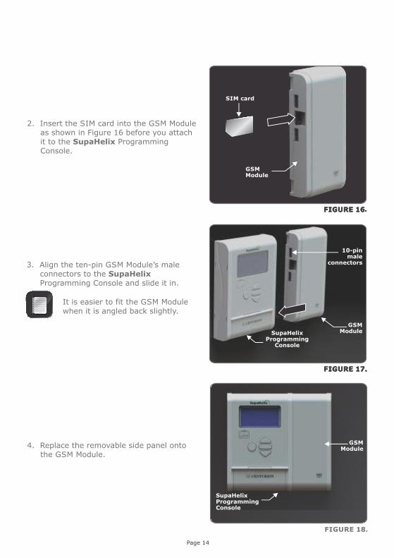
4. Replace the removable side panel onto the GSM Module.
FIGURE 18.
GSMModule
SupaHelix ProgrammingConsole
Page 14
GSMModule
10-pinmale
connectors
SupaHelix Programming
Console
3. Align the ten-pin GSM Module’s male connectors to the SupaHelix Programming Console and slide it in.
It is easier to fit the GSM Module when it is angled back slightly.
GSMModule
2. Insert the SIM card into the GSM Module as shown in Figure 16 before you attach it to the SupaHelix Programming Console.
SIM card
Page 15
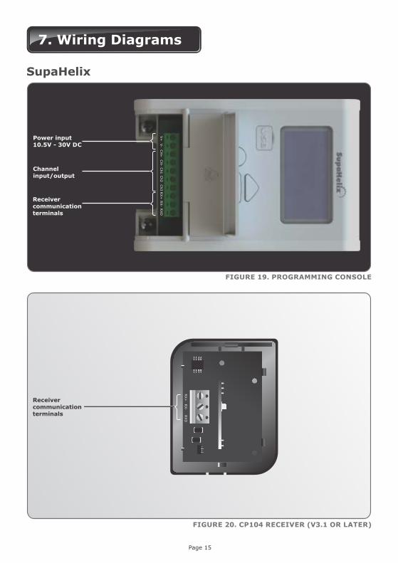
7. Wiring Diagrams
SupaHelix
Power input10.5V - 30V DC
FIGURE 19. PROGRAMMING CONSOLE
FIGURE 20. CP104 RECEIVER (V3.1 OR LATER)
Channel input/output
Receivercommunicationterminals
V+
V-
CH
+C
H-
Ch1
Ch2
Ch3
RX+
RX-
RX
D
Receivercommunicationterminals
RX+
RX-
RX
D

FIGURE 21. TYPICAL SUPAHELIX WIRING DIAGRAM TO D10 AND SWITCHING GEYSER
RX+ RX- RXD
V+ V- CH+ CH- Ch1 Ch2 Ch3 RX+ RX- RXD
D10
SupaHelixProgramming Console
CP104 Receiver(V3.1 or later)
RX+
RX-
RX
D
Page 16
12V relay
Geyser
220V (live)
220V (N)
A maximum distance of 250 metres between the SupaHelix Programming Console and the receiver is allowed, and it is recommended that shielded cable is used
If the unit receives power from the system it is to control, an additional common connection is not necessary

8. Electrical Setup
The full menu of features that can be set up on the system, and an explanation of each feature, is provided in this section.
FIGURE 22.
FIGURE 24
To get into Setup Mode, press the enter ( ) button for two seconds and follow the instructions provided from there
The buttons on the Programming Console for navigating the system are not marked because at each step during the setup, the function of each button is shown on the display
Page 17
FIGURE 23.
While setting up the SupaHelix system via the LCD display, all the steps that have to be followed are clearly provided via the display. It is only necessary to note the following:
Date and Time
Indicating Channel 1set as OUTPUT
Method of triggering
GSM signal indication
Latest system message is
displayed here
Indicating Channel 2set as INPUT with afilter on Rising Edge

1. Remote Controls
1.1. Add New Remotes..................... 1.1.1. Add Remote Button
1.1.2. Template Add Remote
1.2. Delete Remotes........................ 1.2.1. Delete Remote Button
1.2.2. Delete Remote by Button
1.2.3. Delete Remotes by Unit
1.2.4. Delete All Remotes
1.3. Edit Remote Button
1.4. Count Remotes
Menu Navigation Map
8. Logging Options
8.1. View Logs
8.2. Upload Logs
8.3. Delete Logs
9. Firmware Upgrade
4. General Options
4.1. Reset Options........................... 4.1.1. Restore Factory Defaults
4.1.2. Reset All
4.2. Backup and Restore.................. 4.2.1 Backup ALL to USB
4.2.2. Restore from USB
4.3. Available Memory
4.4. Delete Logs
5. G-SWITCH Options
6. Display Options
6.1. Adjust Display Contrast
6.2. Adjust Backlight Intensity
6.3. Adjust Backlight Timeout
7. Security Options
7.1. Menu Locking
2. Input / Output
2.1. Setup Channel 1
2.2. Setup Channel 2
2.3. Setup Channel 3
2.4. Change Mappable Output
3. Date and Time
3.1. Set Date and Time
3.2. Daylight Savings Time
Page 18

Menu Descriptions
Menu 1 – Remote ControlsThe system is capable of learning up to 10,000 CENTURION code-hopping remote control buttons.
1. It is possible to artificially increase the number of buttons of a multi-button remote control by using a two-button combination.
2. One of the buttons is used as a shift button to allow the other buttons to be used again in combination with this button. In other words, the user will press and hold the shift button, before pressing one of the other buttons to create a new button.
3. The shift button cannot be used as a button on its own, it must always be used in combination with the other buttons.
FIGURE 25.
Benefits of the shift button system
4. Use of the shift button system allows a three-button remote control to gain an extra button and operate four channels (for example where two SupaHelix modules are installed on a site) and likewise a four-button remote control gains two extra buttons and can operate six channels. Press and hold the
‘fourth’ button as a shift key together with
button 1, 2 or 3 to operate 4, 5 or 6
2
Shift button
3
1
5 Shift button
6
4
FIGURE 26.
5. Add New Remotes
5.1. Add Remote
a). Any button can be set to control one or more of the three channels provided by the SupaHelix system. When adding remote controls, it is recommended that a record be kept of the ID number allocated by the system to each respective remote control and the person to whom the remote control is given. This is necessary should selective deletion be required at a later stage.
b). Together with the traditional single-press Learning, two secure Learning Modes have been added for remote controls. These are intended to prevent unwanted remote controls from being learned into the system during the remote learning process.
Page 19
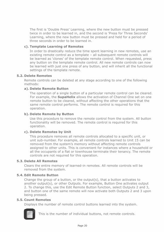
The first is ‘Double Press’ Learning, where the new button must be pressed twice in order to be learned in, and the second is ‘Press for Three Seconds’ Learning, where the new button must be pressed and held for a period of three seconds in order to be learned in.
c). Template Learning of Remotes
In order to drastically reduce the time spent learning in new remotes, use an existing remote control as a template – all subsequent remote controls will be learned as ‘clones’ of the template remote control. When requested, press any button on the template remote control. All new remote controls can now be learned with just one press of any button, and will inherit all the functional settings of the template remote.
5.2. Delete Remotes
Remote controls can be deleted at any stage according to one of the following methods:
a). Delete Remote Button
The operation of a single button of a particular remote control can be cleared. For example, the SupaHelix allows the activation of Channel One set on one remote button to be cleared, without affecting the other operations that the same remote control performs. The remote control is required for this operation.
b). Delete Remote by Button
Use this procedure to remove the remote control from the system. All button functionality will be removed. The remote control is required for this operation.
c). Delete Remotes by Unit
This procedure removes all remote controls allocated to a specific unit, or unit sub-number. For example, all remote controls learned to Unit 15 can be removed from the system’s memory without affecting remote controls assigned to other units. This is convenient for instances where a household or all the occupants of a flat or townhouse terminate their tenancy. The remote controls are not required for this operation.
5.3. Delete All Remotes
Clears the entire memory of learned-in remotes. All remote controls will be removed from the system.
5.4. Edit Remote Button
Change the group of a button, or the output(s), that a button activates to another output(s), or other Outputs. For example, Button One activates output 2. To change this, use the Edit Remote Button function, select Outputs 2 and 3, and button one of the same remote will now activate both Outputs 2 and 3 upon being pressed.
5.5. Count Remotes
Displays the number of remote control buttons learned into the system.
This is the number of individual buttons, not remote controls.
Page 20

Menu 2 – Input/Output
The following additional functionality can be programmed per channel:
a) Set Mode
The output mode can be either:
Momentary: The output will be activated when the remote control button is pressed, remain activated while the button is held in and deactivate once it is released.
Pulsed: When the remote control button is pressed, the output will be activated and remain in this state after the button has been released for the pre-set pulse time. The pulse time can be set from 0.5 seconds to 9999 seconds in 0.5 second increments.
Latched: The output will be activated when the remote control button is pressed and remain activated until the same button is pressed again. The output state is ‘sticky’, and will be remembered if power is cycled.
b) Set Contact Type
The output contact type can be configured as either a normally-open or a normally-closed open collector output. The default contact type is normally-open.
The following additional functionality can be programmed per input:
Trigger On: The input can be set to trigger on a rising edge, a falling edge, or both.
Input Filter Time: (Applicable to both rising and falling edges if set). Sets the time for which a signal must be present before activating the input. For example, an input can be set to only activate if power on the input device has been absent for a period of 60 seconds. The filter can be set from 0 seconds (‘filter disabled’) to 9999 seconds in one second increments.
1. Setup Channel 1,2,3
The functionality of each individual channel can be configured according to the following settings:
1.1. Set Direction of Channel (Input/Output)
Each channel can be configured as either an input or an output. Inputs are used for monitoring purposes, for example to send users an SMS notification when an alarm is activated (when used together with the Optional GSM Module), or to log how many times a safe has been opened. Outputs are used for controlling electrical devices, for example to trigger a gate motor or to turn a geyser on and off. The channel direction will be indicated visually on the display as shown in Figure 23.
FIGURE 27.
Page 21

Basic Function: This feature allows one or more outputs to be triggered upon the activation of the specific input. For example, Input 1 can be configured to activate Outputs 2 and 3 when activated. This is useful in instances where the user wants to create a feedback loop within the system. The SupaHelix automatically calculates which outputs are available.
c). Change Mappable Output
This operation changes the default output that new remote controls are programmed to activate. It is a dynamic output that can be changed at any stage should the need arise, and all remote control buttons that have been assigned to the ‘Mappable Output’ will then be moved to the newly chosen output. For example, if Output 1 is currently being used to open the gate fully, and it later becomes necessary to use the output to perform a different function, the Mappable Output can simply be changed to Output 2 for example, and all remote controls learned to the mappable output will automatically be transferred to Output 2. This obviates the need for relearning or editing each individual remote control button. Certain functionalities may require additional interface devices, such as relays, isolators, etc.
Menu 3 – Date and Time
1. Set Date and Time
Sets the current date and time in the format yyyy-mm-dd for the date and hh:mm:ss for the time. It is important that the date and time be configured if the unit is to be used for data logging applications. The onboard Real Time Clock and Calendar will retain the date and time information for a period of one week without power.
2. Daylight Savings Time
This is set up via the G-WEB online user interface (functionality available in 2014) FIGURE 28.
Menu 4 – General Options
1. Reset Options
The controller settings can be reset through the Reset Options menu. Two reset options are available:
Restore Factory Defaults
All settings will be restored to the default values indicated in the following table overleaf.
FIGURE 29.
Page 22

Channel direction
Mode
Mappable channel
LCD backlight brightness
LCD backlight timeout
LCD contrast
Unit
Input; Output
Pulsing; Latching; Momentary
Channel 1; 2; 3
%
Mm:ss
Level
0%
00m:01s
1
Default
Output
Momentary
Channel 1
50%
00m:15s
30
100%
01m:00s
50
Reset All
Clears and defaults the system completely. The unit will be reset to the Factory Default settings, in addition to clearing all remotes and phone numbers.
2. Backup and Restore
2.1. Back up ALL to USB
Allows all controller settings, remote controls and phone numbers to be backed up onto a USB device via the Programming Console’s USB host. FIGURE 30.
2.2. Restore from USB
Allows all controller settings, remote controls and phone numbers that have previously been backed up, to be restored.
3. Available Memory
Displays the amount of memory available on the unit’s 2GB removable micro SD card. This is expressed as a percentage.
4. Self Test
When selected, this option initiates a series of diagnostic tests to query the system’s health and operation of the following system components: All three input/output channels The up, down and ‘back’ buttons The receiver The onboard buzzer The backlight The USB host The EEPROM The operation of the GSM Module (available in 2014)
At the end of the Self Test, a diagnostic report will be displayed indicating which operations passed, which failed, and what tests were skipped.
Any of the tests can be skipped by momentarily pressing the oblong button. All inputs and outputs must be disconnected prior to performing the Self Test
Page 23
Unit Minimum Default MaximumParameter Description

Reserved for future development.
Menu 5 – G-SWITCH Options (Available in 2014)
Menu 6 – Display Options1. Adjust Display Contrast
Alters the contrast between the LCD background and the text and graphics. The contrast is adjusted between one and 50 in increments of one, up to a maximum of 50. The default value is 30.
2. Adjust Backlight Intensity
Sets the brightness of the backlight. This can be set from 0% (‘disabled’) to 100% in 1% steps.
3. Adjust Backlight Timeout
Sets the amount of time for which the backlight will remain on after the last action has been performed. This can be set from one second to one minute in one second steps. The default Backlight Timeout is 15 seconds.
FIGURE 31.
Menu 7 – Security Options
1. Menu Locking
Various options are available to limit access to the menu and help prevent tampering of the unit and unwanted altering of the settings. No security – the menu is accessible
to anyone Any remote in Group 0 – Any
remote learned to Group 0 can access the menu
Any remote in the system – Any remote learned into the system’s memory can unlock the menu and access settings
FIGURE 32.
Page 24
Delete Logs
The system administrator can choose to either delete all log files currently saved to the unit’s memory, or select a specific log file to be removed.

Menu 8 – Logging Options
The following logging options are available:
1. View Logs
Allows the system administrator to select a log file to view. The user can scroll through the available logs by using the directional arrows and select them using the oblong ( - ) button.
2. Upload Logs
Allows log files to be uploaded from the system’s memory to a USB device. The user can scroll through the available logs by using the directional arrows and select them using the oblong ( - ) button.
3. Delete Logs
Allows the administrator to either delete all log files or select a specific one to be removed from the system’s memory. The user can scroll through the available logs by using the directional arrows and select them using the oblong ( - ) button.
FIGURE 33.
The administrator can bootload the unit with the latest firmware file either by downloading it from the Centurion Systems website and transferring it to the unit via a USB device, or the file can be bootloaded over-the-air(OTA)* via the G-WEB online interface if the optional GSM module has been connected (OTA functionality available in 2014).
Menu 9 – Firmware Upgrade
FIGURE 34.
Page 25

Page 26
9. Diagnostics
The SupaHelix system provides useful visual diagnostic feedback of the overall system health via a series of diagnostic screens which are easily accessible from the main screen by pressing either of the directional arrows.
The following three diagnostic screens and related diagnostic indicators are provided:
Supp Voltage: This is the current supply voltage read by the system as provided by the power source.
Pup: The date and time that the device was last powered up.
Pdn: The date and time that the device was last powered down.
Stat: Displays important messages related to the system health.
FIGURE 35. SCREEN 1
Lang File Version: The version number of the current language file on the SD card.
Micro Version: The version number of the current language file on the micro controller.
Hardware Version: Denotes the version number of the physical components, electronics, etc., used in the construction of the unit.
Device Firmware: The version number of the current product code and persistent memory loaded to the system.
Firmware Revision: This is the actual repository firmware for the application segment of the product code.
Bootloader Version: The repository firmware for the bootloader segment of the product code.
Serial Number: A unique eight-digit number allocated to each manufactured unit.
FIGURE 36. SCREEN 2
FIGURE 37. SCREEN 3
10. Installation handover
Centurion Systems (Pty) Ltd does not accept any liability caused by improper use of the product, or for use other than that for which the automated system was designed.
Once the installation has been successfully completed and tested, it is important for the installer to explain the operation and safety requirements of the system.
Page 27

0.07.A.0206_21112013
www.CentSys.com
Sharecall 0860-CENTURION (0860 236 887)Head Office: +27 11 699 2400
Sharecall Technical Support 0861 003 123 or +27 11 699 2481from 07h00 to 18h00 (GMT+2)
(Sharecall numbers applicable when dialed from within South Africa only)