Administration Guide - Check Point VSX R80.20
397
5 November 2019 Administration Guide CHECK POINT VSX R80.20 Classification: Protected
-
Upload
khangminh22 -
Category
Documents
-
view
0 -
download
0
Transcript of Administration Guide - Check Point VSX R80.20
5 November 2019
Administration Guide
CHECK POINT VSX
R80.20
Clas
sific
atio
n: P
rote
cted

CHAPTE R 1
2019 Check Point Software Technologies Ltd.
All rights reserved. This product and related documentation are protected by copyright and distributed under licensing restricting their use, copying, distribution, and decompilation. No part of this product or related documentation may be reproduced in any form or by any means without prior written authorization of Check Point. While every precaution has been taken in the preparation of this book, Check Point assumes no responsibility for errors or omissions. This publication and features described herein are subject to change without notice.
RESTRICTED RIGHTS LEGEND:
Use, duplication, or disclosure by the government is subject to restrictions as set forth in subparagraph (c)(1)(ii) of the Rights in Technical Data and Computer Software clause at DFARS 252.227-7013 and FAR 52.227-19.
TRADEMARKS:
Refer to the Copyright page https://www.checkpoint.com/copyright/ for a list of our trademarks.
Refer to the Third Party copyright notices https://www.checkpoint.com/about-us/third-party-trademarks-and-copyrights/ for a list of relevant copyrights and third-party licenses.
Important Information
Latest Software
We recommend that you install the most recent software release to stay up-to-date with the latest functional improvements, stability fixes, security enhancements and protection against new and evolving attacks.
Certifications
For third party independent certification of Check Point products, see the Check Point Certifications page https://www.checkpoint.com/products-solutions/certified-check-point-solutions/.
Check Point R80.20
For more about this release, see the R80.20 home page http://supportcontent.checkpoint.com/solutions?id=sk122485.
Latest Version of this Document
Open the latest version of this document in a Web browser https://sc1.checkpoint.com/documents/R80.20_GA/WebAdminGuides/EN/CP_R80.20_VSX_AdminGuide/html_frameset.htm.
Download the latest version of this document in PDF format http://downloads.checkpoint.com/dc/download.htm?ID=60435.
Feedback
Check Point is engaged in a continuous effort to improve its documentation.
Please help us by sending your comments mailto:[email protected]?subject=Feedback on Check Point VSX R80.20 Administration Guide.
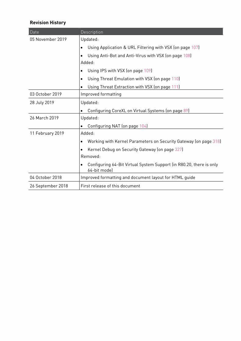
Revision History
Date Description
05 November 2019 Updated:
• Using Application & URL Filtering with VSX (on page 107)
• Using Anti-Bot and Anti-Virus with VSX (on page 108)
Added:
• Using IPS with VSX (on page 109)
• Using Threat Emulation with VSX (on page 110)
• Using Threat Extraction with VSX (on page 111)
03 October 2019 Improved formatting
28 July 2019 Updated:
• Configuring CoreXL on Virtual Systems (on page 89)
26 March 2019 Updated:
• Configuring NAT (on page 104)
11 February 2019 Added:
• Working with Kernel Parameters on Security Gateway (on page 318)
• Kernel Debug on Security Gateway (on page 327)
Removed:
• Configuring 64-Bit Virtual System Support (in R80.20, there is only 64-bit mode)
04 October 2018 Improved formatting and document layout for HTML guide
26 September 2018 First release of this document

Important Information
Check Point VSX Administration Guide R80.20 | 5
SmartConsole Toolbars For a guided tour of SmartConsole, click What's New in the left bottom corner of SmartConsole.
Global Toolbar (top left of SmartConsole) Description and Keyboard Shortcut
The main SmartConsole Menu
The Objects menu.
Also leads to the Object Explorer Ctrl+E
Install policy on managed gateways
Ctrl+Shift+Enter
Navigation Toolbar (left side of SmartConsole) Description and Keyboard Shortcut
Gateways & Servers configuration view
Ctrl+1
Security Policies Access Control view
Security Policies Threat Prevention view
Ctrl+2
Logs & Monitor view
Ctrl+3
Manage & Settings view - review and configure the Security Management Server settings
Ctrl+4
Important Information
Check Point VSX Administration Guide R80.20 | 6
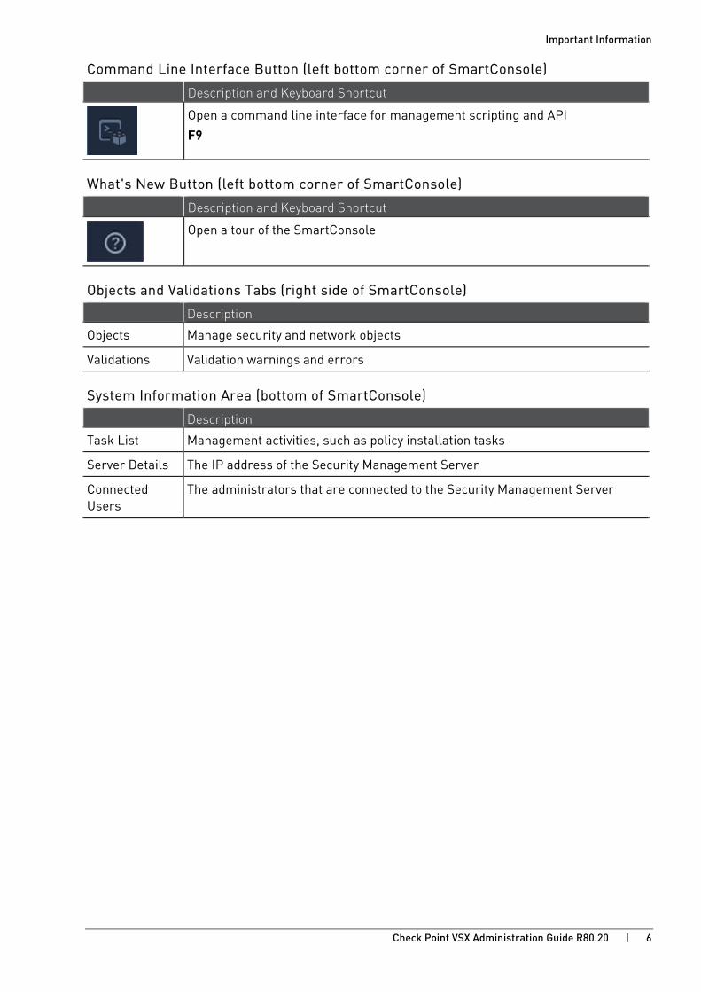
Command Line Interface Button (left bottom corner of SmartConsole) Description and Keyboard Shortcut
Open a command line interface for management scripting and API
F9
What's New Button (left bottom corner of SmartConsole) Description and Keyboard Shortcut
Open a tour of the SmartConsole
Objects and Validations Tabs (right side of SmartConsole) Description
Objects Manage security and network objects
Validations Validation warnings and errors
System Information Area (bottom of SmartConsole) Description
Task List Management activities, such as policy installation tasks
Server Details The IP address of the Security Management Server
Connected Users
The administrators that are connected to the Security Management Server

Contents Important Information ................................................................................................... 3
SmartConsole Toolbars ............................................................................................ 5 Terms .......................................................................................................................... 14 Introduction to VSX ...................................................................................................... 17
VSX Overview........................................................................................................... 17 How VSX Works ....................................................................................................... 18
Physical Network Topology ........................................................................................... 18 VSX Virtual Network Topology ....................................................................................... 19
VSX Architecture and Concepts ................................................................................... 20 The VSX Gateway ..................................................................................................... 20
Management Server Connections .................................................................................. 20 Management Interface .................................................................................................. 24
Virtual Devices ........................................................................................................ 25 Virtual System ............................................................................................................... 25 Virtual Routers .............................................................................................................. 26 Virtual Switches ............................................................................................................. 27
Interfaces ................................................................................................................ 28 Physical Interfaces ........................................................................................................ 29 VLAN Interfaces ............................................................................................................. 29 Warp Links .................................................................................................................... 29 Unnumbered Interfaces ................................................................................................. 30
VSX Management Overview ..................................................................................... 32 Security Management Server Model .............................................................................. 32 Multi-Domain Security Management Model ................................................................... 33 Management Model Comparison ................................................................................... 34 Management Server Communication - SIC .................................................................... 34
VSX Traffic Flow ...................................................................................................... 35 Overview ........................................................................................................................ 35 Context Determination .................................................................................................. 35 Security Enforcement .................................................................................................... 39 Forwarding to Destination ............................................................................................. 39
VSX Routing Concepts ............................................................................................. 40 Routing Overview ........................................................................................................... 40 Routing Between Virtual Systems ................................................................................. 40 Source-Based Routing ................................................................................................... 43 NAT................................................................................................................................ 44 Dynamic Routing............................................................................................................ 44
VSX Clusters............................................................................................................ 45 High Availability ............................................................................................................. 45 Virtual System Load Sharing (VSLS) .............................................................................. 45
Deploying VSX ............................................................................................................. 46 Internal Network Deployment Strategies ............................................................... 46
Security Gateway Deployment on a Physical Network ................................................... 46 VSX Virtual System Deployment Strategies ................................................................... 47 Physical Internal Interface for Each Virtual System ...................................................... 47 Virtual Systems with Internal VLAN Interfaces .............................................................. 48 Internal Virtual Router with Source-Based Routing ...................................................... 49
Virtual Systems in Bridge Mode ..................................................................................... 50 Active/Standby Bridge Mode .......................................................................................... 50
Organizational Deployment Strategies ................................................................... 53 Enterprise Deployments ................................................................................................ 53 Managed Service Providers Using Multi-Domain Server ............................................... 58 Data Centers .................................................................................................................. 59
Configuring VSX .......................................................................................................... 62 Overview .................................................................................................................. 62 Rules & Security Policies ........................................................................................ 63 Configuring VSX Gateways ...................................................................................... 64
Creating a New VSX Gateway ......................................................................................... 64 Working with VSX Gateways .................................................................................... 68
Changing VSX Gateway Definitions ................................................................................ 68 Deleting a VSX Gateway ................................................................................................. 71 Backing up and Restoring VSX Gateway......................................................................... 71
Working with Virtual Systems ................................................................................. 72 Creating a New Virtual System ...................................................................................... 74 Modifying a Virtual System ............................................................................................ 77 Deleting a Virtual System .............................................................................................. 78
Working with Virtual Switches ................................................................................ 79 Creating a New Virtual Switch ....................................................................................... 80 Modifying a Virtual Switch ............................................................................................. 80
Working with Virtual Routers .................................................................................. 82 Creating a New Virtual Router ....................................................................................... 84 Modifying a Virtual Router Definition ............................................................................. 85 Deleting a Virtual Router ............................................................................................... 85 Working with Source-Based Routing ............................................................................. 86
CoreXL for Virtual Systems ..................................................................................... 88 Configuring CoreXL on a VSX Gateway ........................................................................... 88 Configuring CoreXL on Virtual Systems ......................................................................... 89
Dynamic Routing for Virtual Devices ....................................................................... 90 Working with Interface Definitions.......................................................................... 91
Adding a New Interface ................................................................................................. 92 Changing an Interface Definition ................................................................................... 94 Deleting an Interface ..................................................................................................... 94
Working with Authentication ................................................................................... 95 Supported Authentication Schemes ............................................................................... 95 Configuring SecurID ACE/Server ................................................................................... 96 Configuring RADIUS or TACACS/TACACS+ .................................................................. 101
Tracking Activity .................................................................................................... 103 Working with Network Address Translation ......................................................... 104
Configuring NAT .......................................................................................................... 104 Using Application & URL Filtering with VSX .......................................................... 107 Using Anti-Bot and Anti-Virus with VSX ................................................................ 108 Using IPS with VSX ................................................................................................ 109 Using Threat Emulation with VSX .......................................................................... 110 Using Threat Extraction with VSX.......................................................................... 111 Licensing VSX ........................................................................................................ 112
VSX Licenses ............................................................................................................... 112 Upgrading Licenses ..................................................................................................... 112 The Trial Period ........................................................................................................... 112
Virtual System in Bridge Mode .............................................................................. 113 Core Network Security ................................................................................................ 113 Three Layer Hierarchical Model .................................................................................. 114 Configuring Virtual Systems for Active/Standby Bridge Mode ..................................... 114 Enabling Active/Standby Bridge Mode for a New VSX Cluster Member ....................... 114 Enabling Active/Standby Bridge Mode for Existing Cluster Members .......................... 115 Enabling Active/Active Bridge Mode for Existing VSX Cluster Members ...................... 115 Custom Configuration or Override in Bridge Mode ...................................................... 115 VLAN Shared Interface Deployment ............................................................................ 116 VSX Clusters ................................................................................................................ 117 Separate Interfaces in Bridge Mode ............................................................................ 118 Virtual System Load Sharing (VSLS) ............................................................................ 118
Using VSX with Multi-Domain Server ........................................................................ 121 Overview ................................................................................................................ 121 VSX Provisioning ................................................................................................... 123 Defining Multi-Domain Servers ............................................................................. 124 Working with Virtual Devices ................................................................................ 125
Adding a Virtual System to a Domain Management Server .......................................... 125 Adding Virtual Routers and Virtual Switches to a Domain Management Server .......... 125
Introduction to VSX Clusters ..................................................................................... 126 VSX Cluster Overview ............................................................................................ 126
Physical Clusters ......................................................................................................... 126 VSX Clusters ................................................................................................................ 127
Planning a VSX Cluster Deployment ..................................................................... 129 VSX Cluster Architecture ............................................................................................. 129
VSX High Availability ............................................................................................. 131 VSX Gateway High Availability ..................................................................................... 131
Virtual System Load Sharing (VSLS) ..................................................................... 132 Requirements .............................................................................................................. 132 Conceptual Overview ................................................................................................... 133 Failure Recovery ......................................................................................................... 137
Bridge Mode .......................................................................................................... 138 Spanning Tree Protocol (STP) Bridge Mode ................................................................. 138 Active/Standby Bridge Mode ........................................................................................ 138
Using Virtual Switches in a VSX Cluster ................................................................ 141 Working with VSX Clusters ........................................................................................ 142
Configuration Overview ......................................................................................... 142 Creating VSX Clusters ........................................................................................... 142
Creating a New VSX Cluster ........................................................................................ 142 Modifying a Cluster Definition ............................................................................... 146
General Properties ...................................................................................................... 146 VSX Cluster Members .................................................................................................. 146 ClusterXL .................................................................................................................... 147 Creation Templates ..................................................................................................... 147 Physical Interfaces ...................................................................................................... 148 Synchronization ........................................................................................................... 148 Topology ...................................................................................................................... 148 NAT.............................................................................................................................. 151 VSX Bridge Configuration ............................................................................................ 151 Changing the Cluster Management IP and/or Subnet .................................................. 151 Changing the Internal Communication Network IP ...................................................... 151
Working with VSX Cluster Members ..................................................................... 152

Adding a New Member ................................................................................................. 152 Deleting a Member ...................................................................................................... 153
Changing the VSX Cluster Type ............................................................................. 155 Converting from VSLS to High Availability ................................................................... 155 Converting from High Availability to VSLS ................................................................... 157 Sample Command Output ............................................................................................ 158
Enabling VSX Gateway High Availability ................................................................ 159 Configuring New VSX Cluster Members ...................................................................... 159
Configuring Virtual System Load Sharing ............................................................. 160 Enabling VSLS ............................................................................................................. 160 Creating a New VSLS Cluster ...................................................................................... 161 Using the 'vsx_util vsls' Command .............................................................................. 161 Distributing Virtual Systems Amongst VSX Cluster Members ..................................... 162 Viewing VSLS Status .................................................................................................... 163 Exporting and Importing VSLS Configurations ............................................................. 165
Configuring Virtual Systems in Bridge Mode ........................................................ 168 Overview ...................................................................................................................... 168 STP Bridge Mode ......................................................................................................... 168 Active/Standby Bridge Mode ........................................................................................ 169 Multi Bridges ............................................................................................................... 171
Advanced Clustering Configuration ...................................................................... 173 Clusters on the Same Layer-2 Segment ...................................................................... 173 Monitoring all VLANs with ClusterXL........................................................................... 174 Enabling Broadcast Mode ............................................................................................ 175 Configuring CoreXL in a VSLS VSX Cluster .................................................................. 175
Working with Link Aggregation ................................................................................. 176 Link Aggregation Overview ................................................................................... 176
Link Aggregation Terminology .................................................................................... 176 How Link Aggregation Works ...................................................................................... 177 High Availability Overview ........................................................................................... 178 Load Sharing Overview ................................................................................................ 179 Bond Failover .............................................................................................................. 180 Failover Support for VLANs ......................................................................................... 181 Bond Interface & Interface Limitations ........................................................................ 181
Configuring Bond in High Availability Mode .......................................................... 182 Configuring the High Availability Bond ........................................................................ 182 Updating the Interface Topology .................................................................................. 182
Configuring Load Sharing Mode ............................................................................ 184 Configuring the Load Sharing Bond ............................................................................. 185 Setting Critical Required Interfaces ............................................................................ 185 Setting Affinities .......................................................................................................... 186
Configuring Cisco Switches for Link Aggregation Load Sharing Mode ................. 187 For 802.3ad .................................................................................................................. 187 For XOR ....................................................................................................................... 187
Troubleshooting Bonded Interfaces ...................................................................... 188 Troubleshooting Workflow .......................................................................................... 188
Optimizing VSX .......................................................................................................... 190 QoS Enforcement (cpqos) ...................................................................................... 190
Differentiated Services Support .................................................................................. 191 Inbound Prioritization .................................................................................................. 191 Policy with Global Scope .............................................................................................. 191 Resource Allocation .................................................................................................... 191

Latency ........................................................................................................................ 192 WRED .......................................................................................................................... 192 QoS Management......................................................................................................... 193 QoS Configuration ........................................................................................................ 194
Monitoring Memory Resources (vsx mstat) .......................................................... 199 Monitoring CPU Resources (vsx resctrl) ............................................................... 199 SNMP Monitoring .................................................................................................. 200
Supported SNMP Versions ........................................................................................... 200 Supported SNMP Modes .............................................................................................. 200 Configuring SNMP modes ............................................................................................ 203 The VSX SNMP Tree ..................................................................................................... 207
Configuring Jumbo Frames .................................................................................. 208 Jumbo Frames on a Virtual Switch .............................................................................. 208 Jumbo Frames on a Virtual Router .............................................................................. 208 Jumbo Frames on a Virtual System in Bridge Mode .................................................... 209
VSX Diagnostics and Troubleshooting ....................................................................... 210 General Troubleshooting Steps ............................................................................ 210 Troubleshooting Specific Problems ...................................................................... 212
Cannot Establish SIC Trust for VSX Gateway or VSX Cluster Member ......................... 212 SIC Trust Problems with New Virtual Devices ............................................................. 213 Install Policy Error Using VSX Creation Wizard ........................................................... 214 Internal Host Cannot Ping Virtual System ................................................................... 215 Re-establishing SIC Trust with Virtual Devices ............................................................ 216
Command Line Reference ......................................................................................... 217 vsenv ..................................................................................................................... 218 vsx ......................................................................................................................... 219
vsx fetch ...................................................................................................................... 220 vsx fetch_all_cluster_policies ..................................................................................... 222 vsx fetchvs ................................................................................................................... 223 vsx get ......................................................................................................................... 224 vsx initmsg .................................................................................................................. 225 vsx mstat ..................................................................................................................... 226 vsx resctrl ................................................................................................................... 229 vsx showncs ................................................................................................................ 231 vsx sicreset ................................................................................................................. 232 vsx stat ........................................................................................................................ 233 vsx unloadall ............................................................................................................... 235 vsx vspurge ................................................................................................................. 236
vsx_util .................................................................................................................. 237 vsx_util add_member .................................................................................................. 240 vsx_util add_member_reconf ..................................................................................... 241 vsx_util change_interfaces .......................................................................................... 242 vsx_util change_mgmt_ip ........................................................................................... 245 vsx_util change_mgmt_subnet ................................................................................... 246 vsx_util change_private_net ....................................................................................... 247 vsx_util convert_cluster .............................................................................................. 248 vsx_util reconfigure .................................................................................................... 249 vsx_util remove_member ........................................................................................... 250 vsx_util show_interfaces ............................................................................................. 251 vsx_util upgrade .......................................................................................................... 253 vsx_util view_vs_conf .................................................................................................. 254 vsx_util vsls ................................................................................................................. 256

vsx_provisioning_tool ........................................................................................... 257 Transactions ................................................................................................................ 259 vsx_provisioning_tool Commands ............................................................................... 260 Script Examples .......................................................................................................... 283
Configuration Examples ............................................................................................ 284 Example 1: VSX Gateway managed by Security Management Server ................... 285
Topology ...................................................................................................................... 285 Action Plan .................................................................................................................. 286 Step 1: Install the Security Management Server .......................................................... 286 Step 2: Install the VSX Gateway ................................................................................... 287 Step 3: Create the VSX Gateway object in SmartConsole ............................................. 288 Step 4: Configure the VSX Gateway object in SmartConsole ........................................ 290 Step 5: Create the first Virtual System object in SmartConsole ................................... 291 Step 6: Configure the first Virtual System object in SmartConsole .............................. 293 Step 7: Create the second Virtual System object in SmartConsole .............................. 294 Step 8: Configure the second Virtual System object in SmartConsole ......................... 296
Example 2: VSX Cluster managed by Multi-Domain Server .................................. 297 Topology ...................................................................................................................... 298 Action Plan .................................................................................................................. 301 Step 1: Install the Multi-Domain Server ...................................................................... 301 Step 2: Create the Main Domain Management Server that manages the VSX Cluster and Virtual Switch .............................................................................................................. 302 Step 3: Create the Target Domain Management Server that manages the Virtual System 1 .................................................................................................................................. 302 Step 4: Create the Target Domain Management Server that manages the Virtual System 2 .................................................................................................................................. 303 Step 5: Install the VSX Cluster Member 1 .................................................................... 303 Step 6: Install the VSX Cluster Member 2 .................................................................... 304 Step 7: Create the VSX Cluster object with Cluster Members ...................................... 305 Step 8: Configure the VSX Cluster object ..................................................................... 310 Step 9: Create the Virtual Switch object ....................................................................... 311 Step 10: Create the first Virtual System object ............................................................ 312 Step 11: Configure the first Virtual System object ....................................................... 314 Step 12: Create the second Virtual System object ....................................................... 314 Step 13: Configure the second Virtual System object................................................... 317
Working with Kernel Parameters on Security Gateway ............................................ 318 Introduction to Kernel Parameters ....................................................................... 318 FireWall Kernel Parameters ................................................................................. 319 SecureXL Kernel Parameters ............................................................................... 324
Kernel Debug on Security Gateway ........................................................................... 327 Kernel Debug Syntax ............................................................................................. 327 Kernel Debug Filters ............................................................................................. 334 Kernel Debug Procedure ...................................................................................... 338 Kernel Debug Procedure with Connection Life Cycle ........................................... 340 Kernel Debug Modules and Debug Flags .............................................................. 346
Module 'accel_apps' (Accelerated Applications) .......................................................... 348 Module 'accel_pm_mgr' (Accelerated Pattern Match Manager) .................................. 349 Module 'APPI' (Application Control Inspection) ........................................................... 350 Module 'BOA' (Boolean Analyzer for Web Intelligence) ............................................... 351 Module 'CI' (Content Inspection) .................................................................................. 352 Module 'cluster' (ClusterXL) ........................................................................................ 353 Module 'cmi_loader' (Context Management Interface/Infrastructure Loader) ............ 355

Module 'CPAS' (Check Point Active Streaming) ........................................................... 356 Module 'cpcode' (Data Loss Prevention - CPcode) ....................................................... 357 Module 'dlpda' (Data Loss Prevention - Download Agent for Content Awareness) ...... 358 Module 'dlpk' (Data Loss Prevention - Kernel Space) .................................................. 359 Module 'dlpuk' (Data Loss Prevention - User Space) ................................................... 360 Module 'fg' (FloodGate-1 - QoS) ................................................................................... 361 Module 'FILEAPP' (File Application) ............................................................................ 362 Module 'fw' (Firewall) .................................................................................................. 363 Module 'gtp' (GPRS Tunneling Protocol) ...................................................................... 367 Module 'h323' (VoIP H.323) .......................................................................................... 368 Module 'ICAP_CLIENT' (Internet Content Adaptation Protocol Client) ......................... 369 Module 'IDAPI' (Identity Awareness API) ..................................................................... 370 Module 'kiss' (Kernel Infrastructure) .......................................................................... 371 Module 'kissflow' (Kernel Infrastructure Flow) ........................................................... 373 Module 'MALWARE' (Threat Prevention) ..................................................................... 374 Module 'multik' (Multi-Kernel Inspection - CoreXL) .................................................... 375 Module 'MUX' (Multiplexer for Applications Traffic) .................................................... 376 Module 'NRB' (Next Rule Base) ................................................................................... 377 Module 'PSL' (Passive Streaming Library) ................................................................... 378 Module 'RAD_KERNEL' (Resource Advisor - Kernel Space) ........................................ 379 Module 'RTM' (Real Time Monitoring) .......................................................................... 380 Module 'seqvalid' (TCP Sequence Validator and Translator)........................................ 381 Module 'SFT' (Stream File Type) .................................................................................. 382 Module 'SGEN' (Struct Generator) ............................................................................... 383 Module 'synatk' (Accelerated SYN Defender) .............................................................. 384 Module 'UC' (UserCheck) ............................................................................................. 385 Module 'UP' (Unified Policy) ......................................................................................... 386 Module 'upconv' (Unified Policy Conversion) ............................................................... 388 Module 'UPIS' (Unified Policy Infrastructure) .............................................................. 389 Module 'VPN' (Site-to-Site VPN and Remote Access VPN) ........................................... 391 Module 'WS' (Web Intelligence) ................................................................................... 393 Module 'WS_SIP' (Web Intelligence VoIP SIP Parser) .................................................. 395 Module 'WSIS' (Web Intelligence Infrastructure) ......................................................... 397

Terms Administrator
A SmartConsole user with permissions to manage Check Point security products and the network environment.
Bond
A virtual interface that contains (enslaves) two or more physical interfaces for redundancy and load sharing. The physical interfaces share one IP address and one MAC address. See Link Aggregation.
Bridge Mode
A Security Gateway or Virtual System that works as a Layer 2 bridge device for easy deployment in an existing topology.
Cluster
Two or more Security Gateways that work together in a redundant configuration - High Availability.
Cluster Member
A Security Gateway that is part of a cluster.
ClusterXL
Cluster of Check Point Security Gateways that work together in a redundant configuration. The ClusterXL both handles the traffic and performs State Synchronization.
These Check Point Security Gateways are installed on Gaia OS:
• ClusterXL supports up to 5 Cluster Members.
• VRRP Cluster supports up to 2 Cluster Members.
• VSX VSLS cluster supports up to 13 Cluster Members.
Note - In ClusterXL Load Sharing mode, configuring more than 4 Cluster Members significantly decreases the cluster performance due to amount of Delta Sync traffic.
Dedicated Management Interface (DMI)
A separate physical interface on VSX Gateway or VSX Cluster Members, through which Check Point Security Management Server or Multi-Domain Server connects directly to VSX Gateway or VSX Cluster Members. DMI is restricted to management traffic, such as provisioning, logging and monitoring.
Link Aggregation
A technology that joins multiple physical interfaces together into one virtual interface, known as a bond interface. Also known as Interface Bonding.
Main Domain Management Server
A Domain Management Server, on which you defined the object of your VSX Gateway or VSX Cluster. In this case, objects of your Virtual Systems are defined on different Domain Management Servers (Target Domain Management Servers).
Management Server A Check Point Security Management Server or a Multi-Domain Server.
Multi-Domain Log Server
A computer that runs Check Point software to store and process logs in Multi-Domain Security Management environment. The Multi-Domain Log Server consists of Domain Log Servers that store and process logs from Security Gateways that are managed by the corresponding Domain Management Servers.
Multi-Domain Security Management
A centralized management solution for large-scale, distributed environments with many different Domain networks.
Multi-Domain Server
A computer that runs Check Point software to host virtual Security Management Servers called Domain Management Servers.
Non-Dedicated Management Interface (Non-DMI)
A shared physical interface on VSX Gateway or VSX Cluster Members, which carries user "production" traffic and through which Check Point Security Management Server or
Multi-Domain Server connects to VSX Gateway or VSX Cluster Members. Non-DMI configuration requires the use of a Virtual Router or Virtual Switch.
Permission Profile
A predefined group of SmartConsole access permissions assigned to Domains and administrators. With this feature you can configure complex permissions for many administrators with one definition.
Primary Multi-Domain Server
The Multi-Domain Server in Management High Availability that you install as Primary.
Secondary Multi-Domain Server
The <Multi-Domain Server in Management High Availability that you install as Secondary.
Security Gateway
A computer that runs Check Point software to inspect traffic and enforces Security Policies for connected network resources.
Security Management Server
A computer that runs Check Point software to manage the objects and policies in Check Point environment.
SmartDashboard
A legacy Check Point GUI client used to create and manage the security policy in R77.30 and below.
Standby Domain Server
All Domain Management Servers for a Domain that are not designated as the Active Domain Management Server.
Standby Multi-Domain Server
All Multi-Domain Servers in a Management High Availability deployment that cannot manage global policies and global objects. Standby Multi-Domain Servers are synchronized with the Active Multi-Domain Server.
Target Domain Management Server
A Domain Management Server, on which you defined the objects of your Virtual Systems. In this case, object of your VSX Gateway or VSX Cluster are defined on a different Domain Management Server (Main Domain Management Server).
Traffic
The flow of data between network devices.
Virtual Device
A logical object that emulates the functionality of a type of physical network object.
Virtual Router
A Virtual Device that functions as a physical router. Virtual Routers are not supported (see Known Limitations 01413513 and MBS-5214).
Virtual Switch
Also vSwitch. A software abstraction of a physical Ethernet switch. It can connect to physical switches through physical network adapters to join virtual networks with physical networks. It can also be a Distributed Virtual Switch (dvSwitch), for definition and use on multiple ESXi hosts.
Virtual System
A Virtual Device that implements the functionality of a Security Gateway.
VLAN
Virtual Local Area Network. Open servers or appliances connected to a virtual network, which are not physically connected to the same network.
VLAN Trunk
A connection between two switches that contains multiple VLANs.
VPN
Virtual Private Network. A secure, encrypted connection between networks and remote clients on a public infrastructure, to give authenticated remote users and sites

secured access to an organization's network and resources.
VSLS
Virtual System Load Sharing. A VSX Cluster technology that assigns Virtual System traffic to different Active Cluster Members.
VSX
Virtual System Extension. Check Point virtual networking solution, hosted on a computer or cluster with virtual abstractions of Check Point Security Gateways and other network devices. These Virtual Devices provide the same functionality as their physical counterparts.
VSX Gateway
Physical server that hosts VSX virtual networks, including all Virtual Devices that provide the functionality of physical network devices. It holds at least one Virtual System, which is called VS0.
Warp Link
An interface between a Virtual System and a Virtual Switch or Virtual Router that is created automatically in a VSX topology.
Check Point VSX Administration Guide R80.20 | 17
CHAPTE R 2
Introduction to VSX In This Section:
VSX Overview ................................................................................................................. 17
How VSX Works ............................................................................................................. 18
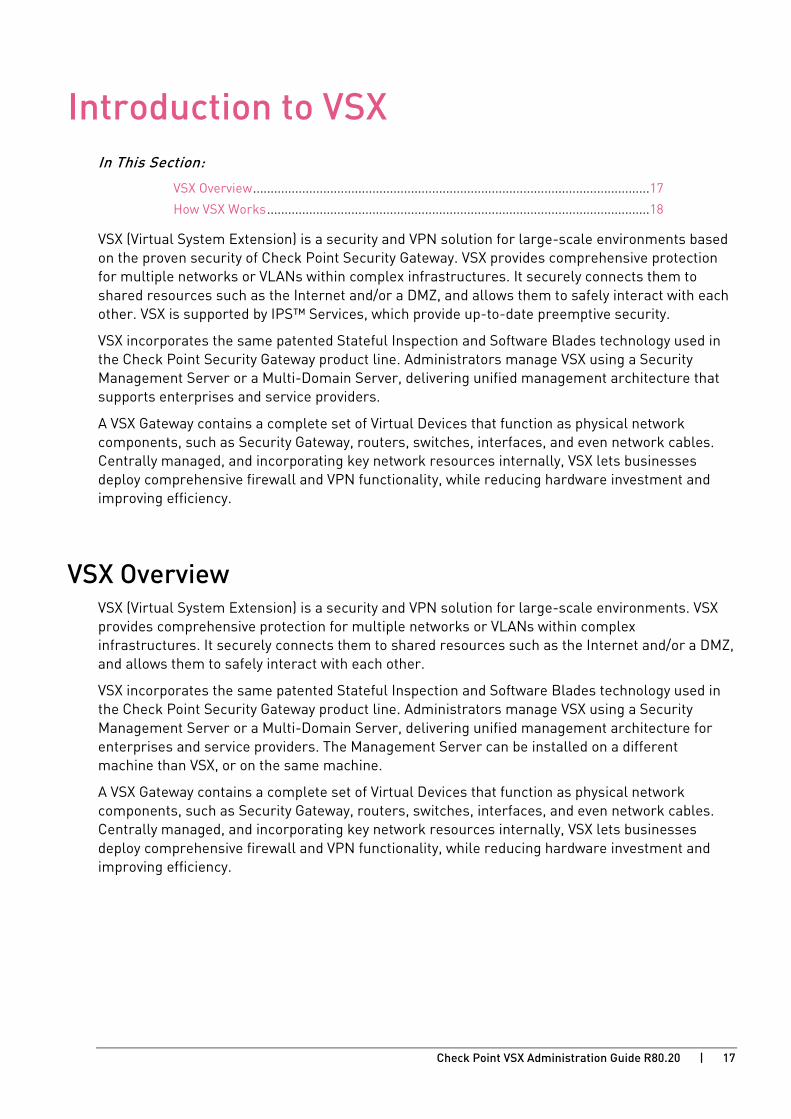
VSX (Virtual System Extension) is a security and VPN solution for large-scale environments based on the proven security of Check Point Security Gateway. VSX provides comprehensive protection for multiple networks or VLANs within complex infrastructures. It securely connects them to shared resources such as the Internet and/or a DMZ, and allows them to safely interact with each other. VSX is supported by IPS™ Services, which provide up-to-date preemptive security.
VSX incorporates the same patented Stateful Inspection and Software Blades technology used in the Check Point Security Gateway product line. Administrators manage VSX using a Security Management Server or a Multi-Domain Server, delivering unified management architecture that supports enterprises and service providers.
A VSX Gateway contains a complete set of Virtual Devices that function as physical network components, such as Security Gateway, routers, switches, interfaces, and even network cables. Centrally managed, and incorporating key network resources internally, VSX lets businesses deploy comprehensive firewall and VPN functionality, while reducing hardware investment and improving efficiency.
VSX Overview VSX (Virtual System Extension) is a security and VPN solution for large-scale environments. VSX provides comprehensive protection for multiple networks or VLANs within complex infrastructures. It securely connects them to shared resources such as the Internet and/or a DMZ, and allows them to safely interact with each other.
VSX incorporates the same patented Stateful Inspection and Software Blades technology used in the Check Point Security Gateway product line. Administrators manage VSX using a Security Management Server or a Multi-Domain Server, delivering unified management architecture for enterprises and service providers. The Management Server can be installed on a different machine than VSX, or on the same machine.
A VSX Gateway contains a complete set of Virtual Devices that function as physical network components, such as Security Gateway, routers, switches, interfaces, and even network cables. Centrally managed, and incorporating key network resources internally, VSX lets businesses deploy comprehensive firewall and VPN functionality, while reducing hardware investment and improving efficiency.

Introduction to VSX
Check Point VSX Administration Guide R80.20 | 18
How VSX Works Each Virtual System works as a Security Gateway, typically protecting a specified network. When packets arrive at the VSX Gateway, it sends traffic to the Virtual System protecting the destination network. The Virtual System inspects all traffic and allows or rejects it according to rules defined in the security policy.
In order to better understand how virtual networks work, it is important to compare physical network environments with their virtual (VSX) counterparts. While physical networks consist of many hardware components, VSX virtual networks reside on a single configurable VSX Gateway or cluster that defines and protects multiple independent networks, together with their virtual components.
Physical Network Topology In a typical deployment with multiple Security Gateways, each protects a separate network. Each physical Security Gateway has interfaces to the perimeter router and to the network it protects.
Item Description
1 Internet
2 Router
3 Security Gateways
4 Network

Introduction to VSX
Check Point VSX Administration Guide R80.20 | 19
VSX Virtual Network Topology Deploy one VSX Gateway with four Virtual Systems to protect multiple networks.
Item Description
1 Internet
2 Router
3 VSX Gateway. Each Virtual System in a VSX environment is a Security Gateway, with the same security and networking functionality as a physical gateway. Each handles packet traffic to and from the one network it protects.
4 Warp Links. Virtual interfaces and network cables connect the Virtual Systems and the Virtual Switch.
5 Virtual Switch. Connects all the Virtual Systems to the Internet router.
6 Networks

Check Point VSX Administration Guide R80.20 | 20
CHAPTE R 3
VSX Architecture and Concepts In This Section:
The VSX Gateway........................................................................................................... 20
Virtual Devices .............................................................................................................. 25
Interfaces ...................................................................................................................... 28
VSX Management Overview .......................................................................................... 32
VSX Traffic Flow ............................................................................................................ 35
VSX Routing Concepts .................................................................................................. 40
VSX Clusters .................................................................................................................. 45
The VSX Gateway A VSX Gateway is a physical machine that hosts virtual networks of Virtual Devices, with the functionality of their physical network counterparts such as: Security Gateways, routers and switches.
A VSX Gateway handles these tasks:
• Communicates with the Management Server to deploy, configure, and manage all Virtual Devices.
• Manages state synchronization for High Availability and for Load Sharing in cluster deployments.
Management Server Connections A Management Server (Security Management Server or Multi-Domain Server) connects to the VSX Gateway and provides provisioning and configuration services for Virtual Devices located on the VSX Gateway. You can connect the Management Server to the VSX Gateway using one of the following scenarios.
• Local Connection: The Management Server connects directly to the VSX Gateway using a dedicated management interface.
• Remote Connection: The Management Server connects remotely from an external or internal network by means of a router connected to a management interface. This method ensures segregation of management traffic from all other traffic.
VSX Architecture and Concepts
Check Point VSX Administration Guide R80.20 | 21
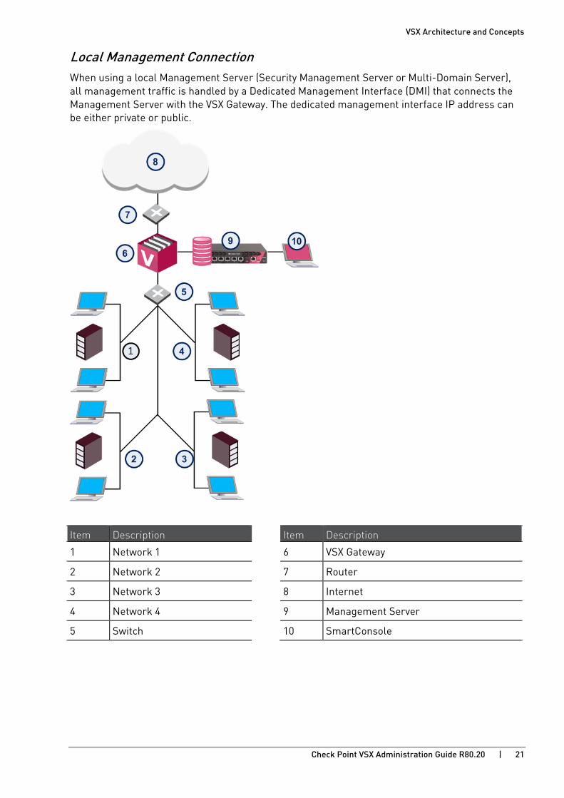
Local Management Connection When using a local Management Server (Security Management Server or Multi-Domain Server), all management traffic is handled by a Dedicated Management Interface (DMI) that connects the Management Server with the VSX Gateway. The dedicated management interface IP address can be either private or public.
Item Description Item Description
1 Network 1 6 VSX Gateway
2 Network 2 7 Router
3 Network 3 8 Internet
4 Network 4 9 Management Server
5 Switch 10 SmartConsole
VSX Architecture and Concepts
Check Point VSX Administration Guide R80.20 | 22
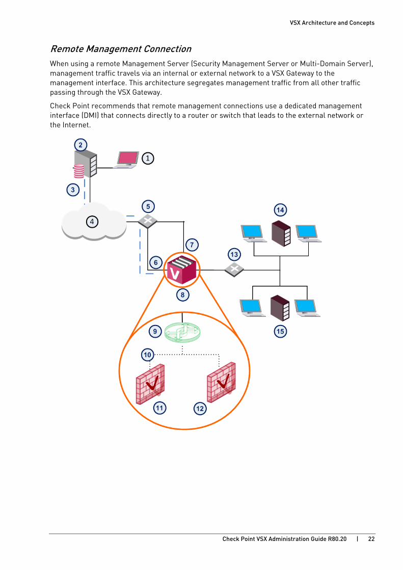
Remote Management Connection When using a remote Management Server (Security Management Server or Multi-Domain Server), management traffic travels via an internal or external network to a VSX Gateway to the management interface. This architecture segregates management traffic from all other traffic passing through the VSX Gateway.
Check Point recommends that remote management connections use a dedicated management interface (DMI) that connects directly to a router or switch that leads to the external network or the Internet.

VSX Architecture and Concepts
Check Point VSX Administration Guide R80.20 | 23
Item Description Item Description
1 SmartConsole 9 Virtual Switch
2 Management Server 10 Warp Link
3 Management traffic 11 Virtual System 1
4 Internet 12 Virtual System 2
5 Router 13 Switch
6 Dedicated management interface (eth0) 14 Network 1
7 External interface 15 Network 2
8 VSX Gateway
You can choose to use a non-dedicated management interface by connecting a Virtual Router or Virtual Switch to the management interface.
When management traffic passes through a Virtual Router or Virtual Switch, you must ensure that the associated Warp Link IP address originates from the remote network. Furthermore, if the remote management connection arrives via the Internet, you must assign a routable, public IP address.

VSX Architecture and Concepts
Check Point VSX Administration Guide R80.20 | 24
Management Interface A VSX deployment can be managed using one of the following interface schemes:
• Dedicated Management Interface (DMI): Uses a separate interface that is restricted to management traffic, such as provisioning, logging and monitoring
• Non-Dedicated Management Interface: Uses a shared internal or external interface that also carries routine user traffic
Dedicated Management Interface (DMI) Check Point recommends that you use a DMI for management to segregate management traffic from routine "production" traffic enhanced performance, especially for end users.
Non-Dedicated Management Interface When configuring a non-DMI deployment, you can define remote management connections only via a Virtual Switch or Virtual Router. Remote management connects via a Virtual System are not supported.
When using non-DMI for the following reasons:
• Provisioning and logging may degrade user performance.
• Non-DMI is irreversible - you cannot change a non-DMI gateway to DMI.
VSX Architecture and Concepts
Check Point VSX Administration Guide R80.20 | 25
Virtual Devices This section describes virtual network components and their characteristics.
Virtual System A Virtual System is a virtual security and routing domain that provides the functionality of a Security Gateway with full Firewall and VPN facilities. Multiple Virtual Systems can run concurrently on a single VSX Gateway.
Virtual System Autonomy Each Virtual System functions independently. Each Virtual System maintains its own Software Blades, interfaces, IP addresses, routing table, ARP table, and dynamic routing configuration. Each Virtual System also maintains its own:
• State Tables: Each Virtual System has its own kernel tables with configuration and runtime data, such as active connections and IPsec tunnel information.
• Security and VPN policies: Each Virtual System enforces its own security and VPN Policies (including INSPECT code). Policies are retrieved from the Management Server and stored separately on the local disk and in the kernel. In a Multi-Domain Server environment, each Domain database is maintained separately on the Management Server and on the VSX Gateway.
• Configuration Parameters: Each Virtual System maintains its own configuration, such as IPS settings and TCP/UDP time-outs. Different Virtual Systems can run in layer-2 or layer-3 mode and co-exist on the same VSX Gateway.
• Logging Configuration: Each Virtual System maintains its own logs and runs logging according to its own rules and configuration.
VSX Architecture and Concepts
Check Point VSX Administration Guide R80.20 | 26
Virtual Routers A Virtual Router is an independent routing domain within a VSX Gateway that performs the functionality of physical routers. Virtual Routers are useful for connecting multiple Virtual Systems to a shared interface, such as the interface leading to the Internet, and for routing traffic from one Virtual System to another. Virtual Routers support dynamic routing.
Virtual Routers perform the following routing functions:
• Packets arriving at the VSX Gateway through a shared interface to the designated Virtual System based on the source or destination IP address.
• Traffic arriving from Virtual Systems directed to a shared interface or to other Virtual Systems.
• Traffic to and from shared network resources such as a DMZ.
As with physical routers, each Virtual Router maintains a routing table with a list of route entries describing known networks and directions on how to reach them. Depending on the deployment requirements, multiple Virtual Routers can be configured.
To protect themselves, Virtual Routers inspect all traffic destined to, or emanating from themselves (for example, an ICMP ping to the Virtual Router IP address) based on the security policy. Traffic that is not sent to, or coming from the Virtual Router is not inspected by the Virtual Router policy and is sent to its destination.
VSX Architecture and Concepts
Check Point VSX Administration Guide R80.20 | 27
Virtual Switches By providing layer-2 connectivity, a Virtual Switch connects Virtual Systems and facilitates sharing a common physical interface without segmenting the existing IP network. As with a physical switch, each Virtual Switch maintains a forwarding table with a list of MAC addresses and their associated ports.
In contrast to a Virtual Router, when sharing a physical interface via a Virtual Switch there is no need:
• To allocate an additional subnet for IP addresses of Virtual Systems connected to the switch.
• To manually configure the routing on the routers adjacent to the shared interface.
You can create multiple Virtual Switches in a virtual network topology.
Note - When sharing a physical interface via a Virtual Switch, the IP addresses for Virtual Systems connected to a Virtual Switch should be allocated from the same subnet as the shared interface. If the only function the Virtual Switch performs is to connect Virtual Systems, then the Virtual Switch can be defined without interfaces (unless Virtual System Load Sharing is enabled).
VSX Architecture and Concepts
Check Point VSX Administration Guide R80.20 | 28
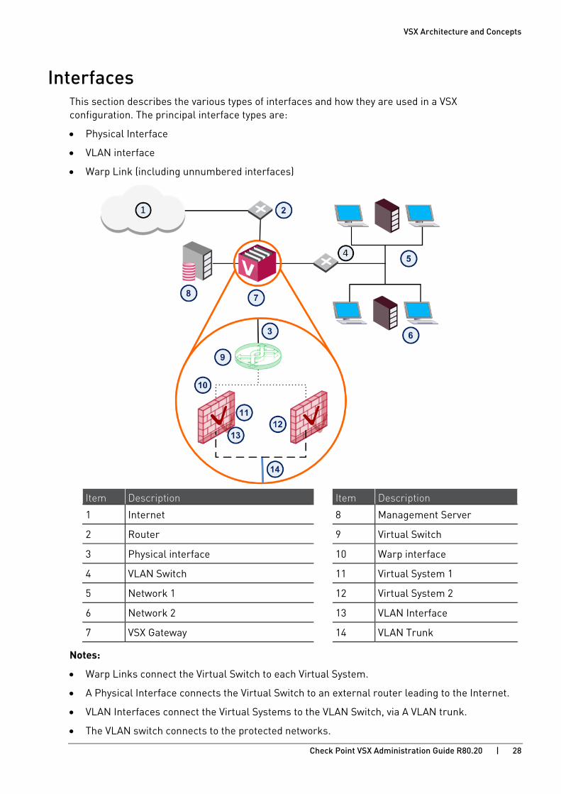
Interfaces This section describes the various types of interfaces and how they are used in a VSX configuration. The principal interface types are:
• Physical Interface
• VLAN interface
• Warp Link (including unnumbered interfaces)
Item Description Item Description
1 Internet 8 Management Server
2 Router 9 Virtual Switch
3 Physical interface 10 Warp interface
4 VLAN Switch 11 Virtual System 1
5 Network 1 12 Virtual System 2
6 Network 2 13 VLAN Interface
7 VSX Gateway 14 VLAN Trunk
Notes:
• Warp Links connect the Virtual Switch to each Virtual System.
• A Physical Interface connects the Virtual Switch to an external router leading to the Internet.
• VLAN Interfaces connect the Virtual Systems to the VLAN Switch, via A VLAN trunk.
• The VLAN switch connects to the protected networks.
VSX Architecture and Concepts
Check Point VSX Administration Guide R80.20 | 29
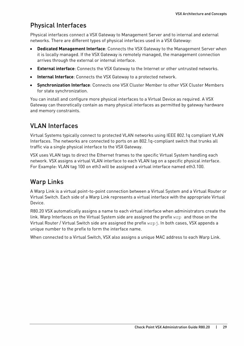
Physical Interfaces Physical interfaces connect a VSX Gateway to Management Server and to internal and external networks. There are different types of physical interfaces used in a VSX Gateway:
• Dedicated Management Interface: Connects the VSX Gateway to the Management Server when it is locally managed. If the VSX Gateway is remotely managed, the management connection arrives through the external or internal interface.
• External interface: Connects the VSX Gateway to the Internet or other untrusted networks.
• Internal Interface: Connects the VSX Gateway to a protected network.
• Synchronization Interface: Connects one VSX Cluster Member to other VSX Cluster Members for state synchronization.
You can install and configure more physical interfaces to a Virtual Device as required. A VSX Gateway can theoretically contain as many physical interfaces as permitted by gateway hardware and memory constraints.
VLAN Interfaces Virtual Systems typically connect to protected VLAN networks using IEEE 802.1q compliant VLAN Interfaces. The networks are connected to ports on an 802.1q-compliant switch that trunks all traffic via a single physical interface to the VSX Gateway.
VSX uses VLAN tags to direct the Ethernet frames to the specific Virtual System handling each network. VSX assigns a virtual VLAN interface to each VLAN tag on a specific physical interface. For Example: VLAN tag 100 on eth3 will be assigned a virtual interface named eth3.100.
Warp Links A Warp Link is a virtual point-to-point connection between a Virtual System and a Virtual Router or Virtual Switch. Each side of a Warp Link represents a virtual interface with the appropriate Virtual Device.
R80.20 VSX automatically assigns a name to each virtual interface when administrators create the link. Warp Interfaces on the Virtual System side are assigned the prefix wrp and those on the Virtual Router / Virtual Switch side are assigned the prefix wrpj. In both cases, VSX appends a unique number to the prefix to form the interface name.
When connected to a Virtual Switch, VSX also assigns a unique MAC address to each Warp Link.

VSX Architecture and Concepts
Check Point VSX Administration Guide R80.20 | 30
Unnumbered Interfaces VSX lets you reduce the number of IP addresses required for a VSX network deployment when using one or more Virtual Routers. A Warp Link connected to a Virtual Router can "borrow" an existing IP address from another interface, instead of assigning a dedicated address to the interface leading to a Virtual Router. This capability is known as an Unnumbered Interface.
Item Description
1 VSX Gateway
2 The external interface serves as the next hop from the Virtual Router
3 External
4 Virtual Router
5 Unnumbered External Interfaces IP “borrowed” from internal interfaces
6 Internal Interfaces with predefined IP addresses
7 Internal
In this example, the external interfaces for each Virtual System are unnumbered and borrow the IP address of the internal interfaces. Unnumbered interfaces act as the next hop from the Virtual Router.
VSX Architecture and Concepts
Check Point VSX Administration Guide R80.20 | 31
Unnumbered Interface Limitations The following limitations apply to Unnumbered Interfaces:
• Unnumbered interfaces must connect to a Virtual Router.
• You can only "borrow" an individual interface IP address once.
• In order to use VPN or Hide NAT, the borrowed address must be routable.

VSX Architecture and Concepts
Check Point VSX Administration Guide R80.20 | 32
VSX Management Overview VSX supports two Check Point management models: Security Management Server and Multi-Domain Server. Both models provide central configuration, management and monitoring for multiple VSX Gateways and Virtual Systems. The choice of management model depends on several factors, including:
• The scale of the current deployment and anticipated expansion
• Administrative requirements
• Physical and operational requirements
• Licensing restrictions
You can use either management model to manage a "physical" Security Gateway together with a VSX Gateway and Virtual Systems. You can also manage VPN communities and remote connections with either model.
Note - According to the Check Point EULA (End User License Agreement), a Security Gateway can only manage security policies for Virtual Systems belonging to a single legal entity. In order to manage Virtual Systems belonging to multiple legal entities, you need to deploy a Multi-Domain Security Management solution with a separate Domain Management Server for each legal entity. For more information regarding Licensing, refer to your Check Point Reseller.
Security Management Server Model The Security Management Server model is for enterprise deployments with many Virtual Systems, but one domain. SmartConsole connects to the VSX Gateway, which contains the Virtual Systems, and directly manages each Virtual System.

VSX Architecture and Concepts
Check Point VSX Administration Guide R80.20 | 33
Multi-Domain Security Management Model With Multi-Domain Security Management, you centrally manage multiple networks, typically of different Domains, divisions, or branches. The Multi-Domain Server is the central management node that controls the policy databases for each of these networks.
Each Domain network is managed by a Domain Management Server, which provides the full functionality of a Security Management Server and can host multiple Virtual Systems, virtual and physical devices. The server that manages the VSX Gateway or VSX Cluster is the Main Domain Management Server. A VSX Gateway or VSX Gateway can host Virtual Systems that are managed by different Domain Management Servers.
Item Description
1 SmartConsole
2 Multi-Domain Server
3 Domain Management Server
4 Main Domain Management Server
5 VSX Gateway
6 Virtual Systems in Domain Management Servers
From a SmartConsole connected to a Multi-Domain Server, provision and configure Domains and Domain Management Servers. Each Domain Management Server uses its own SmartConsole instance to provision and configure its Virtual Systems, Virtual Devices, and policies.
VSX Architecture and Concepts
Check Point VSX Administration Guide R80.20 | 34
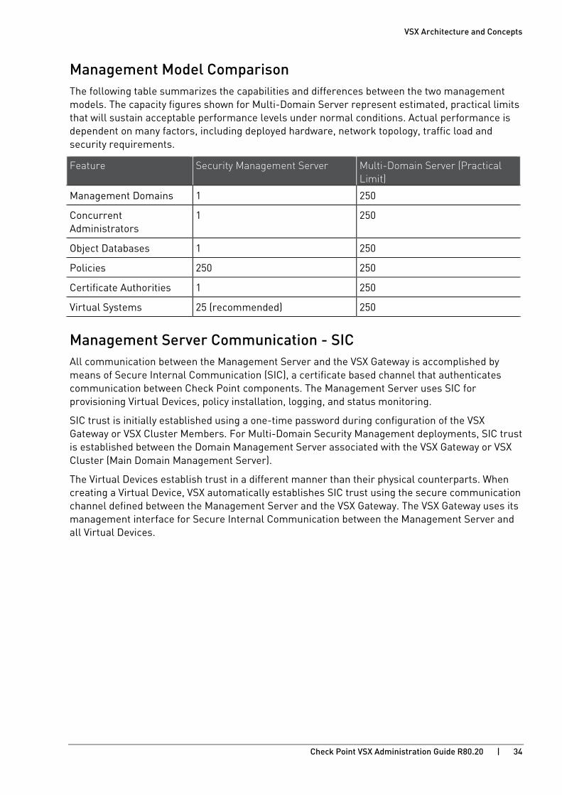
Management Model Comparison The following table summarizes the capabilities and differences between the two management models. The capacity figures shown for Multi-Domain Server represent estimated, practical limits that will sustain acceptable performance levels under normal conditions. Actual performance is dependent on many factors, including deployed hardware, network topology, traffic load and security requirements.
Feature Security Management Server Multi-Domain Server (Practical Limit)
Management Domains 1 250
Concurrent Administrators
1 250
Object Databases 1 250
Policies 250 250
Certificate Authorities 1 250
Virtual Systems 25 (recommended) 250
Management Server Communication - SIC All communication between the Management Server and the VSX Gateway is accomplished by means of Secure Internal Communication (SIC), a certificate based channel that authenticates communication between Check Point components. The Management Server uses SIC for provisioning Virtual Devices, policy installation, logging, and status monitoring.
SIC trust is initially established using a one-time password during configuration of the VSX Gateway or VSX Cluster Members. For Multi-Domain Security Management deployments, SIC trust is established between the Domain Management Server associated with the VSX Gateway or VSX Cluster (Main Domain Management Server).
The Virtual Devices establish trust in a different manner than their physical counterparts. When creating a Virtual Device, VSX automatically establishes SIC trust using the secure communication channel defined between the Management Server and the VSX Gateway. The VSX Gateway uses its management interface for Secure Internal Communication between the Management Server and all Virtual Devices.

VSX Architecture and Concepts
Check Point VSX Administration Guide R80.20 | 35
VSX Traffic Flow
Overview A VSX Gateway processes traffic according to the following steps:
• Context determination
• Security enforcement
• Forwarding to destination
Context Determination VSX incorporates VRF (Virtual Routing and Forwarding) technology that allows creation of multiple, independent routing domains on a single VSX Gateway or VSX Cluster. The independence of these routing domains makes possible the use of Virtual Devices with overlapping IP addresses. Each routing domain is known as a context.
When traffic arrives at a VSX Gateway, a process known as Context Determination directs traffic to the appropriate Virtual System, Virtual Router or Virtual Switch. The context determination process depends on the virtual network topology and the connectivity of the Virtual Devices.
The basic Virtual System connection scenarios are:
• Virtual System directly connected to a physical or VLAN interface
• Virtual System connected via a Virtual Switch
• Virtual System connected via a Virtual Router

VSX Architecture and Concepts
Check Point VSX Administration Guide R80.20 | 36
Direct Connection to a Physical Interface When traffic arrives at an interface (either physical or VLAN) that directly connects to a Virtual System, the connection itself determines the context and traffic passes directly to the appropriate Virtual System via that interface. This diagram shows traffic from a physical VLAN switch that is sent to an interface on the VSX Gateway.
Item Description Item Description
1 Internet 8 Virtual System 2
2 Router 9 VLAN Switch
3 VSX Gateway 10 VLAN 100
4 Virtual Switch 11 VLAN 200
5 Virtual System 1 VLAN Interface
6 eth1.100 VLAN Trunk
7 eth1.200 Warp Link
VSX automatically directs traffic arriving via VLAN Interface eth1.200 to Virtual System 2 according to the context defined by the VLAN ID.

VSX Architecture and Concepts
Check Point VSX Administration Guide R80.20 | 37
Connection via a Virtual Switch Traffic arriving via a Virtual Switch passes to the appropriate Virtual System based on the destination MAC address, as defined in the Virtual Switch forwarding table. Traffic arrives at the Virtual System via the Warp Link associated with the designated MAC address.
Item Description Item Description
1 Internet 8 MAC 00:12:C!:Ce:00:03
2 Router 9 VLAN Switch
3 VSX Gateway 10 VLAN 100
4 Virtual Switch 11 VLAN 200
5 MAC 00:12:C!:Ce:00:01 VLAN Interface
6 Virtual System 1 VLAN Trunk
7 Virtual System 2 Warp Link
If the destination MAC address does not exist in the Virtual Switch forwarding table, the traffic is broadcast over all defined Warp Links. The Virtual Switch scenario is common for inbound traffic from external networks or the Internet.
VSX Architecture and Concepts
Check Point VSX Administration Guide R80.20 | 38
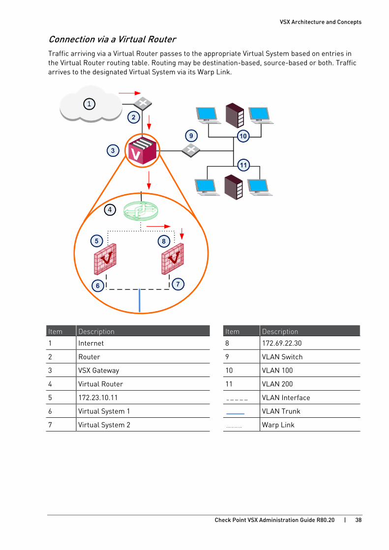
Connection via a Virtual Router Traffic arriving via a Virtual Router passes to the appropriate Virtual System based on entries in the Virtual Router routing table. Routing may be destination-based, source-based or both. Traffic arrives to the designated Virtual System via its Warp Link.
Item Description Item Description
1 Internet 8 172.69.22.30
2 Router 9 VLAN Switch
3 VSX Gateway 10 VLAN 100
4 Virtual Router 11 VLAN 200
5 172.23.10.11 VLAN Interface
6 Virtual System 1 VLAN Trunk
7 Virtual System 2 Warp Link

VSX Architecture and Concepts
Check Point VSX Administration Guide R80.20 | 39
Security Enforcement Since each Virtual System functions as an independent Security Gateway, it maintains its own, unique security policy to protect the network behind it. The designated Virtual System inspects all traffic and allows or blocks it based on the rules contained in the security policy.
Forwarding to Destination Each Virtual System maintains its own unique configuration and rules for processing and forwarding traffic to its final destination. This configuration also includes definitions and rules for NAT, VPN, and other advanced features.

VSX Architecture and Concepts
Check Point VSX Administration Guide R80.20 | 40
VSX Routing Concepts
Routing Overview The traffic routing features in VSX network topologies are analogous to those available for physical networks. This section discusses several routing features and strategies as they apply to a VSX environment.
Routing Between Virtual Systems Virtual Routers and Virtual Switches can be used to send traffic between networks located behind Virtual Systems, much in the same way as their physical counterparts.
The figure below shows an example of how Virtual Systems, connected to a Virtual Switch and a physical VLAN switch, communicate with each other. In this example, a host in VLAN 100 sends data to a server located in VLAN 200.
Item Description Item Description
1 VLAN 100 7 VLAN 200
2 VLAN Switch 8 VSX Gateway
3 VLAN Trunk VLAN Interface
4 Virtual System 1 VLAN Trunk
5 Virtual Switch Warp Link
6 Virtual System 2

VSX Architecture and Concepts
Check Point VSX Administration Guide R80.20 | 41
1. Traffic from the VLAN 100 host arrives at the VLAN switch, which inserts a VLAN tag and sends it to the VSX Gateway by way of a VLAN trunk.
2. Based on its VLAN tag, the VSX Gateway assigns the traffic to the Virtual System named VS1.
3. VS1 inspects the traffic according to its security policy and sends the traffic on to the Virtual Switch. Based on its routing configuration, VS1 sends the traffic to VS2 by way of the Virtual Switch.
4. VS2 inspects the traffic according to its security policy, inserts a VLAN tag, and sends it to back the VLAN switch.
5. The VLAN switch sends the traffic to the server located on VLAN 200.
Route Propagation When a Virtual System is connected to a Virtual Router or to a Virtual Switch, you can choose to propagate its routing information to adjacent Virtual Devices. This feature enables network nodes located behind neighboring Virtual Systems to communicate without the need for manual configuration.
Route propagation works by automatically updating Virtual Device routing tables with routes leading to the appropriate Virtual Systems.
Route Propagation using a Virtual Router
When Virtual Systems are connected to a Virtual Router, VSX propagates routes by automatically adding entries to the routing table contained in the Virtual Router. Each entry contains a route pointing to the destination subnet using the Virtual System router-side Warp Interface (wrpj) as the next hop.
Route Propagation using a Virtual Switch
When Virtual Systems are connected to a Virtual Switch, VSX propagates routes by automatically adding entries to the routing table in each Virtual System. Each entry contains a route pointing to the destination subnet using the Virtual System Warp Interface (wrp) IP address.
Overlapping IP Address Space VSX facilitates connectivity when multiple network segments share the same IP address range (IP address space). This scenario occurs when a single VSX Gateway protects several independent networks that assign IP addresses to endpoints from the same pool of IP addresses. Thus, it is feasible that more than one endpoint in a VSX environment will have the identical IP address, provided that each is located behind different Virtual System.
Overlapping IP address space in VSX environments is possible because each Virtual System maintains its own unique state and routing tables. These tables can contain identical entries, but within different, segregated contexts. Virtual Systems use NAT to facilitate mapping internal IP addresses to one or more external IP addresses.
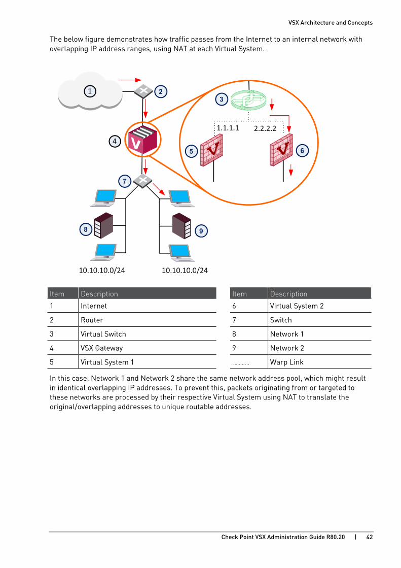
VSX Architecture and Concepts
Check Point VSX Administration Guide R80.20 | 42
The below figure demonstrates how traffic passes from the Internet to an internal network with overlapping IP address ranges, using NAT at each Virtual System.
Item Description Item Description
1 Internet 6 Virtual System 2
2 Router 7 Switch
3 Virtual Switch 8 Network 1
4 VSX Gateway 9 Network 2
5 Virtual System 1 Warp Link
In this case, Network 1 and Network 2 share the same network address pool, which might result in identical overlapping IP addresses. To prevent this, packets originating from or targeted to these networks are processed by their respective Virtual System using NAT to translate the original/overlapping addresses to unique routable addresses.

VSX Architecture and Concepts
Check Point VSX Administration Guide R80.20 | 43
More for Virtual Switch Route Propagation You are not required to manually define the topology, because this is done automatically. But there are required manual steps in the VSX objects.
To update the topology map for each Virtual System after you enable route propagation:
1. For each Virtual System object that is connected to the Virtual Switch:
a) Edit the object properties. Make sure Anti-Spoofing and VPN features are set correctly.
b) Save the object.
2. Install the security policy for the affected Virtual Systems.
Source-Based Routing Source-based routing allows you to create routing definitions that take precedence over ordinary, destination-based, routing decisions. This lets you route packets according to their source IP address or a combination of their source IP address and destination IP address.
Source-based routing is useful in deployments where a single physical interface without VLAN tagging connects several protected Domain networks. All Virtual Systems are connected to an internal Virtual Router. The Virtual Router sends traffic to the applicable Virtual System based on the source IP address, as defined in source-based routing rules.
Limitations • Source-based routing does not support overlapping IP addresses.
• Anti-Spoofing protection is not effective for packets that originate from a shared internal interface, because there is no physical or logical segregation of traffic. In this case, it is recommended that you configure Anti-Spoofing protection on the router itself.

VSX Architecture and Concepts
Check Point VSX Administration Guide R80.20 | 44
NAT Virtual Systems support Network Address Translation (NAT), much in the same manner as a physical firewall. When a Virtual System, using either Static or Hide NAT, connects to a Virtual Router, you must propagate the affected routes to the Virtual Router. To do so, you need to first define NAT addresses for Virtual Systems connected to a Virtual Router.
The NAT configuration section (on page 78) presents the configuration procedure for NAT on Virtual Machines.
Dynamic Routing The Virtual Devices can communicate and distribute routes using dynamic routing. Each Virtual Device has its own routing daemon.
Virtual Systems support:
• OSPF
• RIP
• BGP
• PIM
Virtual Routers support:
• OSPF

VSX Architecture and Concepts
Check Point VSX Administration Guide R80.20 | 45
VSX Clusters A VSX Cluster has two or more identical, interconnected VSX Gateways for continuous data synchronization and transparent failover. Virtual System Load Sharing (VSLS) enhances throughput by distributing Virtual Systems, with their traffic load, among multiple, redundant machines.
For more about Check Point ClusterXL features and functionality see the R80.20 ClusterXL Administration Guide https://sc1.checkpoint.com/documents/R80.20_GA/WebAdminGuides/EN/CP_R80.20_ClusterXL_AdminGuide/html_frameset.htm.
High Availability VSX supports High Availability and transparent failover for VSX Gateways and for Virtual Systems. If the Active VSX Cluster Member fails, all sessions continue to run, securely and without interruption, on a Standby VSX Cluster Member. Users stay connected and do not notice the failover. They are not required to authenticate again on failover.
Use Selective Sync to activate, delay, or disable VSX Cluster Member synchronization.
Virtual System Load Sharing (VSLS) Load Sharing offers significant performance advantages while providing failover for individual Virtual Systems. Using multiple Gateways instead of a single gateway significantly increases performance for CPU intensive applications such as VPNs, Security Servers, Policy Servers, and Active Directory (LDAP).
By distributing Virtual System instances between different VSX Cluster Members, the performance load is efficiently spread amongst the VSX Cluster Members. For example, Active Virtual System 1 runs on VSX Cluster Member A, while Active Virtual System 2 runs on VSX Cluster Member B. Standby and Backup Virtual System instances are likewise distributed amongst VSX Cluster Members to maximize throughput, even in a failover scenario.
VSLS provides an excellent scalability solution, allowing administrators to add additional VSX Cluster Members to an existing VSLS cluster as traffic loads and performance requirements increase.
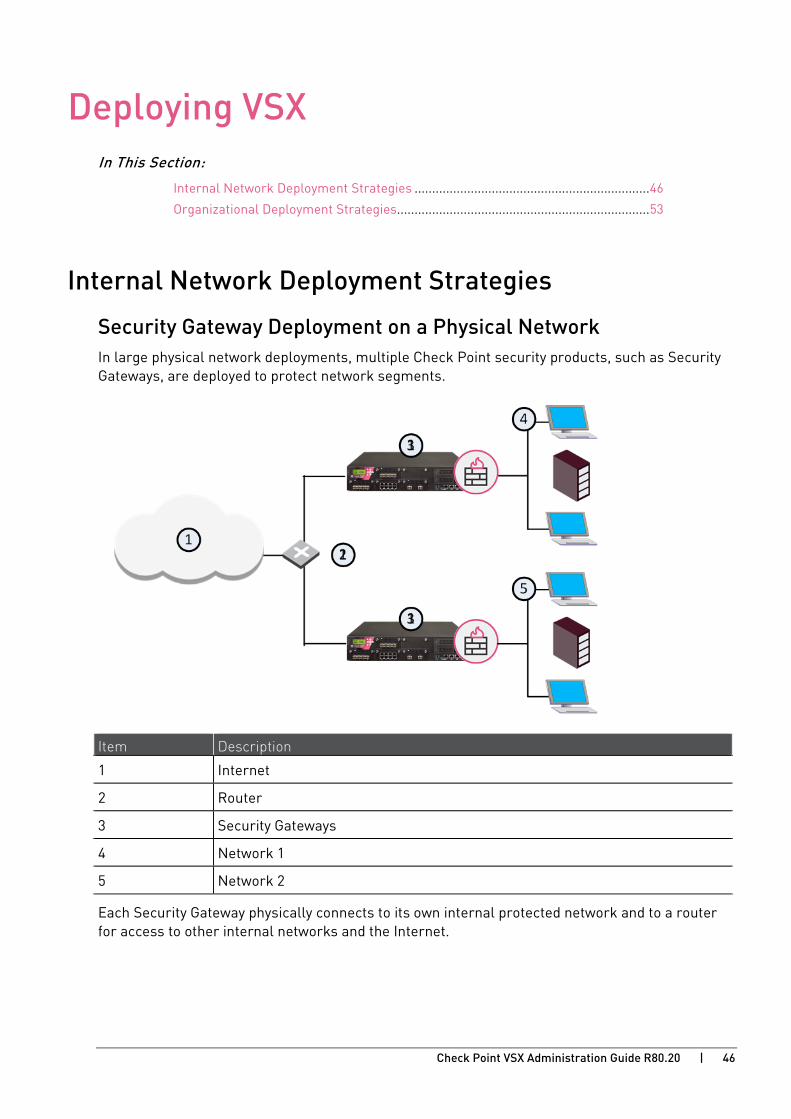
Check Point VSX Administration Guide R80.20 | 46
CHAPTE R 4
Deploying VSX In This Section:
Internal Network Deployment Strategies ................................................................... 46
Organizational Deployment Strategies........................................................................ 53
Internal Network Deployment Strategies
Security Gateway Deployment on a Physical Network In large physical network deployments, multiple Check Point security products, such as Security Gateways, are deployed to protect network segments.
Item Description
1 Internet
2 Router
3 Security Gateways
4 Network 1
5 Network 2
Each Security Gateway physically connects to its own internal protected network and to a router for access to other internal networks and the Internet.
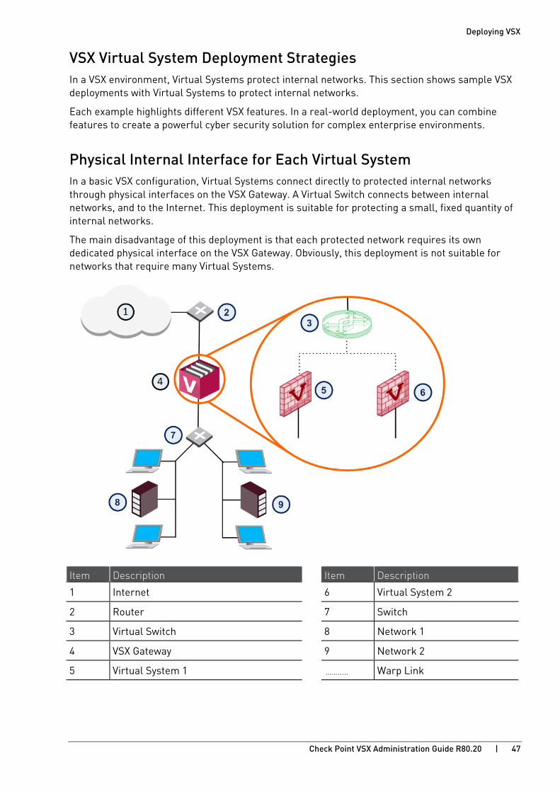
Deploying VSX
Check Point VSX Administration Guide R80.20 | 47
VSX Virtual System Deployment Strategies In a VSX environment, Virtual Systems protect internal networks. This section shows sample VSX deployments with Virtual Systems to protect internal networks.
Each example highlights different VSX features. In a real-world deployment, you can combine features to create a powerful cyber security solution for complex enterprise environments.
Physical Internal Interface for Each Virtual System In a basic VSX configuration, Virtual Systems connect directly to protected internal networks through physical interfaces on the VSX Gateway. A Virtual Switch connects between internal networks, and to the Internet. This deployment is suitable for protecting a small, fixed quantity of internal networks.
The main disadvantage of this deployment is that each protected network requires its own dedicated physical interface on the VSX Gateway. Obviously, this deployment is not suitable for networks that require many Virtual Systems.
Item Description Item Description
1 Internet 6 Virtual System 2
2 Router 7 Switch
3 Virtual Switch 8 Network 1
4 VSX Gateway 9 Network 2
5 Virtual System 1 Warp Link
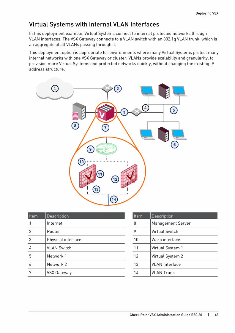
Deploying VSX
Check Point VSX Administration Guide R80.20 | 48
Virtual Systems with Internal VLAN Interfaces In this deployment example, Virtual Systems connect to internal protected networks through VLAN interfaces. The VSX Gateway connects to a VLAN switch with an 802.1q VLAN trunk, which is an aggregate of all VLANs passing through it.
This deployment option is appropriate for environments where many Virtual Systems protect many internal networks with one VSX Gateway or cluster. VLANs provide scalability and granularity, to provision more Virtual Systems and protected networks quickly, without changing the existing IP address structure.
Item Description Item Description
1 Internet 8 Management Server
2 Router 9 Virtual Switch
3 Physical interface 10 Warp interface
4 VLAN Switch 11 Virtual System 1
5 Network 1 12 Virtual System 2
6 Network 2 13 VLAN Interface
7 VSX Gateway 14 VLAN Trunk
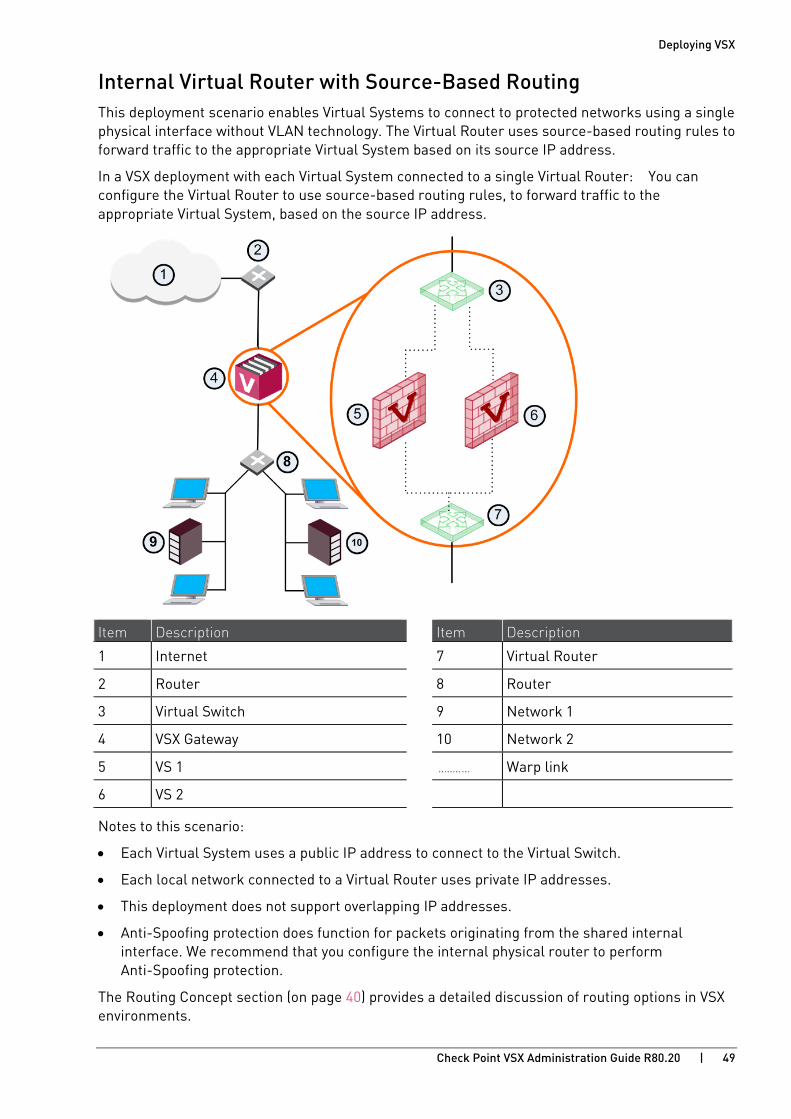
Deploying VSX
Check Point VSX Administration Guide R80.20 | 49
Internal Virtual Router with Source-Based Routing This deployment scenario enables Virtual Systems to connect to protected networks using a single physical interface without VLAN technology. The Virtual Router uses source-based routing rules to forward traffic to the appropriate Virtual System based on its source IP address.
In a VSX deployment with each Virtual System connected to a single Virtual Router: You can configure the Virtual Router to use source-based routing rules, to forward traffic to the appropriate Virtual System, based on the source IP address.
Item Description Item Description
1 Internet 7 Virtual Router
2 Router 8 Router
3 Virtual Switch 9 Network 1
4 VSX Gateway 10 Network 2
5 VS 1 Warp link
6 VS 2
Notes to this scenario:
• Each Virtual System uses a public IP address to connect to the Virtual Switch.
• Each local network connected to a Virtual Router uses private IP addresses.
• This deployment does not support overlapping IP addresses.
• Anti-Spoofing protection does function for packets originating from the shared internal interface. We recommend that you configure the internal physical router to perform Anti-Spoofing protection.
The Routing Concept section (on page 40) provides a detailed discussion of routing options in VSX environments.

Deploying VSX
Check Point VSX Administration Guide R80.20 | 50
Virtual Systems in Bridge Mode A Virtual System in bridge mode implements native layer-2 bridging instead of IP routing and can co-exist with layer-3 Virtual Systems on the same VSX Gateway. This allows network administrators to easily and transparently deploy a Virtual System in an existing network topology without reconfiguring the existing IP routing scheme.
Bridge Mode (on page 138) deployments are particularly suitable for large-scale clustered environments.
Active/Standby Bridge Mode The Active/Standby Bridge Mode provides path redundancy and loop prevention, while offering seamless support for Virtual System Load Sharing and overcoming many Spanning Tree Protocol (STP) Bridge mode limitations.
VLAN Shared Interface Deployment - Active/Standby Bridge Mode In this scenario, each individual member connects to pair of redundant switches via a VLAN trunk. All Virtual Systems in a given member share the same VLAN trunk.

Deploying VSX
Check Point VSX Administration Guide R80.20 | 51
Item Description Item Description
1 Internet 9 VS 3 Backup
2 Redundant switches (external) 10 Redundant switches (internal)
3 VSX Cluster 11 VLAN Switch
4 Member 1 12 Internal Networks
5 Member 2 Sync Network
6 Virtual Systems in Bridge Mode Physical Interface
7 VS 1 Active VLAN Trunk
8 VS 2 Standby
When using the Active/Standby Bridge Mode in a High Availability deployment, VSX directs traffic to VSX Cluster Members according to predefined priorities and state of VSX Cluster Members. In VSLS deployments, VSX distributes the traffic load amongst VSX Cluster Members according to a set of predefined preferences.
This deployment scenario is appropriate for very large enterprises.
Virtual Systems in Bridge Mode A three layer hierarchical model is appropriate for large, high-traffic network environments. It contains a mixture of components as described below:
1. A core network, comprised of high-speed backbone switches directs traffic to and from the Internet and other external networks.
2. A distribution layer, comprised of routers, provides connectivity between the core and the access layer.
3. An access layer, comprised of redundant LAN switches, forwards traffic to and from internal networks.

Deploying VSX
Check Point VSX Administration Guide R80.20 | 52
Use Active/Standby Bridge Mode with VSX to enforce the security policy over the distribution layer.
Item Description Item Description
1 Internet 8 Member 2
2 Core Network Backbone switch 9 LAN switches
3 VSX Cluster 10 Internal Networks
4 Router Sync Network
5 VLAN 10 Physical Interface
6 VLAN 20 VLAN Trunk
7 Member 1
The routers direct external, "dirty" traffic (typically from the Internet) to the appropriate Virtual System via a segregated VLAN. Filtered, "clean" traffic exits the Virtual System through a separate segregated VLAN back to the routers and on to internal destinations.
This deployment scenario is appropriate for very large enterprises.

Deploying VSX
Check Point VSX Administration Guide R80.20 | 53
Organizational Deployment Strategies This section presents deployment scenarios for different types of large organizations and illustrates how VSX provides security both internally and at the perimeter. The discussion covers the following types of organizations:
• Large Enterprises
• Managed Service Providers
• Data Centers
Enterprise Deployments Large enterprise network environments typically have a variety of diverse networks, distributed over multiple locations around the world. These networks often have different security and access requirements for various departments and branches. The ability to centrally manage cyber security, and to maintain throughput, is a critical requirement.
Core Network Security Many Enterprise environments are based on core networks. Situated adjacent to core network backbone switches, VSX protects the internal network by providing security at layer-2, layer-3 or both. VSX communicates with the core network using the existing infrastructure. With Virtual Systems in the Bridge Mode, VSX can protect departmental networks, while simultaneously preventing network segmentation. In this case, switches are located at the entrance to each department's network.

Deploying VSX
Check Point VSX Administration Guide R80.20 | 54
Item Description Item Description
1 Internet 8 LAN Switches
2 Core Network Backbone switch 9 Sales
3 VSX Cluster 10 Finance
4 Router Sync Network
5 VLAN Physical Interface
6 Member 1 VLAN Trunk
7 Member 2
VSX ensures connectivity between the core network and the Internet or external networks, while providing perimeter security. Security can be configured on a per VLAN basis.
Dynamic Routing In an enterprise network with dynamic routing protocols (OSPF/BGP), VSX secures the DMZ services, VPN peers, Domains and partner networks.
In this example, BGP neighbor updates in the routed core network are selectively redistributed to application networks. OSPF provides connectivity between Virtual Routers, Virtual Systems, the core network and application networks.

Deploying VSX
Check Point VSX Administration Guide R80.20 | 55
Item Description Item Description
1 Internet 6 Partner Network
2 Virtual Routers 7 BGP
3 OSPF 8 OSPF 802.1q
4 Virtual Systems 9 BGP in Routed Core
5 Extranet 10 DMZ
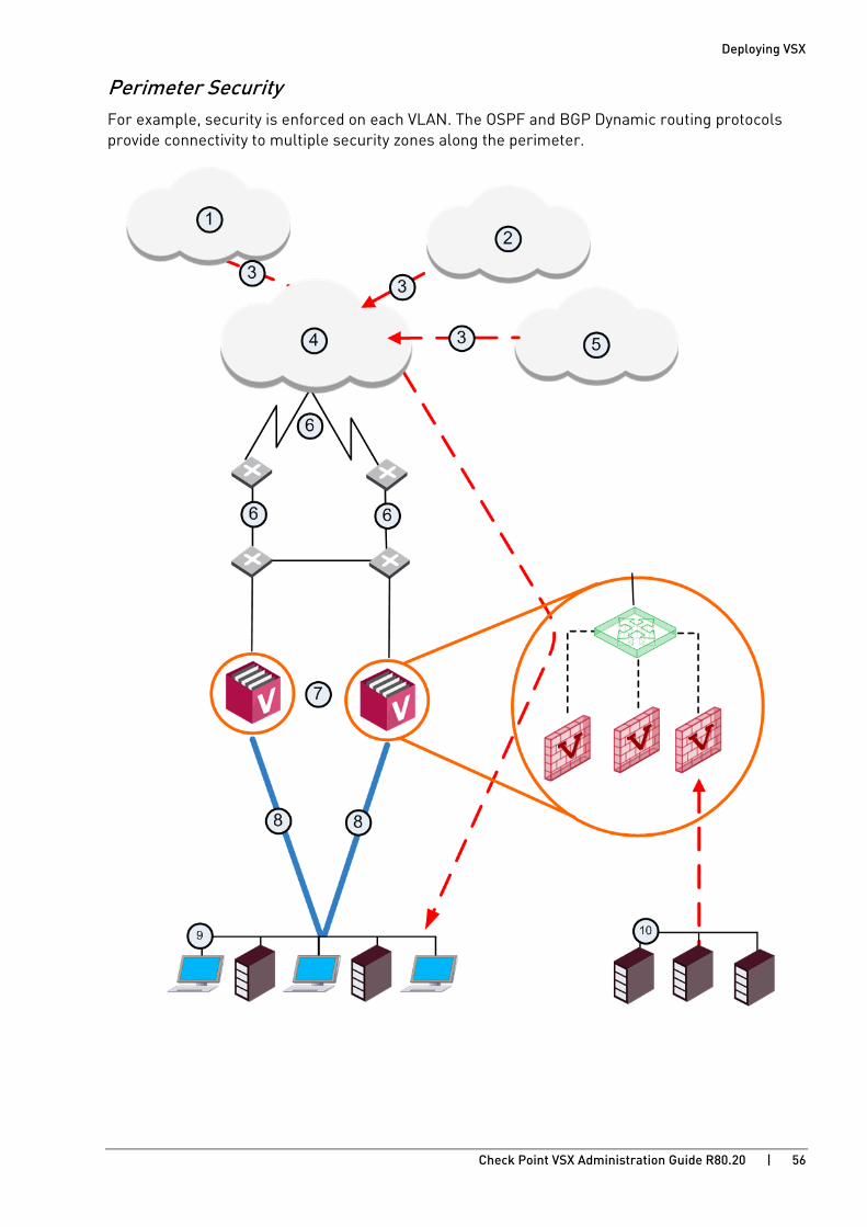
Deploying VSX
Check Point VSX Administration Guide R80.20 | 56
Perimeter Security For example, security is enforced on each VLAN. The OSPF and BGP Dynamic routing protocols provide connectivity to multiple security zones along the perimeter.

Deploying VSX
Check Point VSX Administration Guide R80.20 | 57
Item Description Item Description
1 Partner Access 6 BGP
2 Customers 7 VSX Cluster
3 IPsec tunnel 8 802.1q VLAN Trunk
4 Internet 9 Internal Network
5 Partner 10 DMZ
Notes to this scenario:
• Partners access network resources remotely via Virtual Systems
• Each Virtual System has its own security policy based on its requirements
• Logs and audit information for each partner is collected separately, and saved to a private database
• Applications and services are segregated by private Virtual Systems
• Multiple Virtual Routers / Virtual Switches are used to control the access paths

Deploying VSX
Check Point VSX Administration Guide R80.20 | 58
Managed Service Providers Using Multi-Domain Server Managed service providers give connectivity and security services for Domain networks. Some of these Domains require remote access capabilities. In this service oriented environment, VSX and Multi-Domain Server provide central management and make connectivity and security easier, without affecting the existing IP topology.
In this scenario, a VSX Cluster is in a Point of Presence (POP) deployment for a service provider. VSX consolidates hardware for the service provider and ensures privacy and secure connectivity solutions (VPN) for users. This scenario is appropriate for High Availability and Virtual System Load Sharing cluster modes.
VSX and Multi-Domain Server provide a centralized, granular provisioning system for a number of Domains. Applications and services are separated by discrete Virtual Systems. Access to these services and applications is based on need.

Deploying VSX
Check Point VSX Administration Guide R80.20 | 59
Scenario:
Item Description
1 Internet. Routers are between the VSX Cluster Members and the Internet.
2 VSX Cluster. One VSX Cluster Member handles the Local Exchange, and another VSX Cluster Member handles server traffic of different Domains.
3 Core IP VPN Network.
4 Multi-Domain Server at the Network Operation Center monitors POP and connects to VSX Gateway. The Multi-Domain Log Server in the NOC collects data for each Domain and stores the logs in separate private databases.
5 Multi-Domain Server at the NOC and the VSX Gateway make the Local Exchange.
6 Domain A web servers.
7 Domain B DMZ.
8 Domain C mail servers.
9 PE Router.
10, 11, 12 Domain A, B, and C. Each Domain manages its own security and cannot define Virtual Systems or other network components. Domains have secure VPN connectivity.
13 Remote access
Data Centers Data center providers supply external hosting services for Domain servers and databases. The service typically includes infrastructure, connectivity, and security for multiple Domains.
For example, you can have a scenario such as:
• Multiple Domain networks sharing a common physical infrastructure.
• Backbone that provides connectivity between each Domain and the data center.
• Domain A connects to its web hosting servers.
• Domain B connects to its mail servers.
• Domain C connects to its database servers.

Deploying VSX
Check Point VSX Administration Guide R80.20 | 60
For cyber security and management, the data center provider deploys a VSX Gateway with one Virtual System for each Domain.
Item Description Item Description
1 Remote Users 10 Virtual System for Customer A
2 Internet 11 Virtual System for Customer C
3 Remote network behind VPN-1 Edge 12 Customer C
4 Customer B 13 Data Center
5 Customer A 14 Customer A web servers each with separate VLAN ID
6 MPLS Backbone 15 Customer B mail servers
7 802.1q 16 Customer A Extranet
8 VSX Gateway 17 Customer C databases
9 Virtual System for Customer A

Deploying VSX
Check Point VSX Administration Guide R80.20 | 61
This scenario offers a cost effective scalability solution for network expansion by means of remote connectivity. In this example, a VPN connection between a Domain Virtual System and a Check Point appliance that protects a remote network, integrates that network in the MPLS core. A Virtual System can give access to remote users who connect intermittently.
Data Centers in an Enterprise This example scenario illustrates how VSX provides security management for enterprise data centers. By assigning layer-2 connections to Virtual Systems, VSX reduces the number of physically managed devices within a data center while providing the same high level of security.
For example, a VSX Gateway allows authorized users to access data center resources. The objective here is to protect shared resources with differing access permissions and security requirements, while implementing network granularity.
Item Description Item Description
1 Internet 7 VLAN Trunk
2 VSX Gateway 8 Web Servers VLAN 02
3 VLAN 02 9 Data Bases VLAN 03
4 VLAN 03 10 Application A VLAN 04
5 VLAN 04 11 Application B VLAN 05
6 VLAN 05
For example, one Virtual System protects databases against SQL vulnerabilities. Another Virtual System protects Web Servers using IPS. When new applications and services are added to the enterprise data center, new Virtual Systems are easily created to secure them according to their specific requirements.
Check Point VSX Administration Guide R80.20 | 62
CHAPTE R 5
Configuring VSX In This Section:
Overview ........................................................................................................................ 62
Rules & Security Policies ............................................................................................. 63
Configuring VSX Gateways ........................................................................................... 64
Working with VSX Gateways ......................................................................................... 68
Working with Virtual Systems ...................................................................................... 72
Working with Virtual Switches ..................................................................................... 79
Working with Virtual Routers ....................................................................................... 82
CoreXL for Virtual Systems .......................................................................................... 88
Dynamic Routing for Virtual Devices ........................................................................... 90
Working with Interface Definitions .............................................................................. 91
Working with Authentication ........................................................................................ 95
Tracking Activity ........................................................................................................ 103
Working with Network Address Translation ............................................................. 104
Using Application & URL Filtering with VSX ............................................................. 107
Using Anti-Bot and Anti-Virus with VSX .................................................................... 108
Using IPS with VSX ...................................................................................................... 109
Using Threat Emulation with VSX .............................................................................. 110
Using Threat Extraction with VSX .............................................................................. 111
Licensing VSX .............................................................................................................. 112
Virtual System in Bridge Mode .................................................................................. 113
Overview This chapter explains how to use SmartConsole provision, configure and manage Virtual Devices in a VSX environment.
If you define or configure VSX objects in a Multi-Domain Server deployment: connect with SmartConsole to the Domain Management Server that manages the Virtual Devices. The Multi-Domain Security Management chapter (on page 121) explains these procedures.
To configure Virtual Devices, make sure:
• The Management Servers (Security Management Server or Multi-Domain Server) are configured and running.
• SmartConsole is installed on the appropriate computer.
This chapter assumes that you are familiar with SmartConsole and how to configure standard Security Gateway objects and Security Policies. Many Virtual Device and policy operations are the same as physical Security Gateways and these standard procedures are not in this Administration Guide.
Configuring VSX
Check Point VSX Administration Guide R80.20 | 63
Rules & Security Policies You use the same procedures to define and install Security Policies on a VSX Gateway or Virtual System as for a physical Security Gateway. This statement also applies to the use of IPv6 in Security Policies. These procedures are not included in this Administration Guide.
Configuring VSX
Check Point VSX Administration Guide R80.20 | 64
Configuring VSX Gateways
Creating a New VSX Gateway This section explains how to create a new VSX Gateway using the VSX Gateway Wizard. After you complete the VSX Gateway Wizard, you can change the VSX Gateway definition from SmartConsole. For example, you can add or delete interfaces, or configure existing interfaces to support VLANs.
To start the VSX Gateway wizard:
1. Connect with SmartConsole to the Security Management Server or Main Domain Management Server used to manage the VSX Gateway.
2. From the left navigation panel, click Gateways & Servers.
3. At the top, click New > VSX > Gateway.
The General Properties page of the VSX Gateway Wizard opens.
Wizard Step 1: Defining VSX Gateway General Properties Configure these parameters on the General Properties page:
• VSX Gateway Name: Unique, alphanumeric name for the VSX Gateway. The name cannot contain spaces or special characters except the underscore.
• VSX Gateway Addresses: Management interface addresses.
Note: If you define an IPv6 IP address you must also define an IPv4 address.
• VSX Gateway Version: Select the VSX version installed on the VSX Gateway from the drop-down list.
Wizard Step 2: Selecting Virtual Systems Creation Templates The Creation Templates page lets you provision predefined, default topology and routing definitions to Virtual Systems. This makes sure Virtual Systems are consistent and makes the definition process faster. You always have the option to override the default creation template when you create or change a Virtual System.
The default Creation Templates are:
• Shared Interface: Virtual Systems share one external interface, but maintain separate internal interfaces.
• Separate Interfaces: Virtual Systems use their own separate internal and external interfaces. This template creates a Dedicated Management Interface (DMI) by default.
If the default templates are not appropriate, you can create a custom configuration:
• Custom Configuration: Define Virtual System, Virtual Router, Virtual Switch, and Interface configurations.
Wizard Step 3: Establishing SIC Trust Initialize SIC trust between the VSX Gateway and the Management Server. They cannot communicate without Trust.
Configuring VSX
Check Point VSX Administration Guide R80.20 | 65
Initializing SIC Trust
When you create a VSX Gateway, you must enter an Activation Key. Enter and confirm the activation key and then click Initialize. If you enter the correct activation key, the Trust State changes to Trust established.
Troubleshooting SIC Trust Initialization Problems
If SIC trust was not successfully established, click Check SIC Status to see the reason for the failure. The most common issues are an incorrect activation key and connectivity problems between the Management Server and the VSX Gateway.
Troubleshooting to resolve SIC initialization problems:
• Re-enter and re-confirm the activation key.
• Make sure that the IP address defined in General Properties is correct.
• Ping the Management Server to test the connectivity. Resolve connectivity issues.
• From the VSX Gateway command line, use the cpconfig utility to re-initialize SIC. After this process completes, click Reset in the wizard and then re-enter the activation key.
For more about resolving SIC initialization, see the R80.20 Security Management Administration Guide https://sc1.checkpoint.com/documents/R80.20_GA/WebAdminGuides/EN/CP_R80.20_SecurityManagement_AdminGuide/html_frameset.htm.
Wizard Step 4: Defining Physical Interfaces In the VSX Gateway Interfaces window, define physical interfaces as VLAN trunks. The window shows the interfaces currently defined on the VSX Gateway.
To define an interface as a VLAN trunk, select VLAN Trunk for the interface.
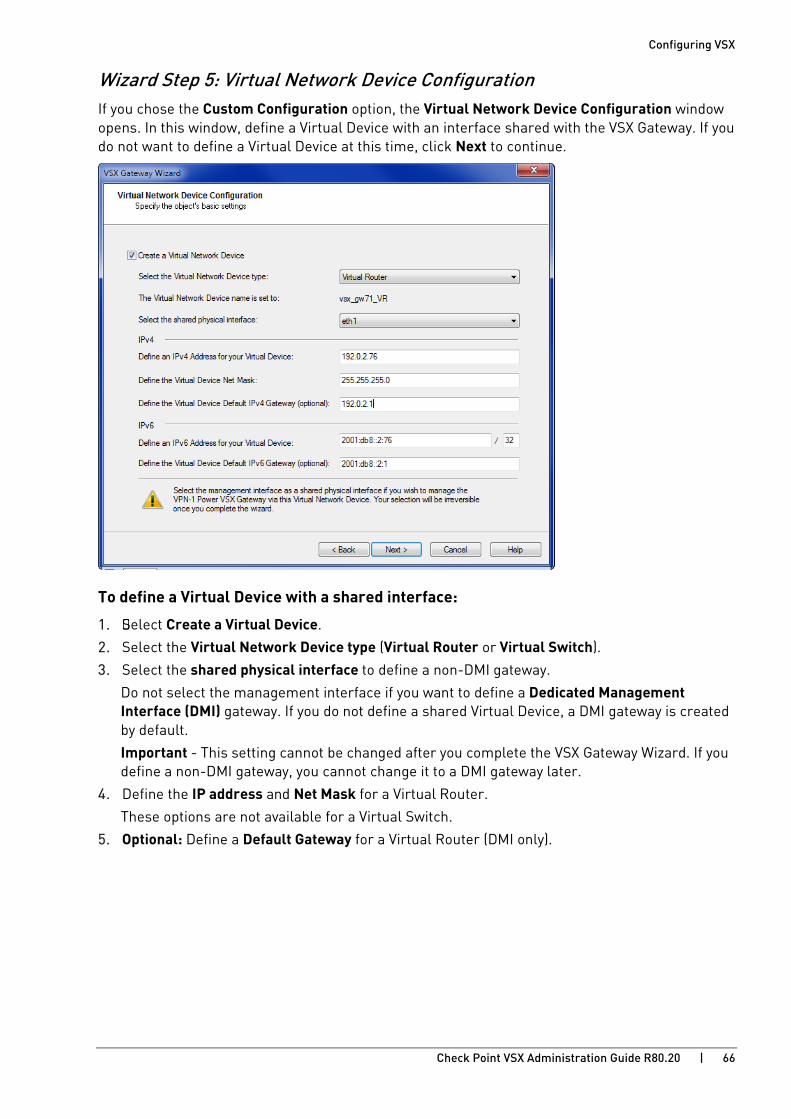
Configuring VSX
Check Point VSX Administration Guide R80.20 | 66
Wizard Step 5: Virtual Network Device Configuration If you chose the Custom Configuration option, the Virtual Network Device Configuration window opens. In this window, define a Virtual Device with an interface shared with the VSX Gateway. If you do not want to define a Virtual Device at this time, click Next to continue.
To define a Virtual Device with a shared interface:
1. Select Create a Virtual Device.
2. Select the Virtual Network Device type (Virtual Router or Virtual Switch).
3. Select the shared physical interface to define a non-DMI gateway.
Do not select the management interface if you want to define a Dedicated Management Interface (DMI) gateway. If you do not define a shared Virtual Device, a DMI gateway is created by default.
Important - This setting cannot be changed after you complete the VSX Gateway Wizard. If you define a non-DMI gateway, you cannot change it to a DMI gateway later.
4. Define the IP address and Net Mask for a Virtual Router.
These options are not available for a Virtual Switch.
5. Optional: Define a Default Gateway for a Virtual Router (DMI only).

Configuring VSX
Check Point VSX Administration Guide R80.20 | 67
Wizard Step 6: VSX Gateway Management In the VSX Gateway Management window, define security policy rules that protect the VSX Gateway. This policy is installed automatically on the new VSX Gateway.
Note - This policy applies only to traffic destined for the VSX Gateway. Traffic destined for Virtual Systems, other Virtual Devices, external networks, and internal networks is not affected by this policy.
The security policy consists of predefined rules for these services:
• UDP - SNMP requests
• TCP - SSH traffic
• ICMP - Echo-request (ping)
• TCP - HTTPS traffic
Completing the VSX Wizard Click Next to continue and then click Finish to complete the VSX Gateway wizard.
This may take several minutes to complete. A message shows successful or unsuccessful completion of the process.
If the process ends unsuccessfully, click View Report to see the error messages. See the Troubleshooting chapter (on page 210).
Configuring the Gateway Security Policy 1. Allow: Select to pass traffic on the selected services. Clear this option to block traffic on this
service. By default, all services are blocked.
For example, to be able to ping the gateway from the Management Server, allow ICMP echo-request traffic.
2. Source: Click the arrow and select a Source Object from the list.
The default value is *Any. Click New Source Object to define a new source.
Configuring VSX
Check Point VSX Administration Guide R80.20 | 68
Working with VSX Gateways A VSX Gateway is a physical machine that serves as a container for Virtual Systems and other virtual network components. This section has step-by-step procedures for creating and configuring standalone VSX Gateways.
Changing VSX Gateway Definitions After you create a VSX Gateway, you can modify the topology, other parameters, and advanced configurations in the VSX Gateway Properties window. To open this window, double-click on the VSX Gateway object in SmartConsole. The VSX Gateway Properties window opens.
VSX Gateway - General Properties In the General Properties page, check and re-establish SIC trust, and activate Check Point products for this VSX Gateway.
You can change these properties:
• Comment - Free text description for the Object List and elsewhere.
• Color - Color of the object icon as it appears in the Object Tree.
• Secure Internal Communication - Check and re-establish SIC trust.
• Check Point Products - Select Check Point products for this gateway.
Secure Internal Communication (SIC)
You can test and reset SIC trust and also see the VSX Gateway Relative Distinguished Name.
To initialize SIC trust:
1. In Gateways & Servers view or Object Explorer, double-click the VSX Gateway.
You can also search for the VSX Gateway in the Object Explorer.
2. In the VSX Gateway Properties window, click Communication.
3. In the Trusted Communication window, enter and confirm the SIC Activation Key.
4. Click Initialize.
Note - If you cannot establish trust, click Test SIC Status to see the reason for the failure. The most common issues are an incorrect activation key and connectivity problems between the Management Server and the VSX Gateway.
To reset SIC trust with the VSX Gateway:
1. From the VSX Gateway CLI, use the cpconfig utility to re-initialize the SIC.
2. In the Communication window, click Reset. 3. Click Yes in the confirmation window.
4. Enter and confirm the SIC authentication password.
5. Click Initialize.
6. Install the applicable policy (<Name of VSX Gateway Object>_VSX) on the VSX Gateway object only.
7. On the VSX Gateway CLI, run: cpstop;cpstart

Configuring VSX
Check Point VSX Administration Guide R80.20 | 69
Check Point Software Blades
Select the Check Point Software Blades to install on this VSX Gateway from the list. The items you see are available for the product version and your license agreement.
VSX Gateway - Creation Templates The Creation Templates page displays the creation template used to create the Virtual Systems for this VSX Gateway. You can change from the current creation template to the Custom Configuration template and change the shared physical interface if the Shared Interface template is active.
• Select Custom Configuration to change from the Shared Interfaces or Separate Interfaces templates. You cannot change back from the Custom Configuration template once you have completed the definition and saved it to the VSX Gateway.
• For a Shared Interface template, click Settings to change the shared interface.
VSX Gateway - Physical Interfaces The Physical Interfaces page lets you add or delete a physical interface on the VSX Gateway, and to define a VLAN trunk.
• To add a new physical interface, click Add and enter the interface name in the appropriate field.
• To remove a physical interface, select the interface and click Remove.
• To define an interface as a VLAN trunk, select VLAN Trunk for the interface.
VSX Gateway - Topology The Topology page contains definitions for interfaces and routes between interfaces and Virtual Devices.
Interfaces
The Interfaces section defines interfaces and links to devices. You can add new interfaces, and delete or modify existing interfaces.
To add an interface:
1. Click New and select one of these options:
• Regular - Create a new interface
• Leads to Virtual Router
• Leads to Virtual Switch
The Interface Properties window opens.
Click Actions > Copy to Clipboard to copy the Interfaces table in CSV format.
2. Define the appropriate properties (on page 92).
3. Click OK.

Configuring VSX
Check Point VSX Administration Guide R80.20 | 70
Routes
The Routes section of the Topology window defines routes between network devices, network addresses, and Virtual Devices. Some routes are defined automatically based on the interface definitions. You can add, change, and delete routes.
To add a default route to the routing table:
1. Click Add Default Route.
The Default Gateway window opens.
2. Enter the default route IP address or select the default Virtual Router.
3. Click OK.
The default route is added to the routing table.
4. Select the default route and click Edit. The Route Configuration window opens.
5. Configure the settings for the default route and click OK.
To add a new route to the routing table:
1. Click Add.
The Route Configuration window opens.
2. Configure the Destination IP address and netmask.
3. Configure the next hop IP address or Virtual Router.
4. Optional: Select Propagate route to adjacent Virtual Devices to "advertise" the route to neighboring Virtual Devices, and enable connectivity between them.
5. Click OK.
To change a route:
1. Select the route.
2. Click Edit. The Route Configuration window opens.
3. Change the settings.
4. Click OK.
To delete a route:
1. Select the route.
2. Click Remove.
A confirmation window opens.
3. Click OK.

Configuring VSX
Check Point VSX Administration Guide R80.20 | 71
Topology Calculation
Select the Calculating topology automatically based on routing information option to let VSX automatically calculate the network topology based on interface and routing definitions. When enabled, VSX creates automatic links, or connectivity cloud objects linked to existing internal or external networks.
• This option is not available in Bridge Mode.
• We recommend that you do not use this option with dynamic routing configurations.
Note - If you wish to enable Anti-Spoofing protection when there are no routes pointing to internal networks, disable the Calculating topology automatically based on routing information option. Modify the appropriate interface definitions to enable Anti-Spoofing.
Deleting a VSX Gateway When you delete a VSX Gateway object, the operation automatically deletes all Virtual Systems and other Virtual Devices associated with that VSX Gateway from the management database.
To delete a VSX Gateway:
1. From the Gateways & Servers view or Object Explorer tree, right-click the VSX Gateway object on the Object Tree and select Delete.
2. In the window that opens, click Yes.
Backing up and Restoring VSX Gateway In the event of a catastrophic VSX Gateway failure, you can restore the VSX Gateway configuration and its Virtual Device configuration.
For VSX Gateway that runs on Gaia OS:
Follow the instructions in the sk100395: How to backup and restore VSX gateway http://supportcontent.checkpoint.com/solutions?id=sk100395.
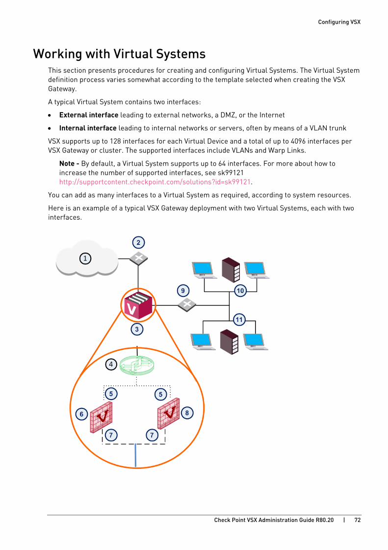
Configuring VSX
Check Point VSX Administration Guide R80.20 | 72
Working with Virtual Systems This section presents procedures for creating and configuring Virtual Systems. The Virtual System definition process varies somewhat according to the template selected when creating the VSX Gateway.
A typical Virtual System contains two interfaces:
• External interface leading to external networks, a DMZ, or the Internet
• Internal interface leading to internal networks or servers, often by means of a VLAN trunk
VSX supports up to 128 interfaces for each Virtual Device and a total of up to 4096 interfaces per VSX Gateway or cluster. The supported interfaces include VLANs and Warp Links.
Note - By default, a Virtual System supports up to 64 interfaces. For more about how to increase the number of supported interfaces, see sk99121 http://supportcontent.checkpoint.com/solutions?id=sk99121.
You can add as many interfaces to a Virtual System as required, according to system resources.
Here is an example of a typical VSX Gateway deployment with two Virtual Systems, each with two interfaces.

Configuring VSX
Check Point VSX Administration Guide R80.20 | 73
Item Description Item Description
1 Internet 8 Virtual System 2
2 Router 9 VLAN Switch
3 VSX Gateway 10 Network 1
4 Virtual Switch 11 Network 2
5 External Interface VLAN Interface
6 Virtual System 1 VLAN Trunk
7 Internal Interface Warp Link

Configuring VSX
Check Point VSX Administration Guide R80.20 | 74
Creating a New Virtual System You use the Virtual Systems Wizard to create a new Virtual System. Modify the initial definition and configure advanced options after you complete the wizard.
To start the Virtual System wizard:
1. Connect with SmartConsole to the Security Management Server or Target Domain Management Server used to manage the new Virtual System.
2. From the left navigation panel, click Gateways & Servers.
3. Create a new Virtual System object in one of these ways:
• From the top toolbar, click the New ( ) > VSX > New Virtual System.
• In the top left corner, click Objects menu > More object types > Network Object > Gateways and Servers > VSX > New Virtual System.
• In the top right corner, click Objects Pane > New > More > Network Object > Gateways and Servers > VSX > Virtual System.
The Virtual System Wizard opens.
Defining General Properties The General Properties wizard page defines the Virtual System object and the hosting VSX Gateway.
These are the parameters in this page:
• Name: Unique, alphanumeric for the Virtual System. The name cannot contain spaces or special characters except the underscore.
• VSX Gateway / Cluster: Select the VSX Gateway that is hosting the Virtual System.
• Bridge Mode: Select this option to create a Virtual System in the Bridge Mode.
• Override Creation Template: Select this option to override the creation template that was used for the initial configuration of the VSX Gateway.
Defining Network Configuration In the Virtual System Network Configuration page, define internal and external interfaces and the IP address topology behind the internal interface. The process to define Virtual System network properties is different in different environments:
• Use the VSX Gateway Creation template to define the VSX Gateway that contains the Virtual System.
• If you choose to override the default VSX Gateway Creation template, you can use the Custom Configuration template.
• You can create the Virtual System in Bridge Mode. Note - Bridge mode is not available for a Virtual System created with the Shared Interface template.

Configuring VSX
Check Point VSX Administration Guide R80.20 | 75
Shared Interface or Separate Interfaces
The Virtual System Network Configuration page for the Shared Interface and Separate Interfaces templates appears as shown.
To configure the external and internal interfaces:
1. Select the desired interfaces from the appropriate list.
2. If the selected Interface is a VLAN interface, enter the VLAN tag in the appropriate field. This field is not available for non-VLAN interfaces.
3. Enter the IP address and net mask in the appropriate fields. Optionally, enter a default gateway for the external interface.
4. Complete the definition process (on page 76).
Separate Interfaces in Bridge Mode
The Virtual System Network Configuration page for the Separate Interfaces template in the Bridge Mode opens.
To configure the external and internal interfaces:
1. Select the desired interfaces for the internal and external networks from the appropriate list.
If the selected Interface is a VLAN interface, enter the same VLAN tag in both the external and internal VLAN Tag fields. This field is not available for non-VLAN interfaces.
2. Define the topology for the internal interface:
• Select Not Defined if you do not wish to define an IP address.
• Select Specific and then select an IP address definition from the list. IP address definitions can be based on object groups or predefined networks that define the topology.
3. To create a new IP address definition:
a) Select Specific, and click New.
b) Select Group to define an object group, or Network to define network properties.
4. Enable Layer-3 bridge interface monitoring to enable Layer 3 network fault detection for this Virtual System.
Enter an IP address and subnet mask, which continuously monitors the specified network for faults or connectivity issues. The IP address/Subnet Mask define the network, on which the Virtual System resides.
5. Complete the definition process (on page 76).

Configuring VSX
Check Point VSX Administration Guide R80.20 | 76
Custom Configuration or Override - Non-Bridge Mode
If you used the Custom Configuration template when creating the VSX Gateway, or if you selected Override Creation Template, manually define the network interfaces and connections. The Virtual System Network Configuration page for Custom Configuration opens.
To configure the external and internal interfaces:
1. In the interface table, define the applicable interfaces.
You can add new interfaces and delete and change existing interfaces.
To add an interface, click Add. The Interface Properties window opens. Select an interface from the list and define its properties.
2. Select the Main IP Address from the list.
This IP address is usually assigned to the external interface and specifies the Virtual System address used with NAT or VPN connections.
To make an external IP address routable, select the external interface IP address as the main IP address.
3. Define network routing for your deployment.
Some routes are automatically defined by the interface definitions. For example, you define a default gateway route leading to an external Virtual Router or to the Virtual System external interface.
To manually add a default route to the Routes table, click Add Default Routes. Enter the default route IP address, or select the default Virtual Router. The Route Configuration window opens.
4. Complete the definition (on page 76).
Custom Configuration or Override in Bridge Mode
If you used the Custom Configuration template to create the VSX Gateway, or if you selected the Override Creation Template option for a Virtual System in Bridge Mode, then manually define the network interfaces.
Interfaces: To configure the external and internal interfaces, define interfaces and links to devices in the Interfaces table. You can add, change, and remove interfaces. To add an interface, click Add. The Interface Properties window opens. Select an interface from the list and define is properties.
Completing the Definition Click Next and then click Finish to create the Virtual System. Note that this may take several minutes to complete. A message appears indicating successful or unsuccessful completion of the process.
If the process ends unsuccessfully, click View Report to view the error messages. Refer to the troubleshooting chapter (on page 210) for further assistance.
After you create a Virtual System using the Virtual System Wizard, you can modify the topology and all other parameters (except the name of the Virtual System) using the Virtual System Properties window.
Configuring VSX
Check Point VSX Administration Guide R80.20 | 77
Modifying a Virtual System 1. Connect with SmartConsole to the Security Management Server or Target Domain
Management Server used to manage the Virtual System.
2. From the Gateways & Servers view or Object Explorer, double-click the Virtual System object.
Virtual System - General Properties The General Properties page lets you specify the main IP address and to enable various Check Point products for a Virtual System.
Virtual System - Topology The Topology page contains definitions for Virtual System interfaces, routes and Warp Links. Based on these interface settings, VSX automatically creates routes to Virtual Devices and the VSX Gateway.
Note - If you modify the topology for a specific Virtual System in a cluster environment, the cluster topology is not updated until you install a policy on that Virtual System.
• Interfaces: The Interfaces table defines interfaces and links to devices. You can add new interfaces as well as delete and modify existing interfaces.
To add an interface, click New and select one of these options:
• Regular - Create a new interface
• Leads to Virtual Router
• Leads to Virtual Switch
The Interface Properties window opens. Select the interface from the list and define the appropriate properties. The Modifying an Interface Definition section (on page 91) and the online help provides explanations of the various properties and options.
Click Actions > Copy to Clipboard to copy the Interfaces table in CSV format.
• Routes: To add a default route to the Routes table, click Add Default Routes and either enter an IP address or select a Virtual Router. The Route Configuration window opens. Click Help for details regarding the various properties and options. You can also add, change and remove routes (on page 70).
• Calculate topology automatically based on routing information: Enable this option to allow VSX to automatically calculate the network topology based on interface and routing definitions (enabled by default). VSX creates automatic links, or connectivity cloud objects linked to existing internal or external networks.
• When this option is enabled, you cannot configure the topology using Topology tab in the Interface Properties window. These options are unavailable on the tab.
• This option is not available in the Bridge Mode.
• When employing dynamic routing, it is recommended to disable this option.
• VPN Domain: The VPN Domain defines the set of hosts located behind a given Virtual System that communicate via a VPN tunnel with peer Virtual Systems. These options are only available if you selected VPN in the Check Point Products section on the General Properties page.

Configuring VSX
Check Point VSX Administration Guide R80.20 | 78
When including a Virtual Device as part of a VPN connection, you must specify a VPN Domain. The domain definition specifies Virtual System interfaces that are included in the VPN. You can define a VPN Domain in one of two ways by enabling the appropriate option:
• All IP Addresses behind gateway based on topology information: Includes all hosts not located behind an external gateway cluster interface.
• Manually Defined: Includes all hosts in the selected network or group.
Virtual System - NAT > Advanced The NAT > Advanced page lets you configure NAT rules for packets originating from a Virtual System.
To enable and configure NAT for a Virtual System:
1. Select Add Automatic Address Translation.
2. Select a translation method:
• Hide: Hide NAT only allows connections originating from the internal network. Internal hosts can access internal destinations, the Internet and other external networks. External sources cannot initiate a connection to internal network addresses.
• Static: Static NAT translates each private address to a corresponding public address.
3. If you select Hide, select one of these options:
• Hide behind Gateway hides the real IP address behind the Virtual System external interface IP address,
or
• Hide behind IP Address hides the real address behind a virtual IP address, which is a routable, public IP address that does not belongs to any real machine.
4. If you selected Static NAT, enter the static IP address in the appropriate field.
5. Select the VSX Gateway from the Install on Gateway list.
In addition, see the Working with Network Address Translation (on page 104) section.
Deleting a Virtual System
To delete a Virtual System:
1. From the Gateways & Servers view or Object Explorer tree, right-click the Virtual System object and select Delete.
2. In the window that opens, click Yes.
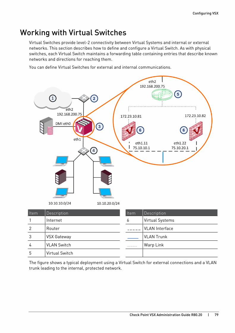
Configuring VSX
Check Point VSX Administration Guide R80.20 | 79
Working with Virtual Switches Virtual Switches provide level-2 connectivity between Virtual Systems and internal or external networks. This section describes how to define and configure a Virtual Switch. As with physical switches, each Virtual Switch maintains a forwarding table containing entries that describe known networks and directions for reaching them.
You can define Virtual Switches for external and internal communications.
Item Description Item Description
1 Internet 6 Virtual Systems
2 Router VLAN Interface
3 VSX Gateway VLAN Trunk
4 VLAN Switch Warp Link
5 Virtual Switch
The figure shows a typical deployment using a Virtual Switch for external connections and a VLAN trunk leading to the internal, protected network.

Configuring VSX
Check Point VSX Administration Guide R80.20 | 80
Creating a New Virtual Switch Use the Virtual Switch Wizard to create a new Virtual Switch. You can modify the initial definition and configure advanced options after completing the wizard.
To create a new Virtual Switch:
1. Connect with SmartConsole to the Security Management Server or Target Domain Management Server used to manage the new Virtual System.
2. From the left navigation panel, click Gateways & Servers.
3. Create a new Virtual Switch object in one of these ways:
• From the top toolbar, click the New ( ) > VSX > New Virtual Switch.
• In the top left corner, click Objects menu > More object types > Network Object > Gateways and Servers > VSX > New Virtual Switch.
• In the top right corner, click Objects Pane > New > More > Network Object > Gateways and Servers > VSX > Virtual Switch.
The Virtual Switch Wizard opens.
4. In the Name field, enter the name for the new Virtual Switch.
5. In the VSX Gateway / Cluster field, select the applicable VSX Gateway or VSX Cluster.
6. Click Next. 7. In the Interfaces section, click Add to add the interface, to which the Virtual Switch connects.
8. Click Next. 9. Click Finish.
Modifying a Virtual Switch 1. Connect with SmartConsole to the Security Management Server or Target Domain
Management Server used to manage the Virtual Switch.
2. From the Gateways & Servers view or Object Explorer, double-click the Virtual Switch object.
Virtual Switch - General Properties The General Properties page allows you to add comments and change the icon color as displayed in SmartConsole.
Virtual Switch - Topology The Topology page defines Virtual Switch interfaces. You can only modify the single defined interface. You cannot change the settings for Warp interfaces in this window.
To add an interface:
1. Click New.
The Interface Properties window opens.
2. Select an interface from the list and define the IP address, net mask and other properties.
3. Optional: Click Actions > Copy to Clipboard to copy the Interfaces table in CSV format.
Configuring VSX
Check Point VSX Administration Guide R80.20 | 81
Deleting a Virtual Switch
To delete a Virtual Switch:
1. Connect with SmartConsole to the Security Management Server or Target Domain Management Server used to manage the new Virtual Switch.
2. From the Gateways & Servers view or Object Explorer, double-click the Virtual Switch object.
3. From the left tree, click Topology.
4. In the Interfaces section, remove all interfaces.
5. Click OK.
6. Right-click the Virtual Switch object and select Delete.
7. Click Yes in the confirmation box.
8. Publish the session.

Configuring VSX
Check Point VSX Administration Guide R80.20 | 82
Working with Virtual Routers This section describes how to define and configure a Virtual Router. As with physical routers, each Virtual Router maintains a routing table containing entries that describe known networks and directions on how to reach them.
You can define Virtual Routers for both external and internal communications. A Virtual Router that connects to external networks, including a DMZ and the Internet, are referred to as an external Virtual Router. A Virtual Router that connects to internal, protected networks is known as an internal Virtual Router.
Item Description Item Description
1 Internet 6 External Virtual Router
2 Router 7 Virtual Systems
3 Security Management Server VLAN Interface
4 VSX Gateway VLAN Trunk
5 VLAN switch Warp Link

Configuring VSX
Check Point VSX Administration Guide R80.20 | 83
An external Virtual Router functions as the external gateway for Virtual Systems, allowing them to share a single secure physical interface leading to external networks and the Internet.
Item Description Item Description
1 Internet 7 Unnumbered
2 Router 8 Virtual Systems
3 Security Management Server 9 Internal Virtual Router
4 VSX Gateway VLAN Interface
5 Switch VLAN Truck
6 External Virtual Router Warp link
In this scenario, VSX creates Warp interfaces between the Virtual Systems and both Virtual Routers. Note that the external Virtual System interfaces are defined as unnumbered interfaces.
An internal Virtual Router typically connects with one interface leading to internal networks through a switch with additional Warp Links leading to other Virtual Systems located in the VSX Gateway.
After you create a new Virtual Router, add new interfaces to the Virtual Systems to connect to the Virtual Router.

Configuring VSX
Check Point VSX Administration Guide R80.20 | 84
Creating a New Virtual Router Use the Virtual Router Wizard to create a new Virtual Router. You can modify the initial definition and configure advanced options after you complete the wizard.
On interfaces and routes, you can select the Propagate route to adjacent Virtual Devices option to broadcast the IP address to neighboring Virtual Devices. This option enables connectivity with these Virtual Devices.
To create a Virtual Router:
1. Connect with SmartConsole to the Security Management Server or Target Domain Management Server used to manage the new Virtual System.
2. From the left navigation panel, click Gateways & Servers.
3. Create a new Virtual Router object in one of these ways:
• From the top toolbar, click the New ( ) > VSX > New Virtual Router.
• In the top left corner, click Objects menu > More object types > Network Object > Gateways and Servers > VSX > New Virtual Router.
• In the top right corner, click Objects Pane > New > More > Network Object > Gateways and Servers > VSX > Virtual Router.
The Virtual Router Wizard opens.
4. In the Name field, enter the name for the new Virtual Router.
5. In the VSX Gateway / Cluster field, select the applicable VSX Gateway or VSX Cluster.
6. Click Next. 7. In the Interfaces section, click Add to add the interface, to which the Virtual Router connects.
8. In the Routes section, click Add to add the applicable network routes.
9. Optional: Click Add Default Route and configure the default route.
10. Click Next. 11. Click Finish.

Configuring VSX
Check Point VSX Administration Guide R80.20 | 85
Modifying a Virtual Router Definition 1. Connect with SmartConsole to the Security Management Server or Target Domain
Management Server used to manage the Virtual Router.
2. From the Gateways & Servers view or Object Explorer, double-click the Virtual Router object.
Virtual Router - General Properties The General Properties page enables you change the Virtual Router IP address as well as to add comments and change the icon color as displayed in SmartConsole.
Virtual Router - Topology The Virtual Router Network Configuration page defines the network topology for the Virtual Router. For an external interface, you define one or more shared external interfaces and a default gateway.
Topology is defined by these properties:
• Interfaces: Add new interfaces, or modify or delete existing interfaces.
To add an interface, click New. The Interface Properties window opens. Select an interface from the list and define the IP address, net mask and other properties (on page 91).
• Routes: Add network routes between this Virtual Router, Virtual Systems, external network devices and network addresses. Some Warp Link routes are defined automatically and cannot be modified or deleted. You can manually add new routes as well as delete and modify non-Warp Link routes.
• Add Default Route: Define the default route as an IP address or Virtual System.
• Advanced Routing: Configure source-based routing (on page 86) rules.
Deleting a Virtual Router 1. Connect with SmartConsole to the Security Management Server or Target Domain
Management Server used to manage the new Virtual Router.
2. From the Gateways & Servers view or Object Explorer, double-click the Virtual Router object.
3. From the left tree, click Topology.
4. In the Interfaces section, remove all interfaces.
5. Click OK.
6. Right-click the Virtual Router object and select Delete.
7. Click Yes in the confirmation box.
8. Publish the session.
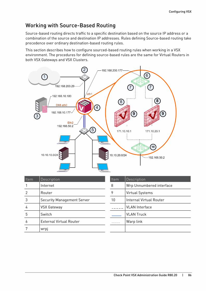
Configuring VSX
Check Point VSX Administration Guide R80.20 | 86
Working with Source-Based Routing Source-based routing directs traffic to a specific destination based on the source IP address or a combination of the source and destination IP addresses. Rules defining Source-based routing take precedence over ordinary destination-based routing rules.
This section describes how to configure sourced-based routing rules when working in a VSX environment. The procedures for defining source-based rules are the same for Virtual Routers in both VSX Gateways and VSX Clusters.
Item Description Item Description
1 Internet 8 Wrp Unnumbered interface
2 Router 9 Virtual Systems
3 Security Management Server 10 Internal Virtual Router
4 VSX Gateway VLAN Interface
5 Switch VLAN Truck
6 External Virtual Router Warp link
7 wrpj
Configuring VSX
Check Point VSX Administration Guide R80.20 | 87
Defining Source-Based Routing Rules Define Source-based Routing rules in the Topology page of the Virtual Router definition window.
To define source-based routing rules:
1. Open the appropriate internal Virtual Router definition and select the Topology page.
2. Click Advanced Routing.
The Advanced Routing Rules window opens.
Note: The highlighted rule is based on a source and a destination address, as compared to the preceding rules, which are based on a source address only.
3. Click Add, to define a new rule or Edit, to change an existing rule.
The Add/Edit Route Rule window opens.
Define the properties:
• Source IP Address and Net Mask
• Destination IP Address and Net Mask
• Next Hop Gateway: Select a Virtual System from the list.
Defining Source-Based Routing Rules Use the Advanced Routing Rules window to define source-based routing rules.
To define source-based routing rules:
1. Connect with SmartConsole to the Security Management Server or Target Domain Management Server that manages the Virtual Router.
2. From the Gateways & Servers view or Object Explorer, right-click the Virtual Router and select Edit. The General Properties window opens.
3. From the left navigation tree, select Topology.
4. Click Advanced Routing.
The Advanced Routing Rules window opens.
5. Click Add, to define a new rule or Edit, to change an existing rule.
The Add/Edit Route Rule window opens.
6. Define these settings:
• Source IP Address and Net Mask
• Destination IP Address and Net Mask
• Next Hop Gateway
7. Click OK.

Configuring VSX
Check Point VSX Administration Guide R80.20 | 88
CoreXL for Virtual Systems CoreXL creates multiple Firewall instances that are, in reality, independent firewalls. You can use CoreXL to increase the performance of the VSX Gateway with multiple CPU cores. You can also assign each CoreXL Firewall instance to a group of CPU cores with the fw ctl affinity command.
You configure CoreXL Firewall instances differently for the VSX Gateway (VS0) than for other Virtual Systems.
• VSX Gateway - Use the CLI to configure the number of CoreXL Firewall instances.
• Other Virtual Systems - Use SmartConsole to configure the number of CoreXL Firewall instances.
You can configure several CoreXL Firewall instances for each Virtual System. When you change the number of CoreXL Firewall instances on a Virtual System, there is some downtime for that Virtual System.
Important:
• Each CoreXL Firewall instance you create uses additional system memory. A Virtual System with five CoreXL Firewall instances would use approximately the same amount of memory as five separate Virtual Systems.
• The number of IPv6 instances cannot exceed the number of IPv4 CoreXL Firewall instances. For more about IPv6 CoreXL Firewall instances and VSX, go to sk97997 http://supportcontent.checkpoint.com/solutions?id=sk97997.
For more about configuring CoreXL, see the R80.20 Performance Tuning Administration Guide https://sc1.checkpoint.com/documents/R80.20_GA/WebAdminGuides/EN/CP_R80.20_PerformanceTuning_AdminGuide/html_frameset.htm.
Configuring CoreXL on a VSX Gateway Use the cpconfig command to configure CoreXL on the VSX Gateway (VS0). The number of instances for the VSX Gateway is limited to the physical number of cores on the server or appliance.
To configure the number of instances on the VSX Gateway:
1. From the CLI, run cpconfig.
2. Select Configure Check Point CoreXL.
3. Make sure that CoreXL is enabled.
4. Configure the number of firewall instances for the VSX Gateway.
5. Exit cpconfig.
6. Note - It is not necessary to reboot the VSX Gateway after you configure CoreXL.
Configuring VSX
Check Point VSX Administration Guide R80.20 | 89
Configuring CoreXL on Virtual Systems Use SmartConsole to configure the number of CoreXL Firewall instances on the Virtual Systems.
• In 32-bit VSX, you can assign up to 10 CoreXL Firewall instances on a Virtual System.
• In 64-bit VSX, you can assign up to 32 CoreXL Firewall instances on a Virtual System.
The number of CoreXL Firewall instances is not limited by the physical CPU cores on the VSX Gateway.
You can assign the number of IPv6 CoreXL Firewall instances. It must be less or equal to the number of IPv4 CoreXL Firewall instances. The number of IPv6 CoreXL Firewall instances may be zero. IPv6 CoreXL Firewall instances are only enabled, if an IPv6 address is configured for that Virtual System.
Notes:
• We recommend that you use the number of CoreXL Firewall instances for each Virtual System according to the expected network traffic on the Virtual System. Configuring unnecessary CoreXL Firewall instances can have a negative impact on performance.
• We recommend that you do not configure more CoreXL Firewall instances than the total number of physical CPU cores on the VSX Gateway.
To configure CoreXL on a Virtual System:
1. Connect with SmartConsole to the Security Management Server or Target Domain Management Server that manages the Virtual System.
2. From the Gateways & Servers view or Object Explorer, double-click the Virtual System object.
The Virtual System General Properties window opens.
3. From the left navigation tree, select CoreXL.
4. Select the number of CoreXL Firewall instances for the Virtual System.
5. Click OK.
6. Install the Access Control Policy on the Virtual System object.
Configuring VSX
Check Point VSX Administration Guide R80.20 | 90
Dynamic Routing for Virtual Devices This section presents procedures for configuring dynamic routing for Virtual Systems and Virtual Routers. The Virtual Devices can use dynamic routing protocols to communicate and distribute routes amongst themselves and with external routers and other devices. VSX uses the Gaia routing daemon (routed).
You can configure dynamic routing for each of these Virtual Devices:
• Virtual System
• Virtual Router
Each of these Virtual Devices has its own dynamic routing instance and configuration file. Use the same procedures to configure the dynamic routing protocols for Warp Links as regular interfaces. You can also configure dynamic routing separately on each VSX Cluster Member.
Important - You cannot use the CLI to configure static routes for VSX. You can only configure them in SmartConsole in the applicable VSX object.
For more about configuring dynamic routing, see the R80.20 Gaia Advanced Routing Administration Guide https://sc1.checkpoint.com/documents/R80.20_GA/WebAdminGuides/EN/CP_R80.20_Gaia_Advanced_Routing_AdminGuide/html_frameset.htm.
To configure dynamic routing for a Virtual Device:
1. Connect to the command line on the VSX Gateway or each VSX Cluster Member.
2. Log in to Gaia Clish.
3. Change the context to the Virtual Device:
set virtual-system <VSID>
4. Run the applicable commands to configure the dynamic routing daemon for the Virtual Device.
5. Save the changes: save config
Configuring VSX
Check Point VSX Administration Guide R80.20 | 91
Working with Interface Definitions All VSX Gateways and Virtual Routers and Virtual Switches contain at least one interface definition. Typically, you define the interfaces during the process of configuring the topology for a given object. Warp interfaces, however, are created automatically based on Virtual Device definitions and their topology. You cannot modify or delete a Warp interface.

Configuring VSX
Check Point VSX Administration Guide R80.20 | 92
Adding a New Interface The procedure and options for defining an interface vary according to the object and the network topology.
Some properties and pages are not available for certain interface definitions.
To add a new interface:
1. Open the Gateway Properties window for the Virtual Device.
2. From the navigation tree, click Topology.
The Topology page opens.
3. From the Interfaces section, click New and select one of these options:
• Regular
• Leads to Virtual Router
• Leads to Virtual Switch
The Interface Properties window for the selected option opens.
Configuring Connection Properties - General The General tab defines the network connections associated with an interface.
One or more of these properties show, depending on the context.
• Interface: Select a physical interface from the list (physical interfaces only).
• VLAN Tag: VLAN tag associated with the defined interface.
• IP Address and Net Mask: IP address and net mask of the device associated with the interface.
• Propagate route to adjacent Virtual Devices: Enable to "advertise" the associated device to neighboring devices, thereby enabling connectivity between them. The Route Propagation section (on page 41) provides additional details.
• MTU: Maximum transmission unit size in bytes (default = 1,500).
Configuring Connections Leading to Virtual Routers and Virtual Switches The General tab for interface connections leading to Virtual Routers or Virtual Switches contains connection properties specific to those Virtual Devices.
• Leads to: Select a Virtual Router or Virtual Switch.
• Enter the dedicated Virtual System IP address for this interface.
• The Net Mask property is always defined as 255.255.255.255 for IPv4 and /128 for IPv6.
• Propagate route to adjacent Virtual Devices: Enable to "advertise" the associated device to neighboring devices, thereby enabling connectivity between them. The Route Propagation section (on page 41) provides additional details.
• MTU: Maximum transmission unit size in bytes (default = 1,500). The minimum and maximum MTU values are:
• IPv6 MTU: 1280 – 16000
• IPv4 MTU: 68 – 16000
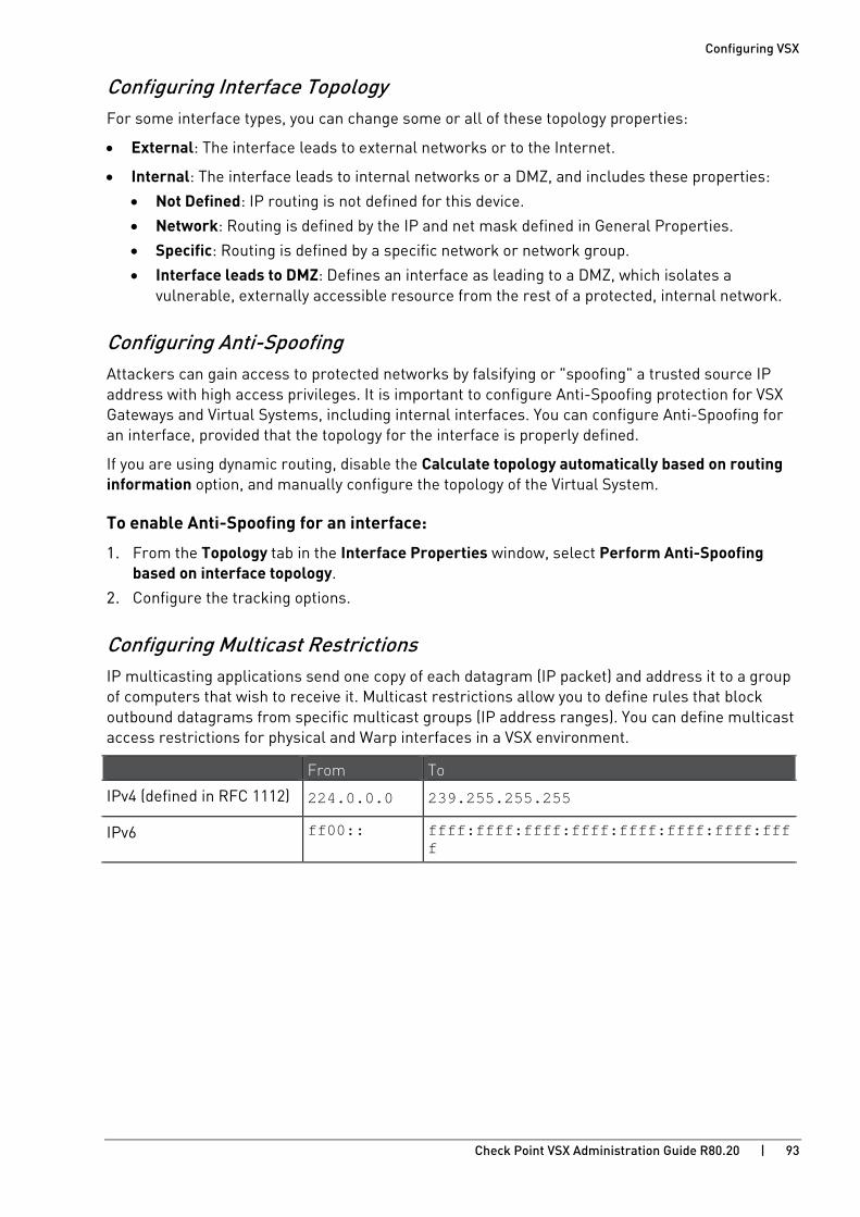
Configuring VSX
Check Point VSX Administration Guide R80.20 | 93
Configuring Interface Topology For some interface types, you can change some or all of these topology properties:
• External: The interface leads to external networks or to the Internet.
• Internal: The interface leads to internal networks or a DMZ, and includes these properties:
• Not Defined: IP routing is not defined for this device.
• Network: Routing is defined by the IP and net mask defined in General Properties.
• Specific: Routing is defined by a specific network or network group.
• Interface leads to DMZ: Defines an interface as leading to a DMZ, which isolates a vulnerable, externally accessible resource from the rest of a protected, internal network.
Configuring Anti-Spoofing Attackers can gain access to protected networks by falsifying or "spoofing" a trusted source IP address with high access privileges. It is important to configure Anti-Spoofing protection for VSX Gateways and Virtual Systems, including internal interfaces. You can configure Anti-Spoofing for an interface, provided that the topology for the interface is properly defined.
If you are using dynamic routing, disable the Calculate topology automatically based on routing information option, and manually configure the topology of the Virtual System.
To enable Anti-Spoofing for an interface:
1. From the Topology tab in the Interface Properties window, select Perform Anti-Spoofing based on interface topology.
2. Configure the tracking options.
Configuring Multicast Restrictions IP multicasting applications send one copy of each datagram (IP packet) and address it to a group of computers that wish to receive it. Multicast restrictions allow you to define rules that block outbound datagrams from specific multicast groups (IP address ranges). You can define multicast access restrictions for physical and Warp interfaces in a VSX environment.
From To
IPv4 (defined in RFC 1112) 224.0.0.0 239.255.255.255
IPv6 ff00:: ffff:ffff:ffff:ffff:ffff:ffff:ffff:ffff
Configuring VSX
Check Point VSX Administration Guide R80.20 | 94
To enable multicast restrictions:
1. From the Multicast Restrictions tab in the Interface Properties window, select Drop multicast packets by the following conditions.
2. Select a restriction type:
• Drop multicast packets whose destination is in the list • Drop all multicast packets except those whose destination is in the list
3. Click Add.
The Add Object window opens.
4. Click New > Multicast Address Range.
The Multicast Address Range Properties window opens.
5. Configure these settings:
• Name
• Type
• If you selected IP Address Range, enter the First and Last IP addresses.
6. Click OK.
7. From the Interface Properties window, select a tracking option.
8. Click OK and close the General Properties window.
9. Add a rule to the Rule Base that allows traffic for the specified multicast groups and install the policy.
Changing an Interface Definition This section presents procedures for modifying existing interface definitions and related features.
Changing an Interface Interfaces definitions are always associated with a Virtual Gateway or a Virtual System definition.
To work with an existing interface definition:
1. Double-click the interface in the Interfaces section.
2. In the Interface Properties window, define the interface properties (on page 92).
Deleting an Interface
To delete an interface:
1. From the Topology page, select the interface and click Delete.
2. Click OK.

Configuring VSX
Check Point VSX Administration Guide R80.20 | 95
Working with Authentication
Supported Authentication Schemes Authentication schemes employ user names and passwords to identify valid users. Some schemes are maintained locally, storing user names and passwords on the VSX Gateway, while others store authentication information on an external authentication server. Some schemes, such as SecurID, are based on providing a one-time password.
All of the schemes can be used with users defined on an LDAP server. For additional information on configuring a Security Gateway to integrate with an LDAP server, refer to the User Directory (LDAP) and User Management section in the R80.20 Security Management Administration Guide https://sc1.checkpoint.com/documents/R80.20_GA/WebAdminGuides/EN/CP_R80.20_SecurityManagement_AdminGuide/html_frameset.htm.
Check Point Password VSX stores a static password for each user in the Management Server database. No more software is required.
Operating System Password VSX can authenticate users by means of a user name and password defined on the Management Server operating system. You can also use passwords stored in a Windows domain. No additional software is required.
RADIUS Remote Authentication Dial In User Service (RADIUS) is an external, server-based authentication protocol that provides authentication services using the UDP protocol.
TACACS, TACACS+ Terminal Access Controller Access Control System (TACACS) is an external, server-based authentication protocol that provides verification services using the TCP protocol. TACACS+ is an enhanced version of the TACACS that supports additional types or authentication requests and response codes.
SecurID SecurID requires users to possess a token authenticator and to supply a password. Token authenticators generate one-time passwords that are synchronized to an RSA ACE/Server. Hardware tokens are key-ring or credit card-sized devices, while software tokens reside on the PC or device from which the user wants to authenticate. All tokens generate a random, one-time use access code that changes approximately every minute. When a user attempts to authenticate to a protected resource, the one-time use code must be validated by the ACE/Server.
Configuring VSX
Check Point VSX Administration Guide R80.20 | 96
Configuring SecurID ACE/Server These are the options to enable connectivity between Virtual Systems and a SecurID ACE/Server:
• Shared configuration: All authentication servers are accessible by all Virtual Systems through the VSX Gateway. The Virtual Systems on each VSX Gateway use the same encryption key. This is the default option.
• Private configuration: Authentication servers are accessed directly by the Virtual System and use the Virtual System cluster IP address as the source address. Each Virtual System uses a separate encryption key. For High Availability configurations, the Virtual Systems on different VSX Cluster Members use the same encryption key.
Note - You can configure authentication for more than one ACE/Server in private mode. Contact Check Point Support https://www.checkpoint.com/support-services/contact-support/ for more information.
The SecurID ACE/Server sends a shared key (called a "node secret") to its peer ACE/Clients. This key is unique per IP address, and is sent when it connects to the ACE/Server for the first time.
Configuring Shared Authentication Configure shared authentication so that all the Virtual Systems on the VSX Gateway use the same encryption key to authenticate to the remote SecurID/ACE server. Each VSX Cluster Member uses a different encryption key and node secret file.
The SecurID encryption key is stored in the sdconf.rec file. When you generate the sdconf.rec file, use the MIP (Member IP) address of a VSX Gateway interface that connects to the ACE/Server.
The first time that a Virtual System connects and attempts to authenticate to the ACE/Server, the server sends the node secret file (securid) to that Virtual System. Copy the node to all the other Virtual Systems.
To generate an sdconf.rec file:
1. From the ACE/Server, generate the sdconf.rec file with the VSX Gateway MIP.
2. Do the previous step again for each VSX Cluster Member using the VSX Gateway MIP.
For example, a VSX Cluster with three VSX Cluster Members and each VSX Cluster Member has five Virtual Systems. Generate three sdconf.rec files, one for each VSX Cluster Member.
Configuring VSX
Check Point VSX Administration Guide R80.20 | 97
To configure shared authentication:
1. Configure shared authentication on the Virtual Systems.
a) Connect with SmartConsole to the Management Server.
b) From the left navigation panel, click Gateways & Servers.
c) Double-click the applicable Virtual System object.
The Virtual Systems General Properties window opens.
d) From the navigation tree, select Other > Legacy Authentication.
e) Make sure that SecurID and Shared are selected.
f) Click OK.
Do all of the previous steps for each Virtual System.
g) Install the Security Policy on the Virtual Systems.
2. From the VSX Gateway CLI, for each Virtual System create the sdopts.rec file that contains the MIP.
a) Connect to the command line on the VSX Gateway.
b) Log in to the Expert mode.
c) Change the context to the Virtual System 0. Run:
# vsenv 0
d) Create the /var/ace/sdopts.rec file:
# touch /var/ace/sdopts.rec
e) In a plain-text editor, add this line to the /var/ace/sdopts.rec file:
CLIENT_IP=<Member IP Address of VSX Gateway>
f) Change the context to other Virtual System:
# vsenv <VSID>
g) Create the $VAR_ACE/sdopts.rec file:
# touch $VAR_ACE/sdopts.rec
h) In a plain-text editor, add this line to the sdopts.rec file:
CLIENT_IP=<Member IP Address of VSX Gateway>
3. For each Virtual System, copy the same encryption key file, sdconf.rec, to the applicable directory:
• For VS0, copy the file to the /var/ace/ directory.
• For other Virtual Systems, copy the file to the $VAR_ACE directory in the context of each Virtual System.
4. For cluster configurations, do all of the previous steps for each VSX Cluster Member.

Configuring VSX
Check Point VSX Administration Guide R80.20 | 98
5. For cluster configurations, on the Management Server of the VSX Cluster, make sure that Hide NAT is disabled.
On Multi-Domain Server, work in the context of the Target Domain Management Server that manages the Virtual System.
a) Open the applicable table.def file. See sk98339 http://supportcontent.checkpoint.com/solutions?id=sk98339.
b) Make sure that the no_hide_services_ports parameter contains UDP port 5500.
Sample parameter with Hide NAT disabled:
no_hide_services_ports = { <500, 17>, <259, 17>, <1701, 17>, <123, 17>, <5500, 17> };
c) Save the file.
d) In SmartConsole, install the policy on the Virtual Systems.
To distribute the node secret to the Virtual Systems:
1. Authenticate to the VSX Gateway with a SecurID ACE/Server user account.
The ACE/Server sends the node secret file to the VSX Gateway.
2. Search each Virtual System to locate the node secret file called securid.
• For VS0, search in the /var/ace/ directory.
• For other Virtual Systems, search in the $VAR_ACE directory in the context of Virtual Systems.
3. Copy the securid file to the applicable directory:
• For VS0, copy the file to the /var/ace/ directory.
• For other Virtual Systems, copy the file to the $VAR_ACE directory.
4. For cluster configurations, for each VSX Cluster Member:
• Locate a Virtual System that is Active on that VSX Cluster Member and do the all the previous steps.
• If there are no Virtual Systems in the Active state on that VSX Cluster Member, fail-over to the applicable VSX Cluster Member and then do the all the previous steps.
Configuring Private Authentication Configure private authentication so that the active and standby Virtual Systems use the same encryption key and node secret file to authenticate to the remote SecurID ACE/Server.
The SecurID encryption key is stored in the sdconf.rec file. When you generate the sdconf.rec file, use the VIP (Virtual IP) address of the Virtual System interface that connects to the ACE/Server.
The first time that a VSX Gateway connects to the ACE/Server, the server sends the node secret file (securid) to that VSX Gateway. Copy the node to all the other VSX Gateways.

Configuring VSX
Check Point VSX Administration Guide R80.20 | 99
To generate an sdconf.rec file:
1. From the ACE/Server, generate the sdconf.rec file with the Virtual System VIP address.
2. Do the previous step again for each Virtual System on the VSX Gateway.
Example:
A VSX Cluster with three Cluster Members. Each VSX Cluster Member has five Virtual Systems.
You need to generate five sdconf.rec files - one for each Virtual System.
To configure private authentication:
1. Configure private authentication on the VSX Gateway and the Virtual Systems:
a) Connect with SmartConsole to the Management Server.
b) From the left navigation panel, click Gateways & Servers.
c) Double-click the VSX Gateway object.
The VSX Gateway General Properties window opens.
d) From the navigation tree, select Other > Authentication.
e) Make sure that SecurID and Private are selected.
f) Click OK.
Do all of the previous steps for each Virtual System.
g) Install the policy on the Virtual Systems.
2. On the VSX Gateway, for each Virtual System create the sdopts.rec file that contains the VIP address of that Virtual System:
a) Connect to the command line on the VSX Gateway.
b) Log in to the Expert mode.
c) Change the context to the Virtual System 0:
# vsenv 0
d) Create the /var/ace/sdopts.rec file:
# touch /var/ace/sdopts.rec
e) In a plain-text editor, add this line to the /var/ace/sdopts.rec file:
CLIENT_IP=<Virtual System VIP Address>
f) Change the context to other Virtual System:
# vsenv <VSID>
g) Create the $VAR_ACE/sdopts.rec file:
# touch $VAR_ACE/sdopts.rec
h) In a plain-text editor, add this line to the sdopts.rec file:
CLIENT_IP=<Virtual System VIP Address>
Configuring VSX
Check Point VSX Administration Guide R80.20 | 100
3. For each Virtual System, copy the same encryption key file, sdconf.rec, to the applicable directory:
• For VS0, copy the file to the /var/ace/ directory.
• For other Virtual Systems, copy the file to the $VAR_ACE directory in the context of each Virtual System.
4. For cluster configurations, do all of the previous steps for each VSX Cluster Member.
5. For cluster configurations, on the Management Server, make sure that Hide NAT is enabled.
On Multi-Domain Server, work in the context of the Target Domain Management Server that manages the Virtual System.
a) Open the applicable table.def file. See sk98339 http://supportcontent.checkpoint.com/solutions?id=sk98339.
b) Make sure that the no_hide_services_ports parameter does not contain UDP port 5500.
Sample parameter with Hide NAT enabled:
no_hide_services_ports = { <500, 17>, <259, 17>, <1701, 17>, <123, 17> };
c) Save the file.
d) In SmartConsole, install the Access Control policy on the Virtual Systems.
To distribute the node secret to Virtual Systems in a VSX Cluster:
1. Authenticate to the Virtual System on the VSX Cluster with a SecurID ACE/Server user account.
The ACE/Server sends the node secret file to the VSX Cluster.
2. Locate the VSX Cluster Member, on which the Virtual System is in the Active state.
3. From that VSX Cluster Member, copy the securid file to the same Virtual System on the other VSX Cluster Members.
• For VS0, copy the file to the /var/ace/ directory.
• For other Virtual Systems, copy the file to the $VAR_ACE directory in the context of each Virtual System.
4. Do all of the previous steps for each Virtual System.

Configuring VSX
Check Point VSX Administration Guide R80.20 | 101
Configuring RADIUS or TACACS/TACACS+ These are the options to enable connectivity between Virtual Systems and a RADIUS or TACACS/TACACS+ server:
• Shared configuration: All authentication servers are accessible by all Virtual Systems through the VSX Gateway. This is the default option.
• Private configuration: Authentication servers are accessed directly by the Virtual System and use the Virtual System cluster IP address as the source address.
For Multi-Domain Server configurations, make sure that you configure the SecurID or Remote Authentication settings of the Domain Management Server that manages the Virtual Systems.
Configuring Shared Authentication Configure shared authentication so that all the Virtual Systems on the VSX Gateway authenticate to the remote RADIUS or TACACS/TACACS+ server.
To configure shared authentication for RADIUS or TACACS/TACACS+:
1. Configure shared authentication on the Virtual Systems.
a) Connect with SmartConsole to the Management Server.
b) From the Gateways & Servers view or Object Explorer, double-click the Virtual System.
The Virtual Systems General Properties window opens.
c) From the navigation tree, select Other > Authentication.
d) Make sure that RADIUS or TACACS and Shared are selected.
e) Click OK.
Do all of the previous steps for each Virtual System.
f) Install the policy on the Virtual Systems.
2. For cluster configurations, on the Management Server of the VSX Cluster, make sure that Hide NAT is disabled.
On Multi-Domain Server, work in the context of the Target Domain Management Server that manages the Virtual System.
a) Open the applicable table.def file. See sk98339 http://supportcontent.checkpoint.com/solutions?id=sk98339.
b) Make sure that the no_hide_services_ports parameter contains the UDP ports for RADIUS or TACACS, or the TCP ports for TACACS+. The default ports are:
RADIUS - 1645
TACACS/TACACS+ - 49
Sample RADIUS parameter with Hide NAT disabled:
no_hide_services_ports = { <49, 6>, <49, 17>, <500, 17>, <259, 17>, <1701, 17>, <123, 17>, <1645, 17> };
c) Save the file.
d) In SmartConsole, install the policy on the Virtual Systems.
Configuring VSX
Check Point VSX Administration Guide R80.20 | 102
Configuring Private Authentication For private configurations, the active and standby Virtual Systems use the same encryption key to authenticate to the remote RADIUS or TACACS/TACACS+ server.
For High Availability configurations, make sure that the Active and Standby Virtual Systems on each VSX Cluster Member use the same VIP address.
To configure private authentication:
1. Configure private authentication on the VSX Gateway and the Virtual Systems.
a) Connect with SmartConsole to the Management Server.
b) From the left navigation panel, click Gateways & Servers.
c) Double-click the VSX Gateway object.
The General Properties view opens.
d) From the navigation tree, select Other > Legacy Authentication.
e) Make sure that RADIUS or TACACS are selected.
f) Click OK.
Do all of the previous steps for each Virtual System.
g) Install the policy on the Virtual Systems.
2. For VSX Cluster configurations:
On the Management Server, make sure that Hide NAT is enabled.
For Multi-Domain Server, use the Domain Management Server that manages the Virtual System.
a) Edit the applicable table.def file (see sk98339 http://supportcontent.checkpoint.com/solutions?id=sk98339) in a plain-text editor.
b) Make sure that the no_hide_services_ports parameter DOES NOT contain the UDP ports for RADIUS or TACACS, or the TCP ports for TACACS+.
The default ports are:
RADIUS - 1645
TACACS/TACACS+ - 49
Sample parameter with Hide NAT enabled:
no_hide_services_ports = { <500, 17>, <259, 17>, <1701, 17>, <123, 17> };
c) Save the changes in the file.
d) From SmartConsole, install the Access Control Policy on the Virtual Systems object.

Configuring VSX
Check Point VSX Administration Guide R80.20 | 103
Tracking Activity Use the SmartConsole Logs & Monitor features to show the status of all Security Gateways, VSX Gateways and other Virtual Devices.
The Overall status of a Virtual Device is the most serious status of its Software Blades. For example, if all the Software Blades statuses are OK except for the SmartEvent blade, which has a Problem status, then the Overall status will be Problem.
Status Icon Description
OK The gateway and all its Software Blades are working properly.
Attention At least one Software Blade has a minor issue, but the gateway works.
Problem At least one Software Blade reported a malfunction, or an enabled Software Blade is not installed.
Waiting SmartView Monitor is waiting for the Security Management Server to send data from Security Gateways.
Disconnected Cannot reach the Security Gateway.
Untrusted Cannot make Secure Internal Communication between the Security Management Server and the gateway.
Configuring VSX
Check Point VSX Administration Guide R80.20 | 104
Working with Network Address Translation This section describes the process for using Network Address Translation (NAT) in a VSX deployment. The procedures described in this section assume that the reader is familiar with NAT concepts and their implementation in Check Point products. For more about NAT, see the Configuring NAT Policy chapter in the R80.20 Next Generation Security Gateway Guide https://sc1.checkpoint.com/documents/R80.20_GA/WebAdminGuides/EN/CP_R80.20_NextGenSecurityGateway_Guide/html_frameset.htm.
VSX supports NAT for Virtual Systems much in the same manner as a physical firewall. When a NAT enabled (Static or Hide) Virtual System connects to a Virtual Router, the translated routes are automatically forwarded to the appropriate Virtual Router.
Configuring NAT Configure NAT using the NAT page in the Virtual System window. Hide or Static NAT addresses configured in this manner are automatically forwarded to the Virtual Router to which the Virtual System is connected. Alternatively, you can manually add NAT routes on the Topology page in the Virtual Router window.
To configure NAT for a Virtual System on a VSX Gateway:
Step Description
1 Connect with SmartConsole to the Security Management Server / Target Domain Management Server that manages this Virtual System.
2 From the left navigation panel, click Gateways & Servers.
3 Open the Virtual System object.
4 From the navigation tree, click NAT > Advanced.
The Advanced page opens.
5 Select Add Automatic Address Translation.
6 Select the Translation method.
• Hide - Hide NAT only allows connections originating from the internal network. Internal hosts can access internal destinations, the Internet and other external networks. External sources cannot initiate a connection to internal network addresses.
Select one of these options:
• Hide behind Gateway - Hides the real address behind the VSX Gateway external interface address. This is equivalent to hiding behind the address 0.0.0.0 for IPv4, or :: for IPv6.
• Hide behind IP Address - Hides the real address behind a virtual IP address, which is a routable, public IP address that does not belongs to any real machine.
• Static - Static NAT translates each private address to a corresponding public address.
Enter the static IP address.
7 From the Install on Gateway list, select the VSX Gateway.
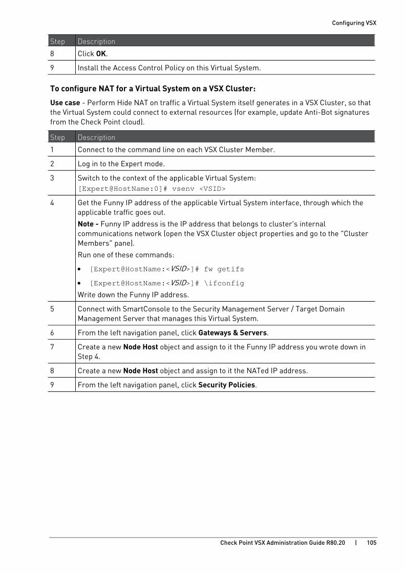
Configuring VSX
Check Point VSX Administration Guide R80.20 | 105
Step Description
8 Click OK.
9 Install the Access Control Policy on this Virtual System.
To configure NAT for a Virtual System on a VSX Cluster:
Use case - Perform Hide NAT on traffic a Virtual System itself generates in a VSX Cluster, so that the Virtual System could connect to external resources (for example, update Anti-Bot signatures from the Check Point cloud).
Step Description
1 Connect to the command line on each VSX Cluster Member.
2 Log in to the Expert mode.
3 Switch to the context of the applicable Virtual System: [Expert@HostName:0]# vsenv <VSID>
4 Get the Funny IP address of the applicable Virtual System interface, through which the applicable traffic goes out.
Note - Funny IP address is the IP address that belongs to cluster's internal communications network (open the VSX Cluster object properties and go to the "Cluster Members" pane).
Run one of these commands:
• [Expert@HostName:<VSID>]# fw getifs
• [Expert@HostName:<VSID>]# \ifconfig
Write down the Funny IP address.
5 Connect with SmartConsole to the Security Management Server / Target Domain Management Server that manages this Virtual System.
6 From the left navigation panel, click Gateways & Servers.
7 Create a new Node Host object and assign to it the Funny IP address you wrote down in Step 4.
8 Create a new Node Host object and assign to it the NATed IP address.
9 From the left navigation panel, click Security Policies.
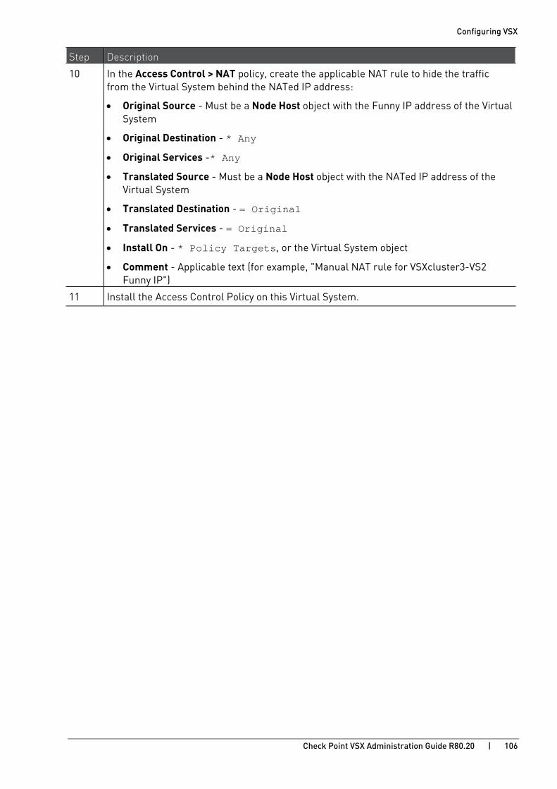
Configuring VSX
Check Point VSX Administration Guide R80.20 | 106
Step Description
10 In the Access Control > NAT policy, create the applicable NAT rule to hide the traffic from the Virtual System behind the NATed IP address:
• Original Source - Must be a Node Host object with the Funny IP address of the Virtual System
• Original Destination - * Any
• Original Services -* Any
• Translated Source - Must be a Node Host object with the NATed IP address of the Virtual System
• Translated Destination - = Original
• Translated Services - = Original
• Install On - * Policy Targets, or the Virtual System object
• Comment - Applicable text (for example, "Manual NAT rule for VSXcluster3-VS2 Funny IP")
11 Install the Access Control Policy on this Virtual System.

Configuring VSX
Check Point VSX Administration Guide R80.20 | 107
Using Application & URL Filtering with VSX When you configure Virtual Systems to use the Application Control and URL Filtering, make sure that the VSX Gateway (VS0) can connect to the Internet. Updates are done only through this Virtual System.
To enable Application & URL Filtering Categories on Virtual Systems:
1. If applicable, configure proxy settings for the VSX Gateway (VS0):
a) In SmartConsole, from the Gateways & Servers view, double-click the VSX Gateway (VS0).
b) From the navigation tree, select Network Management > Proxy.
c) Configure the proxy settings, and click OK.
2. Enable Application Control and URL Filtering on the required Virtual Systems.
Note - You do not have to enable them on the VSX Gateway (VS0).
3. Install policies on the relevant Virtual Systems.
For more about Application & URL Filtering, see the R80.20 Security Management Administration Guide https://sc1.checkpoint.com/documents/R80.20_GA/WebAdminGuides/EN/CP_R80.20_SecurityManagement_AdminGuide/html_frameset.htm.
For more information about these Software Blades on VSX Gateway, see sk106496 http://supportcontent.checkpoint.com/solutions?id=sk106496 and sk79700 http://supportcontent.checkpoint.com/solutions?id=sk79700.
Configuring VSX
Check Point VSX Administration Guide R80.20 | 108
Using Anti-Bot and Anti-Virus with VSX When you configure Virtual Systems to use the Anti-Bot and Anti-Virus Software Blades, make sure the Software Blade:
• Is enabled and configured on the relevant Virtual Systems and enabled and configured on the VSX Gateway (VS0)
VS0 handles contract validation for all Virtual Systems.
• Can connect to the internet
A Virtual System gets updates through the VSX Gateway (VS0). If the VSX Gateway fails, each Virtual System uses its proxy settings to get the update from the internet.
Note - Where applicable, make sure the routing, DNS, and proxy settings for the VSX Gateway (VS0) are configured correctly.
To enable Anti-Bot and Anti-Virus on Virtual Systems:
1. If applicable, configure proxy settings for the VSX Gateway (VS0) or the Virtual Systems or both:
a) From the Network Object tree, double-click the VSX Gateway (VS0).
b) From the navigation tree, select Topology > Proxy.
c) Configure the proxy settings, and click OK.
2. Enable Anti-Bot and Anti-Virus on the VSX Gateway (VS0):
a) From the Network Object tree, double-click the Virtual System.
b) In the Network Security section, select Anti-Bot and Anti-Virus.
c) Click OK.
3. Repeat Steps 1-2 for all Virtual Systems that use Anti-Bot and Anti-Virus.
4. Configure the Threat Prevention Policies for the VSX Gateway (VS0) and the relevant Virtual Systems.
5. Install the Threat Prevention Policies (and Access Control Policies if needed) on the VSX Gateway (VS0) the relevant Virtual Systems.
For more about Anti-Bot and Anti-Virus, see the R80.20 Threat Prevention Administration Guide https://sc1.checkpoint.com/documents/R80.20_GA/WebAdminGuides/EN/CP_R80.20_ThreatPrevention_AdminGuide/html_frameset.htm.
For more information about these Software Blades on VSX Gateway, see sk106496 http://supportcontent.checkpoint.com/solutions?id=sk106496 and sk79700 http://supportcontent.checkpoint.com/solutions?id=sk79700.
Configuring VSX
Check Point VSX Administration Guide R80.20 | 109
Using IPS with VSX To enable IPS on Virtual Systems:
1. If applicable, configure proxy settings for the VSX Gateway (VS0):
a) In SmartConsole, from the Gateways & Servers view, double-click the VSX Gateway (VS0).
b) From the navigation tree, select Network Management > Proxy.
c) Configure the proxy settings, and click OK.
2. Enable IPS and on the required Virtual Systems.
Note - You do not have to enable it on the VSX Gateway (VS0).
3. Configure the Threat Prevention Policies for the relevant Virtual Systems.
4. Install the Threat Prevention Policies (and Access Control Policies if needed) on the relevant Virtual Systems.
The Security Management Server / Domain Management Server downloads the updates for IPS Software Blade and then transfers them to the VSX Gateway during policy installation.
For more about IPS, see the R80.20 Threat Prevention Administration Guide https://sc1.checkpoint.com/documents/R80.20_GA/WebAdminGuides/EN/CP_R80.20_ThreatPrevention_AdminGuide/html_frameset.htm.
For more information about this Software Blade on VSX Gateway, see sk106496 http://supportcontent.checkpoint.com/solutions?id=sk106496 and sk79700 http://supportcontent.checkpoint.com/solutions?id=sk79700.

Configuring VSX
Check Point VSX Administration Guide R80.20 | 110
Using Threat Emulation with VSX To enable Threat Emulation on Virtual Systems:
1. If applicable, configure proxy settings for the VSX Gateway (VS0):
a) In SmartConsole, from the Gateways & Servers view, double-click the VSX Gateway (VS0).
b) From the navigation tree, select Network Management > Proxy.
c) Configure the proxy settings, and click OK.
2. Enable Threat Emulation on the required Virtual Systems.
Note - You do not enable it on the VSX Gateway (VS0).
3. Configure the Threat Prevention Policies for the relevant Virtual Systems.
4. Install the Threat Prevention Policies (and Access Control Policies if needed) on the relevant Virtual Systems.
For more about Threat Emulation, see the R80.20 Threat Prevention Administration Guide https://sc1.checkpoint.com/documents/R80.20_GA/WebAdminGuides/EN/CP_R80.20_ThreatPrevention_AdminGuide/html_frameset.htm.
For more information about this Software Blade on VSX Gateway, see sk106496 http://supportcontent.checkpoint.com/solutions?id=sk106496 and sk79700 http://supportcontent.checkpoint.com/solutions?id=sk79700.

Configuring VSX
Check Point VSX Administration Guide R80.20 | 111
Using Threat Extraction with VSX To enable Threat Extraction on Virtual Systems:
1. If applicable, configure proxy settings for the VSX Gateway (VS0):
a) In SmartConsole, from the Gateways & Servers view, double-click the VSX Gateway (VS0).
b) From the navigation tree, select Network Management > Proxy.
c) Configure the proxy settings, and click OK.
2. Enable Threat Extraction on the required Virtual Systems.
Note - You do not enable it on the VSX Gateway (VS0).
3. Configure the Threat Prevention Policies for the relevant Virtual Systems.
4. Install the Threat Prevention Policies (and Access Control Policies if needed) on the relevant Virtual Systems.
For more about Threat Extraction, see the R80.20 Threat Prevention Administration Guide https://sc1.checkpoint.com/documents/R80.20_GA/WebAdminGuides/EN/CP_R80.20_ThreatPrevention_AdminGuide/html_frameset.htm.
For more information about this Software Blade on VSX Gateway, see sk106496 http://supportcontent.checkpoint.com/solutions?id=sk106496 and sk79700 http://supportcontent.checkpoint.com/solutions?id=sk79700.

Configuring VSX
Check Point VSX Administration Guide R80.20 | 112
Licensing VSX Check Point software is activated with a license key. To obtain a license key, register the certificate key (that appears on the back of the software media pack) with the Check Point User Center. The certificate key is used to generate a license key for the products that you are either evaluating or purchasing. To purchase the required Check Point products, contact your reseller. Check Point software that has not yet been purchased functions for 15 days only.
VSX Licenses Each VSX Gateway or VSX Cluster Member requires its own license, bound to the VSX Gateway or VSX Cluster Member IP address. Each VSX Gateway or VSX Cluster license covers a predefined number of Virtual Systems (3, 10, 25, and 50) and these licenses are cumulative. The VSX licenses are applied in addition to the Security Gateway license (container and Software Blades).
Upgrading Licenses Before upgrading a gateway or Security Management Server to R80.20, you need to have a valid support contract that includes software upgrade and major releases registered to your Check Point User Center account. The Security Management Server stores the contract file and downloads it to Security Gateways during the upgrade. By verifying your status with the User Center, the contract file enables you to easily remain compliant with current Check Point licensing standards.
The license upgrade procedure can be performed if you have purchased any of the Enterprise Software Subscription services. To upgrade a VSX license, do the Software Blades upgrade procedure. See sk65850 http://supportcontent.checkpoint.com/solutions?id=sk65850.
The Trial Period When installing a Check Point product for the first time, users receive a 15 day trial period, during which the product is fully functional. Once the trial period expires, you must purchase and install the appropriate permanent product licenses. During the trial period, you can define up to 25 Virtual Systems.

Configuring VSX
Check Point VSX Administration Guide R80.20 | 113
Virtual System in Bridge Mode
Core Network Security Many Enterprise environments are based on core networks. Situated adjacent to core network backbone switches, VSX protects the internal network by providing security at layer-2, layer-3 or both. VSX communicates with the core network using the existing infrastructure. With Virtual Systems in the Bridge Mode, VSX can protect departmental networks, while simultaneously preventing network segmentation. In this case, switches are located at the entrance to each department's network.
Item Description Item Description
1 Internet 8 LAN Switches
2 Core Network Backbone switch 9 Sales
3 VSX Cluster 10 Finance
4 Router Sync Network
5 VLAN Physical Interface
6 Member 1 VLAN Trunk
7 Member 2
VSX ensures connectivity between the core network and the Internet or external networks, while providing perimeter security. Security can be configured on a per VLAN basis.

Configuring VSX
Check Point VSX Administration Guide R80.20 | 114
Three Layer Hierarchical Model A three-layer hierarchical model is used in large, high-traffic network environments.
1. A core network, with high-speed backbone switches that direct traffic to and from the Internet and other external networks.
2. A distribution layer, with routers, for connectivity between the core and the access layer.
3. An access layer, with redundant LAN switches, that forward traffic to and from internal networks.
VSX in Active/Standby Bridge Mode is incorporated in the distribution layer, enforcing the security policy.
The routers direct external traffic to the appropriate Virtual System through a segregated VLAN. Inspected traffic exits the Virtual System through a separate segregated VLAN, to the routers and then to internal destinations.
Configuring Virtual Systems for Active/Standby Bridge Mode To configure a Virtual System in Bridge Mode, define it as such when you first create the Virtual System object.
To configure a Virtual System for the Active/Standby Bridge Mode:
1. In the Virtual System General Properties page of the new Virtual System object, select Bridge Mode.
2. Click Next. The Virtual System Network Configuration window opens.
3. Configure the external and internal interfaces for the Virtual System.
4. Optional: Select Enable Layer-3 Bridge Interface Monitoring.
The IP address must be unique and on the same subnet as the protected network.
5. Click Next. 6. Click Finish.
Enabling Active/Standby Bridge Mode for a New VSX Cluster Member 1. In the Gaia First Time Configuration Wizard Products page, select ClusterXL.
2. After the First Time Configuration Wizard is complete, from the VSX Gateway CLI, run: cpconfig
• If you enabled the Per Virtual System State feature (required for VSLS), the Active/Standby Bridge Mode is enabled automatically.
• If you chose not to enable the Virtual System Load Sharing, an option to enable Active/Standby Bridge Mode appears.
Enter y and continue with the gateway configuration.

Configuring VSX
Check Point VSX Administration Guide R80.20 | 115
Enabling Active/Standby Bridge Mode for Existing Cluster Members 1. Connect to the command line on each VSX Cluster Member.
2. Log in to the Expert mode.
3. Run: cpconfig
4. Select Enable ClusterXL for Bridge Active/Standby.
5. Reboot each VSX Cluster Member.
Enabling Active/Active Bridge Mode for Existing VSX Cluster Members 1. Connect to the command line on each VSX Cluster Member.
2. Log in to the Expert mode.
3. Run: cpconfig
4. Select Enable ClusterXL membership for this member.
5. Select Disable ClusterXL for Bridge Active/Standby. 6. Reboot each VSX Cluster Member.
Custom Configuration or Override in Bridge Mode If you used the Custom Configuration template to create the VSX Gateway, or if you selected the Override Creation Template option for a Virtual System in Bridge Mode, then manually define the network interfaces.
Interfaces: To configure the external and internal interfaces, define interfaces and links to devices in the Interfaces table. You can add, change, and remove interfaces. To add an interface, click Add. The Interface Properties window opens. Select an interface from the list and define is properties.

Configuring VSX
Check Point VSX Administration Guide R80.20 | 116
VLAN Shared Interface Deployment In this deployment, each member connects to pair of redundant switches through a VLAN Trunk. All Virtual Systems in a given VSX Cluster Member share the same VLAN Trunk.
Item Description Item Description
1 Internet 9 Virtual System 3 is Backup
2 Redundant switches (external) 10 Redundant switches (internal)
3 VSX Cluster 11 VLAN Switch
4 VSX Cluster Member 1 12 Internal Networks
5 VSX Cluster Member 2 Sync Network
6 Virtual Systems in Bridge Mode Physical Interface
7 Virtual System 1 is Active VLAN Trunk
8 Virtual System 2 is Standby
With Active/Standby Bridge Mode in High Availability mode, VSX Cluster directs traffic to VSX Cluster Members according to administrator-defined priorities and status.
In Virtual System Load Sharing deployments, the system distributes the traffic load amongst VSX Cluster Members according to the Virtual System Load Sharing configuration.

Configuring VSX
Check Point VSX Administration Guide R80.20 | 117
VSX Clusters A VSX Cluster has two or more identical, interconnected VSX Gateways for continuous data synchronization and transparent failover. Virtual System Load Sharing (VSLS) enhances throughput by distributing Virtual Systems, with their traffic load, among multiple, redundant machines.
Configuring Clusters for Active/Standby Bridge Mode
To enable the Active/Standby Bridge Mode for a cluster:
1. Connect with SmartConsole to the Security Management Server or Main Domain Management Server used to manage the VSX Cluster.
2. From the Gateways & Servers view or Object Explorer, double-click the VSX Cluster object.
The VSX Cluster Properties window opens.
3. From the left tree, click Other > VSX Bridge Configuration.
4. Select Check Point ClusterXL.
The Active/Standby Bridge Mode loop detection algorithms in ClusterXL are enabled.
5. Click OK.
6. Install the VSX Policy (<Name of VSX Cluster Object>_VSX) on the VSX Cluster object.
Configuring Clusters for Active/Active Bridge Mode
To enable the Active/Active Bridge mode for a cluster:
1. Connect with SmartConsole to the Security Management Server or Main Domain Management Server used to manage the VSX Cluster.
2. From the Gateways & Servers view or Object Explorer, double-click the VSX Cluster object.
The VSX Cluster Properties window opens.
3. From the left tree, click Other > VSX Bridge Configuration.
4. Select Standard Layer-2 Loop Detection Protocols.
5. Click OK.
6. Install the VSX Policy (<Name of VSX Cluster Object>_VSX) on the VSX Cluster object.
Configuring VSX
Check Point VSX Administration Guide R80.20 | 118
Separate Interfaces in Bridge Mode The Virtual System Network Configuration page for the Separate Interfaces template in the Bridge Mode opens.
To configure the external and internal interfaces:
1. Select the desired interfaces for the internal and external networks from the appropriate list.
If the selected Interface is a VLAN interface, enter the same VLAN tag in both the external and internal VLAN Tag fields. This field is not available for non-VLAN interfaces.
2. Define the topology for the internal interface:
• Select Not Defined if you do not wish to define an IP address.
• Select Specific and then select an IP address definition from the list. IP address definitions can be based on object groups or predefined networks that define the topology.
3. To create a new IP address definition:
a) Select Specific, and click New.
b) Select Group to define an object group, or Network to define network properties.
4. Enable Layer-3 bridge interface monitoring to enable Layer 3 network fault detection for this Virtual System.
Enter an IP address and subnet mask, which continuously monitors the specified network for faults or connectivity issues. The IP address/Subnet Mask define the network, on which the Virtual System resides.
5. Complete the definition process (on page 76).
Virtual System Load Sharing (VSLS) VSX Clusters can efficiently balance network traffic load by distributing active Virtual Systems amongst VSX Cluster Members. This capability is known as Virtual System Load Sharing (VSLS).
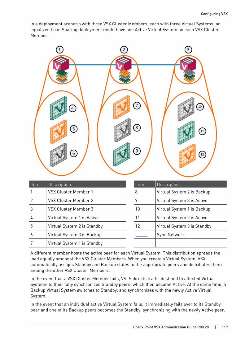
Configuring VSX
Check Point VSX Administration Guide R80.20 | 119
In a deployment scenario with three VSX Cluster Members, each with three Virtual Systems: an equalized Load Sharing deployment might have one Active Virtual System on each VSX Cluster Member.
Item Description Item Description
1 VSX Cluster Member 1 8 Virtual System 2 is Backup
2 VSX Cluster Member 2 9 Virtual System 3 is Active
3 VSX Cluster Member 3 10 Virtual System 1 is Backup
4 Virtual System 1 is Active 11 Virtual System 2 is Active
5 Virtual System 2 is Standby 12 Virtual System 3 is Standby
6 Virtual System 3 is Backup Sync Network
7 Virtual System 1 is Standby
A different member hosts the active peer for each Virtual System. This distribution spreads the load equally amongst the VSX Cluster Members. When you create a Virtual System, VSX automatically assigns Standby and Backup states to the appropriate peers and distributes them among the other VSX Cluster Members.
In the event that a VSX Cluster Member fails, VSLS directs traffic destined to affected Virtual Systems to their fully synchronized Standby peers, which then become Active. At the same time, a Backup Virtual System switches to Standby, and synchronizes with the newly Active Virtual System.
In the event that an individual active Virtual System fails, it immediately fails over to its Standby peer and one of its Backup peers becomes the Standby, synchronizing with the newly Active peer.

Configuring VSX
Check Point VSX Administration Guide R80.20 | 120
Converting from High Availability to VSLS
To convert an existing VSX Cluster from High Availability to VSLS:
1. Close all SmartConsole windows.
2. On each VSX Cluster Member:
a) Run:
cpconfig
b) Enable the Per Virtual System State.
c) Enable ClusterXL for Bridge Active/Standby.
a) Restart the Check Point services:
cpstop ; cpstart
3. On the Management Server:
a) Connect to the command line.
b) Log in to the Expert mode.
c) Run:
vsx_util convert_cluster
d) Enter the IP address of the Security Management Server or Domain Management Server.
e) Enter the Management Server administrator user name and password.
f) Select the VSX Cluster.
g) Enter:
LS
h) At the Proceed with conversion? prompt, enter: y
i) Select an option to distribute Virtual Systems among VSX Cluster Members:
Distribute all Virtual Systems equally.
Set all Virtual Systems as Active on the same VSX Cluster Member.
4. Reboot each VSX Cluster Member.
5. On each VSX Cluster Member:
a) Connect to the command line.
b) Examine the VSX configuration:
vsx state -v
c) Examine the VSX Cluster state and configuration:
cphaprob state
Note - You cannot convert a VSX Cluster to the VSLS mode, if it contains Virtual Systems in the Active/Active Bridge mode or Virtual Routers.
Check Point VSX Administration Guide R80.20 | 121
CHAPTE R 6
Using VSX with Multi-Domain Server In This Section:
Overview ...................................................................................................................... 121
VSX Provisioning ......................................................................................................... 123
Defining Multi-Domain Servers ................................................................................. 124
Working with Virtual Devices ..................................................................................... 125
You can manage a VSX deployment using Multi-Domain Server. This chapter assumes that you are familiar with the Multi-Domain Server product. Only procedures specific to VSX deployments are discussed.
For more about Multi-Domain Server, see the R80.20 Multi-Domain Security Management Administration Guide https://sc1.checkpoint.com/documents/R80.20_GA/WebAdminGuides/EN/CP_R80.20_Multi-DomainSecurityManagement_AdminGuide/html_frameset.htm.
Overview Check Point Multi-Domain Server is a centralized security management solution that addresses the unique requirements of service providers and large enterprises. By using Multi-Domain Server, administrators can centrally manage multiple independent networks, often belonging to different Domains, divisions, or branches.
Item Description
1 SmartConsole
2 Multi-Domain Server
3 Domain Management Server
4 Main Domain Management Server
5 VSX Gateway
6 Virtual Systems in Domain Management Servers
The Multi-Domain Server is a central Management Server that hosts the network management and security policy databases for these networks. Each independent domain is represented by a Domain, which provides the full functionality of a Security Gateway. Each Domain Management Server can host Virtual Systems, Virtual Routers and Virtual Switches as well as physical Check Point Gateways.
The Domain Management Server that manages a VSX Gateway or cluster is known as a Main Domain Management Server. You can host multiple Gateways and/or clusters on one Multi-Domain Server. Virtual Systems belonging to a given Domain can be distributed among multiple VSX Gateways and clusters.

Using VSX with Multi-Domain Server
Check Point VSX Administration Guide R80.20 | 122
When connected to a Multi-Domain Server, SmartConsole offers a centralized management solution for Domains, Domain Management Servers and the Multi-Domain Server environment. Each Domain Management Server uses its own instance of SmartConsole, which is accessible only via the Multi-Domain Server, to provision its Virtual Devices and physical Gateways, as well as to manage their Security Policies.
Using VSX with Multi-Domain Server
Check Point VSX Administration Guide R80.20 | 123
VSX Provisioning The procedures for provisioning and configuring VSX Gateways, clusters and Virtual Devices using the Multi-Domain Server model are essentially the same as described for the Security Gateway management model. The most important difference is that you must first create and configure each Domain and its associated Domain Management Server objects using the SmartConsole connected to a Multi-Domain Server.
Each Domain Management Server is the functional equivalent of one VSX Gateway. You connect to each Domain Management Server with SmartConsole to work with network objects, security policies and other objects for that VSX Gateway.
This is the basic workflow for provisioning a VSX environment in a Multi-Domain Server deployment:
1. Define and configure Multi-Domain Server and Multi-Domain Log Server as applicable for your deployment.
2. Create and configure a Domain and Domain Management Server for each VSX Gateway and/or VSX Cluster.
3. With SmartConsole, connect to the Domain Management Server to create and configure the VSX Gateway (on page 64) and/or VSX Cluster objects (on page 142).
Configure the default security policy for these objects as necessary.
4. Define individual Domains and Domain Management Servers as required for your deployment.
5. Create and configure Virtual Systems (on page 74) and other Virtual Devices for each Domain in the SmartConsole connected to that Domain.
Using VSX with Multi-Domain Server
Check Point VSX Administration Guide R80.20 | 124
Defining Multi-Domain Servers This section briefly presents the procedures for installing and deploying Multi-Domain Server machines in a VSX / Multi-Domain Server environment. See the R80.20 Multi-Domain Security Management Administration Guide https://sc1.checkpoint.com/documents/R80.20_GA/WebAdminGuides/EN/CP_R80.20_Multi-DomainSecurityManagement_AdminGuide/html_frameset.htm for conceptual information and detailed procedures for configuring Multi-Domain Servers and Domain Management Servers.
When working with Management High Availability, define at least two Multi-Domain Server machines. You can also use multiple Multi-Domain Server machines to efficiently distribute management traffic (management Load Sharing) with more than one Domain Management Server for each Domain. For a Load Sharing deployment, define a Domain Management Server for each Multi-Domain Server.

Using VSX with Multi-Domain Server
Check Point VSX Administration Guide R80.20 | 125
Working with Virtual Devices When working with Virtual Devices in Multi-Domain Server, you must use the applicable Domain Management Server SmartConsole. Otherwise, the configuration procedures are the same to those for a Security Management Server. Multi-Domain Server treats Virtual Devices in the same way as physical devices.
You can add as many Virtual Systems to Domain Management Servers as your license permits. Virtual Systems added to a Domain Management Server do not have to reside on the same VSX Gateway or cluster.
Adding a Virtual System to a Domain Management Server
To add a new Virtual System to a Domain Management Server:
1. Launch SmartConsole from the appropriate Domain Management Server.
2. Create and configure the Virtual System (on page 74).
3. Define and install a security policy.
Adding Virtual Routers and Virtual Switches to a Domain Management Server
To add Virtual Routers and Virtual Switches to a Domain Management Server:
1. Launch SmartConsole from the appropriate Domain Management Server.
2. Create and configure Virtual Routers (on page 84) and Virtual Switches (on page 80) as required.
Check Point VSX Administration Guide R80.20 | 126
CHAPTE R 7
Introduction to VSX Clusters In This Section:
VSX Cluster Overview ................................................................................................. 126
Planning a VSX Cluster Deployment .......................................................................... 129
VSX High Availability ................................................................................................... 131
Virtual System Load Sharing (VSLS) .......................................................................... 132
Bridge Mode ................................................................................................................ 138
Using Virtual Switches in a VSX Cluster .................................................................... 141
This chapter presents a conceptual overview of VSX Cluster deployments, with emphasis on clustering features and their application. It assumes you are familiar with network cluster applications and environments, particularly ClusterXL.
The Cluster Management chapter (on page 142) provides detailed configuration procedures, including instructions for enabling and using all VSX Cluster features.
For more about Check Point ClusterXL features and functionality, see the R80.20 ClusterXL Administration Guide https://sc1.checkpoint.com/documents/R80.20_GA/WebAdminGuides/EN/CP_R80.20_ClusterXL_AdminGuide/html_frameset.htm.
VSX Cluster Overview VSX Clusters provide redundancy and load sharing features for Virtual Systems and other Virtual Devices. A VSX Cluster consists of two or more identical, interconnected VSX Gateways that ensure continuous data synchronization.
VSX High Availability ensures continuous operation by means of transparent VSX Cluster Member failover. Virtual System Load Sharing (VSLS) enhances system performance by distributing Active Virtual Systems amongst VSX Cluster Members.
The advantages of using clusters in a VSX environment include:
• Transparent failover in case of VSX Cluster Member or Virtual System failure
• State synchronization ensures zero downtime for mission-critical environments
• Load Sharing maintains system throughput during peak demand
• Enhanced scalability for future traffic growth
Physical Clusters VSX Cluster is based on Check Point ClusterXL concepts. This section reviews these concepts, and then demonstrates how these principles apply to VSX virtualization.
In typical Security Gateway deployment, a cluster consists of two or more identical, interconnected physical Security Gateways that provide redundancy and/or Load Sharing. This cluster behaves as a single Security Gateway and is assigned its own IP address, which is known as its Cluster IP or Virtual IP address. This IP address is distinct from the physical IP addresses of its VSX Cluster Members, which are hidden from the networks connected to the cluster.
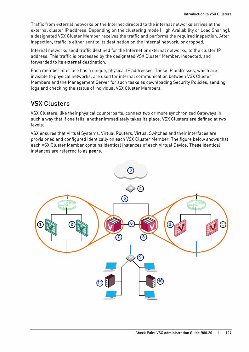
Introduction to VSX Clusters
Check Point VSX Administration Guide R80.20 | 127
Traffic from external networks or the Internet directed to the internal networks arrives at the external cluster IP address. Depending on the clustering mode (High Availability or Load Sharing), a designated VSX Cluster Member receives the traffic and performs the required inspection. After inspection, traffic is either sent to its destination on the internal network, or dropped.
Internal networks send traffic destined for the Internet or external networks, to the cluster IP address. This traffic is processed by the designated VSX Cluster Member, inspected, and forwarded to its external destination.
Each member interface has a unique, physical IP addresses. These IP addresses, which are invisible to physical networks, are used for internal communication between VSX Cluster Members and the Management Server for such tasks as downloading Security Policies, sending logs and checking the status of individual VSX Cluster Members.
VSX Clusters VSX Clusters, like their physical counterparts, connect two or more synchronized Gateways in such a way that if one fails, another immediately takes its place. VSX Clusters are defined at two levels:
VSX ensures that Virtual Systems, Virtual Routers, Virtual Switches and their interfaces are provisioned and configured identically on each VSX Cluster Member. The figure below shows that each VSX Cluster Member contains identical instances of each Virtual Device. These identical instances are referred to as peers.

Introduction to VSX Clusters
Check Point VSX Administration Guide R80.20 | 128
Item Description Item Description
1 Virtual System 2 7 VSX Cluster Member 1
2 Virtual System 1 8 VSX Cluster Member 2
3 Internet 9 VLAN switch
4 Router 10 Network 2
5 External Cluster Interface 11 Network 1
6 Sync VLAN Trunk
VSX provides the management functionality to support network and security virtualization, including:
• Assigning virtual IP addresses: Each Virtual Device interface requires its own virtual IP address.
• State synchronization: Virtual Device state tables are synchronized to peers on other VSX Cluster Members.

Introduction to VSX Clusters
Check Point VSX Administration Guide R80.20 | 129
Planning a VSX Cluster Deployment As with physical network deployments, advance planning is the key to successfully creating a working network. IP address allocation for a VSX deployment requires particular attention. This section takes you through the basics of IP address allocation for a VSX Cluster environment. Your VSX Cluster configuration choices affect the number of IP addresses required, both public and private.
VSX Cluster Architecture VSX IP address allocation is similar to physical networks. Both real and virtual IP addresses are required for network connectivity (internal and external), management, and state synchronization.
VSX simplifies the IP address management task by automatically assigning IP addresses to Warp Links between Virtual Devices. For example, Warp Links between a Virtual Router and its associated Virtual Systems are created automatically and assigned IP addresses without user intervention.
A VSX Cluster network has these components:
• Synchronization Network
• Internal Communications Network
• Virtual IP addresses
Synchronization Network The synchronization network is a physical network that carries state synchronization data between VSX Cluster Members. You configure the synchronization network during the initial VSX Cluster definition and can make changes as necessary when adding or removing VSX Cluster Members.
State Synchronization can be used ClusterXL deployments as well as other OPSEC-certified VSX solutions. The synchronization network must be configured using unique IP addresses that are not used anywhere else in the enterprise network.
Introduction to VSX Clusters
Check Point VSX Administration Guide R80.20 | 130
Internal Communication Network The internal communication network is a virtual network that is required for ClusterXL environments, in addition to the synchronization network. The internal communication network is invisible to external networks and lets VSX Cluster Members communicate and recognize the state of the environment.
VSX assigns an IP address to the internal communication network during the cluster creation process. This eliminates the need to manually assign an IP address to each VSX Cluster Member:
IPv4 address: 192.168.196.0, netmask: 255.255.252.0 (A range of four class C networks).
IPv6 address and netmask: FD9A::1FFE:0:0:0/80
You can modify the default IP address using the Gateway Cluster Properties > Cluster Members page of the VSX Cluster object, but only before creating Virtual Systems. Once Virtual Systems have been created, the IP range of the internal communication network cannot be modified.
Note: To avoid overlapping IP addresses, before creating any Virtual Devices, make sure the default IP address range of the Internal Communication network is not used anywhere else in the external network.
Virtual IP Addresses Cluster (virtual) IP addresses are the only IP addresses visible to the external network. The assigned cluster IP addresses must correspond to the directly-connected subnet and server as a valid next hop address. These IP addresses are similar to virtual addresses configured across traditional cluster setups.
Introduction to VSX Clusters
Check Point VSX Administration Guide R80.20 | 131
VSX High Availability This section describes VSX High Availability features. In a VSX environment, you can work with one of two High Availability scenarios:
In VSX Gateway High Availability, each VSX Cluster Member functions as a VSX Gateway and is synchronized with the other VSX Cluster Members. If one member goes down, it immediately fails over to another member. Likewise, if an individual Virtual System, Virtual Router or Virtual Switch goes down, the entire VSX Cluster Member fails over to another member. All VSX Cluster Members and Virtual Systems function in an Active/Standby mode and are continuously synchronized.
VSX Gateway High Availability VSX Gateway High Availability is the default cluster configuration. All VSX Cluster Members of a VSX Cluster must be configured to use the same clustering mode.
Introduction to VSX Clusters
Check Point VSX Administration Guide R80.20 | 132
Virtual System Load Sharing (VSLS) Virtual System Load Sharing is a cluster technology that assigns traffic for Virtual Systems to different Active VSX Cluster Members, which has these benefits:
• Capacity: VSLS leverages the cluster machines to handle greater network volume by efficiently dividing the load.
• Redundancy: VSLS gives full redundancy by maintaining connectivity for all Virtual Systems even when individual VSX Cluster Members fail.
• Scalability: VSLS provides linear scalability for throughput and session rate.
• Cost Effectiveness: A VSLS cluster uses standard network switches to achieve cost effective Load Sharing.
• Ease of Configuration: Virtual Systems are automatically distributed among all the VSX Cluster Members - no special configuration is required.
• Priority Designation: Mission-critical Virtual Systems can be separated from the other Virtual Systems, providing advantages in terms of bandwidth and resources.
• System Scalability: Every VSX Cluster Member added to the cluster increases the overall system capacity and redundancy.
Note - These Virtual Devices are not supported when the Per Virtual System state is enabled:
- Virtual Routers
- Virtual Switches without physical or VLAN interfaces
Requirements All Virtual Systems in all VSX Cluster Members must have direct connectivity with each other. Connectivity must be accomplished using switches or VLAN connections. This is required for detecting and assigning Virtual System states.
Note - VSLS does not support Virtual Routers.

Introduction to VSX Clusters
Check Point VSX Administration Guide R80.20 | 133
Conceptual Overview This section presents a detailed conceptual overview of Virtual System Load Sharing.
Introduction Virtual System Load Sharing is a cluster technology that assigns traffic for Virtual Systems to different Active VSX Cluster Members. This methodology is different from physical cluster load sharing, because it is not connection-based. Virtual System Load Sharing is useful for mission-critical deployments, where reserving bandwidth for a particular Virtual System is a priority.
VSLS lets administrators manually assign Virtual Systems to specified VSX Cluster Members, or lets VSX automatically assign Virtual System traffic dynamically.
Note - You cannot configure a VSX Cluster in the Load Sharing mode if it contains Virtual Routers.
Virtual System Priority Virtual System priority refers to a preference regarding which member hosts a Virtual System's Active, Standby, and Backup states. This preference is expressed as an integer value.
Priority Definition
0 Highest priority, indicating the cluster designated to host the Virtual System Active state.
1 Second highest priority, indicating the member designated to host the Virtual System Standby state.
> 1 Lower priorities, indicating the VSX Cluster Members designated to host a Virtual System Backup state.
The VSX Cluster Member assigned priority 2 will be the first to switch the Virtual System to the Standby state in the event of a failure of either the Active or Standby Virtual System.
A VSX Cluster Member assigned priority 3 would be the next in line to come online in the event of another failure.
You can change the priority designation (on page 162) with the vsx_util vsls command on the Management Server.
Virtual System Weight Since all Virtual Systems are not equal in terms of traffic and load, VSLS allows you to assign "weights" to individual Virtual Systems. The weight of a Virtual System affects the dispersal pattern of other Virtual Systems across VSX Cluster Members. Assigning a heavier weight to a Virtual System gives it a larger share of a particular member's resources, and accordingly, disperses the other Virtual Systems to other VSX Cluster Members.
By default, all Virtual Systems are assigned an equal weight factor of 10. You can change the weight factor (on page 162) with the vsx_util vsls command on the Management Server.

Introduction to VSX Clusters
Check Point VSX Administration Guide R80.20 | 134
Virtual System States VSLS adds a Backup state to the existing Active and Standby states. The Backup state contains the latest configuration settings for each Virtual System, but does not receive state table synchronization. The figure below illustrates the relationship between Virtual System states.
Item Description
1 VSX Cluster
2 Virtual System 1 on VSX Cluster Member 1 is Active
3 Virtual System 1 on VSX Cluster Member 2 is Standby
4 Virtual System 1 on VSX Cluster Member 3 is Backup
5 Policy updates only
6 State tables are synchronized
Each Virtual System peer in a VSLS cluster is replicated on all VSX Cluster Members, and each copy exists in a different state. The Active and Standby states are synchronized, so that the Standby peer can immediately become Active in the event of a failure of the Active Virtual System or VSX Cluster Member. When this happens, the Backup peer becomes the Standby, and immediately synchronizes with the new Active Virtual System.
VSLS reduces the load on the synchronization network by not synchronizing the Backup Virtual System state tables with the Active Virtual System until a failover occurs.

Introduction to VSX Clusters
Check Point VSX Administration Guide R80.20 | 135
Normalized VSLS Deployment Scenario For example, you can have three VSX Cluster Members, each with three Virtual Systems. In this configuration, an equalized Load Sharing deployment could have one Active Virtual System on each VSX Cluster Member.
Item Description Item Description
1 VSX Cluster Member 1 8 Virtual System 2 is Backup
2 VSX Cluster Member 2 9 Virtual System 3 is Active
3 VSX Cluster Member 3 10 Virtual System 1 is Backup
4 Virtual System 1 is Active 11 Virtual System 2 is Active
5 Virtual System 2 is Standby 12 Virtual System 3 is Standby
6 Virtual System 3 is Backup Sync Network
7 Virtual System 1 is Standby
A different VSX Cluster Member can host the Active state of each Virtual System. This distribution of Virtual Systems spreads the load among the VSX Cluster Members. When a Virtual System is created, the system automatically creates Standby and Backup states and distributes them among the other VSX Cluster Members.

Introduction to VSX Clusters
Check Point VSX Administration Guide R80.20 | 136
Member Failure Scenario In the event that a member fails or experiences a connectivity problem, VSLS detects the problem and routes traffic for the affected Virtual Systems to their respective standby Virtual Systems. Standby Virtual Systems, which are fully synchronized with their active peers, change immediately to the active state and preserve active connections. At the same time, the backup Virtual Systems switch to standby, and synchronize fully with the newly active Virtual Systems.
Item Description Item Description
1 VSX Cluster Member 1 8 Virtual System 2 is Standby
2 VSX Cluster Member 2 9 Virtual System 3 is Active
3 VSX Cluster Member 3 10 Virtual System 1 is Standby
4 Virtual System 1 is Down 11 Virtual System 2 is Active
5 Virtual System 2 is Down 12 Virtual System 3 is Standby
6 Virtual System 3 is Down Sync Network
7 Virtual System 1 is Active Network Traffic
In this scenario, VSX Cluster Member 1 fails and its Active and Standby Virtual Systems fail over to VSX Cluster Member 2 and VSX Cluster Member 3. The Active Virtual System (VS1) moves to VSX Cluster Member 2 and directs all VS1 traffic itself. Its Backup peer on VSX Cluster Member 3 synchronizes with the new Active Virtual System and becomes the Standby.

Introduction to VSX Clusters
Check Point VSX Administration Guide R80.20 | 137
VS2 on VSX Cluster Member 2 becomes the Standby and synchronizes with the Active peer on VSX Cluster Member 3. For VS3, the Active and Standby peers remain the same.
Virtual System Failure Scenario In a failure scenario where an active Virtual System fails on one member, but the standby and backup Virtual Systems remain up: the active Virtual System fails over to its standby peer, and its backup becomes the standby. The new standby synchronizes with the new active member.
Item Description Item Description
1 Member 1 8 VS 2 Backup
2 Member 2 9 VS 3 Active
3 Member 3 10 VS 1 Standby
4 VS 1 Down 11 VS 2 Active
5 VS 2 Standby 12 VS 3 Standby
6 VS 3 Backup Sync Network
7 VS 1 Active
All other Virtual Systems continue to function normally and no failover occurs.
Failure Recovery When the failed VSX Cluster Member or Virtual System comes back online, the system returns to its original Load Sharing configuration.

Introduction to VSX Clusters
Check Point VSX Administration Guide R80.20 | 138
Bridge Mode By implementing native layer-2 bridging instead of IP routing, you can add Virtual Systems without adversely affecting the existing IP structure.
When in the Bridge mode, Virtual System interfaces do not require IP addresses. You can optionally assign an IP address to the Virtual System itself (not the interfaces) to enable layer-3 monitoring, which provides network fault detection functionality.
VSX supports these Bridge mode models:
• Active/Active (STP) Bridge Mode: Provides redundancy while preventing undesirable loops between redundant switches.
• Active/Standby Bridge Mode: Provides path redundancy and loop prevention, while offering seamless support for Virtual System Load Sharing and overcoming many of the limitations of STP.
Spanning Tree Protocol (STP) Bridge Mode The Spanning Tree Protocol is an industry standard technology to prevent loops in high-speed switched networks. To use the STP Bridge mode, you must have STP deployed and properly configured on your network. These STP layer-2 protocols are supported:
• 802.1q
• 802.1D
• 802.1s
• 802.1w
• PVST+
See your vendor documentation to learn how to deploy and configure STP on your network hardware.
Active/Standby Bridge Mode The Active/Standby Bridge Mode enhances both:
• High Availability (for significant improvements).
• Virtual System Load Sharing (VSLS) in VSX Cluster environments (for throughput distributed among Virtual Systems).
Active/Standby Bridge Mode has these advantages:
• Instantaneous failover.
• Enhanced administrator control over bridge failover.
• VSLS support.
• VLAN translation.
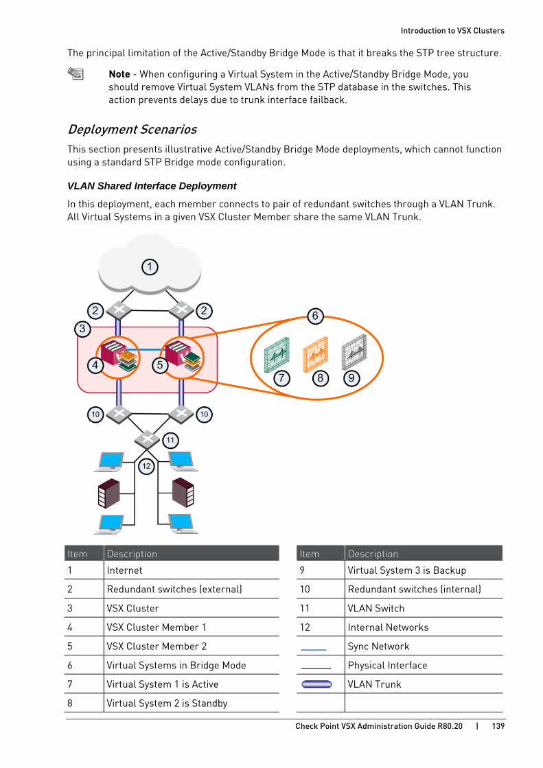
Introduction to VSX Clusters
Check Point VSX Administration Guide R80.20 | 139
The principal limitation of the Active/Standby Bridge Mode is that it breaks the STP tree structure.
Note - When configuring a Virtual System in the Active/Standby Bridge Mode, you should remove Virtual System VLANs from the STP database in the switches. This action prevents delays due to trunk interface failback.
Deployment Scenarios This section presents illustrative Active/Standby Bridge Mode deployments, which cannot function using a standard STP Bridge mode configuration.
VLAN Shared Interface Deployment
In this deployment, each member connects to pair of redundant switches through a VLAN Trunk. All Virtual Systems in a given VSX Cluster Member share the same VLAN Trunk.
Item Description Item Description
1 Internet 9 Virtual System 3 is Backup
2 Redundant switches (external) 10 Redundant switches (internal)
3 VSX Cluster 11 VLAN Switch
4 VSX Cluster Member 1 12 Internal Networks
5 VSX Cluster Member 2 Sync Network
6 Virtual Systems in Bridge Mode Physical Interface
7 Virtual System 1 is Active VLAN Trunk
8 Virtual System 2 is Standby
Introduction to VSX Clusters
Check Point VSX Administration Guide R80.20 | 140
With Active/Standby Bridge Mode in High Availability mode, VSX Cluster directs traffic to VSX Cluster Members according to administrator-defined priorities and status.
In Virtual System Load Sharing deployments, the system distributes the traffic load amongst VSX Cluster Members according to the Virtual System Load Sharing configuration.
Three Layer Hierarchical Model A three-layer hierarchical model is used in large, high-traffic network environments.
1. A core network, with high-speed backbone switches that direct traffic to and from the Internet and other external networks.
2. A distribution layer, with routers, for connectivity between the core and the access layer.
3. An access layer, with redundant LAN switches, that forward traffic to and from internal networks.
VSX in Active/Standby Bridge Mode is incorporated in the distribution layer, enforcing the security policy.
The routers direct external traffic to the appropriate Virtual System through a segregated VLAN. Inspected traffic exits the Virtual System through a separate segregated VLAN, to the routers and then to internal destinations.

Introduction to VSX Clusters
Check Point VSX Administration Guide R80.20 | 141
Using Virtual Switches in a VSX Cluster In a VSX Cluster, Virtual Switches are also clustered for redundancy and are defined as Active/Active.
By means of the ClusterXL Control Protocol (CCP), the physical interface connected to the Virtual Switch is monitored. In the event of a failover, all Virtual Systems on Standby become Active, and send Gratuitous ARP Requests from the warp interface between the Virtual System and the Virtual Switch.
Item Description
1 Active VSX Cluster Member
2 Standby VSX Cluster Member
3 Virtual Switch Cluster
4 Active Virtual Switch
5 Virtual System 1
Physical Link
Warp Link
In the above figure, a simplified VSX Cluster contains two VSX Cluster Members, one Active, and the other Standby. The Virtual Switches within each VSX Cluster are Active/Active. When the physical interface connected to either Virtual Switch fails to respond, a failover occurs.
Check Point VSX Administration Guide R80.20 | 142
CHAPTE R 8
Working with VSX Clusters In This Section:
Configuration Overview .............................................................................................. 142
Creating VSX Clusters ................................................................................................ 142
Modifying a Cluster Definition .................................................................................... 146
Working with VSX Cluster Members .......................................................................... 152
Changing the VSX Cluster Type.................................................................................. 155
Enabling VSX Gateway High Availability .................................................................... 159
Configuring Virtual System Load Sharing ................................................................. 160
Configuring Virtual Systems in Bridge Mode ............................................................ 168
Advanced Clustering Configuration ........................................................................... 173
Configuration Overview You use SmartConsole for most of the basic cluster configurations. Many cluster management procedures require the command line. For example, you need the CLI to change the VSX Cluster definitions.
Creating VSX Clusters
Creating a New VSX Cluster This section describes how to create a new VSX Cluster using the VSX Cluster Wizard. The wizard guides you through the steps to configure a VSX Cluster.
After completing the VSX Cluster Wizard, you can modify most VSX Cluster and VSX Cluster Member properties directly from SmartConsole.
To create a new VSX Cluster:
1. Connect with SmartConsole to the Security Management Server or Main Domain Management Server used to manage the VSX Cluster.
2. From the left navigation panel, click Gateways & Servers.
3. At the top, click Objects menu > More object types > Network Object > Gateways and Servers > VSX > New Cluster.
The VSX Cluster Wizard > General Properties opens.
Working with VSX Clusters
Check Point VSX Administration Guide R80.20 | 143
Defining Cluster General Properties The Cluster General Properties page contains basic properties for VSX Clusters:
• VSX Cluster Name: Unique, alphanumeric name for the cluster. The name cannot contain spaces or special characters except the underscore.
• VSX Cluster IPv4 Address: IPv4 address of the cluster.
• VSX Cluster IPv6 Address: IPv6 address of the cluster.
• VSX Cluster Version: VSX version to use for this cluster.
• VSX Cluster Platform: Platform type hosting the VSX Cluster Members:
• To create a High Availability cluster, select ClusterXL.
• To create a Load Sharing (VSLS) cluster, select ClusterXL Virtual System Load Sharing.
Note - All VSX Cluster Members must use the same type of platform, with the same specifications and configuration.
Selecting Virtual Systems Creation Templates The Virtual Systems Creation Templates allows you to select a Virtual System Creation Template that automatically applies predefined, default topology and routing definitions to Virtual Systems when they are first created. This feature ensures consistency among Virtual Systems and speeds up the provisioning process.
You always have the option of overriding the default creation template when creating or modifying a Virtual System
The available creation templates are as follows:
• Shared Interface: All Virtual Systems share a single external interface, but maintain separate internal interfaces.
• Separate Interfaces: All Virtual Systems use their own separate internal and external interfaces. This template creates a Dedicated Management Interface (DMI) by default.
• Custom Configuration: You manually create a custom configuration without any template.
Adding VSX Cluster Member The VSX Cluster Members window defines the members of the new cluster. You must define at least two VSX Cluster Members. You can add more members later.
To add a new VSX Cluster Member:
1. In the VSX Cluster Members window, click Add.
2. The Member Properties window opens.
3. Enter the name and IP addresses for the VSX Cluster Member.
Note: If you define an IPv6 IP address, you must also have an IPv4 address.
4. Enter and confirm the Activation Key to initialize SIC trust between the VSX Cluster Member and the Management Server.
Note - You defined this Activation Key during the First Time Configuration Wizard of the VSX Cluster Member.
5. Follow these steps for all VSX Cluster Members.
6. Click Next to continue.

Working with VSX Clusters
Check Point VSX Administration Guide R80.20 | 144
Defining Cluster Interfaces The VSX Cluster Interfaces window lets you define physical interfaces as VLAN Trunks.
The list shows all interfaces currently defined on the VSX Gateway or VSX Cluster object.
To configure a VLAN Trunk:
Select one or more interfaces to define them as VLAN Trunks. You can clear an interface to remove the VLAN Trunk assignment.
Important - You cannot define the management interface as a VLAN trunk. To use the management interface as a VLAN, you must define the VLAN on the VSX Gateway before you use SmartConsole to create the VSX Gateway object.
Configuring VSX Cluster Members If you selected the custom configuration option, the VSX Cluster Members window appears.
In this window, you define the synchronization IP address for each VSX Cluster Member.
To configure the VSX Cluster Members:
1. Select the synchronization interface from the list.
2. Enter the synchronization interface addresses and net mask for each VSX Cluster Member.
To use a VLAN as a synchronization interface:
1. On each VSX Cluster Member, define the VLAN interface on the applicable physical interface.
2. In SmartConsole, create the VSX Cluster object.
3. On each VSX Cluster Member, add this line to the $FWDIR/boot/modules/fwken.conf (on page 318) file: fwha_monitor_all_vlan=1
Cluster Management The VSX Gateway Management page allows you to define several security policy rules that protect the cluster itself. This policy is installed automatically on the new VSX Cluster.
Note - This policy applies only to traffic destined for the cluster. Traffic destined for Virtual Systems, other Virtual Devices, external networks, and internal networks is not affected by this policy.
The security policy consists of predefined rules covering the following services:
• UDP: SNMP requests
• TCP: SSH traffic
• ICMP: Echo-request (ping)
• TCP: HTTPS (secure HTTP) traffic

Working with VSX Clusters
Check Point VSX Administration Guide R80.20 | 145
Configuring the Cluster Security Policy 1. Allow: Enable a rule to allow traffic for those services for which you wish to allow traffic. Clear
a rule to block traffic. By default, all services are blocked.
For example, you may wish to allow UDP echo-request traffic in order to be able to ping VSX Cluster Member from the Management Server.
2. Source: Click the arrow and select a Source Object from the list. The default value is *Any.
Click New Source Object to define a new source.
For more about Security Policies, see the R80.20 Security Management Administration Guide https://sc1.checkpoint.com/documents/R80.20_GA/WebAdminGuides/EN/CP_R80.20_SecurityManagement_AdminGuide/html_frameset.htm.
Completing the Wizard
To complete the VSX Cluster Wizard:
1. Click Next to continue and then click Finish to complete the VSX Cluster wizard.
It can take several minutes to complete. A message appears indicating successful or unsuccessful completion of the process.
If the process ends unsuccessfully, click View Report to view the error messages. Refer to the troubleshooting steps (on page 210) for more information
2. In SmartConsole, double-click the new VSX Cluster object.

Working with VSX Clusters
Check Point VSX Administration Guide R80.20 | 146
Modifying a Cluster Definition After you create a cluster with the wizard, you can change the topology and other parameters in the Cluster Members Properties window. This window lets you configure many advanced features not available with the wizard.
To work with a VSX Cluster definition, double-click a cluster object in SmartConsole. The VSX Cluster Properties window opens.
You can define most cluster objects with SmartConsole. There are some features or properties that you must CLI commands to configure.
A brief explanation for each of the definition pages follows. More detailed explanations for features that are not specific to VSX (NAT, IPS, VPN, etc.) are available in the online help or in the applicable product documentation.
General Properties See the General Properties page to view general properties and to activate Software Blades for use with this VSX Cluster.
You can modify the following properties:
• Comment: Free text comment that appears in the Object List and elsewhere
• Color: Color of the object icon as it appears in SmartConsole
• Network Security: Select Software Blades on this VSX Cluster and its Cluster Members
VSX Cluster Members The Cluster Members page lets you view and modify several properties for individual VSX Cluster Members, including IP addresses for Cluster Members and the Internal Communication Network.
Gateway VSX Cluster Member List The Cluster Members page shows all the VSX Cluster Members.
To edit a VSX Cluster Member:
From the Cluster Member page, select a VSX Cluster Member and click Edit.
The Cluster Member Properties window opens. These are the settings that you can edit:
• General tab:
• Comment: Free text comment that appears in the Object List and elsewhere
• Color: Color of the object icon as it appears in SmartConsole
• Secure Internal Communication: Check and reset SIC trust
• Topology tab: Displays the Cluster Member IP address and Net Mask for each interface. Double-click an interface to see its properties.
• NAT tab: Define NAT rules for VSX Cluster Members connected to a Virtual Router.
• VPN tab: Contains a variety of configuration properties for Site-To-Site VPN deployments.
This window is only available if the IPsec VPN is enabled on the General Properties page.

Working with VSX Clusters
Check Point VSX Administration Guide R80.20 | 147
For more about VPN concepts and configurations, see the R80.20 Site to Site VPN Administration Guide. https://sc1.checkpoint.com/documents/R80.20_GA/WebAdminGuides/EN/CP_R80.20_SitetoSiteVPN_AdminGuide/html_frameset.htm
Where Used Click Where used to show information about the selected member in the objects database.
• Name: Cluster name.
• Table: Name of the table in the database under which the selected object is listed.
• Is removable: Specifies whether or not you are allowed to remove the selected object. If the object is not removable and nevertheless you choose to remove it, it will impact the database or Rule Base.
• Refresh: Click to update the window display if you make changes.
• Context: Where the object is used.
Internal IP Address and Net Mask VSX creates an internal communication network and automatically assigns it an IP address and net mask from a predefined pool. You can change this IP address here if you have not yet defined a Virtual System. Although traffic from this address is never sent to any networks, you must ensure that this IP address is unique and not in use anywhere on your defined network.
ClusterXL To manage state synchronization, open the ClusterXL window, or run the vsx_util command on the Management Server.
• Enable or disable state synchronization.
• Select tracking options for VSX Cluster Member state changes.
All other ClusterXL configuration properties are disabled.
Creation Templates The Creation Templates page displays the creation template used to create Virtual Systems. You can change from the current creation template to the Custom Configuration template and change the shared physical interface if the Shared Interface template is active.
• Select the Custom Configuration option to change from the Shared Interfaces or Separate Interfaces templates.
You cannot change back from the Custom Configuration template once you have completed the definition and saved it to the configuration to cluster.
• To change the shared interface, click Settings and select an interface from the list that appears.
Working with VSX Clusters
Check Point VSX Administration Guide R80.20 | 148
Physical Interfaces The Physical Interfaces page allows you to add or delete a physical interface on the VSX Gateway, and to define interfaces to be used as VLAN trunks.
• To add a new physical interface, click Add and enter the interface name in the appropriate field.
• To define an interface as a VLAN trunk, select the desired interface and enable the VLAN Trunk option. To disable a VLAN trunk, clear the option.
Synchronization The Synchronization window displays the state synchronization network. There are no configurable properties.
Topology On the Topology page, you can see and configure interface and routing definitions.
Interfaces The Interfaces section defines interfaces and links to devices. You can add new interfaces as well as delete and modify existing interfaces.
To add an interface:
1. Click New and select one of these options:
• Regular - Create a new interface
• State Synchronization
• Leads to Virtual Router
• Leads to Virtual Switch
The Interface Properties window opens.
Click Actions > Copy to Clipboard to copy the Interfaces table in CSV format.
2. Define the appropriate properties (on page 91).
3. Click OK.
To change an interface:
1. Double-click an interface.
The Interface Properties window opens.
2. Change the parameters for the interface (on page 91).
3. Click OK.
To delete an interface:
1. From the Topology page, select the interface and click Delete.
2. Click OK.
Working with VSX Clusters
Check Point VSX Administration Guide R80.20 | 149
Routes The Routes section of the Topology window defines routes between network devices, network addresses, and Virtual Devices. Some routes are defined automatically based on the interface definitions. You can add, change, and delete routes.
To add a default route to the routing table:
1. Click Add Default Route.
The Default Gateway window opens.
2. Enter the default route IP address or select the default Virtual Router.
3. Click OK.
The default route is added to the routing table.
4. Select the default route and click Edit. The Route Configuration window opens.
5. Configure the settings for the default route and click OK.
To add a new route to the routing table:
1. Click Add.
The Route Configuration window opens.
2. Configure the Destination IP address and netmask.
3. Configure the next hop IP address or Virtual Router.
4. Optional: Select Propagate route to adjacent Virtual Devices to "advertise" the route to neighboring Virtual Devices, and enable connectivity between them.
5. Click OK.
To change a route:
1. Select the route.
2. Click Edit. The Route Configuration window opens.
3. Change the settings.
4. Click OK.
To delete a route:
1. Select the route.
2. Click Remove.
A confirmation window opens.
3. Click OK.
Working with VSX Clusters
Check Point VSX Administration Guide R80.20 | 150
Calculating Topology Automatically Based on Routing Information Enable this option to allow VSX to automatically calculate the network topology based on interface and routing definitions (enabled by default). VSX creates automatic links, or connectivity cloud objects linked to existing internal or external networks.
• This option is not available in Bridge mode.
• When employing dynamic routing, it is recommended to disable this option.
VPN Domain The VPN Domain section in the Topology page defines the set of hosts that use a VPN tunnel to communicate with peer Virtual Systems.
Define a VPN Domain to include a Virtual Device as part of the VPN connection. The domain defines the Virtual System interfaces that are in the VPN. You can define a VPN Domain in different ways:
• All IP Addresses behind Cluster Members are based on topology information: Includes all hosts not located behind an external gateway cluster interface.
• Manually Defined: Includes all hosts in the selected network or group.
• Remote Access Communities: Define an alternative VPN domain for Remote Access Community traffic.
To specify the VPN domain:
1. Click Set domain for Remote Access Community.
The VPN Domain per Remote Access Community window opens.
2. Double-click a Remote Access Community.
The Set VPN Domain window opens.
3. Select a VPN domain from the list, or click New, to define a new domain.
4. Click OK.
Working with VSX Clusters
Check Point VSX Administration Guide R80.20 | 151
NAT The NAT > Advanced page lets you configure NAT rules for packets originating from a Virtual System.
To enable and configure NAT for a Virtual System:
1. Select Add Automatic Address Translation.
2. Select a translation method:
• Hide: Hide NAT only allows connections originating from the internal network. Internal hosts can access internal destinations, the Internet and other external networks. External sources cannot initiate a connection to internal network addresses.
• Static: Static NAT translates each private address to a corresponding public address.
3. If you select Hide, select one of these options:
• Hide behind Gateway hides the real IP address behind the Virtual System external interface IP address,
or
• Hide behind IP Address hides the real address behind a virtual IP address, which is a routable, public IP address that does not belongs to any real machine.
4. If you selected Static NAT, enter the static IP address in the appropriate field.
5. Select the VSX Gateway from the Install on Gateway list.
VSX Bridge Configuration The VSX Bridge Configuration page allows you to specify the loop detection algorithm when working in the Bridge mode.
Enable the Check Point ClusterXL option to enable the Active/Standby Bridge Mode loop detection algorithms contained in ClusterXL.
Enable the Standard Layer-2 Loop Detection Protocols to use standard loop detection protocols, such as STP or PVST+.
Changing the Cluster Management IP and/or Subnet To add, change or delete the cluster management IP address and/or subnet, run the vsx_util change_mgmt_ip (on page 245) and vsx_util change_mgmt_subnet (on page 246) commands on the Management Server.
Changing the Internal Communication Network IP You can change the internal communication network IP address by using the vsx_util change_private_net (on page 247) command on the Management Server.

Working with VSX Clusters
Check Point VSX Administration Guide R80.20 | 152
Working with VSX Cluster Members This section presents procedures for adding and deleting VSX Cluster Members.
Adding a New Member Important - Make sure that no other administrators are connected to the Management Server before you perform this procedure. The vsx_util command cannot modify the management database, if the database is locked because other administrators are connected.
To add a new VSX Cluster Member to an existing VSX Cluster:
1. Close all SmartConsole windows.
2. Create a full backup of the environment (see sk100395 http://supportcontent.checkpoint.com/solutions?id=sk100395).
3. Connect to the command line on the Management Server.
4. Log in the Expert mode.
5. Run the vsx_util add_member command and follow the on-screen instructions:
a) Enter the IP address of the Security Management Server or Main Domain Management Server.
b) Enter the Management Server administrator user name and password.
c) Follow the on-screen instructions.
6. Wait until the add member operation finished successfully message appears, indicating that the database has been successfully updated and saved.
Note - In a Multi-Domain Server environment, this operation skips all Domain Management Servers locked by an administrator. If this should occur, run the command again for the affected Domain Management Servers once they become available.
7. Connect with SmartConsole to the Security Management Server or Main Domain Management Server used to manage the VSX Cluster.
8. From the Gateways & Servers view or Object Explorer, double-click the VSX Cluster object.
9. From the left tree, click Cluster Members.
10. Make sure you see an object representing the new VSX Cluster Member.
11. If necessary, modify the VSX Cluster object configuration and click OK.
12. Close all SmartConsole windows.
13. Connect to the command line on the Management Server.
14. Log in the Expert mode.
15. Run the vsx_util add_member_reconf command and follow the on-screen instructions.
16. Wait until the Reconfigure module operation completed successfully summary notice appears.
Note - In a Multi-Domain Server environment, the operation skips all Domain Management Servers locked by an administrator. If this should occur, run the command again for the affected Domain Management Servers when they become available.
17. Reboot the new VSX Cluster Member.
18. Connect to the command line on each VSX Cluster Member.

Working with VSX Clusters
Check Point VSX Administration Guide R80.20 | 153
19. Examine the VSX Cluster configuration: cphaprob state
20. If the VSX Cluster runs in the VSLS mode:
a) Connect to the command line on the Management Server.
b) Log in the Expert mode.
c) Redistribute Virtual Systems to the newly added VSX Cluster Member:
vsx_util vsls
d) Connect to the command line on each VSX Cluster Member.
e) Examine the VSX Cluster configuration:
cphaprob state
Deleting a Member Important - Make sure that no other administrators are connected to the Management Server before you perform this procedure. The vsx_util command cannot modify the management database if the database is locked.
To remove a VSX Cluster Member from a VSX Cluster:
1. Close all SmartConsole windows.
2. Create a full backup of the environment (see sk100395 http://supportcontent.checkpoint.com/solutions?id=sk100395).
3. Detach the license from the VSX Cluster Member to be removed. Otherwise, you cannot remove a VSX Cluster Member.
4. Close all SmartConsole windows.
5. Connect to the command line on the Management Server.
6. Log in the Expert mode.
7. Run the vsx_util remove_member command and follow the on-screen instructions:
a) Enter the IP address of the Security Management Server or Main Domain Management Server.
b) Enter the Management Server administrator user name and password.
c) Type 'y' to confirm that you have detached the license from the VSX Cluster Member.
d) Select the VSX Cluster.
e) Select the VSX Cluster Member.
f) Type 'y' to confirm that the VSX Cluster Member to be removed is disconnected.
8. Wait until the remove member operation finished successfully message appears.
Note - In a Multi-Domain Server environment, this operation skips all Domain Management Servers locked by an administrator. If this should occur, run the command again for the affected Domain Management Servers once they become available.
The management database is now updated and saved.
In SmartConsole, the object for the deleted VSX Cluster Member no longer appears in the specified VSX Cluster object.

Working with VSX Clusters
Check Point VSX Administration Guide R80.20 | 154
9. Connect with SmartConsole to the Security Management Server or Main Domain Management Server used to manage the VSX Cluster.
10. From the Gateways & Servers view or Object Explorer, double-click the VSX Cluster object.
11. From the left tree, click Cluster Members.
12. Make sure you do not see an object representing the removed VSX Cluster Member.

Working with VSX Clusters
Check Point VSX Administration Guide R80.20 | 155
Changing the VSX Cluster Type This section presents procedures for converting VSX Cluster between High Availability and VSLS.
Changing the VSX Cluster mode involves the use of the vsx_util convert_cluster command on the Management Server.
Converting from VSLS to High Availability Do these procedures to convert a VSX Cluster from VSLS to High Availability:
1. Redistribute all Active Virtual Systems to one VSX Cluster Member
2. Disable the VSLS options
3. Convert the VSX Cluster to High Availability
Redistributing Active Virtual Systems to One VSX Cluster Member
To redistribute all active Virtual Systems to one VSX Cluster Member:
1. Close all SmartConsole windows.
2. Connect to the command line on the Management Server.
3. Log in to the Expert mode.
4. Run: vsx_util vsls
5. Enter the IP address for the Security Management Server or Domain Management Server.
6. Enter the Management Server administrator user name and password.
7. Select the VSX Cluster.
8. From the Load Sharing menu, enter 3. Set all VSs active on one member.
9. Enter the number of the VSX Cluster Member that is hosting the Active Virtual Systems.
10. Enter Y to save and apply the configuration.
11. Exit the Load Sharing menu.
When the vsx_util convert_cluster command finishes, there should be only one Active VSX Cluster Member, on which all Virtual Systems are in the Active state, and one Standby VSX Cluster Member, on which all Virtual Systems are in the Standby state. Any additional VSX Cluster Members should be in Standby state, and their Virtual Systems in the Down state.
Working with VSX Clusters
Check Point VSX Administration Guide R80.20 | 156
Disabling VSLS Options
To convert existing VSX Cluster Members to the VSX High Availability mode:
Perform these steps on each VSX Cluster Member:
1. Connect to the command line.
2. Log in to the Expert mode.
3. Run: cpconfig
4. Disable the Per Virtual System State.
5. Disable the ClusterXL for Bridge Active/Standby.
6. Restart the Check Point services (this can cause cluster failover): cpstop ; cpstart
Converting the Cluster
To convert the VSX Cluster to High Availability:
1. Connect to the command line on the Management Server.
2. Log in to the Expert mode.
3. Run: vsx_util convert_cluster
4. Enter the IP address for the Security Management Server or Main Domain Management Server used to manage this VSX Cluster.
5. Enter the Management Server administrator user name and password.
6. From the Load Sharing menu, enter 3. Set all VSs active on one member.
7. Select the VSX Cluster.
8. Enter: HA
9. Reboot each VSX Cluster Members (this can cause cluster failover).
10. On each VSX Cluster Member:
a) Connect to the command line.
b) Examine the VSX configuration:
vsx state -v
c) Examine the VSX Cluster state and configuration:
cphaprob state
Working with VSX Clusters
Check Point VSX Administration Guide R80.20 | 157
Converting from High Availability to VSLS
To convert an existing VSX Cluster from High Availability to VSLS:
1. Close all SmartConsole windows.
2. On each VSX Cluster Member:
a) Run:
cpconfig
b) Enable the Per Virtual System State.
c) Enable ClusterXL for Bridge Active/Standby.
a) Restart the Check Point services:
cpstop ; cpstart
3. On the Management Server:
a) Connect to the command line.
b) Log in to the Expert mode.
c) Run:
vsx_util convert_cluster
d) Enter the IP address of the Security Management Server or Domain Management Server.
e) Enter the Management Server administrator user name and password.
f) Select the VSX Cluster.
g) Enter:
LS
h) At the Proceed with conversion? prompt, enter: y
i) Select an option to distribute Virtual Systems among VSX Cluster Members:
Distribute all Virtual Systems equally.
Set all Virtual Systems as Active on the same VSX Cluster Member.
4. Reboot each VSX Cluster Member.
5. On each VSX Cluster Member:
a) Connect to the command line.
b) Examine the VSX configuration:
vsx state -v
c) Examine the VSX Cluster state and configuration:
cphaprob state
Note - You cannot convert a VSX Cluster to the VSLS mode, if it contains Virtual Systems in the Active/Active Bridge mode or Virtual Routers.

Working with VSX Clusters
Check Point VSX Administration Guide R80.20 | 158
Sample Command Output The following screen printout shows an example of the output from the vsx_util convert_cluster command.
This sample output is for versions R77.10 and higher.
vsx_util convert_cluster ************************************************* Note: the operation you are about to perform changes the information in the management database. Back up the database before continuing. ************************************************* Enter Security Management Server/main Domain Management Server IP address (Hit 'ENTER' for 'localhost'): Enter Administrator Name: Enter Administrator Password: Select VSX cluster object name: 1) vsx_cluster_A 2) vsx_cluster_B Select: 1 Enter desired ClusterXL mode: HA-High Availability, LS-Load Sharing (HA | LS): LS All modules must be in the 'Per VS State' mode to conclude this operation successfully. Use the command cpconfig on each module to verify compliance before continuing with the operation. When converting a cluster, there are two options for distributing the existing Virtual System(s) among cluster members: 1. Distribute all Virtual Systems so that each cluster member is equally loaded. 2. Set all Virtual Systems as Active on the same cluster member. After converting the cluster, the command vsx_util redistribute_vsls may be used to modify Virtual System distribution. Enter distribution option (1-2) [1]: 1 Converting the cluster to ClusterXL Load Sharing mode... The cluster was successfully converted to ClusterXL Load Sharing mode Installing new policy... ... Policy installation finished successfully.
Working with VSX Clusters
Check Point VSX Administration Guide R80.20 | 159
Enabling VSX Gateway High Availability VSX Gateway High Availability is the default cluster configuration. If Virtual System Load Sharing (VSLS) is not active, a VSX Cluster functions in the VSX Gateway High Availability mode. All VSX Cluster Members must be configured to use the same clustering mode.
Configuring New VSX Cluster Members
To configure VSX Cluster Members for VSX Gateway High Availability:
In the Gaia First Time Configuration Wizard Products page, select ClusterXL.

Working with VSX Clusters
Check Point VSX Administration Guide R80.20 | 160
Configuring Virtual System Load Sharing This section presents the various procedures for configuring VSLS deployments.
You use the vsx_util vsls command on the Management Server to perform various VSLS configurations tasks.
Procedure:
1. Connect to the command line on the Management Server.
2. Log in to the Expert mode.
3. Run: vsx_util vsls
4. Enter the IP address of the Security Management Server or Domain Management Server.
5. Enter the Management Server administrator user name and password.
6. Select the VSX Cluster.
7. From the VSLS menu, select the configuration option.
Enabling VSLS In order to use VSLS for VSX, you must first activate the Per Virtual System State mode on each VSX Cluster Member. You can then create a Load Sharing cluster, either by creating a new cluster object, or by converting an existing High Availability cluster to Load Sharing mode. After completing this process, you can modify Virtual Systems as required.
Enabling the Per Virtual System State Mode The Per Virtual System State mode enables active Virtual Systems to be placed on different VSX Cluster Members, and for Virtual System-specific failover. This setting is mandatory for VSLS. On each VSX Cluster Member, do the following:
Note - The following Virtual Devices are not supported when the Per Virtual System state is enabled:
• Virtual Routers
• Virtual Switches that do not have physical or VLAN interfaces
1. Connect to the command line.
2. Log in to the Expert mode.
3. Run: cpconfig
4. Select:
Enable Check Point Per Virtual System State
5. When the question appears: Would you like to enable Per Virtual System state?
Enter y
6. Reboot the VSX Cluster Member.
Working with VSX Clusters
Check Point VSX Administration Guide R80.20 | 161
Creating a New VSLS Cluster
To create a new VSLS cluster:
1. Connect with SmartConsole to the Security Management Server or Main Domain Management Server used to manage the VSX Cluster.
2. From the navigation panel, click Gateways & Servers.
3. At the top, click Objects menu > More object types > Network Object > Gateways and Servers > VSX > New Cluster.
The VSX Cluster Wizard > General Properties opens.
4. Create and configure the new cluster (on page 142).
a) On the General Properties page, from VSX Cluster Platform, select ClusterXL Virtual System Load Sharing.
b) On the Creation Templates page, select the creation template (on page 143).
c) Complete the VSX Cluster Wizard.
Using the 'vsx_util vsls' Command You use the vsx_util vsls command on the Management Server to perform various Virtual System Load Sharing configuration tasks, including:
• Show the current VSLS configuration
• Distribute Virtual Systems equally amongst VSX Cluster Members
• Set all Virtual Systems as Active on one VSX Cluster Member
• Manually define the priority and weight for individual Virtual Systems
• Import VSLS configuration from CSV text files
• Export VSLS configuration to CSV text files
Procedure:
1. Connect to the command line on the Management Server.
2. Log in to the Expert mode.
3. Run: vsx_util vsls
4. Enter the IP address of the Security Management Server or Domain Management Server.
5. Enter the Management Server administrator user name and password.
6. Select the desired choice from the VSLS menu.
Working with VSX Clusters
Check Point VSX Administration Guide R80.20 | 162
'vsls_config vsls' main menu This sample output is for versions R77.10 and higher.
Enter Administrator Name: aa Enter Administrator Password: Select VSX cluster object name: 1) vsx_cluster_A 2) vsx_cluster_B Select: 1 VS Load Sharing - Menu ________________________________ 1. Display current VS Load sharing configuration 2. Distribute all Virtual Systems so that each cluster member is equally loaded 3. Set all VSs active on one member 4. Manually set priority and weight 5. Import configuration from a file 6. Export configuration to a file 7. Exit Enter redistribution option (1-7) [1]:
Distributing Virtual Systems Amongst VSX Cluster Members The primary advantage of VSLS is the ability to distribute Active, Standby and Backup Virtual Systems amongst VSX Cluster Members to maximize throughput and user response time. You can choose to distribute Virtual Systems according to one of the following options:
• Automatically distribute Active Virtual Systems amongst VSX Cluster Members, so that all VSX Cluster Members are equally loaded, based on assigned weights and existing or default priority definitions.
• Automatically place all Active Virtual Systems on the same VSX Cluster Member.
• Manually define priorities and weights for each Virtual System.
Distributing Virtual Systems for Equal Member Loading
To distribute Virtual Systems for equal member loading:
1. From the VSLS menu, select 2. Distribute all Virtual Systems so that each cluster member is equally loaded.
2. At the Save & apply configuration? prompt, enter "y" to continue.
The process update process may take several minutes or longer to complete, depending on the quantity of Virtual Systems and VSX Cluster Members.
Placing All Active Systems on the Same Member 1. From the VSLS menu, select 3. Set all VSs active on one member.
2. When prompted, enter the number corresponding to the member designated as the Primary member.
3. When prompted, enter the number corresponding to the member designated as the Standby member.
All other VSX Cluster Members will be designated as Backup members.
4. At the Save & apply configuration? prompt, enter "y" to continue.
The process update process may take several minutes or longer to complete, depending on the quantity of Virtual Systems and VSX Cluster Members.
Working with VSX Clusters
Check Point VSX Administration Guide R80.20 | 163
Assigning Priorities and Weights for a Single Virtual System Methods to change priorities and weights:
• Automatically assign weights only to Virtual Systems. This method prompts you for a weight for each Virtual System and then automatically updates the settings.
• Manually assign priorities and weights to individual Virtual Systems.
Note: After you save changes, the update requires time (several minutes or longer), depending on the quantity of Virtual Systems and VSX Cluster Members.
To automatically assign weights to all Virtual Systems:
1. From the VSLS menu, select 4. Manually set priority and weight.
2. Scroll through each Virtual System. Enter: a
3. For each Virtual System, enter a weight value and press Enter.
If you do not enter a weight value for a Virtual System, the assigned weight is not changed. Only Virtual Systems with a new weight value are updated.
To stop entering weight values, enter s.
4. At the Save & apply configuration prompt, enter: y.
To manually update both priorities and weights for individual Virtual Systems:
1. From the VSLS menu, select 4. Manually set priority and weight.
2. Enter: m
3. At the Would you like to change the Virtual System's priority list? prompt, enter: y.
4. Enter the number of the member to get the highest priority.
5. Enter the number of the member to get the next highest priority.
6. Continue until all VSX Cluster Members have a priority.
7. At the Would you like to change the Virtual System's weight? prompt, enter: y.
8. Enter the new weight value. A valid value is an integer between 1 and 100.
9. At the Do you wish to configure another Virtual System? prompt, enter y to configure a different Virtual System or enter n to continue.
10. At the Save & apply configuration? prompt, enter: y.
Viewing VSLS Status To view the current VSLS status and Virtual System distribution amongst VSX Cluster Members, select 1. Display current VS Load Sharing configuration from the VSLS menu.

Working with VSX Clusters
Check Point VSX Administration Guide R80.20 | 164
The output is similar to the below example:
----+---------+-----------+-----------+-----------+--------+ VSID| VS name | gw150 | gw151 | gw152 | Weight | ----+---------+-----------+-----------+-----------+--------+ 2 | vs1 | 0 | 1 | 2 | 10 | 3 | vs2 | 2 | 0 | 1 | 10 | 4 | vs3 | 1 | 2 | 0 | 10 | 5 | vs5 | 0 | 2 | 1 | 10 | 6 | vs4 | 1 | 0 | 2 | 10 | ----+---------+-----------+-----------+-----------+--------+ Total weight | 20 | 20 | 10 | 50 | ----+---------+-----------+-----------+-----------+--------+ Legend: 0 - Highest priority 1 - Next priority 2 - Lowest priority
Virtual System Priority Virtual System priority refers to a preference regarding which VSX Cluster Member hosts a Virtual System's Active, Standby, and Backup states. This preference is expressed as an integer value.
Priority Definition
0 Highest priority, indicating the VSX Cluster Member designated to host the Virtual System Active state.
1 Second highest priority, indicating the VSX Cluster Member designated to host the Virtual System Standby state.
> 1 Lower priorities, indicating VSX Cluster Members designated to host a Virtual System's Backup state.
The VSX Cluster Member assigned priority 2 will be the first to switch the Virtual System to the Standby state in the event of a failure of either the Active or Standby Virtual System.
A VSX Cluster Member assigned priority 3 would be the next in line to come online in the event of another failure.
Virtual System Weight Each Virtual System is assigned a weight factor, which indicates its traffic volume relative to the total traffic volume (the sum of all weight factors) on a given VSX Cluster Member. VSX uses the weight factor to determine the most efficient distribution of Virtual Systems amongst VSX Cluster Members. System resource allocation is not affected by the weight factor, nor does VSX take weight into consideration for any other purpose.
By default, all Virtual Systems are assigned an equal weight factor of 10.
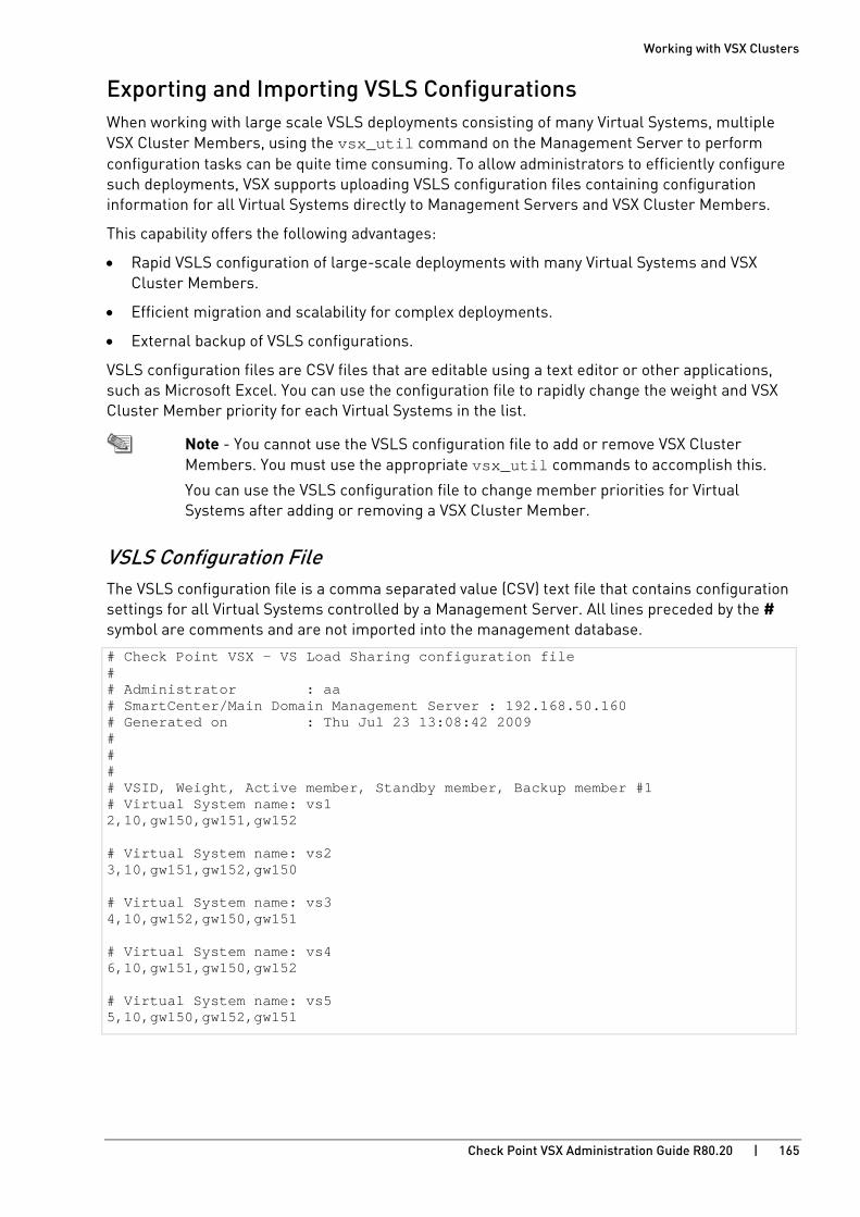
Working with VSX Clusters
Check Point VSX Administration Guide R80.20 | 165
Exporting and Importing VSLS Configurations When working with large scale VSLS deployments consisting of many Virtual Systems, multiple VSX Cluster Members, using the vsx_util command on the Management Server to perform configuration tasks can be quite time consuming. To allow administrators to efficiently configure such deployments, VSX supports uploading VSLS configuration files containing configuration information for all Virtual Systems directly to Management Servers and VSX Cluster Members.
This capability offers the following advantages:
• Rapid VSLS configuration of large-scale deployments with many Virtual Systems and VSX Cluster Members.
• Efficient migration and scalability for complex deployments.
• External backup of VSLS configurations.
VSLS configuration files are CSV files that are editable using a text editor or other applications, such as Microsoft Excel. You can use the configuration file to rapidly change the weight and VSX Cluster Member priority for each Virtual Systems in the list.
Note - You cannot use the VSLS configuration file to add or remove VSX Cluster Members. You must use the appropriate vsx_util commands to accomplish this.
You can use the VSLS configuration file to change member priorities for Virtual Systems after adding or removing a VSX Cluster Member.
VSLS Configuration File The VSLS configuration file is a comma separated value (CSV) text file that contains configuration settings for all Virtual Systems controlled by a Management Server. All lines preceded by the # symbol are comments and are not imported into the management database.
# Check Point VSX - VS Load Sharing configuration file # # Administrator : aa # SmartCenter/Main Domain Management Server : 192.168.50.160 # Generated on : Thu Jul 23 13:08:42 2009 # # # # VSID, Weight, Active member, Standby member, Backup member #1 # Virtual System name: vs1 2,10,gw150,gw151,gw152 # Virtual System name: vs2 3,10,gw151,gw152,gw150 # Virtual System name: vs3 4,10,gw152,gw150,gw151 # Virtual System name: vs4 6,10,gw151,gw150,gw152 # Virtual System name: vs5 5,10,gw150,gw152,gw151
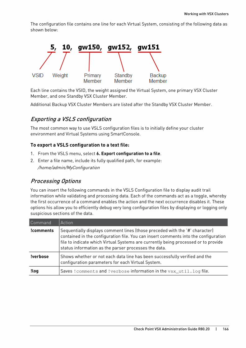
Working with VSX Clusters
Check Point VSX Administration Guide R80.20 | 166
The configuration file contains one line for each Virtual System, consisting of the following data as shown below:
Each line contains the VSID, the weight assigned the Virtual System, one primary VSX Cluster Member, and one Standby VSX Cluster Member.
Additional Backup VSX Cluster Members are listed after the Standby VSX Cluster Member.
Exporting a VSLS configuration The most common way to use VSLS configuration files is to initially define your cluster environment and Virtual Systems using SmartConsole.
To export a VSLS configuration to a text file:
1. From the VSLS menu, select 6. Export configuration to a file.
2. Enter a file name, include its fully qualified path, for example:
/home/admin/MyConfiguration
Processing Options You can insert the following commands in the VSLS Configuration file to display audit trail information while validating and processing data. Each of the commands act as a toggle, whereby the first occurrence of a command enables the action and the next occurrence disables it. These options his allow you to efficiently debug very long configuration files by displaying or logging only suspicious sections of the data.
Command Action
!comments Sequentially displays comment lines (those preceded with the '#' character) contained in the configuration file. You can insert comments into the configuration file to indicate which Virtual Systems are currently being processed or to provide status information as the parser processes the data.
!verbose Shows whether or not each data line has been successfully verified and the configuration parameters for each Virtual System.
!log Saves !comments and !verbose information in the vsx_util.log file.
Working with VSX Clusters
Check Point VSX Administration Guide R80.20 | 167
Importing a VSLS configuration
To import a VSLS configuration from a text file:
1. From the VSLS menu, select 5. Import configuration from a file.
2. Enter the file name, include its fully qualified path, for example:
/home/admin/MyConfiguration
3. At the Save & apply configuration? prompt, enter "y" to continue.
During the import process, the parser reads the configuration file and attempts to validate the contents. Errors are displayed on the screen together with the offending line number. If either the !comments or !verbose processing options are enabled, the appropriate information appears on the screen.
The process update process may take several minutes or longer to complete, depending on the quantity of Virtual Systems, Domain Management Servers, and VSX Cluster Members.
Working with VSX Clusters
Check Point VSX Administration Guide R80.20 | 168
Configuring Virtual Systems in Bridge Mode This section explains configurations and procedures for Virtual Systems in Bridge mode. With native layer-2 bridging instead of IP routing, you can add Virtual Systems without affecting the existing IP structure.
When in Bridge mode, Virtual System interfaces do not require IP addresses. You can assign an IP address to the Virtual System itself (not the interfaces) to enable layer-3 monitoring. This feature enhances network fault detection.
VSX supports these Bridge mode models:
• STP Bridge Mode: Redundancy and prevention of undesirable loops between redundant switches.
• Active/Standby Bridge Mode: Path redundancy and loop prevention, with seamless support for Virtual System Load Sharing. This model overcomes many of the limitations of STP.
Overview
STP Bridge Mode This section presents the procedures for enabling and configuring the STP Bridge mode for Virtual Systems and VSX Gateways.
The same procedures are applicable for a VSX Cluster for PVST + Load Sharing.
Defining the Spanning Tree Structure Define and configure the Spanning Tree structure according to your network requirements. (For PVST + Load Sharing, configure the structure for each VLAN.)
See your hardware documentation for the specific procedures for your network deployment.
Enabling Active/Active Bridge Mode for Existing VSX Cluster Members 1. Connect to the command line on each VSX Cluster Member.
2. Log in to the Expert mode.
3. Run: cpconfig
4. Select Enable ClusterXL membership for this member.
5. Select Disable ClusterXL for Bridge Active/Standby. 6. Reboot each VSX Cluster Member.

Working with VSX Clusters
Check Point VSX Administration Guide R80.20 | 169
Configuring Clusters for Active/Active Bridge Mode
To enable the Active/Active Bridge mode for a cluster:
1. Connect with SmartConsole to the Security Management Server or Main Domain Management Server used to manage the VSX Cluster.
2. From the Gateways & Servers view or Object Explorer, double-click the VSX Cluster object.
The VSX Cluster Properties window opens.
3. From the left tree, click Other > VSX Bridge Configuration.
4. Select Standard Layer-2 Loop Detection Protocols.
5. Click OK.
6. Install the VSX Policy (<Name of VSX Cluster Object>_VSX) on the VSX Cluster object.
Configuring Virtual Systems for STP Bridge Mode
To configure a Virtual System to use bridge mode, define it as a Virtual System in bridge mode when you first create it. You cannot reconfigure a non-Bridge mode Virtual System to use bridge mode later.
Configuring PVST + Load Sharing Defining the Spanning Tree Structure
Define and configure the Spanning Tree structure for each VLAN according to your network deployment. Please refer to your network hardware documentation for specific procedures.
Configuring a Cluster for PVST + Load Sharing
To configure a VSX Cluster for PVST + Load Sharing, perform the procedures described in the STP Bridge Mode section (on page 168).
Active/Standby Bridge Mode This section presents the procedures for enabling and configuring the Active/Standby Bridge Mode for Virtual Systems and VSX Gateways.
Enabling and Configuring Active/Standby Bridge Mode Enabling Active/Standby Bridge Mode for a New VSX Cluster Member 1. In the Gaia First Time Configuration Wizard Products page, select ClusterXL.
2. After the First Time Configuration Wizard is complete, from the VSX Gateway CLI, run: cpconfig
• If you enabled the Per Virtual System State feature (required for VSLS), the Active/Standby Bridge Mode is enabled automatically.
• If you chose not to enable the Virtual System Load Sharing, an option to enable Active/Standby Bridge Mode appears.
Enter y and continue with the gateway configuration.

Working with VSX Clusters
Check Point VSX Administration Guide R80.20 | 170
Enabling Active/Standby Bridge Mode for Existing Cluster Members 1. Connect to the command line on each VSX Cluster Member.
2. Log in to the Expert mode.
3. Run: cpconfig
4. Select Enable ClusterXL for Bridge Active/Standby.
5. Reboot each VSX Cluster Member.
Configuring Clusters for Active/Standby Bridge Mode
To enable the Active/Standby Bridge Mode for a cluster:
1. Connect with SmartConsole to the Security Management Server or Main Domain Management Server used to manage the VSX Cluster.
2. From the Gateways & Servers view or Object Explorer, double-click the VSX Cluster object.
The VSX Cluster Properties window opens.
3. From the left tree, click Other > VSX Bridge Configuration.
4. Select Check Point ClusterXL.
The Active/Standby Bridge Mode loop detection algorithms in ClusterXL are enabled.
5. Click OK.
6. Install the VSX Policy (<Name of VSX Cluster Object>_VSX) on the VSX Cluster object.
Configuring Virtual Systems for Active/Standby Bridge Mode
To configure a Virtual System in Bridge Mode, define it as such when you first create the Virtual System object.
To configure a Virtual System for the Active/Standby Bridge Mode:
1. In the Virtual System General Properties page of the new Virtual System object, select Bridge Mode.
2. Click Next. The Virtual System Network Configuration window opens.
3. Configure the external and internal interfaces for the Virtual System.
4. Optional: Select Enable Layer-3 Bridge Interface Monitoring.
The IP address must be unique and on the same subnet as the protected network.
5. Click Next. 6. Click Finish.
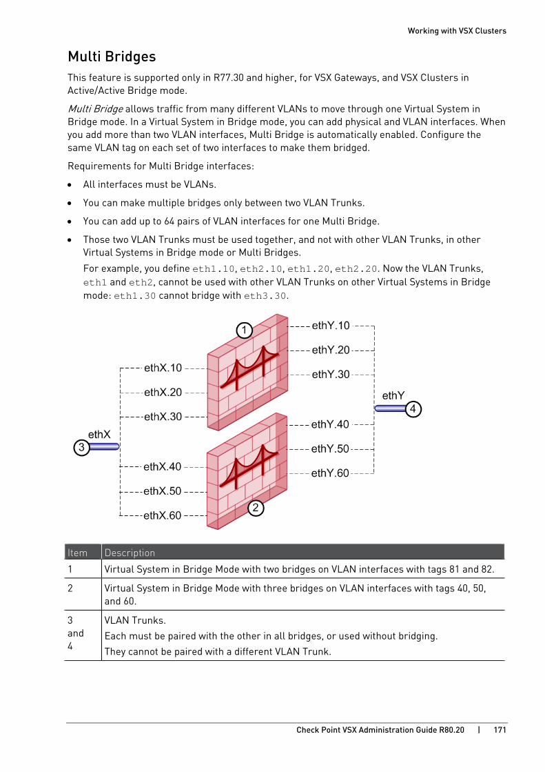
Working with VSX Clusters
Check Point VSX Administration Guide R80.20 | 171
Multi Bridges This feature is supported only in R77.30 and higher, for VSX Gateways, and VSX Clusters in Active/Active Bridge mode.
Multi Bridge allows traffic from many different VLANs to move through one Virtual System in Bridge mode. In a Virtual System in Bridge mode, you can add physical and VLAN interfaces. When you add more than two VLAN interfaces, Multi Bridge is automatically enabled. Configure the same VLAN tag on each set of two interfaces to make them bridged.
Requirements for Multi Bridge interfaces:
• All interfaces must be VLANs.
• You can make multiple bridges only between two VLAN Trunks.
• You can add up to 64 pairs of VLAN interfaces for one Multi Bridge.
• Those two VLAN Trunks must be used together, and not with other VLAN Trunks, in other Virtual Systems in Bridge mode or Multi Bridges.
For example, you define eth1.10, eth2.10, eth1.20, eth2.20. Now the VLAN Trunks, eth1 and eth2, cannot be used with other VLAN Trunks on other Virtual Systems in Bridge mode: eth1.30 cannot bridge with eth3.30.
Item Description
1 Virtual System in Bridge Mode with two bridges on VLAN interfaces with tags 81 and 82.
2 Virtual System in Bridge Mode with three bridges on VLAN interfaces with tags 40, 50, and 60.
3 and 4
VLAN Trunks.
Each must be paired with the other in all bridges, or used without bridging.
They cannot be paired with a different VLAN Trunk.

Working with VSX Clusters
Check Point VSX Administration Guide R80.20 | 172
To define a new Multi Bridge:
1. Connect with SmartConsole to the Security Management Server or Target Domain Management Server used to manage the new Virtual System.
2. From the left navigation panel, click Gateways & Servers.
3. Create a new Virtual System object in one of these ways:
• From the top toolbar, click the New ( ) > VSX > New Virtual System.
• In the top left corner, click Objects menu > More object types > Network Object > Gateways and Servers > VSX > New Virtual System.
• In the top right corner, click Objects Pane > New > More > Network Object > Gateways and Servers > VSX > Virtual System.
4. In the Name field, enter the name for the new Virtual System.
5. In the VSX Gateway / Cluster field, select the applicable VSX Gateway or VSX Cluster.
6. Select Bridge Mode.
7. Click Next. 8. In the Interfaces section, click Add to add the first VLAN interface for the bridge.
9. In the Interfaces section, click Add again to add the second VLAN interface for the bridge.
10. In the Interfaces section, add more VLAN interface pairs to the Multi Bridge in the same way.
Make sure the interfaces in each pair have the same VLAN tag, from different interfaces.
For example:
eth2.50, eth2.51
eth3.50, eth3.51
Make sure to use the same two VLAN Trunks.
11. Click Next. 12. Click Finish.
13. Install the Access Control Policy on the new Virtual System object.
To convert a Bridge to a Multi Bridge:
1. Connect with SmartConsole to the Security Management Server or Target Domain Management Server used to manage the Virtual System in the Bridge mode.
2. From the Gateways & Servers view or Object Explorer, double-click the Virtual System object.
3. From the left tree, click Bridge Configuration > Topology.
4. In the Interfaces section, if there are physical interfaces in the Interfaces list, remove them.
5. In the Interfaces section, add more VLAN interface pairs to the Multi Bridge.
6. Click OK.
7. Install the Access Control Policy on the Virtual System object.
Working with VSX Clusters
Check Point VSX Administration Guide R80.20 | 173
Advanced Clustering Configuration This section presents several advanced cluster scenarios and procedures for their configuration.
Clusters on the Same Layer-2 Segment The recommended cluster architecture contains interfaces connected to a Layer-2 segment that is isolated from other clusters.
However, in a deployment where multiple clusters need to connect to the same Layer-2 segment, the same MAC address may be used by more than one cluster for Cluster Control Protocol (CCP) communication. This may direct traffic to the incorrect cluster.
Follow sk25977 http://supportcontent.checkpoint.com/solutions?id=sk25977.
Source Cluster MAC Addresses Cluster members use CCP to communicate with each other. In order to distinguish CCP packets from ordinary network traffic, CCP packets are given a unique source MAC address.
• The first four bytes of the source MAC address are all zero: 00.00.00.00
• The fifth byte of the source MAC address is a "magic" number, a number that encodes critical information in a way intended to be opaque. Its value indicates its purpose:
Default Value Of Fifth Byte Purpose 0xfe CCP traffic 0xfd Forwarding layer traffic
• The sixth byte is the ID of the source cluster member
When multiple clusters are connected to the same Layer-2 segment, setting a unique value to the fifth byte of the MAC source address of each cluster allows them to coexist on the same Layer-2 segment.
Changing a Cluster's MAC Source Address
To change a cluster's MAC source address, run these commands on each cluster member:
fw ctl set int fwha_mac_magic <value> fw ctl set int fwha_mac_forward_magic <value>
Parameter Default value fwha_mac_magic 0xfe
fwha_mac_forward_magic 0xfd
Use any value, as long as the two gateway configuration parameters are different. To avoid confusion, do not use the value 0x00.
Making the Change Permanent
You can configure the above parameters to persist following reboot.
1. Use a text editor to open the file fwkern.conf, located at $FWDIR/boot/modules/.
2. Add the line Parameter=<value in hex>. Make sure there are no spaces.

Working with VSX Clusters
Check Point VSX Administration Guide R80.20 | 174
Monitoring all VLANs with ClusterXL By default, ClusterXL only monitors two VLANS for failure detection and failover. These are the highest and lowest VLAN tags defined for a given interface.
For example, if the topology for interface eth1 includes several VLAN tags in the range of eth1.10 to eth1.50, ClusterXL only monitors VLANs eth1.10 and eth1.50 for failure. Failures on any of the other VLANs are not detected in the default configuration.
Note - The command cphaprob -a if (or Gaia Clish command show cluster interfaces vlans) displays the highest and lowest VLANs being monitored.
When both the highest and lowest VLANs fail, all the VLANs are considered down, and a failover occurs. This means that if a VLAN which is not listed as the highest or lowest goes down, the trunk is still considered "up", and no failover occurs.
There are instances in which it would be advantageous to monitor all the VLANs in the trunk, not just the highest and lowest, and initiate a failover when any one of the VLANs goes down.
To enable monitoring of all VLANs, enable the fwha_monitor_all_vlan property in $FWDIR/boot/modules/fwkern.conf. Change the property to fwha_monitor_all_vlan=1.

Working with VSX Clusters
Check Point VSX Administration Guide R80.20 | 175
Enabling Broadcast Mode The default ClusterXL Control Protocol transport mode is auto. Use this command to configure the broadcast or multicast mode for the cluster.
To configure the ClusterXL Control Protocol to broadcast or multicast transport mode:
Important - The ClusterXL Control Protocol transport mode must be the same on all Cluster Members. When changing the CCP transport mode on Cluster Members, they can temporarily stop detecting the CCP packets from each other. This can cause a cluster fail-over. Therefore, we recommend you schedule a maintenance window for this change.
1. See the current ClusterXL Control Protocol transport mode. Run:
• In Gaia Clish:
show cluster interfaces virtual
• In Expert mode:
cphaprob [-vs all] -a if
2. On a VSX Cluster Member, run:
• In Gaia Clish:
set cluster ccp {multicast | broadcast}
• In Expert mode:
cphaconf set_ccp {multicast | broadcast}
3. See the new ClusterXL Control Protocol transport mode. Run:
• In Gaia Clish:
show cluster interfaces virtual
• In Expert mode:
cphaprob [-vs all] -a if
4. Do the previous step for all the Cluster Members.
Configuring CoreXL in a VSLS VSX Cluster In VSLS VSX Clusters of version R80.10 and higher, changing the CoreXL configuration or running the cphastop command in the context of VS0 results in failover of all the Active Virtual Systems on that VSX Cluster Member. This behavior is by design. Active Virtual Systems on other VSX Cluster Members do not fail over.

Check Point VSX Administration Guide R80.20 | 176
CHAPTE R 9
Working with Link Aggregation In This Section:
Link Aggregation Overview ........................................................................................ 176
Configuring Bond in High Availability Mode .............................................................. 182
Configuring Load Sharing Mode ................................................................................ 184
Configuring Cisco Switches for Link Aggregation Load Sharing Mode ................... 187
Troubleshooting Bonded Interfaces .......................................................................... 188
Link Aggregation Overview Link aggregation, also known as interface bonding, joins multiple physical interfaces together into a virtual interface, known as a bond interface. A bond interface can be configured for High Availability redundancy or for load sharing, which increases connection throughput above that which is possible using one physical interface.
For more about Link Aggregation, see the R80.20 Gaia Administration Guide https://sc1.checkpoint.com/documents/R80.20_GA/WebAdminGuides/EN/CP_R80.20_Gaia_AdminGuide/html_frameset.htm and R80.20 ClusterXL Administration Guide https://sc1.checkpoint.com/documents/R80.20_GA/WebAdminGuides/EN/CP_R80.20_ClusterXL_AdminGuide/html_frameset.htm.
Link Aggregation Terminology • Link Aggregation (Interface Bonding): Networking technology that binds multiple physical
interfaces together into one virtual interface.
• Bond: A group of physical interfaces that operate together as one virtual interface and share an IP address and MAC address. A bond is identified by the cluster by its Bond ID (for example: bond0).
• Bond Interface: The logical representation of the bond.
• Slave (enslaved interface): A physical interface that is a member of a bond. Slaves do not have an IP Address and in some cases share the same MAC address.

Working with Link Aggregation
Check Point VSX Administration Guide R80.20 | 177
How Link Aggregation Works A bond contains a minimum of one and may contain up to eight slave interfaces. All slave interfaces contained in a bond share a common IP address and may share the same MAC address. We recommend that each cluster member contain the same quantity of identical slave interfaces.
Item Description
1 Switch
2 bond 0
3 Cluster
You can configure Link Aggregation using one of the following strategies:
• High Availability (Active/Backup): Ensures redundancy in the event of interface or link failure. This option also provides switch redundancy.
• Load Sharing (Active/Active): All interfaces are active, but handle different connections simultaneously. Traffic is balanced amongst slave interfaces to maximize throughput. The Load Sharing option does not support switch redundancy.
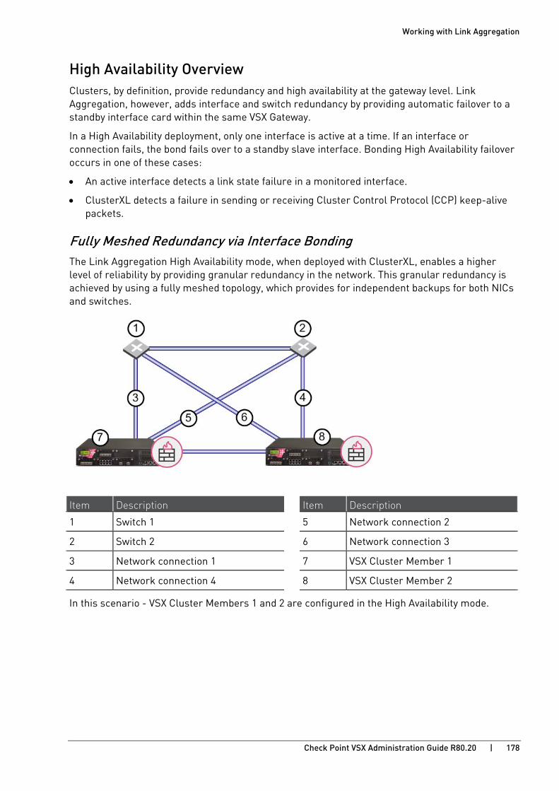
Working with Link Aggregation
Check Point VSX Administration Guide R80.20 | 178
High Availability Overview Clusters, by definition, provide redundancy and high availability at the gateway level. Link Aggregation, however, adds interface and switch redundancy by providing automatic failover to a standby interface card within the same VSX Gateway.
In a High Availability deployment, only one interface is active at a time. If an interface or connection fails, the bond fails over to a standby slave interface. Bonding High Availability failover occurs in one of these cases:
• An active interface detects a link state failure in a monitored interface.
• ClusterXL detects a failure in sending or receiving Cluster Control Protocol (CCP) keep-alive packets.
Fully Meshed Redundancy via Interface Bonding The Link Aggregation High Availability mode, when deployed with ClusterXL, enables a higher level of reliability by providing granular redundancy in the network. This granular redundancy is achieved by using a fully meshed topology, which provides for independent backups for both NICs and switches.
Item Description Item Description
1 Switch 1 5 Network connection 2
2 Switch 2 6 Network connection 3
3 Network connection 1 7 VSX Cluster Member 1
4 Network connection 4 8 VSX Cluster Member 2
In this scenario - VSX Cluster Members 1 and 2 are configured in the High Availability mode.

Working with Link Aggregation
Check Point VSX Administration Guide R80.20 | 179
Load Sharing Overview Load Sharing provides the ability to spread traffic over multiple slave interfaces, in addition to providing interface redundancy. All interfaces are always active.
Traffic is balanced between interfaces in a manner similar to the way load sharing balances traffic between VSX Cluster Members. Load Sharing operates according to either the IEEE 802.3ad or the XOR standard.
In Load Sharing mode, each individual connection is assigned to a specific slave interface. For a specific connection, only the designated slave interface is active. In the event of a failure of the designated slave interface, the traffic fails over to another interface, adding that connection's to the traffic it is already handling.

Working with Link Aggregation
Check Point VSX Administration Guide R80.20 | 180
Bond Failover Either of the following failure scenarios can induce bond failover:
• An active interface detects a link state failure in another monitored interface
• ClusterXL detects a failure in sending or receiving Cluster Control Protocol (CCP) keep-alive packets
Either of these occurrences will induce a failover, either to another slave interface within the bond, or between VSX Cluster Members, depending on the circumstances.
Note - The bond failover operation requires a network interface card that supports the Media-Independent Interface (MII) standard.
Link State Initiated Failover Link-state initiated failover occurs in this sequence:
1. The active slave interface detects a down link state.
2. The bond initiates failover to a standby interface. Since this is a failover within the bond, the status of the other VSX Cluster Member is unaffected.
When the number of available slave interfaces is fewer than the critical minimum number of interfaces (on page 185), failover to other VSX Cluster Members occurs.
3. If the standby interface continues to detect a link failure, and the initial interface is still down, failover to other VSX Cluster Members occurs.
CCP Initiated Failover CCP failover occurs only when other VSX Cluster Members are not down, in this sequence.
1. ClusterXL detects a problem sending or receiving of CCP packets.
2. ClusterXL initiates an internal bond failover.
3. ClusterXL monitors CCP packet transmission and reception. If additional problems are detected within three minutes, the system initiates a failover to another VSX Cluster Member.

Working with Link Aggregation
Check Point VSX Administration Guide R80.20 | 181
Failover Support for VLANs ClusterXL monitors VLAN IDs for connectivity failure or miscommunication, and initiates failover when necessary. By default, both the highest and the lowest VLAN IDs are monitored for failure. This is done by sending ClusterXL Control Protocol (CCP) packets on round-trip paths at a set interval.
You can configure VSX to monitor all VLANs.
Item Description Item Description
1 Cluster 5 VLAN 3
2 bond 0 6 S-1
3 VLAN 1 7 S-2
4 VLAN 2
When a failure is detected, a log of the failure is recorded in the Logs & Monitor view.
Monitoring the Highest and Lowest VLAN IDs By default, the highest and lowest VLAN IDs indicate the status of the physical connection. These VLAN IDs are always monitored and a connectivity failure in either initiates a failover. In most deployments this is the desired setting, as it supports the primary purpose of the feature (detecting a connectivity failure) and the traffic generated on the network is light. However, this setting only detects VLAN configuration problems on the switch for the highest and lowest VLAN IDs.
Bond Interface & Interface Limitations • You can define a maximum of 4096 interfaces on a Gaia server or appliance. The total number
of bond interfaces in use is the sum of bonds plus the number of slave interfaces contained in each bond.
• Up to eight interfaces can be defined in a Link Aggregation deployment for each bond interface.

Working with Link Aggregation
Check Point VSX Administration Guide R80.20 | 182
Configuring Bond in High Availability Mode This section explains how to configure High Availability on a bond interface. Run the CLI commands from the VSX Gateway (VS0) context. For a cluster configuration, run these commands on each VSX Cluster Member.
Use the active-backup value for the mode parameter to configure High Availability.
Configuring the High Availability Bond This is a workflow of CLI commands to configure Link Aggregation in High Availability mode.
Notes:
• For exact commands, see R80.20 Gaia Administration Guide https://sc1.checkpoint.com/documents/R80.20_GA/WebAdminGuides/EN/CP_R80.20_Gaia_AdminGuide/html_frameset.htm.
• When you are enslaving configured interfaces, make sure that these interfaces are not used in other configurations and that IP addresses are not assigned to them.
To configure the Link Aggregation in High Availability mode:
1. Add the bonding group.
2. Add slave interfaces to the bonding group.
3. Make sure that the bond is configured correctly.
4. Open SmartConsole and configure the cluster object.
• For a new Link Aggregation installation, create a new cluster object.
• For updating an existing configuration, update the interface topology (on page 182).
Updating the Interface Topology When you are updating an existing configuration to Link Aggregation, it is necessary to reconfigure the relevant objects to connect to the newly created bond. This includes Virtual Systems, Virtual Routers and Virtual Switches. You can perform these actions in SmartConsole. In most cases, these definitions can be found in the object Properties window.
For large existing VSX deployments containing many Domain Management Servers and Virtual Devices, use the vsx_util change_interfaces command on the Management Server to reconfigure existing object topologies. For example, in a Multi-Domain Server deployment with 200 Domains, each with many Virtual Devices, it is faster to use vsx_util change_interfaces. This command automatically replaces the interface with the new bond on all relevant objects.
Working with Link Aggregation
Check Point VSX Administration Guide R80.20 | 183
Reconfiguring the Bond
To configure the newly created bond for a cluster:
1. Connect with SmartConsole to the Security Management Server or Main Domain Management Server used to manage the VSX Cluster.
2. Delete the slave interfaces from the bond that you are not using.
a) From the navigation tree, click Topology.
b) From the navigation tree, click Physical Interfaces.
c) Select the slave interface, and click Remove.
d) Click OK.
e) Do these steps again for all the slave interfaces.
3. From Gaia Clish on each VSX Cluster Member, create the new bond interface.
4. Connect with SmartConsole to the Security Management Server or Main Domain Management Server used to manage the VSX Cluster.
5. From the Gateways & Servers view or Object Explorer, double-click the VSX Cluster object.
6. From the left navigation tree, click Physical Interfaces.
7. Click Add, and configure the bond interface.
The Physical Interface Properties window opens.
a) Enter the bond name.
b) If the bond is a VLAN trunk, select VLAN Trunk.
c) Click OK.
8. From the left navigation tree, click Topology.
9. Do these steps for each interface that you are adding to the bond:
a) Double-click the interface.
The Interface Properties window opens.
b) From Interface, select the bond interface.
c) Click OK.
10. Install the VSX Policy (<Name of VSX Cluster Object>_VSX) on the VSX Cluster object.
Working with Link Aggregation
Check Point VSX Administration Guide R80.20 | 184
Reconfiguring Topology with 'vsx_util change_interfaces' Important - In a Multi-Domain Server environment, all Domain Management Servers must be unlocked in order for this operation to succeed. Meaning, you need to disconnect all SmartConsole clients from all Domain Management Servers.
To reconfigure objects with vsx_util change_interfaces:
1. Close SmartConsole windows for the Security Management Server and all Domain Management Servers that use the designated interface.
2. Connect to the command line on the Management Server.
3. Log in the Expert Mode.
4. Run the vsx_util change_interfaces command and follow the on-screen instructions:
a) Enter the IP address of the Security Management Server or Main Domain Management Server.
b) Enter the management administrator name and password.
c) Select VSX Cluster object.
d) Select Apply changes to the management database and to the VSX Gateway/Cluster members immediately.
e) When prompted, select the interface to be replaced.
f) When prompted, select the replacement bond interface.
g) If you wish to replace additional interfaces, enter "y" when prompted and repeat the above steps.
h) To complete the process, enter "n".
Configuring Load Sharing Mode This section explains how to configure Load Sharing on a bond interface. Run the CLI commands from the VSX Gateway (VS0) context. For a cluster configuration, run these commands on each VSX Cluster Member.
Configure one of these Load Sharing modes for the bond interface:
• Round Robin - Selects the Active slave interfaces sequentially.
• 802.3ad - Dynamically uses Active slave interfaces to share the traffic load. This mode uses the LACP protocol, which fully monitors the interface link between the Check Point Security Gateway and a switch.
• XOR - All slave interfaces in the UP state are Active for Load Sharing. Traffic is assigned to Active slave interfaces based on the transmit hash policy: Layer 2 information (XOR of hardware MAC addresses), or Layer 3+4 information (IP addresses and Ports).

Working with Link Aggregation
Check Point VSX Administration Guide R80.20 | 185
Configuring the Load Sharing Bond This is a workflow of CLI commands to configure Link Aggregation in Load Sharing mode.
Notes:
• For exact commands, see R80.20 Gaia Administration Guide https://sc1.checkpoint.com/documents/R80.20_GA/WebAdminGuides/EN/CP_R80.20_Gaia_AdminGuide/html_frameset.htm.
• When you are enslaving configured interfaces, make sure that these interfaces are not used in other configurations and that IP addresses are not assigned to them.
To configure the Link Aggregation in Load Sharing mode:
1. Add the bonding group.
2. Add slave interfaces to the bonding group.
3. Define the number of critical interfaces (on page 185).
4. For configurations that use Performance Pack, configure the core affinities (on page 186).
5. Make sure that the bond is configured correctly.
6. Open SmartConsole and configure the VSX Cluster object.
• For a new Link Aggregation installation, create a new cluster object.
• For updating an existing configuration, update the interface topology (on page 182).
Setting Critical Required Interfaces Note - The Critical Required Interfaces feature is supported for ClusterXL only.
A bond in Load Sharing mode is considered to be down when fewer than a critical minimal number of slave interfaces remain up. When not explicitly defined, the critical minimal number of slave interfaces, which must remain up, in a bond of n interfaces is n-1. Failure of an additional slave interface (when n-2 slave interfaces remain up) will cause the entire bond interface to be considered down, even if the bond contains more than two slave interfaces.
If a smaller number of slave interfaces will be able to handle the expected traffic, you can increase redundancy by explicitly defining the critical minimal number of slave interfaces. Divide your maximal expected traffic speed by the speed of your slave interfaces and round up to a whole number to determine an appropriate number of critical slave interfaces.
To define the critical number of slave interfaces explicitly, create and edit the following file:
$FWDIR/conf/cpha_bond_ls_config.conf
Each line of the file should be written in the following syntax:
<Name_of_Bond> <critical_minimal number_of_slave>
For example, if bond0 has 7 slave interfaces, and bond1 has 6 slave interfaces, file contents could be:
bond0 5 bond1 3
In this example:
• bond0 would be considered down when 3 of its slave interfaces have failed.
• bond1 would be considered down when 4 of its slave interfaces have failed.

Working with Link Aggregation
Check Point VSX Administration Guide R80.20 | 186
Setting Affinities If you are running Performance Pack in a multi-core system, after you define bonds, set affinities manually. Use the sim affinity -s command.
Note - The sim affinity commands take effect only if the Performance Pack is enabled and actually running. Performance Pack begins running when you install a Policy for the first time.
For optimal performance, set affinities according to the following guidelines:
1. Run sim affinity -s.
2. Whenever possible, dedicate one processing core to each interface. See sk33520 http://supportcontent.checkpoint.com/solutions?id=sk33250.
3. If there are more interfaces than CPU cores, one or more CPU cores handle two interfaces. Use interface pairs of the same position with internal and external bonds.
a) To view interface positions in a bond, run:
cat /proc/net/bonding/<bond name>.
b) Note the sequence of the interfaces in the output, and compare this for the two bonds (external bond and its respective internal bond). Interfaces that appear in the same position in the two bonds are interface pairs and set to be handled by one processing core.
For example, you might have four processing cores (0-3) and six interfaces (0-5), distributed among two bonds:
bond0 bond1
eth0 eth3
eth1 eth4
eth2 eth5
Two of the CPU cores will need to handle two interfaces each. An optimal configuration can be:
bond0 bond1
eth0 core 0 eth3 core 0
eth1 core 1 eth4 core 1
eth2 core 2
eth5 core 3

Working with Link Aggregation
Check Point VSX Administration Guide R80.20 | 187
Configuring Cisco Switches for Link Aggregation Load Sharing Mode
These are sample configuration commands for Cisco switches.
For 802.3ad Switch# conf t Switch(config)# port-channel load-balance src-dst-ip Switch(config)# interface FastEthernet <all the participating interfaces> Switch(config-if)# channel-group 1 mode active Switch(config-if)# channel-protocol lacp Switch(config-if)# exit Switch(config)# interface port-channel 1 Switch(config-if)# switchport access vlan <the wanted vlan number> Switch(config-if)# end Switch# write
For XOR Switch# conf t Switch(config)# port-channel load-balance src-dst-ip Switch(config)# interface FastEthernet <all the participating interfaces> Switch(config-if)# channel-group 1 mode on Switch(config-if)# exit Switch (config)# interface port-channel 1 Switch(config-if)# switchport access vlan <the wanted vlan number> Switch(config-if)# end Switch# write

Working with Link Aggregation
Check Point VSX Administration Guide R80.20 | 188
Troubleshooting Bonded Interfaces
Troubleshooting Workflow 1. Check the status of the bond. Execute the following command in Expert mode:
cat /proc/net/bonding/<bond id>
2. If there is a problem, check if the physical link is down, as follows:
a) Execute the following command:
In Gaia Clish:
show cluster bond name <bond_name>
In Expert mode:
cphaprob show_bond <bond_name>
b) Look for a slave interface that reports the status of the link as no.
c) Check the cable connections and other hardware.
d) Check the port configuration on the switch.
3. Check if a VSX Cluster Member is down, by running:
• In Gaia Clish:
show cluster state
• In Expert mode:
cphaprob state
If any of the VSX Cluster Members has a State other than Active, see the R80.20 ClusterXL Administration Guide https://sc1.checkpoint.com/documents/R80.20_GA/WebAdminGuides/EN/CP_R80.20_ClusterXL_AdminGuide/html_frameset.htm - Chapter Monitoring and Troubleshooting Clusters.
On a VSX Cluster Member, reboot is needed after the following actions on a bond interface:
1. Changing a bond mode.
2. Adding a slave interface into a bond
Note - Removing a slave interface does not require reboot.
For further information regarding bond status and failovers, view logs in the Logs & Monitor view. Any interface bond status change is logged and can be viewed in Logs & Monitor.
Working with Link Aggregation
Check Point VSX Administration Guide R80.20 | 189
Connectivity Delays on Switches When using certain switches, connectivity delays may occur during some internal bond failovers. With the various features that are now included on some switches, it can take close to a minute for a switch to begin servicing a newly connected interface. The following are suggestions for reducing the startup time after link failure.
1. Disable auto-negotiation on the relevant interface.
2. On some Cisco switches, enable PortFast, as detailed below.
Note - PortFast is not applicable if the bond group on the switch is configured as Trunk.
Warning Regarding Use of PortFast The PortFast feature should never be used on ports that connect to other switches or hubs. It is important that the Spanning Tree complete the initialization procedure in these situations. Otherwise, these connections may cause physical loops where packets are continuously forwarded (or even multiply) in such a way that network will ultimately fail.
Sample Configuration of PortFast on a Cisco Switch The following are the commands necessary to enable PortFast on a Gigabit Ethernet 1/0/15 interface of a Cisco 3750 switch running IOS.
1. Enter configuration mode: cisco-3750A#conf t
2. Specify the interface to configure: cisco-3750A(config)#interface gigabitethernet1/0/15
3. Set PortFast on this interface: cisco-3750A(config-if)#spanning-tree portfast
Check Point VSX Administration Guide R80.20 | 190
CHAPTE R 10
Optimizing VSX In This Section:
QoS Enforcement (cpqos) ........................................................................................... 190
Monitoring Memory Resources (vsx mstat) .............................................................. 199
Monitoring CPU Resources (vsx resctrl) ................................................................... 199
SNMP Monitoring ........................................................................................................ 200
Configuring Jumbo Frames ....................................................................................... 208
QoS Enforcement (cpqos) QoS Enforcement for VSX (Lightweight QoS) provides the ability to control the network quality of service in the VSX network environment. QoS is based on the Differentiated Services architecture and allows assigning different transmission characteristics to different classes of service.
Differentiated Services is a computer networking architecture that specifies a simple, scalable and coarse-grained mechanism for classifying, managing network traffic and providing quality of service (QoS) guarantees on modern IP networks. Differential services can, for example, be used to provide low-latency, guaranteed service (GS) to critical network traffic such as voice or video while providing simple best-effort traffic guarantees to non-critical services such as web traffic or file transfers.
The major characteristics that are controllable by QoS are latency and bandwidth allocation. QoS is designed to provide QoS functionality with minimal impact on performance. QoS works seamlessly with Check Point Performance Pack.
The VSX network usually includes various types of traffic such as:
• Real-time traffic (e.g. VoIP) which requires low bandwidth, and is sensitive to latency (delays) and drops
• Traffic which is sensitive to latency but not to occasional drops
• High-volume, low-priority traffic which has a low sensitivity to latency and drops
• Other traffic which requires its own share of the bandwidth
Without QoS Enforcement, all these different traffic types are given equal priority on the VSX Gateway and are handled in a simple FIFO (first in-first out) manner. When the VSX Gateway is congested, all traffic types suffer the same degree of latency and drops. Also, high-volume traffic may starve other types of low-volume traffic.
With QoS, the special requirements of each traffic type can be met. For example:
• Latency-sensitive traffic will be given preference over other types of traffic
• Traffic which is sensitive to drops will suffer fewer drops than other types of traffic.
• High-volume traffic that consumes bandwidth will be limited during times of congestion.
Optimizing VSX
Check Point VSX Administration Guide R80.20 | 191
Differentiated Services Support QoS provides basic support for Differentiated Services, an architecture for specifying and controlling network traffic by class so that certain types of traffic receive priority over others. The differentiated services architecture PHB's (per-hop behaviors).
When marked packets arrive to the VSX machine, they are classified and prioritized according to their DSCP (differential services code-point) values. To enhance performance, QoS does not mark packets with DSCP and does not change their Type of Service (ToS) values. QoS instead relies on peripheral devices (namely routers) to mark packets with the appropriate ToS value.
Inbound Prioritization While Differentiated Services support in routers is usually performed on outbound traffic, QoS for VSX prioritizes traffic on the inbound side because, in VSX deployments, QoS is primarily governed by system resources, namely the CPU, and not by network bandwidth.
To prevent the VSX machine from becoming a bottleneck in the network, prioritization is enforced when packets arrive at the VSX machine, and before CPU processing is assigned.
Inbound prioritization allows an earlier control on the loss and delay rate.
Policy with Global Scope To minimize the impact of QoS functionality on performance, QoS is not done for each interface, but for all the system. One class of services applies to all traffic entering the VSX Gateway or cluster, regardless of the specified interface from which the traffic originates.
Note - On multi-CPU machines, enforcement is not done system-wide, but for each CPU. Global enforcement is done separately on traffic processed by each CPU.
Resource Allocation System resources are allocated by assigning different weights to different classes of service. A weight is the relative portion of the available resources allocated to a class. Allocating resources according to weights ensures full utilization of the line even if a specific class is not using all of its resources. In such a case, the remaining resources are divided among the remaining classes in accordance with their relative weights.
Optimizing VSX
Check Point VSX Administration Guide R80.20 | 192
Latency For some types of traffic, such as voice and video, it is necessary to minimize the latency (delay) of packets. Latency is controlled by defining special LLQ (low-latency queuing) classes. These classes are handled in a strict priority manner. LLQ packets are handled immediately upon arrival, and before packets that do not belong to LLQ classes.
QoS supports multiple LLQ classes. In some cases, it may be necessary to define more than one Low Latency class, for example when different types of traffic have a different sensitivity to delays. In such cases, a class with the higher sensitivity to delay receives a higher priority than a class with the lower sensitivity.
Note - When LLQ classes are used, it is assumed that the expected traffic will not exceed a relatively small amount of the available resources. Although QoS does not allow LLQ traffic to starve non-LLQ traffic, too much LLQ traffic reduces overall network quality of service and prevents efficient management of weighted resources.
WRED RED (Random Early Drop) is a congestion avoidance mechanism for detecting and preventing congestions. It takes advantage of TCP's congestion control mechanism by randomly dropping packets during periods of congestion. This causes TCP senders to slow down their transmission, thus preventing high congestion.
QoS implements WRED (Weighted RED) in which packets are dropped according to their priority. WRED mostly affects traffic which is of low priority and which exceeds its weight.
Optimizing VSX
Check Point VSX Administration Guide R80.20 | 193
QoS Management To manage the network quality of service it is necessary to create and install a QoS policy. The QoS policy consists of a list of up to 15 classes of service. Each class is assigned certain traffic characteristics and DSCP values.
The QoS policy is managed using the cpqos (on page 194) command.
Class of Service Definitions The definition of a class of service includes the following:
• Name. The class name is a unique identifier which identifies the class during configuration and when presenting statistics
• Type. There are two types of classes, LLQ and regular classes. Regular classes are non-LLQ classes which can be assigned a weight value.
• Priority. Each class is assigned a unique priority value between 1 and 15. The priority value is effective in prioritizing LLQ classes and during congestion, when drops occur.
• Weight value. Each class is assigned a specific weight value
• One or more DSCP values. The Differentiated Services code point
Priority and LLQs If there are multiple LLQ classes, packets are handled in a strict priority-based manner. Packets from a class with a higher priority are handled before packets with a lower priority class.
Priority and Drop Precedence Priority also determines the probability of drops. A class with a lower priority has a higher drop precedence during times of congestion.
The class priority is not the only factor that determines if drops occur. Other factors affect drops, for example if the class is LLQ or if the class exceeds its assigned resource allocation.
LLQ's are not immune to drops. Although LLQ's are processed as soon as they arrive (and thus have a lower drop rate), drops may occur if there are many LLQ classes or if a large portion of the incoming traffic is LLQ.
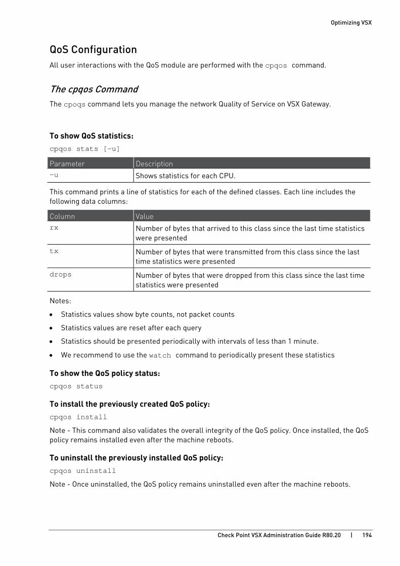
Optimizing VSX
Check Point VSX Administration Guide R80.20 | 194
QoS Configuration All user interactions with the QoS module are performed with the cpqos command.
The cpqos Command The cpoqs command lets you manage the network Quality of Service on VSX Gateway.
To show QoS statistics: cpqos stats [-u]
Parameter Description -u Shows statistics for each CPU.
This command prints a line of statistics for each of the defined classes. Each line includes the following data columns:
Column Value rx Number of bytes that arrived to this class since the last time statistics
were presented
tx Number of bytes that were transmitted from this class since the last time statistics were presented
drops Number of bytes that were dropped from this class since the last time statistics were presented
Notes:
• Statistics values show byte counts, not packet counts
• Statistics values are reset after each query
• Statistics should be presented periodically with intervals of less than 1 minute.
• We recommend to use the watch command to periodically present these statistics
To show the QoS policy status: cpqos status
To install the previously created QoS policy: cpqos install
Note - This command also validates the overall integrity of the QoS policy. Once installed, the QoS policy remains installed even after the machine reboots.
To uninstall the previously installed QoS policy: cpqos uninstall
Note - Once uninstalled, the QoS policy remains uninstalled even after the machine reboots.
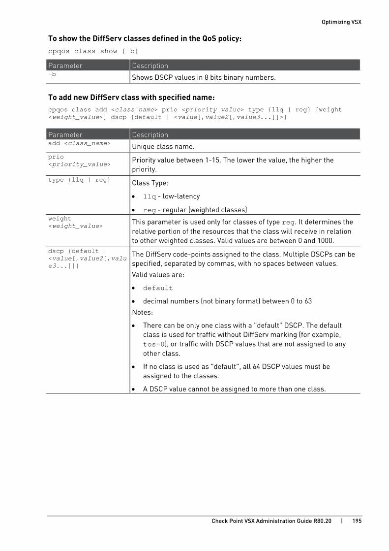
Optimizing VSX
Check Point VSX Administration Guide R80.20 | 195
To show the DiffServ classes defined in the QoS policy: cpqos class show [-b]
Parameter Description -b Shows DSCP values in 8 bits binary numbers.
To add new DiffServ class with specified name: cpqos class add <class_name> prio <priority_value> type {llq | reg} [weight <weight_value>] dscp {default | <value[,value2[,value3...]]>}
Parameter Description add <class_name> Unique class name. prio <priority_value> Priority value between 1-15. The lower the value, the higher the
priority. type {llq | reg} Class Type:
• llq - low-latency
• reg - regular (weighted classes) weight <weight_value> This parameter is used only for classes of type reg. It determines the
relative portion of the resources that the class will receive in relation to other weighted classes. Valid values are between 0 and 1000.
dscp {default | <value[,value2[,value3...]]}
The DiffServ code-points assigned to the class. Multiple DSCPs can be specified, separated by commas, with no spaces between values.
Valid values are:
• default
• decimal numbers (not binary format) between 0 to 63
Notes:
• There can be only one class with a "default" DSCP. The default class is used for traffic without DiffServ marking (for example, tos=0), or traffic with DSCP values that are not assigned to any other class.
• If no class is used as "default", all 64 DSCP values must be assigned to the classes.
• A DSCP value cannot be assigned to more than one class.

Optimizing VSX
Check Point VSX Administration Guide R80.20 | 196
To delete a specified DiffServ class name: cpqos class del <class_name>
Note - Changes to the QoS policy will be are enforced only after the QoS policy is installed.
Notes:
• All commands return a zero value for success
• All commands return a non-zero value for failure
• Options and argument are case-sensitive
QoS Policy File The QoS policy file is $FWDIR/database/qos_policy.C. The QoS policy file is created when the cpqos command is run for the first time.
Important - The QoS policy file should not be edited manually.
Use the cpqos class add/del commands to create entries. To maintain multiple QoS policies, rename the qos_policy.C file or copy it to another directory, and copy it back as $FWDIR/database/qos_policy.C when the policy needs to be enforced.
QoS Default Configuration Default QoS configuration is set to "uninstall" (for example, not enforced).
Run the cpqos install (on page 194) or cpqos uninstall (on page 194) command to set the desired default configuration after boot.
Sample Differentiated Services Implementation This section presents a sample differentiated services implementation. It includes examples for configuration, monitoring and statistics.
Sample Traffic Types Traffic Type Meaning...
Diamond Real-time traffic (e.g. VOIP) which requires little bandwidth and is sensitive to latency and drops. This traffic is usually assigned to the EF (Expedited-Forwarding) PHB (Per Hop Behavior).
Platinum Real-time traffic with low bandwidth requirements that is less sensitive to latency and drops than Diamond.
Gold Traffic which is sensitive to drops
Silver Traffic which is less sensitive to drops than Gold.
Bronze Various types of traffic which require resource allocation. This traffic is usually assigned to the Best-Effort PHB.
Copper High-volume traffic with a tendency to consume bandwidth
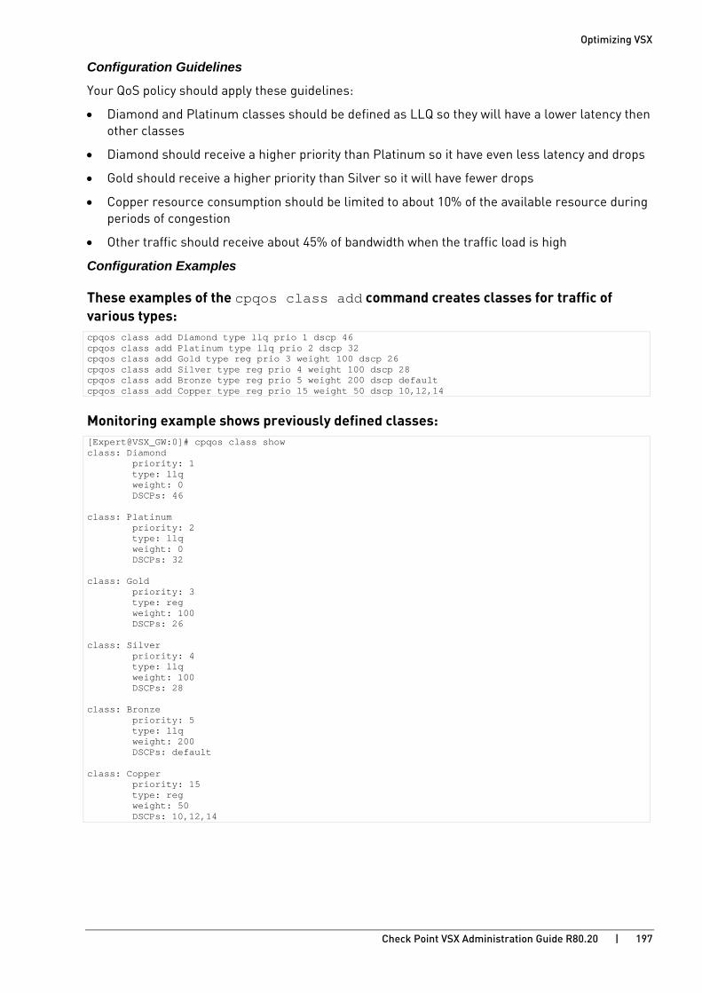
Optimizing VSX
Check Point VSX Administration Guide R80.20 | 197
Configuration Guidelines
Your QoS policy should apply these guidelines:
• Diamond and Platinum classes should be defined as LLQ so they will have a lower latency then other classes
• Diamond should receive a higher priority than Platinum so it have even less latency and drops
• Gold should receive a higher priority than Silver so it will have fewer drops
• Copper resource consumption should be limited to about 10% of the available resource during periods of congestion
• Other traffic should receive about 45% of bandwidth when the traffic load is high
Configuration Examples
These examples of the cpqos class add command creates classes for traffic of various types: cpqos class add Diamond type llq prio 1 dscp 46 cpqos class add Platinum type llq prio 2 dscp 32 cpqos class add Gold type reg prio 3 weight 100 dscp 26 cpqos class add Silver type reg prio 4 weight 100 dscp 28 cpqos class add Bronze type reg prio 5 weight 200 dscp default cpqos class add Copper type reg prio 15 weight 50 dscp 10,12,14
Monitoring example shows previously defined classes: [Expert@VSX_GW:0]# cpqos class show class: Diamond priority: 1 type: llq weight: 0 DSCPs: 46 class: Platinum priority: 2 type: llq weight: 0 DSCPs: 32 class: Gold priority: 3 type: reg weight: 100 DSCPs: 26 class: Silver priority: 4 type: llq weight: 100 DSCPs: 28 class: Bronze priority: 5 type: llq weight: 200 DSCPs: default class: Copper priority: 15 type: reg weight: 50 DSCPs: 10,12,14

Optimizing VSX
Check Point VSX Administration Guide R80.20 | 198
Statistics example shows statistics for the previously defined classes: class priority type weight rx tx drops Diamond 1 llq 0 2775 2650 0 Platinum 2 llq 0 1024 1020 105 Gold 3 reg 100 1775015 1773805 205 Silver 4 reg 100 1862437 1862336 550 Bronze 5 reg 200 3370033 2955120 3147 Copper 15 reg 50 1862437 762336 100689
From this statistical output, it is apparent that:
• In the Diamond class there were no drops.
• In the Platinum class there were a few drops, even though less traffic arrived classed as Platinum than did as Diamond.
• In the Gold class there were fewer drops than from the Silver class.
• In the Bronze class there were twice as many bytes transmitted than in the Silver and Gold classes, and four times as many bytes than there were in the Copper class.
• Most packets in the Copper class were dropped.

Optimizing VSX
Check Point VSX Administration Guide R80.20 | 199
Monitoring Memory Resources (vsx mstat) Use the vsx mstat (on page 226) command to monitor the memory the VSX Gateway uses. The command shows an overview of the memory that the system and each Virtual Device is using. These are the global memory resources that are shown:
• Memory Total - Total physical memory on the VSX Gateway.
• Memory Free - Available physical memory.
• Swap Total - Total of swap memory.
• Swap Free - Available swap memory.
• Swap-in rate - Total memory swaps per second.
The Virtual Devices are listed according to the VSIDs. Run the vsx stat -v command to show the VSID for the Virtual Devices.
You must be in the Expert mode to run this command.
Monitoring CPU Resources (vsx resctrl) Use the vsx resctrl (on page 229) commands to monitor the CPU resources on a VSX Gateway. You can also see real-time statistics on the current and average CPU consumption by the Virtual Devices.
Note - You must enable VSX Resource Control Monitoring to see data about CPU usage for each Virtual System over SNMP.
Optimizing VSX
Check Point VSX Administration Guide R80.20 | 200
SNMP Monitoring For more about using SNMP, see:
• R80.20 Gaia Administration Guide https://sc1.checkpoint.com/documents/R80.20_GA/WebAdminGuides/EN/CP_R80.20_Gaia_AdminGuide/html_frameset.htm - Chapter System Management - Section SNMP
• sk90860: How to configure SNMP on Gaia OS http://supportcontent.checkpoint.com/solutions?id=sk90860
Supported SNMP Versions SNMP v1, v2c, and v3 are supported in all monitor modes.
Note - For SNMP queries of Virtual Devices using the VS0 IP address:
• SNMP V1 and V2c
Query the Virtual Device using the VSID and the configured SNMP community.
• SNMP V3
Query the virtual device using the VSID and SNMP v3 context mechanism.
Supported SNMP Modes VSX supports these SNMP modes:
• SNMP Default Mode
• SNMP VS Mode
• SNMP VS in vs-direct access mode
SNMP Default Mode In SNMP default mode:
• The SNMP daemon runs only in the context of VS0 (the VSX Gateway).
• The VS0 SNMP daemon has a set of tables with counters (VSX SNMP tree) for each Virtual Device.

Optimizing VSX
Check Point VSX Administration Guide R80.20 | 201
• SNMP queries must be sent to IP address of the VSX Gateway (context is VS0).
Item Description Item Description
1 SNMP Server that sends SNMP Requests to VSX Gateway
6 Virtual System 1 (ctx 1)
2 eth0 7 Virtual System in Bridge mode (ctx 2)
3 VSX Gateway 8 Virtual Router (ctx 3)
4 SNMP Daemon 9 Virtual Switch (ctx 4)
5 Virtual System 0
SNMP VS Mode In SNMP VS mode:
• Each Virtual Device has separate SNMP daemon running in the context of that Virtual Device.
• Query for Virtual Devices uses the VS0 IP address.
• You must run the SNMP query using the interface on the VSX Gateway.
• The query is relayed to the specified Virtual Device.
• The Virtual Device sends the response through the same VSX Gateway interface.
• The VS ID must be specified in the SNMP query.

Optimizing VSX
Check Point VSX Administration Guide R80.20 | 202
Note - Default mode query functionality is not decreased when you enable SNMP VS mode.
Item Description Item Description
1 Query Host 4 VS 0
2 eth0 5 SNMP Daemon
3 VSX Gateway 6 UDS
SNMP VS in vs-direct-access mode • Enables SNMP queries on the IP address of a Virtual System (not only VS0), or Virtual Router.
Notes: • For cluster deployments, you can query only Virtual IP addresses.
• Only Virtual Devices with an IP address can be queried, not Virtual Switches or Virtual Bridges.
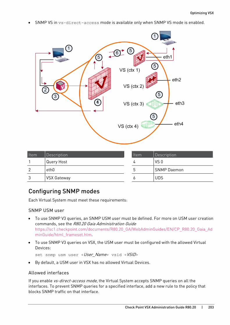
Optimizing VSX
Check Point VSX Administration Guide R80.20 | 203
• SNMP VS in vs-direct-access mode is available only when SNMP VS mode is enabled.
Item Description Item Description
1 Query Host 4 VS 0
2 eth0 5 SNMP Daemon
3 VSX Gateway 6 UDS
Configuring SNMP modes Each Virtual System must meet these requirements:
SNMP USM user
• To use SNMP V3 queries, an SNMP USM user must be defined. For more on USM user creation commands, see the R80.20 Gaia Administration Guide https://sc1.checkpoint.com/documents/R80.20_GA/WebAdminGuides/EN/CP_R80.20_Gaia_AdminGuide/html_frameset.htm.
• To use SNMP V3 queries on VSX, the USM user must be configured with the allowed Virtual Devices:
set snmp usm user <User_Name> vsid <VSID>
• By default, a USM user in VSX has no allowed Virtual Devices.
Allowed interfaces
If you enable vs-direct-access mode, the Virtual System accepts SNMP queries on all the interfaces. To prevent SNMP queries for a specified interface, add a new rule to the policy that blocks SNMP traffic on that interface.

Optimizing VSX
Check Point VSX Administration Guide R80.20 | 204
Query source
In vs mode and vs-direct-access mode, there is no specification for query source. All sources allowed in the Security Policy are valid.
Running SNMP Queries
When you query a Virtual System Load Sharing cluster with the VSX Cluster Member (VS 0) Virtual IP address, the Virtual System on the Active VSX Cluster Member (VS 0) replies to the query. An Active Virtual System on a Standby VSX Cluster Member will not reply to the query.
If you want to query the Active Virtual System on a Standby VSX Cluster Member, use the real IP address of the VSX Cluster Member.
SNMP Configuration
See the R80.20 Gaia Administration Guide https://sc1.checkpoint.com/documents/R80.20_GA/WebAdminGuides/EN/CP_R80.20_Gaia_AdminGuide/html_frameset.htm and sk90860: How to configure SNMP on Gaia OS http://supportcontent.checkpoint.com/solutions?id=sk90860.
To Configure: Run:
SNMP Default 1. set snmp agent on 2. set snmp mode default
SNMP mode VS 1. set snmp agent on 2. set snmp mode vs
SNMP direct-vs-access 1. set snmp agent on 2. set snmp mode vs 3. set snmp vs-direct-access on
Optimizing VSX
Check Point VSX Administration Guide R80.20 | 205
Example SNMP queries for Virtual Systems This section shows example SNMP queries.
To run an SNMP V3 query using the VSX (VS 0) IP address
In Clish
1. Enable the SNMP agent for context VS 0
Run: set snmp agent on
2. Add an SNMP user with permissions for VSs 2,15.
Run: add snmp usm user admin security-level authNoPriv auth-pass-phrase abcd1234 set snmp usm user admin vsid 2,15
3. Set SNMP VS mode.
Run: set snmp mode vs
4. Send the remote queries, where:
• vsidN is the SNMP context name required by SNMP v3.
• The IP address is the management IP address of the VSX Gateway or VSX Cluster.
For example (in Expert mode): snmpwalk -n vsid2 -v 3 -l authNoPriv -u admin -A abcd1234 192.0.2.5 ifDesc snmpwalk -n vsid15 -v 3 -l authNoPriv -u admin -A abcd1234 192.0.2.5 sysName
192.0.2.5 is the IP address of the Management Server.
To run an SNMP V1/V2c query using the VSX (VS 0) IP Address
In Clish:
1. Enable the SNMP agent for context VS 0:
Run: set snmp agent on
2. Enable SNMP V1/V2C
Run: set snmp agent-version any
3. Set the SNMP community: set snmp community public read-only set snmp community private read-write
4. Set the SNMP mode to VS: set snmp mode vs
5. Send remote queries, where:
• The community has the VSID or Virtual System name as a suffix.
• The IP address is the Management IP address of the VSX Gateway or VSX Cluster.
For example, to query a Virtual System with the name “MY_VS” or has VSID “2”, run
in expert mode: snmpwalk -v 1 -c public_2 192.0.2.5 ifDescr snmpwalk -v 1 -c private_MY_VS 192.0.2.5 ifDescr

Optimizing VSX
Check Point VSX Administration Guide R80.20 | 206
Communities with suffixes are created automatically. Community name collisions might occur in special cases, for example if we use these communities:
• Read-only community = private
• Read-write community = private_1
The communities' private_1, and private_1_1 will be automatically created for VSID 1. Private_1 is not a unique community. The community is ambiguous and using it will result unexpected behavior.
To run an SNMP query using the Virtual Device's IP address
1. Enable the SNMP agent for context VS0: set snmp agent on
2. Add an SNMP user: add snmp usm user admin security-level authNoPriv auth-pass-phrase abcd1234
3. Specify USM user permissions for Virtual Devices: set snmp usm user admin vsid 0-10
4. Set the SNMP community: set snmp community public read-only set snmp community private read-write
5. Set SNMP VS mode: set snmp mode vs
6. Enable SNMP queries over Virtual Device's interfaces: set snmp vs-direct-access on
7. Send remote queries, where the IP address is the Virtual IP address of the Virtual Device.
In expert mode, run: snmpwalk -v 1 -c public 192.0.2.81 ifDescr snmpwalk -v 2c -c public 192.0.2.81 ifDescr snmpwalk -v 1 -c private 192.0.2.82 ifDescr snmpwalk -v 2c -c private 192.0.2.82 ifDescr snmpwalk -v 3 -l authNoPriv -u admin -A abcd1234 192.0.2.83 ifDescr
Note -
• The SNMP community used in the queries is the same community that you configured earlier.
• Only the active Virtual Device is queried.
Important - SNMP traps are available only for VS 0
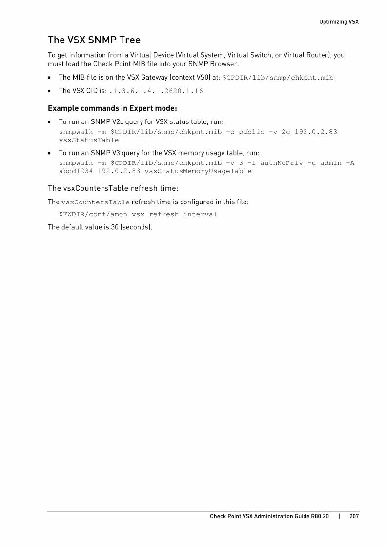
Optimizing VSX
Check Point VSX Administration Guide R80.20 | 207
The VSX SNMP Tree To get information from a Virtual Device (Virtual System, Virtual Switch, or Virtual Router), you must load the Check Point MIB file into your SNMP Browser.
• The MIB file is on the VSX Gateway (context VS0) at: $CPDIR/lib/snmp/chkpnt.mib
• The VSX OID is: .1.3.6.1.4.1.2620.1.16
Example commands in Expert mode:
• To run an SNMP V2c query for VSX status table, run: snmpwalk –m $CPDIR/lib/snmp/chkpnt.mib -c public -v 2c 192.0.2.83 vsxStatusTable
• To run an SNMP V3 query for the VSX memory usage table, run: snmpwalk –m $CPDIR/lib/snmp/chkpnt.mib -v 3 -l authNoPriv -u admin -A abcd1234 192.0.2.83 vsxStatusMemoryUsageTable
The vsxCountersTable refresh time:
The vsxCountersTable refresh time is configured in this file:
$FWDIR/conf/amon_vsx_refresh_interval
The default value is 30 (seconds).
Optimizing VSX
Check Point VSX Administration Guide R80.20 | 208
Configuring Jumbo Frames VSX supports Jumbo Frames and lets you configure up to the maximum MTU of the NIC driver.
Jumbo Frames on a Virtual Switch Configure the MTU of a Virtual Switch to enable Jumbo Frames on the Virtual Systems that are connected to the Virtual Switch. When you configure the MTU of the Virtual Switch, all the related Warp Links and interfaces are automatically changed to the new value.
You cannot configure the MTU of a Warp Link from the Virtual System.
To configure Jumbo Frames on a Virtual Switch:
1. Connect with SmartConsole to the Security Management Server or Target Domain Management Server used to manage the Virtual Switch.
2. From the Gateways & Servers view or Object Explorer, double-click the Virtual Switch object.
3. From the left tree, click Topology.
4. In the Interfaces section, select the applicable interface and click Edit. 5. On the General tab, configure the MTU.
6. Click OK.
7. Publish the session.
Jumbo Frames on a Virtual Router Configure the MTU of a Virtual Router to enable Jumbo Frames on the interfaces. To change the MTU of Warp Links, configure the settings of the Virtual System.
To configure Jumbo Frames on a Virtual Router:
1. Connect with SmartConsole to the Security Management Server or Target Domain Management Server used to manage the Virtual Router.
2. From the Gateways & Servers view or Object Explorer, double-click the Virtual Router object.
3. From the left tree, click Topology.
4. In the Interfaces section, select the applicable interface and click Edit. 5. On the General tab, configure the MTU.
6. Click OK.
7. Publish the session.
8. Install the applicable policy on the Virtual Router object.
Optimizing VSX
Check Point VSX Administration Guide R80.20 | 209
Jumbo Frames on a Virtual System in Bridge Mode Configure the MTU of a Virtual System in Bridge Mode to enable Jumbo Frames on the interfaces.
To configure Jumbo Frames on a Virtual System in Bridge Mode:
1. Connect with SmartConsole to the Security Management Server or Target Domain Management Server used to manage the Virtual System.
2. From the Gateways & Servers view or Object Explorer, double-click the Virtual System object.
3. From the left tree, click Topology.
4. In the Interfaces section, select the applicable interface and click Edit. 5. On the General tab, configure the MTU.
6. Click OK.
7. Publish the session.
8. Install the applicable policy on the Virtual System object.
Check Point VSX Administration Guide R80.20 | 210
CHAPTE R 11
VSX Diagnostics and Troubleshooting In This Section:
General Troubleshooting Steps ................................................................................. 210
Troubleshooting Specific Problems .......................................................................... 212
This chapter presents basic diagnostic and troubleshooting procedures that should be followed in the event you encountering a problem while working with VSX. This diagnostic routine will assist you in determining the source of the problem. This chapter presents several known issues and their solutions.
Most problems are caused by configuration errors occurring during the process of defining VSX Gateway, clusters and/or Virtual Devices. Another common source of problems involves networking and connectivity issues affecting VSX behavior. These problems are listed according to the order in which you will likely encounter them. Before reading and following a certain workaround, make sure you've read all the previous workarounds, and that those steps in the configuration were successful.
In some of the cases, one initial problem can cause problems in later stages of the configuration. For that reason, it is important to find the root of the problem when you are trying to understand what went wrong.
General Troubleshooting Steps If you suspect that there is a problem with your VSX configuration, there are several diagnostic procedures that you can follow to determine the source. These procedures utilize various commands documented in the Command Line section (on page 217).
1. Perform a basic configuration check for each gateway or VSX Cluster Member by running the vsx stat -v command. The output will allow you to:
a) Account for all Virtual Systems and make sure that none are missing from the configuration.
b) Make sure all Virtual Devices are Active
c) Make sure the correct Security Policy is installed for each Virtual System
d) Make sure the SIC trust is established with the Management Server
2. Run the cplic print command on each VSX Gateway, VSX Cluster Member and Management Server to make sure the appropriate licenses are installed.
3. Run the cphaprob stat command on each VSX Cluster Member to verify its status. If a member is listed with a status other than Active, Standby, or Backup, refer to the "Troubleshooting" chapter in the R80.20 ClusterXL Administration Guide https://sc1.checkpoint.com/documents/R80.20_GA/WebAdminGuides/EN/CP_R80.20_ClusterXL_AdminGuide/html_frameset.htm for additional troubleshooting assistance.
VSX Diagnostics and Troubleshooting
Check Point VSX Administration Guide R80.20 | 211
4. If you suspect that a Virtual System is experiencing connectivity problems, perform the following steps:
a) Run: vsenv to set the context to the appropriate Virtual System.
b) Run fw getifs to display the interface list for the Virtual System.
c) Examine connectivity status using standard operating system commands and tools such as: ping, traceroute, tcpdump, ip route, ftp, etc. Some of these run according to context (i.e. routing, source and destination IP addresses). .
You can also execute the ip route and ip link commands.
If these tests indicate that all interfaces and routers have connectivity, and appear to be functioning correctly, you should monitor the passage of packets through the system.
5. Execute the fw monitor -v <VSID> commands to capture details of packets at multiple points. This may return multiple reports on the same packet as it passes various capture points. This command does not report on Virtual Routers, except for packets destined to an external Virtual Router.
6. Execute the tcpdump command to display transmitted or received packets for specific interfaces, including Warp interfaces. This often provides valuable clues for resolving connectivity issues.

VSX Diagnostics and Troubleshooting
Check Point VSX Administration Guide R80.20 | 212
Troubleshooting Specific Problems
Cannot Establish SIC Trust for VSX Gateway or VSX Cluster Member When creating a VSX Gateway or VSX Cluster Member, you cannot establish SIC trust. SmartConsole shows an error message:
Certificate cannot be pushed. Connection error with wait agent.
Possible Causes How to Resolve
Check that you have network connectivity between the gateway and the Security Gateway or Domain Management Server by pinging from the VSX system (a ping from the Management Server to the VSX Gateway will not work because of the default security policy installed on the VSX Gateway / VSX Cluster Member).
Make sure the context is vrf 0 first.
On all relevant machines, re-check the cables, routes, IP addresses and any intermediate networking devices (routers, switches, hubs, and so on) between the management and the gateway(s).
Check that all the Check Point processes on the VSX Gateway(s) are up and running by running cpwd_admin list and making sure each line has a non-zero value in the PID field.
If the gateway(s) has just rebooted, the Check Point processes might still be coming up.
Check that the CPD process is listening to the trust establishment port.
Run netstat -an | grep 18211 on the VSX Gateway(s), and make sure that output looks like this: tcp 0 0 0.0.0.0:18211 0.0.0.0:* LISTEN

VSX Diagnostics and Troubleshooting
Check Point VSX Administration Guide R80.20 | 213
SIC Trust Problems with New Virtual Devices When creating a new Virtual System, Virtual Router or Virtual Switch, you cannot establish SIC trust.
Possible Causes How to Resolve
Time or time zone mismatch between the Management Server and the VSX Gateway. For proper SIC operation, the time, date and time zone must be synchronized between the Management Server and Gateways/ VSX Cluster Members.
Execute the /bin/date -u command on all machines, to obtain the correct UTC/GMT time. The machines can be in different time zones, as long as their UTC/GMT times match.
Change the time, date and time zone on the management and/or the gateway so that their UTC/GMT times match. Refer to your operating system documentation for the exact commands needed to accomplish this.
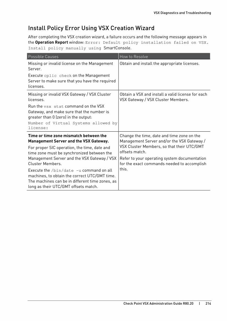
VSX Diagnostics and Troubleshooting
Check Point VSX Administration Guide R80.20 | 214
Install Policy Error Using VSX Creation Wizard After completing the VSX creation wizard, a failure occurs and the following message appears in the Operation Report window: Error: Default policy installation failed on VSX. Install policy manually using SmartConsole.
Possible Causes How to Resolve
Missing or invalid license on the Management Server.
Execute cplic check on the Management Server to make sure that you have the required licenses.
Obtain and install the appropriate licenses.
Missing or invalid VSX Gateway / VSX Cluster licenses.
Run the vsx stat command on the VSX Gateway, and make sure that the number is greater than 0 (zero) in the output: Number of Virtual Systems allowed by license:
Obtain a VSX and install a valid license for each VSX Gateway / VSX Cluster Members.
Time or time zone mismatch between the Management Server and the VSX Gateway. For proper SIC operation, the time, date and time zone must be synchronized between the Management Server and the VSX Gateway / VSX Cluster Members.
Execute the /bin/date -u command on all machines, to obtain the correct UTC/GMT time. The machines can be in different time zones, as long as their UTC/GMT offsets match.
Change the time, date and time zone on the Management Server and/or the VSX Gateway / VSX Cluster Members, so that their UTC/GMT offsets match.
Refer to your operating system documentation for the exact commands needed to accomplish this.

VSX Diagnostics and Troubleshooting
Check Point VSX Administration Guide R80.20 | 215
Internal Host Cannot Ping Virtual System After defining a Virtual System with an internal VLAN interface, an internal host on that VLAN cannot ping the Virtual System internal or external IP address.
Possible Causes How to Resolve
A policy allowing the communication was not installed on the Virtual System. Note that after creating a Virtual System, it has a Default Policy that blocks all traffic.
Install a policy on the Virtual System that enables the traffic. Check with the Logs & Monitor view that the Virtual System is allowing the traffic.
There is the VLAN configuration problem on a switch, or physical cable problem.
Check the switch configuration. Make sure that VLAN tag configured on the switch is the same as used for the Virtual System VLAN interface.
Check the cables, and make sure that you have plugged the cable from the switch to the correct port on the VSX Gateway / VSX Cluster Members.
Incorrect routing on adjacent routers or hosts. Check the routing tables on intermediate routers and hosts. You can use tcpdump command on the relevant VLAN interface on the VSX Gateway / VSX Cluster Members to make sure that the traffic arrives to and leaves the VSX Gateway / VSX Cluster Members.
Incorrect IP address or net mask defined on the Virtual System VLAN interface.
Check the IP address and the net mask assigned to the Virtual System internal VLAN interface.

VSX Diagnostics and Troubleshooting
Check Point VSX Administration Guide R80.20 | 216
Re-establishing SIC Trust with Virtual Devices In the event you encounter connectivity problems due to the loss of SIC Trust for a specific Virtual Device (Virtual System or Virtual Router), you can use the procedure below to manually re-establish the SIC trust.
To manually re-establish SIC Trust with a Virtual Device:
Follow the instructions in the sk34098 http://supportcontent.checkpoint.com/solutions?id=sk34098 .
1. On the VSX Gateway or each VSX Cluster Member:
a) Connect to the command line the VSX Gateway or each VSX Cluster Member.
b) Log in to the Expert mode.
c) Examine the VSX configuration to determine the ID of the Virtual Device:
vsx stat -v
d) Reset the SIC with the specified Virtual Device:
vsx sic reset <ID>
2. On the Management Server:
a) Connect to the command line the Management Server.
b) Log in to the Expert mode.
c) On the Multi-Domain Server, change the context to the applicable Target Domain Management Server used to manage the Virtual Device:
# mdsenv <IP Address or Name of Domain Management Server>
d) Determine the SIC name of the Virtual Device:
# cpca_client lscert -stat valid -kind SIC | grep -i -A 2 <Name of Virtual Device Object>
e) Revoke the SIC certificate of the Virtual Device:
# cpca_client revoke_cert -n <CN=...,O=...,>
3. Connect with SmartConsole to the Security Management Server or Main Domain Management Server used to manage the VSX Cluster.
4. From the Gateways & Servers view or Object Explorer, double-click the Virtual Device object.
5. Click OK.
This action creates a new SIC certificate for the Virtual Device and saves it on the VSX Gateway or each VSX Cluster Member.

Check Point VSX Administration Guide R80.20 | 217
CHAPTE R 12
Command Line Reference In This Section:
vsenv ............................................................................................................................ 218
vsx ................................................................................................................................ 219
vsx_util ........................................................................................................................ 237
vsx_provisioning_tool ................................................................................................. 257
See the R80.20 Command Line Interface Reference Guide https://sc1.checkpoint.com/documents/R80.20_GA/WebAdminGuides/EN/CP_R80.20_CLI_ReferenceGuide/html_frameset.htm.
Below is a limited list of applicable commands.

Command Line Reference
Check Point VSX Administration Guide R80.20 | 218
vsenv Description
Changes the shell's current context to the specified Virtual Device.
Syntax vsenv [{<VSID> | <Name of Virtual Device>}]
Parameters
Parameter Description
No Parameters Changes the context to the default Virtual Device 0.
<VSID> Specifies the Virtual Device by its ID.
<Name of Virtual Device> Specifies the Virtual Device by its Name.
Note - To see the configured Virtual Devices, run vsx stat -v command.
Example 1 - Changing the context to the default Virtual Device 0 [Expert@MyVsxGW:0]# vsenv Context is set to Virtual Device VSX2_192.168.3.242 (ID 0). [Expert@MyVsxGW:0]#
Example 2 - Changing the context to the specific Virtual Device [Expert@MyVsxGW:0]# vsenv 2 Context is set to Virtual Device VS2 (ID 2). [Expert@MyVsxGW:2]#

Command Line Reference
Check Point VSX Administration Guide R80.20 | 219
vsx Description
• Shows VSX configuration.
• Fetches VSX configuration.
• Shows and configures Resource Control.
• Shows and configures Memory Resource Control.
Syntax vsx fetch <options> fetch_all_cluster_policies fetchvs <options> get initmsg <options> mstat <options> resctrl <options> showncs <options> sicreset stat <options> unloadall vspurge
Note - The fw6 vsx commands are not supported.
Parameters
Parameter <options> Description
fetch <options> (on page 220) Fetches configuration for VSX Gateway.
fetch_all_cluster_policies (on page 222)
Fetches security policy for all Virtual Systems and Virtual Routers from cluster peers.
fetchvs <options> (on page 223) Fetches configuration for a Virtual System.
get (on page 224) Shows the information about the current VSX context.
initmsg <options> (on page 225) Sends VSX initialization message.
mstat <options> (on page 226) Shows and configures Memory Resource Control.
resctrl <options> (on page 229) Shows and configures Resource Control.
showncs <options> (on page 231) Shows Check Point Network Configuration Script (NCS) for Virtual Device.
sicreset (on page 232) Resets SIC for Virtual System or Virtual Router in the current VSX context.
stat <options> (on page 233) Shows status information for VSX Gateway.
unloadall (on page 235) Unloads security policy for all Virtual Systems and Virtual Routers.
vspurge (on page 236) Cleans un-used entries for Virtual Devices.
Fetches configuration file for Virtual Devices.
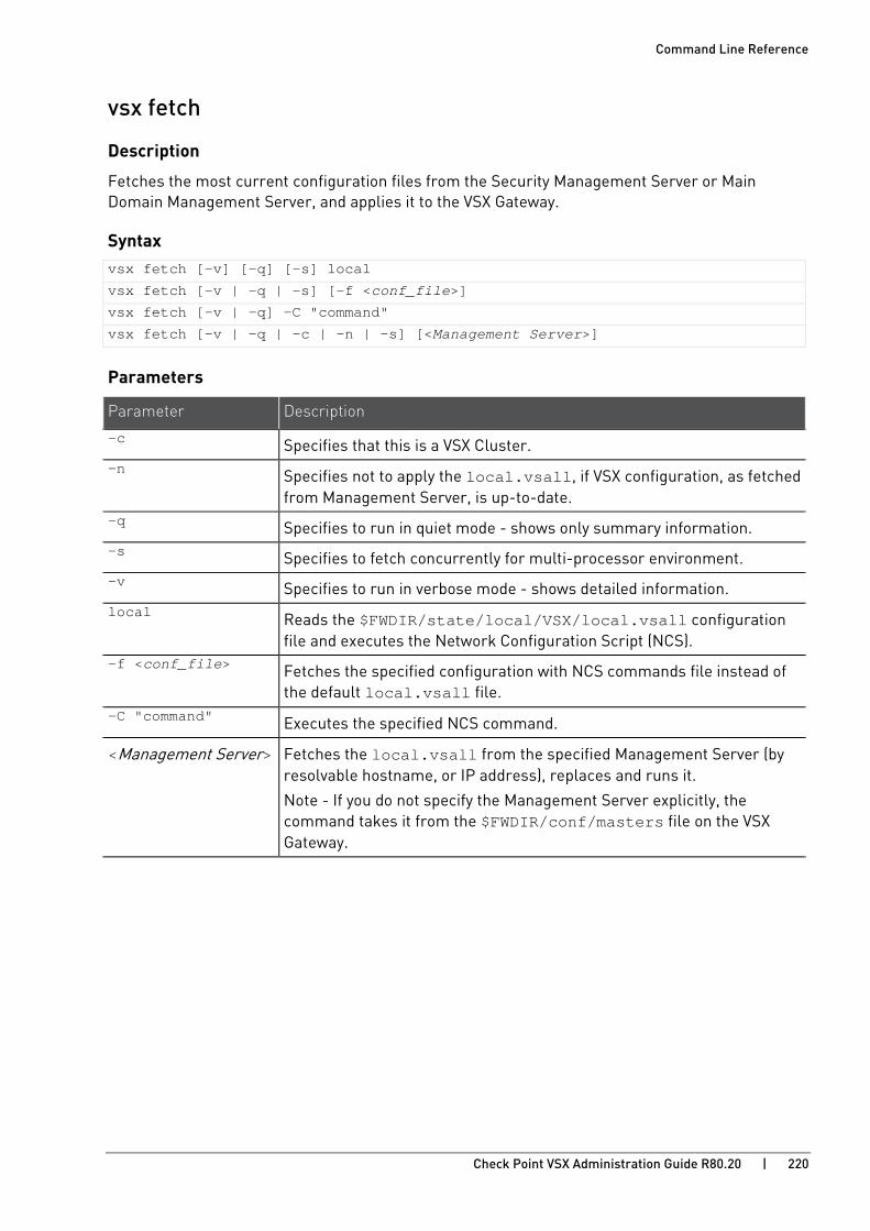
Command Line Reference
Check Point VSX Administration Guide R80.20 | 220
vsx fetch
Description
Fetches the most current configuration files from the Security Management Server or Main Domain Management Server, and applies it to the VSX Gateway.
Syntax vsx fetch [-v] [-q] [-s] local
vsx fetch [-v | -q | -s] [-f <conf_file>]
vsx fetch [-v | -q] -C "command"
vsx fetch [-v | -q | -c | -n | -s] [<Management Server>]
Parameters
Parameter Description
-c Specifies that this is a VSX Cluster. -n Specifies not to apply the local.vsall, if VSX configuration, as fetched
from Management Server, is up-to-date. -q Specifies to run in quiet mode - shows only summary information. -s Specifies to fetch concurrently for multi-processor environment. -v Specifies to run in verbose mode - shows detailed information. local Reads the $FWDIR/state/local/VSX/local.vsall configuration
file and executes the Network Configuration Script (NCS). -f <conf_file> Fetches the specified configuration with NCS commands file instead of
the default local.vsall file. -C "command" Executes the specified NCS command.
<Management Server> Fetches the local.vsall from the specified Management Server (by resolvable hostname, or IP address), replaces and runs it.
Note - If you do not specify the Management Server explicitly, the command takes it from the $FWDIR/conf/masters file on the VSX Gateway.
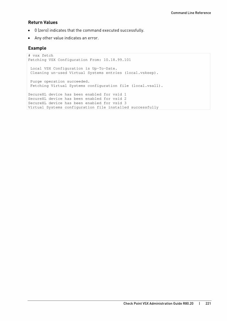
Command Line Reference
Check Point VSX Administration Guide R80.20 | 221
Return Values
• 0 (zero) indicates that the command executed successfully.
• Any other value indicates an error.
Example # vsx fetch Fetching VSX Configuration From: 10.18.99.101 Local VSX Configuration is Up-To-Date. Cleaning un-used Virtual Systems entries (local.vskeep). Purge operation succeeded. Fetching Virtual Systems configuration file (local.vsall). SecureXL device has been enabled for vsid 1 SecureXL device has been enabled for vsid 2 SecureXL device has been enabled for vsid 3 Virtual Systems configuration file installed successfully
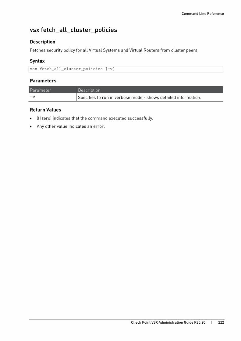
Command Line Reference
Check Point VSX Administration Guide R80.20 | 222
vsx fetch_all_cluster_policies
Description
Fetches security policy for all Virtual Systems and Virtual Routers from cluster peers.
Syntax vsx fetch_all_cluster_policies [-v]
Parameters
Parameter Description -v Specifies to run in verbose mode - shows detailed information.
Return Values
• 0 (zero) indicates that the command executed successfully.
• Any other value indicates an error.

Command Line Reference
Check Point VSX Administration Guide R80.20 | 223
vsx fetchvs
Description
Fetches configuration file for the specified Virtual Device based on information stored locally on the VSX Gateway.
Syntax vsx fetchvs [-v | -q] [{<VSID> | <Name of Virtual Device>}]
Parameters
Parameter Description -q Specifies to run in quiet mode - shows only summary information. -v Specifies to run in verbose mode - shows detailed information.
<Name of Virtual Device> Specifies the name of the Virtual Device.
<VSID> Specifies the ID of the Virtual Device.
Return Values
• 0 (zero) indicates that the command executed successfully.
• Any other value indicates an error.
Example # vsx fetchvs 2
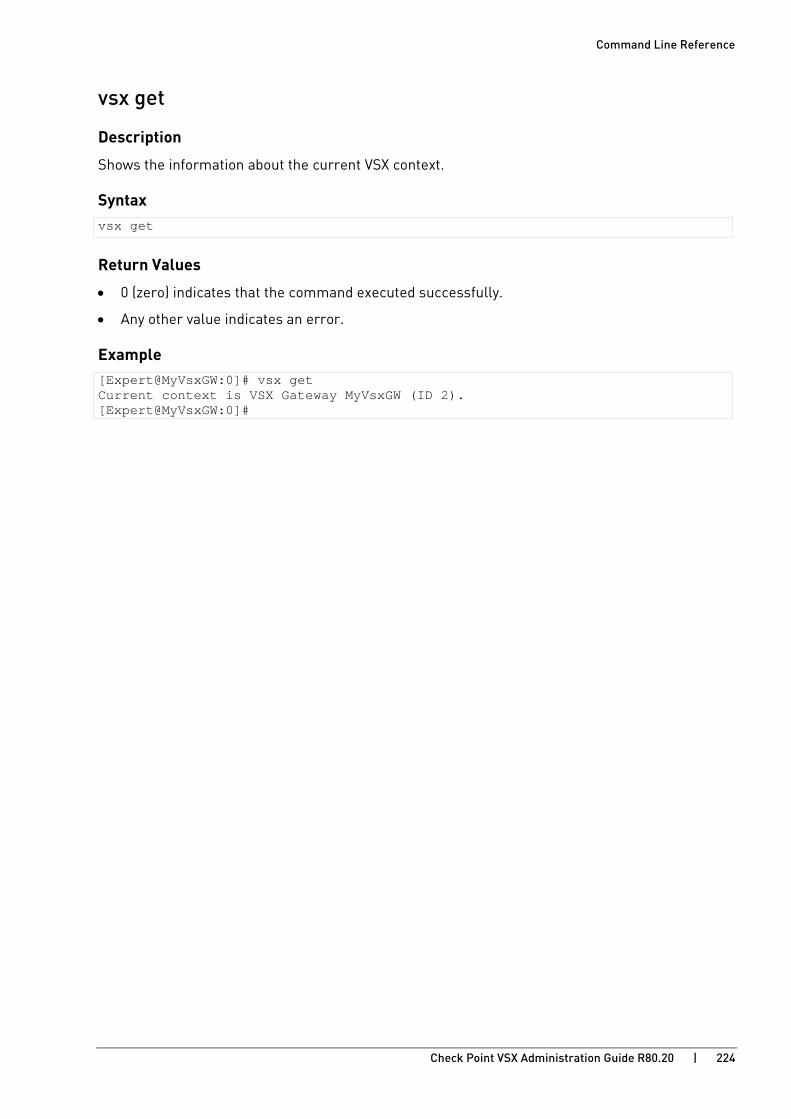
Command Line Reference
Check Point VSX Administration Guide R80.20 | 224
vsx get
Description
Shows the information about the current VSX context.
Syntax vsx get
Return Values
• 0 (zero) indicates that the command executed successfully.
• Any other value indicates an error.
Example [Expert@MyVsxGW:0]# vsx get Current context is VSX Gateway MyVsxGW (ID 2). [Expert@MyVsxGW:0]#

Command Line Reference
Check Point VSX Administration Guide R80.20 | 225
vsx initmsg
Description
Sends VSX initialization message - to initialize the CPD messaging in Virtual Systems.
Syntax vsx initmsg [-q | -v]
Parameters
Parameter Description -q Specifies to run in quiet mode - shows only summary information.
-v Specifies to run in verbose mode - shows detailed information.
Return Values
• 0 (zero) indicates that the command executed successfully.
• Any other value indicates an error.
Example [Expert@MyVsxGW:2]# vsx initmsg -v Sending VSX initialization message. VSX initialization operation succeeded. [Expert@MyVsxGW:2]#

Command Line Reference
Check Point VSX Administration Guide R80.20 | 226
vsx mstat
Description
Shows and configures Memory Resource Control.
Output shows these global memory resources:
• Memory Total - Total physical memory on the VSX Gateway.
• Memory Free - Available physical memory.
• Swap Total - Total of swap memory.
• Swap Free - Available swap memory.
• Swap-in rate - Total memory swaps per second.
Syntax vsx mstat help
vsx mstat [-vs <VSID>] [unit <Unit>] [sort {<Number> | all}] debug disable enable status swap <Minutes>
Parameters
Parameter Description
help Shows the built-in usage.
No Parameters Shows the total memory consumption for each Virtual System.
-vs <VSID> Specifies the Virtual Systems by their IDs.
You can specify:
• One Virtual System.
Example: -vs <VSID1>
• Many individual Virtual Systems (separate their IDs with spaces).
Example: -vs <VSID1> <VSID2>
• A range of Virtual Systems.
Example: -vs <VSID4-VSID6>
Note - You can combine these options (separate them with spaces).
unit <Unit> Specifies the memory measurement unit shown in the command output:
• B - bytes
• K - kilobytes
• M - megabytes (default)
• G - gigabytes

Command Line Reference
Check Point VSX Administration Guide R80.20 | 227
Parameter Description
sort {<Number> | all}
Sorts the Virtual Systems in the output by their memory size.
Specifies the number of Virtual Systems shown in the command output.
Use all to show all Virtual Systems.
If you do not specify this flag, the Virtual Systems in the output are sorted by their VSID.
debug Shows memory consumption debug information for each Virtual System by fields, which are defined in the configuration file.
disable Disables the Memory Resource Control.
Note - The change applies immediately and does not require a reboot.
enable Enables the Memory Resource Control.
Note - The change requires a reboot.
status Shows the current Memory Resource Control status.
swap <Minutes> Specifies the swap-in sample rate in minutes.
Enter the number of minutes that the system measures memory swaps to determine the swap-in rate. Only integers are valid values.
The default swap-in sample rate is 10.
Notes:
• Swap-in sample rate is a system-wide Linux setting. When you change the value for memory monitoring, all the swap-in rates are calculated according to the new value.
• When you enable the monitoring memory resources feature, the swap-in rate setting is saved. When you disable the feature, the system restores the saved setting.
Return Values
• 0 (zero) indicates that the command executed successfully.
• Any other value indicates an error.

Command Line Reference
Check Point VSX Administration Guide R80.20 | 228
Example 1 [Expert@MyVsxGW:0]# vsx mstat unit M sort all VSX Memory Status ================= Memory Total: 7753.95 MB Memory Free: 7168.71 MB Swap Total: 3992.71 MB Swap Free: 3992.71 MB Swap-in rate: 8796093022208.00 MB VSID | Memory Consumption ======+==================== 0 | 260.79 MB 1 | 0.00 MB [Expert@MyVsxGW:0]#
Example 2 [Expert@MyVsxGW:0]# vsx mstat -vs 0 unit G VSX Memory Status ================= Memory Total: 7.572 GB Memory Free: 7.001 GB Swap Total: 3.899 GB Swap Free: 3.899 GB Swap-in rate: 8589934592.000 GB VSID | Memory Consumption ======+==================== 0 | 0.255 GB [Expert@MyVsxGW:0]#
Example 3 [Expert@MyVsxGW:0]# vsx mstat debug VSX Memory Status ================= Memory Total: 7940048.00 KB Memory Free: 7339864.00 KB Swap Total: 4088532.00 KB Swap Free: 4088532.00 KB Swap-in rate: 9007199254740992.00 KB VSID | Private_Clean | Private_Dirty | DispatcherGConn | DispatcherHTab | SecureXL | DispatcherGConn6 | DispatcherHTab6 | SecureXL6 ======+===============+===============+=================+================+=============+==================+=================+=========== 0 | 34456.00 KB | 182104.00 KB | 6.09 KB | 0.00 KB | 51071.91 KB | 0.00 KB | 0.00 KB | 0.00 KB 1 | 0.00 KB | 0.00 KB | 0.00 KB | 0.00 KB | 0.00 KB | 0.00 KB | 0.00 KB | 0.00 KB Note: To add a field to memory table please uncomment the required field (delete the leading '#') To remove a field from memory table please comment out the required field (add a leading '#') Configuration is done in the file /opt/CPsuite-R80.20/fw1/conf/memoryinfo.conf [Expert@MyVsxGW:0]#
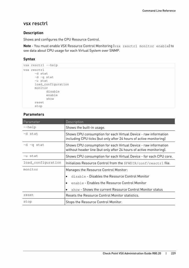
Command Line Reference
Check Point VSX Administration Guide R80.20 | 229
vsx resctrl
Description
Shows and configures the CPU Resource Control.
Note - You must enable VSX Resource Control Monitoring (vsx resctrl monitor enable) to see data about CPU usage for each Virtual System over SNMP.
Syntax vsx resctrl --help
vsx resctrl -d stat -d -q stat -u stat load_configuration monitor disable enable show reset stop
Parameters
Parameter Description --help Shows the built-in usage.
-d stat Shows CPU consumption for each Virtual Device - raw information including CPU ticks (but only after 24 hours of active monitoring)
-d -q stat Shows CPU consumption for each Virtual Device - raw information without header line (but only after 24 hours of active monitoring).
-u stat Shows CPU consumption for each Virtual Device - for each CPU core.
load_configuration Initializes Resource Control from the $FWDIR/conf/resctrl file.
monitor Manages the Resource Control Monitor:
• disable - Disables the Resource Control Monitor
• enable - Enables the Resource Control Monitor
• show - Shows the current Resource Control Monitor status reset Resets the Resource Control Monitor statistics.
stop Stops the Resource Control Monitor.
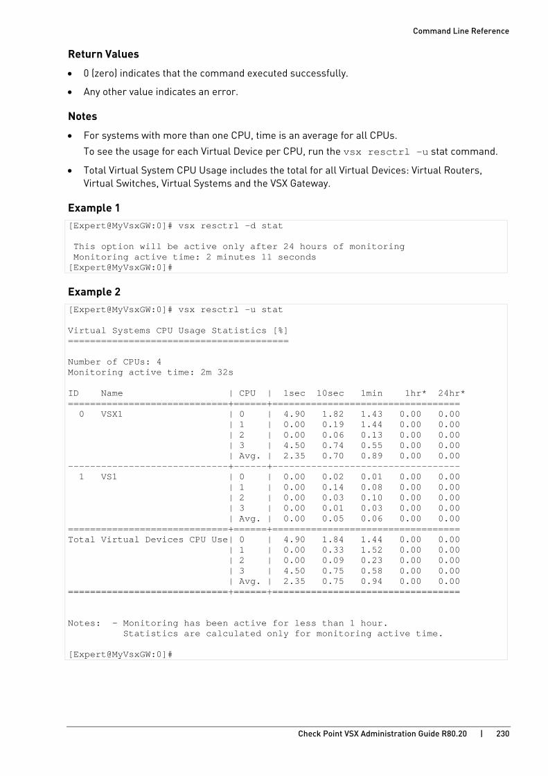
Command Line Reference
Check Point VSX Administration Guide R80.20 | 230
Return Values
• 0 (zero) indicates that the command executed successfully.
• Any other value indicates an error.
Notes
• For systems with more than one CPU, time is an average for all CPUs.
To see the usage for each Virtual Device per CPU, run the vsx resctrl -u stat command.
• Total Virtual System CPU Usage includes the total for all Virtual Devices: Virtual Routers, Virtual Switches, Virtual Systems and the VSX Gateway.
Example 1 [Expert@MyVsxGW:0]# vsx resctrl -d stat This option will be active only after 24 hours of monitoring Monitoring active time: 2 minutes 11 seconds [Expert@MyVsxGW:0]#
Example 2 [Expert@MyVsxGW:0]# vsx resctrl -u stat Virtual Systems CPU Usage Statistics [%] ======================================== Number of CPUs: 4 Monitoring active time: 2m 32s ID Name | CPU | 1sec 10sec 1min 1hr* 24hr* =============================+======+================================== 0 VSX1 | 0 | 4.90 1.82 1.43 0.00 0.00 | 1 | 0.00 0.19 1.44 0.00 0.00 | 2 | 0.00 0.06 0.13 0.00 0.00 | 3 | 4.50 0.74 0.55 0.00 0.00 | Avg. | 2.35 0.70 0.89 0.00 0.00 -----------------------------+------+---------------------------------- 1 VS1 | 0 | 0.00 0.02 0.01 0.00 0.00 | 1 | 0.00 0.14 0.08 0.00 0.00 | 2 | 0.00 0.03 0.10 0.00 0.00 | 3 | 0.00 0.01 0.03 0.00 0.00 | Avg. | 0.00 0.05 0.06 0.00 0.00 =============================+======+================================== Total Virtual Devices CPU Use| 0 | 4.90 1.84 1.44 0.00 0.00 | 1 | 0.00 0.33 1.52 0.00 0.00 | 2 | 0.00 0.09 0.23 0.00 0.00 | 3 | 4.50 0.75 0.58 0.00 0.00 | Avg. | 2.35 0.75 0.94 0.00 0.00 =============================+======+================================== Notes: - Monitoring has been active for less than 1 hour. Statistics are calculated only for monitoring active time. [Expert@MyVsxGW:0]#

Command Line Reference
Check Point VSX Administration Guide R80.20 | 231
vsx showncs
Description
Shows Check Point Network Configuration Script (NCS) for Virtual Device.
Syntax vsx showncs {<VSID> | <Name of Virtual Device>}
Parameters
Parameter Description
<Name of Virtual Device>
Specifies the name of the Virtual Device.
<VSID> Specifies the ID of the Virtual Device.
Return Values
• 0 (zero) indicates that the command executed successfully.
• Any other value indicates an error.

Command Line Reference
Check Point VSX Administration Guide R80.20 | 232
vsx sicreset
Description
Resets SIC for Virtual System or Virtual Router in the current VSX context.
Notes:
• This operation is not supported for the context of VSX Gateway itself (VS0).
• On the Management Server, use the cpca_client revoke_cert command to cancel the old certificate.
• In SmartConsole, open the Virtual System object and click OK. This action creates a new certificate, and transfers the certificate to the VSX Gateway.
Syntax vsenv {<VSID> | <Name of Virtual Device>} vsx sicreset {{<VSID> | <Name of Virtual Device>}
Parameters
Parameter Description
<Name of Virtual Device>
Specifies the name of the Virtual Device.
<VSID> Specifies the ID of the Virtual Device.
Return Values
• 0 (zero) indicates that the command executed successfully.
• Any other value indicates an error.

Command Line Reference
Check Point VSX Administration Guide R80.20 | 233
vsx stat
Description
Shows status information for VSX Gateway.
Syntax vsx stat [-l] [-v] [<VSID>]
Parameters
Parameter Description -l Shows a list of all Virtual Devices and their applicable information.
-v Shows a summary table with all Virtual Devices.
<VSID> Specifies a Virtual Device by its ID.
Return Values
• 0 (zero) indicates that the command executed successfully.
• Any other value indicates an error.
Example 1 - Show a summary table with all Virtual Devices. [Expert@MyVsxGW:2]# vsx stat -v VSX Gateway Status ================== Name: VSX1_192.168.3.241 Access Control Policy: VSX_Cluster_VSX Installed at: 20Sep2018 22:06:33 Threat Prevention Policy: <No Policy> SIC Status: Trust Number of Virtual Systems allowed by license: 25 Virtual Systems [active / configured]: 2 / 2 Virtual Routers and Switches [active / configured]: 0 / 0 Total connections [current / limit]: 5 / 44700 Virtual Devices Status ====================== ID | Type & Name | Access Control Policy | Installed at | Threat Prevention Policy | SIC Stat -----+-------------+-----------------------+-----------------+--------------------------+--------- 1 | S VS1 | VS_Policy | 20Sep2018 22:07 | <No Policy> | Trust 2 | S VS2 | VS_Policy | 20Sep2018 22:07 | <No Policy> | Trust Type: S - Virtual System, B - Virtual System in Bridge mode, R - Virtual Router, W - Virtual Switch. [Expert@MyVsxGW:2]#
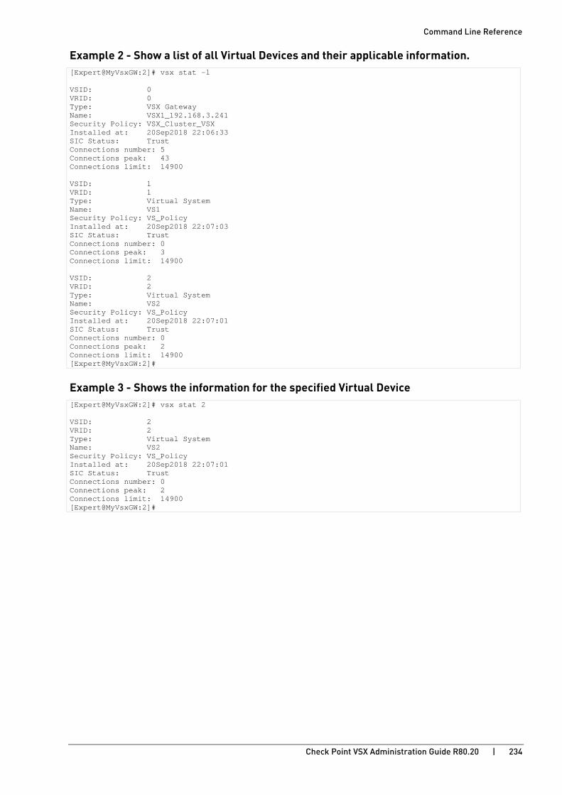
Command Line Reference
Check Point VSX Administration Guide R80.20 | 234
Example 2 - Show a list of all Virtual Devices and their applicable information. [Expert@MyVsxGW:2]# vsx stat -l VSID: 0 VRID: 0 Type: VSX Gateway Name: VSX1_192.168.3.241 Security Policy: VSX_Cluster_VSX Installed at: 20Sep2018 22:06:33 SIC Status: Trust Connections number: 5 Connections peak: 43 Connections limit: 14900 VSID: 1 VRID: 1 Type: Virtual System Name: VS1 Security Policy: VS_Policy Installed at: 20Sep2018 22:07:03 SIC Status: Trust Connections number: 0 Connections peak: 3 Connections limit: 14900 VSID: 2 VRID: 2 Type: Virtual System Name: VS2 Security Policy: VS_Policy Installed at: 20Sep2018 22:07:01 SIC Status: Trust Connections number: 0 Connections peak: 2 Connections limit: 14900 [Expert@MyVsxGW:2]#
Example 3 - Shows the information for the specified Virtual Device [Expert@MyVsxGW:2]# vsx stat 2 VSID: 2 VRID: 2 Type: Virtual System Name: VS2 Security Policy: VS_Policy Installed at: 20Sep2018 22:07:01 SIC Status: Trust Connections number: 0 Connections peak: 2 Connections limit: 14900 [Expert@MyVsxGW:2]#
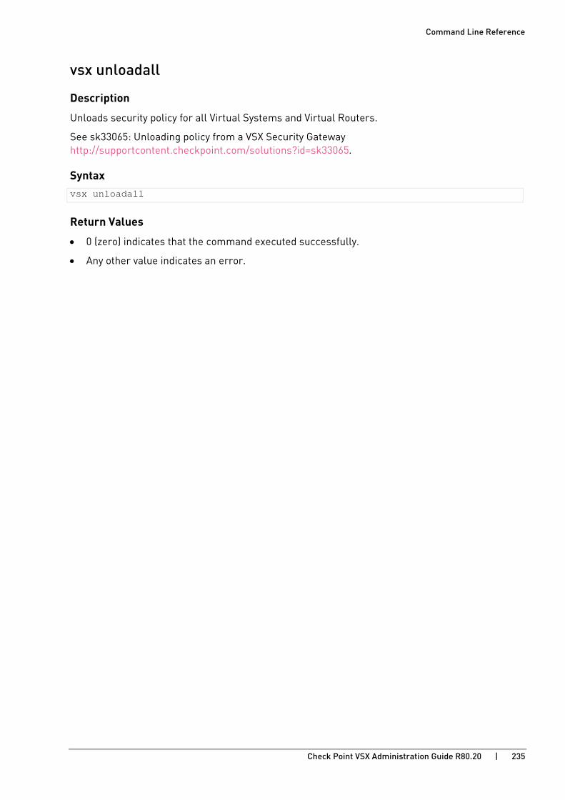
Command Line Reference
Check Point VSX Administration Guide R80.20 | 235
vsx unloadall
Description
Unloads security policy for all Virtual Systems and Virtual Routers.
See sk33065: Unloading policy from a VSX Security Gateway http://supportcontent.checkpoint.com/solutions?id=sk33065.
Syntax vsx unloadall
Return Values
• 0 (zero) indicates that the command executed successfully.
• Any other value indicates an error.

Command Line Reference
Check Point VSX Administration Guide R80.20 | 236
vsx vspurge
Description
Removes Virtual Devices that are no longer defined in the Management Database, but were not removed from the VSX Gateway because the VSX Gateway was down or disconnected when the updated VSX configuration was pushed.
This command cleans all un-used Virtual Devices entries (from the NCS local.vskeep) and fetches the VSX configuration file (NCS local.vskeep) again.
Syntax vsx vspurge [-q | -v] [-f <purge_file>]
Parameters
Parameter Description -q Specifies to run in quiet mode - shows only summary information.
-v Specifies to run in verbose mode - shows detailed information.
-f <purge_file> Specifies the path and the name of the file, in which the command saves the purged information.
Return Values
• 0 (zero) indicates that the command executed successfully.
• Any other value indicates an error.
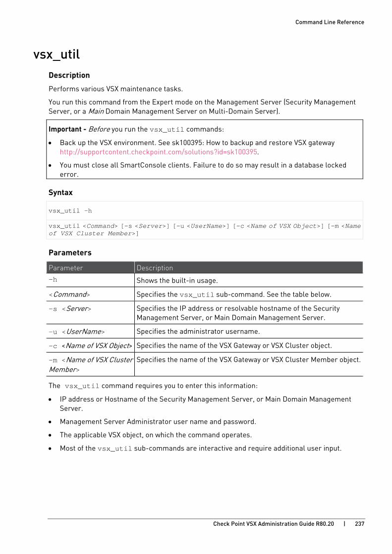
Command Line Reference
Check Point VSX Administration Guide R80.20 | 237
vsx_util Description
Performs various VSX maintenance tasks.
You run this command from the Expert mode on the Management Server (Security Management Server, or a Main Domain Management Server on Multi-Domain Server).
Important - Before you run the vsx_util commands:
• Back up the VSX environment. See sk100395: How to backup and restore VSX gateway http://supportcontent.checkpoint.com/solutions?id=sk100395.
• You must close all SmartConsole clients. Failure to do so may result in a database locked error.
Syntax
vsx_util -h
vsx_util <Command> [-s <Server>] [-u <UserName>] [-c <Name of VSX Object>] [-m <Name of VSX Cluster Member>]
Parameters
Parameter Description
-h Shows the built-in usage.
<Command> Specifies the vsx_util sub-command. See the table below.
-s <Server> Specifies the IP address or resolvable hostname of the Security Management Server, or Main Domain Management Server.
-u <UserName> Specifies the administrator username.
-c <Name of VSX Object> Specifies the name of the VSX Gateway or VSX Cluster object.
-m <Name of VSX Cluster Member>
Specifies the name of the VSX Gateway or VSX Cluster Member object.
The vsx_util command requires you to enter this information:
• IP address or Hostname of the Security Management Server, or Main Domain Management Server.
• Management Server Administrator user name and password.
• The applicable VSX object, on which the command operates.
• Most of the vsx_util sub-commands are interactive and require additional user input.

Command Line Reference
Check Point VSX Administration Guide R80.20 | 238
The 'vsx_util' sub-commands
Sub-command Description
vsx_util add_member (on page 240)
Adds a new Cluster Member to a VSX Cluster.
vsx_util add_member_reconf (on page 241)
Restores VSX configuration after the add_member operation.
vsx_util change_interfaces (on page 242)
Automatically replaces designated existing interfaces with new interfaces on all Virtual Devices, to which the existing interfaces connect.
vsx_util change_mgmt_ip (on page 245)
Changes the VSX Management IP address (within the same subnet) of a VSX Gateway or VSX Cluster Member.
vsx_util change_mgmt_subnet (on page 246)
Changes (or adds) the VSX Management IP address of a VSX Gateway or VSX Cluster Member to a new subnet.
vsx_util change_private_net (on page 247)
Changes the IP address of the Internal Communication Network in a VSX Cluster.
vsx_util convert_cluster (on page 248)
Converts the VSX Cluster mode between High Availability (default) and Virtual System Load Sharing.
vsx_util reconfigure (on page 249)
Restores VSX configuration on a VSX Gateway or VSX Cluster Member.
vsx_util remove_member (on page 250)
Removes a Cluster Member from a VSX Cluster.
vsx_util show_interfaces (on page 251)
Shows configuration of selected interfaces - interface types, connections to Virtual Devices, and IP addresses.
vsx_util upgrade (on page 253) Upgrades the version of a VSX Gateway or VSX Cluster in the management database.
vsx_util view_vs_conf (on page 254)
Shows configuration of a Virtual Device on the Management Server versus the VSX Gateway or VSX Cluster.
vsx_util vsls (on page 256) Shows the configuration menu for Virtual System Load Sharing - see status, redistribute, export/import configuration.
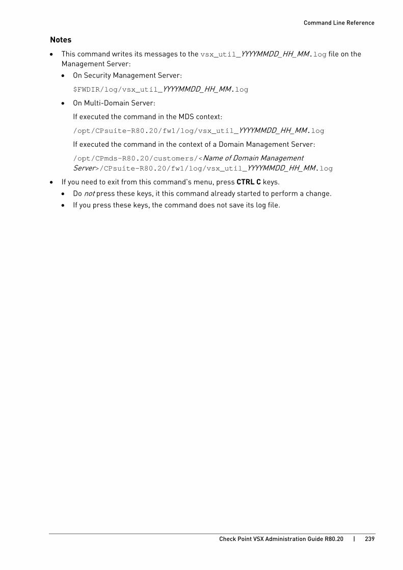
Command Line Reference
Check Point VSX Administration Guide R80.20 | 239
Notes
• This command writes its messages to the vsx_util_YYYYMMDD_HH_MM.log file on the Management Server:
• On Security Management Server:
$FWDIR/log/vsx_util_YYYYMMDD_HH_MM.log
• On Multi-Domain Server:
If executed the command in the MDS context:
/opt/CPsuite-R80.20/fw1/log/vsx_util_YYYYMMDD_HH_MM.log
If executed the command in the context of a Domain Management Server:
/opt/CPmds-R80.20/customers/<Name of Domain Management Server>/CPsuite-R80.20/fw1/log/vsx_util_YYYYMMDD_HH_MM.log
• If you need to exit from this command's menu, press CTRL C keys.
• Do not press these keys, it this command already started to perform a change.
• If you press these keys, the command does not save its log file.

Command Line Reference
Check Point VSX Administration Guide R80.20 | 240
vsx_util add_member
Description
Adds a new Cluster Member to a VSX Cluster.
Syntax vsx_util add_member
Required Input
• The applicable VSX Cluster object
• Name of the new VSX Cluster Member
• IP address for the management interface
• IP address for the synchronization interface
Comments
• Execute the command and follow the instructions on the screen
• After the command finishes, you must run the vsx_util add_member_reconf (on page 241) command

Command Line Reference
Check Point VSX Administration Guide R80.20 | 241
vsx_util add_member_reconf
Description
Restores VSX configuration after the vsx_util add_member (on page 240) operation.
Syntax vsx_util add_member_reconf
Required Input
• The applicable VSX Cluster object
• The applicable VSX Cluster Member object
• The one-time Activation Key (SIC activation key)
Comments
• Execute the command and follow the instructions on the screen
• You must reboot the new cluster member after the command finishes
Command Line Reference
Check Point VSX Administration Guide R80.20 | 242
vsx_util change_interfaces
Description
Automatically replaces designated existing interfaces with new interfaces on all Virtual Devices, to which the existing interfaces connect.
This command is useful when converting a deployment to use Link Aggregation, especially where VLANs connect to many Virtual Devices.
Syntax vsx_util change_interfaces
Required Input
• The applicable VSX Gateway or VSX Cluster object
• Where to apply the change (Management Server only, or Management Server and VSX Gateway / VSX Cluster Members)
• Name of the interface to be replaced
• Name of the new (replacement) interface
Comments
• Execute the command and follow the instructions on the screen
• This command supports the resume feature
• You can use this command to migrate a VSX deployment from an Open Server to a Check Point appliance by using the Management Only mode
• Refer to the Notes (on page 244) section for additional information
Procedure
To change interfaces:
Step Description
1 Close all SmartConsole clients that are connected to the Security Management Server or Domain Management Servers.
2 Connect to the command line on the Management Server.
3 Log in to the Expert Mode.
4 On Multi-Domain Server, go to the context of the Main Domain Management Server that manages the applicable VSX Gateway (VSX Cluster) object:
mdsenv <IP address or Name of Domain Management Server>
5 Run: vsx_util change_interfaces
6 Enter the IP address of the Security Management Server or Main Domain Management Server.
7 Enter the Management Server administrator username and password.

Command Line Reference
Check Point VSX Administration Guide R80.20 | 243
Step Description
8 Select the VSX Gateway (VSX Cluster) object.
9 When prompted, select one of the following options:
• Apply changes to the management database and to the VSX Gateway/Cluster members immediately
Changes the interface on the Management Server and on the VSX Gateway (each VSX Cluster Member).
• Apply changes to the management database only
Changes the interface on the Management Server only. You must use the vsx_util reconfigure (on page 249) command to push the updated VSX configuration to VSX Gateways (each VSX Cluster Member).
10 Select the interface to be replaced.
11 Select the new (replacement) interface.
a) You can optionally add a new interface, if you select the A new interface name option. This interface must physically exist on the VSX Gateway (all VSX Cluster Members). Otherwise, the operation fails.
b) At the prompt, enter the new interface name. If the new interface is a Bond interface, the interface name must match the name of the configured Bond interface exactly.
12 The command prompts you: Would you like to change another interface? (y|n) [n]:
• To replace additional interfaces, enter y.
• To complete the process, enter n.
13 If you selected the option Apply changes to the management database only, you can remove the old (replaced) interfaces from the management database.
When prompted, enter y: Would you like to remove the old interfaces from the database? (y|n) [n]: y
14 Reboot the VSX Gateway (all VSX Cluster Members).
Command Line Reference
Check Point VSX Administration Guide R80.20 | 244
Notes • The option Apply changes to the management database and to the VSX Gateway/Cluster
members immediately verifies connectivity between the Management Server and the VSX Gateway or VSX Cluster Members. In the event of a connectivity failure one of the following actions occur:
a) If all of the newly changed interfaces fail to establish connectivity, the process terminates unsuccessfully.
b) If one or more interfaces successfully establish connectivity, while one or more other interfaces fail, you may optionally continue the process.
In this case, those interfaces for which connectivity was established successfully will be changed. For those interfaces that failed, you must then resolve the issue and then run the vsx_util reconfigure (on page 249) command to complete the process.
• If you select the option Apply changes to the management database only, you can select one of these:
• Another interface from list (if any are available).
• Option to add a new interface.
Command Line Reference
Check Point VSX Administration Guide R80.20 | 245
vsx_util change_mgmt_ip
Description
Changes the VSX Management IP address of a VSX Gateway or VSX Cluster Member.
This command changes the Management IP address within the same subnet.
For more information, see sk92425 http://supportcontent.checkpoint.com/solutions?id=sk92425.
Syntax vsx_util change_mgmt_ip
Required Input
• The applicable VSX Cluster object
• The applicable VSX Cluster Member object
• New management IP address
Comments
• Execute the command and follow the instructions on the screen.

Command Line Reference
Check Point VSX Administration Guide R80.20 | 246
vsx_util change_mgmt_subnet
Description
Changes the VSX Management IP address of a VSX Gateway or VSX Cluster Member.
This command changes the Management IP address from the current subnet to a different subnet.
For more information, see sk92425 http://supportcontent.checkpoint.com/solutions?id=sk92425.
Syntax vsx_util change_mgmt_subnet
Required Input
• The applicable VSX Gateway or VSX Cluster object
• New management IPv4 address
• New management IPv4 netmask
• New management IPv6 address
• New management IPv6 prefix
• New IPv4 default gateway
• New IPv6 default gateway
Comments
• Execute the command and follow the instructions on the screen
• This command updated only routes that were automatically generated
You must remove and/or change all manually created routes that use the previous management subnet
• You must reboot the VSX Gateway (all VSX Cluster Members) after the command finishes

Command Line Reference
Check Point VSX Administration Guide R80.20 | 247
vsx_util change_private_net
Description
Changes the IP address of the Internal Communication Network in a VSX Cluster (cluster private network).
Syntax vsx_util change_private_net
Required Input
• The applicable VSX Cluster object
• New IPv4 address for the cluster private network
• New IPv4 netmask for the cluster private network
• New IPv6 address and prefix for the cluster private network
Comments
• Run the command and follow the instructions on the screen
• The IP address of the Internal Communication Network must be unique
This IP address must not be used anywhere in your environment, including the Virtual Devices on this VSX Cluster
• The illegal IPv4 addresses are: 0.0.0.0, 127.0.0.0, and 255.255.255.255
• For IPv4 address, the network mask must be one of these:
• 255.255.224.0, or /20
• 255.255.240.0, or /21
• 255.255.252.0, or /22 (this is the default)
• For IPv6 address, the new prefix must be /80
Command Line Reference
Check Point VSX Administration Guide R80.20 | 248
vsx_util convert_cluster
Description
Converts the VSX Cluster mode between High Availability (default) and Virtual System Load Sharing.
Syntax vsx_util convert_cluster
Required Input
• The applicable VSX Cluster object
• The ClusterXL mode (case sensitive)
Comments
• Execute the command and follow the instructions on the screen
• When you convert from Virtual System Load Sharing to High Availability:
All Virtual Systems are Active on the same VSX Cluster Member by default
Peer Virtual Systems are Standby on other VSX Cluster Members
• When you convert from High Availability to Virtual System Load Sharing:
All VSX Cluster Members must be in the Check Point Per Virtual System State
(run the cpconfig command and select the option Enable Check Point Per Virtual System State)

Command Line Reference
Check Point VSX Administration Guide R80.20 | 249
vsx_util reconfigure
Description
Restores VSX configuration on a VSX Gateway or VSX Cluster Member (for example, after you perform clean install after a system failure).
Syntax vsx_util reconfigure
Required Input
• The applicable VSX Gateway or VSX Cluster object
• The one-time Activation Key (SIC activation key)
Comments
• Execute the command and follow the instructions on the screen
• The new VSX Gateway or VSX Cluster Member:
• Must be a new installation. You cannot use a computer with a previous VSX configuration
• Must have the same hardware specifications as the original
Most importantly, it must have at least the same number of interfaces
• Must have the same Gaia OS configuration as the original
Most importantly, it must have the same VSX Management IP address

Command Line Reference
Check Point VSX Administration Guide R80.20 | 250
vsx_util remove_member
Description
Removes a Cluster Member from a VSX Cluster.
Syntax vsx_util remove_member
Required Input
• The applicable VSX Cluster object
• The applicable VSX Cluster Member object
Comments
• Before you run this command:
• Make sure to remove (detach) the license from the VSX Cluster Member
• Make sure to run the cphastop command to avoid unexpected failover from the VSX Cluster Member
• Make sure to disconnect the VSX Cluster Member from all networks, except from the Management Server
• Execute the command and follow the instructions on the screen
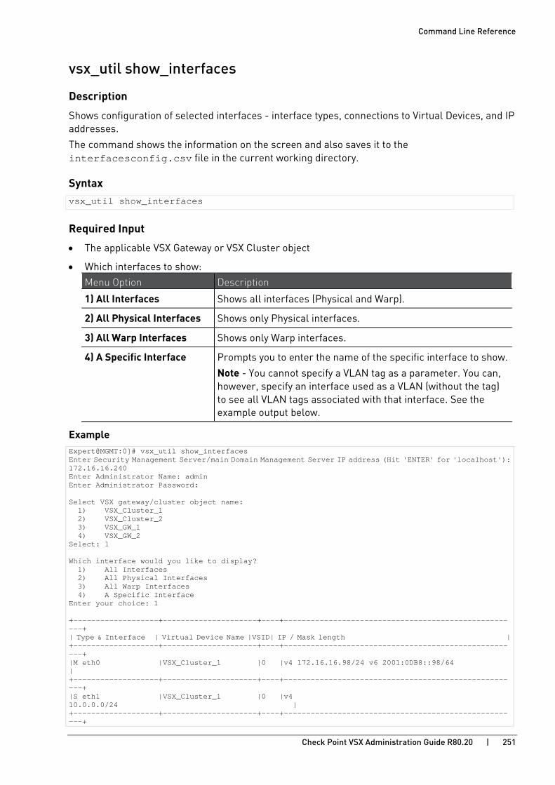
Command Line Reference
Check Point VSX Administration Guide R80.20 | 251
vsx_util show_interfaces
Description
Shows configuration of selected interfaces - interface types, connections to Virtual Devices, and IP addresses.
The command shows the information on the screen and also saves it to the interfacesconfig.csv file in the current working directory.
Syntax vsx_util show_interfaces
Required Input
• The applicable VSX Gateway or VSX Cluster object
• Which interfaces to show: Menu Option Description
1) All Interfaces Shows all interfaces (Physical and Warp).
2) All Physical Interfaces Shows only Physical interfaces.
3) All Warp Interfaces Shows only Warp interfaces.
4) A Specific Interface Prompts you to enter the name of the specific interface to show.
Note - You cannot specify a VLAN tag as a parameter. You can, however, specify an interface used as a VLAN (without the tag) to see all VLAN tags associated with that interface. See the example output below.
Example Expert@MGMT:0]# vsx_util show_interfaces Enter Security Management Server/main Domain Management Server IP address (Hit 'ENTER' for 'localhost'): 172.16.16.240 Enter Administrator Name: admin Enter Administrator Password: Select VSX gateway/cluster object name: 1) VSX_Cluster_1 2) VSX_Cluster_2 3) VSX_GW_1 4) VSX_GW_2 Select: 1 Which interface would you like to display? 1) All Interfaces 2) All Physical Interfaces 3) All Warp Interfaces 4) A Specific Interface Enter your choice: 1 +-------------------+---------------------+----+-----------------------------------------------------+ | Type & Interface | Virtual Device Name |VSID| IP / Mask length | +-------------------+---------------------+----+-----------------------------------------------------+ |M eth0 |VSX_Cluster_1 |0 |v4 172.16.16.98/24 v6 2001:0DB8::98/64 | +-------------------+---------------------+----+-----------------------------------------------------+ |S eth1 |VSX_Cluster_1 |0 |v4 10.0.0.0/24 | +-------------------+---------------------+----+-----------------------------------------------------+

Command Line Reference
Check Point VSX Administration Guide R80.20 | 252
|U eth2 |VS1 |1 |v4 192.0.2.2/24 v6 2001:0DB8:c::1/64 | +-------------------+---------------------+----+-----------------------------------------------------+ |U eth3 |VS1 |1 |v4 192.168.3.3/24 v6 2001:0DB8:b::1/64 | +-------------------+---------------------+----+-----------------------------------------------------+ |A eth4 | | | | +-------------------+---------------------+----+-----------------------------------------------------+ |U eth5 |VS2 |2 |v4 10.10.10.10/24 v6 2001:0DB8:a::1/64 | +-------------------+---------------------+----+-----------------------------------------------------+ |A eth6 | | | | +-------------------+---------------------+----+-----------------------------------------------------+ #Type: M - Management Interface S - Synchronization Interface # V - VLAN Interface W - Warp Interface # U - Used Interface A - Available Interface # X - Unknown Interface E - Error in Interface Properties Logging details are available at /opt/CPsuite-R80.20/fw1/log/vsx_util_20181025_17_45.log [Expert@MGMT:0]# [Expert@MGMT:0]# cat interfacesconfig.csv Interface Name , Type ,Virtual Device Name , VSID , IPv4 Address , IPv4 mask length, IPv6 Address, IPv6 mask length eth0,M,VSX_Cluster_1,0,172.16.16.98,24,2001:0DB8::98,64 eth1,S,VSX_Cluster_1,0,10.0.0.0,24,, eth2,U,VS1,192.0.2.2,24,2001:0DB8:c::1,64 eth3,U,VS1,192.168.3.3,24,2001:0DB8:b::1,64 eth4,A eth5,U,VS2,10.10.10.10,24,2001:0DB8:a::1,64 eth6,A #Type: M - Management Interface S - Synchronization Interface # V - VLAN Interface W - Warp Interface # U - Used Interface A - Available Interface # X - Unknown Interface E - Error in Interface Properties [Expert@MGMT:0]#
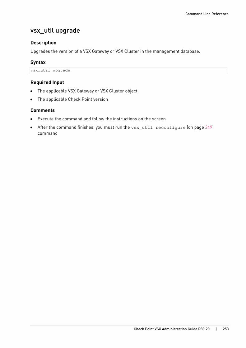
Command Line Reference
Check Point VSX Administration Guide R80.20 | 253
vsx_util upgrade
Description
Upgrades the version of a VSX Gateway or VSX Cluster in the management database.
Syntax vsx_util upgrade
Required Input
• The applicable VSX Gateway or VSX Cluster object
• The applicable Check Point version
Comments
• Execute the command and follow the instructions on the screen
• After the command finishes, you must run the vsx_util reconfigure (on page 249) command

Command Line Reference
Check Point VSX Administration Guide R80.20 | 254
vsx_util view_vs_conf
Description
Compares the configuration of all Virtual Devices on the Management Server and the actual configuration on the VSX Gateway or VSX Cluster Members.
Syntax vsx_util view_vs_conf
Required Input
• The applicable VSX Gateway or VSX Cluster object
• The applicable Virtual Device object
Example Expert@MGMT:0]# vsx_util show_interfaces Enter Security Management Server/main Domain Management Server IP address (Hit 'ENTER' for 'localhost'): 172.16.16.240 Enter Administrator Name: admin Enter Administrator Password: Select VSX gateway/cluster object name: 1) VSX_Cluster_1 2) VSX_Cluster_2 3) VSX_GW 4) VSX_GW_2 Select: 1 Select Virtual Device object name: 1) VS1 2) VS2 3) VS3 4) VSX_Cluster Select: 1 Type: Virtual System Interfaces configuration table: +---------------------------------------------------+-----+-------------------+ |Interfaces |Mgmt |VSX GW(s) | +----------+----------------------------------------+-----+---------+---------+ |Name |IP / Mask length | |mem 1 |mem2 | +----------+----------------------------------------+-----+---------+---------+ |eth2 |v4 10.0.0.0/24 v6 2001:db8::abc::1/64 | V | V | V | |eth3 |v4 10.10.10.10/24 v6 2001:db8::3121/64 | V | V | V | +----------+----------------------------------------+-----+---------+---------+ Interfaces Table Legend: V - Interface exists on the gateway and matches management information (if defined on the management). - - Interface does not exist on the gateway. N/A - Fetching Virtual Device configuration from the gateway failed. !IP - Interface exists on the gateway, but there is an IP address mismatch. !MASK - Interface exists on the gateway, but there is a Net Mask mismatch.

Command Line Reference
Check Point VSX Administration Guide R80.20 | 255
Routing table: +----------------------------------------------------------+-----+-------------+ |Ipv4 Routes |Mgmt |VSX GW(s) | +--------------------------+--------------------+----------+-----+------+------+ |Destination / Mask Length |Gateway |Interface | |mem1 |mem2 | +--------------------------+--------------------+----------+-----+------+------+ |2.2.2.0/24 | |eth2 | V | V | V | |3.3.3.0/24 | |eth3 | V | V | V | +--------------------------+--------------------+----------+-----+------+------+ +--------------------------+--------------------+----------+-----+------+------+ +----------------------------------------------------------+-----+-------------+ |Ipv6 Routes |Mgmt |VSX GW(s) | +--------------------------+--------------------+----------+-----+------+------+ |Destination / Mask Length |Gateway |Interface | |mem1 |mem2 | +--------------------------+--------------------+----------+-----+------+------+ |2001:db8::abc::/64 | |eth2 | V | !NH | !NH | |2001:db8:0a::/64 | |eth3 | V | !NH | !NH | +--------------------------+--------------------+----------+-----+------+------+ |2001:db8::1ffe:0:0:0/112 | |eth2 | - | V | V | |2001:db8::fd9a:0:1:0/112 | |eth3 | - | V | V | +--------------------------+--------------------+----------+-----+------+------+ Routing Table Legend: V - Route exists on the gateway and matches management information (if defined on the management). - - Route does not exist on the gateway. N/A - Fetching Virtual Device configuration from the gateway failed. !NH - Route exists on the gateway, but there is a Next Hop mismatch. Note: Routes can be created automatically on the gateways by the Operating System. Therefore, routes that appear on all gateways, but are not defined on the management, do not necessarily indicate a problem. Logging details are available at /opt/CPsuite-R80.20/fw1/log/vsx_util_20181025_18_11.log [Expert@MGMT:0]#

Command Line Reference
Check Point VSX Administration Guide R80.20 | 256
vsx_util vsls
Description
Shows the configuration menu for Virtual System Load Sharing - see status, redistribute, export/import configuration.
Syntax vsx_util vsls
Required Input
• The applicable VSX Cluster object
• The applicable redistribution option
Comments
• Execute the command and follow the instructions on the screen
• If the command shows "Operation not allowed. Object is not a Virtual System Load Sharing cluster.", then run the vsx_util convert_cluster (on page 248) command
Example Expert@MGMT:0]# vsx_util show_interfaces Enter Security Management Server/main Domain Management Server IP address (Hit 'ENTER' for 'localhost'): 172.16.16.240 Enter Administrator Name: admin Enter Administrator Password: Select VSX gateway/cluster object name: 1) VSX_Cluster_1 2) VSX_Cluster_2 3) VSX_GW_1 4) VSX_GW_2 Select: 1 VS Load Sharing - Menu ________________________________ 1. Display current VS Load sharing configuration 2. Distribute all Virtual Systems so that each cluster member is equally loaded 3. Set all VSes active on one member 4. Manually set priority and weight 5. Import configuration from a file 6. Export configuration to a file 7. Exit Enter redistribution option (1-7) [1]:
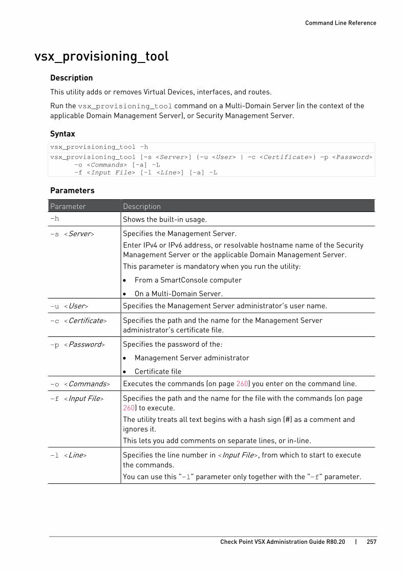
Command Line Reference
Check Point VSX Administration Guide R80.20 | 257
vsx_provisioning_tool Description
This utility adds or removes Virtual Devices, interfaces, and routes.
Run the vsx_provisioning_tool command on a Multi-Domain Server (in the context of the applicable Domain Management Server), or Security Management Server.
Syntax vsx_provisioning_tool -h
vsx_provisioning_tool [-s <Server>] {-u <User> | -c <Certificate>} -p <Password> -o <Commands> [-a] -L -f <Input File> [-l <Line>] [-a] -L
Parameters
Parameter Description
-h Shows the built-in usage.
-s <Server> Specifies the Management Server.
Enter IPv4 or IPv6 address, or resolvable hostname name of the Security Management Server or the applicable Domain Management Server.
This parameter is mandatory when you run the utility:
• From a SmartConsole computer
• On a Multi-Domain Server.
-u <User> Specifies the Management Server administrator's user name.
-c <Certificate> Specifies the path and the name for the Management Server administrator's certificate file.
-p <Password> Specifies the password of the:
• Management Server administrator
• Certificate file
-o <Commands> Executes the commands (on page 260) you enter on the command line.
-f <Input File> Specifies the path and the name for the file with the commands (on page 260) to execute.
The utility treats all text begins with a hash sign (#) as a comment and ignores it.
This lets you add comments on separate lines, or in-line.
-l <Line> Specifies the line number in <Input File>, from which to start to execute the commands.
You can use this "-l" parameter only together with the "-f" parameter.

Command Line Reference
Check Point VSX Administration Guide R80.20 | 258
Parameter Description -a Specifies that before the utility executes the specified commands, it must
make sure it can connect to all VSX Gateways.
Note - This does not guarantee that a VSX Gateway can successfully apply all the specified commands.
-L Specifies local authentication mode.
Exit Codes
Exit Code Description
0 The utility successfully applied all changes, on all cluster members.
1 The utility successfully applied all changes to the management database, but not to all VSX members.
2 The utility successfully applied all changes, but SIC communication failed to establish with at least one cluster member.
3 Connectivity test failed with at least one cluster member (if you used the "-a" parameter).
The utility did not apply changes to the management database, or to the VSX Gateways.
4 The utility failed to apply changes (due to internal error, syntax error, or another reason).
If commands are executed from a file with multiple transactions, the exit code refers to the last transaction processed.
Example 1
Run the utility on the Security Management Server.
Execute the commands from the text /var/log/vsx.txt file.
vsx_provisioning_tool –s localhost -u admin -p mypassword -f /var/log/vsx.txt
Example 2
Run the utility on the Security Management Server.
Create a new Virtual System object called VS1 on the cluster object called VSX1
In the new Virtual System object, on the interface eth4, add a VLAN interface with VLAN ID 100 and IPv4 address 1.1.1.1/24. vsx_provisioning_tool –s localhost –u admin –p mypassword –o add vd name VS1 vsx VSX1, add interface name eth4.100 ip 1.1.1.1/24

Command Line Reference
Check Point VSX Administration Guide R80.20 | 259
Transactions A transaction is a set of operations done on one Virtual Device.
The utility commits all operations to the management database together when the transaction ends. If the transaction fails, the utility discards all its commands.
Name the Virtual Device with a parameter in the first command (all commands have a parameter to name the Virtual Device). You do not need to name it again in other commands of the same transaction.
You cannot send operations to different Virtual Devices in one transaction.
You cannot start a new transaction until you exit the one before.
When you send commands with the "-o" parameter, you can enter multiple commands (for example: add a Virtual System and then add interfaces and routes to it). Separate the commands with a comma ( , ). All the commands are one transaction. The "-o" parameter does not support explicit transaction commands.
When you send commands with the "-f" parameter, you can use explicit transaction commands (on page 260). Commands from a file can be one or more transactions:
• If not inside a transaction, the current line is one transaction, which the utility automatically commits. You can write multiple commands in one line (as one transaction), separated with a comma ( , ).
• If currently inside a transaction, the utility processes the lines, but does not take action until the transaction ends.

Command Line Reference
Check Point VSX Administration Guide R80.20 | 260
vsx_provisioning_tool Commands All vsx_provisioning_tool commands are pairs of key and value.
The first two words in each command must appear in the correct order.
Other pairs can be given in any order.
Explicit Transaction Commands
Operation Command Syntax
Begin a new transaction transaction begin
End a transaction transaction end
Cancel a transaction transaction cancel
Note - SIC with the Virtual System is established automatically. If it fails, operations continue, and the transaction returns error code 2.
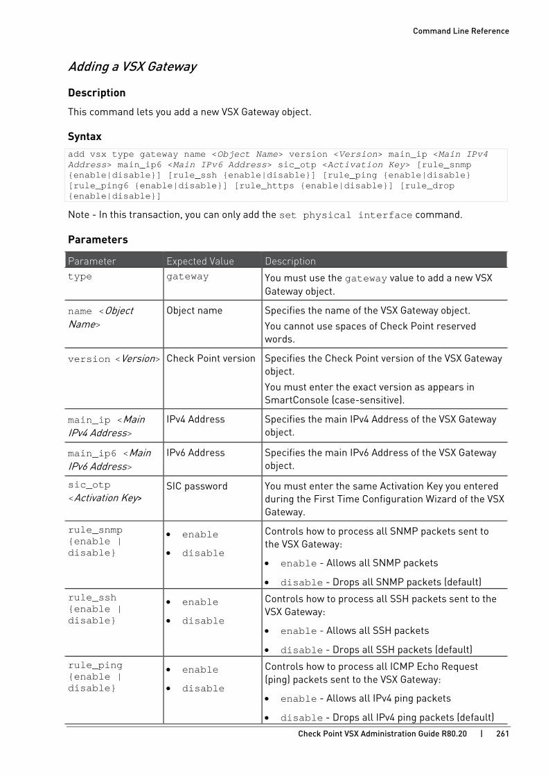
Command Line Reference
Check Point VSX Administration Guide R80.20 | 261
Adding a VSX Gateway
Description
This command lets you add a new VSX Gateway object.
Syntax add vsx type gateway name <Object Name> version <Version> main_ip <Main IPv4 Address> main_ip6 <Main IPv6 Address> sic_otp <Activation Key> [rule_snmp {enable|disable}] [rule_ssh {enable|disable}] [rule_ping {enable|disable} [rule_ping6 {enable|disable}] [rule_https {enable|disable}] [rule_drop {enable|disable}]
Note - In this transaction, you can only add the set physical interface command.
Parameters
Parameter Expected Value Description type gateway You must use the gateway value to add a new VSX
Gateway object.
name <Object Name>
Object name Specifies the name of the VSX Gateway object.
You cannot use spaces of Check Point reserved words.
version <Version> Check Point version Specifies the Check Point version of the VSX Gateway object.
You must enter the exact version as appears in SmartConsole (case-sensitive).
main_ip <Main IPv4 Address>
IPv4 Address Specifies the main IPv4 Address of the VSX Gateway object.
main_ip6 <Main IPv6 Address>
IPv6 Address Specifies the main IPv6 Address of the VSX Gateway object.
sic_otp <Activation Key>
SIC password You must enter the same Activation Key you entered during the First Time Configuration Wizard of the VSX Gateway.
rule_snmp {enable | disable}
• enable
• disable
Controls how to process all SNMP packets sent to the VSX Gateway:
• enable - Allows all SNMP packets
• disable - Drops all SNMP packets (default) rule_ssh {enable | disable}
• enable
• disable
Controls how to process all SSH packets sent to the VSX Gateway:
• enable - Allows all SSH packets
• disable - Drops all SSH packets (default) rule_ping {enable | disable}
• enable
• disable
Controls how to process all ICMP Echo Request (ping) packets sent to the VSX Gateway:
• enable - Allows all IPv4 ping packets
• disable - Drops all IPv4 ping packets (default)

Command Line Reference
Check Point VSX Administration Guide R80.20 | 262
Parameter Expected Value Description rule_ping6 {enable | disable}
• enable
• disable
Controls how to process all ICMPv6 Echo Request (ping) packets sent to the VSX Gateway:
• enable - Allows all IPv6 ping packets
• disable - Drops all IPv6 ping packets (default) rule_https {enable | disable}
• enable
• disable
Controls how to process all HTTPS packets sent to the VSX Gateway:
• enable - Allows all HTTPS packets
• disable - Drops all HTTPS packets (default) rule_drop {enable | disable}
• enable
• disable
Controls how to process all packets (other than SNMP, SSH, ICMP, ICMPv6, HTTPS) sent to the VSX Gateway:
• enable - Drops all other packets (default)
• disable - Allows all other packets
Example vsx_provisioning_tool -s localhost -u admin -p mypassword -o add vsx name VSX_GW1 type gateway main_ip 192.168.20.1 version R80.10 sic_otp ABCDEFG rule_ssh enable rule_ping enable

Command Line Reference
Check Point VSX Administration Guide R80.20 | 263
Adding a VSX Cluster
Description
This command lets you add a new VSX Cluster object.
Syntax add vsx type cluster name <Object Name> version <Version> main_ip <Main Virtual IPv4 Address> main_ip6 <Main Virtual IPv6 Address> cluster_type {vsls|ha|crbm} sync_if_name <Sync Interface Name> sync_netmask <Sync Interface Netmask> [rule_snmp {enable|disable}] [rule_snmp {enable|disable}] [rule_ssh {enable|disable}] [rule_ping {enable|disable} [rule_ping6 {enable|disable}] [rule_http {enable|disable}] [rule_drop {enable|disable}]
Important - You must run the add vsx_member command for each VSX Cluster Member in the same transaction as the add vsx command.
Parameters
Parameter Value Notes type cluster You must use the cluster value to add a
new cluster object.
name <Object Name> Object name Specifies the name of the VSX Cluster object.
You cannot use spaces of Check Point reserved words.
version <Version> Check Point version Specifies the Check Point version of the VSX Cluster object.
You must enter the exact version as appears in SmartConsole (case-sensitive).
main_ip <Main Virtual IPv4 Address>
IPv4 Address Specifies the main IPv4 Virtual Address of the VSX Cluster object.
main_ip6 <Main Virtual IPv6 Address>
IPv6 Address Specifies the main IPv6 Virtual Address of the VSX Cluster object.
cluster_type {vsls | ha | crbm}
Cluster type Specifies the cluster type. Enter one of these:
• vsls - Virtual System Load Sharing mode
• ha - High Availability mode
• crbm - X-Series appliances (former BlueCoat / Crossbeam)
sync_if_name <Sync Interface Name>
Sync interface name Specifies the name of the Cluster Synchronization interface.
sync_netmask <Sync Interface Netmask>
IPv4 Network mask Specifies an IPv4 Netmask for the Cluster Synchronization interface (in a dot-quad format X.X.X.X).

Command Line Reference
Check Point VSX Administration Guide R80.20 | 264
Parameter Value Notes rule_snmp {enable | disable}
• enable
• disable
Controls how to process all SNMP packets sent to the VSX Cluster Members:
• enable - Allows all SNMP packets
• disable - Drops all SNMP packets (default)
rule_ssh {enable | disable}
• enable
• disable
Controls how to process all SSH packets sent to the VSX Cluster Members:
• enable - Allows all SSH packets
• disable - Drops all SSH packets (default)
rule_ping {enable | disable}
• enable
• disable
Controls how to process all ICMP Echo Request (ping) packets sent to the VSX Cluster Members:
• enable - Allows all IPv4 ping packets
• disable - Drops all IPv4 ping packets (default)
rule_ping6 {enable | disable}
• enable
• disable
Controls how to process all ICMPv6 Echo Request (ping) packets sent to the VSX Cluster Members:
• enable - Allows all IPv6 ping packets
• disable - Drops all IPv6 ping packets (default)
rule_https {enable | disable}
• enable
• disable
Controls how to process all HTTPS packets sent to the VSX Cluster Members:
• enable - Allows all HTTPS packets
• disable - Drops all HTTPS packets (default)
rule_drop {enable | disable}
• enable
• disable
Controls how to process all packets (other than SNMP, SSH, ICMP, ICMPv6, HTTPS) sent to the VSX Cluster Members:
• enable - Drops all other packets (default)
• disable - Allows all other packets
Example vsx_provisioning_tool -s localhost -u admin -p mypassword -o add vsx name VSX1 type cluster cluster_type vsls main_ip 192.168.1.1 version R80.10 sync_if_name eth3 sync_netmask 255.255.255.0 rule_ssh enable rule_ping enable
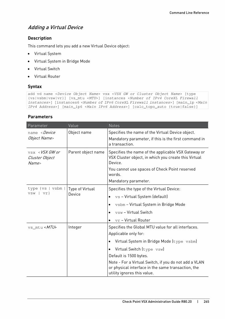
Command Line Reference
Check Point VSX Administration Guide R80.20 | 265
Adding a Virtual Device
Description
This command lets you add a new Virtual Device object:
• Virtual System
• Virtual System in Bridge Mode
• Virtual Switch
• Virtual Router
Syntax add vd name <Device Object Name> vsx <VSX GW or Cluster Object Name> [type {vs|vsbm|vsw|vr}] [vs_mtu <MTU>] [instances <Number of IPv4 CoreXL Firewall instances>] [instances6 <Number of IPv6 CoreXL Firewall instances>] [main_ip <Main IPv4 Address>] [main_ip6 <Main IPv6 Address>] [calc_topo_auto {true|false}]
Parameters
Parameter Value Notes
name <Device Object Name>
Object name Specifies the name of the Virtual Device object.
Mandatory parameter, if this is the first command in a transaction.
vsx <VSX GW or Cluster Object Name>
Parent object name Specifies the name of the applicable VSX Gateway or VSX Cluster object, in which you create this Virtual Device.
You cannot use spaces of Check Point reserved words.
Mandatory parameter.
type {vs | vsbm | vsw | vr}
Type of Virtual Device
Specifies the type of the Virtual Device:
• vs – Virtual System (default)
• vsbm – Virtual System in Bridge Mode
• vsw – Virtual Switch
• vr – Virtual Router
vs_mtu <MTU> Integer Specifies the Global MTU value for all interfaces.
Applicable only for:
• Virtual System in Bridge Mode (type vsbm)
• Virtual Switch (type vsw)
Default is 1500 bytes.
Note - For a Virtual Switch, if you do not add a VLAN or physical interface in the same transaction, the utility ignores this value.

Command Line Reference
Check Point VSX Administration Guide R80.20 | 266
Parameter Value Notes instances <Number of IPv4 CoreXL Firewall instances>
Integer Specifies the number of IPv4 CoreXL Firewall instances.
Applicable only for:
• Virtual System (type vs)
• Virtual System in Bridge Mode (type vsbm)
Default is 1.
For more information about CoreXL, see R80.20 Performance Tuning Administration Guide https://sc1.checkpoint.com/documents/R80.20_GA/WebAdminGuides/EN/CP_R80.20_PerformanceTuning_AdminGuide/html_frameset.htm.
instances6 <Number of IPv6 CoreXL Firewall instances>
Integer Specifies the number of IPv6 CoreXL Firewall instances.
Applicable only for:
• Virtual System (type vs)
• Virtual System in Bridge Mode (type vsbm)
Default is 1.
For more information about CoreXL, see R80.20 Performance Tuning Administration Guide https://sc1.checkpoint.com/documents/R80.20_GA/WebAdminGuides/EN/CP_R80.20_PerformanceTuning_AdminGuide/html_frameset.htm.
main_ip <Main IPv4 Address>
IPv4 Address Specifies the main IPv4 Address of the Virtual Device object.
Applicable only for:
• Virtual System (type vs)
• Virtual Router (type vr)
Note - If you do not specify this value explicitly, the utility uses the IPv4 address of the first interface added to the new device.
main_ip6 <Main IPv6 Address>
IPv6 Address Specifies the main IPv6 Address of the Virtual Device object.
Applicable only for:
• Virtual System (type vs)
• Virtual Router (type vr)
Note - If you do not specify this value explicitly, the utility uses the IPv6 address of the first interface added to the new device.
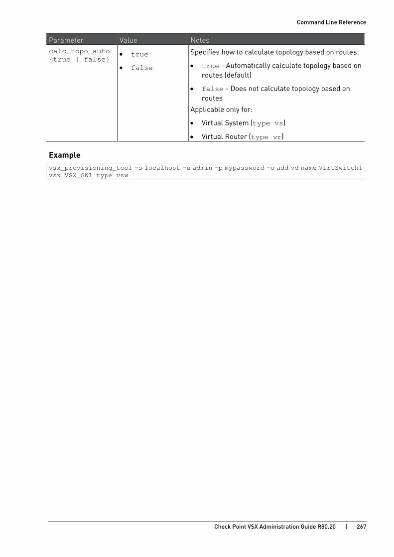
Command Line Reference
Check Point VSX Administration Guide R80.20 | 267
Parameter Value Notes calc_topo_auto {true | false}
• true
• false
Specifies how to calculate topology based on routes:
• true - Automatically calculate topology based on routes (default)
• false - Does not calculate topology based on routes
Applicable only for:
• Virtual System (type vs)
• Virtual Router (type vr)
Example vsx_provisioning_tool -s localhost -u admin -p mypassword -o add vd name VirtSwitch1 vsx VSX_GW1 type vsw
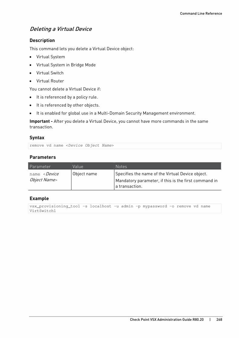
Command Line Reference
Check Point VSX Administration Guide R80.20 | 268
Deleting a Virtual Device
Description
This command lets you delete a Virtual Device object:
• Virtual System
• Virtual System in Bridge Mode
• Virtual Switch
• Virtual Router
You cannot delete a Virtual Device if:
• It is referenced by a policy rule.
• It is referenced by other objects.
• It is enabled for global use in a Multi-Domain Security Management environment.
Important - After you delete a Virtual Device, you cannot have more commands in the same transaction.
Syntax remove vd name <Device Object Name>
Parameters
Parameter Value Notes
name <Device Object Name>
Object name Specifies the name of the Virtual Device object.
Mandatory parameter, if this is the first command in a transaction.
Example vsx_provisioning_tool -s localhost -u admin -p mypassword -o remove vd name VirtSwitch1
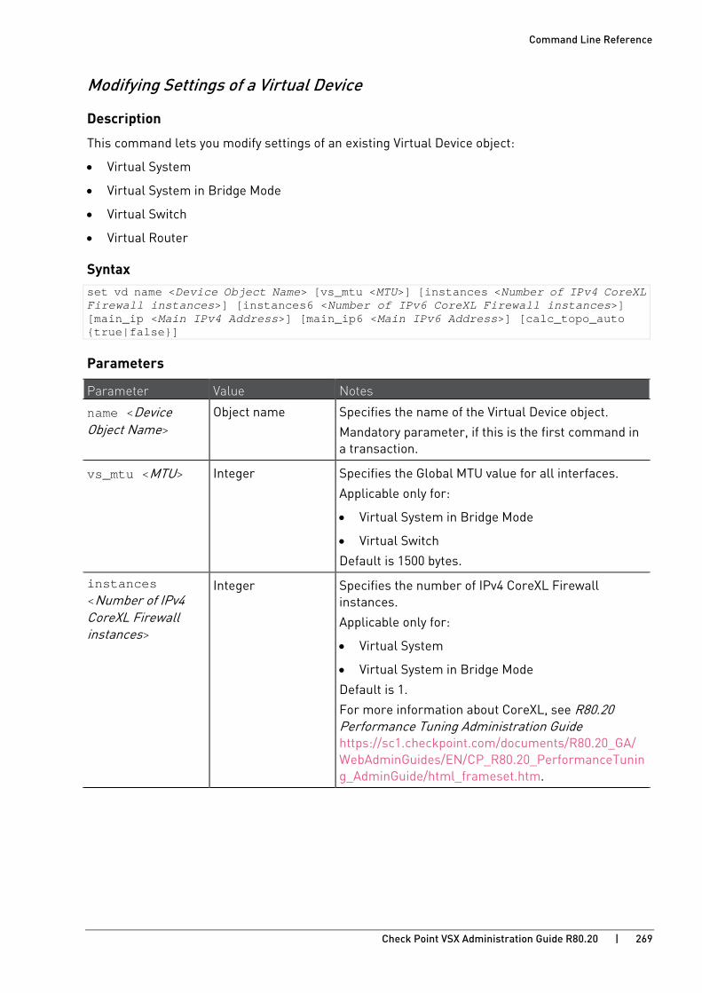
Command Line Reference
Check Point VSX Administration Guide R80.20 | 269
Modifying Settings of a Virtual Device
Description
This command lets you modify settings of an existing Virtual Device object:
• Virtual System
• Virtual System in Bridge Mode
• Virtual Switch
• Virtual Router
Syntax set vd name <Device Object Name> [vs_mtu <MTU>] [instances <Number of IPv4 CoreXL Firewall instances>] [instances6 <Number of IPv6 CoreXL Firewall instances>] [main_ip <Main IPv4 Address>] [main_ip6 <Main IPv6 Address>] [calc_topo_auto {true|false}]
Parameters
Parameter Value Notes
name <Device Object Name>
Object name Specifies the name of the Virtual Device object.
Mandatory parameter, if this is the first command in a transaction.
vs_mtu <MTU> Integer Specifies the Global MTU value for all interfaces.
Applicable only for:
• Virtual System in Bridge Mode
• Virtual Switch
Default is 1500 bytes.
instances <Number of IPv4 CoreXL Firewall instances>
Integer Specifies the number of IPv4 CoreXL Firewall instances.
Applicable only for:
• Virtual System
• Virtual System in Bridge Mode
Default is 1.
For more information about CoreXL, see R80.20 Performance Tuning Administration Guide https://sc1.checkpoint.com/documents/R80.20_GA/WebAdminGuides/EN/CP_R80.20_PerformanceTuning_AdminGuide/html_frameset.htm.
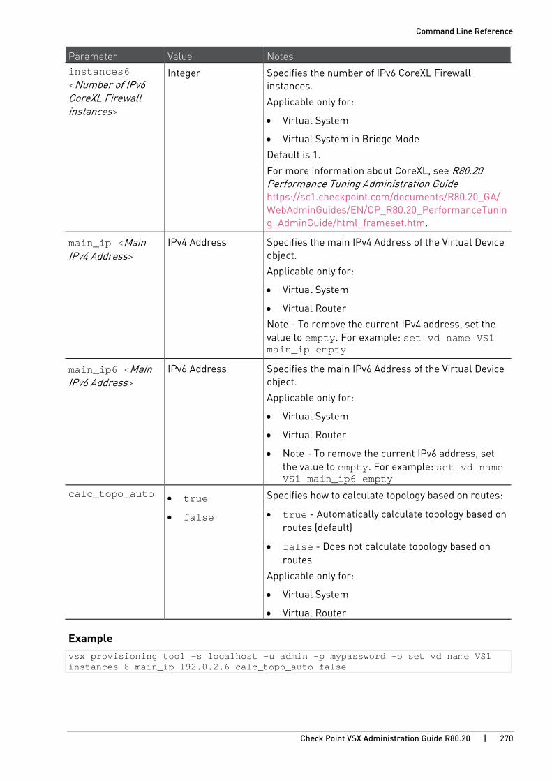
Command Line Reference
Check Point VSX Administration Guide R80.20 | 270
Parameter Value Notes instances6 <Number of IPv6 CoreXL Firewall instances>
Integer Specifies the number of IPv6 CoreXL Firewall instances.
Applicable only for:
• Virtual System
• Virtual System in Bridge Mode
Default is 1.
For more information about CoreXL, see R80.20 Performance Tuning Administration Guide https://sc1.checkpoint.com/documents/R80.20_GA/WebAdminGuides/EN/CP_R80.20_PerformanceTuning_AdminGuide/html_frameset.htm.
main_ip <Main IPv4 Address>
IPv4 Address Specifies the main IPv4 Address of the Virtual Device object.
Applicable only for:
• Virtual System
• Virtual Router
Note - To remove the current IPv4 address, set the value to empty. For example: set vd name VS1 main_ip empty
main_ip6 <Main IPv6 Address>
IPv6 Address Specifies the main IPv6 Address of the Virtual Device object.
Applicable only for:
• Virtual System
• Virtual Router
• Note - To remove the current IPv6 address, set the value to empty. For example: set vd name VS1 main_ip6 empty
calc_topo_auto • true
• false
Specifies how to calculate topology based on routes:
• true - Automatically calculate topology based on routes (default)
• false - Does not calculate topology based on routes
Applicable only for:
• Virtual System
• Virtual Router
Example vsx_provisioning_tool –s localhost –u admin –p mypassword –o set vd name VS1 instances 8 main_ip 192.0.2.6 calc_topo_auto false

Command Line Reference
Check Point VSX Administration Guide R80.20 | 271
Adding an Interface to a Virtual Device
Description
This command lets you add an interface to an existing Virtual Device object:
• Virtual System
• Virtual System in Bridge Mode
• Virtual Switch
• Virtual Router
Syntax add interface vd <Device Object Name> {name <Interface> | leads_to <VSW or VR Object Name>} ip <IPv4 Address>{/<IPv4 Prefix Length> | netmask <IPv4 Netmask> | prefix <IPv4 Prefix>} ip6 <IPv6 Address>{/<IPv6 Prefix Length> | netmask6 <IPv6 Netmask> | prefix6 <IPv6 Prefix>} [propagate {true|false}] [propagate6 {true|false}] [topology {external | internal_undefined | internal_this_network | internal_specific [specific_group <Network Group Object Name>}] [mtu <MTU>]
Parameters
Parameter Value Notes
vd <Device Object Name>
Object name Specifies the name of the Virtual Device object.
Mandatory parameter, if this is the first command in a transaction.
name <Interface> Interface name Specifies the name of the physical or VLAN interface.
Note - You must use name or leads_to parameter, but not both.
leads_to <VSW or VR Object Name>
Object name Specifies the name of the Virtual Switch or Virtual Router object, to which this interface connects.
Applicable only for Virtual System.
Note - You must use name or leads_to parameter, but not both.

Command Line Reference
Check Point VSX Administration Guide R80.20 | 272
Parameter Value Notes
ip <IPv4 Address>{/<IPv4 Prefix> | netmask <IPv4 Netmask> | prefix <IPv4 Prefix>}
IPv4 configuration Specifies the IPv4 settings:
• <IPv4 Address> - IPv4 address
• <IPv4 Prefix> - Integer between 1 and 32
• <IPv4 Netmask> - Number in a format X.X.X.X
Applicable only for:
• Virtual System
• Virtual Router
For interfaces on a Virtual System that connect to a Virtual Router, you must use the possible maximum for the IPv4 address family:
• Netmask 255.255.255.255
• Prefix 32
ip6 <IPv6 Address>{/<IPv6 Prefix> | netmask6 <IPv6 Netmask> | prefix6 <IPv6 Prefix>}
IPv6 configuration Specifies the IPv6 settings:
• <IPv6 Address> - IPv6 address
• <IPv6 Prefix> - Integer between 64 and 128
• <IPv6 Netmask> - Number in a format XXXX:XXXX:XXXX:XXXX:XXXX:XXXX:XXXX:XXXX
Applicable only for:
• Virtual System
• Virtual Router
For interfaces on a Virtual System that connect to a Virtual Router, you must use the possible maximum for the IPv6 address family:
• Netmask FFFF:FFFF:FFFF:FFFF:FFFF:FFFF:FFFF:FFFF
• Prefix 128

Command Line Reference
Check Point VSX Administration Guide R80.20 | 273
Parameter Value Notes propagate {true | false}
• true
• false
Controls how to propagate the IPv4 routes to adjacent Virtual Devices:
• true - Propagate the IPv4 routes
• false - Do not propagate the IPv4 routes (default)
Note - Applicable only for Virtual System with VLAN or physical interfaces.
propagate6 {true | false}
• true
• false
Controls how to propagate the IPv6 routes to adjacent Virtual Devices:
• true - Propagate the IPv6 routes
• false - Do not propagate the IPv6 routes (default)
Note - Applicable only for Virtual System with VLAN or physical interfaces.
topology {external | internal_undefined | internal_this_network | internal_specific }
• external
• internal_undefined
• internal_this_network
• internal_specific
Specifies the Topology configuration of the interface:
• external - External interface.
• internal_undefined - Internal interface with undefined topology. This is the default for Virtual System in Bridge Mode.
• internal_this_network - Internal interface. This is the default for Virtual System and Virtual Router. Virtual System in Bridge Mode does not support this topology.
• internal_specific - Internal interface with topology defined by the specified Network Group object.
Applicable only for:
• Virtual System
• Virtual System in Bridge Mode
• Virtual Router specific_group <Network Group Object Name>
Name of Network Group Object
If you used topology internal_specific, then specify the name of the Network Group object that contains the applicable Network objects
Applicable only if you disable the automatic topology calculation.

Command Line Reference
Check Point VSX Administration Guide R80.20 | 274
Parameter Value Notes
mtu <MTU> Integer Specifies the MTU value for this interface.
Default is 1500 bytes.
Applicable only for:
• Virtual System
• Virtual Router
Example - Add VLAN interface eth4.100 with IPv4 1.1.1.1/24 to the Virtual System 'VirtSystem1' vsx_provisioning_tool–s localhost –u admin –p mypassword –o add interface vd VirtSystem1 name eth4.100 ip 1.1.1.1/24

Command Line Reference
Check Point VSX Administration Guide R80.20 | 275
Removing an Interface from a Virtual Device
Description
This command lets you remove an interface from an existing Virtual Device object:
• Virtual System
• Virtual System in Bridge Mode
• Virtual Switch
• Virtual Router
Important – If the interface you remove leads to a Virtual Router, all routes through that interface are removed automatically.
Note - If there are routes that have a next-hop IP address, which would become inaccessible without this interface, the transaction fails.
Syntax remove interface vd <Device Object Name> {name <Interface> | leads_to <VSW or VR Object Name>}
Parameters
Parameter Value Notes
vd <Device Object Name>
Object name Specifies the name of the Virtual Device object.
Mandatory parameter, if this is the first command in a transaction.
name <Interface> Interface name Specifies the name of the physical or VLAN interface.
Note - You must use name or leads_to parameter, but not both.
leads_to <VSW or VR Object Name>
Object name Specifies the name of the Virtual Switch or Virtual Router object, to which this interface connects.
Applicable only for Virtual System.
Note - You must use name or leads_to parameter, but not both.
Example vsx_provisioning_tool –s localhost –u admin –p mypassword –o remove interface vd VS1 name eth4.100

Command Line Reference
Check Point VSX Administration Guide R80.20 | 276
Modifying Settings of an Interface
Description
This command lets you modify the settings of an interface that belongs to an existing Virtual Device object:
• Virtual System
• Virtual System in Bridge Mode
• Virtual Switch
• Virtual Router
Note - You cannot change or remove the IP address or netmask of an existing interface with this command. You can remove the interface and add a new interface with a different IP address, but not all the previous interface settings will be kept.
Syntax set interface vd <Device Object Name> {name <Interface> [new_name <Interface>] | leads_to <VSW or VR Object Name> [new_leads_to <VSW or VR Object Name>]} [propagate {true|false}] [propagate6 {true|false}] [topology {external | internal_undefined | internal_this_network | internal_specific [specific_group <Network Group Object Name>>]}] [mtu <MTU>]
Parameters
Parameter Value Notes
vd <Device Object Name>
Object name Specifies the name of the Virtual Device object.
Mandatory parameter, if this is the first command in a transaction.
name <Interface> Interface name Specifies the name of the physical or VLAN interface.
Note - You must use name or leads_to parameter, but not both.
new_name <Interface> Interface name You can change the name, but not the type of interface.
Note - You can change a VLAN or physical interface only to a VLAN or physical interface.
leads_to <VSW or VR Object Name>
Object name Specifies the name of the Virtual Switch or Virtual Router object, to which this interface connects.
Applicable only for Virtual System.
Note - You must use name or leads_to parameter, but not both.

Command Line Reference
Check Point VSX Administration Guide R80.20 | 277
Parameter Value Notes
new_leads_to <VSW or VR Object Name>
Object name You can where the interface leads:
• You can change an interface that leads to a Virtual Switch only to lead to a different Virtual Switch.
• You can change an interface that leads to a Virtual Router only to lead to a different Virtual Router.
propagate {true | false}
• true
• false
Controls how to propagate the IPv4 routes to adjacent Virtual Devices:
• true - Propagate the IPv4 routes
• false - Do not propagate the IPv4 routes (default)
Note - Applicable only for Virtual System with VLAN or physical interfaces.
propagate6 {true | false}
• true
• false
Controls how to propagate the IPv6 routes to adjacent Virtual Devices:
• true - Propagate the IPv6 routes
• false - Do not propagate the IPv6 routes (default)
Note - Applicable only for Virtual System with VLAN or physical interfaces.
topology {external | internal_undefined | internal_this_network | internal_specific }
• external
• internal_undefined
• internal_this_network
• internal_specific
Specifies the Topology configuration of the interface:
• external - External interface.
• internal_undefined - Internal interface with undefined topology. This is the default for Virtual System in Bridge Mode.
• internal_this_network - Internal interface. This is the default for Virtual System and Virtual Router. Virtual System in Bridge Mode does not support this topology.
• internal_specific - Internal interface with topology defined by the specified Network Group object.
Applicable only for:
• Virtual System
• Virtual System in Bridge Mode
• Virtual Router

Command Line Reference
Check Point VSX Administration Guide R80.20 | 278
Parameter Value Notes specific_group <Network Group Object Name>
Name of Network Group Object
If you used topology internal_specific, then specify the name of the Network Group object that contains the applicable Network objects
Applicable only if you disable the automatic topology calculation.
mtu <MTU> Integer Specifies the MTU value for this interface.
Default is 1500 bytes.
Applicable only for:
• Virtual System
• Virtual Router
Example - On a Virtual System VS1, change the VLAN interface eth4.10 to the physical interface eth5 vsx_provisioning_tool –s localhost –u admin –p mypassword –o set interface vd VS1 name eth4.100 new_name eth5 propagate true topology internal_specific specific_group NYGWs

Command Line Reference
Check Point VSX Administration Guide R80.20 | 279
Adding a Route
Description
This command lets you add an IPv4 or IPv6 route to an existing Virtual System or Virtual Router object.
Note - This command detects IPv4 and IPv6 automatically.
Syntax add route vd <Device Object Name> destination {<IP Address>[/<IP Prefix>] | default | default6} [{netmask <IP Netmask> | prefix <IP Prefix>}] {next_hop <Next Hop IP Address> | leads_to <VS or VR Object Name>} [propagate {true|false}]
Parameters
Parameter Value Notes
vd <Device Object Name>
Object name Specifies the name of the Virtual System or Virtual Router object.
Mandatory parameter, if this is the first command in a transaction.
destination {<IP Address>[/<IP Prefix>] | default | default6}
See the Notes cell Specifies the route destination settings:
• <IP Address> - IPv4 or IPv6 address
• <IP Prefix> -
For IPv4 - Integer between 1 and 32
For IPv6 - Integer between 64 and 128
• default - Use the default IPv4 route
• default6 - Use the default IPv6 route
netmask <IP Netmask> Number Specifies an IP Netmask:
• For IPv4 - Number in a format X.X.X.X
• For IPv6 - Number in a format XXXX:XXXX:XXXX:XXXX:XXXX:XXXX:XXXX:XXXX
prefix <IP Prefix> Integer Specifies the IP address prefix length:
• For IPv4 - Integer between 1 and 32
• For IPv6 - Integer between 64 and 128
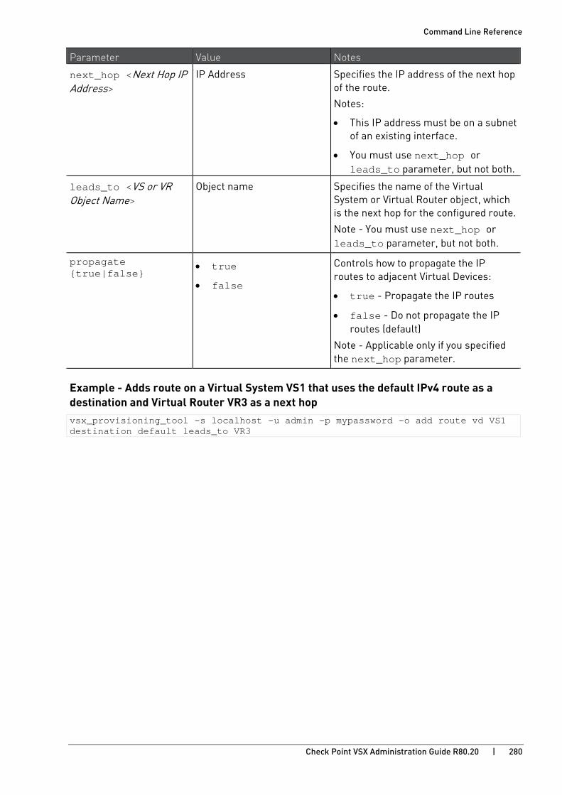
Command Line Reference
Check Point VSX Administration Guide R80.20 | 280
Parameter Value Notes
next_hop <Next Hop IP Address>
IP Address Specifies the IP address of the next hop of the route.
Notes:
• This IP address must be on a subnet of an existing interface.
• You must use next_hop or leads_to parameter, but not both.
leads_to <VS or VR Object Name>
Object name Specifies the name of the Virtual System or Virtual Router object, which is the next hop for the configured route.
Note - You must use next_hop or leads_to parameter, but not both.
propagate {true|false}
• true
• false
Controls how to propagate the IP routes to adjacent Virtual Devices:
• true - Propagate the IP routes
• false - Do not propagate the IP routes (default)
Note - Applicable only if you specified the next_hop parameter.
Example - Adds route on a Virtual System VS1 that uses the default IPv4 route as a destination and Virtual Router VR3 as a next hop vsx_provisioning_tool –s localhost –u admin –p mypassword –o add route vd VS1 destination default leads_to VR3

Command Line Reference
Check Point VSX Administration Guide R80.20 | 281
Removing a Route
Description
This command lets you remove an IPv4 or IPv6 route from an existing Virtual System or Virtual Router object.
Note - This command detects IPv4 and IPv6 automatically.
Syntax remove route vd <Device Object Name> destination {<IP Address>[/<IP Prefix>] | default | default6} [{netmask <IP Netmask> | prefix <IP Prefix>]
Parameters
Parameter Value Notes
vd <Device Object Name>
Object name Specifies the name of the Virtual System or Virtual Router object.
Mandatory parameter, if this is the first command in a transaction.
destination {<IP Address>[/<IP Prefix>] | default | default6}
See the Notes cell Specifies the route destination settings:
• <IP Address> - IPv4 or IPv6 address
• <IP Prefix> -
For IPv4 - Integer between 1 and 32
For IPv6 - Integer between 64 and 128
• default - Use the default IPv4 route
• default6 - Use the default IPv6 route
netmask <IP Netmask> Number Specifies an IP Netmask:
• For IPv4 - Number in a format X.X.X.X
• For IPv6 - Number in a format XXXX:XXXX:XXXX:XXXX:XXXX:XXXX:XXXX:XXXX
prefix <IP Prefix> Integer Specifies the IP address prefix length:
• For IPv4 - Integer between 1 and 32
• For IPv6 - Integer between 64 and 128
Example - Removes route from a Virtual System VS1 that uses the default IPv6 route as a destination vsx_provisioning_tool –s localhost –u admin –p mypassword –o remove route vd VS1 destination default6

Command Line Reference
Check Point VSX Administration Guide R80.20 | 282
Showing Virtual Device Data
Description
This command lets you show the information about an existing Virtual Device object.
Syntax show vd <Device Object Name>
Parameters
Parameter Value Notes
vd <Device Object Name>
Name of the Virtual Device Specifies the name of the Virtual Device object.
Mandatory parameter.
Comments
• The command shows only non-automatic routes.
• The command does not show routes that are created automatically with route propagation.
• For a Virtual Router and Virtual Switch: The command does not show the wrpj interfaces (created automatically) that connect to Virtual Systems.

Command Line Reference
Check Point VSX Administration Guide R80.20 | 283
Script Examples Note - Line numbers in the left column are written only to make it easier to read the examples.
Example 1
Create a Virtual System connected to a Virtual Router.
Add a default route on the Virtual System that routes the traffic to the Virtual Router.
Add applicable routes on the Virtual Router to route the traffic to the Virtual System.
1 2 3 4 5 6 7 8 9 10 11 12 13 14 15
transaction begin add vd name VR1 vsx VSX1 type vr add interface name eth3.100 ip 10.0.0.1/24 transaction end transaction begin add vd name VR2 vsx VSX2 type vr add interface name eth3.200 ip 20.0.0.1/24 transaction end transaction begin add vd name VS1 vsx VSX1 add interface leads_to VR1 ip 192.168.1.1/32 add interface name eth4.20 ip 192.168.20.1/24 propagate true add route destination default leads_to VR1 add route destination 192.168.40.0/25 next_hop 192.168.20.254 transaction end
Example 2
Create a Virtual System connected to a Virtual Switch, with manual topology.
1 2 3 4 5 6 7 8 9 10 11
transaction begin add vd name VSW1 vsx VSX1 type vsw vs_mtu 1400 add interface name eth3.100 transaction end transaction begin add vd name VS1 vsx VSX1 calc_topo_auto false add interface leads_to VSW1 ip 10.0.0.1/24 ip6 2001::1/64 topology external add interface name eth4.20 ip 192.168.20.1/25 ip6 2020::1/64 topology internal_this_network add route destination default next_hop 10.0.0.254 add route destination default6 next_hop 2001::254 transaction end
Example 3
Add CoreXL Firewall instances to the Virtual System made in the last example.
Turn on automatic calculation of topology.
Change the name of the internal interface, and decrease its MTU.
1 2 3 4
transaction begin set vd name VS1 instances 4 instances6 2 calc_topo_auto true set interface name eth4.20 new_name eth4.21 mtu 1400 transaction end

Check Point VSX Administration Guide R80.20 | 284
CHAPTE R 13
Configuration Examples In This Section:
Example 1: VSX Gateway managed by Security Management Server ..................... 285
Example 2: VSX Cluster managed by Multi-Domain Server..................................... 297

Configuration Examples
Check Point VSX Administration Guide R80.20 | 285
Example 1: VSX Gateway managed by Security Management Server
This example shows:
• One VSX Gateway with DMI management connection
• Two Virtual Systems:
• Each Virtual System connects directly to available physical interfaces on the VSX Gateway
• One Virtual System is configured with the IPsec VPN Software Blade
• One Virtual System is configured with the Mobile Access Software Blade
• One Security Management Server manages both the VSX Gateway and the two Virtual Systems.
Related documentation:
• R80.20 Installation and Upgrade Guide https://sc1.checkpoint.com/documents/R80.20_GA/WebAdminGuides/EN/CP_R80.20_Installation_and_Upgrade_Guide/html_frameset.htm
• R80.20 Gaia Administration Guide https://sc1.checkpoint.com/documents/R80.20_GA/WebAdminGuides/EN/CP_R80.20_Gaia_AdminGuide/html_frameset.htm
• R80.20 Security Management Administration Guide https://sc1.checkpoint.com/documents/R80.20_GA/WebAdminGuides/EN/CP_R80.20_SecurityManagement_AdminGuide/html_frameset.htm
Topology
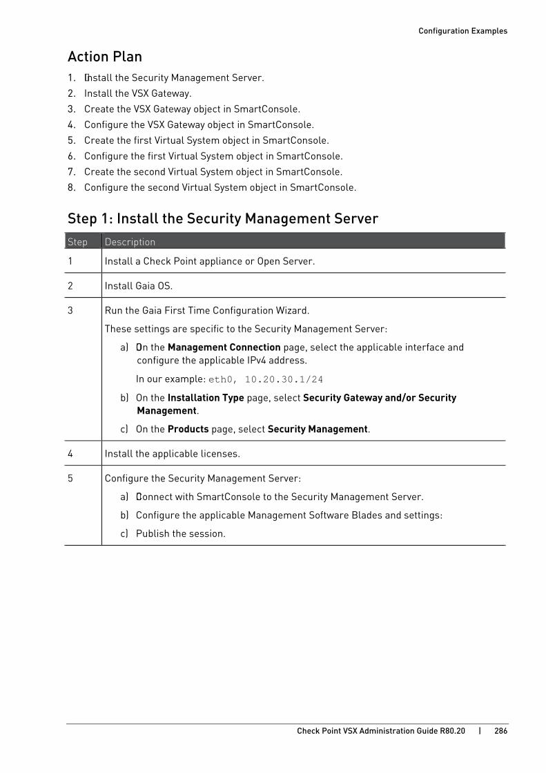
Configuration Examples
Check Point VSX Administration Guide R80.20 | 286
Action Plan 1. Install the Security Management Server.
2. Install the VSX Gateway.
3. Create the VSX Gateway object in SmartConsole.
4. Configure the VSX Gateway object in SmartConsole.
5. Create the first Virtual System object in SmartConsole.
6. Configure the first Virtual System object in SmartConsole.
7. Create the second Virtual System object in SmartConsole.
8. Configure the second Virtual System object in SmartConsole.
Step 1: Install the Security Management Server Step Description
1 Install a Check Point appliance or Open Server.
2 Install Gaia OS.
3 Run the Gaia First Time Configuration Wizard.
These settings are specific to the Security Management Server:
a) On the Management Connection page, select the applicable interface and configure the applicable IPv4 address.
In our example: eth0, 10.20.30.1/24
b) On the Installation Type page, select Security Gateway and/or Security Management.
c) On the Products page, select Security Management.
4 Install the applicable licenses.
5 Configure the Security Management Server:
a) Connect with SmartConsole to the Security Management Server.
b) Configure the applicable Management Software Blades and settings:
c) Publish the session.

Configuration Examples
Check Point VSX Administration Guide R80.20 | 287
Step 2: Install the VSX Gateway Step Description
1 Install a Check Point appliance or Open Server.
2 Install Gaia OS.
3 Run the Gaia First Time Configuration Wizard.
These settings are specific to the VSX Gateway:
a) On the Management Connection page, select the interface for the DMI management connection and configure the applicable IPv4 address.
In our example: eth0, 10.20.30.2/24
b) On the Internet Connection page, do not configure IP addresses on physical interfaces, to which your Virtual Systems connect directly.
c) On the Installation Type page, select Security Gateway and/or Security Management.
d) On the Products page, select Security Gateway.
e) On the Dynamically Assigned IP page, select No.
4 Make sure to enable the applicable physical interfaces:
To enable a physical interface in Gaia Portal
a) Connect to the Gaia Portal in your web browser.
In our example: https://10.20.30.2
b) Click Network Management > Network Interfaces.
c) In the upper left corner, click the lock icon to obtain the configuration lock.
d) Select the applicable physical interface > click Edit.
e) Select Enable.
f) Click OK.
To enable a physical interface in Gaia Clish, run:
a) set interface <Name of Physical Interface> state on
b) save config
5 Install the applicable licenses.
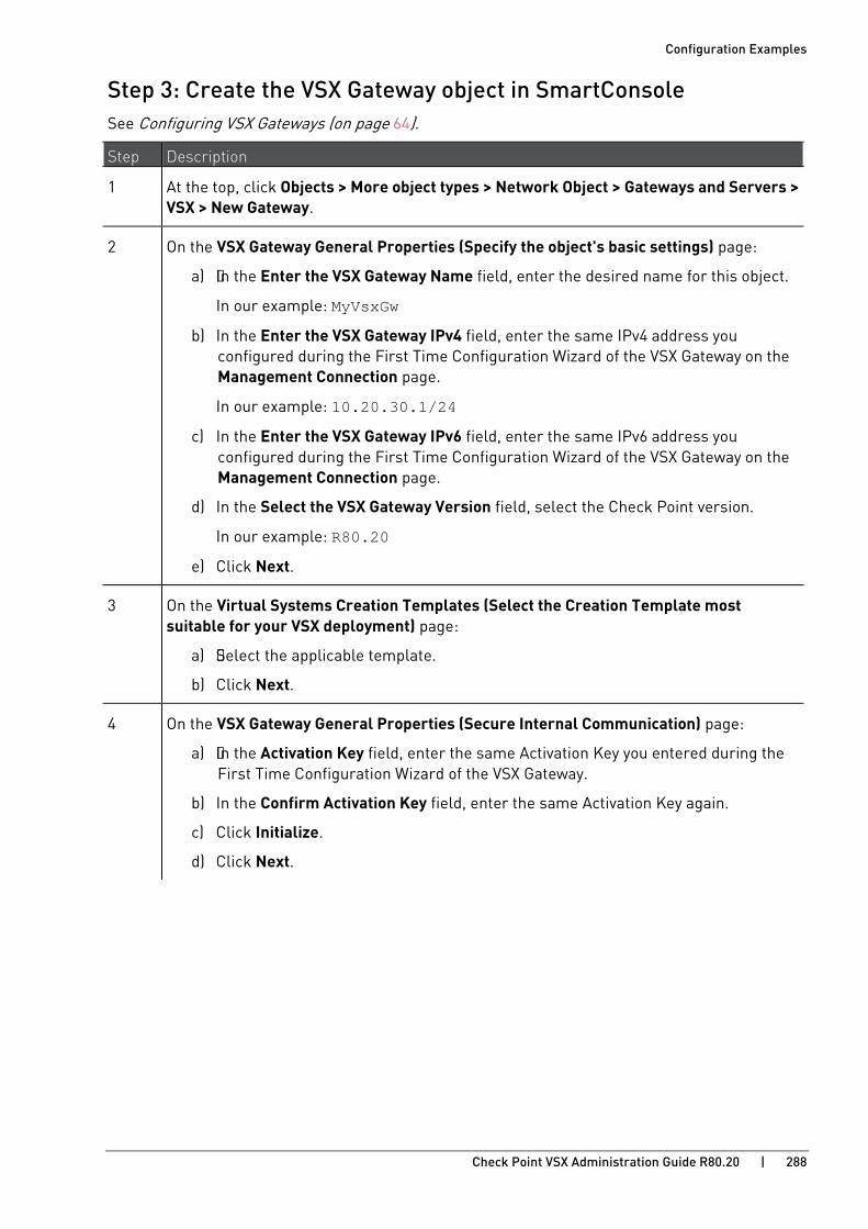
Configuration Examples
Check Point VSX Administration Guide R80.20 | 288
Step 3: Create the VSX Gateway object in SmartConsole See Configuring VSX Gateways (on page 64).
Step Description
1 At the top, click Objects > More object types > Network Object > Gateways and Servers > VSX > New Gateway.
2 On the VSX Gateway General Properties (Specify the object's basic settings) page:
a) In the Enter the VSX Gateway Name field, enter the desired name for this object.
In our example: MyVsxGw
b) In the Enter the VSX Gateway IPv4 field, enter the same IPv4 address you configured during the First Time Configuration Wizard of the VSX Gateway on the Management Connection page.
In our example: 10.20.30.1/24
c) In the Enter the VSX Gateway IPv6 field, enter the same IPv6 address you configured during the First Time Configuration Wizard of the VSX Gateway on the Management Connection page.
d) In the Select the VSX Gateway Version field, select the Check Point version.
In our example: R80.20
e) Click Next.
3 On the Virtual Systems Creation Templates (Select the Creation Template most suitable for your VSX deployment) page:
a) Select the applicable template.
b) Click Next.
4 On the VSX Gateway General Properties (Secure Internal Communication) page:
a) In the Activation Key field, enter the same Activation Key you entered during the First Time Configuration Wizard of the VSX Gateway.
b) In the Confirm Activation Key field, enter the same Activation Key again.
c) Click Initialize.
d) Click Next.

Configuration Examples
Check Point VSX Administration Guide R80.20 | 289
Step Description
If the Trust State field does not show Trust established, perform these steps:
a) Connect to the command line on the VSX Gateway.
b) Make sure there is a physical connectivity between the VSX Gateway and the Management Server (for example, pings can pass).
c) Run: cpconfig
d) Enter the number of this option: Secure Internal Communication
e) Follow the instructions on the screen to change the Activation Key.
f) On the VSX Gateway General Properties page, click Reset.
g) Enter the same Activation Key you entered in the cpconfig menu.
h) Click Initialize.
5 On the VSX Gateway Interfaces (Physical Interfaces Usage) page:
a) Examine the list of the interfaces - it must show all the physical interfaces on the VSX Gateway.
b) If you plan to connect more than one Virtual System directly to same physical interface, you must select VLAN Trunk for that physical interface.
c) Click Next.
6 On the Virtual Network Device Configuration (Specify the object's basic settings) page:
a) You can select Create a Virtual Network Device and configure the first desired Virtual Network Device at this time (we recommend to do this later) - Virtual Switch or Virtual Router.
b) Click Next.
7 On the VSX Gateway Management (Specify the management access rules) page:
a) Examine the default access rules.
b) Select the applicable default access rules.
c) Configure the applicable source objects, if needed.
d) Click Next.
Important - These access rules apply only to the VSX Gateway (context of VS0), which is not intended to pass any "production" traffic.
8 On the VSX Gateway Creation Finalization page:
a) Click Finish and wait for the operation to finish.
b) Click View Report for more information.
c) Click Close.

Configuration Examples
Check Point VSX Administration Guide R80.20 | 290
Step Description
9 Examine the VSX configuration:
a) Connect to the command line on the VSX Gateway.
b) Log in to Gaia Clish, or Expert mode.
c) Run: vsx stat -v
Step 4: Configure the VSX Gateway object in SmartConsole See Working with VSX Gateways (on page 68).
Step Description
1 From the left navigation toolbar, click Gateways & Servers.
2 Open the VSX Gateway object.
In our example: MyVsxGw
3 Enable the applicable Software Blades.
Refer to:
• sk79700 - VSX supported features on R75.40VS and above http://supportcontent.checkpoint.com/solutions?id=sk79700
• sk106496 - Software Blades updates on VSX R75.40VS and above - FAQ http://supportcontent.checkpoint.com/solutions?id=sk106496
• Applicable Administration Guides on the R80.20 Home Page http://supportcontent.checkpoint.com/solutions?id=sk122485.
4 Configure other applicable settings.
5 Click OK to push the updated VSX Configuration.
Click View Report for more information.
6 Install policy on the VSX Gateway object:
a) Click Install Policy.
The Install Policy window opens.
b) In the Policy field, select the default policy for this VSX Gateway object.
This policy is called: <Name of VSX Gateway object>_VSX.
In our example: MyVsxGw_VSX
c) Click Install.
7 Examine the VSX configuration:
a) Connect to the command line on the VSX Gateway.
b) Log in to Gaia Clish, or Expert mode.
c) Run: vsx stat -v

Configuration Examples
Check Point VSX Administration Guide R80.20 | 291
Step 5: Create the first Virtual System object in SmartConsole See Creating a New Virtual System (on page 74).
Step Description
1 At the top, click Objects > More object types > Network Object > Gateways and Servers > VSX > New Virtual System.
2 On the VSX System General Properties (Define the object name and the hosting VSX) page:
a) In the Name field, enter the desired name for this object.
In our example: MyVs1
b) In the VSX Gateway / Cluster field, select the applicable VSX Gateway object.
In our example: MyVsxGw
c) You can select Override Creation Template (Create Custom VS), if you need to override the creation template that was used for the initial configuration of the VSX Gateway.
d) Click Next.
3 On the Virtual System Network Configuration (Define Virtual System Interfaces and Routes) page:
In our example, this Virtual System connects directly to two physical interfaces on the VSX Gateway.
In the Interfaces section, add the "external" interface:
a) Click Add > Regular.
b) In the Interface field, select the applicable physical interface.
In our example: eth1
c) In the IPv4 Configuration section, enter the applicable IP Address and Net Mask.
In our example: 192.168.10.1/24
You can select Propagate route to adjacent Virtual Devices (IPv4) to "advertise" this Virtual System to neighboring Virtual Devices. This enables IPv4 connectivity between neighboring Virtual Devices.
d) In the IPv6 Configuration section, enter the applicable IPv6 Address and Prefix.
You can select Propagate route to adjacent Virtual Devices (IPv6) to "advertise" this Virtual System to neighboring Virtual Devices. This enables IPv6 connectivity between the neighboring Virtual Devices.
e) Click OK.

Configuration Examples
Check Point VSX Administration Guide R80.20 | 292
Step Description
In the Interfaces section, add the "internal" interface:
a) Click Add > Regular.
b) In the Interface field, select the applicable physical interface - this is the "internal" interface.
In our example: eth2
c) In the IPv4 Configuration section, enter the applicable IP Address and Net Mask.
In our example: 172.30.10.1/24
You can select Propagate route to adjacent Virtual Devices (IPv4) to "advertise" this Virtual System to neighboring Virtual Devices. This enables IPv4 connectivity between the neighboring Virtual Devices.
d) In the IPv6 Configuration section, enter the applicable IPv6 Address and Prefix.
You can select Propagate route to adjacent Virtual Devices (IPv6) to "advertise" this Virtual System to neighboring Virtual Devices. This enables IPv6 connectivity between the neighboring Virtual Devices.
e) Click OK.
In the Routes section, click Add to configure the applicable static routes and the Default Route.
Click Next.
4 On the VSX System Creation Finalization page:
a) Click Finish and wait for the operation to finish.
b) Click View Report for more information.
c) Click Close.
5 Examine the VSX configuration:
a) Connect to the command line on the VSX Gateway.
b) Log in to Gaia Clish, or Expert mode.
c) Run: vsx stat -v

Configuration Examples
Check Point VSX Administration Guide R80.20 | 293
Step 6: Configure the first Virtual System object in SmartConsole See Modifying a Virtual System (on page 77).
Step Description
1 From the left navigation toolbar, click Gateways & Servers.
2 Open the first Virtual System object.
In our example: MyVs1
3 Enable the applicable Software Blades.
In our example: IPsec VPN blade
Refer to:
• sk79700 - VSX supported features on R75.40VS and above http://supportcontent.checkpoint.com/solutions?id=sk79700
• sk106496 - Software Blades updates on VSX R75.40VS and above - FAQ http://supportcontent.checkpoint.com/solutions?id=sk106496
• Applicable Administration Guides on the R80.20 Home Page http://supportcontent.checkpoint.com/solutions?id=sk122485.
4 Configure other applicable settings.
5 Click OK to push the updated VSX Configuration.
6 Configure and install the applicable policy on the first Virtual System object.
7 Examine the VSX configuration:
a) Connect to the command line on the VSX Gateway.
b) Log in to Gaia Clish, or Expert mode.
c) Run: vsx stat -v

Configuration Examples
Check Point VSX Administration Guide R80.20 | 294
Step 7: Create the second Virtual System object in SmartConsole See Creating a New Virtual System (on page 74).
Step Description
1 At the top, click Objects > More object types > Network Object > Gateways and Servers > VSX > New Virtual System.
2 On the VSX System General Properties (Define the object name and the hosting VSX) page:
a) In the Name field, enter the desired name for this object.
In our example: MyVs2
b) In the VSX Gateway / Cluster field, select the applicable VSX Gateway object.
In our example: MyVsxGw
c) You can select Override Creation Template (Create Custom VS), if you need to override the creation template that was used for the initial configuration of the VSX Gateway.
d) Click Next.
3 On the Virtual System Network Configuration (Define Virtual System Interfaces and Routes) page:
In our example, this Virtual System connects directly to two physical interfaces on the VSX Gateway.
In the Interfaces section, add the "external" interface:
a) Click Add > Regular.
b) In the Interface field, select the applicable physical interface.
In our example: eth1
c) In the IPv4 Configuration section, enter the applicable IP Address and Net Mask.
In our example: 192.168.20.1/24
You can select Propagate route to adjacent Virtual Devices (IPv4) to "advertise" this Virtual System to neighboring Virtual Devices. This enables IPv4 connectivity between Virtual Devices.
d) In the IPv6 Configuration section, enter the applicable IPv6 Address and Prefix.
You can select Propagate route to adjacent Virtual Devices (IPv6) to "advertise" this Virtual System to neighboring Virtual Devices. This enables IPv6 connectivity between Virtual Devices.
e) Click OK.

Configuration Examples
Check Point VSX Administration Guide R80.20 | 295
Step Description
In the Interfaces section, add the "internal" interface:
a) Click Add > Regular.
b) In the Interface field, select the applicable physical interface - this is the "internal" interface.
In our example: eth2
c) In the IPv4 Configuration section, enter the applicable IP Address and Net Mask.
In our example: 172.30.20.1/24
You can select Propagate route to adjacent Virtual Devices (IPv4) to "advertise" this Virtual System to neighboring Virtual Devices. This enables IPv4 connectivity between the neighboring Virtual Devices.
d) In the IPv6 Configuration section, enter the applicable IPv6 Address and Prefix.
You can select Propagate route to adjacent Virtual Devices (IPv6) to "advertise" this Virtual System to neighboring Virtual Devices. This enables IPv6 connectivity between the neighboring Virtual Devices.
e) Click OK.
In the Routes section, click Add to configure the applicable static routes and the Default Route.
Click Next.
4 On the VSX System Creation Finalization page:
a) Click Finish and wait for the operation to finish.
b) Click View Report for more information.
c) Click Close.
5 Examine the VSX configuration:
a) Connect to the command line on the VSX Gateway.
b) Log in to Gaia Clish, or Expert mode.
c) Run: vsx stat -v

Configuration Examples
Check Point VSX Administration Guide R80.20 | 296
Step 8: Configure the second Virtual System object in SmartConsole See Modifying a Virtual System (on page 77).
Step Description
1 From the left navigation toolbar, click Gateways & Servers.
2 Open the second Virtual System object.
In our example: MyVs2
3 Enable the applicable Software Blades.
In our example: Mobile Access blade
Refer to:
• sk79700 - VSX supported features on R75.40VS and above http://supportcontent.checkpoint.com/solutions?id=sk79700
• sk106496 - Software Blades updates on VSX R75.40VS and above - FAQ http://supportcontent.checkpoint.com/solutions?id=sk106496
• Applicable Administration Guide on the R80.20 Home Page http://supportcontent.checkpoint.com/solutions?id=sk122485.
4 Configure other applicable settings.
5 Click OK to push the updated VSX Configuration.
6 Configure and install the applicable policy on the second Virtual System object.
7 Examine the VSX configuration:
a) Connect to the command line on the VSX Gateway.
b) Log in to Gaia Clish, or Expert mode.
c) Run: vsx stat -v
Configuration Examples
Check Point VSX Administration Guide R80.20 | 297
Example 2: VSX Cluster managed by Multi-Domain Server
This example shows:
• One VSX Cluster in High Availability
• Two VSX Cluster Members with DMI management connection
• One external Virtual Switch
• Two Virtual Systems:
• External interface on each Virtual System connects directly to the Virtual Switch
• Internal interface on each Virtual System connects to the VLAN Trunk interface
• One Virtual System is configured with the IPsec VPN Software Blade
• One Virtual System is configured with the Mobile Access Software Blade
• One Multi-Domain Server:
• One Main Domain Management Server manages the objects of the VSX Cluster and Virtual Switch
• One Target Domain Management Server manages the object of the first Virtual System
• One Target Domain Management Server manages the object of the second Virtual System
Related documentation:
• R80.20 Installation and Upgrade Guide https://sc1.checkpoint.com/documents/R80.20_GA/WebAdminGuides/EN/CP_R80.20_Installation_and_Upgrade_Guide/html_frameset.htm
• R80.20 Gaia Administration Guide https://sc1.checkpoint.com/documents/R80.20_GA/WebAdminGuides/EN/CP_R80.20_Gaia_AdminGuide/html_frameset.htm
• R80.20 Security Management Administration Guide https://sc1.checkpoint.com/documents/R80.20_GA/WebAdminGuides/EN/CP_R80.20_SecurityManagement_AdminGuide/html_frameset.htm
• R80.20 Multi-Domain Security Management Administration Guide https://sc1.checkpoint.com/documents/R80.20_GA/WebAdminGuides/EN/CP_R80.20_Multi-DomainSecurityManagement_AdminGuide/html_frameset.htm
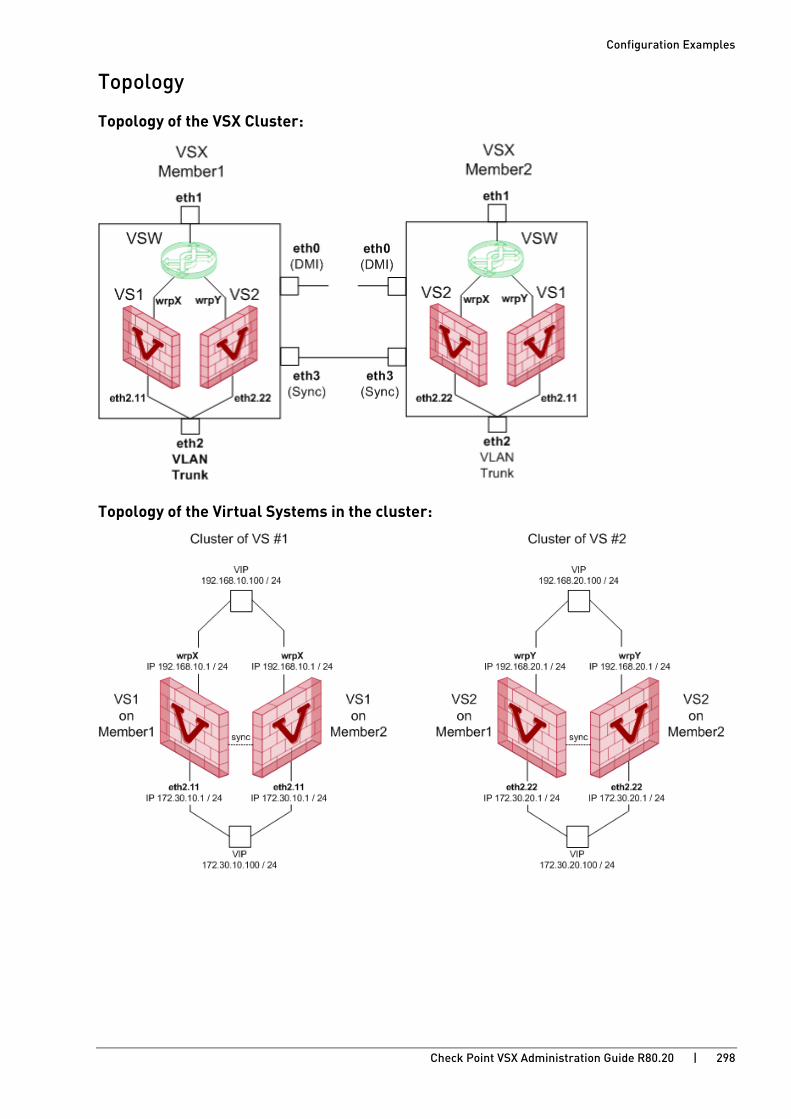
Configuration Examples
Check Point VSX Administration Guide R80.20 | 298
Topology
Topology of the VSX Cluster:
Topology of the Virtual Systems in the cluster:
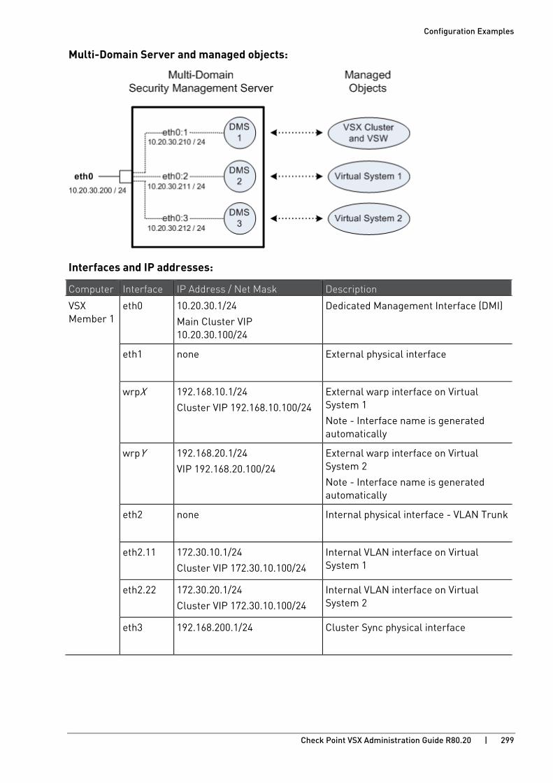
Configuration Examples
Check Point VSX Administration Guide R80.20 | 299
Multi-Domain Server and managed objects:
Interfaces and IP addresses:
Computer Interface IP Address / Net Mask Description
VSX Member 1
eth0 10.20.30.1/24
Main Cluster VIP 10.20.30.100/24
Dedicated Management Interface (DMI)
eth1 none External physical interface
wrpX 192.168.10.1/24
Cluster VIP 192.168.10.100/24
External warp interface on Virtual System 1
Note - Interface name is generated automatically
wrpY 192.168.20.1/24
VIP 192.168.20.100/24
External warp interface on Virtual System 2
Note - Interface name is generated automatically
eth2 none Internal physical interface - VLAN Trunk
eth2.11 172.30.10.1/24
Cluster VIP 172.30.10.100/24
Internal VLAN interface on Virtual System 1
eth2.22 172.30.20.1/24
Cluster VIP 172.30.10.100/24
Internal VLAN interface on Virtual System 2
eth3 192.168.200.1/24 Cluster Sync physical interface
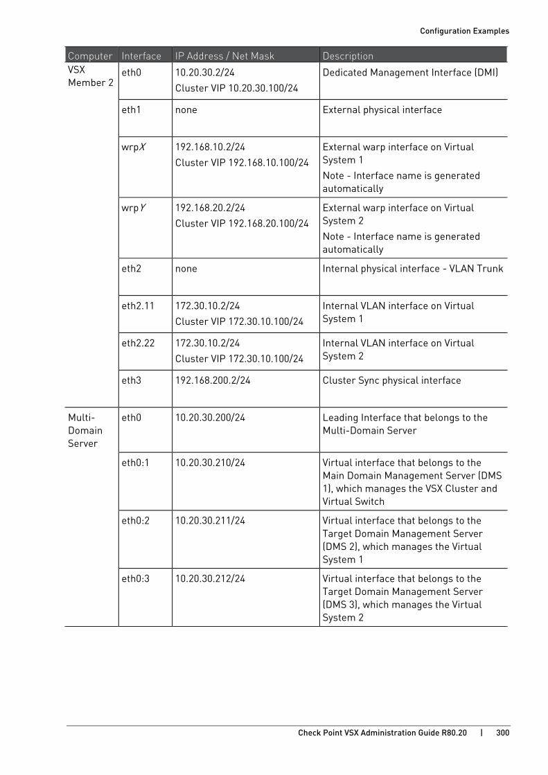
Configuration Examples
Check Point VSX Administration Guide R80.20 | 300
Computer Interface IP Address / Net Mask Description VSX Member 2
eth0 10.20.30.2/24
Cluster VIP 10.20.30.100/24
Dedicated Management Interface (DMI)
eth1 none External physical interface
wrpX 192.168.10.2/24
Cluster VIP 192.168.10.100/24
External warp interface on Virtual System 1
Note - Interface name is generated automatically
wrpY 192.168.20.2/24
Cluster VIP 192.168.20.100/24
External warp interface on Virtual System 2
Note - Interface name is generated automatically
eth2 none Internal physical interface - VLAN Trunk
eth2.11 172.30.10.2/24
Cluster VIP 172.30.10.100/24
Internal VLAN interface on Virtual System 1
eth2.22 172.30.10.2/24
Cluster VIP 172.30.10.100/24
Internal VLAN interface on Virtual System 2
eth3 192.168.200.2/24 Cluster Sync physical interface
Multi- Domain Server
eth0 10.20.30.200/24 Leading Interface that belongs to the Multi-Domain Server
eth0:1 10.20.30.210/24 Virtual interface that belongs to the Main Domain Management Server (DMS 1), which manages the VSX Cluster and Virtual Switch
eth0:2 10.20.30.211/24 Virtual interface that belongs to the Target Domain Management Server (DMS 2), which manages the Virtual System 1
eth0:3 10.20.30.212/24 Virtual interface that belongs to the Target Domain Management Server (DMS 3), which manages the Virtual System 2

Configuration Examples
Check Point VSX Administration Guide R80.20 | 301
Action Plan 1. Install the Multi-Domain Server.
2. Create the Main Domain Management Server in SmartConsole to manage the VSX Cluster and Virtual Switch.
3. Create the Target Domain Management Server in SmartConsole to manage the Virtual System 1.
4. Create the Target Domain Management Server in SmartConsole to manage the Virtual System 2.
5. Install the VSX Cluster Member 1.
6. Install the VSX Cluster Member 2.
7. Create the VSX Cluster object with VSX Cluster Members in SmartConsole.
8. Configure the VSX Cluster object in SmartConsole.
9. Create the Virtual Switch object in SmartConsole.
10. Create the first Virtual System object in SmartConsole.
11. Configure the first Virtual System object in SmartConsole.
12. Create the second Virtual System object in SmartConsole.
13. Configure the second Virtual System object in SmartConsole.
Step 1: Install the Multi-Domain Server Step Description
1 Install a Check Point appliance or Open Server.
2 Install Gaia OS.
3 Run the Gaia First Time Configuration Wizard.
These settings are specific to the Multi-Domain Server:
a) On the Management Connection page, select the applicable interface and configure the applicable IPv4 address.
In our example: eth0, 10.20.30.200/24
b) On the first Installation Type page, select Multi-Domain Server.
c) On the second Installation Type page, select Primary Multi-Domain Server.
d) On the Leading VIP Interfaces Configuration page, select the applicable interface.
In our example: eth0
4 Install the applicable licenses.
5 Configure the applicable settings:
a) Connect with SmartConsole to the Multi-Domain Server.
b) Configure the applicable settings.
c) Publish the session.

Configuration Examples
Check Point VSX Administration Guide R80.20 | 302
Step 2: Create the Main Domain Management Server that manages the VSX Cluster and Virtual Switch Step Description
1 Connect with SmartConsole to the Multi-Domain Server.
2 Create a new Domain and Domain Server.
In our example:
• Name: DMS1
• IPv4: 10.20.30.210/24
3 Publish the session.
4 Configure the Main Domain Management Server:
a) Connect with SmartConsole to the Main Domain Management Server (DMS1).
b) Configure the applicable Management Software Blades and settings:
c) Publish the session.
Step 3: Create the Target Domain Management Server that manages the Virtual System 1 Step Description
1 Connect with SmartConsole to the Multi-Domain Server.
2 Create a new Domain and Domain Server.
In our example:
• Name: DMS2
• IPv4: 10.20.30.211/24
3 Publish the session.
4 Configure the Target Domain Management Server:
a) Connect with SmartConsole to the Target Domain Management Server (DMS2).
b) Configure the applicable Management Software Blades and settings:
c) Publish the session.

Configuration Examples
Check Point VSX Administration Guide R80.20 | 303
Step 4: Create the Target Domain Management Server that manages the Virtual System 2 Step Description
1 Connect with SmartConsole to the Multi-Domain Server.
2 Create a new Domain and Domain Server.
In our example:
• Name: DMS3
• IPv4: 10.20.30.212/24
3 Publish the session.
4 Configure the Target Domain Management Server:
a) Connect with SmartConsole to the Target Domain Management Server (DMS3).
b) Configure the applicable Management Software Blades and settings:
c) Publish the session.
Step 5: Install the VSX Cluster Member 1 Step Description
1 Install a Check Point appliance or Open Server.
2 Make sure you have enough physical interfaces for your VSX topology.
3 Install Gaia OS.
4 Run the Gaia First Time Configuration Wizard.
These settings are specific to the VSX Cluster Member 1:
a) On the Management Connection page, select the interface for the DMI management connection and configure the applicable IPv4 address.
In our example: eth0, 10.20.30.1/24
b) On the Internet Connection page, do not configure IP addresses on physical interfaces, to which your Virtual Systems connect directly.
c) On the Installation Type page, select Security Gateway and/or Security Management.
d) On the Products page, select Security Gateway.
e) On the Dynamically Assigned IP page, select No.

Configuration Examples
Check Point VSX Administration Guide R80.20 | 304
Step Description
5 Make sure to enable the applicable physical interfaces:
To enable a physical interface in Gaia Portal
a) Connect to the Gaia Portal in your web browser.
In our example: https://10.20.30.1
b) Click Network Management > Network Interfaces.
c) In the upper left corner, click the lock icon to obtain the configuration lock.
d) Select the applicable physical interface > click Edit.
e) Select Enable.
f) Click OK.
To enable a physical interface in Gaia Clish, run:
a) set interface <Name of Physical Interface> state on
b) save config
6 Install the applicable licenses.
Step 6: Install the VSX Cluster Member 2 Step Description
1 Install a Check Point appliance or Open Server.
2 Make sure you have enough physical interfaces for your VSX topology.
3 Install Gaia OS.
4 Run the Gaia First Time Configuration Wizard.
These settings are specific to the VSX Cluster Member 1:
a) On the Management Connection page, select the interface for the DMI management connection and configure the applicable IPv4 address.
In our example: eth0, 10.20.30.2/24
b) On the Internet Connection page, do not configure IP addresses on physical interfaces, to which your Virtual Systems connect directly.
c) On the Installation Type page, select Security Gateway and/or Security Management.
d) On the Products page, select Security Gateway.
e) On the Dynamically Assigned IP page, select No.
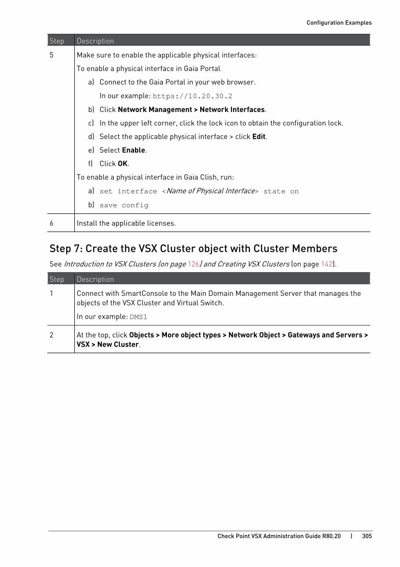
Configuration Examples
Check Point VSX Administration Guide R80.20 | 305
Step Description
5 Make sure to enable the applicable physical interfaces:
To enable a physical interface in Gaia Portal
a) Connect to the Gaia Portal in your web browser.
In our example: https://10.20.30.2
b) Click Network Management > Network Interfaces.
c) In the upper left corner, click the lock icon to obtain the configuration lock.
d) Select the applicable physical interface > click Edit.
e) Select Enable.
f) Click OK.
To enable a physical interface in Gaia Clish, run:
a) set interface <Name of Physical Interface> state on
b) save config
6 Install the applicable licenses.
Step 7: Create the VSX Cluster object with Cluster Members See Introduction to VSX Clusters (on page 126) and Creating VSX Clusters (on page 142).
Step Description
1 Connect with SmartConsole to the Main Domain Management Server that manages the objects of the VSX Cluster and Virtual Switch.
In our example: DMS1
2 At the top, click Objects > More object types > Network Object > Gateways and Servers > VSX > New Cluster.
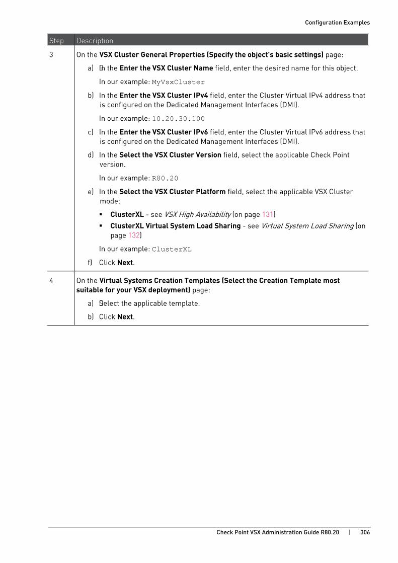
Configuration Examples
Check Point VSX Administration Guide R80.20 | 306
Step Description
3 On the VSX Cluster General Properties (Specify the object's basic settings) page:
a) In the Enter the VSX Cluster Name field, enter the desired name for this object.
In our example: MyVsxCluster
b) In the Enter the VSX Cluster IPv4 field, enter the Cluster Virtual IPv4 address that is configured on the Dedicated Management Interfaces (DMI).
In our example: 10.20.30.100
c) In the Enter the VSX Cluster IPv6 field, enter the Cluster Virtual IPv6 address that is configured on the Dedicated Management Interfaces (DMI).
d) In the Select the VSX Cluster Version field, select the applicable Check Point version.
In our example: R80.20
e) In the Select the VSX Cluster Platform field, select the applicable VSX Cluster mode:
ClusterXL - see VSX High Availability (on page 131)
ClusterXL Virtual System Load Sharing - see Virtual System Load Sharing (on page 132)
In our example: ClusterXL
f) Click Next.
4 On the Virtual Systems Creation Templates (Select the Creation Template most suitable for your VSX deployment) page:
a) Select the applicable template.
b) Click Next.

Configuration Examples
Check Point VSX Administration Guide R80.20 | 307
Step Description
5 On the VSX Cluster Members (Define the members of this VSX Cluster) page:
Add the first VSX Cluster Member:
a) Click Add.
b) In the Cluster Member Name field, enter the desired name for this object.
In our example: MyVsxMember1
c) In the Cluster Member IPv4 Address field, enter the IPv4 address of the Dedicated Management Interface (DMI).
In our example: eth0, 10.20.30.1
d) In the Enter the VSX Gateway IPv6 field, enter the applicable IPv6 address.
e) In the Activation Key field, enter the same Activation Key you entered during the First Time Configuration Wizard of this VSX Cluster Member.
f) In the Confirm Activation Key field, enter the same Activation Key again.
g) Click Initialize.
h) Click OK.
i) e Activation Key you entered in the cpconfig menu.
j) Click Initialize.
If the Trust State field does not show Trust established, perform these steps:
a) Connect to the command line on the VSX Cluster Member.
b) Make sure there is a physical connectivity between the VSX Cluster Member and the Management Server (for example, pings can pass).
c) Run: cpconfig
d) Enter the number of this option: Secure Internal Communication
e) Follow the instructions on the screen to change the Activation Key.
f) On the VSX Cluster General Properties page, click Reset.
g) Enter the same Activation Key you entered in the cpconfig menu.
h) Click Initialize.
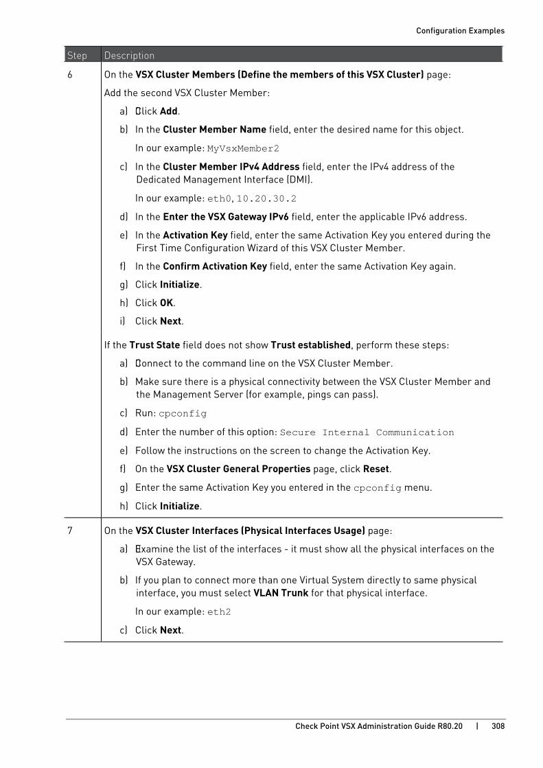
Configuration Examples
Check Point VSX Administration Guide R80.20 | 308
Step Description
6 On the VSX Cluster Members (Define the members of this VSX Cluster) page:
Add the second VSX Cluster Member:
a) Click Add.
b) In the Cluster Member Name field, enter the desired name for this object.
In our example: MyVsxMember2
c) In the Cluster Member IPv4 Address field, enter the IPv4 address of the Dedicated Management Interface (DMI).
In our example: eth0, 10.20.30.2
d) In the Enter the VSX Gateway IPv6 field, enter the applicable IPv6 address.
e) In the Activation Key field, enter the same Activation Key you entered during the First Time Configuration Wizard of this VSX Cluster Member.
f) In the Confirm Activation Key field, enter the same Activation Key again.
g) Click Initialize.
h) Click OK.
i) Click Next.
If the Trust State field does not show Trust established, perform these steps:
a) Connect to the command line on the VSX Cluster Member.
b) Make sure there is a physical connectivity between the VSX Cluster Member and the Management Server (for example, pings can pass).
c) Run: cpconfig
d) Enter the number of this option: Secure Internal Communication
e) Follow the instructions on the screen to change the Activation Key.
f) On the VSX Cluster General Properties page, click Reset.
g) Enter the same Activation Key you entered in the cpconfig menu.
h) Click Initialize.
7 On the VSX Cluster Interfaces (Physical Interfaces Usage) page:
a) Examine the list of the interfaces - it must show all the physical interfaces on the VSX Gateway.
b) If you plan to connect more than one Virtual System directly to same physical interface, you must select VLAN Trunk for that physical interface.
In our example: eth2
c) Click Next.
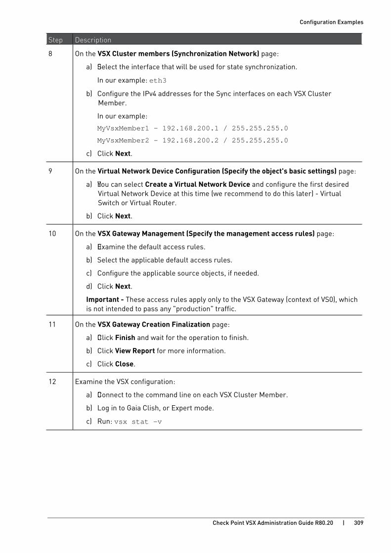
Configuration Examples
Check Point VSX Administration Guide R80.20 | 309
Step Description
8 On the VSX Cluster members (Synchronization Network) page:
a) Select the interface that will be used for state synchronization.
In our example: eth3
b) Configure the IPv4 addresses for the Sync interfaces on each VSX Cluster Member.
In our example:
MyVsxMember1 - 192.168.200.1 / 255.255.255.0
MyVsxMember2 - 192.168.200.2 / 255.255.255.0
c) Click Next.
9 On the Virtual Network Device Configuration (Specify the object's basic settings) page:
a) You can select Create a Virtual Network Device and configure the first desired Virtual Network Device at this time (we recommend to do this later) - Virtual Switch or Virtual Router.
b) Click Next.
10 On the VSX Gateway Management (Specify the management access rules) page:
a) Examine the default access rules.
b) Select the applicable default access rules.
c) Configure the applicable source objects, if needed.
d) Click Next.
Important - These access rules apply only to the VSX Gateway (context of VS0), which is not intended to pass any "production" traffic.
11 On the VSX Gateway Creation Finalization page:
a) Click Finish and wait for the operation to finish.
b) Click View Report for more information.
c) Click Close.
12 Examine the VSX configuration:
a) Connect to the command line on each VSX Cluster Member.
b) Log in to Gaia Clish, or Expert mode.
c) Run: vsx stat -v

Configuration Examples
Check Point VSX Administration Guide R80.20 | 310
Step 8: Configure the VSX Cluster object See Working with VSX Clusters (on page 142).
Step Description
1 From the left navigation toolbar, click Gateways & Servers.
2 Open the VSX Cluster object.
In our example: MyVsxCluster
3 Enable the applicable Software Blades.
Refer to:
• sk79700 - VSX supported features on R75.40VS and above http://supportcontent.checkpoint.com/solutions?id=sk79700
• sk106496 - Software Blades updates on VSX R75.40VS and above - FAQ http://supportcontent.checkpoint.com/solutions?id=sk106496
• Applicable Administration Guides on the R80.20 Home Page http://supportcontent.checkpoint.com/solutions?id=sk122485.
4 Configure other applicable settings.
5 Click OK to push the updated VSX Configuration.
Click View Report for more information.
6 Install policy on the VSX Cluster object:
a) Click Install Policy.
b) In the Policy field, select the default policy for this VSX Cluster object.
This policy is called: <Name of VSX Cluster object>_VSX.
In our example: MyVsxCluster_VSX
c) Click Install.
7 Examine the VSX configuration:
a) Connect to the command line on each VSX Cluster Member.
b) Log in to Gaia Clish, or Expert mode.
c) Run: vsx stat -v
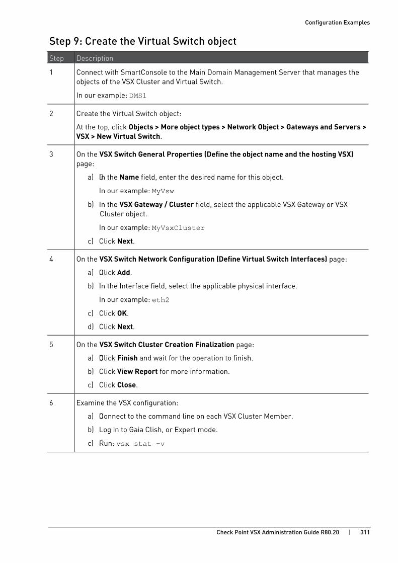
Configuration Examples
Check Point VSX Administration Guide R80.20 | 311
Step 9: Create the Virtual Switch object Step Description
1 Connect with SmartConsole to the Main Domain Management Server that manages the objects of the VSX Cluster and Virtual Switch.
In our example: DMS1
2 Create the Virtual Switch object:
At the top, click Objects > More object types > Network Object > Gateways and Servers > VSX > New Virtual Switch.
3 On the VSX Switch General Properties (Define the object name and the hosting VSX) page:
a) In the Name field, enter the desired name for this object.
In our example: MyVsw
b) In the VSX Gateway / Cluster field, select the applicable VSX Gateway or VSX Cluster object.
In our example: MyVsxCluster
c) Click Next.
4 On the VSX Switch Network Configuration (Define Virtual Switch Interfaces) page:
a) Click Add.
b) In the Interface field, select the applicable physical interface.
In our example: eth2
c) Click OK.
d) Click Next.
5 On the VSX Switch Cluster Creation Finalization page:
a) Click Finish and wait for the operation to finish.
b) Click View Report for more information.
c) Click Close.
6 Examine the VSX configuration:
a) Connect to the command line on each VSX Cluster Member.
b) Log in to Gaia Clish, or Expert mode.
c) Run: vsx stat -v

Configuration Examples
Check Point VSX Administration Guide R80.20 | 312
Step 10: Create the first Virtual System object Step Description
1 Connect with SmartConsole to the Target Domain Management Server that manages the object of the first Virtual System.
In our example: DMS2
2 In SmartConsole, create the first Virtual System object:
See Creating a New Virtual System (on page 74).
At the top, click Objects > More object types > Network Object > Gateways and Servers > VSX > New Virtual System.
3 On the VSX System General Properties (Define the object name and the hosting VSX) page:
a) In the Name field, enter the desired name for this object.
In our example: MyVs1
b) In the VSX Gateway / Cluster field, select the applicable VSX Gateway or VSX Cluster object.
In our example: MyVsxCluster
c) You can select Override Creation Template (Create Custom VS), if you need to override the creation template that was used for the initial configuration of the VSX Cluster object.
d) Click Next.
4 On the Virtual System Network Configuration (Define Virtual System Interfaces and Routes) page:
In our example, this Virtual System connects to the Virtual Switch ("external") and to the physical VLAN Trunk interface ("internal") on the VSX Cluster Members.
In the Interfaces section, add the "external" interface:
a) Click Add > Leads to Virtual Switch.
Add Interface window opens.
b) In the Leads to field, select the Virtual Switch your created earlier.
In our example: MyVsxVsw
c) In the IPv4 Configuration section, enter the applicable IP Address and Net Mask.
In our example: 192.168.10.1/24
d) In the IPv6 Configuration section, enter the applicable IPv6 Address and Prefix.
e) Click OK.
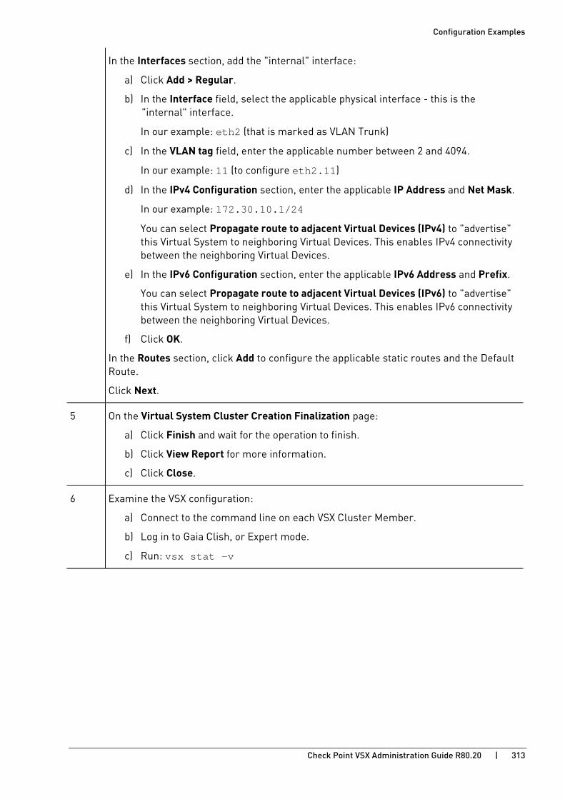
Configuration Examples
Check Point VSX Administration Guide R80.20 | 313
In the Interfaces section, add the "internal" interface:
a) Click Add > Regular.
b) In the Interface field, select the applicable physical interface - this is the "internal" interface.
In our example: eth2 (that is marked as VLAN Trunk)
c) In the VLAN tag field, enter the applicable number between 2 and 4094.
In our example: 11 (to configure eth2.11)
d) In the IPv4 Configuration section, enter the applicable IP Address and Net Mask.
In our example: 172.30.10.1/24
You can select Propagate route to adjacent Virtual Devices (IPv4) to "advertise" this Virtual System to neighboring Virtual Devices. This enables IPv4 connectivity between the neighboring Virtual Devices.
e) In the IPv6 Configuration section, enter the applicable IPv6 Address and Prefix.
You can select Propagate route to adjacent Virtual Devices (IPv6) to "advertise" this Virtual System to neighboring Virtual Devices. This enables IPv6 connectivity between the neighboring Virtual Devices.
f) Click OK.
In the Routes section, click Add to configure the applicable static routes and the Default Route.
Click Next.
5 On the Virtual System Cluster Creation Finalization page:
a) Click Finish and wait for the operation to finish.
b) Click View Report for more information.
c) Click Close.
6 Examine the VSX configuration:
a) Connect to the command line on each VSX Cluster Member.
b) Log in to Gaia Clish, or Expert mode.
c) Run: vsx stat -v
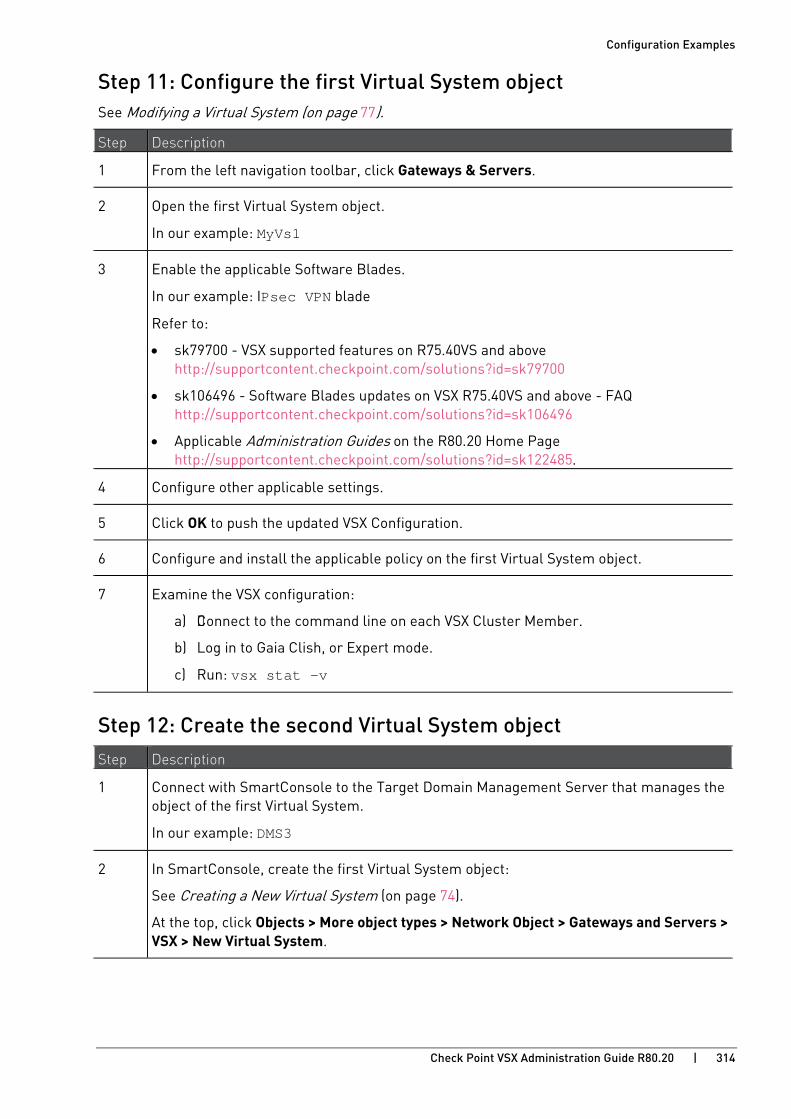
Configuration Examples
Check Point VSX Administration Guide R80.20 | 314
Step 11: Configure the first Virtual System object See Modifying a Virtual System (on page 77).
Step Description
1 From the left navigation toolbar, click Gateways & Servers.
2 Open the first Virtual System object.
In our example: MyVs1
3 Enable the applicable Software Blades.
In our example: IPsec VPN blade
Refer to:
• sk79700 - VSX supported features on R75.40VS and above http://supportcontent.checkpoint.com/solutions?id=sk79700
• sk106496 - Software Blades updates on VSX R75.40VS and above - FAQ http://supportcontent.checkpoint.com/solutions?id=sk106496
• Applicable Administration Guides on the R80.20 Home Page http://supportcontent.checkpoint.com/solutions?id=sk122485.
4 Configure other applicable settings.
5 Click OK to push the updated VSX Configuration.
6 Configure and install the applicable policy on the first Virtual System object.
7 Examine the VSX configuration:
a) Connect to the command line on each VSX Cluster Member.
b) Log in to Gaia Clish, or Expert mode.
c) Run: vsx stat -v
Step 12: Create the second Virtual System object Step Description
1 Connect with SmartConsole to the Target Domain Management Server that manages the object of the first Virtual System.
In our example: DMS3
2 In SmartConsole, create the first Virtual System object:
See Creating a New Virtual System (on page 74).
At the top, click Objects > More object types > Network Object > Gateways and Servers > VSX > New Virtual System.

Configuration Examples
Check Point VSX Administration Guide R80.20 | 315
Step Description
3 On the VSX System General Properties (Define the object name and the hosting VSX) page:
a) In the Name field, enter the desired name for this object.
In our example: MyVs2
b) In the VSX Gateway / Cluster field, select the applicable VSX Gateway or VSX Cluster object.
In our example: MyVsxCluster
c) You can select Override Creation Template (Create Custom VS), if you need to override the creation template that was used for the initial configuration of the VSX Cluster object.
d) Click Next.
4 On the Virtual System Network Configuration (Define Virtual System Interfaces and Routes) page:
In our example, this Virtual System connects to the Virtual Switch ("external") and to the physical VLAN Trunk interface ("internal") on the VSX Cluster Members.
In the Interfaces section, add the "external" interface:
a) Click Add > Leads to Virtual Switch.
b) In the Leads to field, select the Virtual Switch your created earlier.
In our example: MyVsxVsw
c) In the IPv4 Configuration section, enter the applicable IP Address and Net Mask.
In our example: 192.168.20.1/24
d) In the IPv6 Configuration section, enter the applicable IPv6 Address and Prefix.
e) Click OK.

Configuration Examples
Check Point VSX Administration Guide R80.20 | 316
Step Description
In the Interfaces section, add the "internal" interface:
a) Click Add > Regular.
b) In the Interface field, select the applicable physical interface - this is the "internal" interface.
In our example: eth2 (that is marked as VLAN Trunk)
c) In the VLAN tag field, enter the applicable number between 2 and 4094.
In our example: 22 (to configure eth2.22)
d) In the IPv4 Configuration section, enter the applicable IP Address and Net Mask.
In our example: 172.30.20.1/24
You can select Propagate route to adjacent Virtual Devices (IPv4) to "advertise" this Virtual System to neighboring Virtual Devices. This enables IPv4 connectivity between the neighboring Virtual Devices.
e) In the IPv6 Configuration section, enter the applicable IPv6 Address and Prefix.
You can select Propagate route to adjacent Virtual Devices (IPv6) to "advertise" this Virtual System to neighboring Virtual Devices. This enables IPv6 connectivity between the neighboring Virtual Devices.
f) Click OK.
In the Routes section, click Add to configure the applicable static routes and the Default Route.
Click Next.
5 On the Virtual System Cluster Creation Finalization page:
a) Click Finish and wait for the operation to finish.
b) Click View Report for more information.
c) Click Close.
6 Examine the VSX configuration:
a) Connect to the command line on each VSX Cluster Member.
b) Log in to Gaia Clish, or Expert mode.
c) Run: vsx stat -v
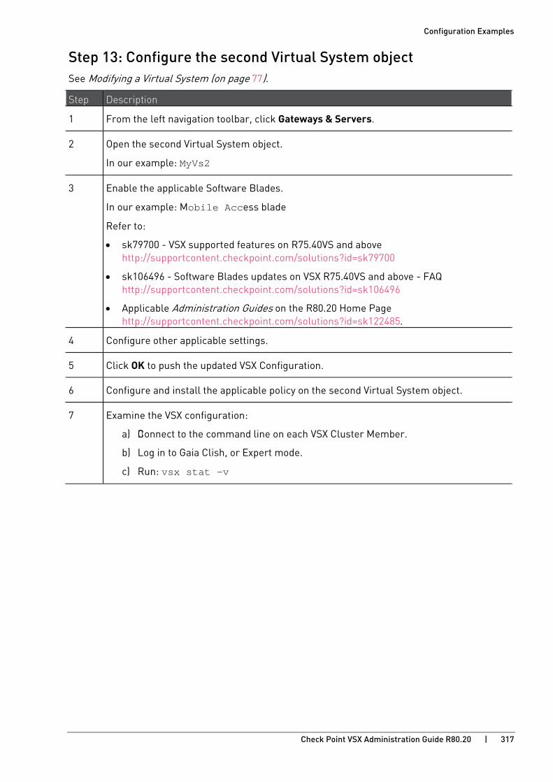
Configuration Examples
Check Point VSX Administration Guide R80.20 | 317
Step 13: Configure the second Virtual System object See Modifying a Virtual System (on page 77).
Step Description
1 From the left navigation toolbar, click Gateways & Servers.
2 Open the second Virtual System object.
In our example: MyVs2
3 Enable the applicable Software Blades.
In our example: Mobile Access blade
Refer to:
• sk79700 - VSX supported features on R75.40VS and above http://supportcontent.checkpoint.com/solutions?id=sk79700
• sk106496 - Software Blades updates on VSX R75.40VS and above - FAQ http://supportcontent.checkpoint.com/solutions?id=sk106496
• Applicable Administration Guides on the R80.20 Home Page http://supportcontent.checkpoint.com/solutions?id=sk122485.
4 Configure other applicable settings.
5 Click OK to push the updated VSX Configuration.
6 Configure and install the applicable policy on the second Virtual System object.
7 Examine the VSX configuration:
a) Connect to the command line on each VSX Cluster Member.
b) Log in to Gaia Clish, or Expert mode.
c) Run: vsx stat -v
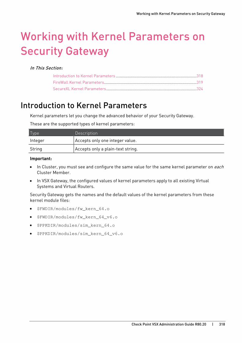
Working with Kernel Parameters on Security Gateway
Check Point VSX Administration Guide R80.20 | 318
CHAPTE R 14
Working with Kernel Parameters on Security Gateway
In This Section:
Introduction to Kernel Parameters ........................................................................... 318
FireWall Kernel Parameters ...................................................................................... 319
SecureXL Kernel Parameters .................................................................................... 324
Introduction to Kernel Parameters Kernel parameters let you change the advanced behavior of your Security Gateway.
These are the supported types of kernel parameters:
Type Description
Integer Accepts only one integer value.
String Accepts only a plain-text string.
Important:
• In Cluster, you must see and configure the same value for the same kernel parameter on each Cluster Member.
• In VSX Gateway, the configured values of kernel parameters apply to all existing Virtual Systems and Virtual Routers.
Security Gateway gets the names and the default values of the kernel parameters from these kernel module files:
• $FWDIR/modules/fw_kern_64.o
• $FWDIR/modules/fw_kern_64_v6.o
• $PPKDIR/modules/sim_kern_64.o
• $PPKDIR/modules/sim_kern_64_v6.o
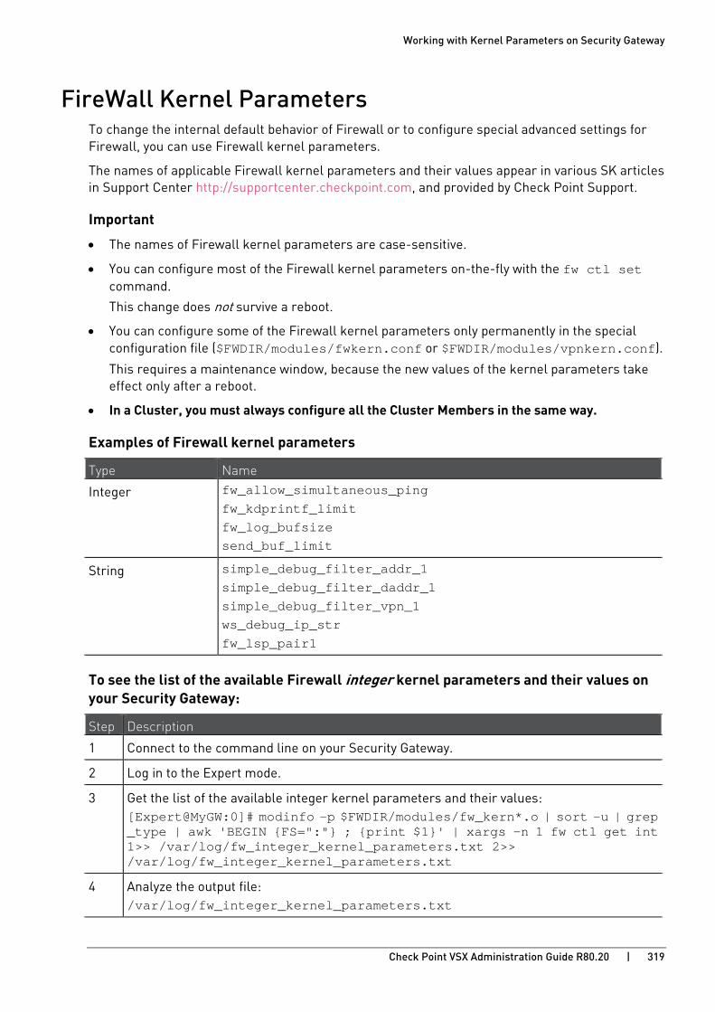
Working with Kernel Parameters on Security Gateway
Check Point VSX Administration Guide R80.20 | 319
FireWall Kernel Parameters To change the internal default behavior of Firewall or to configure special advanced settings for Firewall, you can use Firewall kernel parameters.
The names of applicable Firewall kernel parameters and their values appear in various SK articles in Support Center http://supportcenter.checkpoint.com, and provided by Check Point Support.
Important
• The names of Firewall kernel parameters are case-sensitive.
• You can configure most of the Firewall kernel parameters on-the-fly with the fw ctl set command.
This change does not survive a reboot.
• You can configure some of the Firewall kernel parameters only permanently in the special configuration file ($FWDIR/modules/fwkern.conf or $FWDIR/modules/vpnkern.conf).
This requires a maintenance window, because the new values of the kernel parameters take effect only after a reboot.
• In a Cluster, you must always configure all the Cluster Members in the same way.
Examples of Firewall kernel parameters
Type Name
Integer fw_allow_simultaneous_ping fw_kdprintf_limit fw_log_bufsize send_buf_limit
String simple_debug_filter_addr_1 simple_debug_filter_daddr_1 simple_debug_filter_vpn_1 ws_debug_ip_str fw_lsp_pair1
To see the list of the available Firewall integer kernel parameters and their values on your Security Gateway:
Step Description
1 Connect to the command line on your Security Gateway.
2 Log in to the Expert mode.
3 Get the list of the available integer kernel parameters and their values: [Expert@MyGW:0]# modinfo -p $FWDIR/modules/fw_kern*.o | sort -u | grep _type | awk 'BEGIN {FS=":"} ; {print $1}' | xargs -n 1 fw ctl get int 1>> /var/log/fw_integer_kernel_parameters.txt 2>> /var/log/fw_integer_kernel_parameters.txt
4 Analyze the output file: /var/log/fw_integer_kernel_parameters.txt
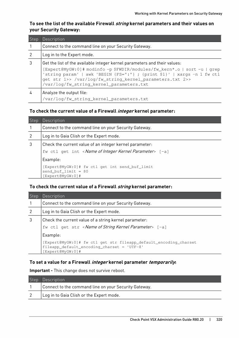
Working with Kernel Parameters on Security Gateway
Check Point VSX Administration Guide R80.20 | 320
To see the list of the available Firewall string kernel parameters and their values on your Security Gateway:
Step Description
1 Connect to the command line on your Security Gateway.
2 Log in to the Expert mode.
3 Get the list of the available integer kernel parameters and their values: [Expert@MyGW:0]# modinfo -p $FWDIR/modules/fw_kern*.o | sort -u | grep 'string param' | awk 'BEGIN {FS=":"} ; {print $1}' | xargs -n 1 fw ctl get str 1>> /var/log/fw_string_kernel_parameters.txt 2>> /var/log/fw_string_kernel_parameters.txt
4 Analyze the output file: /var/log/fw_string_kernel_parameters.txt
To check the current value of a Firewall integer kernel parameter:
Step Description
1 Connect to the command line on your Security Gateway.
2 Log in to Gaia Clish or the Expert mode.
3 Check the current value of an integer kernel parameter:
fw ctl get int <Name of Integer Kernel Parameter> [-a]
Example:
[Expert@MyGW:0]# fw ctl get int send_buf_limit send_buf_limit = 80 [Expert@MyGW:0]#
To check the current value of a Firewall string kernel parameter:
Step Description
1 Connect to the command line on your Security Gateway.
2 Log in to Gaia Clish or the Expert mode.
3 Check the current value of a string kernel parameter:
fw ctl get str <Name of String Kernel Parameter> [-a]
Example:
[Expert@MyGW:0]# fw ctl get str fileapp_default_encoding_charset fileapp_default_encoding_charset = 'UTF-8' [Expert@MyGW:0]#
To set a value for a Firewall integer kernel parameter temporarily:
Important - This change does not survive reboot.
Step Description
1 Connect to the command line on your Security Gateway.
2 Log in to Gaia Clish or the Expert mode.

Working with Kernel Parameters on Security Gateway
Check Point VSX Administration Guide R80.20 | 321
Step Description
3 Set the new value for an integer kernel parameter:
fw ctl set int <Name of Integer Kernel Parameter> <Integer Value>
Example:
[Expert@MyGW:0]# fw ctl set int send_buf_limit 100 Set operation succeeded [Expert@MyGW:0]#
4 Make sure the new value is set:
fw ctl get int <Name of Integer Kernel Parameter>
Example:
[Expert@MyGW:0]# fw ctl get int send_buf_limit send_buf_limit = 100 [Expert@MyGW:0]#
To set a value for a Firewall string kernel parameter temporarily:
Important - This change does not survive reboot.
Step Description
1 Connect to the command line on your Security Gateway.
2 Log in to Gaia Clish or the Expert mode.
3 Set the new value for a string kernel parameter:
Note - You must write the value in single quotes, or double-quotes.
[Expert@MyGW:0]# fw ctl set str <Name of String Kernel Parameter> '<String Text>'
or
[Expert@MyGW:0]# fw ctl set str <Name of String Kernel Parameter> "<String Text>"
Example:
[Expert@MyGW:0]# fw ctl set str debug_filter_saddr_ip '1.1.1.1' Set operation succeeded [Expert@MyGW:0]#
4 Make sure the new value is set:
fw ctl get str <Name of String Kernel Parameter>
Example:
[Expert@MyGW:0]# fw ctl get str debug_filter_saddr_ip debug_filter_saddr_ip = '1.1.1.1' [Expert@MyGW:0]#
To clear the current value from a Firewall string kernel parameter temporarily:
Important - This change does not survive reboot.
Step Description
1 Connect to the command line on your Security Gateway.
2 Log in to Gaia Clish or the Expert mode.

Working with Kernel Parameters on Security Gateway
Check Point VSX Administration Guide R80.20 | 322
Step Description
3 Clear the current value from a string kernel parameter:
Note - You must set an empty value in single quotes, or double-quotes.
[Expert@MyGW:0]# fw ctl set str <Name of String Kernel Parameter> ''
or
[Expert@MyGW:0]# fw ctl set str <Name of String Kernel Parameter> ""
Example:
[Expert@MyGW:0]# fw ctl set str debug_filter_saddr_ip '' Set operation succeeded [Expert@MyGW:0]#
4 Make sure the value is cleared (the new value is empty):
fw ctl get str <Name of String Kernel Parameter>
Example:
[Expert@MyGW:0]# fw ctl get str debug_filter_saddr_ip debug_filter_saddr_ip = '' [Expert@MyGW:0]#
To set a value for a Firewall kernel parameter permanently:
To make a kernel parameter configuration permanent (to survive reboot), you must edit one of the applicable configuration files:
• $FWDIR/modules/fwkern.conf
• $FWDIR/modules/vpnkern.conf
The exact instructions are provided in various SK articles in Support Center http://supportcenter.checkpoint.com, and provided by Check Point Support.
Step Description
1 Connect to the command line on your Security Gateway.
2 Log in to the Expert mode.
3 See if the configuration file already exists: [Expert@MyGW:0]# ls -l $FWDIR/modules/fwkern.conf
or [Expert@MyGW:0]# ls -l $FWDIR/modules/vpnkern.conf
4 If this file already exists, skip to Step 5.
If this file does not exist, then create it manually and then skip to Step 6: [Expert@MyGW:0]# touch $FWDIR/modules/fwkern.conf
or [Expert@MyGW:0]# touch $FWDIR/modules/vpnkern.conf
5 Back up the current configuration file: [Expert@MyGW:0]# cp -v $FWDIR/modules/fwkern.conf{,_BKP}
or [Expert@MyGW:0]# cp -v $FWDIR/modules/vpnkern.conf{,_BKP}
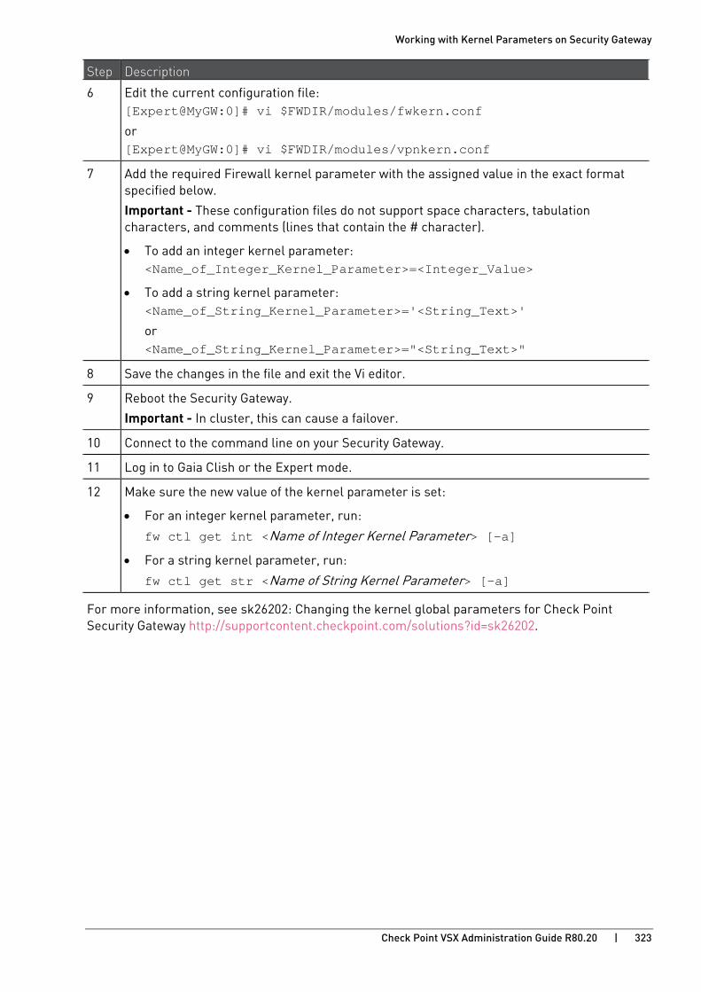
Working with Kernel Parameters on Security Gateway
Check Point VSX Administration Guide R80.20 | 323
Step Description
6 Edit the current configuration file: [Expert@MyGW:0]# vi $FWDIR/modules/fwkern.conf
or [Expert@MyGW:0]# vi $FWDIR/modules/vpnkern.conf
7 Add the required Firewall kernel parameter with the assigned value in the exact format specified below.
Important - These configuration files do not support space characters, tabulation characters, and comments (lines that contain the # character).
• To add an integer kernel parameter: <Name_of_Integer_Kernel_Parameter>=<Integer_Value>
• To add a string kernel parameter: <Name_of_String_Kernel_Parameter>='<String_Text>'
or <Name_of_String_Kernel_Parameter>="<String_Text>"
8 Save the changes in the file and exit the Vi editor.
9 Reboot the Security Gateway.
Important - In cluster, this can cause a failover.
10 Connect to the command line on your Security Gateway.
11 Log in to Gaia Clish or the Expert mode.
12 Make sure the new value of the kernel parameter is set:
• For an integer kernel parameter, run:
fw ctl get int <Name of Integer Kernel Parameter> [-a]
• For a string kernel parameter, run:
fw ctl get str <Name of String Kernel Parameter> [-a]
For more information, see sk26202: Changing the kernel global parameters for Check Point Security Gateway http://supportcontent.checkpoint.com/solutions?id=sk26202.
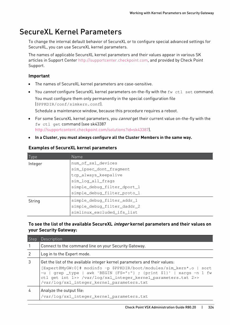
Working with Kernel Parameters on Security Gateway
Check Point VSX Administration Guide R80.20 | 324
SecureXL Kernel Parameters To change the internal default behavior of SecureXL or to configure special advanced settings for SecureXL, you can use SecureXL kernel parameters.
The names of applicable SecureXL kernel parameters and their values appear in various SK articles in Support Center http://supportcenter.checkpoint.com, and provided by Check Point Support.
Important
• The names of SecureXL kernel parameters are case-sensitive.
• You cannot configure SecureXL kernel parameters on-the-fly with the fw ctl set command.
You must configure them only permanently in the special configuration file ($PPKDIR/conf/simkern.conf).
Schedule a maintenance window, because this procedure requires a reboot.
• For some SecureXL kernel parameters, you cannot get their current value on-the-fly with the fw ctl get command (see sk43387 http://supportcontent.checkpoint.com/solutions?id=sk43387).
• In a Cluster, you must always configure all the Cluster Members in the same way.
Examples of SecureXL kernel parameters
Type Name
Integer num_of_sxl_devices sim_ipsec_dont_fragment tcp_always_keepalive sim_log_all_frags simple_debug_filter_dport_1 simple_debug_filter_proto_1
String simple_debug_filter_addr_1 simple_debug_filter_daddr_2 simlinux_excluded_ifs_list
To see the list of the available SecureXL integer kernel parameters and their values on your Security Gateway:
Step Description
1 Connect to the command line on your Security Gateway.
2 Log in to the Expert mode.
3 Get the list of the available integer kernel parameters and their values: [Expert@MyGW:0]# modinfo -p $PPKDIR/boot/modules/sim_kern*.o | sort -u | grep _type | awk 'BEGIN {FS=":"} ; {print $1}' | xargs -n 1 fw ctl get int 1>> /var/log/sxl_integer_kernel_parameters.txt 2>> /var/log/sxl_integer_kernel_parameters.txt
4 Analyze the output file: /var/log/sxl_integer_kernel_parameters.txt

Working with Kernel Parameters on Security Gateway
Check Point VSX Administration Guide R80.20 | 325
To see the list of the available SecureXL string kernel parameters and their values on your Security Gateway:
Step Description
1 Connect to the command line on your Security Gateway.
2 Log in to the Expert mode.
3 Get the list of the available integer kernel parameters and their values: [Expert@MyGW:0]# modinfo -p $PPKDIR/boot/modules/sim_kern*.o | sort -u | grep 'string param' | awk 'BEGIN {FS=":"} ; {print $1}' | xargs -n 1 fw ctl get str 1>> /var/log/sxl_string_kernel_parameters.txt 2>> /var/log/sxl_string_kernel_parameters.txt
4 Analyze the output file: /var/log/sxl_string_kernel_parameters.txt
To set a value for a SecureXL kernel parameter permanently:
Step Description
1 Connect to the command line on your Security Gateway.
2 Log in to the Expert mode.
3 See if the configuration file already exists: [Expert@MyGW:0]# ls -l $PPKDIR/conf/simkern.conf
4 If this file already exists, skip to Step 5.
If this file does not exist, then create it manually and then skip to Step 6: [Expert@MyGW:0]# touch $PPKDIR/conf/simkern.conf
5 Back up the current configuration file: [Expert@MyGW:0]# cp -v $PPKDIR/conf/simkern.conf{,_BKP}
6 Edit the current configuration file: [Expert@MyGW:0]# vi $PPKDIR/conf/simkern.conf
7 Add the required SecureXL kernel parameter with the assigned value in the exact format specified below.
Important - This configuration file does not support space characters, tabulation characters, and comments (lines that contain the # character).
• To add an integer kernel parameter: <Name_of_SecureXL_Integer_Kernel_Parameter>=<Integer_Value>
• To add a string kernel parameter: <Name_of_SecureXL_String_Kernel_Parameter>="<String_Text>"
or <Name_of_SecureXL_String_Kernel_Parameter>="<String_Text>"
8 Save the changes in the file and exit the Vi editor.
9 Reboot the Security Gateway.
Important - In cluster, this can cause a failover.
10 Connect to the command line on your Security Gateway.
11 Log in to Gaia Clish or the Expert mode.
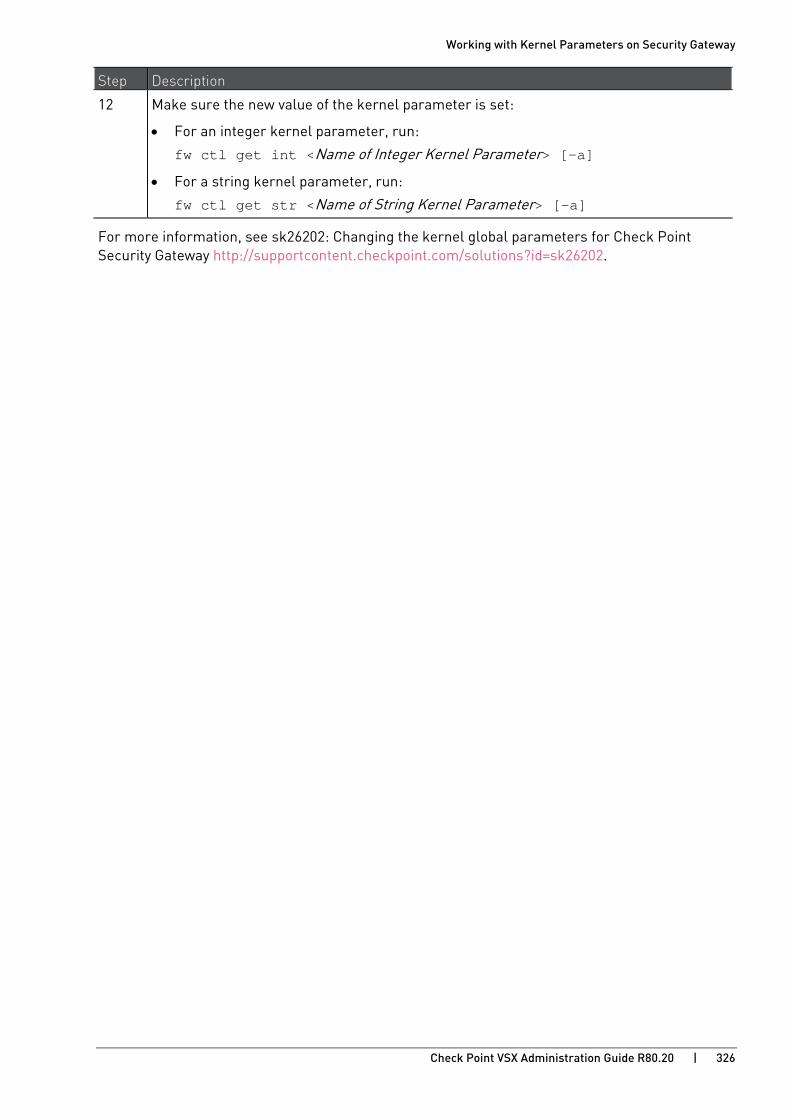
Working with Kernel Parameters on Security Gateway
Check Point VSX Administration Guide R80.20 | 326
Step Description
12 Make sure the new value of the kernel parameter is set:
• For an integer kernel parameter, run:
fw ctl get int <Name of Integer Kernel Parameter> [-a]
• For a string kernel parameter, run:
fw ctl get str <Name of String Kernel Parameter> [-a]
For more information, see sk26202: Changing the kernel global parameters for Check Point Security Gateway http://supportcontent.checkpoint.com/solutions?id=sk26202.
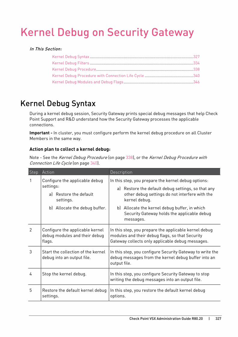
Check Point VSX Administration Guide R80.20 | 327
CHAPTE R 15
Kernel Debug on Security Gateway In This Section:
Kernel Debug Syntax .................................................................................................. 327
Kernel Debug Filters .................................................................................................. 334
Kernel Debug Procedure............................................................................................ 338
Kernel Debug Procedure with Connection Life Cycle .............................................. 340
Kernel Debug Modules and Debug Flags .................................................................. 346
Kernel Debug Syntax During a kernel debug session, Security Gateway prints special debug messages that help Check Point Support and R&D understand how the Security Gateway processes the applicable connections.
Important - In cluster, you must configure perform the kernel debug procedure on all Cluster Members in the same way.
Action plan to collect a kernel debug:
Note - See the Kernel Debug Procedure (on page 338), or the Kernel Debug Procedure with Connection Life Cycle (on page 340).
Step Action Description
1 Configure the applicable debug settings:
a) Restore the default settings.
b) Allocate the debug buffer.
In this step, you prepare the kernel debug options:
a) Restore the default debug settings, so that any other debug settings do not interfere with the kernel debug.
b) Allocate the kernel debug buffer, in which Security Gateway holds the applicable debug messages.
2 Configure the applicable kernel debug modules and their debug flags.
In this step, you prepare the applicable kernel debug modules and their debug flags, so that Security Gateway collects only applicable debug messages.
3 Start the collection of the kernel debug into an output file.
In this step, you configure Security Gateway to write the debug messages from the kernel debug buffer into an output file.
4 Stop the kernel debug. In this step, you configure Security Gateway to stop writing the debug messages into an output file.
5 Restore the default kernel debug settings.
In this step, you restore the default kernel debug options.
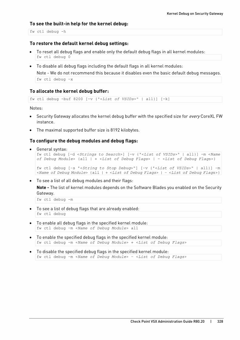
Kernel Debug on Security Gateway
Check Point VSX Administration Guide R80.20 | 328
To see the built-in help for the kernel debug: fw ctl debug -h
To restore the default kernel debug settings:
• To reset all debug flags and enable only the default debug flags in all kernel modules: fw ctl debug 0
• To disable all debug flags including the default flags in all kernel modules:
Note - We do not recommend this because it disables even the basic default debug messages. fw ctl debug -x
To allocate the kernel debug buffer: fw ctl debug -buf 8200 [-v {"<List of VSIDs>" | all}] [-k]
Notes:
• Security Gateway allocates the kernel debug buffer with the specified size for every CoreXL FW instance.
• The maximal supported buffer size is 8192 kilobytes.
To configure the debug modules and debug flags:
• General syntax: fw ctl debug [-d <Strings to Search>] [-v {"<List of VSIDs>" | all}] -m <Name of Debug Module> {all | + <List of Debug Flags> | - <List of Debug Flags>} fw ctl debug [-s "<String to Stop Debug>"] [-v {"<List of VSIDs>" | all}] -m <Name of Debug Module> {all | + <List of Debug Flags> | - <List of Debug Flags>}
• To see a list of all debug modules and their flags:
Note - The list of kernel modules depends on the Software Blades you enabled on the Security Gateway. fw ctl debug -m
• To see a list of debug flags that are already enabled: fw ctl debug
• To enable all debug flags in the specified kernel module: fw ctl debug -m <Name of Debug Module> all
• To enable the specified debug flags in the specified kernel module: fw ctl debug -m <Name of Debug Module> + <List of Debug Flags>
• To disable the specified debug flags in the specified kernel module: fw ctl debug -m <Name of Debug Module> - <List of Debug Flags>
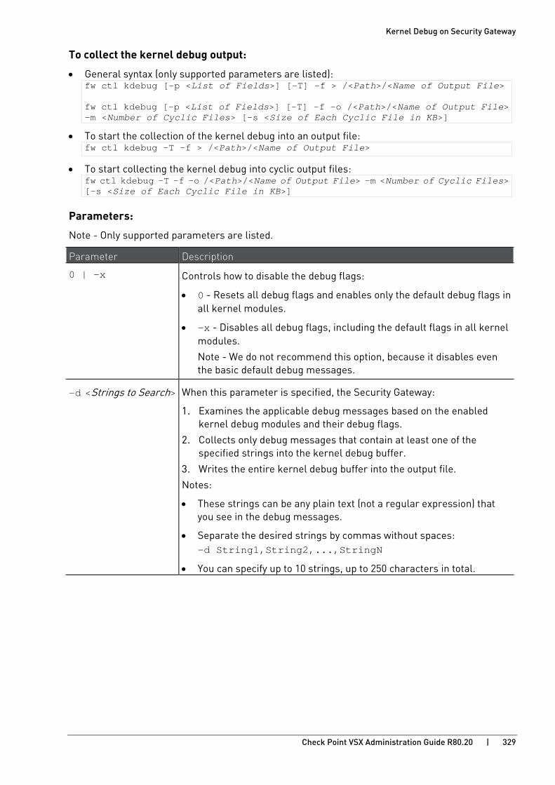
Kernel Debug on Security Gateway
Check Point VSX Administration Guide R80.20 | 329
To collect the kernel debug output:
• General syntax (only supported parameters are listed): fw ctl kdebug [-p <List of Fields>] [-T] -f > /<Path>/<Name of Output File> fw ctl kdebug [-p <List of Fields>] [-T] -f -o /<Path>/<Name of Output File> -m <Number of Cyclic Files> [-s <Size of Each Cyclic File in KB>]
• To start the collection of the kernel debug into an output file: fw ctl kdebug -T -f > /<Path>/<Name of Output File>
• To start collecting the kernel debug into cyclic output files: fw ctl kdebug -T -f -o /<Path>/<Name of Output File> -m <Number of Cyclic Files> [-s <Size of Each Cyclic File in KB>]
Parameters:
Note - Only supported parameters are listed.
Parameter Description
0 | -x Controls how to disable the debug flags:
• 0 - Resets all debug flags and enables only the default debug flags in all kernel modules.
• -x - Disables all debug flags, including the default flags in all kernel modules.
Note - We do not recommend this option, because it disables even the basic default debug messages.
-d <Strings to Search> When this parameter is specified, the Security Gateway:
1. Examines the applicable debug messages based on the enabled kernel debug modules and their debug flags.
2. Collects only debug messages that contain at least one of the specified strings into the kernel debug buffer.
3. Writes the entire kernel debug buffer into the output file.
Notes:
• These strings can be any plain text (not a regular expression) that you see in the debug messages.
• Separate the desired strings by commas without spaces: -d String1,String2,...,StringN
• You can specify up to 10 strings, up to 250 characters in total.

Kernel Debug on Security Gateway
Check Point VSX Administration Guide R80.20 | 330
Parameter Description
-s "<String to Stop Debug>"
When this parameter is specified, the Security Gateway:
1. Collects the applicable debug messages into the kernel debug buffer based on the enabled kernel debug modules and their debug flags.
2. Does not write any of these debug messages from the kernel debug buffer into the output file.
3. Stops collecting all debug messages when it detects the first debug message that contains the specified string in the kernel debug buffer.
4. Writes the entire kernel debug buffer into the output file.
Notes:
• This one string can be any plain text (not a regular expression) that you see in the debug messages.
• String length is up to 50 characters.
-m <Name of Debug Module>
Specifies the name of the kernel debug module, for which you print or configure the debug flags.
{all | + <List of Debug Flags> | - <List of Debug Flags>}
Specifies which debug flags to enable or disable in the specified kernel debug module:
• all - Enables all debug flags in the specified kernel debug module.
• + <List of Debug Flags> - Enables the specified debug flags in the specified kernel debug module.
You must press the space bar key after the plus (+) character:
+ <Flag1> [<Flag2> ... <FlagN>]
Example: + drop conn
• - <List of Debug Flags> - Disables the specified debug flags in the specified kernel debug module.
You must press the space bar key after the minus (-) character:
- <Flag1> [<Flag2> ... <FlagN>]
Example: - conn

Kernel Debug on Security Gateway
Check Point VSX Administration Guide R80.20 | 331
Parameter Description
-v {"<List of VSIDs>" | all}
Specifies the list of Virtual Systems. A VSX Gateway automatically filters the collected kernel debug information for debug messages only for these Virtual Systems.
• -v "<List of VSIDs>" - Monitors the messages only from the specified Virtual Systems. To specify the Virtual Systems, enter their VSID number separated with commas and without spaces: "VSID1[,VSID2,VSID3,...,VSIDn]"
Example: -v "1,3,7"
• -v all - Monitors the messages from all configured Virtual Systems.
Notes:
• This parameter is supported only in VSX mode.
• This parameter and the -k parameter are mutually exclusive.
-e <Expression>
-i <Name of Filter File>
-i -
-u
Specifies the INSPECT filter for the debug:
• -e <Expression> - Specifies the INSPECT filter. For details and syntax, see sk30583: What is FW Monitor? http://supportcontent.checkpoint.com/solutions?id=sk30583.
• -i <Name of Filter File> - Specifies the file that contains the INSPECT filter.
• -i - - Specifies that the INSPECT filter arrives from the standard input. You are prompted to enter the INSPECT filter on the screen.
• -u - Removes the INSPECT debug filter.
Notes:
• This is a legacy parameter.
• When you use this parameter, the Security Gateway cannot apply the specified INSPECT filter to the accelerated traffic.
• For new debug filters, see Kernel Debug Filters (on page 334).
-z The Security Gateway processes some connections in both SecureXL code and in the Host appliance code (for example, Passive Streaming Library (PSL) - an IPS infrastructure, which transparently listens to TCP traffic as network packets, and rebuilds the TCP stream out of these packets.).
The Security Gateway processes some connections in only in the Host appliance code.
When you use this parameter, kernel debug output contains the debug messages only from the Host appliance code.
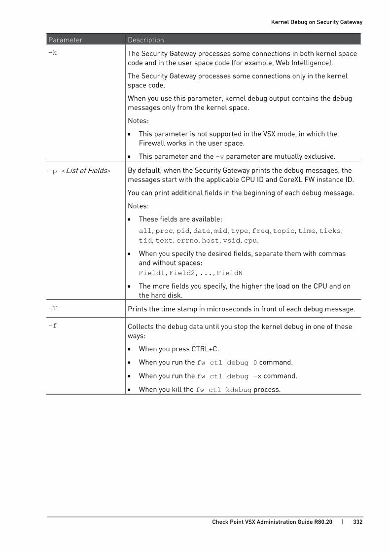
Kernel Debug on Security Gateway
Check Point VSX Administration Guide R80.20 | 332
Parameter Description
-k The Security Gateway processes some connections in both kernel space code and in the user space code (for example, Web Intelligence).
The Security Gateway processes some connections only in the kernel space code.
When you use this parameter, kernel debug output contains the debug messages only from the kernel space.
Notes:
• This parameter is not supported in the VSX mode, in which the Firewall works in the user space.
• This parameter and the -v parameter are mutually exclusive.
-p <List of Fields> By default, when the Security Gateway prints the debug messages, the messages start with the applicable CPU ID and CoreXL FW instance ID.
You can print additional fields in the beginning of each debug message.
Notes:
• These fields are available:
all, proc, pid, date, mid, type, freq, topic, time, ticks, tid, text, errno, host, vsid, cpu.
• When you specify the desired fields, separate them with commas and without spaces: Field1,Field2,...,FieldN
• The more fields you specify, the higher the load on the CPU and on the hard disk.
-T Prints the time stamp in microseconds in front of each debug message.
-f Collects the debug data until you stop the kernel debug in one of these ways:
• When you press CTRL+C.
• When you run the fw ctl debug 0 command.
• When you run the fw ctl debug -x command.
• When you kill the fw ctl kdebug process.

Kernel Debug on Security Gateway
Check Point VSX Administration Guide R80.20 | 333
Parameter Description
/<Path>/<Name of Output File>
Specifies the path and the name of the debug output file.
Important:
• Always use the largest partition on the disk - /var/log/. Security Gateway can generate many debug messages within short time. As a result, the debug output file can grow to large size very fast.
• When Falcon Acceleration Cards (sk116242 http://supportcontent.checkpoint.com/solutions?id=sk116242) are installed, the Host Security Appliance creates several debug output files - a file /var/log/ppk_<Slot_#>_debug.log for each acceleration card and the specified /<Path>/<Name of Output File> file. When you stop the debug, the Host Security Appliance unifies all these files into a single file named /<Path>/<Name of Output File>_unified.
-o /<Path>/<Name of Output File> -m <Number of Cyclic Files> [-s <Size of Each Cyclic File in KB>]
Saves the collected debug data into cyclic debug output files.
When the size of the current <Name of Output File> reaches the specified <Size of Each Cyclic File in KB> (more or less), the Security Gateway renames the current <Name of Output File> to <Name of Output File.0>, and creates a new <Name of Output File>.
If the <Name of Output File.0> already exists, the Security Gateway renames the <Name of Output File.0> to <Name of Output File.1>, and so on - until the specified limit <Number of Cyclic Files>. When the Security Gateway reaches the <Number of Cyclic Files>, it deletes the oldest files.
The valid values are:
• <Number of Cyclic Files> - from 1 to 999
• <Size of Each Cyclic File in KB> - from 1 to 2097150

Kernel Debug on Security Gateway
Check Point VSX Administration Guide R80.20 | 334
Kernel Debug Filters By default, kernel debug output contains information about all processed connections.
You can configure filters for kernel debug to collect debug messages only for the applicable connections.
There are three types of debug filters:
• By connection tuple parameters
• By an IP address parameter
• By a VPN peer parameter
To configure these kernel debug filters, assign the desired values to the applicable kernel parameters before you start the kernel debug. You assign the values to the applicable kernel parameters temporarily with the "fw ctl set" command.
Notes:
• The Security Gateway supports up to five debug filters in total (from all types).
• The Security Gateway applies these debug filters to both the non-accelerated and accelerated traffic.
• The Security Gateway applies these debug filters to Connection Life Cycle (on page 340).
To configure debug filter of the type "By connection tuple parameters":
The Security Gateway processes connections based on the 5-tuple:
• Source IP address
• Source Port (see IANA - Port Numbers https://www.iana.org/assignments/service-names-port-numbers/service-names-port-numbers.xhtml)
• Destination IP address
• Destination Port (see IANA - Port Numbers https://www.iana.org/assignments/service-names-port-numbers/service-names-port-numbers.xhtml)
• Protocol Number (see IANA - Protocol Numbers https://www.iana.org/assignments/protocol-numbers/protocol-numbers.xhtml)
This debug filter lets you filter by these tuple parameters:
Tuple Parameter Syntax for Kernel Parameters
Source IP address
fw ctl set str simple_debug_filter_saddr_<N> "<IPv4 or IPv6 Address>"
Source Ports fw ctl set int simple_debug_filter_sport_<N> <1-65535>
Destination IP address
fw ctl set str simple_debug_filter_daddr_<N> "<IPv4 or IPv6 Address>"
Destination Ports fw ctl set int simple_debug_filter_dport_<N> <1-65535>
Protocol Number fw ctl set int simple_debug_filter_proto_<N> <0-254>
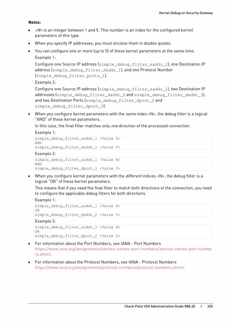
Kernel Debug on Security Gateway
Check Point VSX Administration Guide R80.20 | 335
Notes:
• <N> is an integer between 1 and 5. This number is an index for the configured kernel parameters of this type.
• When you specify IP addresses, you must enclose them in double quotes.
• You can configure one or more (up to 5) of these kernel parameters at the same time.
Example 1:
Configure one Source IP address (simple_debug_filter_saddr_1), one Destination IP address (simple_debug_filter_daddr_1), and one Protocol Number (simple_debug_filter_proto_1).
Example 2:
Configure one Source IP address (simple_debug_filter_saddr_1), two Destination IP addresses (simple_debug_filter_daddr_2 and simple_debug_filter_daddr_3), and two Destination Ports (simple_debug_filter_dport_2 and simple_debug_filter_dport_3).
• When you configure kernel parameters with the same index <N>, the debug filter is a logical "AND" of these kernel parameters.
In this case, the final filter matches only one direction of the processed connection.
Example 1: simple_debug_filter_saddr_1 <Value X> AND simple_debug_filter_daddr_1 <Value Y>
Example 2: simple_debug_filter_saddr_1 <Value X> AND simple_debug_filter_dport_1 <Value Y>
• When you configure kernel parameters with the different indices <N>, the debug filter is a logical "OR" of these kernel parameters.
This means that if you need the final filter to match both directions of the connection, you need to configure the applicable debug filters for both directions.
Example 1: simple_debug_filter_saddr_1 <Value X> OR simple_debug_filter_daddr_2 <Value Y>
Example 2: simple_debug_filter_saddr_1 <Value X> OR simple_debug_filter_dport_2 <Value Y>
• For information about the Port Numbers, see IANA - Port Numbers https://www.iana.org/assignments/service-names-port-numbers/service-names-port-numbers.xhtml.
• For information about the Protocol Numbers, see IANA - Protocol Numbers https://www.iana.org/assignments/protocol-numbers/protocol-numbers.xhtml.
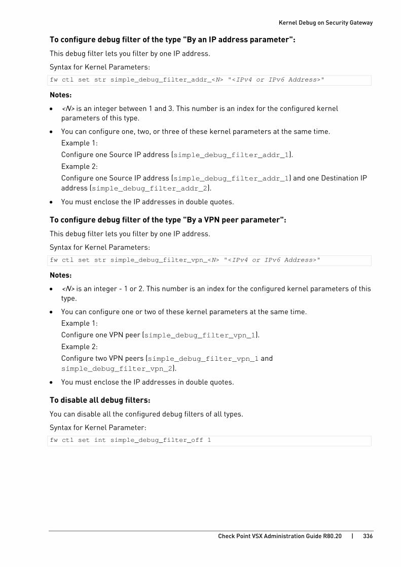
Kernel Debug on Security Gateway
Check Point VSX Administration Guide R80.20 | 336
To configure debug filter of the type "By an IP address parameter":
This debug filter lets you filter by one IP address.
Syntax for Kernel Parameters:
fw ctl set str simple_debug_filter_addr_<N> "<IPv4 or IPv6 Address>"
Notes:
• <N> is an integer between 1 and 3. This number is an index for the configured kernel parameters of this type.
• You can configure one, two, or three of these kernel parameters at the same time.
Example 1:
Configure one Source IP address (simple_debug_filter_addr_1).
Example 2:
Configure one Source IP address (simple_debug_filter_addr_1) and one Destination IP address (simple_debug_filter_addr_2).
• You must enclose the IP addresses in double quotes.
To configure debug filter of the type "By a VPN peer parameter":
This debug filter lets you filter by one IP address.
Syntax for Kernel Parameters:
fw ctl set str simple_debug_filter_vpn_<N> "<IPv4 or IPv6 Address>"
Notes:
• <N> is an integer - 1 or 2. This number is an index for the configured kernel parameters of this type.
• You can configure one or two of these kernel parameters at the same time.
Example 1:
Configure one VPN peer (simple_debug_filter_vpn_1).
Example 2:
Configure two VPN peers (simple_debug_filter_vpn_1 and simple_debug_filter_vpn_2).
• You must enclose the IP addresses in double quotes.
To disable all debug filters:
You can disable all the configured debug filters of all types.
Syntax for Kernel Parameter:
fw ctl set int simple_debug_filter_off 1
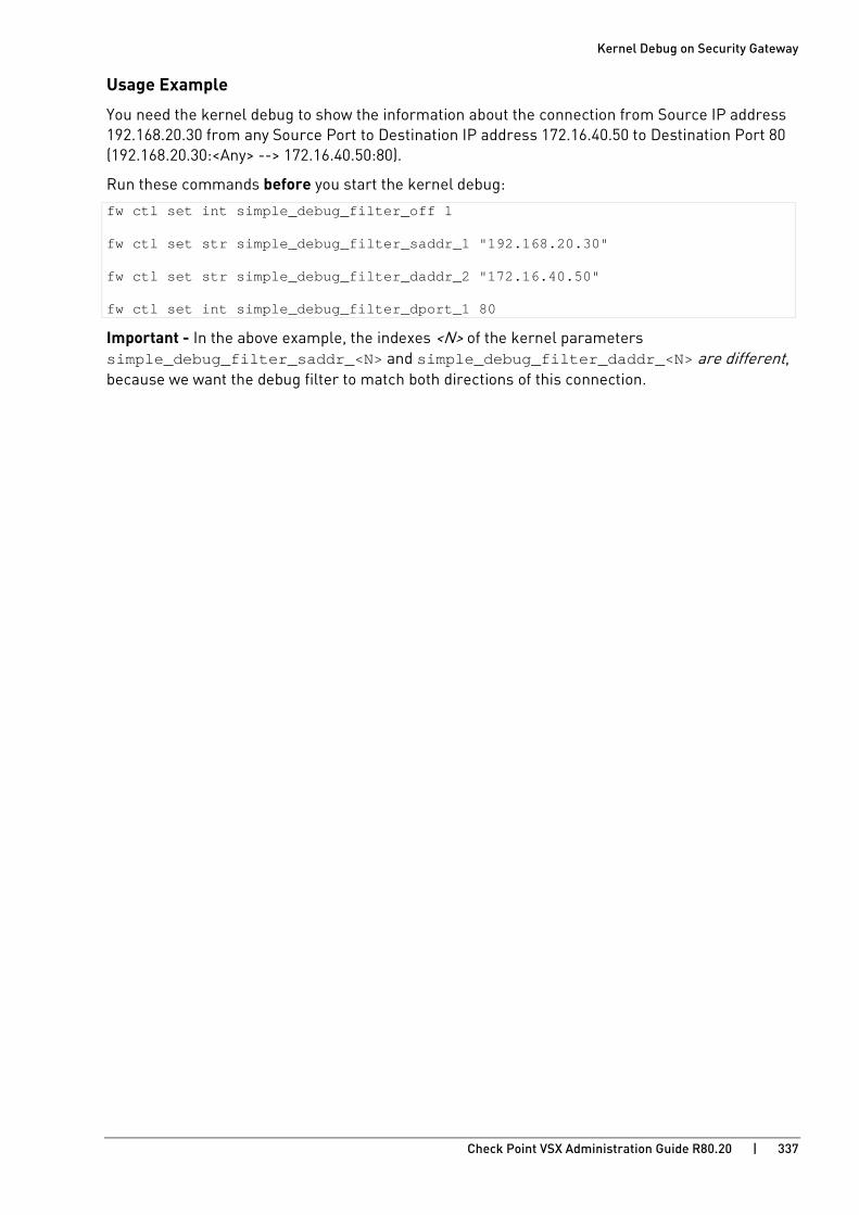
Kernel Debug on Security Gateway
Check Point VSX Administration Guide R80.20 | 337
Usage Example
You need the kernel debug to show the information about the connection from Source IP address 192.168.20.30 from any Source Port to Destination IP address 172.16.40.50 to Destination Port 80 (192.168.20.30:<Any> --> 172.16.40.50:80).
Run these commands before you start the kernel debug:
fw ctl set int simple_debug_filter_off 1 fw ctl set str simple_debug_filter_saddr_1 "192.168.20.30" fw ctl set str simple_debug_filter_daddr_2 "172.16.40.50" fw ctl set int simple_debug_filter_dport_1 80
Important - In the above example, the indexes <N> of the kernel parameters simple_debug_filter_saddr_<N> and simple_debug_filter_daddr_<N> are different, because we want the debug filter to match both directions of this connection.
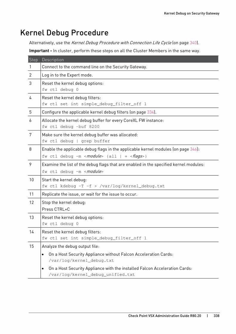
Kernel Debug on Security Gateway
Check Point VSX Administration Guide R80.20 | 338
Kernel Debug Procedure Alternatively, use the Kernel Debug Procedure with Connection Life Cycle (on page 340).
Important - In cluster, perform these steps on all the Cluster Members in the same way.
Step Description
1 Connect to the command line on the Security Gateway.
2 Log in to the Expert mode.
3 Reset the kernel debug options: fw ctl debug 0
4 Reset the kernel debug filters: fw ctl set int simple_debug_filter_off 1
5 Configure the applicable kernel debug filters (on page 334).
6 Allocate the kernel debug buffer for every CoreXL FW instance: fw ctl debug -buf 8200
7 Make sure the kernel debug buffer was allocated: fw ctl debug | grep buffer
8 Enable the applicable debug flags in the applicable kernel modules (on page 346):
fw ctl debug -m <module> {all | + <flags>}
9 Examine the list of the debug flags that are enabled in the specified kernel modules:
fw ctl debug -m <module>
10 Start the kernel debug: fw ctl kdebug -T -f > /var/log/kernel_debug.txt
11 Replicate the issue, or wait for the issue to occur.
12 Stop the kernel debug:
Press CTRL+C
13 Reset the kernel debug options: fw ctl debug 0
14 Reset the kernel debug filters: fw ctl set int simple_debug_filter_off 1
15 Analyze the debug output file:
• On a Host Security Appliance without Falcon Acceleration Cards: /var/log/kernel_debug.txt
• On a Host Security Appliance with the installed Falcon Acceleration Cards: /var/log/kernel_debug_unified.txt
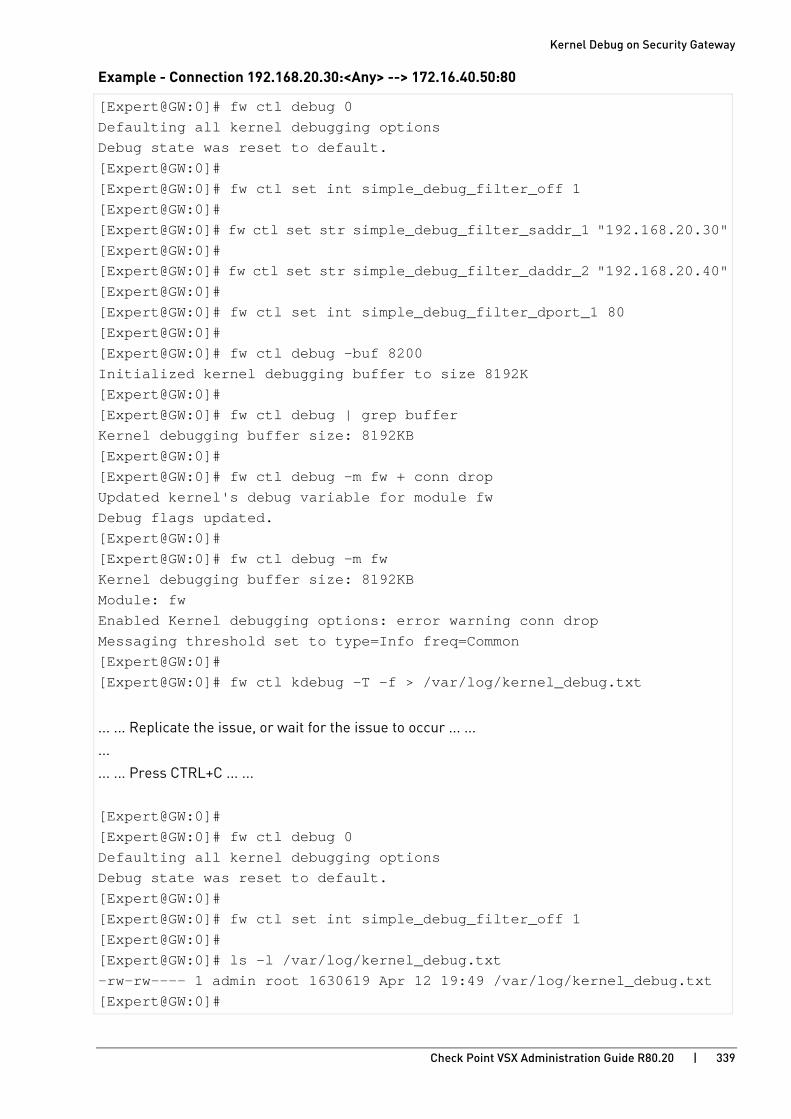
Kernel Debug on Security Gateway
Check Point VSX Administration Guide R80.20 | 339
Example - Connection 192.168.20.30:<Any> --> 172.16.40.50:80
[Expert@GW:0]# fw ctl debug 0 Defaulting all kernel debugging options Debug state was reset to default. [Expert@GW:0]# [Expert@GW:0]# fw ctl set int simple_debug_filter_off 1 [Expert@GW:0]# [Expert@GW:0]# fw ctl set str simple_debug_filter_saddr_1 "192.168.20.30" [Expert@GW:0]# [Expert@GW:0]# fw ctl set str simple_debug_filter_daddr_2 "192.168.20.40" [Expert@GW:0]# [Expert@GW:0]# fw ctl set int simple_debug_filter_dport_1 80 [Expert@GW:0]# [Expert@GW:0]# fw ctl debug -buf 8200 Initialized kernel debugging buffer to size 8192K [Expert@GW:0]# [Expert@GW:0]# fw ctl debug | grep buffer Kernel debugging buffer size: 8192KB [Expert@GW:0]# [Expert@GW:0]# fw ctl debug -m fw + conn drop Updated kernel's debug variable for module fw Debug flags updated. [Expert@GW:0]# [Expert@GW:0]# fw ctl debug -m fw Kernel debugging buffer size: 8192KB Module: fw Enabled Kernel debugging options: error warning conn drop Messaging threshold set to type=Info freq=Common [Expert@GW:0]# [Expert@GW:0]# fw ctl kdebug -T -f > /var/log/kernel_debug.txt
... ... Replicate the issue, or wait for the issue to occur ... ...
...
... ... Press CTRL+C ... ...
[Expert@GW:0]# [Expert@GW:0]# fw ctl debug 0 Defaulting all kernel debugging options Debug state was reset to default. [Expert@GW:0]# [Expert@GW:0]# fw ctl set int simple_debug_filter_off 1 [Expert@GW:0]# [Expert@GW:0]# ls -l /var/log/kernel_debug.txt -rw-rw---- 1 admin root 1630619 Apr 12 19:49 /var/log/kernel_debug.txt [Expert@GW:0]#
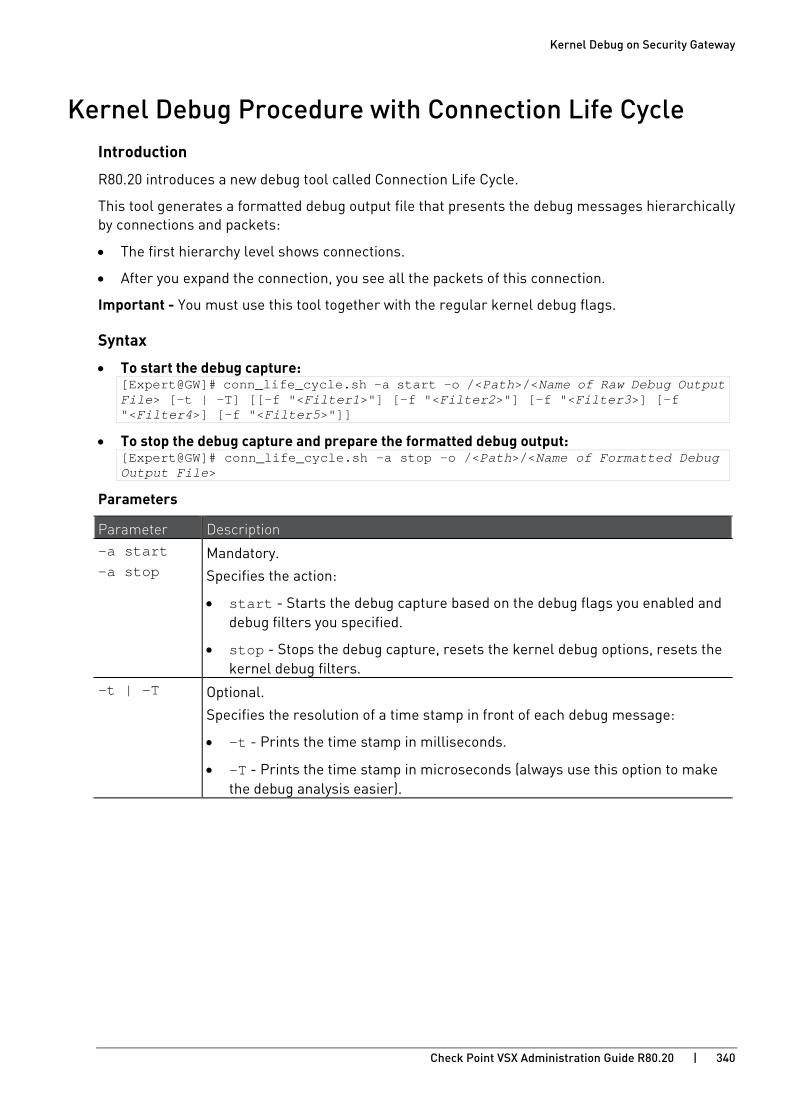
Kernel Debug on Security Gateway
Check Point VSX Administration Guide R80.20 | 340
Kernel Debug Procedure with Connection Life Cycle Introduction
R80.20 introduces a new debug tool called Connection Life Cycle.
This tool generates a formatted debug output file that presents the debug messages hierarchically by connections and packets:
• The first hierarchy level shows connections.
• After you expand the connection, you see all the packets of this connection.
Important - You must use this tool together with the regular kernel debug flags.
Syntax
• To start the debug capture: [Expert@GW]# conn_life_cycle.sh -a start -o /<Path>/<Name of Raw Debug Output File> [-t | -T] [[-f "<Filter1>"] [-f "<Filter2>"] [-f "<Filter3>] [-f "<Filter4>] [-f "<Filter5>"]]
• To stop the debug capture and prepare the formatted debug output: [Expert@GW]# conn_life_cycle.sh -a stop -o /<Path>/<Name of Formatted Debug Output File>
Parameters
Parameter Description -a start -a stop
Mandatory.
Specifies the action:
• start - Starts the debug capture based on the debug flags you enabled and debug filters you specified.
• stop - Stops the debug capture, resets the kernel debug options, resets the kernel debug filters.
-t | -T Optional.
Specifies the resolution of a time stamp in front of each debug message:
• -t - Prints the time stamp in milliseconds.
• -T - Prints the time stamp in microseconds (always use this option to make the debug analysis easier).

Kernel Debug on Security Gateway
Check Point VSX Administration Guide R80.20 | 341
Parameter Description
-f "<Filter>" Optional.
Specifies which connections and packets to capture. For additional information, see Kernel Debug Filters (on page 334).
Important - If you do not specify filters, then the tool prints debug messages for all traffic. This causes high load on the CPU and increases the time to format the debug output file.
Each filter must contain these five numbers (5-tuple) separated with commas:
"<Source IP Address>,<Source Port>,<Destination IP Address>,<Destination Port>,<Protocol Number>"
Example of capturing traffic from IP 192.168.20.30 from any port to IP 172.16.40.50 to port 22 over the TCP protocol: -f "192.168.20.30,0,172.16.40.50,22,6"
Notes:
• The tool supports up to five of such filters.
• The tool treats the value 0 (zero) as "any".
• If you specify two or more filters, the tool performs a logical "OR" of all the filters on each packet.
If the packet matches at least one filter, the tool prints the debug messages for this packet.
• <Source IP Address> and <Destination IP Address> - IPv4 or IPv6 address
• <Source Port> and <Destination Port> - integers from 1 to 65535 (see IANA - Port Numbers https://www.iana.org/assignments/service-names-port-numbers/service-names-port-numbers.xhtml)
• <Protocol Number> - integer from 0 to 254 (see IANA - Protocol Numbers https://www.iana.org/assignments/protocol-numbers/protocol-numbers.xhtml)
-o /<Path>/<Name of Raw Debug Output File>
Mandatory.
Specifies the absolute path and the name of the raw debug output file.
Example: -o /var/log/kernel_debug.txt
-o /<Path>/<Name of Formatted Debug Output File>
Mandatory.
Specifies the absolute path and the name of the formatted debug output file (to analyze by an administrator).
Example: -o /var/log/kernel_debug_formatted.txt

Kernel Debug on Security Gateway
Check Point VSX Administration Guide R80.20 | 342
Procedure
Important - In cluster, perform these steps on all the Cluster Members in the same way.
Step Description
1 Connect to the command line on the Security Gateway.
2 Log in to the Expert mode.
3 Enable the applicable debug flags in the applicable kernel modules (on page 346):
fw ctl debug -m <module> {all | + <flags>}
4 Examine the list of the debug flags that are enabled in the specified kernel modules:
fw ctl debug -m <module>
5 Start the debug capture: conn_life_cycle.sh -a start -o /var/log/kernel_debug.txt -T -f "<Filter1>" [... [-f "<FilterN>"]]
6 Replicate the issue, or wait for the issue to occur.
7 Stop the debug capture and prepare the formatted debug output: conn_life_cycle.sh -a stop -o /var/log/kernel_debug_formatted.txt
8 Transfer the formatted debug output file from your Security Gateway to your desktop or laptop computer: /var/log/kernel_debug_formatted.txt
9 Examine the formatted debug output file in an advanced text editor like Notepad++ (click Language > R > Ruby), or any other Ruby language viewer.
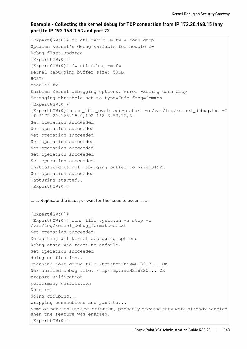
Kernel Debug on Security Gateway
Check Point VSX Administration Guide R80.20 | 343
Example - Collecting the kernel debug for TCP connection from IP 172.20.168.15 (any port) to IP 192.168.3.53 and port 22
[Expert@GW:0]# fw ctl debug -m fw + conn drop Updated kernel's debug variable for module fw Debug flags updated. [Expert@GW:0]# [Expert@GW:0]# fw ctl debug -m fw Kernel debugging buffer size: 50KB HOST: Module: fw Enabled Kernel debugging options: error warning conn drop Messaging threshold set to type=Info freq=Common [Expert@GW:0]# [Expert@GW:0]# conn_life_cycle.sh -a start -o /var/log/kernel_debug.txt -T -f "172.20.168.15,0,192.168.3.53,22,6" Set operation succeeded Set operation succeeded Set operation succeeded Set operation succeeded Set operation succeeded Set operation succeeded Set operation succeeded Initialized kernel debugging buffer to size 8192K Set operation succeeded Capturing started... [Expert@GW:0]#
... ... Replicate the issue, or wait for the issue to occur ... ...
[Expert@GW:0]# [Expert@GW:0]# conn_life_cycle.sh -a stop -o /var/log/kernel_debug_formatted.txt Set operation succeeded Defaulting all kernel debugging options Debug state was reset to default. Set operation succeeded doing unification... Openning host debug file /tmp/tmp.KiWmF18217... OK New unified debug file: /tmp/tmp.imzMZ18220... OK prepare unification performing unification Done :-) doing grouping... wrapping connections and packets... Some of packets lack description, probably because they were already handled when the feature was enabled. [Expert@GW:0]#
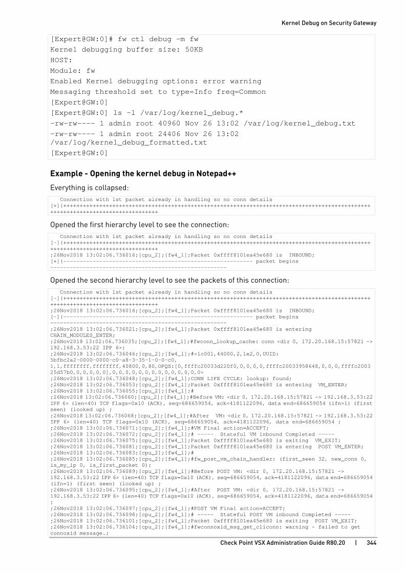
Kernel Debug on Security Gateway
Check Point VSX Administration Guide R80.20 | 344
[Expert@GW:0]# fw ctl debug -m fw Kernel debugging buffer size: 50KB HOST: Module: fw Enabled Kernel debugging options: error warning Messaging threshold set to type=Info freq=Common [Expert@GW:0] [Expert@GW:0] ls -l /var/log/kernel_debug.* -rw-rw---- 1 admin root 40960 Nov 26 13:02 /var/log/kernel_debug.txt -rw-rw---- 1 admin root 24406 Nov 26 13:02 /var/log/kernel_debug_formatted.txt [Expert@GW:0]
Example - Opening the kernel debug in Notepad++
Everything is collapsed: Connection with 1st packet already in handling so no conn details [+]{+++++++++++++++++++++++++++++++++++++++++++++++++++++++++++++++++++++++++++++++++++++++++++++++++++++++++++++++++++++++++++++++
Opened the first hierarchy level to see the connection: Connection with 1st packet already in handling so no conn details [-]{+++++++++++++++++++++++++++++++++++++++++++++++++++++++++++++++++++++++++++++++++++++++++++++++++++++++++++++++++++++++++++++++ ;26Nov2018 13:02:06.736016;[cpu_2];[fw4_1];Packet 0xffff8101ea45e680 is INBOUND; [+]{---------------------------------------------------------- packet begins ------------------------------------------------------
Opened the second hierarchy level to see the packets of this connection: Connection with 1st packet already in handling so no conn details [-]{+++++++++++++++++++++++++++++++++++++++++++++++++++++++++++++++++++++++++++++++++++++++++++++++++++++++++++++++++++++++++++++++ ;26Nov2018 13:02:06.736016;[cpu_2];[fw4_1];Packet 0xffff8101ea45e680 is INBOUND; [-]{---------------------------------------------------------- packet begins ------------------------------------------------------ ;26Nov2018 13:02:06.736021;[cpu_2];[fw4_1];Packet 0xffff8101ea45e680 is entering CHAIN_MODULES_ENTER; ;26Nov2018 13:02:06.736035;[cpu_2];[fw4_1];#fwconn_lookup_cache: conn <dir 0, 172.20.168.15:57821 -> 192.168.3.53:22 IPP 6>; ;26Nov2018 13:02:06.736046;[cpu_2];[fw4_1];#<1c001,44000,2,1e2,0,UUID: 5bfbc2a2-0000-0000-c0-a8-3-35-1-0-0-c0, 1,1,ffffffff,ffffffff,40800,0,80,OPQS:[0,ffffc20033d220f0,0,0,0,0,ffffc20033958648,0,0,0,ffffc200325d57b0,0,0,0,0,0],0,0,0,0,0,0,0,0,0,0,0,0,0,0> ;26Nov2018 13:02:06.736048;[cpu_2];[fw4_1];CONN LIFE CYCLE: lookup: found; ;26Nov2018 13:02:06.736053;[cpu_2];[fw4_1];Packet 0xffff8101ea45e680 is entering VM_ENTER; ;26Nov2018 13:02:06.736055;[cpu_2];[fw4_1];# ;26Nov2018 13:02:06.736060;[cpu_2];[fw4_1];#Before VM: <dir 0, 172.20.168.15:57821 -> 192.168.3.53:22 IPP 6> (len=40) TCP flags=0x10 (ACK), seq=686659054, ack=4181122096, data end=686659054 (ifn=1) (first seen) (looked up) ; ;26Nov2018 13:02:06.736068;[cpu_2];[fw4_1];#After VM: <dir 0, 172.20.168.15:57821 -> 192.168.3.53:22 IPP 6> (len=40) TCP flags=0x10 (ACK), seq=686659054, ack=4181122096, data end=686659054 ; ;26Nov2018 13:02:06.736071;[cpu_2];[fw4_1];#VM Final action=ACCEPT; ;26Nov2018 13:02:06.736072;[cpu_2];[fw4_1];# ----- Stateful VM inbound Completed ----- ;26Nov2018 13:02:06.736075;[cpu_2];[fw4_1];Packet 0xffff8101ea45e680 is exiting VM_EXIT; ;26Nov2018 13:02:06.736081;[cpu_2];[fw4_1];Packet 0xffff8101ea45e680 is entering POST VM_ENTER; ;26Nov2018 13:02:06.736083;[cpu_2];[fw4_1];# ;26Nov2018 13:02:06.736085;[cpu_2];[fw4_1];#fw_post_vm_chain_handler: (first_seen 32, new_conn 0, is_my_ip 0, is_first_packet 0); ;26Nov2018 13:02:06.736089;[cpu_2];[fw4_1];#Before POST VM: <dir 0, 172.20.168.15:57821 -> 192.168.3.53:22 IPP 6> (len=40) TCP flags=0x10 (ACK), seq=686659054, ack=4181122096, data end=686659054 (ifn=1) (first seen) (looked up) ; ;26Nov2018 13:02:06.736095;[cpu_2];[fw4_1];#After POST VM: <dir 0, 172.20.168.15:57821 -> 192.168.3.53:22 IPP 6> (len=40) TCP flags=0x10 (ACK), seq=686659054, ack=4181122096, data end=686659054 ; ;26Nov2018 13:02:06.736097;[cpu_2];[fw4_1];#POST VM Final action=ACCEPT; ;26Nov2018 13:02:06.736098;[cpu_2];[fw4_1];# ----- Stateful POST VM inbound Completed ----- ;26Nov2018 13:02:06.736101;[cpu_2];[fw4_1];Packet 0xffff8101ea45e680 is exiting POST VM_EXIT; ;26Nov2018 13:02:06.736104;[cpu_2];[fw4_1];#fwconnoxid_msg_get_cliconn: warning - failed to get connoxid message.;

Kernel Debug on Security Gateway
Check Point VSX Administration Guide R80.20 | 345
;26Nov2018 13:02:06.736107;[cpu_2];[fw4_1];Packet 0xffff8101ea45e680 is entering CPAS_ENTER; ;26Nov2018 13:02:06.736110;[cpu_2];[fw4_1];Packet 0xffff8101ea45e680 is exiting CPAS_EXIT; ;26Nov2018 13:02:06.736113;[cpu_2];[fw4_1];Packet 0xffff8101ea45e680 is exiting CHAIN_MODULES_EXIT; ;26Nov2018 13:02:06.736116;[cpu_2];[fw4_1];Packet 0xffff8101ea45e680 is ACCEPTED; } ;26Nov2018 13:02:06.770652;[cpu_2];[fw4_1];Packet 0xffff8101ea128580 is INBOUND;

Kernel Debug on Security Gateway
Check Point VSX Administration Guide R80.20 | 346
Kernel Debug Modules and Debug Flags To see the available kernel debug modules and their debug flags, run: fw ctl debug -m
List of kernel debug modules (in alphabetical order):
• Module 'accel_apps' (Accelerated Applications) (on page 348)
• Module 'accel_pm_mgr' (Accelerated Pattern Match Manager) (on page 349)
• Module 'APPI' (Application Control Inspection) (on page 350)
• Module 'BOA' (Boolean Analyzer for Web Intelligence) (on page 351)
• Module 'CI' (Content Inspection) (on page 352)
• Module 'cluster' (ClusterXL) (on page 353)
• Module 'cmi_loader' (Context Management Interface/Infrastructure Loader) (on page 355)
• Module 'CPAS' (Check Point Active Streaming) (on page 356)
• Module 'cpcode' (Data Loss Prevention - CPcode) (on page 357)
• Module 'dlpda' (Data Loss Prevention - Download Agent, Content Awareness module) (on page 358)
• Module 'dlpk' (Data Loss Prevention - Kernel space module) (on page 359)
• Module 'dlpuk' (Data Loss Prevention - User space module) (on page 360)
• Module 'fg' (FloodGate-1 - QoS) (on page 361)
• Module 'FILEAPP' (File Application) (on page 362)
• Module 'fw' (Firewall) (on page 363)
• Module 'gtp' (GPRS Tunneling Protocol) (on page 367)
• Module 'h323' (VoIP H323) (on page 368)
• Module 'ICAP_CLIENT' (Internet Content Adaptation Protocol Client) (on page 369)
• Module 'IDAPI' (Identity Awareness) (on page 370)
• Module 'kiss' (Kernel Infrastructure) (on page 371)
• Module 'kissflow' (Kernel Infrastructure Flow) (on page 373)
• Module 'MALWARE' (Threat Prevention) (on page 374)
• Module 'multik' (Multi-Kernel Inspection - CoreXL) (on page 375)
• Module 'MUX' (Multiplexer for Applications Traffic) (on page 376)
• Module 'NRB' (Next Rule Base) (on page 377)
• Module 'PSL' (Passive Streaming Library) (on page 378)
• Module 'RAD_KERNEL' (Resource Advisor - Kernel space module) (on page 379)
• Module 'RTM' (Real Time Monitoring) (on page 380)
• Module 'seqvalid' (TCP Sequence Validator and Translator) (on page 381)
• Module 'SFT' (Stream File Type) (on page 382)

Kernel Debug on Security Gateway
Check Point VSX Administration Guide R80.20 | 347
• Module 'SGEN' (Struct Generator) (on page 383)
• Module 'synatk' (Accelerated SYN Defender) (on page 384)
• Module 'UC' (UserCheck) (on page 385)
• Module 'UP' (Unified Policy) (on page 386)
• Module 'upconv' (Unified Policy Conversion) (on page 388)
• Module 'UPIS' (Unified Policy Infrastructure) (on page 389)
• Module 'VPN' (Site-to-Site VPN and Remote Access VPN) (on page 391)
• Module 'WS' (Web Intelligence) (on page 393)
• Module 'WS_SIP' (Web Intelligence VoIP SIP Parser) (on page 395)
• Module 'WSIS' (Web Intelligence Infrastructure) (on page 397)

Kernel Debug on Security Gateway
Check Point VSX Administration Guide R80.20 | 348
Module 'accel_apps' (Accelerated Applications) Syntax: fw ctl debug -m accel_apps + {all | <List of Debug Flags>}
Flag Description av_lite Messages from the lite Content Inspection (Anti-Virus) module
cmi_lite Messages from the lite Context Management Interface/Infrastructure module
error General errors
warning General warnings
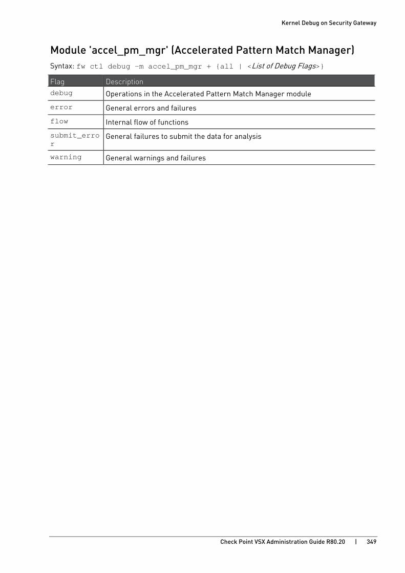
Kernel Debug on Security Gateway
Check Point VSX Administration Guide R80.20 | 349
Module 'accel_pm_mgr' (Accelerated Pattern Match Manager) Syntax: fw ctl debug -m accel_pm_mgr + {all | <List of Debug Flags>}
Flag Description debug Operations in the Accelerated Pattern Match Manager module
error General errors and failures
flow Internal flow of functions
submit_error
General failures to submit the data for analysis
warning General warnings and failures

Kernel Debug on Security Gateway
Check Point VSX Administration Guide R80.20 | 350
Module 'APPI' (Application Control Inspection) Syntax: fw ctl debug -m APPI + {all | <List of Debug Flags>}
Flag Description account Accounting information
address Information about connection's IP address
btime Browse time
connection Application Control connections
coverage Coverage times (entering, blocking, and time spent)
error General errors
global Global policy operations
info General information
limit Application Control limits
memory Memory allocation operations
module Operations in the Application Control module (initialization, module loading, calls to the module, policy loading, and so on)
observer Classification Object (CLOB) observer (data classification)
policy Application Control policy
referrer Application Control referrer
subject Prints the debug subject of each debug message
timestamp Prints the timestamp for each debug message (changes when you enable the debug flag 'coverage')
urlf_ssl Application Control and URL Filtering for SSL
verbose Prints additional information (used with other debug flags)
vs Prints the VSID of the debugged Virtual System
warning General warnings

Kernel Debug on Security Gateway
Check Point VSX Administration Guide R80.20 | 351
Module 'BOA' (Boolean Analyzer for Web Intelligence) Syntax: fw ctl debug -m BOA + {all | <List of Debug Flags>}
Flag Description analyzer Operations in the BOA module
disasm Disassembler information
error General errors
fatal Fatal errors
flow Operations in the BOA module
info General information
lock Information about internal locks in the FireWall kernel
memory Memory allocation operations
spider Internal hash tables
stat Statistics
stream Memory allocation when processing streamed data
warning General warnings

Kernel Debug on Security Gateway
Check Point VSX Administration Guide R80.20 | 352
Module 'CI' (Content Inspection) Syntax: fw ctl debug -m CI + {all | <List of Debug Flags>}
Flag Description address Prints connection addresses (as Source_IP:Source_Port ->
Dest_IP:Dest_Port)
av Anti-Virus inspection
coverage Coverage times (entering, blocking, and time spent)
crypto Basic information about encryption and decryption
error General errors
fatal Fatal errors
filter Basic information about URL filters
info General information
ioctl Currently is not used
memory Memory allocation operations
module Operations in the Content Inspection module (initialization, module loading, calls to the module, policy loading, and so on)
policy Content Inspection policy
profile Basic information about the Content Inspection module (initialization, destroying, freeing)
regexp Regular Expression library
session Session layer
stat Content Inspection statistics
subject Prints the debug subject of each debug message
timestamp Prints the timestamp for each debug message (changes when you enable the debug flag 'coverage')
track Use only for very limited important debug prints, so it can be used in a loaded environment -
Content-Disposition, Content-Type, extension validation, extension matching
uf URL filters and URL cache
vs Prints the VSID of the debugged Virtual System
warning General warnings

Kernel Debug on Security Gateway
Check Point VSX Administration Guide R80.20 | 353
Module 'cluster' (ClusterXL) Syntax: fw ctl debug -m cluster + {all | <List of Debug Flags>}
Notes:
• To print all synchronization operations in Check Point cluster in the debug output, enable these debug flags:
• The 'sync' debug flag in the debug module 'fw' (on page 363)
• The 'sync' debug flag in the debug module 'CPAS' (on page 356)
• To print the contents of the packets in HEX format in the debug output (as "FW-1: fwha_print_packet: Buffer ..."), before you start the kernel debug, set this kernel parameter on each Cluster Member: # fw ctl set int fwha_dprint_io 1
• To print all network checks in the debug output, before you start the kernel debug, set this kernel parameter on each Cluster Member: # fw ctl set int fwha_dprint_all_net_check 1
Flag Description arp ARP Forwarding (see sk111956
http://supportcontent.checkpoint.com/solutions?id=sk111956)
autoccp Operations of CCP in Auto mode
ccp Reception and transmission of Cluster Control Protocol (CCP) packets
cloud Replies to the probe packets in CloudGuard IaaS
conf Cluster configuration and policy installation
correction Correction Layer
cu Connectivity Upgrade (see sk107042 http://supportcontent.checkpoint.com/solutions?id=sk107042)
drop Connections dropped by the cluster Decision Function (DF) module (does not include CCP packets)
forward Forwarding Layer messages (when Cluster Members send and receive a forwarded packet)
if Interface tracking and validation (all the operations and checks on interfaces)
ifstate Interface state (all the operations and checks on interfaces)
io Information about sending of packets through cluster interfaces
log Creating and sending of logs by cluster
Also enable the debug flag 'log' flag in the debug module 'fw' (on page 363)
mac Current configuration of and detection of cluster interfaces
Also enable the debug flags 'conf' and 'if' in this debug module
mmagic Operations on "MAC magic" (getting, setting, updating, initializing, dropping, and so on)
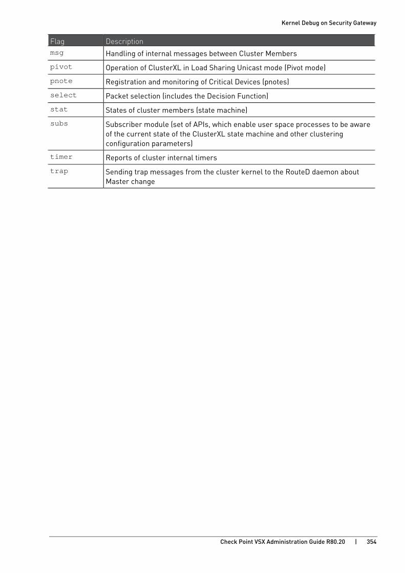
Kernel Debug on Security Gateway
Check Point VSX Administration Guide R80.20 | 354
Flag Description msg Handling of internal messages between Cluster Members
pivot Operation of ClusterXL in Load Sharing Unicast mode (Pivot mode)
pnote Registration and monitoring of Critical Devices (pnotes)
select Packet selection (includes the Decision Function)
stat States of cluster members (state machine)
subs Subscriber module (set of APIs, which enable user space processes to be aware of the current state of the ClusterXL state machine and other clustering configuration parameters)
timer Reports of cluster internal timers
trap Sending trap messages from the cluster kernel to the RouteD daemon about Master change
.

Kernel Debug on Security Gateway
Check Point VSX Administration Guide R80.20 | 355
Module 'cmi_loader' (Context Management Interface/Infrastructure Loader) Syntax: fw ctl debug -m cmi_loader + {all | <List of Debug Flags>}
Flag Description address Information about connection's IP address
connection Internal messages about connection
coverage Coverage times (entering, blocking, and time spent)
cpcode DLP CPcode
Also see the Module 'cpcode' (on page 357)
error General errors
global_states
User Space global states structures
info General information
inspect INSPECT code
memory Memory allocation operations
module Operations in the Context Management Interface/Infrastructure Loader module (initialization, module loading, calls to the module, contexts, and so on)
parsers_is Module parsers infrastructure
policy Policy installation
sigload Signatures, patterns, ranges
subject Prints the debug subject of each debug message
timestamp Prints the timestamp for each debug message (changes when you enable the debug flag 'coverage')
verbose Prints additional information (used with other debug flags)
vs Prints the VSID of the debugged Virtual System
warning General warnings

Kernel Debug on Security Gateway
Check Point VSX Administration Guide R80.20 | 356
Module 'CPAS' (Check Point Active Streaming) Syntax: fw ctl debug -m CPAS + {all | <List of Debug Flags>}
Flag Description api Interface layer messages
conns Detailed description of connections, and connection's limit-related messages
cpconntim Information about internal timers
error General errors
events Event-related messages
ftp Messages of the FTP example server
glue Glue layer messages
http Messages of the HTTP example server
icmp Messages of the ICMP example server
notify E-mail Messaging Security application
pkts Packets handling messages (allocation, splitting, resizing, and so on)
skinny Processing of Skinny Client Control Protocol (SCCP) connections
sync Synchronization operations in cluster
Also see the debug flag 'sync' in the debug module 'fw' (on page 363)
tcp TCP processing messages
tcpinfo TCP processing messages - more detailed description
timer Reports of internal timer ticks
Warning - Prints many messages, without real content
warning General warnings
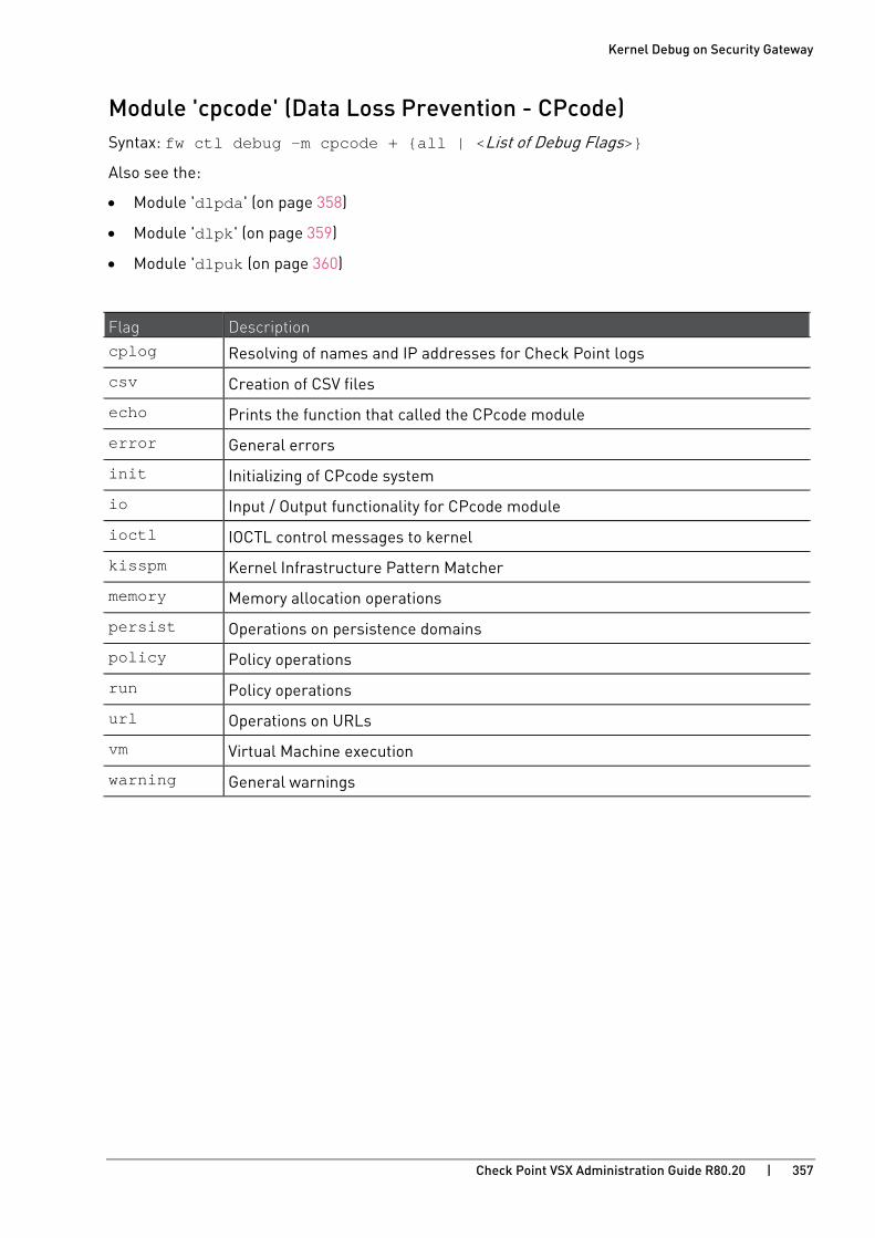
Kernel Debug on Security Gateway
Check Point VSX Administration Guide R80.20 | 357
Module 'cpcode' (Data Loss Prevention - CPcode) Syntax: fw ctl debug -m cpcode + {all | <List of Debug Flags>}
Also see the:
• Module 'dlpda' (on page 358)
• Module 'dlpk' (on page 359)
• Module 'dlpuk (on page 360)
Flag Description cplog Resolving of names and IP addresses for Check Point logs
csv Creation of CSV files
echo Prints the function that called the CPcode module
error General errors
init Initializing of CPcode system
io Input / Output functionality for CPcode module
ioctl IOCTL control messages to kernel
kisspm Kernel Infrastructure Pattern Matcher
memory Memory allocation operations
persist Operations on persistence domains
policy Policy operations
run Policy operations
url Operations on URLs
vm Virtual Machine execution
warning General warnings

Kernel Debug on Security Gateway
Check Point VSX Administration Guide R80.20 | 358
Module 'dlpda' (Data Loss Prevention - Download Agent for Content Awareness) Syntax: fw ctl debug -m dlpda + {all | <List of Debug Flags>}
Also see the:
• Module 'cpcode' (on page 357)
• Module 'dlpk' (on page 359)
• Module 'dlpuk (on page 360)
Flag Description address Information about connection's IP address
cmi Context Management Interface/Infrastructure operations
coverage Coverage times (entering, blocking, and time spent)
ctx Operations on DLP context
engine Content Awareness engine module
error General errors
filecache Content Awareness file caching
info General information
memory Memory allocation operations
mngr Currently is not used
module Initiation / removal of the Content Awareness infrastructure
observer Classification Object (CLOB) observer (data classification)
policy Content Awareness policy
slowpath Currently is not used
subject Prints the debug subject of each debug message
timestamp Prints the timestamp for each debug message (changes when you enable the debug flag 'coverage')
verbose Prints additional information (used with other debug flags)
vs Prints the VSID of the debugged Virtual System
warning General warnings

Kernel Debug on Security Gateway
Check Point VSX Administration Guide R80.20 | 359
Module 'dlpk' (Data Loss Prevention - Kernel Space) Syntax: fw ctl debug -m dlpk + {all | <List of Debug Flags>}
Also see the:
• Module 'cpcode' (on page 357)
• Module 'dlpda' (on page 358)
• Module 'dlpuk (on page 360)
Flag Description cmi HTTP Proxy, connection redirection, identity information, Async
drv DLP inspection
error General errors
identity User identity, connection identity, Async
rulebase DLP rulebase match
stat Counter statistics

Kernel Debug on Security Gateway
Check Point VSX Administration Guide R80.20 | 360
Module 'dlpuk' (Data Loss Prevention - User Space) Syntax: fw ctl debug -m dlpuk + {all | <List of Debug Flags>}
Also see the:
• Module 'cpcode' (on page 357)
• Module 'dlpda' (on page 358)
• Module 'dlpk' (on page 359)
Flag Description address Information about connection's IP address
buffer Currently is not used
coverage Coverage times (entering, blocking, and time spent)
error General errors
info General information
memory Memory allocation operations
module Initiation / removal of the Data Loss Prevention User Space modules' infrastructure
policy Currently is not used
serialize Data buffers and data sizes
subject Prints the debug subject of each debug message
timestamp Prints the timestamp for each debug message (changes when you enable the debug flag 'coverage')
verbose Prints additional information (used with other debug flags)
vs Prints the VSID of the debugged Virtual System
warning General warnings

Kernel Debug on Security Gateway
Check Point VSX Administration Guide R80.20 | 361
Module 'fg' (FloodGate-1 - QoS) Syntax: fw ctl debug -m fg + {all | <List of Debug Flags>}
Flag Description chain Tracing each packet through FloodGate-1 stages in the cookie chain
chainq Internal Chain Queue mechanism - holding and releasing of packets during critical actions (policy installation and uninstall)
classify Classification of connections to QoS rules
conn Processing and identification of connection
dns DNS classification mechanism
drops Dropped packets due to WFRED policy
dropsv Dropped packets due to WFRED policy - with additional debug information (verbose)
error General errors
flow Internal flow of connections (direction, interfaces, buffers, and so on)
fwrate Rate statistics for each interface and direction
general Currently is not used
install Policy installation
llq Low latency queuing
log Everything related to calls in the log
ls Processing of connections in ClusterXL in Load Sharing Mode
memory Memory allocation operations
multik Processing of connections in CoreXL
pkt Packet recording mechanism
policy QoS policy rules matching
qosaccel Acceleration of QoS traffic
rates Rule and connection rates (IQ Engine behavior and status)
rtm Failures in information gathering in the Real Time Monitoring module
Also see the Module 'RTM' (on page 380)
sched Basic scheduling information
tcp TCP streaming (re-transmission detection) mechanism
time Currently is not used
timers Reports of internal timer ticks
Warning - Prints many messages, without real content
url URL and URI for QoS classification
verbose Prints additional information (used with other debug flags)

Kernel Debug on Security Gateway
Check Point VSX Administration Guide R80.20 | 362
Module 'FILEAPP' (File Application) Syntax: fw ctl debug -m FILEAPP + {all | <List of Debug Flags>}
Flag Description address Information about connection's IP address
coverage Coverage times (entering, blocking, and time spent)
error General errors
filetype Information about processing a file type
global Allocation and creation of global object
info General information
memory Memory allocation operations
module Operations in the FILEAPP module (initialization, module loading, calls to the module, and so on)
normalize File normalization operations (internal operations)
parser File parsing
subject Prints the debug subject of each debug message
timestamp Prints the timestamp for each debug message (changes when you enable the debug flag 'coverage')
upload File upload operations
verbose Prints additional information (used with other debug flags)
vs Prints the VSID of the debugged Virtual System
warning General warnings

Kernel Debug on Security Gateway
Check Point VSX Administration Guide R80.20 | 363
Module 'fw' (Firewall) Syntax: fw ctl debug -m fw + {all | <List of Debug Flags>}
Flag Description acct Accounting data in logs for Application Control (also enable the debug of the
module 'APPI' (on page 350))
advp Advanced Patterns (signatures over port ranges) - runs under ASPII and CMI
aspii Accelerated Stateful Protocol Inspection Infrastructure (INPSECT streaming)
balance ConnectControl - logical servers in kernel, load balancing
bridge Bridge mode
caf Mirror and Decrypt feature - only mirror operations on all traffic
cgnat Carrier Grade NAT (CGN/CGNAT)
chain Connection Chain modules, cookie chain
chainfwd Chain forwarding - related to cluster kernel parameter fwha_perform_chain_forwarding
cifs Processing of Microsoft Common Internet File System (CIFS) protocol
citrix Processing of Citrix connections
cmi Context Management Interface/Infrastructure - IPS signature manager
conn Processing of all connections
connstats Connections statistics for Evaluation of Heavy Connections in CPView (see sk105762 http://supportcontent.checkpoint.com/solutions?id=sk105762)
content Anti-Virus content inspection
context Operations on Memory context and CPU context in the module 'kiss' (on page 371)
cookie Virtual de-fragmentation , cookie issues (cookies in the data structure that holds the packets)
corr Correction layer
cptls CRYPTO-PRO Transport Layer Security (HTTPS Inspection) - Russian VPN GOST
crypt Encryption and decryption of packets (algorithms and keys are printed in clear text and cipher text)
cvpnd Processing of connections handled by the Mobile Access daemon
dfilter Operations in the debug filters (on page 334)
dlp Processing of Data Loss Prevention connections
dnstun DNS tunnels
domain DNS queries
dos DDoS attack mitigation (part of IPS)
driver Check Point kernel attachment (access to kernel is shown as log entries)

Kernel Debug on Security Gateway
Check Point VSX Administration Guide R80.20 | 364
Flag Description drop Reason for (almost) every dropped packet
drop_tmpl Operations in Drop Templates
dynlog Dynamic log enhancement (INSPECT logs)
epq End Point Quarantine (also AMD)
error General errors
event Event App features (DNS, HTTP, SMTP, FTP)
ex Expiration issues (time-outs) in dynamic kernel tables
filter Packet filtering performed by the Check Point kernel and all data loaded into kernel
ftp Processing of FTP Data connections (used to call applications over FTP Data - i.e., Anti-Virus)
handlers Operations related to the Context Management Interface/Infrastructure Loader
Also see the Module 'cmi_loader' (on page 355)
highavail Cluster configuration - changes in the configuration and information about interfaces during
traffic processing
hold Holding mechanism and all packets being held / released
icmptun ICMP tunnels
if interface-related information (accessing the interfaces, installing a filter on an interfaces)
install Driver installation - NIC attachment (actions performed by the fw ctl install and fw ctl uninstall commands)
integrity Integrity Client (enforcement cooperation)
ioctl IOCTL control messages (communication between kernel and daemons, loading and unloading of the FireWall)
ipopt Enforcement of IP Options
ips IPS logs and IPS IOCTL
ipv6 Processing of IPv6 traffic
kbuf Kernel-buffer memory pool (for example, encryption keys use these memory allocations)
ld Kernel dynamic tables infrastructure (reads from / writes to the tables)
Warning - Security Gateway can freeze / hang!
leaks Memory leak detection mechanism
link Creation of links in Connections kernel table (ID 8158)
log Everything related to calls in the log
machine INSPECT Virtual Machine (actual assembler commands being processed)
Warning - Security Gateway can freeze / hang!

Kernel Debug on Security Gateway
Check Point VSX Administration Guide R80.20 | 365
Flag Description mail Issues with e-mails over POP3, IMAP
malware Matching of connections to Threat Prevention Layers (multiple rulebases)
Also see the Module 'MALWARE' (on page 374)
media Does not apply anymore
Only on Security Gateway that runs on Windows OS:
Transport Driver Interface information (interface-related information)
memory Memory allocation operations
mgcp Media Gateway Control Protocol (complementary to H.323 and SIP)
misc Miscellaneous helpful information (not shown with other debug flags)
misp ISP Redundancy
monitor Prints output similar to the "fw monitor"command
Also enable the debug flag 'misc' in this module
monitorall Prints output similar to the "fw monitor -p all"command
Also enable the debug flag 'misc' in this module
mrtsync Synchronization between cluster members of Multicast Routes that are added when working with Dynamic Routing Multicast protocols
msnms MSN over MSMS (MSN Messenger protocol)
Also always enable the debug flag 'sip' in this module
multik CoreXL-related (enables all the debug flags in the debug module 'multik' (on page 375), except for the debug flag 'packet')
nac Network Access Control (NAC) feature in Identity Awareness
nat NAT issues - basic information
nat64 NAT issues - 6in4 tunnels (IPv6 over IPv4) and 4in6 tunnels (IPv4 over IPv6)
netquota IPS protection "Network Quota"
ntup Non-TCP / Non-UDP traffic policy (traffic parser)
packet Actions performed on packets (like Accept, Drop, Fragment)
packval Stateless verifications (sequences, fragments, translations and other header verifications)
portscan Prevention of port scanning
prof Connection profiler for Firewall Priority Queues (see sk105762 http://supportcontent.checkpoint.com/solutions?id=sk105762)
q Driver queue (for example, cluster synchronization operations)
This debug flag is crucial for the debug of Check Point cluster synchronization issues
qos QoS (FloodGate-1)
rad Resource Advisor policy (for Application Control, URL Filtering, and others)
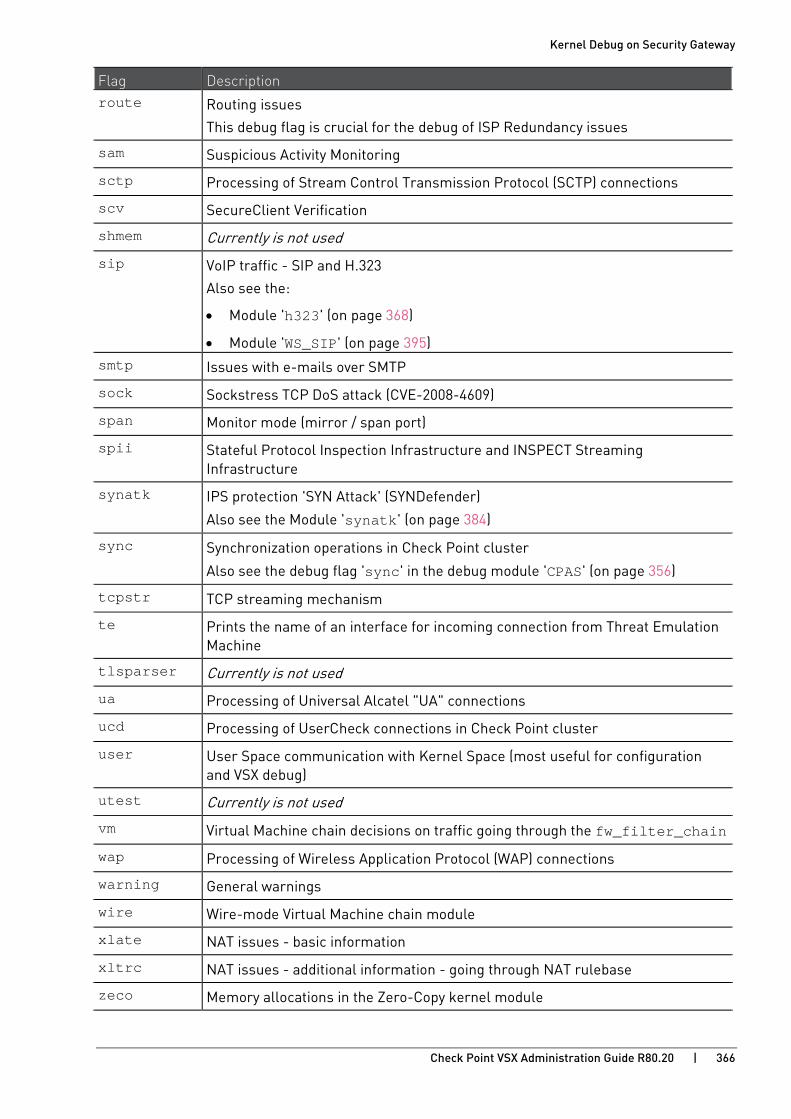
Kernel Debug on Security Gateway
Check Point VSX Administration Guide R80.20 | 366
Flag Description route Routing issues
This debug flag is crucial for the debug of ISP Redundancy issues
sam Suspicious Activity Monitoring
sctp Processing of Stream Control Transmission Protocol (SCTP) connections
scv SecureClient Verification
shmem Currently is not used
sip VoIP traffic - SIP and H.323
Also see the:
• Module 'h323' (on page 368)
• Module 'WS_SIP' (on page 395) smtp Issues with e-mails over SMTP
sock Sockstress TCP DoS attack (CVE-2008-4609)
span Monitor mode (mirror / span port)
spii Stateful Protocol Inspection Infrastructure and INSPECT Streaming Infrastructure
synatk IPS protection 'SYN Attack' (SYNDefender)
Also see the Module 'synatk' (on page 384)
sync Synchronization operations in Check Point cluster
Also see the debug flag 'sync' in the debug module 'CPAS' (on page 356)
tcpstr TCP streaming mechanism
te Prints the name of an interface for incoming connection from Threat Emulation Machine
tlsparser Currently is not used
ua Processing of Universal Alcatel "UA" connections
ucd Processing of UserCheck connections in Check Point cluster
user User Space communication with Kernel Space (most useful for configuration and VSX debug)
utest Currently is not used
vm Virtual Machine chain decisions on traffic going through the fw_filter_chain
wap Processing of Wireless Application Protocol (WAP) connections
warning General warnings
wire Wire-mode Virtual Machine chain module
xlate NAT issues - basic information
xltrc NAT issues - additional information - going through NAT rulebase
zeco Memory allocations in the Zero-Copy kernel module
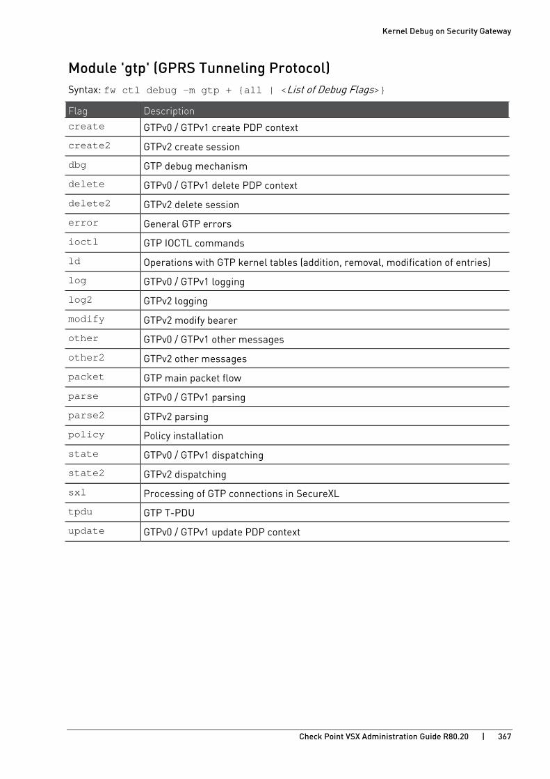
Kernel Debug on Security Gateway
Check Point VSX Administration Guide R80.20 | 367
Module 'gtp' (GPRS Tunneling Protocol) Syntax: fw ctl debug -m gtp + {all | <List of Debug Flags>}
Flag Description create GTPv0 / GTPv1 create PDP context
create2 GTPv2 create session
dbg GTP debug mechanism
delete GTPv0 / GTPv1 delete PDP context
delete2 GTPv2 delete session
error General GTP errors
ioctl GTP IOCTL commands
ld Operations with GTP kernel tables (addition, removal, modification of entries)
log GTPv0 / GTPv1 logging
log2 GTPv2 logging
modify GTPv2 modify bearer
other GTPv0 / GTPv1 other messages
other2 GTPv2 other messages
packet GTP main packet flow
parse GTPv0 / GTPv1 parsing
parse2 GTPv2 parsing
policy Policy installation
state GTPv0 / GTPv1 dispatching
state2 GTPv2 dispatching
sxl Processing of GTP connections in SecureXL
tpdu GTP T-PDU
update GTPv0 / GTPv1 update PDP context
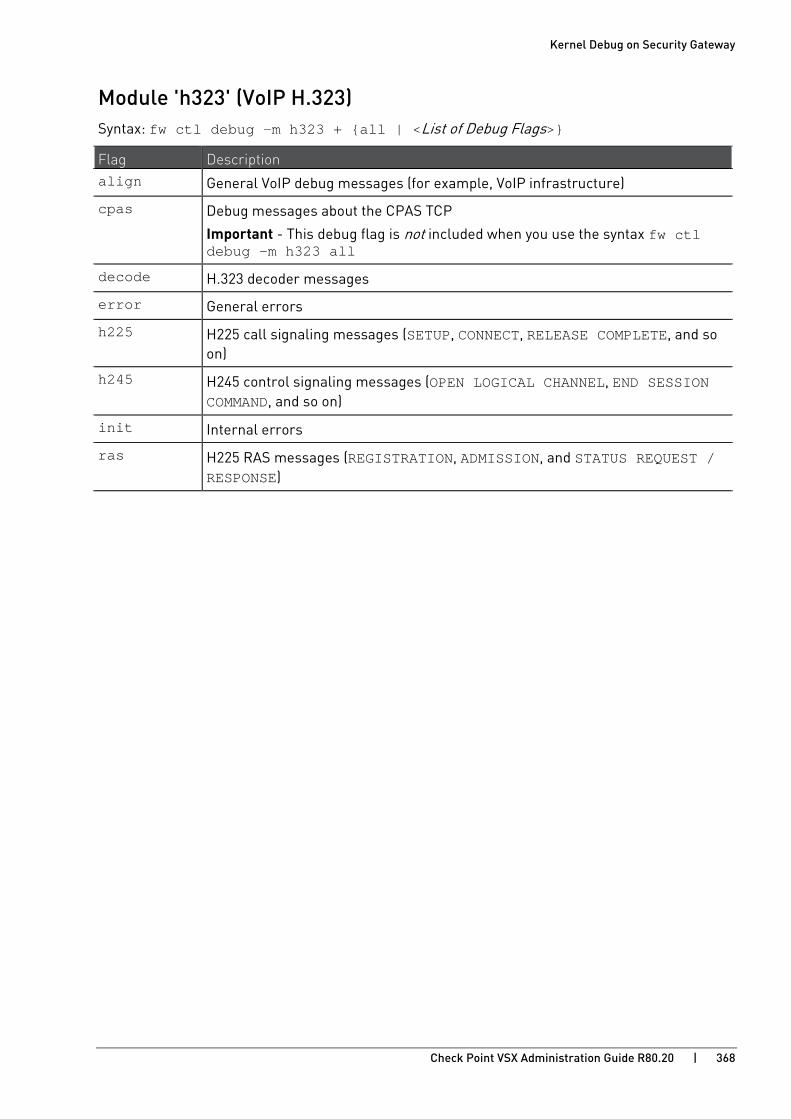
Kernel Debug on Security Gateway
Check Point VSX Administration Guide R80.20 | 368
Module 'h323' (VoIP H.323) Syntax: fw ctl debug -m h323 + {all | <List of Debug Flags>}
Flag Description align General VoIP debug messages (for example, VoIP infrastructure)
cpas Debug messages about the CPAS TCP
Important - This debug flag is not included when you use the syntax fw ctl debug -m h323 all
decode H.323 decoder messages
error General errors
h225 H225 call signaling messages (SETUP, CONNECT, RELEASE COMPLETE, and so on)
h245 H245 control signaling messages (OPEN LOGICAL CHANNEL, END SESSION COMMAND, and so on)
init Internal errors
ras H225 RAS messages (REGISTRATION, ADMISSION, and STATUS REQUEST / RESPONSE)
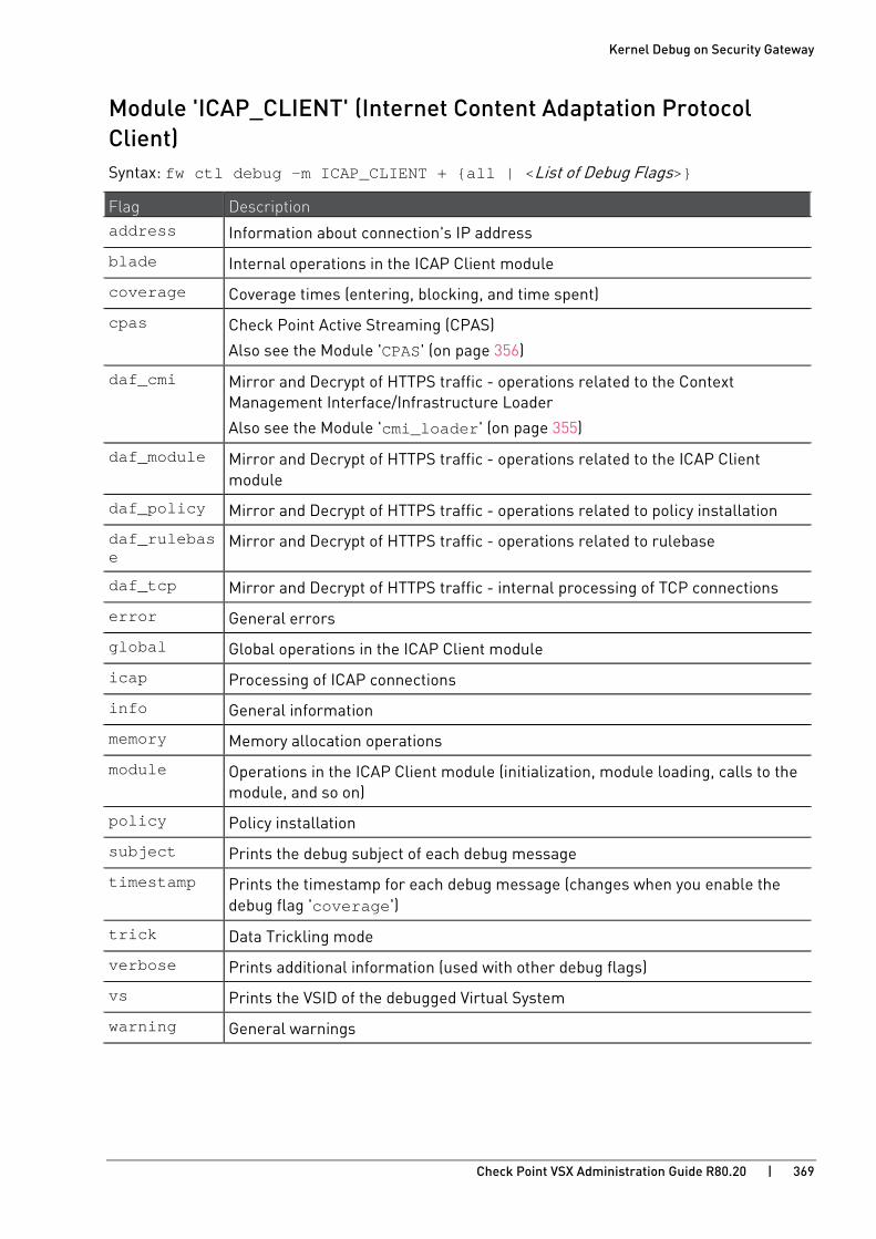
Kernel Debug on Security Gateway
Check Point VSX Administration Guide R80.20 | 369
Module 'ICAP_CLIENT' (Internet Content Adaptation Protocol Client) Syntax: fw ctl debug -m ICAP_CLIENT + {all | <List of Debug Flags>}
Flag Description address Information about connection's IP address
blade Internal operations in the ICAP Client module
coverage Coverage times (entering, blocking, and time spent)
cpas Check Point Active Streaming (CPAS)
Also see the Module 'CPAS' (on page 356)
daf_cmi Mirror and Decrypt of HTTPS traffic - operations related to the Context Management Interface/Infrastructure Loader
Also see the Module 'cmi_loader' (on page 355)
daf_module Mirror and Decrypt of HTTPS traffic - operations related to the ICAP Client module
daf_policy Mirror and Decrypt of HTTPS traffic - operations related to policy installation
daf_rulebase
Mirror and Decrypt of HTTPS traffic - operations related to rulebase
daf_tcp Mirror and Decrypt of HTTPS traffic - internal processing of TCP connections
error General errors
global Global operations in the ICAP Client module
icap Processing of ICAP connections
info General information
memory Memory allocation operations
module Operations in the ICAP Client module (initialization, module loading, calls to the module, and so on)
policy Policy installation
subject Prints the debug subject of each debug message
timestamp Prints the timestamp for each debug message (changes when you enable the debug flag 'coverage')
trick Data Trickling mode
verbose Prints additional information (used with other debug flags)
vs Prints the VSID of the debugged Virtual System
warning General warnings
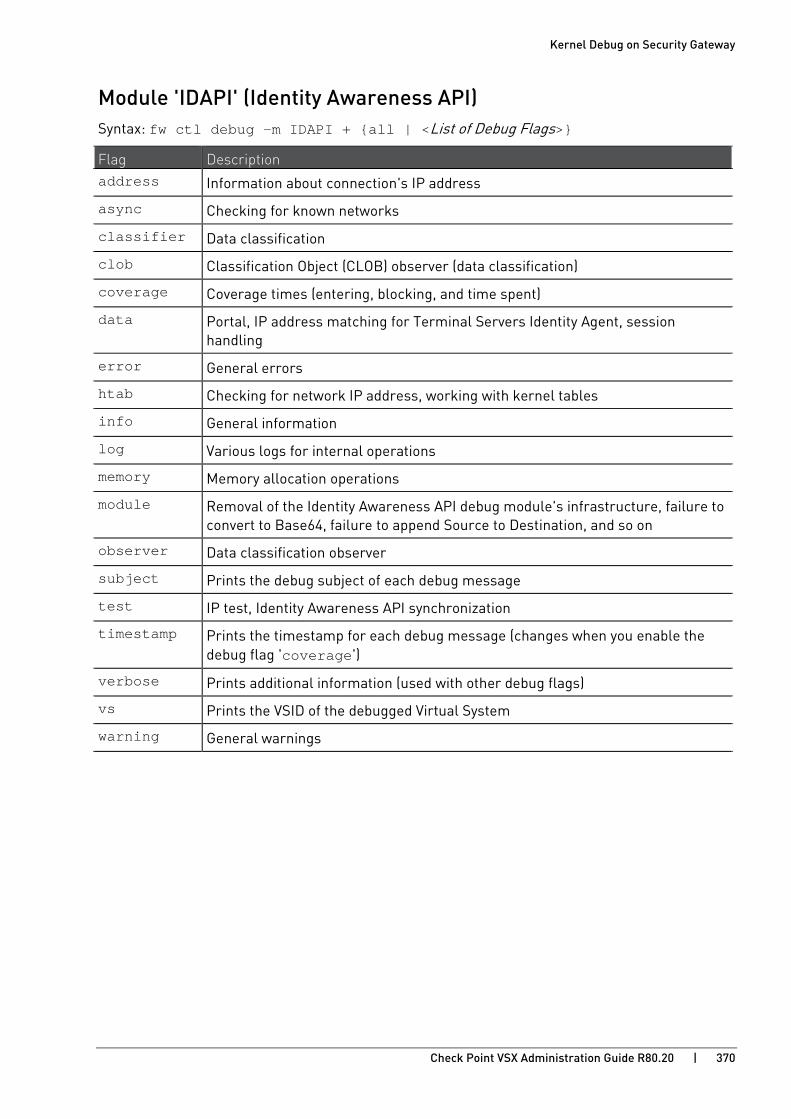
Kernel Debug on Security Gateway
Check Point VSX Administration Guide R80.20 | 370
Module 'IDAPI' (Identity Awareness API) Syntax: fw ctl debug -m IDAPI + {all | <List of Debug Flags>}
Flag Description address Information about connection's IP address
async Checking for known networks
classifier Data classification
clob Classification Object (CLOB) observer (data classification)
coverage Coverage times (entering, blocking, and time spent)
data Portal, IP address matching for Terminal Servers Identity Agent, session handling
error General errors
htab Checking for network IP address, working with kernel tables
info General information
log Various logs for internal operations
memory Memory allocation operations
module Removal of the Identity Awareness API debug module's infrastructure, failure to convert to Base64, failure to append Source to Destination, and so on
observer Data classification observer
subject Prints the debug subject of each debug message
test IP test, Identity Awareness API synchronization
timestamp Prints the timestamp for each debug message (changes when you enable the debug flag 'coverage')
verbose Prints additional information (used with other debug flags)
vs Prints the VSID of the debugged Virtual System
warning General warnings
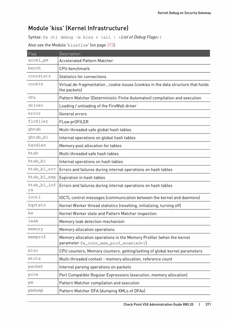
Kernel Debug on Security Gateway
Check Point VSX Administration Guide R80.20 | 371
Module 'kiss' (Kernel Infrastructure) Syntax: fw ctl debug -m kiss + {all | <List of Debug Flags>}
Also see the Module 'kissflow' (on page 373).
Flag Description accel_pm Accelerated Pattern Matcher
bench CPU benchmark
connstats Statistics for connections
cookie Virtual de-fragmentation , cookie issues (cookies in the data structure that holds the packets)
dfa Pattern Matcher (Deterministic Finite Automaton) compilation and execution
driver Loading / unloading of the FireWall driver
error General errors
flofiler FLow prOFILER
ghtab Multi-threaded safe global hash tables
ghtab_bl Internal operations on global hash tables
handles Memory pool allocation for tables
htab Multi-threaded safe hash tables
htab_bl Internal operations on hash tables
htab_bl_err Errors and failures during internal operations on hash tables
htab_bl_exp Expiration in hash tables
htab_bl_infra
Errors and failures during internal operations on hash tables
ioctl IOCTL control messages (communication between the kernel and daemons)
kqstats Kernel Worker thread statistics (resetting, initializing, turning off)
kw Kernel Worker state and Pattern Matcher inspection
leak Memory leak detection mechanism
memory Memory allocation operations
memprof Memory allocation operations in the Memory Profiler (when the kernel parameter fw_conn_mem_prof_enabled=1)
misc CPU counters, Memory counters, getting/setting of global kernel parameters
mtctx Multi-threaded context - memory allocation, reference count
packet Internal parsing operations on packets
pcre Perl Compatible Regular Expressions (execution, memory allocation)
pm Pattern Matcher compilation and execution
pmdump Pattern Matcher DFA (dumping XMLs of DFAs)
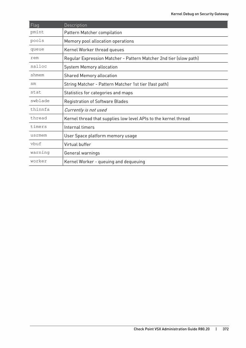
Kernel Debug on Security Gateway
Check Point VSX Administration Guide R80.20 | 372
Flag Description pmint Pattern Matcher compilation
pools Memory pool allocation operations
queue Kernel Worker thread queues
rem Regular Expression Matcher - Pattern Matcher 2nd tier (slow path)
salloc System Memory allocation
shmem Shared Memory allocation
sm String Matcher - Pattern Matcher 1st tier (fast path)
stat Statistics for categories and maps
swblade Registration of Software Blades
thinnfa Currently is not used
thread Kernel thread that supplies low level APIs to the kernel thread
timers Internal timers
usrmem User Space platform memory usage
vbuf Virtual buffer
warning General warnings
worker Kernel Worker - queuing and dequeuing
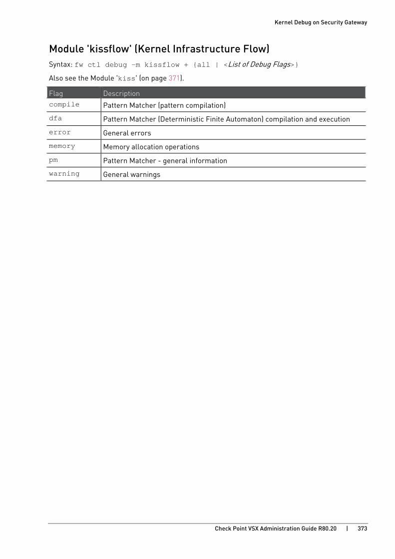
Kernel Debug on Security Gateway
Check Point VSX Administration Guide R80.20 | 373
Module 'kissflow' (Kernel Infrastructure Flow) Syntax: fw ctl debug -m kissflow + {all | <List of Debug Flags>}
Also see the Module 'kiss' (on page 371).
Flag Description compile Pattern Matcher (pattern compilation)
dfa Pattern Matcher (Deterministic Finite Automaton) compilation and execution
error General errors
memory Memory allocation operations
pm Pattern Matcher - general information
warning General warnings

Kernel Debug on Security Gateway
Check Point VSX Administration Guide R80.20 | 374
Module 'MALWARE' (Threat Prevention) Syntax: fw ctl debug -m MALWARE + {all | <List of Debug Flags>}
Flag Description address Information about connection's IP address
av Currently is not used
coverage Coverage times (entering, blocking, and time spent)
error General errors
global Prints parameters from the $FWDIR/conf/mail_security_config file
info General information
ioc Operations on Indicators of Compromise (IoC)
memory Currently is not used
module Removal of the MALWARE module's debug infrastructure
policy Policy installation
subject Prints the debug subject of each debug message
te Currently is not used
timestamp Prints the timestamp for each debug message (changes when you enable the debug flag 'coverage')
verbose Prints additional information (used with other debug flags)
vs Prints the VSID of the debugged Virtual System
warning General warnings

Kernel Debug on Security Gateway
Check Point VSX Administration Guide R80.20 | 375
Module 'multik' (Multi-Kernel Inspection - CoreXL) Syntax: fw ctl debug -m multik + {all | <List of Debug Flags>}
Note - When you enable the debug flag 'multik' in the debug module 'fw' (on page 363), it enables all the debug flags in this debug module, except for the debug flag 'packet'.
Flag Description api Registration and unregistration of cross-instance function calls
cache_tab Cache table infrastructure
conn Creation and deletion of connections in the dispatcher table
counter Cross-instance counter infrastructure
error General errors
event Cross-instance event aggregation infrastructure
fwstats FireWall statistics
ioctl Distribution of IOCTLs to different CoreXL FW instances
lock Obtaining and releasing the fw_lock on multiple CoreXL FW instances
message Cross-instance messages (used for local sync and port scanning)
packet For each packet, shows the CoreXL SND dispatching decision (CoreXL FW instance and reason)
packet_err Invalid packets, for CoreXL SND could not make a dispatching decision
prio Firewall Priority Queues (refer to sk105762 http://supportcontent.checkpoint.com/solutions?id=sk105762)
queue Packet queue
quota Cross-instance quota table (used by the Network Quota feature)
route Routing of packets
state Starting and stopping of CoreXL FW instances, establishment of relationship between CoreXL FW instances
temp_conns Temporary connections
uid Cross-instance Unique IDs
vpn_multik MultiCore VPN (see sk118097 http://supportcontent.checkpoint.com/solutions?id=sk118097)

Kernel Debug on Security Gateway
Check Point VSX Administration Guide R80.20 | 376
Module 'MUX' (Multiplexer for Applications Traffic) R80.20 introduces a new layer between the Streaming layer and the Applications layer - MUX (Multiplexer). Applications are registered to the Streaming layer through the MUX layer. The MUX layer chooses to work over PSL (passive streaming) or CPAS (active streaming).
Syntax: fw ctl debug -m MUX + {all | <List of Debug Flags>}
Flag Description active CPAS (active streaming)
Also see the Module 'CPAS' (on page 356)
advp Advanced Patterns (signatures over port ranges)
api API calls
comm Information about opening and closing of connections
error General errors
http_disp HTTP Dispatcher
misc Miscellaneous helpful information (not shown with other debug flags)
passive PSL (passive streaming)
Also see the Module 'PSL' (on page 378)
proxy_tp Proxy tunnel parser
stream General information about the data stream
test Currently is not used
tier1 Pattern Matcher 1st tier (fast path)
tls General information about the TLS
tlsp TLS parser
tol Test Object List algorithm (to determine whether an application is malicious or not)
udp UDP parser
warning General warnings
ws Web Intelligence
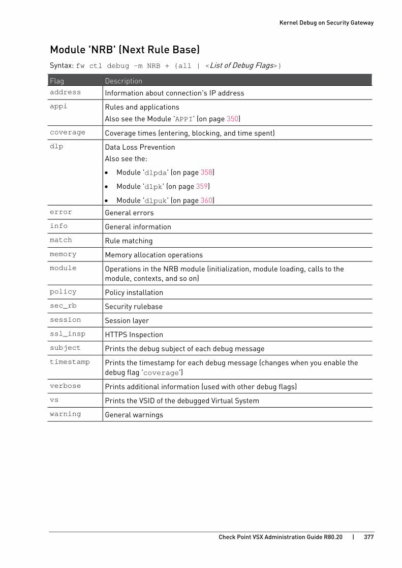
Kernel Debug on Security Gateway
Check Point VSX Administration Guide R80.20 | 377
Module 'NRB' (Next Rule Base) Syntax: fw ctl debug -m NRB + {all | <List of Debug Flags>}
Flag Description address Information about connection's IP address
appi Rules and applications
Also see the Module 'APPI' (on page 350)
coverage Coverage times (entering, blocking, and time spent)
dlp Data Loss Prevention
Also see the:
• Module 'dlpda' (on page 358)
• Module 'dlpk' (on page 359)
• Module 'dlpuk' (on page 360) error General errors
info General information
match Rule matching
memory Memory allocation operations
module Operations in the NRB module (initialization, module loading, calls to the module, contexts, and so on)
policy Policy installation
sec_rb Security rulebase
session Session layer
ssl_insp HTTPS Inspection
subject Prints the debug subject of each debug message
timestamp Prints the timestamp for each debug message (changes when you enable the debug flag 'coverage')
verbose Prints additional information (used with other debug flags)
vs Prints the VSID of the debugged Virtual System
warning General warnings
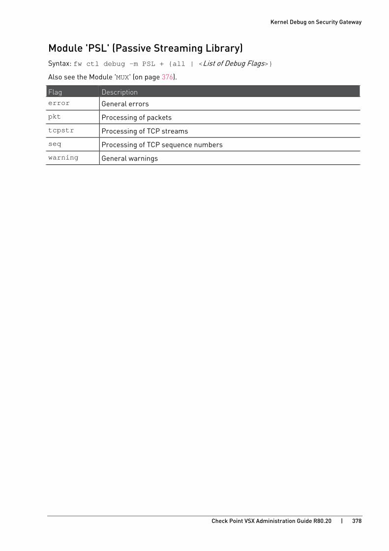
Kernel Debug on Security Gateway
Check Point VSX Administration Guide R80.20 | 378
Module 'PSL' (Passive Streaming Library) Syntax: fw ctl debug -m PSL + {all | <List of Debug Flags>}
Also see the Module 'MUX' (on page 376).
Flag Description error General errors
pkt Processing of packets
tcpstr Processing of TCP streams
seq Processing of TCP sequence numbers
warning General warnings s

Kernel Debug on Security Gateway
Check Point VSX Administration Guide R80.20 | 379
Module 'RAD_KERNEL' (Resource Advisor - Kernel Space) Syntax: fw ctl debug -m RAD_KERNEL + {all | <List of Debug Flags>}
Flag Description address Information about connection's IP address
cache RAD kernel malware cache
coverage Coverage times (entering, blocking, and time spent)
error General errors
global RAD global context
info General information
memory Memory allocation operations
subject Prints the debug subject of each debug message
timestamp Prints the timestamp for each debug message (changes when you enable the debug flag 'coverage')
verbose Prints additional information (used with other debug flags)
vs Prints the VSID of the debugged Virtual System
warning General warnings
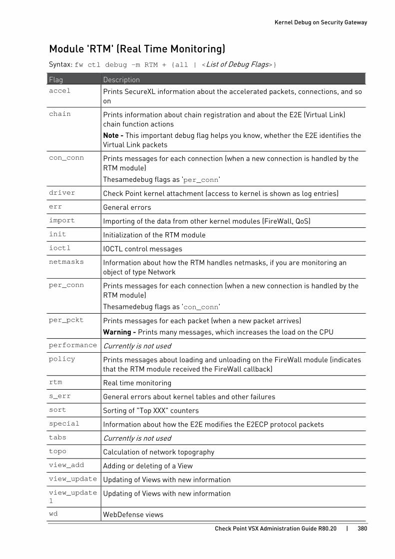
Kernel Debug on Security Gateway
Check Point VSX Administration Guide R80.20 | 380
Module 'RTM' (Real Time Monitoring) Syntax: fw ctl debug -m RTM + {all | <List of Debug Flags>}
Flag Description accel Prints SecureXL information about the accelerated packets, connections, and so
on
chain Prints information about chain registration and about the E2E (Virtual Link) chain function actions
Note - This important debug flag helps you know, whether the E2E identifies the Virtual Link packets
con_conn Prints messages for each connection (when a new connection is handled by the RTM module)
The same debug flags as 'per_conn'
driver Check Point kernel attachment (access to kernel is shown as log entries)
err General errors
import Importing of the data from other kernel modules (FireWall, QoS)
init Initialization of the RTM module
ioctl IOCTL control messages
netmasks Information about how the RTM handles netmasks, if you are monitoring an object of type Network
per_conn Prints messages for each connection (when a new connection is handled by the RTM module)
The same debug flags as 'con_conn'
per_pckt Prints messages for each packet (when a new packet arrives)
Warning - Prints many messages, which increases the load on the CPU
performance Currently is not used
policy Prints messages about loading and unloading on the FireWall module (indicates that the RTM module received the FireWall callback)
rtm Real time monitoring
s_err General errors about kernel tables and other failures
sort Sorting of "Top XXX" counters
special Information about how the E2E modifies the E2ECP protocol packets
tabs Currently is not used
topo Calculation of network topography
view_add Adding or deleting of a View
view_update Updating of Views with new information
view_update1
Updating of Views with new information
wd WebDefense views s

Kernel Debug on Security Gateway
Check Point VSX Administration Guide R80.20 | 381
Module 'seqvalid' (TCP Sequence Validator and Translator) Syntax: fw ctl debug -m seqvalid + {all | <List of Debug Flags>}
Flag Description error General errors
seqval TCP sequence validation and translation
sock Currently is not used
warning General warnings

Kernel Debug on Security Gateway
Check Point VSX Administration Guide R80.20 | 382
Module 'SFT' (Stream File Type) Syntax: fw ctl debug -m SFT + {all | <List of Debug Flags>}
Flag Description error General errors
fatal Fatal errors
info General information
mgr Rule match, database, connection processing, classification
warning General warnings
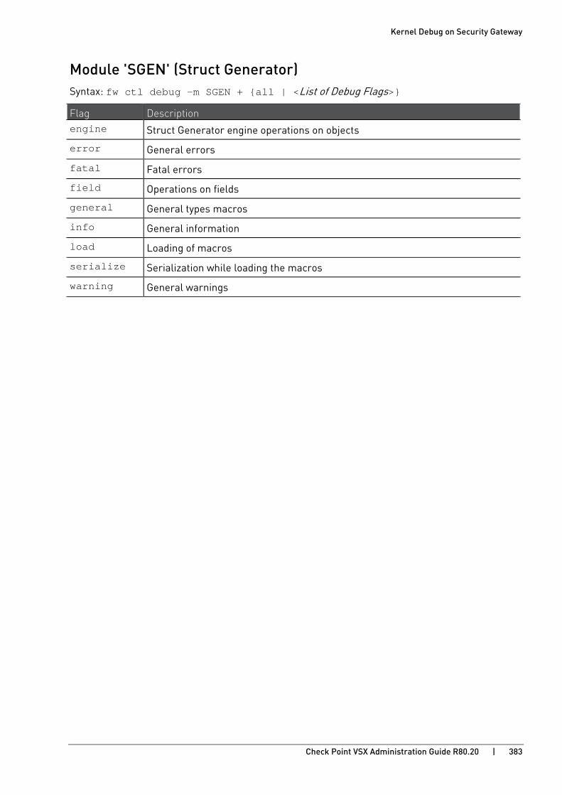
Kernel Debug on Security Gateway
Check Point VSX Administration Guide R80.20 | 383
Module 'SGEN' (Struct Generator) Syntax: fw ctl debug -m SGEN + {all | <List of Debug Flags>}
Flag Description engine Struct Generator engine operations on objects
error General errors
fatal Fatal errors
field Operations on fields
general General types macros
info General information
load Loading of macros
serialize Serialization while loading the macros
warning General warnings

Kernel Debug on Security Gateway
Check Point VSX Administration Guide R80.20 | 384
Module 'synatk' (Accelerated SYN Defender) For additional information, see R80.20 Performance Tuning Administration Guide https://sc1.checkpoint.com/documents/R80.20_GA/WebAdminGuides/EN/CP_R80.20_PerformanceTuning_AdminGuide/html_frameset.htm - Chapter SecureXL - Section Accelerated SYN Defender.
Syntax: fw ctl debug -m synatk + {all | <List of Debug Flags>}
Flag Description cookie TCP SYN Cookie
error General errors
radix_dump Dump of the radix tree
radix_match Matched items in the radix tree
radix_modify
Operations in the radix tree
warning General warnings

Kernel Debug on Security Gateway
Check Point VSX Administration Guide R80.20 | 385
Module 'UC' (UserCheck) Syntax: fw ctl debug -m UC + {all | <List of Debug Flags>}
Flag Description address Information about connection's IP address
coverage Coverage times (entering, blocking, and time spent)
error General errors
htab Hash table
info General information
memory Memory allocation operations
module Operations in the UserCheck module (initialization, UserCheck table hits, finding User ID in cache, removal of UserCheck debug module's infrastructure)
subject Prints the debug subject of each debug message
timestamp Prints the timestamp for each debug message (changes when you enable the debug flag 'coverage')
verbose Prints additional information (used with other debug flags)
vs Prints the VSID of the debugged Virtual System
warning General warnings
webapi URL patterns, UserCheck incidents, connection redirection

Kernel Debug on Security Gateway
Check Point VSX Administration Guide R80.20 | 386
Module 'UP' (Unified Policy) Syntax: fw ctl debug -m UP + {all | <List of Debug Flags>}
Also see the:
• Module 'upconv' (on page 388).
• Module 'UPIS' (on page 389).
Flag Description account Currently is not used
address Information about connection's IP address
btime Currently is not used
clob Classification Object (CLOB) observer (data classification)
connection Information about connections, transactions
coverage Coverage times (entering, blocking, and time spent)
error General errors
info General information
limit Unified Policy download and upload limits
log Some logging operations
mab Mobile Access handler
manager Unified Policy manager operations
match Classification Object (CLOB) observer (data classification)
memory Memory allocation operations
module Operations in the Unified Policy module (initialization, module loading, calls to the module, and so on)
policy Unified Policy internal operations
prob Currently is not used
prob_impl Implied matched rules
rulebase Unified Policy rulebase
sec_rb Secondary NRB rulebase operations
stats Statistics about connections, transactions
subject Prints the debug subject of each debug message
timestamp Prints the timestamp for each debug message (changes when you enable the debug flag 'coverage')
urlf_ssl Currently is not used
verbose Prints additional information (used with other debug flags)
vpn VPN classifier

Kernel Debug on Security Gateway
Check Point VSX Administration Guide R80.20 | 387
Flag Description vs Prints the VSID of the debugged Virtual System
warning General warnings

Kernel Debug on Security Gateway
Check Point VSX Administration Guide R80.20 | 388
Module 'upconv' (Unified Policy Conversion) Syntax: fw ctl debug -m upconv + {all | <List of Debug Flags>}
Also see the:
• Module 'UP' (on page 386).
• Module 'UPIS' (on page 389).
Flag Description error General errors
info General information
map UTF-8 and UTF-16 characters conversion
mem Prints how much memory is used for character sets
tree Lookup of characters
utf7 Conversion of UTF-7 characters to a Unicode characters
utf8 Conversion of UTF-8 characters to a Unicode characters
warning General warnings

Kernel Debug on Security Gateway
Check Point VSX Administration Guide R80.20 | 389
Module 'UPIS' (Unified Policy Infrastructure) Syntax: fw ctl debug -m UPIS + {all | <List of Debug Flags>}
Also see the:
• Module 'UP' (on page 386)
• Module 'upconv' (on page 388)
Flag Description address Information about connection's IP address
clob Classification Object (CLOB) observer (data classification)
coverage Coverage times (entering, blocking, and time spent)
cpdiag CPDiag operations
crumbs Currently is not used
db SQLite Database operations
error General errors
fwapp Information about policy installation for the FireWall application
info General information
memory Memory allocation operations
mgr Policy installation manager
module Operations in the Unified Policy Infrastructure module (initialization, module loading, calls to the module, and so on)
mutex Unified Policy internal mutex operations
policy Unified Policy Infrastructure internal operations
report Various reports about Unified Policy installations
sna Operations on SnA objects ("Services and Application")
subject Prints the debug subject of each debug message
tables Operations on kernel tables
timestamp Prints the timestamp for each debug message (changes when you enable the debug flag 'coverage')
topo Information about topology and Anti-Spoofing of interfaces; about Address Range objects
upapp Information about policy installation for Unified Policy application
update Information about policy installation for CMI Update application
verbose Prints additional information (used with other debug flags)
vpn VPN classifier
vs Prints the VSID of the debugged Virtual System

Kernel Debug on Security Gateway
Check Point VSX Administration Guide R80.20 | 390
Flag Description warning General warnings
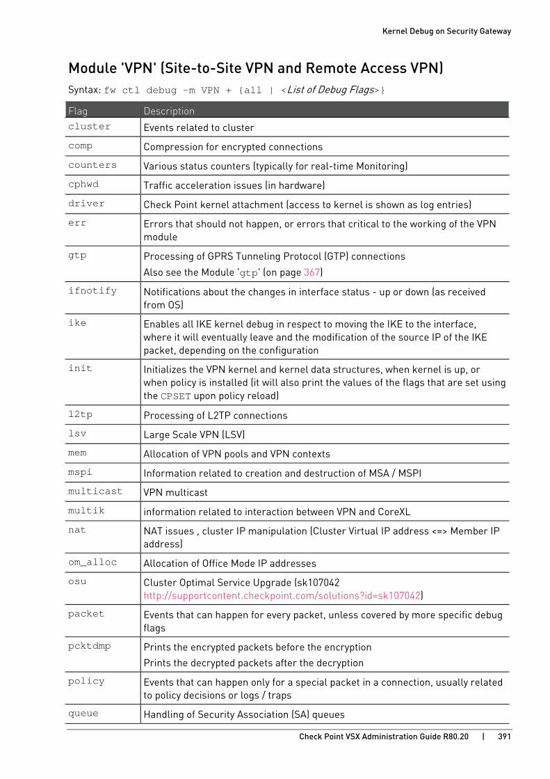
Kernel Debug on Security Gateway
Check Point VSX Administration Guide R80.20 | 391
Module 'VPN' (Site-to-Site VPN and Remote Access VPN) Syntax: fw ctl debug -m VPN + {all | <List of Debug Flags>}
Flag Description cluster Events related to cluster
comp Compression for encrypted connections
counters Various status counters (typically for real-time Monitoring)
cphwd Traffic acceleration issues (in hardware)
driver Check Point kernel attachment (access to kernel is shown as log entries)
err Errors that should not happen, or errors that critical to the working of the VPN module
gtp Processing of GPRS Tunneling Protocol (GTP) connections
Also see the Module 'gtp' (on page 367)
ifnotify Notifications about the changes in interface status - up or down (as received from OS)
ike Enables all IKE kernel debug in respect to moving the IKE to the interface, where it will eventually leave and the modification of the source IP of the IKE packet, depending on the configuration
init Initializes the VPN kernel and kernel data structures, when kernel is up, or when policy is installed (it will also print the values of the flags that are set using the CPSET upon policy reload)
l2tp Processing of L2TP connections
lsv Large Scale VPN (LSV)
mem Allocation of VPN pools and VPN contexts
mspi Information related to creation and destruction of MSA / MSPI
multicast VPN multicast
multik information related to interaction between VPN and CoreXL
nat NAT issues , cluster IP manipulation (Cluster Virtual IP address <=> Member IP address)
om_alloc Allocation of Office Mode IP addresses
osu Cluster Optimal Service Upgrade (sk107042 http://supportcontent.checkpoint.com/solutions?id=sk107042)
packet Events that can happen for every packet, unless covered by more specific debug flags
pcktdmp Prints the encrypted packets before the encryption
Prints the decrypted packets after the decryption
policy Events that can happen only for a special packet in a connection, usually related to policy decisions or logs / traps
queue Handling of Security Association (SA) queues

Kernel Debug on Security Gateway
Check Point VSX Administration Guide R80.20 | 392
Flag Description rdp Processing of Check Point RDP connections
ref Reference counting for MSA / MSPI, when storing or deleting Security Associations (SAs)
resolver VPN Link Selection table and Certificate Revocation List (CRL), which is also part of the peer resolving mechanism
rsl Operations on Range Skip List
sas Information about keys and Security Associations (SAs)
sr SecureClient / SecureRemote related issues
tagging Sets the VPN policy of a connection according to VPN communities, VPN Policy related information
tcpt Information related to TCP Tunnel (Visitor mode - FireWall traversal on TCP port 443)
tnlmon VPN tunnel monitoring
topology VPN Link Selection
vin Does not apply anymore
Only on Security Gateway that runs on Windows OS:
Information related to IPSec NIC interaction
warn General warnings
xl Does not apply anymore
Interaction with Accelerator Cards (AC II / III / IV)

Kernel Debug on Security Gateway
Check Point VSX Administration Guide R80.20 | 393
Module 'WS' (Web Intelligence) Syntax: fw ctl debug -m WS + {all | <List of Debug Flags>}
Notes:
• Also see the Module 'WSIS' (on page 397).
• To print information for all Virtual Systems in the debug output, before you start the kernel debug, set this kernel parameter on the VSX Gateway or each VSX Cluster Member (this is the default behavior): # fw ctl set int ws_debug_vs 0
• To print information for a specific Virtual System in the debug output, before you start the kernel debug, set this kernel parameter on the VSX Gateway or each VSX Cluster Member:
# fw ctl set int ws_debug_vs <VSID>
Example: fw ctl set int ws_debug_vs 2
• To print information for all IPv4 addresses in the debug output, before you start the kernel debug, set this kernel parameter on the VSX Gateway or each VSX Cluster Member (this is the default behavior): # fw ctl set int ws_debug_ip 0
• To print information for a specific IPv4 address in the debug output, before you start the kernel debug, set this kernel parameter on the VSX Gateway or each VSX Cluster Member:
# fw ctl set int ws_debug_ip <XXX.XXX.XXX.XXX>
Example: fw ctl set int ws_debug_vs 192.168.33.44
Flag Description address Information about connection's IP address
body HTTP body (content) layer
connection Connection layer
cookie HTTP cookie header
coverage Coverage times (entering, blocking, and time spent)
crumb Currently is not used
error General errors (the connection is probably rejected)
event Events
fatal Fatal errors
flow Currently is not used
global Handling of global structure (usually, related to policy)
info General information
ioctl IOCTL control messages (communication between the kernel and daemons, loading and unloading of the FireWall)
mem_pool Memory pool allocation operations
memory Memory allocation operations
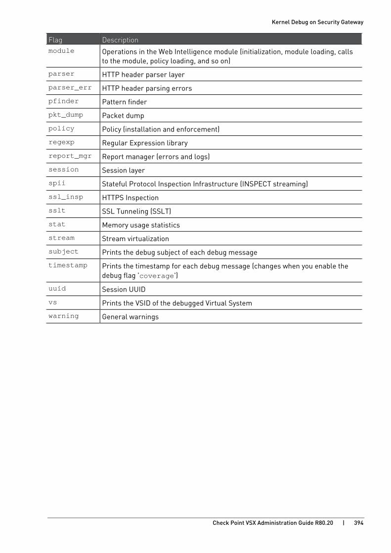
Kernel Debug on Security Gateway
Check Point VSX Administration Guide R80.20 | 394
Flag Description module Operations in the Web Intelligence module (initialization, module loading, calls
to the module, policy loading, and so on)
parser HTTP header parser layer
parser_err HTTP header parsing errors
pfinder Pattern finder
pkt_dump Packet dump
policy Policy (installation and enforcement)
regexp Regular Expression library
report_mgr Report manager (errors and logs)
session Session layer
spii Stateful Protocol Inspection Infrastructure (INSPECT streaming)
ssl_insp HTTPS Inspection
sslt SSL Tunneling (SSLT)
stat Memory usage statistics
stream Stream virtualization
subject Prints the debug subject of each debug message
timestamp Prints the timestamp for each debug message (changes when you enable the debug flag 'coverage')
uuid Session UUID
vs Prints the VSID of the debugged Virtual System
warning General warnings
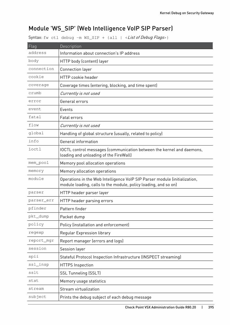
Kernel Debug on Security Gateway
Check Point VSX Administration Guide R80.20 | 395
Module 'WS_SIP' (Web Intelligence VoIP SIP Parser) Syntax: fw ctl debug -m WS_SIP + {all | <List of Debug Flags>}
Flag Description address Information about connection's IP address
body HTTP body (content) layer
connection Connection layer
cookie HTTP cookie header
coverage Coverage times (entering, blocking, and time spent)
crumb Currently is not used
error General errors
event Events
fatal Fatal errors
flow Currently is not used
global Handling of global structure (usually, related to policy)
info General information
ioctl IOCTL control messages (communication between the kernel and daemons, loading and unloading of the FireWall)
mem_pool Memory pool allocation operations
memory Memory allocation operations
module Operations in the Web Intelligence VoIP SIP Parser module (initialization, module loading, calls to the module, policy loading, and so on)
parser HTTP header parser layer
parser_err HTTP header parsing errors
pfinder Pattern finder
pkt_dump Packet dump
policy Policy (installation and enforcement)
regexp Regular Expression library
report_mgr Report manager (errors and logs)
session Session layer
spii Stateful Protocol Inspection Infrastructure (INSPECT streaming)
ssl_insp HTTPS Inspection
sslt SSL Tunneling (SSLT)
stat Memory usage statistics
stream Stream virtualization
subject Prints the debug subject of each debug message
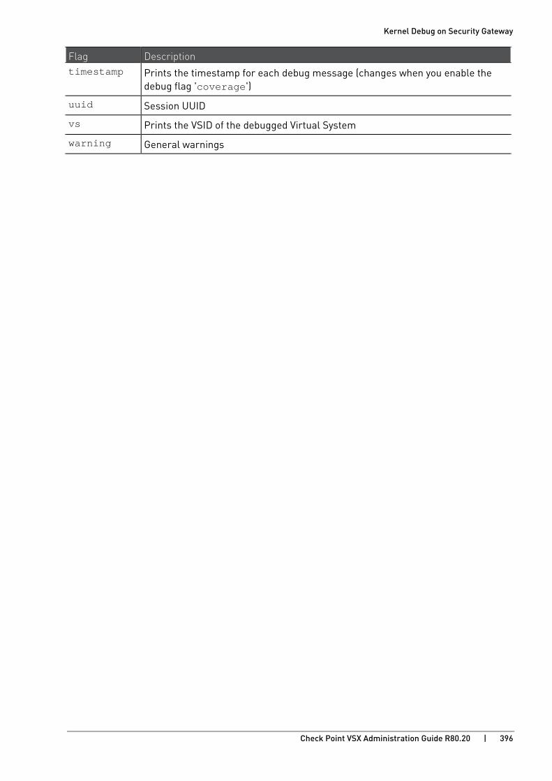
Kernel Debug on Security Gateway
Check Point VSX Administration Guide R80.20 | 396
Flag Description timestamp Prints the timestamp for each debug message (changes when you enable the
debug flag 'coverage')
uuid Session UUID
vs Prints the VSID of the debugged Virtual System
warning General warnings
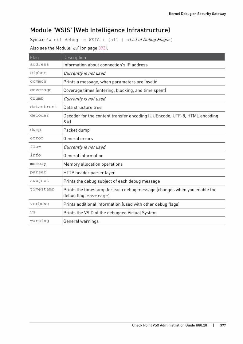
Kernel Debug on Security Gateway
Check Point VSX Administration Guide R80.20 | 397
Module 'WSIS' (Web Intelligence Infrastructure) Syntax: fw ctl debug -m WSIS + {all | <List of Debug Flags>}
Also see the Module 'WS' (on page 393).
Flag Description address Information about connection's IP address
cipher Currently is not used
common Prints a message, when parameters are invalid
coverage Coverage times (entering, blocking, and time spent)
crumb Currently is not used
datastruct Data structure tree
decoder Decoder for the content transfer encoding (UUEncode, UTF-8, HTML encoding &#)
dump Packet dump
error General errors
flow Currently is not used
info General information
memory Memory allocation operations
parser HTTP header parser layer
subject Prints the debug subject of each debug message
timestamp Prints the timestamp for each debug message (changes when you enable the debug flag 'coverage')
verbose Prints additional information (used with other debug flags)
vs Prints the VSID of the debugged Virtual System
warning General warnings