
Address Resolution Protocol Risks and Countermeasures
57
Global Information Assurance Certification Paper Copyright SANS Institute Author Retains Full Rights This paper is taken from the GIAC directory of certified professionals. Reposting is not permited without express written permission. Interested in learning more? Check out the list of upcoming events offering "Auditing & Monitoring Networks, Perimeters & Systems (Audit 507)" at http://www.giac.org/registration/gsna
-
Upload
khangminh22 -
Category
Documents
-
view
1 -
download
0
Transcript of Address Resolution Protocol Risks and Countermeasures

Global Information Assurance Certification Paper
Copyright SANS InstituteAuthor Retains Full Rights
This paper is taken from the GIAC directory of certified professionals. Reposting is not permited without express written permission.
Interested in learning more?Check out the list of upcoming events offering"Auditing & Monitoring Networks, Perimeters & Systems (Audit 507)"at http://www.giac.org/registration/gsna

© S
AN
S In
stitu
te 2
00
5, A
utho
r ret
ains
full
righ
ts.
Key fingerprint = AF19 FA27 2F94 998D FDB5 DE3D F8B5 06E4 A169 4E46
© SANS Institute 2005 Author retains full rights.
Table of Contents ...................................................................................................................................1Michael_I_Lee_GSNA.pdf......................................................................................................................2

© S
AN
S In
stitu
te 2
00
5, A
utho
r ret
ains
full
righ
ts.
Key fingerprint = AF19 FA27 2F94 998D FDB5 DE3D F8B5 06E4 A169 4E46
© SANS Institute 2005 Author retains full rights.
Address Resolution Protocol Risks and Countermeasures
GIAC Systems and Network Auditor
Practical Assignment Version 3.2 Option 2
December 19, 2004
Michael I. Lee

© S
AN
S In
stitu
te 2
00
5, A
utho
r ret
ains
full
righ
ts.
Key fingerprint = AF19 FA27 2F94 998D FDB5 DE3D F8B5 06E4 A169 4E46
© SANS Institute 2005 Author retains full rights.
M. I. Lee ARP Risks & Countermeasures Table of Contents
Table of Contents
Abstract.................................................................................................................1 Introduction ...........................................................................................................2
Objective ...........................................................................................................3 Technical Background ..........................................................................................4
OSI Model Review.............................................................................................4 Physical Layer (Layer 1) ................................................................................4 Data Link Layer (Layer 2) ..............................................................................4 Upper Layers (Layers 3 – 7) ..........................................................................5
Address Resolution Protocol .............................................................................5 ARP Packet Format .......................................................................................6 ARP Packet Encapsulation............................................................................6 ARP Package ................................................................................................7
Cache Table...............................................................................................7 Queues.......................................................................................................8 Output Module............................................................................................8 Input Module ..............................................................................................9 Cache-Control Module ...............................................................................9
ARP Operation.............................................................................................10 Special Types of ARP..................................................................................11
Reverse Address Resolution Protocol (RARP) ........................................11 Proxy ARP................................................................................................12 Gratuitous ARP ........................................................................................12
Transparent Bridging.......................................................................................12 Risks and Scenarios ...........................................................................................13
Defining Risk ...................................................................................................13 Risk Assessment .........................................................................................13
Vulnerability in ARP.........................................................................................17 Threats against ARP .......................................................................................17
Attack Methods ............................................................................................18 Reconnaissance.......................................................................................18 ARP Cache Poisoning..............................................................................18 ARP Spoofing...........................................................................................20 MAC Flooding ..........................................................................................20 Port Stealing.............................................................................................20 IP Smart Spoofing ....................................................................................21
Potential Scenarios .........................................................................................22 Scenario 1: Hacme University......................................................................22
Background..............................................................................................22 Risk Assessment......................................................................................23 Recommendations ...................................................................................25
Scenario 2: McKilme Corporation ................................................................25 Background..............................................................................................25 Risk Assessment......................................................................................26 Recommendations ...................................................................................29
© S
AN
S In
stitu
te 2
00
5, A
utho
r ret
ains
full
righ
ts.
Key fingerprint = AF19 FA27 2F94 998D FDB5 DE3D F8B5 06E4 A169 4E46
© SANS Institute 2005 Author retains full rights.
M. I. Lee ARP Risks & Countermeasures Table of Contents
Demonstration.....................................................................................................30 Wireless Network Attacks................................................................................31
Reconnaissance ..........................................................................................31 Packet Capture ............................................................................................33 Denial-of-Service .........................................................................................35
Wired Network Attacks ....................................................................................36 Packet Filtering ............................................................................................37 SSL Man-in-the-Middle ................................................................................38
Countermeasures ...............................................................................................44 Preventive .......................................................................................................44
Encryption....................................................................................................44 End-User Education.....................................................................................44 Management Subnet ...................................................................................45 ARP Inspection ............................................................................................45 Port Security ................................................................................................45 Static ARP ...................................................................................................45 Wireless LAN Isolation.................................................................................46
Detective .........................................................................................................46 arpwatch ......................................................................................................46 NIDS ............................................................................................................46 Ettercap .......................................................................................................46
Summary ............................................................................................................48 Appendix.............................................................................................................49 Bibliography ........................................................................................................50
List of Figures Figure 1: The OSI Model.......................................................................................4 Figure 2: ARP Packet ...........................................................................................6 Figure 3: ARP Packet Encapsulation ....................................................................7 Figure 4: Hypothetical ARP Package....................................................................7 Figure 5: Typical ARP Operation ........................................................................10 Figure 6: ARP Request Packet Capture .............................................................11 Figure 7: ARP Reply Packet Capture..................................................................11 Figure 8: Relationship between Components of Risk .........................................13 Figure 9: ARP Cache Poisoning .........................................................................19 Figure 10: Port Stealing ......................................................................................21 Figure 11: IP/MAC Configuration of the Attacker’s Machine ...............................31 Figure 12: Ettercap ARP Scan Command ..........................................................31 Figure 13: ARP Scan of LAN Using Ettercap......................................................32 Figure 14: Port Scan of a Host Using Nmap .......................................................32 Figure 15: Network Topology for Wireless Attack Demonstration.......................33 Figure 16: Ettercap Command for MitM/ACP......................................................33 Figure 17: ARP Cache Poisoning using Ettercap ...............................................34 Figure 18: tcpdump from the Attacker’s Machine during ARP Cache Poisoning 34
© S
AN
S In
stitu
te 2
00
5, A
utho
r ret
ains
full
righ
ts.
Key fingerprint = AF19 FA27 2F94 998D FDB5 DE3D F8B5 06E4 A169 4E46
© SANS Institute 2005 Author retains full rights.
M. I. Lee ARP Risks & Countermeasures Table of Contents
Figure 19: ARP Cache Entries on the Victim Before, During and After the Attack.....................................................................................................................35
Figure 20: Performing DoS against a Victim to Block Access to the Gateway....36 Figure 21: ARP Cache Table Before and After “Isolate” Attack ..........................36 Figure 22: Network Topology for Wired Attack Demonstration ...........................36 Figure 23: Ettercap Filter to Drop Outbound TCP 80..........................................37 Figure 24: Ettercap Command for DoS using Packet Filter ................................37 Figure 25: Packet Capture of Victim Attempting Connection over TCP 80 .........37 Figure 26: SSL Certificate Validation Warning (Microsoft Internet Explorer).......38 Figure 27: Ettercap Command for MitM/ACP against Entire Subnet...................38 Figure 28: MitM/ACP in Progress........................................................................39 Figure 29: Certificate Validation Warning for IMAP over SSL (Microsoft Outlook)
.....................................................................................................................39 Figure 30: Invalid SSL Certificate Warning (Mozilla)...........................................40 Figure 31: “Hijacked” HTTPS Site (indistinguishable from legitimate site) ..........40 Figure 32: Invalid SSL Certificate Presented by Ettercap ...................................41 Figure 33: Valid SSL Certificate..........................................................................41 Figure 34: Spoofed SSL Certificate Hierarchy and Public Key ...........................42 Figure 35: Valid SSL Certificate Hierarchy and Public Key.................................43
List of Tables Table 1: Hypothetical ARP Cache-Control Module ...............................................9 Table 2: Template for Risk Assessment .............................................................16 Table 3: Risk Assessment Summary for Hacme University Online Class System
.....................................................................................................................24 Table 4: Risk Assessment Summary for McKilme’s Internal Network.................27 Table 5: Likelihood Definitions ............................................................................49 Table 6: Magnitude of Impact Definitions............................................................49

© S
AN
S In
stitu
te 2
00
5, A
utho
r ret
ains
full
righ
ts.
Key fingerprint = AF19 FA27 2F94 998D FDB5 DE3D F8B5 06E4 A169 4E46
© SANS Institute 2005 Author retains full rights.
M. I. Lee ARP Risks & Countermeasures Abstract
1
Abstract In many organizations, internal network security takes a back seat while perimeter security gets all the attention. Due to the vulnerabilities in the Address Resolution Protocol (ARP), combined with well-known attack methods that are relatively easy to perform, however, numerous internal networks face considerable risks that are often poorly understood or ignored. In many cases, those risks can be mitigated by taking some fundamental steps to network security; unfortunately, many organizations continue to fail to carry out even the basic measures, risking their information assets as a result. This report seeks to increase awareness regarding the risks in ARP and to equip security auditors and other security professionals to lead the efforts in protecting corporate networks from such risks. Although the report was not written as an audit checklist, much of the content can be used as a reference when addressing internal network security. The report is divided into the following main sections:
1. Technical Background 2. Risks and Scenarios 3. Demonstration 4. Countermeasures

© S
AN
S In
stitu
te 2
00
5, A
utho
r ret
ains
full
righ
ts.
Key fingerprint = AF19 FA27 2F94 998D FDB5 DE3D F8B5 06E4 A169 4E46
© SANS Institute 2005 Author retains full rights.
M. I. Lee ARP Risks & Countermeasures Introduction
2
Introduction A key element in a successful information security program is a strategy built upon the defense-in-depth (DiD) concept: prevent single points of security failure by using layers of controls. At a high-level, DiD entails “the perimeter, the internal network, and a human factor.”1 Many organizations have traditionally focused their efforts at securing the perimeter, paying little or no attention to securing the internal network. One of the aspects of internal network security that is often overlooked is the insecurity of lower layer addressing, namely the Address Resolution Protocol (ARP). This report explores the various ways that an attacker may exploit the insecurity of ARP, identifies what the risks are, and makes recommendations on how security auditors can work together with administrators to protect the internal network from the risks. Although risks associated with ARP are nothing new to the security community, they have been largely ignored by network administrators. There are three common reasons for this: 1) administrators simply do not understand the risks; 2) the risks are dismissed because attacks are assumed to be possible only from the internal network; or 3) the risks from insiders are presumed negligible. Dismissing insiders as significant threat-sources is a common misconception that has dire consequences. According to the 2004 E-Crime Watch Survey2, 32% of Electronic Crimes are committed by insiders (i.e. current and former employees, current and former service providers, contractors or consultants). In Insider Threat Study: Illicit Cyber Activity in the Banking and Finance Sector3, researchers point out that “insiders pose a substantial threat by virtue of their knowledge of and access to their employer’s systems”. Moreover, threats against ARP are no longer limited to insiders. The prevalence and popularity of improperly secured wireless access points (WAP) have, in effect, exposed the lower layers of corporate networks beyond the physical boundaries of the building, giving new opportunities to malicious outsiders. Threats against ARP range from simple denial-of-service (DoS) to more sophisticated man-in-the-middle (MitM) attacks. The potential impact arising from such attacks can be devastating if unmitigated. It should be noted, however, that defenses against lower layer addressing attacks, although an important part of the overall defense-in-depth strategy, should not be at the same level of priority with other major aspects of information security program such as management and organizational commitment, sound perimeter security architecture, practicable patch and vulnerability management, comprehensive malware defense, timely user awareness and training, and a solid model for risk management. For organizations with a mature information security program,
1 Northcutt et al., p.8. 2 CSO Magazine/U.S. Secret Service/CERT Coordination Center, p.14. 3 U.S. Secret Service and CERT Coordination Center/SEI, p.2.

© S
AN
S In
stitu
te 2
00
5, A
utho
r ret
ains
full
righ
ts.
Key fingerprint = AF19 FA27 2F94 998D FDB5 DE3D F8B5 06E4 A169 4E46
© SANS Institute 2005 Author retains full rights.
M. I. Lee ARP Risks & Countermeasures Introduction
3
however, mitigating the risks posed by the Address Resolution Protocol should be considered an integral part of their internal network security plan. Due to the reasonably well-known and documented threats against ARP, organizations that fail to prove due-diligence may face legal liabilities and negative publicity if their assets are compromised via one of the threat vectors. Information security, of course, is much more than about doing the bare-minimum to avoid legal action or public relations nightmares. It would be prudent, nevertheless, for organizations to at least educate their network administrators and security auditors to be well aware of the risks presented in this report, and make informed decisions to manage those risks.
Objective The goal of this report is to equip security auditors and other security professionals in addressing a commonly overlooked insecurity in Local Area Networks by
• reviewing the technical background of ARP, • presenting the risks associated with ARP in theory and through discussion
of potential scenarios, • demonstrating the technical steps to audit the internal network using an
attacker’s point of view, and • discussing the countermeasures to mitigate the risks.

© S
AN
S In
stitu
te 2
00
5, A
utho
r ret
ains
full
righ
ts.
Key fingerprint = AF19 FA27 2F94 998D FDB5 DE3D F8B5 06E4 A169 4E46
© SANS Institute 2005 Author retains full rights.
M. I. Lee ARP Risks & Countermeasures Technical Background
4
Technical Background This section reviews the technologies and concepts that are fundamental to understanding the vulnerabilities in and threats against the Address Resolution Protocol.
OSI Model Review Network security related discussions often focus on the upper layers of the Open System Interconnection (OSI) model. This report, however, shifts the focus of discussion to the lower layers of the model, as depicted in Figure 1.
Figure 1: The OSI Model
Physical Layer (Layer 1) The lowest layer of the OSI model is concerned with the actual transmission of bit streams over physical media. This layer defines the physical aspects of the interconnection model: interfaces and media, bit representation, transmission rate, bit synchronization, physical connection, physical topology, and transmission mode. Physical Layer Networking Hardware: Hub/Repeater Hubs operate at the physical layer and simply “repeat” all frames that are passed from one node to all other nodes connected to the hub. Although simple to implement and manage, hubs inherently have performance and management limitations since all frames are broadcast to all nodes, even if the frame is intended for a specific destination. This also creates a confidentiality issue since all nodes on the LAN can easily eavesdrop on packets that are not meant for them. Plain-text packets, such as unencrypted FTP logon information, can easily be seen by all nodes on the LAN simply by putting the Network Interface Cards (NIC) into promiscuous mode.
Data Link Layer (Layer 2) The second layer translates the bits into a reliable link that can be used by the upper layers. It is also responsible for establishing the physical addressing scheme. For example, in Ethernet, the data link layer defines the MAC (Media Access Control) address for each node on the network.

© S
AN
S In
stitu
te 2
00
5, A
utho
r ret
ains
full
righ
ts.
Key fingerprint = AF19 FA27 2F94 998D FDB5 DE3D F8B5 06E4 A169 4E46
© SANS Institute 2005 Author retains full rights.
M. I. Lee ARP Risks & Countermeasures Technical Background
5
Data Link Layer Networking Hardware: Bridge/Switch In response to the issues associated with hubs, layer 2 bridges, or commonly known as switches, were designed. The main issue that switches address is better control over bandwidth on a shared medium. By keeping track of which node is connected to which physical port, switches can send frames only to the intended target, instead of broadcasting them to the entire LAN. This seemed to create a positive side-effect for security: since packets are forwarded only to and from the intended parties, other nodes on the LAN cannot eavesdrop on the communication. Switches, however, were not designed as security devices, and as explained throughout this report, relying on them as such may result in a compromise of information assets.
Upper Layers (Layers 3 – 7) Because the focus of this report is more on the lower layers of the OSI model, the upper layers are described only briefly:
• Network Layer (Layer 3) – The network layer is primarily concerned with routing packets from one network to another. The Internet Protocol (IP) operates on the network layer.
• Transport Layer (Layer 4) – The fourth layer provides a reliable mechanism for transporting the packets from one node to another. The Transmission Control Protocol (TCP) works on this layer.
• Session Layer (Layer 5) – The session layer mainly deals with establishing and maintaining communication between nodes.
• Presentation Layer (Layer 6) – The presentation layer takes in what the application layer provides and converts it into a format that the lower communication layers can understand.
• Application Layer (Layer 7) – The uppermost layer interacts with the operating system and/or the user. The Hypertext Transfer Protocol (HTTP), for example, operates on the application layer.
Address Resolution Protocol Local Area Network (LAN) protocols operate on the lower two layers of the OSI model. On an Ethernet LAN, each host has a 48-bit Media Access Control (MAC) address embedded into the firmware of its NIC. In order to harness the power of the Internet, however, hosts on one network need to communicate with hosts on another. In the TCP/IP world, network to network communication uses the 32-bit IP addressing scheme. Since there is no direct link between a host’s physical (MAC) and logical (IP) addresses, a mechanism to translate one from the other is needed. This can be done using either static or dynamic translation. In static translation, the MAC to IP pair of each host on the LAN must be manually edited and maintained on every machine. This obviously would generate an administrative overhead that would be prohibitive for most situations. In dynamic translation, one type of address is mapped to the other form as needed. Defined in RFC 826, the Address Resolution Protocol (ARP) was

© S
AN
S In
stitu
te 2
00
5, A
utho
r ret
ains
full
righ
ts.
Key fingerprint = AF19 FA27 2F94 998D FDB5 DE3D F8B5 06E4 A169 4E46
© SANS Institute 2005 Author retains full rights.
M. I. Lee ARP Risks & Countermeasures Technical Background
6
proposed to accomplish dynamic translation between different types of addressing schemes.
ARP Packet Format Figure 2 describes the components of an ARP packet, and the description of each field is presented below.
Figure 2: ARP Packet4
• Hardware type defines the type of the LAN. Ethernet, for example, is type
1. • Protocol type defines the type of the protocol in use (e.g. IPv4). • Hardware length defines the length of the hardware address in bytes. • Protocol length defines the length of the protocol (logical) address in
bytes. • Operation identifies the type of ARP operation: request (1) or reply (2). • Sender hardware address defines the sender’s physical address. For
Ethernet, this is the sender’s 48-bit MAC address. • Sender protocol address defines the sender’s logical address. For IPv4,
this is the sender’s 32-bit IP address. • Target hardware address defines the receiver’s physical address. In an
ARP request, this field is empty. • Target protocol address defines the receiver’s logical address.
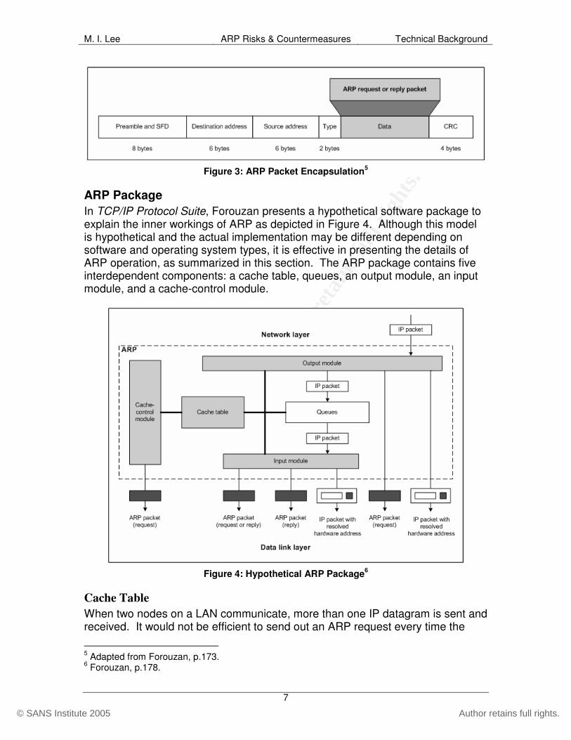
ARP Packet Encapsulation An ARP packet is encapsulated into a data link frame. Figure 3 depicts the ARP packet encapsulation.
4 Adapted from Forouzan, p.172.
© S
AN
S In
stitu
te 2
00
5, A
utho
r ret
ains
full
righ
ts.
Key fingerprint = AF19 FA27 2F94 998D FDB5 DE3D F8B5 06E4 A169 4E46
© SANS Institute 2005 Author retains full rights.
M. I. Lee ARP Risks & Countermeasures Technical Background
7
Figure 3: ARP Packet Encapsulation5
ARP Package In TCP/IP Protocol Suite, Forouzan presents a hypothetical software package to explain the inner workings of ARP as depicted in Figure 4. Although this model is hypothetical and the actual implementation may be different depending on software and operating system types, it is effective in presenting the details of ARP operation, as summarized in this section. The ARP package contains five interdependent components: a cache table, queues, an output module, an input module, and a cache-control module.
Figure 4: Hypothetical ARP Package6
Cache Table When two nodes on a LAN communicate, more than one IP datagram is sent and received. It would not be efficient to send out an ARP request every time the
5 Adapted from Forouzan, p.173. 6 Forouzan, p.178.

© S
AN
S In
stitu
te 2
00
5, A
utho
r ret
ains
full
righ
ts.
Key fingerprint = AF19 FA27 2F94 998D FDB5 DE3D F8B5 06E4 A169 4E46
© SANS Institute 2005 Author retains full rights.
M. I. Lee ARP Risks & Countermeasures Technical Background
8
sender needs to reach the receiver on the LAN. Moreover, if all nodes on a segment broadcasted ARP requests each time a datagram needed to be sent, the network would simply be bogged down and more important packets containing the actual payload would be delayed or even lost. In order to decrease the negative effects of ARP exchange, a cache table is kept on each node. When a sender resolves the receiver’s IP address with its MAC address using ARP, the sender simply caches the resolved address pair on its local table. Any subsequent datagram that the sender transmits to the same receiver would utilize the information in the cache table. Due to the limitation on the memory reserved for the cache, however, the table is maintained for a limited period of time only. Each entry on the cache table contains these fields (only the fields necessary for this discussion are presented):
• State – This field shows the state of the entry, which can be FREE, PENDING, or RESOLVED. The FREE state indicates that the entry has expired and can be used for a new entry. The PENDING state means that a request for this entry has been broadcasted to the LAN, but the reply has not yet been received. The RESOLVED state indicates that the reply has been received for the corresponding request.
• Queue number – Each packet waiting for address resolution is placed in a queue and assigned a number.
• Attempts – This field shows the number of ARP requests that were sent out for a target.
• Timeout – This field shows the time-to-live for the entry. In most cases, the operating system dictates this value.
• Hardware address – This field shows the resolved hardware address of the destination. It would be empty until the ARP reply is received.
• Protocol address – This field shows the protocol address (e.g. IP address) of the destination.
Queues The queues hold packets from the networking layer while ARP attempts to resolve the hardware address. Once ARP resolution is complete, packets are released from the corresponding queues.
Output Module The output module waits for packets from the networking layer. When a packet is received, the output module checks the cache table for an entry with the protocol address field that matches the destination IP address of the packet. If the entry is found and the state of the entry is RESOLVED, the IP packet, along with the destination hardware address, is sent to the data link layer for encapsulation and transmission. If the state is PENDING, the packet waits in the queue until the hardware address resolution is completed. If no entry is found, the output module creates a new queue, in which it places the packet. A new cache table entry with the state of PENDING is created and an ARP request is broadcast to the LAN.
© S
AN
S In
stitu
te 2
00
5, A
utho
r ret
ains
full
righ
ts.
Key fingerprint = AF19 FA27 2F94 998D FDB5 DE3D F8B5 06E4 A169 4E46
© SANS Institute 2005 Author retains full rights.
M. I. Lee ARP Risks & Countermeasures Technical Background
9
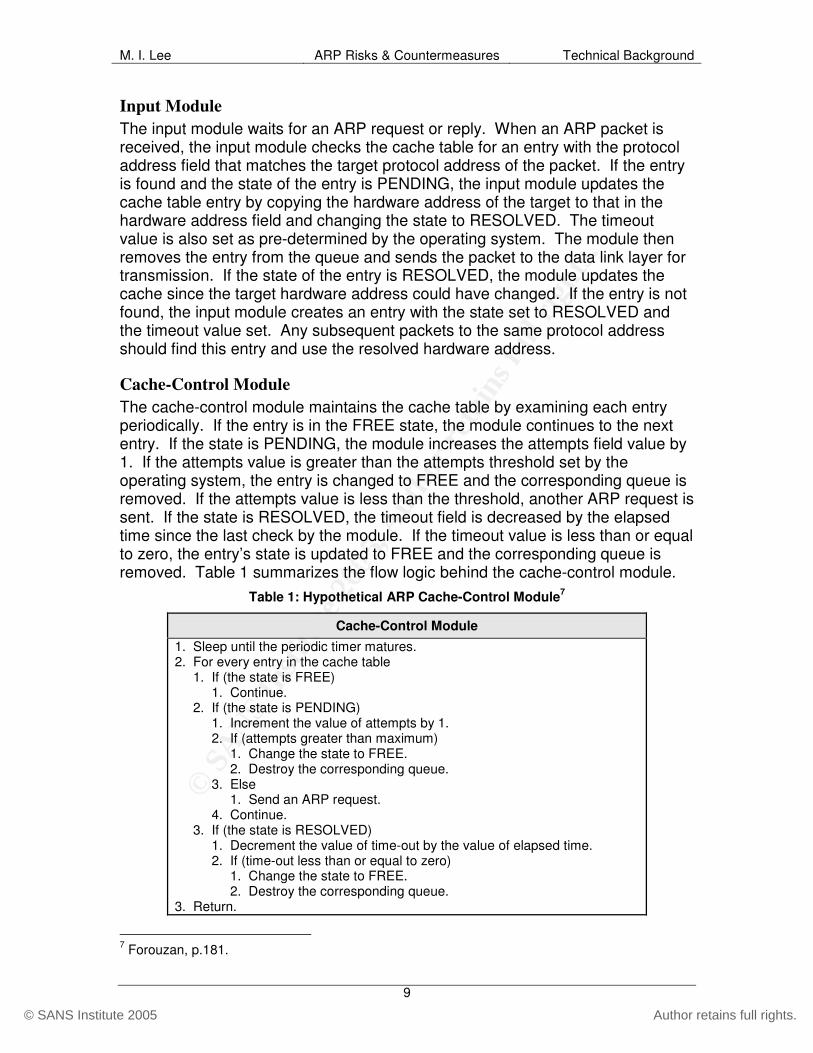
Input Module The input module waits for an ARP request or reply. When an ARP packet is received, the input module checks the cache table for an entry with the protocol address field that matches the target protocol address of the packet. If the entry is found and the state of the entry is PENDING, the input module updates the cache table entry by copying the hardware address of the target to that in the hardware address field and changing the state to RESOLVED. The timeout value is also set as pre-determined by the operating system. The module then removes the entry from the queue and sends the packet to the data link layer for transmission. If the state of the entry is RESOLVED, the module updates the cache since the target hardware address could have changed. If the entry is not found, the input module creates an entry with the state set to RESOLVED and the timeout value set. Any subsequent packets to the same protocol address should find this entry and use the resolved hardware address.
Cache-Control Module The cache-control module maintains the cache table by examining each entry periodically. If the entry is in the FREE state, the module continues to the next entry. If the state is PENDING, the module increases the attempts field value by 1. If the attempts value is greater than the attempts threshold set by the operating system, the entry is changed to FREE and the corresponding queue is removed. If the attempts value is less than the threshold, another ARP request is sent. If the state is RESOLVED, the timeout field is decreased by the elapsed time since the last check by the module. If the timeout value is less than or equal to zero, the entry’s state is updated to FREE and the corresponding queue is removed. Table 1 summarizes the flow logic behind the cache-control module.
Table 1: Hypothetical ARP Cache-Control Module7
Cache-Control Module 1. Sleep until the periodic timer matures. 2. For every entry in the cache table 1. If (the state is FREE) 1. Continue. 2. If (the state is PENDING) 1. Increment the value of attempts by 1. 2. If (attempts greater than maximum) 1. Change the state to FREE. 2. Destroy the corresponding queue. 3. Else 1. Send an ARP request. 4. Continue. 3. If (the state is RESOLVED) 1. Decrement the value of time-out by the value of elapsed time. 2. If (time-out less than or equal to zero) 1. Change the state to FREE. 2. Destroy the corresponding queue. 3. Return.
7 Forouzan, p.181.

© S
AN
S In
stitu
te 2
00
5, A
utho
r ret
ains
full
righ
ts.
Key fingerprint = AF19 FA27 2F94 998D FDB5 DE3D F8B5 06E4 A169 4E46
© SANS Institute 2005 Author retains full rights.
M. I. Lee ARP Risks & Countermeasures Technical Background
10
ARP Operation ARP consists of two types of operations: request and reply. Requests are broadcast (i.e. message sent to all nodes on the LAN) and replies are unicast (i.e. message sent only to a specific node). On a given LAN, such as one depicted in Figure 5, each host is identified by its physical address.
Figure 5: Typical ARP Operation
When a host needs to communicate with another on the same LAN, it needs the receiver’s physical address. For example, if the host with IP address 10.25.0.4 needs to send packets to 10.25.0.1 and does not know the target’s MAC address, it uses ARP to match the logical to the physical address. The steps below show a typical ARP operation using the example LAN setup. The assumption is that it is the first time that the two nodes are attempting to communicate. Figure 6 and Figure 7 show the packet dumps of ARP request and reply, respectively.
1. Host 10.25.0.4 has a message to send to host 10.25.0.1. 2. .4 checks its own ARP cache table and looks for the MAC address of .1.
There is no entry since this is the first transmission. 3. .4’s network layer asks its ARP to create a request to find the MAC
address of .1. Line #2 of Figure 6 shows that the destination MAC address is ff:ff:ff:ff:ff:ff, which is the broadcast address on a LAN. Line #13 shows that the target MAC address is set to 00:00:00:00:00:00 since it is unknown at this point.
4. The ARP request packet is encapsulated into an Ethernet frame and sent out to the LAN. Since the destination MAC address is set to broadcast, every host on the LAN receives the frame.
5. Every host except for .1 discards the frame. 6. The network layer of .1 asks its ARP to send a reply to .4. The packet is
again encapsulated into an Ethernet frame. Line #2 of Figure 7 shows that the ARP reply is unicast to .1 only.

© S
AN
S In
stitu
te 2
00
5, A
utho
r ret
ains
full
righ
ts.
Key fingerprint = AF19 FA27 2F94 998D FDB5 DE3D F8B5 06E4 A169 4E46
© SANS Institute 2005 Author retains full rights.
M. I. Lee ARP Risks & Countermeasures Technical Background
11
7. .4 receives the frame and records the MAC address of .1 in its ARP cache table.
8. Subsequent IP datagrams from .4 to .1 are encapsulated into Ethernet frames using the MAC address of .1, and then unicast directly to the target.
1 Ethernet II, Src: 00:05:4e:47:c2:c8, Dst: ff:ff:ff:ff:ff:ff 2 Destination: ff:ff:ff:ff:ff:ff 3 Source: 00:05:4e:47:c2:c8 (10.25.0.4) 4 Type: ARP (0x0806) 5 Address Resolution Protocol (request) 6 Hardware type: Ethernet (0x0001) 7 Protocol type: IP (0x0800) 8 Hardware size: 6 9 Protocol size: 4 10 Opcode: request (0x0001) 11 Sender MAC address: 00:05:4e:47:c2:c8 12 Sender IP address: 10.25.0.4 13 Target MAC address: 00:00:00:00:00:00 14 Target IP address: 10.25.0.1
Figure 6: ARP Request Packet Capture
1 Ethernet II, Src: 00:09:5b:39:2d:72, Dst: 00:05:4e:47:c2:c8 2 Destination: 00:05:4e:47:c2:c8 3 Source: 00:09:5b:39:2d:72 4 Type: ARP (0x0806) 5 Address Resolution Protocol (reply) 6 Hardware type: Ethernet (0x0001) 7 Protocol type: IP (0x0800) 8 Hardware size: 6 9 Protocol size: 4 10 Opcode: reply (0x0002) 11 Sender MAC address: 00:09:5b:39:2d:72 12 Sender IP address: 10.25.0.1 13 Target MAC address: 00:05:4e:47:c2:c8 14 Target IP address: 10.25.0.4
Figure 7: ARP Reply Packet Capture
Special Types of ARP
Reverse Address Resolution Protocol (RARP) While ARP resolves the physical address from a known logical address, RARP performs the opposite operation: it resolves the logical address from a known physical address. RARP is not used often. One example use of RARP is assigning IP address to a diskless workstation. Since a diskless workstation knows the MAC address of its NIC, it can send a RARP request to the LAN to find its IP address. A host running the RARP server for the LAN receives the request and assigns an IP address to the diskless workstation.

© S
AN
S In
stitu
te 2
00
5, A
utho
r ret
ains
full
righ
ts.
Key fingerprint = AF19 FA27 2F94 998D FDB5 DE3D F8B5 06E4 A169 4E46
© SANS Institute 2005 Author retains full rights.
M. I. Lee ARP Risks & Countermeasures Technical Background
12
Proxy ARP Proxy ARP usually runs on routers and is used to create a subnetting effect without actually changing the subnet information on a group of machines. When a router running proxy ARP receives an ARP request for one of the hosts it is creating the subnetting effect for, the router sends the ARP reply to the requestor as if the router is the target machine.
Gratuitous ARP A machine can use gratuitous ARP (gARP) to tell all hosts on a LAN what its MAC address is without being asked first. gARP is often used in high-availability configurations. gARP is also used at machine boot times to see if there are any duplicate IP addresses on the LAN.
Transparent Bridging One of the ways that LAN traffic is forwarded from one host to another via switches or bridges is by a technique called transparent bridging. A switch using transparent bridging learns the physical addresses of the nodes connected to it by examining the source address of frames. For example, when a switch receives a frame on one of its ports from host A, it records the physical port and the MAC address of host A so that subsequent frames to that host are sent directly to the recorded port. If the destination address is not found in the table, the bridge floods the frame to all ports except to the port that the frame arrived on. By going through the source address learning process, transparent bridges build the address table that is used in all subsequent communication. This learning process is extremely efficient and “transparent” to the nodes, hence the name.

© S
AN
S In
stitu
te 2
00
5, A
utho
r ret
ains
full
righ
ts.
Key fingerprint = AF19 FA27 2F94 998D FDB5 DE3D F8B5 06E4 A169 4E46
© SANS Institute 2005 Author retains full rights.
M. I. Lee ARP Risks & Countermeasures Risks and Scenarios
13
Risks and Scenarios
Defining Risk Risk is defined as “the net negative impact of the exercise of a vulnerability, considering both the probability and the impact of occurrence.”8 The basic components of risk are asset, threat and vulnerability:
• An asset is any tangible or intangible property that is of value to the entity which owns or uses it.
• A threat is the potential for a situation, intent, or method to intentionally exploit or accidentally trigger a vulnerability. A threat-source is the actual situation, intent or method that exercises a specific vulnerability.
• A vulnerability is any weakness or flaw in a given system, procedure, implementation or design that could be exploited accidentally or intentionally and result in a compromise of security.
Figure 8 helps to illustrate the relationship between the various components of risk.
Figure 8: Relationship between Components of Risk9
Risk Assessment Risk assessment is a systematic method used to determine and measure risk to a particular information asset. Risk can be represented as a function of the
8 Stoneburner et al., p.1. 9 Adapted from Australian Standard Handbook of Information Security Risk Management – HB231:2000.

© S
AN
S In
stitu
te 2
00
5, A
utho
r ret
ains
full
righ
ts.
Key fingerprint = AF19 FA27 2F94 998D FDB5 DE3D F8B5 06E4 A169 4E46
© SANS Institute 2005 Author retains full rights.
M. I. Lee ARP Risks & Countermeasures Risks and Scenarios
14
likelihood of a threat-source successfully exploiting a vulnerability given current controls, and the resulting impact on the information asset after a successful compromise. The following generic formula represents the risk function: frisk(n) = (Threat Likelihood) x (Vulnerability Impact) Using the above formula, security auditors and assessment professionals can qualitatively measure the risk to a particular asset given the threats and vulnerabilities. Although there is no central authority that standardizes the method for assessing risk to information assets, the steps below represent a generally accepted process:
1. Identify the information system – The first step is to determine what will be audited or assessed. Keep in mind that an information system can be hardware, software, data, people or procedures, or a combination of some or all of these.
2. Identify information assets – The next step is to identify the actual information assets that are of value to the organization that may be affected by any change to the system determined in the previous step. The asset could be the system itself or any interdependent component.
3. Identify threats – To successfully perform this step, it helps to first identify the threat-sources that may harm the assets. Threat-sources can be natural, environmental or human. Threat-actions, or attack methods, also should be identified.
4. Identify vulnerabilities – After identifying the possible threats, identify the vulnerabilities that exist on the assets that may be exploited by the threat-sources.
5. Identify exposures – Threats and vulnerabilities by themselves do not have much significance. An exposure is created when threats are paired with relevant vulnerabilities, or vice versa. Risk should then be evaluated for each exposure arising from the identified threats and vulnerabilities.
6. Identify existing controls – In order to understand the probability of a threat-source’s ability to exploit a vulnerability, the existing controls that protect the assets must be identified and their effectiveness should be examined.
7. Determine likelihood – In this step, determine the likelihood, or the probability, of identified threat-sources successfully exercising the vulnerabilities, considering the effectiveness (or limitations of) current controls.
8. Determine impact – Determine the impact to the organization or its assets if the vulnerabilities were successfully exploited by the threat-sources.
9. Calculate risk – Finally, determine the risk to the organization or its assets given the likelihood and the impact of threats and vulnerabilities.
Using the risk assessment concepts presented in Risk Management Guide for Information Technology Systems: Recommendations of the National Institute of

© S
AN
S In
stitu
te 2
00
5, A
utho
r ret
ains
full
righ
ts.
Key fingerprint = AF19 FA27 2F94 998D FDB5 DE3D F8B5 06E4 A169 4E46
© SANS Institute 2005 Author retains full rights.
M. I. Lee ARP Risks & Countermeasures Risks and Scenarios
15
Standards and Technology (NIST)10 and the steps outlined above, the template depicted in Table 2 was developed to assist in common risk assessment efforts. Recommendations from NIST are general enough to allow customization per organizational requirements and preference. For determining the likelihood and impact, NIST recommends using simple qualitative rating for each (high, medium or low). For the template in Table 2, the likelihood and impact rating are further divided into granular components to minimize ambiguity and to point out some factors that commonly make up each rating. In determining the likelihood of a given threat-source successfully exercising a vulnerability, the following factors are considered:
• Motivation – Is the threat-source sufficiently motivated to exploit the vulnerability? In the case of non-human threat-sources, this does not apply. In the case of human threat-sources, motivation may be in the form of ego, rebellion, revenge, blackmail, espionage, or curiosity.
• Capability of Threat-Source or Ease of Exploit – Is the threat-source capable of performing the attack on the asset, given sufficient motivation? Are current circumstances such that exploitation of the vulnerabilities is easy (e.g. automated exploit tools already available)?
• Control Limitation – Do the existing controls and countermeasures have limitations that may be overcome by the threat-sources?
Each factor should be rated high, medium or low. Numerically, high is assigned 1.0, medium 0.5 and low 0.1. The likelihood rating is the weighted average score of all three factors. Likewise, when determining the impact of a successful exploit on the organization or the assets, the following factors are considered:
• Mission – What would be the impact to the organization’s mission or objectives?
• Revenue or Profit – What would be the impact to the organization’s revenue or profit?
• Recovery Cost – If an information asset was damaged by an exploit, how high would the monetary and/or resource cost of recovery be? What would be the cost of replacing or repairing the asset?
• Productivity – What would be the effect on the productivity of the organization and its resources?
• Reputation or Liability – What would be the impact to the organization’s reputation or liability? Even if assets were not damaged in tangible terms, would a successful attack decrease customer confidence or loyalty? Could the organization face legal liability as a result (e.g. compromised customer data)?
10 Stoneburner et al.

© S
AN
S In
stitu
te 2
00
5, A
utho
r ret
ains
full
righ
ts.
Key fingerprint = AF19 FA27 2F94 998D FDB5 DE3D F8B5 06E4 A169 4E46
© SANS Institute 2005 Author retains full rights.
M. I. Lee ARP Risks & Countermeasures Risks and Scenarios
16
Similarly to the likelihood rating, each factor is rated high, medium or low. Numerically, high is assigned 100, medium 50 and low 1. The impact rating is then calculated by averaging the four factors’ scores. Some organizations may choose to assign a weight to the impact factors, considering the importance and significance of each. After determining likelihood and impact scores, the risk score is calculated by multiplying the two numbers. Risk is considered to be high if the score is greater than 50, medium if greater than 10 and less than or equal to 50, and low if less than or equal to 10. Depending on the organization, the factors that make up the ratings, the size of the risk matrix (i.e. more qualitative levels than high, medium, or low), and the weight of each factor may differ. It is helpful to consider the definitions from NIST (Table 5 and Table 6 in the Appendix) when creating customized likelihood and impact ratings.
Table 2: Template for Risk Assessment
INFORMATION SYSTEM System to be assessed.
INFORMATION ASSET Asset affected by the system.
THREAT-SOURCE List of threat-sources that may intentionally exploit or accidentally trigger vulnerabilities.
THREAT-ACTION List of threat-actions, or attack methods, that the identified threat-sources may perform.
VULNERABILITY List of vulnerabilities that may be exploited by the threat-source.
EXPOSURE Description of exposures that arise from the combination of threat and vulnerability.
CONTROL List of current controls that may impede or limit the exposure.
Motivation High (1.0); Medium (0.5); Low (0.1)
Capability/Ease High (1.0); Medium (0.5); Low (0.1)
Control Limitation High (1.0); Medium (0.5); Low (0.1) LIKELIHOOD
Likelihood Rating High (1.0); Medium – High (0.6 – 0.9); Medium (0.5); Medium – Low (0.2 – 0.4); Low (0.1)
Mission High (100); Medium (50); Low (1)
Revenue/Profit High (100); Medium (50); Low (1)
Recovery High (100); Medium (50); Low (1)
Productivity High (100); Medium (50); Low (1)
Reputation/Liability High (100); Medium (50); Low (1)
IMPACT
Impact Rating High (100); Medium – High (51 – 99); Medium (50); Medium – Low (2 – 49); Low (1)
RISK (Likelihood x Impact) High (>50 to 100); Medium (> 10 to 50); Low (1 to 10)

© S
AN
S In
stitu
te 2
00
5, A
utho
r ret
ains
full
righ
ts.
Key fingerprint = AF19 FA27 2F94 998D FDB5 DE3D F8B5 06E4 A169 4E46
© SANS Institute 2005 Author retains full rights.
M. I. Lee ARP Risks & Countermeasures Risks and Scenarios
17
Vulnerability in ARP As previously defined, a vulnerability is any weakness or flaw in a system that gives potential for a threat to exploit it, exposing the assets to negative impact. Authentication is a basic concept of security, and along with authorization and accounting makes up the fundamental framework of security functions, better known as AAA. Authentication provides the means for identifying and verifying a user, process or program. It is the lack of authentication in ARP that makes many networks vulnerable to various attacks. As discussed in the ARP Package section earlier, the input module waits for ARP requests or replies. Upon receiving an ARP reply, the input module simply sets the State flag to RESOLVED and uses the newly received hardware address to send any subsequent frames. In other words, ARP does not authenticate that the ARP reply is a result of a previous request or that the change to IP/MAC pair has been authorized. There are some cases where this functionality is perfectly acceptable. For example, gratuitous ARP (gARP) is used in high-availability situations where two or more hosts share the same IP address but have different MAC addresses. When the primary host becomes unavailable, the backup host quickly sends out a gratuitous ARP to the entire LAN, informing every host on the network to use its MAC address for packets destined for the shared IP address. Although the lack of authentication in ARP can be used for legitimate reasons in special situations, this vulnerability makes it all too easy to attack most implementations of local area networks, resulting in potentially serious security risks.
Threats against ARP A threat is the potential for a threat-source to intentionally or accidentally exercise a vulnerability, resulting in negative impact to information assets. Threat-sources can be grouped as natural threats, human threats or environmental threats11. Human threats can either be deliberate or unintentional. An attack, or threat-action, is an act of a threat-source to compromise information assets. Attacks against ARP are of human origin and are usually deliberate in nature. Threat-sources compromise one or more critical characteristics of information: confidentiality, integrity and availability12. There are three main categories of threats against the vulnerability in ARP: information gathering, which compromises the confidentiality of information; man-in-the-middle, which compromises the integrity or confidentiality of information; and denial-of-service, which compromises the availability of information. Each category of threat has several methods of attacks. Although there are numerous attacks that can be
11 Stoneburner et al., p.13. 12 A full list of critical information characteristics should also include accuracy, authenticity, utility and possession, among others [Whitman et al. p.10.].
© S
AN
S In
stitu
te 2
00
5, A
utho
r ret
ains
full
righ
ts.
Key fingerprint = AF19 FA27 2F94 998D FDB5 DE3D F8B5 06E4 A169 4E46
© SANS Institute 2005 Author retains full rights.
M. I. Lee ARP Risks & Countermeasures Risks and Scenarios
18
used to exploit ARP vulnerabilities, a few popular attack methods are discussed in this section.
Attack Methods
Reconnaissance A common tactic prior to an actual attack is to gather relevant information regarding the target network. There are numerous techniques to perform reconnaissance against a network. A popular method is to use a port scanner to locate live hosts, fingerprint operating systems, and find services that are running on each host. A well-known tool to perform these and other reconnaissance techniques is Nmap. Nmap can use various ICMP, TCP or UDP packet manipulations to gather useful information. Another tool for harvesting information on a LAN is Ettercap. Ettercap is a powerful tool used to perform many of the other active attacks by taking advantage of vulnerabilities in ARP. When used for reconnaissance, Ettercap benignly sends out an ARP request for each IP address on a LAN to create a list of IP/MAC pair of live hosts.
ARP Cache Poisoning As the name indicates, ARP cache poisoning attacks the cache table of victims. As discussed earlier, ARP is stateless and does not have an authentication mechanism to verify an incoming ARP message. ARP cache poisoning attacks this lack of authentication by sending false ARP replies to victims. The victims, in most cases, will cache the information supplied by the attacker and use the MAC address defined in the false ARP message for subsequent packet transmission. ARP cache poisoning is among the most popular and effective exploits against switched LANs. Its effectiveness, simplicity and difficulty of detection make ARP cache poisoning particularly dangerous. Figure 9 illustrates ARP cache poisoning at a high-level.

© S
AN
S In
stitu
te 2
00
5, A
utho
r ret
ains
full
righ
ts.
Key fingerprint = AF19 FA27 2F94 998D FDB5 DE3D F8B5 06E4 A169 4E46
© SANS Institute 2005 Author retains full rights.
M. I. Lee ARP Risks & Countermeasures Risks and Scenarios
19
Figure 9: ARP Cache Poisoning13
These are the basic steps involved in an ARP cache poisoning attack:
1. Attacker, who has the IP address 10.25.0.3 and MAC address 00:CC (simplified for illustration), decides to launch a man-in-the-middle attack against 10.25.0.1 and 10.25.0.4 using ARP cache poisoning.
2. The attacker sends out a forged ARP reply to .4, saying “I (00:CC) have .1’s MAC address!”
3. .4, because it does not authenticate that the ARP reply came as a result of a previous request, updates its ARP cache table to map 10.25.0.1 to 00:CC, which is the attacker’s physical address.
4. Any subsequent frames sent from .4 to .1 are first sent to the attacker. Upon receiving the frame, the attacker does whatever he wishes to the packets, and forwards them along to .1.
5. The attacker repeats steps 2, 3 and 4 against .1, prompting .1 to update its ARP cache table to map 10.25.0.4 to 00:CC, and intercepting frames sent from .1 to .4.
6. When finished with the attack, the attacker sends out ARP replies to both .1 and .4, this time with the correct information, returning the normal exchange of packets between the victims.
13 Adapted from Peikari et al.

© S
AN
S In
stitu
te 2
00
5, A
utho
r ret
ains
full
righ
ts.
Key fingerprint = AF19 FA27 2F94 998D FDB5 DE3D F8B5 06E4 A169 4E46
© SANS Institute 2005 Author retains full rights.
M. I. Lee ARP Risks & Countermeasures Risks and Scenarios
20
As illustrated above, ARP cache poisoning indeed is simple to perform yet extremely effective. Although the example shows a man-in-the-middle attack against two victims, perhaps to eavesdrop on communication, the attacker could just as easily perform a man-in-the-middle against an entire subnet by posing as the gateway. It is also simple to perform denial-of-service by poisoning the cache tables of victims with bogus MAC addresses, or by selectively filtering and dropping packets after successfully performing MitM. As explained later, an attacker can carry out ARP cache poisoning against wireless LANs just as effectively. It can also be used to compromise encrypted traffic as well, including SSL and SSH version 1.
ARP Spoofing In an ARP spoofing attack, the attacker listens on the LAN for ARP request broadcasts. When a broadcast is sent looking for the victim host, the attacker sends a forged ARP reply with its MAC address to the requesting party. ARP spoofing is very similar to ARP cache poisoning in that it seeks to update the victim’s ARP cache table with forged information. But because the original ARP request is heard by everyone on the LAN, including the legitimate host that the requestor is looking for, the attacker must win the race condition. The race condition, however, is insignificant since most operating systems simply use the most recent ARP reply to update their cache tables. As long as the attacker repeatedly advertises his MAC as that of the target, the victim’s cache table will be overwritten in most cases.
MAC Flooding MAC flooding is an attack against switches. Switches have a type of cache table called Content-Addressable Memory (CAM), which is populated in most cases through transparent bridging, as discussed earlier. CAM tables basically record the port to MAC address pair so that the switch can intelligently forward packets meant for a target to the physical port that the target is connected to. The CAM tables, however, have limited memory space reserved for them. When flooded with thousands of bogus ARP packets, devices run out of memory for the CAM table. Once the CAM table is overflowed, any subsequent frames must be flooded to all of switch’s ports, temporarily causing the switch to function similar to a hub. The attacker can then eavesdrop on the flooded packets. The behavior of a switch with overflowed CAM table depends on the vendor and the version of the operating system. Also, in certain cases, the attacked switch may simply fail, causing a denial-of-service on the LAN.
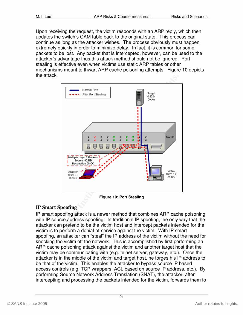
Port Stealing In port stealing, the attacker crafts ARP replies using the victim’s MAC address as the source and its own address as the destination. When the switch receives the packet, it associates the attacker’s port to the victim’s MAC address. Any subsequent packets intended for the victim now go to the attacker. In order to allow the victim to continue receiving packets, the attacker must broadcast an ARP request for the victim’s MAC address immediately following the interception.
© S
AN
S In
stitu
te 2
00
5, A
utho
r ret
ains
full
righ
ts.
Key fingerprint = AF19 FA27 2F94 998D FDB5 DE3D F8B5 06E4 A169 4E46
© SANS Institute 2005 Author retains full rights.
M. I. Lee ARP Risks & Countermeasures Risks and Scenarios
21
Upon receiving the request, the victim responds with an ARP reply, which then updates the switch’s CAM table back to the original state. This process can continue as long as the attacker wishes. The process obviously must happen extremely quickly in order to minimize delay. In fact, it is common for some packets to be lost. Any packet that is intercepted, however, can be used to the attacker’s advantage thus this attack method should not be ignored. Port stealing is effective even when victims use static ARP tables or other mechanisms meant to thwart ARP cache poisoning attempts. Figure 10 depicts the attack.
Figure 10: Port Stealing
IP Smart Spoofing IP smart spoofing attack is a newer method that combines ARP cache poisoning with IP source address spoofing. In traditional IP spoofing, the only way that the attacker can pretend to be the victim host and intercept packets intended for the victim is to perform a denial-of-service against the victim. With IP smart spoofing, an attacker can “steal” the IP address of the victim without the need for knocking the victim off the network. This is accomplished by first performing an ARP cache poisoning attack against the victim and another target host that the victim may be communicating with (e.g. telnet server, gateway, etc.). Once the attacker is in the middle of the victim and target host, he forges his IP address to be that of the victim. This enables the attacker to bypass source IP based access controls (e.g. TCP wrappers, ACL based on source IP address, etc.). By performing Source Network Address Translation (SNAT), the attacker, after intercepting and processing the packets intended for the victim, forwards them to

© S
AN
S In
stitu
te 2
00
5, A
utho
r ret
ains
full
righ
ts.
Key fingerprint = AF19 FA27 2F94 998D FDB5 DE3D F8B5 06E4 A169 4E46
© SANS Institute 2005 Author retains full rights.
M. I. Lee ARP Risks & Countermeasures Risks and Scenarios
22
the victim. This attack utilizes layers 1 through 3, making it extremely difficult to prevent or detect.
Potential Scenarios In this section, two fictional scenarios are used to discuss the implications of risks inherent in ARP. Risk assessment examples are purposely limited in scope to focus the discussions on threats and vulnerabilities related to ARP only.
Scenario 1: Hacme University
Background Hacme is a large private university known for its forward-looking investments in technology. It is one of the few universities in the nation offering a full-range of degree programs through its online system. It has invested millions of dollars developing the system and is about to release the newest version for the upcoming school year. The newer system promises better quality audio and video with real-time messaging capabilities. Several investors have shown interest in sponsoring the school’s new system. In the past few years, a large percentage of the university’s revenue came as a result of its online programs, and that percentage is growing each year. The university has spent a lot of resources building a secure perimeter to support the online system. Its perimeter architecture is comprised of network intrusion detection and prevention systems, deep-packet inspection firewalls, Web application gateways, and even some new devices that promise to stop the spread of worms. The university’s IT department was convinced that its biggest threat came from the Internet and was confident that it had fortified its perimeter well. The university had asked a consulting firm to perform a security assessment of the university’s online class system. The consultants, though impressed by the university’s overall security posture and perimeter architecture, pointed out three major weaknesses related to the online system network:
1. Whenever support personnel dial-in to the remote access modem pool, they are assigned IP addresses that placed them on the same segment as the production network.
2. Remote access does not utilize two-factor authentication. 3. Encryption is not enforced even for inherently insecure protocols such as
FTP, telnet and HTTP. The following section highlights what the consultants found during their assessment engagement.
© S
AN
S In
stitu
te 2
00
5, A
utho
r ret
ains
full
righ
ts.
Key fingerprint = AF19 FA27 2F94 998D FDB5 DE3D F8B5 06E4 A169 4E46
© SANS Institute 2005 Author retains full rights.
M. I. Lee ARP Risks & Countermeasures Risks and Scenarios
23
Risk Assessment The information system that is to be evaluated is the online class system, and the assets are the supporting network, servers, applications, application data, and logon credentials to applications and network equipment. Malicious insiders are the most likely source of threat that could exploit the identified vulnerabilities. Malicious insiders include current and former employees (or students), contractors, consultants or service providers. Because of the insecure remote access, however, malicious outsiders are also considered. On top of the inherent flaw in ARP, the online class system has additional vulnerabilities, including the lack of separation between the production and support network, weak authentication scheme, and uncontrolled usage of clear-text protocols. Each vulnerability on its own may not pose significant risk; it is the combination of the identified vulnerabilities that is of concern. As an example, consider a malicious outsider who brute-forces his way into the support modem pool by taking advantage of the weak authentication scheme. Since the modem pool is on the same segment as production network, the attacker’s machine is immediately given access to the online class system network. The attacker then can use ARP cache poisoning to capture confidential data such as logon credentials for network equipment maintenance, customer IDs and passwords, or any other data that can be harvested and used later. The attacker can also perform a denial-of-service on the entire production network by poisoning the systems with bogus ARP entries or by flooding the CAM table of switches. Given the identified vulnerabilities and threats, breach in confidentiality, integrity and availability of assets are the main exposures to consider in this scenario. It is assumed that the attacker, whether an insider or outsider, is highly motivated in order to carry out such an attack. Due to the lack of safeguards to mitigate the vulnerabilities, attacks on the production network would be relatively easy, driving up the likelihood factor. Impact from breach in confidentiality of assets, such as logon credentials for network equipment administration would be high since the attacker can use the information to further compromise the network and assets. Impact from compromise in availability of assets would also be high. In particular, the mission of the online system, which is to provide the online classes to students (or customers), would be severely impacted. Instability of the system would also impact the university’s revenue stream from registered students and other investors. The university’s reputation for delivering high-quality online curriculum would significantly be downgraded as a result. Overall, the risk arising from the identified threats and vulnerabilities on Hacme’s online class system is high. Table 3 summarizes the risk assessment exercise.

© S
AN
S In
stitu
te 2
00
5, A
utho
r ret
ains
full
righ
ts.
Key fingerprint = AF19 FA27 2F94 998D FDB5 DE3D F8B5 06E4 A169 4E46
© SANS Institute 2005 Author retains full rights.
M. I. Lee ARP Risks & Countermeasures Risks and Scenarios
24
Table 3: Risk Assessment Summary for Hacme University Online Class System
Table 3.1: Identification of Asset, Threat and Vulnerability
INFORMATION SYSTEM Online class system
INFORMATION ASSET
• Online class applications • Online class servers • Online class network • Administrative logon credentials • Application logon credentials
THREAT-SOURCE • Malicious insiders • Malicious outsiders
THREAT-ACTION • ARP-based attacks (e.g. cache poisoning, spoofing, MAC
flooding, etc.) against network and systems • Brute-force attack against modem pool
VULNERABILITY
• Lack of authentication in ARP • Support modem pool on the same segment as the production
network • Unencrypted logon credentials • Weak remote access authentication
Table 3.2: Exposure to Breach in Confidentiality and Integrity of Logon Credentials and Data
EXPOSURE
Breach in confidentiality of logon credentials and data through malicious insider or outsider using ARP-based attacks. Attacker can then use the logon credentials to further compromise the network or the integrity of customer data.
CONTROL None
Motivation High 1.0
Capability/Ease High 1.0
Control Limitation High 1.0 LIKELIHOOD
Likelihood Rating High 1.0
Mission High 100
Revenue/Profit Medium 50
Recovery Medium 50
Productivity Medium 50
Reputation/Liability High 100
IMPACT
Impact Rating Medium – High 70
RISK High 70

© S
AN
S In
stitu
te 2
00
5, A
utho
r ret
ains
full
righ
ts.
Key fingerprint = AF19 FA27 2F94 998D FDB5 DE3D F8B5 06E4 A169 4E46
© SANS Institute 2005 Author retains full rights.
M. I. Lee ARP Risks & Countermeasures Risks and Scenarios
25
Table 3.3: Exposure to Breach in Availability of Network
EXPOSURE
Compromise in availability of production network through malicious insider or outsider using ARP-based attacks.
CONTROL None
Motivation High 1.0
Capability/Ease High 1.0
Control Limitation High 1.0 LIKELIHOOD
Likelihood Rating High 1.0
Mission High 100
Revenue/Profit High 100
Recovery Medium 50
Productivity Medium 50
Reputation/Liability High 100
IMPACT
Impact Rating Medium – High 80
RISK High 80
Recommendations The following controls should be considered to mitigate the risks:
1. Separate the dial-in support network from the production network. 2. Enforce two-factor authentication for all remote access. 3. Encrypt sensitive traffic such as router and server administration logon. 4. Use ARP inspection and/or port security on switches that connect mission-
critical systems. 5. Consider using static ARP entries for critical system connectivity, but keep
in mind that Windows machines will still be vulnerable to ARP cache poisoning attacks.
6. Use arpwatch or tuned NIDS sensors to recognize problematic ARP traffic on mission-critical segments.
Refer to the Countermeasures section for further discussion on recommended controls.
Scenario 2: McKilme Corporation
Background McKilme is a mid-sized financial corporation. It has a fairly standard, but solid, network security infrastructure: host based intrusion detection systems on critical servers, network intrusion detection appliances at critical ingress points, and comprehensive anti-malware architecture covering all nodes. At the perimeter, redundant stateful firewalls guard the network against intrusion attempts from the

© S
AN
S In
stitu
te 2
00
5, A
utho
r ret
ains
full
righ
ts.
Key fingerprint = AF19 FA27 2F94 998D FDB5 DE3D F8B5 06E4 A169 4E46
© SANS Institute 2005 Author retains full rights.
M. I. Lee ARP Risks & Countermeasures Risks and Scenarios
26
Internet. It also has a well-established security audit program that is supported by the leadership of the company. A recent security audit pointed out that although the general network security posture is good, there are some lax points that needed attention on the internal network:
1. Network administrators connect directly from their PCs that are on the general user segment to manage routers and other network equipment. No encryption is used for the administration traffic. They have a control in place, however, so that only specified IP addresses can connect to the equipment to perform maintenance.
2. Encryption is not enforced for Web-based Intranet applications that transmit, process and store confidential data, including HR and benefits sites.
3. Rogue wireless access points exist in certain parts of the network that are not properly secured.
Risk Assessment The information “system” is the internal network in this scenario. In particular, the logon credentials for network administration and sensitive applications, along with application data, are the assets of concern. Malicious insiders are the primary threat-sources, but malicious outsiders are also considered due to the existence of rogue WAPs. Improperly secured WAPs that are connected directly to the enterprise network extend the lower layers beyond the physical boundaries, exposing the corporate network to the outside. Unencrypted traffic for router administration and sensitive intranet applications is a significant vulnerability considering the inherent weakness in ARP. As an illustration, consider a malicious insider who decides to snoop on a network administrator’s communication with various equipments such as servers or routers. In many cases, insiders already have knowledge of, or have the means to obtain, information such as the administrator’s machine name or IP address and the network hardware that the administrator regularly maintains. By using man-in-the-middle attack via ARP cache poisoning, the attacker can capture the administrator’s logon credentials for specific equipment. If the attacker wanted to gain access to the equipment, however, it would not be straight forward since there is a control that only allows specified IP addresses to connect. The attacker, if determined to gain access, can use IP smart spoofing to bypass the source address based filtering. As another example, consider a malicious outsider who gains access to the internal network by attaching his machine to a rogue WAP that is not properly secured. The attacker can easily poison the ARP cache of all the nodes on the network and pose as the default gateway. This would cause all machines to first go through the attacker’s machine before reaching any host or network beyond

© S
AN
S In
stitu
te 2
00
5, A
utho
r ret
ains
full
righ
ts.
Key fingerprint = AF19 FA27 2F94 998D FDB5 DE3D F8B5 06E4 A169 4E46
© SANS Institute 2005 Author retains full rights.
M. I. Lee ARP Risks & Countermeasures Risks and Scenarios
27
the local segment. When unencrypted logon credentials for the HR application is passed through, for instance, the attacker can easily capture the information and use it to gain access to sensitive data. If a disgruntled employee, yet as another example, wanted to deny her manager’s access to certain resources, as to cause unneeded productivity loss, she can poison the ARP cache of the manager’s machine, pose as the default gateway, and then use packet filtering to drop any frames destined for hosts that meet the attacker’s filter conditions. For example, she can perform a surgical denial-of-service by dropping any traffic originating from the manager’s machine over TCP 80 (HTTP). It would be quite difficult for the victim to troubleshoot the source of the issue, especially if the attacker automates the attack so that communication is restored to normal after a few minutes, and then the process is repeated over a random period of time. The exposures in this scenario are breach in confidentiality, integrity and availability of assets. Attackers who may exploit the vulnerabilities are assumed to be sufficiently motivated. Capturing unencrypted traffic would be easy considering that there are no controls in place. Performing denial-of-service would also be easy. While the risk of compromise in administrative logon credentials is medium due to the locally-limited exposure and the source address based filtering in place, the risk of compromised application logon credentials is high because of the sensitive and private nature of the data (e.g. HR/benefits). Table 4 summarizes the risk assessment exercise.
Table 4: Risk Assessment Summary for McKilme’s Internal Network
Table 4.1: Identification of Asset, Threat and Vulnerability
INFORMATION SYSTEM Internal network
INFORMATION ASSET
• Internal network • Administrative logon credentials • Application logon credentials • Application data
THREAT-SOURCE • Malicious insiders • Malicious outsiders
THREAT-ACTION • ARP-based attacks (e.g. cache poisoning, spoofing, MAC flooding, etc.) against network, systems and applications
VULNERABILITY • Lack of authentication in ARP • Unencrypted logon credentials • Unencrypted application data

© S
AN
S In
stitu
te 2
00
5, A
utho
r ret
ains
full
righ
ts.
Key fingerprint = AF19 FA27 2F94 998D FDB5 DE3D F8B5 06E4 A169 4E46
© SANS Institute 2005 Author retains full rights.
M. I. Lee ARP Risks & Countermeasures Risks and Scenarios
28
Table 4.2: Exposure to Breach in Confidentiality of Administrative Logon Credentials
EXPOSURE
Breach in confidentiality of network administration logon credentials through malicious insider or outsider using ARP-based attacks. Attacker can then use the logon credentials to further compromise the network.
CONTROL
Source IP address filtering for network administration (this control does not mitigate harvesting of logon credentials).
Motivation High 1.0
Capability/Ease Medium 0.5
Control Limitation Medium 0.5 LIKELIHOOD
Likelihood Rating High 0.667
Mission Medium 50
Revenue/Profit Low 1
Recovery Medium 50
Productivity High 100
Reputation/Liability Low 1
IMPACT
Impact Rating Medium – Low 40.4
RISK Medium 26.9
Table 4.3: Exposure to Breach in Confidentiality and Integrity of Sensitive Application
EXPOSURE
Breach in confidentiality of logon credentials to HR and benefits applications through malicious insider or outsider using ARP-based attacks. Attacker can then use the logon credentials to further compromise the confidentiality and integrity of sensitive data.
CONTROL None
Motivation High 1.0
Capability/Ease High 1.0
Control Limitation High 1.0 LIKELIHOOD
Likelihood Rating High 1.0
Mission Medium 50
Revenue/Profit Low 1
Recovery High 100
Productivity High 100
IMPACT
Reputation/Liability High 100
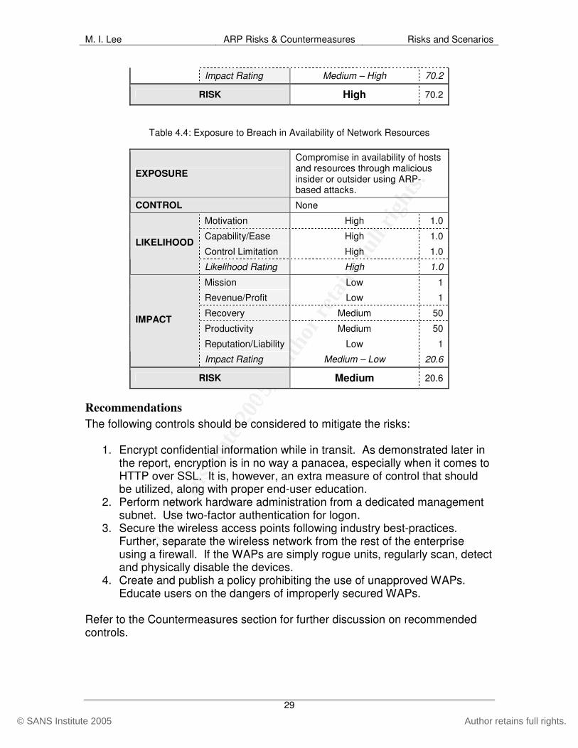
© S
AN
S In
stitu
te 2
00
5, A
utho
r ret
ains
full
righ
ts.
Key fingerprint = AF19 FA27 2F94 998D FDB5 DE3D F8B5 06E4 A169 4E46
© SANS Institute 2005 Author retains full rights.
M. I. Lee ARP Risks & Countermeasures Risks and Scenarios
29
Impact Rating Medium – High 70.2
RISK High 70.2
Table 4.4: Exposure to Breach in Availability of Network Resources
EXPOSURE
Compromise in availability of hosts and resources through malicious insider or outsider using ARP-based attacks.
CONTROL None
Motivation High 1.0
Capability/Ease High 1.0
Control Limitation High 1.0 LIKELIHOOD
Likelihood Rating High 1.0
Mission Low 1
Revenue/Profit Low 1
Recovery Medium 50
Productivity Medium 50
Reputation/Liability Low 1
IMPACT
Impact Rating Medium – Low 20.6
RISK Medium 20.6
Recommendations The following controls should be considered to mitigate the risks:
1. Encrypt confidential information while in transit. As demonstrated later in the report, encryption is in no way a panacea, especially when it comes to HTTP over SSL. It is, however, an extra measure of control that should be utilized, along with proper end-user education.
2. Perform network hardware administration from a dedicated management subnet. Use two-factor authentication for logon.
3. Secure the wireless access points following industry best-practices. Further, separate the wireless network from the rest of the enterprise using a firewall. If the WAPs are simply rogue units, regularly scan, detect and physically disable the devices.
4. Create and publish a policy prohibiting the use of unapproved WAPs. Educate users on the dangers of improperly secured WAPs.
Refer to the Countermeasures section for further discussion on recommended controls.

© S
AN
S In
stitu
te 2
00
5, A
utho
r ret
ains
full
righ
ts.
Key fingerprint = AF19 FA27 2F94 998D FDB5 DE3D F8B5 06E4 A169 4E46
© SANS Institute 2005 Author retains full rights.
M. I. Lee ARP Risks & Countermeasures Demonstration
30
Demonstration As presented throughout this report, due to the inherent vulnerability in ARP, many networks are exposed to a variety of threats. One of the most common and devastating threats is the man-in-the-middle (MitM) attack via ARP cache poisoning (ACP). MitM/ACP is powerful in that it can be used to compromise all three critical characteristics of information: confidentiality, integrity and availability. In this section, MitM/ACP is used as the basis to demonstrate various attack methods, each compromising one or more of the C-I-A triad. Security auditors often must think like an attacker in order to assess the risk that a particular threat/vulnerability pair poses and to communicate that risk to the owners of the asset. In this demonstration, an attacker’s point of view is used to discuss various attack methods. There are two subsections to the demonstration: in the first set, the attacker performs the attacks using a wireless network; in the second section, another attacker uses a traditional wired Ethernet to carry out the damage. The reasons for using both the wireless and wired networks are twofold:
1. It serves to prove the dangers of improperly secured wireless access points (WAP) that, in effect, extend the lower layers beyond traditional boundaries. This ultimately shows that ARP-based attacks should no longer be assumed to be limited to physical LANs.
2. From an attacker’s perspective, the same attacks can be performed whether on wireless or wired network.
Although various tools are available for performing MitM/ACP, Ettercap (version 0.7.1) is used as the primary means to demonstrate the attack methods. Ettercap is a multi-purpose tool for performing a variety of active and passive network attacks. Unlike other free tools, Ettercap is actively developed and a strong support community exists, making it an ideal choice for security auditors. This report is not a primer on Ettercap, thus basic concepts and functions are not discussed; only some of the tool’s ARP-manipulation capabilities are highlighted. It is important to note that whenever performing any type of active or passive testing on a network, a written permission from the owner of the network should first be obtained. Also, keep in mind that some of the demonstrated techniques may bring down systems or networks; careful planning and prudence should be exercised when using these techniques to audit a production network. During the demonstration, the attacker uses Mandrake Linux 9.2 as his operating system of choice. The victims run Windows XP Professional with varying configurations. The victim in the wireless attack demonstration is configured with XP Service Pack 1 and Symantec Internet Security firewall. The other victim has XP Service Pack 2 with built-in Windows firewall enabled. The target machine in the first set of demonstration is running Red Hat Linux 9.0. The default gateway in the wired attack is running a version of Cisco IOS.

© S
AN
S In
stitu
te 2
00
5, A
utho
r ret
ains
full
righ
ts.
Key fingerprint = AF19 FA27 2F94 998D FDB5 DE3D F8B5 06E4 A169 4E46
© SANS Institute 2005 Author retains full rights.
M. I. Lee ARP Risks & Countermeasures Demonstration
31
Wireless Network Attacks
Reconnaissance The attacker, named “Bob”, connects to a WAP that is not properly secured and immediately receives an IP address (172.25.0.3) from the DHCP server. Figure 11 below shows the attacker’s IP configuration and MAC address as reported by ifconfig. wlan0 Link encap:Ethernet HWaddr 00:04:23:7A:8B:6C inet addr:172.25.0.3 Bcast:172.25.0.255 Mask:255.255.255.0 UP BROADCAST RUNNING MULTICAST MTU:1500 Metric:1 RX packets:21 errors:0 dropped:0 overruns:0 frame:0 TX packets:5 errors:0 dropped:0 overruns:0 carrier:0 collisions:0 txqueuelen:1000 RX bytes:1941 (1.8 Kb) TX bytes:592 (592.0 b) Interrupt:5 Memory:e0200000-e0200fff
Figure 11: IP/MAC Configuration of the Attacker’s Machine
The first step that Bob takes is collecting relevant information on the target network. To enumerate the nodes on the network, Bob uses Ettercap to perform a quick ARP scan of the LAN. This sends out an ARP request to each IP address on the subnet in a random fashion and records the IP/MAC address pair of each host from subsequent replies. ARP scan is especially useful in discovering hosts that may be blocking ICMP traffic through software firewall or other packet filters. This process takes only a few seconds to complete on a class C network. On a class B network, however, this may take a long time and may somewhat degrade network performance due to the inordinate number of ARP packets bouncing on the LAN. Bob issues the following command shown in Figure 12 to scan the subnet for live hosts: #ettercap –Tq //
Figure 12: Ettercap ARP Scan Command
The –T flag tells Ettercap to use the “text-only” interface and q tells it to operate in “quiet” mode, which only shows “interesting” packets such as usernames and passwords. In this case, the main purpose is to generate a hosts list. The // at the end basically tells Ettercap to scan the entire subnet to compile the hosts list. Figure 13 shows the recorded list of hosts as seen by Ettercap after the initial scan.
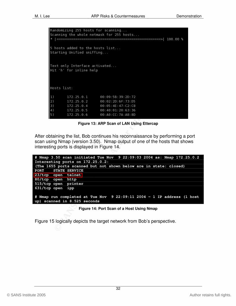
© S
AN
S In
stitu
te 2
00
5, A
utho
r ret
ains
full
righ
ts.
Key fingerprint = AF19 FA27 2F94 998D FDB5 DE3D F8B5 06E4 A169 4E46
© SANS Institute 2005 Author retains full rights.
M. I. Lee ARP Risks & Countermeasures Demonstration
32
Figure 13: ARP Scan of LAN Using Ettercap
After obtaining the list, Bob continues his reconnaissance by performing a port scan using Nmap (version 3.50). Nmap output of one of the hosts that shows interesting ports is displayed in Figure 14. # Nmap 3.50 scan initiated Tue Nov 9 22:09:03 2004 as: Nmap 172.25.0.2 Interesting ports on 172.25.0.2: (The 1655 ports scanned but not shown below are in state: closed) PORT STATE SERVICE 23/tcp open telnet 80/tcp open http 515/tcp open printer 631/tcp open ipp # Nmap run completed at Tue Nov 9 22:09:11 2004 – 1 IP address (1 host up) scanned in 8.525 seconds
Figure 14: Port Scan of a Host Using Nmap
Figure 15 logically depicts the target network from Bob’s perspective.

© S
AN
S In
stitu
te 2
00
5, A
utho
r ret
ains
full
righ
ts.
Key fingerprint = AF19 FA27 2F94 998D FDB5 DE3D F8B5 06E4 A169 4E46
© SANS Institute 2005 Author retains full rights.
M. I. Lee ARP Risks & Countermeasures Demonstration
33
Figure 15: Network Topology for Wireless Attack Demonstration
From the reconnaissance phase, Bob gains some valuable information. For example, he can take an educated guess that 172.25.0.1 is the default gateway, which means all machines on the local network must go through it to reach the Internet or other networks. Bob also notices that 172.25.0.2 is running telnet listening on TCP 23 (Figure 14), which may be passing logon credentials in the clear.
Packet Capture Bob chooses his victim to be 172.25.0.4, “Tom”. He first wants to see if he can capture Tom’s logon credentials to the telnet server on 172.25.0.2. Bob types up the following command shown in Figure 16 from the shell: #ettercap –Tq –M arp:oneway /172.25.0.4/ /172.25.0.2/
Figure 16: Ettercap Command for MitM/ACP
The –M option is for performing man-in-the-middle attacks, in this case using ARP cache poisoning as the method. The arp:oneway option specifies that only Tom’s ARP cache will be poisoned (half-duplex). This option is used since only the packets originating from Tom to the target machine are of interest to the

© S
AN
S In
stitu
te 2
00
5, A
utho
r ret
ains
full
righ
ts.
Key fingerprint = AF19 FA27 2F94 998D FDB5 DE3D F8B5 06E4 A169 4E46
© SANS Institute 2005 Author retains full rights.
M. I. Lee ARP Risks & Countermeasures Demonstration
34
attacker. The two targets are specified within //. Figure 17 shows the attack in progress.
Figure 17: ARP Cache Poisoning using Ettercap
The attacking machine starts by sending an ICMP Echo Request to the victim using a spoofed source address (Figure 18 B ). If the victim does not have the MAC address of the sender, it must broadcast an ARP request in order to respond with an ICMP Echo Reply. The attacker, by sending out spoofed ARP replies to the victim immediately after the initial Echo Request (Figure 18 C ), is able to win the race condition. Using spoofed ICMP packets is necessary when attacking operating systems that only accept solicited ARP replies (e.g. Sun Solaris). Most operating systems, however, will cache any ARP replies, even those that are unsolicited. Note that the MAC address (00:04:23:7a:8b:6c) being advertised as 172.25.0.2 (Figure 18 C ) actually belongs to the attacker (172.25.0.3), as shown in Figure 11. 00:04:23:7a:8b:6c > 00:05:4e:47:c2:c8, ethertype IPv4, length 42: IP 172.25.0.2 > 172.25.0.4: icmp 8: echo request seq 32487 00:04:23:7a:8b:6c > 00:05:4e:47:c2:c8, ethertype ARP, length 42: arp reply 172.25.0.2 is-at 00:04:23:7a:8b:6c 00:04:23:7a:8b:6c > 00:05:4e:47:c2:c8, ethertype ARP, length 42: arp reply 172.25.0.2 is-at 00:04:23:7a:8b:6c 00:04:23:7a:8b:6c > 00:05:4e:47:c2:c8, ethertype ARP, length 42: arp reply 172.25.0.2 is-at 00:04:23:7a:8b:6c 00:04:23:7a:8b:6c > 00:05:4e:47:c2:c8, ethertype ARP, length 42: arp reply 172.25.0.2 is-at 00:02:2d:6f:73:d5
Figure 18: tcpdump from the Attacker’s Machine during ARP Cache Poisoning
A
B
C
D

© S
AN
S In
stitu
te 2
00
5, A
utho
r ret
ains
full
righ
ts.
Key fingerprint = AF19 FA27 2F94 998D FDB5 DE3D F8B5 06E4 A169 4E46
© SANS Institute 2005 Author retains full rights.
M. I. Lee ARP Risks & Countermeasures Demonstration
35
Figure 19 below shows the changes to the victim’s ARP cache before, during and after the attack. The first print of the cache (Figure 19 E ) shows that Tom has the correct IP/MAC pair of three of his neighboring machines. These match what was found during the reconnaissance step in Figure 13. The second ARP cache table (Figure 19 F ), which is produced during the attack, shows that the MAC address of 172.25.0.2 changed to that of 172.25.0.3, the attacking machine. At this point, any messages intended for .2 from the victim will go to Bob first. As can be seen in Figure 17 A , after having waited a little while, Bob is able to intercept Tom’s username and password to the telnet service on 172.25.0.2.
Figure 19: ARP Cache Entries on the Victim Before, During and After the Attack
After the attack, Bob sends out another set of ARP replies, this time to restore the correct IP/MAC values. The last ARP cache table (Figure 19 G ) shows that the correct IP/MAC has been restored for 172.25.0.2.
Denial-of-Service There is a variety of ways to perform DoS on a local network. One of the simplest, yet the most difficult method to detect or determine the cause of, is to poison the ARP cache of the victim so that target ARP entries point to its own or another bogus MAC address. For example, by poisoning the ARP cache of Tom so that the entry for the default gateway points to Tom’s own MAC address, he would not be able to go out to the Internet or any other network outside of his own. Ettercap has a plug-in, isolate, which makes it even simpler to carry out such attack. To perform the discussed attack, Bob uses the following command in Figure 20:
E
F
G

© S
AN
S In
stitu
te 2
00
5, A
utho
r ret
ains
full
righ
ts.
Key fingerprint = AF19 FA27 2F94 998D FDB5 DE3D F8B5 06E4 A169 4E46
© SANS Institute 2005 Author retains full rights.
M. I. Lee ARP Risks & Countermeasures Demonstration
36
#ettercap –TP isolate /172.25.0.4/ /172.25.0.1/
Figure 20: Performing DoS against a Victim to Block Access to the Gateway
Figure 21 I shows that after the attack, the victim’s ARP cache for the gateway points to its own MAC address (see Figure 13 to verify the MAC address of 172.25.0.4). After the attack, any attempts to reach outside of the local network will fail since the packets never make it to the gateway, 172.25.0.1.
Figure 21: ARP Cache Table Before and After “Isolate” Attack
Wired Network Attacks In this section of the demonstration, the attacker is on a typical wired Ethernet network. The attacker turns his attention to intercepting packets destined for another network, namely the Internet. He knows that if he can pretend to be the gateway, he can intercept all packets leaving the LAN. After receiving an IP address from the DHCP server, he sees in his IP configuration that the default gateway for the LAN is 192.168.25.1. He decides to attack all nodes on the network so that every packet destined for the gateway first goes through him. Figure 22 depicts the demonstration network.
Figure 22: Network Topology for Wired Attack Demonstration
H
I

© S
AN
S In
stitu
te 2
00
5, A
utho
r ret
ains
full
righ
ts.
Key fingerprint = AF19 FA27 2F94 998D FDB5 DE3D F8B5 06E4 A169 4E46
© SANS Institute 2005 Author retains full rights.
M. I. Lee ARP Risks & Countermeasures Demonstration
37
Packet Filtering An attacker can utilize the filtering capability of Ettercap to further manipulate packets “on the fly”. For example, building from the earlier demonstration of DoS, Bob can use the filtering engine to carry out his attacks more precisely and flexibly. First, Bob builds a simple Ettercap filter as shown below in Figure 23: if (ip.src == ‘192.168.25.195’ && tcp.dst == 80) { drop(); }
Figure 23: Ettercap Filter to Drop Outbound TCP 80
The logic is simple: if the source IP address is the victim’s machine (192.168.25.195) and the destination port is TCP 80 (HTTP), drop the packet. After saving the logic to a file, the filter must first be compiled into an Ettercap filter binary. By issuing the following command in Figure 24, Bob blocks the victim’s ability to reach any Web sites running on the default HTTP port of 80 (where filter.ef is the name of the filter binary): #ettercap –T –M arp:remote,oneway –F filter.ef /192.168.25.195/ /192.168.25.1/
Figure 24: Ettercap Command for DoS using Packet Filter
Figure 25 shows that when the victim sends TCP SYN to some servers over TCP 80, it does not receive any SYN-ACK in response (as it should, per RFC 793) because the original request is intercepted and dropped by the attacker as defined in the packet filter.
Figure 25: Packet Capture of Victim Attempting Connection over TCP 80

© S
AN
S In
stitu
te 2
00
5, A
utho
r ret
ains
full
righ
ts.
Key fingerprint = AF19 FA27 2F94 998D FDB5 DE3D F8B5 06E4 A169 4E46
© SANS Institute 2005 Author retains full rights.
M. I. Lee ARP Risks & Countermeasures Demonstration
38
Although the example is drastically simplified for the purposes of demonstration, what could actually be done using packet filtering is only limited by the attacker’s imagination. The attacker can filter and even inject data into the traffic, potentially compromising the integrity of information.
SSL Man-in-the-Middle One of the advanced uses of Ettercap is to perform MitM against SSL-enabled packets. Ettercap uses OpenSSL to create its own SSL certificate, and after successfully performing MitM/ACP against a victim, it replaces the server’s certificate with a bogus one, and presents it to the client. If the victim accepts the false certificate, the attacker is able to capture packets just as easily as if the communication had no encryption. One thing to note is that this type of attack does not actually “crack” or “decrypt” SSL-encrypted packets. By using social engineering along with MitM/ACP attack, the attacker fools the victim to think that the attacker’s machine is the trusted server. The victim is presented with a “Security Alert” similar to Figure 26 when such attack is successful. Note the misleading message on the alert, “Information you exchange with this site cannot be viewed or changed by others.” The demonstration in this section proves that the information exchanged can in fact be viewed by others.
Figure 26: SSL Certificate Validation Warning (Microsoft Internet Explorer)
Knowing that most users habitually click “Yes” to these types of prompts without demur, Bob can hijack SSL-encrypted communication and harvest confidential information. The attacker creates a bogus SSL certificate using OpenSSL, and fires up Ettercap on the network using the following command: #ettercap –Tq –M arp:remote // /192.168.25.1/
Figure 27: Ettercap Command for MitM/ACP against Entire Subnet
The above command performs a MitM/ACP against the entire subnet of 192.168.25.0/24 so that all nodes go through the attacker’s machine before reaching the default gateway, 192.168.25.1. The arp:remote option tells Ettercap

© S
AN
S In
stitu
te 2
00
5, A
utho
r ret
ains
full
righ
ts.
Key fingerprint = AF19 FA27 2F94 998D FDB5 DE3D F8B5 06E4 A169 4E46
© SANS Institute 2005 Author retains full rights.
M. I. Lee ARP Risks & Countermeasures Demonstration
39
that the packet capture will be against those that are destined to and arriving from a “remote” host, past the gateway. Figure 28 shows the actual attack in progress.
Figure 28: MitM/ACP in Progress
When a user whose ARP cache is poisoned attempts to connect to an IMAP server over SSL using Microsoft Outlook, she receives the following prompt:
Figure 29: Certificate Validation Warning for IMAP over SSL (Microsoft Outlook)
Once the victim clicks on “Yes”, the attacker is able to capture the logon username and password, as shown in Figure 28 J , as well as any data exchanged between the client and the server. It should be noted that on Outlook clients, there is no easy way for users to manually check the validity of the certificate. Figure 30 shows the message that the victim is prompted with when an SSL-enabled HTTP connection is intercepted by the attacker. Note that on this particular browser (Mozilla), the default radio button is set to “Accept this certificate temporarily for this session”. It is also interesting to take note of the
J K

© S
AN
S In
stitu
te 2
00
5, A
utho
r ret
ains
full
righ
ts.
Key fingerprint = AF19 FA27 2F94 998D FDB5 DE3D F8B5 06E4 A169 4E46
© SANS Institute 2005 Author retains full rights.
M. I. Lee ARP Risks & Countermeasures Demonstration
40
warning that the user may be connected to a site “pretending” to be the actual site “to obtain [user’s] confidential information”.
Figure 30: Invalid SSL Certificate Warning (Mozilla)
If the victim accepts the certificate, his logon credentials to this particular site are instantaneously captured by the attacker, as shown in Figure 28 K . Figure 31 is a screenshot of the “hijacked” HTTPS session after the victim accepts the spoofed certificate in Figure 30.
Figure 31: “Hijacked” HTTPS Site (indistinguishable from legitimate site)

© S
AN
S In
stitu
te 2
00
5, A
utho
r ret
ains
full
righ
ts.
Key fingerprint = AF19 FA27 2F94 998D FDB5 DE3D F8B5 06E4 A169 4E46
© SANS Institute 2005 Author retains full rights.
M. I. Lee ARP Risks & Countermeasures Demonstration
41
The hijacked session is practically impossible to distinguish from a valid connection without further careful inspection. In this demonstration, a popular Web-based email service via a widely used browser is used as an example, but it is important to point out that the vulnerabilities discussed are not specific to a particular Web site, product or service. If the user chooses to further examine the certificate, he sees that the browser complains of the fact that “the issuer of the certificate is unknown” (Figure 32 L ).
Figure 32: Invalid SSL Certificate Presented by Ettercap
In contrast, Figure 33 N shows the status of the valid certificate for the site.
Figure 33: Valid SSL Certificate
L
M
N
O

© S
AN
S In
stitu
te 2
00
5, A
utho
r ret
ains
full
righ
ts.
Key fingerprint = AF19 FA27 2F94 998D FDB5 DE3D F8B5 06E4 A169 4E46
© SANS Institute 2005 Author retains full rights.
M. I. Lee ARP Risks & Countermeasures Demonstration
42
Notice the difference in the cryptographic fingerprints between the two certificates, as highlighted in Figure 32 M and Figure 33 O . Upon further inspection, the user also sees that the “Certificate Hierarchy” for the spoofed certificate has no issuing authority above the actual site’s URL (Figure 34 P ).
Figure 34: Spoofed SSL Certificate Hierarchy and Public Key
This should be a clear indication that the user should be extremely cautious before accepting such certificate. Compare this to the legitimate Certificate Hierarchy in Figure 35 R , which shows that the certificate has been signed and verified by a known Certificate Authority. An observant user may notice the subtle difference in the public keys of the spoofed certificate (Figure 34 Q ) and the valid certificate (Figure 35 S ).
P
Q
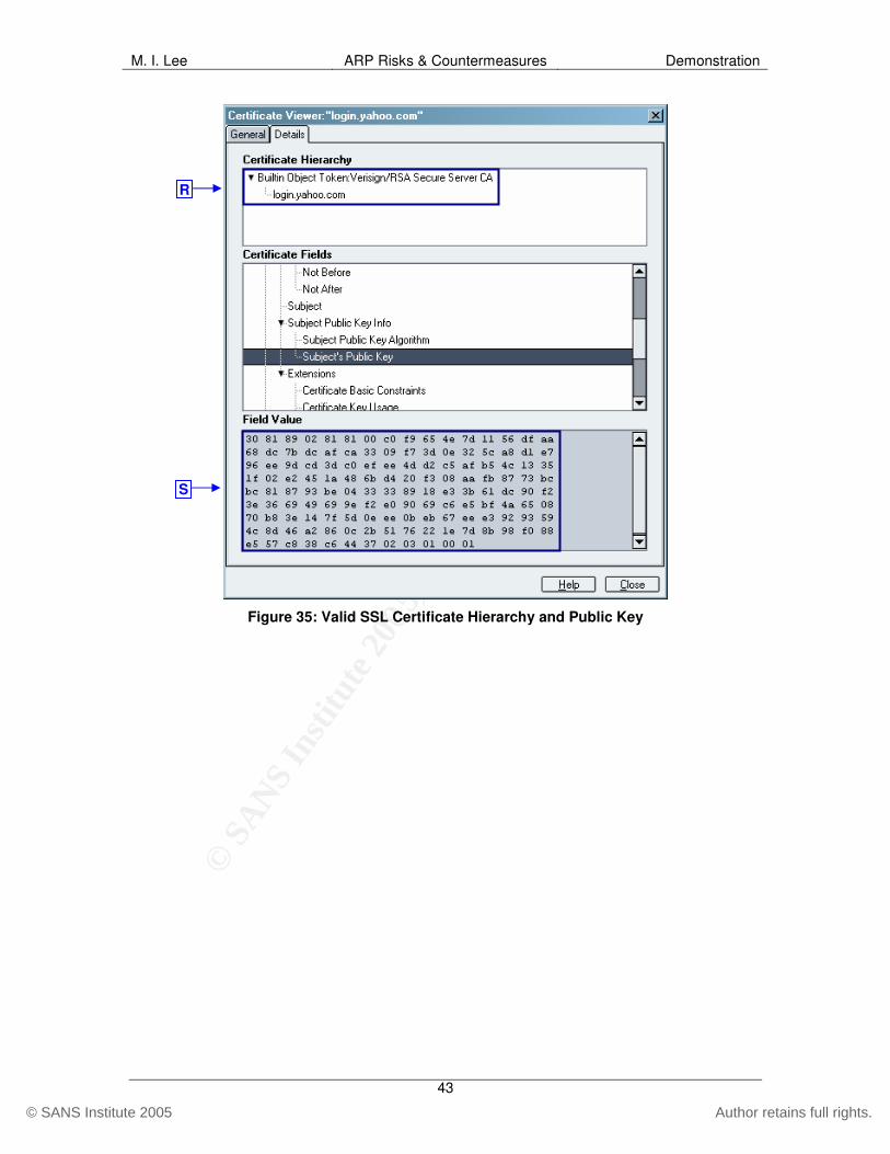
© S
AN
S In
stitu
te 2
00
5, A
utho
r ret
ains
full
righ
ts.
Key fingerprint = AF19 FA27 2F94 998D FDB5 DE3D F8B5 06E4 A169 4E46
© SANS Institute 2005 Author retains full rights.
M. I. Lee ARP Risks & Countermeasures Demonstration
43
Figure 35: Valid SSL Certificate Hierarchy and Public Key
R
S
© S
AN
S In
stitu
te 2
00
5, A
utho
r ret
ains
full
righ
ts.
Key fingerprint = AF19 FA27 2F94 998D FDB5 DE3D F8B5 06E4 A169 4E46
© SANS Institute 2005 Author retains full rights.
M. I. Lee ARP Risks & Countermeasures Countermeasures
44
Countermeasures Because the protocol itself is designed without security in mind, it is not possible to remediate, or completely get rid of, the risks present in ARP. This does not mean, however, that no countermeasures are possible. There are, in fact, several controls that network administrators can implement to mitigate many of the risks in ARP. It is important to point out that using layers of controls is almost always better than using one type of countermeasure alone. In this section, some possible preventive and detective safeguards against the risks in ARP are discussed at a high-level. Details of implementation are beyond the scope of this report.
Preventive
Encryption Properly implemented encryption is one of the most effective ways to protect the confidentiality of sensitive data, such as router and Web application logon information, against MitM attacks. Although relatively easy to implement and use, proper configuration and user education is paramount, when deploying encryption solutions. SSH v.1, for instance, is vulnerable to man-in-the-middle attacks by tools like Ettercap. SSL, the encryption mechanism for most HTTPS implementations, can also be attacked via man-in-the-middle methods. Man-in-the-middle attacks against HTTPS, however, have telltale signs that could be noticed by vigilant and trained users. This makes end-user education all the more important. Despite its pitfalls, when implemented and used properly, encryption is effective and should be utilized whenever possible. In most cases, enabling encryption for clear-text protocols such as telnet, FTP or HTTP is simple enough so that organizations would do well to create policies to enforce its use for critical and sensitive applications as well as for network equipment administration. Such policy should make it clear that encryption must be used around critical assets regardless whether the traffic is Internet-facing or only internal.
End-User Education Any good information security program must include practical end-user education and awareness strategy. One critical concept that every user must be educated on is to not trust everything that shows up on their screen. As shown in the demonstration, when an impostor uses ARP cache poisoning to perform MitM attacks against HTTPS traffic, the user is prompted with a screen that warns them of a mismatched or unauthenticated SSL certificate. If not properly informed, most users would simply click the “Yes” button and accept the bogus certificate, not knowing that any subsequent traffic, including their “encrypted” username and password, will be in plain view of the attacker. End-users must be educated to inspect warnings and verify the authenticity of the certificate. Another awareness that should be communicated is the danger of using plain-

© S
AN
S In
stitu
te 2
00
5, A
utho
r ret
ains
full
righ
ts.
Key fingerprint = AF19 FA27 2F94 998D FDB5 DE3D F8B5 06E4 A169 4E46
© SANS Institute 2005 Author retains full rights.
M. I. Lee ARP Risks & Countermeasures Countermeasures
45
text protocols even on switched networks. This should include network administrators who often assume that logon credentials cannot be harvested as long as switches are used instead of hubs. As discussed throughout this report and proven in the demonstration, it is child’s play for a determined attacker to capture sensitive information, even on switched networks.
Management Subnet Establishing a separate subnet for router and other networking equipment administration is a well-known best-practice for network security. It is especially helpful in mitigating ARP-based MitM attacks against critical networking equipment administration. As previously demonstrated, this is in no way a panacea since attacks such as IP smart spoofing can be used to bypass source address based filtering mechanisms. When used in conjunction with other controls, however, separating management subnet is a sound safeguard that should be considered whenever designing networks.
ARP Inspection14 Some high-end switches have the capability of enforcing ARP inspection to establish VLAN ACL (VACL). By using VACL, administrators can lock specific IP-to-MAC bindings. This method, although effective against ARP poisoning attacks, is manual intensive and impractical for most networks. It is still prudent to use ARP inspection to “freeze” IP-to-MAC bindings to default gateways to disable an attacker attempting to be the middle-man between LAN hosts and the gateway.
Port Security15 Some switches offer the ability to set port security to specify the MAC addresses and the number of devices that can connect to a switch port. For instance, if port security is set to allow only 2 addresses per switch port, the switch can be configured to shutdown a port if more than 2 MAC addresses are detected on that port. Also, port security can be configured so that only a specific MAC address is allowed to connect to a specified port. Port security helps in mitigating MAC flooding or port stealing attacks against switches. Port security, due to its administrative overhead, should be used sparingly, mostly for critical areas of the network.
Static ARP Since most of the attacks against ARP exploit how hosts cache dynamic IP/MAC bindings, in theory static ARP entries would remediate the risk from such attacks. Two caveats to this preventive measure should be considered. First, managing static ARP entries in large networks is out of the question for most organizations. 14 For more information on ARP Inspection for Cisco switches, refer to http://www.cisco.com/univercd/cc/td/doc/product/lan/cat6000/sw_7_5/confg_gd/acc_list.htm#1020673 15 For more information on Port Security for Cisco switches, refer to http://www.cisco.com/univercd/cc/td/doc/product/lan/cat5000/rel_5_4/config/sec_port.htm

© S
AN
S In
stitu
te 2
00
5, A
utho
r ret
ains
full
righ
ts.
Key fingerprint = AF19 FA27 2F94 998D FDB5 DE3D F8B5 06E4 A169 4E46
© SANS Institute 2005 Author retains full rights.
M. I. Lee ARP Risks & Countermeasures Countermeasures
46
The effort would be prohibitively expensive just in terms of required resources to maintain the massive database of IP/MAC bindings. Second, Microsoft Windows machines, for example, override static entries with dynamic ARP replies, rendering static ARP useless as a security measure. Even with these limitations, static ARP should be considered for communication between mission-critical hosts.
Wireless LAN Isolation As seen in the demonstration, popular attack methods against ARP apply to wireless LANs as well. By plugging in an unsecured WAP, layer 2 is expanded out into the open, whereas prior to the prevalence of wireless LANs, the data link layers was traditionally limited to a subsection of a network, usually confined to a physical switch or a VLAN. As a best practice, WAPs should first be secured following industry best-practices, and then further firewalled off from the rest of the wired LAN, only allowing specific communication. That way, even if the wireless LAN is compromised, the rest of the network remains protected. The demonstrated attacks on the wireless network would not have been possible if properly configured firewall was in place.
Detective
arpwatch arpwatch was developed at the network research arm of the Lawrence Berkeley National Lab (LBNL), the same laboratory that brought other useful tools such as tcpdump and libpcap. It is free and can be used to keep track of IP-to-MAC mappings on the network and alert the administrator if there is a change to any of the bindings. arpwatch is efficient and best of all is free to use. Although it natively runs on UNIX-like operating systems, there is a Windows port of the tool called Winarpwatch. It is recommended that at a minimum, arpwatch be installed in mission-critical networks.
NIDS Some Network Intrusion Detection Systems (NIDS) can also be used to keep track of IP-to-MAC mappings or to detect large amounts of ARP packets coming from a node on the network. Since it may be administratively prohibitive to install NIDS on every single broadcast domain, ARP detection should be used on networks that already have NIDS installed or those that are mission-critical to the organization. A popular open source NIDS, Snort, has a preprocessor called ARPspoof, which can detect and alert if the Ethernet source address is different from the one specified in the ARP packet.
Ettercap Although Ettercap was the tool of choice for demonstrating the ARP-based attacks, it can also be used to detect suspicious ARP activities on the network. Ettercap has a plug-in called arp_cop, for example, which passively monitors the LAN for suspicious ARP activity, including poisoning attempts and IP/MAC

© S
AN
S In
stitu
te 2
00
5, A
utho
r ret
ains
full
righ
ts.
Key fingerprint = AF19 FA27 2F94 998D FDB5 DE3D F8B5 06E4 A169 4E46
© SANS Institute 2005 Author retains full rights.
M. I. Lee ARP Risks & Countermeasures Countermeasures
47
conflicts. It can also be used to find other hosts on the network that may be running Ettercap.

© S
AN
S In
stitu
te 2
00
5, A
utho
r ret
ains
full
righ
ts.
Key fingerprint = AF19 FA27 2F94 998D FDB5 DE3D F8B5 06E4 A169 4E46
© SANS Institute 2005 Author retains full rights.
M. I. Lee ARP Risks & Countermeasures Summary
48
Summary Address Resolution Protocol is a necessary part of IP-based Ethernet networks. It was, unfortunately, designed without security in mind, leaving much room for creative minds to exploit its inherent vulnerabilities. Its foremost weakness is in the fact that it is a stateless protocol with no way of authenticating requests and replies. The risks arising from ARP’s insecurities are much more serious than most network administrators have traditionally given thought. What’s more, many administrators are oblivious to the dangers or simply do not pay attention to the simple, yet devastating, attack methods that abound as demonstrated in this report. Popular attack methods include ARP cache poisoning, ARP spoofing, MAC flooding, Port stealing, and IP smart spoofing. These methods can be used to carry out man-in-the-middle and denial-of-service attacks. Some of these attacks can even compromise encrypted traffic, including SSL and SSH version 1. As serious as they are, the risks that the vulnerabilities in and threats against ARP pose on networks may not be as critical, when compared to the risks that arise from the lack of commitment to information security from an organization’s management or the lack of a comprehensive security program. Let this report serve as a wake-up call, nevertheless, for those organizations and network administrators who still fail to do the most basic security due-diligence, such as encrypting confidential data, separating the administrative network and properly tuning the NIDS. Organizations should also note that some of the more devious attacks, such as HTTPS man-in-the-middle, can only be countered by users that are savvy enough to recognize and take proper action on anything that is out of the ordinary; thus, end-user awareness should always complement technical countermeasures. No one group can be made responsible for establishing and maintaining information security for an organization. Information security must be a continual cycle to which everyone in the organization is committed. Likewise, it is not just up to system and network administrators to configure and secure the internal network from the glaring holes in ARP. Security professionals and auditors must be able to articulate the risks so that stakeholders can make informed decisions to protect the assets. It is hoped that this report will serve as an aide to creating security audit checklists that address internal network security, especially in pointing out the dangers of unmitigated risks in ARP.

© S
AN
S In
stitu
te 2
00
5, A
utho
r ret
ains
full
righ
ts.
Key fingerprint = AF19 FA27 2F94 998D FDB5 DE3D F8B5 06E4 A169 4E46
© SANS Institute 2005 Author retains full rights.
M. I. Lee ARP Risks & Countermeasures Appendix
49
Appendix
Table 5: Likelihood Definitions16
Likelihood Level Likelihood Definition
High The threat-source is highly motivated and sufficiently capable, and controls to prevent the vulnerability from being exercised are ineffective.
Medium The threat-source is motivated and capable, but controls are in place that may impede successful exercise of the vulnerability.
Low The threat-source lacks motivation or capability, or controls are in place to prevent, or at least significantly impede, the vulnerability from being exercised.
Table 6: Magnitude of Impact Definitions17
Magnitude of Impact Impact Definition
High
Exercise of the vulnerability (1) may result in the highly costly loss of major tangible assets or resources; (2) may significantly violate, harm, or impede an organization’s mission, reputation, or interest; or (3) may result in human death or serious injury.
Medium Exercise of the vulnerability (1) may result in the costly loss of tangible assets or resources; (2) may violate, harm, or impede an organization’s mission, reputation, or interest; or (3) may result in human injury.
Low Exercise of the vulnerability (1) may result in the loss of some tangible assets or resources or (2) may noticeably affect and organization’s mission, reputation, or interest.
16 Stoneburner et al., p.21. 17 Stoneburner et al., p.23.

© S
AN
S In
stitu
te 2
00
5, A
utho
r ret
ains
full
righ
ts.
Key fingerprint = AF19 FA27 2F94 998D FDB5 DE3D F8B5 06E4 A169 4E46
© SANS Institute 2005 Author retains full rights.
M. I. Lee ARP Risks & Countermeasures Bibliography
50
Bibliography Forouzan, Behrouz A. TCP/IP Protocol Suite – 2nd ed. New York: McGraw-Hill, 2003. Stevens, W. Richard. TCP/IP Illustrated, Volume 1. Reading: Addison Wesley Longman, Inc, 1994. Northcutt, Stephen et al. Inside Network Perimeter Security: The Definitive Guide to Firewalls, Virtual Private Networks (VPNs), Routers, and Intrusion Detection Systems. Indianapolis: New Riders Publishing, 2003. Converey, Sean. Network Security Architectures. Indianapolis: Cisco Press, 2004. Peikari, Cyrus et al. Maximum Wireless Security. Indianapolis: Sams Publishing, 2003. Hoffman, Mark. “ISO 17799 – A Standard for Information Security Management.” Info-Tech White Papers 2003. Info-Tech Research Group, 2003. Stoneburner, Gary et al. “Risk Management Guide for Information Technology Systems. Recommendations of the National Institute of Standards and Technology”. July 2002. URL: http://csrc.nist.gov/publications/nistpubs/800-30/sp800-30.pdf (1 May 2004) Department of Commerce, New South Wales Government. “Information Security Guideline for NSW Government - Part 1 Information Security Risk Management”. June 2003. URL: http://www.oit.nsw.gov.au/content/2.3.16-Security-Pt1.asp (1 May 2004) Plummer, David C. “An Ethernet Address Resolution Protocol”. November 1982. URL: http://www.ietf.org/rfc/rfc0826.txt?number=826 (1 June 2004) Kristoff, J. “Network Port Security”. April 2002. URL: http://condor.depaul.edu/~jkristof/technotes/dpunet-rfc4.txt (1 June 2004) CSO Magazine/U.S. Secret Service/CERT Coordination Center. “2004 E-Crime Watch Survey”. 25 May 2004. URL: http://www.cert.org/archive/pdf/2004eCrimeWatchSummary.pdf (17 Sept. 2004) U.S. Secret Service and CERT Coordination Center/SEI. “Insider Threat Study: Illicit Cyber Activity in the Banking and Finance Sector”. August 2004. URL: http://www.cert.org/archive/pdf/bankfin040820.pdf (17 Sept. 2004)

© S
AN
S In
stitu
te 2
00
5, A
utho
r ret
ains
full
righ
ts.
Key fingerprint = AF19 FA27 2F94 998D FDB5 DE3D F8B5 06E4 A169 4E46
© SANS Institute 2005 Author retains full rights.
M. I. Lee ARP Risks & Countermeasures Bibliography
51
Fleck, Bob. Dimov, Jordan. “Wireless Access Points and ARP Poisoning: Wireless vulnerabilities that expose the wired network.” URL: http://www.cigitallabs.com/resources/papers/download/arppoison.pdf (17 Sept. 2004) Licour, Laurent et al. “The IP Smart Spoofing”. October 2002. URL: http://www.medasys.com/company/fr/mis/securite/docsecurite/smartspoof-en.pdf (5 Oct. 2004.) Cisco Systems. “Internetworking Technology Handbook”. URL: http://www.cisco.com/univercd/cc/td/doc/cisintwk/ito_doc/ (5 Oct. 2004.) Ornaghi, Alberto et al. “Man in the Middle Attacks Demos”. URL: http://Ettercap.sf.net/devel/bh-us-03-ornaghi-valleri.pdf (5 Oct. 2004.) Ettercap Development Forum. URL: http://ettercap.sourceforge.net/forum/index.php (1 May 2004).