MAGNETICMEASURES AND COUNTERMEASURES IN COLDWAR ROMANIA
16
Transcript of MAGNETICMEASURES AND COUNTERMEASURES IN COLDWAR ROMANIA


MAGNETIC MEASURES AND COUNTERMEASURES
IN COLD WAR ROMANIA
OCTAVIAN BALTAG1 GEORGIANA MARIN
2
1Terraflux Control Ltd., Tatarasi Street, No. 65, Iasi, ROMANIA
2Research Center for Navy, Constanta, ROMANIA
E-mail: [email protected]
Abstract — This paper presents the development and magnetometer techniques used in measure and
countermeasure systems for naval and terrestrial equipment during the Cold War era (1970 -1989) and the
beginning of transition in 1990s. Some applications of magnetometer means for naval magnetic fields
control, magnetic characterization and detection of ship magnetic signature are presented. Also, there are
examined some applications related to the magnetic characterization of ground combat equipment. In
parallel, applications related to the development of naval and terrestrial defensive means are presented, that
is naval and anti-tank mines.
Keywords — magnetic measures, countermeasures, degaussing, deperming
1. BRIEF HISTORY OF MAGNETIC MEASUREMENTS IN ROMANIA
The first measurements of the magnetic field in Romania were mentioned by Theodore Stamati
(1812-1852), physics professor at Mihaileana Academy Iasi, and described in the first physics
textbook [1]. The magnetic field value is not known, but there is mentioned: "La noi la Iasi la anul
1846 abaterea era 90,30 spre vest. La anul 1832 Mart 4, dupa Arago, abaterea magnetismului in
Paris este de 220,3 spre est" (Figure 1). (Here in Iasi, in 1846, the deviation was 9
0.30 towards west.
In March 4, 1832, according to Arago, the magnetic deviation in Paris is 220.3 towards east).
Fig. 1. Quote from Theodor Stamati’s work - Elementary Physics (Fizica elementara)
Fig. 2. Theodolite used in Filaret meteorological station - Romania

TECHNOLOGY IN TIMES OF TRANSITION
216
Later, another Romanian physicist - Stefan Hepites (1851-1922), together with lt. St. Murat,
achieved the first magnetic map of Romania. In 1896, he built a terrestrial magnetism station
equipped with a theodolite (Figure 2), on Filaret hill, Bucharest, near a meteorological station
[2].Magnetometer investigations were continued by Stefan Procopius (1890-1972) who drew up
important magnetic maps of Romania, during 1895 - 1954 [3]. He also stated that, since 1932 the
Earth’s magnetic moment began to rise, after it had continuously decreased for over 100 years, thus
solving a controversy lasting for decades. He determined the period of this variation: about 500
years. Researches on magnetic field variation were performed with conventional magnetic dipole
magnetometers in a geodetic point located outside the city of Iasi. Carrying out teaching and
research activities at the Iasi Faculty of Physics and Romanian Academy Technical Physics Center,
he stimulated the researchers’ interest in magnetism and geomagnetic measurements until 1960s.
In the 70s, a group of researchers from the Centre for Technical Physics Iasi (IFT), under
physicist Dr. Al. Moldovanu (1933-2013), initiated a series of research on the development of
saturable core magnetometers. The purpose was to execute a triaxial saturable core magnetometer
for equipping a Soviet satellite in the Intercosmos program. The magnetometer was destined to
measure and transmit information on the circumterrestrial magnetic field [4]. Saturable core
transducers of Vaquier type were made in several versions (Figure 3) and electronic modules were
executed at the Institute of Atomic Physics in Magurele. Research on the development of magnetic
transducers and electronic circuits meeting the specific requirements of space have stimulated the
transition from basic research to technological research.
Fig. 3. Saturable core in various execution stages
Research on saturable core operation stimulated the development of a collective entitled
"Magnetic Detection" coordinated by physicist Dr. Octavian Baltag, whose work focused on the
magnetometer means and methods in detecting ferromagnetic bodies hidden or embedded in non-
magnetic materials. Another area emerged as a result of military and industry demands was the
control of ambient magnetic fields produced by magnetic masses or human activity. Regarding the
documentation means, the lack of specialized magazines and books was replaced by the library of
the State Office for Inventions and Trademarks - Bucharest, which had collections of patents in all
areas and from all states.

O. BALTAG & G. MARIN: Magnetic Measures and Countermeasures
217
On the Romanian contributions to the execution of fluxgate transducers and low strength field
magnetometers, the coordinated and systematic research conducted at the Center for Technical Physics
Iasi can be mentioned: Baltag O., A. Moldovanu with collaborators from: the National Institute of
Metrology Bucharest - Julier V., F. Cretu, U. Wiener, the Research Centre for Navy in Constanta - Nanu
D., Mateiciuc I., Robu O., Balasa L., Ignat V., Institute of Atomic Physics Bucharest - Ciobanu M.
2. MAGNETOMETRY APPLICATIONS IN MEASURES AND COUNTERMEASURES
From military and strategic standpoint, measures are defined as the offensive and direct activities
undertaken by the armed forces, with (materially and psychologically) destructive effect on enemy
forces. On the other hand, countermeasures represent the entire defensive, direct or indirect, actions
performed by own forces to counter-attack or cancel enemy measures. Measures and
countermeasures involve precision, certainty, security and high reliability [5].
Regarding these very special applications for physicists, who had no training in the military area,
the military partners proved to be the perfect partner through the precise definition of problems to
be solved, and some original solutions. In general, this research has been focused on two directions:
1) naval applications in marine environment:
- magnetic measures: magnetic field control, demagnetization, magnetic signature
- magnetic countermeasures: naval mine with multi-parameter sensors
2) applications in defensive terrestrial military equipment:
- magnetic measures: characterization of magnetic signature
- magnetic countermeasures: antitank mine with multi-parameter sensor
2.1. MAGNETIC MEASURES
In 1951, the Romanian Navy received from the Soviet General Staff a degaussing station, among
other equipment [6]. At the 27th meeting of the Standing Committee for the defense industry CAER
(Czechoslovakia, 19-24 November 1973), the Romanian representatives required the specialization
in manufacturing the AG-9 grenade launcher (with carriage), anti-tank guided missile complex and
demagnetization ships [7]. In this context, there increased the interest in naval magnetometry
research, so that the Institute of Technical Physics was contacted by specialists of Navy Research
Center in Constanta, for cooperation in military magnetometry.
2.1.1. TRIAXIAL MAGNETOMETER FOR MINESWEEPERS SAD EQUIPMENT CONTROL
In 1976, the Magnetometry Laboratory received from the Ministry of Defence (Research Center
for Navy, Constanta), a request to perform a complex magnetometer system for controlling the
magnetic field of minesweepers [8]. This was the first research contract that led to a change in the
research team vision regarding the purpose of research projects, special metrological requirements,
issues raised by the marine environment: reliability, endurance, transport conditions, storage and
operation in unprotected environment, marine equipment specific supply, electromagnetic
compatibility, etc. Research was conducted in accordance with the topic requirements, norms and
standards were prepared for system testing and approval.
TECHNOLOGY IN TIMES OF TRANSITION
218
The system provides automatic control of current in the magnetic field compensation windings,
depending on the latitude and ship magnetic heading. Equipment is divided into three identical
channels, measuring the Earth magnetic field components: XT, YT and ZT. Each channel consists of
a fluxgate magnetometer measuring a field component. The transducers are arranged orthogonally
and placed at the ship mast, in order to break-down the geomagnetic field after the vessel axes.
The measured signal on each channel is applied to the control winding of an amplidyne feeding into
the compensation winding a current proportional to the signal amplitude (inductive component)
superimposed onto the permanent component (defined in the degaussing process). The transducer is
provided with compensation and calibration windings for periodic testing. The amplidyne functions in a
negative feedback loop. Negative feedback signal collected through a shunt, forces the degaussing
winding current to follow closely the field variations measured by the magnetometer. The installation is
presented in Figure 4.a, and in Figures 4b, c, d there is presented old installation of Soviet construction.
a b c d
Fig. 4. SAD installation for ship antimagnetic protection
2.1.2. THREE CHANNEL MAGNETOMETER FOR DEMAGNETIZATION CONTROL
The magnetometer is designed to equip a demagnetization ship and to measure the magnetic
field vertical component. Romanian Navy was fitted with three demagnetization ships: Automatica
Energetica, Magnetica and Electronica [9] (Figure 5). They were tasked with processing magnetic
fields of Navy ships.
Fig. 5. Demagnetization ships Magnetica and Electronica [9]

O. BALTAG & G. MARIN: Magnetic Measures and Countermeasures
219
Fig. 6. Image from an US Navy degaussing application [10]
Transducers are placed in sealed enclosures (Figure 7), properly ballasted and resistant to
pressure corresponding to 40 meter depth in seawater. Magnetometer connection cable length is 70
meters. Weights are used to cancel transducers drift due to underwater currents. The magnetometer
operates by a conventional electronic scheme, with excitation on the fundamental frequency and
detection of the second harmonic. The three identical measurement channels are galvanically
separated. Power supply is performed either through 220V/50Hz mains or from a 12V battery. Each
channel is able to manually compensate for the transducer field vertical component, by means of a
helical potentiometer and a switch to change the field polarity. The magnetometer can operate in
both marine and land environment. The measuring range is ±800 mOe, resolution is 0.2 mOe.
Magnetometer indications are measurement units known by the crew, and not in SI units.
Fig. 7. Three channel magnetometer used at demagnetization ships (1988)
Fig. 8. Transducer used at Automatica demagnetization ship (manufactured in URSS, 1950s)
2.1.3. NAVAL MAGNETIC RANGES
Measuring ships physical fields, including the magnetic field, has emerged as a necessity after
the appearance of contactless naval mines. These fields needed be known and maintained below a
certain threshold, set at ship design. Magnetic field measurement is carried in specially designed
ranges, aimed at ship magnetic processing and periodic control of the ship magnetic field values.
The magnetic processing range needs to comply with a sum of requirements [12].

TECHNOLOGY IN TIMES OF TRANSITION
220
The water velocity should not exceed 0.5 km in port waters. The area should be magnetically
uniform, with no nearby ferromagnetic masses or electrical networks. The port waters depth should
be at least 2 m higher than the measurement depth, and the sea bed should have uniform depth,
without any vegetation. The range should be equipped with fixing means in four points, allowing
the ship magnetic orientation on four main magnetic headings (Nm-Sm and Em-Wm) with an
accuracy of ±20.
The range for ship magnetic control is usually a fixed construction, and is placed on the ships
fairway, at the port entry or nearby (Figure 9). The facility area should allow the placement of two
sensors networks arranged on main magnetic directions Nm-Sm and Em-Wm, in order to ensure an
effective magnetic control of the ship on four magnetic headings. Measuring and control equipment
connected to sensors networks and power supply is housed in a nearby facility. The area is marked
in order to avoid ships anchoring.
Ship ranges are usually constructed in a combined structure, to allow measurement of other
physical fields: acoustic, hydrodynamic. As a result, those sea water areas must also meet the
requirements of measuring these fields.
Fig. 9. Naval range – sea waters
2.1.3.1. NAVAL RANGE WITH MULTICHANNEL MAGNETOMETER
In order to equip a naval range several multichannel magnetometers were constructed. These
were designed to measure the Earth's magnetic field strength in several points remote from the
magnetometer block. Applications were both naval and terrestrial. There were several versions
produced, with 8 to 24 channels (Figure 10). The 8-channel magnetometer was used in a terrestrial
range to determine the magnetic signature of military vehicles. The measurement channels are
galvanically separated. The electronic scheme follows the magnetometer basic principles, but with
some particularities, being made with hybrid integrated circuits.
The transducers are fluxgate type with saturable core made of Vacuumschmeltze supermaloi
tape. Due to the large cable length, the excitation voltage supplied by excitation module is higher
than for other magnetometers. Magnetometer output channels provide analog signals that are
applied to a computer system type ECAROM 800, being the first computerized naval magnetic
range. ECAROM was the first Romanian mini computer system manufactured since 1975 at

O. BALTAG & G. MARIN: Magnetic Measures and Countermeasures
221
Automation Elements Enterprise using the 8080 microprocessor. It was equipped with an analog
numeric converter EC 880-CAN representing the magnetometers interface.
The magnetometer system characteristics are [12]:
- measuring range: ± 20.000 nT, ± 2.000 nT
- geomagnetic field compensation range: ± 60.000 nT
- geomagnetic field compensation error: 5 nT
- calibration testing
- resolution: 1 nT
- transducer cable length: 200 m
- measurement error: 2%.
-
Fig. 10. Multichannel magnetometer
2.1.3.2. COMPUTERIZED MULTICHANNEL INSTALLATION
Due to modernization needs of both the magnetometer channels and information system,
Terraflux Control Ltd. was asked to execute a complex magnetometer system with 128 channels
(Figure 11) to establish an underwater measurement network, for ship magnetic field [11]. It
provides data to a computerized analysis and computing remote system, situated ashore, on a nearby
buoy, or on another vessel [12].
The system inputs data from the fluxgate transducers, and provides an output voltage
proportional to the vertical component of the measured field. Electronic circuitry operates based on
signals provided by the fluxgate transducers. Since magnetometers are used in a remote underwater
network, transducers are provided with compensation - calibration windings remotely controlled.
For remote compensation - calibration of the two winding functions are combined and represented
by a single coil powered by a digitally controlled constant current supply. Compensation pulses are
applied in a serial mode, with different length pulse trains for command and reset, in an 8 bit binary
code. Pulses are applied by means of galvanic separation circuits made with optical isolators
controlling the field increment steps through digital-analog conversion circuits.
The measuring system uses as primary elements of the acquisition, data acquisition modules
6B12 Analog Devices Series with 16-bit AD conversion, galvanic separation, and self-calibration
and temperature compensation. The modules are used in a multipoint RS 485 serial communications
network, with local power. This there is enabled the measurement data transmission to a computer
system at 1200 m distance.

TECHNOLOGY IN TIMES OF TRANSITION
222
Calibrations commands are software performed and transmitted through the RS 485 network to each
magnetometer, or to a single preselected magnetometer, by means of a digital card with 24 I/O ports
type 6B50 Analog Devices. Each magnetometer is configured as an individual address corresponding to
a number between 0 and 255. Transmission speed used on the serial line is 19200 baud.
Fig. 11. Computerized multichannel installation [12]
In the graphical representation there illustrated the magnetic field variation produced by the
movement of an elongated shape ferromagnetic object, at different speeds and distances. Through
the user interface to:
- configuration computer port through which the data transmission used on the RS485
communications bus - COM5;
- serial bus transfer rate: 19200 baud;
- measurement channel address selected for acquisition (maximum number of channels that
can be addressed individually or all on a RS485 network is 256);
- magnetometer network scanning, indicating the maximum address number of the last channel;
- system map update and display of system active modules;
- transducer measuring range;
- measured value display in various formats;
- plotting measured values and storing data in a memory buffer of size is chosen by user;
- determining the number of acquired samples (if signal filtering is imposed);
- establishing the field steps for magnetometer calibration
The program first performs a network map of 6B modules, then monitors and controls any of the
measurement network building blocks.
2.1.4. MAGNETIC ANOMALY DETECTION IN MARINE ENVIRONMENT
The existence of wrecks on the seabed, or searching lost bodies, anchors, anchor chains, buoys,
torpedoes, etc., causes changes to the local magnetic map, but also represents a potential risk [13].
As a result, the Magnetic Detection Laboratory of the Institute of Technical Physics Iasi was asked
in 1990 to conduct research related to the electromagnetic detection of these artifacts. The research
was focused on two directions:
- delivery of a portable metal detector for divers, and
- delivery of large metallic objects detector, towed by a boat. The transducer operates on eddy
currents, for this large application (2 x 3) m, and is shown in Figure 12.

O. BALTAG & G. MARIN: Magnetic Measures and Countermeasures
223
Fig. 12. Transducer a metal detector for underwater exploration [13]
In order to update the geomagnetic map of the Romanian littoral area after the 90s, the Navy
Research Centre initiated a project involving aerial modern approach: a helicopter towing a nuclear
precession magnetometer, optical communication of magnetometer information, accurate
identification of magnetometer altitude etc. To increase resolution and reduce the measurement
duration, Terraflux Control Ltd. chose to use the Overhauser effect [13]. Figure 13 illustrates the
Overhauser effect magnetometer within a field application. The project was not completed.
Fig.13. Overhauser effect magnetometer
2.2. NAVAL MAGNETIC COUNTERMEASURES
IFT Magnetometry Laboratory was approached alternately at 2-3 year intervals, with technical
issues related to the implementation of specific countermeasures devices. Approach was delicate, as
the same research team that had worked and conducted military installations intended for magnetic
measurements was regularly approached for magnetic countermeasures, possibly combined with
other systems: acoustic, electric, etc.
2.2.1. MULTI-PARAMETER NAVAL MINE
The Navy Research Center Constanta requested the IFT Magnetometry Laboratory to conduct a
feasibility study of a naval mine with magnetic channel. Multi-parameter naval mine was equipped
with several programmed acoustic, magnetic sensors that conditioned the time of the explosion.
Magnetic channel was the most complex. It was composed of two blocks of triaxial magnetic field
sensors are mounted on a base. One of the blocks provides magnetometer information about the
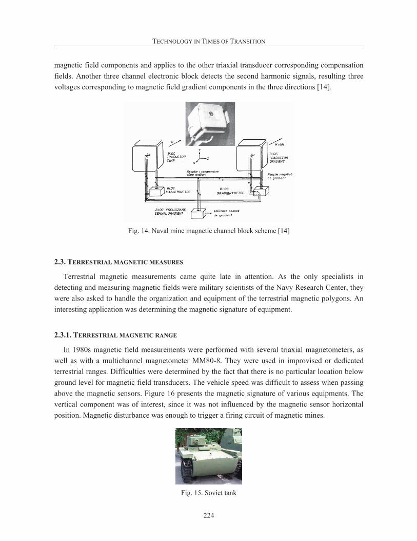
TECHNOLOGY IN TIMES OF TRANSITION
224
magnetic field components and applies to the other triaxial transducer corresponding compensation
fields. Another three channel electronic block detects the second harmonic signals, resulting three
voltages corresponding to magnetic field gradient components in the three directions [14].
Fig. 14. Naval mine magnetic channel block scheme [14]
2.3. TERRESTRIAL MAGNETIC MEASURES
Terrestrial magnetic measurements came quite late in attention. As the only specialists in
detecting and measuring magnetic fields were military scientists of the Navy Research Center, they
were also asked to handle the organization and equipment of the terrestrial magnetic polygons. An
interesting application was determining the magnetic signature of equipment.
2.3.1. TERRESTRIAL MAGNETIC RANGE
In 1980s magnetic field measurements were performed with several triaxial magnetometers, as
well as with a multichannel magnetometer MM80-8. They were used in improvised or dedicated
terrestrial ranges. Difficulties were determined by the fact that there is no particular location below
ground level for magnetic field transducers. The vehicle speed was difficult to assess when passing
above the magnetic sensors. Figure 16 presents the magnetic signature of various equipments. The
vertical component was of interest, since it was not influenced by the magnetic sensor horizontal
position. Magnetic disturbance was enough to trigger a firing circuit of magnetic mines.
Fig. 15. Soviet tank

O. BALTAG & G. MARIN: Magnetic Measures and Countermeasures
225
Fig. 16. Magnetic signature of various vehicles and military equipment [13]
2.3.2. POSTAL BOMB DETECTOR
The postal bomb detector was a portable metal detector, designed for antiterrorist control of
postal mail (envelopes, small packages). In principle, it used to detect small metallic elements -
wires, needles, which could have been part of an electrical circuit, electronic primer circuit or
mechanical percussion device. It was useful in detecting the presence of banknotes by detecting
their magnetic markers. It was also used by special services for the control of packages circulated
with special post.
Fig. 17. Postal bomb detector [13]
2.4. TERRESTRIAL MAGNETIC COUNTERMEASURES
After performing measurements of equipment magnetic signature, the Magnetometry and
Magnetic Detection Laboratory was asked to execute a magnetic transducer designed to work with a
geophone in a magnetic anti-tank mine with cumulative effect.
2.4.1. ANTITANK MULTI-PARAMETRIC MINE
The parametric antitank mine was a sensitive issue, for several reasons. It had to be in magnetic
and seismic standby mode for a few months. The existing accumulators were relatively large; the
seismic and magnetic sensors had to have a very low consumption, and the metallic enclosure
functioned as a magnetic screen and reduced the magnetic channel sensitivity.
After several stages of research, there were homologated: the geophone (ICPE Iasi), the
magnetic transducer, the multiflux transducer, the electronic module [15] [16], the priming circuit
and batteries. There was executed a zero series of sensors as well as multiple models (Figure 18),
along with Electrotehnica enterprise. The project was stopped without completion.
TECHNOLOGY IN TIMES OF TRANSITION
226
Fig. 18. Antitank mine with seismic and magnetic sensor [13]
3. ELECTRONIC COMPONENTS AND MAGNETIC SENSORS USED IN MILITARY
EQUIPMENT
Research and technological development in magnetometry was particularly rich both in diversity
and complexity of magnetometer installations, as well as in very special applications with great
specificity, which is unusual for a group of researchers of the Romanian Academy. Precisely these
applications and different requirements led the change in researchers’ optics and research approach.
Thus, new electronic components were imagined, field transducers and sensors were created, new
methods and means of measuring and detecting magnetic fields and disturbances were developed.
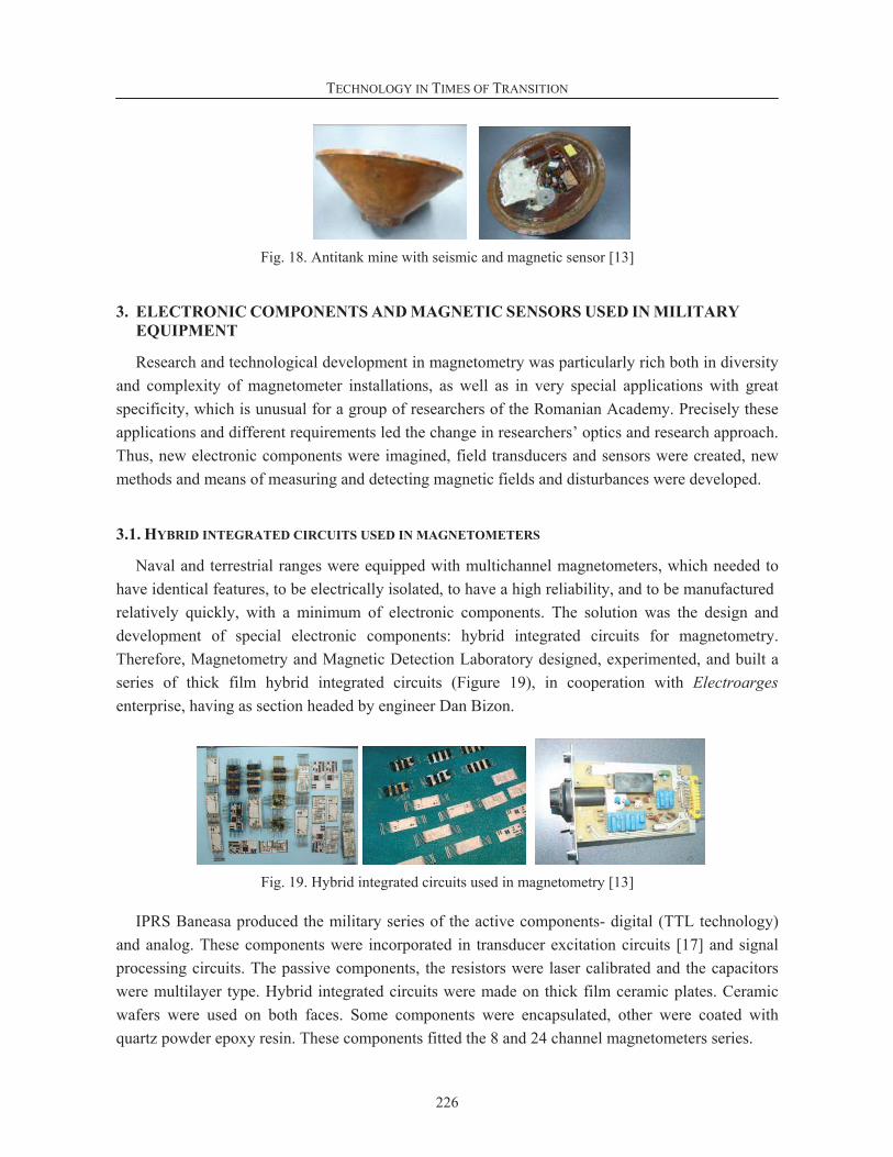
3.1. HYBRID INTEGRATED CIRCUITS USED IN MAGNETOMETERS
Naval and terrestrial ranges were equipped with multichannel magnetometers, which needed to
have identical features, to be electrically isolated, to have a high reliability, and to be manufactured
relatively quickly, with a minimum of electronic components. The solution was the design and
development of special electronic components: hybrid integrated circuits for magnetometry.
Therefore, Magnetometry and Magnetic Detection Laboratory designed, experimented, and built a
series of thick film hybrid integrated circuits (Figure 19), in cooperation with Electroarges
enterprise, having as section headed by engineer Dan Bizon.
Fig. 19. Hybrid integrated circuits used in magnetometry [13]
IPRS Baneasa produced the military series of the active components- digital (TTL technology)
and analog. These components were incorporated in transducer excitation circuits [17] and signal
processing circuits. The passive components, the resistors were laser calibrated and the capacitors
were multilayer type. Hybrid integrated circuits were made on thick film ceramic plates. Ceramic
wafers were used on both faces. Some components were encapsulated, other were coated with
quartz powder epoxy resin. These components fitted the 8 and 24 channel magnetometers series.
O. BALTAG & G. MARIN: Magnetic Measures and Countermeasures
227
3.2. MULTIFLUX TRANSDUCER
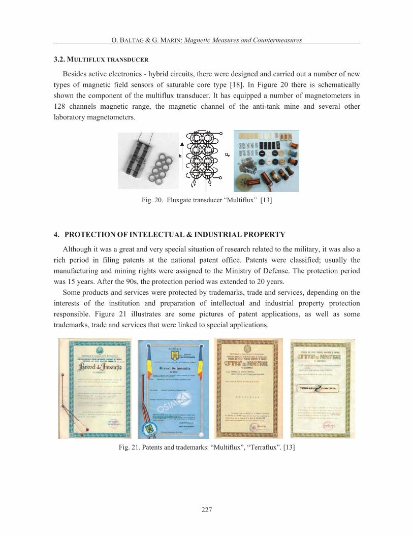
Besides active electronics - hybrid circuits, there were designed and carried out a number of new
types of magnetic field sensors of saturable core type [18]. In Figure 20 there is schematically
shown the component of the multiflux transducer. It has equipped a number of magnetometers in
128 channels magnetic range, the magnetic channel of the anti-tank mine and several other
laboratory magnetometers.
Fig. 20. Fluxgate transducer “Multiflux” [13]
4. PROTECTION OF INTELECTUAL & INDUSTRIAL PROPERTY
Although it was a great and very special situation of research related to the military, it was also a
rich period in filing patents at the national patent office. Patents were classified; usually the
manufacturing and mining rights were assigned to the Ministry of Defense. The protection period
was 15 years. After the 90s, the protection period was extended to 20 years.
Some products and services were protected by trademarks, trade and services, depending on the
interests of the institution and preparation of intellectual and industrial property protection
responsible. Figure 21 illustrates are some pictures of patent applications, as well as some
trademarks, trade and services that were linked to special applications.
Fig. 21. Patents and trademarks: “Multiflux”, “Terraflux”. [13]

TECHNOLOGY IN TIMES OF TRANSITION
228
5. CONCLUSIONS
Scientific and technological research had a period of intense creativity in the use of magnetic
field measurement and detection principles and techniques. Doctoral theses were supported in
magnetic protection. Manufacturing technologies of magnetic sensors for measuring weak magnetic
fields were developed. New technologies to conduct special electronic components, such as the first
hybrid integrated circuits for magnetometry in the world were designed and implemented.
The multichannel magnetometers were the first magnetometers in the world equipped with
hybrid integrated circuits. Several devices for military and special purpose defensive applications
have been patented. The first complex ranges for determining the magnetic signature of marine and
river vessels and land-based equipment have been constructed. A series of military magnetometry
theses were presented, some of which were classified. One book on ships physical fields was
reported (1990).
REFERENCES
[1] Stamati, Theodor. Fizika Elementara – pentru clasele colegiale din Principatul Moldovei. Iasi:
Tipografia Institutul Albinei, 1849, 132.
[2] Constantinescu, Liviu. “Contributia lui tefan Hepites la dezvoltarea geofizicii”. Studii i cercet ri de
geologie, geofizic i geografie, Seria geofizic , 15 (1977), pp. 179–185.
[3] Procopiu, Stefan. Opere alese. Bucharest: RSR Academy, 1979.
[4] *** Technical Report no. 177/39059/1972, Realizarea unui magnetometru pentru masuratori spatiale
INTERCOSMOS, CFT Iasi, 1972.
[5] Barbu, Mihail. Campurile fizice ale navelor. Bucharest: Military Publishing, 1990.
[6] Petre Opris, “Procesul de modernizare a Armatei Române cu armament i tehnic de lupt , 1951-1955”,
ART-EMIS Journal, March, 2014, http://www.art-emis.ro/istorie.
[7] *** http://jurnalul.ro, May, 12, 2009.
[8] Nanu, Dumitru. “Cercetarea campului magnetic al navelor militare si conceperea unor instalatii de
control si compensare automata a magnetizarii navei”. PhD Thesis, Military Technical Academy,
Bucharest, 1982.
[9] http://romaniaforum.info/index.php?page=Index, 2014
[10] http://www.compassadjustment.com/
[11] Balasa, Lucian. “Cercetari si contributii privind realizarea unui system computerizat de masura a
campului magnetic al navei”. PhD Thesis, Dunarea de Jos University, Galati, 2001.
[12] Baltag, Octavian; Costandache, Doina; Robu, Octavian; Ignat, Vasile. Magnetometrie. Iasi: Inventica
Publishing House, 2001) http://books.google.ro.
[13] www.terrafluxcontrol.ro
[14] Baltag, Octavian. "Contributions to development of low magnetic fields magnetometers", PhD Thesis,
Institute of Technical Physics Iasi - Central Institute of Physics, Bucuresti, 1982.
[15] Baltag, Octavian. Devices for magnetic detonation of a mine. Patent RO 102963, 1989.
[16] Baltag, Octavian. Magnetic detection devices. Patent RO 921162, 2006.
[17] Baltag, Octavian. Devices for generating the fluxgate excitation and reference signal. Patent RO 80140,
1982.
[18] Baltag, Octavian. Fluxgate with multiple path of flux. Patent RO 60346, 1975.