ADDIS ABABA UNIVERSITY INSTITUTE OF TECHNOLOGY
71
AAiT ADDIS ABABA UNIVERSITY INSTITUTE OF TECHNOLOGY SCHOOL OF MECHANICAL AND INDUSTRIAL ENGINEERING EFFECT OF SPEED AND SKEWING ANGLE IN CONTROLLING AXIAL THRUST OF ROTARY KILN A THESIS IN PARTIAL FULFILLMENT OF THE REQUIREMENTS FOR THE DEGREE OF MASTER OF SCIENCE IN MECHANICAL ENGINEERING (MECHANICAL DESIGN STREAM) BY SEIFU ABEGAZ SUBMITTED TO THE SCHOOL OF MECHANICAL AND INDUSTRIAL ENGINEERING ADVISOR: DANIEL TILAHUN (Dr.) SEPTEMBER 2015
-
Upload
khangminh22 -
Category
Documents
-
view
1 -
download
0
Transcript of ADDIS ABABA UNIVERSITY INSTITUTE OF TECHNOLOGY
AAiT
ADDIS ABABA UNIVERSITY
INSTITUTE OF TECHNOLOGY
SCHOOL OF MECHANICAL AND INDUSTRIAL ENGINEERING
EFFECT OF SPEED AND SKEWING ANGLE IN CONTROLLING
AXIAL THRUST OF ROTARY KILN
A THESIS IN PARTIAL FULFILLMENT OF THE REQUIREMENTS FOR THE DEGREE OF
MASTER OF SCIENCE IN MECHANICAL ENGINEERING
(MECHANICAL DESIGN STREAM)
BY SEIFU ABEGAZ
SUBMITTED TO THE SCHOOL OF MECHANICAL AND INDUSTRIAL ENGINEERING
ADVISOR: DANIEL TILAHUN (Dr.)
SEPTEMBER 2015

EFFECT OF ROTATIONAL SPEED IN CONTROLLING AXIAL THRUST OF ROTARY KILN
Seifu Abegaz AAU, AAiT, SMIE-2015
i i
Acknowledgment
First and for most my gratitude shall go to my family especially my wife
Selamawit Bekele for this, without her understanding would not have been realized.
To my beloved kids Zemikael and Melketsedek, I have gone all through these times
because of the courage I always get whenever I think about you. I would also like to
extend my sincere gratitude to my advisor Dr. Daniel Tilahun, for all of his help
starting from valuable lecturing for different courses to the completion of this thesis.
My classmates also have made not little contribution in participating brainstorming
processes and important discussions from which value adding ideas have been
incorporated, thanks to all. Above all glory to the Almighty God in the highest Who
always whatever in times between has happened ultimately help me attain my
objectives.
EFFECT OF ROTATIONAL SPEED IN CONTROLLING AXIAL THRUST OF ROTARY KILN
Seifu Abegaz AAU, AAiT, SMIE-2015 ii ii
ABSTRACT
Usually the axial thrust of a rotary kiln has been controlled by a hydraulic thrust
device that constantly pushes the kiln up against gravity. However, the life of the
device will be deteriorating earlier expected if other mechanisms are ignored to
consider incorporating so that magnitude of the thrust is shared with because the
thrust load varies for different factors to extreme values that could damage different
components of rotary kiln system including the hydraulic thrust. Using static and
dynamic modeling together with ANSYS and CATIA software it is possible to show the
effects of speed and skewing angle in controlling the axial thrust of rotary kiln. And
this will help for the development of technology which will further be assisted by
automation by considering the different varying factors of operating conditions that
include mainly the surface condition of support rollers, slope of the kiln, rotational
speed of the kiln, capacity of the rotary kiln, stability of the support roller alignment,
roller lubrication, proper functioning of the hydraulic thrust device and others. After
going through all these variables it is easy to come up with a particular setup that
guides the operator/maintenance crew to maintain the specific condition to help
moderate the axial thrust of the rotary kiln. Because of time and resource limitation
this thesis is mainly concerned with the effect of rotational speed and skewing angle of
a kiln which are the major factors affecting axial thrust and it will use analysis
method of mathematical and ANSYS modeling. And with this we can prolong the lives
of different components, increase production uptime, and reduce power consumption
EFFECT OF ROTATIONAL SPEED IN CONTROLLING AXIAL THRUST OF ROTARY KILN
Seifu Abegaz AAU, AAiT, SMIE-2015 iii iii
TABLE OF CONTENT
CONTENT PAGE
TITLE PAGE Cover page
AKNOWLEDGEMENT I
ABSTRACT II
TABLE OF CONTENT III
List of figures V
CHAPTER ONE
1. INTRODUCTION 1
1.1 BACKGROUND 2
1.2 PURPOSE 3
1.3 OBJECTIVE 3
1.4 STATEMENT OF THE PROBLEM 4
1.5 ORGANIZATION OF THE PAPER 4
CHAPTER TWO
2. LITERATURE REVIEW 5
2.1 Introduction 5
2.2 How Thrust Affects Each Component 7
2.2.1 Inlet sealing 7
2.2.2 Outlet sealing 8
2.2.3 Surfaces of Tire Rings and Support Rollers 8
2.2.4 Support roller slope misalignment 9
2.2.5 Horizontal/diagonal wears on riding rings or support
rollers
10
2.2.6 Surface spalling on riding rings or support rollers 11
2.2.7 Broken edges on riding ring and support rollers 11
2.2.8 Tire and kiln shell interaction 11
2.2.9 Pinion and main gear interaction 13
2.2.10 Roller and tire contact surface condition 14
EFFECT OF ROTATIONAL SPEED IN CONTROLLING AXIAL THRUST OF ROTARY KILN
Seifu Abegaz AAU, AAiT, SMIE-2015 iv iv
2.2.11 Bearing thrust mechanism loads 14
2.2.12 Roller shaft to bearing liner interface 14
2.2.13 Roller lubrication 15
2.2.14 Proper functioning of the hydraulic thrust device 16
2.3 Axial Motion of skewed rollers 17
2.4 Conclusion 18
CHAPTER THREE
3. MATERIAL, METHOD AND CONDITION 19
3.1 MATERIAL 19
3.2 DIMENSION 19
3.3 METHOD 20
3.4 ANALYSIS AND RESULT 22
3.4.1 Static Analysis for Mass of Kiln System 22
3.4.1.1 Refractory bricks 22
3.4.1.2 Inlet zone 23
3.4.1.3 Calcining zone 23
3.4.1.4 Safety zone 23
3.4.1.5 Upper transition zone, Lower transition zone and Central
burning zone 24
3.4.1.6 Cooling zone 24
3.4.1.7 Rotary kiln shell with different thickness for different zones 26
3.4.1.8 Tire rings at three basements 27
3.4.2 Determining Center of Mass 27
3.4.2.1 Mass center of the kiln shell 27
3.4.2.2 Mass center of refractory bricks 28
3.4.2.2.1 Inlet zone 28
3.4.2.2.2 Calcining zone 28
3.4.2.2.3 Safety zone 28
3.4.2.2.4 Upper transition, Central and Lower transition zone 28
EFFECT OF ROTATIONAL SPEED IN CONTROLLING AXIAL THRUST OF ROTARY KILN
Seifu Abegaz AAU, AAiT, SMIE-2015 v v
3.4.2.2.5 Cooling zone 29
3.4.3 Dynamic Analysis 33
3.4.4 Skewing of support roller 34
3.4.5 Contact of Two Cylinders with Axes Parallel 35
3.4.6 Contact of Two Cylinders with Inclined Axes 38
3.4.7 Axial Motion 40
3.4.8 Stability Criterion 44
3.4.9 Mathematical analysis for ANSYS input 45
3.4.10 Axial thrust due to tire-roller contact surface 46
3.5 CONDITION 51
CHAPTER FOUR
4. RESULT AND DISCUSSION 53
4.1 RESULT 53
4.2 DISCUSSION 59
CHAPTER FIVE
5. CONCLUSION, RECOMMENDATION AND FUTURE WORK 61
5.1 CONCLUSION 61
5.2 RECOMMENDATION 61
5.3 FUTURE WORK 62
REFERENCE 63
APPENDIX Attached
EFFECT OF ROTATIONAL SPEED IN CONTROLLING AXIAL THRUST OF ROTARY KILN
Seifu Abegaz AAU, AAiT, SMIE-2015 vi vi
List of figures
Figure
No.
Figure Description Page
1 Mugher Cement Factory kiln no. I design parameters 19
2 Summary of mass analysis for bricks at different zones of kiln 25
3 Rotary kiln zones 25
4 Kiln tire dimensions including mass 27
4a Mass center of kiln shell from inlet end 27
4b Bricks zone center masses 29
4c Static modeling of the kiln system 31
5 Results of Analysis for support roller reactions 32
6 Results of Analysis for overall Center of mass of kiln system 32
7 Dimensions to be determined at the end 33
8 Basic Roller Adjustment rules 34
9 Roller skewing as angle to be taken the largest one 35
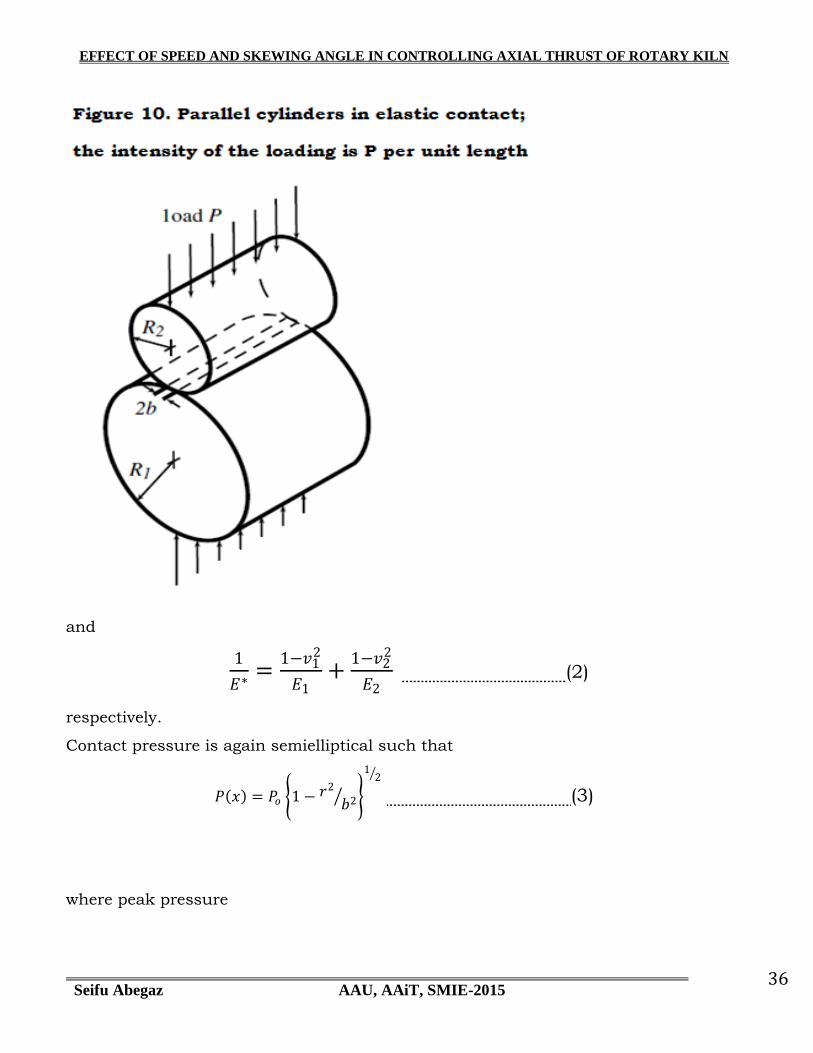
10 Parallel cylinders in elastic contact 36
11 The geometry of two circular cylinders in skewed contact 38
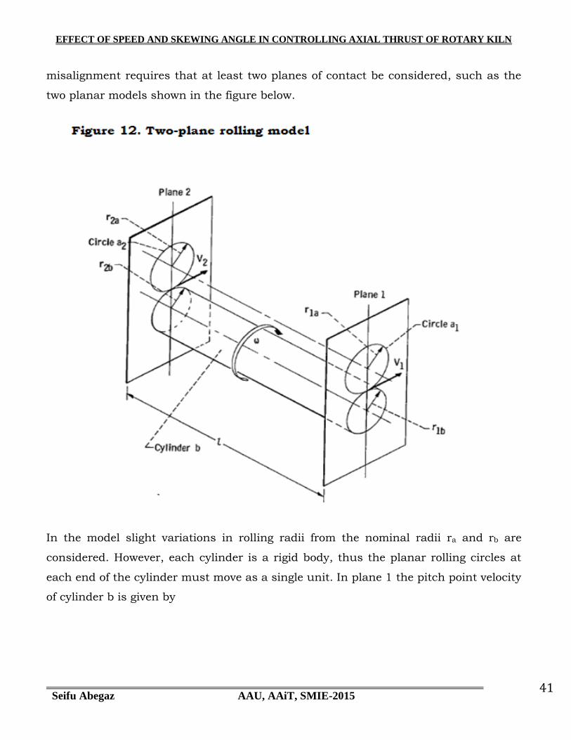
12 Two-plane rolling model 41
12a Roller kinematic instability 42
14 Loads acting on contact surface of support roller 46
15 Load Application areas on kiln tire 47
16 Quantities of tangential load torque obtained by varying rotational
speed of kiln
47
16a Quantities of tangential load obtained by varying skewing angle 48
17 All force components for varying speed 49
17a All force components for varying skewing angle 49
18 Areas of Tangential load application from top view
and radial load from side view
50
21 CATIA modeling for tire and roller assembly 52
21a Meshing results of ANSYS 53
EFFECT OF ROTATIONAL SPEED IN CONTROLLING AXIAL THRUST OF ROTARY KILN
Seifu Abegaz AAU, AAiT, SMIE-2015 vii vii
22 ANSYS Results for one revolution, 360ᴼ 54
23 Tabulated results of ANSYS for one revolution 55
24 ANSYS Results for two revolutions, 720ᴼ 56
25 ANSYS Results for three revolutions, 1080ᴼ 58

EFFECT OF ROTATIONAL SPEED IN CONTROLLING AXIAL THRUST OF ROTARY KILN
Seifu Abegaz AAU, AAiT, SMIE-2015 1
CHAPTER ONE
1. INTRODUCTION
The rotating kiln shell on a floating tire rings is supported by paired rollers as many
as one pair for every 20m length of kiln shell which must have the same inclination as
the kiln shell so that the support rollers and kiln tire rings make a line contact. The
contact pressure with the rotational motion tends to create a huge axial thrust load
that can have a direct impact on the temperature rise of support roller bearings and
also causes other mechanical component failures. The major working conditions (or
simply the variables) that result in complex phenomena in controlling the axial thrust
of the kiln include capacity of the rotary kiln, rotational speed of kiln, conditions of
contact surface between support rollers and tire rings, inclination of all rotating and
static components of kiln system, stability of the support roller alignment, roller-tire
contact surface lubrication, proper functioning of the hydraulic thrust device and
others. Identifying the relationship among each variable will be one of the steps in
devising mechanisms ultimately to control axial thrust of the kiln. Presently rotary
kilns particularly in our country which have axial lengths up to 66m are given nearly
from 3 to 3.5% inclination with the combination of rotational motion of kiln to allow
material flowing out in one direction. The rotary kiln consists of a tube made from
steel plate, and lined with firebrick. The tube slowly rotates on its axis at between 30
and 250 revolutions per hour. Efficiency of kiln operation is usually evaluated by
running the kiln for as much long period of time as possible. That is why rotary kilns
run 24 hours a day, and are typically stopped only for a few days once or twice a year
for essential maintenance. This is because heating up and cooling down are long,
wasteful and damaging processes. For example, the starting cost of a 3000tones/day
capacity kiln operation could roughly mount to ETB 1.5million as of now. That is why
uninterrupted runs as long as 18 months have been achieved and highly appreciated
in some of the kiln operations around the world. However, there are also on the
contrary, side effects particularly on the maintenance department when the kiln runs
for considerably long period of time. Distortion which is a bent axis creates a
multitude of problems depending on their magnitude and location. This problem
EFFECT OF SPEED AND SKEWING ANGLE IN CONTROLLING AXIAL THRUST OF ROTARY KILN
Seifu Abegaz AAU, AAiT, SMIE-2015 2
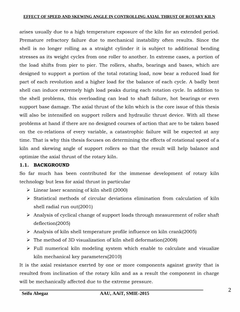
arises usually due to a high temperature exposure of the kiln for an extended period.
Premature refractory failure due to mechanical instability often results. Since the
shell is no longer rolling as a straight cylinder it is subject to additional bending
stresses as its weight cycles from one roller to another. In extreme cases, a portion of
the load shifts from pier to pier. The rollers, shafts, bearings and bases, which are
designed to support a portion of the total rotating load, now bear a reduced load for
part of each revolution and a higher load for the balance of each cycle. A badly bent
shell can induce extremely high load peaks during each rotation cycle. In addition to
the shell problems, this overloading can lead to shaft failure, hot bearings or even
support base damage. The axial thrust of the kiln which is the core issue of this thesis
will also be intensified on support rollers and hydraulic thrust device. With all these
problems at hand if there are no designed courses of action that are to be taken based
on the co-relations of every variable, a catastrophic failure will be expected at any
time. That is why this thesis focuses on determining the effects of rotational speed of a
kiln and skewing angle of support rollers so that the result will help balance and
optimize the axial thrust of the rotary kiln.
1.1. BACKGROUND
So far much has been contributed for the immense development of rotary kiln
technology but less for axial thrust in particular
Linear laser scanning of kiln shell (2000)
Statistical methods of circular deviations elimination from calculation of kiln
shell radial run out(2001)
Analysis of cyclical change of support loads through measurement of roller shaft
deflection(2005)
Analysis of kiln shell temperature profile influence on kiln crank(2005)
The method of 3D visualization of kiln shell deformation(2008)
Full numerical kiln modeling system which enable to calculate and visualize
kiln mechanical key parameters(2010)
It is the axial resistance exerted by one or more components against gravity that is
resulted from inclination of the rotary kiln and as a result the component in charge
will be mechanically affected due to the extreme pressure.
EFFECT OF SPEED AND SKEWING ANGLE IN CONTROLLING AXIAL THRUST OF ROTARY KILN
Seifu Abegaz AAU, AAiT, SMIE-2015 3
Factors affecting axial thrust
1. Skewing of paired support rollers
2. Rotational speed of the kiln
3. Surface conditions of support rollers and tires
4. Controlling slope changes of all rotating parts
5. Operational load of the kiln
1.2. Purpose
This thesis is mainly concerned with determining the effects of rotational speed
and skewing angle of support rollers of a kiln which are supposed to be the
major factors affecting axial thrust. The speed and skewing angle variation of
the kiln rotation is assumed to have a significant alternating axial pressure on
different components of rotary kiln. For example kiln thrust rollers, inlet and
outlet sealing, slide bearings of kiln support rollers particularly at contact
points of bearing collar and shaft shoulder, surfaces of tire ring and support
rollers are all affected by the axial thrust of altering kiln rotating speed and
skewing angle. Knowing and understanding the effects of speed and skewing
angle will help to device a mechanism to control the axial thrust. And with this
we can prolong the lives of different components, increase production uptime,
and reduce power consumption
1.3. OBJECTIVE
General objective
- Objective of the thesis is determining the effects of rotational speed and skewing
angle of support rollers in controlling axial thrust of a cement rotary kiln
Specific objectives
Determining the effect of rotational speed
Identifying which pair of support rollers makes significant change
to control thrust when they are subjected to skewing
EFFECT OF SPEED AND SKEWING ANGLE IN CONTROLLING AXIAL THRUST OF ROTARY KILN
Seifu Abegaz AAU, AAiT, SMIE-2015 4
Determining the effect of roller skewing quantitatively
Comparing effects of the two factors
1.4. STATEMENT OF THE PROBLEM
Determining the effects of rotational speed and skewing angle on axial thrust of rotary
kiln using static and dynamics modeling based on operating and design conditions of
rotary kiln so that optimal axial thrust on support rollers and thrust device can be
obtained whenever adjustments are made.
In the earlier times, axial thrust was controlled by skewing of the support rollers.
However, nowadays a hydraulic thrust roller has been in use to support the axial
thrust. Still the problem is not completely solved for the fact that the components of
hydraulic thrust system usually fail due to extreme pressure of the rotary kiln
especially during full load operation
1.5. ORGANIZATION OF THE PAPER
The rest of this thesis is organized as follows. Chapter 2 gives a description of
literature review which delivers information about an overview of what has been said,
who the key writers are, what are the prevailing theories and hypotheses that have
finally been converted to technology, what questions are being asked, and what
methods are appropriate and useful relevant to the topic of the thesis. The third
chapter describes the materials, methods and conditions of the thesis. Chapter 4 is all
about reporting the findings. It has summarized results obtained and discussed
figures and tables of the result. The last chapter or the fifth one has included
conclusion, possible recommendations and future works of the writer. Finally
references and appendix have been included.

EFFECT OF SPEED AND SKEWING ANGLE IN CONTROLLING AXIAL THRUST OF ROTARY KILN
Seifu Abegaz AAU, AAiT, SMIE-2015 5
CHAPTER TWO
2. LITERATURE REVIEW
2.1 Introduction
[5]Even though a rotary kiln could be categorized under rotor dynamic
equipment a particular attention should be given to, for the fact that the physical
nature appears to be huge and heavy. The mass of a typical 6 x 60 m kiln, including
refractory and feed, is around 1100 tons. The effect of a slight misalignment could
cause a catastrophic failure. The contact pressure between the bearing collar and
shaft shoulder of a support roller becomes so high that bearing temperature will
immediately rise to an unfavorable condition. This is due to the axial movement of the
rotary kiln usually against gravity. Cause of the axial movement depends on one or
more of a number of variables. Usually actions are taken independently not in an
integrated way without taking the co-relation between variables into consideration.
This would take days, weeks, even months before getting the real solution. This is
because the different actions taken are trial and error. As of today there have not been
devices formulated to easily apply in getting into a course of action that enables us to
control the situation so that the production interruption can be minimized to a great
extent.
[1]The roots of Geoservex date back to 1978, when the company founder, MSc Eng.
Bolesław Krystowczyk, was given the challenge to measure rotary kiln alignment.
Firstly, he applied a classic attitude and took the kiln measurements during machine
stoppage. He quickly noticed that as soon as the kiln was started up its cold state
adjustment did not give satisfactory effects. The support system geometry appeared to
behave differently when compared to its hot condition. The findings induced him to do
further researches and studies for the reasons of the described effect. This led to the
conclusion that measurements concerning such a type of machine should be
performed during the kiln operation. Then, he undertook a challenge to work out a
proper rotary kiln alignment measurement and support rollers‟ location method while
the machine was operating. Research and design works lasted two years. In effect, as
the first in the World he worked out the method that was later called “Hot Kiln
Alignment”. Nowadays, nobody undermines the principle of such an attitude but then
EFFECT OF SPEED AND SKEWING ANGLE IN CONTROLLING AXIAL THRUST OF ROTARY KILN
Seifu Abegaz AAU, AAiT, SMIE-2015 6
it was a true technology breakthrough. In the 1980s, the method was implemented
and applied to dozens of kilns. Bolesław Krystowczyk published principles listing the
advantages of his solution in periodical “Zement Kalk Gips” (1983). The method was
widely discussed and adduced in “Rock Produckts” (1987 & 1989) and “Wermessungs
wesen und Raumordnung” (1986) magazines. An innovative character of the solution
won for him an international patent and the author himself wrote a doctoral thesis in
1980 to be granted the title of the Doctor of Technical Sciences.
At that time, the problems with misalignment of multi-support kilns were so common.
Despite of fact that Poland was a socialist country, alignment services based on PhD
Eng. Bolesław Krystowczyk‟s method were ordered by cement plants from such
countries as the USA and Canada. True business breakthrough took place in 1990,
right after a system revolution in Poland. Then, private company Geoservex was
established and its founder gained an access to global market. At the same time, the
method of kiln alignment at operating conditions was quickly gaining supporters and
followers including leading kiln producers. Based on the same principle of
measurement in operating state new solutions were worked out. In the next years,
obvious new needs and new technical possibilities of development of kiln parameters
diagnostics were appearing. In 2000, the founder‟s son, Zbigniew Krystowczyk, joined
the team of engineers. Combining staff experience with his own knowledge about
world technical news started to introduce solutions such as linear laser scanning of
kiln shell (2000), statistical methods of circular deviations elimination from
calculation of kiln shell radial run-out (2001), analysis of cyclical change of support
loads through the measurement of rollers‟ shaft deflection (2005) and analysis of kiln
shell temperature profile influence on kiln crank (2005). In 2007 Zbigniew
Krystowczyk took up the position of Managing Director and the company‟s main
strategist. He noticed the potential of numerical modeling and the possibility of its
application in the diagnostics of rotary kilns and appointed a new research team to
work out the method of three-dimensional visualization of kiln shell deformation
(2008). After that the team worked out full numerical kiln modeling system which
enables to calculate and visualize all kiln mechanical key parameters (2010). The
system bases on the Finite Element Method. Geoservex will continue its service
EFFECT OF SPEED AND SKEWING ANGLE IN CONTROLLING AXIAL THRUST OF ROTARY KILN
Seifu Abegaz AAU, AAiT, SMIE-2015 7
development hoping that the offered scope of service meets customers‟ needs as
properly fitted roots of girth gear and pinion.
Kiln as a system generates an axial forces depending on the natural gravitational
movement down that is balanced by axial forces coming from rollers‟ skewing,
inclination and surface shape. Thus, mechanical kiln balance depends on many
factors. During kiln inspection all the influences are analyzed at the same time and
the whole system is adjusted by paying special attention to all factors optimization.
Theoretically, 30 % of the axial force should be balanced by the skewing of support
rollers and their axial forces. If hydraulic system exists on the kiln, it should carry 70
% of the axial force and its pressure should be in the range of 40 – 60 Bar.
Nevertheless, the adjustment process requires an individual examination of each case
and that is why the task must be carried out by a specialized and experienced expert.
The axial thrust of kiln affects the following components of the system
Both inlet and outlet sealing
Surfaces of tire rings and support rollers
Slide bearings of support rollers
Gear and pinion contact surfaces
Drive unit overloading
Retaining rings
2.2. How Thrust Affects Each Component
2.2.1.Inlet sealing
[5]Inlet sealing plays an important role in protecting material fall out and most
importantly preventing entry of false air that has a huge negative impact on
productivity of rotary kiln. This is accomplished by adjusting predefined range of
clearance between the stationary sealing and rotating kiln. However, because of
continuous upward thrust, kiln inlet sealing is exposed to considerably fast wear.
Since wear by nature means removal of material particles from the body of a
component, a continuous removal of material will make the sealing lose its
functionality. In addition to wear, the pressure exerted by upward thrust of kiln on
the sealing will damage fixtures even structure of the system.
The following mechanical actions initiate upward movement of kiln
EFFECT OF SPEED AND SKEWING ANGLE IN CONTROLLING AXIAL THRUST OF ROTARY KILN
Seifu Abegaz AAU, AAiT, SMIE-2015 8
2.2.2.Outlet sealing
[5]Usually kiln tends to move axially downward due to gravity that results from the
3% inclination. It is easy to imagine how big this thrust load on the outlet sealing
would be for the fact that the total mass of fully loaded rotary kiln climbs to 700ton.
The surface conditions of contacts between support rollers and tire rings have also a
huge impact of the downward thrust on outlet sealing. When the roughness values of
the surfaces decrease, it implies that there sounds to be more slippage between the
contact surfaces. Since support rollers remain axially stationary this slippage means
the axial movement of tire ring together with rotary kiln towards the outlet and
produces a wearing and/or damaging thrust on the outlet sealing.
2.2.3.Surfaces of Tire Rings and Support Rollers
[4]When two bodies having curved surfaces are pressed together, point or line contact
changes to area contact, and the stresses developed in the two bodies are three
dimensional. Typical failures are seen as cracks, pits, or flaking in the surface
material.
Wear conditions of surfaces of riding rings and support rollers:
Convex and concave wear patterns
Conical/tapered wear on riding ring/support roller diameters
Uneven wear conditions
Horizontal/diagonal marks on contact surfaces
Surface spalling and high stress concentrations
Broken edges on riding ring or support rollers
Wear on riding ring thrust faces and thrust rollers
Convex/concave wear is the most common form of wear on the surfaces of riding rings
and support rollers. The wear is a result of the support roller adjustment procedure
employed to control the axial thrust of the kiln. The very act of adjusting the support
rollers to control the axial thrust of the kiln will generate a convex/concave wear
pattern between the riding rings and the support rollers.

EFFECT OF SPEED AND SKEWING ANGLE IN CONTROLLING AXIAL THRUST OF ROTARY KILN
Seifu Abegaz AAU, AAiT, SMIE-2015 9
The extent of the wear is directly proportional to the amount of support roller
adjustment needed to control the axial thrust of the kiln. The greater the amount of
bearing movements made to control axial thrust of the kiln will actually accelerate the
wear on the surfaces of the riding rings and support rollers. As the contact face of the
riding rings and support rollers decrease, the hertz pressures on these surfaces
increase and subsequently, wear accelerates at a much higher rate. If the hertz
pressures increase to a high enough level, surface spalling or metal flaking will occur.
As the surface contact is lost, support roller adjustments also will increase to gain the
same axial control Convex / concave wear and kiln operations:
The axial thrust of the kiln will be unstable
Individual support roller thrust can be excessive
Increased wear will increase support roller adjustments
Increased roller adjustments increase kiln drive amperages
Increased drive amperage increases drive component wear
Operating costs of the kiln increases
2.2.4.Support roller slope misalignment
In correct adjustment of the support rollers to control the axial thrust of the kiln(E.g.
support rollers excessively skewed in opposite directions), conical wear, kiln alignment
and support roller adjustment. The existence of conical wear patterns on the surfaces
of riding rings and support rollers has an adverse effect of the alignment of the riding
rings on individual piers for the following reasons.
The riding ring will tilt towards the smaller diameter and cause misalignment between
the shell axis and riding ring axis. The kiln is designed so all components are rotating
on the same axis. For example, if the kiln is set at an elevation slope of ½/ft, the
rotational axis of the kiln shell, the riding ring and the support rollers need to be on
this slope for ideal operating conditions to exist. Furthermore, the kiln shell axis and
the support roller axis must be parallel in the horizontal plane for all the component
parts to operate ideally. If for any reason, the surfaces of the riding ring or support
rollers develop conical wear, the axis of the riding ring will not be aligned with the axis
of the shell. The result will be a high thrust placed on the retaining blocks or rings
that restrict the axial movement of the riding ring. In addition to this, a misalignment
EFFECT OF SPEED AND SKEWING ANGLE IN CONTROLLING AXIAL THRUST OF ROTARY KILN
Seifu Abegaz AAU, AAiT, SMIE-2015 10
will occur between the riding ring ID and the filler bar OD exaggerating the wear
between the frictional surfaces. Both of these conditions are continuous problems in
the maintenance of the kiln. Excessive wear of retaining blocks/rings will cause the
riding ring to move axially and ride off center on the support rollers. As the riding ring
ID wears against the filler bars, a large gap will generate between the riding ring and
the filler bars and result in higher kiln shell ovalities. In some cases, the conical wear
condition on the surfaces of the riding rings and support rollers will cause problems
with the axial thrust of the kiln and the individual thrust of the support rollers. If the
surfaces of the riding rings and support rollers have excessive conical wear, the kiln
may not be able to move freely in the axial directions as operational changes occur.
This will cause higher thrust loading on individual support roller bearings and thrust
rollers. It is not uncommon for the kiln drive amperage to run high in this situation
and subsequently causes accelerated wear on the drive components. On some kilns,
the signs of maintenance problems will occur if the riding rings and support rollers
have a radial taper of greater than .015" other kilns may tolerate up to .125" radial
taper without noticeable problems. Conical wear is not visible in all but the most
severe cases, however, if riding rings thrust hard against retaining blocks/rings, the
axial thrust of kiln is not manageable and certain support roller bearings overheat on
occasion, it would be best to measure the diameters of the riding rings and support
rollers. An electronic measuring instrument can be used during operation, but greater
accuracy is achieved by using a pie-tape during a kiln outage. Uneven wear on riding
rings and support rollers. Uneven wear is typical of product contamination or erratic
axial thrust conditions of the kiln. The adverse affect of uneven wear is it will restrict
the ability to adjust support rollers with minimal moves and may affect the axial
thrust of the kiln.
2.2.5.Horizontal/diagonal wears on riding rings or support rollers
Horizontal or diagonal wear patterns develop on the surfaces of riding rings or support
rollers because of support roller miss-adjustments. If the support roller shaft‟s
rotational axis is not parallel to each other on each riding ring station, a slip will
occur between the riding ring and support rollers and these marks will appear. In
EFFECT OF SPEED AND SKEWING ANGLE IN CONTROLLING AXIAL THRUST OF ROTARY KILN
Seifu Abegaz AAU, AAiT, SMIE-2015 11
severe cases, the marks will cause rough operation of the kiln and high vibration will
be noticeable.
2.2.6.Surface spalling on riding rings or support rollers
Surface spalling on the riding rings or support rollers is cause by support roller slope
problems, kiln shell misalignment or severe maladjustment of support rollers. If the
spalling is severe, stress cracks may form that can weaken the structural stability of
the riding rings or support rollers.
2.2.7.Broken edges on riding ring and support rollers
As excessive concave wear develops on the surfaces of support rollers or in rare cases
riding rings, the edges will begin to break off as a result of the contact between the
components. Again these edges may lead to surface stress cracks that can affect the
structural stability of the component parts.
Wear on riding ring thrust face and thrust rollers
In cases where the axial kiln thrust runs in the same direction for extended periods
of time, (for example uphill or downhill), the surfaces of the thrust face on the riding
ring and the thrust rollers will wear. Excessive wear of these components will cause
broken edges on both the riding ring and the thrust roller. Also, if the wear occurs
over an extended period of time, the kiln can actually move axially in that direction as
the surfaces wear, causing a misalignment between the riding ring and support rollers
and the drive gear and pinion.
Slide bearings of support rollers
Gear and pinion contact surfaces
Drive unit overloading
Retaining rings
2.2.8.Tire and kiln shell interaction
[4]The tire ID is larger than the shell OD. As the kiln rotates, there is
circumferential displacement between the tire and the shell as a result. This
motion is commonly referred to as tire creep. If the plane of the tire is not
perpendicular to the rotating axis of the shell, the direction of motion of the
EFFECT OF SPEED AND SKEWING ANGLE IN CONTROLLING AXIAL THRUST OF ROTARY KILN
Seifu Abegaz AAU, AAiT, SMIE-2015 12
shell is slightly different than the direction of motion of the tire. The tire moves
uphill or downhill as a result, until it hits the tire retainers. On other words,
the tire creep has a horizontal component. If the angle between the tire plane
and the shell is not between 89.5 and 90.5 degrees, the pressure on the tire
retainers will be high. Furthermore, since the tire retainer pressure comes from
the interaction between the tire ID and the support pads, the rate of wear of the
support pads (due to slippage in the horizontal direction) will be high. There are
two mechanisms that tilt the tire plane relative to the shell axis:
a) A taper condition on the tire or the support rollers
b) Support roller slopes.
Correcting a high stop block load condition therefore requires either the
resurfacing of the tire and the rollers or changing the support roller slopes.
Since the tire retainer pressure is caused by a motion component between the
tire and the shell, the pressure is directly proportional to the tire creep, and
therefore to the tire clearance. Decreasing the tire clearance by 50% (by
shimming or replacing the support pads) will decrease the tire retainer pressure
by 50%. The source of the force causing retainer pressure is traction between
the tire ID and the shell. If the tire ID is lubricated, the coefficient of friction
between the tire and the shell will decrease, and the tire retainer pressure will
also decrease. The most effective lubricant for this application consists of soft
metal powders dispersed in a carrier that evaporates. The lubricant is available
in the form of wax bars or a sprayable liquid. The sprayable form prevents the
close proximity to moving parts that is required to install the wax bars between
support pads. Please note that graphite is a very ineffective lubricant for this
application. It does not laminate onto the tire ID, and is very easily dislodged
from the surfaces it is supposed to lubricate. Bearing adjustments are
commonly made with the intention of decreasing tire retainer pressure. It is
mistakenly believed that if, for example, the downhill stop blocks on a pier are
EFFECT OF SPEED AND SKEWING ANGLE IN CONTROLLING AXIAL THRUST OF ROTARY KILN
Seifu Abegaz AAU, AAiT, SMIE-2015 13
overloaded, and the pressure can be decreased by adjusting the support rollers
to push the tire uphill. This attempt to fix the problem rests on a lack of
understanding of the relationship between two independent sets of forces
effecting mechanical stability at each pier. The horizontal motion component
between the tire and the roller affects the axial motion of the entire kiln, but
will not affect the position of the tire relative to the stop blocks. Stop block
pressure is a function of the horizontal motion component between the tire ID
and the shell; this motion component is independent of the tire to roller
interaction. (For the record, the previous statement is not an absolute truth.
Very extreme bearing adjustments, with one roller pushing uphill and the other
downhill, will tilt the tire plane relative to the kiln axis, and will thus affect the
tire retainer pressure. The magnitude of bearing adjustment required to do
this, however, is so extreme that it results in the overload of the support roller
bearing thrust mechanism. While this procedure can be beneficial as a short
term fix, it does not work in the long term).
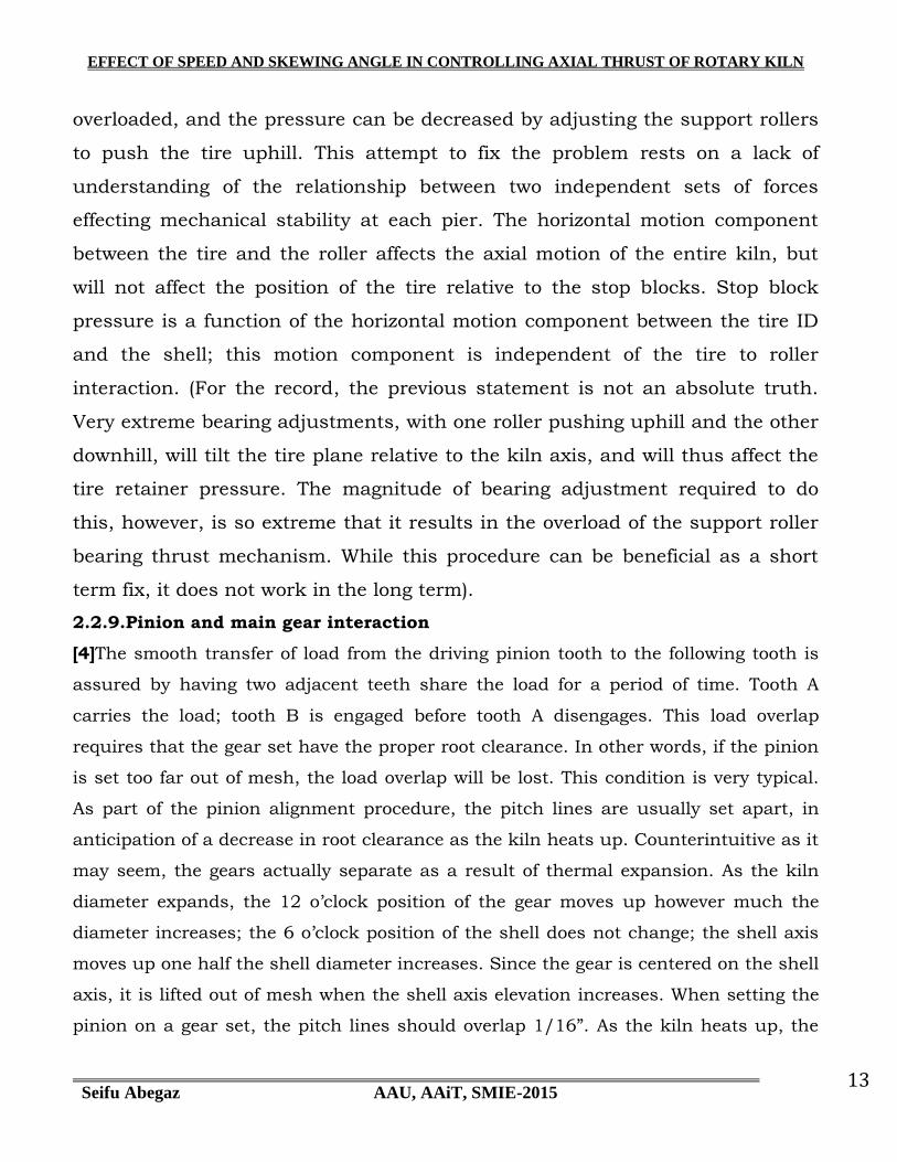
2.2.9.Pinion and main gear interaction
[4]The smooth transfer of load from the driving pinion tooth to the following tooth is
assured by having two adjacent teeth share the load for a period of time. Tooth A
carries the load; tooth B is engaged before tooth A disengages. This load overlap
requires that the gear set have the proper root clearance. In other words, if the pinion
is set too far out of mesh, the load overlap will be lost. This condition is very typical.
As part of the pinion alignment procedure, the pitch lines are usually set apart, in
anticipation of a decrease in root clearance as the kiln heats up. Counterintuitive as it
may seem, the gears actually separate as a result of thermal expansion. As the kiln
diameter expands, the 12 o‟clock position of the gear moves up however much the
diameter increases; the 6 o‟clock position of the shell does not change; the shell axis
moves up one half the shell diameter increases. Since the gear is centered on the shell
axis, it is lifted out of mesh when the shell axis elevation increases. When setting the
pinion on a gear set, the pitch lines should overlap 1/16”. As the kiln heats up, the

EFFECT OF SPEED AND SKEWING ANGLE IN CONTROLLING AXIAL THRUST OF ROTARY KILN
Seifu Abegaz AAU, AAiT, SMIE-2015 14
pitch lines will separate via the above thermal mechanism, but the overlap of the gear
set will remain adequate.
2.2.10. Roller and tire contact surface condition
[4]The mechanical stability of the tire to roller interaction requires that the roller axis
and the kiln rotation axis be parallel. The direction of motion of a rotating object is
perpendicular to its axis. If the roller and kiln axis are not parallel, the direction of
motion of the two components will not be along the same line. In other words, the
motion of the tire relative to the roller will have a horizontal component. This
condition causes the kiln to move uphill or downhill and the roller to move in the
opposite direction. If the horizontal motion component is high, the roller bearing
thrust mechanism overheats from high pressure, and the load on the kiln thrust roller
may be high. Correcting this condition requires the adjustment of one of the roller
bearings such that the direction of motion of the kiln and the roller become identical.
2.2.11. Bearing thrust mechanism loads
[4]The thrust load on a support roller moves the roller along a line parallel to the kiln
axis. The motion of the roller is stopped by a thrust mechanism in one of the bearings.
There are two types of bearing thrust mechanisms: a) a heavy bearing housing end
plate that contacts the end of the roller shaft and b) a thrust collar or flange on a
roller shaft that contacts a flange on the bearing liner. If the thrust load on the roller
is high enough, the pressure per square inch on the loaded thrust mechanism will be
excessive, resulting in a) lubricant breakdown and bearing failure or b) structural
failure of the thrust wear plate. Measuring and minimizing the thrust load on a
support roller can prevent these undesirable consequences. Measuring the bearing
thrust pressures and making the proper bearing adjustments should be part of the
scope of work of a comprehensive hot kiln alignment. The pressure on the thrust
mechanism has to be less than 300 psi to assure reliable stability.
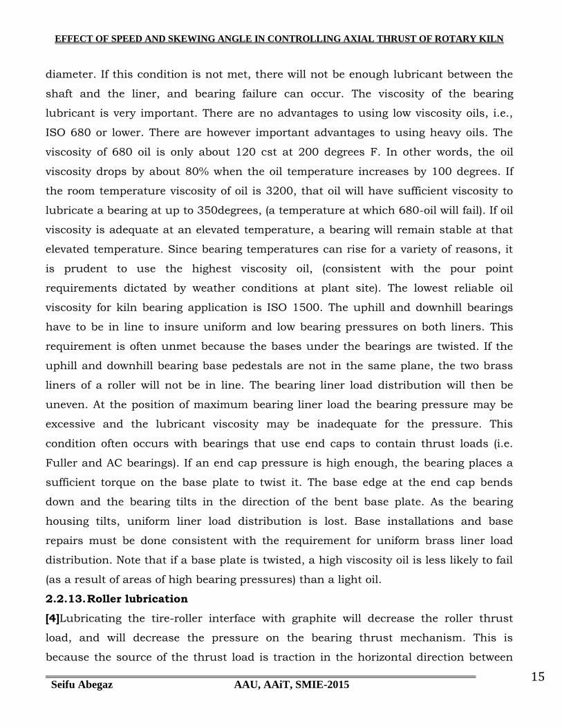
2.2.12. Roller shaft to bearing liner interface
[4]The interaction between a roller shaft and a bearing liner will generate high
temperature leading to bearing failure unless certain stability conditions are met. The
diameter of the brass liner has to be 0.002” greater than the shaft diameter for every
inch of shaft diameter. In other words, a 20” shaft has to have a liner with a 20.040”
EFFECT OF SPEED AND SKEWING ANGLE IN CONTROLLING AXIAL THRUST OF ROTARY KILN
Seifu Abegaz AAU, AAiT, SMIE-2015 15
diameter. If this condition is not met, there will not be enough lubricant between the
shaft and the liner, and bearing failure can occur. The viscosity of the bearing
lubricant is very important. There are no advantages to using low viscosity oils, i.e.,
ISO 680 or lower. There are however important advantages to using heavy oils. The
viscosity of 680 oil is only about 120 cst at 200 degrees F. In other words, the oil
viscosity drops by about 80% when the oil temperature increases by 100 degrees. If
the room temperature viscosity of oil is 3200, that oil will have sufficient viscosity to
lubricate a bearing at up to 350degrees, (a temperature at which 680-oil will fail). If oil
viscosity is adequate at an elevated temperature, a bearing will remain stable at that
elevated temperature. Since bearing temperatures can rise for a variety of reasons, it
is prudent to use the highest viscosity oil, (consistent with the pour point
requirements dictated by weather conditions at plant site). The lowest reliable oil
viscosity for kiln bearing application is ISO 1500. The uphill and downhill bearings
have to be in line to insure uniform and low bearing pressures on both liners. This
requirement is often unmet because the bases under the bearings are twisted. If the
uphill and downhill bearing base pedestals are not in the same plane, the two brass
liners of a roller will not be in line. The bearing liner load distribution will then be
uneven. At the position of maximum bearing liner load the bearing pressure may be
excessive and the lubricant viscosity may be inadequate for the pressure. This
condition often occurs with bearings that use end caps to contain thrust loads (i.e.
Fuller and AC bearings). If an end cap pressure is high enough, the bearing places a
sufficient torque on the base plate to twist it. The base edge at the end cap bends
down and the bearing tilts in the direction of the bent base plate. As the bearing
housing tilts, uniform liner load distribution is lost. Base installations and base
repairs must be done consistent with the requirement for uniform brass liner load
distribution. Note that if a base plate is twisted, a high viscosity oil is less likely to fail
(as a result of areas of high bearing pressures) than a light oil.
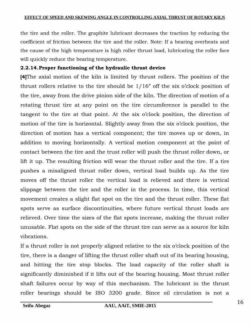
2.2.13. Roller lubrication
[4]Lubricating the tire-roller interface with graphite will decrease the roller thrust
load, and will decrease the pressure on the bearing thrust mechanism. This is
because the source of the thrust load is traction in the horizontal direction between
EFFECT OF SPEED AND SKEWING ANGLE IN CONTROLLING AXIAL THRUST OF ROTARY KILN
Seifu Abegaz AAU, AAiT, SMIE-2015 16
the tire and the roller. The graphite lubricant decreases the traction by reducing the
coefficient of friction between the tire and the roller. Note: If a bearing overheats and
the cause of the high temperature is high roller thrust load, lubricating the roller face
will quickly reduce the bearing temperature.
2.2.14. Proper functioning of the hydraulic thrust device
[4]The axial motion of the kiln is limited by thrust rollers. The position of the
thrust rollers relative to the tire should be 1/16” off the six o‟clock position of
the tire, away from the drive pinion side of the kiln. The direction of motion of a
rotating thrust tire at any point on the tire circumference is parallel to the
tangent to the tire at that point. At the six o‟clock position, the direction of
motion of the tire is horizontal. Slightly away from the six o‟clock position, the
direction of motion has a vertical component; the tire moves up or down, in
addition to moving horizontally. A vertical motion component at the point of
contact between the tire and the trust roller will push the thrust roller down, or
lift it up. The resulting friction will wear the thrust roller and the tire. If a tire
pushes a misaligned thrust roller down, vertical load builds up. As the tire
moves off the thrust roller the vertical load is relieved and there is vertical
slippage between the tire and the roller in the process. In time, this vertical
movement creates a slight flat spot on the tire and the thrust roller. These flat
spots serve as surface discontinuities, where future vertical thrust loads are
relieved. Over time the sizes of the flat spots increase, making the thrust roller
unusable. Flat spots on the side of the thrust tire can serve as a source for kiln
vibrations.
If a thrust roller is not properly aligned relative to the six o‟clock position of the
tire, there is a danger of lifting the thrust roller shaft out of its bearing housing,
and hitting the tire stop blocks. The load capacity of the roller shaft is
significantly diminished if it lifts out of the bearing housing. Most thrust roller
shaft failures occur by way of this mechanism. The lubricant in the thrust
roller bearings should be ISO 3200 grade. Since oil circulation is not a

EFFECT OF SPEED AND SKEWING ANGLE IN CONTROLLING AXIAL THRUST OF ROTARY KILN
Seifu Abegaz AAU, AAiT, SMIE-2015 17
consideration, the high pour point of the oil is immaterial. The high viscosity of
the 3200 oil provides significant separation between the shaft and the brass
liner.
2.3. Axial Motion of skewed rollers
[1]The primary cause of axial motion of the wheel set is skewing. The
flanges, which provide a kinetic support for the wheel set, are always on the
inside of the wheels. This produces a wheel cone with its apex outside the
wheel set. The effect of these cones is to provide a kinematic stabilization of the
wheel set as it runs on the rails. Were the cones reversed, the wheel sets would
oscillate wildly in an axial mode as the train moves down the track (ref. 1).
Two basic causes of roller axial motion are identified in this study. These
are skewing and externally applied axial thrust. Both causes can be converted
into correcting mechanisms that will enable the rollers to roll true (i.e., in their
plane of contact without axial motion). The first correcting mechanism is
kinematic; the second is kinetic. Although a kinetic or force correction, in the
form of a roller flange or bumper, is sometimes required to insure that gross
axial motion cannot occur, the kinematic correction is unquestionably more
desirable. The kinematic correction, which results in self-centering action, can
be implemented without seriously affecting either the mechanical efficiency or
durability of the contact. Axial motion that is not corrected kinematically will
create significantly large thrust forces that have to be withheld by flanges or
thrust bearings. The investigation conducted by Virabov (ref. 7) shows that
even a minute misalignment between the contact and spin axes of interacting
cylindrical rollers caused by unavoidable errors in the manufacture or
alignment of the rolling bodies will result in significant axial forces being
generated. Tests results for a pair of 50millimeter (2-in. ) diameter steel rollers
running dry (traction coefficient = 0.32) indicated that a roller skew angle of
only 0.27' will produce a thrust force that is 24 percent of the normal load

EFFECT OF SPEED AND SKEWING ANGLE IN CONTROLLING AXIAL THRUST OF ROTARY KILN
Seifu Abegaz AAU, AAiT, SMIE-2015 18
acting on the body. Obviously, roller flanges or thrust bearings that are
required to operate continuously under such conditions would be unattractive
from a system life and performance standpoint.
In a private communication to the authors, Dr. Veljko Milenkovic extended
his work regarding the stability of a railroad wheel-rail contact (ref. 1)to the
more generalized case of roller pairs in free-rolling contact. In this
communication, he advocated the technique of using self-corrective geometries
to promote roller stability. Milenkovic's
2.4. Conclusion
So far we have seen that rotary kiln axial thrust can be controlled in an individual
approach. However, this approach could take longer time to adjust any misalignment
after observing the effect of one trial. This thesis is supposed to solve the
aforementioned problem by applying an integrated approach for both skewing angle
and rotational speed of the rotary kiln with the possible values of current variables
fed. And this could show where exactly the problem lies so that the action to be taken
wouldn‟t be as such longer than hours.
EFFECT OF SPEED AND SKEWING ANGLE IN CONTROLLING AXIAL THRUST OF ROTARY KILN
Seifu Abegaz AAU, AAiT, SMIE-2015 19
CHAPTER THREE
3. MATERIAL, METHOD, CONDITION
3.1. MATERIAL
Even though the problem selected to address comprises possibly all rotary kilns
that are engaged to manufacture mining products, materials for this thesis are
decided to collect from Muger Cement Factory rotary cement kiln. All data necessary
to carry out the thesis will be utilized from MCF existing line. It has been tried to
indicate that the objective of the thesis is to contribute for the formulation of a set up
in control mechanism for rotary kiln axial thrust. The effect of rotational speed plays
an important role in the magnitude of the thrust that exerts on different components
of kiln system. Data are to be collected for a random capacity of rotary kiln which is
for this particular thesis Mugher cement factory kiln No. one has been considered.
These data include kiln length and diameter, number of base-rollers, rotational speed
of the kiln, contact surface condition between tire and rollers, slope of rotary kiln axis
from design point of view etc…
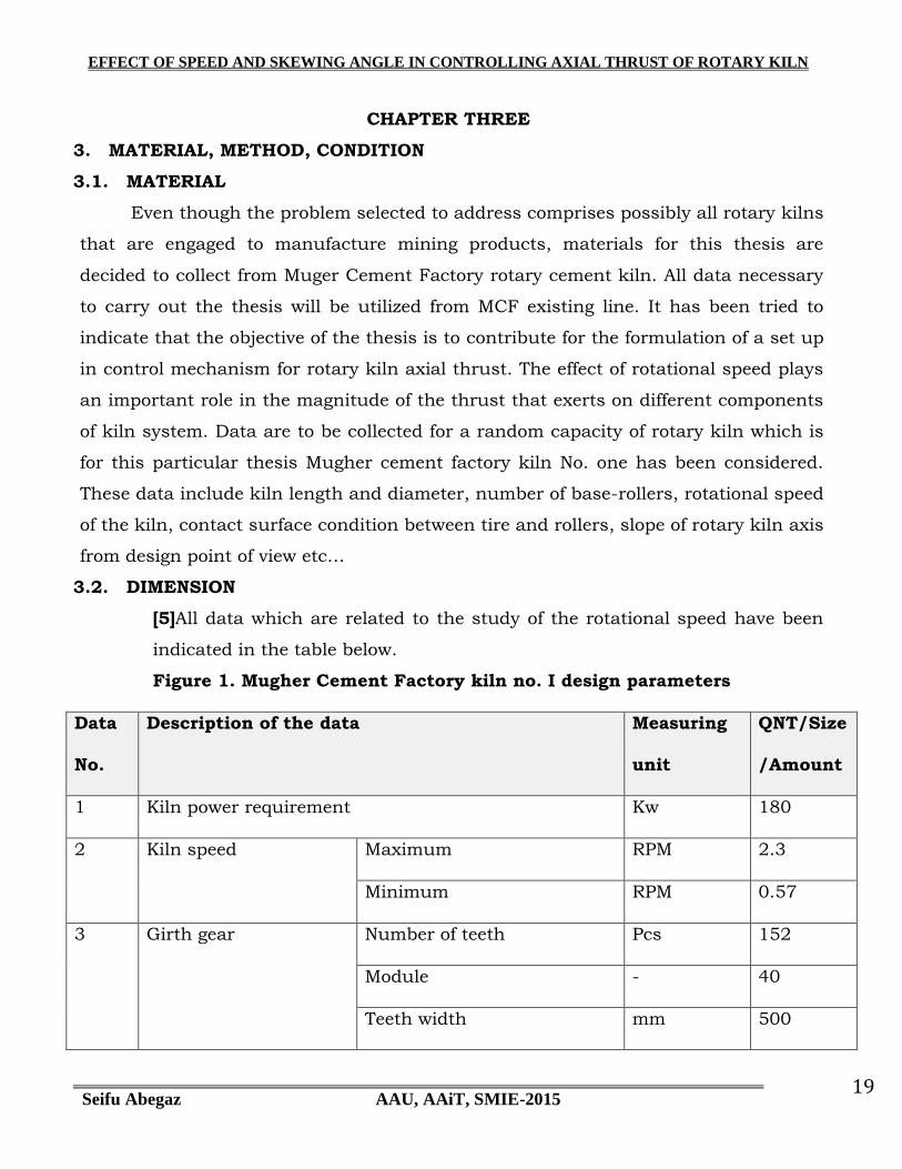
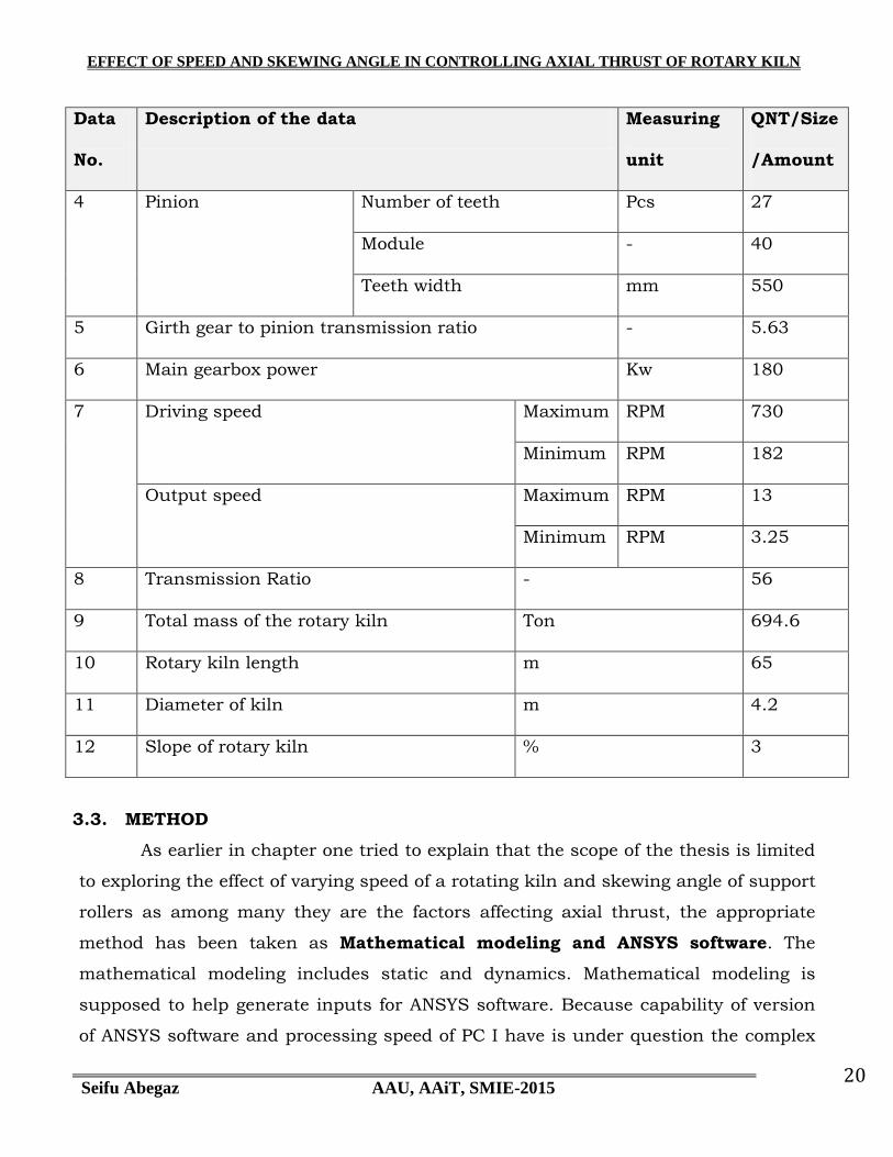
3.2. DIMENSION
[5]All data which are related to the study of the rotational speed have been
indicated in the table below.
Figure 1. Mugher Cement Factory kiln no. I design parameters
Data
No.
Description of the data Measuring
unit
QNT/Size
/Amount
1 Kiln power requirement Kw 180
2 Kiln speed Maximum RPM 2.3
Minimum RPM 0.57
3 Girth gear Number of teeth Pcs 152
Module - 40
Teeth width mm 500
EFFECT OF SPEED AND SKEWING ANGLE IN CONTROLLING AXIAL THRUST OF ROTARY KILN
Seifu Abegaz AAU, AAiT, SMIE-2015 20
Data
No.
Description of the data Measuring
unit
QNT/Size
/Amount
4 Pinion Number of teeth Pcs 27
Module - 40
Teeth width mm 550
5 Girth gear to pinion transmission ratio - 5.63
6 Main gearbox power Kw 180
7 Driving speed Maximum RPM 730
Minimum RPM 182
Output speed Maximum RPM 13
Minimum RPM 3.25
8 Transmission Ratio - 56
9 Total mass of the rotary kiln Ton 694.6
10 Rotary kiln length m 65
11 Diameter of kiln m 4.2
12 Slope of rotary kiln % 3
3.3. METHOD
As earlier in chapter one tried to explain that the scope of the thesis is limited
to exploring the effect of varying speed of a rotating kiln and skewing angle of support
rollers as among many they are the factors affecting axial thrust, the appropriate
method has been taken as Mathematical modeling and ANSYS software. The
mathematical modeling includes static and dynamics. Mathematical modeling is
supposed to help generate inputs for ANSYS software. Because capability of version
of ANSYS software and processing speed of PC I have is under question the complex
EFFECT OF SPEED AND SKEWING ANGLE IN CONTROLLING AXIAL THRUST OF ROTARY KILN
Seifu Abegaz AAU, AAiT, SMIE-2015 21
dynamic analysis of rotary kiln system using ANSYS software has been found so
difficult. Hence static analysis is engaged in the ANSYS software to show the effect of
rotational speed on axial thrust. It is assumed that ANSYS will show indirectly
tendency of axial movement if there is an increase in directional displacement along
Z-axis as the tangential load changes due to change in rotational speed. Besides
number of components and their dimensions in the system are extremely huge as
compared to the equipment (PC) capacity to solve, only the middle tire and a pair of
support rollers are taken to model this phenomenon. That is why mathematically
static analysis has been used to show which of the three pairs of support rollers carry
the maximum normal load. This is because it is assumed that if we make a certain
skewing angle on this pair of support rollers effective axial movement could be
observed for the fact that axial load would have a direct relation with normal load of
the carrying roller. Mathematical analysis is also another method that is engaged to
find the tangential force. Here, by varying angular speed of the rotary kiln we can get
different values of tangential force. The resultant of these two forces (i.e. normal load
on the support roller and rotation-causing tangential force) will have an axial effect
for a chosen value of skewing angle. Assuming that there is enough traction-causing
frictional force between tire and support rollers the idea of helical gear meshing that
causes an axial load due to helix angle has been taken for this analysis. Helix angle
is analogous to skewing angle. The possible methods that will be engaged for future
investigation of axial thrust affecting factors are that the dynamics together with
contact surface modeling is supposed to fit for Tire and kiln shell interaction, roller
and tire contact surface condition, bearing thrust mechanism loads, hydraulic thrust
device, pure contact surface model analysis is to be employed for pinion and main
gear interaction, roller shaft to bearing liner interface and roller lubrication. With all
these model analysis carried out simulation of the effect for different values of all
parameters will be done.

EFFECT OF SPEED AND SKEWING ANGLE IN CONTROLLING AXIAL THRUST OF ROTARY KILN
Seifu Abegaz AAU, AAiT, SMIE-2015 22
3.4. ANALYSIS AND RESULT
3.4.1.Static Analysis for Mass of Kiln System
Static analysis needs to be carried out in order to locate the maximum normal load
that the rotary kiln exerts so that we can identify which of the three pairs of base
rollers accommodates lion‟s share of the pressure load. This is done because axial
movement of the rotary kiln is caused by the traction force that is created due to the
interaction between the pairs of rollers and tire ring because of their non parallel axes
or skewing.
The following points are to be considered when mass of a running kiln shell system is
supposed to determine
1. Thinking of mass of the whole body to be concentrated at a point along
the axis and calculate for center of mass
2. Considering thickness differences of segmented shell bodies and calculate
for masses of each segmented body, tire and girth gear mass
3. Considering types of bricks lined at different zones of kiln shell to
determine specific densities so that one can calculate mass of lining
bricks for each zone
The components that result in the whole mass system of a rotary kiln include
3.4.1.1. Refractory bricks
[5]More than 60% of the mass system is comprised by refractory bricks that are lined
the whole length of rotary kiln. Depending on the process zone on which phenomena
of different chemical and physical properties take place, the types of bricks to be lined
and the length of lining differ also. It is found that the mass per meter length of bricks
lining for upper and lower transition and central burning zone is found to be
maximum which is 7493kg/m. This finding will help choose which of the three pairs
of support rollers experience high normal load.
Here are the names of zones and respective load shares of refractory bricks

EFFECT OF SPEED AND SKEWING ANGLE IN CONTROLLING AXIAL THRUST OF ROTARY KILN
Seifu Abegaz AAU, AAiT, SMIE-2015 23
3.4.1.2. Inlet zone
Length of zone is 1.4m. For a single ring, 128 bricks are needed and mass of
a single brick is:
M=3.873dm3x1000x2.175kg/cm3
=8.42Kg
Mass of a ring of bricks=8.42kgx128bricks
=1078.2kg
Mass of bricks in one meter per ring=1078.2kg/ringx5ring/meter
=5391.2kg/meter
Mass of bricks in inlet zone=5391.2kg/meterx1.4m
=7547.7kg
3.4.1.3. Calcining zone
Length of zone is 28.76m. For a single ring, 128 bricks are needed and
mass of a single brick is:
M=3.873dm3x1000x2.175kg/cm3
=8.42Kg
Mass of a ring of bricks=8.42kgx128bricks
=1078.2kg
Mass of bricks in one meter per ring=1078.2kg/ringx5ring/meter
=5391.2kg/meter
Mass of bricks in calcining zone=5391.2kg/meterx28.76m
=155051.4kg
3.4.1.4. Safety zone
Length of zone is 8.8m. For a single ring, 128 bricks are needed and mass
of a single brick is:
M=3.873dm3x1000x2.675kg/cm3
=10.36Kg
Mass of a ring of bricks=10.36kgx128bricks
=1326.11kg
Mass of bricks in one meter per ring=1326.11kg/ringx5ring/meter
=6630.57kg/meter
EFFECT OF SPEED AND SKEWING ANGLE IN CONTROLLING AXIAL THRUST OF ROTARY KILN
Seifu Abegaz AAU, AAiT, SMIE-2015 24
Mass of bricks in safety zone=6630.57kg/meterx8.8m
=58349kg
3.4.1.5. Upper transition zone, Lower transition zone and Central burning zone
These three zones can be considered to use the same type of bricks which
is called basic and have densities from 2.95 kg/cm3 to 3.10kg/cm3. Hence
total length of the three zones:
Total length=4m+13m+6m
=23m
Length of zone is 23m. For a single ring, 175 bricks are needed and mass
of a single brick is:
M=2.831dm3x1000x3.025kg/cm3
=8.564Kg
Mass of a ring of bricks=8.564kgx175bricks
=1498.66kg
Mass of bricks in one meter per ring=1498.66kg/ringx5ring/meter
=7493.3kg/meter
Mass of bricks in the three zones=7493.3kg/meterx23m
=172345kg
3.4.1.6. Cooling zone
Length of zone is 3m. For a single ring, 128 bricks are needed and mass
of a single brick is:
M=3.873dm3x1000x2.825kg/cm3
=10.94Kg
Mass of a ring of bricks=10.94kgx128bricks
=1400.5kg
Mass of bricks in one meter per ring=1400.5kg/ringx5ring/meter
=7002.4kg/meter
Mass of bricks in cooling zone=7002.4kg/meterx3m
=21007.2kg

EFFECT OF SPEED AND SKEWING ANGLE IN CONTROLLING AXIAL THRUST OF ROTARY KILN
Seifu Abegaz AAU, AAiT, SMIE-2015 25
Figure 2. Summary of mass Analysis for bricks at different zones of kiln
Zone t
ype
Zone
length
(mete
r)
Bri
cks t
ype
Volu
me(d
m3)
Densit
y(g
/cm
3)
No.
of
bri
cks p
er
ring
No.
of
rings p
er
mete
r
No.
of
bri
cks
per
mete
r
No.
of
bri
cks i
n
zone
Mass o
f bri
cks
per
pie
ce
Tota
l m
ass o
f
bri
cks i
n z
ones
(Kg)
Inlet 1.4 KROLEX 40 3.873 2.175 128 5 640 896 8.42 7544
Calcining 28.76 KROLEX 40 3.873 2.175 128 5 640 1840 8.42 154982
Safety 8.8 KROLEX 70 3.873 2.675 128 5 640 5632 10.36 58348
Upper
transition
6 PERILEX83 2.831 3.025 175 5 875 5250 8.564 44961
Central
burning
13 PERILEX83 2.831 3.025 175 5 875 11375 8.564 97416
Lower
transition
4 PERILEX83 2.831 3.025 175 5 875 3500 8.564 29974
Cooling 3 KROLEX 85 3.873 2.825 128 5 640 1920 10.94 21005
Total Mass of
bricks
414230
Figure 3. Rotary kiln zones
Inlet Calcining Safety Upper
transition
Central
burning
Lower
transition
Cooling
1 2 3
5
4 5 6 7
EFFECT OF SPEED AND SKEWING ANGLE IN CONTROLLING AXIAL THRUST OF ROTARY KILN
Seifu Abegaz AAU, AAiT, SMIE-2015 26
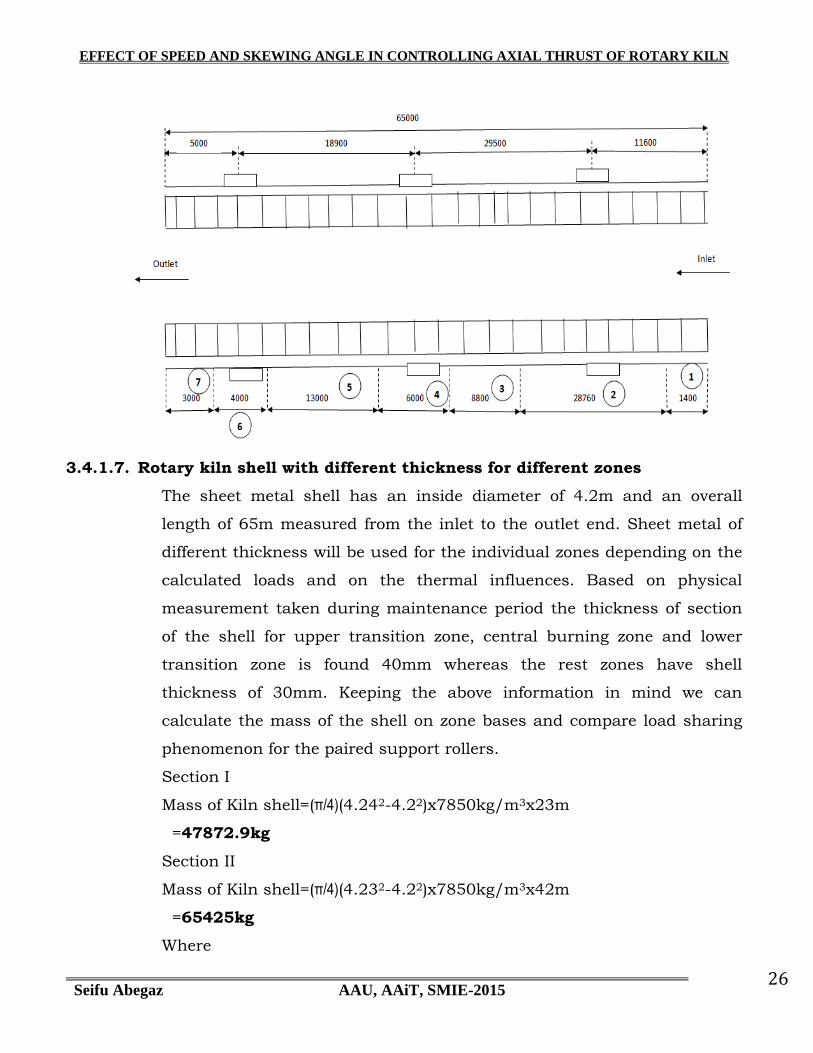
3.4.1.7. Rotary kiln shell with different thickness for different zones
The sheet metal shell has an inside diameter of 4.2m and an overall
length of 65m measured from the inlet to the outlet end. Sheet metal of
different thickness will be used for the individual zones depending on the
calculated loads and on the thermal influences. Based on physical
measurement taken during maintenance period the thickness of section
of the shell for upper transition zone, central burning zone and lower
transition zone is found 40mm whereas the rest zones have shell
thickness of 30mm. Keeping the above information in mind we can
calculate the mass of the shell on zone bases and compare load sharing
phenomenon for the paired support rollers.
Section I
Mass of Kiln shell=(π/4)(4.242-4.22)x7850kg/m3x23m
=47872.9kg
Section II
Mass of Kiln shell=(π/4)(4.232-4.22)x7850kg/m3x42m
=65425kg
Where
EFFECT OF SPEED AND SKEWING ANGLE IN CONTROLLING AXIAL THRUST OF ROTARY KILN
Seifu Abegaz AAU, AAiT, SMIE-2015 27
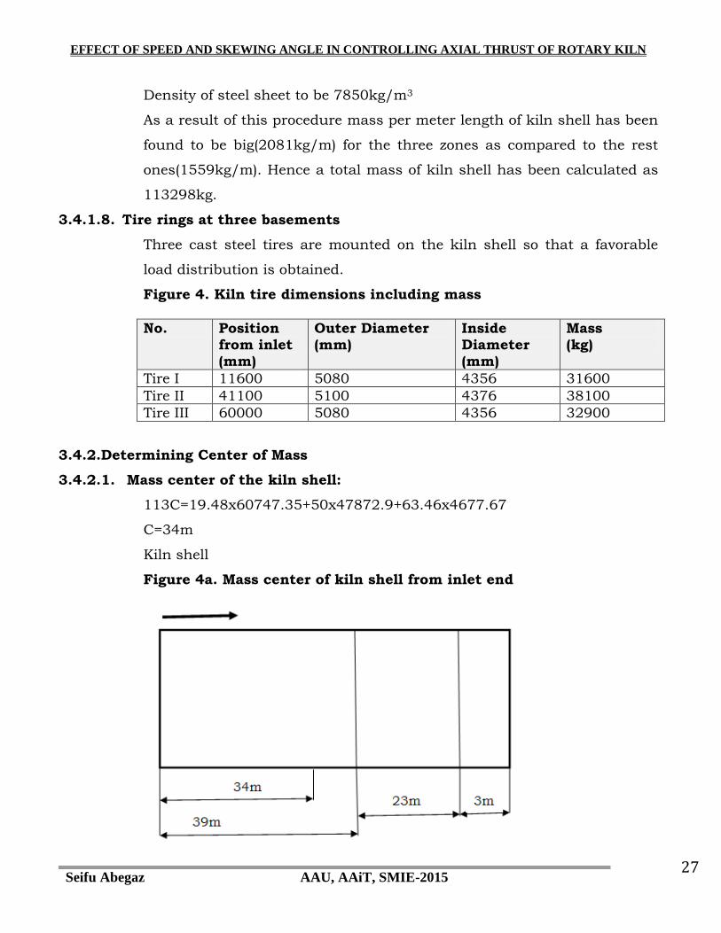
Density of steel sheet to be 7850kg/m3
As a result of this procedure mass per meter length of kiln shell has been
found to be big(2081kg/m) for the three zones as compared to the rest
ones(1559kg/m). Hence a total mass of kiln shell has been calculated as
113298kg.
3.4.1.8. Tire rings at three basements
Three cast steel tires are mounted on the kiln shell so that a favorable
load distribution is obtained.
Figure 4. Kiln tire dimensions including mass
No. Position from inlet (mm)
Outer Diameter (mm)
Inside Diameter (mm)
Mass (kg)
Tire I 11600 5080 4356 31600
Tire II 41100 5100 4376 38100
Tire III 60000 5080 4356 32900
3.4.2.Determining Center of Mass
3.4.2.1. Mass center of the kiln shell:
113C=19.48x60747.35+50x47872.9+63.46x4677.67
C=34m
Kiln shell
Figure 4a. Mass center of kiln shell from inlet end

EFFECT OF SPEED AND SKEWING ANGLE IN CONTROLLING AXIAL THRUST OF ROTARY KILN
Seifu Abegaz AAU, AAiT, SMIE-2015 28
3.4.2.2. Mass center of refractory bricks
3.4.2.2.1. Inlet zone
The center of mass for inlet zone refractory bricks as counted from the inlet end is
calculated as the length of bricks lining divided by two which is:
CI =LI/2
=0.7m.
3.4.2.2.2. Calcining zone
The center of mass for calcining zone refractory bricks is calculated as the sum of the
lengths for inlet zone and half the length of the calcining zone which is:
Cc =LI+Lc/2
=1.4+14.38
=15.08m
3.4.2.2.3. Safety zone
The center of mass for safety zone refractory bricks is calculated as the sum of the
lengths for inlet zone, calcining zone and half the length of the safety zone which is:
Cs=LI+Lc+Ls/2
=1.4m+28.76m+8.8/2m
=34.56m
3.4.2.2.4. Upper transition, Central and Lower transition zone
Since the types of bricks to be lined on these zones have identical physical and
chemical properties one can calculate the center of mass as one zone. Hence it is as
the sum of the lengths for inlet zone, calcining zone, safety zone and half the
combined lengths of the three zones:

EFFECT OF SPEED AND SKEWING ANGLE IN CONTROLLING AXIAL THRUST OF ROTARY KILN
Seifu Abegaz AAU, AAiT, SMIE-2015 29
Cb=LI+Lc+Ls+Lb/2
=1.4m+28.76m+8.8m+23/2m
=50.46m
3.4.2.2.5. Cooling zone
The center of mass for cooling zone refractory bricks is calculated as the sum of the
lengths for inlet zone, calcining zone, safety zone, combined burning zone and half the
length of the cooling zone which is:
Ccl=LI+Lc+Ls+Lb+Lcl/2
=1.4m+28.76m+8.8m+23m+3/2m
=63.46m
Finally the mass center of refractory bricks can be calculated as:
Cx414=CIx7.547+Ccx155+Csx58.35+Cbx172.3+Cclx21
Cx414=0.7x7.547m+15.08x155m+34.56x58.35m+50.46x172.3m+63.46x21m
C=35.13m
EFFECT OF SPEED AND SKEWING ANGLE IN CONTROLLING AXIAL THRUST OF ROTARY KILN
Seifu Abegaz AAU, AAiT, SMIE-2015 30
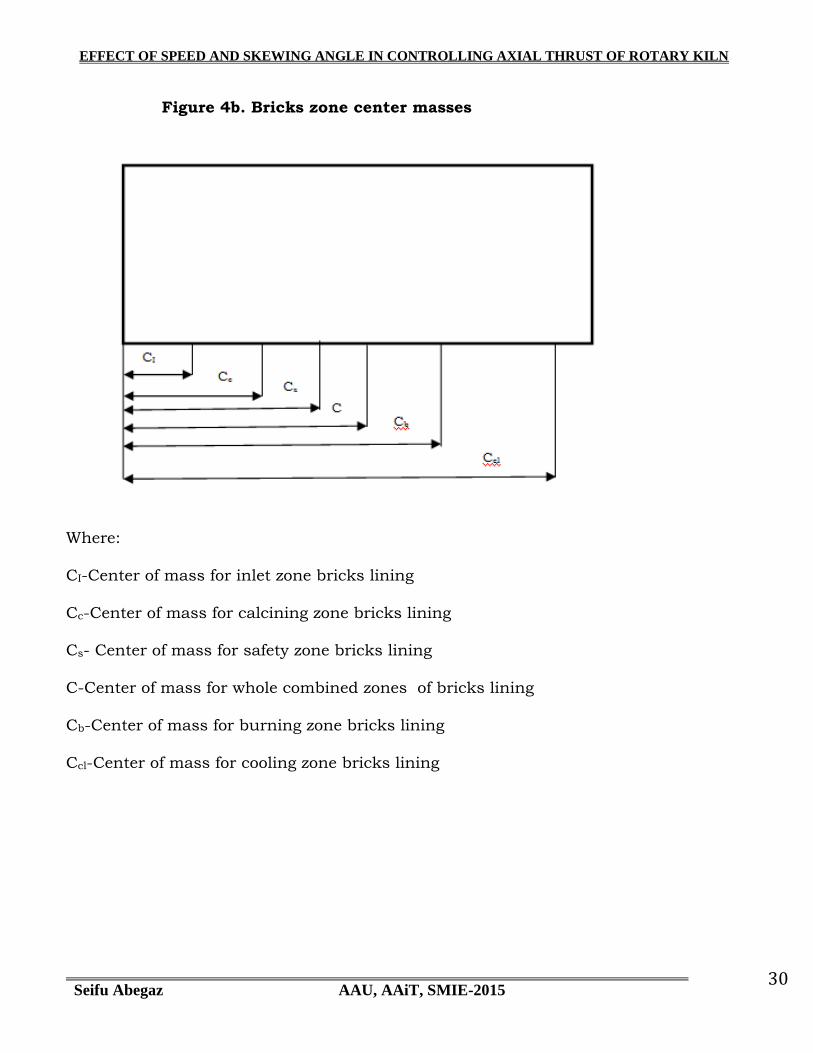
Figure 4b. Bricks zone center masses
Where:
CI-Center of mass for inlet zone bricks lining
Cc-Center of mass for calcining zone bricks lining
Cs- Center of mass for safety zone bricks lining
C-Center of mass for whole combined zones of bricks lining
Cb-Center of mass for burning zone bricks lining
Ccl-Center of mass for cooling zone bricks lining

EFFECT OF SPEED AND SKEWING ANGLE IN CONTROLLING AXIAL THRUST OF ROTARY KILN
Seifu Abegaz AAU, AAiT, SMIE-2015 31
Figure 4c. Static modeling of the kiln system
Applying equilibrium conditions
𝐹𝑦31 = 0, 𝑅1 + 𝑅2 + 𝑅3 = 680 ……………………………..a
𝑀0 = 0, 11.6𝑅1 + 41.1𝑅2 + 60𝑅3 = 23336.2 ……………b
Since the equilibrium condition is not enough to solve for three unknowns we need to
incorporate superposition method which is used for redundant reactions.
Hence the sum of deflections from all loads and reactions at a point on the span of the
beam results in zero effect.
∇p1=0
342.2𝑅2 + 561.4𝑅3 = 184694.48 ………………………..c
EFFECT OF SPEED AND SKEWING ANGLE IN CONTROLLING AXIAL THRUST OF ROTARY KILN
Seifu Abegaz AAU, AAiT, SMIE-2015 32
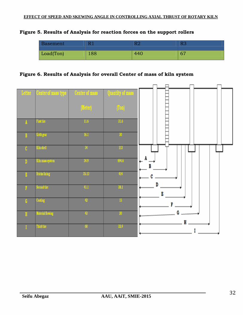
Figure 5. Results of Analysis for reaction forces on the support rollers
Basement R1 R2 R3
Load(Ton) 188 440 67
Figure 6. Results of Analysis for overall Center of mass of kiln system

EFFECT OF SPEED AND SKEWING ANGLE IN CONTROLLING AXIAL THRUST OF ROTARY KILN
Seifu Abegaz AAU, AAiT, SMIE-2015 33
3.4.3.Dynamic Analysis
[5]It is important to understand that traction force depends on the normal force
applied at contact surfaces of the two rolling components. There are hence different
options to examine axial movement of rotary kiln by skewing optionally three pairs of
support rollers either doing for all pair together or individual treatment. In this case
we have considered starting on the support roller pair with maximum normal load
shared.
Determining component of the traction force along the kiln axis for a pair of support
rollers at a maximum pressure load will help find out displacement of rotary kiln
along its axis. It‟s also important to check up if speed variation of the rotary kiln
affects traction force and thereby rate of displacement of kiln along its axis. In
addition to the static load, rotation of the kiln has an influence on the traction force
due to the skewing of support rollers. Hence torque has to be analyzed. Torque is
applied by the drive set of the rotary kiln. This torque is transmitted through the
pinion-girth gear meshing mechanism to the mega mass of rotary kiln system. The
kiln rolls on three pairs of support rollers. The roller and tire contact surface
generates traction force for the kiln to move axially upward or downward depending
on the skewing directions of the paired rollers. Skewing refers shifting of the paired
roller axes from the tire ring axis i.e. the roller axes and the tire ring axis will become
non-parallel and that is said to be roller skewing.
How far the kiln advances upward for a defined skewing value on a single pair of
support rollers and pre-determined traction coefficient between tire ring and support
rollers in a certain period of time? And it is also important in the analysis to observe
the axial movement and its rate for different values of rotational speed of kiln.
Figure 7. Dimensions to be determined at the end
Dimensions to be
determined
Rotational speed of kiln(RPM) Skewing angle of support roller for middle pier
1.75 2.0 2.1 2.3 0.21 0.32 0.42 0.57
Axial 0.299 0.299 0.299 0.299 2764.4 3472.4 3873.4 4583.2
EFFECT OF SPEED AND SKEWING ANGLE IN CONTROLLING AXIAL THRUST OF ROTARY KILN
Seifu Abegaz AAU, AAiT, SMIE-2015 34
Displacement(µm)
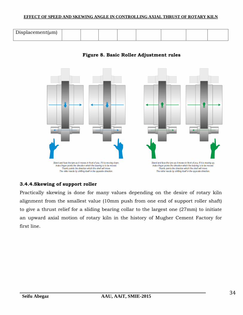
Figure 8. Basic Roller Adjustment rules
3.4.4.Skewing of support roller
Practically skewing is done for many values depending on the desire of rotary kiln
alignment from the smallest value (10mm push from one end of support roller shaft)
to give a thrust relief for a sliding bearing collar to the largest one (27mm) to initiate
an upward axial motion of rotary kiln in the history of Mugher Cement Factory for
first line.

EFFECT OF SPEED AND SKEWING ANGLE IN CONTROLLING AXIAL THRUST OF ROTARY KILN
Seifu Abegaz AAU, AAiT, SMIE-2015 35
3.4.5.Contact of Two Cylinders with Axes Parallel
[2]When any two curved bodies of different radii of curvature are brought into contact
they will initially touch at either a point or along a line. With the application of the
smallest load, elastic deformation enlarges these into contact areas across which the
loads are distributed as pressures
If two circular cylinders with radii R1 and R2 are pressed together by a force per unit
length of magnitude P with their axes parallel, as shown in Figure 10, then the
contact patch will be of half-width b such that
𝑏 = 2𝑃𝑅
𝜋𝐸∗ 1
2 1
where R and E* are the reduced radius of contact and the contact modulus defined by
1
𝑅=
1
𝑅1+
1
𝑅2 (1a)
EFFECT OF SPEED AND SKEWING ANGLE IN CONTROLLING AXIAL THRUST OF ROTARY KILN
Seifu Abegaz AAU, AAiT, SMIE-2015 36
and
1
𝐸∗ =1−𝑣1
2
𝐸1+
1−𝑣22
𝐸2 (2)
respectively.
Contact pressure is again semielliptical such that
𝑃 𝑥 = 𝑃𝑜 1 − 𝑟2
𝑏2
12
(3)
where peak pressure

EFFECT OF SPEED AND SKEWING ANGLE IN CONTROLLING AXIAL THRUST OF ROTARY KILN
Seifu Abegaz AAU, AAiT, SMIE-2015 37
𝑃𝑜 = 𝑃𝐸∗
𝜋𝑅 1 2
(4)
and coordinate x is measured in a direction perpendicular to that of the cylinder axes.
The mean pressure pm over the contact strip is equal to P/2 b and is given by
𝑃𝑚 =𝜋𝑃𝑜
4 (5)
The axes of the cylinders move together by a small distance Δ where
∆= 1 − 𝑣12
ln 4𝑅1
𝑏 −12
𝐸1+ 1 − 𝑣2
2 ln
4𝑅2𝑏 −1
2
𝐸2 (6)
Once again, if one of the surfaces is planar, then the value of R will be equal to the
radius of curvature of the other.

EFFECT OF SPEED AND SKEWING ANGLE IN CONTROLLING AXIAL THRUST OF ROTARY KILN
Seifu Abegaz AAU, AAiT, SMIE-2015 38
3.4.6.Contact of Two Cylinders with Inclined Axes
[2]Suppose the lower cylinder is of radius R1 and the upper of R2, as shown in Figure
11. The cylinders touch at the point O but their axes are inclined at an angle θ. Ox1y1
is a set of Cartesian axes with Oy1 along a generator of the lower cylinder, and Ox2 a
second similar set with Oy2 along a generator of the upper cylinder.
Close to the origin we can approximate the circular section of each cylinder by a
parabolic profile and so write that the separation h of the two solid surfaces at the
point P, which has coordinates (x1,y1) in the first coordinate system or (x2,y2) in the
second, is given by

EFFECT OF SPEED AND SKEWING ANGLE IN CONTROLLING AXIAL THRUST OF ROTARY KILN
Seifu Abegaz AAU, AAiT, SMIE-2015 39
ℎ ≈𝑥1
2
2𝑅1+
𝑥22
2𝑅2 (7)
It is possible to choose a common set of axes (Oxy), in which Ox is inclined to the Ox1-
direction by the angle α, such that the original Heinrich Hertz formula is recovered
which is
ℎ = 𝐴𝑥2 + 𝐵𝑦2 (7a)
where h is the gap between the undeformed surfaces , x and y are orthogonal
coordinates lying in the common tangent plane to the two surfaces, provided that A
and B satisfy the conditions
𝐵 − 𝐴 =1
2
1
𝑅12 +
1
𝑅22 + 2
𝑅1𝑅2 cos 2𝜃
12
(8)
and
𝐵 + 𝐴 =1
2 1
𝑅1 + 1
𝑅2 (9)
And α is given by the solution of
𝑅2
𝑅1sin 2α = sin2 𝜃 − 𝛼 (10)
Equation (7a) can then be written as
ℎ =𝑥2
2𝑅′ +𝑦2
2𝑅′′ (11)
by defining
𝑅′ = 12𝐴 and 𝑅′′ = 1
2𝐴 (12)
R′ and R″ are known as the principal radii of relative curvature.
It is evident from Equation (12) that contours of constant gap h between the
undeformed surfaces will be ellipses, the lengths of whose axes are in the ratio
(R′/R″)1/2.
When a normal load P is applied, the point of contact spreads into an elliptical area
with semi-axes a and b, such that the eccentricity, i.e., the ratio b/a, is independent

EFFECT OF SPEED AND SKEWING ANGLE IN CONTROLLING AXIAL THRUST OF ROTARY KILN
Seifu Abegaz AAU, AAiT, SMIE-2015 40
of the load and depends only on the ratio of R′/R″. For mildly elliptical contacts, i.e.,
A/B < 5, then the ratio b/a is given by
𝑏𝑎 ≈ 𝐴 𝐵
23 (13)
An “equivalent” radius Re can be defined as
𝑅𝑒 = 𝑅′′ × 𝑅′ 1
2 =1
2 𝐴𝐵
−12 (14)
and this used to estimate the contact area or Hertz stress by using the circular
contact equations with R replaced by Re. The approach of the bodies can be
calculated using equation
∆= 𝑎2
𝑅 =𝑎𝜋𝑃𝑜
2𝐸∗ = 9𝑃2
16𝑅𝐸∗2
13
(14a)
but with R replaced by (AB)–1/2 rather than Re.
If the two cylinders make contact with their axes parallel so that
θ = 0, it follows from Equations 8, 9, and 12 that
1
𝑅′=
1
𝑅1+
1
𝑅2 (15)
i.e. Equation 2 is recovered.
On the other hand, if the axes of the two cylinders are perpendicular to one another
θ = 90°; then R′ =R1 and R″ =R2. It follows that
ℎ =𝑥2
2𝑅1+
𝑦2
2𝑅2 (16)
Consequently, for the particular case of a pair of equal cylinders crossing at an angle
of 90°, contours of constant surface separation close at the contact point will be
circles.
3.4.7.Axial Motion
[1]The contact of interest is that of two cylindrical elements rolling on each other. This
can be modeled in one plane as a pair of rolling circles or in a continuous series of
parallel planes as a sequence of rolling circles rigidly attached to each other along the
respective axes of the two cylinders. A kinematic analysis of the effects of
EFFECT OF SPEED AND SKEWING ANGLE IN CONTROLLING AXIAL THRUST OF ROTARY KILN
Seifu Abegaz AAU, AAiT, SMIE-2015 41
misalignment requires that at least two planes of contact be considered, such as the
two planar models shown in the figure below.
In the model slight variations in rolling radii from the nominal radii ra and rb are
considered. However, each cylinder is a rigid body, thus the planar rolling circles at
each end of the cylinder must move as a single unit. In plane 1 the pitch point velocity
of cylinder b is given by
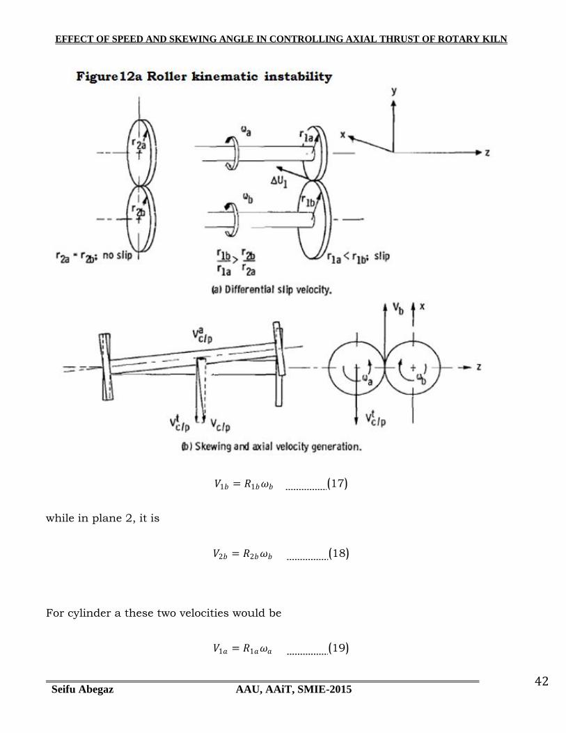
EFFECT OF SPEED AND SKEWING ANGLE IN CONTROLLING AXIAL THRUST OF ROTARY KILN
Seifu Abegaz AAU, AAiT, SMIE-2015 42
𝑉1𝑏 = 𝑅1𝑏𝜔𝑏 (17)
while in plane 2, it is
𝑉2𝑏 = 𝑅2𝑏𝜔𝑏 (18)
For cylinder a these two velocities would be
𝑉1𝑎 = 𝑅1𝑎𝜔𝑎 (19)

EFFECT OF SPEED AND SKEWING ANGLE IN CONTROLLING AXIAL THRUST OF ROTARY KILN
Seifu Abegaz AAU, AAiT, SMIE-2015 43
and
𝑉2𝑎 = 𝑅2𝑎𝜔𝑎 (20)
For no slip at plane 2
𝑉2𝑎 = 𝑉2𝑏 (21)
or
𝑅2𝑎𝜔𝑎 = 𝑅2𝑏𝜔𝑏 (22)
𝜔𝑎 =𝑅2𝑏
𝑅2𝑎𝜔𝑏 (23)
In plane 1
𝑉1𝑎
𝑅1𝑎=
𝑅2𝑏
𝑅2𝑎𝜔𝑏 (24)
For no slippage at plane1
𝑉1𝑏 = 𝑉1𝑎 (25)
From the above equations
𝑅1𝑏
𝑅1𝑎𝜔𝑏 =
𝑅2𝑏
𝑅2𝑎𝜔𝑏 (26)
or
R1b
R1a=
R2b
R2a (27)
As shown in figure 2(a), if rlb/rla is greater than r2b/r2a and pure rolling exists at the
contact in plane 2, then slippage will occur at the contact in plane 1. For the geometry
shown, where r2a =r2b and rla < rlb, a slip velocity will be developed in the positive x
direction between the contacting points on the roller surfaces. Thus,
∆𝑈1 = 𝑉1𝑏 − 𝑉1𝑎 (28)
will be a positive slip velocity of roller b under roller a. Friction will convert this
relative velocity into a tractive force that tends to skew cylinder a on cylinder b. This
skewing will generate a component of the relative velocity of cylinder a's center with

EFFECT OF SPEED AND SKEWING ANGLE IN CONTROLLING AXIAL THRUST OF ROTARY KILN
Seifu Abegaz AAU, AAiT, SMIE-2015 44
respect to the pitch point in the axial direction from plane 2 to plane 1. This velocity
component is in the direction towards the smaller rolling radius circle. The tangential
component of this relative velocity Vt c /P
is subtracted from the pitch line velocity V for
the net circumferential motion. The axial component of this relative velocity Vac /P
remains unopposed. This produces a net axial motion of cylinder a with respect to
cylinder b. Unopposed, this axial motion or 'walking", which a consequence of roller
skewing, will continue until either a mechanical restraint is encountered or the rollers
have become disengaged.
3.4.8.Stability Criterion
[1]Kinematic stability is achieved when a roller pair, which is momentarily disturbed
from its equilibrium position by an external force, is capable of returning to a neutral
position only because of corrective geometry changes. If the geometry of the contact
between the two cylinders is such that the inequality that initiates this axial motion is
changed to the equality of equation (27) by the axial motion, then the contacts will be
kinematically stable. Therefore, to achieve kinematic stability, the object is to select
the roller geometry that tends to satisfy equation (27) after the roller has been
disturbed. The model chosen to evaluate the roller's tendency to return to equilibrium
assumes the contacting surfaces at the roller ends to be both continuous and
symmetric. Since these surfaces are rigidly connected, axial motion of one roller
relative to the other will cause equal but opposite changes of contacting radius ratio at
the roller ends. Therefore, the total stability question of the roller pair can be studied
by considering the contact geometry changes at one end only. In plane 1 a stabilizing
condition exists when
𝜕
𝜕𝑧 𝑅1𝑏
𝑅1𝑎 < 0 (29)
where z denotes a shift of cylinder a to the right as indicated in figure 12a. Since the
contact geometry is symmetric, then in plane 2

EFFECT OF SPEED AND SKEWING ANGLE IN CONTROLLING AXIAL THRUST OF ROTARY KILN
Seifu Abegaz AAU, AAiT, SMIE-2015 45
𝜕
𝜕𝑧 𝑅1𝑏
𝑅1𝑎 > 0 (30)
The sign of the inequality appearing in equation (29) is a consequence of the rollers
tendency to move axially in the direction towards the end that possesses the smaller
rolling radius. For the example selected in figure 12a(a), as roller a moves in the
positive z direction relative to roller b, the radius ratio rlb/rla is required to decrease in
value in order to restore equilibrium in accordance with equation (27). Considering
the anti-symmetric behavior of the contact occurring in plane 2, just the opposite
change would be required; that is, r2b/r2a is required to increase in value to restore
equality between the radius ratios at each end. These stability requirements are
reflected by equations (29) and (30) as shown. As previously mentioned, for roller
bodies with symmetric ends, it is sufficient to consider the stability characteristics of
the contacting geometry at only one end. In the analysis that follows, the contact
occurring at the plane1 end or the end on the right side of the roller will be examined.
The compliance of an axially disturbed roller pair to the criterion described in
equation (29) will cause the rollers to eventually approach a condition of pure rolling
where equation (27) is satisfied. If the axes are still skewed at this point, further
motion will cause r2b/r2a to become larger than rlb/rla, which will tend to skew the
axes in the opposite direction. This correction would tend to return the cylinders to
their stable equilibrium point of pure rolling where these ratios are equal. In practice,
a damped oscillation would most likely result. A roller pair exhibiting this behavior
would be considered to have both axial as well as angular kinematic stability.
3.4.9.Mathematical analysis for ANSYS input
[15]The idea that axial displacement or deformation is supposed to show the possible
thrust load on different kiln system components has made use of static analysis using
ANSYS software. This analysis was accomplished for different values of rotational
speed and skewing angle. This has brought different values for axial displacement or
deformation of the kiln tire which shows that this effect will be reflected on the axial
thrust load impact for the kiln components.

EFFECT OF SPEED AND SKEWING ANGLE IN CONTROLLING AXIAL THRUST OF ROTARY KILN
Seifu Abegaz AAU, AAiT, SMIE-2015 46
3.4.10. Axial thrust due to tire-roller contact surface
[15]Due to skewing of support roller the action of axial thrust load resembles that of
the load acting on two meshing helical gears.
When support roller reaction analysis was statically done it was found that 63% of the
total load of the kiln system has rested on the second basement roller pair. Since they
are pair of rollers seated symmetrically at 60ᴼ to each other they equally share the
load both in the x and y direction. And even the load in the x direction has been
canceled due to opposite actions of the two support rollers.

EFFECT OF SPEED AND SKEWING ANGLE IN CONTROLLING AXIAL THRUST OF ROTARY KILN
Seifu Abegaz AAU, AAiT, SMIE-2015 47
As the aim of this thesis is to show the effect of rotational speed on axial thrust of any
rotary kiln for a fixed roller skew value, it has been tried to show with four different
values of rotational speed.
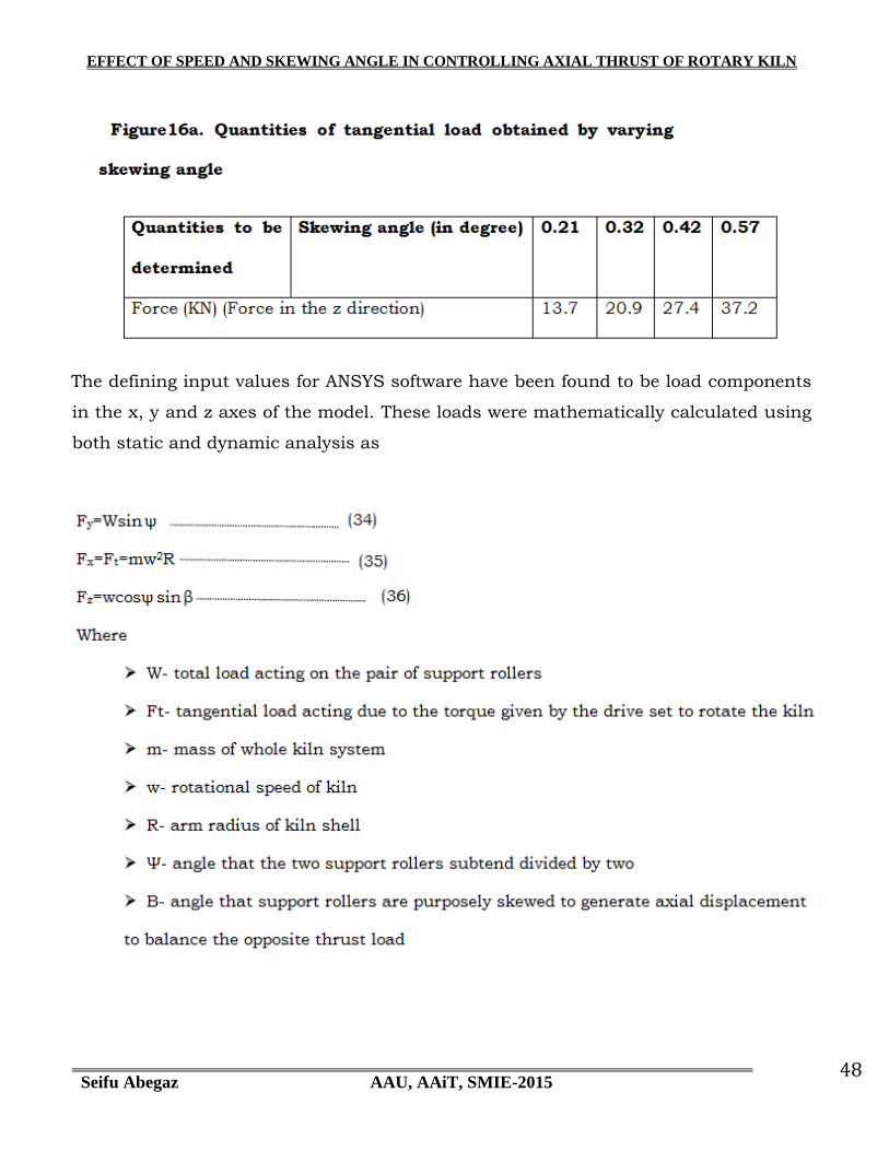
EFFECT OF SPEED AND SKEWING ANGLE IN CONTROLLING AXIAL THRUST OF ROTARY KILN
Seifu Abegaz AAU, AAiT, SMIE-2015 48
The defining input values for ANSYS software have been found to be load components
in the x, y and z axes of the model. These loads were mathematically calculated using
both static and dynamic analysis as

EFFECT OF SPEED AND SKEWING ANGLE IN CONTROLLING AXIAL THRUST OF ROTARY KILN
Seifu Abegaz AAU, AAiT, SMIE-2015 49
Figure 17a. All force components for varying skewing angle
Figure 17. All force components for varying speed

EFFECT OF SPEED AND SKEWING ANGLE IN CONTROLLING AXIAL THRUST OF ROTARY KILN
Seifu Abegaz AAU, AAiT, SMIE-2015 50
EFFECT OF SPEED AND SKEWING ANGLE IN CONTROLLING AXIAL THRUST OF ROTARY KILN
Seifu Abegaz AAU, AAiT, SMIE-2015 51
3.5. CONDITION
This chapter particularly deals with the question that when this thesis is conducted
„how the desired output could be obtained.‟ The whole research is all about treating
the two variables by describing using different modeling methods. Since the thesis
considers the effect of rotational speed and skewing angle on the axial thrust of a
rotary kiln we need to put some conditions while trying to show the effect of speed and
skewing angle though there are other factors that determine the magnitude of the
axial thrust. Axial movement of rotary kiln due to skewing of rollers will not create
huge wear damage on the surfaces of support rollers and tire rings unless there faces
a resistance to the motion due to skewing. If we are able to control the motion by
skewing the support rollers in both directions from the absolute parallel state of axes
of support rollers and rotary kiln we can keep the axial thrust less harm to
components of kiln system. Here the principle of kinematics and kinetics is applied.
Controlling the axial motion with kinetic correction will produce considerable thrust
on components. Usually the axial thrust of rotary kiln nowadays is controlled by
hydraulic thrust roller unit. However, this is totally kinetic or force correction which
will create significantly large thrust force that has to be withheld by disc of the thrust
unit and this will accelerate shortening the life of thrust roller.
It is assumed that the varying rotational speeds will be taken for every
maximum value of other parameters
It is also assumed that the varying skewing angles will be taken for every
maximum value of other parameters
Even though the slope of base plates, support rollers and tire rings are
susceptible to change when the kiln is in operation for longer time for the sake of
my analysis it is considered to be the design value which is 3%
The surface conditions of all contacts between the tire rings and support
rollers are assumed to be uniform and taken from the design values.

EFFECT OF SPEED AND SKEWING ANGLE IN CONTROLLING AXIAL THRUST OF ROTARY KILN
Seifu Abegaz AAU, AAiT, SMIE-2015 52
Figure 21 CATIA modeling for tire and roller assembly
Nearly all components which exist in real situation of rotary kiln system have been
modeled using CATIA V5. And all components were assembled based on the order
of instruction manual and the assembly is shown in figure 19. However, capacity
of the personal computer which has been engaged to execute all the tasks and
efficiency of ANSYS software cannot allow for analyzing the real motion of the
process.
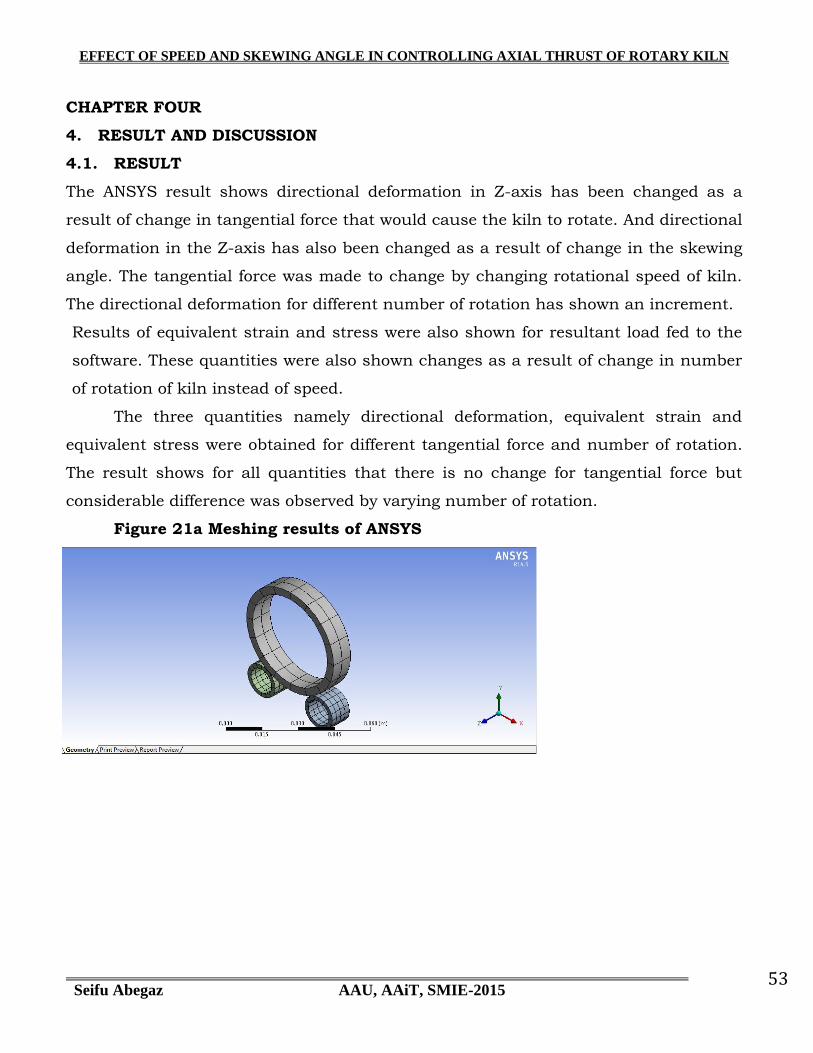
EFFECT OF SPEED AND SKEWING ANGLE IN CONTROLLING AXIAL THRUST OF ROTARY KILN
Seifu Abegaz AAU, AAiT, SMIE-2015 53
CHAPTER FOUR
4. RESULT AND DISCUSSION
4.1. RESULT
The ANSYS result shows directional deformation in Z-axis has been changed as a
result of change in tangential force that would cause the kiln to rotate. And directional
deformation in the Z-axis has also been changed as a result of change in the skewing
angle. The tangential force was made to change by changing rotational speed of kiln.
The directional deformation for different number of rotation has shown an increment.
Results of equivalent strain and stress were also shown for resultant load fed to the
software. These quantities were also shown changes as a result of change in number
of rotation of kiln instead of speed.
The three quantities namely directional deformation, equivalent strain and
equivalent stress were obtained for different tangential force and number of rotation.
The result shows for all quantities that there is no change for tangential force but
considerable difference was observed by varying number of rotation.
Figure 21a Meshing results of ANSYS

EFFECT OF SPEED AND SKEWING ANGLE IN CONTROLLING AXIAL THRUST OF ROTARY KILN
Seifu Abegaz AAU, AAiT, SMIE-2015 54
Figure 22 ANSYS Results for one revolution, 360ᴼ

EFFECT OF SPEED AND SKEWING ANGLE IN CONTROLLING AXIAL THRUST OF ROTARY KILN
Seifu Abegaz AAU, AAiT, SMIE-2015 55
Figure 23 Tabulated results of ANSYS for one revolution
Object Name Directional Deformation Total
Deformation
Equivalent Elastic
Strain Equivalent Stress
State Solved
Scope
Scoping Method Geometry Selection
Geometry All Bodies 3 Bodies All Bodies
Definition
Type Directional Deformation Total
Deformation
Equivalent Elastic
Strain
Equivalent (von-Mises)
Stress
Orientation Z Axis
By Time
Display Time Last
Coordinate System Global Coordinate
System
Calculate Time
History Yes
Identifier
Suppressed No
Results
Minimum -1.6144e-007 m 3.3142e-017 m 2.1639e-009 m/m 192.07 Pa
Maximum 1.6144e-007 m 1.3265e-002 m 1.262e-004 m/m 2.3957e+007 Pa
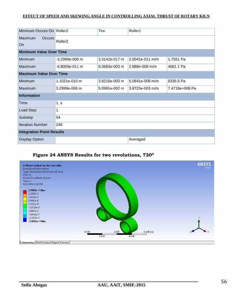
EFFECT OF SPEED AND SKEWING ANGLE IN CONTROLLING AXIAL THRUST OF ROTARY KILN
Seifu Abegaz AAU, AAiT, SMIE-2015 56
Minimum Occurs On Roller2 Tire Roller1
Maximum Occurs
On Roller2
Minimum Value Over Time
Minimum -3.2999e-006 m 3.3142e-017 m 2.5041e-011 m/m 1.7551 Pa
Maximum -6.8009e-011 m 9.3683e-003 m 2.888e-008 m/m 4661.1 Pa
Maximum Value Over Time
Minimum 1.1021e-010 m 3.9215e-003 m 5.0841e-008 m/m 9335.5 Pa
Maximum 3.2999e-006 m 5.0991e-002 m 3.8723e-003 m/m 7.4718e+008 Pa
Information
Time 1. s
Load Step 1
Substep 54
Iteration Number 246
Integration Point Results
Display Option Averaged
Figure 24 ANSYS Results for two revolutions, 720ᴼ

EFFECT OF SPEED AND SKEWING ANGLE IN CONTROLLING AXIAL THRUST OF ROTARY KILN
Seifu Abegaz AAU, AAiT, SMIE-2015 57

EFFECT OF SPEED AND SKEWING ANGLE IN CONTROLLING AXIAL THRUST OF ROTARY KILN
Seifu Abegaz AAU, AAiT, SMIE-2015 58
Figure 25 ANSYS Results for three revolutions, 1080ᴼ

EFFECT OF SPEED AND SKEWING ANGLE IN CONTROLLING AXIAL THRUST OF ROTARY KILN
Seifu Abegaz AAU, AAiT, SMIE-2015 59
4.2. DISCUSSION
Initially the static analysis was chosen so as to see the change in directional
deformation with respect to tangential force because the force is subject to
change due to change of rotational speed. However, results have shown that the
skewing angle change has more direct impact on axial load than the speed
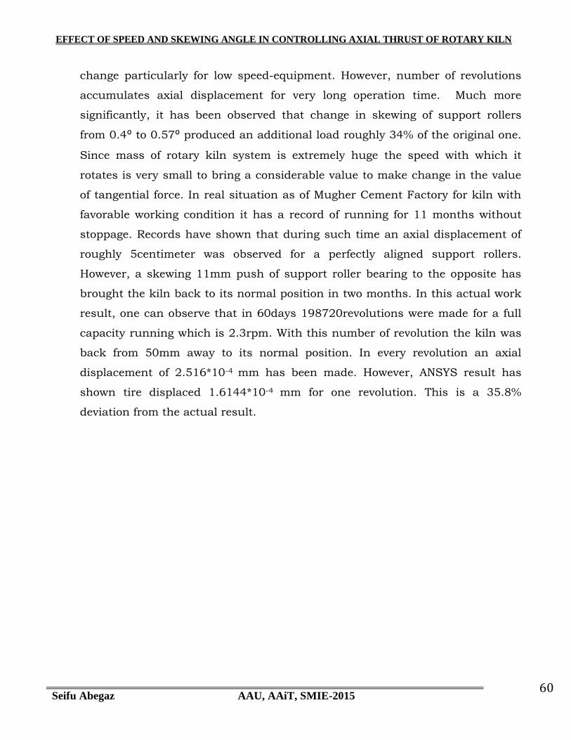
EFFECT OF SPEED AND SKEWING ANGLE IN CONTROLLING AXIAL THRUST OF ROTARY KILN
Seifu Abegaz AAU, AAiT, SMIE-2015 60
change particularly for low speed-equipment. However, number of revolutions
accumulates axial displacement for very long operation time. Much more
significantly, it has been observed that change in skewing of support rollers
from 0.4ᴼ to 0.57ᴼ produced an additional load roughly 34% of the original one.
Since mass of rotary kiln system is extremely huge the speed with which it
rotates is very small to bring a considerable value to make change in the value
of tangential force. In real situation as of Mugher Cement Factory for kiln with
favorable working condition it has a record of running for 11 months without
stoppage. Records have shown that during such time an axial displacement of
roughly 5centimeter was observed for a perfectly aligned support rollers.
However, a skewing 11mm push of support roller bearing to the opposite has
brought the kiln back to its normal position in two months. In this actual work
result, one can observe that in 60days 198720revolutions were made for a full
capacity running which is 2.3rpm. With this number of revolution the kiln was
back from 50mm away to its normal position. In every revolution an axial
displacement of 2.516*10-4 mm has been made. However, ANSYS result has
shown tire displaced 1.6144*10-4 mm for one revolution. This is a 35.8%
deviation from the actual result.
EFFECT OF SPEED AND SKEWING ANGLE IN CONTROLLING AXIAL THRUST OF ROTARY KILN
Seifu Abegaz AAU, AAiT, SMIE-2015 61
CHAPTER FIVE
5. CONCLUSION, RECOMMENDATION AND FUTURE WORK
5.1. CONCLUSION
At the beginning, the idea of this thesis is to show the effect of rotational
speed and skewing angle on axial thrust of a rotary kiln. The result of both
mathematical and software analysis have shown that effect of change in
skewing angle of support rollers have larger than that of rotational speed on
axial thrust of rotary kiln for the fact that (unlike equipment such as pumps,
helical gearboxes, fan etc.. which have extremely high speed as compared to
kiln) speed of this equipment is so small that the result of change in
tangential force will considerably be insufficient to bring about axial thrust
due to skewing. However, the result has also shown that the number of
revolution the kiln makes during its operation has a significant effect to
axially displace depending on the sense of skewing direction. Most
importantly skewing angle changes have a considerable change in axial
thrust.
5.2. RECOMMENDATION
In cement or mining industry as a whole axial thrust of any rotary kiln causes a
massive destruction on different kiln system components as it has been
observed from different experience and exposure. Having been in cement factory
for nearly ten years as mechanical engineer, I can witness that the damage has
been causing potential loss in terms of increasing cost of production for
replacing damaged components or loss due to stoppage for maintenance. Hence
I herewith recommend the following procedural steps for short and long term
solution to minimize damage of components and ultimately eliminate
unnecessary axial thrust of rotary kiln:
It is advisable to control axial thrust using kinematic methods instead of
force control or kinetic action.
Although a kinetic or force correction, in the form of a roller flange or
bumper, is sometimes required to ensure that gross axial motion cannot
occur, the kinematic correction is unquestionably more desirable.
EFFECT OF SPEED AND SKEWING ANGLE IN CONTROLLING AXIAL THRUST OF ROTARY KILN
Seifu Abegaz AAU, AAiT, SMIE-2015 62
The kinematic correction, which results in self-centering action, can be
implemented without seriously affecting either the mechanical efficiency
or durability of the contact.
Axial motion that is not corrected kinematically will create significantly
large thrust forces that have to be withheld by flanges or thrust bearings
As effect of rotational speed has been studied as one factor to affect axial
thrust it is also important and compulsory to complete study of the other
factors to apply in formulating a controlling setup that could be developed
into a technology which would make use of flexible skewing of support
rollers that acts depending on the magnitude of thrust exerted on kiln
system components to relieve pick thrust situations.
5.3. FUTURE WORK
This thesis, as tried to note in the introduction part, is to investigate the
effect of rotational speed and skewing angle on axial thrust of rotary kiln and
it is done. However, the effect of these two changes and other factors should
be further analyzed for technology application. Then it will have a potential
attraction for sponsors to invest to change it to technology.
REFERENCES
1. KINEMATIC stability OF ROLLER PAIRS IN FREE-ROLLING CONTACT by
Michael Savage* and Stuart H. Loewenthal Lewis Research Center and U. S.
Army Air Mobility R&D Laboratory
2. Contact between Solid Surfaces by John A. Williams Cambridge University
3. Reports on Professional highly accurate measurements of geometry and
deformations of machinery structures and constructions by Geoservex
4. NAK Instruction No. 8 Revised 032705
5. Operating manual of Mugher Cement Factory First line
6. Zement Kalk Gips” (1983)
7. Statistical methods of circular deviations elimination from calculation of kiln
shell radial run-out (2001)
8. Instruction manual for rotary kiln erection (by FLSmidth)

EFFECT OF SPEED AND SKEWING ANGLE IN CONTROLLING AXIAL THRUST OF ROTARY KILN
Seifu Abegaz AAU, AAiT, SMIE-2015 63
9. Hassan Yousefi, On Modeling, System Identification and Control of Servo-
Systems with a Flexible Load (2007)
10. External alignment procedure fofr rotary kilns, cooler, dryers and similar
rotating machines( by Fuller company, 728-75-1-8801)
11. Maintenance Practices in Cement Industry by Hani Shafeek, Faculty of
Engineering ,Industrial Engineering Department King Abdulaziz University,
Rabigh Branch, KSA Faculty of Industrial Education, Suez Canal University,
Egypt
12. Mechanical stability of cement rotary kilns to prevent brick lining failure by g.c.
dalela, Raju Goyal and Kamal Kumar Holtec Consulting Private Limited, New
Delhi
13. Dynamic modeling and analysis of the largescale rotary machine with
multisupporting rollers. By Xuejun Li, Yiping Shen_ and SonglaiWang Hunan
(University of Science and Technology, Hunan Provincial Key Laboratory of
Health Maintenance for Mechanical Equipment, Hunan, China)
14. ACHIEVING MECHANICAL STABILTY OF ROTARY KILN BY FEM Sumesh
Krishnan B.E, M.B.A., M.Tech
15. Mechanical Engineering McGraw−Hill Primis ISBN: 0−390−76487−6 Text:
Shigley‟s Mechanical Engineering Design Eighth Edition Budynas−Nisbett
Shigley‟s Mechanical Engineering Design, Eighth Edition Budynas−Nisbett