ADDENDUM NUMBER 01 TO THE BID DOCUMENTS To all ...
114
SAN JOSE EVERGREEN COMMUNITY COLLEGE DISTRICT Measure G-2010 San Jose City College #31125 – PE Building Audio Visual System Page 1 of 1 Addendum #1 ADDENDUM NUMBER 01 TO THE BID DOCUMENTS To all general contract bidders of record on the Bid Proposal: BID DOCUMENT: RFP #G2010.0160 PE Building – Audio Visual System San Jose City College Addendum Date: December 16, 2016 A. This addendum shall be considered part of the bid documents for the above mentioned project as though it had been issued at the same time and shall be incorporated integrally therewith. Where provisions of the following supplementary data differ from those of the original bid documents, this Addendum shall govern and take precedence. B. Bidders are hereby notified that they shall make any necessary adjustments in their estimates as a result of this Addendum. It will be construed that each bidder’s proposal is submitted with full knowledge of all modifications and supplemental data specified herein. The bid documents are modified and clarified, as follows (General Update to Documentation): Project Manual II, Dated October 14, 2016: Division 27 - Audio Visual Systems Inclusion of Division 27 – Audio Visual Systems
-
Upload
khangminh22 -
Category
Documents
-
view
0 -
download
0
Transcript of ADDENDUM NUMBER 01 TO THE BID DOCUMENTS To all ...
SAN JOSE EVERGREEN COMMUNITY COLLEGE DISTRICT
Measure G-2010San Jose City College#31125 – PE Building Audio Visual System Page 1 of 1Addendum #1
ADDENDUM NUMBER 01 TO THE BID DOCUMENTS
To all general contract bidders of record on the Bid Proposal:
BID DOCUMENT: RFP #G2010.0160PE Building – Audio Visual System
San Jose City College
Addendum Date: December 16, 2016
A. This addendum shall be considered part of the bid documents for the above mentioned project as though it had been issued at the same time and shall be incorporated integrally therewith. Where provisions of the following supplementary data differ from those of the original bid documents, this Addendum shall govern and take precedence.
B. Bidders are hereby notified that they shall make any necessary adjustments in their estimates as a result of this Addendum. It will be construed that each bidder’s proposal is submitted with full knowledge of all modifications and supplemental data specified herein.
The bid documents are modified and clarified, as follows (General Update to Documentation):
Project Manual II, Dated October 14, 2016:
Division 27 - Audio Visual Systems
Inclusion of Division 27 – Audio Visual Systems
SAN JOSÉ / EVERGREEN COMMUNITY COLLEGE DISTRICT
Measure G-2010San José City College#31125 – PE Bldg & Wellness Center Audio Visual SystemVersion: 05/01/2012 Page 1
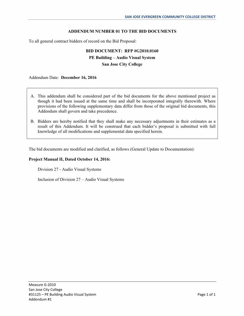
TABLE OF CONTENTS
PROJECT MANUAL VOLUME II
DIVISION 27 – AUDIO VISUAL SYSTEMS
Section 27 41 00 Common Work Results Section 27 41 01 Grounding and BondingSection 27 41 02 Hangers and SupportsSection 27 41 03 Conduits and Back Boxes Section 27 41 06 Noise and Vibration ControlsSection 27 41 07 IdentificationSection 27 41 08 Audio Visual Racks, Cabinets, & AccessoriesSection 27 41 09 Audio Visual Cable ManagementSection 27 41 16 Integrated Audio Visual Systems and Equipment
END OF TABLE OF CONTENTS for VOLUME II PROJECT MANUAL
slott
Typewritten Text
ADDENDUM #1 - December 16, 2016
SAN JOSE CITY COLLEGE PROJECT NO: 1089-002Physical Education Building & And Renovated Lab Building ADDENDUM 1- October 14, 2016
DIVISION 27 SPECIFICATIONS PAGE 1
SECTION 27 41 00 - COMMON WORK RESULTS FOR AUDIOVISUAL SYSTEMS
PART 1 - GENERAL
1.1 SUMMARY
A. Section includes, but is not necessarily limited to:1. Common standards and procedures for the Audiovisual Work.2. Design, engineer and provide complete, all means of support, suspension, attachment,
fastening, bracing, and restraint (hereinafter "support") of the Audiovisual Systems.Provide engineering of such support by parties licensed to perform work of this type inthe Project jurisdiction.
B. Provisions of this Section apply to Audiovisual Work, including the following Sections:1. Section 27 41 01 – Grounding and Bonding for Audiovisual Systems2. Section 27 41 02 – Hangers and Supports for Audiovisual Systems3. Section 27 41 03 – Conduits and Backboxes for Audiovisual Systems4. Section 27 41 06 – Noise and Vibration Controls for Audiovisual Systems5. Section 27 41 07 – Identification for Audiovisual Systems6. Section 27 41 08 – Audiovisual Cabinets, Racks, Frames and Enclosures7. Section 27 41 09 – Audiovisual Cable Management8. Section 27 41 16 – Integrated Audio-Video Systems and Equipment
1.2 REFERENCES
A. Usage: In accordance with Division 1 - Regulatory Requirements
B. American National Standards Institute (ANSI)1. ANSI/TIA/EIA-568-B.1-2001, Commercial Building Telecommunications Cabling
Standard – Part 1: General Requirements2. ANSI/TIA/EIA-568-B.2-2001, Commercial Building Telecommunications Cabling
Standard – Part 2: Balanced Twisted Pair Cabling Components3. ANSI/TIA/EIA-568-B.3-2000, Optical Fiber Cabling Components Standard4. ANSI/TIA/EIA-606-A-2002, Administration Standard for Commercial
Telecommunications Infrastructure1.3 DEFINITIONS
A. General Abbreviations used in these specifications. Refer additionally to the abbreviationslist appearing on the Drawings.1. ADA Americans with Disabilities Act.2. AFC Above Finished Ceiling.3. AFF Above Finished Floor.4. BLDG Building5. CAT Category6. CL Centerline7. DIV Division8. (E) Existing
SAN JOSE CITY COLLEGE PROJECT NO: 1089-002Physical Education Building & And Renovated Lab Building ADDENDUM 1- October 14, 2016
DIVISION 27 SPECIFICATIONS PAGE 2
9. FBU Furnished By District10. HR Home Run11. ID Inside Diameter12. LAN Local Area Network13. MAX Maximum14. NIC Not In Contract.15. OD Outside Diameter16. PSRH Project Standard Receptacle Height.17. PSSH Project Standard Switch Height.18. TYP Typical19. UFE District Furnished Equipment.20. UON Unless Otherwise Noted.
B. Electrical and electronics terms used in the Audiovisual Sections shall be as defined in:1. ANSI/TIA/EIA-568-B.12. ANSI/TIA/EIA-568-B.23. ANSI/TIA/EIA-568-B.34. ANSI/TIA/EIA-569-B5. ANSI/TIA/EIA-606-A6. IEEE Std 1007. This Section.
C. Open Cable - Cabling that is not run in a raceway as defined by NFPA 70. This refers tocabling that is open to the space in which the cable has been installed and is thereforeexposed to the environmental conditions associated with that space.
D. Open Office - A floor space division provided by furniture, moveable partitions, or othermeans instead of by building walls.
E. Pathway - A physical infrastructure utilized for the placement and routing of Audiovisualcable.
1.4 SUBMITTALS
A. Within bidding documentation, Contractor to provide a room by room equipment list.
B. Comply with Section 013300 and the following:1. Submit all materials for review arranged in same order as Specifications, individually
referenced to Specification Section, Paragraph and Contract Drawing number. Conformin every detail as applies to each referencing Section.
2. Submit 8 ½"x 11" items bound in volumes and drawings in edge bound sets. Submit alldrawings on sheets of the same size.
3. Make each specified submittal as a coordinated package complete with all informationspecified herein. Incomplete or uncoordinated submittals will be returned with noreview action.
4. Progress Schedule: Comply with Section 013300.
C. Contractor and Key Personnel Experience.1. A minimum of 30 days prior to installation, submit documentation of the experience of
the low voltage systems, equipment and infrastructure contractor(s) and of their keypersonnel.
SAN JOSE CITY COLLEGE PROJECT NO: 1089-002Physical Education Building & And Renovated Lab Building ADDENDUM 1- October 14, 2016
DIVISION 27 SPECIFICATIONS PAGE 3
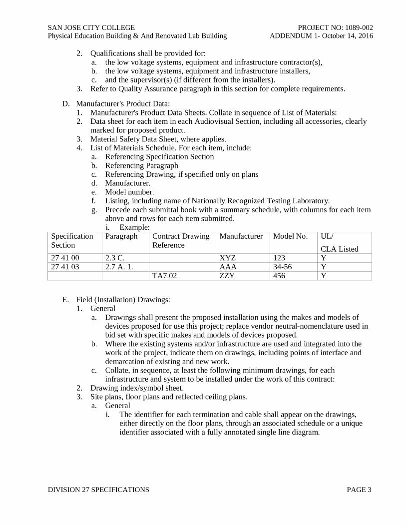
2. Qualifications shall be provided for:a. the low voltage systems, equipment and infrastructure contractor(s),b. the low voltage systems, equipment and infrastructure installers,c. and the supervisor(s) (if different from the installers).
3. Refer to Quality Assurance paragraph in this section for complete requirements.
D. Manufacturer's Product Data:1. Manufacturer's Product Data Sheets. Collate in sequence of List of Materials:2. Data sheet for each item in each Audiovisual Section, including all accessories, clearly
marked for proposed product.3. Material Safety Data Sheet, where applies.4. List of Materials Schedule. For each item, include:
a. Referencing Specification Sectionb. Referencing Paragraphc. Referencing Drawing, if specified only on plansd. Manufacturer.e. Model number.f. Listing, including name of Nationally Recognized Testing Laboratory.g. Precede each submittal book with a summary schedule, with columns for each item
above and rows for each item submitted.i. Example:
SpecificationSection
Paragraph Contract DrawingReference
Manufacturer Model No. UL/CLA Listed
27 41 00 2.3 C. XYZ 123 Y27 41 03 2.7 A. 1. AAA 34-56 Y
TA7.02 ZZY 456 Y
E. Field (Installation) Drawings:1. General
a. Drawings shall present the proposed installation using the makes and models ofdevices proposed for use this project; replace vendor neutral-nomenclature used inbid set with specific makes and models of devices proposed.
b. Where the existing systems and/or infrastructure are used and integrated into thework of the project, indicate them on drawings, including points of interface anddemarcation of existing and new work.
c. Collate, in sequence, at least the following minimum drawings, for eachinfrastructure and system to be installed under the work of this contract:
2. Drawing index/symbol sheet.3. Site plans, floor plans and reflected ceiling plans.
a. Generali. The identifier for each termination and cable shall appear on the drawings,
either directly on the floor plans, through an associated schedule or a uniqueidentifier associated with a fully annotated single line diagram.

SAN JOSE CITY COLLEGE PROJECT NO: 1089-002Physical Education Building & And Renovated Lab Building ADDENDUM 1- October 14, 2016
DIVISION 27 SPECIFICATIONS PAGE 4
ii. Include wiring diagrams and installation details of equipment indicatingproposed location, layout and arrangement, control panels, accessories, piping,ductwork, and other items that must be shown to ensure a coordinatedinstallation. Drawings shall indicate adequate clearance for operation,maintenance, and replacement of operating equipment devices.
iii. At scale of Contract Documents, show:(1) Device locations and type(2) Rough-in.(3) Mounting height.(4) Conduit size.(5) J-hook routes(6) Wire type.(7) Wire fill.
iv. On the floor plans, indicate floor and wall mounted devices and pathway belowa height of 7 feet above finish floor. Indicate the locations of the AudiovisualProgram and Control Rooms and provide reference to the enlargedAudiovisual Program and Control Rooms plans.
v. On the reflected ceiling plan, indicate ceiling and wall mounted devices andpathway above a height of 7 feet above finish floor. Indicate the locations ofthe Audiovisual Program and Control Rooms and provide reference to theenlarged Audiovisual Program and Control Rooms plans.
b. Audiovisual Systems, including KMVT Systemsi. Indicate:
(1) Device locations, orientation and depict integration of systems that need tobe viewed from the complete building perspective.
(2) For distributed speaker systems, indicate limits of zones of coverage.(3) Vertical and horizontal pathways(4) Equipment rooms and racks(5) Reference to enlarged plans and related details.
4. Enlarged Plansa. General
i. Indicate at least as much information as is provided in the ContractDocuments, supplemented by the dimensions and arrangement of the proposedequipment, trade coordination and field conditions.
b. Audiovisual Systems:i. At equipment rooms
(1) Rack elevations, showing(a) all equipment occupying the actual number of rack units required(b) blank panels(c) vent panels(d) aux panels(e) power strips(f) UPS(g) Reference mounting details.
5. System Conduit and Riser Diagrams,a. General:
SAN JOSE CITY COLLEGE PROJECT NO: 1089-002Physical Education Building & And Renovated Lab Building ADDENDUM 1- October 14, 2016
DIVISION 27 SPECIFICATIONS PAGE 5
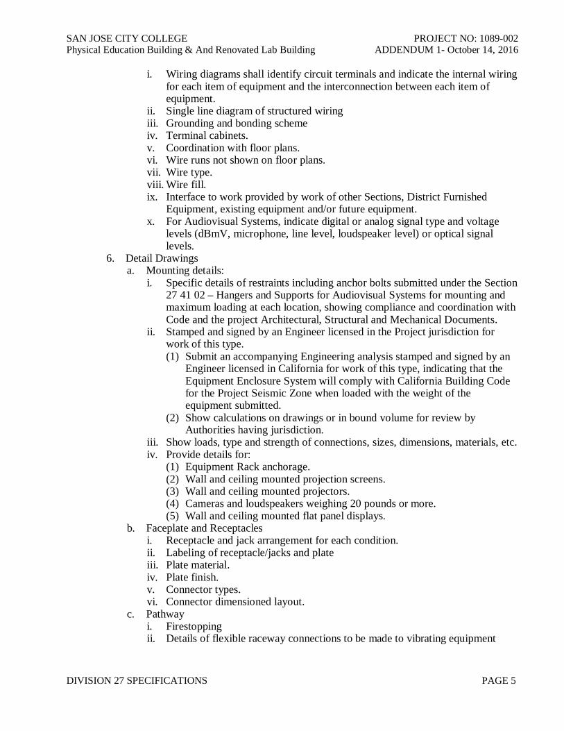
i. Wiring diagrams shall identify circuit terminals and indicate the internal wiringfor each item of equipment and the interconnection between each item ofequipment.
ii. Single line diagram of structured wiringiii. Grounding and bonding schemeiv. Terminal cabinets.v. Coordination with floor plans.vi. Wire runs not shown on floor plans.vii. Wire type.viii. Wire fill.ix. Interface to work provided by work of other Sections, District Furnished
Equipment, existing equipment and/or future equipment.x. For Audiovisual Systems, indicate digital or analog signal type and voltage
levels (dBmV, microphone, line level, loudspeaker level) or optical signallevels.
6. Detail Drawingsa. Mounting details:
i. Specific details of restraints including anchor bolts submitted under the Section27 41 02 – Hangers and Supports for Audiovisual Systems for mounting andmaximum loading at each location, showing compliance and coordination withCode and the project Architectural, Structural and Mechanical Documents.
ii. Stamped and signed by an Engineer licensed in the Project jurisdiction forwork of this type.(1) Submit an accompanying Engineering analysis stamped and signed by an
Engineer licensed in California for work of this type, indicating that theEquipment Enclosure System will comply with California Building Codefor the Project Seismic Zone when loaded with the weight of theequipment submitted.
(2) Show calculations on drawings or in bound volume for review byAuthorities having jurisdiction.
iii. Show loads, type and strength of connections, sizes, dimensions, materials, etc.iv. Provide details for:
(1) Equipment Rack anchorage.(2) Wall and ceiling mounted projection screens.(3) Wall and ceiling mounted projectors.(4) Cameras and loudspeakers weighing 20 pounds or more.(5) Wall and ceiling mounted flat panel displays.
b. Faceplate and Receptaclesi. Receptacle and jack arrangement for each condition.ii. Labeling of receptacle/jacks and plateiii. Plate material.iv. Plate finish.v. Connector types.vi. Connector dimensioned layout.
c. Pathwayi. Firestoppingii. Details of flexible raceway connections to be made to vibrating equipment
SAN JOSE CITY COLLEGE PROJECT NO: 1089-002Physical Education Building & And Renovated Lab Building ADDENDUM 1- October 14, 2016
DIVISION 27 SPECIFICATIONS PAGE 6
iii. Details of J-Box and sealant application for the typical conditions listed inSection 27 41 06 – Noise and Vibration Controls for Audiovisual System, anda schedule of rooms to receive application of mastic and sealant at J-Boxes
iv. An itemized list of all items of equipment to be fitted with flexible electricalconnections.
v. Conduit racking details.d. California Access Compliance Manual and Americans with Disabilities Act (ADA)
compliance.e. For systems with contractor or manufacturer programmed control and human
interfaces submit at least:i. Narrative of the sequence of operation.ii. Color, full-size layouts of each touchpanel and/or computer screen (menu)
image, cross-referenced to the sequence of operations.iii. Show chaining of sub-menus.
f. Terminal cabinets: Terminations.g. Voice cable plant: Cut sheets for use by District's Telephone Systems Contractor
F. Samples: Samples for review by the District’s Representative of all finishes/materials whichwill be visible to the public, including but not limited to:1. The Contractor shall submit a sample of each type of label to be used for labeling
cables, patch panels, termination frames, and faceplates for the telephone and datasystems.
G. Test Plan1. Submit complete documentation of the proposed test plan and equipment to be used to
document that the performance of the cabling, equipment, sub-systems and completesystems installed under the work of this project conform to the performance standardsoutlined in each specification section.
2. Submit not less than 45 days prior to the proposed test date. Include procedures forcertification, validation, and testing.
H. Test Reports1. Manufacturer's Field Reports
a. Factory reel tests2. Project Site Test Reports:
a. Submit following system completion and prior to and as condition precedent toAcceptance Review and Testing of the Work of this Section.
b. Schedule: Submit test reports in timely manner relative to Project schedule suchthat the District’s Representative may conduct verification of submitted test datawithout delay of scheduled progress.
c. Project Site test report:d. Content: Include at least:
i. Time and date of test.ii. Personnel conducting test.iii. Test equipment, including serial and date of calibration.iv. Test object.v. Procedure used.vi. Results of testvii. Numerical or graphical presentation.
SAN JOSE CITY COLLEGE PROJECT NO: 1089-002Physical Education Building & And Renovated Lab Building ADDENDUM 1- October 14, 2016
DIVISION 27 SPECIFICATIONS PAGE 7
e. Submit copy of final results on paper and in electronic form, organized by circuitnumber, consistent with circuit numbering scheme used in preparing submittaldrawings and in labeling receptacles and terminations.i. Submit machine-generated documentation and raw data of all test results in
electronic form on CD-R mediaii. Where the electronic documentation requires use of a proprietary computer
program to view the data, provide the District with 1 licensed copy of thesoftware.
1.5 QUALITY ASSURANCE
A. Contractor Firm and Personnel Qualifications:
B. Designated Supervisor: Provide a designated supervisor present and in responsible charge inthe fabrication shop and on the Project Site during all phases of installation and testing of theWork of this Section. This supervisor shall be the same individual through the execution ofthe Work unless illness, loss of personnel, or other circumstances reasonably beyond thecontrol of the Contractor intervene.
C. Reference Documents: At all times when the work is in progress, maintain at the workplace,fabrication shop or Project Site as applies.1. A complete set of the latest stamped, actioned submittals of record.2. A complete set of manufacturer's original operation, instruction and service manuals for
each equipment item.
D. Standard Products1. Audiovisual Systems Equipment. Provide Audiovisual Systems materials and
equipment that are products of manufacturers regularly engaged in the production ofsuch products which are of equal material, design and workmanship. Products shallhave been in satisfactory commercial or industrial use for six months prior to bidopening. The six month period shall include applications of equipment and materialsunder similar circumstances and of similar size. The product shall have been on sale onthe commercial market through advertisements, manufacturers' catalogs, or brochuresduring the six month period.a. Alternative Qualifications. Products having less than a 1-year field service record
will be acceptable if a certified record of satisfactory field operation for not lessthan 2500 hours, exclusive of the manufacturers' factory or laboratory tests, isfurnished.
2. Material and Equipment Manufacturing Datea. Products manufactured more than 3 years prior to date of delivery to site shall not
be used, unless specified otherwise.
E. Test Equipment1. Requirements:
a. Maintain and operate test equipment at the fabrication shop and the job site for bothroutine and Acceptance Testing of the Work of this Section.
b. Maintain test equipment at the job site while work is in progress from installationof equipment racks until District Acceptance of this Work; thereafter remove all ofthis test equipment from the job site.
c. Unless otherwise indicated, test equipment shall remain property of the Contractor.
SAN JOSE CITY COLLEGE PROJECT NO: 1089-002Physical Education Building & And Renovated Lab Building ADDENDUM 1- October 14, 2016
DIVISION 27 SPECIFICATIONS PAGE 8
d. Provide all required test cables, jigs and adapters.e. Provide equipment with traceable calibration, with calibration date not greater than
one year prior to the date of the use of the equipment to perform the specifiedtesting.
F. Qualifications1. Audiovisual Qualifications
a. Audiovisual Systems work shall be performed by and the equipment shall beprovided by the Audiovisual Systems contractor and key personnel. Qualificationsshall be provided for:i. the Audiovisual Systems contractor,ii. the Audiovisual Systems installer,iii. and the supervisor (if different from the installer).
b. A minimum of 30 days prior to installation, submit documentation of theexperience of the Audiovisual Systems and of the key personnel.
2. Audiovisual Systems Installera. The installer of the Audiovisual systems shall be a firm regularly and
professionally engaged in the business of installation, configuration and testing ofthe specified Audiovisual systems and equipment.i. Where the manufacturers of the specified and contractor proposed systems
provide mandatory installer and programming training programs, theContractor's programming and installation staff shall provide documentation todemonstrate their successful completion of the relevant training programs forthe types and versions of equipment proposed for installation on this Project.
ii. Where the manufacturer of the specified and contractor proposed systems andequipment lawfully restricts sales of their equipment to a network of dealers,the contractor shall provide documentation to their standing as such a dealer ingood standing at the time of bid submittal.
iii. The Audiovisual systems contractor shall demonstrate experience in providingsuccessful Audiovisual systems of a similar scope and nature of those requiredby the work of this Project within the past 3 years.
iv. Submit documentation for a minimum of three and a maximum of fivesuccessful Audiovisual system installations for the Audiovisual systemscontractor.
b. Key Personneli. Provide key personnel who are regularly and professionally engaged in the
business of the installing, programming, configuring and testing of thespecified Audiovisual systems and related presentations and equipment.(1) There may be one key person or more key persons proposed for this
project depending upon how many of the key roles each has successfullyprovided.
(2) Each of the key personnel shall demonstrate experience in providingsuccessful Audiovisual systems of a similar nature scope and extent tothose required by the work of this Project within the past 3 years.
1.6 REGULATORY REQUIREMENTS
A. Regulations Applicable: Including but not limited to those defined in Section 014200 –Definitions, References, and Regulations:
SAN JOSE CITY COLLEGE PROJECT NO: 1089-002Physical Education Building & And Renovated Lab Building ADDENDUM 1- October 14, 2016
DIVISION 27 SPECIFICATIONS PAGE 9
1. Nothing in the Contract Documents shall be construed to permit Work not conformingto applicable laws, ordinances, rules, or regulations.
2. Safety Agency Listing: All devices provided under the Work of this Section which areconnected to the Project electrical system shall be listed by a Nationally RecognizedTesting Laboratory, and shall be so labeled.
3. In each of the publications referred to herein, consider the advisory provisions to bemandatory, as though the word, "shall" had been substituted for "should" wherever itappears. Interpret references in these publications to the "authority having jurisdiction,"or words of similar meaning, to mean the District's Representative. Equipment,materials, installation, and workmanship shall be in accordance with the mandatory andadvisory provisions of NFPA 70 unless more stringent requirements are specified orindicated.
1.7 DELIVERY, STORAGE AND HANDLING
A. Procedures:1. As specified in the individual sections of Division 27 and the following.
a. Provide protection from weather, moisture, extreme heat and cold, dirt, dust, andother contaminants for cabling and equipment placed in storage.
1.8 ENVIRONMENTAL REQUIREMENTS
A. Connecting hardware shall be rated for operation under ambient conditions of 32 to 140degrees F and in the range of 0 to 95 percent relative humidity, non-condensing.
1.9 SEQUENCING
A. Not Used1.10 OPERATING AND MAINTENANCE DATA
A. Commercial off the shelf manuals shall be furnished for operation, installation,configuration, and maintenance of products provided as a part of the low voltage systems,equipment and infrastructure work of this Project. Precede the manuals with a systemsnarrative specific to this Project, outlining the major systems functionality, the majorsystems components, and identifying which manuals document the performance of whichsubsystems.1. Submit operations and maintenance data in accordance with Section 017800 – Project
Record Documents and as specified herein not later than 2 months prior to the date ofbeneficial occupancy.
1.11 PROJECT RECORD DOCUMENTS
A. Comply with Section 017800 – Project Record Documents, and the following. Include atleast as much information as required for the submittal drawings.1. Record Drawings
a. CAD.i. Use a computer aided drafting (CAD) system in the preparation of record
drawings for this Project. CAD system shall produce files in AutoCAD®.DWG format, version 2000 or later.
b. Except where prohibited by Contract, District’s Representative will furnish CADbackgrounds in AutoCAD® .DWG format, for use by the Contractor in preparing
SAN JOSE CITY COLLEGE PROJECT NO: 1089-002Physical Education Building & And Renovated Lab Building ADDENDUM 1- October 14, 2016
DIVISION 27 SPECIFICATIONS PAGE 10
Record Drawings.c. Contractor shall be responsible for updating building and Audiovisual plans to
reflect as-built conditions.i. Indicate actual work on Drawings; indicate actual products used, replace
vendor neutral nomenclature used in bid set with makes and models of actualinstalled devices.
d. Disk copy of Record Drawings: Provide 2 separate copies of each drawing file inthe format noted above. Submit on CD-R disk.
e. Reproduceables: Provide 1 set of Mylars.2. Software
a. Controls and DSP Systemsi. Provide licensing for project specific software programming at programmable
devices.ii. Provide licensing and original software copies for each device provided that
uses software for operation, configuration or control.iii. Provide licensing for required workstation operating systems, and required
third party software.iv. For controls systems, provide a complete copy of the source code, including
the device interface driver code modules.v. Upgrade each software package to the release in effect at the end of the
Warranty Period.b. Provide at least a copy of software with at least 1 user license if required to view
submitted test data.3. Spare Parts
a. In addition to the requirements of Division 01 – Record Documents, provide acomplete list of parts and supplies, with current unit prices and source of supply,and a list of spare parts recommended for stocking.
1.12 WARRANTY SERVICE
A. In addition to provisions of Section 017800 – Guaranties, Warranties, Bonds andMaintenance Contracts, provide the following.1. Response Time: Provide a qualified technician familiar with the work at the Project
Site within 24 hours after receipt of a notice of malfunction. Provide the District’sRepresentative with telephone number attended 8 hours a day, 5 days a week, to becalled in the event of a malfunction.
B. Provide all additional Warranties as defined in each Communication Systems Section.1.13 ACCEPTANCE REVIEW AND TESTING PROCEDURES
A. Complete all Work of this Section. Submit Test Report. Submit review copies of Operatingand Maintenance Manuals, less reduced set of Record Drawings. Notify the District’sRepresentative in writing that the Work of these Sections is complete and fully complieswith the Contract Documents. Request Acceptance Review and Testing. The District’sRepresentative will conduct Verification of Submitted Test Data, and otherwise directtesting and adjustment of this Work. These procedures may be performed at any hour of theday or night as required by the District’s Representative to comply with the Project Scheduleand avoid conflict with Residents. Provide all specified personnel and equipment at anytime without claim for additional cost or time.
SAN JOSE CITY COLLEGE PROJECT NO: 1089-002Physical Education Building & And Renovated Lab Building ADDENDUM 1- October 14, 2016
DIVISION 27 SPECIFICATIONS PAGE 11
B. Personnel: Provide services of the designated supervisor and additional technicians familiarwith work of this Section. Provide quantity of technicians as required to comply withProject Schedule.
C. In Addition, Provide:1. All tools appropriate for performance of adjustment of and corrections to this Work.
Include spare wire and connectors and specified tooling for application.2. Ladders, scaffolding and/or lifts as required to access high devices.3. All test equipment.4. Complete set of latest stamped, actioned submittals of record for reference.5. Complete set of Test Reports.6. Complete set of manufacturer's original operation, instruction and service manuals for
each equipment item for reference.7. Demonstrate: Complete operation of all systems and equipment, including Portable
Equipment.8. Adjust: As directed by the District’s Representative.9. Correct: In timely manner, failure to comply with the Contract Documents, as
reasonably determined by the District’s Representative.
D. Temporary Equipment: Provide and operate, without claim for additional cost or time,temporary equipment and/or systems to provide reasonably equivalent function, asdetermined by the District’s Representative, in place of the Work of this Section which isincomplete or found not in conformance with the Contract Documents as of seven (7) daysprior to the scheduled completion date. Provide such temporary equipment until Acceptanceof the Work of this Section. Thereafter, remove such temporary equipment.
1.14 CLOSEOUT
A. Punch List: Perform any and all remedial work, at no claim for additional cost or time.Where required, retest and submit Test Report. Notify the District’s Representative ofcompletion of Punch List.
B. Portable Equipment: Furnish all portable equipment and spares to the District’sRepresentative, along with complete documentation of the materials presented. Whereapplicable, furnish portable equipment in the original manufacturer's packing.
C. Operating and Maintenance Data: Install framed operating and maintenance instructions.Submit Manuals.
D. Project Record Documents: Submit print and digital copies. Digital files shall be in CADsystem shall produce files in AutoCAD® .DWG format, latest version at time of bid.(District Standard, no substitution permitted) as defined above.
E. Keys: If applicable, replace construction locks with permanent locks. Provide 5 sets of keysto the District’s Representative.
F. Instruction: Conduct specified instruction.
G. Warranty: Submit Warranty dated to run from date of Acceptance of the Work of thisSection.
PART 2 - PRODUCTS

SAN JOSE CITY COLLEGE PROJECT NO: 1089-002Physical Education Building & And Renovated Lab Building ADDENDUM 1- October 14, 2016
DIVISION 27 SPECIFICATIONS PAGE 12
2.1 GENERAL
A. Where a particular material, device, piece of equipment or system is specified directly, thecurrent manufacturer's specification for the same shall be considered to be a part of thesespecifications, as if completely contained herein in every detail.
B. Each material, device or piece of equipment shall comply with all of the manufacturer'scurrent published specifications for that item.
C. Products shall be made by manufacturers regularly engaged in the production of suchproducts.
D. Provide quantity as shown on Contract Drawings, or as otherwise indicated.
E. Provide all auxiliary and incidental materials and equipment necessary for the operation andprotection of the Work of this Section as if specified in full herein.
F. Unless recycled content is specified, provide new materials.
G. Provide the manufacturer's latest design/model, permanently labeled with the manufacturer'sname, model number and serial number.
H. Where products are of similar type or use, provide products of the same manufacturer,unless otherwise indicated.
I. Components1. UL or third party certified. Cabling and interconnecting hardware and components for
Audiovisual systems shall be UL listed or third party independent testing laboratorycertified, and shall comply with NFPA 70 and conform to the requirements specifiedherein.
2. Where equipment or materials are specified to conform to industry and technical societyreference standards of the organizations, submit proof of such compliance.a. The label or listing by the specified organization will be acceptable evidence of
compliance.b. In lieu of the label or listing, submit a certificate from an independent testing
organization, competent to perform testing, and approved by the District'sRepresentative.
c. The certificate shall state that the item has been tested in accordance with thespecified organization's test methods and that the item complies with the specifiedorganization's reference standard.
J. Enclosures:1. Provide steel frames and enclosures designed and wired to eliminate all induced
currents.2. Make bolted connections with self-locking devices.
K. Finishes: Any item or component of the Work of this Section which is visible shall complywith the following.1. Finishes noted or scheduled on the Contract Drawings take precedence.2. Where design location requires that products, materials or equipment are visible to the
public, no manufacturer's logos larger than 1/2 inch shall be visible. Unless otherwise
SAN JOSE CITY COLLEGE PROJECT NO: 1089-002Physical Education Building & And Renovated Lab Building ADDENDUM 1- October 14, 2016
DIVISION 27 SPECIFICATIONS PAGE 13
noted or directed, neatly remove or permanently paint out such logos.3. Where finishes are not noted or otherwise defined in the Contract Documents, submit
manufacturer's standard finish samples for selection by the District’s Representative.PART 3 - EXECUTION
3.1 EXAMINATION
A. Examine existing conditions before starting work. Submit conflicts in a timely manner forresolution
3.2 WIRING CLASSIFICATION AND RELATED
A. Audio Signal Wiring Classification:1. Type A-l: Microphone level wiring less than -30 dBu, 20 Hz to 20 kHz.2. Type A-2: Line level wiring -30 dBu to +24 dBu, 20 Hz to 20 kHz.3. Type A-3: Loudspeaker level or circuit wiring greater than +24 dBu, from 20 Hz to 20
kHz.
B. Video and Related Signal Wiring Classification:1. Type V-1: Baseband and composite video wiring 1 volt peak-to-peak into 75 ohms, 0 to
10.0 MHz.2. Type V-2: Synchronization and switching pulse wiring 4 volts peak-to-peak into 75
ohms, 15.62 to 15.75 kHz.3. Type V-3: Color subcarrier wiring 0 to 4 volts peak-to-peak into 75 ohms, 3.57 to 4.43
MHz.4. Type V-4: KMVT system wiring 0.1 to 1000 microVolts peak-to-peak into 50 or 75
ohms, 47 to 890 MHz.
C. Control Signal Wiring Classifications:1. Type C-1: DC control wiring 0 to 50 volts.2. Type C-2: Synchronous control or data wiring 0 to 40 volts, peak-to-peak.3. Type C-3: AC control wiring 0 to 48 volts, 60 Hz.
D. Additional Wiring Classifications:1. Type M-1: DC power wiring 0 to 48 volts.2. Type M-2: AC power wiring greater than 50 volts, 60 Hz.3. Wiring Combinations:
E. Except as indicated herein, conduit, wireways and cable bundles shall contain only wiring ofa single classification. The following combinations are acceptable in conduit, or cableharnesses. Additional acceptable combinations may be indicated on the Drawings.1. Types A-1, C-1, and M-1.2. Types A-2, C-l, C-2, and M-l, runs less than 20 feet.3. Types A-2, C-1, and M-1.4. Types A-3, C-1, C-2, and M-1.5. Types A-2, V-1, and V-3.6. Types V-1, V-2, V-3, and C-1.7. Types M-2 and C-3.
3.3 PREPARATION
SAN JOSE CITY COLLEGE PROJECT NO: 1089-002Physical Education Building & And Renovated Lab Building ADDENDUM 1- October 14, 2016
DIVISION 27 SPECIFICATIONS PAGE 14
A. Protection: Cover all computers, electronic equipment, desks, chairs, furniture and otherarticles when working at ceiling level and/or performing dust producing tasks.
3.4 REPAIR AND RESTORATION
A. Where working in spaces occupied by the District, return to their original positions anyfurniture or articles relocated to perform the work.
3.5 CLEANING
A. Where working in spaces occupied by the District:1. Immediately after completing work within each space, clean up and remove all
materials, scrap and dust.2. All scrap material in work area shall be picked up and removed from the building at the
end of each day. See also Section 017800 - Project Record Documents for additionalrequirements.
3. All dust resulting from work performed shall be vacuumed up daily.4. All scrap material shall be removed and disposed of in an authorized disposal site.
Refer to Section 017410 - LEED Waste Management.
END OF SECTION

SAN JOSE CITY COLLEGE PROJECT NO: 1089-002Physical Education Building & And Renovated Lab Building ADDENDUM 1- October 14, 2016
DIVISION 27 SPECIFICATIONS PAGE 15
SECTION 27 41 01 - GROUNDING AND BONDING FOR AUDIOVISUAL SYSTEMS
PART 4 - GENERAL
4.1 SCOPE OF WORK
A. Section includes grounding and bonding of Audiovisual Work, including but not limited to:1. Audiovisual Raceways2. Cable Runway3. Cable Shields4. Protector Fields5. Audiovisual Cabinets and enclosures.
B. Related Work Under Other Sections1. Section 27 41 00 – Common Work Results for Audiovisual Systems2. Section 27 41 02 – Hangers and Supports for Audiovisual Systems3. Section 27 41 03 – Conduits and Backboxes for Audiovisual Systems4. Section 27 41 07 –Identification for Audiovisual Systems5. Section 27 41 08 – Audiovisual Cabinets, Racks, Frames and Enclosures6. Section 27 41 09 – Audiovisual Cable Management7. Section 27 41 16 – Integrated Audio-Video Systems and Equipment
4.2 SYSTEM DESCRIPTION
A. Provide Audiovisual system grounding conductor as described herein and indicate ondrawings.
B. Except as otherwise indicated, the complete Audiovisual installation including the metallicconduits and raceways, cable trays, boxes, cabinets and equipment shall be completely andeffectively grounded in accordance with all code requirements, whether or not suchconnections are specifically shown or specified.
C. Resistance:1. Resistance from the farthest ground bus through the ground electrode to earth shall not
exceed 5 Ohms or the requirements of ANSI-J-STD-607-A-2002, whichever is morerestrictive.
4.3 REFERENCES
A. American National Standards Institute (ANSI)1. ANSI/TIA/EIA-606-A-2002 Administration Standard for Commercial
Telecommunications Infrastructure2. ANSI-J-STD-607-A-2002 Commercial Building Grounding (Earthing) and Bonding
Requirements for Telecommunications3. Underwriters Laboratories (UL)4. UL 467 (1993); R 2004 Grounding and Bonding Equipment
4.4 SUBMITTALS
A. Conform with the requirements of Division 1 and Section 27 41 00 - Common Work Resultsfor Audiovisual Systems.

SAN JOSE CITY COLLEGE PROJECT NO: 1089-002Physical Education Building & And Renovated Lab Building ADDENDUM 1- October 14, 2016
DIVISION 27 SPECIFICATIONS PAGE 16
PART 5 - PRODUCTS
5.1 MANUFACTURERS
A. Equal products by the following manufacturers will be considered providing that all featuresof the specified product are provided:1. Ground Rod:
a. High strength high carbon steel, with electrolytically bonded jacket of copper onsurface
b. UL spec. 467c. ANSI C-33.8-1072.d. Manufacturer:
i. Allied Boltii. Inwesco 12A60iii. Blackburniv. Cooper Power Systemsv. Weaver.vi. Erico "Cadweld" Products, Inc.vii. ITT Blackburn.viii. Or equal.
2. Ground Wells:a. Christy Concrete Products, Inc.b. Forni Corp.c. Or equal.
3. Ground Bushings, Connectors, Jumpers and Bus:a. O-Z/Gedney.b. Thomas & Betts Corp.c. Or equal.
4. Compression Connector Luga. Panduitb. B-Line SB-479 Seriesc. Thomas & Bettsd. Or equal.
5. Audiovisual Ground Bus Bara. CPIb. B-Linec. Panduitd. or equal.
6. Rack and Cabinet Groundinga. Panduit Structured Ground Kitb. Chatsworth Products Inc.c. or equal.
7. Bonding Ribbon:a. Annealed solid copper 3/8 inch wide x 1/16 inch thick, tin plated.b. Manufacturer:
i. Inwesco 12A55ii. Corning Cable Systemsiii. Preformed Line Products.
SAN JOSE CITY COLLEGE PROJECT NO: 1089-002Physical Education Building & And Renovated Lab Building ADDENDUM 1- October 14, 2016
DIVISION 27 SPECIFICATIONS PAGE 17
iv. or equal.8. Bonding Ribbon Clamp:
a. Soft leadb. 1/16 inch thickc. Bolt hole for attachmentd. Manufacturer:
i. Inwesco 12A56ii. Corning Cable Systemsiii. Preformed Line Products.iv. Or equal.
9. Fargo Clamp:a. Cast copper, silver plated, furnished with copper bolt.b. RUS Listedc. Manufacturer:
i. Allied Boltii. Inwesco 12A57iii. Corning Cable Systemsiv. or equal.
10. Ground Inserts:a. Cast Bronze w 1/4 Copper Rod.b. Provide minimum one each maintenance hole or vault.c. Manufacturer:
i. Inwesco 12H69ii. or equal by vault or manhole manufacturer.iii. or equal.
5.2 GROUND CONDUCTORS
A. General purpose insulated: UL listed and code sized copper conductor, with dual ratedTHHN/THWN insulation, color identified green. Where continuous color-coded conductorsare not commercially available, provide a minimum 4" long color band with green, non-aging, plastic tape in accordance with NEC.
B. Bonding pigtails: Insulated copper conductor, identified green, sized per code, and providedwith termination screw or lug. Provide solid conductors for #10 AWG or smaller andstranded conductors for #8 AWG or larger.
5.3 COMPRESSION CONNECTOR LUG
A. Description1. Connector lug with compression connection to conductor.2. Copper alloy body.3. Provide lug size to match conductor being terminated.4. Provide 2-hole pattern lugs.5. Provide each lug with silicon bronze hardware, including 2 bolts, 2 split lock washers
and 2 nuts.5.4 INSULATED GROUNDING BUSHINGS
SAN JOSE CITY COLLEGE PROJECT NO: 1089-002Physical Education Building & And Renovated Lab Building ADDENDUM 1- October 14, 2016
DIVISION 27 SPECIFICATIONS PAGE 18
A. Plated malleable iron or steel body with 150 degree Centigrade molded plastic insulatingthroat and lay-in grounding lug.
5.5 CONNECTIONS TO PIPE
A. For cable to pipe: UL listed bolted connection complying with CEC requirements.5.6 CONNECTIONS TO STRUCTURAL STEEL, GROUND RODS, OR SPLICES
A. Where required by the Drawings or Specifications, grounding conductors shall be splicedtogether, connected to ground rods or connected to structural steel using exothermic weldsor high pressure compression type connectors.1. Exothermic welds shall be used for cable-to-cable and cable-to-ground rod and for cable
to structural steel surfaces. Exothermic weld kits shall be as manufactured by Cadweld,Thermoweld or equal. Each particular type of weld shall use a kit unique to that type ofweld.
2. High-pressure compression type connectors shall be used for cable-to-cable and cable-to-ground rod connections. Connections shall be as manufactured by Thomas & Betts#53000 series, Burndy “Hy-Ground” or equal.
5.7 EXTRA FLEXIBLE, FLAT BONDING JUMPERS
A. Where required by the drawing or specified herein.PART 6 - EXECUTION
6.1 GENERAL
A. Provide Grounding and Bonding according to the most restrictive requirements of:1. ANSI-J-STD-607-A.2. California Electrical Code Article 250 and references therein.3. California Electrical Code Article 800.
B. In the event of conflicting requirements, National Electrical Code requirements shall prevail.
C. Point of Connection1. Under Work of this Section, make connections to Audiovisual Ground Busbars.
Coordinate with District Electrical Representative and conform to District requirementsfor electrical Grounding and Bonding
2. Mechanical Connections
D. Make connections bare metal to bare metal.1. Where required, remove paint to bare metal, make grounding or bonding connection,
and touch up paint.2. Torque threaded fasteners to manufacturer’s recommended values.
E. Compression Connections1. Make compression connections with the lug or fitting manufacturer’s recommended
tooling, with the tooling set to the recommended force and stroke.
F. Audiovisual Raceways and Sleeves1. Bond metallic raceway and sleeves to the Audiovisual Ground Busbar at the
Audiovisual Room that serves the related Audiovisual Receptacle.
SAN JOSE CITY COLLEGE PROJECT NO: 1089-002Physical Education Building & And Renovated Lab Building ADDENDUM 1- October 14, 2016
DIVISION 27 SPECIFICATIONS PAGE 19
2. Where a metallic raceway connects two or more Audiovisual Rooms, bond to theAudiovisual Ground Busbar at each.
G. Cable Shields1. Comply with California Electrical Code Article 800.
H. Protector Fields1. Comply with California Electrical Code Article 800.
I. Audiovisual Cabinets and enclosures1. Bond to the Audiovisual Ground Busbar at the Audiovisual Room.
6.2 LABELING
A. Provide labeling according to the requirements of:1. ANSI/TIA/EIA-606-A.2. Section 27 41 07 - Identification for Audiovisual Systems.
END OF SECTION
SAN JOSE CITY COLLEGE PROJECT NO: 1089-002Physical Education Building & And Renovated Lab Building ADDENDUM 1- October 14, 2016
DIVISION 27 SPECIFICATIONS PAGE 20
SECTION 27 41 02 - HANGERS AND SUPPORTS FOR AUDIOVISUAL SYSTEMS
PART 7 - GENERAL
7.1 SCOPE OF WORK
A. The work covered under this section consists of the furnishing of all necessary labor,supervision, materials, equipment, and services to completely execute the provision ofAudiovisual supports and cable hook system as described in this specification, including butnot limited to:1. Strut supports2. Cable Hooks (J-hooks)3. Beam clamps4. Concrete Fasteners5. Touch-Up Materials6. Conduit supports.7. Equipment supports.8. Fastening hardware.
B. Related work: Consult all other Sections, determine the extent and character of related workand properly coordinate work specified herein with that specified elsewhere to produce acomplete installation.1. Section 27 41 00 – Common Work Results for Audiovisual Systems2. Section 27 41 01 – Grounding and Bonding for Audiovisual Systems3. Section 27 41 03 – Conduits and Backboxes for Audiovisual Systems4. Section 27 41 06 – Noise and Vibration Controls for Audiovisual Systems5. Section 27 41 07 – Identification for Audiovisual Systems6. Section 27 41 08 – Audiovisual Cabinets, Racks, Frames and Enclosures7. Section 27 41 09 – Audiovisual Cable Management8. Section 27 41 16 – Integrated Audio-Video Systems and Equipment
7.2 SYSTEM DESCRIPTION
A. Provide devices specified in this Section and related Sections for support of Audiovisualequipment specified for this Project.
B. Provide support systems that are adequate for the weight of equipment, conduit and wiringto be supported.
7.3 REFERENCES
A. American Society for Testing and Materials (ASTM)1. ASTM A123/A123M-02 Standard Specification for Zinc (Hot-Dip Galvanized)
Coatings on Iron and Steel Products2. ASTM A153/A153M-04 Standard Specification for Zinc Coating (Hot-Dip) on Iron and
Steel Hardware

SAN JOSE CITY COLLEGE PROJECT NO: 1089-002Physical Education Building & And Renovated Lab Building ADDENDUM 1- October 14, 2016
DIVISION 27 SPECIFICATIONS PAGE 21
3. ASTM B633-98e1 Specification for Electro-deposited Coatings of Zinc on Iron andSteel.
4. ASTM A653/A653M-04a Standard Specification for Steel Sheet, Zinc-Coated(Galvanized) or Zinc-Iron Alloy-Coated (Galvannealed) by the Hot-Dip Process.
B. American National Standards Institute (ANSI)1. ANSI/TIA/EIA-568-B.1-2001, Commercial Building Telecommunications Cabling
Standard – Part1: General Requirements2. ANSI/TIA/EIA-568-B.2-2001, Commercial Building Telecommunications Cabling
Standard – Part2: Balanced Twisted Pair Cabling Components3. ANSI/TIA/EIA-568-B.3-2000, Optical Fiber Cabling Components Standard4. ANSI/ TIA/ EIA 569-B Commercial Building Standard for Telecommunications
Pathways and Spaces
C. National Fire Protection Association1. NFPA 70, National Electrical Code
7.4 SUBMITTALS
A. Conform with Division 1 and Section 27 41 00 - Common Work Results for AudiovisualSystems and the following:1. As part of the project submittals, the contractor to provide engineered shop drawings
indicating the proposed design for mounting all work of this Division weighing morethan 20 pounds, inclusive of mounting systems, and for equipment mounted at theexterior, inclusive of its effective wind load under conditions the range of conditionsexperiencea. Shop drawings to be accompanied by anchorage calculations indicating that it shall
remain attached to the mounting surface after experiencing forces in conformancewith CCR, Title 24, Table 23P, Part II and with Section 2312 "EarthquakeRegulations" of the "Uniform Building Code" for Seismic Zone 4 Area, ImportanceFactor of 1.25.
b. Structural Calculations shall be prepared and signed by a California RegisteredStructural Engineer. Specify proof loads for drilled-in anchors, if used.
7.5 QUALITY ASSURANCE
A. All materials, equipment and parts comprising the units specified herein shall be new andunused, and of current manufacturer.
B. Cable hooks shall be listed and labeled by Underwriters Laboratories (UL) as required.
C. Cable hooks shall have the manufacturers name and part number stamped in the part itselffor identification.
PART 8 - PRODUCTS
8.1 SUPPORTING DEVICES
A. General1. Supports to be sized to suit load and selected to match mounting conditions

SAN JOSE CITY COLLEGE PROJECT NO: 1089-002Physical Education Building & And Renovated Lab Building ADDENDUM 1- October 14, 2016
DIVISION 27 SPECIFICATIONS PAGE 22
B. Manufacturers1. Equal products by the following manufacturers will be considered providing that all
features of the specified product are provided:a. Concrete fasteners:
i. Phillips "Red-Head".ii. Remington.iii. Ramset.iv. Hiltiv. Simpson Strong-Tievi. or equal.
b. Concrete inserts and construction channel:i. Unistrut Corp.ii. GS Metals "Globe Strut."iii. Thomas & Betts "Kindorf" Corp.iv. Or equal.
c. Conduit straps:i. O-Z/Gedney.ii. Erico "Caddy" Fastening Products.iii. Thomas & Betts "Kindorf" Corp.iv. Or equal.
d. Beam Clampsi. Cooper B-Lineii. SuperStrutiii. Unistrutiv. or equal
e. Aircraft Cable Sway Bracesi. Mason Industriesii. M.W. Sausse/Vibrexiii. Loos & Company, Inc.iv. or equal.
C. Concrete Fasteners1. Provide expansion-shield type concrete anchors.2. Provide powder driven concrete fasteners with washers. Obtain approval by District’s
Representative prior to use.
D. Concrete Inserts1. Provide pressed galvanized steel, concrete spot insert, with oval slot capable of
accepting square or rectangular support nuts of ¼ inch to ½ inch diameter thread for rodsupport.
E. Aircraft cable sway braces1. Steel rope sized to meet load.
F. Construction Channel:1. Construction:
a. 1-5/8" square galvanized channel formed from U.S.S.G No. 12 or 0.109 inch coldformed steel with 17/32-inch diameter bolt holes, and 1-1/2 inch on center in thebase of the channel.
SAN JOSE CITY COLLEGE PROJECT NO: 1089-002Physical Education Building & And Renovated Lab Building ADDENDUM 1- October 14, 2016
DIVISION 27 SPECIFICATIONS PAGE 23
b. 10 foot sections.2. All supporting materials by same manufacturer.
G. Beam Clamps1. Malleable iron electro-galvanized steel beam clamps selected to match building
structural steel members.
H. Conduit Straps1. One hole strap, steel or malleable iron, with malleable iron clamp-back spacer for
surface mounted wall and ceiling applications.a. Use malleable strap with spacers for exterior and wet locations.b. Use steel strap without spacers for interior locations.
2. Steel channel conduit strap for support from construction channel.3. Steel conduit hanger for pendant support with threaded rod4. Steel wire conduit support strap for support from independent #12 gauge hanger wires.
I. Threaded rods, couplings, screws and nuts:1. Electrolytically coated with zinc, 2 oz. zinc per square foot of surface, ASTM A123 or
A153.
J. Miscellaneous Parts1. Hot dipped galvanized after fabrication; after cutting, de-burring and hole drilling.
Coated with zinc, 2 oz. zinc per square foot of surface, ASTM A123 or A153.
K. Paint/Tape for Touch-up:1. Zinc: CRC "Zinc-It", Glyptal, Enterprise Galvanizing “Galambra”, or equal.
8.2 CABLE HANGERS
A. Ceiling Hung J-Hooks1. Drawing Reference(s):
a. WMJb. ACJ
2. Features/Functions/Constructiona. Specifically intended to carry the load of up to 50 Audiovisual cables without
applying excess forces to cables at bottom of bundle.b. Integral broad bottom edge to spread cable load with flat bottom and provide a
minimum of 1-5/8 inch cable bearing surface.c. Integral hanger rod attachment hardware at top.d. Load rated for application.e. Incorporates smooth 90-degree radiused edges to prevent snagging cable jackets on
installation.f. Designed so the mounting hardware is recessed to prevent cable damage.g. Integral mechanical cable latch retainer to provide containment of cables within the
hook. The retainer shall be removable and reusable.h. Suitable for direct attachment to walls, hanger rods, beam flanges, purlins, strut,
floor posts, etc. to meet job conditions.i. Multi-tiered cable hooks to be used where required to provide separate cabling
compartments, or where additional capacity is needed.j. Finishes:
SAN JOSE CITY COLLEGE PROJECT NO: 1089-002Physical Education Building & And Renovated Lab Building ADDENDUM 1- October 14, 2016
DIVISION 27 SPECIFICATIONS PAGE 24
i. Cable hooks for non-corrosive areas shall be pre-galvanized steel, ASTMA653. Where additional strength is required, cable hooks shall be spring steelwith a zinc-plated finish, ASTM B633, SC3.
ii. Cable hooks for corrosive areas shall be stainless steel, AISI Type 304.3. Manufacturer
a. Cooper B-Line series BCH21, BCH32, BCH64b. Caddy/Erico CableCatc. or equal.
PART 9 - EXECUTION
9.1 GENERAL
A. The District’s Representative reserves the right to request additional supports where in theirsole opinion said supports are required. Any additional supports shall be installed at noadditional cost to the District.
9.2 EXAMINATION
A. Thoroughly examine site conditions for acceptance of supporting device installation toverify conformance with manufacturer and specification tolerances. Do not commence withinstallation until all conditions are made satisfactory.
9.3 PREPARATION
A. Coordinate size, shape and location of concrete pads required for equipment installation withBase Building General Contractor.
B. Layout support devices to maintain headroom, neat mechanical appearance and to supportthe equipment loads.
C. Where shown on the Drawings or Specifications, install freestanding Audiovisual equipmenton concrete pads.
9.4 INSTALLATION
A. Furnish and install supporting devices as noted throughout the Audiovisual Systems work.
B. Audiovisual device and conduit supports shall be independent of all other system supportsthat are not structural elements of the building, unless otherwise noted.
C. Fasten hanger rods, conduit clamps, outlet and junction boxes to building structure usingprecast inserts, expansion anchors, preset inserts or beam clamps.
D. Use toggle bolts or hollow wall fasteners in hollow masonry, plaster or gypsum boardpartitions and walls.
E. Use expansion anchors or preset inserts in solid masonry walls.
F. Use self-drilling anchors, expansion anchor, or preset inserts on concrete surfaces.
G. Use sheet metal screws in sheet metal studs and wood screws in wood construction.

SAN JOSE CITY COLLEGE PROJECT NO: 1089-002Physical Education Building & And Renovated Lab Building ADDENDUM 1- October 14, 2016
DIVISION 27 SPECIFICATIONS PAGE 25
H. Do not fasten supports to piping, ductwork, mechanical equipment, conduit, or acousticalceiling suspension wires.
I. Do not drill structural steel members unless first approved in writing by the District’sRepresentative.
J. Fabricate supports from structural steel or steel channel, rigidly welded or bolted to present aneat appearance. Use hexagon head bolts with spring lock washers under all nuts.
K. Install surface-mounted cabinets with minimum of four anchors. Provide additional supportbacking in stud walls prior to sheet rocking as required to adequately support cabinets andpanels.
L. Bridge studs top and bottom with channels to support flush mounted cabinets andpanelboards in stud walls.
9.5 ERECTION OF METAL SUPPORTS
A. Cut, fit, and place miscellaneous metal fabrications accurately in location, alignment, andelevation to support and anchor electrical materials and equipment.
B. Field Welding: Comply with AWS "Structural Welding Code."9.6 WOOD SUPPORTS
A. Cut, fit, and place wood grounds, nailers, blocking, and anchorage accurately in location,alignment, and elevation to support and anchor electrical materials and equipment.
9.7 DISTRIBUTION PATHWAY VIA CEILING HUNG CABLE HOOKS (J-HOOKS):
A. Void, Plenum or Suspended Ceiling Exposed Cable Installation. Where drawingsspecifically show or permit use of exposed cable installation in voids, conform to the mostrestrictive requirements of Code, TIA-569-B and this Section.
B. Provide support for all cabling. Do not place or attach directly to T-bar grid, concealedspline grid, flexible or rigid ductwork, HVAC registers, sprinkler piping or fixtures, lightfixtures or building structure. Conform to the California Electric Code.
C. Placement:1. All pathways created by ceiling hung cable hooks shall be reviewed by the District’s
Representative prior to installation.2. Ceiling hung cable hooks and cabling supported by same shall not obscure access to
access doors, hatches, air dampers, valves, filter sections, VAV boxes, cable trays,junction boxes, pull boxes or similar areas of access required by other trades.
3. All ceiling hung cable hooks shall be mounted close enough together such that uponcompletion of the station cable installation a minimum amount of cable droop occursbetween adjacent rings. The distance between supporting rings shall not exceed 48inches or as required by the current edition of TIA-569-B.
D. Follow manufacturer’s recommendations for allowable fill capacity for each size of cablehook.1. Cable hooks shall be capable of supporting a minimum of 30 pounds with a safety
factor of 3.
SAN JOSE CITY COLLEGE PROJECT NO: 1089-002Physical Education Building & And Renovated Lab Building ADDENDUM 1- October 14, 2016
DIVISION 27 SPECIFICATIONS PAGE 26
2. Spring steel cable hooks shall be capable of supporting a minimum of 100 pounds witha safety factor of 3 where extra strength is required.
END OF SECTION
SAN JOSE CITY COLLEGE PROJECT NO: 1089-002Physical Education Building & And Renovated Lab Building ADDENDUM 1- October 14, 2016
DIVISION 27 SPECIFICATIONS PAGE 27
SECTION 27 41 03 - CONDUITS AND BACKBOXES FOR AUDIOVISUAL SYSTEMS
PART 10 - GENERAL
10.1 SCOPE OF WORK:
A. Provide Audiovisual pathways in accordance with EIA TIA/EIA-569-B, as specified in thisSection and as shown on the plans. Provide system furniture pathways in accordance withUL 1286. Provision of all low voltage Audiovisual Systems Pathway, including:1. Rigid steel conduit and fittings.2. PVC insulated rigid steel conduit and fittings.3. Intermediate metal conduit and fittings.4. Electrical metallic tubing and fittings.5. Flexible metallic conduit and fittings.6. Liquidtight flexible metallic conduit and fittings.7. Miscellaneous conduit fittings and products.8. Junction Boxes9. Floor Boxes10. Hinged cover enclosures.11. Pullboxes and Terminal Cabinets.
B. At Hazardous Occupancies, installation conforms to the requirements of California ElectricCode for Class and Division rating of spaces.
10.2 RELATED WORK IN OTHER SECTIONS:
A. Patching and Painting – Patching, painting, and repair of existing finishes shall becoordinated by the Contractor with District Representatives.
B. Related work: Consult all other Sections, determine the extent and character of related workand properly coordinate work specified herein with that specified elsewhere to produce acomplete installation.1. Section 27 41 00 – Common Work Results for Audiovisual Systems.2. Section 27 41 01 – Grounding and Bonding for Audiovisual Systems3. Section 27 41 02 – Hangers and Supports for Audiovisual Systems4. Section 27 41 03 – Conduits and Backboxes for Audiovisual Systems5. Section 27 41 06 – Noise and Vibration Controls for Audiovisual Systems6. Section 27 41 16 – Integrated Audio-Video Systems and Equipment
10.3 REFERENCES
A. Usage: In accordance with Section 14200—Definitions, References, and Regulations.1. American National Standards Institute (ANSI)
a. ANSI C80.1 1994 Rigid Steel Conduit - Zinc Coatedb. ANSI C80.3 1991 Electrical Metallic Tubing - Zinc Coated
2. National Electrical Manufacturers Association (NEMA)a. NEMA 250-2003 Enclosures for Electrical Equipment (1000 Volts Maximum)b. NEMA FB 1 (ANSI/NEMA FB 1-2003) Fittings, Cast Metal Boxes and Conduit
Bodies for Conduit, Electrical Metallic Tubing, and Cablec. FB 2.10 2000 Selection and Installation Guidelines For Fittings For Use With
SAN JOSE CITY COLLEGE PROJECT NO: 1089-002Physical Education Building & And Renovated Lab Building ADDENDUM 1- October 14, 2016
DIVISION 27 SPECIFICATIONS PAGE 28
Non-Flexible Metallic Conduit Or Tubing (Rigid Metal Conduit, IntermediateMetal Conduit, And Electrical Metallic Tubing).
d. FB 2.20 2000 Selection and Installation Guidelines for Fittings for use withFlexible Electrical Conduit and Cable
e. NEMA ICS 6 1988 (Rev. 1) Enclosures for Industrial Control and Systemsf. NEMA OS 3-2002 Selection and Installation Guidelines for Electrical Outlet
Boxes.g. NEMA RN 1-1998 Polyvinyl Chloride (PVC) Externally Coated Galvanized
Rigid Steel Conduit and Intermediate Metal Conduit.h. NEMA TC 7 2000 Smooth Wall Coilable Polyethylene Electrical Plastic Ducti. NEMA TC 13 2000 Electrical Nonmetallic Tubing (ENT).j. NEMA TC 14 1984(R 1986) Filament-Wound Reinforced Thermosetting Resin
Conduit and Fittings3. Underwriters Laboratories, Inc. (UL)
a. UL 1 2000 Flexible Metal Conduitb. UL 6 2004 Electrical Rigid Metal Conduit - Steelc. UL 50 (1995; R 1999, Bul. 2001) Enclosures for Electrical Equipmentd. UL 360 1986 (Bul. 1991) (R 1993) Liquid-Tight Flexible Steel Conduite. UL 514A 1991 (R 2004) Metallic Outlet Boxesf. UL 514B 1989 (R 2004) Conduit, Tubing and Cable Fittingsg. UL 514C 1996 (R 2000) Nonmetallic Outlet Boxes, Flush-Device Boxes, and
Covers.h. UL 651 1989 (R 1989) (Bul. 1993) Schedule 40 and 80 Rigid PVC Conduit.i. UL 797 1993 (R 2004) Electrical Metallic Tubing - Steelj. UL 1242 1983 (R1993) (Bul. 1993) Intermediate Metal Conduit.k. UL 1286(1999; R 2001, Bul. 2002) Office Furnishingsl. UL 1479 Fire Tests of Through Penetration Firestopsm. UL Fire Resistance Directories
10.4 SUBMITTALS
A. Conform with the requirements of Division 1 and Section 27 41 00 - Common Work Resultsfor Audiovisual Systems.
10.5 QUALITY ASSURANCE
A. All materials, equipment and parts comprising the units specified herein shall be new andunused, and of current manufacturer.
B. Only products and applications listed in this Section may be used on the project unlessotherwise submitted and approved by the District’s Representative.
PART 11 - PRODUCTS
11.1 GENERAL
A. Provide the following types of conduit systems listed by their commonly used generic name.11.2 RACEWAY
A. Manufacturers:

SAN JOSE CITY COLLEGE PROJECT NO: 1089-002Physical Education Building & And Renovated Lab Building ADDENDUM 1- October 14, 2016
DIVISION 27 SPECIFICATIONS PAGE 29
1. Raceway:a. Allied Tube and Conduit Co.b. Triangle PWC, Inc.c. Western Tube and Conduit Corp.d. Spring City Electrical Manufacturing Co.e. Occidental Coating Co. (OCAL).f. Alflex Corp.g. American Flexible Metal Conduit Co.h. Anaconda.i. Or equal.
2. Fittings:a. Appleton Electric Co.b. OZ/Gedney.c. Thomas & Betts Corp.d. Spring City Electrical Manufacturing Co.e. Occidental Coating Co. (OCAL).f. Carlon.g. or equal.
B. Rigid Steel Conduit.1. Drawing and Spec Reference: RSC.2. Construction:
a. Conduit: Full weight, threaded, hot-dip galvanized steel, conforming to ANSIC80.1 and UL 6.
b. Standard threaded couplings, locknuts, bushings, and elbows: Only materials ofsteel or malleable iron are acceptable. Locknuts shall be bonding type with sharpedges for digging into the metal wall of an enclosure.
c. Three piece couplings: Electroplated, cast malleable iron.d. Insulating bushings: Threaded polypropylene or thermosetting phenolic rated 150
degree C minimum.e. Insulated grounding bushings: Threaded cast malleable iron body with insulated
throat and steel "lay-in" ground lug with compression screw.f. Insulated metallic bushings: Threaded cast malleable iron body with plastic
insulated throat rated 150 degrees C.g. All fittings and connectors shall be threaded.
C. Coated Rigid Steel Conduit:1. Drawing and Spec Reference: CRSC.2. Conduit: Full weight, threaded, hot-dip galvanized steel, conforming to ANSI C80.1
and NEMA RN-1 with nominal 40 mil thermoplastic vinyl coating, heat fused andbonded to the exterior of the conduit.
3. Fittings:a. Conduit couplings and connectors shall be as specified for galvanized rigid steel
conduit and shall be factory PVC coated with an insulating jacket equivalent to thatof the coated material.
b. Fittings over-sleeve to extend 1 conduit diameter or 1-1/2" beyond fitting,whichever is less.
4. Performance:a. Tensile Strength: 3500 psi.

SAN JOSE CITY COLLEGE PROJECT NO: 1089-002Physical Education Building & And Renovated Lab Building ADDENDUM 1- October 14, 2016
DIVISION 27 SPECIFICATIONS PAGE 30
5. Approvals:a. NEMA RN1 (Type 40 - 40 mils thick)b. CalTrans Type 2
6. Manufacturers:a. Plastibond by RobRoy Industries.b. Occal-40 by Occidental Coating Company.c. KorKap by Plastic Applicators.d. Ocal-Bluee. or equal.
D. Intermediate Metal Conduit1. Drawing Reference: IMC2. Conduit: Hot dip galvanized steel meeting the requirements of CEC Article 345 and
conforming to ANSI C80.6 and UL 1242.3. Fittings: Conduit couplings, connector and bushing shall be as specified for galvanized
rigid steel conduit. Integral retractable type IMC couplings are also acceptable.
E. Electrical Metallic Tubing.1. Drawing and Spec Reference: EMT.2. Conduit: Shall be formed of cold rolled strip steel, electrical resistance welded
continuously along the longitudinal seam and hot dip galvanized after fabrication.Conduit shall conform to ANSI C80.3 specifications and shall meet UL classifications.
3. Set screw type couplings: Electroplated, steel or cast malleable iron, UL listed concretetight. Use set screw type couplings with four setscrews each of conduit sizes over 2inches. Setscrews shall be of case hardened steel with hex head and cup point to firmlyseat in wall of conduit for positive grounding.
4. Set screw type connectors: Electroplated steel or cast malleable iron UL listed concretetight with male hub and insulated plastic throat, 150 degree C temperature rated.Setscrew shall be same as for couplings.
5. Raintight couplings: Electroplate steel or cast malleable iron; UL listed raintight andconcrete tight, using gland and ring compression type construction.
6. Raintight connectors: Electroplated steel or cast malleable iron, UL listed raintight andconcrete tight, with insulated throat, using gland and ring compression typeconstruction.
F. Flexible Conduit:1. Drawing Reference: FLEX2. Construction:
a. Flexible steel, zinc coated on both inside and outside by hot-dipping process.b. Interlocking spirally wound continuous steel strip.c. 3/4" minimum size.
3. Fittings: Connectors shall be of the single screw clamp variety with steel or castmalleable iron bodies and threaded male hubs with insulated throats. Exception:Pressure cast screw-in connectors shall be acceptable for fixture connection insuspended ceilings and cut-in outlet boxes within existing furred walls.
4. Approvals:a. UL 1
G. Liquidtight Flexible Metallic Conduit
SAN JOSE CITY COLLEGE PROJECT NO: 1089-002Physical Education Building & And Renovated Lab Building ADDENDUM 1- October 14, 2016
DIVISION 27 SPECIFICATIONS PAGE 31
1. Drawing Reference: Liquidtight2. Conduit: Shall be fabricated in continuous lengths from galvanized steel strips,
interlocking spirally wound, covered with extruded liquid-tight jacket of polyvinylchloride (PVC) and conforming to UL 360. Provide conduit with a continuous copper-bonding conductor wound spirally between the convolutions.
3. Fittings: Connector body and gland nut shall be of cadmium plated steel or castmalleable iron, with tapered, male, threaded hub; insulated throat and neoprene "O" ringgasket recessed into the face of the stop nut. The clamping gland shall be of moldednylon with an integral brass push-in ferrule.
11.3 MISCELLANEOUS CONDUIT FITTINGS AND PRODUCTS
A. General1. UL 514B.2. Listed in UL Electrical Construction Materials List.
B. Conduit Fittings, Insulated Throat Grounding Bushings1. Description
a. Threaded for Rigid Steel Conduit and Intermediate Metal Conduit.b. UL Listed for use with copper conductors.c. Thermoplastic insulated liner for 105 degrees Celsius.d. Body of malleable iron, zinc plated; or die cast zinc.
2. Manufacturera. Thomas & Betts (Steel City) BG-801 Seriesb. O-Z/Gedneyc. or equal.
C. Watertight conduit entrance seals: Steel or cast malleable iron bodies and pressure clampswith PVC sleeve, neoprene sealing grommets and PVC coated steel pressure rings. Fittingsshall be supplied with neoprene sealing rings between the body and PVC sleeve.
D. Watertight cable sealing bushings: One piece, compression molded sealing ring with PVCcoated steel pressure disks, stainless steel sealing screws and zinc plated cast malleable ironlocking collar.
E. Expansion fittings: Multi-piece unit comprised of a hot dip galvanized malleable iron orsteel body and outside pressure bussing designed to allow a maximum of 4" conduitmovement (2" in either direction). Furnish with external braid tinned copper bondingjumper. Unit shall be UL listed for wet or dry locations.
F. Expansion/deflection couplings: Multi-piece unit comprised of a neoprene sleeve withinternal flexible tinned copper braid attached to bronze end couplings with stainless steelbands. Coupling shall accommodate .75-inch deflection, expansion, or contraction in anydirection, and allow 30-degree angular deflections. Flexible, corrosion-resistant, watertight,moisture and heat resistant molded rubber jacket and stainless steel jacket clamps. Unit shallcomply with UL467 and UL514.1. Manufacturer:
a. OZ/Gedney Type DXb. Steel City Type EDFc. or equal.

SAN JOSE CITY COLLEGE PROJECT NO: 1089-002Physical Education Building & And Renovated Lab Building ADDENDUM 1- October 14, 2016
DIVISION 27 SPECIFICATIONS PAGE 32
G. Fire rated penetration seals:1. UL classified.2. Conduit penetrations in fire rated separation shall be sealed with a UL classified
assembly consisting of fill, void or cavity materials.3. The fire rated sealant material shall be the product best suited for each type of
penetration, and may be a caulk, putty, composite sheet or wrap/strip.4. Penetrations of rated floors shall be sealed with an assembly having both F and T
ratings at least equal to rating of the floor.5. Penetrations of rated walls shall be sealed with an assembly having an F rating at least
equal to the rating of the wall.
H. Standard products not herein specified:1. Submit for review a listing of standard electrical conduit hardware and fittings not
herein specified prior to use or installation, i.e. locknuts, bushings, etc.2. Listing shall include manufacturers name, part numbers, and a written description of the
item indicating type of material and construction.3. Miscellaneous components shall be equal in quality, material, and construction to
similar items herein specified.
I. Hazardous area fittings: UL listed for the application.11.4 JUNCTION AND DEVICE BOXES
A. Junction and Device Boxes1. Drawing References: As shown on Symbol Schedule2. Construction:
a. Concealed/Flush Mounted:b. One or two piece welded knockout boxes.c. UL 514A, cadmium or zinc-coated 1.25 oz/sq. ft., if ferrous metal.d. Pressed sheet steel, for indoor locations.e. UL 514C approved if non-metallic.f. At hollow masonry, tile walls and plaster walls, provide with device rings as
required.g. Surface mounted:
i. Exterior - Conform to the Junction and/or PullBox construction scheduled onthe Plans. Where construction not otherwise scheduled or noted on the plans,conform to the following:(1) Cast iron or aluminum with threaded hubs and mounting lugs.(2) Gasketed cover with spring lid.
ii. Concrete floor embedded:(1) Cast iron concrete pour boxes with screwed brass cover, unless otherwise
noted.(2) Cadmium plated screw cover attachment at least 6" on center.
h. If size not otherwise noted, at least 4S (4" square) by 2-1/8" deep, or Codeminimum size, whichever is larger.i. Wherever 4S is indicated, contractor may at their option substitute 4-11/16"
square boxes while maintaining the minimum depth required by thesespecifications and the drawings.
ii. At recessed masonry wall installations, provide gangable masonry boxes.

SAN JOSE CITY COLLEGE PROJECT NO: 1089-002Physical Education Building & And Renovated Lab Building ADDENDUM 1- October 14, 2016
DIVISION 27 SPECIFICATIONS PAGE 33
i. Provide complete with approved type of connectors and required accessories,including attachment lugs or hangers. Provide raised device covers as required toaccept scheduled device.
3. Approvals.a. UL 514A
4. Manufacturers:a. Interior:
i. Steel City.ii. Bowersiii. or equal.
b. Exterior, exposed with cover of same construction.i. Appletonii. Pyle-Nationaliii. or equal.
c. Other conditions:i. Any meeting approvals and requirements.
B. Flat-panel Wall Box1. Drawing reference: FPWB2. Features, functions and construction:
a. Box provides means to install Audiovisual, network and power receptacles flush inwall behind flat-panel display. With box cover installed, connectors are concealedand cables, both power and communications pass through slot at base of cover plateinto connection points on back of flat-panel.
b. Cover plate protrudes less than 1/2" from face of wall.c. 16 gauge box construction with 1/16" inch thick minimum cover plate, white finish
baked enamel or powder coat, field paintabled. Box incorporates provisions to mount up to two electrical device boxes for
provision of duplex power receptacles either from above or below.e. Additionally box mounts manufacturers low-voltage conduit entry box which
accommodates manufacturer's line of Audiovisual connector inserts. Design of FPWB permits installation of up to two low-voltage conduit entry boxes, which maybe mounted either above or below the FPWB.
f. Manufacturers Audiovisual insert line shall support at least the followingreceptacles:i. BNC, in combinations of 1 to 5 BNC's, color-coded for composite,
component analog and RGBHV video formats, as required.ii. RCA, in combinations of 1 to 3 RCA's color-coded for Composite and
component analog video formats, as required.iii. S-Video.iv. XLR, 3 and 4 pin.v. DB-15vi. DB-9vii. Neutrik Speakon.viii. DVIix. HDMIx. 1/4" and mini TRS.
g. Provide with manufacturer's connector inserts as required to terminate cabling

SAN JOSE CITY COLLEGE PROJECT NO: 1089-002Physical Education Building & And Renovated Lab Building ADDENDUM 1- October 14, 2016
DIVISION 27 SPECIFICATIONS PAGE 34
types and applications indicated on the single-line diagrams. Punch blank panelinserts and provide other receptacle types as required or indicated to fulfill therequirements of the contract documents. Fill remaining openings with blankinserts.
3. Manufacturers:a. FSR Inc. PWB-100 with:
i. (2) low voltage backboxesii. (2) electrical gem boxesiii. Connectors and inserts from manufacturer's IPS series.
b. Or equal (no known equal).
11.5 FLOOR BOXES, POKE-THROUGHS AND MONUMENTS
A. Floor Box High Capacity, 4 Compartment
1. Drawing Reference: FC62. Features
a. UL Listedb. Box
i. Size at least 13.5 inches by 12 inches by 6 inches deep.ii. Four compartments, with voltage barriers, with standard electrical plate
mounting brackets for at least:(1) One 6 gang(2) One 3 gang(3) Two single gang
c. Knockouts concentric, combination 1 inch and 1.25 inch.d. Flat cover - metallic finish. Confirm finish w/ University's Representative.e. Cover size approximately 14 inches by 12.5 inches.f. At least 11 gage steel.g. Within cover, provide a lift-off, full-access door, open area approximately 6.5
inches by 8 inches.h. Within the lift-off, full-access door, provide a hinged, fold-back cable exit port.i. Open area approximately 2 inches by 2 inches.j. Flush in closed position.
3. Applications:a. FC6: Concrete floor systems. Provide "pour pan" protection at slab on grade
conditions4. Approvals:
a. UL 514A scrub water5. Manufacturers
a. FSR Inc.i. FC6: FL-600P with cover. Submit cover finish for approval by the
Architect. Provide manufacturer's “Pour Pan” FL-GRD2 or FL-GRD4 toprotect from moisture at installations at grade level.
b. or equal (No known equal).11.6 CABINETS AND ENCLOSURES
A. Equipment Rack, Undercounter, Pullout and Pivoting
SAN JOSE CITY COLLEGE PROJECT NO: 1089-002Physical Education Building & And Renovated Lab Building ADDENDUM 1- October 14, 2016
DIVISION 27 SPECIFICATIONS PAGE 35
1. Drawing Reference: R18
2. Features/Construction:a. EIA compliant 19” rotating slide-out equipment rack intended for
permanent installation and integration into a millwork or cabinetopening.
b. Overall dimensions of rack shall be not more than 19.25” wide x 20”deep
c. Provide 14 RU rack spaces, 28”H max.d. Rack shall support up to a 300 pound loading, in closed and pull-out
operation.e. Rack shall pull out 19” on integrated ball bearing slides and rotate 90º
for equipment servicing. When rotating rack, locking detent shall allowrack to lock in place at 0, 60 and 90 degrees of rotation.
f. Rackrail shall be 11-gauge steel with tapped 10-32 holes in universalEIA spacing. Rackrail shall be finished in black e-coat with markedrackspaces.
g. Rough-in pan shall be 14-gauge steel.h. Finish on assembly shall be durable flat black powder coat.i. Trim/locking panel shall lock SRSR in closed position and be 11-gauge
aluminum with brushed black anodized finish.j. Unless otherwise noted, completely enclose interior of enclosure, or
ensembles of enclosures with equipment, blank or vent panels3. Manufacturers
a. Middle Atlantic SRSR-4-14.b. Or equal (no known equal).
B. Zone 4 Equipment Rack, Front, Rear and Side Access.
1. Drawing Reference: R33
2. Construction:a. Manufacturer tested Zone 4 assembly, rated for at least 900 pounds of
uniformly distributed load under Zone 4 forces.b. Vertical Height (Min): 44 RUc. Overall Depth: 27" minimum.d. Overall Width: Nominally 24"e. No Front Doorf. Lockable wire mesh rear door.g. Fully Adjustable 19" Mounting Rails, 10-32 threaded openings on EIA
spacing standardh. Qty (2) full height receptacle strips, each at least one (1) circuit, 20A,
unless otherwise noted, as specified elsewhere in Section 27 11 26.i. Provide each rack with the following accessory shelves:
i. One (1) Exhaust Fan Panel, at top or rear doors, at least 200CFM.
j. Gangable. Racks have been designed such that they are suitable forinstallation either as a single, standalone unit, or in a row of identicalracks (gangable).
SAN JOSE CITY COLLEGE PROJECT NO: 1089-002Physical Education Building & And Renovated Lab Building ADDENDUM 1- October 14, 2016
DIVISION 27 SPECIFICATIONS PAGE 36
i. Single rack installation. Provide side panels at both sides.ii. Multirack installation in a row. Bolt racks together using means
provided by manufacturer. Omit side panels except at ends ofrow of racks – provide at ends of rows of racks.
3. Manufacturers. Provide manufacturer’s accessories or 3rd party accessories asspecified elsewhere in this Section for other specified elements. Coordinateselected shelves, fans and similar with rack submitted for finish and mountingmeans.:a. Middle Atlantic WRK-44SA-27LRD, MW-LVRD-44 rear door, WRK-
Z4 Mounting Brackets, MW-4FT top w/ 4 fans.b. APCc. AFCOd. CPIe. APW/PFTf. Hoffmanng. or equal.
C. Terminal Cabinets:1. Drawing Reference: As Scheduled.2. Construction:
a. Zinc Coated Sheet Steel, code gauge with standard concentric knockouts forconduit terminations.
b. Interior dimensions not less than those scheduled.c. Finish: Manufacturer's standard gray baked enamel finish.d. Covers: Trim fitted, continuous hinged steel door, flush catch – lockable and keyed
to match. Screw fastened doors not acceptable.i. Door face to be not less than 95% of panel interior dimensions.
e. Provide with 3/4" fire retardant treated ply backboard.3. Mounting:
a. Flush cabinets shall be furnished with concealed trim clamps and shall be not lessthan 4 inches deep.
b. Surface cabinets shall be furnished with screw cover trim, flush hinged door andshall not be less than 6 inches deep.
c. Interior Applications:i. NEMA 250 Type 1, unless otherwise noted. Refer to plans and schedules.
d. Exterior Applications:i. NEMA 250 Type - As Scheduled, not less than NEMA 3R.
4. Manufacturers:a. B-Line Electrical Enclosuresb. Circle AW Products.c. Hammondd. Henessey.e. Hoffman.f. Myers Electric Productsg. Rittal.h. or equal.
PART 12 - EXECUTION
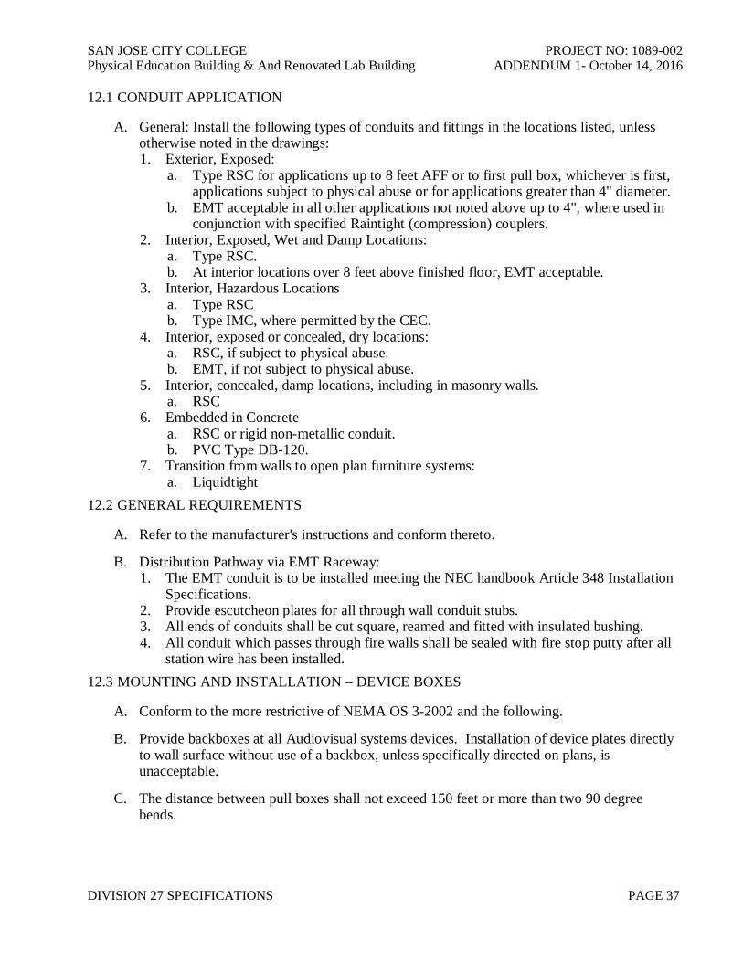
SAN JOSE CITY COLLEGE PROJECT NO: 1089-002Physical Education Building & And Renovated Lab Building ADDENDUM 1- October 14, 2016
DIVISION 27 SPECIFICATIONS PAGE 37
12.1 CONDUIT APPLICATION
A. General: Install the following types of conduits and fittings in the locations listed, unlessotherwise noted in the drawings:1. Exterior, Exposed:
a. Type RSC for applications up to 8 feet AFF or to first pull box, whichever is first,applications subject to physical abuse or for applications greater than 4" diameter.
b. EMT acceptable in all other applications not noted above up to 4", where used inconjunction with specified Raintight (compression) couplers.
2. Interior, Exposed, Wet and Damp Locations:a. Type RSC.b. At interior locations over 8 feet above finished floor, EMT acceptable.
3. Interior, Hazardous Locationsa. Type RSCb. Type IMC, where permitted by the CEC.
4. Interior, exposed or concealed, dry locations:a. RSC, if subject to physical abuse.b. EMT, if not subject to physical abuse.
5. Interior, concealed, damp locations, including in masonry walls.a. RSC
6. Embedded in Concretea. RSC or rigid non-metallic conduit.b. PVC Type DB-120.
7. Transition from walls to open plan furniture systems:a. Liquidtight
12.2 GENERAL REQUIREMENTS
A. Refer to the manufacturer's instructions and conform thereto.
B. Distribution Pathway via EMT Raceway:1. The EMT conduit is to be installed meeting the NEC handbook Article 348 Installation
Specifications.2. Provide escutcheon plates for all through wall conduit stubs.3. All ends of conduits shall be cut square, reamed and fitted with insulated bushing.4. All conduit which passes through fire walls shall be sealed with fire stop putty after all
station wire has been installed.12.3 MOUNTING AND INSTALLATION – DEVICE BOXES
A. Conform to the more restrictive of NEMA OS 3-2002 and the following.
B. Provide backboxes at all Audiovisual systems devices. Installation of device plates directlyto wall surface without use of a backbox, unless specifically directed on plans, isunacceptable.
C. The distance between pull boxes shall not exceed 150 feet or more than two 90 degreebends.

SAN JOSE CITY COLLEGE PROJECT NO: 1089-002Physical Education Building & And Renovated Lab Building ADDENDUM 1- October 14, 2016
DIVISION 27 SPECIFICATIONS PAGE 38
D. Align boxes plumb with floor and surrounding construction. At door frames, locate 4" fromframe. Verify placement with District’s Representative details to ensure that box clears alltrim, etc.
E. Support and fasten boxes securely. At stud walls use rigid bar hangers, attached to hangerwith stud and nut.
F. At existing locations, provide cutting, patching and finishing as required to maintain orrestore finishes so that resulting installation is integrated into the Architectural decor of theparticular location.
G. Mounting Height: the mounting height of a wall-mounted outlet box is defined as the heightfrom the finished floor to the horizontal center line of the cover plate.
H. Mount outlet boxes with the long axis vertical. Three or more gang boxes shall be mountedwith the long axis horizontal.
I. Install wiring jacks and outlet devices only in boxes which are clean; free from excessbuilding materials, dirt, and debris.
J. Install wiring jacks and outlet devices after wiring work is complete.12.4 TERMINAL CABINETS, JUNCTION BOXES AND PULL BOXES
A. General1. Thoroughly examine site conditions for acceptance of cabinets and enclosures
installation to verify conformance with manufacturer and specification tolerances. Donot commence with installation until all conditions are made satisfactory.
B. Set cabinets and enclosures plumb and symmetrical with building lines. Furnish and installall construction channel bolts, angles, etc. required to mount all equipment furnished underthis Section of the Specifications.
C. Cabinets and enclosures shall be anchored and braced to withstand seismic forces calculatedin accordance with standards referenced in Section 27 41 02 – Hangers and Supports forAudiovisual Systems.
D. "Train" interior wiring, bundle and clamp using specified plastic wire wraps. Separatepower and signal wiring.
E. Replace doors or trim exhibiting dents, bends, warps or poor fit that may impede readyaccess, security or integrity.
F. Terminate conduit in cabinet with lock nut and grounding bushing.
G. Cleaning1. Touch-up paint any marks, blemishes or other finish damage suffered during
installation.2. Vacuum clean cabinet on completion of installation.
12.5 SUPPORT
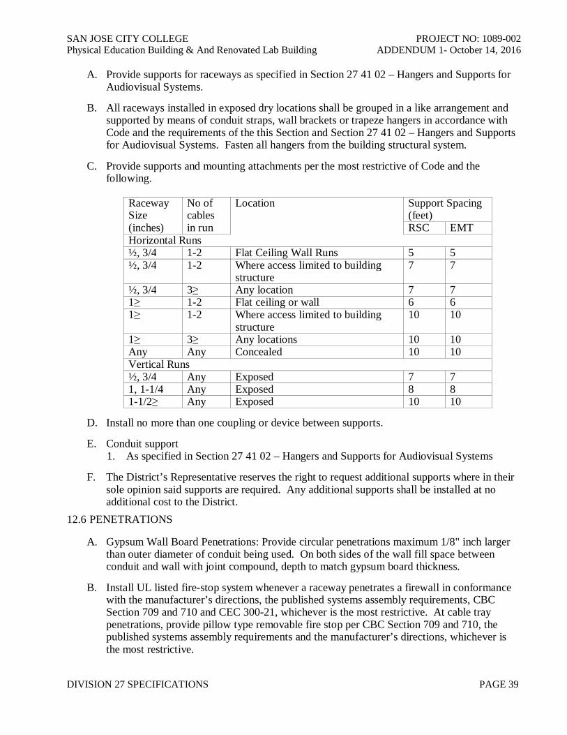
SAN JOSE CITY COLLEGE PROJECT NO: 1089-002Physical Education Building & And Renovated Lab Building ADDENDUM 1- October 14, 2016
DIVISION 27 SPECIFICATIONS PAGE 39
A. Provide supports for raceways as specified in Section 27 41 02 – Hangers and Supports forAudiovisual Systems.
B. All raceways installed in exposed dry locations shall be grouped in a like arrangement andsupported by means of conduit straps, wall brackets or trapeze hangers in accordance withCode and the requirements of the this Section and Section 27 41 02 – Hangers and Supportsfor Audiovisual Systems. Fasten all hangers from the building structural system.
C. Provide supports and mounting attachments per the most restrictive of Code and thefollowing.
RacewaySize(inches)
No ofcablesin run
Location Support Spacing(feet)RSC EMT
Horizontal Runs½, 3/4 1-2 Flat Ceiling Wall Runs 5 5½, 3/4 1-2 Where access limited to building
structure7 7
½, 3/4 3≥ Any location 7 71≥ 1-2 Flat ceiling or wall 6 61≥ 1-2 Where access limited to building
structure10 10
1≥ 3≥ Any locations 10 10Any Any Concealed 10 10Vertical Runs½, 3/4 Any Exposed 7 71, 1-1/4 Any Exposed 8 81-1/2≥ Any Exposed 10 10
D. Install no more than one coupling or device between supports.
E. Conduit support1. As specified in Section 27 41 02 – Hangers and Supports for Audiovisual Systems
F. The District’s Representative reserves the right to request additional supports where in theirsole opinion said supports are required. Any additional supports shall be installed at noadditional cost to the District.
12.6 PENETRATIONS
A. Gypsum Wall Board Penetrations: Provide circular penetrations maximum 1/8" inch largerthan outer diameter of conduit being used. On both sides of the wall fill space betweenconduit and wall with joint compound, depth to match gypsum board thickness.
B. Install UL listed fire-stop system whenever a raceway penetrates a firewall in conformancewith the manufacturer’s directions, the published systems assembly requirements, CBCSection 709 and 710 and CEC 300-21, whichever is the most restrictive. At cable traypenetrations, provide pillow type removable fire stop per CBC Section 709 and 710, thepublished systems assembly requirements and the manufacturer’s directions, whichever isthe most restrictive.
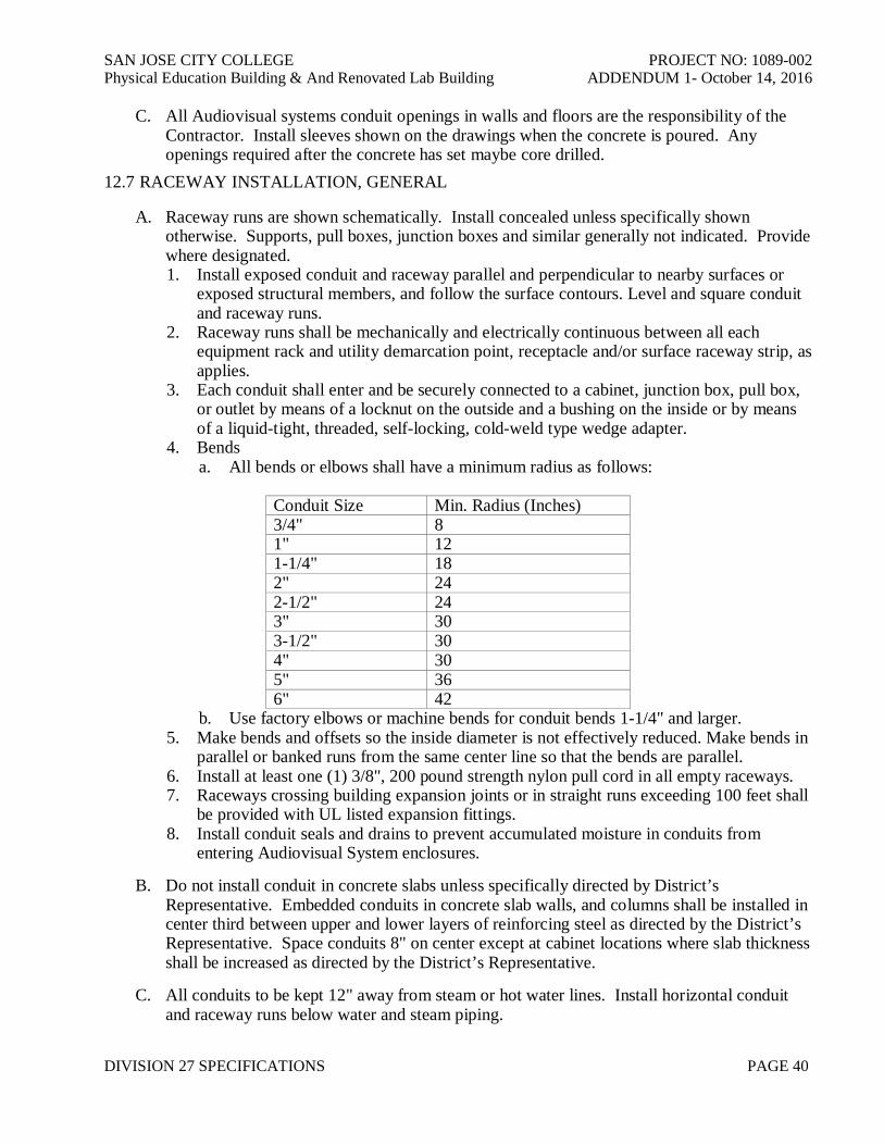
SAN JOSE CITY COLLEGE PROJECT NO: 1089-002Physical Education Building & And Renovated Lab Building ADDENDUM 1- October 14, 2016
DIVISION 27 SPECIFICATIONS PAGE 40
C. All Audiovisual systems conduit openings in walls and floors are the responsibility of theContractor. Install sleeves shown on the drawings when the concrete is poured. Anyopenings required after the concrete has set maybe core drilled.
12.7 RACEWAY INSTALLATION, GENERAL
A. Raceway runs are shown schematically. Install concealed unless specifically shownotherwise. Supports, pull boxes, junction boxes and similar generally not indicated. Providewhere designated.1. Install exposed conduit and raceway parallel and perpendicular to nearby surfaces or
exposed structural members, and follow the surface contours. Level and square conduitand raceway runs.
2. Raceway runs shall be mechanically and electrically continuous between all eachequipment rack and utility demarcation point, receptacle and/or surface raceway strip, asapplies.
3. Each conduit shall enter and be securely connected to a cabinet, junction box, pull box,or outlet by means of a locknut on the outside and a bushing on the inside or by meansof a liquid-tight, threaded, self-locking, cold-weld type wedge adapter.
4. Bendsa. All bends or elbows shall have a minimum radius as follows:
Conduit Size Min. Radius (Inches)3/4" 81" 121-1/4" 182" 242-1/2" 243" 303-1/2" 304" 305" 366" 42
b. Use factory elbows or machine bends for conduit bends 1-1/4" and larger.5. Make bends and offsets so the inside diameter is not effectively reduced. Make bends in
parallel or banked runs from the same center line so that the bends are parallel.6. Install at least one (1) 3/8", 200 pound strength nylon pull cord in all empty raceways.7. Raceways crossing building expansion joints or in straight runs exceeding 100 feet shall
be provided with UL listed expansion fittings.8. Install conduit seals and drains to prevent accumulated moisture in conduits from
entering Audiovisual System enclosures.
B. Do not install conduit in concrete slabs unless specifically directed by District’sRepresentative. Embedded conduits in concrete slab walls, and columns shall be installed incenter third between upper and lower layers of reinforcing steel as directed by the District’sRepresentative. Space conduits 8" on center except at cabinet locations where slab thicknessshall be increased as directed by the District’s Representative.
C. All conduits to be kept 12" away from steam or hot water lines. Install horizontal conduitand raceway runs below water and steam piping.
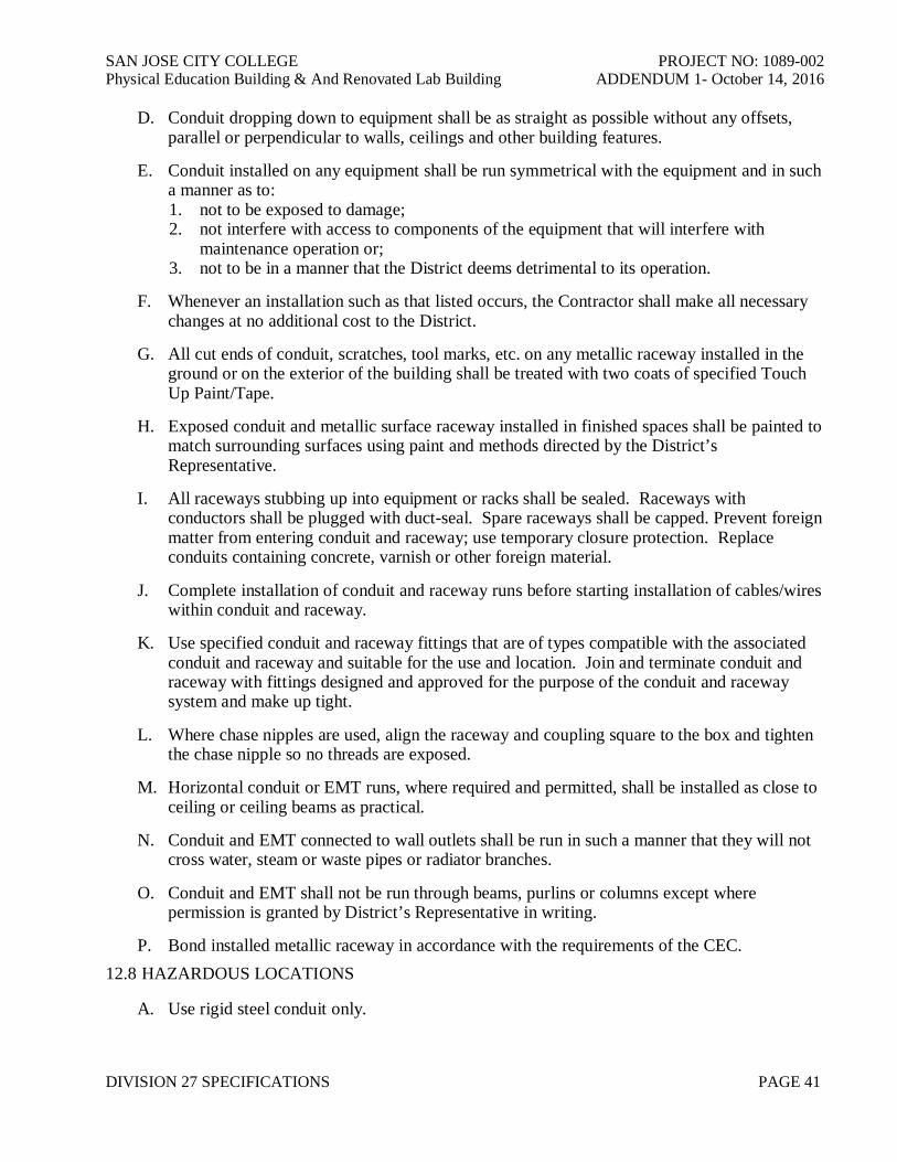
SAN JOSE CITY COLLEGE PROJECT NO: 1089-002Physical Education Building & And Renovated Lab Building ADDENDUM 1- October 14, 2016
DIVISION 27 SPECIFICATIONS PAGE 41
D. Conduit dropping down to equipment shall be as straight as possible without any offsets,parallel or perpendicular to walls, ceilings and other building features.
E. Conduit installed on any equipment shall be run symmetrical with the equipment and in sucha manner as to:1. not to be exposed to damage;2. not interfere with access to components of the equipment that will interfere with
maintenance operation or;3. not to be in a manner that the District deems detrimental to its operation.
F. Whenever an installation such as that listed occurs, the Contractor shall make all necessarychanges at no additional cost to the District.
G. All cut ends of conduit, scratches, tool marks, etc. on any metallic raceway installed in theground or on the exterior of the building shall be treated with two coats of specified TouchUp Paint/Tape.
H. Exposed conduit and metallic surface raceway installed in finished spaces shall be painted tomatch surrounding surfaces using paint and methods directed by the District’sRepresentative.
I. All raceways stubbing up into equipment or racks shall be sealed. Raceways withconductors shall be plugged with duct-seal. Spare raceways shall be capped. Prevent foreignmatter from entering conduit and raceway; use temporary closure protection. Replaceconduits containing concrete, varnish or other foreign material.
J. Complete installation of conduit and raceway runs before starting installation of cables/wireswithin conduit and raceway.
K. Use specified conduit and raceway fittings that are of types compatible with the associatedconduit and raceway and suitable for the use and location. Join and terminate conduit andraceway with fittings designed and approved for the purpose of the conduit and racewaysystem and make up tight.
L. Where chase nipples are used, align the raceway and coupling square to the box and tightenthe chase nipple so no threads are exposed.
M. Horizontal conduit or EMT runs, where required and permitted, shall be installed as close toceiling or ceiling beams as practical.
N. Conduit and EMT connected to wall outlets shall be run in such a manner that they will notcross water, steam or waste pipes or radiator branches.
O. Conduit and EMT shall not be run through beams, purlins or columns except wherepermission is granted by District’s Representative in writing.
P. Bond installed metallic raceway in accordance with the requirements of the CEC.12.8 HAZARDOUS LOCATIONS
A. Use rigid steel conduit only.

SAN JOSE CITY COLLEGE PROJECT NO: 1089-002Physical Education Building & And Renovated Lab Building ADDENDUM 1- October 14, 2016
DIVISION 27 SPECIFICATIONS PAGE 42
B. Install UL listed sealing fittings that prevent passage of explosive vapors in accordance withthe manufacturers written instructions. Locate fittings at suitable, accessible locations andfill them with UL-listed sealing compound. For concealed raceways, install each fitting in aflush steel box with a blank coverplate having a finish similar to that of adjacent plates orsurfaces.
C. Install raceway sealing fittings at the following points and elsewhere as indicated:1. Where conduits enter or leave hazardous locations.
END OF SECTION
SAN JOSE CITY COLLEGE PROJECT NO: 1089-002Physical Education Building & And Renovated Lab Building ADDENDUM 1- October 14, 2016
DIVISION 27 SPECIFICATIONS PAGE 43
SECTION 27 41 06 - NOISE AND VIBRATION CONTROLS FOR AUDIOVISUAL SYSTEMS
PART 13 - GENERAL
13.1 SCOPE OF WORK
A. Provisions of:1. Flexible Audiovisual raceway connections to vibrating machinery2. Sealing of Audiovisual device boxes related installed in sound rated walls.3. Coordination of airtight installation requirements at Mechanical and Electrical Rooms
and/or duct enclosures.13.2 RELATED WORK IN OTHER SECTIONS
A. Consult all other Sections, determine the extent and character of related work and properlycoordinate work specified herein with that specified elsewhere to produce a completeinstallation.1. Division 15
a. Energy Management Panels mounted on vibrating equipment connected to theAudiovisual Work.
2. Division 27a. UPS equipment connected to the Audiovisual Work.b. Section 27 41 03 - Conduits and Backboxes for Audiovisual Systems
13.3 REFERENCES
A. American National Standards Institute (ANSI)1. ANSI/UL 1479-2003 Fire Tests of Through Penetration Firestops
B. American Society for Testing and Materials (ASTM)1. ASTM E814-02 Standard Test Method for Fire Tests of Through Penetration Fire Stops.
C. Underwriters Laboratories, Inc. (UL)1. UL Fire Resistance Directories
13.4 SUBMITTALS
A. Comply with the requirements of Section 01 33 23 - Shop Drawings, Product Data andSamples and Section 27 41 00 – Common Work Results for Audiovisual Systems.
PART 14 - PRODUCTS
14.1 FLEXIBLE AUDIOVISUAL CONNECTIONS:
A. Make Audiovisual connections to vibrating equipment flexible as follows:1. For conduit over 1" O.D. make Audiovisual connections to vibrating equipment via a
flexible expansion/deflection conduit coupling sized as required. Coupling shall haveflexible and watertight outer jacket, internal grounding strap, plastic inner sleeve tomaintain smooth wireway, and end hubs with threads to fit standard threaded metal

SAN JOSE CITY COLLEGE PROJECT NO: 1089-002Physical Education Building & And Renovated Lab Building ADDENDUM 1- October 14, 2016
DIVISION 27 SPECIFICATIONS PAGE 44
conduit.2. Manufacturers:
a. XD Xpansion Deflection Coupling by Crouse-Hinds of Syracuse, N.Y.b. Type DF Expansion and Deflection fitting by Spring City Electrical Mfg. Co.c. or equal.
3. For conduit under 1" O.D. utilize FLEX or LIQUIDTIGHT conduit as specified inSection 27 41 03 – Conduits and Backboxes for Audiovisual Systems with slack at least3' or 15 diameters long, whichever is the longer or provide a flexible coupling asdefined above.
14.2 J-BOX MASTIC:
A. At all electrical boxes penetrating sound isolating partitions, utilize sheet form adhesivemastic as directed elsewhere herein
B. Manufacturers:1. Insul-Pad by Dottie Corp.2. Duct-Seal by Gardner Bender, Inc.3. Duxseal by Manville4. Outlet Pad by Lowry5. or equal.
14.3 RESILIENT PENETRATIONS:
A. For conduit:1. Sleeves: Sleeves of appropriate gage galvanized sheet metal shall be formed to at least
the thickness of the penetrated construction and 3/4" to 1" larger in each cross-sectionaldimension than the penetrating element.a. Manufacturers:
i. Century-Line Sleeves by Thunderline Corporationii. Custom by Contractoriii. or equal.
2. Batt: Glass fiber of batt or mineral wool, 1 to 3 lb./cu. ft. density.a. Manufacturers
i. Certain-Teedii. Johns-Manvilleiii. Owens-Corningiv. or equal.
3. Acoustical Sealant:a. Manufacturers
i. DAPii. Pecoraiii. Tremcoiv. U.S. Gypsumv. or equal.
4. Firestop Sealant:a. Where required, resilient firestop caulking may be used in lieu of Acoustical
Sealant when installed in strict conformance with the manufacturer's directions.Fully hardened firestop caulk shall develop a Shore A hardness of no greater than35. Refer to the requirements of Section 27 41 03 – Conduits and Backboxes for
SAN JOSE CITY COLLEGE PROJECT NO: 1089-002Physical Education Building & And Renovated Lab Building ADDENDUM 1- October 14, 2016
DIVISION 27 SPECIFICATIONS PAGE 45
Audiovisual Systems.PART 15 - EXECUTION
15.1 GENERAL INSTALLATION REQUIREMENTS, CONNECTION TO VIBRATINGEQUIPMENT
A. The Contractor shall not install any vibrating equipment or conduit attached thereto whichmakes rigid contact with the "building" unless it is approved in this specification or by theDistrict's Representative. "Building" includes, but is not limited to slabs, beams, columns,walls, partitions, ceilings, studs, ceiling framing and suspension systems.
B. Prior to installation, the Contractor shall bring to the District' Representative's attention anyconflicts between trades which will result in unavoidable rigid contact at equipment,conduit, piping, ducts, etc., as described herein, due to inadequate space or other unforeseenconditions. Corrective work necessitated by conflicts after installation shall be at theresponsible contractor's expense.
C. The Contractor shall obtain inspection and approval from the District's Representative of anyinstallation to be covered or enclosed, prior to such closure.
15.2 INSPECTION OF CONDITIONS:
A. Examine related Work and surfaces before starting Work of this Section. Report to theDistrict's Representative, in writing, conditions which will prevent proper provision of thiswork. Beginning the Work of this Section without reporting unsuitable conditions to theDistrict's Representative constitutes acceptance of such conditions by Contractor. Performany required removal, repair, or replacement of this Work caused by unsuitable conditions atno additional cost to the District.
B. Coordination1. Coordinate with the work of the Base Building Construction Contract. Coordinate
Work of this Section with all other impacted trades.15.3 INSTALLATION REQUIREMENTS, FLEXIBLE ELECTRICAL CONNECTIONS
A. The installation of flexible electrical connections to vibration isolated equipment shall in noway impair or restrain the function of the vibration isolation installed by the work by Others.1. Using gross slack. Install flexible conduit in a grossly slack loop form or shallow "U"
form. Install stranded conductors with sufficient slack to accommodate maximumpossible movement.
2. Using flexible coupling. The flexible coupling shall be free and not in contact with anynearby building construction and shall be installed slack, and free of strain in anydirection. Install stranded conductors as above
15.4 INSTALLATION REQUIREMENTS, J-BOX MASTIC
A. Application: All Audiovisual Systems work in sound isolating assemblies, including but notlimited to residential rooms, offices, mechanical rooms, electrical rooms and related toutilize backboxes for all services, including but not limited to low voltage communication.Installation of backboxes to conform with following:1. Space outlet boxes on opposite faces of the wall by more than 24" o.c. Where daisy
SAN JOSE CITY COLLEGE PROJECT NO: 1089-002Physical Education Building & And Renovated Lab Building ADDENDUM 1- October 14, 2016
DIVISION 27 SPECIFICATIONS PAGE 46
chainned conduits indicated on the plans, connect such boxes by slack flexible conduit(2 times longer than distance between outlets).
2. Cutouts for electrical boxes and penetrating piping/conduit shall be no more than 1/4"oversize.
3. Caulk gap between drywall and electrical boxes and/or piping/conduit airtight withAcoustical Sealant. Apply J-Box mastic to back of all penetrating electrical boxes andpress firmly at joint to wallboard to provide an airtight seal.
15.5 INSTALLATION REQUIREMENTS, RESILIENT PENETRATIONS
A. Penetrations included in this Section of the Specifications include all Audiovisual conduitconnected to vibrating equipment within 30 feet of such equipment
B. Method for round or rectangular penetrations.1. Cut a clean opening in the penetrated construction very nearly the size of the sleeve for
each penetrating element. Provide lintels above, relief structure below and verticalframing between and to the sides, as required. Provide the above, escutcheon plates andsuch related construction as is necessary to make the penetrated structure as solid andmassive near the penetrations as the surrounding construction.
2. Set the metal sleeve into the penetrated construction in an airtight manner around itsouter periphery, using grout, dry packing, plaster or drywall compound full depth andall around - but only to a maximum width of ½" - or the requirements of the aboveparagraph shall not have been satisfied.
3. Pack annular opening with glass fiber between metal sleeve and penetrating element fulldepth, all around to a firm degree of compaction. Leave a ½" deep annular opening freeat each end of the metal sleeve; fill this fully with sealant.
15.6 MECHANICAL AND ELECTRICAL ROOMS REQUIREMENTS
A. All mechanical and electrical rooms, plenums, duct shafts and drywall duct enclosures andother enclosures of high noise sources shall be constructed airtight. This means that everyprecaution shall be taken to maintain construction completely airtight around a room sodesignated. Construction joints, duct penetrations, electrical boxes, frames, supports,cabinets, doors, access panels, fixtures, etc., all shall be built or installed in such a manner asto prevent sound transmission through any construction enclosing a room horizontally orvertically. Appropriate lintels, frames, blocking, escutcheons, grouting, gaskets, packing,caulking, taping, filling, etc., all shall be employed to prevent sound transmission. Refer torequirements of this Section for Resilient Penetrations.
B. All work under this section is to comply with the above. Contractor to report to District'sRepresentative any construction conditions which arise which might compromisecompliance with this requirement.
END OF SECTION

SAN JOSE CITY COLLEGE PROJECT NO: 1089-002Physical Education Building & And Renovated Lab Building ADDENDUM 1- October 14, 2016
DIVISION 27 SPECIFICATIONS PAGE 47
SECTION 27 41 07 - IDENTIFICATION FOR AUDIOVISUAL SYSTEMS
PART 16 - GENERAL
16.1 SUMMARY:
A. Provide all labor, materials, tools, and equipment required for permanent intelligible labelingon, or adjacent to, all cabling, connectors, innerduct, faceplates, jacks, receptacles, controls,fuses, circuit breakers, patching jacks, and racks.
B. This section includes minimum requirements for the following:1. Labeling Audiovisual Cabling2. Labeling Closet Hardware3. Labeling Work Stations4. Labeling Pathways, Spaces, Grounding and Bonding.
C. Refer to detailed plans for additional requirements.
D. Clearly and distinctly indicate the function of the item.
E. Coordinate with Record Drawings16.2 REFERENCES:
A. Usage: In accordance with Section 014200 – Definitions, References, and Regulations
B. American Society for Testing and Materials (ASTM)1. ASTM D 709(2001) Laminated Thermosetting Materials
C. Electronic Industries Alliance (EIA)1. EIA TIA/EIA-606-A(2002) Administration Standard for Commercial
Telecommunications Infrastructure (ANSI/TIA/EIA-606)
D. Underwriters Laboratories (UL)1. UL 969 (1995; R 2001) Marking and Labeling Systems
16.3 QUALITY ASSURANCE
A. Identification and administration work specified herein shall comply with the applicablerequirements of:1. ANSI/TIA/EIA – 606-A Administration Standards.2. ANSI/TIA/EIA – 569B Pathway and Spaces3. ANSI/TIA/EIA – 568B Telecommunications Cabling Standard.4. BICSI Telecommunications Distribution Methods Manual.5. UL 969 (1995; R 2001) Marking and Labeling Systems.
16.4 SUBMITTALS
A. Conform with the requirements of Section 013300 – Submittal Procedures and Section 27 4100 - Common Work Results for Audiovisual Systems.

SAN JOSE CITY COLLEGE PROJECT NO: 1089-002Physical Education Building & And Renovated Lab Building ADDENDUM 1- October 14, 2016
DIVISION 27 SPECIFICATIONS PAGE 48
16.5 DELIVERY, STORAGE AND HANDLING
A. Procedures: In accordance with Section 011100 – Summary of Work.16.6 SEQUENCING
A. Not Used.PART 17 - PRODUCTS
17.1 COMMUNICATION CABLING LABELS, INTERIOR
A. Shall meet the legibility, defacement, exposure and adhesion requirements of UL 969.
B. Shall be preprinted or computer printed type. Hand written labels are not acceptable.
C. Provide vinyl substrate with a white printing area and black print. If cable jacket is white,provide cable label with printing area that is any other color than white, preferably orange oryellow – so that the labels are easily distinguishable.
D. Shall be flexible vinyl or other substrates to apply easy and flex as cables are bent.
E. Shall use aggressive adhesives that stay attached even to the most difficult to adhere tojacketing.
F. Manufacturers:1. Cable Type – Audiovisual Cabling, General Purpose
a. Brady TLS2200 labels – PTL-31-427,PTL-32-427b. Brady Laser tab labels – LAT-18-361, LAT-53-361c. Hubbelld. Levitone. Panduit.f. or equal.
2. Cable Type – RG-6 Coaxa. Brady TLS2200 labels – PTL-31-427, PTL-32-427b. Brady Laser tab labels –LAT-18-361, LAT-53-361c. Panduit.d. or equal.
3. Cable Type – RG-59 Coaxa. Brady TLS2200 labels – PTL-31-427, PTL-32-427b. Brady Laser tab labels – LAT-18-361, LAT-53-361c. Panduit.d. or equal.
4. Cable Bundlesa. Brady TLS2200 labels – PTL-12-109b. Panduit.c. or equal.
17.2 GROUNDING AND BONDING, PATHWAY, AND SPACE LABELS
A. Shall meet the legibility, defacement, exposure and adhesion requirements of UL 969.
SAN JOSE CITY COLLEGE PROJECT NO: 1089-002Physical Education Building & And Renovated Lab Building ADDENDUM 1- October 14, 2016
DIVISION 27 SPECIFICATIONS PAGE 49
B. Shall be preprinted or computer printed type. Hand written labels are not acceptable.
C. Manufacturers:1. Brady Corporation
a. TLS2200 labelsi. PTL-20-422, Size 2.0” x 1.0”ii. PTL-22-422, Size 3.0” x 1.0”iii. PTL-37-422, Size 3.0” x 1.9”iv. PTL-23-422, Size 4.0” x 1.0”v. PTL-38-422, Size 4.0” x 1.0”
b. Laser tab labelsi. LAT-13-747, Size 1.875” x 0.833”ii. LAT-24-747, Size 1.75” x 1.0”iii. LAT-32-747, Size 3.0” x 0.9 “iv. LAT-33-747, Size 2.0” x 1.437”v. LAT-34-747, Size 3.0” x 1.437”
c. Continuous tape for TLS2200i. PTL-8-422, Size 0.5” white polyesterii. PTL-8-430, Size 0.5” clear polyesteriii. PTL-8-439, Size 0.5” white vinyliv. PTL-42-439, Size 1.0” white vinylv. PTL-43-439, Size 1.9” white vinyl
2. Panduit.3. or equal.
17.3 NAMEPLATES
A. Field Fabricated Nameplates1. Features/Function/Construction
a. Provide laminated plastic nameplates for each equipment enclosure, relay, switch,and device; as specified or as indicated on the drawings.
b. Comply with ASTM D 709.c. Each nameplate inscription shall identify the function and, when applicable, the
position.d. Nameplates shall be melamine plastic, 0.125 inch thick, white with black center
core.e. Surface shall be matte finish.f. Corners shall be square.g. Accurately align lettering and engrave into the core.h. Minimum size of nameplates shall be one by 2.5 inches.i. Lettering shall be a minimum of 0.25 inch high normal block style
PART 18 - EXECUTION
18.1 GENERAL
A. Apply labeling to clean surfaces free of oil, dust, solvents or loose material.
B. Apply after Project painting in area of application is complete.
SAN JOSE CITY COLLEGE PROJECT NO: 1089-002Physical Education Building & And Renovated Lab Building ADDENDUM 1- October 14, 2016
DIVISION 27 SPECIFICATIONS PAGE 50
C. Apply to locations where labeling will not be damaged, covered over or in the way of theordinary maintenance and operation of the installed Audiovisual infrastructure or system.
D. Apply labeling right side up, parallel to major edges of surfaces to which it is applied. Whenno line is evident, apply parallel to floor line. Correct conditions of labeling applied out oftrue.
E. Protect installed labeling from damage.
F. Replace labeling that is defaced, illegible or peeling off of the surface to which it is applied.18.2 IDENTIFICATION & LABELING
A. Pathways1. Pathways shall be marked at each endpoint and at all intermediate pull or junction
boxes. In the case of partitioned pathways (i.e. innerduct) each partition shall have aunique identifier.
2. Label pathways using the appropriate abbreviation and a number.3. Use adhesive type labels.
B. Labels shall be affixed at the entry to all Audiovisual Control Rooms and spaces (Includesentrance facilities, communication equipment rooms, communication equipment spaces andwork areas)1. Use adhesive type labels for all Audiovisual space labeling,2. Affix labels to entrance doors – coordinate location with District's Representative.
C. Cables1. Horizontal shall be marked within 12” of each endpoint or to innerduct in which the
cable is installed.2. Except where installed in innerduct or conduit, all backbone fiber optic cable shall have
affixed to the outer jacket, labels of a bright color that contain at least the legend"FIBER OPTIC CABLE." These labels must be affixed at separations no greater than10 ft.
3. Any cable installed in conduit shall be labeled at all intermediate pull or junction boxes.4. Label cables using the appropriate circuit ID.5. Use adhesive type labels for all AV cable labels.6. Affix labels to cables – marking cable is not permitted.7. Where cable is fully encased in innerduct label the outside of the innerduct with the
cable label and, where the contents are fiber optic cabling, the "FIBER OPTIC CABLE"label.
D. Grounding and Bonding1. The AVGB(s) (Audiovisual main ground bar) shall be labeled as such with an adhesive
type label(s) affix label(s) to TMGB.2. The conductor connecting the AVGB (Audiovisual main ground bar) to the building
ground shall be labeled at each end with an affixed label in a visible location as close aspracticable to the bonding point at each end of the conductor.
E. Firestopping1. Each firestopping location shall be labeled at each location where firestopping is
installed, on each side of the penetrated fire barrier, within 12 in. of the firestopping
SAN JOSE CITY COLLEGE PROJECT NO: 1089-002Physical Education Building & And Renovated Lab Building ADDENDUM 1- October 14, 2016
DIVISION 27 SPECIFICATIONS PAGE 51
material.
END OF SECTION
SAN JOSE CITY COLLEGE PROJECT NO: 1089-002Physical Education Building & And Renovated Lab Building ADDENDUM 1- October 14, 2016
DIVISION 27 SPECIFICATIONS PAGE 52
SECTION 27 41 08 - AUDIOVISUAL RACKS, CABINETS, & ACCESSORIES
PART 19 - GENERAL
19.1 SCOPE OF WORK
A. Audiovisual racks and cabinets.
B. Production Desks and Mobile Production Racks.19.2 RELATED WORK IN OTHER SECTIONS
A. Section 27 41 01 – Grounding and Bonding for Audiovisual Systems1. Bonds racks and cabinets.
B. Section 27 41 03 – Conduits and Backboxes for Audiovisual Systems1. Signal systems raceways at Audiovisual Control Rooms
19.3 REFERENCES
A. American National Standards Institute (ANSI)1. EIA-310-D (1992) Cabinets, Racks, Panels, and Associated Equipment
(ANSI/EIA/310-D)2. ANSI-J-STD-607-A Commercial Building Grounding (Earthing) and Bonding
Requirements for Telecommunications (ANSI/J-STD-607-A-2002)
B. International Conference of Building Officials (ICBO)1. AC156 ICBO ES Acceptance Criteria for Seismic Qualification Testing of
Nonstructural Components (Jul. 2004)
C. Telecordia Technologies1. Network Equipment Building System (NEBS) GR-63-CORE (Seismic Zone 4)
19.4 SUBMITTALS
A. Conform with the requirements of Section 013300 – Submittal Procedures and Section 27 4100 - Common Work Results for Audiovisual Systems.
19.5 DELIVERY, STORAGE AND HANDLING
A. Procedures: In accordance with Section 011100 – Summary of Work.PART 20 - PRODUCTS
20.1 GENERAL
A. KEYS1. Key all boxes, cabinets, enclosures, panels, controls, doors and related provided for
similar usage within a system identically.20.2 EQUIPMENT ENCLOSURE SYSTEMS

SAN JOSE CITY COLLEGE PROJECT NO: 1089-002Physical Education Building & And Renovated Lab Building ADDENDUM 1- October 14, 2016
DIVISION 27 SPECIFICATIONS PAGE 53
A. General:1. Provide enclosure systems including, but not limited to enclosures, cabinets, cases and
related panels and accessories as specified herein. Provide size and quantity as shownon drawings or scheduled.
2. Provide color as shown on drawings. If no color is shown on drawings, submitmanufacturer's standard color chips for selection.
3. Provide enclosure systems conforming to the UBC/CBC, latest edition, for seismicdesign.
4. Equipment Enclosures: Each rack provided with frame angles tapped 10-32, ANSI/EIA310-D Universal Spaced.
B. Zone 4 Slide Out Rack, Steel Enclosure1. Drawing Reference: R352. Features
a. Rack cabinet, 1 bay, steel frame mounted, with slide out inner frame for rear accessof equipment from front of rack, floor supported.
b. Zone 4 rated for up to 500 pounds of uniformly distributed load.c. 41 useable rack units.d. Fan System, 100 cfm minimum mounted into slide out inner frame.e. No front except where called for on the plans - at such conditions, provide fully
perforated steel door.f. No rear doorsg. Locking side panels.h. Open top outer framei. Raised floor base - provide engineered means of support where installation at
raised floor conditions are indicated sufficient to maintain racks Zone 4 rating.j. Provide vertical power strips in accordance with Section 27 11 26.k. Provide sliding shelf.
3. Manufacturer:a. Middle Atlantic Products AXS Slide Out System in MRK Steel Host Enclosure,
configured with:(1) MRK-4426AXS-Z4(2) AXS-WT50 Cable Management Tray(3) TRACK50 Service Track.(4) TRACKL Service Stand for Steel Cabinets.(5) 1 each MW-4FT fan top (openings only) in outer frame.(6) 2 each AXS-FAN with GUARD, 2 fans installed in the top of inner frame.(7) 1 each FC-4-1C Thermostatic Fan Control(8) At raised floor conditions, provide with SRB series base to match floor
construction.(9) or equal (No known equal).
C. Zone 4 Equipment Rack, Front, Rear and Side Access.
1. Drawing Reference: R33
2. Construction:a. Manufacturer tested Zone 4 assembly, rated for at least 900 pounds of
uniformly distributed load under Zone 4 forces.b. Vertical Height (Min): 44 RU
SAN JOSE CITY COLLEGE PROJECT NO: 1089-002Physical Education Building & And Renovated Lab Building ADDENDUM 1- October 14, 2016
DIVISION 27 SPECIFICATIONS PAGE 54
c. Overall Depth: 27" minimum.d. Overall Width: Nominally 24"e. No Front Doorf. Lockable wire mesh rear door.g. Fully Adjustable 19" Mounting Rails, 10-32 threaded openings on EIA
spacing standardh. Qty (2) full height receptacle strips, each at least one (1) circuit, 20A,
unless otherwise noted, as specified elsewhere in Section 27 11 26.i. Provide each rack with the following accessory shelves:
i. One (1) Exhaust Fan Panel, at top or rear doors, at least 200CFM.
j. Gangable. Racks have been designed such that they are suitable forinstallation either as a single, standalone unit, or in a row of identicalracks (gangable).i. Single rack installation. Provide side panels at both sides.ii. Multirack installation in a row. Bolt racks together using means
provided by manufacturer. Omit side panels except at ends ofrow of racks – provide at ends of rows of racks.
3. Manufacturers. Provide manufacturer’s accessories or 3rd party accessories asspecified elsewhere in this Section for other specified elements. Coordinateselected shelves, fans and similar with rack submitted for finish and mountingmeans.:a. Middle Atlantic WRK-44SA-27LRD, MW-LVRD-44 rear door, WRK-
Z4 Mounting Brackets, MW-4FT top w/ 4 fans.b. APCc. AFCOd. CPIe. APW/PFTf. Hoffmanng. or equal.
D. Equipment Rack, Undercounter, Pullout and Pivoting1. Drawing Reference: R182. Features/Construction:
a. EIA compliant 19” rotating slide-out equipment rack intended for permanentinstallation and integration into a millwork or cabinet opening.
b. Overall dimensions of rack shall be not more than 19.25” wide x 20” deepc. Provide the following quantity of rack spaces:d. R18E: 12 RUe. R18G: 14 RUf. R18M: 20 RUg. Rack shall support up to a 300 pound loading, in closed and pull-out operation.h. Rack shall pull out 19” on integrated ball bearing slides and rotate 90º for
equipment servicing. When rotating rack, locking detent shall allow rack to lock inplace at 0, 60 and 90 degrees of rotation.
i. Rackrail shall be 11-gauge steel with tapped 10-32 holes in universal EIA spacing.Rackrail shall be finished in black e-coat with marked rackspaces.
j. Rough-in pan shall be 14-gauge steel.
SAN JOSE CITY COLLEGE PROJECT NO: 1089-002Physical Education Building & And Renovated Lab Building ADDENDUM 1- October 14, 2016
DIVISION 27 SPECIFICATIONS PAGE 55
k. Finish on assembly shall be durable flat black powder coat.l. Trim/locking panel shall lock SRSR in closed position and be 11-gauge aluminum
with brushed black anodized finish.m. Unless otherwise noted, completely enclose interior of enclosure, or ensembles of
enclosures with equipment, blank or vent panels3. Manufacturers
a. Middle Atlantic SRSR–4-14.b. Or equal (no known equal).
20.3 RACK PANELS AND ACCESSORIES
A. Rack Mounting Screws:1. Screws 10-32; length as required for at least 1/4" excess when fully seated; oval head
with black plastic non marring cup washer or equivalent ornamental head; nickel,cadmium or black plated; Phillips, Allen Hex, Square-Tip or Torx drive. Slotted screwsare not acceptable.
B. Sliding Shelf:1. Plan Reference: SLIDING SHELF2. Construction/Features:
a. 16 gauge minimum cold rolled steelb. Powder coat finish to match rack color, unless otherwise notedc. 19" Wide Pull out with handhole or knob.d. Solid or perforated surfacee. Depth: At least 20", u.o.n.f. 50 pound minimum load capacity
3. Manufacturers:a. Atlas Soundb. BGW Systems, Inc. Sliding Shelvesc. Chatsworth Products 32" Deep Megaframe Sliding Shelf.d. Elkay SLSH seriese. Homaco Adjustable Pull-Out Equipment Shelvesf. Hubbell MCCTELSHLFg. Middle Atlantic Heavy-Duty Sliding Shelfh. APW SSDC30.i. AFCO AS-SO-19-24.j. Or equal.
C. Fixed Shelf - 4 post rack applications1. Plan Reference(s):
a. FIXED SHELFb. SHELF
2. Construction:a. 16 gauge minimum cold rolled steelb. Powder coat finish to match rack color, unless otherwise notedc. Holds 100 lbs loadd. Mounts to front and rear rails, U.O.N.e. Solid or Perforated bottom panel to suit equipment being mounted.f. Depth to equal not less than 75% of depth of equipment rack.
SAN JOSE CITY COLLEGE PROJECT NO: 1089-002Physical Education Building & And Renovated Lab Building ADDENDUM 1- October 14, 2016
DIVISION 27 SPECIFICATIONS PAGE 56
g. Not more than 1 RU in height.3. Manufacturers:
a. Atlas Sound Heavy Duty Shelves, SH series.b. BGW Systems, Inc. Rack Mount Traysc. Elkay SSH Seriesd. Homaco Adjustable Equipment Shelves and Fixed Dual Shelvese. Lowell Rack Mounted Utility Shelvesf. Middle Atlantic Universal Rackshelvesg. Rack Innovations, Inc.h. ZERO/Stantron Stationary Shelvesi. AFCO AS-SF-19-24j. APW ESDC30.k. Hubbell MCCPSHLFl. Chatsworth Products 29" Deep Megaframe Fixed Shelves.m. or equal
D. Keyboard/Mouse Shelf1. Drawing Reference: Keyboard/Mouse Shelf2. Stores fullsize keyboard and mouse inside rack.3. Upon retraction to rack front, pivots 90 degrees for operator access.4. Manufacturers
a. APC 19" Rotating Keyboard Drawer.b. Middle Atlanticc. or equal.
E. Grommet Panel1. Features/Functions/Construction
a. 1 RU steel or aluminum panel with 18" wide x 1" tall smooth edgedopening in face
b. Cable management panel protrudes below opening perpendicular to rear face.2. Manufacturers:
a. Middle Atlantic BR1b. Custom by Contractor using Blank Panelc. or equal.
F. Blank Panels:1. Construction
a. 16 gauge minimum cold rolled steelb. Powder coat finish to match rack color, unless otherwise noted
2. Manufacturersa. Middle Atlantic Products SB Series.b. Atlas Sound S19 Series.c. BGW Systems Inc. Flanged Steel Blank Panelsd. Dukanee. Elkayf. Lowell Series L3g. Zero ZP112000 Series.h. Hubbelli. or equal.
SAN JOSE CITY COLLEGE PROJECT NO: 1089-002Physical Education Building & And Renovated Lab Building ADDENDUM 1- October 14, 2016
DIVISION 27 SPECIFICATIONS PAGE 57
G. Vent Panels:1. Construction
a. 20 gauge minimum cold rolled steelb. 1/8" minimum holes, at least 70% open total panel cross-section.c. Powder coat finish to match rack color, unless otherwise noted
2. Manufacturersa. Atlas Sound SVP Series.b. BGW Systems Inc. Perforated Vent Panelsc. House of Metal Enclosures (HOME) Series PRP.d. Lowell Series L5e. Middle Atlantic Products VT Series.f. Zero.g. or equal.
H. Drawers1. Construction
a. 16 gauge minimum cold rolled steelb. Powder coat finish to match rack color, unless otherwise notedc. Suitable for mounting from face of 4 post rackd. At least 14-1/2" deep.e. Full extension ball bearing slides with trigger release disconnect.f. Rated for at least 100 pound load.g. Flush handle does not protrude from drawer face.h. Provide key lock where indicated.
2. Manufacturersa. BGW Systems Inc. Rack Mount Drawer Systems.b. Middle Atlantic Heavy Duty D or TD series.c. Atlas Sound SD*-165FP Series.d. Elkay SSD Series.e. or equal.
I. Vertical Lacer Strips1. 44RU high vertical steel strips with points for attachment of velco cable ties at at least
6” o.c.2. Manufacturers:
a. Middle Atlantic LACE-44LPb. APWc. or equal.
J. Horizontal Lacer Bars1. EIA 19” Width steel strips or bars suitable to provide support to large cable dressed
horizontally through racks2. Size to suit load and mounting width.3. Manufacturers:
a. Middle Atlantic LBP-1R4, LBP-1.5 and LBP-1S.b. APWc. or equal.
K. Seismic Hold-down Equipment Straps
SAN JOSE CITY COLLEGE PROJECT NO: 1089-002Physical Education Building & And Renovated Lab Building ADDENDUM 1- October 14, 2016
DIVISION 27 SPECIFICATIONS PAGE 58
1. Drawing Reference: None - Provide as required to secure equipment that cannot bescrew fastened to mounting shelves.
2. Manufacturers:a. BGW Systemsb. Everest Electronic Equipment Lock Down Kitc. Ergotrond. Chatsworth Productse. Middle Atlantic Productsf. Q-Safety, Inc.g. or equal.
PART 21 - EXECUTION
21.1 MOUNTING
A. Unless otherwise noted, all floor supported equipment racks shall be bolted to the structurein accordance with the requirements of the CBC, the UBC and the contractors approvedstructural engineering submittal demonstrating the method to be used to conform to theserequirements.
B. Rows of identical racks shall be bolted together in addition to being bolted to the floor andbonded to form a single electrical ground plane.
C. Wall mounted equipment racks and cabinets shall similarly be bolted to structural membersin accordance with the requirements of the CBC, the UBC and the contractors approvedstructural engineering submittal demonstrating the method to be used to conform to theserequirements.
21.2 EQUIPMENT ENCLOSURE (RACK) AND EQUIPMENT BACKBOARD FABRICATION
A. Combustible material, other than incidental trim of indicated equipment, is prohibited withinequipment racks.
B. Provide permanent labels for all equipment and devices.
C. Floor racks to be bolted floor unless otherwise indicated.
D. Access shall not require demounting or de-energizing of equipment. Install access covers,hinged panels, or pull-out drawers to insure complete access to terminals and interiorcomponents.
E. Provide a permanent label on the front of each equipment rack including the rackdesignation, and the circuit breaker number and associated electrical distribution paneldesignation servicing same.
F. Where wiring of mixed types are called for on the plans, maintain separation of wiringclassifications as specified in the individual sections of the Audiovisual Work. Separatelydress, route and land microphone, audio line level and data cables and related on the rightside of the equipment enclosure, as viewed from the rear; dress, route, and land loudspeakerlevel, data and control cables on the left side of the equipment enclosure, as viewed fromthe rear.
SAN JOSE CITY COLLEGE PROJECT NO: 1089-002Physical Education Building & And Renovated Lab Building ADDENDUM 1- October 14, 2016
DIVISION 27 SPECIFICATIONS PAGE 59
G. Provide vertical wire management of cabling within the rack independent of the adjustableEIA mounting rails. Vertical wiring management provided by the contractor within the rackshall not prevent such rails from being moved as required by the District.
H. Dress and support cabling at a minimum of 24 inch on center.
I. Access shall not require demounting or de-energizing of equipment or cabling. Install accesscovers, hinged panels, or pull-out drawers to insure complete access to terminals and interiorcomponents.
J. Fasten removable covers containing any wired component with a continuous hinge alongone side, with associated wiring secured and dressed to provide an adequate service loop.Provide an appropriate stop locks to hold all hinged panels and drawers in a serviceableposition.
K. Provide permanent labels for all equipment and devices. Where possible, fasten such labelsto the rack frame or to blank or vent panels which will remain in place when activeequipment is removed for possible service.
L. At audio and video jackfields, provide service loop to permit removal of jackfields from racksufficient to conveniently access all jack contacts for routine cleaning and maintenance.Organize the service loop and harness such that reasonable reconnection of jacks and jacknormals is possible without cutting apart the harness.
M. Coordinate the design and execution of wire harnessing of multi-bay audio and video rackensembles with conditions of delivery to installation locations at Project Site, and with therequirement herein for test of the completely wired system in the shop prior to delivery tothe Project Site. Organize the wiring harnesses such that they will fold within one shippableunit without risk of damage, or provide polarized multipin connectors and relatedinterconnect systems as specified elsewhere herein.
21.3 SIGNAL GROUNDING & BONDING PROCEDURES
A. Comply with National Electrical Code and the California Electric Code. Bond equipmentracks to ground in accordance with the California Electric Code and ANSI/ EIA/ TIA 607and Section 27 41 01 – Grounding and Bonding for Audiovisual Systems.
B. Unless otherwise noted maintain a unipoint ground scheme.
C. Equipment enclosures shall not be permitted to touch each other unless bolted together andelectrically bonded.
END OF SECTION
SAN JOSE CITY COLLEGE PROJECT NO: 1089-002Physical Education Building & And Renovated Lab Building ADDENDUM 1- October 14, 2016
DIVISION 27 SPECIFICATIONS PAGE 60
SECTION 27 41 09 - AUDIOVISUAL CABLE MANAGEMENT
PART 22 - GENERAL
22.1 SCOPE OF WORK
A. Section includes provision of cable management for cabling installed under the work of thisProject as well as for District furnished patch cords at equipment racks
B. Scope includes:1. Innerduct2. Cable End Spillway
C. Backboard Cable Management
D. Patch Panel Cable Management at racks and cabinets22.2 RELATED WORK IN OTHER SECTIONS
1. Section 27 41 03 – Conduits and Backboxes for Audiovisual Systems2. Section 27 41 07 – Identification for Audiovisual Systems3. Section 27 41 08 – Audiovisual Cabinets, Racks, Frames and Enclosures
22.3 REFERENCES
A. American Society For Testing and Materials (ASTM)1. ASTM D2239-03 Standard Specification for Polyethylene (PE) Plastic Pipe (SIDR-PR)
Based on Controlled Inside Diameter
B. Underwriters Laboratories (UL)1. UL 910 Test for Flame-Propagation and Smoke-Density Values for Electrical and
Optical-Fiber Cables used in Spaces Transporting Environmental Air (Nov. 1998)22.4 SUBMITTALS
A. Conform with the requirements of Section 013300 – Submittal Procedures and Section 27 4100 - Common Work Results for Audiovisual Systems.
22.5 DELIVERY, STORAGE AND HANDLING
A. Procedures: In accordance with Section 011100 – Summary of Work.PART 23 - PRODUCTS
23.1 INNERDUCT
A. Innerduct, Single Chamber1. Drawing and spec reference(s):
a. ID*, Innerduct ("*" denotes cross sectional area of innerduct referenced to standardconduit trade size).
b. IDP*, Innerduct, Plenum ("*" denotes cross sectional area of innerduct referencedto standard conduit trade size).

SAN JOSE CITY COLLEGE PROJECT NO: 1089-002Physical Education Building & And Renovated Lab Building ADDENDUM 1- October 14, 2016
DIVISION 27 SPECIFICATIONS PAGE 61
2. Construction:a. Selected product suitable for:
i. underground installation in ductbank,ii. plenum (IDP)iii. exposed, in interior utility rooms where indicated.
b. High density polyethylene.c. Ribbed or similar exterior construction to resist crushing surface to promote fiber
cable installation.d. Provides an interior chamber with a capacity equal to a trade size conduit
referenced above.3. Approvals:
a. ASTM D2239(1985) Polyethylene (PE) Plastic Pipe (SIDR-PR) Based onControlled Inside Diameter.
b. IDP - UL Standard Test Method 2024 of UL 910.4. Manufacturers, ID in underground ductbanks:
a. Carlon Optic-Gard/PE.b. Arnco.c. Vikimatic.d. or equal.
5. Manufacturers, ID in interior, non-plenum applications:a. Carlon Optic-Gard/PVC.b. Arnco.c. Vikimatic.d. or equal.
6. Manufacturers, IDP:a. Carlon Plenum-Gard.b. Arnco.c. Vikimatic.d. or equal.
B. Innerduct, Multi-Chamber:1. Drawing and spec reference: #ID*, Innerduct ("#" denotes number of chambers, "*"
denotes cross sectional area of each chamber referenced to standard conduit trade size).2. Construction:
a. Multi-Chamber Innerduct shall be installed within an outer diameter CRSC or PVCConduit per manufacturer's recommendation, and as described elsewhere herein.
b. Shall provide independent interior chambers each with a capacity equal to a tradesize conduit referenced above.
3. Approvals:a. ASTM D2239(1985) Polyethylene (PE) Plastic Pipe (SIDR-PR) Based on
Controlled Inside Diameter.4. Manufacturers, MultiChamber Innerduct:
a. AMP OptiDuct (Design Basis) Provide in combinations to meet scheduledrequirement.i. 3ID1 - Provide one (1) Three Cell innerduct in one-half of a 4" diameter PVC
conduit. Each cell to have 1” cross-sectional area.ii. 1ID3 - Provide one (1) Single Cell innerduct in one-half of a 4" diameter PVC
conduit, with 3" cross-sectional area.
SAN JOSE CITY COLLEGE PROJECT NO: 1089-002Physical Education Building & And Renovated Lab Building ADDENDUM 1- October 14, 2016
DIVISION 27 SPECIFICATIONS PAGE 62
iii. 2ID1.25 - Provide one (1) Two cell innerduct in one-half of a 4" diameter PVCconduit. Each cell to have 1.25" cross-sectional area.
b. Carlon Multi-Gardc. North Supply Multi-Guard Multi-Cell Conduit.d. Tamaqua.e. or equal
5. Manufacturers - Independent InnerDuct runs in overall PVC conduit - Multiple runs ofsingle chamber inner duct may be provided in lieu of single, multiple chamber innerductprovided above. Contractor bears burden of selected innerduct quantity to provide anexact match of cross-sectional area of each chamber of multi-chamber assembly and tore-size overall PVC conduit to accommodate this use.a. Carlon.b. American Plasticsc. Vikimaticd. Or equal
6. Manufacturers, for direct burial or boring:a. Tamaquab. Carlonc. Or equal
C. Innerduct, UV Rated1. Drawing Reference: ID, UV Rated*, where"*" denotes cross sectional area of each
chamber referenced to standard conduit trade size).2. Approvals:
a. ASTM D2239(1985) Polyethylene (PE) Plastic Pipe (SIDR-PR) Based onControlled Inside Diameter.
3. Construction.a. Listed for UV exposure.
4. Manufacturers:a. Tamaqua Plus II Series Telecom Duct.b. Allwire Black AllDuct.c. or equal.
D. Woven Mesh Innerduct1. Drawing Reference: MID, WMID2. Features/Functions
a. Three inch wide woven mesh assembly contains at least three continuous pullablesleeves, each can accommodate a cable of at least 1” diameter.
b. Systems providing fewer than 3 integrally woven sleeves per WMID assembly notacceptable.
c. Includes color coded pull tape in each sleeve.d. Pre-Lubricated for cable pullinge. Non-Hydroscopicf. 2500 Pound Tensile Strengthg. 480 degree F melting point.h. At least 5 years prior field use including at least 25 million feet of product in use.i. Provide plenum rated assembly at plenum locations as defined by the California
Electric Code.3. Manufacturers:
SAN JOSE CITY COLLEGE PROJECT NO: 1089-002Physical Education Building & And Renovated Lab Building ADDENDUM 1- October 14, 2016
DIVISION 27 SPECIFICATIONS PAGE 63
a. Maxcell/TVC 3” 3-cell in three unique colors per duct.b. or equal (No known equal with identical 3 sleeves woven into a single assembly
nor equal industry usage).23.2 CONDUIT CABLE MANAGEMENT
A. Conduit End Waterfall Spillway1. Drawing Reference: CEW2. Features/Functions
a. Spillway fastens to end of EMT conduit, provides radius sweep, open on top, solidfrom below
b. Maintains proper bend radii for fiber/cablec. Provides tie points for fire pillow retentiond. Supports up to 100 lbs. of hanging fiber/cablee. Clamp for securing to EMTf. Self-fastening tie down system for supporting cabling
3. Construction:a. Fire Retardant ABS
4. Manufacturers:a. Bejed BJ-2049 Spillway.b. or equal (no known equal).
PART 24 - EXECUTION
24.1 INNERDUCT INSTALLATION
A. Schedule of Application1. At plenum tray conditions, provide IDP.2. At 4” and larger interior conduits, provide WMID. Provide plenum rated WMID at
plenum ceiling conditions.24.2 CONDUIT END WATERFALL
A. Fasten securely to conduit end wherever cabling will exit conduit 18" or more above thecable tray to prevent damage due to cabling due to weight of cable bearing on a conduit end.
B. Secure cabling with integral cable restraint system.
END OF SECTION
SAN JOSE CITY COLLEGE PROJECT NO: 1089-002Physical Education Building & And Renovated Lab Building ADDENDUM 1- October 14, 2016
DIVISION 27 SPECIFICATIONS PAGE 64
SECTION 27 41 16 - INTEGRATED AUDIOVISUAL SYSTEMS AND EQUIPMENT
PART 25 - GENERAL
25.1 SECTION INCLUDES
A. Provide all labor, materials, transportation and equipment to complete the furnishing,installation, assembly, set up, and testing of the Sound and Audiovisual System workindicated on the drawings and specified herein. Notwithstanding any detailed information inthis Section, provide complete, working systems.
B. Design, engineer and provide complete, all means of support, suspension, attachment,fastening, bracing, and restraint (hereinafter "support") of the Work of this Section. Provideengineering of such support by parties licensed to perform work of this type in the Projectjurisdiction.
25.2 AUDIOVISUAL SYSTEMS AND EQUIPMENT
A. Provide the following, in addition to work shown on the drawings, along with any additionalequipment and accessories required for a complete, working system:
B. Install (N) Audiovisual, DSP, and control systems and equipment in Offices, Open Office,Lobby, Box Office, Instructional and Physical Activity spaces, and Locker Rooms.
C. Develop user interface for control systems with District Representatives familiar with theoperation of Assemblies, Performances, and other Events within the Auditorium. Providesystem programming, training, and support to District during first-substantial-use of (N)systems and equipment.
D. Loudspeaker/Audio Processing, general:1. Program audio and speech content to output through overhead loudspeakers.
E. Racking compartment, general:1. Provide blank plates at all unused openings.2. Provide fans as required to keep the interior of each equipment rack at a temperature at
least 5-10 degrees cooler than equipment manufacturer’s recommended operatingtemperature.a. Fans to emit not more than 30 dB of noise.
F. Control Systems, general:1. Review all push button and touch panel button nomenclature with District
Representative prior to system programming.2. Provide graphic indication of program volume level on control touch panel when
volume control I s selected.3. Provide Main Menu selection button on all touch panel screens to route user back to
main touch panel menu.
G. Control Functions:1. Control: Confirm all control functions and layouts with District Representative prior to
SAN JOSE CITY COLLEGE PROJECT NO: 1089-002Physical Education Building & And Renovated Lab Building ADDENDUM 1- October 14, 2016
DIVISION 27 SPECIFICATIONS PAGE 65
system programming.2. Wall Control:
a. General: Functions to operate by scene/mode, not by device.b. End user selection of a single A/V input source (push buttons) automates:
i. Projections screen lowers.ii. Projector turns on.iii. Presets recalled.iv. Sets audio chain to loudspeakers.
c. End user selection on an Audio Only input automates:i. Sets audio chain.
d. Touch Panel Menus:i. Startup Page: “Press here to Begin”ii. Home Page:
(1) “Select Source”: provides sub-menus of source selections.(2) “Controls”: Provides sub-menu of:
(a) Screen up/down control.(b) Individual projector on/off control.
(3) “Power Off”: Provides sub-menu selection of “Do you want to power offthe system?” with “Yes” and “No” selections. Upon selection of “Yes”,menu reads “Please wait, shutting down system.”
iii. All menus, except Home Page, to include “Home” button to revert back toHome Page.
25.3 REFERENCE STANDARDS
A. Conform to the applicable portions of the current standards published by theseorganizations:1. SMPTE Society of Motion Picture and Television Engineers.2. NAB National Association of Broadcasters.3. EIA Electrical Industries Association of America.4. UL Underwriters Laboratories.5. AES Audio Engineering Society.6. NEC National Electrical Code.7. UBC Uniform Building Code.8. NFPA National Fire Protection Association.9. EIAJ Electrical Industries Association of Japan.10. IEC International Electrotechnical Commission.11. FCC Federal Communications Commission.12. NTC Network Transmission Committee of the Video Transmission
Engineering Advisory Committee.13. NCTA National Cable Television Association.14. BTSC Broadcast Television Stereo Committee.15. TASO Television Allocation Study Organization.
B. Conform additionally to the following specific standards:1. American National Standards Institute (ANSI)
a. ANSI S1.4-1983 (R2001) American National Standard Specification for SoundLevel Meters

SAN JOSE CITY COLLEGE PROJECT NO: 1089-002Physical Education Building & And Renovated Lab Building ADDENDUM 1- October 14, 2016
DIVISION 27 SPECIFICATIONS PAGE 66
b. ANSI S1.11-1986 (R2001) American National Standard Specification for Octave-Band and Fractional Octave-Band Analog and Digital Filters
c. ANSI S1.42-1986 (R2001) American National Standard Design Response ofWeighting Networks for Acoustical Measurements
d. ANSI IT 7.214-89 Audio-visual Systems - Front Projection Screens (Tripod/Free-Standing) - Methods for Testing and Reporting Performance Characteristics.
2. Audio Engineering Society Incorporated (AES)a. AES2-1984 (r1997) AES Recommended Practice Specification of Loudspeaker
Components Used in Professional Audio and Sound Reinforcementb. AES5-1998 (Revision of AES5-1984) AER recommended practice for professional
digital audio – Preferred sampling frequencies for applications employing pulse-code modulation
c. AES14-1992 (r1998) AES standard for professional audio equipment – Applicationof connectors, part 1, XLR-type polarity and gender
d. AES20-1996 AES recommended practice for professional audio – Subjectiveevaluation of loudspeakers
e. AES26-2001 Revision of AES26-1995 AES recommended practice forprofessional audio interconnections – Conservation of the polarity of audio signals
f. AES-R2-1998 AES project report for articles on professional audio and forequipment specifications – Notations for expressing levels
3. Electronic Industries Association of America (EIA)a. EIA-160 Sound Systemsb. EIA-310-E Racks, Panels and Associated Equipmentc. EIA-101-A Amplifiers for Sound Equipmentd. SE-103 Speakers for Sound Equipmente. SE-104 Engineering Specifications for Amplifiers for Sound Equipment
4. International Electrotechnical Commission (IEC)a. IEC 268-3 (1988) Sound system equipment – Part 3: Amplifiersb. IEC 268-5 (1989) Sound system equipment – Part 5: Loudspeakersc. IEC 268-12 (1987) Sound system equipment – Part 12: Application of Connectors
for Broadcast and Similar Used. IEC 651 (1979) Sound level meters
5. International Organization for Standardization (ISO)a. ISO 1996-1 Acoustics – Description and measurement of environmental noise –
Part 1: Basic quantities and – Composite Analog Video Signal – NTSC for StudioApplications
6. Federal Specifications (FS)a. GG-S-00172D Screen, Projection. Federal Supply Classification (FSC) 670.
7. Federal Standards (Fed-Std)a. 191A Textile Test Methods.
i. 5760 Mildew Resistance of Textile Materials; Mixed Culture Method.ii. 5903.1 Flame Resistance of Cloth; Vertical.
8. NFPAa. 255 Method of Testing Surface Burning Characteristics of Building
Materials.b. 701 Methods of Fire Tests for Flame-Resistant Textiles and Films.
9. Society of Motion Picture Engineers (SMPTE).a. SMPT 196M-86 Motion Picture - Screen Luminance and Viewing Conditions -
SAN JOSE CITY COLLEGE PROJECT NO: 1089-002Physical Education Building & And Renovated Lab Building ADDENDUM 1- October 14, 2016
DIVISION 27 SPECIFICATIONS PAGE 67
Indoor Theater Projection Guide.b. SMPTE 202M-1998 Motion Pictures – B Chain Electroacoustic Response –
Dubbing Theaters, Review Rooms and Indoor Theatersc. SMPTE RP167-1995 Alignment of NTSC Color Picture Monitorsd. SMPTE EG1-1990 Alignment Color Bar Test Signal for Television Picture
Monitorse. SMPTE EG27-1994 Supplemental Information for ANSI/SMPTE 170M and
Background on the Development of NTSC Color Standards (R1999)f. RP 94 Recommended Practice for Gain Determination of Front Projection Screens.g. SMPTE RP 95 Recommended Practice for Installation of Gain Screens.h. SMPTE RP 98 Recommended Practice for Measurement of Screen Luminance in
Theatres.10. Underwriters Laboratories Incorporated (UL)
a. UL 813 Commercial Audio Equipment 1996b. UL 1419 Professional Video and Audio Equipment 1997c. UL 1492 Audio-Video products and Accessories 1996d. UL 6500 Audio/Video and Musical Instrument Apparatus for Household,
Commercial and Similar General Use 199925.4 RELATED WORK IN OTHER SECTIONS
A. Section 27 41 01 – Grounding and Bonding for Audiovisual Systems
B. Section 27 41 02 – Hangers and Supports for Audiovisual Systems
C. Section 27 41 03 – Conduits and Backboxes for Audiovisual Systems1. Raceway system for work of this Project, including floorboxes.
D. Section 27 41 06 – Noise and Vibration Controls for Audiovisual Systems1. Outlet box pads for the work of this Project.
E. Section 27 41 07 – Identification for Audiovisual Systems
F. Section 27 41 08 – Audiovisual Cabinets, Racks, Frames1. Floor Mounted and Casework Equipment Racks for the work of this Section.
G. Section 27 41 09 – Audiovisual Cable Management25.5 QUALITY ASSURANCE
A. Test Equipment - Refer to 27 41 00:1. Sound Systems:
a. Wide band oscilloscope, 50 MHz, analog. (Example: Tektronix TAS-250 or2212).
b. True RMS audio digital volt-ohm-millimeter (Example: Fluke 8060A).c. Integrated audio test set (Example: Audio Precision or Neutrik A1 or A2 System).d. Acoustic polarity tester (Example: BSS Audio Ltd. Phasecheck System AR 130).e. Pink Noise generator (Example: Ivie IE-20B).f. Calibrated microphone and pre-amplifier assembly (Example: Ivie IE-2P
preamplifier/power supply with Ivie/ACCO, Bruel & Kjaer, or Larson-Davismicrophone capsule).
SAN JOSE CITY COLLEGE PROJECT NO: 1089-002Physical Education Building & And Renovated Lab Building ADDENDUM 1- October 14, 2016
DIVISION 27 SPECIFICATIONS PAGE 68
g. Real time audio spectrum analyzer, one-third octave (Example: Ivie IE-30A orJBL Smaart system).
h. Frequency/time audio analyzer (Example: Crown TEF system or JBL Smaartsystem).
B. Baseband Video Systems:1. Wide band oscilloscope, 50 MHz, analog. (Example: Tektronix TAS-250 or 2212).2. Analog composite test generator (Example: Tektronix TSG 170A or TSG 100 Opt.
01).3. Analog composite waveform/vector monitor (Example: Tektronix 1740A or WFM 90.)
C. RGBHV Wideband Component Analog Video Systems:1. Wide band oscilloscope, 200 MHz, analog. (Example: Tektronix TAS-485).2. RGBHV test generator (Example: Extron VTG 100).
D. Projection Systems:1. Luminance meter. (Example: Tektronix J17/J18 with J1803 8 degree luminance
head.).2. Grey scale chart.3. Precision optical comparator. (Example: Phillips or Tektronix J17/J18 with
J1810/J1820 chromaticity head.).
E. High-bandwidth Digital Content Protection (HDCP) check1. Quantum Data 882E HDMI-HDCP Compliance Test Tool
F. Any other items of equipment or materials required to demonstrate conformance with theContract Documents.
25.6 SUBMITTALS
A. Conform with Section 27 41 00 - Common Work Results for Audiovisual Systems25.7 CONFLICTS
A. Present any conflicts between codes, regulations, specifications and/or requirements at leastthirty (30) days prior to the commencement of the scheduled work.
25.8 SYSTEM PERFORMANCE REQUIREMENTS, AUDIO-VISUAL SYSTEM
A. Using the listed test equipment, document that the installed systems meet or exceed theperformance standards below.
B. Audio Playback and Sound Reinforcement Systems:1. Electrical Performance; Source Input to Power Amplifier Output:
a. Frequency Response (Equalizer flat): +0.5 dB 30 Hz to 15 kHz.b. Total Harmonic Distortion (THD): Less than 0.5%, 30 Hz to 15 kHz, +4 dBm line
level.c. Signal to Noise: At least 70 dB, 30 Hz to 15 kHz, referenced to input of +4 dBm.d. Crosstalk: At least -60 dB, 30 Hz to 15 kHz.
2. Electro/Acoustic Performance:a. Uniformity of Coverage: ±4 dBA, 5 feet above the floor.

SAN JOSE CITY COLLEGE PROJECT NO: 1089-002Physical Education Building & And Renovated Lab Building ADDENDUM 1- October 14, 2016
DIVISION 27 SPECIFICATIONS PAGE 69
b. Minimum Sound Pressure Level at Center of Target - at indicated aiming point,down centerline of device. 83 dBA, 5 feet above the floor.
3. Equipment: Specified individually.4. Audio Signal Path: Shall not degrade performance of connected equipment.
C. Video Systems:1. Video Signal System: NTSC to EIA RS-170A, except as noted.2. Video Signal Path: To EIA RS-250B short haul where equalized, otherwise to the
performance limit of the specified video cable.
D. RGBS Video Systems:1. Video Signal: Pass 300 Hz to 120 MHz sine wave from any input to any output with
losses of less than 1 dB over cable loss at cable manufacturer specified performancepoints without amplification.
E. Projection and Display Systems:1. Consistent with performance of specified displays, projectors and screens.2. Brightness, convergence per ANSI standard procedures for device.
F. High-bandwidth Digital Content Protection (HDCP) check1. At spaces with HDMI transmission:
a. Run HDCP check to ensure all devices are HDCP compliant.b. Test with sample source device with quantity of HDCP keys as required to operate
by the system.25.9 TRAINING
A. Conduct training on completed system at reasonable convenience of the Agency duringnormal business hours.
B. Operator Training: Sixteen (16) hours.
C. Initial Use Support: Provide standby trainer/system engineer during two (2) system uses,each not to exceed four (4) hours of training.
25.10 DEFINITIONS
A. Definitions of Terms: The following definitions and conditions apply to each of therespective parameters and the measurements of those parameters, unless specifically statedotherwise:1. Frequency Response: The minimum acceptable frequency band over which the
amplitude response is within 3 dB (or any specified range), or the specified limits of theresponse relative to the reference frequency (1 kHz for audio, 1.0 MHz for video) underdesign load conditions, at any operating level up to and including the specifiedmaximum output while fully in compliance with all other performance specifications.
2. Maximum Output Level: The minimum acceptable maximum signal output level(voltage, current or power) attained under design load conditions attained while fully incompliance with all other performance specifications.
3. Harmonic Distortion: The maximum acceptable harmonic distortion measured at anyoperating level, up to and including the specified maximum output, with an applied sinewave signal of any frequency in the range of the specified frequency response.

SAN JOSE CITY COLLEGE PROJECT NO: 1089-002Physical Education Building & And Renovated Lab Building ADDENDUM 1- October 14, 2016
DIVISION 27 SPECIFICATIONS PAGE 70
4. Audio Intermodulation Distortion: The maximum acceptable intermodulation distortionresulting from the introduction of 60 Hz and 7 kHz signals in a ratio of 4:1 under designload conditions at any operating level up to and including the specified maximumoutput level.
5. Signal to Noise Ratio: The minimum acceptable ratio of signal to noise levels derivedfrom broadband measurements under design load at maximum output over the entirerange of the specified frequency response.
6. Clipping Level: The minimum acceptable maximum level of signal applied to thedevice under design load conditions while fully in compliance with all otherperformance specifications.
7. Sensitivity: The maximum acceptable level of input signal applied to the device that isnecessary to provide the maximum output under design load conditions.
8. Design Load: The load (in ohms) specified by usage of the particular device input oroutput.
9. Composite Triple Beat Ratio: The ratio of visual carrier level to composite third orderdistortion products.
10. Cross Modulation Ratio: The ratio of visual carrier level to coherent spurious signallevel (i.e. intermodulation products).
11. Carrier to Noise Ratio: The ratio of visual carrier to noise levels derived frombroadband measurements under design load at maximum output over the entire range ofthe specified frequency response.
B. Signal Levels: The following voltage levels shall be considered the standard operatinglevels for the particular circuitry, unless specifically noted otherwise (0.775 Volt = 0 dBu =0 dbm for a 600 ohms terminated circuit):1. Microphone Circuits: -30 dBu or less.2. Audio Line Level Circuits: -30 dBu to +24 dBu; equivalent to -30 dBm to +24 dBm for
a 600 ohms terminated circuit.3. Loudspeaker Level Circuits: More than +24 dBu.4. Video Line Level Circuits: 1.0 Volt, peak to peak composite signal.5. Radio Frequency (RF), Television (KMVT) Circuits: +6 to +72 dBmV (0 dBmV =
1,000 microvolts).
C. Characteristic Impedances: The following operating impedances shall be considered to bethe standard operating impedances for the particular circuitry, unless specifically notedotherwise:1. Microphone Circuits: 50-250 ohms source, 150-1500 ohms terminating,
electrostatically and electromagnetically balanced to ground.2. Audio Line Level Circuits: 600 ohms maximum source, 600 ohms minimum
terminating, line to line, electrostatically and electromagnetically balanced to ground.3. Video Line Level Circuits: 75 ohms maximum source, 75 ohms minimum terminating
to shield and signal ground, with Vertical Standing Wave Ratio (VSWR) not to exceed1.2.
4. Radio Frequency (RF) Television Circuits: 75 ohms nominal to shield and signalground, with Vertical Standing Wave Ratio (VSWR) not to exceed 1.2.
25.11 SOFTWARE LICENSING
A. Provide licensing for project specific software programming at programmable devices.

SAN JOSE CITY COLLEGE PROJECT NO: 1089-002Physical Education Building & And Renovated Lab Building ADDENDUM 1- October 14, 2016
DIVISION 27 SPECIFICATIONS PAGE 71
B. Provide licensing and original software copies for each device provided under Work of thisSection that uses software for operation, configuration or control.1. Provide licensing for required workstation operating systems, and required third party
software.2. For the Control System, provide a complete copy of the source code, including the
device interface driver code modules.
C. Upgrade each software package to the release in effect at the end of the Warranty Period.
PART 26 - PRODUCTS
26.1 PACKAGED LOUDSPEAKER ASSEMBLIES AND RELATED
A. Compact Package 2-way Program Audio Speakers1. Drawing Reference: SP2. General:
a. Two-way speaker system, includingi. Point source time-coherent driver system, orii. 6-1/2" Woofer and 1" Softdome HF driver
b. Minimum Features, Functions, Performance:i. Frequency Response, on axis: 80Hz to 16kHz + 2.5dBii. Power Handling Capacity: 100 watts rms, as per EIA RS-426-A.iii. Pressure Sensitivity: Not less than 90 dB at 1M with 1 watt from 100Hz to
10kHz.iv. Nominal Impedance: 4-8 ohmsv. Dispersion: 120 degrees horizontal, 120 degrees vertical nominal 6dB down at
2 kHz.c. Construction:
i. Maximum Dimensions: 9" (H) x 6" (W) x 5" (D)ii. Maximum Weight: 6 lbs.iii. Integral anchorage for mounting hardware.iv. All direction adjustable anchorage.v. Black or White Plastic enclosure, black or white painted grill. Color selected
by University's Representative.3. Manufacturers:
a. JBL Control 25 with Omnimount 60 WB mount.b. Tannoy T8 or i7 Contour with Omnimount 60 WB mount.c. Cambridge Sound Newton Series M60 or M80 with Omnimount 60 WB mount.d. QSC Audioe. or equal.
26.2 DISTRIBUTED LOUDSPEAKER ASSEMBLIES AND RELATED
A. 4" Loudspeaker Assembly - 70V Coupled, Accessible Ceiling1. Drawing Reference: SA2. Complete Assembly to consist of:
a. Four-inch loudspeaker.b. Seventy volt tap transformer.
SAN JOSE CITY COLLEGE PROJECT NO: 1089-002Physical Education Building & And Renovated Lab Building ADDENDUM 1- October 14, 2016
DIVISION 27 SPECIFICATIONS PAGE 72
c. Ceiling baffles with 1” wide maximum steel trim ring at the baffle perimeter, fineperforated mesh over the remainder of the baffle, blind studs for mountingloudspeaker, and torsion spring for blind attachment of baffle to enclosure. Thebaffle can mount to the enclosure through ceilings up to 2” thick.
d. Round recessed steel enclosure, with damping compound to prevent metallicresonance.
e. Manufactureri. JBL Control 24CTii. Boseiii. Or equal
26.3 POWER AMPLIFIERS AND RELATED
A. Power Amplifiers, General1. Drawing Symbol: PA [number].2. Provide the following functions and/or features
a. Employ solid state devices (integrated circuits and/or transistors) throughout andemploy positive protection of circuit components.
b. With amplifier input driven 10 dB beyond input level required to produce full ratedoutput, amplifier shall withstand for at least 15 seconds any of the following loadconditions without instability or operation of main over current protection (i.e. noblown fuses or circuit breakers).i. "Short" circuit of 0.1 ohm.ii. Open circuit (no load).iii. Standard Reactive Load: 5.4 ohms in series with the parallel combination of
12.5 microhenrys; 800 microfarads and 18.3 ohms resistive.c. Peak voltage of turn-on and/or turn-off transients not greater than 20 dB below
maximum rated amplifier output.i. Time duration of transients not to exceed 3 seconds.
d. Input level controls for each output channel to be calibrated, stepped attenuatorswith at least 50 dB range.i. For 0 to 34 dB of attenuation, steps not to be greater than 2.0 dB.ii. Attenuators to track calibration within 0.5 dB.iii. Stepped attenuators are not required at Power Amplifiers where the connected
driving source device includes a precision attenuator under digital control withprecision not less than that specified herein.
e. Input Connectors: XLR connector or tip sleeve (standard) phone jack or barrierstrip.
f. Output Connectors: Standard 0.75 inch spacing "5-way" binding posts, or barrierstrip.
g. Where integral cooling fans are provided, such fans shall have a minimum liferating of 50,000 hours at 25 degree Centigrade ambient temperature.
h. Where indicated, provide balanced input, differential or transformer. Providematching accessory to implement if not a standard feature of the product provided.
i. Listed by a Nationally Recognized Testing Laboratory.3. Minimum performance requirements with all channels driven
a. Power Output Per Channel: As scheduled on Drawings as Minimum Amplifier(Min Amp) and specified below; continuous average sine wave power into 70 Voltline over a bandwidth of 40 Hz to 20 kHz.

SAN JOSE CITY COLLEGE PROJECT NO: 1089-002Physical Education Building & And Renovated Lab Building ADDENDUM 1- October 14, 2016
DIVISION 27 SPECIFICATIONS PAGE 73
i. Frequency Response: plus 0 dB, minus 0.5 dB, 40 Hz to 20 kHz at ratedoutput.
ii. Total Harmonic Distortion: Less than 0.25 percent at rated output, 40 Hz to 20kHz.
iii. Intermodulation Distortion: Less than 0.04 percent at rated output usingfrequencies of 60 Hz and 7 kHz, mixed in a ratio of 4:1.
iv. Input Impedance: 15,000 ohms minimum; unbalanced, or balanced as shownon drawings.
v. Hum & Noise: At least 94 dB signal-to-noise ratio.vi. Channel Separation: At least 75 dB at 1 kHz.vii. Phase Shift: Less than plus20 degrees from 20 Hz to 20 kHz.viii. D.C. Offset: Less than 10 millivolts.
B. Power Amplifiers, 2 Channel, Low Impedance1. Drawing Symbols
a. PA 25b. PA100c. PA200d. PA300
2. Comply with Power Amplifiers, General, in this Section.3. Power Output Per Channel, continuous average sine wave power into 8 ohm voice coil
impedance, not less than:a. PA25, 25 Wattsb. PA100, 100 Wattsc. PA200, 200 Wattsd. PA300, 275 Watts
4. Dimensionsa. PA 25, not to exceed 1 rack unit for 2 channels.b. PA100, PA200 and PA300, not to exceed 3 rack units for 2 channels.
5. Manufacturer, PA25a. Crown D-45b. Stewart Electronicsc. Or equal
6. Manufacturer, PA100a. Crown CL1b. Crown Cdi in low impedance mode.c. QSCd. Stewart Electronicse. Electro-Voicef. Peaveyg. Or equal
7. Manufacturer, PA200a. Crown CL1b. Crown Cdi in low impedance mode.c. QSCd. Stewart Electronicse. Electro-Voicef. Peavey
SAN JOSE CITY COLLEGE PROJECT NO: 1089-002Physical Education Building & And Renovated Lab Building ADDENDUM 1- October 14, 2016
DIVISION 27 SPECIFICATIONS PAGE 74
g. Or equal8. Manufacturer, PA300
a. Crown CL1b. Crown Cdi in low impedance mode.c. QSCd. Stewart Electronicse. Electro-Voicef. Peaveyg. Or equal
C. Power Amplifiers, 2 Channel, 70 Volt1. Drawing Symbol
a. PA50-70b. PA100-70c. PA200-70d. PA300-70e. PA600-70
2. Comply with Power Amplifiers, General, in this Section.3. Power Output Per Channel, continuous average sine wave power into 70 Volt line
impedance, not less than.a. PA50-70, 50 Wattsb. PA100-70, 100 Wattsc. PA200-70, 200 Wattsd. PA300-70, 300 Wattse. PA600-70, 600 Watts
4. Dimensions: Not to exceed 3 rack units for 2 channels.a. Manufacturer, PA50-70
i. Stewart CVA-50-1ii. Crowniii. QSCiv. Peaveyv. Or equal
b. Manufacturer, PA100-70i. Crown CH-1ii. QSCiii. Peaveyiv. Or equal
c. Manufacturer, PA200-70i. Crown CH-1ii. QSCiii. Peaveyiv. Or equal
d. Manufacturer, PA300-70i. Crown CH-1ii. QSCiii. Peaveyiv. Or equal
e. Manufacturer, PA600-70
SAN JOSE CITY COLLEGE PROJECT NO: 1089-002Physical Education Building & And Renovated Lab Building ADDENDUM 1- October 14, 2016
DIVISION 27 SPECIFICATIONS PAGE 75
i. Crown CH-2ii. QSCiii. Peaveyiv. Or equal
26.4 ASSISTIVE LISTENING SYSTEM (ALS):
A. General
1. Provide Radio Frequency Type, Frequency Modulated2. 72 MHz Assistive Listening band.3. Quantity of Devices:
B. ALS Transmitter
1. Drawing Symbol: ALS TX2. Features
a. Balanced bridging line input.b. Rack mounted.c. Connector for remote-mounted antenna.d. Selectable transmitting frequency.
3. Manufacturera. Listen Technologies LT-800-072 Stationary Transmitter with LA-326 Rack
Mounting Kitb. Phonic Earc. Williams Sound Corpd. Or equal.
C. ALS Remote Transmitting Antenna
1. Drawing Symbol: A2. Features
a. Antenna system with mounting hardware, matching specified ALS TX.3. Manufacturer
a. Listen Technologies LA-123b. Phonic Earc. Williams Sound Corpd. Or equal.
D. Receivers and Accessories
1. Receivera. Battery powered, rechargeable.b. Volume control.c. Receptacle for earphone/accessory.d. Rechargeable battery.e. Tuneable to channel in use by the user.

SAN JOSE CITY COLLEGE PROJECT NO: 1089-002Physical Education Building & And Renovated Lab Building ADDENDUM 1- October 14, 2016
DIVISION 27 SPECIFICATIONS PAGE 76
f. Quantity: As Scheduled on the plans2. Earphone
a. Ear hung, not inserted in the ear canal.b. Hearing-Aid Compatible - For hearing-aid compatible receivers:c. Wireless neck loop compatible with “T” coil hearing aids.d. Built-in antennae. Operates with provided receivers
3. Manufacturera. Listen Technologies LR-500-072-0-M-C, LA-164 earphones, and LA-166 neck
loopsb. Phonic Earc. Williams Sound Corpd. Or equal.
E. Battery Charger/Storage/Carry Case
1. Featuresa. Store and charge up to 16 Receivers and related accessories.b. Cover, latches and carrying handles.c. Removable lid.
2. Quantity: To simultaneously recharge each received as scheduled on the plansManufacturer
a. Listen Technologies LA-325b. Phonic Earc. Williams Sound Corpd. Or equal.
26.5 AUDIO PROCESSING
A. Digital Signal Processing (DSP) System1. Drawing Symbol(s): DSP2. Function/Features:
a. Implement functions shown on Drawings using Digital Signal Processing (DSP)hardware and software.
b. System implements in software at least the following functions as indicated on theplans:i. AMIX - automatic microphone mixer - MIC and LINE INPUTS as indicatedii. REMOTE - Remote power on/off, gain control, auxiliary mixer select, System
Mode - controlled through interface to Control System specified elsewhere inthis Section.
iii. DELAY - multi-channel delay, output quantity as indicated with 0-100 msdelay assignable to each output on selection of delay mode operation.
iv. LEVEL - Gain control under control of REMOTEv. X02WAY 24dB - Crossover network, 2 port, 24 dB/octavevi. HP - High Pass Filtervii. LIM - Limiterviii. SHELF - Shelving Filter
SAN JOSE CITY COLLEGE PROJECT NO: 1089-002Physical Education Building & And Renovated Lab Building ADDENDUM 1- October 14, 2016
DIVISION 27 SPECIFICATIONS PAGE 77
ix. FBX - Automatic Feedback Suppressorx. PEQ* - Parametric Equalizer, where * indicates bands providedxi. MIX* - Mixer, where * indicates channel countxii. LP - Low pass filter
c. Field reconfigurable functions and parameters.d. Performance:
i. Sample at 48 kHz or greater.ii. At least 20 bit input/output quantization.iii. Noise performance within 3 dB of theoretical limit.iv. Minimum of 24 bit internal processing.v. Provide control with true status feedback.
e. Priority volume attenuator implemented as indicated on the drawings/specificationnarrative.
3. Manufacturer - DSP Systema. Biamp Systems AudiaFLEX configured with Audia IP2 input boards, Audia OP2
output boards and AudiaEXPO output expander as required.b. Peavey Electronics MediaMatrixc. BSS Soundweb Seriesd. Symetrix SymNet Seriese. Or equal.
26.6 CONTROL SYSTEM AND RELATED
A. General1. Products provide under this Section shall be made by manufacturers regularly engaged
in the production of programmable commercial audio-visual control systems. Suchmanufacturers shall have at least 5 years prior production experience in the manufactureof such goods.
2. Provide control system to perform functions scheduled on drawings and herein.a. System to be field programmable.b. Provide programming allowance to implement system as defined in Part 1 and as
modified by District prior to first use. Provide an additional $2,000 to implementsystem operation enhancements determined by District following first use.
B. CONTROL/INPUT FLIPTOP
1. Drawings reference: AVCFT
2. Features/functionsa. Control interface and cabling passthrough in a single flush-mount fliptop
enclosure.b. Housing mounts flush in virtually any flat, horizontal surface up to 1-15/16 inch
(49 mm) thick for a clean, low-profile appearance.c. Integrated Touch Screen: 3.6" color touch screen provides a fully-customizable
user interface for control of AV, lighting, and other functions. Ten backlitpushbuttons are included for quick access to commonly used functions. Customengraving of the faceplate is available to designate each button. To preventaccidental button presses, the touch screen and pushbuttons are automaticallydisabled whenever the lid is not fully opened.

SAN JOSE CITY COLLEGE PROJECT NO: 1089-002Physical Education Building & And Renovated Lab Building ADDENDUM 1- October 14, 2016
DIVISION 27 SPECIFICATIONS PAGE 78
d. Cable Storage Compartment: Provides easy pull-out storage for cabling and awide variety of other AV, data, and communication cables. Eight grommetedholes are provided in the bottom of the storage compartment to accommodateeither premade or custom cables, allowing each cable to be pulled out smoothlyas needed. When not in use, the user end of each cable stows neatly within thestorage compartment while excess cable simply drops out-of-sight below thebox.
E. AC power outlet: includes a single ac power receptacle.
3. Manufacturera. Crestron FT-TS600 with applicable insert modulesb. Or equal.
C. Control Processor1. Drawing Reference: CONTROL2. Features/Functions/Performance:
a. Control System shall utilize a processor at no less that of sufficient capacity toprovide the indicated control functions without degradation due to system overload.
b. I/O Ports:i. At least 3 RS-232/422/485 Ports.ii. At least 8 IR/Serial Ports.iii. At least 8 Isolated Relay Portsiv. At least 8 I/O Ports.v. At least 1 Port for the control system manufacturer's proprietary A/V network.vi. At least 1 TCP/IP Ethernet Network connection via an RJ-45 connector.
c. Control System shall be fully compatible with the control system manufacturer'sprojector and A/V equipment status monitoring and management software.
d. Control System shall include a 10/100 BaseT Ethernet Port that supports all of thefollowing features:i. TCP/IP Communicationsii. DHCP and DNS Supportiii. IEEE 802.11b and Bluetooth Compatibilityiv. Native Email Clientv. Remote Diagnosticsvi. Remote Program Loading and Administrationvii. Built-In Web Serverviii. FAT32 File System for easy data managementix. SSL security plug-inx. PDA Integration and Control, XPanel PDA - Pocket PC 2002xi. WebTablet Integration and Control – Microsoft Tablet PCxii. Self Generating Executable GUI, XPanel EXE – Microsoft Family of
Operating Systemsxiii. Self Generating ActiveX powered Microsoft Internet Explorer Integration and
Control, XPanel Microsoft Internet Explorer.xiv. Self Generating Java powered Web Integration and Control
e. Control System Processor shall utilize a real time, event driven, multitasking,multi-threaded operating system with a dual bus architecture.
f. High speed processor shall communicate directly with Ethernet, control ports and

SAN JOSE CITY COLLEGE PROJECT NO: 1089-002Physical Education Building & And Renovated Lab Building ADDENDUM 1- October 14, 2016
DIVISION 27 SPECIFICATIONS PAGE 79
proprietary control network utilizing high-speed, parallel bus infrastructure.Control processors that communicate via a serial bus shall not be accepted.
g. Control processor shall contain sufficient memory for the applications indicated.h. Control System processor shall utilize a FAT32 file structure.i. Control System shall support internal communications speed via two, independent
communications busses. First control bus speed shall be at least 40 mb/s, secondcontrol bus speed shall be at least 300 mb/s.
j. Full API (Applications Interface) directly to control system via TCP/IP forintegration with Visual Basic, C++, Java, etc. applications. API support throughincluded control system manufacturer's ActiveX modules and/or their DynamicLink Library (.DLL) file.Control system manufacturer's to continuously monitor the integrity of the A/Vcontrol network for wiring faults, marginal communication performance, networkerrors – all information is viewable.
k. System Support RS-485 token passing network with data communication for aminimum distance of 5000 feet.
l. Allow proprietary A/V Network network expansion via Ethernet or RS-232 ports,which can allow for high-speed network acceleration.
m. Support a minimum of 253 proprietary network devices simultaneously.n. Control system shall support object-oriented logic based programming
language and a C-like language programming language. Both programming typesare supported to run simultaneously and integral toeach other.
o. Control system manufacture shall supply Windows-based graphicalprogramming software for drag and drop object oriented programming for thecontrol system operation.
p. Control system manufacture shall provide Windows-based graphicalprogramming software, which is self-documenting in that it generates asymbolic flow diagram printout from the system program.
q. The control system shall support a variety of wireless communicationmodes, including one-way and two-way radio frequency and infraredtransmission.
3. Manufacturers:a. Crestron CP3 w/ power supply as required to remotely power connected control
and transmit/receive devices as shown on drawings.b. Extronc. or equal.
D. Control Distribution1. Drawing Reference: CBLOCK, CTRL BUS EXPAN2. Features/Functions
a. Distribution block for up to (8) terminations of control cabling.b. Power isolationc. LEDs to indicate presence of power and data.d. Surface mountable.
3. Manufacturersa. Crestron CNTBLOCKb. Extron

SAN JOSE CITY COLLEGE PROJECT NO: 1089-002Physical Education Building & And Renovated Lab Building ADDENDUM 1- October 14, 2016
DIVISION 27 SPECIFICATIONS PAGE 80
E. Presentation AV Switcher1. Drawing Reference: DMPS, AVSW2. Functions/Features:
a. High-Definition multimedia system switcher, mic mixer, audio DSP, amplifier, andcontrol system
b. Provides connectivity as shown on drawings.c. Matrix signal routing for up to 7 simultaneous sources and 4 outputsd. Compatible with HDMI, DVI, DisplayPort Multimode, and SPDIF digital sourcese. Compatible with RGB, composite, S-Video, component, and stereo audio analog
sourcesf. Features auto-detecting, auto-switching inputs for all types of video and audio
sourcesg. Includes built-in 6-channel gated microphone mixing w/DSPh. Audio signal mixing and routing to 7 separate outputsi. Audio-follow-video or breakaway switching for all inputsj. Enables HDMI audio signal extraction and embeddingk. Provides 3 stereo analog outputs with independent DSP per outputl. Features built-in 40 Watt amplifier, selectable for 8 Ohm stereo or 70/100 Volt
mono operationm. Multi-channel audio signals can be routed to the HDMI and specified receiver
outputsn. Transmits audio, video and control signaling to specified receiver over a single
UTP6-4P cable.o. Provides remote power to specified control and transmit devicesp. Manages HDCP keys for reliable, low-latency switchingq. Performs automatic AV signal format management via EDIDr. Scaler options provide discrete image optimization for each display devices. Integrated Ethernet switch provides a single-point LAN connectiont. Control system provides fully-programmable device controlu. Compatible with specified control devices.v. Ability to provide remote control operations via Apple iPadw. Internal universal power supplyx. 3-space, 19-inch rack-mountable
3. Manufacturera. Crestron DMPS-300-AEC-Cb. Or equal.
F. 100Base-T Layer 2 Edge Switch1. Drawing References: 100 ESW2. Port Count:
a. As Required plus at least 3 spare3. Features/Functions/Performance:
a. RJ-45 10/100Base-TX ports (IEEE 802.3 Type 10Base-T; 802.3u Type 100Base-TX) ports.
b. Each port can automatically provide 10 or 100 MBps Ethernet Layer 2 switching.c. Each port can automatically sense maximum connection speed of attached device (10
or 100 MBps) and its ability to support full or half duplex connectivity and respond

SAN JOSE CITY COLLEGE PROJECT NO: 1089-002Physical Education Building & And Renovated Lab Building ADDENDUM 1- October 14, 2016
DIVISION 27 SPECIFICATIONS PAGE 81
(auto-sensing). .d. Performance - at least:
i. throughput: 1 million pps (64-byte packets)ii. address table size: 2,000 entries
e. Communications - provides full support for the following standards:i. IEEE 802.1p Priority;ii. IEEE 802.1D Spanning Tree;iii. IEEE 802.1Q VLANs;iv. IEEE 802.3x Flow Control
f. Management - Provide at least:i. SNMPv1/v2c
g. Environmental - can operate normally within at the following range of conditions:i. operating temperature: 0 degrees C to 55 degrees C (32 degrees F to 131
degrees F)ii. relative humidity: 15 to 95% @ 40 degrees C (104 degrees F), non-condensing
h. Provides port filtering by MAC address.i. Automatic shutdown of ports detecting jabberj. Status lights indicating at least port activity on each port.
4. Construction.a. 1 Rack Unit maximum per 12 ports provided.b. Provide accessories as required to rack mount.
5. Manufacturers:a. Netgearb. DLinkc. Hewlett Packardd. Cisco Systemse. or equal.
G. Control Panel with integral processor and serial port, Hardwired, Module Style1. Drawing References: CBP2. Features:
a. Wall mount pushbutton control panelb. Programmable buttons to accommodate control of a device's:
i. Power On and Offii. Volume Up and Downiii. Source Select Toggle
(1) Multiple pushes of a single button switches between controlled device'sinput sources
c. Communication: RS232d. 1-gang, Decora wall-mountable
3. Manufacturer:
SAN JOSE CITY COLLEGE PROJECT NO: 1089-002Physical Education Building & And Renovated Lab Building ADDENDUM 1- October 14, 2016
DIVISION 27 SPECIFICATIONS PAGE 82
a. SP Controls PixiePlus PXE-DCM+b. Crestron BPC-8c. RTId. or equal
H. Control Panel, Hardwired, Wallmounted, Touchscreen1. Drawing Reference: CTW2. Minimum Performance/Function/Features - Touchscreen Display:
a. Touchscreen Displayi. Display Type TFT Active matrix color LCDii. Size 7 inch diagonal, widescreeniii. Aspect Ratio 4:39 SVGAiv. Resolution 800x600 pixelsv. Brightness 400 nits (cd/m2)vi. Contrast 300:1vii. Color Depth 18-bit, 256K colorsviii. Illumination Backlit fluorescentix. Viewing Angle ±70° horizontal, ±45/55° verticalx. Touchscreen Resistive membrane
b. Processori. CPU 32-bit Freescale ColdFire® Microprocessor
c. Memoryi. DDR RAM 128 MBii. Flash 64 MBiii. Compact Flash Accepts up to 4GB Type II CF
d. Graphic Enginei. Isys engine, 24-bit non-palette graphics + 8-bit alpha channel transparency,
16.7 million colors, Synapse image rendering algorithm, multi-mode objects,DNav dynamic menu objects, dynamic graphics, PNG translucency, full-motion (60 fps) animation, transition effects, color key video windowing
e. Etherneti. 10BaseT/100BaseTX, auto-switching, auto-negotiating, auto-discovery,
full/half duplex, TCP/IP, UDP/IP, CIP, DHCP, IEEE 802.3U compliantf. Video
i. Signal Types Auto-detecting composite, S-Video, or componentii. Formats NTSC 480i or PAL 576iiii. Color Depth 24-bit, 16.7M colorsiv. Features Single-window scalable to full-screen, input switching between
QM and VIDEO inputs, gamma correction, line doublingg. Audio
i. Hardware Features Built-in microphone and amplified speakers, stereoheadphone output, internal volume control and audio mixer
ii. Audio Feedback (WAV) 8-bit PCM, mono, 8 kHz sampling rateiii. D-A Conversion (QM only) 24-bit, 48 kHziv. Amplification Mono, 5 Watts x 2
h. Buttonsi. (4) Backlit “hard key” buttons, programmableii. (1) Miniature recessed hard reset button, reboots the touchpanel
SAN JOSE CITY COLLEGE PROJECT NO: 1089-002Physical Education Building & And Renovated Lab Building ADDENDUM 1- October 14, 2016
DIVISION 27 SPECIFICATIONS PAGE 83
i. Connectorsi. QM IN (1) 8-wire RJ45 female, QuickMedia input port; Signal Types:
Auto-detecting component (YPbPr), S-Video (Y/C), or composite video withstereo program audio and (2) mic channels; Video Formats: NTSC 480i orPAL 576i;
ii. VIDEO IN (1) 8-wire RJ45 female, CAT5 balanced video input port; SignalTypes: Auto-detecting component (YPbPr), S-Video (Y/C), or composite;Formats: NTSC 480i or PAL 576i;
iii. Input Impedance: 100 ohms balanced;iv. AUDIO I/O (1) 8-wire RJ45 female, bidirectional CAT5 balanced audio port;
Signal Types: Receives (1) balanced stereo audio signal, and transmits (1)balanced stereo audio signal from internal microphone; Maximum Input Level:4 Vrms; Maximum Output Level: 2 Vrms; Input/Output Impedance: 600 ohms;
v. HEADPHONES (1) 3.5 mm TRS mini phone jack; Output Power: 12mWper channel; Minimum Impedance: 32 ohms
vi. USB (1) USB Type B female, computer consolevii. NET (1) 4-pin 3.5mm detachable terminal block; Cresnet Slave Port,
connects to Cresnet control network, or TPMC-CH-IMC interface module(included) via 15 foot "triamese" cable provided
viii. LAN (1) 8-wire RJ45 with 2 LED indicators; 10BaseT/100BaseTX Ethernetport; Green LED indicates link status; Yellow LED indicates Ethernet activity
ix. RS-232 (1) 6-pin RJ11 female; Computer console, touch output ormouse input port; Bidirectional RS-232 up to 115.2k baud; Hardware andsoftware handshaking support
x. G (1) 6-32 screw, chassis ground lugxi. MEMORY EXPANSION (1) Type II Compact Flash card slot for memory
expansionj. Minimum Environmentals
i. Temperature 41° to 113°F (5° to 45°C)ii. Humidity 10% to 90% RH (non-condensing)
k. Enclosurei. Construction White high impact injection-molded case, tilt screen with
adjustable tension, integral rear cover and cable strain relief in baseii. Screen Tilt Adjustable 45 to 90 degrees
3. Manufacturersa. Crestron TSW-750b. AMXc. or equal
I. Media Output Panel1. Drawing Reference: MP22. Functions/Features:
a. 2-gang backbox with:i. (4) 3-pin XLR(f) microphone input connectors
3. Manufacturer:a. ProCob. FSRc. Or equal.
SAN JOSE CITY COLLEGE PROJECT NO: 1089-002Physical Education Building & And Renovated Lab Building ADDENDUM 1- October 14, 2016
DIVISION 27 SPECIFICATIONS PAGE 84
J. High Definition A/V Transmitter1. Drawing Reference: DMTX2. Functions/Features:
a. Provides HDMI, RGBHV and mini stereo audio inputsb. Provides USB extensionc. Provides LAN connectivityd. Transmits audio, video and control signaling to specified receiver over a single
UTP6-4P cable.e. HDCP compatible.f. Can be remotely powered by specified control system.g. Mounts to underside of table.h. Nominal dimensions: 6.5” x 7” x 1.5”
3. Manufacturera. Crestron DM-TX-201-Cb. Or equal.
K. HDMI and RGBHV w/ Stereo Audio Input Plate1. Drawing Reference: MP12. Features/Functions
a. Inputsi. HDMIii. RGBHViii. Stereo Audioiv. USB
b. 2x1 combination digital/analog switchc. Supports resolutions up to 2048x1080 @ 24Hzd. Analog-To-Digital Conversion 10-bit 165 MHz per each of 3 channelse. Communications
i. Audio, video and control 330 feet over a single UTP Cat 6 cable.ii. HDCP management, EDID format management, CEC
f. USB Supports USB HID class devicesg. Compatible with specified switcher.h. Remotely powered from switcher/headend equipment location.i. 2 gang.
3. Manufacturersa. Crestron DM-TX-200-C-2G w/ required remote power accessories.b. Extronc. Or equal.
L. Multimedia Receiver w/ Scaler1. Drawing Reference: DMRX2. Features/Functions
a. Receives audio, video and control over a single UTP Cat 6 cable.b. Outputs
i. HDMI, DVIii. RS-232iii. IRiv. USBv. LAN
SAN JOSE CITY COLLEGE PROJECT NO: 1089-002Physical Education Building & And Renovated Lab Building ADDENDUM 1- October 14, 2016
DIVISION 27 SPECIFICATIONS PAGE 85
c. Communications: HDCP management, EDID format management, CECd. Supports resolutions up to 2048x1080 @ 24Hze. Compatible with specified switcher.f. Enclosure
i. Metal, black finish, vented sides and frontii. 8” x 8” x 2”
g. Built-in video scaler: HD video scaler, motion-adaptive deinterlacer, interlacer,intelligent frame rate conversion, Deep Color support, 3D to 2D conversion,content-adaptive noise reduction
3. Manufacturersa. Crestron DM-RMC-SCALER-Cb. Or equal.
26.7 SOURCE EQUIPMENT AND RELATED
A. Radio Frequency Receiver/Wireless Microphone System:
1. Drawing Reference(s):a. WRECb. WMIC LAV – Wireless Mic, Lavalierc. WHMIC – Wireless Mic, Headwornd. ANT. DIST.e. Wireless microphone symbol.
2. Provide quantity of complete systems to match quantity of microphone symbols shown.a. Coordinate operating frequency with other UHF local sources, including but not
limited to current television operating frequencies and DTV frequency allocationsand/or local public safety operating frequencies to eliminate any interference fromoutside RF sources.
b. Provide Receiver unit configured for diversity reception.c. Allows the expansion of wireless microphone systems by splitting one pair of
antennas to multiple receivers. It also amplifies RF signals to compensate forinsertion loss that results from splitting signal power to multiple outputs. A singlesystem can support up to four wireless receivers.
3. Function/Features/Performance:a. WREC/WMIC/WMIC LAV/WHMIC
i. Operating Range Under Typical Conditions: 100m (300 ft.) Note: actual rangedepends on RF signal absorption, reflection, and interference
ii. Audio Frequency Response (+/– 2 dB): Minimum: 45 Hz; Maximum: 15 kHziii. Total Harmonic Distortion (ref. +/– 38 kHz deviation, 1 kHz tone): 0.5%, typicaliv. Dynamic Range: >100 dB A-weightedv. Operating Temperature Range: –18°C (0°F) to +57°C (+135°F)
Note: battery characteristics may limit this rangevi. Transmitter Audio Polarity: Positive pressure on microphone diaphragm (or
positive voltage applied to tip of WA302 phone plug) produces positive voltageon pin 2 (with respect to pin 3 of low impedance output) and the tip of the highimpedance 1/4-inch output.
SAN JOSE CITY COLLEGE PROJECT NO: 1089-002Physical Education Building & And Renovated Lab Building ADDENDUM 1- October 14, 2016
DIVISION 27 SPECIFICATIONS PAGE 86
b. ANT. DIST.i. Carrier Frequency Range: 470-952 MHzii. Distributed RF Output Level (Gain): -0.5 to 3 dB, 1 dB typical, from antenna
input (unused ports terminated with 50 )iii. Output Connector Isolation: 30 dB, typicaliv. Third Order Intercept Point (3 OIP): 21 dBm, typicalv. DC Input Voltage: 14 to 18 Vdcvi. DC Output Voltage: 14 to 18 Vdc, 4 connectorsvii. Maximun Current Supply from DC Outputs: 1.5 Ampsviii. DC Antenna Voltage: 12 Vdcix. Impedance: 50 Ωx. RF Input/Output Antenna Connector Type: BNCxi. Operating Temperature Range: -7° C to 49° C (20° to 120° F)
4. Manufacturer, WMIC LAV Systema. Shure SLX14/85 Lavalier Wireless System and SLX1 Body Pack with carrying case
and SLX4 Diversity Receiverb. Telexc. Audio Technicad. Sennheisere. Or equal
5. Manufacturer, WHMIC Systema. Shure SLX14/WH30 Headset Mic and SLX1 Body Pack with carrying case and
SLX4 Diversity Receiverb. Telexc. Audio Technicad. Sennheisere. Or equal
6. Manufacturer, ANT. DIST.a. Shure UA844SWBb. Telexc. Audio Technicad. Sennheisere. Or equal
B. Blu-Ray Player:1. Drawing Reference: BP2. Function/Features/Performance:
a. Supports playback of high-definition Blu-ray Discsb. HDMI audio/video output.c. Plays DVD disks and audio CD's.d. Front loading.e. LAN terminal.f. Serial remote control
3. Manufacturers:a. Oppo

SAN JOSE CITY COLLEGE PROJECT NO: 1089-002Physical Education Building & And Renovated Lab Building ADDENDUM 1- October 14, 2016
DIVISION 27 SPECIFICATIONS PAGE 87
b. Pioneerc. Panasonicd. Samsunge. Sonyf. or equal.
26.8 VIDEO TERMINAL EQUIPMENT
A. LCD, 32” Diagonal1. Drawing Reference(s): LCD322. Features/Functions:
a. Panel Technology S-IPSb. Viewable Image Size 32"c. Native Resolution 1920 x 1080d. Pixel Pitch 0.36mme. Backlight Type LED Edge-litf. Brightness (typical) 320cd/m2g. Brightness (maximum) 450cd/m2h. Contrast Ratio (typical) 1300:1i. Viewing Angle 178° Vert., 178° Hor. (89U/89D/89L/89R) @ CR>10j. Refresh Rate 60Hzk. Aspect Ratio 16:9l. Active Screen Area 27.5x 15.5in. / 698.4 x 392.9mmm. Orientation Landscape/Portraitn. Displayable Colors More than 16.7 milliono. Synchronization Range
i. Horizontal (Analog/Digital) Analog: 15.625 / 15.734 / 31.5 - 91.1KHz, Digital: 31.5 - 91.1KHz
ii. Vertical Analog: 50 - 85 Hz, Digital: 50.0 - 85.0 Hzp. Input Signal
i. Video Analog RGB 0.7 Vp-p/75 Ohms Digital TMDS / DisplayPortii. Sync Analog: Separate sync: TTL Level (Positive/Negative)iii. Sync on green: (0.3Vp-p negative), Digital: TMDS / DisplayPort
q. Connectivityi. PC Signal Compatibility Yesii. Macintosh Compatibility Yesiii. Input Terminalsiv. Digital DisplayPort, HDMI, DVI-Dv. Analog VGA 15-pin D-sub (shared S-Video, Video, Component, RGB)vi. Audio Stereo Mini-Jack, HDMI Audio, DisplayPort Audiovii. External Control RS-232C, Ethernet (RJ45), IR Remote
r. Output Terminalsi. Audio Stereo Mini-Jackii. Digital DVI-Diii. External Control RS-232C
s. Power Consumption (typical)i. On 48Wii. ECO Mode Standby <1W
t. Physical Specifications

SAN JOSE CITY COLLEGE PROJECT NO: 1089-002Physical Education Building & And Renovated Lab Building ADDENDUM 1- October 14, 2016
DIVISION 27 SPECIFICATIONS PAGE 88
i. Bezel Width (Left/Right, Top/Bottom) 0.9 in. / 0.9 in., 0.9 in. / 0.9 in. ;24.0mm/24.0mm, 24.0mm/24.0mm
ii. Dimensions (WxHxD)(1) Net (with stand) 29.5 x 19.6 x 9.4 in. / 750.0 x 497.1 x 240.0mm(2) Net (without stand) 29.5 x 17.5 x 2.4 in. / 750.0 x 444.5 x 60.8mm(3) Shipping 34.5 x 22.9 x 6.8 in. / 876.0 x 582.0 x 172.0mm
iii. Weight(1) Net (with stand) 23.8lbs. / 10.8kg(2) Net (without stand) 20.9lbs / 9.5kg(3) Shipping 25.0lbs / 11.4kg
u. VESA Hole Configuration Specificationsi. 200 x 200mm (4-hole)
v. Environmental Conditionsi. Operating Temperature 41-104°F / 5-40°Cii. Operating Humidity 20-80%iii. Operating Altitude 9843 ft. / 3000miv. Storage Temperature -4-140°F / -20-60°Cv. Storage Humidity 10-90%vi. Storage Altitude 40,000 ft. / 12,192m\
w. Limited Warranty (parts & labor, including backlight)i. 3 years
3. Manufacturer:a. NEC V323-2b. Sonyc. Or equal.
B. LCD, 46” Diagonal1. Drawing Reference(s): LCD462. Features/Functions:
a. Panel Technology A-MVAb. Viewable Image Size 46"c. Native Resolution 1920 x 1080d. Pixel Pitch 0.53mme. Backlight Type LED Edge-litf. Pixels Per Inch 47@ native resolutiong. Brightness (typical) 350cd/m2h. Brightness (maximum) 500cd/m2i. Contrast Ratio (typical) 4000:1j. Viewing Angle 178° Vert., 178° Hor. (89U/89D/89L/89R) @ CR>10k. Refresh Rate 60Hzl. Aspect Ratio 16:9m. Active Screen Area 40.1x 22.5in. /1018.1 x 572.7mmn. Orientation Landscape/Portraito. Displayable Colors More than 16.7 millionp. Synchronization Range
i. Horizontal (Analog/Digital) 31.5-91.1 kHzii. Vertical 50-85 Hz
SAN JOSE CITY COLLEGE PROJECT NO: 1089-002Physical Education Building & And Renovated Lab Building ADDENDUM 1- October 14, 2016
DIVISION 27 SPECIFICATIONS PAGE 89
q. Input Signali. Video Analog RGB 0.7 Vp-p/75 Ohmsii. Sync Separate sync: TTL Level (Positive/Negative)iii. Composite sync: TTL Level (Positive/Negative)iv. Composite sync on green: (0.3Vp-p negative 0.7Vp-p positive)
r. Connectivityi. PC Signal Compatibility Yesii. Macintosh Compatibility Yesiii. Input Terminalsiv. Digital DisplayPort, HDMI, DVI-Dv. Analog VGA 15-pin D-sub (shared S-Video, Video, Component), BNC
Compositevi. Audio Stereo Mini-Jack, HDMI Audio, DisplayPort Audiovii. External Control RS-232C, Ethernet (RJ45), IR Remote, DDC/CI
s. Output Terminalsi. Audio Stereo Mini-Jack, External Speaker Jack (2)ii. Digital DVI-Diii. External Control RS-232C
t. Power Consumption (typical)i. On 76Wii. ECO Mode Standby <2W
u. Physical Specificationsi. Bezel Width (Left/Right, Top/Bottom) 0.7 in./0.7 in., 0.7 in./0.7 in. ;
18.3mm/18.3mm, 18.3mm/18.3mmii. Dimensions (WxHxD)
(1) Net (with stand) 41.7 x 25.6 x 9.4in. / 1058.2 x 649.8 x 240.0mm(2) Net (without stand) 41.7 x 24.1 x 2.6in. / 1058.2 x 612.8 x 65.1mm(3) Shipping 49.6 x 31.0 x 8.9 in. / 1260 x 788 x 225mm
iii. Weight(1) Net (with stand) 44.5 lbs. / 20.2 kg(2) Net (without stand) 41.7 lbs. / 18.9 kg(3) Shipping 52.7 lbs. / 23.9 kg
v. VESA Hole Configuration Specificationsi. 300 x 300mm (4-hole)
w. Environmental Conditionsi. Operating Temperature 41-104°F / 5-40°Cii. Operating Humidity 20-80%iii. Operating Altitude 9843 ft. / 3000miv. Storage Temperature -4-140°F / -20-60°Cv. Storage Humidity 10-90%vi. Storage Altitude 40,000 ft. / 12,192m\
x. Limited Warranty (parts & labor, including backlight)i. 3 years
3. Manufacturer:a. NEC V463b. Sonyc. Or equal.
SAN JOSE CITY COLLEGE PROJECT NO: 1089-002Physical Education Building & And Renovated Lab Building ADDENDUM 1- October 14, 2016
DIVISION 27 SPECIFICATIONS PAGE 90
C. LCD, 50” Diagonal1. Drawing Reference(s): LCD502. Features/Functions:
a. Viewable Image Size 55"b. Native Resolution 1920 x 1080c. Pixel Pitch 0.63mmd. Backlight Type LED Edge-lite. Pixels Per Inch 47@ native resolutionf. Brightness (typical) 320cd/m2g. Brightness (maximum) 450cd/m2h. Contrast Ratio (typical) 4000:1i. Viewing Angle 178° Vert., 178° Hor. (89U/89D/89L/89R) @ CR>10j. Response Time(Gray to Gray) 8msk. Refresh Rate 60Hzl. Aspect Ratio 16:9m. Active Screen Area 47.6 x 26.8 in. / 1209.6 x 680.4mmn. Orientation Landscape/Portraito. Displayable Colors More than 16.7 millionp. Synchronization Range
i. Horizontal (Analog/Digital) 31.5-91.1 kHzii. Vertical 50-85 Hz
q. Input Signali. Video Analog RGB 0.7 Vp-p/75 Ohmsii. Sync Separate sync: TTL Level (Positive/Negative)iii. Composite sync: TTL Level (Positive/Negative)iv. Composite sync on green: (0.3Vp-p negative 0.7Vp-p positive)
r. Connectivityi. PC Signal Compatibility Yesii. Macintosh Compatibility Yes
s. Input Terminalsi. Digital DisplayPort, HDMI, DVI-Dii. Analog VGA 15-pin D-sub, 5 BNC (RGBHV, DVD/HD, S-Video or
Video), BNC Compositeiii. Audio Stereo Mini-Jack, HDMI Audio, DisplayPort Audioiv. External Control RS-232C, Ethernet (RJ45), IR Remote, DDC/CI
t. Output Terminalsi. Analog N/Aii. Audio Stereo Mini-Jack, External Speaker Jack (2)iii. Digital DVI-Div. External Control RS-232C
u. Power Consumption (typical)i. On 100Wii. ECO Mode Standby <2W
v. Physical Specificationsi. Bezel Width (Left/Right, Top/Bottom) 0.7 in./0.7 in., 0.7 in./0.7 in. ;
18.3mm/18.3mm, 18.3mm/18.3mmii. Dimensions (WxHxD)
(1) Net (with stand) 49.2 x 29.8 x 13.8 in. / 1249.7 x 756.0 x 351mm

SAN JOSE CITY COLLEGE PROJECT NO: 1089-002Physical Education Building & And Renovated Lab Building ADDENDUM 1- October 14, 2016
DIVISION 27 SPECIFICATIONS PAGE 91
(2) Net (without stand) 49.2 x 28.4 x 2.5 in. / 1249.7 x 720.5 x 63mm(3) Shipping 56.3 x 36.2 x 9.8 in. / 1430 x 920 x 250mm
iii. Weight(1) Net (with stand) 62.2 lbs. / 28.2 kg(2) Net (without stand) 58 lbs. / 26.3 kg(3) Shipping 73.4 lbs. / 33.3 kg
w. VESA Hole Configuration Specificationsi. 300 x 300mm (4-hole)
x. Environmental Conditionsi. Operating Temperature 41-104°F / 5-40°Cii. Operating Humidity 20-80%iii. Operating Altitude 9843 ft. / 3000miv. Storage Temperature -4-140°F / -20-60°Cv. Storage Humidity 10-90%vi. Storage Altitude 40,000 ft. / 12,192m\
y. Limited Warranty (parts & labor, including backlight)i. 3 years
3. Manufacturer:a. NEC V552b. Sonyc. Or equal.
D. LCD, 70” Diagonal1. Drawing Reference(s): LCD702. Features/Functions:
a. Panel Technology UV²Ab. Viewable Image Size 70"c. Native Resolution 1920 x 1080d. Pixel Pitch 0.8mme. Backlight Type LED Edge-litf. Brightness (typical) 360cd/m2g. Brightness (maximum) 450cd/m2h. Contrast Ratio (typical) 4000:1i. Viewing Angle 176° Vert., 176° Hor. (88U/88D/88L/88R) @ CR>10j. Response Time(Gray to Gray) 8msk. Refresh Rate 60Hzl. Aspect Ratio 16:9m. Active Screen Area 60.6 x 34.1in. / 1538.9 x 865.6mmn. Orientation Landscapeo. Displayable Colors More than 16.7 millionp. Synchronization Range
i. Horizontal (Analog/Digital) 15.625 / 15.734 / 31.5-91.1 kHzii. Vertical 50-85 Hz
q. Input Signali. Video Analog RGB 0.7 Vp-p/75 Ohms , Digital TMDS / DisplayPortii. Sync Separate sync: TTL Level (Positive/Negative)iii. Composite sync: TTL Level (Positive/Negative)iv. Composite sync on green: (0.3Vp-p negative 0.7Vp-p positive)

SAN JOSE CITY COLLEGE PROJECT NO: 1089-002Physical Education Building & And Renovated Lab Building ADDENDUM 1- October 14, 2016
DIVISION 27 SPECIFICATIONS PAGE 92
r. Connectivityi. PC Signal Compatibility Yesii. Macintosh Compatibility Yes
s. Input Terminalsi. Digital DisplayPort, HDMI (2), DVIii. Analog VGA 15-pin D-subiii. Audio Audio Mini-Jack x 2iv. External Control Ethernet (RJ45), RS-232C
t. Output Terminalsi. Audio Audio Mini-Jack, External Speaker Jack (2)
u. Power Consumption (typical)i. On 150Wii. ECO Mode Standby <2.5W
v. Physical Specificationsi. Bezel Width (Left/Right, Top/Bottom) 0.9/0.9, 0.9/0.9 in. / 23.0/23.0,
23.0/23.0 mmii. Dimensions (WxHxD)
(1) Net (with stand) 62.5 x 37.7 x 23.9 in. / 1587.0 x 956.8 x 606 mm(2) Net (without stand) 62.5 x 36.2 x 3.4 in. / 1587.0 x 919.6 x 86.9 mm(3) Shipping 68.4 x 45.4 x 12.5 in. / 1738 x 1153 x 318 mm
iii. Weight(1) Net (with stand) 113.5lbs / 51.6 kg(2) Net (without stand) 103.4lbs / 47.0 kg(3) Shipping 134.2lbs / 61 kg
w. VESA Hole Configuration Specificationsi. 400 x 400mm
x. Environmental Conditionsi. Operating Temperature 41-104°F / 5-40°Cii. Operating Humidity 20-80%iii. Operating Altitude 9843 ft. / 3000miv. Storage Temperature 32-104°F / 0-40°Cv. Storage Humidity 10-90%vi. Storage Altitude 40,000 ft. / 12,192m
y. Limited Warranty (parts & labor, including backlight)i. 3 years
3. Manufacturer:a. NEC E705b. Sonyc. Or equal.
E. LCD, 80” Diagonal1. Drawing Reference(s): LCD802. Features/Functions:
a. Panel Technology UV²Ab. Viewable Image Size 80"c. Native Resolution 1920 x 1080d. Pixel Pitch 0.92mme. Backlight Type LED Edge-lit
SAN JOSE CITY COLLEGE PROJECT NO: 1089-002Physical Education Building & And Renovated Lab Building ADDENDUM 1- October 14, 2016
DIVISION 27 SPECIFICATIONS PAGE 93
f. Brightness (typical) 280cd/m2g. Brightness (maximum) 350cd/m2h. Contrast Ratio (typical) 5000:1i. Viewing Angle 176° Vert., 176° Hor. (88U/88D/88L/88R) @ CR>10j. Response Time(Gray to Gray) 4msk. Refresh Rate 60Hzl. Aspect Ratio 16:9m. Active Screen Area 69.7 x 39.2 in. / 1771.2 x 996.3.mmn. Orientation Landscapeo. Displayable Colors More than 1 billionp. Synchronization Range
i. Horizontal (Analog/Digital) 15.625 / 15.734 / 31.5-91.1 kHzii. 50-85 Hz
q. Input Signali. Video Analog RGB 0.7 Vp-p/75 Ohms , Digital TMDS / DisplayPortii. Sync Separate sync: TTL Level (Positive/Negative)iii. sync: TTL Level (Positive/Negative)iv. Composite sync on green: (0.3Vp-p negative 0.7Vp-p positive)
r. Connectivityi. PC Signal Compatibility Yesii. Macintosh Compatibility Yes
s. Input Terminalsi. Digital DisplayPort, HDMI (2), DVIii. Analog VGA 15-pin D-subiii. Audio Audio Mini-Jack x 2iv. External Control Ethernet (RJ45), RS-232C
t. Output Terminalsi. Audio Audio Mini-Jack, External Speaker Jack (2)
u. Power Consumption (typical)i. On 235Wii. ECO Mode Standby <2.5W
v. Physical Specificationsi. Bezel Width (Left/Right, Top/Bottom) 1.2/1.2, 1.2/1.2 in. / 29.7/29.7,
29.7/29.7mmii. Dimensions (WxHxD)
(1) Net (with stand) 72.3 x 43.2 x 23.9 in. / 1836.2 x 1098.5 x 606 mm(2) Net (without stand) 72.3 x 41.8 x 3.4 in. / 1836.2 x 1061.3 x 86.9 mm(3) Shipping 81.2 x 54.8 x 14.2 in. / 2063 x 1391.0 x 360 mm
iii. Weight(1) Net (with stand) 145.4lbs / 66.1 kg(2) Net (without stand) 135.3lbs / 61.5 kg(3) Shipping 173.8lbs / 79 kg
w. VESA Hole Configuration Specificationsi. 400 x 400mm
x. Environmental Conditionsi. Operating Temperature 32-104°F / 0-40°Cii. Operating Humidity 20-80%iii. Operating Altitude 9843 ft. / 3000m

SAN JOSE CITY COLLEGE PROJECT NO: 1089-002Physical Education Building & And Renovated Lab Building ADDENDUM 1- October 14, 2016
DIVISION 27 SPECIFICATIONS PAGE 94
iv. Storage Temperature -4-140°F / -20-60°Cv. Storage Humidity 10-90%vi. Storage Altitude 40,000 ft. / 12,192m
y. Limited Warranty (parts & labor, including backlight)i. 3 years
3. Manufacturer:a. NEC E805b. Sonyc. Or equal.
26.9 SOUND CABLES AND RELATED
A. General1. Provide cable with electrical conductors of soft drawn annealed copper, bare or tinned,
solid or concentric stranded as applies, conductivity not less than 98 percent of purecopper.
2. Comply with applicable Code for insulation, jacket, marking and listing for applicableuse.a. Refer to California Electrical Code, Table 725-61. Cable Uses and Permitted
Substitutions.3. Manufacturer part number specified is for a Listed Type CM construction to indicate
intended cable construction and quality.a. Code requirements take precedence.b. Provide type required by Code at no additional cost to the District.
B. Cable, Microphone and Line Level, General Purpose1. Drawing Symbol(s): SP, 2A.2. Description: Shielded, single twisted pair, with #20 AWG color coded stranded
conductors and foil shield with drain wire.3. Performance/Construction
a. Conductors AWG #20.b. Conductors Stranding: 7 by 28.c. D.C. Resistance Per 1000 feet: 15 ohms maximum.d. Shield: Aluminum polyester foil with #20 AWG stranded tinned copper drain wire.e. Diameter 0.24 inch maximum.
4. Where 2A indicated, provide 2 each SP5. Manufacturer
a. Belden 8762b. West Penn.c. Or equal.
C. Cable, Microphone and Line Level, Miniature1. Drawing Symbol: SP, 2A2. Restriction: For use within fixed equipment racks only.3. Description: Shielded, single twisted pair, with #22 AWG color coded stranded
conductors and foil shield with drain wire.4. Performance/Construction:
a. Conductors AWG #22.b. Conductors Stranding: 7 by 30.
SAN JOSE CITY COLLEGE PROJECT NO: 1089-002Physical Education Building & And Renovated Lab Building ADDENDUM 1- October 14, 2016
DIVISION 27 SPECIFICATIONS PAGE 95
c. D.C. Resistance Per 1000 feet: 20 ohms maximum.d. Shield: Aluminum polyester foil with #24 stranded tinned copper drain wire.e. Diameter 0.15 inch maximum.
5. Where 2A indicated, provide 2 each SP6. Manufacturer
a. Belden 8451, 9451, 1266A.b. Alpha.c. West Penn.d. Or equal.
D. Cable, Antenna, Assistive Listening System and Wireless Microphone System1. Description
a. Nominal 50 ohms (actual 51 or 52 ohms) coaxial cable.2. Minimum 97 percent shield coverage.3. Joint Army Navy (JAN) or Military (MIL) Construction
a. RG-8/U to JAN-C-17Ab. RG-8 A/U to MIL-C-17Dc. RG-9/U to JAN-C-17A.
4. Manufacturera. Belden 8237, 9251 or 8242.b. CommScope.c. Or equal.
E. Cable, Loudspeaker and D.C. Power1. Drawing Symbol(s)
a. #18TPb. #16TPc. #14TPd. #12TP
2. Descriptiona. Twisted pair, jacketed, unshielded cables, #12, #14, #16, or #18, as shown on
Drawings.3. Plenum rated where installed in open plenum return voids.4. Performance/Construction
a. Conductor, AWG: #12, #14, #16, and #18, as noted.b. Maximum diameter
i. 0.384 inch (#12)ii. 0.332 inch (#14)iii. 0.256 inch (#16)iv. 0.224 inch (#18).
5. Manufacturera. Belden.
i. #12TP, Belden 8477ii. #14TP, Belden 8473iii. #16TP, Belden 8471iv. #18TP, Belden 9740v. West Penn.vi. Or equal.
SAN JOSE CITY COLLEGE PROJECT NO: 1089-002Physical Education Building & And Renovated Lab Building ADDENDUM 1- October 14, 2016
DIVISION 27 SPECIFICATIONS PAGE 96
26.10 VIDEO CABLES, COPPER COAX AND RELATED
A. General1. Provide cable with electrical conductors of soft drawn annealed copper, bare or tinned,
solid or concentric stranded as applies, conductivity not less than 98 percent of purecopper.
2. Comply with applicable Code for insulation, jacket, marking and listing for applicableuse.a. Refer to California Electrical Code, Table 725-61. Cable Uses and Permitted
Substitutions.b. Manufacturer part number specified is for a Listed Type CM construction to
indicate intended cable construction and quality.3. Code requirements take precedence.
a. Provide type required by Code at no additional cost to the District.
B. Cable, Data Monitor Precision Video1. Plan Reference(s):
a. D5b. 5DVideo
2. Constructiona. 5 miniature high resolution coax cables in an overall shielded overall jacket to
transmit analog component video based on the Red-Green-Blue-Horizontal Sync-Vertical Sync (RGBHV) transmission method.
b. Sub cables are color coded Red, Green, Blue, Black, Grey; or approved alternatecolor coding scheme.
c. Jacket: Code approved equal for application.d. Overall five sub cable assembly diameter: 0.56" maximum in raceway
applications.e. Center Conductor AWG: Twenty two (22) ga Silver Plated Copper.f. Insulation: Foamed Teflon.g. Shield:
i. Each subcable is double shieldedii. Overall cable has 100% tape shield.
3. Approval/Rating:a. UL: Recognized Type CL2P (Article 725 of NEC) for plenum application, riser
rated elsewhere.4. Performance - each sub-cable:
a. Resistance: 0.0162 ohms/ft nominal @ 20Cb. Impedance: 75 ohm nominalc. Capacitance: 17.5 pf/ft nominald. Velocity of Propagation: 80% nominale. Time Delay: 1.19ns/ft nominalf. Maximum Attenuation Per 100':
i. 10 MHz: 0.8 dB/100 ft.ii. 50 MHz: 2.5 dB/100 ft.iii. 100 MHz: 3.5 dB/100 ft.iv. 200 MHz: 4.6 dB/100 ft.v. 300 MHz: 5.0 dB/100 ft.vi. 400 MHz: 7.2 dB/100 ft.
SAN JOSE CITY COLLEGE PROJECT NO: 1089-002Physical Education Building & And Renovated Lab Building ADDENDUM 1- October 14, 2016
DIVISION 27 SPECIFICATIONS PAGE 97
vii. 1000 MHz: 14.6 dB/100 ft.5. Manufacturers:
a. Altinex CB5100PL in plenum spaces, riser rated elsewhere.b. Extronc. Beldend. Gepco.e. or equal.
C. HDMI/DVI Cabling1. Drawing Reference: DVI/HDMI2. Features/Functions
a. The plans indicate the required distances for HDMI format transmission.Contractor to provide a transmission system appropriate to the indicated lengths.Contractor engineered solutions may consist of:i. Passive HDMI cabling, where the indicated length is within the service
distance of such systems.ii. Copper HDMI cabling and active HMDI repeatersiii. Fiber Optic Cabling and HDMI transceivers.
b. Contractor to select and provide the method of transmission appropriate to thelength and operating parameters of the selected transmission system as defined bythe manufacturers of the cabling systems, the repeaters and/or transceivers and theHDMI transmission standard as defined at www.hdmi.com.
3. Manufacturers, copper cabling and extenders:a. Extronb. Broadatac. Altinexd. Liberty Cablee. or equal.
26.11 CONTROL CABLING
A. General1. Provide cable with electrical conductors of soft drawn annealed copper, bare or tinned,
solid or concentric stranded as applies, conductivity not less than 98 percent of purecopper.
2. Comply with applicable Code for insulation, jacket, marking and listing for applicableuse.a. Refer to California Electrical Code, Table 725-61. Cable Uses and Permitted
Substitutions.b. Manufacturer part number specified is for a Listed Type CM construction to
indicate intended cable construction and quality.3. Code requirements take precedence.
a. Provide type required by Code at no additional cost to the District.
B. USB Cabling1. Drawing Reference: USB2. Features/Functions:
a. Conforms with minimum USB 2.0 standardb. Provides USB input in a single gang wall plate
SAN JOSE CITY COLLEGE PROJECT NO: 1089-002Physical Education Building & And Renovated Lab Building ADDENDUM 1- October 14, 2016
DIVISION 27 SPECIFICATIONS PAGE 98
c. Extends USB signal up to at least 200' or distance as required by projectrequirements.
3. Manufacturers:a. Extronb. Trulinkc. or equal.
C. High Speed, TIA/TIA Category Cabling1. Drawing Reference:** UTP6-4, where ** denotes cable count2. Construction:
a. Provide horizontal copper cable in accordance with:i. EIA ANSI/TIA/EIA-568-B.2ii. UL 444,iii. NEMA WC 66 (Performance Standard for Category 6 and Category 7 100
Ohm Shielded and Unshielded Twisted Pair)iv. ICEA S-90-661
b. UTP (unshielded twisted pair),c. 100 ohm impedanced. Four each individually twisted pair, 22 or 24 AWG conductors,
i. Color code(1) Pair 1 White/Blue Blue(2) Pair 2 White/Orange Orange(3) Pair 3 White/Green Green(4) Pair 4 White/Brown Brown
e. No shield in the sheath.f. Jacket
i. Thermoplastic jacketii. Color: Blue unless otherwise indicated.iii. Cable imprinted with manufacturers name or identifier, flammability rating,
gauge of conductor, transmission performance rating (category designation) atregular intervals not to exceed 2 feet.
iv. The word "FEET" or the abbreviation "FT" shall appear after each lengthmarking.
v. Provide communications general purpose (CM or CMG), communicationsplenum (CMP) or communications riser (CMR) rated cabling in accordancewith NFPA 70.
vi. Type CMP and CMR may be substituted for type CM or CMG and type CMPmay be substituted for type CMR in accordance with NFPA 70.
3. Certificationa. Warrantied by the manufacturer to provide Category 6 performance when installed
in accordance with applicable EIA/TIA standards and when terminated with thejacks supplied by the Contractor for this Project.
4. Performancea. Assembly electrically meets or exceeds EIA ANSI/TIA/EIA-568-B.2 Category 6
performance standards5. Manufacturers:
a. Berk-Tek LANmark-1000b. Belden/CDT
SAN JOSE CITY COLLEGE PROJECT NO: 1089-002Physical Education Building & And Renovated Lab Building ADDENDUM 1- October 14, 2016
DIVISION 27 SPECIFICATIONS PAGE 99
c. Berk-Tekd. Commscope/Systimaxe. Commscope/Uniprisef. General Cableg. Mohawk/CDTh. Superior/Essexi. or equal
D. High Speed, Category 6 Cabling, Plenum Rated1. Drawing Reference:** UTP6-4P, where ** denotes cable count2. Construction:
a. As for non-plenum, with fire retardant overall jacket construction.b. UL listed, NEC compliant for plenum installation.c. CSA Certified type PCC FT4 FT6.
3. Manufacturersa. As for non-plenum Cat-6, plenum construction.
26.12 MISCELLANEOUS PRODUCTS
A. Audio and Control Connectors and Related:1. Circular Audio Connector, Cord, 3 through 5 contacts, gold plated contacts, captive
cable clamp strain relief, matte black chrome finish over nickel metal shella. Neutrik C-Series, X-Series.b. Switchcraft.c. Or equal.
2. Circular Audio Connector, Panel mount, male and female devices to fit same panelcutout including fasteners, 3 through 5 contacts, gold plated contacts, matte blackchrome finish over nickel metal shell, female receptacles locking type:a. Neutrik D Series Version L.b. Switchcraftc. Or equal.
3. Loudspeaker Connector, Panel mount, female devices to fit same panel cutout includingfasteners as other panel mount receptacles, 4 contacts, matte black finishPolyamid/graphite shell, female receptacles locking type. UL Component Recognized:a. Neutrik NL4MP.b. Switchcraftc. Or equal.
B. Video Connectors and Related1. Video Connector, BNC type, 75 ohms, Panel, recessed, flush with panel face, insulated
from panel, double femalea. Manufacturer
i. Canare BCJ-JRU.ii. Tec Neciii. Liberty Wire & Cable/Panelcraftiv. or equal.
2. Video Connector, BNC type, 75 ohms, Panel, recessed, flush with panel face, insulatedfrom panel, single female to solder pina. Manufacturer

SAN JOSE CITY COLLEGE PROJECT NO: 1089-002Physical Education Building & And Renovated Lab Building ADDENDUM 1- October 14, 2016
DIVISION 27 SPECIFICATIONS PAGE 100
i. Canare BCJ-RU.ii. Tec Neciii. Liberty Wire & Cable/Panelcraftiv. or equal.
3. Video connector, BNC type, 75 ohms, cord, crimp applied. Coordinate with cable.a. Manufacturer
i. Amp.ii. Amphenol.iii. Augat/LRC Productsiv. Canare.v. Kings.vi. Liberty Wire & Cable/Panelcraftvii. RFI/Celltronics.viii. Trompeter.ix. or equal.
4. Video Precision 75 ohms Terminator, BNC:a. Manufacturer
i. Canare BCP-TAii. Trompeter TNAI-1-75.iii. or equal.
5. DB15 Connectorsa. Drawing Reference HD15b. Manufacturer
i. Amp.ii. Amphenol.iii. Canare.iv. Kings.v. Liberty Wire & Cable/Panelcraftvi. RFI/Celltronics.vii. or equal.
C. Custom Facility Panels, Rackmount Auxiliary Panels, Rack Lighting1. Drawing Reference(s):
a. MP* - Media Panels, where * is a number indicating the panel type.b. FP* - Facility Panels, where * is a number indicating the panel type.c. Aux Panel
2. Provide connector types and plate finish as shown. If none shown, provide:a. Rack mount panels:
i. 16 gauge minimum, cold rolled steel or 1/8" minimum aluminum, finish tomatch rack finish.
ii. At contractor's option, fabricate using rack mount panels withDecora/Decorator openings and steel plates with specified connectors. Matchinsert color to panel color provided. Refer to Rack Panel with DecoraOpenings below.
b. Wall Panels: 16 gauge minimum cold rolled steel, finish to match surroundingelectrical and other low voltage panels.
3. Manufacturers, Rack Mount Panelsa. BGW Systems Inc.
SAN JOSE CITY COLLEGE PROJECT NO: 1089-002Physical Education Building & And Renovated Lab Building ADDENDUM 1- October 14, 2016
DIVISION 27 SPECIFICATIONS PAGE 101
b. Conquestc. Middle Atlantic Products Universal Connector Paneld. Middle Atlantic Products Universal Connector Panel, Modular Custom Connector
Panel Systemse. ProCo Sound, Inc.f. Ultimate Plates and Panelsg. or equal.
4. Manufacturers, Wall Panelsa. PanelCrafters Division of Liberty Wire & Cable, Classic Seriesb. FSRc. RCI Systemsd. Middle Atlantice. Ultimate Plates and Panelsf. Whirlwindg. Or equal.
5. Manufacturers, Decora/Decorator connector inserts:a. Connector Plates by Radio Design Labs. Provide specified connectors rear
mounted in D-Blank insert for connector combinations not available from RDL.b. Grey by Pathway Connectivity Solutions. Provide specified connectors rear
mounted in 5100 insert for connector combinations not available from PathwayConnectivity Solutions.
c. or equal.6. Manufacturers, Rack Mount Decora Panel Openings
a. Lowell Manufacturing LD8-RMP with Lowell DBB-4 blank Decora plates atopenings not fitted with equipment.
b. Middle Atlantic DECP Seriesc. or equal.
7. Manufacturers, Rack Lightinga. Middle Atlantic PDLT-815RV-RN.b. or equal.
26.13 POWER DISTRIBUTION EQUIPMENTA. Comply with applicable Codes. Provide UL Listed devices suitable for commercial use.
Provide all junction boxes, raceway, fittings, wire, supports and fastenings as required forcomplete installation. Contractor to coordinate plug end of selected strip with rack powerreceptacles installed under the work of Division 16. Unless otherwise noted, providereceptacles of NEMA 5-15R configuration.
B. Power Sequencer System1. Drawing References: PSEQ
a. Power Sequencerb. Fire Alarm Interface – provide where required to shunt system operation on
receipt of closure from Fire Alarm system.c. Sold State Relay (SSR) SSR1 through SSR7
2. Featuresa. Power sequencing system.b. Solid state switching, zero crossing.c. Sequencing on power up and power down.d. Front panel button and external closure activation.e. Alarm terminal to sequence the system down when tripped.
SAN JOSE CITY COLLEGE PROJECT NO: 1089-002Physical Education Building & And Renovated Lab Building ADDENDUM 1- October 14, 2016
DIVISION 27 SPECIFICATIONS PAGE 102
f. UL Listed.3. Manufacturer
a. FSR Inc. Power Products Group SPC-20 Power Sequencer and SPC-20X SolidState Relay
b. Furmanc. Or equal.
C. Power Supplies and Related:1. Drawing Reference: PS24.2. Relay and Lamp Power Supply:3. 24 VDC, regulated within 5%. Ripple not greater than 1.5%. Output current rating at
least 150% of maximum possible load. Circuit breaker or intrinsic over currentprotection. UL Recognized or UL Listed.
D. Full Height Receptacle Strip, One (1) Circuit, 15A1. Features/Construction:
a. Not less than 60" Longb. Not less than eleven (11) 15A receptaclesc. Integral circuit breakerd. NEMA 5-15P plug on 6' cord.e. UL Listed Assemblyf. Provide mounting hardware as necessary to attach to rack interior.
2. Manufacturers.a. Wiremold Series 7011ULBC.b. Lowell ACS 1524c. Geist NSVB200-101S15d. Hubbell PR206e. Levitonf. Middle Atlanticg. Chatsworth 12848-701h. or equal.
E. Full Height Receptacle Strip, One (1) Circuit, 20A1. Features/Construction:
a. Not less than 70" Longb. Not less than eleven (11) 15A receptaclesc. Integral circuit breakerd. NEMA 5-20P plug on 6' cord.e. UL Listed Assemblyf. Provide mounting hardware as necessary to attach to rack interior.
2. Manufacturers. Contractor to coordinate selected strip with rack power receptaclesinstalled under the work of Division 26.a. Geist NSVB200-102S20b. Hubbell PR20820DRTLc. Leviton P104x seriesd. Lowell ACS-2024e. Midde Atlantic PD-1020C-NSf. Wiremold Series 7011ULBC20.g. Chatsworth 12848-705h. or equal.
F. Rackmount Power Panel, Horizontal Mount, User Aux device use:
SAN JOSE CITY COLLEGE PROJECT NO: 1089-002Physical Education Building & And Renovated Lab Building ADDENDUM 1- October 14, 2016
DIVISION 27 SPECIFICATIONS PAGE 103
1. Drawing Reference: POWER.2. Functions/Features:
a. Front face of panel shall provide two electrical power outlets and a switch. Anindicator lamp shall show the presence of AC power when on. The front face ofpanel shall have a black finish. The rear face shall provide a minimum of atleast four receptacles. The panel shall be racked mounted in a maximum of tworack units. The panel shall be Code approved and UL rated for this application.
3. Manufacturers:a. Hubbell MCCPSS19TSb. Leviton 4515c. Geist SP124-1020
26.14 POWER PANEL:1. Drawing Reference: POWER.2. Functions/Features:
a. Front face of panel shall provide two electrical power outlets and a switch. Anindicator lamp shall show the presence of AC power when on. The front face ofpanel shall have a black finish. The rear face shall provide a minimum of at leastfour receptacles. The panel shall be racked mounted in a maximum of two rackunits. The panel shall be Code approved and UL rated for this application.
3. Manufacturers:a. Hubbell MCCPSS19TSb. Geist SP124-1020c. Or equal.
PART 27 - EXECUTION
27.1 GENERAL
A. Perform the Work of this Section in accordance with acknowledged industry andprofessional standards and practices, and the procedures specified herein.
B. Furnish and install (herein, "provide") all materials, devices, components, and equipmentrequired for complete, operational systems.
C. Refer to Section 27 15 00 for additional execution requirements that apply to the work ofthis Section.
27.2 PRECONSTRUCTION PROGRAMMING MEETING
A. Not less than 60 days prior to the scheduled completion of the project, Contractor to initiatea request of the District's Representative to schedule an Audiovisual Systems programmingmeeting.1. The District's Representative will schedule the meeting at the reasonable mutual
convenience of the Contractor and the District's technical systems representatives.2. The purpose of the meeting is for the District's Representative to indicate to the
contractor how the programmable interfaces of the Audiovisual systems are to beimplemented, including:a. Integration of Owner-furnished VoIP system conference dialing into AV controls.b. Button assignments and labels for physical button panels
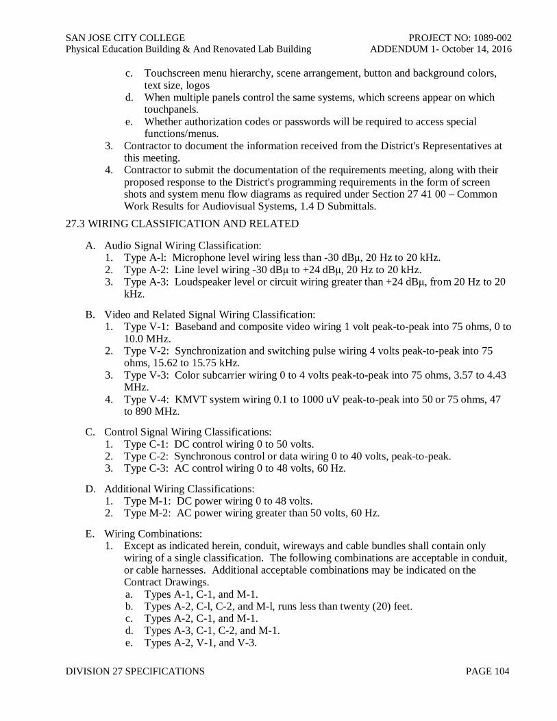
SAN JOSE CITY COLLEGE PROJECT NO: 1089-002Physical Education Building & And Renovated Lab Building ADDENDUM 1- October 14, 2016
DIVISION 27 SPECIFICATIONS PAGE 104
c. Touchscreen menu hierarchy, scene arrangement, button and background colors,text size, logos
d. When multiple panels control the same systems, which screens appear on whichtouchpanels.
e. Whether authorization codes or passwords will be required to access specialfunctions/menus.
3. Contractor to document the information received from the District's Representatives atthis meeting.
4. Contractor to submit the documentation of the requirements meeting, along with theirproposed response to the District's programming requirements in the form of screenshots and system menu flow diagrams as required under Section 27 41 00 – CommonWork Results for Audiovisual Systems, 1.4 D Submittals.
27.3 WIRING CLASSIFICATION AND RELATED
A. Audio Signal Wiring Classification:1. Type A-l: Microphone level wiring less than -30 dBμ, 20 Hz to 20 kHz.2. Type A-2: Line level wiring -30 dBμ to +24 dBμ, 20 Hz to 20 kHz.3. Type A-3: Loudspeaker level or circuit wiring greater than +24 dBμ, from 20 Hz to 20
kHz.
B. Video and Related Signal Wiring Classification:1. Type V-1: Baseband and composite video wiring 1 volt peak-to-peak into 75 ohms, 0 to
10.0 MHz.2. Type V-2: Synchronization and switching pulse wiring 4 volts peak-to-peak into 75
ohms, 15.62 to 15.75 kHz.3. Type V-3: Color subcarrier wiring 0 to 4 volts peak-to-peak into 75 ohms, 3.57 to 4.43
MHz.4. Type V-4: KMVT system wiring 0.1 to 1000 uV peak-to-peak into 50 or 75 ohms, 47
to 890 MHz.
C. Control Signal Wiring Classifications:1. Type C-1: DC control wiring 0 to 50 volts.2. Type C-2: Synchronous control or data wiring 0 to 40 volts, peak-to-peak.3. Type C-3: AC control wiring 0 to 48 volts, 60 Hz.
D. Additional Wiring Classifications:1. Type M-1: DC power wiring 0 to 48 volts.2. Type M-2: AC power wiring greater than 50 volts, 60 Hz.
E. Wiring Combinations:1. Except as indicated herein, conduit, wireways and cable bundles shall contain only
wiring of a single classification. The following combinations are acceptable in conduit,or cable harnesses. Additional acceptable combinations may be indicated on theContract Drawings.a. Types A-1, C-1, and M-1.b. Types A-2, C-l, C-2, and M-l, runs less than twenty (20) feet.c. Types A-2, C-1, and M-1.d. Types A-3, C-1, C-2, and M-1.e. Types A-2, V-1, and V-3.

SAN JOSE CITY COLLEGE PROJECT NO: 1089-002Physical Education Building & And Renovated Lab Building ADDENDUM 1- October 14, 2016
DIVISION 27 SPECIFICATIONS PAGE 105
f. Types V-1, V-2, V-3, and C-1.g. Types M-2 and C-3.
27.4 WIRE AND CABLE INSTALLATION
A. Provide permanent identification of run destination at all raceway terminations.
B. All wire and cable shall be continuous and splice-free for the entire length of run betweendesignated connections or terminations.
C. All shielded cables shall be insulated. Do not permit shields to contact conduit, raceway,boxes, panels or equipment enclosures.
D. Within buildings, make splices only in designated terminal cabinets and/or on designatedequipment backboards. Outside buildings, make splices only in designated manholes and/orhandholes. Protect splices outside of buildings with splicing kits equivalent to ScotchcastRe-enterable. Make splices only with connectors or terminal devices specified herein.Document all splices on Record Drawings.
E. Verify that all raceway has been de-burred and properly joined, coupled, and terminatedprior to installation of cables. Verify that all raceway is clear of foreign matter andsubstances prior to installation of wire or cable.
F. Inspect all conduit bends to verify proper radius. Comply with Code for minimumpermissible radius and maximum permissible deformation.
G. Apply a chemically inert lubricant to all wire and cable prior to pulling in conduit. Do notsubject wire and cable to tension greater than that recommended by the manufacturer. Usemulti-spool rollers where cable is pulled in place around bends. Do not pull reverse bends.
H. Provide a box loop for all wire and cable routed through junction boxes or distributionpanels. Provide tool formed thermal expansion loops at cable at manholes, handholes and atboth sides of all fixed mounted equipment. Cable loops and bends shall not be bent at aradius greater than that recommended by the manufacturer.
I. Secure all wire and cable run vertically for continuous distances greater than thirty (30) feet.Secure robust non-coaxial cables with screw-flange nylon cable ties or similar devicesappropriate to weight of cable. For all other cables, provide symmetrical conformingnonmetallic bushings or woven cable grips appropriate to weight of cable.
27.5 SIGNAL POLARITY CONVENTION
A. Maintain consistent absolute signal polarity at all connectors, patch points and connectionpoints accessible in the system. Comply with AES26-2001.Where applicable, a positivepolarity electrical signal shall yield positive acoustic pressure from the loudspeakers.
B. Audio signal connector convention: Comply with AES 14-1992 (r1998)Signal Connector WireSignal Phase Pin 2 Red or WhiteSignal Anti-Phase Pin 3 BlackSignal Ground Pin 1 Drain Wire
C. Video and RF/KMVT Connector Convention:

SAN JOSE CITY COLLEGE PROJECT NO: 1089-002Physical Education Building & And Renovated Lab Building ADDENDUM 1- October 14, 2016
DIVISION 27 SPECIFICATIONS PAGE 106
Signal Connector WireSignal Phase Center Pin Center conductorSignal Anti-Phase Shell ShieldSignal Ground Shell Shield
27.6 WIRING PRACTICE
A. Land all non-coaxial field wiring entering each equipment rack at specified terminal devicesprior to connection to any equipment or devices within racks. At Contractor's option, suchterminals may be located in the equipment racks or in the terminal cabinets provided.Coordinate such selection with Project construction sequence and test procedures specifiedherein.
B. Identify all wire and cable clearly with permanent labels wrapped about the fullcircumference within one (1) inch of each connection. Indicate the number designated onthe associated field or shop drawing or run sheet, as applies. Assign wire or cabledesignations consistently throughout a given system. Each wire or cable shall carry thesame labeled designation over its entire run, regardless of intermediate terminations.Conform with the requirements of Section 27 41 00.
C. Apply all crimp connectors only with manufacturer's recommended ratchet type tooling andcorrect crimp dies for connector and wire size. Plier type crimp tooling shall not beacceptable.
D. Coordinate insulation displacement (quick connect) terminal devices with wire size andtype. Comply with manufacturer's recommendations. Make connections with automaticimpact type tooling set to recommended force.
E. Make all connections to screw-type barrier blocks with insulated crimp-type spade lugs.Lugs are not required at captive compression terminal type blocks. Provide permanentdesignation strips designed for use with the terminal blocks provided. Make neat,intelligible markings with indelible markers equivalent to "Sharpie".
F. Tin terminated shield drain wires and insulate with heat shrinkable tubing.
G. Use only rosin core 60/40 tin/lead solder for all solder connections.
H. Dress, lace or harness all wire and cable to prevent mechanical stress on electricalconnections. No wire or cable shall be supported by a connection point. Provide serviceloops where harnesses of different classes cross, or where hinged panels are to beinterconnected.
I. Termination and build-out resistors and related circuit correction components shall bevisible. Do not install in connector shells or internally modify equipment. Show locationson Record Drawings.
J. Correct any and all of the following unacceptable wiring conditions:1. Deformed, brittle or cracked insulation.2. Insulation shrunken or stripped further than 1/8" away from the actual point of
connection within a connector, or on a punch block.3. Cold solder joints.
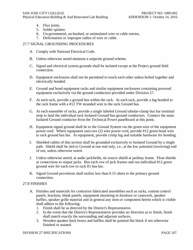
SAN JOSE CITY COLLEGE PROJECT NO: 1089-002Physical Education Building & And Renovated Lab Building ADDENDUM 1- October 14, 2016
DIVISION 27 SPECIFICATIONS PAGE 107
4. Flux joints.5. Solder splatter.6. Un-grommeted, un-bushed, or uninsulated wire or cable entries.7. Deformation or improper radius of wire or cable.
27.7 SIGNAL GROUNDING PROCEDURES
A. Comply with National Electrical Code.
B. Unless otherwise noted maintain a unipoint ground scheme.
C. Signal and electrical system grounds shall be isolated except at the Project ground fieldconnection.
D. Equipment enclosures shall not be permitted to touch each other unless bolted together andelectrically bonded.
E. Ground and bond equipment racks and similar equipment enclosures containing poweredequipment exclusively via the ground conductors provided under Division 27.
F. At each rack, provide a ground bus within the rack. At each rack, provide a lug bonded tothe rack frame with a #12 TW stranded wire to the rack Ground bus.
G. At each ensemble of racks, provide a single labeled Ground tubular-clamp bus bar terminalstrip to land the individual rack Isolated Ground bus ground conductors. Connect the mainIsolated Ground conductor from the Technical Power panelboard at this point.
H. Equipment signal ground shall be to the Ground System via the green wire of the equipmentpower cord. Where equipment uses two (2) wire power cord, provide #12 green bond wireto rack ground bus bar. At equipment, provide crimp lug and suitable hardware for bonding.
I. Shielded cables of this section shall be grounded exclusively to Isolated Ground by a singlepath. Shield shall be tied to Ground at one end only, i.e., at the low potential (receiving) endof run, unless otherwise noted.
J. Unless otherwise noted, at audio jackfields, tie source shield at jackbay frame. Float shieldsat connections to output jacks. Bus each row of jack frames and run individual #12 greenground wire for each row to rack IG bus bar.
K. Signal Ground provisions shall realize less than 0.15 ohms to the primary groundconnection.
27.8 FINISHES
A. Finishes and materials for contractor fabricated assemblies such as racks, custom controlpanels, brackets, blank panels, equipment mounting in furniture or casework, speakerbaffles, speaker grille material and in general any item or component herein which is visibleshall adhere to the following:1. Finish shall be as directed by the District's Representative.2. In the event that the District's Representative provides no direction as to finish, finish
shall match exactly the surrounding and adjacent surfaces.3. Wooden speaker back boxes and baffles shall be painted flat black if not otherwise
finished or stained.
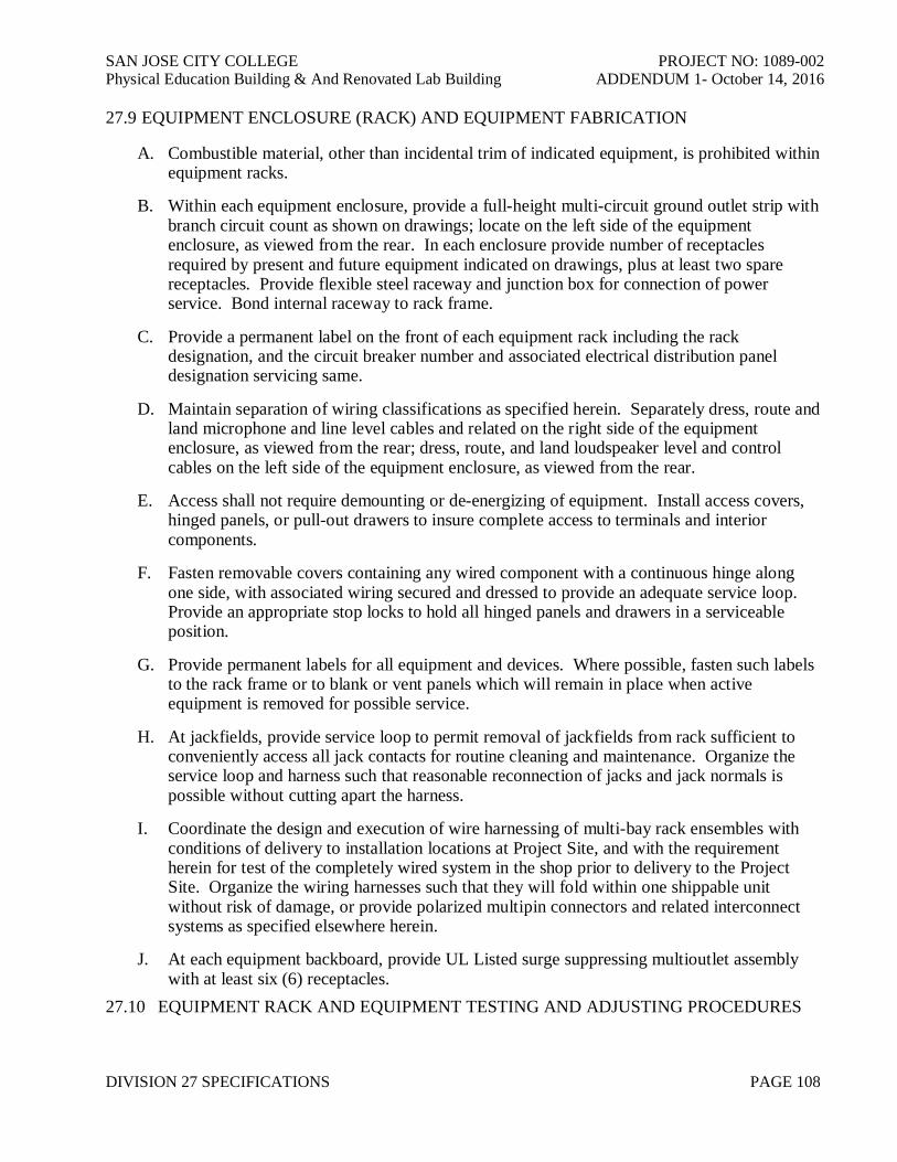
SAN JOSE CITY COLLEGE PROJECT NO: 1089-002Physical Education Building & And Renovated Lab Building ADDENDUM 1- October 14, 2016
DIVISION 27 SPECIFICATIONS PAGE 108
27.9 EQUIPMENT ENCLOSURE (RACK) AND EQUIPMENT FABRICATION
A. Combustible material, other than incidental trim of indicated equipment, is prohibited withinequipment racks.
B. Within each equipment enclosure, provide a full-height multi-circuit ground outlet strip withbranch circuit count as shown on drawings; locate on the left side of the equipmentenclosure, as viewed from the rear. In each enclosure provide number of receptaclesrequired by present and future equipment indicated on drawings, plus at least two sparereceptacles. Provide flexible steel raceway and junction box for connection of powerservice. Bond internal raceway to rack frame.
C. Provide a permanent label on the front of each equipment rack including the rackdesignation, and the circuit breaker number and associated electrical distribution paneldesignation servicing same.
D. Maintain separation of wiring classifications as specified herein. Separately dress, route andland microphone and line level cables and related on the right side of the equipmentenclosure, as viewed from the rear; dress, route, and land loudspeaker level and controlcables on the left side of the equipment enclosure, as viewed from the rear.
E. Access shall not require demounting or de-energizing of equipment. Install access covers,hinged panels, or pull-out drawers to insure complete access to terminals and interiorcomponents.
F. Fasten removable covers containing any wired component with a continuous hinge alongone side, with associated wiring secured and dressed to provide an adequate service loop.Provide an appropriate stop locks to hold all hinged panels and drawers in a serviceableposition.
G. Provide permanent labels for all equipment and devices. Where possible, fasten such labelsto the rack frame or to blank or vent panels which will remain in place when activeequipment is removed for possible service.
H. At jackfields, provide service loop to permit removal of jackfields from rack sufficient toconveniently access all jack contacts for routine cleaning and maintenance. Organize theservice loop and harness such that reasonable reconnection of jacks and jack normals ispossible without cutting apart the harness.
I. Coordinate the design and execution of wire harnessing of multi-bay rack ensembles withconditions of delivery to installation locations at Project Site, and with the requirementherein for test of the completely wired system in the shop prior to delivery to the ProjectSite. Organize the wiring harnesses such that they will fold within one shippable unitwithout risk of damage, or provide polarized multipin connectors and related interconnectsystems as specified elsewhere herein.
J. At each equipment backboard, provide UL Listed surge suppressing multioutlet assemblywith at least six (6) receptacles.
27.10 EQUIPMENT RACK AND EQUIPMENT TESTING AND ADJUSTING PROCEDURES
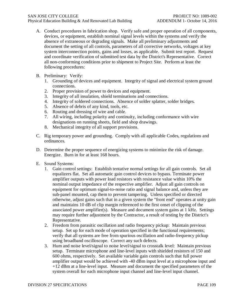
SAN JOSE CITY COLLEGE PROJECT NO: 1089-002Physical Education Building & And Renovated Lab Building ADDENDUM 1- October 14, 2016
DIVISION 27 SPECIFICATIONS PAGE 109
A. Conduct procedures in fabrication shop. Verify safe and proper operation of all components,devices, or equipment, establish nominal signal levels within the systems and verify theabsence of extraneous or degrading signals. Make all preliminary adjustments anddocument the setting of all controls, parameters of all corrective networks, voltages at keysystem interconnection points, gains and losses, as applicable. Submit test report. Requestand coordinate verification of submitted test data by the District's Representative. Correctall non-conforming conditions prior to shipment to Project Site. Perform at least thefollowing procedures:
B. Preliminary: Verify:1. Grounding of devices and equipment. Integrity of signal and electrical system ground
connections.2. Proper provision of power to devices and equipment.3. Integrity of all insulation, shield terminations and connections.4. Integrity of soldered connections. Absence of solder splatter, solder bridges.5. Absence of debris of any kind, tools, etc.6. Routing and dressing of wire and cable.7. All wiring, including polarity and continuity, including conformance with wire
designations on running sheets, field and shop drawings.8. Mechanical integrity of all support provisions.
C. Rig temporary power and grounding. Comply with all applicable Codes, regulations andordinances.
D. Determine the proper sequence of energizing systems to minimize the risk of damage.Energize. Burn in for at least 168 hours.
E. Sound Systems:1. Gain control settings: Establish tentative normal settings for all gain controls. Set all
equalizers flat. Set all automatic gain control devices to bypass. Terminate poweramplifier outputs with power load resistors with resistance value within 10% thenominal output impedance of the respective amplifier. Adjust all gain controls onequipment for optimum signal-to-noise ratio and signal balance and, unless they aresub-panel mounted, cap them to prevent tampering. Unless specified or directedotherwise, adjust gains such that in a given system the "front end" operates at unity gainand maintains 10 dB of clip margin referenced to the first onset of clipping of theassociated power amplifier(s). Measure and document system gains at 1 kHz. Settingsmay require further adjustment by the Contractor, a result of testing by the District'sRepresentative.
2. Freedom from parasitic oscillation and radio frequency pickup: Maintain previoussetup. Set up for each mode of operation specified in the functional requirements;verify that all systems are free from spurious oscillation and radio-frequency pickupusing broadband oscilloscope. Correct any such defects.
3. Hum and noise level/signal to noise level/signal to crosstalk level: Maintain previoussetup. Terminate microphone and line-level inputs with shielded resistors of 150 and600 ohms, respectively. Set available variable gain controls such that full poweramplifier output would be achieved with -40 dBm input level at a microphone input and+12 dBm at a line-level input. Measure and document the specified parameters of thesystem overall for each microphone input channel and line-level input channel.
SAN JOSE CITY COLLEGE PROJECT NO: 1089-002Physical Education Building & And Renovated Lab Building ADDENDUM 1- October 14, 2016
DIVISION 27 SPECIFICATIONS PAGE 110
Compare with nominal signal level.4. Total Harmonic Distortion: Maintain previous setup. Measure at reference operating
level at least at 63 Hz, 125 Hz, 1 kHz, 10 kHz.
F. Baseband Video Systems:1. Picture Monitors:
a. Apply crosshatch. Verify linearity.b. Apply red field. Adjust purity.c. Apply SMPTE bars and PLUGE. Adjust to standards.
2. Video Path Test: Use manufacturer's procedures. Use full field or line signals.
G. Data/Graphics Systems:1. Projector:
a. Apply crosshatch. Converge at design distance. Verify linearity.b. Apply red, green and blue field. Adjust purity.
2. Wideband Component Analog Video Path Test: Use manufacturer's procedures.
H. Control System:1. Demonstrate complete operation.
27.11 PROJECTION SCREEN INSTALLATION
A. Inspection1. General: Examine surfaces and rough framing to determine suitability to install screen
and mount. Do not start work until unsatisfactory conditions are corrected.
B. Installation1. Install screen and projector mount horizontal and plumb for proper operation per
manufacturer's recommendations. Securely anchor to supporting structure to withstandall loading conditions and strain of service.
C. Adjustment1. Adjust units as required for smooth operation and alignment as required.2. Just prior to final acceptance of project, clean the screen surface according to the
manufacturer's instructions.3. Protect completed work from damage until acceptance by the District's Representative.
27.12 LOUDSPEAKER ASSEMBLY INSTALLATION
A. Loudspeakers:1. Verify proper installation of loudspeaker enclosures and related support.2. Verify that no loudspeaker assembly is subjected to stresses or loading effects in any
way contributing to possible extraordinary failure.27.13 VIDEO PROJECTOR ASSEMBLY INSTALLATION
A. Design, engineer and provide complete, all means of support, suspension, attachment,fastening, bracing, and restraint (hereinafter "support") of such equipment. Provideengineering of such support by parties licensed to perform work of this type in the Projectjurisdiction. Submit in timely manner.
B. Comply with applicable Code and the requirements of the Authorities having jurisdiction.
SAN JOSE CITY COLLEGE PROJECT NO: 1089-002Physical Education Building & And Renovated Lab Building ADDENDUM 1- October 14, 2016
DIVISION 27 SPECIFICATIONS PAGE 111
C. Provide safety factor greater than six (6) or as required by Code, whichever is greater.
D. Do not apply any load to building structure without first obtaining written approval of theDistrict’s Representative. Obtain per Project procedures.
E. During Acceptance Testing, adjust orientation of Video Projector as directed to achieveoptimum picture. Provide workers and ladders as required. Perform such adjustment withno claim for additional cost or time.
27.14 SYSTEMS PERFORMANCE TESTING AND ADJUSTING PROCEDURES
A. Upon completion of the installation of all equipment in an area, perform the following testsand record results. Verify safe and proper operation of all components, devices, orequipment, establish nominal signal levels within the systems and verify the absence ofextraneous or degrading signals. Make all preliminary adjustments and document the settingof all controls, parameters of all corrective networks, voltages at key system interconnectionpoints, gains and losses, as applicable. Submit test report. Correct all non-conformingconditions prior to requesting Acceptance Review and Testing. Perform at least thefollowing procedures:1. Mechanical: Verify:
a. Integrity of all support provisions.b. Absence of debris of any kind, tools, etc.
2. Power and Isolated Ground: Verify:a. Isolation of Isolated Ground system from raceway and related ground.b. Grounding of devices and equipment. Integrity of signal and technical power
system ground connections.c. Proper provision of power to devices and equipment.
3. Signal Wiring: Verify:a. Integrity of all insulation, shield terminations and connections.b. Integrity of soldered connections. Absence of solder splatter, solder bridges.c. Routing and dressing of wire and cable.d. Continuity, including conformance with wire designations on running sheets, field
and shop drawings.e. Absence of ground faults.f. Polarity.
4. Use the proper sequence of energizing systems to minimize the risk of damage.Energize.
5. Sound Systems, Electronic Tests; confirm:a. Gain at 1 kHz.b. Maximum output.c. Input clipping level.d. Frequency response.e. Total harmonic distortion.f. Signal to noise ration.g. Signal to crosstalk ratio.
6. Electro/Acoustic Tests:a. Uniformity of coverage.b. Electronic and acoustic frequency response/one-third octave equalization. Measure
at ear level. Comply with applicable portions of ANSI (SMPTE) PH22.202M-

SAN JOSE CITY COLLEGE PROJECT NO: 1089-002Physical Education Building & And Renovated Lab Building ADDENDUM 1- October 14, 2016
DIVISION 27 SPECIFICATIONS PAGE 112
1984, "B chain electro-acoustic response - control rooms and indoor theaters."Adjust to "curve X of B chain characteristic". District's Representative will directfinal adjustment.
c. Maximum continuous sound pressure level (in the reverberant field). Drivesystems with broadband pink noise. Sustain for at least five (5) minutes with nosystem damage. Measure for "A" and "C" weightings at ear level on loudspeakeraxis. Turn off noise.
d. Acoustic signal-to-noise ratio referenced to the specified maximum continuoussound pressure level in the reverberant field. Measure for "A" and "C" weightingsat ear level on loudspeaker axis with mechanical systems operating. Presentcomparison with previous measurement.
7. Video Systems:a. Picture Monitors:
i. Apply crosshatch. Verify linearity.ii. Apply red field. Adjust purity.iii. Apply SMPTE bars and PLUGE. Adjust to standards.
b. Video Path Test: Use NTC Report No. 7 procedures. Use full field or line signals.i. Insertion Gain.ii. Gain/Frequency Distortion.
8. Control System: Demonstrate complete operation.27.15 LABELING
A. Conform with the requirements of Section 27 41 07 – Identification for AudiovisualSystems.
B. Provide permanent "wedge" type labels on all controls, as applies, to indicate correct settingsafter systems performance testing and adjustment procedures have been successfullycompleted.
END OF SECTION