ADDENDUM #01 Monday, January 28, 2019 ... - Dodge County
23
«Projectname» PROJECT «ProjectNo» Page - 1 of 2 Addendum # 1 Dodge County Sheriff's Department - HVAC Upgrades Angus Young Associates Project No. 66200 ADDENDUM #01 Monday, January 28, 2019 This addendum is issued to modify, explain or correct the original Drawings, Specifications, and Addenda marked Project Description, Dodge County Sheriff's Department - HVAC Upgrades dated and hereby made part of the contract documents. This addendum consists of (02) page(s) of text, (00) Specification(s) and (00) drawings(s). Please attach this Addendum to the Drawings and Project Manual in your possession. Bid Date: All bids must be received on 1/31/2019 by 10:30 am CST/CDT. If you are delivering your response in person, you must deliver your bid to the Dodge County Administration Building County Clerk Room 167 located on 127 East Oak Street Juneau, WI 53039. Bids shall be time-stamped no later than bid closing on the opening date. Attn: Mr. Russ Freber, Physical Facilities Director, Dodge County, [email protected] General Notes: A. All contractors are required to submit non-collusion affidavit, bidders proof of response, information attachment, bid bond, power of attorney and certain documents with their bids, as outlined in the specifications. B. Refer to the attached document with attendees from the pre-bid walk thru. Contractors wishing an additional site visit must contract Mr. Russ Freber, Physical Facilities Director at 608.386.3665 or 920.210.3090. Failure to submit all forms, completed in their entirety, shall be grounds for rejection of the bid. C. Refer to the attached documents from the pre-bid walk thru attendance. D. Each contractor when applicable is responsible for Permit Fees. E. For all work on site coordinate with Diggers Hotline. Call toll free at 1-800-242-8511, Fax a locate at 1-800-338-3860, or online at www.DiggersHotline.com. Wisconsin Statute 182.0175 (1974) requires a minimum of three (3) working days notice prior to digging. F. All documents can be found on Dodge County Web Site Business RFP Post. G. The AIA contract is subject to change. H. All reference to Juneau Sheriff’s Department shall be replaced with Dodge County Sheriff’s Department throughout the contract. I. The contractor shall extend the existing concrete pads associated with AHU-1 and ACCU-1. Pads shall extend 6” on all sides beyond the equipment. Refer to cutsheets for more information. Specifications: A. Section 23 00 00 Heating, Ventilation & Air Conditioning: 1. Naming of specification section 2.01 – Air Cooled Condensing Unit shall be replaced
-
Upload
khangminh22 -
Category
Documents
-
view
0 -
download
0
Transcript of ADDENDUM #01 Monday, January 28, 2019 ... - Dodge County

«Projectname» PROJECT «ProjectNo» Page - 1 of 2 Addendum # 1
Dodge County Sheriff's Department - HVAC Upgrades Angus Young Associates Project No. 66200 ADDENDUM #01
Monday, January 28, 2019 This addendum is issued to modify, explain or correct the original Drawings, Specifications, and Addenda marked Project Description, Dodge County Sheriff's Department - HVAC Upgrades dated and hereby made part of the contract documents. This addendum consists of (02) page(s) of text, (00) Specification(s) and (00) drawings(s). Please attach this Addendum to the Drawings and Project Manual in your possession.
Bid Date:
All bids must be received on 1/31/2019 by 10:30 am CST/CDT. If you are delivering your response in person, you must deliver your bid to the Dodge County Administration Building County Clerk Room 167 located on 127 East Oak Street Juneau, WI 53039. Bids shall be time-stamped no later than bid closing on the opening date.
Attn: Mr. Russ Freber, Physical Facilities Director, Dodge County, [email protected]
General Notes:
A. All contractors are required to submit non-collusion affidavit, bidders proof of response, information attachment, bid bond, power of attorney and certain documents with their bids, as outlined in the specifications.
B. Refer to the attached document with attendees from the pre-bid walk thru. Contractors wishing an additional site visit must contract Mr. Russ Freber, Physical Facilities Director at 608.386.3665 or 920.210.3090.
Failure to submit all forms, completed in their entirety, shall be grounds for rejection of the bid.
C. Refer to the attached documents from the pre-bid walk thru attendance.
D. Each contractor when applicable is responsible for Permit Fees.
E. For all work on site coordinate with Diggers Hotline. Call toll free at 1-800-242-8511, Fax a locate at 1-800-338-3860, or online at www.DiggersHotline.com. Wisconsin Statute 182.0175 (1974) requires a minimum of three (3) working days notice prior to digging.
F. All documents can be found on Dodge County Web Site Business RFP Post.
G. The AIA contract is subject to change.
H. All reference to Juneau Sheriff’s Department shall be replaced with Dodge County Sheriff’s Department throughout the contract.
I. The contractor shall extend the existing concrete pads associated with AHU-1 and ACCU-1. Pads shall extend 6” on all sides beyond the equipment. Refer to cutsheets for more information.
Specifications:
A. Section 23 00 00 Heating, Ventilation & Air Conditioning:
1. Naming of specification section 2.01 – Air Cooled Condensing Unit shall be replaced

«Projectname» PROJECT «ProjectNo» Page - 2 of 2 Addendum # 1
with 2.03 Air Cooled Condensing Unit and sequential parts within the specification shall follow continue from 2.03.
2. Section 2.02 – Air Handling Unit and 2.01 – Air Cooled Condensing Unit have been finalized. Omit any performance or material requirements outlined in the contract specifications. Refer to the attached size of the equipment and model number for more information.
3. Section 2.02 shall indicate that the knockdown construction with field erection services is provided by the equipment supplier. The pallet rigging into final location shall be provided by mechanical contractor and coordinated with general contractor. All unit sections will be erected by equipment supplier in field. It is the mechanical contractors’ responsibility to perform final unit assembly of adjoining AHU sections and field build the return plenum off the air handling unit. Field built plenum shall be insulated with 2” ridged insulation per specification 22 07 00. All controls associated with the air handling unit shall be provided by the controls contractor per specification section 23 09 00.
4. Startup for the air-cooled condensing unit (ACCU-1) is included in the equipment suppliers bid.
5. The mechanical contractor shall perform start up on the air handling unit.
6. The mechanical contractor shall provide vibration isolators for the new air handling unit and condensing unit.
Drawings:
A. Sheet M101 Mechanical New and Demolition HVAC Plan and Notes:
1. The existing VFDs that are removed shall become the property of Dodge County. The contractor shall keep all VFDs in working order during removal process.
2. The existing condensing unit and refrigerant piping located to the south of ACCU-1 shall be removed as part of the contract. The refrigerant piping shall be capped at the exterior wall to avoid matching existing brick.
End of Addendum


SUBMITTAL PRIVILEGE AND CONFIDENTIALITY NOTICE: The information contained in this message is proprietary and confidential under
applicable law, and is intended only for the use of the individual or entity named.
Date: 1-17-19
Purchaser: Dodge County Job Name: Sheriff Department HVAC Upgrade
Engineer: Angus Young
Glacier Project #: 17990
WWW.THEGLACIERGROUP.NET
1001 Fourier Drive | Suite 202 | Madison WI 53717
P. 608-830-5210 | F.608-830-5215
The Glacier Group is please to provide the following equipment for Approval:
Equipment will not be released for production until (1) copy of the Approved submittal
is returned.
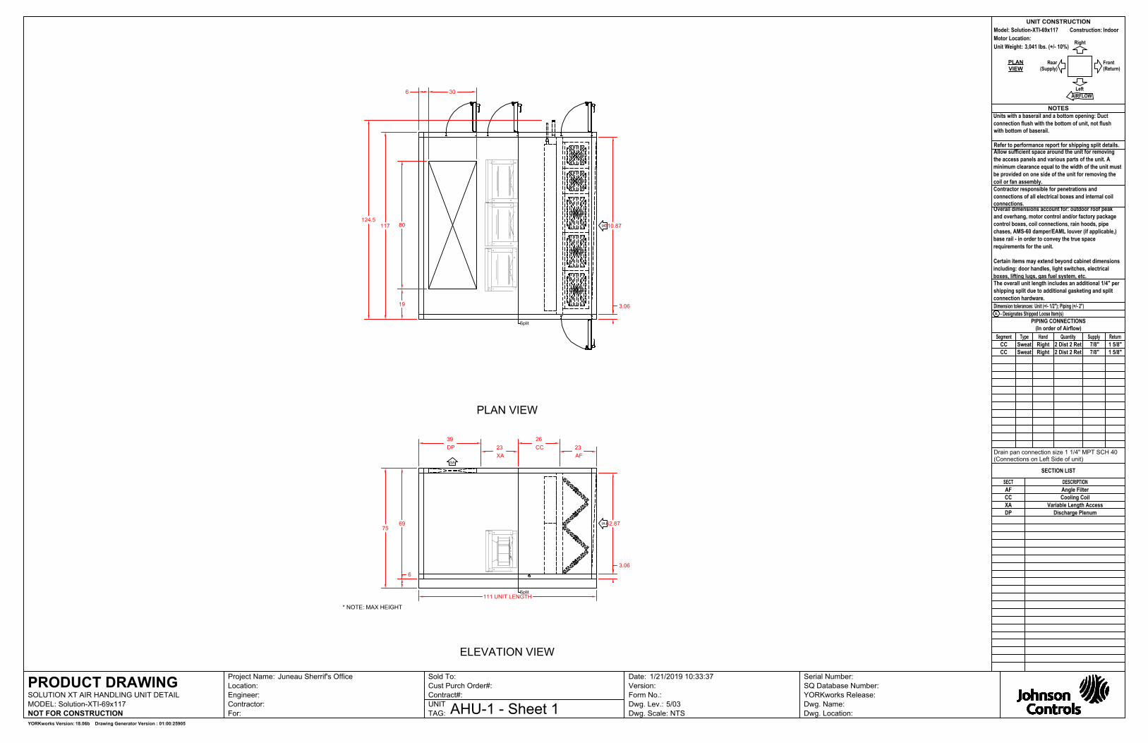
SOLUTION AIR-HANDLING UNIT
(01) YORK Solution indoor air-handling unit complete with:
• 21,000 CFM @ 1.50'' ESP
• Double wall construction
• Angled Filter Section with 2''-MERV 8 pleated filters o Filter gauges o Spare set of filters
• DX Cooling Coil Section with stainless steel drain pan
• (3) ECM Supply Fans
• 6'' Base Rail
• Knockdown construction with field erection services o Pallets rigged into final location by others o Unit Sections erected by Glacier in space o Final unit assembly by others
ITEMS NOT INCLUDED
• Fan motor starters and disconnect switches
• Controls and control valves
• Labor warranty
• Hauling/Rigging of equipment
• Dampers or damper operators
Andy Schiltz
The Glacier Group LLC
608.830.5213 Direct
608.395.4451 Cell
www.theglaciergroup.net
1001 Fourier Drive, Suite 202
Madison WI 53717
Aschiltz
Line

SUBMITTAL PRIVILEGE AND CONFIDENTIALITY NOTICE: The information contained in this message is proprietary and confidential under
applicable law, and is intended only for the use of the individual or entity named.
Date: 1-17-19
Purchaser: Dodge County Job Name: Sheriff Department HVAC Upgrade
Engineer: Angus Young
Glacier Project #: 17990
WWW.THEGLACIERGROUP.NET
1001 Fourier Drive | Suite 202 | Madison WI 53717
P. 608-830-5210 | F.608-830-5215
The Glacier Group is please to provide the following equipment for Approval:
Equipment will not be released for production until (1) copy of the Approved submittal
is returned.
YORK AIR COOLED CONDENSING UNIT
(01) York packaged R-410a air cooled condensing unit completely factory assembled and include the following:
• 50 Tons
• 208-3-60
• (2) Circuits
• Micro-Computer Control Center
• (1) Digital Scroll Compressor, (3) Scroll compressors
• BacNet control card
• 1st year parts warranty
• Factory start-up by Authorized Service Technician
ITEMS NOT INCLUDED
• Hauling or rigging equipment into place / offloading of equipment
• Refrigerant
• Non-Fused Disconnect switch
• Unit vibration isolators
• Sight glass and filter drier
• Thermal expansion valves
Andy Schiltz
The Glacier Group LLC
608.830.5213 Direct
608.395.4451 Cell
www.theglaciergroup.net
1001 Fourier Drive, Suite 202
Madison WI 53717

Date01/04/2019Project NameJuneau Sherrif'sProject NumberClient / Purchaser
Submittal Summary Page Qty Tag # Model # Description1 YD600C00A2GAA2 50 Ton, York Millennium Split System R-410A Air Conditioner, 4-
Pipe, Four Stage Cooling, 208/230-3-60, Copper Tube/AluminumFin Condenser Coil• HACR Circuit Breaker/Disconnect (Sized for 208 Volts)• Smart Equipment Controller with Gateway to BACnet MS/TP(Programmable to Modbus or N2)
WARNING: Cancer and Reproductive Harm - www.P65Warnings.ca.gov
Equipment start-up and commissioning by a factory trained technician is recommended.Contact your supplying distributor or sales representative for additional information & guidance.
Unitary Sales Tool v1.5.9.0 Information is subject to change without notice. Check local codes. Printed 01/09/2019

Cooling PerformanceTotal gross capacity 603.0 MBHSensible gross capacity .0 MBHAmbient DB temp. 95.0 °FPower input (w/o blower) 50.52 kWSuction pressure 134.8 psigSaturated suction temp. 46 °F
RefrigerantRefrigerant type R-410A
Electrical Data Power supply 208-3-60Unit min circuit ampacity 227.6 AmpsUnit max over-current protection 250 Amps
Dimensions & WeightHgt 58 in. Len 129 in. Wth 89 in.Weight with factory installed options 2345 lbs.
ClearancesRight 30 in. Front 36 in. Back 24 in.Top 120 in. Bottom 0 in. Left 30 in.Note: Please refer to the tech guide for listed maximum static pressures
50 Ton• York Millennium units are Manufactured at an ISO 9001 Registered Facilityand each Rooftop is Completely Computer-run Tested Prior to Shipment.
Unit Features• Four Stage Cooling• Unit Cabinet Constructed of Powder Painted Steel, Certified At 750 HoursSalt Spray Test (ASTM B-117 Standards)• Full Perimeter Base rails with Built in Rigging Capabilities• Dual Circuit 4 Stage Cooling with Scroll Compressors and Lead Digital Scroll• Solid Core Liquid Line Filter Driers• Copper Tube/Aluminum Fin Condenser Coil• Sweat Connection Fittings• Single Point Power Connection• Condenser Coil Guards Standard• Short Circuit Current: 5kA RMS SymmetricalStandard Unit Controller: Smart Equipment Control Board• An Integrated Low-Ambient Control, Anti-short Cycle Protection, Lead-Lag,Fan on and Fan off Delays, Low Voltage Protection, On-board Diagnostic andFault Code Display• Safety Monitoring - Monitors the High and Low-Pressure Switches. The UnitControl Board will Alarm on Compressor Lockouts and Repeated Limit SwitchTripsBAS Controller• Smart Equipment Controller with Gateway to BACnet MS/TP (Programmableto Modbus or N2)
Warranty• One (1) Year Limited Warranty on the Complete Unit• One (1) Year Warranty - Compressors
Unitary Sales Tool v1.5.9.0 Information is subject to change without notice. Check local codes. Printed 01/09/2019
Millennium OD Split SystemSplit-System Outdoor R-410A AC
Page: 3
Project Name: Juneau Sherrif's Unit Model #: YD600C00A2GAA2Quantity: 1 System: YD600C00A2GAA2

Factory Installed Options
YD600C00A2GAA2
Equipment Options Option(s) Selected|
Product Category: Y York Millennium Split System R-410A Air Conditioner Product Identifier: D 4-Pipe Nominal Cooling Capacity: 600 50 Ton Heat Type and Nominal Heat Capacity: C00 Airflow: A Voltage: 2 208/230-3-60
Installation Options: G HACR Circuit Breaker/Disconnect (Sized for 208 Volts)
Additional Options: AA
Copper Tube/Aluminum Fin Condenser Coil Smart Equipment Controller with Gateway to BACnetMS/TP (Programmable to Modbus or N2)
Product Generation: 2
Field Installed Accessories
Unitary Sales Tool v1.5.9.0 Information is subject to change without notice. Check local codes. Printed 01/09/2019
Millennium OD Split SystemSplit-System Outdoor R-410A AC
Page: 4
Project Name: Juneau Sherrif's Unit Model #: YD600C00A2GAA2Quantity: 1 System: YD600C00A2GAA2
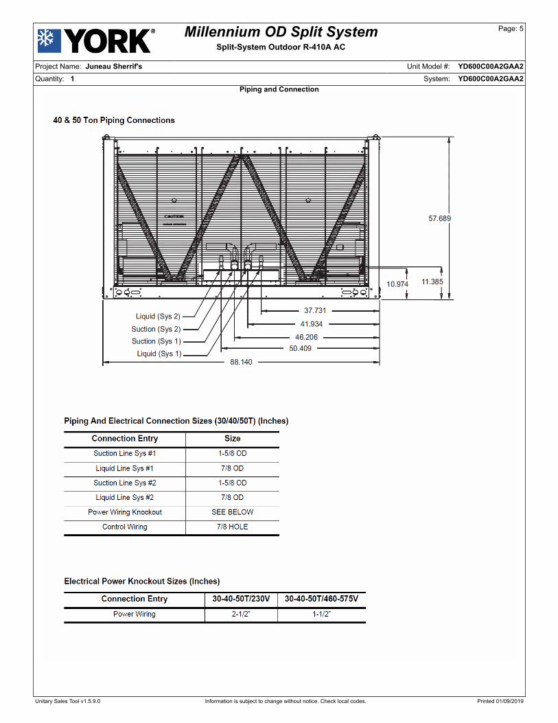
Piping and Connection
Unitary Sales Tool v1.5.9.0 Information is subject to change without notice. Check local codes. Printed 01/09/2019
Millennium OD Split SystemSplit-System Outdoor R-410A AC
Page: 5
Project Name: Juneau Sherrif's Unit Model #: YD600C00A2GAA2Quantity: 1 System: YD600C00A2GAA2
ASchiltz
Rectangle
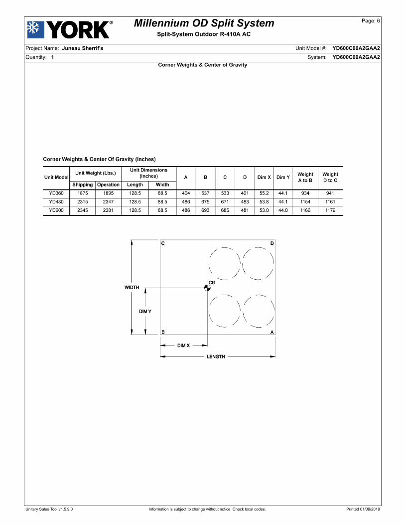
Corner Weights & Center of Gravity
Unitary Sales Tool v1.5.9.0 Information is subject to change without notice. Check local codes. Printed 01/09/2019
Millennium OD Split SystemSplit-System Outdoor R-410A AC
Page: 6
Project Name: Juneau Sherrif's Unit Model #: YD600C00A2GAA2Quantity: 1 System: YD600C00A2GAA2
ASchiltz
Line

Unit Dimensions
Unitary Sales Tool v1.5.9.0 Information is subject to change without notice. Check local codes. Printed 01/09/2019
Millennium OD Split SystemSplit-System Outdoor R-410A AC
Page: 7
Project Name: Juneau Sherrif's Unit Model #: YD600C00A2GAA2Quantity: 1 System: YD600C00A2GAA2
ASchiltz
Line

Sound Performance
Unitary Sales Tool v1.5.9.0 Information is subject to change without notice. Check local codes. Printed 01/09/2019
Millennium OD Split SystemSplit-System Outdoor R-410A AC
Page: 8
Project Name: Juneau Sherrif's Unit Model #: YD600C00A2GAA2Quantity: 1 System: YD600C00A2GAA2
ASchiltz
Line

Wiring Diagram
Unitary Sales Tool v1.5.9.0 Information is subject to change without notice. Check local codes. Printed 01/09/2019
Millennium OD Split SystemSplit-System Outdoor R-410A AC
Page: 9
Project Name: Juneau Sherrif's Unit Model #: YD600C00A2GAA2Quantity: 1 System: YD600C00A2GAA2
247077-UAD-J-0116
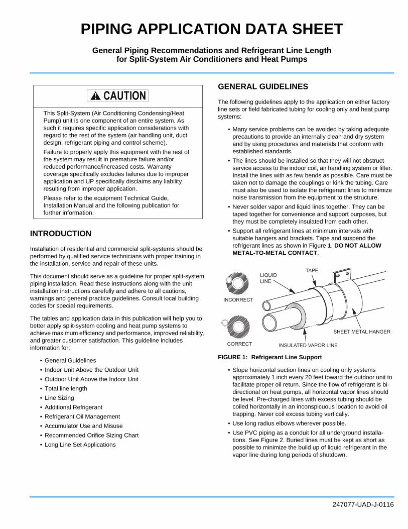
PIPING APPLICATION DATA SHEET
INTRODUCTION
Installation of residential and commercial split-systems should be
performed by qualified service technicians with proper training in
the installation, service and repair of these units.
This document should serve as a guideline for proper split-system
piping installation. Read these instructions along with the unit
installation instructions carefully and adhere to all cautions,
warnings and general practice guidelines. Consult local building
codes for special requirements.
The tables and application data in this publication will help you to
better apply split-system cooling and heat pump systems to
achieve maximum efficiency and performance, improved reliability,
and greater customer satisfaction. This guideline includes
information for:
• General Guidelines
• Indoor Unit Above the Outdoor Unit
• Outdoor Unit Above the Indoor Unit
• Total line length
• Line Sizing
• Additional Refrigerant
• Refrigerant Oil Management
• Accumulator Use and Misuse
• Recommended Orifice Sizing Chart
• Long Line Set Applications
GENERAL GUIDELINES
The following guidelines apply to the application on either factory
line sets or field fabricated tubing for cooling only and heat pump
systems:
• Many service problems can be avoided by taking adequate
precautions to provide an internally clean and dry system
and by using procedures and materials that conform with
established standards.
• The lines should be installed so that they will not obstruct
service access to the indoor coil, air handling system or filter.
Install the lines with as few bends as possible. Care must be
taken not to damage the couplings or kink the tubing. Care
must also be used to isolate the refrigerant lines to minimize
noise transmission from the equipment to the structure.
• Never solder vapor and liquid lines together. They can be
taped together for convenience and support purposes, but
they must be completely insulated from each other.
• Support all refrigerant lines at minimum intervals with
suitable hangers and brackets. Tape and suspend the
refrigerant lines as shown in Figure 1. DO NOT ALLOW
METAL-TO-METAL CONTACT.
FIGURE 1: Refrigerant Line Support
• Slope horizontal suction lines on cooling only systems
approximately 1 inch every 20 feet toward the outdoor unit to
facilitate proper oil return. Since the flow of refrigerant is bi-
directional on heat pumps, all horizontal vapor lines should
be level. Pre-charged lines with excess tubing should be
coiled horizontally in an inconspicuous location to avoid oil
trapping. Never coil excess tubing vertically.
• Use long radius elbows wherever possible.
• Use PVC piping as a conduit for all underground installa-
tions. See Figure 2. Buried lines must be kept as short as
possible to minimize the build up of liquid refrigerant in the
vapor line during long periods of shutdown.
This Split-System (Air Conditioning Condensing/Heat
Pump) unit is one component of an entire system. As
such it requires specific application considerations with
regard to the rest of the system (air handling unit, duct
design, refrigerant piping and control scheme).
Failure to properly apply this equipment with the rest of
the system may result in premature failure and/or
reduced performance/increased costs. Warranty
coverage specifically excludes failures due to improper
application and UP specifically disclaims any liability
resulting from improper application.
Please refer to the equipment Technical Guide,
Installation Manual and the following publication for
further information.
LIQUIDLINE
TAPE
INCORRECT
CORRECT INSULATED VAPOR LINE
SHEET METAL HANGER
General Piping Recommendations and Refrigerant Line Lengthfor Split-System Air Conditioners and Heat Pumps

247077-UAD-J-0116
2 Johnson Controls Unitary Products
FIGURE 2: Underground Application
• Pack fiberglass insulation and a sealing material such as
permagum around refrigerant lines where they penetrate
a wall to reduce vibration and to retain some flexibility. If
multiple line sets are routed through a common conduit,
then all lines must be insulated.
• Insulate all vapor lines with a minimum of 1/2 inch of foam
rubber. Liquid lines that will be exposed to direct sunlight
or high ambient temperatures such as an attic must also
be insulated.
The following additional guidelines apply to field fabricated
piping:
• Use hard drawn refrigeration type copper tubing where no
appreciable amount of bending around pipes or
obstructions is necessary. If soft copper must be used,
care should be taken to avoid sharp bends which may
cause a restriction.
• Braze all copper to copper joints with Silfos-5 or
equivalent brazing material. DO NOT USE SOFT
SOLDER.
• During brazing operations, flow an inert gas such as
nitrogen through the system to prevent internal scaling
and contamination.
TRAPS
Traps are not required if the piping is properly sized. Traps will
only add pressure drop to the system, further reducing capacity.
INDOOR UNIT ABOVE OUTDOOR UNIT
NOTE: Lift applications where micro-channel condensers are
lower than evaporators check valves should be
employed at the outlet of the condenser to minimize
startup pressure spiking on cooling only systems. This
effects starting of reciprocating compressors with orifice
or TXV.
With this configuration, a common problem with the cooling
cycle (air conditioning or heat pump) is that the amount of liquid
sub-cooling varies as operating conditions change (such as
outdoor ambient). Under some conditions, it is possible that
flashing will actually occur in the liquid riser. As long as only
liquid is present in the liquid riser, the liquid static pressure loss
can be calculated at 1/2 psi per foot of rise. However, as soon
as flashing starts, the rate of pressure loss increases and
continues to increase as the amount of gas increases. For this
reason, the restrictions on elevation differences for this
configuration must be based on the entire range of operating
conditions.
When the indoor unit is above the outdoor unit, the pressure
loss in the liquid line during the cooling cycle will limit the
amount of elevation difference allowed. Since both friction and
static head contribute to pressure loss, it can be stated that the
elevation difference allowed decreases as the total equivalent
line length (horizontal plus vertical) increases.
OUTDOOR UNIT ABOVE INDOOR UNIT
COOLING CYCLE
When the outdoor unit is above the indoor unit, the static
pressure gain in the liquid line vertical drop (1/2 psi per foot)
may overcome the frictional pressure loss resulting in a total
pressure gain. A pressure gain in the liquid line is not
detrimental to the performance of the system.
On cooling only systems where the outdoor unit is located high
above the indoor coil, it may even be possible to reduce the
size of the liquid line. The static gain in the vertical drop will
offset the increased friction loss caused by smaller tubing. In
addition, the reduction in the total system charge due to the
smaller liquid line will enhance the reliability of the system.
With this configuration, gas velocity in the vapor riser must be
kept above 1000 feet per minute for proper oil return and below
3000 feet per minute to avoid noise and vibration problems.
HEATING CYCLE (Heat Pumps Only)
In the heating mode, liquid will travel from the indoor unit up the
liquid riser to the outdoor unit. This will result in a liquid line
pressure drop and a starved outdoor coil. Since heat pumps
have a defrost cycle, coil freeze-up is not a problem. However,
the resulting lower suction pressure will decrease the capacity
and efficiency of the system.
TOTAL LINE LENGTH
The total length of interconnecting tubing is the sum of all
horizontal and vertical runs from the indoor unit to the outdoor
unit. Total measured line lengths are limited to:
• The limiting factor on heat pumps is the storage capacity
of the accumulator. The limiting factor on cooling units is
oil sump capacity in the compressor.
• Total equivalent line lengths must only be used when
calculating pressure drop. Therefore use Table 1 to
calculate equivalent lengths for elbows.
TO INDOOR COILLIQUID LINE
PVCCONDUIT
INSULATEDVAPOR LINE
TO OUTDOOR UNIT
CAP(WATER TIGHT)

247077-UAD-J-0116
Johnson Controls Unitary Products 3
LINE SIZING
Every split-system unit is shipped with a factory-mounted sweat
fitting.
For split systems, interconnecting refrigerant lines should be
sized to match the factory supplied fittings unless the
application dictates different line sizes due to pressure drop,
refrigerant velocity constraints and/or line set lengths.
For cooling systems where the indoor and outdoor sections are
installed at the same elevation, refrigerant line sizes can usually
be matched with the factory supplied fittings. There are
exceptions for total line lengths exceeding 75 feet where
pressure drop limitations are exceeded. Refer to Long Line Set
section.
In some applications, especially where elevation differences
exist between the indoor and outdoor sections, suction and
liquid line sizes can be increased (or decreased) to minimize
pressure loss (or gain) and improve oil return to the
compressor. When sizing refrigerant lines for split-system
cooling units, the following factors must be considered:
1. Suction line pressure loss due to friction.
2. Suction line velocity for oil return.
3. Liquid line pressure loss due to friction.
4. Liquid line pressure loss (or gain) due to static head.
The effect that each of these factors have on a cooling system
depends on the orientation of the indoor and outdoor sections;
e.g., indoor unit above the outdoor unit. Before we discuss the
various orientations, it is important to understand a few things
about suction and liquid lines.
First, lets consider suction lines. Suction pressure loss reduces
system capacity by 1% for R-22 and 0.6% for R-410A per psi.
This can be a serious problem if suction lines are not sized
properly and pressure loss is 8 or 9 psi. Therefore, in order to
minimize capacity loss and maximize efficiency, suction
pressure loss must be minimized. This is achieved by
increasing the size of the suction line. As a good achievable
guideline, suction pressure loss should not be allowed to
exceed 3 psi (5 psi for R-410A).
Another important consideration when sizing suction lines is
refrigerant gas velocity in a suction riser. Velocity of at least
1000 feet per minute is required to carry oil up a suction riser.
Of course, this is only a factor when the outdoor unit is above
the indoor unit and the oil must overcome the pull of gravity to
return to the compressor. Greater refrigerant velocities are
obtained by decreasing the size of the suction line. In
applications where smaller tubing is required for a suction riser
and larger tubing is needed to minimize pressure drop, the riser
must be sized to achieve a velocity of at least 1000 feet per
minute while the horizontal runs can be sized larger to minimize
pressure drop.
NOTE: Must maintain 800 fpm minimum velocity on all
horizontal pipe runs.
Liquid lines must also be sized to minimize pressure change.
The total pressure change in a liquid line is the sum of the loss
due to friction and the loss (or gain) due to static head in the
vertical line. Liquid pressure loss reduces the amount of liquid
sub-cooling at a rate of 1 degree for every 3 psi for R-22 and 5
psi for R-410A. Sufficient sub-cooling must be maintained at the
expansion valve to provide proper operation. If the liquid
pressure drop is high enough to deplete all of the liquid sub-
cooling in the system, liquid will begin to flash reducing the
refrigerant flow through the indoor coil expansion valve.
However, as soon as flashing begins, the rate of pressure loss
increases and continues to increase as the amount of gas
increases. Careful consideration must be given to liquid line
sizing to minimize pressure drop and system charge. Liquid
lines should be sized as small as possible without exceeding
the recommended maximum pressure drop. The maximum
recommended liquid line velocity is 400 fpm. Velocities
exceeding 400 fpm can result in higher than acceptable noise
levels.
ADDITIONAL REFRIGERANT
In many applications, additional refrigerant will have to be
added to the system. The actual amount of charge that must be
added is determined by adding the following:
1. The indoor coil charge adjustment from the Installation
Manual.
2. The additional charge required for the interconnecting
piping and the size of the vapor and liquid lines.
Example: For a system using a 3/8 liquid line and a 3/4 suction
line with a total measured length of 50 feet,
NOTE: On residential equipment 15 feet of line is included on
nameplate charge.
TABLE 1: EQUIVALENT LENGTHS OF ELBOWS IN FEET
LINE SIZE
INCHES (O.D.)
90° SHORT
RADIUS
ELBOW (FT.)*
*. Two 45° radius ells equals one 90° radius ell.
90° LONG
RADIUS
ELBOW (FT.)
1/4 0.7 0.6
5/16 0.8 0.7
3/8 0.9 0.8
1/2 1.2 1.0
5/8 1.5 1.3
3/4 1.6 1.4
7/8 1.8 1.6
1-1/8 2.4 2.0
1-3/8 3.2 2.2
1-5/8 3.8 2.6
2-1/8 5.2 3.4
2-5/8 6.5 4.2
Liquid line 50 - 15 feet x 0.62 oz./foot = 21.7 oz.
Suction line 50 - 15 feet x 0.06 oz./foot = 2.1 oz.
Charge add for interconnecting tubing = 23.8 oz.
247077-UAD-J-0116
4 Johnson Controls Unitary Products
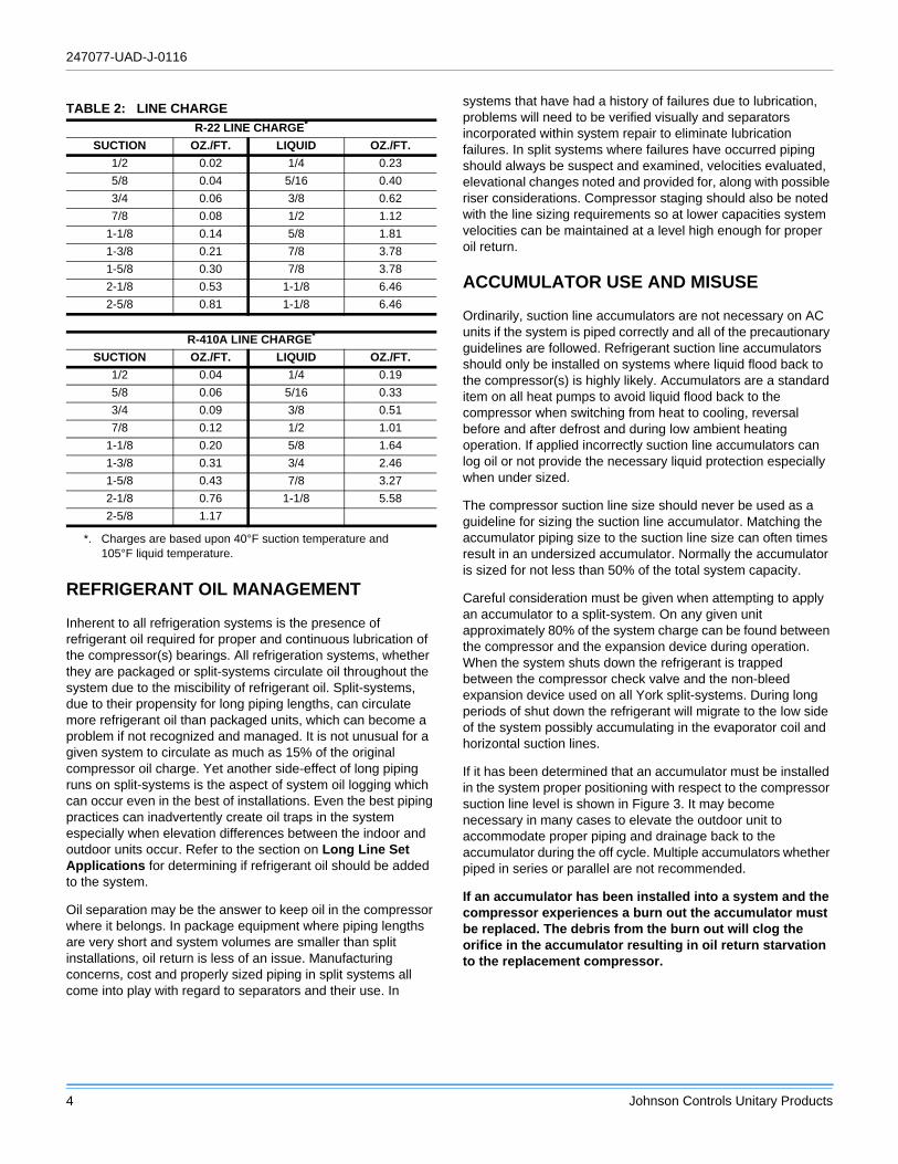
REFRIGERANT OIL MANAGEMENT
Inherent to all refrigeration systems is the presence of
refrigerant oil required for proper and continuous lubrication of
the compressor(s) bearings. All refrigeration systems, whether
they are packaged or split-systems circulate oil throughout the
system due to the miscibility of refrigerant oil. Split-systems,
due to their propensity for long piping lengths, can circulate
more refrigerant oil than packaged units, which can become a
problem if not recognized and managed. It is not unusual for a
given system to circulate as much as 15% of the original
compressor oil charge. Yet another side-effect of long piping
runs on split-systems is the aspect of system oil logging which
can occur even in the best of installations. Even the best piping
practices can inadvertently create oil traps in the system
especially when elevation differences between the indoor and
outdoor units occur. Refer to the section on Long Line Set
Applications for determining if refrigerant oil should be added
to the system.
Oil separation may be the answer to keep oil in the compressor
where it belongs. In package equipment where piping lengths
are very short and system volumes are smaller than split
installations, oil return is less of an issue. Manufacturing
concerns, cost and properly sized piping in split systems all
come into play with regard to separators and their use. In
systems that have had a history of failures due to lubrication,
problems will need to be verified visually and separators
incorporated within system repair to eliminate lubrication
failures. In split systems where failures have occurred piping
should always be suspect and examined, velocities evaluated,
elevational changes noted and provided for, along with possible
riser considerations. Compressor staging should also be noted
with the line sizing requirements so at lower capacities system
velocities can be maintained at a level high enough for proper
oil return.
ACCUMULATOR USE AND MISUSE
Ordinarily, suction line accumulators are not necessary on AC
units if the system is piped correctly and all of the precautionary
guidelines are followed. Refrigerant suction line accumulators
should only be installed on systems where liquid flood back to
the compressor(s) is highly likely. Accumulators are a standard
item on all heat pumps to avoid liquid flood back to the
compressor when switching from heat to cooling, reversal
before and after defrost and during low ambient heating
operation. If applied incorrectly suction line accumulators can
log oil or not provide the necessary liquid protection especially
when under sized.
The compressor suction line size should never be used as a
guideline for sizing the suction line accumulator. Matching the
accumulator piping size to the suction line size can often times
result in an undersized accumulator. Normally the accumulator
is sized for not less than 50% of the total system capacity.
Careful consideration must be given when attempting to apply
an accumulator to a split-system. On any given unit
approximately 80% of the system charge can be found between
the compressor and the expansion device during operation.
When the system shuts down the refrigerant is trapped
between the compressor check valve and the non-bleed
expansion device used on all York split-systems. During long
periods of shut down the refrigerant will migrate to the low side
of the system possibly accumulating in the evaporator coil and
horizontal suction lines.
If it has been determined that an accumulator must be installed
in the system proper positioning with respect to the compressor
suction line level is shown in Figure 3. It may become
necessary in many cases to elevate the outdoor unit to
accommodate proper piping and drainage back to the
accumulator during the off cycle. Multiple accumulators whether
piped in series or parallel are not recommended.
If an accumulator has been installed into a system and the
compressor experiences a burn out the accumulator must
be replaced. The debris from the burn out will clog the
orifice in the accumulator resulting in oil return starvation
to the replacement compressor.
TABLE 2: LINE CHARGE
R-22 LINE CHARGE*
*. Charges are based upon 40°F suction temperature and
105°F liquid temperature.
SUCTION OZ./FT. LIQUID OZ./FT.
1/2 0.02 1/4 0.23
5/8 0.04 5/16 0.40
3/4 0.06 3/8 0.62
7/8 0.08 1/2 1.12
1-1/8 0.14 5/8 1.81
1-3/8 0.21 7/8 3.78
1-5/8 0.30 7/8 3.78
2-1/8 0.53 1-1/8 6.46
2-5/8 0.81 1-1/8 6.46
R-410A LINE CHARGE*
SUCTION OZ./FT. LIQUID OZ./FT.
1/2 0.04 1/4 0.19
5/8 0.06 5/16 0.33
3/4 0.09 3/8 0.51
7/8 0.12 1/2 1.01
1-1/8 0.20 5/8 1.64
1-3/8 0.31 3/4 2.46
1-5/8 0.43 7/8 3.27
2-1/8 0.76 1-1/8 5.58
2-5/8 1.17

247077-UAD-J-0116
Johnson Controls Unitary Products 5
FIGURE 3: Accumulator Field Piping
RECOMMENDED ORIFICE SIZE
ORIFICE SIZING
Use the York® Comfort Cooling Piping software to determine
liquid line pressure drop to select proper orifice sizing.
Accumulator
Liquid Level
Drainage in Off Cycle
ScrollCompressor
TABLE 3: RECOMMENDED ORIFICE SIZE
LIQUID LINE PRESSURE
GAINS (PSI)
STANDARD
ORIFICE
SIZE
LIQUID LINE
PRESSURE
LOSSES (PSI)
51 41 31 21 11 11 21
Thru Thru Thru Thru Thru Thru Thru
60 50 40 30 20 20 30
CORRECTED
ORIFICE SIZE
CORRECT ORIFICE
SIZE
- - - - 39 41 43 45
- - - 39 41 43 45 47
41 43 45 47 49 51 53 55
43 45 47 49 51 53 55 57
45 47 49 51 53 55 57 59
47 49 51 53 55 57 59 61
49 51 53 55 57 59 61 63
51 53 55 57 59 61 63 65
53 55 57 59 61 63 65 67
55 57 59 61 63 65 67 69
57 59 61 63 65 67 69 71
59 61 63 65 67 69 71 73
61 63 65 67 69 71 73 75
63 65 67 69 71 73 75 78
65 67 69 71 73 75 78 81
69 71 73 75 75 78 81 84
71 73 75 78 78 81 84 87
75 75 78 81 81 84 87 90
78 78 81 84 84 87 90 93
81 81 84 87 87 90 93 96
84 84 87 90 90 93 96 99
87 87 90 93 93 96 99 102
90 90 93 96 96 99 102 105
93 93 96 99 99 102 105 105
247077-UAD-J-0116
6 Johnson Controls Unitary Products
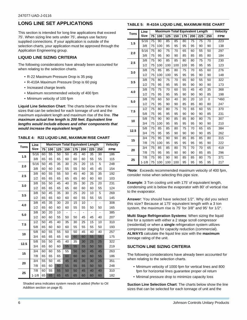
LONG LINE SET APPLICATIONS
This section is intended for long line applications that exceed
75'. When sizing line sets under 75', always use factory
supplied connections. If your application is outside of the
selection charts, your application must be approved through the
Application Engineering group.
LIQUID LINE SIZING CRITERIA
The following considerations have already been accounted for
when relating to the selection charts.
• R-22 Maximum Pressure Drop is 35 psig
• R-410A Maximum Pressure Drop is 60 psig
• Increased charge levels
• Maximum recommended velocity of 400 fpm
• Minimum velocity of 100 fpm
Liquid Line Selection Chart: The charts below show the line
sizes that can be selected for each tonnage of unit and the
maximum equivalent length and maximum rise of the line. The maximum actual line length is 200 feet. Equivalent line lengths would include elbows and other components that would increase the equivalent length.
Shaded area indicates system needs oil added (Refer to Oil
Addition section on page 8).
*Note: Exceeds recommended maximum velocity of 400 fpm,
consider noise when selecting this pipe size.
Example: 3 Ton cooling unit with 175' of equivalent length,
condensing unit is below the evaporator with 80' of vertical rise
to the evaporator.
Answer: You should have selected 1/2”. Why did you select
this size? Because at 175' equivalent length with a 3 ton
system, the maximum rise is 75’ for 3/8” and 95’ for 1/2".
Multi Stage Refrigeration Systems: When sizing the liquid
line for a system with either a 2 stage scroll compressor
(residential) or when a single refrigeration system utilizes
compressor staging for capacity reduction (commercial).
ALWAYS calculate the liquid line size with the maximum
tonnage rating of the unit.
SUCTION LINE SIZING CRITERIA
The following considerations have already been accounted for
when relating to the selection charts.
• Minimum velocity of 1000 fpm for vertical lines and 800
fpm for horizontal lines guarantee proper oil return
• Minimal pressure drop to minimize capacity loss
Suction Line Selection Chart: The charts below show the line
sizes that can be selected for each tonnage of unit and the
TABLE 4: R22 LIQUID LINE, MAXIMUM RISE CHART
Tons Line
Size
Maximum Total Equivalent Length Velocity
75 100 125 150 175 200 225 250 FPM
1.5 5/16 60 55 50 50 45 40 35 30 186
3/8 65 65 65 60 60 60 55 55 115
2.0 5/16 50 45 35 30 25 20 15 5 248
3/8 60 60 60 55 55 50 45 45 154
2.5 3/8 60 55 55 50 45 40 35 35 192
1/2 65 65 65 65 65 60 60 60 103
3.0 3/8 55 50 45 40 35 30 25 20 231
1/2 65 65 65 65 60 60 60 55 124
3.5 3/8 50 45 35 30 25 20 10 5 269
1/2 65 65 60 60 60 55 55 55 145
4.0 3/8 45 35 30 20 15 10 - - 308
1/2 65 60 60 60 55 55 50 50 165
5.0 3/8 30 20 10 - - - - - 385
1/2 60 60 55 50 50 45 45 40 207
7.5 1/2 50 45 40 35 30 25 15 10 310
5/8 65 60 60 60 55 55 55 50 193
10 5/8 60 55 55 50 50 45 40 40 257
3/4 65 65 65 60 60 60 55 55 175
12.5 5/8 55 50 45 40 35 30 25 25 322
3/4 65 60 60 55 55 55 50 50 219
15 3/4 60 60 55 55 50 50 45 45 263
7/8 65 65 65 60 60 60 60 55 186
20 3/4 55 50 45 45 40 35 30 25 351
7/8 65 60 60 55 55 55 50 50 248
25 7/8 60 55 55 50 50 45 40 40 310
1-1/8 65 65 65 65 65 60 60 60 182
TABLE 5: R-410A LIQUID LINE, MAXIMUM RISE CHART
Tons Line
Size
Maximum Total Equivalent Length Velocity
75 100 125 150 175 200 225 250 FPM
1.5 5/16 75 90 85 85 80 75 75 70 223
3/8 75 100 95 95 95 95 90 90 138
2.0 5/16 75 80 75 70 65 60 55 50 297
3/8 75 95 90 90 85 85 85 80 184
2.5 3/8 75 90 85 85 80 80 75 70 230
1/2 75 100 100 100 100 95 95 95 123
3.0 3/8 75 85 85 80 75 70 65 60 276
1/2 75 100 100 95 95 95 90 90 148
3.5 3/8 75 80 75 70 65 60 55 50 322
1/2 75 95 95 95 95 90 90 90 173
4.0 3/8 75 75 70 60 55 45 40 35 368
1/2 75 95 95 95 90 90 90 85 198
5.0 3/8 70 60 50 40 30 20 10 0 *460
1/2 75 95 90 90 85 85 80 80 247
7.5 1/2 75 80 80 75 70 65 60 55 370
5/8 75 95 95 95 90 90 90 85 231
10 5/8 75 90 90 85 85 80 80 75 307
3/4 75 100 95 95 95 95 90 90 210
12.5 5/8 75 85 85 80 75 70 65 65 384
3/4 75 95 95 90 90 90 90 85 262
15 3/4 75 95 90 90 85 85 85 80 315
7/8 75 100 95 95 95 95 95 90 222
20 3/4 75 85 85 80 75 70 70 65 419
7/8 75 95 95 90 90 90 85 85 296
25 7/8 75 95 90 90 85 85 80 75 371
1-1/8 75 100 100 100 95 95 95 95 217

247077-UAD-J-0116
Johnson Controls Unitary Products 7
percent of capacity reduction the system will have because of
the long line set application. The maximum actual line length is 200 feet, equivalent line lengths would include elbows and other components that would increase the equivalent length.
Note: (-) Indicates unacceptable pressure drop in suction line
*Velocity is below 1000 fpm, should only be used on horizontal
line.
Multi Stage Refrigeration Systems: When sizing the suction
line for a system with either a 2 stage scroll compressor
(residential) or when a single refrigeration system utilizes
compressor staging for capacity reduction (commercial).
ALWAYS select the largest available pipe size from the
minimum tonnage of capacity reduction.
Example: 10 ton R-22 2 pipe system that reduces capacity to 5
tons. Select 1-3/8” suction line, this is the largest available
suction line size for a 5 ton suction line.
Note: 2 stage scroll compressors operate at 67% of full load
capacity.
TABLE 6: R22 SUCTION LINE, CAPACITY REDUCTION
CHART (%)
Tons Line
Size
Total Equivalent Length Velocity
75 100 125 150 175 200 225 250 FPM
1.5 5/8 5 7 9 12 - - - - 1682
3/4 4 5 6 7 9 11 12 13 1147
2.0 3/4 3 4 6 8 9 11 - - 1529
7/8 3 4 5 6 7 8 9 10 1081
2.5 3/4 3 5 7 - - - - - 1911
7/8 2 3 4 5 7 8 9 10 1351
3.0 3/4 5 7 8 - - - - - 2294
7/8 2 3 5 6 8 9 10 11 1621
3.5 7/8 2 4 6 7 - - - - 1892
1-1/8 2 3 4 4 5 5 6 7 1109
4.0 7/8 3 5 7 - - - - - 2162
1-1/8 2 2 3 4 4 5 6 7 1268
5.0
7/8 5 - - - - - - - 2703
1-1/8 1 2 3 4 5 6 6 7 1585
1-3/8 1 2 3 3 4 4 5 6 1048
7.51-3/8 1 2 2 2 3 4 5 5 1561
1-5/8 1 2 2 2 3 3 4 4 1103
101-3/8 1 1 2 3 4 5 6 - 2082
1-5/8 1 1 2 2 2 3 3 3 1471
12.51-5/8 1 1 1 2 2 3 3 4 1839
2-1/8 1 1 1 1 2 2 3 3 1057
151-5/8 1 1 2 3 3 4 4 5 2207
2-1/8 1 1 1 2 2 2 2 3 1268
202-1/8 1 1 1 1 2 2 2 2 1691
2-5/8 1 1 1 1 1 2 2 2 1096
252-1/8 1 1 1 1 1 2 2 3 2114
2-5/8 1 1 1 1 1 2 2 2 1370
TABLE 7: R-410A SUCTION LINE, CAPACITY REDUCTION
CHART (%)
Tons Line
Size
Total Equivalent Length Velocity
75 100 125 150 175 200 225 250 FPM
1.5 5/8 3 4 5 7 8 10 12 13 1185
3/4 3 4 5 6 8 10 11 12 808*
2.0 5/8 2 4 6 7 - - - - 1582
3/4 3 4 4 5 6 7 8 10 1078
2.5 3/4 2 3 4 5 6 7 8 10 1346
7/8 2 3 4 5 6 6 7 8 952*
3.0 3/4 2 2 4 5 6 8 - - 1616
7/8 2 3 3 4 5 5 6 7 1143
3.5 3/4 2 3 4 6 - - - - 1887
7/8 2 2 3 3 4 5 6 7 1333
4.0 3/4 2 4 5 - - - - - 2155
7/8 1 2 2 3 5 6 7 8 1523
5.0 7/8 1 2 3 5 6 - - - 1905
1-1/8 1 2 2 3 3 4 4 5 1117
7.51-1/8 1 1 2 2 3 4 5 5 1676
1-3/8 1 1 2 2 3 3 3 4 1100
101-3/8 1 1 1 2 2 2 3 3 1467
1-5/8 1 1 1 2 2 2 3 3 1036
12.51-3/8 1 1 1 1 2 2 3 4 1834
1-5/8 1 1 1 1 2 2 2 3 1295
151-3/8 1 1 1 2 3 4 5 - 2200
1-5/8 1 1 1 1 1 2 2 2 1554
201-5/8 1 1 1 1 1 2 3 3 2073
2-1/8 1 1 1 1 1 1 2 2 1191
251-5/8 1 1 1 2 3 4 - - 2591
2-1/8 1 1 1 1 1 1 1 2 1489

247077-UAD-J-0116
8 Johnson Controls Unitary Products
LONG LINE SET ACCESSORIES
All long line set applications must have the following
accessories installed if they are not already installed from the
factory.
• Crankcase Heater - A crankcase heater will warm the
compressor sump and prevent the refrigerant from
migrating to the compressor in the off cycle.
• Non Bleed TXV's on all ID Coils - Prevents refrigerant
from bleeding into the low side of the system through the
evaporator in the off cycle.
• Hard Start Kit - A hard start kit is necessary to increase
the compressor starting torque anytime a TXV is used in a
system. This is necessary to overcome the pressure
difference across the compressor.
• Cooling Only Units - Require liquid line check valve
placed in the liquid line near the condensing unit. This is
used to lock the refrigerant in the liquid line between the
TXV and the condensing unit to reduce off cycle
migration.
• Heat Pumps with Orifice in OD Coil - Require check
valve and solenoid valve placed in liquid line to prevent
off cycle migration, refer to Figure 4 for proper placement.
• Heat Pumps with TXV’s on both Coils - Do not require
additional check valves and solenoid valves.
• Pump Out Accessory - This is required on commercial
applications where available.
OIL ADDITION
If the line set you selected is in the shaded area of Table 4,
(R22 Liquid Line, Maximum Rise Chart) oil needs to be added
to the compressors. The formula below determines the amount
of oil to add to the compressors.
(TSC x .03 x 16) - (SOC x .1) = AOR
• TSC = Total System Charge in pounds
• SOC = System Oil Charge in ounces
• AOR = Additional Oil Required in ounces
ROTARY COMPRESSOR
If you are selecting a unit with a rotary compressor, the
maximum actual line set is 100 ft.
FIGURE 4: Heat Pump Solenoid/Check Valve Installation
Arrangement
Any application that falls outside standard limits should
be referred to Unitary Products application Engineering
@ 1-877-UPG-SERV.
TABLE 8: CRANKCASE HEATERS FOR SPLIT UNITS
Model Part # Voltage WattsMin.
Circum
Max.
Circum
Danfoss Scrolls
(All)
S1-02541100000 240 70 19.625 27.125
S1-02541101000 460 70 19.625 27.125
S1-02541102000 575 70 19.625 27.125
Copeland Scrolls
(Residential)
S1-02531959000 240 80 22 26
S1-02531960000 460 80 22 26
S1-02531958000 575 80 22 26
Copeland Scrolls
(Commercial)S1-02533474240 240 90 28.75 35.75
Bristol H23AS1-02533474460 460 90 28.75 35.75
S1-02533474575 575 90 28.75 35.75
Bristol Recips
(Remainder)
S1-02537399240 240 70 21.81 29
S1-02537399480 460 70 21.81 29
S1-02537399575 575 70 21.81 29
TABLE 9: HP SOLENOID VALVE
Model Part# Voltage
3/8" Liquid Line Solenoid Valve S1-02541203000 24V
Subject to change without notice. Printed in U.S.A. 247077-UAD-J-0116Copyright © 2016 by Johnson Controls, Inc. All rights reserved. Supersedes: 247077-UAD-I-0713
York International Corporation
5005 York Drive
Norman, OK 73069
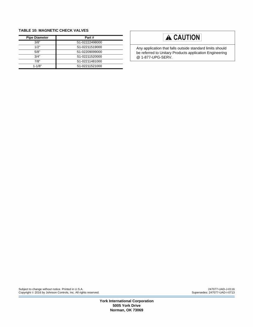
TABLE 10: MAGNETIC CHECK VALVES
Pipe Diameter Part #
3/8” S1-02222498000
1/2” S1-02211519000
5/8” S1-02209099000
3/4” S1-02211520000
7/8” S1-02211481000
1-1/8” S1-02211521000
Any application that falls outside standard limits should
be referred to Unitary Products application Engineering
@ 1-877-UPG-SERV.