Adaptive quality control for multimedia communications
14
Original Article Adaptive quality control for multimedia communications Santichai Chuaywong*, Sinchai Kamolphiwong, Thossaporn Kamolphiwong, Kevin Robert Elz and Suthon Sae-Wong Centre of Network Research (CNR), Department of Computer Engineering, Faculty of Engineering, Prince of Songkla University, Hat Yai, Songkhla, 90112 Thailand. Received 18 April 2007 ; Accepted 26 February 2008 Abstract Multimedia communications are communications with several types of media, such as audio, video and data. The current Internet has some levels of capability to support multimedia communications, unfortunately, the QoS (Quality of Service) is still challenging. A large number of QoS mechanisms has been proposed; however, the main concern is for low levels, e.g. layer 2 (Data Link) or 3 (Transport). In this paper, mechanisms for control the quality of audio and video are proposed. G.723.1 and MPEG-4 are used as the audio and video codec respectively. The proposed algorithm for adaptive quality control of audio communication is based on forward error correction (FEC). In the case of video communication, the proposed algorithm adapts the value of key frame interval, which is an encoding parameter of MPEG-4. We evaluated our proposed algorithms by computer simulation. We have shown that, in most cases, the proposed scheme gained a higher throughput compared to other schemes. Keywords: Adaptive, multimedia communications, quality control, FEC, MPEG-4 Songklanakarin J. Sci. Technol. 30 (1), 71-84, Jan. - Feb. 2008 1. Introduction Internet is the big widely-used world network. There is a huge variety of services that are using the Internet, not only data (WWW, FTP, etc.), but also communications of other types of medium such as audio and video. Since the current Internet does not guarantee QoS, the packet loss problem always occurs. In multimedia communications, it is not guaranteed that the source media, transmitted by the sender, and the received media, at the receiver, will have the same quality because some packets may be dropped in the network. For data traffic, packet loss can be solved by retrans- mission, but this approach cannot be applied to real- time traffic such as audio and video. A number of packets lost can degrade media quality at the receiver end. So it is necessary for the sender to monitor the quality of media re- ceived by the receiver, and to adapt its transmission param- eters in order to control the quality of the received media in acceptable level. There are a number of previous works pro- posing adaptation techniques for audio and video services, but there is still no perfect solution. In this paper, we propose new adaptive quality control algorithms for audio and video communications over the Internet, so call “CNR algorithm”. The remainder of this paper is organized as follows. In section 2, background information of fundamentals of related topics is given. In section 3, some of important related works are described. Then the proposed mechanism is presented the next section, together with the proposed algo- rithm in section 5. The simulation results are shown and compared in section 6, following with section 7: result discussion. Finally, the conclusion is presented in section 8. 2. Background information In this section, some topics of necessary background information are described. *Corresponding author. Email address: [email protected] http://www.sjst.psu.ac.th
-
Upload
independent -
Category
Documents
-
view
0 -
download
0
Transcript of Adaptive quality control for multimedia communications

Original Article
Adaptive quality control for multimedia communications
Santichai Chuaywong*, Sinchai Kamolphiwong, Thossaporn Kamolphiwong,Kevin Robert Elz and Suthon Sae-Wong
Centre of Network Research (CNR), Department of Computer Engineering,Faculty of Engineering, Prince of Songkla University, Hat Yai, Songkhla, 90112 Thailand.
Received 18 April 2007 ; Accepted 26 February 2008
Abstract
Multimedia communications are communications with several types of media, such as audio, video and data. Thecurrent Internet has some levels of capability to support multimedia communications, unfortunately, the QoS (Quality ofService) is still challenging. A large number of QoS mechanisms has been proposed; however, the main concern is for low levels,e.g. layer 2 (Data Link) or 3 (Transport). In this paper, mechanisms for control the quality of audio and video are proposed.G.723.1 and MPEG-4 are used as the audio and video codec respectively. The proposed algorithm for adaptive quality controlof audio communication is based on forward error correction (FEC). In the case of video communication,the proposed algorithm adapts the value of key frame interval, which is an encoding parameter of MPEG-4. We evaluatedour proposed algorithms by computer simulation. We have shown that, in most cases, the proposed scheme gained a higherthroughput compared to other schemes.
Keywords: Adaptive, multimedia communications, quality control, FEC, MPEG-4
Songklanakarin J. Sci. Technol.30 (1), 71-84, Jan. - Feb. 2008
1. Introduction
Internet is the big widely-used world network. There isa huge variety of services that are using the Internet, not onlydata (WWW, FTP, etc.), but also communications of othertypes of medium such as audio and video. Since the currentInternet does not guarantee QoS, the packet loss problemalways occurs. In multimedia communications, it is notguaranteed that the source media, transmitted by the sender,and the received media, at the receiver, will have the samequality because some packets may be dropped in thenetwork. For data traffic, packet loss can be solved by retrans-mission, but this approach cannot be applied to real-time traffic such as audio and video. A number of packetslost can degrade media quality at the receiver end. So it isnecessary for the sender to monitor the quality of media re-ceived by the receiver, and to adapt its transmission param-eters in order to control the quality of the received media in
acceptable level. There are a number of previous works pro-posing adaptation techniques for audio and video services,but there is still no perfect solution. In this paper, we proposenew adaptive quality control algorithms for audio and videocommunications over the Internet, so call “CNR algorithm”.
The remainder of this paper is organized as follows.In section 2, background information of fundamentals ofrelated topics is given. In section 3, some of important relatedworks are described. Then the proposed mechanism ispresented the next section, together with the proposed algo-rithm in section 5. The simulation results are shown andcompared in section 6, following with section 7: resultdiscussion. Finally, the conclusion is presented in section 8.
2. Background information
In this section, some topics of necessary backgroundinformation are described.
*Corresponding author.Email address: [email protected]
http://www.sjst.psu.ac.th

Chuaywong, et al. / Songklanakarin J. Sci. Technol. 30 (1), 71-84, 200872
2.1 Forward Error Correction (FEC)
When the audio traffic is sent over the internet, aproblem that always occurs is the packet loss. If there aretoo many lost packets, audio quality can be degraded. So itis necessary to use the error recovery mechanism for reduc-ing the effect of the packet loss. Forward Error Correction(FEC) is an effective error recovery mechanism with lowlatency.
FEC is separated into two classes, media independentFEC and media specific FEC. In the media independentFEC, when a set of packets is sent, it produces the additionalpacket. This additional packet is generated from the arith-metic operation of all packets in the same set. But thisscheme cannot protect the loss of several packets which arein the same set.
Figure 1 shows the second FEC scheme, the mediaspecific FEC. In this scheme, each packet contains theredundant version of the prior packets. But the audio codecof the redundant data may have lower bit rate than the primarycodec, for bandwidth saving. For example, the primary codecis G.711 u-law (64 kbps) and the redundant codec is LPC (4.8kbps). But if the bit rate of primary codec is low,the redundant data can use the same codec as the primarydata. In Figure 1, if the packet numbered 3 is lost, thereceiver can recovery this audio unit from the packetnumbered 4.
In this paper, we focus on media specific FEC becauseit is more effective than the media independent FEC. The packetformat for redundant audio data is defined in RFC2198 (Perkins et al., 1997). When the FEC mechanism isapplied in audio communication, there are two values of lossrate to be considered. They are loss rate before reconstruc-tion (Lb) and loss rate after reconstruction (La). Lb isonly the packet loss rate and La indicates the loss of audiodata.
2.2 MPEG-4
MPEG-4 (ISO/IEC 14496-2, 2001) is an openstandard developed by the Moving Picture Expert Group
(MPEG) for low bit rate digital media applications. Thereare several parts in MPEG-4 such as the system, videocoding, audio coding, file format, etc. But in this paper, wefocus on the part of video coding, which is officially calledMPEG-4 Visual part. The input video of MPEG-4 encoder mustbe in the YCbCr color space.
1) MPEG-4 Frame Types
The compression method of the MPEG-4 encoderconcerns both spatial and temporal redundancy, so it usesinter-frame prediction. In MPEG-4 standard, the video frame iscalled Video Object Plane (VOP). But for easier understand-ing, in this paper we will use the word frame instead of VOP.There are three types of MPEG-4 encoded frames,intra frame (I-frame), predicted frame (P-Frame) and bidirec-tional frame (Bframe). The dependency between each typeof frames is shown in Figure 2.
I-frame is the intra-coded frame which is encoded byreducing the redundancy in the same frame only. P-frame isthe forward prediction frame and it is depend on previous I-frame or P-frame. So it can reduce the temporal redundancy. B-frame is both forward and backward prediction frame. It isdepend on previous and succeeding non B-frame. Since theencoding of B-frame has to wait for the succeeding frame,so this frame type is not suitable for real-time video trans-mission.
Figure 1. Media Specific FEC
Figure 2. MPEG-4 Frame Types
Since the encoding process of MPEG-4 uses inter-frame prediction, so the lost of a video frame can affect thesucceeding frames. Figure 3 shows the error propagationwhen a video frame is lost. The error propagation will berecovered only when an Iframe is received because the I-frame does not depend on other frames. So I-frame is oftencalled key frame or reference frame and in this paper we usethe words I-frame and key frame interchangeably.
The key frame interval is a parameter of the MPEG-4encoder. It is the distance between adjacent I-frames. Forexample, in Figure 4, the key frame interval is 5 frames. If
Figure 3. Error Propagation in MPEG-4 Decoder

73Chuaywong, et al. / Songklanakarin J. Sci. Technol. 30 (1), 71-84, 2008
key frame interval is low, the error propagation will bedecreased. But the video bit rate is increased because thelower value of key frame interval means that there are moreIframes. And the size of I-frame is much bigger than P-framebecause I-frame stores information of the entire frame while P-frame stores only difference between current and previousframe.
2) Rate Control in MPEG-4 Encoder
The output bit rate of video encoder will be variedbased on the characteristics of video such as motion, tempo-ral redundancy, and spatial redundancy. Rate control involvesmodifying the encoding parameters in order to control theoutput video bit rate to meet the target bit rate. The mostwidely-used parameter is the quantization scale or step sizebecause increasing quantization scale can reduce the encodedframe length and lead to the higher distortion (lower imagequality). In the other hand, reducing quantization scale willreduce distortion but increase the encoded frame length(Richardson, 2003).
3. Related works
In this section, some important and well knownrelated works are described and analysed as follows:
3.1 Adaptive FEC-Based Algorithm for Audio Commu-nication
Since the FEC mechanism increases the bandwidthusage. Sending too much audio redundancy may be waste ofbandwidth if the packet loss rate is low. So the adaptivealgorithm is required to determine the quantity of audioredundancy. The previous works in adaptive FEC-based errorcontrol algorithm are Bolot algorithm (Bolot and Garcia, 1996),USF algorithm (Padhye et al., 2000) and RCCSalgorithm (Ji et al., 2001).
1) Bolot Algorithm
Bolot et al. proposed an adaptive FEC-based algo-rithm to reduce the effect of audio packet loss in (Bolot andGarcia, 1996). They do several experiments to find a value
called “reward” of each combination of audio redundancy.The reward is the ratio of Lb and La.
Reward = Lb / La
Table 1 shows detail of combinations used in Bolotalgorithm. This algorithm will change combination based onaudio loss rate. The meaning of the syntax in the secondcolumn (combination), for example, syntax (PCM, ADM4(1)) means each packet N contains the primary data (encodedwith PCM) and the redundant version of packet N-1(encoded with ADM4). The syntax of other combinationscan be interpreted in the equivalent way. The reward of eachcombination is the empirical value that tells the effective-ness that each combination can recover the loss of audiodata.
According to the diagram in Figure 4, Bolot algo-rithm does not use the real value of the loss rate after recon-struction (La). But it calculates La from Lb (feedback fromthe receiver) divided by the reward of the current combinationand then uses the calculated La to determine whichcombination to use. The pseudo code of this algorithm isshown in Figure 5. Bolot algorithm will increase combina-tion (increase selected combination number in Table 1) if La isover HIGH threshold and decreasing combination if La islower than LOW threshold.
Figure 4. Diagram of adaptive error control with BolotAlgorithm
Table 1. Combination table used in Bolot algorithm
No. Combination Reward
0 (PCM) 11 (PCM, ADM4(1)) 2.52 (PCM, GSM(1)) 2.53 (PCM, LPC(1)) 2.54 (PCM, ADM4(2)) 65 (PCM, ADM4(1), ADM2(2)) 66 (PCM, ADM4(1), ADM2(3)) 107 (PCM, ADM4(1), ADM2(2), ADM2(3)) 18
Figure 5. Pseudo code of Bolot Algorithm

Chuaywong, et al. / Songklanakarin J. Sci. Technol. 30 (1), 71-84, 200874
2) USF Algorithm
The USF Algorithm (Padhye et al., 2000), improves somedrawback of Bolot algorithm. In the paper of Padhey (Padhyeet al., 2000), the authors said that the Bolot has twodrawbacks.First, it uses empirical value of rewardto calculate La. This value may not be correct in all conditions.So the USF algorithm uses the real value of La. The seconddrawback of Bolot algorithm is the cyclical behavior. Whenthe value of La in the current period is less than the HIGHthreshold, the combination number is decreased. Inthe next period, the decreased combination is not reliableenough. So the value of La becomes over the HIGH thresholdand the combination number is increased to the same value.The value of La in the next period will be less than HIGH thresh-old again and the combination number will be changed cycli-cally. In the USF algorithm, this problem is solved by usingthe difference of Lb in the current and previous periods. Thecombination number will not be decreased if the difference ofLb is not big enough.
In fact, the cyclical behavior of the Bolot algorithmoccurs when the HIGH threshold is too closed to LOWthreshold. Especially in this paper (Padhye et al., 2000), theHIGH threshold and LOW threshold are the same value.
According to the diagram of USF algorithm in Figure 6,the receiver has to feed back 3 parameters to the senders, Lb,La and Lburst. Lburst is the loss rate after reconstructionthat counts only packets in the burst loss periods. In thepaper of Padhye (Padhye et al., 2000), burst loss means theconsecutive loss of 10 packets or higher. USF algorithmavoids increasing combination in the case of burst loss. Thisis not a good idea. In the case of burst loss, althoughincreasing combination cannot recover all of the lostpackets, it must be better than using the same combination.Further detail of this algorithm can be consideredthrough its pseudo code in Figure 7.
3) RCCS Algorithm
Redundant Codec Combination Selection (RCCS)algorithm (Ji et al., 2001) uses both loss rate and end-to-enddelay to determine which combination of audio redundancyto use. But the authors did not explain how to find the end-to-end delay clearly. This algorithm uses not only the reward,but it also uses the penalty value. The penalty is the ratio ofthe end-to-end delay after and before reconstruction.
End-to-End Delay after ReconstructionPenalty =
End-to-End Delay before Reconstruction
Table 2 shows combination table used in RCCS algo-rithm. The initial rewards are taken from Bolot experiment butthe penalties are defined in this algorithm. RCCS algorithmwants to avoid the drawback of Bolot algorithm that uses theempirical reward value. So, when receive the RTCP receiverreport packet is received, this algorithm will change the valueof reward of the current combination.
According to the diagram of the RCCS algorithm inFigure 8 and its pseudo code in Figure 9, there are manyparameters used in this algorithm. The description of thesesparameters is in Table 3. From the pseudo code, after calculat-ing the value of Lb, La, Db and Da in step 1-2, the next stepis updating reward and penalty with the following filterequations.
Figure 6. Diagram of adaptive error control with USFAlgorithm
Figure 7. The pseudo code of the USF algorithm
Table 2. Combination Table used in RCCS algorithm
No. Combination Initial Reward Penalty
0 (G.711) 1 11 (G.711,GSM(1)) 2.5 1.52 (G.711,G.723(1)) 2.5 23 (GSM,G.723(1)) 2.5 44 (G.711,GSM(1),G.729(2)) 6 2.45 (G.729,G.723(1),LPC10(2)) 6 4.56 (G.711,GSM(1),G.729(2),
LPC10(3)) 18 3.47 (G.711,GSM(1),G.723(2),
LPC10(3)) 18 4.5

75Chuaywong, et al. / Songklanakarin J. Sci. Technol. 30 (1), 71-84, 2008
Ri = α(La / Lb) + (1-α)Ri-1
Pi = α(Da / Db) + (1-α)Pi-1
In step 4, selecting the combination, this algorithmwill consider each combination in the combination table andselect the first combination that matches the following twoconditions.
- Produce the value of La’ lower than HIGH thresholdand higher than LOW threshold.
- Produce the value of Da’ lower than Dmin (thresholdof end-to-end delay).
If there is no combination that matches these condi-tions, this algorithm will not change the used combination.
4) Drawback of the Previous Works
Bolot algorithm does not use the real value of La forincreasing or decreasing combination. But it calculates Lafrom Lb divided by reward of the current combination. Thevalue of reward got from the experiment, so it may not becorrect in all environments.
USF algorithm improves the drawback of Bolot algo-rithm by using real value of La. But there is a new problem, theoscillation of La. If La changes with high oscillation, low Ladoes not mean low network congestion. This behaviorcan affect the USF algorithm to be misunderstanding. In thestep of decrement combination of this algorithm, it considersboth La and Lb-difference. But this mechanism does not solvethis problem because Lb can be changed with high oscillationtoo.
RCCS algorithm has a drawback in the step of select-ing combination. This algorithm does not separate theincreasing and decreasing conditions. So it is possible thatthis algorithm does not increase combination although thevalue of La is higher than HIGH threshold if there is nocombination that matches the specified conditions.
3.2 Adaptation Techniques for Video Communication
The previous works on adaptation techniques for
video communication can be separated into 3 schemes, rateadaptation, adaptive error correction and receiver-drivenadaptation. In this paper, we will focus on the first twoschemes because this paper focuses on point-to-point com-munication. According to previous works on rate adaptationand adaptive error control techniques, there is no algorithmthat can control the video quality obviously.
Most of previous works on rate adaptation techniqueschange video bit rate based on the packet loss rate, feedbackfrom the receiver. In (Busse et al., 1996), the authors proposemethod for setting video bit rate. This method will reducevideo bit rate when the network is congested (packet loss rateis too high) and increase video bit rate when loss rate is lowenough. The value of video bit rate is adapted based onadditive increase multiplicative decrease (AIMD) schemes.This method was evaluated by doing experiments in a realnetwork. The experiments used vic (vic, 2005), a well-knownvideo conferencing software, for transmitting video and itcan specify the target bit rate. But there is no explanationabout how to set the transmission parameters in order to meetthe target bit rate.
In the paper of Sisalem and Schulzrinne (1998),(2000), the authors proposed the methods for adapting videobit rate based on TCP-friendly scheme. The formulas for
Table 3. Description of parameters used in RCCSalgorithm
Parameters Description
Ri Reward of combination number iPi Penalty of combination number i
La (La′) Loss rate after reconstruction,La′ is the predicted value
Lb Loss rate before reconstructionDa End-to-End Delay after reconstructionDb End-to-End Delay before reconstructionα a Smoothing factor in the filter equation for
updating Ri and Pi
Figure 8. Diagram of adaptive error control with RCCSAlgorithm
Figure 9. Pseudo code of RCCS algorithm

Chuaywong, et al. / Songklanakarin J. Sci. Technol. 30 (1), 71-84, 200876
calculating video bit rate use both packet loss rate and roundtrip time (RTT) between sender and receiver. But these twopapers did not say how to set video parameters in order tomeet the target bit rate.
IVS (Turletti and Huitema, 1996), video conferencingsoftware, which uses H.261 as the video codec, also adaptsvideo bit rate based on packet loss rate. It will reduce video bitrate when packet loss rate is too high and increase bit ratewhen packet loss rate is low enough. After calculating valueof video bit rate, it will change video parameter in order tomeet the target bit rate. There are 2 modes of adaptation,Privilege Quality (PQ) mode and Privilege Frame Rate (PFR)mode.
In PQ mode, frame rate will be adapted in order to meetthe target bit rate. The quantization scale of each frame isconstant, which means that the spatial quality of videoframe is not changed. In the PFR mode, frame rate isconstant, but quantization scale is varied. So the spatialquality of each video frame is varied too.
All of the rate adaptation techniques, described above,assume that reducing video bit rate can reduce network
congestion and the loss rate of video packets will be reducedtoo. But this assumption may be not correct in some situa-tions, especially in the almost fully utilized network. Besides,the packet loss rate does not actually reflect the video qualityseen by the viewer.
The second scheme of adaptation technique, adaptiveerror control, can be separated into 2 methods. The first oneuses FEC to reduce effect of packet loss (Bolot and Turletti1996). But using FEC with video transmission seems to beinappropriate because the size of video data is much biggerthan audio. Using FEC will increase large of bandwidthusage. The second method of error control is adapting theparameters of video encoder. For example, IVS reduces keyframe interval when network is congested. But the paper ofTurletti and Huitema, (1996), it did not describe how to set thevalue of key frame interval.
4. CNR Algorithm: Proposed adaptive quality control foraudio communication
Since previous works on adaptive FEC-based algo-rithms have some drawbacks, so we propose a new adaptiveerror control algorithm, called CNR algorithm (CNR: Centre forNetwork Research, where this work has been done). CNR al-gorithm removes the drawback of Bolot algorithm by usingreal value of La. And the oscillation of La is solved by countingthe number of periods that La lower than LOW threshold. CNRalgorithm decreases conditions of the combinationwhen low-loss period is big enough. The drawback of RCCSalgorithm is solved by separating the condition for incrementand decrement combination. According to the diagram ofCNR algorithm shown in Figure 10, the receiver has to feed-back Lb and La to the sender by the RTCP receiver reportpacket. Value of Lb is filled in the fraction lost field and La is putthe RTCP header extension part.
Table 4 shows the combinations used in the CNRalgorithm. All of the previous algorithms use different codecin primary and redundant audio data. But in CNR algorithm,the audio codec for both redundant and primary part isG.723.1 because the bit rate of this codec is low enough (6.3kbps). The format of combination of audio redundancy is inthe second column. For example, the syntax -1 means thatthere is a redundant version of packet N-1 in every packet N.The syntax -1-2 means that the redundant version of packet
Figure 10. Diagram of adaptive error control with CNRAlgorithm
Figure 11. Pseudo code of CNR algorithm
Table 4. Combination table used in CNR algorithm
No. Combination Format Initial Reward(Bolot Reward)
0 - 11 -1 2.52 -2 63 -1-2 64 -1-3 105 -1-2-3 18

77Chuaywong, et al. / Songklanakarin J. Sci. Technol. 30 (1), 71-84, 2008
N-1 and N-2 are placed in every packet N. The syntax ofother combinations can be interpreted in the equivalent way.The third column is the initial reward, taken from Bolotreward. CNR algorithm used reward to predict the next combi-nation when La becomes too high. But value of reward will bechanged based on real network status when the senderreceives the receiver report.
The pseudo code of CNR algorithm is shown in Fig-ure 11. After receiving the value of La and Lb, the first step isupdating reward of the current combination. The second stepis counting the number of periods that Lb is lower than LOWthreshold consecutively and saves in count_Lb_under_low.This variable will be checked in the part of decrement com-bination. The third step is checking the value La. If La is overthe HIGH threshold, it means that the current combination isnot robust enough, so it is necessary to find the next com-bination. The selected combination is the first upperordercombination that produces the value of predicted La (Lai inthe pseudo code) not over the HIGH threshold.
If value of La is lower than LOW threshold, CNRalgorithm does not decrease combination as in Bolot andUSF algorithm, but it will count the number of periods thatLa is lower than LOW threshold consecutively and saves incount_La_under_low. To make sure that it is safety for tryingto decrease combination, CNR algorithm will decrease combi-nation when the value of count_La_under_low or count_Lb_under_low reaches to MIN_UNDER_LOW. Thismechanism can solve the problem of La oscillation. We set thevalue of MIN_UNDER_LOW to 10 periods (50 seconds).The result in the next section show that using this value ismore effective in loss protection, compared with other algo-rithm.
5. Adaptive key frame interval adjustment algorithm
The transmission of video over the internet can beaffected by packet loss. Reducing the key frame interval isan approach that can minimize the effect of packet lossbecause it reduces the error propagation in P-frames.Although this approach will increase the video bit rate, butthis problem can be solved by using rate control. In theMPEG-4 encoder that applies the rate control, reducing keyframe interval will increase the mean quantization scale. Thedisadvantage of increasing quantization scale is the higherdistortion. But the advantage is that the mean frame lengthwill be decreased. When the encoded frame is bigger thanthe maximum transfer unit (MTU) of transmission link, itwill be fragmented. Smaller frames, which have a lower num-ber of fragments, will have higher probability of completelytransmitting of the entire frame to the receiver than biggerframes.
It is hard to specify the value of key frame intervalbecause of the tradeoff between quantity of distortion anderror resilience. So we propose a new adaptive algorithmthat changes the value of key frame interval based on networkstatus. Figure 12 presents the architecture of the adaptive key
frame interval adjustment. Since video is transmitted overRTP, so the receiver can send feedback information withRTCP. The information that the quality control unit uses forspecifying the key frame interval are PSNR, reported by theencoder, and received frame rate, reported by the receiver.
Since this mechanism is designed for point-to-pointvideo communication, so the receiver sends the RTCPreceiver report to the sender about every 5 seconds. In thispacket, it puts value of received frame rate in the RTCP headerextension part. The received frame rate is calculated fromthe correctly-decoded frames only. The corrupted frames anderror prediction P-frames are removed, so the received framerate, put in the receiver report packet, is the worst case value.
When the sender receives a receiver report, it uses thereceived frame rate in this packet in addition with the valueof mean PSNR, got from the encoder, in order to specify thekey frame interval based on the pseudo code in Figure 13.Parameters in the pseudo code are described in Table 5. Thisalgorithm decreases key frame interval when thereceived frame rate is too low (Frcv < Flow) except when themean PSNR is too low (PSNRavg < MIN_PSNR). Because it
Figure 12. Architecture of adaptive key frame intervaladjustment
Figure 13. Pseudo code of the adaptive key frame intervaladjustment algorithm

Chuaywong, et al. / Songklanakarin J. Sci. Technol. 30 (1), 71-84, 200878
is useless to try to increase the video frame rate if there are toohigh distortion to see the content in video frames. When thereceived frame rate is high enough (Frcv > Fhigh) fora specify number of periods (MIN_DURATION), this algo-rithm experiences that it is safe to try to increase the keyframe interval in order to get better image quality.
In our proposed algorithm, the key frame intervalmay not be increased or decreased by one frame per RTCPperiods because the changing of key frame interval in someregions has small effect on the image quality of video frames.Figure 14 is the graph of PSNR at different key frameinterval resulted from the encoding of 320x240 pixel, 24 fpsvideo when the target bit rate is fixed at 800 kbps. The contentin this video scene has low motion which is thegeneral characteristic of the input video in the video tele-phony or video conferencing environment.
According to this graph, mean PSNR of Y, Cb and Crcomponents are sharply decreased when key frame intervalis lower than 5 frames. We use this value as the critical value
of key frame interval which is Ic in the pseudo code in Figure13. The value of Ic is not always 5 frames. It is dependent onthe content of video frame and the rate control algorithm ofthe encoder. However, after trying to encode several lowmotion video sequences using XviD MPEG-4 Codec (XviD,2005), we found that the value of Ic is about 4-6 frames.
The value of key frame interval is changed by oneframe per RTCP period only when it is lower than Ic, otherwiseit will jump between Ic and maximum value of keyframe interval. We use the value of transmitted frame rate (infps) as the maximum value of key frame interval. This meansthat the time of error propagation in the decoder will not bemore than a seconds.
6. Evaluation of the proposed posed algorithms
6.1 Evaluation of CNR Algorithm
To evaluate the CNR algorithm and compare theperformance with previous adaptive FEC-based algorithms,we setup an experiment and used NS-2 (2005) as a networksimulator. All of the previous algorithms use different codec inprimary and redundant audio data. But in this experiment, wewould like to evaluate CNR algorithm and other algo-rithms in the case that the redundant and primary codec areG.723.1. There are 6 combinations used in this experimentas shown in Table 4. The HIGH threshold used for all algo-rithms is 5% because the loss of audio data more than 5% isconsidered harmful (Jayant and Christensen, 1981). In thecase of RCCS algorithm, it is not described clearly abouthow to find the end-to-end delay. So we assume that allcombinations have acceptable end-to-end delay.
In this experiment, we build a simulation model inNS-2. Figure 15 shows the topology of the simulation model.The RS node sends audio traffic over RTP to the RR node.This node selects the combination of audio redundancybased on the algorithm that we adjust. There are other nodesthat send TCP and UDP traffic. They act as other users inthe same network. In order to see the result in the differentnetwork environments, we separate this experiment into 4 parts.The difference between each part is the transmission behav-ior of the TCP nodes and number of TCP nodes.
Figure 14. Mean PSNR at different key frame interval
Table 5. Parameters in adaptive key frame intervaladjustment algorithm
Parameters Description
I Key frame intervalIc Critical value of I that can suddenly
changed the image quality of videoframes
Ftran Transmitted frame rateFrcv Received frame rate in the receiver
reportFlow,Fhigh Thresholds of Frcv used to increase or
decrease key frame interval.PSNRavg Mean PSNR of Y components.MIN_PSNR Minimum PSNR of the acceptable
image qualityNh Number of periods that Frcv is more
than FhighMIN_DURATION Threshold of Nh used to avoid the
fluctuation of key frame interval
Figure 15. Topology of simulation model
79Chuaywong, et al. / Songklanakarin J. Sci. Technol. 30 (1), 71-84, 2008
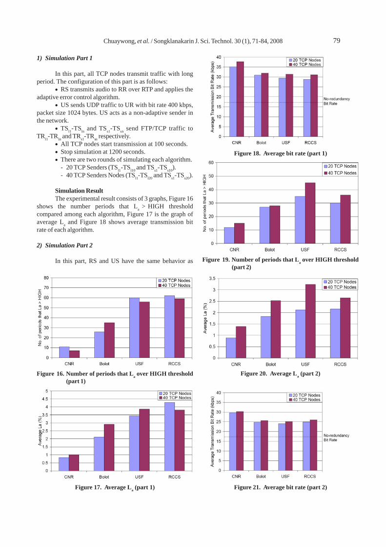
1) Simulation Part 1
In this part, all TCP nodes transmit traffic with longperiod. The configuration of this part is as follows:
• RS transmits audio to RR over RTP and applies theadaptive error control algorithm.
• US sends UDP traffic to UR with bit rate 400 kbps,packet size 1024 bytes. US acts as a non-adaptive sender inthe network.
• TSl1-TSln and TSs1-TSsn send FTP/TCP traffic toTRl1-TRln and TRs1-TRsn respectively.
• All TCP nodes start transmission at 100 seconds.• Stop simulation at 1200 seconds.• There are two rounds of simulating each algorithm.
- 20 TCP Senders (TSl1-TSl10 and TSs1-TSs10).- 40 TCP Senders Nodes (TSl1-TSl20 and TSs1-TSs20).
Simulation ResultThe experimental result consists of 3 graphs, Figure 16
shows the number periods that La > HIGH thresholdcompared among each algorithm, Figure 17 is the graph ofaverage La and Figure 18 shows average transmission bitrate of each algorithm.
2) Simulation Part 2
In this part, RS and US have the same behavior as
Figure 18. Average bit rate (part 1)
Figure 19. Number of periods that La over HIGH threshold(part 2)
Figure 20. Average La (part 2)
Figure 21. Average bit rate (part 2)
Figure 16. Number of periods that La over HIGH threshold(part 1)
Figure 17. Average La (part 1)

Chuaywong, et al. / Songklanakarin J. Sci. Technol. 30 (1), 71-84, 200880
part 1. The difference is in the TCP nodes. The configurationof this part is as follows:
• TSl1-TSln and TSs1-TSsn start and stop transmissionevery 200 seconds. We would like to see the result in thedifferent network characteristic from part 1. In this part, thelevel of network congestion is not constant.
• Other configurations are same as part 1.
Simulation ResultThe simulation result of this part is shown in the graph
in Figure19, Figure 20 and Figure 21
3) Simulation Part 3
The configuration of this part is as follows:• The parking-lot nodes (TSs1-TSsn) do not transmit.• TSl1-TSln start transmission at 100 seconds and stop
at the end of simulation time (1200 seconds).• All other configurations are the same as in Part 1.
Simulation ResultThe simulation result of this part is shown in the
graph in Figure 22, Figure 23 and Figure 24.
4) Simulation Part 4
The configuration of this part is as follow:• The parking-lot nodes (TSs1-TSsn) do not transmit.• TSl1-TSln start and stop transmission every 200
seconds.• All other configurations are the same as in Part 2.
Simulation ResultThe simulation result of this part is shown in the graph
in Figure 25, Figure 26 and Figure 27.
5) Summary of Simulation Results
The simulation results of CNR algorithm from 4 partsare summarised in Table 6. The result shows that CNR algo-rithm is the best in recovery the loss of audio data (low loss).
Figure 24. Average bit rate (part 3)
Figure 22. Number of periods that La over HIGH threshold(part 3)
Figure 25. Number of periods that La over HIGH threshold(part 4)
Figure 26. Average La (part 4)
Figure 23. Average La (part 3)

81Chuaywong, et al. / Songklanakarin J. Sci. Technol. 30 (1), 71-84, 2008
However, it has the average bit rate a little higher than otheralgorithms because CNR algorithm decreases combinationslower than others. Fortunately, it is a reasonable figurebecause the slow decrement combination is used for avoidthe oscillation of La.
6.2 Evaluation of Rate Adaptation Techniques
In this section, we will evaluate one of the rate adapta-tion techniques. We use AIMD (Busse et al., 1996) as the casestudy. We evaluate this technique by the simulation in NS-2.The network topology of the simulation model is shown inFigure 28. RS transmits video packets to node RR withAIMD algorithm. We use the video trace from the encoding ofthe same video sequence as used in the graph in Figure 14,frame size 320x240 pixels, frame rate 24 fps and target bit rate is800 kbps. TSl1 - TSl00 and TSs1 - TSs100 transfer file to TRl1 -
TRl100 and TRs1 - TRs100 over FTP/TCP. This TCPtraffic acts as the background traffic from other users in thenetwork. We use TCP Reno in this simulation and set packetsize to be 1024 bytes. The bit rate of TCP connections isvaried based on its congestion control algorithm. US transmitUDP packets to UR with bit rate 400 kbps, packet size 1024bytes.
We run the simulation for 600 seconds and each nodestarts and stops transmission at the following time:
• RS and US start transmission at the beginning ofthe simulation.
• All senders stop transmission at 600 seconds.• Value of AIMD parameters are specified as follow, α
= 0.3, μ = 0.875, ν = 50 kbps, λc = 4% and λu = 2%. These valuesare suggested in the paper of Busse (Busse et al.,1996). We set bmin = 200 kbps and bmax = 2000 kbps.
• AIMD algorithm focuses on setting value of bitrate only. But when we use MPEG-4 as the video codec, wemust specify value of key frame interval. We set it to be 1frame.
According the graph in Figure 29 that shows thechanging of video bit rate and packet loss rate during thesimulation. The adaptation of bit rate starts at 10 secondsbecause TCP senders start transmission. However, thedecreasing of video bit rate never make the packet loss rate tobe lower than 4% (λc). And AIMD stop reducing bit rate at theminimum value (200 kbps).
According to the graph in Figure 30, received framerate is acceptable because it is always higher than 15 fps.But this is resulted from setting key frame interval to be 1frame. So the video transmission is robust from packet loss.If we use other values, the experimental result will be different.
The graph in Figure 31 shows the received frame rateat difference key frame interval. When we set key frameinterval to be 4 frames, most of received frame rates arelower than 15 fps. And it will be also reduced when we setkey frame interval to be 24 fps. So, bit rate adaptation is notenough. The adaptive quality control should mention keyframe interval.
Table 6. Summary of experimental result of CNR algorithm
Part No. of periods Avg. La Candidate RCNR - Rcandidatethat La > HIGH Algorithm
20 TCP 40 TCPSenders Senders
1 Lowest Lowest Bolot 4.20 5.692 Lowest Lowest Bolot 4.91 4.623 Lowest Lowest Bolot 9.14 8.864 Lowest Lowest Bolot 5.14 5.63
Non-redundancyBit Rate
Figure 27. Average bit rate (part 4)
Figure 28. Topology of the simulation model

Chuaywong, et al. / Songklanakarin J. Sci. Technol. 30 (1), 71-84, 200882
6.3 Evaluation of Adaptive Key Frame Interval Adjust-ment
1) Simulation Setup
To evaluate the key frame interval adjustment algo-rithm that we propose, we setup the experiment by usingsimulation in NS-2 and the topology of the simulation model isshown in Figure 28. RS transmits video packets to nodeRR with adaptive keyframe interval adjustment algorithm.We use the video trace from the encoding of the same videosequence as used in the graph in Figure 14, frame size 320x240 pixels, frame rate 24 fps and target bit rate is 800 kbps. TSl1- TSl20 and TSs1 - TSs20 transfer file to TRl1 - TRl20 and TRs1 -TRs20 over FTP/TCP. This TCP traffic acts as the backgroundtraffic from other users in the network. We use TCP Reno inthis simulation and set packet size to be on 1024 bytes. Thebit rate of TCP connections is varied based its congestioncontrol algorithm. We run the simulation for 600 seconds andeach node starts and stops transmission at the following times:
• RS and US start transmission at the beginning ofsimulation and stops at time 600 seconds.
Figure 29. Video bit rate and packet loss rate
Figure 30. Received frame rate (key frame interval =1 frame)
Figure 31. Received frame rate at different key frameinterval
Figure 32. The adaptation of key frame interval and receivedframe rate
• All TCP nodes (TSl1 - TSl20 and TSs1 - TSs20) starttransmission at time 100 seconds.
• TSl1 - TSl10 and TSs1 - TSs10 stop transmission attime 300 seconds.
• TSl11 - TSl20 and TSs11 - TSs20 stop transmission attime 500 seconds.
So there is no TCP traffic during 0-100 seconds and500-600 seconds. There are 20 nodes that transmit TCPtraffic during 100-300 seconds and 10 nodes during 300-500 seconds. So the loss rate of video in each time is variedand we can see the adaptation of key frame interval.
We set parameters in adaptive key-frame intervaladjustment algorithm as follows. We set Ic to be 5 frames asdescribed in the previous section. The value of Ftran is 24 fps,which is the frame rate of film production. We set Flow to be15 fps which is widely-used frame rate of the video stream-ingin the Internet (Benedetti, 2005). Video seems to be not smoothwhen frame rate is less than 15 fps. Fhigh is set to 20 fps, whichis safety enough to try to increase key frameinterval and there is not much different smoothness between20 fps and 24 fps video. MIN_PSNR is 30 dB because in gen-eral, a PSNR of at least 30 dB provides an acceptablequality image (Chen et al., 1998), (Zelinski et al., 2004), (Ramacand Varshney, 2000), (Karayiannis and Li, 2001).
83Chuaywong, et al. / Songklanakarin J. Sci. Technol. 30 (1), 71-84, 2008
And the value of MIN_DURATION is set to be 4 periodswhich is equivalent to 20 seconds. The objective of thisexperiment is to evaluate the adaptive key frame intervaladjustment algorithm whether it can control quality of thereceived video.
2) Result and Discussion
According to the simulation results in the previoussection, the result that we would like to see is the adaptationkey frame interval and the received video frame rate, whichis the graph in Figure 32. According to this graph, in the first100 seconds, the transmitted and received video have thesame frame rate because there are no nodes transmitting TCPtraffic. And key frame interval is still 24 frames. From time 100-300 seconds, which has 40 TCP transmitting TCP traffic, keyframe interval is decreased to be 1 frame. And it can keep thevalue of received frame rate not be below 15 fps. During thenumber of nodes transmitting TCP traffic isdecreased to be 20 nodes and the network congestion isreduced. So the key frame interval is increased to be 3-4frames. And the last 100 seconds, there is no nodes transmit-ting TCP traffic again, so the key frame interval is increasedand stop at 24 frames.
When we consider the value of mean PSNR, whichindicate the image quality of video frames, mean PSNR is of-ten over 30dB (MIN_PSNR) except during time 170-320 sec-onds. During that time, mean PSNR is around 29 dB.But it does not influence the decision to decrement key frameinterval because the value of key frame interval during timeis 1 frame that is the lowest value.
7. Conclusion
In this paper, we present QoS (Quality of Service)adaptations to support multimedia communications. Most ofthe rate adaptation techniques in previous works, assumedthat reducing video bit rate can reduce network congestionand the loss rate of video packets will be reduced too. Un-fortunately this assumption may not be correct in somesituations, especially in the almost fully utilized network.Besides, the packet loss rate does not actually reflect thevideo quality seen by the viewer. Moreover previous workson adaptive FEC-based (Forward Error Correction) algorithmsalso have some drawbacks. We have proposed new adaptiveerror control algorithm, called CNR algorithm (CNR: Centre forNetwork Research, where this work has been done). We haveshown that, through various simulation scenarios, CNR algo-rithm removes the drawbacks of those previous algo-rithms,for example, increase the system throughput andreduce the rate oscillation. Moreover, CNR algorithmdecreases conditions of the combination when low-lossperiod is big enough. In addition, we have proposed the keyframe interval adjustment algorithm to gain a better trafficthroughput. However, a small disadvantage of CNR is itrequires a small higher bandwidth than others, but it is in amarginally acceptable figure.
Acknowledgement
This work was supported by NECTEC, Project ID:NT-B-22-T3-19-48-06
References
Benedetti, B. Video Basics. http://www.pierce.ctc.edu/bbenedet/digvideo/Documents/Videobasics/videobasics.htm [October 23, 2005]
Bolot, J. C. and Garcia, A.V., 1996. Control mechanisms forpacket audio in the Internet. Proceedings of IEEEINFOCOM ’96, vol. 1, San Francisco, USA, March 1996,232-239.
Bolot, J. C. and Turletti, T. 1996. Adaptive error control forpacket video in the Internet. Proceedings of IEEEICIP ’96, vol. 1, Lausanne, Switzerland, September 1996,25-28.
Busse, I., Deffner, B. and Schulzrinne, H. 1996. DynamicQoS control of multimedia applications based onRTP. Computer Communications, 9(1): 49-58.
Chen, T. S., Chang, C. C; and Hwang, M.S. 1998. A virtualimage cryptosystem based upon vector quantization.IEEE Transactions on Image Processing, 7(10): 1485-1488.
Digital Video for the Web, http://stream.uen.org/medsol/digvid/html/3B_videoframerate.html[October 23, 2005]
http://www.matrox.tv/includes/pdfs/tutorial2.pdf [October23, 2005]
ISO/IEC 14496-2. 2001. Coding of audio-visual objects - Part 2:Visual.
Jayant, N. and Christensen, S. W. 1981. Effect of PacketLosses in Waveform Coded Speech and Improve-ments due to an Odd-Even Sample-InterpolationProcedure. IEEE Transactions on Communications,COM-29(2): 101-109,
Ji M. K., Lee, S. H.; Choi, T. U.; Park, S. H.; Kang, J. G. ; andChung, K.D. 2001. Selecting an audio redundancy codeccombination for error control in Internet telephony. Pro-ceedings of IEEE ICPADS 2001, Kyongju, South Ko-rea, June 2001, 645–649.
Karayiannis, N. B. and Li, Y. 2001. A replenishment techniquefor low bit-rate video compression basedonwavelets and vector quantization. IEEE Transactionson Circuits and Systems for Video Technology,11(5): 658-663.
Padhye, C., et al. 2000. A new adaptive FEC loss controlalgorithm for voice over IP applications. Proceedingsof IEEE IPCCC ‘OO, Phoenix, USA, February 2000, 307-313.
Perkins, C. S., et al. 1997. RTP Payload for redundant audiodata, RFC2198, September 1997.
Ramac, L. C. and Varshney, P. K. Y. 2000. A wavelet domaindiversity method for transmission of images over-wireless channels. IEEE Journal on Selected Areas inCommunications, 18(6): 891-898.

Chuaywong, et al. / Songklanakarin J. Sci. Technol. 30 (1), 71-84, 200884
Richardson, I. E. G. 2003. H.264 and MPEG-4: Video Compres-sion Video Coding for Next-generation Multi-media, John Wiley & Sons, England.
Sisalem, D. and Schulzrinne, H. 1998. The loss-delay basedadjustment algorithm: A TCP-friendly adaptationscheme. Proceedings of International Workshop onNetwork and Operating Systems Support for DigitalAudio and Video, Cambridge, England, July 1998,215-226.
Sisalem, D. and Schulzrinne, H. 2000. The Direct AdjustmentAlgorithm: a TCP-friendly adaptation scheme. Proceed-ings of International Workshop on Quality ofFuture Internet Services, Berlin, Germany, September2000, 68-79.
The Network Simulator, NS-2. http://www.isi.edu /nsnam/ns/[October 23, 2005]
Turletti, T. and Huitema, C. 1996. Videoconferencing in theInternet. IEEE/ACM Transactions on NetworkingJournal. 4(3):340-351.
UBC/LBNL Video Conferencing Tool (vic). http://www-nrg.ee.lbl.gov/vic/ [October 23, 2005]
XviD. http://www.xvid.org [October 23, 2005]Zelinski, A. C.; et al. 2004. Automatic cost minimization for
multiplierless implementations of discrete signaltransforms. Proceedings of IEEE ICASSP’04,5(May) : V-221-V-224.