
Neuro-developmental engineering: Towards early diagnosis of neuro-developmental disorders
Upload
khangminh22Category
view
3download
0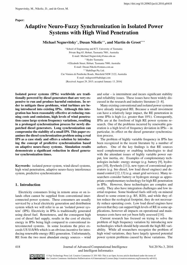
Negnevitsky, M., Nikolic, D., and de Groot, M.
Paper:
Adaptive Neuro-Fuzzy Synchronization in Isolated PowerSystems with High Wind Penetration
Michael Negnevitsky∗, Dusan Nikolic∗∗, and Martin de Groot∗∗∗
∗School of Engineering and ICT, University of TasmaniaPrivate Bag 65, Hobart, Tasmania 7001, Australia
E-mail: [email protected]∗∗Hydro Tasmania
4 Elizabeth Street, Hobart, Tasmania 7000, AustraliaE-mail: [email protected]
∗∗∗HabiDapt Pty Ltd.Cnr Vimiera & Pembroke Roads, Marsfield NSW 2122, Australia
E-mail: [email protected][Received August 29, 2015; accepted January 13, 2016]
Isolated power systems (IPSs) worldwide are tradi-tionally powered by diesel generators that are very ex-pensive to run and produce harmful emissions. In or-der to mitigate these problems, wind turbines are be-ing introduced into existing IPSs. Although this inte-gration has been reasonably effective at reducing run-ning costs and emissions, high levels of wind penetra-tion cause large system frequency variations, resultingin a prolonged synchronization process for newly dis-patched diesel generators. Long synchronization cancompromise the stability of a small IPS. This paper ex-amines the diesel synchronization problem using a realIPS as a case study and offers a solution by introduc-ing the concept of predictive synchronization basedon adaptive neuro-fuzzy systems. Simulation resultsdemonstrate a significant reduction in diesel genera-tor synchronization times.
Keywords: isolated power system, wind-diesel systems,high wind penetration, adaptive neuro-fuzzy interferencesystem, predictive synchronization
1. Introduction
Electricity consumers living in remote areas or on is-lands often cannot be supplied from conventional inter-connected power systems. These consumers are usuallyserviced by a local electricity generation and distributionsystem which we will refer to as an ‘isolated power sys-tem’ (IPS). Electricity in IPSs is traditionally generatedusing diesel fuel. Remoteness, and the consequent highcost of diesel fuel supply, results in the cost of electricenergy in IPSs being high compared to conventional in-terconnected systems. In some locations the price ex-ceeds US $1/kWh which is an obvious incentive for intro-ducing renewable energy (RE) generation. Unfortunately,RE from the two most abundant energy sources – wind
and solar – is intermittent and incurs significant stabilityand reliability issues. These issues have been widely dis-cussed in the research and industry literature [1–8].
Many existing conventional and isolated power systemshave already integrated RE. Because a small investmentcan have a relatively large impact, the RE penetration insome IPSs is high (i.e. greater than 10%). Consequently,IPSs are at the forefront of high RE power systems re-search. One of the problems incurred by renewable gen-eration is a high level of frequency deviation in IPSs – inparticular, its effect on the diesel generator synchroniza-tion process.
The problem of highly variable frequency in IPSs hasbeen recognized in the recent literature by a number ofauthors. One of the key findings is that RE sourcesneed complementary or enabling technologies to dealwith the attendant issues of highly variable power out-put, low inertia, etc. Examples of complementary tech-nologies include: energy storage (e.g. battery [9], hydro-gen [10], flywheels [11]), new types of conventional gen-erators (e.g. bio diesel, low load diesel engines) and de-mand control [12, 13] (e.g. smart grid services). Many re-searchers consider battery or hydrogen storage as appro-priate complementary technology for high RE penetrationin IPSs. However, these technologies are complex andcostly. They also have integration challenges and low in-ertial response. Some biodiesel fuels still rely on mineraldiesel to some extent (e.g. B5, B20), and while they of-ten reduce the ecological footprint, they do not necessar-ily reduce operating costs. Low load diesel engines haveproven that they can support high levels of RE in some ap-plications, however all impacts on operational and main-tenance costs have not yet been fully assessed [14].
Current research has focused on trying to solve theproblem of high frequency variation by introducing newtechnologies which should help smooth the high RE vari-ability. While all researchers recognize the problem ofhigh wind variations, they have largely ignored potentialpower system problems caused by those variations. The
418 Journal of Advanced Computational Intelligence Vol.20 No.3, 2016and Intelligent Informatics
https://doi.org/10.20965/jaciii.2016.p0418
© Fuji Technology Press Ltd. Creative Commons CC BY-ND: This is an Open Access article distributed under the terms of the Creative Commons Attribution-NoDerivatives 4.0 International License (http://creativecommons.org/licenses/by-nd/4.0/).
Adaptive Neuro-Fuzzy Synchronization in Isolated Power Systems
main reason cited for reducing frequency variation is usu-ally the general need to improve power quality.
As an alternative to solving the problem of high fre-quency fluctuations, this paper focuses on improving syn-chronization times during high frequency fluctuations insub 10 megawatt scale, low-inertia wind-diesel IPSs withno energy storage. We propose a predictive synchroniza-tion method which can be implemented in a low-cost syn-chronizer. The proposed method is based on predictingthe system frequency and phase two seconds ahead, andadjusting the phase of the diesel generator in order to putit in a statistically better state for performing the synchro-nization.
This paper examines a very specific power engineeringproblem requiring short term forecasting and offers a so-lution using neural network prediction algorithms. Thegenerator synchronization problem in IPSs is explainedin detail in Section 2. A high level model of our proposedsolution is specified in Section 3. Section 4 justifies theuse of neural networks to implement our prediction modeland analyses the mathematical properties of the solution.Section 5 is a case study of the proposed technique us-ing a real IPS. Section 6 presents simulation results of themodel introduced in Section 3 along with a comparisonagainst a base line prediction technique. Section 7 con-cludes the paper.
2. Synchronization Challenges in IsolatedPower Systems
Diesel generators are used extensively in IPSs – theyare proven technology. Control, governing and synchro-nizing equipment for these generators has usually beenbuilt for a completely diesel ‘genset’ supplied power sys-tem. Since IPSs are usually remote, their maintenanceincurs higher costs. Therefore, IPS equipment needsto be sufficiently robust to reduce maintenance require-ments. Hence, all components – including synchroniz-ers – should operate on simple and well proven princi-ples. A further consequence of this simplicity is the lowcost of modern diesel system synchronizers (usually be-low US$1,000). Fig. 1 shows daily diagram of operationof a typical IPS with virtually no renewable generation.
As the customer load changes slowly during the day, sodoes the diesel generation. This scenario results in a verystable system frequency that is almost steady at 50 Hz.
In the past few decades, many IPSs around the worldhave started integrating RE in order to reduce operationalcosts. As a result, completely new hybrid systems with arange of generation sources and operational characteris-tics have emerged. In contrast to conventional grids, IPSsnot only supply less power (usually MWs, not GWs) theyare also spatially much smaller. Being smaller in capacitymeans that demand is less predictable. Being smaller inarea means that supply from RE sources is more variable– as a larger percentage of the RE generators are likelyto be affected by the same weather events (e.g. a lull inthe wind or passing clouds). Due to their reduced de-
Fig. 1. Profile of a typical daily load in a 3 MW scale IPS.The load as seen by the diesel generation changes slowlyduring the day. Data for this example is taken from our casestudy system described in Section 5.
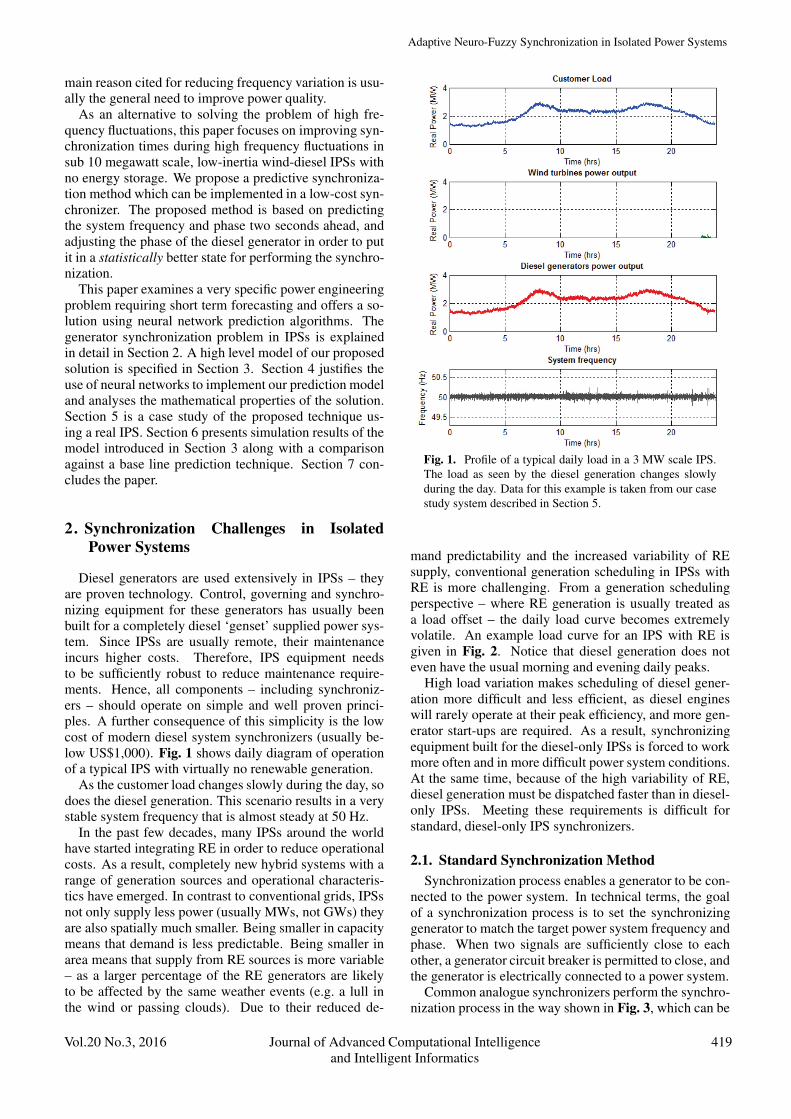
mand predictability and the increased variability of REsupply, conventional generation scheduling in IPSs withRE is more challenging. From a generation schedulingperspective – where RE generation is usually treated asa load offset – the daily load curve becomes extremelyvolatile. An example load curve for an IPS with RE isgiven in Fig. 2. Notice that diesel generation does noteven have the usual morning and evening daily peaks.
High load variation makes scheduling of diesel gener-ation more difficult and less efficient, as diesel engineswill rarely operate at their peak efficiency, and more gen-erator start-ups are required. As a result, synchronizingequipment built for the diesel-only IPSs is forced to workmore often and in more difficult power system conditions.At the same time, because of the high variability of RE,diesel generation must be dispatched faster than in diesel-only IPSs. Meeting these requirements is difficult forstandard, diesel-only IPS synchronizers.
2.1. Standard Synchronization MethodSynchronization process enables a generator to be con-
nected to the power system. In technical terms, the goalof a synchronization process is to set the synchronizinggenerator to match the target power system frequency andphase. When two signals are sufficiently close to eachother, a generator circuit breaker is permitted to close, andthe generator is electrically connected to a power system.
Common analogue synchronizers perform the synchro-nization process in the way shown in Fig. 3, which can be
Vol.20 No.3, 2016 Journal of Advanced Computational Intelligence 419and Intelligent Informatics
Negnevitsky, M., Nikolic, D., and de Groot, M.
Fig. 2. Daily load diagram in an IPS as seen by conventionaldiesel generators during high wind generation power outputis highly variable and does not necessarily reflect the usualpeaks or dips.
PI controller
Engine Delay
Generator response
Check synch
CB Close command
VGEN(t)
VSYS(t)Signal
Conditioner
Phase detector
Fig. 3. Functional diagram of a conventional synchronizercontrol loop [15].
described as follows. As their inputs, synchronizers usethe power system and generator phase to phase voltages.Based on the present generator and power system voltagephase, the synchronizer will calculate the speed correc-tion signal it needs to send to the synchronizing genera-tor. This signal is processed using the synchronizer’s in-ternal PI (proportional-integral) controller. After process-ing, the signal is sent to the diesel engine governor. Dieselengines have an inherent delay in responding to govern-ing changes, which is usually around 250 ms. When thegenerator starts responding to a speed correction signal, itslowly ramps to a new value [15]. When a synchronizersees that the generator and power system frequencies andphases are within allowable limits, it issues a close com-
0 1 2 3 4 5 6 7 8 9 1049.5
50
50.5
Time (s)
Freq
uenc
y(H
z)
Generator FrequencySystem frequency
0 1 2 3 4 5 6 7 8 9 10-200
-100
0
100
Time (s)
Pha
se(d
egre
es)
Phase difference
CB close
Beginsynchronization
Beginsynchronization
CB close
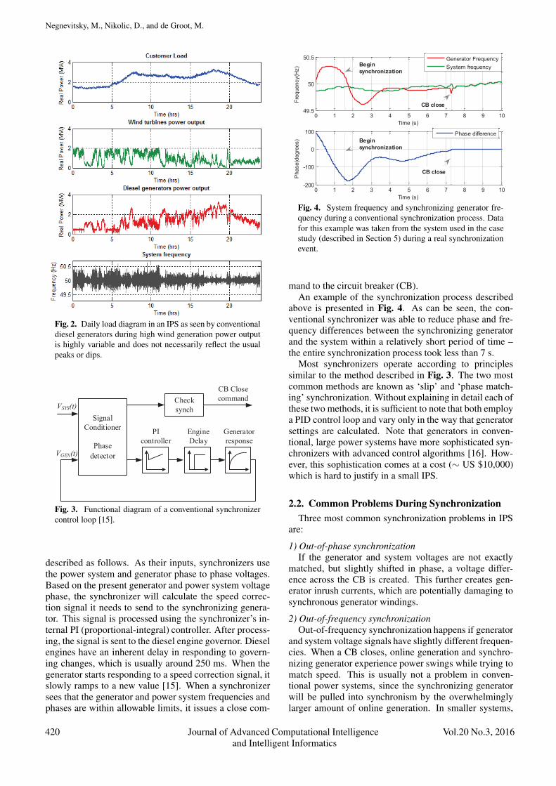
Fig. 4. System frequency and synchronizing generator fre-quency during a conventional synchronization process. Datafor this example was taken from the system used in the casestudy (described in Section 5) during a real synchronizationevent.
mand to the circuit breaker (CB).An example of the synchronization process described
above is presented in Fig. 4. As can be seen, the con-ventional synchronizer was able to reduce phase and fre-quency differences between the synchronizing generatorand the system within a relatively short period of time –the entire synchronization process took less than 7 s.
Most synchronizers operate according to principlessimilar to the method described in Fig. 3. The two mostcommon methods are known as ‘slip’ and ‘phase match-ing’ synchronization. Without explaining in detail each ofthese two methods, it is sufficient to note that both employa PID control loop and vary only in the way that generatorsettings are calculated. Note that generators in conven-tional, large power systems have more sophisticated syn-chronizers with advanced control algorithms [16]. How-ever, this sophistication comes at a cost (∼ US $10,000)which is hard to justify in a small IPS.
2.2. Common Problems During SynchronizationThree most common synchronization problems in IPS
are:
1) Out-of-phase synchronizationIf the generator and system voltages are not exactly
matched, but slightly shifted in phase, a voltage differ-ence across the CB is created. This further creates gen-erator inrush currents, which are potentially damaging tosynchronous generator windings.
2) Out-of-frequency synchronizationOut-of-frequency synchronization happens if generator
and system voltage signals have slightly different frequen-cies. When a CB closes, online generation and synchro-nizing generator experience power swings while trying tomatch speed. This is usually not a problem in conven-tional power systems, since the synchronizing generatorwill be pulled into synchronism by the overwhelminglylarger amount of online generation. In smaller systems,
420 Journal of Advanced Computational Intelligence Vol.20 No.3, 2016and Intelligent Informatics
Adaptive Neuro-Fuzzy Synchronization in Isolated Power Systems
Fig. 5. Example of a prolonged synchronization. Synchro-nization can only occur when the phase difference is withinallowed limits (usually ±10◦ phase) for a defined amount oftime (usually 500 ms). Data for this example is taken fromthe case study, described in Section 5.
however, if only a small number of generators are online,the power swing can be significant. Power swings poten-tially create large currents and system frequency oscilla-tions.
3) Prolonged synchronizationThis condition arises if a generator fails to synchronize
in an appropriate amount of time. This is a problem ifthere is insufficient spinning reserve and additional gener-ation is needed quickly by the system. If generation doesnot come online in a timely manner, load shedding mightbecome necessary.
The first two problems are potentially damaging to gen-erator equipment and effect power quality, while the thirdproblem can cause a loss of load which might be con-sidered the most severe of all three. While Fig. 4 showedthe normal synchronization process taking less than 6 sec-onds, the example given in Fig. 5 exhibits prolonged syn-chronization taking over 30 seconds. This figure alsoshows how the generator frequency is constantly huntingthe variable system frequency. As a result, their phase dif-ference is too high for synchronization to occur. Huntingresults from the total delay in common synchronizer con-trol loops (Fig. 3). Simply put, by the time generator getsto the right position at the right time, system conditionshave changed significantly.
Prolonged synchronization might not be a big problemin systems where customer load changes slowly (shownin Fig. 1). However, when the load, as seen by the gen-erators, changes faster than the generators can potentiallyrespond because of long synchronization times (shown inFig. 2), it is easy to see that the entire power system canbecome unstable.
Another difference between the synchronization pro-cesses presented in Figs. 4 and 5 is the variation in sys-tem frequency. Based on these two graphs, we can con-clude that a synchronization process necessarily takes
0
50
100
150
200
250
0 20 40 60 80
Die
sel G
ener
ator
star
t-up
and
sync
hron
isat
ion
time
[sec
onds
]
Wind Penetration [%]
Corr. coef. = 0.34
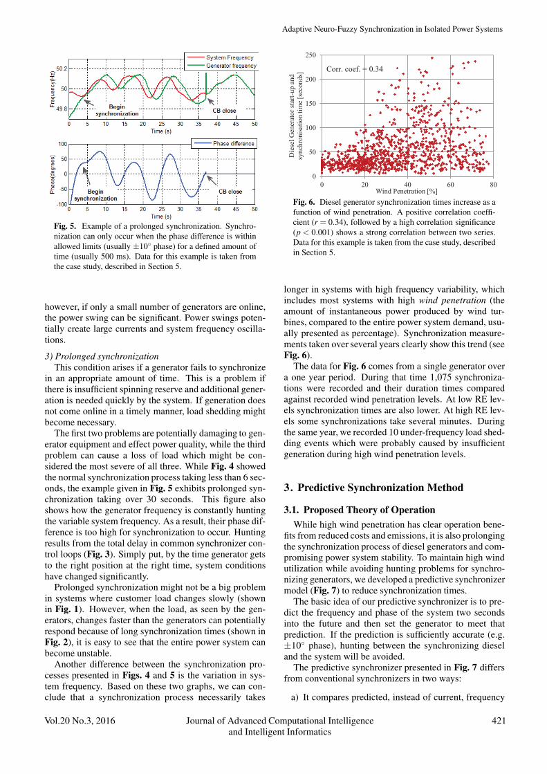
Fig. 6. Diesel generator synchronization times increase as afunction of wind penetration. A positive correlation coeffi-cient (r = 0.34), followed by a high correlation significance(p < 0.001) shows a strong correlation between two series.Data for this example is taken from the case study, describedin Section 5.
longer in systems with high frequency variability, whichincludes most systems with high wind penetration (theamount of instantaneous power produced by wind tur-bines, compared to the entire power system demand, usu-ally presented as percentage). Synchronization measure-ments taken over several years clearly show this trend (seeFig. 6).
The data for Fig. 6 comes from a single generator overa one year period. During that time 1,075 synchroniza-tions were recorded and their duration times comparedagainst recorded wind penetration levels. At low RE lev-els synchronization times are also lower. At high RE lev-els some synchronizations take several minutes. Duringthe same year, we recorded 10 under-frequency load shed-ding events which were probably caused by insufficientgeneration during high wind penetration levels.
3. Predictive Synchronization Method
3.1. Proposed Theory of OperationWhile high wind penetration has clear operation bene-
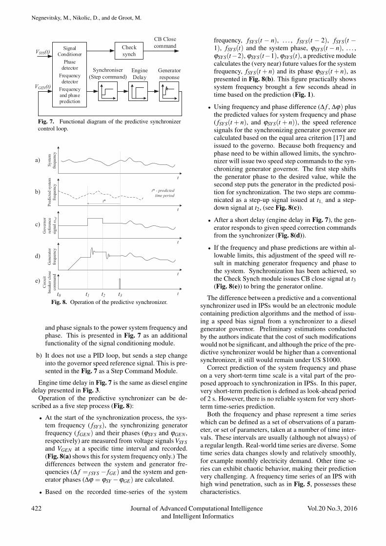
fits from reduced costs and emissions, it is also prolongingthe synchronization process of diesel generators and com-promising power system stability. To maintain high windutilization while avoiding hunting problems for synchro-nizing generators, we developed a predictive synchronizermodel (Fig. 7) to reduce synchronization times.
The basic idea of our predictive synchronizer is to pre-dict the frequency and phase of the system two secondsinto the future and then set the generator to meet thatprediction. If the prediction is sufficiently accurate (e.g.±10◦ phase), hunting between the synchronizing dieseland the system will be avoided.
The predictive synchronizer presented in Fig. 7 differsfrom conventional synchronizers in two ways:
a) It compares predicted, instead of current, frequency
Vol.20 No.3, 2016 Journal of Advanced Computational Intelligence 421and Intelligent Informatics
Negnevitsky, M., Nikolic, D., and de Groot, M.
Engine Delay
Generator response
Check synch
CB Close command
VGEN(t)
VSYS(t)Signal
ConditionerPhase
detectorFrequency detector
Frequency and phase prediction
Synchroniser(Step command)
Fig. 7. Functional diagram of the predictive synchronizercontrol loop.
Syst
emfr
eque
ncy
Gen
erat
orfr
eque
ncy
Gov
erno
rre
fere
nce
sign
alω
ref
Circ
uit
brea
kerc
lose
com
man
dPr
edic
ted
syst
emfr
eque
ncy
a)
c)
b)
d)
e)
t*
t* - predictedtime period
t1 t2 t3t0 t
t
t
t
t
Fig. 8. Operation of the predictive synchronizer.
and phase signals to the power system frequency andphase. This is presented in Fig. 7 as an additionalfunctionality of the signal conditioning module.
b) It does not use a PID loop, but sends a step changeinto the governor speed reference signal. This is pre-sented in the Fig. 7 as a Step Command Module.
Engine time delay in Fig. 7 is the same as diesel enginedelay presented in Fig. 3.
Operation of the predictive synchronizer can be de-scribed as a five step process (Fig. 8):
• At the start of the synchronization process, the sys-tem frequency ( fSY S), the synchronizing generatorfrequency ( fGEN) and their phases (ϕSY S and ϕGEN ,respectively) are measured from voltage signals VSYSand VGEN at a specific time interval and recorded.(Fig. 8(a) shows this for system frequency only.) Thedifferences between the system and generator fre-quencies (Δ f = f SYS − fGE) and the system and gen-erator phases (Δϕ = ϕSY −ϕGE) are calculated.
• Based on the recorded time-series of the system
frequency, fSY S(t − n), . . . , fSY S(t − 2), fSY S(t −1), fSY S(t) and the system phase, ϕSYS(t − n), . . . ,ϕSYS(t−2), ϕSYS(t−1), ϕSY S(t), a predictive modulecalculates the (very near) future values for the systemfrequency, fSY S(t + n) and its phase ϕSYS(t + n), aspresented in Fig. 8(b). This figure practically showssystem frequency brought a few seconds ahead intime based on the prediction (Fig. 1).
• Using frequency and phase difference (Δ f , Δϕ) plusthe predicted values for system frequency and phase( fSY S(t + n), and ϕSYS(t + n)), the speed referencesignals for the synchronizing generator governor arecalculated based on the equal area criterion [17] andissued to the governo. Because both frequency andphase need to be within allowed limits, the synchro-nizer will issue two speed step commands to the syn-chronizing generator governor. The first step shiftsthe generator phase to the desired value, while thesecond step puts the generator in the predicted posi-tion for synchronization. The two steps are commu-nicated as a step-up signal issued at t1, and a step-down signal at t2, (see Fig. 8(c)).
• After a short delay (engine delay in Fig. 7), the gen-erator responds to given speed correction commandsfrom the synchronizer (Fig. 8(d)).
• If the frequency and phase predictions are within al-lowable limits, this adjustment of the speed will re-sult in matching generator frequency and phase tothe system. Synchronization has been achieved, sothe Check Synch module issues CB close signal at t3(Fig. 8(e)) to bring the generator online.
The difference between a predictive and a conventionalsynchronizer used in IPSs would be an electronic modulecontaining prediction algorithms and the method of issu-ing a speed bias signal from a synchronizer to a dieselgenerator governor. Preliminary estimations conductedby the authors indicate that the cost of such modificationswould not be significant, and although the price of the pre-dictive synchronizer would be higher than a conventionalsynchronizer, it still would remain under US $1000.
Correct prediction of the system frequency and phaseon a very short-term time scale is a vital part of the pro-posed approach to synchronization in IPSs. In this paper,very short-term prediction is defined as look-ahead periodof 2 s. However, there is no reliable system for very short-term time-series prediction.
Both the frequency and phase represent a time serieswhich can be defined as a set of observations of a param-eter, or set of parameters, taken at a number of time inter-vals. These intervals are usually (although not always) ofa regular length. Real-world time series are diverse. Sometime series data changes slowly and relatively smoothly,for example monthly electricity demand. Other time se-ries can exhibit chaotic behavior, making their predictionvery challenging. A frequency time series of an IPS withhigh wind penetration, such as in Fig. 5, possesses thesecharacteristics.
422 Journal of Advanced Computational Intelligence Vol.20 No.3, 2016and Intelligent Informatics
Adaptive Neuro-Fuzzy Synchronization in Isolated Power Systems
The time scale is important when trying to create a pre-diction system. Two main classes of techniques have beenused for very short-term predictions. These are statisti-cal methods and methods based upon artificial neural net-works (ANN). The statistical methods are auto-recursive.This means they use the difference between the predictedand actual values in the immediate past to tune the modelparameters. The neural networks use past data taken overa longer time-frame to learn the relationship between theinput data and output wind speeds. The accuracy of thesemethods degrades rapidly with increasing prediction leadtime.
Prediction research is a growth area and increasinglyoften this research involves the use of artificial intelli-gence. In this paper, we investigate a hybrid approach –a combination of an ANN and fuzzy logic for very short-term system frequency and phase prediction.
3.2. Hardware ApplicationConventional synchronizers have three main compo-
nents: signal conditioning circuits (signal input), signalprocessing circuits and signal output components. Thesecond component, signal-processing circuits, determinesthe action based on the input signal; this componentpresents the main difference between different types ofsynchronizers.
Analogue conventional synchronizers, which are oftenused in isolated power systems, are based on the basicelectronic components. Digital, more advanced conven-tional synchronizers do have integrated chipsets and couldbe programed to perform within given parameters.
We envisage that a predictive synchronizer would re-quire an integrated chipset capable of holding and pro-cessing a neural network. Given the progresses in com-putation technology, the required processor could come ata relatively low cost and could be installed instead of ex-isting integrated chipsets of modern digital conventionalsynchronizers. Signal conditioning (input) and signal out-put circuitry used in digital conventional synchronizerscould be retained. This would bring the production costof a predictive synchronizer very close to the cost of con-ventional synchronizers.
4. Adaptive Neuro-Fuzzy System
The application of fuzzy (i.e. fuzzy logic based) andadaptive neuro-fuzzy (i.e. neural networks incorporatingfuzzy logic) interference system (ANFIS) techniques towind-diesel power systems has been proposed by sev-eral authors [18–20]. Previous work in this area has usedfuzzy control algorithms during periods of high wind pen-etration to decrease the variability of RE or to better posi-tion diesel generation. Fuzzy systems showed better per-formance over standard PID control techniques in all in-stances. Our approach is to use fuzzy techniques to con-trol the synchronizing generator so that it can better copewith highly variable system frequency during the syn-chronization process. For this, we needed to develop a
Fig. 9. The ANFIS structure.
prediction technique, which would work for non-linearsystems. As we previously had success with a similarproblem relating to short-term wind speed prediction [21],we decided to apply ANFIS techniques to this new predic-tion problem. Our approach is to extend the techniquesused to perform short term forecasting of variable windspeeds to enable forecasting of frequency and phase vari-ation in an IPS.
To predict system frequency and phase, we developedtwo ANFIS systems, one for frequency prediction and an-other for phase prediction.
Fuzzy systems and neural networks are complemen-tary tools for building intelligent systems. While neu-ral networks are low-level computational structures thatperform well when dealing with raw data, fuzzy logicdeals with reasoning on a higher level. However, fuzzysystems lack the ability to learn and cannot adjust them-selves. The combination of a neural network with a fuzzylogic into one integrated system therefore offers a promis-ing approach to building very short-term wind predictionmodels. A neuro-fuzzy system is, in fact, a neural net-work that is functionally equivalent to a fuzzy inferencemodel.
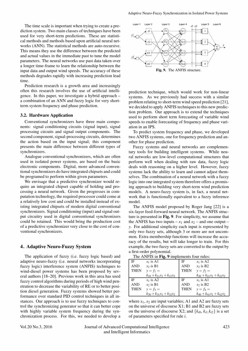
The ANFIS model proposed by Roger Jang [22] is asix-layer feed-forward neural network. The ANFIS struc-ture is presented in Fig. 9. For simplicity, we assume thatthe ANFIS has two inputs – x1 and x2 – and one output –y. For additional simplicity each input is represented byonly two fuzzy sets, although 3 or more are not uncom-mon. Extra membership functions will increase the accu-racy of the results, but will take longer to train. For thisexample, the two fuzzy sets are converted to the output bya first-order polynomial.
The ANFIS in Fig. 9 implements four rules:IF x1 is A1 IF x1 is A2AND x2 is B1 AND x2 is B2THEN y = f1 =
k10 + k11x1 + k12x2
THEN y = f2 =k20 + k21x1 + k22x2
IF x1 is A2 IF x1 is A1AND x2 is B1 AND x2 is B2THEN y = f3 =
k30 + k31x1 + k32x2
THEN y = f4 =k40 + k41x1 + k42x2
where x1, x2 are input variables; A1 and A2 are fuzzy setson the universe of discourse X1; B1 and B2 are fuzzy setson the universe of discourse X2; and {ki0, ki1,ki2} is a setof parameters specified for rule i.
Vol.20 No.3, 2016 Journal of Advanced Computational Intelligence 423and Intelligent Informatics
Negnevitsky, M., Nikolic, D., and de Groot, M.
Layer 1 is the input layer. Neurons in this layer simplypass external crisp signals to Layer 2.
Layer 2 is the fuzzification layer. Neurons in this layerperform fuzzification. In Jang’s model, fuzzification neu-rons normally use a bell activation function.
Layer 3 is the rule layer. Each neuron in this layer cor-responds to a single fuzzy rule. A rule neuron receivesinputs from the respective fuzzification neurons and cal-culates the firing strength of the rule it represents.
Layer 4 is the normalization layer. Each neuron in thislayer receives inputs from all neurons in the rule layer, andcalculates the normalized firing strength of a given rule –the ratio of the firing strength of a given rule to the sum offiring strengths of all rules. It represents the contributionof a given rule to the final result.
Layer 5 is the defuzzification layer. Each neuron in thislayer is connected to the respective normalization neuron,and also receives the initial inputs, x1 and x2. A defuzzi-fication neuron calculates the weighted consequent valueof a given rule.
Layer 6 is represented by a single summation neuron.This neuron calculates the sum of outputs of all defuzzi-fication neurons and produces the overall ANFIS output,y.
An ANFIS uses a hybrid learning algorithm that com-bines the least-squares estimator and the gradient descentmethod [22]. First, initial activation functions are as-signed to each membership neuron. The function centersof the neurons connected to input xi are set so that the do-main of xi is divided equally, and the widths and slopesare set to allow sufficient overlapping of the respectivefunctions. In the ANFIS training algorithm, each trainingepoch is composed from a forward pass and a backwardpass. In the forward pass, a training set of input patterns(an input vector) is presented to the ANFIS, neuron out-puts are calculated on the layer-by-layer basis, and ruleconsequent parameters are identified. A detailed ANFISdescription is given in [23].
5. The Case Study System
5.1. Overview
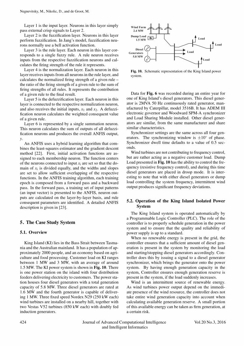
King Island (KI) lies in the Bass Strait between Tasma-nia and the Australian mainland. It has a population of ap-proximately 2000 people, and an economy based on agri-culture and food processing. Customer load on KI rangesbetween 1 MW and 3 MW, with an average of around1.5 MW. The KI power system is shown in Fig. 10. Thereis one power station on the island with four distributionfeeders delivering electricity to customers. The power sta-tion houses four diesel generators with a total generationcapacity of 5.8 MW. Three diesel generators are rated at1.6 MW and the fourth generator is capable of deliver-ing 1 MW. Three fixed speed Nordex N29 (250 kW each)wind turbines are installed on a nearby hill, together withtwo Vestas V52 turbines (850 kW each) with doubly fedinduction generators.
Dump Load1.5 MW Load
Wind Farm2.4 MW
DieselGenerators
5.8 MW
Load
Load
Load…
Fig. 10. Schematic representation of the King Island powersystem.
Data for Fig. 6 was recorded during an entire year forone of King Island’s diesel generators. This diesel gener-ator is 2MVA 50 Hz continuously rated generator, man-ufactured by Caterpillar, model 3516B. It has ADEM IIIelectronic governor and Woodward SPM-A synchronizerand Load Sharing Module installed. Other diesel gener-ators are similar, from the same manufacturer and sharesimilar characteristics.
Synchronizer settings are the same across all four gen-erators. The synchronizing window is ±10◦ of phase.Synchronizer dwell time defaults to a value of 0.5 sec-onds.
Wind turbines are not contributing to frequency control,but are rather acting as a negative customer load. DumpLoad presented in Fig. 10 has the ability to control the fre-quency (resistive frequency control), and during this timediesel generators are placed in droop mode. It is inter-esting to note that with either diesel generators or dumpload controlling the system frequency, intermittent windoutput produces significant frequency deviations.
5.2. Operation of the King Island Isolated PowerSystem
The King Island system is operated automatically bya Programmable Logic Controller (PLC). The role of thecontroller is to properly schedule generation in the powersystem and to ensure that the quality and reliability ofpower supply is up to a standard.
When no renewable energy is present in the grid, thecontroller ensures that a sufficient amount of diesel gen-eration is present in the system by monitoring the loadand starting/stopping diesel generators accordingly. Con-troller does this by issuing a signal to a diesel generatorsynchronizer, which brings the generator onto the powersystem. By having enough generation capacity in thesystem, Controller ensures enough generation reserve ispresent in the system, if the load suddenly increases.
Wind is an intermittent source of renewable energy.As wind turbines power output depend on the immedi-ate presence of the wind resource, the controller does nottake entire wind generation capacity into account whencalculating available generation reserve. A small portionof this available energy can be taken as firm generation, ata certain risk.
424 Journal of Advanced Computational Intelligence Vol.20 No.3, 2016and Intelligent Informatics

Adaptive Neuro-Fuzzy Synchronization in Isolated Power Systems
During high wind penetration periods, a higher portionof renewable generation can be taken as generation re-serve. In fact, the controller can decide to switch off somediesel generation. At this moment, power system can finditself in a situation where running diesel generation is lessthan the entire power system load. At this time, the con-troller depends on renewable generation to cover the dif-ference between what diesel generation can provide andwhat the load currently is. If the controller decides thatvariability of the wind resource is too high, it will attemptto start and synchronize another diesel generator.
As Fig. 6 shows, the synchronization process duringhigh wind penetration can sometimes take up to a coupleof minutes. Since the wind resource is intermittent, it mayslowly decay over a couple of minutes, where it will notbe sufficient to cover the difference between the availablerunning diesel generation and the load. At this moment,power system stability can be compromised. This is whytimely operation of the diesel generator synchronizer isimportant in isolated power systems.
It is also worth mentioning that the controller helpsmaintaining power system stability during faults andtransient processes. This is achieved by using under-frequency load shedding (UFLS), where some loads aredisconnected, so the majority of the system load is pre-served. Since dynamic processes during the fault condi-tions happen very quickly (in a matter of a few seconds),the synchronization process of diesel generators cannot beused.
6. Simulation and Results
The effectiveness of the predictive synchronizing tech-nique was proven by running simulations and comparingresults with the real and simulated conventional synchro-nizer.
Firstly, network frequency from our case study sys-tem was recorded in high speed (1 kHz) over a period ofaround 8 hours, during which wind penetration was about30% of the consumer load. This real frequency data waslater used as input data for the synchronizer model.
Secondly, the diesel generator described in Section 5was modelled and used as a virtual generator to be con-trolled by a synchronizer in simulations. The generatormodel was verified against the actual generator sampledata.
Next, three synchronizer models are built:
1. Model of a conventional synchronizer, explainedin Section 5. This model represented the basecase against which the predictive synchronizer mod-els were compared. It was modeled using avail-able manufacturer’s data [15], common MATLABSimulink models and tuned using the recordedgenerator synchronization performance presented inFig. 6.
2. Model of a predictive synchronizer using a basic pre-diction technique - moving average. The purpose of
this model was to compare the effectiveness of thesynchronizer using more advanced prediction tech-nique, ANFIS, to a synchronizer using moving aver-age as a baseline prediction technique.
3. Model of a predictive synchronizer using ANFIS asa prediction technique. This predictive synchronizermodel was firstly trained using a large set of fre-quency sample data collected from the case studysystem.
In three separate simulations for three different syn-chronizer models, all synchronizers were controlling adiesel generator which was constantly trying to synchro-nize to the system frequency. If it was unsuccessful,the synchronizer was restarted, and it went through an-other cycle. When it synchronized, synchronization wasrecorded and the synchronizer was restarted for the nextrun.
6.1. Synchronization Duration ResultsThe outcome of all performed simulations is presented
in Table 1, and compared to recorded data from the casestudy system.
The first row shows results for a conventional synchro-nizer, from the case study system, presented in Section 5.This data set is also presented in Fig. 6. Median synchro-nization time for the given data set was 42 s.
This conventional synchronizer is then simulated; itproduces the median synchronization time of 44 s, whichis very similar to the data recorded. These data alsodemonstrate the validity of the model.
Following this, a synchronizer using moving averageas the basic prediction technique is simulated (presentedin row 3 of Table 1). This simple prediction techniqueshows better performance than the conventional synchro-nizer.
Finally, a synchronizer using ANFIS as the predictiontechnique is simulated. The result shows the median av-erage time of 18 s, which is an improvement when com-pared to both the conventional synchronizer and the sim-ulated synchronizer with the basic prediction technique.
It is important to note that the simulation results showthat a predictive synchronizer has achieved statisticallybetter performance when compared with a conventionalsynchronizer. The presented result, however, does not im-ply that a predictive synchronizer will perform better inevery possible scenario.
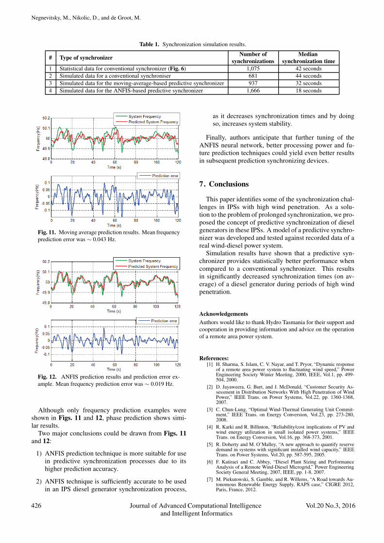
6.2. Prediction Techniques ResultsIt is also interesting to compare prediction accuracy be-
tween the moving average and ANFIS prediction tech-niques. An example of prediction results for moving av-erage and ANFIS are presented in Figs. 11 and 12 respec-tively. The same data sample is used for both predictiontechniques, and resulted in moving average showing dou-ble frequency prediction error than ANFIS.
Vol.20 No.3, 2016 Journal of Advanced Computational Intelligence 425and Intelligent Informatics
Negnevitsky, M., Nikolic, D., and de Groot, M.
Table 1. Synchronization simulation results.
# Type of synchronizer Number of Mediansynchronizations synchronization time
1 Statistical data for conventional synchronizer (Fig. 6) 1,075 42 seconds2 Simulated data for a conventional synchroniser 681 44 seconds3 Simulated data for the moving-average-based predictive synchronizer 937 32 seconds4 Simulated data for the ANFIS-based predictive synchronizer 1,666 18 seconds
Fig. 11. Moving average prediction results. Mean frequencyprediction error was ∼ 0.043 Hz.
Fig. 12. ANFIS prediction results and prediction error ex-ample. Mean frequency prediction error was ∼ 0.019 Hz.
Although only frequency prediction examples wereshown in Figs. 11 and 12, phase prediction shows simi-lar results.
Two major conclusions could be drawn from Figs. 11and 12:
1) ANFIS prediction technique is more suitable for usein predictive synchronization processes due to itshigher prediction accuracy.
2) ANFIS technique is sufficiently accurate to be usedin an IPS diesel generator synchronization process,
as it decreases synchronization times and by doingso, increases system stability.
Finally, authors anticipate that further tuning of theANFIS neural network, better processing power and fu-ture prediction techniques could yield even better resultsin subsequent prediction synchronizing devices.
7. Conclusions
This paper identifies some of the synchronization chal-lenges in IPSs with high wind penetration. As a solu-tion to the problem of prolonged synchronization, we pro-posed the concept of predictive synchronization of dieselgenerators in these IPSs. A model of a predictive synchro-nizer was developed and tested against recorded data of areal wind-diesel power system.
Simulation results have shown that a predictive syn-chronizer provides statistically better performance whencompared to a conventional synchronizer. This resultsin significantly decreased synchronization times (on av-erage) of a diesel generator during periods of high windpenetration.
AcknowledgementsAuthors would like to thank Hydro Tasmania for their support andcooperation in providing information and advice on the operationof a remote area power system.
References:[1] H. Sharma, S. Islam, C. V. Nayar, and T. Pryor, “Dynamic response
of a remote area power system to fluctuating wind speed,” PowerEngineering Society Winter Meeting, 2000, IEEE, Vol.1, pp. 499-504, 2000.
[2] D. Jayaweera, G. Burt, and J. McDonald, “Customer Security As-sessment in Distribution Networks With High Penetration of WindPower,” IEEE Trans. on Power Systems, Vol.22, pp. 1360-1368,2007.
[3] C. Chun-Lung, “Optimal Wind-Thermal Generating Unit Commit-ment,” IEEE Trans. on Energy Conversion, Vol.23, pp. 273-280,2008.
[4] R. Karki and R. Billinton, “Reliability/cost implications of PV andwind energy utilization in small isolated power systems,” IEEETrans. on Energy Conversion, Vol.16, pp. 368-373, 2001.
[5] R. Doherty and M. O’Malley, “A new approach to quantify reservedemand in systems with significant installed wind capacity,” IEEETrans. on Power Systems, Vol.20, pp. 587-595, 2005.
[6] F. Katiraei and C. Abbey, “Diesel Plant Sizing and PerformanceAnalysis of a Remote Wind-Diesel Microgrid,” Power EngineeringSociety General Meeting, 2007, IEEE, pp. 1-8, 2007.
[7] M. Piekutowski, S. Gamble, and R. Willems, “A Road towards Au-tonomous Renewable Energy Supply, RAPS case,” CIGRE 2012,Paris, France, 2012.
426 Journal of Advanced Computational Intelligence Vol.20 No.3, 2016and Intelligent Informatics
Adaptive Neuro-Fuzzy Synchronization in Isolated Power Systems
[8] G. Lalor, J. Ritchie, S. Rourke, D. Flynn, and M. J. O’Malley, “Dy-namic frequency control with increasing wind generation,” PowerEngineering Society General Meeting, 2004, IEEE, Vol.2, pp. 1715-1720, 2004.
[9] D. Kottick, M. Blau, and D. Edelstein, “Battery energy storage forfrequency regulation in an island power system,” IEEE Trans. onEnergy Conversion, Vol.8, pp. 455-459, 1993.
[10] A. Gargoom, H. Abu Mohammad Osman, M. E. Haque, and M.Negnevitsky, “Hybrid stand-alone power systems with hydrogenenergy storage for isolated communities,” Transmission and Distri-bution Conference and Exposition, 2010 IEEE PES, pp. 1-6, 2010.
[11] N. Hamsic, A. Schmelter, A. Mohd, E. Ortjohann, E. Schultze, A.Tuckey, and J. Zimmermann, “Increasing Renewable Energy Pene-tration in Isolated Grids Using a Flywheel Energy Storage System,”Int. Conf. on Power Engineering, Energy and Electrical Drives 2007(POWERENG 2007), pp. 195-200, 2007.
[12] X. Zhao, J. Ostergaard, and M. Togeby, “Demand as FrequencyControlled Reserve,” IEEE Trans. on Power Systems, Vol.26,pp. 1062-1071, 2011.
[13] J. A. Short, D. G. Infield, and L. L. Freris, “Stabilization of GridFrequency Through Dynamic Demand Control,” IEEE Trans. onPower Systems, Vol.22, pp. 1284-1293, 2007.
[14] ABB-PowerCorp, Low-Load Diesel (LLD) product, Available:http://www.pcorp.com.au [Accessed April 2016].
[15] Woodward, SPM synchronisers product, Available:www.woodward.com/synchronizers.aspx [Accessed April 2016].
[16] ABB, Synchrotact Synchroniser product, Available:http://www.abb.com [Accessed April 2016].
[17] R. J. Best, D. J. Morrow, D. J. McGowan, and P. A. Crossley, “Syn-chronous Islanded Operation of a Diesel Generator,” IEEE Trans.on Power Systems, Vol.22, pp. 2170-2176, 2007.
[18] R. Chedid, S. Karaki, and C. Chemali, “Adaptive fuzzy control forwind-diesel weak power systems,” Power Engineering Society Win-ter Meeting, 2000, IEEE, Vol.2, p. 1426, 2000.
[19] H. Bevrani and P. R. Daneshmand, “Fuzzy Logic-Based Load-Frequency Control Concerning High Penetration of Wind Tur-bines,” Systems J., IEEE, Vol.6, pp. 173-180, 2012.
[20] M. Marzband, A. Sumper, O. Gomis-Bellmunt, P. Pezzini, and M.Chindris, “Frequency control of isolated wind and diesel hybrid Mi-croGrid power system by using fuzzy logic controllers and PID con-trollers,” 2011 11th Int. Conf. on Electrical Power Quality and Util-isation (EPQU), pp. 1-6, 2011.
[21] C. W. Potter and M. Negnevitsky, “Very short-term wind forecastingfor Tasmanian power generation,” IEEE Trans. on Power Systems,Vol.21, pp. 965-972, 2006.
[22] J. S. R. Jang, “ANFIS: adaptive-network-based fuzzy inferencesystem,” IEEE Trans. on Systems, Man and Cybernetics, Vol.23,pp. 665-685, 1993.
[23] M. Negnevitsky, Artificial Intelligence: A Guide to Intelligent Sys-tems. Harlow, England: Addison Wesley, 2011.
Name:Michael Negnevitsky
Affiliation:School of Engineering and ICT, University ofTasmania
Address:Private Bag 65, Hobart, Tasmania 7001, AustraliaBrief Biographical History:1983 Received the Ph.D. degree from the Byelorussian University ofTechnology1984- Senior Research Fellow and Senior Lecturer in the ByelorussianUniversity of TechnologyCurrently- Chair Professor in Power Engineering and ComputationalIntelligence, University of TasmaniaMain Works:• M. Negnevitsky, Artificial Intelligence: A Guide to Intelligent Systems,3rd Ed., Addison Wesley, Harlow, England, 2011.• M. Negnevitsky, N. Tomin, and C. Rehtanz, “Preventing Large-ScaleEmergencies in Modern Power Systems: AI approach,” J. of AdvancedComputational Intelligence and Intelligent Informatics (JACIII), Vol.18,No.5, pp. 1-14, 2014.• M. Negnevitsky, “Computational Intelligence Approach to CrisisManagement in Power Systems,” Int. J. of Automation and Control, Vol.2Nos.2/3, pp. 247-273, 2008.Membership in Academic Societies:• Counseil International des Grands Reseaux Electriques (CIGRE)• Senior Member, The Institute of Electrical and Electronics Engineers(IEEE)• Fellow, Engineers Australia
Name:Dusan Nikolic
Affiliation:Entura, Hydro Tasmania
Address:Level 25/500 Collins Street, Melbourne, VIC 3000, AustraliaBrief Biographical History:2006 Graduated from University of Belgrade, Power Systems Department2006-2009 Researcher, Innovations Centre ICEF, SerbiaCurrently- Senior Electrical Engineer at Entura, Hydro Tasmania, AustraliaMain Works:• D. Nikolic, M. Negnevistky, and M. De Groot, “Effect of the DieselEngine Delay on Stability of Isolated Power Systems with High Levels ofRenewable Energy Penetration,” Int. Symp. on Smart Electric DistributionSystems and Technologies (EDST), Austria, 2015.• D. Nikolic, M. Negnevitsky, M. De Groot, S. Gamble, J. Forbes, and M.Ross, “Fast Demand Response as an Enabling Technology for HighRenewable Energy Penetration in Isolated Power Systems,” IEEE GeneralMeeting 2014, Washington, USA, 2014.Membership in Academic Societies:• The Institute of Electrical and Electronics Engineers (IEEE)• Engineers Australia
Vol.20 No.3, 2016 Journal of Advanced Computational Intelligence 427and Intelligent Informatics

Negnevitsky, M., Nikolic, D., and de Groot, M.
Name:Martin de Groot
Affiliation:HabiDapt Pty Ltd.
Address:Cnr Vimiera & Pembroke Roads, Marsfield NSW 2122, AustraliaBrief Biographical History:2007 Received Ph.D. from University of New South Wales in SoftwareEngineering2007-2014 Senior Research Scientist at CSIRO, AustraliaCurrently- Founder and CTO at HabiDapt Pty Ltd.Main Works:• J. J. Zic, M. Groot, D. Liu, J. Jang, and C. Wang, “Hardware securitydevice facilitated trusted energy services,” Mobile Networks andApplications, Vol.17, No.4, pp. 564-577, 2012.• C. Wang, and M. de Groot. “Managing end-user preferences in the smartgrid,” Proc. of the 1st Int. Conf. on Energy-Efficient Computing andNetworking, ACM, 2010.• M. De Groot, “Integrating formal methods with system management,”Formal Methods and Software Engineering, Springer Berlin Heidelberg,pp. 19-36, 2007.Membership in Academic Societies:• The Institute of Electrical and Electronics Engineers (IEEE)
428 Journal of Advanced Computational Intelligence Vol.20 No.3, 2016and Intelligent Informatics
Powered by TCPDF (www.tcpdf.org)
Copyright © 2022 FDOKUMEN