Magnetically levitated planar actuator with moving ... - CiteSeerX
Micromachines 2013, 4, 80-89; doi:10.3390/mi4010080
micromachines ISSN 2072-666X
www.mdpi.com/journal/micromachines
Article
Active Continuous-Flow Micromixer Using an External Braille
Pin Actuator Array
Yawar Abbas 1,4,
*, Junichi Miwa 1, Roland Zengerle
1,2,3 and Felix von Stetten
1,2
1 Laboratory for MEMS Applications, Department of Microsystems Engineering, IMTEK, University
of Freiburg, Georges-Koehler-Allee 103, 79110 Freiburg, Germany;
E-Mails: [email protected] (J.M.); [email protected] (R.Z.);
[email protected] (F.V.S) 2 HSG-IMIT, Institut für Mikro- und Informationstechnik, Georges-Koehler-Allee 103, 79110
Freiburg, Germany 3 BIOSS—Centre for Biological Signalling Studies, University Freiburg, 79104 Freiburg, Germany
4 BIOS-Lab on chip group, MESA+ Institution of Nanotechnology, University of Twente, 7522 NH
Enschede, The Netherlands
* Author to whom correspondence should be addressed; E-Mail: [email protected];
Tel.: +31-53-489-2604; Fax: +31-53-489-3595.
Received: 17 December 2012; in revised form: 11 February 2013 / Accepted: 1 March 2013 /
Published: 14 March 2013
Abstract: We present a continuous-flow active micromixer based on channel-wall
deflection in a polydimethylsiloxane (PDMS) chip for volume flows in the range up to
2 μL s−1
which is intended as a novel unit operation for the microfluidic Braille pin
actuated platform. The chip design comprises a main microchannel connected to a series of
side channels with dead ends aligned on the Braille pins. Computer-controlled deflection of
the side-channel walls induces chaotic advection in the main-channel, which substantially
accelerates mixing in low-Reynolds number flow. Sufficient mixing (mixing index MI
below 0.1) of volume flows up to 0.5 μL s−1
could be achieved within residence times
~500 ms in the micromixer. As an application, continuous dilution of a yeast cell sample
by a ratio down to 1:10 was successfully demonstrated. The mixer is intended to serve as a
component of bio-analytical devices or as a unit operation in the microfluidic Braille pin
actuated platform.
Keywords: active micromixer; continuous-flow; chaotic advection; channel wall
deflection; PDMS chip; cell sample dilution; microfluidic Braille pin actuated platform
OPEN ACCESS
Micromachines 2013, 4
81
1. Introduction
Mixing of fluids in microchannels is challenging due to the stable laminar flow. The speed of
mixing is limited by molecular diffusion, and is inversely proportional to the size of the fluid molecule
or particle to be mixed [1]. Typically, for relatively large biomolecules or even cells, mixing can
amount to hours in microchannels. An efficient method for mixing enhancement in microchannels is
needed for bio-analytical applications such as cell counting, enzyme assays, screening assays, cell lysis,
protein folding, and many others [2].
In recent years, several active and passive mixers have been designed, based on the idea of reducing
characteristic diffusion length in microchannels [3]. One profound phenomena for efficient microscale
mixing is chaotic advection [4], which involves local stretching and folding of the fluid streams and
results in significant reduction in effective diffusion length. The key to effective mixing lies in the
generation of strong stretching and folding [5]. Chaotic advection is induced in passive mixers through
channel geometries [6–9], whereas in active mixers, stretching and folding is introduced with the aid of
external perturbation sources [10–12]. Active micromixers generally provide enhanced control over
the process for a broader range of flow conditions [11,12]. Several active mixers based on chaotic
advection have been reported where efficient mixing was observed in sub-seconds [4,5,11]. Most of
the previously reported active mixers have been fixed-volume mixers. Mixing in continuous-flow
condition is challenging due to the lower speed of mixing compared to the typically short residence
time of the particles in the mixer. Tabeling et al. [4] reported a cross-channel micromixer which
exploits chaotic motion of fluid particles in the main channel due to pressure perturbation at side
channels. Such structures with robust and compact pressure-perturbation sources can be used for rapid
mixing in microscale for continuous flow condition.
In this work we present a continuous-flow active micromixer that creates chaotic advection in cross-
channel structures with the aid of mechanical actuation of polydimethylsiloxane (PDMS) membranes.
The mixer is a novel unit operation for the Braille pin controlled microfluidic platform first described
by Gu et al. [13] and Erickson [14].
2. Material and Method
2.1. Principle of Braille Pin Controlled Continuous Micromixer
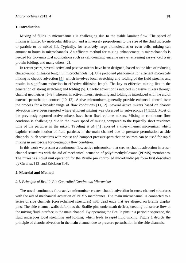
The novel continuous-flow active micromixer creates chaotic advection in cross-channel structures
with the aid of mechanical actuation of PDMS membranes. The main microchannel is connected to a
series of side channels (cross-channel structures) with dead ends that are aligned on Braille display
pins. The side channel walls deform as the Braille pins underneath deflect, creating transverse flow at
the mixing fluid interface in the main channel. By operating the Braille pins in a periodic sequence, the
fluid undergoes local stretching and folding, which leads to rapid fluid mixing. Figure 1 depicts the
principle of chaotic advection in the main channel due to pressure perturbation in the side channels.
Micromachines 2013, 4
82
Figure 1. Schematic of a cross-channel mixer and principle of pressure perturbation. (a) At
no actuation, flow in main channel is laminar. (b) After Braille pin actuation stretching and
folding of fluid interface occurs in main channel.
2.2. Chip Fabrication
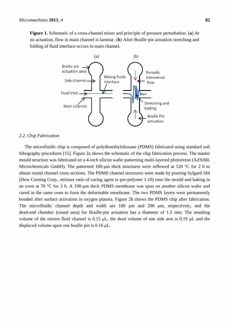
The microfluidic chip is composed of polydimethylsiloxane (PDMS) fabricated using standard soft
lithography procedures [15]. Figure 2a shows the schematic of the chip fabrication process. The master
mould structure was fabricated on a 4-inch silicon wafer patterning multi-layered photoresist (AZ9260,
Microchemicals GmbH). The patterned 100-μm thick structures were reflowed at 120 °C for 2 h to
obtain round channel cross sections. The PDMS channel structures were made by pouring Sylgard 184
(Dow Corning Corp., mixture ratio of curing agent to pre-polymer 1:10) onto the mould and baking in
an oven at 70 °C for 2 h. A 100-μm thick PDMS membrane was spun on another silicon wafer and
cured in the same oven to form the deformable membrane. The two PDMS layers were permanently
bonded after surface activation in oxygen plasma. Figure 2b shows the PDMS chip after fabrication.
The microfluidic channel depth and width are 100 μm and 200 μm, respectively, and the
dead-end chamber (round area) for Braille-pin actuation has a diameter of 1.5 mm. The resulting
volume of the mixers fluid channel is 0.15 μL, the dead volume of one side arm is 0.19 μL and the
displaced volume upon one braille pin is 0.16 μL.
Micromachines 2013, 4
83
Figure 2. (a) Polydimethylsiloxane (PDMS) chip fabrication steps. (b) Snapshot of the
microfluidics chip after fabrication, magnified view of one cross-channel structure in the
PDMS chip shows the cross-channel with round area at the dead end. Braille pins deflect
the membrane at the round areas.
(a) (b)
2.3. Braille Pin Actuator
The feasibility of Braille pin device as a mechanical actuator for fluid metering in bio-analytical
applications has been demonstrated by several groups [13,16]. We used a commercial Braille display
(KGS Corp., Saitama, Japan) that provides an 8 × 8 array of 1.3 mm diameter pins that are each
connected to piezoelectric bimorphs. These pins each deliver a force of 0.1 N for membrane deflection
of up to 700 μm. The force corresponds to approximately 280 kPa pressure at the PDMS chambers
when the chip is aligned and clamped on the Braille display (Figure 3b). The resonance frequency of
each piezoelectric element is 10 Hz. The pin actuation is controlled by a computer interface connected
through an electronic interface circuit manufactured by Biofluidix GmbH, Freiburg, Germany [17].
2.4. Experimental Setup
A schematic of the experimental setup is illustrated in Figure 3a. The membrane side of the PDMS
chip is placed directly on top of the Braille display pin after careful alignment of the dead-end
chambers with the Braille display pins. To pump the fluid through the chip at a precisely
predetermined flow rate, a commercial syringe pump (neMESYS, Cetoni GmbH, Korbussen, Germany)
was used. A high-speed camera (pco. 1200, PCO AG, Kelheim, Germany) was used to acquire

Micromachines 2013, 4
84
instantaneous images of the fluid mixing inside the fluid channels. A 12× objective lens (Navitar Inc.,
New York, NY, USA) was attached to the high-speed camera to magnify the images.
Figure 3. (a) Schematic of complete experimental setup. (b) PDMS chip with integrated
cross channel and inlet/outlet tubes on a commercially available Braille pin actuator.
(a) (b)
2.5. Mixing Quantification Technique
The efficiency of the Braille-actuated micromixer is evaluated by image analysis of instantaneous
images of two water streams, one of which is colored with ink. The performance is quantified using a
mixing index (MI) defined as the standard deviation of the pixel intensity values of an instantaneous
image at time t from a certain reference image. In this study, the reference is defined as the image
where the fluid is homogenized or completely mixed [11]. The expression for MI is given in
Equation (1).
(1)
where N is number of pixels and I is the optical intensity. MI values of 1 and 0 indicate perfect laminar
distribution and completely mixed state, respectively. Many of the literature consider 0.1 MI as a
threshold value to define well mixed states [11,18]. Therefore, mixing time, which is the time it takes
for the two fluids to be well mixed in the main channel, is defined as the time when the MI reaches 0.1.
In case of this continuous micromixer the mixing time is equivalent to the residence time of the fluid in
the micromixer which is related to the volume flow and the active volume of the micromixers
fluid channel.
Micromachines 2013, 4
85
3. Results and Discussion
3.1. Qualitative Analysis
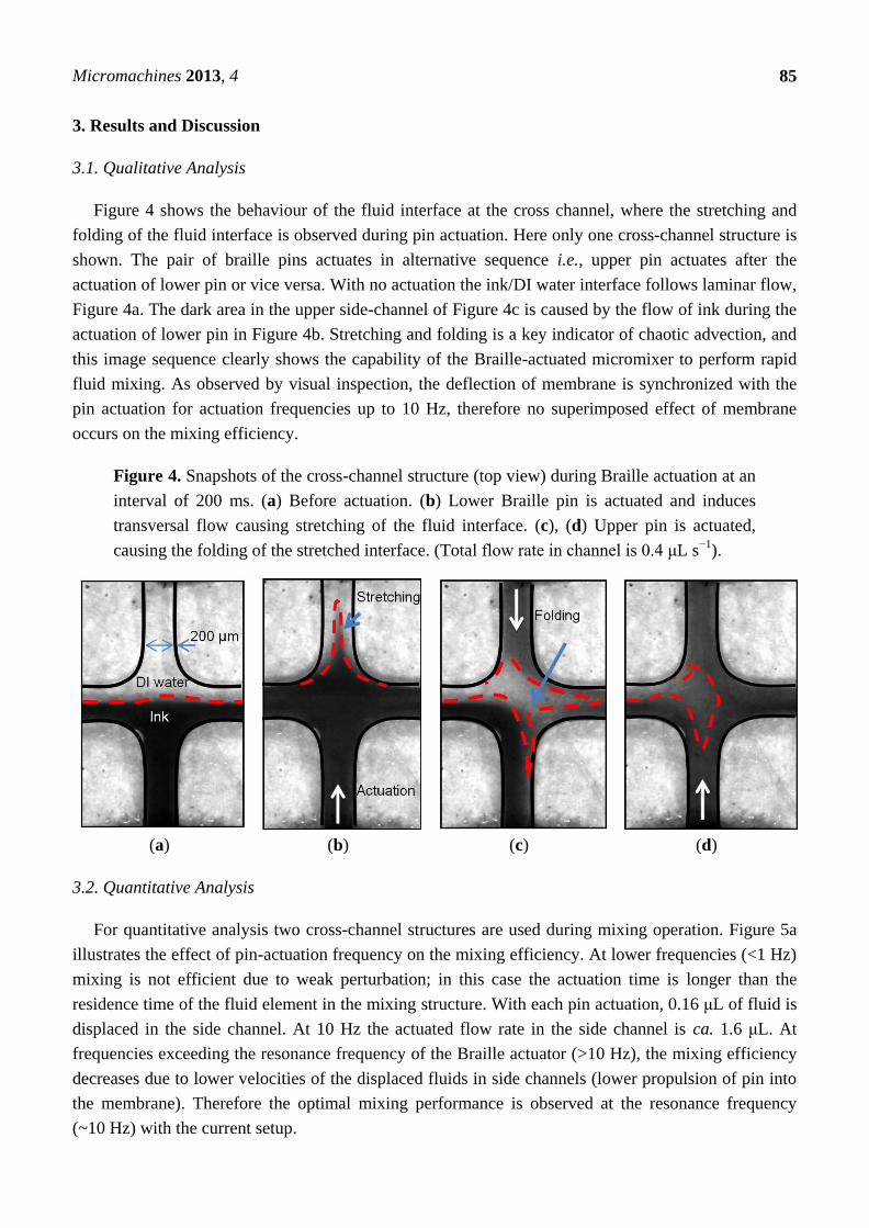
Figure 4 shows the behaviour of the fluid interface at the cross channel, where the stretching and
folding of the fluid interface is observed during pin actuation. Here only one cross-channel structure is
shown. The pair of braille pins actuates in alternative sequence i.e., upper pin actuates after the
actuation of lower pin or vice versa. With no actuation the ink/DI water interface follows laminar flow,
Figure 4a. The dark area in the upper side-channel of Figure 4c is caused by the flow of ink during the
actuation of lower pin in Figure 4b. Stretching and folding is a key indicator of chaotic advection, and
this image sequence clearly shows the capability of the Braille-actuated micromixer to perform rapid
fluid mixing. As observed by visual inspection, the deflection of membrane is synchronized with the
pin actuation for actuation frequencies up to 10 Hz, therefore no superimposed effect of membrane
occurs on the mixing efficiency.
Figure 4. Snapshots of the cross-channel structure (top view) during Braille actuation at an
interval of 200 ms. (a) Before actuation. (b) Lower Braille pin is actuated and induces
transversal flow causing stretching of the fluid interface. (c), (d) Upper pin is actuated,
causing the folding of the stretched interface. (Total flow rate in channel is 0.4 μL s−1
).
(a) (b) (c) (d)
3.2. Quantitative Analysis
For quantitative analysis two cross-channel structures are used during mixing operation. Figure 5a
illustrates the effect of pin-actuation frequency on the mixing efficiency. At lower frequencies (<1 Hz)
mixing is not efficient due to weak perturbation; in this case the actuation time is longer than the
residence time of the fluid element in the mixing structure. With each pin actuation, 0.16 μL of fluid is
displaced in the side channel. At 10 Hz the actuated flow rate in the side channel is ca. 1.6 μL. At
frequencies exceeding the resonance frequency of the Braille actuator (>10 Hz), the mixing efficiency
decreases due to lower velocities of the displaced fluids in side channels (lower propulsion of pin into
the membrane). Therefore the optimal mixing performance is observed at the resonance frequency
(~10 Hz) with the current setup.

Micromachines 2013, 4
86
Figure 5b depicts the dependency of mixing efficiency on the total flow rate of fluids inside the
main channel. The mixing efficiency decreases with increasing flow rates due to the fact that the
residence time of the fluid in the channel is shortened and fluid elements undergo less perturbation
before they leave the mixing chamber. Although the Reynolds number of the main-channel flow at
2 μL s−1
is relatively high (~20), it is not high enough to enhance mixing by turbulence. Thus for flow
rates higher than 0.4 μL s−1
, more than two cross-channels structures are required (i.e., Number of
actuating pins > 4) for efficient mixing. The ratio of the side-channel flow rate to the main-channel
flow rate is also an important parameter to quantify the operational parameter of this mixer. Figure 5d
depicts the relation between the side-channel flow rates and the main-channel flow rates for sufficient
mixing efficiency (MI < 0.1). To achieve sufficient mixing the required side-channel flow rate is
almost the square of the main-channel flow rate, as apparent from Figure 5d.
Figure 5. Different effects on the MI of the cross-channel mixer. (a) Effect of actuation
frequency of braille pin actuator. (b) Effect of total flow velocity of fluids in main channel.
(c) Effect of fluid viscosity. (d) Relation between the main-channel flow rates and the
side-channel flow rates for acquiring mixing index within 0.1.
Figure 5c depicts the effect of fluid viscosity on the MI. Fluids with different viscosities were
prepared by diluting glycerol at different percentages in DI water. The MI increases (decreasing
mixing efficiency) with the increase in the fluid viscosity, which is natural since viscosity is inversely
Micromachines 2013, 4
87
proportional to the diffusion constant. Still, for a wide range of viscosities (up to 50 mPa s), the MI is
below 0.1 which is the threshold of ‘good mixing’ commonly used in other studies [11,18].
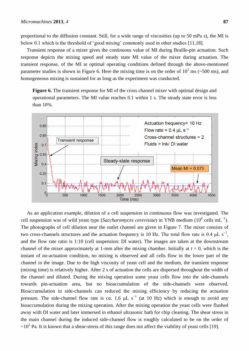
Transient response of a mixer gives the continuous value of MI during Braille-pin actuation. Such
response depicts the mixing speed and steady state MI value of the mixer during actuation. The
transient response, of the MI at optimal operating conditions defined through the above-mentioned
parameter studies is shown in Figure 6. Here the mixing time is on the order of 102 ms (~500 ms), and
homogeneous mixing is sustained for as long as the experiment was conducted.
Figure 6. The transient response for MI of the cross channel mixer with optimal design and
operational parameters. The MI value reaches 0.1 within 1 s. The steady state error is less
than 10%.
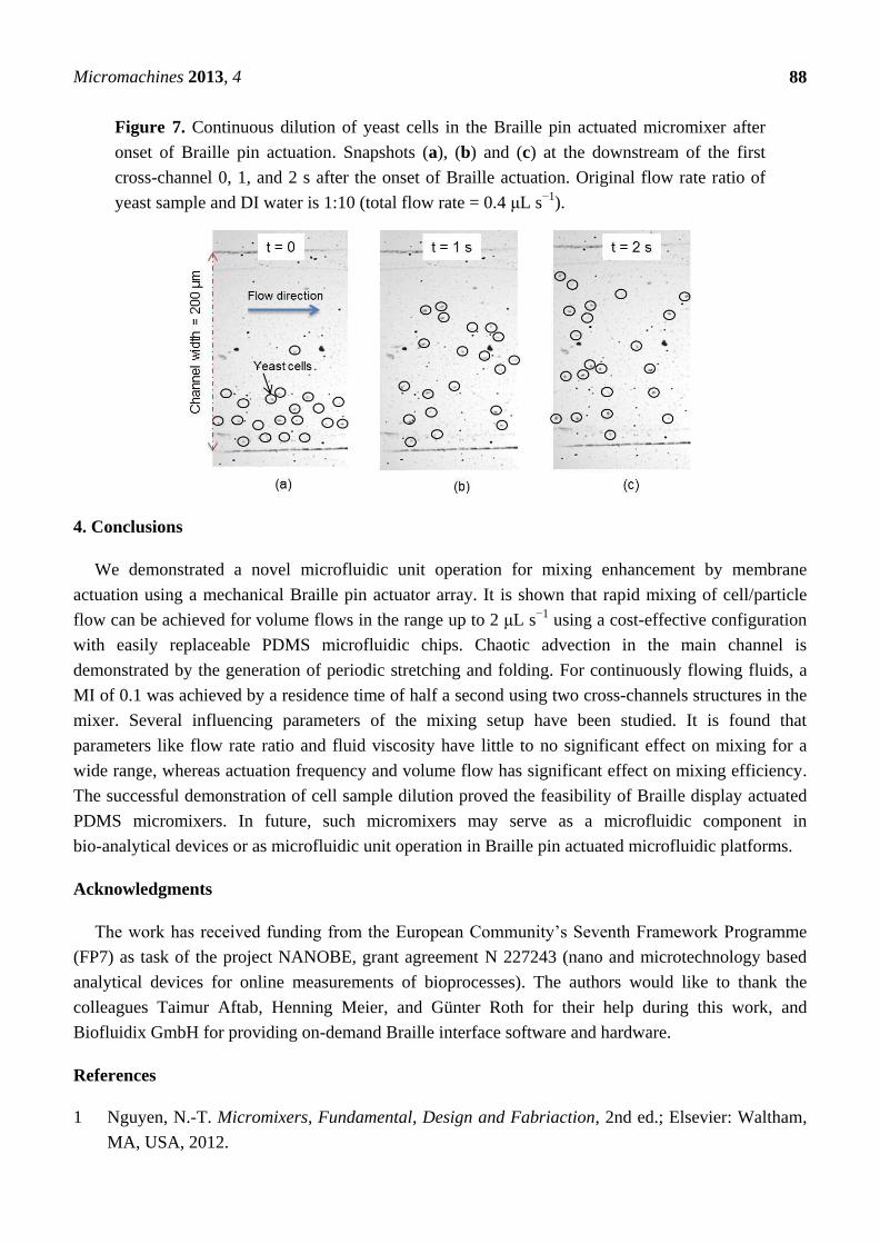
As an application example, dilution of a cell suspension in continuous flow was investigated. The
cell suspension was of wild yeast type (Saccharomyces cerevisiae) in YNB medium (106 cells mL
−1).
The photographs of cell dilution near the outlet channel are given in Figure 7. The mixer consists of
two cross-channels structures and the actuation frequency is 10 Hz. The total flow rate is 0.4 μL s−1
,
and the flow rate ratio is 1:10 (cell suspension: DI water). The images are taken at the downstream
channel of the mixer approximately at 1-mm after the mixing chamber. Initially at t = 0, which is the
instant of no-actuation condition, no mixing is observed and all cells flow in the lower part of the
channel in the image. Due to the high viscosity of yeast cell and the medium, the transient response
(mixing time) is relatively higher. After 2 s of actuation the cells are dispersed throughout the width of
the channel and diluted. During the mixing operation some yeast cells flow into the side-channels
towards pin-actuation area, but no bioaccumulation of the side-channels were observed.
Bioaccumulation in side-channels can reduced the mixing efficiency by reducing the actuation
pressure. The side-channel flow rate is ca. 1.6 μL s−1
(at 10 Hz) which is enough to avoid any
bioaccumulation during the mixing operation. After the mixing operation the yeast cells were flushed
away with DI water and later immersed in ethanol ultrasonic bath for chip cleaning. The shear stress in
the main channel during the induced side-channel flow is roughly calculated to be on the order of
~102 Pa. It is known that a shear-stress of this range does not affect the viability of yeast cells [19].
Micromachines 2013, 4
88
Figure 7. Continuous dilution of yeast cells in the Braille pin actuated micromixer after
onset of Braille pin actuation. Snapshots (a), (b) and (c) at the downstream of the first
cross-channel 0, 1, and 2 s after the onset of Braille actuation. Original flow rate ratio of
yeast sample and DI water is 1:10 (total flow rate = 0.4 μL s−1
).
4. Conclusions
We demonstrated a novel microfluidic unit operation for mixing enhancement by membrane
actuation using a mechanical Braille pin actuator array. It is shown that rapid mixing of cell/particle
flow can be achieved for volume flows in the range up to 2 μL s−1
using a cost-effective configuration
with easily replaceable PDMS microfluidic chips. Chaotic advection in the main channel is
demonstrated by the generation of periodic stretching and folding. For continuously flowing fluids, a
MI of 0.1 was achieved by a residence time of half a second using two cross-channels structures in the
mixer. Several influencing parameters of the mixing setup have been studied. It is found that
parameters like flow rate ratio and fluid viscosity have little to no significant effect on mixing for a
wide range, whereas actuation frequency and volume flow has significant effect on mixing efficiency.
The successful demonstration of cell sample dilution proved the feasibility of Braille display actuated
PDMS micromixers. In future, such micromixers may serve as a microfluidic component in
bio-analytical devices or as microfluidic unit operation in Braille pin actuated microfluidic platforms.
Acknowledgments
The work has received funding from the European Community’s Seventh Framework Programme
(FP7) as task of the project NANOBE, grant agreement N 227243 (nano and microtechnology based
analytical devices for online measurements of bioprocesses). The authors would like to thank the
colleagues Taimur Aftab, Henning Meier, and Günter Roth for their help during this work, and
Biofluidix GmbH for providing on-demand Braille interface software and hardware.
References
1 Nguyen, N.-T. Micromixers, Fundamental, Design and Fabriaction, 2nd ed.; Elsevier: Waltham,
MA, USA, 2012.

Micromachines 2013, 4
89
2 Jeong, G.S.; Chung, S.; Kim, C.B.; Lee, S.H. Applications of micromixing technology. Analyst
2010, 135, 460–473.
3 Nguyen, N.-T.; Wu, Z. Micromixers—a review. J. Micromech. Microeng. 2005, 15, R1–R16.
4 Tabeling, P.; Chabert, M.; Dodge, A.; Jullien, C.; Okkels, F. Chaotic mixing in cross-channel
micromixers. Philos. Transact. A Math. Phys. Eng. Sci. 2004, 362, 987–1000.
5 Gouillart, E.; Dauchot, O.; Thiffeault, J.L. Measures of mixing quality in open flows with chaotic
advection. Phys. Fluids 2011, 23, doi:10.1063/1.3506817.
6 Stroock, A.D.; Dertinger, S.K.W.; Ajdari, A.; Mezić, I.; Stone, H.A.; Whitesides, G.M. Chaotic
mixer for micro channels. Science 2002, 295, 647–651.
7 Liu, R.H.; Stremler, M.A.; Sharp, K.V.; Olsen, M.G.; Santiago, J.G.; Adrian, R.J.; Aref, H.;
Beebe, D.J. Passive mixing in a three-dimensional serpentine microchannel. J. Microelectromech.
Syst. 2000, 9, 190–197.
8 Jen, C.P.; Wu, C.Y.; Lin, Y.C. Design and simulation of the micromixer with chaotic advection in
twisted micro channels. Lab Chip 2003, 3, 77–81.
9 Xia, H.; Wan, S.; Shu, C.; Chew, Y. Chaotic micromixers using two-layer crossing channels to
exhibit fast mixing at low Reynolds numbers. Lab Chip 2005, 5, 748–755.
10 Lu, L.H.; Ryu, K.S.; Liu, C. A magnetic microstirrer and array for microfluidic mixing. J.
Microelectromech. Syst. 2002, 11, 462–469.
11 Tekin, H.C.; Sivagnanam, V.; Ciftlik, A.T.; Sayah, A.; Vandevyver, C.; Gijs, M.A.M. Chaotic
mixing using source–sink microfluidic flows in a PDMS chip. Microfluid. Nanofluid. 2011, 10,
749–759.
12 Lee, Y.K.; Deval, J.; Tabeling, P.; Ho, C.M. Chaotic mixing in electrokinetically and pressure
driven micro flows. In Proceedings of the 14th IEEE International Conference on Micro Electro
Mechanical Systems, Interlaken, Switzerland, 21–25 January 2001; pp. 483–486.
13 Gu, W.; Zhu, X.; Futai, N.; Cho, B.S.; Takayama, S. Computerized microfluidic cell culture using
elastomeric channels and Braille displays. Proc. Natl. Acad. Sci. USA 2004, 101, 15861–15866.
14 Erickson, B.E. Braille pins control microfluidic flow. Anal. Chem. 2005, 77, 93–93.
15 Duffy, D.C.; McDonald, J.C.; Schueller, O.J.A.; Whitesides, G.M. Rapid prototyping of
microfluidic systems in poly (dimethylsiloxane). Anal. Chem. 1998, 70, 4974–4984.
16 Futai, N.; Gu, W.; Song, J.W.; Takayama, S. Handheld recirculation system and customized
media for microfluidic cell culture. Lab Chip 2005, 6, 149–154.
17 BioFluidix GmbH Web site. Available online: http://www.biofluidix.com (accessed on 3
November 2012).
18 Mao, X.; Juluri, B.K.; Lapsley, M.I.; Stratton, Z.S.; Huang, T.J. Milliseconds microfluidic chaotic
bubble mixer. Microfluid. Nanofluid. 2010, 8, 139–144.
19 Lange, H.; Taillandier, P.; Riba, J.P. Effect of high shear stress on microbial viability. J. Chem.
Technol. Biotechnol. 2001, 76, 501–505.
© 2013 by the authors; licensee MDPI, Basel, Switzerland. This article is an open access article
distributed under the terms and conditions of the Creative Commons Attribution license
(http://creativecommons.org/licenses/by/3.0/).
Copyright © 2022 FDOKUMEN