ACS - Laboratory Manual
64
TPCT’s College of Engineering, Osmanabad Laboratory Manual Automatic Control System For Final Year Students Manual Prepared by Prof. S.N.Pawar Author COE, Osmanabad
-
Upload
khangminh22 -
Category
Documents
-
view
3 -
download
0
Transcript of ACS - Laboratory Manual

TPCT’s
College of Engineering, Osmanabad
Laboratory Manual
Automatic Control System
For
Final Year Students
Manual Prepared by
Prof. S.N.Pawar
Author COE, Osmanabad

TPCT’s
College of Engineering Solapur Road, Osmanabad
Department of Mechanical engineering
Vision of the Department:
To impart strong foundation in Mechanical Engineering Fundamentals, so that students will be competent professionals to meet the global challenges
Mission of the Department:
To promote scientific & educational activities for facing problems of global competition and prepare engineering students for successful carriers.

College of Engineering
Technical Document
This technical document is a series of Laboratory manuals of Mechanical
engineering Department and is a certified document of College of engineering,
Osmanabad. The care has been taken to make the document error-free. But still if
any error is found, kindly bring it to the notice of subject teacher and HOD.
Recommended by,
HOD
Approved by,
Principal

FOREWORD
It is my great pleasure to present this laboratory manual for final year
engineering students for the subject of Automatic Control System to understand
the basic concepts of Control actions used in system. This is a core subject to study and understands the systems works
automatically with the help of different control system components. This lab
manual provides a platform to the students for understanding the control system, its
components, control action and it‘s working.
This practical background will help students to understand different control
systems.
H.O.D MECH Dept
LABORATORY MANUAL CONTENTS
This manual is intended for the Second Year students of MECH branches in the
subject of Automatic Control System. This manual typically contains practical/
Lab Sessions related to Automatic Control System covering various aspects related
to the subject for enhanced understanding.
Students are advised to thoroughly go through this manual rather than only topics
mentioned in the syllabus as practical aspects are the key to understanding and
conceptual visualization of theoretical aspects covered in the books.
SUBJECT INDEX:
1. Study of different Control System Component.
2. An Experiment on various modes of control action P,I,P+I,P+D,P+I+D
3. An Experiment on ON/OFF Temperature controller
4. An Experiment on DC/AC Servomotor.
5. An experiment on speed control of stepper motor
6. Four assignments based on syllabus.
Dos and Don’ts in Laboratory :- 1. Do not handle any equipment before reading the instructions
/Instruction manuals.
2. Don‘t use an electrical outlet or switch if the protective cover is cracked
or missing.
3. Observe type of sockets of equipment power to avoid mechanical
damage.
4. Ensure the fitting of stirrer while starting bomb calorimeter.
5. Do not touch the boiler during steam generation.
6. Ensure the flow of LPG gas is proper while starting the gas burner.
7. Strictly observe the instructions given by the Teacher/ Lab Instructor.
Instruction for Laboratory Teachers:-
Submission related to whatever lab work has been completed should be
done during the next lab session. Students should be instructed to switch on the power supply after getting
the checked by the lab assistant / teacher. After the experiment is over, the
students must hand over the model of equipment to the lab
assistant/teacher. The promptness of submission should be encouraged by way of marking
and evaluation patterns that will benefit the sincere students.

Experiment No. 01
Study of different control system components.
Servo Motors:
A servo motor is a linear or rotary actuator that provides fast precision position control
for closed-loop position control applications. Unlike large industrial motors, a servo
motor is not used for continuous energy conversion.
Servo motors have a high speed response due to low inertia and are designed with small
diameter and long rotor length. Then how do servo motors work?
Servo motors work on servo mechanism that uses position feedback to control the speed
and final position of the motor. Internally, a servo motor combines a motor, feedback
circuit, controller and other electronic circuit.
It uses encoder or speed sensor to provide speed feedback and position. This feedback
signal is compared with input command position (desired position of the motor
corresponding to a load), and produces the error signal (if there exist a difference between
them).
The error signal available at the output of error detector is not enough to drive the
motor. So the error detector followed by a servo amplifier raises the voltage and power
level of the error signal and then turns the shaft of the motor to desired position.
Types of Servo Motors
Basically, servo motors are classified into AC and DC servo motors depending upon the
nature of supply used for its operation. Brushed permanent magnet DC servo motors are
used for simple applications owing to their cost, efficiency and simplicity.
These are best suited for smaller applications. With the advancement of microprocessor
and power transistor, AC servo motors are used more often due to their high accuracy
control.
DC Servo Motors
A DC servo motor consists of a small DC motor, feedback potentiometer, gearbox,
motor drive electronic circuit and electronic feedback control loop. It is more or less
similar to the normal DC motor.
The stator of the motor consists of a cylindrical frame and the magnet is attached to the
inside of the frame.
The rotor consists of brush and shaft. A commutator and a rotor metal supporting frame
are attached to the outside of the shaft and the armature winding is coiled in the rotor
metal supporting frame.

Armature control DC servo Motor
A brush is built with an armature coil that supplies the current to the commutator. At the
back of the shaft, a detector is built into the rotor in order to detect the rotation speed.
With this construction, it is simple to design a controller using simple circuitry because
the torque is proportional to the amount of current flow through the armature.
And also the instantaneous polarity of the control voltage decides the direction of torque
developed by the motor. Types of DC servo motors include series motors, shunt control
motor, split series motor, and permanent magnet shunt motor.
A DC servo motor is an assembly of four major components, namely a DC motor, a
position sensing device, a gear assembly, and a control circuit. The below figure shows
the parts that consisting in RC servo motors in which small DC motor is employed for
driving the loads at precise speed and position
A DC reference voltage is set to the value corresponding to the desired output. This
voltage can be applied by using another potentiometer, control pulse width to voltage
converter, or through timers depending on the control circuitry.
The dial on the potentiometer produces a corresponding voltage which is then applied as
one of the inputs to error amplifier.
In some circuits, a control pulse is used to produce DC reference voltage corresponding
to desired position or speed of the motor and it is applied to a pulse width to voltage
converter.
In this converter, the capacitor starts charging at a constant rate when the pulse high.
Then the charge on the capacitor is fed to the buffer amplifier when the pulse is low and
this charge is further applied to the error amplifier.
So the length of the pulse decides the voltage applied at the error amplifier as a desired
voltage to produce the desired speed or position.
In digital control, microprocessor or microcontroller are used for generating the PWM
pluses in terms of duty cycles to produce more accurate control signals.
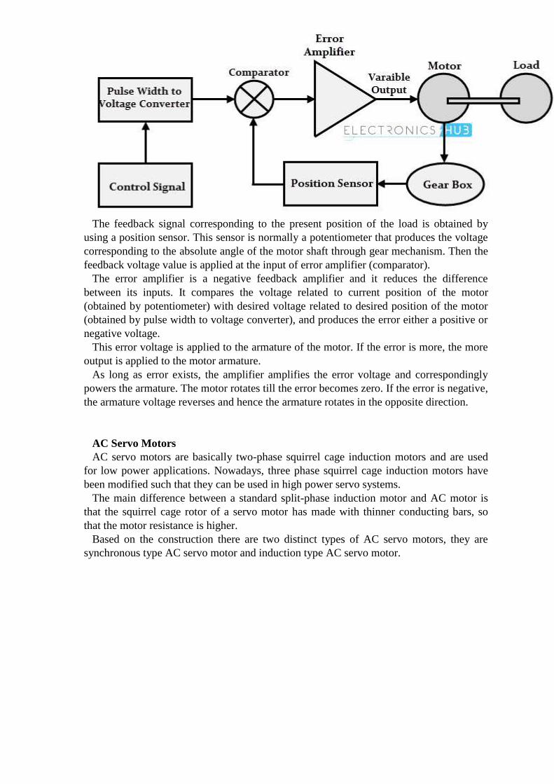
The feedback signal corresponding to the present position of the load is obtained by
using a position sensor. This sensor is normally a potentiometer that produces the voltage
corresponding to the absolute angle of the motor shaft through gear mechanism. Then the
feedback voltage value is applied at the input of error amplifier (comparator).
The error amplifier is a negative feedback amplifier and it reduces the difference
between its inputs. It compares the voltage related to current position of the motor
(obtained by potentiometer) with desired voltage related to desired position of the motor
(obtained by pulse width to voltage converter), and produces the error either a positive or
negative voltage.
This error voltage is applied to the armature of the motor. If the error is more, the more
output is applied to the motor armature.
As long as error exists, the amplifier amplifies the error voltage and correspondingly
powers the armature. The motor rotates till the error becomes zero. If the error is negative,
the armature voltage reverses and hence the armature rotates in the opposite direction.
AC Servo Motors
AC servo motors are basically two-phase squirrel cage induction motors and are used
for low power applications. Nowadays, three phase squirrel cage induction motors have
been modified such that they can be used in high power servo systems.
The main difference between a standard split-phase induction motor and AC motor is
that the squirrel cage rotor of a servo motor has made with thinner conducting bars, so
that the motor resistance is higher.
Based on the construction there are two distinct types of AC servo motors, they are
synchronous type AC servo motor and induction type AC servo motor.
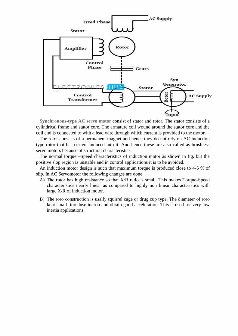
Synchronous-type AC servo motor consist of stator and rotor. The stator consists of a
cylindrical frame and stator core. The armature coil wound around the stator core and the
coil end is connected to with a lead wire through which current is provided to the motor.
The rotor consists of a permanent magnet and hence they do not rely on AC induction
type rotor that has current induced into it. And hence these are also called as brushless
servo motors because of structural characteristics.
The normal torque –Speed characteristics of induction motor as shown in fig. but the
positive slop region is unstable and in control applications it is to be avoided.
An induction motor design is such that maximum torque is produced close to 4-5 % of
slip. In AC Servomotor the following changes are done:
A) The rotor has high resistance so that X/R ratio is small. This makes Torque-Speed
characteristics nearly linear as compared to highly non linear characteristics with
large X/R of induction motor.
B) The roro construction is usally squirrel cage or drug cup type. The diameter of roro
kept small toreduse inertia and obtain good acceleration. This is used for very low
inertia applications.
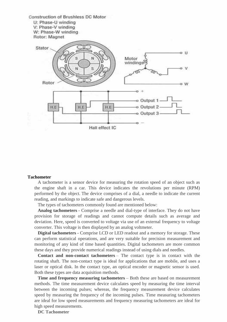
Tachometer
A tachometer is a sensor device for measuring the rotation speed of an object such as
the engine shaft in a car. This device indicates the revolutions per minute (RPM)
performed by the object. The device comprises of a dial, a needle to indicate the current
reading, and markings to indicate safe and dangerous levels.
The types of tachometers commonly found are mentioned below:
Analog tachometers - Comprise a needle and dial-type of interface. They do not have
provision for storage of readings and cannot compute details such as average and
deviation. Here, speed is converted to voltage via use of an external frequency to voltage
converter. This voltage is then displayed by an analog voltmeter.
Digital tachometers - Comprise LCD or LED readout and a memory for storage. These
can perform statistical operations, and are very suitable for precision measurement and
monitoring of any kind of time based quantities. Digital tachometers are more common
these days and they provide numerical readings instead of using dials and needles.
Contact and non-contact tachometers – The contact type is in contact with the
rotating shaft. The non-contact type is ideal for applications that are mobile, and uses a
laser or optical disk. In the contact type, an optical encoder or magnetic sensor is used.
Both these types are data acquisition methods.
Time and frequency measuring tachometers – Both these are based on measurement
methods. The time measurement device calculates speed by measuring the time interval
between the incoming pulses; whereas, the frequency measurement device calculates
speed by measuring the frequency of the incoming pulses. Time measuring tachometers
are ideal for low speed measurements and frequency measuring tachometers are ideal for
high speed measurements.
DC Tachometer

These tachometers employ small magnet type d.c or a.c generators which translate the
rotational speeds into d.c. or a.c voltage signal. The operating principle of such
tachometers is illustrated in Fig. Relative perpendicular motion between a magnetic field
and conductor results in voltage generation in the conductor.
(i) D. C. tachometergenerator: This is an accurately made dc. generator with a
permanent magnet of horse-shoe type. With rotation of the shaft, a pulsating dc. Voltage
proportional to the shaft speed is produced, and measured with the help of a moving coil
voltmeter having uniform scale and calibrated directly in terms of speed. The tachometer
is sensitive to the direction of rotation and thus can be used to indicate this direction by
the use of an indicator with its zero point at mid-scale. For greater accuracy, air gap of the
magnetic paths must be maintained as uniform as possible. Further, the instrument
requires some form of commutation which presents the problem of brush maintenance.
(ii) A.C. tachometer generator: The unit embodies a stator surrounding a rotating
permanent magnet. The stator consists of a multiple pole piece (generally four), and the
permanent magnet is installed in the shaft whose speed is being measured. When the
magnet rotates, an a.c. voltage is induced in the stator coil. The output voltage is rectified
and measured with a permanent magnet moving coil instrument. The instrument can also
be used to measure a difference in speed of two sources by differentially connecting the
stator coils.
Potentiometer
Potentiometers consist of a resistive element, a sliding contact (wiper) that moves along
the element, making good electrical contact with one part of it, electrical terminals at each
end of the element, a mechanism that moves the wiper from one end to the other, and a
housing containing the element and wiper.
Potentiometer is a three terminal device which is used for controlling the level of
voltage in the circuit. The resistance between two external terminals is constant while the
third terminal is connected with moving contact (Wiper) which is variable. The value of
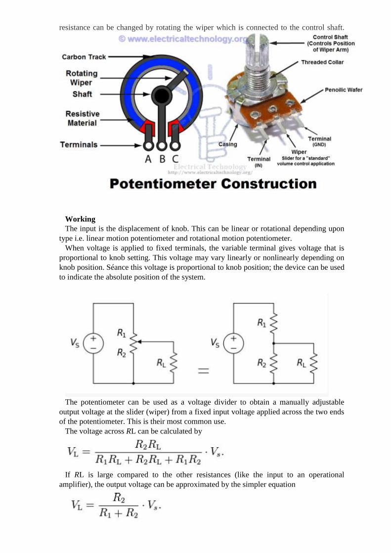
resistance can be changed by rotating the wiper which is connected to the control shaft.
Working
The input is the displacement of knob. This can be linear or rotational depending upon
type i.e. linear motion potentiometer and rotational motion potentiometer.
When voltage is applied to fixed terminals, the variable terminal gives voltage that is
proportional to knob setting. This voltage may vary linearly or nonlinearly depending on
knob position. Séance this voltage is proportional to knob position; the device can be used
to indicate the absolute position of the system.
The potentiometer can be used as a voltage divider to obtain a manually adjustable
output voltage at the slider (wiper) from a fixed input voltage applied across the two ends
of the potentiometer. This is their most common use.
The voltage across RL can be calculated by
If RL is large compared to the other resistances (like the input to an operational
amplifier), the output voltage can be approximated by the simpler equation
One of the advantages of the potential divider compared to a variable resistor in series
with the source is that, while variable resistors have a maximum resistance where some
current will always flow, dividers are able to vary the output voltage from maximum (VS)
to ground (zero volts) as the wiper moves from one end of the potentiometer to the other.
There is, however, always a small amount of contact resistance.
In addition, the load resistance is often not known and therefore simply placing a
variable resistor in series with the load could have a negligible effect or an excessive
effect, depending on the load
Incremental Encoder
Incremental encoder are frequently found in modern control systems for converting
linear or rotary displacement into digitally coded or pulse signals. The encoders that
output is digital signal known as absolute encoder.
Encoders can provide a pulse for each increment of resolution but do not make
distinction between increments. Types of encoders we can use depends on economics and
control objective.
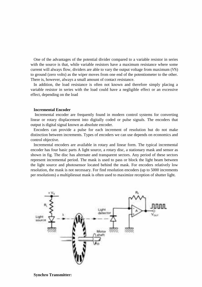
Incremental encoders are available in rotary and linear form. The typical incremental
encoder has four basic parts A light source, a rotary disc, a stationary mask and sensor as
shown in fig. The disc has alternate and transparent sectors. Any period of these sectors
represent incremental period. The mask is used to pass or block the light beam between
the light source and photosensor located behind the mask. For encoders relatively low
resolution, the mask is not necessary. For find resolution encoders (up to 5000 increments
per resolutions) a multipliessut mask is often used to maximize reception of shutter light.
Synchro Transmitter:
These are electromechanical devices resembling electric motors. Functionally, they
resemble transformers whose primary to secondary magnetic couplings may be varied by
physically changing the relative orientation of the two windings. By their inherent physical
properties and mechanical & electrical designs, synchros make possible the accurate
transmission and reproduction to a remote location of any data or information which can be
converted to angular rotation.
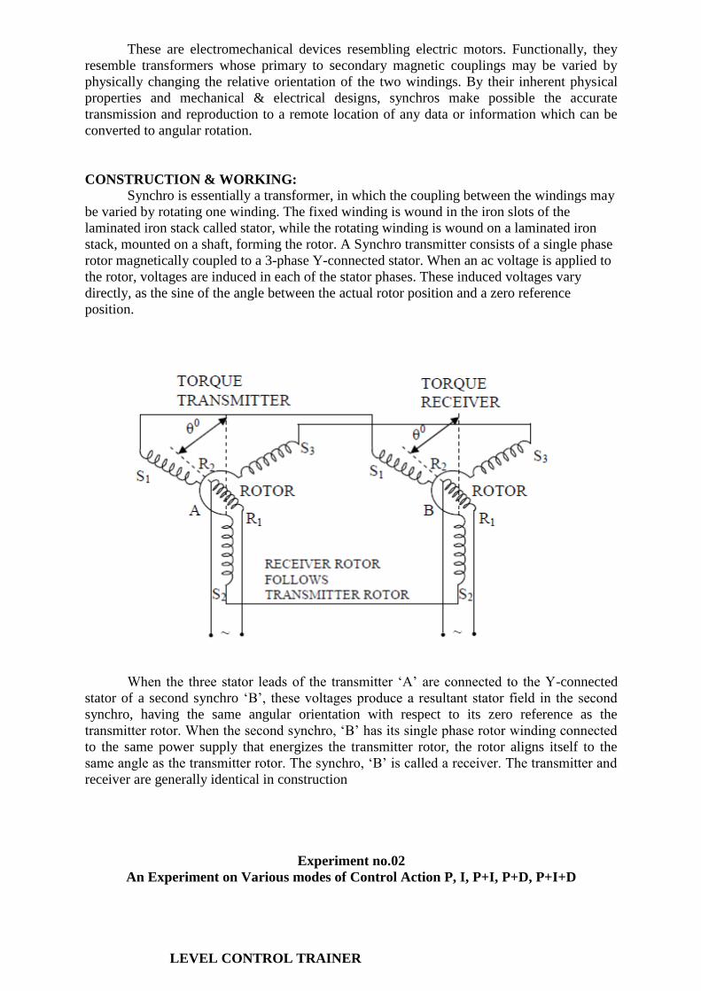
CONSTRUCTION & WORKING:
Synchro is essentially a transformer, in which the coupling between the windings may
be varied by rotating one winding. The fixed winding is wound in the iron slots of the
laminated iron stack called stator, while the rotating winding is wound on a laminated iron
stack, mounted on a shaft, forming the rotor. A Synchro transmitter consists of a single phase
rotor magnetically coupled to a 3-phase Y-connected stator. When an ac voltage is applied to
the rotor, voltages are induced in each of the stator phases. These induced voltages vary
directly, as the sine of the angle between the actual rotor position and a zero reference
position.
When the three stator leads of the transmitter ‗A‘ are connected to the Y-connected
stator of a second synchro ‗B‘, these voltages produce a resultant stator field in the second
synchro, having the same angular orientation with respect to its zero reference as the
transmitter rotor. When the second synchro, ‗B‘ has its single phase rotor winding connected
to the same power supply that energizes the transmitter rotor, the rotor aligns itself to the
same angle as the transmitter rotor. The synchro, ‗B‘ is called a receiver. The transmitter and
receiver are generally identical in construction
Experiment no.02
An Experiment on Various modes of Control Action P, I, P+I, P+D, P+I+D
LEVEL CONTROL TRAINER
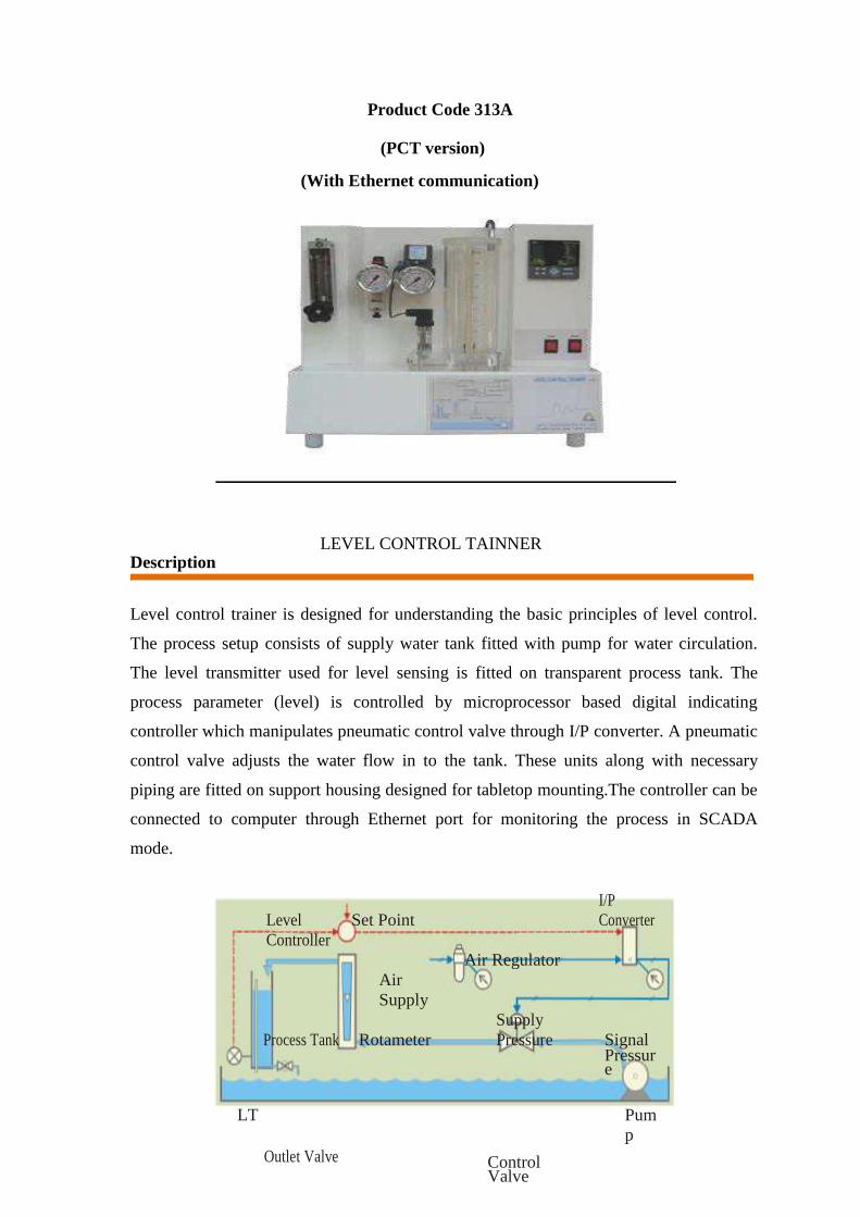
Product Code 313A
(PCT version)
(With Ethernet communication)
LEVEL CONTROL TAINNER Description
Level control trainer is designed for understanding the basic principles of level control.
The process setup consists of supply water tank fitted with pump for water circulation.
The level transmitter used for level sensing is fitted on transparent process tank. The
process parameter (level) is controlled by microprocessor based digital indicating
controller which manipulates pneumatic control valve through I/P converter. A pneumatic
control valve adjusts the water flow in to the tank. These units along with necessary
piping are fitted on support housing designed for tabletop mounting.The controller can be
connected to computer through Ethernet port for monitoring the process in SCADA
mode.
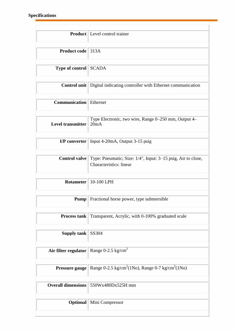
Level
Controller
Set Point
I/P
Converter
Air Regulator
Air
Supply
Process Tank Rotameter
Supply
Pressure Signal
Pressure
LT Pum
p
Outlet Valve
Control Valve
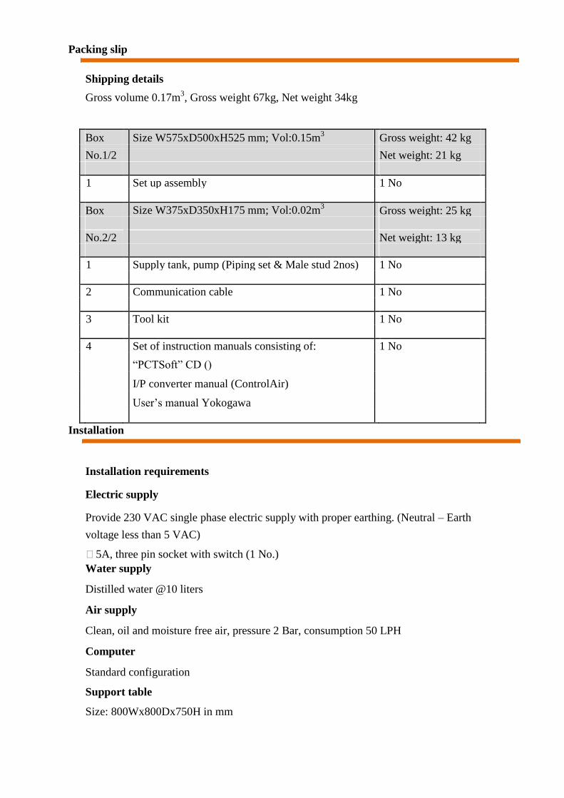
Specifications
Product Level control trainer
Product code 313A
Type of control SCADA
Control unit Digital indicating controller with Ethernet communication
Communication Ethernet
Level transmitter Type Electronic, two wire, Range 0–250 mm, Output 4–20mA
I/P converter Input 4-20mA, Output 3-15 psig
Control valve Type: Pneumatic; Size: 1/4", Input: 3–15 psig, Air to close,
Characteristics: linear
Rotameter 10-100 LPH
Pump Fractional horse power, type submersible
Process tank Transparent, Acrylic, with 0-100% graduated scale
Supply tank SS304
Air filter regulator Range 0-2.5 kg/cm2
Pressure gauge Range 0-2.5 kg/cm2(1No), Range 0-7 kg/cm
2(1No)
Overall dimensions 550Wx480Dx525H mm
Optional Mini Compressor
Packing slip
Shipping details
Gross volume 0.17m3, Gross weight 67kg, Net weight 34kg
Box Size W575xD500xH525 mm; Vol:0.15m3
Gross weight: 42 kg
No.1/2 Net weight: 21 kg
1 Set up assembly 1 No
Box Size W375xD350xH175 mm; Vol:0.02m3 Gross weight: 25 kg
No.2/2 Net weight: 13 kg
1 Supply tank, pump (Piping set & Male stud 2nos) 1 No
2 Communication cable 1 No
3 Tool kit 1 No
4 Set of instruction manuals consisting of: 1 No
―PCTSoft‖ CD ()
I/P converter manual (ControlAir)
User‘s manual Yokogawa
Installation
Installation requirements
Electric supply
Provide 230 VAC single phase electric supply with proper earthing. (Neutral – Earth
voltage less than 5 VAC)
5A, three pin socket with switch (1 No.) Water supply
Distilled water @10 liters
Air supply
Clean, oil and moisture free air, pressure 2 Bar, consumption 50 LPH
Computer
Standard configuration
Support table
Size: 800Wx800Dx750H in mm
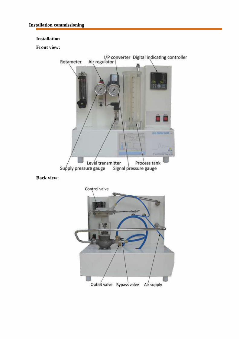
Installation commissioning
Installation
Front view:
Back view:

Pump and tank:
Unpack the box(es) received and ensure that all material is received as per packing slip
(provided in instruction manual). In case of short supply or breakage contact / your
supplier for further actions.
Place the set up on table.
Remove packing wire inserted in the Rotameter by removing plug on the top
of the rotameter. (Use small nose pliers)
Connect SS pipe (supplied loose) from rotameter outlet to Process tank
Air supply: Ensure that clean and oil free air is received from compressed air
source (compressor / mini compressor) by venting out the air for few minutes.
Then connect air supply to the set up.
Clean the Supply tank. Remove pump from its box.
Commissioning
Fill supply tank with distilled water and keep the pump inside the water.
Keep the setup over the tray. Take the pump cable and pump outlet tube to the top
side through the hole on the base plate. Connect the cable to the pump switch and
connect the pump outlet tube to the inlet of control valve.
Return the bypass line back to SS tray through the hole provided on the base plate.
Switch on electric supply. Switch on Mains.
Switch on the pump and ensure that flow through rotameter is above 100 LPH.
Close the drain valve of level tank.
Fill the process tank up to @ 50% level and switch off the pump. Confirm the
reading on digital indicating controller is within +/- 2%.
Switch on the compressed air source and adjust the air regulator to set supply air
pressure at @ 2 kg/cm^2.
Set the controller to manual mode by pressing the A/M key.
Increase output of controller from 0 to 100% in steps of 25%. Check the pressure on
pressure gauge at the output of I/P converter is varying from 3-15 psig and ensure that
control valve operates from full open to fully close position.
Switch on the computer and install ―MCRInstaller ― provided on PCTSoft CD
Copy the file ―Apex_Process_Trainers― at any drive/ folder.
Create the desktop icon for the ―Apex _Process_Trainers‖ for further use.
Set computer IP address as 192.168.1.2
Execute the software and ensure correct signals are displayed on computer.
NOTE: For longer shut down, remove water from the supply tank and clean it.
Troubleshooting
Note: For component specific problems refer Components‘ Manuals
Problems Possible causes / remedies
Control valve does not Valve diaphragm leakage/breakage
operate Faulty I/P converter
No output from Controller
I/P converter does not Insufficient supply air pressure
work Faulty electrical input signal
Clogged orifice
No communication with
Check communication settings for IP addresses of computer and
computer
controller. Default setting computer 192.168.1.2 and
controller
192.168.1.13

Components used
Product Level control trainer
Product code 313A
Level transmitter Make WIKA, Model SL-1-A-MAG-ND-ZA4Z-ZZZ and output 4-20
mA, supply 10-30 VDC, conn. 1/2"NPT (M), Range 0-25
mbar.
Digital indicating controller Make Yokogawa, Model UT35A-002-11-00 with Ethernet
communication
I/P converter Make Control air inc, Type T500-AC, Input 4-20 mA DC, output 3-
15 psig, end connection 1/4 NPT
Control valve Make Pneucon, Type globe 2 way, Model 119, size 1/2"x1/8",
Screwed end(F), Body CCS, Trim SS, Travel 14.3,
CV=0.63, Air to
CLOSE, Spring range 0.2-1, actuator 12 sq inch.
Rotameter Make Eureka, Model MG 11, Range 10-100 lph, Connection ¼‖
BSP back, screwed, Packing PTFE + Silicon
Pump Model HQB 4500, Head max. 4.5m, Output 5000 lph, Watts 100,
Volts 220-240 AC, 50Hz.
Air filter regulator Make Airmatic, Model MB10-02-1-PAP-PD( Alu body,
Polycarbonate bowl, G1/4 BSP, Range 0-2 Kg/cm^2,
Relieving,
25M Plastic element, Bunan diaphragm.
Pressure gauge Make Wika, Dia.2.5", Gly. filled, Brass internls, S.S. casing, Range
0-2.5 Kg/cm^2 and 0-35 PSI, 1/4"BSP (M) back connection
without bracket.
Pressure gauge Make Wika, Dia.2.5", Gly. filled, Brass internls, S.S. casing, Range
0-7 Kg/cm^2 and 0-100PSI, 1/4"BSP (M) back connection

without
bracket.
Experiments
The experiment nos 1 thr 6 are to get feel of the process and PID settings.
1 Study of open loop response (Manual control)
Procedure
Switch on electric supply. Switch on Mains.
Switch on the pump and adjust the bypass valve to set rotameter flow at 100 LPH.
Switch on the compressed air source and adjust the air regulator to set supply air
pressure at
@ 2 kg/cm^2
Switch on the computer.
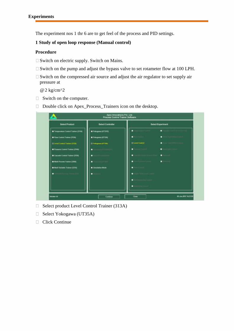
Double click on Apex_Process_Trainers icon on the desktop.
Select product Level Control Trainer (313A)
Select Yokogawa (UT35A)
Click Continue

Click Connect
Click on Select Experiment
Select Open Loop and click Start
Open the control valve fully by decreasing the controller output to 0%. (Click on
Auto, Change it to Man then change OP to 0%)
Adjust the tank drain valve such that the tank level shall remain between 90 and
100% Change the controller to Auto mode
Close the control valve by increasing the controller output to 100%.
Apply the step change by 10% to controller output in manual mode, wait for the
level to reach the steady state value.
Repeat the above step until the controller output reaches to minimum i.e. 0%.
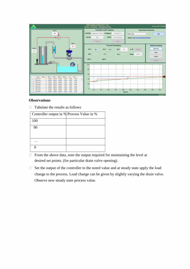
Observations
Tabulate the results as follows Controller output in % Process Value in % 100 90
… 0
From the above data, note the output required for maintaining the level at
desired set points. (for particular drain valve opening).
Set the output of the controller to the noted value and at steady state apply the load
change to the process. Load change can be given by slightly varying the drain valve.
Observe new steady state process value.

2 Study of on/off controller
Procedure
Switch on electric supply. Switch on Mains.
Switch on the pump and adjust the bypass valve to set rotameter flow at 100 LPH.
Switch on the compressed air source and adjust the air regulator to set supply air
pressure at
@ 2 kg/cm^2
Switch on the computer.
Double click on Apex_Process_Trainers icon on the desktop.
Select product Level Control Trainer (314A)
Select Yokogawa (UT35A)
Click Continue
Click Connect
Click on Select Experiment
Select On-Off Mode and click Start
Open the control valve fully by decreasing the controller output to 0%. (Click on
Auto, Change it to Man then change OP to 0%)
Adjust the tank drain valve such that the tank level shall remain between 90 and
100% Change the controller to Auto mode
Change Hystresis value to 5%.(Range 0.1-10%)
Change the values of the set point and observe the On-Off control operation.
Observations
Observe that if process value exceeds the set point and increases above the value of (0.5x
Hysteresis), control valve is fully closed and if process value decreases below the set
point by (0.5 x Hysteresis), the control valve opens fully i.e. controller operates like
On/Off switch.

3 Study of proportional controller
Switch on electric supply. Switch on Mains.
Switch on the pump and adjust the bypass valve to set rotameter flow at 100 LPH.
Switch on the compressed air source and adjust the air regulator to set supply air
pressure at
@ 2 kg/cm^2
Switch on the computer.
Double click on Apex_Process_Trainers icon on the desktop.
Select product Level Control Trainer (313A)
Select Yokogawa (UT35A)
Click Continue
Click Connect
Click on Select Experiment
Select P Mode and click Start
Open the control valve fully by decreasing the controller output to 0%. (Click on
Auto, Change it to Man then change OP to 0%)
Adjust the tank drain valve such that the tank level shall remain between 90 and
100% Change the controller to Auto mode
Adjust the process value by switching the controller to manual mode to a
particular level (say 50 %) on the screen and apply output of the controller as bias
value. Change the proportional band to 100%.
Switch the controller to auto mode.
Apply step change of 10% to set point.
Switch the controller to manual mode. Decrease proportional band to half of the
previous value. With each decrease, obtain a new response of the step change.
Ensure that the set point changes are around the same operating point (Say 50%).

Observations
Observe the effect of very low proportional band values (system works as on-off
control).
Observe the response of the system at load change. Load change can be given by
slightly manipulating the drain valve of the tank.
4 Study of proportional integral controller
Switch on electric supply. Switch on Mains.
Switch on the pump and adjust the bypass valve to set rotameter flow at 100 LPH.
Switch on the compressed air source and adjust the air regulator to set supply air
pressure at
@ 2 kg/cm^2
Switch on the computer.
Double click on Apex_Process_Trainers icon on the desktop.
Select product Level Control Trainer (313A)
Select Yokogawa (UT35A)
Click Continue
Click Connect
Click on Select Experiment
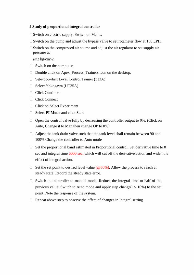
Select PI Mode and click Start
Open the control valve fully by decreasing the controller output to 0%. (Click on
Auto, Change it to Man then change OP to 0%)
Adjust the tank drain valve such that the tank level shall remain between 90 and
100% Change the controller to Auto mode
Set the proportional band estimated in Proportional control. Set derivative time to 0
sec and integral time 6000 sec, which will cut off the derivative action and widen the
effect of integral action.
Set the set point to desired level value (@50%). Allow the process to reach at
steady state. Record the steady state error.
Switch the controller to manual mode. Reduce the integral time to half of the
previous value. Switch to Auto mode and apply step change(+/- 10%) to the set
point. Note the response of the system.
Repeat above step to observe the effect of changes in Integral setting.

Observations
Observe the effect of reducing integral time on the response of the process.

5 Study of proportional derivative controller
Switch on electric supply. Switch on Mains.
Switch on the pump and adjust the bypass valve to set rotameter flow at 100 LPH.
Switch on the compressed air source and adjust the air regulator to set supply air
pressure at
@ 2 kg/cm^2
Switch on the computer.
Double click on Apex_Process_Trainers icon on the desktop.
Select product Level Control Trainer (313A)
Select Yokogawa (UT35A)
Click Continue
Click Connect
Click on Select Experiment
Select PD Mode and click Start
Open the control valve fully by decreasing the controller output to 0%. (Click on
Auto, Change it to Man then change OP to 0%)
Adjust the tank drain valve such that the tank level shall remain between 90 and
100% Change the controller to Auto mode
Set the proportional band estimated from Proportional control (P only) Set
derivative time to 0 and integral time=6000 sec.
Set the set point to desired value. Allow the process to reach at steady state.
Note the response of the system.
Switch the controller to manual mode Increase the derivative time by 1 sec. Switch
to Auto mode and apply step change to the set point by 5 to 10%. Note the response
of the system.
Increase the derivative time gradually and observe the process response for step
change.

Observations
Compare the steady state response of the PD controller with PI controller obtained
in the previous experiment.
6 Study of proportional integral derivative controller
Switch on electric supply. Switch on Mains.
Switch on the pump and adjust the bypass valve to set rotameter flow at 100 LPH.
Switch on the compressed air source and adjust the air regulator to set supply air
pressure at
@ 2 kg/cm^2
Switch on the computer.
Double click on Apex_Process_Trainers icon on the desktop.
Select product Level Control Trainer (313A)
Select Yokogawa (UT35A)
Click Continue
Click Connect
Click on Select Experiment
Select PID Mode and click Start
Open the control valve fully by decreasing the controller output to 0%. (Click on
Auto, Change it to Man then change OP to 0%)
Adjust the tank drain valve such that the tank level shall remain between 90 and
100% Change the controller to Auto mode
Switch the controller to manual mode.
Change the proportional band to the value that estimated in proportional
controller. Set integral time and derivative time based on the responses in
previous experiments.
Adjust the set point to @ 50 %. Switch the controller to auto mode. Apply step
change of 10%. Observe the process response.
Change the proportional band, integral time, derivative time and observe the
response of the process for step change for each change in setting.
Observations
Compare the steady state response of the PID controller with P. PI and PD
controller obtained in the above experiment.

7 Tuning of controller (Open loop method)
Switch on electric supply. Switch on Mains.
Switch on the pump and adjust the bypass valve to set rotameter flow at 100 LPH.
Switch on the compressed air source and adjust the air regulator to set supply air
pressure at
@ 2 kg/cm^2
Switch on the computer.
Double click on Apex_Process_Trainers icon on the desktop.
Select product Level Control Trainer (313A)
Select Yokogawa (UT35A)
Click Continue
Click Connect
Click on Select Experiment
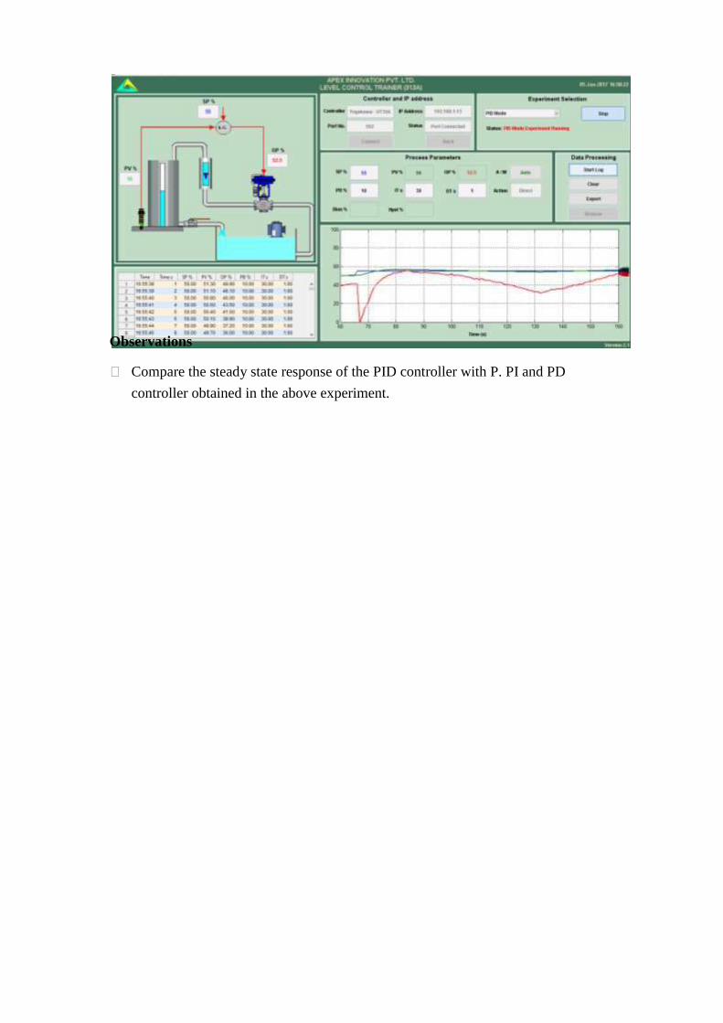
Select Process Reaction and click Start
Open the control valve fully by decreasing the controller output to 0%. (Click on
Auto, Change it to Man then change OP to 0%)
Adjust the tank drain valve such that the tank level shall remain between 90 and
100% Change the controller to Auto mode
Adjust controller output, so that the process value is maintained at 50%.
Start data logging.
Apply a 20 - 30 % change to controller output. (Open the control valve) Record
the step response. Wait for the steady state.
Stop data logging.
Plot the step response (Process reaction curve) from stored data. Find out the value of
slope at the point of inflection and time lag.
Calculate P I D settings for different modes.
Select close loop, switch auto manual key to auto mode and then select controller to
study. Set the PID values obtained from the calculations. Apply the step change &
observe the response of the system. Allow the system to reach steady state.
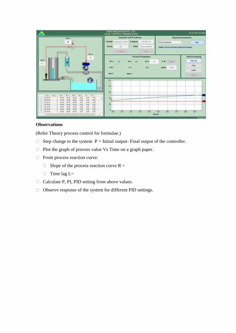
Observations
(Refer Theory process control for formulae.)
Step change to the system P = Initial output- Final output of the controller.
Plot the graph of process value Vs Time on a graph paper.
From process reaction curve:
Slope of the process reaction curve R =
Time lag L=
Calculate P, PI, PID setting from above values.
Observe response of the system for different PID settings.
8 Tuning of controller (Closed loop method)
Switch on electric supply. Switch on Mains.
Switch on the pump and adjust the bypass valve to set rotameter flow at 100 LPH.
Switch on the compressed air source and adjust the air regulator to set supply air
pressure at
@ 2 kg/cm^2
Switch on the computer.
Double click on Apex_Process_Trainers icon on the desktop.
Select product Level Control Trainer (313A)
Select Yokogawa (UT35A)
Click Continue
Click Connect
Click on Select Experiment
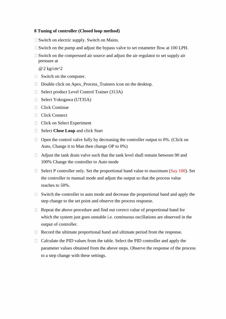
Select Close Loop and click Start
Open the control valve fully by decreasing the controller output to 0%. (Click on
Auto, Change it to Man then change OP to 0%)
Adjust the tank drain valve such that the tank level shall remain between 90 and
100% Change the controller to Auto mode
Select P controller only. Set the proportional band value to maximum (Say 100). Set
the controller to manual mode and adjust the output so that the process value
reaches to 50%.
Switch the controller to auto mode and decrease the proportional band and apply the
step change to the set point and observe the process response.
Repeat the above procedure and find out correct value of proportional band for
which the system just goes unstable i.e. continuous oscillations are observed in the
output of controller.
Record the ultimate proportional band and ultimate period from the response.
Calculate the PID values from the table. Select the PID controller and apply the
parameter values obtained from the above steps. Observe the response of the process
to a step change with these settings.

Observations
Record the ultimate proportional band (Pbu) and ultimate period (Tu) from
above experiment.
Calculate PID values by referring theory part for different control actions.
Observe the process response for these settings.
Compare the values obtained with open loop response method.

9 Tuning of controller (Using Auto Tuning method)
Switch on electric supply. Switch on Mains.
Switch on the pump and adjust the bypass valve to set rotameter flow at 100 LPH.
Switch on the compressed air source and adjust the air regulator to set supply air
pressure at
@ 2 kg/cm^2
Switch on the computer.
Double click on Apex_Process_Trainers icon on the desktop.
Select product Level Control Trainer (313A)
Select Yokogawa (UT35A)
Click Continue
Click Connect
Click on Select Experiment
Select Autotune and click Start
Wait Till Autotune is complete. (Blinking of green LED stops).
Controller automatically finds the PB, IT & DT values.
Find out PID values at different set points /flow rates
Observations
The controller has preprogrammed logic for finding ―Auto tune‖ values. Based on the
response of the process the controller calculates PID values or comes out without
finding the
―Auto tune‖ values.
10 To study stability of the system (Bode plot)
Switch on electric supply. Switch on Mains.
Switch on the pump and adjust the bypass valve to set rotameter flow at 100 LPH.
Switch on the compressed air source and adjust the air regulator to set supply air
pressure at
@ 2 kg/cm^2
Switch on the computer.
Double click on Apex_Process_Trainers icon on the desktop.
Select product Level Control Trainer (313A)
Select Yokogawa (UT35A)
Click Continue
Click Connect
Click on Select Experiment
Select Stability analysis and click Start
Open the control valve fully by decreasing the controller output to 0%. (Click on
Auto, Change it to Man then change OP to 0%)
Adjust the tank drain valve such that the tank level shall remain between 90 and
100% Change the controller to Auto mode
Start data logging.
Select function generator to apply the sinusoidal input to the output of the controller.
Enter Reference point, Amplitude and Period.
Observe the sinusoidal output of the controller and sinusoidal response of the process.
Log the data for records.
Change the period and repeat the observation for 3-4 different values of the period.
Repeat above procedure for different amplitude and period values.
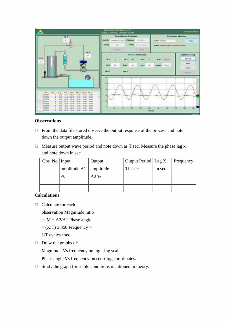
Observations
From the data file stored observe the output response of the process and note
down the output amplitude.
Measure output wave period and note down as T sec. Measure the phase lag x
and note down in sec.
Obs. No. Input Output Output Period Lag X Frequency
amplitude A1 amplitude Tin sec In sec
% A2 %
Calculations
Calculate for each
observation Magnitude ratio
as M = A2/A1 Phase angle
= (X/T) x 360 Frequency =
1/T cycles / sec.
Draw the graphs of:
Magnitude Vs frequency on log - log scale
Phase angle Vs frequency on semi-log coordinates.
Study the graph for stable conditions mentioned in theory.
An Experiment On
On/OFF TEMPERATURE CONTROL SETUP
AIM: To conduct temperature controller experiment by using thermostat
APPARATUS: Temperature controller, RTD Sensor and Water Bath.
THEORY:
Temperature control is a process in which change of temperature of a space (and
objects collectively there within) is measured or otherwise detected, and the passage of heat
energy into or out of the space is adjusted to achieve a desired average temperature.
Control loops: A home thermostat is an example of a closed control loop: It constantly assesses
the current room temperature and controls a heater and/or air conditioner to increase or decrease
the temperature according to user-defined setting(s). A simple (low-cost, cheap) thermostat
merely switches the heater or air conditioner either on or off, and temporary overshoot and
undershoot of the desired average temperature must be expected. A more expensive thermostat
varies the amount of heat or cooling provided by the heater or cooler, depending on the
difference between the required temperature (the "setpoint") and the actual temperature. This
minimizes over/undershoot. This method is called Proportional control. Further enhancements
using the accumulated error signal (Integral) and the rate at which the error is changing
(Derivative) are used to form more complex PID Controllers which is the form usually seen in
industry.
Energy Balance: An object's or space's temperature increases when heat energy moves into it,
increasing the average kinetic energy of its atoms, e.g., of things and air in a room. Heat energy
leaving an object or space lowers its temperature. Heat flows from one place to another (always
from a higher temperature to a lower one) by one or more of three
processes: conduction, convection and radiation. In conduction, energy is passed from one atom
to another by direct contact. In convection, heat energy moves by conduction into some movable
fluid (such as air or water) and the fluid moves from one place to another, carrying the heat with
it. At some point the heat energy in the fluid is usually transferred to some other object by means
conduction again. The movement of the fluid can be driven by negative-buoyancy, as when
cooler (and therefore denser) air drops and thus upwardly displaces warmer (less-dense) air
(natural convection), or by fans or pumps (forced convection). In radiation, the heated atoms
make electromagnetic emissions absorbed by remote other atoms, whether nearby or at
astronomical distance. For example, the Sun radiates heat as both invisible and visible
electromagnetic energy. What we know as "light" is but a narrow region of the electromagnetic
spectrum.
If, in a place or thing, more energy is received than is lost, its temperature increases. If the
amount of energy coming in and going out are exactly the same, the temperature stays
constant—there is thermal balance, or thermal equilibrium.
Resistance thermometers, also called resistance temperature detectors (RTDs),
are sensors used to measure temperature. Many RTD elements consist of a length of fine wire
wrapped around a ceramic or glass core but other constructions are also used. The RTD wire is a
pure material, typically platinum, nickel, or copper. The material has an accurate
resistance/temperature relationship which is used to provide an indication of temperature. As
RTD elements are fragile, they are often housed in protective probes.
RTDs, which have higher accuracy and repeatability, are slowly replacing thermocouples in
industrial applications below 600 °C
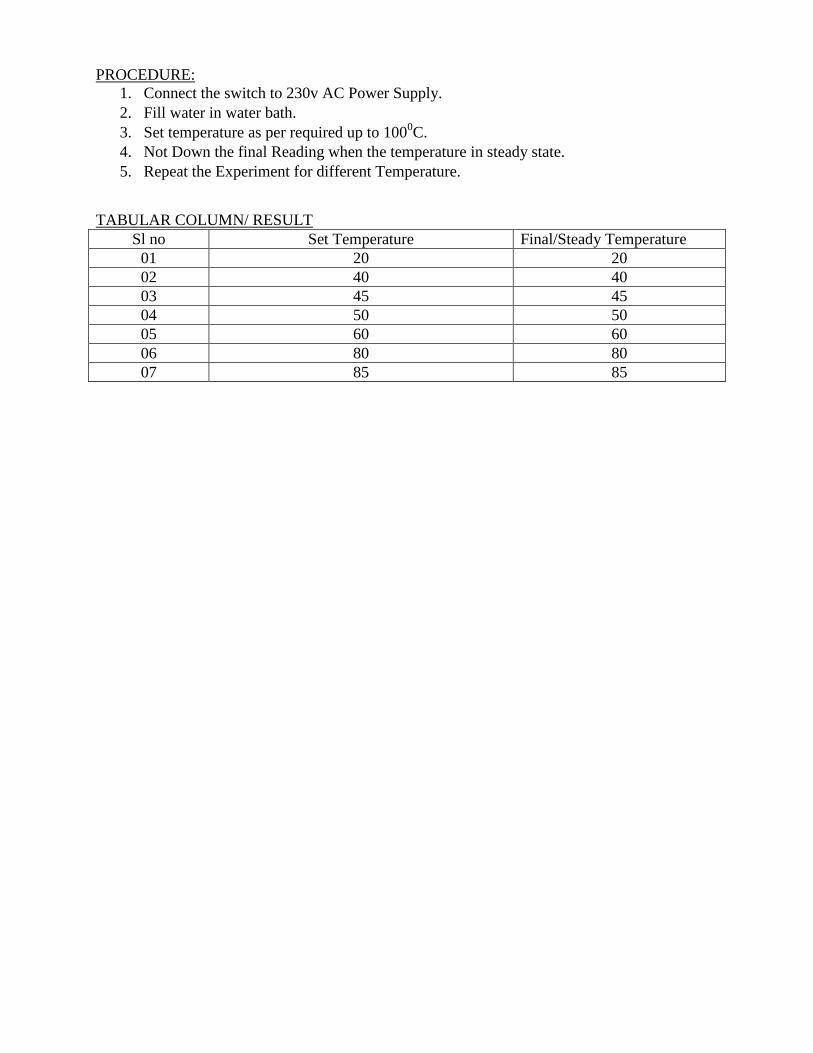
PROCEDURE:
1. Connect the switch to 230v AC Power Supply.
2. Fill water in water bath.
3. Set temperature as per required up to 1000C.
4. Not Down the final Reading when the temperature in steady state.
5. Repeat the Experiment for different Temperature.
TABULAR COLUMN/ RESULT
Sl no Set Temperature Final/Steady Temperature
01 20 20
02 40 40
03 45 45
04 50 50
05 60 60
06 80 80
07 85 85

An Experiment On
AC/DC Servomotor
Theory:
Constructionaldetails, principle of operation and performance characteristics of universal motor
A universal motor is a special type of motor which is designed to run on either DC or
single phase AC supply. These motors are generally series wound (armature and field winding
are in series), and hence produce high starting torque (See characteristics of DC motorshere).
That is why, universal motors generally comes built into the device they are meant to drive.
Most of the universal motors are designed to operate at higher speeds, exceeding 3500 RPM.
They run at lower speed on AC supply than they run on DC supply of same voltage, due to the
reactance Voltage drop which is present in AC and not in DC.
There are two basic types of universal motor:
(i)compensated type and
(ii) uncompensated type
Construction of a universal motor is very similar to the construction of a DC machine. It
consists of a stator on which field poles are mounted. Field coils are wound on the field poles.
However, the whole magnetic path (stator field circuit and also armature) is laminated.
Lamination is necessary to minimize the eddy currents which induce while operating on AC. The
rotary armature is of wound type having straight or skewed slots and commutator with brushes
resting on it. The commutation on AC is poorer than that for DC. because of the current induced
in the armature coils. For that reason brushes used are having high resistance. Working of
universal motor
A universal motor works on either DC or single phase AC supply. When the universal
motor is fed with a DC supply, it works as a DC series motor. (seeworking of a DC series
motorhere). When current flows in the field winding, it produces an electromagnetic field. The
same

Current also flows from the armature conductors. When a current carrying conductor is placed in
an electromagnetic field, it experiences a mechanical force. Due to this mechanical force, or
torque, the rotor starts to rotate. The direction of this force is given by Fleming's left hand rule.
When fed with AC supply, it still produces unidirectional torque. Because,
armaturewinding andfield winding are connected in series, they are in same phase. Hence, as
polarity ofAC changes periodically, the direction of current in armature and field winding
reverses at the sametime.
Thus, direction of magnetic field and the direction of armature current reverses in such
a way that the direction of force experienced by armature conductors remains same. Thus,
regardless of AC or DC supply, universal motor works on the same principle that DC series
motor works. Speed/load characteristics
Speed/load characteristics of a universal motor is similar to that of DC series motor. The speed
of a universal motor is low at full load and very high at no load. Usually, gears trains are used to
get the required speed on required load. The speed/load characteristics are (for both AC as well
as DC supply) are shown in the figure. Applications of universal motor Universal motors find their use in various home appliances like vacuum cleaners, drink
and food mixers, domestic sewing machine etc. The higher rating universal motors are used in portable drills, blenders etc.
1.2 Constructional details, principle of operation and performance characteristics
ofservomotor
A servo motor is an electrical device which can push or rotate an object with great
precision. If you want to rotate and object at some specific angles or distance, then you use

servo motor. It is just made up of simple motor which run through servo mechanism. If
motor is used is DC powered then it is called DC servo motor, and if it is AC powered
motor then it is called AC servo motor. We can get a very high torque servo motor in a
small and light weight packages. Doe to these features they are being used in many
applications like toy car, RC helicopters and planes, Robotics, Machine etc.
Servo motors are rated in kg/cm (kilogram per centimeter) most hobby servo motors
are rated at 3kg/cm or 6kg/cm or 12kg/cm. This kg/cm tells you how much weight your
servo motor can lift at a particular distance. For example: A 6kg/cm Servo motor should be
able to lift 6kg if the load is suspended 1cm away from the motors shaft, the greater the
distance the lesser the weight carrying capacity.
The position of a servo motor is decided by electrical pulse and its circuitry is placed beside
the motor.
Servo Mechanism
It consists of three parts: Controlled device Output sensor Feedback system
It is a closed loop system where it uses positive feedback system to control motion and final
position of the shaft. Here the device is controlled by a feedback signal generated by
comparing output signal and reference input signal.
Here reference input signal is compared to reference output signal and the third signal is
produces by feedback system. And this third signal acts as input signal to control device.
This signal is present as long as feedback signal is generated or there is difference between
reference input signal and reference output signal. So the main task of servomechanism is to
maintain output of a system at desired value at presence of noises.

Working principle of Servo Motors
A servo consists of a Motor (DC or AC), a potentiometer, gear assembly and a
controlling circuit. First of all we use gear assembly to reduce RPM and to increase torque of
motor. Say at initial position of servo motor shaft, the position of the potentiometer knob is such
that there is no electrical signal generated at the output port of the potentiometer. Now an
electrical signal is given to another input terminal of the error detector amplifier. Now difference
between these two signals, one comes from potentiometer and another comes from other source,
will be processed in feedback mechanism and output will be provided in term of error signal.
This error signal acts as the input for motor and motor starts rotating. Now motor shaft is
connected with potentiometer and as motor rotates so the potentiometer and it will generate a
signal. So as the potentiometer‘s angular position changes, its output feedback signal changes.
After sometime the position of potentiometer reaches at a position that the output of
potentiometer is same as external signal provided. At this condition, there will be no output
signal from the amplifier to the motor input as there is no difference between external applied
signal and the signal generated at potentiometer, and in this situation motor stops rotating. Controlling Servo Motor: All motors have three wires coming out of them. Out of which two will be used for Supply
(positive and negative) and one will be used for the signal that is to be sent from the MCU. Servo
motor is controlled by PWM (Pulse with Modulation) which is provided by the control wires.
There is a minimum pulse, a maximum pulse and a repetition rate. Servo motor can turn
90 degree from either direction form its neutral position. The servo motor expects to see a pulse
every 20 milliseconds (ms) and the length of the pulse will determine how far the motor turns.
For example, a 1.5ms pulse will make the motor turn to the 90° position, such as if pulse is
shorter than 1.5ms shaft moves to 0° and if it is longer than 1.5ms than it will turn the servo to
180°.

Servo motor works on PWM (Pulse width modulation)principle, means its angle of rotation is
controlled by the duration of applied pulse to its Control PIN. Basically servo motor is made up
of DC motor which is controlled by a variable resistor (potentiometer) and some gears.
High speed force of DC motor is converted into torque by Gears. We know that WORK=
FORCE X DISTANCE, in DC motor Force is less and distance (speed) is high and in Servo,
force is High and distance is less. Potentiometer is connected to the output shaft of the Servo, to
calculate the angle and stop the DC motor on required angle. Servo motor can be rotated from 0 to 180 degree, but it can go up to 210 degree, depending on
the manufacturing. This degree of rotation can be controlled by applying the Electrical Pulse of
proper width, to its Control pin. Servo checks the pulse in every 20 milliseconds. Pulse of 1 ms
(1 millisecond) width can rotate servo to 0 degree, 1.5ms can rotate to 90 degree (neutral
position) and 2 ms pulse can rotate it to 180 degree. All servo motors work directly with your +5V supply rails but we have to be careful on the
amount of current the motor would consume, if you are planning to use more than two servo
motors a proper servo shield should be designed.
1.3 Constructional details, principle of operation and performance characteristics of
steppermotor
It is a brushless electromechanical device which converts the train of electric pulses applied at
their excitation windings into precisely defined step-by-step mechanical shaft rotation. The shaft
of the motor rotates through a fixed angle for each discrete pulse. This rotation can be linear or
angular.It gets one step movement for a single pulse input.
When a train of pulses is applied, it gets turned through a certain angle. The angle through
which the stepper motor shaft turns for each pulse is referred as the step angle, which is generally
expressed in degrees.
The number of input pulses given to the motor decides the step angle and hence the
position of motor shaft is controlled by controlling the number of pulses. This unique feature
makes the stepper motor to be well suitable for open-loop control system wherein the precise
position of the shaft is maintained with exact number of pulses without using a feedback
sensor.
If the step angle is smaller, the greater will be the number of steps per revolutions and higher will
be the accuracy of the position obtained. The step angles can be as large as 90 degrees and as
small as 0.72 degrees, however, the commonly used step angles are 1.8 degrees, 2.5 degrees, 7.5
degrees and 15 degrees.
The direction of the shaft rotation depends on the sequence of pulses applied to the stator.
The speed of the shaft or the average motor speed is directly proportional to the frequency (the
rate of input pulses) of input pulses being applied at excitation windings. Therefore, if the
frequency is low, the stepper motor rotates in steps and for high frequency, it continuously
rotates like a DC motor due to inertia.
Like all electric motors, it has stator and rotor. The rotor is the movable part which has no
windings, brushes and a commutator. Usually the rotors are either variable reluctance or
permanent magnet kind. The stator is often constructed with multipole and multiphase windings,
usually of three or four phase windings wound for a required number of poles decided by desired
angular displacement per input pulse.
Unlike other motors it operates on a programmed discrete control pulses that are applied
to the stator windings via an electronic drive. The rotation occurs due to the magnetic interaction
between poles of sequentially energized stator winding and poles of the rotor. There are several types of stepper motors are available in today‘s market over a wide range of
sizes, step count, constructions, wiring, gearing, and other electrical characteristics. As these
motors are capable to operate in discrete nature, these are well suitable to interface with digital
control devices like computers.
Due to the precise control of speed, rotation, direction, and angular position, these are of
particular interest in industrial process control systems, CNC machines, robotics, manufacturing
automation systems, and instrumentation.

There are three basic categories of stepper motors, namely permanent magnet
steppermotor, variable reluctance stepper motor and hybrid stepper motor. In all these
motorsexcitation windings are employed in stator where the number of windings refer to the
number of phases.
A DC voltage is applied as an excitation to the coils of windings and each winding terminal
is connected to the source through a solid state switch. Depends on the type of stepper motor, its
rotor design is constructed such as soft steel rotor with salient poles, cylindrical permanent
magnet rotor and permanent magnet with soft steel teeth.
1.4 Constructional details, principle of operation and performance characteristics
of reluctance motor
A reluctance motor is a type of electric motor that induces non-permanent magnetic
poles on the ferromagnetic rotor. The rotor does not have any windings. Torque is generated
through the phenomenon of magnetic reluctance.
There are various types of reluctance motors: Synchronous reluctance Variable reluctance Switched reluctance Variable reluctance stepping.
Reluctance motors can deliver very high power density at low cost, making them ideal for
many applications. Disadvantages are high torque ripple (the difference between maximum
and minimum torque during one revolution) when operated at low speed, and noise [1]
caused
by torque ripple. Until the early twenty-first century their use was limited by the complexity
of designing and controlling them. These challenges are being overcome by advances in the
theory, by the use of sophisticated computer design tools, and by the use of low-cost
embedded systems for control, typically based on microcontrollers using control algorithms
and real-time computing to tailor drive waveforms according to rotor position and current or
voltage feedback. Before the development of large-scale integrated circuits the control
electronics would have been prohibitively costly. The stator consists of a single winding called main winding. But single winding can
not produce rotating magnetic field. So for production of rotating magnetic field, there must be at
least two windings separated by certain phase angle. Hence stator consists of an additional winding called auxiliary winding which consists
of capacitor in series with it.

Thus there exists a phase difference between the currents carried by the two windings
and corresponding fluxes. Such two fluxes react to produce the rotating magnetic field. The technique is called
split phase technique of production of rotating magnetic field. The speed of this field is synchronous speed which is decided by the number of poles
for which stator winding is wound. The rotor carries the short circuited copper or aluminium bars and it acts as squirrel
cage rotor of an induction motor. If an iron piece is placed in a magnetic field, it aligns itself in a minimum reluctance
position and gets locked magnetically. Similarly in the reluctance motor, rotor tries to align itself with the axis of rotating
magnetic field in a minimum reluctance position. But due to rotor inertia it is not possible when rotor is standstill. So rotor starts rotating
near synchronous speed as a squirrel cage induction motor. When the rotor speed is about synchronous, stator magnetic field pulls rotor into
synchronism i.e. minimum reluctance position and keeps it magnetically locked. Then rotor continues to rotate with a speed equal to synchronous speed. Such a torque
exerted on the rotor is called the reluctance torque.
Thus finally the reluctance motor runs as a synchronous motor. The resistance of the rotor
must be very small and the combined inertia of the rotor and the load should be small to run
the motor as a synchronous motor.
Specification:
1. Motor – 24V 2A DC Servo motor with Tacho Feedback.
2. RPM Sensor – Photo sensor
3. Measuring speed – Microcontroller based measurement speed.
4. Potantiometer -0-24 V
5. Current Measuring – Ammeter.

Tabular Column:
Speed in
RPM
Ammeter Load S in Grams Torque
S1 S2
700 0.11 50 70 20 50
950 0.20 50 80 30 75
1200 0.26 50 100 50 125
1470 0.33 50 110 60 150
2000 0.411 50 120 70 175
2550 0.705 60 180 120 300
2700 0.77 60 220 140 350
2800 0.82 60 230 170 425
Graph:
Speed Vs Torque
RPM
Torque

Experiment No.
Experiment on speed control of stepper motor
Aim: Study of stepper motor control.
Apparatus:
1] Stepper motor control kit.
2] UJT oscillator.
3] Translator & stepper motor.
4] Connecting wire & Power supply.
Theory:
Stepper motor is an electro mechanical device, which actuates a train of step angular or linear
moment in response to train of input pulse one to one basis .One step actuation of each pulse
input. .
Step motors (often referred as stepper motors) are different from all other types of electrical
drives in the sense that they operate on discrete control pulses received and rotate in discrete
steps. On the other hand ordinary electrical a.c and d.c drives are analog in nature and rotate
continuously depending on magnitude and polarity of the control signal received. The discrete
nature of operation of a step motor makes it suitable for directly interfacing with a computer and
direct computer control. These motors are widely employed in industrial control, specifically for
CNC machines, where open loop control in discrete steps are acceptable. These motors can also
be adapted for continuous rotation. In this lesson we would discuss about the construction and
principle of operations of different type of step motors and elaborate on the drive schemes used.
Step motors are normally of two types:
(a) Permanent magnet.
(b) Variable reluctance type.
In a step motor the excitation voltage to the coils is d.c. and the number of phases indicates the
number of windings. In both the two cases the excitation windings are in the stator. In a
permanent magnet type step motor the rotor is a permanent magnet with a number of poles. On
the other hand the rotor of a variable reluctance type motor is of a cylindrical structure with a
number of projected teeth.
Permanent magnet step motor
` The principle of step motor can be understood from the basic schematic arrangement of a
small permanent magnet step motor is shown in Fig.1. This type of motor is called a two-phase
two-pole permanent magnet step motor; the number of windings being two (phase 1 and phase 2)
each split into two identical halves; the rotor is a permanent magnet with two poles. So winding
A is split into two halves A1
and A2. They are excited by constant d.c. voltage V and the
direction of current through A1
and A2
can be set by switching of four switches Q1, Q
2, Q
3 and
where four switches Q5-Q8 are used to control the direction of current as shown in Fig. 2(b). The
directions of the currents and the corresponding polarities of the induced magnets are shown in
Fig. 1. Q4
as shown in Fig.2(a). For example, if Q1
and Q2
are closed, the current flows from A1
to
A2, while closing of the switches Q
3 and Q
4 sets the direction of current from A
2 to A
1. Similar is
the case for the halves B1
and B2
Now consider Fig. 3. Let Winding A be energised and the
induced magnetic poles are as shown in Fig. 3(a) (we will denote the switching condition as

S1=1). The other winding B is not energised. As a result the moving permanent magnet will align
itself along the axis of the stator poles as shown in Fig. 3(a). In the next step, both the windings
A and B are excited simultaneously, and the polarities of the stator poles are as shown in Fig.
3(b). We shall denote S2=1, for this switching arrangement for winding B. The rotor magnet will
now rotate by an angle of 45o
and align itself with the resultant magnetic field produced. In the
next step, if we now make S1=0 (thereby de-energising winding A), the rotor will rotate further
clockwise by 45o
and align itself along winding B, as shown in Fig. 3(c). In this way if we keep
on changing the switching sequence, the rotor will keep on rotating by 45o
in each step in the
clockwise direction. The switching sequences for the switches Q1
to Q8
for first four steps are
tabulated in Table
Fig. 1 Schematic diagram of a two-phase two-pole permanent magnet stepper motor
Fig. 2 switching sequence for Fig. 1.

Pole Fig. 3 stepping sequence (half-stepping) for a two-phase two-pole PM step motor for
clockwise rotation.
The advantage of a permanent magnet step motor is that it has a holding torque. This means that
due to the presence of permanent magnet the rotor will lock itself along the stator pole even
when the excitation coils are de-energized. But the major disadvantage is that the direction of
current for each winding needs to be reversed. This requires more number of transistor switches
that may make the driving circuit unwieldy. This disadvantage can be overcome with a variable
reluctance type step motor, as explained in the next section.
Control of Step Motors
In many cases step motors are used for accurate positioning of tools and devices. Precision
control over the rotation of the motor is required for these cases. Control of step motors can be
achieved in two ways: open loop and closed loop. The open loop control is simpler and more
widely used, such a scheme is shown schematically in Fig. The command to the pulse generator
sets the number of steps for rotation and direction of rotation. The pulse generator
correspondingly generates a train of pulse. The Translator is a simple logical device and
distributes the position pulse train to the different phases. The amplifier block amplifies this
signal and drives current in the corresponding winding. The direction of rotation can also be

reversed by sending a direction pulse train to the translator. After receiving a directional pulse
the step motor reverses the direction of rotation.
Open-loop control of a step motor.
The major disadvantage of the open loop scheme is that in case of a missed pulse, there is no
way to detect it and correct the switching sequence. A missed pulse may be due to
malfunctioning of the driver circuit or the pulse generator. This may give rise to erratic
behaviour of the rotor.
In this sequel the closed loop arrangement has the advantage over open loop control, since it
does not allow any pulse to be missed and a pulse is send to the driving circuit after making sure
that the motor has rotated in the proper direction by the earlier pulse sent. In order to implement
this, we need a feedback mechanism that will detect the rotation in every step and send the
information back to the controller. Such an arrangement is shown in Fig. The incremental
encoder here is a digital transducer used for measuring the angular displacement.
Feedback control of a step motor.
Specification:
I] Step Angle = 1.8 Degree
2] Operating Voltage = 12 Volt (D.C)
3] Current Rating = 1.2 Amp
4] Torque = 3 Kg.cm
Anti clock wise Clockwise
1 A C 1 A C
2 B C 2 B C
3 B D 3 B D
4 A D 4 A D

Properties:
1] When driven with digital pulses it moves one & only one step per pulse.
2] Self-starting, no external means is required.
3] It starts /stops & reverses instantaneously.
4] It is bi-directional motor and can rotate in either directional
Applications of stepper motor:
1] Pulse converter on production lines.
2] Remote indicator.
3] Numerically controlled machine tool drive.
4] Line spacing controls for point out machine.
5] Punch tape drives.
6] In optical & medical equipment.
7] Focus control of camera & filmstrip projector.
8] Automatic servo operated AC voltage regulator.
9] AC drives, it can be used, strip chart recorder & curve tracer.
10]For recording instruments
Conclusion:
In this way we studied the operation of stepper in open loop mode. It is observed that as
frequency is changed the speed of motor is also changed and direction of motor can be changed
by changing the pulses to bifilar windings

Assignment no. 01
Part A 1. Whatiscontrolsystem? 2. Defineopenloopcontrolsystem. 3. Defineclosedloopcontrolsystem. 4. Definetransferfunction. 5. Whatarethebasicelementsusedformodelingmechanicalrotationalsystem?
6. Write the differential equations governing the Mechanical system shown in
fig. and determine thetransferfunction.
7. DeterminethetransferfunctionY2(S)/F(S)ofthesystemshowninfig.
8. WritethedifferentialequationsgoverningtheMechanicalrotationalsystemshownin
fig.DrawtheTorque-voltageandTorque-currentelectricalanalogouscircuits.
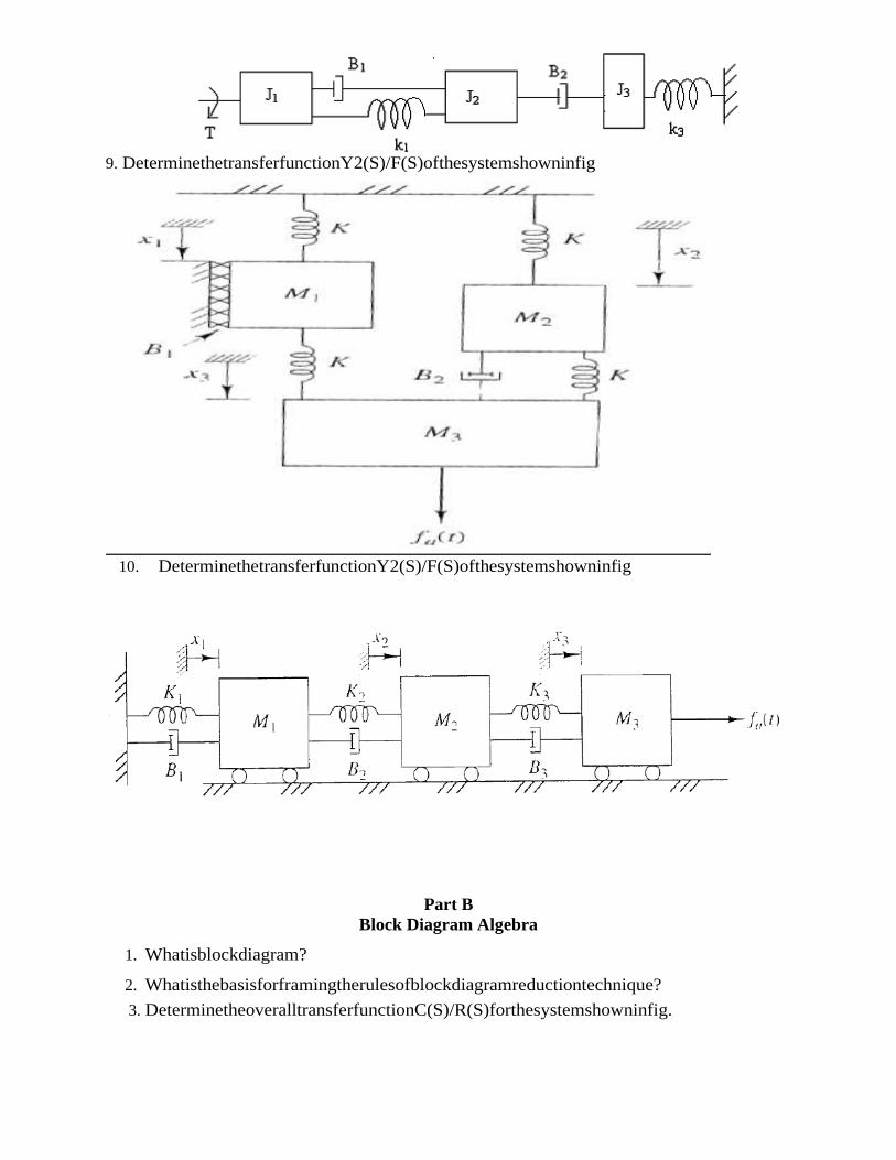
9. DeterminethetransferfunctionY2(S)/F(S)ofthesystemshowninfig
10. DeterminethetransferfunctionY2(S)/F(S)ofthesystemshowninfig
Part B
Block Diagram Algebra
1. Whatisblockdiagram?
2. Whatisthebasisforframingtherulesofblockdiagramreductiontechnique?
3. DeterminetheoveralltransferfunctionC(S)/R(S)forthesystemshowninfig.
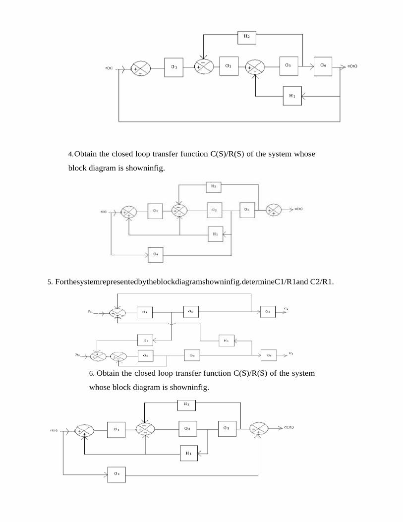
4. Obtain the closed loop transfer function C(S)/R(S) of the system whose
block diagram is showninfig.
5. Forthesystemrepresentedbytheblockdiagramshowninfig.determineC1/R1and C2/R1.
6. Obtain the closed loop transfer function C(S)/R(S) of the system
whose block diagram is showninfig.
Part C
Signal Flow Graph
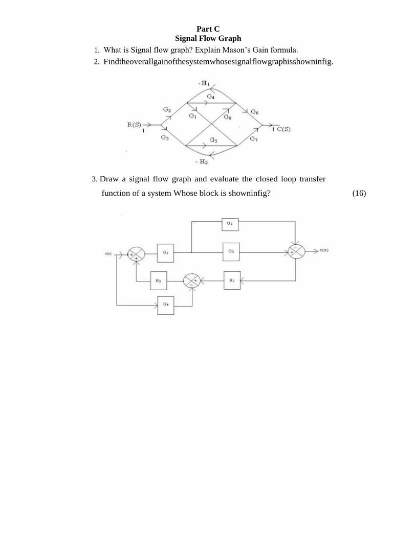
1. What is Signal flow graph? Explain Mason‘s Gain formula.
2. Findtheoverallgainofthesystemwhosesignalflowgraphisshowninfig.
3. Draw a signal flow graph and evaluate the closed loop transfer
function of a system Whose block is showninfig? (16)

Assignment No.2
Part I
Time Domain Analysis
1. What is Time Response?
2. Define Delay Time, Rise Time, Peak Time, Peak Over Shoot, Settling Time.
3. Explain Different types of Input signals.
4. Find time domain specification of following for unity feedback.
a. G(S) = 200/ s(s+8)
b. G(S) = 16/s(s+8)
c. G(S) = 64/s2+5s+64
Part II
Stability Analysis
1. Write a note on Hurwitz Criterion.
2. Explain Routh‘s Stability Criteria.
3. Find the Stability of following system.
a. S3+6S
2+12S+8=0
b. S5+S
4+2S
3+2S
2+3S+5=0
c. S6+2S
5+8S
4+12S
3+20S
2+16S+16=0
d. F(S)=S6+S5-2S4-3S3-7S2-4S1-4=0
4. Find the range of K if system is stable
a. C(s)/r(s) =K / s(s2+s+1)(s+4)
b. G(S) = k (s+1) / s2(s+2)(s+5)
c. G(S) = K(1+s)2
/s3

Assignment No. 03
Root Locus
1. Whatarefrequencydomainspecifications?
2. Sketch the root locus for the open loop transfer function of unity feedback
control system givenbelow:
G(S)H(S)= K / S(S+2)(S+4).
3. Sketch the root locus for the open loop transfer function of unity feedback
control systemgivenbelow:
G(S)H(S)=K / S(S+1)(S+2).
AlsofindKofbreakawaypoint.
4. Draw the root locus for
GH= k (s+4)/ s(s+2)(s+6)(s+8)
5. Sketch root locus for k > 0
6. GH (s) = k(s+2) / (s+1+j 3) (s+1- j 3)

Assignment No.04
Bode Plot
1. Sketch Bode Plot and find gain and phase margin..
a. G (s)H(s) = 10 / s(s+1)(s+10)
b. G(S) = ks2 /(1+0.2s)(1+0.02s)
c. G(s)H(s) = 12 /s(s+4)(s+12)