
ACS Cold Plate: Leak Detection and Intervention White Paper
46
LEAK DETECTION AND INTERVENTION Revision 1.0 Authors: Michael Berktold, Jessica Gullbrand (Intel), Fred Rebarber, Nigel Gore (Vertiv), Matthew Archibald, Michael Thompson (nVent), Cam Turner (CoolIT)
-
Upload
khangminh22 -
Category
Documents
-
view
0 -
download
0
Transcript of ACS Cold Plate: Leak Detection and Intervention White Paper

LEAK DETECTION AND INTERVENTION
Revision 1.0
Authors:
Michael Berktold, Jessica Gullbrand (Intel), Fred Rebarber, Nigel Gore (Vertiv),
Matthew Archibald, Michael Thompson (nVent), Cam Turner (CoolIT)
PAGE 2
License
This work is licensed under a Creative Commons Attribution-ShareAlike 4.0 International License.
Executive SummaryWith increasing compute performance there is a corresponding increase in the need for cooling. Air is a poor
cooling medium for very high power densities. Liquid cooling can support very high power densities but
comes with potential concerns of coolant leakage near sensitive electronic equipment.
This document outlines different leak mitigation, detection, and intervention examples with pros and cons. It
also covers multiple coolants; water with additives, glycol-based, dielectric, and refrigerants. This document
also gives general guidance on the considerations for the Cost of Ownership (CO). An example of risk analysis is
performed in order to outline potential risks. A significant amount of the risk will be centered around the fluids
used. This risk analysis will focus on detection and intervention aspects but does not include other risks to the
system.
This document does not include a deep dive into system management, or recommend or promote a specific
cooling solution. It provides guidance on the steps of risk analysis and mitigation for educational purposes
only.
This document should be used with the OCP® documents “ACS Liquid Cooling Cold Plate Requirements” and
the “ACS Door Heat Exchanger Specification for Open Rack”. See the Reference section for more details. The
hardware scope is the Technology Cooling System (TCS). This includes cold plates, integrated pumps,
manifolds, Coolant Distribution Unit (CDU, end of row or in rack CDUs), heat exchangers, hoses, and couplings.
PAGE 3
Table of Contents
License 2
Executive Summary 2
Table of Contents 3
Introduction 4
Design Considerations 5
Definitions 8
Definitions Images 12
Examples 16Risk Analysis of an example: 16Lessons learned from early liquid cooling applications at US National Labs 16Reliability Data 18Figure 7. Above rack PP-R piping at Magma supercomputer 19Gaseous Pressure Testing 19
Leak Detection and Mitigation 22Indirect 23
Pros and Cons 23Direct 24
Pros and Cons 25Installations 26
Examples: 28Control Systems 35
Reporting 36Nuisance Alarms 36
Leak Intervention 37Leak intervention classifications 37Manual 37
Manual shutoff valves 38Dry Break Quick Disconnects 38Interlocking Valves 39
Automatic 40Electrical De-energization 40Solenoid Valves 41CDU Shut downs 43

PAGE 4
Conclusion 44
References 45
Trademarks 45
About Open Compute Foundation 45
PAGE 5
IntroductionThis document outlines considerations for leak detection and intervention technologies when using liquid
cooling to provide the cooling required for the Information Technology (IT) equipment in liquid cooled
servers/racks/data center installations. A more efficient cooling solution than air is needed to meet the
continuously increasing compute performance demand, which results in increased power and power density
solutions. Liquid cooling using cold plates and rear door heat exchangers are such cooling technologies that
are more efficient and can meet more stringent cooling requirements. However, adding liquid into the data
center and IT equipment can cause concerns for users regarding potential leaks. The cooling solution needs to
be designed to minimize the risk of any leaks, and it is best practice to ensure that leak detection and
intervention methods are in place, in the rare event of a leak. This document is focused on the discussion of
options with pros and cons for the installation of leak detection and interventions for all cooling liquids used
(water with additives, glycol-based, dielectric, and refrigerants). Examples of leak events are also shared. This
document builds on the “ACS liquid cooling cold plate requirements” document (Chapter 7) generated by the
Advanced Cooling Solution (ACS) cold plate community. It is also focused on liquid cooling specifically within
the Technology Cooling System (TCS), which includes cooling components such as cold plates, integrated
pumps, manifolds, Coolant Distribution Unit (CDU, end of row, or in rack CDUs), heat exchangers, hoses, and
couplings.
This document also gives general guidance on cost considerations. The up-front Capital Expenditures need to
be compensated by reliability improvements, savings in coolant and cleanup, and possible hardware damage.
System downtime can have a big impact on operating costs. A risk analysis is also shown to outline potential
risks. A significant amount of the risk will be centered around the fluids used. This risk analysis focuses on
detection and intervention aspects but does not include other risks to the system. The document will not
include a deep dive into system management and does not recommend or promote a specific solution. It can
provide guidance on the steps of risk analysis and mitigation for educational purposes only.
Design ConsiderationsThere are many benefits of using liquid cooling and also many different considerations to be evaluated for a
community that is traditionally used to work with air cooling. In order to take the appropriate considerations
into account, let’s discuss the liquid cooling environment and management a bit more in detail. The cooling
liquid is distributed through pipework through the facility, CDU, rack, manifold, and IT equipment. The cooling
liquids can be electrically conductive or non-electrically conductive fluids. When the fluids are electrically
conductive, there is a risk of failure to electronic equipment that comes into direct contact with the liquid. For
PAGE 6
non-electrically conductive fluids, the risk of electronic failure is not expected and the focus is instead on leak
awareness to minimize the volume of cooling liquid lost due to cost or operational impediment. It is
imperative to ensure appropriate data center mitigation and protection strategies including leak prevention
and leak detection. These mitigations should be considered during the design stage of deploying Advanced
Cooling Solutions which utilize liquids to cool IT equipment.
The TCS distributes liquids from CDUs to rows of racks. The consideration of leak mitigation and early, accurate
reporting capabilities of liquid leak detection systems are to be included in the pipework design. The pipework
can be distributed within the facility overhead, underfloor, or in a floor recess depending on access
requirements. Pipework joints, couplings, and connectors are required between the CDU manifolds, row
manifold, rack manifolds, and within devices. Each connection point is a potential risk for leakage. Appropriate
considerations for design include the selection of pipework joining either via welding, threading, flanging, or
coupling systems that are designed specifically not to leak and include, amongst other characteristics, wetted
material compatibility for the liquid that is transported.
Best practices that encompass the pipework design considerations include wetted material compatibility.
Operating temperatures can affect pipe length and dimensions through thermal expansion and this extends to
the materials used in joining pipework. The risk of contaminants fouling systems and impeding performance
includes the risk of leaks caused at the connections. The rate of flow of liquids within the pipework is
considerable, where disruption and cavitation combined with a buildup of contaminants can corrode and
impact the integrity of joins over time. Detailed information on material compatibility including joining
method, materials, and the liquid used in the TCS fluid network can be obtained by manufacturers, ASHRAE®
liquid cooling guidelines (10), OCP cold plate guidelines (1), and the Energy Efficiency High-Performance
Compute (EEHPC) Working group (8). Within these guidelines, special attention is made to strainers and
filtration to remove contaminants and debris that may build up such as scale, fouling, and bacterial growth
which can contribute to corrosion. The installation and commissioning stages of a liquid-cooled system are
where contaminants can enter the liquid network and specific guidelines on installation by experienced teams
are highly recommended.
The liquid flow rates within TCS pipework are set based on manufacturing guidelines and cooling duty
required. These flow requirements form boundary conditions to design the pipework layout. Whilst
considering leak detection and mitigation approaches, flow meters with setpoints could be considered to
ensure system operation is within design parameters. Within the TCS pipe size selection shall be compatible
PAGE 7
with the maximum velocity and flow rate requirements to support heat loads and desired differential
temperature (Delta T) of the system. The liquid flow can be interrupted, and flow variations potentially starve
liquid delivery to the IT equipment cold plate with sub-optimal performance affecting the heat removal
performance and potentially causing throttling of IT equipment operation.
The flow meters and liquid leak detection can be supported by demarcated zones with shut off valves as part
of the leak mitigation design approach. These contingency measures can cause disruption or frictional loss to
the liquid flow, including pressure drop, water hammer, expansion vessels, and cavitation; add to this the pipe
material selected, direction changes, and obstacles all of which can impact the IT equipment rack. It is
therefore imperative to maintain the system in balance through design consideration methods such as flow
management simulation and design resources with the aid of computer so�ware. These resources can include
material usage, sizing, and visual layouts with simulation of scenarios to support decision making.
The sensor configuration will require management and monitoring by administrators usually via a facility
automated system, with particular attention given to communication protocols to ensure compatibility. The
operating parameters will need to be established to ensure they are maintained within the design
specification. These should be well documented through the implementation stages (design, install,
commission, operation) to allow for the management system to allocate the required parameters. This
discipline will support fast reporting of leaks and ensure alerts are communicated for the system or
administrators to act on with the least amount of disruption.
The leak detection components consist of sensors, probes, and monitoring systems that, when properly
designed, specify the location of the leak to minimize downtime by accurate determination of the source of the
leak. Accuracy of data with minimal to no false alarms is imperative to ensure productivity and high confidence
of operation is maintained. To support accuracy, appropriate insulation of pipework and connectors to
minimize condensation forming which can contribute to false reporting of leak detection sensors.
Other design considerations include what gets wet. Designing high voltage equipment higher in the system so
it is less likely to get wet. Concerns over pools of fluid becoming an electrical hazard.

PAGE 8
DefinitionsAutomatic Reaction: An automatic intervention that is triggered by a leak detection indication. Node level
actions will be taken by the BMC. Rack level detection actions will be taken by the Rack Managers or the rack
CDU talking to the Rack Manager. Row-level actions will be taken by the row’s CDU talking directly to the
Building Management System.
BACnet®: A data communications protocol typically used with building management systems. There are many
possible physical layers including serial buses and Ethernet.
Baseboard Management Controller (BMC): A small, specialized processor used for remote monitoring and
management of a host system.[6]
British Standard Pipe Parallel (BSPP): An obsolete thread standard now defined in ISO 228-1. The thread size
is designated with a “G” and the imperial dimension of the threads. Requires an O-Ring or sealing washer.
British Standard Pipe Thread (BSPT): An obsolete thread standard now defined in ISO 7-1. The thread size is
designated with an “R” and the imperial dimension of the threads. Forms a thread-to-thread seal between the
fittings. Not intermatable with and commonly mistaken for an NPT fitting.
Building Management System (BMS): A system of specialized sensors, hardware and so�ware used to
implement a centralized management system for a building’s infrastructure.
Coolant Distribution Units (CDU): The Coolant Distribution Unit, CDU, provides an isolated cooling loop to
the ITE. Heat transfer occurs inside the CDU, via a heat exchanger, between the heated liquid from the ITE loop
(TCS) and the facility liquid (FWS) on the facility side. There is no coolant flow between the TCS and the FWS.
(From ACS COLDPLATE)
Conductive fluids: Coolant fluids that are capable of conducting electric current where both negative and
positive particles are present. Variances in fluid conductivity depend on the Ionic strength and temperature,
increased temperature increases conductivity measured in Siemens per meter (S/m) alternatively
milli-Siemens per centimeter (mS/cm).
Containment: Contains possible facility or cooling liquid leaks to a small area to minimize potential damage
and may aid in leak detection.

PAGE 9
Couplings: A device that used to connect pipework of the same or different diameter. Couplings can reduce
flow and require special consideration with the fluid flow network to ensure appropriate design.
Data Center Infrastructure Management (DCIM): A system of specialized sensors, hardware and so�ware
used to implement a centralized management system for a data center’s infrastructure.
Detection - Indirect: Using non-contact methods of leak detection, such as tracking changes in pressure
difference over time, monitoring the liquid level of reservoirs for changes, and using optical sensors for
monitoring spot areas for liquid coolant build-up.
Detection - Direct: A method of detecting the undesired presence of coolant outside of the cooling system.
This method usually requires the coolant to be electrically conductive.
Facility Water System (FWS): The liquid circuit that allows the transport of heat from the CDU out to the
facility cooling infrastructure and back to the CDU. The facility cooling infrastructure could include chillers,
cooling towers, economizers, and evaporative coolers. Commonly referred to in the Datacom space as Primary
cooling loop.
Flow meters: An instrument or sensor used to measure the volumetric flow rate of a liquid over a time interval
where accuracy depends on data frequency updates and location of device or sensor, and is typically
measured in m3/s, liters per minute (LPM), or gallons per minute (GPM).
FRU (Field Replaceable Unit): A single component, assembly, or chassis that can be easily and quickly
replaced.
Heat exchanger: For the purpose of heat transfer between two isolated liquid circuits and prevents mixing.
Flow arrangement of fluids can be counter-flow where liquid passes from opposite ends or parallel-flow where
liquids travel in parallel in the same direction.
Information Technology Equipment (ITE): The computational servers, connectivity, networking and
communication devices, data storage found in the data center and typically contained in racks.

PAGE 10
Intervention: A physical act that will reduce or eliminate the effects of a coolant leak. This may include
powering off systems that no longer have coolant flow.
Intervention - Manual: Manual closing of valves or disconnecting of hoses is required to isolate the leak.
Intervention - Automatic: A system where the leak is detected and localized and valves that isolate a leak are
automatically controlled.
Manifold: A device that distributes cooling liquid from a central pipe to multiple smaller pipes, alternatively
from multiple to one, and can be located with the CDU, at the row-level or inside the rack. The cooling liquid
requires two-way transport called supply and return.
Mitigation: Equipment design features that reduce the probability or impact of a coolant leak.
Modbus®: A data communications protocol typically used with programmable logic controllers. The physical
layer can be either a serial bus (Modbus RTU) or Ethernet (Modbus IP).
Node: A Node in this document refers to one server system running one operating system with one BMC. A
node could have multiple CPUs. A chassis with multiple nodes would have one BMC designated as the Primary
Node. A node can also be referred to as ITE.
Non Conductive fluids: Coolant fluids that are incapable of conducting an electric current, commonly referred
to as a dielectric. They can be referred to as insulators and contain or stop the flow of electrons.
NPT: National Pipe Thread, or National Pipe Taper. Defined in ANSI/ASME standard B1.20.1. Commonly used
for fittings in North America. Not intermatable with BSPT fittings.
Pipework: Pipes carrying liquid that are connected together to form a system that supports flow rate and
pressures based on system requirements.
Pipework Design: The integrity of pipework starts off with design requirements which include multiple
components such as; spatial requirements, minimizing frictional points, pipe diameter, pipe joints, isolation,
condensation, cost, heat load, and cooling duty, building codes including seismic and regulatory compliance.

PAGE 11
Reaction - Automatic: An automatic intervention that is triggered by a leak detection indication. Node level
actions will be taken by the BMC. Rack level detection actions will be taken by the Rack Managers or the rack
CDU talking to the Rack Manager. Row-level actions will be taken by the row’s CDU talking directly to the
Building Management System.
Reaction - Manual: Manual intervention by an operator who is reacting to a leak detection indication.
Redfish®: A collection of Distributed Management Task Force (DMTF) protocol specifications that define a
RESTful interface used to manage servers, storage, networking, and infrastructure.
Reservoir Pumping Units (RPU): The Reservoir Pumping Unit, RPU, provides flow control to a single isolated
cooling loop to the ITE and a heat transfer device. A RPU differs from a CDU in that there is no facility liquid
(FWS) loop to remove the heat. Heat is typically removed from the TCS loop via air with a liquid-to-air heat
exchanger.
Simple Network Management Protocol (SNMP): an Internet Standard protocol for collecting and organizing
information about managed devices on IP networks and for modifying that information to change device
behavior. (5)
Technology Cooling System (TCS): The liquid circuit from the Coolant Distribution Unit (CDU) to the rack,
through the manifold and the IT equipment, and then back through the return manifold to the CDU.
Commonly referred to in the Datacom space as Secondary cooling loop.
PAGE 12
Definitions Images
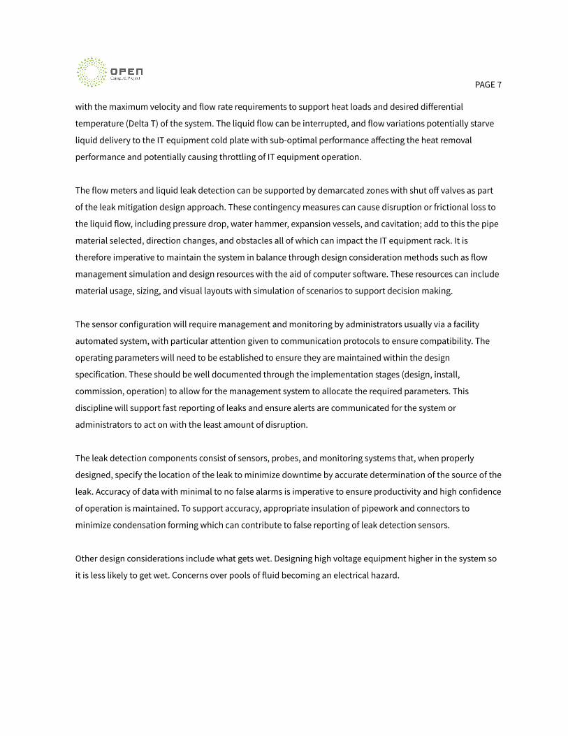
Figure 1. Rack mount CDU and dual manifold installation

PAGE 13
Figure 2. Manifold supply/return and ITE cold plate supply/return connections
Figure 3. Potential Leak Points

PAGE 14
Figure 4. Data center liquid cooling terminology
PAGE 15
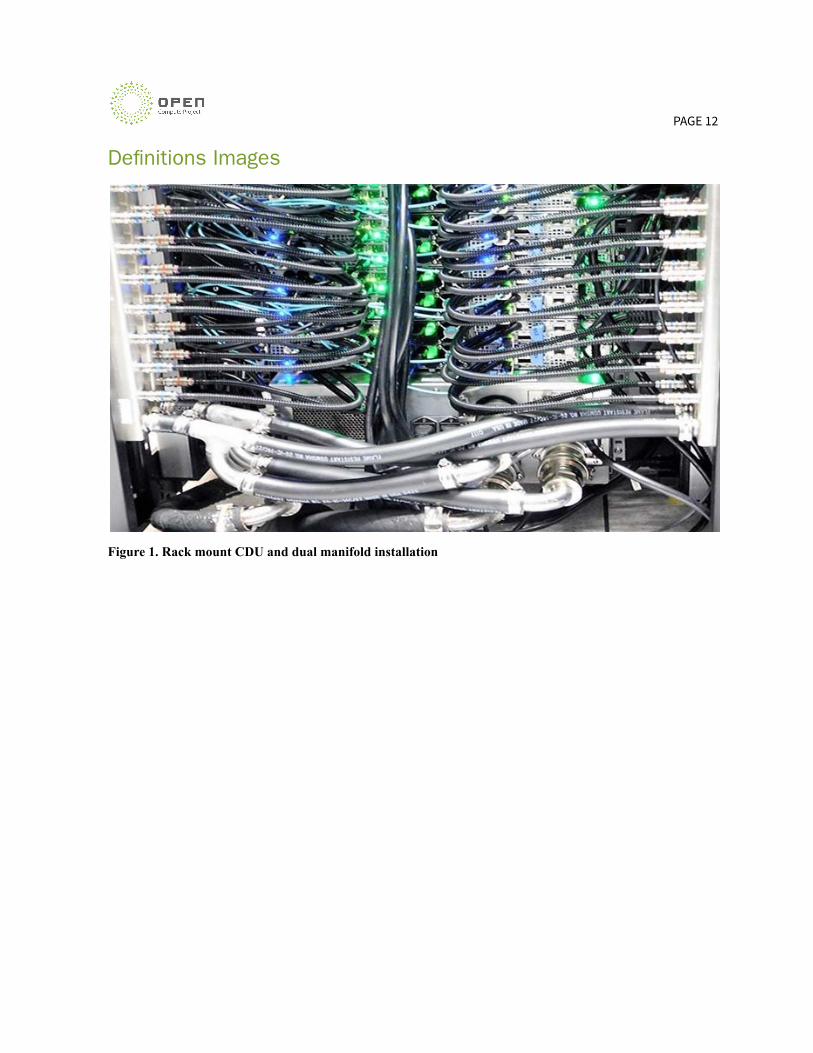
Figure 5. TCS Cooling loop with end of row CDU
Figure 6. TCS Cooling loop with in rack CDU
PAGE 16
Examples
Risk Analysis of an example:
A full risk analysis should be performed at the beginning of a project. All facility leak risks should have been
considered before looking at the data center design. Need to start with a solid design by designing for no leaks
from the beginning. Include total cost of ownership (TCO) evaluation and risk analysis (probability and
impact). Another cost to consider is service maintenance (visual inspections, connection maintenance, CDU
maintenance, regular checks for leaks, etc.).
Any part of the design that is susceptible to leaks, like where pipes are joining, should be reviewed in detail.
Fitting selections and quick disconnects should be planned out for optimal sealing and material compatibility.
Any connection that needs to be serviceable should receive extra scrutiny. BSPP connections with an O-ring or
washer are preferred over BSPT with tape or putty. Connections that do not need to be serviced could be hard
piped like brazed or welded joints. Containment pans should be considered for high-risk areas.
Other local considerations may be required like earthquake rules for fastening down racks and having some
flexibility in the tube connections from rack to rack. Those best practices may factor into leak detection
requirements.
Leak detection should be placed near all connections where the risk is highest. Cost may need to be balanced,
cable leak detectors around all connections would be ideal but costly where one point detector in a pan under
several fittings could also be used for leak detection.
System intervention and reactions to a leak detection should be carefully considered for the customer's use
condition. Some customers might have enough redundancy to shut down nodes when leaks are detected and
some customers will want to avoid shutdowns at all costs. If measures are to be taken, it should be determined
if automated reactions should be immediately taken upon leak detection or if manual reactions should be
flagged for human interaction and a final evaluation before and if actions are to be taken.
Lessons learned from early liquid cooling applications at US National Labs
A US National Lab worked with a vendor to develop a new liquid cooling system for IT systems. As part of the
initial design, an inexpensive O-ring was used which caused leaks to develop over time outside of the IT
PAGE 17
equipment. The leaks weren’t catastrophic and were not significant enough to cause the facility leak detection
system to trigger. This resulted in the IT cooling loop gradually losing liquid volume, requiring out-of-sequence
maintenance to top up liquid volumes. The issue wasn’t discovered until a deeper analysis of the facility
infrastructure was performed to determine where leaks were and why leaks developed. Since this issue
appeared, the positioning of the leak detection cable was changed to be able to identify small leaks closer to
the potential leak points. In this particular case, the facility manifolds are located under the raised floor, so
simple LED strip lighting was added as well to be able to visually detect small leaks under the manifolds very
quickly. The failing O-rings identified as the problem were also changed out with O-rings of a different
composition to prevent this issue in the future. For future installations, this issue highlighted the importance
of making sure a thorough assessment of the wetted materials list of the entire solution is validated against
the liquid coolant chemistry to ensure compatibility. For the leak detection rope, a change was also made from
a two-wire leak detection rope to a four-wire leak detection rope to be able to identify leak location under the
raised floor, and the location on the leak detection rope was mapped to the data center coordinates to be able
to quickly action detected leaks.
Another example from the US National Labs was with quick disconnects fittings leaking over time. It was
determined that this leaking was due to seal fatigue, with the test system quick disconnect fittings being
connected and disconnected many times during the setup and commissioning process. Over time, small leaks
at the quick disconnects fittings developed and it was determined that this was due to sideload on the quick
disconnect fittings on the liquid coolant lines hanging in the warmer area at the back of the IT equipment
racks. The sideload force from the hanging liquid cooling lines was deforming the seals in the quick disconnect
fittings. The IT equipment was not affected, as the quick disconnect fittings are located outside of the IT
systems. The leaks noticed were small, typically resulting in visible water drops on the affected connectors.
One proposed solution was to use vertical cable managers to better support the weight of the interconnection
liquid lines that go between the rack manifolds and IT systems. When employed on a subset of racks in the
cluster, it was found that leaks were mitigated without changing out the old connectors with new connectors.
The warmer temperature of the liquid coolant and surrounding air allowed the deformed seals to return to
their original shape and provide proper sealing.
Other technologies that the National Labs are looking at in order to mitigate and avoid leaks is with negative
pressure or sub ambient pressure liquid cooling systems. These systems draw air into the liquid cooling system
where compromised and separate the air from the liquid at the CDU. Negative pressure technology helps users

PAGE 18
who are new to liquid cooling that may have concerns around deploying liquid coolant close to and within the
ITE. Negative pressure technology is one way to remove considerable risk from the solution.
Reliability Data
The use of non-metallic piping systems for both FWS and TCS loops in datacom liquid cooling applications is
becoming increasingly popular. One of the more common non-metallic piping materials used is
polypropylene-random (PP-R). With PP-R piping, joints are made by heating the pipe and fittings to a molten
state and rapidly pressing them together rapidly to form a homogeneous bond. Larger diameter pipes and
fittings are joined using butt fusion, where two butt ends are joined directly together. Smaller diameter pipes
use socket fusion, where the pipe ends and fittings are heated and then manually pressed together and
allowed to cool where they become a single piece with no potential for leaks. The fusion is less prone to leaks
than threaded and applications where there are concerns with sealant coverage.
Plastic or PP-R pipe has a broad operating range, which makes it ideal for use on both FWS and TCS loops. PP-R
pipe is also ideally suited for potable and chemically inert applications and where high physical durability is
desired.
Long-term reliability studies show that PP-R and similar plastic piping solutions are immune to galvanic or
dissimilar metal corrosion and have better wear expectancy compared to copper or even carbon and stainless
steel materials.
The Magma Supercomputer installed at Lawrence Livermore National Laboratory uses PP-R for the above rack
FWS as shown below. This picture also shows an ISO base for seismic considerations.

PAGE 19
Figure 7. Above rack PP-R piping at Magma supercomputer
Gaseous Pressure Testing
Gaseous pressure leak testing using dry nitrogen or forming (95% nitrogen, 5% hydrogen) gas is where the
assembly holds pressure against a known decay curve. With forming gas, a hydrogen hand detector can be
used to identify spot leaks at specific components.
Helium vacuum chamber testing is a global test using helium gas as the working fluid in a vacuum
environment with a mass spectrometer detecting the presence of helium in the vacuum indicating a leak.
Helium is used as the working fluid due to it having the smallest molecular size, with the mass spectrometer
setup to detect the ionization of helium in the vacuum stream process sample. Helium is the best test gas to
use for manufacturing leak tests because it has the smallest molecule size, hence the greatest chance of
detecting small pinhole leaks. Helium leak testing utilizes specialized chambers that put components under
vacuum prior to filling the components with helium and using mass spectrometry to determine if there are
leaks and the rate of leakage. Due to helium being a finite resource, manufacturers should utilize helium leak

PAGE 20
testing chambers for general leak testing in order to be able to recover the helium used in the global test. If
leaks are detected under a global test, then hand-held helium detectors can be used to identify the source of
the leak and take corrective action.
Dry nitrogen (moisture removed) is another gas that is commonly used for leak testing. The vessel being tested
is flushed and filled with dry nitrogen above atmospheric pressure and the pressure decay is monitored over a
time interval and compared to a known decay curve to determine if there is a leak in the vessel. Leak testing
with dry nitrogen, as with forming gas, can be effective for leak testing vessels in the field due to not requiring
large leak testing chambers and mass spectrometer equipment.
Shipping manufactured units pressurized with dry nitrogen or forming gas also help to limit biogrowth during
shipping and periods of storage prior to deployment. The pressure charges for shipping and storage are
relatively low for safety reasons and transport regulations.
Care should be taken not to use a standard air compressor as a source of pressurized gas for leak testing
because the untreated air can contain a significant amount of moisture and particulate contamination. Dry
nitrogen and forming gas are available in portable tanks and are safe to use in working environments without
special handling or working conditions.
TCS and FWS systems are always assembled on site due to the custom nature of data center layouts. During
the commissioning, it is absolutely imperative that they are checked for leaks prior to filling with coolant or
refrigerant. Regardless of the material used, there will either be manufacturer recommended or industry
accepted leak testing procedures that must be followed.
Additional leak tests that are o�en implemented are:
● Gas pressure dwell test - with all direct connected (i.e. no quick disconnect) valves open, pressurize
the system with dry nitrogen to pressure slightly below the setting of the pressure relief valves (i.e. 35
PSI) and leave for 8 hours. There should be no reduction in pressure in the morning.
● Hydro-static Pressure Test - when filling the FWS with coolant, bring the system up to a static pressure
of 14.5 PSI (1 bar) for an hour. There should be no reduction in pressure.
● Active Test - look at pressure gauges and check for shipping damage. Connect to the refrigerant
source and check pressure for leaks. There are other risks for leaks when pumps are moving that can
be tested without the IT equipment.

PAGE 21
● Check for insulation. Note that condensation could be detected as a leak.
● Filtering in use and flushing the system when hardware comes in are important to avoid leaks in QDC.
PAGE 22
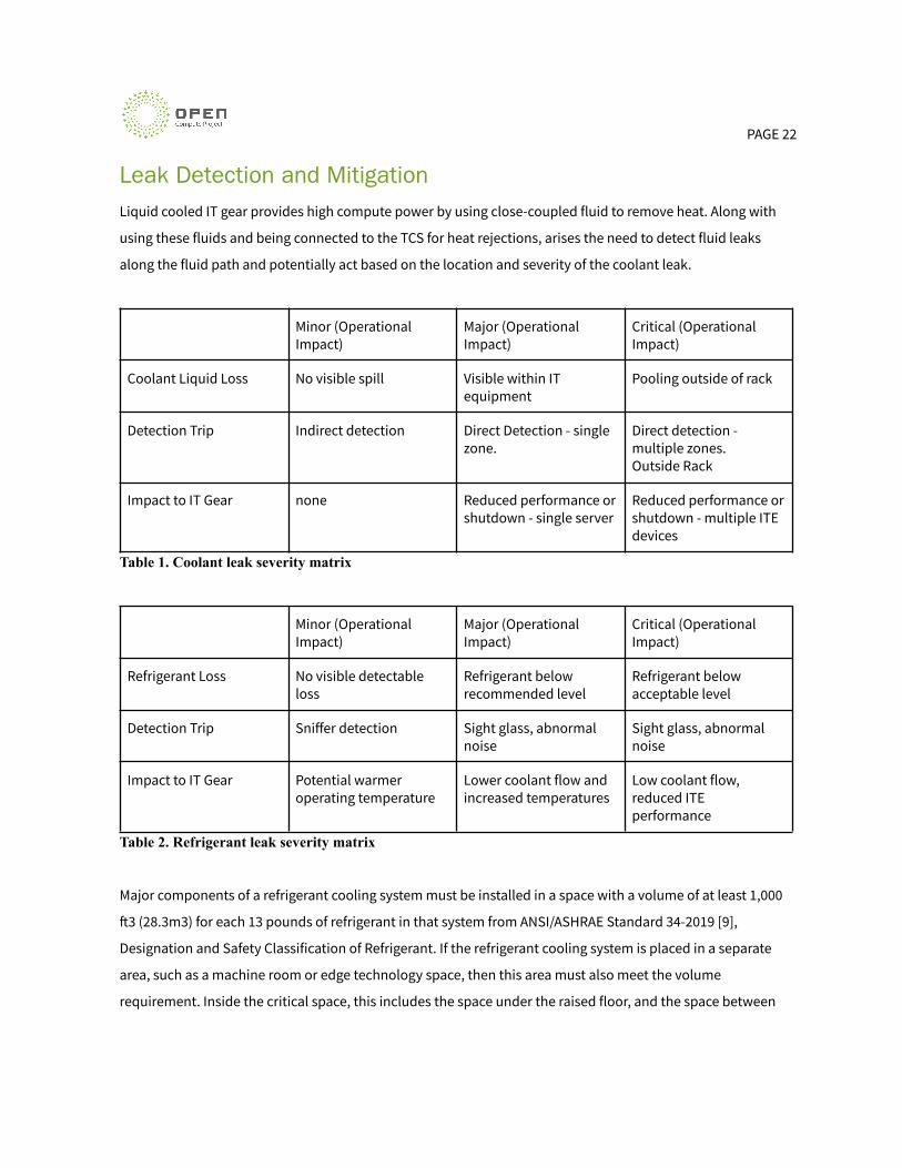
Leak Detection and MitigationLiquid cooled IT gear provides high compute power by using close-coupled fluid to remove heat. Along with
using these fluids and being connected to the TCS for heat rejections, arises the need to detect fluid leaks
along the fluid path and potentially act based on the location and severity of the coolant leak.
Minor (OperationalImpact)
Major (OperationalImpact)
Critical (OperationalImpact)
Coolant Liquid Loss No visible spill Visible within ITequipment
Pooling outside of rack
Detection Trip Indirect detection Direct Detection - singlezone.
Direct detection -multiple zones.Outside Rack
Impact to IT Gear none Reduced performance orshutdown - single server
Reduced performance orshutdown - multiple ITEdevices
Table 1. Coolant leak severity matrix
Minor (OperationalImpact)
Major (OperationalImpact)
Critical (OperationalImpact)
Refrigerant Loss No visible detectableloss
Refrigerant belowrecommended level
Refrigerant belowacceptable level
Detection Trip Sniffer detection Sight glass, abnormalnoise
Sight glass, abnormalnoise
Impact to IT Gear Potential warmeroperating temperature
Lower coolant flow andincreased temperatures
Low coolant flow,reduced ITEperformance
Table 2. Refrigerant leak severity matrix
Major components of a refrigerant cooling system must be installed in a space with a volume of at least 1,000
�3 (28.3m3) for each 13 pounds of refrigerant in that system from ANSI/ASHRAE Standard 34-2019 [9],
Designation and Safety Classification of Refrigerant. If the refrigerant cooling system is placed in a separate
area, such as a machine room or edge technology space, then this area must also meet the volume
requirement. Inside the critical space, this includes the space under the raised floor, and the space between
PAGE 23
the top of the raised floor and the bottom of a suspended ceiling. If the suspended ceiling is all open grates,
then this additional space, up to the overhead deck, would also be included.
Leak detection can be done by incorporating simple point leak detectors and/or ropes to provide more detail
on the location of the leak. You can also look at CDU performance and pressure losses that may indicate a leak
feeding the TCS.
Leak detection can be implemented either directly using sensors that the liquid must touch, or indirectly using
one or more sensors that when combined with knowledge of the operating conditions and service events can
indicate that there is a leak.
Indirect
As defined, indirect leak detection uses non-contact sensors to determine when a leak has occurred.
Common Options Available
● Monitor changes in differential liquid coolant pressure over time
● Monitor changes in absolute refrigerant pressure over time
● Monitor changes in liquid coolant level in the reservoir
● An optical sensor that monitors liquid coolant build up in target areas
● Turbidity sensors for refrigerant or coolant
Pros and Cons
Over time, temperature changes can cause small amounts of expansion/contraction of the wetted materials,
resulting in changes in the liquid coolant level in the reservoir. These changes in volumes can be correlated to
temperature tracking over the same time interval to establish this relationship.
Changes in differential pressure due to nodes/racks being added/removed from the liquid loop should be
factored into the changes in differential pressure monitoring.
Measurements of differential pressures are typically done across the pumps in the TCS loop. This allows the
differential pressure of the entire TCS loop to be monitored from a single sense point. This offers the smallest
measurement and greatest level of sensitivity due to the large number of varying factors within the TCS loop.
PAGE 24
Differential pressure measurement across the TCS pumps should be considered as a requirement for liquid
cooling applications. This capability is typically available in most off-the-shelf CDUs and RPUs available today.
In cases where the TCS loop contains multiple racks of ITE, more granular differential pressure could be at the
inlet and outlet connection to each manifold in the rack of ITE. This would increase the sensitivity of the
differential pressure measurement, but would come with additional cost of adding more sensors to the TCS
loop. Most off-the-shelf CDUs and pump units are not designed to support external inputs, so there could be
additional cost of a localized controller to monitor and process these additional sense points.
In some liquid cooling installations, the ITE to liquid cooling connections reside within the ITE or chassis. In
these cases, having optical liquid sensors to detect leaks results in lower cost sensors and less space required
for sensors. These optical sensors can be integrated into the ITE BMC for simplicity of installation. Another
positive attribute is that small drip trays below the connections can be installed to catch any droplets of
coolant when liquid cooling connections are disconnected.
Direct
Direct leak detection has two fundamental requirements: the liquid must touch the sensor with enough
volume to detect it; the liquid must be electrically conductive.
Common Options Available
● Leak Detection Rope
● Point Detectors
● Floats
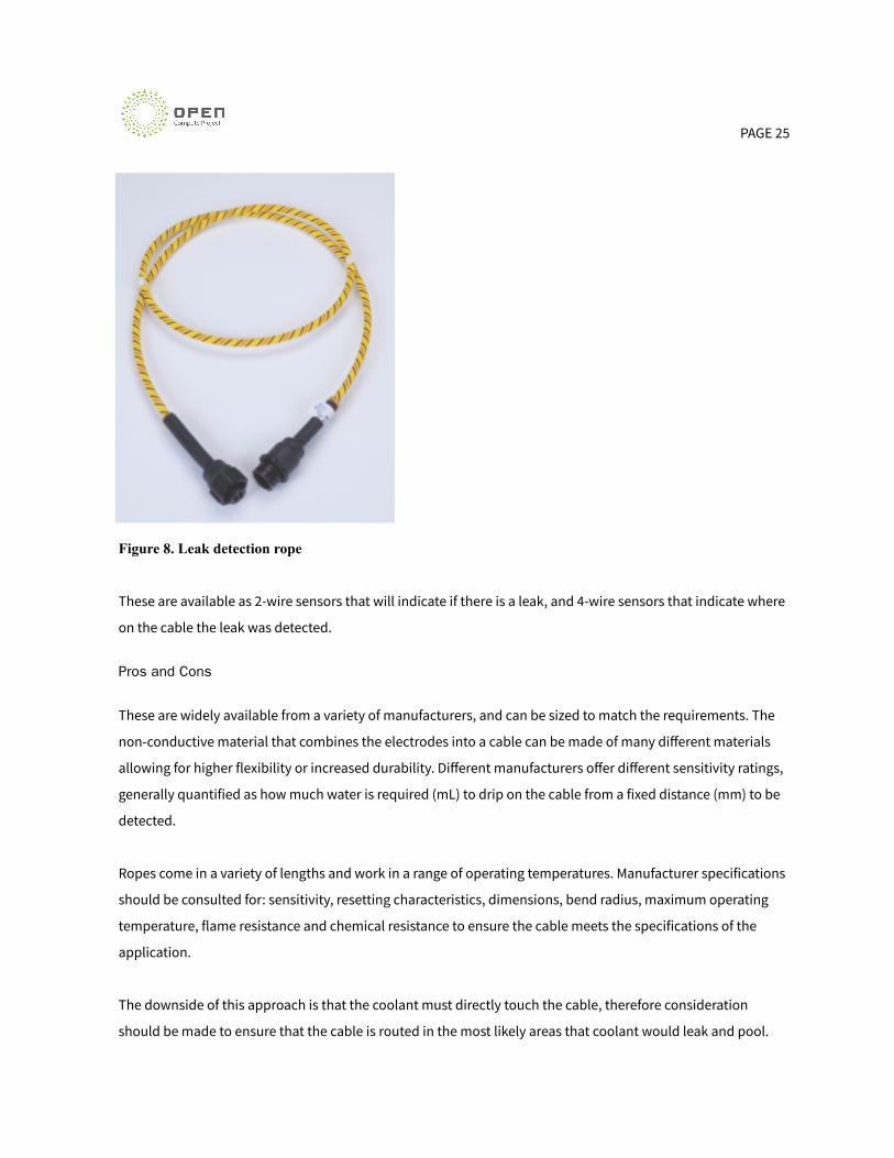
The most commonly available leak detection for water based coolants is a leak detection rope as shown below.
These cables work by having two (or four) electrodes separated by a di-electric material. When the electrically
conductive coolant provides a path between the electrodes, the resistance between the electrodes changes,
indicating a leak.
PAGE 25
Figure 8. Leak detection rope
These are available as 2-wire sensors that will indicate if there is a leak, and 4-wire sensors that indicate where
on the cable the leak was detected.
Pros and Cons
These are widely available from a variety of manufacturers, and can be sized to match the requirements. The
non-conductive material that combines the electrodes into a cable can be made of many different materials
allowing for higher flexibility or increased durability. Different manufacturers offer different sensitivity ratings,
generally quantified as how much water is required (mL) to drip on the cable from a fixed distance (mm) to be
detected.
Ropes come in a variety of lengths and work in a range of operating temperatures. Manufacturer specifications
should be consulted for: sensitivity, resetting characteristics, dimensions, bend radius, maximum operating
temperature, flame resistance and chemical resistance to ensure the cable meets the specifications of the
application.
The downside of this approach is that the coolant must directly touch the cable, therefore consideration
should be made to ensure that the cable is routed in the most likely areas that coolant would leak and pool.
PAGE 26
Slow leaks are o�en characterized by residue le� behind from glycol or additives to the coolant, as the water
evaporates quickly. This scenario would not be caught by a leak detection rope, however it likely wouldn’t
damage the IT gear either.
Leak detection ropes are analog cables which require an analog to digital converter (ADC) to convert the
resistance between sensor wires into a value that a BMC can read and act upon. If the BMC doesn’t have analog
inputs, a separate conversion board will be required, with the output of this conversion board providing an
interface that the BMC can use, such as I2C, or TTL digital outputs. The conversion board can be used to tune
the severity threshold required before indicating a leak.
The implementation of leak detection with ITE gear should ensure that the leak detection rope is placed in a
location that is most likely to leak, such as at junctions and sealing surfaces. Consideration should also be
given to the location that the fluid will pool if a leak occurs.
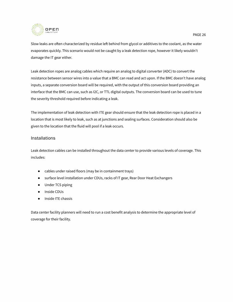
Installations
Leak detection cables can be installed throughout the data center to provide various levels of coverage. This
includes:
● cables under raised floors (may be in containment trays)
● surface level installation under CDUs, racks of IT gear, Rear Door Heat Exchangers
● Under TCS piping
● Inside CDUs
● Inside ITE chassis
Data center facility planners will need to run a cost benefit analysis to determine the appropriate level of
coverage for their facility.
PAGE 27
Figure 9. Leak detection sensor layout
PAGE 28
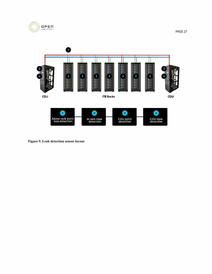
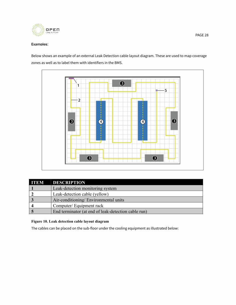
Examples:
Below shows an example of an external Leak Detection cable layout diagram. These are used to map coverage
zones as well as to label them with identifiers in the BMS.
ITEM DESCRIPTION1 Leak-detection monitoring system2 Leak-detection cable (yellow)3 Air-conditioning/ Environmental units4 Computer/ Equipment rack5 End terminator (at end of leak-detection cable run)
Figure 10. Leak detection cable layout diagram
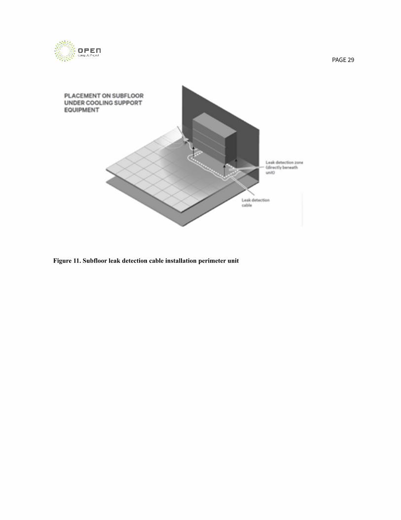
The cables can be placed on the sub-floor under the cooling equipment as illustrated below:
PAGE 29
Figure 11. Subfloor leak detection cable installation perimeter unit
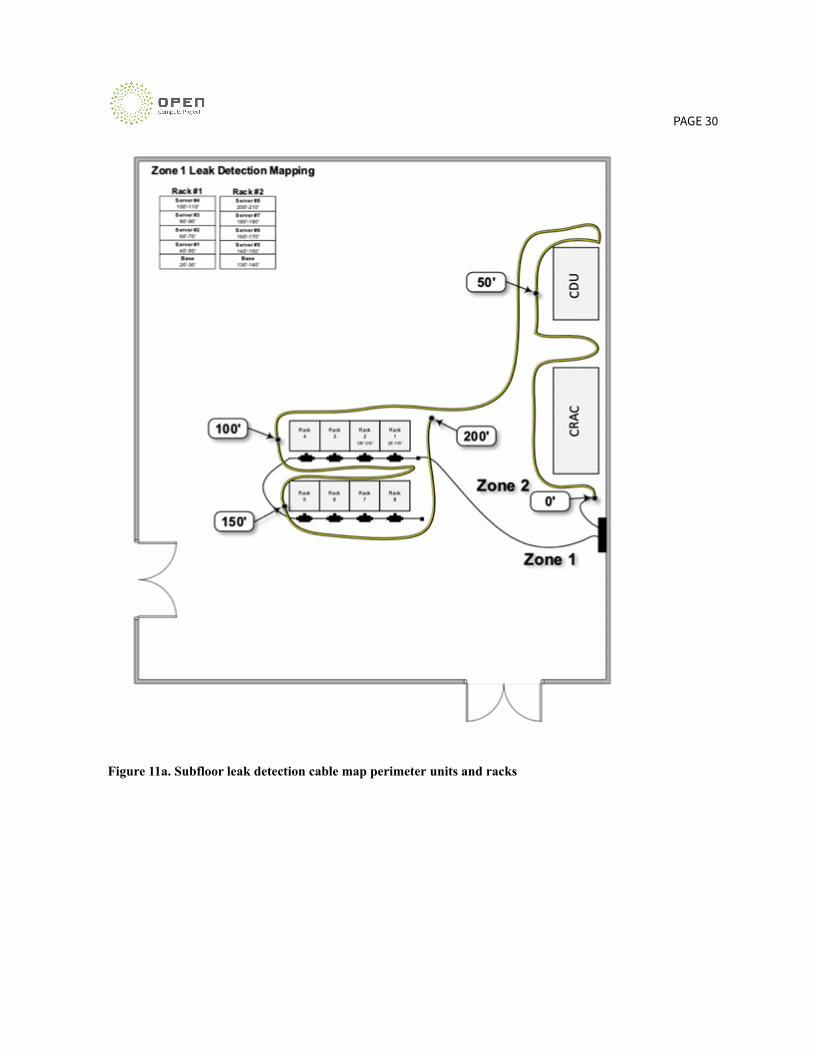
PAGE 30
Figure 11a. Subfloor leak detection cable map perimeter units and racks
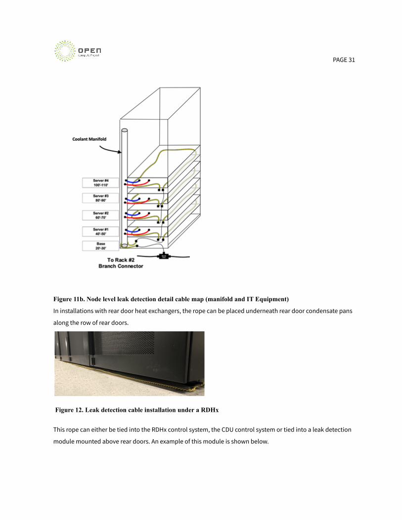
PAGE 31
Figure 11b. Node level leak detection detail cable map (manifold and IT Equipment)
In installations with rear door heat exchangers, the rope can be placed underneath rear door condensate pans
along the row of rear doors.
Figure 12. Leak detection cable installation under a RDHx
This rope can either be tied into the RDHx control system, the CDU control system or tied into a leak detection
module mounted above rear doors. An example of this module is shown below.

PAGE 32
Figure 13. Leak detection module
In raised floor environments several options are available. Leak detection ropes can be run in the sub-floor
positioned such that it would detect a leak in either the TCS or FWS piping. Texas Advanced Computing Center
has a system like this installed with their Frontera Supercomputer. [2]
Figure 14. Subfloor leak detection rope installation at TACC

PAGE 33
Containment systems can also be installed in the sub-floor. This has the added benefit of allowing for shaping
the bottom of the containment pan to ensure that liquid will pool at the sensor. This allows for use of point
sensors in the tray, rather than ropes as shown below. In such a system, the containment tray should be
designed to hold enough volume of coolant to allow for an alarm or action to occur. It is unlikely that a leak in
a high flow rate manifold or high pressure FWS would be able to be contained for any duration.
Figure 15. Leak detection in subfloor containment system
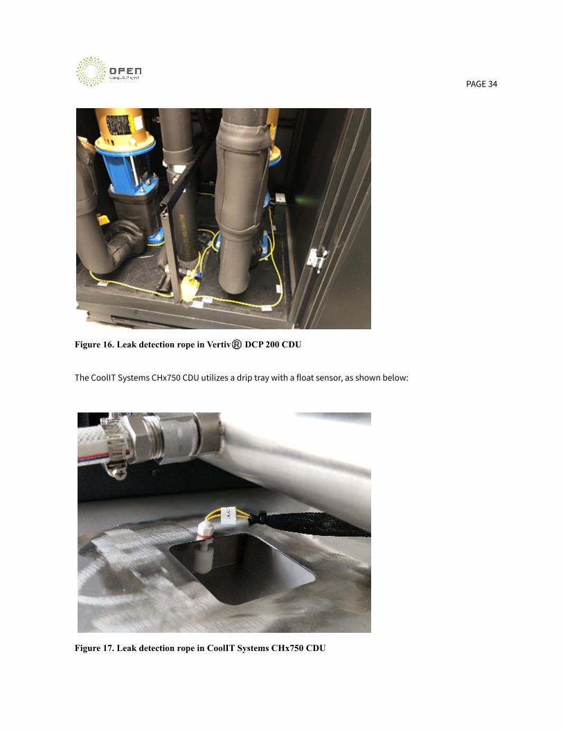
Most CDUs on the market offer leak detection both internal and external to the cabinet. The internal leak
detection rope of the Vertiv® DCP 200 CDU is shown below:
PAGE 34
Figure 16. Leak detection rope in Vertiv® DCP 200 CDU
The CoolIT Systems CHx750 CDU utilizes a drip tray with a float sensor, as shown below:
Figure 17. Leak detection rope in CoolIT Systems CHx750 CDU

PAGE 35
At the ITE level, various different types of sensors can be used including the leak detection rope or optical
sensors.
An example Implementation a leak detection rope on an OCP Project Olympus Server is shown below:
Figure 18. Leak detection rope in Project Olympus Server
Control Systems
The above examples explain how to detect a leak, however these leak alarms need to be conveyed to the
operator in order so a decision can be made on the appropriate action to take. The action could be taken
either automatically or manually.
In all cases, when a leak is detected an alarm signal must be sent to the DCIM or BMS. A thorough discussion on
what actions should be taken is discussed below in the Leak Intervention section. The remainder of this
section focuses on the IT infrastructure requirements to alert the operator of the issue.

PAGE 36
Reporting
The common protocols implemented in CDU reported include Modbus RTU, Modbus IP, SNMP and BACnet.
Redfish is gaining momentum with the help of OCP, however the schemas for liquid cooling equipment have
yet to be accepted by DMTF®. This activity is being coordinated by the OCP Hardware Management
workgroup.
Data center operators should validate that the equipment they wish to utilize offers an interface that is
compatible with their BMS. Once this has been confirmed, some customizations will be required in order to
map the telemetry and control data set from the equipment to the BMS. Once the points are mapped, the
operator then needs to determine what they want to do when a leak is detected. Some options are:
● Alert an operator
● Perform a controlled electrical shutdown
● Isolate the fluid flow to the affected node / rack
● Stop the fluid flow at the CDU
Each of these actions have varying levels of operational impact to the data center. The extreme example would
be to stop the fluid flow at the CDU. This would require that every server that utilizes liquid cooling be shut
down and the entire system stopped. Unfortunately, there is an inverse relationship between operational
impact and potential damage to equipment. Looking at the other extreme, if the decision is made to only
alarm an operator when a leak is detected, IT equipment could be damaged by the leak, or it could overheat as
there would not be sufficient cooling in the case of a refrigerant based system.
It is also important to consider personnel safety. Significant leaks of coolant can cause slip hazards or potential
electrocution if the accumulation becomes energized. In the case of refrigerants, the depletion of oxygen can
be hazardous.[9] Immersion-based systems have a few special handling conditions to consider. The
immersion fluids themselves can pose increased slip hazards when compared to water-based coolants. Due to
the fact that systems are immersed or submerged in liquid, handling of systems outside of the tank for service
increases the potential for liquid spillage, so special oil-absorbing mats, grip-tape floor coverings, and/or floor
grates can be used in areas where liquid spillage can occur. In the case of two-phase immersion cooling
systems, there may be potential concerns and hazards with IT support staff working directly with boiling
liquid. These issues could include inhalation of vaporization, splashing, and spillage.
PAGE 37
Nuisance Alarms
Careful consideration should be given to alarm definitions and thresholds. If alarm thresholds are set too low,
a high number of false alarms could be triggered. This can be a significant problem in two ways. First, the
operators spend too much time investigating issues that aren’t actually there, and second, eventually
operators may ignore the alarm as it isn’t a real problem, until eventually it is.
One method to deal with this is to utilize redundant sensors. For example, if you have a point sensor installed
in a catch tray and a leak detection rope installed on a rack manifold, if either of them detects fluid an alarm is
sent to the operator. If both of them detect fluid and automatic intervention is executed.
The sensitivity of leak detection sensors and methods should be included in the process of choosing sensors
for specific applications, as the sensitivity adjustment can be changed to best suit each unique application.
Alarm thresholds should be examined and agreed upon during the commissioning stages to suit the specific
application and type of detection, as these threshold and sensitivity levels will be specific to each application.
Leak InterventionFrom ACS cold plate requirement document [1]:
The lowest level of intervention is manual intervention when a notification is sent out to the facilitypersonnel that a leak has been detected. The next level can be automatic electrical intervention, when anotification is sent of a leak event and an automatic electrical de-energization is done of the ITequipment. This can save the hardware that gets exposed to the leak/cooling liquid, andrecommissioning has to address how to deal with the wet but saved equipment. A more sophisticatedapproach is the automatic electrical and fluid intervention. This is when a leak notification is detected,the IT equipment is being de-energized, and the cooling liquid is shut-off. This can save extensivehardware exposure to leakage, which can simplify the recommissioning of the exposed IT equipment.The reduced risk with having automatic intervention solutions comes with a cost, which again needs toweigh against the requirement of the installation.
...
Leak intervention classifications
● Manual: using manual intervention after leak detected eg closing flow control valves andshutting down IT equipment
● Automatic: using automatic intervention approach after leak detected eg de-energized ITequipment and/or cooling liquid shut-off
PAGE 38
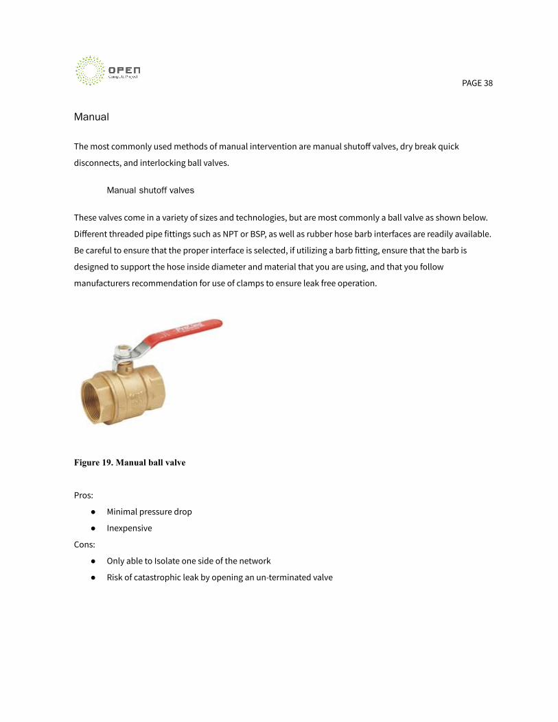
Manual
The most commonly used methods of manual intervention are manual shutoff valves, dry break quick
disconnects, and interlocking ball valves.
Manual shutoff valves
These valves come in a variety of sizes and technologies, but are most commonly a ball valve as shown below.
Different threaded pipe fittings such as NPT or BSP, as well as rubber hose barb interfaces are readily available.
Be careful to ensure that the proper interface is selected, if utilizing a barb fitting, ensure that the barb is
designed to support the hose inside diameter and material that you are using, and that you follow
manufacturers recommendation for use of clamps to ensure leak free operation.
Figure 19. Manual ball valve
Pros:
● Minimal pressure drop
● Inexpensive
Cons:
● Only able to Isolate one side of the network
● Risk of catastrophic leak by opening an un-terminated valve

PAGE 39
Dry Break Quick Disconnects
Dry break quick disconnects, such as the Universal Quick Disconnect (UQD) shown below allow the fluidic
connection to be broken with very little fluid loss (for example, a UQD2 is specified to drip less than 0.063cc
when disconnected at 200PSI). This offers many advantages including no-mess servicing, reduction of the risk
of spilling coolant on expensive ITE gear or electrical connections, and generally requires less radial space than
ball valves. The QDs add cost and pressure drop to the system. Careful consideration into sizing must occur to
ensure the flow rate and pressure during connection and disconnection can be handled. The probability of a
leak on a QD is higher than a standard fixed connector when disconnecting due to the potential of the valve
being stuck open with contaminants.
Pros:
● Isolate both sides of the fluid connection
● Protect IT gear with minimal coolant loss during disconnection
Cons:
● Add cost to solution
● Add pressure drop to solution
● Valves may be proprietary and therefore not interchangeable between vendors
Figure 20. Parker UQD02 quick disconnect

PAGE 40
Interlocking Valves
Interlocking valves, such as the Eaton FD83 shown below contain ball valves and offer full flow at minimal
pressure drops. These valves interlock preventing the ball valve from being opened without the mating
connector being securely in place, eliminating the risk of a catastrophic leak during servicing. These valves add
cost, but the system does not incur any additional pressure drop. These valves are generally used with large
diameter tubing, such as the connection between the TCS pipe network and the rack manifolds.
Figure 21. Eaton interlocking valve
Pros:
● Isolate both sides of the fluid connection
● Protect IT gear with minimal coolant loss during disconnection
Cons:
● Add cost to solution
● Lose a noticeable amount of coolant on disconnect
● Valves may be proprietary and therefore not interchangeable between vendors
Automatic
Automatic intervention can be added to liquid cooling systems to reduce the impact of a leak. The system
designer will have to carefully consider the business impacts of shutting down equipment against the
potential cost of replacing damaged IT gear.
PAGE 41
Automatic intervention techniques add complexity to the system but can reduce the amount of time required
for data center personnel to respond to a leak alarm. These methods can be deployed both within the IT
equipment and in the TCS fluid loop.
Electrical De-energization
This technique can be deployed within the server itself, or at a rack manager level. In this system, when a leak
is detected by the leak rope, the BMC initiates a controlled shut-down and then turns off the power supply.
This requires that the leak detection sensor is tied directly into the BMC, and that the server architecture
includes a power manager board that is capable of decoupling the PSU from the motherboard.
Implementing this functionality at the rack manager level adds the ability to electrically isolate the server
before the power enters the chassis. In AC powered systems with in-chassis PSUs, this ensures that the high
voltage and current inputs are not shorted out by the electrically conductive fluid. This adds complexity of
having the leak signal sent from the server BMC to the rack manager in order for the intervention to be
initiated.
Pros:
● May prevent permanent damage in the server
● Server level isolation reduces business impact
● Low hardware cost - only requires leak sensor added to each server
Cons:
● Custom firmware required for BMC and / or Rack Manager
● Potential for false alarms
● Does not mitigate fluid loss from a leak
Solenoid Valves
Solenoid Valves or Motor Operated Valves can be installed in multiple locations throughout the FWS and TCS
to allow for isolation when a leak is detected. These valves can be pneumatic or electrical and are available in
many different sizes. Electrically operated solenoid valves are commonly used as it does not require a separate
compressed air system to operate. Electric solenoid valve controllers come in various voltages and will offer
PAGE 42
different types of control signals including analog signals for PLCs, to digital interfaces such as modbus IP and
BACNet.
These valves can be installed in the TCS at the CDU supply, in the supply and return manifolds, at the rack
manifold or even in the server node. The closer to the IT gear the valve, the less impact closing it will have on
the data center, however the tradeoff is in cost. Each valve adds cost, complexity and additional potential
failure points. A cost benefit analysis should be performed by data center operators to determine how granular
they want their isolation protection to be.
When adding solenoid controlled isolation valves, there are some key factors that need to be considered
including: input power, control and monitoring interfaces, reliability, failure control and swing time. Input
power and Control / Monitoring Interface must be evaluated to ensure compatibility with the data center
infrastructure. Each valve manufacturer should report the design life of the valve. This is reported as the
number of full cycles / number of partial cycles that the valve is guaranteed to perform over its life. If the valve
is only used for isolation, this will not be a big concern. If it is being used for modulating fluid flow rates or
pressure, it is very important. Valves can also be bought with failure control, this means if a power / control
signal failure occurs the valve will perform an action. This can be: fail last (stay in the existing location), fail
open (open to 100%), or fail closed (open to 0%).
It is important that the valve swing time is carefully considered in order to prevent hydraulic shock, also
known as a water hammer. This occurs when a valve closes suddenly and the mass of the water moving
through the system builds up pressure causing a shock wave to be propagated through the pipe. This can
cause knocking, vibration and even pipe ruptures. The engineer responsible for the plumbing design must
ensure that the valve cannot close fast enough for this to occur
An example of a Solenoid valve manufactured by Belimo is shown below:

PAGE 43
Figure 22. Belimo control valve
Pros:
● Can isolate leaks from the system, reducing the amount of equipment impacted
● If installed in the correct locations, can allow for future expansion without impacting the existing
equipment
● Perform automatic actions reducing amount of damage
Cons:
● Adds cost
● Adds complexity
CDU Shut downs
Most commercially available CDUs have built-in leak detection that can be configured to perform an action.
CDUs are also o�en connected to the BMS and may allow for external control to initiate a shutdown if the leak
is detected in another region. When a CDU shutdown is initiated, the pumps will ramp down, potentially very
quickly depending on the configuration. In order to prevent a potentially catastrophic overpressure event, all
ICs enabled with cold plates must have thermal throttling enabled. Otherwise the slowed or stopped fluid flow
could cause a boil event.

PAGE 44
As a best practice, a safe (panic) shutdown should be issued to the affected IT gear before the CDU initiates its
shutdown. This allows for the workload to be stopped in a known state and reduce the amount of work lost
due to the cooling system failure.
It should be noted that the severity of shutting down a CDU is directly related to the amount of IT gear
connected to it. For rack based CDUs, the affected area is o�en limited to one rack, however there are
scenarios where several racks are connected to one rack based CDU. In the row based CDU scenario, o�en 10
or more racks are connected to CDUs. These systems may have a redundant CDU installed, so the BMS must
ensure that the shutdown signal is sent to both CDUs.
Pros:
● Built-in functionality with most CDUs
● Autonomous operation - can be controlled without intervention from the BMS.
Cons:
● All cooling equipment connected to the CDU will be disabled.
Conclusion
This has been an educational whitepaper to help readers to understand the available options and industry
best practices for leak detection and mitigation for data centers enabled with advanced cooling solutions.
Leak detection and intervention methodologies have been discussed here for different classifications of fluids.
Examples have been provided that describe lessons learned from early liquid cooling deployments. As the best
method for preventing a leak comes from engineering design principles and rigorous production testing at the
manufacturer, this has also been discussed. A section on installation and commissioning best practices was
included to ensure readers are aware of the best practices in these areas to prevent leaks in equipment
assembled on premise.
There are many ways of implementing leak detection and mitigation into data centers, some of which are
specific to the type of fluid used. It is up to the individual operators to determine requirements which solution
PAGE 45
to select based on a risk analysis, cost analysis and operational impact study. These studies were described
here with some guidance on how to evaluate them in a particular data center.
A discussion on the different classifications of leak intervention, as well as examples of both indirect and direct
detectors was provided including how they would interface to the BMS system. FInally, common methods for
leak intervention were discussed including manual and automatic methods.
This document provides the reader with the fundamental knowledge of leak detection in a liquid cooling
enabled data center. It serves as a starting point for discussion and should be used when introducing liquid
cooling into a data center. It is not intended as a specification to be used in design.
PAGE 46
References
[1] “ACS Liquid Cooling Cold Plate Requirements”https://docs.google.com/document/d/1HR5O_bPcgpcjhEMGIejJ6hUor7DDx6_ek6bzvKcc7X8/edit#
[2]”Frontera Media Toolkit” https://frontera-portal.tacc.utexas.edu/about/media-toolkit/
Demonstration of alternative cooling for rack equipment
[3] “ANSI / ASHRAE 15-2019 Safety Standards for Refrigeration Systems.”
https://ashrae.iwrapper.com/ASHRAE_PREVIEW_ONLY_STANDARDS/STD_15_2019
[4] DOE Very Dense computing
[5] Douglas R. Mauro & Kevin J. Schmidt. (2001). Essential SNMP (1st ed.). Sebastopol, CA: O’Reilly &
Associates.
[6] ”Gigabyte glossary” https://www.gigabyte.com/Glossary/bmc
[7] “ACS Door Heat Exchanger Specification for Open Rack”
http://files.opencompute.org/oc/public.php?service=files&t=e8e46af5aa3d470fc91c8618bb239dee&dow
[8] “Energy Efficient High Performance Computing Working Group ” https://eehpcwg.llnl.gov/
[9] “ANSI / ASHRAE 34-2019” Designation and Safety Classification of Refrigerants
[10] “ASHRAE TC9.9” Technical Committee 9.9 (Mission Critical Facilities, Data Centers, Technology Spaces &
Electronic Equipment)
Energy Performance Evaluation of Aquila’s Fixed Cold Plate Cooling System at NREL’s High Performance
Computing Center https://www.nrel.gov/docs/fy19osti/73356.pdf
TrademarksAll product and company names are trademarks™ or registered® trademarks of their respective holders. Use of
them does not imply any affiliation with or endorsement by them.
About Open Compute FoundationThe Open Compute Project Foundation is a 501(c)(6) organization which was founded in 2011 by Facebook,Intel, and Rackspace. Our mission is to apply the benefits of open source to hardware and rapidly increase thepace of innovation in, near and around the data center and beyond. The Open Compute Project (OCP) is acollaborative community focused on redesigning hardware technology to efficiently support the growingdemands on compute infrastructure..For more information about OCP, please visit us athttp://www.opencompute.org