ACMV, FPS & IBMS Volume - Ticel Bio Park
161
TICEL BIO PARK-III Vol-III ACMV, FPS & IBMS WORKS EC: TAAMAESEK ENGINEERING CONSORTIUM Page 1 TICEL BIO PARK LTD COMPETITIVE TECHNO COMMERCIAL TENDER SUPPLY, INSTALLATION, TESTING AND COMMISSIONING OF ACMV, FIRE PROTECTION AND IBMS WORKS IN CONSTRUCTION OF TICEL BIO PARK–III, At SF No. 66, 67, 68 & 75, Off Maruthamalai Road, Somayampalayam Village, Bharathiyar University P.O, Coimbatore - 641 046 (G +13 UPPER FLOORS) TECHNICAL SPECIFICATION VOLUME - III DUE DATE FOR SUBMISSION: ON OR BEFORE 03.04.2019 at 3.00PM TO BE SUBMITTED TO: M/s TICEL BIO PARK Ltd., CSIR Road, Taramani, Chennai - 600 113. Telephone No.: +91 44 22542061 Fax No: 91-44-2254 2055 E-mail: [email protected] ENGINEERING CONSULTANTS: M/s TAAMAESEK ENGINEERING CONSORTIUM Architects & Engineers No 5, 1st Floor, Bishop Wallers Avenue West. Off TTK Road, Mylapore, Chennai- 600 004 – INDIA. Tel No: 044-24671139 / 57 Fax No: 044-24672237 E-Mail: [email protected] TENDER SUBMITTED BY: M/s._________________________ Address______________________ _____________________________ _____________________________ 2019
-
Upload
khangminh22 -
Category
Documents
-
view
4 -
download
0
Transcript of ACMV, FPS & IBMS Volume - Ticel Bio Park

TICEL BIO PARK-III Vol-III ACMV, FPS & IBMS WORKS
EC: TAAMAESEK ENGINEERING CONSORTIUM Page 1
TICEL BIO PARK LTD
COMPETITIVE TECHNO COMMERCIAL TENDER
SUPPLY, INSTALLATION, TESTING AND COMMISSIONING OF ACMV, FIRE PROTECTION AND IBMS WORKS IN CONSTRUCTION OF TICEL BIO PARK–III,
At SF No. 66, 67, 68 & 75, Off Maruthamalai Road, Somayampalayam Village,
Bharathiyar University P.O, Coimbatore - 641 046 (G +13 UPPER FLOORS)
TECHNICAL SPECIFICATION
VOLUME - III
DUE DATE FOR SUBMISSION: ON OR BEFORE 03.04.2019 at 3.00PM
TO BE SUBMITTED TO: M/s TICEL BIO PARK Ltd., CSIR Road, Taramani, Chennai - 600 113. Telephone No.: +91 44 22542061 Fax No: 91-44-2254 2055 E-mail: [email protected]
ENGINEERING CONSULTANTS: M/s TAAMAESEK ENGINEERING CONSORTIUM Architects & Engineers
No 5, 1st Floor, Bishop Wallers Avenue West. Off TTK Road, Mylapore,
Chennai- 600 004 – INDIA. Tel No: 044-24671139 / 57
Fax No: 044-24672237 E-Mail: [email protected]
TENDER SUBMITTED BY: M/s._________________________
Address______________________
_____________________________
_____________________________
2019
TICEL BIO PARK-III Vol-III ACMV, FPS & IBMS WORKS
EC: TAAMAESEK ENGINEERING CONSORTIUM Page 2
Table of Contents
1.0 TECHNICAL SPECIFICATION FOR AIR CONDITION AND MECHANICAL WORKS ........................ 5
1.1.0 GENERAL REQUIREMENTS ........................................................................................................................ 5
1.2.0 AIR COOLED CHILLER ................................................................................................................................. 6
1.2.1 GENERAL ................................................................................................................................................. 6
1.2.3 QUALITY ASSURANCE COMPONENTS ............................................................................................ 6
1.2.4 FACTORY TESTS ................................................................................................................................... 6
1.2.5 CODES & STANDARDS ......................................................................................................................... 8
1.2.6 CONSTRUCTION .................................................................................................................................... 8
1.3.0 CHILLED WATER PUMP SET..................................................................................................................... 21
1.4.0 DOUBLE SKIN AIR HANDLING UNIT ...................................................................................................... 34
1.5.0 VENTILATION FANS .................................................................................................................................. 44
1.5.1 CABINET TYPE EXHAUST & FRESH AIR FANS ............................................................................ 44
1.5.2 VANE AXIAL FANS (DIRECT DRIVE) ................................................................................................ 48
1.5.3 SMOKE EXTRACTION ......................................................................................................................... 49
1.5.4 CENTRIFUGAL FANS ........................................................................................................................... 49
1.5.5 IN-LINE CENTRIFUGAL DUCT FAN .................................................................................................. 50
1.6.0 VARIABLE FREQUENCY DRIVE .............................................................................................................. 51
1.7.0 SHEET METAL DUCTING, GRILLES, DIFFUSERS, LOW LEAKAGE VCDS & FDS ............................. 55
1.8.0 PIPING WORKS AND RELATED VALVES ............................................................................................... 59
1.9.0 THERMAL INSULATION ............................................................................................................................ 69
1.10.0 ELECTRICAL EQUIPMENT & INSTALLATION WORKS ..................................................................... 75
1.11.0 MODE OF MEASUREMENTS ................................................................................................................... 79
1.12.0 TESTING ..................................................................................................................................................... 81
1.13.0 PERFORMANCE TEST .............................................................................................................................. 81
1.14.0 TESTING GAURANTEE ............................................................................................................................ 82
1.15.0 LIST OF APPROVED MAKES – ACMV WORKS ..................................................................................... 82
1.16.0 LIST OF DRAWINGS ................................................................................................................................. 84
2. INTELLIGENT BUILDING MANAGEMENT SYSTEM ................................................................................. 85
2.1 BUILDING MANAGEMENT SYSTEM ..................................................................................................................... 85
2.1.1 System Description ................................................................................................................................ 85
2.1.1.1 Native multiple Protocols ................................................................................................................... 85
2.1.2 Central Station Hardware ...................................................................................................................... 86
2.1.3 Central Station Software ....................................................................................................................... 87
2.1.4 Bacnet IP DDC / 3rd Party Interface Controller ................................................................................. 90
2.1.5 Data Communication ............................................................................................................................. 93
2.1.6 Field Devices .......................................................................................................................................... 93
2.1.7 Submittals ................................................................................................................................................ 99
2.2 FIRE ALARM SYSTEM ....................................................................................................................................... 100
2.2.1 General Requirements For Fire Alarm System ................................................................................ 100
2.2.2 Submittals And Shop Drawings .......................................................................................................... 101
2.2.3 Basic System ........................................................................................................................................ 101
2.2.4 Reference standards ........................................................................................................................... 101
TICEL BIO PARK-III Vol-III ACMV, FPS & IBMS WORKS
EC: TAAMAESEK ENGINEERING CONSORTIUM Page 3
2.2.5 Material And Workmanship ................................................................................................................. 102
2.2.6 Fire Alarm Control Panel ..................................................................................................................... 103
2.2.7 Intelligent Initiation Devices ................................................................................................................ 106
2.2.8 Intelligent Audible Sounder, With Loop-Power Option: .................................................................. 107
2.2.9 Device Programming Unit ................................................................................................................... 107
2.2.10 Manual Call Points Or Pull Stations – Resettable Type ............................................................... 108
2.2.11addressable Monitor Module ............................................................................................................. 108
2.2.12 Addressable Control Relay Module ................................................................................................. 108
2.2.13 Isolator Module ................................................................................................................................... 108
2.2.14 Cabling ................................................................................................................................................. 109
2.2.15 Specifications For Addressable Fire Alarm Panel: ........................................................................ 109
2.2.16 Addressable Repeater Panel: .......................................................................................................... 110
2.2.17 Addressable Multi-Sensor / Multi-Criteria Detector: ...................................................................... 111
2.2.18 Addressable Sounder: ....................................................................................................................... 111
2.2.19 Addressable Manual Call Point: ....................................................................................................... 111
2.2.20 Addressable Isolator Module: ........................................................................................................... 111
2.2.21 Addressable Control Relay Module ................................................................................................. 112
2.2.22 Addressable Monitor Module ............................................................................................................ 112
2.2.23 Testing ................................................................................................................................................. 112
2.2.24 Examination ........................................................................................................................................ 113
2.2.25 Installation ........................................................................................................................................... 113
2.2.26 Boxes, Enclosures And Wiring Devices.......................................................................................... 113
2.2.27 Conductors .......................................................................................................................................... 113
2.2.28 Devices ................................................................................................................................................ 114
2.2.29 Commissioning ................................................................................................................................... 114
2.2.30 Documentation ................................................................................................................................... 114
2.2.31 Training ................................................................................................................................................ 114
2.2.32 Certification ......................................................................................................................................... 114
2.3 PUBLIC ADDRESS SYSTEM ............................................................................................................................... 115
2.3.1 Description ............................................................................................................................................ 115
2.3.2 Voice Alarm controller .......................................................................................................................... 115
2.3.3 Call Station ............................................................................................................................................ 117
2.3.4 Speakers: .............................................................................................................................................. 118
2.3.5 Wiring ..................................................................................................................................................... 120
2.4.1 Description ............................................................................................................................................ 121
2.4.2 Door Access Controller........................................................................................................................ 121
2.4.3 Door Access Reader/ Card Readers ................................................................................................. 122
2.4.4 Exit Switch ............................................................................................................................................. 122
2.4.5 Electro Magnetic Locks: ...................................................................................................................... 123
2.4.6 Emergency Exit Switch ........................................................................................................................ 123
2.4.7 Biometric Attendance Reader ............................................................................................................ 123
2.4.8 Automatic Boom Barriers .................................................................................................................... 124
2.4.9 Hand Held Metal Detector ................................................................................................................... 125
2.5 CCTV CENTRAL MONITORING SYSTEM ........................................................................................................... 126
2.5.1 Description ............................................................................................................................................ 126
2.5.2 Central Monitoring Workstation .......................................................................................................... 126
2.5.3 Large Format Display For CCTV Monitoring .................................................................................... 126
2.5.4 Network Video Recorder (NVR) ......................................................................................................... 127
2.5.5 IP Cameras ........................................................................................................................................... 128
2.6 DATA NETWORKS ............................................................................................................................................ 130

TICEL BIO PARK-III Vol-III ACMV, FPS & IBMS WORKS
EC: TAAMAESEK ENGINEERING CONSORTIUM Page 4
2.6.1 Description ............................................................................................................................................ 130
2.6.2 Active Components .............................................................................................................................. 130
2.6.3 Passive Components ........................................................................................................................... 130
2.7 EPABX SYSTEM ................................................................................................................................................ 131
2.7.1 Description ............................................................................................................................................ 131
2.7.2 General Features Of EPABX System ............................................................................................... 132
2.7.3 Extension Features .............................................................................................................................. 134
2.7.4 Attendant's Console Features ............................................................................................................ 135
2.7.5 Analogue Telephone Features ........................................................................................................... 136
2.7.6 Digital Key Telephone Features ......................................................................................................... 136
2.7.7 Mdf/Idf .................................................................................................................................................... 136
2.7.8 EPABX ................................................................................................................................................... 136
2.7.9 List of Makes-IBMS .............................................................................................................................. 137
2.6.0 LIST OF DRAWINGS - IBMS ..................................................................................................................... 139
3.0 TECHNICAL SPECIFICATION FOR FIRE PROTECTION WORKS ..................................................... 140
3.1.0 GENERAL REQUIREMENTS .................................................................................................................... 140
3.1.1 CODES & STANDARDS ..................................................................................................................... 140
3.2.0 FIRE PROTECTION SYSTEM ........................................................................................................... 142
3.3.0 APPROVALS ........................................................................................................................................ 142
3.4.0 PIPING VALVES & ACCESSORIES ................................................................................................. 142
3.5.0 SPRINKLER SYSTEM ................................................................................................................................ 144
3.5.1 GENERAL SPECIFICATION .............................................................................................................. 144
3.5.2 SPRINKLER INSTALLATION ............................................................................................................ 145
3.5.3 CONTROL VALVES ............................................................................................................................ 145
3.5.4 INSPECTION & TEST VALVE ASSEMBLY ..................................................................................... 145
3.6.0 EXTERNAL STAND POST & HYDRANT ASSEMBLY .......................................................................... 146
HOSE CABINET ............................................................................................................................................. 146
FIRE BRIGADE CONNECTION .................................................................................................................. 146
3.7.0 INTERNAL HYDRANT ASSEMBLY ........................................................................................................ 146
3.8.0 ABOVE GROUND PIPING ......................................................................................................................... 147
3.9.0 UNDER GROUND PIPING ......................................................................................................................... 148
3.10.0 EXCAVATION & BACK FILLING .......................................................................................................... 148
3.11.0 PUMPS ....................................................................................................................................................... 148
3.11.1 AUTOMATIC FIRE PUMPS & CONTROLLERS ........................................................................... 148
3.11.2 JOCKEY PUMP .................................................................................................................................. 149
3.11.3 DIESEL ENGINE DRIVEN PUMP SET .......................................................................................... 149
3.11.4 CONTROL PANELS .......................................................................................................................... 150
3.11.5 POWER PANEL ................................................................................................................................. 151
3.12.0 ELECTRICAL INSTALLATIONS ............................................................................................................ 152
3.13.0 COMMISSIONING GUARANTEE .......................................................................................................... 157
3.14.0 PRE COMMISSIONING ........................................................................................................................... 158
3.15.0 TESTING & BALANCING ....................................................................................................................... 158
3.16.0 FINAL ACCEPTANCE TEST ................................................................................................................... 159
3.17.0 MODE OF MEASUREMENT ................................................................................................................... 159
3.18.0 TECHNICAL DETAILS TO BE FILLED BY THE TENDERER ............................................................. 159
3.19.0 LIST OF APPROVED MAKES – FIRE PROTECTION SYSTEM ........................................................... 160
3.20.0 LIST OF DRAWINGS– FIRE PROTECTION SYSTEM WORKS ........................................................... 161

TICEL BIO PARK-III Vol-III ACMV, FPS & IBMS WORKS
EC: TAAMAESEK ENGINEERING CONSORTIUM Page 5
1.0 TECHNICAL SPECIFICATION FOR AIR CONDITION AND MECHANICAL WORKS
1.1.0 GENERAL REQUIREMENTS The Special / Particular Instruction and Conditions of Contract as described in this document are intended to amplify the General conditions of Contract and shall be read in conjunction with specifications of work, drawings and all other documents forming part of this Contract wherever the context so requires. The following clauses shall be considered as an extension and not in limitation of obligation of the Contractor.
All expenses incurred by the contractor in connection with obtaining information for submitting this tender including his visits to the site or efforts in compiling the tender shall be borne by the contractor and no claims for reimbursement shall be entertained. Not-withstanding the sub‐division of the documents into separate sections and volumes every part of each shall be deemed to be supplementary to and complementary of every other part and shall be read with and into the contract.
Wherever it is mentioned in the specification, that the contractor shall perform certain work or provide certain facilities, it is understood that the contractor shall do so at his own cost.
The obligation of Contractor in fulfillment of ACMV works are stated below:
1. Procurement, fabrication and supply.
2. Inspection and testing.
3. Expediting and co‐ordinating with other agencies.
4. Scheduling and Monitoring.
5. Training the Client in the Operation & Maintenance of the Plant.
6. Erection, checking and testing.
7. Commissioning.
8. Carrying out performance tests to meet the specification requirement and to the full satisfaction of CLIENT.
9. Providing Guarantee, Maintenance during Guarantee/Defects Liability period & Final documentation.
1.2.0 AIR COOLED CHILLER
1.2.1 GENERAL
This Section specifies the requirements necessary to furnish and install complete Air-
cooled Screw chillers.
1.2.3 QUALITY ASSURANCE COMPONENTS
The entire unit shall meet the requirements of the Machinery Directive. The unit shall be
manufactured according to ISO 9001.

TICEL BIO PARK-III Vol-III ACMV, FPS & IBMS WORKS
EC: TAAMAESEK ENGINEERING CONSORTIUM Page 6
1.2.4 FACTORY TESTS
The chiller shall be tested for it performance under various load conditions in
manufacturers testing facility. The performance test shall be shown at 100% load, 75% load,
50% Load & 25 % load with simulated ambient conditions of Coimbatore (98 DB/76WB Deg F).
The manufacturer shall supply a certified test report to confirm performance as specified. The
performance test shall be conducted in accordance with Euro vent/ARI and also as per site
condition.
If the equipment fails to perform within allowable tolerances (+/-1.5 % for Equipment Capacity
(on Agreed Capacity) & ± 0% for Power Consumption) the manufacturer will be allowed to make
necessary revisions to his equipment and retest as required. The manufacturer shall pay all
expenses resulting from retesting. In the event that these revisions do not achieve submitted
performance, Client reserves the right to reject the equipment or impose the following penalties:
1. Capacity Test: For each ton below 98.5 percent of the design capacity, INR 50,000
(Fifty Thousand Only) per ton will be deducted from the contract price.
2. Power Consumption Test: INR 100,000 / KW Short fall.
3. Total Performance Penalty: The total performance penalty will be the capacity penalty plus
the power consumption penalty.
4. The Owner or his representative shall be notified 14 days in advance to witness.
5. The factory performance test:
All the expenses towards Visit for witnessing performance test at manufacturers facility for
7 representatives from Clients side should be considered in the Vendors Offer.
6. A certified test report of all data shall be submitted to the Owner prior to completion of the
project. The factory-certified test report shall be signed by an officer of the manufacturer's
company. Preprinted certification will not be acceptable certification shall be in the original.
7. Manufacturer shall operate chiller for 4 hours and maintain LBT at plus or minus 0.28
degree C to tolerance. Temperature tolerance to be recorded with strip chart recorder or
data logger.
8. Declared COP figures shall be demonstrated during the chiller test.
9. Factory Balance: The chillers shall be factory balanced in accordance with the following
procedure. During factory dynamic balance, equipment shall be at the design load.
Balancing shall be performed on an elastic suspension test apparatus. This test base must
weigh no more than 15 percent of the equipment weight and provide a minimum of 25-mm
actual spring deflection for its suspension.
Vibration measurements shall be made in three orthogonal axes at each bearing
location. Overall velocity shall be measured in the frequency range of 2 Hz to 1,000 Hz and
reported to the Contractor in histogram certified and signed by an officer of the
manufacturer's company. Include date from startup and surge events.

TICEL BIO PARK-III Vol-III ACMV, FPS & IBMS WORKS
EC: TAAMAESEK ENGINEERING CONSORTIUM Page 7
Vibration shall not exceed 2.5-mm-per-second peak in any axis.
10. Submittals: Provide the following in addition to the standard requirements with the Bid:
Complete specifications, descriptive drawings, catalog cuts, maintenance manuals, and
descriptive literature which shall include make, model, dimensions, weight of equipment,
electrical and control field wiring diagrams, breaker settings, electrical schematics, motor
starting and motor torque curves, remote starter under voltage relay settings, part-load
performance curves, and external field connections for all service.
Catalogue cuts on flow switches, temperature switches. Installation details: Weight of
compressor/ motor assembly. Starter requirements as per the technical specifications.
Include information on retrofitting proposed chillers to future.
11. Refrigerants General Description:
The Contractor shall ensure that the equipment offered is selected and installed to
minimized noise & vibration levels. Exposed metal surfaces shall be painted with air- dry
beige direct to metal single component paint prior to shipment. Each unit shall ship with a
full operating charge of refrigerant and oil. Molded neoprene isolation pads shall be
supplied for placement under all support points. Start-up and operation instruction by
factory trained service personnel shall be included.
12. All the chillers selections pertain to operation, performance & efficiency must be suitable
for water applications. The unit shall be manufactured according to ISO 9001.
1.2.5 CODES & STANDARDS
The design, materials, construction, inspection, testing and performance of screw
liquid chilling package shall comply with all currently applicable statues, regulations, codes and
standards in the locality where the equipment is to be installed. Nothing in this Specification
shall be construed to relieve the CONTRACTOR of this responsibility.
In particular, the screw liquid chilling package shall conform to the latest edition of following
standards.
ASHRAE 15 / ASHRAE 23 : Safety Code for Mechanical Refrigeration
Method of testing for rating positive
Displacement refrigerant compressors and
condensing units.
ASHRAE 30 : Methods of testing liquid chilling packages.
ASME SEC VIII, DIV 1 : Boiler and pressure vessel code.
ANSI B 31.5 : Code for refrigeration piping.
ARI 550 / 590 : Water Chilling packages using the
Vapour compression cycle.
ANSI/ASHRAE Std 90 : Energy Standard
ARI 575 : Standard for method of measuring
machinery sound within an equipment
space.

TICEL BIO PARK-III Vol-III ACMV, FPS & IBMS WORKS
EC: TAAMAESEK ENGINEERING CONSORTIUM Page 8
TEMA : Standards of the Tubular exchanger
Manufacturers association.
ARI 370 : Standard for sound rating of large outdoor
refrigerating and Air conditioning equipment
1.2.6 CONSTRUCTION
The chiller package shall consist of compressor-motor units, condenser coils, condenser fans, chiller, receiver, refrigerant piping & fittings, refrigerant feeding devices, valves, strainer, liquid moisture indicator, suction line insulation, first charge of oil & gas, starter panel & Micro-processor panel etc., all the components being mounted on welded steel base frame; the base frame, structural profiles & panels made of galvanized sheet steel (GSS) shall be protected with primary coating & finished with acrylic paint. The machine shall be mounted on vibration isolators. The package shall be suitable for outdoor installation; in other words, no weather protection of any kind by way of wall or roof is contemplated.
The machine mounted Microprocessor panel & starter panel shall be suitable for outdoor application & shall confirm IP - 55 grade of protection. The panel shall incorporate main disconnect switches & fuses for individual motors, contactors, over load relays, single phase preventors, under/ over voltage trip, on/off push buttons, auto manual switches to facilitate automatic operation through DDC System or for manual operation to facility.
For remote starting & stopping of chiller packages, auxiliary contactors, etc. if any required. The disconnect switches provided shall be suitable for terminating aluminum conductor PVC cables If not all necessary arrangements for terminating Aluminum PVC conductor cable, Water flow switch/compressor Sound jockt/Fins External mesh for protection shall be carried out by ACMV Contractor / Chiller manufacturer at his cost.
The Contractor should furnish the details the microprocessor panel can handle & display the details on the panel board along with his bidding. The chillers shall incorporate segmental baffles in the shell. The shell shall include adequate number of drain points of ample size to permit draining and cleaning of the shell side. The refrigerant heads shall incorporate liquid inlet and suction outlet connections, bypass divisions, equalizer and oil return connections.
COMPRESSOR
The compressor motor unit shall be Accessible Hermetic Screw / Semi Hermetic with double direct drive, 3000 rpm at 50 Hz, rotary screw compressor suitable for use with refrigerant R134A. It shall be complete with suction and discharge shut-off valves, relief valve, oil filter, suction filter, muffler, dual manual reset type pressure state, oil safety switch, refrigerant suction and discharge pressure gauges, crankcase heaters and relays, direct coupled motor, oil separator ,oil cooler. The compressor shall incorporate automatic capacity control feature. The unit shall be provided with slide valve unloading for partial load operations. The compressors shall have reducing capacity down to 10% of full load condition. Motor shall be suction gas-cooled, hermetically sealed, two pole, squirrel cage induction type. Further, compressors should be in unloaded condition during starting.
AIR COOLED WATER CHILLERS

TICEL BIO PARK-III Vol-III ACMV, FPS & IBMS WORKS
EC: TAAMAESEK ENGINEERING CONSORTIUM Page 9
Water Chillers shall be of shell & tube Flooded Design type and shall be insulated with rubber or polyvinyl chloride foam. The shell shall be of MS and tubes shall be of copper in construction. Chillers shall be suitable for use with thermostatic / electronic expansion valves as refrigerant feeding device. Provision shall be made on the chiller for fixing manually reset-type antifreeze thermostat. Evaporator shall be designed, tested and stamped in accordance with ASME Code for refrigerant side working side pressure of 200 psig and test pressure shall be 300 psig.
AIR COOLED CONDENSER
The condenser coil shall be made out of copper tube with Aluminium fins. The coils shall be sized so as to optimize performance with respect to air flow rate, pressure drop, condensing temperature, power consumption, etc. Thus the values furnished for the parameters of the coil in the Schedule of Equipment shall be regarded as suggested values rather than specified values. The condenser coils shall provided with protective weld mesh to protect the fins from damage.
CASING
The casing and structure of the machine shall be of robust construction. The panels shall be of heavy gauge, hot dip galvanized steel and they shall be assembled with folded joints. Where and if ferrous materials are used, whether for supporting structure or for any other system or for components, such materials / components / sections shall be given one coat of epoxy primer and two coats of epoxy paint of approved colour.
FAN MOTOR SETS (HIGH EFFICIENCY IE2)
The air cooled condenser shall incorporate necessary number of propeller fans of adequate size to obtain the required air flow rate under operating conditions. The fan shall be balanced both statically and dynamically. The fan motor shall be of TEFC squirrel cage construction and to IP-55 protection. Wherever condensers with discharge of hot air in the vertically upward direction are involved, special care must be taken to ensure that the fan motors are suitable for such service. The motor shall be suitable for outdoor installation and also for location in the stream of hot air leaving the condenser coil. The fan motor sets shall be complete with protecting guards.
REFRIGERANT CIRCUIT
An electronically controlled expansion valve shall be provided to maintain proper
refrigerant flow.
INTEGRALS CONTROL PANEL& CONTROLS
The unit shall have a microprocessor-based control panel with a diagnostic display and a
keypad.
The control panel shall be provided in accordance Electrical and Controls Requirements for
Packaged Equipment. The unit control panel shall be equipped with the following:
a) Electronic display to indicate evaporator, condenser pressures.
b) Motor current draw limit selector switch or key pad input for determining percent of full
load current allowed, adjustable between 40 and 100 percent.

TICEL BIO PARK-III Vol-III ACMV, FPS & IBMS WORKS
EC: TAAMAESEK ENGINEERING CONSORTIUM Page 10
c) One contact shall be provided for an all-inclusive failure alarm of the chiller. This remote
alarm-annunciation contact shall be of fail-safe design (a normally open contact maintained closed in non-alarm conditions) so as to alarm upon the loss of control power or upon any other failures to the chiller. The dry contact is to be rated at 10 amps 120 Vac.
d) A chiller operating control mode selector at the chiller control panel for off, local, and remote control mode selections. In the remote mode, the chiller controls must operate in the following manner:
I. When in the remote run position, the chiller shall accept two 24 Vdc signals, one to start and one to stop the chiller.
II. When the chiller is commanded to run (either locally or remotely), the chiller will
command the evaporator isolation valves to open and evaporator pumps to run via
a dry contact closure (rated 10 amps, 120 Vac) located in the chiller cabinet. Pump
control power will be provided from the individual MCC control circuits (24 Vdc).
e) Safety controls and interlocks for unloaded start, time between starts, refrigerant pressure and temperature, condenser water, and evaporator water flows, pressure switches and proof of status switches, anti-freeze protection, oil pressure and temperature, surge protection, phase unbalance, phase reversal, electrical distribution protection, high current limit, and high motor temperature. Provide ride-through capability of 6 cycles at 30 percent voltage sag. Antifreeze protections to be part of scope.
f) Temperature sensors for the chilled water inlet/outlet lines shall be furnished, installed,
and pre wired with the chiller package.
g) Operating hours and number of starts meters. This function may also be provided
through the Integral Control Panel software.
h) Field interface terminal strip for all field wiring.
Chiller operating mode, chiller outlet temperature and set point, current limit set point, and
system diagnostic information displays.
The control system shall provide the following chiller control functions:
Sequencing.
Lead / Lag.
Failure Recovery
Diagnostics
Operator Interface
System Optimization
Protection against single phasing and under voltage.
It shall be able to perform and program the running time for a minimum 3 months. It shall be
capable of equalizing the total running hours of all the compressors housed in the unit.

TICEL BIO PARK-III Vol-III ACMV, FPS & IBMS WORKS
EC: TAAMAESEK ENGINEERING CONSORTIUM Page 11
All safety and cycle shutdowns shall be annunciated through the alpha-numeric display and
consist of day, time, cause of shut-down and type of re-start required.
Safety shutdowns shall include:-
High oil pressure.
High compressor discharge pressure.
Low evaporator refrigerant pressure.
Motor fault
Sensor malfunction
Antifreeze protection
Cycle shut-downs shall include:-
Low water outlet temperature.
Low oil temperature.
Chilled water low flow or interruption or chilled water pump failure
Power fault.
Internal Time lock.
Anti-recycle.
System operating information shall include:
Chilled water inlet and outlet temperature.
Evaporator and condenser temperatures.
Oil pressure and oil filter differential pressure
Oil temperature and oil level
Suction and discharge temperatures
Slide valve position.
Chiller package status like Start-up sequence status & Shut-down and operation status
Number of compressor starts.
Total hours of operation.
Hours since last start.
Fault history.
Security access shall be provided to prevent unauthorized change of set points and to allow authorized local or remote control of chilling package.The Control panel shall include machine protection shutdown with automatic reset when the condition is corrected for:
Momentary power loss
Under/over voltage
Loss of evaporator or condenser water flow
Over 100 diagnostic checks shall be made and displayed when a fault is detected. The display shall indicate the fault, the type of reset required, the fault, the time and date the diagnostic occurred, the mode in which the machine was operating at the time of the diagnostic and a help message. A diagnostic history shall display the last 20 diagnostics with the time and ate of their occurrence.
Clear language Display Panel:

TICEL BIO PARK-III Vol-III ACMV, FPS & IBMS WORKS
EC: TAAMAESEK ENGINEERING CONSORTIUM Page 12
Factory mounted to the door of the control panel, the operator interface shall have a 16 button keypad for operator input and a two line by 40 character display screen. A chiller report, refrigerant report, compressor report, an operator configurable custom report, operator configurable custom report, operator settings, service settings, service tests, and diagnostics may thus be accessed. All diagnostics and messages shall be displayed in “clear language.” The data contained in the chiller report, refrigerant report, and compressor report shall include:
All water temperatures and set points
Current chiller operating mode
Diagnostic history
Control Source (ie., local panel, external source, remote BAS)
Current Limit set points
Outdoor air temperature.
Saturated refrigerant temperatures and pressures
Compressor starts and hours running
Line currents
Line Voltage.
Approach temperatures.
All necessary settings and set points shall be programmed into the microprocessor controller via keypad of the operator interface. The controller shall be capable of receiving signals from a variety of control sources (which shall not be mutually exclusive - ie.,, any combination of control sources can coexist simultaneously) and shall be capable of programmed at the keypad as to which control source has priority.
Control sources can be:
Local operator interface (standard).
A 4-20 mA or 2-10 VDC signal from an external source.
Control panel shall be interfaced with Third Party BMS system. Necessary Integrator required for integrating the chillers with third party BMS System should be considered in quote of Chiller Package. Chiller Manufacturer shall consider all necessary hardware & software required for integrating with Third Party BMS System. It should be possible to transfer all the parameters available on the microprocessor panel to third party BMS System and also it should be possible to view / control the system using the above integrator from third party BMS System.
“Communication link between the chillers and the BMS shall be provided to make all the status / parameters in the chillers’ microprocessor based panel available in the BMS. For this purpose, the ACMV NSC shall provide all necessary hardware and software at the chiller end to make available the data in any one of BacNet, Lon or ModBus protocols. The ACMV Contractor shall provide all engineering data such as address and data list, type of connection, baud rates, handshake, parity, etc. to the BMS Contractor. The ACMV Contractor shall also provide the looping / interlinking of the chillers’ microprocessor based panels. The BMS Contractor shall provide all necessary hardware and software at the BMS end and also the interconnecting cable between the chillers’ master panel and the BMS. In case of multiple makes / models of the chiller panels, as many links as required for each make / model shall be provided by the BMS Contractor and the ACMV Contractor shall loop each make / model’s panels. The BMS Contractor shall use the engineering data provided by the ACMV Contractor to implement the communication link. The BMS supplier shall perform all engineering including and up to generation of graphic pages, reports, alarms, etc. to display the status / parameters. The

TICEL BIO PARK-III Vol-III ACMV, FPS & IBMS WORKS
EC: TAAMAESEK ENGINEERING CONSORTIUM Page 13
chiller’s microprocessor panel shall have multiple hierarchy password protection for managing access to various categories of O&M personnel. The entire chiller package including microprocessor panel shall be suitable for operation in ambient temperature up to 50 deg. C UNIT MOUNTED STARTER
A NEMA 1 type enclosure with top power wiring access and three phase solid-state overload protection. Starters shall be available in Wye-Delta closed-transition configuration starting current should be less than 2 times of full load current.. The starter shall be factory mounted and completely pre-wired to the compressor motor and the control panel. A factory installed and wired 600 VA control power transformer provides all unit control power (120 VAC secondary) as well as UCP2 module power (24 VAC) secondary. It should also have an additional feature like circuit breakers and mechanical non-fused disconnects.
ISOLATION MOUNTING
Isolation mountings should be furnished by the manufacturer and installed by the installation contractor.
EXECUTION
A chiller manufacturer’s service technician shall assist the subcontractors by visiting the site once at 50 percent installation and a second visit prior to startup, and provide written certification that the equipment has been completely installed as specified and in accordance with the manufacturer’s directions as approved. FUNCTIONAL TESTING
Tests shall be in accordance with ARI 550-98 / Eurovent Standards. APLV method shall be used for nonstandard conditions. The manufacturer’s service technician shall provide initial startup of the chillers in Clients presence. Inspect all piping and electrical circuits. Provide and charge the machines with initial refrigerant and oil charges. Perform initial startup of the chillers, measure and adjust water flows through the machine components for proper operation of the system, and complete other functions normally associated with startup. Coordinate these procedures so that the cooling tower service representative can provide initial tower startup at the same time. Perform operating checks on all operating and safety controls. Calibrate all integral controls, gauges, and thermometers, as well as all field-mounted controls furnished with the chiller. Provide required programming and setup of the required hardware / software assistance to the BMS vendor for software integration. Before starting the chiller, confirm that the remote starters have been field checked and certified in writing by an authorized factory service representative. During initial run testing of the chillers, provide support for the starter. authorized factory service representative to reinsert the starters to ensure that the devices are operating correctly, all electrical connections are tight and secure, and that the ammeter is properly calibrated. In addition, check for proper loading and perform all calibrating procedures on the motor overload relays to match the cutout points with the requirements of the chiller motor. Verify the equipment operates as designed, and rectify all deficiencies. Perform an oil analysis after 200 hours of operation.
MINIMUM SERVICE REQUIREMENTS
In order to establish the minimum service requirements, a manufacturer’s representative for the equipment specified herein shall be present at the jobsite for:

TICEL BIO PARK-III Vol-III ACMV, FPS & IBMS WORKS
EC: TAAMAESEK ENGINEERING CONSORTIUM Page 14
Functional testing for each chiller including installation assistance, inspection, and certification
of the installation.
Operation and maintenance instruction on chiller system.
TECHNICAL REQUIREMENTS OF AIR COOLED WATER CHILLER PACKAGE
S.No DESCRIPTION TECHNICAL DETAILS VENDORS TO
CONFIRM
A GENERAL
1 Type of the Machine Air-cooled Screw Chiller
Package.
2
Actual Capacity at specified
design conditions per chiller
package (Don’t Quote for
Nominal Capacity)
Normal mode (+/-1.5%) TR
Capacity @ 7 / 12 deg C
conditions.
2a Nominal Capacity of Chiller 226TR
3 Quantity Required
2 nos complying to the
technical specifications
attached
4 Location Terrace of the Plant (Refer
Tender Dwg )
5 Refrigerant R 134 a.
6 Chiller shall be Constant flow -
medium
Water
6 Maximum IKW/TR at full
load@40Deg C
1.24 Higher Efficiency
Machine not more 1.24
kw/TR at design conditions
should only be quoted.
IKW/TR should be selected
at actual design conditions
& not at ARI Conditions.
Please Attach Computer
Selection Details in form of
both hard copy & soft copy
at various % of loads.
7
Maximum noise level at a
distance of 1.5 meters
anywhere in the terrace
80 dB . If required additional
acoustic media should be
used to reduce the noise
TICEL BIO PARK-III Vol-III ACMV, FPS & IBMS WORKS
EC: TAAMAESEK ENGINEERING CONSORTIUM Page 15
level of the machine to meet
requirements.
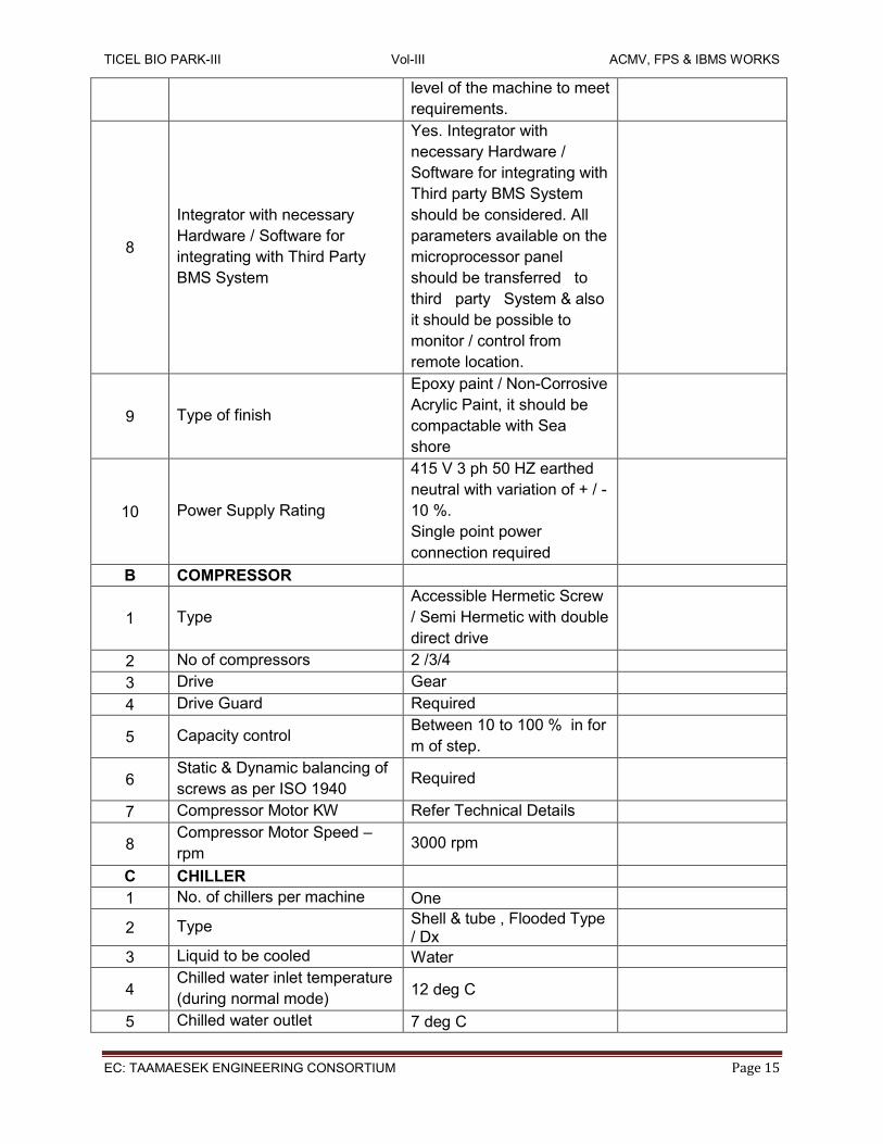
8
Integrator with necessary
Hardware / Software for
integrating with Third Party
BMS System
Yes. Integrator with
necessary Hardware /
Software for integrating with
Third party BMS System
should be considered. All
parameters available on the
microprocessor panel
should be transferred to
third party System & also
it should be possible to
monitor / control from
remote location.
9 Type of finish
Epoxy paint / Non-Corrosive
Acrylic Paint, it should be
compactable with Sea
shore
10 Power Supply Rating
415 V 3 ph 50 HZ earthed
neutral with variation of + / -
10 %.
Single point power
connection required
B COMPRESSOR
1 Type
Accessible Hermetic Screw
/ Semi Hermetic with double
direct drive
2 No of compressors 2 /3/4
3 Drive Gear
4 Drive Guard Required
5 Capacity control Between 10 to 100 % in for
m of step.
6 Static & Dynamic balancing of
screws as per ISO 1940 Required
7 Compressor Motor KW Refer Technical Details
8 Compressor Motor Speed –
rpm 3000 rpm
C CHILLER
1 No. of chillers per machine One
2 Type Shell & tube , Flooded Type / Dx
3 Liquid to be cooled Water
4 Chilled water inlet temperature
(during normal mode) 12 deg C
5 Chilled water outlet 7 deg C

TICEL BIO PARK-III Vol-III ACMV, FPS & IBMS WORKS
EC: TAAMAESEK ENGINEERING CONSORTIUM Page 16
temperature (during normal
mode)
7
Minimum chilled water flow
per package
during normal operation)
603 US GPM
8 Chiller and suction line
insulation Required
9 Pressure drop across chiller Not to exceed 15.00 ft H2O
10 Fouling Factor 0.0001 hr-sqft-deg F / Btu
D AIR COOLED CONDENSER
1 Capacity
2 Type of condenser Out door Air Cooled type
3 Ambient temperature – deg C 36.6 deg C
4 Condensing temperature –
deg C 55.0deg C
5 Type of fan Propeller
6 Fan arrangement Shaft vertical, Air
delivering upwards
7 No of Fans 12 or as per
manufacturers standards
8 Fan motor KW / each 1.1 KW each
9 Type of fan motor
Suitable for out door
application – confirming to
IP 55
10 Fins concentrations fins / cm Not less than 5.5
11 Material of the tubes Copper
12 Material of fins Aluminium
13 Type of fins Plate or helical fins
E Percentage of Load IKW/TR at 36.6 Deg C NET TR
1 100% Load
2 75% Load
3 50% Load
TECHNICAL REQUIREMENTS OF AIR COOLED WATER SCREW CHILLER TO BE FILLED
BY VENDOR
S.NO DESCRIPTION TECHNICAL DETAILS BY VENDOR
A GENERAL
1 Make & Model
2 Capacity at operation conditions
3 Operating Condensing Temperature [-
deg C]
4 Operating Suction temperature [- deg C]
5 Leaving water Temperature [- deg C]

TICEL BIO PARK-III Vol-III ACMV, FPS & IBMS WORKS
EC: TAAMAESEK ENGINEERING CONSORTIUM Page 17
6 Overall dimensions including stand [-
mm x mm x mm]
7 Operating Weight [- Kg]
8 Operating Charge [- Kg]
9 Minimum clearance required from
adjacent structures [- m]
10 Minimum clearance required between
two machines [- m]
11
Whether any platform or pedestal
required for installation? If so, furnish
details
12
Noise level at a distance of 1 m from
the machine at intervals of 1 m along
the perimeter
13 Noise level when all the machines are
working [- db]
B Casing
1 Material
2 Thickness of material
3 Method and details of construction
4 Nature and joints of constriction
5 What is the finish, i.e, hot dip?
galvanized, corrosion resistant, etc.,
6 Whether factory fabricated?
C COMPRESSOR MOTOR UNIT :
1 Type of Compressor
2 Manufacturer’s Name
3 Model
4 Refrigerant
5 Number of cylinders
6 Bore and stroke [- mm] ]
7 Maximum speed [- rpm]
8 Displacement at maximum rpm [- cmh]
9 Capacity at maximum displacement and
10 [55.0 Deg C] condensing and [-3 deg C]
suction [- TR]
11 Operating condensing and suction
temperature [- deg C]
12 Speed at design operating conditions [-
rpm]
13 BKW
14 Motor losses
15 KW at operating conditions
16 KW / TR at operating conditions
TICEL BIO PARK-III Vol-III ACMV, FPS & IBMS WORKS
EC: TAAMAESEK ENGINEERING CONSORTIUM Page 18
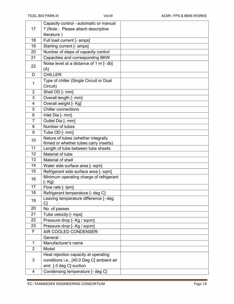
17
Capacity control - automatic or manual
? (Note : Please attach descriptive
literature )
18 Full load current [- amps]
19 Starting current [- amps]
20 Number of steps of capacity control
21 Capacities and corresponding BKW
22 Noise level at a distance of 1 m [- db]
(A)
D CHILLER:
1 Type of chiller (Single Circuit or Dual
Circuit)
2 Shell OD [- mm]
3 Overall length [- mm]
4 Overall weight [- Kg]
5 Chiller connections
6 Inlet Dia [- mm]
7 Outlet Dia [- mm]
8 Number of tubes
9 Tube OD [- mm]
10 Nature of tubes (whether integrally finned or whether tubes carry inserts)
11 Length of tube between tube sheets
12 Material of tube
13 Material of shell
14 Water side surface area [- sqm]
15 Refrigerant side surface area [- sqm]
16 Minimum operating charge of refrigerant [- Kg]
17 Flow rate [- lpm]
18 Refrigerant temperature [- deg C]
19 Leaving temperature difference [- deg C] :
20 No. of passes
21 Tube velocity [- mps]
22 Pressure drop [- Kg / sqcm]
23 Pressure drop [- Kg / sqcm]
F AIR COOLED CONDENSER:
General :
1 Manufacturer’s name
2 Model
3
Heat rejection capacity at operating
conditions i.e., [40.0 Deg C] ambient air
and [-3 deg C] suction
4 Condensing temperature [- deg C]
TICEL BIO PARK-III Vol-III ACMV, FPS & IBMS WORKS
EC: TAAMAESEK ENGINEERING CONSORTIUM Page 19
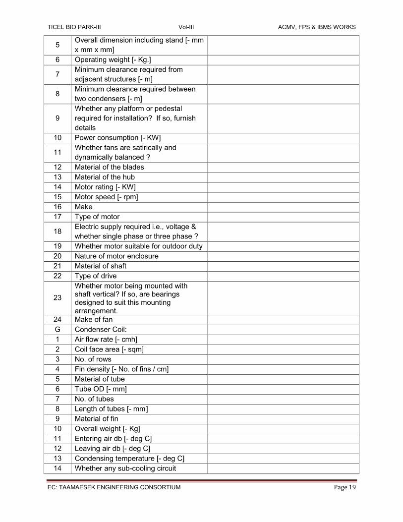
5 Overall dimension including stand [- mm
x mm x mm]
6 Operating weight [- Kg.]
7 Minimum clearance required from
adjacent structures [- m]
8 Minimum clearance required between
two condensers [- m]
9
Whether any platform or pedestal
required for installation? If so, furnish
details
10 Power consumption [- KW]
11 Whether fans are satirically and
dynamically balanced ?
12 Material of the blades
13 Material of the hub
14 Motor rating [- KW]
15 Motor speed [- rpm]
16 Make
17 Type of motor
18 Electric supply required i.e., voltage &
whether single phase or three phase ?
19 Whether motor suitable for outdoor duty
20 Nature of motor enclosure
21 Material of shaft
22 Type of drive
23
Whether motor being mounted with shaft vertical? If so, are bearings designed to suit this mounting arrangement.
24 Make of fan
G Condenser Coil:
1 Air flow rate [- cmh]
2 Coil face area [- sqm]
3 No. of rows
4 Fin density [- No. of fins / cm]
5 Material of tube
6 Tube OD [- mm]
7 No. of tubes
8 Length of tubes [- mm ]
9 Material of fin
10 Overall weight [- Kg]
11 Entering air db [- deg C]
12 Leaving air db [- deg C]
13 Condensing temperature [- deg C]
14 Whether any sub-cooling circuit

TICEL BIO PARK-III Vol-III ACMV, FPS & IBMS WORKS
EC: TAAMAESEK ENGINEERING CONSORTIUM Page 20
provided and if so, indicate the deg C of sub-cooling
15 Pressure drop across the coil [- mm wg]
16 Operating charge [- Kg]
17 Maximum charge [- Kg]
Is a receiver required ? If so, whether
receiver included.
18 Test pressure [- Kg]
19 Method of test
DATA TO BE FURNISHED BY THE CONTRACTOR AFTER THE AWARD OF CONTRACT
1. Quality Assurance Plan (QAP). 2. Dimensioned general arrangement drawing showing all accessories, mounting, details, nozzle location etc., for the air cooled screw chiller packages. 3. Overall space and head room requirement details of handling during erection, operation and maintenance. 4. Foundation drawing with static and dynamic loading details, pocket data, Foundation outline etc., 5. Cross sectional drawings of all items with part list and materials of construction. 6. Power wiring and control wiring diagrams. 7. Operation and maintenance manual.
1.3.0 CHILLED WATER PUMP SET
GENERAL
This section specifies the requirements necessary to furnish various type of centrifugal
pump sets as shown in the Main schematic Diagram.
REGULATORY REQUIREMENTS
a) Conform to BOCA National Building Code.
b) Conform to BOCA National Fire Protection Code.
c) Conform to National Electric Code NFPA 70.
d) Conform to applicable ANSI/HI standards.
e) Conform to applicable ANSI/HI standards.
f) Products: Listed and classified by Underwriters Laboratories
SUBMITTALS WHICH NEED TO BE SUBMITTED ALONG WITH THE OFFER
a) Submit each item in this article according to the Conditions of the Contract as listed in
Volume I and Specification Sections.
b) Submit manufacturer’s installation instructions under provisions of General Conditions
listed under Volume I & technical specifications.
TICEL BIO PARK-III Vol-III ACMV, FPS & IBMS WORKS
EC: TAAMAESEK ENGINEERING CONSORTIUM Page 21
c) Product Data including certified performance curves and rated capacities of selected
models, weights (shipping, installed, and operating), furnished specialties, and
accessories. Indicate pump’s operating point on curves.
d) Complete Package information Product Data including:
System summary sheet (where applicable).
Sequence of Operation.
Shop drawing indicating dimensions, required clearances and location and size of each
field connection.
Power and control wiring diagram.
System profile analysis including pump curves, system curve, and variable speed pump
curves & also Correction curves for water to be provided (where applicable).
Pump data sheets - Rated capacities of selected models and indication of pump’s
operating point on curves.
Submittals on furnished specialties and accessories.
Submittals must be specific to this project. Generic submittals will not be accepted
Hanging and support requirements should follow the recommendations in the
manufacturer’s installation instructions.
OPERATION & MAINTENANCE DATA
a) Submit Operation and Maintenance information.
b) Operation and Maintenance Data: Include installation instructions, assembly views, lubrication instructions, and replacement parts lists.
c) Under provisions of commissioning documentation; testing of pumps, as well as training of owner’s operation and maintenance personnel may be required in cooperation with the commissioning team from Project Management Team.
DELIVERY STORAGE & HANDLING
a) Deliver materials to the site in such a matter as to protect the materials from
b) Shipping and handling damage. Provide materials on factory provided shipping skids and lifting lugs if required for handling. Materials damaged by the elements should be packaged in such a matter that they could withstand short-term exposure to the elements during transportation.
c) Store materials in clean, dry place and protect from weather and construction traffic. Handle carefully to avoid damage.
DESIGN CRITERIA
a) The pumps shall be long coupled, base mounted, single stage, end suction, vertical split case design, in cast iron bronze fitted construction specifically designed for quiet operation. Suitable standard operations at 225° F and 175 PSIG working pressure or optional operations at up to 250° F and 250 PSIG working pressures. Working pressures shall not be de-rated at temperatures up to 250F. The pump internals shall be capable of being services without disturbing piping connections, electrical motor connections or pump to motor alignment (Refer above paragraph for the areas as specified above) For End Suction Horizontal split case double suction pump sets, similar specs as specified above shall be used.

TICEL BIO PARK-III Vol-III ACMV, FPS & IBMS WORKS
EC: TAAMAESEK ENGINEERING CONSORTIUM Page 22
b) The pumps shall be composed of three separable components a motor, bearing assembly,
and pump end (wet end). The motor shaft shall be connected to the pump shaft via a replaceable flexible coupler.
c) A bearing assembly shall support the shaft via two heavy-duty regreaseable ball bearings. Bearing assembly shall be replaceable without disturbing the system piping and shall have foot support at the coupling end. Pump bearings shall be regreaseable without removal of the bearings from the bearing assembly. Thermal expansion of the shaft toward the impeller shall be prevented via an inboard thrust bearing.
d) The bearing assembly shall have a solid SAE1144 steel shaft. A non-ferrous shaft sleeve shall be employed to completely cover the wetted area under the seal.
e) Pump shall be equipped with an internally flushed mechanical seal assembly installed in an enlarged tapered seal chamber. Application of an internally flushed mechanical seal shall be adequate for seal flushing without requiring external flushing lines. Seal assembly shall have a brass housing, Buna bellows and seat gasket, stainless steel spring, and be of a carbon ceramic design with the carbon face rotating against a stationary ceramic face.
f) Bearing assembly shaft shall connect to a bronze impeller. Impeller shall be both hydraulically and dynamically balanced to ANSI/HI 1.1-1.5-1994, balance grade G6.3 and keyed to the shaft and secured by a stainless steel locking cap screw or nut.
g) Pump should be designed to allow for true back pull-out allowing access to the pump’s working components, without disturbing motor or piping, for ease of maintenance.
h) A center drop-out type coupling, capable of absorbing torsional vibration, shall be employed between the pump and motor. Pumps for variable speed application shall be provided with a suitable coupler sleeve. Coupler shall allow for removal of pump’s wetted end without disturbing pump volute or movement of the pump’s motor and electrical connections. On variable speed applications the coupler sleeve should be constructed of an EPDM material to maximize performance life.
i) An ANSI and OSHA rated coupler guard shall shield the coupler during operation. Coupler guard shall be dual rated ANSI B15.1, Section 8 and OSHA 1910.219 compliant coupling guard and contain viewing windows for inspection of the coupling. No more than .25 inches of either rotating assembly shall be visible beyond the coupling guard.
j) Pump volute shall be of a cast iron design for Cooling systems (or cast bronze for domestic water systems) with integrally cast pedestal volute support, rated for 175 PSIG with integral cast iron flanges drilled for 125# ANSI companion flanges. (Optional 250 PSIG working pressures are available and are 250# flange drilled) Volute shall include gauge ports at nozzles, and vent and drain ports.
k) Motors shall meet scheduled horsepower, speed, voltage, and enclosure design. Pump and motors shall be factory aligned, and shall be realigned after installation by the manufacturer’s representative. Motors shall be non-overloading at any point on the pump curve and shall meet NEMA specifications and conform to the standards outlined in EPACT 92.
l) Base plate shall be of structural steel or fabricated steel channel configuration fully enclosed at sides and ends, with securely welded cross members and fully open grouting

TICEL BIO PARK-III Vol-III ACMV, FPS & IBMS WORKS
EC: TAAMAESEK ENGINEERING CONSORTIUM Page 23
area (for field grouting). The minimum base plate stiffness shall conform to ANSI/HI 1.3.4-1997 for Horizontal Base plate Design standards.
m) Pump shall be of a maintainable design and for ease of maintenance should use machine fit parts and not press fit components.
n) The pump(s) vibration limits shall conform to Hydraulic Institute ANSI/HI 1.1-1.5-1994, section 1.4.6.1.1 for recommended acceptable unfiltered field vibration limits for pumps with rolling contact bearings. Pump manufacturer shall be ISO-9001 certified.
o) The seismic capability of the pump shall allow it to withstand a horizontal load of 0.5g, excluding piping and/or fasteners used to anchor the pump to mounting pads or to the floor, without adversely affecting pump operation.
p) Each pump shall be factory tested and name-plated before shipment.
q) Pump shall conform to ANSI/HI 9.6.3.1 standard for Preferred Operating Region (POR) unless otherwise approved by the engineer. The pump NPSH shall confirm to the ANSI/HI 9.6.1-1997 standards for Centrifugal and Vertical Pumps for NPSH Margin.
DESIGN REQUIREMENTS
The power ratings of the pump motor shall be larger of the following: The maximum power required by the pump from zero discharge to zero head. 110% of the power required at the duty point. Pumps of a particular category shall be identical and shall be suitable for parallel operation with equal load division. Components of identical pumps shall be interchangeable.
TEST & INSPECTION HYDROSTATIC TESTING
a) Each pressure casing shall be hydrostatically tested with water at Ambient temperature.
The minimum test pressure shall be 1 1/2 times the rated maximum allowable casing
pressure. Cooling water jackets shall be hydrostatically tested at 115-psig minimums.
b) All hydrostatic tests shall be maintained for a minimum period of 30 minutes. Repair any
leaks. Certification of test results is required.
PERFORMANCE
TESTS: STANDARD RUNNING TEST
a) Pumps with drivers over 50 hp shall be given a performance test on water.
b) Test speeds shall be at the rated speed of the pump, as shown on the individual pump
data sheet.
c) Certified test curves are required. Curves shall be drawn from the test data obtained for
the purchased pump and shall include, head, efficiency, and BHP recalculated to the
proper specific gravity plotted against capacity

TICEL BIO PARK-III Vol-III ACMV, FPS & IBMS WORKS
EC: TAAMAESEK ENGINEERING CONSORTIUM Page 24
d) Each pump that is given a performance test shall be checked for acceptable vibration
limits during the factory running and performance test.
e) Mechanical seals shall be used during the running tests but are not required for the
hydrostatic test.
NPSH TEST
a) An NPSH test shall be provided when the NPSH available indicated on the pump data
sheet does not exceed the NPSH required by the pump by at least 1 Meter.
b) Suppression tests shall be carried out in a closed loop as described in the Standards of
the Hydraulic Institute. Alternative methods may be acceptable when mutually agreed prior
to placement of the Purchase Order.
MECHANICAL BALANCING
In addition to static balancing, impeller and balancing drum shall be balanced dynamically at or near the operating speed. FIELD TESTING After Installation, the pumps shall be subjected to testing at site also. If the field performance is found not to meet the requirements regarding vibration and noise as specified, the equipment shall be rectified or replaced by Contractor, at no extra cost to the Clients.
a) A Run Test shall be conducted on one pump of each size. The following measurements shall be made during the test.
b) Discharge Vs. Head c) Discharge Vs. Efficiency d) Discharge Vs. BHP e) Hydraulic test for casing at 1.5 times the design pressure. f) Vibration Level g) Noise Level
INSTALLATION
h) The pumps shall be installed on inertia bases as per the manufacturer recommendations. Competent personnel on a floating foundation shall install the pump sets with suitable vibration isolators.
i) The bedplate levels and alignment shall be shown to the Consultant representative / Project managers before bolting and grouting the pumps to the foundation.
j) Pressure gauges and other accessories shall be provided as per the drawings. All fitments for gauges, thermometers and similar items must extend a minimum of 25 mm beyond outside the insulation to minimize the condensation problems.
k) A Run Test shall be conducted on one pump of each size
QUALITY ASSURANCE
The pump manufacturer shall assemble the pumping package. An assembler of pumping systems not actively engaged in the design and construction of centrifugal pumps shall not be

TICEL BIO PARK-III Vol-III ACMV, FPS & IBMS WORKS
EC: TAAMAESEK ENGINEERING CONSORTIUM Page 25
considered a pump manufacturer. The manufacturer shall assume “Unit Responsibility” for the complete pumping package. Unit responsibility shall be defined as responsibility for interface and successful operation of all systems components supplied by the pumping system manufacturer. The local supplier of chilled water variable speed pumping system must have relevant expertise in all aspects of design, application engineering, installation, programming, interfacing, commissioning and after sales service. Supplier must have, as a minimum, commissioned 25 sets of chilled water VSPS in India. All functions of the variable speed pump control system shall be tested at the factory prior to shipment. This test shall be conducted with motors connected to AFD output and it shall test all inputs, outputs and program execution specific to this application The manufacturer shall be fully certified by the international standards organization per ISO 9001. Proof of this certification shall be furnished at the time of submittal.
Bidders shall comply with all sections of this specification relating to package pumping systems. Any deviations from this specification shall be bid as a voluntary alternate clearly defined in writing. If no exceptions are noted, the supplier or contractor shall be bound by these specifications.
COMPONENTS OF VARIABLE SPEED PUMPING SYSTEM
Pump Logic Controller (should be fully compatible to hook up to BMS / Chiller Plant
Management System)
a) The technologic pump logic controller assembly shall be listed by and bear the label of Underwriter’s Laboratory, Inc. (UL)
b) The Equipment should be able to hook up to chiller plant management system (BMS) via software integration either in ASHRAE Bacnet / RTU Modbus Protocol. Necessary hardware / software for integration should be part of scope.
c) The controller shall be specifically designed for variable speed pumping applications. d) The controller shall function to proven program that safeguards against damaging
Hydraulic conditions including: e) Pump flow Surges. f) Hunting End of Curve g) System Over Pressure
The pump logic controller shall be capable of receiving up to two discrete analog inputs from zone sensor / transmitter as indicated on the plans. It will then select he analogue signal that has deviated the greatest amount from its set point. This selected signal will used as the command feedback input for a hydraulic stabilization function to minimize hunting. Each input signal shall be capable of maintaining a different set point value. Controller shall be capable of controlling up to three pumps in parallel. The pump logic controller shall be capable of accepting an additional analog input for a flow sensor. This input shall serve as the criteria for the end of curve protection algorithm. The pump logic controller shall be self-prompting. All messages shall be displayed in plain English.

TICEL BIO PARK-III Vol-III ACMV, FPS & IBMS WORKS
EC: TAAMAESEK ENGINEERING CONSORTIUM Page 26
The operator interface shall have the following features:
a) Multi-fault memory and recall last 10 faults and related operational data.
b) Red fault light, Yellow warning light and Green power on light.
c) Soft-touch membrane keypad switches.
The display shall have four lines, with 20 characters on three lines and eight large characters on
one line. Actual pump information shall be displayed indicating pump status.
Controller shall be capable of performing the following pressure booster functions:
a) Low suction pressure cutout to protect the pumps against operating with insufficient suction pressure.
b) High system pressure cutout to protect the piping system against high-pressure conditions.
c) No flow shutdown to turn the pumps off automatically when system demand is low enough to be supplied by hydro pneumatic tank. No flow shutdown shall require any external flow meters, flow switches, nor pressure switches to determine when a No Flow conditions exist.
The following communication features shall be provided to BAS:
a) Remote system starts / stops non-powered digital input.
b) Failure of any system component. Output closes to indicate alarm condition.
c) Four 4-20 mA output with output of :
d) Frequency
e) Process variable
f) Output current
g) Output Power
The following communication features shall be provided to the Chiller Plant Management system (Building Automation system) via an RS-485 port suitable to hook up either in ASHRAE Bac net / RTU Mod bus protocol. Necessary hardware /software required for integration should be part of scope.
a) Individual Analog Input.
b) Individual Zone Set points.
c) Individual Pump / AFD on/off status
d) System percent speed
e) System start/stop command
f) System operation mode
g) Individual kW signals
h) System flow, when optional flow sensor is provided.
“Communication link between the Pump Logic Control Panel and the BMS shall be provided to make all the status / parameters in the Logic Control Panel of pump set. For this purpose, the ACMV NSC shall provide all necessary hardware and software at the chiller end to make available the data in any one of Bac Net, Lon or Mod Bus protocols. The ACMV NSC shall provide all engineering data such as address and data list, type of connection, baud rates, handshake, parity, etc. to the BMS NSC. The ACMV NSC shall also provide the looping / interlinking of the Pumps microprocessor based panels. The BMS NSC shall provide all necessary hardware and software at the BMS end and also the interconnecting cable between the Logic Control panel and the BMS. In case of multiple makes / models of the pump panels, as many links as required for each make / model shall be provided by the BMS NSC and the

TICEL BIO PARK-III Vol-III ACMV, FPS & IBMS WORKS
EC: TAAMAESEK ENGINEERING CONSORTIUM Page 27
ACMV NSC shall loop each make / model’s panels. The BMS NSC shall use the engineering data provided by the ACMV NSC to implement the communication link. The BMS supplier shall perform all engineering including and up to generation of graphic pages, reports, alarms, etc. to display the status / parameters.
The pump logic controller shall be of a high end type ie., all the parameters available on the logic control panel should be able to monitor / controlled from the remote location and should housed in a NEMA 1 Enclosure
ADJUSTABLE FREQUENCY DRIVE
a) The adjustable frequency drives shall be pulse width modulation (PWM) type,
microprocessor controlled design.
b) VFD Shall be HVAC Series only.
c) The AFD, including all factory-installed options, be tested to UL standard 508. The AFD
also meets C-UL and is CE marked and builds to ISO 9001 standards.
d) The AFD shall be housed in a NEMA 1 enclosure. AFF with plastic enclosure shall not be
acceptable.
e) The AFD shall employ an advanced sine wave approximation and voltage vector control to allow operation at rated motor shaft output speed with no derating. This voltage vector control shall minimize harmonics to the motor to increase motor efficiency and life. Power factor shall be near unity regardless of speed or load.
f) The VFD shall have balanced DC link reactors to minimize power line harmonics. VFDs without a DC link reactor shall provide a 3 % impedance line reactor.
g) Input and output power circuit switching can be done without interlocks or damage to the VFD.
h) The following customer modifiable adjustments shall be provided: i) Accel time.
j) Decel time.
k) Minimum frequency.
l) Maximum frequency.
m) An automatic energy optimization selection feature shall be provided. This feature shall
reduce voltage when lightly loaded and provide a 3% to 10% additional energy savings.
n) The AFD shall be suitable for elevations to 3300 feet above sea level without derating.
Maximum operating ambient temperature shall not less than 104 degrees F. AFD shall
be suitable for operation in environments up to 95% non-condensing humidity.
The AFD shall be capable of displaying the following information in plain English via an
alphanumeric display:
i. Accel time.
ii. Decel time.
iii. Minimum frequency.
iv. Maximum frequency.
SENSOR / TRANSMITTERS
Provide field mounted differential pressure sensor transmitters as indicated in the BOQ & also in the drawings. Unit shall transmit an isolated 4-20 mA dc signal indicative of process variable to the pump logic controller via standard two wire 24 DC system. Unit shall have a corrosion resistant steel body with 1/8” NPT process connection.

TICEL BIO PARK-III Vol-III ACMV, FPS & IBMS WORKS
EC: TAAMAESEK ENGINEERING CONSORTIUM Page 28
It shall have a NEMA 1 electrical enclosure capable of withstanding 450-PSI static pressure. Accuracy shall be within 0.5% of full span.
SEQUENCE OF OPERATION
a) The system shall consist of Technologic pump logic controller, multiple pump / AFD sets, with manual and automatic alternation and pump staging.
b) The pumping system shall start upon the closure of customer’s contact when pump logic controller mode of operation selector switch is in the REMOTE position.
c) When the pump logic controller selector switch is in the LOCAL position, and start command on controller is given via operator interface, the pumping system shall operate automatically.
d) Sensor / transmitter shall send a 4-20 mA signal to the pump logic controller, indicative of process variable condition.
e) The pump logic controller shall compare each signal to the independent engineer / user determined set points.
f) When all set points are satisfied by the process variable, the pump speed shall remain constant at the optimum energy consumption level.
g) The pump logic controller shall continuously scan and compare each process variable to its individual set point and control to the latest satisfied zone.
h) If the set point cannot be satisfied by the designated lead pump, the pump logic controller shall initiate a timed sequence of operation to stage a lag pump.
i) The lag pump shall accelerate resulting in the lead pumps decelerating until they equalize in speed.
j) Further change in process variable shall cause the pumps to change speed together. k) When the set point criteria can be safely satisfied with fewer pumps, the technologic
pump logic controller shall initiate a timed sequence and continue variable speed operation.
l) As the worst-case zone deviates from set point, the pump logic controller shall send the appropriate analog signal to the AFD to speed up or slow down the pump/motor.
m) In the event of an AFD fault, the pump logic controller automatically initiates a times sequence of events to start the redundant pump/AFD set in the variable speed mode. The redundant variable speed system shall be started through the pump logic controller.
n) Upon AFD faults, the pump controller shall display an alarm condition through a plain English message.
o) AFD fault indication shall be continuously displayed on the operator interface of the pump until the fault has been corrected and the controller has been manually reset.
p) In the event of the failure of a zone sensor/transmitter, its process variable signal shall be removed from the scan/compare program. Alternative zone sensor/transmitters, if available, shall remain in the scan/compare program for control.
q) Upon sensor failure a plain English warning message shall be displayed on the operator interface of the pump logic controller.
r) In the event of failure to receive all zone process variable signals, a user selectable number of AFDs shall maintain a user adjustable speed; reset shall be automatic upon correction of the zone failure.
MOTORS (HIGH EFFICIENCY IE2)
The motor shall be as per IS: 325 and with class "F" insulation, totally enclosed fan cooled, horizontal induction foot mounted type and rated not to draw starting current more than 6 times normal running current. Fan motors shall be suitable for 415 volts, 50 cycles, 3-phase, squirrel - cage, totally enclosed fan cooled with IP-55 protection. Motor shall be selected for quite operation and the speed of the motor shall not exceed 1400 RPM. Drive to fan shall be

TICEL BIO PARK-III Vol-III ACMV, FPS & IBMS WORKS
EC: TAAMAESEK ENGINEERING CONSORTIUM Page 29
provided through belt-drive arrangement. Belts shall of the oil-resistant type. Fan motor shall be suitable for variable speed by variable frequency drive application. The motor shall be capable of handling the required starting torque of the pumps. Speed of motor shall be compatible with the speed of the pump. The cooling fans shall be directly driven from motor shaft. Motor situated outdoors or exposed to the weather shall be weather protected. Motors shall be enclosed type and shall have dust tight construction with suitable means of breathing and of drainage to prevent accumulation of water from condensation. Drain holes shall exclude bodies greater than 6mm diameter. All components shall be of adequate mechanical strength and robustness and shall be constructed of metal unless otherwise approved. All motors shall be dynamically balanced. The enclosure shall be designed to provide an effective sealing between the primary and secondary air circuits. Motor winding shall be vacuum impregnated with heat and moisture resistant varnish glass fiber insulated. Two independent earthing points shall be provided in accordance with IS:3043 on opposite sides of the motor for bolted connection. The cable boxes and termination shall be designed to enable easy disconnection and replacement of cables. (Motor should be part of scope with manufacturer & should not be supplied separately by ACMV Contractor).
VFD ENCLOSURE PANEL
All pump sets should be supplied with dedicated Motor isolator with enclosure Panel The switchboard shall be metal clad, totally enclosed, rigid, floor / Wall mounting, air insulated, extensible cubicle type for use on low voltage power, 400V, 3 phase 4 wire, 50 Hz system. The equipment shall be designed for operation in high ambient temperature and high humidity tropical atmospheric conditions. Means shall be provided to facilitate ease of inspection, cleaning and repairs for use in installations where continuity of operation is of prime importance.
TYPE AND CONSTRUCTION
The VFD panel board shall be metal clad, totally enclosed, rigid, compartmentalized design, floor mounting, air insulated, extensible cubicle type for use on medium voltage power, 3 phase 4 wire 50Hz system.
GENERAL CONSTRUCTIONAL FEATURES
CRCA-14 G / 2mm thick Sheet steel enclosed, indoor floor mounted free standing
cubicle type & CNC fabricated.
a) Made up of the requisite vertical sections modular type which when coupled together shall form continuous switchboards.
b) Dust, vermin and damp proof and enclosure protection not less than IP 54.
c) Each feeder/instrument compartment shall be provided with a hinged door interlocked with MCCB/Load Break Switch inside the compartment such that door can only be opened when MCCB is in off position.
d) Readily extendable on either sides by the addition of vertical sections after removal of the end covers.

TICEL BIO PARK-III Vol-III ACMV, FPS & IBMS WORKS
EC: TAAMAESEK ENGINEERING CONSORTIUM Page 30
e) Switchboards shall have access to the feeders, bus bars, cable termination, cable alley, etc. as required.
f) Doors shall be of minimum 2mm thick sheet steel and covers/partitions of 1.6mm thick sheet steel, gland plate shall be 3mm thick sheet steel. All sheet steel work forming the exterior of switchboards shall be smoothly finished, levelled and free from flaws. The corners should be rounded.
METAL TREATMENT FINISH
a) After fabrication the panel shall undergo 7tank treatment/sand blasting for removing grease, Rust etc.
b) The panel shall be coated with zinc chromate primer (Applicable for outdoor panels).
c) After coating of primer, the panel shall be coated with Epoxy based paint (powder coating/spray paint). Paint shade shall be as specified by the client/consultant during drawing approval.
METERS
All instruments and meters shall be enclosed in dust proof, moisture resistant, black finished cases and shall be suitable for tropical use. They shall be calibrated to read directly the primary quantities. They shall be accurately adjusted and calibrated at Works and shall have means of calibration, check and adjustment at site. Indicating instruments shall be flush mounted, digital type. The size of all instruments shall be 96mm x 96mm. The Ammeter and Wattmeter current coils shall withstand 200% of rated current continuously and 10 times the rated current for 0.5 seconds without loss of accuracy. Voltmeter and Wattmeter potential coils shall withstand 120% of rated voltage continuously and twice the rated voltage for 0.5 sec. without loss of accuracy.
DIGITAL VOLTMETERS
a) Voltmeter shall be of Digital type with accuracy class of 1.
b) All Voltmeters are 96sq.mm in size & suitable for flush mounting on panels.
DIGITAL AMMETERS
a) Ammeter shall be of Digital type with accuracy class of 1.
b) Ammeter shall be CT operated (5A) with a dial marked for line currents.
c) Ammeter is 96sq.mm in size & suitable for flush mounting on panels.
d) Type, Sl.No., Accuracy class, Operating Current, Burden etc., shall be indicated on the
meters.
INDICATING LAMPS
All indicating lamps shall be of LED type & 22.5m dia in size. Indicating lamps shall be
suitable for panel mounting with screw connections on backside.
TECHNICAL REQUIREMENTS OF CHILLED WATER PUMPSETS

TICEL BIO PARK-III Vol-III ACMV, FPS & IBMS WORKS
EC: TAAMAESEK ENGINEERING CONSORTIUM Page 31
SI.No DESCRIPTION TECHNICAL DETAILS BY VENDOR
1 Application
2 Make
3 Model
4 Type of pump
5 Design Capacity
6 Head
7 Pump Efficiency
8 Motor Efficiency at duty point
9 Motor Rating
10 Rated Speed
11
Material of construction as
per specification indicate
deviations
a Casing Material
b Impeller Material
c Shaft
d
Packing
e Bearing type and detail

TICEL BIO PARK-III Vol-III ACMV, FPS & IBMS WORKS
EC: TAAMAESEK ENGINEERING CONSORTIUM Page 32
f Base Plate
12 Impeller type-refer Boq
13
Logic Control Panel for
Variable Pumping System
wherever specified
14
Is logic control panel
compatible to hook up to BMS
System? If so necessary hard
ware & software included in
scope of work? What is the
protocol considered for
Integration? Is it suitable
15
Is variable frequency
drives considered is as per the
Models specified in the
document ie., HVAC Series
16
Inertia Blocks with Spring
Isolators included under the
part of scope?
17 Pump Weight – Dynamic
Weight
18
Is Suction Guide considered for
the pumpsets as per
specifications?
19 Maximum Pump power required
21 NPSH
22 Noise level of Pump @ 1.5 Mtr
Distance
24
Motor starter panel as per
specification has it been
considered?
25 Mechanical seal
DATA TO BE FURNISHED BY THE CONTRACTOR AFTER AWARD OF CONTRACT
a) Quality Assurance Plan (QAP).

TICEL BIO PARK-III Vol-III ACMV, FPS & IBMS WORKS
EC: TAAMAESEK ENGINEERING CONSORTIUM Page 33
b) Dimensioned general arrangement drawing of pumps and driver.
c) Foundation drawing of pump and driver with static and dynamic loads, details of fixing,
grouting and all relevant data required for design of foundation.
d) Cross-sectional drawings of the pump with complete part list, material of construction
and relevant standards for each part.
e) Pump performance curves flow rate Vs head, BKW, efficiency, NPSHR from zero flow to
maximum flow and torque-speed curve.
f) Scheme for pump sealing, lubrication and cooling.
g) Driver dimensional drawing.
h) Surface preparation and painting procedures.
i) Catalogues, data sheets and drawings for instruments.
j) Installation, operation and maintenance manual.
1.4.0 DOUBLE SKIN AIR HANDLING UNIT
GENERAL
This specification covers the general design, materials, construction features, manufacture, Factory inspection, Full Assembled condition and testing at manufacturer’s works, delivery at site, handling at site, installation, testing, commissioning and carrying out performance test at site of Ceiling Suspended Air Handling Units (AHU’s).
CODES & STANDARDS:
The design, materials, manufacture, inspection, testing and performance of the Ceiling suspended AHU’s shall comply with all currently applicable statutes, regulations, codes and standards in the locality where the equipment is to be installed. Nothing in this specification shall be construed to relieve the CONTRACTOR of this responsibility.
In particular AHUs shall confirm to the latest edition of the following standards:
IS 7613 Methods of Testing panel type Air Filters for Air-Conditioning
and Ventilation purposes.
ASHRAE 33 Methods of testing – Forced Circulation Air Cooling and Air
Heating Coils
ARI 410 Forced circulation air –air cooling and air heating coils.
ARI 430 Central-station air handling units.
AMCA 210 Laboratory methods of testing fans for ratings.
NFPA 90 A Installation of Air-Conditioning and Ventilation Systems.
DESIGN CRITERIA
In addition to the standard requirements, provide the following with the Bid:
a) Estimates of inlet and outlet sound power levels (in dB re 10(-12) watt) in each octave
band from 63 Hz to 4,000 Hz. These estimates shall take into account the attenuation
provided by the cabinet of the air handler, which shall be acoustically lined as described
in this Specification.
b) Provide fan performance curves showing static pressure, rpm, and motor
c) horsepower requirements versus air quantity handled over full range of fan capacity.

TICEL BIO PARK-III Vol-III ACMV, FPS & IBMS WORKS
EC: TAAMAESEK ENGINEERING CONSORTIUM Page 34
d) Complete ARI-certified performance data at standard design conditions for all coils with
performance at actual site conditions listed on the data sheets. Complete coil
dimensional data and installation requirements
e) Data for each filter type: Complete certified performance data at design
f) Conditions, including volumetric flow rate and air pressure drop.
g) Seismic design calculations shall be submitted and certified with Bid.
h) Provide proposed tie-down details with equipment submittals.
FACTORY VIBRATION BALANCE REPORT
a) Certificate of compliance papers shall be attached to each fan at shipment, and signed by the fan manufacturer’s quality control inspector. An additional copy shall be sent to Client / Project Managers.
b) All factory balancing test results shall be furnished to certify the fan vibration does not exceed 50 mils per second rms for belt-driven units. Measurements shall be taken in a direction parallel to the shaft in a horizontal plane, and in a direction perpendicular to the shaft in both the horizontal and the vertical planes.
c) During balancing tests, the fan shall be operating at rated volume flow against the design external static pressure.
The scope of this section comprises of supply and installation of Double skin cabinet Air
handling unit with all its accessories conforming to this specification and in accordance with the
relevant drawings.
The Air handling units shall be constructed using double-skinned acoustic panels with minimum 0.8 mm thick pre-coated GSS sheet for outer skin and & 0.8 mm plain GSS sheet for inner skin of the unit. All the panels shall incorporate 50 mm thick PUF insulation sandwiched in between inner & outer skin. Outlet Velocity of the fan should be restricted to 8 – 9 m/s. In addition to the above, Pre/Bag filter Section, PVC drifter, SS304 drain pan with 25mm thick nitrile rubber insulation, Attenuators Section on the supply air outlet of minimum 900 mm length should be considered with sufficient acoustically treated baffles. The entire frame work shall be mounted on a 100 mm (minimum) aluminium alloy channel base. The panels shall be sealed to the frame work by heavy duty “O” ring neoprene gaskets held captive in the framed extrusion. All panels shall be detachable or hinged. Hinges shall be made of die cast aluminium with stainless steel pivots. Handles shall be made of hard nylon and operational from both inside and outside of the unit. Units supplied with various sections shall be suitable for on-site assembly match drilled, with bolts, nuts and continuous neoprene rubber gaskets. All fixing and gaskets shall be concealed. AHU’s shall have hinged quick opening insulated access door on fan and filter sections. Access doors shall be double skin type and shall have same construction as the wall panels. Four (4) lifting lugs shall be bolted to each base section for lifting or placing the AHU in place. All connecting fasteners and related hardware and its accessories shall be in stainless steel. The air handling unit’s capacities, fan motor HP, fan static pressure & all other details are furnished in the equipment schedule & relevant drawings. All the panels shall be assembled on a supporting frame of anodized hollow aluminum sections. Panel - to - frame joints shall be provided with EPDM Gaskets. Only stain less steel screws shall

TICEL BIO PARK-III Vol-III ACMV, FPS & IBMS WORKS
EC: TAAMAESEK ENGINEERING CONSORTIUM Page 35
be used for fastening panels to the supporting frame. The inside of the unit shall have clear surfaces free from bolt & bolt - head projections. The entire unit shall be of sturdy construction to ensure freedom from vibration while running. All sections shall incorporate access doors / panels. The hinges shall be of cast aluminum handles shall be of pressed steel. Self - lubricated Nylon sleeves shall be provided. The entire housing shall be mounted on extruded aluminum channel framework having pressure die cast aluminum jointers. All access doors, coil connections etc. Shall be provided on one side of the unit. In other words, access to the other side of the unit should not be necessary for any purpose what so ever. Special care shall be taken to ensure that doors, handles, hinges, etc. shall be robust enough to with stand heavy industrial usage. The vibration of the AHU fans (as measured on the bearing block after assembly) shall not exceed a peak-to-peak displacement of 100 microns. For all AHUs, serrated rubber pads shall be provided for vibration isolation. Casing shall be of air-tight construction and sufficiency rigid to exclude vibrations, throughout the working capacity range of AHU.
APPLICABLE TO ALL AHUs SERVING TO HALLS, OFFICE & COMMON AREAS COMPONENTS
a) Filter Section with Pre-filter of efficiency 90% down to 3 -10 microns, 75% down 0.3 – 1
micron by Gravimetric test (MERV-13) & Bag Filters 85% down to 1micron, 55% down to 0.3 micron by Gravimetric test (EU7).
b) Chilled Water Cooling Coil Section, Eliminator section ,Copper header with MS adaptor for pipe taping
c) Fan Section (Should be AMCA Certified). Fan to be insulated with 13 mm Open Cell Arma sound insulation. Fan should be designed with max 8 to 9 m/s velocity.
d) Supply Air Plenum Section with damper for Supply Air Duct Tapings.
ACCESSORIES
a) 1 Set of Vibration Isolators (Rubber Pads) for each Air Handling Units.
b) Two Sets of Canvass Cloth apart from the one provided at the outlet of the Fan section
in the Air Handling Units.
c) 1Set of Commissioning Filters for Each AHU
d) All the accessories shown in the drawings as indicated shall be included.
e) Each air-handling unit shall be provided with manual air vent at high point in the cooling
coil and drain plug at the bottom of the coil.
f) Inspection Window
a) Bulkhead lighting
DOCUMENTATION
6sets of technical documentation such as electrical schematics, cooling schematics, installation, operation & maintenance manual and spare part list in English Language to be included in the part of scope. FAN SECTION

TICEL BIO PARK-III Vol-III ACMV, FPS & IBMS WORKS
EC: TAAMAESEK ENGINEERING CONSORTIUM Page 36
Fans shall have AMCA certification. The ratings which are to be submitted along with the proposal shall be based on the tests and procedures performed in accordance with AMCA publication 311 and comply with the requirements of AMCA certified ratings program. The fan shall be of Backward curved aero foil blades of no overloading characteristics, double inlet double width type (DIDW). Outlet Velocity of fan should be designed at max 8 to 9 m/s. The wheel and housing shall be fabricated from heavy gauge galvanized steel. The fan impeller shall be mounted on a solid shaft supported to housing with angle iron frame and pillow block heavy-duty ball bearings. Bearings shall be self-aligning; pillow block type selected for an average life of 200,000 hours at design operating conditions and shall be provided with grease line extending to outside of the AHU Casing. The impeller & blades shall be selected / designed for quiet - running. The fan assembly shall be statically & dynamically balanced. A single impeller for the entire flow rate specified for the unit is preferred. The bearings shall be mounted on the scroll. Fan shall be driven by or internally unit-mounted motor connected to fan by V-belt drive. Access panel for easy belt change shall be provided for internally mounted motors. Belt connected motor capacity and shall adjustable to provide not less than ± 20% speed variation. The fan & fan motor shall be assembled on a common frame, which shall be mounted on the floor of the casing with spring vibration isolators. The fan outlet shall be connected to the casing with fire retardant fabric acting as a flexile connection to avoid any vibration from the unit on to the ducts. The fan shall not exceed outlet velocity 8 to 9 meters / second. Fan motor shall be totally enclosed fan-cooled type and shall be suitable for 415 V/3 Ph / 50 Hz. Motor shall be sized to provide the additional power requirements when the fan is operated to provide an additional 20% of the rated capacity. The fan shall be selected for a noise level less than 60 dB. Fans for AHU’s connected to variable frequency drives (VFD’s) shall be selected to have their peak efficiencies at about 75% of their design flow rates.
MOTOR & DRIVE (HIGH EFFICIENCY IE2)
The motor shall be as per IS: 325 and with class "F" insulation, totally enclosed fan cooled, horizontal induction foot mounted type and rated not to draw starting current more than 6 times normal running current. Fan motors shall be suitable for 415 volts, 50 cycles, 3-phase, squirrel - cage, totally enclosed fan cooled with IP-55 protection. Motor shall be selected for quite operation and the speed of the motor shall not exceed 1400 RPM. Drive to fan shall be provided through belt-drive arrangement. Belts shall of the oil-resistant type. Fan motor shall be suitable for variable speed by variable frequency drive application. The motor shall be capable of handling the required starting torque of the pumps. Speed of motor shall be compatible with the speed of the pump. The cooling fans shall be directly driven from motor shaft. Motor situated outdoors or exposed to the weather shall be weather protected. Motors shall be enclosed type and shall have dust tight construction with suitable means of breathing and of drainage to prevent accumulation of water from condensation. Drain holes shall exclude bodies greater than 6mm diameter. All components shall be of adequate mechanical strength and robustness and shall be constructed of metal unless otherwise approved. All motors shall be dynamically balanced. The enclosures shall be designed to provide an effective sealing between the primary and secondary air circuits. Motor winding shall be vacuum impregnated with heat and moisture resistant varnish glass fiber insulated. Two independent earthing points shall be provided in accordance with IS:3043 on opposite sides of the motor for bolted connection. The cable

TICEL BIO PARK-III Vol-III ACMV, FPS & IBMS WORKS
EC: TAAMAESEK ENGINEERING CONSORTIUM Page 37
boxes and termination shall be designed to enable easy disconnection and replacement of cables.
CHW COIL SECTION & MOISTURE ELIMINATOR
The coil section of the AHU shall be of the cartridge type, removable from the side of the casing and supported over the entire length of the coil. The Cooling coil section shall have 12.5 mm to 15 mm dia copper tubes minimum of 24 G thick sine wave aluminum fins firmly bonded to copper tubes assembled in zinc coated steel frame. Face and surface area shall be such as to ensure rated capacity from each unit and such that air velocity across each coil shall not exceed 2.4 m/sec. Where required, eliminator shall be provided down stream of the cooling coil to arrest entrained free moisture from the air stream. An appropriate panel of the Coil Section shall incorporate factory made openings for coil inlet & outlet connections. The coils shall be mounted over an adequately sized condensate drain pan. Particular, care shall be taken to ensure that condensate is drained totally without leaving any stagnant pools any where in the unit. Each coil shall be factory tested under water. Tube shall be hydraulically expanded for minimum thermal contact resistance with fins. Fin spacing shall be 13 fins per inch. The Coil shall be mounted on castors to facilitate removal for cleaning. Flanges of resilient isolation material shall be provided both at the inlet and outlet connections of all cooling coils with necessary bushes of similar material to minimize transmission of vibration to connected piping. Coil shall have automatic air vents, the vent outlets beings piped to the drain pan with a copper pipe. Coil performance shall be rated in accordance with ARI Standard 410. Each coil shall be leak tested at 17 bars. Moisture eliminator should be fitted after the cooling coil / humidifier section to avoid carry over of moisture. Eliminator blades are made of PVC and are assembled within in a heavy gauge galvanized steel frame.
FILTER SECTION
The Filter Section shall consist of Pre-filters, Bag Filter.
Filter Section with Pre-filter of efficiency 90% down to 3 -10 Microns, 75% down 0.3 – 1 micron by Gravimetric test. Each unit shall be provided with a factory assembled filter sections containing washable synthetic type air filters having GSS frame. The media shall be supported with High Density Polyethylene (HDPE) mesh on one side and aluminum on the other side. Filter banks shall be easily accessible and designed for easy withdrawal and replacement of filter cells. Filter banks frame work shall be fully sealed and constructed from GSS. Similarly Bag filters shall have an efficiency of 99% @ 3 microns, 85% @ 1 Micron & 55% 0.3 Micron by Gravimetric Test. Filter banks shall be easily accessible and designed for easy withdrawal and replacement of filter cells. Filter banks frame work shall be fully sealed and constructed from GSS.
FILTERS
ASHRAE 52.1 Gravimetric and Dust Spot Procedures for Testing Air Cleaning Devices used Removing Particulate Matter.
IS:7613 Methods of Testing Panel Type Air Filters
ISO-14644-1&2 Clean Rooms and Associated Controlled Environments
SAFETY FEATURES
Each Air Handling unit shall have safety features as described below, but not limited to
those listed below: -

TICEL BIO PARK-III Vol-III ACMV, FPS & IBMS WORKS
EC: TAAMAESEK ENGINEERING CONSORTIUM Page 38
The fan access door shall be equipped with micro-switch inter locked with fan motor to enable switching off the fan motor automatically in the event of door opening. The access door shall be further having wire mesh screen as an added safety feature bolted on to the unit frame. Fan and motor base shall be properly earthen from the factory. All screws used for panel fixing, projecting inside the unit shall be covered with PVC caps to avoid human injury. Air handling units shall be selected for the lowest operating noise level of the equipment. Fan performance rating and power consumption data, with operating points clearly indicating shall be submitted and verified at the time of testing & commissioning of the installation.
LIGHTING INSIDE AIR HANDLER
Revision elements for fan- and filter components must be equipped with interior lighting. Interior lighting must be wet room execution, with a 40 W/ 230 V lamp, terminal box and switch mounted on the unit’s outside, wired and ready for operation.
PERFORMANCE DATA
Air handling units shall be selected for the lowest operating noise level of the equipment.
Fan performance rating and power consumption data, with operating points clearly indicating
shall be submitted and verified at the time of commissioning of the equipment.
TESTING, ADJUSTING & BALANCING Cooling capacity of various air handling unit models shall be computed from the measurements of airflow and dry & wet bulb temperature instruments. An anemometer and the butterfly shall do flow measurement / ball valves shall be adjusted as per the piping flow diagram. The Contractor is responsible in all the respects to balance the whole system. Computed results shall confirm to the specified capacities and quoted ratings. Power consumption shall be computed from measurement of incoming voltage and input current.
FACTORY TESTS
The Contractor / manufacturer shall describe the tests that will be conducted at their works on the Air Handling Units. They shall furnish a test certificate / certificates to the effect that such tests have been duly performed on the AHUs. However, Witness test for AHU’s units (One in each type of capacity) should be tested for Vibration test, Cabinet leakage test, Cabinet deflection test, sound level, air qty (run test) in presence of clients and clients representative. Contractor should consider 4 people to & fro charges and testing expenses in his Quote. Tests shall be conducted on all AHU’s at the factory for measurement of delivery vs. static Pressure, total pressure, BKW, efficiency & noise level at 100%, 80% 60%, 50% & 40% speeds. The Consultants / Project managers / Architects shall be intimated in advance of the date of the tests, which they will witness at their option. IMPORTANT NOTES:
All spares, filters, plenum with outlets having dampers, 50 Hz motors, variable frequency drives etc should be part of manufacturer & should not be separated & locally procured from other agencies. EXECUTION
Field Quality Control.

TICEL BIO PARK-III Vol-III ACMV, FPS & IBMS WORKS
EC: TAAMAESEK ENGINEERING CONSORTIUM Page 39
Manufacturer’s Startup Services: A manufacturer’s representative for the fans shall be provided as necessary to assist the Subcontractor during installation, and to provide written certification that the equipment has been installed complete as specified and in accordance with the manufacturer’s directions as approved. All fan equipment shall be verified by field vibration tests that factory balance has been maintained during shipment and erection. Field rebalances if required. After the fan is operating normally, provide instructional time with Client’s personnel to review the maintenance manuals and perform each step necessary for startup, shutdown, troubleshooting, and routine maintenance. This service orientation shall be scheduled through the Contractor so that he may observe the training sessions. Upon completion of the inspections, startup, testing, and checkout procedures, the fan manufacturer shall submit written notice to Contractor that the units are ready for beneficial use by Client. In order to establish the minimum service requirements, a manufacturer’s representative for the equipment specified herein shall be present at the jobsite for the following: Installation assistance, inspection, and certification of the installation for each unit. For plant startup and maintenance instructional time for each air-handling unit. All instruments are to be calibrated at the supplier’s factory. A calibration sheet for each instrument shall be supplied showing the calibration range and date calibrated. Allow time at the factory for others to perform an acceptance test and inspection on the controls supplied and installed.
TECHNICAL REQUIREMENTS OF DOUBLE SKINNED AIR HANDLING UNIT
S.No DESCRIPTION TECHNICAL DETAILS BY VENDOR
CABINET TYPE AIR DOUBLE SKIN AIRHANDLING UNIT
(Please furnish the following)
a) leaflet
b) details noted below for all AHUs
c) Noise Spectrum from at various frequencies from 16 Hz to 8000 Hz
A GENERAL
1 Manufacturers name
2 Model & Size
3 Overall dimensions - mm x mm x mm
4 Overall weight (including cooling coil & fan
5 Is AHU suitable for Indoor Installation?

TICEL BIO PARK-III Vol-III ACMV, FPS & IBMS WORKS
EC: TAAMAESEK ENGINEERING CONSORTIUM Page 40
B CASING
1 PANELS
a Material of outer skin
b Material of inner skin
c Thickness of outer skin
d Thickness of inner skin
e Finish of outer skin
f Finish of inner skin
g Panel thickness
2 FRAME
a Description
b Material of frame
c Describe frame - panel joints
3 PANEL INSULATION
a Material
b K value - W/m. °C
c Density - Kg/cum
4 Access Doors:
a List sections for which Access doors are included
b Door material
c Construction details
d Type of hinges
e Type of handle
5 FAN AND FAN MOTOR
a Type of fan
b Number of fan drums
c Diameter of fan drum - mm
d Length of fan drum - mm
e Number of blades
f Type of blades
g Delivery – CFM
h
Total Static Pressure - mm wg (to be considered at dirty condition)? Please give details for pressure drop for various sections like Mixing Box Pre Filter Section Bag Filter Section
j
Moisture Eliminator Cooling Coil A/W Section Fan Section Plenum for SA Dampers at inlet & outlet Others

TICEL BIO PARK-III Vol-III ACMV, FPS & IBMS WORKS
EC: TAAMAESEK ENGINEERING CONSORTIUM Page 41
k Maximum static pressure capability – mm wg
l Speed – rpm
m Critical speed - rpm
n BKW
o Motor selected
p Type of motor
q Motor speed - rpm
r Type of VFD
s
Fan Noise Level? Please ensure that noise levels at various, frequencies are attached along with quote (starting from 16 Hz to 8 K Hz)
t Whether impellor and shaft dynamically, (and statically) balanced?
u Vibration level
6 FILTER SECTION
a Overall dimensions - mm x mm x mm
b Number of filters - Nos.
c Nominal dimensions of each filter – mm
d Type of filter
e Media used
f Efficiency of filter (State the test method)
g Manufacturer's name
h Resistance of filter when clean-mm wg
i Maximum resistance of filter - mm wg
j Dust Holding Capacity ( Per & bag Filter ) – gms
k Is the media cleanable ?
l Is 2 sets of spare filters considered in the quote apart from one set in the AHU
m Is one set of commissioning filters considered in the Quote?
7 COOLING COIL / DX COIL
a Consider only Euro vent certified cooling coil only
b Material of Construction for Coil / Tubes
c Material of Construction for Fins

TICEL BIO PARK-III Vol-III ACMV, FPS & IBMS WORKS
EC: TAAMAESEK ENGINEERING CONSORTIUM Page 42
d Is special quoting specified in the Specs for Fins considered in the Scope
e Is Moisture eliminator considered after coil section?
f What is the material of construction for moisture eliminator
g No of Rows
h Bypass Factor
8 MIXING CHAMBER
a Is mixing box considered in the scope?
b Is it with dampered outlets? If yes is it considered for 2 return air & 2 fresh air outlets?
c Is material of construction in terms of thickness & material same as other panels?
d Is AHU is of Thermal Break Construction?
9 SAFETY FEATURES
a Please specify safety features considered in AHU?
E.CHILLED WATER CASSETTE UNIT
1. GENERAL Chilled water Cassette air conditioners units shall be factory assembled and tested complete in all respect and confirming to Indian/ASHRAE standards.
2. CASSETTE UNIT (IN-DOOR UNIT)
These units shall be installed between the bottom of finished slab & top of false ceiling. The maximum allowable height for the cassette type units shall be 375 mm. The unit shall be suitable for operation with 1 phase 230 V, 50 Hz Power Supply. The cooling Coil shall be copper tube. The Fan motor shall be of Class B insulation. The Air Discharge shall be 4 way Automatic (Up and Down). The unit must have in built drain pump, suitable for vertical lift of 750 mm. The unit casing shall be Galvanized Steel Plate. Unit must be insulated with sound absorbing thermal insulation material, Polyurethane foam. The noise level of unit at the highest operating level shall not exceed 52 dB(A) at a vertical distance of 1.5 m from the grille of the unit for 3.5 TR and less for other lower capacities..

TICEL BIO PARK-III Vol-III ACMV, FPS & IBMS WORKS
EC: TAAMAESEK ENGINEERING CONSORTIUM Page 43
Unit shall have provision of connecting fresh air without any special chamber & without increasing the total height of the unit The unit shall be supplied with suitable decorative panel. The Index of Protection shall be not less than IP20. The unit shall be supplied with Resin Net filter with Mold Resistance. The filter shall be easy to remove, washable & re install. The unit will be connected in series to a suitable Chilled water supply & it must be possible to operate the unit independently, through corded/ cordless remote specified in the “Bill of quantities”. The unit shall be supplied with following from the factory Operation Manual Installation Manual Paper pattern for installation Drain hose/clamp metal/washer fixing plate/ceiling pads/clamp screws/washer for hanging bracket/Insulation for fittings.
1.5.0 VENTILATION FANS
1.5.1 CABINET TYPE EXHAUST & FRESH AIR FANS
GENERAL
This specification covers the general design, materials and Full assembled construction features, manufacture, shop inspection and testing at manufacturer’s works, delivery at site, handling at site, erection testing, commissioning, performance testing and handing over of Centrifugal Fans of Ventilation and process plants. CODES & STANDARDS
The design, materials, construction, manufacture, inspection, testing and performance of centrifugal fans shall comply with all currently applicable statues, regulations and safety codes in the locality where the equipment is to be installed. The equipment shall also conform to the latest applicable Indian or equivalent standards. Other international standards are also acceptable, if these are established to be equal or superior to the listed standards. Nothing in this specification shall be construed to relieve the VENDOR / CONTRACTOR of this responsibility.
CONSTRUCTION FEATURES
CASING
The casing shall be Single skin 18G thick as per specification
IMPELLER
The impeller shall have dia formed blades welded to the rim and back plate. Rim shall be spun to have a smooth contour. Shaft sleeves shall be provided, if necessary. If required, intermediate stiffening rings shall be provided. The impeller shall be statically and dynamically balanced.
GENERAL
Belt driven fans shall be provided with V belts, V-belt pulleys and belt guards. Pulleys shall have minimum two (2) grooves to prevent start-up failure and premature belt failure. Pulleys shall be statically and dynamically balanced. Belts shall have a minimum service factor of 1.5. Common base frame for belt driven fans shall be with adjustable rails for motors.

TICEL BIO PARK-III Vol-III ACMV, FPS & IBMS WORKS
EC: TAAMAESEK ENGINEERING CONSORTIUM Page 44
Bolts, nuts and washers used shall be of non-corrosive material and of superior quality. Bearings shall have minimum life of 50,000 hours. DRIVE MOTOR (HIGH EFFICIENCY IE2)
The motor shall be as per IS: 325 and with class "F" insulation, totally enclosed fan cooled, horizontal induction foot mounted type and rated not to draw starting current more than 6 times normal running current. Fan motors shall be suitable for 415 volts, 50 cycles, 3-phase, squirrel - cage, totally enclosed fan cooled with IP-55 protection. Motor shall be selected for quite operation and the speed of the motor shall not exceed 1400 RPM. Drive to fan shall be provided through belt-drive arrangement. Belts shall of the oil-resistant type. Fan motor shall be suitable for variable speed by variable frequency drive application. . The motor shall be capable of handling the required starting torque of the pumps. Speed of motor shall be compatible with the speed of the pump. The cooling fans shall be directly driven from motor shaft. Motor situated outdoors or exposed to the weather shall be weather protected. Motors shall be enclosed type a and shall have dust tight construction with suitable means of breathing and of drainage to prevent accumulation of water from condensation. Drain holes shall exclude bodies greater than 6mm diameter. All components shall be of adequate mechanical strength and robustness and shall be constructed of metal unless otherwise approved. All motors shall be dynamically balanced. The enclosure shall be designed to provide an effective sealing between the primary and secondary air circuits. Motor winding shall be vacuum impregnated with heat and moisture resistant varnish glass fiber insulated. Two independent earthing points shall be provided in accordance with IS:3043 on opposite sides of the motor for bolted connection. The cable boxes and termination shall be designed to enable easy disconnection and replacement of cables. (Motor should be part of scope with manufacturer & should not be supplied separately by ACMV Contractor)
FILTER SECTION
The Filter Section shall consist of Pre-filters,
Filter Section with Pre-filter of efficiency 90% down to 3 -10 Microns,
CABINET CENTRIFUGAL FAN
Fan contained within the cabinet shall be licensed to ear the AMCA Air and Sound Certified rating seal. Fan shall be DIDW backward curved with fan scroll, belt drive or direct drive assembled within a cabinet. Cabinet shall be constructed of Galvanized Steel material. Cabinet shall be “Panel Construction” assembled together by means of fasteners for ease of dismantling for service and maintenance. Welded cabinets are not acceptable. Cabinet shall be capable of taking on added acoustic insulation, if required to meet the acoustic noise levels specified. Thickness of the panel would be 25 mm and specs would be same as Air Handling unit.
KITCHEN EXHAUST FAN
Kitchen exhaust fan shall be SISW Centrifugal direct or belt driven type. DIDW Centrifugal fan where the belts or motors are in the air stream are not acceptable. The air flows specified are for NTP (normal temperature and pressure). While selecting the fan the temperature of the exhaust gas shall be considered.
NOISE & VIBRATION

TICEL BIO PARK-III Vol-III ACMV, FPS & IBMS WORKS
EC: TAAMAESEK ENGINEERING CONSORTIUM Page 45
Noise level produced by any rotating equipment individually or collectively shall not exceed 75 dB (A) measured at a distance of 1.5 meters from the source in any direction. The overall vibration level shall be as per zones A and B of ISO 10816-1. Balance quality requirement shall be G 6.3 conforming to ISO 1940/1.
PERFORMANCE GAURANTEES
Performance parameters to be guarantee by the VENDOR / CONTRACTOR and tolerances permitted shall be as indicated in specifications. Bidder shall confirm acceptance of these by indicating values in data sheet attached along with the document. Fan or any portion thereof is liable for rejection, if it fails to give any of the guaranteed performance parameters. Bidder to note that all fan performance curves shall be AMCA certified. Contractor shall also
submit corrected performance curves for the fan considering the as installed condition of the fan
at site.
FACTORY TESTS
The Contractor / manufacturer shall describe the tests that will be conducted at their works. They shall furnish a test certificate / certificates to the effect that such tests have been duly performed on the Fans. However, Witness test for fan’s units (One in each type of capacity) should be tested in presence of clients and clients representative. Contractor should consider 4 people to & fro charges and testing expenses in his Quote. DATA TO BE FURNISHED BY THE VENDOR / CONTRACTOR AFTER THE ISSUE OF
PURCHASE ORDER / AWARD OF CONTRACT
a) Schedule of drawings and documents to be submitted for review, approval and information with submission dates.
b) Quality Assurance Plan (QAP). c) General arrangement and section drawing with all dimensions and complete part list with
codes and materials of construction. This drawing shall include all data indicated in technical data sheets.
d) Foundation drawing with static and dynamic loads, unbalanced forces and moments, if any, pocket details. etc.,
e) Drawing showing fabrication and constructional details of the fan. f) Fan rating chars or tables with selection marked. g) Performance curves for fans with duty point marked (AMCA Certified, as well as installed
condition at site). h) Torque-speed curve for fans. i) Erection, operation and maintenance manual with lubrication schedule.
TECHNICAL REQUIREMENTS OF CABINET TYPE (OUT DOOR) FRESH AIR AND
EXHAUST FANS
SI NO DESCRIPTION TECHNICAL DETAILS BY VENDOR
CABINET TYPE (OUT DOOR) FANS
LOCATION : FANS IN TERRACE
(Please furnish the following)
a) leaflet
b) details noted below for all Fans
c) Noise Spectrum from at various frequencies from 16 Hz

TICEL BIO PARK-III Vol-III ACMV, FPS & IBMS WORKS
EC: TAAMAESEK ENGINEERING CONSORTIUM Page 46
to 8000 Hz
A GENERAL
1 Manufacturers name
2 Model & Size
3 Over all dimensions - mm x mm x mm
4 Overall weight (including cooling coil & fan
5 Is fan suitable for outdoor Installation?
B CASING
1 PANELS
a Material of Single skin
b Thickness of Single skin
c Finish of Single skin
2 FRAME
a Description
b Material of frame
c Describe frame - panel joints
3 Panel Insulation
a Material
b K value - W/m. °C
c Density - Kg/cum
4 Access Doors:
a List sections for which Access doors are included
b Door material
c Construction details
d Type of hinges
e Type of handle
5 FAN AND FAN MOTOR
a Type of fan
b Number of fan drums
c Diameter of fan drum - mm
d Length of fan drum - mm
e Number of blades
f Type of blades
g Delivery – CFM
h Maximum static pressure capability – mm wg
l Speed – rpm
m Critical speed - rpm
n BKW
o Motor selected
p Type of motor
q Motor speed - rpm

TICEL BIO PARK-III Vol-III ACMV, FPS & IBMS WORKS
EC: TAAMAESEK ENGINEERING CONSORTIUM Page 47
r Type of VFD
s Fan Noise Level? Please ensure that noise levels at various, frequencies are attached along with quote (starting from 16 Hz to 8 K Hz)
t Whether impellor and shaft dynamically, (and statically) balanced?
u Vibration level
6 FILTER SECTION
a Overall dimensions - mm x mm x mm
b Number of filters - Nos.
c Nominal dimensions of each filter – mm
d Type of filter
e Media used
f Efficiency of filter (State the test method)
g Manufacturer's name
h Resistance of filter when clean-mm wg
i Maximum resistance of filter - mm wg
j Is the media cleanable ?
k Is 2 sets of spare filters considered in the quote apart from one set in the fan
l Is one set of commissioning filters considered in the Quote?
8 MIXING CHAMBER
a Is it with dampered outlets?
b Is material of construction in terms of thickness & material same as other panels?
c Is fan is of non Thermal Break Construction?
9 SAFETY FEATURES
a Please specify safety features considered In fan?
TICEL BIO PARK-III Vol-III ACMV, FPS & IBMS WORKS
EC: TAAMAESEK ENGINEERING CONSORTIUM Page 48
1.5.2 VANE AXIAL FANS (DIRECT DRIVE)
To achieve the minimum and equal clearance between the blade tips and casing, tube casing shall maintain its roundness by means of using one piece of sheet metal with 90 edge flanging up with Fixed Guide Vanes. Fan Casing should be provided with Special Designed Integral Straightening Vanes to reduced turbulence provide high performance & low noise level. Attaching separate casing with straightening vanes is not acceptable. Fan motor base support shall be properly secured (locked and sealed) to the fan housing and be of adjustable type to have precise control of motor shaft central position as well as running clearance between blade tips and casing. Motor (KW/HP) shall be able to be changed or upgraded at site without changing fan housing or ducting construction. Fans supplied shall be complete with factory fabricated mounting bracket (ceiling or foot mounted) and suction/discharge matching flanges as accessories. All hubs shall be cast Aluminium alloy (Grade LM2) unless for Smoke Extractor Fans where high temperature (300C/2Hrs) air is expected then Aluminium alloy or steel fan impeller blades are required. Otherwise impeller blade material with Polypropylene (PP), Glass-reinforced Polypropylene (PPG) and Glass-reinforced Polyamide (PAG), to provide self-balancing, anti-static, anti-sparking characteristic is preferable. Impellers shall be secured to the drive shaft by a key and keyway. Axial location shall be provided by a collar or shoulder on the drive shaft together with a retaining washer and screw fitted into a tapped hole at the end of the shaft and locked in position. Blades shall be secured in place to the angle setting by setscrews, locking nuts or setting pins. Fans shall not exceed 1500 RPM. All fans after assembly shall be dynamically trim-balanced to ISO1940 and AMCA 204/3 - G2.5 quality grade. A computer printout with vibration spectrum analysis shall be attached to the fans. The Fan should be AMCA Certified for Air Performance. Fan should be of G.S.S., the Steel sheet should be JFE Galvazinc (Base metal cold rolled), JIS G3302, SGCC with Z22 (minimum coating weight on both sides @ 220 g/m2) zinc coating & Zero Spangle, skin passed, chromated and dry for small diameters and MS with polyester powder coating for bigger diameters.
1.5.3 SMOKE EXTRACTION
Smoke and heat exhaust fans are required to be in compliance with the requirements of Class B performance, as defined in clause 9 of EN 12101-3: 2002. This requires the fan to be subjected to a rated temperature of 300C for a rated duration of 2hrs. The fan is required to satisfy the performance criteria specified in EN 12101-3: 2002 relating to structural performance, electrical performance and aerodynamic performance throughout the rated duration The testing certificate or test report shall be issued by Warrington Fire Research Centre Ltd in U.K., CTICM-France or approval equivalent test laboratory.

TICEL BIO PARK-III Vol-III ACMV, FPS & IBMS WORKS
EC: TAAMAESEK ENGINEERING CONSORTIUM Page 49
For two-stage counter-rotating Smoke Spill Fan for high-pressure application, each impeller shall be driven by a separate motor within a separate casing. Fan should be of G.S.S., the Steel sheet should be JFE Galvazinc (Base metal cold rolled), JIS G3302, SGCC with Z22 (minimum coating weight on both sides @ 220 g/m2) zinc coating & Zero Spangle, skin passed, chromated and dry for small diameters and MS with polyester powder coating for bigger diameters.
1.5.4 CENTRIFUGAL FANS
Fans, Aerofoil, forward or backward curved, SISW or DIDW, shall be licensed to bear the AMCA Air and Sound Certified Ratings Seal. The test standard used shall be ANSI/AMCA 210-85, ANSI/ASHRAE Standard 51-1985 “Laboratory Method of Testing Fans for Rating” and AMCA 300 “Reverberant Room Method for Sound Testing of fans”. All fans shall be dynamically trim-balanced to ISO1940 and AMCA 204/3 - G2.5 quality grade after assembly. A computer printout with vibration spectrum analysis shall be attached to the fans. Fan should be of G.S.S. , the Steel sheet should be JFE Galvazinc (Base metal cold rolled), JIS G3302, SGCC with Z22 (minimum coating weight on both sides @ 220 g/m2) zinc coating & Zero Spangle, skinpassed, chromated and dry. Fans housing shall be of an appropriate thickness to prevent vibration and drumming. The fan scroll shall be attached to the side plate by means of continuous lock seam or intermittent spot welding. The wheel and inlet cone shall be aerodynamically designed and constructed to provide maximum performance and efficiency as published by the manufacturer. Fans must be physically capable of operating safely at every point of rating at or below the “minimum performance” limit for that class as defined in AMCA standard 99-2408-69 “Performance Class of Operating Limits for Centrifugal Fans”. Shafts sizes shall be carefully calculated and designed such that the maximum operating speed (RPM) shall not exceed 75% of the first critical speed. For any application that is not a standard product from catalogue of the fan manufacturer detailed calculation of critical speed characteristic shall be submitted for approval.
Shafts shall be made of carbon steel (C45) machined and polished to tolerance of standard ISO 286-2 - grade g6. Protective coat of anti-rusting shall be applied to all bare surfaces of the shafts at the factory.
Bearings shall be of self-alignment (concentric) type with adaptor sleeve bearing. Bearings of eccentric locking collar with grub screw type are not acceptable. Bearing shall be maintenance free with permanently lubricated sealed ball bearing type. Bearing life shall be at least 75,000 hours based on basic rating life, L10 of ISO 281 standard. Calculation sheet of Bearing Life shall be submitted for approval. Motor installed shall be of a minimum 115% of the fan power absorbed (Brake horsepower) and shall have sufficient torque available for starting and continuous operation. Belts and pulleys shall be sized for a minimum 150% of the installed motor horsepower. The belt speed shall not exceed 30m/s. The pulley shall be of Taper Lock SPZ, SPA, SPB or SPC

TICEL BIO PARK-III Vol-III ACMV, FPS & IBMS WORKS
EC: TAAMAESEK ENGINEERING CONSORTIUM Page 50
type. Conventional type of pulley is not acceptable. Both fan and motor pulley shall be balanced to the quality grade G.2.5. Fan outlet velocity shall not exceed 10% of the main duct air velocity designed (0.1” per 100 ft or 1 Pascal per meter duct length). Pressure Loss is as referred to in SMACNA Standard, unless otherwise specified. Computer printout on fan performance rating corresponding to the AMCA licensed data, with corrected rating for altitude and temperature, fan operating speed, bearing life, etc. shall be submitted for approval.
1.5.5 IN-LINE CENTRIFUGAL DUCT FAN
Fan shall be of SISW / DIDW, forward or backward curved centrifugal, Direct driven or Belt driven type. Casing shall be of Galvanized steel. Impeller material shall be either Galvanized Steel or Glass Reinforced Polypropylene. Motor shall be external power supply 220~240V/50Hz/Single Phase or 400~420V/50Hz/Three Phase. Fan should be of G.S.S., the Steel sheet should be JFE Galvazinc (Base metal cold rolled), JIS G3302, SGCC with Z22 (minimum coating weight on both sides @ 220 g/m2) zinc coating & Zero Spangle, skin passed, chromated and dry.
1.6.0 VARIABLE FREQUENCY DRIVE
1 Product type Dedicated HVAC Engineered design. General purpose
products are not acceptable
2 Manufacturer Shall have minimum 20 years experience in design and
manufacturing VFDs. Brand labelled drives not accepted.
3 Certification UL, CE, C tick
4 VFD Design requirements:
4.1 Voltage variations 380-480 V + 10%
4.2 Nominal supply frequency 50 Hz + 5%
4.3 True Power Factor (λ) > 0.9 at nominal rated load
4.4 Displacement P.F. (cos φ) > 0.98
4.5 Harmonic current control
5% non-saturating dual reactors on both rails of DC bus.
Swinging chokes which do not provide full harmonic
filtering throughout the entire load range are not
acceptable. VFDs with saturating (non linear) DC reactors
to provide additional 3% AC chokes.
4.6 EMC Compliance (for emission and immunity)
For powers ≤90 kW : Shall comply with requirements of IEC 61800-3 : 2004, Category C1 with 50m motor cable.
For powers >90 kW : Shall comply with requirements of
IEC 61800-3 :2004, Category C2 with 50m motor cable.
4.7 VFD rated continuous output current
Meet or exceed the normal rated currents of standard IEC
induction motors

TICEL BIO PARK-III Vol-III ACMV, FPS & IBMS WORKS
EC: TAAMAESEK ENGINEERING CONSORTIUM Page 51
4.8 Torque mode Variable torque. Not programmable in constant torque
mode for variable torque fan and pump applications
4.9 Torque ratings Starting torque : Min 120% for 0.5 seconds
Overload torque : 110% for 1 minute
4.10 Cable lengths Upto 150 m for screened / armoured cable
Upto 300 m for unscreened / armoured cable
4.11 Cable type
To allow for SWA (Single Wire Armour) cable & MICS
(Mineral Insulated Copper Sheath) cable in the motor
circuit.
4.12 V/f ratio
Dynamically varying; fixed V/f curves not acceptable. The
factory default programming for this function shall be
dynamic V/f.
4.13 Energy optimization function
Automatic energy optimization algorithm which
continuously adjusts the applied voltage based on load
and speed as factory default programming.
4.14 Output power switching Without any interlocks and damage to VFD
4.15 Motor tuning function Automatic, without having to decouple the load and motor.
4.16 Signal Isolation Galvanic Isolation between power and control circuitry
4.17 Motor noise reduction Adjustable carrier frequency modulation. VFDs with fixed
switching frequency not acceptable
4.18 Ramp time Programmable from 1 to 3,600 seconds
5 Service Conditions:
5.1 Ambient temperature with full VFD rated output current:
a) For powers ≤90 kW : 45 0C without derating
b) For powers >90 kW : 40 0C without derating
5.2 Relative Humidity 0 to 95%. non condensing
5.3 Max. altitude above sea level Upto 1000m without derating
5.4 AC line voltage variation + 10% of nominal with full output
5.5 VFD enclosure protection Minimum IP 54 without any secondary or additional
enclosures
5.6 Aggressive environment To offer circuit boards as per Class 3C2
5.7 Vibration 1.0 g
5.8 Input disconnect switch To be made available on the VFD enclosure itself.
6 Protective features:
6.1 Motor overload protection Class 20 I2t electronic motor overload protection with
automatic compensation for changes in motor speed.
6.2 Protective functions
Against input transients, loss of AC line phase, output
short circuit, output ground fault, over voltage, under
voltage, VFD over temperature and motor over
temperature.
6.3 Function at input phase loss Auto derate and warning. Should cause no damage to
VFD
6.4 Function at over temperature Automatically reduce carrier frequency or auto derate.
6.5 Function at over load Automatically reduce output current to a pre-programmed
value
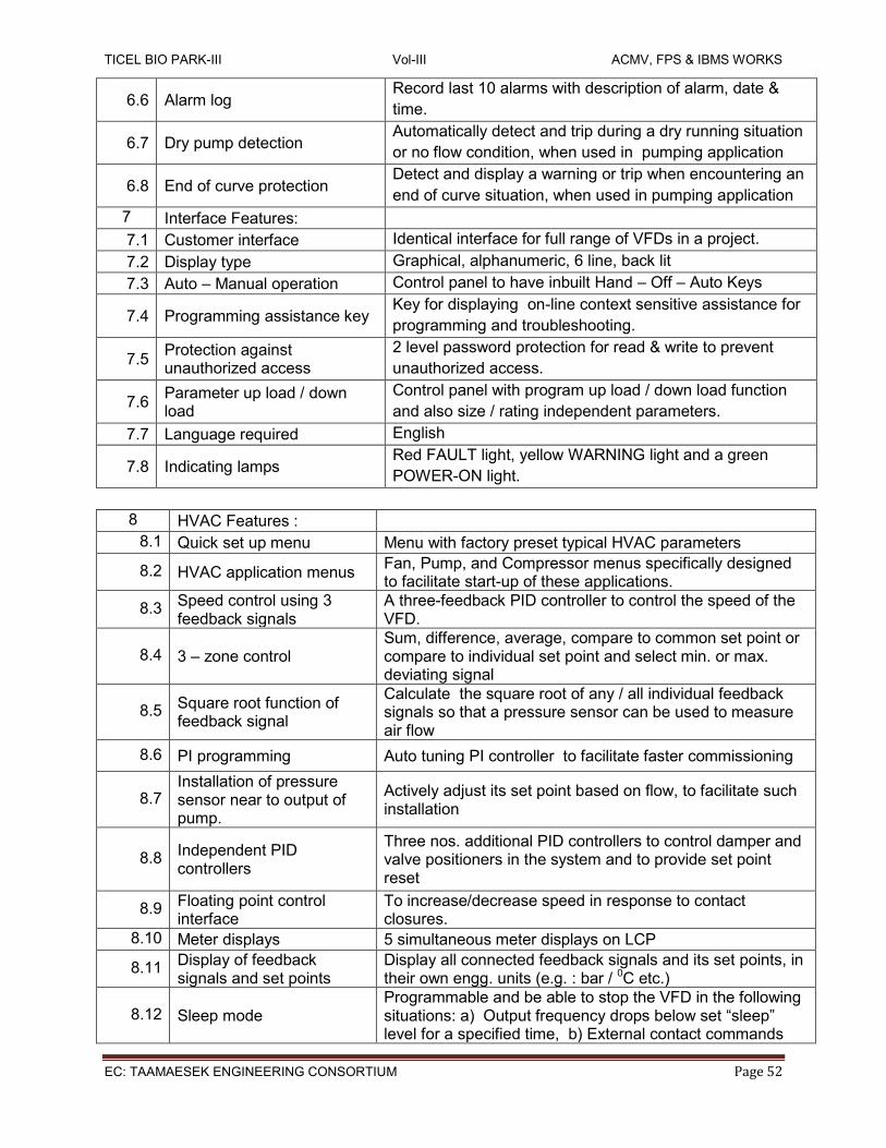
TICEL BIO PARK-III Vol-III ACMV, FPS & IBMS WORKS
EC: TAAMAESEK ENGINEERING CONSORTIUM Page 52
6.6 Alarm log Record last 10 alarms with description of alarm, date &
time.
6.7 Dry pump detection Automatically detect and trip during a dry running situation
or no flow condition, when used in pumping application
6.8 End of curve protection Detect and display a warning or trip when encountering an
end of curve situation, when used in pumping application
7 Interface Features:
7.1 Customer interface Identical interface for full range of VFDs in a project.
7.2 Display type Graphical, alphanumeric, 6 line, back lit
7.3 Auto – Manual operation Control panel to have inbuilt Hand – Off – Auto Keys
7.4 Programming assistance key Key for displaying on-line context sensitive assistance for
programming and troubleshooting.
7.5 Protection against unauthorized access
2 level password protection for read & write to prevent
unauthorized access.
7.6 Parameter up load / down load
Control panel with program up load / down load function
and also size / rating independent parameters.
7.7 Language required English
7.8 Indicating lamps Red FAULT light, yellow WARNING light and a green
POWER-ON light.
8 HVAC Features :
8.1 Quick set up menu Menu with factory preset typical HVAC parameters
8.2 HVAC application menus Fan, Pump, and Compressor menus specifically designed to facilitate start-up of these applications.
8.3 Speed control using 3 feedback signals
A three-feedback PID controller to control the speed of the VFD.
8.4 3 – zone control Sum, difference, average, compare to common set point or compare to individual set point and select min. or max. deviating signal
8.5 Square root function of feedback signal
Calculate the square root of any / all individual feedback signals so that a pressure sensor can be used to measure air flow
8.6 PI programming Auto tuning PI controller to facilitate faster commissioning
8.7 Installation of pressure sensor near to output of pump.
Actively adjust its set point based on flow, to facilitate such installation
8.8 Independent PID controllers
Three nos. additional PID controllers to control damper and valve positioners in the system and to provide set point reset
8.9 Floating point control interface
To increase/decrease speed in response to contact closures.
8.10 Meter displays 5 simultaneous meter displays on LCP
8.11 Display of feedback signals and set points
Display all connected feedback signals and its set points, in their own engg. units (e.g. : bar / 0C etc.)
8.12 Sleep mode Programmable and be able to stop the VFD in the following situations: a) Output frequency drops below set “sleep” level for a specified time, b) External contact commands

TICEL BIO PARK-III Vol-III ACMV, FPS & IBMS WORKS
EC: TAAMAESEK ENGINEERING CONSORTIUM Page 53
that the VFD go into Sleep Mode, or c) Detects a no-flow situation.
8.13 Run permissive circuit Receive a “system ready” signal before starting and also be capable of initiating an output “run request” signal to the external equipment.
8.14 Loss of load detection
Monitor a broken belt / loose coupling and indicate via key pad warning, relay output or serial communication. This function shall be based on torque and shall have a proof timer.
8.15 Real time clock
Integral feature and shall be capable of : Display current date & time on control panel Start / stop, change speed depending on time Time stamp all faults Program maintenance reminders based on time
8.16 Energy log Function to monitor energy consumption pattern over programmable hours, days & weeks
8.17 Load profile Store a load profile to assist in analyzing system demand and energy consumption
8.18 Sequential logic controller To perform logic functions which has logic operators, comparators and timer functions.
8.19 Cascade controller for multiple motors
To control one variable speed motor and 2 fixed speed motors. Software to have full functionality and not just on / off.
8.20 Automatic restart To automatically restart on receiving power after a power failure.
8.21 Adjustable ramp time To avoid nuisance tripping, automatically adjust the ramp times.
8.22 Catching a spinning fan To have a flying start function to effectively control an already spinning fan – in both forward and reverse direction
8.23 Programmable current limit
Programmable for site / application requirement. Shall be able to program for trip after an adjustable time.
8.24 Start Delay A programmable start delay shall be provided.
8.25 Critical frequency lock out Semi-automatic setting of lock out range. 4 such lock out ranges to be provided
9 Inputs and Outputs
9.1 I/Os required and additional I/O cards
5 DI; 5 DO; 2 relay outputs - of min 240V AC, 2 A; 4 AI programmable for both 0-10V & 4-20 mA inputs; 2 AO of 4-20 mA
9.2 Optional I/O modules & Special I/O requirement
In addition to 9.1, the drive shall be offered with the necessary I/Os as required for the control strategies for various applications as mentioned in this document.
9.3 Display of analog signal The Local Control Panel to display each analog signal in its engg. units for trouble shooting & setup.
9.4 Serial com interface for AI/DI
Capable of reading the status of all analog and digital inputs of the VFD through serial bus communications
9.5 Serial com interface for AO/DO
Capable to command all digital and analog outputs (including options) through the serial communication bus
9.7 Fire over ride mode
On receipt of a digital fire input, override all other local or remote commands, ignore most normal safety circuits including motor overload, display FIREMODE, select forward or reverse operation and speed source or preset

TICEL BIO PARK-III Vol-III ACMV, FPS & IBMS WORKS
EC: TAAMAESEK ENGINEERING CONSORTIUM Page 54
speed.
10 Serial Communications
10.1 Serial Com Port EIA-485 (RS 485)
10.2 Standard serial com protocols
Modbus RTU, Johnson Controls Metasys N2
10.3 Protocol options Bacnet MS/TP, Lonworks, Profibus, Devicenet or open protocal
10.4 Connection to Personal Computer
Using USB port
10.5 Communication in case of power failure to VFD
Facility to provide optional 24 V DC back up power interface for keeping the controls section powered to keep communication to BMS
The VFD supplier shall provide details of all harmonic currents up to and including the 40th when operating at full load and provide an estimation of the total harmonic voltage distortion resulting at the point(s) of common coupling due to the installation of all the VSDs on the project. Details of the loads, supply transformer, impedances, cable sizes and lengths and other relevant supply network data will be supplied to enable this calculation to be made. If this estimation concludes the total harmonic voltage distortion is expected to be above the value prescribed by the electricity distributor / international standards like IEEE 519, the VFD supplier shall propose additional passive or active advanced harmonic filters to reduce the harmonic distortion to within the value prescribed by the electricity distributor / standards. In such cases they shall include the cost of such advanced harmonic reduction as a separate section in their offer itself. A harmonic distortion report shall be submitted by the VFD manufacturer to support the calculated distortion and advanced filter offer.
1.7.0 SHEET METAL DUCTING, GRILLES, DIFFUSERS, LOW LEAKAGE VCDs & FDs
GENERAL
The scope of this section comprises of the supply, erection, testing and commissioning of fabricated sheet metal ducting, grills, diffusers, thermal insulation and other connected works with the air distribution system, conforming of these specifications and in accordance with the requirements of the drawing and of the Schedule of Quantities.
SHEET METAL WORKS, GRILLES, DIFFUSER, ETC SHEET METAL WORKS Ducts shall be made of aluminium sheets. The galvanized steel sheets shall conform to I.S.277 - 1965. Aluminium sheets shall be of grade S-IC or S-3 as specified in I.S.737 - 1965. Galvanizing shall be as per Clause VIII of ISI specification.
The thickness of sheets and type of bracings shall be as given below:
Longest side mm Minimum Sheet Thickness (mm)
Type of Bracings
for G.S.S.
for Aluminium
Upto 600 0.63 0.80 Cross bracings 25 x 25 x 3 mm MS

TICEL BIO PARK-III Vol-III ACMV, FPS & IBMS WORKS
EC: TAAMAESEK ENGINEERING CONSORTIUM Page 55
601 to 750 0.63 0.80 Angles bracing at 1200mm from joints.
751 to 1000 0.80 1.00 32 x 32 x 3 mm MS Angles bracing at 1200 mm from joints.
1001 to 1500 0.80 1.00 40 x 40 x 3 mm MS Angles bracing at 1200 mm from joints.
1501 to 2250 1.00 1.55 40 x 40 x 3 mm MS Angles bracing at 600 mm from joints or 40 x 40 x 3 mm MS Angles diagonal bracing.
2251 and above 1.25 2.00 50 x 50 x 6 mm MS Angles bracing at 600 mm from joints or 50 x 50 x 6 mm MS Angles diagonal bracing.
This specification covers the general design, materials, construction features, manufacture, testing, delivery, installation, testing, commissioning and carrying out performance test at site of Air Distribution System and its components. CODES & STANDARDS The design, manufacture and performance of ducting, dampers & grilles shall comply with all currently applicable statutes, regulations and safety codes in the locality where the equipment will be installed. The equipment shall also conform to the following latest Standards. Nothing in this specification shall be construed to relieve Vendor of his responsibility. All sheet metal ducting work for various air systems shall be supplied, installed, completely connected, tested and adjusted. All main ducting shall be factory fabricated and only assembled at site. All ducting shall be provided with M.S duly painted angle frames only. The Contractor shall arrange at site all necessary equipments like lock forming machine, drilling machine, welding machines, etc for carrying out duct fabrication of site adjustment ducting, minor branching, collar connection pieces etc., The Contractor shall make working drawings of all duct work and the same shall include details of all fittings, dampers, elbows, grilles, return air risers, etc. required for the proper operation of the system. All diffusers, duct lengths, grille necks / boxes must be kept duly covered during construction to keep out dust and rubbish. All ducting flanges shall be out of M.S angles and duly nut bolted with gaskets. The nut bolting shall be within the maximum spacing of 150 mm. All duct angle flanges and duct supports shall be epoxy painted by VENDOR. Ducts shall be adequately supported from ceiling trapeze hangers firmly fixed and generally suspended from the building structure with the help of welded joints / anchor fasteners / embedded plates. Ducts shall rest on supporting angle or channel and the angle or channel shall be supported by CS rods on both sides of ducts with weld or bolts. The hangers and supports shall not pierce the insulation. The hangers shall be spaced on average 2.4 m centres with a hanger no further than 0.6 m on each side of any change in direction. Ducts passing through any building expansion joints shall be supported on either side of the joint. All anchors, hanging rods and other metallic exposed parts must be galvanised or painted with a rust protecting paint. For ducts having HEPA filters, food grade silicon sealant approved by USFDA must be applied on all duct joints. Transformations in main ducts and in branches must be tapered. The cross section of the duct must be gradually decreased at a rate of 1 mm / 5 mm of length. Wire mesh of maximum opening of 10 mm shall be provided for all external opening to avoid entry of Birds. In general the following points to be noted while fabricating/installing of ducts:

TICEL BIO PARK-III Vol-III ACMV, FPS & IBMS WORKS
EC: TAAMAESEK ENGINEERING CONSORTIUM Page 56
Duct sealant to be applied in all transverse joints. Exposed duct to be sealed on the inner surface only. Provide full radius tees and elbows for change in direction, except where square elbows are required due to space restrictions. Provide balancing dampers, splitter dampers as per approved drawings Isolate equipment with connections. Duct support shall be as per IS:655 standards / approved drawings / standard clean room practices. Irrespective of the standards, only angle flanges to be used for duct connection. Sheet flanges are not acceptable. All the support angle and rods shall be painted with approved colour on one coat of red oxide.
MARKING OF THE DUCTS
The ducts and other equipment must be marked after insulation by arrows to indicate the
direction of air flow and also the serial number of the system corresponding to the AHU
distribution chart enclosed.
DAMPERS
Contractor shall supply and install all dampers where necessary for proper control of volume and balancing of air distribution system. These dampers shall be separate from any other dampers provided with supply and return air diffusers, registers and grilles. A multi leaf opposed blade type damper shall be installed in each supply air duct / return air duct / fresh air entry near the air handling unit outlet to adjust the total supply air cfm. Dampers shall be of rigid construction free of all rattling and vibrations with edges crimped or creased for stiffness. It should be possible to adjust and lock the damper in any position. Fully open and fully closed position shall be clearly marked for ease in operation. Dampers shall be provided with Teflon or brass bushings for blade shaft.
HANGER FOR DUCTS
Duct size (mm) size of ms angle (MM x MM) Size of rod dia (MM)
Upto 750 40 x 3 10
751 to 1500 40 x 3 12
1501 to 2250 50 x 3 15
2251 & above 50 x 3 15
NOTES: Where ducting is supported from ceiling/roof slab, Anchor grip bolts shall be used to fasten the suspension rods (for duct supports) to the ceiling/roof slab. All civil works involved including the drilling of holes for fixing the grip bolts and any chipping and finishing of the ceiling/roof slab shall be carried out by the successful contractor at no extra cost. All joints shall be made tight and all interior surface shall be smooth. Bends shall be made with radius not less than one-half of the width of the duct or with scientifically designed interior curved vanes, as approved. The vanes shall be so spaced that the aspect ratio of each of the individual elbows formed by the vanes will be about five.
GRILLES & DIFFUSERS
All (supply) side air grilles shall be of approved make with single deflection vanes and approved dampers. Supply air grilles shall be provided with non-adjustable type horizontal bars

TICEL BIO PARK-III Vol-III ACMV, FPS & IBMS WORKS
EC: TAAMAESEK ENGINEERING CONSORTIUM Page 57
and adjustable type volume control multi louver damper which shall be key operated from the front of the grilles. All return air grilles shall be identical to supply air grilles except that they do not incorporate volume control dampers. All exhaust air grilles shall be of approved design with adjustable dampers. All ceiling outlets shall be of approved make. Ceiling outlets for supply air to be equipped with volume control dampers, fixed grid and blanking baffles, where desired. All grilles and diffusers shall be complete with powder coated painting (Color scheme will be provided by the Client.) All air diffusers and grilles shall be purchased only from Air master or from established sources with full application literature available and fixed with fasteners which are not visible from outside and dampers which are operated from the face. All MS frames rectangular or circular for fixing thereon of supply and return air grilles and diffusers shall be supplied by the Air-conditioning contractors. All grilles/diffusers shall be fixed using brass screws only. All grilles/diffusers shall be selected in consultation with the Client/Architect. Differ-ent spaces shall require horizontal or vertical face bars and different width or margin frames.
LOW LEAKAGE DAMPERS
All volume control dampers except fresh air shall be of GI louvered type design of robust construction and tightly fitted. The fresh air dampers shall be provided with 74 deg. C fusible links as explained in 2.4. The design, method of handling and control, shall be suitable for the location and service required. The casing and blades shall be of 16 G- GSS (1.55mm) stiffened suitably and strengthened by press bending. Dampers shall be provided with suitable links, levers and quadrants as required for their proper operation, control or setting in any desired position. Dampers and their operating devices shall be made robust, easily operable and accessible through suitable access doors in the ducts. Every damper shall have an indicating device clearly showing the damper position at all times. Dampers shall be placed in ducts and at every branch supply or return air duct connection whether indicated or not indicated, on the drawings for the proper volume control balancing of the system.
FIRE DAMPER WITH ACTUATOR CUM SENSOR
The fire damper shall be constructed of 16 Gauge galvanized steel frame and 16 G GSS blades. Gravity is used to drop the blade stack on this type of damper. 74 Deg. C UL rated shall be employed. This damper shall be designed to fit completely in the inside of ducting with no transition required. Only heavy duty bronze bushes, GSS blade brackets with bronze fasteners shall be used. Metallic compression type seals at jambs shall be used for construction. Actuator shall be suitable for AC 230V, 50HZ operation, with fire sensors it shall be BMS compatible.
FLEXIBLE DUCTING
MATERIAL
The flexible ducts used to tap supply air shall be of high quality thermally insulated duct. The thickness of the insulation shall be 25 mm thick and the density shall be not less than of 16 kg / cum. The inner core of the flexible duct shall be of PVC / tough aluminum material bonded with stainless steel spirally reinforced wire. The outer jacket is made out of very tough spirally reinforced multiple layer aluminum laminated construction.
TICEL BIO PARK-III Vol-III ACMV, FPS & IBMS WORKS
EC: TAAMAESEK ENGINEERING CONSORTIUM Page 58
The flexible ducts proposed to install in the exhaust side shall be of same description as mentioned above but without insulation material having 2 layers of aluminised polyester construction, encapsulates a high tensile steel wire helix. INSTALLATION PROCEDURE Flexible ducts shall be cut to the required size to ensure a curved connection between the main duct and the air terminal plenum. The contractor shall not join any small flexible. pieces by any foreign materials before installation. The minimum length of the flexile duct shall not be less than 750 mm in length. A groove of 2 mm shall be made on the round collars to ensure that the spiral wire inside the flexible duct shall be fitted ahead of the groove. Stainless steel metal clamps, which are made out of 8-mm wide band with lifted edges, shall be used to tighten the connection of the flexible ducts on the round collars of the plenums. On the flexible ducts the clamp is fitted with a flip up and quick lock tightening head of ease of fixing. The contractor shall ensure that all the flexile ducts wherever installed shall follow the above procedure. The contractor has to obtain the approval from the consultant / project managers before starting the actual installation.
1.8.0 PIPING WORKS AND RELATED VALVES GENERAL
The Contractor on the Award of the work shall design the piping installation and prepare detailed working drawings, showing the cross-section longitudinal sections, detail off fittings, and location of isolating drain and air valves, instruments etc., for approval of the Employer. Care shall be taken to provide expansion or contraction due to temperature changes. Work shall be started only after the drawings have been approved in writing by the Employer. Proper additional precautions shall be taken, as directed by Employer for vibration isolation of piping, passing through sensitive areas. SCOPE OF SUPPLY AND ERECTION
The CONTRACTOR shall supply all piping materials like pipe, fittings, flanges (along with
gasket, Galvanized Bolts, Galvanized nuts), pipe supports, anti corrosive treatment, paints and
any other items required for the proper functioning of the system. Supports shall include all
accessories like U Bolts, clamps, rods etc., and all steel structure required for proper supporting of
the pipe.
CONTRACTOR shall supply all necessary drains and vents as required for the safe and effective draining / venting of piping systems. It must be noted that the flow diagram / piping layouts may not indicate all drains / vents that would be required. It shall be the responsibility of the Contractor to provide all required vents / drains for the proper operation of the systems. The drains shall be led up to the nearest floor drain.
Manual air vents shall be installed at all high sections of piping as well as in the AHU Cooling coil connection. All air vents shall have an isolating valve of equal size. The discharge from these air vents shall be piped to the nearest waste drain point. The vent size shall be as follows:- Upto ND 150 pipe Size 15 mm size Above ND 150 pipe size 25 mm size
The CONTRACTOR shall install primary elements for flow measurements, control valves and on-line metering equipment and any other instruments /sensors required by ACMV system or BMS System.

TICEL BIO PARK-III Vol-III ACMV, FPS & IBMS WORKS
EC: TAAMAESEK ENGINEERING CONSORTIUM Page 59
All piping shall be internally cleaned and flushed by Contractor before and after erection in a manner suited to the service as directed by the Purchaser. For flushing as well as temporary blow out, all primary elements such as orifice plates, flow nozzle pipe assemblies shall be removed. Flow nozzle pipe assembly shall be replaced by suitable spool piece and orifice plates by suitable dummy plates. Both spool piece and dummy plates shall be furnished by the Contractor for on-line instruments which have no bypass shall be replaced by suitable spool pieces while flushing and / or blowout. These spool pieces shall be furnished by the Contractor. In addition if certain valves / specialties are not available during testing / commissioning stage, contractor shall provide suitable spool pieces and replace the same with valves / specialties when they are available.
The CONTRACTOR shall hydrostatically test the entire piping system including valves and specialties. For hydrostatic testing and water flushing, the CONTRACTOR shall furnish necessary pumps, equipment and instruments, piping etc., The PURCHASER will provide water at available points (REFER GENERAL CONDITIONS – IF NOT; GENERAL CONDITIONS SUPERCEEDS ABOVE STATEMENT) of supply to which the CONTRACTOR’s temporary piping will be connected.
MATERIAL AND OTHER SPECIFICATION
The material and other specification for piping, valves and specialties shall be as per Data Sheet
listed under the end of this section.
Colour code shall be used to identify pipe material. The CONTRACTOR shall be able to identify
on request all random piping prior to any field fabrication.
The VENDOR shall furnish six (6) copies of certificates for piping for:-
Dimensions and Hydrostatic test
Material test certificates
WELDING
The VENDOR’s scope under this includes the following:-Welding materials like welding electrodes (Advani / Esab), gas rods, oxygen, acetylene, propane and other consumable materials and backing rings etc., as required. Jointing material as required for all screw joints. Fasteners (bolts, nuts, stud washers etc., Should be Galvanized MS ) and gaskets is required for all flanged joints. Services of erection superintendents, erection superiors, fitters, riggers, other skilled and unskilled labour. Erection tools, tackles and material, including welding machines. All fusion welding shall be done with direct current electricity using the metallic arc process with coated electrodes of a type suitable for respective kinds of material. Where the CONTRACTOR desires to use alternating current shielded metal arc welding, he shall submit his procedure to PURCHASER for approval.
WELDING PROCESS Unless otherwise noted, for all carbon steel piping systems the entire welding including root pass may be carried out by Manual metal arc welding only.
PROCEDURE QUALIFICATIONS

TICEL BIO PARK-III Vol-III ACMV, FPS & IBMS WORKS
EC: TAAMAESEK ENGINEERING CONSORTIUM Page 60
No production welding shall be undertaken until the procedure qualifications testes which are to be used have been established as per ASME Boiler and Pressure Vessel Code – Section IX. Test results and specimens from qualification tests of the welding process and welding operators shall be made available to the PURCHASER / ENGINEERS / INSPECTOR for approval. For purposes of identification and to enable tracing full history of each joint, each welder employed on the work shall be given a designation. The welder’s designation and the date on which the joint was made, shall be stamped / marked on the relevant piping/ drawings so marked shall be furnished to the PURCHASER / ENGINEER for record purposes.
PREPARATION OF WELD ENDS
Surfaces to be welded shall be smooth, uniform and free from fins, tears and other defects which would adversely affect the quality of the weld. All welding faces and adjoining surfaces shall be thoroughly cleaned of rust, scale, paint, oil or grease both inside and outside upto a distance of at least 150 mm from the edge of welding groove or 12 mm from the toe of the fillet in the case of socket welded or fillet welded joints. Unless otherwise specified, joints for carbon steel pipe, 50 mm NPS and smaller, shall be socket welding type as per ANSI B 16.11 and for pipes, 65 mm NPS and larger shall be of the butt-welding type as per ANSI B 16.25. All Butt welds shall be full penetration welds. For stainless steel piping all joints shall be butt welded. Stainless steel pipe lines shaving nominal wall thickness 3mm and less shall have ends cut square or slightly chamfered. “Mirror Technique” shall be adopted for joining of HDPE pipelines. For PVC pipe lines either solvent method / hot welding or both shall be adopted.
WELDING OF PIPES
Gouging or back gouging of butt welds may be carried out where feasible by grinding, chipping, machining or other approved methods, but the surface of the cut must be cleaned to remove any carbon or oxidized metal before commencing the welding. The maximum face width of any manual arc or inert gas welding run shall be20 mm No single run horizontal-vertical position manual metallic arc weld filled shall exceed 8 mm in size. The arc shall be struck only on those parts of parent metal where weld metal is to be deposited. No welding or welded parts shall be painted, plated, galvanized or heat until inspected and inspected and approved by the PURCHASER / ENGINEER. After deposition, each layer of weld metal shall be cleaned with a wire brush to remove all slag, scale and defects, to prepare for the proper deposition of the next layer. In case where the weld joint on pipes 100 mm NB and larger has to be radiographed as per the requirements of this specification, it is recommended that the root run be checked by liquid penetrant or magnetic particle procedures. Irrespective of the class of steel, root runs shall be made without interruption other than for changing the electrodes or to allow the welder to reposition himself. Root runs made in the shop may afterwards be allowed to cool by taking suitable precautions to ensure slow cooling. Welds made at site shall not be allowed to cool until the thickness of weld deposited exceeds tone third of final weld thickness or 10 mm, whichever is greater. Also no welding shall be done when the ambient temperature is less than 10 deg C. If the welding is unavoidable, then the contractor shall meet the preheating requirement after discussion with site engineer.
ELECTRODES

TICEL BIO PARK-III Vol-III ACMV, FPS & IBMS WORKS
EC: TAAMAESEK ENGINEERING CONSORTIUM Page 61
The specification and size of the electrodes voltages and amperages, thickness of beads and number of passes shall be specified in the approved welding procedure or otherwise agreed in writing. In general, coated electrodes shall be used, which deposit weld will metal having the same or higher physical properties and similar chemical composition to the members being joined. All electrodes to be used on carbon steel shall conform to ASME boiler and Pressure Vessel Codes Sec II part C or IS 814 or any other equivalent code. INSPECTIONS This includes inspection and testing welding at all stages of fabrications and erection.10 % of Radiography is allowed for testing, it should be attached to the measurement of piping. HANGER AND SUPPORTS All piping supports, guides, anchors, rod hangers, rollers, with incidental structural sub-framing shall be furnished and erected by the CONTRACTOR. The fabrication of the hangers, anchors and materials shall conform to the requirements of MSS-SP-58 or PURCHASER’S specification unless otherwise noted. The provision of pipe support will include auxiliary steel or concrete pedestals wherever applicable. The CONTRACTOR shall be responsible for the design of hangers, supports etc., for the complete piping system. However, CONTRACTOR shall obtain ENGINEER’s / PURCHASER’s approval before fabrication and erection of these supports. All piping shall be suspended, guided and anchored with due regard to general requirements and to avoid interference with other pipes, hangers, electrical conduits and their supports, ducts, and structural members. It is the responsibility of the piping CONTRACTOR to avoid all interference while locating hangers and supports. Hangers rods on all pipe lines shall not be less than 12 mm (3/8”) to support pipes.
Parameter Valve
Welding Process Electric Arc welding
Type Manual
Application Chilled water piping
Groove Design Single ‘V’ Size of Electrode Filler 11.5 mm to 4.0mm
Type of Electrode J.B. Advani Over cord ‘S’ , Philips ‘2S’ Size of Electrode filler 11.5mm - 4.0mm
Pre-heat Not required
Post weld heating Not required
Welding technique Root, filling and capping weaving
Welding progression Vertical Upward.
Pipe installation shall be carried out in a workman like manner with approved drawings, which
shows the locations of equipment, valves, drains and air-vents. Pipe hangers shall be spaced as
follows:- (unless otherwise stated in the drawings)
Nominal pipe size mm - dia Spacing (meters) Hanger Rod size

TICEL BIO PARK-III Vol-III ACMV, FPS & IBMS WORKS
EC: TAAMAESEK ENGINEERING CONSORTIUM Page 62
12 & 15 1.25 9mm
20 & 25 9mm
32, 40, 50 & 65 2.00 12mm
80, 100 & 125 2.00 15mm
150 & above 2.50 20mm
SURFACE PREPARATION AND PAINTING
All pipelines and piping components shall be adequately protected against corrosion during manufacture, shipment and storage by appropriate protective paint. Use of grease or oil for this purpose is prohibited. After completion of cleaning and testing operations at site, completed pipe work, hanger and support components shall be give n a coat of primer as follows: Before the applications of paint, the CONTRACTOR shall prepare all surfaces. The surfaces shall be cleaned of all mill scale, dirt, dust, soot, grease, rust etc., and of all substances which would damage the coating or impair its adhesion. Existing coating shall be removed thoroughly for satisfactory painting. Spools which are already corrosive shall be completely derusted and repaired as necessary before the application of paint. Immediately after the surface cleaning, the CONTRACTOR shall give two coats of red oxide zinc chromate primer (confirming to IS 2074) with minimum Dry Film Thickness (DFT) of 25 microns per coat. The Contractor shall test the coating executed by him as regards to their satisfactory adhesion. Painting operations shall generally be in line with IS 1477 part II. In addition to above all pipes other than galvanized or insulated pipes and pipe supports shall be given two coats of finish paints using enamel paint of approve make by brushing or spraying generally as per IS 1477 to give a minimum total DFT of 100microns (after two coats of primer and two coats of finish paint). Shades shall be as per IS 5 or as indicated by PURCHASER. Paint manufacturer’s instruction for primer or finish paint shall also be followed. Before selection of colour code, PURCHASER’S / ENGINEER’s approval shall b obtained. SURFACE PREPARATION
Pipe surfaces to be provided with underground protection shall be cleaned by shot or sand blasting. The cleaning shall e so carried out that the piping surface is free from mill scale, rust, oil, welding scale and other foreign materials. Primer shall be applied immediately after shot or sand blasting to prevent rust forming. Superficial rust formed shall be removed by wire brushing or by the use of emery paper. If the rust formation is heavy, reblasting may be necessary. Around field joints, the pipe surfaces may be cleaned by wire brushing prior to the application of anti-corrosive protection.
BUTTERFLY VALVES
Butterfly valves shall be of slim seal WITH EXTENDED STEM OF 125MM, short water type with standard finish. The valves shall be suitable for mounting between flanges drilled to ANSI 125. The valve body shall be cast iron. The disc shall consist of disc pivot and driving stem. The disc shall move in bearings on both ends with ‘O’ Ring to prevent leakage. The seat shall be moulded black nitrile rubber or nylon. The valves shall be suitable for a working pressure of 16.5 kg/scm and shall be complete with flow control lever and notches, factory machined companion flanges, bolts & nuts.
AUTOMATIC AIR VENTS-In addition to the manual air vents described above, automatic air vents of size 25 mm shall b placed at the top of the chilled water riser piping in the building. Operation of

TICEL BIO PARK-III Vol-III ACMV, FPS & IBMS WORKS
EC: TAAMAESEK ENGINEERING CONSORTIUM Page 63
Automatic air vent: The float of the air vent keeps the venting valve closed. When air is collected inside the float chamber, the water level inside the vent valve decreases and the venting valve is opened. The collected air escapes through the venting valve and the water level inside the vent valve increases again, which in turn results in the closing of the venting valve. The process is a continuous one as long as air is collected in the vent valve. The air cushion in the upper part of each vent valve protects the venting valve against corrosion. When the pressure inside the system decreases below the ambient pressure, for instance during draining of the system, the air vent acts as a vacuum breaker, and lets air into the system. Drain pipe with isolation valve shall be installed at the lowest point of the AHU cooling coil, at the bottom of each chilled water rise pipe, and at all the other system low points. The discharge from these drain valves shall be piped to the nearest waste drain point. The drain size shall be as follows Upto ND 150 pipe size: 15mmsize Above ND 150 pipe size: 25mmsize.
BALL VALVES
Ball valves shall have body of carbon steel. The ball and the shaft shall be of stainless steel. The seat shall be of PTFE. The valve shall be complete with socket weld ends. Pressure rating shall be 16.5 kg/sqcm CHECK VALVES Swing check valves shall normally be used in all water services. Life type valves may be used in horizontal runs. All release and clean out plugs shall be provided and valves shall be suitable for 21 Kg/sq.cm test pressure. Check valves shall be of non-slamming type to prevent water hammer either by providing springs or accumulators. Valves shall be suitable for 15 Kg/cm2 operating pressure. All check valves must be only vertical type. STRAINERS “Y” strainers up to 50 mm shall be of gunmetal and above 50 mm shall be of cast iron body. Strainers shall incorporate a removable bronze screen with 3mm perforations and a permanent magnet. Strainers shall be provided with flanges at both inlet and outlet of the chilled water pumpset. They shall be designed to enable blowing out the accumulated dirt and facilitate removal / replacement of screen without disconnecting the main pipe. The strainer shall be suitable for 16.5 Kg/sqcm test pressure. FLANGE S & UNIONS Sufficient number of flanges and unions shall be provided as required to facilitate the maintenance work after the piping is installed. Mild steel ANSI 125 flanges shall be used for pipes of 65mm dia and above. AUTOMATIC EXPANSION TANK Cylindrical pressure tank, vertically arranged, with oven enameled finish, balloon-type membrane made of high quality buthyl caoutchouc compound for excess water, including preinstalled air compressor and all required fastening and sealing materials. Max. operating temperature: 100°C Max. operating pressure: 4 – 6 bar Nominal volume: Refer BOQ It shall be provided with necessary pumping system in the configuration of N + 1 which is suitable for Outdoor Operation with BMS compactable. PRESSURE/TEMPERATURE GAUGES ( ALL SS TYPE)

TICEL BIO PARK-III Vol-III ACMV, FPS & IBMS WORKS
EC: TAAMAESEK ENGINEERING CONSORTIUM Page 64
Pressure gauges shall be not less than 100 mm dia. They shall be selected for appropriate range
and shall be complete with siphon and cock, etc. Temperature gauge complete with thermo well
Pressure gauges shall be provided as shown in the drawings & as per price schedule.
DYNAMIC CUM CONTROL VALVES
The SM Series are self-balancing dynamic flow control valves that are pressure independent, two-way, modulating to accept digital or analog input signals and provide flow feedback signal to the control system. The valves accept 2-10V DC, 0-10 V DC, 4-20 mA, digital 3-point floating or PWM input signals and shall be capable of providing 4-20 mA or 2-10V DC flow feedback signal to the control system. Each valve has 51 adjustable maximum flow rate setting to enable flow limitation and balancing to the coils or zones that the valves are controlling. All SM actuators are microprocessor based with a self-calibrating feature. The valves from 15 to 40 mm shall be designed for double union piping connections while above 40 mm of the wafer style for fitting between flanges, to be provided by others.
VALVE SPECIFICATIONS
For 15 to 40 mm For 50 to 150 mm
Static Pressure 2500 kPa, 360 psi
Media Temperature -20 ° to 120 °C, -4 ° to 248 °F
Ambient Temperature 10 ° to 54 °C, 14 ° to 131 °F
Body material Forged Brass ASTM B584 Ductile Iron, ASTM A536-65T, Class 60-45-18
Internal Components AISI Type 316 Stainless Steel AISI Type 316 Stainless Steel
Test Ports/ Body Tappings 1/4” NPT (Body Tappings) 1/4” ISO (Test Ports)
End Connections Bronze Alloy ISO, NPT or Sweat
Wafer style ( by others)
Stem Seals EPDM and Nitrile O-Rings EPDM
Maximum Close Off Pressure
700 kPaD, 101 psi 700 kPa, 101 psi
Maximum Operational .P 320 kPaD, 46 psi 400 kPa, 58 psi
ACTUATOR SPECIFICATION FOR ALL VALVES
Supply voltage power Consumption : 230V
Frequency Control : 50HZ
Input Position Outp : 2-10V DC, 0-10 VDC, 4-20Ma, 3Point Floating,
PWM.
Turn Time : 2-10V DC 4-20mA
Direction of rotation : 50Seconds (from closed to fully open valve)
Humidity Rating : 15MM Grommet connection Bi- directional
Housing Material : Fully coated Electronic Board
Housing Insulation : Aluminum IP 5
Valve shall be electronic, dynamic, modulating, 2-way, control device.

TICEL BIO PARK-III Vol-III ACMV, FPS & IBMS WORKS
EC: TAAMAESEK ENGINEERING CONSORTIUM Page 65
Dynamic control valve shall accurately control flow, independent of system pressure fluctuation.
Maximum flow setting shall be adjustable to 51 different settings within the range of the valve size.
VALVE ACTUATORS
Valve actuator housing shall be rated to IP 44.Actuator shall be driven by a 230 v, 4-20 mA, 3-point floating or pulse width modulation electric signal and shall include resistor to facilitate any of these signals. Actuator shall be capable of providing 4-20 mA or 2-10V DC feedback signal to the control system. External LED read-out of current valve position and maximum valve position setting shall be available. VALVE HOUSING Housing for 15 – 40 mm size shall be constructed of forged ASTM (CuZn39Pb2) brass rated at no less than 2500 kPa static pressure and 120°C. Housing for 50 – 150 mm shall be constructed of Ductile Iron ASTM A536-65T, Class 60-45-18 rated at no less than 4000 kPa static pressure and 120°C. Valve housing for 15 – 40 mm shall be double union construction with a range of pipe connections available for the appropriate pipe size. Identification tags shall be available for all valves. FLOW REGULATION UNIT Flow regulation unit shall consist of stainless steel and hydrogenated acrylonitrile butadiene rubber and shall be capable of controlling flow within +/- 3% of each rated flow. Flow regulation unit shall be accessible, for maintenance. Optional dual pressure/temperature test plugs for verifying accuracy of flow performance shall be available for all valve sizes. BALANCING VALVES Balancing valves shall be supplied and installed as shown on the drawings to ensure proper balancing of water flows in the hydraulic heating and cooling system. Flow measurement and balancing shall be possible with an accuracy of 4 to 7% in the normal measuring range of the valves. (When valve opening position is more than 50%) Pressure measuring nipples shall be provided for measuring differential pressure and be integral with the body and incorporate a means for shutoff when normal use. Adjustment and presetting of flows shall be made with a digital hand wheel. The setting shall be lockable with a mechanical stop to allow the valve to be closed but not opened further than to the preset value. For valves in size 10 to 50 mm the balancing valves shall offer a facility for draining of water with a separate hose connection and a stop valve. The optional draining facility shall be capable of being mounted on or removed from the balancing valve without interruption to the system operation. MATERIAL AND PRESSURE RATINGS Balancing valves with thread connections in sizes from 10 to 50 mm shall bemade in a dezincification resistant copper alloy with Brinell hardness of atleast130 and a body pressure rating of at least 20 bar (300 psi) at 150 degrees C (AMetal). Balancing Valves with flange connection from 20 to 300 mm shall be made in cast iron for a body pressure rating at least 16 bar – 25 bar 150 degrees C. Valves sized 65 mm – 300 mm shall to

TICEL BIO PARK-III Vol-III ACMV, FPS & IBMS WORKS
EC: TAAMAESEK ENGINEERING CONSORTIUM Page 66
be fitted with a pressure balanced cone to reduce closing to que to allow the valve to be closed and opened easily. Balancing valves shall be sized to operate in a normal measuring range of 50% to 100% of full opening to ensure maximum accuracy. All balancing valves shall be manufactured in accordance IS09001.Certificate of Origin and Certificate of Quality from factory shall be submitted for inspection when the balancing valves are delivered to site before installation. Installation of balancing valves without the specified certificates shall not be permitted. A computerized balancing instrument (CBI) with ISO 9000 calibration certificate shall be handed over after testing and commissioning. To enable accurate and practical operation, measurement of flow and differential pressure shall be made with a microprocessor instrument which shall enable the operator to read the flow directly without the use of diagrams or tables. The balancing of the system shall be verified in a written report, documenting valve position and water flow which shall be handed over to the consultant for approval and acceptance.
CBI SHALL HAVE TWO MAIN COMPONENTS
An instrument which contain a micro computer, input touch pad and LCD display and rechargeable batteries and built-in-charger. An sensor unit which contain a piezo-resistant pressure sensor, one measurement valve and connection hoses. The measurement valve shall have a safety function which protects the sensor from high differential pressures. In addition to measuring flow rate, differential pressure and temperature, the CBI shall have a computer program to provide following functions. To balance the installation of HVAC system and calculate the necessary valve setting, based on the system measurements. To store the result of balancing. To log measured values from a valve (differential pressure, flow rate or temperature) To printout saved data in computerized measurement protocol (CMP) consisting of Name and size of Balancing Valve (BV) Presetting position of BV Dp at BV Flow at BV Design flow DATA SHEET FOR PIPING AND SPECIALITES PIPING MATERIAL SPECIFICATION
nominal pipe size in mm
15 20 25 32 40 50 65 80 100 125 150 200 250 300 350 400
outside dia in mm
21.4 26.9 33.8 42.5 48.4 60.3 76 88.8 114.3 139.7 168.3 219.1 273.1 323.9 355.6 406.4
thickness mm 3.25 3.25 4.05 4.05 4.05 4.5 4.5 4.85 5.4 5.4 5.4 6.4 6.4 6.4 6.4 7.9
nominal pipe size in mm
450 500 550 600 650 700 750 800 850 900 950 1000 1100 1200
outside dia in mm
457 508 558.8 609.6 660 711 762 813 864 914 965 1016 1016 1224
thickness mm 7.9 8 8 8 8 8 8 8 10 10 10 10 10 12
LINE JOINT: 50 MM & BELOW - SOCKET WELDING AS PER ANSI B 16.11
65 & ABOVE - BUTT WELDING AS PER ANSI B 16.25
ITEM NOMINAL PIPE
SIZE RANGE MM MATERIAL
SPECIFICATION DIMENSION
STANDARDS REMARKS

TICEL BIO PARK-III Vol-III ACMV, FPS & IBMS WORKS
EC: TAAMAESEK ENGINEERING CONSORTIUM Page 67
PIPES 15 TO 150 ERW, BLACK, IS 1239 (PT-1)
IS 1239 (PT-1) HEAVY CLASS
200 TO 450
ERW IS 1978 OR API 5L GRB OR IS 3589 FABRICATED FROM IS 2062 PLATES
IS - 1978 REFER NOTE - 9
500 & ABOVE
IS 3589 FABRICATED FROM IS 2062 PLATES
ELBOWS BENDS MITRE
65 TO 150 ASTM 234 GR WPB ANSI B 16.9 REFER NOTES 1 & 2
50 & BELOW SAME AS PIPE R = 5D
200 & ABOVE SAME AS PIPE ANSI B 16.9 REFER NOTES 1 & 3
BRANCH CONN
COUPLINGS
15 TO 50
ASTM A 105 OR IS 1875 CL-2
ANSI B 16.11 3000 LBS
NOZZLES
65 & ABOVE
SAME AS PIPE REFER NOTE 6
TEES 50 & BELOW ASTM A 105 OR IS 1875 CL-2
ANSI B 16.11 3000 LBS
65 TO 200 ASTM A 234 GR WPB ANSI B 16.9 REFER NOTE 2
REDUCERS 50 & BELOW ASTM A 105 OR IS 1875 CL-2
ANSI B 16.11 3000 LBS
65 TO 150 ASTM A 234 GR WPB ANSI B 16.9 REFER NOTE 2
200 & ABOVE SAME AS PIPE ANSI B 16.9 FABRICATED
FLANGES 15 TO 150 ASTM A 105 OR IS 1875 CL-2
ANSI B 16.1 / 16.5
CLASS 150 SLIP ON, REFER NOTES 4 & 7
200 & ABOVE IS 2062 FABRICATED ANSI 16.1 / 16.5 CLASS 150 REF NOTES 4 & 7
BLIND FLANGES
15 TO 150 ASTM A 105 OR IS 1875 CL-2
ANSI B 16.1 / 16.5
CLASS 150 SLIP ON, REFER NOTES 4 & 7
200 & ABOVE IS 2062 FABRICATED ANSI 16.1 / 16.5 CLASS 150 REF NOTES 4 & 7

TICEL BIO PARK-III Vol-III ACMV, FPS & IBMS WORKS
EC: TAAMAESEK ENGINEERING CONSORTIUM Page 68
1.9.0 THERMAL INSULATION
GENERAL
This section details the supply and application of thermal insulation to chilled water piping, condensate drain piping, thermal insulation for sheet metal ducting etc., for the temperature between ambient and (-) 80 deg C and also for dual temperatures (both hot and cold) service with hot temperature above ambient and up to 230 deg C. Unless specified otherwise in section C and / or data sheet, the scope of supply of the contractor shall include, but not be limited to, the following items: Insulation material of all types as specified and required.
BOLTS ALL IS 1367 CL.4.6 OR ASTM A307 GR B
ANSI B 18.2.1 THREADS AS PER ANSI B1.1CLASS 2A
NUTS (HEXAGONAL)
ALL ASTM A 307 GR.B (OR) IS 1367 CL.4
ANSI B 18.2.2 THREADED AS PER ANSI B1.1 CLASS 2B
GASKETS ALL WIRE INSERTED RED RUBBER
ANSI B 16.21, 3 MM THICK
REFER NOTE 5
CAPS 50 & BELOW ASTM A 105 OR IS 1875 CL 2
ANSI B 16.11 3000 LBS
65 TO 150 ASTM A 234 GR WPB ANSI B 16.9 REFER NOTE 2
END OF CLOSURES
200 NB AND ABOVE
FABRICATEDFROM ASTM A 283 GR. C OR IS 2062 PLATES
TYPE OF
VALVE SIZE RANGE (NB) MATERIAL
PRESSURE
RATING ANSI-
kg/sqcm
TYPE OF END
CONNECTION REMARKS
BODY TRIM
GATE GLOBE CHECK
50 & BELOW 65 & ABOVE
IS 318 GR 2/ ASTM B
62 IS 210 GR
FG 210
IS 318 GR 2 / ASTM B
62 IS 210 GF
FG 210
16.516.5
FLANGED (FLATE FACE)
BRONZE CAST IRON
BUTTERFLY
200 & ABOVE IS 210 GR
FG 210 IS 210 GF
FG 210 16.5
FLANGED (FLATE FACE)
CAST IRON
STRAINER
S
65 TO 150 IS 210 GR
FG 210 16.5
FLANGED (FLATE FACE)
Y-TYPE
200 & ABOVE IS 210 GR
FG 210
FLANGED (FLATE FACE)
BASKET TYPE

TICEL BIO PARK-III Vol-III ACMV, FPS & IBMS WORKS
EC: TAAMAESEK ENGINEERING CONSORTIUM Page 69
Insulation adhesives, vapour barriers and finishing materials of all types as specified and required. Auxiliary materials such as binding and lacing wires, wire netting, bands, screws, pop rivets etc., as specified and required. Angles, clamps, lugs etc., for supporting insulation. Weather hoods Any other material as may be required for making the insulation complete.
INSULATION MATERIALS
The insulation materials shall be on or more of the following types as specified in the technical
specifications / data sheets,
SL
NO INSULATION MATERIAL
STANDAR
D
DENSITY TEMP
RANGE MATERIAL
Kg / Cum DEG C CODE
1.00 Fire-retardant quality expanded
polystyrene IS 4671 24 (-) 80 to 80 EP
2.00 Rigid polyurethane / Polyisocyanurate
foarm BS 5608 32 (-) 80 to 110 PUR / PIR
3.00 Phenolic foam BS 3927 32 (-) 80 to 130 PF
4.00 Lightly resin-bonded glass wool
mattresses IS 8183 32 (-) 40 to 230 LRG
5.00 Resin-bonded glass wool pipe sections IS 9842 85 (-) 40 to 230 PSG
6.00 Unbonded rock and slag wool IS 3677 150 (-) 80 to 230 U 150
INSULATION ADHESIVES
The insulation adhesive shall be one or more of the following types as specified in the technical
specification / data sheets:
SI.no Material Description Material Code
1 Hot Bitumen of grade 85/25 or 85/40 conforming to IS 702 shall be
uniformly applied at 1.5 Kg/sqm on the surface to be insulated. A
similar layer shall also be applied on the inside surface of the
insulation. This material shall not be used for stainless steel surfaces.
BIT
CPRX compound shall be uniformly applied at 1.5 Kg/Sqm on the
surface to be insulated. A similar layer shall also be applied on the
inside surface of the insulation. This material shall not be used for
stainless steel surfaces.
CPRX
MAS 83 with 0.5 mm wet film thickness shall be uniformly applied at
0.5 lit / Sqm by toweling. MAS 83 shall not be used with polystyrene
as insulation material. MAS 83 can be used only between (-) 46 and
(+) 149 deg C
MAS 83

TICEL BIO PARK-III Vol-III ACMV, FPS & IBMS WORKS
EC: TAAMAESEK ENGINEERING CONSORTIUM Page 70
VAPOUR BARRIERS
The vapour barrier shall be one or more of the following types as specified in data sheets
SI NO Material Description MATERIAL
CODE
1
Hot bitumen of grade 85 /25 or 85 / 40 conforming to IS 702
shall be uniformly applied at 2.5 Kg/ sqm on the outer surface
of insulation and allowed to dry. Reinforced Plastic (RP) tissue
paper shall be applied on the dried bitumen. This material
shall not be used for stainless steel surfaces 0.1 mm thick
factory-laminated aluminium foil with craft paper shall be
provided. All joints shall be provided with 50 mm overlap and
all joints shall be sealed with aluminium tape. For temperature
between (-) 43 and (+) 149 deg C MAS 35 may also be used
as sealant.
MAS 130 with 1.02 mm wet film thickness primer coat at 1.0 lit
/ Sqm and 2.25 mm wet film thickness finish coat at 2.5 lit /
sqm shall be uniformly applied over the insulation by spatula
or toweling. MAS 130 shall not be used with polystyrene as
insulation material. MAS 130 can be used only between (-) 40
and (+) 60 deg C
VB1
ALF
MAS 130
FINISHING MATERIALS
The finishing material shall be one or more of the following types as specified in data sheets.
SI. NO Material Description Material Code
1 Portland cement and inorganic fibre with water proofing compound at an application density of 1050 to 1100 kg / cum
FC
2 Aluminum sheet as per IS 737, designation 31000, condition H3
ALI
a) Insulation outside diameter above 450 mm - sheet thickness 18 SWG
b) Insulation outside diameter 150 to 450 mm - sheet thickness 20 SWG
c) Insulation outside diameter below 150 mm - sheet thickness
TICEL BIO PARK-III Vol-III ACMV, FPS & IBMS WORKS
EC: TAAMAESEK ENGINEERING CONSORTIUM Page 71
22 SWG
d) Air Conditioning ducts - sheet thickness 24 SWG
e) Equipment - sheet thickness 18 SWG
3 Galvanised Steel (GS) sheets as per IS 277, designation GP GSI
a) Insulation outside diameter above 450 mm - sheet thickness 20 SWG
b) Insulation outside diamter 150 to 450 mm - sheet thickness
22 SWG
c) Insulation outside diameter below 150 mm - sheet thickness 24 SWG
d) Air Conditioning ducts - sheet thickness 26 SWG
e) Equipment - sheet thickness 20 SWG
4
MAS 134 with 1.0 mm wet film thickness at 1.0 lit / Sqm shall be uniformly applied when using over porous insulation materials. Wet film thickness shall be 0.5 mm at o.5 lit / sqm for impervious insulation surfaces including polystyrene. MAS 134 can be used only between (-) 18 and (+) 82 deg C
MAS 134
AUXILLARY MATERIALS
Binding and Lacing Wires
Binding and lacing wire shall be annealed GS 24 SWG.
Wire Netting Wire netting shall be with GS 24 SWG wire and 20 mm hexagonal opening.
BANDS
For securing insulation material 24 SWG GS, 20 mm wide
For securing aluminum and GS Sheets 24 SWG anodized aluminum or SS 304,
20 mm wide
SCREWS
Screws shall be of self-tapping type and shall be of aluminum or stainless steel for aluminum
sheets and GS for GS Sheets.
POP REVITS
Pop Rivets shall be of stainless steel
INSULATION OF PIPES, PIPE FITTINGS, VALVES AND OTHER SEPCIAL FITTINGS
All vertical pipes shall be provided with suitable insulation supports to prevent the insulation from collapsing due to its own weight. Any welding required, shall be carried out by the Contractor with the prior permission of the PURCHASER and only under his direct supervision. Where welding is not permitted, suitable clamped supports shall be used. The insulation shall be applied starting from bottom up. Mattress type insulation materials shall be clamped from top. All pipe fittings, valves and special fittings shall be covered with the same type and thickness of insulation as specified for the adjoining pipe. On pipe fittings, insulation outside diameter shall be same as the outside diameter of adjacent pipe insulation. Unless specified otherwise in relevant section, valves and special fittings of sizes 100 mm NB and larger shall be provided with removable box type insulation. Box shall be fabricated from sheet material specified for adjoining
TICEL BIO PARK-III Vol-III ACMV, FPS & IBMS WORKS
EC: TAAMAESEK ENGINEERING CONSORTIUM Page 72
pipes. Pipe insulation on adjoining flanges shall be stopped at one bolt length plus 25 mm before flange to permit removal of bolts and nuts. The insulation shall be applied after the finish has been applied over insulation on the adjacent piping. Flanged joints shall also be insulated with removable type of boxes. Arrangement shall be similar to that for valves. The sheets shall be installed with the longitudinal lap joints at 45 deg below the horizontal for horizontal pipes and the joints sealed with bitumastic paint. On vertical pipes the sheets shall be applied working from bottom up. Each section of sheet shall have a minimum overlap of 50 mm longitudinally and circumferentially. Each circumferential joint shall be made weather-proof by securing with a band of sheet material and sealing with bitumastic paint. Longitudinal lap joints shall be fixed with screws or pop rivets at approximately 150 mm centers. Valves shall be insulated up to and including their bonnet flange
Weather hoods shall be provided for insulated piping passing through roof and external walls.
EQUIPMENT
Where the insulation material is in the mattress form, cleats in the form of wire nails or nuts or angles and flats for supporting the insulation material, shall be welded to the equipment by others. If wire nails are to be used as insulation cleats, these shall e bent and secured with the metal fabric of the mattress, after the insulation has been applied. Where insulation cleats are in the form of M6 and M10 nuts, the CONTRACTOR shall supply and install bolts of suitable length for fixing the insulation. The insulation applied to equipment shall be reinforced with wire netting. One course of wire netting shall be applied to the surface of the equipment and each layer of insulation shall be backed up with wire netting. All irregularities of the surface shall be filled and leveled over the with insulating cement. All mattress joints shall be butted tightly and mattresses shall be secured with 20 mm wide 24 SWG GS bands at 450 mm centers. After banding, all mattress edges shall be laced tightly. All equipment, unless specified other wise, shall have a smooth aluminium or GS Sheet finish as specified in the technical data sheet, applied in a manner similar to that specified for piping. For fixing of aluminium or GS Sheets, wooden spacer rings at 1000 mm centers shall be fixed to the equipment by the Contractor. All vertical and horizontal sheets shall be overlapped a minimum of 75 mm. The lapped joints of adjoining sections of sheets shall be secured with screws or pop rivets. On all equipment above 2500 mm diameter and flat surfaces, the sheet shall be further secured by circumferential bands at approximately 1000mm centers. Each sheet joints shall be sealed with bitumastic paint. The roof sections shall overlap the side walls to prevent water seepage between insulation and the equipment wall. Side wall sheets be securely banded at intersections of the side wall and roof sections. All equipment manholes, hatches, bolted or screwed cover plates, flanged ends etc., shall have removable box type insulation, with same thickness of insulation as for adjacent surfaces. Insulation adjoining such equipment openings shall be tapered towards these openings to permit removal of bolts, screws, heads, covers or plates with no damage to adjacent surface insulation or cover. Nozzles and other connections on tanks and other equipment shall be insulated in the same manner as the pipes.

TICEL BIO PARK-III Vol-III ACMV, FPS & IBMS WORKS
EC: TAAMAESEK ENGINEERING CONSORTIUM Page 73
Pump casing shall be completely insulated with removable type of boxes fabricated from the specified sheet material. Proper care shall be taken to maintain continuity of vapour barrier between static and removable portion of insulation. Name plates on equipment shall not be insulated. Proper care shall be taken to eliminate seepage of moisture from such un-insulated portions into the insulating material. INSULATION FOR SHEET METAL DUCTING For Thermal Insulation for ducts, acoustic insulation (duct liner) & under slab insulation it is proposed to use Class “O” type Armaflex / Eurobatex (no alternative makes are acceptable) make closed cell elastomeric foam structure flexible thermal & acoustic insulation. Insulation of specified thickness of above specified material manufactured as per ASTM E 84 test & which should also meet NFPA 90A supplementary materials for air distribution system which should not absorbs less 0.2% water by volume (ASTM c 209), should not support microbial growth (ASTM C1071, G21, G22) and should emit objectionable odors (ASTM C 665) and should have thermal conductivity of 0.27 ( R - 2.78 in 3.4" thickness) and water vapor permeance of 0.10. All joints of the Insulation material should be further covered with 50 mm wide 3 mm thick self adhesive tape made of similar material & Black Cotton Tape shall not be used. The insulation executed on the ducts inside the AHU Room shall be further finished with fiber glass cloth for mechanical protection.
THICKNESS OF INSULATION
Sheet Metal Ducting:-
SA & RA ducts passing through un-conditioned areas------25mm
SA & RA ducts passing through conditioned areas----------20mm
Note: costing shall be included in insulation over that 24G aluminum cladding for protection, no
such extra cost paid for cladding
ACOUSTIC LINING
Duct liner (Insulation) of specified thickness of above mentioned manufactures manufactured as per ASTM E 84 test & which should also meet NFPA 90A supplementary materials for air distribution system which should not absorbs less 0.2% water by volume (ASTM c 209), should not support microbial growth (ASTM C1071, G21, G22) and should emit objectionable odours (ASTM C 665) and should have thermal conductivity of 0.27 ( R -2.78 in 3.4" thickness) and water vapour permeance of 0.10.
PHYSICAL DATA / PROPERTIES OF MATERIAL SHOULD BE AS UNDER
Thermal Conductivity at 75 deg F mean
Temperature
Thermal Conductivity at 90 deg F means Microbial: Growth
Temperature
Water permeability perm-inch (kg/(s m Pa): Corrosiveness
Flame & smoke rating through 1” 0.27 as per ASTM C 177 or C S18: Should Not. As per ASTM G 21
(Fungal)
0.276 as per ASTM C 177 or C S18 ASTM G 22 (Bacterial

TICEL BIO PARK-III Vol-III ACMV, FPS & IBMS WORKS
EC: TAAMAESEK ENGINEERING CONSORTIUM Page 74
0.08 as per ASTM E 96 Procedure A Should not. As per ASTM C 665
25 / 50 as per ASTM E 84 CAN ULC S 102 Should Not. As per ASTM C 665
SOUND ABSORPTION COEFFICIENT AT VARIOUS FREQUENCIES
Thickness 125 Hz 250 Hz 500 Hz 1000 Hz 2000 Hz 4000 Hz NRC
5 & 10 mm 0.04 0.07 0.16 0.69 0.18 0.25 0.30
15 & 19 mm 0.00 0.08 0.32 0.55 0.23 0.21 0.30
Should be as per ASTM C 423 with ASTM E 795 Type “A” Mounting insulation should be again
Class “O”
UNDERDECK INSULATION
Roof Insulation of specified 20 mm thickness of same material as specified for thermal
insulation & manufactured as per ASTM E 84 test & which should also meet NFPA 90A
supplementary materials for air distribution system which should not absorbs less 0.2% water by
volume (ASTM c 209), should not support microbial growth (ASTM C1071, G21, G22) and should
emit objectionable odours (ASTM C 665) and should have thermal conductivity of 0.27 ( R - 2.78
in 3.4" thickness) and water vapour permeance of 0.10. All joints of the Insulation material should
be further covered with 50 mm wide 3 mm thick self adhesive tape made of similar material &
Black Cotton Tape shall not be used.
1.10.0 ELECTRICAL EQUIPMENT & INSTALLATION WORKS
GENERAL
The scope of work covers execution and completion of the electrical installation work of the proposed project in accordance with drawings and specifications prepared by and under the direction and to the satisfaction of employer. RULES & REGULATIONS The installation shall generally be carried out in conformity with the requirement of Indian Electricity Act 1910 as amended up-to-date and the latest Indian Electricity Rules and supplementary regulations of the State Electricity departments and electricity undertakings. Where the installation is subject to inspection and approval of Fire Insurance and Explosive Authorities, such installation shall be planned and executed to conform their special rules. MATERIALS All materials, fittings and appliances used in the electrical installation shall be of the best quality obtainable and of approved manufacture and shall conform to the latest Indian Standard Specification wherever these exist. WORKMANSHIP Good workmanship and neat appearance are the pre-requisites for compliance with the various sections of these specifications. The work shall be carried out under direct supervision
TICEL BIO PARK-III Vol-III ACMV, FPS & IBMS WORKS
EC: TAAMAESEK ENGINEERING CONSORTIUM Page 75
of a person holding certificate of competency issued by the state government and in accordance with statutory rules and regulations in force. The relevant ISI code of practice shall be followed wherever applicable. DRAWINGS The tender drawings indicate only the general scheme of requirement. Exact position of all points, controls, switch boxes and inspection boxes, main and sub-distribution boards etc., shall be got approved by the Employer before the commencement of the work. Wherever required, detailed drawings shall be prepared and got approved. The contractor shall provide detailed general arrangement drawing showing each compartments, modules, location of meters and relays etc. and wiring drawing with location of connectors, ferrule nos. Color code of wires etc., before starting of the manufacturing of panel. The contractor is requested to obtain necessary approval from the Employer before start manufacturing the panel. Any modifications required as per the local authorities shall have to be carried out without any extra cost.
RATING AND STANDARDS OF MOTORS ( HIGH EFFICIENCY IE2 )
Rating of the motors shall be as indicated under the equipment schedule. Where the equipment supplied needs a higher rated motor, the contractor shall point out the same clearly and make his offer for the higher motor required by his equipment. Ratings shall be on the basis of the specified ambient temperatures, and without exceeding the maximum temperatures specified in IS 325 - 1961 amended upto date. Unless otherwise stated, Indian Standard Specifications shall apply.
INDUCTION MOTORS (HIGH EFFICIENCY IE2) & STARTERS
All motors 11kw and below shall be TEFC type with class 'B' insulation conforming to IS25, unless otherwise specified. Bearings shall be combination of ball and roller bearings with limit lubricators. Ventilation shall be by means of shaft mounted fans designed to give maximum ventilation with a minimum of noise. Terminals shall be of ample size housed in a terminal box. Modified sheet metal terminal boxes shall be provided to suit for cable or conduit entry as required. Two earth terminals shall be provided for terminal boxes. All motors used for open type compressors and for air cooled condensers, shall be provided with IP 55 protection.
STARTER
Unless otherwise specified the following starting methods shall be adopted for the various
motors.
Type of Motor KW Starting Maximum Minimum
-----------------------------------------------------------------------------------------------
Squirrel Cage upto 7.5 D.O.L 5.0 F.L. 1.2 F.L
Induction 9.0 to 30 Star/delta 2.0 F.L.0.4 F.L
----------------------------------------------------------------------------------------------

TICEL BIO PARK-III Vol-III ACMV, FPS & IBMS WORKS
EC: TAAMAESEK ENGINEERING CONSORTIUM Page 76
Where the load torque calls for a higher starting torque, (essentially for compressor drive and centrifugal fan drive) the contractor may provide the appropriate type of motor required to meet the load torque.
a) Starters for Sq. cage induction motors shall conform to IS 1822 - 1961 and be the totally enclosed metal clad, dust proof, air enclosed type. The starter shall be suitable for the specified supply system and the ambient conditions.
b) Semi hermetic compressors cooled by Refrigerant shall be started with part wind starter. c) Starters shall be complete with the following protection.
I. Thermal overload on all the three phases with adjustable settings. II. Under voltage protection.
III. L & T - ES - 100 / EE Single phase preventers. (These shall be provided separately in the panel as part of Electrical Work for all Starters of centralised AC system and only for compressors in Packaged Air conditioners.
IV. Sufficient extra contacts shall be provided for interlocks, indicating lamps etc. Starters for motors of 11.0 kw and above shall be provided with ammeters with CTs wherever
required.
INSULATION FOR MOTORS
All motors shall be provided with two separate earth connections. Size of copper earth shall be equal to the size suitable for the supply conductor and as indicated in BOQ. Flexible connections shall be provided to all motor wherever the motor is mounted on slide rails and belt drive is adopted. Even in the case of direct drive the connections shall be flexible enough to prevent transmission of vibration. (Adequate slack to be provided).
TESTING OF MOTORS (HIGH EFFICIENCY IE2)
Motors shall be tested in accordance with the relevant Indian Standard Specifications and test certificates furnished for routine, type and high voltage tests. Induction motor upto 37 KW shall be directly tested with 500 volts D.C meggar for one minute. If the insulation resistance is less than two meg ohms, the motor shall be dried out till a steady I.R. value of not less than two meg ohms is achieved.
ELECTRICAL WORKS
The equipment schedule calls for electrical work under the following heads. Motors and matching starters these shall be offered under the respective heads where called for Switch boards for Air-conditioning/ventilation system. Electrical power wiring from switch board to individual motors and other equipment. Control circuit wiring from switch board to individual motors and other equipment. Earthing stations and loop earthing of the equipment. Note: Item (b) above is detailed with a starter. It is however clearly understood that this starter and ancillaries are the same as called for in (a) above and no duplication of these items, is to be made. Item (c), (d) and (e) - the electrical scope of work shall include for wiring of all controls, interlocks, cabling, earthing etc. upto obtaining electrical inspectorate approval and all similar formalities.
GENERAL

TICEL BIO PARK-III Vol-III ACMV, FPS & IBMS WORKS
EC: TAAMAESEK ENGINEERING CONSORTIUM Page 77
I. Unless otherwise specified in the tender specification the entire equipment shall be suitable for operating on 400 Volts / 230 Volts, 50 Hz, earthed neutral, 3/1 phase AC system.
II. Electricity quality - motors and other electric equipments shall be operatable at following electricity quality without trouble
Voltage: 400V, 3Ph, 230V, 1Ph +5%, -15% variation Cycle: 50 Hz +1%, -7% variation Voltage dip: 5Hz voltage dip shall be allowed.
III. Control - if other voltage system for control system is required, necessary inbuilt transformer shall be provided.
IV. All components, accessories raw materials and finished parts used in the manufacture and assembly of switch boards, power and control circuit wiring and earthing system shall comply with the relevant Indian Standards amended upto date.
V. The entire work shall comply with CEA Safety Regulations 2010.
POWER WIRING
Three phase motors and other power circuits of the air-conditioning system shall be connected to the main switch board through 3, 3.5, 4 core XLPE insulated PVC sheathed cables conforming to IS. 1334. The size selections of these cables shall be made taking into account of the maximum rated current of the equipment, ambient temperatures and the applicable de-rating factors. All cables shall be of approved make only. They shall be of the XLPE PVC sheathed Copper Armoured and installed in tight fittings of treated brass glands and sockets. The cable sizing shall be done based on BOQ/ the manufacturer's data. Each individual motor feeder shall have a continuous capacity of at least 125% of the motor full load current. The minimum capacity of a cable supplying a group of motors should be at least equal to the sum of the full load current ratings of all the motors plus 25% of the full load current rating of the largest motor in the group. Cables shall be laid directly in ground or alternatively clamped in suitable metalic cable trays suspended from the ceiling or mounted on the walls. Wherever cables are laid underground, they shall be of the armoured type. The termination of cable sockets shall be of adequate dimensions. The cable conductors shall be crimped or soldered into these cable sockets. In the case of soldered joints, care should be taken to remove the oxide film through the use of appropriate type of flux. Cables shall be laid generally in accordance with Indian Standard Codes of practice. Cables shall be laid in trenches or buried or carried on walls as stated in the schedule, or approved by the Employer Were more than one cable is running, proper spacing shall be provided to minimise the loss in the current carrying capacity. The control cables shall be suitably supported with wooden cleats fixed on M.S. supports when run on walls or in a trench. The cables in trenches shall not be laid loose or haphazardly and shall be tied up so that cooling of cables can be effective. When buried they shall be covered with a layer of soft shifted earth and protected with cement concrete tiles.

TICEL BIO PARK-III Vol-III ACMV, FPS & IBMS WORKS
EC: TAAMAESEK ENGINEERING CONSORTIUM Page 78
Special care shall be taken to ensure that no undue stress is caused on the insulation. (to a radius of not less than 20 times the overall diameter). When cables pass through pipes, wooden bushes shall be provided at the ends. When these pass through floors and walls the cable holes shall be sealed. All cables shall have identification tags and shall be supported at close intervals to avoid strain on the glands. For the cables to be directly buried in ground, the scope of Air-conditioning contractor shall include excavation of trenches, supply of sand, bricks, concrete troughs, cable markers and back filling of trenches with river sand.
ISOLATING SWITCHES
Isolating switches or lockable type on & off stations shall be provided for isolation of each motor in emergency in accordance with IS 900 - "Code of practice for installation and maintenance of induction motors". All equipments away from the main switchboard requiring isolators close to their location shall be fitted with such isolators. Isolators will be complete with sheet steel enclosures, mounted in an approved manner on free standing angle iron frames. Double door constructions conforming to IP-55 grade of protection and epoxy coated isolators shall be mounted in an approved manner for the equipments located in exposed atmosphere.
EARTHING
The Contractor shall provide earthing to ISI requirements. All the work shall be done to the satisfaction of the Electrical Inspectoriate / concerned authorities. SIZE FOR EARTHING OF ALL EQUIPMENTS AND SWITCHBOARDS The main panel shall be connected to the main earth bus by means of two numbers 50mm X 6mm GI strips. All switches, isolators db's and conduits shall be connected to the earth and the sizes of the earth conductors selected for various equipments shall be as follows unless otherwise specified in BOQ.:
Cross sectional area of the size of earth conductor
(Current carrying conductor Sqmm)
400V motor control centre 50mmX 6mm - GI strip
LT AC motor 150 to 200 kw 50mmX 6mm - GI strip
LT AC motor 110 to 132 kw 40mmX 6mm - GI strip
LT AC motor 55 to 90 kw 25mmX 6mm - GI strip
LT AC motor 15 to 45 kw 25mmX 6mm - GI strip
LT AC motor 3.75to 11 kw 16sqmm stranded GI wire
LT AC motor 0.75to 2.2 kw 6sqmm stranded GI wire
Control desk, control post 50sqmm stranded GI wire
Isolator and socket outlet 50sqmm stranded GI wire
Above 16A and upto and
Including 100A
Push button station, limit Switches, switch boxes 6sqmm stranded GI wire
Isolators and socket outlets Upto 16A

TICEL BIO PARK-III Vol-III ACMV, FPS & IBMS WORKS
EC: TAAMAESEK ENGINEERING CONSORTIUM Page 79
The branch earth lines from the main panel to earth equipments shall be separated and should not criss-cross other lines. Earthing shall not be done by looping from one board. If screws slackens, all connection after that become ineffective. So it should be tied up or welded by running earth bus at convenient places and giving short and rigid lugs to the switches and glands. The earth resistance of the earth pit shall be measured and the Contractor shall submit a record of measurement so obtained.
1.11.0 MODE OF MEASUREMENTS Representatives from the Contractor and Department shall conduct a joint inspection of the equipments. All the discrepancies observed either incomplete works or defective work shall be clearly indicated in the joint inspection report. An approved metallic tape shall be used at site and utmost care shall be taken to see that the same is preserved in good conditions throughout the period of execution. The entire refrigeration unit/Chillers with all accessories, starters, controls, control panels, control wiring, vibration mounts, local control stations, discharge side plenum for direct throw units, floor mounting MS angle iron base, wall mounting MS angle brackets, protection grill for condensing unit, suspension arrangement, refrigerant piping, refrigerant charge oil, erection, commissioning and testing shall be regarded as one unit for the purposes of measurement and payment. Refrigeration piping and its insulation will also form a part of refrigeration/chillers unit and hence no measurement will be carried out for the same. All sheet metal ducting complete with duct supports, hangers, vibration isolation pads, turning vanes, girth angles, flanges and gaskets, access panels, turning vanes, erected in position shall be measured externally and paid per unit area. All duct dampers shall be included in the duct area. All manual control / splitter damper sections with operating linkages, locking, quadrant, sheet steel enclosure, frame, erection, supporting etc., shall be measured on the basis of damper cross sectional area and paid per unit area. Intake louvers with bird screen, sheet steel louvers and control damper, frame, erection etc., shall be measured on the basis of cross sectional area and paid per unit area. Side wall grilles shall be measured on the basis of the core area excluding the margin flange and the unit rate shall include necessary frames. Ceiling diffusers also shall be measured on the basis of the core area excluding margin flanges and the unit rate shall include necessary frames and dampers. Area of duct insulation finished as per specification shall be calculated on the basis of finished duct area before insulation and paid at unit area. Air handling unit/Packaged unit insulation along with supply and return air plenum insulation shall form one unit. Acoustic insulation shall be calculated on basis of external duct size and paid for per unit area. Room acoustic insulation shall be calculated on the basis of the finished area and paid for per unit area. All painting shall form part of the cost of equipment, piping etc. No separate payment shall be admissible. The unit rate for the cables includes the cost of cables and clamps, installation, commissioning and testing, cable marks or ceiling support. The distribution board shall be considered as one unit and shall include: Incoming and outgoing feeders

TICEL BIO PARK-III Vol-III ACMV, FPS & IBMS WORKS
EC: TAAMAESEK ENGINEERING CONSORTIUM Page 80
Interconnections, controls and instrument wiring Meters, relays, indicating lamps, CTS, control fuses etc. Supporting structure, sheet steel enclosure. Installation and testing. All water pipes shall be measured net length as laid or fixed and measured linear over all fittings such as bends junction etc., and given in running meters. The length shall be taken along the centre-lines of the pipes and fittings. Length of other fittings (valves and strainers) which are paid under appropriate item shall not be re-measured under linear measurement, but they will be measured by number and paid separately.
1.12.0 TESTING Routine and type test for various items of equipment shall be performed at the Contractor works and test certificates shall be furnished. If required by the Client, his authorized representative shall be permitted to be present during the tests. After notification to the Client that the installation has been completed, the Contractor shall make under the direction of Client such tests and inspections as have been specified or as the Client shall consider necessary to determine whether or not the full intent of the specifications have been fulfilled and whether further tests shall be considered necessary. The Contractor shall bear all the expenses thereof. The contractor shall operate, test and adjust all Air-conditioning, ventilation and exhaust system units, fan motors, all air handling appliances provided in connection with the installation and shall make all necessary adjustments and corrections thereof including the adjustments of all regulating dampers. A carefully detailed record of the results of these adjustments shall be furnished to and be subject to the approval of the Client.
1.13.0 PERFORMANCE TEST A performance test by keeping the plant running for a period of 72 hrs. Shall be carried out in peak summer, peak monsoon and peak winter periods. During the tests reading shall be taken hourly. From the readings so taken, the Contractor shall also establish the plant capacity. The computed results shall tally with the specified capacities furnished with Tender. All the test equipment, instruments, labor, operating personnel, oil and refrigerant required for these tests shall be furnished by the Contractor at his own cost. If the tests do not show satisfactory result, the Contractor shall at his own cost, rectify/replace the defective installation or part thereof as directed by the Client within two months. The decision of the Client shall be final and binding in this respect. Only after all these tests are satisfactorily completed and the defects found during these are rectified, the plant will be finally accepted. TEST READINGS
The following minimum test readings will be taken to assess the performance of the plant.
SI.No. Item Test Readings.
1. Compressor Refrigerant gas, suction pressure (PSIG)
Refrigerant gas, suction temperature (DegC)
Refrigerant gas, discharge pressure (PSIG)
Refrigerant gas, discharge temperature (DegC)

TICEL BIO PARK-III Vol-III ACMV, FPS & IBMS WORKS
EC: TAAMAESEK ENGINEERING CONSORTIUM Page 81
BHP consumption -100% load
75% load
50% load
2. Condensers Refrigerant condensing pressure (PSIG)
Refrigerant condensing temperature (DegC)
Air flow rate - (lps)
Air temperature - Leaving/Entering (DegC)
3. Air handling units Air quantity (CMH/Static Pressure)
Coil entering condition (DB/WB)
Coil leaving aircondition (DB/WB)
Canvass temperature (DB/WB)
4. Motors Amperage
Voltage
Single phase trip time
Power factor
1.14.0 TESTING GAURANTEE All equipments and space conditions shall be tested after carrying out necessary adjustments and balancing to establish the equipment ratings and indoor space conditions. At least four sets of readings shall be taken daily for each item tested and submitted in the form shown separately. Instruments required for testing shall be furnished by the Contractor. All equipment shall be guaranteed for the specified ratings plus/minus 3% tolerance. All equipments and the entire installation shall be guaranteed against defective materials and workmanship for a period of 24 (Twenty four) months from the date, the equipment and installation are handed over.
1.15.0 LIST OF APPROVED MAKES – ACMV WORKS 1. Air Cooled Chiller : Trane / York / Carrier
(Supply from USA/EUROPE only)
2. Pump Sets : ITT / KSB / Grund fos
3. Air Handling Units : Flakt wood /Carrier / Trane
4. Precision Unit : Climavenita / Emerson / Uniflair / Stuliz
5. Fan Coil Unit : Trane / York / Daikin / ETA / Luftek
6. Cabinet Fans : Kruger / Systemaire / Flakt wood/
Luftek
7. Smoke Extract Fans : Kruger / Systemaire / Flaktwood / Aerovent
8. Vane Axial Fans : Kruger / Systemaire / Flaktwood / Aerovent
9. Ductable Inline Fans : Kruger / Systemaire / Flaktwood / Aerovent
10. VFD : ABB / Siemens / Danfoss / L & T
11. Chilled water Cassette Unit : Carrier / Trane / Media / Clivert / Daikin
12. Duct Attenuator : Carryaire / Airmaster / Kruger / Systemaire
/Flaktwood / Sai Engineering/cosmic
13. MS pipe : Tata / Jindal / Sail
14. Copper Pipe : Rajco / Mandev
15. RPUF / EPS : LLyods / JL Engineering / Beared cell
16. Butterfly Valve : Audco / Saunder / Honeywell / Crane / Leader
17. Balancing Valve : OvenTrap / T&A / Siemens / Honeywell
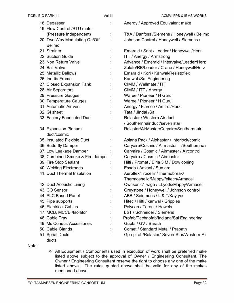
TICEL BIO PARK-III Vol-III ACMV, FPS & IBMS WORKS
EC: TAAMAESEK ENGINEERING CONSORTIUM Page 82
18. Degasser : Anergy / Approved Equivalent make
19. Flow Control /BTU meter
(Pressure Independent) : T&A / Danfoss /Siemens / Honeywell / Belimo
20. Two Way Modulating On/Off : Johnson Control / Honeywell / Siemens /
Belimo
21. Strainer : Emerald / Sant / Leader / Honeywell/Herz
22. Suction Guide : ITT / Anergy / Armstrong
23. Non Return Valve : Advance / Emerald / Intervalve/Leader/Herz
24. Ball Valve : Zoloto/RB/Leader / Crane / Honeywell/Herz
25. Metallic Bellows : Emarald / Kori / Kanwal/Resistoflex
26. Inertia Frame : Kanwal /Sai Engineering
27. Closed Expansion Tank : CIMM / Wellmate / ITT
28. Air Separators : CIMM / ITT / Anergy
29. Pressure Gauges : Waree / Pioneer / H Guru
30. Temperature Gauges : Waree / Pioneer / H Guru
31. Automatic Air vent : Anergy / Flamco / Amtrol/Herz
32. GI sheet : Tata / Jindal /Sail
33. Factory Fabricated Duct : Rolastar / Western Air duct
/ Southernnair duct/seven star
34. Expansion Plenum : Rolastar/AirMaster/Caryaire/Southernnair
duct/cosmic
35. Insulated Flexible Duct : Asiana Pack / Alphastar / Interlock/comic
36. Butterfly Damper : Caryaire/Cosmic / Airmaster /Southernnair
37. Low Leakage Damper : Caryaire / Cosmic / Airmaster / Aircontrol
38. Combined Smoke & Fire damper : Caryaire / Cosmic / Airmaster
39. Fire Stop Sealant : Hilti / Promat / Birla 3 M / Dow coning
40. Welding Electrodes : Essab / Advani / Sun arc
41. Duct Thermal Insulation : Aeroflex/Trocellin/Thermobreak/
Thermosheild/Mappy/feltech/Armacell
42. Duct Acoustic Lining : Ownsonic/Twiga / LLyods/Mappy/Armacell
43. CO Sensor : Greystone / Honeywell / Johnson control
44. PLC Based Panel : ABB / Seiemens / L & T/Kay yes
45. Pipe supports : Hitec / Hilti / kanwal / Gripples
46. Electrical Cables : Polycab / Torent / Hawels
47. MCB, MCCB /Isolator : L&T / Schneider / Siemens
48. Cable Tray : Profab/Technofab/Indiana/Sai Engineering
49. Ms Conduit Accessories : Gupta / GV / Barath
50. Cable Glands : Comet / Standard Metal / Prabath
51. Sprial Ducts : Gp spiral /Rolastar/ Seven Star/Western Air
ducts
Note:-
All Equipment / Components used in execution of work shall be preferred make listed above subject to the approval of Owner / Engineering Consultant. The Owner / Engineering Consultant reserve the right to choose any one of the make listed above. The rates quoted above shall be valid for any of the makes mentioned above.

TICEL BIO PARK-III Vol-III ACMV, FPS & IBMS WORKS
EC: TAAMAESEK ENGINEERING CONSORTIUM Page 83
Country of Origin shall be USA/INDIA/EUROPE
1.16.0 LIST OF DRAWINGS
SI NO NAME OF DRAWING REMARKS
1 Ground Floor ACMV Layout. For tender
2 Typical Floor ACMV Layout. (1st ,3 st ,7 th ,9 th FLOORS)
For tender
3 Typical Floor ACMV Layout. (2nd ,4th ,6th ,10th ,12th FLOORS)
For tender
4 Typical Floor ACMV Layout. (5th ,11 th FLOORS)
For tender
5 8 th FLOOR HVAC LAYOUT For tender
6 13 th FLOOR HVAC LAYOUT For tender
7 Terrace Floor ACMV Layout. For tender
8 Plant Room Layout – Chillers. For tender
9 Chilled Water Schematic Layout. For tender
10 Utility Building Ventilation Layout. For tender

TICEL BIO PARK-III Vol-III ACMV, FPS & IBMS WORKS
EC: TAAMAESEK ENGINEERING CONSORTIUM Page 84
2. INTELLIGENT BUILDING MANAGEMENT SYSTEM
2.1 Building Management System 2.1.1 System Description UL Listed, 32 bit Microprocessor based Direct Digital Controllers (DDC) with real time clock shall interface with sensors, actuators and environmental control systems (i.e. HVAC units, chillers, pumps, electrical & plumbing system etc.) and carry out followings functions:
A. Individual input/output point scanning, processing and control.
B. Centralized operation of the building (remote control).
C. Dynamic graphic details of plant and building.
D. Alarm Detection and early recognition of faults.
E. Time, event and holiday scheduling as well as temporary scheduling.
F. Prevention of unauthorized or unwanted access.
G. Communication interface and control.
The control system shall be designed such that mechanical equipment will be able to operate under de-centralized control. In general, the operation of any controllers on the network shall not rely on any other controller for its functional operation. System controllers that require a master computer will not be considered. Function specific modules may be used to supplement the functionality resident in each controller. As such, in the event of a network communication failure or the loss of any other controller, the control system shall continue to independently operate under local control of the resident program stored in nonvolatile memory as detailed herein. In such a case, each individual controller shall continue to perform basic functions until a network connection can be restored. 2.1.1.1 Native multiple Protocols The Building Management System (BMS) shall be comprised of Controllers & Third Party Integration Units. The Controllers (DDC) shall connect to the local or wide area network, depending on configuration. Access to the system, either locally in each building, or remotely from a central site or sites, shall be accomplished through standard Web browsers, via the Internet and/or local area network. Each Controllers shall communicate to BACnet IP/Lonmark IP 852.

TICEL BIO PARK-III Vol-III ACMV, FPS & IBMS WORKS
EC: TAAMAESEK ENGINEERING CONSORTIUM Page 85
2.1.1.2 Networks
The Local Area Network (LAN) shall be a 100 Megabits/sec Ethernet network supporting BACnet, Java, XML, HTTP, and SOAP for maximum flexibility for integration of building data with enterprise information systems and providing support for multiple Network Area Controllers (NACs), user workstations and, if specified, a local server. Local area network minimum physical and media access requirements:
1. Ethernet; IEEE standard 802.3
2. Cable; 100 Base-T, UTP-8 wire, category 5
3. Minimum throughput; 100 Mbps.
2.1.1.3 Web access
Each Controller (DDC) must have the ability to serve out web pages containing the same information that is available from the WorkStation. The development of the screens to accomplish this shall not require any additional engineering labor over that required to show them at the WorkStation itself. No additional software, other than a Java supported network browser, shall be required.
2.1.1.4 Graphics The system shall use FBD/Scalable Vector Graphics (SVG) technology. Change in monitor or screen resolution should not affect the graphics quality and ratio.
2.1.1.5 Integration with existing system The System should seamlessly integrate with the existing system such that existing system can be easily accessed through new system. The number of controllers for central plant room equipments shall be decided by the contractor with a maximum capacity limited to 160 points per controller. Overall, the system shall be provided with 10% spare capacity, with spare of at least 10% points on each controller. There shall be one control station located in Chief Engineer Room. The computer shall be sized to cover the graphic display memory and planning information. The display shall be in the form of dynamic color graphics and text format with menu driven pop-up windows and help facility.
2.1.1.6 Reports
The system should be capable of providing user defined custom dashboard based reports. Reports shall be pulled or mailed automatically to the designated mail ids without using SNMP and also be stored on the local server simultaneously. Reporting should have User-friendly functionality, including drag-and-drop trending, one-click reporting, interactive graphics, calendar-like scheduling, and easy-to-use alarms, lets you focus on optimizing your buildings, rather than just running them.
Software shall be able to generate customized reports as per client requirement.
System shall be capable to generate reports in Excel, PDF & Graphical formats.
2.1.1.7 Alarming, Trending & Scheduling System shall generate & store the alarms & there shall be pop up for critical/as defined by Customer/Consultants.
System shall be capable to generate the trends for energy data for analysis purpose.
Scheduling shall also be possible through system as required at site.

TICEL BIO PARK-III Vol-III ACMV, FPS & IBMS WORKS
EC: TAAMAESEK ENGINEERING CONSORTIUM Page 86
2.1.2 Central Station Hardware The Control stations shall comprise of Personal computers (PC) providing high-level operator interface with the system. The terminals shall be capable of providing the operator with the facility for remote system interrogation, control, and retrieval /storage of logged data, annunciation of alarms and reports, analysis of recorded data and the formatting of management reports. The control station shall consist of the following hardware with all of them suitable for the power
supply voltage of 230 V AC ± 10%, 50 HZ + 3%.
2.1.2.1 FEATURES DESCRIPTION
Processor Intel Core i7 Processor Memory 8 GB RAM Cache 4MB Cache Graphic Accelerator High Speed Graphic Accelerator Hard Disk 1 TB HDD, 10/100 Mbps Ethernet card SATA Hard Drive Power Supply 350 W switchable/50 Hz Keyboard 104 keys window keyboard Operating System Microsoft(R) Windows(R) 8 or better or latest OS Professional
Enterprise/ 32 or 64 bit processor Software As per System requirement Desktop Manager Based on SNMP protocol Network 100 Mbps Network Interface Card with wake on LAN support CD Writer 16X DVD burner (DVD+/-RW), write to DVD
Key board: The central station shall be complete with detached keys keyboard which includes full upper/lower case, a numeric pad, dedicated cursor control pad, and a minimum of 10 programmable functional keys. Colour Monitor: The colour monitors shall be with a minimum 24 inch diagonal nonglare LED screen and minimum Super resolution of minimum 1024 pixels horizontal, 768 lines vertical and minimum 16 base colors. Mouse: For keyboardless operation, in addition to the enhanced keyboard, a mouse shall also be provided as an alternative user interface for day to day system operation. Mouse pads shall be provided for mouse. Printers: The contractor shall provide printers as specified in the BoQ for printing alarms, operator transactions and reports. It shall be dedicated for alarm printing, printing reports, trend log, summary, totalizer logging, recording alarms and providing system reports etc. Printer shall be Laser Jet, black & white A-4 size printers.
2.1.3 Central Station Software 1. As a minimum, the menu driven command and operating software shall permit the operator
to perform the following tasks with a minimum knowledge of the HVAC Control System provided and basic computing skills.
i. Configure the network. ii. Create control sequences. iii. Graphical interface to systems.

TICEL BIO PARK-III Vol-III ACMV, FPS & IBMS WORKS
EC: TAAMAESEK ENGINEERING CONSORTIUM Page 87
2. Security: Each operator shall be required to log on to that system with a user name and password in order to view, edit, add, or delete data. System security shall be selectable for each operator. The system supervisor shall have the ability to set passwords and security levels for all other operators. Each operator password shall be able to restrict the operator‟s access for viewing and/or changing each system application, full screen editor, and object. Each operator shall automatically be logged off of the system if no keyboard or mouse activity is detected. This auto log-off time shall be set per operator password. All system security data shall be stored in an encrypted format.
3. System Diagnostics: The system shall automatically monitor the operation of all HVAC
control workstations, printers, modems, network connections, and nodes. The failure of these devices shall be annunciated to the operator.
4. Reports and Logs: Provide a reporting package that allows the operator to select, modify, or
create reports. Each report shall be definable as to data content, format, interval, and date. Report data shall be archived on the hard disk for historical reporting. Provide the ability for the operator to obtain real time logs of designated lists of objects. Reports and logs shall be stored on the PC hard disk in a format that is readily accessible by other standard software applications including spreadsheets and word processing. Reports and logs shall be readily printed to the system printer. Data shall be able to transferable to other software packages so as to create custom reports.
5. Web Browser Access: The DDC system shall provide total integration of the facility
infrastructure systems with user access to all system data, either locally over a secure Intranet within the building or by remote access by a standard Web Browser over the Internet.
IBMS Software shall be a fully integrated Human Machine Interface (HMI) solution that enables customers to increase return on assets by delivering a highly scalable, reliable control and monitoring system. The Software architecture shall provide the advanced clustering technology available and help safeguard plant reliability. It shall also extend the benefits to rapid-change deployment and a number of other enhancements that help increase security and maximize engineering productivity. Also the following parameters shall be ensured through the Central Management System Software but not limited to the same Provide view across existing control systems Provide a combination of control (including alarms, reports and trends), local to the
process, paired with a central standby server Support additional processing for expansion requirements by simply adding a new I/O
Modules and/or servers to the control system Segment your control system to ensure changes in one business unit do not affect the
others Connect to multiple control systems to analyze the alarms and trend data directly from
the similar systems Use cluster swapping to re-use graphics screens between matching systems or for
simulation or replay Reduced code overhead by processing code only when tags change Simplified logging of users‟ actions Support for MS Windows XP-embedded Support for Virtual Machine environments Dynamic-point licensing whereby customers only pay for the points they use

TICEL BIO PARK-III Vol-III ACMV, FPS & IBMS WORKS
EC: TAAMAESEK ENGINEERING CONSORTIUM Page 88
BMS software shall be easily integrated with all existing business systems using software Reports, which connects the building and business database systems to facilitate plant-wide reporting, leading to increased production and profitability. In addition, it shall allow transformation, analyze and present real-time information throughout the enterprise for prioritized decision-making. Web Client of the software shall be of zero-maintenance, fully functional client that can be viewed using Internet Explorer. This web client shall allow all users throughout an enterprise to take advantage of real-time information by providing easy access to the BMS system. Software shall allow operators and process engineers to analyze the cause of process disturbances by bringing together trend and alarm data, which traditionally has been stored separately. The central software shall provide an operating environment, which enables the following functions. The user must able to query or change any point in the system (save or reload a controller database or generate a system report) from a single command line. Control Schedules: time of day scheduling shall be arranged in a monthly format. Multiple days, weeks or months shall be programmable from a single schedule. Scheduling shall be capable of one year in advance configuration. Multiple week and month selection shall allow the user to define a schedule over the elected. Range: The user shall also be allowed to select individual days over a selected range during configuration (example Mondays, Wednesday and Fridays for the months of February and March). This selection shall be capable of overriding the existing schedules for those days or apprehending to them. The range selectable shall cover a minimum of twelve months. This system must possess the ability to copy a schedule for any day, range of days, months, range of months or entire year within its own schedule calendar or between calendars. It must also allow the user to view an entire week at one time. The system must allow for a logical arrangement between equipment and schedules so that devices and schedules being configured for interaction may form an English language component relationship. The ability to configure a holiday schedule for any or all days of a selected range shall be vial a one year calendar format. Holiday schedules shall be stored vial user defined names for repetitive use and later data selectivity via menu options. Holidays shall be superimposed (or overlapped) in a yearly format onto a base schedule therefore taking priority for each day which has been defined within the holiday schedule. Holidays shall be differentiated on the calendar vial color-coded dating for quick and visual acknowledgment. Any changes made to a holiday schedule shall automatically be made to any base schedule without the need to select the Holiday schedule. The ability to configure a special day schedule shall be via a one-year format. Special day schedules shall be stored via user defined names for repetitive use and later data select ability via menu options. Special days shall be superimposed (or overlapped) in a yearly format onto a base schedule hence taking top priority for each day which has been defined within the special day schedule. Special day shall be differentiated on the calendar vial color-coded dating for quick and visual acknowledgment. Any changes made to a special day schedule shall automatically be made to any base schedule to which it has been superimposed. Special days must represent on the base schedule without the need to select the special day's schedule.

TICEL BIO PARK-III Vol-III ACMV, FPS & IBMS WORKS
EC: TAAMAESEK ENGINEERING CONSORTIUM Page 89
The system shall allow for the user to define a single schedule for any or all devices configured in the system. Any change made to this single schedule will automatically be down loaded to all controllers. Report Generation: The system shall contain a full text editor for the creation of custom reports. All reports created shall have full access to the systems database for the purpose of embedding any selected point into a report location for ease of display and view. The system shall permit full programmability for report generation. The following logical and mathematical operators must provide. Greater than, equal to, not equal to, add, subtract, multiply, divide, square root, and/or comparators, absolute value and modules. All of the above operators shall be capable of being used in an easy to follow English language based program to trigger generation and/or change formats of specific reports. The system shall allow for report grouping so that pre-defined or selected reports may be generated by a single request. The report generator shall have the ability to conduct mathematical calculations at report time so as not to burden the CPU with processing which will not be required until generation time. A report shall be configurable to ask for user input, which can be used in the calculation
and generation of a report. The system must include a programmable looping function to allow for the repeated
generation of one report containing different data. A report must be capable of being configured to invoke other executable software
programs at generation time. All report programs shall be capable of time of day, day of week, or day of year
scheduling. Standard report generation to be provided by the manufacturer with the system shall include: System Points Status summary - Print out in text format descriptor, value, status an
engineering unit of each system point. Alarm Summary - Print out in text format descriptor, value, status and engineering unit of
each point in alarm. Historical Trend - System shall have software capable of sampling points at periodic
intervals and logging values for future reporting. Dynamic Trending - System shall have software capable of plotting dynamic line graphs,
bar charts curve plots and pie charts for up to six values. Point Definition - The system shall incorporate a single screen forms based points editor which shall allow for both a terse system name and a verbose descriptive name to be assigned for all points configured in the system. The number of points, which are configurable for any device, shall only be limited by hard disk space. All points in the system shall be accessible via an on-line directory for immediate use to avoid the need for point’s reference notebooks or any other written material. Point grouping shall be allowed so that operator defined groups allows the recall by name to view the status of a pre-selected group of points. Automatic and manual storage and reload ability of full programming database and point‟s configuration for stand-alone controllers. The GUI shall employ browser-like functionality for ease of navigation. It shall include a tree view (similar to Windows Explorer) for quick viewing of, and access to, the hierarchical structure

TICEL BIO PARK-III Vol-III ACMV, FPS & IBMS WORKS
EC: TAAMAESEK ENGINEERING CONSORTIUM Page 90
of the database. In addition, menu-pull downs, and toolbars shall employ buttons, commands and navigation to permit the operator to perform tasks with a minimum knowledge of the HVAC Control System and basic computing skills. These shall include, but are not limited to, forward/backward buttons, home button, and a context sensitive locator line (similar to a URL line), that displays the location and the selected object identification. Programming software shall be same as GUI. The Same GUI can be used to configure the DDCs & NAC.
2.1.4 Bacnet IP DDC / 3rd Party Interface Controller a. All DDCs (controller), 3rd party interface controller, shall be UL and BTL certified, 32-bit
microprocessor with real time operation system. b. DDCs shall Modular/Standalone types – The Controllers & IO Modules both shall have built
in LCD displays, to monitor & control the IOs connected to the Controllers c. Programming shall be object oriented using control program blocks by means of the
Visual/Login programming system. Provide documentation in flow chart form for all programming as part of the final system as-built documentation. Include samples of flow chart documentation in submittals. All flow charts shall be generated with Visual/Logic system and automatically downloaded to controller. No reentry of database shall be necessary.
d. Provide means to view inputs and outputs to each program block in real time as program is executing. This function may be done via the operator's terminal, field computer or via modem.
e. Power failure safety data and programs are secured on internal flash memory failing which built in battery backup should be present. Real time clock will be provided in the controller
f. Modular controller shall have the capability to handle the maximum no. of hard wired data points not more than 100 hard points.
g. A/D and D/A converters and/or multiplexer (MUX) shall not be allowed for increasing IO points in DDCs.
h. Max of 5 IO Modules will be allowed on one DDC. i. Each controller shall have built in Memory to save graphics in controllers j. Each controller shall have built in two Ethernet ports k. Power supply to power up the controller shall be UL Listed l. The controller shall have the additional approval requirements, listings, and approvals:
1. UL/ listed under UL916 (Standard for Open Energy Management Equipment) with plenum rating.
2. BTL Listed / Lon Mark certified, vendor has to submit the certificates at the time of approval
A. Remote Communication
1. Provide all functions that will allow remote communications via modern to off-site locations. Include modem along with all cabling necessary for installation.
2. Provide Windows 10 software for off-site computer, which allows operator to view, and change all information associated with system on color graphic displays if desired. Operator shall be able to change all parameters in this section form off-site location including all programming of global controllers and programmable terminal unit controllers.
B. Schedules
1. Each schedule object (Weekly or Exception) shall be capable of performing an optimum start. Optimum start calculation shall be based on outside air temperature, zone air temperature deviation from zones daytime cooling set points, and individual zone adaptive cooling

TICEL BIO PARK-III Vol-III ACMV, FPS & IBMS WORKS
EC: TAAMAESEK ENGINEERING CONSORTIUM Page 91
coefficients that are adjusted each day based on performance parameters of the individual zone.
C. Alarm Generation
1. Object type change of values and change of states may be identified as alarm conditions. This summary of active alarms (Event State property value not equal to NORMAL) is presented to and displayed at the operator's terminal for system user action. Alarm may be generated within the system for any object type change of value or state either real or calculated. This includes things such as analog object type value changes, binary object type state changes, and various controller communication failures. 2. Alarm log shall be provided for viewing of alarms. Log may be viewed in-site at the operator's terminal/ controller or off-site remote communications.
D. Demand Limiting
System shall monitor energy demand. Energy demand may be form any type of energy source such as electrical or gas. Provide a demand limiting routing which shall shed appropriate system objects types to prevent the demand from exceeding preset limits. Demand limiting routine shall be a priority shed type allowing automatic override of specified object type sheds when assigned analog object (temperature sensor) exceeds limits as set by system user at operator's terminal. The DDC‟s shall have 10% spare capacity (digital/analog input/output) to give flexibility for future expansion. All DDC controllers shall be capable of handling voltage, milli-ampere, resistance or open and closed contacts inputs in any mix, if required. Analog Inputs/outputs of the following minimum types shall be supported:
i. 4-20 mA. ii. 0-10 volts. iii. 2-10 volts. iv. vi) Resistance Signals (either PTC or NTC like PT 100, PT 1000, NI 1000)
Digital input/output types to be supported shall be, but not limited to the following:
i. Normally-open contacts. ii. Normally-closed contacts.
Modulating outputs shall be true proportional outputs and not floating control type. Controller’s packaging shall be such that, complete installation and check out of field wiring can be done prior to the installation of electronic boards. All board terminations shall be made via plug-in connectors to facilitate troubleshooting, repair and replacement. Soldering of connections shall not be permitted. Controllers shall preferably be equipped with diagnostic LED indicators with at least indication for Power up Test OK etc.

TICEL BIO PARK-III Vol-III ACMV, FPS & IBMS WORKS
EC: TAAMAESEK ENGINEERING CONSORTIUM Page 92
It shall be possible for the controllers to accept regulated uninterrupted power supply to maintain full operation of the controller functions (control, logging, monitoring and communications) in the event of a localized mains failure. There shall be the facility for programming / accessing the controllers (DDC) locally, via either an integrated GUI display, access to the system thus provided shall be restricted by passwords in the same way as at the main operator terminal. The controllers shall be housed in vandal proof enclosures to protect them from tampering by any unauthorized personnel. All DDC controllers used in plant room spaces and external application shall be housed IP66/IP54 rating enclosures. It shall be possible to add new controllers to the system without taking any part of the system off-line. Detailed description of software features and operating sequence of all available energy management software shall be submitted with the tender for evaluation by the Consultant. Alarm Lockout shall be provided to prevent nuisance alarms. On the initial start up of air handler and other mechanical equipment a “timed lockout” period shall be assigned to analog points to allow them to reach a stable condition before activating an alarm comparison logic. Tenderers shall indicate their proposed system alarm handling capability & features. Run time shall be accumulated based on the status of a digital input point. It shall be possible to total either ON time or OFF time. It shall be possible to accommodate Holiday and other planned exceptions to the normal time programs. Exception schedules shall be operator programmable up to one year in advance.
2.1.5 Data Communication
The communication between controllers shall be via a dedicated communication network as per recommended standards. Controller’s microprocessor failures shall not cause loss of communication of the remainder of any network. All networks shall support global application programs, without the presence of a host PC. Every DDC must be capable of communicating with other DDC‟s either peer to peer or through an IP network.
2.1.6 Field Devices
2.1.6.1 Electric and Electronic Control Equipments
General Requirements a. All controls shall operate in ambient conditions varying between 0- 50 deg C and 90%
R.H. non-condensing. b. Ancillary Items
When items of equipment are installed in the situations listed below, the BAS contractor shall include the following ancillary items: (i) Weather Protection

TICEL BIO PARK-III Vol-III ACMV, FPS & IBMS WORKS
EC: TAAMAESEK ENGINEERING CONSORTIUM Page 93
All devices required to be weather proofed shall be as per manufacturer recommendation or as detailed in the BoQ. IP ratings required for the equipment is mentioned in the respective section. All devices required to be weatherproofed shall be as per manufacturer recommendation or as detailed in the Schedule of Quantities. IP ratings required for the equipment is mentioned in the respective section. (ii) Pipework Immersion Corrosion resisting pockets of a length suitable for the complete active length of the device, screwed ½” (13 mm) or ¾” (20 mm) NPT suitable for the temperature, pressure and medium. (iii) Duct Mounting (Metal or Builders Work) Mounting flanges, clamping bushes, couplings, locknuts, gaskets, brackets, sealing glands and any special fittings necessitated by the device. 2.1.6.2 Temperature Sensor a. Temperature sensors for space, pipes and ducts shall be of the resistance temperature
detector (RTD) type or thermistor. These shall be two wire type and shall conform to the following specifications.
b. The sensors shall be high accuracy type with a high resistance versus temperature change. The accuracy shall be at least ±0.15°C @ 0°C (±0.28°F@ 32°F).
c. Immersion sensors shall be provided with separate stainless steel thermo well. d. The connection to the pipe shall be screwed (½ inch NPT) (M). An aluminum sleeve shall be
provided to ensure proper heat transfer from the well to the sensor. e. The sensor housing shall plug into the base so that the same can be easily removed without
disturbing the wiring connections. f. Duct temperature sensors shall be with rigid stem and of averaging type. These shall be
suitable for duct installation. g. The sensors shall not be mounted near any heat source such as windows, electrical
appliances etc. h. The temperature sensors may be of any of the following types:
1. PT 100, PT 1000, PT 3000 2. RTD 3. Thermistor
2.1.6.3 Duct Temperature and Humidity Sensor
a. The sensors shall have Relative Humidity Range: 0 to 100% RH. Temperature Range: -40 to 140°F (-40 to 60°C).
b. RH sensor accuracy shall be ±3% 20-80% RH @ 25°C. Temperature sensor accuracy shall be Thermistor Temp Sensor: ±0.22°C @ 25°C (±0.4°F @77°F). And for RTD Temp Sensor: ±0.3°C @ 0°C (±0.54°F @ 32°F).
c. The Output of the sensor shall be RH Sensor: 4-20 mA and for Temperature Sensor: RTD or pt-1000.
d. The sensor housing shall plug into the base so that the same can be easily removed without disturbing the wiring connections.
e. The sensors shall not be mounted near any heat source such as windows, electrical appliances etc.

TICEL BIO PARK-III Vol-III ACMV, FPS & IBMS WORKS
EC: TAAMAESEK ENGINEERING CONSORTIUM Page 94
2.1.6.4 Water Meter
a. Water flow meters shall be flanged type. The meter shall have long-term measuring stability and high reliability. The flow sensor shall be designed for temperatures up to 120°C with safety up to 130°C. The meter shall be with high measuring accuracy and excellent measuring stability.
b. The meter shall have pulsed output with the following specifications:
Switch type Reed switch proximity sensor Contracts Volt free Max. load current 500mA Max. Switching voltage 180Vdc Max. contact rating 10W Connection type Flying lead Lead length 2 Meters
The exact ranges to be set shall be determined by the contractor at the time of commissioning. It should be possible to „zero‟ the flow meter without any external instruments, with the overall accuracy of at least ± 1% full scale. 2.1.6.5 Duct Static Pressure Transmitter F or Air These sensors shall be used to measure the pressure across the ducts. Output shall be 4-20mA or 0-10V DC and the range as specified in the data sheet depending on the duct pressure. Power supply shall be either 24 V AC or 24 V DC. Connection shall be as per manufacturer’s standards. The sensor shall have temperature limits of 0 to 150°F (-18 to 66°C) and pressure limits of 1 psi maximum, operation; 10 psi, burst.
2.1.6.6 Duct Mount CO2 Sensor These sensors shall be used to measure the pressure the CO2 level across the ducts. Output shall be 4-20mA or 0-10V DC and the range shall be of 0-2000 ppm. Power supply shall be either 24 V AC or 24 V DC. Connection shall be as per manufacturer’s standards. The sensor shall have accuracy of ±40 ppm ±3% of reading. The sensor shall response time of 2 min for 99% step change. The housing of the sensor shall be NEMA 4X (IP66).
2.1.6.7 Differential Pressure Switch for Air Systems a. These switches shall be used to measure the filter dirty status and the fan run status of the
HVAC units. The switch range shall be of 200-1000 pa. Connection shall be as per manufacturer’s standards. The enclosure of the switch shall be NEMA 13 (IP54).
b. The switch shall be of differential pressure type complete with connecting tube and metal bends for connections to the duct.
c. The pressure switches shall be available in minimum of 2 ranges suitable for applications like Air flow proving, dirty filter, etc. The set point shall be concealed type. The contact shall be SPDT type with electrical rating of Electrical Rating: Max. 1.5 A res./0.4 A ind./250 VAC, 50/60 Hz; Max. switching rate: 6 cycles/min.
d. The switch shall be supplied suitable for wall mounting on ducts in any plane. The switches shall be provided with site adjustable scale and with 1 set of NO/NC contacts.
2.1.6.8 Ambient TRH Sensor a. These sensors shall be used to measure the ambient temperature and relative humidity
value. b. The sensors shall have Relative Humidity Range: 0 to 100% RH. Temperature Range: -40
to 140°F (-40 to 60°C).

TICEL BIO PARK-III Vol-III ACMV, FPS & IBMS WORKS
EC: TAAMAESEK ENGINEERING CONSORTIUM Page 95
c. RH sensor accuracy shall be ±3% 20-80% RH @ 25°C. Temperature sensor accuracy shall be Thermistor Temp Sensor: ±0.22°C @ 25°C (±0.4°F @ 77°F). And for RTD Temp Sensor: 0.3°C @ 0°C (±0.54°F @ 32°F).
d. The Output of the sensor shall be RH Sensor: 4-20 mA and for Temperature Sensor: RTD or pt-1000.
e. The sensor housing shall plug into the base so that the same can be easily removed without disturbing the wiring connections.
f. The sensors shall not be mounted near any heat source such as windows, electrical appliances etc.
2.1.6.9 IAQ Sensor These sensors shall be used to measure the pressure the CO2 level in the space. Output shall be 4-20mA or 0-10V DC and the range shall be of 0-2000 ppm. Power supply shall be either 24 V AC or 24 V DC. Connection shall be as per manufacturer’s standards. The sensor shall have accuracy of ±40 ppm ±3% of reading. The sensor shall response time of 2 min for 99% step change. The housing of the sensor shall be IP54.
2.1.6.10 Air Flow Measuring Station These sensors shall be used to measure the airflow across the ducts. Output shall be 4-20mA or 0-10V DC and the range as specified in the data sheet depending on the requirement of the duct size. Power supply shall be either 24 V AC or 24 V DC. Connection shall be as per manufacturer’s standards. The sensor shall have Low signal-to-noise ratio, galvanized casing and 6063-T5 anodized aluminum flow sensors.
2.1.6.11 Level Switch The level switches shall have to meet the following requirement:
Type : Float Type/Capacitance type/Conductivity type Mounting : To suit application. Float material : 316 SS Stem Material : 316 SS Output: Potential free Switch Enclosure: IP 55
2.1.6.12 Enclosures for Controllers and Electrical Panels
All the controllers shall be housed in Lockable Vandal proof enclosures which shall either be floor mounted or wall mounted. These shall be free standing, totally enclosed, dust and vermin proof and suitable for tropical climatic conditions. All panels and covers shall be properly fitted and secured with the frame and holes in the panels correctly positioned. Fixing screws shall enter into holes tapped into an adequate thickness of metal or provided with nuts. Self threading screws shall not be used in the construction of control panels. Knockout holes of approved size and number shall be provided in the panels in conformity with the location of incoming and outgoing conduits/cables.
2.1.6.13 Conduits and Wiring
Prior to laying and fixing of conduits, the contractor shall carefully examine the drawings indicating the layout, satisfy himself about the sufficiency of number and sizes of conduits, sizes and location of conduits and other relevant details. Any discrepancy found in the drawings shall be brought to the notice of Architect/Engineers. Any modifications suggested by the client shall be got approved by the Architect /Engineers before the actual laying of conduits is commenced.

TICEL BIO PARK-III Vol-III ACMV, FPS & IBMS WORKS
EC: TAAMAESEK ENGINEERING CONSORTIUM Page 96
2.1.6.14 Conduits Conduits and accessories shall conform to relevant Indian Standards. PVC/MS conduits of required dia shall be used as called for in the schedule of quantities. Joints between conduits and accessories shall be securely made. PVC FRLS shall be used in concealed areas of indoor locations; MS conduits shall be used in open areas of an indoor locations and GI conduits for outdoor location. The conduits shall be delivered to the site of construction in original bundles and each length of conduit shall bear the label of the manufacturer. 2.1.6.15 Connections All jointing methods shall be subject to the approval of the Architect/Engineer. Separate conduits shall run for all power wiring. The threads and sockets shall be free from grease and oil. Connections between conduit and controller metal boxes shall be by means of brass hexagon smooth bore bush, fixed inside the box and connected through a coupler to the conduit. The joints in conduits shall be smooth to avoid damage to insulation of conductors while pulling them through the conduits.
2.1.6.16 Bends in Conduit Where necessary, bends or diversions may be achieved by means of bends and/or circular inspection boxes with adequate and suitable inlet and outlet screwed joints. In case of recessed system each junction box shall be provided with a cover properly secured and flush with a finished wall surface. No bends shall have radius less than 2-1/2 times the outside diameter of the conduit.
2.1.6.17 Cable Trays Prior to laying and fixing of trays, the contractor shall carefully examine the drawings indicating the layout, satisfy himself about the sufficiency of number and sizes of trays, sizes and location of trays and other relevant details. Any discrepancy found in the drawings shall be brought to the notice of Architect/Engineers. Any modifications suggested by the client shall be got approved by the Architect /Engineers before the actual laying of trays is commenced. The trays shall be perforated powder coated tray with cover and shall have support rods and brackets at regular intervals to find the cables in position with necessary accessories like bends, couplers etc.
2.1.6.18 Signal & Communication Cable
1 Signal Cable for Digital Input & Output
No of Core 2 / 4 Type of Conductor Annealed Tinned Copper Size of Conductor 1.0 Sq. mm. Insulation Material PVC Outer Sheath Material FRLS Screened / Unscreened Unscreened Shielded / Unshielded Unshielded Armoured / Unarmoured Unarmoured
2 Signal Cable For Analog Input & Output

TICEL BIO PARK-III Vol-III ACMV, FPS & IBMS WORKS
EC: TAAMAESEK ENGINEERING CONSORTIUM Page 97
No of Core 2 / 4 Type of Conductor Annealed Tinned Copper Size of Conductor 1.0 Sq. mm. Insulation Material PVC Outer Sheath Material FRLS Screened / Unscreened Screened Shielded / Unshielded Shielded Armoured / Unarmoured Unarmoured
3 Communication Cable for Third Party Integration
No of Core 2 Type of Conductor Annealed Tinned Copper Size of Conductor 1.5 Sq. mm. Number of Twist 16 to 18 Nos Insulation Material Polyethylene / PVC Outer Sheath Material FRLS Screened / Unscreened Screened Shielded / Unshielded Shielded Armoured / Unarmoured Unarmoured
4 Category 6 Cable
Type of Category Cable CAT6 Unshielded Twisted Pair No of conductors 4 pair Conductor Size 23AWG Type of conductor Copper Operating speed 10 / 100 / 1000 Mbps Bandwidth 250MHz Armoured / Unarmoured Unarmoured
2.1.6.18 AHUs IO Schedule
Total AHUs: 55Nos Shown below is for one AHU
SNo Description AI DI DO AO Remarks
1 AHU Temperature Sensor 1 Return Air Temperature
2 AHU Auto/Manual Status 1
3 AHU Start/Stop Command 1
4 AHU Run Status 1
5 AHU Trip Status 1
6 Filter Status 1 Filter Health
7 Fire Damper Control & Status* 1 1 *Only selected floors
8 VFD Control & Feedback 1 1
9 Chilled Water Valve Control, & Feedback 1 1
Total 3 5 2 2
Spare 1 1 1 1
Total inclusive of Spares 4 6 3 3
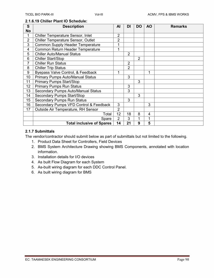
TICEL BIO PARK-III Vol-III ACMV, FPS & IBMS WORKS
EC: TAAMAESEK ENGINEERING CONSORTIUM Page 98
2.1.6.19 Chiller Plant IO Schedule:
S No
Description AI DI DO AO Remarks
1 Chiller Temperature Sensor, Inlet 2
2 Chiller Temperature Sensor, Outlet 2
3 Common Supply Header Temperature 1
4 Common Return Header Temperature 1
5 Chiller Auto/Manual Status 2
6 Chiller Start/Stop 2
7 Chiller Run Status 2
8 Chiller Trip Status 2
9 Byepass Valve Control, & Feedback 1 1
10 Primary Pumps Auto/Manual Status 3
11 Primary Pumps Start/Stop 3
12 Primary Pumps Run Status 3
13 Secondary Pumps Auto/Manual Status 3
14 Secondary Pumps Start/Stop 3
15 Secondary Pumps Run Status 3
16 Secondary Pumps VFD Control & Feedback 3 3
17 Outside Air Temperature, RH Sensor 2
Total 12 18 8 4
Spare 2 3 1 1
Total inclusive of Spares 14 21 9 5
2.1.7 Submittals
The vendor/contractor should submit below as part of submittals but not limited to the following.
1. Product Data Sheet for Controllers, Field Devices
2. BMS System Architecture Drawing showing BMS Components, annotated with location
information.
3. Installation details for I/O devices
4. As built Flow Diagram for each System
5. As-built wiring diagram for each DDC Control Panel.
6. As built wiring diagram for BMS

TICEL BIO PARK-III Vol-III ACMV, FPS & IBMS WORKS
EC: TAAMAESEK ENGINEERING CONSORTIUM Page 99
2.2 Fire Alarm System
2.2.1 General Requirements For Fire Alarm System
This section of the specification includes the furnishing, installation, and connection of a microprocessor controlled, addressable fire alarm equipment required to form a complete coordinated system ready for operation. It shall include, but not be limited to, alarm initiating devices, alarm notification appliances, control panels, auxiliary control devices, power supplies, and wiring as per shop drawings and specified herein. The design should confirm to the Fire and Life Safety requirements (Occupancy Classification Group-E) of National Building Code of India or requirements of NFPA Standard No. 72 for protected premises signaling systems except as modified and supplemented by this specification. The system shall be supervised either electrically or by software-directed polling of field devices and adhere to the design guidelines mentioned there in. Fire Detection & Alarm System is a key element of the fire protection system. It is designed to detect the presence of fire to initiate action. The type of fire alarm system considered is Analogue Addressable Fire Detection & Alarm System. The system shall be designed such that each loop shall limited to only 80% of its total capacity at initial installation. The Fire Alarm System panel and Initiating Devices (like smoke, heat, multi sensor detectors, manual call points etc.) Notification Appliances (like sounders, strobes, horn/sirens etc.) and Building Safety Interfaces (like Monitor Modules, Control Relay Modules etc.) should be wired using Class A (Style 6 or 7) wiring unless the manufacturer recommends otherwise. The Repeater Panel can be connected to Fire Alarm System panel using RS485 Communication or Ethernet TCP/IP Communication. The wiring used shall be of fire rated (Low Smoke, and Flame Retardant and/or Zero Halogen) with sufficient cross sectional area to carry sufficient power and successful communication. The authorized representative of the manufacturer of the major equipment, such as control panels, shall be responsible for the satisfactory installation of the complete system. All equipment and components shall be installed in strict compliance with each manufacturer's recommendations. Consult the manufacturer's installation manuals for all wiring diagrams, schematics, physical equipment sizes, etc. before beginning system installation. Refer to the riser/connection diagram for all specific system installation/termination/wiring data. All equipment shall be attached to walls and ceiling/floor assemblies and shall be held firmly in place (e.g., detectors shall not be supported solely by suspended ceilings). Fasteners and supports shall be adequate to support the required load. This specification is intended to set out in general outline the minimum requirements and standards of installation for the various units of equipment and works it covers. Provision set out, or claim made in the successful tender which are in excess of, or improved upon the basic requirements of the specification shall unless otherwise determined by the client become part of the requirements of the specification whether or not they are subsequently incorporated in addenda to the specification.
The client shall be the sole judge of what constitute an improvement upon or exceeds the requirements of the specification.
TICEL BIO PARK-III Vol-III ACMV, FPS & IBMS WORKS
EC: TAAMAESEK ENGINEERING CONSORTIUM Page 100
The specification shall be read in conjunction with the tender drawings (as per schedule of drawings) and are intended to be mutually explanatory and complementary to one another. All works and specification called for by one, i.e. specification or drawings even if not by the other shall be fully executed and complied with in total. The entire system shall be engineered by the contractor based on the guidelines furnished in the specification, various codes / standards, with good engineering practice. Supplies and services to be covered under this tender specification and the conditions thereof are detailed in the subsequent sections of the specifications. In case of conflict among various sections, subsections, documents, drawings the same shall be referred to purchaser whose decision shall be final and binding to the Bidder.
2.2.2 Submittals And Shop Drawings
Sufficient information shall be clearly presented and shall include manufacturer’s name, model numbers, power requirements, equipment layout, device arrangement and complete wiring.
1. Sequence and Description of Operation.
2. Product Data for each type of equipment, initiating device, signal device, peripheral device and cable provided on the project.
3. Shop drawings shall include battery calculations, floor plans and wiring diagrams.
4. OPERATION MANUAL
a. Installation instructions for use by installing contractor.
b. Operational instructions or manual for use by building personnel, including Name
and phone number of service representative.
c. Maintenance instructions as required for use by building personnel.
d. Copy of approved shop drawings.
2.2.3 Basic System
The system shall be complete, electrically supervised fire detection with microprocessor based operating system having the following; capabilities, features and capacities. The local system shall provide status indicators and control switches for all of the following functions. Fire Alarm System panel should provide Audio, Visual notifications like audible beeps, alert, warning tones and status indicators for sprinkling system water-flow and valve supervisory devices (if any.) Any additional status or control functions as indicated on the drawings, including but not limited to: emergency generator functions, fire pump functions, door unlocking and security with bypass capabilities. Each intelligent addressable device zone on the system shall be displayed at the fire alarm control panel by a unique alphanumeric label identifying its location.
2.2.4 Reference standards The publications listed below form a part of this specification. The publications are referenced in text by the basic designation only.
INDIA NBC National Building Code of India 2005, Part – 4, Fire and Life Safety IS-2189 Selection, Installation & Maintenance of Fire Detection and Alarm System
(BRITISH / EUROPEAN)
EN 54 British Standards: Fire Detection & Alarm systems

TICEL BIO PARK-III Vol-III ACMV, FPS & IBMS WORKS
EC: TAAMAESEK ENGINEERING CONSORTIUM Page 101
NFPA-72 National Fire Protection Academy code for Fire Alarm & Public Address
System NFPA-70 National Electric Code No. 92A Smoke Control Systems NFPA-101 Life Safety Code
Underwriters Laboratories Inc. (UL) – USA
No. 50 Cabinets and Boxes No. 268 Smoke Detectors for Fire Protective Signaling Systems No. 864 Control Units for Fire Protective Signaling Systems No. 268A Smoke Detectors for Duct Applications. No. 521 Heat Detectors for Fire Protective No. 228 Door Closers-Holders for Fire Protective Signaling Systems. No. 464 Audible Signaling Appliances. No. 38 Manually Actuated Signaling Boxes. No. 346 Water flow Indicators for Fire Protective Signaling Systems. No. 1481 Power supplies for Fire Protective Signaling Systems. No. 1076 Control Units for Burglar Alarm Proprietary Protective Signaling Systems. No. 1971 Visual Notification Appliances.
2.2.5 Material And Workmanship
Unless expressed to the contrary, all materials, and equipment supplied by the contractor shall comply with the applicable Indian standards (I.S) or various codes or specifications with good practice as approved by the Indian standards. Where a standard is referred to, that standard shall be the latest published edition thereof, unless otherwise stated. All materials and equipment supplied shall be new and of the best type for each particular purpose and of the first quality with regard to design, manufacture and performance. The equipment and materials shall be suitably designed and constructed for safe, proper and continuous operation under all conditions described or implied in this specification without undue heat, strain, vibration, corrosion or other operating difficulties. Unless otherwise specified, the equipment and material within the scope of this specification shall be of a standard proven design. Design incorporating components which may be considered prototype in nature will not be accepted. Equipment and equipment components shall be designed and supported to permit free expansion and contraction without causing excessive strains, distortion or leakage. Parts subject to wear, corrosion or other deterioration, or requiring adjustment, inspection or repair shall be accessible and capable of reasonably convenient removal, replacement and repair. All such parts shall be of suitable material for keeping maintenance to a minimum. The equipment shall be designed to permit replacement of parts and ease of access during inspection, maintenance and repair. Vibration, noise, mechanical and thermal stresses and susceptibility

TICEL BIO PARK-III Vol-III ACMV, FPS & IBMS WORKS
EC: TAAMAESEK ENGINEERING CONSORTIUM Page 102
2.2.6 Fire Alarm Control Panel
The fire alarm control panel shall be microprocessor based providing rapid processing of smoke/ heat detector and other initiation device information to control system output functions. There shall be a watchdog circuit, which shall verify the system processors and the software program are running. Problems with either the processors or the system program shall activate a trouble signal, and reset the panel. The system modules shall communicate with an RS 485 network communications protocol. All module wiring shall be to terminal blocks, which will plug into the system card cage. The blocks shall be color coded to prevent accidental crossing of wiring. The control panel shall be capable of expansion via up to 8 or more Loops. A single panel / node can be used using remote cabinets and distributing the 8 Nos. of addressable loops locally in floor wise architecture. This will save the cost of wiring from floors to Main panel. Maximum system capacity shall be at least 1600 intelligent Addressable detectors & devices. The basic system shall have capabilities for up to 200 or more intelligent Addressable detectors & devices per loop of any combinations and can be expanded up to 1600 or more intelligent Addressable detectors & devices. A minimum of 150 intelligent Addressable detectors per loop shall be mandatory. The system shall employ a flexible number of detection input loops to reach maximum system capacity. Systems which, have a fixed number of device addresses per node based on a fixed number of device circuits (loops) shall provide 20% of loop maximum spare capacity on all loops to meet this requirement. LED’s on the board shall provide annunciation for the following: Power, Card Failure, Network Failure, Ground Fault, Alarm, Trouble, Loop errors. The system shall have the facility to store minimum history of 1000 Events; Shall have Automatic Environmental Compensation for Smoke Detectors, Multiple Levels of Password Protection, shall supports Pre-Action, Deluge and agent releasing, Built-in strobe synchronization, 2 notification appliance circuits , shall be Modular assembled. Shall be capable of supplying up to 24V DC, minimum1.0 Amps to NAC circuit. Detect the activation of any initiating device and the location of the alarm condition. Degrade mode operation; operate all notification appliances and auxiliary devices as programmed. In the event of CPU failure, all SLC [Signal Line Circuit loop modules shall fallback to degrade mode. Such degrade mode shall treat the corresponding SLC loop control modules and associated detection devices as conventional two-wire operation. Any activation of a detector in this mode shall automatically activate associated devices for notification. The Signal Line Circuits shall be tested for opens, shorts, ground faults, device status and multiple device response (2 devices at same address) and communications with all addressable devices installed before connection to the control panel. Systems without this capability shall have a test panel installed for initial testing to eliminate any possible damage short term or long term to the control panel. After initial testing replace the test panel and proceed with complete testing. NFPA 170 provides standard symbols used to communicate fire safety, emergency and associated hazards information. Using easily understood uniform symbols on labels and signs provide consistency, eliminate confusion, and improve communication. This standard is intended for the general public and the fire service, as well as for architectural and engineering drawings, diagrams, fire fighting operations, and pre-incident planning sketches. It includes symbology for emergency management mapping, and emergency evacuation diagrams and plans.

TICEL BIO PARK-III Vol-III ACMV, FPS & IBMS WORKS
EC: TAAMAESEK ENGINEERING CONSORTIUM Page 103
The Network Interface Card shall provide communication between enclosures. The network card supervises the network to insure proper operation. Any faults that are detected shall be reported to the display for annunciation. The network card shall isolate short circuits to each individual segment of the network. If a short occurs only the segment between the network cards will be affected. The card shall have the ability to provide Style 6 or 7 network wiring configurations. The card shall have as the minimum the following diagnostic LED; Reset, Power, Card Fail, GND Fault, and Loop Failure. Where required to monitor a large amount of relays, such as monitoring subsystems or normally open contact devices, provide a Supervised Input Module, which will monitor up to 16 inputs. Each input shall be individually programmed for supervised or non-supervised circuits. This module shall be connected to a system network. The module shall contain 2 programmable forms “C” relays for control of the monitored subsystem. The system card cage shall provide the mounting of all system cards, field wiring, and panel’s inter-card wiring. The terminal strips for the cards shall be color-coded to eliminate the possibility of making the wrong connection. The terminal blocks maybe disconnected and reconnected while the system is powered up without causing any difficulties. All power limited field wiring shall connect to the top of the card cage. All non-power limited internal wiring shall be connected to the bottom of the card cage. The card cage shall hold the systems cards and have capability of connecting multiple card cages to meet system demands.
2.2.6.1POWER SUPPLY The system Power Supply/Charger shall be a 16-amp supply with battery charger. The power supply shall be filtered and regulated. The power supply shall have a minimum of 1 power limited output rated at 4 amps, and a minimum of 1 output rated at 12 amps. The system power supply can be expanded up to 48 amps. The auxiliary power supply module shall share common batteries with the primary power supply. The system power supply shall have 4 relays, 1 for common alarm, one for common trouble and two programmable relays. The power supply shall be rated for 240V AC, 50HZ. The power supply shall have a plug for an AC adapter cable, which allows a technician to plug in a laptop computer for up or down loading program information or test equipment. Transfer from AC to battery power shall be instantaneous when AC voltage drops to a point where it is not sufficient for normal operation
2.2.6.2 BATTERIES: Batteries shall have sufficient capacity to power the fire alarm system for not less than 24 hours plus 30 minutes of alarm upon a normal AC power failure. The batteries used shall be rechargeable and rated to C20 and completely maintenance free. The charger shall be designed and rated so that the battery can be charged automatically; A battery discharged to its final voltage can be recharged to at least 80 % of its rated capacity within 24 hours and to its rated capacity within another 48 hours; The charging characteristics are within the battery manufacturer ’s specification over the ambient temperature range of the battery. For systems designed in accordance with BS 5839-1, compliance with the code requires that the battery capacity of valve regulated lead acid batteries should be calculated in accordance with the following formula: CMIN = 1.25T(T1I1+DI2/2) where

TICEL BIO PARK-III Vol-III ACMV, FPS & IBMS WORKS
EC: TAAMAESEK ENGINEERING CONSORTIUM Page 104
CMIN = minimum capacity of the battery when new at the 20 hour discharge rate and at 20ºC (in ampere-hours). T1 = total battery standby period in hours. I1 = total battery standby load in amperes. I2 = total battery alarm load in amperes. D = a de-rating factor. and 1.25 is a factor to allow for battery ageing.
A manufacturer’s supplied software tool may be used to provide the calculations required to determine the minimum battery capacity required for the associated system loading over the expected standby time. An optional Thermistor for monitoring battery temperature to control charging rate shall be available.
2.2.6.3SYSTEM ENCLOSURES: Provide the enclosure needed to hold all the cards and modules as specified with at least spare capacity for two cards. The enclosures shall be black. The outer doors shall be capable of being a left hand open or a right hand open. The inner door shall have a left hand opening. System enclosure doors shall provide where required ventilation for the modules or cards in the enclosure. Provide system enclosure for all amplifiers. Where required by the manufacturer, provide means for venting heat from the enclosure either by having enclosure sides and top vented or the doors vented.
2.2.6.4 LOOP CARDS: The Device Loop Card shall be capable of up to 200 or more intelligent Addressable detectors & devices distributed between two SLC circuits. Any trouble on one circuit shall not affect the other circuit. This module controls the signaling from the initiation devices reporting alarms and troubles to the control panel. This module shall also provide the signaling to the field devices for controlling the output of specific initiation devices. The circuit shall be capable of being connected with polarity insensitive intelligent devices. Polarity insensitive wiring allows fire detection devices to operate flawlessly even when detector and devices wiring polarity are inverted on the wrong screw terminals. When wiring polarity doesn't need to be observed, wiring troubleshooting is greatly reduced, this will also save time of installation. The circuits shall have the ability to be wired, Class A Style 6 or 7. Any or all of the 200 devices on the loop card shall be capable of activating up to two devices (relay base, audible base or remote lamps). These accessories shall not take away from the 200 addresses available per loop. Systems which, require unique addresses for SLC circuit accessories (remote relays, relay bases, audible bases and remote lamps) shall provide 20% spare capacity for each loop to provide for system expansion. The on board microprocessor provides the loop card with the ability to function even if the main microprocessor fails.
The Loops are designed as below:
Loops 1 - Utility
Loops 2 - Ground Floor, Lift
Loops 3 - First, Second, Third, Fourth Floor
Loops 4 - Fifth, Sixth, Seventh, Eighth Floor
Loops 5 - Ninth, Tenth, Eleventh, Twelfth, Thirteenth Floor, Terrace

TICEL BIO PARK-III Vol-III ACMV, FPS & IBMS WORKS
EC: TAAMAESEK ENGINEERING CONSORTIUM Page 105
2.2.6.5 ACTIVE REPEATER PANEL:
The Remote system display shall provide a remote LED/LCD display that shows the local status of a Fire alarm system. An LED shall illuminate when alarm, supervisory, trouble and security events occur on the system. The Remote system display shall consist of a LCD display that has four lines of forty characters each that provides details of the event in alphanumeric form. The Remote system display shall have three additional control buttons for acknowledging events, silencing audible circuits, and resetting the system. The Remote system display shall have an integral key switch that enables these control buttons to operate. The Remote system display shall have the ability to be located within a locked cabinet, so no additional key switch is required for enabling the control buttons.
The active repeater panel shall be mounted in security room.
2.2.7 Intelligent Initiation Devices All initiation devices shall be insensitive to initiating loop polarity. Polarity insensitive wiring allows fire detection devices to operate flawlessly even when detector and devices wiring polarity are inverted on the wrong screw terminals. When wiring polarity doesn't need to be observed, wiring troubleshooting is greatly reduced, this will also save time of installation. Specifically, the devices shall be insensitive to plus/minus voltage connections on either Style 4 or Style 6 circuits. The multi-criteria sensor detector shall be an intelligent digital photoelectric detector with a programmable heat detector. The detector must provide up to 11 different environmental algorithms that allow the detector to provide superior false alarm immunity without the need for additional alarm verification delays. The detector shall have a multicolor LED to streamline system maintenance/inspection by plainly indicating detector status as follows: green for normal operation, amber for maintenance required, red for alarm. Detector shall have shock-resistant thermistor to sense temperature changes. The “on-board” Fire technology shall allow the detector to gather smoke and thermal data, and to analyze this information in the detector’s “neural network”. Detectors shall be listed for use as open area protective coverage, in duct installation and duct sampling assembly installation and shall be insensitive to air velocity changes .The detector communications shall allow the detector to provide alarm input to the system and alarm output from the system. Detectors shall be programmable as application specific, selected in software for a minimum of eleven environmental fire profiles unique to the installed location. These fire profiles shall eliminate the possibility of false indications caused by dust, moisture, RFI/EMI, chemical fumes and air movement while factoring in conditions of ambient temperature rise, obscuration rate changes and hot/cold smoke phenomenon into the alarm decision to give the earliest possible real alarm condition report. The intelligent smoke detector shall be capable of providing three distinct outputs from the control panel. The system controlled output functions shall be from an individual or unique input of smoke obscuration, a thermal condition or a combination of obscuration and thermal conditions. The detector shall be designed to eliminate calibration errors associated with field cleaning of the chamber. The detector shall support the use of a relay and LED remote indicator at the same time. Low profile, white case shall not exceed 2.5 inches of extension below the finished ceiling. Detector wiring shall not require any special shielded cable. It should have a multi detector status LED: Green for normal and red for alarm.
Thermal Detectors shall be rated at 135 degrees for fixed temperature. Detectors shall be constructed to compensate for the thermal lag inherent in conventional type detectors due to the

TICEL BIO PARK-III Vol-III ACMV, FPS & IBMS WORKS
EC: TAAMAESEK ENGINEERING CONSORTIUM Page 106
thermal mass, and alarm at the set point of 135 degrees Fahrenheit. The choice of alarm reporting as a fixed temperature detector shall be made in system software and be changeable at any time without the necessity of hardware replacement. The detectors shall be installed according to the requirements of NFPA 72 for open area coverage. The smoke detector shall be an intelligent digital photoelectric detector with a programmable heat detector. Detectors shall be listed for use as open area protective coverage, in duct installation and sampling assembly installation and shall be insensitive to air velocity changes. The detector communications shall allow the detector to provide alarm input to the system and alarm output from the system. The detector shall be mounted in a duct detector housing listed for that purpose. The duct detector shall support the use of a remote test switch, relay or LED remote indicator. The duct detector shall be supplied with the appropriate sampling tubes to fit the installation. Where duct detectors are exposed to the weather provide a weatherproof enclosure. Detector bases shall be low profile twist lock type with screw clamp terminals and self-wiping contacts. Bases shall be installed on an industry standard, 4" square or octagonal electrical outlet box. Where selective localized control of electrical devices is required for system operation, furnish and install detector base with software programmed addressable relay integral to the base. The relay shall switch electrical loads within relay ratings, as indicated on the drawings. Operation of the addressable control circuit shall be independent of the number of detectors and relays on the circuit or the number in an alarm state. Relay bases shall be rated for resistive or inductive load (120VAC or 24VDC), minimum 1 Amps. Where indicated on the drawings, furnish detector base with integral approved audible evacuation alarm signal having an output of 85db @ 10’. The audible signal shall be individually addressable and software programmed for operation.
2.2.8 Intelligent Audible Sounder, With Loop-Power Option: Intelligent Audible Sounder, with loop-power option shall be EN54/UL Listed - has the option of being powered directly from a signal line circuit (SLC) in a two-wire configuration. In turn, this connection feature gives each Sounder. The innovative loop-power option shall provide easier two-wire connection for new or expansion applications where additional wiring or power options are limited. Sounder shall be capable of generating a 3,000 Hz tone that provides a signal up to 85dBA at 10 feet (3.1m) for localized annunciation. Where selective localized control of electrical devices is required for system operation, furnish and install detector base with software programmed addressable relay integral to the base. The relay shall switch electrical loads within relay ratings, as indicated on the drawings. Operation of the addressable control circuit shall be independent of the number of detectors and relays on the circuit or the number in an alarm state. Relay bases shall be rated for resistive or inductive load (120VAC or 24VDC), minimum 1 Amps.
Where indicated on the drawings, furnish detector base with integral approved audible
evacuation alarm signal having an output of 85db. The audible signal shall be individually
addressable and software programmed for operation.
2.2.9 Device Programming Unit
Device Programming Unit: The programming tool shall program the intelligent devices with
addresses. The unit shall test the device to respond to its address.

TICEL BIO PARK-III Vol-III ACMV, FPS & IBMS WORKS
EC: TAAMAESEK ENGINEERING CONSORTIUM Page 107
2.2.10 Manual Call Points Or Pull Stations – Resettable Type
Provide addressable manual stations where shown on the drawings, to be flush or surface mounted as required. Manual stations shall contain the intelligence for reporting address, identity, alarm and trouble to the fire alarm control panel. The manual station communications shall allow the station to provide alarm input to the system and alarm output from the system within less than four (4) seconds. The manual station shall be equipped with terminal strip and pressure style screw terminals for the connection of field wiring. Surface mounted stations where indicated on the drawings shall be mounted using a manufacturer's prescribed matching red enamel outlet box. “They shall use a key operated test-reset lock and shall be designed so that after actual Emergency operation they cannot be restored to normal use except by the use of key.
2.2.11addressable Monitor Module Addressable monitor modules shall be provided to connect one supervised IDC zone of conventional 2-wire smoke detectors or alarm initiating devices (any N.O. dry contact device). The two-wire monitor module shall mount in a suitable junction box or surface back box. The IDC zone shall be wired for operation. An LED shall be provided that shall flash under normal conditions, indicating that the monitor module is operational and in regular communication with the control panel.
2.2.12 Addressable Control Relay Module Addressable control modules shall be provided to supervise and control the operation of one conventional devices of compatible, 24 VDC powered polarized audio/visual notification appliances. For fan shutdown and other auxiliary control functions, the control module may be set to operate as a dry contract relay. The control module shall mount in a suitable junction box, or on a surface mounted back box. The control module shall be loop powered and provide a dry contact relay capable of handling 24v DC, minimum 1Amp. Audio/visual power shall be provided by a separate supervised power circuit from the main fire alarm control panel. The control module shall be suitable for pilot duty applications and rated for a minimum of 1Amp at 24V DC.
2.2.13 Isolator Module Isolator modules shall be provided to automatically isolate wire-to-wire short circuits on a loop Class A. The isolator module shall limit the number of modules or detectors that may be rendered inoperative by a short circuit fault on the loop segment or branch. At least one isolator module shall be provided for each set of detectors (max 19 numbers).

TICEL BIO PARK-III Vol-III ACMV, FPS & IBMS WORKS
EC: TAAMAESEK ENGINEERING CONSORTIUM Page 108
If a wire-to-wire short occurs, the isolator module shall automatically open-circuit (disconnect) the loop. When the short circuit condition is corrected, the isolator module shall automatically reconnect the isolated section. The isolator module shall not require any address-setting, and its operations shall be totally automatic. It shall not be necessary to replace or reset an isolator module after its normal operation. The isolator module shall mount in a suitable junction box or in a surface mounted back box. It shall provide a single LED that shall flash to indicate that the isolator is operational and shall illuminate steadily to indicate that a short circuit condition has been detected and isolated. Addressable Interface Devices shall be provided to monitor contacts for such items as conventional gas/ agent release panels, water-flow, and tamper switches connected to the fire alarm system. These interface devices shall be able to monitor a single or dual contacts. An address will be provided for each device and all physical devices shall require only one address on a signaling line circuit regardless of the number of circuits on an individual module. Where remote supervised relay is required the interface shall be equipped with a SPDT relay rated for minimum 1 Amps DC 24v.
2.2.14 Cabling 1. All fire alarm system cabling must be new. 2. Only FRLS Armored copper 2cx1.5sqmm cables should be used as per the manufacturer
specification. All the cables should have minimum of 30min Fire resistance rating. 3. All wire and cable shall be listed and/or approved by a recognized testing agency for use
with a protective signaling system. 4 Cables shall be neatly bunched, adequately supported & properly routed to allow for easy
access & maintenance. 5. All field wiring shall be completely supervised. In the event of a primary power failure,
disconnected standby battery, removal of any internal modules, or any open circuits in the field wiring; a trouble signal will be activated until the system and its associated field wiring are restored to normal condition.
2.2.15 Specifications For Addressable Fire Alarm Panel: Features:
1. The available electrical power is 230 VAC (±10%) and 50 Hz (±3%).
2. The environmental conditions are 10% to 93% RH and ≤10 to ≥50OC ambient temperature.
3. The FAS shall conform to EN-54 part 13 “Fire detection and fire alarm systems - Compatibility assessment of system components”
4. The FAS shall conform to EN-54 part 14 “Fire detection and fire alarm systems. Planning, design, installation, commissioning, use and maintenance.”
5. The FAS shall operate on 2 wires (or a 2 core cable) with single loop.
6. The FACP should have redundancy in CPU and loop cards.
7. The FACP design should be modular for the ensuring easy maintenance and seamless functioning of the system, i.e. the internal cards of the FACP shall be arranged such that no other card is disturbed/ removed while removing the faulty card. Cards shall be mounted on only one common bus without any physical contact with one another.
8. In order to maintain robustness of the system, there shall be only one common bus in one panel. The communication amongst cards in a panel shall take place via the common bus. The use of two or more bays shall be avoided as this will avoid the need to interlink them via loose cable links within the panel.

TICEL BIO PARK-III Vol-III ACMV, FPS & IBMS WORKS
EC: TAAMAESEK ENGINEERING CONSORTIUM Page 109
9. All system components like detectors, manual call points, sounders shall have corrosion resistant contact points. Termination of SLC cable at devices & panel shall be properly sealed to avoid false alarms due to spurious signal pick up. Recessing & dressing of cabling work inside & outside of building on wall & ceiling shall be done neatly to maintain good aesthetic view.
10. The FAS shall operate on captive or external 24 VDC (nominal) SMF batteries with inbuilt charger to give minimum of 24 hours in normal conditions and 30 minutes in alarm condition in case of failure of mains power.
11. Any addressable device in the system may be enabled or disabled through the system keypad.
12. The detectors shall have a plug-in wiring connector for ease of installation and serviceability. Easy wiring using terminal block shall be provided to enable removal of a detector without loss of power to the remaining loop.
13. The detectors should have a facility of automatic drift compensation and they should adjust to the environmental changes. Day/Night automatic adjustment of detector sensitivity shall be possible.
14. The detectors shall have LED, which will light up continuously in alarm condition.
15. Power and control cables will be laid on existing false ceiling. Any damage done to the false ceiling during installation will have to be corrected by the supplier with the same finish.
16. Good aesthetics shall be maintained in the dressing of cables. Minimum efforts shall be required in removing old faulty cables and inserting new cables without disturbing the healthy cables.
Technical:
1. Code Conformance EN54-Part 2, EN54-Part 4
2. Number of Loops 6 loops expandable to 8 loops or more
3. Capacity ≥ 200 devices per loop 4. Sensitivity
Adjustment Adjustable from FACP
5. Authentication Two level password protection
6. No. of users 3 users or more by authenticated
7. Programmability Through local panel
8. Display 5.7" TFT/LCD colour plain text display / 160 character LCD display
9. Sounder Inbuilt, different tones for fire & fault
10. Event Logging ≥ 1000 events 11. Dialling Automatic dialling to 5 telephone numbers for giving
messages (pre-recorded on non-volatile memory) of 60 seconds duration.
12. Checking Continuous checking of FAS integrity.
13. Connectivity RS 485
14. Enclosure Lockable
2.2.16 Addressable Repeater Panel:
1. Display 5.7" TFT colour display / ≥ 160 Characters
2. Navigation Scroll wheel or arrow buttons
3. Function Should display same information as on FACP
4. Powering Loop powered
5. Communication RS 485

TICEL BIO PARK-III Vol-III ACMV, FPS & IBMS WORKS
EC: TAAMAESEK ENGINEERING CONSORTIUM Page 110
2.2.17 Addressable Multi-Sensor / Multi-Criteria Detector:
1. Code Conformances EN 54- Part 5, EN 54-Part 7
2. Detection Smoke, temperature, rate of rise.
3. Optical detection Light Scatter Principle
4. Light Emission Photoelectric / high power LED
5. Heat Detection Circuit
NTC sensors
6. Sensitivity Adjustability
using FACP OR GUI software
7. Controls with FACP The detector shall be able to read its settings from the control panel. Latching the detector and isolating the detector from the FACP shall be possible.
8. Construction Polycarbonate ABS Plastic
9. Output Local and FACP
10. Powering Loop powered
11. Features Transceiver type
12. Integration with FACP
Through interface module on each detector.
13. Powering Dedicated uninterrupted DC power supply or loop powered
2.2.18 Addressable Sounder:
1. Code conformances EN 54 - Part 3
2. Sound Level 85 dB (A)
3. Function Test Possible from FACP
4. Tone adjustability Yes
5. Powering Loop powered
2.2.19 Addressable Manual Call Point:
1. Code Conformances EN54-Part 11
2. Intelligent Feature Integral Microprocessor
3. Type double action / hard push
4. Cover Transparent protective unbreakable
5. Reset Local , Resettable with Key only.
6. Color Red
7. Powering Loop powered
2.2.20 Addressable Isolator Module:
1. Code Conformances EN54-Part 17
2. Supply Voltage 17~28v
3. Supply Voltage during Isolation
18~28v
4. Loop Test Current in Isolation
50mA pulsed
5. Operating Temperature
-20O to 60O C
6. Storage Temperature -30O to 80O C
7. Powering Loop powered

TICEL BIO PARK-III Vol-III ACMV, FPS & IBMS WORKS
EC: TAAMAESEK ENGINEERING CONSORTIUM Page 111
2.2.21 Addressable Control Relay Module
1. Code Conformances EN54-Part 17, Part 18
2. Supply Voltage 15~30v
3. Inputs 0
4. Output 1, Form C relay minimum 1A @24V DC
5. Operating Temperature
-20O to 60O C
6. Storage Temperature -30O to 80O C
7. Powering Loop powered
2.2.22 Addressable Monitor Module
1. Code Conformances EN 54-17, EN 54-18
2. Supply Voltage 15~30v
3. Inputs 1
4. Output 0
5. Operating Temperature
-25O to 70O C
6. Storage Temperature
-30O to 80O C
7. Powering Loop powered
2.2.23 Testing
Contractor has to provide the service of a competent, factory-trained engineer or technician authorized by the manufacturer of the fire alarm equipment to technically supervise and participate during all of the adjustments and tests for the system.
Before energizing the cables and wires, check for correct connections and test for short
circuits, ground faults, continuity, and insulation.
Close each sprinkler system flow valve and verify proper supervisory alarm at the FACP.
Verify activation of all flow switches.
Open initiating device circuits and verify that the trouble signal actuates.
Open signaling line circuits and verify that the trouble signal actuates.
Open and short notification appliance circuits and verify that trouble signal actuates.
Ground initiating device circuits and verify response of trouble signals.
Ground signaling line circuits and verify response of trouble signals.
Ground notification appliance circuits and verify response of trouble signals.
Check presence and audibility of tone at all alarm notification devices.
Check installation, supervision, and operation of all intelligent heat, multi-sensor smoke
and heat detectors during a walk test.
Each of the alarm conditions that the system is required to detect should be introduced on the system. Verify the proper receipt and the proper processing of the signal at the FACP and the correct activation of the control points. When the system is equipped with optional features, the manufacturer's manual should be consulted to determine the proper testing procedures. This is intended to address such items as verifying controls performed by individually addressed or grouped devices, sensitivity monitoring, verification functionality and similar.

TICEL BIO PARK-III Vol-III ACMV, FPS & IBMS WORKS
EC: TAAMAESEK ENGINEERING CONSORTIUM Page 112
2.2.24 Examination
Examine areas and conditions for compliance with requirements for installation tolerances and other conditions affecting performance of the Work. Proceed with installation only after unsatisfactory conditions have been corrected.
2.2.25 Installation
Surface cabling should be neatly run and securely fixed at suitable intervals in accordance with the manufacturers recommendations. Joints in cables, other than those within equipment enclosures should be avoided wherever possible. Where a cable passes through an external wall it should be contained in a smooth bore sleeve of metal or other non-hygroscopic material sealed into the wall. This material will slope downwards towards the outside and should be sealed with a suitable waterproof compound. Where cables, conduits or trunking pass through floors, walls, partitions or ceilings the surrounding hole shall be made good with a fire stopping material with sufficient fire resistance to maintain the integrity of the construction. Each junction box will include the legend “Fire Alarm System” on its cover. All wires shall be provided with an identifying permanent label within 25mm of its termination. A consistent color code for fire alarm conductors will be used throughout the installation. Wiring within enclosures will be arranged to allow accessibility to equipment for adjustment & maintenance.
2.2.26 Boxes, Enclosures And Wiring Devices
Boxes shall be installed plumb and firmly in position. Extension rings with blank covers shall be installed on junction boxes where required. Junction boxes served by concealed conduit shall be flush mounted. Upon initial installation, all wiring outlets, junction, pull and outlet boxes shall have dust covers installed. Dust covers shall not be removed until wiring installation when permanent dust covers or devices are installed.
2.2.27 Conductors Each conductor shall be identified as shown on the drawings at each with wire markers at terminal points. Attach permanent wire markers within 5 cm of the wire termination. Marker legends shall be visible. All wiring shall be supplied and installed in compliance with the requirements of the Electrical Code and that of the manufacturer. All splices shall be made using solder less connectors. All connectors shall be installed in conformance with the manufacturer recommendations. Crimp-on type spade lugs shall be used for terminations of stranded conductors to binder screw or stud type terminals. Spade lugs shall have upset legs and insulation sleeves sized for the conductors. The installation contractor shall submit for approval prior to installation of wire, a proposed color code for system conductors to allow rapid identification of circuit types. Wiring within sub panels shall be arranged and routed to allow accessibility to equipment for adjustment and maintenance.

TICEL BIO PARK-III Vol-III ACMV, FPS & IBMS WORKS
EC: TAAMAESEK ENGINEERING CONSORTIUM Page 113
2.2.28 Devices Wiring within enclosures will be arranged to allow accessibility to equipment for adjustment & maintenance. All devices shall be mounted to or in a suitable electrical box.
2.2.29 Commissioning The entire system shall be inspected & tested to ensure that it operates in accordance with this specification and the country requirements. In particular that: All manual call points & automatic fire detectors function correctly. All devices carry an accurate identification label. All manual call points and automatic fire detectors when operated result in the correct text & zone indications at all necessary indicating equipment. That sound pressure levels meet as per requirements. That the systems cause and effects match the requirements of this specification. The sitting of all manual call points & automatic fire detectors meet the country requirements. Readings taken & recorded of all insulation resistance, earth continuity and circuit impedance.
2.2.30 Documentation
On completion of the system the contractor shall provide the following documentation:
a. Complete listings of fitted devices, their programmed parameters, texts and
assignments.
b. Documentation of all programmed cause & effects.
c. Documentation of actual field wiring topology.
d. System log book.
2.2.31 Training
Training shall be provided as follows:
The contractor shall provide full training on system operation & user responsibilities to at least
two persons nominated by the customer.
2.2.32 Certification
Upon completion the contractor will provide the following certificates in accordance with the
country regulation, Installation certificate, Commissioning certificate, Acceptance certificate,
Verification certificate.

TICEL BIO PARK-III Vol-III ACMV, FPS & IBMS WORKS
EC: TAAMAESEK ENGINEERING CONSORTIUM Page 114
2.3 Public Address System
2.3.1 Description
The scope of work under this head shall include designing supplying and installing of Public Address System. The work under this system shall consist of furnishing all materials, equipment’s and appliances and labour necessary to install the said system, complete with Speakers, Amplifiers, Mic and Zone selection Panel. The PA System is designed to serve the multipurpose of playing music, making general announcement or to transmit the fire tone under fire condition. The Speakers shall be distributed in the entire floor and shall be configured in different zones. The announcement can be made in zone wise or to all the speakers simultaneously in ALL CALL mode. Fire Alarm shall be announced immediately on receipt of Fire signal from the panel to all zones. The zones are designed as below:
Zone 1 - Ground Floor, First Floor
Zone 2 - Second, Third, Fourth Floor
Zone 3 - Fifth, Sixth, Seventh Floor
Zone 4 - Eighth, Ninth, Tenth Floor
Zone 5 - Eleventh, Twelfth, Thirteenth Floor, Terrace
Zone 6 - Utility, Building Periphery, and Security.
2.3.2 Voice Alarm controller
The voice alarm system shall be the integrated solution for BGM and EVAC. The voice alarm system shall be designed for public address and emergency evacuation. All the essential EVAC functionality – such as system supervision, spare amplifier switching, loudspeaker line surveillance, digital message management and a fireman’s panel interface – shall be combined. The system shall provide for emergency call (EMG), business call and BGM audio, up to 60 zones, 8 call stations and two remote control panels. The voice alarm system shall be a one -channel/two channel system. It shall be compatible with BGM sources and 100 V booster amplifiers. It shall be capable of connecting to EVAC compliant loudspeakers and accessories for an integrated public address and voice alarm solution. The system shall be fully IEC 60849 compliant. It shall have full system supervision, loudspeaker line impedance supervision, a supervised emergency microphone on the front panel and a supervised message manager for 12 pre-recorded messages and chimes. It shall be possible to merge messages to allow even more flexible use of pre-recorded announcements and evacuation messages. It shall be possible for each message to have any length within the total available capacity. The memory shall have a capacity of 16 MB. It shall be possible to upload from a PC via USB into the memory, after which the unit shall operate without PC connection. The standard WAV-format shall be used for the messages and sample rates of 8 kHz up to 24 kHz with 16-bit word length (linear PCM) shall be supported.
Volume override relay contacts shall be provided for each zone separately for overriding local loudspeaker volume controls. All current override schemes shall be supported (3-wire and 4-wire override schemes i.e. standard 24V and failsafe). Upon a call or an activated trigger input

TICEL BIO PARK-III Vol-III ACMV, FPS & IBMS WORKS
EC: TAAMAESEK ENGINEERING CONSORTIUM Page 115
these contacts shall be activated for the appropriate zones, together with an additional voltage free contact (Call Active) for control purposes. A 24Vdc output shall be available to supply power to external relays, so no external power supply shall be required for that purpose. A LED VU-meter shall allow for monitoring of the master output. The maximum allowed total cable length between the controller and the last router in the chain shall be 1000 meters. The maximum allowed total cable length between the controller and the last call station in the chain shall be 1000 meters. The maximum allowed total cable length between the controller and the RC panel shall be 1000 meters. The controller and each connected router shall have 12 trigger inputs to start business and emergency messages. Each shall be configurable for a message consisting of a sequence of up to 8wave files. It shall be possible for wave files to be used in different combinations with other messages, optimizing flexibility and used storage space. As the basis of the voice alarm system, the controller shall have all the essential functionality for compliance with IEC 60849 standard, including full system supervision, loudspeaker line impedance supervision, a supervised emergency microphone on the front panel and a supervised message manager The messages shall be merge-able to allow even more flexible use of pre-recorded announcements and evacuation messages. The controller shall be used as a stand-alone system with up to 6 zones, or expanded to up to 60 zones using additional 6-zone routers. Up to 8 call stations shall be connectable. Interconnections shall be made using standard RJ45 connectors and CAT5 cable. It shall be possible to connect 480 watts per router. The audio output shall use standard analog audio 100 V line switching for full compatibility with public address equipment and EVAC-compliant loudspeakers. The system shall be configured using DIP switches for basic functionality and a PC form or advanced functions. It shall be possible to specify 16 priority levels. A built-in 240W Mixer amplifier shall provide the power for the emergency call channel and BGM. It shall be possible to add additional booster amplifiers as spare, to provide two-channel operation or if the total power requirement exceeds 240W (maximum480Wper6zones). All booster amplifiers shall be supervised. The maximum/rated output power of the internal booster shall be 360 W / 240 W. max mains inrush current shall be 8A @ 230Vac / 16A @ 115Vac. The frequency response shall be 60 Hz – 18 kHz (+1/-3 dB, @ -10 dB ref. rated output. The distortion shall not exceed 1% at the rated output, 1 kHz. The controller shall have tone controls to allow for adjustment of the BGM sound. It shall have separate bass and treble controls. The controller shall have two BGM source inputs and a mic/line input with configurable priority, speech filter, phantom power and selectable VOX activation. It shall be possible to select 16 priority levels for microphone, call stations and trigger inputs for optimum system flexibility. It shall have two connectors to connect the call stations. It shall have 12 input triggers with 6 supervised trigger inputs. Furthermore, it shall have one tape output on cinch connectors. The trigger outputs shall be on floating relays with a rating of 250V 7A. The controller shall have an emergency active relay, a fault relay and two general-purpose relays, for control purposes. The fault relay shall be failsafe.

TICEL BIO PARK-III Vol-III ACMV, FPS & IBMS WORKS
EC: TAAMAESEK ENGINEERING CONSORTIUM Page 116
The output section shall have six transformer-isolated 100 V constant voltage outputs for driving 100 V- loudspeakers in six separate zones. All zones shall be individually selectable from the front panel and the BGM output level in each zone shall be individually settable in 6 steps. The BGM output shall be connected to the 70V line, thus it shall be possible to connect a total load of 480 Watts in a two channel system combined with a 480 Watt booster. The output of the booster shall be also available as a separate output on 100V and 70 V. A separate 100 V Call Only output shall be provided for addressing an area where BGM is not required but where priority announcements are. Six configurable volume override output contacts shall be available for overriding local volume controls during priority calls. A LED VU-meter shall monitor the output.
2.3.3 Call Station
The 6-zone call station shall be a stylish high quality call station with a stable metal base, a flexible microphone stem and a unidirectional condenser microphone. It shall be intended for making calls to selected zones. The special design shall allow for neatly flush mounting in desktops. Using dipswitches on the bottom of the call station, the call station ID shall be selectable. The call station shall have selectable gain, speech filter and limiter for improved intelligibility. On each call station it shall be possible to select 6 zones with the possibility to connect a call station keypad to increase the number of zones or zone groups that can be selected. It shall have LED indications for zone selection, fault and emergency state. The call station extension shall provide seven additional zone and zone group keys On each call station it shall be possible to extend to up to 120 zones adding additional call station keypads to increase the number of zones or zone groups that can be selected. Selected zones are indicated with LEDs on the call station, three additional LEDs give visible feedback on the active state of the microphone and the system. Green indicates microphone active, amber indicates that the system has detected a fault (IEC80649) and red indicates that the system shall be in the emergency state. The power supply voltage range shall be 18 – 24V with a current consumption of less than 50 mA. The nominal sensitivity shall be 85 dB SPL (gain preset 0dB). The nominal output level shall be 700 mV. The maximum allowable sound pressure level shall be 110 dB SPL. The microphone shall have a limiter. The distortion shall be less than 0.6% at maximum input. The equivalent input noise level shall be no more than 30 dB SPLA. The frequency range shall be 100Hz – 16 kHz. The speech filter shall be a 315 Hz, high-pass, 6 dB/oct filter. The output impedance shall be 200 Ohms. The stem length with microphone shall be 390mm. Mains voltage shall be 230Vac and 115Vac, ±15%, 50 / 60Hz (selectable) Power consumption of the Controller shall not exceed 600Watts; the router shall not exceed 50Watts. Battery backup provisions shall be implemented; the battery voltage shall be 24Vdc, +20% / -10%. All low level connections and volume override shall be on MC1, 5/XX-ST-3, 5 type connector blocks. All high level connections except mains shall be on MSTB2, 5/XX-ST. The input contact shall have supervision based on a series and parallel resistor. The controller shall be rack mountable with removable rack mounts. The router shall be not higher than 2U. The controller shall be not higher than 3U. The rack mounting kit shall be included.

TICEL BIO PARK-III Vol-III ACMV, FPS & IBMS WORKS
EC: TAAMAESEK ENGINEERING CONSORTIUM Page 117
The operating temperature range shall be -10°C to +55°C. The storage temperature range shall be -40°C to+70°C. 2.3.4 Speakers: 2.3.4.1 CEILING MOUNTED SPEAKERS The speaker shall be flush mounted in the False Ceiling cavity and shall be suitable for a general purpose applications such as Public Address, Music Reproduction etc., The Speaker shall consists of a single piece 6 W dual cone loudspeaker, frame, a 100 V line matching transformer and a circular metal grille. The speaker shall come with a screw terminal block for line matching transformer connection. The speakers shall also meet the following specifications Rated voltage : 100 VAC Rated impedance : 1667Ohms Effective frequency range : 70 to18000Hz Opening angle : (1KHz/4KHz) 160O/55O Power handling capacity : Min 6 watts with a tapping facility for1.5, 3, 6Watts Sound Pressure Level (at 1 KHz, 6W, 1m)
: Min 99dB Sound pressure level at 1KHz,Min 91dB
Connection : 2 Pole Push Connection OP. Temp : 25°C to+55°C The speaker shall be wall mounted type and shall be suitable for a general purpose applications such as Public Address, Music Reproduction etc.,
2.3.4.2 WALL MOUNTED SPEAKERS The Speaker shall consists of a wall mount enclosure, 12W high quality speakers and a 100 V line matching transformer. The speaker shall come with a screw terminal block for line matching transformer connection for full load and shall also have a provision for secondary tappings. Connectors shall be provided on the rear of the speakers for cable connections. There shall be a uniformity of sound both in loudness & quality. The speaker shall be designed to minimize reverberation effects, howling etc., caused due to reflection of sound from hard surfaces. The speakers shall also meet the following specifications
Rated voltage : 100 VAC Rated impedance : 1667Ohms Effective frequency range : 75 to18000Hz Opening angle (1KHz/4KHz) : 100O/80O Power handling capacity : Min 12 watts with a tapping facility for 3, 6, 12W Connection : 3-way screw connector Op .Temp : 25°Cto+55°
2.3.4.3 HORN SPEAKERS Horn loudspeakers provide excellent speech reproduction and sound distribution for a wide scope of outdoor applications. Here 30W horn speakers are used in Utility building and periphery of the main building. The speaker shall be supplied with suitable mounting accessory/fixture and with stand outdoor environment with protection against water and dust. Rated voltage : 100 VAC Rated impedance : 500 Ohms Effective frequency range : 75 to18000Hz

TICEL BIO PARK-III Vol-III ACMV, FPS & IBMS WORKS
EC: TAAMAESEK ENGINEERING CONSORTIUM Page 118
Opening angle (1KHz/4KHz) : 70O/40O Power handling capacity : 30 watts with a tapping facility for 30, 15, 7.5W Connection : 3-way screw connector Op .Temp : 25°Cto+55°
2.3.4.4 WIRELESS MICROPHONE
The microphones shall operate in the UHF band providing interference reduction, while the true
diversity ensures stable reception, with selectable band of operation to match with free wireless
uhf band in India. Should operate for a minimum of 8 Hours of continuous operation on a single
charge. The wireless microphone should be supplied along with receiver.
Operation Band : UHF Frequency Response : 15Hz to 20KHz S/N Ratio : > 90 dB Dynamic Range : > 110 dB Power Mode : Removable/Built-in Batteries, Rechargeable Battery Life : Minimum 8 Hrs on Full Charge.
2.3.4.5 AMPLIFIER
The main function of the power amplifier shall be the amplification of audio signals for the speakers. It shall be possible to select the output voltage between 100V, 70V or 50V by changing outputs The Booster mono amplifiers shall be capable of operating for speech and music applications. They shall be mounted on a suitable 19” Euro Racks. The power amplifiers shall have adequate continuous power output to meet the requirement of the configuration. The unit shall be capable of delivering the rated output watts with less than 0.1% harmonic distortion in the design band width. The amplifier shall have a broad band frequency response of 50 Hz to 20 KHz. The output voltage and impedance shall meet with the system requirements. Amplifiers shall be protected against over loads and output shorts and a special thermal overload on the heat sink. Additionally, all booster amplifiers have an overheat protection circuit that switches off the power stage if the internal temperature reaches a critical limit due to poor ventilation or overload. A temperature-controlled fan shall be provided to ensure high reliability at high output power and low acoustic noise at lower power output. Balanced input and a loop-through connector shall be available for easy connection of multiple booster amplifiers to increase the available output power. The power amplifier shall obtain two balanced inputs with priority control, each with a loop-through facility. This allows for easy and automatic switching between e.g. a local music source and a priority announcement from a remote system. It shall be possible to connect multiple Booster amplifiers for single zone by using just loop thro connectors and it shall also be possible to connect one amplifier to multiple zones thro router. The amplifier shall also meet the following specifications PERFORMANCE
Frequency response 50Hz–20kHz (+1/-3dB, @-10dB ref. rated output) Distortion <1% @ rated
output power, 1kHz
2.3.4.6 CDPLAYER
The background music source shall comprise of a CD player and a digitally controlled FM/AM tuner in a compact housing. It shall have a mono operation with capability to deliver high quality music continuously throughout the day. It shall be capable of playing music from a single MP3

TICEL BIO PARK-III Vol-III ACMV, FPS & IBMS WORKS
EC: TAAMAESEK ENGINEERING CONSORTIUM Page 119
disc in multiple folders with music selection facility for different occasions. Provision shall be available for repeat and random play operations. The FM/AM tuner shall be digitally controlled using a frequency synthesizer for accurate capture of radio stations. It shall have at least 10 pre sets each for FM/AM stations for storing the favorite radio stations. The CD player shall also meet the following specifications Tuner
Frequency response : 30 Hz to 15KHz
Distortion : <1%
S/N ratio : >63dB
Output level : 200mV CD Player
Frequency response : 30 Hz to 15KHz
Distortion : <0.1%
S/N ratio : >85dB
Output level : 200mV
2.3.5 Wiring PA system wiring shall be done with 2 X 1.5 sq.mm armored cable including termination complete as required. The speakers in each zone are connected in parallel and are connected to the respective output. The cables from each zone are separately routed and terminated in the Panel. Terminal connectors shall have sufficient cross sectional area to take in all the strands. Cables shall be installed by skilled and experienced workmen.

TICEL BIO PARK-III Vol-III ACMV, FPS & IBMS WORKS
EC: TAAMAESEK ENGINEERING CONSORTIUM Page 120
2.4 Access Control And Attendance
2.4.1 Description
The objective of physical access control is not to restrict access but to control it. That is, the security/property manager should know who is granted access, when access is granted, and even why access is granted. Access control devices and systems comprise an important part of every security system. Even the simplest single-door access control system includes at least an electric strike to automatically unlock the door, a timer to make sure that the door does not stay open all day, and a bell or light to indicate when the door is opened or that it has not reclosed properly. In a large-scale security system there may be intrusion alarms, exit alarms, closed-circuit surveillance, guards and patrols, physical barriers and turnstiles, and a variety of other devices and systems. The combined advantages of these elements constitute an effective physical security system. In TICEL Phase -III Project, A door Access Controller has been proposed to control access to IBMS centre. Boom Barriers are proposed to manage the entry and exit to premises. For ensuring security, security personnel are provided with a rechargeable hand held metal detector. The entire Access Control System is built on 13.56 MHz MiFare smartcard standards i.e. ISO/IEC 14443 and smartcards conforming to ISO/IEC 7810 ID1 size are used. Door Access Control System is designed for the entrances/exit of IBMS centre and Ticel Office. Attendance Systems is based on fingerprint and card based biometric attendance reader. It shall be mounted near a convenient place at reception.
2.4.2 Door Access Controller Door Access Controllers are the brain of the system which allows only authorized users in the premises and registers their entry and exit time. These door controllers are available in various models with advanced connectivity and interface options to tackle present and future access control and time-attendance needs of any type of the businesses. This door controller will identify EM Proximity Cards and interfaces with Exit Switch or EM Proximity Card Reader. Should have provisions to interface with Door Sense, Exit Reader, Exit Switch, Built In Door Lock Interface. Controller will accept ISO 7810 ID1 cards confirming to ISO/IEC14443B2 standards. The Door Access Controller shall be supplied with suitable software for access, user management and generating reports. Technical Specifications of Door Access Controller
Controller 2 Doors CPU 8 bit or better microcontroller Program Memory 512 KBytes Data Memory 2 MB flash & 256 KB nonvolatile RAM Database 10,000 card holders Transactions 50,000 events storage capacity RTC Non volatile real time clock Communication Ethernet Interface Reader Interface Weigand configurable from 26 bits to 40 bits/clock data, four reader

TICEL BIO PARK-III Vol-III ACMV, FPS & IBMS WORKS
EC: TAAMAESEK ENGINEERING CONSORTIUM Page 121
ports Reader Control LED control, buzzer control & reader tamper switch input Lock Interface 2 potential free changeover relays, support both fail safe & fail secure
locks Digital Inputs Optically isolated inputs for 2 door sensor, 2 exit switch Digital Output 2 General purpose relay outputs Watchdog Inbuilt watchdog supervisor Supply 13.8V DC / 5 Amp with battery charger, provision to connect 12V/7.2 AH
battery Protection Miniature circuit breaker (MCB) for over current protection Power 180V AC ~ 230V AC/50 Hz Operating Temp. -10 to 50°C Humidity RH 5-95% non-condensing
2.4.3 Door Access Reader/ Card Readers
Card Readers shall be mounted at a convenient height (normally 1.4m). The reader shall be a Mifare reader. The reader shall be connected to the Door Access Controller. In high security areas, another reader allows the personnel to exit from the protected zone. Here in, exit switches are used instead of Card Reader. The card reader shall have visual/audio indications of success authentication or rejection of presented card. Reader shall have tamper interface to connect with controller to alert in case of any sabotage or physical damage. The card will communicate with the door controller using secure communication.
Technical Specifications of Door Access Reader / Card Reader
Frequency 13.56MHz, IS0/IEC 14443A Output Interface Wiegand 26~ 40 Bits Read Range Up to 5cm Support Tags Mifare Classic 1K/4K, Ultralight, Desfire, Mifare Plus, Smart Card Visual Indication Tri Color LED Tamper Output Yes Configuration CSN & Sector Read Mode, Configurable through Master Card for Mifare
1K/4K Color Black/Grey Input Voltage 12V DC Operating Temp. Minimum -10 to 55OC
2.4.4 Exit Switch
Exit switches allow the persons inside egress from the secure zones. Exit switch is connected in place of Exit Readers where the logs of people are not necessary or you expect visitors and guests frequently visit the secure zones. The Exit switch shall be mountable on standard electrical gang box or backboxes. Technical Specification of Exit Switch Item size (L x D): 86mm x 86mm Material: PC Fireproof Plastic Color: White

TICEL BIO PARK-III Vol-III ACMV, FPS & IBMS WORKS
EC: TAAMAESEK ENGINEERING CONSORTIUM Page 122
2.4.5 Electro Magnetic Locks:
Doors are held by Electro Magnetic Locks when powered. EM Locks should be selected depending on the door type i.e. Single Leaf Lock, Double Leaf, and Frameless Glass Door Locks. They need to be secured in position using suitable L, Z, U Frames. Also they should have built in Magnetic Contacts, Door Open Signal. Single Leaf locks should have a minimum holding force of 600Lbs. Double Leaf Locks should have a minimum force of 2x600Lbs. EM Locks shall be powered by a 12v DC Source.
Technical Specifications of EM Lock
Parameter Single Leaf Double Leaf
Magnet(L X W X H ) 250 X 42 X 26 mm 500 x 42 x 25mm
Armature Plate(L X W X H ) 180 X 38 X 11 mm 180 X 38 X 11 mm, 2Nos
Mounting Plate(L X W X H) 250 x 25 x 6mm Mounting Plate(L X W X H
Current 500 mA 1Amp
Power 12 V 12V/24V
Holding Force 600lbs 1200lbs
Temperature 10°C – 55°C 10°C – 55°C
Operating Humidity 0%-95% 0%-95%
Suitable for Wooden, Glass, Alluminium, Fireproof doors
Wooden, Glass, Alluminium, Fireproof doors
Lock Status Green/Red LED Green/Red LED
2.4.6 Emergency Exit Switch
This should be used when the Exit Reader fails or in emergency situations. The Emergency Release Switch should be clearly marked instructions like “Break Glass”, “Press Here” or “Press to Exit”. The Release should be Resettable.
Technical Specifications of Exit Switch
Material ABS Plastic Colour Green/Red Size 86x86x51mm Operating Temperature -10 ~ 60OC Operating Humidity 0-95OC Contact Resistance < 0.1 ohm Switch rating 3A @12~28v
2.4.7 Biometric Attendance Reader
The biometric attendance reader shall be mounted in the reception. The biometric reader will mark the entry and exit timings of the staff. The software shall have provision to manage user security, staff management, attendance management, and leave management. Also various reports pertaining to events, staff attendance shall be possible. The biometric attendance reader shall register minimum 2 finger prints and accept mifare cards. It shall have a minimum of 3000 fingerprints, 10000 cards, and 50000 transactions capacity. The device should be powered by a 12v DC supply.
Technical Specifications of Biometric Attendance Reader
Credential Support Fingerprint, RFID Card and PIN Finger Templates Per Use 2

TICEL BIO PARK-III Vol-III ACMV, FPS & IBMS WORKS
EC: TAAMAESEK ENGINEERING CONSORTIUM Page 123
Fingerprint Module Type Optical, 500dpi Card Type Smart Card (Mifare/NFC and HID iCLASS) Fingerprint Capacity 3000 FAR <=0.0001% FRR <=1% Card Capacity 10,000 Events Buffer/ No. of transactions 50,000 Display >= 2.5" TFT Display Communication TCP/IP, USB, ( Optional : Wifi, GPRS, GPRS+ GPS) Push data Yes
Standard features Work Code, SMS, DLST, Self service query, Status Switch
LED Indicator Green/Red Power Supply DC 12V: 1.5Amp Operating Temperature 0oC to 45oC Operating Humidity 20% -80%
2.4.8 Automatic Boom Barriers
The booms shall be upto 6M long, rectangular shaped bar of 40 x 100 mm made of highly stable Aluminium alloy; housing finished with suitable white powder coating and Red/Orange reflector strips. The booms should have a rubber base and a LED flashing lights on top for visual indication. All housing and internal parts must have rust & corrosion free metals / alloys of high strength with suitable epoxy coating as applicable. The control unit should be housed in weather proof housing with IP 54/ IP 55 protection for easy maintenance. The booms should be capable of withstanding heavy duty/intensive use. The booms should operate with electromechanical technology and comprise of a multi-functional controller and relay output. The Boom should be remotely and electrically push button operated; should have the provision of being lifted manually (in case of power failure). The boom system should have RFID compatibility and capable of integration with access control system. The control unit should have Microcontroller/PLC and guarantee optimum braking without the boom bouncing, jerking and swinging at the end positions. Force of opening and closing should be adjustable. The Boom barrier shall be able to operate manually by cranking or release key. Boom Barrier shall be suitable for Left and Right hand assembly. Boom Barrier shall have automatic reverse movement upon hitting or obstacle. The Boom barrier should be fitted with embedded Controller Software to detect presence of vehicles and Safety device to prevent barriers from closing on the Vehicle. Technical Specifications of the Boom Barrier:
Boom Barrier Length 06m Boom Construction Should be made of white painted Aluminium alloy finished with powder
coating with bright red reflective tape strips in order to be visible even at night having section of 100 x 40 mm & Tube link LED to be provided
Height of the boom from ground
700 – 1000 mm
Opening & Closing 2 to 6 second maximum

TICEL BIO PARK-III Vol-III ACMV, FPS & IBMS WORKS
EC: TAAMAESEK ENGINEERING CONSORTIUM Page 124
Time Duty Cycle Intensive use Housing The control unit is housed in weather proof housing with IP 54/ IP 55
Enclosure Operating Voltage 230 ± 10 % Volt, AC 50 Hz Motor power supply 24 V.D.C Control Unit Microcontroller / PLC Operation Stand alone with push Button switch & wireless remote control and
shall be integrated with Access Control system. Safety Optical beam sensor / photo cell be provided to prevent barrier from
closing on the vehicles. Certification
CE or Equivalent
2.4.9 Hand Held Metal Detector
Hand Held Metal Detectors help screening the visitors for any imbedded or concealed weapons or objects. This helps a lot in thwarting potential security breaches and pilferage. The hand held metal detectors should be rugged, and withstand normal course of usage. It should be lightweight and not cause fatigue using for a long time. Detectors should be sensitive enough to detect metallic (ferrous/non ferrous objects) even when they are concealed. To help the security better, the hand held metal detectors shall have and give various audio/visual/vibration cues on detecting a potential object. The Detector shall come with a rechargeable battery and support disposable batteries as recommended by the manufacturer. Then detector shall work minimum 36 hours on a full charge.
Technical Specifications of HHMD
Detection Detects all metals , both ferrous and non-ferrous Indication On & low battery through separate LED.
Auto- Visual indication through Red Colour Led and Piezo buzzer. Construction ABS Moulded cabinet Sensitivity Pistol, 25 cal. at : 8” (200 mm), Mini Revolver, 22 cal. at: 6” (150 mm),
Razor Blade at : 2” (50 mm), Hat Pin at : 1” (25 mm) Battery Rechargeable 1.2volt x 4 600mAh "AAA" Eveready Ni-MH battery. Battery Back-up >= 48 hours

TICEL BIO PARK-III Vol-III ACMV, FPS & IBMS WORKS
EC: TAAMAESEK ENGINEERING CONSORTIUM Page 125
2.5 CCTV Central Monitoring System
2.5.1 Description
State of the Art IP based CCTV system has been proposed to cover the Ticel, Phase under Video Surveillance, to achieve an efficient, safe and cost-effective solution by using latest technologies. This document provides the basis of design to be finalized as Final Design and develop the design into detailed engineering documents for Tender purpose i.e Tender specifications, Bill of Materials (BOM) and Tender drawings etc. It covers the standards and design requirements for the security system, CCTV. The Entire building i.e Main Security Entrance, Building Entrance, Lift Lobby Areas, Common Corridors, Terrace, Utility Building inside, Periphery are shall be covered. IP based CCTV System shall have Centralised monitor at IBMS room Remote monitoring for Key persons Networking Video Recorder with 30 days storage at minimum 720p resolution, 15fps. All IP cameras shall have 1920x1080 resolution and IR LEDs for Night vision. All IP Cameras should support ONVIF for open protocol for CCTV All the cameras shall have edge storage (sd/microsd storage) Networking switches and Racks Power Over Ethernet (POE) for power supply Cat 6 cable and Fibre Optic Cable for communication.
Note: The IP based CCTV system, cameras will be supplied with UPS power.
2.5.2 Central Monitoring Workstation Central Monitoring station allows the management to manage user security, configuration management, live view, play back of past events, backup of event of interest. CMS should allow user to cameras for single view or multiple cameras for multi camera view of minimum 4, 8 cameras at a time for live as well as playback. CMS shall allow the user to recordings on an external drive along with forensic stamp for authenticity. User should be able to manage the cameras, and nvr configuration and should be easy to use. An IBM PC compatible system with minimum of i5, 8GB RAM, 1TB Hard Disk, Optical Reader/Writer Drive, Wired Keyboard, 21" LED Display with 2 or more PCI Expansion Slots, 2 or more USB 2.0 or later ports, 1 RS232 or RS485 port loaded with Windows 7 Professional or later, Antivirus Software with Licenses shall be used as Central Monitoring station.
2.5.3 Large Format Display For CCTV Monitoring A large format display i.e. 40” LED TV is recommended for connecting to NVR for configuration of NVR, Live View monitoring, and Playback. Technical Specifications of Central Monitoring workstation
Processor I5, 6th Generation or later Memory 8GB Ram Storage Capacity 1TB Graphics Controller type Intel® HD Graphics 630 or better Display Port HDMI, VGA Monitor 21” LED monitor supporting 1920x1080 resolution at the minimum
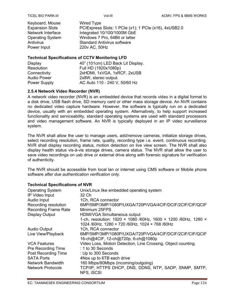
TICEL BIO PARK-III Vol-III ACMV, FPS & IBMS WORKS
EC: TAAMAESEK ENGINEERING CONSORTIUM Page 126
Keyboard, Mouse Wired Type Expansion Slots PCIExpress Slots: 1 PCIe (x1); 1 PCIe (x16), 4xUSB2.0 Network Interface Integrated 10/100/1000M GbE Operating System Windows 7 Pro, 64Bit or latter Antivirus Standard Antivirus software Power Input 220v AC, 50Hz
Technical Specifications of CCTV Monitoring LFD
Display 40” (101cm) LED Back Lit Display. Resolution Full HD (1920x1080p) Connectivity 2xHDMI, 1xVGA, 1xRCF, 2xUSB Audio Power 2x8W, stereo output. Power Supply AC Auto 110 - 240 V, 50/60 Hz
2.5.4 Network Video Recorder (NVR)
A network video recorder (NVR) is an embedded device that records video in a digital format to a disk drive, USB flash drive, SD memory card or other mass storage device. An NVR contains no dedicated video capture hardware. However, the software is typically run on a dedicated device, usually with an embedded operating system. Alternatively, to help support increased functionality and serviceability, standard operating systems are used with standard processors and video management software. An NVR is typically deployed in an IP video surveillance system. The NVR shall allow the user to manage users, add/remove cameras, initialize storage drives, select recording resolution, frame rate, quality, recording type i.e. event, continuous recording. NVR shall display recording status, motion detection on live view screen. The NVR shall also display health status vis-à-vis storage drives, camera status. The NVR shall allow the user to save video recordings on usb drive or external drive along with forensic signature for verification of authenticity. The NVR should be accessible from local lan or internet using CMS software or Mobile phone software after due authentication verification only.
Technical Specifications of NVR
Operating System Unix/Linux like embedded operating system IP Video Input 32 Ch Audio Input 1Ch, RCA connector Recording resolution 6MP/5MP/3MP/1080P/UXGA/720P/VGA/4CIF/DCIF/2CIF/CIF/QCIF Recording Frame Rate Minimum 25FPS Display Output HDMI/VGA Simultaneous output
1-ch, resolution: 1920 × 1080 /60Hz, 1600 × 1200 /60Hz, 1280 × 1024 /60Hz, 1280 × 720 /60Hz, 1024 × 768 /60Hz
Audio Output 1Ch, RCA connector Live View/Playback 6MP/5MP/3MP/1080P/UXGA/720P/VGA/4CIF/DCIF/2CIF/CIF/QCIF
16-ch@4CIF, 12-ch@720p, 6-ch@1080p VCA Features Video Loss, Motion Detection, Line Crossing, Object counting. Pre Recording Time : 1 to 30 Seconds Post Recording Time : Up to 300 Seconds SATA Ports 4Nos up to 6TB each drive Network Bandwidth 160 Mbps/80Mbps (incoming/outgoing) Network Protocols TCP/IP, HTTPS DHCP, DNS, DDNS, NTP, SADP, SNMP, SMTP,
NFS, iSCSI

TICEL BIO PARK-III Vol-III ACMV, FPS & IBMS WORKS
EC: TAAMAESEK ENGINEERING CONSORTIUM Page 127
Network Interface 1 RJ45 10/100/1000Mbps Serial Interface RS232, RS485 Form Factor 19” Rack Mountable Consumption: < 20W without Hard Disk Drives Power Input 220V AC, 50Hz Working temperature: -10°C~+55°C Working humidity: 10%~90%
2.5.5 IP Cameras
Various IP cameras of indoor and outdoor type are employed to monitor inside and outdoor areas of the building. Dome cameras, with 30m IR is elected for indoor, and Bullet Camera, Varifocal Bullet camera for outdoor usage. All the cameras shall have 1920x1080 i.e 2MP resolution and IR LEDs for Night vision. Camera should support dual stream (Main, Sub streams). Cameras for outdoor usage shall meet IP65 specification at the minimum. All cameras shall be ONVIF compliant, and should have edge storage technology. In the event of network failure, camera should record locally and store on the NVR when network is available. All cameras shall support Power over Ethernet (POE) for power supply, and DC 12V.
Technical Specifications of IP IR Dome Camera
Image Sensor 1/2.7’’ Image Sensor Lens 2.8mm Day & Night IR cut filter with auto switch IR Max Distance 30m Camera Features DWDR, Day/Night (ICR), 3DNR, AWB, AGC, BLC Video Compression H.264/MJPEG H.264 Type Baseline Profile / Main Profile Video Bit Rate 32 Kbps – 8 Mbps Max. Resolution 1920 × 1080 @25FPS Operating Conditions -30 °C – 60 °C (-22 °F – 140 °F), Humidity 95% or less (non-
condensing) Power Supply 12 V DC ± 10%, PoE (802.3af) Technical Specifications of IP IR Bullet Camera Image Sensor 1/2.7’’ minimum Lens 2.8mm Day & Night IR cut filter with auto switch IR Max Distance 30m Camera Features DWDR, Day/Night (ICR), 3DNR, AWB, AGC, BLC Video Compression H.264/MJPEG H.264 Type Baseline Profile / Main Profile Video Bit Rate 32 Kbps – 8 Mbps Max. Resolution 1920 × 1080 @25FPS Operating Conditions -30 °C – 60 °C (-22 °F – 140 °F), Humidity 95% or less (non-
condensing) Power Supply 12 V DC ± 10%, PoE (802.3af) Technical Specifications of IP IR Vari-focal Bullet Camera Image Sensor 1/2.7’’ minimum Lens 2.8mm-12mm, Varifocal Day & Night IR cut filter with auto switch IR Max Distance 50 m

TICEL BIO PARK-III Vol-III ACMV, FPS & IBMS WORKS
EC: TAAMAESEK ENGINEERING CONSORTIUM Page 128
Camera Features DWDR, Day/Night (ICR), 3DNR, AWB, AGC, BLC Video Compression H.264/MJPEG H.264 Type Baseline Profile / Main Profile Video Bit Rate 32 Kbps – 8 Mbps Max. Resolution 1920 × 1080 @25FPS Operating Conditions -30 °C – 60 °C (-22 °F – 140 °F), Humidity 95% or less (non-
condensing) Power Supply 12 V DC ± 10%, PoE (802.3af)

TICEL BIO PARK-III Vol-III ACMV, FPS & IBMS WORKS
EC: TAAMAESEK ENGINEERING CONSORTIUM Page 129
2.6 Data Networks
2.6.1 Description
The IBMS and TICEL Office network is connected with high speed 1000Mbps data networks making use of CAT6 cables and optical networks wherever necessary. Due to inherent limitation of 100 meter length for Cat5 or Cat6 networks, design should take care of this limitation. This can be achieved by providing network switches within the vicinity of end devices such that they won’t exceed the length of 100m. To achieve this, it is suggested that a network switch may be introduced at 5th or 6th floor. Wherever necessary, single mode fiber optics cable can be used to achieve full 1000Mbps bandwidth. Since the distance between IBMS and utility building are more than 100m, fibre optic connectivity has been proposed to link them together with single mode 6 core OFC cable. It is proposed that CCTV, Data network share the same resources like racks, switches wherever possible.
2.6.2 Active Components The main active components of data network are Switches. Switches shall be of 24 ports, PoE. Switches shall be smart/web managed with features like VLAN, QoS. Additionally it shall have 2xSFP ports for connecting fibre links. The switch shall provide a minimum of 15.4 watts and have 802.3af compliant ports at the minimum.
2.6.3 Passive Components All the copper based passive components like patch panels, patch cords, keystones, jacks, data outlet faceplates etc shall be of CAT6 standard. All the cores of OFC cable shall be properly terminated in a rack mounted or rack mounted LIU as per site conditions. All the fibre optic passive components like LIU, pig tails, patch cords are SC compatible to keep it economical. The SFP modules shall be supplied as recommended by the switch manufacturer and shall be compatible with switch supplied. Technical Specifications of Layer2 Smart/Web Managed Switch No of 10/100/1000 ports, PoE Ports
24, 24
No of SFP ports 2 or more Port Standards IEEE 802.3, IEEE 802.3u, IEEE 802.3ab, IEEE 802.3z, IEEE
802.3x, PoE IEEE 802.3at Duplex Mode Full/Half Duplex for 10/100 Mbps, Full Duplex for 1000Mbps Media Interface for copper ports Auto MDI/MDIX Switching Capacity >= 48Gbps Static Mac/Mac Address Table 256/8K or better 64byte packet forward rate >= 40 Mpps PoE standard IEEE 802.3af or better PoE power budget 193 Watts or better Status LEds Power, Link/Activity/Speed Physical Size Standard 19” Rack Mountable L2 Features MAC Address Table, IGMP Snooping, Link Aggregation,
Jumbo Frame, Spanning Tree Protocol, Flow Control, VLAN, VLAN Group, QoS
Management Telnet, Web based Management, SNMP, System Log
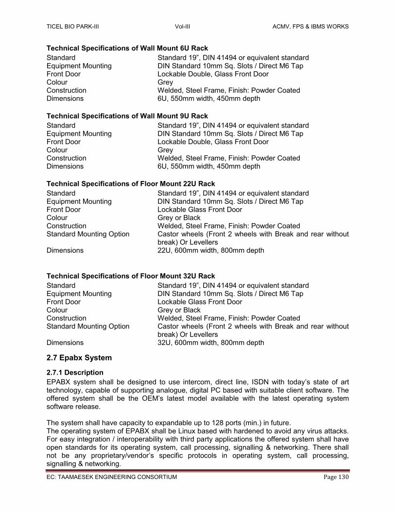
TICEL BIO PARK-III Vol-III ACMV, FPS & IBMS WORKS
EC: TAAMAESEK ENGINEERING CONSORTIUM Page 130
Technical Specifications of Wall Mount 6U Rack
Standard Standard 19”, DIN 41494 or equivalent standard Equipment Mounting DIN Standard 10mm Sq. Slots / Direct M6 Tap Front Door Lockable Double, Glass Front Door Colour Grey Construction Welded, Steel Frame, Finish: Powder Coated Dimensions 6U, 550mm width, 450mm depth
Technical Specifications of Wall Mount 9U Rack
Standard Standard 19”, DIN 41494 or equivalent standard Equipment Mounting DIN Standard 10mm Sq. Slots / Direct M6 Tap Front Door Lockable Double, Glass Front Door Colour Grey Construction Welded, Steel Frame, Finish: Powder Coated Dimensions 6U, 550mm width, 450mm depth
Technical Specifications of Floor Mount 22U Rack
Standard Standard 19”, DIN 41494 or equivalent standard Equipment Mounting DIN Standard 10mm Sq. Slots / Direct M6 Tap Front Door Lockable Glass Front Door Colour Grey or Black Construction Welded, Steel Frame, Finish: Powder Coated Standard Mounting Option Castor wheels (Front 2 wheels with Break and rear without
break) Or Levellers Dimensions 22U, 600mm width, 800mm depth
Technical Specifications of Floor Mount 32U Rack
Standard Standard 19”, DIN 41494 or equivalent standard Equipment Mounting DIN Standard 10mm Sq. Slots / Direct M6 Tap Front Door Lockable Glass Front Door Colour Grey or Black Construction Welded, Steel Frame, Finish: Powder Coated Standard Mounting Option Castor wheels (Front 2 wheels with Break and rear without
break) Or Levellers Dimensions 32U, 600mm width, 800mm depth
2.7 Epabx System
2.7.1 Description
EPABX system shall be designed to use intercom, direct line, ISDN with today’s state of art technology, capable of supporting analogue, digital PC based with suitable client software. The offered system shall be the OEM’s latest model available with the latest operating system software release. The system shall have capacity to expandable up to 128 ports (min.) in future. The operating system of EPABX shall be Linux based with hardened to avoid any virus attacks. For easy integration / interoperability with third party applications the offered system shall have open standards for its operating system, call processing, signalling & networking. There shall not be any proprietary/vendor’s specific protocols in operating system, call processing, signalling & networking.

TICEL BIO PARK-III Vol-III ACMV, FPS & IBMS WORKS
EC: TAAMAESEK ENGINEERING CONSORTIUM Page 131
Main system shall have the call billing software to get details of calls made by each extension through EPABX and other features. The system shall be modular in design and shall be based on standard protocols. The equipment shall be capable of maintaining it guaranteed performance when operating continuously for 24 hrs a day and 365 days a year. The EPABX system shall be compatible with the public switched telephone network of BSNL/other ISPs operating in India. System shall be designed as per relevant international standards/equivalent applicable Indian standards and safety measures. The system shall have the flexibility and upgradeability features without replacing major equipment elements. The architecture of the EPABX shall be capable of seamless migration to its maximum capacity by simply adding peripherals cards on the same set of cards and CPU without compromising function/features of the system. The installation and commissioning of complete system including laying and termination of cables shall be in the scope of bidder. All routine testing and operation of the system shall be carried out by the bidder at site. Installation shall be done as per the applicable relevant standard. All the required commissioning spares and consumables shall be in the bidder’s scope. The vendor shall provide comprehensive training on various operation and maintenance aspects of EPABX system to the in-charges. The training shall be conducted at supplier’s works/at site. The supplied EPABX will have system configured for 04xCO Lines, 1xT1/E1/PRI, 2xDigital Ports, 48xSLT analogue extensions
2.7.2 General Features Of EPABX System The EPABX System should have Digital PCM/TDM (non-blocking) technology. /switching. Tone and Ringing: The system shall provide the standard tones and ringing current as in the Public Telephone Network as follows: Ringing 75 V AC, 25 Hz. Ring back tone 400 Hz. 0.4 sec ON, 0.4 sec OFF. Dial tone 400 Hz modulated by 25 Hz. Busy tone 400 Hz, 0.75 sec ON, 0.75 sec OFF. Operating Voltage 48 V +/- 4 V DC.
The equipment and circuits for tones and ringing shall form part of main EPABX equipment. The equipment should have Automatic Route Selection facility to determine least cost route automatically based on class of service.
Extension-to-Extension Dialling: It shall be possible to establish internal calls automatically by
dialling any number without assistance of the attendant.

TICEL BIO PARK-III Vol-III ACMV, FPS & IBMS WORKS
EC: TAAMAESEK ENGINEERING CONSORTIUM Page 132
Direct Outward Dialling: It shall be possible to establish external calls automatically by dialling
any number without the assistance of the attendant (subject to class of service).
Provision of DID & DISA: It shall have facility for direct inward dialling and direct inward station access. Direct Outwards Station Access (DOSA): Any Extension can access the trunk lines of the System through personal pass code to make outward calls from outside. All DOSA calls remain in account of that particular Extension. Access To Exchange Network: It shall be possible for an extension to get access to public network with or without the attendant in such cases, facility shall exist for the attendant to either dial the required No. or to merely extend the junction to the extension and permit the subscriber to dial the number. Privacy of Call: Full privacy of conversation shall be available on all calls whether established directly or by the attendant. A warning tone of a specified frequency shall be applied when the attendant exercises trunk-offering facility on an extension user. Class of Service: It shall be possible to exercise control on an extension over the telephone usage by providing suitable class of service. During night, when the board/reception desk is shut, external lines should be linked to any pre-defined extensions. Flexible Numbering Scheme: System should have provision for flexible numbering plan up to four digits for extensions. Universal Port Configuration: All ports of the System should be identical to facilitate flexible configuration of the System as per user needs. Discriminate Ringing: The System should support discriminate ringing to indicate internal & external calls. Mixed Station Dialling: To support all the features irrespective of type of telephone instruments i.e., Pulse or DTMF. SMDR: The System should support SMDR, which is a call accounting application that can record & print up to at least 3500 calls without dedicated printer. Power Failure Transfer: In the case of power failure all PSTN lines become available on the pre-set Extensions. Programmable Class of Service: The System should support programmable class of service for PSTN (STD/ISD/LOCAL) dialling as per need. Direct Call Billing In Rupees: The System should support direct call billing (near value) through parallel/serial port printer without computer. Call Billing Printout Options: The System should support versatile multiple combinations of direct printout options with total amount viz., Extension wise, Trunk wise. Today’s call, Group wise, Particular date, Particular Month, Particular Time, Particular Phone etc.

TICEL BIO PARK-III Vol-III ACMV, FPS & IBMS WORKS
EC: TAAMAESEK ENGINEERING CONSORTIUM Page 133
Calling Line Identification (CLIP): This is an optional feature and when ordered it enables the incoming calling No. is displayed on Key/ Analogue Phone. Remote Maintenance: The System programming can even be done from remote locations.
2.7.3 Extension Features Automatic Call Back: Facility shall exist for an extension user on encountering a busy signal on a called extension, to invoke the automatic call back feature by dialling a code before hanging up. When both the calling and called parties are free, the call should be automatically put through. On no answer the call may be disconnected after a specified period. Call Forwarding: An extension with this class of service shall be able to transfer all incoming calls, temporarily to another pre-selected extension. Such requests shall be registered by dialling a code followed by the extension No. Facility shall also exist for cancellation of a request registered earlier. Consultation Hold: An extension engaged on an external call (incoming or outgoing) shall be able to hold the call while making internal call for private consultation. The external subscriber shall not overhear such consultation. There must be facility of music during hold condition. Brokers Call: An extension engaged on an external call (incoming or outgoing) shall be able to hold the call while making another call and then alternate between the two. The other party shall not over hear such consultation. There must be facility of music during hold condition. Automatic Call Transfer: It shall be possible for an extension user to transfer incoming calls to another extension with or without help of the attendant. Executive/Secretary: A combination of call-forwarding, consultation &hold provisions to be there for executive to selectively answer calls. Executive Over Ride: There must be facility offering priority to minimum five extensions to over-ride ongoing conversations. Conference Call: It shall be possible for an extension user (up to a maximum number of 6) to talk to each other at the same time on a conference circuit. One of the extension user or the attendant may set up the conference call. Call Pick-Up: It shall be possible for an extension user to pick up incoming calls ringing on another extension without the help of the attendant. Call Re-Routing: It shall be possible for a call to be re-routed, without help of the attendant, to other pre-defined extensions when certain conditions apply. Auto Call Disconnection: The system should facilitate to fix the time of call beyond which it will be automatically disconnected. Dynamic STD Lock: The System should support that individual extension can lock outward dialling (STD/ISD/LOCAL) by a personal secret pass code to prevent misuse by others. Background Music: The Key Phone user can enjoy the light background music channelled from System When Voice DISA Card is incorporated.
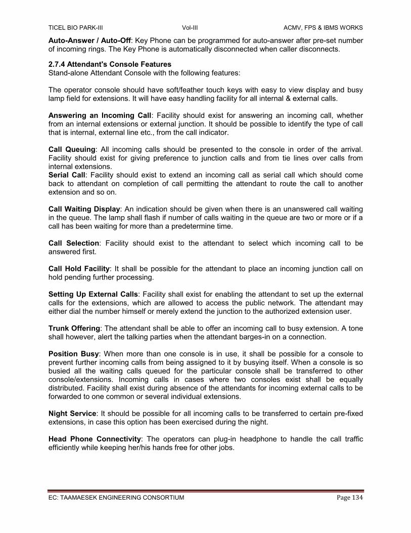
TICEL BIO PARK-III Vol-III ACMV, FPS & IBMS WORKS
EC: TAAMAESEK ENGINEERING CONSORTIUM Page 134
Auto-Answer / Auto-Off: Key Phone can be programmed for auto-answer after pre-set number of incoming rings. The Key Phone is automatically disconnected when caller disconnects.
2.7.4 Attendant's Console Features Stand-alone Attendant Console with the following features: The operator console should have soft/feather touch keys with easy to view display and busy lamp field for extensions. It will have easy handling facility for all internal & external calls. Answering an Incoming Call: Facility should exist for answering an incoming call, whether from an internal extensions or external junction. It should be possible to identify the type of call that is internal, external line etc., from the call indicator. Call Queuing: All incoming calls should be presented to the console in order of the arrival. Facility should exist for giving preference to junction calls and from tie lines over calls from internal extensions. Serial Call: Facility should exist to extend an incoming call as serial call which should come back to attendant on completion of call permitting the attendant to route the call to another extension and so on. Call Waiting Display: An indication should be given when there is an unanswered call waiting in the queue. The lamp shall flash if number of calls waiting in the queue are two or more or if a call has been waiting for more than a predetermine time. Call Selection: Facility should exist to the attendant to select which incoming call to be answered first. Call Hold Facility: It shall be possible for the attendant to place an incoming junction call on hold pending further processing. Setting Up External Calls: Facility shall exist for enabling the attendant to set up the external calls for the extensions, which are allowed to access the public network. The attendant may either dial the number himself or merely extend the junction to the authorized extension user. Trunk Offering: The attendant shall be able to offer an incoming call to busy extension. A tone shall however, alert the talking parties when the attendant barges-in on a connection. Position Busy: When more than one console is in use, it shall be possible for a console to prevent further incoming calls from being assigned to it by busying itself. When a console is so busied all the waiting calls queued for the particular console shall be transferred to other console/extensions. Incoming calls in cases where two consoles exist shall be equally distributed. Facility shall exist during absence of the attendants for incoming external calls to be forwarded to one common or several individual extensions. Night Service: It should be possible for all incoming calls to be transferred to certain pre-fixed extensions, in case this option has been exercised during the night. Head Phone Connectivity: The operators can plug-in headphone to handle the call traffic efficiently while keeping her/his hands free for other jobs.

TICEL BIO PARK-III Vol-III ACMV, FPS & IBMS WORKS
EC: TAAMAESEK ENGINEERING CONSORTIUM Page 135
2.7.5 Analogue Telephone Features Basic Telephones should support Pulse/Tone dialling, Modular connection plugs for line & handsets. Telephone shall have Electronic ringer with adjustable volume & melodies ring. Shall have Flash, Pause, redial, mute function. Telephone shall be desktop or wall mountable. Telephone shall be supplied with minimum 2m long detachable line cord. Telephone shall have CLIP feature
2.7.6 Digital Key Telephone Features The digital key phone shall have adjustable handset volume, Caller name display, Distinctive ringing according to hierarchical level, fixed function keys, Duplex hands free operation. Phone shall feature a LCD display. Shall have features like Call Hold, Call Forward, Message waiting indication. It shall have Calling line identification presentation/restriction (CLIP/CLIR.) It shall have storage of unanswered calls with date, time, and call back.
2.7.7 Mdf/Idf Suitable MDF/IDF shall be provided for termination of the extension, trunk lines. The MDF/IDF shall be housed in self standing/wall type metal frame. The termination strips shall be disconnection type provided with isolation facility. Suitable protection shall be provided against induced voltages and currents due to lightning, high voltages line etc. The devices shall provide prompt isolation and protection from accidental high voltage power contact and safe guard the equipment against any damage.
2.7.8 EPABX The EPABX system & its accessories shall be grounded to a common ground point to prevent interference from the external & internal sources. Earthing electrode shall be as per the relevant applicable standard/B.S.3043 (latest) for EPABX, MDF/IDF and batteries. The earthing material shall be as per the applicable IS/Internationally applicable standards. Earthing shall be done as per the ITU recommendation. Technical Specifications of EPABX SLT/FXS Ports 48 expandable up to 100 extensions DKP/DSS Ports 8 CO/FXO (TWT) Ports 8 T1/E1/PRI Ports 2 SIP Trunks 8 IP Users 50 Features Auto-Attendant, Voice Help, Voice Tones
Web-based Configuration, PMS, SMDR, System Log, VOIP (LAN and WAN) and VMS
Numbers of 3-Party Conferences 6 or more LED Indications Power, Health Status Power Input 100-240 VAC, 47-60Hz (250W) Operating Temperature 0OC to +45OC Operating Humidity 5-95% RH, Non-Condensing Mounting Standard 19” Rack Mounting Supply Configuration 04xCO Lines, 1xT1/E1/PRI, 2xDigital Ports,
76xSLT analogue extensions

TICEL BIO PARK-III Vol-III ACMV, FPS & IBMS WORKS
EC: TAAMAESEK ENGINEERING CONSORTIUM Page 136
Technical Specifications of Analogue Phones Dialling Mode Tone/pulse LCD Display 7segment LCD display, Date Time Display,
Call Timer Speaker Phone Yes, Hands free Speaker phone. Ringer Volume 2 Levels Memory 30 incoming calls/5 outgoing calls Flash Programmable Special Keys Flash, Mute, Redial Operating Temperature 0 to 45°C Operating Humidity 5 to 95%, RH, Non-Condensing
Technical Specifications of Digital Key Phones
Display LCD with Backlit Tone Polyphonic Ringtone Navigation Keys Touch Sensitive, context aware Function Keys Voice Mail, Mute, Do Not Disturb, Headset, Speaker , Hold,
Conference, Redial, Transfer Programmable Keys 10 LED/Lamp Message Wait, Ringer Headset Interface 3.5 mm, RJ9 Operating Temperature 0 to 45°C Operating Humidity 5 to 95%, RH, Non-Condensing
2.7.9 List of Makes-IBMS
LIST OF MAKES
Sno ITEM MAKES
BMS
1 BMS Software Siemens/Honeywell/Scheider
2 Workstation DELL/HP/LENOVO
3 Color Laser Printer HP/CANON/BROTHER/LEXMARK
3 DDC Controller Siemens/Honeywell/Scheider
4 Field Devices Siemens/Honeywell/Dwyer/Graystone
5 Float/Level Switch SRIDHAN/FILLPRO or Equivalent Brand
6 BTU Meters Seimens/Honeywell/SENITECH
7 CABLE TRAY PROFAB/PUSHPAK/
8 PVC Conduits VIP/ PRECISION/FINOLEX/AVON
9 Signal and Communication Cables POLYCAB/ORBIT/HAVELLS/FINOLEX
10 CAT6 Cables UTP, STP DLINK/MOLEX/SYSTIMAX/BELDEN
11 LFD TV/Monitors Samsung/Panasonic/Sony
FAS
1 Fire Alarm Panels, Repeater Panels Bosch / GST / Honeywell-Morley/Siemens
2 Detectors Bosch / GST / Honeywell-Morley/Siemens
3 Response Indicator Bosch / GST / AGNI /Siemens
4 Control Relay Modules Bosch / GST / Honeywell-Morley/Siemens
5 Monitor Modules Bosch / GST / Honeywell-Morley/Siemens
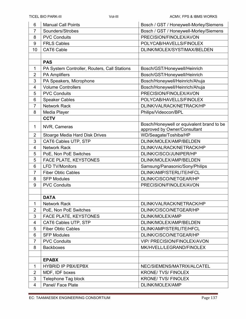
TICEL BIO PARK-III Vol-III ACMV, FPS & IBMS WORKS
EC: TAAMAESEK ENGINEERING CONSORTIUM Page 137
6 Manual Call Points Bosch / GST / Honeywell-Morley/Siemens
7 Sounders/Strobes Bosch / GST / Honeywell-Morley/Siemens
8 PVC Conduits PRECISION/FINOLEX/AVON
9 FRLS Cables POLYCAB/HAVELLS/FINOLEX
10 CAT6 Cable DLINK/MOLEX/SYSTIMAX/BELDEN
PAS
1 PA System Controller, Routers, Call Stations Bosch/GST/Honeywell/Heinrich
2 PA Amplifiers Bosch/GST/Honeywell/Heinrich
3 PA Speakers, Microphone Bosch/Honeywell/Heinrich/Ahuja
4 Volume Controllers Bosch/Honeywell/Heinrich/Ahuja
5 PVC Conduits PRECISION/FINOLEX/AVON
6 Speaker Cables POLYCAB/HAVELLS/FINOLEX
7 Network Rack DLINK/VALRACK/NETRACK/HP
8 Media Player Philips/Videocon/BPL
CCTV
1 NVR, Cameras Bosch/Honeywell or equivalent brand to be approved by Owner/Consultant
2 Stoarge Media Hard Disk Drives WD/Seagate/Toshiba/HP
3 CAT6 Cables UTP, STP DLINK/MOLEX/AMP/BELDEN
4 Network Rack DLINK/VALRACK/NETRACK/HP
5 PoE, Non PoE Switches DLINK/CISCO/JUNIPER/HP
5 FACE PLATE, KEYSTONES DLINK/MOLEX/AMP/BELDEN
6 LFD TV/Monitors Samsung/Panasonic/Sony/Philips
7 Fiber Obtic Cables DLINK/AMP/STERLITE/HFCL
8 SFP Modules DLINK/CISCO/NETGEAR/HP
9 PVC Conduits PRECISION/FINOLEX/AVON
DATA
1 Network Rack DLINK/VALRACK/NETRACK/HP
2 PoE, Non PoE Switches DLINK/CISCO/NETGEAR/HP
3 FACE PLATE, KEYSTONES DLINK/MOLEX/AMP
4 CAT6 Cables UTP, STP DLINK/MOLEX/AMP/BELDEN
5 Fiber Obtic Cables DLINK/AMP/STERLITE/HFCL
6 SFP Modules DLINK/CISCO/NETGEAR/HP
7 PVC Conduits VIP/ PRECISION/FINOLEX/AVON
8 Backboxes MK/HVELL/LEGRAND/FINOLEX
EPABX
1 HYBRID IP PBX/EPBX NEC/SIEMENS/MATRIX/ALCATEL
2 MDF, IDF boxes KRONE/ TVS/ FINOLEX
3 Telephone Tag block KRONE/ TVS/ FINOLEX
4 Panel/ Face Plate DLINK/MOLEX/AMP

TICEL BIO PARK-III Vol-III ACMV, FPS & IBMS WORKS
EC: TAAMAESEK ENGINEERING CONSORTIUM Page 138
5 Telephone I/O DLINK/MK/LEGRAND/FINOLEX
6 Telephone Cables Polycab/Finolex/Havells
7 PVC Conduits PRECISION/FINOLEX/AVON
8 Telephones, Corded and Cordless Beetel/Panasonic/Motorola
9 Digital Key Phones NEC/SIEMENS/MATRIX
ACCESS CONTROL
1 Door Access Controllers HONEYWELL/SMARTI/SPECTRA/ESSL
2 Smart Card Readers HID/SPECTRA/ESSL/ROSSLARE
3 Boom Bariers Magnetic Auto Controls/Nice or equivalent Brand to be approved by Owner/Consultant
4 Hand Held Metal Detectors STATIC/GODREJ/SIVANANDA/METSCAN
5 Biometric Attendance SPECTRA/ESSL/REALTIME
6 PVC Conduits PRECISION/FINOLEX/AVON PLAST
7 CAT6 Cables UTP, STP DLINK/MOLEX/AMP/BELDEN
8 Single, Double Leaf EM Locks ESSL/BEL/Faraday/Assa Abloy
9 EXIT Switch ESSL/BEL/Faraday/Assa Abloy
Note:-
All Equipment / Components used in execution of work shall be preferred make listed above subject to the approval of Owner / Engineering Consultant. The Owner / Engineering Consultant reserve the right to choose any one of the make listed above. The rates quoted above shall be valid for any of the makes mentioned above.
Country of Origin shall be USA/INDIA/EUROPE
2.6.0 LIST OF DRAWINGS - IBMS
SI NO NAME OF DRAWING REMARKS
1 Basement 2 BMS Layout. For tender
2 Basement1BMS Layout. For tender
4 Ground Floor BMS Layout. For tender
5 Ground Mezz. Floor BMS Layout. For tender
6 First Floor BMS Layout. For tender
7 EXT.LAN,DAT & CCTV Layout For tender
8 Block diagram-Data Telephone & CCTV For tender
9 Gnd, Type A& B, Ter LAN, DATA,CCTV & Power
Conduit Layout
For tender

TICEL BIO PARK-III Vol-III ACMV, FPS & IBMS WORKS
EC: TAAMAESEK ENGINEERING CONSORTIUM Page 139
10 GF to 13th FLOOR PLAN LAYOUT - PA For tender
11 GF to 13th FLOOR PLAN LAYOUT - FA For tender
3.0 TECHNICAL SPECIFICATION FOR FIRE PROTECTION WORKS
3.1.0 GENERAL REQUIREMENTS The fire Protection system is designed and installed as per National Building Code / Local Fire Authorities requirement. It should also include getting the necessary approvals / NOC from the Fire Department or Local fire Authority. The Fire Protection System shall comprise of following: Fire Pumps – Electrical Motor driven, Diesel engine driven Pump, Jockey Pump. Yard Hydrant systems, Internal Hydrant systems, Automatic Sprinkler systems, Fire Extinguishers Balancing, testing & commissioning of the entire Fire protection system. Training of Owner’s staff. Type of System Proposed is with Centralized fire water tank and fire pump room equipment at above fire sump, Wet riser system, Yard Hydrant with external ring main, Automatic sprinkler system and fire extinguishers. Fire water storage tanks -Water tank at fire pump room below ground level, fire sump is 200cum and 20cum on terrace, Five number of Fire Pumps – Electrical driven main pumps one for Hydrant and one for sprinkler system, one Diesel engine driven common standby pump for both systems, Two Electrical driven jockey pumps. Fire Hydrant System – A Ring main at periphery of the building with isolation valves, Ring main on Terrace level for inter connecting the all wet risers. Yard Hydrant - Yard Hydrant at every 30mtrs of periphery of the building with single headed hydrant valve, 2 x 15 mtrs long RRL hoses. Automatic Sprinkler System - Sprinklers at ceiling in common areas for all floors. List of Technical submittals, shop drawings, Material sample to be submitted after the award of contract. Upon Completion of installation the Contractor shall test the system and hand over the same in operating condition to the Client or other agencies as assigned by the Client. Necessary operating and maintenance manuals together with as-built drawings, all in Triplicate as hard copy and also on soft copy shall be submitted.
3.1.1 CODES & STANDARDS
NBC : National Building Code of India Part IV for
Fire Protection System – 2016.

TICEL BIO PARK-III Vol-III ACMV, FPS & IBMS WORKS
EC: TAAMAESEK ENGINEERING CONSORTIUM Page 140
IS-1239 / IS 3589 : Specification for MS / GI Pipes.
IS-800 : Specifications for Structural steel.
IS-814 : Specifications for covered electrodes for metal are
Welding of structural steel.
BS-5155 : Specifications for C.I. butterfly valve.
IS-4927 : Specifications for Canvas Hose Pipes.
IS-903 : Specifications for Branch pipes Fire hose
couplings and auxiliary equipments.
IS-5290 : Specifications for hydrant landing valves.
IS-1200 : Method of measuring of building & civil
Engineering Works.
(water supply, plumbing drain & sanitary fittings)
IS-636 : Synthetic, jacketed hose pipes.
IS-2198 : Control Panels.
IS-2629 : Hot dip galvanizing of iron and steel.
IS-5 : Specification for painting.
IS 9137 : Specification for horizontal end suction centrifugal
Pump.
BS-1965 Part I : Specification for butt-welded Pipe Fittings.
IS 8423 ; Controlled percolating hose for fire fighting.
IS 2871 : Branch pipe, universal for fire fighting purposes.
IS 884 : First aid hose reel for fire fighting.
IS 2190 : Code of practice for selection, installation
And maintenance of portable first aid fire extinguishers.
IS 937 : Specification for washers for water fittings for fire
Fighting system.
IS 9972 : Specification for automatic sprinkler heads.
IS 15683 ; ABC type Fire extinguishers.
IS3844 : Installation and Maintenance of Internal Fire
Hydrants and Hose Reels on Premises
IS 5290 : Landing Valves Specification
IS12469 : Specification for Pumps For Fire Fighting System.
IS 15105 Design and Installation of Fixed Automatic Sprinkler Fire Extinguishing System
IS-2189 : Installation & Maintenance of Fire Detection and

TICEL BIO PARK-III Vol-III ACMV, FPS & IBMS WORKS
EC: TAAMAESEK ENGINEERING CONSORTIUM Page 141
Alarm System. IS-2175 : Detectors.
IS-694 : Copper wire.
IS-9968 (Pt-1) : Rubber Insulated Braided Wire.
IS-1554 (Pt-1) : PVC Insulated Cables.
Shade No.536 of IS-5 : Paint Shade for main Equipments/accessories.
3.2.0 FIRE PROTECTION SYSTEM
The Fire Fighting and Sprinkler System designed features a Pressurized Wet Riser completes with Landing Valves and Hose Reels at every floor level. The Hose Reels - accommodated in glass-fronted boxes - are located in the staircase at various floors, so as to have easy approachability. The system design has been carried out in accordance with relevant IS Codes and NBC Regulations. The fire pumps shall be located in the pump room located along with other water supply pumps in the utility building. The fire water sump shall be located near the fire pump room. The external part of the building shall be protected by Yard Hydrants placed at intervals as per specifications. The main piping for the hydrants shall be tapped-off from the discharge header of the fire pump sets and the same shall be run buried as shown in the layout drawings.
3.3.0 APPROVALS After completion of Installation, necessary submission drawings shall be prepared by the Contractor and submitted to the relevant authorities. The scope of this tender includes the responsibility of obtaining the approval for the installation from the Fire Department and other relevant Departments and obtaining the required No Objection Certificate.
3.4.0 PIPING VALVES & ACCESSORIES The scope of this section comprises the supply and laying of pipes, pipe fittings and valves and testing of all water piping required for the complete installation as shown on the drawings. All piping inclusive of fittings and valves shall follow the applicable Indian Standards.
3.4.1 PIPING All Hydrant Pipes, Stand Pipes, Sprinkler Pipes, etc., shall be as per the Approved Make indicated elsewhere in this Specification conforming to relevant ISI Codes. Pipes upto 150 mm NB shall be as per IS 1239, Medium grade. Pipes of 200 mm NB and above shall be as per IS 3589, with 6.35 mm wall thickness. All the Pipes shall have welded / flanged joints. All welding shall be done by qualified welder sand shall strictly conform to Indian Standards code of procedure for manual metal arc welding of mild steel. All fittings shall be of Mild Steel conforming to A 234 GR WPD Sch. 40. The Flanges shall be drilled as per relevant IS Standards. All Flanges, fittings and accessories shall be suitable for Grade 150 Pressure Rating unless otherwise specified. All pipes and their steel supports shall be thoroughly cleaned and given one primary coat of red oxide paint before being installed. Fittings shall be as per IS 1239 Part II of Pressure rating suitable for the piping system. Fittings used on welded piping shall be of weldable type.

TICEL BIO PARK-III Vol-III ACMV, FPS & IBMS WORKS
EC: TAAMAESEK ENGINEERING CONSORTIUM Page 142
3.4.2 VALVES SLUICE VALVE Sluice valve shall be as per IS: 778 and pressure rating shall be PN16. Sluice valves shall be ofnon-rising bronze spindle type. The sluice valves shall be provided with hand wheel, position indicator and locking facility. Sluice valves shall be provided with back seating bush to facilitate gland renewal during full open condition. Sluice Valves shall be with IS mark. C.I. NON RETURN VALVE For delivery line of pumps sets must be with, reinforced rubber coat ball type Non ReturnValves, conforming to IS 5312. All C.I non return valve shall be “Dual Plate” Check Valves as per API 594. These check valves, without bypass shall be provided for the Header lines and also for the interconnection of the fire hydrant and the sprinkler system. The makes shall be as specified elsewhere in this tender. BUTTERFLY VALVE All isolation / shut-off valve shall be of Butterfly type wherever indicated in the Drawings. The Valves shall have cast iron body conforming to IS 210 FG 260 / EN 1561 Gr. GJL200, face to face dimensions conforming to BS 5155. The Valve stem shall be of SS316. The disk material shall be of Ductile Iron with Electro less Nickel Plating. The seat material shall be EPDM. All shutoff valves of 50 mm NB and above shall be Butterfly valves only. BALL VALVE All shut-off valves of size 40 mm NB and below shall be full bore / flanged type ball valves with Rating Must be PN25 only. conforming to BS 5351 unless otherwise mentioned. Nickel plated Forged Brass body with brass chrome plated ball, PTFE seat, carbon steel sheet level. GATE VALVE All shut-off valves of size 40 mm NB and below shall be full bore / flanged type ball valves with Rating Must be PN16. conforming to IS 778, unless otherwise mentioned. Leaded tin bronze body, with high tensile brass for non rising stem arrangement, cast iron hand wheel, gland packing must be jute & asbestos hemp. VALVE CHAMBER Brick masonry chamber of size 1000 mm x 1000 mm x 1500 mm depth with 600 mm x 600mm Ductile iron manhole cover, shall be provided for the butterfly valve that are proposed for the underground fire hydrant lines. Flanges shall be of approved make. The supply of flanges shall also include supply of bolts and nuts and suitable asbestos / fiber rubber insertion gaskets (minimum 3 mm thick). POT STRAINER Strainers shall be of approved make, pot strainers, with Cast iron fabricated body & cover conforming to C.I to IS 210 Gr. FG 200. Carbon steel bolts & nuts conform to BS 916, with SS 304 strainer .Strainers shall have bronze screen with 3 mm perforations. Screen shall be removable and replaceable without disconnection of the main pipes. All strainers shall be provided with equal size isolation valves, so that the strainer may be cleaned without draining the system. All strainers wherever specified shall be CI fabricated type only. All pipe supports shall be mild steel, thoroughly cleaned and given one primary coat of red oxide paint before being installed.
3.4.3 ACCESSORIES AIR VESSEL

TICEL BIO PARK-III Vol-III ACMV, FPS & IBMS WORKS
EC: TAAMAESEK ENGINEERING CONSORTIUM Page 143
The air vessel shall be provided to compensate for slight loss of pressure in the system and to provide an air cushion for counter-acting pressure, surges, whenever the pumping sets come into operation. Air vessel shall conform to IS:3844. It shall be normally half full of water, when the system is in normal operation. Air vessel shall be fabricated with 8 mm thick M.S. plate with dished ends and suitable supporting legs. It shall be provided with one 100 mm dia flanged connection from pump, one 25 mm drain with valve, one water level gauge and 25 mm sockets for pressure switches. The air vessel shall be tested to pressure for 12 hours at 2 times the operating pressure or 1.5 times the shut-off. FLOW SWITCH Flow switch shall accommodate a micro switch with at least 2 NO and 2 NC contacts and the same shall be actuated by metallic bellows sealed pivoted paddle. The instrument must be weather proof with IP55 when the cover and suitable cable gland are properly fixed. The flow switch shall be suitable for mounted on 150/100 mm dia pipe line. The flow switches shall be provided for sprinkler system. Out of 2 NO/NC contacts, one will be used for connecting to Fire alarm panel and other will be used for connecting to BMS.
TAMPER SWITCH
If specified and listed in BOQ, valve supervisory switches shall be on all control valves throughout.
Switches shall be mounted so not to interfere with the normal operation of the valve and shall be
adjusted to operate within two revolutions of the valve control or when the stem has moved no
more than one fifth of the distance from its normal position. The switch mechanism shall be
contained in a weather proof die cast aluminium which shall provide a 1” tapped conduit entrance
and incorporate the necessary facilities for attachment baked enamel. The switch mechanism
shall have a minimum rated capacity of 7 amp., 220 volt, 0.25 amp., 24 volt D.C. The entire
installed assembly shall be tamper proof and arranged to cause a switch operation if the housing
cover is removed or if the unit is removed from its mounting.
3.5.0 SPRINKLER SYSTEM
3.5.1 GENERAL SPECIFICATION
The scope of work shall include supply, commissioning, testing of the system as a whole. The sprinkler heads are to be fixed into heavy quality black steel pipes, conforming to IS 1239 or any other approved specification. The size of pipe will vary from 20 mm to 150mm to suit the hydraulics of the system. Reduction in pipe sizes shall not be made by use of bushings. All piping shall be done by means of welding, as per codes. Due care shall be taken that sprinklers are not applied with paint at the time of applying paint to piping and fittings. All control, drain, test and alarm valves shall be provided with signs to identify their purposes, functions, direction of flow the satisfaction of the Architect. Sprinkler heads shall be made of brass / quartzoid bulb sufficiently strong, in compression to withstand any pressure, surge or hammer likely to occur in the system. The yoke & body shall be made of high quality gun metal brass with arms streamlined to ensure minimum interference with the spread of water. The deflector of suitable design shall be fitted to give even distribution of water over the area commanded by the sprinkler. The bulb shall contain a liquid having a freezing point below any natural climatic figure and a high coefficient of expansion. The temperature rating of the sprinkler shall be stamped on the deflector

TICEL BIO PARK-III Vol-III ACMV, FPS & IBMS WORKS
EC: TAAMAESEK ENGINEERING CONSORTIUM Page 144
& the colour of the liquid filled in the bulb shall be according to the temperature rating as per NFPA standard. The orifice size shall be marked on the body or the deflector of the sprinkler. Metal guards for protection of sprinkler against accidental or mechanical damage shall be provided as desired by the Architect. Contractor shall submit detailed submittal and discharge spray pattern for the Sprinkler for the approval of Architect. The Operating temperature eat which the quartzoid bulb of the sprinkler head shall actuate, shall be 68 degree C or as specifically mentioned.
3.5.2 SPRINKLER INSTALLATION
Sprinkler heads shall be located in positions shown on the drawings. While slight relocation may result from building construction features or interference from other services, the maximum spacing between sprinkler heads and coverage area shall not exceed those stipulated in the the NFPA 13. Allowance shall be made for such relocations within a radius of 1500 mm of the indicated positions without additional cost. The Fire Protection Services Trade shall co-ordinate with the ceiling Trade to set out the sprinkler locations to suit the site location of the unit grid. In general, all sprinklers shall be located at the centre of the ceiling unit and a provision of about 10% more sprinklers and pipe work than required NFPA Rules shall be included in this sub-contract. Chrome plated wire mesh guards shall be used to protect the sprinkler heads which are liable to accidental or mechanical (at no extra cost) damage.
3.5.3 CONTROL VALVES
Each installation shall be provided with a set of installation control valves comprising, An Alarm Valve, A Water Motor Alarm & Gong, Installation valves shall be installed on the sprinkler circuits as shown on the drawings, Contractor shall submit detailed shop drawings showing the exact location, details of installation of the valves/alarm in all respects. Installation valve shall comprise of a cast iron body with gunmetal trim, and double seated clapper check valves, pressure gauges, test valve and orifice assembly and drain valve with pressure gauges, turbine water gong including all accessories necessary and required and as supplied by original equipment manufacturer and required for full and satisfactory performance of the system. A cast iron isolation valve with lock and chain at the inlet of the installation valve shall be provided. The waste water coming out of the gong shall be drained properly. The gong shall be capable of making a alarm at a minimum pressure of 3.5 kg/cm2. Also, strainer shall be provided at the inlet side of the wall to prevent clogging. The alarm valve shall be FM approved.
3.5.4 INSPECTION & TEST VALVE ASSEMBLY
Inspection and testing of the automatic starting of the sprinkler system shall be done by providing an assembly consisting of gunmetal valves, gunmetal sight glass, bye-pass valve and orifice assembly as per approved drawing.
MAIN STOP VALVE These shall be of cast iron body of requisite size. When closed, these will shut off supply of water
to the installation.
A location plate must be fixed on the outside or an external wall, as near to the main stop valve as possible, bearing the following words on raised letters. Sprinkler Stop Valve Inside- The word `sprinkler stop valve' shall be in letters of at least 35mm and the word "INSIDE" at least 25mm in height. The words shall be painted white on black back ground.

TICEL BIO PARK-III Vol-III ACMV, FPS & IBMS WORKS
EC: TAAMAESEK ENGINEERING CONSORTIUM Page 145
All stop valves shall be right handed i.e. they shall be so constructed that in order to shut the valve the spindle shall turn from left to right. There shall be an indicator which will show whether the valve is open or shut.
3.6.0 EXTERNAL STAND POST & HYDRANT ASSEMBLY
STAND POST MS Stand Post with MS heavy grade pipe for seating the yard hydrant valve 80 mm dia. x 1500 mm long. SINGLE HEADED HYDRANT VALVE Gun Metal oblique type hydrant valve of single outlet with necessary hose coupling adaptor of 63 mm size, instantaneous spring lock arrangement and blank cap conforming to IS 5290. HOSE WITH COUPLING Controlled percolation / RRL Hose conforming to IS 8423 of 63 mm dia. x 15 RMT long shall be provided with suitable fire hose delivery coupling of instantaneous spring lock arrangement comprising of male and female half and rubber cup washer as per IS 903. GUN METAL BRANCH PIPE WITH NOZZLE Gun metal short branch pipe shall be of 63 mm dia. Female instantaneous inlet, male threaded outlet complete with hexagonal nozzle of 19 mm dia. heavy quality as per IS 903 shall be provided.
HOSE CABINET MS Hose Cabinet to accommodate two nos. of Hose Pipes with coupling and 1 No. branch pipe shall be provided for each yard hydrant valve. This cabinet shall be glass fronted with hinged door and lock. The cabinet is spray painted to scarlet red colour. The size of the cabinet shall be 750 mm x 600 mm x 250 mm.
FIRE BRIGADE CONNECTION Fire brigade connection shall be provided to the reservoir comprising of four instantaneous pattern 63 mm dia. inlets with four nos. built-in non-return valve including cap with chair and150 mm dia. sluice valve. The fire brigade inlet connection shall be of four way type incorporating non-return valves. The inside portion of the box shall be painted with one coat of zinc rich primer and two coats of white enamel paint. The outside shall be painted with one coat of zinc rich primer and two coats of red enamel paint. The box shall be also provided with lock and key. Fire Brigade connection shall confirm to IS: 5131.
3.7.0 INTERNAL HYDRANT ASSEMBLY
DOUBLE HEADED HYDRANT VALVE
Gun Metal oblique type hydrant valve of Double outlet with necessary hose coupling adapter of 63 mm size, instantaneous spring lock arrangement and blank cap conforming to IS 5290. HOSE WITH COUPLING Controlled percolation / RRL Hose conforming to IS 8423 of 63 mm dia x 15 RMT long shall be provided with suitable fire hose delivery coupling of instantaneous spring lock arrangement comprising of male and female half and rubber cup washer as per IS 903. GUN METAL BRANCH PIPE WITH NOZZLE

TICEL BIO PARK-III Vol-III ACMV, FPS & IBMS WORKS
EC: TAAMAESEK ENGINEERING CONSORTIUM Page 146
Gun metal short branch pipe shall be of 63 mm dia. Female instantaneous inlet, male threaded outlet complete with hexagonal nozzle of 19 mm dia. heavy quality as per IS 903 shall be provided. HOSE REEL Hose Reel of swing type with 19 mm dia. and 30 RMT long hose and hand controlled nozzle of 63 mm dia, shall be provided on a drum with suitable bracket for fixing on the wall, conforming to IS: 884. HOSE REEL CABINET MS Hose cabinet of size to suit the location shown in drawing for the fire escape hydrant and the hose reel assembly and shall be flush with the wall. These cabinets shall be of glass fronted with hinged door and lock. The cabinet shall be made of 16 gauge thick MS sheet and spray painted to shade No. 536 of IS:5.
3.8.0 ABOVE GROUND PIPING All pipes inside and outside the building, laid above the ground shall be properly supported on, or suspended from, stands, clamps, hangers as specified and as required. The Contractor shall adequately design all the brackets, saddles, anchors, clamps and hangers, and be responsible for their selection and usage. Approved type of Anchor fasteners shall be use daylong with Standard pipe supports, like HITEC supports. The pipes shall be duly painted with one coat of red oxide primer and two coats of synthetic enamel paint of fire red colour as per Shade No. 536 per IS 5. The pipes shall be supported at a minimum interval of 3.5 Mts. between adjacent supports. Vertical risers shall be parallel to walls and column lines and shall be straight and plumb. Risers passing from floor to floor shall be supported at each floor by clamps or collars attached to pipe and with a 15 mm thick rubber pad or any resilient material. Where pipes pass through the terrace floor, suitable flashing shall be provided to prevent water leakage. Pipe Sleeves, 50 mm larger diameter than pipes, shall be provided wherever pipes pass through walls and slabs, and annular space filled with fiber glass and finished with retainer rings. All pipe work shall be carried out in workmen like manner, causing minimum disturbance to the existing services, buildings, roads and structure. The entire piping work shall be organized, in consultation with other agencies work, so that laying of pipe supports, pipe and pressure testing for each area shall be carried out in one stretch. Cut-outs in the floor slab for installing the various pipes are indicated in the drawings. Modification of these cutouts / additional cutouts if required shall be included in the offer. The Contractor shall make sure that the clamps, brackets, clamps saddles and hangers provided for pipe supports are adequate. Piping layout shall take due care for expansion and contraction in pipes, and include expansion joints where required. All pipes shall be accurately cut to the required sizes in accordance with relevant ISI Codes and Burrs removed before laying. Open ends of the piping shall be closed as the pipe is installed to avoid entrance of foreign matter. Where reducers are to be made in horizontal runs, eccentric reducers shall be used for the piping to drain freely. In other locations, concentric reducers may be used.

TICEL BIO PARK-III Vol-III ACMV, FPS & IBMS WORKS
EC: TAAMAESEK ENGINEERING CONSORTIUM Page 147
Wherever required all pipe headers shall be worded indicating the direction of the pipe and its purpose such as "TO RISER NO.1" etc. All welding of pipes shall be carried out by certified welders only. A welding procedure shall be Pre-pared and qualified before any welding is done. The Welding Standard shall be as per AWS D 10.9, level AR - 3.
3.9.0 UNDER GROUND PIPING All buried piping shall be duly painted with one coat of bituminous primer and above this one layer of 4mm thickness Tar shall be wrapped, before adhering the tape to the pipe, it is advisable to gently heat the synthetic primer coated pipe by a run of LPG torch until the wrapper gets blend with the pipe, tape is wrapped by spiral method over the pipe, the thickness of overlapped wrapping must be not less than 10mm thick in pipes and in joints wraping thickness must be not less than 40mm Work will include cleaning of pipe, degreasing, etc. The UG piping is to be laid in such a way that T.O. P level is minimum 1.5 Mtr. From ground level. PCC 1:4:8 anchor supports shall be provided for bends and tees wherever change in flow direction occurs.
3.10.0 EXCAVATION & BACK FILLING Excavation for pipe lines shall be in underground to levels and grades shown on the drawings or as required at site. Pipe lines shall be buried with a minimum of 1.5 meter or as shown on drawings. Wherever required, Contractor shall support all pipes with regular intervals. On completion of testing in the presence of the Project Manager and pipe protection, it shall be backfilled with river sand and consolidated. Contractor shall dispose off all surplus earth as directed by the Project Manager.
3.11.0 PUMPS
3.11.1 AUTOMATIC FIRE PUMPS & CONTROLLERS Complete fire pump system, including pump motor, auxiliary components, controllers, and inter connecting power and control wiring. For rating, Model No. total dynamic head and electrical characteristics of pumps, refer to schedule on drawings and BOQ. Motor: Shall be of suitable continuous rating type as specified and shall be TEFC squirrel cage induction type with class F insulation. RPM shall be 3000. The pump shall also deliver not less than 150 % of rated capacity at a pressure not less than 65 % rated head. The shut-off pressure should not exceed 120 % of the rated pressure. The electric fire pump shall be suitable for automatic operation complete with necessary electric motor and automatic starting gear, suitable for operation on 415 volts, 3 phase, 50 Hz. A.C. system. Both the motor and the pump shall be assembled on a common base plate, fabricated M.S. channel type or cast iron type. The fire pump shall be horizontally mounted end suction centrifugal type. It shall have a capacity to deliver the requirements as specified in the Bill of quantities, and developing adequate head so as to ensure a minimum pressure of 3.5 Kg/Sq.cm at the highest and the farthest outlet. The pump shall be capable of giving a discharge of not less than 150 per cent of the rated discharge, at a head of not less than 65 per cent of the rated head and the motor Kw shall be selected for 150 % discharge flow. The shut off head shall be within 120 per cent of the rated

TICEL BIO PARK-III Vol-III ACMV, FPS & IBMS WORKS
EC: TAAMAESEK ENGINEERING CONSORTIUM Page 148
head. The pump casing shall be of cast iron to grade FG 200 to IS: 210 and parts like impeller, shaft sleeve, wearing ring etc. shall be of non-corrosive metal like bronze. The shaft shall be of stainless steel. Provision of mechanical seal shall also be made. Bearings of the pump shall be effectively sealed to prevent loss of lubricant or entry of dust or water. The pump shall be provided with a plate indicating the suction lift, delivery head, discharge, speed and number of stages. The pump shall be designed to withstand 1.5 times the working pressure.
3.11.2 JOCKEY PUMP Vertical In line type pump, TEFC with class F insulation& IP 55 protection for Fire Hydrant & Sprinkler system at 141 Mtrs. Head and 2900 rpm with all necessary accessories like providing and fixing SS304 impeller & stage casing, stainless steel shaft, Mechanical seal, mechanical seal, coupling guard & CI base for pump, fabricated Cast Iron / mild steel channel with foundation bolts, etc. Pump shall have electrical motor of adequate H.P. suitable for electric supply of 415V, 50 Hz, 3Ph for Soft Starter connection.
3.11.3 DIESEL ENGINE DRIVEN PUMP SET As a stand-by for the Main Electric Motor Driven Pump set, a Diesel Engine Pump Set shall be provided. The Pump construction and duty conditions shall be similar to the Electric Motor Driven Pump Sets. The engine shall be multi cylinder radiator water cooled diesel engine directly coupled to the pump. The capacity of the engine shall be atleast 20% greater than HP required to drive the pump at its duty point. The engine shall be complete with following accessories.
1. Fly Wheel. 2. Direct coupling for pump and coupling gaurd, radiator with fan, water pump drive
arrangement and guard. 3. Air Cleaner. 4. Corrosion resister. 5. Fuel Service tank as specified in boq, level gauge, supports, fuel oil filter with GI Pipe
work & valves from tank to engine. 6. Lube oil pump & filter. 7. Electrical Starting battery 2 x 12 V. 8. Residential Exhaust silencer with insulated exhaust piping.
9. Provision shall be made for two separate methods of engine starting, viz.:
10. Automatic starting by means of a battery powered electric starter motor incorporating the
axial displacement type of pinion, having automatic repeat start facilities initiated by a fall in pressure in the water supply pipe to the spray installation.
11. Manual starting
i) Crank handle, if engine size permits or ii)) Electric starter motor.

TICEL BIO PARK-III Vol-III ACMV, FPS & IBMS WORKS
EC: TAAMAESEK ENGINEERING CONSORTIUM Page 149
12. There should be two set of Batteries one set for Manual Starting and the other for Automatic starting. The Batteries shall be rack supported above the floor to avoid damage by water.
13. The battery capacity should be adequate for ten consecutive starts without recharging with a cold engine under full compression.
14. Battery Chargers shall be by a 2-rate trickle charger with manual selection of boost charge and the batteries shall be charged in position.
15. The batteries provided for automatic and manual starting, the battery charger shall be capable of trickle charging both the batteries simultaneously.
16. Equipment shall be provided to enable the state of charge of the batteries to be determined.
17. The Engine Shall be provided with an adjustable governor to control the engine speed within 10% of its rated speed under any conditions of load up to the full load rating. The governor should be set to maintain the rated pump speed at maximum pump load.
18. The Engine shall be capable of operating continuously on full load at the site elevation
for a period of 6 h.
19. In the Exhaust pipe system, a section of stainless steel seamless or welded corrugated flexible not less than 305 mm in length shall be made between the Engine Exhaust outlet and Exhaust Pipe.
20. The Engine shall be supplied with Standard Tool Kit. Instrumentation panel complete with Lube oil pressure, temperature gauges, water temperature, pressure guages, tachometer, hour meter and starter switch with key for manual operation. Safety controls consisting of low lube oil pressure, high cooling water and lube oil temperature, over speed, Anti vibration mounting, Battery charger with float and booster charger. The exhaust system shall be complete with silencer suitable for outdoor installation, silencer
piping including bends and accessories needed from the engine manifold. The total back
pressure shall not exceed the engine manufacture's recommendation. The exhaust piping shall
be suitably supported.
3.11.4 CONTROL PANELS A combined control panels for automatic / manual operation of fire pump sets shall be provided. The functional requirement of control panel shall be as follows. When the water pressure in the system falls 0.35 kg / sqcm below normal system pressure, the jockey pump shall start automatically when set to auto status and shut down when the system pressure reaches set value. The pressure setting shall be adjustable. When the water pressure in the system falls below 1 kg/ sqcm below the normal system pressure (due to opening of hydrant / test valves etc.,) the main electric pump shall start

TICEL BIO PARK-III Vol-III ACMV, FPS & IBMS WORKS
EC: TAAMAESEK ENGINEERING CONSORTIUM Page 150
automatically when set to auto status and shut down when system pressure reaches set value. The pressure setting shall be adjustable. If within preset period the electric pump has not started pumping water or electric fire pump fails during operation, the electric pump shall be locked out and start up of diesel pump shall be initiated. An audio visual alarm shall be given indicating failure of main pump operation. If within a preset period the standby pump also fails to start pumping water, the standby pump shall be shut down and an audio visual indication of standby pump failure shall be given a control panel. The control panel shall have be manual / auto operation selector switches. During manual operation individual pumps shall be manually operated through relevant push buttons. Returning the locked out pumps to normal operation shall be feasible by manual reset of locked out units by operation of appropriate push buttons. When main fire pump is in operation an audible tone shall be provided to indicate healthiness of the system. This tone will be shut down along with Main Fire Pump shut down. Alarm for failure / lock out of the pump shall be distinct from the healthy alarm. Failure alarm shall be loud and can be silenced on acceptance. The control system shall be designed for 24 V DC Supply and shall be complete with battery charger unit with boost / float charge facility with voltmeter capable of charging 2 sets of batteries at a time. The Indication for various signals shall be based on the following principle. Green - Healthy condition Amber indicator - Fault - the device in question is defective and is not able to operate normally. Action required. Red indicator - Alarm- Immediate action required.
3.11.5 POWER PANEL Incomer - 2 Nos 630 A TP&N 25kA MCCB with 2 locks single key
interlock
Bus bar -630 A TP&N Copper bus bar.
Outgoing
a. 2 Nos. 400 A TP&N 25KA MCCB and Soft starter suitable for Main Pump & Sprinkler
Pump.
b. 2 Nos. 63 A TP&N 25KA MCCB and Soft starter suitable for Jockey Pump.
c. 2 Nos.16 A DP MCBB for battery charger and control panel.
d. Indication Lamps and Ammeter with CTs for Fire Pump Motors.
The panel shall be totally enclosed, free standing floor mounted cubicle type fabricated out of sheet steel of 2 mm thick. The construction shall be compartmentalized, sectionalized suitable for front operation with all connections accessible from the front. Removable Gland Plates shall

TICEL BIO PARK-III Vol-III ACMV, FPS & IBMS WORKS
EC: TAAMAESEK ENGINEERING CONSORTIUM Page 151
be provided at top / bottom as required. The bus bars shall be covered with PVC Sleeves and supported by non hygroscopic insulated supports such as DMC and shall be capable of withstanding 25kA RMS symmetrical current for 1 sec. Copper Earth bus of 25 mm x 3 mm shall be run along entire length of board with 2 earth terminals. The entire panel shall be given a primer coat of red lead after degreasing and phosphating and 2 coats of final paint of approved shade. Suitable engraved panels shall be fixed at the panel for all switches, instruments, push button, indicating lamps, etc., The control wiring shall be with 1.5 sq.mm FRLS Multi stranded copper cable for potential circuits and Grey Color and 2.5 sq.mm FRLS Multi stranded copper cable for current circuit Red, Yellow, Blue and Black for R, Y and B phases and neutral respectively. Green for Earth wire. Power circuit wiring shall be designed based on the current that it has to carry.
3.12.0 ELECTRICAL INSTALLATIONS
SCOPE
The scope of this section comprises of fabrication, supply, erection, testing and commissioning of Motor Control Centre (MCC), wiring and earthing of all air-conditioning equipment, components and accessories. GENERAL Work shall be carried out in accordance with the accompanying specifications and shall comply with the latest relevant Indian Standards and Electricity Rules and Regulations. All motor control centres shall be CPRI approved and shall be suitable for operation on 3 phase/single phase 415/230 volts, 50 cycles power supply system. CONSTRUCTIONAL FEATURES The Motor Control Centre (MCC) electrical panels shall be sheet steel cabinet for indoor installation, dead front, floor mounting/wall mounting type and shall be 3b construction. The control panel shall be totally enclosed, completely dust and vermin proof and shall be with hinged doors with Neoprene gasket. Control panel shall be suitable for the climatic conditions as specified in Specifications. Steel sheets used in the construction of Control panel shall be 2 mm thick and shall be folded and braced as necessary to provide a rigid support for all components. Joints of any kind in sheet metal shall be seam welded, all welding, slag shall be rounded off and welding pits wiped smooth with plumber metal. The general construction shall confirm to relevant BIS Codes. All panels and covers shall be properly fitted and square with the frame, and holes in the panel correctly positioned. Fixing screws shall enter into holes tapped into an adequate thickness of metal or provided with wing nuts. Self threading screws shall not be used in the construction of Control panels. A base channel of 75 mm x 40 mm x 5 mm thick shall be provided at the bottom for floor mounted panels. Minimum clearance of 275 mm shall be provided between the floor of control panel and the lowest unit. The control panel shall be of adequate size with a provision of 25% spare space to accommodate possible future breakers. Breakers shall be arranged in multi-tier. Knockout holes of appropriate size and number shall be provided in the Motor Control Centre in conformity with the location of cable/conduit connections. Removable sheet steel plates shall be provided at the top to make holes for additional cable entry at site if required.

TICEL BIO PARK-III Vol-III ACMV, FPS & IBMS WORKS
EC: TAAMAESEK ENGINEERING CONSORTIUM Page 152
Every cabinet shall be provided with Trifoliate or engraved metal name plates. All panels shall be provided with circuit diagram mounted on inside of door shutter protected with Hylam sheet. All live accessible connections shall be shrouded and shall be finger touch proof and minimum clearance between phase and earth shall be 20 mm and phase to phase shall be 25 mm. WIRING SYSTEM
All L T power cabling between MCC and motors shall be carried out with 1100 volts grade PVC insulated, overall PVC sheathed Copper conductor armoured cables, Cables shall be sized by applying proper derating factor. All control wiring shall be carried out by using PVC insulated copper conductor wires in conduits. Minimum size of control wiring shall be 1.5 sq mm. Minimum size of conductor for power wiring shall be 4 sq. mm 1100 volts grade PVC insulated copper conductor wires in conduit. CIRCUIT COMPARTMENT Each circuit breaker, contactor and relay shall be housed in a separate compartment and shall have steel sheets on top and bottom of compartment. Sheet steel hinged lockable door shall be duly interlocked with the breaker in the “ON” position. Safety interlocks shall be provided to prevent the breaker from being drawn-out when the breaker is in ‘ON’ position. The door shall not form an integral part of the draw-out portion of the panel. Sheet steel barriers shall be provided between the tiers in a vertical section. INSTRUMENT ACCOMMODATION Adequate space shall be provided for accommodating instruments, indicating lamps, control contactors and control MCBs. These shall be accessible for testing and maintenance without any danger of accidental contact with live parts of the circuit breaker and bus bar `ON’ lamps shall be provided on all outgoing feeders.
BUS BAR CONNECTIONS
Bus bar and interconnections shall be of high conductivity electrolytic aluminium complying with requirement of grade E91E of IS:5082-1981 and shall be of rectangular cross section suitable for carrying the rated full load current and short circuit current without overheating of phase and neutral bus bar and shall be extendable on either side. Bus bar and interconnections shall be insulated with heat shrinkable sleeve and shall be colour coded and shall be supported on glass fiber reinforced thermosetting plastic insulated supports at regular intervals to withstand the force arising from in case of short circuit in the system. All bus bar shall be provided in a separate chamber and all connections shall be done by bolting. Additional cross sectional area shall be added to the bus bar to compensate for the holes. All connections between bus bar and breaker shall be through solid copper strips of proper size to carry full rated current as per approved for construction shop drawing and insulated with insulating sleeves. Bus bar shall be rated for current density of 1.0 amps/mm2 cross section area.
TEMPERATURE - RISE LIMIT
Unless otherwise specified, in the case of external surface of enclosures of bus bar trunking system which shall be accessible but do not need to be touched during normal operation, an increase in the temperature rise limits of 25° C above ambient temperature shall be permissible for metal surface and of 15° C above ambient temperature for insulating surfaces as per relevant IS Codes.
CABLE COMPARTMENTS

TICEL BIO PARK-III Vol-III ACMV, FPS & IBMS WORKS
EC: TAAMAESEK ENGINEERING CONSORTIUM Page 153
Cable compartment of adequate size shall be provided in the control panel for easy clamping of all incoming and outgoing cables entering from the top/bottom. Adequate supports shall be provided in cable compartment to support cables as per approved for construction shop drawing.
MOULDED CASE CIRCUIT BREAKER (MCCB)
All MCCB’s shall be motor duty and Current Limiting type, and comprise of Quick Make - break switching mechanism, preferably Double Break Contact system, arc extinguishing device and the tripping unit shall be contained in a compact, high strength, heat resistant, flame retardant, insulating moulded case with high withstand capability against thermal and mechanical stresses. All MCCB’s shall be capable of defined Variable overload adjustment. All MCCB’s rated 200 Amps and above shall have adjustable Magnetic short circuit pick up. The trip command shall override all other commands. MCCB shall employ maintenance free double break contact system to minimize the let thru’ energies and capable of achieving discrimination up to full short circuit capacity of downstream MCCB. The manufacturer shall provide both discrimination tables and let thru energy curves. The breaking capacity of MCCB’s shall be asked for in the schedule of quantities. The breaking capacities specified will be ICU=ICS i.e type-2. Co-ordination as per relevant IS and IEC Codes. The MCCB’s shall be provided with rotary handle operating mechanism. The handle position shall give positive indication of ‘ON’, ‘OFF’ or ‘Tripped’ thus qualifying to Disconnection as per the IS/IEC indicating the true position of all the contacts.
MINIATURE CIRCUIT BREAKER (MCB)
Miniature Circuit Breaker shall comply with relevant IS Codes and shall be quick make and break type for 230/415 VAC 50 Hz application with magnetic thermal release for over current and short circuit protection. The breaking capacity shall not be less than 10 KA at 415 VAC. MCBs shall be DIN mounted. The MCB shall be Current Limiting type (Class-3). MCBs shall be classified (B,C,D ref IS standard) as per their Tripping Characteristic curves defined by the manufacturer. The MCB shall have the minimum power loss (Watts) per pole defined as per the IS/IEC and the manufacturer shall publish the values. The housing shall be heat resistant and having a high impact strength. The terminals shall be protected against finger contact to IP20 Degree of protection. All DP, TP and TPN miniature circuit breakers shall have a common trip bar independent to the external operating handle.
PAINTING
All sheet steel work shall undergo a process of degreasing, pickling in acid, cold rinsing, phosphating, passivating (seven tank processing) and then painted with electrostatic paint (Powder coating). The shade of colour of panel inside/outside shall be as per relevant BIS code. LABELS Engraved PVC labels shall be provided on all incoming and outgoing feeder. Circuit diagram showing the arrangements of the circuit inside the control panel shall be pasted on inside of the panel door and covered with transparent plastic sheet. METERS
1. All voltmeters and indicating lamps shall be through MCB’s. 2. Meters and indicating instruments shall be plug type.

TICEL BIO PARK-III Vol-III ACMV, FPS & IBMS WORKS
EC: TAAMAESEK ENGINEERING CONSORTIUM Page 154
3. All CT’s connection for meters shall be through Test Terminal Block (TTB). 4. CT ratio and burdens shall be as specified on the Single line diagram.
CURRENT TRANSFORMERS Current transformers shall be provided for Control panels carrying current in excess of 60 amps. All phase shall be provided with current transformers of suitable VA burden with 5 amps secondary’s for operation of associated metering. The CTs shall confirm to relevant Indian Standards. The design and construction shall be dry type, epoxy resin cast robust to withstand thermal and dynamic stresses during short circuits. Secondary terminals of CTs shall be brought out suitable to a terminal block which shall be easily accessible for testing and terminal connections. The protection CTs shall be of accuracy class 5P10 and measurement CTs shall be of accuracy class I. SELECTOR SWITCH Where called for, selector switches of rated capacity shall be provided in control panels, to give the choice of operating equipment in selective mode. STARTERS Each motor shall be provided with a starter of suitable rating. Starters shall be in accordance with relevant IS Codes. All Star Delta Starters shall be fully automatic. CONTACTOR
Contactor shall be built into a high strength thermoplastic body and shall be provided with an arc shield for quick arc extinguishing. Silver alloy tips shall be provided to ensure a high degree of reliability and endurance under continuous operation. The magnet system shall consist of laminated yoke and armature to ensure clean operation without hum or chatter. Starters contactors shall have 3 main and 2 Nos. NO / NC auxiliary contacts and shall be air break type suitable for making and breaking contact at minimum power factor of 0.35. For design consideration of contactors the starting current of connected motor shall be assumed to be 6 times the full load current of the motor in case of direct-on-line starters and 3 times the full load current of the motor in case of Star Delta and Reduced Voltage Starters. The insulation for contactor coils shall be of Class “E”. Coil shall be tape wound vacuum impregnated and shall be housed in a thermostatic bobbin, suitable for tropical conditions and shall withstand voltage fluctuations. Coil shall be suitable for 220/415±10% volts AC, 50 cycles AC supply. THERMAL OVERLOAD RELAY Thermal over load relay shall have built in phase failure sensitive tripping mechanism to prevent against single phasing as well as on overloading. The relay shall operate on the differential system of protection to safeguard against three phase overload, single phasing and unbalanced voltage conditions. Auto-manual conversion facility shall be provided to convert from auto-reset mode to manual-reset mode and vice-versa at site. Ambient temperature compensation shall be provided for variation in ambient temperature from -5° C to +55°C.

TICEL BIO PARK-III Vol-III ACMV, FPS & IBMS WORKS
EC: TAAMAESEK ENGINEERING CONSORTIUM Page 155
All overload relays shall be of three elements, positive acting ambient temperature compensated time lagged thermal over load relays with adjustable setting. Relays shall be directly connected for motors upto 35 HP capacity. C.T. operated relays shall be provided for motors above 35 HP capacity. Heater circuit contactors may not be provided with overload relays. TIME DELAY RELAYS Time delay relays shall be adjustable type with time delay adjustment from 0-180 seconds and shall have one set of auxiliary contacts for indicating lamp connection. INDICATING LAMP AND METERING All meters and indicating lamps shall be in accordance with IS:1248 and IS-1258. The meters shall be flush mounted type. The indicating lamp shall be of low wattage. Each MCC and control panel shall be provided with voltmeter 0-500 volts with three way and off selector switch, CT operated ammeter of suitable range with three nos. CTS of suitable ratio with three way and off selector switch, phase indicating lamps, and other indicating lamps as called for. Each phase indicating lamp shall be backed up with 5 MCB. Other indicating lamps shall be backed up with fuses as called for in Schedule of Quantities. TOGGLE SWITCH Toggle switches, where called for in Schedule of Quantities, shall be in conformity with relevant IS Codes and shall be of 5 amps rating. PUSH BUTTON STATIONS Push button stations shall be provided for manual starting and stopping of motors / equipment Green and Red colour push buttons shall be provided for ‘Starting’ and ‘Stopping’ operations. ‘Start’ or ‘Stop’ indicating flaps shall be provided for push buttons. Push Buttons shall be suitable for panel mounting and accessible from front without opening door, Lock lever shall be provided for ‘Stop’ push buttons. The push button contacts shall be suitable for 6 amps current capacity.
CABLES
The MV cables shall be XLPE insulated PVC sheathed Copper conductor cables conforming to IS Codes. Cables shall be armoured and suitable for laying in trenches, ducts, and on cable trays as required. M.V. Cables shall be termite resistant. Cable glands shall be double compression glands. Control cables and indicating panel cables shall be multi core PVC insulated copper conductor and armoured cables. CABLE LAYING Cable shall be laid in accordance with IS code of Practice. Cables shall be laid on 14 gage factory fabricated perforated galvanized sheet steel cable trays, and cable drops / risers shall be fixed to ladder type cable trays factory fabricated out of galvanized steel angle. Access to all cables shall be provided to allow cable withdrawal / replacement in the future. Where more than one cable is running on a cable tray, one dia spacing shall be provided between cables to minimise the loss in current carrying capacity. Cables shall be suitably supported with Galvanized saddles when run on walls / trays. When buried, they shall be laid in 350 mm wide and 750 mm deep trench and shall be covered with 250 mm thick layer of soft sifted sand & protected with bricks/tiles. Special care shall be taken to ensure that the cables are not damaged at bends. The radius of bend of the cables when installed shall not be less than 12 times the diameter of cable.

TICEL BIO PARK-III Vol-III ACMV, FPS & IBMS WORKS
EC: TAAMAESEK ENGINEERING CONSORTIUM Page 156
EARTHING Earthing shall be provided in accordance with relevant BIS Codes and shall be copper strips /wires .The main panel shall be connected to main earthing system of the power supply. All single phase metal clad switches and control panels be earthed with minimum 3 mm diameter copper conductor wire. All 3 phase motors and equipment shall be earthed with 2 numbers distinct and independent copper wires / tapes as follows:
Motor upto and including 10 HP rating. 2 Nos. of 10 SWG copper wire
Motor 12.5 HP to 40 HP capacity 2 Nos. of 8 SWG copper wires
Motor 50 to 75 HP capacity 2 Nos. Of 6 SWG copper wire or 25x1.5 mm
copper flat.
Motor above 75 HP. 2 Nos. 25 mm x 3 mm copper tapes.
All switches shall be earthed with two numbers distinct and independent copper wires’ tapes as
follows:
3 phase switches and control panels upto 60 A rating
- 2 Nos. 10 SWG copper wire
3 phase switches, and control panels 63 amps to 100 A
- 2 Nos.8 SWG copper wires
3 phase switches and control Panels 125 amps to 200 amps rating.
- 2 Nos. 8 SWG copper wire
3 phase switches, control Panels, bus ducts, above 200 amps rating.
- 2 Nos. 3 mm x 25 mm copper tapes
The earthing connections shall be tapped off from the main earthing of electrical installation.
The overlapping in earthing strips at joints where required shall be minimum 75 mm. These
straight joints shall be riveted with brass rivets & brazed in approved manner. Sweated lugs of
adequate capacity and size shall be used for all termination of wires. Lugs shall be bolted to the
equipment body to be earthed after the metal body is cleaned of paint and other oily substance,
and properly tinned.
3.13.0 COMMISSIONING GUARANTEE
Work under this section shall be executed without any additional cost. The rates quoted in this tender shall be inclusive of the works given in this section. Contractor shall provide all tools, equipment, metering and testing devices required for the purpose.On award of work, Contractor shall submit a detailed proposal giving methods of testing and gauging the performance of the equipment to be supplied and installed under this contract. All tests shall be made in the presence of the Client / Architect or any inspecting authority. At least five working days notice in writing shall be given to the inspecting parties before performing any test. Three copies of all test results shall be submitted to the Architect in A4 size sheet paper within two weeks after completion of the tests. Before commissioning of the equipment, the entire electrical installation shall be tested in accordance with relevant BIS codes and test report furnished by a qualified and authorised person. The entire electrical installation shall be gotten approved by Electrical Inspector and a

TICEL BIO PARK-III Vol-III ACMV, FPS & IBMS WORKS
EC: TAAMAESEK ENGINEERING CONSORTIUM Page 157
certificate from Electrical Inspector shall be submitted. All tests shall be carried out in the presence of Project Manager. Testing of the panels shall be as per relevant BIS Codes Pump factory test data. SUBMITTAL Shop drawings for the installation of the Main and Jockey pump sets, including foundation details. Working drawings for the sprinkler system, showing the location of the sprinklers, pipe layout, location of landing valves and hose reel assemblies, etc., shall be submitted and approval sought for from the Architect before start of work. Care should be taken to co-ordinate with other services like HVAC, Lighting etc., so that there shall be no mutual hindrances. Upon completion of the installation, as-built drawings for the entire system shall be prepared and submitted along with 4 sets of operating manuals for the systems.
3.14.0 PRE COMMISSIONING 1. Check all hydrant valves by opening and closing any valve found to be open shall be
closed. 2. Check all the piping under hydro test. 3. Check that all suction and delivery connections are properly made for all pump sets. 4. Check rotation of each motor after decoupling and correct the same if required. 5. Test runs each pump set. 6. All pump sets shall be run continuously for 8 hours (if required with temporary piping
back to the tank).
3.15.0 TESTING & BALANCING 1. Pressurize the fire hydrant system by running the jockey pump and after it attains the
shutoff pressure of the pump , then 2. Open bypass valve and allow the pressure to drop in the system. Check that the jockey
pump cuts-in and cuts-out at the preset pressure. If necessary adjust the pressure switch for the jockey pump. Close by-pass valve.
3. Open hydrant valve and allow the water to below into the fire water tank in order to avoid wastage of water. The main fire pump shall cut-in at the preset pressure and shall not cutout automatically on reaching the normal line pressure. The main fire pump shall stop only by manual push button. However the jockey pump shall cut-out as soon as the main pump starts,
4. Switch off the main fire pump and test check the diesel engine driven pump in the same manner as the electrically driven pump,
5. When the fire pumps have been checked for satisfactory working on automatic controls, open fire hydrant valves simultaneously and allow the hose pipes to discharge water into the fire tank to avoid wastage.
6. Check each landing valve, male and female couplings and branch pipes, for compatibility with each other. Any fitting which is found to be incompatible and do not fit into the other properly shall be replace by the Contractor. Each landing valve shall also be checked by opening and closing under pressure.
7. Check all annunciations by simulating the alarm conditions at site. 8. Start the sprinkler pump and develop the required pressure in the sprinkler pipes. 9. Open the test valve to test the automatic starting of the pump. If necessary, make
necessary adjustments in the setting of pressure switch. The sprinkler water gong alarm shall also operate when the test valve is open. This operation is to be done for each and every section of the sprinkler system and the alarm for each section (via flow switch) shall be checked for operation.

TICEL BIO PARK-III Vol-III ACMV, FPS & IBMS WORKS
EC: TAAMAESEK ENGINEERING CONSORTIUM Page 158
10. After satisfactory operation of the pump the Contractor shall set up mock fire and test the system.
11. Check all annunciations by simulating the alarm conditions at site.
3.16.0 FINAL ACCEPTANCE TEST Following commissioning and inspection of the entire installation, and prior to issue of the Completion Certificate, the Contractor shall carry out final acceptance tests in accordance with a programme to be agreed with the Client/ Architect. On completion of installation works at site the complete system shall be tested for satisfactory performance in line with specifications as per Tender / requirements of Employer / Consultants. Pumps should test for Sequential Auto start in case of using the Hydrants / sprinklers system. Also pump shall deliver minimum required flow & pressure at top most hydrant point. All instruments for testing should be arranged by the Contractor. The performance test includes commissioning spares like, diesel oil, engine oil, coolant, grease, gland packs and spare refills for Fire extinguishers etc complete
3.17.0 MODE OF MEASUREMENT Unless otherwise specified measurements for piping for the project shall be on the basis of centre line measurements described herewith. Shall be measured in units of length along the centre line of installed pipes including all pipe fittings, flanges (with gaskets and nuts and bolts for jointing) unions, bends, elbows, tees, concentric and / or eccentric reducers, inspection pieces, expansion loops etc., The above accessories shall be measured as part of piping length along the centre line of installed pipes and no special rates for these accessories shall be permitted. The quoted unit rates for centre line linear measurements of piping shall include all wastage allowance, pipe supports including hangers, MS Channel, wooden haunches, nuts and check nuts, vibration isolator suspension where specified or required, and any other item required to complete the piping installation as per the specification. None of these items will be separately measure NOR paid for. However, all valves (gate / globe / check / balancing / butterfly / ball etc.,) strainers, orifice plates, thermometers, pressure gages shall be separately measured and paid as per their individual unit rates.
3.18.0 TECHNICAL DETAILS TO BE FILLED BY THE TENDERER
ITEM MAIN PUMP SPRINKLER
PUMP DIESEL PUMP
JOCKEY PUMP
Water flow rate CMH
Total Head mWC
Pump speed RPM
150% Flow on rated Flow & 65% head of rated head

TICEL BIO PARK-III Vol-III ACMV, FPS & IBMS WORKS
EC: TAAMAESEK ENGINEERING CONSORTIUM Page 159
Pump Type
Pump Drive
Type of coupling
Pump casing Material
Impeller
Shaft
Shaft Seal
Type of Starting
3.19.0 LIST OF APPROVED MAKES – FIRE PROTECTION SYSTEM
1. Pumps - Kirloskar /KSB/Mather& Platt
2. Motors - Kirloskar/ABB/Siemens
3. Diesel Engine - Kirloskar/Greaves
4. MS Pipes - Jindal/Tata/SAIL
5. Fittings - VS / SANT / BM
6. Butterfly valves - Audco / Leader / Normex /intervalve
7. Non-Return Valve - Advance/Normex/Advance/
Intervalve
8. Ball valve (Screwed end) - Leader / RB / Audco
9. Pressure Gauge - H.Guru / Mahaveer
10. Pressure Switch - Indfoss / Switzer / Danfoss
11. Pressure Reducing Valve/Drum type - RB / Honeywell / Lehry
12. Annunciation Panel - Honeywell / Systemsensor
13. Hydrant Valve, Branch Pipe - NewAge / Winco / Lifeguard/
Safefire
14. RRL Hose - NewAge / Chataria/Arihant
15. Hose Box - Fabricated
16. Cable - Polycab/Universal
17. Cable Tray - Profab/Hitech

TICEL BIO PARK-III Vol-III ACMV, FPS & IBMS WORKS
EC: TAAMAESEK ENGINEERING CONSORTIUM Page 160
18. Sprinklers - Tyko/Viking/Victaulic
19. Paint - Berger/Asian
20. Manhole Covers - NECO/Kaplansh
21. Fire Extinguishers - Minimax/Ceasefire/Safeguard
22. Pipe Clamps & Supports - Hitech/Equivalent
23. Air Release Valve - Zoloto/OR/ Arco
24. Y’ or Pot Strainer - Leader/Emerald/Zoloto
25. Anti vibration mounting - Dunlop/Flexionics/Resistoflex
26. Welding Rods - Cosmos /Esab /Super Bond (S)
27. Fasteners - Fisher / Hilti
28. Fire Sealant - Birla 3 M /Hilti / Promat
29. MCCB - Siemens/LT/Scheider
30. Power/Aux. Contactor - L&T/ABB/Siemens
31. Cable glands - comet/dowels/multi
32. Panels - Approved manufacturer by Architect
33. Digital Meters - Enercon /L&T/Electrex
34. Starters/Bi metal Relay - Siemens / L&T / CutlerHammer /
Telemechanic
35. Push Button / Indicating Lamps - L&T/Tecknic/BCH
36. CTs - Kappa /AE
37. Relays - L &T /GE /ABB
38. MCB - MDS/L&T Hager/Schneider
39. RCC Pipe - Approved manufacturer by Architect
40. Installation Control Valve - HD/Tyco/ Viking
41. Pipe Protection Wrapping - IWL – Pypkote/Rustech – Coatek
42. Air Release Valve - Fouress/Arco/OR/Zoloto
43. Electronic Flow meter - Krohne / Rockwin / Electronet
Note:-
All Equipment / Components used in execution of work shall be preferred make listed above subject to the approval of Owner / Engineering Consultant. The Owner / Engineering Consultant reserve the right to choose any one of the make listed above. The rates quoted above shall be valid for any of the makes mentioned above.
Country of Origin shall be USA/INDIA/EUROPE
3.20.0 LIST OF DRAWINGS– FIRE PROTECTION SYSTEM WORKS
SI NO NAME OF DRAWING REMARKS
1. Ground Floor Fire protection System Layout. For tender
2. 1st, 3rd, 7th, 9th, 13th Floor Fire protection System Layout.
For tender
3. 2nd, 4th, 6th, 10th, 12th Floor Fire protection System Layout.
For tender
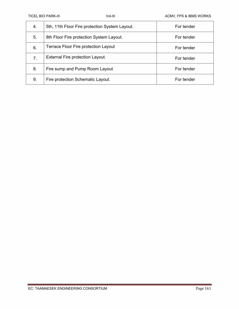
TICEL BIO PARK-III Vol-III ACMV, FPS & IBMS WORKS
EC: TAAMAESEK ENGINEERING CONSORTIUM Page 161
4. 5th, 11th Floor Fire protection System Layout. For tender
5. 8th Floor Fire protection System Layout. For tender
6. Terrace Floor Fire protection Layout For tender
7. External Fire protection Layout. For tender
8. Fire sump and Pump Room Layout For tender
9. Fire protection Schematic Layout. For tender