Q:\THIRD\2 Ben 09-10\Civil\Castrillo 09-4369\SJ FINAL II 09 ...
Upload
khangminh22Category
view
0download
0
ACI ITG-5.2-09
Requirements for Design of a SpecialUnbonded Post-Tensioned Precast
Shear Wall Satisfying ACI ITG-5.1(ACI ITG-5.2-09) and Commentary
Reported by ACI Innovation Task Group 5
An ACI Standard
Copyright American Concrete Institute Provided by IHS under license with ACI Licensee=University of Texas Revised Sub Account/5620001114, User=wer, weqwe
Not for Resale, 01/26/2015 02:11:30 MSTNo reproduction or networking permitted without license from IHS
--`,`,,```,,`,```,`,`,```,``,,,,-`-`,,`,,`,`,,`---
daneshlink.com
Daneshlink.com

American Concrete Institute®
Advancing concrete knowledge
Requirements for Design of a Special Unbonded Post-Tensioned Precast Shear WallSatisfying ACI ITG-5.1 (ACI ITG-5.2-09) and Commentary
First printingAugust 2009
ISBN 978-0-87031-339-4
Copyright by the American Concrete Institute, Farmington Hills, MI. All rights reserved. This materialmay not be reproduced or copied, in whole or part, in any printed, mechanical, electronic, film, or otherdistribution and storage media, without the written consent of ACI.
The technical committees responsible for ACI committee reports and standards strive to avoid ambiguities,omissions, and errors in these documents. In spite of these efforts, the users of ACI documents occasionallyfind information or requirements that may be subject to more than one interpretation or may beincomplete or incorrect. Users who have suggestions for the improvement of ACI documents arerequested to contact ACI. Proper use of this document includes periodically checking for errata atwww.concrete.org/committees/errata.asp for the most up-to-date revisions.
ACI committee documents are intended for the use of individuals who are competent to evaluate thesignificance and limitations of its content and recommendations and who will accept responsibility for theapplication of the material it contains. Individuals who use this publication in any way assume all risk andaccept total responsibility for the application and use of this information.
All information in this publication is provided “as is” without warranty of any kind, either express or implied,including but not limited to, the implied warranties of merchantability, fitness for a particular purpose ornon-infringement.
ACI and its members disclaim liability for damages of any kind, including any special, indirect, incidental,or consequential damages, including without limitation, lost revenues or lost profits, which may resultfrom the use of this publication.
It is the responsibility of the user of this document to establish health and safety practices appropriate tothe specific circumstances involved with its use. ACI does not make any representations with regard tohealth and safety issues and the use of this document. The user must determine the applicability of allregulatory limitations before applying the document and must comply with all applicable laws and regulations,including but not limited to, United States Occupational Safety and Health Administration (OSHA) healthand safety standards.
Order information: ACI documents are available in print, by download, on CD-ROM, through electronicsubscription, or reprint and may be obtained by contacting ACI.
Most ACI standards and committee reports are gathered together in the annually revised ACI Manual ofConcrete Practice (MCP).
American Concrete Institute38800 Country Club DriveFarmington Hills, MI 48331U.S.A.Phone: 248-848-3700Fax: 248-848-3701
www.concrete.org
Copyright American Concrete Institute Provided by IHS under license with ACI Licensee=University of Texas Revised Sub Account/5620001114, User=wer, weqwe
Not for Resale, 01/26/2015 02:11:30 MSTNo reproduction or networking permitted without license from IHS
--`,`,,```,,`,```,`,`,```,``,,,,-`-`,,`,,`,`,,`---
daneshlink.com
Daneshlink.com
ACI ITG-5.2-09 was adopted May 4, 2009 and published August 2009.Copyright © 2009, American Concrete Institute.All rights reserved including rights of reproduction and use in any form or by any
means, including the making of copies by any photo process, or by electronic ormechanical device, printed, written, or oral, or recording for sound or visual reproductionor for use in any knowledge or retrieval system or device, unless permission in writingis obtained from the copyright proprietors.
ITG-5.2-1
ACI Committee Reports, Guides, Manuals, StandardPractices, and Commentaries are intended for guidance inplanning, designing, executing, and inspecting construction.This Commentary is intended for the use of individuals whoare competent to evaluate the significance and limitations of itscontent and recommendations and who will acceptresponsibility for the application of the material it contains.The American Concrete Institute disclaims any and allresponsibility for the stated principles. The Institute shall notbe liable for any loss or damage arising therefrom.
Reference to this Commentary shall not be made in contractdocuments. If items found in this document are desired by thelicensed design professional to be a part of the contractdocuments, they shall be restated in mandatory language.
Requirements for Design of a Special UnbondedPost-Tensioned Precast Shear Wall SatisfyingACI ITG-5.1 (ACI ITG-5.2-09) and Commentary
An ACI Standard
Reported by ACI Innovation Task Group 5
ACI ITG-5.2-09
This standard defines procedures that may be used to design specialprecast concrete shear walls, coupled or uncoupled, composed ofdiscretely jointed precast panels that are vertically post-tensioned to thefoundation with unbonded tendons. Such walls are suitable for use inregions of high seismicity and for structures assigned to high seismicdesign categories. After a major seismic event, these walls can be expectedto exhibit minimal damage in the flexural hinging region at the base of thewall as well as negligible permanent displacements. Such walls do notsatisfy the prescriptive requirements of Chapter 21 of ACI 318-05 for shearwalls of monolithic construction. According to 21.2.1.5 of ACI 318-05, theiracceptance requires demonstration by experimental evidence and analysisthat the walls have strength and toughness equal to or exceeding thoseprovided by comparable monolithic reinforced concrete walls that satisfythe prescriptive requirements of Chapter 21. This standard describes theprocedures that the designer may use to demonstrate, through analysis,that one type of unbonded post-tensioned precast wall has strength and tough-ness at least equal to that of comparable special reinforced concrete monolithicwalls. The standard consists of Design Requirements and a Commentary.
Among the subjects covered in these Design Requirements are requirementsfor:
1. Materials, including considerations for the coupling or connectiondevices, that provide the primary source of energy dissipation for the wall system;
2. Individual walls, including considerations to ensure ductility,energy dissipation, integrity, stiffness, and strength; and
3. Coupled walls, including considerations of the roles of the post-tensioning tendons and coupling devices in providing energy dissipation,and strength and stiffness for coupled walls greater than the sum of thoseprovided by the coupled walls acting as separate units.
The Commentary references documentary evidence, additional to thereferences of ACI ITG-5.1-07 and Chapter 21 of ACI 318R-05, that supportsthese Design Requirements. In this standard, however, no comparison ismade between the performance of precast test modules satisfying theprescriptive requirements of ACI 318 and modules satisfying these DesignRequirements but not satisfying ACI 318. Such comparisons, both experi-mental and analytical, are available in the cited references.
All references to ACI 318 and ACI 318R in these Design Requirementsand Commentary refer to ACI 318-05 unless another edition of ACI 318 isspecifically designated. All references to ASCE/SEI 7 in these DesignRequirements and Commentary are to ASCE/SEI 7-05, includingSupplement No. 1.
In this standard, consistent with the format of ACI 318-05, the word“Section” is not included before a reference to a section of ACI 318-05. Tomore clearly designate a section in this standard, however, the word“Section” is used before any reference to a section of this standard.Consistent with the format of ASCE/SEI 7-05, the word “Section” isincluded before a reference to a section of ASCE/SEI 7-05.
Keywords: coupling devices; drift angle; energy dissipation; lateral resis-tance; post-tensioning; precast concrete; prestressed concrete; seismicdesign; special shear wall; test module; toughness.
Attila B. Beres Ronald Klemencic Stephen P. Pessiki John W. Wallace
Ned M. Cleland Vilas S. Mujumdar Carol K. Shield Loring A. Wyllie, Jr.
Neil M. Hawkins Suzanne Dow Nakaki
Consulting member
S. K. Ghosh
Charles W. DolanChair
Copyright American Concrete Institute Provided by IHS under license with ACI Licensee=University of Texas Revised Sub Account/5620001114, User=wer, weqwe
Not for Resale, 01/26/2015 02:11:30 MSTNo reproduction or networking permitted without license from IHS
--`,`,,```,,`,```,`,`,```,``,,,,-`-`,,`,,`,`,,`---
daneshlink.com
Daneshlink.com

ITG-5.2-2 ACI STANDARD
CONTENTSChapter 1—General, p. ITG-5.2-2
1.1—Introduction1.2—Scope1.3—Drawings
Chapter 2—Notation and definitions, p. ITG-5.2-52.1—Notation2.2—Definitions
Chapter 3—Materials, p. ITG-5.2-73.1—General3.2—Ducts3.3—Reinforcement3.4—Concrete3.5—Interface grout3.6—Coupling devices3.7—Corrosion protection of prestressing tendons
Chapter 4—Structural system requirements for walls, p. ITG-5.2-9
4.1—General4.2—Strength4.3—Drift4.4—Wall characteristics4.5—Distribution of walls within structures4.6—Wall system-gravity load frame interactions
Chapter 5—Design requirements for uncoupled wall systems, p. ITG-5.2-12
5.1—Scope5.2—Materials5.3—Prestress force5.4—Energy-dissipating reinforcement5.5—Shear strength5.6—Flexural strength and drift limits5.7—Detailing of lowermost wall panel5.8—Interface grout
Chapter 6—Design requirements for coupled wall systems, p. ITG-5.2-16
6.1—Scope6.2—Materials6.3—Coupling devices6.4—Prestress force6.5—Shear strength6.6—Flexural strength and drift limits6.7—Lowermost panel6.8—Interface grout
Chapter 7—Design requirements for coupling devices, p. ITG-5.2-18
7.1—Scope7.2—General7.3—Materials7.4—Design methodology
Chapter 8—References, p. ITG-5.2-198.1—Referenced standards and reports8.2—Cited references
CHAPTER 1—GENERAL1.1—Introduction
For regions of high seismic risk, where structures assignedto Seismic Design Category (SDC) D, E, or F shall be used,21.2.1.5 of ACI 318 permits the use of structural systems thatdo not meet the prescriptive requirements of Chapter 21 ifcertain experimental evidence and analysis are provided (allreferences to ACI 318 and ACI 318R in this standard refer toACI 318-05 unless another edition of ACI 318 is specificallydesignated). The intent of ACI ITG-5.1 is to define theminimum experimental evidence that is deemed sufficient topermit the use of unbonded post-tensioned precast structuralwall systems, in accordance with 21.2.1.5 of ACI 318, whenthose systems do not satisfy fully the prescriptive require-ments for wall systems in Chapter 21 of ACI 318.
Before validation testing can be undertaken, ACI ITG-5.1requires that a design procedure be developed for prototypewall systems having the generic form for which acceptanceis sought, and that design procedure is used to proportion thetest modules. This standard defines the design procedure fora specific type of wall system that does not satisfy theprescriptive requirements of Chapter 21 of ACI 318, but isvalidated for use in regions of high seismicity under ACIITG-5.1. The wall system uses precast concrete panels thatare post-tensioned to the foundation and intended to rock onthat foundation under seismic actions.
For coupled walls, coupling devices located along thevertical boundaries of adjacent walls provide the requiredenergy dissipation and energy-dissipating reinforcement thatcrosses the wall-foundation interface is unnecessary. Duringan earthquake, the coupled walls displace as rigid bodies thatare tied together. Wall deformations occur primarily at theinterface between each individual wall and the foundation,with each wall rocking separately at that interface.
The unbonded post-tensioning has two purposes. First, thepost-tensioning steel is deliberately designed to remainessentially elastic during the design basis earthquake (DBE),defined in ASCE/SEI 7, so that it forces the walls to return totheir undeformed positions following the event. Second, thefriction induced by the post-tensioning and gravity loadingon the wall transfers the horizontal shears due to lateral loadingsat the interfaces between the wall and the foundation andbetween the precast panels of the wall.
The detailing procedures described in this standard are forone specific type of unbonded post-tensioned precast shearwall system, coupled or uncoupled. Four statements definekey characteristics of uncoupled and coupled unbondedpost-tensioned precast concrete cantilever shear walls thatsatisfy this standard:
(a) Post-tensioning tendons unbonded from an anchor inthe foundation to an anchor at the top of the wall and locatedin a single duct on the vertical centerline of the wall or, ifneeded, in two or more ducts positioned symmetrically oneither side of that vertical centerline and within 10% of thewall length from that centerline;
(b) Precast panels one story or more in height; and(c) For uncoupled walls, two sets of energy-dissipating
reinforcing bars crossing the interface between the lower-Copyright American Concrete Institute Provided by IHS under license with ACI Licensee=University of Texas Revised Sub Account/5620001114, User=wer, weqwe
Not for Resale, 01/26/2015 02:11:30 MSTNo reproduction or networking permitted without license from IHS
--`,`,,```,,`,```,`,`,```,``,,,,-`-`,,`,,`,`,,`---
daneshlink.com
Daneshlink.com

DESIGN REQUIREMENTS OF SHEAR WALL SATISFYING ACI ITG-5.1 ITG-5.2-3
most precast panel of the wall and the foundation and withthe sets located symmetrically about the vertical centerlineof the wall; or
(d) For coupled walls, energy-dissipating coupling devicesfor a given vertical joint between coupled walls, of equalstrength, at least two in number for each coupled edge of apanel in the wall, and positioned so that the width of thevertical joint between panels remains approximatelyconstant in width as the walls rock on their bases.
R1.1Large-scale laboratory experiments (Bora et al. 2007;
Perez et al. 2003; Priestley et al. 1999; Rahman andRestrepo 2000; Santana 2005) have shown that unbondedpost-tensioned precast concrete cantilever shear walls canprovide safety and serviceability levels, during and after anearthquake, that meet or exceed performance levels requiredby 21.2.1.5 of ACI 318 and ACI ITG-5.1. Analytical studies(Kurama 2002; Perez et al. 2004a,b; Rahman and Restrepo2000; Stanton and Nakaki 2002; Thomas and Sritharan2004; Sritharan et al. 2007) have shown that to achieve suchperformance levels, the shear walls should be proportionedand detailed in accordance with specific considerations.This standard is developed from the aforementioned studiesand related references. This standard contains the minimumrequirements for ensuring that one type of unbonded post-tensioned precast concrete cantilever shear wall system,uncoupled or coupled, can sustain a series of oscillations intothe inelastic range of response without critical decay in strengthor excessive story drifts. Further, that shear wall should showonly minimal or no damage to the wall, and minimal or nopermanent displacements after the oscillations cease.
In this specific type of coupled or uncoupled wall system,the post-tensioning tendons are unbonded and designed toremain elastic during the DBE. Except at the foundation, thehorizontal joints between the precast panels that make up acantilever wall are designed to remain closed during anearthquake.
For uncoupled walls, vertical reinforcing bars groutedinto ducts located in the wall panels abutting the foundationand in the foundation, and described in this standard asenergy-dissipating reinforcement, provide energy dissipationas they yield alternately in tension and compression duringan earthquake. These bars also provide continuity additionalto the post-tensioning between the cantilever wall and thefoundation, and additional moment strength for the wall. Thegrouted bars are deliberately debonded for a specificdistance in the panel adjacent to the wall-foundation interfaceto reduce the high cyclic strains that would otherwise occurat that location. Consequently, during an earthquake, thecantilever wall can displace essentially as a rigid body.Vertical deformations occur primarily at the wall-foundationinterface as the wall rocks against the foundation.
Under seismic loading, the special shear walls describedin this standard are intended to behave differently thanmonolithic shear walls. Most of the deformations of the wallsoccur from the opening and closing of the joint at the interfacebetween the precast walls and the foundation. Consequently,
with the detailing procedures described in this standard,damage during a DBE event is limited in extent, confinedessentially to the wall to foundation joint filler material or tothe concrete cover over the boundary element reinforcementat the wall toes, and can be readily repaired after the earth-quake. By contrast, monolithic walls, coupled and uncou-pled, designed to Chapter 21 of ACI 318, can suffersignificant cracking, crushing, and spalling in the plastichinging regions at the base of the walls, in the couplingbeams, or both, and repair can be costly. Further, mono-lithic special shear walls designed to Chapter 21 of ACI 318may show permanent lateral deformations following a DBEevent whereas the special shear walls described in this stan-dard should not.
Precast shear walls with the following can be propor-tioned to have performance characteristics similar to thewalls described in this standard:
1. Unbonded tendons that cross the wall-foundation inter-face at locations along the length of the wall that are morethan 10% of the wall length from its vertical centerline; or
2. Uncoupled walls with energy dissipation devices havingcharacteristics differing from those for the energy-dissi-pating reinforcement described in Section 1.1(c) and posi-tioned differently along the length of the wall; or
3. Coupled walls with coupling elements connectingvertical boundaries of adjacent walls and having character-istics for the coupling elements differing from those for thecoupling devices described in Section 1.1(d).
Research investigations additional to those completed todate, and modifications of the procedures described in thisstandard, however, are needed before prescriptive provisionsfor the design of such precast shear walls can be formulated.
1.2—Scope1.2.1 This standard defines design requirements for a
certain class of unbonded post-tensioned precast concreteshear walls that can be used as special reinforced concreteshear walls for Bearing Wall and Building Frame SpecialReinforced Concrete Shear Wall Systems, as defined inASCE/SEI 7.
1.2.2 The requirements described in this standard are forspecial unbonded post-tensioned precast shear walls with:
1. Essentially planar proportions in the vertical direction,no significant discontinuities in plan, in vertical configuration,or in their lateral-force-resisting system, and designed tohave a single critical section for flexure and axial loads at thebase of the shear wall;
2. Post-tensioning tendons unbonded from anchor toanchor and located in a single duct at the centroid of thetransverse cross section of the wall, or in an additional twoor more ducts positioned symmetrically on either side of thatcentroid and within 10% of the shear wall length from thatcentroid; and
3. Energy dissipation provided: a) for uncoupled walls byenergy-dissipating reinforcement that crosses the interfacebetween the base of the wall and the foundation; and b) forcoupled walls by coupling devices that connect adjacent
Copyright American Concrete Institute Provided by IHS under license with ACI Licensee=University of Texas Revised Sub Account/5620001114, User=wer, weqwe
Not for Resale, 01/26/2015 02:11:30 MSTNo reproduction or networking permitted without license from IHS
--`,`,,```,,`,```,`,`,```,``,,,,-`-`,,`,,`,`,,`---
daneshlink.com
Daneshlink.com

ITG-5.2-4 ACI STANDARD
vertical boundaries of shear walls, number at least two foreach connected vertical boundary of each precast panel, andare distributed uniformly over the height of the panel.
R1.2.2 While the shear walls described in this standard donot fully satisfy the prescriptive requirements of Chapter 21of ACI 318, analyses and tests, and reporting consistent withthe intent of the requirements of ACI ITG-5.1, have establisheddependable and predictable strength, energy dissipation,stiffness, and drift capacities for the characteristic wallconfigurations described in this standard. The main featuresof the wall systems covered by this standard are illustratedin Fig. R1.1(a) and (b). Details for a typical uncoupledcantilever shear wall are shown in Fig. R1.1(a), and detailsfor typical coupled shear wall systems in Fig. R1.1(b). Forwalls designed in accordance with this standard, the numberof upper panels can be greater or less than the two panelsshown in Fig. R1.1(a) and each panel can be one or morestories in height.
The uncoupled cantilever shear wall in Fig. R1.1(a) is aplanar wall composed of three precast concrete panels andintended for use in a building that is three stories high.Except for two regions where large compressive stressesdevelop in the concrete and the associated reinforcementnear the toes of the wall, the only reinforcement yielding intension under lateral loading is the energy-dissipatingreinforcement that crosses the wall-foundation interface.The unbonded length and prestress level for the central tendonis deliberately selected so that the prestressing steel does notyield as a result of the opening of the gap at the wall base atthe design displacement. The deformed bar reinforcementfor energy dissipation is anchored by grouting in ductspreformed in the lower-most panel and the foundation. Thelength over which the energy-dissipating reinforcement isdebonded in the panel adjacent to the wall-foundation interfaceand the position of the two sets of bars either side of thecenter of the wall are selected deliberately to provide thedesired design level of overall performance. The axial loadstress level in the wall due to combined gravity load andprestressing is relatively low and, therefore, the neutral axisdepth at the wall-foundation interface that gives rise to theregion of high compressive strains in the toe of the wall isrelatively small.
For the coupled planar two- and three-wall systems shownin Fig. R1.1(b), each wall is composed of three precastpanels and each system is for a building five stories inheight. The upper panels in each wall are two stories inheight while the lower-most panel, where large compressivestresses develop in the toe of the wall under lateral loading,is detailed differently than the upper panels. Energy dissipationis provided by connection devices that can yield and arelocated, with at least two per panel, along the vertical edgesthat are coupled. The shearing displacements imposed on thedevices are a direct function of the gap opening allowed at thewall-foundation interface under the design displacement. Theprestress level for the central tendon in each wall is selected sothat the prestressing steel does not yield under the gap openingimposed by the design displacement. The axial load stresslevel imposed on each wall at the design displacement is a
function of the gravity load, the prestress level, and the effectiveyield strength of the connection devices. Because of thegreater weight of the precast panels and the greater length
Fig. R1.1(a)—Main features of uncoupled unbonded post-tensioned precast shear wall.
(i) Two-wall system
(ii) Three-wall system
Fig. R1.1(b)—Main features of coupled wall systems.
Copyright American Concrete Institute Provided by IHS under license with ACI Licensee=University of Texas Revised Sub Account/5620001114, User=wer, weqwe
Not for Resale, 01/26/2015 02:11:30 MSTNo reproduction or networking permitted without license from IHS
--`,`,,```,,`,```,`,`,```,``,,,,-`-`,,`,,`,`,,`---
daneshlink.com
Daneshlink.com

DESIGN REQUIREMENTS OF SHEAR WALL SATISFYING ACI ITG-5.1 ITG-5.2-5
of the tendons for the coupled walls of Fig. R1.1(b) (ascompared with the uncoupled wall of Fig. R1.1(a)), blockoutsmay need to be provided on the line of the tendons and at thebottom of each panel for the location of access to couplersfor the prestressing tendons.
1.2.3 All precast and reinforced concrete components andsystems for the shear wall, energy dissipation and couplingdevices, and associated gravity load systems, shall bedesigned to satisfy the requirements of ACI 318 except asmodified by this standard.
1.2.4 All precast, prestressed, and reinforced concretecomponents and systems for the shear wall system, includingenergy dissipation and coupling devices and associatedgravity load systems, shall meet the quality assurancerequirements of Appendix 11A of ASCE/SEI 7. Require-ments of Sections 11A.1.3.2, 11A.1.3.3, and 11A.1.3.4 shallapply for any shear wall panel element constructed on or offsite, for assembly and post-tensioning operations on site, andfor construction and installation of coupling devices.
R1.2.4 For the shear wall systems described in this stan-dard to be accepted as special shear wall systems defined byASCE/SEI 7, the periodic special and continuous specialinspection requirements during steel placement, weldingoperations, grouting, and concrete placement need to beproperly executed by personnel who are qualified to performthe work and such inspection should be specified in thecontract documents.
1.3—Drawings Drawings of the shear walls and associated framing shall
show all features of the work, including those details essentialfor satisfactory seismic performance of the wall system,associated gravity load systems, and any special tolerancesassociated with construction. Essential details for the wallsinclude: anchoring the post-tensioning tendons within thefoundation and at the top of the walls; uncoupled walls ofdebonding and anchoring the energy-dissipating reinforce-ment that crosses the interface between the base of the walland the foundation; coupled walls for fabricating couplingdevices, anchoring them to the walls and connecting them toone another; anchoring seismic reinforcement at precast panelboundaries; and developing floor slab-wall-frame interactionsthat conform to those assumed in the design documents.
R1.3Because reinforcing details at the base of the wall and at
the location of the coupling devices for coupled walls areessential to the satisfactory performance of walls in a majorseismic event, details should be designed meticulously andfully documented on the drawings for each connection of awall to the foundation and for each device that connectscoupled walls. For uncoupled walls with energy-dissipatingreinforcement, essential elements include the location of thereinforcement along the wall to foundation interface, thelength of the reinforcement that is deliberately debonded,how the reinforcement is debonded, details of its anchorage
in the wall panel and the foundation, and any special toler-ances associated with installation. For the post-tensioningtendon, essential elements are how and where the tendonwill be anchored and, if appropriate, coupled, and how itwill be assured that the tendon remains debonded during thegrouting of the joint between the wall and the foundation andduring any grouting of joints between wall panels.
CHAPTER 2—NOTATION AND DEFINITIONS2.1—NotationAps = area of post-tensioning tendons crossing wall-
foundation interface, in.2 (mm2)As = area of energy-dissipating reinforcement crossing
wall-foundation interface, in.2 (mm2)a = depth of equivalent rectangular stress block for
confined concrete, in. (mm)asc = radius of 180-degree bend for connecting link
measured to its inside face, in. (mm)bsc = width of connecting link bar, in. (mm)C = compression force on toe of wall when probable
flexural strength Mpr acts at wall-foundationinterface, lb (N)
c = distance from extreme compression fiber of groutpad to neutral axis of wall at wall-foundationinterface, in. (mm)
Dc = self-weight of wall plus any dead loads acting onit, including the self-weight of componentsdirectly attached to the wall, lb (N)
db = bar diameter of energy-dissipating reinforcement,in. (mm)
dsc = distance center to center of prongs of connectinglink of U-shaped flexure plate (UFP) couplingdevice, in. (mm); refer to Fig. R7.1
E = load effects of earthquakes or related internalmoments and forces
Es modulus of elasticity of reinforcement and struc-tural steel, psi (MPa)
e = distance between centroid of wall and centroid ofenergy-dissipating reinforcement located furthestfrom the compression toe of wall, in. (mm)
Fcon = force in coupling device at drift angle corre-sponding to design displacement, lb (N)
fc′ = specified compressive strength of concrete, psi(MPa)
fcc′ = stress in confined concrete in toe of wall, psi(MPa)
fL′ = effective lateral confining stress provided bytransverse reinforcement in toe of wall, psi (MPa)
fprs = stress in post-tensioning tendons when stress inenergy-dissipating reinforcement is fu, psi (MPa)
fpu = specified tensile strength of post-tensioningtendons, psi (MPa)
fpy = specified yield strength of post-tensioningtendons, psi (MPa)
fscu = specified tensile strength of connecting link steel,psi (MPa)
fse = effective stress in post-tensioning tendons (afterallowance for all prestress losses), psi (MPa)
Copyright American Concrete Institute Provided by IHS under license with ACI Licensee=University of Texas Revised Sub Account/5620001114, User=wer, weqwe
Not for Resale, 01/26/2015 02:11:30 MSTNo reproduction or networking permitted without license from IHS
--`,`,,```,,`,```,`,`,```,``,,,,-`-`,,`,,`,`,,`---
daneshlink.com
Daneshlink.com

ITG-5.2-6 ACI STANDARD
fu = specified tensile strength of energy-dissipatingreinforcement crossing wall-foundation interface,psi (MPa)
fy = specified yield strength of energy-dissipatingreinforcement, psi (MPa)
fyt = specified yield strength of transverse reinforce-ment in wall, psi (MPa)
hw = height of wall, in. (mm)Ksc = elastic stiffness of connecting link of UFP
coupling device, in.-lb (Nm)Lp = effective height of plastic hinging zone in toe of
wall, in. (mm)Lu = length over which energy-dissipating reinforce-
ment crossing wall-foundation interface is delib-erately debonded, in. (mm)
Lups = length over which post-tensioning tendon isunbonded, in. (mm)
ld = development length in tension for a straightdeformed reinforcing bar, in. (mm)
lw = overall length of individual wall at wall-founda-tion interface, in. (mm)
Mdw = design moment for wall providing greater, or greatest,resistance for coupled wall system, in.-lb (Nm)
Mn = nominal flexural strength, in.-lb (Nm)Mpr = probable flexural strength of uncoupled wall at the
wall-foundation interface, see Section 5.6.3 orprobable flexural strength of wall system forcoupled walls at wall-foundation interface, seeSection 6.6.2, in.-lb (Nm)
Mprs = contribution of post-tensioning reinforcement toMpr , in.-lb (Nm)
Mpsc = plastic moment strength of connecting linksection, in.-lb (Nm)
Ms = contribution of energy-dissipating reinforcementto Mpr , in.-lb (Nm)
Mu = factored moment acting on wall or wall system,in.-lb (Nm)
n = number of walls in wall systemncon = number of coupling devices per vertical joint for
coupled wall systemT = post-tensioning force, lb (N)tsc = thickness of connecting link bar, in. (mm)tw = width of compression face of wall at wall-founda-
tion interface, in. (mm)Vi = shear strength of wall foundation interface for i-th
wall, lb (N)Vn = nominal shear strength, lb (N)Vni = nominal shear strength of wall foundation interface,
lb (N)Vscu = nominal shear capacity of UFP coupling device,
lb (N)α = factor relating average effective stress for depth of
compression block at toe of wall to fcc′
αb = coefficient quantifying the effective additionaldebonded length for energy-dissipating reinforce-ment at probable flexural strength
β = factor relating depth of equivalent rectangular stressblock for confined concrete to neutral axis depth
εcmax = maximum usable strain in extreme compressionfiber of wall
εf = strain in energy-dissipating reinforcement at itsfracture
εprs = strain in post-tensioning tendon when stress inenergy-dissipating reinforcement is fu
εscu = strain in connecting link steel at its fractureεse = strain in post-tensioning tendon due to effective
prestress only (after allowance for all losses)εsu = strain in energy-dissipating reinforcement at
elongation Δsεsut = ultimate specified strain capacity of transverse
reinforcement in toe of wallεu = strain in energy-dissipating reinforcement at its
tensile strength fuμ = coefficient of frictionΔprs = additional elongation of post-tensioning tendon at
probable flexural strength, in. (mm)Δs = elongation of energy-dissipating reinforcement at
probable flexural strength Mpr , in. (mm)θL = drift angle, radiansθLdesign = drift angle at design displacement, radians θLmax= drift angle at probable flexural capacity, radiansλ = modification factor related to unit weight of
concrete; refer to ACI 318λp = participation factor for wall of coupled wall systemρr = redundancy factor as defined in ASCE/SEI 7ρs = ratio of volume of hoop or spiral reinforcement to
total volume of core confined by hoop or spiralρx = ratio of volume of rectangular hoops in direction
parallel to major axis of compressed area to totalvolume of core confined by hoop
ρy = ratio of volume of rectangular hoops in directionparallel to minor axis of compressed area to totalvolume of core confined by hoop
Ωo = overstrength factor as defined in ASCE/SEI 7φ = strength reduction factor
2.2—DefinitionsThe following definitions, additional to those of 21.1 of
ACI 318 and of ACI ITG-5.1, shall apply.coupling devices—mechanical devices connecting adjacent
boundaries of precast structural walls and providing stiffnessand energy dissipation for the connected walls greater thanthe sum of those provided by the connected walls acting asseparate units. The mechanical devices consist of connectinglinks that cross the interface between adjacent precast panelsand anchorages that attach those connecting links to the panels.
reinforcement, energy-dissipating—reinforcement(nonprestressed) crossing the wall-foundation interface anddesigned to yield over a specified unbonded length during adesign event. Refer to Section 5.4.
reinforcement, seismic—reinforcement that conforms toASTM A706 or reinforcement that conforms to ASTM A615Grades 40 or 60 (ASTM A615M Grades 280 or 420) and hasan actual yield strength not greater than the specified yieldstrength by more than 18,000 psi (125 MPa) and a ratio of
Copyright American Concrete Institute Provided by IHS under license with ACI Licensee=University of Texas Revised Sub Account/5620001114, User=wer, weqwe
Not for Resale, 01/26/2015 02:11:30 MSTNo reproduction or networking permitted without license from IHS
--`,`,,```,,`,```,`,`,```,``,,,,-`-`,,`,,`,`,,`---
daneshlink.com
Daneshlink.com

DESIGN REQUIREMENTS OF SHEAR WALL SATISFYING ACI ITG-5.1 ITG-5.2-7
actual tensile strength to actual yield strength not less than1.25. Refer to 21.2.5 of ACI 318.
R2.2—DefinitionsThe following is Commentary on the foregoing definitions.coupling devices—for ACI ITG-5.1, either coupling
devices or coupling beams can connect adjacent verticalboundaries of precast structural walls. For this standard,only mechanical coupling devices are permitted. Typicaldevices (PCI Ad Hoc Committee on Precast Walls 1997;Schultz and Magana 1996; Stanton and Nakaki 2002) haveanchorages cast into each panel and a connecting link thatis subsequently made between the panels after their erection.Details of the mechanical coupling devices used for the walldirection loading for the Precast Seismic Structural Systems(PRESSS) building test are shown in Fig. R2.1. The bentU-shaped flexure plate (UFP) is the connecting link and thewelded studs, and ASTM A706 bars and embedded plates arethe anchorage.
reinforcement—the definition of reinforcement in ACI318 does not permit easy differentiation between the types ofreinforcement permitted in special shear walls in accor-dance with this standard. Therefore, a terminology is usedfor different deformed bar reinforcement types consistentwith that of ACI ITG-1.2 (ACI Innovation Task Group 12003). The designer can choose ordinary deformed barreinforcement per 3.5 of ACI 318, or prestressing reinforce-ment for wall panels other than panels in contact with thefoundation. That is because this standard requires all panelsexcept those in contact with the foundation to remain elastic
under the design displacement. By contrast, reinforcement inthe boundaries of panels in contact with the foundation isusually stressed inelastically at the design displacement. Thedesigner needs to use reinforcement at those locationsconforming to 21.2.5 of ACI 318. Energy-dissipating reinforce-ment, other than post-tensioning reinforcement, that crossesthe interface between the wall and the foundation can haveproperties deliberately chosen to differ from those of ordinaryand seismic reinforcement. The term “energy-dissipatingreinforcement” is used to describe that reinforcement.
CHAPTER 3—MATERIALS3.1—General
All materials and material tests shall conform to therequirements of ACI 318, except as specified in this standard.
3.2—DuctsDucts, including those for energy-dissipating reinforce-
ment, shall conform to requirements of 18.17 of ACI 318.
R3.2Ducts for the unbonded prestressing steel need to be large
enough to preclude kinking ( the act where the tendon comesin contact with the duct wall and is bent sharply) of thetendons at the wall-to-foundation interface as the wall rocks,and small enough to not cause a significant loss of trans-verse wall area on the line of the duct. For those reasons,flat-profile ducts have been used in some tests (Rahman andRestrepo 2000).
Fig. R2.1—Typical UFP coupling device used in PRESSS building.
Copyright American Concrete Institute Provided by IHS under license with ACI Licensee=University of Texas Revised Sub Account/5620001114, User=wer, weqwe
Not for Resale, 01/26/2015 02:11:30 MSTNo reproduction or networking permitted without license from IHS
--`,`,,```,,`,```,`,`,```,``,,,,-`-`,,`,,`,`,,`---
daneshlink.com
Daneshlink.com
ITG-5.2-8 ACI STANDARD
Ducts should be tied at intervals of 2 ft or less to main wallreinforcement to prevent their displacement during wallpanel casting.
3.3—Reinforcement3.3.1 Reinforcement in shear wall boundary elements shall
comply with 21.2.5 of ACI 318.R3.3.1 At the design displacement, the longitudinal bars in
the shear wall boundary elements are likely to yield incompression and the confining reinforcement for those barsis likely to yield in tension.
3.3.2 Energy-dissipating reinforcement shall have the ribdeformation heights, yield strength, ultimate elongation, andstress-strain properties required by ASTM A706. Instead ofusing ASTM A706, reinforcement-specific test data on thestress-strain properties of the energy-dissipating reinforce-ment shall be obtained before design and construction. Insuch cases, the tensile strength shall be taken as the specifiedminimum tensile strength fu. The strain εu at the tensilestrength shall be taken as a strain 0.02 less than the strain atthe minimum elongation specified in ASTM A706 for thegiven bar size. Stress-strain properties of energy-dissipatingreinforcement for each bar size used for the wall system shallbe obtained from tension tests as specified in ASTM A706.The average strain εu of reinforcement at its average tensilestrength fu shall be obtained. Averages shall be based on theresults of a minimum of three tension tests for each bar sizefor every steel heat used in the wall system.
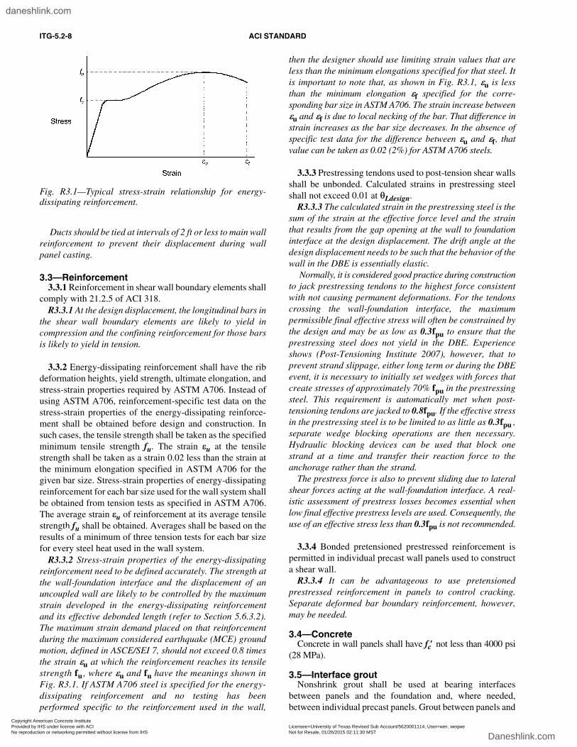
R3.3.2 Stress-strain properties of the energy-dissipatingreinforcement need to be defined accurately. The strength atthe wall-foundation interface and the displacement of anuncoupled wall are likely to be controlled by the maximumstrain developed in the energy-dissipating reinforcementand its effective debonded length (refer to Section 5.6.3.2).The maximum strain demand placed on that reinforcementduring the maximum considered earthquake (MCE) groundmotion, defined in ASCE/SEI 7, should not exceed 0.8 timesthe strain εu at which the reinforcement reaches its tensilestrength fu , where εu and fu have the meanings shown inFig. R3.1. If ASTM A706 steel is specified for the energy-dissipating reinforcement and no testing has beenperformed specific to the reinforcement used in the wall,
then the designer should use limiting strain values that areless than the minimum elongations specified for that steel. Itis important to note that, as shown in Fig. R3.1, εu is lessthan the minimum elongation εf specified for the corre-sponding bar size in ASTM A706. The strain increase betweenεu and εf is due to local necking of the bar. That difference instrain increases as the bar size decreases. In the absence ofspecific test data for the difference between εu and εf, thatvalue can be taken as 0.02 (2%) for ASTM A706 steels.
3.3.3 Prestressing tendons used to post-tension shear wallsshall be unbonded. Calculated strains in prestressing steelshall not exceed 0.01 at θLdesign.
R3.3.3 The calculated strain in the prestressing steel is thesum of the strain at the effective force level and the strainthat results from the gap opening at the wall to foundationinterface at the design displacement. The drift angle at thedesign displacement needs to be such that the behavior of thewall in the DBE is essentially elastic.
Normally, it is considered good practice during constructionto jack prestressing tendons to the highest force consistentwith not causing permanent deformations. For the tendonscrossing the wall-foundation interface, the maximumpermissible final effective stress will often be constrained bythe design and may be as low as 0.3fpu to ensure that theprestressing steel does not yield in the DBE. Experienceshows (Post-Tensioning Institute 2007), however, that toprevent strand slippage, either long term or during the DBEevent, it is necessary to initially set wedges with forces thatcreate stresses of approximately 70% fpu in the prestressingsteel. This requirement is automatically met when post-tensioning tendons are jacked to 0.8fpu. If the effective stressin the prestressing steel is to be limited to as little as 0.3fpu ,separate wedge blocking operations are then necessary.Hydraulic blocking devices can be used that block onestrand at a time and transfer their reaction force to theanchorage rather than the strand.
The prestress force is also to prevent sliding due to lateralshear forces acting at the wall-foundation interface. A real-istic assessment of prestress losses becomes essential whenlow final effective prestress levels are used. Consequently, theuse of an effective stress less than 0.3fpu is not recommended.
3.3.4 Bonded pretensioned prestressed reinforcement ispermitted in individual precast wall panels used to constructa shear wall.
R3.3.4 It can be advantageous to use pretensionedprestressed reinforcement in panels to control cracking.Separate deformed bar boundary reinforcement, however,may be needed.
3.4—ConcreteConcrete in wall panels shall have fc′ not less than 4000 psi
(28 MPa).
3.5—Interface groutNonshrink grout shall be used at bearing interfaces
between panels and the foundation and, where needed,between individual precast panels. Grout between panels and
Fig. R3.1—Typical stress-strain relationship for energy-dissipating reinforcement.
Copyright American Concrete Institute Provided by IHS under license with ACI Licensee=University of Texas Revised Sub Account/5620001114, User=wer, weqwe
Not for Resale, 01/26/2015 02:11:30 MSTNo reproduction or networking permitted without license from IHS
--`,`,,```,,`,```,`,`,```,``,,,,-`-`,,`,,`,`,,`---
daneshlink.com
Daneshlink.com
DESIGN REQUIREMENTS OF SHEAR WALL SATISFYING ACI ITG-5.1 ITG-5.2-9
the foundation shall contain at least 0.1% fibers by volumeand conform to ASTM C1107.
R3.5Fiber-reinforced grout is required because testing has
shown that fibers are needed to keep the grout in place andessentially intact when the walls are at the maximumdisplacements permitted by this standard. Fibers may besteel or polypropylene. Refer to Section 5.8.
3.6—Coupling devices3.6.1 Materials for connecting links shall have deforma-
tions at failure at least twice the calculated deformation ofthe link at the design displacement.
R3.6.1 For the coupling device shown in Fig. R2.1, theconnecting link has the shape shown in Fig. R7.1. Deforma-tion demand on the U-shaped connecting link can be deter-mined from the design displacement of the wall system. Thestrain imposed on the material used in the connecting linkcannot be readily determined from theoretical consider-ations. Therefore, full-scale testing of links, using the materialthat will be used in the connecting links of the wall system, asrequired by ACI ITG-5.1, is necessary to ensure that thedeformability criteria of this provision can be satisfied.
3.6.2 Materials used for connecting links that are exposedto weather or corrosive environments shall be stainless steelconforming to ASTM A955 or shall be corrosion-protected.
R3.6.2 A weldable stainless steel was used for theconnecting links of the UFP coupling devices in the PRESSSbuilding test (Priestley et al. 1999). Suitable materials forcorrosion protection are described in R18.16 of ACI 318.
3.7—Corrosion protection of prestressing tendons3.7.1 Unbonded prestressing steel shall be corrosion
protected in accordance with 18.16 of ACI 318.
R3.7.1 The prestressing steel may be strand, bars, or wire,and may be single-strand or multistrand tendons. Multi-strand tendons may require different protection methodsthan single-strand tendons. Ducts need to be larger in sizethan the prestressing steel so that kinking of the steel at thewall-foundation interface does not occur.
3.7.2 Corrosion protection methods shall be used whereprestressing tendons cross the wall to foundation interfaces.
3.7.3 Post-tensioning anchorages shall be sealed toprevent water intrusion.
R3.7.3 Encapsulation in accordance with ACI 423.7 (ACICommittee 423) Section 2.5.1 should provide adequateprotection.
CHAPTER 4—STRUCTURAL SYSTEM REQUIREMENTS FOR WALLS
4.1—GeneralDesigns shall meet the performance requirements of this
section.
R4.1The design of a building in a given wall system direction can
be controlled by strength or drift considerations. Performancerequirements for the wall system, post-tensioning tendons,wall system-floor system interactions and, for uncoupledwalls, the energy-dissipating reinforcement that crosses thewall-foundation interface, or for coupled walls, the couplingdevices that link the vertical boundaries of adjacent walls, aregiven in Chapter 4. Specific detailing requirements for uncou-pled wall systems, concentrically post-tensioned, and theirenergy-dissipating reinforcement, are given in Chapter 5, andthose for a coupled wall system with the walls concentricallypost-tensioned and vertically coupled are given in Chapter 6.Specific detailing requirements for the coupling devices forcoupled walls are given in Chapter 7.
4.1.1 For all components, there shall be a continuousuninterrupted load path to the foundation, having adequatestrength and stiffness, for all required design loads and loadcombinations, including the load effects of earthquakes.
4.1.2 Integrity of the entire load path shall be ensuredwhen the structure, and every story in it, is subject to thelimiting story drift angle required by Eq. (5-1) of ACI ITG-5.1for the smallest value of hw /lw of any wall in the structure.
R4.1.2 The integrity of the load path to the foundation forall components should be examined for the position to whichthe structure deforms at its maximum anticipated drift angle.That angle can be taken as controlled by the smallest hw/lwvalue for any wall in one of the orthogonal directions forframing in the building.
4.2—Strength4.2.1 At all sections, nominal strengths calculated in
accordance with the requirements of ACI 318 and Chapters 5and 6 of these Design Requirements, multiplied by thestrength reduction factors specified in ACI 318, shall equalor exceed the required strengths for all the load combinationsof 9.2 of ACI 318 involving the earthquake loading E.
R4.2.1 While the requirements of Section 4.2 need to besatisfied for all sections in the structure, greater nominalstrengths may be required for sections where capacitydesign procedures are used to ensure that horizontal jointsdo not open during earthquake events and that inelasticaction is confined to the toe regions of the walls.
4.2.2 Where required, load conditions necessitating over-strength factor Ωo applications shall be determined in accor-dance with ASCE/SEI 7.
4.2.3 The effect of higher modes of vibration on the shearsand moments at all joints within walls and at the base ofwalls shall be evaluated and included in required strengths.
R4.2.3 Higher modes of vibration may cause a lowering ofthe effective centroid of the seismic loading from that evaluatedusing equivalent lateral force procedures. For a givenresistance to overturning moment, the base shear is increased,
Copyright American Concrete Institute Provided by IHS under license with ACI Licensee=University of Texas Revised Sub Account/5620001114, User=wer, weqwe
Not for Resale, 01/26/2015 02:11:30 MSTNo reproduction or networking permitted without license from IHS
--`,`,,```,,`,```,`,`,```,``,,,,-`-`,,`,,`,`,,`---
daneshlink.com
Daneshlink.com
ITG-5.2-10 ACI STANDARD
and local shears and moments within the wall may beincreased. Eberhard and Sozen (1993) provide a method forcalculating higher mode effects.
4.3—Drift4.3.1 The total drift angle shall be computed as the lateral
displacement at the top of the wall divided by its height.
4.3.2 The story drift angle shall be computed as the relativelateral displacement between adjacent floors divided by thestory height.
4.3.3 The design total drift angle θLdesign and the designstory drift angle for the structure, of which the walls are part,shall be calculated as required by Sections 12.8.6, 12.9.2, or16.1 of ASCE/SEI 7. Foundation flexibility shall be consid-ered and, where appropriate, included in the analysis. Theload-deformation characteristics of the foundation on whichthe structure is located shall be modeled in accordance withSection 12.13.3 of ASCE/SEI 7.
4.3.4 The design total drift angle θLdesign and the designstory drift angle, calculated as required in Section 4.3.3, shallnot exceed two-thirds of the limiting drift required by Eq. (5-1)of ACI ITG-5.1 for the smallest value of hw /lw of any wallin the structure.
R4.3.4 The limiting drift required by Eq. (5-1) of ACIITG-5.1 is
0.90 ≤ 0.8[hw /lw] + 0.5 ≤ 3.0 (R4-1)
4.3.5 The drift angle demand and drift angle capacity forany wall shall be calculated as the sum of the componentscaused by: a) the inelastic deformations at the wall-foundationinterface at the probable moment strength for that interface;and b) the sum of the deformations, flexural and shear, of thewall framing into that interface.
4.3.6 Any wall shall be designed to have a drift anglecapacity θLmax and story drift angle capacities equal to orgreater than the limiting story drift angle required by Eq. (5-1)of ACI ITG-5.1 for the hw/lw value of that wall.
4.3.7 The story drift angle capacity for the structure shallbe the least drift angle capacity for any wall in that story.
4.4—Wall characteristics4.4.1 The unbonded post-tensioned, uncoupled or vertically
coupled, precast concrete walls described in this standardshall, in addition to satisfying the requirements of 21.2 and21.7 of ACI 318, have characteristics meeting the requirementsof Sections 4.4.2 through 4.4.5.
4.4.2 Walls shall be of constant thickness over the heightof the building and have a height-length ratio hw /lw equal toor greater than 0.5.
R4.4.2 This standard assumes that wall behavior iscontrolled by rocking on the wall-foundation interface and
by flexural deformations. Experimental studies have shownthat the behavior of walls with hw/lw less than 0.5 is domi-nated by shear deformations. Therefore, walls designed tothis standard should have hw/lw equal to or greater than 0.5.
4.4.3 Walls may consist of a single precast panel or severalprecast panels stacked vertically on one another. For stackedpanels all horizontal joints, except those at the wall foundationinterface, shall not open in the DBE.
4.4.4 Precast panels shall be single elements and shall notbe built up from several elements connected across verticaljoints.
R4.4.4 This standard requires that any connection acrossa vertical joint be ductile. Precast panels should not be builtup from several elements connected across vertical jointsthat are intended to remain rigid. Unless such joints arepost-tensioned, the resulting panel has a rigidity less thanthat of a panel without such joints.
4.4.5 Under horizontal ground motions, the precast wallsshall be designed to rock about their individual bases inessentially a rigid body motion.
R4.4.5 With the horizontal joints between panelsremaining closed during the DBE, the effects of horizontalmotions are absorbed primarily by the wall rocking on itsinterface with the foundation.
4.4.6 Under the DBE and for uncoupled walls, the inter-face between the wall and the foundation shall be the onlylocation where nonlinear behavior is permitted. Under theDBE and for coupled walls, the interfaces between the wallsand the foundation and the coupling devices linking thevertical boundaries of adjacent walls shall be the only locationswhere nonlinear behavior is permitted.
R4.4.6 Capacity design principles can be used to ensurethat there is no opening of horizontal wall joints betweenpanels and that horizontal joint opening occurs at wall tofoundation interfaces only.
4.4.7 Post-tensioning tendons in walls shall be concentricwithin walls and the force in the tendons shall have: a) asrequired by Sections 5.5 and 6.5, a steel stress fprs that, incombination with the wall stress due to gravity loads,provides a clamping force across the wall-foundation inter-face sufficient to resist, without slipping, the lateral forceacting on the wall when the probable flexural strength of thewall is developed; and b) a maximum stress fprs, at the designdrift angle θLdesign, that is less than the specified yieldstrength fpy for the post-tensioning tendons.
R4.4.7 There should be no slip of the base of the wall relativeto the foundation under the maximum forces in a seismicevent. To ensure that condition and that the building will notshow permanent displacements following a major event, thepost-tensioning tendons passing through the walls need toremain essentially elastic during the DBE. Further, foruncoupled walls, the effective prestress force in the post-tensioning tendons needs to be sufficient to cause compressive
Copyright American Concrete Institute Provided by IHS under license with ACI Licensee=University of Texas Revised Sub Account/5620001114, User=wer, weqwe
Not for Resale, 01/26/2015 02:11:30 MSTNo reproduction or networking permitted without license from IHS
--`,`,,```,,`,```,`,`,```,``,,,,-`-`,,`,,`,`,,`---
daneshlink.com
Daneshlink.com

DESIGN REQUIREMENTS OF SHEAR WALL SATISFYING ACI ITG-5.1 ITG-5.2-11
yielding in the energy-dissipating reinforcement crossing thewall-foundation interface. Only then will any gap betweenthe wall and the foundation that develops during an eventclose after oscillations cease, because the energy-dissi-pating reinforcement develops permanent elongations asthose bars yield in tension. Similarly, for coupled walls, theeffective prestress force in the tendons needs to be sufficientto overcome any residual distortions of the coupling devices.Only then will the building have no residual lateral displace-ment after seismic oscillations cease.
4.4.8 For uncoupled walls, one-half the area of the energy-dissipation reinforcement at the wall-foundation interfaceshall be placed on either side of the vertical centerline of thelongitudinal direction of the wall and shall be evenly distributedabout that centerline. This reinforcement shall be anchored inthe foundation and debonded for a specified length in the walladjacent to the wall-foundation interface. This reinforcementshall have a strength that is large enough to provide the relativeenergy-dissipation ratio of not less than 1/8 required by ACIITG-5.1 and small enough that the effective prestress in thepost-tensioning tendon can close any gap at the wall-foundationinterface when earthquake motions cease.
R4.4.8 For uncoupled walls, the energy-dissipatingreinforcement crossing the wall-foundation interface fulfillsthree functions. First, it is the primary source of energydissipation that is relied upon for the wall during a seismicevent. For that function, the reinforcement needs, asrequired by ACI ITG-5.1, to provide a relative energy dissi-pation ratio exceeding 1/8. Second, the reinforcementcontributes to the flexural strength of the wall. Third, thereinforcement can act as integrity steel that resists out-ofplane displacements of the wall in the unusual case that thepost-tensioning steel anchorages or couplers slip during anunexpected event. Because the strain capacity of the energy-dissipating reinforcement is likely to control the maximumstrength or drift capacity of the wall, that reinforcement isbest placed as close as possible to the centroid of the wall.
4.4.9 Devices that couple the vertical faces of adjacentwalls to create a coupled wall system shall have a strengthlarge enough to provide the relative energy dissipation ratioof not less than 1/8 as required by ACI ITG-5.1, and smallenough that the effective prestress in the wall can ensure thatthe residual drift for the coupled walls is zero when earth-quake motions cease.
R4.4.9 For coupled walls, the devices that cross theinterface fulfill three functions. First, they are the primarysource of energy dissipation that is relied upon for thecoupled walls during a seismic event. For that function, thedevices need, as required by ACI ITG-5.1, to provide arelative energy-dissipation ratio exceeding 1/8. Second,the devices couple adjacent walls so that the strength of thecoupled walls is greater than the sum of the individualstrengths of the walls that are coupled. Finally, the devicesprovide an integrity action additional to that provided bythe post-tensioning tendons.
4.4.10 For any precast panel making up a wall:(a) Reinforcement shall be provided around the perimeter
of the panel, and anchored at corners, that provides anominal tensile strength of not less than 6000 lb (26,690 N)per horizontal foot of panel;
(b) Except for the bottom panel-to-foundation connection,the reinforcement used to make connections between panelsshall not yield prior to attainment of the design strength ofthe wall; and
(c) Reinforcement used to make connections betweenpanels shall be spliced using Type 1 mechanical splices.
R4.4.10 By selection of the prestressing force and materialstrengths in accordance with the principles of capacitydesign, joints between panels can effectively be made bothrigid and adequately strong. No significant opening orsliding should then occur on joints internal to a wall duringseismic motions. The reinforcement tensile strength require-ment of 6000 lb (26,690 N) per horizontal foot of panel isconsistent with the vertical tension tie requirements of16.5.2.5 of ACI 318.
4.5—Distribution of walls within structures4.5.1 In structures where precast walls are used in combina-
tion with precast concrete gravity-load-carrying frames, thelateral-force-resisting walls shall be well distributed within thestructure. The requirements of Section 12.3.2.1 of ASCE/SEI 7concerning horizontal irregularity shall be satisfied.
R4.5.1 If the walls are not well distributed within the struc-ture, excessive out-of-plane actions can be exerted on walls.
4.5.2 The redundancy factor ρr requirements of Section12.3.4.2 of ASCE/SEI 7 shall be satisfied.
R4.5.2 For special shear walls ASCE/SEI 7 specifies thata redundancy factor of 1.3 shall be applied to the lateralload forces unless certain conditions on wall distributionand number are satisfied.
4.6—Wall system-gravity load frame interactions The lateral stiffness of the gravity load system increases
the shear demands on the lateral-force-resisting shear wallsand the effect of their presence on the performance of thewall system shall be evaluated. Gravity load frames that aresupported on the ends of shear walls or parallel shear wallsshall not be assumed to contribute to the strength of the shearwall system.
R4.6Perimeter framing and shear walls undergo equal lateral
displacements during seismic action and therefore theperimeter framing can contribute to the overall stiffness ofthe structure. In the PRESSS building test, that effectresulted in approximately 30% of the strength in the walldirection being provided by the gravity load perimeterframing (Thomas and Sritharan 2004). While such contribu-tions of the perimeter gravity load framing to the overallstiffness of the building can be recognized, those contributionsshould not be relied upon in building strength evaluation.
Copyright American Concrete Institute Provided by IHS under license with ACI Licensee=University of Texas Revised Sub Account/5620001114, User=wer, weqwe
Not for Resale, 01/26/2015 02:11:30 MSTNo reproduction or networking permitted without license from IHS
--`,`,,```,,`,```,`,`,```,``,,,,-`-`,,`,,`,`,,`---
daneshlink.com
Daneshlink.com
ITG-5.2-12 ACI STANDARD
CHAPTER 5—DESIGN REQUIREMENTS FOR UNCOUPLED WALL SYSTEMS
5.1—Scope The requirements of this section apply to cantilever walls
that are uncoupled and used as part of the seismic-force-resisting system.
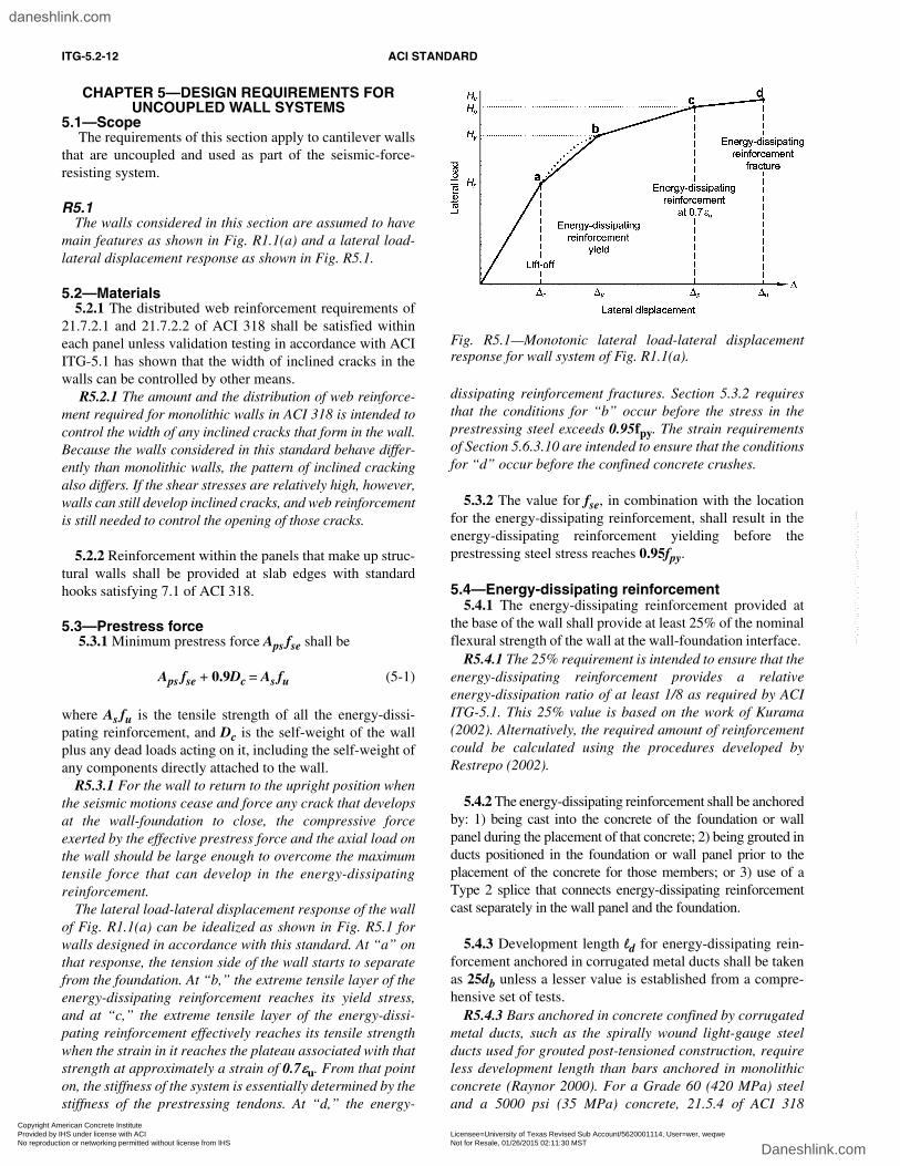
R5.1The walls considered in this section are assumed to have
main features as shown in Fig. R1.1(a) and a lateral load-lateral displacement response as shown in Fig. R5.1.
5.2—Materials5.2.1 The distributed web reinforcement requirements of
21.7.2.1 and 21.7.2.2 of ACI 318 shall be satisfied withineach panel unless validation testing in accordance with ACIITG-5.1 has shown that the width of inclined cracks in thewalls can be controlled by other means.
R5.2.1 The amount and the distribution of web reinforce-ment required for monolithic walls in ACI 318 is intended tocontrol the width of any inclined cracks that form in the wall.Because the walls considered in this standard behave differ-ently than monolithic walls, the pattern of inclined crackingalso differs. If the shear stresses are relatively high, however,walls can still develop inclined cracks, and web reinforcementis still needed to control the opening of those cracks.
5.2.2 Reinforcement within the panels that make up struc-tural walls shall be provided at slab edges with standardhooks satisfying 7.1 of ACI 318.
5.3—Prestress force 5.3.1 Minimum prestress force Aps fse shall be
Aps fse + 0.9Dc = As fu (5-1)
where As fu is the tensile strength of all the energy-dissi-pating reinforcement, and Dc is the self-weight of the wallplus any dead loads acting on it, including the self-weight ofany components directly attached to the wall.
R5.3.1 For the wall to return to the upright position whenthe seismic motions cease and force any crack that developsat the wall-foundation to close, the compressive forceexerted by the effective prestress force and the axial load onthe wall should be large enough to overcome the maximumtensile force that can develop in the energy-dissipatingreinforcement.
The lateral load-lateral displacement response of the wallof Fig. R1.1(a) can be idealized as shown in Fig. R5.1 forwalls designed in accordance with this standard. At “a” onthat response, the tension side of the wall starts to separatefrom the foundation. At “b,” the extreme tensile layer of theenergy-dissipating reinforcement reaches its yield stress,and at “c,” the extreme tensile layer of the energy-dissi-pating reinforcement effectively reaches its tensile strengthwhen the strain in it reaches the plateau associated with thatstrength at approximately a strain of 0.7εu. From that pointon, the stiffness of the system is essentially determined by thestiffness of the prestressing tendons. At “d,” the energy-
dissipating reinforcement fractures. Section 5.3.2 requiresthat the conditions for “b” occur before the stress in theprestressing steel exceeds 0.95fpy. The strain requirementsof Section 5.6.3.10 are intended to ensure that the conditionsfor “d” occur before the confined concrete crushes.
5.3.2 The value for fse, in combination with the locationfor the energy-dissipating reinforcement, shall result in theenergy-dissipating reinforcement yielding before theprestressing steel stress reaches 0.95fpy.
5.4—Energy-dissipating reinforcement5.4.1 The energy-dissipating reinforcement provided at
the base of the wall shall provide at least 25% of the nominalflexural strength of the wall at the wall-foundation interface.
R5.4.1 The 25% requirement is intended to ensure that theenergy-dissipating reinforcement provides a relativeenergy-dissipation ratio of at least 1/8 as required by ACIITG-5.1. This 25% value is based on the work of Kurama(2002). Alternatively, the required amount of reinforcementcould be calculated using the procedures developed byRestrepo (2002).
5.4.2 The energy-dissipating reinforcement shall be anchoredby: 1) being cast into the concrete of the foundation or wallpanel during the placement of that concrete; 2) being grouted inducts positioned in the foundation or wall panel prior to theplacement of the concrete for those members; or 3) use of aType 2 splice that connects energy-dissipating reinforcementcast separately in the wall panel and the foundation.
5.4.3 Development length ld for energy-dissipating rein-forcement anchored in corrugated metal ducts shall be takenas 25db unless a lesser value is established from a compre-hensive set of tests.
R5.4.3 Bars anchored in concrete confined by corrugatedmetal ducts, such as the spirally wound light-gauge steelducts used for grouted post-tensioned construction, requireless development length than bars anchored in monolithicconcrete (Raynor 2000). For a Grade 60 (420 MPa) steeland a 5000 psi (35 MPa) concrete, 21.5.4 of ACI 318
Fig. R5.1—Monotonic lateral load-lateral displacementresponse for wall system of Fig. R1.1(a).
Copyright American Concrete Institute Provided by IHS under license with ACI Licensee=University of Texas Revised Sub Account/5620001114, User=wer, weqwe
Not for Resale, 01/26/2015 02:11:30 MSTNo reproduction or networking permitted without license from IHS
--`,`,,```,,`,```,`,`,```,``,,,,-`-`,,`,,`,`,,`---
daneshlink.com
Daneshlink.com

DESIGN REQUIREMENTS OF SHEAR WALL SATISFYING ACI ITG-5.1 ITG-5.2-13
requires a 32.6db development length for a straight bar.Because of the presence of the metal duct, a shorter develop-ment length can be required for the special reinforcementthan that specified in 21.5.4 of ACI 318. Analysis of avail-able results shows that a length of 25db is appropriate if nofibers are used in the grout, and even shorter lengths areappropriate when a polypropylene multifilament fiber isused in the grout. The depth of the foundation needs to belarge enough to anchor the energy-dissipating reinforce-ment. The use of heads on the deformed bars can reduce theanchorage length of that energy-dissipating reinforcement.
5.5—Shear strength5.5.1 Unless demonstrated by test and analysis that alter-
nate procedures can be used, the Vn of the wall shall becalculated as specified in 21.7.4.1 and 21.7.4.2 of ACI 318,and shear reinforcement shall be provided as required by21.7.4.3 of ACI 318.
R5.5.1 Details of the connection of walls to the foundationare critical. The deformations that occur at the base of thewall due to plastic hinging or extension of the reinforcingbars and post-tensioning steel crossing the wall to foundationinterface are in part determined by details of the anchorageand the bonding of those reinforcements on either side of theinterface. Where grout is used to bed panels on the founda-tion and between panels, the characteristics of that grout interms of materials, strength, and thickness can have a largeeffect on wall performance. The typical grout pad with athickness of 1 in. (25 mm) or less can be expected to providea coefficient of friction of approximately 0.6 under reversedloadings (Hutchinson et al. 1993; Soudki et al. 1995a,b).Pads with greater thickness and without fiber reinforcementexhibit lesser coefficients of friction. Adequate frictionalresistance is essential to preventing undesirable slip alongthe wall-foundation interface. Fiber reinforcement is essentialto preventing breakup of the grout and maintenance of thecoefficient of friction. Section 5.8 permits the use of grouttypes that differ from those tested by Hutchinson et al. (1993)and the maximum joint thickness permitted in Section 5.8 islarger than the maximum considered in those tests. For thesereasons, a smaller value of μ, equal to 0.5, is specified.
At horizontal joints within the wall, other than the joint atthe wall-foundation interface, the nominal shear strengthcan be computed using shear friction principles becausecapacity design principles should be used to ensure thatthose joints remain closed during the DBE event.
5.5.2 At the probable flexural strength for the wall-foun-dation interface Mpr , calculated as described in Section5.6.3, φ times the nominal shear strength Vn for the wall, andφ times the nominal horizontal shear strength for the inter-face Vni, shall be equal to or greater than the base shearcausing Mpr. In addition, φ times the nominal horizontalshear strength on each horizontal joint between precastpanels within the wall shall be equal to or greater than theshear acting at the level of that joint when Mpr is developedat the wall-foundation interface. The increase in the post-
tensioning force with lateral displacement may be used incalculating Vn and Vni.
5.5.3 Unless demonstrated by test and analysis that analternative procedure can be used, the wall-foundation inter-face requirement of Section 5.5.2 shall be satisfied by takingφ times the nominal horizontal shear strength Vni as μC,where C is the compressive force acting on the concrete atthe interface at Mpr and is computed in accordance withSection 5.6.3.8. The coefficient of friction μ shall be taken as0.5 unless demonstrated by a comprehensive series of teststhat the use of a higher value is justified. Unless demon-strated by tests and analysis that an alternative procedure canbe used, the requirement of Section 5.5.2 for the shearstrength on the horizontal joints between precast panels shallbe satisfied by computing Vn on each joint using the shearfriction provisions of 11.7 of ACI 318, with μ taken as 0.6λ,and fy in Eq. (11-25) taken as fprs.
5.5.4 φ for shear shall be taken as 0.75 as specified in9.3.2.3 of ACI 318.
R5.5.4 Because the wall is designed for the shear that accom-panies development of the probable flexural strength of thewall, the reduced φ of 9.3.4 of ACI 318 is not applicable.
5.6—Flexural strength and drift limits5.6.1 General considerations
5.6.1.1 Walls and portions of walls shall satisfy therequirements for flexure and axial loads of 21.7.5 of ACI318. The boundary element design requirements of 21.7.6 shallbe satisfied unless testing in accordance with ACI ITG-5.1has shown otherwise. Until θL exceeds θLdesign the openingof horizontal joints between precast panels within the wallshall be prevented using capacity design principles.
R5.6.1.1 The lateral force-drift angle response of a wallis similar to that of the lateral force-lateral displacementresponse shown in Fig. R5.1. The probable flexural strengthMpr at the wall-foundation interface and the correspondingmaximum drift angle capacity θLmax of the wall are the peakresponse values. θLdesign is to be less than two-thirds θLmax,and φ Mn is to be greater than the Mu at which θLdesigndevelops. Sritharan et al. (2007) showed that the assumptionof Section 5.6.1.2 is realistic once the rotation at the wall-foundation interface exceeds about 0.003; therefore, formost designs, the assumption is reasonable for calculationsof both Mn and Mpr. Provided the wall rocks about its baseand the horizontal joints between precast panels over theheight of the wall do not open, the assumption of Section5.6.1.4 is also realistic. Opening at other horizontal jointlocations can be prevented through the use of capacitydesign principles.
5.6.1.2 The distance from the extreme compression fiberto the neutral axis shall be assumed to remain constant as θLincreases from θLdesign to θLmax.
5.6.1.3 The value of θLmax shall equal or exceed 1.5times θLdesign.
Copyright American Concrete Institute Provided by IHS under license with ACI Licensee=University of Texas Revised Sub Account/5620001114, User=wer, weqwe
Not for Resale, 01/26/2015 02:11:30 MSTNo reproduction or networking permitted without license from IHS
--`,`,,```,,`,```,`,`,```,``,,,,-`-`,,`,,`,`,,`---
daneshlink.com
Daneshlink.com

ITG-5.2-14 ACI STANDARD
5.6.1.4 As the connection at the interface opens, theelongation Δs of the energy-dissipating reinforcement intension, and the additional elongation Δprs of the post-tensioning tendon, shall be assumed to be directly propor-tional to distance from the neutral axis.
5.6.2 Nominal flexural strength5.6.2.1 φ times the nominal flexural strength at the wall-
foundation interface shall be equal to or greater than thedesign overturning moment Mu. In addition, φ times thenominal flexural strength at any section within the height ofthe wall shall exceed the overturning moment acting at thesame section.
5.6.2.2 The design drift angle, θLdesign, corresponding tothe design displacement and the design story drift angle,shall satisfy Section 4.3.4.
5.6.2.3 The nominal flexural strength Mn at the wall-foundation interface for the design drift angle, θLdesign,corresponding to the design displacement, shall be calcu-lated based on satisfaction of applicable conditions of equi-librium and compatibility of deformations.
5.6.3 Probable flexural strength5.6.3.1 The probable flexural strength Mpr at the wall-
foundation interface and the corresponding maximum driftangle capacity θLmax shall be calculated based on theassumptions given in Sections 5.6.3.2 through 5.6.3.9 of thisstandard and satisfaction of applicable conditions of equilib-rium and compatibility of deformations.
R5.6.3.1 Figure R5.2 shows the conditions assumed toexist at the wall-foundation interface when the energy-dissi-pating reinforcement is stressed to its tensile strength fu. Theassumptions for the magnitude and location for the compres-sion force and the use of fu for both groups of energy-dissi-pating reinforcement are consistent with the limitations forthose characteristics described herein. The width of the jointopening at the location of the energy-dissipating reinforce-ment furthest from the extreme compression fiber of the wallis given by Eq. (5-2). The effective debonded length of αbdd,additional to the deliberately debonded length of Lu, isbased on an analysis of the crack widths measured in thetests reported by Cheok et al. (1996). Smaller additionaleffective debonded lengths were found in tests (Raynor 2000)where anchorage conditions were different to those reportedby Cheok et al. (1996). It is desirable that the designerexamine variations in the calculated response with varia-tions in values for Lu and αb before settling on a designdetail for the deliberately debonded region of the energy-dissipating reinforcement. As αb values vary from 2.0 to 5.5,values for Mpr increase slowly, while values for driftincrease more rapidly.
When the interface rotates about its neutral axis, locatedat a distance c from the extreme compression fiber of thewall or the grout pad, whichever is the lesser, the jointopening at the level of the post-tensioned strands is Δprs ,where Δprs is given by
Δprs = Δs [(lw /2) – c]/((lw /2 + e – c) (R5-1)
If Lups is the length over which the post-tensioning tendonis unbonded, the strain in the strands at the probable flexuralstrength can be computed by Eq. (5-3). Because the tendonis unbonded anchorage to anchorage, Lups equals theanchorage-to-anchorage distance, and Δprs is the jointopening at the tendon location. The strain εprs is directlyrelated to Δprs because Section 4.4.6 requires no openings ofjoints along the length of the tendon except at the wall-to-foundation interface at the design displacement.
The probable flexural strength Mpr is the sum of thecontributions from the energy-dissipating reinforcement Msand the post-tensioned reinforcement Mprs. Those momentsare given by
Ms = Asfu(lw – a)/2 (R5-2)
provided
(lw/2 – e)/(lw/2 + e) > 0.78 (R5-3)
and
Mprs = Apsfprs(lw – a)/2 (R5-4)
where
a = βc (R5-5)
and fprs is the stress corresponding to εprs.The 0.78 limit is needed to ensure that the steel stress can
be taken as fu for the two groups of energy-dissipatingreinforcement located on either side of the centroid of the wall.
For a design earthquake having a 10% probability ofoccurrence in 50 years, the design drift angle concept shouldbe consistent with the design displacement concept specifiedin 21.1 of ACI 318.
Fig. R5.2—Conditions as probable flexural strength forbase of wall of Fig. R1.1(a).
Copyright American Concrete Institute Provided by IHS under license with ACI Licensee=University of Texas Revised Sub Account/5620001114, User=wer, weqwe
Not for Resale, 01/26/2015 02:11:30 MSTNo reproduction or networking permitted without license from IHS
--`,`,,```,,`,```,`,`,```,``,,,,-`-`,,`,,`,`,,`---
daneshlink.com
Daneshlink.com

DESIGN REQUIREMENTS OF SHEAR WALL SATISFYING ACI ITG-5.1 ITG-5.2-15
5.6.3.2 The strain in the energy-dissipating reinforce-ment in tension, εsu , shall be calculated as
(5-2)
where Lu is the length over which the energy-dissipatingreinforcement is deliberately debonded in the wall adjacentto the interface, and αb is a coefficient quantifying the effec-tive additional debonded length that develops in the energy-dissipating reinforcement at the probable flexural strength ofthe wall-foundation interface. The value of αb shall not betaken as greater than 5.5 nor less than 2.0.
5.6.3.3 At Mpr , the strain calculated from Eq. (5-2) shallbe not greater than 0.85εu. Unless the steel stress correspondingto the εsu calculated from Eq. (5-2) is determined from themeasured stress-strain properties for that steel, it shall bepermitted to take the stress in the energy-dissipating reinforce-ment at the probable flexural strength as fu.
5.6.3.4 The total strain in the prestressing reinforcement,εprs, after rotation at the interface, shall be calculated as
(5-3)
where εse is the strain in the prestressing reinforcement at itseffective stress, and Lups is the unbonded length of thetendon from its anchor in the foundation to its anchor at thetop of the wall. The stress fprs in the post-tensioning tendonat θLdesign shall not exceed fpy.
5.6.3.5 Strain in the compressed concrete shall beassumed directly proportional to the distance from theneutral axis and the maximum usable strain at the extremecompression fiber shall be that given by Eq. (5-5).
5.6.3.6 The compressed concrete shall be confined bytransverse reinforcement satisfying the requirements of21.7.6.4(c) of ACI 318. The transverse reinforcement shallextend horizontally from the extreme compression fiber adistance not less than 0.95c, and not less than 12 in. (305 mm),where c is the neutral axis depth.
5.6.3.7 The relationship between concrete compressivestress distribution and concrete strain shall be assumed to beof any shape in substantial agreement with the results ofcomprehensive tests.
5.6.3.8 Requirements of Section 5.6.3.7 are satisfied byan equivalent rectangular concrete stress distribution definedby the following:
(a) Concrete stress of 0.92fcc′ assumed uniformly distrib-uted over a rectangular compression zone extending adistance of 0.96c from the extreme concrete compressionfiber; and
εsuΔs
Lu αbdb+( )-----------------------------=
εprs εseΔprs
Lups----------⎝ ⎠
⎛ ⎞+=
(b) A value of fcc′ determined from Table 5.1, where fL′
is the effective lateral confining stress provided by the trans-verse reinforcement, and fL′ equals 0.45ρs fyt for spiral rein-forcement and 0.35ρs fyt for rectangular hoops, where ρs isthe ratio of volume of hoop or spiral reinforcement to totalvolume of core confined by hoops or spirals and measuredout-to-out of hoops or spirals. Where the transverse rein-forcement is rectangular hoops, ρs equals ρx + ρy where ρx,ρy are the transverse reinforcement ratios in the directionsparallel to the major, minor axes of the compressed area; andfyt is the specified yield strength of transverse reinforcement, psi.Interpolation shall be permitted between values in Table 5.1.
R5.6.3.8 Calculation of the neutral axis depth, themagnitude of the compression force at Mpr , and themaximum usable strain at the extreme compression fiber arebased on the models proposed by Sritharan et al. (2007). Itis assumed in this standard that the magnitude of thecompression force is determined by the strength of theconfined concrete in the toe of the wall, and not by thestrength of the grout pad or the concrete foundation. Wherevery heavy transverse confining reinforcement is used in thetoe of the wall, any limitation imposed by the bearingstrengths of the grout pad and foundation should be checked.Those strengths depend on the geometric proportions of thepad and of the foundation in addition to the measuredcompressive strengths of the materials used in the pad andthe foundation. Bearing strength limitations for the founda-tion are specified in 10.17.1 of ACI 318. Bearing strengthlimitations for the interface grout are specified in Section5.8.3 of this standard.
The compression force at the toe of the wall is providedby a stress of α fcc′ acting over a wall length of β c. Thevalues for α and β vary with the concrete strength in thewall, the confinement of the toe, and the extreme fibercompressive strain for the wall. The values of 0.92 and 0.96used for α and β , respectively, are reasonable lower-boundvalues for the range of fc′ values of 4000 to 8000 psi (28 to55 MPa) and the fL′ /fc′ values shown in Table 5.1. The ratioof fcc′ /fc′ depends on the effective lateral confining stress fL′
provided by the transverse reinforcement. Values of fL′ /fc′ inTable 5.1 are multiples of the minimum confinementrequired by Eq. (21-2) of ACI 318.
5.6.3.9 The value of θLmax shall not exceed the value ofθL at which the maximum usable strain εcmax is reached inthe extreme compression fiber
θLmax = εcmaxLp /c (5-4)
where
εcmax = 0.004 + 4.6εsut(fL′ /fcc′ ) (5-5)
Table 5.1—Ratio of core strength to concrete strength based on lateral confinement
fL′/fc′ 0.036 0.072 0.108 0.144 0.180
fcc′ /fc′ 1.23 1.43 1.60 1.76 1.90
Copyright American Concrete Institute Provided by IHS under license with ACI Licensee=University of Texas Revised Sub Account/5620001114, User=wer, weqwe
Not for Resale, 01/26/2015 02:11:30 MSTNo reproduction or networking permitted without license from IHS
--`,`,,```,,`,```,`,`,```,``,,,,-`-`,,`,,`,`,,`---
daneshlink.com
Daneshlink.com
ITG-5.2-16 ACI STANDARD
and εsut is the ultimate specified strain capacity of transversereinforcement, and Lp is effective height of plastic hingingzone at toe of wall = 0.06hw.
R5.6.3.9 The value of θLmax will usually be limited bythe conditions specified in Section 5.6.1. The value of εcmaxspecified by Eq. (5-5) is the maximum strain at which frac-ture is predicted for the transverse reinforcement.
5.7—Detailing of lowermost wall panel5.7.1 The bottom of the lowermost wall panel that sits on
the foundation shall be detailed to minimize the effects ofcrushing and spalling where the corners of that panel bear onthe interface grout. The details to satisfy this requirementshall be indicated on the design drawings or in the projectspecifications.
5.7.2 Reinforcement shall be provided in the bottom of thelowermost wall panel parallel to the foundation surface thatis adequate to resist the spalling stresses at the panel surfacecreated by the force C, specified in Section 5.5.3, acting overan area equal to the thickness of the wall at the interface and0.96 times the neutral axis depth at the probable flexuralstrength of the interface.
5.8—Interface grout5.8.1 Interface grout shall satisfy the requirements of
Section 3.5. The thickness of the nonshrink interface groutshall not exceed 1.5 in. (38 mm).
R5.8.1 The performance of the joint between the wall andthe foundation directly depends on the toughness of the groutused in the interface. The interface is also one of the fewlocations where erection tolerances can be provided. Thegrout in the joint should remain intact and not crush or fallout before the compression end of the wall starts crushing orspalling in an extreme event. Section 3.5 requires use of fiberreinforcement in the grout to ensure adequate grout tough-ness. Fibers may be steel or polypropylene. Polypropylenefibers are desirable in exposed locations because joints withsteel fibers can be susceptible to rusting, and polypropylenefibers provide added resistance to spalling during fire. Thetesting described in the references (Rahman and Restrepo2000; Sause and Pessiki 2005; Schultz and Magana 1996)used polypropylene fibers.
If the joint is too thick, the grout can fail under a combina-tion of shear and axial stress at stresses less than thecompressive strength of the grout. The compressive strengthof the grout should be approximately the same as thecompressive strength of the precast wall. If the grout hasconsiderably greater strength than the wall, it can causepremature crushing of the concrete at the compressioncorner of the wall at high displacement levels. If the grouthas considerably less strength than the wall, it will crushfirst at high strain levels and cause a prestress loss, theeffects of which will be difficult to offset during any subse-quent repair operations. The limitation of Section 5.8.3recognizes the strength increase that results as the thicknessof the grout layer decreases in relation to the lesser width ofthe grout layer (Price 1951).
5.8.2 The specified compressive strength of the grout shallbe not less than fc′ .
5.8.3 The stress fcc′ calculated in Section 5.6.3.8(b) shallnot exceed 2.5 times the specified compressive strength ofthe grout.
CHAPTER 6—DESIGN REQUIREMENTSFOR COUPLED WALL SYSTEMS
6.1—Scope The requirements of this section apply to shear walls that
are connected along adjacent vertical edges by couplingdevices and are used as part of the seismic-force-resistingsystem. Except for possible height variations as a result ofsetbacks or the extension of one wall above the other adja-cent wall to which it is coupled, walls shall have identicalcross-sectional dimensions, reinforcement details, and initialprestressing forces; and all coupled edges shall contain anequal number of identical coupling devices.
6.2—Materials Materials shall satisfy the requirements of Section 5.2.
6.3—Coupling devices 6.3.1 Each coupling device shall exhibit a relative energy-
dissipation ratio greater than 1/8 when cycled betweenmaximum displacements equal to the displacement imposedon the connectors when the wall system is displaced to 1.5times its design displacement.
R6.3.1 The UFP coupling devices, defined in R2.2 anddescribed in Section 7.0, provide a relative energy-dissipa-tion ratio greater than 1/8 when they are constructed ofASTM A240 Type 304 stainless steel and are designed toyield before the wall system reaches its design displacement.
6.3.2 The number of devices, ncon, in each joint betweenprecast walls shall be equal to or greater than
ncon = 0.3Mn/((n – 1)Fconlw) (6-1)
where Mn is the nominal moment capacity of wall system atthe design displacement, in.-lb (Nm); n is the number ofwalls in the system; and Fcon is the connector force at designdisplacement, lb (N).
R6.3.2 The basis for Eq. (6-1) is detailed in Sritharan et al.(2007) and should ensure that the coupling devices yieldbefore the wall system reaches its design displacement.
6.3.3 For a UFP coupling device, Fcon equals Vscu calcu-lated from Eq. (7-1).
6.4—Prestress force 6.4.1 The required area Aps of the post-tensioning steel
shall be determined using moment equilibrium for the forcesacting on the base of the wall that provides the larger, orlargest, moment resistance at the design displacement.Coupling devices shall be assumed to have reached theirlimiting strength, and the prestressing steel shall be assumedto be at 0.95fpy at the design displacement. For a two-wall
Copyright American Concrete Institute Provided by IHS under license with ACI Licensee=University of Texas Revised Sub Account/5620001114, User=wer, weqwe
Not for Resale, 01/26/2015 02:11:30 MSTNo reproduction or networking permitted without license from IHS
--`,`,,```,,`,```,`,`,```,``,,,,-`-`,,`,,`,`,,`---
daneshlink.com
Daneshlink.com

DESIGN REQUIREMENTS OF SHEAR WALL SATISFYING ACI ITG-5.1 ITG-5.2-17
system, the larger resistance is provided by the leading wall.For a three or greater wall system, the largest resistance isprovided by an intermediate wall.
R6.4.1 The forces acting on two- and three-wall coupledsystems for a given base rotation θ are shown in Fig. R6.1.For the three-wall system, the individual walls in the systemare described as “leading,” “intermediate,” and “trailing,”as shown in Fig. R1.1(b)(ii) and Fig. R6.1. Horizontalground motions cause each wall to rock about its base,moving essentially as a rigid body. The idealized monotoniclateral load-lateral displacement response for such systems,designed in accordance with this standard, is essentially asshown in Fig. R5.1. At “a,” the tension side of each wallstarts to separate from the foundation. At “b,” the couplingdevices yield, and at “c,” the strain in the coupling devicesreaches approximately 0.7εscu. At “d,” the coupling devicesfracture. While the response of the coupling devices is likelyto be elastoplastic; for simplicity, that response is assumedto be rigid plastic in this standard. The basis for the λpfactor used in Eq. (6-2), and the procedures for calculatingthe area of post-tensioning steel and the initial stress levelfor that steel are detailed in Sritharan et al. (2007).
6.4.2 The design moment Mdw for the wall providing thegreater or greatest resistance shall be taken as
Mdw = Mu/n + (λpnconFconlw) (6-2)
where λp equals 0.9 for a two-wall system and 1.05 for athree or greater wall system, and ncon is the number ofcoupling devices per vertical joint for the walls.
6.4.3 For determination of Mdw, the position at which thecompressive force acts on the toe of the wall shall bedetermined in accordance with Section 5.6.3.8.
6.4.4 The required initial stress in the prestressing steel,fse, shall be determined by calculating the neutral axis depthat the compression toe of the trailing wall and assuming thepost-tensioning tendons in the trailing wall are at 0.9fpy at thedesign displacement.
6.4.5 The area Aps determined in accordance withSection 6.4.1 and the initial stress fse determined in accor-dance with Section 6.4.4 shall be used for all walls in thecoupled wall system.
6.5—Shear strength6.5.1 The Vn value for each wall in the system shall be
calculated as specified in Section 5.5.1 and φVn for each wallshall exceed the fraction of the horizontal base shear actingon that wall when the wall system develops its probableflexural strength.
R6.5.1 Failure in shear of any one of the walls in acoupled wall system is likely to trigger shear failure of thewhole system. A sliding shear movement at the base of a wallsystem, however, would involve movement of all walls in the
system and, therefore, the shear strength is controlled by thesum of the Vni values for the individual walls.
6.5.2 The sum of the Vni values for each wall in the systemshall exceed the horizontal base shear acting on the wallsystem when the system develops its probable flexuralstrength. The Vni value for each wall shall be calculated asspecified in Section 5.5.3. The sum of the Vn values for anyhorizontal joint between precast panels for each wall in thesystem shall exceed the horizontal shear acting on that levelof the wall system when the system develops its probableflexural strength. The Vn on horizontal joints shall be calcu-lated as specified in Section 5.5.3.
6.5.3 φ for shear shall be taken as 0.75 as specified in9.3.2.3 of ACI 318.
6.6—Flexural strength and drift limits6.6.1 Coupled walls and portions of coupled walls shall
satisfy the requirements of Sections 5.6.1, 5.6.2, and 5.6.3.
6.6.2 The probable flexural strength Mpr at the wall-foundation interface for the coupled wall system and the
Fig. R6.1—Forces and displacements for wall systems ofFig. R1.1(b) at base rotation θLdesign.
Copyright American Concrete Institute Provided by IHS under license with ACI Licensee=University of Texas Revised Sub Account/5620001114, User=wer, weqwe
Not for Resale, 01/26/2015 02:11:30 MSTNo reproduction or networking permitted without license from IHS
--`,`,,```,,`,```,`,`,```,``,,,,-`-`,,`,,`,`,,`---
daneshlink.com
Daneshlink.com

ITG-5.2-18 ACI STANDARD
corresponding maximum drift angle capacity θLmax shall becalculated based on the assumptions given in Section 5.6.1and 5.6.3 of this standard and satisfaction of applicableconditions of equilibrium and compatibility of deformations.
6.6.3 The value of θLmax for the coupled wall system shallequal or exceed 1.5 θLdesign.
6.6.4 The assumptions and requirements of Section 5.6 shallapply separately to each wall in the coupled wall system.
6.7—Lowermost panelThe detailing of the bottom of the lowermost panel of
every wall in the coupled wall system shall satisfy therequirements of Section 5.7.
6.8—Interface groutThe interface grout provided between the coupled wall and
the foundation shall satisfy the requirements of Section 5.8.
CHAPTER 7—DESIGN REQUIREMENTSFOR COUPLING DEVICES
7.1—ScopeThe requirements of this section apply to coupling devices
used to transfer shear between adjacent vertical edges ofseismic-force-resisting coupled walls.
R7.1 In accordance with ACI ITG-5.1, coupling devices should
be demonstrated to have the strength, ductility, and energy-dissipating toughness required for their use in an actualstructure either by prior testing of those elements at halfscale or larger or by their testing as part of the validationtesting of the unbonded post-tensioned precast coupledwalls. The use of commercially fabricated devices whosestrength, displacement ductility, and energy-dissipatingtoughness is guaranteed by the device supplier is preferableto the use of shear transfer devices developed in accordancewith the requirements of this section. Design requirementsare described in this section for UFP coupling devices thatreplicate the devices used in the PRESSS building. Conceptsfor other types of shear transfer devices are described inBanks and Stanton (2005).
7.2—General In accordance with the requirements of Section 5.4 of ACI
ITG-5.1, commercially available coupling devices shall beused unless commercial devices are not available, in whichcase design and fabrication procedures shall satisfy therequirements of Sections 7.3 and 7.4.
Coupling devices are defined in Section 2.2. as consistingof anchorages and connecting links. This section concernsthe design of the connecting links. Anchorages must meetthe strength requirements of 21.13.3 of ACI 318.
7.3—MaterialsFor devices incorporated into an actual structure, steel
materials shall be from the same heat and to the samespecification, and the fabrication procedures used shall be the
same as those for devices that are tested to demonstrate thatthey have the strength, shear displacement capacity, andenergy-dissipating toughness required by the designer. Addi-tional material requirements are specified in Section 3.6.
7.4—Design methodology This section details a design methodology for a
connecting link of a UFP coupling device that consists of asteel plate bent through 180 degrees and welded at its ends toembed plates anchored in adjacent panels. A pair of linkswith their bends oriented in opposite directions provides asymmetrical connection.
The nominal shear capacity Vscu equals
Vscu = (bsctsc /2)(fscuεscu)/2 (7-1)
where bsc is the width of link bar, in. (mm); tsc is the thicknessof link bar, in. (mm); fscu is the specified tensile strength oflink bar material, psi (MPa); and εscu is the ultimate tensilestrain of link bar material.
The distance between the start of the attachment point forthe UFP connecting link and the springing point for the 180-degree bend shall be one-third greater than the required ulti-mate shear displacement capacity for the link.
The initial stiffness Ksc of the link can be calculatedapproximately as
Ksc = Es(tsc)3/(4.5)(π)(asc)
3 (7-2)
where Es is the modulus of elasticity of steel, psi (MPa); andasc is the radius of the 180 degree bend for the link measuredto its inside face, in. (mm).
R7.4The connecting link of the UFP coupling device is an
energy-dissipating flexible connector in which rolling-bending action resists vertical shear force. The link provideslittle resistance to in-plane movement that is normal to thejoint so that it is well suited to coupled wall applications.
The forces Msc and Vsc assumed to be acting on a linkwhen the two sides are displaced relative to one another areshown in Fig. R7.1(i) (Stanton and Nakaki 2002). Momentequilibrium requires that at the nominal strength of the link
Vscudsc = 2Mpsc (R7-1)
where Mpsc is the plastic moment strength of the link, andMpsc = (bsctsc
2)fscu /4.As the straight part of the plate is bent, the strain change in
the outer fiber of the link caused by the change in curvature is
εsc = tsc/dsc (R7-2)
where εsc is the maximum strain that can be imposed cycli-cally and repeatedly on the link without damaging it. Thatmaximum strain is approximately εscu /2. Combining thosethree equations results in the Vscu value of Eq. (7-1). One
Copyright American Concrete Institute Provided by IHS under license with ACI Licensee=University of Texas Revised Sub Account/5620001114, User=wer, weqwe
Not for Resale, 01/26/2015 02:11:30 MSTNo reproduction or networking permitted without license from IHS
--`,`,,```,,`,```,`,`,```,``,,,,-`-`,,`,,`,`,,`---
daneshlink.com
Daneshlink.com

DESIGN REQUIREMENTS OF SHEAR WALL SATISFYING ACI ITG-5.1 ITG-5.2-19
limitation on the displacement capacity is the distance AB inFig. R7.1 between the springing point for the bend (A in Fig.R7.1(ii)) in the connecting link of the UFP coupling deviceand the start of its attachment point (B in Fig. R7.1(ii)) to theembedded plate. The other is the strain capacity for the steelin the connecting link.
In experiments (Schultz and Magana 1996), ASTM A36steel cracked when bent to the radius shown in Fig. R7.1(ii).Therefore, ASTM A240/A240M Type 304 stainless steel wasused in their link test because of its high strain capacity. Inother tests (Conley et al. 2002; Thomas 2003) and in thePRESSS building, the same steel was used with excellentresults. In those tests, the effective yield stress of the link wasabout 60% of its ultimate capacity. Figure R7.2 (Thomas2003) shows the response for a 3 x 3/8 in. (76 x 10 mm) UFPconnecting link bent so that dsc was 3.88 in. (98 mm) andsubject to a cyclically reversing load history and to a loadhistory similar to that imposed on the UFP coupling devicein the PRESSS building. The stainless steel plate had a yieldstress of 40 ksi (276 MPa), an ultimate strength of 85 ksi(586 MPa) and an ultimate strain at fracture of 38%. Forthat test, the distance AB in Fig. R7.1(ii) was 3 in. (76 mm).Results for tests on duplicate specimens were very similar.The relationship recommended by Thomas (2003) is shownin Fig. 7.2(i) by broken lines for design for the UFP couplingdevice used in the PRESSS building.
CHAPTER 8—REFERENCESR8.1—Referenced standards and reports
The standards and reports listed below were used todevelop this report.
American Concrete Institute 318-05 Building Code Requirements for Structural
Concrete and CommentaryITG-5.1-07 Acceptance Criteria for Special Unbonded
Post-Tensioned Precast Structural Walls Basedon Validation Testing and Commentary
ASTM InternationalA240/A240M-04 Standard Specification for Chromium
and Chromium-Nickel Stainless SteelPlate, Sheet, and Strip for PressureVessels and for General Applications
A615-07 Standard Specification for Deformedand Plain Carbon-Steel Bars forConcrete Reinforcement
A706/A706M-04 Standard Specification for Low-AlloySteel Deformed and Plain Bars forConcrete Reinforcement
A955/A955M-07a Standard Specification for Deformedand Plain Stainless-Steel Bars forConcrete Reinforcement
C1107/C1107M-97 Standard Specification for Packaged Dry,Hydraulic-Cement Grout (Nonshrink)
These publications may be obtained from these organizations:
American Concrete Institute38800 Country Club DriveFarmington Hills, MI 48331www.concrete.org
Fig. R7.1—(i) UFP connecting link forces; and (ii) typicaldetails as tested by Thomas (2003).
Fig. R7.2—Response to differing loading histories for UFPconnecting links of type used in PRESSS building and withdimensions shown in Fig. R7.1(ii).
Copyright American Concrete Institute Provided by IHS under license with ACI Licensee=University of Texas Revised Sub Account/5620001114, User=wer, weqwe
Not for Resale, 01/26/2015 02:11:30 MSTNo reproduction or networking permitted without license from IHS
--`,`,,```,,`,```,`,`,```,``,,,,-`-`,,`,,`,`,,`---
daneshlink.com
Daneshlink.com

ITG-5.2-20 ACI STANDARD
ASTM International100 Barr Harbor DriveWest Conshohocken, PA 19428www.astm.org
R8.2—Cited referencesACI Committee 423, 2007, “Specification for Unbonded
Single-Strand Tendon Materials and Commentary (ACI423.7-07),” American Concrete Institute, Farmington Hills,MI, 21 pp.
ACI Innovation Task Group 1, 2003, “Special HybridMoment Frames Composed of Discretely Jointed Precastand Post-Tensioned Concrete Members (ACI ITG-1.2-03)and Commentary (ITG-1.2R-03),” American Concrete Insti-tute, Farmington Hills, MI, 14 pp.
ACI Innovation Task Group 5, 2007, “Acceptance Criteriafor Special Unbonded Post-Tensioned Precast StructuralWalls Based on Validation Testing and Commentary (ACIITG-5.1-07),” American Concrete Institute, FarmingtonHills, MI, 19 pp.
ASCE/SEI Minimum Design Loads for Buildings andOther Structures Standards Committee, 2005, “MinimumDesign Loads for Buildings and Other Structures (ASCE/SEI 7-05)—Seismic Provisions,” American Society of CivilEngineers, Structural Engineering Institute, Reston, VA.
Banks, G., and Stanton, J., 2005, “Panel-to-Panel Connec-tions for Hollow-Core Shear Walls Subject to SeismicLoading,” PCI Convention, Palm Springs, CA.
Bora, C.; Oliva, M. G.; Nakaki, S. D.; and Becker, R.,2007, “Development of a Precast Concrete Shear-WallSystem Requiring Special Code Acceptance,” PCI Journal,V. 52, No. 1, Jan.-Feb., pp. 122-135.
Cheok, G. S.; Stone, W. C.; and Nakaki, S. D., 1996,“Simplified Design Procedure for Hybrid Precast ConcreteConnections,” NISTIR 5765, NIST, Gaithersburg, MD,Feb., 81 pp.
Conley, J.; Sritharan, S.; and Priestley, M. J. N., 2002,“Precast Seismic Structural Systems PRESSS-3: The Five-Story Precast Test Building V. 3-1; Wall DirectionResponse,” Report No. SSRP-99/19, Department of Struc-tural Engineering, University of California at San Diego,CA, July.
Eberhard, M. O., and Sozen, M. A., 1993, “A Behavior-Based Method to Determine Design Shear in Earthquake-Resistant Walls,” ASCE Journal of Structural Engineering,V. 119, No. 2, Feb., pp. 619-640.
Hutchinson, R. L.; Rizkalla, S. H.; Lau, M.; and Heuvel, M.,1993, “Horizontal Post-Tensioned Connections for PrecastConcrete Bearing Shear Walls,” PCI Journal, V. 36, No. 3,Nov.-Dec., pp. 64-76.
Kurama, Y. C., 2002, “Hybrid Post-Tensioned PrecastConcrete Walls for Use in Seismic Regions,” PCI Journal,V. 47, No. 5, Sept.-Oct., pp. 36-59.
PCI Ad Hoc Committee on Precast Walls, 1997, “Designfor Lateral Force Resistance with Precast Concrete ShearWalls,” PCI Journal, V. 42, No. 5, Sept.-Oct., pp. 44-64.
Perez, F. J.; Pessiki, S.; and Sause, R., 2004a, “SeismicDesign of Unbonded Post-Tensioned Precast Concrete Walls
with Vertical Connectors,” PCI Journal, V. 49, No. 1, Jan.-Feb., pp. 58-79.
Perez, F. J.; Pessiki, S.; and Sause, R., 2004b, “LateralLoad Behavior of Unbonded Post-Tensioned PrecastConcrete Walls with Vertical Joints,” PCI Journal, V. 49,No. 2, Mar.-Apr., pp. 48-65.
Perez, F. J.; Pessiki, S.; and Sause, R., 2004c, “Experi-mental and Analytical Lateral Load Response of UnbondedPost-Tensioned Precast Concrete Walls,” ATLSS ReportNo. 04-11, Lehigh University, Bethlehem, PA, May.
Perez, F. J.; Pessiki, S.; Sause, R.; and Lu, L-W., 2003,“Lateral Load Tests of Unbonded Post-Tensioned PrecastConcrete Walls,” Large-Scale Structural Testing, SP-211,M. A. Issa and Y. L. Mo, eds., American Concrete Institute,Farmington Hills, MI, pp. 161-182.
Post-Tensioning Institute, 2007, “Recommendations forStay-Cable Design, Testing and Installation,” fifth edition,Phoenix, AZ, 101 pp.
Price, W. H., 1951, “Factors Influencing ConcreteStrength,” ACI JOURNAL, Proceedings, V. 47, No. 2, Feb.,pp. 417-432.
Priestley, M. J. N.; Sritharan, S.; Conley, J.; andPampanin, S., 1999, “Preliminary Results and Conclusionsfrom the PRESSS Five-Story Precast Concrete TestBuilding,” PCI Journal, V. 44, No. 6, Nov.-Dec., pp. 42-67.
Rahman, A. M., and Restrepo, J. I., 2000, “EarthquakeResistant Precast Concrete Buildings: Seismic Performanceof Cantilever Walls Prestressed Using Unbonded Tendons,”Research Report 2000-5, Department of Civil Engineering,University of Canterbury, Christchurch, New Zealand, Aug.
Raynor, D. J., 2000, “Bond Assessment of Hybrid FrameContinuity Reinforcement,” MSCE thesis, University ofWashington, Seattle, WA.
Restrepo, J. I., 2002, “New Generation of EarthquakeResisting Systems,” Proceedings, First fib Congress, Osaka,Japan, Session 6, Seismic Design of Concrete Structures,Oct., pp. 41-60.
Santana, G., 2005, “Conventional Reinforced ConcreteWalls Versus Hybrid Post-Tensioned Precast ConcreteWalls,” Proceedings, Third International Conference,Structural Concrete in the Americas, American ConcreteInstitute, Farmington Hills, MI, Nov. 2005.
Sause, R., and Pessiki, S., 2005, “Seismic Behavior andDesign of Precast Concrete Walls,” PCI Convention, PalmSprings, CA.
Schultz, A. E., and Magana, R. A., 1996, “Seismic Behaviorof Connections in Precast Concrete Walls,” Mete A. SozenSymposium—A Tribute from His Students, SP-162, J. K.Wight and M. E. Kreger, eds., American Concrete Institute,Farmington Hills, MI, pp. 273-312.
Soudki, K. A.; Rizkalla, S. H.; and LeBlanc, B., 1995a,“Horizontal Connections for Precast Concrete Shear WallsSubjected to Cyclic Deformations Part 1: Mild Steel Connec-tions,” PCI Journal, V. 40, No. 4, July-Aug., pp. 78-96.
Soudki; K. A.; Rizkalla, S. H.; and Daikiw, R. W., 1995b,“Horizontal Connections for Precast Concrete Shear WallsSubjected to Cyclic Deformations Part 2: PrestressedConcrete,” PCI Journal, V. 40, No. 5, July-Aug., pp. 82-96.
Copyright American Concrete Institute Provided by IHS under license with ACI Licensee=University of Texas Revised Sub Account/5620001114, User=wer, weqwe
Not for Resale, 01/26/2015 02:11:30 MSTNo reproduction or networking permitted without license from IHS
--`,`,,```,,`,```,`,`,```,``,,,,-`-`,,`,,`,`,,`---
daneshlink.com
Daneshlink.com

DESIGN REQUIREMENTS OF SHEAR WALL SATISFYING ACI ITG-5.1 ITG-5.2-21
Sritharan, S.; Aaleti, S.; and Thomas, D. J., 2007, “SeismicAnalysis and Design of Precast Concrete Jointed WallSystems,” ISU-ERI-Ames Report ERI-07404, Iowa StateUniversity, Dec.
Stanton, J. F., and Nakaki, S. D., 2002, “Design Guidelinesfor Precast Concrete Seismic Structural Systems-UnbondedPost-Tensioned Split Walls,” PRESSS Report No. 01/03-09,UW Report SM 02-02, Department of Civil Engineering,University of Washington, Seattle, WA, Feb., pp. 3-19.
Thomas, D. J., 2003, “Sec. 3.4 Force-DisplacementBehavior of U-Shaped Flexural Plate (UFP) Connectors, inAnalysis and Validation of a Seismic Design MethodProposed for Precast Jointed Wall System,” MS thesis, IowaState University, Ames, IA.
Thomas, D. J., and Sritharan, S., 2004, “An Evaluation ofSeismic Design Guidelines Proposed for Precast JointedWall Systems,” ISU-ERI-Ames Report ERI-04643, Depart-ment of Civil, Construction and Environmental Engineering,Iowa State University, Ames, IA, June.
Copyright American Concrete Institute Provided by IHS under license with ACI Licensee=University of Texas Revised Sub Account/5620001114, User=wer, weqwe
Not for Resale, 01/26/2015 02:11:30 MSTNo reproduction or networking permitted without license from IHS
--`,`,,```,,`,```,`,`,```,``,,,,-`-`,,`,,`,`,,`---
daneshlink.com
Daneshlink.com

As ACI begins its second century of advancing concrete knowledge, its original chartered purposeremains “to provide a comradeship in finding the best ways to do concrete work of all kinds and inspreading knowledge.” In keeping with this purpose, ACI supports the following activities:
· Technical committees that produce consensus reports, guides, specifications, and codes.
· Spring and fall conventions to facilitate the work of its committees.
· Educational seminars that disseminate reliable information on concrete.
· Certification programs for personnel employed within the concrete industry.
· Student programs such as scholarships, internships, and competitions.
· Sponsoring and co-sponsoring international conferences and symposia.
· Formal coordination with several international concrete related societies.
· Periodicals: the ACI Structural Journal and the ACI Materials Journal, and Concrete International.
Benefits of membership include a subscription to Concrete International and to an ACI Journal. ACImembers receive discounts of up to 40% on all ACI products and services, including documents, seminarsand convention registration fees.
As a member of ACI, you join thousands of practitioners and professionals worldwide who share acommitment to maintain the highest industry standards for concrete technology, construction, andpractices. In addition, ACI chapters provide opportunities for interaction of professionals and practitionersat a local level.
American Concrete Institute38800 Country Club DriveFarmington Hills, MI 48331U.S.A.Phone: 248-848-3700Fax: 248-848-3701
www.concrete.org
American Concrete Institute®
Advancing concrete knowledge
Copyright American Concrete Institute Provided by IHS under license with ACI Licensee=University of Texas Revised Sub Account/5620001114, User=wer, weqwe
Not for Resale, 01/26/2015 02:11:30 MSTNo reproduction or networking permitted without license from IHS
--`,`,,```,,`,```,`,`,```,``,,,,-`-`,,`,,`,`,,`---
daneshlink.com
Daneshlink.com

The AMERICAN CONCRETE INSTITUTE
was founded in 1904 as a nonprofit membership organization dedicated to publicservice and representing the user interest in the field of concrete. ACI gathers anddistributes information on the improvement of design, construction andmaintenance of concrete products and structures. The work of ACI is conducted byindividual ACI members and through volunteer committees composed of bothmembers and non-members.
The committees, as well as ACI as a whole, operate under a consensus format,which assures all participants the right to have their views considered. Committeeactivities include the development of building codes and specifications; analysis ofresearch and development results; presentation of construction and repairtechniques; and education.
Individuals interested in the activities of ACI are encouraged to become a member.There are no educational or employment requirements. ACI’s membership iscomposed of engineers, architects, scientists, contractors, educators, andrepresentatives from a variety of companies and organizations.
Members are encouraged to participate in committee activities that relate to theirspecific areas of interest. For more information, contact ACI.
www.concrete.org
Requirements for Design of a Special Unbonded Post-TensionedPrecast Shear Wall Satisfying ACI ITG-5.1 (ACI ITG-5.2-09) and Commentary
American Concrete Institute®
Advancing concrete knowledge
Copyright American Concrete Institute Provided by IHS under license with ACI Licensee=University of Texas Revised Sub Account/5620001114, User=wer, weqwe
Not for Resale, 01/26/2015 02:11:30 MSTNo reproduction or networking permitted without license from IHS
--`,`,,```,,`,```,`,`,```,``,,,,-`-`,,`,,`,`,,`---
daneshlink.com
Daneshlink.com
Copyright © 2022 FDOKUMEN